Welcome message from author
This document is posted to help you gain knowledge. Please leave a comment to let me know what you think about it! Share it to your friends and learn new things together.
Transcript

8122019 Cor Flex
httpslidepdfcomreaderfullcor-flex 120
8122019 Cor Flex
httpslidepdfcomreaderfullcor-flex 220
INDEX
Instrumentation Cables- Pairs and Triads (600V) 2 - 3
Power and Control Cables- Multi-conductor w Bare Ground(s) (600V) 4 - 5
Composite Power andControl Cables
- Multi-conductor w Bare Ground (600V) 6 - 7
Power Cables- 600V 3 and 4 Conductors with Bare Ground(s) 8 - 9
Medium Voltage Cables- 5kV - 133 Insulation Levels10 - 11
- 8kV - 100 Insulation Level10 - 11
- 15kV - 100 amp 133 Insulation Levels12 - 13
Pulling Instructions 14
Pulling Tension Tables 15
Conductor ID 16
600V1000V Marine Shipboard Cable
Nexans AmerCable believes the information presented throughout this catalog to be reliable and current All information is subject to change without notice The informationlisted is approximate and is presented only as a guide for product selection We make no claims or warranties for the suitability of any product for any particular application
Nexans AmerCable and CORFLEX are registered trademarks of Nexans copy 2013 AmerCable Incorporated
Flame Retardant
All CORFLEX cables passUL 1685 and IEEE 383vertical tray fire tests at
70000 BTUhr IEC60332-3 category Afire test IEEE 1202
and CSA FT4
CORFLEX rated less than5 kV also passes ICEAT-29-520 fire test at
210000 BTUhr
ArmorContinuous corrugatedand welded impervious
aluminum sheathwith no more than02 trace copperprovides completeprotection against
liquid and gas ingress
The Original MC-HL Technology
In 1958 Canada Wire and Cable which is nowpart of Nexans developed the first continuouscorrugated and welded cable sheath Thisproduct proved to be ideal for the oil and gasindustry where liquid and gas ingress inhazardous operating conditions is a huge safety
issue The CORFLEXreg trade mark was registeredin 1960 and more than 50 years later continuesto be recognized as a symbol of excellence forcontinuously corrugated cable in the MC-HLand MV-105 or MC-HL markets
8122019 Cor Flex
httpslidepdfcomreaderfullcor-flex 3201
Nexans CORFLEXreg cables are designed for reliable performance in a variety
of industrial commercial and utility applications including oil and gas
applications requiring an externally armored cable Exceptional fire ratings
impact resistance flexibility and an impervious metallic sheath are key
features of this popular cable product
CORFLEX installation may be in wet or dry locations in trays troughs
wireways directly buried or embedded in concrete It can also be used in
plenums (with no outer coverings) ducts and other airways per NEC 2008
and NEC 2011 Article 30022
Nexans CORFLEX MC-HL and MV-105 or MC-HL cables can be installedin hazardous locations designated Class I II amp III Divisions 1 amp 2
as per NEC 2008 and NEC 2011 (HL Rated)
CORFLEX MC-HL cables are designed for use on power and control
circuits with 600 volt rating Cables are suitable for use as feeders
and branch circuits for power control lighting and signaling as per
NEC 2008 and NEC 2011 Articles 330 725 amp 727
CORFLEX MV-105 or MC-HL cables in this catalog are designed for
use on power circuits Cables are suitable for use as per NEC 2008and NEC 2011 Article 328 as feeders and branch circuits
CORFLEX cables are UL Listed as Marine Shipboard Cable
(File E86139) 600V1000V
Ampacity Ratings
InstrumentationPower amp Control
VFD
Medium Voltage
Based on NEC 2011 Table 31015(B)(16) for not morethan three current-carrying conductors (where the 4thconductor is the neutral of a 3-phase 4 wire system)in raceway cable or earth (direct buried) based onan ambient temperature of 30degC (86degF) Refer to Table31015(B)(2) for the ampacity correction factors wherethe ambient temperature is other than 30degC (86degF)
See Notes on Pages 11 -13
8122019 Cor Flex
httpslidepdfcomreaderfullcor-flex 420
CORFLEXreg is a registered trademark of Nexans
2 www nexansamercablecom bull e-mail marineamercablecom
CORFLEXreg MC-HL Instrumentation600V bull Pairs amp Triads600V1000V Marine Shipboard CableRated 90degC bull Single or Multiple Individually Shielded Pairsor Triads Overall Cable Shield
Ratings amp Approvals
90˚C Temperature Rating
Meets UL 1309 and IEEE 1580 requirementsfor Marine Shipboard Cable
Meets UL 1569 requirements forType MC Metal Clad cables
Meets UL 2225 for Hazardous Locations
Designated Type MC as per NEC2008 and NEC 2011 Article 330
ApplicationCORFLEXreg instrumentation cables minimize noise and signalinterference to enhance performance in instrumentationdata flow computer amp data logging applications ndash especiallyin areas where high voltages or high currents are present
Features UL listed as Marine Shipboard Cable (File E86139)
600V1000V
UL listed as Type MC-HL 600V (File E47409)
UL listed insulated conductors
Flame retardant UL 1685 and IEEE 383 vertical tray firetests at 70000 BTUhr ICEA T-29-520 fire test at 210000
BTUhr IEC 60332-3 category A fire test IEEE 1202 andCSA FT4
Cables are American Bureau of Shipping (ABS) listedas CWC MC Type MC
Cables are marked ldquo-40degCrdquo and are suitable for handlingand installation down to -10degC (based on -40degC impactand bend tests per UL 1569)
Temperature rating of 90degC dry and wet
130degC emergency rating and 250degC short circuit rating
Continuous impervious aluminum armor corrugated for
flexibility prevents ingress of moisture gases and liquids Aluminum armor resistance exceeds requirements of the
NEC 2008 and NEC 2011 Article 250178 for equipmentgrounding conductor
Minimal noise and signal interference
Excellent mechanical and physical properties
Sunlight resistant jacket
Suitable for direct burial use in cable tray andembedment in concrete
Suitable for Class I II and III Divisions 1 amp 2as per NEC 2008 and NEC 2011 (HL Rated)
Bend Radius Fixed position 7 x cable overall diameter
During pulling 12 x cable overall diameter
Conductor
Bare annealed copper
conforming to ASTM B3and Class B stranded inaccordance with ASTM B8
Assembly
Pairstriads are cabled in concentriclayers with interstices filled withsuitable non-hygroscopic fillers asrequired A binder tape of syntheticmaterial assembles the core in anessentially round configuration
Conductor ID
Pairs blackwhite ampnumber coded
Triads blackredwhite ampnumber coded
ArmorContinuous corrugated andwelded impervious aluminumsheath with no more than02 trace copper providingcomplete protection againstliquid and gas ingressProvides excellent mechanicalprotection additionalelectrostatic shieldingand serves as an easymeans for groundingequipment
Insulation
Flame-retardant PVC 15 mils
nominal thickness nylon jacket4 mil nominal thickness90degC temperature rating perUL Standard 66
Insulation Shield
Aluminum foilpolyestershield helically wrapped toprovide 100 coverage andtinned copper drain wire thatis two gauge sizes smallerthan the circuit conductorsThese shields are electricallyisolated from each other
Overall Cable Shield
Aluminum foilpolyester shieldhelically wrapped to provide100 coverage Tinned copperdrain wire that is the same sizeas the circuit conductors
Jacket
Overall black polyvinylchloride jacket per UL 156990degC temperature ratinglow acid gas emission limitedflame spread and excellentcorrosion resistance
Inner Jacket
Polyvinyl chloride jacket overcabled core as per UL156990degC temperature rating with
additional resistance to flamespread A rip cord is laidlongitudinally under thejacket to facilitate stripping
8122019 Cor Flex
httpslidepdfcomreaderfullcor-flex 5203800-506-9473 bull 713-896-5800 bull Fax 713-849-9009
NexansDesign
No
654988654921654947654962665250662116
Noof
Pairs
248121624
(inches)
031903800517064707311016
(mils)
404050505050
(inches)
040504650621075308371124
(inches)
059406330836097611421420
(mils)
505050505050
(inches)
069907350940108012471525
(lbkft)
2182573736218171427
Inner JacketThickness
Nominal DiameterOver Inner Jacket
Nominal DiameterOver Armor
Outer JacketThicknessPVC
(mils)
15
15
15
15
15
15
Nylon(mils)
4
4
4
4
4
4
Insulation Thickness Nominal DiameterOver Outer Jacket
Approx NetCable Weight
Nominal DiameterOver Core
Pairs with Individual and Overall Shield bull 600V ndash 18 AWG (7w)600V1000V Marine Shipboard Cable
Pairs with Individual and Overall Shield bull 600V ndash 16 AWG (7w)600V1000V Marine Shipboard Cable
Triads with Individual and Overall Shield bull 600V ndash 16 AWG (7w)600V1000V Marine Shipboard Cable
Electrical Properties ndashPairsTriads with Individual and Overall Cable Shield
Conductor Size(AWG)
DC Resistance(ohmskft 20degC)
ConductorndashConductor(pfft)
Pairs
Capacitance
Triads
ConductorndashShield(pfft)
ConductorndashConductor(pfft)
ConductorndashShield(pfft)
1816
664418
7486
148172
6387
156180
NexansDesign
No
645390659052645291659078650796654889654905650788
No
of
Pairs
124812162436
(inches)
02090424048206350797088211241312
(mils)
4040505050505050
(inches)
02930477053306760835098311261370
(inches)
04920639076709261140132014221746
(mils)
5050505050505060
(inches)
06050744087110301246143115261879
(lbkft)
157216375604862115114322121
Inner JacketThickness
Nominal DiameterOver Inner Jacket
Nominal DiameterOver Armor
Outer JacketThicknessPVC
(mils)
15
15
15
15
15
15
15
15
Nylon(mils)
4
4
4
4
4
4
4
4
Insulation Thickness Nominal DiameterOver Outer Jacket
Approx NetCable Weight
Nominal DiameterOver Core
NexansDesign
No
654863644344670083670067
No
of
Triads
14812
(inches)
0225048406800820
(mils)
40505050
(inches)
0304058707860925
(inches)
0507079809981212
(mils)
50505050
(inches)
0619090011021317
(lbkft)
1713004671007
Inner JacketThickness
Nominal DiameterOver Inner Jacket
Nominal DiameterOver Armor
Outer JacketThicknessPVC
(mils)
15
15
15
15
Nylon(mils)
4
4
4
4
Insulation Thickness Nominal DiameterOver Outer Jacket
Approx NetCable Weight
Nominal DiameterOver Core
8122019 Cor Flex
httpslidepdfcomreaderfullcor-flex 620
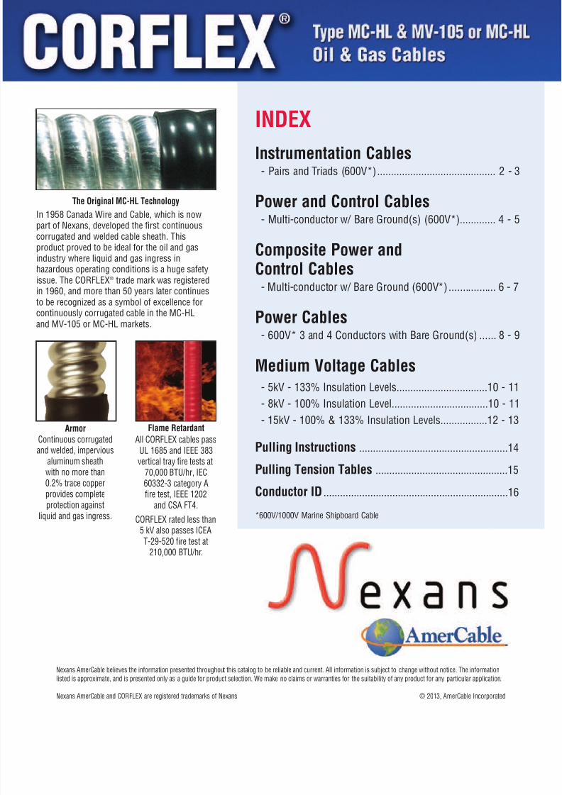
CORFLEXreg MC-HL Armored Power amp Control600V bull Multi-conductor600V1000V Marine Shipboard CableRated 90degC bull Multi-Power Conductors with Bare Ground(s)
Ratings amp Approvals
90˚C Temperature Rating
Meets UL 1309 and IEEE 1580 requirementsfor Marine Shipboard Cable
Meets UL 44 XHHW-2 600V conductors
Meets UL 1569 requirements for Type MC
Metal Clad cables Meets UL 2225 for Hazardous Locations (HL)
Dual certified IEEE 1580 and UL 1309Type CWCMC
Designated Type MC as per NEC 2008 andNEC 2011 Article 330
Meets CSA C222 No 123 for AluminumSheathed Cables
Meets CSA C222 No 174 for Hazardous Locations
ApplicationDesigned and constructed for the demanding environmentsof offshore drilling and petroleum facilities locatedthroughout the world requiring a type MC-HL cable
Features UL listed as Marine Shipboard Cable (File E86139)
600V1000V
UL listed as Type MC-HL 600V (File E47409)
UL listed insulated conductors
Flame retardant UL 1685 and IEEE 383 vertical tray firetests at 70000 BTUhr ICEA T-29-520 fire test at 210000BTUhr IEC 60332-3 category A fire test IEEE 1202 and
CSA FT4 Cables are American Bureau of Shipping (ABS) listed
as CWC MC Type MC
Cables are marked ldquo-40degCrdquo and are suitable for handlingand installation down to -10degC (based on -40degC impactand bend tests per UL 1569)
Temperature rating of 90degC dry and wet
130degC emergency rating and 250degC short circuit rating
Continuous impervious aluminum armor corrugated forflexibility prevents ingress of moisture gases and liquids
Aluminum armor resistance exceeds requirements of theNEC 2008 and NEC 2011 Article 250178 for equipmentgrounding conductor
Armor provides good EMI shielding so that CORFLEXcan be used in certain instrumentation applicationswhen adequately grounded
Excellent mechanical and physical properties
Sunlight resistant jacket
Suitable for direct burial use in cable tray andembedment in concrete
Suitable for Class I II and III Divisions 1 amp 2as per NEC 2008 and NEC 2011 (HL Rated)
Bend Radius Fixed position 7 x cable overall diameter
During pulling 12 x cable overall diameter
Conductor
Bare annealed copper
conforming to ASTM B3and Class B stranded inaccordance with ASTM B8
Assembly
Conductors are cabledin concentric layers withgrounding wire intersticesare filled with suitablenon-hygroscopic fillersas required A binder tapeof synthetic materialassembles the core inan essentially round
configuration
Insulation
Cross-linked polyethylene
type XHHW-2 per UL 44Grounding Conductor
Bare annealed copperconforming to ASTM B3and Class B stranded inaccordance with ASTM B8Meets or exceedsrequirements of NECTable 250122
Jacket
Overall black polyvinylchloride jacket per UL 156990degC temperature ratinglow acid gas emissionlimited flame spread andexcellent corrosionresistance
Armor
Continuous corrugatedand welded imperviousaluminum sheath with
no more than 02 tracecopper providing completeprotection against liquidand gas ingress Providesexcellent mechanicalprotection additionalelectrostatic shieldingand serves as an easymeans for groundingequipment
CORFLEXreg is a registered trademark of Nexans
4 www nexansamercablecom bull e-mail marineamercablecom
Conductor ID
Multi-conductor
14 AWG to 10 AWGMethod 1-E2 perICEA S-73-532
8122019 Cor Flex
httpslidepdfcomreaderfullcor-flex 7205800-506-9473 bull 713-896-5800 bull Fax 713-849-9009
Power amp Control bull 600V600V1000V Marine Shipboard Cable
NexansDesign
No
670155670142317677318345318352318360318378318386318394318402318410
670156670144317693318436318444318451318469318447318485318493318501
670157670146317719
318527318535318543318550665148
2345791215192537
2345791215192537
234
5791237
(mils)
3030303030303030303030
3030303030303030303030
303030
3030303030
(inches)
02730390033603360417048605610610066907970933
03450340038504140478055106390691076008971059
036104500449
04790556069307451227
(inches)
04690555050305320601064507830811092110051218
05120555055005990640077708280936098111901374
052706200621
06410780093709711591
(mils)
5050505050505050505050
5050505050505050505050
505050
5050505060
Ω kft
2555325553255532555325553255532555325553255532555325553
1608216082160821608216082160821608216082160821608216082
101181011810118
1011810118101181011810118
InsulationThickness
NominalDiameterOver Core
NominalDiameter
Over ArmorJacket
Thickness
(inches)
05810660060606350704074808870915102811111323
06140660065307020744088109321039108512951478
063207250724
07430884104010741725
NominalDiameter
Over Jacket
DCResistance
20degC
Ω kft
2606426064260642606426064260642606426064260642606426064
1640416404164041640416404164041640416404164041640416404
103201032010320
1032010320103201032010320
DCResistance
25degC
60 HzΩ kft
3258332583325833258332583325833258332583325833258332583
2050720507205072050720507205072050720507205072050720507
129021290212902
1290212902129021290212902
ACResistance
90degC
Ω kft60Hz
0037600376003760049700545005960064100666006940074300787
0035300353003530047500526005740062000644006720071900765
003320033200332
0045400507005790060100744
InductiveReactance
90degC
Ampskft
2948929489294892954229566295852960429615296272964929668
1861018610186101866318685187061872618737187491876918789
117561175611756
1180911832118641187411936
VoltageDrop
Volts75degC
15151515141410101098
2020202018181313131110
303028
2825251814
90degC
1515151515151313131110
2020202020201515151412
303030
3028282016
(lbkft)
155200191212263307388443572691986
1852262392803384375026357439871365
231312319
3644846307321984
ApproxNet Cable
WeightNo ofCond kcmil
14(7w)14(7w)14(7w)14(7w)14(7w)14(7w)14(7w)14(7w)14(7w)14(7w)14(7w)
12(7w)12(7w)12(7w)12(7w)12(7w)12(7w)12(7w)12(7w)12(7w)12(7w)12(7w)
10(7w)10(7w)10(7w)
10(7w)10(7w)10(7w)10(7w)10(7w)
ConductorSizeAWG
AWG
14(7w)3x18(7w)14(7w)14(7w)14(7w)14(7w)14(7w)14(7w)14(7w)14(7w)14(7w)
12(7w)3x16(7w)12(7w)12(7w)12(7w)12(7w)12(7w)12(7w)12(7w)12(7w)12(7w)
10(7w)3x14(7)10(7w)
10(7w)10(7w)10(7w)10(7w)10(7w)
GroundWireSize
Notes1) Ampacities are in accordance with NEC 2008 Table 31016 or NEC 2011 Table 31015(B)(16) for conductors in raceway or direct
buried at 30degC ambient temperature and 90degC conductor temperature The overcurrent protection shall not exceed 15 amperesfor 14 AWG 20 amperes for 12 AWG and 30 amperes for 10 AWG copper conductors after any correction factors for ambienttemperature and number of conductors have been applied (NEC 2008 and NEC 2011 Article 2404(D)) For correction factors fordifferent ambient temperatures and ampacities at different conductor temperatures see NEC 2008 Table 31016 or NEC 2011Table 31015(B)(16) Ampacities for cables having more than three conductors have been derated per NEC 2008 Article31015(B)(2)(a) or NEC 2011 Article 31015(B)(3)(a)
Three conductor cables with 3 grounds are also suitable for VFD applications
Ampacities(Note 1)
8122019 Cor Flex
httpslidepdfcomreaderfullcor-flex 820
CORFLEXreg MC-HL Armored Composite Power amp Control600V bull Multi-conductor600V1000V Marine Shipboard CableRated 90degC bull 1 Bare Ground
Ratings amp Approvals
90˚C Temperature Rating
Meets UL 1309 and IEEE 1580 requirementsfor Marine Shipboard Cable
Meets UL 44 XHHW-2 600V conductors
Meets UL 1569 requirements for Type MC
Metal Clad cables Meets UL 2225 for Hazardous Locations (HL)
Dual certified IEEE 1580 and UL 1309Type CWCMC
Designated Type MC as per NEC 2008 andNEC 2011 Article 330
Meets CSA C222 No 123 for AluminumSheathed Cables
Meets CSA C222 No 174 for Hazardous Locations
ApplicationDesigned and constructed for the demanding environmentsof offshore drilling and petroleum facilities located
throughout the world requiring a type MC-HL cable
Features UL listed as Marine Shipboard Cable (File E86139)
6001000V
UL listed as Type MC-HL 600V (File E47409)
UL listed insulated conductors
Flame retardant UL 1685 and IEEE 383 vertical tray firetests at 70000 BTUhr ICEA T-29-520 fire test at 210000BTUhr IEC 60332-3 category A fire test IEEE 1202 and
CSA FT4 Cables are American Bureau of Shipping (ABS) listed
as CWC MC Type MC
Cables are marked ldquo-40degCrdquo and are suitable for handlingand installation down to -10degC (based on -40degC impactand bend tests per UL 1569)
Temperature rating of 90degC dry and wet
130degC emergency rating and 250degC short circuit rating
Continuous impervious aluminum armor corrugated forflexibility prevents ingress of moisture gases and liquids
Aluminum armor resistance exceeds requirements of theNEC 2008 and NEC 2011 Article 250178 for equipmentgrounding conductor
Armor provides good EMI shielding so that CORFLEXcan be used in certain instrumentation applicationswhen adequately grounded
Excellent mechanical and physical properties
Sunlight resistant jacket
Suitable for direct burial use in cable tray andembedment in concrete
Suitable for Class I II and III Divisions 1 amp 2as per NEC 2008 and NEC 2011 (HL Rated)
Bend Radius Fixed position 7 x cable overall diameter
During pulling 12 x cable overall diameter
Conductor
Bare annealed copper
conforming to ASTM B3and Class B stranded inaccordance with ASTM B8
Assembly
Conductors are cabledin concentric layers withgrounding wire intersticesare filled with suitablenon-hygroscopic fillersas required A binder tape
of synthetic materialassembles the core inan essentially roundconfiguration
Insulation
Cross-linked polyethylenetype XHHW-2 per UL 44
Grounding Conductor
Bare annealed copper
conforming to ASTM B3and Class B stranded inaccordance with ASTM B8Meets or exceedsrequirements ofNEC Table 250122
Jacket
Overall black polyvinylchloride jacket per UL 156990degC temperature ratinglow acid gas emission
limited flame spread andexcellent corrosionresistance
Armor
Continuous corrugatedand welded imperviousaluminum sheath withno more than 02 tracecopper providing complete
protection against liquidand gas ingress Providesexcellent mechanicalprotection additionalelectrostatic shieldingand serves as an easymeans for groundingequipment
CORFLEXreg is a registered trademark of Nexans
6 www nexansamercablecom bull e-mail marineamercablecom
Conductor ID
Power Conductors8 AWG and larger
Method 4 perICEA S-73-532
Control Conductors14 12 amp 10 AWG
Method 1-E2 perICEA S-73-532
8122019 Cor Flex
httpslidepdfcomreaderfullcor-flex 920
Notes1) Ampacities are based on NEC 2011 Table 31015(B)(16) for not more than three current-carrying conductors (where the 4th conductor
is the neutral of a 3-phase 4 wire system) in raceway cable or earth (direct buried) based on an ambient temperature of 30degC (86degF)Refer to Table 31015(B)(2) for the ampacity correction factors where the ambient temperature is other than 30degC (86degF)
7800-506-9473 bull 713-896-5800 bull Fax 713-849-9009
JacketThickness
(mils)
505050505050
505050
505050
505050505050
5050505050
50
505050505050
75degC
303030303030
505050
505050
656565656565
8585858585
85
115115115115115115
ControlConductorsNo x Size
AWG kcmil
4x12(7w)3x12(7w)4x14(7w)3x14(7w)4x12(7w)4x14(7w)
4x12(7w)3x12(7w)4x14(7w)
3x14(7w)4x12(7w)4x14(7w)
4x12(7w)3x12(7w)4x14(7w)3x14(7w)4x12(7w)4x14(7w)
4x12(7w)3x12(7w)4x14(7w)3x14(7w)4x12(7w)
4x14(7w)
4x12(7w)3x12(7w)4x14(7w)3x14(7w)4x12(7w)4x14(7w)
NexansDesign
No
199760665024665036665041665019665047
290783665025665037
665042665020665048
290791665027665038665044665021665049
290809665028665039665045665022
665050
654277665035665040665046665023665051
PowerConductorsNo x Size
AWG kcmil
3x10(7w)3x10(7w)3x10(7w)3x10(7w)4x10(7w)4x10(7w)
3x8(7w)3x8(7w)3x8(7w)
3x8(7w)4x8(7w)4x8(7w)
3x6(7w)3x6(7w)3x6(7w)3x6(7w)4x6(7w)4x6(7w)
3x4(7w)3x4(7w)3x4(7w)3x4(7w)4x4(7w)
4x4(7w)
3x2(7w)3x2(7w)3x2(7w)3x2(7w)4x2(7w)4x2(7w)
ControlInsulationThickness
(mils)
303030303030
303030
303030
303030303030
3030303030
30
303030303030
PowerInsulationThickness
(mils)
303030303030
454545
454545
454545454545
4545454545
45
454545454545
NominalDiameter
OverArmor
(in)
077207500754063507820777
091708000811
080009140831
097509370941092109580938
11490964096109871012
0999
116811601128118012141214
NominalDiameter
OverCore(in)
054004950510047005600550
066405900610
059106590645
075006950700067007250695
08450735073007700807
0787
087008600820088509270927
NominalDiameter
OverJacket
(in)
087608540860073808870881
102609040915
090410240935
107710411045102810621042
12541068106510911117
1103
127312651240128513191319
Ampac(Note
DCResist
20C 991526 kft
101181011810118101181011810118
063610636106361
063610636106361
040020400204002040020400204002
0251602516025160251602516
02516
015740157401574015740157401574
DCResist
25C 991526 kft
103201032010320103201032010320
064880648806488
064880648806488
040820408204082040820408204082
0256602566025660256602566
02566
016050160501605016050160501605
ACResist
90C 60 Hz991526 kft
129021290212902129021290212902
081110811108111
081110811108111
051040510405104051040510405104
0320903209032090320903209
03209
020090200902009020090200902009
InductiveReactance90C 60 Hz991526 kft
003320033200332003320033200332
003480034800348
003480034800348
003290032900329003290032900329
0031200312003120031200312
00312
002990029900299002990029900299
VoltageDropVolts
Ampskft
117561175611756117561175611756
074520745207452
074520745207452
047370473704737047370473704737
0302503025030250302503025
03025
019380193801938019380193801938
GroundWireSizeAWG
10(7w)10(7w)10(7w)10(7w)10(7w)10(7w)
10(7w)10(7w)10(7w)
10(7w)10(7w)10(7w)
8(7w)8(7w)8(7w)8(7w)8(7w)8(7w)
8(7w)8(7w)8(7w)8(7w)8(7w)
8(7w)
6(7w)6(7w)6(7w)6(7w)6(7w)6(7w)
ApproxNet Cable
Weight(lbsKft)
425396387340463428
565473478
457630535
685665640641778749
926807799788993
953
119811701165114614361401
Composite Power amp Control bull 600V
600V1000V Marine Shipboard Cable
8122019 Cor Flex
httpslidepdfcomreaderfullcor-flex 1020
CORFLEXreg MC-HL Power Cable bull 600V600V1000V Marine Shipboard CableRated 90degC bull 3 and 4 Power Conductors with Ground(s)
Ratings amp Approvals
90˚C Temperature Rating Meets UL 1309 and IEEE 1580 requirements
for Marine Shipboard Cable Meets UL 44 XHHW-2 600V conductors Meets UL 1569 requirements for Type MC
Metal Clad cables
Meets UL 2225 for Hazardous Locations (HL) Dual certified IEEE 1580 and UL 1309
Type CWCMC Designated Type MC as per NEC 2008 and
NEC 2011 Article 330 Meets CSA C222 No 123 for Aluminum
Sheathed Cables Meets CSA C222 No 174 for Hazardous Locations
ApplicationDesigned and constructed for the demanding environmentsof offshore drilling and petroleum facilities locatedthroughout the world requiring a type MC-HL cable
Features
UL listed as Marine Shipboard Cable (File E86139)600V1000V
UL listed as Type MC-HL 600V (File E47409)
UL listed insulated conductors
Flame retardant UL 1685 and IEEE 383 vertical tray firetests at 70000 BTUhr ICEA T-29-520 fire test at 210000BTUhr IEC 60332-3 category A fire test IEEE 1202 and
CSA FT4 Cables are American Bureau of Shipping (ABS) listed
as CWC MC Type MC
Cables are marked ldquo-40degCrdquo and are suitable for handlingand installation down to -10degC (based on -40degC impactand bend tests per UL 1569)
Temperature rating of 90degC dry and wet
130degC emergency rating and 250degC short circuit rating
Continuous impervious aluminum armor corrugated forflexibility prevents ingress of moisture gases and liquids
Aluminum armor resistance exceeds requirements of theNEC 2008 and NEC 2011 Article 250178 for equipmentgrounding conductor
Excellent mechanical and physical properties
Sunlight resistant jacket
Suitable for direct burial use in cable tray andembedment in concrete
Three conductor cables have three symmetrical groundingconductors suitable for PWMVFD and other modern AC
drivemotor applications Suitable for Class I II and III Divisions 1 amp 2
as per NEC 2008 and NEC 2011 (HL Rated)
Bend Radius Fixed position 7X cable overall diameter
During pulling 12X cable overall diameter
Conductors
Bare annealed copperconforming to ASTM B3
and Class B stranded inaccordance with ASTM B8
Assembly
Conductors are cabledin concentric layers withgrounding wire intersticesare filled with suitablenon-hygroscopic fillersas required A binder tapeof synthetic materialassembles the core inan essentially roundconfiguration
Insulation
Cross-linked polyethylenetype XHHW-2 per UL 44
Grounding Conductor(s)Bare annealed copperconforming to ASTM B3and Class B stranded inaccordance with ASTM B8Meets or exceedsrequirements ofNEC Table 250122
Jacket
Overall black polyvinylchloride jacket per UL 156990degC temperature ratinglow acid gas emissionlimited flame spread andexcellent corrosionresistance
Armor
Continuous corrugatedand welded imperviousaluminum sheath withno more than 02 trace
copper providing completeprotection against liquidand gas ingress Providesexcellent mechanicalprotection additionalelectrostatic shieldingand serves as an easymeans for groundingequipment
CORFLEXreg is a registered trademark of Nexans
8 www nexansamercablecom bull e-mail marineamercablecom
Conductor ID
Sizes 14 AWG to 2 AWGMethod 1-E2 perICEA S-73-532
Sizes 1 AWG to 500 kcmilMethod 4 perICEA S-73-532
8122019 Cor Flex
httpslidepdfcomreaderfullcor-flex 11209800-506-9473 bull 713-896-5800 bull Fax 713-849-9009
NexansDesign
No
670142317677670144317693670146317719670148317735670149317750
670150317776670151317792670152698571670153317818670118317834670119660631670120317867670121670577
670122317891670123317917
JacketThickness
(mils)
50505050505050505050
50505050505050505050606060606060
60757575
75degC
15152020303050506565
8585115115130130150150175175200200230230255255
310310380380
90degC
15152020303055557575
9595130130145145170170195195225225260260290290
350350430430
CondSize
AWG kcmil
14(7w)14(7w)12(7w)12(7w)10(7w)10(7w)8(7w)8(7w)6(7w)6(7w)
4(7w)4(7w)2(7w)2(7w)1(19w)1(19w)
10(19w)10(19w)20(19w)20(19w)30(19w)30(19w)40(19w)40(19w)250(37w)250(37w)
350(37w)350(37w)500(37w)500(37w)
No ofCond
3434343434
3434343434343434
3434
Insulation
Thickness(mils)
30303030303045454545
45454545555555555555555555556565
65656565
NominalDiameter
OverArmor
(in)
0555050305550549062006200750079508020930
0937099511271214123013611350142714221598160617301734193619252012
2028223023402694
NominalDiameter
OverCore(in)
0390033603400396045004500520058506000680
0700078208300927095010411040113411261238125013561360150014771653
1685188919542196
NominalDiameter
OverJacket
(in)
0660060606600652072507300838090009051027
1039109512321320132014661473152515101732173918651867206920582147
2162238725042861
Ampacities(Note 1)DC
Resist
20C 991526 kft
25553255531608216082101181011806361063610400204002
02516025160157401574012550125500999009990079700791006290062700497004970042400424
00301003010021200212
DCResist
25C 991526 kft
26064260641640416404103201032006488064880408204082
02566025660160501605012800128001019010190081300806006420064000507005070043200432
00307003070021600216
ACResist
90C 60 Hz991526 kft
32583325832050720507129021290208111081110510405104
03209032090200902009016030160301278012780102101011008080080400641006410058400584
00395003950029000282
InductiveReactance90C 60 Hz
991526 kft
00376003750035300353003320033200348003480032900329
00312003120029900299002880028800281002830028000281002750027600271002710026300264
00263002630025000251
VoltageDropVolts
Ampskft
29489293071861018510117561175807452074720473704737
03025030240193801938015680156701272012690104101033008470084400695006940060800607
00470004680036700363
GroundWireSizeAWG
3x18(7w)1x14(7w)3x16(7w)1x12(7w)3x14(7w)1x10(7w)3x14(7w)1x10(7w)3x12(7w)1x8(7w)
3x12(7w)1x8(7w)3x10(7w)1x6(7w)
3x10(7w)1x6(7w)
3x10(7w)1x6(7w)
3x10(7w)1x6(7w)3x8(7w)1x4(7w)3x8(7w)1x4(7w)3x8(7w)1x4(7w)
3x6(7w)1x3(7w)3x6(7w)1x2(7w)
ApproxNet Cable
Weight(lbsKft)
200191226245312320413465542675
73589210971332133016281592192218822393240029752910360533164110
4375561760267892
Power Cable bull 600V600V1000V Marine Shipboard Cable
Notes1) Ampacities are based on NEC 2011 Table 31015(B)(16) for not more than three current-carrying conductors (where the 4th conductor
is the neutral of a 3-phase 4 wire system) in raceway cable or earth (direct buried) based on an ambient temperature of 30degC (86degF)Refer to Table 31015(B)(2) for the ampacity correction factors where the ambient temperature is other than 30degC (86degF)
2) Three conductor cables with 3 ground wires are also suitable for VFD applications
8122019 Cor Flex
httpslidepdfcomreaderfullcor-flex 1220
CORFLEXreg MV-105 or MC-HL Medium Voltage5kV 133 Insulation Level8kV 100 Insulation LevelRated 105degC bull 3 Conductors with 3 Bare Grounds
ApplicationDesigned and constructed for the demanding environmentsof offshore drilling and petroleum facilities locatedthroughout the world requiring a type MV-105 orMC-HL Medium Voltage cable
Features UL listed as Marine Shipboard Cable (File E86139)
UL listed as Type MV-105 5kV and 8kV (File E66901)
Flame retardant UL 1685 and IEEE 383 vertical tray firetests at 70000 BTUhr IEC 60332-3 category A fire testIEEE 1202 and CSA FT4
Cables are American Bureau of Shipping (ABS) listed
as CWC MC Type MVMC (Metal Clad Medium Voltage) Cables are marked ldquo-40degCrdquo and are suitable for handling
and installation down to -10degC (based on -40degC impactand bend tests per UL 1569)
Continuous impervious aluminum armor corrugated forflexibility prevents ingress of moisture gases and liquids
Aluminum armor resistance exceeds requirements of theNEC 2008 and NEC 2011 Article 250178 for equipmentgrounding conductor
Excellent mechanical and physical properties
Minimal noise and signal interference Sunlight resistant jacket
Suitable for direct burial use in cable tray andembedment in concrete
Suitable for Class I II and III Divisions 1 amp 2as per NEC 2008 and NEC 2011 (HL Rated)
Three symmetrical grounding conductors for PWMVFDand other modern AC drivemotor applications
Phase identification Color coded (black red blue)polyester ribbon laid longitudinally under the coppershield tape
Bend Radius Fixed position 7 x cable overall diameter
During pulling 12 x cable overall diameter
Insulation
EPR meets or exceedselectrical and physicalrequirements of UL 1072
Conductor Shield
Extruded semiconducting
conductor shield meetsor exceeds electrical andphysical requirementsof UL 1072
Insulation ShieldNonmetallic
Extruded semiconducting
insulation shield meetsor exceeds electricaland physical requirementsof UL 1072
Metallic Shield
Bare copper tape shieldhelically wrapped toprovide 100 coverage
Conductor
Bare annealed copperconforming to ASTM B3and Class B Compactstranded in accordancewith ASTM B496
Jacket
Overall yellow polyvinylchloride jacket per UL 107290degC temperature ratinglow acid gas emissionlimited flame spread andexcellent corrosionresistance
Armor
Continuous corrugatedand welded imperviousaluminum sheath withno more than 02 tracecopper providing completeprotection against liquidand gas ingress Providesexcellent mechanicalprotection additionalelectrostatic shieldingand serves as an easymeans for groundingequipment
Binder Tape
Synthetic materialassembles the core inan essentially roundconfiguration
CORFLEXreg is a registered trademark of Nexans
10 www nexansamercablecom bull e-mail marineamercablecom
Ratings amp Approvals
105˚C Temperature Rating Meets UL 1309 and IEEE 1580 requirements
for Marine Shipboard Cable
Meets UL 1072 requirements for mediumvoltage power cables
Meets UL 1569 requirements for Type MCMetal Clad cables
Meets UL 2225 for Hazardous Locations (MC-HL) Designated Type MC as per NEC 2008 and
NEC 2011 Article 330 Insulation meets electrical and physical requirements
of ICEA S-93-639NEMA WC 74 and UL 1072 Designated Type MV-105 as per NEC 2008 and
NEC 2011 Article 328
Grounding Conductors
Bare annealed copperconforming to ASTM B3and Class B stranded inaccordance with ASTM B8
8122019 Cor Flex
httpslidepdfcomreaderfullcor-flex 1320
5kV bull 133 Insulation Level bull EPR insulation 90 mils
NexansPartNo
662776665017660072660648662186670667670669665029660075660076660349665014
JacketThickness
(mils)
506060606060606075758585
CondSize
AWG kcmil
6(7w)4(7w)2(7w)
1(18w)10(18w)20(18w)40(18w)250(36w)350(36w)500(36w)750(58w)1000(58w)
GroundWireSizeAWG
3 x 103 x 103 x 103 x 83 x 83 x 83 x 63 x 63 x 63 x 43 x 43 x 4
NominalDiameter
OverInsulation
(in)
042604700525055605930634073307860884104511861339
NominalDiameter
OverArmor
(in)
137215421631173119051948210322402459277933663505
NominalDiameter
OverJacket
(in)
147716781765186420472081224023872623294635653687
InAir
Note 1
105135185210240275360400490600745860
CableTray
Note 2
92120165185215245320350430525635725
DirectBurialNote 3
120155200225255290375410495590720810
DCResist
20C 991526 kft
040080252001585012600099900792004980042200302002110014100106
DCResist
25C 991526 kft
040880257001616012850101900808005080043100308002150014400108
ACResist
90C 60 Hz991526 kft
051110321302022016070127501012006390054300392002810019600159
InductiveReactance90C 60 Hz991526 kft
004600042700400003870037400361003380033200312003040029200283
VoltageDropVolts
Ampskft
048010307801994016160131101069007230063400492003860030600266
AmpacitiesNominalDiameter
OverCore (in)
106611621298136814481534174918652076233527313063
ApproxNet Cable
Weight(lbsKft)
11021402177320922389268036734181536373231029212871
8kV bull 100 Insulation Level bull EPR insulation 115 mils
Notes
1) Ampacities in air are based on NEC 2011 Table 31060(C)(71) 5001-35000 Volts Ampacity column for insulated three conductorcopper cable isolated in air maximum conductor temperature of 105degC ambient air temperature of 40degC
2) Ampacities in cable tray are based on NEC 2011 Table 31060(C)(75) 5001-35000 Volts Ampacity column for insulated threeconductor copper cable in isolated conduit in air maximum conductor temperature of 105degC ambient air temperature of 40degC
3) Ampacities for direct burial are based on NEC 2011 Table 31060(C)(83) 5001-35000 Volts Ampacity column for insulatedthree conductor copper cable directly buried maximum conductor temperature of 105degC ambient earth temperatureof 20degC 100 percent load factor earth thermal resistivity of 90degC cm W
Three conductor cables with 3 ground wires are also suitable for VFD applications
Notes1) Ampacities in air are based on NEC 2011 Table 31060(C)(71) 2001-5000 Volts Ampacity column for insulated three conductor
copper cable isolated in air maximum conductor temperature of 105degC ambient air temperature of 40degC
2) Ampacities in cable tray are based on NEC 2011 Table 31060(C)(75) 2001-5000 Volts Ampacity column for insulated three conductorcopper cable in isolated conduit in air maximum conductor temperature of 105degC ambient air temperature of 40degC
3) Ampacities for direct burial are based on NEC 2011 Table 31060(C)(83) 2001-5000 Volts Ampacity column for insulatedthree conductor copper cable directly buried maximum conductor temperature of 105degC ambient earth temperatureof 20degC 100 percent load factor earth thermal resistivity of 90degC cm W
Three conductor cables with 3 ground wires are also suitable for VFD applications
11800-506-9473 bull 713-896-5800 bull Fax 713-849-9009
NexansPartNo
603837603838603839603840603841603842603843603844603845603846603847603848
JacketThickness
(mils)
505060606060606075758585
Cond
SizeAWG kcmil
6(7w)4(7w)2(7w)1(18w)
10(18w)20(18w)40(18w)250(36w)350(36w)500(36w)750(58w)
1000(58w)
Ground
WireSizeAWG
3 x 103 x 103 x 103 x 83 x 83 x 83 x 63 x 63 x 63 x 43 x 43 x 4
NominalDiameter
OverInsulation
(in)
038604300485051705540594069307470844096511471299
NominalDiameter
OverArmor
(in)
131113791564160817041806200421152350269431943464
NominalDiameter
OverJacket
(in)
142714841698174118381939213822492514286033763663
InAir
Note 1
88115154180205240320355440545685790
CableTray
Note 2
77100135155185210285315390475585660
DirectBurialNote 3
115150190215245280360395475570700785
DCResist
20C 991526 kft
040080252001585012600099900792004980042200302002110014100106
DCResist
25C 991526 kft
040880257001616012850101900808005080043100308002150014400108
AC
Resist90C 60 Hz991526 kft
051110321302022016080127501013006400054400393002820019900160
Inductive
Reactance90C 60 Hz991526 kft
004470040900308003680035600345003240031900306002940027500283
Voltage
DropVolts
Ampskft
047920307101986019080130301062007170062900487003820030300264
AmpacitiesNominal
DiameterOver
Core (in)
098110761195126213451432164617061973223326282958
Approx
Net CableWeight(lbsKft)
1058123416231877216324733435389450817000983712951
8122019 Cor Flex
httpslidepdfcomreaderfullcor-flex 1420
CORFLEXreg MV-105 or MC-HL Medium Voltage15kV 100 Insulation Level amp 133 Insulation LevelRated 105degC bull 3 Conductors with 1 Bare Ground
Ratings amp Approvals
105˚C Temperature Rating Meets UL 1309 and IEEE 1580 requirements
for Marine Shipboard Cable
Meets UL 1072 requirements for mediumvoltage power cables
Meets UL 1569 requirements for Type MCMetal Clad cables Meets UL 2225 for Hazardous Locations (MC-HL) Designated Type MC as per NEC 2008 and
NEC 2011 Article 330 Insulation meets electrical and physical requirements
of ICEA S-93-639NEMA WC 74 and UL 1072 Designated Type MV-105 as per NEC 2008 and
NEC 2011 Article 328
ApplicationDesigned and constructed for the demanding environmentsof offshore drilling and petroleum facilities locatedthroughout the world requiring a type MV-105 orMC-HL Medium Voltage cable
Features UL listed as Marine Shipboard Cable (File E86139)
UL listed as Type MV-105 15 kV (File E66901)
Flame retardant UL 1685 and IEEE 383 vertical tray firetests at 70000 BTUhr IEC 60332-3 category A fire testIEEE 1202 and CSA FT4
Cables are American Bureau of Shipping (ABS) listed
as CWC MC Type MVMC (Metal Clad Medium Voltage) Cables are marked ldquo-40degCrdquo and are suitable for handling
and installation down to -10degC (based on -40degC impactand bend tests per UL 1569)
Continuous impervious aluminum armor corrugated forflexibility prevents ingress of moisture gases and liquids
Aluminum armor resistance exceeds requirements of theNEC 2008 and NEC 2011 Article 250178 for equipmentgrounding conductor
Excellent mechanical and physical properties
Minimal noise and signal interference Sunlight resistant jacket
Suitable for direct burial use in cable tray andembedment in concrete
Suitable for Class I II and III Divisions 1 amp 2as per NEC 2008 and NEC 2011 (HL Rated)
Phase identification Color coded (black red blue)polyester ribbon laid longitudinally under the coppershield tape
Bend Radius Fixed position 7 x cable overall diameter
During pulling 12 x cable overall diameter
CORFLEXreg is a registered trademark of Nexans
12 www nexansamercablecom bull e-mail marineamercablecom
Jacket
Overall red polyvinylchloride jacket per UL 107290degC temperature ratinglow acid gas emissionlimited flame spread andexcellent corrosionresistance
Insulation
EPR meets or exceedselectrical and physicalrequirements of UL 1072
Conductor Shield
Extruded semiconductingconductor shield meetsor exceeds electrical and
physical requirementsof UL 1072
Metallic Shield
Bare copper tape shieldhelically wrapped toprovide 100 coverage
Binder Tape
Synthetic materialassembles the core inan essentially roundconfiguration
Insulation ShieldNonmetallic
Extruded semiconductinginsulation shield meetsor exceeds electrical
and physical requirementsof UL 1072
Conductor
Bare annealed copperconforming to ASTM B3
and Class B Compactstranded in accordancewith ASTM B496
Armor
Continuous corrugatedand welded imperviousaluminum sheath withno more than 02 tracecopper providing completeprotection against liquidand gas ingress Providesexcellent mechanicalprotection additionalelectrostatic shieldingand serves as an easy
means for groundingequipment
Grounding Conductor
Bare annealed copperconforming to ASTM B3and Class B stranded inaccordance with ASTM B8
8122019 Cor Flex
httpslidepdfcomreaderfullcor-flex 1520
15kV bull 100 Insulation Level
15kV bull 133 Insulation Level
NexansDesign
No
664931664933664934664935664936664676664677664678664679
JacketThickness
(mils)
606060607575758585
InAir
Note 1
185210240275360400490600745
CableTray
Note 2
165185215245320350430525635
DirectBurialNote 3
200225255290375410495590720
CondSizeAWG kcmil
2(7w)1(18w)
10(18w)20(18w)40(18w)250(36w)350(36w)500(36w)750(58w)
GroundWireSizeAWG
64443221
10
Nominal
DiameterOverInsulation
(in)
065506790716075608560910100711281310
Nominal
DiameterOverArmor
(in)
197419962036215424262490278431853480
Nominal
DiameterOverJacket
(in)
210721292171228925892653296933673671
Ampacities DCResist
20C 991526 kft
015850126000999007920049800422003020021100141
DCResist
25C 991526 kft
016160128501019008080050800431003080021500144
ACResist90C 60 Hz
991526 kft
020220160701275010120063900543003920028000196
InductiveReactance90C 60 Hz
991526 kft
004450042800412003980037100363003460033000314
VoltageDropVolts
Ampskft
020130163301327010850073700647005030039600313
NominalDiameterOver
Core (in)
158616311711180020142131234226072999
ApproxNet CableWeight(lbsKft)
2121236026302987407845995985778910716
Notes1) Ampacities in air are based on NEC 2011 Table 31060(C)(71) 5001-35000 Volts Ampacity column for insulated three conductor
copper cable isolated in air maximum conductor temperature of 105degC ambient air temperature of 40degC2) Ampacities in cable tray are based on NEC 2011 Table 31060(C)(75) 5001-35000 Volts Ampacity column for insulated three
conductor copper cable in isolated conduit in air maximum conductor temperature of 105degC ambient air temperature of 40degC
3) Ampacities for direct burial applications are based on NEC 2011 Table 31060(C)(83) 5001-35000 Volts Ampacity column forinsulated three conductor copper cable directly buried maximum conductor temperature of 105degC ambient earth temperatureof 20degC 100 percent load factor earth thermal resistivity of 90degC cm W
NexansDesign
No
665006665007665008665005665010665011665012665013
JacketThickness
(mils)
6060606075758585
InAir
Note 1
185210240275360400490600
CableTray
Note 2
165185215245320350430525
DirectBurialNote 3
200225255290375410495590
CondSize
AWG kcmil
2(7w)1(18w)
10(18w)20(18w)40(18w)250(36w)350(36w)500(36w)
GroundWireSizeAWG
64443221
Nominal
DiameterOver
Insulation(in)
07350766080308440943099610941215
Nominal
DiameterOver
Armor(in)
20942177229923622681276831543387
Nominal
DiameterOver
Jacket(in)
22352311244224962853294033363575
AmpacitiesDC
Resist
20C 991526 kft
0158501260009990079200498004220030200211
DCResist
25C 991526 kft
0161601285010190080800508004310030800215
ACResist
90C 60 Hz
991526 kft
0202201607012750101200639005430039200280
InductiveReactance90C 60 Hz
991526 kft
0046800454004370042100391003820036300345
VoltageDropVolts
Ampskft
0202401644013380109500746006550051000402
NominalDiameter
OverCore (in)
17401822190219892203231825282792
ApproxNet Cable
Weight(lbsKft)
22512616295632704546510663968209
Notes1) Ampacities in air are based on NEC 2011 Table 31060(C)(71) 5001-35000 Volts Ampacity column for insulated three conductor
copper cable isolated in air maximum conductor temperature of 105degC ambient air temperature of 40degC
2) Ampacities in cable tray are based on NEC 2011 Table 31060(C)(75) 5001-35000 Volts Ampacity column for insulated threeconductor copper cable in isolated conduit in air maximum conductor temperature of 105degC ambient air temperature of 40degC
3) Ampacities for direct burial applications are based on NEC 2011 Table 31060(C)(83) 5001-35000 Volts Ampacity column forinsulated three conductor copper cable directly buried maximum conductor temperature of 105degC ambient earth temperatureof 20degC 100 percent load factor earth thermal resistivity of 90degC cm W
13800-506-9473 bull 713-896-5800 bull Fax 713-849-9009
8122019 Cor Flex
httpslidepdfcomreaderfullcor-flex 162014 www nexansamercablecom bull e-mail marineamercablecom
CORFLEXreg Pulling InstructionsCertain installations require thepulling of CORFLEXreg into ducts ortrays These installations requirecareful planning and executionThe following provides informationon how to calculate tensions
developed during pulling andwhat precautions to take toprevent damage to the cable
Pulling TensionThe maximum tension applied to acable is limited to prevent damageor distortion of cable componentswhich could reduce the life orreliability of the cable The methodof pulling is significant in that
different methods will resultin different stresses on criticalcable components for the sameoverall tension Nexans AmerCablerecommends that CORFLEX MC-HLInstrumentation 600V cables arepulled by means of the aluminumsheath and jacket with a gripapplied over the jacketed coresheath and overall jacket All otherCORFLEX cable types described
in this catalog should be pulledby means of the conductorsaided with a grip over the outeraluminum sheath The conductors and the sheath must be pulled together Maximum allowablepulling tensions for CORFLEXcables should never exceed thevalues shown in pulling tensiontable
Calculating Pulling TensionsThe tension developed in anyStraight Section of duct iscalculated as
T = L x W x f lbf whereL = section length (feet)W = cable weight per unit length
(lbfoot)f = coefficient of dynamic friction
The tension developed in anyBend is calculated asT = T1 x efa lbf whereT1 = tension at bend entrance (lbf)e = base of natural logarithms
(271828)
f = coefficient of dynamic frictiona = angle of bend (radians)or efa is given in the following tablefor common conditionsBendAngle f=015 f=030 f=035 f=040
30deg 108 117 120 12345deg 113 127 132 13760deg 117 137 144 15290deg 127 160 173 188
Coefficients of dynamic frictionwith lubricant are given in thefollowing table for common ductand cable jacket materials Thesecoefficients can be used forcalculation of tensions
CoefficientDuct Type Cable Jacket of Friction
PVC PVC 050PE PVC 030
Fiber PVC 040Asbestos Cement PVC 070
Considerations must be given toSide Wall Bearing Pressure (SWBP) when pulling CORFLEXthrough a bend The SWBP iscalculated as follows
For CORFLEX Nexans AmerCablerecommends a maximum SWBPof 500 pounds forcefoot Duringinstallation of the CORFLEX cableit is recommended that the bendradii be as noted in thecable descriptions
Pulling in DuctIt is extremely important for thesuccess of any pull in duct to useapproved lubricants Lubricantsmust be compatible with the cablejacket and duct material
Lubricating the pulling rope willdecrease the tension on the pullingequipment and more importantlywill reduce the risk of damage tothe inside of the duct whichin turn can damage the cableWhen designing the duct layoutit is suggested that the bends beconcentrated near the end fromwhich the cable is to be pulledThis practice will result in lowertensions In some cases thetensions resulting from alternativedirections should be calculated
Pulling in Trays amp TrenchesFor the installation of CORFLEX intrays rollers are normally usedUsing well lubricated rollers andlong radius sheaves at bends willresult in a lower coefficient of
friction when compared to ductA coefficient of friction of 015 canbe used when calculating pullingtension using rollers For long pullswith bends it may be necessary to
install assist pullers before thebends to reduce the tension onthe cable entering a bend andreducing the risk of damagefrom excessive SWBP
The recommendations given aboveare intended to cover a wide varietyof pulling conditions It is possibleunder ideal conditions and withexperienced supervision to exceedthese limits
For further guidance see IEEEPaper 84 T amp D 365-3 orcontact Nexans AmerCable
SWBP = Pulling Tension Cable at Bend Exit (lbf)
Radius of Bend (feet)
8122019 Cor Flex
httpslidepdfcomreaderfullcor-flex 172015800-506-9473 bull 713-896-5800 bull Fax 713-849-9009
CORFLEXreg is a registered trademark of Nexans
Pulling Tension Tables
MaxCORFLEX No of PullingINST Size Pairs Tension
(AWG) Triads (lbf)
18 2 pairs 1874 pairs 2348 pairs 26012 pairs 29016 pairs 33220 pairs 41224 pairs 41236 pairs 461
16 1 pair 1592 pairs 2074 pairs 2348 pairs 29012 pairs 33216 pairs 41220 pairs 41224 pairs 46136 pairs 550
16 1 triad 1594 triads 234
8 triads 29412 triads 36816 triads 412
CORFLEX
MC Size(AWGkcmil) 3 Cond 4 Cond
8 265 3966 420 6304 670 9953 840 12632 1060 15931 1340 2009
10 1690 253420 2130 3194
30 2685 402740 3385 5078250 4000 6000350 5600 8400500 8000 10000750 10000 100001000 10000 10000
CORFLEX Number Max PullingMC Size of Tension(AWG) Conductors (lbf)
14 2 167
3 1674 1915 1917 2079 23412 23415 26019 26025 29537 326
12 2 1913 1914 2075 2077 2349 23412 26015 26019 29525 295
37 326
10 2 1913 2074 2075 2347 2349 26012 26015 295
19 29525 32637 411
1210 43 191128 43 264126 43 420124 43 668122 43 1062
Max Pulling
Tension (lbf)
8122019 Cor Flex
httpslidepdfcomreaderfullcor-flex 1820
CORFLEXreg is a registered trademark of Nexans
16 www nexansamercablecom bull e-mail marineamercablecom
CORFLEXreg Conductor ID
Conductor Insulation Stripe Conductor Insulation Stripe
1st BLACK ndash 19th ORANGE Blue2nd RED ndash 20th YELLOW Blue
3rd BLUE ndash 21st BROWN Blue
4th ORANGE ndash 22nd BLACK Orange
5th YELLOW ndash 23rd RED Orange
6th BROWN ndash 24th BLUE Orange
7th RED Black 25th YELLOW Orange
8th BLUE Black 26th BROWN Orange
9th ORANGE Black 27th BLACK Yellow
10th YELLOW Black 28th RED Yellow
11th BROWN Black 29th BLUE Yellow
12th BLACK Red 30th ORANGE Yellow
13th BLUE Red 31st BROWN Yellow
14th ORANGE Red 32nd BLACK Brown
15th YELLOW Red 33rd RED Brown
16th BROWN Red 34th BLUE Brown
17th BLACK Blue 35th ORANGE Brown
18th RED Blue 36th YELLOW Brown
Method 1-E2 per ICEA S-73-532
Method 4 of ICEA S-73-532
Conductor Printing Details Conductor Printing Details
1st ldquo1-ONE-1rdquo 5th ldquo5-FIVE-5rdquo
2nd ldquo2-TWO-2rdquo 6th ldquo6-SIX-6rdquo
3rd ldquo3-THREE-3rdquo 7th ldquo7-SEVEN-7rdquo
4th ldquo4-FOUR-4rdquo 8th ldquo8-EIGHT-8rdquo
8122019 Cor Flex
httpslidepdfcomreaderfullcor-flex 1920
8122019 Cor Flex
httpslidepdfcomreaderfullcor-flex 2020
The industrystandard forflexible highquality powercontrol andinstrumentationType P cables
Crush andImpactResistantType P cableswithout
externalarmoring
Low smoke
halogen-freefire resistantor flameretardantType Pcables
Precisionengineeredcableassembliesfor hazardousand industrialapplications
Foil shielded
power cablesengineered for
use in variable
frequency
AC drive
applications
Available in several
constructions
Top DriveServiceLoops
Nexans AmerCable is an ISO 9001 certified cablemanufacturer that combines leading-edge manufacturing
technology innovative thinking and high qualityservice to deliver the finest oil amp gas cable andengineered cable assemblies available
Nexans AmerCable serves the world fromour Oil amp Gas Group headquarters in Houston TexasOur professional field engineers and sales force work withyou to create innovative cost-effective project solutions
10633 West Little York bull Building 1 bull Suite 100 bull Houston TX 77041
800-506-9473 bull 713-896-5800 bull Fax 713-849-9009 bull e-mail marineamercablecom
What can you expect fromNexans AmerCable
983150 Best at On-Time Delivery
983150 Outstanding Engineering Supportand Customer Service
983150 Innovative Productivity Solutions
983150 Global Cable Management
8122019 Cor Flex
httpslidepdfcomreaderfullcor-flex 220
INDEX
Instrumentation Cables- Pairs and Triads (600V) 2 - 3
Power and Control Cables- Multi-conductor w Bare Ground(s) (600V) 4 - 5
Composite Power andControl Cables
- Multi-conductor w Bare Ground (600V) 6 - 7
Power Cables- 600V 3 and 4 Conductors with Bare Ground(s) 8 - 9
Medium Voltage Cables- 5kV - 133 Insulation Levels10 - 11
- 8kV - 100 Insulation Level10 - 11
- 15kV - 100 amp 133 Insulation Levels12 - 13
Pulling Instructions 14
Pulling Tension Tables 15
Conductor ID 16
600V1000V Marine Shipboard Cable
Nexans AmerCable believes the information presented throughout this catalog to be reliable and current All information is subject to change without notice The informationlisted is approximate and is presented only as a guide for product selection We make no claims or warranties for the suitability of any product for any particular application
Nexans AmerCable and CORFLEX are registered trademarks of Nexans copy 2013 AmerCable Incorporated
Flame Retardant
All CORFLEX cables passUL 1685 and IEEE 383vertical tray fire tests at
70000 BTUhr IEC60332-3 category Afire test IEEE 1202
and CSA FT4
CORFLEX rated less than5 kV also passes ICEAT-29-520 fire test at
210000 BTUhr
ArmorContinuous corrugatedand welded impervious
aluminum sheathwith no more than02 trace copperprovides completeprotection against
liquid and gas ingress
The Original MC-HL Technology
In 1958 Canada Wire and Cable which is nowpart of Nexans developed the first continuouscorrugated and welded cable sheath Thisproduct proved to be ideal for the oil and gasindustry where liquid and gas ingress inhazardous operating conditions is a huge safety
issue The CORFLEXreg trade mark was registeredin 1960 and more than 50 years later continuesto be recognized as a symbol of excellence forcontinuously corrugated cable in the MC-HLand MV-105 or MC-HL markets
8122019 Cor Flex
httpslidepdfcomreaderfullcor-flex 3201
Nexans CORFLEXreg cables are designed for reliable performance in a variety
of industrial commercial and utility applications including oil and gas
applications requiring an externally armored cable Exceptional fire ratings
impact resistance flexibility and an impervious metallic sheath are key
features of this popular cable product
CORFLEX installation may be in wet or dry locations in trays troughs
wireways directly buried or embedded in concrete It can also be used in
plenums (with no outer coverings) ducts and other airways per NEC 2008
and NEC 2011 Article 30022
Nexans CORFLEX MC-HL and MV-105 or MC-HL cables can be installedin hazardous locations designated Class I II amp III Divisions 1 amp 2
as per NEC 2008 and NEC 2011 (HL Rated)
CORFLEX MC-HL cables are designed for use on power and control
circuits with 600 volt rating Cables are suitable for use as feeders
and branch circuits for power control lighting and signaling as per
NEC 2008 and NEC 2011 Articles 330 725 amp 727
CORFLEX MV-105 or MC-HL cables in this catalog are designed for
use on power circuits Cables are suitable for use as per NEC 2008and NEC 2011 Article 328 as feeders and branch circuits
CORFLEX cables are UL Listed as Marine Shipboard Cable
(File E86139) 600V1000V
Ampacity Ratings
InstrumentationPower amp Control
VFD
Medium Voltage
Based on NEC 2011 Table 31015(B)(16) for not morethan three current-carrying conductors (where the 4thconductor is the neutral of a 3-phase 4 wire system)in raceway cable or earth (direct buried) based onan ambient temperature of 30degC (86degF) Refer to Table31015(B)(2) for the ampacity correction factors wherethe ambient temperature is other than 30degC (86degF)
See Notes on Pages 11 -13
8122019 Cor Flex
httpslidepdfcomreaderfullcor-flex 420
CORFLEXreg is a registered trademark of Nexans
2 www nexansamercablecom bull e-mail marineamercablecom
CORFLEXreg MC-HL Instrumentation600V bull Pairs amp Triads600V1000V Marine Shipboard CableRated 90degC bull Single or Multiple Individually Shielded Pairsor Triads Overall Cable Shield
Ratings amp Approvals
90˚C Temperature Rating
Meets UL 1309 and IEEE 1580 requirementsfor Marine Shipboard Cable
Meets UL 1569 requirements forType MC Metal Clad cables
Meets UL 2225 for Hazardous Locations
Designated Type MC as per NEC2008 and NEC 2011 Article 330
ApplicationCORFLEXreg instrumentation cables minimize noise and signalinterference to enhance performance in instrumentationdata flow computer amp data logging applications ndash especiallyin areas where high voltages or high currents are present
Features UL listed as Marine Shipboard Cable (File E86139)
600V1000V
UL listed as Type MC-HL 600V (File E47409)
UL listed insulated conductors
Flame retardant UL 1685 and IEEE 383 vertical tray firetests at 70000 BTUhr ICEA T-29-520 fire test at 210000
BTUhr IEC 60332-3 category A fire test IEEE 1202 andCSA FT4
Cables are American Bureau of Shipping (ABS) listedas CWC MC Type MC
Cables are marked ldquo-40degCrdquo and are suitable for handlingand installation down to -10degC (based on -40degC impactand bend tests per UL 1569)
Temperature rating of 90degC dry and wet
130degC emergency rating and 250degC short circuit rating
Continuous impervious aluminum armor corrugated for
flexibility prevents ingress of moisture gases and liquids Aluminum armor resistance exceeds requirements of the
NEC 2008 and NEC 2011 Article 250178 for equipmentgrounding conductor
Minimal noise and signal interference
Excellent mechanical and physical properties
Sunlight resistant jacket
Suitable for direct burial use in cable tray andembedment in concrete
Suitable for Class I II and III Divisions 1 amp 2as per NEC 2008 and NEC 2011 (HL Rated)
Bend Radius Fixed position 7 x cable overall diameter
During pulling 12 x cable overall diameter
Conductor
Bare annealed copper
conforming to ASTM B3and Class B stranded inaccordance with ASTM B8
Assembly
Pairstriads are cabled in concentriclayers with interstices filled withsuitable non-hygroscopic fillers asrequired A binder tape of syntheticmaterial assembles the core in anessentially round configuration
Conductor ID
Pairs blackwhite ampnumber coded
Triads blackredwhite ampnumber coded
ArmorContinuous corrugated andwelded impervious aluminumsheath with no more than02 trace copper providingcomplete protection againstliquid and gas ingressProvides excellent mechanicalprotection additionalelectrostatic shieldingand serves as an easymeans for groundingequipment
Insulation
Flame-retardant PVC 15 mils
nominal thickness nylon jacket4 mil nominal thickness90degC temperature rating perUL Standard 66
Insulation Shield
Aluminum foilpolyestershield helically wrapped toprovide 100 coverage andtinned copper drain wire thatis two gauge sizes smallerthan the circuit conductorsThese shields are electricallyisolated from each other
Overall Cable Shield
Aluminum foilpolyester shieldhelically wrapped to provide100 coverage Tinned copperdrain wire that is the same sizeas the circuit conductors
Jacket
Overall black polyvinylchloride jacket per UL 156990degC temperature ratinglow acid gas emission limitedflame spread and excellentcorrosion resistance
Inner Jacket
Polyvinyl chloride jacket overcabled core as per UL156990degC temperature rating with
additional resistance to flamespread A rip cord is laidlongitudinally under thejacket to facilitate stripping
8122019 Cor Flex
httpslidepdfcomreaderfullcor-flex 5203800-506-9473 bull 713-896-5800 bull Fax 713-849-9009
NexansDesign
No
654988654921654947654962665250662116
Noof
Pairs
248121624
(inches)
031903800517064707311016
(mils)
404050505050
(inches)
040504650621075308371124
(inches)
059406330836097611421420
(mils)
505050505050
(inches)
069907350940108012471525
(lbkft)
2182573736218171427
Inner JacketThickness
Nominal DiameterOver Inner Jacket
Nominal DiameterOver Armor
Outer JacketThicknessPVC
(mils)
15
15
15
15
15
15
Nylon(mils)
4
4
4
4
4
4
Insulation Thickness Nominal DiameterOver Outer Jacket
Approx NetCable Weight
Nominal DiameterOver Core
Pairs with Individual and Overall Shield bull 600V ndash 18 AWG (7w)600V1000V Marine Shipboard Cable
Pairs with Individual and Overall Shield bull 600V ndash 16 AWG (7w)600V1000V Marine Shipboard Cable
Triads with Individual and Overall Shield bull 600V ndash 16 AWG (7w)600V1000V Marine Shipboard Cable
Electrical Properties ndashPairsTriads with Individual and Overall Cable Shield
Conductor Size(AWG)
DC Resistance(ohmskft 20degC)
ConductorndashConductor(pfft)
Pairs
Capacitance
Triads
ConductorndashShield(pfft)
ConductorndashConductor(pfft)
ConductorndashShield(pfft)
1816
664418
7486
148172
6387
156180
NexansDesign
No
645390659052645291659078650796654889654905650788
No
of
Pairs
124812162436
(inches)
02090424048206350797088211241312
(mils)
4040505050505050
(inches)
02930477053306760835098311261370
(inches)
04920639076709261140132014221746
(mils)
5050505050505060
(inches)
06050744087110301246143115261879
(lbkft)
157216375604862115114322121
Inner JacketThickness
Nominal DiameterOver Inner Jacket
Nominal DiameterOver Armor
Outer JacketThicknessPVC
(mils)
15
15
15
15
15
15
15
15
Nylon(mils)
4
4
4
4
4
4
4
4
Insulation Thickness Nominal DiameterOver Outer Jacket
Approx NetCable Weight
Nominal DiameterOver Core
NexansDesign
No
654863644344670083670067
No
of
Triads
14812
(inches)
0225048406800820
(mils)
40505050
(inches)
0304058707860925
(inches)
0507079809981212
(mils)
50505050
(inches)
0619090011021317
(lbkft)
1713004671007
Inner JacketThickness
Nominal DiameterOver Inner Jacket
Nominal DiameterOver Armor
Outer JacketThicknessPVC
(mils)
15
15
15
15
Nylon(mils)
4
4
4
4
Insulation Thickness Nominal DiameterOver Outer Jacket
Approx NetCable Weight
Nominal DiameterOver Core
8122019 Cor Flex
httpslidepdfcomreaderfullcor-flex 620
CORFLEXreg MC-HL Armored Power amp Control600V bull Multi-conductor600V1000V Marine Shipboard CableRated 90degC bull Multi-Power Conductors with Bare Ground(s)
Ratings amp Approvals
90˚C Temperature Rating
Meets UL 1309 and IEEE 1580 requirementsfor Marine Shipboard Cable
Meets UL 44 XHHW-2 600V conductors
Meets UL 1569 requirements for Type MC
Metal Clad cables Meets UL 2225 for Hazardous Locations (HL)
Dual certified IEEE 1580 and UL 1309Type CWCMC
Designated Type MC as per NEC 2008 andNEC 2011 Article 330
Meets CSA C222 No 123 for AluminumSheathed Cables
Meets CSA C222 No 174 for Hazardous Locations
ApplicationDesigned and constructed for the demanding environmentsof offshore drilling and petroleum facilities locatedthroughout the world requiring a type MC-HL cable
Features UL listed as Marine Shipboard Cable (File E86139)
600V1000V
UL listed as Type MC-HL 600V (File E47409)
UL listed insulated conductors
Flame retardant UL 1685 and IEEE 383 vertical tray firetests at 70000 BTUhr ICEA T-29-520 fire test at 210000BTUhr IEC 60332-3 category A fire test IEEE 1202 and
CSA FT4 Cables are American Bureau of Shipping (ABS) listed
as CWC MC Type MC
Cables are marked ldquo-40degCrdquo and are suitable for handlingand installation down to -10degC (based on -40degC impactand bend tests per UL 1569)
Temperature rating of 90degC dry and wet
130degC emergency rating and 250degC short circuit rating
Continuous impervious aluminum armor corrugated forflexibility prevents ingress of moisture gases and liquids
Aluminum armor resistance exceeds requirements of theNEC 2008 and NEC 2011 Article 250178 for equipmentgrounding conductor
Armor provides good EMI shielding so that CORFLEXcan be used in certain instrumentation applicationswhen adequately grounded
Excellent mechanical and physical properties
Sunlight resistant jacket
Suitable for direct burial use in cable tray andembedment in concrete
Suitable for Class I II and III Divisions 1 amp 2as per NEC 2008 and NEC 2011 (HL Rated)
Bend Radius Fixed position 7 x cable overall diameter
During pulling 12 x cable overall diameter
Conductor
Bare annealed copper
conforming to ASTM B3and Class B stranded inaccordance with ASTM B8
Assembly
Conductors are cabledin concentric layers withgrounding wire intersticesare filled with suitablenon-hygroscopic fillersas required A binder tapeof synthetic materialassembles the core inan essentially round
configuration
Insulation
Cross-linked polyethylene
type XHHW-2 per UL 44Grounding Conductor
Bare annealed copperconforming to ASTM B3and Class B stranded inaccordance with ASTM B8Meets or exceedsrequirements of NECTable 250122
Jacket
Overall black polyvinylchloride jacket per UL 156990degC temperature ratinglow acid gas emissionlimited flame spread andexcellent corrosionresistance
Armor
Continuous corrugatedand welded imperviousaluminum sheath with
no more than 02 tracecopper providing completeprotection against liquidand gas ingress Providesexcellent mechanicalprotection additionalelectrostatic shieldingand serves as an easymeans for groundingequipment
CORFLEXreg is a registered trademark of Nexans
4 www nexansamercablecom bull e-mail marineamercablecom
Conductor ID
Multi-conductor
14 AWG to 10 AWGMethod 1-E2 perICEA S-73-532
8122019 Cor Flex
httpslidepdfcomreaderfullcor-flex 7205800-506-9473 bull 713-896-5800 bull Fax 713-849-9009
Power amp Control bull 600V600V1000V Marine Shipboard Cable
NexansDesign
No
670155670142317677318345318352318360318378318386318394318402318410
670156670144317693318436318444318451318469318447318485318493318501
670157670146317719
318527318535318543318550665148
2345791215192537
2345791215192537
234
5791237
(mils)
3030303030303030303030
3030303030303030303030
303030
3030303030
(inches)
02730390033603360417048605610610066907970933
03450340038504140478055106390691076008971059
036104500449
04790556069307451227
(inches)
04690555050305320601064507830811092110051218
05120555055005990640077708280936098111901374
052706200621
06410780093709711591
(mils)
5050505050505050505050
5050505050505050505050
505050
5050505060
Ω kft
2555325553255532555325553255532555325553255532555325553
1608216082160821608216082160821608216082160821608216082
101181011810118
1011810118101181011810118
InsulationThickness
NominalDiameterOver Core
NominalDiameter
Over ArmorJacket
Thickness
(inches)
05810660060606350704074808870915102811111323
06140660065307020744088109321039108512951478
063207250724
07430884104010741725
NominalDiameter
Over Jacket
DCResistance
20degC
Ω kft
2606426064260642606426064260642606426064260642606426064
1640416404164041640416404164041640416404164041640416404
103201032010320
1032010320103201032010320
DCResistance
25degC
60 HzΩ kft
3258332583325833258332583325833258332583325833258332583
2050720507205072050720507205072050720507205072050720507
129021290212902
1290212902129021290212902
ACResistance
90degC
Ω kft60Hz
0037600376003760049700545005960064100666006940074300787
0035300353003530047500526005740062000644006720071900765
003320033200332
0045400507005790060100744
InductiveReactance
90degC
Ampskft
2948929489294892954229566295852960429615296272964929668
1861018610186101866318685187061872618737187491876918789
117561175611756
1180911832118641187411936
VoltageDrop
Volts75degC
15151515141410101098
2020202018181313131110
303028
2825251814
90degC
1515151515151313131110
2020202020201515151412
303030
3028282016
(lbkft)
155200191212263307388443572691986
1852262392803384375026357439871365
231312319
3644846307321984
ApproxNet Cable
WeightNo ofCond kcmil
14(7w)14(7w)14(7w)14(7w)14(7w)14(7w)14(7w)14(7w)14(7w)14(7w)14(7w)
12(7w)12(7w)12(7w)12(7w)12(7w)12(7w)12(7w)12(7w)12(7w)12(7w)12(7w)
10(7w)10(7w)10(7w)
10(7w)10(7w)10(7w)10(7w)10(7w)
ConductorSizeAWG
AWG
14(7w)3x18(7w)14(7w)14(7w)14(7w)14(7w)14(7w)14(7w)14(7w)14(7w)14(7w)
12(7w)3x16(7w)12(7w)12(7w)12(7w)12(7w)12(7w)12(7w)12(7w)12(7w)12(7w)
10(7w)3x14(7)10(7w)
10(7w)10(7w)10(7w)10(7w)10(7w)
GroundWireSize
Notes1) Ampacities are in accordance with NEC 2008 Table 31016 or NEC 2011 Table 31015(B)(16) for conductors in raceway or direct
buried at 30degC ambient temperature and 90degC conductor temperature The overcurrent protection shall not exceed 15 amperesfor 14 AWG 20 amperes for 12 AWG and 30 amperes for 10 AWG copper conductors after any correction factors for ambienttemperature and number of conductors have been applied (NEC 2008 and NEC 2011 Article 2404(D)) For correction factors fordifferent ambient temperatures and ampacities at different conductor temperatures see NEC 2008 Table 31016 or NEC 2011Table 31015(B)(16) Ampacities for cables having more than three conductors have been derated per NEC 2008 Article31015(B)(2)(a) or NEC 2011 Article 31015(B)(3)(a)
Three conductor cables with 3 grounds are also suitable for VFD applications
Ampacities(Note 1)
8122019 Cor Flex
httpslidepdfcomreaderfullcor-flex 820
CORFLEXreg MC-HL Armored Composite Power amp Control600V bull Multi-conductor600V1000V Marine Shipboard CableRated 90degC bull 1 Bare Ground
Ratings amp Approvals
90˚C Temperature Rating
Meets UL 1309 and IEEE 1580 requirementsfor Marine Shipboard Cable
Meets UL 44 XHHW-2 600V conductors
Meets UL 1569 requirements for Type MC
Metal Clad cables Meets UL 2225 for Hazardous Locations (HL)
Dual certified IEEE 1580 and UL 1309Type CWCMC
Designated Type MC as per NEC 2008 andNEC 2011 Article 330
Meets CSA C222 No 123 for AluminumSheathed Cables
Meets CSA C222 No 174 for Hazardous Locations
ApplicationDesigned and constructed for the demanding environmentsof offshore drilling and petroleum facilities located
throughout the world requiring a type MC-HL cable
Features UL listed as Marine Shipboard Cable (File E86139)
6001000V
UL listed as Type MC-HL 600V (File E47409)
UL listed insulated conductors
Flame retardant UL 1685 and IEEE 383 vertical tray firetests at 70000 BTUhr ICEA T-29-520 fire test at 210000BTUhr IEC 60332-3 category A fire test IEEE 1202 and
CSA FT4 Cables are American Bureau of Shipping (ABS) listed
as CWC MC Type MC
Cables are marked ldquo-40degCrdquo and are suitable for handlingand installation down to -10degC (based on -40degC impactand bend tests per UL 1569)
Temperature rating of 90degC dry and wet
130degC emergency rating and 250degC short circuit rating
Continuous impervious aluminum armor corrugated forflexibility prevents ingress of moisture gases and liquids
Aluminum armor resistance exceeds requirements of theNEC 2008 and NEC 2011 Article 250178 for equipmentgrounding conductor
Armor provides good EMI shielding so that CORFLEXcan be used in certain instrumentation applicationswhen adequately grounded
Excellent mechanical and physical properties
Sunlight resistant jacket
Suitable for direct burial use in cable tray andembedment in concrete
Suitable for Class I II and III Divisions 1 amp 2as per NEC 2008 and NEC 2011 (HL Rated)
Bend Radius Fixed position 7 x cable overall diameter
During pulling 12 x cable overall diameter
Conductor
Bare annealed copper
conforming to ASTM B3and Class B stranded inaccordance with ASTM B8
Assembly
Conductors are cabledin concentric layers withgrounding wire intersticesare filled with suitablenon-hygroscopic fillersas required A binder tape
of synthetic materialassembles the core inan essentially roundconfiguration
Insulation
Cross-linked polyethylenetype XHHW-2 per UL 44
Grounding Conductor
Bare annealed copper
conforming to ASTM B3and Class B stranded inaccordance with ASTM B8Meets or exceedsrequirements ofNEC Table 250122
Jacket
Overall black polyvinylchloride jacket per UL 156990degC temperature ratinglow acid gas emission
limited flame spread andexcellent corrosionresistance
Armor
Continuous corrugatedand welded imperviousaluminum sheath withno more than 02 tracecopper providing complete
protection against liquidand gas ingress Providesexcellent mechanicalprotection additionalelectrostatic shieldingand serves as an easymeans for groundingequipment
CORFLEXreg is a registered trademark of Nexans
6 www nexansamercablecom bull e-mail marineamercablecom
Conductor ID
Power Conductors8 AWG and larger
Method 4 perICEA S-73-532
Control Conductors14 12 amp 10 AWG
Method 1-E2 perICEA S-73-532
8122019 Cor Flex
httpslidepdfcomreaderfullcor-flex 920
Notes1) Ampacities are based on NEC 2011 Table 31015(B)(16) for not more than three current-carrying conductors (where the 4th conductor
is the neutral of a 3-phase 4 wire system) in raceway cable or earth (direct buried) based on an ambient temperature of 30degC (86degF)Refer to Table 31015(B)(2) for the ampacity correction factors where the ambient temperature is other than 30degC (86degF)
7800-506-9473 bull 713-896-5800 bull Fax 713-849-9009
JacketThickness
(mils)
505050505050
505050
505050
505050505050
5050505050
50
505050505050
75degC
303030303030
505050
505050
656565656565
8585858585
85
115115115115115115
ControlConductorsNo x Size
AWG kcmil
4x12(7w)3x12(7w)4x14(7w)3x14(7w)4x12(7w)4x14(7w)
4x12(7w)3x12(7w)4x14(7w)
3x14(7w)4x12(7w)4x14(7w)
4x12(7w)3x12(7w)4x14(7w)3x14(7w)4x12(7w)4x14(7w)
4x12(7w)3x12(7w)4x14(7w)3x14(7w)4x12(7w)
4x14(7w)
4x12(7w)3x12(7w)4x14(7w)3x14(7w)4x12(7w)4x14(7w)
NexansDesign
No
199760665024665036665041665019665047
290783665025665037
665042665020665048
290791665027665038665044665021665049
290809665028665039665045665022
665050
654277665035665040665046665023665051
PowerConductorsNo x Size
AWG kcmil
3x10(7w)3x10(7w)3x10(7w)3x10(7w)4x10(7w)4x10(7w)
3x8(7w)3x8(7w)3x8(7w)
3x8(7w)4x8(7w)4x8(7w)
3x6(7w)3x6(7w)3x6(7w)3x6(7w)4x6(7w)4x6(7w)
3x4(7w)3x4(7w)3x4(7w)3x4(7w)4x4(7w)
4x4(7w)
3x2(7w)3x2(7w)3x2(7w)3x2(7w)4x2(7w)4x2(7w)
ControlInsulationThickness
(mils)
303030303030
303030
303030
303030303030
3030303030
30
303030303030
PowerInsulationThickness
(mils)
303030303030
454545
454545
454545454545
4545454545
45
454545454545
NominalDiameter
OverArmor
(in)
077207500754063507820777
091708000811
080009140831
097509370941092109580938
11490964096109871012
0999
116811601128118012141214
NominalDiameter
OverCore(in)
054004950510047005600550
066405900610
059106590645
075006950700067007250695
08450735073007700807
0787
087008600820088509270927
NominalDiameter
OverJacket
(in)
087608540860073808870881
102609040915
090410240935
107710411045102810621042
12541068106510911117
1103
127312651240128513191319
Ampac(Note
DCResist
20C 991526 kft
101181011810118101181011810118
063610636106361
063610636106361
040020400204002040020400204002
0251602516025160251602516
02516
015740157401574015740157401574
DCResist
25C 991526 kft
103201032010320103201032010320
064880648806488
064880648806488
040820408204082040820408204082
0256602566025660256602566
02566
016050160501605016050160501605
ACResist
90C 60 Hz991526 kft
129021290212902129021290212902
081110811108111
081110811108111
051040510405104051040510405104
0320903209032090320903209
03209
020090200902009020090200902009
InductiveReactance90C 60 Hz991526 kft
003320033200332003320033200332
003480034800348
003480034800348
003290032900329003290032900329
0031200312003120031200312
00312
002990029900299002990029900299
VoltageDropVolts
Ampskft
117561175611756117561175611756
074520745207452
074520745207452
047370473704737047370473704737
0302503025030250302503025
03025
019380193801938019380193801938
GroundWireSizeAWG
10(7w)10(7w)10(7w)10(7w)10(7w)10(7w)
10(7w)10(7w)10(7w)
10(7w)10(7w)10(7w)
8(7w)8(7w)8(7w)8(7w)8(7w)8(7w)
8(7w)8(7w)8(7w)8(7w)8(7w)
8(7w)
6(7w)6(7w)6(7w)6(7w)6(7w)6(7w)
ApproxNet Cable
Weight(lbsKft)
425396387340463428
565473478
457630535
685665640641778749
926807799788993
953
119811701165114614361401
Composite Power amp Control bull 600V
600V1000V Marine Shipboard Cable
8122019 Cor Flex
httpslidepdfcomreaderfullcor-flex 1020
CORFLEXreg MC-HL Power Cable bull 600V600V1000V Marine Shipboard CableRated 90degC bull 3 and 4 Power Conductors with Ground(s)
Ratings amp Approvals
90˚C Temperature Rating Meets UL 1309 and IEEE 1580 requirements
for Marine Shipboard Cable Meets UL 44 XHHW-2 600V conductors Meets UL 1569 requirements for Type MC
Metal Clad cables
Meets UL 2225 for Hazardous Locations (HL) Dual certified IEEE 1580 and UL 1309
Type CWCMC Designated Type MC as per NEC 2008 and
NEC 2011 Article 330 Meets CSA C222 No 123 for Aluminum
Sheathed Cables Meets CSA C222 No 174 for Hazardous Locations
ApplicationDesigned and constructed for the demanding environmentsof offshore drilling and petroleum facilities locatedthroughout the world requiring a type MC-HL cable
Features
UL listed as Marine Shipboard Cable (File E86139)600V1000V
UL listed as Type MC-HL 600V (File E47409)
UL listed insulated conductors
Flame retardant UL 1685 and IEEE 383 vertical tray firetests at 70000 BTUhr ICEA T-29-520 fire test at 210000BTUhr IEC 60332-3 category A fire test IEEE 1202 and
CSA FT4 Cables are American Bureau of Shipping (ABS) listed
as CWC MC Type MC
Cables are marked ldquo-40degCrdquo and are suitable for handlingand installation down to -10degC (based on -40degC impactand bend tests per UL 1569)
Temperature rating of 90degC dry and wet
130degC emergency rating and 250degC short circuit rating
Continuous impervious aluminum armor corrugated forflexibility prevents ingress of moisture gases and liquids
Aluminum armor resistance exceeds requirements of theNEC 2008 and NEC 2011 Article 250178 for equipmentgrounding conductor
Excellent mechanical and physical properties
Sunlight resistant jacket
Suitable for direct burial use in cable tray andembedment in concrete
Three conductor cables have three symmetrical groundingconductors suitable for PWMVFD and other modern AC
drivemotor applications Suitable for Class I II and III Divisions 1 amp 2
as per NEC 2008 and NEC 2011 (HL Rated)
Bend Radius Fixed position 7X cable overall diameter
During pulling 12X cable overall diameter
Conductors
Bare annealed copperconforming to ASTM B3
and Class B stranded inaccordance with ASTM B8
Assembly
Conductors are cabledin concentric layers withgrounding wire intersticesare filled with suitablenon-hygroscopic fillersas required A binder tapeof synthetic materialassembles the core inan essentially roundconfiguration
Insulation
Cross-linked polyethylenetype XHHW-2 per UL 44
Grounding Conductor(s)Bare annealed copperconforming to ASTM B3and Class B stranded inaccordance with ASTM B8Meets or exceedsrequirements ofNEC Table 250122
Jacket
Overall black polyvinylchloride jacket per UL 156990degC temperature ratinglow acid gas emissionlimited flame spread andexcellent corrosionresistance
Armor
Continuous corrugatedand welded imperviousaluminum sheath withno more than 02 trace
copper providing completeprotection against liquidand gas ingress Providesexcellent mechanicalprotection additionalelectrostatic shieldingand serves as an easymeans for groundingequipment
CORFLEXreg is a registered trademark of Nexans
8 www nexansamercablecom bull e-mail marineamercablecom
Conductor ID
Sizes 14 AWG to 2 AWGMethod 1-E2 perICEA S-73-532
Sizes 1 AWG to 500 kcmilMethod 4 perICEA S-73-532
8122019 Cor Flex
httpslidepdfcomreaderfullcor-flex 11209800-506-9473 bull 713-896-5800 bull Fax 713-849-9009
NexansDesign
No
670142317677670144317693670146317719670148317735670149317750
670150317776670151317792670152698571670153317818670118317834670119660631670120317867670121670577
670122317891670123317917
JacketThickness
(mils)
50505050505050505050
50505050505050505050606060606060
60757575
75degC
15152020303050506565
8585115115130130150150175175200200230230255255
310310380380
90degC
15152020303055557575
9595130130145145170170195195225225260260290290
350350430430
CondSize
AWG kcmil
14(7w)14(7w)12(7w)12(7w)10(7w)10(7w)8(7w)8(7w)6(7w)6(7w)
4(7w)4(7w)2(7w)2(7w)1(19w)1(19w)
10(19w)10(19w)20(19w)20(19w)30(19w)30(19w)40(19w)40(19w)250(37w)250(37w)
350(37w)350(37w)500(37w)500(37w)
No ofCond
3434343434
3434343434343434
3434
Insulation
Thickness(mils)
30303030303045454545
45454545555555555555555555556565
65656565
NominalDiameter
OverArmor
(in)
0555050305550549062006200750079508020930
0937099511271214123013611350142714221598160617301734193619252012
2028223023402694
NominalDiameter
OverCore(in)
0390033603400396045004500520058506000680
0700078208300927095010411040113411261238125013561360150014771653
1685188919542196
NominalDiameter
OverJacket
(in)
0660060606600652072507300838090009051027
1039109512321320132014661473152515101732173918651867206920582147
2162238725042861
Ampacities(Note 1)DC
Resist
20C 991526 kft
25553255531608216082101181011806361063610400204002
02516025160157401574012550125500999009990079700791006290062700497004970042400424
00301003010021200212
DCResist
25C 991526 kft
26064260641640416404103201032006488064880408204082
02566025660160501605012800128001019010190081300806006420064000507005070043200432
00307003070021600216
ACResist
90C 60 Hz991526 kft
32583325832050720507129021290208111081110510405104
03209032090200902009016030160301278012780102101011008080080400641006410058400584
00395003950029000282
InductiveReactance90C 60 Hz
991526 kft
00376003750035300353003320033200348003480032900329
00312003120029900299002880028800281002830028000281002750027600271002710026300264
00263002630025000251
VoltageDropVolts
Ampskft
29489293071861018510117561175807452074720473704737
03025030240193801938015680156701272012690104101033008470084400695006940060800607
00470004680036700363
GroundWireSizeAWG
3x18(7w)1x14(7w)3x16(7w)1x12(7w)3x14(7w)1x10(7w)3x14(7w)1x10(7w)3x12(7w)1x8(7w)
3x12(7w)1x8(7w)3x10(7w)1x6(7w)
3x10(7w)1x6(7w)
3x10(7w)1x6(7w)
3x10(7w)1x6(7w)3x8(7w)1x4(7w)3x8(7w)1x4(7w)3x8(7w)1x4(7w)
3x6(7w)1x3(7w)3x6(7w)1x2(7w)
ApproxNet Cable
Weight(lbsKft)
200191226245312320413465542675
73589210971332133016281592192218822393240029752910360533164110
4375561760267892
Power Cable bull 600V600V1000V Marine Shipboard Cable
Notes1) Ampacities are based on NEC 2011 Table 31015(B)(16) for not more than three current-carrying conductors (where the 4th conductor
is the neutral of a 3-phase 4 wire system) in raceway cable or earth (direct buried) based on an ambient temperature of 30degC (86degF)Refer to Table 31015(B)(2) for the ampacity correction factors where the ambient temperature is other than 30degC (86degF)
2) Three conductor cables with 3 ground wires are also suitable for VFD applications
8122019 Cor Flex
httpslidepdfcomreaderfullcor-flex 1220
CORFLEXreg MV-105 or MC-HL Medium Voltage5kV 133 Insulation Level8kV 100 Insulation LevelRated 105degC bull 3 Conductors with 3 Bare Grounds
ApplicationDesigned and constructed for the demanding environmentsof offshore drilling and petroleum facilities locatedthroughout the world requiring a type MV-105 orMC-HL Medium Voltage cable
Features UL listed as Marine Shipboard Cable (File E86139)
UL listed as Type MV-105 5kV and 8kV (File E66901)
Flame retardant UL 1685 and IEEE 383 vertical tray firetests at 70000 BTUhr IEC 60332-3 category A fire testIEEE 1202 and CSA FT4
Cables are American Bureau of Shipping (ABS) listed
as CWC MC Type MVMC (Metal Clad Medium Voltage) Cables are marked ldquo-40degCrdquo and are suitable for handling
and installation down to -10degC (based on -40degC impactand bend tests per UL 1569)
Continuous impervious aluminum armor corrugated forflexibility prevents ingress of moisture gases and liquids
Aluminum armor resistance exceeds requirements of theNEC 2008 and NEC 2011 Article 250178 for equipmentgrounding conductor
Excellent mechanical and physical properties
Minimal noise and signal interference Sunlight resistant jacket
Suitable for direct burial use in cable tray andembedment in concrete
Suitable for Class I II and III Divisions 1 amp 2as per NEC 2008 and NEC 2011 (HL Rated)
Three symmetrical grounding conductors for PWMVFDand other modern AC drivemotor applications
Phase identification Color coded (black red blue)polyester ribbon laid longitudinally under the coppershield tape
Bend Radius Fixed position 7 x cable overall diameter
During pulling 12 x cable overall diameter
Insulation
EPR meets or exceedselectrical and physicalrequirements of UL 1072
Conductor Shield
Extruded semiconducting
conductor shield meetsor exceeds electrical andphysical requirementsof UL 1072
Insulation ShieldNonmetallic
Extruded semiconducting
insulation shield meetsor exceeds electricaland physical requirementsof UL 1072
Metallic Shield
Bare copper tape shieldhelically wrapped toprovide 100 coverage
Conductor
Bare annealed copperconforming to ASTM B3and Class B Compactstranded in accordancewith ASTM B496
Jacket
Overall yellow polyvinylchloride jacket per UL 107290degC temperature ratinglow acid gas emissionlimited flame spread andexcellent corrosionresistance
Armor
Continuous corrugatedand welded imperviousaluminum sheath withno more than 02 tracecopper providing completeprotection against liquidand gas ingress Providesexcellent mechanicalprotection additionalelectrostatic shieldingand serves as an easymeans for groundingequipment
Binder Tape
Synthetic materialassembles the core inan essentially roundconfiguration
CORFLEXreg is a registered trademark of Nexans
10 www nexansamercablecom bull e-mail marineamercablecom
Ratings amp Approvals
105˚C Temperature Rating Meets UL 1309 and IEEE 1580 requirements
for Marine Shipboard Cable
Meets UL 1072 requirements for mediumvoltage power cables
Meets UL 1569 requirements for Type MCMetal Clad cables
Meets UL 2225 for Hazardous Locations (MC-HL) Designated Type MC as per NEC 2008 and
NEC 2011 Article 330 Insulation meets electrical and physical requirements
of ICEA S-93-639NEMA WC 74 and UL 1072 Designated Type MV-105 as per NEC 2008 and
NEC 2011 Article 328
Grounding Conductors
Bare annealed copperconforming to ASTM B3and Class B stranded inaccordance with ASTM B8
8122019 Cor Flex
httpslidepdfcomreaderfullcor-flex 1320
5kV bull 133 Insulation Level bull EPR insulation 90 mils
NexansPartNo
662776665017660072660648662186670667670669665029660075660076660349665014
JacketThickness
(mils)
506060606060606075758585
CondSize
AWG kcmil
6(7w)4(7w)2(7w)
1(18w)10(18w)20(18w)40(18w)250(36w)350(36w)500(36w)750(58w)1000(58w)
GroundWireSizeAWG
3 x 103 x 103 x 103 x 83 x 83 x 83 x 63 x 63 x 63 x 43 x 43 x 4
NominalDiameter
OverInsulation
(in)
042604700525055605930634073307860884104511861339
NominalDiameter
OverArmor
(in)
137215421631173119051948210322402459277933663505
NominalDiameter
OverJacket
(in)
147716781765186420472081224023872623294635653687
InAir
Note 1
105135185210240275360400490600745860
CableTray
Note 2
92120165185215245320350430525635725
DirectBurialNote 3
120155200225255290375410495590720810
DCResist
20C 991526 kft
040080252001585012600099900792004980042200302002110014100106
DCResist
25C 991526 kft
040880257001616012850101900808005080043100308002150014400108
ACResist
90C 60 Hz991526 kft
051110321302022016070127501012006390054300392002810019600159
InductiveReactance90C 60 Hz991526 kft
004600042700400003870037400361003380033200312003040029200283
VoltageDropVolts
Ampskft
048010307801994016160131101069007230063400492003860030600266
AmpacitiesNominalDiameter
OverCore (in)
106611621298136814481534174918652076233527313063
ApproxNet Cable
Weight(lbsKft)
11021402177320922389268036734181536373231029212871
8kV bull 100 Insulation Level bull EPR insulation 115 mils
Notes
1) Ampacities in air are based on NEC 2011 Table 31060(C)(71) 5001-35000 Volts Ampacity column for insulated three conductorcopper cable isolated in air maximum conductor temperature of 105degC ambient air temperature of 40degC
2) Ampacities in cable tray are based on NEC 2011 Table 31060(C)(75) 5001-35000 Volts Ampacity column for insulated threeconductor copper cable in isolated conduit in air maximum conductor temperature of 105degC ambient air temperature of 40degC
3) Ampacities for direct burial are based on NEC 2011 Table 31060(C)(83) 5001-35000 Volts Ampacity column for insulatedthree conductor copper cable directly buried maximum conductor temperature of 105degC ambient earth temperatureof 20degC 100 percent load factor earth thermal resistivity of 90degC cm W
Three conductor cables with 3 ground wires are also suitable for VFD applications
Notes1) Ampacities in air are based on NEC 2011 Table 31060(C)(71) 2001-5000 Volts Ampacity column for insulated three conductor
copper cable isolated in air maximum conductor temperature of 105degC ambient air temperature of 40degC
2) Ampacities in cable tray are based on NEC 2011 Table 31060(C)(75) 2001-5000 Volts Ampacity column for insulated three conductorcopper cable in isolated conduit in air maximum conductor temperature of 105degC ambient air temperature of 40degC
3) Ampacities for direct burial are based on NEC 2011 Table 31060(C)(83) 2001-5000 Volts Ampacity column for insulatedthree conductor copper cable directly buried maximum conductor temperature of 105degC ambient earth temperatureof 20degC 100 percent load factor earth thermal resistivity of 90degC cm W
Three conductor cables with 3 ground wires are also suitable for VFD applications
11800-506-9473 bull 713-896-5800 bull Fax 713-849-9009
NexansPartNo
603837603838603839603840603841603842603843603844603845603846603847603848
JacketThickness
(mils)
505060606060606075758585
Cond
SizeAWG kcmil
6(7w)4(7w)2(7w)1(18w)
10(18w)20(18w)40(18w)250(36w)350(36w)500(36w)750(58w)
1000(58w)
Ground
WireSizeAWG
3 x 103 x 103 x 103 x 83 x 83 x 83 x 63 x 63 x 63 x 43 x 43 x 4
NominalDiameter
OverInsulation
(in)
038604300485051705540594069307470844096511471299
NominalDiameter
OverArmor
(in)
131113791564160817041806200421152350269431943464
NominalDiameter
OverJacket
(in)
142714841698174118381939213822492514286033763663
InAir
Note 1
88115154180205240320355440545685790
CableTray
Note 2
77100135155185210285315390475585660
DirectBurialNote 3
115150190215245280360395475570700785
DCResist
20C 991526 kft
040080252001585012600099900792004980042200302002110014100106
DCResist
25C 991526 kft
040880257001616012850101900808005080043100308002150014400108
AC
Resist90C 60 Hz991526 kft
051110321302022016080127501013006400054400393002820019900160
Inductive
Reactance90C 60 Hz991526 kft
004470040900308003680035600345003240031900306002940027500283
Voltage
DropVolts
Ampskft
047920307101986019080130301062007170062900487003820030300264
AmpacitiesNominal
DiameterOver
Core (in)
098110761195126213451432164617061973223326282958
Approx
Net CableWeight(lbsKft)
1058123416231877216324733435389450817000983712951
8122019 Cor Flex
httpslidepdfcomreaderfullcor-flex 1420
CORFLEXreg MV-105 or MC-HL Medium Voltage15kV 100 Insulation Level amp 133 Insulation LevelRated 105degC bull 3 Conductors with 1 Bare Ground
Ratings amp Approvals
105˚C Temperature Rating Meets UL 1309 and IEEE 1580 requirements
for Marine Shipboard Cable
Meets UL 1072 requirements for mediumvoltage power cables
Meets UL 1569 requirements for Type MCMetal Clad cables Meets UL 2225 for Hazardous Locations (MC-HL) Designated Type MC as per NEC 2008 and
NEC 2011 Article 330 Insulation meets electrical and physical requirements
of ICEA S-93-639NEMA WC 74 and UL 1072 Designated Type MV-105 as per NEC 2008 and
NEC 2011 Article 328
ApplicationDesigned and constructed for the demanding environmentsof offshore drilling and petroleum facilities locatedthroughout the world requiring a type MV-105 orMC-HL Medium Voltage cable
Features UL listed as Marine Shipboard Cable (File E86139)
UL listed as Type MV-105 15 kV (File E66901)
Flame retardant UL 1685 and IEEE 383 vertical tray firetests at 70000 BTUhr IEC 60332-3 category A fire testIEEE 1202 and CSA FT4
Cables are American Bureau of Shipping (ABS) listed
as CWC MC Type MVMC (Metal Clad Medium Voltage) Cables are marked ldquo-40degCrdquo and are suitable for handling
and installation down to -10degC (based on -40degC impactand bend tests per UL 1569)
Continuous impervious aluminum armor corrugated forflexibility prevents ingress of moisture gases and liquids
Aluminum armor resistance exceeds requirements of theNEC 2008 and NEC 2011 Article 250178 for equipmentgrounding conductor
Excellent mechanical and physical properties
Minimal noise and signal interference Sunlight resistant jacket
Suitable for direct burial use in cable tray andembedment in concrete
Suitable for Class I II and III Divisions 1 amp 2as per NEC 2008 and NEC 2011 (HL Rated)
Phase identification Color coded (black red blue)polyester ribbon laid longitudinally under the coppershield tape
Bend Radius Fixed position 7 x cable overall diameter
During pulling 12 x cable overall diameter
CORFLEXreg is a registered trademark of Nexans
12 www nexansamercablecom bull e-mail marineamercablecom
Jacket
Overall red polyvinylchloride jacket per UL 107290degC temperature ratinglow acid gas emissionlimited flame spread andexcellent corrosionresistance
Insulation
EPR meets or exceedselectrical and physicalrequirements of UL 1072
Conductor Shield
Extruded semiconductingconductor shield meetsor exceeds electrical and
physical requirementsof UL 1072
Metallic Shield
Bare copper tape shieldhelically wrapped toprovide 100 coverage
Binder Tape
Synthetic materialassembles the core inan essentially roundconfiguration
Insulation ShieldNonmetallic
Extruded semiconductinginsulation shield meetsor exceeds electrical
and physical requirementsof UL 1072
Conductor
Bare annealed copperconforming to ASTM B3
and Class B Compactstranded in accordancewith ASTM B496
Armor
Continuous corrugatedand welded imperviousaluminum sheath withno more than 02 tracecopper providing completeprotection against liquidand gas ingress Providesexcellent mechanicalprotection additionalelectrostatic shieldingand serves as an easy
means for groundingequipment
Grounding Conductor
Bare annealed copperconforming to ASTM B3and Class B stranded inaccordance with ASTM B8
8122019 Cor Flex
httpslidepdfcomreaderfullcor-flex 1520
15kV bull 100 Insulation Level
15kV bull 133 Insulation Level
NexansDesign
No
664931664933664934664935664936664676664677664678664679
JacketThickness
(mils)
606060607575758585
InAir
Note 1
185210240275360400490600745
CableTray
Note 2
165185215245320350430525635
DirectBurialNote 3
200225255290375410495590720
CondSizeAWG kcmil
2(7w)1(18w)
10(18w)20(18w)40(18w)250(36w)350(36w)500(36w)750(58w)
GroundWireSizeAWG
64443221
10
Nominal
DiameterOverInsulation
(in)
065506790716075608560910100711281310
Nominal
DiameterOverArmor
(in)
197419962036215424262490278431853480
Nominal
DiameterOverJacket
(in)
210721292171228925892653296933673671
Ampacities DCResist
20C 991526 kft
015850126000999007920049800422003020021100141
DCResist
25C 991526 kft
016160128501019008080050800431003080021500144
ACResist90C 60 Hz
991526 kft
020220160701275010120063900543003920028000196
InductiveReactance90C 60 Hz
991526 kft
004450042800412003980037100363003460033000314
VoltageDropVolts
Ampskft
020130163301327010850073700647005030039600313
NominalDiameterOver
Core (in)
158616311711180020142131234226072999
ApproxNet CableWeight(lbsKft)
2121236026302987407845995985778910716
Notes1) Ampacities in air are based on NEC 2011 Table 31060(C)(71) 5001-35000 Volts Ampacity column for insulated three conductor
copper cable isolated in air maximum conductor temperature of 105degC ambient air temperature of 40degC2) Ampacities in cable tray are based on NEC 2011 Table 31060(C)(75) 5001-35000 Volts Ampacity column for insulated three
conductor copper cable in isolated conduit in air maximum conductor temperature of 105degC ambient air temperature of 40degC
3) Ampacities for direct burial applications are based on NEC 2011 Table 31060(C)(83) 5001-35000 Volts Ampacity column forinsulated three conductor copper cable directly buried maximum conductor temperature of 105degC ambient earth temperatureof 20degC 100 percent load factor earth thermal resistivity of 90degC cm W
NexansDesign
No
665006665007665008665005665010665011665012665013
JacketThickness
(mils)
6060606075758585
InAir
Note 1
185210240275360400490600
CableTray
Note 2
165185215245320350430525
DirectBurialNote 3
200225255290375410495590
CondSize
AWG kcmil
2(7w)1(18w)
10(18w)20(18w)40(18w)250(36w)350(36w)500(36w)
GroundWireSizeAWG
64443221
Nominal
DiameterOver
Insulation(in)
07350766080308440943099610941215
Nominal
DiameterOver
Armor(in)
20942177229923622681276831543387
Nominal
DiameterOver
Jacket(in)
22352311244224962853294033363575
AmpacitiesDC
Resist
20C 991526 kft
0158501260009990079200498004220030200211
DCResist
25C 991526 kft
0161601285010190080800508004310030800215
ACResist
90C 60 Hz
991526 kft
0202201607012750101200639005430039200280
InductiveReactance90C 60 Hz
991526 kft
0046800454004370042100391003820036300345
VoltageDropVolts
Ampskft
0202401644013380109500746006550051000402
NominalDiameter
OverCore (in)
17401822190219892203231825282792
ApproxNet Cable
Weight(lbsKft)
22512616295632704546510663968209
Notes1) Ampacities in air are based on NEC 2011 Table 31060(C)(71) 5001-35000 Volts Ampacity column for insulated three conductor
copper cable isolated in air maximum conductor temperature of 105degC ambient air temperature of 40degC
2) Ampacities in cable tray are based on NEC 2011 Table 31060(C)(75) 5001-35000 Volts Ampacity column for insulated threeconductor copper cable in isolated conduit in air maximum conductor temperature of 105degC ambient air temperature of 40degC
3) Ampacities for direct burial applications are based on NEC 2011 Table 31060(C)(83) 5001-35000 Volts Ampacity column forinsulated three conductor copper cable directly buried maximum conductor temperature of 105degC ambient earth temperatureof 20degC 100 percent load factor earth thermal resistivity of 90degC cm W
13800-506-9473 bull 713-896-5800 bull Fax 713-849-9009
8122019 Cor Flex
httpslidepdfcomreaderfullcor-flex 162014 www nexansamercablecom bull e-mail marineamercablecom
CORFLEXreg Pulling InstructionsCertain installations require thepulling of CORFLEXreg into ducts ortrays These installations requirecareful planning and executionThe following provides informationon how to calculate tensions
developed during pulling andwhat precautions to take toprevent damage to the cable
Pulling TensionThe maximum tension applied to acable is limited to prevent damageor distortion of cable componentswhich could reduce the life orreliability of the cable The methodof pulling is significant in that
different methods will resultin different stresses on criticalcable components for the sameoverall tension Nexans AmerCablerecommends that CORFLEX MC-HLInstrumentation 600V cables arepulled by means of the aluminumsheath and jacket with a gripapplied over the jacketed coresheath and overall jacket All otherCORFLEX cable types described
in this catalog should be pulledby means of the conductorsaided with a grip over the outeraluminum sheath The conductors and the sheath must be pulled together Maximum allowablepulling tensions for CORFLEXcables should never exceed thevalues shown in pulling tensiontable
Calculating Pulling TensionsThe tension developed in anyStraight Section of duct iscalculated as
T = L x W x f lbf whereL = section length (feet)W = cable weight per unit length
(lbfoot)f = coefficient of dynamic friction
The tension developed in anyBend is calculated asT = T1 x efa lbf whereT1 = tension at bend entrance (lbf)e = base of natural logarithms
(271828)
f = coefficient of dynamic frictiona = angle of bend (radians)or efa is given in the following tablefor common conditionsBendAngle f=015 f=030 f=035 f=040
30deg 108 117 120 12345deg 113 127 132 13760deg 117 137 144 15290deg 127 160 173 188
Coefficients of dynamic frictionwith lubricant are given in thefollowing table for common ductand cable jacket materials Thesecoefficients can be used forcalculation of tensions
CoefficientDuct Type Cable Jacket of Friction
PVC PVC 050PE PVC 030
Fiber PVC 040Asbestos Cement PVC 070
Considerations must be given toSide Wall Bearing Pressure (SWBP) when pulling CORFLEXthrough a bend The SWBP iscalculated as follows
For CORFLEX Nexans AmerCablerecommends a maximum SWBPof 500 pounds forcefoot Duringinstallation of the CORFLEX cableit is recommended that the bendradii be as noted in thecable descriptions
Pulling in DuctIt is extremely important for thesuccess of any pull in duct to useapproved lubricants Lubricantsmust be compatible with the cablejacket and duct material
Lubricating the pulling rope willdecrease the tension on the pullingequipment and more importantlywill reduce the risk of damage tothe inside of the duct whichin turn can damage the cableWhen designing the duct layoutit is suggested that the bends beconcentrated near the end fromwhich the cable is to be pulledThis practice will result in lowertensions In some cases thetensions resulting from alternativedirections should be calculated
Pulling in Trays amp TrenchesFor the installation of CORFLEX intrays rollers are normally usedUsing well lubricated rollers andlong radius sheaves at bends willresult in a lower coefficient of
friction when compared to ductA coefficient of friction of 015 canbe used when calculating pullingtension using rollers For long pullswith bends it may be necessary to
install assist pullers before thebends to reduce the tension onthe cable entering a bend andreducing the risk of damagefrom excessive SWBP
The recommendations given aboveare intended to cover a wide varietyof pulling conditions It is possibleunder ideal conditions and withexperienced supervision to exceedthese limits
For further guidance see IEEEPaper 84 T amp D 365-3 orcontact Nexans AmerCable
SWBP = Pulling Tension Cable at Bend Exit (lbf)
Radius of Bend (feet)
8122019 Cor Flex
httpslidepdfcomreaderfullcor-flex 172015800-506-9473 bull 713-896-5800 bull Fax 713-849-9009
CORFLEXreg is a registered trademark of Nexans
Pulling Tension Tables
MaxCORFLEX No of PullingINST Size Pairs Tension
(AWG) Triads (lbf)
18 2 pairs 1874 pairs 2348 pairs 26012 pairs 29016 pairs 33220 pairs 41224 pairs 41236 pairs 461
16 1 pair 1592 pairs 2074 pairs 2348 pairs 29012 pairs 33216 pairs 41220 pairs 41224 pairs 46136 pairs 550
16 1 triad 1594 triads 234
8 triads 29412 triads 36816 triads 412
CORFLEX
MC Size(AWGkcmil) 3 Cond 4 Cond
8 265 3966 420 6304 670 9953 840 12632 1060 15931 1340 2009
10 1690 253420 2130 3194
30 2685 402740 3385 5078250 4000 6000350 5600 8400500 8000 10000750 10000 100001000 10000 10000
CORFLEX Number Max PullingMC Size of Tension(AWG) Conductors (lbf)
14 2 167
3 1674 1915 1917 2079 23412 23415 26019 26025 29537 326
12 2 1913 1914 2075 2077 2349 23412 26015 26019 29525 295
37 326
10 2 1913 2074 2075 2347 2349 26012 26015 295
19 29525 32637 411
1210 43 191128 43 264126 43 420124 43 668122 43 1062
Max Pulling
Tension (lbf)
8122019 Cor Flex
httpslidepdfcomreaderfullcor-flex 1820
CORFLEXreg is a registered trademark of Nexans
16 www nexansamercablecom bull e-mail marineamercablecom
CORFLEXreg Conductor ID
Conductor Insulation Stripe Conductor Insulation Stripe
1st BLACK ndash 19th ORANGE Blue2nd RED ndash 20th YELLOW Blue
3rd BLUE ndash 21st BROWN Blue
4th ORANGE ndash 22nd BLACK Orange
5th YELLOW ndash 23rd RED Orange
6th BROWN ndash 24th BLUE Orange
7th RED Black 25th YELLOW Orange
8th BLUE Black 26th BROWN Orange
9th ORANGE Black 27th BLACK Yellow
10th YELLOW Black 28th RED Yellow
11th BROWN Black 29th BLUE Yellow
12th BLACK Red 30th ORANGE Yellow
13th BLUE Red 31st BROWN Yellow
14th ORANGE Red 32nd BLACK Brown
15th YELLOW Red 33rd RED Brown
16th BROWN Red 34th BLUE Brown
17th BLACK Blue 35th ORANGE Brown
18th RED Blue 36th YELLOW Brown
Method 1-E2 per ICEA S-73-532
Method 4 of ICEA S-73-532
Conductor Printing Details Conductor Printing Details
1st ldquo1-ONE-1rdquo 5th ldquo5-FIVE-5rdquo
2nd ldquo2-TWO-2rdquo 6th ldquo6-SIX-6rdquo
3rd ldquo3-THREE-3rdquo 7th ldquo7-SEVEN-7rdquo
4th ldquo4-FOUR-4rdquo 8th ldquo8-EIGHT-8rdquo
8122019 Cor Flex
httpslidepdfcomreaderfullcor-flex 1920
8122019 Cor Flex
httpslidepdfcomreaderfullcor-flex 2020
The industrystandard forflexible highquality powercontrol andinstrumentationType P cables
Crush andImpactResistantType P cableswithout
externalarmoring
Low smoke
halogen-freefire resistantor flameretardantType Pcables
Precisionengineeredcableassembliesfor hazardousand industrialapplications
Foil shielded
power cablesengineered for
use in variable
frequency
AC drive
applications
Available in several
constructions
Top DriveServiceLoops
Nexans AmerCable is an ISO 9001 certified cablemanufacturer that combines leading-edge manufacturing
technology innovative thinking and high qualityservice to deliver the finest oil amp gas cable andengineered cable assemblies available
Nexans AmerCable serves the world fromour Oil amp Gas Group headquarters in Houston TexasOur professional field engineers and sales force work withyou to create innovative cost-effective project solutions
10633 West Little York bull Building 1 bull Suite 100 bull Houston TX 77041
800-506-9473 bull 713-896-5800 bull Fax 713-849-9009 bull e-mail marineamercablecom
What can you expect fromNexans AmerCable
983150 Best at On-Time Delivery
983150 Outstanding Engineering Supportand Customer Service
983150 Innovative Productivity Solutions
983150 Global Cable Management

8122019 Cor Flex
httpslidepdfcomreaderfullcor-flex 5203800-506-9473 bull 713-896-5800 bull Fax 713-849-9009
NexansDesign
No
654988654921654947654962665250662116
Noof
Pairs
248121624
(inches)
031903800517064707311016
(mils)
404050505050
(inches)
040504650621075308371124
(inches)
059406330836097611421420
(mils)
505050505050
(inches)
069907350940108012471525
(lbkft)
2182573736218171427
Inner JacketThickness
Nominal DiameterOver Inner Jacket
Nominal DiameterOver Armor
Outer JacketThicknessPVC
(mils)
15
15
15
15
15
15
Nylon(mils)
4
4
4
4
4
4
Insulation Thickness Nominal DiameterOver Outer Jacket
Approx NetCable Weight
Nominal DiameterOver Core
Pairs with Individual and Overall Shield bull 600V ndash 18 AWG (7w)600V1000V Marine Shipboard Cable
Pairs with Individual and Overall Shield bull 600V ndash 16 AWG (7w)600V1000V Marine Shipboard Cable
Triads with Individual and Overall Shield bull 600V ndash 16 AWG (7w)600V1000V Marine Shipboard Cable
Electrical Properties ndashPairsTriads with Individual and Overall Cable Shield
Conductor Size(AWG)
DC Resistance(ohmskft 20degC)
ConductorndashConductor(pfft)
Pairs
Capacitance
Triads
ConductorndashShield(pfft)
ConductorndashConductor(pfft)
ConductorndashShield(pfft)
1816
664418
7486
148172
6387
156180
NexansDesign
No
645390659052645291659078650796654889654905650788
No
of
Pairs
124812162436
(inches)
02090424048206350797088211241312
(mils)
4040505050505050
(inches)
02930477053306760835098311261370
(inches)
04920639076709261140132014221746
(mils)
5050505050505060
(inches)
06050744087110301246143115261879
(lbkft)
157216375604862115114322121
Inner JacketThickness
Nominal DiameterOver Inner Jacket
Nominal DiameterOver Armor
Outer JacketThicknessPVC
(mils)
15
15
15
15
15
15
15
15
Nylon(mils)
4
4
4
4
4
4
4
4
Insulation Thickness Nominal DiameterOver Outer Jacket
Approx NetCable Weight
Nominal DiameterOver Core
NexansDesign
No
654863644344670083670067
No
of
Triads
14812
(inches)
0225048406800820
(mils)
40505050
(inches)
0304058707860925
(inches)
0507079809981212
(mils)
50505050
(inches)
0619090011021317
(lbkft)
1713004671007
Inner JacketThickness
Nominal DiameterOver Inner Jacket
Nominal DiameterOver Armor
Outer JacketThicknessPVC
(mils)
15
15
15
15
Nylon(mils)
4
4
4
4
Insulation Thickness Nominal DiameterOver Outer Jacket
Approx NetCable Weight
Nominal DiameterOver Core
8122019 Cor Flex
httpslidepdfcomreaderfullcor-flex 620
CORFLEXreg MC-HL Armored Power amp Control600V bull Multi-conductor600V1000V Marine Shipboard CableRated 90degC bull Multi-Power Conductors with Bare Ground(s)
Ratings amp Approvals
90˚C Temperature Rating
Meets UL 1309 and IEEE 1580 requirementsfor Marine Shipboard Cable
Meets UL 44 XHHW-2 600V conductors
Meets UL 1569 requirements for Type MC
Metal Clad cables Meets UL 2225 for Hazardous Locations (HL)
Dual certified IEEE 1580 and UL 1309Type CWCMC
Designated Type MC as per NEC 2008 andNEC 2011 Article 330
Meets CSA C222 No 123 for AluminumSheathed Cables
Meets CSA C222 No 174 for Hazardous Locations
ApplicationDesigned and constructed for the demanding environmentsof offshore drilling and petroleum facilities locatedthroughout the world requiring a type MC-HL cable
Features UL listed as Marine Shipboard Cable (File E86139)
600V1000V
UL listed as Type MC-HL 600V (File E47409)
UL listed insulated conductors
Flame retardant UL 1685 and IEEE 383 vertical tray firetests at 70000 BTUhr ICEA T-29-520 fire test at 210000BTUhr IEC 60332-3 category A fire test IEEE 1202 and
CSA FT4 Cables are American Bureau of Shipping (ABS) listed
as CWC MC Type MC
Cables are marked ldquo-40degCrdquo and are suitable for handlingand installation down to -10degC (based on -40degC impactand bend tests per UL 1569)
Temperature rating of 90degC dry and wet
130degC emergency rating and 250degC short circuit rating
Continuous impervious aluminum armor corrugated forflexibility prevents ingress of moisture gases and liquids
Aluminum armor resistance exceeds requirements of theNEC 2008 and NEC 2011 Article 250178 for equipmentgrounding conductor
Armor provides good EMI shielding so that CORFLEXcan be used in certain instrumentation applicationswhen adequately grounded
Excellent mechanical and physical properties
Sunlight resistant jacket
Suitable for direct burial use in cable tray andembedment in concrete
Suitable for Class I II and III Divisions 1 amp 2as per NEC 2008 and NEC 2011 (HL Rated)
Bend Radius Fixed position 7 x cable overall diameter
During pulling 12 x cable overall diameter
Conductor
Bare annealed copper
conforming to ASTM B3and Class B stranded inaccordance with ASTM B8
Assembly
Conductors are cabledin concentric layers withgrounding wire intersticesare filled with suitablenon-hygroscopic fillersas required A binder tapeof synthetic materialassembles the core inan essentially round
configuration
Insulation
Cross-linked polyethylene
type XHHW-2 per UL 44Grounding Conductor
Bare annealed copperconforming to ASTM B3and Class B stranded inaccordance with ASTM B8Meets or exceedsrequirements of NECTable 250122
Jacket
Overall black polyvinylchloride jacket per UL 156990degC temperature ratinglow acid gas emissionlimited flame spread andexcellent corrosionresistance
Armor
Continuous corrugatedand welded imperviousaluminum sheath with
no more than 02 tracecopper providing completeprotection against liquidand gas ingress Providesexcellent mechanicalprotection additionalelectrostatic shieldingand serves as an easymeans for groundingequipment
CORFLEXreg is a registered trademark of Nexans
4 www nexansamercablecom bull e-mail marineamercablecom
Conductor ID
Multi-conductor
14 AWG to 10 AWGMethod 1-E2 perICEA S-73-532
8122019 Cor Flex
httpslidepdfcomreaderfullcor-flex 7205800-506-9473 bull 713-896-5800 bull Fax 713-849-9009
Power amp Control bull 600V600V1000V Marine Shipboard Cable
NexansDesign
No
670155670142317677318345318352318360318378318386318394318402318410
670156670144317693318436318444318451318469318447318485318493318501
670157670146317719
318527318535318543318550665148
2345791215192537
2345791215192537
234
5791237
(mils)
3030303030303030303030
3030303030303030303030
303030
3030303030
(inches)
02730390033603360417048605610610066907970933
03450340038504140478055106390691076008971059
036104500449
04790556069307451227
(inches)
04690555050305320601064507830811092110051218
05120555055005990640077708280936098111901374
052706200621
06410780093709711591
(mils)
5050505050505050505050
5050505050505050505050
505050
5050505060
Ω kft
2555325553255532555325553255532555325553255532555325553
1608216082160821608216082160821608216082160821608216082
101181011810118
1011810118101181011810118
InsulationThickness
NominalDiameterOver Core
NominalDiameter
Over ArmorJacket
Thickness
(inches)
05810660060606350704074808870915102811111323
06140660065307020744088109321039108512951478
063207250724
07430884104010741725
NominalDiameter
Over Jacket
DCResistance
20degC
Ω kft
2606426064260642606426064260642606426064260642606426064
1640416404164041640416404164041640416404164041640416404
103201032010320
1032010320103201032010320
DCResistance
25degC
60 HzΩ kft
3258332583325833258332583325833258332583325833258332583
2050720507205072050720507205072050720507205072050720507
129021290212902
1290212902129021290212902
ACResistance
90degC
Ω kft60Hz
0037600376003760049700545005960064100666006940074300787
0035300353003530047500526005740062000644006720071900765
003320033200332
0045400507005790060100744
InductiveReactance
90degC
Ampskft
2948929489294892954229566295852960429615296272964929668
1861018610186101866318685187061872618737187491876918789
117561175611756
1180911832118641187411936
VoltageDrop
Volts75degC
15151515141410101098
2020202018181313131110
303028
2825251814
90degC
1515151515151313131110
2020202020201515151412
303030
3028282016
(lbkft)
155200191212263307388443572691986
1852262392803384375026357439871365
231312319
3644846307321984
ApproxNet Cable
WeightNo ofCond kcmil
14(7w)14(7w)14(7w)14(7w)14(7w)14(7w)14(7w)14(7w)14(7w)14(7w)14(7w)
12(7w)12(7w)12(7w)12(7w)12(7w)12(7w)12(7w)12(7w)12(7w)12(7w)12(7w)
10(7w)10(7w)10(7w)
10(7w)10(7w)10(7w)10(7w)10(7w)
ConductorSizeAWG
AWG
14(7w)3x18(7w)14(7w)14(7w)14(7w)14(7w)14(7w)14(7w)14(7w)14(7w)14(7w)
12(7w)3x16(7w)12(7w)12(7w)12(7w)12(7w)12(7w)12(7w)12(7w)12(7w)12(7w)
10(7w)3x14(7)10(7w)
10(7w)10(7w)10(7w)10(7w)10(7w)
GroundWireSize
Notes1) Ampacities are in accordance with NEC 2008 Table 31016 or NEC 2011 Table 31015(B)(16) for conductors in raceway or direct
buried at 30degC ambient temperature and 90degC conductor temperature The overcurrent protection shall not exceed 15 amperesfor 14 AWG 20 amperes for 12 AWG and 30 amperes for 10 AWG copper conductors after any correction factors for ambienttemperature and number of conductors have been applied (NEC 2008 and NEC 2011 Article 2404(D)) For correction factors fordifferent ambient temperatures and ampacities at different conductor temperatures see NEC 2008 Table 31016 or NEC 2011Table 31015(B)(16) Ampacities for cables having more than three conductors have been derated per NEC 2008 Article31015(B)(2)(a) or NEC 2011 Article 31015(B)(3)(a)
Three conductor cables with 3 grounds are also suitable for VFD applications
Ampacities(Note 1)
8122019 Cor Flex
httpslidepdfcomreaderfullcor-flex 820
CORFLEXreg MC-HL Armored Composite Power amp Control600V bull Multi-conductor600V1000V Marine Shipboard CableRated 90degC bull 1 Bare Ground
Ratings amp Approvals
90˚C Temperature Rating
Meets UL 1309 and IEEE 1580 requirementsfor Marine Shipboard Cable
Meets UL 44 XHHW-2 600V conductors
Meets UL 1569 requirements for Type MC
Metal Clad cables Meets UL 2225 for Hazardous Locations (HL)
Dual certified IEEE 1580 and UL 1309Type CWCMC
Designated Type MC as per NEC 2008 andNEC 2011 Article 330
Meets CSA C222 No 123 for AluminumSheathed Cables
Meets CSA C222 No 174 for Hazardous Locations
ApplicationDesigned and constructed for the demanding environmentsof offshore drilling and petroleum facilities located
throughout the world requiring a type MC-HL cable
Features UL listed as Marine Shipboard Cable (File E86139)
6001000V
UL listed as Type MC-HL 600V (File E47409)
UL listed insulated conductors
Flame retardant UL 1685 and IEEE 383 vertical tray firetests at 70000 BTUhr ICEA T-29-520 fire test at 210000BTUhr IEC 60332-3 category A fire test IEEE 1202 and
CSA FT4 Cables are American Bureau of Shipping (ABS) listed
as CWC MC Type MC
Cables are marked ldquo-40degCrdquo and are suitable for handlingand installation down to -10degC (based on -40degC impactand bend tests per UL 1569)
Temperature rating of 90degC dry and wet
130degC emergency rating and 250degC short circuit rating
Continuous impervious aluminum armor corrugated forflexibility prevents ingress of moisture gases and liquids
Aluminum armor resistance exceeds requirements of theNEC 2008 and NEC 2011 Article 250178 for equipmentgrounding conductor
Armor provides good EMI shielding so that CORFLEXcan be used in certain instrumentation applicationswhen adequately grounded
Excellent mechanical and physical properties
Sunlight resistant jacket
Suitable for direct burial use in cable tray andembedment in concrete
Suitable for Class I II and III Divisions 1 amp 2as per NEC 2008 and NEC 2011 (HL Rated)
Bend Radius Fixed position 7 x cable overall diameter
During pulling 12 x cable overall diameter
Conductor
Bare annealed copper
conforming to ASTM B3and Class B stranded inaccordance with ASTM B8
Assembly
Conductors are cabledin concentric layers withgrounding wire intersticesare filled with suitablenon-hygroscopic fillersas required A binder tape
of synthetic materialassembles the core inan essentially roundconfiguration
Insulation
Cross-linked polyethylenetype XHHW-2 per UL 44
Grounding Conductor
Bare annealed copper
conforming to ASTM B3and Class B stranded inaccordance with ASTM B8Meets or exceedsrequirements ofNEC Table 250122
Jacket
Overall black polyvinylchloride jacket per UL 156990degC temperature ratinglow acid gas emission
limited flame spread andexcellent corrosionresistance
Armor
Continuous corrugatedand welded imperviousaluminum sheath withno more than 02 tracecopper providing complete
protection against liquidand gas ingress Providesexcellent mechanicalprotection additionalelectrostatic shieldingand serves as an easymeans for groundingequipment
CORFLEXreg is a registered trademark of Nexans
6 www nexansamercablecom bull e-mail marineamercablecom
Conductor ID
Power Conductors8 AWG and larger
Method 4 perICEA S-73-532
Control Conductors14 12 amp 10 AWG
Method 1-E2 perICEA S-73-532
8122019 Cor Flex
httpslidepdfcomreaderfullcor-flex 920
Notes1) Ampacities are based on NEC 2011 Table 31015(B)(16) for not more than three current-carrying conductors (where the 4th conductor
is the neutral of a 3-phase 4 wire system) in raceway cable or earth (direct buried) based on an ambient temperature of 30degC (86degF)Refer to Table 31015(B)(2) for the ampacity correction factors where the ambient temperature is other than 30degC (86degF)
7800-506-9473 bull 713-896-5800 bull Fax 713-849-9009
JacketThickness
(mils)
505050505050
505050
505050
505050505050
5050505050
50
505050505050
75degC
303030303030
505050
505050
656565656565
8585858585
85
115115115115115115
ControlConductorsNo x Size
AWG kcmil
4x12(7w)3x12(7w)4x14(7w)3x14(7w)4x12(7w)4x14(7w)
4x12(7w)3x12(7w)4x14(7w)
3x14(7w)4x12(7w)4x14(7w)
4x12(7w)3x12(7w)4x14(7w)3x14(7w)4x12(7w)4x14(7w)
4x12(7w)3x12(7w)4x14(7w)3x14(7w)4x12(7w)
4x14(7w)
4x12(7w)3x12(7w)4x14(7w)3x14(7w)4x12(7w)4x14(7w)
NexansDesign
No
199760665024665036665041665019665047
290783665025665037
665042665020665048
290791665027665038665044665021665049
290809665028665039665045665022
665050
654277665035665040665046665023665051
PowerConductorsNo x Size
AWG kcmil
3x10(7w)3x10(7w)3x10(7w)3x10(7w)4x10(7w)4x10(7w)
3x8(7w)3x8(7w)3x8(7w)
3x8(7w)4x8(7w)4x8(7w)
3x6(7w)3x6(7w)3x6(7w)3x6(7w)4x6(7w)4x6(7w)
3x4(7w)3x4(7w)3x4(7w)3x4(7w)4x4(7w)
4x4(7w)
3x2(7w)3x2(7w)3x2(7w)3x2(7w)4x2(7w)4x2(7w)
ControlInsulationThickness
(mils)
303030303030
303030
303030
303030303030
3030303030
30
303030303030
PowerInsulationThickness
(mils)
303030303030
454545
454545
454545454545
4545454545
45
454545454545
NominalDiameter
OverArmor
(in)
077207500754063507820777
091708000811
080009140831
097509370941092109580938
11490964096109871012
0999
116811601128118012141214
NominalDiameter
OverCore(in)
054004950510047005600550
066405900610
059106590645
075006950700067007250695
08450735073007700807
0787
087008600820088509270927
NominalDiameter
OverJacket
(in)
087608540860073808870881
102609040915
090410240935
107710411045102810621042
12541068106510911117
1103
127312651240128513191319
Ampac(Note
DCResist
20C 991526 kft
101181011810118101181011810118
063610636106361
063610636106361
040020400204002040020400204002
0251602516025160251602516
02516
015740157401574015740157401574
DCResist
25C 991526 kft
103201032010320103201032010320
064880648806488
064880648806488
040820408204082040820408204082
0256602566025660256602566
02566
016050160501605016050160501605
ACResist
90C 60 Hz991526 kft
129021290212902129021290212902
081110811108111
081110811108111
051040510405104051040510405104
0320903209032090320903209
03209
020090200902009020090200902009
InductiveReactance90C 60 Hz991526 kft
003320033200332003320033200332
003480034800348
003480034800348
003290032900329003290032900329
0031200312003120031200312
00312
002990029900299002990029900299
VoltageDropVolts
Ampskft
117561175611756117561175611756
074520745207452
074520745207452
047370473704737047370473704737
0302503025030250302503025
03025
019380193801938019380193801938
GroundWireSizeAWG
10(7w)10(7w)10(7w)10(7w)10(7w)10(7w)
10(7w)10(7w)10(7w)
10(7w)10(7w)10(7w)
8(7w)8(7w)8(7w)8(7w)8(7w)8(7w)
8(7w)8(7w)8(7w)8(7w)8(7w)
8(7w)
6(7w)6(7w)6(7w)6(7w)6(7w)6(7w)
ApproxNet Cable
Weight(lbsKft)
425396387340463428
565473478
457630535
685665640641778749
926807799788993
953
119811701165114614361401
Composite Power amp Control bull 600V
600V1000V Marine Shipboard Cable
8122019 Cor Flex
httpslidepdfcomreaderfullcor-flex 1020
CORFLEXreg MC-HL Power Cable bull 600V600V1000V Marine Shipboard CableRated 90degC bull 3 and 4 Power Conductors with Ground(s)
Ratings amp Approvals
90˚C Temperature Rating Meets UL 1309 and IEEE 1580 requirements
for Marine Shipboard Cable Meets UL 44 XHHW-2 600V conductors Meets UL 1569 requirements for Type MC
Metal Clad cables
Meets UL 2225 for Hazardous Locations (HL) Dual certified IEEE 1580 and UL 1309
Type CWCMC Designated Type MC as per NEC 2008 and
NEC 2011 Article 330 Meets CSA C222 No 123 for Aluminum
Sheathed Cables Meets CSA C222 No 174 for Hazardous Locations
ApplicationDesigned and constructed for the demanding environmentsof offshore drilling and petroleum facilities locatedthroughout the world requiring a type MC-HL cable
Features
UL listed as Marine Shipboard Cable (File E86139)600V1000V
UL listed as Type MC-HL 600V (File E47409)
UL listed insulated conductors
Flame retardant UL 1685 and IEEE 383 vertical tray firetests at 70000 BTUhr ICEA T-29-520 fire test at 210000BTUhr IEC 60332-3 category A fire test IEEE 1202 and
CSA FT4 Cables are American Bureau of Shipping (ABS) listed
as CWC MC Type MC
Cables are marked ldquo-40degCrdquo and are suitable for handlingand installation down to -10degC (based on -40degC impactand bend tests per UL 1569)
Temperature rating of 90degC dry and wet
130degC emergency rating and 250degC short circuit rating
Continuous impervious aluminum armor corrugated forflexibility prevents ingress of moisture gases and liquids
Aluminum armor resistance exceeds requirements of theNEC 2008 and NEC 2011 Article 250178 for equipmentgrounding conductor
Excellent mechanical and physical properties
Sunlight resistant jacket
Suitable for direct burial use in cable tray andembedment in concrete
Three conductor cables have three symmetrical groundingconductors suitable for PWMVFD and other modern AC
drivemotor applications Suitable for Class I II and III Divisions 1 amp 2
as per NEC 2008 and NEC 2011 (HL Rated)
Bend Radius Fixed position 7X cable overall diameter
During pulling 12X cable overall diameter
Conductors
Bare annealed copperconforming to ASTM B3
and Class B stranded inaccordance with ASTM B8
Assembly
Conductors are cabledin concentric layers withgrounding wire intersticesare filled with suitablenon-hygroscopic fillersas required A binder tapeof synthetic materialassembles the core inan essentially roundconfiguration
Insulation
Cross-linked polyethylenetype XHHW-2 per UL 44
Grounding Conductor(s)Bare annealed copperconforming to ASTM B3and Class B stranded inaccordance with ASTM B8Meets or exceedsrequirements ofNEC Table 250122
Jacket
Overall black polyvinylchloride jacket per UL 156990degC temperature ratinglow acid gas emissionlimited flame spread andexcellent corrosionresistance
Armor
Continuous corrugatedand welded imperviousaluminum sheath withno more than 02 trace
copper providing completeprotection against liquidand gas ingress Providesexcellent mechanicalprotection additionalelectrostatic shieldingand serves as an easymeans for groundingequipment
CORFLEXreg is a registered trademark of Nexans
8 www nexansamercablecom bull e-mail marineamercablecom
Conductor ID
Sizes 14 AWG to 2 AWGMethod 1-E2 perICEA S-73-532
Sizes 1 AWG to 500 kcmilMethod 4 perICEA S-73-532
8122019 Cor Flex
httpslidepdfcomreaderfullcor-flex 11209800-506-9473 bull 713-896-5800 bull Fax 713-849-9009
NexansDesign
No
670142317677670144317693670146317719670148317735670149317750
670150317776670151317792670152698571670153317818670118317834670119660631670120317867670121670577
670122317891670123317917
JacketThickness
(mils)
50505050505050505050
50505050505050505050606060606060
60757575
75degC
15152020303050506565
8585115115130130150150175175200200230230255255
310310380380
90degC
15152020303055557575
9595130130145145170170195195225225260260290290
350350430430
CondSize
AWG kcmil
14(7w)14(7w)12(7w)12(7w)10(7w)10(7w)8(7w)8(7w)6(7w)6(7w)
4(7w)4(7w)2(7w)2(7w)1(19w)1(19w)
10(19w)10(19w)20(19w)20(19w)30(19w)30(19w)40(19w)40(19w)250(37w)250(37w)
350(37w)350(37w)500(37w)500(37w)
No ofCond
3434343434
3434343434343434
3434
Insulation
Thickness(mils)
30303030303045454545
45454545555555555555555555556565
65656565
NominalDiameter
OverArmor
(in)
0555050305550549062006200750079508020930
0937099511271214123013611350142714221598160617301734193619252012
2028223023402694
NominalDiameter
OverCore(in)
0390033603400396045004500520058506000680
0700078208300927095010411040113411261238125013561360150014771653
1685188919542196
NominalDiameter
OverJacket
(in)
0660060606600652072507300838090009051027
1039109512321320132014661473152515101732173918651867206920582147
2162238725042861
Ampacities(Note 1)DC
Resist
20C 991526 kft
25553255531608216082101181011806361063610400204002
02516025160157401574012550125500999009990079700791006290062700497004970042400424
00301003010021200212
DCResist
25C 991526 kft
26064260641640416404103201032006488064880408204082
02566025660160501605012800128001019010190081300806006420064000507005070043200432
00307003070021600216
ACResist
90C 60 Hz991526 kft
32583325832050720507129021290208111081110510405104
03209032090200902009016030160301278012780102101011008080080400641006410058400584
00395003950029000282
InductiveReactance90C 60 Hz
991526 kft
00376003750035300353003320033200348003480032900329
00312003120029900299002880028800281002830028000281002750027600271002710026300264
00263002630025000251
VoltageDropVolts
Ampskft
29489293071861018510117561175807452074720473704737
03025030240193801938015680156701272012690104101033008470084400695006940060800607
00470004680036700363
GroundWireSizeAWG
3x18(7w)1x14(7w)3x16(7w)1x12(7w)3x14(7w)1x10(7w)3x14(7w)1x10(7w)3x12(7w)1x8(7w)
3x12(7w)1x8(7w)3x10(7w)1x6(7w)
3x10(7w)1x6(7w)
3x10(7w)1x6(7w)
3x10(7w)1x6(7w)3x8(7w)1x4(7w)3x8(7w)1x4(7w)3x8(7w)1x4(7w)
3x6(7w)1x3(7w)3x6(7w)1x2(7w)
ApproxNet Cable
Weight(lbsKft)
200191226245312320413465542675
73589210971332133016281592192218822393240029752910360533164110
4375561760267892
Power Cable bull 600V600V1000V Marine Shipboard Cable
Notes1) Ampacities are based on NEC 2011 Table 31015(B)(16) for not more than three current-carrying conductors (where the 4th conductor
is the neutral of a 3-phase 4 wire system) in raceway cable or earth (direct buried) based on an ambient temperature of 30degC (86degF)Refer to Table 31015(B)(2) for the ampacity correction factors where the ambient temperature is other than 30degC (86degF)
2) Three conductor cables with 3 ground wires are also suitable for VFD applications
8122019 Cor Flex
httpslidepdfcomreaderfullcor-flex 1220
CORFLEXreg MV-105 or MC-HL Medium Voltage5kV 133 Insulation Level8kV 100 Insulation LevelRated 105degC bull 3 Conductors with 3 Bare Grounds
ApplicationDesigned and constructed for the demanding environmentsof offshore drilling and petroleum facilities locatedthroughout the world requiring a type MV-105 orMC-HL Medium Voltage cable
Features UL listed as Marine Shipboard Cable (File E86139)
UL listed as Type MV-105 5kV and 8kV (File E66901)
Flame retardant UL 1685 and IEEE 383 vertical tray firetests at 70000 BTUhr IEC 60332-3 category A fire testIEEE 1202 and CSA FT4
Cables are American Bureau of Shipping (ABS) listed
as CWC MC Type MVMC (Metal Clad Medium Voltage) Cables are marked ldquo-40degCrdquo and are suitable for handling
and installation down to -10degC (based on -40degC impactand bend tests per UL 1569)
Continuous impervious aluminum armor corrugated forflexibility prevents ingress of moisture gases and liquids
Aluminum armor resistance exceeds requirements of theNEC 2008 and NEC 2011 Article 250178 for equipmentgrounding conductor
Excellent mechanical and physical properties
Minimal noise and signal interference Sunlight resistant jacket
Suitable for direct burial use in cable tray andembedment in concrete
Suitable for Class I II and III Divisions 1 amp 2as per NEC 2008 and NEC 2011 (HL Rated)
Three symmetrical grounding conductors for PWMVFDand other modern AC drivemotor applications
Phase identification Color coded (black red blue)polyester ribbon laid longitudinally under the coppershield tape
Bend Radius Fixed position 7 x cable overall diameter
During pulling 12 x cable overall diameter
Insulation
EPR meets or exceedselectrical and physicalrequirements of UL 1072
Conductor Shield
Extruded semiconducting
conductor shield meetsor exceeds electrical andphysical requirementsof UL 1072
Insulation ShieldNonmetallic
Extruded semiconducting
insulation shield meetsor exceeds electricaland physical requirementsof UL 1072
Metallic Shield
Bare copper tape shieldhelically wrapped toprovide 100 coverage
Conductor
Bare annealed copperconforming to ASTM B3and Class B Compactstranded in accordancewith ASTM B496
Jacket
Overall yellow polyvinylchloride jacket per UL 107290degC temperature ratinglow acid gas emissionlimited flame spread andexcellent corrosionresistance
Armor
Continuous corrugatedand welded imperviousaluminum sheath withno more than 02 tracecopper providing completeprotection against liquidand gas ingress Providesexcellent mechanicalprotection additionalelectrostatic shieldingand serves as an easymeans for groundingequipment
Binder Tape
Synthetic materialassembles the core inan essentially roundconfiguration
CORFLEXreg is a registered trademark of Nexans
10 www nexansamercablecom bull e-mail marineamercablecom
Ratings amp Approvals
105˚C Temperature Rating Meets UL 1309 and IEEE 1580 requirements
for Marine Shipboard Cable
Meets UL 1072 requirements for mediumvoltage power cables
Meets UL 1569 requirements for Type MCMetal Clad cables
Meets UL 2225 for Hazardous Locations (MC-HL) Designated Type MC as per NEC 2008 and
NEC 2011 Article 330 Insulation meets electrical and physical requirements
of ICEA S-93-639NEMA WC 74 and UL 1072 Designated Type MV-105 as per NEC 2008 and
NEC 2011 Article 328
Grounding Conductors
Bare annealed copperconforming to ASTM B3and Class B stranded inaccordance with ASTM B8
8122019 Cor Flex
httpslidepdfcomreaderfullcor-flex 1320
5kV bull 133 Insulation Level bull EPR insulation 90 mils
NexansPartNo
662776665017660072660648662186670667670669665029660075660076660349665014
JacketThickness
(mils)
506060606060606075758585
CondSize
AWG kcmil
6(7w)4(7w)2(7w)
1(18w)10(18w)20(18w)40(18w)250(36w)350(36w)500(36w)750(58w)1000(58w)
GroundWireSizeAWG
3 x 103 x 103 x 103 x 83 x 83 x 83 x 63 x 63 x 63 x 43 x 43 x 4
NominalDiameter
OverInsulation
(in)
042604700525055605930634073307860884104511861339
NominalDiameter
OverArmor
(in)
137215421631173119051948210322402459277933663505
NominalDiameter
OverJacket
(in)
147716781765186420472081224023872623294635653687
InAir
Note 1
105135185210240275360400490600745860
CableTray
Note 2
92120165185215245320350430525635725
DirectBurialNote 3
120155200225255290375410495590720810
DCResist
20C 991526 kft
040080252001585012600099900792004980042200302002110014100106
DCResist
25C 991526 kft
040880257001616012850101900808005080043100308002150014400108
ACResist
90C 60 Hz991526 kft
051110321302022016070127501012006390054300392002810019600159
InductiveReactance90C 60 Hz991526 kft
004600042700400003870037400361003380033200312003040029200283
VoltageDropVolts
Ampskft
048010307801994016160131101069007230063400492003860030600266
AmpacitiesNominalDiameter
OverCore (in)
106611621298136814481534174918652076233527313063
ApproxNet Cable
Weight(lbsKft)
11021402177320922389268036734181536373231029212871
8kV bull 100 Insulation Level bull EPR insulation 115 mils
Notes
1) Ampacities in air are based on NEC 2011 Table 31060(C)(71) 5001-35000 Volts Ampacity column for insulated three conductorcopper cable isolated in air maximum conductor temperature of 105degC ambient air temperature of 40degC
2) Ampacities in cable tray are based on NEC 2011 Table 31060(C)(75) 5001-35000 Volts Ampacity column for insulated threeconductor copper cable in isolated conduit in air maximum conductor temperature of 105degC ambient air temperature of 40degC
3) Ampacities for direct burial are based on NEC 2011 Table 31060(C)(83) 5001-35000 Volts Ampacity column for insulatedthree conductor copper cable directly buried maximum conductor temperature of 105degC ambient earth temperatureof 20degC 100 percent load factor earth thermal resistivity of 90degC cm W
Three conductor cables with 3 ground wires are also suitable for VFD applications
Notes1) Ampacities in air are based on NEC 2011 Table 31060(C)(71) 2001-5000 Volts Ampacity column for insulated three conductor
copper cable isolated in air maximum conductor temperature of 105degC ambient air temperature of 40degC
2) Ampacities in cable tray are based on NEC 2011 Table 31060(C)(75) 2001-5000 Volts Ampacity column for insulated three conductorcopper cable in isolated conduit in air maximum conductor temperature of 105degC ambient air temperature of 40degC
3) Ampacities for direct burial are based on NEC 2011 Table 31060(C)(83) 2001-5000 Volts Ampacity column for insulatedthree conductor copper cable directly buried maximum conductor temperature of 105degC ambient earth temperatureof 20degC 100 percent load factor earth thermal resistivity of 90degC cm W
Three conductor cables with 3 ground wires are also suitable for VFD applications
11800-506-9473 bull 713-896-5800 bull Fax 713-849-9009
NexansPartNo
603837603838603839603840603841603842603843603844603845603846603847603848
JacketThickness
(mils)
505060606060606075758585
Cond
SizeAWG kcmil
6(7w)4(7w)2(7w)1(18w)
10(18w)20(18w)40(18w)250(36w)350(36w)500(36w)750(58w)
1000(58w)
Ground
WireSizeAWG
3 x 103 x 103 x 103 x 83 x 83 x 83 x 63 x 63 x 63 x 43 x 43 x 4
NominalDiameter
OverInsulation
(in)
038604300485051705540594069307470844096511471299
NominalDiameter
OverArmor
(in)
131113791564160817041806200421152350269431943464
NominalDiameter
OverJacket
(in)
142714841698174118381939213822492514286033763663
InAir
Note 1
88115154180205240320355440545685790
CableTray
Note 2
77100135155185210285315390475585660
DirectBurialNote 3
115150190215245280360395475570700785
DCResist
20C 991526 kft
040080252001585012600099900792004980042200302002110014100106
DCResist
25C 991526 kft
040880257001616012850101900808005080043100308002150014400108
AC
Resist90C 60 Hz991526 kft
051110321302022016080127501013006400054400393002820019900160
Inductive
Reactance90C 60 Hz991526 kft
004470040900308003680035600345003240031900306002940027500283
Voltage
DropVolts
Ampskft
047920307101986019080130301062007170062900487003820030300264
AmpacitiesNominal
DiameterOver
Core (in)
098110761195126213451432164617061973223326282958
Approx
Net CableWeight(lbsKft)
1058123416231877216324733435389450817000983712951
8122019 Cor Flex
httpslidepdfcomreaderfullcor-flex 1420
CORFLEXreg MV-105 or MC-HL Medium Voltage15kV 100 Insulation Level amp 133 Insulation LevelRated 105degC bull 3 Conductors with 1 Bare Ground
Ratings amp Approvals
105˚C Temperature Rating Meets UL 1309 and IEEE 1580 requirements
for Marine Shipboard Cable
Meets UL 1072 requirements for mediumvoltage power cables
Meets UL 1569 requirements for Type MCMetal Clad cables Meets UL 2225 for Hazardous Locations (MC-HL) Designated Type MC as per NEC 2008 and
NEC 2011 Article 330 Insulation meets electrical and physical requirements
of ICEA S-93-639NEMA WC 74 and UL 1072 Designated Type MV-105 as per NEC 2008 and
NEC 2011 Article 328
ApplicationDesigned and constructed for the demanding environmentsof offshore drilling and petroleum facilities locatedthroughout the world requiring a type MV-105 orMC-HL Medium Voltage cable
Features UL listed as Marine Shipboard Cable (File E86139)
UL listed as Type MV-105 15 kV (File E66901)
Flame retardant UL 1685 and IEEE 383 vertical tray firetests at 70000 BTUhr IEC 60332-3 category A fire testIEEE 1202 and CSA FT4
Cables are American Bureau of Shipping (ABS) listed
as CWC MC Type MVMC (Metal Clad Medium Voltage) Cables are marked ldquo-40degCrdquo and are suitable for handling
and installation down to -10degC (based on -40degC impactand bend tests per UL 1569)
Continuous impervious aluminum armor corrugated forflexibility prevents ingress of moisture gases and liquids
Aluminum armor resistance exceeds requirements of theNEC 2008 and NEC 2011 Article 250178 for equipmentgrounding conductor
Excellent mechanical and physical properties
Minimal noise and signal interference Sunlight resistant jacket
Suitable for direct burial use in cable tray andembedment in concrete
Suitable for Class I II and III Divisions 1 amp 2as per NEC 2008 and NEC 2011 (HL Rated)
Phase identification Color coded (black red blue)polyester ribbon laid longitudinally under the coppershield tape
Bend Radius Fixed position 7 x cable overall diameter
During pulling 12 x cable overall diameter
CORFLEXreg is a registered trademark of Nexans
12 www nexansamercablecom bull e-mail marineamercablecom
Jacket
Overall red polyvinylchloride jacket per UL 107290degC temperature ratinglow acid gas emissionlimited flame spread andexcellent corrosionresistance
Insulation
EPR meets or exceedselectrical and physicalrequirements of UL 1072
Conductor Shield
Extruded semiconductingconductor shield meetsor exceeds electrical and
physical requirementsof UL 1072
Metallic Shield
Bare copper tape shieldhelically wrapped toprovide 100 coverage
Binder Tape
Synthetic materialassembles the core inan essentially roundconfiguration
Insulation ShieldNonmetallic
Extruded semiconductinginsulation shield meetsor exceeds electrical
and physical requirementsof UL 1072
Conductor
Bare annealed copperconforming to ASTM B3
and Class B Compactstranded in accordancewith ASTM B496
Armor
Continuous corrugatedand welded imperviousaluminum sheath withno more than 02 tracecopper providing completeprotection against liquidand gas ingress Providesexcellent mechanicalprotection additionalelectrostatic shieldingand serves as an easy
means for groundingequipment
Grounding Conductor
Bare annealed copperconforming to ASTM B3and Class B stranded inaccordance with ASTM B8
8122019 Cor Flex
httpslidepdfcomreaderfullcor-flex 1520
15kV bull 100 Insulation Level
15kV bull 133 Insulation Level
NexansDesign
No
664931664933664934664935664936664676664677664678664679
JacketThickness
(mils)
606060607575758585
InAir
Note 1
185210240275360400490600745
CableTray
Note 2
165185215245320350430525635
DirectBurialNote 3
200225255290375410495590720
CondSizeAWG kcmil
2(7w)1(18w)
10(18w)20(18w)40(18w)250(36w)350(36w)500(36w)750(58w)
GroundWireSizeAWG
64443221
10
Nominal
DiameterOverInsulation
(in)
065506790716075608560910100711281310
Nominal
DiameterOverArmor
(in)
197419962036215424262490278431853480
Nominal
DiameterOverJacket
(in)
210721292171228925892653296933673671
Ampacities DCResist
20C 991526 kft
015850126000999007920049800422003020021100141
DCResist
25C 991526 kft
016160128501019008080050800431003080021500144
ACResist90C 60 Hz
991526 kft
020220160701275010120063900543003920028000196
InductiveReactance90C 60 Hz
991526 kft
004450042800412003980037100363003460033000314
VoltageDropVolts
Ampskft
020130163301327010850073700647005030039600313
NominalDiameterOver
Core (in)
158616311711180020142131234226072999
ApproxNet CableWeight(lbsKft)
2121236026302987407845995985778910716
Notes1) Ampacities in air are based on NEC 2011 Table 31060(C)(71) 5001-35000 Volts Ampacity column for insulated three conductor
copper cable isolated in air maximum conductor temperature of 105degC ambient air temperature of 40degC2) Ampacities in cable tray are based on NEC 2011 Table 31060(C)(75) 5001-35000 Volts Ampacity column for insulated three
conductor copper cable in isolated conduit in air maximum conductor temperature of 105degC ambient air temperature of 40degC
3) Ampacities for direct burial applications are based on NEC 2011 Table 31060(C)(83) 5001-35000 Volts Ampacity column forinsulated three conductor copper cable directly buried maximum conductor temperature of 105degC ambient earth temperatureof 20degC 100 percent load factor earth thermal resistivity of 90degC cm W
NexansDesign
No
665006665007665008665005665010665011665012665013
JacketThickness
(mils)
6060606075758585
InAir
Note 1
185210240275360400490600
CableTray
Note 2
165185215245320350430525
DirectBurialNote 3
200225255290375410495590
CondSize
AWG kcmil
2(7w)1(18w)
10(18w)20(18w)40(18w)250(36w)350(36w)500(36w)
GroundWireSizeAWG
64443221
Nominal
DiameterOver
Insulation(in)
07350766080308440943099610941215
Nominal
DiameterOver
Armor(in)
20942177229923622681276831543387
Nominal
DiameterOver
Jacket(in)
22352311244224962853294033363575
AmpacitiesDC
Resist
20C 991526 kft
0158501260009990079200498004220030200211
DCResist
25C 991526 kft
0161601285010190080800508004310030800215
ACResist
90C 60 Hz
991526 kft
0202201607012750101200639005430039200280
InductiveReactance90C 60 Hz
991526 kft
0046800454004370042100391003820036300345
VoltageDropVolts
Ampskft
0202401644013380109500746006550051000402
NominalDiameter
OverCore (in)
17401822190219892203231825282792
ApproxNet Cable
Weight(lbsKft)
22512616295632704546510663968209
Notes1) Ampacities in air are based on NEC 2011 Table 31060(C)(71) 5001-35000 Volts Ampacity column for insulated three conductor
copper cable isolated in air maximum conductor temperature of 105degC ambient air temperature of 40degC
2) Ampacities in cable tray are based on NEC 2011 Table 31060(C)(75) 5001-35000 Volts Ampacity column for insulated threeconductor copper cable in isolated conduit in air maximum conductor temperature of 105degC ambient air temperature of 40degC
3) Ampacities for direct burial applications are based on NEC 2011 Table 31060(C)(83) 5001-35000 Volts Ampacity column forinsulated three conductor copper cable directly buried maximum conductor temperature of 105degC ambient earth temperatureof 20degC 100 percent load factor earth thermal resistivity of 90degC cm W
13800-506-9473 bull 713-896-5800 bull Fax 713-849-9009
8122019 Cor Flex
httpslidepdfcomreaderfullcor-flex 162014 www nexansamercablecom bull e-mail marineamercablecom
CORFLEXreg Pulling InstructionsCertain installations require thepulling of CORFLEXreg into ducts ortrays These installations requirecareful planning and executionThe following provides informationon how to calculate tensions
developed during pulling andwhat precautions to take toprevent damage to the cable
Pulling TensionThe maximum tension applied to acable is limited to prevent damageor distortion of cable componentswhich could reduce the life orreliability of the cable The methodof pulling is significant in that
different methods will resultin different stresses on criticalcable components for the sameoverall tension Nexans AmerCablerecommends that CORFLEX MC-HLInstrumentation 600V cables arepulled by means of the aluminumsheath and jacket with a gripapplied over the jacketed coresheath and overall jacket All otherCORFLEX cable types described
in this catalog should be pulledby means of the conductorsaided with a grip over the outeraluminum sheath The conductors and the sheath must be pulled together Maximum allowablepulling tensions for CORFLEXcables should never exceed thevalues shown in pulling tensiontable
Calculating Pulling TensionsThe tension developed in anyStraight Section of duct iscalculated as
T = L x W x f lbf whereL = section length (feet)W = cable weight per unit length
(lbfoot)f = coefficient of dynamic friction
The tension developed in anyBend is calculated asT = T1 x efa lbf whereT1 = tension at bend entrance (lbf)e = base of natural logarithms
(271828)
f = coefficient of dynamic frictiona = angle of bend (radians)or efa is given in the following tablefor common conditionsBendAngle f=015 f=030 f=035 f=040
30deg 108 117 120 12345deg 113 127 132 13760deg 117 137 144 15290deg 127 160 173 188
Coefficients of dynamic frictionwith lubricant are given in thefollowing table for common ductand cable jacket materials Thesecoefficients can be used forcalculation of tensions
CoefficientDuct Type Cable Jacket of Friction
PVC PVC 050PE PVC 030
Fiber PVC 040Asbestos Cement PVC 070
Considerations must be given toSide Wall Bearing Pressure (SWBP) when pulling CORFLEXthrough a bend The SWBP iscalculated as follows
For CORFLEX Nexans AmerCablerecommends a maximum SWBPof 500 pounds forcefoot Duringinstallation of the CORFLEX cableit is recommended that the bendradii be as noted in thecable descriptions
Pulling in DuctIt is extremely important for thesuccess of any pull in duct to useapproved lubricants Lubricantsmust be compatible with the cablejacket and duct material
Lubricating the pulling rope willdecrease the tension on the pullingequipment and more importantlywill reduce the risk of damage tothe inside of the duct whichin turn can damage the cableWhen designing the duct layoutit is suggested that the bends beconcentrated near the end fromwhich the cable is to be pulledThis practice will result in lowertensions In some cases thetensions resulting from alternativedirections should be calculated
Pulling in Trays amp TrenchesFor the installation of CORFLEX intrays rollers are normally usedUsing well lubricated rollers andlong radius sheaves at bends willresult in a lower coefficient of
friction when compared to ductA coefficient of friction of 015 canbe used when calculating pullingtension using rollers For long pullswith bends it may be necessary to
install assist pullers before thebends to reduce the tension onthe cable entering a bend andreducing the risk of damagefrom excessive SWBP
The recommendations given aboveare intended to cover a wide varietyof pulling conditions It is possibleunder ideal conditions and withexperienced supervision to exceedthese limits
For further guidance see IEEEPaper 84 T amp D 365-3 orcontact Nexans AmerCable
SWBP = Pulling Tension Cable at Bend Exit (lbf)
Radius of Bend (feet)
8122019 Cor Flex
httpslidepdfcomreaderfullcor-flex 172015800-506-9473 bull 713-896-5800 bull Fax 713-849-9009
CORFLEXreg is a registered trademark of Nexans
Pulling Tension Tables
MaxCORFLEX No of PullingINST Size Pairs Tension
(AWG) Triads (lbf)
18 2 pairs 1874 pairs 2348 pairs 26012 pairs 29016 pairs 33220 pairs 41224 pairs 41236 pairs 461
16 1 pair 1592 pairs 2074 pairs 2348 pairs 29012 pairs 33216 pairs 41220 pairs 41224 pairs 46136 pairs 550
16 1 triad 1594 triads 234
8 triads 29412 triads 36816 triads 412
CORFLEX
MC Size(AWGkcmil) 3 Cond 4 Cond
8 265 3966 420 6304 670 9953 840 12632 1060 15931 1340 2009
10 1690 253420 2130 3194
30 2685 402740 3385 5078250 4000 6000350 5600 8400500 8000 10000750 10000 100001000 10000 10000
CORFLEX Number Max PullingMC Size of Tension(AWG) Conductors (lbf)
14 2 167
3 1674 1915 1917 2079 23412 23415 26019 26025 29537 326
12 2 1913 1914 2075 2077 2349 23412 26015 26019 29525 295
37 326
10 2 1913 2074 2075 2347 2349 26012 26015 295
19 29525 32637 411
1210 43 191128 43 264126 43 420124 43 668122 43 1062
Max Pulling
Tension (lbf)
8122019 Cor Flex
httpslidepdfcomreaderfullcor-flex 1820
CORFLEXreg is a registered trademark of Nexans
16 www nexansamercablecom bull e-mail marineamercablecom
CORFLEXreg Conductor ID
Conductor Insulation Stripe Conductor Insulation Stripe
1st BLACK ndash 19th ORANGE Blue2nd RED ndash 20th YELLOW Blue
3rd BLUE ndash 21st BROWN Blue
4th ORANGE ndash 22nd BLACK Orange
5th YELLOW ndash 23rd RED Orange
6th BROWN ndash 24th BLUE Orange
7th RED Black 25th YELLOW Orange
8th BLUE Black 26th BROWN Orange
9th ORANGE Black 27th BLACK Yellow
10th YELLOW Black 28th RED Yellow
11th BROWN Black 29th BLUE Yellow
12th BLACK Red 30th ORANGE Yellow
13th BLUE Red 31st BROWN Yellow
14th ORANGE Red 32nd BLACK Brown
15th YELLOW Red 33rd RED Brown
16th BROWN Red 34th BLUE Brown
17th BLACK Blue 35th ORANGE Brown
18th RED Blue 36th YELLOW Brown
Method 1-E2 per ICEA S-73-532
Method 4 of ICEA S-73-532
Conductor Printing Details Conductor Printing Details
1st ldquo1-ONE-1rdquo 5th ldquo5-FIVE-5rdquo
2nd ldquo2-TWO-2rdquo 6th ldquo6-SIX-6rdquo
3rd ldquo3-THREE-3rdquo 7th ldquo7-SEVEN-7rdquo
4th ldquo4-FOUR-4rdquo 8th ldquo8-EIGHT-8rdquo
8122019 Cor Flex
httpslidepdfcomreaderfullcor-flex 1920
8122019 Cor Flex
httpslidepdfcomreaderfullcor-flex 2020
The industrystandard forflexible highquality powercontrol andinstrumentationType P cables
Crush andImpactResistantType P cableswithout
externalarmoring
Low smoke
halogen-freefire resistantor flameretardantType Pcables
Precisionengineeredcableassembliesfor hazardousand industrialapplications
Foil shielded
power cablesengineered for
use in variable
frequency
AC drive
applications
Available in several
constructions
Top DriveServiceLoops
Nexans AmerCable is an ISO 9001 certified cablemanufacturer that combines leading-edge manufacturing
technology innovative thinking and high qualityservice to deliver the finest oil amp gas cable andengineered cable assemblies available
Nexans AmerCable serves the world fromour Oil amp Gas Group headquarters in Houston TexasOur professional field engineers and sales force work withyou to create innovative cost-effective project solutions
10633 West Little York bull Building 1 bull Suite 100 bull Houston TX 77041
800-506-9473 bull 713-896-5800 bull Fax 713-849-9009 bull e-mail marineamercablecom
What can you expect fromNexans AmerCable
983150 Best at On-Time Delivery
983150 Outstanding Engineering Supportand Customer Service
983150 Innovative Productivity Solutions
983150 Global Cable Management
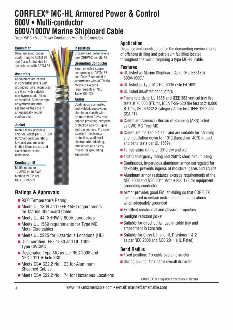
8122019 Cor Flex
httpslidepdfcomreaderfullcor-flex 1020
CORFLEXreg MC-HL Power Cable bull 600V600V1000V Marine Shipboard CableRated 90degC bull 3 and 4 Power Conductors with Ground(s)
Ratings amp Approvals
90˚C Temperature Rating Meets UL 1309 and IEEE 1580 requirements
for Marine Shipboard Cable Meets UL 44 XHHW-2 600V conductors Meets UL 1569 requirements for Type MC
Metal Clad cables
Meets UL 2225 for Hazardous Locations (HL) Dual certified IEEE 1580 and UL 1309
Type CWCMC Designated Type MC as per NEC 2008 and
NEC 2011 Article 330 Meets CSA C222 No 123 for Aluminum
Sheathed Cables Meets CSA C222 No 174 for Hazardous Locations
ApplicationDesigned and constructed for the demanding environmentsof offshore drilling and petroleum facilities locatedthroughout the world requiring a type MC-HL cable
Features
UL listed as Marine Shipboard Cable (File E86139)600V1000V
UL listed as Type MC-HL 600V (File E47409)
UL listed insulated conductors
Flame retardant UL 1685 and IEEE 383 vertical tray firetests at 70000 BTUhr ICEA T-29-520 fire test at 210000BTUhr IEC 60332-3 category A fire test IEEE 1202 and
CSA FT4 Cables are American Bureau of Shipping (ABS) listed
as CWC MC Type MC
Cables are marked ldquo-40degCrdquo and are suitable for handlingand installation down to -10degC (based on -40degC impactand bend tests per UL 1569)
Temperature rating of 90degC dry and wet
130degC emergency rating and 250degC short circuit rating
Continuous impervious aluminum armor corrugated forflexibility prevents ingress of moisture gases and liquids
Aluminum armor resistance exceeds requirements of theNEC 2008 and NEC 2011 Article 250178 for equipmentgrounding conductor
Excellent mechanical and physical properties
Sunlight resistant jacket
Suitable for direct burial use in cable tray andembedment in concrete
Three conductor cables have three symmetrical groundingconductors suitable for PWMVFD and other modern AC
drivemotor applications Suitable for Class I II and III Divisions 1 amp 2
as per NEC 2008 and NEC 2011 (HL Rated)
Bend Radius Fixed position 7X cable overall diameter
During pulling 12X cable overall diameter
Conductors
Bare annealed copperconforming to ASTM B3
and Class B stranded inaccordance with ASTM B8
Assembly
Conductors are cabledin concentric layers withgrounding wire intersticesare filled with suitablenon-hygroscopic fillersas required A binder tapeof synthetic materialassembles the core inan essentially roundconfiguration
Insulation
Cross-linked polyethylenetype XHHW-2 per UL 44
Grounding Conductor(s)Bare annealed copperconforming to ASTM B3and Class B stranded inaccordance with ASTM B8Meets or exceedsrequirements ofNEC Table 250122
Jacket
Overall black polyvinylchloride jacket per UL 156990degC temperature ratinglow acid gas emissionlimited flame spread andexcellent corrosionresistance
Armor
Continuous corrugatedand welded imperviousaluminum sheath withno more than 02 trace
copper providing completeprotection against liquidand gas ingress Providesexcellent mechanicalprotection additionalelectrostatic shieldingand serves as an easymeans for groundingequipment
CORFLEXreg is a registered trademark of Nexans
8 www nexansamercablecom bull e-mail marineamercablecom
Conductor ID
Sizes 14 AWG to 2 AWGMethod 1-E2 perICEA S-73-532
Sizes 1 AWG to 500 kcmilMethod 4 perICEA S-73-532
8122019 Cor Flex
httpslidepdfcomreaderfullcor-flex 11209800-506-9473 bull 713-896-5800 bull Fax 713-849-9009
NexansDesign
No
670142317677670144317693670146317719670148317735670149317750
670150317776670151317792670152698571670153317818670118317834670119660631670120317867670121670577
670122317891670123317917
JacketThickness
(mils)
50505050505050505050
50505050505050505050606060606060
60757575
75degC
15152020303050506565
8585115115130130150150175175200200230230255255
310310380380
90degC
15152020303055557575
9595130130145145170170195195225225260260290290
350350430430
CondSize
AWG kcmil
14(7w)14(7w)12(7w)12(7w)10(7w)10(7w)8(7w)8(7w)6(7w)6(7w)
4(7w)4(7w)2(7w)2(7w)1(19w)1(19w)
10(19w)10(19w)20(19w)20(19w)30(19w)30(19w)40(19w)40(19w)250(37w)250(37w)
350(37w)350(37w)500(37w)500(37w)
No ofCond
3434343434
3434343434343434
3434
Insulation
Thickness(mils)
30303030303045454545
45454545555555555555555555556565
65656565
NominalDiameter
OverArmor
(in)
0555050305550549062006200750079508020930
0937099511271214123013611350142714221598160617301734193619252012
2028223023402694
NominalDiameter
OverCore(in)
0390033603400396045004500520058506000680
0700078208300927095010411040113411261238125013561360150014771653
1685188919542196
NominalDiameter
OverJacket
(in)
0660060606600652072507300838090009051027
1039109512321320132014661473152515101732173918651867206920582147
2162238725042861
Ampacities(Note 1)DC
Resist
20C 991526 kft
25553255531608216082101181011806361063610400204002
02516025160157401574012550125500999009990079700791006290062700497004970042400424
00301003010021200212
DCResist
25C 991526 kft
26064260641640416404103201032006488064880408204082
02566025660160501605012800128001019010190081300806006420064000507005070043200432
00307003070021600216
ACResist
90C 60 Hz991526 kft
32583325832050720507129021290208111081110510405104
03209032090200902009016030160301278012780102101011008080080400641006410058400584
00395003950029000282
InductiveReactance90C 60 Hz
991526 kft
00376003750035300353003320033200348003480032900329
00312003120029900299002880028800281002830028000281002750027600271002710026300264
00263002630025000251
VoltageDropVolts
Ampskft
29489293071861018510117561175807452074720473704737
03025030240193801938015680156701272012690104101033008470084400695006940060800607
00470004680036700363
GroundWireSizeAWG
3x18(7w)1x14(7w)3x16(7w)1x12(7w)3x14(7w)1x10(7w)3x14(7w)1x10(7w)3x12(7w)1x8(7w)
3x12(7w)1x8(7w)3x10(7w)1x6(7w)
3x10(7w)1x6(7w)
3x10(7w)1x6(7w)
3x10(7w)1x6(7w)3x8(7w)1x4(7w)3x8(7w)1x4(7w)3x8(7w)1x4(7w)
3x6(7w)1x3(7w)3x6(7w)1x2(7w)
ApproxNet Cable
Weight(lbsKft)
200191226245312320413465542675
73589210971332133016281592192218822393240029752910360533164110
4375561760267892
Power Cable bull 600V600V1000V Marine Shipboard Cable
Notes1) Ampacities are based on NEC 2011 Table 31015(B)(16) for not more than three current-carrying conductors (where the 4th conductor
is the neutral of a 3-phase 4 wire system) in raceway cable or earth (direct buried) based on an ambient temperature of 30degC (86degF)Refer to Table 31015(B)(2) for the ampacity correction factors where the ambient temperature is other than 30degC (86degF)
2) Three conductor cables with 3 ground wires are also suitable for VFD applications
8122019 Cor Flex
httpslidepdfcomreaderfullcor-flex 1220
CORFLEXreg MV-105 or MC-HL Medium Voltage5kV 133 Insulation Level8kV 100 Insulation LevelRated 105degC bull 3 Conductors with 3 Bare Grounds
ApplicationDesigned and constructed for the demanding environmentsof offshore drilling and petroleum facilities locatedthroughout the world requiring a type MV-105 orMC-HL Medium Voltage cable
Features UL listed as Marine Shipboard Cable (File E86139)
UL listed as Type MV-105 5kV and 8kV (File E66901)
Flame retardant UL 1685 and IEEE 383 vertical tray firetests at 70000 BTUhr IEC 60332-3 category A fire testIEEE 1202 and CSA FT4
Cables are American Bureau of Shipping (ABS) listed
as CWC MC Type MVMC (Metal Clad Medium Voltage) Cables are marked ldquo-40degCrdquo and are suitable for handling
and installation down to -10degC (based on -40degC impactand bend tests per UL 1569)
Continuous impervious aluminum armor corrugated forflexibility prevents ingress of moisture gases and liquids
Aluminum armor resistance exceeds requirements of theNEC 2008 and NEC 2011 Article 250178 for equipmentgrounding conductor
Excellent mechanical and physical properties
Minimal noise and signal interference Sunlight resistant jacket
Suitable for direct burial use in cable tray andembedment in concrete
Suitable for Class I II and III Divisions 1 amp 2as per NEC 2008 and NEC 2011 (HL Rated)
Three symmetrical grounding conductors for PWMVFDand other modern AC drivemotor applications
Phase identification Color coded (black red blue)polyester ribbon laid longitudinally under the coppershield tape
Bend Radius Fixed position 7 x cable overall diameter
During pulling 12 x cable overall diameter
Insulation
EPR meets or exceedselectrical and physicalrequirements of UL 1072
Conductor Shield
Extruded semiconducting
conductor shield meetsor exceeds electrical andphysical requirementsof UL 1072
Insulation ShieldNonmetallic
Extruded semiconducting
insulation shield meetsor exceeds electricaland physical requirementsof UL 1072
Metallic Shield
Bare copper tape shieldhelically wrapped toprovide 100 coverage
Conductor
Bare annealed copperconforming to ASTM B3and Class B Compactstranded in accordancewith ASTM B496
Jacket
Overall yellow polyvinylchloride jacket per UL 107290degC temperature ratinglow acid gas emissionlimited flame spread andexcellent corrosionresistance
Armor
Continuous corrugatedand welded imperviousaluminum sheath withno more than 02 tracecopper providing completeprotection against liquidand gas ingress Providesexcellent mechanicalprotection additionalelectrostatic shieldingand serves as an easymeans for groundingequipment
Binder Tape
Synthetic materialassembles the core inan essentially roundconfiguration
CORFLEXreg is a registered trademark of Nexans
10 www nexansamercablecom bull e-mail marineamercablecom
Ratings amp Approvals
105˚C Temperature Rating Meets UL 1309 and IEEE 1580 requirements
for Marine Shipboard Cable
Meets UL 1072 requirements for mediumvoltage power cables
Meets UL 1569 requirements for Type MCMetal Clad cables
Meets UL 2225 for Hazardous Locations (MC-HL) Designated Type MC as per NEC 2008 and
NEC 2011 Article 330 Insulation meets electrical and physical requirements
of ICEA S-93-639NEMA WC 74 and UL 1072 Designated Type MV-105 as per NEC 2008 and
NEC 2011 Article 328
Grounding Conductors
Bare annealed copperconforming to ASTM B3and Class B stranded inaccordance with ASTM B8
8122019 Cor Flex
httpslidepdfcomreaderfullcor-flex 1320
5kV bull 133 Insulation Level bull EPR insulation 90 mils
NexansPartNo
662776665017660072660648662186670667670669665029660075660076660349665014
JacketThickness
(mils)
506060606060606075758585
CondSize
AWG kcmil
6(7w)4(7w)2(7w)
1(18w)10(18w)20(18w)40(18w)250(36w)350(36w)500(36w)750(58w)1000(58w)
GroundWireSizeAWG
3 x 103 x 103 x 103 x 83 x 83 x 83 x 63 x 63 x 63 x 43 x 43 x 4
NominalDiameter
OverInsulation
(in)
042604700525055605930634073307860884104511861339
NominalDiameter
OverArmor
(in)
137215421631173119051948210322402459277933663505
NominalDiameter
OverJacket
(in)
147716781765186420472081224023872623294635653687
InAir
Note 1
105135185210240275360400490600745860
CableTray
Note 2
92120165185215245320350430525635725
DirectBurialNote 3
120155200225255290375410495590720810
DCResist
20C 991526 kft
040080252001585012600099900792004980042200302002110014100106
DCResist
25C 991526 kft
040880257001616012850101900808005080043100308002150014400108
ACResist
90C 60 Hz991526 kft
051110321302022016070127501012006390054300392002810019600159
InductiveReactance90C 60 Hz991526 kft
004600042700400003870037400361003380033200312003040029200283
VoltageDropVolts
Ampskft
048010307801994016160131101069007230063400492003860030600266
AmpacitiesNominalDiameter
OverCore (in)
106611621298136814481534174918652076233527313063
ApproxNet Cable
Weight(lbsKft)
11021402177320922389268036734181536373231029212871
8kV bull 100 Insulation Level bull EPR insulation 115 mils
Notes
1) Ampacities in air are based on NEC 2011 Table 31060(C)(71) 5001-35000 Volts Ampacity column for insulated three conductorcopper cable isolated in air maximum conductor temperature of 105degC ambient air temperature of 40degC
2) Ampacities in cable tray are based on NEC 2011 Table 31060(C)(75) 5001-35000 Volts Ampacity column for insulated threeconductor copper cable in isolated conduit in air maximum conductor temperature of 105degC ambient air temperature of 40degC
3) Ampacities for direct burial are based on NEC 2011 Table 31060(C)(83) 5001-35000 Volts Ampacity column for insulatedthree conductor copper cable directly buried maximum conductor temperature of 105degC ambient earth temperatureof 20degC 100 percent load factor earth thermal resistivity of 90degC cm W
Three conductor cables with 3 ground wires are also suitable for VFD applications
Notes1) Ampacities in air are based on NEC 2011 Table 31060(C)(71) 2001-5000 Volts Ampacity column for insulated three conductor
copper cable isolated in air maximum conductor temperature of 105degC ambient air temperature of 40degC
2) Ampacities in cable tray are based on NEC 2011 Table 31060(C)(75) 2001-5000 Volts Ampacity column for insulated three conductorcopper cable in isolated conduit in air maximum conductor temperature of 105degC ambient air temperature of 40degC
3) Ampacities for direct burial are based on NEC 2011 Table 31060(C)(83) 2001-5000 Volts Ampacity column for insulatedthree conductor copper cable directly buried maximum conductor temperature of 105degC ambient earth temperatureof 20degC 100 percent load factor earth thermal resistivity of 90degC cm W
Three conductor cables with 3 ground wires are also suitable for VFD applications
11800-506-9473 bull 713-896-5800 bull Fax 713-849-9009
NexansPartNo
603837603838603839603840603841603842603843603844603845603846603847603848
JacketThickness
(mils)
505060606060606075758585
Cond
SizeAWG kcmil
6(7w)4(7w)2(7w)1(18w)
10(18w)20(18w)40(18w)250(36w)350(36w)500(36w)750(58w)
1000(58w)
Ground
WireSizeAWG
3 x 103 x 103 x 103 x 83 x 83 x 83 x 63 x 63 x 63 x 43 x 43 x 4
NominalDiameter
OverInsulation
(in)
038604300485051705540594069307470844096511471299
NominalDiameter
OverArmor
(in)
131113791564160817041806200421152350269431943464
NominalDiameter
OverJacket
(in)
142714841698174118381939213822492514286033763663
InAir
Note 1
88115154180205240320355440545685790
CableTray
Note 2
77100135155185210285315390475585660
DirectBurialNote 3
115150190215245280360395475570700785
DCResist
20C 991526 kft
040080252001585012600099900792004980042200302002110014100106
DCResist
25C 991526 kft
040880257001616012850101900808005080043100308002150014400108
AC
Resist90C 60 Hz991526 kft
051110321302022016080127501013006400054400393002820019900160
Inductive
Reactance90C 60 Hz991526 kft
004470040900308003680035600345003240031900306002940027500283
Voltage
DropVolts
Ampskft
047920307101986019080130301062007170062900487003820030300264
AmpacitiesNominal
DiameterOver
Core (in)
098110761195126213451432164617061973223326282958
Approx
Net CableWeight(lbsKft)
1058123416231877216324733435389450817000983712951
8122019 Cor Flex
httpslidepdfcomreaderfullcor-flex 1420
CORFLEXreg MV-105 or MC-HL Medium Voltage15kV 100 Insulation Level amp 133 Insulation LevelRated 105degC bull 3 Conductors with 1 Bare Ground
Ratings amp Approvals
105˚C Temperature Rating Meets UL 1309 and IEEE 1580 requirements
for Marine Shipboard Cable
Meets UL 1072 requirements for mediumvoltage power cables
Meets UL 1569 requirements for Type MCMetal Clad cables Meets UL 2225 for Hazardous Locations (MC-HL) Designated Type MC as per NEC 2008 and
NEC 2011 Article 330 Insulation meets electrical and physical requirements
of ICEA S-93-639NEMA WC 74 and UL 1072 Designated Type MV-105 as per NEC 2008 and
NEC 2011 Article 328
ApplicationDesigned and constructed for the demanding environmentsof offshore drilling and petroleum facilities locatedthroughout the world requiring a type MV-105 orMC-HL Medium Voltage cable
Features UL listed as Marine Shipboard Cable (File E86139)
UL listed as Type MV-105 15 kV (File E66901)
Flame retardant UL 1685 and IEEE 383 vertical tray firetests at 70000 BTUhr IEC 60332-3 category A fire testIEEE 1202 and CSA FT4
Cables are American Bureau of Shipping (ABS) listed
as CWC MC Type MVMC (Metal Clad Medium Voltage) Cables are marked ldquo-40degCrdquo and are suitable for handling
and installation down to -10degC (based on -40degC impactand bend tests per UL 1569)
Continuous impervious aluminum armor corrugated forflexibility prevents ingress of moisture gases and liquids
Aluminum armor resistance exceeds requirements of theNEC 2008 and NEC 2011 Article 250178 for equipmentgrounding conductor
Excellent mechanical and physical properties
Minimal noise and signal interference Sunlight resistant jacket
Suitable for direct burial use in cable tray andembedment in concrete
Suitable for Class I II and III Divisions 1 amp 2as per NEC 2008 and NEC 2011 (HL Rated)
Phase identification Color coded (black red blue)polyester ribbon laid longitudinally under the coppershield tape
Bend Radius Fixed position 7 x cable overall diameter
During pulling 12 x cable overall diameter
CORFLEXreg is a registered trademark of Nexans
12 www nexansamercablecom bull e-mail marineamercablecom
Jacket
Overall red polyvinylchloride jacket per UL 107290degC temperature ratinglow acid gas emissionlimited flame spread andexcellent corrosionresistance
Insulation
EPR meets or exceedselectrical and physicalrequirements of UL 1072
Conductor Shield
Extruded semiconductingconductor shield meetsor exceeds electrical and
physical requirementsof UL 1072
Metallic Shield
Bare copper tape shieldhelically wrapped toprovide 100 coverage
Binder Tape
Synthetic materialassembles the core inan essentially roundconfiguration
Insulation ShieldNonmetallic
Extruded semiconductinginsulation shield meetsor exceeds electrical
and physical requirementsof UL 1072
Conductor
Bare annealed copperconforming to ASTM B3
and Class B Compactstranded in accordancewith ASTM B496
Armor
Continuous corrugatedand welded imperviousaluminum sheath withno more than 02 tracecopper providing completeprotection against liquidand gas ingress Providesexcellent mechanicalprotection additionalelectrostatic shieldingand serves as an easy
means for groundingequipment
Grounding Conductor
Bare annealed copperconforming to ASTM B3and Class B stranded inaccordance with ASTM B8
8122019 Cor Flex
httpslidepdfcomreaderfullcor-flex 1520
15kV bull 100 Insulation Level
15kV bull 133 Insulation Level
NexansDesign
No
664931664933664934664935664936664676664677664678664679
JacketThickness
(mils)
606060607575758585
InAir
Note 1
185210240275360400490600745
CableTray
Note 2
165185215245320350430525635
DirectBurialNote 3
200225255290375410495590720
CondSizeAWG kcmil
2(7w)1(18w)
10(18w)20(18w)40(18w)250(36w)350(36w)500(36w)750(58w)
GroundWireSizeAWG
64443221
10
Nominal
DiameterOverInsulation
(in)
065506790716075608560910100711281310
Nominal
DiameterOverArmor
(in)
197419962036215424262490278431853480
Nominal
DiameterOverJacket
(in)
210721292171228925892653296933673671
Ampacities DCResist
20C 991526 kft
015850126000999007920049800422003020021100141
DCResist
25C 991526 kft
016160128501019008080050800431003080021500144
ACResist90C 60 Hz
991526 kft
020220160701275010120063900543003920028000196
InductiveReactance90C 60 Hz
991526 kft
004450042800412003980037100363003460033000314
VoltageDropVolts
Ampskft
020130163301327010850073700647005030039600313
NominalDiameterOver
Core (in)
158616311711180020142131234226072999
ApproxNet CableWeight(lbsKft)
2121236026302987407845995985778910716
Notes1) Ampacities in air are based on NEC 2011 Table 31060(C)(71) 5001-35000 Volts Ampacity column for insulated three conductor
copper cable isolated in air maximum conductor temperature of 105degC ambient air temperature of 40degC2) Ampacities in cable tray are based on NEC 2011 Table 31060(C)(75) 5001-35000 Volts Ampacity column for insulated three
conductor copper cable in isolated conduit in air maximum conductor temperature of 105degC ambient air temperature of 40degC
3) Ampacities for direct burial applications are based on NEC 2011 Table 31060(C)(83) 5001-35000 Volts Ampacity column forinsulated three conductor copper cable directly buried maximum conductor temperature of 105degC ambient earth temperatureof 20degC 100 percent load factor earth thermal resistivity of 90degC cm W
NexansDesign
No
665006665007665008665005665010665011665012665013
JacketThickness
(mils)
6060606075758585
InAir
Note 1
185210240275360400490600
CableTray
Note 2
165185215245320350430525
DirectBurialNote 3
200225255290375410495590
CondSize
AWG kcmil
2(7w)1(18w)
10(18w)20(18w)40(18w)250(36w)350(36w)500(36w)
GroundWireSizeAWG
64443221
Nominal
DiameterOver
Insulation(in)
07350766080308440943099610941215
Nominal
DiameterOver
Armor(in)
20942177229923622681276831543387
Nominal
DiameterOver
Jacket(in)
22352311244224962853294033363575
AmpacitiesDC
Resist
20C 991526 kft
0158501260009990079200498004220030200211
DCResist
25C 991526 kft
0161601285010190080800508004310030800215
ACResist
90C 60 Hz
991526 kft
0202201607012750101200639005430039200280
InductiveReactance90C 60 Hz
991526 kft
0046800454004370042100391003820036300345
VoltageDropVolts
Ampskft
0202401644013380109500746006550051000402
NominalDiameter
OverCore (in)
17401822190219892203231825282792
ApproxNet Cable
Weight(lbsKft)
22512616295632704546510663968209
Notes1) Ampacities in air are based on NEC 2011 Table 31060(C)(71) 5001-35000 Volts Ampacity column for insulated three conductor
copper cable isolated in air maximum conductor temperature of 105degC ambient air temperature of 40degC
2) Ampacities in cable tray are based on NEC 2011 Table 31060(C)(75) 5001-35000 Volts Ampacity column for insulated threeconductor copper cable in isolated conduit in air maximum conductor temperature of 105degC ambient air temperature of 40degC
3) Ampacities for direct burial applications are based on NEC 2011 Table 31060(C)(83) 5001-35000 Volts Ampacity column forinsulated three conductor copper cable directly buried maximum conductor temperature of 105degC ambient earth temperatureof 20degC 100 percent load factor earth thermal resistivity of 90degC cm W
13800-506-9473 bull 713-896-5800 bull Fax 713-849-9009
8122019 Cor Flex
httpslidepdfcomreaderfullcor-flex 162014 www nexansamercablecom bull e-mail marineamercablecom
CORFLEXreg Pulling InstructionsCertain installations require thepulling of CORFLEXreg into ducts ortrays These installations requirecareful planning and executionThe following provides informationon how to calculate tensions
developed during pulling andwhat precautions to take toprevent damage to the cable
Pulling TensionThe maximum tension applied to acable is limited to prevent damageor distortion of cable componentswhich could reduce the life orreliability of the cable The methodof pulling is significant in that
different methods will resultin different stresses on criticalcable components for the sameoverall tension Nexans AmerCablerecommends that CORFLEX MC-HLInstrumentation 600V cables arepulled by means of the aluminumsheath and jacket with a gripapplied over the jacketed coresheath and overall jacket All otherCORFLEX cable types described
in this catalog should be pulledby means of the conductorsaided with a grip over the outeraluminum sheath The conductors and the sheath must be pulled together Maximum allowablepulling tensions for CORFLEXcables should never exceed thevalues shown in pulling tensiontable
Calculating Pulling TensionsThe tension developed in anyStraight Section of duct iscalculated as
T = L x W x f lbf whereL = section length (feet)W = cable weight per unit length
(lbfoot)f = coefficient of dynamic friction
The tension developed in anyBend is calculated asT = T1 x efa lbf whereT1 = tension at bend entrance (lbf)e = base of natural logarithms
(271828)
f = coefficient of dynamic frictiona = angle of bend (radians)or efa is given in the following tablefor common conditionsBendAngle f=015 f=030 f=035 f=040
30deg 108 117 120 12345deg 113 127 132 13760deg 117 137 144 15290deg 127 160 173 188
Coefficients of dynamic frictionwith lubricant are given in thefollowing table for common ductand cable jacket materials Thesecoefficients can be used forcalculation of tensions
CoefficientDuct Type Cable Jacket of Friction
PVC PVC 050PE PVC 030
Fiber PVC 040Asbestos Cement PVC 070
Considerations must be given toSide Wall Bearing Pressure (SWBP) when pulling CORFLEXthrough a bend The SWBP iscalculated as follows
For CORFLEX Nexans AmerCablerecommends a maximum SWBPof 500 pounds forcefoot Duringinstallation of the CORFLEX cableit is recommended that the bendradii be as noted in thecable descriptions
Pulling in DuctIt is extremely important for thesuccess of any pull in duct to useapproved lubricants Lubricantsmust be compatible with the cablejacket and duct material
Lubricating the pulling rope willdecrease the tension on the pullingequipment and more importantlywill reduce the risk of damage tothe inside of the duct whichin turn can damage the cableWhen designing the duct layoutit is suggested that the bends beconcentrated near the end fromwhich the cable is to be pulledThis practice will result in lowertensions In some cases thetensions resulting from alternativedirections should be calculated
Pulling in Trays amp TrenchesFor the installation of CORFLEX intrays rollers are normally usedUsing well lubricated rollers andlong radius sheaves at bends willresult in a lower coefficient of
friction when compared to ductA coefficient of friction of 015 canbe used when calculating pullingtension using rollers For long pullswith bends it may be necessary to
install assist pullers before thebends to reduce the tension onthe cable entering a bend andreducing the risk of damagefrom excessive SWBP
The recommendations given aboveare intended to cover a wide varietyof pulling conditions It is possibleunder ideal conditions and withexperienced supervision to exceedthese limits
For further guidance see IEEEPaper 84 T amp D 365-3 orcontact Nexans AmerCable
SWBP = Pulling Tension Cable at Bend Exit (lbf)
Radius of Bend (feet)
8122019 Cor Flex
httpslidepdfcomreaderfullcor-flex 172015800-506-9473 bull 713-896-5800 bull Fax 713-849-9009
CORFLEXreg is a registered trademark of Nexans
Pulling Tension Tables
MaxCORFLEX No of PullingINST Size Pairs Tension
(AWG) Triads (lbf)
18 2 pairs 1874 pairs 2348 pairs 26012 pairs 29016 pairs 33220 pairs 41224 pairs 41236 pairs 461
16 1 pair 1592 pairs 2074 pairs 2348 pairs 29012 pairs 33216 pairs 41220 pairs 41224 pairs 46136 pairs 550
16 1 triad 1594 triads 234
8 triads 29412 triads 36816 triads 412
CORFLEX
MC Size(AWGkcmil) 3 Cond 4 Cond
8 265 3966 420 6304 670 9953 840 12632 1060 15931 1340 2009
10 1690 253420 2130 3194
30 2685 402740 3385 5078250 4000 6000350 5600 8400500 8000 10000750 10000 100001000 10000 10000
CORFLEX Number Max PullingMC Size of Tension(AWG) Conductors (lbf)
14 2 167
3 1674 1915 1917 2079 23412 23415 26019 26025 29537 326
12 2 1913 1914 2075 2077 2349 23412 26015 26019 29525 295
37 326
10 2 1913 2074 2075 2347 2349 26012 26015 295
19 29525 32637 411
1210 43 191128 43 264126 43 420124 43 668122 43 1062
Max Pulling
Tension (lbf)
8122019 Cor Flex
httpslidepdfcomreaderfullcor-flex 1820
CORFLEXreg is a registered trademark of Nexans
16 www nexansamercablecom bull e-mail marineamercablecom
CORFLEXreg Conductor ID
Conductor Insulation Stripe Conductor Insulation Stripe
1st BLACK ndash 19th ORANGE Blue2nd RED ndash 20th YELLOW Blue
3rd BLUE ndash 21st BROWN Blue
4th ORANGE ndash 22nd BLACK Orange
5th YELLOW ndash 23rd RED Orange
6th BROWN ndash 24th BLUE Orange
7th RED Black 25th YELLOW Orange
8th BLUE Black 26th BROWN Orange
9th ORANGE Black 27th BLACK Yellow
10th YELLOW Black 28th RED Yellow
11th BROWN Black 29th BLUE Yellow
12th BLACK Red 30th ORANGE Yellow
13th BLUE Red 31st BROWN Yellow
14th ORANGE Red 32nd BLACK Brown
15th YELLOW Red 33rd RED Brown
16th BROWN Red 34th BLUE Brown
17th BLACK Blue 35th ORANGE Brown
18th RED Blue 36th YELLOW Brown
Method 1-E2 per ICEA S-73-532
Method 4 of ICEA S-73-532
Conductor Printing Details Conductor Printing Details
1st ldquo1-ONE-1rdquo 5th ldquo5-FIVE-5rdquo
2nd ldquo2-TWO-2rdquo 6th ldquo6-SIX-6rdquo
3rd ldquo3-THREE-3rdquo 7th ldquo7-SEVEN-7rdquo
4th ldquo4-FOUR-4rdquo 8th ldquo8-EIGHT-8rdquo
8122019 Cor Flex
httpslidepdfcomreaderfullcor-flex 1920
8122019 Cor Flex
httpslidepdfcomreaderfullcor-flex 2020
The industrystandard forflexible highquality powercontrol andinstrumentationType P cables
Crush andImpactResistantType P cableswithout
externalarmoring
Low smoke
halogen-freefire resistantor flameretardantType Pcables
Precisionengineeredcableassembliesfor hazardousand industrialapplications
Foil shielded
power cablesengineered for
use in variable
frequency
AC drive
applications
Available in several
constructions
Top DriveServiceLoops
Nexans AmerCable is an ISO 9001 certified cablemanufacturer that combines leading-edge manufacturing
technology innovative thinking and high qualityservice to deliver the finest oil amp gas cable andengineered cable assemblies available
Nexans AmerCable serves the world fromour Oil amp Gas Group headquarters in Houston TexasOur professional field engineers and sales force work withyou to create innovative cost-effective project solutions
10633 West Little York bull Building 1 bull Suite 100 bull Houston TX 77041
800-506-9473 bull 713-896-5800 bull Fax 713-849-9009 bull e-mail marineamercablecom
What can you expect fromNexans AmerCable
983150 Best at On-Time Delivery
983150 Outstanding Engineering Supportand Customer Service
983150 Innovative Productivity Solutions
983150 Global Cable Management
8122019 Cor Flex
httpslidepdfcomreaderfullcor-flex 11209800-506-9473 bull 713-896-5800 bull Fax 713-849-9009
NexansDesign
No
670142317677670144317693670146317719670148317735670149317750
670150317776670151317792670152698571670153317818670118317834670119660631670120317867670121670577
670122317891670123317917
JacketThickness
(mils)
50505050505050505050
50505050505050505050606060606060
60757575
75degC
15152020303050506565
8585115115130130150150175175200200230230255255
310310380380
90degC
15152020303055557575
9595130130145145170170195195225225260260290290
350350430430
CondSize
AWG kcmil
14(7w)14(7w)12(7w)12(7w)10(7w)10(7w)8(7w)8(7w)6(7w)6(7w)
4(7w)4(7w)2(7w)2(7w)1(19w)1(19w)
10(19w)10(19w)20(19w)20(19w)30(19w)30(19w)40(19w)40(19w)250(37w)250(37w)
350(37w)350(37w)500(37w)500(37w)
No ofCond
3434343434
3434343434343434
3434
Insulation
Thickness(mils)
30303030303045454545
45454545555555555555555555556565
65656565
NominalDiameter
OverArmor
(in)
0555050305550549062006200750079508020930
0937099511271214123013611350142714221598160617301734193619252012
2028223023402694
NominalDiameter
OverCore(in)
0390033603400396045004500520058506000680
0700078208300927095010411040113411261238125013561360150014771653
1685188919542196
NominalDiameter
OverJacket
(in)
0660060606600652072507300838090009051027
1039109512321320132014661473152515101732173918651867206920582147
2162238725042861
Ampacities(Note 1)DC
Resist
20C 991526 kft
25553255531608216082101181011806361063610400204002
02516025160157401574012550125500999009990079700791006290062700497004970042400424
00301003010021200212
DCResist
25C 991526 kft
26064260641640416404103201032006488064880408204082
02566025660160501605012800128001019010190081300806006420064000507005070043200432
00307003070021600216
ACResist
90C 60 Hz991526 kft
32583325832050720507129021290208111081110510405104
03209032090200902009016030160301278012780102101011008080080400641006410058400584
00395003950029000282
InductiveReactance90C 60 Hz
991526 kft
00376003750035300353003320033200348003480032900329
00312003120029900299002880028800281002830028000281002750027600271002710026300264
00263002630025000251
VoltageDropVolts
Ampskft
29489293071861018510117561175807452074720473704737
03025030240193801938015680156701272012690104101033008470084400695006940060800607
00470004680036700363
GroundWireSizeAWG
3x18(7w)1x14(7w)3x16(7w)1x12(7w)3x14(7w)1x10(7w)3x14(7w)1x10(7w)3x12(7w)1x8(7w)
3x12(7w)1x8(7w)3x10(7w)1x6(7w)
3x10(7w)1x6(7w)
3x10(7w)1x6(7w)
3x10(7w)1x6(7w)3x8(7w)1x4(7w)3x8(7w)1x4(7w)3x8(7w)1x4(7w)
3x6(7w)1x3(7w)3x6(7w)1x2(7w)
ApproxNet Cable
Weight(lbsKft)
200191226245312320413465542675
73589210971332133016281592192218822393240029752910360533164110
4375561760267892
Power Cable bull 600V600V1000V Marine Shipboard Cable
Notes1) Ampacities are based on NEC 2011 Table 31015(B)(16) for not more than three current-carrying conductors (where the 4th conductor
is the neutral of a 3-phase 4 wire system) in raceway cable or earth (direct buried) based on an ambient temperature of 30degC (86degF)Refer to Table 31015(B)(2) for the ampacity correction factors where the ambient temperature is other than 30degC (86degF)
2) Three conductor cables with 3 ground wires are also suitable for VFD applications
8122019 Cor Flex
httpslidepdfcomreaderfullcor-flex 1220
CORFLEXreg MV-105 or MC-HL Medium Voltage5kV 133 Insulation Level8kV 100 Insulation LevelRated 105degC bull 3 Conductors with 3 Bare Grounds
ApplicationDesigned and constructed for the demanding environmentsof offshore drilling and petroleum facilities locatedthroughout the world requiring a type MV-105 orMC-HL Medium Voltage cable
Features UL listed as Marine Shipboard Cable (File E86139)
UL listed as Type MV-105 5kV and 8kV (File E66901)
Flame retardant UL 1685 and IEEE 383 vertical tray firetests at 70000 BTUhr IEC 60332-3 category A fire testIEEE 1202 and CSA FT4
Cables are American Bureau of Shipping (ABS) listed
as CWC MC Type MVMC (Metal Clad Medium Voltage) Cables are marked ldquo-40degCrdquo and are suitable for handling
and installation down to -10degC (based on -40degC impactand bend tests per UL 1569)
Continuous impervious aluminum armor corrugated forflexibility prevents ingress of moisture gases and liquids
Aluminum armor resistance exceeds requirements of theNEC 2008 and NEC 2011 Article 250178 for equipmentgrounding conductor
Excellent mechanical and physical properties
Minimal noise and signal interference Sunlight resistant jacket
Suitable for direct burial use in cable tray andembedment in concrete
Suitable for Class I II and III Divisions 1 amp 2as per NEC 2008 and NEC 2011 (HL Rated)
Three symmetrical grounding conductors for PWMVFDand other modern AC drivemotor applications
Phase identification Color coded (black red blue)polyester ribbon laid longitudinally under the coppershield tape
Bend Radius Fixed position 7 x cable overall diameter
During pulling 12 x cable overall diameter
Insulation
EPR meets or exceedselectrical and physicalrequirements of UL 1072
Conductor Shield
Extruded semiconducting
conductor shield meetsor exceeds electrical andphysical requirementsof UL 1072
Insulation ShieldNonmetallic
Extruded semiconducting
insulation shield meetsor exceeds electricaland physical requirementsof UL 1072
Metallic Shield
Bare copper tape shieldhelically wrapped toprovide 100 coverage
Conductor
Bare annealed copperconforming to ASTM B3and Class B Compactstranded in accordancewith ASTM B496
Jacket
Overall yellow polyvinylchloride jacket per UL 107290degC temperature ratinglow acid gas emissionlimited flame spread andexcellent corrosionresistance
Armor
Continuous corrugatedand welded imperviousaluminum sheath withno more than 02 tracecopper providing completeprotection against liquidand gas ingress Providesexcellent mechanicalprotection additionalelectrostatic shieldingand serves as an easymeans for groundingequipment
Binder Tape
Synthetic materialassembles the core inan essentially roundconfiguration
CORFLEXreg is a registered trademark of Nexans
10 www nexansamercablecom bull e-mail marineamercablecom
Ratings amp Approvals
105˚C Temperature Rating Meets UL 1309 and IEEE 1580 requirements
for Marine Shipboard Cable
Meets UL 1072 requirements for mediumvoltage power cables
Meets UL 1569 requirements for Type MCMetal Clad cables
Meets UL 2225 for Hazardous Locations (MC-HL) Designated Type MC as per NEC 2008 and
NEC 2011 Article 330 Insulation meets electrical and physical requirements
of ICEA S-93-639NEMA WC 74 and UL 1072 Designated Type MV-105 as per NEC 2008 and
NEC 2011 Article 328
Grounding Conductors
Bare annealed copperconforming to ASTM B3and Class B stranded inaccordance with ASTM B8
8122019 Cor Flex
httpslidepdfcomreaderfullcor-flex 1320
5kV bull 133 Insulation Level bull EPR insulation 90 mils
NexansPartNo
662776665017660072660648662186670667670669665029660075660076660349665014
JacketThickness
(mils)
506060606060606075758585
CondSize
AWG kcmil
6(7w)4(7w)2(7w)
1(18w)10(18w)20(18w)40(18w)250(36w)350(36w)500(36w)750(58w)1000(58w)
GroundWireSizeAWG
3 x 103 x 103 x 103 x 83 x 83 x 83 x 63 x 63 x 63 x 43 x 43 x 4
NominalDiameter
OverInsulation
(in)
042604700525055605930634073307860884104511861339
NominalDiameter
OverArmor
(in)
137215421631173119051948210322402459277933663505
NominalDiameter
OverJacket
(in)
147716781765186420472081224023872623294635653687
InAir
Note 1
105135185210240275360400490600745860
CableTray
Note 2
92120165185215245320350430525635725
DirectBurialNote 3
120155200225255290375410495590720810
DCResist
20C 991526 kft
040080252001585012600099900792004980042200302002110014100106
DCResist
25C 991526 kft
040880257001616012850101900808005080043100308002150014400108
ACResist
90C 60 Hz991526 kft
051110321302022016070127501012006390054300392002810019600159
InductiveReactance90C 60 Hz991526 kft
004600042700400003870037400361003380033200312003040029200283
VoltageDropVolts
Ampskft
048010307801994016160131101069007230063400492003860030600266
AmpacitiesNominalDiameter
OverCore (in)
106611621298136814481534174918652076233527313063
ApproxNet Cable
Weight(lbsKft)
11021402177320922389268036734181536373231029212871
8kV bull 100 Insulation Level bull EPR insulation 115 mils
Notes
1) Ampacities in air are based on NEC 2011 Table 31060(C)(71) 5001-35000 Volts Ampacity column for insulated three conductorcopper cable isolated in air maximum conductor temperature of 105degC ambient air temperature of 40degC
2) Ampacities in cable tray are based on NEC 2011 Table 31060(C)(75) 5001-35000 Volts Ampacity column for insulated threeconductor copper cable in isolated conduit in air maximum conductor temperature of 105degC ambient air temperature of 40degC
3) Ampacities for direct burial are based on NEC 2011 Table 31060(C)(83) 5001-35000 Volts Ampacity column for insulatedthree conductor copper cable directly buried maximum conductor temperature of 105degC ambient earth temperatureof 20degC 100 percent load factor earth thermal resistivity of 90degC cm W
Three conductor cables with 3 ground wires are also suitable for VFD applications
Notes1) Ampacities in air are based on NEC 2011 Table 31060(C)(71) 2001-5000 Volts Ampacity column for insulated three conductor
copper cable isolated in air maximum conductor temperature of 105degC ambient air temperature of 40degC
2) Ampacities in cable tray are based on NEC 2011 Table 31060(C)(75) 2001-5000 Volts Ampacity column for insulated three conductorcopper cable in isolated conduit in air maximum conductor temperature of 105degC ambient air temperature of 40degC
3) Ampacities for direct burial are based on NEC 2011 Table 31060(C)(83) 2001-5000 Volts Ampacity column for insulatedthree conductor copper cable directly buried maximum conductor temperature of 105degC ambient earth temperatureof 20degC 100 percent load factor earth thermal resistivity of 90degC cm W
Three conductor cables with 3 ground wires are also suitable for VFD applications
11800-506-9473 bull 713-896-5800 bull Fax 713-849-9009
NexansPartNo
603837603838603839603840603841603842603843603844603845603846603847603848
JacketThickness
(mils)
505060606060606075758585
Cond
SizeAWG kcmil
6(7w)4(7w)2(7w)1(18w)
10(18w)20(18w)40(18w)250(36w)350(36w)500(36w)750(58w)
1000(58w)
Ground
WireSizeAWG
3 x 103 x 103 x 103 x 83 x 83 x 83 x 63 x 63 x 63 x 43 x 43 x 4
NominalDiameter
OverInsulation
(in)
038604300485051705540594069307470844096511471299
NominalDiameter
OverArmor
(in)
131113791564160817041806200421152350269431943464
NominalDiameter
OverJacket
(in)
142714841698174118381939213822492514286033763663
InAir
Note 1
88115154180205240320355440545685790
CableTray
Note 2
77100135155185210285315390475585660
DirectBurialNote 3
115150190215245280360395475570700785
DCResist
20C 991526 kft
040080252001585012600099900792004980042200302002110014100106
DCResist
25C 991526 kft
040880257001616012850101900808005080043100308002150014400108
AC
Resist90C 60 Hz991526 kft
051110321302022016080127501013006400054400393002820019900160
Inductive
Reactance90C 60 Hz991526 kft
004470040900308003680035600345003240031900306002940027500283
Voltage
DropVolts
Ampskft
047920307101986019080130301062007170062900487003820030300264
AmpacitiesNominal
DiameterOver
Core (in)
098110761195126213451432164617061973223326282958
Approx
Net CableWeight(lbsKft)
1058123416231877216324733435389450817000983712951
8122019 Cor Flex
httpslidepdfcomreaderfullcor-flex 1420
CORFLEXreg MV-105 or MC-HL Medium Voltage15kV 100 Insulation Level amp 133 Insulation LevelRated 105degC bull 3 Conductors with 1 Bare Ground
Ratings amp Approvals
105˚C Temperature Rating Meets UL 1309 and IEEE 1580 requirements
for Marine Shipboard Cable
Meets UL 1072 requirements for mediumvoltage power cables
Meets UL 1569 requirements for Type MCMetal Clad cables Meets UL 2225 for Hazardous Locations (MC-HL) Designated Type MC as per NEC 2008 and
NEC 2011 Article 330 Insulation meets electrical and physical requirements
of ICEA S-93-639NEMA WC 74 and UL 1072 Designated Type MV-105 as per NEC 2008 and
NEC 2011 Article 328
ApplicationDesigned and constructed for the demanding environmentsof offshore drilling and petroleum facilities locatedthroughout the world requiring a type MV-105 orMC-HL Medium Voltage cable
Features UL listed as Marine Shipboard Cable (File E86139)
UL listed as Type MV-105 15 kV (File E66901)
Flame retardant UL 1685 and IEEE 383 vertical tray firetests at 70000 BTUhr IEC 60332-3 category A fire testIEEE 1202 and CSA FT4
Cables are American Bureau of Shipping (ABS) listed
as CWC MC Type MVMC (Metal Clad Medium Voltage) Cables are marked ldquo-40degCrdquo and are suitable for handling
and installation down to -10degC (based on -40degC impactand bend tests per UL 1569)
Continuous impervious aluminum armor corrugated forflexibility prevents ingress of moisture gases and liquids
Aluminum armor resistance exceeds requirements of theNEC 2008 and NEC 2011 Article 250178 for equipmentgrounding conductor
Excellent mechanical and physical properties
Minimal noise and signal interference Sunlight resistant jacket
Suitable for direct burial use in cable tray andembedment in concrete
Suitable for Class I II and III Divisions 1 amp 2as per NEC 2008 and NEC 2011 (HL Rated)
Phase identification Color coded (black red blue)polyester ribbon laid longitudinally under the coppershield tape
Bend Radius Fixed position 7 x cable overall diameter
During pulling 12 x cable overall diameter
CORFLEXreg is a registered trademark of Nexans
12 www nexansamercablecom bull e-mail marineamercablecom
Jacket
Overall red polyvinylchloride jacket per UL 107290degC temperature ratinglow acid gas emissionlimited flame spread andexcellent corrosionresistance
Insulation
EPR meets or exceedselectrical and physicalrequirements of UL 1072
Conductor Shield
Extruded semiconductingconductor shield meetsor exceeds electrical and
physical requirementsof UL 1072
Metallic Shield
Bare copper tape shieldhelically wrapped toprovide 100 coverage
Binder Tape
Synthetic materialassembles the core inan essentially roundconfiguration
Insulation ShieldNonmetallic
Extruded semiconductinginsulation shield meetsor exceeds electrical
and physical requirementsof UL 1072
Conductor
Bare annealed copperconforming to ASTM B3
and Class B Compactstranded in accordancewith ASTM B496
Armor
Continuous corrugatedand welded imperviousaluminum sheath withno more than 02 tracecopper providing completeprotection against liquidand gas ingress Providesexcellent mechanicalprotection additionalelectrostatic shieldingand serves as an easy
means for groundingequipment
Grounding Conductor
Bare annealed copperconforming to ASTM B3and Class B stranded inaccordance with ASTM B8
8122019 Cor Flex
httpslidepdfcomreaderfullcor-flex 1520
15kV bull 100 Insulation Level
15kV bull 133 Insulation Level
NexansDesign
No
664931664933664934664935664936664676664677664678664679
JacketThickness
(mils)
606060607575758585
InAir
Note 1
185210240275360400490600745
CableTray
Note 2
165185215245320350430525635
DirectBurialNote 3
200225255290375410495590720
CondSizeAWG kcmil
2(7w)1(18w)
10(18w)20(18w)40(18w)250(36w)350(36w)500(36w)750(58w)
GroundWireSizeAWG
64443221
10
Nominal
DiameterOverInsulation
(in)
065506790716075608560910100711281310
Nominal
DiameterOverArmor
(in)
197419962036215424262490278431853480
Nominal
DiameterOverJacket
(in)
210721292171228925892653296933673671
Ampacities DCResist
20C 991526 kft
015850126000999007920049800422003020021100141
DCResist
25C 991526 kft
016160128501019008080050800431003080021500144
ACResist90C 60 Hz
991526 kft
020220160701275010120063900543003920028000196
InductiveReactance90C 60 Hz
991526 kft
004450042800412003980037100363003460033000314
VoltageDropVolts
Ampskft
020130163301327010850073700647005030039600313
NominalDiameterOver
Core (in)
158616311711180020142131234226072999
ApproxNet CableWeight(lbsKft)
2121236026302987407845995985778910716
Notes1) Ampacities in air are based on NEC 2011 Table 31060(C)(71) 5001-35000 Volts Ampacity column for insulated three conductor
copper cable isolated in air maximum conductor temperature of 105degC ambient air temperature of 40degC2) Ampacities in cable tray are based on NEC 2011 Table 31060(C)(75) 5001-35000 Volts Ampacity column for insulated three
conductor copper cable in isolated conduit in air maximum conductor temperature of 105degC ambient air temperature of 40degC
3) Ampacities for direct burial applications are based on NEC 2011 Table 31060(C)(83) 5001-35000 Volts Ampacity column forinsulated three conductor copper cable directly buried maximum conductor temperature of 105degC ambient earth temperatureof 20degC 100 percent load factor earth thermal resistivity of 90degC cm W
NexansDesign
No
665006665007665008665005665010665011665012665013
JacketThickness
(mils)
6060606075758585
InAir
Note 1
185210240275360400490600
CableTray
Note 2
165185215245320350430525
DirectBurialNote 3
200225255290375410495590
CondSize
AWG kcmil
2(7w)1(18w)
10(18w)20(18w)40(18w)250(36w)350(36w)500(36w)
GroundWireSizeAWG
64443221
Nominal
DiameterOver
Insulation(in)
07350766080308440943099610941215
Nominal
DiameterOver
Armor(in)
20942177229923622681276831543387
Nominal
DiameterOver
Jacket(in)
22352311244224962853294033363575
AmpacitiesDC
Resist
20C 991526 kft
0158501260009990079200498004220030200211
DCResist
25C 991526 kft
0161601285010190080800508004310030800215
ACResist
90C 60 Hz
991526 kft
0202201607012750101200639005430039200280
InductiveReactance90C 60 Hz
991526 kft
0046800454004370042100391003820036300345
VoltageDropVolts
Ampskft
0202401644013380109500746006550051000402
NominalDiameter
OverCore (in)
17401822190219892203231825282792
ApproxNet Cable
Weight(lbsKft)
22512616295632704546510663968209
Notes1) Ampacities in air are based on NEC 2011 Table 31060(C)(71) 5001-35000 Volts Ampacity column for insulated three conductor
copper cable isolated in air maximum conductor temperature of 105degC ambient air temperature of 40degC
2) Ampacities in cable tray are based on NEC 2011 Table 31060(C)(75) 5001-35000 Volts Ampacity column for insulated threeconductor copper cable in isolated conduit in air maximum conductor temperature of 105degC ambient air temperature of 40degC
3) Ampacities for direct burial applications are based on NEC 2011 Table 31060(C)(83) 5001-35000 Volts Ampacity column forinsulated three conductor copper cable directly buried maximum conductor temperature of 105degC ambient earth temperatureof 20degC 100 percent load factor earth thermal resistivity of 90degC cm W
13800-506-9473 bull 713-896-5800 bull Fax 713-849-9009
8122019 Cor Flex
httpslidepdfcomreaderfullcor-flex 162014 www nexansamercablecom bull e-mail marineamercablecom
CORFLEXreg Pulling InstructionsCertain installations require thepulling of CORFLEXreg into ducts ortrays These installations requirecareful planning and executionThe following provides informationon how to calculate tensions
developed during pulling andwhat precautions to take toprevent damage to the cable
Pulling TensionThe maximum tension applied to acable is limited to prevent damageor distortion of cable componentswhich could reduce the life orreliability of the cable The methodof pulling is significant in that
different methods will resultin different stresses on criticalcable components for the sameoverall tension Nexans AmerCablerecommends that CORFLEX MC-HLInstrumentation 600V cables arepulled by means of the aluminumsheath and jacket with a gripapplied over the jacketed coresheath and overall jacket All otherCORFLEX cable types described
in this catalog should be pulledby means of the conductorsaided with a grip over the outeraluminum sheath The conductors and the sheath must be pulled together Maximum allowablepulling tensions for CORFLEXcables should never exceed thevalues shown in pulling tensiontable
Calculating Pulling TensionsThe tension developed in anyStraight Section of duct iscalculated as
T = L x W x f lbf whereL = section length (feet)W = cable weight per unit length
(lbfoot)f = coefficient of dynamic friction
The tension developed in anyBend is calculated asT = T1 x efa lbf whereT1 = tension at bend entrance (lbf)e = base of natural logarithms
(271828)
f = coefficient of dynamic frictiona = angle of bend (radians)or efa is given in the following tablefor common conditionsBendAngle f=015 f=030 f=035 f=040
30deg 108 117 120 12345deg 113 127 132 13760deg 117 137 144 15290deg 127 160 173 188
Coefficients of dynamic frictionwith lubricant are given in thefollowing table for common ductand cable jacket materials Thesecoefficients can be used forcalculation of tensions
CoefficientDuct Type Cable Jacket of Friction
PVC PVC 050PE PVC 030
Fiber PVC 040Asbestos Cement PVC 070
Considerations must be given toSide Wall Bearing Pressure (SWBP) when pulling CORFLEXthrough a bend The SWBP iscalculated as follows
For CORFLEX Nexans AmerCablerecommends a maximum SWBPof 500 pounds forcefoot Duringinstallation of the CORFLEX cableit is recommended that the bendradii be as noted in thecable descriptions
Pulling in DuctIt is extremely important for thesuccess of any pull in duct to useapproved lubricants Lubricantsmust be compatible with the cablejacket and duct material
Lubricating the pulling rope willdecrease the tension on the pullingequipment and more importantlywill reduce the risk of damage tothe inside of the duct whichin turn can damage the cableWhen designing the duct layoutit is suggested that the bends beconcentrated near the end fromwhich the cable is to be pulledThis practice will result in lowertensions In some cases thetensions resulting from alternativedirections should be calculated
Pulling in Trays amp TrenchesFor the installation of CORFLEX intrays rollers are normally usedUsing well lubricated rollers andlong radius sheaves at bends willresult in a lower coefficient of
friction when compared to ductA coefficient of friction of 015 canbe used when calculating pullingtension using rollers For long pullswith bends it may be necessary to
install assist pullers before thebends to reduce the tension onthe cable entering a bend andreducing the risk of damagefrom excessive SWBP
The recommendations given aboveare intended to cover a wide varietyof pulling conditions It is possibleunder ideal conditions and withexperienced supervision to exceedthese limits
For further guidance see IEEEPaper 84 T amp D 365-3 orcontact Nexans AmerCable
SWBP = Pulling Tension Cable at Bend Exit (lbf)
Radius of Bend (feet)
8122019 Cor Flex
httpslidepdfcomreaderfullcor-flex 172015800-506-9473 bull 713-896-5800 bull Fax 713-849-9009
CORFLEXreg is a registered trademark of Nexans
Pulling Tension Tables
MaxCORFLEX No of PullingINST Size Pairs Tension
(AWG) Triads (lbf)
18 2 pairs 1874 pairs 2348 pairs 26012 pairs 29016 pairs 33220 pairs 41224 pairs 41236 pairs 461
16 1 pair 1592 pairs 2074 pairs 2348 pairs 29012 pairs 33216 pairs 41220 pairs 41224 pairs 46136 pairs 550
16 1 triad 1594 triads 234
8 triads 29412 triads 36816 triads 412
CORFLEX
MC Size(AWGkcmil) 3 Cond 4 Cond
8 265 3966 420 6304 670 9953 840 12632 1060 15931 1340 2009
10 1690 253420 2130 3194
30 2685 402740 3385 5078250 4000 6000350 5600 8400500 8000 10000750 10000 100001000 10000 10000
CORFLEX Number Max PullingMC Size of Tension(AWG) Conductors (lbf)
14 2 167
3 1674 1915 1917 2079 23412 23415 26019 26025 29537 326
12 2 1913 1914 2075 2077 2349 23412 26015 26019 29525 295
37 326
10 2 1913 2074 2075 2347 2349 26012 26015 295
19 29525 32637 411
1210 43 191128 43 264126 43 420124 43 668122 43 1062
Max Pulling
Tension (lbf)
8122019 Cor Flex
httpslidepdfcomreaderfullcor-flex 1820
CORFLEXreg is a registered trademark of Nexans
16 www nexansamercablecom bull e-mail marineamercablecom
CORFLEXreg Conductor ID
Conductor Insulation Stripe Conductor Insulation Stripe
1st BLACK ndash 19th ORANGE Blue2nd RED ndash 20th YELLOW Blue
3rd BLUE ndash 21st BROWN Blue
4th ORANGE ndash 22nd BLACK Orange
5th YELLOW ndash 23rd RED Orange
6th BROWN ndash 24th BLUE Orange
7th RED Black 25th YELLOW Orange
8th BLUE Black 26th BROWN Orange
9th ORANGE Black 27th BLACK Yellow
10th YELLOW Black 28th RED Yellow
11th BROWN Black 29th BLUE Yellow
12th BLACK Red 30th ORANGE Yellow
13th BLUE Red 31st BROWN Yellow
14th ORANGE Red 32nd BLACK Brown
15th YELLOW Red 33rd RED Brown
16th BROWN Red 34th BLUE Brown
17th BLACK Blue 35th ORANGE Brown
18th RED Blue 36th YELLOW Brown
Method 1-E2 per ICEA S-73-532
Method 4 of ICEA S-73-532
Conductor Printing Details Conductor Printing Details
1st ldquo1-ONE-1rdquo 5th ldquo5-FIVE-5rdquo
2nd ldquo2-TWO-2rdquo 6th ldquo6-SIX-6rdquo
3rd ldquo3-THREE-3rdquo 7th ldquo7-SEVEN-7rdquo
4th ldquo4-FOUR-4rdquo 8th ldquo8-EIGHT-8rdquo
8122019 Cor Flex
httpslidepdfcomreaderfullcor-flex 1920
8122019 Cor Flex
httpslidepdfcomreaderfullcor-flex 2020
The industrystandard forflexible highquality powercontrol andinstrumentationType P cables
Crush andImpactResistantType P cableswithout
externalarmoring
Low smoke
halogen-freefire resistantor flameretardantType Pcables
Precisionengineeredcableassembliesfor hazardousand industrialapplications
Foil shielded
power cablesengineered for
use in variable
frequency
AC drive
applications
Available in several
constructions
Top DriveServiceLoops
Nexans AmerCable is an ISO 9001 certified cablemanufacturer that combines leading-edge manufacturing
technology innovative thinking and high qualityservice to deliver the finest oil amp gas cable andengineered cable assemblies available
Nexans AmerCable serves the world fromour Oil amp Gas Group headquarters in Houston TexasOur professional field engineers and sales force work withyou to create innovative cost-effective project solutions
10633 West Little York bull Building 1 bull Suite 100 bull Houston TX 77041
800-506-9473 bull 713-896-5800 bull Fax 713-849-9009 bull e-mail marineamercablecom
What can you expect fromNexans AmerCable
983150 Best at On-Time Delivery
983150 Outstanding Engineering Supportand Customer Service
983150 Innovative Productivity Solutions
983150 Global Cable Management

8122019 Cor Flex
httpslidepdfcomreaderfullcor-flex 1220
CORFLEXreg MV-105 or MC-HL Medium Voltage5kV 133 Insulation Level8kV 100 Insulation LevelRated 105degC bull 3 Conductors with 3 Bare Grounds
ApplicationDesigned and constructed for the demanding environmentsof offshore drilling and petroleum facilities locatedthroughout the world requiring a type MV-105 orMC-HL Medium Voltage cable
Features UL listed as Marine Shipboard Cable (File E86139)
UL listed as Type MV-105 5kV and 8kV (File E66901)
Flame retardant UL 1685 and IEEE 383 vertical tray firetests at 70000 BTUhr IEC 60332-3 category A fire testIEEE 1202 and CSA FT4
Cables are American Bureau of Shipping (ABS) listed
as CWC MC Type MVMC (Metal Clad Medium Voltage) Cables are marked ldquo-40degCrdquo and are suitable for handling
and installation down to -10degC (based on -40degC impactand bend tests per UL 1569)
Continuous impervious aluminum armor corrugated forflexibility prevents ingress of moisture gases and liquids
Aluminum armor resistance exceeds requirements of theNEC 2008 and NEC 2011 Article 250178 for equipmentgrounding conductor
Excellent mechanical and physical properties
Minimal noise and signal interference Sunlight resistant jacket
Suitable for direct burial use in cable tray andembedment in concrete
Suitable for Class I II and III Divisions 1 amp 2as per NEC 2008 and NEC 2011 (HL Rated)
Three symmetrical grounding conductors for PWMVFDand other modern AC drivemotor applications
Phase identification Color coded (black red blue)polyester ribbon laid longitudinally under the coppershield tape
Bend Radius Fixed position 7 x cable overall diameter
During pulling 12 x cable overall diameter
Insulation
EPR meets or exceedselectrical and physicalrequirements of UL 1072
Conductor Shield
Extruded semiconducting
conductor shield meetsor exceeds electrical andphysical requirementsof UL 1072
Insulation ShieldNonmetallic
Extruded semiconducting
insulation shield meetsor exceeds electricaland physical requirementsof UL 1072
Metallic Shield
Bare copper tape shieldhelically wrapped toprovide 100 coverage
Conductor
Bare annealed copperconforming to ASTM B3and Class B Compactstranded in accordancewith ASTM B496
Jacket
Overall yellow polyvinylchloride jacket per UL 107290degC temperature ratinglow acid gas emissionlimited flame spread andexcellent corrosionresistance
Armor
Continuous corrugatedand welded imperviousaluminum sheath withno more than 02 tracecopper providing completeprotection against liquidand gas ingress Providesexcellent mechanicalprotection additionalelectrostatic shieldingand serves as an easymeans for groundingequipment
Binder Tape
Synthetic materialassembles the core inan essentially roundconfiguration
CORFLEXreg is a registered trademark of Nexans
10 www nexansamercablecom bull e-mail marineamercablecom
Ratings amp Approvals
105˚C Temperature Rating Meets UL 1309 and IEEE 1580 requirements
for Marine Shipboard Cable
Meets UL 1072 requirements for mediumvoltage power cables
Meets UL 1569 requirements for Type MCMetal Clad cables
Meets UL 2225 for Hazardous Locations (MC-HL) Designated Type MC as per NEC 2008 and
NEC 2011 Article 330 Insulation meets electrical and physical requirements
of ICEA S-93-639NEMA WC 74 and UL 1072 Designated Type MV-105 as per NEC 2008 and
NEC 2011 Article 328
Grounding Conductors
Bare annealed copperconforming to ASTM B3and Class B stranded inaccordance with ASTM B8
8122019 Cor Flex
httpslidepdfcomreaderfullcor-flex 1320
5kV bull 133 Insulation Level bull EPR insulation 90 mils
NexansPartNo
662776665017660072660648662186670667670669665029660075660076660349665014
JacketThickness
(mils)
506060606060606075758585
CondSize
AWG kcmil
6(7w)4(7w)2(7w)
1(18w)10(18w)20(18w)40(18w)250(36w)350(36w)500(36w)750(58w)1000(58w)
GroundWireSizeAWG
3 x 103 x 103 x 103 x 83 x 83 x 83 x 63 x 63 x 63 x 43 x 43 x 4
NominalDiameter
OverInsulation
(in)
042604700525055605930634073307860884104511861339
NominalDiameter
OverArmor
(in)
137215421631173119051948210322402459277933663505
NominalDiameter
OverJacket
(in)
147716781765186420472081224023872623294635653687
InAir
Note 1
105135185210240275360400490600745860
CableTray
Note 2
92120165185215245320350430525635725
DirectBurialNote 3
120155200225255290375410495590720810
DCResist
20C 991526 kft
040080252001585012600099900792004980042200302002110014100106
DCResist
25C 991526 kft
040880257001616012850101900808005080043100308002150014400108
ACResist
90C 60 Hz991526 kft
051110321302022016070127501012006390054300392002810019600159
InductiveReactance90C 60 Hz991526 kft
004600042700400003870037400361003380033200312003040029200283
VoltageDropVolts
Ampskft
048010307801994016160131101069007230063400492003860030600266
AmpacitiesNominalDiameter
OverCore (in)
106611621298136814481534174918652076233527313063
ApproxNet Cable
Weight(lbsKft)
11021402177320922389268036734181536373231029212871
8kV bull 100 Insulation Level bull EPR insulation 115 mils
Notes
1) Ampacities in air are based on NEC 2011 Table 31060(C)(71) 5001-35000 Volts Ampacity column for insulated three conductorcopper cable isolated in air maximum conductor temperature of 105degC ambient air temperature of 40degC
2) Ampacities in cable tray are based on NEC 2011 Table 31060(C)(75) 5001-35000 Volts Ampacity column for insulated threeconductor copper cable in isolated conduit in air maximum conductor temperature of 105degC ambient air temperature of 40degC
3) Ampacities for direct burial are based on NEC 2011 Table 31060(C)(83) 5001-35000 Volts Ampacity column for insulatedthree conductor copper cable directly buried maximum conductor temperature of 105degC ambient earth temperatureof 20degC 100 percent load factor earth thermal resistivity of 90degC cm W
Three conductor cables with 3 ground wires are also suitable for VFD applications
Notes1) Ampacities in air are based on NEC 2011 Table 31060(C)(71) 2001-5000 Volts Ampacity column for insulated three conductor
copper cable isolated in air maximum conductor temperature of 105degC ambient air temperature of 40degC
2) Ampacities in cable tray are based on NEC 2011 Table 31060(C)(75) 2001-5000 Volts Ampacity column for insulated three conductorcopper cable in isolated conduit in air maximum conductor temperature of 105degC ambient air temperature of 40degC
3) Ampacities for direct burial are based on NEC 2011 Table 31060(C)(83) 2001-5000 Volts Ampacity column for insulatedthree conductor copper cable directly buried maximum conductor temperature of 105degC ambient earth temperatureof 20degC 100 percent load factor earth thermal resistivity of 90degC cm W
Three conductor cables with 3 ground wires are also suitable for VFD applications
11800-506-9473 bull 713-896-5800 bull Fax 713-849-9009
NexansPartNo
603837603838603839603840603841603842603843603844603845603846603847603848
JacketThickness
(mils)
505060606060606075758585
Cond
SizeAWG kcmil
6(7w)4(7w)2(7w)1(18w)
10(18w)20(18w)40(18w)250(36w)350(36w)500(36w)750(58w)
1000(58w)
Ground
WireSizeAWG
3 x 103 x 103 x 103 x 83 x 83 x 83 x 63 x 63 x 63 x 43 x 43 x 4
NominalDiameter
OverInsulation
(in)
038604300485051705540594069307470844096511471299
NominalDiameter
OverArmor
(in)
131113791564160817041806200421152350269431943464
NominalDiameter
OverJacket
(in)
142714841698174118381939213822492514286033763663
InAir
Note 1
88115154180205240320355440545685790
CableTray
Note 2
77100135155185210285315390475585660
DirectBurialNote 3
115150190215245280360395475570700785
DCResist
20C 991526 kft
040080252001585012600099900792004980042200302002110014100106
DCResist
25C 991526 kft
040880257001616012850101900808005080043100308002150014400108
AC
Resist90C 60 Hz991526 kft
051110321302022016080127501013006400054400393002820019900160
Inductive
Reactance90C 60 Hz991526 kft
004470040900308003680035600345003240031900306002940027500283
Voltage
DropVolts
Ampskft
047920307101986019080130301062007170062900487003820030300264
AmpacitiesNominal
DiameterOver
Core (in)
098110761195126213451432164617061973223326282958
Approx
Net CableWeight(lbsKft)
1058123416231877216324733435389450817000983712951
8122019 Cor Flex
httpslidepdfcomreaderfullcor-flex 1420
CORFLEXreg MV-105 or MC-HL Medium Voltage15kV 100 Insulation Level amp 133 Insulation LevelRated 105degC bull 3 Conductors with 1 Bare Ground
Ratings amp Approvals
105˚C Temperature Rating Meets UL 1309 and IEEE 1580 requirements
for Marine Shipboard Cable
Meets UL 1072 requirements for mediumvoltage power cables
Meets UL 1569 requirements for Type MCMetal Clad cables Meets UL 2225 for Hazardous Locations (MC-HL) Designated Type MC as per NEC 2008 and
NEC 2011 Article 330 Insulation meets electrical and physical requirements
of ICEA S-93-639NEMA WC 74 and UL 1072 Designated Type MV-105 as per NEC 2008 and
NEC 2011 Article 328
ApplicationDesigned and constructed for the demanding environmentsof offshore drilling and petroleum facilities locatedthroughout the world requiring a type MV-105 orMC-HL Medium Voltage cable
Features UL listed as Marine Shipboard Cable (File E86139)
UL listed as Type MV-105 15 kV (File E66901)
Flame retardant UL 1685 and IEEE 383 vertical tray firetests at 70000 BTUhr IEC 60332-3 category A fire testIEEE 1202 and CSA FT4
Cables are American Bureau of Shipping (ABS) listed
as CWC MC Type MVMC (Metal Clad Medium Voltage) Cables are marked ldquo-40degCrdquo and are suitable for handling
and installation down to -10degC (based on -40degC impactand bend tests per UL 1569)
Continuous impervious aluminum armor corrugated forflexibility prevents ingress of moisture gases and liquids
Aluminum armor resistance exceeds requirements of theNEC 2008 and NEC 2011 Article 250178 for equipmentgrounding conductor
Excellent mechanical and physical properties
Minimal noise and signal interference Sunlight resistant jacket
Suitable for direct burial use in cable tray andembedment in concrete
Suitable for Class I II and III Divisions 1 amp 2as per NEC 2008 and NEC 2011 (HL Rated)
Phase identification Color coded (black red blue)polyester ribbon laid longitudinally under the coppershield tape
Bend Radius Fixed position 7 x cable overall diameter
During pulling 12 x cable overall diameter
CORFLEXreg is a registered trademark of Nexans
12 www nexansamercablecom bull e-mail marineamercablecom
Jacket
Overall red polyvinylchloride jacket per UL 107290degC temperature ratinglow acid gas emissionlimited flame spread andexcellent corrosionresistance
Insulation
EPR meets or exceedselectrical and physicalrequirements of UL 1072
Conductor Shield
Extruded semiconductingconductor shield meetsor exceeds electrical and
physical requirementsof UL 1072
Metallic Shield
Bare copper tape shieldhelically wrapped toprovide 100 coverage
Binder Tape
Synthetic materialassembles the core inan essentially roundconfiguration
Insulation ShieldNonmetallic
Extruded semiconductinginsulation shield meetsor exceeds electrical
and physical requirementsof UL 1072
Conductor
Bare annealed copperconforming to ASTM B3
and Class B Compactstranded in accordancewith ASTM B496
Armor
Continuous corrugatedand welded imperviousaluminum sheath withno more than 02 tracecopper providing completeprotection against liquidand gas ingress Providesexcellent mechanicalprotection additionalelectrostatic shieldingand serves as an easy
means for groundingequipment
Grounding Conductor
Bare annealed copperconforming to ASTM B3and Class B stranded inaccordance with ASTM B8
8122019 Cor Flex
httpslidepdfcomreaderfullcor-flex 1520
15kV bull 100 Insulation Level
15kV bull 133 Insulation Level
NexansDesign
No
664931664933664934664935664936664676664677664678664679
JacketThickness
(mils)
606060607575758585
InAir
Note 1
185210240275360400490600745
CableTray
Note 2
165185215245320350430525635
DirectBurialNote 3
200225255290375410495590720
CondSizeAWG kcmil
2(7w)1(18w)
10(18w)20(18w)40(18w)250(36w)350(36w)500(36w)750(58w)
GroundWireSizeAWG
64443221
10
Nominal
DiameterOverInsulation
(in)
065506790716075608560910100711281310
Nominal
DiameterOverArmor
(in)
197419962036215424262490278431853480
Nominal
DiameterOverJacket
(in)
210721292171228925892653296933673671
Ampacities DCResist
20C 991526 kft
015850126000999007920049800422003020021100141
DCResist
25C 991526 kft
016160128501019008080050800431003080021500144
ACResist90C 60 Hz
991526 kft
020220160701275010120063900543003920028000196
InductiveReactance90C 60 Hz
991526 kft
004450042800412003980037100363003460033000314
VoltageDropVolts
Ampskft
020130163301327010850073700647005030039600313
NominalDiameterOver
Core (in)
158616311711180020142131234226072999
ApproxNet CableWeight(lbsKft)
2121236026302987407845995985778910716
Notes1) Ampacities in air are based on NEC 2011 Table 31060(C)(71) 5001-35000 Volts Ampacity column for insulated three conductor
copper cable isolated in air maximum conductor temperature of 105degC ambient air temperature of 40degC2) Ampacities in cable tray are based on NEC 2011 Table 31060(C)(75) 5001-35000 Volts Ampacity column for insulated three
conductor copper cable in isolated conduit in air maximum conductor temperature of 105degC ambient air temperature of 40degC
3) Ampacities for direct burial applications are based on NEC 2011 Table 31060(C)(83) 5001-35000 Volts Ampacity column forinsulated three conductor copper cable directly buried maximum conductor temperature of 105degC ambient earth temperatureof 20degC 100 percent load factor earth thermal resistivity of 90degC cm W
NexansDesign
No
665006665007665008665005665010665011665012665013
JacketThickness
(mils)
6060606075758585
InAir
Note 1
185210240275360400490600
CableTray
Note 2
165185215245320350430525
DirectBurialNote 3
200225255290375410495590
CondSize
AWG kcmil
2(7w)1(18w)
10(18w)20(18w)40(18w)250(36w)350(36w)500(36w)
GroundWireSizeAWG
64443221
Nominal
DiameterOver
Insulation(in)
07350766080308440943099610941215
Nominal
DiameterOver
Armor(in)
20942177229923622681276831543387
Nominal
DiameterOver
Jacket(in)
22352311244224962853294033363575
AmpacitiesDC
Resist
20C 991526 kft
0158501260009990079200498004220030200211
DCResist
25C 991526 kft
0161601285010190080800508004310030800215
ACResist
90C 60 Hz
991526 kft
0202201607012750101200639005430039200280
InductiveReactance90C 60 Hz
991526 kft
0046800454004370042100391003820036300345
VoltageDropVolts
Ampskft
0202401644013380109500746006550051000402
NominalDiameter
OverCore (in)
17401822190219892203231825282792
ApproxNet Cable
Weight(lbsKft)
22512616295632704546510663968209
Notes1) Ampacities in air are based on NEC 2011 Table 31060(C)(71) 5001-35000 Volts Ampacity column for insulated three conductor
copper cable isolated in air maximum conductor temperature of 105degC ambient air temperature of 40degC
2) Ampacities in cable tray are based on NEC 2011 Table 31060(C)(75) 5001-35000 Volts Ampacity column for insulated threeconductor copper cable in isolated conduit in air maximum conductor temperature of 105degC ambient air temperature of 40degC
3) Ampacities for direct burial applications are based on NEC 2011 Table 31060(C)(83) 5001-35000 Volts Ampacity column forinsulated three conductor copper cable directly buried maximum conductor temperature of 105degC ambient earth temperatureof 20degC 100 percent load factor earth thermal resistivity of 90degC cm W
13800-506-9473 bull 713-896-5800 bull Fax 713-849-9009
8122019 Cor Flex
httpslidepdfcomreaderfullcor-flex 162014 www nexansamercablecom bull e-mail marineamercablecom
CORFLEXreg Pulling InstructionsCertain installations require thepulling of CORFLEXreg into ducts ortrays These installations requirecareful planning and executionThe following provides informationon how to calculate tensions
developed during pulling andwhat precautions to take toprevent damage to the cable
Pulling TensionThe maximum tension applied to acable is limited to prevent damageor distortion of cable componentswhich could reduce the life orreliability of the cable The methodof pulling is significant in that
different methods will resultin different stresses on criticalcable components for the sameoverall tension Nexans AmerCablerecommends that CORFLEX MC-HLInstrumentation 600V cables arepulled by means of the aluminumsheath and jacket with a gripapplied over the jacketed coresheath and overall jacket All otherCORFLEX cable types described
in this catalog should be pulledby means of the conductorsaided with a grip over the outeraluminum sheath The conductors and the sheath must be pulled together Maximum allowablepulling tensions for CORFLEXcables should never exceed thevalues shown in pulling tensiontable
Calculating Pulling TensionsThe tension developed in anyStraight Section of duct iscalculated as
T = L x W x f lbf whereL = section length (feet)W = cable weight per unit length
(lbfoot)f = coefficient of dynamic friction
The tension developed in anyBend is calculated asT = T1 x efa lbf whereT1 = tension at bend entrance (lbf)e = base of natural logarithms
(271828)
f = coefficient of dynamic frictiona = angle of bend (radians)or efa is given in the following tablefor common conditionsBendAngle f=015 f=030 f=035 f=040
30deg 108 117 120 12345deg 113 127 132 13760deg 117 137 144 15290deg 127 160 173 188
Coefficients of dynamic frictionwith lubricant are given in thefollowing table for common ductand cable jacket materials Thesecoefficients can be used forcalculation of tensions
CoefficientDuct Type Cable Jacket of Friction
PVC PVC 050PE PVC 030
Fiber PVC 040Asbestos Cement PVC 070
Considerations must be given toSide Wall Bearing Pressure (SWBP) when pulling CORFLEXthrough a bend The SWBP iscalculated as follows
For CORFLEX Nexans AmerCablerecommends a maximum SWBPof 500 pounds forcefoot Duringinstallation of the CORFLEX cableit is recommended that the bendradii be as noted in thecable descriptions
Pulling in DuctIt is extremely important for thesuccess of any pull in duct to useapproved lubricants Lubricantsmust be compatible with the cablejacket and duct material
Lubricating the pulling rope willdecrease the tension on the pullingequipment and more importantlywill reduce the risk of damage tothe inside of the duct whichin turn can damage the cableWhen designing the duct layoutit is suggested that the bends beconcentrated near the end fromwhich the cable is to be pulledThis practice will result in lowertensions In some cases thetensions resulting from alternativedirections should be calculated
Pulling in Trays amp TrenchesFor the installation of CORFLEX intrays rollers are normally usedUsing well lubricated rollers andlong radius sheaves at bends willresult in a lower coefficient of
friction when compared to ductA coefficient of friction of 015 canbe used when calculating pullingtension using rollers For long pullswith bends it may be necessary to
install assist pullers before thebends to reduce the tension onthe cable entering a bend andreducing the risk of damagefrom excessive SWBP
The recommendations given aboveare intended to cover a wide varietyof pulling conditions It is possibleunder ideal conditions and withexperienced supervision to exceedthese limits
For further guidance see IEEEPaper 84 T amp D 365-3 orcontact Nexans AmerCable
SWBP = Pulling Tension Cable at Bend Exit (lbf)
Radius of Bend (feet)
8122019 Cor Flex
httpslidepdfcomreaderfullcor-flex 172015800-506-9473 bull 713-896-5800 bull Fax 713-849-9009
CORFLEXreg is a registered trademark of Nexans
Pulling Tension Tables
MaxCORFLEX No of PullingINST Size Pairs Tension
(AWG) Triads (lbf)
18 2 pairs 1874 pairs 2348 pairs 26012 pairs 29016 pairs 33220 pairs 41224 pairs 41236 pairs 461
16 1 pair 1592 pairs 2074 pairs 2348 pairs 29012 pairs 33216 pairs 41220 pairs 41224 pairs 46136 pairs 550
16 1 triad 1594 triads 234
8 triads 29412 triads 36816 triads 412
CORFLEX
MC Size(AWGkcmil) 3 Cond 4 Cond
8 265 3966 420 6304 670 9953 840 12632 1060 15931 1340 2009
10 1690 253420 2130 3194
30 2685 402740 3385 5078250 4000 6000350 5600 8400500 8000 10000750 10000 100001000 10000 10000
CORFLEX Number Max PullingMC Size of Tension(AWG) Conductors (lbf)
14 2 167
3 1674 1915 1917 2079 23412 23415 26019 26025 29537 326
12 2 1913 1914 2075 2077 2349 23412 26015 26019 29525 295
37 326
10 2 1913 2074 2075 2347 2349 26012 26015 295
19 29525 32637 411
1210 43 191128 43 264126 43 420124 43 668122 43 1062
Max Pulling
Tension (lbf)
8122019 Cor Flex
httpslidepdfcomreaderfullcor-flex 1820
CORFLEXreg is a registered trademark of Nexans
16 www nexansamercablecom bull e-mail marineamercablecom
CORFLEXreg Conductor ID
Conductor Insulation Stripe Conductor Insulation Stripe
1st BLACK ndash 19th ORANGE Blue2nd RED ndash 20th YELLOW Blue
3rd BLUE ndash 21st BROWN Blue
4th ORANGE ndash 22nd BLACK Orange
5th YELLOW ndash 23rd RED Orange
6th BROWN ndash 24th BLUE Orange
7th RED Black 25th YELLOW Orange
8th BLUE Black 26th BROWN Orange
9th ORANGE Black 27th BLACK Yellow
10th YELLOW Black 28th RED Yellow
11th BROWN Black 29th BLUE Yellow
12th BLACK Red 30th ORANGE Yellow
13th BLUE Red 31st BROWN Yellow
14th ORANGE Red 32nd BLACK Brown
15th YELLOW Red 33rd RED Brown
16th BROWN Red 34th BLUE Brown
17th BLACK Blue 35th ORANGE Brown
18th RED Blue 36th YELLOW Brown
Method 1-E2 per ICEA S-73-532
Method 4 of ICEA S-73-532
Conductor Printing Details Conductor Printing Details
1st ldquo1-ONE-1rdquo 5th ldquo5-FIVE-5rdquo
2nd ldquo2-TWO-2rdquo 6th ldquo6-SIX-6rdquo
3rd ldquo3-THREE-3rdquo 7th ldquo7-SEVEN-7rdquo
4th ldquo4-FOUR-4rdquo 8th ldquo8-EIGHT-8rdquo
8122019 Cor Flex
httpslidepdfcomreaderfullcor-flex 1920
8122019 Cor Flex
httpslidepdfcomreaderfullcor-flex 2020
The industrystandard forflexible highquality powercontrol andinstrumentationType P cables
Crush andImpactResistantType P cableswithout
externalarmoring
Low smoke
halogen-freefire resistantor flameretardantType Pcables
Precisionengineeredcableassembliesfor hazardousand industrialapplications
Foil shielded
power cablesengineered for
use in variable
frequency
AC drive
applications
Available in several
constructions
Top DriveServiceLoops
Nexans AmerCable is an ISO 9001 certified cablemanufacturer that combines leading-edge manufacturing
technology innovative thinking and high qualityservice to deliver the finest oil amp gas cable andengineered cable assemblies available
Nexans AmerCable serves the world fromour Oil amp Gas Group headquarters in Houston TexasOur professional field engineers and sales force work withyou to create innovative cost-effective project solutions
10633 West Little York bull Building 1 bull Suite 100 bull Houston TX 77041
800-506-9473 bull 713-896-5800 bull Fax 713-849-9009 bull e-mail marineamercablecom
What can you expect fromNexans AmerCable
983150 Best at On-Time Delivery
983150 Outstanding Engineering Supportand Customer Service
983150 Innovative Productivity Solutions
983150 Global Cable Management
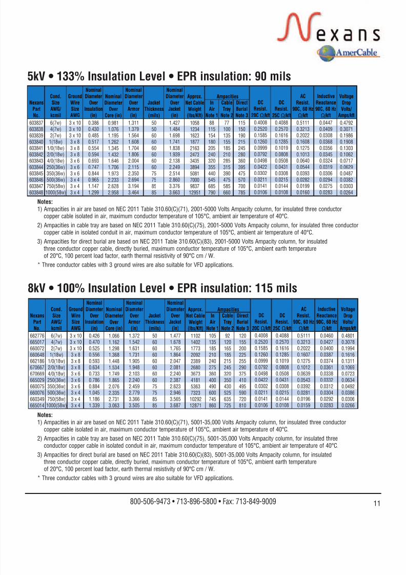
8122019 Cor Flex
httpslidepdfcomreaderfullcor-flex 2020
The industrystandard forflexible highquality powercontrol andinstrumentationType P cables
Crush andImpactResistantType P cableswithout
externalarmoring
Low smoke
halogen-freefire resistantor flameretardantType Pcables
Precisionengineeredcableassembliesfor hazardousand industrialapplications
Foil shielded
power cablesengineered for
use in variable
frequency
AC drive
applications
Available in several
constructions
Top DriveServiceLoops
Nexans AmerCable is an ISO 9001 certified cablemanufacturer that combines leading-edge manufacturing
technology innovative thinking and high qualityservice to deliver the finest oil amp gas cable andengineered cable assemblies available
Nexans AmerCable serves the world fromour Oil amp Gas Group headquarters in Houston TexasOur professional field engineers and sales force work withyou to create innovative cost-effective project solutions
10633 West Little York bull Building 1 bull Suite 100 bull Houston TX 77041
800-506-9473 bull 713-896-5800 bull Fax 713-849-9009 bull e-mail marineamercablecom
What can you expect fromNexans AmerCable
983150 Best at On-Time Delivery
983150 Outstanding Engineering Supportand Customer Service
983150 Innovative Productivity Solutions
983150 Global Cable Management
Related Documents