COPYRIGHT American Society of Mechanical Engineers Licensed by Information Handling Services COPYRIGHT American Society of Mechanical Engineers Licensed by Information Handling Services

Welcome message from author
This document is posted to help you gain knowledge. Please leave a comment to let me know what you think about it! Share it to your friends and learn new things together.
Transcript

COPYRIGHT American Society of Mechanical EngineersLicensed by Information Handling ServicesCOPYRIGHT American Society of Mechanical EngineersLicensed by Information Handling Services
The American Society of Mechanical Engineers
A N - A M E R I C A N N A T I O N A L S T A N D A R D
FAC E=TO= FAC E AND EI\ID.TO-END
DIMEMSIONS OF VALVES
ASME BI 6.1 0-2000 (Revision of ASME 11 6.1 0-1 992)
COPYRIGHT American Society of Mechanical EngineersLicensed by Information Handling ServicesCOPYRIGHT American Society of Mechanical EngineersLicensed by Information Handling Services
Date of Issuance: June 15, 2001
This Standard will be revised when the Society approves the issuance of a new edition. There will be no addenda issued to this edition. The next edition of this Standard is scheduled for publication in 2005.
ASME will issue wri t ten replies to inquiries concerning interpretation of technical aspects of this Standard.
ASME is the registered trademark of The American Society of Mechanical Engineers.
This code or standard was developed under procedures accredited as meeting the criteria for American National Standards. The Standards Committee that approved the code or standard was balanced to assure that individuals from competent and concerned interests have had an opportunity to participate. The proposed code or standard was made available for public review and comment that provides an opportunity for additional public input from industry, academia, regulatory agencies, and the pu blic-at-large.
ASME does not "approve," "rate," or "endorse" any item, construction, proprietary device, or activity.
ASME does not take any position with respect t o the validity of any patent rights asserted in connection with any items mentioned in this document, and does not undertake to insure anyone utilizing a standard against liability for infringement of any applicable letters patent, nor assume any such liability. Users of a code or standard are expressly advised that determination of the validity of any such patent rights, and the risk of infringement of such rights, is entirely their own responsibility.
Participation by federal agency representative(s1 or personís) affiliated with industry is not to be interpreted as government or industry endorsement of this code or standard.
ASME accepts responsibil i ty for on ly those interpretat ions of this document issued i n accordance with the established ASME procedures and policies, which precludes the issuance of interpretations by individuals.
No part of this document may be reproduced in any form, in an electronic retrieval system or otherwise,
without the prior written permission of the publisher.
The American Society of Mechanical Engineers Three Park Avenue, New York, NY 10016-5990
Copyright O 2001 by THE AMERICAN SOCIETY OF MECHANICAL ENGINEERS
All Rights Reserved Printed in U.S.A.
COPYRIGHT American Society of Mechanical EngineersLicensed by Information Handling ServicesCOPYRIGHT American Society of Mechanical EngineersLicensed by Information Handling Services
FOREWORD
In 192 1 the American Engineering Standards Committee, later the American Standards Association (ASA), organized Sectional Committee B 16 to unify and further develop national standards for pipe flanges and fittings (and, later, for valves, gaskets, and valve actuators). Cosponsors of the B16 Committee were the American Society of Mechanical Engineers (ASME), the Heating and Piping Contractors National Association [(now the Mechanical Contractors Association of America (MCAA)], and the Manufacturers Standardization Society of the Valve and Fittings Industry (MSS). Cosponsors were later designated as cosecretariat organizations.
Pioneer work on standardization of end-to-end dimensions of valves began in 1917 under the direction of J. A. Stevens. It was put aside at the end of World War I and interest did not revive until 1926. ASA and ASME agreed to include the topic in the scope of the B 16 Committee, and Subcommittee 5 (now Subcommittee E) was established for the purpose. Work began in 1928 and covered ferrous flanged-end gate, globe, angle, and check valves.
Development of a national standard was hindered by the diversity of existing practices and by adverse economic conditions in the early 1930s. A proposed 1933 American Standard for face-to-face dimensions of ferrous flanged valves did not gain acceptance, even though it was largely based on a 1931 Standard Practice of MSS. Further work and industry developments led to a meeting in May 1937, which undertook to reconcile differences among the draft ASA standard, two American Petroleum Institute (API) standards (5-Ci- 1 on pipeline valves and 600A on flanged OS&Y steel wedge gate valves), and a newly updated MSS SP-32.
A revised B16 proposal was voted favorably in June 1938, was approved by ASA, and was published in 1939. The standard was reaffirmed in 1947. Work began on a revision in 1953 to include buttwelding end valves, plug valves, and control valves in both cast iron and steel. That edition was published as ASA B16.10-1957. Further revision was begun in 1964. After reorganization of ASA, first as the United States of America Standards Institute (USASI), then as American National Standards Institute (ANSI), with the Sectional Committee being redesignated as an American National Standards Committee, a new edition adding ball valves was approved and published as ANSI B16.10-1973.
In 1982 American National Standards Committee B16 was reorganized as an ASME Committee operating under procedures accredited by ANSI. In the 1986 Edition, ductile iron and the alloys covered by ANSI B16.34 were added to the materials covered. Wafer type gate and check valves, Class 150 Y-pattern globe and check valves, and several patterns of butterfly valves were added to the types covered. Inch dimensions were converted from common to two-place decimal fractions.
In 1991 Subcommittee E - Face-to-Face and End-to-End Dimensions of Valves, was combined with Subcommittee N - Steel Valves. In the 1992 Edition, steel offset seat and grooved end butterfly valves were added. Globe and flangeless style control valves, which previously had been included, were removed from the Standard. Information regarding control valve dimensions may be obtained from Instrument Society of America, 67 Alexandria Drive, Research Triangle Park, NC 27709.
In this 2000 Edition, metric dimension tables were added. All tables and references to Class 400 steel and Class 800 cast iron were removed. All tables were renumbered.
... 111
COPYRIGHT American Society of Mechanical EngineersLicensed by Information Handling ServicesCOPYRIGHT American Society of Mechanical EngineersLicensed by Information Handling Services
Requests for interpretations or suggestions for revisions should be sent to the Secretary, B16 Committee, The American Society of Mechanical Engineers, Three Park Avenue, New York, NY 10016.
Following approval by the B16 Main Committee and the ASME Supervisory Board, this Standard was approved as an American National Standard by ANSI on June 7, 2000.
i v
COPYRIGHT American Society of Mechanical EngineersLicensed by Information Handling ServicesCOPYRIGHT American Society of Mechanical EngineersLicensed by Information Handling Services

ASME B I 6 COMMITTEE Standardization of Va Ives, Flanges,
Fittings, and Gaskets
(The following is the roster of the Committee at the time of approval of this Standard.)
OFFICERS
W. N. McLean, Chair H. R. Sonderegger, Vice Chair
S. J. Rossi, Secretary
COMMITTEE PERSONNEL
R. W. Barnes, Anric Enterprises, Ontario, Canada R. R. Brodin, Fisher Controls International, Inc., Marshalltown, Iowa M. A. Clark, Nibco, Inc., Elkhart, Indiana A. Cohen, Consultant, Albuquerque, New Mexico C. E. Floren, Mueller Co., Decatur, Illinois D. R. Frikken, Monsanto Co., St. Louis, Missouri G. A. Jolly, Edward Vogt Valve Co., Jeffersonville, Indiana W. G. Knecht, BW/IP International, Williamsport, Pennsylvania R. Koestar, The William Powell Co., Cincinnati, Ohio W. N. McLean, Newco Valves, Palos Park, Illinois M. L. Nayyar, Bechtel Power Corp., Frederick, Maryland R. A. Schmidt, Ladish Co., Russellville, Arkansas H. R. Sonderegger, TYCO Flow Control, Cranston, Rhode Island W. M. Stephan, Flexitallic, Inc., Mount Laurel, New Jersey T. F. Stroud, Ductile Iron Pipe Research Association, Birmingham, Alabama M. D. Wasicek, American Bureau of Shipping, Houston, Texas D. A. Williams, Southern Company Services, Birmingham, Alabama L. A. Willis, Dow Chemical Co., Freeport, Texas W. R. Worley, Union Carbide Corp., South Charleston, West Virginia
SUBCOMMITTEE N - STEEL VALVES
W. N. McLean, Chair, Newco Valves, Palos Park, Illinois S. J. Rossi. Secretary, The American Society of Mechanical Engineers, New York, New York E. A. Bake, Consultant, Cary, North Carolina D. R. Frikken, Solutia, Inc., St. Louis, Missouri G. R. Icenogle, Fisher Controls International, Inc., Marshalltown, Iowa G. A. Jolly, Edward Vogt Valve Co., Jeffersonville, Indiana R. J. Kiessel, Consutant, Livingston, Texas W. G. Knecht, BW/IP International, Inc., Williamsport, Pennsylvania M. L. Nayyar, Bechtel Corp., Gaithersburg, Maryland F. R. O'Brien, Crane Pacific Valves, Long Beach, California G. J. Paptzun, George J. Paptzun, PE, Lansdale, Pennsylvania D. W. Rahoi, CCM 2000, Rockaway, New Jersey H. R. Sonderegger, Grinnell Corp., Cranston, Rhode Island F. C. Tsao, Department of Navy, Washington, DC M. D. Wasicek, ABS Americas, Houston, Texas
V
COPYRIGHT American Society of Mechanical EngineersLicensed by Information Handling ServicesCOPYRIGHT American Society of Mechanical EngineersLicensed by Information Handling Services

CORRESPONDENCE WITH THE B I 6 COMMITTEE
General. ASME Standards are developed and maintained with the intent to represent the consensus of concerned interests. As such, users of this Standard may interact with the Committee by requesting interpretations, proposing revisions, and attending Committee meetings. Correspondence should be addressed to:
Secretary, B16 Main Committee The American Society of Mechanical Engineers Three Park Avenue New York, NY 10016-5990
Proposing Revisions. Revisions are made periodically to the Standard to incorporate changes that appear necessary or desirable, as demonstrated by the experience gained from the application of the Standard. Approved revisions will be published periodically.
The Committee welcomes proposals for revisions to this Standard. Such proposals should be as specific as possible, citing the paragraph number(s), the proposed wording, and a detailed description of the reasons for the proposal, including any pertinent documentation.
Interpretations. Upon request, the B 16 Committee will render an interpretation of any requirement of the Standard. Interpretations can only be rendered in response to a written request sent to the Secretary of the BI6 Main Committee.
The request for interpretation should be clear and unambiguous. It is further recommended that the inquirer submit hidher request in the following format:
Subject: Edition:
Question:
Cite the applicable paragraph number(s) and the topic of the inquiry. Cite the applicable edition of the Standard for which the interpretation is being requested. Phrase the question as a request for an interpretation of a specific requirement suitable for general understanding and use, not as a request for an approval of a proprietary design or situation. The inquirer may also include any plans or drawings, which are necessary to explain the question; however, they should not contain proprietary names or information.
Requests that are not in this format will be rewritten in this format by the Committee prior to being answered, which may inadvertently change the intent of the original request.
ASME procedures provide for reconsideration of any interpretation when or if additional information that might affect an interpretation is available. Further, persons aggrieved by an interpretation may appeal to the cognizant ASME Committee or Subcommittee. ASME does not “approve,” “certify,” “rate,” or “endorse” any item, construction, proprietary device, or activity.
Attending Committee Meetings. The B 16 Main Committee regularly holds meetings, which are open to the public. Persons wishing to attend any meeting should contact the Secretary of the BI6 Main Committee.
vi
COPYRIGHT American Society of Mechanical EngineersLicensed by Information Handling ServicesCOPYRIGHT American Society of Mechanical EngineersLicensed by Information Handling Services

CONTENTS
. . . . . . . . . . . . . . . Foreword . . . . . . . . . . . . . . . . . . . . . . . . . . . . . . . . . . . . . . . . . . . . . . . . . . . . . . . . . . . . . . . . . Standards Committee Roster . . . . . . . . . . . . . . . . . . . . . . . . . . . . . . . . . . . . . . . . . . . . . . . . . Correspondence With the €3 16 Committee . . . . . . . . . . . . . . . . . . . . . . . . . . . . . . . . . . . . . . . . . . . . . . . . . . . . . . . . .
1 Scope . . . . . . . . . . . . . . . . . . . . . . . . . . . . . . . . . . . . . . . . . . . . . . . . . . . . . . . . . . . . . . . . . . . . . . . . . . . . . . . . . .
2 Definitions . . . . . . . . . . . . . . . . . . . . . . . . . . . . . . . . . . . . . . . . . . . . . . . . . . . . . . . . . . . . . . . . . . . . . . . .
3
4
Facings of Flanged Valves . . . . . . . . . . . . . . . . . . . . . . . . . . . . . . . . . . . . . . . . . . . . . . . . . . . . . . . . .
Variations of Length Within a Class of Valves . . . . . . . . . . . . . . . . . . . . . . . . . . . . . . . . . . . . . . . .
5 Tolerances . . . . . . . . . . . . . . . . . . . . . . . . . . . . . . . . . . . . . . . . . . . . . . . . . . . . . . . . . . . . . . . . . . . . . . . . . . . . .
Figures 1 Flange Facings and Their Relationships . . . . . . . . . . . . . . . . . . . . . . . . . . . . . . . . . . . . . . . . . . . . . . . . . . . 2 Welding Ends . . . . . . . . . . . . . . . . . . . . . . . . . . . . . . . . . . . . . . . . . . . . . . . . . . . . . . . . . . . . . . . . . . . . . . . . . . .
Tables
1
2
3
4
5
6
7
8
9
10
Metric Unit Tables Tables 1 to 10 are formatted using millimeter units.
See para. 1.2 for applicability.
Class 125 Cast Iron Flanged and Class 150 Steel Flanged and Buttwelding End
Class 250 Cast Iron Flanged and Class 300 Steel Flanged and Buttwelding End
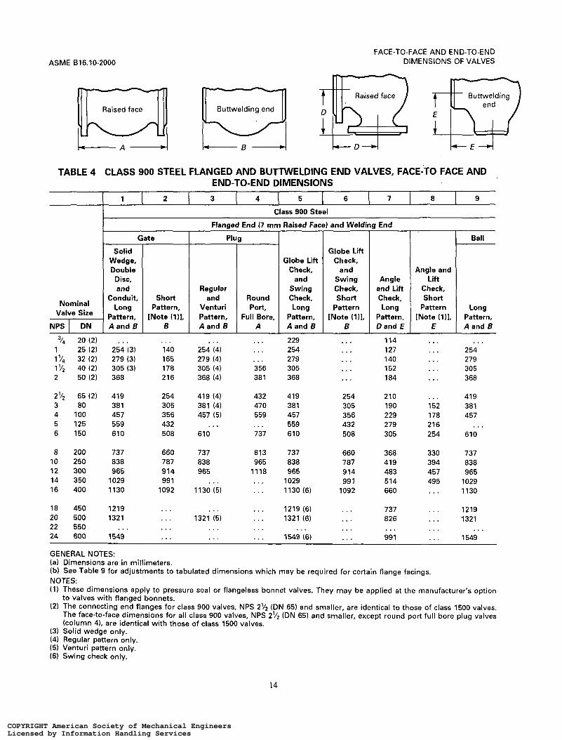
Class 600 Steel Flanged and Buttwelding End Valves, Face-to-Face and End-to-End
Class 900 Steel Flange uttwelding End Valves, Face-to-Face and End-to-End
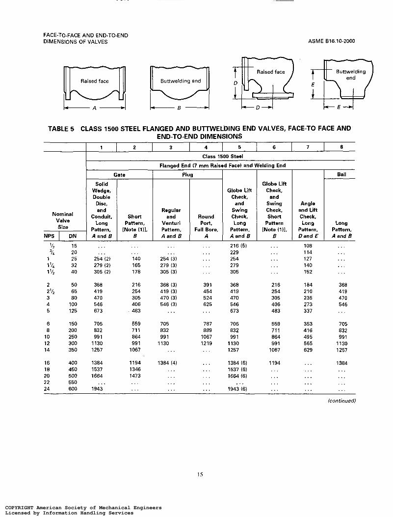
Class 1500 Steel Flanged and Buttwelding End Valves, Face-to-Face and
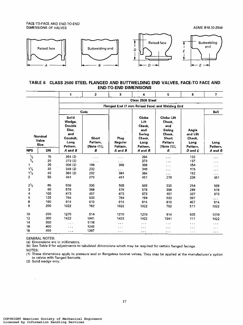
Class 2500 Steel Flanged and Buttwelding End Valves, Face-to-Face and End-to-End
Classes 125 and 250 Cast Iron and Classes 150 to 2500 Steel Wafer Type Valves,
Classes 25 and 125 Cast Iron and Classes 150 to 600 Steel Butterfly Valves,
Determination of Face-to-Face and End-to-End Dimensions of Flanged Valves Having
Classes 150 to 2500 Steel Valves Having End Flanges With Ring Joint Facings,
Valves, Face-to-Face and End-to-End Dimensions .....................
Valves, Face-to-Face and End-to-End Dimensions . . . . . . . . . . . . . . . . . . . . . . . . . . . . . . . . . .
Dimensions . . . . . . . . . . . . . . . . . . . . . . . . . . . . . . . . . . . . . . . . . . . . . . . . . . . . . . . . . . . . . . .
Dimensions . . . . . . . . . . . . . . . . . . . . . . . . . . . . . . . . . . . . . . . . . . . . . . . . . . . . . . . . . . . . . . . . . . . . . . .
Dimensions . . . . . . . . . . . . . . . . . . . . . . . . . . . . . . . . . . . . . . . . . . . . . . . . . . .....................
Dimensions . . . . . . . . . . . . . . . . . . . . . . . . . . . . . . . . . . . . . . . . . . . . . . . . . . . . . . . . . . . . . . . . . . . . . . . . . . .
Face-to-Face Dimensions . . . . . . . . . . . . . . . . . . . . . . . . . . . . . . . . . . . . . . . . . . . . . . . . . . . . . . . . . . . . . . .
Face-to-Face Dimensions . . . . . . . . . . . . . . . . . . . . . . . . . . . . . . . . . . . . . . . . . . . . . . . . . . . . . . . . . . . . . . .
Various Flange Facings . . . . . . . . . . . . . . . . . . . . . . . . . . . . . . . . . . . . . . . . . . . . . . . . . . . . . . . . . . . . .
End-to-End Dimensions . . . . . . . . . . . . . . . . . . . . . . . . . . . . . . . . . . . . . . . . . . . . . . . . . . . . . . . . .
1 . .
111
V
vi
1
2
4 5
6
9
12
14
15
17
18
19
20
21
vii
COPYRIGHT American Society of Mechanical EngineersLicensed by Information Handling ServicesCOPYRIGHT American Society of Mechanical EngineersLicensed by Information Handling Services

A l
A2
A3
A4
A5
A6
AI
A8
A9
A10
U.S. Customary Unit Tables Tables A l to A10 are formatted using inch units.
See para. 1.2 for applicability.
Class 125 Cast Iron Flanged and Class 150 Steel Flanged and Buttwelding End
Class 250 Cast Iron Flanged and Class 300 Steel Flanged and Buttwelding End
Class 600 Steel Flanged and Buttwelding End Valves, Face-to-Face and End-to-End Dimensions . . . . . . . . . . . . . . . . . . . . . . . . . . . . . . . . . . . . . . . . . . . . . . . . . . . .
Class 900 Steel Flanged and Buttwelding End Valves, Face-to-Face a Dimensions . . . . . . . . . . . . . . . . . . . . . . . . . . . . . . . . . . . . . . . . . . . . . . . . . . . . . . . . . . . . . . . . . . . . . . . . . . . 3 1
Class 1500 Steel Flanged and Buttwelding End Valves, Face-to-Face and End-to-End Dimensions . . . . . . . . . . . . . . . . . . . . . . . . . . . . . . . . . . . . . . . . . . . . . . . . . . . . . . . . . . . . . . . . . . . . . . . . . . . 32
Class 2500 Steel Flanged and Buttwelding End Valves, Face-to-Face and End-to-End Dimensions . . . . . . . . . . . . . . . . . . . . . . . . . . . . . . . . . . . . . . . . . . . . . . . . . . . . . . . . . . . . . . . . . . . . . . . . . . . 34
Classes 125 and 250 Cast Iron and Classes 150 to 2500 Steel Wafer Type Valves, Face-to-Face Dimensions . . . . . . . . . . . . . . . . . . . . . . . . . . . . . . . . . . . . . . . . . . . . . . . . . . . . . . . . . . . . . . . 35
Classes 25 and i25 Cast Iron and Classes 150 to 600 Steel Butteríly Valves, Face-to-Face Dimensions . . . . . . . . . . . . . . . . . . . . . . . . . . . . . . . . . . . . . . . . . . . . . . . . . . . . . . . . . . . . . . . 36
Determination of Face-to-Face and End-to-End Dimensions of Flanged Valves Having Various Flange Facings . . . . . . . . . . . . . . . . . . . . . . . . . . . . . . . . . . . . . . . . . . . . . . . . . . . . . . . . . . . . . . . . 3 1
Classes 150 to 2500 Steel Valves Having End Flanges With Ring Joint Facings,
Valves, Face-to-Face and End-to-End Dimensions . . . . . . . . . . . . . . . . . . . . . . . . . . . . . . . . . . . . . . . 23
Valves, Face-to-Face and End-to-End Dimensions ..................... . . . . . . . . . . . . . . . 26
End-to-End Dimensions . . . . . . . . . . . . . . . . . . . . . . . . . . . . . . . . . . . . . . . . . . . . . . . . . . . . . . . . .
Mandatory Annex I References . . . . . . . . . . . . . . . . . . . . . . . . . . . . . . . . . . . . . . . . . . . . . . . . . . . . . . . . . . . . . . . . . . . . . . . . . . . . . . 4 1
viii
COPYRIGHT American Society of Mechanical EngineersLicensed by Information Handling ServicesCOPYRIGHT American Society of Mechanical EngineersLicensed by Information Handling Services

1 SCOPE
ASME 616.10-2000
FACE-TO-FACE AND END-TO-END DIMENSIONS OF VALVES
1.3 Cast Iron Valves
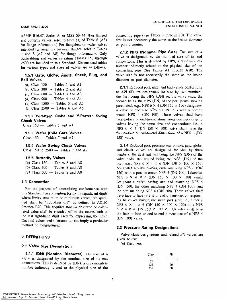
1.1 General
This Standard covers face-to-face and end-to-end dimensions of straightway valves, and center-to-face and center-to-end dimensions of angle valves. Its purpose is to assure installation interchangeability for valves of a given material, type, size, rating class, and end connec- tion. Face-to-face and center-to-face dimensions apply to flanged end valves with facings defined in para. 2.3.1 and to other valves intended for assembly between flat face or raised face flanges. End-to-end dimensions apply to grooved end, buttwelding end, and flanged end valves with facings defined in para. 2.3.3. Center- to-end dimensions apply to buttwelding end and to flanged end valves with facings defined in para. 2.3.3.
In Tables 1 to 6 (Tables A l to A6), A or D in a column head denotes valves having flanged ends as illustrated; B or E denotes valves having buttwelding ends.
1.2 Standard Units
Only flanged end valves (and others intended for assembly between flanges) are covered by this Standard. Mating dimensions and facings of flanged ends conform to those in ASME B 16.1. Dimensional tables for various types and sizes of valves are as follows.
1.3.1 Gate, Plug, and Check Valves (a) Class2 125 - Tables 1 and A l (b) Class 250 - Tables 2 and A2
1.3.2 Globe and Angle Valves (a) Class 125 - Tables 1 and A l (b) Class 250 - Tables 2 and A2
1.3.3 Wafer Swing Check Valves (a ) Class 125 - Tables 7 and A7 (b) Class 250 - Tables 7 and A7
1.3.4 Butterfly Valves ( a ) Class 25 - Tables 8 and A8 (b) Class 125 - Tables 8 and A8
The values stated in either millimeter units (Tables 1.4 Ductile Iron Valves 1 to 10) or inch units' (Tables A l to AIO) are to be regarded separately as standard. Within the text, the inch units are shown in parentheses. The values stated in each system are not exact equivalents; therefore, each system must be used independently of the other. Combining values from the two systems may result in nonconformance with the standard.
Only flanged end valves (and others intended for assembly between flanges) are covered. Mating dimen- sions and facings of flanged ends conform to those in ASME B16.42. Valves are rated Class 150 and Class 300. The following cast iron and steel dimensional tables are also used for ductile valves.
( a ) Class 150 - Tables 1 and Al ( b ) Class 300 - Tables 2 and A2
' Linear inch dimensions in this Standard are expressed using two- place decimal fractions. These values are actually common fractions of an inch rounded to the nearest two-place decimal value as follows:
0.03 = '132
0.06 = ' / I 6
0.12 = '/H
0.19 = 3/16
0.22 = 7/32
0.31 = '116
0.38 = 3/s
0.44 = '116
0.50 = '12
0.56 = 9/i6
0.69 = ' ' / i 6
0.75 = 314
0.94 = "/i6
0.16 = '132 0.62 = 5/H
0.25 = I/J 0.88 = 7/H
1.5 Steel and Alloy Valves
This category includes carbon, alloy, and stainless steels, and the nonferrous materials listed in ASME B 16.34. It includes flanged, buttwelding, and grooved ends, as well as the types of valves intended for assembly between flanges. Mating dimensions and fac- ings of flanged ends conform to those in ASME B16.5,
* For explanation of Class and relationship to PN, see para. 2.2.
1
COPYRIGHT American Society of Mechanical EngineersLicensed by Information Handling ServicesCOPYRIGHT American Society of Mechanical EngineersLicensed by Information Handling Services
ASME 816.10-2000
FACE-TO-FACE AND END-TO-END DIMENSIONS OF VALVES
ASME B16.47, Series A, or MSS SP-44. [For flanged end butterfly valves, refer to Note (3) of Table 8 (AS) for flange information.] For flangeless or wafer valves intended for assembly between flanges, refer to Tables 7 and 8 (A7 and AS) for flange information. Only
2500 are included in his Standard, ~ i ~ ~ ~ ~ i ~ ~ ~ l tables for various types and sizes of valves are as follows.
1.5.1 Gate, Globe, Angle, Check, Plug, and
connecting pipe (See Tables 1 through IO). The valve size is not necessarily the same as the inside diameter or port diameter.
2.1.2 NPS (Nominal Pipe Size). The size of a
connections. This is denoted by NPS, a dimensionless number indirectly related to the physical size of the connecting pipe (See Tables A l through Alo). The valve size is not necessarily the same as the inside diameter or port diameter.
buttwelding end valves in rating Classes 150 through valve is designated by the nominal size of its end
Ball Valves (a) Class 150 - Tables 1 and Al (b) Class 300 - Tables 2 and A2 (c) Class 600 - Tables 3 and A3 (á) Class 900 - Tables 4 and A4 ( e ) Class 1500 - Tables 5 and A5 (f) Class 2500 - Tables 6 and A6
1.5.2 Y-Pattern Globe and Y-Pattern Swing Check Valves Class 150 - Tables 1 and A l
1.5.3 Wafer Knife Gate Valves Class 150 - Tables 7 and A7
1.5.4 Wafer Swing Check Valves Class 150 to 2500 - Tables 7 and A7
1.5.5 Butterfly Valves (a) Class 150 - Tables 8 and A8 (b) Class 300 - Tables 8 and A8 (c) Class 600 - Tables 8 and A8
1.6 Convention
For the purpose of determining conformance with this Standard, the convention for fixing significant digits where limits, maximum or minimum values, are speci- fied shall be "rounding off" as defined in ASTM Practice E29. This requires that an observed or calcu- lated value shall be rounded off to the nearest unit in the last right-hand digit used for expressing the limit. Decimal values and tolerance do not imply a particular method of measurement.
2 DEFINITIONS
2.1 Valve Size Designation
2.1.1 (DN) (Nominal Diameter). The size of a valve is designated by the nominal size of its end connections. This is denoted by (DN), a dimensionless number indirectly related to the physical size of the
2.1.3 Reduced port, gate, and ball valves conforming to API 6D are designated for size by two numbers, the first being the NPS (DN) on the valve ends, the second being the NPS (DN) of the port (seats, moving parts, etc.); e.g., NPS 6 X 4 (DN 150 x 100) designates a valve of end size NPS 6 (DN 150) with a port to match NPS 4 (DN 100). These valves shall have face-to-face or end-to-end dimensions corresponding to valves having the same size end connections; i.e., a NPS 6 x 4 (DN 150 x 100) valve shall have the face-to-face or end-to-end dimensions of a NPS 6 (DN 150) valve.
2.1.4 Reduced port, pressure seal bonnet, gate, globe, and check valves are designated for size by three numbers, the first and last being the NPS (DN) of the valve ends, the second being the NPS (DN) of the port; e.g., NPS 6 x 4 x 6 (DN 150 X 100 X 150) designates a valve having ends matching NPS 6 (DN 150) with a port to match NPS 4 (DN 100). Likewise, NPS 6 X 4 x 4 (DN 150 X 100 X 100) would designate a valve having one end matching NPS 6 (DN 150), the other matching NPS 4 (DN IOO), and the port matching NPS 4 (DN 100). These valves shall have face-to-face or end-to-end dimensions correspond- ing to valves having the same port size; Le., either a NPS 6 X 4 x 6 (DN 150 X 100 x 150) or a NPS 6 X 4 X 4 (DN 150 x 100 x 100) valve shall have the face-to-face or end-to-end dimensions of a NPS 4 (DN 100) valve.
2.2 Pressure Rating Designations
given below: Valve class designations and related PN values are
(a) Cast iron
Class PN
25 . . . 125 20 250 50
-
2
COPYRIGHT American Society of Mechanical EngineersLicensed by Information Handling ServicesCOPYRIGHT American Society of Mechanical EngineersLicensed by Information Handling Services
FACE-TO-FACE AND END-TO-END DIMENSIONS OF VALVES ASME B 16.10-2000
(b) Ductile iron
Class PN
i 50 20 3 O0 50
~
(c) steel3
Class PN
150 20 300 50 600 1 I O 900 150
1500 260 2500 420
__
2.3 Flanged Valve Dimensions
2.3.1 Face-to-Face. The face-to-face dimension for flanged valves is the distance between the extreme ends which are the gasket contact surfaces (see Fig. i). Face- to-face applies to flanged valves having the following nominal flange facing identifiers:
(a) flat (b) 2 mm (0.06 in.) raised (c) 7 mm (0.25 in.) raised (d) large or small male4 ( e ) large or small tongue4
2.3.2 Installed Face-to-Face. The installed face- to-face dimension of certain butterfly valves [see Table 8 (Ag), Note (i)] may include allowances for gasket or resilient-facing compression. Refer to MSS SP-67 for definitive illustrations.
2.3.3 End-to-End. For those flanged valves where the gasket contact surfaces are not located at the extreme ends of the valve, the distance between the extreme ends is described as the end-to-end dimension and applies to flanged valves having the following nominal flange facing identifiers:
(a) ring joint (b) large or small female (c) large or small groove
Includes all ferrous and nonferrous materials in ASME B16.34. Face-to-face dimensions in Tables 1 to 6 (A l to A6) must be adjusted as indicated in Table 9 (A9).
2.4 Buttwelding End Valve Dimensions (Also see Section 4)
For buttwelding end valves, the end-to-end dimension is the distance between the extreme ends (root faces) of the welding bevels (see Fig. 2).
2.5 Grooved End Valve Dimensions
The end-to-end dimension for grooved end valves is the distance between extreme ends.
2.6 Angle Valves
For flanged angle type valves (those in which the ends are at an angle of 90 deg to each other), the center- to-face dimension is the distance from the centerline of the port to the extreme end which is the gasket contact surface. For flanged angle type valves in which the gasket seating surface is not located at the extreme end and for angle type valves having buttwelding ends, the phrase center-to-end denotes the distance from the centerline of the port to the extreme end.
3 FACINGS OF FLANGED VALVES
Figure 1 shows facings for flanged ends.
3.1 Facings Normally Furnished
3.1.1 Flat Face. Flanges for Classes 25 and 125 cast iron valves are flat faced.
3.1.2 2 mm (0.06 in.) Raised Face. Flanges for Class 250 cast iron and for Classes 150 and 300 steel, alloy, and ductile iron valves have 2 mm (0.06 in.) raised faces, which are included in the face-to-face (or center-to-face) dimension. When Classes 150 and 300 valves are required with flat faces, either the full thickness of flange or the thickness with the 2 mm (0.06 in.) raised face removed may be furnished, unless otherwise specified by the customer. Users are reminded that removing the 2 mm (0.06 in.) raised face will make the face-to-face dimension nonstandard.
3.1.3 7 mm (0.25 in.) Raised Face. Flanges for Class 600 and higher steel and alloy valves have 7 mm (0.25 in.) raised faces, which are included in the face-to-face (or center-to-face) dimensions.
3.2 Other Standard Facings
Table 9 (A9) summarizes data on all flange facings and can be used with Tables 1 to 6 (AI to A6) in calculating face-to-face and end-to-end dimensions of
3
COPYRIGHT American Society of Mechanical EngineersLicensed by Information Handling ServicesCOPYRIGHT American Society of Mechanical EngineersLicensed by Information Handling Services

ASME 816.10-2000
k
FACE-TO-FACE AND END-TO-END DIMENSIONS OF VALVES
4
Face-to-face dimension - - Basic flange edge to flange edge - -
I Face-to-face dimension given in the tables
L - n Flat Face
Regular facing on Class 125 cast iron
I Basic flange edge to flange edge
_ _ I - Face-to-face dimension given in the tables
2 rnm (0.06 AL 1 2 in.)
mm (0.06 in.) Raised Face
Regular facing on Class 250 cast iron and Classes 150 and 300 steel [Note ( l ) ]
(0.25 in.) 7 mm (0.25 in.) Raised Face
Regular facing on Class 600 and higher steel valves [Note ( l ) ]
Large or Small Male Face
For steel valves only [Note ( I ) ]
Basic flange edge to flange edge
Face-to-face dimension L
4 - F
Large or Small Female Face
For steel valves only [Note (1 )I
L I
Basic flange edge to flange edge
Face-to-face dimension
7 m m Large or Small
Tongue (0.25 in.)
For steel valves only I [Note (1 11
I I
I Basic flange edge to flange edge - * - Basic flange edge to flange edge - - End-to-end dimension
(0.19 in.
End-to-end dimension [see Table 10 (Alo)]
Depth of groove - Ring Joint
Facing for steel
Groove
valves only [Note ( l ) ] Facing for steel valves only [Note (1 )I
(a) Regular Standard Facings (b) Other Standard Facings
GENERAL NOTE: Regular flange facings for valves are shown above. valves normally carried in stock are so faced.
GENERAL NOTE: Valves are supplied with the facings shown above when specified. See Table 9 (9A) to determine face-to-face dimensions of valves with these facings.
NOTE: (1) Steel includes nonferrous materials in ASME 816.34.
FIG. 1 FLANGE FACINGS AND THEIR RELATIONSHIPS
4
COPYRIGHT American Society of Mechanical EngineersLicensed by Information Handling ServicesCOPYRIGHT American Society of Mechanical EngineersLicensed by Information Handling Services

FACE-TO-FACE AND END-TO-END DIMENSIONS OF VALVES ASME 816.10-2000
f- Root face n Root face
(a) Plain Bevel (b) Compound Bevel
GENERAL NOTE: Typical bevels are shown for illustration only.
FIG. 2 WELDING ENDS
flanged valves having standard facings other than those described in para. 3.1.
3.3 Ring Joint Facings
The X dimension given in Table 10 (AIO), when added to the face-to-face dimension of a valve having raised face flanges in Tables 1 to 6 (A1 to A6), establishes the end-to-end dimension for the valve having flanges with ring joint facings.
4 VARIATIONS OF LENGTH WITHIN A CLASS OF VALVES
4.1 Buttwelding End Valves (Also see Para. 2.4)
Tables 1 to 6 (AI to A6) include end-to-end dimen- sions for valves having buttwelding ends. In many cases, the dimensions are different from those of face- to-face dimensions of flanged valves, as evidenced by the differences between dimensions A and B of the tables.
4.1.1 Short Pattern. For pressure seal or flangeless bonnet valves having buttwelding ends in Class 600 and higher, the regular end-to-end dimensions shall be equal to the short pattern dimensions shown in Tables 3 to 6 (A3 to A6). At the manufacturer’s option, the end-to-end dimensions of these valves may be the same as the face-to-face dimensions of raised face flanged valves.
4.1.2 Long Pattern. For flanged bonnet valves having buttwelding ends in Class 600 and higher, the regular end-to-end dimensions shall be equal to the
face-to-face dimensions of raised face flanged valves shown in Tables 3 to 6 (A3 to A6). At the manufacturer’s option, the end-to-end dimensions may be the same as the short pattern end-to-end dimensions.
4.2 Narrow, Wide, and Extra Wide Designations
Certain butterfly valves are designated narrow, wide, or extra wide for the purpose of consolidating a diversity of manufacturer’s lengths into two or three sets of dimensions for a given size. At the manufacturer’s option, any of the two or three dimensions listed for a size may be used.
5 TOLERANCES
5.1 Straightway Valves
A tolerance of 12 mm (10.06 in.) shall be allowed on face-to-face and end-to-end dimensions of valves of NPS 10 (DN 250) and smaller, and a tolerance of +3 mm (20.12 in.) shall be allowed for NPS 12 (DN 300) and larger. For exceptions as related to wafer type and butterfly valves, see General Note (b) in Table 7 (A7) and Notes (4) and ( 5 ) in Table 8 (Ag).
5.2 Angle Valves
The tolerances on center-to-face and center-to-end dimensions of angle type valves shall be one-half those listed in para. 5.1.
5
COPYRIGHT American Society of Mechanical EngineersLicensed by Information Handling ServicesCOPYRIGHT American Society of Mechanical EngineersLicensed by Information Handling Services

ASME B16.10-2000
~
7
FACE-TO-FACE AND END-TO-END DIMENSIONS OF VALVES
Buttwelding end
-6
~~
8 9 10
Plain face Raised face
1 2
L A 4 L A - 4
3 4 5 6
Class 125 Cast iron Class 150 Steel Class 150 Steel
Conduit, A
TABLE 1 CLASS 125 CAST IRON FLANGED AND CLASS 150 STEEL FLANGED AND BUTTWELDING END VALVES, FACE-TO FACE AND END-TO-END DIMENSIONS
Solid Wedge, Double Disc, and
Conduit, B
Wedge
NPS I D N I A I A
'14
"8
l/2 "4
1 '14
1 '/2
2 '/*
1
2
3
4 5 6 8
10
12 14 16 18 20
22 24 26 28 30
32 34 36
8 10 15 20 25
32 40 50 65 80
1 O0 125 150 200 250
300 350 400 450 500
550 600 650 700 750
800 850 900
. . .
. . .
..,
. . .
. . .
. . .
. . . 178 190 203
229 2 54 267 292 330
356 381 (2) 406 (2) 432 (2) 457 (2)
. . . 508 (2)
. . .
. . .
. . .
. . .
. . .
. . .
. . .
. . .
...
. . . 140
. . . 165 178 190 203
229 254 267 292 330
356 . . . . . . . . . . . . . . . . . . ... . . . . . . . . . . . . ...
Regular Round
. . .
. . .
...
. . . 140 (3)
165 (3) 165 (3) 190 (3) 210 (3) 229 (3)
229 (3) 356 (3) 394 457 533
610 686 762 864 914
. . . 1067 (4)
. . .
. . . 1295 (4)
. . .
. . . 1600 14)
Globe, Lift
Check, and
Swing Check
[Note (111, A
. . . . . .
. . . . . .
. I . ...
. . . . . . 140 . . . 152 . . . 165 . . . 190 203 210 216 229 241
305 292 381 330 457 356 559 495 660 622
162 698 . . . 787 . . . 914 (5) . . . . . . . . . . . . . . . . . . . . . ...
. . . . . .
. . . ..
. . . . . .
... ...
Angle and Lift
Check, 0
. . .
...
. . .
. . .
. . . 102 108 121
146 165 178 248 31 1
349 394 457 . . . . . . . . . . . . . . . . . . < . .
. . .
. . . ,.,
Flanged End (2 mm Raised Face) and Welding End
Gate I Plug
Solid Wedge
and Double
Disc, A
Short Pattern,
A I l I
~
102 102 108 117 127
140 165 178 190 203
229 254 267 292 330
356 381 406 432 457
. . . 508 559 610 61 O
. . .
. . . 71 1
~
. . .
... ,.. ... . . . ... . . . 178 190 203
229
267 292 330
356 38 1 406 432 457
508 508 559 610 660
711 762 813
. . .
102 . . . 102 . . . 108 ... 117 ... 127 140
140 . . . 165 165 216 178 24 1 190 282 203
305 229 381 254 403 267 419 292 457 330
502 356 572 ... 610 . . . 660 . . . 71 1 ... 762 ... 813 . . . 864 (6) . . . 914(6) . . . 914(6) . . . 965 (6) . . .
1016(6) 1016 lOlS(6) ...
(con tin ued)
6
COPYRIGHT American Society of Mechanical EngineersLicensed by Information Handling ServicesCOPYRIGHT American Society of Mechanical EngineersLicensed by Information Handling Services

FACE-TO-FACE AND END-TO-END DIMENSIONS OF VALVES
Plain face
11
ASME 616.10-2000
12 13 14 15 16 17 18 19 20 21
Buttwelding T>7
Nominal
!: NPS DN
Class 125 Cast Iron Class 150 Steel Class 150 Steel
Flanged End (2 rnm Raised Face) and W
Plug Globe, Lift
Check, Short and and Round Swing
Regular Regular Venturi Port, Check Pattern, Pattern, Pattern, Full Bore, [Note (111.
A B A A A and B
Class 150 Steel
32 . . . I'/, 40 . . . 2 50 . . . 2'12 65 . . . 3 80 . . .
4 100 305 5 125 381 6 150 394 8 200 457 10 250 533
12 300 610 14 350 686 16 400 762 18 450 864 20 500 914
22 550 . . . 24 600 1067 26 650 . . . 28 700 . . . 30 750 . . .
32 800 ... 34 850 . . . 36 900 . . .
. . . . . . . . . 140
. . . . . . 222 165 267 178 267 203 305 . . . 298 216 330 203 343 241
356 229 432 292 381 . . . . . . 356 (7) 457 394 . . . 406 (7) 52 1 457 . . . 495 559 533 . . . 622
635 610 . . . 698 . . . 686 . . . 787 . . . 762 . . . 914(8) . . . 864 . . . 978 (9) . . . 914 . . . 978 (9)
. . . . . . . . . 1067 (9)
. . . 1067 . . . 1295 (9)
. . . . . . . . . 1295 (9)
. . . . . . . . . 1448 (9)
.... . . . . . . 1524 (9)
. . . . . . . . . . . .
. . . . . . . . . . . .
. . . . . . . . . 1956(9)
Iding End I Flanged End I Welding End
I I Ball
Y-Globe
51 51 57 64 70
76 83 102 108 121
146 178 203 248 31 1
349 394 457 . . . . . . . . . . . . . . . . . . . . .
. . .
. . .
. . .
. . .
. . . 140 152 165
184 203 229 279 318
368
470 597 673
775
. . .
. . .
. . .
...
. . .
. . .
. . .
. . .
. . .
. . .
. . .
. . .
1 Logng I sg. i Lyg 1 Pattern, Pattern, Pattern, Pattern,
. . .
. . . 108 117 127
140 165 178 190 203
229
394 457 533
610 686 762
914
. . .
a64
. . . 1067 . . . . . . . . . . . . . . .
. . .
. . . 108 117 127
140 165 178 190 203
229
267 292 330
356 38 1 406
. . .
. . .
. . .
. . .
. . .
...
. . .
. . .
. . .
...
. . .
. . .
. . .
. . .
. . .
. . .
... 190 216 241 282
305
457 521 559
635 762 838 914 99 1
1092 1143 1245 1346 1397
1524 1626 1727
. . .
. . .
. . . 140 152 165
178 190 216 24 1 282
305
403 419 457
502 572 610 660 71 1
. . .
... a13 . . . . . . . . . . . . . . . ...
(continued)
7
COPYRIGHT American Society of Mechanical EngineersLicensed by Information Handling ServicesCOPYRIGHT American Society of Mechanical EngineersLicensed by Information Handling Services
ASME 816.10-2000 FACE-TO-FACE AND END-TO-END
DIMENSIONS OF VALVES
TABLE 1 (CONT'D)
GENERAL NOTES: (a) Dimensions are in millimeters. (b) See Table 9 for adjustments to tabulated dimensions which may be required for certain flange facings. NOTES: (1) These dimensions are not intended to cover the type of check valve having the seat angle at appoximately 45 deg to the
(2) Solid wedge only. (3) Regular pattern only. The face-to-face dimension of NPS 4 (DN 100) may be 305 at the manufacturer's option. (4) Venturi pattern only. (5) Globe and horizontal lifî check only. (6) Double disc and conduit only. (7) Globe and horizontal lift check only. The face-to-face and end-to-end dimension for class 150 steel flanged and buttwelding
(8) Globe and horizontal lift check only. The face-to-face and end-to-end dimension for class 150 steel flanged and buttwelding
(9) Swing check only.
run of the valve, or the "Underwriter Pattern," or other patterns where large clearances are required.
end swing check valves in NPS 5 (DN 125) is 330 and in NPS 6 (DN 150) is 356.
end swing check valves in NPS 16 (DN 400) is 864.
8
COPYRIGHT American Society of Mechanical EngineersLicensed by Information Handling ServicesCOPYRIGHT American Society of Mechanical EngineersLicensed by Information Handling Services

FACE-TO-FACE AND END-TO-END DIMENSIONS OF VALVES
1 2 3 4 5 6 7 8
Raised face Buttwelding end
9
ACME 816.10-2000
Valve
NPS DN
Class 250 Cast Iron and Class 300 Steel
Class 250 Cast Iron
Flanged End (2 rnrn Raised Face)
Gate, Plug Globe, Solid Lift
Wedge Check, and and Angleand
Double Short Regular Venturi Swing Lift Disc, Pattern, Pattern, Pattern, Check, Check,
A A A A A D
Class 300 Steel
'12 15
1 25 I Y4 32 1 '/z 40
2 50 2 '/2 65 3 80 4 1 O0 5 125
6 150 8 200 10 250 12 300 14 350
16 400 18 450 20 500 22 550 24 600
26 650 28 700 30 750 32 800 34 850 36 900
"4 20 . . . . . . . . . . . . . . .
216 241 282 305 381
403 419 457 502 572
610 660 711
787 . . .
. . .
. . .
. . .
. . .
. . .
. . .
. . .
. . .
. . .
. . .
. . .
184 203 235 267 . . .
378 . . . 568 648 . . .
. . .
. . .
...
...
. . .
. . .
. ..
. . .
. . .
. . .
. . .
. . .
. . . 159
190
216 241 282 305 387
425 502 597 711
. . .
. . .
. . .
. . .
. . .
. . .
. . .
. . .
. . .
. . .
. . .
. . .
. . .
. . . . . .
. . . . . .
. . . . . .
. . . . . .
. . . . . .
. . . 267
. . . 292
. . . 318
. . . 356
. . . 400
403 444 419 533 457 622 502 711 762 . . .
838 . . . 914 . . . 99 1 . . . 1118 . . . 1143 . . .
. . . . . .
... ...
. . . . . .
. . . . . .
. . . . . .
. . . . . .
. . .
. . .
. . .
. . .
. . .
133 146 159
200
222 267 31 1 356
178
. . .
. . .
. . .
. . .
. . .
. . .
. . .
. ..
. . .
. . .
. . .
. . .
Class 300 Steel
Flanged and Welding End
Ball
L;g 1 Short 1 L;g Pattern, Pattern, Pattern,
A and B
140 152 165 178 190
216 241 282 305 . . .
403 502 568 648 762
838 914 99 1 1092 1143
1245 1346 1397 1524 1626 1727
140 152 165 178 190
216 241 282 305 . . .
403 41 9 457 502 572
610 660 71 1
813 . . .
. . .
. . .
. . .
. . .
. . .
. . .
. . .
. . .
. . .
. . . 190
216 24 1 282 305 . . .
457 521 559 635 762
838 914 991 1092 1143
1245 1346 1397 1524 1626 1727
Icon tin uedì
9
COPYRIGHT American Society of Mechanical EngineersLicensed by Information Handling ServicesCOPYRIGHT American Society of Mechanical EngineersLicensed by Information Handling Services

ASME 816.10-2000
I 10 11 I 12 13 14 15
FACE-TO-FACE AND END-TO-END DIMENSIONS OF VALVES
16 17
Raised face Buttwelding
Nominal Valve Size
NPS D N
Class 250 Cast Iron and Class 300 Steel
Class 300 Steel
Gate, Solid
Wedge, Double Short Disc, and and Venturi
Conduit, Pattern, Aand B A
TABLE 2 CLASS 250 CAST IRON FLANGED AND CLASS 300 STEEL FLANGED AND BUTWELDING END VALVES, FACE-TO FACE AND END-TO-END DIMENSIONS (CONT'D)
Angle and Lift Check, D and E
Swing Check,
A and B
I Class 300 Steel
Flanged End (2 rnrn Raised Face) and Welding End
'12
"4
1 7 4 1 '/2
2 '/2
1
2
3 4 5
6 8
10 12 14
16 18 20 22 24
26 28 30 32 34
15 140 (1) . . . 20 152 (1) . . . 25 165 (1) 159 (2) 32 178 (1) . . . 40 190 190 (2)
50 216 216 65 241 241 80 282 282
100 305 305 125 381 . .
150 403 403 200 419 419 250 457 457 300 502 502 350 762 762 (3)
400 838 838 (3) 450 914 914 (3) 500 991 991 (3) 550 1092 1092 (3) 600 1143 1143 (3)
650 1245 1245 (3) 700 1346 1346 (3) 750 1397 1397 (3) 800 1524 1524 (3) 850 1626 1626 (3)
36 900 1727 1727 (3)
Plug I
Short and Venturi Pattern,
B
. . .
...
. . .
. . .
. . .
267 (2) 305 (2) 330 (2) 356 (2)
. . .
457 521 559 635 762 (3)
838 (3) 914 (3) 991 (3)
1092 (3) 1143 (3)
1245 (3) 1346 (3) 1397 (3) 1524 (3) 1626 (3) 1727 (3)
Round Regular Port, Full Globe and Pattern, Bore, Lift Check, . A and B A and B
...
. . .
. . .
. . .
. . .
. . .
...
. . .
. . .
...
403 502 568 711 762
838 914 991
1092 1143
1245 1346 1397 1524 1626 1727
. . .
. . . 190
241
282 330 387 457
. . .
. . .
559 686 826 965 . . .
. . .
...
. . .
. . .
. . .
. . .
. . .
. . .
. . .
. . .
. . .
152 178 203 216 229
267 292 318 356 400
444 559 622 711 . . .
. . .
...
. . .
. . .
. . .
. . .
. . .
. . .
. . .
. . .
. . .
76 89
102 108 114
133 146 159 178 200
222 279 31 1 356 . . .
. . .
. . .
. . .
. . .
. . .
. . .
...
. . .
. . .
. . .
. . .
...
. . . 216 229 24 1
267 292 318 356 400
444 533 622 71 1 838
864 978
1016 1118 1346
1346 1499 1594 . . . . . .
2083
(continued)
10
COPYRIGHT American Society of Mechanical EngineersLicensed by Information Handling ServicesCOPYRIGHT American Society of Mechanical EngineersLicensed by Information Handling Services

FACE-TO-FACE AND END-TO-END DIMENSIONS OF VALVES ACME B16.10-2000
TABLE 2 (CONT'D)
GENERAL NOTES: (a) Dimensions are in millimeters. (b) See Table 9 for adjustments to tabulated dimensions which may be required for certain flange facings. NOTES: (1) Solid wedge only. (2) Plug-short pattern only. (3) Venturi pattern only.
I l
COPYRIGHT American Society of Mechanical EngineersLicensed by Information Handling ServicesCOPYRIGHT American Society of Mechanical EngineersLicensed by Information Handling Services
ASME 816.10-2000
Ball Gate Plug
Solid Wedge, Double
Disc, and Regular
Conduit, Short and Round Round Long Long Pattern, Venturi Bore, Bore,
Pattern, Pattern, [Note il)], Pattern, Full Port, Full Port, A and B A and B B A and B A B
FACE-TO-FACE AND END-TO-END DIMENSIONS OF VALVES
Globe Globe Lift Lift Check,
Check, and Angle and
Swing Check, and Lift Check, Check, Short Check, Short Long Pattern Long Pattern
Pattern, [Note (111. Pattern, [Note (111. A and B B Dand E E
and Swing Angle Lift
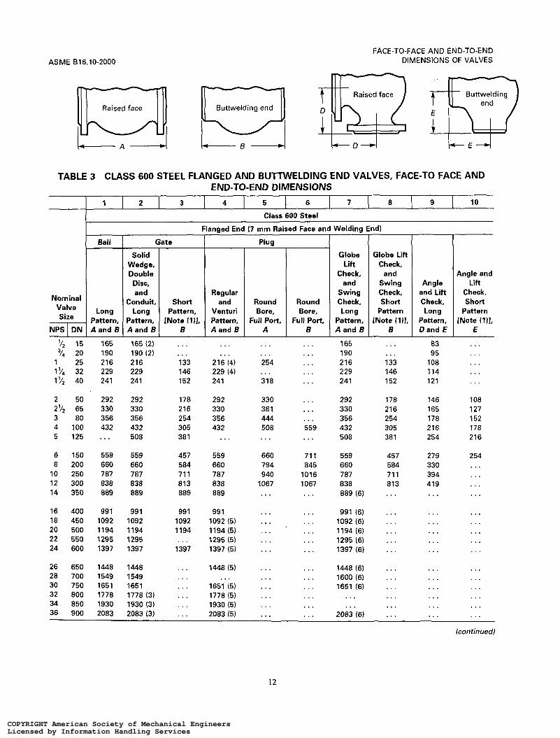
Raised face Dl Buttwelding end LI Raised face i-3 Buttwelding $J TABLE 3 CLASS 600 STEEL FLANGED AND BUTTWELDING END VALVES, FACE-TO FACE AND
END-TO-END DIMENSIONS
Nominal Valve Size
NPS I DN
'/2 15 165 165 (2) . . . . . . . . . . . . 165 . . . 83 . . . "4 20 190 190 (2) . . . . . . . . . . . . 190 . . . 95 . . .
1'/2 40 241 241 152 241 318 . . . 241 152 121 . . .
2'4 65 330 330 216 330 381 . . . 330 216 165 127
1 25 216 216 133 216 (4) 254 . . . 216 133 108 . . . 32 229 229 146 229 (4) . . . . . . 229 146 114 ...
2 50 292 292 178 292 330 . . . 292 178 146 108
3 80 356 356 254 356 444 . . . 356 254 178 152 4 100 432 432 305 432 508 559 432 305 216 178 5 125 . . . 508 38 1 . . . . . . . . . 508 38 1 254 216
6 150 559 559 457 559 660 71 1 559 457 279 254 8 200 660 660 584 660 794 845 660 584 330 . . .
10 250 787 787 71 1 787 940 1016 787 71 1 394 . . . 12 300 838 838 813 838 1067 1067 838 813 419 . . . 14 350 889 889 889 889 . . . . . . 889 (6) . . . . . . . . .
. . . 16 400 991 991 991 99 1 . . . . . . 991 (6) . . . ... 18 450 1092 1092 1092 1092 (5) . . . . . . 1092 (6) . . . . . . . . . 20 500 1194 1194 1194 1194(5) . . . . . . 1194 (6) . . . . . . 22 550 1295 1295 1295 (5) . . . . . . 1295 (6) . . . . . . 24 600 1397 1397 1397 1397 (5) . . . . . . 1397 (6) . . . . . .
26 650 1448 1448 1448í5) . . . . . . . . . . . . . . . 28 700 1549 1549 1600 (6) . . . 30 750 1651 1651 1651 (5) . . . . . . . . . . . . . . . 32 800 1778 1778 (3) 1778 (5) . . . . . . . . . . . . . . . . . . 34 850 1930 1930 (3) 1930 15) . . . . . . . . . . . . . . . ... 36 900 2083 2083 (3) 2083 15) . . . 2083 (6) . . . . . .
. . .
. . . . . .
. . .
... 1448 (6)
1651 (6) . .. . . . . . . . . . . . . . . . . . . . . . . . .
. . . . . . ...
(continued)
12
COPYRIGHT American Society of Mechanical EngineersLicensed by Information Handling ServicesCOPYRIGHT American Society of Mechanical EngineersLicensed by Information Handling Services

FACE-TO-FACE AND END-TO-END DIMENSIONS OF VALVES ASME B 16.1 0-2000
TABLE 3 (CONT'DI
GENERAL NOTES: (a) Dimensions are in millimeters. (b) See Table 9 for adjustments to tabulated dimensions which may be required for certain flange facings. NOTES: (1) These dimensions apply to pressure seal or flangeless bonnet valves. They may be applied at the manufacturer's option
(2) Solid wedge only. (3) Double disc and conduit only. (4) Regular pattern only. (5) Venturi pattern only. (6) Swing check only.
to valves with flanged bonnets.
13
COPYRIGHT American Society of Mechanical EngineersLicensed by Information Handling ServicesCOPYRIGHT American Society of Mechanical EngineersLicensed by Information Handling Services
ASME 916.10-2000
1 2 3 4 5 6 7 8
FACE-TO-FACE AND END-TO-END DIMENSIONS OF VALVES
9
Angle and Lift Check, Long
Pattern, D a n d E
Nominal Valve Size
Angle and Lift
Check, Short
Pattern [Note (111.
E NPS 1 DN
Double
A and B
PI1 ~~
Regular and
Venturi Pattern, A and B
I
Round Port,
Full Bore, A
Globe Lift Check,
and Swing Check, Long
Pattern, A and B
Globe Lift Check,
and Swing Check, Short
Pattern [Note (111,
B
Ball
Long Pattern, A and B
3/4 20 (2) 1 25 (2)
32 (2)
2 50 (2) 11/2 40 ( 2 )
21/2 65 (2) 3 80 4 100 5 125 6 150
8 200 10 250 12 300 14 350 16 400
18 450 20 500 22 550 24 600
. . . 254 (3) 279 (3) 305 (3) 368
419 381 457 559 610
737 838 965 1029 1130
1219 1321
1549 . . .
. . . 140 165 178 216
254 305 356 432 508
660 787 914 99 1 1092
. . .
. . .
. . .
. . .
. . . 254 (4) 279 (4) 305 (4) 368 (4)
419 (4) 381 (4) 457 (5)
61 O
737 838 965
. . .
.,. 1130 (5)
. . . 1321 (5)
. . .
. . .
. . . 229
... 254
. . . 279 356 305 381 368
432 419 470 381 559 457 ... 5 59 737 610
813 737 965 838 1118 965 . . , 1029 . . . 1130(6)
... 1219 (6)
. . . 1321 (6)
. . . 1549 (6)
. . . . . .
. . .
. . .
. . .
. . .
. . .
254 305 356 432 508
660 787 914 991 1092
. . .
. . .
. . .
. . .
114 127 140 152 184
210 190 229 279 305
368 419 483 514 660
737 826
991 . . .
. . .
. . . < . . . . . . . .
. . . 152 178 216 254
330 394 457 495 . . .
. . .
. . .
. . .
. . .
. . . 254 279 305 368
419 381 457
610
737 838 965 1029 1130
1219 1321
1549
. . .
. . .
GENERAL NOTES: (a) Dimensions are in millimeters. (b) See Table 9 for adjustments to tabulated dimensions which may be required for certain flange facings. NOTES: (1) These dimensions apply to pressure seal or flangeless bonnet valves. They may be applied at the manufacturer's option
to valves with flanged bonnets. (2) The connecting end flanges for class 900 valves, NPS 2l/2 (DN 65) and smaller, are identical to those of class 1500 valves.
The face-to-face dimensions for all class 900 valves, NPS 2'4 (DN 65) and smaller, except round port full bore plug valves (column 4), are identical with those of class 1500 valves.
(3) Solid wedge only. (4) Regular pattern only. (5) Venturi pattern only. (6) Swing check only.
14
COPYRIGHT American Society of Mechanical EngineersLicensed by Information Handling ServicesCOPYRIGHT American Society of Mechanical EngineersLicensed by Information Handling Services
FACE-TO-FACE AND END-TO-END DIMENSIONS OF VALVES
1 2 3 4 5 6
ASME 816.10-2000
7 8
Raised face Buttwelding end
te
Short Pattern,
[Note (1 11. B
Pli
Regular and
Venturi Pattern, A and B
Nominal Valve Size
NPS 1 DN
(
Solid Wedge, Double Disc, and
Conduit, Long
Pattern, A and B
Round Port,
Full Bore, A
Globe Lift Check,
and Swing Check, Long
Pattern, A and B
Globe Lift Check,
and Swing Check, Short
Pattern [Note il)],
B
Angle and Lift Check, Long
Pattern, D a n d E
Ball
Long Pattern, A and B
'12
"4
1 5% 1 '/2
2 '/2
1
2
3 4 5
6 8
10 12 14
16 18 20 22 24
15 . . . 20 . . . 25 254 (2) 32 279 (2) 40 305 (2)
50 368 65 41 9 80 47 O
1 O0 546 125 673
150 705 200 832 250 99 1 300 1130 350 1257
400 1384 450 1537 500 1664 550 . . 600 1943
. . .
. . . 140 165 178
216 254 305 406 483
559 711 864 99 1
1067
1194 1346 1473 . . . . . .
. . .
. . . 254 (3) 279 (3) 305 (3)
368 (3) 419 (3) 470 (3) 546 (3)
. . .
705 832 991
1130 . . .
1384 (4) . . . . . . . . . . . .
. . .
. . .
. . .
. . .
. . .
39 1 454 524 625 . . .
787 889
1067 1219 . . .
. . .
. . .
. . .
. . .
. . .
216 (5) 229 254 279 305
368 41 9 47 O 546 673
705 832 99 1
1130 1257
1384 (6) 1537 (6) 1664 (6)
1943 (6) . . .
. . .
. . .
. . .
. . .
. . .
216 254 305 406 483
559 71 1 864 99 1
1067
1194 . . . . . . . . . . . .
108 114 127 140 152
184 210 235 273 337
353 416 495 565 629
. . .
. . .
. . .
. . .
. . .
. . .
. . .
. . .
. . .
. . .
368 419 470 546 . . .
705 832 991
1130 1257
1384 ... ... ... . . .
(continued)
15
COPYRIGHT American Society of Mechanical EngineersLicensed by Information Handling ServicesCOPYRIGHT American Society of Mechanical EngineersLicensed by Information Handling Services
ASME 816.10-2000 FACE-TO-FACE AND END-TO-END
DIMENSIONS OF VALVES
TABLE 5 (CONT'D)
GENERAL NOTES: (a) Dimensions are in millimeters. (b) See Table 9 for adjustments to tabulated dimensions which may be required for certain flange facings. NOTES: (1) These dimensions apply to pressure seal or flangeless bonnet valves. They may be applied at the manufacturer's option
(2 ) Solid wedge only. (3) Regular pattern only. (4) Venturi pattern only. (5) Globe and lift check only. (6) Swing check only.
to valves with flanged bonnets.
16
COPYRIGHT American Society of Mechanical EngineersLicensed by Information Handling ServicesCOPYRIGHT American Society of Mechanical EngineersLicensed by Information Handling Services
FACE-TO-FACE AND END-TO-END DIMENSIONS OF VALVES
1
Raised face Dl 2 3 4 5 6 7
Buttwelding end
Globe Lift
Check, and
Swing Check, Long
Pattern, A and B
Raised face a Globe Lift
Check, and
Swing Check, Short
Pattern [Note (111,
8
ASME 816.10-2000
Buttwelding $2 TABLE 6 CLASS 2500 STEEL FLANGED AND BUTTWELDING END VALVES, FACE-TO FACE AND
END-TO-END DIMENSIONS
Class 2500 Steel
Flanged End (7 mm Raised Face1 and Welding End
Gate I Solid
Wedge, Double Disc, and
Nominal Valve Size Pattern,
NPS I DN I Aand B I I
'12 15
1 25 1 '14 32 1 '12 40 2 50
2 '12 65 3 80 4 1 O0 5 125 6 150 8 200
74 20
10 250 12 300 14 350 16 400 18 450
~
264 (2) 273 (2) 308 (2) 349 (2) 384 (2) 45 1
508 578 673 794 914
1022
1270 1422
. . .
. . .
. . .
1 Pattern, Regular
[Note í111. Pattern,
. . . . . .
. . . . . . 186 308 232 ... 232 384 279 45 1
330 508 368 578 457 673 533 794 610 914 762 1022
914 1270 1041 1422 1118 ... 1245 ... 1397 . . .
Angle and Lift Check, Long
Pattern, Dand E
132 137 154 175 192 226
Ball
Long Pattern, A and B
. . .
. . .
. . .
. . .
. . . 45 1
508 330 254 508 578 368 289 578 673 457 337 673 794 533 397 ... 914 610 457 914
1022 762 51 1 1022
1270 914 635 1270 1422 1041 71 1 1422 . . . . . . . . . . . . . . . . . . . . . . . . . . . . . . . . . . . .
GENERAL NOTES: (a) Dimensions are in millimeters. (b) See Table 9 for adjustments to tabulated dimensions which may be required for certain flanged facings. NOTES: (1) These dimensions apply to pressure seal or flangeless bonnet valves. They may be applied at the manufacturer's option
(2) Solid wedge only. t o valves with flanged bonnets.
17
COPYRIGHT American Society of Mechanical EngineersLicensed by Information Handling ServicesCOPYRIGHT American Society of Mechanical EngineersLicensed by Information Handling Services

FACE-TO-FACE AND END-TO-END DIMENSIONS OF VALVES ASME 816.10-2000
O O c
0 n - - m r u>
8 L al O 0
L-
al
- c
5
L - U m O m b
- z n O m m a z N ln .- u>
O LL
a, m
L
L
- - E U m O O co z
- 0 2 m a z N u>
.- In
O In C O u> C
L
-4-
.-
.- : U
8 m
Y; O Y W o m O u-
c
O O m
m m m ~ : r r - L - 4 ,
m m s k i : : : . . . . . . . . . . . . . . . . . . . . .
O O (D
u) u) m o
-
VI u) m u
m m m c u : m r - - N . N
(v m
o m
O $
O O In N
O O c
O O al
O O (D
O O o
O c
VI u) m o
o m o o m o 0 0 0 0 0 0 0 0 0 0 0 0 U - J ' O ~ C ~ ~ o m o m o m o o m o m o n i ~ m m e e ~ W P I ~ O N
- r
COPYRIGHT American Society of Mechanical EngineersLicensed by Information Handling ServicesCOPYRIGHT American Society of Mechanical EngineersLicensed by Information Handling Services

FACE-TO-FACE AND END-TO-END DIMENSIONS OF VALVES
Nominal Valve Size
NPS DN
ASME 816.10-2000
Steel Steel ûffset Seat Class 150 Cast Iron and Steel Grooved End
(411
Lug and Wafer Style [Notes (2). (3). and (411 [Notes (2). [Notes (5). (611
Class Class Class Class Flanged End Lug and Wafer Style [Note (111
Narrow Wide Narrow Wide Extra Wide 150 150 300 600
TABLE 8 CLASSES 25 AND 125 CAST IRON AND CLASSES 150 TO 600 STEEL BUTTERFLY VALVES, FACE-TO-FACE DIMENSIONS
I l 1 2 1 3 1 4 1 5 I 6 1 7 1 8 1 9 I I I I I
6 150 127 203 56 70 71 148 57 59 78 8 200 152 216 60 71 75 133 64 73 102
10 250 203 381 68 76 79 159 71 83 117 12 300 203 381 78 83 86 165 81 92 140 14 350 203 406 78 92 95 178 92 117 155 16 400 203 406 79 102 105 178 102 133 178
18 450 203 406 102 114 117 203 114 149 200 20 500 203 457 111 127 130 216 127 159 216 24 600 203 457 ... 154 157 254 154 181 232 30 750 305 559 165 . . . . . . 36 900 305 559 200 . . . 42 1050 305 610 251 . . . ...
. . . . . . . . . . . .
... . . . . . . . . . . . .
. . . . . . . . . . . .
. . . . . . . . . . . . . . . 48 1200 381 660 276 . . . 54 1350 381 71 1 . . . 60 1500 381 762 . . . . . . 66 1650 457 864 . . . . . . 72 1800 457 914 . . . . . .
GENERAL NOTE: Dimensions are in millimeters. NOTES: (1) The installed face-to-face dimension is the dimension of the valve face-to-face after installation in the pipeline. It does not
include the thickness of gaskets where separate gaskets are used. It does include the compressed (installed) thickness of gaskets or seals that are an integral part of the valve.
(2) These butterfly valves are of the design generally having concentric location of disc and seat, covered by MSS SP-67, from which these data are extracted.
(3) These valves are dimensionally compatible with flanges conforming to ASME 816.1 Class 25 or Class 125, ASME 816.5 Class 150, ASME 816.24 Class 150, ASME 816.42 Class 150, or AWWA C-207.
(4) For these butterfly valves, a tolerance of +/- 2 m m shall be allowed on face-to-face dimensions of valves of NPS 6(DN 150) and smaller, and a tolerance of +/- 3 m m on NPS 8 (DN 200) and larger, except that for single flange and flangeless valves of NPS 30 (DN 750) and larger, a tolerance of +/- 6 rnm shall be allowed.
(5) For these valves, a tolerance of +/-3 m m shall be allowed on the face-to-face dimensions for all sizes and pressure classes. (6) The data for offset seat valves, columns 7-9, are extracted from MSS SP-68 and API 609 [except NPS 16-NPS 24 (DN 400-
. . . . . . . . . . . . . . . . . .
. . . . . . . . . . . . . . .
. . . . . . . . . . . . . . .
. . . . . . . . . . . . . . .
DN 600) Class 600, which are only in MSS SP-681.
19
COPYRIGHT American Society of Mechanical EngineersLicensed by Information Handling ServicesCOPYRIGHT American Society of Mechanical EngineersLicensed by Information Handling Services
ASME 816.10-2000
Face-to-Face [Notes (1) and (211
Large or Small 2 mm 7 rnm Raised Face Raised Face Male Face Tongue Face
FACE-TO-FACE AND END-TO-END DIMENSIONS OF VALVES
Large or Small Ring
Joint Female Face Groove Face Type
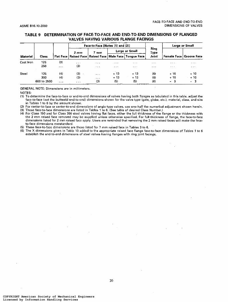
TABLE 9 DETERMINATION OF FACE-TO-FACE AND END-TO-END DIMENSIONS OF FLANGED VALVES HAVING VARIOUS FLANGE FACINGS
Cast Iron 125 (3) 250 . . .
Steel 125 (4) 300 (4)
600 t o 2500 ...
. . . . . . . . . . . . . . . . . . . . . . . . . . . . . . . . . . . . . . . (3)
(3) . . . + 13 + 13 (6) + 10 + 10 (3) . . . + 13 + 13 (6) -+ 10 + 10 . . . (3) (5) (5) (6) - 3 - 3
GENERAL NOTE: Dimensions are in millimeters. NOTES: (1) To determine the face-to-face or end-to-end dimensions of valves having both flanges as tabulated in this table, adjust the
face-to-face (not the buttweld end-to-end) dimensions shown for the valve type (gate, globe, etc.), material, class, and size in Tables 1 t o 6 by the amount shown.
(2) For center-to-face or center-to-end dimensions of angle type valves, use one-half the numerical adjustment shown herein. (3) These face-to-face dimensions are listed in Tables 1 to 6. (See table of desired Class Number.) (4) For Class 150 and for Class 300 steel valves having flat faces, either the full thickness of the flange or the thickness with
the 2 m m raised face removed may be supplied unless otherwise specified. For full thickness of flange, the face-to-face dimensions listed for 2 rnm raised face apply. Users are reminded that removing the 2 m m raised faces will make the face- to-face dimensions nonstandard.
(5) These face-to-face dimensions are those listed for 7 m m raised face in Tables 3 to 6. (6) The X dimensions given in Table 10 added to the appropriate raised face flange face-to-face dimensions of Tables 1 to 6
establish the end-to-end dimensions of steel valves having flanges with ring joint facings.
20
COPYRIGHT American Society of Mechanical EngineersLicensed by Information Handling ServicesCOPYRIGHT American Society of Mechanical EngineersLicensed by Information Handling Services

FACE-TO-FACE AND END-TO-END DIMENSIONS OF VALVES ASME 816.10-2000
m m m * *
m w w o m r r
m m m m m
m m m m m
m m e e w
m m m m m
l n m l n m l n
m m m m m
w w w w w
e m w m :
m m m m m
w w w w w
0 0 0 0 0 m o m o m r N N m m
W W O N P r r r
. . . . . . . . . . . .
. . . . . . . . . . . .
m m z 1,- . r
N N N 'a N N N : a
e m l n : u
o m m : u - r r . C
m m m w u
- r -
m m w y z
w w w w ( T :
I
c - W W r n N N r r r N N
m m m s m
- r -
m m m m m r r r r -
0 0 0 0 0 o m o m o P P m m W
W ~ O N P - - t -NNN
COPYRIGHT American Society of Mechanical EngineersLicensed by Information Handling ServicesCOPYRIGHT American Society of Mechanical EngineersLicensed by Information Handling Services

ASME 61 6.10-2000
FACE-TO-FACE AND END-TO-END DIMENSIONS OF VALVES
O O Y) N in m o
-
O O In
u)
m
c
o
-
O O
in
m
m
o
-
O O to u)
m o
-
O o m v1
m Y
-
o IC
U (i
c
E
-
. . . . . . . . . . . . . . . . . .
. . . . . . . . . . . . . . . . . .
. . . . . . . . . . . . . . . . . .
. . . . . . . . . . . . . . . . . .
. . . . . . . . . . . . . . . . . .
. . . . . . . . . . . . . . . . . .
. . . . . . . . . . . . . . .
0 0 0 0 0 0 m o m o m o W b b m m a
U 4
.- N v)
C U O
cn .-
E+ L x 5 W
L
c O
a In
al v)
.- L
b-
m 2
z r
W
a U m d
a 0 v)
P
2 *-
P 5 O 4-
E
o *-
In
.- In
W L
FJ - U m
SI W
Z O - W N
v) a z I
O m in
z O N N
22
COPYRIGHT American Society of Mechanical EngineersLicensed by Information Handling ServicesCOPYRIGHT American Society of Mechanical EngineersLicensed by Information Handling Services

FACE-TO-FACE AND END-TO-END DIMENSIONS OF VALVES
7 8
Plain face Raised face
9 I 10
L A - / L A - I
1 2 3 4 5
Class 125 Cast Iron Class 150 Steel
6
ASME 816.10-2000
Nominal Va've Size
NPS DN
Class 150 Steel
Class 125 Cast Iron
- Flanged End (Flat Face)
Globe, Plug
Gate, Lift Solid Check,
Wedge Regular Round and Angle and and Port, Swing and
Double Short Venturi Full Check Lift Disc, Pattern, Pattern, Bore, [Note (111. Check,
A A A A A D
TABLE A1 CLASS 125 CAST IRON FLANGED AND CLASS 150 STEEL FLANGED AND BUTTWELDING END VALVES, FACE-TO-FACE AND END-TO-END DIMENSIONS
'/4 8 . . . "8 1 o < . . '/* 15 . . .
20 , . . 1 25 . . .
32 . . .
2 50 7.00 2'/2 65 7.50 3 80 8.00
4 100 9.00 5 125 10.00 6 150 10.50 8 200 11.50
10 250 13.00
12 300 14.00 14 350 15.00 (2) 16 400 16.00 (2) 18 450 17.00 (2) 20 500 18.00 (2)
22 550 . . . 24 600 20.00 (2) 26 650 . . . 28 700 . . . 30 750 . . .
32 800 . . . 34 850 . . . 36 900 . . .
1'/2 40 . . .
. . . . . . . . . . . . . . .
. . . . . . . . . . . . . . .
. . . . . . . . . . . . . . . . . . . . . . . . . . . . . 5.50 5.50 (3) 5.50 . . . . . .
. . . 6.50 (3) 6.00 . . . . . . 6.50 6.50 (3) 6.50 . . . . . . 7.00 7.50 (3) 7.50 8.00 4.00 7.50 8.25 (3) 8.25 8.50 4.25 8.00 9.00 (3) 9.00 9.50 4.75
9.00 9.00 (3) 12.00 11.50 5.75 10.00 14.00 (3) 15.00 13.00 6.50 10.50 15.50 18.00 14.00 7.00 11.50 18.00 22.00 19.50 9.75 13.00 21.00 26.00 24.50 12.25
14.00 24.00 30.00 27.50 13.75 . . . 27.00 . . . 31.00 15.50 . . . 30.00 . . . 36.00 (5) 18.00 . . . 34.00 . . . . . . . . . . . . 36.00 . . . . . . . . . . . . . . . . . . . . . . .. 42.00 (4) . . . . . . . . . . . . . . . . . . . . .
. . . . . . . . . . . . . . .
. . . 51.00 (4) . . . . . . . . .
. . . . . . . . . . . . . . .
. . . . . . . . . . . . . . .
. . . 63.00 (4) . . . . . . . . .
Class 150 Steel
Flanged End (0.06 in. Raised Face) and Welding End
Gate
Solid Solid Wedge,
Wedge Double Disc,
4.00 . . . 4.00 4.00 . . . 4.00 4.25 . . . 4.25 4.62 . . . 4.62 5.00 . . . 5.00
5.50 . . . 5.50 6.50 . . . 6.50 7.00 7.00 8.50 7.50 7.50 9.50 8.00 8.00 11.12
9.00 9.00 12.00 10.00 . . . 15.00 10.50 10.50 15.88 i1.50 11.50 16.50 13.00 13.00 18.00
14.00 14.00 19.75 15.00 15.00 22.50 16.00 16.00 24.00 17.00 17.00 26.00 18.00 18.00 28.00
... 20.00 30.00 20.00 20.00 32.00 22.00 22.00 34.00 (6) 24.00 24.00 36.00 (6) 24.00 26.00 36.00 (6)
. . . 28.00 38.00 (6)
... 30.00 40.00 (6) 28.00 32.00 40.00 (6)
Plug
Short Pattern,
A
...
. . .
. . .
. . . 5.50
. . . 6.50 7.00 7.50 8.00
9.00 10.00 10.50 11.50 13.00
14.00 . . . ... ... . . .
. . .
. . .
. . .
. . .
. . .
. . . 40.00 . . .
Icon tinuedl
23
COPYRIGHT American Society of Mechanical EngineersLicensed by Information Handling ServicesCOPYRIGHT American Society of Mechanical EngineersLicensed by Information Handling Services
ACME B16.10-2000
11
FACE-TO-FACE AND END-TO-END DIMENSIONS OF VALVES
~~ ~ ~
12 13 14 15 16 17 18 19 20 21
Class 125 Cast Iron Class 150 Steel Class 150 Steel
I Plug
Short Round and Port,
Regular Venturi Full Pattern, Pattern, Bore,
B A A
TABLE A I CLASS 125 CAST IRON FLANGED AND CLASS 150 STEEL FLANGED AND BUTTWELDING END VALVES, FACE-TO-FACE AND END-TO-END DIMENSIONS (CONT'D)
Globe, Lift
Check, and
Swing Check
[Note (111, Aand B
Y-Globe and
Y-Swing Check,
Aand B
L Flanged End (0.06 in. Raised Face) and Welding End I FlangedEnd 1 Welding End
I
Long Pattern,
A
I- NPS
Nominal I
DN A
'14
"8
'I* 7 4
1 '/4 1 ' I 2
2'/2
1
2
3
4 5 6 8
10
12 14 16 18 20
22 24 26 28 30
32 34 36
8 . . . 10 . . . 15 . . . 20 . . . 25 . . . 32 . . . 40 . . . 50 . . . 65 . . . 80 . . .
100 12.00 125 15.00 150 15.50 200 18.00 250 21.00
300 24.00 350 27.00 400 30.00 450 34.00 500 36.00
550 . . . 600 42.00 650 . . . 700 ... 750 . . . 800 . . . 850 . . . 900 . . .
. . . . . . . . . 5.50
. . . . . . 8.75 6.50 10.50 7.00 10.50 8.00 12.00 . . . 11.75 8.50 13.00 8.00 13.50 9.50
14.00 9.00 17.00 11.50 15.00 . . . . . . 14.00 (7) 18.00 15.50 . . . 16.00 (7) 20.50 18.00 . . . 19.50 22.00 21.00 . . . 24.50
25.00 24.00 . . . 27.50 . . . 27.00 . . . 21.00 . . . 30.00 . . . 36.00 (8) . . . 34.00 . . . 38.50 (9) . . . 36.00 . . . 38.50 (9)
. . . . . . . . . 42.00 (9)
. . . 42.00 . . . 51.00 (9)
. . . . . . . . . 51.00 (9)
... . . . . . . 57.00 (9)
. . . . . . . . . 60.00 (9)
. . . . . . . . . . . . . . . . . . . . . . . . . .
. . . . . . . . . 77.00 (9)
Angle and Lift Check,
Dand E
2.00 . . . 2.00 . . . 2.25 5.50 2.50 6.00 2.75 6.50
3.00 7.25 3.25 8.00 4.00 9.00 4.25 11.00 4.75 12.50
5.75 14.50 7.00 . . . 8.00 18.50 9.75 23.50
12.25 26.50
13.75 30.50 15.50 . . . 18.00 . . .
. . . . . .
... . . .
. . . . . .
. . . . . .
4.25 4.62 5.00
5.50 6.50 7.00 7.50 8.00
9.00
15.50 18.00 21 .o0
24.00 27.00 30.00 34.00 36.00
. . .
42.00 . . . . . .
. . . . . . .
. . . . . .
I Short Long Short
Pattern, 1 Pa;rn, 1 Pattern, A 8
. . .
. . . 4.25 4.62 5.00
5.50 6.50 7.00 7.50 8.00
9.00
10.50 11.50 13.00
14.00 15.00 16.00
. . .
. . .
. . .
. . .
. . .
. . .
. . .
. . .
. . .
. . .
. . .
. . . . . .
. . . . . .
. . . 5.50
. . . 6.00
. . . 6.50
. . . 7.00 7.50 7.50 8.50 8.50 9.50 9.50
11.12 11.12
12.00 12.00
18.00 15.88 20.50 16.50 22.00 18.00
25.00 19.75 30.00 22.50 33.00 24.00 36.00 26.00 39.00 28.00
43.00 . . . 45.00 32.00 49.00 . . . 53.00 . . . 55.00 ... 60.00 . . . 64.00 . . . 68.00 . . .
. . . . . .
(continued)
24
COPYRIGHT American Society of Mechanical EngineersLicensed by Information Handling ServicesCOPYRIGHT American Society of Mechanical EngineersLicensed by Information Handling Services
FACE-TO-FACE AND END-TO-END DIMENSIONS OF VALVES
TABLE A I (CONT'D)
ASME 816.10-2000
GENERAL NOTES: (a) Dimensions are in inches. (b) See Table A9 for adjustments to tabulated dimensions which may be required for certain flange facings. NOTES: (1) These dimensions are not intended to cover the type of check valve having the seat angle at approximately 45 deg to the
(2) Solid wedge only. (3) Regular pattern only. The face-to-face dimension of NPS 4 may be 12.00 at the manufacturer's option. (4) Venturi pattern only. (5) Globe and horizontal lift check only. (6) Double disc and conduit only. (7) Globe and horizontal lift check only. The face-to-face and end-to-end dimension for Class 150 steel flanged and buttwelding
(8 ) Globe and horizontal lift check only. The face-to-face and end-to-end dimension for Class 150 steel flanged and buttwelding
(9) Swing check only.
run of the valve, or the "Underwriter Pattern," or other patterns where large clearances are required.
end swing check valves in NPS 5 is 13.00 and in NPS 6 is 14.00.
end swing check valves in NPS 16 is 34.00
25
COPYRIGHT American Society of Mechanical EngineersLicensed by Information Handling ServicesCOPYRIGHT American Society of Mechanical EngineersLicensed by Information Handling Services

ASME 816.10-2000
Gate, Plug 1 Solid I I I
FACE-TO-FACE AND EN D-TO-EN D DIMENSIONS OF VALVES
~
Globe, Ball Lift I I
Raised face Buttwelding end
Wedge
Double Disc,
Nom in a I Valve Size
Class 250 Cast Iron and Class 300 Steel
Check, and Angle
Short Regular Venturi Swing and Lift Long Short Long Pattern, Pattern, Pattern, Check, Check, Pattern, Pattern, Pattern,
Class 300 Steel
NPS I D N I A
TABLE A2 CLASS 250 CAST IRON FLANGED AND CLASS 300 STEEL FLANGED AND BUTTWELDING END VALVES, FACE-TO-FACE AND END-TO-END DIMENSIONS
A A A A D A 1 ' A and B B
I Class 250 Cast Iron I Class 300 Steel
I Flanged End (0.06 in. Raised Face) 1 Flanaed and Weldina End
2 50 8.50 7.25 8.50 . . . 10.50 5.25 8.50 8.50 8.50 2l/2 65 9.50 8.00 9.50 . . . 11.50 5.75 9.50 9.50 9.50 3 80 11.12 9.25 11.12 . . . 12.50 6.25 11.12 11.12 11.12 4 100 12.00 10.50 12.00 . . . 14.00 7.00 12.00 12.00 12.00 5 125 15.00 15.25 15.75 7.88 . . . . . . . . . . . . ...
6 150 15.88 14.88 16.75 15.88 17.50 8.75 15.88 15.88 18.00 8 200 16.50 . . . 19.75 16.50 21.00 10.50 19.75 16.50 20.50
10 250 18.00 22.38 23.50 18.00 24.50 12.25 22.38 18.00 22.00
14 350 22.50 30.00 . . . 30.00 22.50 30.00
16 400 24.00 33.00 . . . . . . 33.00 24.00 33.00 18 450 26.00 36.00 . . . . . . 36.00 26.00 36.00 20 500 28.00 39.00 . . . . . . 39.00 28.00 39.00 22 550 44.00 . . . . . . 43.00 . . . 43.00 24 600 31.00 45.00 . . . 45.00 32.00 45.00
12 300 19.75 25.50 28.00 19.75 28.00 14.00 25.50 19.75 25.00 . . . . . . . . .
. . . . . .
. . . . . .
. . . . . . . . . . . . . . .
. . . . . . . . . . . . . . . . . . . . . . . . 26 650 . . . 49.00 . . . 49.00
28 700 . . . 53.00 . . . 53.00 30 750 . . . 55.00 ... 55.00 32 800 . . . 60.00 ... 60.00 34 850 . . . 64.00 ... 64.00 36 900 . . . 68.00 . . . 68.00
. . . . . . . . . . . . . . .
. . . . . . . . . . . . . . .
. . . . . . . . . . . . ...
. . . . . . . . . . . . . . .
. . . . . . . . . . . . . . . (con tin ued)
26
COPYRIGHT American Society of Mechanical EngineersLicensed by Information Handling ServicesCOPYRIGHT American Society of Mechanical EngineersLicensed by Information Handling Services

FACE-TO-FACE AND END-TO-END DIMENSIONS OF VALVES
10
ASME 616.10-2000
11 12 13 14 15 16 17
Raised face Buttwe Id i ng
Angle and Lift Check, Dand E
Class 250 Cast Iron and Class 300 Steel
Class 300 Steel
Swing Check,
A and B
Short and Venturi Pattern,
A
I Class 300 Steel
and Round Venturi Regular Port, Full Pattern, Pattern, Bore,
B A A and B
Solid Wedge, Double
Nominal Valve Size
NPS 1 DN I 72 "4
1 '14
1 '/2
2 '12
1
2
3 4 5
6 8
10 12 14
16 18 20 22 24
26 28 30 32 34 36
15 20 25 32 40
Disc, and
Conduit, A and B
5.50 (1) 6.00 (1 ì 6.50 (1 ) 7.00 (1) 7.50
50 8.50 65 9.50 80 11.12
100 12.00 125 15.00
150 15.88 200 16.50 250 18.00 300 19.75 350 30.00
400 33.00 450 36.00 500 39.00 550 43.00 600 45.00
650 49.00 700 53.00 750 55.00 800 60.00 850 64.00 900 68.00
Flanged End (0.06 in. Raised Face) and Welding End
Plug
1 Short I Globe
and Lift Check, A and B
I
. . .
. . . 6.25 (2)
7.50 (2)
8.50 9.50
11.12 12.00
. . .
. . .
15.88 16.50 18.00 19.75 30.00 (3)
33.00 (3) 36.00 (3) 39.00 (3) 43.00 (3) 45.00 (3)
49.00 (3) 53.00 (3) 55.00 (3) 60.00 (3) 64.00 (3) 68.00 (3)
. . .
. . .
. . .
. . .
. . .
10.50 (2) 12.00 (2) 13.00 (2) 14.00 (2)
. . .
18.00 20.50 22.00 25.00 30.00 (3)
33.00 (3) 36.00 (3) 39.00 (3) 43.00 (3) 45.00 (3)
49.00 (3) 53.00 (3) 55.00 (3) 60.00 (3) 64.00 (3) 68.00 (3)
. . .
. . .
. . .
. . .
. . .
. . .
. . .
. . .
. . .
. . .
15.88 19.75 22.38 28.00 30.00
33.00 36.00 39.00 43.00 45.00
49.00 53.00 55.00 60.00 64.00 68.00
. . . 7.50
9.50
11.12 13.00 15.25 18.00
. . .
. . .
22.00 27 .OO 32.50 38.00 . . .
. . .
. . .
. . .
. . .
. . .
. . .
. . .
. . .
. . .
. . .
. . .
6.00 7.00 8.00 8.50 9.00
10.50 11.50 12.50 14.00 15.75
17.50 22.00 24.50 28.00 . . .
. . .
. . .
. . .
. . .
...
. . .
. . .
. . .
...
. . .
. . .
3.00 3.50 4.00 4.25 4.50
5.25 5.75 6.25 7.00 7.88
8.75 11.00 12.25 14.00 . . .
. . .
. . .
. . .
. . .
. . .
. . .
. . .
. . .
. . .
. . .
. . .
. . .
. . . 8.50 9.00 9.50
10.50 11.50 12.50 14.00 15.75
17.50 21 .o0 24.50 28.00 33.00
34.00 38.50 40.00 44.00 53.00
53.00 59.00 62.75 . . . . . .
82.00
Icon tin uedl
21
COPYRIGHT American Society of Mechanical EngineersLicensed by Information Handling ServicesCOPYRIGHT American Society of Mechanical EngineersLicensed by Information Handling Services

ASME 81 6.10-2000 FACE-TO-FACE AND END-TO-END
DIMENSIONS OF VALVES
GENERAL NOTES: (a) Dimensions are in inches. (b) See Table A9 for adjustments to tabulated dimensions which may be required for certain flange facings. NOTES: (1) Solid wedge only. (2) Plug-short pattern only. (3) Venturi pattern only.
28
COPYRIGHT American Society of Mechanical EngineersLicensed by Information Handling ServicesCOPYRIGHT American Society of Mechanical EngineersLicensed by Information Handling Services
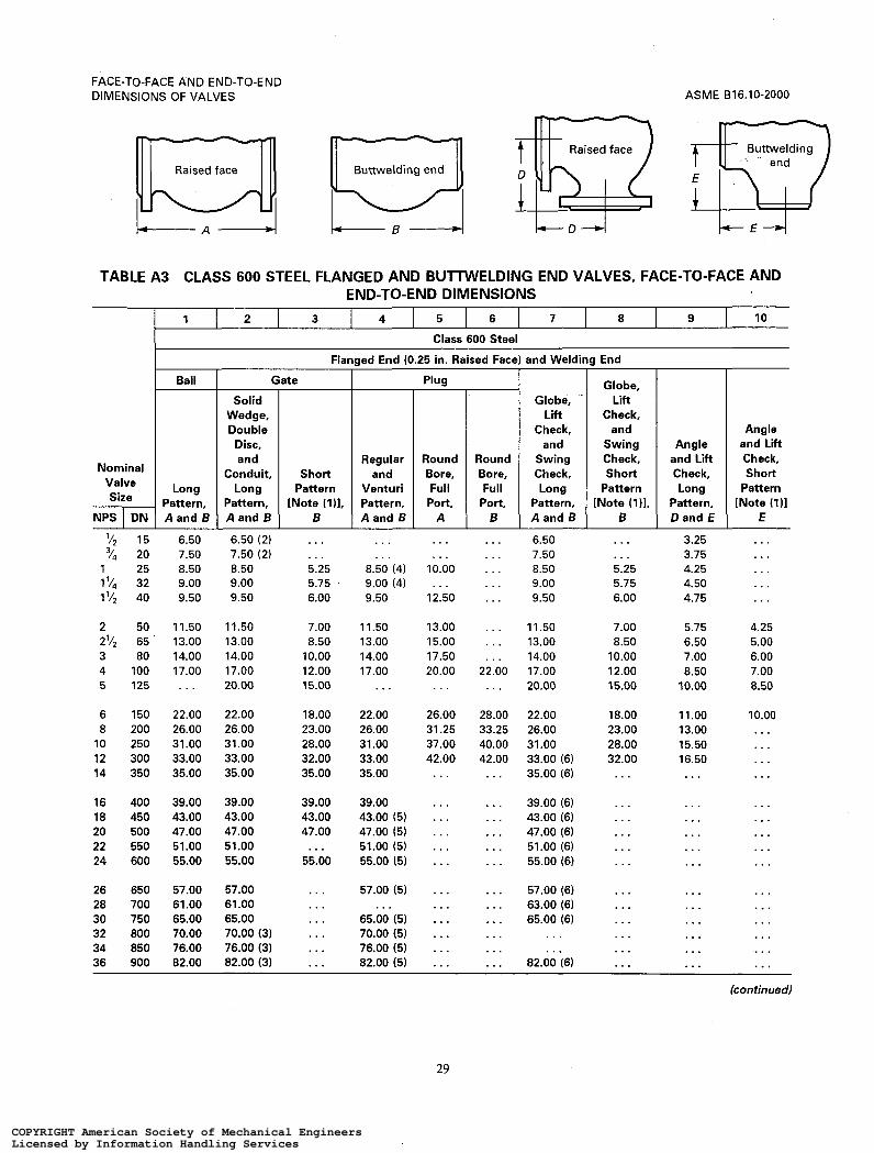
FACE-TO-FACE AND END-TO-END DIMENSIONS OF VALVES
1 2 3 4 5 6 7
ASME 616.10-2000
8 9 1 0
Raised face m Buttwelding end
Raised face $52 Buttwelding h p
Nominal
val: 1 Long Size Pattern,
NPS I D N 1 A and B
'12 15 6.50 '14 20 7.50
1 25 8.50 l 5 $ 32 9.00 I l 1 2 40 9.50
2 50 11.50 2'12 65 13.00 3 80 14.00 4 100 17.00 5 125 . . .
6 150 22.00 8 200 26.00
10 250 31.00 12 300 33.00 14 350 35.00
16 400 39.00 18 450 43.00 20 500 47.00 22 550 51.00 24 600 55.00
26 650 57.00 28 700 61.00 30 750 65.00 32 800 70.00 34 850 76.00 36 900 82.00
Flanaed End (0.25 in. Raised Face
(
Solid Wedge, Double
Disc, and
Conduit, Long
Pattern, A and 6
6.50 (2) 7.50 (2) 8.50 9.00 9.50
11.50 13.00 14.00 17.00 20.00
22.00 26.00 31.00 33.00 35.00
39.00 43.00 47.00 51.00 55.00
57.00 61.00 65.00 70.00 (3) 76.00 (3) 82.00 (3)
Regular
Pattern Venturi [Note (111, Pattern,
A and B . . . . . . . . . . . . 5.25 8.50 (4) 5.75 ' 9.00 (4) 6.00 9.50
7.00 11.50 8.50 13.00
10.00 14.00 12.00 17.00 15.00 ...
18.00 22.00 23.00 26.00 28.00 31.00 32.00 33.00 35.00 35.00
39.00 39.00 43.00 43.00 (5) 47.00 47.00 (5) . . . 51.00 (5)
55.00 55.00 15)
. . . 57.00 (5)
. .. 65.00 (5)
... 70.00 (5)
... 76.00 (5)
... 82.00 (5)
... ...
Plug
Round Bore, Full
Port, A
Round Bore, Full
Port, B
and Weldina End
Globe, Lift
Check, and
Swing Check, Long
Pattern, A and B
Globe, Lift
Check, and
Swing Check, Short
Pattern [Note i1)l.
B
Angle and Lift Check, Long
Pattern, Dand E
Angle and Lift Check, Short
Pattern [Note (111
E . . . . . .
10.00
12.50
13.00 15.00 17.50 20.00
. . .
. . .
26.00 31.25 37.00 42.00 . . .
. . .
. . .
. . .
. . .
. . .
. . .
. . .
. . .
. . .
. . .
...
. . .
. . .
. . .
. . .
. . .
. . .
. . .
. . . 22.00 . . .
28.00 33.25 40.00 42.00 . . .
. . .
. . .
. . .
. . .
. . .
. . .
. . .
. . .
...
. . .
. . .
6.50 . . . 7.50 . . . 8.50 5.25 9.00 5.75 9.50 6.00
11.50 7.00 13.00 8.50 14.00 10.00 17.00 12.00 20.00 15.00
22.00 18.00 26.00 23.00 31.00 28.00 33.00 (6) 32.00 35.00 (6) . . .
39.00 (6) . . . 43.00 (6) . . . 47.00 (6) . . . 51.00 (6) . . . 55.00 (6) . . .
57.00 (6) . . . 63.00 (6) 65.00 (6)
. . .
. . . . . . . . . . . . ...
82.00 (6) ...
3.25 3.75 4.25 4.50 4.75
5.75 6.50 7.00 8.50
10.00
11.00 13.00 15.50 16.50 . . .
. . .
...
. . .
. . .
. . .
. . .
...
. . .
...
. . .
...
. . .
. . .
4.25 5.00 6.00 7.00 8.50
10.00 . . . . . . ... ...
...
...
. . .
. . .
. . .
...
. . .
...
. . .
... (continued)
29
COPYRIGHT American Society of Mechanical EngineersLicensed by Information Handling ServicesCOPYRIGHT American Society of Mechanical EngineersLicensed by Information Handling Services

ASME 816.10-2000
TABLE A3 (CONT'D)
FACE-TO-FACE AND END-TO-END DIMENSIONS OF VALVES
GENERAL NOTES: (a) Dimensions are in inches. (b) See Table A9 for adjustments to tabulated dimensions which may be required for certain flange facings. NOTES: (1) These dimensions apply to pressure seal or flangeless bonnet valves. They may be applied at the manufacturer's option
(2) Solid wedge only. (3) Double disc and conduit only. (4) Regular pattern only. (5) Venturi pattern only. (6) Swing check only.
t o valves with flanged bonnets.
30 -
COPYRIGHT American Society of Mechanical EngineersLicensed by Information Handling ServicesCOPYRIGHT American Society of Mechanical EngineersLicensed by Information Handling Services

FACE-TO-FACE AND END-TO-END DIMENSIONS OF VALVES
1 2 3 4 5 6 7
ASME 616.10-2000
8 9
T b i s e i f a c e l
Raised face Buttwelding end
II I , B 4 k o - 4
Buttwelding ‘Q Nominal Valve
Size
NPS I DN
Gate
Solid Wedge, Double
Disc, and
Conduit, Long
Pattern, A and B
Short Pattern
[Note (1)l. B
314 (2) 20 (2) . . . 1 (2) 25 (2) 10.00 (3) I y4 (2) 32 (2) 1 1 .O0 (3) 172 (2) 40 (2) 12.00 (3) 2 (2) 50 (2) 14.50
2’/2 (2) 65 (2) 16.50 3 80 15.00 4 100 18.00 5 125 22.00 6 150 24.00
8 200 29.00 10 250 33.00 12 300 38.00 14 350 40.50 16 400 44.50
18 450 48.00 20 500 52.00 22 550 . . . 24 600 61.00
. . . 5.50 6.50 7.00 8.50
10.00 12.00 14.00 17.00 20.00
26.00 31.00 36.00 39.00 43.00
. . .
. . .
. . .
. . .
Flanged End (0.25 in. Raised Face) and Wt
Plu
Regular and
Venturi Pattern, A and B
10.00 (4) 1 1 .o0 (4) 12.00 (4) 14.50 (4)
16.50 (4) 15.00 (4) 18.00 (5)
24.00
29.00 33.00 38.00
44.50 (5)
. . .
. . .
. . .
. . . 52.00 (5)
...
...
Globe,
Check,
Full
. . . 9.00
. . . 10.00
. . . 11.00 14.00 12.00 15.00 14.50
17.00 16.50 18.50 15.00 22.00 18.00 , . . 22.00 29.00 24.00
32.00 29.00 38.00 33.00 44.00 38.00 . . . 40.50 . . . 44.50 (6)
. . . 48.00 (6)
. . . 52.00 (6)
. . . 61.00 (6)
. . . . . .
Globe, Lift Check,
and Swing Check, Short
Pattern [Note ilil .
B
. . .
. . .
. . .
. . .
. . .
10.00 12.00 14.00 17.00 20.00
26.00 31.00 36.00 39.00 43.00
. . .
. . .
. . .
. . .
ling End
I Angle
and Lift Check, Long
Pattern, i Dand E
4.50 5.00 5.50 6.00 7.25
Angle and Lift Check, Short
Pattern [Note ilil
E
. . .
. . .
. . .
. . .
. . .
8.25 . . . 7.50 6.00 9.00 7.00
1 1 .o0 8.50 12.00 10.00
14.50 13.00 16.50 15.50 19.00 18.00 20.25 19.50 26.00 . . .
29.00 . . . 32.50 . . .
39.00 . . . . . . . . .
Ball
Long Pattern, A and 6
. . . 10.00 11.00 12.00 14.50
16.50 15.00 18.00
24.00
29.00 33.00 38.00 40.50 44.50
48.00 52.00
61 .O0
. . .
. . .
GENERAL NOTES: (a) Dimensions are in inches. (b) See Table A9 for adjustments to tabulated dimensions which may be required for certain flange facings. NOTES: (1) These dimensions apply to pressure seal or flangeless bonnet valves. They may be applied at the manufacturer’s option
to valves with flanged bonnets. (2) The connecting end flanges for Class 900 valves, NPS 2’12 and smaller, are identical t o those of Class 1500 valves. The face-
to-face dimensions for all Class 900 valves, NPS 2’/2 and smaller, except round port full bore plug valves (column 4), are identical with those of Class 1500 valves
(3) Solid wedge only. (4) Regular pattern only. (5) Venturi pattern only. (6) Swing check only.
31
COPYRIGHT American Society of Mechanical EngineersLicensed by Information Handling ServicesCOPYRIGHT American Society of Mechanical EngineersLicensed by Information Handling Services

AS ME BI 6.10-2000
1
FACE-TO-FACE AND END-TO-END DIMENSIONS OF VALVES
2 3 4 5 6 7 8
Raised face D
and
Long Pattern, A and B
Valve Size
Buttwelding F R
Short Pattern
[Note (111. B
TABLE A5 CLASS 1500 STEEL FLANGED AND BUTTWELDING END VALVES, FACE-TO-FACE AND END-TO-END DIMENSIONS
I Gate ~
Solid Wedge, Double
Disc,
72 "4
I V4 1 '/2
2 '/2
1
2
3 4 5
6 8 10 12 14
16 18 20 22 24
Venturi
A and B
Globe, Lift
Check, and
Swing Check, Long
Pattern, A and 8
Globe, Lift Check,
and Swing Check, Short
Pattern [Note (111,
B
Angle and Liít Check, Long
Pattern, Dand E
15 . . . 20 . . . 25 10.00 (2) 32 11.00 (2) 40 12.00 (2)
50 14.50 65 16.50 80 18.50 100 21.50 125 26.50
150 27.75 200 32.75 250 39.00 300 44.50 350 49.50
400 54.50 450 60.50 500 65.50 550 . . .
. . .
. . . 5.50 6.50 7.00
8.50 10.00 12.00 16.00 19.00
22.00 28.00 34.00 39.00 42.00
47.00 53.00 58.00 . . .
. . .
. . . 10.00 (3) 1 1 .o0 (3) 12.00 (3)
14.50 (3) 16.50 (3) 18.50 (3) 21.50 (3)
. . .
27.75 32.75 39.00 44.50
. . .
54.50 (4) . . . . . . . . .
. . . 8.50 (5) . . .
. . . 9.00 . . .
. . . 10.00 . . .
. . . 1 1 .o0 . . .
. . . 12.00 . . .
15.38 14.50 8.50 17.88 16.50 10.00 20.62 18.50 12.00 24.62 21.50 16.00 . . . 26.50 19.00
31.00 27.75 22.00 35.00 32.75 28.00 42.00 39.00 34.00 48.00 44.50 39.00 . . . 49.50 42.00
. . . 54.50 (6) 47.00
. . . 60.50 (6) . . .
. . . 65.50 (6) . . . . . . . .
4.25 4.50 5.00 5.50 6.00
7.25 8.25 9.25 10.75 13.25
13.88 16.38 19.50 22.25 24.75
. . .
. . .
. . .
. . .
Ball
Long Pattern, A and B
. . .
. . .
. . .
. . .
. . .
14.50 16.50 18.50 21.50 . . .
27.75 32.75 39.00 44.50 49.50
54.50 . . . . . . . . . . . .
. . . . . . . . . . . . . . . 600 76.50 76.50 (6) . . .
(con tin ued)
32
COPYRIGHT American Society of Mechanical EngineersLicensed by Information Handling ServicesCOPYRIGHT American Society of Mechanical EngineersLicensed by Information Handling Services
FACE-TO-FACE AND END-TO-END DIMENSIONS OF VALVES ASME 816.10-2000
TABLE A5 (CONT'D)
GENERAL NOTES: (a) Dimensions are in inches. (b) See Table A9 for adjustments to tabulated dimensions which may be required for certain flange facings. NOTES: (1) These dimensions apply t o pressure seal or flangeless bonnet valves. They may be applied at the manufacturer's option
(2) Solid wedge only. (3) Regular pattern only. (4) Venturi pattern only. (5) Globe and lift check only. (6) Swing check only.
t o valves with flanged bonnets.
33
COPYRIGHT American Society of Mechanical EngineersLicensed by Information Handling ServicesCOPYRIGHT American Society of Mechanical EngineersLicensed by Information Handling Services
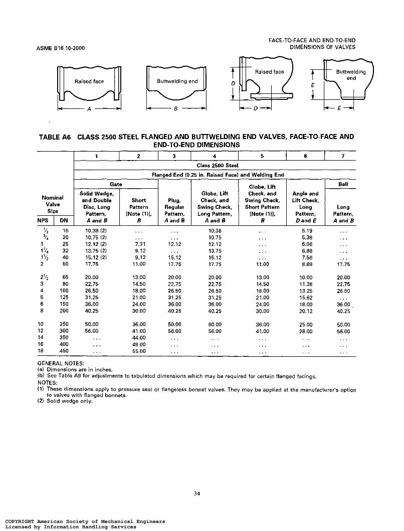
FACE-TO-FACE AND END-TO-END DIMENSIONS OF VALVES
1 2 3 4 5
ASME 816.10-2000
6 7
Angle and Liit Check,
Long Pattern, Dand E
Long Pattern, A and B
Raised face m Buttwelding end Ln Raised face Buttwelding
I ' D 4 L A - I
TABLE A6 CLASS 2500 STEEL FLANGED AND BUTTWELDING END VALVES, FACE-TO-FACE AND END-TO-END DIMENSIONS
~~ ~~ ~~ ~ _ _ ~ ~ ~ Flanged End (0.25 in. Raised Face) and Welding End
Globe, Lift Solid Wedge, Check, and and Double Plug. Disc, Long Pattern, [Note (111, A and B A and B A and B
Ball
Nominal Valve Size
NPS I DN
'12
"4
15 20 25 32 40 50
10.38 (2) 10.75 (2) 12.12 (2) 13.75 (2) 15.12 (2) 17.75
10.38 10.75 12.12 13.75 15.12 17.75
5.19 5.38 6.06 6.88 7.56 8.88
. . . 7.31 9.12 9.12 11.00
. . . . . . . . . . .
1
1 2
1 '/4 12.12
15.12 17.75
. . . . . . . . . . . . 11.00 17.75
2'4 3 4 5 6 8
65 80
1 O0 125 150 200
20.00 22.75 26.50 31.25 36.00 40.25
13.00 14.50 18.00 21.00 24.00 30.00
20.00 22.75 26.50 31.25 36.00 40.25
20.00 22.75 26.50 31.25 36.00 40.25
13.00 14.50 18.00 21 .o0 24.00 30.00
10.00 11.38 13.25 15.62 18.00 20.12
20.00 22.75 26.50
36.00 . 40.25
10 12 14 16 18
250 300 350 400 450
50.00 56.00
36.00 41 .O0 44.00 49.00 55.00
50.00 56.00
50.00 56.00 . . .
36.00 41 .O0 . . .
25.00 28.00
50.00 56.00
. . .
. . . . . .
..
.. ..
. .
GENERAL NOTES: (a) Dimensions are in inches. (b) See Table A9 for adjustments to tabulated dimensions which may be required for certain flanged facings. NOTES: (1) These dimensions apply to pressure seal or flangeless bonnet valves. They may be applied at the manufacturer's option
(2) Solid wedge only. to valves with flanged bonnets.
34
COPYRIGHT American Society of Mechanical EngineersLicensed by Information Handling ServicesCOPYRIGHT American Society of Mechanical EngineersLicensed by Information Handling Services

FACE-TO-FACE AND END-TO-END DIMENSIONS OF VALVES
1 2 3 4 5 6 7 8 9 10 11 12
ASME B16.10-2000
13 14
Cast Iron [Note (211
Swing Check, Single and Dual Plate, Installation
Between Standard
ANSI Flanges Nominal
Valve Size
Swing Check, Single and Dual Plate, Installation Between Standard ANSI Flanges [Note (311
.
Class Class
NPS I DN
Flange Mating
Dimensions
Steel [Note (111
Bonnet- less
Knife Gate, Class 150 -
150 300 600 900 1500 2500 150 300 600 900 1500 -
Class
125 I 250 Long Pattern [Note (411 Short Pattern [Note (511
2
3 4 5 6
8 10 12 14 16 18
20 24 30 36 42 48
2 '/2 50 65 80
1 O0 125 150
200 250 300 350 400 450
500 600 7 50 900
1050
1.88 2.12 . . . 2.38 2.00 2.62 2.00 2.62 2.25 3.25 2.25 3.75
2.75 5.00 2.75 5.50 3.00 7.12 3.00 7.25 3.50 7.50 3.50 8.00
4.50 8.38 4.50 8.75 . . . 12.00 . . . 14.50 . . . 17.00
2.12 2.38 2.62 2.62 3.25 3.75
5.00 5.50 7.12 8.75 9.12
10.38
11.50 12.50 14.50 19.00 22.38
2.38 2.38 2.62 2.62 2.88 2.88 2.88 2.88
3.88 3.88
5.00 5.00 5.75 5.75 7.12 7.12 7.25 8.75 7.50 9.12 8.00 10.38
8.62 11.50 8.75 12.50
12.00 14.50 14.50 19.00 17.00 22.38
. . . . . .
2.38 2.62 2.88 3.12
5.38
6.50 8.38 9.00
10.75 12.00 14.25
14.50 17.25 19.88 25.00 27.62
. . .
2.75 3.25 3.25 4.00
6.25
8.12 9.50
11.50 14.00 15.12 17.75
17.75 19.50
. . .
. . .
. . .
. . .
2.75 3.25 3.25 4.00
6.25
8.12 9.75
12.00 14.00 15.12 18.44
21.00 22.00
. . .
. . .
. . .
. . .
2.75 0.75 0.75 0.75 0.75 0.75 3.25 0.75 0.75 0.75 0.75 0.75 3.38 0.75 0.75 0.75 0.75 0.88 4.12 0.75 0.75 0.88 0.88 1.25
6.25 0.75 0.88 1.12 1.38 1.75 . . . . . . . . . . . . . . . . . .
8.12 1.12 1.12 1.50 1.75 2.25 10.00 1.12 1.50 2.25 2.25 2.88 12.00 1.50 2.00 2.38 . . . . . . . . . 1.75 2.00 2.62 . . . . . . . . . 2.00 2.00 2.88 . . . . . . . . . 2.38 3.00 3.25 . . . . . .
. . . 2.50 3.25 3.62 . . . . . . . . . . . . . . . . . . . . . . . . . . . . . . . . . . . . . . . .
. . . . . . . . . . . . . . . . . .
. . . . . . . . . . . . . . . . . . 1200 . . . 20.62 24.75 20.62 24.75 . . . . . . . . . . . . . . . . . . . . . . . . . . .
GENERAL NOTES: (a) Dimensions are in inches. (b) The tolerances of para. 5.1 apply to face-to-face dimensions for sizes NPS 24 and smaller. For sizes NPS 30 and larger, the
NOTES: (1) These data for knife gate valves are extracted frm TAPPI TIS 405-8 and MSS-SP-81. (2) These data for cast iron swing check valves are extracted from API 594. (3) Valves of sizes NPS 30 and larger in Classes 150, 300, and 600 shall have body outside diameters and gasket surface
(4) These data for long pattern steel swing check valves in sizes NPS 24 and smaller are extracted from API 6D and API 594.
(5) These data for short pattern steel swing check valves are extracted from API 6D.
tolerance shall be * 0.25 in.
dimensions compatible with flange standards specified in the purchase order, e.g., API 605 or MSS SP-44.
Data for larger sizes are extracted from API 594.
35
COPYRIGHT American Society of Mechanical EngineersLicensed by Information Handling ServicesCOPYRIGHT American Society of Mechanical EngineersLicensed by Information Handling Services

ASME 816.10-2000
1 2 3 4 5 6
Cast Iron and Class 150 Steel [Notes (21, (3). and (411
Steel Grooved End [Notes (2). (411
Flanged End Lug and-Wafer Style [Note (I)]
Class b :
Narrow Wide Narrow Wide Extra Wide 150
FACE-TO-FACE AND END-TO-END DIMENSIONS OF VALVES
7 a 9
Steel ûffset Seat Lug and Wafer Style [Notes (5). (611
Class Class Class 150 300 600
TABLE A8
Nominal Valve Size
NPS I D N
1 '12
2'/2 2
3 4 5
6 8
10 12 14 16
18 20 24 30 36 42
48 54 60 66 72
40 50 65 80
1 O0 125
150 200 250 300 350 400
450 500 600 750 900
1050
1200 1350 1500 1650 1800
. . .
. . .
. . . 5.00 5.00 5.00
5.00 6.00 8.00 8.00 8.00 8.00
8.00 8.00 8.00
12.00 12.00 12.00
15.00 15.00 15.00 18.00 18.00
. . .
. . .
. . . 5.00 7.00 7.50
8.00 8.50
15.00 15.00 16.00 16.00
16.00 18.00 18.00 22.00 22.00 24.00
26.00 28.00 30.00 34.00 36.00
1.31 1.44 1.50 1.69 1.75 1.81 1.81 1.94 2.00 1.81 1.94 2.00 2.06 2.19 2.25 2.19 2.50 2.56
2.19 2.75 2.81 2.38 2.81 2.94 2.69 3.00 3.12 3.06 3.25 3.38 3.06 3.62 3.75 3.12 4.00 4.12
4.00 4.50 4.62 4.38 5.00 5.12 . . . 6.06 6.19 . . . 6.50 . . . . . . 7.88 . . . . . . 9.88 . . .
. . . 10.88 . . .
. . . . . . . . . . . . . . .
. . . . . . . . .
. . . . . . . . .
3.38 3.19 . 3.81 3.81 4.56 5.81
5.81 5.25 6.25 6.50 7.00 7.00
8.00 8.50
10.00 . . . . . . . . .
. . .
. . .
. . .
. . .
. . .
. . . . . .
. . . . . .
. . . . . . 1.88 1.88 2.12 2.12 . . . . . .
2.25 2.31 2.50 2.88 2.81 3.25 3.19 3.62 3.62 4.62 4.00 5.25
4.50 5.88 5.00 6.25 6.06 7.12 . . . . . . . . . . . . . . . . . .
. . . . . .
. . . . . .
. . . . . .
. . . . . .
. .. ...
. . .
. . . . .
. . . 2.12 2.50 . . .
3.06 4.00 4.62 5.50 6.12 7.00
7.88 8.50 9.13 . . . . . . . . .
. . .
. . .
. . .
. . .
. . . GENERAL NOTE: Dimensions are in inches. NOTES:
The installed face-to-face dimension is the dimension of the valve face-to-face after installation in the pipeline. It does not include the thickness of gaskets where separate gaskets are used. It does include the compressed (installed) thickness of gaskets or seals that are an integral part of the valve. These butterfly valves are of the design generally having concentric location of disc and seat, covered by MSS SP-67, from which these data are extracted. These valves are dimensionally compatible with flanges conforming to ASME 816.1 Class 25 or Class 125, ASME 816.5 Class 150, ASME 816.24 Class 150, ASME B16.42 Class 150, or AWWA C-207. For these butterfly valves, a tolerance of k0.06 in. shall be allowed on face-to-face dimensions of valves of NPS 6 and smaller, and a tolerance of k0.13 in. on NPS 8 and larger, except that for single flange and flangeless valves of NPS 30 and larger, a tolerance of 50.25 in. shall be allowed. For these valves, a tolerance of k0.13 in. shall be allowed on the face-to-face dimensions for all sizes and pressure classes. The data for offset seat valves, columns 7-9, are extracted from MSS SP-68 and API 609 (except 16"-24" Class 600, which are only in MSS SP-68).
36
COPYRIGHT American Society of Mechanical EngineersLicensed by Information Handling ServicesCOPYRIGHT American Society of Mechanical EngineersLicensed by Information Handling Services

FACE-TO-FACE AND END-TO-END DIMENSIONS OF VALVES
Face-to-Face [Notes (1) and (211
Large or Small
Material Class Face Face Face Face Face
0.06 in. 0.25 in. Flat Raised Raised Male Tongue
ASME 816.10-2000
End-to-End [Notes (11 and (211
Ring Type Female Groove Joint Face Face
Large or Small
GENERAL NOTE: Dimensions are in inches. NOTES: (1) To determine the face-to-face or end-to-end dimensions of valves having both flanges as tabulated in this table, adjust the
face-to-face (not the buttweld end-to-end) dimensions shown for the valve type (gate, globe, etc.), material, class, and size in Tables A l to A6 by the amount shown.
(2) For center-to-face or center-to-end dimensions of angle type valves, use one-half the numerical adjustment shown herein. (3) These face-to-face dimensions are listed in Tables A I to A7 (See table of desired class.) (4) For Class 150 and for Class 300 steel valves having flat faces, either the full thickness of the flange or the thickness with
the 0.06 in. raised face removed may be supplied unless otherwise specified. For full thckness of flange, the face-to-face dimensions listed for 0.06 in. raised face apply. Users are reminded that removing the 0.06 in. raised faces wil l make the face-to-face dimensions nonstandard.
(5) These face-to-face dimensions are those listed for 0.25 in. raised face in Tables A3 to A6. (6) The Xdimensions given in Table AIO added to the appropriate raised face flange face-to-face dimensions of Tables A I t o
A6 establish the end-to-end dimensions of steel valves having flanges with ring joint facings.
37
COPYRIGHT American Society of Mechanical EngineersLicensed by Information Handling ServicesCOPYRIGHT American Society of Mechanical EngineersLicensed by Information Handling Services

FACE-TO-FACE AND END-TO-END DIMENSIONS OF VALVES ASME 816.10-2000
::::: 0 0 0 0 0
"N<D<D r r r r r -
0 0 0 ò 0 O O VI N (o
m o
-
O O r m o u7
-
O O QI
ul
m o
-
O O <o I o
-
O O W
I o
-
O y>
u1 ul
c
o
-
. . . .
. . . . .
N N c r
o0000 N l n l n m o 0 0 0 0 0 Y""?"
. . . . . . . . . . . . . . .
N N N N N r r r - -
0 0 0 0 0
""N r r r r -
0 0 0 0 0 l n W W N l n
0 0 0 0 0 N?c!?<4r l
0 0 0 0 0
Z ? ? ? ? 0 0 0 0 0
N N W W W r r r r r
00000
w u ) < D w ( D r r r r r
8 8 0 8 0 m m m .ru
. N 000 'O r r r
""N r r r r r
0 0 0 0 0 N N N N W
0 0 0 0 0 7 7 7 7 9
0 0 0 0 0
N < D c D < D W - 7 r - r
0 0 0 0 0 m m m m m
0 0 0 0 0 r r r r r
0 <D
: o 0 0 0 N N N N N r r c r c
0 0 0 0 0 N N ( V N N r r r r r
0 0 0 0 0 N N L D C Q W
0 0 0 0 0 7 7 " " " !
N W < D ( D < O r r r r r
00000 ""DI
0 0 0 0 0 N N N "
N N N N N
0 0 0 0 0 NNNN.
" N l n m
0 0 0 0 0 "NN.
r I
N N l n W W
00000 ? < 4 ? < 4 ? i - .
< D u > ( D w ( o r r r r r
0 0 0 0 0 N" c.4 r r r l ?
0 0 0 1 0
. . ' ' 0 0 0
O 0 0 """" 0 0 0 0 0
0 0 0 0 0 9""""
0 0 0 0 0
0 0 0 0 0 """""
l n O l n N 0 r N C V m e
olnooln L D W W O N
F r
0 0 0 0 0 o m o l n o PPlnln(D
38
COPYRIGHT American Society of Mechanical EngineersLicensed by Information Handling ServicesCOPYRIGHT American Society of Mechanical EngineersLicensed by Information Handling Services

FACE-TO-FACE AND END-TO-END DIMENSIONS OF VALVES
O O m <v In
m O -
._
O O In
ln In r
m u
O O m In
m u
O O <D In
m u
O O W In
m o
O c
o In
m
. . . . . . . . . . . . . . . . . .
. . . . . . . . . . . . . . . . . .
. . . . . . . . . . . . . . . . . .
. . . . . . . . . . . . . . . . . .
. . . . . . . . . . . . . . . . . .
. . . . . . . . . . . . . . . . . .
N N N - , - W. N. N. N N N 000---
- - - - - A
- - - - ? Y 11----
0 0 0 N N N
0 0 0 0 0 0 L " " " < 9 < 9 ' 4
Lo m m I-A
""NN 000---
- - - - - A
- - - Y ? - - -----1
0 0 0 N N N 9 9 9 c r r - - r F F -
. . . . . . . . . . . . . . . . . .
. . . . . . . . . . . . . . . . . .
0 0 0 0 0 0 m o L D o m 0 W P I ~ C O Q J ~ ~ I
W C O O N ~ W ~ ~ m m m m
ASME 816.10-2000
o>
U O
.-
n
L!
5
Q
O
al
L
c O
u) al
al m
.- L
PI-
m 2 r 7
m U m
Q
3 B m m z c
W u) O
O c c
E
8 O C c
u) al u)
al
m U
.- L
L -
m
al 5 Lc
c r o> al r al
.-
5
L!
I c
u) m
al r
.- N
2 lß
al m c 4- C O
o>
.-
.-
.-
.- L
m D m - .- - n P m al 1
O
0 al -c al
c
ï .-
5 al u) 3 m o al D
39
COPYRIGHT American Society of Mechanical EngineersLicensed by Information Handling ServicesCOPYRIGHT American Society of Mechanical EngineersLicensed by Information Handling Services

ASME 816.10-2000
MANDATORY ANNEX I REFERENCES
The following is a list of publications referenced in this Standard.
API 6D, Twenty-First Edition, Pipeline Valves (Steel
API 594, Fifth Edition, Wafer and Wafer-Lug Check
API 609, Fifth Edition, Lug-and-Wafer-Type Butterfly
Gate, Plug, Ball, and Check Valves)
Valves
Valves
Publisher: American Petroleum Institute (API), Produc- tion Department, 2535 One Main Place, Dallas, TX 75201-3688
ASME B16.1-1989, Cast Iron Pipe Flanges and Flanged
ASME B 16.5- 1996, Pipe Flanges and Flanged Fittings ASME B16.24-1991, Cast Copper Alloy Pipe Flanges
and Flanged Fittings, Class 150, 300, 400, 600, 900, 1500, and 2500
ASME B16.34-1996, Valves - Flanged and Buttweld- ing End - Steel, Nickel Alloy, and Other Special Alloys
ASME B16.42-1987, Ductile Iron Pipe Flanges and Flanged Fittings, Class 150 and 300
ASME B 16.47- 1996, Large Diameter Steel Flanges NPS 26 through NPS 60
Fittings, Class 25, 125, 250, and 800
Publisher: The American Society of Mechanical Engi- neers (ASME), Three Park Avenue, New York, NY 10016; Order Department: 22 Law Drive, Box 2300, Fairfield, NJ 07007
AWWA C207-94, Steel Pipe Flanges Publisher: American Water Works Association
(AWWA), 6666 W. Quincy Avenue, Denver, CO 80235
MSS SP-44-1996, Steel Pipe Line Flanges MSS-SP-67-1995, Butterfly Valves MSS-SP-81-1995, Stainless Steel Bonnetless, Flanged
Knife Gate Valves Publisher: Manufacturers Standardization Society of the
Valve and Fittings Industry (MSS), 127 Park Street, N.E., Vienna, VA 22180
TAPPI TIS 405-8-198 1, Recommendations for Stainless Steel, Bonnetless, Flanged, Wafer, and Knife Gate Valves
Publisher: Technical Association of the Pulp and Paper Industry (TAPPI), Technology ParWAtlanta, P.O. Box 105113, Atlanta, GA 30348
Publications appearing above that have been approved as American National Standards may also be obtained from the American National Standards Institute (ANSI), 11 West 42nd Street, New York, NY 10036.
41
COPYRIGHT American Society of Mechanical EngineersLicensed by Information Handling ServicesCOPYRIGHT American Society of Mechanical EngineersLicensed by Information Handling Services

ASME Services
ASME is committed to developing and delivering technical information. At ASME’s Information Central, we make every effort to answer your questions and expedite your orders. Our representatives are ready to assist you in the following areas:
ASME Press Member Services & Benefits Public Information Codes & Standards Other ASME Programs Self-Study Courses Credit Card Orders Payment Inquiries Shipping Information IMechE Publications Professional Development Subscriptions/JournalsMagazines Meetings & Conferences Short Courses Symposia Volumes Member Dues Status Publications Technical Papers
How can you reach us? It’s easier than ever!
There are four options for making inquiries* or placing orders. Simply mail, phone, fax, or E-mail us and an Information Central representative will handle your request.
Mail Call Toll Free Fax-24 hours E-Mail- ASME US & Canada: 800-THE-ASME 973-882-17 17 24 hours 22 Law Drive, Box 2900 (800-843-2763) 973-882-5155 Infocentral @ asme.org Fairfield, New Jersey Mexico: 95-800-THE-ASME 07007-2900 (95-800-843-2763)
Universal: 973-882-1 167
* Information Central staff are not permitted to answer inquiries about the technical content of this code or standard. Information as to whether or not technical inquiries are issued to this code or standard is shown on the copyright page. All technical inquiries must be submitted in writing to the staff secretary. Additional procedures for inquiries may be listed within.
COPYRIGHT American Society of Mechanical EngineersLicensed by Information Handling ServicesCOPYRIGHT American Society of Mechanical EngineersLicensed by Information Handling Services

AMERICAN NATIONAL STANDARDS FOR PIPING, PIPE FLANGES, FITTINGS, AND VALVES
Scheme for the Identification of Piping Systems ........................................................... .A13.1-1996 Pipe Threads, General Purpose (Inch). . ........................................................... B1.20.1-1983(R1992) Dryseal Pipe Threads (Inch). . .................................................................... B1.20.3-1976(R1998) Cast Iron Pipe Flanges and Flanged Fittings: Classes 25, 125, and 250.. ...................................... .B16.1-1998 Malleable Iron Threaded Fittings: Classes 150 and 300.. .................................................... .B16.3-1998 Gray Iron Threaded Fittings: Classes 125 and 250 .......................................................... .B16.4-1998 Pipe Flanges and Flanged Fittings (NPS '/2 Through NPS 24) ................................................ .B16.5-1996 Factory-Made Wrought Buttwelding Fittings ............................................................... .B16.9-2001 Face-to-Face and End-to-End Dimensions of Valves . . . . . . .............................................. .B16.10-2000 Forged Fittings, Socket-Welding and Threaded. . . . . . . . . . . ............................................... 816.11-1996 Cast Iron Threaded Drainage Fittings . .......................... . . . . . . . . . . . . . . . . . . . . . . . . . . . .B16.12-1998 Ferrous Pipe Plugs, Bushings, and Locknuts with Pipe Threads.. . . . . . . . . . . . . . . . . . . . . . . . . . . . . . . . . . . . . . . . . . . . .B16.14-1991 Cast Bronze Threaded Fittings: Classes 125 and 250 . . . . . . . . . . . . . . . . . . . . B16.15-1985(R1994) Cast Copper Alloy Solder Joint Pressure Fittings.. . . . . . . . . . . . . . . . . . . . . . B16.18-1984(R1994) Metallic Gaskets for Pipe Flanges: Ring-Joint, Spiral-Wound, and Jacketed. . . . . . . . . . . . . . . . . . . . . . . . . . . . . . . . . . . .B16.20-1998 Nonmetallic Flat Gaskets for Pipe Flanges. . . . . . . . . . . . . . . . . . . . ....................... 816.21-1992 Wrought Copper and Copper Alloy Solder Joint Pressure . . . . . . . . . . . . . . . . . . . . . . . . . . . . . . . . . . . . . . . . . . . . B16.22-1995 Cast Copper Alloy Solder Joint Drainage Fittings - DWV.. . . . . . . . . . . . . . . . . . . . . . . . . . . . . . . . . . . . . . . . . . . . . . . . . ,816.23-1992 Cast Copper Alloy Pipe Flanges and Flanged Fittings: Class 150, 300, 400, 600, 900, 1500, and 2500 . . . . . . B16.24-1991(R1998) Buttwelding Ends . . . . . . . . . . . . . . . . . . . . . . . . . . . . . . . . . . . . . . . . . . . . . . . . . . . . . . . . . . . . . . . . . . . . . . . . . . . . . . . . . . . . . . . 816.25-1997
..................................... . . .B16.26-1988 . .B16.28-1994 . .B16.29-1994
. . .B16.33-1990
. . . . . . . . . . . . . . . . . . . . . . . . . . . . . . . . . . . . . . . . . . 816.36-1996 25 psig Maximum) . . . . . . B16.38-1985(R1994)
Cast Copper Alloy Fittings for Flared Copper Tubes . . . . Wrought Steel Buttwelding Short Radius Elbows and Re Wrought Copper and Wrought Copper Alloy Solder Joint Drainage Fittings - DWV . . . . . . . . . . . . . . . . .
. . . . . . . . . . . . . . . . . . . . . . . . . . . . . . . . . . .
Manually Operated Metallic Gas Valves for Use in Gas Piping Systems up to 125 psig
Valves - Flanged, Threaded, and Welding End.. . . . . . . . . . . . . . . . . . . . . . . . . . . . . . . . . . . . . . . . . . . . . . . . . Orifice Flanges . . Large Metallic Valves for Gas Distribution (Man Malleable Iron Threaded Pipe Unions. . . . . . . . . . . . . . . . . . . . . . . . . . . . . . . Manually Operated Thermoplastic Gas Shutoffs ves in Gas Distri System Functional Qualification Requirements for Power Operated Active Valve Assemblies
for Nuclear Power Plants . . . . . . . . . . . . . . . . . . . . . . . . . . . . . . . . . . . . . . . . . . . . . . . . . . . . . . . . . . . . . . . . B16.41-1983(R1989) Ductile Iron Pipe Flanges and Flanged Fittings, Classes 150 and 300 .......................... . . . . . . . . . ,816.42-1998 Manually Operated Metallic Gas Valves for Use in House Piping Systems . . . . . . . . . . . . . . . . . . . . . . . . . . . . . . . . . . . ,816.44-1995 Cast Iron Fittings for . . .B16.45-1998 Large Diameter Steel Steel Line Blanks.. . . . . . . . . . . . . . . . . . . . Factory-Made Wroug . . .B16.49-2000 Power Piping.. . . . . . Fuel Gas Piping (not an ANSI standard). . . . . . . . . . . . . . . Process Piping . . . . . Pipeline Transportation Systems for Liquid Hydrocarbons and Other Liquids.. . . . . . . . .B31.4-1998 Refrigeration Piping and Heat Exchanger Components. . . . . . . . . . . . . . . . . . . . . . . . . . . . . . . . . . . . . . . . . . . . . . . . . . . . . . ,831.5-2000 Gas Transmission and Distribution Piping Systems. . . . . . . . . . . . . . . . . . . . . . . . . . . . . . . . . . . . . . . . . . . . . . . . . . . . . . . . . .B31.8-1999
(Sizes '12 Through 2) .................... .................................
. ........................ Building Services Piping.. . . . . . . .B31.9-1996 Slurry Transportation Pipin terns. . . . . . . . . . . . . . . . . . . . ........................ ( R I 998) Manual for Determining the Remaining Strength of Corroded Pipelines ....................... G-1991 Welded and Seamless Wrought Steel Pipe . . . . . . . . . . . . . . . . . . . . . . . . . . . . . . . . . . . . . . . . . . . . . . . . . . . . . . . . . . . . . . M-1996 Stainless Steel Pipe.. . . . . . . . . . . . . . . . . . . . . . . . . . . . B36.19M-I985(R1994) Self-operated and Power-Operated S rd. . . . . . . . . . . . . N278.1-1975(R1992)
.............................
. . . . . . . . . . . . .
l he ASME Publications Catalog shows a complete list of all the Standards published by the Society. For a complimentary catalog, or the latest information about our publications, call 1-800-THE-ASME (1-800-843-2763).
COPYRIGHT American Society of Mechanical EngineersLicensed by Information Handling ServicesCOPYRIGHT American Society of Mechanical EngineersLicensed by Information Handling Services

COPYRIGHT American Society of Mechanical EngineersLicensed by Information Handling ServicesCOPYRIGHT American Society of Mechanical EngineersLicensed by Information Handling Services
Related Documents