Copyright © 2014 Delmar, Cengage Learning Modern Truck Electrical Systems Instructor Name: (Your Name) 15 CHAPTER

Copyright © 2014 Delmar, Cengage Learning Modern Truck Electrical Systems Instructor Name: (Your Name) 15 CHAPTER.
Mar 31, 2015
Welcome message from author
This document is posted to help you gain knowledge. Please leave a comment to let me know what you think about it! Share it to your friends and learn new things together.
Transcript

Copyright © 2014 Delmar, Cengage Learning
Modern Truck Electrical Systems
Instructor Name: (Your Name)
15CHAPTER

Copyright © 2014 Delmar, Cengage Learning
Learning Objectives
• Explain the basic functionality of an electronically controlled automatic transmission
• Discuss the functionality of an automated manual transmission
• Define the terms PRNDL, NSBU, VIM, chuff test, differential braking, and ABS modulator
• Explain how an air ABS system and traction control operate

Copyright © 2014 Delmar, Cengage Learning
Learning Objectives (continued)• Test an ABS wheel sensor circuit• Describe how a fault detected by a trailer
ABS ECU causes the trailer ABS warning lamp to illuminate in the truck instrument panel
• Discuss the operation of an Eaton electric hybrid system
• Discuss the difference between a series hybrid and parallel hybrid truck
• List the steps to troubleshoot a wiring problem with the J1939 data link

Copyright © 2014 Delmar, Cengage Learning
Allison World Transmission
• Currently the most common in North America• Full authority control; transmission will only shift
when commanded by the transmission ECU• WTEC – World Transmission Electronic
Controls• Electronic shift control; no hard line to the
transmission• Transmission ECU can use information from the
J1708/1587 & J1939 data link
Copyright © 2014 Delmar, Cengage Learning
World Transmission Controls
Figure 15-2 World transmission components.

Copyright © 2014 Delmar, Cengage Learning
Allison WT Electronic Shift Selectors
Figure 15-3 Allison WT electronic shift selectors.

Copyright © 2014 Delmar, Cengage Learning
Allison World Transmission (continued)
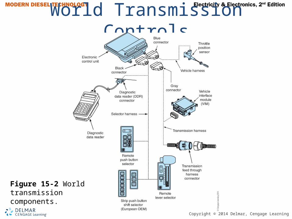
• WT Transmissions uses 3 reluctance type speed sensors: engine, turbine, and tail shaft
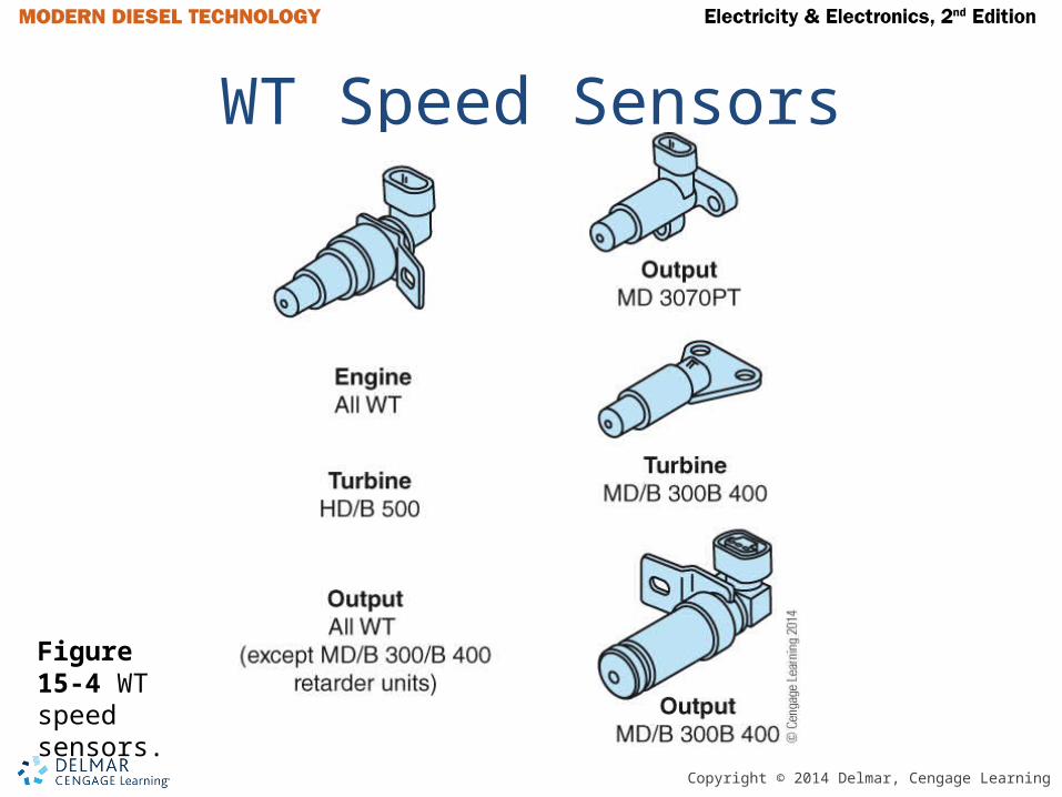
• There are two types of solenoids used: normally open and normally closed
• Allison Diagnostic Optimized Connection (DOCTM) troubleshooting software
• WT Generation 4 can display diagnostic trouble codes on digital display
Copyright © 2014 Delmar, Cengage Learning
WT Speed Sensors
Figure 15-4 WT speed sensors.
Copyright © 2014 Delmar, Cengage Learning
Figure 15-6 WT normally closed solenoid. Figure 15-7 WT normally open solenoid.
WT Solenoids
Copyright © 2014 Delmar, Cengage Learning
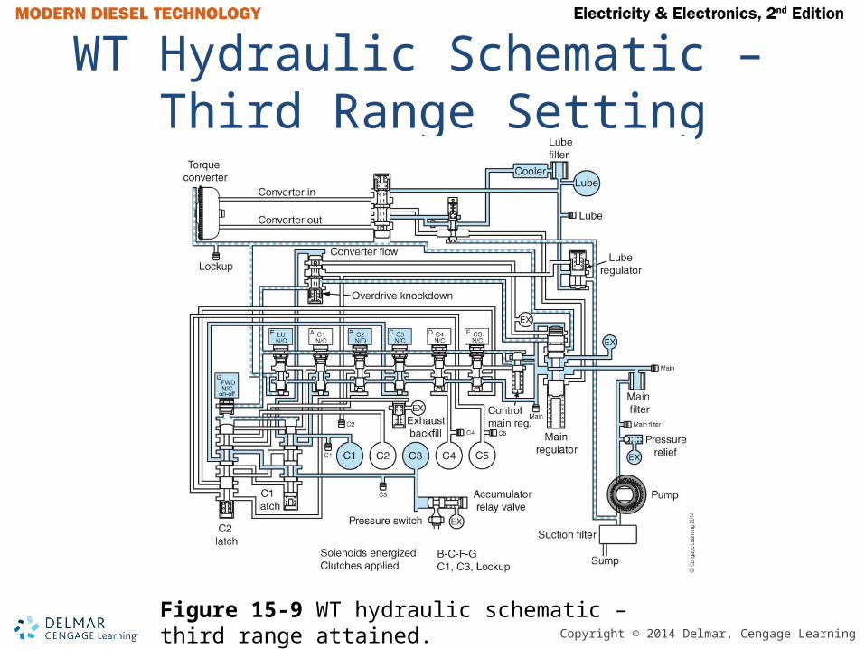
WT Hydraulic Schematic – Third Range Setting
Figure 15-9 WT hydraulic schematic – third range attained.
Copyright © 2014 Delmar, Cengage Learning
Automated Manual Transmissions
• AMT – Automated manual transmission• Manual transmission with automatic
control• One or two pedal system• Eaton Fuller is currently the most common• Driver interface and transmission ECU
communicate via private J1939 network called the EPL
Copyright © 2014 Delmar, Cengage Learning
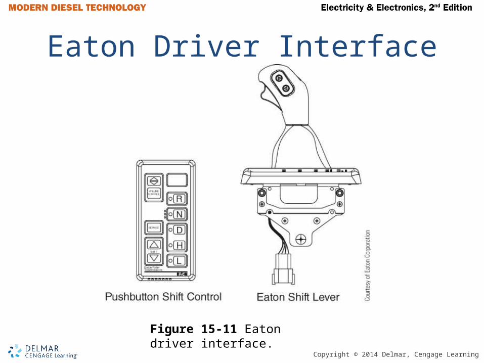
Eaton Driver Interface
Figure 15-11 Eaton driver interface.
Copyright © 2014 Delmar, Cengage Learning
Automated Manual Transmissions (continued)
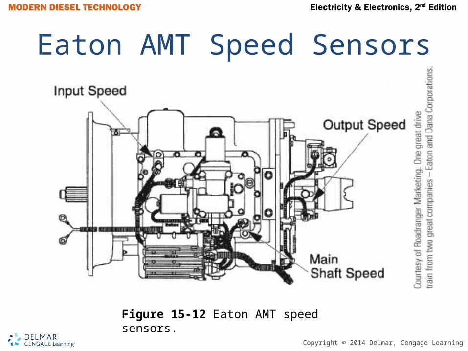
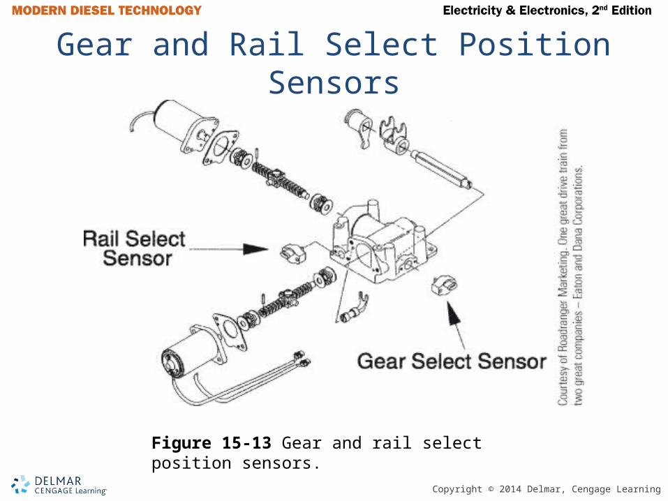
• Primary inputs to ECU are from three transmission mounted speed sensors and rail select and gear select position sensors
• Eaton AutoShift – Three pedal system• Eaton UltraShift – Two pedal system• Eaton ServiceRanger™ is a PC-based
EST used to diagnose an Eaton AMT
Copyright © 2014 Delmar, Cengage Learning
Eaton AMT Speed Sensors
Figure 15-12 Eaton AMT speed sensors.
Copyright © 2014 Delmar, Cengage Learning
Gear and Rail Select Position Sensors
Figure 15-13 Gear and rail select position sensors.

Copyright © 2014 Delmar, Cengage Learning
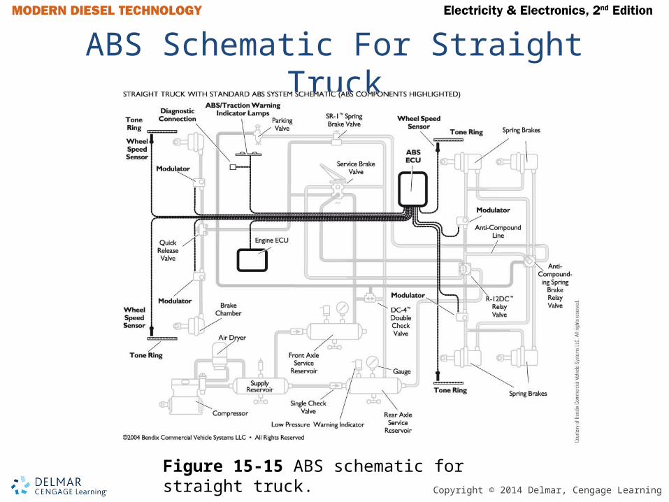
Antilock Brake System
• Reluctance-type speed sensors on both front and at least two rear wheels on a tandem axle tractor
• Typical ABS tone wheel has 100 teeth• The ABS ECU measures the frequency of the
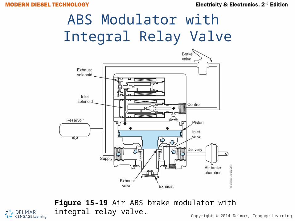
waveform produced• ABS modulators control air flow to service
brake chambers to prevent brake lock up• Modulators are designed to revert to non-ABS
in the event of failure
Copyright © 2014 Delmar, Cengage Learning
ABS Schematic For Straight Truck
Figure 15-15 ABS schematic for straight truck.

Copyright © 2014 Delmar, Cengage Learning
Four Channel ABS With ATC
Figure 15-18 Four-channel ABS with ATC.
Copyright © 2014 Delmar, Cengage Learning
ABS Modulator with Integral Relay Valve
Figure 15-19 Air ABS brake modulator with integral relay valve.
Copyright © 2014 Delmar, Cengage Learning
Antilock Brake System (continued)
• A chuff test is a brief actuation of the modulation coil at start up
• A drive axle event can trigger a signal to the transmission and engine ECU or a signal on the J1939 data link
• Automatic traction control (ATC) will limit wheel slip under acceleration
Copyright © 2014 Delmar, Cengage Learning
WARNING
Differential braking can cause a truck to drive off a jack stand if only one drive axle wheel end is lifted off the ground and the driveline is operated. Traction control must also be disabled if truck is operated on a dyno.
Copyright © 2014 Delmar, Cengage Learning
Advanced ABS Features
• Steering wheel angle sensor• Air application pressure sensor• Air suspension pressure sensor • Yaw rate sensor• Lateral acceleration sensor• VORAD – Vehicle onboard radar
Copyright © 2014 Delmar, Cengage Learning
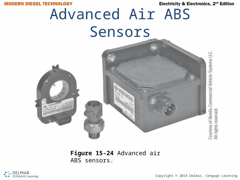
Advanced Air ABS Sensors
Figure 15-24 Advanced air ABS sensors.
Copyright © 2014 Delmar, Cengage Learning
ABS Warning Lamp
• FMVSS 121 requires an amber-colored ABS warning lamp in clear view of the operator
• Three methods of controlling ABS warning lamp:1) Direct control by ECU
2) Control by fail safe relay
3) Controlled by J1939 data link with a J1939 multiplexed IPC

Copyright © 2014 Delmar, Cengage Learning
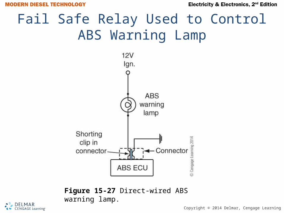
Direct-Wired ABS Warning Lamp
Figure 15-27 Direct-wired ABS warning lamp.
Copyright © 2014 Delmar, Cengage Learning
Fail Safe Relay Used to Control ABS Warning Lamp
Figure 15-27 Direct-wired ABS warning lamp.
Copyright © 2014 Delmar, Cengage Learning
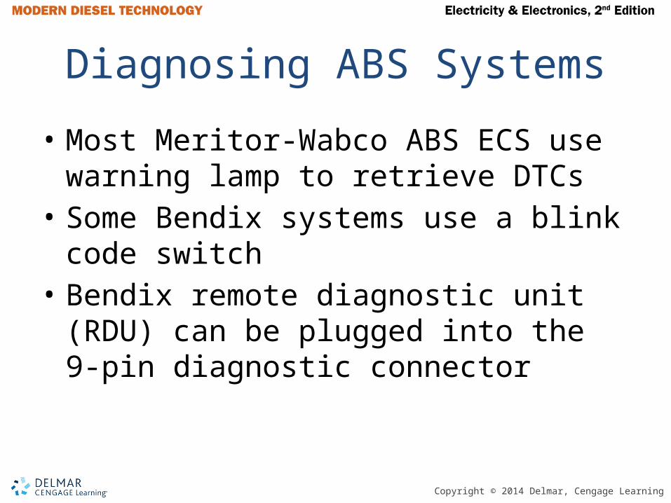
Diagnosing ABS Systems
• Most Meritor-Wabco ABS ECS use warning lamp to retrieve DTCs
• Some Bendix systems use a blink code switch
• Bendix remote diagnostic unit (RDU) can be plugged into the 9-pin diagnostic connector
Copyright © 2014 Delmar, Cengage Learning
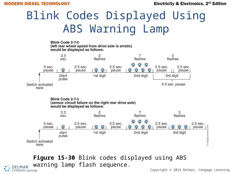
Blink Codes Displayed Using ABS Warning Lamp
Figure 15-30 Blink codes displayed using ABS warning lamp flash sequence.

Copyright © 2014 Delmar, Cengage Learning
Bendix RDU
Figure 15-31 Bendix remote diagnostic unit (RDU).
Copyright © 2014 Delmar, Cengage Learning
Trailer ABS
• All trailers built after March 1, 1989 are required to have ABS
• Power to the trailer ABS is provided through pin 7 of the J560 trailer socket
• Trucks and trailer built after March 1, 2001 are required to have a trailer ABS warning lamp on ICP of truck
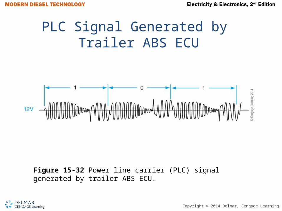
• PLC – Power line carrier
Copyright © 2014 Delmar, Cengage Learning
PLC Signal Generated by Trailer ABS ECU
Figure 15-32 Power line carrier (PLC) signal generated by trailer ABS ECU.

Copyright © 2014 Delmar, Cengage Learning
Tech Tip
A problem with the trailer ABS power supply circuit may cause the trailer ABS warning lamps to flash when the service or trailer brakes are applied.

Copyright © 2014 Delmar, Cengage Learning
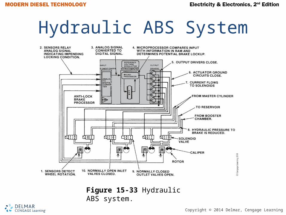
Hydraulic ABS Systems
• Required on all trucks built after March 1, 1999
• Functions similar to air ABS systems • Hydraulic fluid is returned to the reservoir
during an ABS event
Copyright © 2014 Delmar, Cengage Learning
Hydraulic ABS System
Figure 15-33 Hydraulic ABS system.
Copyright © 2014 Delmar, Cengage Learning
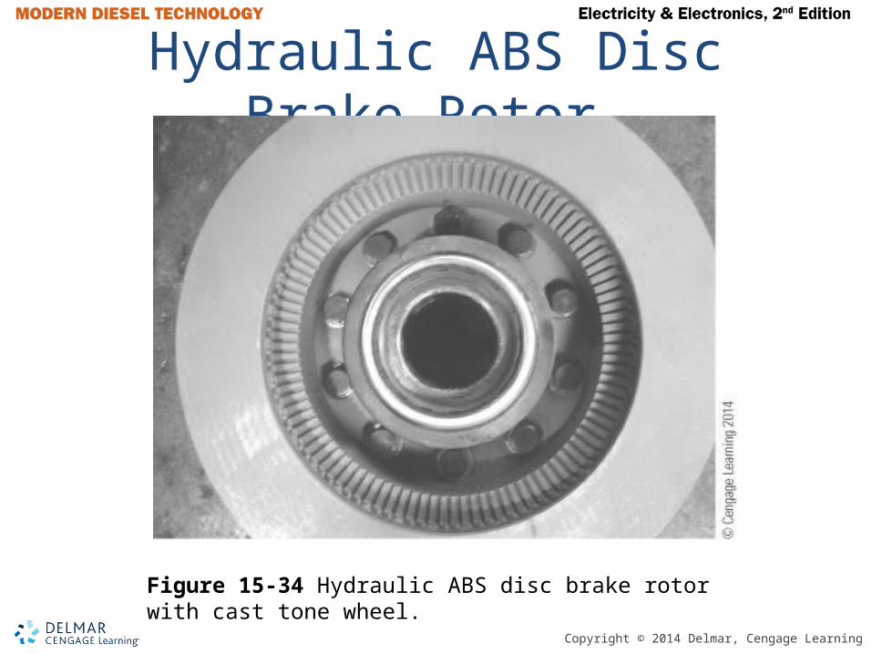
Hydraulic ABS Disc Brake Rotor
Figure 15-34 Hydraulic ABS disc brake rotor with cast tone wheel.

Copyright © 2014 Delmar, Cengage Learning
Hydraulic Power Brakes
• Uses two electric pump motors to charge gas filled accumulators with brake fluid under pressure
• HCU – Hydraulic compact unit• The HPB system is connected to the J1939
data link• Accumulator pressure is maintained at
approximately 2320 psi• If pressure drops below 1523 a low pressure
lamp illuminates
Copyright © 2014 Delmar, Cengage Learning
WARNING
Never attempt to drive a vehicle with HPB that has the brake warning lamp illuminated. You may not be able to stop the vehicle.
Copyright © 2014 Delmar, Cengage Learning
Hydraulic Power Brakes (continued)
• Ignition off, vehicle not moving, service brakes released, unit will go into sleep mode
• If ignition is turned on or brake pressed, system will wake and control pump motors as needed
• SAHR – Spring-applied hydraulically released parking brake
• Meritor-WABCO Toolbox™ is the EST used to diagnose the HPB system

Copyright © 2014 Delmar, Cengage Learning
WABCO HPB SAHR Park Brake
Figure 15-35 Wabco HPB spring-apply hydraulic-release (SAHR) park brake.

Copyright © 2014 Delmar, Cengage Learning
Twisted Wiring for ABS Speed Sensors and Modulators
Figure 15-36 Twisted wiring for ABS wheel-speed sensors and modulators.
Copyright © 2014 Delmar, Cengage Learning
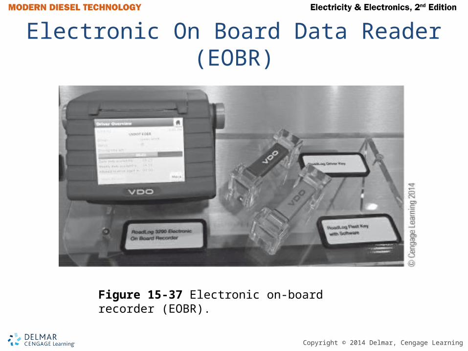
Electronic On Board Data Reader (EOBR)
Figure 15-37 Electronic on-board recorder (EOBR).
Copyright © 2014 Delmar, Cengage Learning
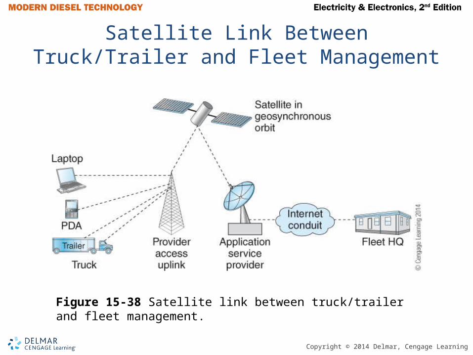
Satellite Link Between Truck/Trailer and Fleet Management
Figure 15-38 Satellite link between truck/trailer and fleet management.
Copyright © 2014 Delmar, Cengage Learning
Hybrid Electric Trucks
• Parallel System – Internal combustion engine is supplemented by electric motor
• Series System – Truck is propelled only by electric motor and internal combustion engine charges batteries
• A three-phase motor/generator is used to propel vehicle and charge batteries
• A battery bank with up to 340V DC power and inverter producing up to 500V AC

Copyright © 2014 Delmar, Cengage Learning
WARNING
Lethal voltage levels are used in hybrid electric systems. You should not attempt to work on the high-voltage components of an HEV until you have had proper training and have all of the proper protective equipment including insulated gloves. High-voltage wiring is identified by orange-colored insulation. Never splice into this high-voltage wiring.

Copyright © 2014 Delmar, Cengage Learning
Online Service Information Systems (SYS)
• Caterpillar Service Information System• Cummins QuickServe Online• Mack Trucks Electrical Information System• Navistar Service Information• Paccar DAVIE and ServiceNet• Volvo IMPACT

Copyright © 2014 Delmar, Cengage Learning
J1939 Bus Type Network
Figure 15-42 J1939 bus-type network.
Copyright © 2014 Delmar, Cengage Learning
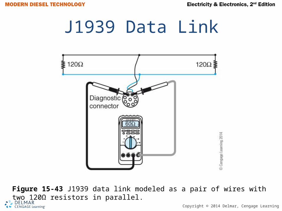
J1939 Data Link
Figure 15-43 J1939 data link modeled as a pair of wires with two 120Ω resistors in parallel.
Copyright © 2014 Delmar, Cengage Learning
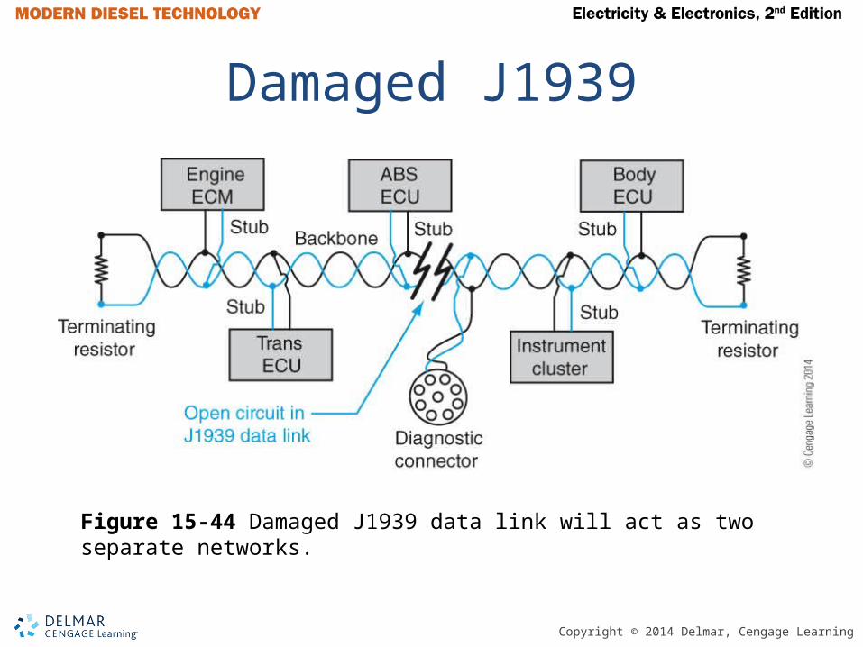
Damaged J1939
Figure 15-44 Damaged J1939 data link will act as two separate networks.

Copyright © 2014 Delmar, Cengage Learning
Summary
• Allison electronic automatic transmissions use three variable reluctance speed sensors to measure engine, turbine, and output speeds. The transmission ECU controls a series of normally open and closed solenoids using PWM. These solenoids control the flow of transmission fluid to apply clutches for specific ranges.
Copyright © 2014 Delmar, Cengage Learning
Summary (continued)
• Eaton automated manual transmissions (AMTs) use two electric motors to activate the shift mechanism. AMTs are divided into two- and three-pedal systems, indicating if the clutch is controlled by the operator or the transmission ECU. Inputs to the ECU include three speed sensors and rail and gear select positions.
Copyright © 2014 Delmar, Cengage Learning
Summary (continued)• Air ABS systems use wheel-speed sensors to
determine if a wheel lock up is occurring or is about to occur. The ABS ECU then controls modulators to block air flowing to the brake chambers and exhaust air out of the brake chambers to prevent wheel lock up.
• Testing wheel-speed sensors and the associated circuits may involve raising each wheel end and rotating the wheel by hand while watching for the amplitude of the AC voltage that is generated by the variable reluctance sensor.
Copyright © 2014 Delmar, Cengage Learning
Summary (continued)
• Trailer air ABS ECUs on modern trucks use the power line carrier technique to signal the truck or tractor ABS ECS that a trailer ABS fault is active. A variable frequency signal is placed onto the 12V power supply by the trailer ABS ECU. This signal is detected by the truck ABS ECU in its 12V power supply, causing the truck ABS ECU to energize the trailer ABS warning lamp on the truck’s instrument panel.
Copyright © 2014 Delmar, Cengage Learning
Summary (continued)• Electronic on-board recorders (EOBRs) are
electronic truck operator log books designed to record the hours of service (HOS) for each truck operator.
• In a parallel hybrid system, a diesel engine and electric motor/generator are coupled together. The electric motor is used to supplement the diesel engine. In a series hybrid system, the electric motor alone is used to propel and the engine is used as a generator for the electric motor. A dual-mode hybrid system acts as a series hybrid system during acceleration and a parallel hybrid system at higher speeds.
Related Documents