Copper in Electrical Contacts

Welcome message from author
This document is posted to help you gain knowledge. Please leave a comment to let me know what you think about it! Share it to your friends and learn new things together.
Transcript

Copper in Electrical Contacts
2 | COPPER IN ELECTRICAL CONTACTS
Copper in Electrical ContactsDavid Chapman
Copper Development Association is a non-trading organisation that promotes and supports the use of copper based on its superior technical performance and its contribution to a higher quality of life. Its services, which include the provision of technical advice and information, are available to those interested in the utilisation of copper and copper alloys in all their aspects. The Association also provides a link between research and the user industries and is part of an international network of trade associations, the Copper Alliance™.
Founded in 1996, ECI is a joint venture between the International Copper Association, Ltd (ICA), headquartered in New York, representing the majority of the world’s leading mining companies, custom smelters and semi-fabricators, and the European copper industry. ECI is also part of the Copper Alliance, an international network of industry associations. Its shared mission is to work, with its members, to defend and grow markets for copper based on its superior technical performance and contributions to a higher quality of life.
David ChapmanDavid Chapman was the Electrical Programme Manager for Copper Development Association in the UK, where his main interests included power quality and energy efficiency. He was an author and Chief Editor of the LPQI Power Quality Application Guide.
Cover page picture acknowledgments (from left to right):Electrical energy substation in a power plant(Courtesy mmmx/Shutterstock.com) Copper bus in an industrial power case(Courtesy Kalabi Yau/Shutterstock.com) CAN 9 (9 pin) connectors on a printed circuit board(Courtesy Jan Jirous/Shutterstock.com)
Copper Development Association Publication No 223 European Copper Institute Publication No Cu0169 July 2015
This publication is a revision by David Chapman of CDA Technical Note TN23 issued in December 1980. This was an edited version of an original script commissioned by Copper Development Association from H W Turner and C Turner of ERA Technology Ltd, Leatherhead Surrey.
DisclaimerWhile this publication has been prepared with care, Copper Development Association, European Copper Institute and other contributors provide no warranty with regards to the content and shall not be liable for any direct, incidental or consequential damages that may result from the use of the information or the data contained.
Copyright© Copper Development Association and European Copper Institute.

COPPER IN ELECTRICAL CONTACTS | 3
Contents
1.0 Introduction .............................................. 4
2.0 The Contact Interface .............................. 52.1 Contact Resistance ................................................................... 5
2.2 A-Spot Temperature ................................................................. 6
2.3 Degradation Mechanisms ...................................................... 7
2.3.1 Oxidation and Corrosion ......................................... 7
2.4 Fretting .......................................................................................... 7
2.4.1 Creep ............................................................................... 8
2.4.2 Stress Relaxation ........................................................ 8
3.0 Types of Contacts and their Applications .................................... 9
3.1 Arcing Contacts .......................................................................... 9
3.1.1 Making the Contact .................................................. 9
3.1.2 Breaking the Contact ................................................ 9
3.1.3 Welding ........................................................................ 11
3.1.4 Material Requirements for Arcing Contacts ........................................................ 11
3.2 Demountable Contacts .........................................................13
3.2.1 High Power Applications .......................................13
3.2.2 Low Power Applications ........................................13
3.2.3 Signal and Control Applications ........................15
3.3 Fixed Contacts ..........................................................................18
3.3.1 Crimped Connections .............................................18
3.3.2 Bolted Connections .................................................18
3.4 Sliding Contacts .......................................................................19
4.0 Materials for Contacts and Contact Assemblies ............................................... 20
4.1 Copper ..........................................................................................20
4.2 Copper Alloys ............................................................................20
4.2.1 Silver-bearing Copper ............................................20
4.2.2 Silver-copper ..............................................................21
4.2.3 Copper-beryllium .....................................................21
4.2.4 Copper-cadmium .....................................................21
4.2.5 Copper-cadmium-tin .............................................21
4.2.6 Copper-chromium ...................................................21
4.2.7 Copper-nickel ............................................................22
4.2.8 Copper-nickel-zinc ..................................................22
4.2.9 Copper-sulphur .........................................................22
4.2.10 Copper-lead ................................................................22
4.2.11 Copper-palladium ....................................................22
4.2.12 Copper-gold ...............................................................22
4.2.13 Copper-silver-gold ..................................................22
4.2.14 Copper-tin ...................................................................22
4.2.15 Copper-tellurium ......................................................23
4.2.16 Copper-zirconium ....................................................23
4.2.17 Bronzes .........................................................................23
4.2.18 Brasses ..........................................................................23
4.2.19 Powder Metallurgy ..................................................23
4.3 Silver .............................................................................................24
4.3.1 Silver-palladium .......................................................24
4.3.2 Silver-copper ..............................................................25
4.3.3 Silver-nickel ................................................................25
4.3.4 Silver-cadmium .........................................................25
4.3.5 Silver-lithium-lanthanum ....................................25
4.4 Platinum ......................................................................................25
4.4.1 Platinum Alloys .........................................................25
4.5 Palladium ....................................................................................25
4.5.1 Palladium Alloys .......................................................25
4.6 Gold ...............................................................................................26
4.6.1 Gold Alloys ..................................................................26
4.7 Rhodium ......................................................................................26
4.8 Tungsten ......................................................................................26
5.0 Properties of Materials for Contact Applications ........................................... 27
4 | COPPER IN ELECTRICAL CONTACTS
Tables
Table 1 Properties Influenced by Addition of Selected Elements .......................................................................................... 24
Table 2 Chemical Symbols for Selected Elements.......................... 27
Table 3 Physical Properties of the Most Important Contact Materials (1 of 3) ......................................................................... 28
Table 4 Physical and Mechanical Properties of the Most Important Contact Materials (2 of 3) .................................. 29
Table 5 Physical Properties of the Most Important Contact Materials (3 of 3) ......................................................................... 30
Table 6 Physical Properties of Some Contact Metals at their Melting Points ............................................................................... 31
Table 7 Physical and Mechanical Properties of Silver-based Alloys ................................................................................................ 32
Table 8 Physical and Mechanical Properties of Gold-based Alloys ................................................................................................ 33
Table 9 Physical and Mechanical Properties of Platinum- and Palladium-based Alloys .................................................... 33
Table 10 Physical and Mechanical Properties of Copper-based (Carrier) Alloy Materials ............................................................ 34
Table 11 Physical and Mechanical Properties of Copper-based (Spring) Alloy Materials ............................................................ 34
Table 12 Physical and Mechanical Properties of Alloys for Low-current Contacts ................................................................ 35
Table 13 Physical and Mechanical Properties of Materials for Collectors and Collector Rings of Electrical Machines ......................................................................................... 36
Table 14 Typical Materials for Arcing Contacts ................................. 37
Table 15 Typical Materials for Non-arcing Contacts ....................... 37
1.0 Introduction
Copper has many advantages as a contact material and is present in nearly all electrical contact applications. In many cases, the contacts themselves, as well as the backing material, contact carrier, connections and terminals, are made of copper or copper alloys. Although some applications require precious metal contacts, for economy, the small contact tips are mounted on copper alloy carriers.
One of the great advantages of copper is that there is a wide selection of alloys available, combining excellent electrical properties with good mechanical properties.
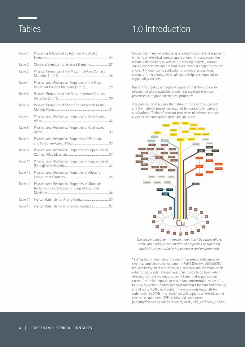
This publication discusses the nature of the electrical contact and the material properties required for contacts for various applications. Tables of relevant properties of selected contact alloys, carrier and spring materials* are given.
The copper alloy tree - there are more than 400 copper alloys, each with a unique combination of properties, to suit many applications, manufacturing processes and environments
* EU legislation restricting the use of hazardous substances in electrical and electronic equipment (RoHS Directive 2002/95/EC) requires heavy metals, such as lead, mercury and cadmium, to be substituted by safer alternatives. Care needs to be taken when selecting contact materials as some listed in this publication exceed the limits imposed (a maximum concentration value of up to 0.1% by weight in homogeneous materials for lead and mercury and of up to 0.01% by weight in homogeneous materials for cadmium). By 2019, this restriction will apply to all electrical and electronic equipment (EEE), cables and spare parts (see http://ec.europa.eu/environment/waste/rohs_eee/index_en.htm).
1.0 Introduction 2.0 The Contact Interface
This section presents a very brief introduction to some essential concepts. For further information, Electrical Contacts – Principles and Applications1 and Electrical Contacts – Fundamentals, Applications and Technology2 are recommended.
2.1 Contact Resistance
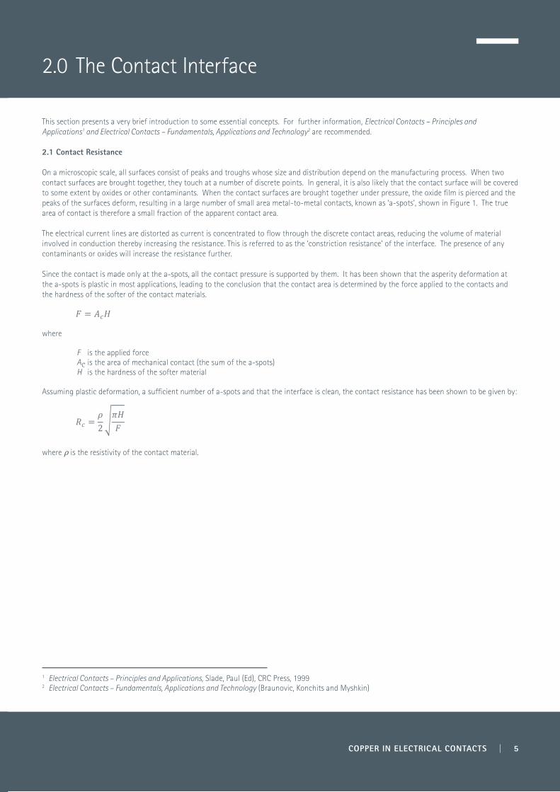
On a microscopic scale, all surfaces consist of peaks and troughs whose size and distribution depend on the manufacturing process. When two contact surfaces are brought together, they touch at a number of discrete points. In general, it is also likely that the contact surface will be covered to some extent by oxides or other contaminants. When the contact surfaces are brought together under pressure, the oxide film is pierced and the peaks of the surfaces deform, resulting in a large number of small area metal-to-metal contacts, known as ‘a-spots’, shown in Figure 1. The true area of contact is therefore a small fraction of the apparent contact area. The electrical current lines are distorted as current is concentrated to flow through the discrete contact areas, reducing the volume of material involved in conduction thereby increasing the resistance. This is referred to as the ‘constriction resistance’ of the interface. The presence of any contaminants or oxides will increase the resistance further.
Since the contact is made only at the a-spots, all the contact pressure is supported by them. It has been shown that the asperity deformation at the a-spots is plastic in most applications, leading to the conclusion that the contact area is determined by the force applied to the contacts and the hardness of the softer of the contact materials.
where
F is the applied forceAc is the area of mechanical contact (the sum of the a-spots)H is the hardness of the softer material
Assuming plastic deformation, a sufficient number of a-spots and that the interface is clean, the contact resistance has been shown to be given by:
where ρ is the resistivity of the contact material.
1 Electrical Contacts – Principles and Applications, Slade, Paul (Ed), CRC Press, 19992 Electrical Contacts – Fundamentals, Applications and Technology (Braunovic, Konchits and Myshkin)
COPPER IN ELECTRICAL CONTACTS | 5
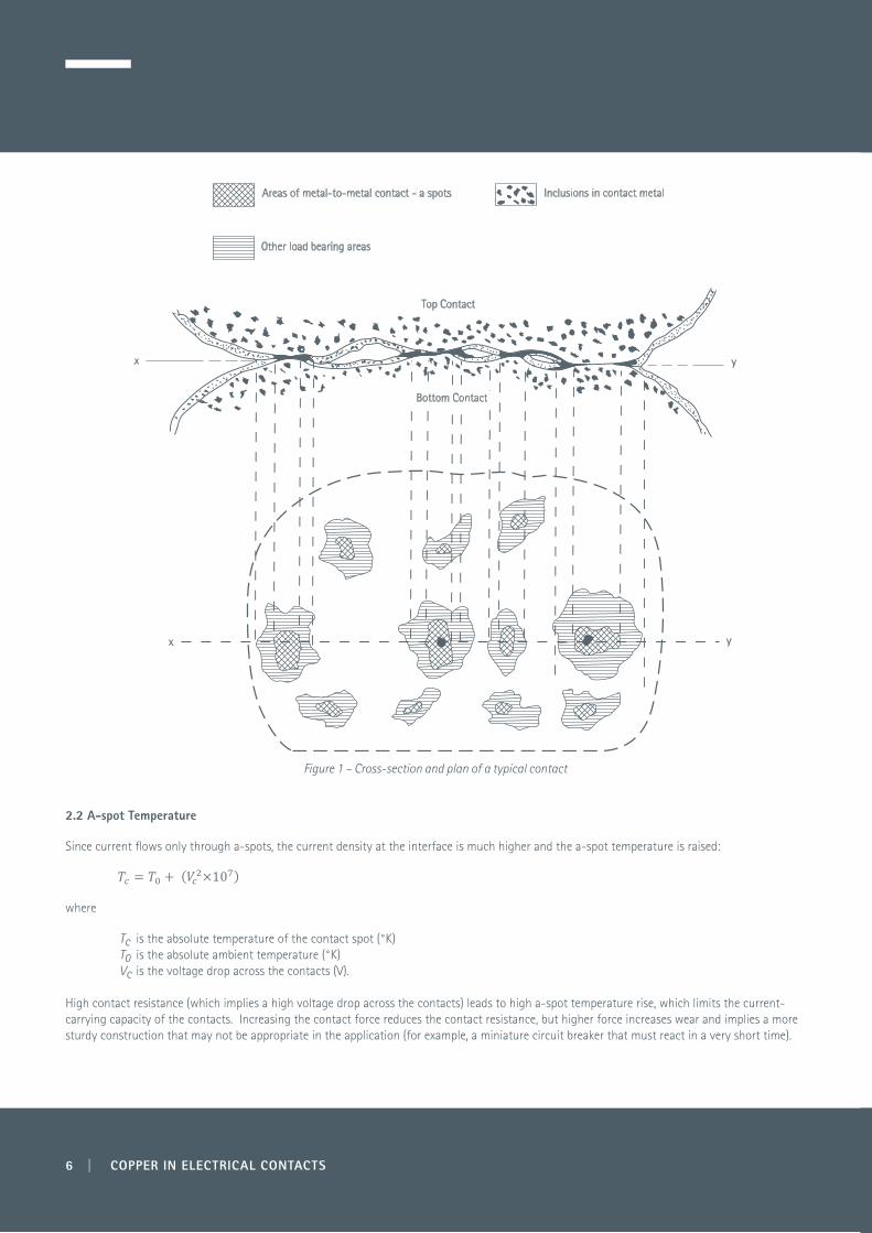
Figure 1 – Cross-section and plan of a typical contact
2.2 A-spot Temperature
Since current flows only through a-spots, the current density at the interface is much higher and the a-spot temperature is raised:
where
Tc is the absolute temperature of the contact spot (°K)T0 is the absolute ambient temperature (°K)Vc is the voltage drop across the contacts (V).
High contact resistance (which implies a high voltage drop across the contacts) leads to high a-spot temperature rise, which limits the current-carrying capacity of the contacts. Increasing the contact force reduces the contact resistance, but higher force increases wear and implies a more sturdy construction that may not be appropriate in the application (for example, a miniature circuit breaker that must react in a very short time).
Inclusions in contact metalAreas of metal-to-metal contact - a spots
Other load bearing areas
Top Contact
x
x
y
y
Bottom Contact
6 | COPPER IN ELECTRICAL CONTACTS
COPPER IN ELECTRICAL CONTACTS | 7
Contact resistance can be reduced by other means, such as the use of materials which produce good metallic contact with moderate contact force, or by designing the contact system in such a way that the contacts are wiped clean as they are brought together. The softness of copper and silver means that contacts faced with these materials need lower contact forces.
Contact lubricants can be used to protect contacts against external attack, but must be properly applied. In general they are effective on contacts which are not required to switch frequently at moderately high currents.
Copper contacts have the advantage that their relatively modest price permits them to be larger, so that higher contact forces can be used and larger wear can be tolerated. The a-spot temperature will also be lower, because the good thermal conductivity will dissipate the local heat to the mass of the contact.
2.3 Degradation Mechanisms
The deterioration of a well-designed connector proceeds relatively slowly at a rate determined by the nature of a number of different processes operating in the contact zone and in the environment. This initial stage persists for a long time without causing any noticeable changes because it is an intrinsic property of clusters of a-spots that their overall constriction resistance is not sensitive to small changes in their size. However, when the contact resistance increases sufficiently to raise the local temperature, a self-accelerating deterioration, resulting from the interaction of thermal, chemical, mechanical and electrical processes, will be triggered and the contact resistance will rise abruptly. Hence, no deterioration will be noticeable until the final stages of the connector life.
2.3.1 Oxidation and Corrosion
Oxidation is widely accepted as the most serious degradation mechanism occurring in mechanical connectors.
Corrosion is a chemical or electrochemical reaction between a metal component and the surrounding environment. It begins at an exposed metal surface with the formation of a corrosion product layer and continues as long as reactants can diffuse through the layer and sustain the reaction. The composition and characteristics of the corrosion product layer can significantly influence the corrosion rate. Corrosion can be caused by polluted atmospheres, or may be electrochemically accelerated by the use of dissimilar metals in the contact.
Oxide films and the products of corrosion on the contact surfaces reduce real contact area and increase contact resistance. The resultant increase in temperature in turn accelerates the rate of attack.
If contacts are designed to slide over each other (or wipe) when they are brought together, or if connectors are frequently plugged and unplugged, the contact will have a self-cleaning action which helps to reduce contamination at the expense of increased wear. Contact lubricants are useful in this case, providing they do not dissolve any aggressive pollutant to increase its surface attack.
Copper is not very active chemically so it oxidises very slowly in air at ordinary temperatures. However, copper contacts are affected by oxide films formed, for example, by arcing or by other causes which may lead to runaway oxidation. A silver coating usually solves this problem, but is itself subject to environmental attack, forming silver compounds, especially the sulphide, on the surface. However, these will tend to decompose under the heating action of a temporary high contact resistance, and restore the contact resistance again to a low level.
2.4 Fretting
Fretting is the accelerated surface damage occurring at the interface of contacting materials subjected to small oscillatory movements. Experimental evidence shows that amplitudes of <100 nm are sufficient to produce fretting.
There is still no complete unanimity on the mechanisms of fretting, specifically with regard to the relative importance of the processes involved. Nevertheless, based on the existing knowledge of the phenomenon, it can be safely assumed that the following processes are present:
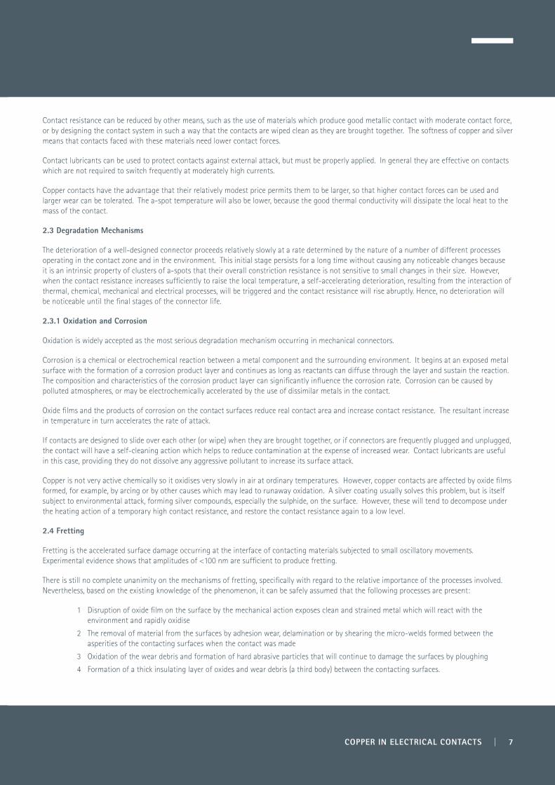
1 Disruption of oxide film on the surface by the mechanical action exposes clean and strained metal which will react with the environment and rapidly oxidise
2 The removal of material from the surfaces by adhesion wear, delamination or by shearing the micro-welds formed between the asperities of the contacting surfaces when the contact was made
3 Oxidation of the wear debris and formation of hard abrasive particles that will continue to damage the surfaces by ploughing
4 Formation of a thick insulating layer of oxides and wear debris (a third body) between the contacting surfaces.

The oscillatory movement of the contacting members can be produced by mechanical vibrations, differential thermal expansion, load relaxation and junction heating as the load is cycled. Because fretting is concerned with slip amplitudes not greater than 125 µm it is ineffective in clearing away the wear debris and accumulated oxides and a highly localised, thick insulating layer is formed in the contact zone, leading to a dramatic increase in contact resistance and, subsequently, to virtual open circuits.
2.4.1 Creep
Creep, or cold flow, occurs when metal is subjected to a constant external force over a period of time. It results in a dimensional change. The rate of creep depends on stress and temperature and is much higher for aluminium than for copper.
2.4.2 Stress Relaxation
Stress relaxation also depends on time, temperature and stress but, unlike creep, is not accompanied by dimensional changes. It occurs at high stress levels and is evidenced by a reduction in the contact pressure due to changes in metallurgical structure. It is important in the spring elements of contact assemblies because the change from elastic to plastic strain has the effect of significantly reducing the residual contact pressure in the contact, resulting in increased resistance, possibly to the point of failure.
All metals are subject to stress relaxation. However, copper alloys offer a wide range of stress relaxation resistance so it is important to select the alloy carefully.
In addition to cold deformation, there are three mechanisms by which alloys are strengthened:
1 Solid solution strengthened 2 Dispersion-strengthened 3 Precipitation-hardened.
The stress relaxation behaviour tends to be related to the strengthening mechanism. Cold deformation alone is ineffective because the effect is reversed by time and temperature.
Solid solution alloys are suitable only for low contact forces – higher forces require cold deformation, the effect of which will gradually reduce.
Dispersion-strengthened alloys have good resistance to relaxation but are capable of only intermediate strength. They are useful when low contact forces are required for use at elevated temperatures.
Precipitation-strengthened alloys are heat treated to increase their strength. Preferably, the heat treatment is the last stage of manufacturing of the part so that it is used in the unworked state, but parts can also be stamped from heat-treated strip. In the latter case, the part will be subject to some stress relaxation but the effect may be insignificant. Copper-beryllium, which is frequently used for small demountable contacts, is an example of a precipitation-strengthened alloy.
2.4.2.1 Thermal Expansion
The effect of temperature variation on contact pressure has already been discussed. Longitudinal expansion is also important since it can lead to slip in the joint followed by loosening. It is important that long bars are provided with a flexible element so that movement can take place elsewhere.
The following sections discuss various types of contacts and their requirements.
8 | COPPER IN ELECTRICAL CONTACTS

3.0 Types of Contacts and their Applications
The basic categories of contacts are:
• Arcing contact (make/break contacts) - which may make or break contact while under load • Non-arcing contacts (demountable contacts) - which are intended to make or break while off load • Fixed contacts - which may be clamped together permanently for years and never opened• Sliding contacts - which maintain contact during relative movement under load.
Although each of these types shares common characteristics, they each have different requirements according to the electrical and mechanical requirements.
3.1 Arcing Contacts
When contacts make or break currents above about 0.1 A and at voltages above a few volts, an arc will be initiated.
3.1.1 Making the Contact
If a voltage greater than the breakdown voltage is impressed across open contacts, the resulting electric field causes the emission of electrons from the cathode which are collected by the anode. The time for initiation of this current is ~4 µS for a voltage 1% above breakdown or 4 nS if the applied voltage is twice the breakdown voltage. Electron collisions cause ionisation of the gas in the contact gap and initiate the arc. The voltage required to maintain the arc reduces while the current rises rapidly. In practice, this occurs for all make/break contacts; as the contacts are brought together, breakdown will occur at some small separation. The time for which the arc burns is determined by the time taken for the contacts to move from the point at which the arc is initiated to the fully closed position. Even if the contacts are closing at 1 m/s and the arc initiates at a separation of 100 µm, the arc will burn for 100 µs.
3.1.2 Breaking the Contact
When current-carrying contacts are opened, the area of the a-spots decreases as the contact force is reduced so the voltage drop across the contacts increases. This results in an increase in the temperature at the a-spots which quickly exceeds the melting point of the contact surface. The voltage at which this occurs is called the melting voltage and is typically less than one volt (melting voltages for some contact materials are given in Table 3). As the contacts move apart, the molten metal forms a bridge which is drawn out until it becomes unstable and ruptures, releasing metal vapour into the contact gap. Thermal ionisation takes place due to both electron-atom and atom-atom collisions and an arc is rapidly formed. The process is shown in Figure 2.
The loss of material and the contact damage that results from the initiation of the arc is particularly important for devices which perform a large number of switching operations during their life, such as motor starters and control contacts.
Several factors influence the duration of the arc. In an a.c. circuit the current will pass through zero, giving an opportunity for the arc to be quenched. For this to be successful the conditions must be appropriate. In virtually all a.c. circuits the power factor will be less than unity so the voltage at the current zero will not be zero and may be near to the peak voltage. As the arc extinguishes at zero current the voltage across the contacts will rise to the instantaneous open circuit voltage (the transient recovery voltage, TRV) which is determined only by the circuit conditions.
Figure 2 - The process involved in opening a circuit by means of contacts
Two contactsat rest
carrying current
As contact pressure and contact area
decreases, contactis overheated to
the melting point
The contactsbegin to separate
and a molten bridge is drawn out
which then bursts,initiating arcing.
Arcing persists until the circult
is cleared
and the circuitbreaking process
is completed.
COPPER IN ELECTRICAL CONTACTS | 9
Immediately after the arc has extinguished the dielectric strength of the gap is comparatively low so the arc could be re-established were the voltage to exceed the re-ignition voltage. This is determined only by the contact gap parameters (arc current before zero current, gap length, contact material and arc chamber design). The recovery starts when the current falls to zero and the voltage reverses, creating a space charge at the new cathode. The next stage is the recombination of electrons and ions which reduces the conductance of the gas followed by cooling of the arc chamber. In a well-designed contact set the arc will quench at the first current zero.
In a d.c. circuit there is no natural current zero so it is necessary to design the break so that the arc voltage is greater than the transient system voltage, so creating a zero current condition within a few milliseconds. This principle is also used in current-limiting circuit breakers for a.c. circuits; these breakers are designed to limit the fault current to much less than the peak short-circuit current.
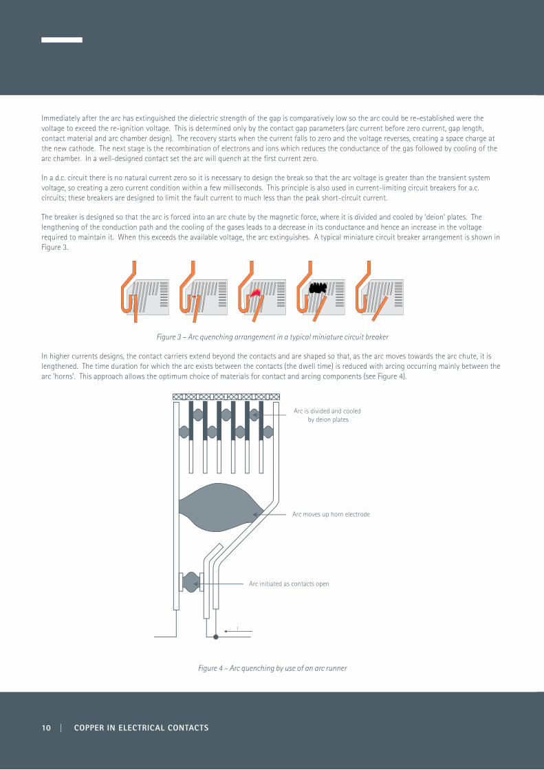
The breaker is designed so that the arc is forced into an arc chute by the magnetic force, where it is divided and cooled by ‘deion’ plates. The lengthening of the conduction path and the cooling of the gases leads to a decrease in its conductance and hence an increase in the voltage required to maintain it. When this exceeds the available voltage, the arc extinguishes. A typical miniature circuit breaker arrangement is shown in Figure 3.
Figure 3 – Arc quenching arrangement in a typical miniature circuit breaker
In higher currents designs, the contact carriers extend beyond the contacts and are shaped so that, as the arc moves towards the arc chute, it is lengthened. The time duration for which the arc exists between the contacts (the dwell time) is reduced with arcing occurring mainly between the arc ‘horns’. This approach allows the optimum choice of materials for contact and arcing components (see Figure 4).
Figure 4 – Arc quenching by use of an arc runner
Arc initiated as contacts open
I
Arc moves up horn electrode
Arc is divided and cooled by deion plates
10 | COPPER IN ELECTRICAL CONTACTS
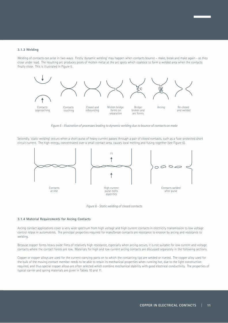
3.1.3 Welding Welding of contacts can arise in two ways. Firstly ‘dynamic welding’ may happen when contacts bounce – make, break and make again - as they close under load. The resulting arc produces pools of molten metal at the arc spots which coalesce to form a welded area when the contacts finally close. This is illustrated in Figure 5.
Figure 5 - Illustration of processes leading to dynamic welding due to bounce of contacts on make
Secondly, ‘static welding’ occurs when a short pulse of heavy current passes through a pair of closed contacts, such as a fuse-protected short circuit current. The high energy, concentrated over a small contact area, causes local melting and fusing together (see Figure 6).
Figure 6 - Static welding of closed contacts
3.1.4 Material Requirements for Arcing Contacts
Arcing contact applications cover a very wide spectrum from high voltage and high current contacts in electricity transmission to low voltage control relays in automobiles. The principal properties required for make/break contacts are resistance to erosion by arcing and resistance to welding.
Because copper forms heavy oxide films of relatively high resistance, especially when arcing occurs, it is not suitable for low current and voltage contacts where the contact forces are low. Materials for high and low current arcing contacts are discussed separately in the following sections.
Copper or copper alloys are used for the current-carrying parts on to which the contacting tips are welded or riveted. The copper alloy used for the bulk of the moving contact member needs to be able to retain its mechanical properties when running hot, due to the light construction required, and thus special copper alloys are often selected which combine mechanical stability with good electrical conductivity. The properties of typical carrier and spring materials are given in Tables 10 and 11.
Contacts approaching
Contacts touching
Closed andrebounding
Molten bridge forms on
separation
Bridgebroken andarc forms
Arcing Re-closed and welded
Contactsat rest
High currentpulse meltsasperities
Contacts weldedafter pulse
I2t
COPPER IN ELECTRICAL CONTACTS | 11
3.1.4.1 High Current Contacts
Copper can be used for high current contacts because the friable oxides are cleared from the contact area by the higher contact force and by the arcing that occurs on make/break operations under load. Additionally, high voltages can break down the oxide film. However, the welding and erosion performance must be taken into account. High current, high voltage circuit breaker contacts are contained within special arcing chambers which may be in air at normal pressure, in a blast of air, in vacuum or in oil or other arc extinguishing medium. Typically, the large moving contact is often a massive rod of copper while the fixed contact is a ring of sprung copper contact fingers. The contacts may be tipped with arc-resistant material to reduce erosion by the arc, and the surfaces may be plated (e.g. with silver) to improve the performance of the stationary contact. The mechanical properties of copper, combined with its excellent electrical conductivity and good arcing endurance under oil, have made it the principal metal in this application. The large size of these devices makes it easy to provide high breaking forces to ensure that contacts separate properly.
When contacts remain closed for long periods in air, the growth of oxide on copper contacts can become excessive and lead to overheating, sometimes followed by complete loss of contact. If sustained arcing at low current is initiated, runaway oxide growth can penetrate deep into the contacts. Silver facing of copper contacts prevents oxidation troubles in such a case.
The effect of surface layers can be overcome for air-break contactors by, for instance, introducing a sliding and rolling action of the contacts, or by high contact force. This increases mechanical wear, and implies that pure copper contacts would need to be larger than electrically necessary, in order to accommodate this wear.
Static and dynamic welding of copper contacts is discouraged to a certain extent by the existence of oxide layers dependent on the contact force. The threshold of static welding is of the order of 4 kA at 100 N contact force, with a weld strength of 330 N/mm2, while the threshold of dynamic welding lies at about 50 A for 25 N contact force, with a weld strength of the order of grammes. Weld strength rises with current, until at 200 A it is approximately 100 N/mm2, measured by direct pull. A ‘knuckling’ action is needed to assist the breaking of welds in copper contacts. The lower strength of the dynamic weld of a given area is thought to be due to imperfections (e.g. inclusions of air or oxide) in the welded area.
Erosion of contact material due to arcing is very important. The relation between rate of wear (in microgrammes/sec) and arc current (in amperes), valid between 5 A and 800 A, is of the form:
in which k =2.4 for copper.
This relationship applies only at currents at which bulk melting of the material and spraying of droplets does not occur. Above 800 A (the ‘discontinuous erosion current’), where bulk melting occurs, a similar power law is followed but with a numerical erosion factor (k) of 36.
In contactors for d.c. use, the erosion of the two contacts may be quite different. Although the transfer of material is generally from the anode, this is not the case for all values of current; in fact the transfer of metal by the arc has a number of regions dependent on the mode of arcing, and the formation of jets from anode and cathode. For copper, at a current between 10 and 300 A in air, the transfer is from cathode to anode and the rate of transfer is approximately proportional to a power function of the arcing current:
At approximately 300 A the transfer is such that the anode keeps constant weight, and above this current it increases in weight. This kind of arc transfer is a different phenomenon from the 'fine transfer' occurring in relay contacts at low currents, which is due to the rupture of metallic bridges, and is generally from anode to cathode.
Smaller air-break (medium voltage) circuit breakers use copper in all internal conducting parts but the contacts are often faced with a silver-based alloy to resist welding. Such circuit breakers rarely open and close, being protective devices.
3.1.4.2 Low Voltage Contacts
In low voltage circuit breakers (moulded case breakers) dissimilar pairs of contacts are sometimes used, in which one side is copper or copper alloy, while the other is a small silver-alloy contact mounted on copper carriers. Table 12 gives the properties of typical contact materials.
12 | COPPER IN ELECTRICAL CONTACTS
COPPER IN ELECTRICAL CONTACTS | 13
Control switches and relays break low voltages and currents. At the lowest end of the scale this is sometimes referred to as ‘dry circuit conditions’, because the voltage being switched is below the ‘melting voltage’ of the contact material. For making and breaking such voltages and currents it is usual to face the contacts with noble metals to reduce contact resistance. The bulk of the contact is made of copper alloy, which gives the required good conductivity at low cost, and has the appropriate mechanical properties for the contact member to also act as a spring to maintain the contact force between the fixed and moving contacts. Phosphor bronze and copper-beryllium are frequently used in such cases.
3.2 Demountable Contacts
Demountable contacts are not intended to make or break the connection under load and so are not subject to arcing. Many demountable connections remain in place for years without being disturbed – for example inter-board connections within electronic equipment – while others – such as a mobile phone charging socket - may be cycled very frequently. Good resistance to stress relaxation is important for this class of contacts.
Examples of demountable connectors for power, signal and control applications can be loosely categorised as including:
• High power applications, e.g isolators (non-load breaking), off-load tap changers, power plugs and sockets • Low power applications, e.g. harness connectors, multi-way plugs and sockets, module-rack connectors, bulkhead connectors• Signal and control applications, e.g. cable connectors, edge connectors on printed circuit boards, insulation displacement connectors.
3.2.1 High Power Applications
This class of contacts may be carrying high currents at high voltages (e.g. high voltage isolators or high voltage or medium voltage fuse contacts). They have to carry current reliably for long periods, without overheating or loss of contact, but do not make or break current. They are not subjected to the duress of arcing and hence do not get the inherent cleaning action associated with it. They are frequently designed to have some frictional action on closing to remove superficial oxide or corrosion films which might impede contact. Copper and its alloys, with or without plating, are the most frequently used materials for the bulk of demountable contacts.
3.2.2 Low Power Applications
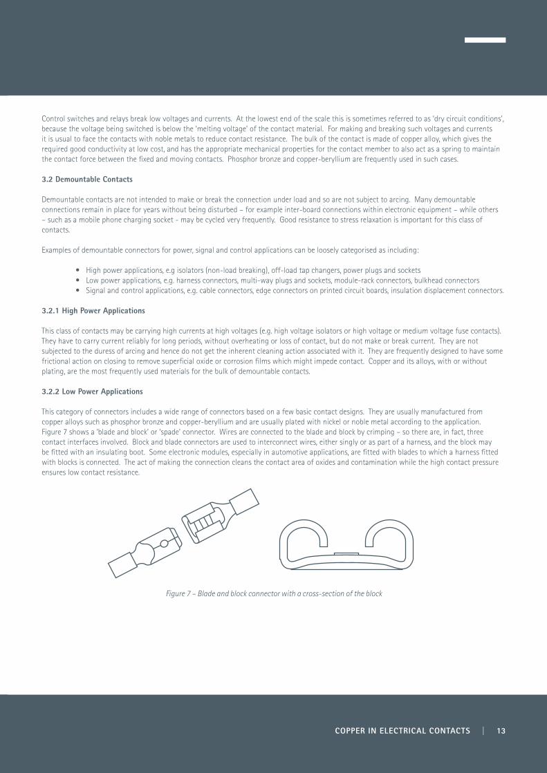
This category of connectors includes a wide range of connectors based on a few basic contact designs. They are usually manufactured from copper alloys such as phosphor bronze and copper-beryllium and are usually plated with nickel or noble metal according to the application. Figure 7 shows a ‘blade and block’ or ‘spade’ connector. Wires are connected to the blade and block by crimping – so there are, in fact, three contact interfaces involved. Block and blade connectors are used to interconnect wires, either singly or as part of a harness, and the block may be fitted with an insulating boot. Some electronic modules, especially in automotive applications, are fitted with blades to which a harness fitted with blocks is connected. The act of making the connection cleans the contact area of oxides and contamination while the high contact pressure ensures low contact resistance.
Figure 7 – Blade and block connector with a cross-section of the block
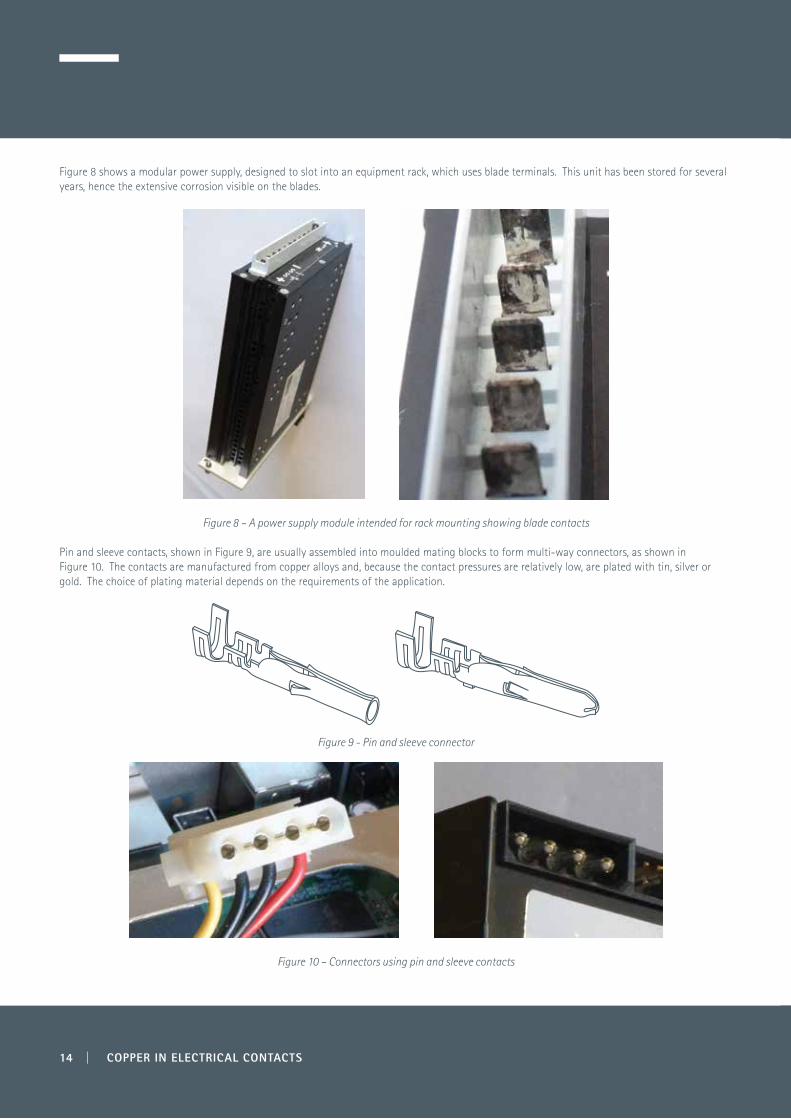
Figure 8 shows a modular power supply, designed to slot into an equipment rack, which uses blade terminals. This unit has been stored for several years, hence the extensive corrosion visible on the blades.
Figure 8 – A power supply module intended for rack mounting showing blade contacts
Pin and sleeve contacts, shown in Figure 9, are usually assembled into moulded mating blocks to form multi-way connectors, as shown in Figure 10. The contacts are manufactured from copper alloys and, because the contact pressures are relatively low, are plated with tin, silver or gold. The choice of plating material depends on the requirements of the application.
Figure 9 - Pin and sleeve connector
Figure 10 – Connectors using pin and sleeve contacts
14 | COPPER IN ELECTRICAL CONTACTS

Figure 11 shows a screw terminal block intended for terminating individual wires to a printed circuit board. The wire is clamped into the barrel by a flat contact spring which is pressed by a small screw. They are usually made from copper alloy and often tin plated. High contact pressure ensures that contact resistance is low, but thermal cycling may result in the screw torque reducing and the contact becoming loose.
Figure 11 – A screw terminal block intended for PCB mounting
3.2.3 Signal and Control Applications
Connectors of this type generally carry very small voltages and currents. They are often embedded within equipment and may remain mated and undisturbed for the lifetime of the equipment. Although there is a very wide variety of design of connectors, they follow very similar principles.
Generally, a solid, non-deformable member is introduced into a deformable receptacle made of a copper alloy spring material, such as phosphor bronze or copper-beryllium. The deformation of the receptacle provides the contact force that ensures low contact resistance for the life of the contact. The requirement to deform the receptacle means that a certain ‘insertion force’ is required to mate the connector, particularly for those with many poles. Often the contact force is sufficient to maintain the connector in the mated position and no special retention measures are needed. Since the connectors are rarely disturbed there is no wiping action so it is very important that the contact surfaces are plated (or selectively plated at the contact surface), normally with a noble metal over a nickel under-plate.
Figure 12 shows a printed circuit board (PCB) with gold-plated copper contacts on the lower edge and the corresponding female connector on the upper edge. This is typical of the connectors used to connect extension boards to motherboards in personal computers and other electronic equipment.
Figure 12 – A PCB riser board from a desktop PC with a detail of the female connector
COPPER IN ELECTRICAL CONTACTS | 15
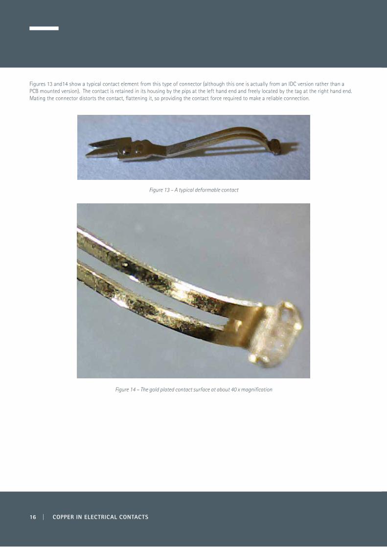
Figures 13 and14 show a typical contact element from this type of connector (although this one is actually from an IDC version rather than a PCB mounted version). The contact is retained in its housing by the pips at the left hand end and freely located by the tag at the right hand end. Mating the connector distorts the contact, flattening it, so providing the contact force required to make a reliable connection.
Figure 13 – A typical deformable contact
Figure 14 – The gold plated contact surface at about 40 x magnification
16 | COPPER IN ELECTRICAL CONTACTS
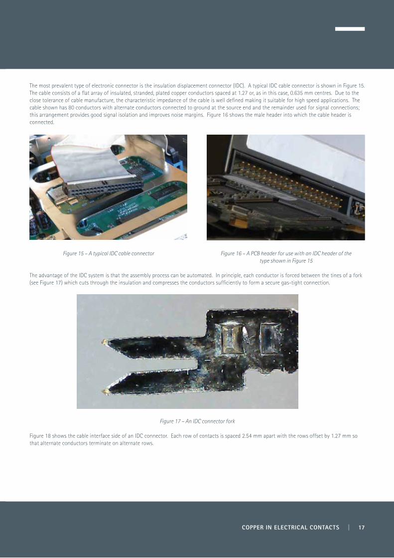
The most prevalent type of electronic connector is the insulation displacement connector (IDC). A typical IDC cable connector is shown in Figure 15. The cable consists of a flat array of insulated, stranded, plated copper conductors spaced at 1.27 or, as in this case, 0.635 mm centres. Due to the close tolerance of cable manufacture, the characteristic impedance of the cable is well defined making it suitable for high speed applications. The cable shown has 80 conductors with alternate conductors connected to ground at the source end and the remainder used for signal connections; this arrangement provides good signal isolation and improves noise margins. Figure 16 shows the male header into which the cable header is connected.
Figure 15 – A typical IDC cable connector Figure 16 – A PCB header for use with an IDC header of the type shown in Figure 15
The advantage of the IDC system is that the assembly process can be automated. In principle, each conductor is forced between the tines of a fork (see Figure 17) which cuts through the insulation and compresses the conductors sufficiently to form a secure gas-tight connection.
Figure 17 – An IDC connector fork
Figure 18 shows the cable interface side of an IDC connector. Each row of contacts is spaced 2.54 mm apart with the rows offset by 1.27 mm so that alternate conductors terminate on alternate rows.
COPPER IN ELECTRICAL CONTACTS | 17
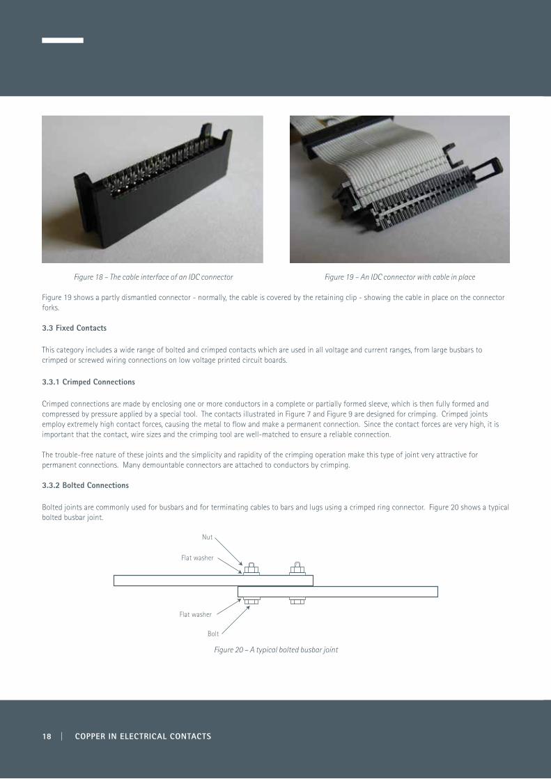
Figure 18 – The cable interface of an IDC connector Figure 19 – An IDC connector with cable in place
Figure 19 shows a partly dismantled connector - normally, the cable is covered by the retaining clip - showing the cable in place on the connector forks. 3.3 Fixed Contacts
This category includes a wide range of bolted and crimped contacts which are used in all voltage and current ranges, from large busbars to crimped or screwed wiring connections on low voltage printed circuit boards.
3.3.1 Crimped Connections
Crimped connections are made by enclosing one or more conductors in a complete or partially formed sleeve, which is then fully formed and compressed by pressure applied by a special tool. The contacts illustrated in Figure 7 and Figure 9 are designed for crimping. Crimped joints employ extremely high contact forces, causing the metal to flow and make a permanent connection. Since the contact forces are very high, it is important that the contact, wire sizes and the crimping tool are well-matched to ensure a reliable connection. The trouble-free nature of these joints and the simplicity and rapidity of the crimping operation make this type of joint very attractive for permanent connections. Many demountable connectors are attached to conductors by crimping.
3.3.2 Bolted Connections
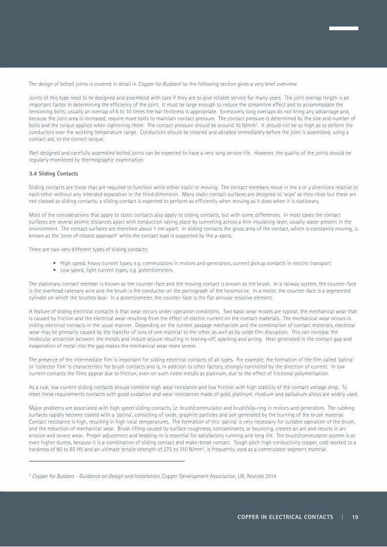
Bolted joints are commonly used for busbars and for terminating cables to bars and lugs using a crimped ring connector. Figure 20 shows a typical bolted busbar joint.
Figure 20 – A typical bolted busbar joint
Flat washer
Nut
Bolt
Flat washer
18 | COPPER IN ELECTRICAL CONTACTS
The design of bolted joints is covered in detail in Copper for Busbars3 so the following section gives a very brief overview.
Joints of this type need to be designed and assembled with care if they are to give reliable service for many years. The joint overlap length is an important factor in determining the efficiency of the joint. It must be large enough to reduce the streamline effect and to accommodate the tensioning bolts; usually an overlap of 6 to 10 times the bar thickness is appropriate. Excessively long overlaps do not bring any advantage and, because the joint area is increased, require more bolts to maintain contact pressure. The contact pressure is determined by the size and number of bolts and the torque applied when tightening them. The contact pressure should be around 10 N/mm2. It should not be so high as to deform the conductors over the working temperature range. Conductors should be cleaned and abraded immediately before the joint is assembled, using a contact aid, to the correct torque.
Well designed and carefully assembled bolted joints can be expected to have a very long service life. However, the quality of the joints should be regularly monitored by thermographic examination.
3.4 Sliding Contacts
Sliding contacts are those that are required to function while either static or moving. The contact members move in the x or y directions relative to each other without any intended separation in the third dimension. Many static contact surfaces are designed to ‘wipe’ as they close but these are not classed as sliding contacts; a sliding contact is expected to perform as efficiently when moving as it does when it is stationary.
Most of the considerations that apply to static contacts also apply to sliding contacts, but with some differences. In most cases the contact surfaces are several atomic distances apart with conduction taking place by tunnelling across a thin insulating layer, usually water present in the environment. The contact surfaces are therefore about 1 nm apart. In sliding contacts the gross area of the contact, which is constantly moving, is known as the ‘zone of closest approach’ while the contact load is supported by the a-spots.
There are two very different types of sliding contacts:
• High speed, heavy current types, e.g. commutators in motors and generators, current pickup contacts in electric transport • Low speed, light current types, e.g. potentiometers.
The stationary contact member is known as the counter-face and the moving contact is known as the brush. In a railway system, the counter-face is the overhead catenary wire and the brush is the conductor on the pantograph of the locomotive. In a motor, the counter-face is a segmented cylinder on which the brushes bear. In a potentiometer, the counter-face is the flat annular resistive element.
A feature of sliding electrical contacts is that wear occurs under operation conditions. Two basic wear modes are typical; the mechanical wear that is caused by friction and the electrical wear resulting from the effect of electric current on the contact materials. The mechanical wear occurs in sliding electrical contacts in the usual manner. Depending on the current passage mechanism and the combination of contact materials, electrical wear may be primarily caused by the transfer of ions of one material to the other, as well as by oxide film disruption. This can increase the molecular attraction between the metals and induce seizure resulting in tearing-off, sparking and arcing. Heat generated in the contact gap and evaporation of metal into the gap makes the mechanical wear more severe.
The presence of the intermediate film is important for sliding electrical contacts of all types. For example, the formation of the film called ‘patina’ or ‘collector film’ is characteristic for brush contacts and is, in addition to other factors, strongly controlled by the direction of current. In low current contacts the films appear due to friction, even on such noble metals as platinum, due to the effect of frictional polymerisation.
As a rule, low current sliding contacts should combine high wear resistance and low friction with high stability of the contact voltage drop. To meet these requirements contacts with good oxidation and wear resistances made of gold, platinum, rhodium and palladium alloys are widely used. Major problems are associated with high speed sliding contacts, i.e. brush/commutator and brush/slip-ring in motors and generators. The rubbing surfaces rapidly become coated with a ‘patina’, consisting of oxide, graphite particles and ash generated by the burning of the brush material. Contact resistance is high, resulting in high local temperatures. The formation of this ‘patina’ is very necessary for suitable operation of the brush, and the reduction of mechanical wear. Brush lifting caused by surface roughness, contaminants, or bouncing, creates an arc and results in arc erosion and severe wear. Proper adjustment and bedding-in is essential for satisfactory running and long life. The brush/commutator system is at even higher duress, because it is a combination of sliding contact and make-break contact. Tough pitch high conductivity copper, cold worked to a hardness of 80 to 85 HV and an ultimate tensile strength of 275 to 310 N/mm2, is frequently used as a commutator segment material.
3 Copper for Busbars – Guidance on Design and Installation, Copper Development Association, UK, Revised 2014
COPPER IN ELECTRICAL CONTACTS | 19

The range of materials used in contact and assembly design is extremely wide ranging and includes materials selected for their excellent low current behaviour as well as strong, mechanically stable and durable alloys for high current contact assemblies. Copper and copper alloys have a place in most, perhaps all, contact assemblies as conductors, contacts or as mechanical parts of the assembly. The following sections give brief information on many of these materials.
4.1 Copper
Copper is a soft, malleable and ductile metal with a high conductivity which can be easily welded and soldered. Various forms suitable for electrical purposes can be made by rolling and drawing. The high conductivity copper useful for electrical applications must be produced by careful refining treatments such as electrolytic refining which removes silver, gold, arsenic, antinomy and other impurities. The most common coppers used in the power industry are tough-pitch copper (ETP) or, more commonly, C101 made by the electrolytic refining of copper.
The principal shortcoming of ETP copper is that embrittlement can occur when it is heated in a hydrogen atmosphere (such as during welding) to temperatures of 370°C or more. This results from the presence of oxygen in the metal which reacts with hydrogen to form steam, leading to internal cracking. To avoid this problem it is necessary to use copper with substantially reduced oxygen content. Reduced oxygen content can be achieved by careful processing of cathodes in inert atmosphere resulting in >99.98% pure copper with essentially no oxygen and less than 0.005% of any one impurity, known as oxygen-free high conductivity copper (OFHC). Note that de-oxidised copper, which contains a metal deoxidiser such as phosphorus, has a much lower conductivity and is not suitable for electrical applications.
The conductivity of copper is frequently referred to in terms of the International Annealed Copper Standard (IACS). In absolute terms, the 100% IACS is equal to a conductivity of 58 MS/m (equivalent to a resistivity of 1.7241 µΩcm at 20°C). OFHC copper frequently achieves an IACS of 101 to 103%. The conductivity of copper alloys for electrical purposes is normally given in terms of IACS.
Under normal atmospheric conditions, copper is comparatively resistant to corrosion. At room temperature a layer of cuprous oxide, Cu2O, forms to protect the surface against further oxidation; it is semiconducting. At higher temperatures, as a result of exposure to air, a layer of copper oxide, CuO, is formed.
Considerable corrosion of copper may occur in atmospheres containing ammonia or chlorine compounds. Consequently, the use of unprotected copper near sea coasts is undesirable because the salts present in the air can cause severe corrosion. In a sulphur-bearing atmosphere, tarnishing of the copper surface occurs because of sulphide formation from hydrogen sulphide in the atmosphere. The growth of tarnished film is strongly dependent on the humidity, which can reduce if a low sulphide concentration prevails or increase it if sulphide concentration is high.
While the spring properties of pure copper are poor, many copper alloys, e.g. with beryllium or phosphorus, greatly improves these properties. For many electrical applications, the mechanical properties of copper have to be improved but, in doing so, the electrical conductivity is often reduced. Strengthening can be achieved by cold working and/or alloying copper with various elements. Cold-drawn pure copper can be softened by annealing at 200–325°C, but previous cold deformation and the presence of impurities can alter this annealing range. The higher the degree of prior cold deformation, the lower is the range of the annealing temperature, whereas the presence of impurities or the additions of various elements raise the annealing temperature.
Some specific alloy families are reviewed below.
4.2 Copper Alloys
A number of copper-based alloys are used for contact and contact backing manufacture, because their particular balance of properties makes them particularly suitable for these applications. The alloys most frequently used are briefly described in the following sections.
4.2.1 Silver-bearing Copper
The addition of small amounts of silver (within the range 0.030–0.1%) results in improved creep strength, an increase in the annealing temperature and resistance to softening at elevated temperatures without appreciable sacrifice of the electrical conductivity. This alloy is commonly used for
4.0 Materials for Contacts and Contact Assemblies
20 | COPPER IN ELECTRICAL CONTACTS
current collectors of electrical machines. It can be soft soldered without loss of hardness. Alloys with higher silver content (2-8%) plus, in some cases, up to 1.5% cadmium, have been used for anti-weld contacts in transformer load switches.
4.2.2 Silver-copper
These alloys have improved hardness, wear and dynamic welding properties. They are used for contacts rather than contact backing. Well known alloys are hard silver (3% copper), standard silver (7.5%) and coin silver (10%). Silver-copper-phosphorus (2% copper, 0.1% phosphorus) is used for sliding contacts because of its hardness and resistance against mechanical wear and transfer.
Silver-copper is not normally used in contactor contacts, although alloys with 7.5% and 10% copper have been found to have a threshold of dynamic welding at about the same current as for copper or silver, but with a much lower weld strength up to 250 A. Silver-copper oxide has a considerably improved performance in this respect, being highly resistant to dynamic welding.
The physical properties of the silver-copper alloys vary with the percentage of copper and with heat treatment, which can produce a tensile strength range for, for instance, hard silver from 450 to 1150 N/mm2 or, for a 50% copper alloy, from 800 to 1550 N/mm2. 4.2.3 Copper-beryllium
This alloy contains 0.5–2% beryllium as the principal alloying element, but nickel and cobalt are also often added to achieve desirable properties. It is non-magnetic, has high tensile strength and has excellent mechanical (elastic) properties and low stress relaxation. Its main application is for springs, diaphragms, switch parts, and electrical and electronic connectors, e.g. IDC connectors.
The precipitation-hardened alloy is heat-treated by annealing at 900°C, followed by water quenching and subsequent ageing at 425°C.
4.2.4 Copper-cadmium
This material, generally containing up to 1% of cadmium, has a slightly lower conductivity than copper (80-90% IACS) but a higher strength. It has excellent cold working and hot forming properties and can be connected by soft soldering, brazing and gas-shielded arc welding without loss of hardness.
It is widely used in thin wire applications for aircraft electric circuitry, as well as in commutator segments, and high strength contact supports and other applications. It is also used for trolley wires, where its improved mechanical strength, fatigue and wear resistance are advantageous, especially since these are maintained at higher temperatures than for pure copper.
4.2.5 Copper-cadmium-tin
The total amount of cadmium and tin may reach 2%. Main applications are for telephone lines, electric motor brushes and parts for switching devices.
4.2.6 Copper-chromium
The chromium concentration is within the range 0.15–0.9%. This precipitation-hardened alloy has a large part of the solute contained in the second phase, which imparts an excellent mechanical resistance at elevated temperatures. The conductivity is slightly lower than pure copper at 80-85% IACS. The material is useful for contacts in resistance welding machines, but not for switching contacts, because of the ease of formation and strong adherence of chromium oxide layers on the surface which prevent good contact making. It is easily worked and takes inlays of other materials well, so that it can be used as a contact base, where strength and hardness are required. It can be used at temperatures up to 350°C without impairment of properties.
Its main applications include electrode materials for welding machines, heavy-duty electric motors, circuit-breaker parts, switch contacts, current-carrying arms and shafts, and electrical and thermal conductors requiring more strength than is provided by unalloyed copper.
COPPER IN ELECTRICAL CONTACTS | 21
4.2.7 Copper-nickel
The addition of nickel to copper improves the mechanical properties and resistance to oxidation and wear. Copper-nickel alloys are widely used in electrical engineering, but the amount of nickel added is generally small because of the drastic effect on conductivity (alloys with higher nickel content are used as resistance alloys). Consequently they find little application as heavy current electrical contacts, but they are used as relay contacts at moderate currents, sometimes with a tinned surface.
Low nickel content alloys (below 10%) are widely used for slip ring manufacture, the wear rate being very low. 4.2.8 Copper-nickel-zinc These alloys, containing 12-20% nickel, are commonly known as ‘nickel silvers’ and occasionally as ‘German silver’. They can be cold worked to high hardnesses, and in this condition have excellent spring properties. They also have good tarnish and corrosion resistance and can be readily soldered. They are widely used for the manufacture of contact springs and contact supports, but their tendency to form insulating surface films under the effects of arcing precludes them from being used as contacts.
4.2.9 Copper-sulphur
The addition of 0.3-0.6% sulphur to copper improves its machining properties while maintaining a high electrical conductivity (90-98% IACS). From the contact viewpoint it has other advantages, improving the resistance to dynamic welding and arc erosion. There is a possible problem, however, due to the formation of sulphide films on the surface as a result of arcing.
4.2.10 Copper-lead
The addition of lead to copper, in amounts up to 10%, improves the resistance to dynamic welding due to the formation of a liquid phase above 325°C. Large amounts of lead are difficult to alloy with copper by conventional techniques, and a material with better lead distribution is made by powder metallurgy techniques. Copper-lead contacts can be used against other materials, e.g. silver-graphite, as the opposing contact.
4.2.11 Copper-palladium
The alloy with 40% copper is used because of its hardness, resistance to metal transfer, mechanical wear and tarnish resistance in catenary contacts. The conductivity is only moderate (4.9% IACS).
4.2.12 Copper-gold
The use of these alloys is restricted to relay and light duty contacts only, because of their price. Metal migration in relay contacts is reduced by using these alloys. 4.2.13 Copper-silver-gold There are several forms of copper-silver-gold available, with percentage of gold between 60% and 70%, the remainder being a silver-copper mixture. It is a very hard alloy, with a conductivity of 12% IACS, used for light duty sliding contacts, operating against palladium, rhodium or alloys of palladium. Its spring qualities are comparable to those of phosphor bronze, and it is completely resistant to tarnishing at room temperature. A softer form of this alloy is used for headed rivets and inlaid bi-metal. An alloy with 10% copper is used for printed circuit edge connectors; it will stand up to frequent insertions without increase in contact resistance because of its durability and freedom from tarnish.
4.2.14 Copper-tin
These alloys, more widely known as the ‘phosphor bronzes’, contain up to 8% tin in the wrought forms, though in castings the tin content can be as high as 12%. All the alloys contain a small amount of phosphorus (0.02-0.4%), hence the common name.
When cold worked, the alloys are hard and springy, but tin has a marked effect on conductivity. They therefore tend to be used as a contact backing material rather than as contacts, in switches and relays. One exception is ‘conductivity bronze’, an alloy containing 1.0-1.5% tin, which is used for trolley wire, having high strength and wear resistance.
22 | COPPER IN ELECTRICAL CONTACTS
4.2.15 Copper-tellurium
Tellurium is added (in the range 0.3–0.7%) to improve machinability while retaining approximately 90% IACS. This alloy also has an excellent solderability and corrosion resistance. It can also be used at relatively elevated temperatures. Typical uses include electrical connectors and motor and switch parts.
4.2.16 Copper-zirconium This alloy, containing 0.1-0.20% zirconium, is a heat treatable alloy which retains good electrical conductivity (85-90% IACS) with improved strength, resistance to softening and creep performance at elevated temperatures. Its low tendency to embrittlement makes it suitable for use in switches and circuit breakers intended for high-temperature and high-vibration service, commutators, etc. It has good resistance to static welding and is used for the manufacture of spot welding electrodes.
4.2.17 Bronzes
This group covers copper–tin alloys with a tin concentration of between 5% and 15%. All bronzes have superior mechanical but inferior electrical properties relative to copper. The electrical conductivity of bronze can be 2–20 times higher than that of electrolytic copper. Bronzes are frequently ternary or quaternary alloys, containing third elements such as phosphorus, silicon, manganese, zinc, aluminium, cadmium or nickel; the alloy is usually named after the third element, e.g. aluminium bronze. Bronzes for electrical applications contain less tin and other metals than bronzes for structural applications, for which the mechanical properties and corrosion resistance are the governing factors. Typical applications of bronzes are springs, diaphragms, bushings, face plates, connectors and electrical machine parts.
4.2.18 Brasses
These are alloys containing nominally 15–40% zinc. The addition of other metals such as manganese, nickel and aluminium improves their mechanical strength. Brasses are seldom used for electrical conductors due to their low conductivity. Typical electrical uses are conduits, screw shells, sockets and receptacle contact plates, where formability is important. When using some types of brass intended for mechanical or structural applications, care should be taken to avoid dezincification and stress corrosion cracking, which occur under certain conditions.
4.2.19 Powder Metallurgy
Some metals, metal oxides and non-metallic materials have desirable characteristics for contact applications, such as erosion and welding resistance, but are of low conductivity. Combining some of these materials with copper might be expected to yield superior materials with higher conductivity and a more optimum balance of properties. Unfortunately these materials have high melting points and do not alloy with copper. The only viable manufacturing procedure to produce such combinations is powder metallurgy. The method generally consists of mixing the powdered components, pressing and sintering at a temperature below the melting point of the lowest melting component. High densities can be obtained by repeating the process. Another possibility is to form a matrix of the higher melting material, by pressing and sintering, and to impregnate this afterwards with the molten low melting component by capillary action.
The powder metallurgy method can result in fibrous or laminated structures, where the properties of the contact material become dependent on the direction of the fibres. Sintering can also be used to produce multilayered contacts, by pre-pressing, sintering and final pressing of the layers. This method can be used, for instance, to produce contacts with a high tungsten content in the arcing tip (more refractory), a high silver or copper percentage in the contact area (high conductivity) and also at the base (for ease in brazing to the backing). 4.2.19.1 Copper-tungsten
Copper-tungsten sintered materials are manufactured with different copper contents, from 20% up to 70%, depending on the use to which they are put. The method of manufacture depends on the percentage of tungsten present. Materials with large percentages of tungsten (around 80%) are generally made by the impregnation process, where it is advantageous to use a coarse grain tungsten powder to decrease arc erosion. For percentages of the order of 60%, liquid phase sintering is more appropriate and, for materials with less tungsten, powder mixtures without a liquid phase are sintered together.
COPPER IN ELECTRICAL CONTACTS | 23
Materials with a low copper content are used for high currents to improve contact life and breaking capacity. With a higher copper content, about 67%, the material erodes slightly less than pure copper at low currents (around 20 A), and the improvement in erosion resistance is enhanced at higher currents, but this is accompanied by considerable deformation of the contact surface. The contact resistance increases considerably on arcing, due to oxidation and depletion of copper in the interface.
For larger contact forces, the static welding limit of copper-tungsten (60/40) is very much higher than for any other material of this type, although at low contact forces the hardness of the material produces very small metallic contact areas, resulting in high contact resistance and low welding limit.
4.2.19.2 Copper-molybdenum
This material is occasionally used instead of copper-tungsten, but its properties are in general not as good as those of copper-tungsten. 4.2.19.3 Copper-alumina
This dispersion-strengthened material has superior resistance to softening at high temperatures and has good electrical and thermal conductivity. 4.2.19.4 Copper-graphite
Copper-graphite can contain up to 70% graphite, dependent on application. All copper-graphite mixtures have higher conductivity and lower contact resistance than pure graphite, but the graphite content continues to give a lubricating effect, which reduces electrical contact losses without increasing mechanical wear. Even small proportions of graphite have considerable influence on the rate of wear. Copper-graphites with low percentages of graphite are used for slip rings and low voltage d.c. machines with very high current densities. For lower current densities and better cooling conditions, higher percentages of graphite are used because of their lower wear rate.
4.3 Silver
This is the most widely used material for a considerable range of make and break contacts operating at currents from 1 to 600 A and contact forces greater than 15 g. It has the highest electrical and thermal conductivities of all metals. It is widely used as plating or coating material for the contact parts of connectors. The main drawbacks of silver are low melting and boiling points, low mechanical strength, possible contact welding and a tendency to tarnish, forming sulphide films. Another problem with silver is the diffusion of silver atoms through certain electrical insulation materials, such as phenolic fibre, under the influence of applied electrical fields, which may cause the failure of the insulation to occur. Silver is a relatively rare metal and is consequently expensive, so economy of use is important.
In the presence of suphur-containing compounds, a surface film of silver sulphide readily forms, especially in the presence of moisture and such gases as NO2, Cl2, and O2. Compounds of sulphur, particularly sulphur dioxide, are present in great amounts in the atmosphere due to environmental pollution from combustion engines and industrial waste.
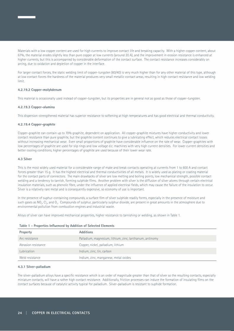
Alloys of silver can have improved mechanical properties, higher resistance to tarnishing or welding, as shown in Table 1.
Table 1 - Properties Influenced by Addition of Selected Elements
Property Additions
Arc resistance Palladium, magnesium, lithium, zinc, lanthanum, antinomy
Abrasion resistance Copper, nickel, palladium, lithium
Lubrication Indium, zinc, tin, carbon
Weld resistance Indium, zinc, manganese, metal oxides
4.3.1 Silver-palladium
The silver-palladium alloys have a specific resistance which is an order of magnitude greater than that of silver so the resulting contacts, especially miniature contacts, will have a rather high contact resistance. Additionally, friction processes can induce the formation of insulating films on the contact surfaces because of catalytic activity typical for palladium. Silver-palladium is resistant to suphide formation.
24 | COPPER IN ELECTRICAL CONTACTS
COPPER IN ELECTRICAL CONTACTS | 25
4.3.2 Silver-copper Silver-copper alloys are superior in strength and wear resistance but are the least resistant to corrosive environments among all silver alloys. Alloys rich in copper are unsuitable for contacts operating under arcing conditions and low pressures because the transition resistance is unstable due to oxidation. 4.3.3 Silver-nickel
Small amounts of nickel (0.2–3%) improve the wear resistance and lessen the probability of welding and tarnishing.
4.3.4 Silver-cadmium
The addition of cadmium decreases the electrical conductivity, melting point and oxidation resistance, but improves the resistance to tarnishing. Silver alloys with 1–10% of cadmium are also some of the most popular materials for relatively high-speed sliding contacts such as spring contacts, sliding fingers and others because of their excellent hardness, low transfer rate, wear resistance, stable resistance under small contact forces, slight resistivity to arcing and relatively low cost. Cadmium is environmentally harmful and is no longer used where alternatives are available.
4.3.5 Silver-lithium-lanthanum
This alloy has been developed as a replacement for silver-cadmium (1%) as a light duty sliding contact. The silver–lithium–lanthanum alloy has low contact resistance, good abrasion resistance and arc resistance compared to silver-cadmium (1%). The favourable properties of silver, such as workability and chemical stability, are retained due to the low concentration of the added elements. 4.4 Platinum
Platinum has an exceptional resistance to tarnishing, oxidation and corrosion so platinum contacts provide a highly stable transition resistance. It is suitable for light duty applications where operating currents are below 2 A, the contact-pressure is low and where the reliability is the most important parameter. The minimal arc formation current for platinum is the highest (0.9 A) compared to other noble metals (0.35–0.45 A). The voltage of arc ignition for platinum is also higher than for other metals. However, under fretting conditions, platinum contacts are susceptible to frictional polymerisation. Pure platinum is rarely used for fabricating contacts because of its low hardness. Additions of iridium, ruthenium and osmium to form binary or ternary alloys increase the hardness, mechanical strength, melting point, resistivity and wear resistance of platinum.
4.4.1 Platinum Alloys
Platinum-iridium alloys are used because of their low tendency to arc formation and greater resistance to electro-erosion than platinum. Platinum-rubidium alloys are harder than platinum–iridium alloys with a low affinity to contact welding compared with platinum. Platinum–nickel alloys are resistant to needling and contact welding. Compared to platinum, platinum-rhodium alloys are harder and have a low volatility at elevated temperatures.
4.5 Palladium
Palladium is less expensive than platinum but has a lower resistance to corrosion, oxidation and tarnishing. It begins to tarnish at 350°C, but the tarnish film formed decomposes at 900°C. The additions of copper, ruthenium, silver or combinations of other metals improve the mechanical properties of palladium with some reduction in the corrosion resistance and cost.
Palladium and its alloys are of interest as possible low-cost substitutes for gold in separable connectors, switches and printed circuit boards. However, in atmospheres containing traces of organic compounds, palladium contacts subjected to relative motion tend to form an insulating frictional polymer.
4.5.1 Palladium Alloys
Palladium-iridium alloys possess good contact properties while their cost is much less than that of platinum–iridium alloys. Palladium-silver alloys with the palladium content in excess of 50% do not form sulphide films on the surface. Palladium-copper alloys with copper contents of 15 or 40% are commonly used as contact materials in telecommunications and automotive engineering because of their good resistance against material transfer.

4.6 Gold
Gold is the softest noble metal. It has an excellent tarnish and oxidation resistance but is very soft and susceptible to mechanical wear, metal transfer and welding. It is widely used in computers and telecommunication and data transmission devices where operating currents are not more than 0.5 A.
4.6.1 Gold Alloys
The addition of copper, silver, palladium or platinum, forming binary and ternary alloys, improves the hardness without loss of the tarnish resistance, but application is restricted to low current applications.
Gold-silver contact alloys containing over 50% gold show no tendency to form sulphur films. Also, gold-platinum-nickel alloys are used. Among ternary alloys of gold, the hard, non-tarnishing gold-silver-platinum contact alloy is the best known. Additions of copper and nickel to gold-silver-copper and gold-silver-nickel alloys improve their hardness. Hard refractory gold-palladium-nickel alloys are also used.
4.7 Rhodium
Rhodium is very resistant to tarnishing but is very hard and extremely useful as a contact material. However, owing to difficult fabrication, it is used exclusively as a plating material in light duty electrical contacts where the reliability is of the utmost importance.
4.8 Tungsten
Tungsten is a very hard metal with an excellent resistance to wear, welding and material transfer, with high melting and boiling points. Its main disadvantages are a low corrosion and oxidation resistance, high electrical resistivity and poor formability. It is best suited to applications where currents range from 1 to 5 A and where impact on closing the contact is high. Tungsten for contact applications is generally made by powder metallurgical processes. The advantages of tungsten contacts are their resistance to the appearance of arc discharges (tungsten has the highest minimal arcing current); resistance to electrical erosion and welding because tungsten is a refractory metal; and a low mechanical wear due to a high hardness.
26 | COPPER IN ELECTRICAL CONTACTS
COPPER IN ELECTRICAL CONTACTS | 27
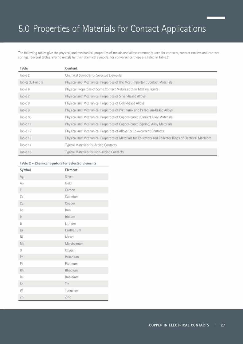
The following tables give the physical and mechanical properties of metals and alloys commonly used for contacts, contact carriers and contact springs. Several tables refer to metals by their chemical symbols; for convenience these are listed in Table 2.
Table Content
Table 2 Chemical Symbols for Selected Elements
Tables 3, 4 and 5 Physical and Mechanical Properties of the Most Important Contact Materials
Table 6 Physical Properties of Some Contact Metals at their Melting Points
Table 7 Physical and Mechanical Properties of Silver-based Alloys
Table 8 Physical and Mechanical Properties of Gold-based Alloys
Table 9 Physical and Mechanical Properties of Platinum- and Palladium-based Alloys
Table 10 Physical and Mechanical Properties of Copper-based (Carrier) Alloy Materials
Table 11 Physical and Mechanical Properties of Copper-based (Spring) Alloy Materials
Table 12 Physical and Mechanical Properties of Alloys for Low-current Contacts
Table 13 Physical and Mechanical Properties of Materials for Collectors and Collector Rings of Electrical Machines
Table 14 Typical Materials for Arcing Contacts
Table 15 Typical Materials for Non-arcing Contacts
Table 2 - Chemical Symbols for Selected Elements
Symbol Element
Ag Silver
Au Gold
C Carbon
Cd Cadmium
Cu Copper
Fe Iron
Ir Iridium
Li Lithium
La Lanthanum
Ni Nickel
Mo Molybdenum
O Oxygen
Pd Palladium
Pt Platinum
Rh Rhodium
Ru Rubidium
Sn Tin
W Tungsten
Zn Zinc
5.0 Properties of Materials for Contact Applications

28 | COPPER IN ELECTRICAL CONTACTS
Table 3 - Physical Properties of the Most Important Contact Materials (1 of 3)
Material Chemical Symbol
Atomic Number
Atomic Weight
Density (g/cm3)
Softening Temperature
(°C)
Softening Voltage
(Measured)(V)
Melting Point(°C)
Boiling Point (°C)
Melting Voltage
(Measured) (V)
Melting Voltage
(Calculated) (V)
Aluminium Al 13 26.98 2.70 150 0.1 660 2450 0.3 0.29
Antimony Sb 51 121.75 6.7 0.2 630 1380 0.28
Beryllium Be 4 9.01 1.85 1277 2770 0.48
Bismuth Bi 83 208.98 9.80 271 1560 0.15
Cadmium Cd 48 112.40 8.65 321 765 0.17
Carbon C 6 12.01 2.3 (0)
Chromium Cr 24 52.00 7.19 1875 2480 0.67
Cobalt Co 27 58.93 8.85 1490 2900 0.54
Copper Cu 29 63.54 8.95 190 0.12 1083 2595 0.43 0.42
Gallium Ga 31 69.72 5.91 30 2,237 0.04
Gold Au 79 196.97 19.32 100 0.08 1063 2966 0.43 0.42
Indium In 49 114.82 7.31 156 2000 0.11
Iridium Ir 77 192.20 22.5 2450 4600 0.86
Iron Fe 26 55.85 7.87 500 0.19 1537 2750 0.6 0.57
Lead Pb 82 207.19 11.36 200 0.12 327 1750 0.19 0.17
Magnesium Mg 12 24.31 1.74 650 1120 0.28
Manganese Mn 25 54.94 7.43 1245 2095 0.47
Mercury Hg 80 200.59 13.55 -39 357
Molybdenum Mo 42 95.94 10.21 900 0.3 2610 5560 0.75 0.91
Nickel Ni 28 58.71 8.90 520 0.16 1453 2800 0.65 0.54
Niobium Nb 41 92.91 8.57 2469 4900 0.78
Osmium Os 76 190.20 22.60 3050 5500 1.04
Palladium Pd 46 106.40 12.02 1552 3170 0.57 0.57
Platinum Pt 78 195.09 21.45 540 0.25 1769 3850 0.71 0.64
Rhenium Re 75 186.20 21.04 3180 5900 1.09
Rhodium Rh 45 102.91 12.41 1966 3900 0.70
Ruthenium Ru 44 101.07 12.30 2350 4900 0.81
Silver Ag 47 107.87 10.49 180 0.09 961 2212 0.37 0.38
Tantalum Ta 73 180.95 16.60 850 0.3 2996 5425 1.03
Tin Sn 50 118.69 7.30 100 0.07 232 2270 0.13 0.14
Titanium Ti 22 47.90 4.51 1668 3280 0.61
Tungsten W 74 183.85 19.32 1,000 0.4 3410 5930 1.1 1.16
Vanadium V 23 50.94 6.10 1900 3400 0.68
Zinc Zn 30 63.37 7.13 170 0.1 420 907 0.17 0.20
Zirconium Zr 40 91.22 6.49 1852 3580 0.67
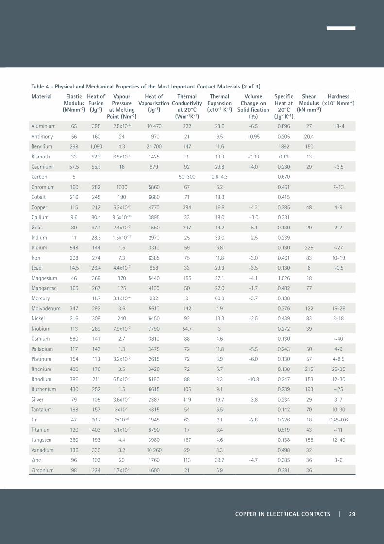
COPPER IN ELECTRICAL CONTACTS | 29
Table 4 - Physical and Mechanical Properties of the Most Important Contact Materials (2 of 3)
Material Elastic Modulus (kNmm-2)
Heat of Fusion (Jg-1)
Vapour Pressure
at Melting Point (Nm-2)
Heat of Vapourisation
(Jg-1)
Thermal Conductivity
at 20°C (Wm-1K-1)
Thermal Expansion (x10-6 K-1)
Volume Change on
Solidification (%)
Specific Heat at 20°C
(Jg-1K-1)
Shear Modulus
(kN mm-2)
Hardness(x102 Nmm-2)
Aluminium 65 395 2.5x10⁻⁶ 10 470 222 23.6 -6.5 0.896 27 1.8-4
Antimony 56 160 24 1970 21 9.5 +0.95 0.205 20.4
Beryllium 298 1,090 4.3 24 700 147 11.6 1892 150
Bismuth 33 52.3 6.5x10⁻⁴ 1425 9 13.3 -0.33 0.12 13
Cadmium 57.5 55.3 16 879 92 29.8 -4.0 0.230 29 ~3.5
Carbon 5 50–300 0.6–4.3 0.670
Chromium 160 282 1030 5860 67 6.2 0.461 7-13
Cobalt 216 245 190 6680 71 13.8 0.415
Copper 115 212 5.2x10⁻² 4770 394 16.5 -4.2 0.385 48 4-9
Gallium 9.6 80.4 9.6x10-36 3895 33 18.0 +3.0 0.331
Gold 80 67.4 2.4x10⁻³ 1550 297 14.2 -5.1 0.130 29 2-7
Indium 11 28.5 1.5x10⁻¹⁷ 2970 25 33.0 -2.5 0.239
Iridium 548 144 1.5 3310 59 6.8 0.130 225 ~27
Iron 208 274 7.3 6385 75 11.8 -3.0 0.461 83 10-19
Lead 14.5 26.4 4.4x10⁻⁷ 858 33 29.3 -3.5 0.130 6 ~0.5
Magnesium 46 369 370 5440 155 27.1 -4.1 1.026 18
Manganese 165 267 125 4100 50 22.0 -1.7 0.482 77
Mercury 11.7 3.1x10⁻⁴ 292 9 60.8 -3.7 0.138
Molybdenum 347 292 3.6 5610 142 4.9 0.276 122 15-26
Nickel 216 309 240 6450 92 13.3 -2.5 0.439 83 8-18
Niobium 113 289 7.9x10⁻² 7790 54.7 3 0.272 39
Osmium 580 141 2.7 3810 88 4.6 0.130 ~40
Palladium 117 143 1.3 3475 72 11.8 -5.5 0.243 50 4-9
Platinum 154 113 3.2x10⁻² 2615 72 8.9 -6.0 0.130 57 4-8.5
Rhenium 480 178 3.5 3420 72 6.7 0.138 215 25-35
Rhodium 386 211 6.5x10⁻¹ 5190 88 8.3 -10.8 0.247 153 12-30
Ruthenium 430 252 1.5 6615 105 9.1 0.239 193 ~25
Silver 79 105 3.6x10⁻¹ 2387 419 19.7 -3.8 0.234 29 3-7
Tantalum 188 157 8x10⁻¹ 4315 54 6.5 0.142 70 10-30
Tin 47 60.7 6x10-21 1945 63 23 -2.8 0.226 18 0.45-0.6
Titanium 120 403 5.1x10⁻¹ 8790 17 8.4 0.519 43 ~11
Tungsten 360 193 4.4 3980 167 4.6 0.138 158 12-40
Vanadium 136 330 3.2 10 260 29 8.3 0.498 32
Zinc 96 102 20 1760 113 39.7 -4.7 0.385 36 3-6
Zirconium 98 224 1.7x10⁻³ 4600 21 5.9 0.281 36

30 | COPPER IN ELECTRICAL CONTACTS
Table 5 - Physical Properties of the Most Important Contact Materials (3 of 3)
Material Electrical Resistivity (µΩcm)
Temp Coeff of Resistivity (x10-3K-1)
Electrical Conductivity
at 20°C(mΩ-1mm-2)
Minimum Arc Voltage
(V)
Minimum Arc Current
(A)
Work Function Range(eV)
Ionisation Potential
(eV)
Aluminium 2.65 4.29 37.7 11.2 0.4 3.0-4.4 5.98
Antimony 37.0 2.6 10.5 8.64
Beryllium 4.0 25.0 25.0 3.2-3.9 9.32
Bismuth 106.8 4.0 0.94 4.1-4.5 8.0
Cadmium 6.83 4.2 14.7 12 0.1 3.7-4.1 8.99
Carbon 6500 0.015 20 0.01-0.02 4.0-4.8 11.27
Chromium 14.95 3.0 6.7 16 0.4 4.4-4.7 6.76
Cobalt 6.24 6.6 16.1 4.4-4.6 7.86
Copper 1.65 4.3 59.9 13 0.4 4.5 7.72
Gallium 43.2 4.0 2.3 3.8-4.1 6.0
Gold 2.19 4.0 45.7 11.5 0.35 4.0-4.9 9.22
Indium 8.37 4.9 12.0 5.79
Iridium 5.3 4.1 18.9 11.5 4.6-5.3
Iron 9.71 6.5 10.3 11.5 0.45 3.9-4.8 7.9
Lead 20.65 3.36 4.9 11.5 4.0-4.1 7.42
Magnesium 4.45 16.5 22.4 2.8-3.8 7.64
Manganese 185 0.5 0.54 3.8-4.1 7.43
Mercury 96.0 1.0 1.04 4.5 10.44
Molybdenum 5.2 4.7 19.4 12 0.75 4.1-4.5 7.18
Nickel 6.84 6.8 14.6 13.5 0.5 3.7-5.2 7.63
Niobium 10.6 3.9 7.6 6.77
Osmium 9.5 4.2 10.5 4.5
Palladium 10.8 3.77 9.3 14 0.8 4.5-5.0 8.33
Platinum 10.6 3.93 9.5 14 0.9 4.1-5.5 8.96
Rhenium 19.3 4.6 5.2 4.7-5.0
Rhodium 4.51 4.4 22.2 14 0.35 4.6-4.9 7.7
Ruthenium 6.71 4.6 14.9 4.5 7.5
Silver 1.59 4.1 63.0 12 0.4 3.1-4.5 7.57
Tantalum 12.45 3.5 8.1 12 4.0-4.2
Tin 11.6 4.6 8.7 12.6 3.6-4.1 7.33
Titanium 41.6 5.5 2.4 12 4.0-4.4 6.83
Tungsten 5.55 4.8 18.0 13 0.8-1.2 4.3-5.0 7.98
Vanadium 26 3.9 3.8 3.8-4.2 6.71
Zinc 5.92 4.2 16.9 11 0.1 3.1-4.3 9.39
Zirconium 43.5 4.4 2.3 3.7-4.3 6.92
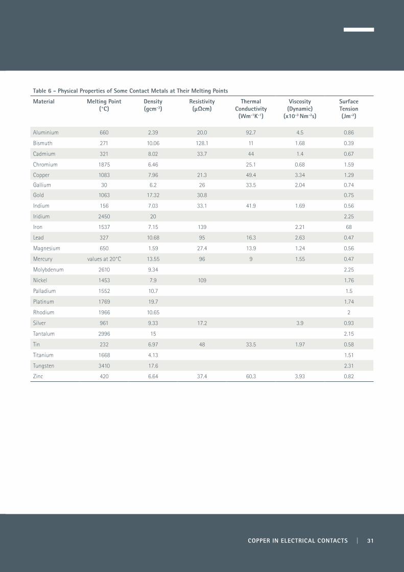
COPPER IN ELECTRICAL CONTACTS | 31
Table 6 - Physical Properties of Some Contact Metals at Their Melting Points
Material Melting Point (°C)
Density (gcm-3)
Resistivity (µΩcm)
Thermal Conductivity(Wm-1K-1)
Viscosity (Dynamic)
(x10-3 Nm-2s)
Surface Tension(Jm-2)
Aluminium 660 2.39 20.0 92.7 4.5 0.86
Bismuth 271 10.06 128.1 11 1.68 0.39
Cadmium 321 8.02 33.7 44 1.4 0.67
Chromium 1875 6.46 25.1 0.68 1.59
Copper 1083 7.96 21.3 49.4 3.34 1.29
Gallium 30 6.2 26 33.5 2.04 0.74
Gold 1063 17.32 30.8 0.75
Indium 156 7.03 33.1 41.9 1.69 0.56
Iridium 2450 20 2.25
Iron 1537 7.15 139 2.21 68
Lead 327 10.68 95 16.3 2.63 0.47
Magnesium 650 1.59 27.4 13.9 1.24 0.56
Mercury values at 20°C 13.55 96 9 1.55 0.47
Molybdenum 2610 9.34 2.25
Nickel 1453 7.9 109 1.76
Palladium 1552 10.7 1.5
Platinum 1769 19.7 1.74
Rhodium 1966 10.65 2
Silver 961 9.33 17.2 3.9 0.93
Tantalum 2996 15 2.15
Tin 232 6.97 48 33.5 1.97 0.58
Titanium 1668 4.13 1.51
Tungsten 3410 17.6 2.31
Zinc 420 6.64 37.4 60.3 3.93 0.82

32 | COPPER IN ELECTRICAL CONTACTS
Table 7 - Physical and Mechanical Properties of Silver-based Alloys
Material Density(gcm3)
Melting Temperature
(°C)
Electrical Resistivity at 20°C (µΩcm)
Temperature Coefficient of
Electrical Resistance(x103K-1)
Thermal Conductivity
at 20°C (Wm-1K-1)
Elastic Modulus (kNmm-2)
Hardness(x102 Nmm-2)
Ag 10.5 960 1.59 4.1 419 79 3–7
Ag - 10% Cd 10.3 910–925 4.3 1.4 150 60 3.6–10
Ag - 15% Cd 10.1 850-875 4.8 2 109 60 4.0–11.5
Ag - 3% Cu 10.4 900–934 1.92 3.2 385 85 4.5–9.5
Ag - 5% Cu 10.4 905–940 1.96 3 380 85 5–10
Ag - 10% Cu 10.3 779–875 2.08 2.8 335 85 6.5–12
Ag - 20% Cu 10.2 779–810 2.17 2.7 335 85 8–13
Ag - 2% Cu–Ni 10.4 940 1.92 3.5 385 85 5.5–10
Ag - 30% Pd 10.9 1150–1220 15.6 0.4 60 16 7–14
Ag - 40% Pd 11.1 1225–1285 20 0.36 46 134 7.5–15
Ag - 50% Pd 11.2 1290–1340 33.3 0.23 33.5 137 8–16
Ag - 60% Pd 11.4 1330–1385 41.7 29.3 10–18
Ag - 30% Pd - 5% Cu 10.8 1120–1165 15.4 0.37 108 9–17
Ag - 0.15% Ni 10.5 960 1.7 4 414 85 4.5–9
Ag - 10% Ni 10.2 960 2 3.5 310 84 5–11
Ag - 20% Ni 10 960 2.2 3.5 270 98 6–10.5
Ag - 30% Ni 9.8 960 2.4 3.4 240 115 6.5–11.5
Ag - 40% Ni 9.7 960 2.7 2.9 210 129 7.5–12
Ag - 50% Ni 9.6 960 3.1 185 145 7.5–13
Ag - 60% Ni 9.4 960 3.7 155 160 8–14
Ag - 70% Ni 9.3 960 4 140 170 8–15.5
Ag - 3% C 9 960 2.1 3.5 325 4.2
Ag - 5% C 8.5 960 2.3 3.3 318 4.0
Ag - 10% C 7.4 960 2.9 3.1
Ag - 15% C 6.5 960 4.5 2.6
Ag - 25% C 5.1 960 14.5
Ag - 50% C 3.2 960 23
Ag - 70% C 2.6 960 53
Ag - 90% C 2.14 960 87
Properties of Selected Sliding Contact Materials
Ag - 5% Cu - 10% C 6.8 905–940 4.7
Ag - 48.5% Cu - 3% C 8.3 779–875 4.0 5.2
Ag - 47.5% Cu - 7% C 7.4 779–875 8.0
Ag - 35% Cu - 30% C 4.2 779–815 63.6
Ag - 69.75% Cu - 5% C 8.2 779–945 3.2 5.2
Ag - 72% Cu - 3% C 8.3 779–960 5.3 7.1
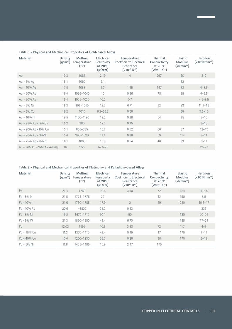
COPPER IN ELECTRICAL CONTACTS | 33
Table 8 - Physical and Mechanical Properties of Gold-based Alloys
Material Density (gcm-3)
Melting Temperature
(°C)
Electrical Resistivity at 20°C (µΩcm)
Temperature Coefficient Electrical
Resistance(x10-3 K-1)
Thermal Conductivity
at 20°C (Wm-1 K-1)
Elastic Modulus (kNmm-2)
Hardness (x102Nmm-2)
Au 19.3 1063 2.19 4 297 80 2–7
Au - 8% Ag 18.1 1060 6.1 82
Au - 10% Ag 17.8 1058 6.3 1.25 147 82 4–8.5
Au - 20% Ag 16.4 1036–1040 10 0.86 75 89 4–9.5
Au - 30% Ag 15.4 1025–1030 10.2 0.7 4.5–9.5
Au - 5% Ni 18.3 995–1010 13.3 0.71 52 83 11.5–16
Au - 5% Co 18.2 1010 6.2–55.5 0.68 88 9.5–16
Au - 10% Pt 19.5 1150–1190 12.2 0.98 54 95 8–10
Au - 25% Ag - 5% Cu 15.2 980 12.2 0.75 9–16
Au - 20% Ag -10% Cu 15.1 865–895 13.7 0.52 66 87 12–19
Au - 26% Ag - 3%Ni 15.4 990–1020 11.4 0.88 59 114 9–14
Au - 25% Ag - 6%Pt 16.1 1060 15.9 0.54 46 93 6–11
Au - 14% Cu - 9% Pt – 4% Ag 16 955 14.3–25 19–27
Table 9 - Physical and Mechanical Properties of Platinum- and Palladium-based Alloys
Material Density (gcm-3)
Melting Temperature
(°C)
Electrical Resistivity at 20°C (µΩcm)
Temperature Coefficient Electrical
Resistance(x10-3 K-1)
Thermal Conductivity
at 20°C (Wm-1 K-1)
Elastic Modulus (kNmm-2)
Hardness (x102Nmm-2)
Pt 21.4 1769 10.6 3.90 72 154 4–8.5
Pt - 5% lr 21.5 1774–1776 22 42 190 8.5
Pt - 10% Ir 21.6 1780–1785 17.9 2 29 220 10.5–17
Pt - 10% Ru 20.6 ~1800 33.3 0.83 235
Pt - 8% Ni 19.2 1670–1710 30 1 50 180 20–26
Pt - 5% W 21.3 1830–1850 43.4 0.70 185 17–24
Pd 12.02 1552 10.8 3.80 72 117 4–9
Pd - 15% Cu 11.3 1370–1410 43.4 0.49 17 175 7–11
Pd - 40% Cu 10.4 1200–1230 33.3 0.28 38 175 8–12
Pd - 5% Ni 11.8 1455–1485 16.9 2.47 175
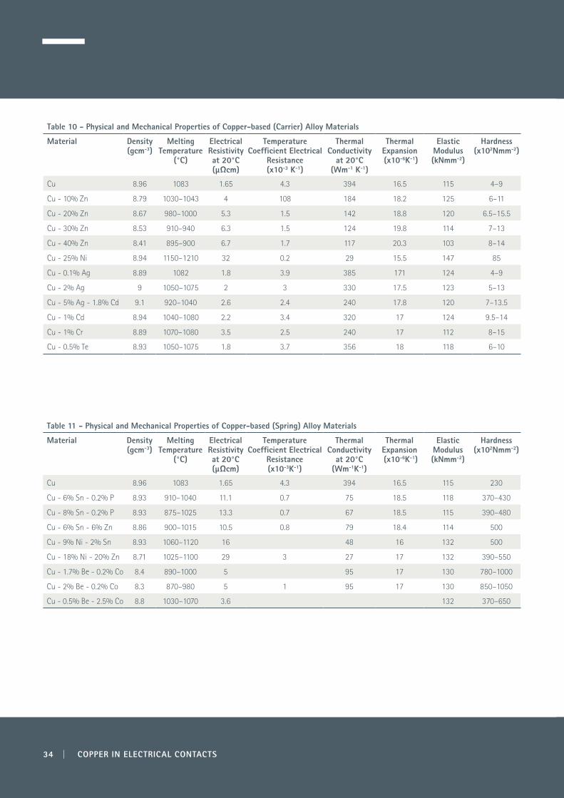
34 | COPPER IN ELECTRICAL CONTACTS
Table 10 - Physical and Mechanical Properties of Copper-based (Carrier) Alloy Materials
Material Density (gcm-3)
Melting Temperature
(°C)
Electrical Resistivity at 20°C (µΩcm)
Temperature Coefficient Electrical
Resistance(x10-3 K-1)
Thermal Conductivity
at 20°C (Wm-1 K-1)
Thermal Expansion (x10-6K-1)
Elastic Modulus (kNmm-2)
Hardness (x102Nmm-2)
Cu 8.96 1083 1.65 4.3 394 16.5 115 4–9
Cu - 10% Zn 8.79 1030–1043 4 108 184 18.2 125 6–11
Cu - 20% Zn 8.67 980–1000 5.3 1.5 142 18.8 120 6.5–15.5
Cu - 30% Zn 8.53 910–940 6.3 1.5 124 19.8 114 7–13
Cu - 40% Zn 8.41 895–900 6.7 1.7 117 20.3 103 8–14
Cu - 25% Ni 8.94 1150–1210 32 0.2 29 15.5 147 85
Cu - 0.1% Ag 8.89 1082 1.8 3.9 385 171 124 4–9
Cu - 2% Ag 9 1050–1075 2 3 330 17.5 123 5–13
Cu - 5% Ag - 1.8% Cd 9.1 920–1040 2.6 2.4 240 17.8 120 7–13.5
Cu - 1% Cd 8.94 1040–1080 2.2 3.4 320 17 124 9.5–14
Cu - 1% Cr 8.89 1070–1080 3.5 2.5 240 17 112 8–15
Cu - 0.5% Te 8.93 1050–1075 1.8 3.7 356 18 118 6–10
Table 11 - Physical and Mechanical Properties of Copper-based (Spring) Alloy Materials
Material Density (gcm-3)
Melting Temperature
(°C)
Electrical Resistivity at 20°C (µΩcm)
Temperature Coefficient Electrical
Resistance(x10-3K-1)
Thermal Conductivity
at 20°C (Wm-1K-1)
Thermal Expansion (x10-6K-1)
Elastic Modulus (kNmm-2)
Hardness (x102Nmm-2)
Cu 8.96 1083 1.65 4.3 394 16.5 115 230
Cu - 6% Sn - 0.2% P 8.93 910–1040 11.1 0.7 75 18.5 118 370–430
Cu - 8% Sn - 0.2% P 8.93 875–1025 13.3 0.7 67 18.5 115 390–480
Cu - 6% Sn - 6% Zn 8.86 900–1015 10.5 0.8 79 18.4 114 500
Cu - 9% Ni - 2% Sn 8.93 1060–1120 16 48 16 132 500
Cu - 18% Ni - 20% Zn 8.71 1025–1100 29 3 27 17 132 390–550
Cu - 1.7% Be - 0.2% Co 8.4 890–1000 5 95 17 130 780–1000
Cu - 2% Be - 0.2% Co 8.3 870–980 5 1 95 17 130 850–1050
Cu - 0.5% Be - 2.5% Co 8.8 1030–1070 3.6 132 370–650
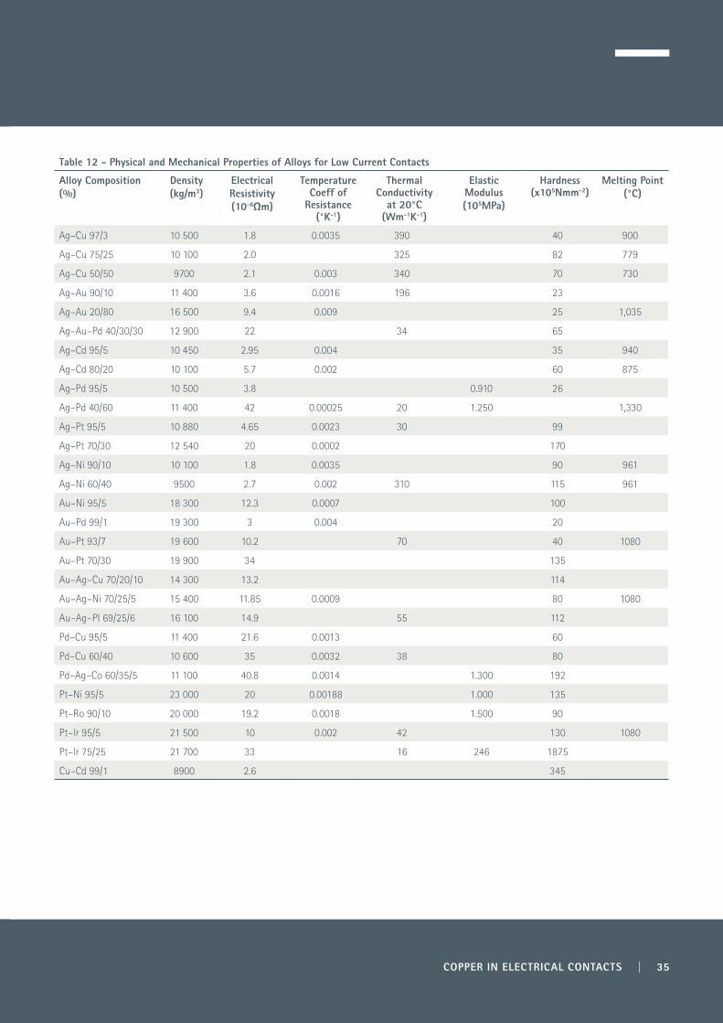
COPPER IN ELECTRICAL CONTACTS | 35
Table 12 - Physical and Mechanical Properties of Alloys for Low Current Contacts
Alloy Composition (%)
Density (kg/m3)
Electrical Resistivity(10-8Ωm)
Temperature Coeff of
Resistance(°K-1)
Thermal Conductivity
at 20°C (Wm-1K-1)
Elastic Modulus(105MPa)
Hardness(x105Nmm-2)
Melting Point(°C)
Ag–Cu 97/3 10 500 1.8 0.0035 390 40 900
Ag–Cu 75/25 10 100 2.0 325 82 779
Ag–Cu 50/50 9700 2.1 0.003 340 70 730
Ag–Au 90/10 11 400 3.6 0.0016 196 23
Ag–Au 20/80 16 500 9.4 0.009 25 1,035
Ag–Au–Pd 40/30/30 12 900 22 34 65
Ag–Cd 95/5 10 450 2.95 0.004 35 940
Ag–Cd 80/20 10 100 5.7 0.002 60 875
Ag–Pd 95/5 10 500 3.8 0.910 26
Ag–Pd 40/60 11 400 42 0.00025 20 1.250 1,330
Ag–Pt 95/5 10 880 4.65 0.0023 30 99
Ag–Pt 70/30 12 540 20 0.0002 170
Ag–Ni 90/10 10 100 1.8 0.0035 90 961
Ag–Ni 60/40 9500 2.7 0.002 310 115 961
Au–Ni 95/5 18 300 12.3 0.0007 100
Au–Pd 99/1 19 300 3 0.004 20
Au–Pt 93/7 19 600 10.2 70 40 1080
Au–Pt 70/30 19 900 34 135
Au–Ag–Cu 70/20/10 14 300 13.2 114
Au–Ag–Ni 70/25/5 15 400 11.85 0.0009 80 1080
Au–Ag–PI 69/25/6 16 100 14.9 55 112
Pd–Cu 95/5 11 400 21.6 0.0013 60
Pd–Cu 60/40 10 600 35 0.0032 38 80
Pd–Ag–Co 60/35/5 11 100 40.8 0.0014 1.300 192
Pt–Ni 95/5 23 000 20 0.00188 1.000 135
Pt–Ro 90/10 20 000 19.2 0.0018 1.500 90
Pt–lr 95/5 21 500 10 0.002 42 130 1080
Pt–lr 75/25 21 700 33 16 246 1875
Cu–Cd 99/1 8900 2.6 345
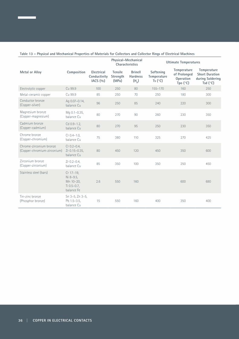
36 | COPPER IN ELECTRICAL CONTACTS
Table 13 – Physical and Mechanical Properties of Materials for Collectors and Collector Rings of Electrical Machines
Metal or Alloy Composition Electrical Conductivity
IACS (%)
Physical–Mechanical Characteristics Ultimate Temperatures
Tensile Strength (MPa)
Brinell Hardness
(HB)
Softening Temperature
Ts (°C)
Temperature of Prolonged Operation Tpo (°C)
Temperature Short Duration
during Soldering Tsd (°C)
Electrolytic copper Cu 99.9 100 250 80 155–170 160 250
Metal–ceramic copper Cu 99.9 85 250 70 250 180 300
Conductor bronze(Copper-silver)
Ag 0.07–0.14, balance Cu
96 250 85 240 220 300
Magnesium bronze(Copper-magnesium)
Mg 0.1–0.35, balance Cu
80 270 90 260 230 350
Cadmium bronze(Copper-cadmium)
Cd 0.9–1.2, balance Cu
80 270 95 250 230 350
Chrome bronze(Copper-chromium)
Cr 0.4–1.0, balance Cu
75 380 110 325 270 425
Chrome-zirconium bronze(Copper-chromium-zirconium)
Cr 0.2–0.4, Zr 0.15–0.35, balance Cu
80 450 120 450 350 600
Zirconium bronze(Copper-zirconium)
Zr 0.2–0.4, balance Cu
85 350 100 350 250 450
Stainless steel (bars) Cr 17–19, Ni 8–9.5, Mn 10–20, Ti 0.5–0.7, balance Fe
2.6 550 160 600 680
Tin-zinc bronze(Phosphor bronze)
Sn 3–5, Zn 3–5, Pb 1.5–3.5, balance Cu
15 550 160 400 350 400

COPPER IN ELECTRICAL CONTACTS | 37
Table 14 – Typical Materials for Arcing Contacts
Type of Device or Contact
Required Properties Material Shape of Contact
Motor controls switching under oil
Resistant to arcs in oil Cu, WCu Solid contacts, brazed material
Large L.V. contactors with arcing contacts
Withstand high short circuits on make and break, low resistance on rated current, anti-weld
Arcing contacts: Cu, WAg Main contacts: AgCu, AgNi, AgCdO, AgZnO, AgSnO
Solid contacts in Cu. Others brazed or welded
On-load isolators As isolators, and low erosion of arcing contacts Arcing: WCu, Mo Main: Silver-plated Cu, AgCu, AgNi
Welded, brazed; Plated, welded
Circuit breakers L.V. and H.V
Low erosion, low metal vapour, low temperature rise for closed contacts; low temperature rise at high current, sufficient strength against deformation
Arcing parts: WCu, Mo, Cu Closed contacts: Cu, Silver-plated Cu, AgCu, AgNi, AgW
Mechanically fixed, welded, brazed
Transformer tap changers
Low temperature rise for continuous high current, good sliding, low wear when switching no load under oil
Cu, silver-plated Cu, AgCu Cast or pressed parts with welded or brazed onlay
Oil breakers High resistance to erosion and arcing under oil Cu, WCu Contacts solid or brazed
High current d.c. breakers
Low transfer, low erosion at high current low contact resistance
Cu Laminated strip
Generator, commutator alternator
Hard, creep resistant, low contact resistance Cu + 0.1% Ag Solid
Slip rings Low mechanical wear under brushes. Easy manufacturing
Cu, gunmetal, Cupronickel, ’Monel’, for corrosive atmospheres
Cast and machined
Light switches Low contact resistance, low erosion, no weld on overcurrent
AgCu, AgCdO Solid or bimetal rivets, automatically welded parts
Small circuit breakers Anti-weld on short-circuit, low temperature rise at rated current, moderate erosion
Dependent on rating and construction - Cu, AgCdO, AgW, AgWC, AgC mixed: AgC against Cu
Profiled, pressed, brazed, welded
Sliding in very small motors
Very resistant to frictional wear, good contact for very low force
Ag or Au-alloy, AgPd, AgCu Sliding: flattened or formed wire Collector: Au-plated or formed from profiled wire
Vacuum switches Low transfer and erosion under vacuum Cu + inserts - very low gas content Specially shaped
Table 15 – Typical Materials for Non-arcing Contacts
Type of Device or Contact
Required Properties Material Shape of Contact
Isolators for outdoor use
Low mechanical wear for high forces, low contact resistance, generally operated on no-load
Silver-plated Cu, AgCu against Cu Profiled Cu
Isolators Low contact resistance for high current, sufficient mechanical strength. Operation generally on no-load.
Ag, AgCu, AgNi Electroplated, welded
Control switches Reliable contact for prolonged operation Ag, AgCu, AgNi, Au-faced Rivets, solid or faced, faced pressed parts, gold-plated rivets
Rotary switch, manually operated
Reliable switching of rated and overcurrent with compact shape
AgCu, AgNiCu, phosphor bronze Rivets, solid or faced, automatically welded, profiled

Notes
38 | COPPER IN ELECTRICAL CONTACTS

COPPER IN ELECTRICAL CONTACTS | 39
Notes

Copy
right
© 2
015.
Cop
per D
evel
opm
ent A
ssoc
iatio
n an
d Eu
rope
an C
oppe
r Ins
titut
e
Copper Development Association5 Grovelands Business Centre
Boundary WayHemel Hempstead, HP2 7TE
UK
Related Documents