TECHNOLOGY FOR DESIGN ENGINEERING September 2012 / deskeng.com REVIEW: HP ELITEBOOK 8560W P. 26 VIRTUALIZATION AND THE GPU P. 20 THE ECOCAR2 COMPETITION P. 44 MULTIDISCIPLINARY ANALYSIS CAE Trends, Successes, and Strategies 2012 NX CAE Symposium Visit siemens.com/plm/nxcae-symposium to learn more. Coordinate simulations across disciplines to increase collaboration. Hypersonic Vehicle Designs P. 35 LightWave 11 Review P. 40 Workstation Technologies FOCUS ON:

Welcome message from author
This document is posted to help you gain knowledge. Please leave a comment to let me know what you think about it! Share it to your friends and learn new things together.
Transcript

TECHNOLOGY FOR DESIGN ENGINEERING
September 2012 / deskeng.com
REVIEW: HP ELITEBOOK 8560W P. 26
VIRTUALIZATION AND THE GPU P. 20
THE ECOCAR2 COMPETITION P. 44
MULTIDISCIPLINARYANALYSIS
CAE Trends, Successes, and Strategies 2012 NX CAE SymposiumVisit siemens.com/plm/nxcae-symposium to learn more.
DTE_banner_NXCAE _SEP2012.indd 1 8/8/12 2:41:19 PM
Coordinate simulations across
disciplines to increase collaboration.
Hypersonic Vehicle Designs P. 35
LightWave 11 Review P. 40
P. 35
WorkstationTechnologies
FOCUS ON:
de0912_Cover.indd 1 8/16/12 9:34 AM


Wireless Data Collection
Web-based Temperature Monitoring
iSD-TCStarts at
$495
Visit omega.com/isd-tc
Miniature Wireless Thermocouple Connections
MWTC-D
Visit omega.com/mwtc_series Visit omega.com/wseries
Wireless Sensor System IEEE 802.11 b/g / Wi-Fi Transmitters
MWTC-REC1
MWTC-REC5
Temperature, Humidity and Barometric Pressure Wireless Sensor System• High Power Transmitter up to 1 Kilometer• Web Server to Monitor and Record Data • NEMA4/IP65 Enclosure• Alarms by Email or Text MessageVisit omega.com/zed-p_series
CHART
http://75.49.246.157/GaugePost?MAC=00033400d47d&group=0
Readings Chart Setup Data
ChartGauge
24 C
0 50
6.0 43.8
12.5 37.5
18.825
31.3
46.3 %
0 50
6.0 43.8
12.5 37.5
18.825
31.3
Temperature Pressure Humidity
Last Updated: 2011/11/01 12:30:47 Group NoneTransmitter Temperature/P/RH
1,017.8 hPa
800 1100
837.5 1062.5
875 1025
912.5950
987.5
24 C
0 50 50 50 50 50
6.0 43.8
12.512.5 37.537.5
18.8 31.3
wSeries Starts at
$195
Visit omega.com/wseriesVisit omega.com/wseriesVisit omega.com/wseries
ost?MAC=00033400d47d&group=0
Chart Setup Data
ChartGauge
46.3 %
0 50 50 50 50
6.0 43.8
12.512.5 37.537.5
18.825
31.3
Pressure Humidity
Last Updated: 2011/11/01 12:30:47 Group NoneTransmitter Temperature/P/RH
1,017.8 hP1,017.8 hP1,017.8 hPaaa
000 11111100
5 1062.5
875 15 15 10202555
912.5950
987.5
808080000
837.837.5
87
http://192.168.1.200Address
Chart
10.0C/Div
10.0C/Div
Temperature 1 Temperature 2Max. 65.1 / Min. 47.9 Max. 69.9 / Min. 30.1High 70.0 / Low 39.0 High 78.0 / Low 25.0
100
0
100
0
Save Chart
Print Chart
54.2 F 50.8 F
Thu Sep 17 12:05:07 PDT 2009Thu Sep 16 08:00:00 PDT 2009
Data Source:
Alarm Relay Set Points:
Live
Bold
Readings Chart Web Link Setup
Recording: ON
Help[?]
1 Hour/Div
Y-axis (right): Temperature 2 Style: Bold
Y-axis (left): Temperature 1 Style: Bold
X-axis: 1 Day
© COPYRIGHT 2011 OMEGA ENGINEERING, INC. ALL RIGHTS RESERVED
© COPYRIGHT 2012 OMEGA ENGINEERING, INC. ALL RIGHTS RESERVED
omega.com
®
Because of transmission frequency regulations, these wireless products may only be used in the United States, Canada and Europe.
© COPYRIGHT 2011 OMEGA ENGINEERING, INC. ALL RIGHTS RESERVED
© COPYRIGHT 2012 OMEGA ENGINEERING, INC. ALL RIGHTS RESERVED
®
wi8 SeriesStarts at
$395
zSeriesStarts at
$95
zED-P SeriesStarts at
$195
Starts at$495
0C/Div
Thu Sep 16 08:00:00 PD
Data Source
Alarm Relay Set Points:
iSD-TCStarts at
10.0C/Div
0
Save Chart
Print Chart
Thu Sep 17 12:05:07 PDT 2009Thu Sep 16 08:00:00 PDT 2009
Data Source:
Alarm Relay Set Points:
Live
Bold
1 Hour/Div
Y-axis (right):axis (right): Temperature 2 Style: Bold
Y-axis (left): T: Temperature 1: Temperature 1: T Style: Bold
X-axis: 1 Day
Omega.indd 1 8/14/12 12:31 PM
2 DESKTOP ENGINEERING September 2012 /// deskeng.com
Degrees of Freedom by Jamie J. Gooch
Remember that high-pitched static whine punctuated by the digital chimes that signaled your dial-up modem was shaking hands with your Internet service provider (ISP)? Maybe you doubled your speed from 14.4 kbps
to 28.8 kbps at some point and were impressed with how fast Netscape rendered a web page. Then broadband arrived and wow, was it fast. But, everything is relative.
Nowadays, things don’t seem so fast. The average broad-band speed in the U.S. today is about 5.8 Mbps, which is only slightly faster than the maximum speeds 16 years ago. While computing power has doubled every 12 to 18 months and storage capacity — both locally and networked — has be -come increasingly affordable, broadband has not kept pace. In fact, the price of broadband has increased for many, while broadband speeds are being capped.
Need for SpeedThe static pace of broadband speeds doesn’ t sit well with Google. If it hopes to move more customers to its cloud-based solutions, they need to have fast access to the Google-
hosted services that comprise their digital lives. Google’s answer to the problem is Google Fiber, which it rolled out in Kansas City recently. Using fiber optics, the company is delivering upload and download speeds of 1 Gbps for less than what others are charging for half those speeds.
The lack of innovation among traditional ISPs shouldn’t sit well with design engineers either. Even though many of you have fast access at work, chances are you’re doing some of your work from home. Others are working in smaller offices that are using the same cable and DSL connection technolo-gies as consumers. But while a fast connection would certainly be a convenience when uploading and downloading large files away from the office, and the many home-based engineering contractors’ productivity would greatly benefit from gigabit speeds, those are relatively minor benefits.
Engineering a Connected WorldThe bigger benefits to widespread, affordable, extremely high-speed access are the product innovations it would en-
able. It’s easy to imagine new music and movie sharing busi-ness plans taking advantage of the higher speeds, or new apps that pop up based on faster access to data in the cloud, but what about more “Jetsonian” technologies?
An Aug. 1 Wall Street Journal online article titled “En-trepreneurs Dream of Jumping on Super -Fast Network” profiled a few Kansas City start-ups hoping to capitalize on Google’s experiment. Integrated Roadways LLC would like to embed sensors in roads to transmit data about hazardous conditions via Google Fiber, and maybe someday communi-cate with self-driving cars. Another business, Caregiv, hopes to bring doctor-patient teleconferencing to the homes of the elderly, allowing medical professionals to monitor patients and provide online therapy sessions.
Many of the future’s most promising innovations depend on removing the broadband bottleneck. Imagine what huge increases in average broadband speeds could do for sensor-based monitoring, teleconferencing, online education, In-ternet-connected appliances, home-based manufacturing, telemedicine, simulation, crowd sourcing and more.
“Like electricity a century ago, broadband is a foundation for economic growth, job creation, global competitiveness and a better way of life,” according to the executive summary of the National Broadband Plan (broadband.gov). “It is enabling entire new industries and unlocking vast new possibilities for existing ones. It is changing how we educate children, deliver health care, manage energy, ensure public safety, engage gov-ernment, and access, organize and disseminate knowledge.”
Just a First StepTo say that gigabit speeds lead to new innovation is an oversimpli-fication. There are many challenges to overcome along the way.
Google Fiber is just in Kansas City, and Google has been pretty tight-lipped about any expansion plans. If we take a step back, we’ll see that about 100 million Americans don’t have any broadband — fast or slow — in their homes, and many countries have higher average connection speeds than the U.S.
Surely Google hopes its entrance into the market will shake the cobwebs off traditional network providers. Engi-neers should too. Even if Google Fiber never extends beyond the test bed of KC, it could serve as a wake up call that will lead to competitive offerings by other ISPs. It’s an important first step down a road that could help jumpstart innovation in the U.S.
Jamie Gooch is the managing editor of Desktop Engineering. Contact him at [email protected].
Kansas City, Here I Come
Many future innovations depend on removing the broadband bottleneck.
de0912_DOF.indd 2 8/14/12 12:40 PM

NationalInstruments.indd 1 8/14/12 12:36 PM
March 2011 VOLUME 16/ISSUE 7
4 DESKTOP ENGINEERING September 2012 /// deskeng.com
September 2012 VOLUME 18/ISSUE 1
35 Better Answers Faster A research team uses Tecplot Chorus for hypersonic vehicle design. By Mark Clarkson
37 Aluminum Casting SimulationsClosed-loop, automatic optimization makes fast work of enhancing FLOW-3D CFD analyses.By Antoni Drys and Stefano Mascetti
42 The Back and Forth of Windshield Wiper DesignHyundai Motor Co. uses Abaqus Unifi ed FEA to perform faster, integrated design simulations.By Lynn Manning
44 Plugging into the Chevy Malibu’s Eco FutureEmbry-Riddle University’s EcoEagles put digital simulation in driver’s seat.By Kenneth Wong
DESIGN
40 Review: Two Parts in OneWith LightWave 11, NewTek once again puts most of the shine on half the product.By Mark Clarkson
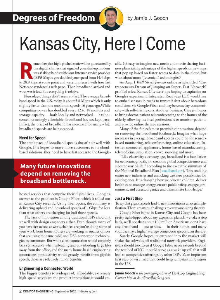
COVER STORY
Simulation Collaboration
Pamela J. Waterman explores the benefits of coordinating simulations across multiple disciplines. Accessing the right simulation software, tracking all possible input data, combining analysis results and connecting with databases across teams and vendors can present a huge challenge. The good news is that traditional simulation packages are being extended—not only to help different disciplines work with the same models, but also to share the results across higher level collaborations.
30
ON THE COVER: Complicated designs, such as those used in the automotive and aerospace industries, make multidisci-plinary collaboration a must to make sure mechanical, elec-tronic and thermal modeling work together. Images courtesy of iStockphoto.com and ANSYS. Cover design by Darlene Sweeney.
SIMULATE
FOCUS ON WORKSTATIONS
20 Virtualization and the GPUHow GPUs can deliver engineering application performance.By Peter Varhol
22 Consumer PCs Vs. Pro WorkstationsConsumer brands cost less initially, but incompatibility with professional software may add costs down the road.By Kenneth Wong
26 Review: Upwardly MobileThe new HP EliteBook 8560w mobile workstation with DreamColor display improves upon its predecessor.By David Cohn
de0912_TOC.indd 4 8/15/12 11:36 AM
COMSOLCONFERENCEBOSTON 20 1 2 OCTOBER 3 - 5
© Copyright 2012. COMSOL, COMSOL Multiphysics and LiveLink are either registered trademarks or trademarks of COMSOL AB. AutoCAD and Inventor are registered trademarks of Autodesk, Inc., in the USA and other countries. LiveLink for AutoCAD and LiveLink for Inventor are not affiliated with, endorsed by, sponsored by, or supported by Autodesk, Inc., and/or its affiliates and/or subsidiaries. MATLAB is a registered trademark of The Mathworks, Inc. Pro/ENGINEER and Creo are trademarks or registered trademarks of Parametric Technology Corporation or its subsidiaries in the U.S. and in other countries. SolidWorks is a registered trademark of Dassault Systèmes SolidWorks Corp. CATIA is a registered trademark of Dassault Systémes. SpaceClaim is a registered trademark of SpaceClaim Corporation.
®
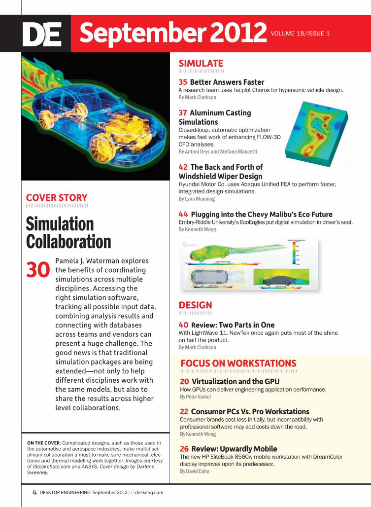
Verify and optimize your designs with COMSOL Multiphysics.
COMSOL Multiphysics
FLUIDCFD Module Pipe Flow ModuleMicrofluidics ModuleSubsurface Flow Module
CHEMICALChemical Reaction Engineering Module Batteries & Fuel Cells ModuleElectrodeposition Module Corrosion Module
MECHANICALHeat Transfer ModuleStructural Mechanics Module Nonlinear Structural Materials ModuleGeomechanics Module Acoustics Module
ELECTRICALAC/DC ModuleRF ModuleMEMS ModulePlasma Module
MULTIPURPOSEOptimization ModuleMaterial LibraryParticle Tracing Module
INTERFACINGCAD Import ModuleFile Import for CATIA® V5LiveLink™ for SolidWorks®
LiveLink™ for SpaceClaim®
LiveLink™ for Pro/ENGINEER®
LiveLink™ for Creo™ ParametricLiveLink™ for Inventor®
LiveLink™ for AutoCAD®
LiveLink™ for MATLAB®
Product Suite
Multiphysics tools let you build simulations that accurately replicate the important characteristics of your designs. The key is the ability to include all physical effects that exist in the real world. Order your free Introduction to Multiphysics CD at www.comsol.com/intro
Verify and optimize your designs Verify and optimize your designs Verify and optimize your designs Verify and optimize your designs Verify and optimize your designs Verify and optimize your designs Verify and optimize your designs Verify and optimize your designs Verify and optimize your designs Verify and optimize your designs with with with with with CCOMSOLOMSOLOMSOLOMSOL ® Multiphysics.® Multiphysics.® Multiphysics. Multiphysics. Multiphysics. Multiphysics. Multiphysics. Multiphysics. Multiphysics.Verify and optimize your designs Verify and optimize your designs Verify and optimize your designs
OMSOLOMSOLOMSOLOMSOL Multiphysics. Multiphysics. Multiphysics. Multiphysics. Multiphysics. Multiphysics. Multiphysics. Multiphysics.Verify and optimize your designs Verify and optimize your designs
OMSOLOMSOL ® Multiphysics.® Multiphysics.® Multiphysics. Multiphysics. Multiphysics. Multiphysics. Multiphysics. Multiphysics.
THERMAL MANAGEMENT: Convective cooling of a circuit board where temperature and fluid flow are modeled as a conjugate heat transfer application.
Verify and optimize your designs Verify and optimize your designs Verify and optimize your designs Verify and optimize your designs Verify and optimize your designs Verify and optimize your designs Verify and optimize your designs Verify and optimize your designs Verify and optimize your designs Verify and optimize your designs Verify and optimize your designs Verify and optimize your designs OMSOLOMSOL Multiphysics. Multiphysics. Multiphysics. Multiphysics. Multiphysics. Multiphysics.®
Verify and optimize your designs Verify and optimize your designs Verify and optimize your designs Verify and optimize your designs Verify and optimize your designs Verify and optimize your designs Verify and optimize your designs Verify and optimize your designs Verify and optimize your designs Multiphysics.® Multiphysics.® Multiphysics.
Verify and optimize your designs Verify and optimize your designs Verify and optimize your designs Verify and optimize your designs Verify and optimize your designs Verify and optimize your designs Verify and optimize your designs Verify and optimize your designs Verify and optimize your designs Verify and optimize your designs Verify and optimize your designs Verify and optimize your designs Verify and optimize your designs Verify and optimize your designs Verify and optimize your designs Verify and optimize your designs Verify and optimize your designs Verify and optimize your designs Verify and optimize your designs Verify and optimize your designs Verify and optimize your designs Verify and optimize your designs Verify and optimize your designs Verify and optimize your designs Verify and optimize your designs Verify and optimize your designs Verify and optimize your designs Verify and optimize your designs Verify and optimize your designs Verify and optimize your designs Verify and optimize your designs Verify and optimize your designs Verify and optimize your designs
COMSOL.indd 1 8/14/12 12:36 PM

6 DESKTOP ENGINEERING September 2012 /// deskeng.com
September 2012 VOLUME 18/ISSUE 1
EDITORIALSteve Robbins | Executive EditorJamie J. Gooch | Managing EditorKenneth Wong | Senior EditorAnthony J. Lockwood | Editor at Large Heather Pi ̃ inger | Copy Editor
CONTRIBUTING EDITORSBrian Albright, Mark Clarkson, David S. Cohn, Barbara Goode, Mike Hudspeth, John Newman, Susan Smith, Peter Varhol, Pamela J. Waterman
PUBLISHERThomas Conlon
ADVERTISING SALES603-563-1631 • Fax 603-563-8192 Erich Herbert | Sales Executive (x263)Jeanne DuVal | Account Manager (x274)
ART & PRODUCTIONDarlene Sweeney | Director (x257)
A LEVEL 5 COMMUNICATIONS PUBLICATIONSteve Robbins | Chief Executive Offi cerThomas Conlon | President
ADVERTISING, BUSINESS, & EDITORIAL OFFICESDesktop Engineering ® magazineLevel 5 Communications, Inc.1283D Main St., PO Box 1039 • Dublin, NH 03444603-563-1631 • Fax 603-563-8192E-mail: [email protected]
SUBSCRIBER CUSTOMER SERVICEDesktop Engineering ® magazinePO Box 677 • Northbrook, IL 60065-0677847-559-7581 • Fax 847-564-9453E-mail: [email protected]
Desktop Engineering® (ISSN 1085-0422) is published monthly by Level 5 Communications, Inc., 1283D Main Street, P.O. Box 1039, Dublin, NH 03444, 603-563-1631. Periodicals postage paid at Dublin, NH, and at additional mailing offi ces. Desktop Engineering® is distributed free to qualifi ed U.S. subscribers.
SUBSCRIPTION RATES: for non-qualifi ed; U.S. $108 one year; Canada and Mexico $126 one year; all other countries $195 one year.
LIST RENTALS: For information on list rentals, contact Statlistics, Danbury, CT: 203-778-8700.
POSTMASTER: Send all address changes to Desktop Engineering, P.O. Box 677, Northbrook, IL 60065-0677.
Address all editorial correspondence to the Editor, Desktop Engineering. Opinions expressed by the authors are not necessarily those of Desktop En gineering. Unaccepted manuscripts will be returned if accompanied by a self-addressed envelope with suffi cient fi rst-class postage. Not responsible for lost manuscripts or photos.
Each separate contribution to this issue, and the issue as a collective work, is copyright © 2012 Level 5 Communications, Inc. All rights reserved. Copying for other than personal or internal reference use without the permission of Level 5 Communications, Inc. is prohibited. Requests for permission should be addressed in writing to Desktop Engineering Per missions, 1283D Main Street, P.O. Box 1039, Dublin, NH 03444. PRINTED IN THE USA.
DEPARTMENTS
2 Degrees of FreedomKansas City, here I come.By Jamie J. Gooch
8 Kenneth Wong's Virtual Desktop
Looking back on Curiosity’s engineering, looking ahead toward automating optimi-zation and looking for designs based on their shape.
14 Engineering on the EdgeStretchable electronics, sprayable batteries, twisted light data transfers, magnetic drive simulations and USC’s Holodeck.
16 Rapid Ready TechSolidscape’s 3Z Pro 3D printer, alumi-num composites, magic arms, Applied Technology Integration case study and articulated 3D printing.
17 What’s NewMathWorks’ Simulink and SimPower Systems.
18 Editor’s Picks Products that have grabbed the editors’ attention. By Anthony J. Lockwood
19 Fast Apps Engineering case studies.
45 SpotlightDirecting your search to the companies that have what you need.
47 Advertising Index
48 CommentaryExploiting the integrated desktop.By Tony Christian, Cambashi
deskeng.comRAPID READY TECH BLOGRead all about making digital designs physical @ rapidreadytech.com.
ENGINEERING ON THE EDGE BLOGSee the future of engineering technology @ engineeringontheedge.com.
VIRTUAL DESKTOP BLOGRead Kenneth Wong @ deskeng.com/virtual_desktop for a closer look at lifecycle components via articles, podcasts and video reports.
NEWSLETTER REGISTRATIONNewslink; Editor’s Pick of the Week; Check It Out; Virtual Desktop; Focus on Analysis and Simulation; Focus on Engineering IT & Computing; Focus on MCAD; and Focus on Rapid Technologies.
DE MOBILE BETACheck out our mobile app for Android and iOS by visiting wbxapp.com/de-mobile on your mobile device, or scan the QR code to the right.
DE ON TWITTERFollow us @ DEeditor
LIKE DE ON FACEBOOKVisit DE @ deskeng.com/facebook
Directing your search to the
de0912_TOC.indd 6 8/15/12 8:34 AM
POWERED WITH ELECTRICITY, GAS,
AND AUTOMATICALLY-GENERATED CODE.
THAT’S MODEL-BASED DESIGN.
To create a two-mode hybridpowertrain, engineers at GMused models to continuously verify their design, test prototypes,and automatically generate the embedded code.The result: a breakthrough HEV, delivered on time. To learn more, visit mathworks.com/mbd
©2011 The MathWorks, Inc.
C M Y K
Cosmos Communications 718.482.1800 1
5ja
19763a 07.08.11 133
Q1 Q2Client Name: The MathworksJob# 070811A
Title: MBD_GM_NEW_LOGO_7.875x10.75Full Page 4/c
Size: 7.875”x10.75”
This Advertisement prepared by:Magnitude 9.6
345 W. 13th StreetNew York, NY 10014
19763a.qxd:Layout 1 7/8/11 11:28 AM Page 1
TheMathWorks.indd 1 8/14/12 12:37 PM
Virtual Desktop by Kenneth Wong
8 DESKTOP ENGINEERING September 2012 /// deskeng.com
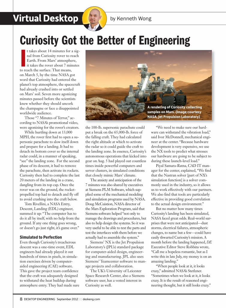
It takes about 14 minutes for a sig-nal from Curiosity rover to reach Earth. From Mars’ atmosphere, it takes the rover about 7 minutes
to reach the surface. That means, on March 5, by the time NASA got word that Curiosity had entered the planet’s top atmosphere, the spacecraft had already crashed into or settled on Mars’ soil. Seven more agonizing minutes passed before the scientists knew whether they should uncork the champagne or face a disappointed worldwide audience.
Those “7 Minutes of Terror,” ac-cording to NASA’s promotional video, were agonizing for the rover’s creators.
While hurtling down at 13,000 MPH, the rover first had to open a su-personic parachute to slow itself down and prepare for a landing. It had to detach its bottom cover so the internal radar could, in a manner of speaking, “see” the landing zone. For the second phase of its descent, it had to remove the parachute, then activate its rockets. Curiosity then had to complete the last 20 meters of the landing in a crane, dangling from its top cap. Once the rover was on the ground, the rocket-propelled top had to detach and fly off to avoid crashing into the craft below.
Tom Rivellini, a NASA Entry, Descent, Landing (EDL) engineer, summed it up: “The computer has to do it all by itself, with no help from the ground. If any one thing goes wrong, or doesn’t go just right, it’s game over.”
Simulated to PerfectionEven though Curiosity’s treacherous descent was a one-time event, EDL engineers had already played it out hundreds of times in pixels, in simula-tion exercises driven by computer-aided engineering (CAE) software. This gave the project team confidence that the craft was adequately designed to withstand the heat buildup during atmosphere entry. They had made sure
the 100-lb. supersonic parachute could put a break on the 65,000-lb. force of the falling craft. They had calculated the right altitude at which to activate the radar so it could guide the craft to the landing zone. In essence, Curiosity’s autonomous operations that kicked into gear on Aug. 5 had played out countless times inside powerful computers and server clusters, in simulated conditions that closely mimic Mars’ climate.
The anxiety and anticipation of the 7 minutes was also shared by executives at Siemens PLM Software, which sup-plied some of the mechanical modeling and simulation programs used by NASA. Doug McCuistion, NASA director of the Mars Exploration Program, said that Siemens software helped “not only to manage the drawings and procedures, but also to help design the systems. So it was very useful to be able to test the parts and test the interfaces with them before we actually had to assemble the system.”
Siemens’ NX is the Jet Propulsion Laboratory’s (JPL’s) standard package for computer-aided design, engineer-ing and manufacturing. JPL also uses Siemens’ Teamcenter software to man-age projects and collaboration.
The UK’s University of Leicester Space Research Center, also a Siemens software user, has a vested interest in Curiosity as well.
“We need to make sure our hard-ware can withstand the vibration load,” said Ivor McDonnell, mechanical engi-neer at the center. “Because hardware development is very expensive, we use the NX tools to predict what stresses our hardware are going to be subject to during these launch-level load.”
Piyal Samara-Ratna, CAD IT man-ager for the center, explained, “We find that the Nastran solver [part of NX’s simulation function] is a solver com-monly used in the industry, so it allows us to work effectively with our partners. We also find that tools are particularly effective in providing good correlation to the actual design environment.”
But no matter how many times Curiosity’s landing has been simulated, NASA faced great odds. Real-world sur-prises that were not anticipated—dust storms, electrical failures, atmospheric changes, to name but a few—could have easily thwarted Curiosity’s mission. A month before the landing happened, DE Executive Editor Steve Robbins wrote, “Call me a hopeless romantic, but as I write this in late July, my money is on an amazing landing.”
“When people look at it, it looks crazy,” admitted NASA’s Stetlzner. “Sometimes when we look at it, it looks crazy. It is the result of reasoned engi-neering thought, but it still looks crazy.”
Curiosity Got the Better of Engineering
A rendering of Curiosity collecting samples on Mars. (Image courtesy NASA, Jet Propulsion Laboratory)
de0912_VD_Wong.indd 8 8/14/12 12:45 PM

“�There�are�more�things�in�heaven�and�earth…than�are�dreamt�of�in�your�philosophy.”
–William Shakespeare
Create�the�wings�of�an�airplane.�Design�dazzling�new�worlds.�Whatever�your�digital�challenge,�AMD�FirePro™�professional�graphics�cards�can�help�you�do�it�better.�You’ll�see�more�and�do�more�by�using�up�to�six�displays1�
�at�the�same�time�with�our�exclusive�AMD�Eyefinity�multi-display�technology�—�and�still�have�just�a�single�graphics�card�in�your�system.�If�your�work�calls�for�the�latest�industry�standards,�such�as�OpenGL®,�OpenCL™�and�DirectX®11�technology,�your�AMD�FirePro™�professional�graphics�card�fully�supports�them.�Choose�AMD,��and�unleash�your�digital�potential.
1 AMD Eyefinity technology can support up to six DisplayPort displays using a single enabled AMD graphics card. The number of supported displays varies by card model and board design; confirm specifications with the manufacturer before purchase. Additional hardware may be required. Utilizing DisplayPort 1.2 and Multi-Stream technology-enabled displays, connectors and/or hubs, a single graphics card may support up to two more displays than it has display outputs; limit six displays. Microsoft® Windows® 7, Windows Vista®, or Linux® is required to support more than 2 displays; Windows XP is no longer supported. AMD Eyefinity technology works with applications that support non-standard aspect ratios, which is required for panning across multiple displays. SLS (“Single Large Surface”) functionality requires an identical display resolution on all displays. See www.amd.com/firepro or www.amd.com/eyefinity for details.
© 2012 Advanced Micro Devices, Inc. All rights reserved. AMD, the AMD logo, FirePro, the FirePro logo, and combinations thereof are trademarks of Advanced Micro Devices, Inc. Microsoft, Windows, Windows Vista and DirectX are registered trademarks of Microsoft Corporation in the United States and/or other jurisdictions. OpenCL is a trademark of Apple Inc., and is used with permission from Khronos. Other names are for informational purposes only and may be trademarks and/or registered trademarks of their respective owners. PID 52386C
Be�limitless,�when�every�detail�counts.Demand�AMD�FirePro™�in�your�system.
Visit�www.amd.com/firepro�to�learn�more.
52386C_FireProTechnology_DE_MAGAZINE_FINAL.indd 1 8/9/12 4:56 PMAMD.indd 1 8/14/12 12:38 PM
Virtual Desktop by Kenneth Wong
10 DESKTOP ENGINEERING September 2012 /// deskeng.com
T he term that has lately been stirring up discussions and de-bates among DE editors is op-timization. After a recent visit
to Altair’s office in Troy, MI, I found myself deep in conversation with DEManaging Editor Jamie Gooch and Ex-ecutive Editor Steve Robbins about the very topic. It’s important for us to have consensus, because we’re considering a number of articles devoted to the sub-ject in the year-end issue. The tone, the stories—and the perspectives of these stories—will very likely be determined by how we define optimization.
Altair recently launched Altair-Enlighten.com, a site dedicated to reduc-ing weight in product design. In Altair’s own words, the Enlighten portal “strives to be the world’s leading source for use-ful, informative and inspirational content concerned with minimizing the weight of products across industry.”
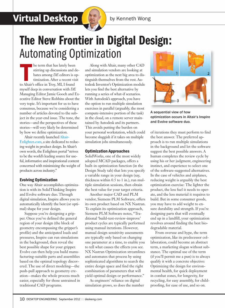
Evolving OptimizationOne way Altair accomplishes optimiza-tion is with its SolidThinking Inspire and Evolve software duo. Through digital simulation, Inspire allows you to automatically identify the best (or opti-mal) shape for your design.
Suppose you’re designing a grip-per. Once you’ve defined the general region of your design (the block of geometry encompassing the gripper’s profile) and the anticipated loads and pressures, Inspire can run simulations in the background, then reveal the best possible shape for your gripper. Evolve can then help you build manu-facturing-suitable parts and assemblies based on the optimal topology discov-ered. The use of direct modeling—the push-pull approach to geometry cre-ation—makes the whole process much easier, especially for those untrained in traditional CAD programs.
Along with Altair, many other CAD and simulation vendors are looking at optimization as the next big area to dis-tinguish themselves from the rest. Au-todesk Inventor’s Optimization module lets you find the best alternative by running a series of what-if scenarios. With Autodesk’s approach, you have the option to run multiple simulation exercises in parallel (arguably, the most compute-intensive portion of the task) in the cloud, on a remote server main-tained by Autodesk and its partners. This avoids putting the burden on your personal workstation, which could become sluggish if it takes on multiple simulation jobs simultaneously.
Optimization ApproachesSolidWorks, one of the most widely adopted MCAD packages, offers a built-in optimization function (in the Design Study tab) that lets you specify a variable range in your design (say, thickness within 0.5 to 1 in.), run mul-tiple simulation sessions, then obtain the best value for your target criteria.
Another major CAD and PLM vendor, Siemens PLM Software, offers its own product based on NX Nastran. To explain its optimization approach, Siemens PLM Software notes, “Tra-ditional ‘build-test-review-improve’ product cycles are typically performed using manual iterations. However, manual design sensitivity assessments are typically only based on changing one parameter at a time, to enable you to tell what causes the effects you see. NX Nastran Optimization streamlines and automates that process by using sophisticated algorithms to search the entire design space and find the right combination of parameters that will yield optimal design or performance.”
As engineers’ reliance on digital simulation grows, so does the number
of iterations they must perform to find the best answer. The preferred ap-proach is to run multiple simulations in the background and let the software suggest the best possible answers. A human completes the review cycle by using his or her judgment, engineering instinct, and experience to select one of the software-suggested alternatives. In the case of vehicles and airplanes, reducing weight is arguably the best optimization exercise: The lighter the product, the less fuel it needs to oper-ate, and the less material it requires to build. But in some consumer goods, you may have to add weight to en-sure durability and strength. If you’re designing parts that will eventually end up in a landfill, your optimization revolves around finding the best bio-degradable material.
From overuse and hype, the term optimization, like its predecessor col-laboration, could become an abstract term, a marketing slogan without sub-stance. The optimal use of the term (if you’ll permit me a pun) is to always qualify it with a concrete objective: Optimizing the design for environ-mental health, for quick deployment in combat zones, for longevity, for recycling, for easy assembly, for child-proofing, for ease of use, and so on.
The New Frontier in Digital Design:Automating Optimization
A sequential view of how optimization occurs in Altair’s Inspire and Evolve software duo.
de0912_VD_Wong.indd 10 8/14/12 12:45 PM
NX CAE: Smarter decisions, better products.
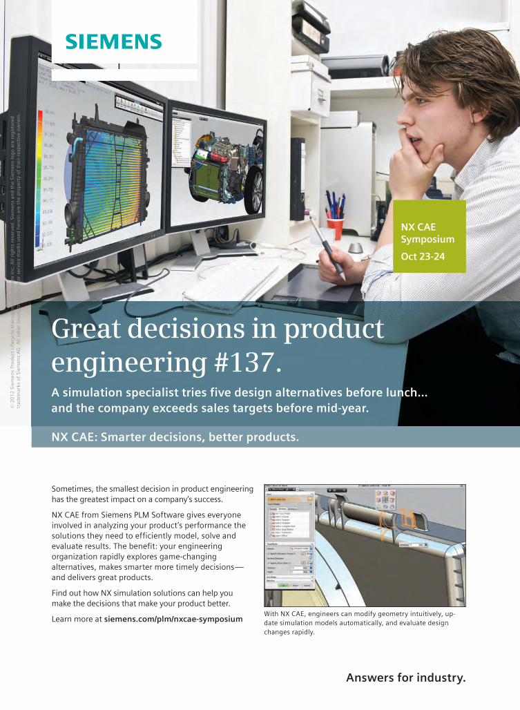
Great decisions in product engineering #137.A simulation specialist tries five design alternatives before lunch…and the company exceeds sales targets before mid-year.
Answers for industry.
With NX CAE, engineers can modify geometry intuitively, up-date simulation models automatically, and evaluate design changes rapidly.
Sometimes, the smallest decision in product engineering has the greatest impact on a company’s success.
NX CAE from Siemens PLM Software gives everyone involved in analyzing your product’s performance the solutions they need to efficiently model, solve and evaluate results. The benefit: your engineering organization rapidly explores game-changing alternatives, makes smarter more timely decisions—and delivers great products.
Find out how NX simulation solutions can help you make the decisions that make your product better.
Learn more at siemens.com/plm/nxcae-symposium
© 2
01
2 S
iem
ens
Pro
du
ct L
ifec
ycle
Man
agem
ent
Soft
war
e In
c. A
ll ri
gh
ts r
eser
ved
. Si
emen
s an
d t
he
Siem
ens
log
o a
re r
egis
tere
d tr
adem
arks
of
Siem
ens
AG
. A
ll ot
her
log
os,
tra
dem
arks
or
serv
ice
mar
ks u
sed
her
ein
are
th
e p
rop
erty
of
thei
r re
spec
tive
ow
ner
s.
NX CAE Symposium
Oct 23-24
Siemens_NXCAE_DTE_SEP2012.indd 1 8/8/12 2:37:37 PMSiemens_Full_pg.indd 1 8/14/12 12:38 PM
Virtual Desktop by Kenneth Wong
12 DESKTOP ENGINEERING September 2012 /// deskeng.com
I t’s easy to forget that the ubiq-uitous search box that has be-come such an integral part of how we find and locate informa-
tion today is a fairly recent phenom-enon. It’s made possible by search engine providers’ preparatory effort to scan, classify and tag the vast body of knowledge we now have at our disposal. Without their service, it would take much more labor on our end to locate what we need, buried somewhere among homegrown cold remedies and scientific papers on the origin of the universe.
Finding and locating a 3D part, however, requires a slightly differ-ent approach, because the infor-mation you seek is geometric, not always describable in text strings, keywords and metadata. This is where emerging shape-based search technologies can give you an ad-vantage. Shape-based searches scan, find and locate matching results based on geometry, not file names and tags alone; therefore, if the ref-erence information is geometry—say, a unique type of bracket or a non-standard hammerhead—you have a much greater chance of lo-cating matching models.
Search AlgorithmsA good example of a shape-based search technology is CADseek from iSeek. CADseek employs “fully auto-mated shape coding” and “fully au-tomated classification,” the company says. According to Abir Qamhiyah, president and CEO of iSeek, CAD-seek “doesn’t work by predefined classifications, rule-based hierarchy … We don’t try to slice objects, we don’t send down [the reference ge-ometry] as skeleton, and we certainly do not depend on extracted views or
profiles to reduce the complexity of the geom-etry to the 2D domain. We take the full geom-etry content with its full richness, and feed it into our mathematical cod-ing algorithm. The code becomes the exact corre-spondent of the true 3D content the shape owns.”
Google and other successful search engines accomplish this with sophisticated algorithms that take into account your past search his-tory, the words and phrases you use to search, and display the results in order of relevance. The most likely answers appear at the top; the less-relevant answers are at the bottom.
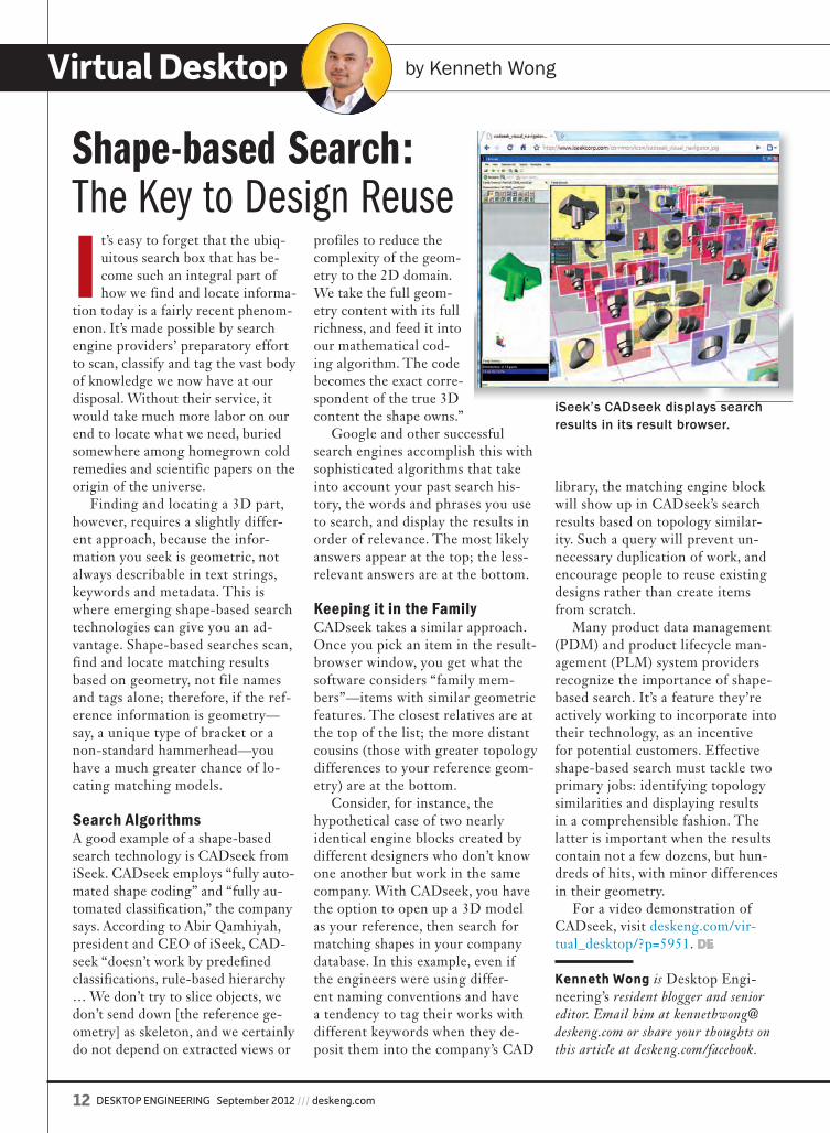
Keeping it in the FamilyCADseek takes a similar approach. Once you pick an item in the result-browser window, you get what the software considers “family mem-bers”—items with similar geometric features. The closest relatives are at the top of the list; the more distant cousins (those with greater topology differences to your reference geom-etry) are at the bottom.
Consider, for instance, the hypothetical case of two nearly identical engine blocks created by different designers who don’t know one another but work in the same company. With CADseek, you have the option to open up a 3D model as your reference, then search for matching shapes in your company database. In this example, even if the engineers were using differ-ent naming conventions and have a tendency to tag their works with different keywords when they de-posit them into the company’s CAD
library, the matching engine block will show up in CADseek’s search results based on topology similar-ity. Such a query will prevent un-necessary duplication of work, and encourage people to reuse existing designs rather than create items from scratch.
Many product data management (PDM) and product lifecycle man-agement (PLM) system providers recognize the importance of shape-based search. It’s a feature they’re actively working to incorporate into their technology, as an incentive for potential customers. Effective shape-based search must tackle two primary jobs: identifying topology similarities and displaying results in a comprehensible fashion. The latter is important when the results contain not a few dozens, but hun-dreds of hits, with minor differences in their geometry.
For a video demonstration of CADseek, visit deskeng.com/vir-tual_desktop/?p=5951. DE
Kenneth Wong is Desktop Engi-neering’s resident blogger and senior editor. Email him at [email protected] or share your thoughts on this article at deskeng.com/facebook.
Shape-based Search:The Key to Design Reuse
iSeek’s CADseek displays search results in its result browser.
de0912_VD_Wong.indd 12 8/14/12 12:46 PM

This is AcuSolve, not just another CFD solver. It’s finite element-based and achieves
excellent correlation to industry standard benchmarks while being forgiving to the
element quality of your model. Solution times are fast for both steady state and
transient problems, plus AcuSolve uses a flexible licensing model that replaces
expensive traditional plans. Accuracy, robustness, and speed, all part of HyperWorks,
the broadest CAE platform. Really.
Learn how AcuSolve can help you solve your CFD challenges by visiting altair.com/really
Photograph courtesy of HTT Automobile httsupercar.com
Really,Another CFD Solver?
Follow Altair on:
Innovation Intelligence®
Altair.indd 1 8/14/12 12:39 PM
Engineering on the Edge Future Focus
14 DESKTOP ENGINEERING September 2012 /// deskeng.com
Northwestern Stretches Electronics TechImplanted electronics typically risk rejection, and most electronics have the potential to cause injury because the materials they are constructed from are far more rigid than the fleshy human body. Researchers at Northwestern University’s McCormick School of Engineering have been working on this problem—and as a result, have designed flexible electronics that could be used for remote patient monitoring, among other applications.
The new electronics are able to stretch to more than 200% of their original size. According to the university, that is four times greater elasticity than is available now. The secret to the breakthrough is the result of combining a porous polymer and liquid metal, with no loss of conductivity.
“With current technology, electronics are able to stretch a small amount, but many potential applications require a device to stretch like a rubber band,” says Yonggang Huang, Joseph Cummings professor of Civil and Environmental Engineering and Mechanical Engineering. “With that level of stretchability we could see medical devices integrated into the human body.”
MORE ➜ engineeringontheedge.com/?p=2193
Simulation Drives Magnetic Drive SystemsIn any design project, simulation plays a key role in testing (and discarding) the often-countless possible variations of any given construct. But that’s something Sheffield, UK-based Magnomatics has been able to leverage in the design of its magnetic power transmissions.
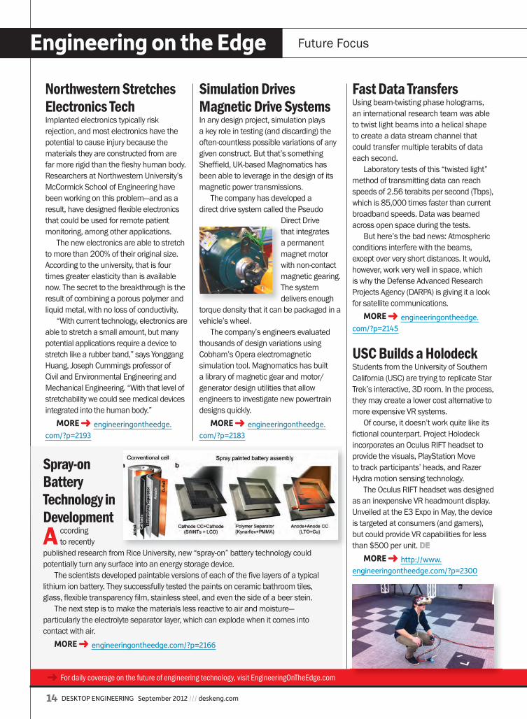
The company has developed a direct drive system called the Pseudo
Direct Drive that integrates a permanent magnet motor with non-contact magnetic gearing. The system delivers enough
torque density that it can be packaged in a vehicle’s wheel.
The company’s engineers evaluated thousands of design variations using Cobham’s Opera electromagnetic simulation tool. Magnomatics has built a library of magnetic gear and motor/generator design utilities that allow engineers to investigate new powertrain designs quickly.
MORE ➜ engineeringontheedge.com/?p=2183
Spray-on Battery Technology in DevelopmentA ccording
to recently published research from Rice University, new “spray-on” battery technology could potentially turn any surface into an energy storage device.
The scientists developed paintable versions of each of the five layers of a typical lithium ion battery. They successfully tested the paints on ceramic bathroom tiles, glass, flexible transparency film, stainless steel, and even the side of a beer stein.
The next step is to make the materials less reactive to air and moisture—particularly the electrolyte separator layer, which can explode when it comes into contact with air.
MORE ➜ engineeringontheedge.com/?p=2166
Fast Data TransfersUsing beam-twisting phase holograms, an international research team was able to twist light beams into a helical shape to create a data stream channel that could transfer multiple terabits of data each second.
Laboratory tests of this “twisted light” method of transmitting data can reach speeds of 2.56 terabits per second (Tbps), which is 85,000 times faster than current broadband speeds. Data was beamed across open space during the tests.
But here’s the bad news: Atmospheric conditions interfere with the beams, except over very short distances. It would, however, work very well in space, which is why the Defense Advanced Research Projects Agency (DARPA) is giving it a look for satellite communications.
MORE ➜ engineeringontheedge.com/?p=2145
USC Builds a HolodeckStudents from the University of Southern California (USC) are trying to replicate Star Trek’s interactive, 3D room. In the process, they may create a lower cost alternative to more expensive VR systems.
Of course, it doesn’t work quite like its fictional counterpart. Project Holodeck incorporates an Oculus RIFT headset to provide the visuals, PlayStation Move to track participants’ heads, and Razer Hydra motion sensing technology.
The Oculus RIFT headset was designed as an inexpensive VR headmount display. Unveiled at the E3 Expo in May, the device is targeted at consumers (and gamers), but could provide VR capabilities for less than $500 per unit. DE
MORE ➜ http://www.engineeringontheedge.com/?p=2300
➜ For daily coverage on the future of engineering technology, visit EngineeringOnTheEdge.com
that integrates
with non-contact
The system
de0912_Edge_Albright.indd 14 8/14/12 12:48 PM

Put Our Expertise to Work For You
Users worldwide pushing the limits of technology in engineering, simulation, media, and research rely on Microway’s expertise and attention to detail. From configuration to integration to technical support, we’ve been resolving the complicated issues – so you don’t have to – since 1982.
Call a Technical Advisor at 508-746-7341 Visit microway.com/maximus Sign up for our technical newsletter at microway.com/newsletter Visit our blog at microway.com/hpc-tech-tips
CUDA-Enabled Applications Supported by WhisperStation:
Abaqus, Acusim Acusolve, Fluent, MSC Nastran and Moldflow for Simulations AMBER, CUDA-BLASTP, GROMACS, LAMMPS, NAMD, Quantum ESPRESSO, TeraChem and VMD for BioTech
Design & Simulate Without the Wait!New NVIDIA® Maximus™ Technology Provides Integrated Workflow on a Single WhisperStation™
WhisperStation – Maximus enables you to visualize on the NVIDIA Quadro® GPU, while automatically offloading simulation and rendering onto the NVIDIA Tesla® GPU. By providing explosive performance, WhisperStation – Maximus shortens your development time and accelerates your workflow. Faster and Greener Computing with:
NVIDIA Quadro® GPUs for visualization + NVIDIA Tesla GPUs for lightning-fast computationHigh clock speed Intel® CPUs; SSDs and/or RAID for fast I/O; up to 8 drives 1P Configuration – 4 or 6 core Intel CPU, 2 GPUs, and 8 DIMM sockets for up to 64 GB DDR3 Memory 2P Configuration – two 4, 6, or 8 core Intel CPUs, 1 to 4 GPUs, and 16 DIMM sockets for up to 512 GB Memory80 PLUS™ certified power supplies, ultra-quiet fans, sound proofing materials and high-efficiency componentsLinux and/or Windows configured, tested and ready to run your applicationsPCI-E Gen3 support for future Tesla and Quadro upgrades
Technology can count on since 1982
Maximus Certified Applications Include: 3d Design
3ds Max®
Bunkspeed
CATIA® V5/V6
PTC Creo™
Media
Adobe® CS6
Adobe CS5
Maya®
Engineering
ANSYS® Mechanical
SIMULIA®
SolidWorks®
MATLAB®
GS-35F-0431N
GSA ScheduleContract Number:GS-35F-0431N
Microway.indd 1 8/14/12 12:39 PM
Rapid Ready Tech Making Digital Designs Physical
16 DESKTOP ENGINEERING September 2012 /// deskeng.com
Solidscape Announces 3Z ProSolidscape, a Stratasys company, has announced its newest 3D printer, the 3Z Pro. This system continues the use of Solidscape’s drop-on-demand (DOD) thermoplastic ink-jetting technology, along with precision milling of each layer. For those unfamiliar with Solidscape, the company’s process is mainly used to create objects for lost-wax casting/investment casting and mold-making applications, using a wax-like material.
The 3Z Pro is a desktop printer, weighing in at 80 lbs. and a footprint of 21.4x18x16 in. It has a build envelope of 6x6x4 in., with a resolution of 5,000 x 5,000 dpi and an accuracy of ±0.001 in.MORE ➜ rapidreadytech.com/?p=1802
Aluminum Composites Research AdvancesResearchers from the UK’s University of Exeter published a paper in the Journal of Alloys and Compounds, documenting their work with aluminum composites for use in additive manufacturing (AM), specifically for use in laser sintering.
The goal of the Exeter researchers was to find specific powder mixes of aluminum and other metals. By mixing in an iron o xide combination, for example, the team was able to build objects with complex geometries that retained the light weight of aluminum, but were more durable.
The new materials have fine particles compared with other composites, making them more robust. The reaction between constituents releases energy, which also means materials can be produced at a higher rate using less power. This technique is cheaper and more sustainable than other selective laser melting methods.
MORE ➜ rapidreadytech.com/?p=1837
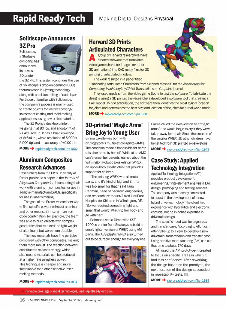
3D-printed ‘Magic Arms’ Bring Joy to Young UserEmma Lavelle was born with arthrogryposis multiplex congenita (AMC). The condition made it impossible for her to raise her arms by herself. While at an AMC conference, her parents learned about the Wilmington Robotic Exoskeleton (WREX), an upper-body exoskeleton that provides support for children.
“The existing WREX was all metal parts, and it’s kind of big, and Emma was too small for that,” said Tariq Rahman, head of pediatric engineering and research, Nemours/Alfred I. duPont Hospital for Children in Wilmington, DE. “So we required something light and small that would attach to her body and go with her.”
Rahman used a Dimension SST 1200es printer from Stratasys to build a small, lighter version of WREX using AM parts. The ABS plastic WREX also turned out to be durable enough for everyday use.
Harvard 3D Prints Articulated CharactersA group of Harvard researchers have
created software that translates video game character images (or other 3D animations) into CAD-ready files for 3D printing of articulated models.
The work resulted in a paper titled “Fabricating Articulated Characters from Skinned Meshes” for the Association for Computing Machinery’s (ACM’s) Transactions on Graphics journal.
They used models from the video game Spore to test the software. To fabricate the designs using a 3D printer, the researchers developed a software tool that creates a CAD model. To add articulation, the software then identifies the most logical location for joints and determines the best size and location of the joints for a real-world model.MORE ➜ rapidreadytech.com/?p=1938
➜ For more coverage of rapid technologies, visit RapidReadyTech.com
Emma called the exoskeleton her “magic arms” and would begin to cry if they were taken away for repair. Since the creation of the smaller WREX, 15 other children have benefited from 3D printed exoskeletons.MORE ➜ rapidreadytech.com/?p=1949
Case Study: Applied Technology IntegrationApplied Technology Integration (ATI) provides product development, engineering, finite element analysis (FEA), design, prototyping and testing services. The company was recently contracted to assist in the development of a new hybrid drive technology. The client had experience with hydraulics and electronic controls, but no in-house expertise in drivetrain design.
The specific need was for a gearbox and transfer case. According to ATI, it can often take up to a year to develop a new drivetrain, transmission and transfer case. Using additive manufacturing (AM) can cut that time to about 170 days.
ATI used the AM prototype it created to focus on specific areas in which it had less confidence. After reworking the design based on the prototype, the next iteration of the design succeeded in repeatability tests. DEMORE ➜ rapidreadytech.com/?p=1993
Making Digital Designs Physical
de0912_RapidReady_.indd 16 8/15/12 9:41 AM
deskeng.com /// September 2012 DESKTOP ENGINEERING 17
Simulink and SimPowerSystems What’s New
Based in Germany, Steve Miller is a technical marketing manager for physi-cal modeling products for MathWorks. Desktop Engineering recently spoke with Miller to understand some of MathWorks’ latest products, its philosophy in offer-ing physical modeling software, the Simulink family of products, and its SimPowerSystems product:
DE: Can you give us an overview of Simulink? SM: Simulink is an environment for multi-domain simulation and model-based design (MBD) for dynamic and embedded systems. MBD with MATLAB and Simulink provides an interactive graphical environment and a customiz-able set of block libraries that allows engineers, scientists and researchers across the globe design, simulate, imple-ment and test a variety of time-varying systems, including communications, controls, signal processing, video pro-cessing and image processing.
MBD begins with the creation of an executable specification that can be linked to the original requirements, providing two-way traceability between the design and the requirements. At the heart of the executable specifica-tion is an executable model, used and elaborated on throughout the process. The executable specification can also include inputs and expected outputs, the application environment and clear communication of the design goals to enable feasibility analysis of the require-ments. By using the links in the execut-able specification to the original require-ments, engineers can monitor whether the design conforms to the require-ments throughout the process, and quickly assess the impact of a proposed change on original requirements.
DE: Let’s talk a little about your recently released SimPowerSystems.SM: SimPowerSystems is used to model and simulate electrical power systems, covering the generation, transmission, distribution and consumption of elec-trical power. For example, it includes the power supplies used in laptops, power converters used in solar power systems and electric drives, and the electrical grid that transmits and dis-tributes renewable energy sources to our homes. SimPowerSystems provides models of many components used in these systems, and automates key power system analyses, such as those used to check required component sizes and detect harmonics or other problems in the system.
The recent announcement discusses the new, stronger connection from SimPowerSystems to Simscape and other physical modeling products in the Simulink family. With new capabilities such as support for the Simscape Editing Mode, SimPowerSystems 5.5 now offers engineers the ability to share models of electrical power systems with all other Simscape users. SimPowerSystems models can connect to models built using Simscape and other domain-specific add-on products, such as SimMechanics and SimHydraulics—helping engineers detect integration issues among electrical, mechanical and control systems early in the development process.
DE: From your point of view, what do your products offer that other simulation software developers do not offer? SM: Through the MATLAB and Simulink families, MathWorks products offer a development environment where engineers create a model of the entire system that is used throughout the entire
development process. There are two key points in that state-
ment: the entire system and the entire development process. Engineers can add just as much detail as they need for a given task, and quickly adjust the level of fidelity of any part of their system as necessary. This makes it possible to simulate the entire system in a reason-able amount of time, and find integration problems early. By using the same model from start to finish, from requirements gathering and refinement through test-ing of the final software design on the embedded system, it enables engineers to be extremely efficient by detecting problems as early as possible.
DE: What attributes of simulation soft-ware truly drive its effectiveness? SM: The effectiveness of simulation software can be measured by its capa-bilities that help an engineer get the job done quickly. Anything provided that saves engineers time will make them more effective.
With MATLAB, engineers can automate virtually any task they need to perform in the MathWorks toolchain, eliminating repetitive work. SimPowerSystems and SimDriveline make it possible for engineers to model a physical system without deriving and programming equations, allowing them to spend more time on design and analysis—and less time on program-ming and implementation. DE
Jim Romeo is based in Chesapeake, VA. Contact him via [email protected].
MathWorks’ Simulink Family: Have Equation, Will TravelBy JiM Ro MEo
iNFo ➜ MathWorks: MathWorks.com
For more information on this topic, visit deskeng.com.
de0612_WhatsNew_MathWorks_Romeo.indd 17 8/14/12 1:18 PM
Editor’s Picks by Anthony J. Lockwood
Each week, Tony Lockwood combs through dozens of new products to bring you the ones he thinks will help you do your job better, smarter and faster. Here are Lockwood’s most recent musings about the products that have really grabbed his attention.
18 DESKTOP ENGINEERING September 2012 /// deskeng.com
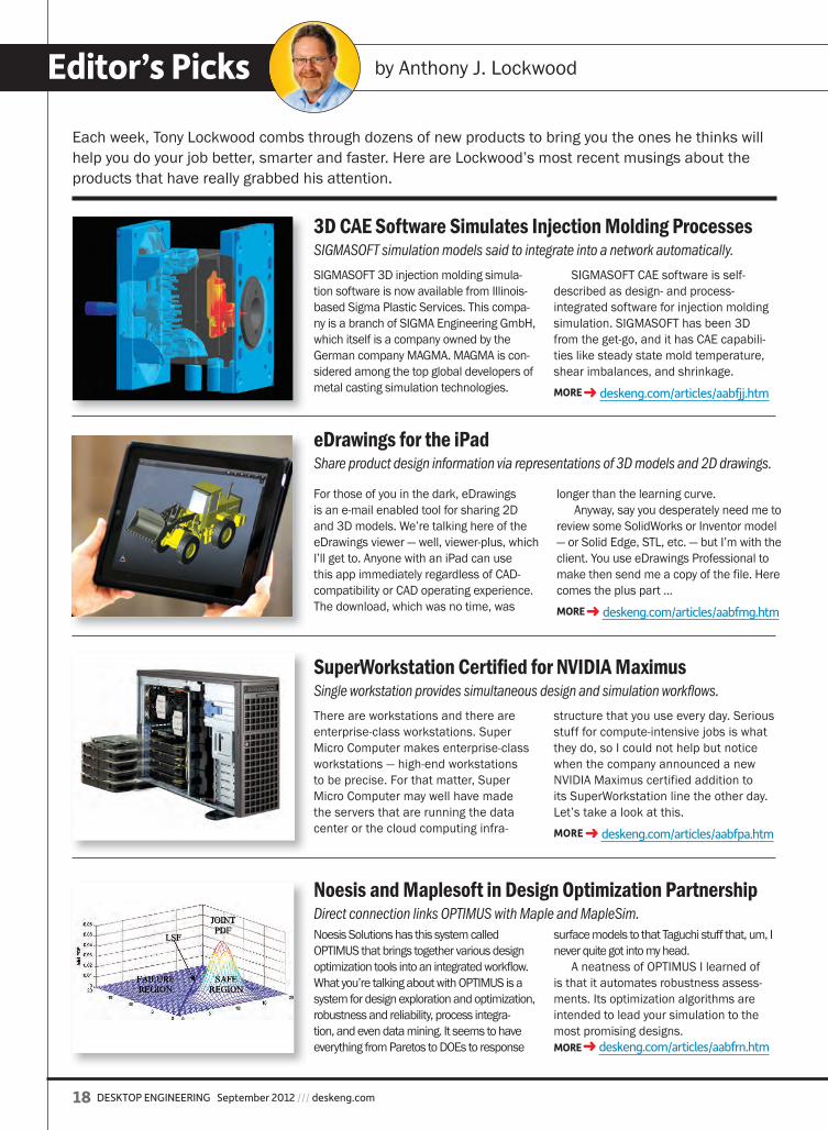
SIGMASOFT 3D injection molding simula-tion software is now available from Illinois-based Sigma Plastic Services. This compa-ny is a branch of SIGMA Engineering GmbH, which itself is a company owned by the German company MAGMA. MAGMA is con-sidered among the top global developers of metal casting simulation technologies.
SIGMASOFT CAE software is self-described as design- and process-integrated software for injection molding simulation. SIGMASOFT has been 3D from the get-go, and it has CAE capabili-ties like steady state mold temperature, shear imbalances, and shrinkage.MORE ➜ deskeng.com/articles/aabfjj.htm
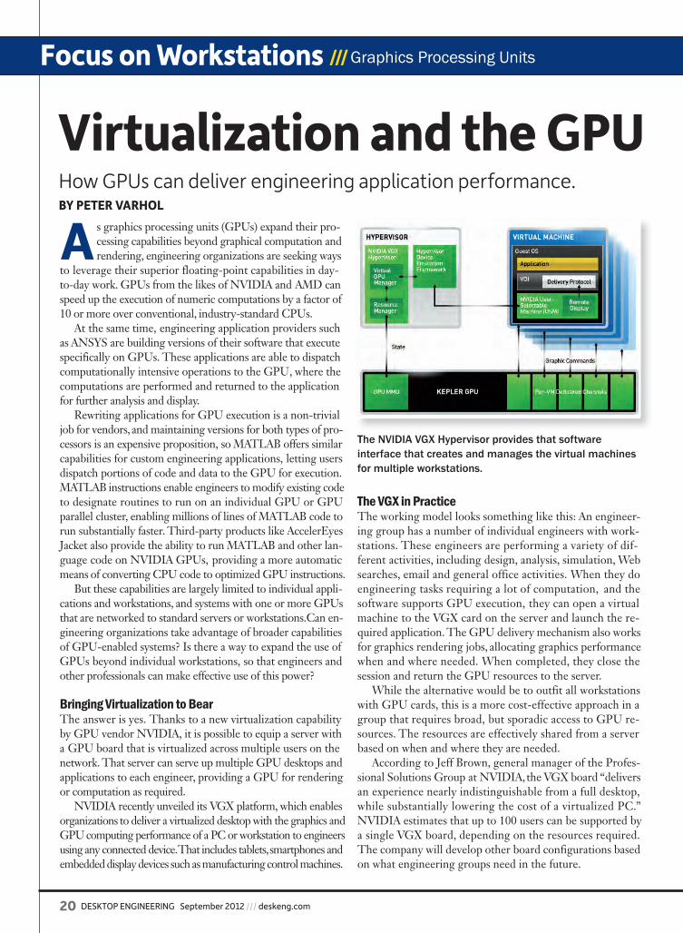
For those of you in the dark, eDrawings is an e-mail enabled tool for sharing 2D and 3D models. We’re talking here of the eDrawings viewer — well, viewer-plus, which I’ll get to. Anyone with an iPad can use this app immediately regardless of CAD-compatibility or CAD operating experience. The download, which was no time, was
longer than the learning curve.Anyway, say you desperately need me to
review some SolidWorks or Inventor model — or Solid Edge, STL, etc. — but I’m with the client. You use eDrawings Professional to make then send me a copy of the file. Here comes the plus part ...MORE ➜ deskeng.com/articles/aabfmg.htm
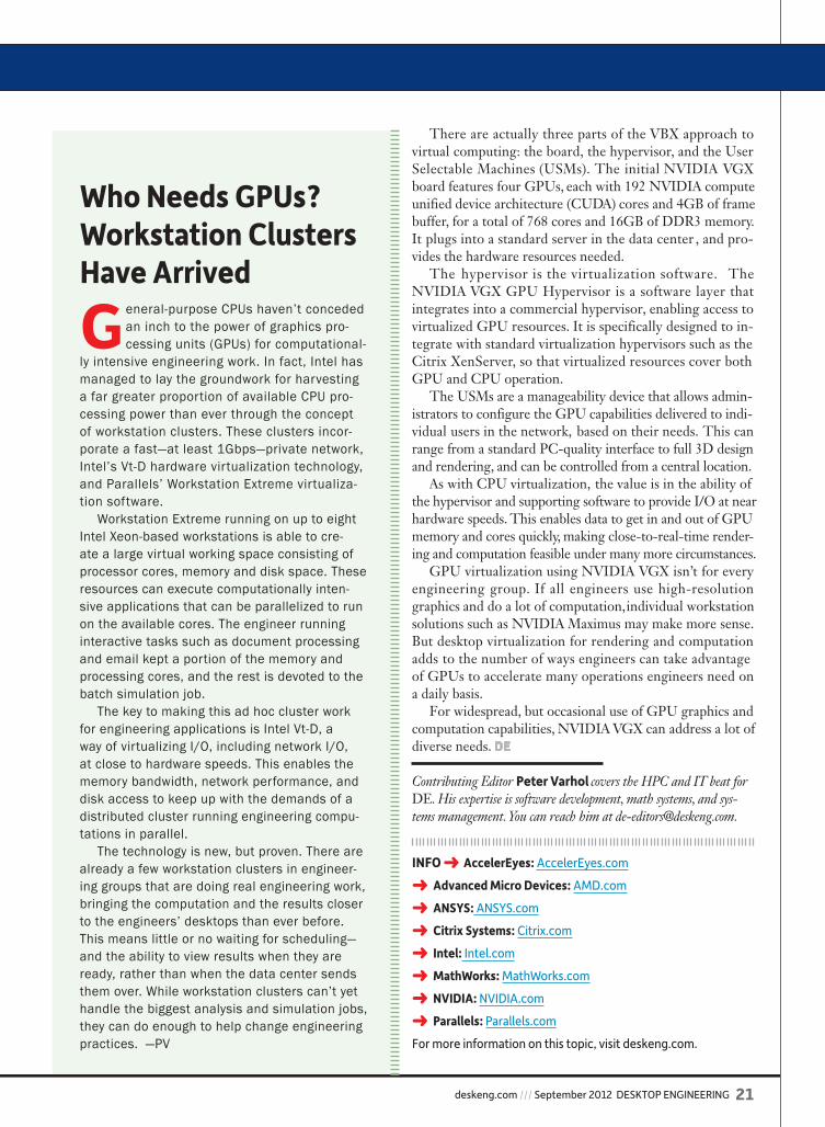
There are workstations and there are enterprise-class workstations. Super Micro Computer makes enterprise-class workstations — high-end workstations to be precise. For that matter, Super Micro Computer may well have made the servers that are running the data center or the cloud computing infra-
structure that you use every day. Serious stuff for compute-intensive jobs is what they do, so I could not help but notice when the company announced a new NVIDIA Maximus certified addition to its SuperWorkstation line the other day. Let’s take a look at this.MORE ➜ deskeng.com/articles/aabfpa.htm
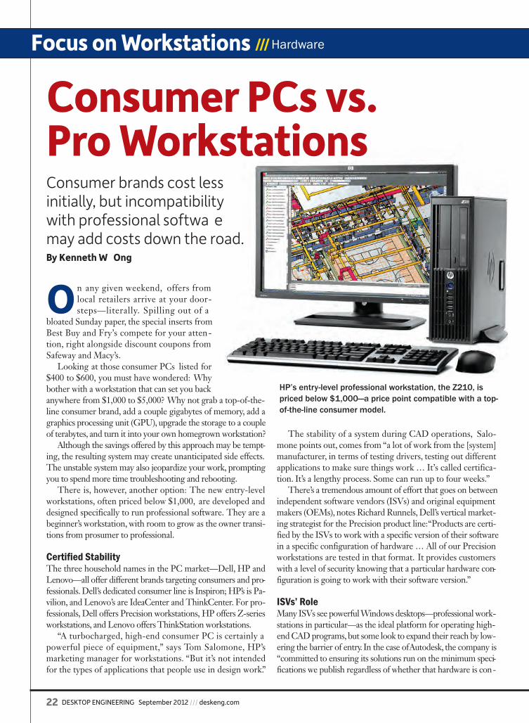
Noesis Solutions has this system called OPTIMUS that brings together various design optimization tools into an integrated workflow. What you’re talking about with OPTIMUS is a system for design exploration and optimization, robustness and reliability, process integra-tion, and even data mining. It seems to have everything from Paretos to DOEs to response
surface models to that Taguchi stuff that, um, I never quite got into my head.
A neatness of OPTIMUS I learned of is that it automates robustness assess-ments. Its optimization algorithms are intended to lead your simulation to the most promising designs.MORE ➜ deskeng.com/articles/aabfrn.htm
3D CAE Software Simulates Injection Molding ProcessesSIGMASOFT simulation models said to integrate into a network automatically.
eDrawings for the iPadShare product design information via representations of 3D models and 2D drawings.
SuperWorkstation Certified for NVIDIA MaximusSingle workstation provides simultaneous design and simulation workflows.
Noesis and Maplesoft in Design Optimization PartnershipDirect connection links OPTIMUS with Maple and MapleSim.
de0912_EditorsPicks.indd 18 8/14/12 12:52 PM

deskeng.com /// September 2012 DESKTOP ENGINEERING 19
Engineering Case Studies Fast Apps
Creating a jetpack for the mass market has long been Glenn Martin’s dream. For the past 30 years, the founder of Martin Aircraft has pursued that goal. In 2008, he moved all development onto a 3D design platform to accelerate the process. The move resulted in the selec-tion of the Martin Jetpack as one of Time magazine’s 50 Best Inventions of 2010.Martin Aircraft selected SolidWorks solutions to finalize develop-
ment of the jetpack, implementing SolidWorks Professional and SolidWorks Premium design software, and SolidWorks Simulation and SolidWorks Flow Simulation analysis tools. The Martin Jetpack uses vector controls and a custom-
designed gasoline engine, which drives twin-ducted fans that produce sufficient thrust to lift and stabilize the jetpack dur-ing vertical takeoff and landing, enabling sustained flight.
The Jet SetMartin Aircraft Co. innovates the world’s first practical jetpack with SolidWorks solutions.
DREAM. CREATE.
MONTHS OF PLANNING | A FuTurISTIc MOvIe SeT | AN IdeA TurNed TO reALITy.
Lenovo® recommends Windows® 7 Professional.
INTrOducING THe LeNOvO® THINKSTATION® 30 SerIeS, FeATurING THe d30 FOr HIGH-eNd GrAPHIcS ANd PrOceSSING POWer. Energy-efficient • Quiet Acoustics • Scalable Storage • ISV-certified
www.lenovo.com/thinkstation
Lenovo, the Lenovo logo, For Those Who Do and ThinkStation are trademarks or registered trademarks of Lenovo. Microsoft and Windows are registered trademarks of Microsoft Corporation in the U.S. and other countries. Nvidia is registered trademarks of Nvidia Corporation in the U.S. and other countries.© Lenovo 2012. All rights reserved.
Biomass gasification provides a clean, low-cost means of con-verting renewable biomass fuels into synthetic gas to produce heat and power. Vancouver-based Nexterra Systems Corp. designs and supplies biomass gasification systems for industri-al customers and public institutions that want to reduce energy costs and comply with environmental mandates for renewable energy. To stay competitive in this expanding market, Nexterra needed long-term business strategies that pare down project expenses and reduce project times.
“Our projects can take thousands of hours over a period of six to 18 months,” explains Dragan Strujic, Nexterra’s chief designer.When Strujic started working at Nexterra
two years ago as supervisor of the mechan-ical design department, he was tasked with improving design and documentation.
More Power to ThemNexterra Systems reduces renewable-energy project hours by 45% with Adept Engineering document management.
MORE ➜ deskeng.com/articles/aabgfy.htmMORE ➜ deskeng.com/articles/aabgfx.htm
➜ For the complete application stories visit deskeng.com/fastapps
de0912_FastApps.indd 19 8/14/12 1:06 PM
20 DESKTOP ENGINEERING September 2012 /// deskeng.com
Focus on Workstations /// Graphics Processing Units
A s graphics processing units (GPUs) expand their pro-cessing capabilities beyond graphical computation and rendering, engineering organizations are seeking ways
to leverage their superior floating-point capabilities in day-to-day work. GPUs from the likes of NVIDIA and AMD can speed up the execution of numeric computations by a factor of 10 or more over conventional, industry-standard CPUs.
At the same time, engineering application providers such as ANSYS are building versions of their software that execute specifically on GPUs. These applications are able to dispatch computationally intensive operations to the GPU, where the computations are performed and returned to the application for further analysis and display.
Rewriting applications for GPU execution is a non-trivial job for vendors, and maintaining versions for both types of pro-cessors is an expensive proposition, so MATLAB offers similar capabilities for custom engineering applications, letting users dispatch portions of code and data to the GPU for execution. MATLAB instructions enable engineers to modify existing code to designate routines to run on an individual GPU or GPU parallel cluster, enabling millions of lines of MATLAB code to run substantially faster. Third-party products like AccelerEyes Jacket also provide the ability to run MATLAB and other lan-guage code on NVIDIA GPUs, providing a more automatic means of converting CPU code to optimized GPU instructions.
But these capabilities are largely limited to individual appli-cations and workstations, and systems with one or more GPUs that are networked to standard servers or workstations. Can en-gineering organizations take advantage of broader capabilities of GPU-enabled systems? Is there a way to expand the use of GPUs beyond individual workstations, so that engineers and other professionals can make effective use of this power?
Bringing Virtualization to BearThe answer is yes. Thanks to a new virtualization capability by GPU vendor NVIDIA, it is possible to equip a server with a GPU board that is virtualized across multiple users on the network. That server can serve up multiple GPU desktops and applications to each engineer, providing a GPU for rendering or computation as required.
NVIDIA recently unveiled its VGX platform, which enables organizations to deliver a virtualized desktop with the graphics and GPU computing performance of a PC or workstation to engineers using any connected device. That includes tablets, smartphones and embedded display devices such as manufacturing control machines.
The VGX in PracticeThe working model looks something like this: An engineer-ing group has a number of individual engineers with work-stations. These engineers are performing a variety of dif-ferent activities, including design, analysis, simulation, Web searches, email and general office activities. When they do engineering tasks requiring a lot of computation, and the software supports GPU execution, they can open a virtual machine to the VGX card on the server and launch the re-quired application. The GPU delivery mechanism also works for graphics rendering jobs, allocating graphics performance when and where needed. When completed, they close the session and return the GPU resources to the server.
While the alternative would be to outfit all workstations with GPU cards, this is a more cost-effective approach in a group that requires broad, but sporadic access to GPU re-sources. The resources are effectively shared from a server based on when and where they are needed.
According to Jeff Brown, general manager of the Profes-sional Solutions Group at NVIDIA, the VGX board “delivers an experience nearly indistinguishable from a full desktop, while substantially lowering the cost of a virtualized PC.” NVIDIA estimates that up to 100 users can be supported by a single VGX board, depending on the resources required. The company will develop other board configurations based on what engineering groups need in the future.
Virtualization and the GPUHow GPUs can deliver engineering application performance.BY PETER VARHOL
The NVIDIA VGX Hypervisor provides that software interface that creates and manages the virtual machines for multiple workstations.
de0912_Focus_Virtual_Optimization_Varhol.indd 20 8/14/12 3:06 PM
deskeng.com /// September 2012 DESKTOP ENGINEERING 21
There are actually three parts of the VBX approach to virtual computing: the board, the hypervisor, and the User Selectable Machines (USMs). The initial NVIDIA VGX board features four GPUs, each with 192 NVIDIA compute unified device architecture (CUDA) cores and 4GB of frame buffer, for a total of 768 cores and 16GB of DDR3 memory. It plugs into a standard server in the data center , and pro-vides the hardware resources needed.
The hypervisor is the virtualization software. The NVIDIA VGX GPU Hypervisor is a software layer that integrates into a commercial hypervisor, enabling access to virtualized GPU resources. It is specifically designed to in-tegrate with standard virtualization hypervisors such as the Citrix XenServer, so that virtualized resources cover both GPU and CPU operation.
The USMs are a manageability device that allows admin-istrators to configure the GPU capabilities delivered to indi-vidual users in the network, based on their needs. This can range from a standard PC-quality interface to full 3D design and rendering, and can be controlled from a central location.
As with CPU virtualization, the value is in the ability of the hypervisor and supporting software to provide I/O at near hardware speeds. This enables data to get in and out of GPU memory and cores quickly, making close-to-real-time render-ing and computation feasible under many more circumstances.
GPU virtualization using NVIDIA VGX isn’t for every engineering group. If all engineers use high-resolution graphics and do a lot of computation, individual workstation solutions such as NVIDIA Maximus may make more sense. But desktop virtualization for rendering and computation adds to the number of ways engineers can take advantage of GPUs to accelerate many operations engineers need on a daily basis.
For widespread, but occasional use of GPU graphics and computation capabilities, NVIDIA VGX can address a lot of diverse needs. DE
Contributing Editor Peter Varhol covers the HPC and IT beat for DE. His expertise is software development, math systems, and sys-tems management. You can reach him at [email protected].
INFO ➜ AccelerEyes: AccelerEyes.com
➜ Advanced Micro Devices: AMD.com
➜ ANSYS: ANSYS.com
➜ Citrix Systems: Citrix.com
➜ Intel: Intel.com
➜ MathWorks: MathWorks.com
➜ NVIDIA: NVIDIA.com
➜ Parallels: Parallels.com
For more information on this topic, visit deskeng.com.
Who Needs GPUs? Workstation Clusters Have Arrived
General-purpose CPUs haven’t conceded an inch to the power of graphics pro-cessing units (GPUs) for computational-
ly intensive engineering work. In fact, Intel has managed to lay the groundwork for harvesting a far greater proportion of available CPU pro-cessing power than ever through the concept of workstation clusters. These clusters incor-porate a fast—at least 1Gbps—private network, Intel’s Vt-D hardware virtualization technology, and Parallels’ Workstation Extreme virtualiza-tion software.
Workstation Extreme running on up to eight Intel Xeon-based workstations is able to cre-ate a large virtual working space consisting of processor cores, memory and disk space. These resources can execute computationally inten-sive applications that can be parallelized to run on the available cores. The engineer running interactive tasks such as document processing and email kept a portion of the memory and processing cores, and the rest is devoted to the batch simulation job.
The key to making this ad hoc cluster work for engineering applications is Intel Vt-D, a way of virtualizing I/O, including network I/O, at close to hardware speeds. This enables the memory bandwidth, network performance, and disk access to keep up with the demands of a distributed cluster running engineering compu-tations in parallel.
The technology is new, but proven. There are already a few workstation clusters in engineer-ing groups that are doing real engineering work, bringing the computation and the results closer to the engineers’ desktops than ever before. This means little or no waiting for scheduling—and the ability to view results when they are ready, rather than when the data center sends them over. While workstation clusters can’t yet handle the biggest analysis and simulation jobs, they can do enough to help change engineering practices. —PV
de0912_Focus_Virtual_Optimization_Varhol.indd 21 8/14/12 3:07 PM
22 DESKTOP ENGINEERING September 2012 /// deskeng.com
Focus on Workstations /// Hardware
On any given weekend, offers from local retailers arrive at your door-steps—literally. Spilling out of a
bloated Sunday paper, the special inserts from Best Buy and Fry’s compete for your atten-tion, right alongside discount coupons from Safeway and Macy’s.
Looking at those consumer PCs listed for $400 to $600, you must have wondered: Why bother with a workstation that can set you back anywhere from $1,000 to $5,000? Why not grab a top-of-the-line consumer brand, add a couple gigabytes of memory, add a graphics processing unit (GPU), upgrade the storage to a couple of terabytes, and turn it into your own homegrown workstation?
Although the savings offered by this approach may be tempt-ing, the resulting system may create unanticipated side effects. The unstable system may also jeopardize your work, prompting you to spend more time troubleshooting and rebooting.
There is, however, another option: The new entry-level workstations, often priced below $1,000, are developed and designed specifically to run professional software. They are a beginner’s workstation, with room to grow as the owner transi-tions from prosumer to professional.
Certified StabilityThe three household names in the PC market—Dell, HP and Lenovo—all offer different brands targeting consumers and pro-fessionals. Dell’s dedicated consumer line is Inspiron; HP’s is Pa-vilion, and Lenovo’s are IdeaCenter and ThinkCenter. For pro-fessionals, Dell offers Precision workstations, HP offers Z-series workstations, and Lenovo offers ThinkStation workstations.
“A turbocharged, high-end consumer PC is certainly a powerful piece of equipment,” says Tom Salomone, HP’s marketing manager for workstations. “But it’s not intended for the types of applications that people use in design work.”
The stability of a system during CAD operations, Salo-mone points out, comes from “a lot of work from the [system] manufacturer, in terms of testing drivers, testing out different applications to make sure things work … It’s called certifica-tion. It’s a lengthy process. Some can run up to four weeks.”
There’s a tremendous amount of effort that goes on between independent software vendors (ISVs) and original equipment makers (OEMs), notes Richard Runnels, Dell’s vertical market-ing strategist for the Precision product line: “Products are certi-fied by the ISVs to work with a specific version of their software in a specific configuration of hardware … All of our Precision workstations are tested in that format. It provides customers with a level of security knowing that a particular hardware con-figuration is going to work with their software version.”
ISVs’ RoleMany ISVs see powerful Windows desktops—professional work-stations in particular—as the ideal platform for operating high-end CAD programs, but some look to expand their reach by low-ering the barrier of entry. In the case of Autodesk, the company is “committed to ensuring its solutions run on the minimum speci-fications we publish regardless of whether that hardware is con-
HP’s entry-level professional workstation, the Z210, is priced below $1,000—a price point compatible with a top-of-the-line consumer model.
Consumer PCs vs. Pro WorkstationsConsumer brands cost less initially, but incompatibility with professional softwa e may add costs down the road.By Kenneth W Ong
de0912_Focus_ConsumerPro_Wong.indd 22 8/14/12 4:22 PM
deskeng.com /// September 2012 DESKTOP ENGINEERING 23
sidered consumer or professional,” according to Steve Hooper, senior product manager for Autodesk Product Design Suite, Manufac-turing. Among major CAD de-v e l o p e r s , Autodesk is arguably the most enthu-
siastic in advocating the use of its software on all hardware platforms, including mo-bile tablets, cloud-hosted environments, and even Mac OS.
However, there may be areas where a user cannot get peak performance from a modeling program when running a con-sumer system. Pete Lord, Autodesk’s se-nior product manager, Design, Lifecycle and Simulation (DLS) Product Group, pointed out, “Autodesk Inventor features direct 3D capability [which doesn’t rely on special hardware to deliver visualiza-tion], so this is not a significant concern, but older generation graphics cards may not provide access to all of Inventor’s rich graphics capability … Inventor has added support for multicore computing in several areas. If a consumer computer doesn’t include multicore support, these performance benefits will be forgone.” Nevertheless, if you’re running Autodesk software on a system that meets mini-mum requirements, the company will offer tech support.
Visuals vs. AccuracyProfessional design programs usually take advantage of a GPU to display complex surfaces and assembly models with accuracy. In most consumer-brand PCs, the GPU upgrade options are lim-ited to those developed for gaming, mul-timedia and entertainment—not ideal for design programs.
GPU maker NVIDIA, for example, offers the GeForce product line for consumers, and Quadro and Tesla for professionals. (Quadro is often used in individual workstations and Tesla in high-performance computing clusters;
however, in the newer Maximus-class workstations, buyers have the option to deploy more than one GPU in a single ma-chine to boost its parallel processing power.) NVIDIA’s rival Advanced Micro Devices also offers two distinct lines: Radeon for general consumers, and FirePro for professionals.
“A CAD application is a massive piece of software,” says HP’s Salomone. “It’s going to take control of your screen and calculate forms that are accurate in terms of geometry.
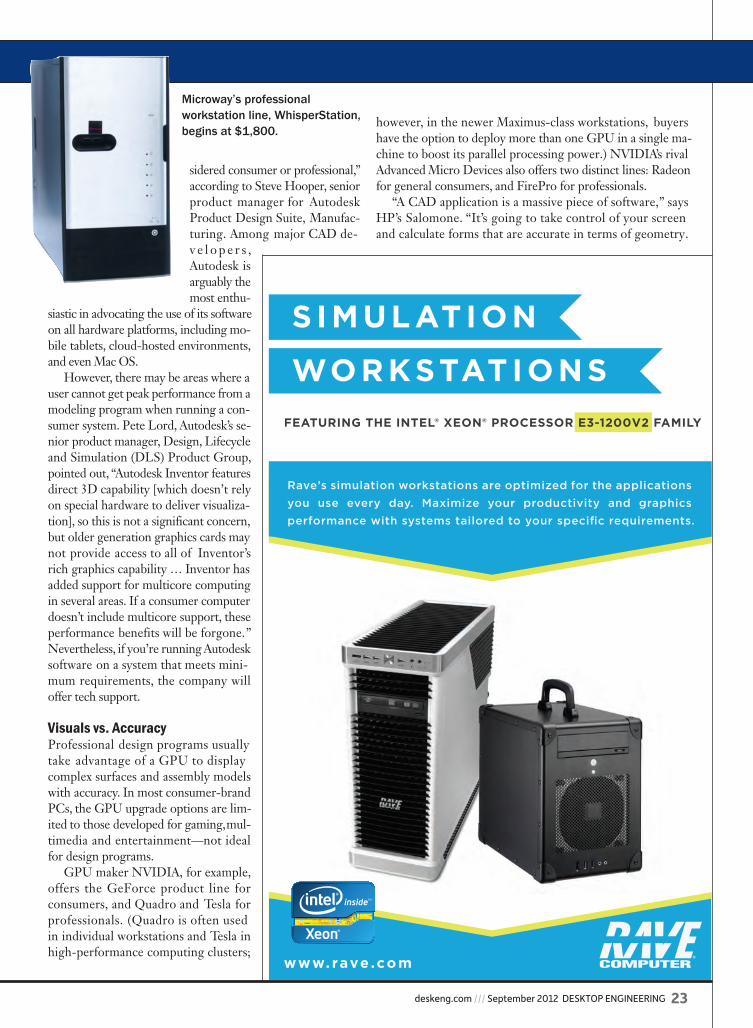
Microway’s professional workstation line, WhisperStation, begins at $1,800.
de0912_Focus_ConsumerPro_Wong.indd 23 8/14/12 4:23 PM
24 DESKTOP ENGINEERING September 2012 /// deskeng.com
Focus on Workstations /// Hardware
Every CAD application is a little different in how it treats the visualization … In order to run something like that, you need stability in your system and in your graphics.”
“The ISVs I work with do not certify non-professional graphics cards,” says Dell’s Runnels. “When you play games, you’re looking for visuals; when you’re building a CAD model, it needs to be airtight so you can run analysis pro-grams and later use that model for machining. For that, you need a level of complexity and error-correction significantly beyond a gaming graphics card.”
Eliot Eshelman, senior technical account manager at Mi-croway, notes that professional GPUs feature dual-DMA, or dual copy, engines—“allowing data to simultaneously move in and out of GPU memory. Consumer products move data in only one direction at a time, which reduces performance and lowers frame rates. Other functions, which are never needed in games, but frequently required by professional applications, are completely missing from consumer cards.”
Error Detection and CorrectionAlmost all professional workstations come preloaded with error correction code (ECC) memory, marked by its inher-ent ability to detect and correct errors. Engineering applica-tions—and finite element analysis (FEA) programs in par-ticular—rely heavily on the memory footprint to calculate,
solve and process complex algorithms in digital proto-typing exercises. Therefore, ECC memory provides added assurance of the ac-curacy of the results. ECC memory finds and fixes 99.988% of all soft memory errors, according to Intel.
Wes Shimanek, Intel’s workstation segment man-ager, technical computing group, points out that while most users just don’t want to believe an error will occur, “a study by Lambda Diode would make you think twice: It suggests that there is a 96% chance you will experience a memory error every three days. If you are not using the part of the memory that failed, you do not notice it. But the worst part is, if it is a soft error, you do not see it, either—and that can be catastrophic.”
“The consumer equipment generally has lower ceilings on system memory,” says Microway’s Eshelman. “Will the engineer’s models fit? Error-correcting memory is usually only available on professional equipment. Can the engineer get by when single-bit errors go unnoticed and change the results of simulations?”
Dell’s entry-level workstation T1600 was later replaced with the T1650, shown here.
de0912_Focus_ConsumerPro_Wong.indd 24 8/14/12 4:23 PM
deskeng.com /// September 2012 DESKTOP ENGINEERING 25
Starter Workstations In mid-2011, PC vendors began delivering a new type of workstation, targeted at budget-conscious buyers. HP’s first product was the Z210, priced beginning from $569. Dell’s entry-level desktop tower, the T1650, was priced at $549.
Microway concentrates on servers, storage devices, and professional workstations. Its WhisperStation workstations are priced beginning at $1,829.
Consumer PCs undeniably offer price advantage in initial investment, but bear in mind that workstations are usually investments in revenue-generating professional activities. In the long run, the number of unexpected errors and system crashes resulting from running professional software on an unsanctioned hardware platform may undo the initial saving that comes with a turbocharged consumer PC.
“Intel Xeon processor-based workstations are much more than a turbocharged PC. They are workload-optimized in-novation platforms that today are surprisingly affordable when compared to a PC,” says Frank Soqui, Intel’s worksta-tion general manager, technical computing group. “Sure, you can save a few dollars in hardware by buying a PC, but the money you save up front will probably be eroded in less than three months in the lost time while engineers wait for results from high-value activities (e.g. simulations or ray-traced im-ages) that play an enormous part in product decisions.”
Microway’s Eshelman agrees. “Often a workstation pur-chased from a vendor who specializes in customized, profes-sional configurations will outperform the top end of a consumer stock-keeping unit,” he concludes. “While such systems may seem expensive up front, they will perform for years—and save you time, energy and money in the long run.” DE
Kenneth Wong is Desktop Engineering’s resident blog-ger and senior editor. Email him at [email protected] or share your thoughts on this article at deskeng.com/facebook.
Opera v15 for Motor and Generator Designfrom Cobham Technical Services
See the future of Virtual DesignVisit: www.operaFEA.com or call: (630) 851 1734
Opera Features:
• Advanced multi-physics finite element analysis
• Rapid design and prototyping software
• Electromechanical and thermal simulation
• Accuracy comparable to experiment
http://linkd.in/RA7ib0
INFO ➜ Advanced Micro Devices: AMD.com
➜ Autodesk: Autodesk.com
➜ Dell: Dell.com
➜ HP: HP.com
➜ Intel: Intel.com
➜ Lambda Diode: Lambda-Diode: com
➜ Lenovo: Lenovo.com
➜ Microway: Microway.com
➜ NVIDIA: NVIDIA.com
For more information on this topic, visit deskeng.com.
de0912_Focus_ConsumerPro_Wong.indd 25 8/14/12 4:24 PM

26 DESKTOP ENGINEERING September 2012 /// deskeng.com
Focus on Workstations /// Review
HP has a long history of building powerful mobile workstations, so we were excited when the company’s latest offering arrived. The HP EliteBook 8560w is
the newest in a line of successful mobile workstations. And while last year’s 8540w was impressive (see DE, April 2011), its successor surpasses it in virtually all aspects.
The HP EliteBook 8560w is housed in a gunmetal gray HP DuraCase, a brushed anodized aluminum exterior bonded to a magnesium-alloy chassis. But the case has been redesigned and now features precision aluminum-alloy hinges, cast titanium-alloy display latches, and a radial-spun display cover with a backlit HP logo. The system is essentially the same size as the 8540w, measuring 14.7x 9.9x 1.7 in., but at 7.9 lbs., it’s nearly 1 lb. heavier than its predecessor. The large (6.7x 3.2x 1.6-in.), 200-watt AC adapter required by the HP DreamColor display adds nearly 2 lbs. more to the total package.
Raising the lid reveals a 101-key keyboard that includes a separate numeric keypad. All of the keys are full-size, with the exception of the function keys along the top row and the cursor keys just to the left of the numeric keypad. HP notes that the keyboard is spill-resistant, thanks to a thin layer of Mylar film under the keyboard and a drain in the bottom of the notebook, but we decided not to test this feature.
Our evaluation unit came with a backlit keyboard (a $65 op-tion). There’s also an orange point stick nestled above the B-key, along with its own complement of three buttons just below the spacebar. A fingerprint reader is below the right corner of the keyboard. Indicator lights for wireless, power, battery and hard drive activity are on the front-left edge of the case.
A small power button is located above the keyboard in the upper left, while four similar buttons in the upper right let you toggle the wireless functions and speakers on and off, access your web browser or start the Windows calculator application. When the system is powered off, you can press the web browser button to start up the HP QuickWeb ap-plication without actually booting the operating system. We were surfing the web using QuickWeb in about 15 seconds.
The 8560w also includes a large (4.25x 2-in.) touchpad cen-tered below the keyboard, with its own dedicated buttons. New this year is gesture support. You can use one finger to point and click, two fingers to scroll up/down and left/right, and a two-finger spread or pinch gesture to zoom in or out. A double-tap in the upper-left corner turns the touchpad on and off. Al-
the newest in a line of successful mobile workstations. And while last year’s 8540w was impressive (see its successor surpasses it in virtually all aspects.
DuraCase, a brushed anodized aluminum exterior bonded to a magnesium-alloy chassis. But the case has been redesigned and now features precision aluminum-alloy hinges, cast titanium-alloy display latches, and a radial-spun display cover with a backlit HP logo. The system is essentially the same size as the 8540w, measuring 14.7x 9.9x 1.7 in., but at 7.9 lbs., it’s nearly 1 lb. heavier than its predecessor. The large (6.7x 3.2x 1.6-in.), 200-watt AC adapter required by the HP DreamColor display adds nearly 2 lbs. more to the total package.
a separate numeric keypad. All of the keys are full-size, with the exception of the function keys along the top row and the
INFO ➜ HP: HP.comHP EliteBook 8560w• Price: $4,063 as tested ($1,549 base price)• Size: 14.7x9.9x1.7-in. (WxDxH) notebook• Weight: starting at 6.69 lbs., 7.9 lbs. as tested, plus power supply • CPU: 2.30GHz Intel Core i7-2820QM quad-core with 8MB
L3 cache• Memory: 16GB 1333MHz DDR3 SDRAM (32GB max)• Graphics: NVIDIA Quadro 2000M with 2GB memory• LCD: 15.6-in. diagonal 16:9 LED-backlit FHD anti-glare
DreamColor (1920x1200)• Hard disk: 500GB, 7,200 rpm 2.5-in. Smart SATA II • Optical: Blu-ray Disc ROM DVD+/-RW SuperMulti DL • Audio: microphone and headphone jacks, built-in microphone
and speakers• Network: integrated Intel Gigabit Ethernet (10/100/1000
NIC); Intel 802.11 wireless LAN; optional integrated Bluetooth 2.1; optional Mobile Broadband (requires separate mobile service)
• Modem: 56K V.92 modem• Other: two USB 3.0, two USB 2.0, one eSATA/USB 2.0 combo
port, one IEEE 1394a Firewire, media card reader (SC, SD, MMC, MS/Pro, XD), one Express Card/54 slot, one Smart Card reader, DisplayPort, 15-pin VGA, 720p HD webcam
• Keyboard: integrated 101-key keyboard with numeric keypad• Pointing device: integrated three-bu ̃ on touchpad and
pointing stick, fi ngerprint reader
Upwardly MobileThe new HP EliteBook 8560w mobile workstation with DreamColor display improves upon its predecessor.BY DAVID COHN
ree.F 0www.hsmxpress.com
FREE 2D & 2-1/2 Axis CAM for all licensed users of SolidWorks 2010 or newer. Download and activate your copy today to be eligible to win a free 3D Mouse from 3DConnexion.
de0912_Focus_EliteBook_Cohn.indd 26 8/15/12 8:35 AM

deskeng.com /// September 2012 DESKTOP ENGINEERING 27
though these gestures are similar to what Apple has offered for a while now on its devices, the HP workstation was much less responsive than what we’ve come to expect on Apple devices.
Powerful GraphicsThe DreamColor display remains unsurpassed in terms of image quality. HP’s DreamColor technology, developed in conjunction with DreamWorks Animation SKG, uses a RGB LED backlight and 10-bit graphics card to produce 30-bit color accuracy. The 15.6-in. diagonal UWVA anti-glare display in our evaluation unit produced gorgeous images at 1920x1080 resolu-tion, with more than 1 billion colors. The DreamColor display is a $425 option, but also requires the larger 200-watt power supply. HP also offers the 8560w with a 1600x900 display or a 1920x1080 panel without the DreamColor technology.
An optional 720p webcam is centered above the display, flanked by a webcam light on the left and an ambient light sensor to the right. There’s also a dual microphone array and wireless antennas along the top edge.
Our EliteBook’s display was powered by an NVIDIA Quadro 2000M with 2GB of dedicated DDR3 video mem-ory and 192 compute unified device architecture (CUDA) cores. Other GPU options include the NVIDIA 1000M and a choice of AMD ATI FirePro graphics boards. The FirePro boards incorporate AMD Eyefinity Technology, which sup-
ports up to five independent displays when using the HP Advanced Docking Station. Otherwise, in addition to the system’s built-in display, the EliteBook 8560w can power an external monitor at up to 2048x1536 via its VGA port, or at up to 2560x1600 using the built-in DisplayPort. DVI is only available using a docking station.
A Fast CPU and Lots of MemoryAt the heart of our HP EliteBook 8560w was a 2.3GHz Intel Core i7-2820QM processor, based on Intel’s Sandy Bridge processor architecture. This CPU has a maximum turbo fre-quency of 3.4GHz, an 8MB L3 Smart Cache, and integrated Intel HD Graphics 3000, yet has a thermal design power (TDP) rating of just 45 watts. HP has since replaced that CPU with the faster Core i7-2860QM, a 2.5GHz quad-core processor, at the same price. Other CPU choices include second-generation Intel Core i7 quad-core processors at 2 and 2.2GHz, the 2.7GHz dual-core i7-2620M processor, and Core i5 dual-core processors at either 2.5 or 2.6GHz.
The quad-core i7 CPUs support up to 32GB of memory, and our evaluation unit came equipped with 16GB of RAM, installed as four 4GB 1333MHz DDR3 small outline dual in-line memory module (SO-DIMM) modules. Customers who opt for lesser processors should note that the Core i5 processors support a maximum of 16GB, and the dual-core
ree.F 0www.hsmxpress.com
FREE 2D & 2-1/2 Axis CAM for all licensed users of SolidWorks 2010 or newer. Download and activate your copy today to be eligible to win a free 3D Mouse from 3DConnexion.
de0912_Focus_EliteBook_Cohn.indd 27 8/15/12 8:36 AM
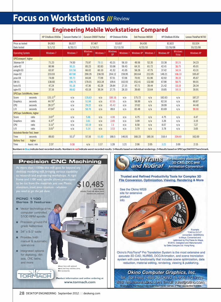
28 DESKTOP ENGINEERING September 2012 /// deskeng.com
Focus on Workstations /// Review
Engineering Mobile Workstations ComparedHP EliteBook 8560w Eurocom Panther 3.0 Eurocom D900F Panther HP Elitebook 8540w Dell Precision M6500 HP EliteBook 8530w Lenovo ThinkPad W700
Price as tested $4,063 $8,027 $7,467 $3,657 $4,430 $2,822 $3,524Date tested 5/1/12 8/20/11 1/14/11 12/13/10 4/23/10 12/18/08 10/22/08
Operating System Windows 7 Windows 7 Windows XP Windows 7 Windows
XP Windows 7 Windows XP Windows 7 Windows XP Windows Vista Windows XP
SPECviewperf, higher3dsmax-04 71.23 74.50 75.97 79.11 43.31 56.10 49.56 52.35 33.38 32.21 34.23catia-02 80.96 95.31 85.23 82.83 53.08 59.43 64.31 61.72 42.41 39.75 45.01ensight-03 63.97 101.50 66.02 60.10 41.52 41.05 58.28 47.75 37.42 34.24 43.31maya-02 233.93 407.90 290.35 236.55 204.12 159.95 283.64 212.05 149.21 108.33 165.87proe-04 74.69 95.73 84.84 77.09 57.51 57.06 70.91 61.96 42.92 39.33 45.67SW-01 138.60 198.76 178.01 163.34 109.6 102.93 152.41 132.68 67.98 59.75 90.01tcvis-01 47.24 91.18 47.36 42.28 29.84 27.15 47.71 39.44 21.42 19.19 28.34ugnx-01 37.16 86.62 43.18 39.34 27.75 28.10 39.60 33.64 19.85 18.11 30.91SPECapc SolidWorks, lowerScore seconds 131.172 n/a 135.63 n/a 198.16 n/a 175.72 n/a 182.63 n/a 187.27Graphics seconds 44.762 n/a 51.94 n/a 67.55 n/a 58.99 n/a 62.16 n/a 60.87CPU seconds 39.372 n/a 29.22 n/a 45.42 n/a 37.62 n/a 39.99 n/a 44.40I/O seconds 47.042 n/a 58.76 n/a 89.8 n/a 83.48 n/a 83.69 n/a 96.66SPECapc SolidWorks, higherScore ratio 3.672 n/a 5.66 n/a 4.08 n/a 4.75 n/a 4.75 n/a 4.47Graphics ratio 4.372 n/a 3.61 n/a 2.69 n/a 3.09 n/a 3.26 n/a 3.15CPU ratio 3.112 n/a 10.19 n/a 7.1 n/a 8.58 n/a 8.07 n/a 7.27I/O ratio 3.012 n/a 5.14 n/a 3.53 n/a 3.79 n/a 3.78 n/a 3.65Autodesk Render Test, lowerTime seconds 89.83 53.31 57.16 51.83 188.5 146.81 168.33 180.16 318.4 324.60 162.00Battery Test higherTime hours: min 2:37 0:38 n/a 1:17 1:28 1:21 2:06 2:05 3:21 3:00 2:15
Numbers in blue indicate best recorded results. Numbers in red indicate worst recorded results. 1=Results based on individual renderings. 2=Results based on SPECapcSW2007 benchmark.
Precision CNC MachiningAt more than 1100lbs this mill goes far beyond any desktop modeling mill, bringing serious capability to research and engineering workshops. A rigid frame and 1100 watt spindle allows prototypes to be cut from the materials you use: Plastic, aluminum, steel, even titanium - whatever you need to get the job done.
■ Vector technology drive, computer controlled, 5100 RPM spindle
■ Precision ground P4 grade ballscrews
■ 34” x 9.5” table
■ Provides both manual & automatic operations
■ Integrated options for digitizing, 4th axis, CNC lathe, and more
$10,485
Shown here with optional stand, tool tray, machine arms, and accessories.
PCNC 1100 Series 3 features:
Product information and online ordering at
www.tormach.com
Shown here with optional stand, tool tray, machine arms, and accessories.
Product information and online ordering at
(plus shipping)includes 3 axis mill, deluxe stand,
machine arm, and more
de0912_Focus_EliteBook_Cohn.indd 28 8/15/12 8:36 AM
deskeng.com /// September 2012 DESKTOP ENGINEERING 29
i7 CPU supports just 8GB of system memory. The dual-core versions of the 8560w come with just two DIMM sockets.
Our evaluation unit also came with a 500GB, 7,200 rpm Smart SATA II drive. HP offers other drives ranging from 320 to 750GB, as well as solid-state drives of 128 or 256GB capacity. HP also included a Blu-ray Disc DVD+/-RW Su-perMulti dual-layer drive. Other upgrade bay options in-clude a DVD+/-RW drive, a DVD-ROM drive, or a second 500GB 7,200 rpm SATA hard drive.
Our evaluation unit came with an 8-cell, 83 watt-hour lithium-ion battery for which HP claims up to 6 hours and 30 minutes of life. But in our battery run-down test, which keeps the DVD drive spinning continuously, our system shut down after 2 hours and 37 minutes in spite of turning off all wireless features and cutting the display’s backlighting to its lowest setting. HP offers a long-life 75WHr battery, as well as an optional secondary extended life battery that the com-pany claims can power the system for up to nearly 15 hours.
Very Good PerformanceOn the SPECviewperf test, which looks solely at graphics performance, the HP EliteBook 8560 definitely surpassed the 8540w—as well as any other system we’ve tested to date, with the exception of the mobile workstations from Euro-com, which used some distinctly non-mobile components.
For our SolidWorks tests, we switched to the newer SPE-Capc SW 2007 benchmark, which runs properly under Win-dows 7 64-bit. Because it’s a different version of the bench-mark than we’ve used in the past, however, the numbers are not directly comparable. We will eventually shift all results to the newer benchmark.
When we ran our AutoCAD rendering test, the HP EliteBook clearly showed what it’s capable of, completing the finished scene in less than 90 seconds. Again, only the Xeon-equipped Eurocom mobile workstations were faster.
HP EliteBook 8560w prices start at $1,334 for dual-core systems or $1,549 for a quad-core. As configured, our evaluation unit priced out at $4,063. Regardless of how you configure your EliteBook 8560w, though, the end result will be a high-quality mobile workstation—fully ca-pable of bringing your professional applications with you wherever you go. DE
David Cohn is the technical publishing manager at 4D Tech-nologies. He also does consulting and technical writing from his home in Bellingham, WA, and has been benchmarking PCs since 1984. He’s a contributing editor to Desktop En-gineering and the author of more than a dozen books. You can contact him via email at [email protected] or visit his website at DSCohn.com.
Engineering Success...
Simulation Software for a New Frontier in Engineering Innovation.
Follow us online.For more information: [email protected] www.cd-adapco.com/aerospace
de0912_Focus_EliteBook_Cohn.indd 29 8/15/12 8:36 AM
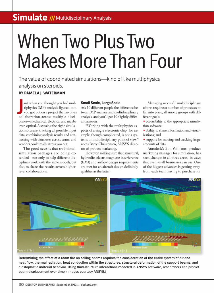
30 DESKTOP ENGINEERING September 2012 /// deskeng.com
Simulate /// Multidisciplinary Analysis
Just when you thought you had mul-tiphysics (MP) analysis figured out, you got put on a project that involves
collaboration across multiple disci-plines—mechanical, electrical and maybe even optical. Accessing the right simula-tion software, tracking all possible input data, combining analysis results and con-necting with databases across teams and vendors could really stress you out.
The good news is that traditional simulation packages are being ex-tended—not only to help different dis-ciplines work with the same models, but also to share the results across higher level collaborations.
Small Scale, Large ScaleAsk 10 different people the difference be-tween MP analysis and multidisciplinary analysis, and you’ll get 10 slightly differ-ent answers.
“Working with the multiphysics as-pects of a single electronic chip, for ex-ample, though complicated, is not a sys-tems or multidisciplinary point of view,” notes Barry Christensen, ANSYS direc-tor of product marketing.
However, making sure that structural, hydraulic, electromagnetic interference (EMI) and airflow design requirements are met for an aircraft design definitely qualifies as the latter.
Managing successful multidisciplinary efforts requires a number of processes to fall into place, all among groups with dif-ferent goals:• accessibility to the appropriate simula-tion software;• ability to share information and visual-izations; and• support for moving and tracking large amounts of data.
Autodesk’s Bob Williams, product marketing manager for simulation, has seen changes in all three areas, in ways that even small businesses can use. One of the biggest advances is getting away from each team having to purchase its
When Two Plus Two Makes More Than Four The value of coordinated simulations—kind of like multiphysics analysis on steroids.BY PAMELA J. WATERMAN
Determining the effect of a room fi re on ceiling beams requires the consideration of the entire system of air and heat fl ow, thermal radiation, heat conduction within the structures, structural deformation of the support beams, and elastoplastic material behavior. Using fl uid-structure interactions modeled in ANSYS software, researchers can predict beam displacement over time. (Images courtesy ANSYS.)
de0912_Multidisciplinary_Waterman.indd 30 8/14/12 3:42 PM
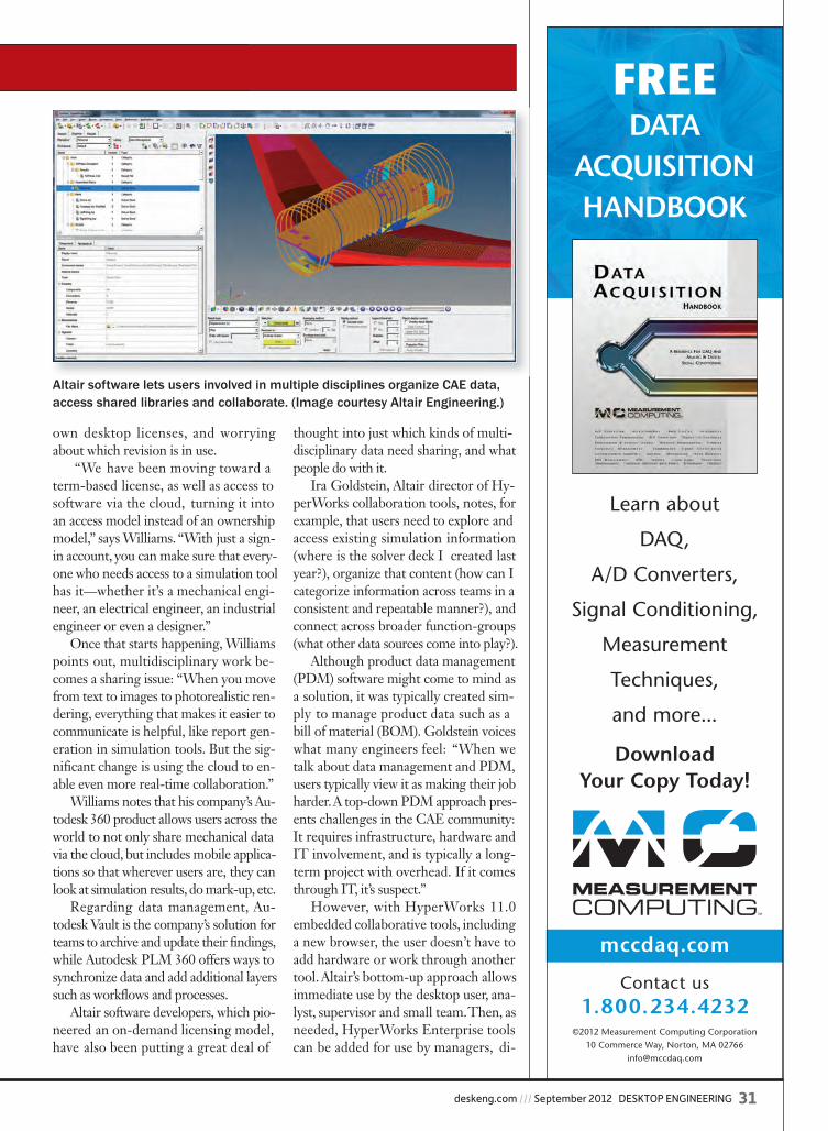
deskeng.com /// September 2012 DESKTOP ENGINEERING 31
own desktop licenses, and worrying about which revision is in use.
“We have been moving toward a term-based license, as well as access to software via the cloud, turning it into an access model instead of an ownership model,” says Williams. “With just a sign-in account, you can make sure that every-one who needs access to a simulation tool has it—whether it’s a mechanical engi-neer, an electrical engineer, an industrial engineer or even a designer.”
Once that starts happening, Williams points out, multidisciplinary work be-comes a sharing issue: “When you move from text to images to photorealistic ren-dering, everything that makes it easier to communicate is helpful, like report gen-eration in simulation tools. But the sig-nificant change is using the cloud to en-able even more real-time collaboration.”
Williams notes that his company’s Au-todesk 360 product allows users across the world to not only share mechanical data via the cloud, but includes mobile applica-tions so that wherever users are, they can look at simulation results, do mark-up, etc.
Regarding data management, Au-todesk Vault is the company’s solution for teams to archive and update their findings, while Autodesk PLM 360 offers ways to synchronize data and add additional layers such as workflows and processes.
Altair software developers, which pio-neered an on-demand licensing model, have also been putting a great deal of
thought into just which kinds of multi-disciplinary data need sharing, and what people do with it.
Ira Goldstein, Altair director of Hy-perWorks collaboration tools, notes, for example, that users need to explore and access existing simulation information (where is the solver deck I created last year?), organize that content (how can I categorize information across teams in a consistent and repeatable manner?), and connect across broader function-groups (what other data sources come into play?).
Although product data management (PDM) software might come to mind as a solution, it was typically created sim-ply to manage product data such as a bill of material (BOM). Goldstein voices what many engineers feel: “When we talk about data management and PDM, users typically view it as making their job harder. A top-down PDM approach pres-ents challenges in the CAE community: It requires infrastructure, hardware and IT involvement, and is typically a long-term project with overhead. If it comes through IT, it’s suspect.”
However, with HyperWorks 11.0 embedded collaborative tools, including a new browser, the user doesn’t have to add hardware or work through another tool. Altair’s bottom-up approach allows immediate use by the desktop user, ana-lyst, supervisor and small team. Then, as needed, HyperWorks Enterprise tools can be added for use by managers, di-
©2012 Measurement Computing Corporation 10 Commerce Way, Norton, MA 02766
mccdaq.com
Learn about
DAQ,
A/D Converters,
Signal Conditioning,
Measurement
Techniques,
and more...
DownloadYour Copy Today!
Contact us1.800.234.4232
FREEDATA
ACQUISITIONHANDBOOK
Altair software lets users involved in multiple disciplines organize CAE data, access shared libraries and collaborate. (Image courtesy Altair Engineering.)
de0912_Multidisciplinary_Waterman.indd 31 8/14/12 3:43 PM

32 DESKTOP ENGINEERING September 2012 /// deskeng.com
Simulate /// Multidisciplinary Analysis
rectors and chief engineers, viewing dif-ferent defined interfaces.
Product development that addresses the standard triple mantra of “faster, bet-ter, cheaper” is truly today’s norm. At ANSYS, developers believe the only way to keep pace is for engineering teams in every industry to shift from a compo-nent, or subsystem view to a higher-level systems perspective—applying multiple physics, multiple scales and a collabora-tive engineering approach. Christensen says teams of electrical, structural and fluids engineers must overcome their distinct functional silos to work together.
ANSYS has supported a system-level point of view for at least 10 years, start-ing with its Workbench Platform. Cross-functional teams can use ANSYS Work-bench solvers for a variety of MP analyses, on both component- and system-level designs. And the ANSYS Engineering Knowledge Manager (EKM) tool fills the need for data back-ups, archiving, trace-ability and audit trails, while permitting real-time data sharing across time zones.
ANSYS recently acquired Esterel Technologies, a provider of embedded software simulation solutions for applica-tions such as aircraft-safety systems and
nuclear power-plant monitoring tools. Es-terel solutions will complement ANSYS’ systems point of view by going beyond the physics to include control system software simulations. Work is under way on soft-ware links between the two.
Speeding up Development CyclesMentor Graphics has long been familiar with the need to look at system-level be-havior. With its roots in electronic chip, package and board design, the company expanded in 2008 to include 3D heat transfer and fluid-flow capabilities based on FloEFD computational fluid dynam-ics (CFD) software, offering engineering fluid dynamic solutions in more than 30 industries. This electro/mechanical/ther-mal analysis foundation has served it well, as the company continues to expand its interfaces to dozens of other design and analysis packages.
As a result, John Parry, electronics industry manager, Mentor Graphics me-chanical analysis division, has an interest-ing perspective on working with multi-disciplinary design projects.
“Vendors have acquired different analysis technologies such as CFD, finite element analysis (FEA), computational
electromagnetics (CEM)—and many are trying to integrate them into a single anal-ysis platform, based on a common data model, instead of supporting lots of differ-ent tools,” he explains. “This is great from the vendors’ perspective, because they can consolidate their development efforts.”
However, the resulting platform may be cumbersome, so design productivity suffers. Mentor Graphics sees greater value in openness to working with other tools—even in-house codes—that are used adjacent to its own tools.
In addition, the company prefers to develop tools that work at different lev-els of abstraction. Classic MP modeling in electronic design involves determin-ing, say, current in a printed circuit board (PCB) trace, then modeling the heat flow, then using that heat as the source for me-chanical stress. The problem is that ex-tending first-principles FEA-type model-ing, with everything in exact geometric detail, simply isn’t feasible for today’s billion-transistor chips. Rather, analysis must work based on behavioral models that capture the way the chip behaves in some macroscopic way.
Mentor Graphics has found that same principle also applies to electronics cool-ing, with customers showing great inter-est in using behavioral models of fans and heat sinks. Connecting their tools together this way is very different from a classical MP approach to 3D fluid-flow. Parry says it’s much faster to do the anal-ysis based on a behavioral model than it is to try to do detailed analysis modeling, making this approach more efficient.
Two additional Mentor Graph-ics’ products support collaboration and higher-level system requirements. Sys-temVision is a virtual lab for design and analysis of analog, mixed signal, digital and electro-mechanical designs, while SystemVision conneXion is a virtual ex-ecution environment that dynamically connects otherwise isolated, domain-specific modeling and software tools (LabVIEW and Simulink, for example) in a networked architecture.
Dassault Systèmes, developer of CATIA, SolidWorks and Simulia Abaqus
MP Analysis vs. Multidisciplinary Analysis
Multiphysics (MP) analysis produces very detailed simulations involving forces, pressures, stresses, temperature distributions, flow rates, etc., in small gradations across often-complex geometries. Results from
one simulation serve as input to another, either loosely or closely coupled. Multidisciplinary analysis works at a higher level across an entire structure,
assembly or thousand-part system, developed across multiple teams with very different specialties and involving interactions (possibly closed-loop) between, say, mechanical parts and their electronic control systems. ANSYS’ Barry Christensen highlights the differences by comparing the complexity of a tradi-tional automotive powertrain system with that of a hybrid gas-electric design.
“We have a tremendous amount of experience with developing powertrains for internal combustion,” he points out, “but electric-vehicle people are dealing with a revolution. They must rely more on multidisciplinary simulation.”
Multidisciplinary simulations also encompass many more types of files than the data handled with standard product data management (PDM) pack-ages: inputs, file decks, outputs and simulation results (which can be very large files). Yet while some complete simulations may need to be stored, a lot of them involve transient data and intermediate results—and perhaps just baseline information is needed. Efficient but flexible links, storage options and sharing protocols are key to effective multidisciplinary operations. —PJW
de0912_Multidisciplinary_Waterman.indd 32 8/14/12 3:44 PM
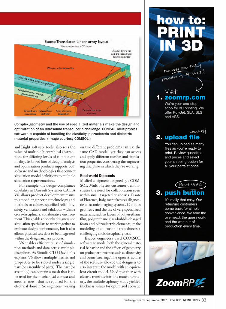
deskeng.com /// September 2012 DESKTOP ENGINEERING 33
and Isight software tools, also sees the value of multiple hierarchical abstrac-tions for differing levels of component fidelity. Its broad line of design, analysis and optimization products supports both software and methodologies that connect simulation model definitions to multiple simulation representations.
For example, the design-compliance capability in Dassault Systèmes CATIA V6 allows product development teams to embed engineering technology and methods to achieve specified reliability, safety, verification and validation within a cross-disciplinary, collaborative environ-ment. This enables not only designers and simulation specialists to work together to evaluate design performance, but it also allows physical test data to be integrated within the design analysis process.
V6 enables efficient reuse of simula-tion methods and data across multiple disciplines. As Simulia CTO David Fox explains, V6 allows multiple meshes and properties to be stored under a single part (or assembly of parts). The part (or assembly) can contain a mesh that is to be used for the mechanical context and another mesh that is required for the electrical domain. So engineers working
on two different problems can use the same CAD model, yet they can access and apply different meshes and simula-tion properties considering the engineer-ing discipline in which they’re working.
Real-world DemandsMedical equipment designed by a COM-SOL Multiphysics customer demon-strates the need for collaboration even within small, targeted businesses. Esaote of Florence, Italy, manufactures diagnos-tic ultrasonic imaging systems. Complex geometry and the use of very specialized materials, such as layers of polyurethane film, polyurethane glass-bubble-charged foam and piezoelectric elements, make modeling the ultrasonic transducers a challenging multidisciplinary task.
Esaote engineers used COMSOL software to model both the general mate-rial behavior and the effects of geometry on probe performance such as directivity and beam-steering. The open structure of the software allowed the designers to also integrate the model with an equiva-lent circuit model. Used together with electric transmission-line matching the-ory, the multidisciplinary study yielded thickness values for optimized acoustic
Complex geometry and the use of specialized materials make the design and optimization of an ultrasound transducer a challenge. COMSOL Multiphysics software is capable of handling the elasticity, piezoelectric and dielectric material properties. (Image courtesy COMSOL.)
3. push button
2. upload file
1. zoomrp.com
how to: PRINTIN 3D
We’re your one-stop-shop for 3D printing. We offer PolyJet, SLA, SLS and ABS.
Visit
The only ship to
day
provider of 3D
prints!
You can upload as many files as you’re ready to print. Review quantities and prices and select your shipping option for all your parts at once.
securely!
It’s really that easy. Our returning customers come back for simpleconvenience. We take the overhead, the guesswork, and the wait out of production every time.
Place Order
de0912_Multidisciplinary_Waterman.indd 33 8/14/12 3:45 PM

34 DESKTOP ENGINEERING September 2012 /// deskeng.com
Simulate /// Multidisciplinary Analysis
impedances supporting improved broadband operation.Kirk Fraser is a design engineer at Roche Ltd. Consulting
Group, a Canadian engineering-construction firm. The compa-ny’s multidisciplinary teams work on projects ranging from min-ing and mineral processing to forestry and urban planning, often combining the skills of mechanical, structural, civil and geotech-nical specialists. Traditionally, the different disciplines have used quite different software packages (STAAD for structural, Femap for mechanical, etc.) with little crossover between analyses.
However, Fraser’s experience working with LS-DYNA products from Livermore Science Technology Corp. (LSTC) has convinced him that using various capabilities within a single
package would produce the best level of validity. CFD analy-ses, loads and heat transfer could all be done with LS-DYNA, requiring less transfer of information and improving accuracy.
With its upcoming LS-DYNA_R7, LSTC continues its ef-forts to push costs down and MP capabilities up, adding electro-magnetism and compressible/incompressible fluid analyses. The company’s “one-code strategy” tackles multidisciplinary analy-ses: “to combine the multiphysics capabilities into one scalable code for solving highly non-linear transient problems to enable the solution of coupled multiphysics and multi-stage problems.”
A Shift in MindsetOther companies whose products support multidisciplinary analysis include Siemens, with its NX TeamCenter collaboration tools, and MSC Software, whose MSC Nastran and Adams solu-tions work well, for example, with Comet, an integrated modeling and simulation process automation tool from Comet Solutions.
Autodesk’s Williams sums up the benefits of multidisciplinary analysis by observing, “I think it’s very promising that we are ac-tually having a conversation that almost all the time in the past would have been centered around design and CAD. The fact that increased collaboration and data management are now important enough and prevalent enough for simulation, points to the fact that simulation is used a lot more often than it was in the past.” DE
Contributing Editor Pamela Waterman, DE’s simulation expert, is an electrical engineer and freelance technical writer based in Ari-zona. You can send her e-mail to [email protected].
INFO ➜ Altair: Altair.com
➜ ANSYS: ANSYS.com
➜ Autodesk: Autodesk.com
➜ Bentley: Bentley.com
➜ Comet Solutions: CometSolutions.com
➜ COMSOL Multiphysics: COMSOL.com
➜ Dassault Systèmes: 3DS.com
➜ Esaote: Esaote.com
➜ Esterel Technologies: Esterel-Technologies.com
➜ Livermore Science Technology Corp.: LSTC.com
➜ Mathworks: Mathworks.com
➜ Mentor Graphics: Mentor.com
➜ MSC Software: MSCsoftware.com
➜ National Instruments: NI.com
➜ Roche Ltd. Consulting Group: Roche.ca
➜ Siemens: Siemens.com/plm
➜ Simulia: Simulia.com
For more information on this topic, visit deskeng.com.
An integrated design approach from Mentor Graphics bridges the gap between conducting detailed fi nite element analyses and engineering the systems that use those components. (Image courtesy Mentor Graphics.)
de0912_Multidisciplinary_Waterman.indd 34 8/14/12 3:46 PM
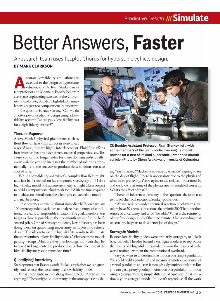
deskeng.com /// September 2012 DESKTOP ENGINEERING 35
Predictive Design /// Simulate
A ccurate, low-fidelity simulations are essential to the design of hypersonic vehicles, says Dr. Ryan Starkey, assis-
tant professor and McAnally Faculty Fellow in aerospace engineering sciences at the Univer-sity of Colorado, Boulder. High-fidelity simu-lations are just too computationally expensive.
The question is, says Starkey, “Can we do a better job of predictive design using a low-fidelity system? Can we pay a low-fidelity cost for a high-fidelity answer?”
Time and ExpenseAbove Mach 5, physical phenomena such as fluid flow or heat transfer act in non-linear ways. Worse, they are highly interdependent: Fluid flow affects heat transfer; heat transfer affects material properties, etc. Be-cause you can no longer solve for these domains individually , every variable you add increases the number of solutions expo-nentially—and the analyses to produce those solutions can take a lot of time.
While a low-fidelity analysis of a complex flow field might take just half a second on his computer, Starkey says, “If I do a high-fidelity model of that same geometry, it might take an expert to build a computational fluid mesh for it. With the time required to do the actual simulation, the whole process can take a month—and maybe more.”
That becomes untenable almost immediately. If you have, say, 100 interdependent variables to analyze over a range of condi-tions, it’s clearly an impossible situation. The goal, therefore, was to get as close as possible to the one-month answer for the half-second price. One of Starkey’s students, Kevin Basore, has been doing work on quantifying uncertainty in hypersonic vehicle design. The idea is to use the high-fidelity results to illuminate the shortcomings of low-fidelity models. What are those models getting wrong? What are they overlooking? How can they be tweaked and augmented to produce results closer to those of the high-fidelity analyses in much less time?
Quantifying UncertaintyStarkey notes that Basore’s work “looked at whether we can quan-tify [and reduce] the uncertainty in a low-fidelity model.
What uncertainty are we talking about, exactly? Practically ev-erything. “There might be uncertainty in the atmospheric model-
ing,” says Starkey. “Maybe it’s not exactly what we’re going to see on the day of flight. There is uncertainty due to the physics of what we’re predicting. We’re trying to use reduced-order models, and we know that some of the physics are not modeled correctly. What’s the effect of that?”
There’s an inherent uncertainty in the equations the team uses to model chemical reactions, Starkey points out.
“We use reduced-order chemical reaction mechanisms; we might have 20 chemical reactions that mimic 200. That’s another source of uncertainty and error,” he adds. “What is the sensitivity of our final design to all of that uncertainty? Understanding that uncertainty helps us to do a better job of design.”
Surrogate ModelsBasore’s low-fidelity models were primarily surrogate, or “black box,” models. The idea behind a surrogate model is to reproduce the results of a high-fidelity simulation—or the results of real-world testing—without the computational overhead.
Say you want to understand the motion of a simple pendulum. You could build a pendulum and measure its motion, or construct a virtual pendulum and run it through a dynamics simulation. But you can get a pretty good approximation of a pendulum’s motion using a (comparatively) simple differential equation. That equa-tion is your surrogate model. It doesn’t reproduce all the work
Better Answers, FasterA research team uses Tecplot Chorus for hypersonic vehicle design.BY MARK CLARKSON
CU-Boulder Assistant Professor Ryan Starkey, left, with some members of his team, looks over engine model nozzles for a fi rst-of-its-kind supersonic unmanned aircraft vehicle. (Photo by Glenn Asakawa, University of Colorado.)
de0912_Tecplot_Clarkson.indd 35 8/15/12 9:49 AM
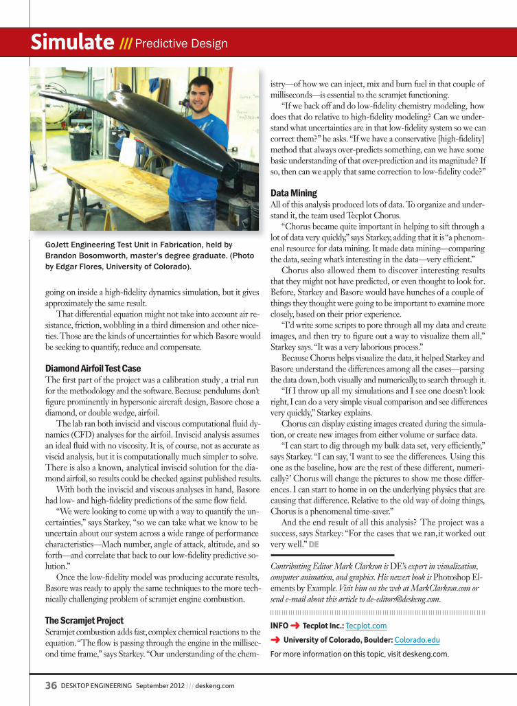
36 DESKTOP ENGINEERING September 2012 /// deskeng.com
Simulate /// Predictive Design
going on inside a high-fidelity dynamics simulation, but it gives approximately the same result.
That differential equation might not take into account air re-sistance, friction, wobbling in a third dimension and other nice-ties. Those are the kinds of uncertainties for which Basore would be seeking to quantify, reduce and compensate.
Diamond Airfoil Test CaseThe first part of the project was a calibration study, a trial run for the methodology and the software. Because pendulums don’t figure prominently in hypersonic aircraft design, Basore chose a diamond, or double wedge, airfoil.
The lab ran both inviscid and viscous computational fluid dy-namics (CFD) analyses for the airfoil. Inviscid analysis assumes an ideal fluid with no viscosity. It is, of course, not as accurate as viscid analysis, but it is computationally much simpler to solve. There is also a known, analytical inviscid solution for the dia-mond airfoil, so results could be checked against published results.
With both the inviscid and viscous analyses in hand, Basore had low- and high-fidelity predictions of the same flow field.
“We were looking to come up with a way to quantify the un-certainties,” says Starkey, “so we can take what we know to be uncertain about our system across a wide range of performance characteristics—Mach number, angle of attack, altitude, and so forth—and correlate that back to our low-fidelity predictive so-lution.”
Once the low-fidelity model was producing accurate results, Basore was ready to apply the same techniques to the more tech-nically challenging problem of scramjet engine combustion.
The Scramjet ProjectScramjet combustion adds fast, complex chemical reactions to the equation. “The flow is passing through the engine in the millisec-ond time frame,” says Starkey. “Our understanding of the chem-
istry—of how we can inject, mix and burn fuel in that couple of milliseconds—is essential to the scramjet functioning.
“If we back off and do low-fidelity chemistry modeling, how does that do relative to high-fidelity modeling? Can we under-stand what uncertainties are in that low-fidelity system so we can correct them?” he asks. “If we have a conservative [high-fidelity] method that always over-predicts something, can we have some basic understanding of that over-prediction and its magnitude? If so, then can we apply that same correction to low-fidelity code?”
Data MiningAll of this analysis produced lots of data. To organize and under-stand it, the team used Tecplot Chorus.
“Chorus became quite important in helping to sift through a lot of data very quickly,” says Starkey, adding that it is “a phenom-enal resource for data mining. It made data mining—comparing the data, seeing what’s interesting in the data—very efficient.”
Chorus also allowed them to discover interesting results that they might not have predicted, or even thought to look for. Before, Starkey and Basore would have hunches of a couple of things they thought were going to be important to examine more closely, based on their prior experience.
“I’d write some scripts to pore through all my data and create images, and then try to figure out a way to visualize them all,” Starkey says. “It was a very laborious process.”
Because Chorus helps visualize the data, it helped Starkey and Basore understand the differences among all the cases—parsing the data down, both visually and numerically, to search through it.
“If I throw up all my simulations and I see one doesn’t look right, I can do a very simple visual comparison and see differences very quickly,” Starkey explains.
Chorus can display existing images created during the simula-tion, or create new images from either volume or surface data.
“I can start to dig through my bulk data set, very efficiently,” says Starkey. “I can say, ‘I want to see the differences. Using this one as the baseline, how are the rest of these different, numeri-cally?’ Chorus will change the pictures to show me those differ-ences. I can start to home in on the underlying physics that are causing that difference. Relative to the old way of doing things, Chorus is a phenomenal time-saver.”
And the end result of all this analysis? The project was a success, says Starkey: “For the cases that we ran, it worked out very well.” DE
Contributing Editor Mark Clarkson is DE’s expert in visualization, computer animation, and graphics. His newest book is Photoshop El-ements by Example. Visit him on the web at MarkClarkson.com or send e-mail about this article to [email protected].
INFO ➜ Tecplot Inc.: Tecplot.com
➜ University of Colorado, Boulder: Colorado.edu
For more information on this topic, visit deskeng.com.
GoJett Engineering Test Unit in Fabrication, held by Brandon Bosomworth, master’s degree graduate. (Photo by Edgar Flores, University of Colorado).
de0912_Tecplot_Clarkson.indd 36 8/14/12 1:11 PM

deskeng.com /// September 2012 DESKTOP ENGINEERING 37
Heat-transfer Coefficients /// Simulate
When it comes to virtual model-ing, most modern simulation tools already operate at near
state-of-the-art. What often limits their use is the uncertainty of a specific, em-pirical tuning parameter that requires a user to make a best guess. This, in turn, introduces a new source of error—setting up the question, how can you know your choices are well suited to your application?
Although getting effective results from computer simulations always depends on the quality of the inputs, process simula-tion applied to the world of metal casting presents particular challenges. Nemak Po-land in Bielsko-Biala, Poland, faces these challenges daily as it manufactures alu-minum-casting products such as cylinder heads and engine blocks for the automo-tive industry. The company uses FLOW-3D computational fluid dynamics (CFD) simulation software from Flow Science to model its high-pressure die-casting processes, and is continually working to fine-tune the real-world values it uses for simulation input parameters. Capturing the variations across a complete thermal mold (die) cycle significantly increases the simulation’s accuracy, which in turn yields more realistic temperature and heat transfer properties to guide the choice of equipment settings throughout filling and solidification. (See Figure 1.)
Fine-tuning Process SettingsThe different phases of a casting’s ther-mal cycle involve complex physics, be-cause the speed of the fluid is always
changing as it proceeds through each section of the die. Conduction and con-vection are both present (at comparable magnitudes) in the molten metal, com-plicating the determination of liquid-to-metal heat transfer coefficients (HTCs). Moreover, it is no simple matter to sub-divide the production cycle into well-defined steps to come up with average properties for these effects. Nemak pro-cess engineers turned to Sigma Tech-nology to help them zero in on the best operating parameters for setting up their equipment based on the 3D simulations.
FLOW-3D’s CFD software can model the free-surface flows encoun-tered while filling high-pressure dies, generating results across the entire cast-ing cycle. By tapping into Sigma Tech-nology’s indirect optimization on the basis of self-organization (IOSO) optimi-zation software, now directly integrated with FLOW-3D, Nemak could evaluate possible HTC combinations and feed them back for additional CFD calcula-tions. This closed-loop strategy allowed the engineers to automatically determine new HTCs and manage repeated simula-tions until the values of theoretical and measured temperatures closely matched. In addition, plans for future part runs could use those same, more accurate HTCs for any successive simulations and new operating profiles (see Figure 2).
Characterizing the Die ProcessHTCs are notoriously difficult to de-termine with high precision. Typically,
Closed-loop, automatic optimization makes fast work of enhancing FLOW-3D CFD analyses.BY ANTONI DRYS AND STEFANO MASCETTI
FIGURE 2: HTC optimization loop, performed with FLOW-3D simulation software and IOSO optimization software.
FIGURE 1: Example of FLOW-3D thermal die cycling simulation, taking into account cooling channel structure.
FIGURE 3: FLOW-3D simulation software run showing high-pressure die-casting temperature vs. time. The regime temperature pattern per cast becomes stable after the initial casting cycles.
Aluminum Casting Simulations
de0912_FlowScience_Waterman.indd 37 8/14/12 1:30 PM

38 DESKTOP ENGINEERING September 2012 /// deskeng.com
Simulate /// Heat-transfer Coefficients
engineers use coefficient values taken from standard literature references, based on general material properties such as fluid velocities, viscosity, the condition of the heating surfaces and the magnitude of the thermal differen-tial. Nemak started the improvement project by focusing on the thermal behavior of an actual, aluminum alloy (A380) high-pressure die-cast engine block (approximately 200x170x300mm) throughout its production cycle in a die made of tool steel (1.2343).
One full thermal cycle includes all the steps for producing one cast part. This cycle can be divided into homo-geneous sub-steps that are performed sequentially; the more sub-steps iden-tified, the more accurate the corre-sponding simulation results. For this experiment, the thermal cycle was di-vided into five different segments, each
mirrored in the FLOW-3D software model. These sub-steps comprised:1. metal filling of the die via the shot hole;2. part solidification and removal;3. lubrication of the die with a water/
oil mixture;4. blowing out the die cavity to remove
excess lubricant moisture; and5. closing the sections of the die for the
next cast.Starting with the die at room tem-
perature, three test parts were cast and discarded—for the sole purpose of allowing the molten metal to bring the tool steel die to its nominal, near-steady operating temperature, called the regime temperature. From then on, because each complete part-production cycle only took 95 seconds, the die never had the chance to cool back to room temperature (see Figure 3).
To capture actual temperature read-ings, Nemak’s quality-control thermo-cameras were positioned to take ther-mal images of the die at different times and different locations. Images were observed over the course of a month, and average values were used for com-parison to the simulated values at the end of each processing step.
Simulation with a Power BoostA CAD model of the sample part was loaded into FLOW-3D. Because cool-ing channels play an active role in the die-casting process, FLOW-3D’s ability to model both the part and the function of the channel structure helped produce results with high fidelity to the real-world Nemak system. For the actual analysis, each of the five sub-steps was loaded with the inputs of the average temperature of the surrounding liquid, the duration in seconds and an initially chosen HTC.
A single FLOW-3D simulation con-sists of running several cycles of the die through all the sub-steps until the calcu-lations converge to identify the regime (base) temperature. The software auto-matically brings the die in contact with the different fluid medias (molten metal, lubricant, air, etc.) for the prescribed du-
ration, simulating the thermal exchange. Those values are then compared to those recorded through the thermo-camera. No fluid dynamics simulation is involved at this stage, only a simple ther-mal simulation, which is much faster.
Use of standard heat-transfer values in the CFD simulation initially pro-duced calculated temperature values that differed by up to 50 Celsius de-grees from the measured thermo-cam-era values. In addition, the simulated distribution pattern across the die did not correlate well. Clearly, the imper-fect input data demanded another level of effort to generate more accurate re-sults. The team brought in the IOSO tool to rapidly refine the simulations and zero in on optimized HTCs.
Optimization of complex physical pro-cesses, such as those found in CFD analy-ses, is historically a non-trivial problem. IOSO software solves it by integrating mathematical models, engineering pro-totypes and exploration methods inside a unified optimization environment based on direct stochastic formulation. Taking a statistical approach to evaluating response surfaces at each iteration, the IOSO pro-cess is particularly fast because it approxi-mates the functions of many variables.
Integrated with the FLOW-3D user interface, IOSO directs multiple simu-lation runs. It needs only to specify the variables to change, the output to ana-lyze and the mathematical goal(s), called the objective function(s). Nemak set up five HTC variables (one for each step of the cycle), each with an upper and lower constraint, plus a single objective func-tion. IOSO called FLOW-3D automati-cally, analyzing the results, proposing new values for the HTCs and rerunning the casting simulation again until reach-ing satisfactory results (see Figure 4).
A Simulation Team EffortAs usually happens with optimization runs, strong improvements were re-corded immediately at the beginning of the task. In this case, a 50% reduction of the objective function was reached after
FIGURE 4: Comparison between initial and fi nal FLOW-3D die-casting simulation solutions and thermo-camera values, after optimization of HTCs with IOSO software from Sigma Technology.
FIGURE 5: IOSO optimization run minimizing an objective function comparing casting temperature values.
de0912_FlowScience_Waterman.indd 38 8/14/12 1:33 PM
deskeng.com /// September 2012 DESKTOP ENGINEERING 39
Heat-transfer Coefficients /// Simulate
only 27 calls. As convergence—a global minimum of the func-tion—is approached, the run-to-run improvement tends to be more moderate. Upon reaching a user-defined accuracy, the software was stopped and the solution analyzed as a candidate for the input producing the best simulation. In this case, al-though 118 runs were conducted, run No. 49 was accepted as the last run to produce an improvement (see Figure 5).
Compared to the original 50° discrepancy , the final FLOW-3D casting simulation based on optimized HTC values exhibited a better match to real-world temperatures. Differences were typically only 2 to 4°C, with a maximum deviation of 15°C at a single probe-point; overall tempera -ture distribution was also greatly improved. Moreover, the optimized HTCs were within a reasonable range for this par-ticular material and process, adding to their usefulness. These values could now be used as a good starting point for other accurate filling and solidification simulations for 3D models of other parts to be cast using the same machine and alloy.
A subsequent, more critical analysis showed that for some optimal solutions, the newly calculated coefficients lie exactly on the borders of the fixed constraints. This situation may imply that some of the chosen constraints were too limiting, and that even further improvements in the optimal HTC solution set may be identified if the constraints are set more loosely.
Simulation: A Valuable Step FLOW-3D performs simulations on real 3D geometry, and takes into account possible heat transfer mechanisms—con-duction, convection and, if desired, radiation. Yet, because it employs efficient algorithms to mesh and solve complex fluid simulations, each IOSO-directed, autonomous FLOW-3D iteration took less than 30 minutes on a typical desktop com-puter. Hence, this optimization job took 12 hours to reach near-final (convergence) values without the need for high-performance computing (HPC) machines.
Taken together with the potential improvement possible with relaxed HTC value constraints and further develop-ments in the objective function, Nemak believes even stron-ger correlations between casting process simulations and real-world performance can be made. DE
Antoni Drys is a virtual simulation expert in the Product Development Centre of Nemak Poland. Stefano Mascetti is with XC Engineering Srl. Send e-mail about this article to [email protected].
Nowadays, a multidis-ciplinary approach is the key for a suc-
cessful design process. En-gineers and designers are able to simultaneously take different disciplinary aspects into account to determine the optimal solution. This perspective allows for exploitation of interactions between multiple design aspects, while increas-ing the problem complexity: that’s why a powerful platform is needed to streamline the process into one single environment.
modeFRONTIER, the multiobjective and multidisciplinary optimization platform, supplies full integration with any CAE/CAD software and complete automation of the simulation pro-cess leading — with a powerful post processing set of tools — to the best possible design. Multidisciplinary design optimization with modeFRONTIER can be applied to a wide spectrum of industrial sectors, from aerospace to materials science, with the automotive sector being the main field of application. The ben-efits are evident if applied to structural and CFD research, as explained in the multidisciplinary robust optimization of a F1 rear wing project by Javier Gutiérrez Diez (METCA) .
At high speed, aeroelastic reactions are to be considered by analyzing the aerodynamic and structural effects at the same time, therefore it is necessary to run the optimization process from both disciplines’ viewpoints. By employing the advanced coupling capabilities in modeFRONTIER, as well as the versatile control and its statistical tools, this goal can be achieved easily.
The whole optimization cycle of the rear wing is controlled and managed by the workflow generated in the modeFR ON-TIER environment by combining MEF and CFD calculation from third-party software. modeFRONTIER shares the data re-sulting from each iterative simulation as many times as necessary to achieve the tolerance required by the designer. This achieves a design that features better performances for the whole speed range, not just for a single value.
Advertorial /// ESTECO
High Speed Optimization
INFO ➜ ESTECO: esteco.com
All-in-one multidisciplinary design process with modeFRONTIER: optimizing a F1 rear wing.
INFO ➜ Flow Science Inc.: FLOW3D.com
➜ Nemak Poland: Nemak.com/Poland.html
➜ Sigma Technology: IOSOtech.com
➜ XC Engineering Srl: XCeng.com
de0912_FlowScience_Waterman.indd 39 8/14/12 1:33 PM
40 DESKTOP ENGINEERING September 2012 /// deskeng.com
Design /// Software Review
D espite age-old hints and promises to the contrary, LightWave remains two distinct applications: Modeler and Layout. Modeler is where you create your geom-
etry. Layout is for everything else—rendering, animation, light-ing, and so forth. I don’t mind this separation of the workflow, but it’s something that continues to chafe on the community.
I’ve always liked LightWave’s modeler, which is fortunate, because it’s still the same modeler as was in version 10. And version 9. However, the company says version 11.5 will in -clude a number of new modeling features.
For the last several releases, NewTek has been pouring its resources into Layout, improving the rendering workflow, adding better cameras and lights, fur, etc. True to form, that’s where it’s put all the big improvements this time.
Installation WoesI started hitting hiccups before I got a chance to run the program. Upon installation, I found the resources—models, scenes, tex-tures, etc.—were on the disc in a two-part Zip archive. Windows does not handle multi-part archives natively, so my only options (and the actual procedure recommended in the docs) were to download and install third-party software, or use the command line mode to manually combine the two parts into a single file, then unzip them. Are you kidding me? I really hope my problems were the result of my getting a very early release of the program.
Likewise, the help file loaded only blank pages. It turns out that the help files don’t like Google’s Chrome browser. Once I re-verted to Internet Explorer, I found the help files were actually for version 10. Despite the application having been shipping for half a year, were are no current help files. Version 11’s help consists of addenda in PDF format. Adding insult to injury, the web-based help option on the help menu took me to a non-existent website.
When questioned about the installation and documen -tation issues, Rob Powers, president of the LightWave 3D Group, responded that the content, documentation, and files are now distributed with a digital download. He also says the company’s new site is being updated to include more support, including video tutorials and documentation files.
Instancing, Flocking and PhysicsLightWave version 11 introduces Instancing—a way to cre-ate lots of copies of a single mesh without the usual memory overhead. You could use instancing to cover a tabletop in ball bearings or machine screws, for example, or to create a vast
array of cell phones stretching to the horizon. The difference between, say, a single instance of a 1.6 million-polygon object and 500 instances of the same object is only on the order of 2 or 3MB. That’s not to say that those extra 499 meshes don’t impart a performance hit when it comes time to display them onscreen—I definitely felt it—but the memory hit is nil.
These instances don’t have to be identical copies of the original. You can make them quite different from one another by adding random scaling, positioning and rotation, as well as applying different materials.
The new Flocking feature allows you to create large groups, swarms, flocks or herds of objects that move through your scene in a cohesive way—either following a path, or chas-ing or avoiding various goals. These flocks can be made up of static meshes, or they can use objects with animated behaviors.
If you ever feel like smashing your models, you’ll be happy with LightWave’s new Bullet Physics. Bullet is an open-source physics engine, also available in Blender, Cinema 4D and other 3D applications. It is great for bouncing balls, collapsing towers or, more practically, for scattering a ton of bolts across a tabletop without having to place each one individually.
Modeler has a new tool called Fracture, designed to sup-port Bullet Physics by automatically breaking up your solid models into little bits so that Bullet can explode or collapse them. A simpler version of Fracture is available within Layout.
Render Buffer EnhancementsIt’s often useful, and sometimes necessary, to export different render passes separately. When the art director wants “more shine” or a deeper shade of red, for example, having separate render passes to work with—reflection, specularity, diffuse color, etc.—lets you quickly tweak the final results in Photo-shop rather than resetting and re-rendering your scene.
LightWave has long had the ability to render different passes to separate layers in a layer Photoshop file, but you had little control over them. LightWave 11’s Compositing Buffer export panel (which is hiding under image filters, rather than as an output option) gives you control over which passes to render and which objects to include. Your checkable options include everything from the normal (reflections, shadows) to the arcane (x and y motion, object ID). For some reason, though, my ambient occlusion passes were borked.
You can also create and save your own named presets, rather than checking and unchecking dozens of boxes with every render.
Two Parts in OneWith LightWave 11, NewTek once again puts most of the shine on half the product.By Mark Clarkson
de0912_LightWave_Clarkson.indd 40 8/15/12 9:52 AM
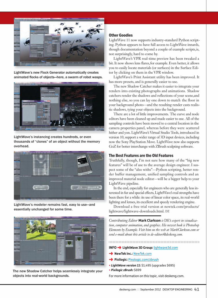
deskeng.com /// September 2012 DESKTOP ENGINEERING 41
Other GoodiesLightWave 11 now supports industry-standard Python script-ing. Python appears to have full access to LightWave innards, though documentation beyond a couple of example scripts, is, not surprisingly, hard to come by.
LightWave’s VPR real-time preview has been tweaked a bit. It now shows lens flares, for example. Even better, it allows you to easily locate materials (or surfaces) in the Surface Edi-tor by clicking on them in the VPR window.
LightWave’s Print Assistant utility has been improved. It has more presets, and is generally easier to use.
The new Shadow Catcher makes it easier to integrate your renders into existing photographs and animations. Shadow catchers render the shadows and reflections of your scene, and nothing else, so you can lay one down to match the floor in your background photo—and the resulting render casts realis-tic shadows, tying your objects into the background.
There are a lot of little improvements. The curve and node editors have been cleaned up and made easier to use. All of the sampling controls have been moved to a central location in the camera properties panel, whereas before they were scattered hither and yon. LightWave’s Virtual Studio Tools, introduced in version 10, support a wider range of 3D input devices, including now the Sony PlayStation Move. LightWave now also supports GoZ for better interchange with ZBrush sculpting software.
The Best Features are the Old FeaturesTruthfully, though, I’m not sure how many of the “big new features” will be of use to the average design engineer. I sus-pect some of the “also withs”—Python scripting, better ren-der buffer management, unified sampling controls and an improved material node editor—will be a bigger help to your LightWave pipeline.
In the end, especially for engineers who are generally less in-terested in fur and special effects, LightWave’s real strengths have been there for a while: its use of linear color space, its real-world lighting and lenses, its excellent and speedy rendering engine.
Download a free trial version at newtek.com/products/lightwave/lightwave-downloads.html. DE
Contributing Editor Mark Clarkson is DE’s expert in visualiza-tion, computer animation, and graphics. His newest book is Photoshop Elements by Example. Visit him on the web at MarkClarkson.com or send e-mail about this article to [email protected].
INFO ➜ LightWave 3D Group: lightwave3d.com
➜ NewTek Inc.: NewTek.com
➜ Pixilogic: Pixologic.com/zbrush
• LightWave version 11: $1,495 (upgrades $695)• Pixilogic zBrush: $699
For more information on this topic, visit deskeng.com.
LightWave’s instancing creates hundreds, or even thousands of “clones” of an object without the memory overhead.
LightWave’s new Flock Generator automatically creates animated fl ocks of objects—here, a swarm of robot wasps.
LightWave’s modeler remains fast, easy to use—and essentially unchanged for some time.
The new Shadow Catcher helps seamlessly integrate your objects into real-world backgrounds.
de0912_LightWave_Clarkson.indd 41 8/15/12 9:52 AM
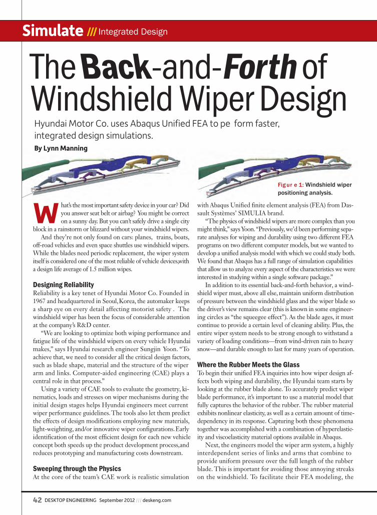
42 DESKTOP ENGINEERING September 2012 /// deskeng.com
Simulate /// Integrated Design
Fig ur e 1: Windshield wiper positioning analysis.
W hat’s the most important safety device in your car? Did you answer seat belt or airbag? You might be correct on a sunny day. But you can’t safely drive a single city
block in a rainstorm or blizzard without your windshield wipers.And they’re not only found on cars: planes, trains, boats,
off-road vehicles and even space shuttles use windshield wipers. While the blades need periodic replacement, the wiper system itself is considered one of the most reliable of vehicle devices, with a design life average of 1.5 million wipes.
Designing ReliabilityReliability is a key tenet of Hyundai Motor Co. Founded in 1967 and headquartered in Seoul, Korea, the automaker keeps a sharp eye on every detail affecting motorist safety . The windshield wiper has been the focus of considerable attention at the company’s R&D center.
“We are looking to optimize both wiping performance and fatigue life of the windshield wipers on every vehicle Hyundai makes,” says Hyundai research engineer Sungjin Yoon. “To achieve that, we need to consider all the critical design factors, such as blade shape, material and the structure of the wiper arm and links. Computer-aided engineering (CAE) plays a central role in that process.”
Using a variety of CAE tools to evaluate the geometry, ki-nematics, loads and stresses on wiper mechanisms during the initial design stages helps Hyundai engineers meet current wiper performance guidelines. The tools also let them predict the effects of design modifications employing new materials, light-weighting, and/or innovative wiper configurations. Early identification of the most efficient design for each new vehicle concept both speeds up the product development process, and reduces prototyping and manufacturing costs downstream.
Sweeping through the PhysicsAt the core of the team’s CAE work is realistic simulation
with Abaqus Unified finite element analysis (FEA) from Das-sault Systèmes’ SIMULIA brand.
“The physics of windshield wipers are more complex than you might think,” says Yoon. “Previously, we’d been performing sepa-rate analyses for wiping and durability using two different FEA programs on two different computer models, but we wanted to develop a unified analysis model with which we could study both. We found that Abaqus has a full range of simulation capabilities that allow us to analyze every aspect of the characteristics we were interested in studying within a single software package.”
In addition to its essential back-and-forth behavior, a wind-shield wiper must, above all else, maintain uniform distribution of pressure between the windshield glass and the wiper blade so the driver’s view remains clear (this is known in some engineer-ing circles as “the squeegee effect”). As the blade ages, it must continue to provide a certain level of cleaning ability. Plus, the entire wiper system needs to be strong enough to withstand a variety of loading conditions—from wind-driven rain to heavy snow—and durable enough to last for many years of operation.
Where the Rubber Meets the GlassTo begin their unified FEA inquiries into how wiper design af-fects both wiping and durability, the Hyundai team starts by looking at the rubber blade alone. To accurately predict wiper blade performance, it’s important to use a material model that fully captures the behavior of the rubber. The rubber material exhibits nonlinear elasticity, as well as a certain amount of time-dependency in its response. Capturing both these phenomena together was accomplished with a combination of hyperelastic-ity and viscoelasticity material options available in Abaqus.
Next, the engineers model the wiper arm system, a highly interdependent series of links and arms that combine to provide uniform pressure over the full length of the rubber blade. This is important for avoiding those annoying streaks on the windshield. To facilitate their FEA modeling, the
The Back-and-Forth of Windshield Wiper Design
Hyundai Motor Co. uses Abaqus Unified FEA to pe form faster, integrated design simulations.By Lynn Manning
de0912_Hyundai_Abaqus.indd 42 8/14/12 1:34 PM

deskeng.com /// September 2012 DESKTOP ENGINEERING 43
group uses kinematic visualization software with a specific template for each vehicle wiper arm type.
Then the team is ready to run full Abaqus models to evaluate wiping. The first step is to properly load the wiper blade against the windshield to establish the correct initial contact pressures against the glass (see Figure 1). The axial connector element in Abaqus is used to express the behavior of the arm spring.
“It’s important to establish what the preloading strain is,” says Yoon, “because it needs to be taken into account as the wiper moves, when the deformation shape of the blade section on the glass will affect the results over the total wiping area.”
A rotational moment is loaded at the base of the wiper arm to replicate the motor torque, at the point where the arm pivots. This causes the arm to slide across the glass with a wiping motion. The analysis can subsequently track the total strain on the blade at specific times and varying temperatures (the latter can particularly affect blade rubber). Final outputs are reported through an in-house post-program that shows
the pressure distribution throughout a complete sweep of the windshield glass. (See Figure 2.) These results can then be compared against established design specifications to deter-mine whether the blade is performing as expected.
“Clear” ResultsThe second part of the analysis, for durability (fatigue life), can be performed on the same FEA model that was set up for the wiping sequence.
“All we need to do is change the boundary and loading conditions in our Abaqus Unified FEA model,” says Yoon.
Just as was done with the wiping analysis, a rotational mo-ment is entered as a loading condition. But this time, station-ary “snow blocks” are mounted to halt the wiper blade before the lower and upper extremes of its sweep across the wind-shield glass model. As the analysis is run, the moving blade arm contacts the snow blocks, and the resulting internal forces on the linkage as the blade stops can be determined.
Stresses corresponding to these internal forces are used to predict fatigue life during moderate snow conditions or, in the case of heavy snow , plastic deformation or failure within the wiper assembly. These predictions are then vali-dated under real-world conditions that include actual snow deposited on the windshield of a typical mass-produced car in Hyundai’s test facilities. (See Figure 3.)
Optimizing Wiping and Durability With their wiping and durability results in hand, engineers can then optimize both factors by varying different design parameters and observing their effect on the overall perfor-mance of the wiper system.
“The superiority of the unified analysis model is that it enables us to consider a wide range of design factors affecting both wiping and durability,” says Yoon. “With an optimized blade arm and link combination, we can achieve a lighter-weight wiper system—while also increasing key link stiffness measures and reducing maximum stresses.” (See Figure 4.)
Hyundai’s R&D group is continuing to expand its use of templates to speed the windshield wiper design workflow. The Abaqus analyses are contributing to the buildup of a knowledge base with parameter studies that give the group better insight into which design variables have the greatest effect on compo-nent operation. All this points to their customers’ having a very clear view of the road ahead—in any weather. DE
Lynn Manning is vice president of Parker Group, a public relations firm based in Providence, RI, that represents Dassault Systèmes’ SIMULIA Corp.˜
INFO ➜ Dassault Systèmes: 3DS.com
➜ Hyundai Motor Co.: Hyundai.com
For more information on this topic, visit deskeng.com.
FIGURE 3: Indoor “snowstorm” at Hyundai R&D center (left) recreates the conditions that windshield wipers are designed to withstand. Snow block (in red at left) analysis duplicates these conditions to guide early design.
FIGURE 4: Comparison of FEA results for wiper arm and link, before and after optimization.FIGURE 4: Comparison of FEA results for wiper arm and
FIGURE 2: Wiper and glass model (left). Results of a wiper analysis, showing pressure distribution for both passenger (middle) and driver (right).
de0912_Hyundai_Abaqus.indd 43 8/14/12 1:35 PM
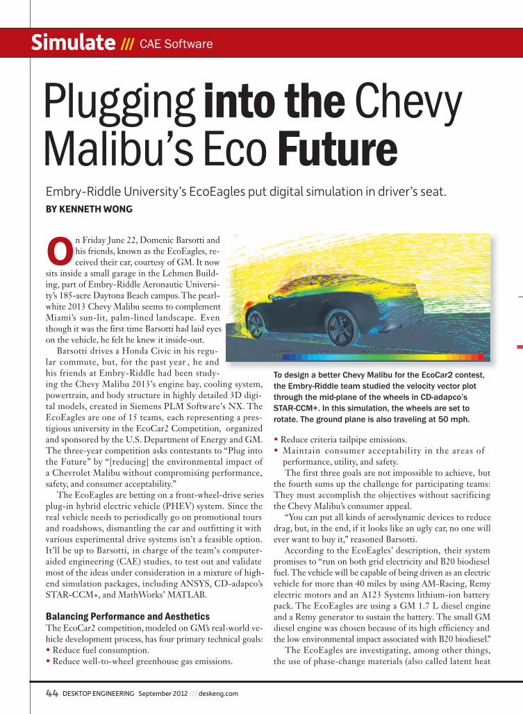
44 DESKTOP ENGINEERING September 2012 /// deskeng.com
Simulate /// CAE Software
On Friday June 22, Domenic Barsotti and his friends, known as the EcoEagles, re-ceived their car, courtesy of GM. It now
sits inside a small garage in the Lehmen Build-ing, part of Embry-Riddle Aeronautic Universi-ty’s 185-acre Daytona Beach campus. The pearl-white 2013 Chevy Malibu seems to complement Miami’s sun-lit, palm-lined landscape. Even though it was the first time Barsotti had laid eyes on the vehicle, he felt he knew it inside-out.
Barsotti drives a Honda Civic in his regu-lar commute, but, for the past year , he and his friends at Embry-Riddle had been study-ing the Chevy Malibu 2013’s engine bay, cooling system, powertrain, and body structure in highly detailed 3D digi-tal models, created in Siemens PLM Software’s NX. The EcoEagles are one of 15 teams, each representing a pres-tigious university in the EcoCar2 Competition, organized and sponsored by the U.S. Department of Energy and GM. The three-year competition asks contestants to “Plug into the Future” by “[reducing] the environmental impact of a Chevrolet Malibu without compromising performance, safety, and consumer acceptability.”
The EcoEagles are betting on a front-wheel-drive series plug-in hybrid electric vehicle (PHEV) system. Since the real vehicle needs to periodically go on promotional tours and roadshows, dismantling the car and outfitting it with various experimental drive systems isn’t a feasible option. It’ll be up to Barsotti, in charge of the team’s computer-aided engineering (CAE) studies, to test out and validate most of the ideas under consideration in a mixture of high-end simulation packages, including ANSYS, CD-adapco’s STAR-CCM+, and MathWorks’ MATLAB.
Balancing Performance and Aesthetics The EcoCar2 competition, modeled on GM’s real-world ve-hicle development process, has four primary technical goals:• Reduce fuel consumption.• Reduce well-to-wheel greenhouse gas emissions.
• Reduce criteria tailpipe emissions.• Maintain consumer acceptability in the areas of performance, utility, and safety.
The first three goals are not impossible to achieve, but the fourth sums up the challenge for participating teams: They must accomplish the objectives without sacrificing the Chevy Malibu’s consumer appeal.
“You can put all kinds of aerodynamic devices to reduce drag, but, in the end, if it looks like an ugly car, no one will ever want to buy it,” reasoned Barsotti.
According to the EcoEagles’ description, their system promises to “run on both grid electricity and B20 biodiesel fuel. The vehicle will be capable of being driven as an electric vehicle for more than 40 miles by using AM-Racing, Remy electric motors and an A123 Systems lithium-ion battery pack. The EcoEagles are using a GM 1.7 L diesel engine and a Remy generator to sustain the battery. The small GM diesel engine was chosen because of its high efficiency and the low environmental impact associated with B20 biodiesel.”
The EcoEagles are investigating, among other things, the use of phase-change materials (also called latent heat
Plugging into the Chevy Malibu’s Eco FutureEmbry-Riddle University’s EcoEagles put digital simulation in driver’s seat.BY KENNETH WONG
To design a better Chevy Malibu for the EcoCar2 contest, the Embry-Riddle team studied the velocity vector plot through the mid-plane of the wheels in CD-adapco’s STAR-CCM+. In this simulation, the wheels are set to rotate. The ground plane is also traveling at 50 mph.
de0912_EcoCar_Wong.indd 44 8/15/12 8:17 AM
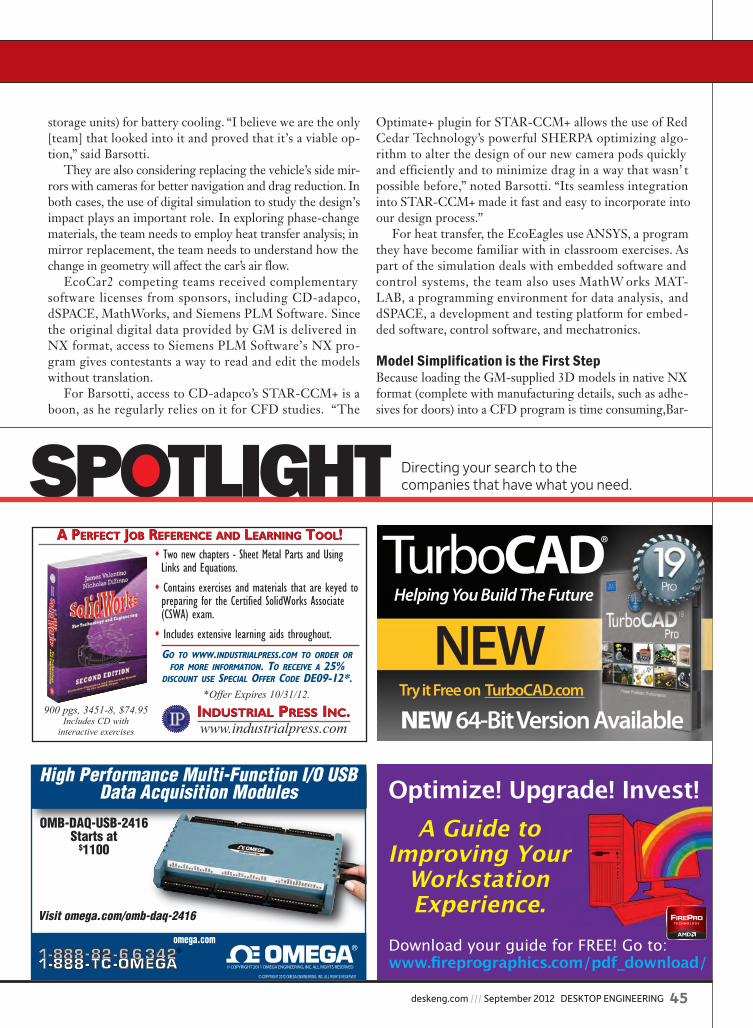
deskeng.com /// September 2012 DESKTOP ENGINEERING 45
storage units) for battery cooling. “I believe we are the only [team] that looked into it and proved that it’s a viable op-tion,” said Barsotti.
They are also considering replacing the vehicle’s side mir-rors with cameras for better navigation and drag reduction. In both cases, the use of digital simulation to study the design’s impact plays an important role. In exploring phase-change materials, the team needs to employ heat transfer analysis; in mirror replacement, the team needs to understand how the change in geometry will affect the car’s air flow.
EcoCar2 competing teams received complementary software licenses from sponsors, including CD-adapco, dSPACE, MathWorks, and Siemens PLM Software. Since the original digital data provided by GM is delivered in NX format, access to Siemens PLM Software’s NX pro-gram gives contestants a way to read and edit the models without translation.
For Barsotti, access to CD-adapco’s STAR-CCM+ is a boon, as he regularly relies on it for CFD studies. “The
Optimate+ plugin for STAR-CCM+ allows the use of Red Cedar Technology’s powerful SHERPA optimizing algo-rithm to alter the design of our new camera pods quickly and efficiently and to minimize drag in a way that wasn’ t possible before,” noted Barsotti. “Its seamless integration into STAR-CCM+ made it fast and easy to incorporate into our design process.”
For heat transfer, the EcoEagles use ANSYS, a program they have become familiar with in classroom exercises. As part of the simulation deals with embedded software and control systems, the team also uses MathW orks MAT-LAB, a programming environment for data analysis, and dSPACE, a development and testing platform for embed-ded software, control software, and mechatronics.
Model Simplification is the First StepBecause loading the GM-supplied 3D models in native NX format (complete with manufacturing details, such as adhe-sives for doors) into a CFD program is time consuming, Bar-
SPOTLIGHT
SPOTLIGHT Directing your search to the companies that have what you need.
A PERFECT JOB REFERENCE AND LEARNING TOOL!A PERFECT JOB REFERENCE AND LEARNING TOOL!
INDUSTRIAL PRESS INC.www.industrialpress.comINDUSTRIAL PRESS INC.
� Two new chapters - Sheet Metal Parts and Using Links and Equations.
� Contains exercises and materials that are keyed to preparing for the Certified SolidWorks Associate (CSWA) exam.
� Includes extensive learning aids throughout.
GO TO WWW.INDUSTRIALPRESS.COM TO ORDER ORFOR MORE INFORMATION. TO RECEIVE A 25%
DISCOUNT USE SPECIAL OFFER CODE DE09-12*.*Offer Expires 10/31/12.
900 pgs, 3451-8, $74.95Includes CD with
interactive exercises
DESpotlight09-12.qxp 7/2/2012 1:19 PM Page 1
High Performance Multi-Function I/O USB Data Acquisition Modules
OMB-DAQ-USB-2416Starts at
$1100
Visit omega.com/omb-daq-2416
© COPYRIGHT 2012 OMEGA ENGINEERING, INC. ALL RIGHTS RESERVED
© COPYRIGHT 2011 OMEGA ENGINEERING, INC. ALL RIGHTS RESERVED
omega.com Download your guide for FREE! Go to:www.fireprographics.com/pdf_download/
Optimize! Upgrade! Invest!A Guide to
Improving Your Workstation Experience.
TurboCAD®
NEW 64-Bit Version Available
Helping You Build The Future
Try it Free on TurboCAD.com
NEW
de0912_EcoCar_Wong.indd 45 8/15/12 9:55 AM

46 DESKTOP ENGINEERING September 2012 /// deskeng.com
Simulate /// CAE Software
sotti uses Parasolid (the geometric format native to Siemens’ software packages, also widely used by many CAD software developers) as the intermediary lightweight format. When possible, Barsotti reduces the complexity of the model using NX’s Synchronology Technology, a direct-editing method. (For more on this topic, read “Direct Modelers as FEA Pre-processors, Part I and Part II,” April-May 2012.)
Because of Embry-Riddle’s long tradition in aerospace en-gineering, the faculty and its students are more familiar with Dassault Systèmes’ CATIA, a software package widely used in aerospace industry. However, despite limited exposure to NX, Barsotti found that NX’s Synchronous Technology, which lets users push and pull on faces to create or edit geometry, gave him an easy way to strip out unnecessary details.
When analyzing the engine bay, Barsotti simplified it by reducing the amount of details and holes in the model. Sim-ilarly, when preparing the floor of the vehicle, he turned the model into solid, flat geometry. These treatments reduced the computation required to solve the analysis scenarios and produce the results faster. (Even a simplified model still contained roughly 16 million cells, Barsotti estimated.)
“The Wrap allowed for a quick ‘Wrap’ of the grills that quickly sealed the engine bay,” noted Barsotti. “Also, the Wave geometry linker allowed the flat floor to be drawn with linked dimensions to the body’s shell without any risk of modifying the original design of the vehicle.”
HPC on a Smaller ScaleThe EcoEagles’ garage is equipped with a Dell Precision T7500 workstation, powered by dual CPUs (two CPUs, of-fering 12 processing cores), 24GB RAM, a NVIDIA Quadro 2000 professional GPU, and a 120GB solid-state drive. A
SpaceMouse from 3DConnexion rounds out the system. “CD-adapco is nice enough to give us HPC licenses,
so we could use all 12 cores,” Barsotti remarked. Running analysis software on multiple CPU cores lets you obtain the results faster; however, doing so often requires special licenses, often called HPC licenses.
As powerful as the Dell Precision workstation is, Bar-sotti explained some of the analysis jobs took an entire day to converge even when processing on all 12 cores. Fur-thermore, when the system is engaged in analysis jobs, it has no remaining processing power for anything else. Out of consideration for others who might need access to the workstation, Barsotti usually schedules his analysis jobs to begin at the end of the day.
One advantage STAR-CCM+ offers, Barsotti explained, is the option to pause a job in progress. “You can stop the solver at any time, then start up again at a later time,” he said. “Obviously I share the workstation with others, so if someone has to use the workstation, I can stop my simula-tion, save it, then start it again later.”
He also showed his teammates how to stop a simula-tion, then reload it on fewer number of cores: for example, switching the simulation to run from 12 cores to 8, thus leaving four free cores to run other programs (such as email, web browsers, or CAD) while the simulation contin-ues in the background.
Experiments in Bits and BytesOn July 25, the EcoEagles provided an update to its fans through their Facebook page: “Our vehicle dynamom-eter has arrived. Installation into the EcoEagles’ garage begins next week. Exercising our hybrid power system
Simulation results for the Embry-Riddle team’s design study. Top image shows surface pressure on the vehicle with velocity streamlines. Bottom left image shows a velocity vector plot through a plane that is about 3/4 of the way up the tire. Bottom right image shows velocity through the mid-plane of the vehicle. They are simulated with a vehicle with rotating wheels and a moving ground plane traveling at 50 mph.
de0912_EcoCar_Wong.indd 46 8/15/12 8:17 AM
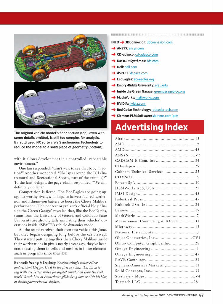
deskeng.com /// September 2012 DESKTOP ENGINEERING 47
with it allows development in a controlled, repeatable environment.”
One fan responded: “Can’t wait to see that baby in ac-tion!” Another wondered: “No laps around the ICI (In-tramural and Recreational Sports, part of the campus)?” To the fans’ delight, the page admin responded: “We will definitely do laps.”
Competition is fierce. The EcoEagles are going up against worthy rivals, who hope to harvest fuel-cells, etha-nol, and lithium-ion battery to boost the Chevy Malibu’s performance. The contest organizer’s official blog “In-side the Green Garage” revealed that, like the EcoEagles, teams from the University of Victoria and Colorado State University are also digitally simulating their vehicles’ op-erations inside dSPACE’s vehicle dynamics mode.
All the teams received their own test vehicle this June, but they began designing long before the car arrived. They started putting together their Chevy Malibus inside their workstations in pixels nearly a year ago; they’ve been crash-testing them in cells and meshes in finite element analysis programs since then. DE
Kenneth Wong is Desktop Engineering’s senior editor and resident blogger. He’ll be the first to admit that his driv-ing skills are better suited for digital simulation than the real world. Reach him at [email protected] or visit his blog at deskeng.com/virtual_desktop.
Advertising IndexAltair .. . . . . . . . . . . . . . . . . . . . . . . . . . . . . . . . . . . . . . . . . . . . . . . . . . . . . . . . 13AMD ..... . . . . . . . . . . . . . . . . . . . . . . . . . . . . . . . . . . . . . . . . . . . . . . . . . . . . . . .9AMD ..... . . . . . . . . . . . . . . . . . . . . . . . . . . . . . . . . . . . . . . . . . . . . . . . . . . . . . 45ANSYS .... . . . . . . . . . . . . . . . . . . . . . . . . . . . . . . . . . . . . . . . . . . . . . . . . . CV2CADCAM-E.Com, Inc ... . . . . . . . . . . . . . . . . . . . . . . . . . . . . . 34CD-adapco .... . . . . . . . . . . . . . . . . . . . . . . . . . . . . . . . . . . . . . . . . . . . . . 29Cobham Technical Services ... . . . . . . . . . . . . . . . . . . . . . . 25COMSOL .... . . . . . . . . . . . . . . . . . . . . . . . . . . . . . . . . . . . . . . . . . . . . . . . .5Esteco SpA .... . . . . . . . . . . . . . . . . . . . . . . . . . . . . . . . . . . . . . . . . . . . . . 39HSMWorks ApS, USA .... . . . . . . . . . . . . . . . . . . . . . . . . . . . . . 27IMSI Design ... . . . . . . . . . . . . . . . . . . . . . . . . . . . . . . . . . . . . . . . . . . . . 45Industrial Press ... . . . . . . . . . . . . . . . . . . . . . . . . . . . . . . . . . . . . . . . 45Kubotek USA, Inc. .. . . . . . . . . . . . . . . . . . . . . . . . . . . . . . . . . . . . . 24Lenovo .... . . . . . . . . . . . . . . . . . . . . . . . . . . . . . . . . . . . . . . . . . . . . . . . . . . . 19MathWorks ... . . . . . . . . . . . . . . . . . . . . . . . . . . . . . . . . . . . . . . . . . . . . . . .7Measurement Computing & IOtech .... . . . . . . . . . 31Microway ... . . . . . . . . . . . . . . . . . . . . . . . . . . . . . . . . . . . . . . . . . . . . . . . . 15National Instruments ... . . . . . . . . . . . . . . . . . . . . . . . . . . . . . . . . .3Objet Geometries, Inc. .. . . . . . . . . . . . . . . . . . . . . . . . . . . . . CV3Okino Computer Graphics, Inc. .. . . . . . . . . . . . . . . . . . 28Omega Engineering ... . . . . . . . . . . . . . . . . . . . . . . . . . . . . . . . . . . .1Omega Engineering ... . . . . . . . . . . . . . . . . . . . . . . . . . . . . . . . . . 45RAVE Computer ... . . . . . . . . . . . . . . . . . . . . . . . . . . . . . . . . . . . . . . 23Siemens-Americas Marketing.... . . . . . . . . . . . . . . . . . . . 11Solid Concepts, Inc. .. . . . . . . . . . . . . . . . . . . . . . . . . . . . . . . . . . . 33Stratasys - Mojo ... . . . . . . . . . . . . . . . . . . . . . . . . . . . . . . . . . . . . CV4Tormach LLC .... . . . . . . . . . . . . . . . . . . . . . . . . . . . . . . . . . . . . . . . . 28
INFO ➜ 3DConnexion: 3dconnexion.com
➜ ANSYS: ansys.com
➜ CD-adapco: cd-adapco.com
➜ Dassault Systèmes: 3ds.com
➜ Dell: dell.com
➜ dSPACE: dspace.com
➜ EcoEagles: ecoeagles.org
➜ Embry-Riddle University: erau.edu
➜ Inside the Green Garage: greengarageblog.org
➜ MathWorks: mathworks.com
➜ NVIDIA: nvidia.com
➜ Red Cedar Technology: redcedartech.com
➜ Siemens PLM Software: siemens.com/plm
The original vehicle model’s fl oor section (top), even with some details omitted, is still too complex for analysis. Barsotti used NX software’s Synchronous Technology to reduce the model to a solid piece of geometry (bottom).
de0912_EcoCar_Wong.indd 47 8/15/12 8:18 AM
Commentary By Tony Christian
48 DESKTOP ENGINEERING September 2012 /// deskeng.com
T here is no doubt that the rudimentary 2D drafting systems and manual intensive analysis packages of the early 1980s revolutionized engineering design—not only in terms of productivity, but also because
of the ability to reach the physical prototyping and testing stage with much greater confidence in the product’s perfor-mance. Since then, the computer-based design tools avail-able to engineers have steadily increased in both range and sophistication, resulting in the fully integrated 3D modeling and multiphysics analysis tools available today. They have also decreased substantially in cost, which, together with the growth in computing power and advances in computing in-frastructures, means that today’s engineer can develop con-cept designs, create fully detailed 3D models and perform a wide range of analyses and simulations on the desktop.
The advances that have made this level of accessibility possible are primarily in the areas of system integration, ease of use and processing power. The exchange of geometry among CAD and simulation and analysis systems has become practically seamless,
even among systems from different vendors. For vendors that offer a suite of tools, moving between systems is largely a matter of simply moving to a different set of menu options. For many types of analysis, even those of some complexity, much of the groundwork of setting up the model in the required form is now largely handled intelligently by the system “behind the scenes.” And of course, the levels of computing power available to desktop users are now huge, whether through exploitation of the cloud or by adding power locally in the form of processors dedicated to the kinds of tasks associated with computer-aided engineering. What’s more, the power required is highly affordable.
Industry ImpactThe availability of integrated, sophisticated and easier-to-use engineering tools on the desktop has far-reaching implica-tions for most industries. First, it offers the prospect of a fully integrated design process in which the simulation and analy-sis steps for all physical aspects are embedded seamlessly into the design engineer’s workflows. That is not to suggest that a rigorous analysis by simulation and analysis specialists can be eliminated, but the design engineers’ ability to perform
initial analyses does mean the specialist’s involvement comes at a stage at which the design should already be quite robust.
Of course, the extent to which the technology can affect the design process depends on the ability of an organization to absorb such potentially disruptive changes into its work-flows—and this varies widely by industry. The aerospace sec-tor, for example, is certainly deriving benefits such as improved designs through the ability to explore more options, reduced development time through delaying physical prototyping, elim-inating waste associated with over-engineering, etc. But it must also maintain the carefully staged and controlled approach to component, sub-system and integrated system design that has evolved over many decades. In contrast, less complex, more fast-moving industries can modify their work practices more readily.
Lower Barriers to EntryThe second implication of the advances in desktop engineer-ing tools is that many more organizations can take advantage of these technologies. For any industry, the result is a “raising of the bar” in terms of almost every aspect of product perfor-mance, including functionality, safety, reliability, cost, environ-mental impact and, for many products, aesthetic appeal. As a re-sult, computer-aided simulation and analysis tools are becoming essential design resources, even for small companies in sectors for which such tools were previously considered overkill.
It also means that small companies with access to today’s desktop engineering design tools can compete in some of the areas that have only been within the capabilities of larger companies with heavy investments in design technologies. The market, therefore, seems to be self-sustaining.
A third major implication is managing the engineering data that results from access to design tools. For large companies, the volume and scope of the data generated by more engineers performing a wider range of tasks is likely to put pressure on their product data management environments. But for small companies, it may well be raising a new requirement in terms of managing product data. The good news is that the vendor community is responding to this need by developing more ac-cessible technology in this area, too. DE
Exploiting the Integrated Desktop
The exchange of geometry among CAD and simulation and analysis systems has become practically seamless.
INFO ➜ Cambashi: Cambashi.com
For more information on this topic, visit deskeng.com.
With a range of experience in engineering, manufacturing, en-ergy and IT, Tony Christian is director of the research analyst and consulting company Cambashi. Send e-mail about this article to [email protected].
de0912_Commentary_Cambashi.indd 48 8/14/12 1:18 PM


GIVE YOUR BIG IDEA
A LITTLE MOJO.
Introducing A World-Class 3D Printer For Only $185/Month.
When you bring an idea to the table, the new Mojo 3D Printer brings
it to life with ease. Now you can have 3D printing right at your desktop
at a remarkably low cost. With the magic of Mojo
at your f ingertips, there’s really no limit to your creativity. The
affordable Mojo 3D Print Pack includes everything you need to
start printing immediately – matching your design’s brilliance
with an equally inspiring model.
Find out more at www.Mojo3Dprinting.com/DE
Leasing available only in the United States. Additional options, shipping, applicable taxes and/or duties not included. ©2012 Stratasys, Inc.
3D PRINTER
Stratasys– 62386Desktop Engineering _MOJO R!5/2/12Publication: Desktop EngineeringMaterials Due: 4/30/12
Trim: 7.825” x 10.75”Live: 7.375” x 10.25Bleed: 8.125” x 11” Spot Colors: n/a
Creative:Susan Schmidt
Account:Michael Jensen
Production: Tina Anderson
Proofreader:
Stratasys_Mojo.indd 1 8/14/12 12:30 PM
Related Documents