200 A Loadbreak Connectors EZ ™ II Splice Loadbreak Elbow Connector with Test Point Shield Adapter Bushing Well Insert w/Latch Indicator Ring Transformer or Switching Apparatus Rotatable Feedthru Insert Bushing Well Plug One-Piece Bushing (pg 32) Standoff Bushing Portable Feedthru Parking Stand Arrester (pg 26) Grounding Elbow (pg 28) Loadbreak Junction Loadbreak Protective Cap Loadbreak Elbow Connector Bushing Well M.O.V.E. Elbow Arrester Jacket Seal FCI (pg 36) FCI (pg 36) FCI (pg 36) Sectionalizing Cabinets (pg 38) FCI (pg 36) Loadbreak Elbow Connector Loadbreak Junction (pg 24) (pg 26) (pg 32) Cooper’s 200 A 15, 25, and 35 kV Loadbreak Elbow Connectors and Accessories are submersible, fully-shielded and insulated plug-in terminations, ideal for connecting underground cable to transformers, switching cabinets and junctions. These connectors are molded using high-quality, peroxide-cured EPDM insulation for reliable field performance. The entire connector system can be applied to concentric neutral cable with Cooper’s JS200 Series Sealing Kit or to almost any other type of cable with Cooper’s SA Series Shield Adapter Kit. All 200 A loadbreak connectors meet the electrical, mechanical, and dimensional requirements of IEEE Standards 386 ™ and are designed to be fully interchangeable with other major manufacturers currently complying with IEEE Standard 386 ™ . 25 kV POSI-BREAK ™ Elbow and Cap The Cooper POSI-BREAK Elbow and Cap is an engineered solution that increases strike distance and improves reliability.The added features solve problems, such as: ■ Partial Vacuum Flashovers – Under certain conditions during 25 kV switching, a partial vacuum can decrease the dielectric strength of the air inside the elbow/bushing or cap/bushing. This increases the possibility of a flashover from the elbow or cap’s probe along the bushing interface to the grounded collar on the mating bushing product. The POSI-BREAK design eliminates the possibility of partial vacuum flashovers during switching because of the increased strike distance. ■ Capacitance – Adding insulation minimizes the possibility of flashovers when switching long runs of underground cable, which can induce capacitance and create transient overvoltages. ■ Ferroresonance – Adding insulation minimizes the possibility of flashovers that can occur due to transient overvoltages created by ferroresonance. ■ Contamination – The field-proven interface seal prevents the ingress of moisture or contaminants. However, contamination introduced during installation or switching operations can reduce the strike distance along the interface. The increased insulation of the POSI-BREAK design counteracts the effect of contamination, increasing system reliability. 25 kV POSI-BREAK ™ Elbow and Cap Specification Information To capitalize on the benefits of the POSI-BREAK Elbow and Cap, include the following information for both the 25 kV 200 A Loadbreak Elbow and Insulated Protective Cap in your specification: ■ Both elbow and cap must fully comply with IEEE Standard 386 ™ . ■ Strike distance from energized component to ground shall be at least 5.6" at 1 / 2 " interface separation. ■ Both elbow and cap shall have probe and conductive Faraday Cage for relief of electrical stress and prevention of partial discharge. ■ Semi-conductive insert shall be completely surrounded with EPDM insulating rubber. 35 kV Elbow and Accessories Specification Information To capitalize on the benefits of the Cooper 35 kV Large Interface Elbow include the following information in your specification: ■ The 200 A Elbows and Accessories shall be 21.1 kV/36.6 kV three- phase rated, meeting the requirements of IEEE Standard 386 ™ interface No. 1A (large 35 kV class interface). 35 kV Large Interface Elbow Bushing System* The Cooper 35 kV 200 A Large Interface Elbow Bushing System is a reliable, field proven design. This system has over 25 years of field experience while being used on large 35 kV distribution systems. Features of the Cooper Large Interface System include: ■ Increased strike distance to provide greater reliability and overall performance. ■ Reliable loadbreak switching and fault closure capability. ■ Full line of large interface accessory products. * Refer to bushing section on page 32 for more information on the bushing.

Welcome message from author
This document is posted to help you gain knowledge. Please leave a comment to let me know what you think about it! Share it to your friends and learn new things together.
Transcript

200 A Loadbreak Connectors
EZ™ II Splice
LoadbreakElbow Connectorwith Test Point
ShieldAdapter
Bushing Well Insertw/Latch Indicator Ring
Transformer orSwitchingApparatus
Rotatable FeedthruInsert
Bushing Well Plug
One-Piece Bushing(pg 32)
StandoffBushing
Portable Feedthru
ParkingStand Arrester
(pg 26)Grounding Elbow(pg 28)
LoadbreakJunction
LoadbreakProtective Cap
LoadbreakElbowConnector
BushingWell
M.O.V.E.ElbowArrester
JacketSeal
FCI(pg 36)
FCI (pg 36)
FCI (pg 36)
SectionalizingCabinets(pg 38)
FCI(pg 36)
LoadbreakElbow Connector
LoadbreakJunction(pg 24)
(pg 26)
(pg 32)
Cooper’s 200 A 15, 25, and 35 kV Loadbreak ElbowConnectors and Accessories are submersible,fully-shielded and insulated plug-in terminations,ideal for connecting underground cable to transformers, switching cabinets and junctions.These connectors are molded using high-quality,peroxide-cured EPDM insulation for reliable fieldperformance.The entire connector system can be applied toconcentric neutral cable with Cooper’s JS200Series Sealing Kit or to almost any other type ofcable with Cooper’s SA Series Shield Adapter Kit.All 200 A loadbreak connectors meet the electrical,mechanical, and dimensional requirements ofIEEE Standards 386™ and are designed to be fullyinterchangeable with other major manufacturerscurrently complying with IEEE Standard 386™.
25 kV POSI-BREAK™ Elbow and CapThe Cooper POSI-BREAK Elbow and Cap is an engineered solution that increases strike distance andimproves reliability. The added features solve problems,such as:■ Partial Vacuum Flashovers – Under certain conditions
during 25 kV switching, a partial vacuum can decreasethe dielectric strength of the air inside the elbow/bushingor cap/bushing. This increases the possibility of aflashover from the elbow or cap’s probe along thebushing interface to the grounded collar on the matingbushing product. The POSI-BREAK design eliminatesthe possibility of partial vacuum flashovers duringswitching because of the increased strike distance.
■ Capacitance – Adding insulation minimizes the possibility of flashovers when switching long runs ofunderground cable, which can induce capacitanceand create transient overvoltages.
■ Ferroresonance – Adding insulation minimizes the possibility of flashovers that can occur due to transientovervoltages created by ferroresonance.
■ Contamination – The field-proven interface sealprevents the ingress of moisture or contaminants.However, contamination introduced during installationor switching operations can reduce the strike distancealong the interface. The increased insulation of thePOSI-BREAK design counteracts the effect of contamination, increasing system reliability.
25 kV POSI-BREAK™ Elbow andCap Specification Information
To capitalize on the benefits of thePOSI-BREAK Elbow and Cap, includethe following information for both the25 kV 200 A Loadbreak Elbow andInsulated Protective Cap in yourspecification:
■ Both elbow and cap must fullycomply with IEEE Standard 386™.
■ Strike distance from energized component to ground shall be atleast 5.6" at 1/2" interface separation.
■ Both elbow and cap shall haveprobe and conductive FaradayCage for relief of electrical stressand prevention of partial discharge.
■ Semi-conductive insert shall be completely surrounded with EPDM insulating rubber.
35 kV Elbow and Accessories Specification Information
To capitalize on the benefits of the Cooper 35 kV Large Interface Elbowinclude the following information in your specification:
■ The 200 A Elbows and Accessories shall be 21.1 kV/36.6 kV three-phase rated, meeting the requirements of IEEE Standard 386™
interface No. 1A (large 35 kV class interface).
35 kV Large Interface Elbow Bushing System*The Cooper 35 kV 200 A Large Interface Elbow Bushing System is a reliable, field proven design. This system has over 25 years of field experience while being used on large 35 kV distribution systems. Features of the Cooper Large Interface System include:■ Increased strike distance to provide greater reliability and overall
performance.■ Reliable loadbreak switching and fault closure capability.■ Full line of large interface accessory products.* Refer to bushing section on page 32 for more information on the bushing.
page 11
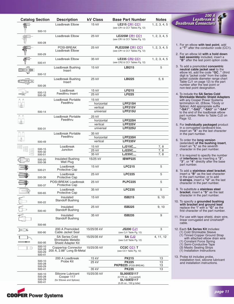
1. For an elbow with test point, add a “T” after the conductor code (CC1).
2. For an elbow kit with a hold downbail assembly included, insert a “B” after the test point option code.
3. To add a premolded concentricneutral cable jacket seal to the elbow kit, add the code “GC_” (thirddigit is “jacket code” from the cablejacket outside diameter range chartTable CJ1 on page 12) to the part number after the test point or non-test point designation.
4. To include the SA Series ColdShrinkable Metallic Shield Adapterswith any Cooper Power Systemstermination kit, (Elbow, T-body orSplice): Add appropriate suffix “-SA1”, “-SA2”, “-SA3” or “-SA4”to the end of the loadbreak elbow part number. Refer to Table CJ2 on Page 12.
5. For individually packaged productin a corrugated cardboard box, insert an “X” as the last character in the part number.
6. To order the long version(extended) of the bushing insert,insert an “L” as the seventh character in the part number.
7. It is required to specify the number of interfaces by inserting a “2”,“3”, or “4” directly after the base part number.
8. To add a stainless steel bracket,insert a “B” as the last character in the part number, or to add U-straps, insert a “U” as the last character in the part number.
9. To substitute a stainless steel bracket, insert a “S” as the last character in the part number.
10. To specify a grounded bushing with bracket and ground leadreplace the “I” with a “G” as the first character of the part number.
11. For use with tape shield, drain wire, linear corrugated and Unishield®
cable.
12. Each SA Series Kit includes:(1) Cold Shrinkable Sleeve (1) Tinned Copper Ground Strap
with attached elbow drain wire (1) Constant Force Spring (1) Semi-Conductive Tape (3) Mastic Sealing Strips (1) Installation Instructions
13. Probe kit includes probe, installation tool, silicone lubricant and installation instructions.
Catalog Section Description kV Class Base Part Number NotesLoadbreak Elbow 15 kV LE215 CR1 CC1 1, 2, 3, 4, 5
(see CR1 & CC1 Tables Pg. 12)
Loadbreak Elbow 25 kV LE225M CR1 CC1 1, 2, 3, 4, 5(see CR1 & CC1 Tables Pg. 12)
POSI-BREAK 25 kV PLE225M CR1 CC1 1, 2, 3, 4, 5Loadbreak Elbow (see CR1 & CC1 Tables Pg. 12)
Loadbreak Elbow 35 kV LE235 CR2 CC1 1, 2, 3, 4, 5(see CR2 & CC1 Tables Pg. 12)
Loadbreak Bushing 15 kV LBI215 5Insert
Loadbreak Bushing 25 kV LBI225 5, 6Insert
Loadbreak 15 kV LFI215Feedthru Insert 25 kV LFI225
Loadbreak Portable 15 kVFeedthru horizontal LPF215H
vertical LPF215Vuniversal LPF215U
Loadbreak Portable 25 kVFeedthru horizontal LPF225H
vertical LPF225Vuniversal LPF225U
Loadbreak Portable 35 kVFeedthru horizontal LPF235H
vertical LPF235V
Loadbreak 15 kV LJ215C— 7, 8Junction 25 kV LJ225C— 7, 8
35 kV LJ235C— 7, 8
Insulated Bushing 15/25 kV IBWP225Well Plug
Loadbreak 15 kV LPC215 5Protective Cap
Loadbreak 25 kV LPC225 5Protective Cap
POSI-BREAK Loadbreak 25 kV PLPC225 5Protective Cap
Loadbreak 35 kV LPC235 5Protective Cap
Insulated 15 kV ISB215 9, 10Standoff Bushing
Insulated 25 kV ISB225 9, 10Standoff Bushing
Insulated 35 kV ISB235 9Standoff Bushing
200 A Premolded 15/25/35 kV JS200 CJ1 3Cable Jacket Seal (see CJ1 Table Pg. 12)
SA Series Cold 15/25/35 kV SA CJ2 4, 11, 12Shrinkable Metallic (see CJ2 Table Pg. 12)Shield Adapter Kit
Coppertop Connector 15/25/35 kV CC2C CC1 T200 A, 2.88" Long Bi-Metal (see CC1 Table Pg. 12)
200 A Loadbreak 15 kV PK215 13Probe Kit 25 kV PK225 13
PKPB225 (POSI-BREAK) 1335 kV PK235 13
Silicone Lubricant 15/25/35 kV SL005ES117Cooper 117 (0.175 oz., 5 g packet)
(for Elbows and Splices) SL150ES117(5.25 oz., 150 g tube)
17.78-23 .11 MM
LE215B
100-.910 IN
500-10
500-29
500-41
500-12
500-26
500-14
500-31
500-49
500-15500-32500-51
500-10500-28500-29500-41
500-10500-28500-29500-41
500-10500-28500-29500-41
500-20500-38
500-21
500-37
500-39
500-65
500-22
500-13500-30
500-28
500-40
500-66
500-95
500-90
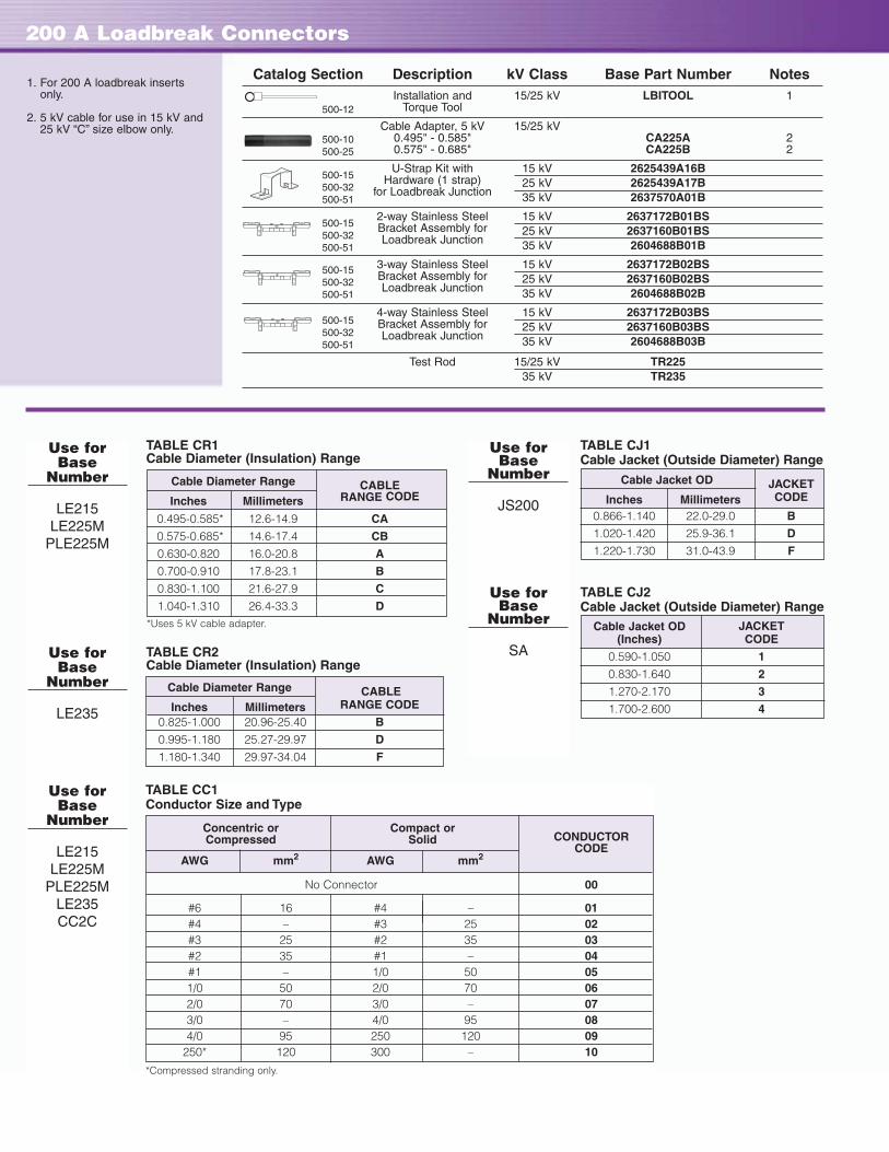
200 A Loadbreak Connectors
Catalog Section Description kV Class Base Part Number NotesInstallation and 15/25 kV LBITOOL 1
Torque Tool
Cable Adapter, 5 kV 15/25 kV0.495" - 0.585" CA225A 20.575" - 0.685" CA225B 2
U-Strap Kit with 15 kV 2625439A16BHardware (1 strap) 25 kV 2625439A17B
for Loadbreak Junction 35 kV 2637570A01B
2-way Stainless Steel 15 kV 2637172B01BSBracket Assembly for 25 kV 2637160B01BSLoadbreak Junction 35 kV 2604688B01B
3-way Stainless Steel 15 kV 2637172B02BSBracket Assembly for 25 kV 2637160B02BSLoadbreak Junction 35 kV 2604688B02B
4-way Stainless Steel 15 kV 2637172B03BSBracket Assembly for 25 kV 2637160B03BSLoadbreak Junction 35 kV 2604688B03B
Test Rod 15/25 kV TR22535 kV TR235
500-12
500-10500-25
500-15500-32500-51
500-15500-32500-51
500-15500-32500-51
500-15500-32500-51
Use for Base
Number
LE215LE225M
PLE225M
Use for Base
Number
LE235
Use for Base
Number
LE215LE225M
PLE225MLE235CC2C
TABLE CC1Conductor Size and Type
Concentric or Compact orCONDUCTORCompressed Solid
CODEAWG mm2 AWG mm2
No Connector 00
#6 16 #4 – 01#4 – #3 25 02#3 25 #2 35 03#2 35 #1 – 04#1 – 1/0 50 051/0 50 2/0 70 062/0 70 3/0 – 073/0 – 4/0 95 084/0 95 250 120 09
250* 120 300 – 10
*Compressed stranding only.
TABLE CJ1Cable Jacket (Outside Diameter) Range
Cable Jacket OD JACKETInches Millimeters CODE
0.866-1.140 22.0-29.0 B
1.020-1.420 25.9-36.1 D
1.220-1.730 31.0-43.9 F
TABLE CJ2Cable Jacket (Outside Diameter) Range
Cable Jacket OD JACKET(Inches) CODE
0.590-1.050 1
0.830-1.640 2
1.270-2.170 3
1.700-2.600 4
Use for Base
Number
JS200
Use for Base
Number
SA
1. For 200 A loadbreak insertsonly.
2. 5 kV cable for use in 15 kV and25 kV “C” size elbow only.
TABLE CR2Cable Diameter (Insulation) Range
TABLE CR1Cable Diameter (Insulation) Range
Cable Diameter Range CABLEInches Millimeters RANGE CODE
0.825-1.000 20.96-25.40 B
0.995-1.180 25.27-29.97 D
1.180-1.340 29.97-34.04 F
Cable Diameter Range CABLEInches Millimeters RANGE CODE
0.495-0.585* 12.6-14.9 CA
0.575-0.685* 14.6-17.4 CB
0.630-0.820 16.0-20.8 A
0.700-0.910 17.8-23.1 B
0.830-1.100 21.6-27.9 C
1.040-1.310 26.4-33.3 D*Uses 5 kV cable adapter.

page 13
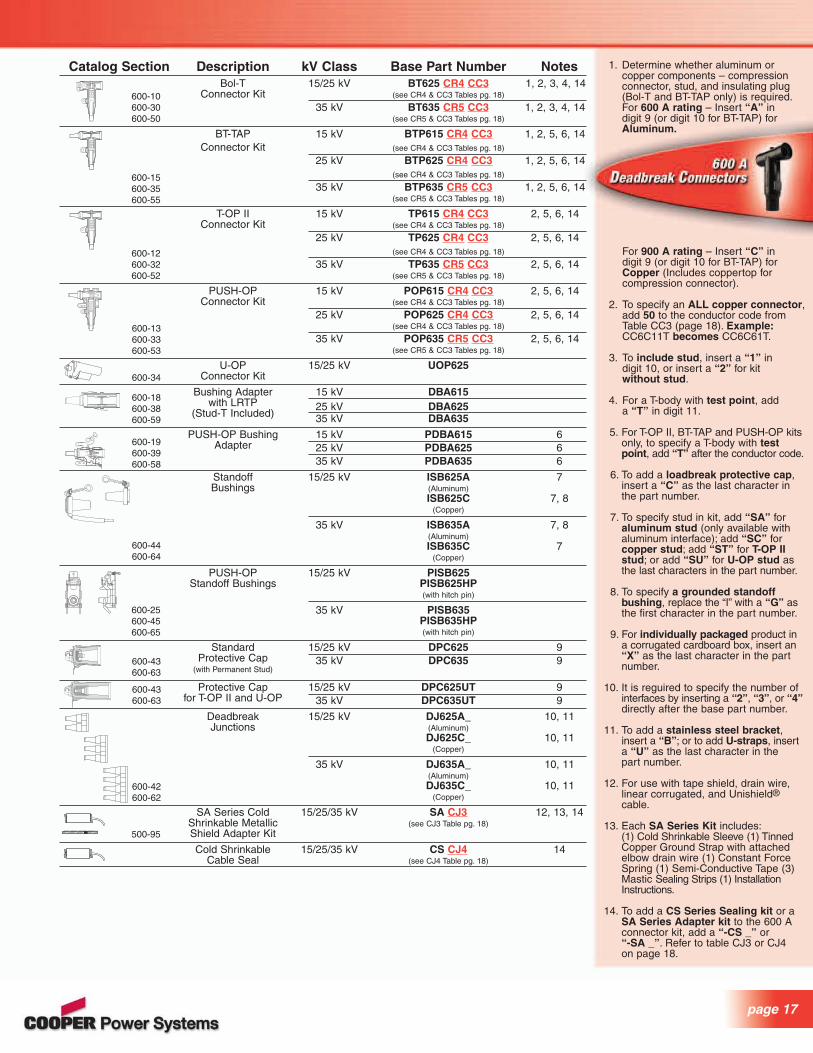
200 A Deadbreak Connectors
Catalog Section Description kV Class Base Part Number NotesDeadbreak Elbow 15/25 kV DE225 CR3 CC1 T 1, 2
(see CR3 & CC1 Tables Below)
Deadbreak Straight 15/25 kV DS225 CR3 CC1 T 1, 2(see CR3 & CC1 Tables Below)
Deadbreak 15/25 kV DJ250-4 3, 4Junction (4-way)
15/25 kV DJ250-T1 3, 4(3-way, Type 1)
15/25 kV DJ250-T2 3, 4(3-way, Type 2)
Deadbreak 15/25 kV DJ250-2 3, 4Junction
Insulated Deadend 15/25 kV DPD250 3Plug
Insulated Standoff 15/25 kV DPS250 3Bushing
Grounded Standoff 15/25 kV DPE250 3Bushing
Deadbreak Protective 15/25 kV DRC250 2Cap
Apparatus 15/25 kV DB250Bushing DB250S
(Short Shank)DB250L
(Long Shank)
Coppertop Connectors 15/25 kV CC2C CC1 Tfor Deadbreak (see CC1 Table Below)
Elbows
Crimp Connectors 15/25 kV CC2C CC1 Sfor Deadbreak (see CC1 Table Below)
Straight
Probe and Probe 15/25 kV 2638370C01EXWrench for (Probe)
Deadbreak Elbow 2639205B01(Probe Wrench)
Bail Assembly 15/25 kV 2638409C06B
550-12
I550-12
I550-12
I550-13
I550-13
I550-13
I550-13
I550-15
I550-13
I550-13
I550-13
550-10
550-10
Use for Base
Number
DE225DS225
Use for Base
Number
DE225DS225CC2C
1. To add a premolded concentricneutral jacket seal to the elbow kit,add the code “GC_” (third digit is“jacket code” from the cable jacketrange outside diameter range chartTable CJ1 on page 12) as the last characters in the part number.
2. Bail assembly included in kit.
3. Bail assembly is ordered separately.
4. See following for appropriate junctionstrap. For DJ250-2 and DJ250-T1,order 2639524B01. For DJ250-T2,order 2638617C01. For DJ250-4, consult factory.
TABLE CR3Cable Diameter (Insulation) Range
Cable Diameter Range CABLEInches Millimeters RANGE CODE
0.531-0.685 18.5-17.4 BA0.640-0.820 16.3-20.8 DA0.770-0.950 19.6-24.1 FA0.910-1.130 23.1-28.7 HA1.100-1.320 27.9-33.5 JA
TABLE CC1Conductor Size and Type
Concentric or Compressed Compact or Solid CONDUCTORAWG mm2 AWG mm2 CODE
No Connector 00
#6 16 #4 – 01#4 – #3 25 02#3 25 #2 35 03#2 35 #1 – 04#1 – 1/0 50 051/0 50 2/0 70 062/0 70 3/0 – 073/0 – 4/0 95 084/0 95 250 120 09
250* 120 300 – 10
*Compressed stranding only.

200 A Stacking Dimensions
Elbow Connector (25 kV POSI-BREAK™ shown)
S4S3
S6
S5
S2S1
Bushing Insert with Latch Ring Indicator (25 kV shown)
Rotatable Feedthru Insert (25 kV shown)
S2
A
S4S3
S5
S8S7
S6
Insulated Standoff Bushing (25 kV shown)
A
S2
ED
Loadbreak Protective Cap (25 kV POSI-BREAK™ shown)
S3
Insulated Bushing Well Plug
B
Loadbreak Portable Feedthru (15 kV shown)
S3
A
S1S2
A
S2
Dim. 15 kV 25 kV 35 kV
S3 3.44" 3.86" 4.13"(87 mm) (98.04 mm) (105.0 mm)
S4 4.16" 4.54" 5.01"(106 mm) (115.32 mm) (127.3 mm)
S5 2.73" 3.14" 3.58"(69 mm) (79.76 mm) (91.0 mm)
S6 1.23" 1.64" 1.77"(31 mm) (41.66 mm) (45.0 mm)
Dim. 15 kV 25 kV Short 25 kV Long
S1 0.76" 0.76" 0.76"(19.3 mm) (19.3 mm) (19.3 mm)
S2 6.3" 7.14" 9.97"(106 mm) (181.4 mm) (253.2 mm)
Dim. 15 kV 25 kV
A 7.1" 7.1"(179 mm) (179 mm)
S2 9.50" 11.0"(241 mm) (279 mm)
Dim. 15 kV/25 kV
S3 5.1"(130 mm)
A 2.7"(69 mm)
Dim. 15 kV 25 kV 35 kV
S3 2.15" 2.61" 2.66"(54.5 mm) (66.3 mm) (67.5 mm)
Dim. 15 kV 25 kV 35 kV
A 6.3" 6.3" 7.1"(160 mm) (160 mm) (181 mm)
S2 5.91" 7.34" 11.67"(150 mm) (186 mm) (296.4 mm)
15 kV 25 kV 35 kVDim. Horizontal Vertical Horizontal Vertical Horizontal Vertical
B 5.6" – 5.6" – 7.2" –(142.2 mm) (142.2 mm) (182.9 mm)
D – 8.9" – 8.9" – 11.6"(226 mm) (226 mm) (294 mm)
E 6.0" – 6.7" – 8.8" –(153 mm) (171 mm) (224 mm)
S3 3.44" 3.44" 3.86" 3.86 4.13" 4.13"(87 mm) (87 mm) (98 mm) (98 mm) (105 mm) (105 mm)
S4 4.16" 4.16" 4.54" 4.54" 5.01" 5.01"(106 mm) (106 mm) (115 mm) (115 mm) (127.3 mm) (127.3 mm)
S5 2.73" 2.73" 3.14" 3.14" 3.58" 3.58"(69 mm) (69 mm) (80 mm) (80 mm) (91 mm) (91 mm)
S6 1.23" 1.23" 1.64" 1.64" 1.77" 1.77"(31 mm) (31 mm) (42 mm) (42 mm) (45 mm) (45 mm)
S7 0.75" 0.75" 0.75" 0.75" 0.75" 0.75"(19 mm) (19 mm) (19 mm) (19 mm) (19 mm) (19 mm)
S8 7.07" 7.20" 8.63" 8.77" 11.8" 11.8"(180 mm) (183 mm) (219 mm) (223 mm) (300 mm) (300 mm)

page 15
S10
S9
S7
E
MIN.
MIN.
MIN.
M4
B
MAX.
MAX.
MAX.
CONFIGURATION – 3*
CONFIGURATION – 2*
CONFIGURATION – 1*
S11
A
Underground Surge Arresters
A
2.2"(55 mm)
S3
Parking Stand Arresters
A
B
2.2"(55 mm)S8
Loadbreak Junctions (15 kV shown)
** Refer to CatalogSection 500-51 fordetailed drawing of 35 kVjunction.
VariGAP MOV Parking Stand Arrester
DutyDim. Cycle (kV) 15 kV 25 kV
A 9-15 11.9" (302 mm) 11.9" (302 mm)18-21 14.5" (368 mm) 14.5" (368 mm)
B 9-15 8.0" (203 mm) 8.0" (203 mm)18-21 10.6" (269 mm) 10.6" (269 mm)
S8 9-21 7.4" (188 mm) 7.4" (188 mm)
MOV Parking Stand Arrester
DutyDim. Cycle (kV) 15 kV 25 kV
A 3-21 11.9" (302 mm) 11.9" (302 mm)B 3-21 8.0" (203 mm) 8.0" (203 mm)S8 3-21 7.4" (188 mm) 7.4" (188 mm)
DutyDim. Cycle (kV) 15 kV/25 kV 35 kV
A 9-15 8.5" (216 mm) –18-27 10.9" (276 mm) 13.3" (338 mm)
S3 9-27 4.2" (107 mm) 4.7" (120 mm)
VariGAP® M.O.V.E.™ Arrester
M.O.V.E. Arrester
DutyDim. Cycle (kV) 15 kV/25 kV 35 kV
A 3-27 8.5" (216 mm) 13.3" (338 mm)S3 3-27 4.2" (107 mm) 4.7" (120 mm)
Dim. 15 kV 25 kV 35 kV
E 3.25" (83 mm) 4.0" (102 mm) 5.0" (127 mm)S7 0.75" (19 mm) 0.75" (19 mm) 1.02" (26 mm)S9 4.38" (111 mm) 4.38" (111 mm) 5.46" (139 mm)S10 6.77" (172 mm) 8.34" (212 mm) 11.8" (299 mm)S11 9.20" (234 mm) 10.77" (274 mm) 13.9" (163 mm)M4 See Table 15 kV See Table 25 kV See Table 35 kV
Physical M4 Mounting Dimensions in./mmNumber Dimensions
of in./mm Configuration 1 Configuration 2 Configuration 3Interfaces A B Min. Max. Min. Max. Min. Max.
2 12.5 6.0 10.8 14.4 7.2 10.8 3.6 7.2(318) (152) (275) (366) (183) (275) (92) (183)
3 19.6 9.2 14.7 18.3 11.1 14.7 7.4 11.1(498) (230) (374) (465) (282) (374) (188) (282)
4 22.9 12.4 17.9 21.5 14.3 17.9 10.7 14.3(582) (315) (455) (547) (364) (455) (272) (364)
TABLE 15 kV
Configuration 1. Both feet turned out.Configuration 2. One foot turned out, one in.Configuration 3. Both feet turned in.
TABLE 25 KV
Physical M4 Mounting Dimensions in./mmNumber Dimensions
of in./mm Configuration 1 Configuration 2 Configuration 3Interfaces A B Min. Max. Min. Max. Min. Max.
2 14.2 6.7 11.9 15.6 8.0 11.7 4.2 7.8(361) (170) (302) (396) (203) (297) (107) (198)
3 23.0 10.7 16.8 20.4 12.9 16.5 9.0 12.6(584) (272) (427) (518) (328) (419) (229) (320)
4 27.0 14.7 20.8 24.4 16.9 20.5 13.0 16.6(686) (373) (528) (620) (429) (521) (330) (422)
Configuration 1. Both feet turned out.Configuration 2. One foot turned out, one in.Configuration 3. Both feet turned in.
Number of Mounting Dimensions in./mmInterfaces A B C D
2 23.1 8.8 ** **(587) (223)
3 33.3 13.8 ** **(846) (350)
4 38.5 18.8 ** **(978) (477)
TABLE 35 kV

600 A Deadbreak Connectors
Connecting Plug
Loadbreak ElbowConnector
(pg 10)
BushingAdapter
ProtectiveCap
Bol-T™Connector
Bol-T™Connector 600 A
One-PieceBushing(pg 32)
StandoffBushing
ParkingStand
Bracket
Transformer orSwitchgearApparatus
GroundingElbow (pg 28)
U-OP™Connector**
EZ II Splice(pg 24)
U-OP™Connector**
LoadbreakProtective
Cap
PUSH-OP™Connector*
T-OP™ IIConnector
T-OP™ IIConnector
BT-TAP™Connector
M.O.V.E.™ElbowArrester(pg 26)
FCI(pg 36)
FCI (pg 36)
FCI
FCI
FCI
600 A SeparableSplice Kit
Deadbreak JunctionT-OP IIConnector
DeadbreakJunction
SectionalizingCabinets(pg 38)
LoadbreakProtective Cap
ShieldAdapter
DeadbreakJunction
U-OP™ Connector**
* PUSH-OP requires modified bushing and tank hardware.**U-OP requires frontplate stud provisions. Refer to Installation Instructions S600-14-1 for details.
Cooper’s 600 A Deadbreak Connector Systems are designedto fill the demand for a deadfront underground installation in600 A main and lateral feeders. They provide a completelyshielded, deadfront, fully submersible cable connection forhigh-voltage apparatus – such as transformers, switchgear,large motors, etc., and can also be used to make splices,junctions, taps and deadends for main underground, distributionfeeders. They provide the same high degree of operatingflexibility and reliability as our 200 A products. All componentsfit together easily and assembly variations are available.These connector systems are designed for installation onvarious types of cables. The entire system can be applied toconcentric neutral cable, and with Cooper’s SA Series ShieldAdapter Kit to almost any other type of cable.All Cooper 600 A Deadbreak Connectors meet the electrical,mechanical and dimensional requirements of IEEE Standard386™ and are designed to be fully interchangeable withthose currently available from other major manufacturers.
900 A RATINGA 900 A continuous rating can be achieved with Bol-T™,BT-TAP™ and T-OP™ II Systems when used with a coppertopcompression connector and all copper mating componentsincluding apparatus bushing or junction. (See note 1 onpage 17 for details when selecting a system.)
BOL-T™ Connector SystemCooper’s Bol-T Deadbreak Connector System is designedfor use on applications where the terminations would not beoperated after installation, would not need a 200 A interfacefor grounding or arrester provisions, and would not requiredirect conductor testing or the use of a hotstick. It is a bolteddesign that is interchangeable with other manufacturers’ bolted600 A systems and requires no special tools for installation.
BT-TAP™ Connector SystemCooper’s BT-TAP Deadbreak Connector System includes a200 A loadbreak tap instead of the standard insulated plug.The other components of BT-TAP are the same as Bol-T, making it an ideal option to retrofit existing Bol-T (or otherbolted systems that use unthreaded compression connectors)systems with a 200 A loadbreak tap for testing, grounding,or overvoltage protection.
T-OP™ II Connector SystemCooper’s T-OP II Deadbreak Connector System also has a 200 A loadbreak tap and has all the advantages of the BT-TAP System. In addition, the T-OP II is single-person hotstick operable, making it ideal for terminations that may require moving or sectionalizing to achieve a visible open or visible ground. The T-OP II design offers added reliability (900 A rated all copper alloy current path) and has several assembly/operating advantages.
PUSH-OP® Connector SystemCooper’s PUSH-OP Deadbreak Connector System is essentially a T-OP II Termination with a non-bolted design for use on any deadfront apparatus where the terminations may be operated frequently. The PUSH-OP 600 A deadbreak probe and finger contact design eliminates cross-threading and normal thread
wear during repeated sectionalizing operations. It is the onlyavailable system that allows operators to move the terminatorwhile it is fully grounded. The PUSH-OP System providesstainless steel bracketry and a mechanical lever for thefastest and easiest one-person hotstick operation possible.The PUSH-OP System requires special apparatus bushings,which makes it suitable for new installations only.
U-OP™ Connector SystemCooper’s U-OP Deadbreak Connector System is used withT-OP II and designed to provide a visible break and visible ground without having to move large 600 A cable.The U-OP System requires special apparatus bracketry,which makes it suitable for new installations only.
Note: 600 A Separable Splice kits can be found in the splice section on page 25.
page 17
Catalog Section Description kV Class Base Part Number NotesBol-T 15/25 kV BT625 CR4 CC3 1, 2, 3, 4, 14
Connector Kit (see CR4 & CC3 Tables pg. 18)
35 kV BT635 CR5 CC3 1, 2, 3, 4, 14(see CR5 & CC3 Tables pg. 18)
BT-TAP 15 kV BTP615 CR4 CC3 1, 2, 5, 6, 14Connector Kit (see CR4 & CC3 Tables pg. 18)
25 kV BTP625 CR4 CC3 1, 2, 5, 6, 14(see CR4 & CC3 Tables pg. 18)
35 kV BTP635 CR5 CC3 1, 2, 5, 6, 14(see CR5 & CC3 Tables pg. 18)
T-OP II 15 kV TP615 CR4 CC3 2, 5, 6, 14Connector Kit (see CR4 & CC3 Tables pg. 18)
25 kV TP625 CR4 CC3 2, 5, 6, 14(see CR4 & CC3 Tables pg. 18)
35 kV TP635 CR5 CC3 2, 5, 6, 14(see CR5 & CC3 Tables pg. 18)
PUSH-OP 15 kV POP615 CR4 CC3 2, 5, 6, 14Connector Kit (see CR4 & CC3 Tables pg. 18)
25 kV POP625 CR4 CC3 2, 5, 6, 14(see CR4 & CC3 Tables pg. 18)
35 kV POP635 CR5 CC3 2, 5, 6, 14(see CR5 & CC3 Tables pg. 18)
U-OP 15/25 kV UOP625Connector Kit
Bushing Adapter 15 kV DBA615with LRTP 25 kV DBA625
(Stud-T Included) 35 kV DBA635
PUSH-OP Bushing 15 kV PDBA615 6Adapter 25 kV PDBA625 6
35 kV PDBA635 6
Standoff 15/25 kV ISB625A 7Bushings (Aluminum)
ISB625C 7, 8(Copper)
35 kV ISB635A 7, 8(Aluminum)ISB635C 7
(Copper)
PUSH-OP 15/25 kV PISB625Standoff Bushings PISB625HP
(with hitch pin)
35 kV PISB635PISB635HP(with hitch pin)
Standard 15/25 kV DPC625 9Protective Cap 35 kV DPC635 9
(with Permanent Stud)
Protective Cap 15/25 kV DPC625UT 9for T-OP II and U-OP 35 kV DPC635UT 9
Deadbreak 15/25 kV DJ625A_ 10, 11Junctions (Aluminum)
DJ625C_ 10, 11(Copper)
35 kV DJ635A_ 10, 11(Aluminum)DJ635C_ 10, 11
(Copper)
SA Series Cold 15/25/35 kV SA CJ3 12, 13, 14Shrinkable Metallic (see CJ3 Table pg. 18)Shield Adapter Kit
Cold Shrinkable 15/25/35 kV CS CJ4 14Cable Seal (see CJ4 Table pg. 18)
600-10600-30600-50
600-13600-33600-53
600-34
600-18600-38600-59
600-25600-45600-65
500-95
600-44600-64
600-19600-39600-58
600-43600-63
600-43600-63
600-42600-62
600-15600-35600-55
600-12600-32600-52
For 900 A rating – Insert “C” indigit 9 (or digit 10 for BT-TAP) forCopper (Includes coppertop for compression connector).
2. To specify an ALL copper connector,add 50 to the conductor code from Table CC3 (page 18). Example:CC6C11T becomes CC6C61T.
3. To include stud, insert a “1” indigit 10, or insert a “2” for kit without stud.
4. For a T-body with test point, add a “T” in digit 11.
5. For T-OP II, BT-TAP and PUSH-OP kitsonly, to specify a T-body with testpoint, add “T” after the conductor code.
6. To add a loadbreak protective cap,insert a “C” as the last character in the part number.
7. To specify stud in kit, add “SA” for aluminum stud (only available with aluminum interface); add “SC” for copper stud; add “ST” for T-OP IIstud; or add “SU” for U-OP stud asthe last characters in the part number.
8. To specify a grounded standoff bushing, replace the “I” with a “G” asthe first character in the part number.
9. For individually packaged product in a corrugated cardboard box, insert an“X” as the last character in the partnumber.
10. It is reguired to specify the number ofinterfaces by inserting a “2”, “3”, or “4”directly after the base part number.
11. To add a stainless steel bracket,insert a “B”; or to add U-straps, insert a “U” as the last character in the part number.
12. For use with tape shield, drain wire, linear corrugated, and Unishield®cable.
13. Each SA Series Kit includes:(1) Cold Shrinkable Sleeve (1) TinnedCopper Ground Strap with attachedelbow drain wire (1) Constant ForceSpring (1) Semi-Conductive Tape (3)Mastic Sealing Strips (1) InstallationInstructions.
14. To add a CS Series Sealing kit or a SA Series Adapter kit to the 600 A connector kit, add a “-CS _” or“-SA _”. Refer to table CJ3 or CJ4 on page 18.
1. Determine whether aluminum or copper components – compression connector, stud, and insulating plug(Bol-T and BT-TAP only) is required.For 600 A rating – Insert “A” indigit 9 (or digit 10 for BT-TAP) forAluminum.
DEADBREAK
PUSH HERE
RTE

600 A Deadbreak Connectors
TABLE CR4Cable Diameter (Insulation) Range
Cable Diameter Range
CABLE RANGEInches mm CODE
0.640-0.760 16.3-19.3 A
0.720-0.845 18.3-21.5 B
0.785-0.970 19.9-24.6 C
0.910-1.065 23.1-27.1 D
0.980-1.140 24.9-29.0 E
1.080-1.280 27.4-32.5 F
1.220-1.420 31.0-36.1 G
1.360-1.560 34.5-39.6 H
1.480-1.700 37.6-43.2 J
1.640-1.840 41.7-46.7 K
1.780-1.965 45.2-49.9 L
TABLE CJ3Cable Jacket (Outside Diameter) Range
Cable Jacket JACKETOD (Inches) CODE
0.590-1.050 1
0.830-1.640 2
1.270-2.170 3
1.700-2.600 4
TABLE CJ4Jacketed Concentric Neutral Cable
Minimum Maximum Seal Installed
Diameter Diameter CODE(Inches) (Inches)
.950 1.94 1
1.28 2.67 2
1.60 3.50 3
Use for Base
Number
BT625BTP615BTP625TP615TP625
POP615POP625CA625
Use for Base
Number
BT625BT635
BTP615BTP625BTP635TP615TP625TP635
POP615POP625POP635
CC6A _ UCC6C _ TCC6C _ U
Use for Base
Number
SA
TABLE CR5Cable Diameter (Insulation) Range
Cable Diameter Range
CABLE RANGEInches mm CODE
0.875-0.985 22.2-25.0 D
0.930-1.040 23.6-26.4 E
0.980-1.115 24.9-28.3 F
1.040-1.175 26.4-29.8 G
1.095-1.240 27.8-31.5 H
1.160-1.305 29.5-33.1 J
1.220-1.375 31.0-34.9 K
1.285-1.395 32.5-35.4 L
1.355-1.520 34.4-38.6 M
1.485-1.595 37.7-40.5 N
1.530-1.640 38.9-41.7 P
1.575-1.685 40.0-42.8 Q
1.665-1.785 42.3-45.3 R
1.755-1.875 44.6-47.9 S
1.845-1.965 46.9-50.0 T
Concentric or Compact orCONDUCTORCompressed Solid
CODEAWG or kcmil mm2 AWG or kcmil mm2
No Connector 00
#2 35 1 _ 11
#1 – 1/0 50 12
1/0 50 2/0 70 13
2/0 70 3/0 – 14
3/0 – 4/0 95 15
4/0 95 250 120 16
250 120 300 – 17
300 – 350 – 18
350 – 400 185 19
400 185 450 – 20
450 – 500a 240 21
500 240 600 300 22
600 300 700 – 23
650b – 750c – 24
750d – 900 – 25
900 – 1000 500 26
1000 500 – – 27
a. Also accepts 550 kcmil compact conductor.b. Also accepts 700 kcmil compressed conductor.c. Also accepts 800 kcmil compact conductor.d. Also accepts 700 kcmil concentric conductor.
TABLE CC3Conductor Size and Type
Use for Base
Number
BT635BTP635TP635
POP635CA635
Use for Base
Number
CS
page 19
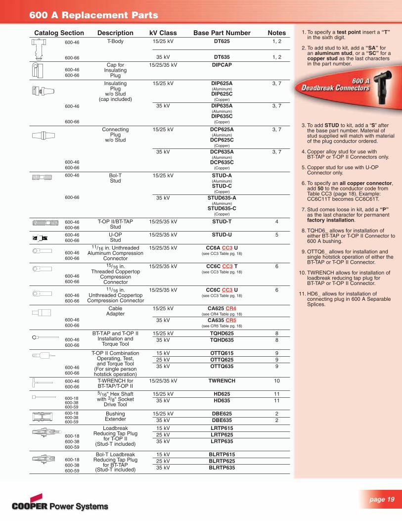
600 A Replacement Parts
Catalog Section Description kV Class Base Part Number NotesT-Body 15/25 kV DT625 1, 2
35 kV DT635 1, 2
Cap for 15/25/35 kV DIPCAPInsulating
Plug
Insulating 15/25 kV DIP625A 3, 7Plug (Aluminum)
w/o Stud DIP625C(cap included) (Copper)
35 kV DIP635A 3, 7(Aluminum)DIP635C
(Copper)
Connecting 15/25 kV DCP625A 3, 7Plug (Aluminum)
w/o Stud DCP625C(Copper)
35 kV DCP635A 3, 7(Aluminum)
DCP635C(Copper)
Bol-T 15/25 kV STUD-AStud (Aluminum)
STUD-C(Copper)
35 kV STUD635-A(Aluminum)
STUD635-C(Copper)
T-OP II/BT-TAP 15/25/35 kV STUD-T 4Stud
U-OP 15/25/35 kV STUD-U 5Stud
11/16 in. Unthreaded 15/25/35 kV CC6A CC3 UAluminum Compression (see CC3 Table pg. 18)
Connector15/16 in. 15/25/35 kV CC6C CC3 T 6
Threaded Coppertop (see CC3 Table pg. 18)Compression
Connector11/16 in. 15/25/35 kV CC6C CC3 U 6
Unthreaded Coppertop (see CC3 Table pg. 18)Compression Connector
Cable 15/25 kV CA625 CR4Adapter (see CR4 Table pg. 18)
35 kV CA635 CR5(see CR5 Table pg. 18)
BT-TAP and T-OP II 15/25 kV TQHD625 8Installation and 35 kV TQHD635 8
Torque Tool
T-OP II Combination 15 kV OTTQ615 9Operating, Test, 25 kV OTTQ625 9and Torque Tool 35 kV OTTQ635 9(For single person
hotstick operation)T-WRENCH for 15/25/35 kV TWRENCH 10BT-TAP/T-OP II5/16" Hex Shaft 15/25 kV HD625 11with 3/8" Socket 35 kV HD635 11
Drive Tool
Bushing 15/25 kV DBE625 2Extender 35 kV DBE635 2
Loadbreak 15 kV LRTP615Reducing Tap Plug 25 kV LRTP625
for T-OP II 35 kV LRTP635(Stud-T included)
Bol-T Loadbreak 15 kV BLRTP615Reducing Tap Plug 25 kV BLRTP625
for BT-TAP 35 kV BLRTP635(Stud-T included)
600-46
600-66
600-46600-66
600-46
600-66
600-46600-66
600-46600-66
600-46600-66
600-46600-66
600-46600-66
600-46600-66
600-46600-66
600-18600-38600-59
600-18600-38600-59
600-18600-38600-59
600-18600-38600-59
600-46600-66
600-46
600-66
1. To specify a test point insert a “T”in the sixth digit.
2. To add stud to kit, add a “SA” for an aluminum stud, or a “SC” for acopper stud as the last characters in the part number.
3. To add STUD to kit, add a “S” afterthe base part number. Material of stud supplied will match with materialof the plug conductor ordered.
4. Copper alloy stud for use with BT-TAP or T-OP II Connectors only.
5. Copper stud for use with U-OPConnector only.
6. To specify an all copper connector,add 50 to the conductor code fromTable CC3 (page 18). Example:CC6C11T becomes CC6C61T.
7. Stud comes loose in kit, add a “P”as the last character for permanentfactory installation.
8. TQHD6_ allows for installation ofeither BT-TAP or T-OP II Connector to600 A bushing.
9. OTTQ6_ allows for installation andsingle hotstick operation of either theBT-TAP or T-OP II Connector.
10. TWRENCH allows for installation ofloadbreak reducing tap plug for BT-TAP or T-OP II Connector.
11. HD6_ allows for installation of connecting plug in 600 A SeparableSplices.
600-46600-66
600-46600-66

Bol-T™ Connector SystemThe Bol-T™ Deadbreak Connector System is designed foruse on applications that will not be operated, do not needgrounding or arrester provisions, and do not require directconductor testing or the use of a hotstick. It is a bolted designthat is interchangeable with other manufacturers’ bolted 600 Asystems that require no special tools for installation.The capacitive test point on the insulating plug provides ameans of confirming an energized circuit without disturbingthe bolted connection. In addition to the capacitive test pointfeature on the insulating plug, Cooper offers a capacitivetest point on the T-Body. This allows the use of the CooperType “TPR” Series Faulted Circuit Indicators, and provides ameans of confirming that a circuit is energized when usedwith high impedance voltage sensing devices designed fortest points.Refer to Figure 1 for Bol-T Connector Kit Components.
Installation of Bol-T™ on a 600 A BushingThe Bol-T Connector is installed on any 600 A bushingusing a standard 1-inch socket. No special tools arerequired.
BT-TAP™ Connector SystemThe BT-TAP™ Deadbreak Connector System is designed foruse on applications where a 200 A interface is required fortesting, grounding, or overvoltage protection. It is primarilyused in retrofit applications of existing 600 A Bol-T installations(or other bolted systems that use unthreaded compressionconnectors).The BT-TAP Connector System uses the standard unthread-ed aluminum compression connector, which makes it idealfor retrofitting existing Bol-T installations into a system witha 200 A tap. It also uses the extended length stud and hasan internal rotating nut feature in the loadbreak reducing tapplug that eliminates cross threading.The BT-TAP provides the following features:■ Visible ground and visible break■ 200 A Interface for:
– addition of Cooper M.O.V.E.™ Arresters for overvoltageprotection
– addition of Cooper Grounding Elbows– access for direct conductor phasing and testing– hipot testing of switch or cables
Refer to Figure 2 for BT-TAP Connector Kit Components.
Installation of BT-TAP™ on a 600 A BushingThe BT-TAP Connector is installed on an apparatus bushingusing a 600 A Torque Tool.
600 A Connector Systems
Bol-T™ Specification Information
To specify the 600 A Bol-T Connector System, include in your specification:
■ The system must fully comply with IEEE Standard 386™.
■ All cable adapters, insulating plugs, compression connectors and other component parts must be interchangeable withother manufacturers.
■ For 900 A rating, full copper current carrying path with copper-top compression connector, copper stud and insulating plugwith copper insert.
■ Bol-T Connector System base part number BT625 for 15 kVand 25 kV systems and BT635 for 35 kV systems.
Figure 1.Bol-T Connector Kit (BT6_5) Components. For more details,see Cooper catalog sections 600-10, 600-30 and 600-50.
INSULATING PLUG WITHBOL-T STUD (STUD-A)
DIP625ASDIP635AS
ALUMINUM COMPRESSIONCONNECTOR 11/16"
UNTHREADED HOLECC6A _ _ U
CABLEADAPTER
CA625CA635
T-BODYDT625DT635
BT-TAP™ Specification Information
To specify a 600 A BT-TAP Connector System, include in yourspecification:
■ The system must fully comply with IEEE Standard 386™.
■ The connector system must provide operation with hot linetools, direct conductor phasing and testing.
■ It must provide a location to add overvoltage arresters andaccess for direct conductor phasing or hipot testing of switchor cables.
■ Must be easy to install with proper torque such that concernfor cross threading is eliminated.
■ Loadbreak reducing tap plug must include extended lengthstud and internal rotating nut features to eliminate crossthreading during assembly.
■ Loadbreak reducing tap plug must include latch indicator ring.
■ BT-TAP Connector System base part number BTP615 for 15 kV,BTP625 for 25 kV and BTP635 for 35 kV.
Figure 2.BT-TAP Connector Kit (BTP6_5_) Components. For more details,see Cooper catalog sections 600-15, 600-35 and 600-55.
LOADBREAK REDUCINGTAP PLUG BLRTP615BLRTP625BLRTP635
ALUMINUM COMPRESSIONCONNECTOR 11/16"
UNTHREADED HOLECC6A _ _ U
CABLE ADAPTERCA625CA635
T-BODYDT625DT635
T-OP II STUDSTUD-T

T-OP™ II Connector SystemThe T-OP™ II Deadbreak Connector System is designed foruse on applications where a 200 A interface is required fortesting, grounding, or overvoltage protection. It is single person hotstick operable and is ideal for terminations that mayrequire moving to achieve a visible open or visible ground.One person can move the T-OP II Deadbreak Terminatorfrom the apparatus bushing to a standoff bushing using ahotstick and Operating Test and Torque Tool (OTTQ6_5).The T-OP II Connector System uses a threaded coppertop(bi-metal) compression connector for a threaded connection.It also has an alignment segment and internal rotating nutfeature in the loadbreak reducing tap plug which, along withthe extended length stud, eliminates cross threading andensures proper torque.The T-OP II system provides the following features:■ Single person hotstick operable■ Mechanical assist■ All copper alloy current path■ 900 A continuous current rating■ Visible ground and visible break■ 200 A Interface for:
– addition of Cooper M.O.V.E Arresters for overvoltageprotection
– addition of Cooper Grounding Elbows– access for direct conductor phasing and testing– hipot testing of switch or cables
Refer to Figure 3 for T-OP II Connector Kit Components.
Installation of T-OP™ II on a 600 A BushingThe T-OP II Connector is installed on an apparatus bushingusing a T-Wrench and a 600 A Torque Tool.
U-OP™ Connector SystemThe U-OP™ Connector System is used to provide a visiblebreak and visible ground on 600 A distribution systems withouthaving to move the heavy cable. The U-OP Connector is adeadbreak system rated for operation on 15 or 25 kV classequipment, including transformers, switches, switchgear, andother apparatus.Under normal operating conditions, the current path isthrough the apparatus bushing, through the U-connector,through a two-way 600 A deadbreak junction, and through aT-OP II 600 A Connector (sold separately) to the under-ground cable. When isolating underground cable, a groundedstandoff bushing can be put in the parking stand (with thesystem de-energized). The U-connector can then beremoved, rotated 90°, and re-installed over the apparatusbushing and grounded standoff bushing, to ground the apparatus bushing.A grounding elbow can be installed on the 200 A interfaceof the T-OP II Connector to ground the cable. A 600 A U-OPProtective Cap can then be put on the upper bushing of thedeadbreak junction to insulate that bushing. Since all bushingsof the connector system are then insulated or grounded, andif the cable is grounded on the other end, it is safe to performwork on the underground cable. See Figure 4 for a typicalU-OP Connector configuration.
page 21
T-OP™ II Specification Information
To specify a 600 A T-OP II System, include in your specification:■ The system must fully comply with IEEE Standard 386™.
■ Must include an all copper alloy current path.■ System must include disconnecting back-off feature.■ The connector system must provide operation with live line
tools, direct conductor phasing and testing, visible groundand visible break.
■ It must provide a location to add overvoltage arresters andaccess for direct conductor phasing or hipot testing of switch or cables.
■ Must be one-person hotstick operable and easy to install withproper torque such that concern for cross threading is eliminated.
■ Loadbreak reducing tap plug must include extended length stud, internal rotating nut and an alignment segment feature toeliminate cross threading of this compression connector andensure proper torque.
■ Loadbreak reducing tap plug must include latch indicator ring.■ T-OP II Connector System base part number TP615 for 15 kV,
TP625 for 25 kV and TP635 for 35 kV.
Figure 3.T-OP II Connector Kit (TP6_5_) Components. For more details,see Cooper catalog sections 600-12, 600-32 and 600-52.
LOADBREAK REDUCINGTAP PLUGLRTP615LRTP625LRTP635
COPPERTOP COMPRESSIONCONNECTOR 15/16" THREADED
HOLECC6C _ _ T CABLE
ADAPTERCA625CA635
T-BODYDT625DT635
T-OP II STUDSTUD-T
U-OP™ Specification Information
To specify a 600 A U-OP Connector System that achieves avisible break and visible ground without having to move heavycable, include in your specification:
■ The system must fully comply with IEEE Standard 386™.
■ The system must provide a visible break and visible groundwithout having to move 600 A cable.
■ A U-connection shall remain connected on the equipmenteven while performing repair to the underground cable toensure the interfaces are not exposed to the environmentand thus potentially contaminated.
■ U-OP Connector System base part number UOP625 for both15 and 25 kV.
Figure 4.U-OP Connector Kit (UOP625) Components. For more details,see Cooper catalog section 600-34.
CURRENT PATHTHROUGH U-OP CONNECTOR SYSTEM
T-OP II CONNECTOR(not included, ordered
separately)TP615 _ _TP625 _ _
2 BUSHING 600 A DEADBREAK
JUNCTIONDJ625A2
PARKINGSTAND
U-CONNECTORAPPARATUSBUSHING

600 A Stacking Dimensions
BT-TAP™ and T-OP™ II Deadbreak Connector 15 kV and 25 kV
S1 S3S2
Bushing Adapter with LRTP (15 kV shown)
S3 S2
Standoff Bushing
S35
C
A
B
Separable Splice
A
B
DC
PUSH-OP® Standoff Bushing (15/25 kV shown)
A
B
A
B
Standard Protective Cap
Protective Cap for T-OP™ II and U-OP™ (15/25 kV shown)
A
D
B S3S2
S5
BT-TAP™ and T-OP™ II Deadbreak Connector 35 kV
Bol-T™ Deadbreak Connector
A
B
PUSH-OP® Deadbreak Connector (15 kV shown)
S5
S2 S4S3
Dim. 15/25 kV 35 kV
A 5.4" (137.2 mm) 5.4" (137.2 mm)B 5.6" (142.2 mm) 5.6" (142.2 mm)C 4.4" (111.8 mm) 4.4" (111.8 mm)
S35 4.21" (106.9 mm) 5.2" (132.1 mm)
Dim. 15/25 kV
S1 4.93" (125.2 mm)S2 0.50" (12.7 mm)S3 8.29" (210.6 mm)
Dim. 35 kV
A 18.10" (459.7 mm)B 0.22" (5.59 mm)D 12.89" (327.4 mm)S2 0.50" (12.7 mm)S3 12.46" (316.5 mm)S5 2.84" (72.1 mm)
Dim. 15/25 kV 35 kV
A 5.8" (147.3 mm) 6.8" (173 mm)B 3.25" (82.6 mm) 3.5" (88.9 mm)
Dim. 15/25 kV 35 kV
A 7.6" (193 mm) 8.66" (220 mm)B 3.25" (82.6 mm) 3.25" (82.6 mm)
Dim. 15/25 kV 35 kV
A 4.0" (101.6 mm) 5.80" (147.3 mm)B 2.37" (60.2 mm) 2.88" (73.2 mm)C 5.25" (133.4 mm) 6.0" (152.4 mm)D 5.50" (139.7 mm) 6.27" (159.3 mm)
Dim. 15/25 kV 35 kVS2 0.50" (13 mm) 0.50" (13 mm)S3 8.29" (210.6 mm) 12.46" (316.5 mm)
Dim. 15 kV 25 kV 35 kV
A 12.8" 15.5" 17.9" (325.1 mm) (393.7 mm) (454.7 mm)
B 14.05" 14.05" –(356.9 mm) (356.9 mm)
S5
S3CP S4S2
S3IP
15/25 kV
Overall Length Deadend 11.24" (285 mm)Overall Length 2-Way Splice 19.97" (507 mm)Overall Length 3-Way Splice 28.70" (729 mm)Overall Length 4-Way Splice 37.43" (951 mm)
S2 0.50" (12 mm)S3CP 8.23" (209 mm)S3IP 3.87" (98 mm)S4 1.50" (38 mm)S5 2.40" (61 mm)
Dim. 15/25 kV 35 kV
S2 0.50" 0.50" (12.7 mm) (12.7 mm)
S3 3.87" 4.97" (98.3 mm) (126 mm)
S4 1.50" 1.50" (38.1 mm) (38 mm)
S5 2.4" 2.84" (61 mm) (72 mm)

page 23
S10
E
5/8 x 7/8" OBROUNDMOUNTING HOLES
S11S7
S9
F
G
H
B
CD
A
Deadbreak Junction (35 kV shown)
S7
S9
S10
S11
BE F
G
A
M4
S11
0.56"(1 mm)
2.00"(51 mm)
1.4"(37 mm)
MAX. MIN.
MIN.MAX.
MIN.MAX.
CONFIGURATION - 2
CONFIGURATION - 1
CONFIGURATION - 3
Deadbreak Junction (15/25 kV shown)
TABLE 15/25 kV
Physical M4 Mounting Dimensions in./(mm)Dimensions
Number of in./(mm) Configuration 1 Configuration 2 Configuration 3
Interfaces A B Min. Max. Min. Max. Min. Max.
2 19.0 7.0 5.6 8.5 9.7 12.6 13.9 16.8(483) (178) (142) (215) (248) (321) (354) (427)
3 23.0 11.0 10.1 13.0 14.3 17.2 18.5 21.4(584) (279) (257) (331) (363) (437) (469) (543)
4 27.0 15.0 15.6 18.5 19.8 22.7 24.0 23.0(686) (381) (397) (470) (507) (576) (609) (584)
Configuration 1. Both feet turned out.Configuration 2. One foot turned out, the other in.Configuration 3. Both feet turned in.
TABLE 35 kV
Physical Dimensions Mounting DimensionsNumber of in. (mm) in. (mm)Interfaces A B C D
2 21.5 9.0 15.5 12.5(546) (229) (394) (318)
3 27.5 15.0 21.5 18.5(699) (381) (546) (470)
4 33.5 21.0 27.5 24.5(851) (533) (699) (622)
Note: C and D are minimum and maximum stud centerline separations for mounting.
Dim. 15/25 kV
E 4.0" (101 mm)F 4.1" (102 mm)G 3.0" (76 mm)S7 0.75" (19 mm)S9 3.4" (86 mm)S10 6.2" (157 mm)S11 7.2" (182 mm)
Dim. 35 kV
E 6.0" (152 mm)F 6.2" (158 mm)G 3.0" (76 mm)H 3.8" (96 mm)S7 0.75" (19 mm)S9 5.55" (141 mm)S10 7.0" (178 mm)S11 10.4" (264 mm)

Cooper offers various types of splices for your undergroundneeds on 200 A and 600 A systems. The EZ II™ One-PieceSplices at 15, 25, and 35 kV include advantages for typicalapplications of repair, replacement, or extension of high voltage underground cables. These all peroxide-curedEPDM rubber splices provide a highly reliable, permanent,fully shielded, and submersible cable joint with a current rating equal to that of the mating cable. EZ II Splices can be installed in conduit, direct buried or in vault applications.The EZ II Splice line meets or exceeds all requirements ofIEEE Standard 404™.Cooper offers a full line of 600 A Separable Splice kits forapplication on feeder circuits. These use standard Bol-Ttype components along with a peroxide-cured EPDM rubberconnecting plug that allows for installation of multiple waysplices. Separable splices are used to splice multiple cablesor to deadend a single cable. The splices are rated for 600 A (900 A ratings are available) and are suitable for therepair or extension of underground feeders.EZ II™ SplicesCooper’s EZ II One-Piece Splices offer a number of featuresand benefits, including:Easiest to Install – The design features of the EZ II Spliceincluding the tapered cable entrance, smooth bore, relievedconductive insert, and reformulated rubber provide for easier field installation. EZ II Splices have been shown to be30% easier to install than other manufacturers’ splices.Wide Range Taking – The wide range taking cableentrances are sized to accept all common cable insulationdiameters. The wider cable ranges increase installation flexibility.Sure Grip – The contoured EZ II Splice body provides aneasy gripping location during installation.Long Term Reliability – The EZ II Splice has successfullypassed all requirements of the IEEE Standard 404™ andCooper’s exclusive field-proven multi-stress test to show thelong term reliability of the design.
EZ ll™ Splice Specification Information
To ensure you have the most reliable, economical, installation friendly premolded one-piece splice available,your specification for EZ II™ Splice should include:
■ Manufactured in full compliance with all applicableIEEE Standards 404™.
■ Manufactured from peroxide-cured EPDM rubber.
■ Tapered ribs of the inside diameter of the conductiveinsert.
■ Molded in compression connector diameters.
■ Conductive insert ends encapsulated with insulatingrubber.
Splice Applications
Connecting Plug
Transformer orSwitchgearApparatus
EZ II Splice
FCI (pg 36)
600 A SeparableSplice Kit
Deadbreak JunctionT-OP IIConnector
Protective Cap(pg 11)
SectionalizingCabinets(pg. 38)
U-OP™ Connector**
Splices
CAP CONNECTINGPLUG
THREADEDSTUD
INSULATIONPLUG
CAPACITIVETEST POINT
CABLEADAPTER
T-BODYCOMPRESSIONCONNECTOR
Typical components of a 600 A 2-way separable splice.
page 25
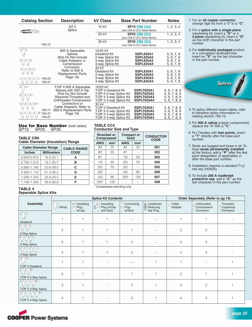
Catalog Section Description kV Class Base Part Number NotesEZ II 15 kV SP15 CR6 CC4 1, 2, 3, 4
Splice (see CR6 & CC4 Tables Below)
25 kV SP25 CR6 CC4 1, 2, 3, 4(see CR6 & CC4 Tables Below)
35 kV SP35 CR6 CC4 1, 2, 3, 4(see CR6 & CC4 Tables Below)
600 A Separable 15/25 kVSplices Deadend Kit SSPL625A1 5, 6, 7, 8
(Kits Do Not Include 2-way Splice Kit SSPL625A2 5, 6, 7, 8Cable Adapters or 3-way Splice Kit SSPL625A3 5, 6, 7, 8
Compression 4-way Splice Kit SSPL625A4 5, 6, 7, 8Connector. 35 kV
Refer to 600 A Deadend Kit SSPL635A1 5, 6, 7, 8Replacement Parts 2-way Splice Kit SSPL635A2 5, 6, 7, 8
Page 19) 3-way Splice Kit SSPL635A3 5, 6, 7, 84-way Splice Kit SSPL635A4 5, 6, 7, 8
T-OP II 600 A Separable 15/25 kVSplices with 200 A Tap T-OP II Deadend Kit SSPLT625A1 5, 6, 7, 8, 9
(Kits Do Not Include T-OP II 2-way Splice Kit SSPLT625A2 5, 6, 7, 8, 9Required Threaded and T-OP II 3-way Splice Kit SSPLT625A3 5, 6, 7, 8, 9
Unthreaded Compression T-OP II 4-way Splice Kit SSPLT625A4 5, 6, 7, 8, 9Connectors or 35 kV
Cable Adapters. Refer to T-OP II Deadend Kit SSPLT635A1 5, 6, 7, 8, 9600 A Replacement Parts T-OP II 2-way Splice Kit SSPLT635A2 5, 6, 7, 8, 9
Page 19) T-OP II 3-way Splice Kit SSPLT635A3 5, 6, 7, 8, 9T-OP II 4-way Splice Kit SSPLT635A4 5, 6, 7, 8, 9
700-15
700-22700-31
700-17700-37700-57
4. To splice different sized cables, refer to transition splice information in catalog section 700-15.
5. For 900 A rating (copper components)replace the “A” with a “C”.
6. For T-bodies with test points, insert a “T” directly after the base part number.
7. Studs are bagged and loose in kit. To have studs permanently installedat the factory, add a “P” after the testpoint designation (if applicable) orafter the base part number.
8. Installation requires a standard 5/16"hex key (HD625).
9. To include 200 A loadbreak protective cap, add a “C” as the last character in the part number.
�����������������������������������������������������������������������������������������������
��������
����������
1. For an all copper connector,change digit six from a “0” to a “C”.
2. For a splice with a single-piecerejacketing kit, insert a “S” or a 2-piece rejacketing kit, insert a “D”as the ninth character in the partnumber.
3. For individually packaged productin a corrugated cardboard box,insert an “X” as the last characterin the part number.
TABLE CR6Cable Diameter (Insulation) Range
Cable Diameter Range CABLE RANGEInches Millimeters CODE
0.640-0.910 16.3-23.1 A
0.750-1.010 19.1-25.7 B
0.890-1.140 22.6-29.0 C
0.840-1.110 21.3-28.2 D
1.000-1.310 25.4-33.3 E
1.140-1.450 29.0-36.8 F
TABLE CC4Conductor Size and Type
Stranded or Compact or CONDUCTORCompressed Solid CODEAWG mm2 AWG mm2
#3 25 #2 35 001
#2 35 #1 – 002
#1 – 1/0 50 003
1/0 50 2/0 70 004
2/0 70 3/0 – 005
3/0 – 4/0 95 006
4/0 95 250 120 007
250* 120 – – 008* Compressed stranding only
Use for Base Number (both tables)SP15 SP25 SP35
Splice Kit Contents Order Separately (Refer to pg 19)
Assembly Insulating Insulating Connecting Loadbreak Cable Unthreaded ThreadedT-Body Plug Plug w/Cap Plug Reducing Adapter Compression Coppertop
w/Cap and Stud w/Stud Tap Plug Connector Connector
1 1 1 – – 1 1 –Deadend
2 1 1 1 – 2 2 –2-Way Splice
3 1 1 2 – 3 3 –3-Way Splice
4 1 1 3 – 4 4 –4-Way Splice
1 1 – — 1 1 – 1T-OP II Deadend
2 1 – 1 1 2 1 1T-OP II 2-Way Splice
3 1 – 2 1 3 2 1T-OP II 3-Way Splice
4 1 – 3 1 4 3 1T-OP II 4-Way Splice
TABLE 4Separable Splice Kits

Cooper Metal Oxide Varistor Elbow (M.O.V.E.™) and ParkingStand Arresters are used in pad-mounted transformer andentry cabinets, vaults, switching enclosures and other installations to provide shielded deadfront arrester protection.These arresters are designed for use with 200 A loadbreakinterfaces to limit overvoltages to acceptable levels, protectequipment and extend cable life.
The gapped structure of our VariGAP® M.O.V.E. Arresterprovides excellent temporary overvoltage (TOV) characteristics while the MOV disks offer rapid front-of-waveresponse with virtually no power follow current. Extensivelaboratory testing and over 10 years of field history haveproven the hybrid VariGAP design offers the followingadvantages over standard ungapped MOV arresters:■ Lower Discharge Voltage Characteristics
■ Increased Thermal Capacity
■ Improved Front-of-Wave Response
■ Higher Temporary Overvoltage Capability
To experience the benefits of our VariGAP M.O.V.E.Arrester, see the following specification information.
VariGAP® M.O.V.E.™ Arrester SpecificationInformation
■ Total compliance to IEEE Std 386™.
■ Total compliance to IEEE Std C62.11™,including full certification to the deadfrontarrester failure mode safety test.
■ Specify a maximum discharge voltage equivalent or lower than the VariGAP published data (see Table 3).
Example: for a 10 kV arrester, specify discharge voltage for a 20 kA 8/20 µs current wave to be 35 kV crest or less.
■ Specify a minimum temporary overvoltagerating higher than 1.8 per unit for at least1000 seconds.
Example: for a 10 kV arrester, specify aTOV recovery voltage of at least 8.4 * 1.8 = 15.12 kV for 1000 seconds at 85° C.
Temporary overvoltage curve. No prior dutyat 85˚ C ambient.
10.01
PE
R U
NIT
MC
OV
1.2
1.6
1.8
2
2.2
1.4
1
0.1 10103 4
10010TIME (Seconds)
IEEE Std. C62.22
MINIMUM
M.O.V.E. ARRESTER(Ref. Catalog Section 235-65)
VariGAP M.O.V.E.ARRESTER
(Ref. Catalog Section 235-55) TABLE 2M.O.V.E.™ and Parking Stand Arrester Protective Characteristics
* Equivalent front-of-wave voltage is the expected discharge voltage of the arrester when tested with a 5 kA current surge cresting in 0.5 µs.
Equivalent Maximum Discharge Voltage (kV crest)Duty Cycle Front-of- 8/20 µs Current Wave
Voltage Rating MCOV Wave (kV) (kV) (kV crest)* 1.5 kA 3 kA 5 kA 10 kA 20 kA
3 2.55 13.7 10.7 12.0 12.8 13.4 15.76 5.1 27.4 21.9 24.5 26.2 28.6 34.99 7.65 37.4 27.4 29.9 31.4 34.7 38.4
10 8.4 39.7 28.4 30.6 32.9 36.7 40.412 10.2 56.1 41.1 44.8 47.1 52.0 57.615 12.7 63.0 45.0 49.2 52.5 57.8 66.018 15.3 74.8 54.7 59.7 62.7 69.3 76.821 17.0 81.7 58.7 64.2 68.2 75.2 85.224 19.5 95.8 69.7 76.1 80.2 88.6 98.827 22.0 105.0 75.0 82.0 87.4 96.2 110.0
TABLE 1Commonly Applied Voltage Ratings of M.O.V.E.™ and Parking Stand Arresters
System Voltage (V rms) Commonly Applied Arrester Duty-cycle (MCOV) Voltage Rating (kV rms) on Distribution Systems
Delta and4-Wire 3-Wire Low 3-Wire High
Nominal Maximum Multigrounded Impedance ImpedanceVoltage Voltage Neutral Wye Grounded Grounded
2400 2540 – – 3 (2.55)4160 Y/2400 4400 Y/2540 3 (2.55) 6 (5.1) 6 (5.1)
4260 4400 – – 6 (5.1)4800 5080 – – 6 (5.1)6900 7260 – – 9 (7.65)
8320 Y/4800 8800 Y/5080 6 (5.1) 9 (7.65) –12000 Y/6930 12700 Y/7330 9 (7.65) 12 (10.2) –12470 Y/7200 13200 Y/7620 9 (7.65) or 10 (8.4) 15 (12.7) –13200 Y/7620 13970 Y/8070 10 (8.4) 15 (12.7) –13800 Y/7970 14520 Y/8388 10 (8.4) and 12 (10.2) 15 (12.7) –
13800 14520 – – 18 (15.3)20780 Y/12000 22000 Y/12700 15 (12.7) 21 (17.0) –22860 Y/12000 22000 Y/12700 15 (12.7) 21 (17.0) –24940 Y/14400 26400 Y/15240 18 (15.3) 27 (22.0) –27600 Y/15935 29255 Y/16890 21 (17.0) – –34500 Y/19920 36510 Y/21080 27 (22.0) – –
Underground Surge Arresters

page 27
Catalog Section Description kV Class Base Part Number MCOV (kV)VariGAP Metal Oxide 15 kV 3238118C09M 7.65
Varistor Elbow 3238118C10M 8.40(M.O.V.E.) Arrester 3238118C12M 10.2
3238118C15M 12.73238118C18M 15.3
25 kV 3238119C09M 7.653238119C10M 8.403238119C12M 10.23238119C15M 12.73238119C18M 15.33238119C21M 17.0
35 kV 3238120C18M 15.3(Interface 1A 3238120C21M 17.0
Large 3238120C24M 19.5Interface per 3238120C27M 22.0
IEEE Std. 386™)
Metal Oxide 15 kV 3238018C03M 2.55Varistor Elbow 3238018C06M 5.10
(M.O.V.E.) 3238018C09M 7.65Arrester 3238018C10M 8.40
3238018C12M 10.23238018C15M 12.73238018C18M 15.3
25 kV 3238019C09M 7.653238019C10M 8.403238019C12M 10.23238019C15M 12.73238019C18M 15.33238019C21M 17.0
35 kV 3238020C18M 15.3(Interface 1A 3238020C21M 17.0
Large 3238020C24M 19.5Interface per 3238020C27M 22.0
IEEE Std. 386™)
VariGAP Metal Oxide 15 kV 3238104C09M 7.65Varistor (MOV) 3238104C10M 8.40Parking Stand 3238104C12M 10.2
Arrester 3238104C15M 12.73238104C18M 15.3
25 kV 3238105C09M 7.653238105C10M 8.403238105C12M 10.23238105C15M 12.73238105C18M 15.33238105C21M 17.0
Metal Oxide 15 kV 3237686C03M 2.55Varistor (MOV) 3237686C06M 5.10Parking Stand 3237686C09M 7.65
Arrester 3237686C10M 8.403237686C12M 10.23237686C15M 12.73237686C18M 15.3
25 kV 3237758C09M 7.653237758C10M 8.403237758C12M 10.23237758C15M 12.73237758C18M 15.33237758C21M 17.0
235-55
The following notes apply to all partnumbers on this page.
■ Digits 9 & 10 designate duty cycle voltage rating. For other protectivecharacteristics, refer to Table 2 forM.O.V.E. and Parking StandArresters and Table 3 for VariGAPM.O.V.E. and Parking StandArresters.
■ Refer to page 15 for dimensionalinformation.
TABLE 3VariGAP® M.O.V.E.™ and Parking Stand Arrester Protective Characteristics
Duty Front-of- Maximum Discharge VoltageCycle Minimum Wave 8/20 µs Current Wave Maximum
Voltage 60 Hz Protective (kV crest) 1.2/50 µsRating MCOV Sparkover Level* Sparkover
(kV) (kV) (kV crest/√2 ) (kV crest) 0.5 kA 1.5 kA 3 kA 5 kA 10 kA 20 kA (kV crest)
9 7.65 13.5 25.8/28.5 19.5 21.2 23.8 24.7 28.5 33.3 24.210 8.4 15.0 27.1/30.0 20.5 22.3 25.0 26.0 30.0 35.0 25.512 10.2 18.0 35.5/39.5 25.0 27.0 29.6 31.4 36.8 43.2 31.315 12.7 22.5 37.8/41.0 30.0 31.3 33.7 36.2 40.4 44.5 36.018 15.3 27.0 48.8/59.3 35.8 40.2 44.4 46.8 49.4 60.5 42.821 17.0 31.5 60.1/65.3 39.4 44.3 48.9 51.5 54.4 66.6 51.324 19.5 36.0 64.4/70.0 44.1 47.3 51.7 55.2 60.7 69.4 55.027 22.0 40.5 70.9/79.0 49.8 54.0 57.9 62.8 73.4 86.2 62.5
* First number is the value of the sparkover of the gap assembly based on a wave rising 100 kV per µs per 12 kV of arrester rating.
* Second number is based on 5 kA current impulse that results in a discharge voltage cresting in 0.5 µs.
235-65
235-58
235-68
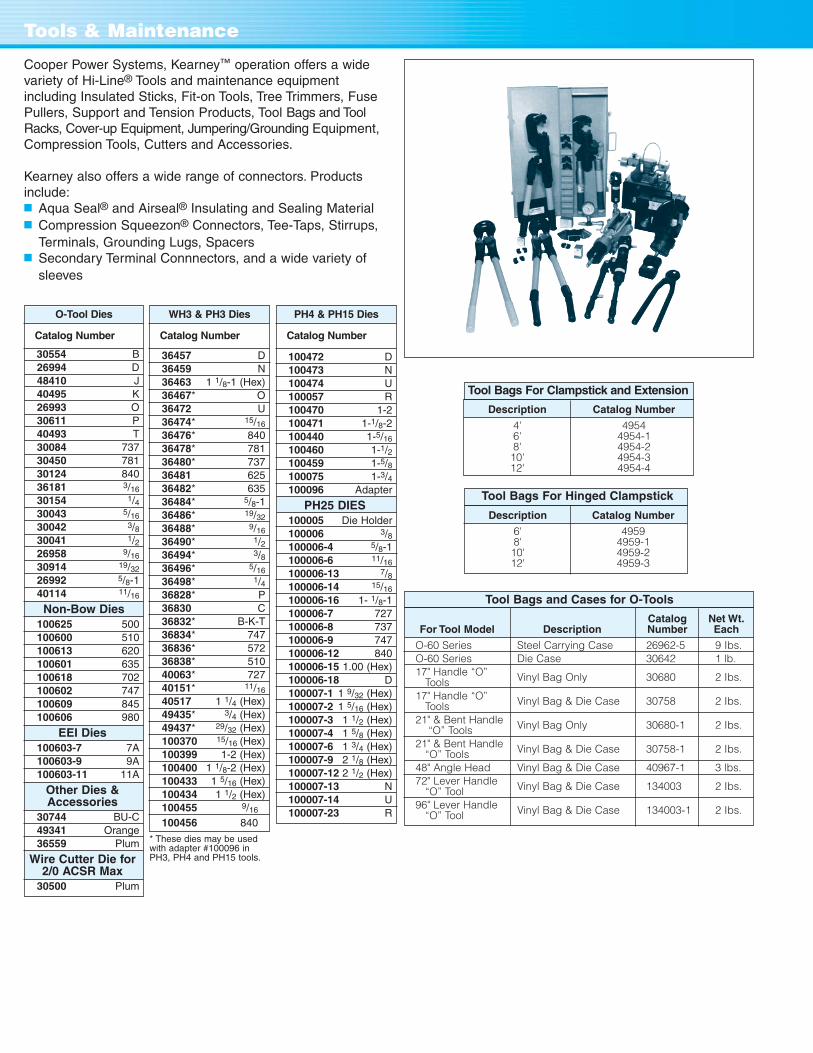
Cooper Power Systems, Kearney™ operation offers a widevariety of Hi-Line® Tools and maintenance equipmentincluding Insulated Sticks, Fit-on Tools, Tree Trimmers, FusePullers, Support and Tension Products, Tool Bags and ToolRacks, Cover-up Equipment, Jumpering/Grounding Equipment,Compression Tools, Cutters and Accessories.
Kearney also offers a wide range of connectors. Productsinclude:■ Aqua Seal® and Airseal® Insulating and Sealing Material■ Compression Squeezon® Connectors, Tee-Taps, Stirrups,
Terminals, Grounding Lugs, Spacers ■ Secondary Terminal Connnectors, and a wide variety of
sleeves
Tools & Maintenance
* These dies may be usedwith adapter #100096 inPH3, PH4 and PH15 tools.
O-Tool Dies
Catalog Number
30554 B26994 D48410 J40495 K26993 O30611 P40493 T30084 73730450 78130124 84036181 3/16
30154 1/430043 5/16
30042 3/830041 1/226958 9/16
30914 19/32
26992 5/8-140114 11/16
Non-Bow Dies100625 500100600 510100613 620100601 635100618 702100602 747100609 845100606 980
EEI Dies100603-7 7A100603-9 9A100603-11 11A
Other Dies & Accessories
30744 BU-C49341 Orange36559 Plum
Wire Cutter Die for 2/0 ACSR Max
30500 Plum
WH3 & PH3 Dies
Catalog Number
36457 D36459 N36463 1 1/8-1 (Hex)36467* O36472 U36474* 15/16
36476* 84036478* 78136480* 73736481 62536482* 63536484* 5/8-136486* 19/32
36488* 9/16
36490* 1/236494* 3/836496* 5/16
36498* 1/436828* P36830 C36832* B-K-T36834* 74736836* 57236838* 51040063* 72740151* 11/16
40517 1 1/4 (Hex)49435* 3/4 (Hex)49437* 29/32 (Hex)100370 15/16 (Hex)100399 1-2 (Hex)100400 1 1/8-2 (Hex)100433 1 5/16 (Hex)100434 1 1/2 (Hex)100455 9/16
100456 840
PH4 & PH15 Dies
Catalog Number
100472 D100473 N100474 U100057 R100470 1-2100471 1-1/8-2100440 1-5/16
100460 1-1/2100459 1-5/8100075 1-3/4100096 Adapter
PH25 DIES100005 Die Holder100006 3/8100006-4 5/8-1100006-6 11/16
100006-13 7/8100006-14 15/16
100006-16 1- 1/8-1100006-7 727100006-8 737100006-9 747100006-12 840100006-15 1.00 (Hex)100006-18 D100007-1 1 9/32 (Hex)100007-2 1 5/16 (Hex)100007-3 1 1/2 (Hex)100007-4 1 5/8 (Hex)100007-6 1 3/4 (Hex)100007-9 2 1/8 (Hex)100007-12 2 1/2 (Hex)100007-13 N100007-14 U100007-23 R
Catalog Net Wt.For Tool Model Description Number Each
O-60 Series Steel Carrying Case 26962-5 9 Ibs.O-60 Series Die Case 30642 1 lb.17" Handle “O”
Tools Vinyl Bag Only 30680 2 Ibs.
17" Handle “O” Tools Vinyl Bag & Die Case 30758 2 Ibs.
21" & Bent Handle “O” Tools Vinyl Bag Only 30680-1 2 Ibs.
21" & Bent Handle “O” Tools Vinyl Bag & Die Case 30758-1 2 Ibs.
48" Angle Head Vinyl Bag & Die Case 40967-1 3 lbs.72" Lever Handle
“O” Tool Vinyl Bag & Die Case 134003 2 Ibs.
96" Lever Handle “O” Tool Vinyl Bag & Die Case 134003-1 2 Ibs.
Tool Bags and Cases for O-Tools
Tool Bags For Clampstick and Extension
Description Catalog Number
4' 49546' 4954-18' 4954-210' 4954-312' 4954-4
Tool Bags For Hinged Clampstick
Description Catalog Number
6' 49598' 4959-110' 4959-212' 4959-3
Related Documents


![H20youryou[2] · 2020. 9. 1. · 65 pdf pdf xml xsd jpgis pdf ( ) pdf ( ) txt pdf jmp2.0 pdf xml xsd jpgis pdf ( ) pdf pdf ( ) pdf ( ) txt pdf pdf jmp2.0 jmp2.0 pdf xml xsd](https://static.cupdf.com/doc/110x72/60af39aebf2201127e590ef7/h20youryou2-2020-9-1-65-pdf-pdf-xml-xsd-jpgis-pdf-pdf-txt-pdf-jmp20.jpg)


