COOPER Bussmann TRANSPORTATION PRODUCTS Solutions for the Transportation Industry Circuit Protection • Power Distribution • Wiring Accessories Courtesy of Steven Engineering, Inc.-230 Ryan Way, South San Francisco, CA 94080-6370-Main Office: (650) 588-9200-Outside Local Area: (800) 258-9200-www.stevenengineering.com

Welcome message from author
This document is posted to help you gain knowledge. Please leave a comment to let me know what you think about it! Share it to your friends and learn new things together.
Transcript
COOPER Bussmann
TRANSPORTATION PRODUCTSSolutions for the Transportation Industry
Circuit Protection • Power Distribution • Wiring Accessories
Courtesy of Steven Engineering, Inc.-230 Ryan Way, South San Francisco, CA 94080-6370-Main Office: (650) 588-9200-Outside Local Area: (800) 258-9200-www.stevenengineering.com
Contents
PageCustom Solutions for Power Distribution 1SERIES 31000/32000
Vehicle Electrical Centers 2-3
Vehicle Electrical Center Connectors 4
Vehicle Electrical Center Accessories 5
SERIES 15301 RTMRRear Terminal Mini Fuse & Relay Panels 6-7
SERIES 37700 PRM/PFMPower Relay Module/Power Fuse Module 8-9
SERIES 15710 RTARear Terminal ATC® Fuse Block 10
SERIES 15600ATC® Blade-Type Fuse Panels 11
HMGAutomotive Bolt-In Fuseholder for the AMG Fuse 12
FMGAutomotive Bolt-In Fuseholder for the AMG Fuse 13
Inline Fuseholders 14
SERIES 15250Battery Disconnect Switch 15
Stud Type Junction Blocks 16
Stud Type Junction Blocks(Non-Feed-Thru) 17
Basic Overcurrent Technology 18-19
MINI Blade Fuses 20
SERIES 21X MINI Circuit Breakers 21
ATC® Blade Fuses 22
SERIES 22X ATC® Circuit Breakers 23
SERIES 227 ATC' Circuit Breakers (Low Profile) 24
MAXI® Blade Fuses 25
SERIES 19X MAXI ® Circuit Breakers 26
SERIES 3200/32013Insertion/Extraction Tool 27
SERIES 174 FLAT-PAKManual Reset Circuit Breakers 28-29
SERIES 12X SHORTSTOP SAuto, Manual & Modified Reset Circuit Breakers 30
SERIES 25X MID-RANGEAuto, Manual Reset, & Manual Resetw/ Push-to-Trip Circuit Breakers 31
SERIES 18X HI-AMPAuto, Manual Reset & Switchable Circuit Breakers 32
SERIES 187 MRCBSwitchable Circuit Breakers 33
AMI SERIESBolt In Automotive Fuses 34
AMG SERIESBolt In Automotive Fuses 35
NOTES 36-37
Courtesy of Steven Engineering, Inc.-230 Ryan Way, South San Francisco, CA 94080-6370-Main Office: (650) 588-9200-Outside Local Area: (800) 258-9200-www.stevenengineering.com

Custom Solutions For Power DistributionCooper Bussmann plays a key role in developing custom solutions for vehicle power distribution applications.
Once a product need is identified, an innovative team of design engineers works closely with the customer to dis-cuss their needs. This enables our team to design and develop custom solutions tailored to meet specific cus-tomer requirements.
Many custom solutions include developing linkage systems to join two or more of our products together . Thisallows the customer "one-stop shopping" to create their vehicle electrical system . Other examples includebussing/jumpering, color-coding, and changing thread sizes.
If you are in need 2f a custom solution, plgase contact your Bussmann sales representative for assistance .
Courtesy of Steven Engineering, Inc.-230 Ryan Way, South San Francisco, CA 94080-6370-Main Office: (650) 588-9200-Outside Local Area: (800) 258-9200-www.stevenengineering.com
SERIES 31000/32000 VEHICLE ELECTRICAL CENTERS
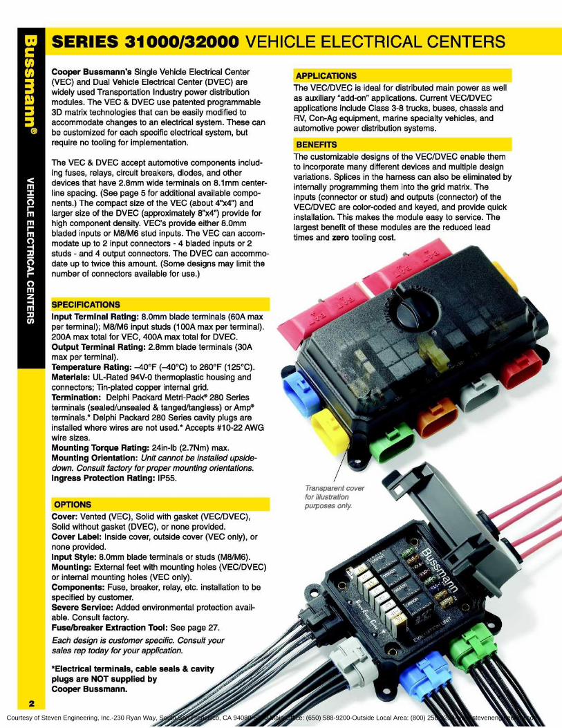
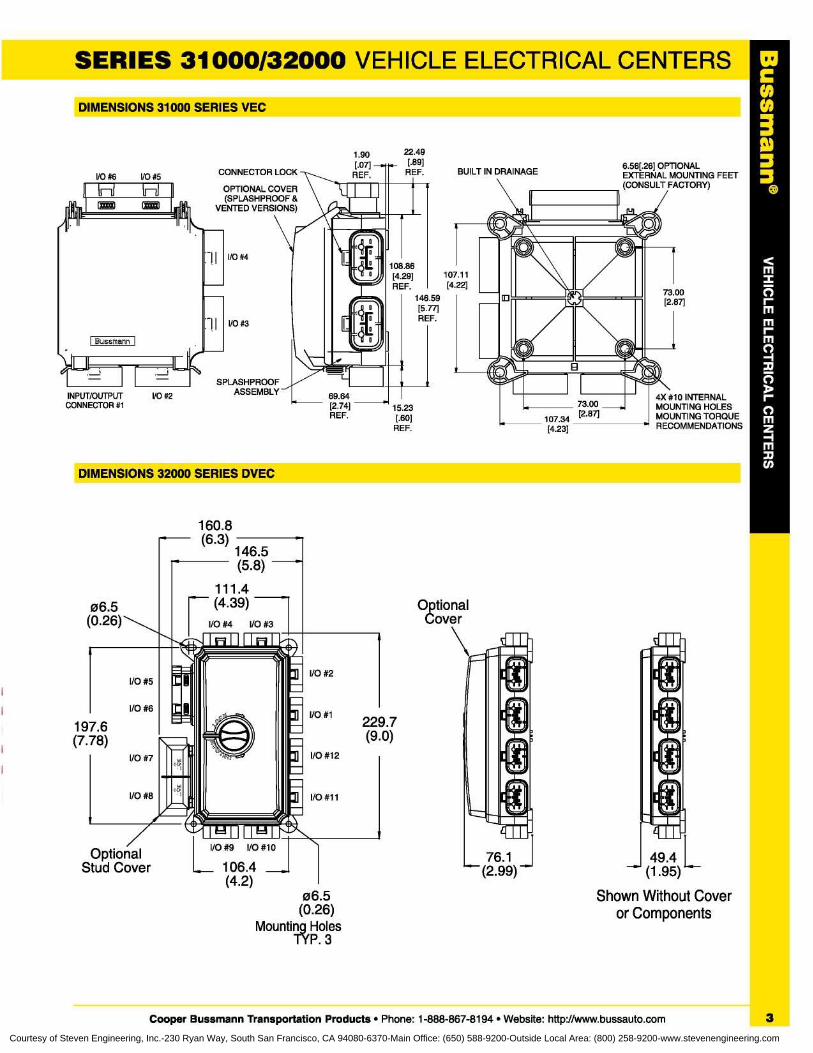
Cooper Bussmann's Single Vehicle Electrical Center(VEC) and Dual Vehicle Electrical Center (DVEC) arewidely used Transportation Industry power distributionmodules . The VEC & DVEC use patented programmable3D matrix technologies that can be easily modified toaccommodate changes to an electrical system . These canbe customized for each specific electrical system, butrequire no tooling for implementation.
The VEC & DVEC accept automotive components includ-ing fuses, relays, circuit breakers, diodes, and otherdevices that have 2 .8mm wide terminals on 8 .1 mm center-line spacing . (See page 5 for additional available compo-nents .) The compact size of the VEC (about 4"x4") andlarger size of the DVEC (approximately 8"x4") provide forhigh component density. VEC's provide either 8 .0mmbladed inputs or M8/M6 stud inputs . The VEC can accom-modate up to 2 input connectors - 4 bladed inputs or 2studs - and 4 output connectors . The DVEC can accommo-date up to twice this amount . (Some designs may limit thenumber of connectors available for use .)
Input Terminal Rating : 8 .0mm blade terminals (60A maxper terminal) ; M8/M6 input studs (100A max per terminal).200A max total for VEC, 400A max total for DVEC.Output Terminal Rating : 2 .8mm blade terminals (30Amax per terminal).Temperature Rating : -40°F (-40°C) to 260°F (125°C).Materials : UL-Rated 94V-0 thermoplastic housing andconnectors ; Tin-plated copper internal grid.Termination : Delphi Packard Metri-Pack® 280 Seriesterminals (sealed/unsealed & tanged/tangless) or Amp ®terminals .* Delphi Packard 280 Series cavity plugs areinstalled where wires are not used .* Accepts #10-22 AWGwire sizes.Mounting Torque Rating : 24in-lb (2 .7Nm) max.Mounting Orientation : Unit cannot be installed upside-down . Consult factory for proper mounting orientations.Ingress Protection Rating : IP55 .
The VEC/DVEC is ideal for distributed main power as wellas auxiliary "add-on" applications . Current VEC/DVECapplications include Class 3-8 trucks, buses, chassis andRV, Con-Ag equipment, marine specialty vehicles, andautomotive power distribution systems.
The customizable designs of the VEC/DVEC enable themto incorporate many different devices and multiple designvariations . Splices in the harness can also be eliminated byinternally programming them into the grid matrix . Theinputs (connector or stud) and outputs (connector) of theVEC/DVEC are color-coded and keyed, and provide quickinstallation . This makes the module easy to service . Thelargest benefit of these modules are the reduced leadtimes and zero tooling cost.
Transparent coverfor illustrationpurposes only.
Cover : Vented (VEC), Solid with gasket (VEC/DVEC),Solid without gasket (DVEC), or none provided.Cover Label : Inside cover, outside cover (VEC only), ornone provided.Input Style: 8 .0mm blade terminals or studs (M8/M6).Mounting : External feet with mounting holes (VEC/DVEC)or internal mounting holes (VEC only).Components : Fuse, breaker, relay, etc . installation to bespecified by customer.Severe Service: Added environmental protection avail-able . Consult factory.Fuse/breaker Extraction Tool : See page 27.
Each design is customer specific. Consult yoursales rep today for your application.
*Electrical terminals, cable seals & cavityplugs are NOT supplied byCooper Bussmann .
Courtesy of Steven Engineering, Inc.-230 Ryan Way, South San Francisco, CA 94080-6370-Main Office: (650) 588-9200-Outside Local Area: (800) 258-9200-www.stevenengineering.com
C00
3
SERIES 31000/32000 VEHICLE ELECTRICAL CENTERSDIMENSIONS 31000 SERIES VEC
DIMENSIONS 32000 SERIES DVEC
160 .8(6.3)
146 .5(5.8)
111 .406.5 (4 .39) Optional
(0 .26) I/O #4
I/O #3 Cover
22 .49[.89]REF.
15 .23[.60]REF.
I/O #5
I/O #6
197 .6(7 .78)
I/O #7
I/O #8
OptionalStud Cover
06.5(0 .26)
Mounting HolesP. 3
76.1f (2.99)
49 .4 L- (1 .95)Shown Without Cover
or Components
229.7(9 .0)
I/O #2
Cooper Bussmann Transportation Products • Phone : 1-888-867-8194 • Website : http://www.bussauto.com
3
Courtesy of Steven Engineering, Inc.-230 Ryan Way, South San Francisco, CA 94080-6370-Main Office: (650) 588-9200-Outside Local Area: (800) 258-9200-www.stevenengineering.com
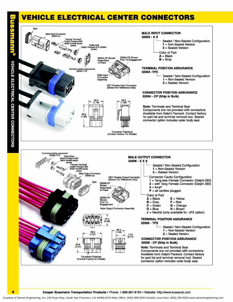
MALE INPUT CONNECTOR32004 - X X
Sealed / Non-Sealed Configuration1 = Non-Sealed Version2 = Sealed Version
Color of PartA = Black
t
B=Gray
TERMINAL POSITION ASSURANCE32004 -TPX
L Sealed / Non-Sealed Configuration1 = Non-Sealed Version2 = Sealed Version
CONNECTOR POSITION ASSURANCE32004 - CP (Ship in Bulk)
Female Terminal*Delphi Packard 800Metri-Pack® series
shown
Cable sealDlhi Pkd #12129381epacarr
shown
26.8(1 .06)
Note : Terminals and Terminal SealComponents are not provided with connectors.Available from Delphi Packard . Contact factoryfor part list and terminal removal tool . Sealedconnector option includes outer body seal.
Connector Polarized(Consult Factory For Details)
00C003
3
Terminal position assurance32006-TPX Cable Seal.-
Delphi Packard 280Metri-Pack® series
shownFemale Terminal*
Delphi Packard 280Metri-Pack® series
shownMale Output Connector,/ 32006-sax
MALE OUTPUT CONNECTOR32006 - X X X
L Sealed / NonSealed Configuration-1 = Non-Sealed Version2 = Sealed Version
Connector Cavity Configuration1 = Tang-less Female Connector (Delphi 280)2 = with Tang Female Connector (Delphi 280)3 = Amp®P = all cavities plugged
Color of PartA = Black
E = YellowB = Gray
F = RedC = Green
G = OrangeD = Blue
H = BrownJ = Neutral (only available for -JP2 option)
VEC Female Output Connector(Shown For Reference Only)
32006-CPShownAssembledIn-Place
24 .4(0.96)
26 3(1 .04)
_ 17 .9(0 .71)
_7-
TERMINAL POSITION ASSURANCE32006 - TPX
I- Sealed / Non-Sealed Configuration1 = Non-Sealed Version2 = Sealed Version
CONNECTOR POSITION ASSURANCE32006 - CP (Ship in Bulk)
Note : Terminals and Terminal SealComponents are not provided with connectors.Available from Delphi Packard . Contact factoryfor part list and terminal removal tool . Sealedconnector option includes outer body seal.
4 Cooper Bussmann Transportation Products • Phone : 1-888-867-8194 • Website : http://www.bussauto.com
Courtesy of Steven Engineering, Inc.-230 Ryan Way, South San Francisco, CA 94080-6370-Main Office: (650) 588-9200-Outside Local Area: (800) 258-9200-www.stevenengineering.com
SPECIFICATIONS
ELECTRICAL COMPONENTS
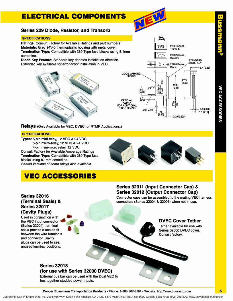
Series 229 Diode, Resistor, and Transorb12 .2[0.48]-1
TVS 22901 SeriesTransorb
C
0
3Ratings : Consult Factory for Available Ratings and part numbersMaterials : Grey 94V-0 thermoplastic housing with metal cover.Termination Type : Compatible with 280 Type fuse blocks using 8 .1mmcenterline.Diode Key Feature : Standard key denotes installation direction.Extended key available for error-proof installation in VEC .
6.4 [0.25]
Relays (Only Available for VEC, DVEC, or RTMR Applications .)
SPECIFICATIONSTypes : 5-pin mini-relay, 12 VDC & 24 VDC
5-pin micro-relay, 12 VDC & 24 VDC4-pin mini-micro relay, 12 VDC
Consult Factory for Available Amperage RatingsTermination Type : Compatible with 280 Type fuseblocks using 8 .1mm centerline.Sealed versions of some relays also available.
VEC ACCESSORIES
Series 32011 (Input Connector Cap) &Series 32012 (Output Connector Cap)
Series 32016
Connector caps can be assembled to the mating VEC harness(Terminal Seals) &
connectors (Series 32004 & 32006) when not in use.
Series 32017(Cavity Plugs)Used in conjunction withthe VEC input connector
~>>(Series 32004), terminalseals provide a sealed fitbetween the wire terminals
•and connector. Cavityplugs can be used to sealunused terminal positions.
Series 32018(for use with Series 32000 DVEC)External bus bar can be used with the Dual VEC tobus together studded power inputs.
Cooper Bussmann Transportation Products • Phone : 1-888-867-8194 • Website: http://www.bussauto.com
IJW\r[ 22902 SeriesResistor
7 .6OPTIONAL
[0 .30]"WING"
FOR ADDITIONALDIODE KEYING
STANDARDDIODE KEY
0.8 [0 .03]3.8 [0 .15]
DVEC Cover TetherTether available for use withSeries 32000 DVEC cover.Consult factory.
5
Courtesy of Steven Engineering, Inc.-230 Ryan Way, South San Francisco, CA 94080-6370-Main Office: (650) 588-9200-Outside Local Area: (800) 258-9200-www.stevenengineering.com
SERIES 15301 RTMRatedRear Terminal Mini Fuse & Relay
66► ~ R6Power Distribution Module
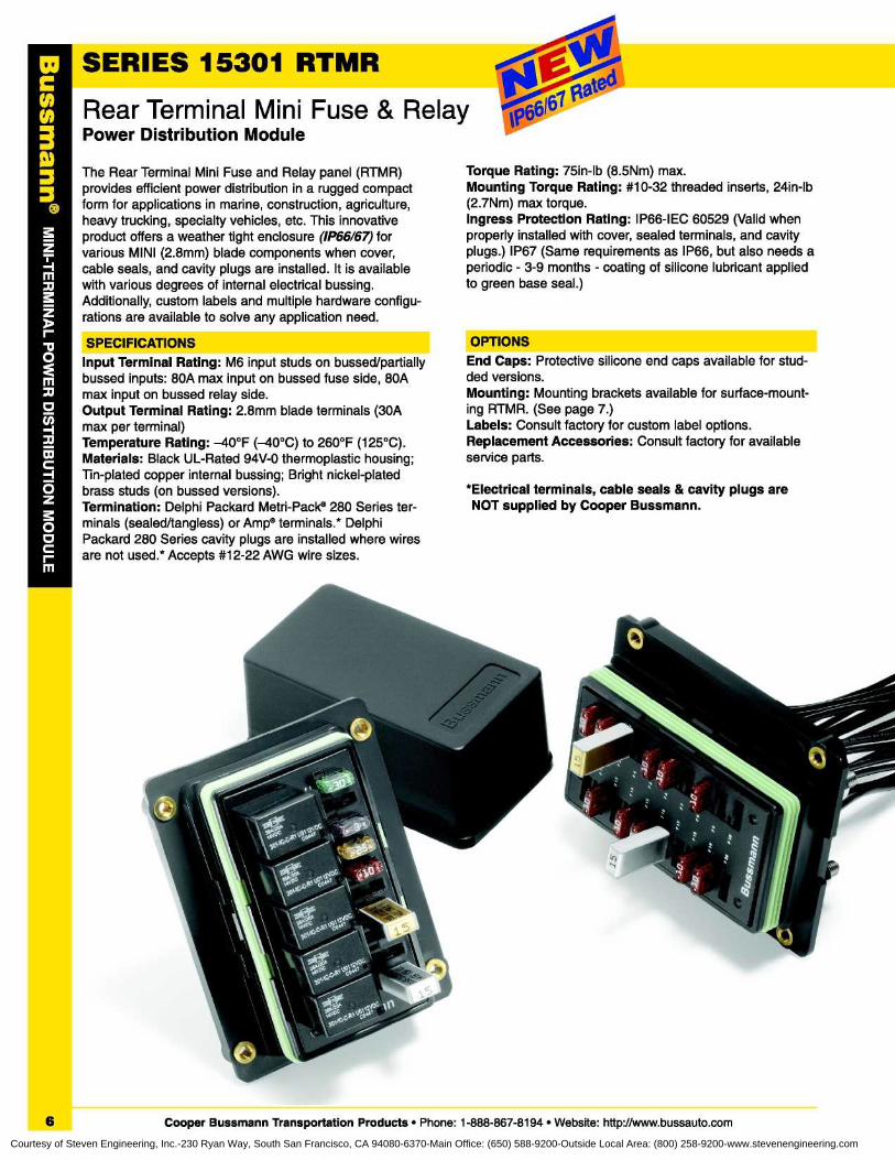
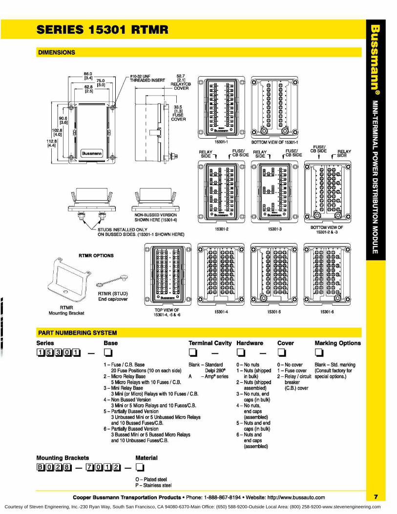
The Rear Terminal Mini Fuse and Relay panel (RTMR)provides efficient power distribution in a rugged compactform for applications in marine, construction, agriculture,heavy trucking, specialty vehicles, etc . This innovativeproduct offers a weather tight enclosure (1P66/67) forvarious MINI (2 .8mm) blade components when cover,cable seals, and cavity plugs are installed . It is availablewith various degrees of internal electrical bussing.Additionally, custom labels and multiple hardware configu-rations are available to solve any application need.
SPECIFICATIONSInput Terminal Rating : M6 input studs on bussed/partiallybussed inputs : 80A max input on bussed fuse side, 80Amax input on bussed relay side.Output Terminal Rating : 2 .8mm blade terminals (30Amax per terminal)Temperature Rating : -40°F (-40°C) to 260°F (125°C).Materials: Black UL-Rated 94V-0 thermoplastic housing;Tin-plated copper internal bussing ; Bright nickel-platedbrass studs (on bussed versions).Termination : Delphi Packard Metri-Pack® 280 Series ter-minals (sealed/tangless) or Amp® terminals .* DelphiPackard 280 Series cavity plugs are installed where wiresare not used .* Accepts #12-22 AWG wire sizes .
Torque Rating : 75in-lb (8 .5Nm) max.Mounting Torque Rating : #10-32 threaded inserts, 24in-lb(2 .7Nm) max torque.Ingress Protection Rating : IP66-IEC 60529 (Valid whenproperly installed with cover, sealed terminals, and cavityplugs .) IP67 (Same requirements as IP66, but also needs aperiodic - 3-9 months - coating of silicone lubricant appliedto green base seal .)
OPTIONSEnd Caps : Protective silicone end caps available for stud-ded versions.Mounting : Mounting brackets available for surface-mount-ing RTMR. (See page 7 .)Labels : Consult factory for custom label options.Replacement Accessories : Consult factory for availableservice parts.
*Electrical terminals, cable seals & cavity plugs areNOT supplied by Cooper Bussmann.
6
Cooper Bussmann Transportation Products • Phone : 1-888-867-8194 • Website : http://www.bussauto.com
Courtesy of Steven Engineering, Inc.-230 Ryan Way, South San Francisco, CA 94080-6370-Main Office: (650) 588-9200-Outside Local Area: (800) 258-9200-www.stevenengineering.com
C003
SERIES 15301 RTMRDIMENSIONS
71NON-BUSSED VERSIONSHOWN HERE (15301-4)
STUDS INSTALLED ONLYON BUSSED SIDES. (15301-1 SHOWN HERE)
#10-32 UNF
52 .7THREADED INSERT
[2.11RELAY/CB
COVER
RTMR OPTIONS
0 C Bussmann 0 0
RELAYSIDE 1
15301-2
Gs, _r r_
GO OGG.GO 00GO GGG.GO OGGO GGG.GO OGGO OGG.GO OG .-GO GG
RTMRMounting Bracket
TOP VIEW OF15301-4, -5 & -6
15301-5 15301-615301-4
PART NUMBERING SYSTEMHardware
Cover
Marking Options
0 - No nuts
0 - No cover
Blank - Std. marking1 - Nuts (shipped 1 - Fuse cover
(Consult factory forin bulk)
2 - Relay / circuit special options .)2 - Nuts (shipped
breakerassembled)
(C .B .) cover3 - No nuts, end
caps (in bulk)4 - No nuts,
end caps(assembled)
5 - Nuts and endcaps (in bulk)
6 - Nuts andend caps(assembled)
Mounting Brackets
Material
Eqqq - qqqq - q0 - Plated steelP - Stainless steel
Cooper Bussmann Transportation Products • Phone : 1-888-867-8194 • Website: http://www.bussauto.com
Series~~~~
Base
q~:1~:1~:1q - q
1 - Fuse / C .B. Base
Blank - Standard20 Fuse Positions (10 on each side)
Delpi 280®2 - Micro Relay Base
A
- Amp® series5 Micro Relays with 10 Fuses / C.B.
3 - Mini Relay Base3 Mini (or Micro) Relays with 10 Fuses / C.B.
4 - Non Bussed Version3 Mini or 5 Micro Relays and 10 Fuses/C .B.
5 - Partially Bussed Version3 Unbussed Mini or 5 Unbussed Micro Relaysand 10 Bussed Fuses/C .B.
6 - Partially Bussed Version3 Bussed Mini or 5 Bussed Micro Relaysand 10 Unbussed Fuses/C.B .
Terminal Cavity
LI
7Courtesy of Steven Engineering, Inc.-230 Ryan Way, South San Francisco, CA 94080-6370-Main Office: (650) 588-9200-Outside Local Area: (800) 258-9200-www.stevenengineering.com
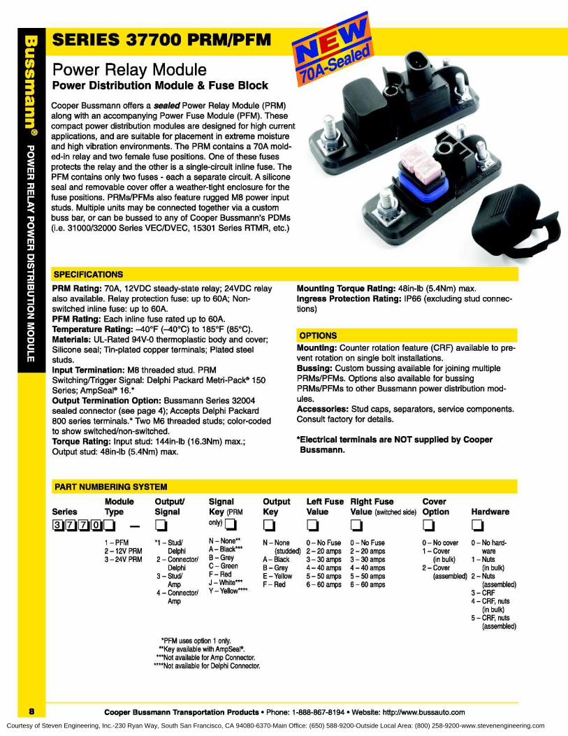
SERIES 37700 PRM/PFMPower Relay ModulePower Distribution Module & Fuse Block
Cooper Bussmann offers a sealed Power Relay Module (PRM)along with an accompanying Power Fuse Module (PFM) . Thesecompact power distribution modules are designed for high currentapplications, and are suitable for placement in extreme moistureand high vibration environments . The PRM contains a 70A mold-ed-in relay and two female fuse positions. One of these fusesprotects the relay and the other is a single-circuit inline fuse . ThePFM contains only two fuses - each a separate circuit . A siliconeseal and removable cover offer a weather-tight enclosure for thefuse positions. PRMs/PFMs also feature rugged M8 power inputstuds . Multiple units may be connected together via a custombuss bar, or can be bussed to any of Cooper Bussmann's PDMs(i .e . 31000/32000 Series VEC/DVEC, 15301 Series RTMR, etc.)
SPECIFICATIONS
PRM Rating : 70A, 12VDC steady-state relay; 24VDC relayalso available . Relay protection fuse : up to 60A; Non-switched inline fuse : up to 60A.PFM Rating : Each inline fuse rated up to 60A.Temperature Rating : -40°F (-40°C) to 185°F (85°C).Materials : UL-Rated 94V-0 thermoplastic body and cover;Silicone seal ; Tin-plated copper terminals ; Plated steelstuds.Input Termination : M8 threaded stud . PRMSwitching/Trigger Signal : Delphi Packard Metri-Pack® 150Series ; AmpSeal® 16 .*Output Termination Option : Bussmann Series 32004sealed connector (see page 4) ; Accepts Delphi Packard800 series terminals .* Two M6 threaded studs ; color-codedto show switched/non-switched.Torque Rating : Input stud : 144in-lb (16 .3Nm) max .;Output stud : 48in-lb (5 .4Nm) max .
Mounting Torque Rating : 48in-lb (5 .4Nm) max.Ingress Protection Rating : IP66 (excluding stud connec-tions)
OPTIONSMounting : Counter rotation feature (CRF) available to pre-vent rotation on single bolt installations.Bussing : Custom bussing available for joining multiplePRMs/PFMs . Options also available for bussingPRMs/PFMs to other Bussmann power distribution mod-ules.Accessories: Stud caps, separators, service components.Consult factory for details.
*Electrical terminals are NOT supplied by CooperBussmann.
PART NUMBERING SYSTEM
LIN - None
(studded)A- BlackB - GreyE - YellowF - Red
Module
Output/
Signal
OutputSeries
Type
Signal
Key (PRM
Key
q1111qq - q
only)q
1 - PFM
*1 - Stud/2 - 12V PRM
Delphi3 - 24V PRM
2 - Connector/Delphi
3 - Stud/Amp
4 - Connector/Amp
*PFM uses option 1 only.**Key available with AmpSeal°.
***Not available for Amp Connector.****Not available for Delphi Connector .
Left Fuse Right Fuse
CoverValue
Value (switched side) Option
Hardware
q q q q
0 - No Fuse 0 - No Fuse 0 - No cover 0 - No hard-2 - 20 amps 2 - 20 amps 1 - Cover ware3 - 30 amps 3 - 30 amps (in bulk) 1 - Nuts4 - 40 amps 4 - 40 amps 2 - Cover (in bulk)5 - 50 amps 5 - 50 amps (assembled) 2 - Nuts6 - 60 amps 6 - 60 amps (assembled)
3-CRF4 - CRF, nuts
(in bulk)5 - CRF, nuts
(assembled)
N - None**A - Black***B - GreyC - GreenF - RedJ - White***Y - Yellow****
8
Cooper Bussmann Transportation Products • Phone : 1-888-867-8194 • Website: http://www.bussauto.comCourtesy of Steven Engineering, Inc.-230 Ryan Way, South San Francisco, CA 94080-6370-Main Office: (650) 588-9200-Outside Local Area: (800) 258-9200-www.stevenengineering.com
C003
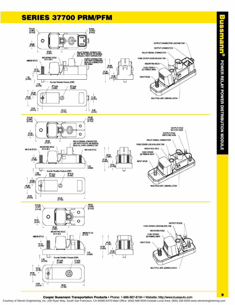
SERIES 37700 PRM/PFM
95 .62[3765]
Cooper Bussmann Transportation Products • Phone : 1-888-867-8194 • Website : http://www.bussauto.com
RELAY SIGNAL CONNECTOR
FUSE COVER LOCKAINLOCK TAB
MOUNTING HOLE
R6.50
(2 PLS)
RELAY SIGNAL CONNECTORUSE WITH DELPHI 150 SERIES,SEALED, 2 WAY CONNECTOR
OUPUT CONNECTORUSE WITH BUSSMANNSEALED CONNECTORP/N 32004
R10 .00[0.394](2 PLS)
50 .90[2 .004]
57.90[2.280]
i12.00[0.472]
20.00[0.787]
40.00 i
~' Ir[1 .575]
13 .04[0 .513]
R10.00[0.394](2 PLS)
~~20.00[0.787]
]
Y11 .09[0 .437]
- -
5 .3812121[4.772]
[0212]
66.50[0.256](2 PLS)
OUTPUT STUDBATTERY SIDE
JII A- n~7
® OUTPUT STUDWITCHESIDE
RELAY SIGNAL CONNECTOR
FUSE COVER LOCK/UNLOCK TAB
MOUNTING HOLE
FUSE COVER(2) FEMALE MAXI
44 .00[1 .732]
51 .00[2.608]
V12.00
[0.472]
}19.19[0 .756]
]
1 .00[0.039]
13.04[0.513]
9
Courtesy of Steven Engineering, Inc.-230 Ryan Way, South San Francisco, CA 94080-6370-Main Office: (650) 588-9200-Outside Local Area: (800) 258-9200-www.stevenengineering.com
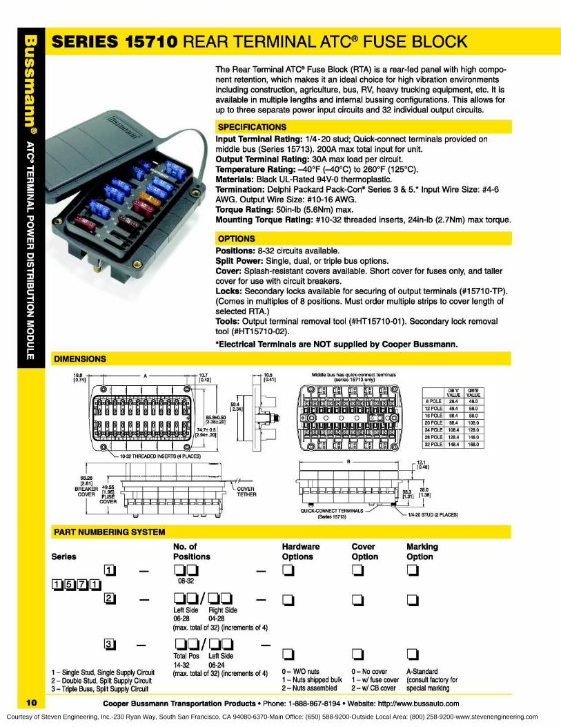
SERIES 15710 REAR TERMINAL ATC ® FUSE BLOCK
The Rear Terminal ATC® Fuse Block (RTA) is a rear-fed panel with high compo-nent retention, which makes it an ideal choice for high vibration environmentsincluding construction, agriculture, bus, RV, heavy trucking equipment, etc . It isavailable in multiple lengths and internal bussing configurations . This allows forup to three separate power input circuits and 32 individual output circuits.
SPECIFICATIONSInput Terminal Rating : 1/4-20 stud ; Quick-connect terminals provided onmiddle bus (Series 15713) . 200A max total input for unit.Output Terminal Rating : 30A max load per circuit.Temperature Rating : -40°F (-40°C) to 260°F (125°C).Materials : Black UL-Rated 94V-0 thermoplastic.Termination : Delphi Packard Pack-Con® Series 3 & 5.* Input Wire Size : #4-6AWG. Output Wire Size : #10-16 AWG.Torque Rating : 50in-lb (5 .6Nm) max.Mounting Torque Rating : #10-32 threaded inserts, 24in-lb (2 .7Nm) max torque.
OPTIONSPositions : 8-32 circuits available.Split Power : Single, dual, or triple bus options.Cover : Splash-resistant covers available . Short cover for fuses only, and tallercover for use with circuit breakers.Locks : Secondary locks available for securing of output terminals (#15710-TP).(Comes in multiples of 8 positions . Must order multiple strips to cover length ofselected RTA.)Tools: Output terminal removal tool (#HT15710-01) . Secondary lock removaltool (#HT15710-02).*Electrical Terminals are NOT supplied by Cooper Bussmann.
DIMENSIONS18.8[0 .74]
10.7[0.42]
59 .4[ 2.34]
COVERTETHER
10 .5[0.41]
68.28[2 .61]
BREAKER 4[9195
5.5]COVER FUSE
COVER----M'
%iI,Ia1111'~Ia111'IL'11
III,
Ig ,l
III,
11}1
11,
O
+1111[+1111[+1111[+1I1[+1111[+1ljl[+111u +1+1L11II[+Ill[+1111[+11
n 111'1 fl~fl~fl~fl~11i1Iil l lilli!I'IiI' n
'LIE l!ll! I!i ILi l! l! l!ll!i l!i l!1211u1j~l[J11121~l[J111[u111[J111[u111121IR11~21112w1[
,, , ,© 111III' IIIIII11 fO
B
_----_
'•11 r
n-
PART NUMBERING SYSTEMNo. ofPositions
~.1
qqII
1111~~..11EMq
08-32~~..
q
qq/ qqLeft Side
Right Side06-28
04-28(max. total of 32) (increments of 4)
q
q q
0 - W/O nuts
0 - No cover
A-Standard1 - Nuts shipped bulk 1 - w/ fuse cover (consult factory for2 - Nuts assembled
2 - w/ CB cover special marking
QUICK-CONNECT TERMINALS(Series 15713)
DIM 'A'VALUE
DIMS'VALUE
8 POLE 28 .4 48.0
12 POLE 48 .4 68.0
16 POLE 68 .4 88.0
20 POLE 88 .4 108 .0
24 POLE 108.4 128 .0
28 POLE 128.4 148 .032 POLE 148.4 168 .0
12 .1[0.48]
1/4-20 STUD (2 PLACES)
SeriesHardware
Cover
MarkingOptions
Option
Option
q q q
q q q
1 - Single Stud, Single Supply Circuit2 - Double Stud, Split Supply Circuit3 - Triple Buss, Split Supply Circuit
Total Pos Left Side14-32
06-24(max. total of 32) (increments of 4)
10
Cooper Bussmann Transportation Products • Phone : 1-888-867-8194 • Website: http://www.bussauto.comCourtesy of Steven Engineering, Inc.-230 Ryan Way, South San Francisco, CA 94080-6370-Main Office: (650) 588-9200-Outside Local Area: (800) 258-9200-www.stevenengineering.com
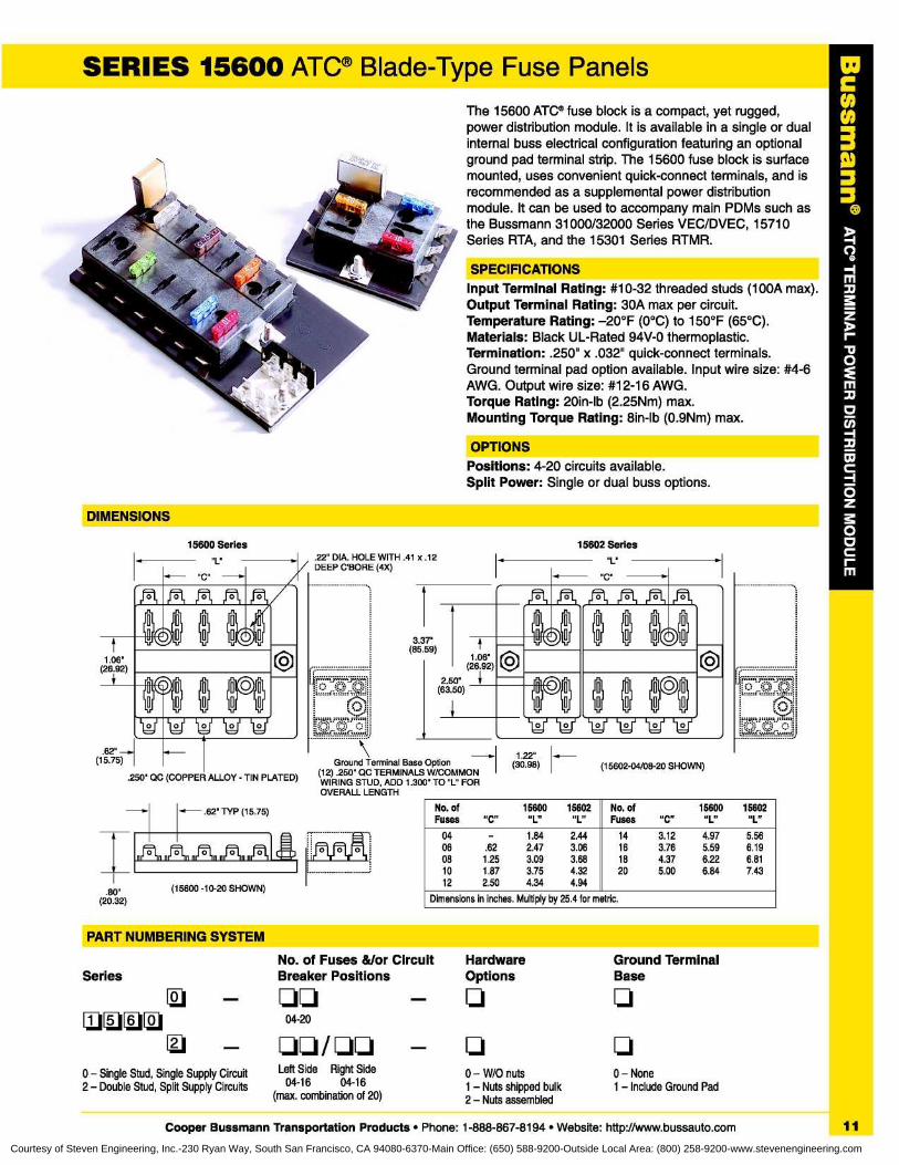
SERIES 15600 ATC® Blade-Type Fuse PanelsThe 15600 ATC® fuse block is a compact, yet rugged,power distribution module . It is available in a single or dualinternal buss electrical configuration featuring an optionalground pad terminal strip . The 15600 fuse block is surfacemounted, uses convenient quick-connect terminals, and isrecommended as a supplemental power distributionmodule . It can be used to accompany main PDMs such asthe Bussmann 31000/32000 Series VEC/DVEC, 15710Series RTA, and the 15301 Series RTMR.
SPECIFICATIONSInput Terminal Rating : #10-32 threaded studs (100A max).Output Terminal Rating : 30A max per circuit.Temperature Rating : -20°F (0°C) to 150°F (65°C).Materials : Black UL-Rated 94V-0 thermoplastic.Termination : .250" x .032" quick-connect terminals.Ground terminal pad option available . Input wire size : #4-6AWG. Output wire size: #12-16 AWG.Torque Rating : 20in-lb (2 .25Nm) max.Mounting Torque Rating : 8in-lb (0 .9Nm) max.
OPTIONSPositions : 4-20 circuits available.Split Power: Single or dual buss options.
DIMENSIONS
15602 Series.22" DIA . HOLE WITH .41DEEP C'BORE (4X)
---------------------------
Ground Terminal Ba(12) .250" QC TERMINAWIRING STUD, ADD 1 .300" TO "L" FOROVERALL LENGTH
x .12 „ L.
1 .37'5 .59)
2.50"(63 .50)
§ 0 0
0
0 0
(26 .92)1 .O O
0
0 0
0
0
0~
Ltd
1-1&1-i Lid Lid1 .22"
oe OptionQWicrnenenM
(30 .98) (15602-04/08-20 SHOWN)
.80"(20.32)
. .. .. .. .. .. .. .. .. .. .. .. .. ...
0
No. of
15600
15602Fuses
"C"
"L"
"L"No . ofFuses
15600
15602"C"
"L"
"L"
04
-
1 .84
2.4406
.62
2.47
3.0608
1 .25
3.09
3.6810
1 .87
3.75
4.3212
2.50
4.34
4.94
14161820
3 .12
4 .97
5 .563 .76
5 .59
6 .194 .37
6 .22
6 .815 .00
6 .84
7 .43
Dimensions in inches . Multiply by 25 .4 for metric.
PART NUMBERING SYSTEM
No. of Fuses &/or Circuit
Hardware Ground TerminalSeries Breaker Positions
Options Base
q
- qqJu1u 0q 04-20
q qq / qq
-
q q0 - Single Stud, Single Supply Circuit Left Side
Right Side
0 - W/O nuts 0 - None2 - Double Stud, Split Supply Circuits 04-16
04-16
1 - Nuts shipped bulk 1 - Include Ground Pad(max. combination of 20)
2 - Nuts assembled
Cooper Bussmann Transportation Products • Phone : 1-888-867-8194 • Website: http://www.bussauto.com 11
Courtesy of Steven Engineering, Inc.-230 Ryan Way, South San Francisco, CA 94080-6370-Main Office: (650) 588-9200-Outside Local Area: (800) 258-9200-www.stevenengineering.com
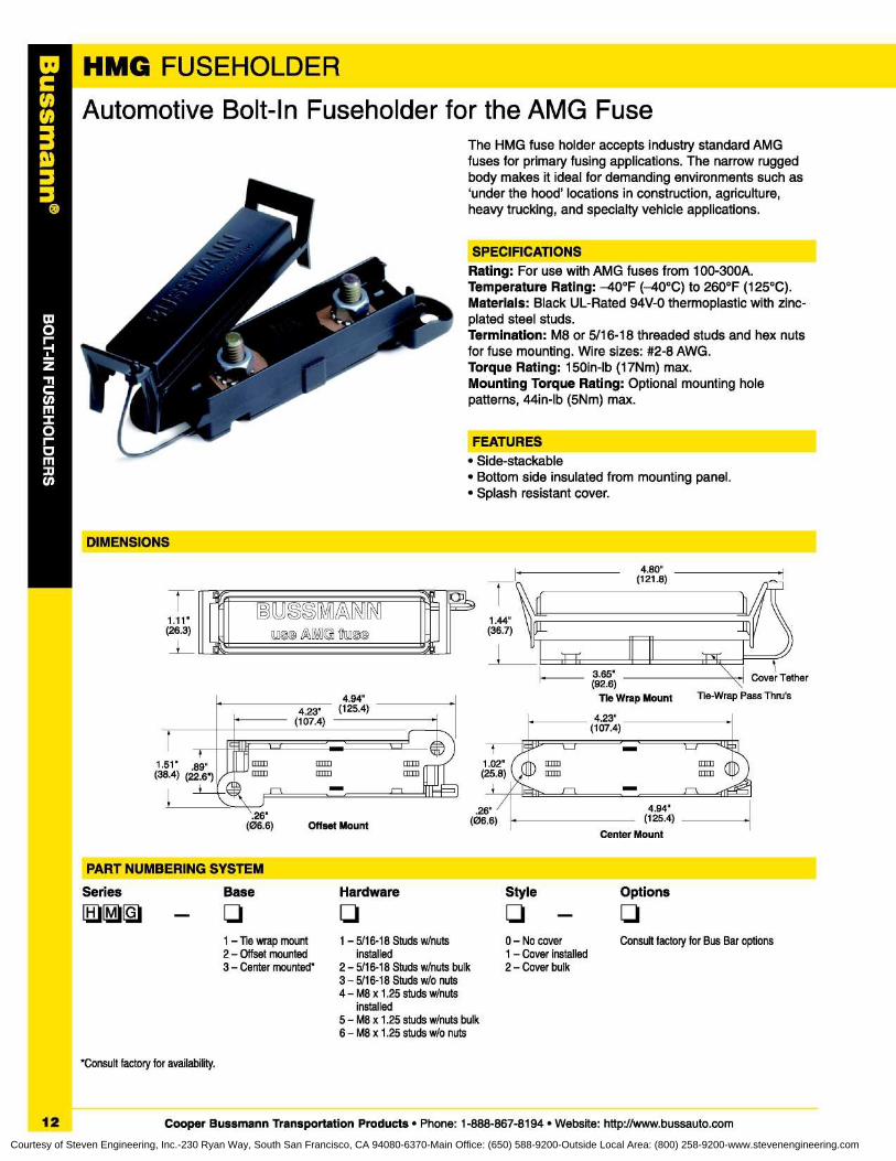
HMG FUSEHOLDER
i
Automotive Bolt-In Fuseholder for the AMG FuseThe HMG fuse holder accepts industry standard AMGfuses for primary fusing applications . The narrow ruggedbody makes it ideal for demanding environments such as`under the hood' locations in construction, agriculture,heavy trucking, and specialty vehicle applications.
SPECIFICATIONSRating : For use with AMG fuses from 100-300A.Temperature Rating : -40°F (-40°C) to 260°F (125°C).Materials : Black UL-Rated 94V-0 thermoplastic with zinc-plated steel studs.Termination : M8 or 5/16-18 threaded studs and hex nutsfor fuse mounting . Wire sizes : #2-8 AWG.Torque Rating: 150in-lb (17Nm) max.Mounting Torque Rating : Optional mounting holepatterns, 44in-lb (5Nm) max.
FEATURES• Side-stackable• Bottom side insulated from mounting panel.• Splash resistant cover.
DIMENSIONS
IKII'
1 .11 ' ° M NaNN26 .3)
um /I\ 'gaoa
rr
4 .80"(121 .8)
1 .51 ' .89"(38 .4) (22 .6')
.26'
-
(06 .6)
Offset Mount
3.65"(92 .6)
Tle Wrap Mount Tie-Wrap Pass Thru's
r-L
herc
4.94"(125.4)4 .23 "
(107.4)
PART NUMBERING SYSTEM
1Series
Base Hardware Style
Options
q - q
12
1 - Tie wrap mount 1 - 5/16-18 Studs w/nuts
02 - Offset mounted installed
13 - Center mounted* 2 - 5/16-18 Studs w/nuts bulk
23 - 5/16-18 Studs w/o nuts4 - M8 x 1 .25 studs w/nuts
installed
*Consult factory for availability.
Cooper Bussmann Transportation Products • Phone : 1-888-867-8194 • Website: http://www.bussauto.com
- No cover
Consult factory for Bus Bar options- Cover installed- Cover bulk
5 - M8 x 1 .25 studs w/nuts bulk6 - M8 x 1 .25 studs w/o nuts
Courtesy of Steven Engineering, Inc.-230 Ryan Way, South San Francisco, CA 94080-6370-Main Office: (650) 588-9200-Outside Local Area: (800) 258-9200-www.stevenengineering.com
CHN3
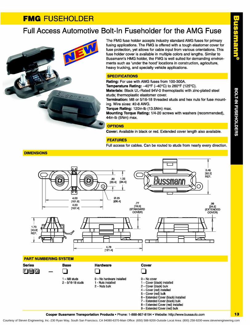
FMG FUSEHOLDERFull Access Automotive Bolt-In Fuseholder for the AMG Fuse
The FMG fuse holder accepts industry standard AMG fuses for primaryfusing applications . The FMG is offered with a tough elastomer cover forfuse protection, yet allows for cable input from various orientations . Thisfuse holder cover is available in multiple colors and lengths . Similar toBussmann's HMG holder, the FMG is well suited for demanding environ-ments such as 'under the hood' locations in construction, agriculture,heavy trucking, and specialty vehicle applications.
SPECIFICATIONSRating : For use with AMG fuses from 100-300A.Temperature Rating : -40°F (-40°C) to 260°F (125°C).Materials : Black UL-Rated 94V-0 thermoplastic with zinc-plated steelstuds; thermoplastic elastomer cover.Termination : M8 or 5/16-18 threaded studs and hex nuts for fuse mount-ing . Wire sizes: #2-8 AWG.Torque Rating : 120in-lb (13.5Nm) max.Mounting Torque Rating : 1/4-20 screws with washers (recommended),44in-lb (5Nm) max.
OPTIONSCover : Available in black or red . Extended cover length also available.
FEATURESFull access for cables . Can be routed to studs from nearly every direction.
DIMENSIONS
.77[19.5]
(STANDARDCOVER)
2 .46[62.5]REF.
.96[24 .5]
(EXTENDEDCOVER)
Bussmann
1 .73[43.9]REF.
I i II
PART NUMBERING SYSTEM
Series
Base
Hardware
Cover
1 - M8 studs
0 - No hardware installed
0 - No cover2 - 5/16-18 studs
1 - Nuts installed
1 - Cover (black) installed2 - Nuts bulk
2 - Cover (black) bulk4 - Cover (red) installed5 - Cover (red) bulk6 - Extended Cover (black) installed7 - Extended Cover (black) bulk8 - Extended Cover (red) installed9 - Extended Cover (red) bulk
Cooper Bussmann Transportation Products • Phone : 1-888-867-8194 • Website: http://www.bussauto.com 13
Courtesy of Steven Engineering, Inc.-230 Ryan Way, South San Francisco, CA 94080-6370-Main Office: (650) 588-9200-Outside Local Area: (800) 258-9200-www.stevenengineering.com

INLINE FUSEHOLDERSIn-Line Fuseholders for Blade-Type FusesHHC, HHD, HHF,HHG, HHR, and HHS
r.43011-1-4"-)---1
(TYP/2)1
®~-
~ .606'r 1 .850"-t-5"1
_f1 .100'.6,0"
250"1 .820" o
.920'
=^;1
P~
`! ~~ 1 .000""50 .360'
.eaz" +sm .HHR
1 .250"- HHF / HHG
.701'
.157'
40'
.993'
~.806'
.280•H
-
.906•
.140'-.l
I
.500. _1
Itsit
y~
4.
(TYP/2)~
4" ~~ y,
__;
o
1_
I .
f
.250'
.375•
mP/2 )~ 1 .375'
I~ 4' ~y~ 1.,2'
HHC
r4'~ 1.25" ~f
HHD
4• -/~~ +A1o'
Dimensions in inches. Multiply by 25 .4 for metric.
ATV' Blade Type HolderCatalog No. Description Fuse Size Electrical Connection
HHC Yellow fuseholder (body only) 3-20A #16 AWG lead black wireHHD Black fuseholder (body only) 3-30A #12 AWG lead yellow wireHHD-C Cover only Fits only HHD Clear polycarbonateHHF Black fuseholder w/cover 3-20A #16 AWG lead yellow wireHHG Black fuseholder w/cover 3-30A #12 AWG lead yellow wire
HHR Black waterproof fuseholderw/locking cover & mounting hole 30 A #12 AWG lead orange wire
5" length
HHS Blue fuseholder ~~ A Self-stripping ; accepts #18-#14 AWG copper wire only
HHL and HHM1 .56"
. ff I(del)7r-.25"
r .59"
.25"4 .75' 4 .75"
Dimensions in inches. Multiply by 25 .4 for metric.
MINI• Fuse Blade Type HolderCatalog No . Description Fuse Size Electrical Connection
HHL Fuseholder w/cover2 20 A #i6 AWG lead black wire;
4" lengthHHL-B Body onlyHHM Fuseholder w/cover
2-30 A #12 AWG lead red wire;4" lengthHHM-B Body only
HHM-C Cover only
HHX
3.35'
6 .70" 6.70"
®1 .37"
Dimensions in inches . Multiply by 25.4 for metric . .265' DIA. HOLE
MAXI- Fuse Blade Type HolderCatalog No. Description Fuse Size Electrical Connection
HHX Fuseholder w/cover20-60 amps #6 lead wire;
5"lenthHHX-B Body onlyHHX-C Cover only
In-Line Fuseholders for ATC ® Blade-Type Fuses.Rating : 32V, See table for max. amp. "Write-in"space for circuit identification on HHC holder.Plastic cover fits only HHD holder. HHR holder iswaterproof with a locking cover and mountinghole . HHS is a self-stripping holder.
In-Line Fuseholders for ATM MINI® Fuses.Rating: 32V, See table for max. amp.Body material withstands high temps.Protective cover has removable straps . RatedIP67 with cover installed.
In-Line Fuseholder for MAXI"" Fuses.Rating: 32V, 60A Max. Firewall mounting holepermits two or more holders to be mountedtogether. Cover comes with a removable strap.
14
Cooper Bussmann Transportation Products • Phone : 1-888-867-8194 • Website: http://www.bussauto.comCourtesy of Steven Engineering, Inc.-230 Ryan Way, South San Francisco, CA 94080-6370-Main Office: (650) 588-9200-Outside Local Area: (800) 258-9200-www.stevenengineering.com
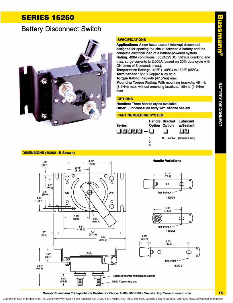
SPECIFICATIONSApplications : A non-fused current interrupt disconnectdesigned for opening the circuit between a battery and thecomplete electrical load of a battery-powered system.Rating : 400A continuous, . 50VACNDC . Vehicle cranking andmax . surge currents to 2,000A (based on 20% duty cycle withON times of 5 seconds max .).Temperature Rating : -40°F (-40°C) to 150°F (65°C).Termination : 1/2-13 Copper alloy stud.Torque Rating : 420in-lb (47 .5Nm) max.Mounting Torque Rating : With mounting brackets : 48in-lb(5 .4Nm) max ; without mounting brackets : 10in-lb (1 .lNm)max.
OPTIONSHandles : Three handle styles available.Other : Lubricant-filled body with silicone sealant.
PART NUMBERING SYSTEM
Handle Bracket LubricantSSe
eriees~
s~~~~~~
w/~Option Option w/Sealant
1
B - Bracket (Grease Filled)23
C003
SERIES 15250
Battery Disconnect Switch
DIMENSIONS (15250-1B Shown)
Handle Variations
Ref. Point A
1 .56"(39.7) I ON O
1 .25"(31 .7)
4.50"(114 .3)
3 0
15250-33 .81"(96 .8)
,...-- Stainless washers and lodmuts supplied1 .12"(28 .4)
1/2-13 Copper alloy stud
Cooper Bussmann Transportation Products • Phone : 1-888-867-8194 • Website: http://www.bussauto.com
15
Courtesy of Steven Engineering, Inc.-230 Ryan Way, South San Francisco, CA 94080-6370-Main Office: (650) 588-9200-Outside Local Area: (800) 258-9200-www.stevenengineering.com
C003A)33
16
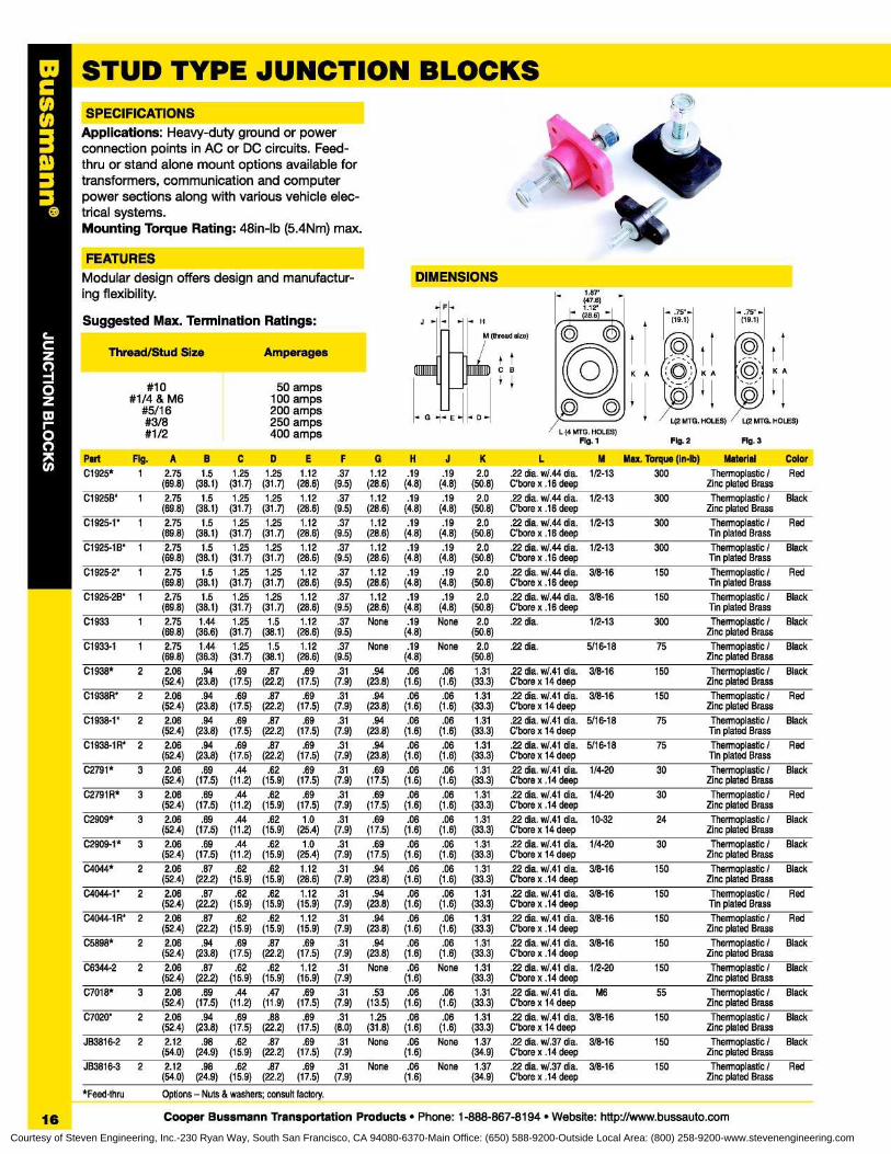
STUD TYPE JUNCTION BLOCKS
SPECIFICATIONSApplications: Heavy-duty ground or powerconnection points in AC or DC circuits . Feed-thru or stand alone mount options available fortransformers, communication and computerpower sections along with various vehicle elec-trical systems.Mounting Torque Rating : 48in-lb (5 .4Nm) max.
#10
50 amps#1/4 & M6
100 amps#5/16
200 amps#3/8
250 amps#1/2
400 amps
Part Fig . A B C D E F G H J K L M Max. Torque (in-lb) Material ColorC1925* 1 2.75 1 .5 1 .25 1 .25 1 .12 .37 1 .12 .19 .19 2.0 .22 dia . w/.44 dia . 1/2-13 300 Thermoplastic / Red
(69 .8) (38 .1) (31 .7) (31 .7) (28.6) (9.5) (28 .6) (4.8) (4.8) (50 .8) C'bore x .16 deep Zinc plated BrassC1925B* 1 2.75 1 .5 1 .25 1 .25 1 .12 .37 1 .12 .19 .19 2.0 .22 dia . w/.44 dia . 1/2-13 300 Thermoplastic / Black
(69 .8) (38 .1) (31 .7) (31 .7) (28.6) (9.5) (28 .6) (4.8) (4.8) (50 .8) C'bore x .16 deep Zinc plated BrassC1925-1* 1 2.75 1 .5 1 .25 1 .25 1 .12 .37 1 .12 .19 .19 2.0 .22 dia . w/.44 dia . 1/2-13 300 Thermoplastic / Red
(69 .8) (38 .1) (31 .7) (31 .7) (28.6) (9.5) (28 .6) (4.8) (4.8) (50 .8) C'bore x .16 deep Tin plated BrassC1925-1B* 1 2.75 1 .5 1 .25 1 .25 1 .12 .37 1 .12 .19 .19 2.0 .22 dia . w/.44 dia . 1/2-13 300 Thermoplastic / Black
(69 .8) (38 .1) (31 .7) (31 .7) (28.6) (9.5) (28 .6) (4.8) (4.8) (50 .8) C'bore x .16 deep Tin plated BrassC1925-2* 1 2.75 1 .5 1 .25 1 .25 1 .12 .37 1 .12 .19 .19 2.0 .22 dia . w/.44 dia . 3/8-16 150 Thermoplastic / Red
(69 .8) (38 .1) (31 .7) (31 .7) (28.6) (9.5) (28 .6) (4.8) (4.8) (50 .8) C'bore x .16 deep Tin plated Brass
C1925-2B* 1 2.75 1 .5 1 .25 1 .25 1 .12 .37 1 .12 .19 .19 2.0 .22 dia . w/.44 dia . 3/8-16 150 Thermoplastic / Black(69 .8) (38 .1) (31 .7) (31 .7) (28.6) (9.5) (28 .6) (4.8) (4.8) (50 .8) C'bore x .16 deep Tin plated Brass
C1933 1 2.75 1 .44 1 .25 1 .5 1 .12 .37 None .19 None 2.0 .22 dia . 1/2-13 300 Thermoplastic / Black(69 .8) (36 .6) (31 .7) (38.1) (28.6) (9.5) (4.8) (50 .8) Zinc plated Brass
C1933-1 1 2.75 1 .44 1 .25 1 .5 1 .12 .37 None .19 None 2.0 .22 dia . 5/16-18 75 Thermoplastic / Black(69 .8) (36 .3) (31 .7) (38.1) (28.6) (9.5) (4.8) (50 .8) Zinc plated Brass
C1938* 2 2.06 .94 .69 .87 .69 .31 .94 .06 .06 1 .31 .22 dia . w/.41 dia . 3/8-16 150 Thermoplastic / Black(52 .4) (23 .8) (17 .5) (22.2) (17.5) (7.9) (23.8) (1 .6) (1 .6) (33 .3) C'bore x 14 deep Zinc plated Brass
C1938R* 2 2.06 .94 .69 .87 .69 .31 .94 .06 .06 1 .31 .22 dia . w/.41 dia . 3/8-16 150 Thermoplastic / Red(52 .4) (23 .8) (17 .5) (22.2) (17.5) (7.9) (23.8) (1 .6) (1 .6) (33 .3) C'bore x 14 deep Zinc plated Brass
C1938-1* 2 2.06 .94 .69 .87 .69 .31 .94 .06 .06 1 .31 .22 dia . w/.41 dia . 5/16-18 75 Thermoplastic / Black(52 .4) (23 .8) (17 .5) (22.2) (17.5) (7.9) (23.8) (1 .6) (1 .6) (33 .3) C'bore x 14 deep Tin plated Brass
C1938-1 R* 2 2.06 .94 .69 .87 .69 .31 .94 .06 .06 1 .31 .22 dia . w/.41 dia . 5/16-18 75 Thermoplastic / Red(52 .4) (23 .8) (17 .5) (22.2) (17.5) (7.9) (23.8) (1 .6) (1 .6) (33 .3) C'bore x 14 deep Tin plated Brass
C2791* 3 2.06 .69 .44 .62 .69 .31 .69 .06 .06 1 .31 .22 dia . w/.41 dia . 1/4-20 30 Thermoplastic / Black(52 .4) (17 .5) (11 .2) (15.9) (17.5) (7.9) (17.5) (1 .6) (1 .6) (33 .3) C'bore x .14 deep Zinc plated Brass
C2791 R* 3 2.06 .69 .44 .62 .69 .31 .69 .06 .06 1 .31 .22 dia . w/.41 dia . 1/4-20 30 Thermoplastic / Red(52 .4) (17 .5) (11 .2) (15.9) (17.5) (7.9) (17.5) (1 .6) (1 .6) (33 .3) C'bore x .14 deep Zinc plated Brass
C2909* 3 2.06 .69 .44 .62 1 .0 .31 .69 .06 .06 1 .31 .22 dia . w/.41 dia . 10-32 24 Thermoplastic / Black(52 .4) (17 .5) (11 .2) (15.9) (25.4) (7.9) (17.5) (1 .6) (1 .6) (33 .3) C'bore x 14 deep Zinc plated Brass
C2909-1* 3 2.06 .69 .44 .62 1 .0 .31 .69 .06 .06 1 .31 .22 dia . w/.41 dia . 1/4-20 30 Thermoplastic / Black(52 .4) (17 .5) (11 .2) (15.9) (25.4) (7.9) (17.5) (1 .6) (1 .6) (33 .3) C'bore x 14 deep Zinc plated Brass
C4O44* 2 2.06 .87 .62 .62 1 .12 .31 .94 .06 .06 1 .31 .22 dia . w/.41 dia . 3/8-16 150 Thermoplastic / Black(52 .4) (22 .2) (15 .9) (15.9) (28.6) (7.9) (23.8) (1 .6) (1 .6) (33 .3) C'bore x .14 deep Zinc plated Brass
C4O44-1 * 2 2.06 .87 .62 .62 1 .12 .31 .94 .06 .06 1 .31 .22 dia . w/.41 dia . 3/8-16 150 Thermoplastic / Red(52 .4) (22 .2) (15 .9) (15.9) (15.9) (7.9) (23.8) (1 .6) (1 .6) (33 .3) C'bore x .14 deep Tin plated Brass
C4O44-1 R* 2 2.06 .87 .62 .62 1 .12 .31 .94 .06 .06 1 .31 .22 dia . w/.41 dia . 3/8-16 150 Thermoplastic / Red(52 .4) (22 .2) (15 .9) (15.9) (15.9) (7.9) (23.8) (1 .6) (1 .6) (33 .3) C'bore x .14 deep Zinc plated Brass
C5898* 2 2.06 .94 .69 .87 .69 .31 .94 .06 .06 1 .31 .22 dia . w/.41 dia . 3/8-16 150 Thermoplastic / Black(52 .4) (23 .8) (17 .5) (22.2) (17.5) (7.9) (23.8) (1 .6) (1 .6) (33 .3) C'bore x .14 deep Zinc plated Brass
C6344-2 2 2.06 .87 .62 .62 1 .12 .31 None .06 None 1 .31 .22 dia . w/.41 dia . 1/2-20 150 Thermoplastic / Black(52 .4) (22 .2) (15 .9) (15.9) (15.9) (7.9) (1 .6) (33 .3) C'bore x .14 deep Zinc plated Brass
C7O18* 3 2.06 .69 .44 .47 .69 .31 .53 .06 .06 1 .31 .22 dia . w/.41 dia . M6 55 Thermoplastic / Black(52 .4) (17 .5) (11 .2) (11 .9) (17.5) (7.9) (13.5) (1 .6) (1 .6) (33 .3) C'bore x 14 deep Zinc plated Brass
C7O2O* 2 2.06 .94 .69 .88 .69 .31 1 .25 .06 .06 1 .31 .22 dia . w/.41 dia . 3/8-16 150 Thermoplastic / Black(52 .4) (23 .8) (17 .5) (22.2) (17.5) (8.0) (31 .8) (1 .6) (1 .6) (33 .3) C'bore x 14 deep Zinc plated Brass
JB3816-2 2 2.12 .98 .62 .87 .69 .31 None .06 None 1 .37 .22 dia . w/.37 dia . 3/8-16 150 Thermoplastic / Black(54 .0) (24 .9) (15 .9) (22.2) (17.5) (7.9) (1 .6) (34 .9) C'bore x .14 deep Zinc plated Brass
JB3816-3 2 2.12 .98 .62 .87 .69 .31 None .06 None 1 .37 .22 dia . w/.37 dia . 3/8-16 150 Thermoplastic / Red(54 .0) (24 .9) (15 .9) (22.2) (17.5) (7.9) (1 .6) (34 .9) C'bore x .14 deep Zinc plated Brass
*Feed-thru
Options - Nuts & washers ; consult factory.
Cooper Bussmann Transportation Products • Phone : 1-888-867-8194 • Website: http://www.bussauto.com
FEATURESModular design offers design and manufactur-ing flexibility.
Suggested Max . Termination Ratings:
Thread/Stud Size
Amperages
DIMENSIONS1 .8T(47.6)1 .12'(28 .6)
G • . E
D
L (4 MTG . HOLES)Fig. 1
F .
H
M (thread size)
CB11111111111111111111
(19.1)
L(2 MTG. HOLES)
L(2 MTG . HOLES)
Fig . 2
Fig. 3
K A
(19.1)
K AK A
Courtesy of Steven Engineering, Inc.-230 Ryan Way, South San Francisco, CA 94080-6370-Main Office: (650) 588-9200-Outside Local Area: (800) 258-9200-www.stevenengineering.com
CHN
3
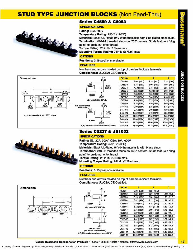
STUD TYPE JUNCTION BLOCKS (Non Feed-Thru)Series C4559 & C6083
SPECIFICATIONSRating : 30A, 600VTemperature Rating : 250°F (120°C)Materials : Black UL-Rated 94V-0 thermoplastic with zinc-plated steel studs.Termination : #10-24 threaded studs on .750" centers . Studs feature a "dogpoint" to guide nut onto thread.Torque Rating : 25 in-lb (2 .8Nm) max.Mounting Torque Rating : 24in-lb (2 .7Nm) max.OPTIONSPositions : 2-16 positions available.FEATURESNumbers and arrows molded on top of barriers indicate terminals.Compliances : UUCSA ; CE Certified.
Series C5237 & JB1032
&PECIFICATIONSRating : UL : 30A, 300V ; CSA: 30A, 600V.Temperature Rating : 250°F (120°C)Materials : Black UL-Rated 94V-0 thermoplastic with brass studs.Termination : #10-32 threaded studs on .625" centers . Studs feature a "dogpoint" to guide nut onto thread.Torque Rating : 25 in-lb (2 .8Nm) max.Mounting Torque Rating : 24in-lb (2 .7Nm) max.OPTIONSPositions : 1-15 positions available.FEATURESNumbers and arrows molded on top of barriers indicate terminals.Compliances : UUCSA ; CE Certified.
.84'(21 .34)
}1 .05"
(26 .67)
C4559
t
.31"(7 .87)
Mtg . holes 9/32"x 3/8" slot
r 9 I (27.69)1 .09"
C6083
l 1" r
(7.87)(A,B,C Dimensions are the same as C4559)
Part No .
A
B
C
C4559-2 3.00 (76.2) 2 .25 (57 .1) 0.75 (19 .0)C4559-3 3.75 (95.2) 3 .00 (76 .2) 1 .50 (38 .1)C4559-4 4 .50 (114.3) 3 .75 (95 .2) 2.25 (57 .1)C4559-5 5.25 (133.3) 4 .50 (114.3) 3.00 (76 .2)C4559-6 6.00 (152.4) 5 .25 (133 .3) 3.75 (95 .2)C4559-7 6.75 (171 .4) 6 .00 (152 .4) 4.50 (114 .3)C4559-8 7.50 (190.5) 6 .75 (171 .4) 5.25 (133 .3)C4559-9 8.25 (209.5) 7 .50 (190 .5) 6.00 (152 .4)
C4559-10 9.00 (228.6) 8 .25 (209 .5) 6.75 (171 .4)C4559-11 9.75 (247.6) 9 .00 (228 .6) 7.50 (190 .5)C4559-12
10.50 (266.7) 9 .75 (247 .6) 8.25 (209 .5)C4559-13 11 .25 (285 .7) 10 .50 (266 .7) 9.00 (288 .6)C4559-14
12.00 (308.4) 11 .25 (285.7) 9.75 (247 .6)C4559-15 12.75 (323.8) 12 .00 (308 .4) 10.50 (266 .7)C4559-16 13.50 (342.9) 12 .75 (323 .8) 11 .25 (285 .7)
Dimensions
I
#10-32 zinc plated
(21 .34)steel studs
AC
(28 .45)
p IIC)II®
75"(19 .05)
}375'
(9 .53)
.75"(19.05)
B
.375"(9.53)
Other series available with .750" centers:
Dimensions
.81"
Part No .
A
B
C
C5237-1 2.00 (50.8) 1 .25 (31 .7)C5237-2
2.62 (66.7) 1 .87 (47.5) .625 (15.9)C5237-3 3.25 (82.5) 2.50 (63.4) 1 .25 (31 .7)C5237-4 3.87 (98.4) 3.12 (79.4) 1 .87 (47.5)C5237-5 4 .50 (114.3) 3.75 (95.2) 2 .50 (63.4)C5237-6 5.12 (130.8) 4 .37 (111 .1) 3 .12 (79.4)C5237-7 5.75 (146.0) 5.00 (127.0) 3 .75 (95.2)
C5237-8 6.37 (161 .9) 5.62 (142.9) 4.37 (111 .1)C5237-9 7.00 (177.8) 6.25 (158.7) 5 .00 (127.0)
C5237-10 7.62 (193.7) 6.87 (174.6) 5 .62 (142.9)C5237-11 8.25 (209.5) 7.50 (190.5) 6 .25 (158.7)C5237-12 8.87 (225.4) 8.12 (206 .4) 6 .87 (174.6)C5237-13 9.50 (241 .3) 8.75 (222 .2) 7 .50 (190.5)C5237-14
10.12 (257.2) 9.37 (238 .1) 8 .12 (206.4)C5237-15 10.75 (273.0) 10.00 (254.0) 8 .75 (222.2)
1 .16"
}.31"
JB1032-120-XX(No bosses between studs)
(A,B,C Dimensions ars the same as C5237)
~5n
116'
l} r
C5237
Mtg . holes 9/32"X3/8" slot.31"
A
C
}O.75"
+ .375'
0
f .625" -
375'
B
Of\OiO O
Cooper Bussmann Transportation Products • Phone : 1-888-867-8194 • Website : http://www.bussauto.com
17Courtesy of Steven Engineering, Inc.-230 Ryan Way, South San Francisco, CA 94080-6370-Main Office: (650) 588-9200-Outside Local Area: (800) 258-9200-www.stevenengineering.com
Cy03ID33
Basic Overcurrent Technology
Overcurrent devices may serve several purposes inelectrical circuits:• To protect components, equipment, and associated wiringfrom the effects of electric circuit overloads and/or shortcircuits.
• To isolate branch circuits from the main power supplyonce an overload or short circuit has occurred.
Fuses and circuit breakers are commonly selected as thepreferred overcurrent device.
TYPES OF OVERCURRENT
An overcurrent device is constructed to react in aprescribed fashion to varying levels of electrical current,where at pre-determined levels, the device providesinterruption of the current flow through it. Any current thatexceeds the ampere rating of the fuse or circuit breaker isan overcurrent. Overcurrents are generally classified aseither short circuits or overloads and are defined asfollows:
• Short circuit - a current that greatly exceeds the rating ofthe device . It is caused when a malfunction or accidentcreates a break in the normal path allowing electricity toflow directly to ground or another phase. This shortercurrent path bypasses the resistance offered by thecircuit components and the load connected in the normalcurrent path . In this situation there is little resistance toimpede the current and the current will build to a levelwhere the heat generated can cause insulation damageand/or equipment breakdown.
• Overload - an overcurrent that is within the normalcurrent path . Overloads occur when the current exceedsthe value for which the equipment or associated wiring israted . This typically occurs when too many devices areconnected to the circuit or when a device connected tothe circuit malfunctions . Overloads are also caused byharmless temporary surge currents ; such as when motorsare started . These overload currents are normal, usuallybrief in duration, and have no harmful effect on the circuitcomponents . (It is important that protective devices donot react to such overloads .) Sustained overloads,however, may slowly cause overheating of the wiring andthe components. Provided the overload is of sufficientmagnitude and duration to activate the device, the circuitprotection device shall open before the overload inducessystem component failures.
SELECTING OVERCURRENT PROTECTION
During normal conditions, an overcurrent protection devicemust carry the current without nuisance openings.However, when an overload or short circuit occurs thedevice interrupts the overcurrent and withstands thevoltage across the device . To properly select anovercurrent device the following items must be carefully
considered:
• Voltage rating - represents the maximum system voltagepresent in the circuit in which the overcurrent device isinstalled . The system voltage should not exceed thisvalue for proper operation of the device during anovercurrent event.
• Current Rating - the amperage value marked on thecircuit protection device . The circuit protection device isdesigned to handle this value under steady operatingconditions and at room ambient temperatures . Since fieldapplications often deliver loading conditions and ambienttemperatures that vary from ideal nominal settings, it isrecommended that circuit designers select device ratingsabove the nominal circuit current continuous load toprevent nuisance trips . Additionally, the continuouscurrent flowing through the overcurrent protective deviceshould not be more than 80% of the current rating.
• Characteristics of equipment to be protected - duringthe operation of protected equipment, system current cansignificantly vary. This is particularly evident when motoror other inductive loads in the circuit cause large currentsurges during start-up . Circuit protection designers shouldbe aware of these surges and/or in-rush characteristicsand select the overcurrent protection devices accordingly.
• Available short circuit current - during a fault or shortcircuit condition the fuse or circuit breaker may see alarge amount of current . Large DC battery supplies andhigh current rated electric distribution buses often havethis potential for severe short circuits . In these situations,the circuit protection device should have an interruptingrating that is equal to or greater than the short circuitcurrent that can be delivered.
• Ambient temperature - the time it takes to interrupt thecurrent is dependent upon the ambient currenttemperature characteristics . Ambient temperature refersto the temperature of the air immediately surrounding thecircuit protection device . The ambient temperature aroundthe fuse or circuit breaker can be appreciably differentthan the outside room or larger enclosure containing thedevice . This can occur when the device is contained in atight area or it is mounted in or near a heat-producingcomponent such as a transformer or resistor. Whenselecting a fuse or circuit breaker at ambienttemperatures significantly different from the statednominal temperature, the circuit designer should adjustthe selected overcurrent protection rating based on thepublished temperature re-rating curves.
OVERCURRENT PROTECTION DEVICES
Two categories of overcurrent devices are available.
FusesThe key component of a fuse is the "element', a shortpiece of metallic wire or link made of a material with a
18
Cooper Bussmann Transportation Products • Phone : 1-888-867-8194 • Website: http://www.bussauto.com
Courtesy of Steven Engineering, Inc.-230 Ryan Way, South San Francisco, CA 94080-6370-Main Office: (650) 588-9200-Outside Local Area: (800) 258-9200-www.stevenengineering.com

relatively low and predictable melting point . Fuses arecurrent-sensitive devices and the resistance is so low thatthey simply act as a conductor. Circuit protection isprovided when the fuse element melts and interrupts anovercurrent . The key criteria used to judge the performanceof a fuse is the time-versus-current characteristic curve.This curve can be used to match the fuse with the load.Fuses may be preferred when fast response to a shortcircuit condition is required or when high available shortcircuit currents occur. Fuse characteristic curves can beused to carefully size the device to a critical or specialapplication.
Thermal Circuit BreakersThe basic components of a thermal circuit breaker are thethermal alloy element, electrical contacts, and the terminalsfor external connections . When an overload occurs, heat isgenerated as the current flows through the thermal alloyelement causing it to deflect and separate the electricalcontacts, interrupting current flow. An important parameterused to judge the performance of a thermal circuit breakeris the time-versus-current characteristic curve, which issimilar to that of a fuse . A thermal circuit breaker isgenerally not a one-event type device as is a fuse . Theresettable features of circuit breakers are often foundattractive for use in electrical circuits where non-resettinginterruption of current flow is undesirable . It is important tonote that cycle life of a thermal circuit breaker isimpacted both by the operational characteristic of thecircuit breaker as well as the relative magnitude andduration of overcurrents or short circuits that thedevice experiences. There are different operationalcharacteristics of Cooper Bussmann thermal circuitbreakers, which are described below.
CIRCUIT BREAKEROPERATIONAL CHARACTERISTICS
Four different methods for reset are generally available:
• Type I (automatic reset): the circuit breaker trips andresets in response to the overcurrent condition in arepetitive fashion . This version should be used inapplications that provide for other self-limiting ornon-resettable means (such as after a main fuse, mainmanual-reset circuit breaker, or momentary switch).These devices, while automatic in reset function, arenot designed for long-term cycling conditions inapplications where operator awareness of circuit faultor serviceability access is limited, leading tounsatisfactory failure events. Refer to SAE J553 orJ1625 for additional details.
• Type II (modified reset) : the circuit breaker contains anadditional resistive component that enables the device tohave only brief trip and reset activity and then afterwardsmaintains an open circuit condition (except for a low
milliamp draw through the resistor) . Requires minimumvoltage/current to maintain open circuit - see standards fordetails SAEJ553.
• Type III (manual reset) : the circuit breaker will trip inresponse to an overcurrent condition after which a resetbutton or lever extends externally to indicate that thebreaker has tripped and is in a non-conducting state . Thetrip indicator button or lever must be manually activated toreturn the device to normal operation.
• Type III (switchable) : same as the manual Type IIImanual reset with the additional feature of allowing theuser to open the circuit using an externally accessible tripmechanism.
CIRCUIT BREAKER APPLICATION NOTES
• Circuit Breaker Performance - Cooper Bussmannthermal circuit breakers are designed to conform torelevant industry standards (refer to individual models forstandard references) . There are specific performanceaspects that may not always make circuit breakerssuitable for certain applications, especially in circuitsthat are incapable ofproviding enough current tooperate the circuit breaker in a timely manner relativeto the associated components and wiring. It is ofutmost importance that the circuit designer investigatescomponents that have finite overload capabilities whichare below the time-current levels to initiate timely circuitbreaker activation.
• Evaluation - Design-in situations require that the userconsiders all application conditions and conductsoperational testing to establish the correctness ofampere/voltage rating as well as overload protectionsuitability. Further review of industry standards is advisedto understand all performance aspects that affect usage.
• Wiring Considerations - Additional evaluation of circuitconditions is essential to achieve proper matching of wiresizes to the current load conditions anticipated undernormal operating conditions, and estimated abnormaloperating conditions when overloads could occur . Thermalcircuit breakers and fuses introduce some level ofresistance to the current path where installed . Thesefactors should also be considered when choosing wire,both in gauge as well as in temperature ratingof insulation.
• Installation Environment - Thermal circuit breakers areproduced in various configurations . Installationenvironmental conditions need to be considered andcompared to the capability of the particular product ofchoice . Not all circuit breaker designs are suitable forharsh conditions, such as may be encountered under-hood or external cavities.
C003
Basic Overcurrent Technology
Cooper Bussmann Transportation Products • Phone : 1-888-867-8194 • Website: http://www.bussauto.com
19
Courtesy of Steven Engineering, Inc.-230 Ryan Way, South San Francisco, CA 94080-6370-Main Office: (650) 588-9200-Outside Local Area: (800) 258-9200-www.stevenengineering.com
f.150"(3.81)
T
.110"(2 .79) x.0325"
( .82)
MINI FUSE PULLER - PART NUMBER 32002
.15"(3 .81)
t
See page 27 formore information.
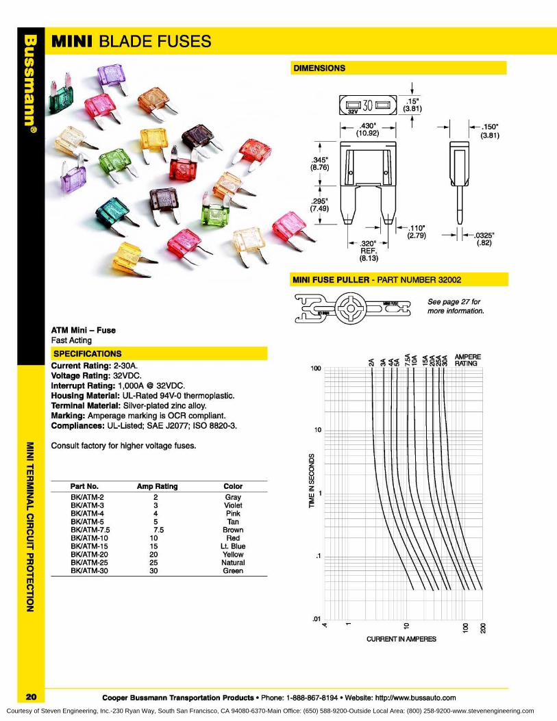
Current Rating : 2-30A.Voltage Rating: 32VDC.Interrupt Rating : 1,000A © 32VDC.Housing Material : UL-Rated 94V-0 thermoplastic.Terminal Material : Silver-plated zinc alloy.Marking : Amperage marking is OCR compliant.Compliances : UL-Listed ; SAE J2077 ; ISO 8820-3.
Consult factory for higher voltage fuses.
BK/ATM-2
2
GrayBK/ATM-3
3
VioletBK/ATM-4
4
PinkBK/ATM-5
5
TanBK/ATM-7.5 7.5 BrownBK/ATM-10
10
RedBK/ATM-15 15 Lt. BlueBK/ATM-20
20
YellowBK/ATM-25
25
NaturalBK/ATM-30 30 Green
Part No .
Amp Rating
Color
10
.1
.01
100
QQ ¢N t5~ n° g¢N
gNp(7
AMPERERATING
Illlllllllllllllll n nIMEME lall~iaIIME lnnn nI.n 1nnnn I n1. nn.nnnnnn~ ~I.n 1n nnn I nn1 .1.11 n.nnnnIIIIn •In1II11111 n~in I.IIII n II11
..- nI.. i. .. .I~~.nn n.-nL.1nn.nn. =I=I...nn.IIn =I•III n111 n=ii1 1 ..
NI.El
IIn •1UIIII111~=1n It'n III11
II!HILiiiIII I i
IMMiiiil•n===lRUE1 .11iiionon
.1=1RUIlM=UMIEWEIIEEIII
RIMIM11,1MMIMBI.Urnn11~MURIE11111 nW= MI.1IIII
1n\\11_iM\\11L111111~M1K11IMM111111111
nM111"""11111
IIIn11111\\ 1111111lI►on
MEELIEMWInMI=MILIEL'=on
nEEELIMnIaWIMLILIIII
n••E111nMnaILIERIL11M11~nnEIII 1WIM1,I n EV11MII
=01111k IISM01111\\II
=1111IMWOD1111111\\
v
0
8 8CURRENT IN AMPERES
20
Cooper Bussmann Transportation Products • Phone : 1-888-867-8194 • Website : http://www.bussauto.com
Courtesy of Steven Engineering, Inc.-230 Ryan Way, South San Francisco, CA 94080-6370-Main Office: (650) 588-9200-Outside Local Area: (800) 258-9200-www.stevenengineering.com
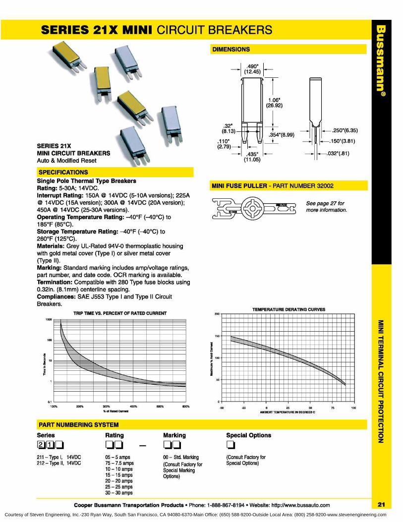
SERIES 21X MINI CIRCUIT BREAKERS
SPECIFICATIONSSingle Pole Thermal Type BreakersRating: 5-30A ; 14VDC.Interrupt Rating : 150A @ 14VDC (5-10A versions) ; 225A@ 14VDC (15A version) ; 300A © 14VDC (20A version);450A © 14VDC (25-30A versions).Operating Temperature Rating : -40°F (-40°C) to185°F (85°C).Storage Temperature Rating: -40°F (-40°C) to260°F (125°C).Materials : Grey UL-Rated 94V-0 thermoplastic housingwith gold metal cover (Type I) or silver metal cover(Type II).Marking : Standard marking includes amp/voltage ratings,part number, and date code . OCR marking is available.Termination : Compatible with 280 Type fuse blocks using0 .32in . (8 .1 mm) centerline spacing.Compliances: SAE J553 Type I and Type II CircuitBreakers.
SERIES 21XMINI CIRCUIT BREAKERSAuto & Modified Reset
100
i 10
E
1000
DIMENSIONS
.490"(12 .45)
x.032"(.81)
T1 .06"
(26 .92)
1.1- .250"(6 .35).354"(8 .99)
.-.150"(3 .81)
TEMPERATURE DERATING CURVES200
.32"(8 .13)
.110"(2 .79) -
.435"(11 .05)
MINI FUSE PULLER - PART NUMBER 32002
See page 27 formore information.
300%
400%
%o1 Rated Current25
50
AMBIENT TEMPERATURE IN DEGREES C
200% -25500%500% -50 75 100
PART NUMBERING SYSTEM
Series Rating Marking Special Options
q IJ qq
211 - Type I,
14VDC 05 - 5 amps 00 - Std . Marking (Consult Factory for212 - Type II, 14VDC 75 - 7 .5 amps (Consult Factory for Special Options)
10 - 10 amps Special Marking15 - 15 amps Options)20 - 20 amps25 - 25 amps30 - 30 amps
Cooper Bussmann Transportation Products • Phone : 1-888-867-8194 • Website: http://www.bussauto.com 21
C003
Courtesy of Steven Engineering, Inc.-230 Ryan Way, South San Francisco, CA 94080-6370-Main Office: (650) 588-9200-Outside Local Area: (800) 258-9200-www.stevenengineering.com
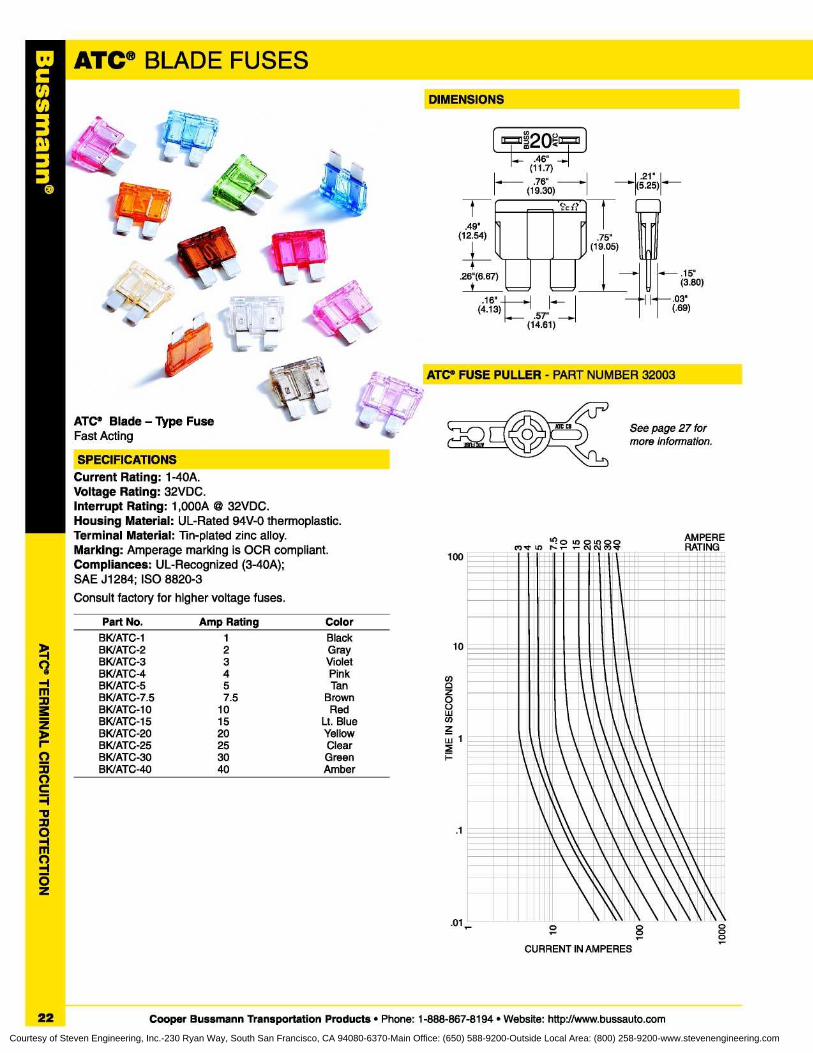
rATC® FUSE PULLER - PART NUMBER 32003
See page 27 formore information.
DIMENSIONS
21"5.25)
149'
(12.54) I
I.26"(6.67)
t U
.57" ,(14.61)
16"(4.13)
.75"(19 .05)
x .15"(3 .80)
03"( .69)
Current Rating : 1-40A.Voltage Rating: 32VDC.Interrupt Rating : 1,000A © 32VDC.Housing Material : UL-Rated 94V-0 thermoplastic.Terminal Material : Tin-plated zinc alloy.Marking : Amperage marking is OCR compliant.Compliances : UL-Recognized (3-40A);SAE J1284; ISO 8820-3
Consult factory for higher voltage fuses .
100
Part No. Amp Rating Color
BK/ATC-1 1 BlackBK/ATC-2 2 Gray 10
BKIATC-3 3 VioletBKIATC-4 4 Pink coBKIATC-5 5 Tan 0BKIATC-7 .5 7 .5 Brown
z0
BKIATC-10BK/ATC-15
1015
RedLt. Blue
Uww
BKIATC-20 20 Yellow z
BK/ATC-25 25 Clearw 1
BKIATC-30 30 Green I-BKIATC-40 40 Amber
.1
.01
II I I I
11•iii LIUi nMirURIlLMnMiiiiiii\1n11\'n--Mn1Mn11111_---nnnn11\\\111~~\ii\Dgi11\`i~nnnuu11
111111n\\III~II\\\111111IIIi11\\ 1111►11E\\\1111111nnn111\_\\~~nn \nn_~1~1~\nnn11nnn11IMMMEMENNI\_\\\\ MI111illomwiNumimmamllo111111n \\111111\\ \\11111111111n111!II'~\11~1111'I1
o
0r
0000
CURRENT IN AMPERES
22
Cooper Bussmann Transportation Products • Phone : 1-888-867-8194 • Website : http://www.bussauto.com
Courtesy of Steven Engineering, Inc.-230 Ryan Way, South San Francisco, CA 94080-6370-Main Office: (650) 588-9200-Outside Local Area: (800) 258-9200-www.stevenengineering.com
C003
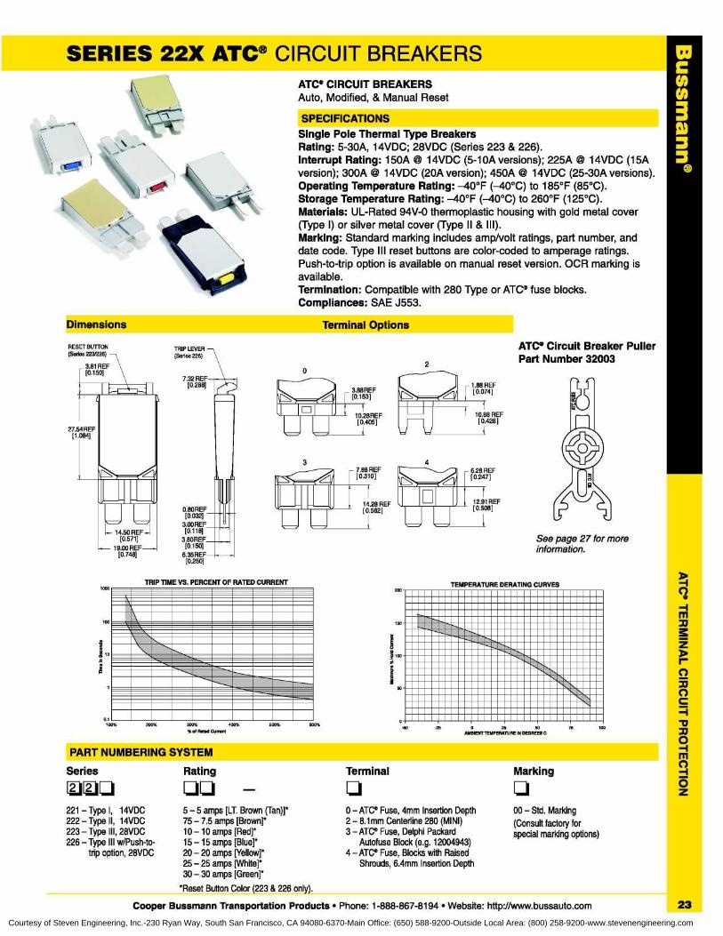
SERIES 22X ATC® CIRCUIT BREAKERSATC® CIRCUIT BREAKERSAuto, Modified, & Manual Reset
SPECIFICATIONSSingle Pole Thermal Type BreakersRating : 5-30A, 14VDC; 28VDC (Series 223 & 226).Interrupt Rating : 150A @ 14VDC (5-10A versions) ; 225A © 14VDC (15Aversion) ; 300A © 14VDC (20A version) ; 450A @ 14VDC (25-30A versions).Operating Temperature Rating: -40°F (-40°C) to 185°F (85°C).Storage Temperature Rating: -40°F (-40°C) to 260°F (125°C).Materials : UL-Rated 94V-0 thermoplastic housing with gold metal cover(Type I) or silver metal cover (Type II & III).Marking : Standard marking includes amp/volt ratings, part number, anddate code . Type III reset buttons are color-coded to amperage ratings.Push-to-trip option is available on manual reset version . OCR marking isavailable.Termination : Compatible with 280 Type or ATC ® fuse blocks.Compliances : SAE J553.
dimensions
Terminal Options
Rating Terminal Marking
qq q q
5 - 5 amps [LT. Brown (Tan)]* 0 - ATC® Fuse, 4mm Insertion Depth 00 - Std. Marking75 - 7 .5 amps [Brown]* 2 - 8 .1 mm Centerline 280 (MINI) (Consult factory for10 -10 amps [Red]* 3 - ATC° Fuse, Delphi Packard special marking options)15 - 15 amps [Blue]* Autofuse Block (e .g. 12004943)20 - 20 amps [Yellow]* 4 - ATC° Fuse, Blocks with Raised25 - 25 amps [White]*30 - 30 amps [Green]*
Shrouds, 6.4mm Insertion Depth
*Reset Button Color (223 & 226 only).
Cooper Bussmann Transportation Products • Phone : 1-888-867-8194 • Website: http://www.bussauto.com
PART NUMBERING SYSTEM
2
ATC® Circuit Breaker PullerPart Number 32003
27.54REF[1 .084]
14 .50REF[0 .571]
19.00 REF[0.748]
See page 27 for moreinformation.
1000 200
100
0 10
F
0.1100X 600%500%200% 300%
400%
%a R6160 Curtest100J5
0
Series
~:1~:1q
221 - Type I, 14VDC222 - Type II, 14VDC223 - Type III, 28VDC226 - Type III w/Push-to-
trip option, 28VDC
23Courtesy of Steven Engineering, Inc.-230 Ryan Way, South San Francisco, CA 94080-6370-Main Office: (650) 588-9200-Outside Local Area: (800) 258-9200-www.stevenengineering.com
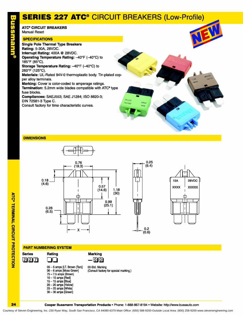
• ATC® CIRCUIT BREAKERSManual Reset
SERIES 227 ATC® CIRCUIT BREAKERS (Low-Profile)
0SPECIFICATIONSSingle Pole Thermal Type Breakers
• Rating : 5-30A, 28VDC.• Interrupt Rating : 400A © 28VDC.
Operating Temperature Rating : -40°F (-40°C) to185°F (85°C).Storage Temperature Rating : -40°F (-40°C) to260°F (125°C).Materials : UL-Rated 94V-0 thermoplastic body. Tin-plated cop-per alloy terminals.Marking : Cover is color-coded to amperage ratings.Termination : 5 .2mm wide blades compatible with ATC ® typefuse blocks.Compliances : SAEJ553; SAE J1284 ; ISO 8820-3;DIN 72581-3 Type C.Consult factory for time characteristic curves.
{1 d [
1DIMENSIONS
x -I
0 .57(14 .6)
1 .18(30)
0.99(25 .1)
0 .2(0 .6)
0.25(6 .4)
0 .18(4 .6)
0 .26(6.5)
PART NUMBERING SYSTEM
1Series
Rating
Marking
111111 qq
-U05 - 5 amps [LT. Brown (Tan)]
00-Std. Marking06 - 6 amps [Moss Green]
(Consult factory for special marking.)75 - 7.5 amps [Brown]10 - 10 amps [Red]15 -15 amps [Blue]20 - 20 amps [Yellow]25 - 25 amps [White]30 - 30 amps [Green]
24
Cooper Bussmann Transportation Products • Phone : 1-888-867-8194 • Website : http://www.bussauto.com
Courtesy of Steven Engineering, Inc.-230 Ryan Way, South San Francisco, CA 94080-6370-Main Office: (650) 588-9200-Outside Local Area: (800) 258-9200-www.stevenengineering.com
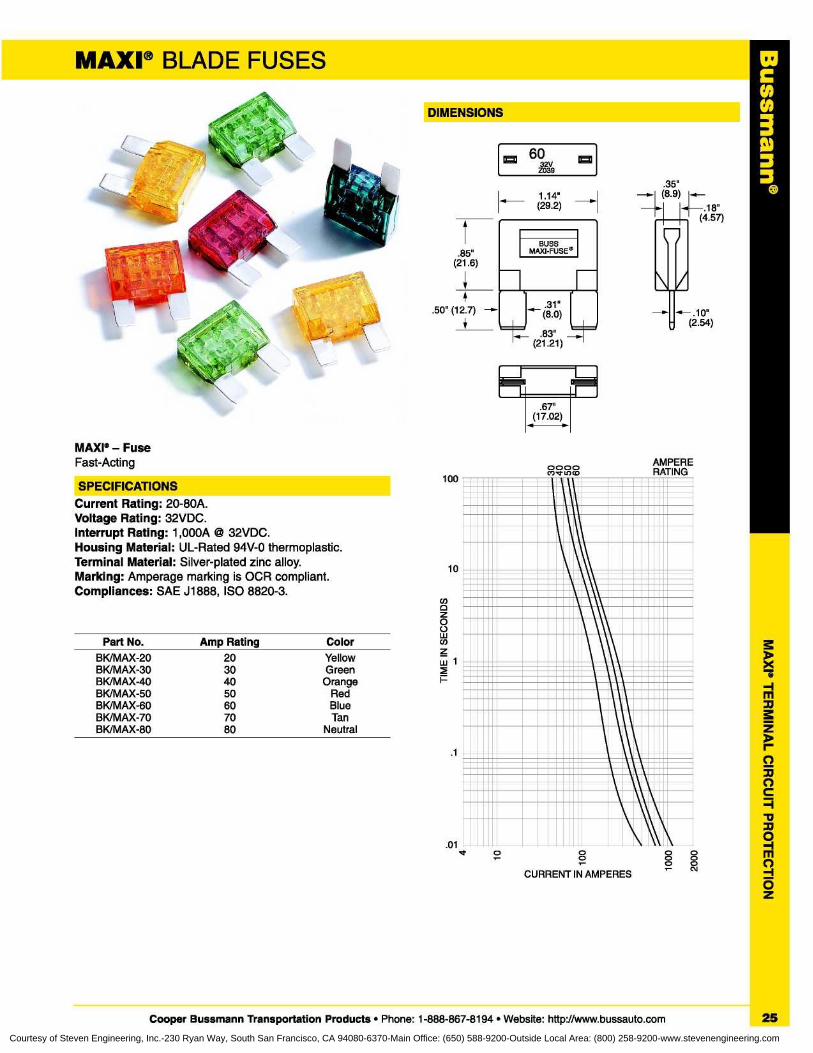
MAXI* - FuseFast-Acting
SPECIFICATIONS100
Current Rating : 20-80A.Voltage Rating: 32VDC.Interrupt Rating : 1,000A © 32VDC.Housing Material : UL-Rated 94V-0 thermoplastic.Terminal Material : Silver-plated zinc alloy.Marking : Amperage marking is OCR compliant.Compliances: SAE J1888, ISO 8820-3.
10
Coz0wCoPart No . Amp Rating
ColorBK/MAX-20 20
Yellowzw 1
BK/MAX-30BK/MAX-40
30
Green40
Orange FBK/MAX-50BK/MAX-60BK/MAX-70BK/MAX-80
50
Red60
Blue70
Tan80
Neutral
.1
MAXI ® BLADE FUSES
DIMENSIONS
® 602VZ039
1 .14"(29 .2)
BUSSMAXI-FUSE®
.31"(8.0)
.35"- (8.9) r...
.18"(4.57)
\/
.10"(2 .54)
.83"(21 .21)
0000CO,* OW
AMPERERATING
.67"(17 .02)
C003
0 00N
00
00
CURRENT IN AMPERES
Cooper Bussmann Transportation Products • Phone : 1-888-867-8194 • Website: http://www.bussauto.com
25
Courtesy of Steven Engineering, Inc.-230 Ryan Way, South San Francisco, CA 94080-6370-Main Office: (650) 588-9200-Outside Local Area: (800) 258-9200-www.stevenengineering.com
i
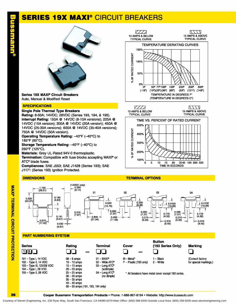
SPECIFICATIONSSingle Pole Thermal Type BreakersRating: 8-50A ; 14VDC; 28VDC (Series 193, 194, & 195).Interrupt Rating : 150A © 14VDC (8-10A versions) ; 225A14VDC (15A version) ; 300A Q 14VDC (20A version) ; 450A14VDC (25-30A versions) ; 600A @I 14VDC (35-40A versions);750A © 14VDC (50A version).Operating Temperature Rating : -40°F (-40°C) to185°F (85°C).Storage Temperature Rating: -40°F (-40°C) to260°F (125°C).Materials: Grey UL-Rated 94V-0 thermoplastic.Termination : Compatible with fuse blocks accepting MAXI ® orATC® blade fuses.Compliances: SAE J553 ; SAE J1428 (Series 193) ; SAEJ1171 (Series 193) Ignition Protected.
DIMENSIONS
TERMINAL OPTIONS
' PART NUMBERING SYSTEM
ButtonRating
Terminal
Cover
(193 Series Only)
Marking
08 - 8 amps
01 - MAXI ,10 -10 amps
02 - Wide ATC®15-15 amps
03 - Long ATV'20 - 20 amps
(w/dimple)25 - 25 amps
04 - Long ATC®30 - 30 amps
(no dimple)35 - 35 amps40 - 40 amps50 - 50 amps (191, 193, 194 only)
MW
Series 19X MAXI® Circuit BreakersAuto, Manual & Modified Reset
15 AMPS & ABOVETYPICAL CURVE
0%0°
50° 77°100° 150° 200 4 2504 3004(-18°) ( 1 0°)(25°)(38°) (65°)
(93°) (121°) (149°)TEMPERATURE IN DEGREES F°
(TEMPERATURE IN DEGREES C°)
(14VDC only)
1---(29 .21)--l
h 0 .360(9.14)
0.190(4 .83)
0.3100.141
(7 .87)(3 .57)7I~0.032
0.500(12 .70)
~
1 I
0.290(7.37)
0 .840
0 .450
(21 .34)
(11 .43)
1-0.920
(23 .37)
l -7
0.670(17 .02)
1 1
(0 .81)
04
d0 .4100(10 .29)
4f0 .170(4 .32)f0.370
(9.40)
(9 .40)
/ I"10 AMPS & BELOW
TYPICAL CURVE15 AMPS & ABOVETYPICAL CURVE
400%
300%
200%
100%0
Series
191 - Type I, 14 VDC192 - Type II, 14 VDC193 - Type III, 12V/28 VDC194 - Type I, 28 VDC195 - Type II, 28 VDC
M- Metal*
1 - Black
(Consult factoryP - Plastic (193 only)
2 - White
for special markings .)
* All breakers have metal cover except 193 series.
26
Cooper Bussmann Transportation Products • Phone : 1-888-867-8194 • Website: http://www.bussauto.comCourtesy of Steven Engineering, Inc.-230 Ryan Way, South San Francisco, CA 94080-6370-Main Office: (650) 588-9200-Outside Local Area: (800) 258-9200-www.stevenengineering.com
CHN3
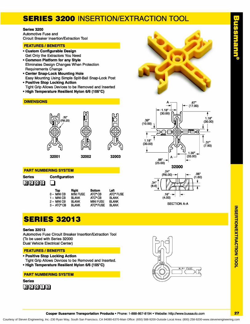
SERIES 3200 INSERTION/EXTRACTION TOOLSeries 3200Automotive Fuse andCircuit Breaker Insertion/Extraction Tool
FEATURES / BENEFITS• Custom Configurable Design
Get Only the Extractors You Need• Common Platform for any Style
Eliminates Design Changes When ProtectionRequirements Change
• Center Snap-Lock Mounting HoleEasy Mounting Using Simple Split-Ball Snap-Lock Post
• Positive Stop Locking ActionTight Grip Allows Devices to be Removed and Inserted
• High Temperature Resilient Nylon 6/6 (105°C)
Top Right Bottom Left0 - MINI CB MINI FUSE ATC® CB ATC® FUSE1 - MINI CB BLANK ATC® CB BLANK2 - MINI CB BLANK MINI FUSE BLANK3 - ATC® CB BLANK ATC® FUSE BLANK
SERIES 32013Series 32013Automotive Fuse Circuit Breaker Insertion/Extraction Tool(To be used with Series 32000Dual Vehicle Electrical Center)
FEATURES / BENEFITS• Positive Stop Locking Action
Tight Grip Allows Devices to be Removed and Inserted.• High Temperature Resilient Nylon 6/6 (105°C)
PART NUMBERING SYSTEMSeries
qqqqq
DIMENSIONS
PART NUMBERING SYSTEMSeries
Configuration
J
32001 32002 32003
~.1
.34"(8.6)
SECTION A-A
Cooper Bussmann Transportation Products • Phone : 1-888-867-8194 • Website: http://www.bussauto.com
27
Courtesy of Steven Engineering, Inc.-230 Ryan Way, South San Francisco, CA 94080-6370-Main Office: (650) 588-9200-Outside Local Area: (800) 258-9200-www.stevenengineering.com
003ID33
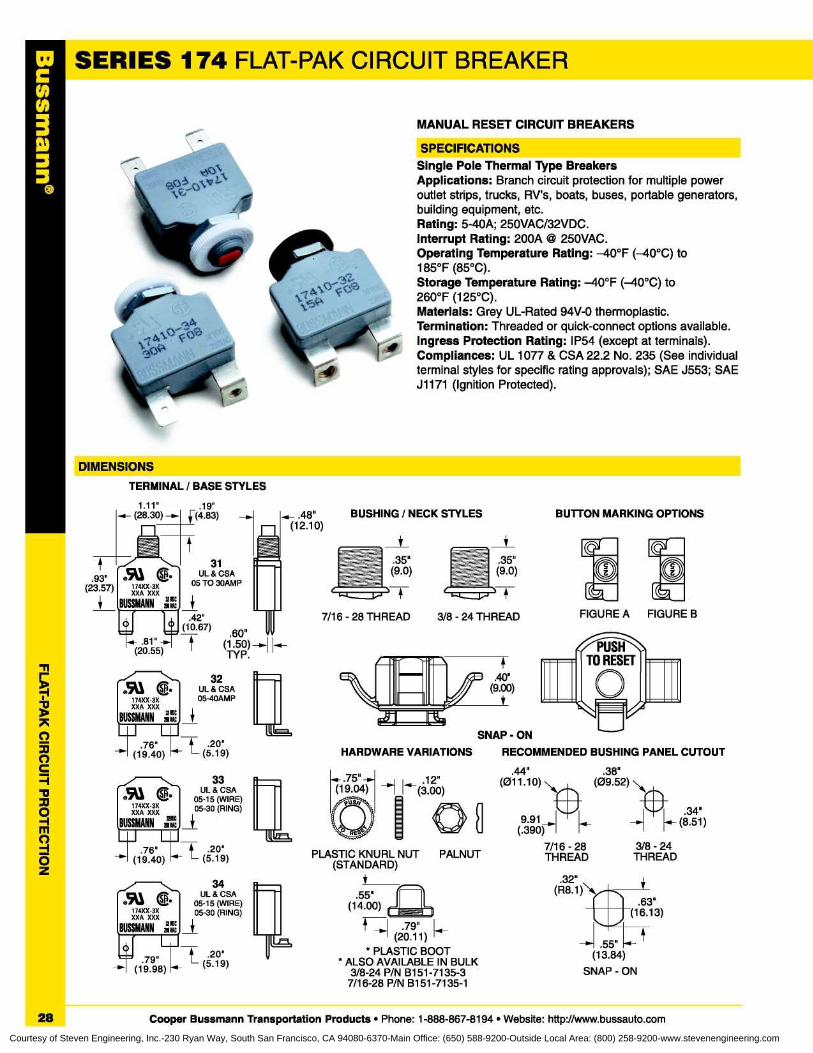
SERIES 174 FI AT-PAK (IR(I JIT BREAKER
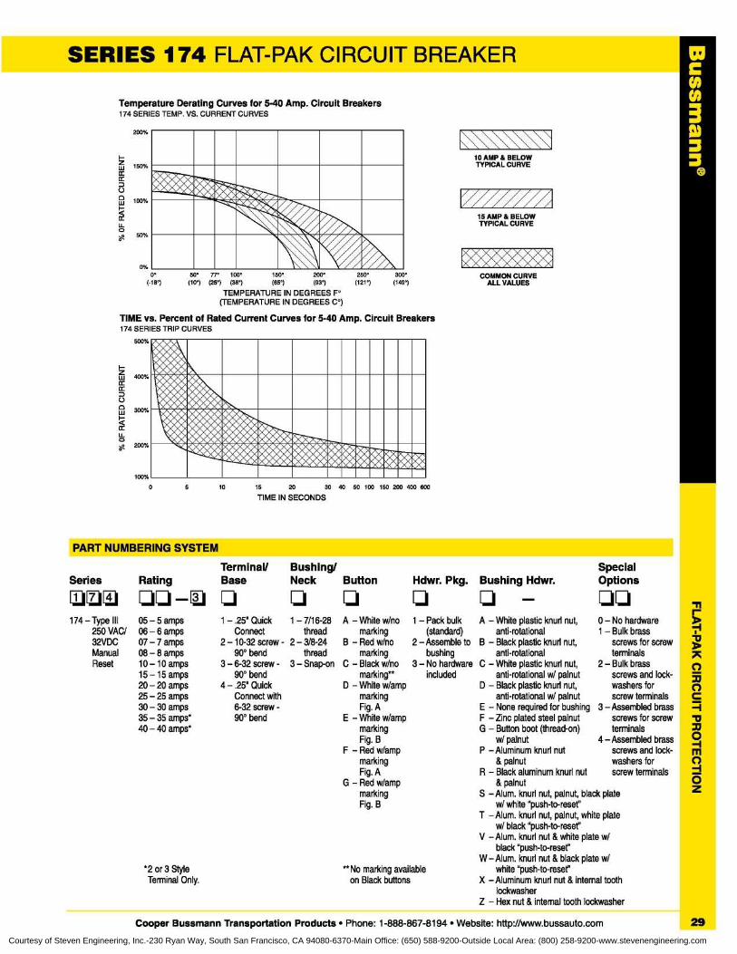
1MANUAL RESET CIRCUIT BREAKERS
Single Pole Thermal Type BreakersApplications : Branch circuit protection for multiple poweroutlet strips, trucks, RV's, boats, buses, portable generators,building equipment, etc.Rating : 5-40A; 250VAC/32VDC.Interrupt Rating : 200A @ 250VAC.Operating Temperature Rating : -40°F (-40°C) to185°F (85°C).Storage Temperature Rating: -40°F (-40°C) to260°F (125°C).Materials : Grey UL-Rated 94V-0 thermoplastic.Termination : Threaded or quick-connect options available.Ingress Protection Rating : IP54 (except at terminals).Compliances : UL 1077 & CSA 22.2 No . 235 (See individualterminal styles for specific rating approvals) ; SAE J553 ; SAEJ1171 (Ignition Protected).
TERMINAL / BASE STYLES
.93"(23 .57)
1 .11"
.19"f (28.30) - ,k-(4 .83) - _ .48"
(12 .10)BUTTON MARKING OPTIONS
174XX-3XXXA XXX
BUSSMANN4:.42"O
O (10 .67)
.60"x .81"-
(20 .55)
tUL & CSA
05 TO 30AMP
(1 .50)
IfTYP .
1L ,
r I
.76"
t 20"
(19 .40)
(5 .19)
BUSSMANN4:
31
HARDWARE VARIATIONS
3/8 - 24 THREAD7/16 - 28 THREAD
N-.
32®~ SA•
174XX-3X
05-40AMPXXA XXX
BUSSMANN4: ,
UL & CSA
I40"
(9 .00)
33
174XX-3XXXA XXX
BUSSMANN 19*̀
.76"(19 .40)
- 20"t (5 .19)
UL&CSA05-15 (WIRE)05-30 (RING)
Um,
34
®911 G.174XX-3XXXA XXX
20"
0(1998) tt (5 .19)
UL & CSA05-15 (WIRE)05-30 (RING)
.44"(011 .10)
9.91~( .390)
"~I
12"(3 .00)
PLASTIC KNURL NUT PALNUT(STANDARD)
i
.55"(14 .00)
L.] .79" k,(20 .11)
* PLASTIC BOOT* ALSO AVAILABLE IN BULK
3/8-24 P/N B151-7135-37/16-28 P/N B151-7135-1
.38"(09 .52)
I
.34"(8 .51)
7/16 - 28
3/8 - 24THREAD
THREAD
32"(R8.1)
.63"(16.13)
-w I .55"(13 .84)
SNAP - ON
28
Cooper Bussmann Transportation Products • Phone : 1-888-867-8194 • Website: http://www.bussauto.com
Courtesy of Steven Engineering, Inc.-230 Ryan Way, South San Francisco, CA 94080-6370-Main Office: (650) 588-9200-Outside Local Area: (800) 258-9200-www.stevenengineering.com
SERIES 174 FLAT-PAK CIRCUIT BREAKER
TIME vs . Percent of Rated Current Curves for 5-40 Amp . Circuit Breakers174 SERIES TRIP CURVES
C003
Temperature Derating Curves for 5-40 Amp. Circuit Breakers174 SERIES TEMP . VS. CURRENT CURVES
200%
150%
100%
0%o°
50°
7r
100°
150°
200°
(-131
(101 (25°) (35°)
(551
(931
TEMPERATURE IN DEGREES F°(TEMPERATURE IN DEGREES C°)
PART NUMBERING SYSTEM
Series Rating
174 - Type III 05 - 5 amps250 VAC/ 06 - 6 amps32VDC 07 - 7 ampsManual 08 - 8 ampsReset 10 -10 amps
15 -15 amps20 - 20 amps25 - 25 amps30 - 30 amps35 - 35 amps*40 - 40 amps*
Terminal/
Bushing/Base
Neck
1 -.25" Quick
1 - 7/16-28
Connect
thread2 - 10-32 screw - 2 - 3/8-24
90° bend
thread3 - 6-32 screw - 3 - Snap-on
90° bend4 - .25" Quick
Connect with6-32 screw -90° bend
Button
Hdwr. Pkg.
q q
A - White w/no 1 - Pack bulkmarking
(standard)B - Red w/no
2 - Assemble tomarking
bushingC - Black w/no 3 - No hardware
marking**
includedD - White w/amp
markingFig. A
E - White w/ampmarkingFig. B
F - Red w/ampmarkingFig. A
G - Red w/ampmarkingFig. B
**No marking availableon Black buttons
SpecialBushing Hdwr.
Options
A - White plastic knurl nut,anti-rotational
B - Black plastic knurl nut,anti-rotational
C - White plastic knurl nut,anti-rotational w/ palnut
D - Black plastic knurl nut,anti-rotational w/ palnut
E - None required for bushingF - Zinc plated steel palnutG - Button boot (thread-on)
w/ palnutP -Aluminum knurl nut
&palnutR - Black aluminum knurl nut
& palnutS -Alum. knurl nut, palnut, black plate
w/ white "push-to-reset"T -Alum. knurl nut, palnut, white plate
w/ black "push-to-reset"V -Alum. knurl nut & white plate w/
black "push-to-reset"W - Alum. knurl nut & black plate w/
white "push-to-reset"X -Aluminum knurl nut & internal tooth
lockwasherZ - Hex nut & internal tooth lockwasher
*2 or 3 StyleTerminal Only.
0 - No hardware1 - Bulk brass
screws for screwterminals
2 - Bulk brassscrews and lock-washers forscrew terminals
3 - Assembled brassscrews for screwterminals
4 - Assembled brassscrews and lock-washers forscrew terminals
Cooper Bussmann Transportation Products • Phone : 1-888-867-8194 • Website: http://www.bussauto.com
29
Courtesy of Steven Engineering, Inc.-230 Ryan Way, South San Francisco, CA 94080-6370-Main Office: (650) 588-9200-Outside Local Area: (800) 258-9200-www.stevenengineering.com
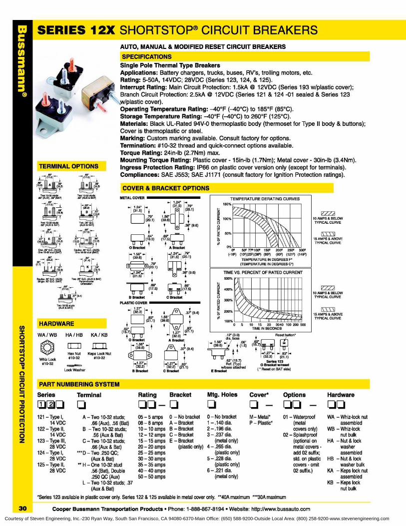
SERIES 12X SHORTSTOP® CIRCUIT BREAKERS
i
AUTO, MANUAL & MODIFIED RESET CIRCUIT BREAKERSSPECIFICATIONS
Single Pole Thermal Type BreakersApplications : Battery chargers, trucks, buses, RV's, trolling motors, etc.Rating : 5-50A, 14VDC; 28VDC (Series 123, 124, & 125).Interrupt Rating : Main Circuit Protection : 1 .5kA @ 12VDC (Series 193 w/plastic cover);Branch Circuit Protection : 2 .5kA @ 12VDC (Series 121 & 124 -01 sealed & Series 123,w/plastic cover).Operating Temperature Rating : -40°F (-40°C) to 185°F (85°C).Storage Temperature Rating : -40°F (-40°C) to 260°F (125°C).Materials : Black UL-Rated 94V-0 thermoplastic body (thermoset for Type II body & buttons);Cover is thermoplastic or steel.Marking : Custom marking available . Consult factory for options.Termination : #10-32 thread and quick-connect options available.Torque Rating : 24in-lb (2 .7Nm) max.Mounting Torque Rating : Plastic cover - 15in-lb (1 .7Nm); Metal cover - 30in-lb (3 .4Nm).Ingress Protection Rating : IP66 on plastic cover version only (except for terminals).Compliances : SAE J553; SAE J1171 (consult factory for Ignition Protection ratings).
PART NUMBERING SYSTEM
TERMINAL OPTIONS(1.;
1(1T .5)
80•
SBOwl
04.2)
Two,a32 studs:(AUX) ; se• (BAT)
Double .25' D.C. (AUTO;
Two .25• as. (AUX & BAT)slnele 25' 00. lean
Po„
vodentaboAtem °
HARDWARE
Two 1532 5tu0e:.66• (AUX & BAT)
a4.(21 .4)
s
WA/WB HA/HB KA/KB
Whiz Lock#10-32
Br'
68'(16.6)
Two 10-32 studs(AUX & BAT)
66'
L
.37. (9.4)
Lock Washer
Hex Nut
Keps Lock Nut#10-32
#10-32
52030 .25 Ds.Ctutl
.Ste
T) '
I (21A)
j-f
Twe .25 ' QC.(AUX & BAT)
.62'(175))
~e I )
Two,a32 studs:.56' (AUX & BAT)
(252)
1-5
COVER & BRACKET OPTIONS
12' (3.0)dia . boss
1 .56'
06"(39 .6)
t (1 .5)r }II
1J.62" (15.7)Ref. (Typ
w/base attachedE Bracket
Reset button'
066) •laa railII 17 83
1 .27
63'(32 .3)
(21 .1)Series 123
0 Bracket w/reset(' Reset on BAT side)
10 AMPS & BELOWTYPICAL CURVE
15 AMPS & ABOVETYPICAL CURVE
10 AMPS & BELOWTYPICAL CURVE
15 AMPS & ABOVETYPICAL CURVE
METAL COVER
1 .24"(31 .5) 1
1 .24'(31 .5) 79'
(20.1)
1 .56"(39 .6)
.36' (9 .6)
(9 .4)
1 .27"
(21 .1)(32.3)
A Bracket
37' (9 .4)
21 .27".- 65""(32.2) (21 .1)
B Bracket
C Bracket(32 .2)
50%
0%0°
50° 77°100° 150° 200° 250° 300°(-18°) (10°)(25°)(36°) (65°)
(93°) (121°) (149°)TEMPERATURE IN DEGREES F°
(TEMPERATURE IN DEGREES C°)
Series
Terminal
Rating
Bracket
Mtg . Holes
Cover*Se~
121 - Type I,
A - Two 10-32 studs ;
05 - 5 amps 0 - No bracket 0 - No bracket
M - Metal*
14 VDC
.66 (Aux), .56 (Bat)
08 - 8 amps A - Bracket
1 - .140 dia .
P - Plastic*
122 - Type II,
B - Two 10-32 studs ;
10 -10 amps B - Bracket
2 - .196 dia.
14 VDC
.56 (Aux & Bat)
12 -12 amps C - Bracket
3 - .237 dia.
123 - Type III,
C - Two 10-32 studs ;
15 -15 amps E - Bracket
(metal only)
28 VDC
.66 (Aux & Bat)
20 - 20 amps
(plastic only) 4 - .265 dia.
124 - Type I,
***D - Two .250 QC;
25 - 25 amps
(plastic only)
28 VDC
(Aux & Bat)
30 - 30 amps
5 - .228 dia.
125 - Type II,
** H - One 10-32 stud
35 - 35 amps
(plastic only)
28 VDC
.56 (Bat), Double
40 - 40 amps
6 - .221 dia..250 QC (Aux)
50 - 50 amps
(metal only)L - Two 10-32 studs ; .37
(Aux & Bat)
Options
Hardware
qq qq
01 - Waterproof
WA - Whiz-lock nut(metal
assembledcovers only)
WB - Whiz-lock02 - Splashproof
nut bulk(optional on
HA - Nut & lockmetal covers -
washeradd 02 suffix;
assembledstd. on plastic HB - Nut & lockcovers - omit
washer bulk02 suffix .)
KA - Keps lock nutassembled
KB - Keps locknut bulk
30
*Series 123 available in plastic cover only . Series 122 & 125 available in metal cover only . **40A maximum ***30A maximum
Cooper Bussmann Transportation Products • Phone : 1-888-867-8194 • Website : http ://www.bussauto .comCourtesy of Steven Engineering, Inc.-230 Ryan Way, South San Francisco, CA 94080-6370-Main Office: (650) 588-9200-Outside Local Area: (800) 258-9200-www.stevenengineering.com
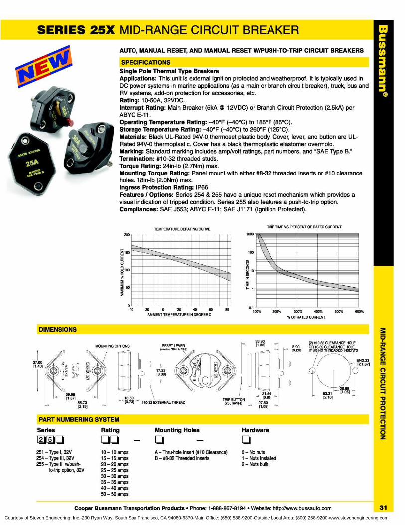
CHN3
SERIES 25X MID-RANGE CIRCUIT BREAKER
AUTO, MANUAL RESET, AND MANUAL RESET W/PUSH-TO-TRIP CIRCUIT BREAKERS
SPECIFICATIONSSingle Pole Thermal Type BreakersApplications : This unit is external ignition protected and weatherproof . It is typically used inDC power systems in marine applications (as a main or branch circuit breaker), truck, bus andRV systems, add-on protection for accessories, etc.Rating : 10-50A, 32VDC.Interrupt Rating : Main Breaker (5kA @ 12VDC) or Branch Circuit Protection (2 .5kA) perABYC E-11.Operating Temperature Rating : -40°F (-40°C) to 185°F (85°C).Storage Temperature Rating: -40°F (-40°C) to 260°F (125°C).Materials : Black UL-Rated 94V-0 thermoset plastic body. Cover, lever, and button are UL-Rated 94V-0 thermoplastic . Cover has a black thermoplastic elastomer overmold.Marking : Standard marking includes amp/volt ratings, part numbers, and "SAE Type B."Termination : #10-32 threaded studs.Torque Rating : 24in-lb (2 .7Nm) max.Mounting Torque Rating : Panel mount with either #8-32 threaded inserts or #10 clearanceholes . 18in-lb (2 .0Nm) max.Ingress Protection Rating : IP66Features / Options : Series 254 & 255 have a unique reset mechanism which provides avisual indication of tripped condition . Series 255 also features a push-to-trip option.Compliances : SAE J553 ; ABYC E-11 ; SAE J1171 (Ignition Protected).
-20
0
20
40
60AMBIENT TEMPERATURE IN DEGREE C
DIMENSIONS
200
0-40
TEMPERATURE DERATING CURVE
200%
300%
400%
%OF RATED CURRENT
80 500% 600%
1000
100
0zw 10
F 1
TRIP TIME VS . PERCENT OF RATED CURRENT
(2) #10-32 CLEARANCE HOLE5.00
OR #8-32 CLEARANCE HOLE[0.20]
IF USING THREADED INSERTS
042.33[01 .67]
26.65a [1 .05] -
33.80[1 .33]MOUNTING OPTIONS
#1032 EXTERNAL THREADTRIP BUTTON
(255 series) °
27.09].80
°
21 .50[0 .85] °
53.31[2 .10]18.50
° [0 .73] °
37 .00[1 .46]
55.73[2 .19]
PART NUMBERING SYSTEM
Series
251 - Type I, 32V254 - Type III, 32V255 - Type III w/push-
to-trip option, 32V
Rating Mounting Holes Hardware
10 -10 amps A - Thru-hole Insert (#10 Clearance) 0 - No nuts15 -15 amps B - #8-32 Threaded Inserts 1 - Nuts Installed20 - 20 amps 2 - Nuts bulk25 - 25 amps30 - 30 amps35 - 35 amps40 - 40 amps50 - 50 amps
Cooper Bussmann Transportation Products • Phone : 1-888-867-8194 • Website: http://www.bussauto.com
31Courtesy of Steven Engineering, Inc.-230 Ryan Way, South San Francisco, CA 94080-6370-Main Office: (650) 588-9200-Outside Local Area: (800) 258-9200-www.stevenengineering.com
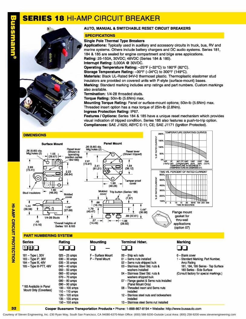
SERIES 18 HI-AMP CIRCUIT BREAKERAUTO, MANUAL & SWITCHABLE RESET CIRCUIT BREAKERS
SPECIFICATIONSSingle Pole Thermal Type BreakersApplications : Typically used in auxiliary and accessory circuits in truck, bus, RV andmarine systems . Others include battery chargers and DC audio systems. Series 181,184 & 185 are sealed for engine compartment and bilge area applications.Rating : 25-150A, 30VDC ; 48VDC (Series 184 & 185).Interrupt Rating : 3,000A © 30VDC.Operating Temperature Rating : -25°F (-32°C) to 180°F (82°C).Storage Temperature Rating : -30°F (-34°C) to 300°F (149°C).Materials : Black UL-Rated 94V-0 thermoset plastic . Thermoplastic elastomer studinsulators are provided on covered units with F-style (surface-mount) bases.Marking: Standard marking includes amp ratings and part numbers . Custom markingsalso available.Termination : 1/4-28 threaded studs.Torque Rating : 50in-lb (5 .6Nm) max.Mounting Torque Rating : Panel or surface-mount options ; 50in-lb (5.6Nm) max.Threaded insert option has a max torque of 25in-lb (2 .8Nm).Ingress Protection Rating : IP67.Features / Options: Series 184 & 185 have a unique reset mechanism which providesvisual indication of tripped condition . Series 185 also features a push-to-trip option.Compliances : SAE J1625 ; ABYC E-11 ; CE ; SAE J1171 (Ignition Protected).
.26 (6 .60) dia.Reset lever
Mtg .holes (2)(Shown inoperating
position series184/185)
2 .91(73.91) 241
.(61 .21)
Panel Mount
0% 50° 0°
50°77°10<J° 150° 200° 250°(-459('189 (109(259(389 (659 (93°) (1219
TEMPERATURE IN DEGREES F° (TEMPERATURE IN DEGREES C°)
TIME VS . PERCENT OF RATED CURRENT600%
500%
400%
300%
200%
I 1nnnn 1111111I `\nnn 1111111\nn1111111nh '~~1111111••I .mm.2!11
I ll
I
Flange mountgasket forthru-wall
applications(option 07)
PART NUMBERING SYSTEM
100% 05 10 15 20 3040 100 200 500
TIME IN SECONDS
Series
181 - Type I, 30V183 - Type I I*, 30V184 - Type III, 48V185 - Type III-PTT, 48V
"183 Available in PanelMount Only (Coverless)
Rating
Mounting
025 - 25 amps
F - Surface Mount030 - 30 amps
P - Panel Mount035 - 35 amps040 - 40 amps050 - 50 amps060 - 60 amps070 - 70 amps080 - 80 amps090 - 90 amps100 -100 amps110-110 amps120 -120 amps135 - 135 amps150 -150 amps
Terminal Hdwr.
00 - Ship w/o nuts01 - Sems nuts installed02 - Sems nuts shipped bulk03 - Stainless Steel Std . nuts &
washers installed04 - Stainless Steel Std . nuts &
washers shipped bulk07 - Flange gasket & Sems nuts installed
(Panel Mount Only)08 - Threaded insert and Sems nuts
installed12 - Stanless steel nuts and lockwashers
installed13 - Stainless steel Sems nut installed
Marking
0 - Blank cover1 - Standard Marking ; Part Number,
Amp Rating181, 184, 185 Series - Top Surface183 Series - Side Surface
(Consult factory for special markings .)
32
Cooper Bussmann Transportation Products • Phone : 1-888-867-8194 • Website: http://www.bussauto.comCourtesy of Steven Engineering, Inc.-230 Ryan Way, South San Francisco, CA 94080-6370-Main Office: (650) 588-9200-Outside Local Area: (800) 258-9200-www.stevenengineering.com
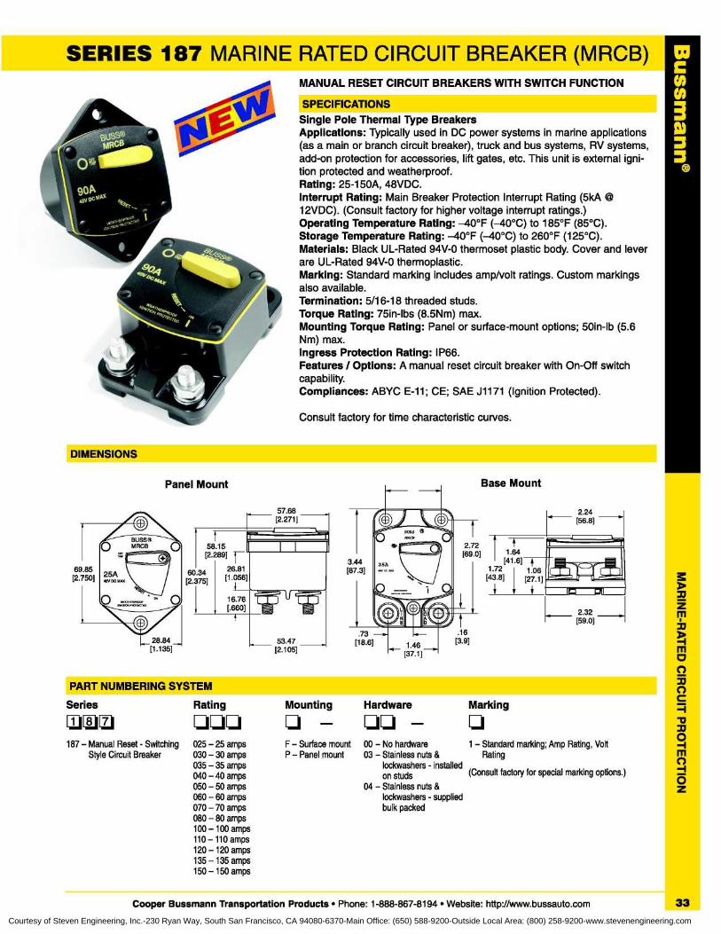
SERIES 187 MARINE RATED CIRCUIT BREAKER (MRCB)MANUAL RESET CIRCUIT BREAKERS WITH SWITCH FUNCTION
SPECIFICATIONSSingle Pole Thermal Type BreakersApplications : Typically used in DC power systems in marine applications(as a main or branch circuit breaker), truck and bus systems, RV systems,add-on protection for accessories, lift gates, etc . This unit is external igni-tion protected and weatherproof.Rating : 25-150A, 48VDC.Interrupt Rating : Main Breaker Protection Interrupt Rating (5kA12VDC) . (Consult factory for higher voltage interrupt ratings .)Operating Temperature Rating: -40°F (-40°C) to 185°F (85°C).Storage Temperature Rating: -40°F (-40°C) to 260°F (125°C).Materials : Black UL-Rated 94V-0 thermoset plastic body. Cover and leverare UL-Rated 94V-0 thermoplastic.Marking: Standard marking includes amp/volt ratings . Custom markingsalso available.Termination : 5/16-18 threaded studs.Torque Rating : 75in-lbs (8 .5Nm) max.Mounting Torque Rating : Panel or surface-mount options ; 50in-lb (5 .6Nm) max.Ingress Protection Rating : IP66.Features / Options: A manual reset circuit breaker with On-Off switchcapability.Compliances : ABYC E-11 ; CE; SAE J1171 (Ignition Protected).
Consult factory for time characteristic curves.
DIMENSIONS
C003
Base Mount
[69 .0]2 .72
11 .64
[41 .6]
T~T1 .72
1 .06 ONO,[43 .8]
[27,1] ICJ
2.32[59 .0]
2.24[56 .8]
Panel Mount
69 .85[2.750]
53 .4728 .84[1 .135]
[2.105]
57 .68[2 .271]
r'58.15[2 .289] F
60 .34
26.81[2.375]
[1 .056]
3.44[87 .3]
.73[18 .6]
16.76[.660]
f
PART NUMBERING SYSTEMMounting Hardware Marking
q - qq - q
F - Surface mount 00 - No hardware 1 - Standard marking ; Amp Rating, VoltP - Panel mount 03 - Stainless nuts & Rating
lockwashers - installedon studs (Consult factory for special marking options .)
04 - Stainless nuts &
Series
Ratingq~~
qqq
187 - Manual Reset - Switching 025 - 25 ampsStyle Circuit Breaker 030 - 30 amps
035 - 35 amps040 - 40 amps050 - 50 amps060 - 60 amps
lockwashers - supplied070 - 70 amps
bulk packed080 - 80 amps100 - 100 amps110-110 amps120 -120 amps135 - 135 amps150 -150 amps
Cooper Bussmann Transportation Products • Phone : 1-888-867-8194 • Website: http://www.bussauto.com
33Courtesy of Steven Engineering, Inc.-230 Ryan Way, South San Francisco, CA 94080-6370-Main Office: (650) 588-9200-Outside Local Area: (800) 258-9200-www.stevenengineering.com
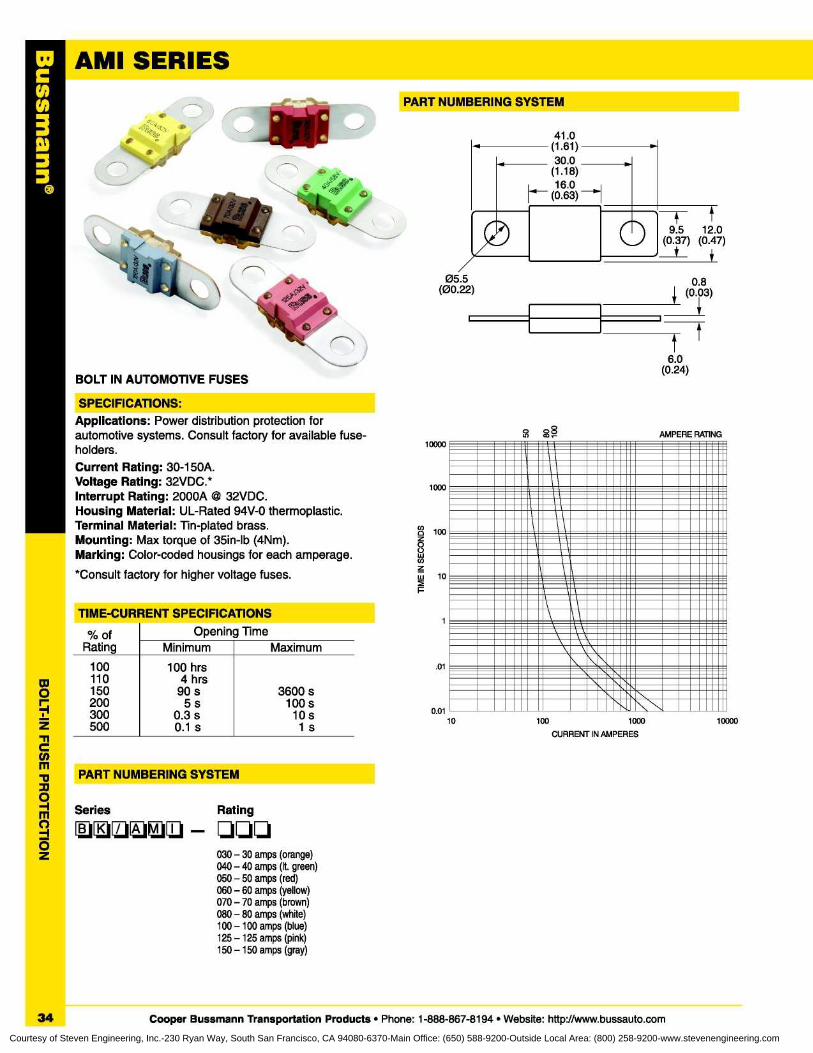
AMI SERIES
Applications : Power distribution protection forautomotive systems. Consult factory for available fuse-holders.Current Rating : 30-150A.Voltage Rating : 32VDC .*Interrupt Rating : 2000A @ 32VDC.Housing Material : UL-Rated 94V-0 thermoplastic.Terminal Material : Tin-plated brass.Mounting : Max torque of 35in-lb (4Nm).Marking : Color-coded housings for each amperage.
*Consult factory for higher voltage fuses .
nSPECIFICATIONS :
PART NUMBERING SYSTEM
41 .0(1 .61)30 .0
(1 .18)16 .0
(0.63)
liulIlIllIllIll11111--I-.--.--.
IMMUNE
MITE 11111EEIMEEMIS
1111E11111111 11111=MI
IIIM\1iiIIIIIlE mEEEE:.,.III
10
100
1000
CURRENT IN AMPERES
_.=.I=MI
VIII
10000
1000
100
10
1
.01
0.01
s AMPERE RATING
VIII
10000
05.5(00 .22)
0 .8(0.0 3)
tt
6 .0(0.24)
TIME-CURRENT SPECIFICATIONS
n
% ofRating
100110150200300500
Minimum
100 hrs4 hrs
90 s5s
0.3 s0 .1 s
Maximum
3600 s100 s10s1s
Opening Time
PART NUMBERING SYSTEM
n
Series~~
Rating
030 - 30 amps (orange)040 - 40 amps (It . green)050 - 50 amps (red)060 - 60 amps (yellow)070 - 70 amps (brown)080 - 80 amps (white)100 - 100 amps (blue)125 -125 amps (pink)150 - 150 amps (gray)
34
Cooper Bussmann Transportation Products • Phone : 1-888-867-8194 • Website : http://www.bussauto.com
C003ID
Courtesy of Steven Engineering, Inc.-230 Ryan Way, South San Francisco, CA 94080-6370-Main Office: (650) 588-9200-Outside Local Area: (800) 258-9200-www.stevenengineering.com
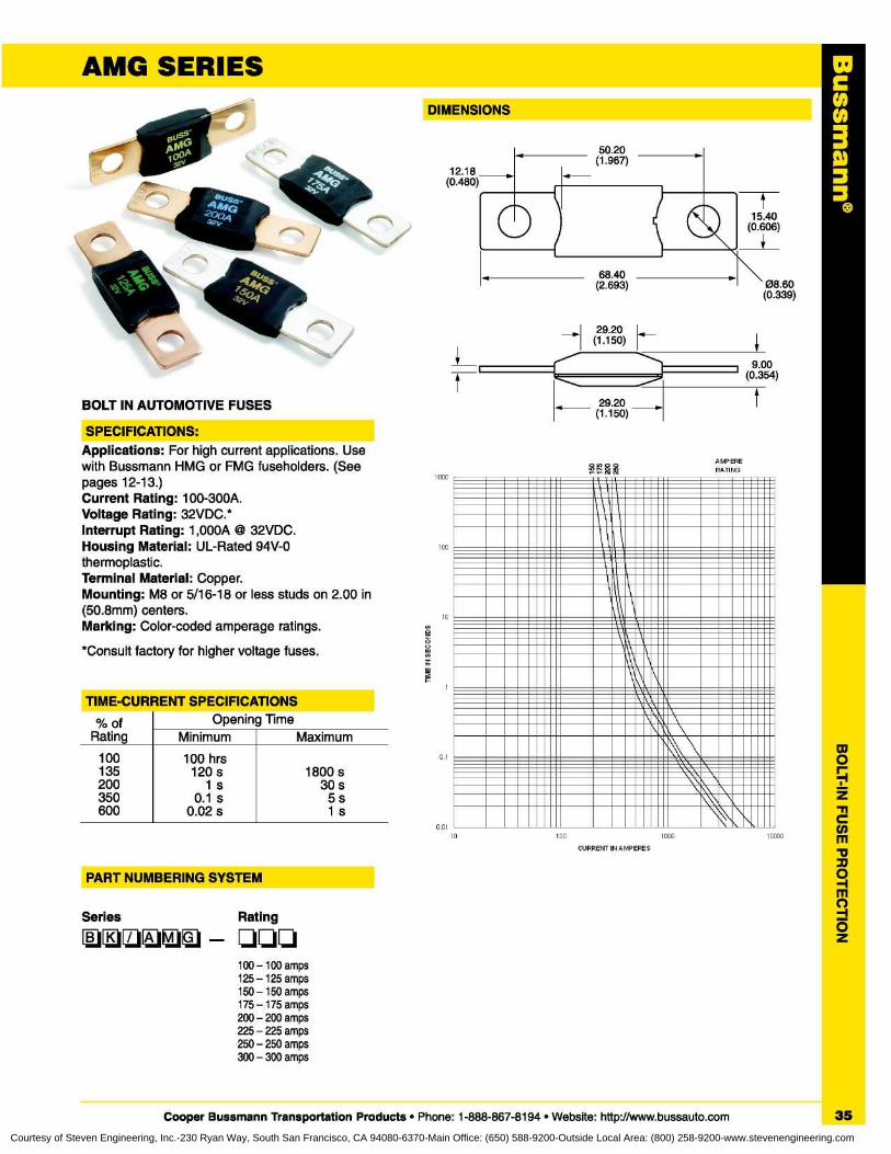
AMG SERIES
BOLT IN AUTOMOTIVE FUSES
DIMENSIONS
00
12.18(0.480)
50 .20(1 .967)
C003
10
001
SPECIFICATIONS:Applications : For high current applications . Usewith Bussmann HMG or FMG fuseholders . (Seepages 12-13 .)Current Rating : 100-300A.Voltage Rating : 32VDC.*Interrupt Rating : 1,000A © 32VDC.Housing Material : UL-Rated 94V-0thermoplastic.Terminal Material : Copper.Mounting : M8 or 5/16-18 or less studs on 2 .00 in(50 .8mm) centers.Marking : Color-coded amperage ratings.
*Consult factory for higher voltage fuses.
TIME-CURRENT SPECIFICATIONS
PART NUMBERING SYSTEM
Series
Rating
100 - 100 amps125 -125 amps150 -150 amps175-175 amps200 - 200 amps225 - 225 amps250 - 250 amps300 - 300 amps
15 .40(0 .606)
68 .40(2 .693) 08 .60
(0 .339)
29.20(1 .150)
9 .00(0 .354)
29 .20
t(1 .150)
AMPERERATING
% ofRating Minimum
Opening TimeMaximum
100135200350600
100 hrs120 s
1s0.1 s
0 .02 s
1800 s30 s5s1s
100
1000 10000
CURRENT IN AMPERES
Cooper Bussmann Transportation Products • Phone : 1-888-867-8194 • Website: http://www.bussauto.com
35
Courtesy of Steven Engineering, Inc.-230 Ryan Way, South San Francisco, CA 94080-6370-Main Office: (650) 588-9200-Outside Local Area: (800) 258-9200-www.stevenengineering.com

COOPER BussmannTransportation Products
Cooper Bussmann Bussmann Products Cooper Bussmann India Ltd.P. O. Box 14460 Authorized European EVR Street, SedarapetSt. Louis, Missouri 63178-4460 Sales Office Pondicherry - 605 111 IndiaTelephone: 636-394-2877 Wilhelm Pudenz GmbH Telephone: 91-80-227-0893Facsimile :
800-544-2570 Klosterseelter Strasse 5-17 Facsimile :
91-80-224-5725D-27243 Dunsen, Germany
Cooper Bussmann Telephone : 49-42-44-819133 Bussmann do Brazil Ltd.Transportation Products Facsimile :
49-42-44-819139 Rodovia Santos Dumont, Km 23175 Hansen Court Cruz das Almas - 13 .300-000Wood Dale, IL 60191-1145 Cooper Bussmann Caixa Postal 095Telephone: 888-867-8194 Asia Headquarters Itu-Sao Paulo BrazilFacsimile :
800-832-9873 Cooper Electric Co. Ltd . Telephone: 55-11-4024-840028th Floor Yu An Building Facsimile :
55-11-4024-8424European Headquarters 738 Dongfang Road
Cooper Bussmann U .K. Ltd . Pudong, Shanghai 200122 Bussmann TransportationBurton-on-the-Wolds China Products Authorized SalesLeicestershire LE12 5 TH Telephone : +8621 5831 6805 Office, MexicoEngland Facsimile :
+8621 6876 5532 Kruvand and AssociatesTelephone: 44-1509-882737 Cooper Electrical Australia 1202 Richardson Drive,Facsimile :
44-1509-882786 205-209 Woodpark Road Suite 113P.O. Box 2577 Richardson, Texas 75080Smithfield, Sydney Telephone: 972-437-3355NSW 2163, Australia Facsimile :
972-680-8854Telephone : 61-2-8787-2700Facsimile :
61-2-9609-2342
BussmannSolutions for the Transportation Industry
COOPER BUSSMANN • 175 HANSEN COURT • WOOD DALE, IL 60191-1145CUSTOMER SATISFACTION PHONE: (888) 867-8194 • TECHNICAL SUPPORT PHONE: (888) 478-8324 • FAX : (800) 832-9873
WEB SITE : WWW.BUSSAUTO .COMREORDER # 7003 04-5M
Courtesy of Steven Engineering, Inc.-230 Ryan Way, South San Francisco, CA 94080-6370-Main Office: (650) 588-9200-Outside Local Area: (800) 258-9200-www.stevenengineering.com
Related Documents