Causes and Effects of cavitation In Hydraulic power plants BY HOSAM ALRYES MICHANICHAL ENGINEERING DEPARTMENT

Welcome message from author
This document is posted to help you gain knowledge. Please leave a comment to let me know what you think about it! Share it to your friends and learn new things together.
Transcript

Causes and Effects of cavitation
In Hydraulic power plants BY HOSAM ALRYES MICHANICHAL ENGINEERING DEPARTMENT

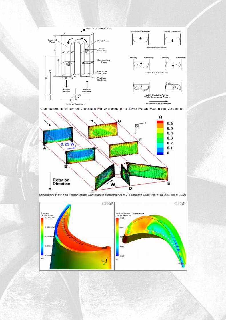
Some Information about cooling turbine`s blade systems
Turbine blade: Gas turbines play a vital role in the today’s industrialized society, and as the demands for power increase, the power output and thermal efficiency of gas turbines must also increase. One method of increasing both the power output and thermal efficiency of the engine is to increase the temperature of the gas entering the turbine. In the advanced gas turbines of today, the turbine inlet temperature can be as high as 1500°C; like the Snecma M88, can see turbine temperatures of 2,900 °F (1,590 °C).Those high temperatures weaken the blades and make them more susceptible to creep failures and also exceeds the melting temperature of the metal airfoils. Therefore, it is imperative that the blades and vanes are cooled, so they can withstand these extreme temperatures. Cooling air around 650°C is extracted from the compressor and passes through the airfoils. With the hot gases and cooling air, the temperature of the blades can be lowered to approximately 1000°C, which is permissible for reliable operation of the engine.
It is widely accepted that the life of a turbine blade can be reduced by half if the temperature prediction of the metal blade is off by only 30°C. In order to avoid premature failure, designers must accurately predict the local heat transfer coefficients and local airfoil metal temperatures. By preventing local hot spots, the life of the turbine blades and vanes will increase. However, due to the complex flow around the airfoils it is difficult for designers to accurately predict the metal temperature. Figure 1 shows the heat flux distribution around the rotor blade, The heat flux at the leading edge is very high and continues decrease as the flow travels along the blade; on the suction surface, the flow transitions from laminar to turbulent, and the heat flux sharply increases; the heat transfer on the pressure surface increases as the flow accelerates around the blade.

Methods of Cooling Cooling of components can be achieved by air or liquid
cooling. Liquid cooling seems to be more attractive because
of high specific heat capacity and chances of evaporative
cooling but there can be problem of leakage, corrosion,
choking, etc. which works against this method. On the other
hand air cooling allows to discharging air into main flow
without any problem. Quantity of air required for this
purpose is 1-3% of main flow and blade temperature can be
reduced by 200-300°C. There are many types of cooling used
in gas turbine blades: Impingement cooling, tip cap cooling
are under the categories of external cooling, and film cooling,
rib turbulators cooling under the categories of internal they all
work by using cooler air (often bled from the compressor) to
remove heat from the turbine blades
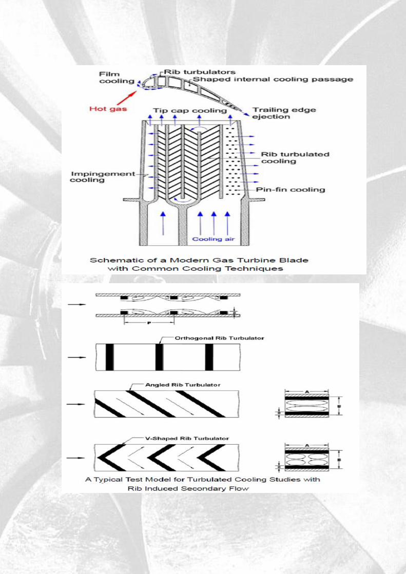

Rib Turbulated Cooling


1_Introduction
Hydroelectric power is a form of sustainable green energy, by use moving water to produce electricity. This power is generated by converting the kinetic energy of flowing water into mechanical and then electrical energy. This process involves the use of turbines, which consist of a set of blades. The moving water flows over the blades, causing them to turn. The blades are connected to a rotating drive shaft. The mechanical energy of the drive shaft is transferred to a generator through a gearbox. The generator uses the mechanical energy of the drive shaft to move an electric conductor (typically coils of copper wire) through a magnetic field, which causes electrons to flow through the conductor, generating electricity. The electricity is then fed into the electrical grid to be used in homes, businesses, and by industry.
The ideal power that can be derived from flowing water at a site is given by:
where P is power in KW , γ is specific weight of liquid in N/m3,Q is flow rate in m3/s and H is gross head in m.
Hydraulic turbines are divided into two groups:
Impulse Turbine
Reaction Turbine

Impulse Turbines are high head, low discharge, and low specific speed and operate at atmospheric pressure, while the reaction turbines operate under low and medium head with high specific speed and operate under variable pressure
Francis Turbine Gorlov helical turbine Pelton wheel Banki Water Turbine Turgo turbine
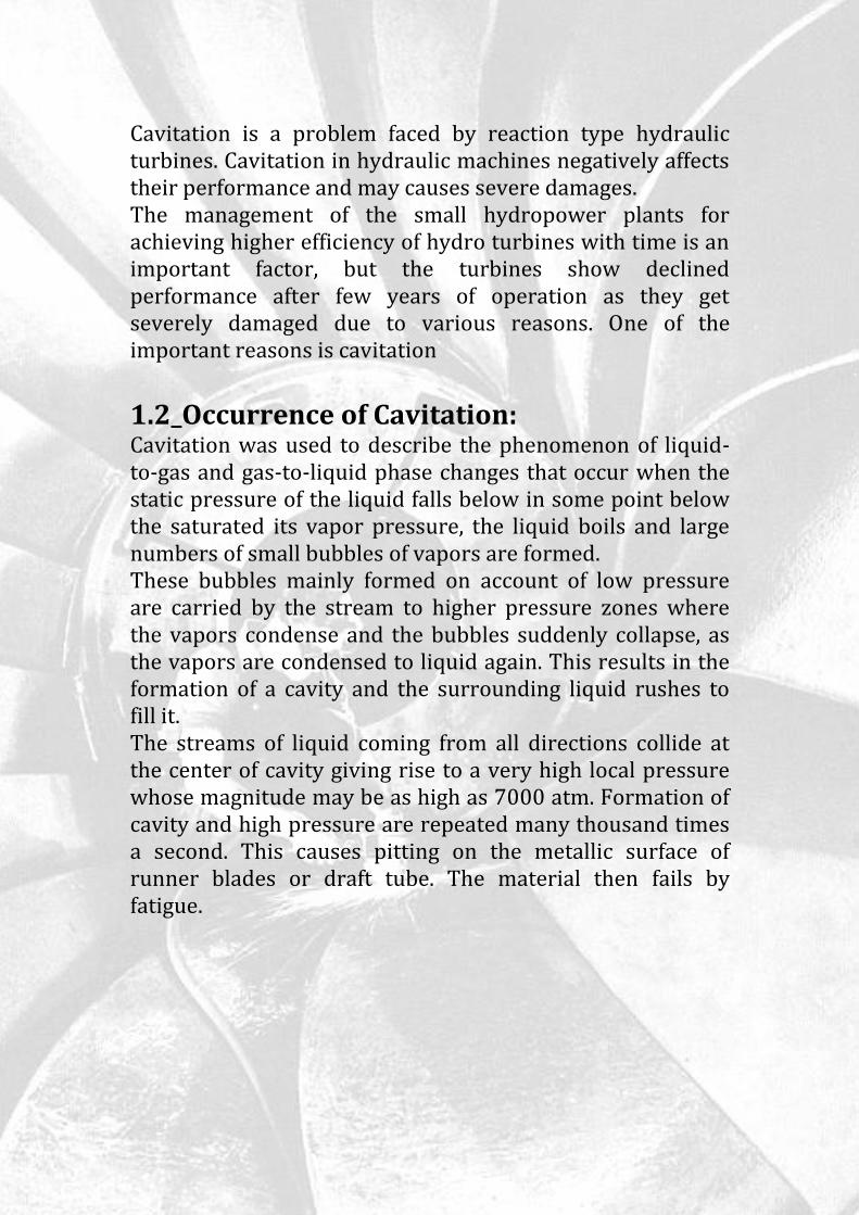
Cavitation is a problem faced by reaction type hydraulic turbines. Cavitation in hydraulic machines negatively affects their performance and may causes severe damages. The management of the small hydropower plants for achieving higher efficiency of hydro turbines with time is an important factor, but the turbines show declined performance after few years of operation as they get severely damaged due to various reasons. One of the important reasons is cavitation
1.2_Occurrence of Cavitation: Cavitation was used to describe the phenomenon of liquid-to-gas and gas-to-liquid phase changes that occur when the static pressure of the liquid falls below in some point below the saturated its vapor pressure, the liquid boils and large numbers of small bubbles of vapors are formed. These bubbles mainly formed on account of low pressure are carried by the stream to higher pressure zones where the vapors condense and the bubbles suddenly collapse, as the vapors are condensed to liquid again. This results in the formation of a cavity and the surrounding liquid rushes to fill it. The streams of liquid coming from all directions collide at the center of cavity giving rise to a very high local pressure whose magnitude may be as high as 7000 atm. Formation of cavity and high pressure are repeated many thousand times a second. This causes pitting on the metallic surface of runner blades or draft tube. The material then fails by fatigue.

CAVITATION PLOTTED
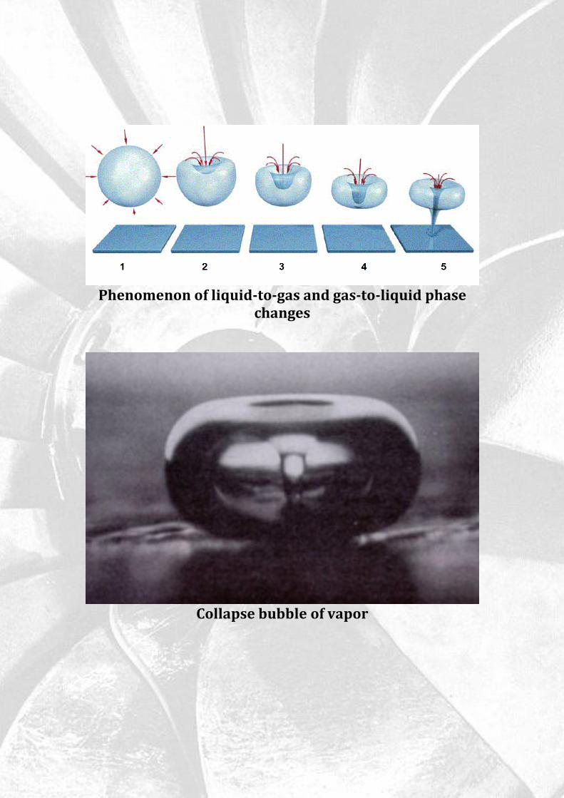
Phenomenon of liquid-to-gas and gas-to-liquid phase changes
Collapse bubble of vapor

2.1_SOME EXAMPLES OF CAVITATION:
KAPLAN`S TURBINE
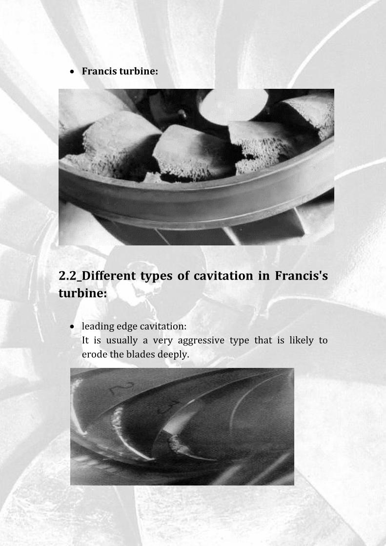
Francis turbine:
2.2_Different types of cavitation in Francis's
turbine:
leading edge cavitation:
It is usually a very aggressive type that is likely to
erode the blades deeply.

travelling bubble cavitation:
It is noisy type of cavitation that reduces machine
efficiency and provokes blade erosion.
draft tube swirl:
It generates low frequency pressure pulsations that in
case of hydraulic resonance can cause strong vibrations
on the turbine and even on the power-house
inter-blade vortex cavitation:
It produces structural vibrations at the trailing edge of
vanes

2_PHYSICAL DESCRIPTION OF CAVITATION:
Thoma Suggested a dimensionless number called as Thoma’s
Cavitation factor σ (sigma), which can be used for
determining the region where cavitation takes place in
reaction turbines:
Where pressure Ha is the atmospheric head in m of water,
Hs is the suction pressure at outlet of reaction turbine in m
of water or height of turbine runner above the tail water
surface , Hv is vapor pressure head, H is the net head on the
turbine in m of water The value of σ depends on Ns (specific
speed) of the turbine and for a turbine of given Ns the factor
σ can be reduced up-to a certain value up to which its
efficiency, ηo remains constant. A further decrease in value
of σ results in a sharp fall in ηo. The value of σ at this turning
point is called critical cavitation factor σc. The value of σc for
different turbines may be determined with the help of
following empirical relationships.
The values of σ from equation (1) is compared with the
value of σc from equation (2) and (3) and if value of σ is
greater than σc, cavitation will not occur in that turbine

3-Reducing Cavitation:
The figure below shows that a high strain, work hardening austenitic stainless steel produces superior resistance to cavitational erosion. Several industrial alloys were evaluated using the vibratory and high velocity cavitation test
4-Conclusions: Cavitation is a phenomenon of formation of vapor bubbles in low pressure regions and collapse in high pressure regions, high pressure is produced and metallic surfaces are subjected to high local stresses. Cavitation can present different forms in hydraulic turbines depending on the machine design and the operating condition. It is difficult to avoid cavitation completely in hydraulic turbines but can be reduced to economic acceptable level.

5-References
www.agiweb.org
en.wikipedia.org
Energy Information Administration
http://www.usgs.gov
Environment Canada
www.frenchriverland.com
Enhanced Internal Cooling of Turbine Blades and
Vanes/Je-Chin Han & Lesley M. Wright Turbine Heat
Transfer Laboratory Department of Mechanical
Engineering/Texas A&M University
Scientific Bulletin of the “Politehnica” University of
Timisoara Transactions on Mechanics/Tom 52(66),
Fascicola 6, 2007
Effect of Cavitation on Hydraulic Turbines/S. Khuranaa,
Navtejb and Hardeep SinghC International Journal of
Current Engineering and Technology/ Khuranaa,
Navtejb and Hardeep Singh/Department of Mechanical
Engineering, Baddi University of Emerging Sciences
and Technology Baddi
Related Documents