Cooling Systems 5

Cooling Systems
Jan 24, 2016
Cooling System Control
Welcome message from author
This document is posted to help you gain knowledge. Please leave a comment to let me know what you think about it! Share it to your friends and learn new things together.
Transcript
CoolingSystems
5
5 Cooling SystemsChillers 5 3
Packaged Chillers 5 4Condenser Water Systems 5 7Secondary Chilled Water Circuits 5 11
Static Cooling 5 15
Heat Pump Systems 5 21
Examples1 Large Building Cooling System 5 25
5 2 Cooling Systems
ChillersChillers are controlled by Chiller Controllers. Two versions are available, the 3T variant for simple installations, Air Cooled Condensers etc and the 6R* version which has more comprehensive features, and may contain the System Housekeeping Function - see General Introduction section.
Chiller Controllers are Demand Driven from the zones of the building that they serve; you will need at least one Zone Controller in order to make the Chillers run. Chiller Controllersmay need Submodules registered to them to extend their control abilities to match your application.
* 6R Chiller Controller available Q2 2000
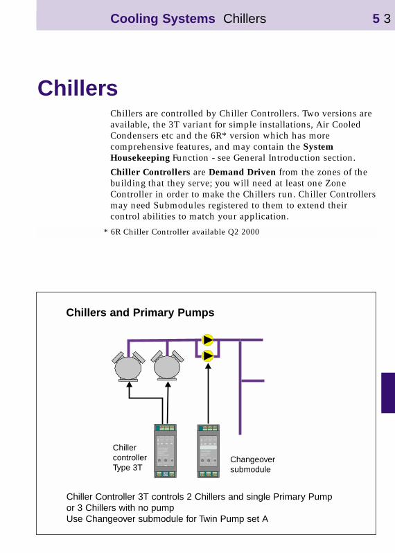
Chillers and Primary Pumps
ChillercontrollerType 3T
Changeoversubmodule
Cooling Systems Chillers 5 3
Chiller Controller 3T controls 2 Chillers and single Primary Pumpor 3 Chillers with no pumpUse Changeover submodule for Twin Pump set A

Packaged ChillersTypes of Control
•Sequenced control of a number of packaged chillers based onReturn Chilled Water Temperature. As the Return Temperature rises, indicating more load in the building, morepackaged chiller stages are added to the sequence. Chiller Flow temperature and all Flow and Pressure interlocks are controlled by the chiller’s own packaged controls. Set CMDE parameter to 1 in 3T Controller for this mode. Occupancy status will be determined from the Demand signals sent by the Energy Consumer and Distributormodules and/or Volt Free Contact input.
•Demand-Driven Control of a number of packaged chillers based on Demand signals from the building; as more demandis signalled by the Energy Consumer and Distributor modules, so more chiller stages are enabled. Chiller Flow temperature and all flow and pressure interlocks are controlled by the chiller’s own packaged controls Set CMDE parameter to 0 in 3T Controller for this Mode
•Occupancy Control based on Building Occupancy derived from the Energy Demand signals and/or Volt Free Contact input - use the MIND, MNAV and MNOC parameters to determine Occupancy Status and use Occupation Switchoutput on the 3T Controller
Sensors•if you are controlling the Return Temperature, you must fit a
Return Temperature sensor. Otherwise, sensors are optional, for monitoring purposes
•3T Chiller Controllers have 2 sensor inputs; one for Flow, and one for Return temperature
•6R Chiller Controllers have 4 sensor inputs; Flow and ReturnTemperature, plus a spare channel and a fourth input for Outside Temperature if this is the System Housekeeping module
5 4 Cooling Systems Chillers
Inputs (3T)•can use Volt-free contact wired to sensor input to force 3T
Chiller Controller into Occupancy - a Demand signal that will enable the chillers as an “OR” function with any Demand signals being received from other modules
•can use Volt-free contact wired to sensor input of 3T Chiller Controller as a flow-proving input from a flow switch to prevent chillers running unless flow is proved; normally this is a back-up to a hardwired scheme provided by the chiller’s own controls
Inputs (6R)•the 6R Chiller Controller has 2 inputs for Fault or Status
monitoring
•alternatively one input may be used for flow-proving or occupancy input as per the 3T - see above
Outputs Chillers and single pumps•3T Chiller Controllers have 3 Triac Outputs for enabling up
to 3 packaged chillers in sequence - CTU/DIN/3T/209
•or 2 packaged chillers in sequence and Chilled Water pump enable - CTU/DIN/3T/208
•6R Chiller Controllers have 4 Relay outputs for enabling up to 4 packaged chillers in sequence, and 2 Relay outputs to enable Chilled and Condenser Water Pumps
Twin Pumpsets•Chilled Water Pumpsets may be controlled using a
Changeover Submodule registered to the Chiller Controller
•must fit at least one VFC status signal to indicate pump is running n.b.. it must be a status signal, trip signals will not work
•either a flow switch across each pump, or a single one for thepump pair
Cooling Systems Chillers 5 5

5 6 Cooling Systems Chillers
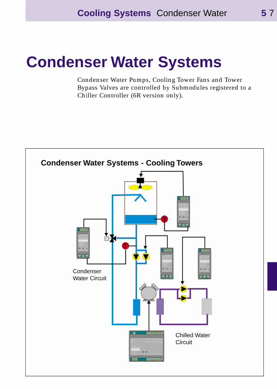
Condenser Water SystemsCondenser Water Pumps, Cooling Tower Fans and Tower Bypass Valves are controlled by Submodules registered to a Chiller Controller (6R version only).
Chilled WaterCircuit
CondenserWater Circuit
Condenser Water Systems - Cooling Towers
Cooling Systems Condenser Water 5 7
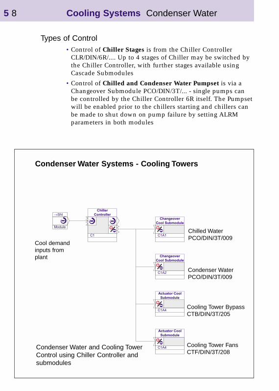
Types of Control•Control of Chiller Stages is from the Chiller Controller
CLR/DIN/6R/.... Up to 4 stages of Chiller may be switched by the Chiller Controller, with further stages available using Cascade Submodules
•Control of Chilled and Condenser Water Pumpset is via a Changeover Submodule PCO/DIN/3T/... - single pumps can be controlled by the Chiller Controller 6R itself. The Pumpsetwill be enabled prior to the chillers starting and chillers can be made to shut down on pump failure by setting ALRM parameters in both modules
Condenser Water Systems - Cooling Towers
Cool demandinputs fromplant
Chilled WaterPCO/DIN/3T/009
Condenser WaterPCO/DIN/3T/009
Cooling Tower BypassCTB/DIN/3T/205
Cooling Tower FansCTF/DIN/3T/208
5 8 Cooling Systems Condenser Water
Condenser Water and Cooling TowerControl using Chiller Controller andsubmodules

•Control of Cooling Tower Bypass Valve is via a Actuator Submodule CTB/DIN/3T/205 Control will be to a constant Condenser Water Return Temperature
•Control of Cooling Tower Fans is via a Actuator Submodule CTF/DIN/3T/208 Control will be to a constant Cooling Tower Pond Temperature. Tower fans can be single speed or have 2 or 3 speeds.
Sensors•Condenser Water Return Temperature sensor must be fitted
and wired to the Submodule controlling the Tower Bypass Valve.
•Cooling Tower Pond Temperature sensor must be fitted if the Tower Fans are to be controlled; it must be wired to the Submodule controlling the fans
Inputs•can use Volt-free contact from a level switch in the Tower
Pond wired to an input on the Submodule controlling the Tower Fans; this will prevent the Condenser Water Pumps running if there is no water in the Tower.
Twin Pumpsets•Condenser Water Pumpsets may be controlled using a
Changeover Submodule registered to the Chiller Controller
•must fit at least one VFC status signal to indicate pump is running, it must be a status signal, trip signals will not work
•either a flow switch across each pump, or a single one for thepump pair
• flow failure will disable the Chillers and Tower Fans.
Cooling Systems Condenser Water 5 9
5 10 Cooling Systems
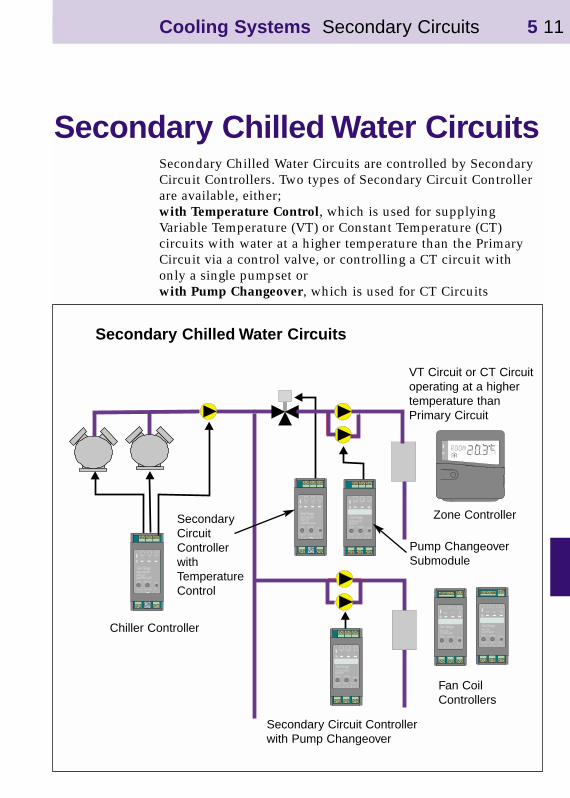
Secondary Chilled Water CircuitsSecondary Chilled Water Circuits are controlled by Secondary Circuit Controllers. Two types of Secondary Circuit Controller are available, either;with Temperature Control, which is used for supplying Variable Temperature (VT) or Constant Temperature (CT) circuits with water at a higher temperature than the Primary Circuit via a control valve, or controlling a CT circuit with only a single pumpset orwith Pump Changeover, which is used for CT Circuits
VT Circuit or CT Circuitoperating at a highertemperature thanPrimary Circuit
Pump ChangeoverSubmodule
Chiller Controller
Zone Controller
Fan CoilControllers
Secondary Circuit Controllerwith Pump Changeover
SecondaryCircuitControllerwithTemperatureControl
Secondary Chilled Water Circuits
Cooling Systems Secondary Circuits 5 11
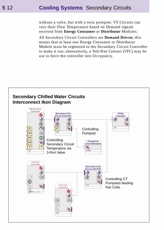
Secondary Chilled Water CircuitsInterconnect Ikon Diagram
ControllingSecondary CircuitTemperature via 3-Port Valve
Controlling CTPumpsets feedingFan Coils
ControllingPumpset
without a valve, but with a twin pumpset. VT Circuits can vary their Flow Temperature based on Demand signals received from Energy Consumer or Distributor Modules.
All Secondary Circuit Controllers are Demand Driven; this means that at least one Energy Consumer or Distributor Module must be registered to the Secondary Circuit Controller to make it run; alternatively, a Volt-Free Contact (VFC) may be use to force the controller into Occupancy.
5 12 Cooling Systems Secondary Circuits

Types of control• for VT Circuits, setpoint is set by Zone Demand - use
VTU/DIN/3T/..
• for VT Circuits with twin pumpsets, use a PCO/DIN/3T/007Changeover Submodule registered to the Secondary Circuit Controller
• for CT Circuits with twin pumpset,use CTU/DIN/PCO/3T/007
• for CT Circuits with single pump, or that need VFC input from a legacy system to generate a Cooling Demand, use CTC/DIN/3T/201
Which Version?• to control or measure Secondary Circuit temperature, use
version with Temperature Control
• to use a VFC as an Occupancy Input, use version with Temperature Control
• to control a Pump Pair with auto-changeover, use Secondary Circuit with Pump Changeover - it has no sensor inputs to measure temperature.
Sensors (versions with temperature control)
•must fit flow sensor for VT applications if flow temperature limits are important
• if no sensor is fitted to Secondary Circuit with Temperature Control, valve will be positioned according to Zone Demand
• for CT Circuits, sensor can be fitted for monitoring purposes even if there is no valve to control - set CMDE=0
•can use Volt-free contact wired to sensor input to force CT controller into Occupancy - a Demand signal that will cause the controller to work to its Occupied setpoint and pass on a Demand signal to cause the Chiller plant to run
•Condensation Sensor input is available to inhibit Secondary Circuit if Condensation is detected. This can be used with Static Cooling systems as an alternative to Condensation Detection per Zone
Cooling Systems Secondary Circuits 5 13
Inputs (versions with Pump Changeover)
•must fit at least one VFC status signal to indicate pump is running - it must be a status signal, trip signals will not work
•either a flow switch across each pump, or a single one for thepump pair
•or auxiliary contact from pump motor starter, one per pump, or one per pumpset
Valves•valves are Raise / Lower type; if 0-10V DC valves are used,
use Analogue Output Secondary Circuit Controller to give 0-10V dc outputs
Pumps•single pump controlled from output on Secondary Circuit
Controllers with Temperature Control
•Twin Pumpsets are controlled by PCO/DIN/3T/007 - a Changeover Submodule for Circuits controlled by Secondary Circuit Controllers with Temperature Control,
•or CTU/DIN/PCO/3T/007- a Secondary Circuit Controller with built-in Pump Changeover function for CT pumpsets
Zone and CT Circuit Demand Signals•Secondary Circuits are Demand Driven
•each VT Secondary Circuit must have at least one Consumeror Distributor Module to send Energy Demand Signals The VT setpoint, and whether the pumps will run or not, is determined from this signal
•more than one Zone Controller can be used per secondary circuit; the highest or average Energy Demand signal will be used to determine the VT setpoint and pump status.
•CT Circuits must also have Energy Demand signals sent to them in order to make them run. Often, CT circuits feed multiple loads e.g. AHUs, Fan Coils
•either each load must be controlled by a SeaChange Module e.g. AHU Controller, Fan Coil Controller
•or a Volt-free contact must be wired from the loads into the Secondary Circuit Controller otherwise it will not run.
5 14 Cooling Systems Secondary Circuits
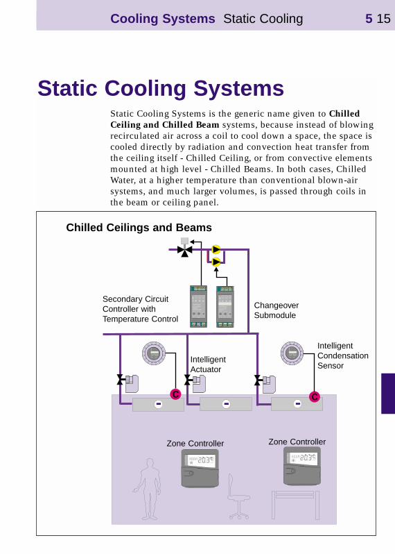
Static Cooling SystemsStatic Cooling Systems is the generic name given to Chilled Ceiling and Chilled Beam systems, because instead of blowingrecirculated air across a coil to cool down a space, the space is cooled directly by radiation and convection heat transfer from the ceiling itself - Chilled Ceiling, or from convective elementsmounted at high level - Chilled Beams. In both cases, Chilled Water, at a higher temperature than conventional blown-air systems, and much larger volumes, is passed through coils in the beam or ceiling panel.
Zone Controller
IntelligentCondensationSensor
IntelligentActuator
Secondary CircuitController withTemperature Control
ChangeoverSubmodule
Chilled Ceilings and Beams
Zone Controller
Cooling Systems Static Cooling 5 15
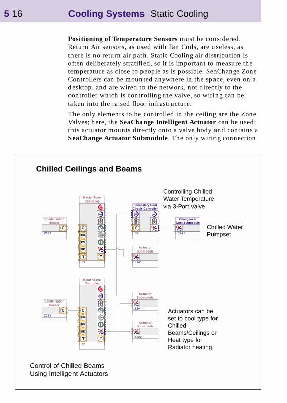
Positioning of Temperature Sensors must be considered. Return Air sensors, as used with Fan Coils, are useless, as there is no return air path. Static Cooling air distribution is often deliberately stratified, so it is important to measure the temperature as close to people as is possible. SeaChange Zone Controllers can be mounted anywhere in the space, even on a desktop, and are wired to the network, not directly to the controller which is controlling the valve, so wiring can be taken into the raised floor infrastructure.
The only elements to be controlled in the ceiling are the Zone Valves; here, the SeaChange Intelligent Actuator can be used; this actuator mounts directly onto a valve body and contains a SeaChange Actuator Submodule. The only wiring connection
Chilled Ceilings and Beams
Actuators can beset to cool type forChilledBeams/Ceilings orHeat type forRadiator heating.
Control of Chilled BeamsUsing Intelligent Actuators
5 16 Cooling Systems Static Cooling
Controlling ChilledWater Temperaturevia 3-Port Valve
Chilled WaterPumpset
necessary is the 2-wire network, thus simplifying wiring in the ceiling. Also re-zoning of the building after Changing the floor plan can be achieved by re-registration (pushing buttons) rather than re-wiring.
The other important problem to overcome is condensation- “Office Rain” which can occur if Supply Air conditions drift outside design - the Supply Air becomes too humid, or if a plant failure allows the Chilled Water temperature to drop too low. The onset of condensation is detected by a SeaChange Condensation Sensor - an Intelligent Sensor which is wired to the network, and clamps to the pipework or ceiling. Itis registered either to a Zone Controller for Zone-by-Zone control or to a Secondary Circuit Controller to shut down a whole circuit. If condensation is detected, the Zone or Secondary Circuit closes down until the condition clears and normal control is restored. Thus a simple form of Dew point Control is achieved.
Types of control•Time and Temperature control of Cooling including
Optimum Start and Stop using a Zone Controller with Intelligent Actuators registered to it - up to 8 per zone.Use ZON/PTR/LCD/001 and ACD/VLV/LPR/001,2 or 3 depending on valve size - up to 40mm valves may be controlled.
•Time and Temperature control of Cooling and Heatingincluding Optimum Start using a Zone Controller with Intelligent Actuators registered to it - up to 4 heating, 4 cooling per zone. The Intelligent Actuators can be set to respond to heating or cooling Control Demand signals.
‘Office Rain’•Condensation control can be added to the above schemes
using Condensation Sensors, wired to the network and registered either to a Zone Controller - one sensor per Zone or to a Secondary Circuit Controller - one sensor per circuit. Use SEN/PR/CND/001.
•Alternatively Condensation Sensor can be Registered to a Secondary Circuit Controller which allows one CondensationSensor to cover a number of Control Zones
Cooling Systems Static Cooling 5 17
Zone Control•a Zone Controller is used to control the space temperature; it
provides temperature control, Optimum Start, Fabric Protection and a user interface for setting Occupancy Times and Setpoint.
•Zone Controllers have integral sensors and have several remote sensing options - see Data Sheet
Zone Demands to Main Plant•if the Secondary Circuit is controlled by a SeaChange
Secondary Circuit Controller, it will be Demand Driven; the Zone Controllers will send their Cooling Demand signals to the Secondary Circuit Controller which will enable pumps/valves etc.
5 18 Cooling Systems Static Cooling

Room SensorSEN/PTR/ROM/001
CondensationSensor
Fan Coil ControllerFCU/DIN/4R/001
Optional Setpoint trim inputand Temperature SensorSEN/PTR/ROM/002
Zone Controller sets Occupancy, Optimum Start/Stop and Setpointfor a number of Zones.
Chilled Ceiling and Radiator Control Using Fan Coil Controller
An Alternative Control Method forChilled Ceilings and Radiators using Fan Coil Controllers
Cooling Systems Static Cooling 5 19
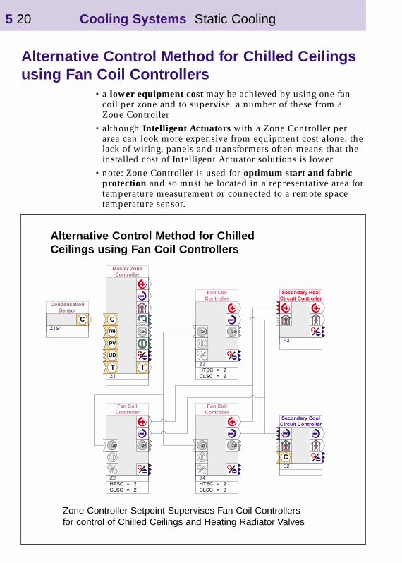
Alternative Control Method for Chilled Ceilings using Fan Coil Controllers
•a lower equipment cost may be achieved by using one fan coil per zone and to supervise a number of these from a Zone Controller
•although Intelligent Actuators with a Zone Controller per area can look more expensive from equipment cost alone, thelack of wiring, panels and transformers often means that the installed cost of Intelligent Actuator solutions is lower
•note: Zone Controller is used for optimum start and fabric protection and so must be located in a representative area fortemperature measurement or connected to a remote space temperature sensor.
5 20 Cooling Systems Static Cooling
Alternative Control Method for ChilledCeilings using Fan Coil Controllers
Zone Controller Setpoint Supervises Fan Coil Controllersfor control of Chilled Ceilings and Heating Radiator Valves

Heat PumpsHeat Pumps can be either Terminal Units or Central Plant. An example of Terminal Units would be Water-to-Air Reversible Heat Pumps distributed around a building dumping energy into a Condenser Water system. Such Terminal Units are controlled by Fan Coil Controllers - see Fan Coil section.
Heat PumpController
ChangeoverSubmodule
Secondary CircuitControllers withPump Changeover
2-pipe ChangeoverFan Coils
Heat PumpsCentral Plant
Cooling Systems Heat Pumps 5 21
2 Pipe Changeover Fan Coils work with Heat Pump Controller thatswitches Plant between Heat and Cool modes
Central Plant Heat Pumps typically feed a number of TerminalUnits; they are controlled by a Heat Pump Controller. An example of Central Plant Heat Pumps are Air-to-Water Heat Pumps which are feeding Hot or Chilled Water to a group of 2-pipe Changeover Fan Coils which each have only one control valve and coil which can heat or cool.
The Changeover from Heating to Cooling mode can be done automatically, if the plant will allow; the Fan Coils send their demand signals to the Heat Pump Controller, which assesses which mode to run in and changes over if necessary. The Fan Coils can monitor the Flow Temperature from the Heat Pump via the network and can thus decide whether they are able to heat or cool; if the medium is in the wrong mode i.e. they are trying to heat the space, and the Heat Pump is delivering Chilled Water, their valves will remain closed.
If the main plant needs manual intervention to switch from Heating to Cooling, the Automatic Changeover function can beignored; a Volt-Free Contact from the manual changeover switch can be wired as an input to force the Heat Pump Controller into Heating or Cooling mode.
Another example of Central Plant Heat Pumps are Water-to-Air Reversible Heat Pumps which feed a plenum; the plenum feeds multiple VAV Terminal Units, often used in air-conditioned apartments. Here again the Terminal Units can dictate the mode of the Heat Pump - supplying either Hot or Cold Air; the VAV Controllers monitor the plenum temperaturewhich is monitored by the Heat Pump Controller and Broadcast over the network so all of the Terminal Units can access this Temperature without any Interconnect being specifically set up and so can control their air volumes accordingly.
Usually the Heat Pump will come with its own built-in controls for compressor cycling, reversing valve, defrost control of outdoor unit etc. as appropriate. The SeaChange Heat Pump Controller is designed to overlay these simple controls to provide management of the Heat Pump.
5 22 Cooling Systems Heat Pumps
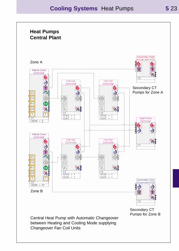
Heat PumpsCentral Plant
Secondary CTPumps for Zone A
Secondary CTPumps for Zone B
Cooling Systems Heat Pumps 5 23
Central Heat Pump with Automatic Changeoverbetween Heating and Cooling Mode supplyingChangeover Fan Coil Units
Zone B
Zone A

Types of Control•Temperature Control of the Heat Pump output is possible
using sequenced - staged outputs. A Flow Setpoint will be determined from Fan Coil Demands; the Heating/Cooling Mode and number of stages will be set to control to this setpoint. Set SPTY parameter to 2 in Heat Pump Controller
•Demand Control only; here the Heating/Cooling Mode and number of stages will be set directly by the Fan Coil Demands; the Heat Pump’s own controls will control the flowtemperature. This is the usual method of control where the Heat Pump has its own embedded Temperature Controller. Set SPTY Parameter to 1 in Heat Pump Controller.
Sensors•must fit Primary flow sensor so that Terminal Units can
determine whether the Heat Pump is in the correct mode - Heating or Cooling, for them to open their valves or not
•can fit 2 additional sensors for Monitoring Purposes
•must fit Outside Temperature Sensor if this is the System Housekeeping Module
Inputs•can wire 2 Volt-Free Contacts as status or alarm monitoring
points
•other input options available - contact SeaChange for details
Outputs•Relay Output for Heat/Cool select and 4 Relays to switch
Heating or Cooling Stages are provided
•other Output configurations are possible - contact SeaChangefor details
Zone Demands•Heat Pump Controllers may be Demand Driven
• to Demand-Drive the Heat Pump, one or many Terminal Units, which are Energy Consumer Modules, must be registered to the Heat Pump Controller
• the Terminal Units Heating or Cooling Demand signals are collated by the Heat Pump Controller
• the maximum demand will set heating or cooling mode
5 24 Cooling Systems Heat Pumps
ExampleLarge Building Cooling System
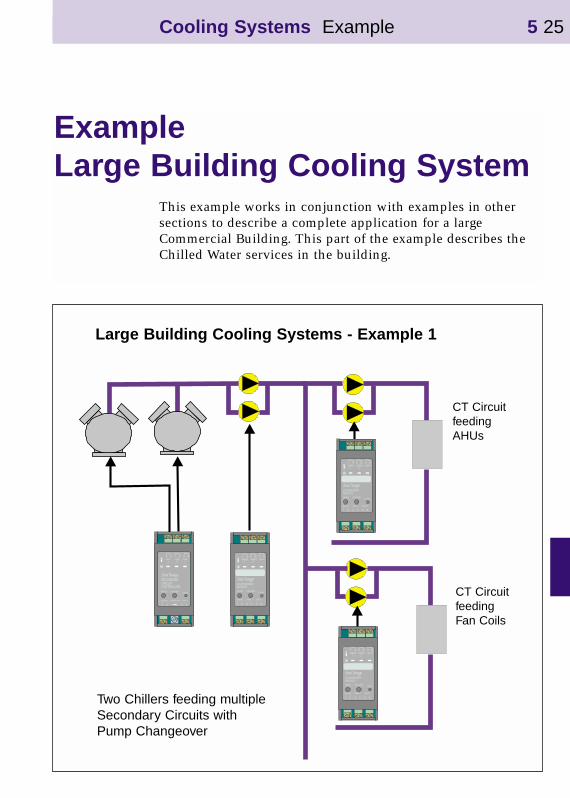
This example works in conjunction with examples in other sections to describe a complete application for a large Commercial Building. This part of the example describes the Chilled Water services in the building.
CT CircuitfeedingAHUs
CT CircuitfeedingFan Coils
Large Building Cooling Systems - Example 1
Cooling Systems Example 5 25
Two Chillers feeding multipleSecondary Circuits withPump Changeover
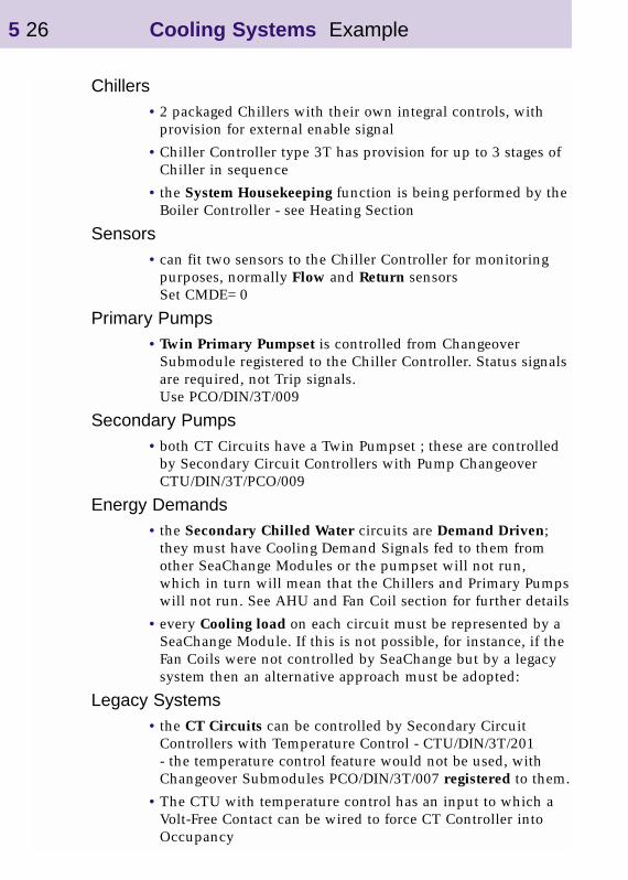
Chillers•2 packaged Chillers with their own integral controls, with
provision for external enable signal
•Chiller Controller type 3T has provision for up to 3 stages of Chiller in sequence
• the System Housekeeping function is being performed by theBoiler Controller - see Heating Section
Sensors•can fit two sensors to the Chiller Controller for monitoring
purposes, normally Flow and Return sensorsSet CMDE=0
Primary Pumps•Twin Primary Pumpset is controlled from Changeover
Submodule registered to the Chiller Controller. Status signalsare required, not Trip signals.Use PCO/DIN/3T/009
Secondary Pumps•both CT Circuits have a Twin Pumpset ; these are controlled
by Secondary Circuit Controllers with Pump Changeover CTU/DIN/3T/PCO/009
Energy Demands• the Secondary Chilled Water circuits are Demand Driven;
they must have Cooling Demand Signals fed to them from other SeaChange Modules or the pumpset will not run, which in turn will mean that the Chillers and Primary Pumpswill not run. See AHU and Fan Coil section for further details
•every Cooling load on each circuit must be represented by a SeaChange Module. If this is not possible, for instance, if the Fan Coils were not controlled by SeaChange but by a legacy system then an alternative approach must be adopted:
Legacy Systems• the CT Circuits can be controlled by Secondary Circuit
Controllers with Temperature Control - CTU/DIN/3T/201 - the temperature control feature would not be used, with Changeover Submodules PCO/DIN/3T/007 registered to them.
•The CTU with temperature control has an input to which a Volt-Free Contact can be wired to force CT Controller into Occupancy
5 26 Cooling Systems Example
Cooling Systems Example 5 27
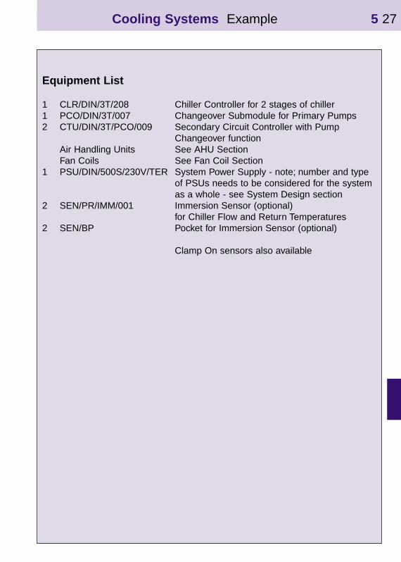
Equipment List
1 CLR/DIN/3T/208 Chiller Controller for 2 stages of chiller1 PCO/DIN/3T/007 Changeover Submodule for Primary Pumps2 CTU/DIN/3T/PCO/009 Secondary Circuit Controller with Pump
Changeover functionAir Handling Units See AHU Section Fan Coils See Fan Coil Section
1 PSU/DIN/500S/230V/TER System Power Supply - note; number and type of PSUs needs to be considered for the system as a whole - see System Design section
2 SEN/PR/IMM/001 Immersion Sensor (optional)for Chiller Flow and Return Temperatures
2 SEN/BP Pocket for Immersion Sensor (optional)
Clamp On sensors also available

5 28 Cooling Systems Example 1
Cooling Demandsignals fromAHU’s - see AHUsection
Cooling Demandsignals from Fan Coils- see Fan Coil section
Chilled Waterpumpset feedingAHU’s
Chilled Waterpumpset feedingFan Coils
Chillers
Primary ChilledWater pumpset
Large Building - Example
Chillers feeding 2 CT Circuits for Fan Coils and AHU’s
Interconnect Diagram•Cooling Demand signals are generated by AHU Controllers
and FCU Controllers - Energy Consumer Modules - not shown here, see AHU and Fan Coil sections. These signals also contain Occupancy Status information.
•The Secondary Circuit Controllers collate the Cooling Demands from the AHU and Fan Coil Controllers and send a CT Demand signal to the Chiller Controller where it is used to set the Primary Flow temperature.
•The Chiller Controller commands its Changeover Submodule to run the pumps whenever the Chiller is running.

Configuration Parameter SettingsAutomatically set during Registration
•CLSC Parameters in the Secondary Circuit Controllers will be automatically set to 2, to “point” the Heating Demand signal at the Chiller Controller, which has address C2. The CLSC parameters in the AHU Controllers will be set to 3, andthe CLSC Parameters in the Fan Coil Controllers will be set to4 to “point” to the relevant Secondary Circuit Controllers C3 and C4 respectively.
Parameters that must be set manually
•no other parameters have to be adjusted
Examples of Parameters that may need to be set manually
• the Secondary Circuit Controllers have a “grace time” associated with the Changeover function to allow time for flow switches to make contact after pumps have started. This can be adjusted on parameter DLAY
•Pump Exercise Routine can be enabled. Set MXDYin Changeover submodule to number of without running before pump is exercised for MNON Period in mins
•Pump Delay Time Parameter CLDY (Default=0) can be set to+2 mins to bring Pumps on before Chillers
Cooling Systems 5 29
Related Documents