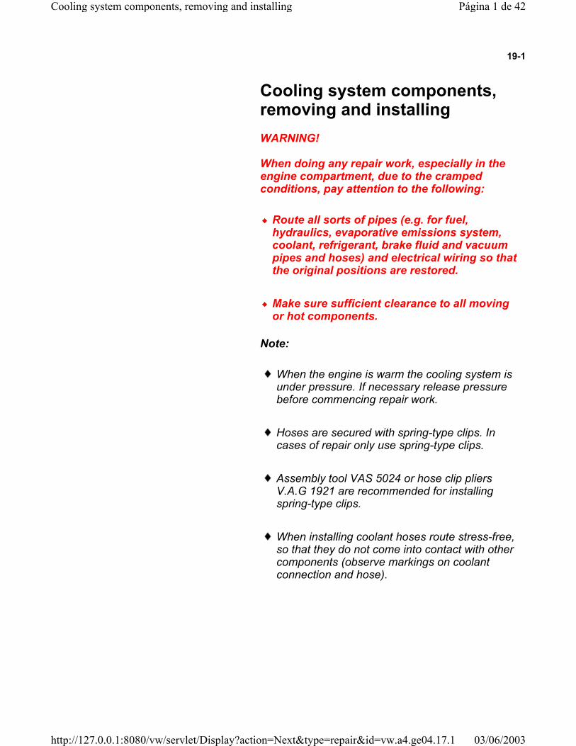
19-1 Cooling system components, removing and installing WARNING! When doing any repair work, especially in the engine compartment, due to the cramped conditions, pay attention to the following: Route all sorts of pipes (e.g. for fuel, hydraulics, evaporative emissions system, coolant, refrigerant, brake fluid and vacuum pipes and hoses) and electrical wiring so that the original positions are restored. Make sure sufficient clearance to all moving or hot components. Note: When the engine is warm the cooling system is under pressure. If necessary release pressure before commencing repair work. Hoses are secured with spring-type clips. In cases of repair only use spring-type clips. Assembly tool VAS 5024 or hose clip pliers V.A.G 1921 are recommended for installing spring-type clips. When installing coolant hoses route stress-free, so that they do not come into contact with other components (observe markings on coolant connection and hose). Página 1 de 42 Cooling system components, removing and installing 03/06/2003 http://127.0.0.1:8080/vw/servlet/Display?action=Next&type=repair&id=vw.a4.ge04.17.1

Cooling Syste and Installing 1.8 T
Oct 27, 2015
Welcome message from author
This document is posted to help you gain knowledge. Please leave a comment to let me know what you think about it! Share it to your friends and learn new things together.
Transcript
19-1
Cooling system components, removing and installing
WARNING!
When doing any repair work, especially in the engine compartment, due to the cramped conditions, pay attention to the following:
Route all sorts of pipes (e.g. for fuel, hydraulics, evaporative emissions system, coolant, refrigerant, brake fluid and vacuum pipes and hoses) and electrical wiring so that the original positions are restored.
Make sure sufficient clearance to all moving or hot components.
Note:
When the engine is warm the cooling system is under pressure. If necessary release pressure before commencing repair work.
Hoses are secured with spring-type clips. In cases of repair only use spring-type clips.
Assembly tool VAS 5024 or hose clip pliers V.A.G 1921 are recommended for installing spring-type clips.
When installing coolant hoses route stress-free, so that they do not come into contact with other components (observe markings on coolant connection and hose).
Página 1 de 42Cooling system components, removing and installing
03/06/2003http://127.0.0.1:8080/vw/servlet/Display?action=Next&type=repair&id=vw.a4.ge04.17.1
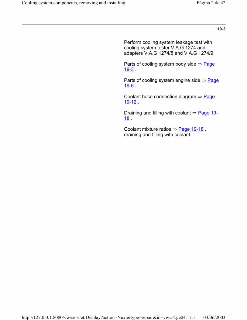
19-2
Perform cooling system leakage test with cooling system tester V.A.G 1274 and adapters V.A.G 1274/8 and V.A.G 1274/9.
Parts of cooling system body side Page 19-3 .
Parts of cooling system engine side Page 19-6 .
Coolant hose connection diagram Page 19-12 .
Draining and filling with coolant Page 19-18 .
Coolant mixture ratios Page 19-18 , draining and filling with coolant.
Página 2 de 42Cooling system components, removing and installing
03/06/2003http://127.0.0.1:8080/vw/servlet/Display?action=Next&type=repair&id=vw.a4.ge04.17.1

19-3
Cooling system components (body side)
1 - Radiator
Removing and installing
Page 19-25
After replacing replace entire coolant
2 - O-ring
Replace if damaged
3 - Upper coolant hose
Secured to radiator with retaining clip
Check securely seated
Coolant hose connection diagram Page 19-12
4 - Air ducting
Página 3 de 42Cooling system components, removing and installing
03/06/2003http://127.0.0.1:8080/vw/servlet/Display?action=Next&type=repair&id=vw.a4.ge04.17.1
5 - 10 Nm
6 - Additional fan
Only vehicles with optional equipment
Página 4 de 42Cooling system components, removing and installing
03/06/2003http://127.0.0.1:8080/vw/servlet/Display?action=Next&type=repair&id=vw.a4.ge04.17.1
19-4
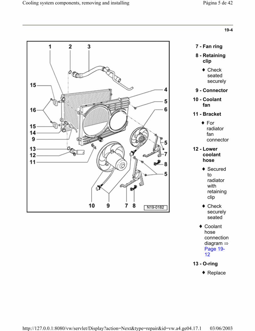
7 - Fan ring
8 - Retaining clip
Check seated securely
9 - Connector
10 - Coolant fan
11 - Bracket
For radiator fan connector
12 - Lower coolant hose
Secured to radiator with retaining clip
Check securely seated
Coolant hose connection diagram Page 19-12
13 - O-ring
Replace
Página 5 de 42Cooling system components, removing and installing
03/06/2003http://127.0.0.1:8080/vw/servlet/Display?action=Next&type=repair&id=vw.a4.ge04.17.1
19-5
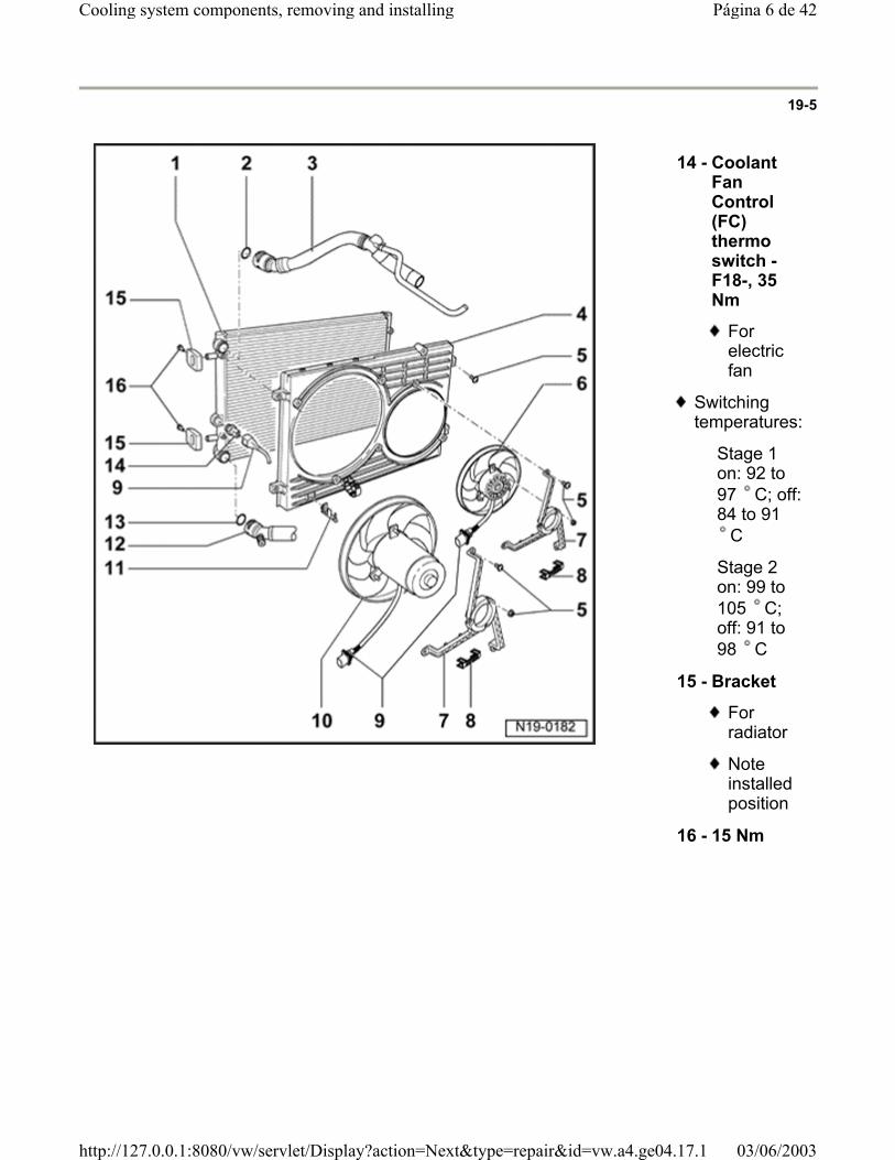
14 - Coolant Fan Control (FC) thermo switch -F18-, 35 Nm
For electric fan
Switching temperatures:
Stage 1 on: 92 to 97 C; off: 84 to 91
C
Stage 2 on: 99 to 105 C; off: 91 to 98 C
15 - Bracket
For radiator
Note installed position
16 - 15 Nm
Página 6 de 42Cooling system components, removing and installing
03/06/2003http://127.0.0.1:8080/vw/servlet/Display?action=Next&type=repair&id=vw.a4.ge04.17.1
19-6
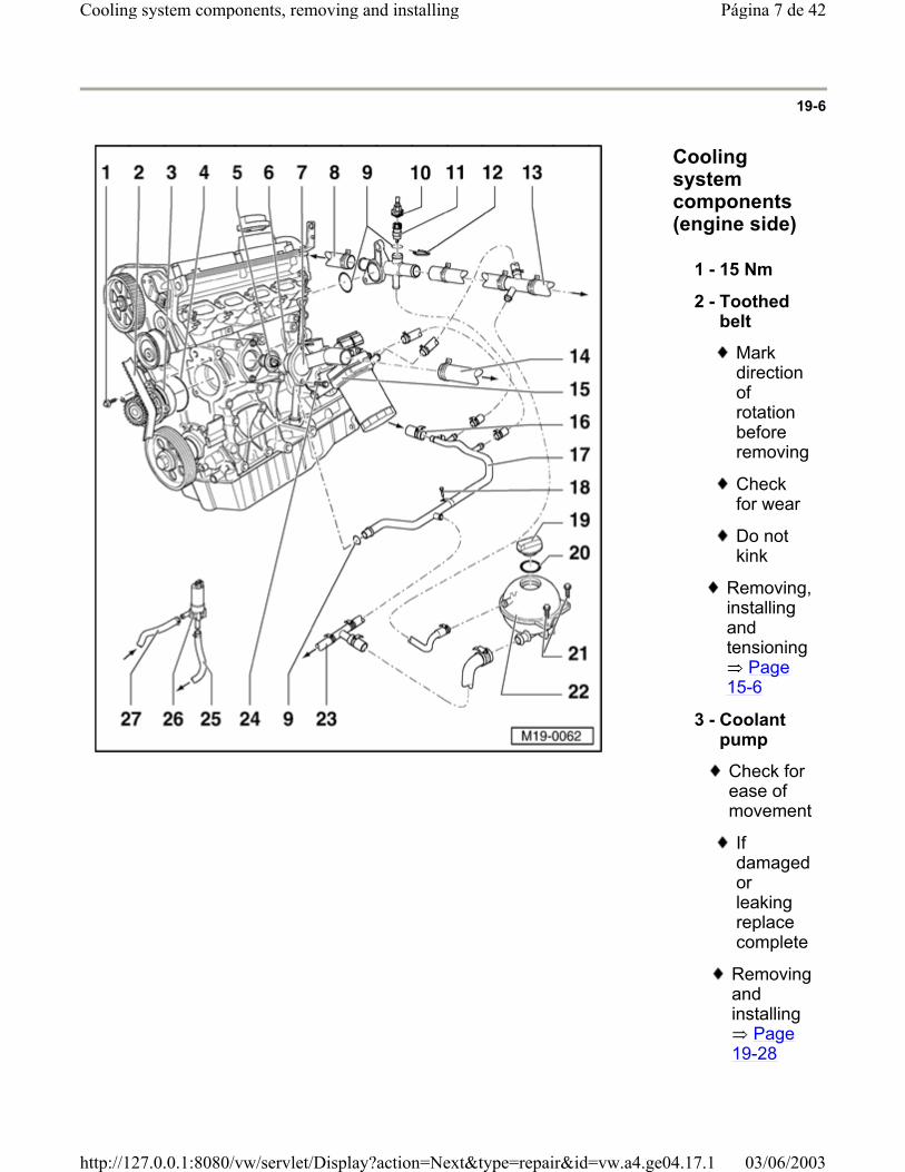
Cooling system components (engine side)
1 - 15 Nm
2 - Toothed belt
Mark direction of rotation before removing
Check for wear
Do not kink
Removing, installing and tensioning
Page 15-6
3 - Coolant pump
Check for ease of movement
If damaged or leaking replace complete
Removing and installing
Page 19-28
Página 7 de 42Cooling system components, removing and installing
03/06/2003http://127.0.0.1:8080/vw/servlet/Display?action=Next&type=repair&id=vw.a4.ge04.17.1

4 - O-ring
Replace
Página 8 de 42Cooling system components, removing and installing
03/06/2003http://127.0.0.1:8080/vw/servlet/Display?action=Next&type=repair&id=vw.a4.ge04.17.1
19-7
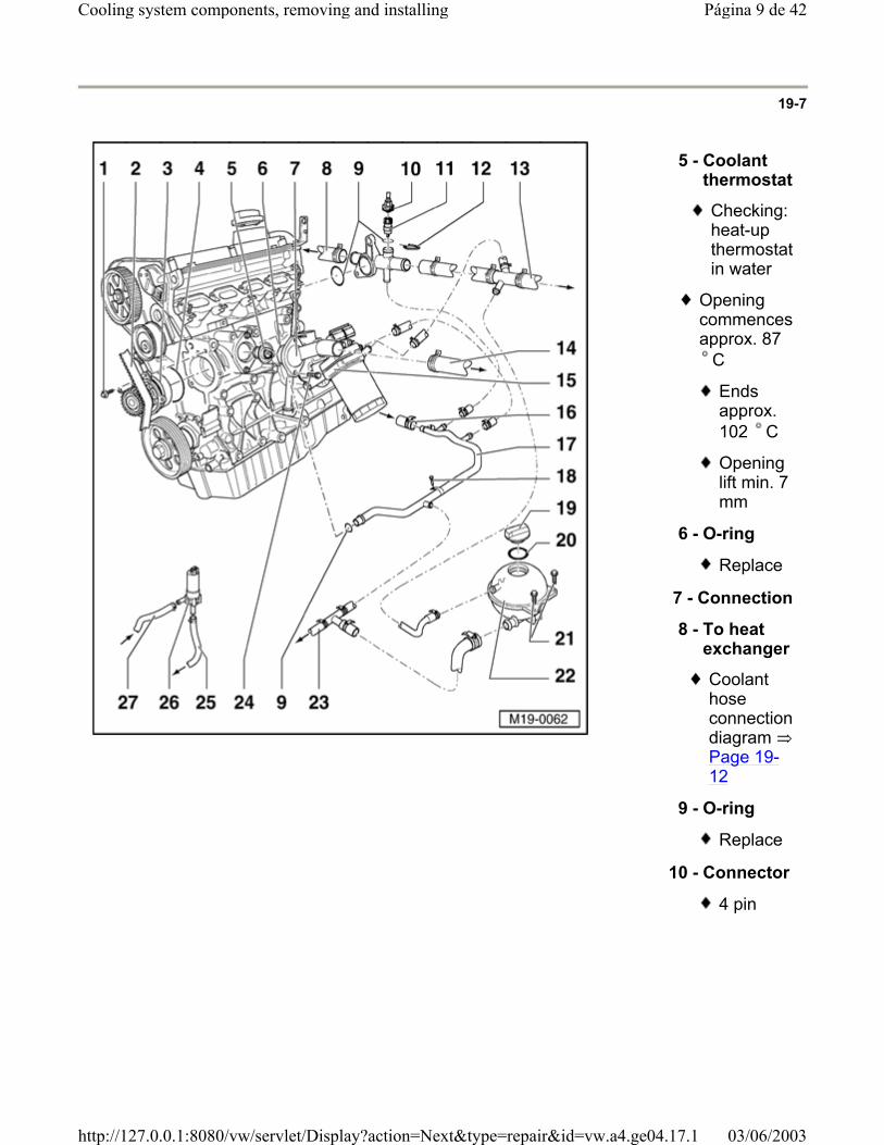
5 - Coolant thermostat
Checking: heat-up thermostat in water
Opening commences approx. 87
C
Ends approx. 102 C
Opening lift min. 7 mm
6 - O-ring
Replace
7 - Connection
8 - To heat exchanger
Coolant hose connection diagram Page 19-12
9 - O-ring
Replace
10 - Connector
4 pin
Página 9 de 42Cooling system components, removing and installing
03/06/2003http://127.0.0.1:8080/vw/servlet/Display?action=Next&type=repair&id=vw.a4.ge04.17.1
19-8
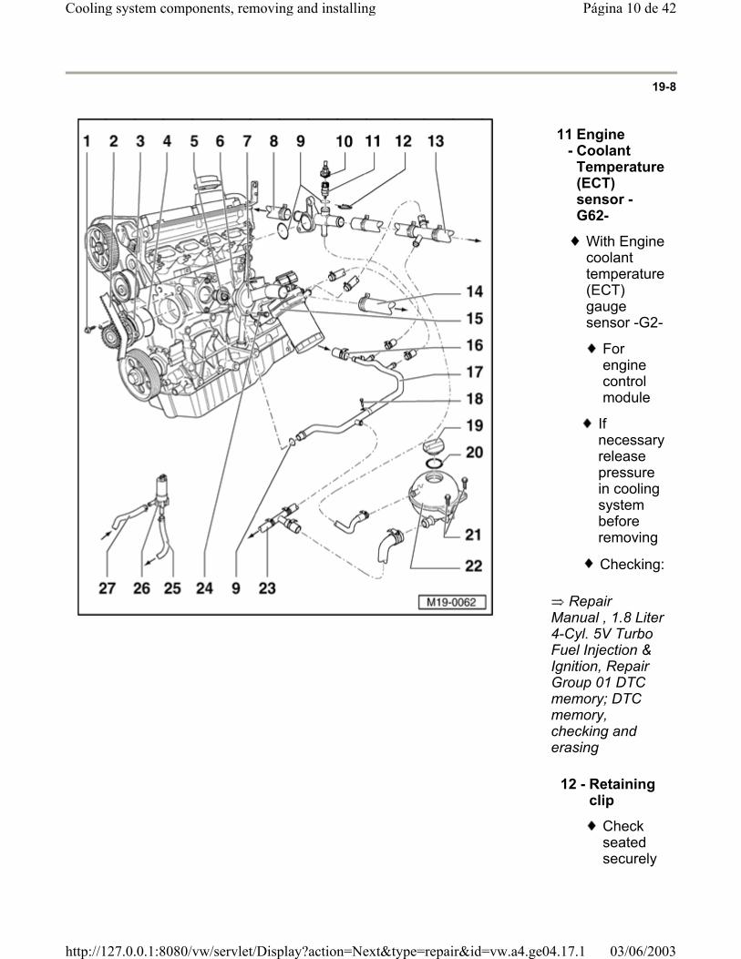
Repair Manual , 1.8 Liter 4-Cyl. 5V Turbo Fuel Injection & Ignition, Repair Group 01 DTC memory; DTC memory, checking and erasing
11 -
Engine Coolant Temperature (ECT) sensor -G62-
With Engine coolant temperature (ECT) gauge sensor -G2-
For engine control module
If necessary release pressure in cooling system before removing
Checking:
12 - Retaining clip
Check seated securely
Página 10 de 42Cooling system components, removing and installing
03/06/2003http://127.0.0.1:8080/vw/servlet/Display?action=Next&type=repair&id=vw.a4.ge04.17.1
13 - Upper coolant hose
Secured to radiator with retaining clip
Check securely seated
Coolant hose connection diagram Page 19-12
14 - Lower coolant hose
Secured to radiator with retaining clip
Check securely seated
Coolant hose connection diagram Page 19-12
Página 11 de 42Cooling system components, removing and installing
03/06/2003http://127.0.0.1:8080/vw/servlet/Display?action=Next&type=repair&id=vw.a4.ge04.17.1

19-9
15 - Oil cooler
Removing and installing
Page 17-11 , item 22
16 - From heat exchanger
Coolant hose connection diagram Page 19-12
17 - Lower coolant pipe
Coolant hose connection diagram Page 19-12
18 - 10 Nm
19 - Cap
Check with cooling system tester V.A.G 1274 and adapter V.A.G 1274/9
Test pressure 1.4 to 1.6 bar
Página 12 de 42Cooling system components, removing and installing
03/06/2003http://127.0.0.1:8080/vw/servlet/Display?action=Next&type=repair&id=vw.a4.ge04.17.1
20 - Seal
Replace if damaged
21 - 10 Nm
Página 13 de 42Cooling system components, removing and installing
03/06/2003http://127.0.0.1:8080/vw/servlet/Display?action=Next&type=repair&id=vw.a4.ge04.17.1
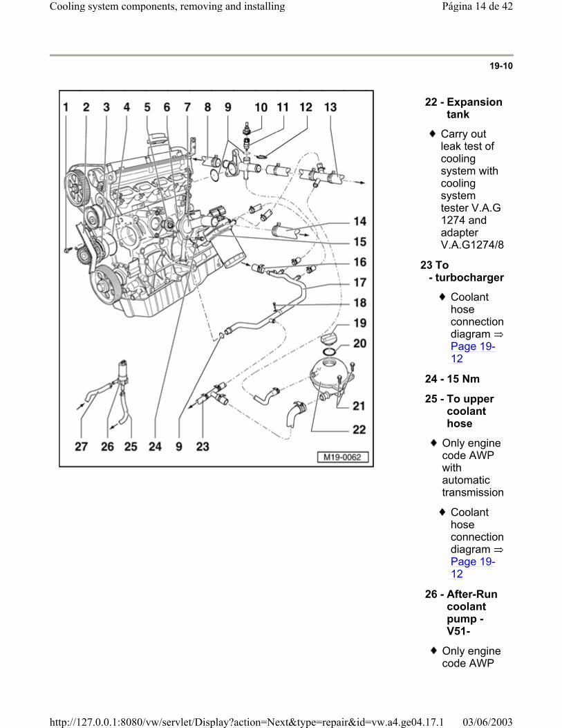
19-10
22 - Expansion tank
Carry out leak test of cooling system with cooling system tester V.A.G 1274 and adapter V.A.G1274/8
23 -
To turbocharger
Coolant hose connection diagram Page 19-12
24 - 15 Nm
25 - To upper coolant hose
Only engine code AWP with automatic transmission
Coolant hose connection diagram Page 19-12
26 - After-Run coolant pump -V51-
Only engine code AWP
Página 14 de 42Cooling system components, removing and installing
03/06/2003http://127.0.0.1:8080/vw/servlet/Display?action=Next&type=repair&id=vw.a4.ge04.17.1
with automatic transmission
Coolant hose connection diagram Page 19-12
Checking Page
19-34
Página 15 de 42Cooling system components, removing and installing
03/06/2003http://127.0.0.1:8080/vw/servlet/Display?action=Next&type=repair&id=vw.a4.ge04.17.1

19-11
27 -
From turbocharger
Only engine code AWP with automatic transmission
Coolant hose connection diagram Page 19-12
Página 16 de 42Cooling system components, removing and installing
03/06/2003http://127.0.0.1:8080/vw/servlet/Display?action=Next&type=repair&id=vw.a4.ge04.17.1
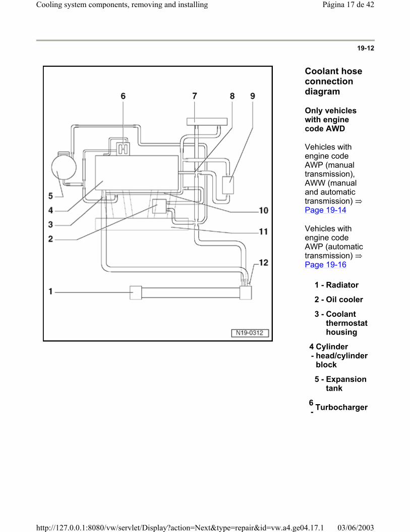
19-12
Coolant hose connection diagram
Only vehicles with engine code AWD
Vehicles with engine code AWP (manual transmission), AWW (manual and automatic transmission) Page 19-14
Vehicles with engine code AWP (automatic transmission) Page 19-16
1 - Radiator
2 - Oil cooler
3 - Coolant thermostat housing
4 -
Cylinder head/cylinder block
5 - Expansion tank
6 - Turbocharger
Página 17 de 42Cooling system components, removing and installing
03/06/2003http://127.0.0.1:8080/vw/servlet/Display?action=Next&type=repair&id=vw.a4.ge04.17.1
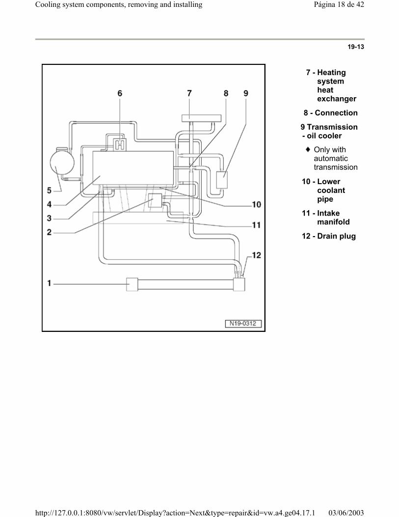
19-13
7 - Heating system heat exchanger
8 - Connection
9 -
Transmission oil cooler
Only with automatic transmission
10 - Lower coolant pipe
11 - Intake manifold
12 - Drain plug
Página 18 de 42Cooling system components, removing and installing
03/06/2003http://127.0.0.1:8080/vw/servlet/Display?action=Next&type=repair&id=vw.a4.ge04.17.1
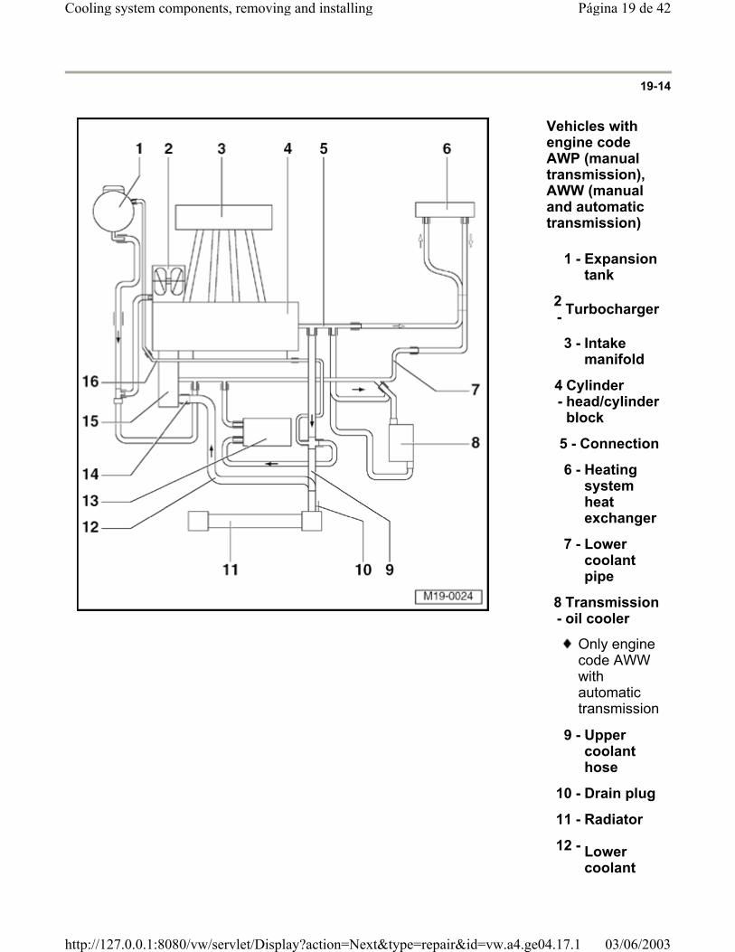
19-14
Vehicles with engine code AWP (manual transmission), AWW (manual and automatic transmission)
1 - Expansion tank
2 - Turbocharger
3 - Intake manifold
4 -
Cylinder head/cylinder block
5 - Connection
6 - Heating system heat exchanger
7 - Lower coolant pipe
8 -
Transmission oil cooler
Only engine code AWW with automatic transmission
9 - Upper coolant hose
10 - Drain plug
11 - Radiator
12 - Lower coolant
Página 19 de 42Cooling system components, removing and installing
03/06/2003http://127.0.0.1:8080/vw/servlet/Display?action=Next&type=repair&id=vw.a4.ge04.17.1

hose
Página 20 de 42Cooling system components, removing and installing
03/06/2003http://127.0.0.1:8080/vw/servlet/Display?action=Next&type=repair&id=vw.a4.ge04.17.1
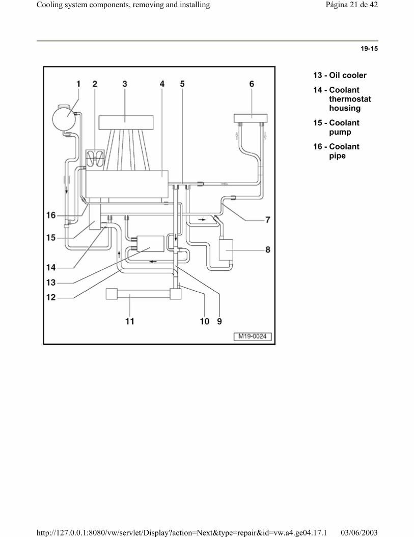
19-15
13 - Oil cooler
14 - Coolant thermostat housing
15 - Coolant pump
16 - Coolant pipe
Página 21 de 42Cooling system components, removing and installing
03/06/2003http://127.0.0.1:8080/vw/servlet/Display?action=Next&type=repair&id=vw.a4.ge04.17.1
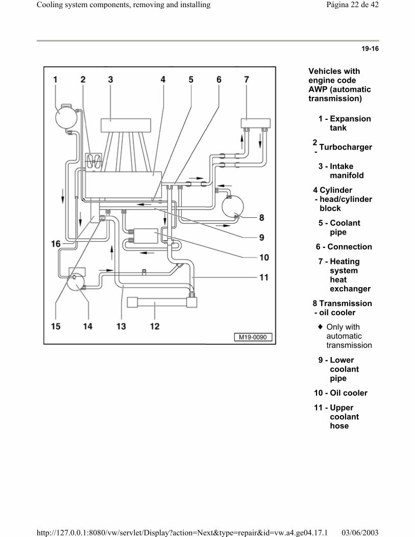
19-16
Vehicles with engine code AWP (automatic transmission)
1 - Expansion tank
2 - Turbocharger
3 - Intake manifold
4 -
Cylinder head/cylinder block
5 - Coolant pipe
6 - Connection
7 - Heating system heat exchanger
8 -
Transmission oil cooler
Only with automatic transmission
9 - Lower coolant pipe
10 - Oil cooler
11 - Upper coolant hose
Página 22 de 42Cooling system components, removing and installing
03/06/2003http://127.0.0.1:8080/vw/servlet/Display?action=Next&type=repair&id=vw.a4.ge04.17.1
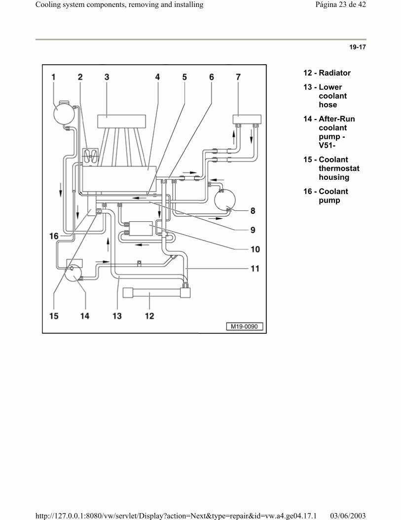
19-17
12 - Radiator
13 - Lower coolant hose
14 - After-Run coolant pump -V51-
15 - Coolant thermostat housing
16 - Coolant pump
Página 23 de 42Cooling system components, removing and installing
03/06/2003http://127.0.0.1:8080/vw/servlet/Display?action=Next&type=repair&id=vw.a4.ge04.17.1
19-18
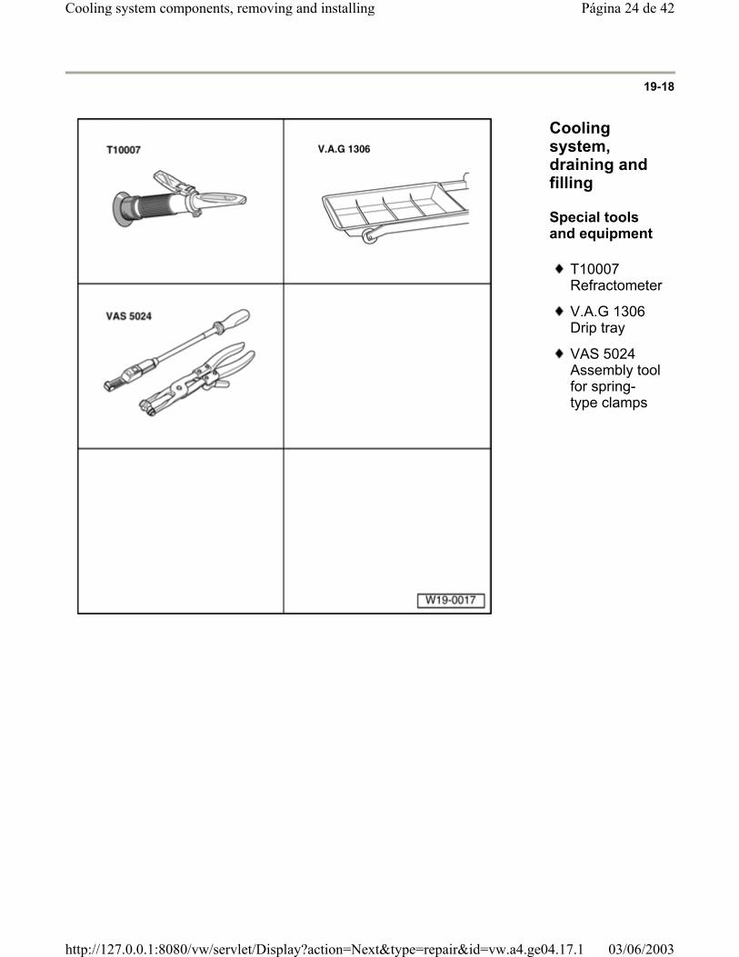
Cooling system, draining and filling
Special tools and equipment
T10007 Refractometer
V.A.G 1306 Drip tray
VAS 5024 Assembly tool for spring-type clamps
Página 24 de 42Cooling system components, removing and installing
03/06/2003http://127.0.0.1:8080/vw/servlet/Display?action=Next&type=repair&id=vw.a4.ge04.17.1
19-19
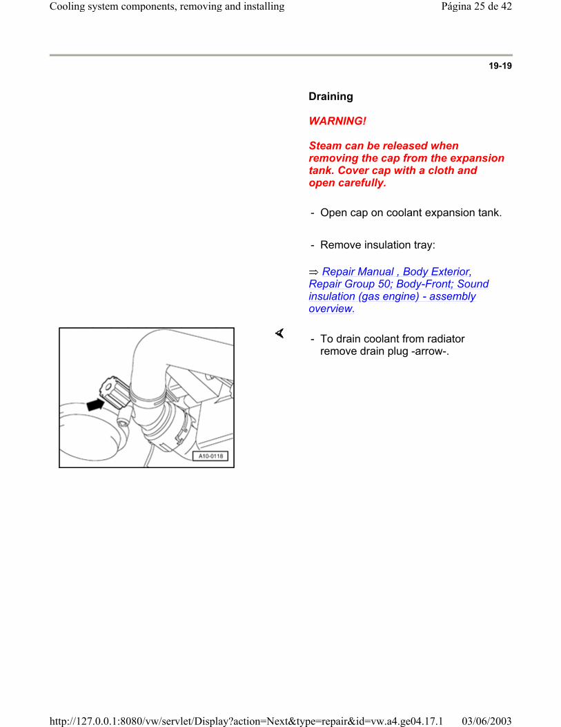
Draining
WARNING!
Steam can be released when removing the cap from the expansion tank. Cover cap with a cloth and open carefully.
- Open cap on coolant expansion tank.
- Remove insulation tray:
Repair Manual , Body Exterior, Repair Group 50; Body-Front; Sound insulation (gas engine) - assembly overview.
- To drain coolant from radiator remove drain plug -arrow-.
Página 25 de 42Cooling system components, removing and installing
03/06/2003http://127.0.0.1:8080/vw/servlet/Display?action=Next&type=repair&id=vw.a4.ge04.17.1
19-20
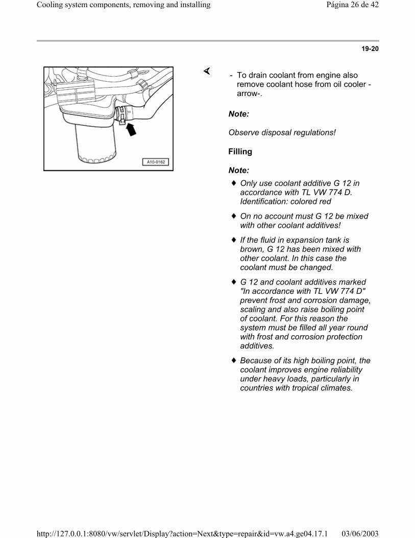
Note:
Observe disposal regulations!
Filling
Note:
- To drain coolant from engine also remove coolant hose from oil cooler -arrow-.
Only use coolant additive G 12 in accordance with TL VW 774 D. Identification: colored red
On no account must G 12 be mixed with other coolant additives!
If the fluid in expansion tank is brown, G 12 has been mixed with other coolant. In this case the coolant must be changed.
G 12 and coolant additives marked "In accordance with TL VW 774 D" prevent frost and corrosion damage, scaling and also raise boiling point of coolant. For this reason the system must be filled all year round with frost and corrosion protection additives.
Because of its high boiling point, the coolant improves engine reliability under heavy loads, particularly in countries with tropical climates.
Página 26 de 42Cooling system components, removing and installing
03/06/2003http://127.0.0.1:8080/vw/servlet/Display?action=Next&type=repair&id=vw.a4.ge04.17.1
19-21
Protection against frost must be assured to about -25 C (in arctic climatic countries to about -35 C).
The coolant concentration must not be reduby adding water even in warmer seasons anwarmer countries. The anti-freeze ratio musat least 40 %.
If for climatic reasons a greater frost protectis required, the amount of G 12 can be increased, but only up to 60 % (frost protecto about -40 C), as otherwise frost protectis reduced again and cooling effectiveness also reduced.
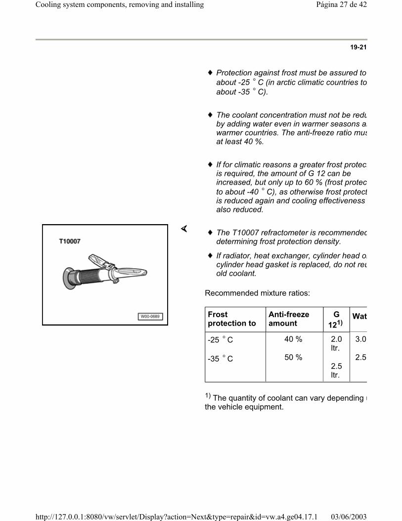
Recommended mixture ratios:
1) The quantity of coolant can vary depending uthe vehicle equipment.
The T10007 refractometer is recommendeddetermining frost protection density.
If radiator, heat exchanger, cylinder head orcylinder head gasket is replaced, do not reuold coolant.
Frost protection to
Anti-freeze amount
G 121)
Wat
-25 C
-35 C
40 %
50 %
2.0 ltr.
2.5 ltr.
3.0
2.5
Página 27 de 42Cooling system components, removing and installing
03/06/2003http://127.0.0.1:8080/vw/servlet/Display?action=Next&type=repair&id=vw.a4.ge04.17.1
19-22
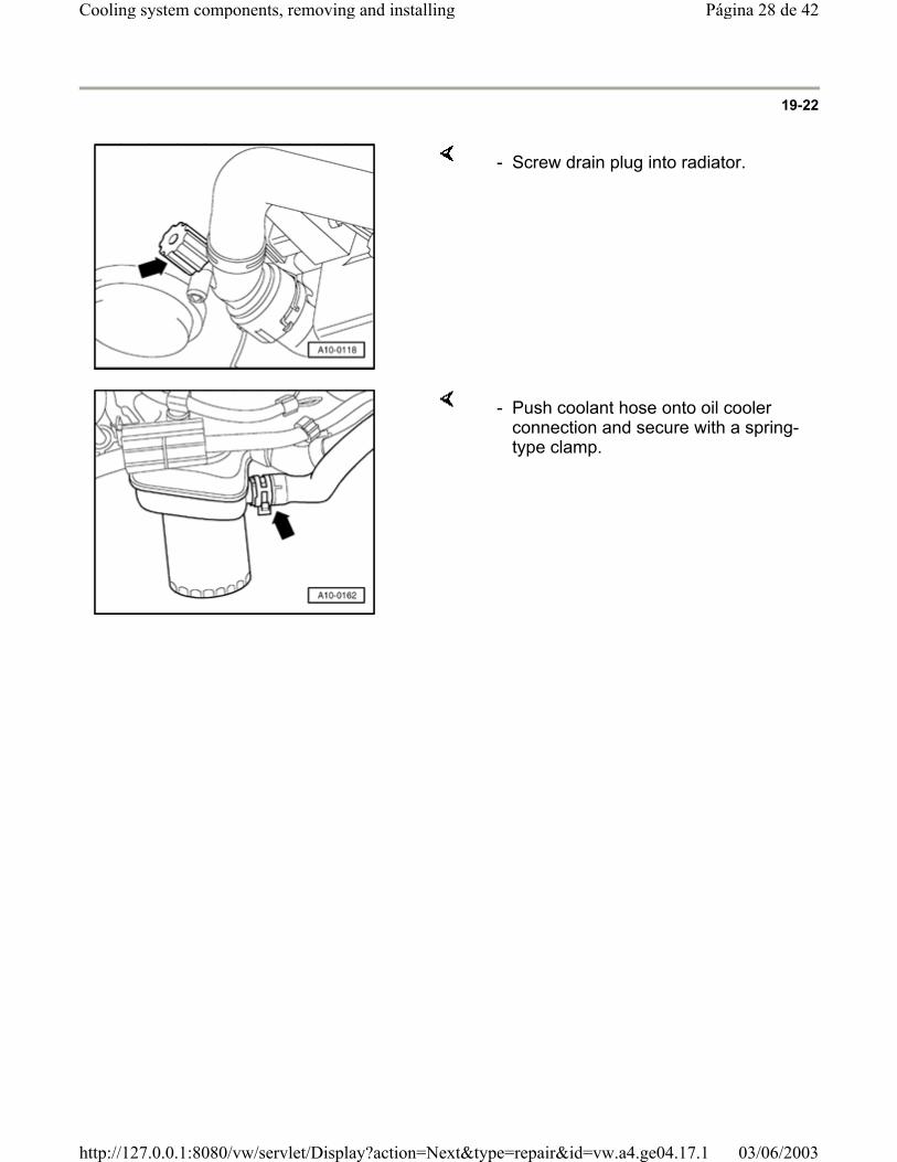
- Screw drain plug into radiator.
- Push coolant hose onto oil cooler connection and secure with a spring-type clamp.
Página 28 de 42Cooling system components, removing and installing
03/06/2003http://127.0.0.1:8080/vw/servlet/Display?action=Next&type=repair&id=vw.a4.ge04.17.1
19-23
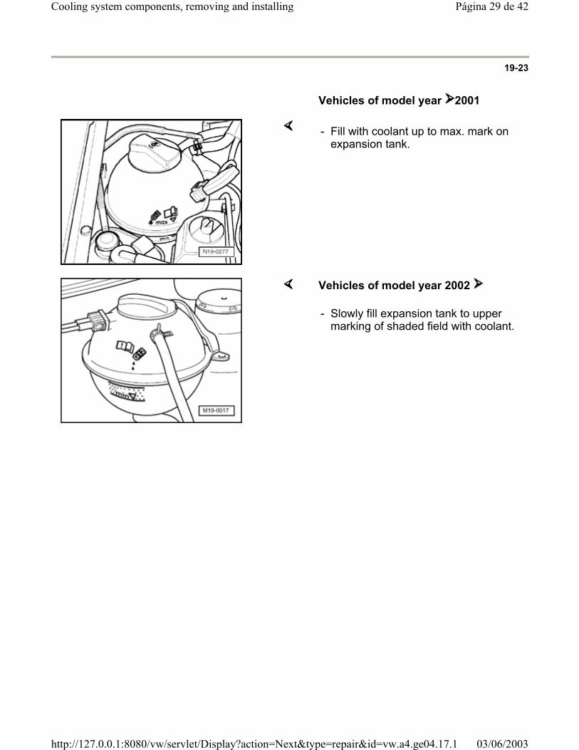
Vehicles of model year 2001
- Fill with coolant up to max. mark on expansion tank.
Vehicles of model year 2002
- Slowly fill expansion tank to upper marking of shaded field with coolant.
Página 29 de 42Cooling system components, removing and installing
03/06/2003http://127.0.0.1:8080/vw/servlet/Display?action=Next&type=repair&id=vw.a4.ge04.17.1
19-24
Continuation for all vehicles
- Install expansion tank cap.
- Switch off heater and air conditioner.
- Start engine and maintain an engine speed of about 2000 RPM for approx. 3 minutes.
- Run engine until coolant fan starts.
WARNING!
Steam can be released when removing the cap from the expansion tank. Cover cap with a cloth and open carefully.
- Check coolant level and top-up if necessary.
Vehicles of model year 2001
When engine is at normal operating temperature, coolant level must be on the max. mark. When engine is cold, between min. and max. marks.
Vehicles of model year 2002
When engine is at normal operating temperature, coolant level must be at upper marking of shaded field.
When engine is cold, coolant level should be at approximately middle of shaded field.
Página 30 de 42Cooling system components, removing and installing
03/06/2003http://127.0.0.1:8080/vw/servlet/Display?action=Next&type=repair&id=vw.a4.ge04.17.1
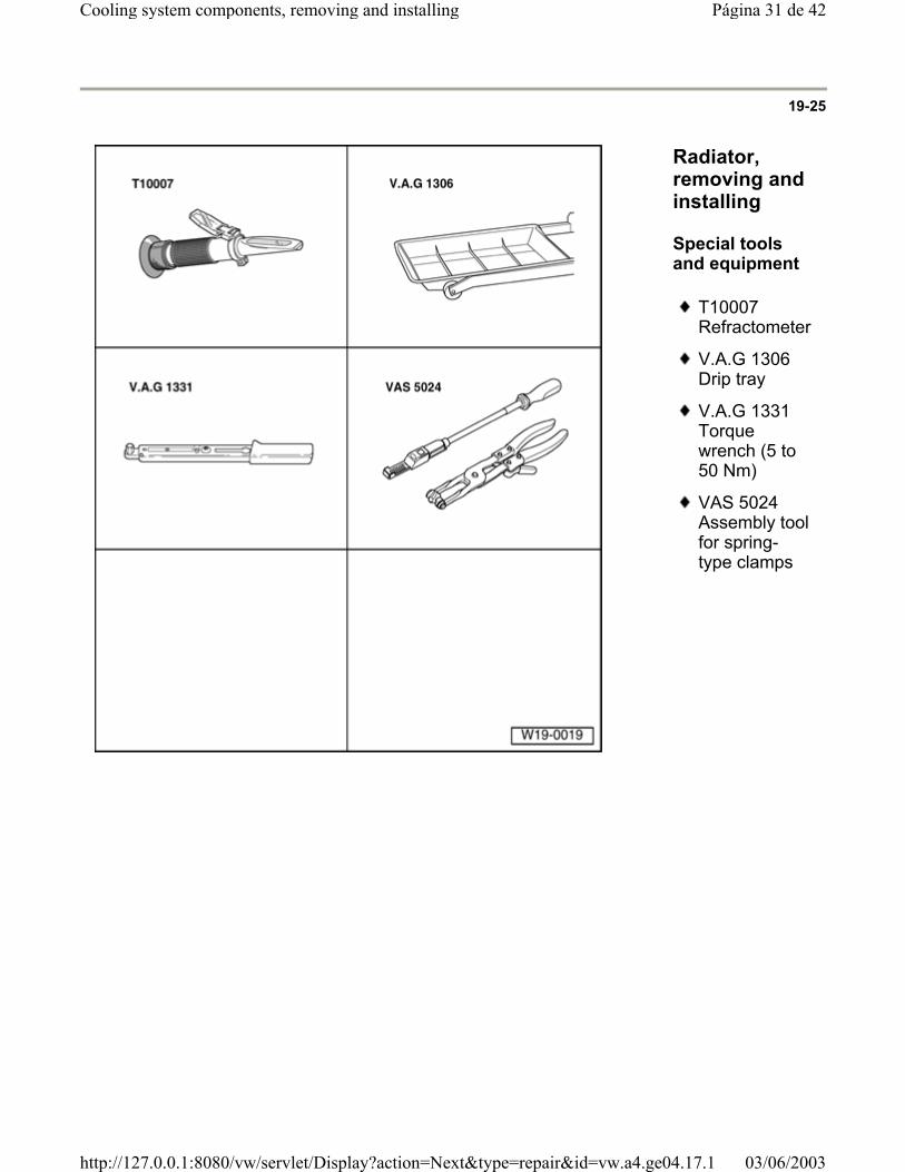
19-25
Radiator, removing and installing
Special tools and equipment
T10007 Refractometer
V.A.G 1306 Drip tray
V.A.G 1331 Torque wrench (5 to 50 Nm)
VAS 5024 Assembly tool for spring-type clamps
Página 31 de 42Cooling system components, removing and installing
03/06/2003http://127.0.0.1:8080/vw/servlet/Display?action=Next&type=repair&id=vw.a4.ge04.17.1
19-26
Removing
- Drain coolant Page 19-18 .
- Remove front bumper:
Repair Manual , Body Exterior, Repair Group 63; Front bumper, removing and installing front bumper
- Remove coolant hoses from radiator.
- Disconnect connector of thermo-switch.
- Bring lock carrier into service position:
Repair Manual , Body Exterior, Repair Group 50; Body, front; Lock carrier service position
- Remove radiator securing bolts and take radiator with fan out downward.
Note:
Vehicles with air conditioner:
- Observe additional information and removal work Page 19-27 .
Installing
Installation is carried out in the reverse order. Note the following:
Filling with new coolant Page 19-18 .
Página 32 de 42Cooling system components, removing and installing
03/06/2003http://127.0.0.1:8080/vw/servlet/Display?action=Next&type=repair&id=vw.a4.ge04.17.1

19-27
Additional information and removal work on vehicles with air conditioner
CAUTION!
The air conditioner refrigerant circuit must not be opened.
Note:
To prevent damage to condenser also to the refrigerant lines/hoses, make sure that the lines and hoses are not stretched, kinked or bent.
- Remove retaining clamp(s) from refrigerant lines.
- Remove condenser from radiator and secure to lock carrier.
Página 33 de 42Cooling system components, removing and installing
03/06/2003http://127.0.0.1:8080/vw/servlet/Display?action=Next&type=repair&id=vw.a4.ge04.17.1

19-28
Coolant pump, removing and installing
Special tools and equipment
T10007 Refractometer
V.A.G 1306 Drip tray
V.A.G 1331 Torque wrench (5 to 50 Nm)
VAS 5024 Assembly tool for spring-type clamps
Página 34 de 42Cooling system components, removing and installing
03/06/2003http://127.0.0.1:8080/vw/servlet/Display?action=Next&type=repair&id=vw.a4.ge04.17.1
19-29
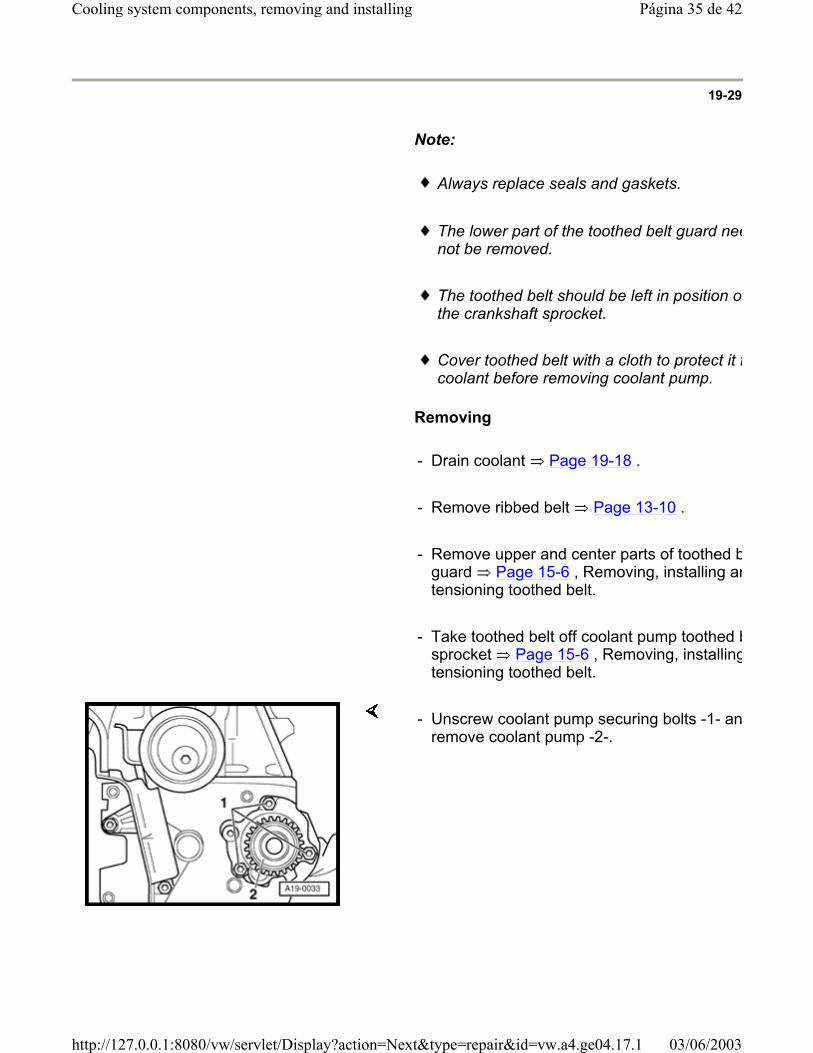
Note:
Always replace seals and gaskets.
The lower part of the toothed belt guard neenot be removed.
The toothed belt should be left in position onthe crankshaft sprocket.
Cover toothed belt with a cloth to protect it fcoolant before removing coolant pump.
Removing
- Drain coolant Page 19-18 .
- Remove ribbed belt Page 13-10 .
- Remove upper and center parts of toothed bguard Page 15-6 , Removing, installing antensioning toothed belt.
- Take toothed belt off coolant pump toothed bsprocket Page 15-6 , Removing, installingtensioning toothed belt.
- Unscrew coolant pump securing bolts -1- anremove coolant pump -2-.
Página 35 de 42Cooling system components, removing and installing
03/06/2003http://127.0.0.1:8080/vw/servlet/Display?action=Next&type=repair&id=vw.a4.ge04.17.1
19-30
Installing
Installation is carried out in the reverse order. Note the following:
- Moisten new O ring with coolant.
- Insert coolant pump into cylinder block and tighten securing bolts. Tightening torque: 15 Nm
Note:
The coolant pump plug faces downward.
- Install toothed belt and adjusting timing Page 15-6 .
- Install ribbed belt Page 13-10 .
Filling with new coolant Page 19-18 .
Página 36 de 42Cooling system components, removing and installing
03/06/2003http://127.0.0.1:8080/vw/servlet/Display?action=Next&type=repair&id=vw.a4.ge04.17.1
19-31
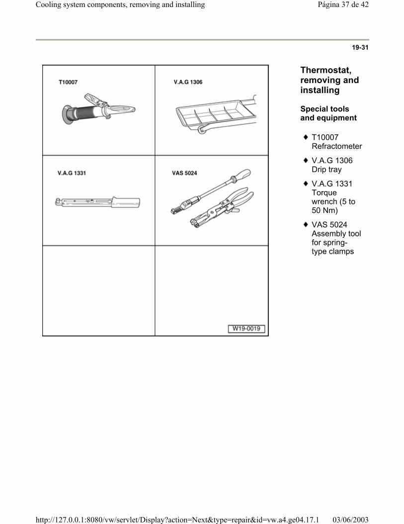
Thermostat, removing and installing
Special tools and equipment
T10007 Refractometer
V.A.G 1306 Drip tray
V.A.G 1331 Torque wrench (5 to 50 Nm)
VAS 5024 Assembly tool for spring-type clamps
Página 37 de 42Cooling system components, removing and installing
03/06/2003http://127.0.0.1:8080/vw/servlet/Display?action=Next&type=repair&id=vw.a4.ge04.17.1
19-32
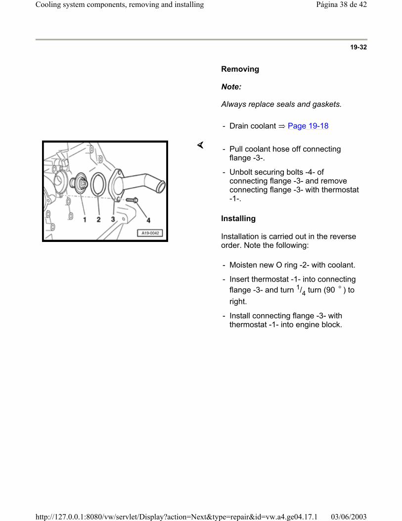
Removing
Note:
Always replace seals and gaskets.
- Drain coolant Page 19-18
Installing
Installation is carried out in the reverse order. Note the following:
- Pull coolant hose off connecting flange -3-.
- Unbolt securing bolts -4- of connecting flange -3- and remove connecting flange -3- with thermostat -1-.
- Moisten new O ring -2- with coolant.
- Insert thermostat -1- into connecting flange -3- and turn 1/4 turn (90 ) to right.
- Install connecting flange -3- with thermostat -1- into engine block.
Página 38 de 42Cooling system components, removing and installing
03/06/2003http://127.0.0.1:8080/vw/servlet/Display?action=Next&type=repair&id=vw.a4.ge04.17.1
19-33
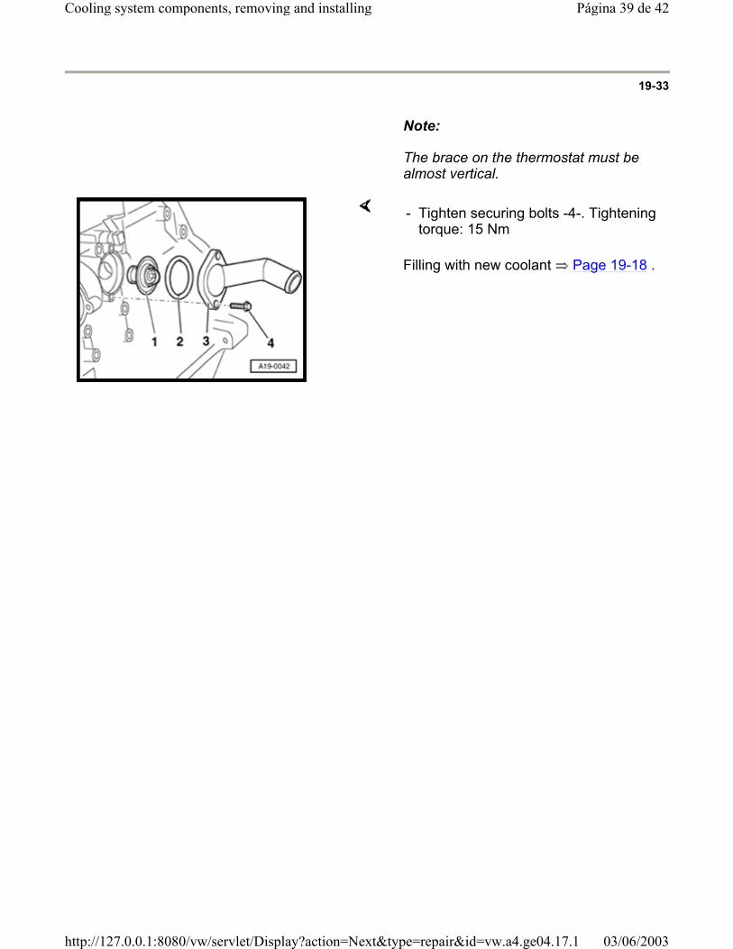
Note:
The brace on the thermostat must be almost vertical.
Filling with new coolant Page 19-18 .
- Tighten securing bolts -4-. Tightening torque: 15 Nm
Página 39 de 42Cooling system components, removing and installing
03/06/2003http://127.0.0.1:8080/vw/servlet/Display?action=Next&type=repair&id=vw.a4.ge04.17.1
19-34
After-run coolant pump, checking
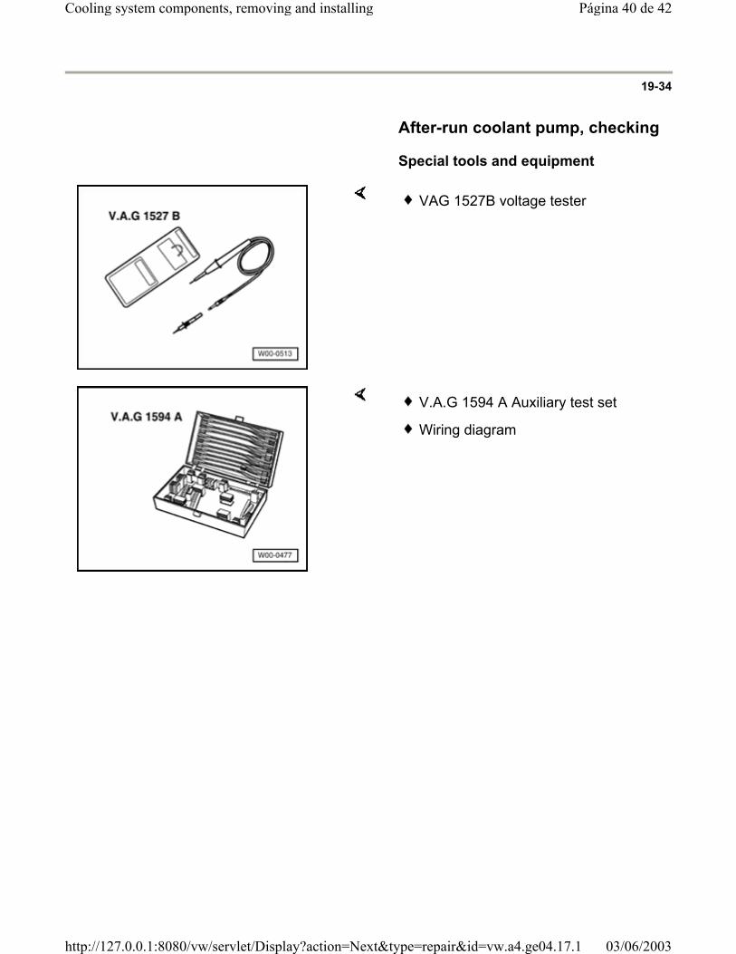
Special tools and equipment
VAG 1527B voltage tester
V.A.G 1594 A Auxiliary test set
Wiring diagram
Página 40 de 42Cooling system components, removing and installing
03/06/2003http://127.0.0.1:8080/vw/servlet/Display?action=Next&type=repair&id=vw.a4.ge04.17.1
19-35
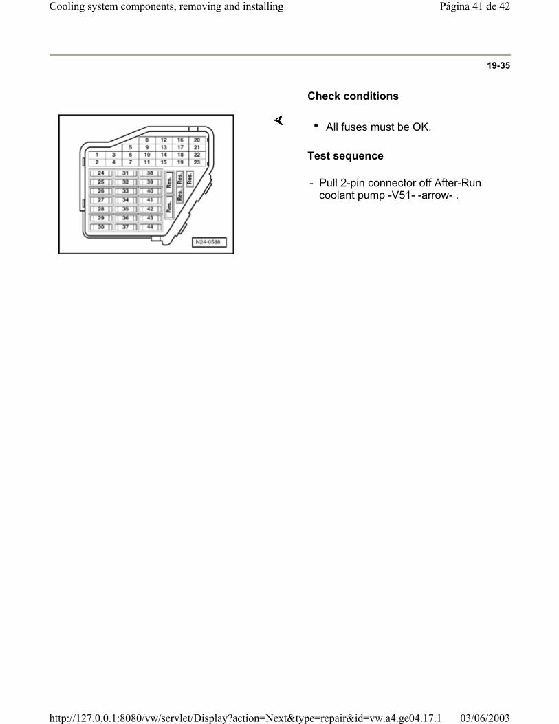
Check conditions
Test sequence
All fuses must be OK.
- Pull 2-pin connector off After-Run coolant pump -V51- -arrow- .
Página 41 de 42Cooling system components, removing and installing
03/06/2003http://127.0.0.1:8080/vw/servlet/Display?action=Next&type=repair&id=vw.a4.ge04.17.1
19-36
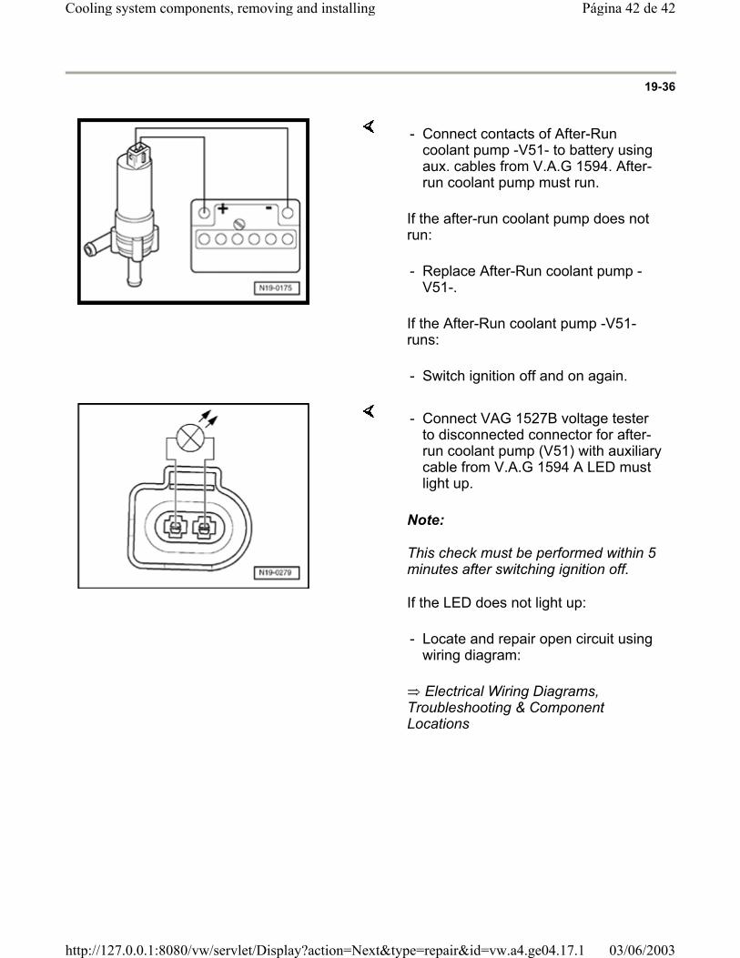
If the after-run coolant pump does not run:
If the After-Run coolant pump -V51- runs:
- Connect contacts of After-Run coolant pump -V51- to battery using aux. cables from V.A.G 1594. After-run coolant pump must run.
- Replace After-Run coolant pump -V51-.
- Switch ignition off and on again.
Note:
This check must be performed within 5 minutes after switching ignition off.
If the LED does not light up:
Electrical Wiring Diagrams, Troubleshooting & Component Locations
- Connect VAG 1527B voltage tester to disconnected connector for after-run coolant pump (V51) with auxiliary cable from V.A.G 1594 A LED must light up.
- Locate and repair open circuit using wiring diagram:
Página 42 de 42Cooling system components, removing and installing
03/06/2003http://127.0.0.1:8080/vw/servlet/Display?action=Next&type=repair&id=vw.a4.ge04.17.1
Related Documents