Supplementary To Form No: 6088A - DUNNAM·!iUSM Products Thal Perf orm ...By people IM_io Care Water· Cooled Rotary Screw Tandem Water Chillers SIS to 720 Tons MO D EL: WCFX 30 - 30 WCFX 30-33 WCFX 33-33 WCFX 33-36 WCFX 36-36

Welcome message from author
This document is posted to help you gain knowledge. Please leave a comment to let me know what you think about it! Share it to your friends and learn new things together.
Transcript
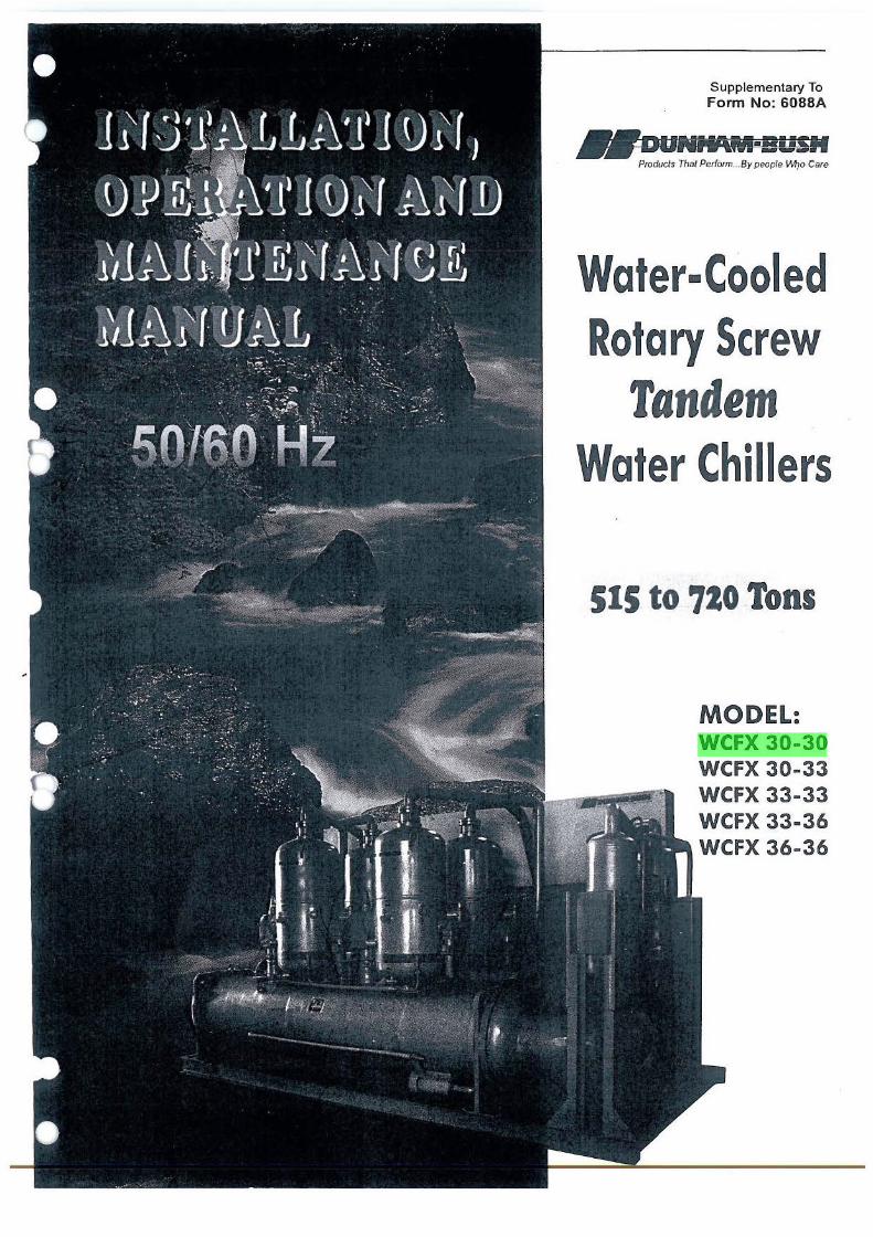
Supplementary To Form No: 6088A
- DUNNAM·!iUSM Products Thal Perform ... By people IM_io Care
Water· Cooled Rotary Screw
Tandem Water Chillers
SIS to 720 Tons
MODEL: WCFX 30-30 WCFX 30-33 WCFX 33-33 WCFX 33-36 WCFX 36-36
NL35077
Highlight
TABLE OF CONTENTS
1.0 GENERAL INFORMATION
1.1 RECEIVING AND INSPECTION ...................... .4
1.2 RIGGING AND MOVING .................................. 4
l.3 DIMENSIONAL DATA . .......... ~ .......................... .4
1.4 APPLICATION PRECAUTIONS . ......... ... ........ .. 4 1.4 .I Water Connections .................... ... ................. .... .. 4 1.4.2 Chilled Water Flow ........ ........... ... .. ..................... 4 1.4.3 Water Cooled Condenser ............... ..... ................. 9 1.4.4 Condensing Water Treatment. ........ ......... ..... .... ... 9
2.0 INSTALLATION 2.1 FOUNDATION .............. .......... ......... ................... 10
2.2 VIBRATIONISOLATION .. ................................ 10
2.3 WATER PIPING CONNECTIONS ..... ........ .. ..... 10
2.4 ELECTRICAL WIRING ................ ...... ............. 10
2.S CONTROLS ............... .............................. ..... .... ... 13
2.5.1 Connections .......... ...................... .. ... ...... .... ....... .. . 13 2.5.2 Settings ...... ............................. .......... ..... ..... .... ..... 13
2.6 REQUEST FOR START-UP REPRESENTATIVE .................. .......................... 13
3.0 OPERATION 3.1 SYSTEM WATER FLOW RATE ....................... 14
3.2 SEASONAL SHUT-DOWN PROCEDURE ........ 14
3.3 SEASONAL START-UP PROCEDURE ......... ..... 14
3.4 SAFETY RELIEF VALVES ........... ..................... 15
3.S REFRIGERATION CYCLE ... .. ........................... 15
3.6 OIL MANAGEMENT SYSTEMS ..... .................. 15
3.7 HYDRAULIC CAPACITY CONTROL SYSTEM .............. ................................................ 17
3.8 FREEZE PROTECTION ..... ........ ... ..................... 18
3.8. l Standby At Low Ambient Temperatures ........ ..... 18 3.8.2 In Operation ........ ........... ....... .............. ................ 18 3.8.3 During Maintenance ............ ........ ... .. .... .... ....... .... I 8
4.0 ELECTRICAL 4.1 50/60HZELECTRICALDATA ........................... 19
4.2 WIRING DIAGRAM .... ......... .............................. 20
4.3 TYPICAL OPERATION ..... ................................ 20
4.4 MICROCOMPUTER CONTROLLER ........... .... 20 4.4.I To Display Data From The Menu ....... ................. 23 4.4.2 To Reset All Control Points To Computer
Control .. .. .... .... ...... ............ .......................... .... .. .. 23 4.4.3 To Display Alarms ................ ............. ........... .. .. .. 23 4.4.4 To Become Authorized .... ..... ...... ........ .......... ... ... . 23 4.4.5 To Alter Setpoint Data ............. ....... .................... . 23 4.4.6 To Calibrate Temperature And Pressure
Sensors ........ ........... ... ...... .. ........... ....... ........... ... .. 24
4.4.7 To Set Date And Time ...... ...... .. ................ ........... 24 4.4.8 To Display Data Without Accessing Operation ...... 24 4.4 .9 Unit Schedule Of Operation ...... ........... ......... .. ....... 24
4.S CONTROL FUNCTIONS ...................................... 25
4 .5. l Chilled Water Pump Interlock And Flow Switch .26 4.5.2 Customer Control Interlock ............ ........... ....... .... 26 4.5.3 Anti- Recycle Timer ............. .. .... ...... ...... .............. 26 4.5.4 Part Wind Start Timer ...................... ......... .... ....... 26 4.5.5 Load Control ...... ..... .... ........... ...... .... ..... ......... ...... 26 4.5.6 Ramp Control .................. .... ...... ... ..... .. ..... ........... 26 4.5.7 Current Limiting ......... .. .. .... .... ....... ...... .. ... ... .... .. .. 27 4.5.8 Staging Control ................ ..................... ............ ... 27 4.5.9 Modmotor Setback Control... .......... ... .. ................ 27 4.5. I 0 Evaporator Pressure Control .......... ..... .......... ...... . 27 4.5.11 Manual Lead-Lag Control. .... ....... ............. .......... . 28 4.5.12 Manual Load-Unload Control ............. .... ............. 28 4.5.13 Chilled Water Reset And Customer Control
4 .5.14 4 .5.15 4 .5.16
~~~r~::s·;;~~~·:: ::::::: : : :::::::::: ::::: ::::: ::::::: ::::: :::: : :::;: c· Sump Heater Control ......... ... ..... .......... ....... ......... 29 Low Pressure Load Limit ............. .. .. ... ....... .. ...... .. 29
4 .5.17 High Pressure Load Limit .... .... ........ ........ .. .. ........ 29
4.6 SAFETY FUNCTIONS .. .... ...... .............. ................ 29
4.6.1 Control Power Loss .............. ........ .... .. .. ............ ... 29 4.6.2 Low Pressure Cut-off ..... ........ .............. ....... ........ . 29 4 .6.3 Evaporator Freeze Shutoff .... ........... ..... .. ...... ....... . 29 4.6.4 High Pressure Cut-Off ... .. .. ......... .... ....... ..... .... ..... 30 4.6.5 Oil Level Sensor. ........................ .. ..... ..... .... .... ..... . 30 4.6.6 1-ligh Oii Temperature Thermostat ....................... 30 4.6.7 Motor Temperature Protector ........ ...... ... .............. 30 4.6.8 Overload Protector ......... ... ..... ........... ..... ........... ... 30 4.6.9 Undcrvoltage Relay .......... ....... .. .. ....... .... ... .... ....... 31 4.6.10 SensorAlarm ............. ........... .......... ..... .. .............. 31 4.6.11 No-Stop Alarm ........ ............. ............. ...... .......... ... 31 4.6.12 Low Differential Pressure Alarm ............. .. ......... .. 31
s.o MAINTENANCE
5.1 GENERAL. .............. ..... .. ........................................ 32 (
5.2 PERIODIC INSPECTION ..................... ........ ........ 32
5.3 MONTHLY INSPECTION . ... ... ............................ 32
5.4 WATER SIDE CLEANING OF VESSELS ........... 32
5.5 ELECTRICAL MALFUNCTION ......................... 34
S.6 CHARGING ............................ ................. .............. 34
5.6.I Refrigerant Charge ............. ...... .... .. .. .... ... ..... ...... .... 34 5.6.2 Oil Charge ............. ... .... ... .... ...... ..... ....... ................. 34
5.7 TROUBLESHOOTING ......... ... ............ ................. 35
5.8 SAMPLE LOG SHEET .................... ..................... 37
6.0 RENEWAL PARTS. 6.1 COMPRESSOR & COMPRESSOR PARTS ...... .. 38
6.2 WCFX TANDEM ELECTRICALPARTS ............ 39
6.3 UNIT MODEL NUMBER CODE ... ... .......... ......... .40
(
INTRODUCTION
This equipment is a factory built and tested packaged chiller designed for the
purpose of cooling water or other non-corrosive liquid. The liquid to be cooled
is to be circulated through the tubes of a refrigerant evaporator where the
temperature is reduced to the desired level. The heat absorbed by the
refrigerant in the evaporator is rejected via the condenser where it raises the
temperature of another liquid stream (usually water) being circulated through
the tubes. This heat is usually rejected by a cooling tower or closed circuit
r cooler.
r
To assure satisfactory operation and to avoid damage to the unit, the
installation should be made by a qualified refrigeration mechanic. It is
assumed that the reader of this manual and those who install, operate and
maintain this equipment have a basic understanding of the principles of air
conditioning, refrigeration and electrical controls. These instructions are
general in nature and are for standard catalog units. Non-standard units may
vary in some respects from these instructions. . \
Your Dunham-Bush packaged chiller has been manufactured under a careful
quality control system. It has been performance tested at the factory at
specified field operating conditions as a final verification of reliability. If it is
installed, operated and maintained with care and attention to these
instructions, it will give many years of satisfactory service.
- 3 -
Lo GENERAL INFORMATION
1.1 RECEIVING AND INSPECTION
The unit should be inspected immediately, in the presence of the carrier's representative, for any evidence of damage during shipping. Any damage should be noted on the carrier's delivery receipt before it is signed. A damage claim should then be filed by the purchaser against the delivering carrier as all shipments are made at the purchaser's risk. The receiving inspection instructions, sent with the installation instructions, should also be filled out at this time and forwarded to the DunhamBush Sales & Services Sdn Bhd.
1.2 RIGGING AND MOVING
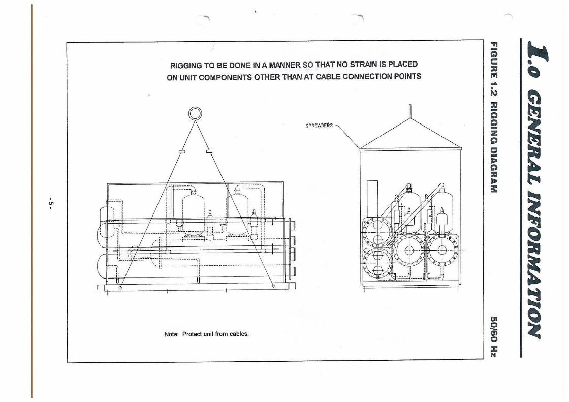
Each unit has been carefully tested and inspected at the factory where every precaution was taken to ensure that it reaches its destination in perfect condition. It is very important that the installers, movers, and riggers use the same care in handling the unit. The unit is designed to be lifted from the lifting holes in the steel structural base. For proper rigging, see Figure 1.2.
It is important to protect the unit from damage during storage, rigging and installation. Particular care should q~ given to avoid damage to controls and pj~ing . Do not allow the unit to be used as a lad~er or scaffold!
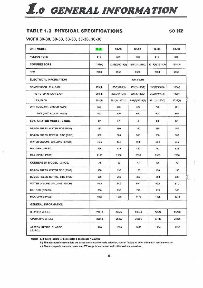
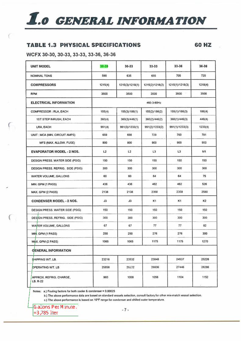
1.3 DIMENSIONAL DATA
Dimensional outline drawings and physical data of the packages are shown in Figures 1.3 and Table 1.3 respectively. Note especially the space and clearance requirements necessary for servicing the unit.
1.4 APPLICATION PRECAUTIONS
The following instructions are intended to help assure proper and successful application of your water chilling machines.
1.4.1 Water Conditions
Standard construction of the evaporator and condenser used in Dunham-Bush model WCFX Tandem chillers is copper tubes with steel tube sheets and liquid heads.
These materials are generally suitable( for use with clean fresh water found in most localities. However, minerals and other contaminants found in some water systems may promote aggressive attack on the tubes or tube sheets, resulting in failure with serious consequences for the entire package chiller.
Because Dunham-Bush has no control over the condition of the water used in these machines, we can take no responsibility for failure of tubes or tube sheets due to water corrosion or erosion. It is recommended that the buyer obtain the services of loca( water treatment specialists to prescribe water treatment.
1.4.2 Chilled Water Flow
- 4 -
The Dunham-Bush WCFX Tandem Chiller is designed for a constant chilled water flow rate, even when the cooling load is varying. The machine will generally perform satisfactorily with steady flow rates deviating from design by as much as +I 0% I -50%. However, varying water flow rates can
<JI
-... l
RIGGING TO BE DONE IN A MANNER Sp THAT NO STRAIN IS PLACED
ON UNIT COMPONENTS OTHER THAN AT CABLE CONNECTION POINTS
-:::· ...... ·11 ... , :: : :; . ·:
_,.._::::~~:it,
[ 1 ! ~ n
_£:(~~:::::]'!
l ~ : : I\ : :
; i t : :
,hi ~:::_-_-_-_-_·::: ----:.-.--7~---.--r.i-.-.-_:m.·=·]:--:---~~:J~;;~-----·.r:,__ _ ,.;-: u ! -- •• . . . , •• -...r .. .. '\.-•-· • • ....... r •• '\ .. ...,,,_ , , P .... / ... 1r·t·1------=--···-------~ ........ ... ............ =------·-·---: __ .. _ -r-··-----
.. - . . ' ' , ..
Note: Protect unit from cables.
semocRs ~-~~===================,
.., -g c :a m ~
• 9'.)
:a -g g -z g a -J> g :a J> !:
UI
~ 0 :z N
-
-
-
Z.o GENERAL INFORMATION
TABLE 1.3 PHYSICAL SPECIFICATIONS 50HZ
WCFX 30-30, 30-33, 33-33, 33-36, 36-36
UNIT MODEL 30-30 30-33 33-33 33-36 36-36
NOMINAL TONS 515 555 570 610 625
COMPRESSORS 1215(4) 1215(3)/1218(1) 1215(2)/1218(2) 1215(1)/1218(3) 1218(4)
RPM 2950 2950 2950 2950 2950
ELECTRICAL INFORMATION 400-3-50Hz
COMPRESSOR : RLA, EACH 155(4) 155(3)/186(1) 155(2)/186(2) 155(1)/186(3) 186(4)
1ST STEP INRUSH, EACH 360(4) 360(3)/446(1) 360(2)/446(2) 360(1)/446(3) 446(4)
LRA, EACH 991(4) 991(3)/1233(1) 991 (2)/1233(2) 991(1)/1233(3) 1233(4)
UNIT : MCA (MIN. CIRCUIT AMPS) 659 698 729 760 791
MFS (MAX. ALLOW. FUSE) 800 800 900 900 900
EVAPORATOR MODEL· 2 NOS. l2 l2 l3 l3 M1
DESIGN PRESS. WATER SIDE (PSIG) 150 150 150 150 150
DESIGN PRESS. REFRIG. SIDE (PSIG) 300 300 300 300 300
WATER VOLUME, GALLONS (EACH) 46.6 46.6 49.0 49.0 53.2 -
MIN. GPM (1 PASS) 436 436 482 482 526
MAX. GPM (1 PASS) 2138 2138 2358 2358 2580
CONDENSER MODEL • 2 NOS. J3 J3 K1 K1 K2
DESIGN PRESS. WATER SIDE (PSIG) 150 150 150 150 150
DESIGN PRESS. REFRIG. SIDE (PSIG) 300 300 300 300 300
WATER VOLUME, GALLONS (EACH) 54.9 54.9 59.1 59.1 61.2
MIN. GPM (2 PASS) 250 250 276 276 300
MAX. GPM (2 PASS) 1065 1065 1175 1175 1270
GENERAL INFORMATION
SHIPPING WT. LB. 23216 23532 23848 24537 25226
OPERATING WT. LB 25858 26232 26606 27446 28286
APPROX. REFRIG. CHARGE, 960 1008 1056 1104 1152
LB.R-22
Notes: a.) Fouling factors for both cooler & condenser" 0.00025
b.) The above performance data are based on standard vessels selection, consult faclory for olher mix-match vessel selection.
c .) The above performance is based on 10'F range for condenser and chilled water temperalu re.
- 6 -
I
NL35077
Highlight
NL35077
Text Box
ton is equal to 3.5168525 kilowatts
(
(
Z .. o GENERAL INFORMATION
TABLE 1.3 PHYSICAL SPECIFICATIONS 60HZ
WCFX 30-30, 30-~3, 33-33, 33-36, 36-36
UNIT MODEL 30-30 30-33 33-33 33-36 36-36
NOMINAL TONS 590 635 655 705 720
COMPRESSORS 1215(4) 1215(3)/1218(1) 1215(2)/1218(2) 1215(1)/1218(3) 1218(4)
RPM 3500 3500 3500 3500 3500
ELECTRICAL INFORMATION 460-3-60Hz
COMPRESSOR:RLA,EACH 155(4) 155(3)/186(1) 155(2)/186(2) 155(1)/186(3) 186(4)
1ST STEP INRUSH, EACH 360(4) 360(3)/446(1) 360(2)/446(2) 360(1 )/446(3) 446(4)
LRA, EACH 991 (4) 991 (3)/1233(1) 991 (2)/1233(2) 991 (1)/1233(3) 1233(4)
UNIT : MCA {MIN. CIRCUIT AMPS) 659 698 729 760 791
MFS {MAX. ALLOW. FUSE) 800 800 900 900 900
EVAPORATOR MODEL - 2 NOS. L2 L2 L3 L3 M1
DESIGN PRESS. WATER SIDE (PSIG} 150 150 150 150 150
DESIGN PRESS. REFRIG. SIDE (PSIG) 300 300 300 300 300
WATER VOLUME, GALLONS 60 60 64 64 75
MIN. GPM (1 PASS) 436 436 482 482 526
MAX. GPM (2 PASS) 2138 2138 2358 2358 2580
CONDENSER MODEL - 2 NOS. J3 J3 K1 K1 K2
DESIGN PRESS. WATER SIDE (PSIG) 150 150 150 150 150
DESIGN PRESS. REFRIG. SIDE {PSIG) 300 300 300 300 300
WATER VOLUME, GALLONS 67 67 77 77 82
MIN. GPM {1 PASS) 250 250 276 276 300
MAX. GPM (2 PASS) 1065 1065 1175 1175 1270
GENERAL INFORMATION
SHIPPING WT. LB. 23216 23532 23848 24537 25226
OPERATING WT. LB 25858 262.)2 26606 27446 28286
APPROX. REFRIG. CHARGE, 960 1008 1056 1104 1152
LB. R-22
Notes: a.) Fouling factors for both cooler & condenser= 0.00025
b.} The above performance data are based on standard vessels selection, consult factory for other mix-match vessel selection.
c.) The above performance is based on 1o•F range for condenser and chilled water temperature.
- 7 -
NL35077
Highlight
NL35077
Callout
Gallons Per Minute. 1 Gallon =3,785 liter
NL35077
Callout
1650 L/min, 99m3/h
NL35077
Callout
8092 L/min, 486m3/h
NL35077
Callout
4031 L/min, 242m3/h
NL35077
Callout
946 L/min, 57m3/h
Z.o GENERAL INFORMATION
FIGURE 1.3 DIMENSIONAL DATA
WCFX 30-30, 30-33, 33-33, 33-36, 36-36
150'SUGGES TEO CL(ARANC£ f'OR TUBE Ct.EAN!NG
( JTH(R ( NO
DIMENSIONAL CHART
EVAPORATOR WATER CONN. "R"
CONDENS(;R WA TER CONN. "S"
MQO(L MA TCHES 1 PASS I PASS 2 PASS J PASS
JO-JO 10· 10" 6" 6"
JO-JJ .J.0. 10" 6" 6"
JJ..JJ 10· 10· a· 6"
JJ- 36 10· 10· a· 6"
J6- J6 12" 10· a· 6"
NOTES:
1 - WATER PIPING TO BE SUPPORTED TO MINIMIZE LOAD ON UNIT.
2 - ALL DIMENSIONS ARE IN INCHES.
A
22 J/<"
22 J/4"
22 J/4"
22 J / 4"
23 J/4"
50/60 Hz
VESSEL l£NG IH (VI.):
VE SSH COO( (( VAP /CONO) (VAP CONN. CONO CONN.
l /J L/ K M/R
' PASS 2 PASS (I./~) l?J. 1&0· •eti•
1 PAS'S 2 P.ASS {R/H) 11.)'" 180" 1ao·
I P..t.S~ ' 0~ J PASS 11r 119· 179·
50'
98'
so· - -i-----ee·-----i--
B c 0 E f
99• 9 •/8" I I 1/ 4" 12· II 1/4"
89" 9 1/8'' 11 1/4" 12" 11 1/4"
99• 9 5/ a ·· 12 J/>6" 14" 12 J/•6·
89" 9 5/8" 12 J / 16" 14" 12 J/16·
90· 9 5/8" 12 J/16" 14" 12 J/16"
3 - VENT AND DRAIN CONNECTIONS PROV1DED ON EVAPORATOR AND CONDENSER.
4 - SUFFICIENT ROOM MUST BE ALLOWED FOR EVAPORATOR AND CONDENSER WATER CONNECTIONS.
5 36" OF FLEXIBLE CONDUIT SHOULD BE USED.
6 - ALL WATER NOZZLES ARE IPS, WITH VICTAULIC GROOVES. SUITABLE FOR VICTAUUC COUPLINGS OR SLIP ON FLANGES.
7 - SPRING ISOLA TORS ARE OPTIONAL.
- 8 -
(
(
r
(
Z.o GENERAL INFORMATION
cause control instability which will result in undesirable system effects, particularly poor control of leaving chilled water temperature. If two-way valves are used to control flow through cooling coils, some means such as an automatic modulating valve should be provided in the system to maintain steady flow through the evaporator.
If chilled water flow rate and/ or load vary, the variation must be controlled so that return water temperature does not vary at a rate exceeding 2°F per minute.
If the chilled water system is arranged for the dual purpose of cooling and heating, the evaporator must incorporate valves to prevent the flow of hot water through it. This can be done with either manual or automatic shutoff valves, but the method of control must be such that water temperature entering the evaporator never exceeds 90°F.
1.4.3 Water Cooled Condensers
The water cooled condenser is also designed for constant water flow rate, and should be supplied with the design GPM ±10%. The condenser must be protected from rapid changes in temperature as well. The maximum allowable rate of change in condenser entering water is 1°F per minute. Fluctuating flow rate or temperature will cause unstable control of the machine, resulting in poor control of
leaving chilled water temperature. If a cooling tower is used to reject heat from the condensing water loop, it must be controlled to provide an entering condensing water temperature which does not change more rapidly than 1°F/min. and does not go below 60°F. One or more of the following methods may be used to control the tower:
1.4.3.1 A modulating three-way valve which by-passes tower sprays at low load and low ambient temperature.
1.4.3.2 Tower fan staging in response to a thermostat in the tower sump. Fan thermostat should have a differential of at least 20°F to avoid short-cycling.
1.4.3.3 A modulating three-way valve which by-passes the cooling tower to blend warm leaving condenser water with cold tower water.
1.4.4 Condensing Water Treatment
- 9 -
Condensing water tends to leave silt, algae and mineral deposits in the condenser tubes. This fouling gradually decreases unit efficiency. For this reason, a program of water treatment should be employed. Also, at regular intervals depending on water quality, the unit should be shut down, condenser heads re~oved and tubes cleaned. See Section 5.4.
Z.o INSTALLATION
2.1 FOUNDATION
A flat, level concrete foundation or floor capable of supporting the weight of the unit must be provided. Weights are given in Figure 2. l. The unit must be leveled to within 1/16" per foot for proper operation.
2.2 VIBRATION ISOLATION
Where structure-borne vibrahon may be of concern, it is recommended that the unit be mounted on vibration isolators. Rubber-inshear isolators or spring isolators are available for this unit as optional equipment. If spring isolators are installed, it is also necessary to provide isolation in condenser water and chilled water pipes by means of flexible connectors and in main power supply conduit
through use of flexible conduit. Isolation of piping and electrical conduit is desirable in any event, to avoid noise transmission.
2.3 WATER PIPING CONNECTIONS
Refer to Figures 1.3. for water p1pmg connection locations. Note that the condenser water inlet must be on the bottom. If necessary, evaporator or condenser heads can be reversed, left to right or vice versa. Leaving chilled water temp sensor must be located in leaving chilled water stream. After the unit has been leveled and isolators (if any) installed and adjusted, connect evaporator and condenser water piping. Piping must be properly supported to avoid stress on unit water connections. Install air vent valves in all high
connections on evaporator and condenser heads. Install drain valves in similar low points to facilitate gravity draining of the system. It is important that water systems be cleaned before start-up to avoid collecting debris in cooler and condenser. The best way to do this is ·to install strainers in both systems upstream of the unit. After filling systems with water, bleed trapped air from the various vent valves. Check for proper flow rates by measuring water pressure drop across heat exchangers and reading GPM from charts, Figure 2.3. Compare measured GPM's with values specified on purchase order. Check in Table 1.3. to see that ( evaporator and condenser GPM's fall between min. and max. limits.
2.4 ELECTRICAL WIRING
In connecting power wiring to the unit, the following precautions should be taken:
- All fi eld wiring is to be in accordance with the National Electric Code and must comply with state and local codes.
Check unit wiring for damage and all terminal connections for tightness. Unit terminal blocks are to be connected with ( copper conductors only, sized per ampacity listed on unit data plate.
- Connections to unit should match the unit nameplate in volts, phase and Hertz. Voltage must not vary beyond ±I 0% of nameplate value and voltage imbalance between phases must not exceed 2% at any time during operation of the unit.
- Phase sequence to connections L1, Li, L3 shall be in that order. Check with Amprobe phase sequence adapter PSA-1 or equivalent.
- 10 -
Z.o INSTALLATION
FIGURE 2.1 FLOOR LOADING DIAGRAM
WCFX 30-30, 30-33, 33-33, 33-36 & 36-36
84 '
50/60 Hz
Z.o INSTALLATION
FIGURE 2.3 PRESSURE DROPS
1.a.) EVAPORATOR 1 PASS (WCFX 30-30, 30-33, 33-33, 33-36 & 36-36)
ex: w
.. .. >O
~ " u.. 0 .. 1-u..
~ ' ~ . w ' ex: ::::> • Ill Ill w ex: a.
J
'
1
L3- .---LI
L21 I ~ ' ,, I
, /, ~ v;
Vi/If ,, , ,
' I If r'
I
' ' I' ' , If I,
If v , I
'
WATER FLOW RATE - GPM
1.b.) CONDENSER 2 PASS (WCFX 30-30, 30-33, 33-33, 33-36 & 36-36)
..
.. )()
ex: ,. w l-et " ;: u.. 0 •• 1-u. a. 0 , ex: 0 w • ex: ::::> Ill Ill w ex: a.
1
J3-i I
I I II
, 'I , l/ ,,
~ J.' '/
II , ,,
I '6
l lllf
' I 11
1r rt )I/
/'I
WATER FLOW RATE - GPM
- 12 -
..-- Kl
2 ~K
50/60 Hz
(
· (
NL35077
Highlight
NL35077
Highlight
NL35077
Callout
1 ft w.g. = 2,99 kPa
Z.o INSTALLATION
2.5 CONTROLS
2.5.1 Connections
Controls which are to be field installed should be connected in accordance with the appropriate wiring diagram accompanying the unit. The following connections should be made where applicable:
2.5.1.1 Connect a set of normally open auxiliary contacts from chilled water pump contactor into unit controls as shown on
r unit wiring diagram.
2.5.1.2 Install a chilled water flow switch (paddle type recommended) in straight length of chilled water piping to avoid turbulence. Connect in same electrical circuit as 2.5.1.1.
2.5.1.3 For control of condensing water pumps, connect contacts supplied in unit in series with condensing water pump starter coil.
2.5.1.4 Connect an enable/disable contact into the unit controls
( as shown on the wiring diagram. Closure of this contact enables the unit to operate.
2.5.2 Settings 1'
All controls are factory set, however operating control settings are not always applicable under all operating conditions. For recommended control settings, see wmng diagram accompanying unit. Safety controls must be set factory recommendations.
2.6 REQUEST FOR START· UP REPRESENTATIVE
After the installation has been completed and checked, contact the Dunham-Bush Sales & Services for an authorized start-up representative to perform the initial start-up of the Dunham-Bush packaged chiller. The purchaser must have competent service and operating personnel in attendance to assist in the work involved, and also to be trained in the service and maintenance of this unit. (During the warranty period, the manufacturer is responsible for parts only upon proof of defective workmanship or manufacture).
Following this contact a representative will be sent to the customer. He will inspect the installation to determine whether it meets Dunham-Bush requirements, perform the initial start-up of the installation, determine whether it is in satisfactory operating condition, and instruct the specified customer personnel in its operation and maintenance for the length of time specified in the purchase contract.
NOTE: Sump oil heaters should be energized for a minimum of 24 hours and the oil sump temperature must be at a minimum of 100°F (38°C) prior to arrival of start-up representative. This will ensure that the oil is warm enough to vaporize any dissolved refrigerant and that the oil is within the normal operating temperature range. Sump oil heaters are energized simply by turning on the control power switch.
WARNING The compressor(s) should be started initially ONLY under the direct supervision of an Authorized Dunham-Bush Start-Up Representative.
- 13 -
J.o OPERATION
3.1 SYSTEM WATER FLOW RATE
The quantity of chilled water being circulated can be measured quite accurately (±5%) by determining the water pressure drop through the evaporator and reading GPM from evaporator pressure drop curve, Figures 2.3. Connect reliable pressure gauges to valves installed in evaporator entering and leaving water vent connections and read pressure difference with chilled water pump in operation. Condenser water flow rate can be measured in the same way. An alternate method of determining GPM is to measure pressure difference from pump inlet to outlet and read GPM from the pump curve.
3.2 SEASONAL SHUT· DOWN PROCEDURE
3.2.1 If the unit is to be shut down for a prolonged period (a month or more), the power supply to the unit may be deenergized to conserve energy.
3.2.2 The cooling tower may be drained to avoid freezing. If the unit is located in an area where the ambient temperature constantly remains above freezing, the condenser need not be drained. It is better to leave the condenser and evaporator fi11ed with water during a shutdown period. If the unit is located where ambient temperature will be below freezing, drain all water thoroughly, removing all vent and drain plugs from both heads of each vessel, and blow out tubes with compressed air. NOTE: Simply draining is not sufficient. Stagnant water may cause serious corrosion.
3.2.3 It is recommended that an oil sample be taken from each compressor and submitted for laboratory analysis.
Dunham-Bush offers this service in its Oil Kare Program. This analysis should be done at the beginning and end of each operating season, or every six months if the unit is used year round.
3.3 SEASONAL START-UP PROCEDURE
When the unit is to be started up after being shut down for a prolonged period:
3.3.1 Check unit for evidence of rust or corrosion. Clean surfaces and repaint as necessary. Repair insulation if necessary.
3.3.2 Energize power supply to unit. Unit must be energized for 24 hours in order to warm up compressor oil sump before starting. Control circuit power switch should be off during this period to prevent compressor operation. Clean water side heat transfer surface of condenser and evaporator by removing heads and brushing tubes.
3.3.3 Check water circuits to see that cooling tower is ready for operation, and both circuits are filled. Start pumps and check for flow in both cooler and condenser.
3.3.4 Turn control circuit power switches on, turn compressor switch on, and pres( reset on computer keyboard. Compressor should start after start-up clock times out and leaving water temperature should be automatically controlled. Check refrigerant charge and check for normal suction and discharge pressures.
3.3.5 Have a trained service mechanic check the function of all control setpoints. Check signal lights for proper operation.
3.3.6 Take oil sample from each compressor and submit it for laboratory analysis.
- 14 -
r
r
J.o OPERATION
3.4 SAFETY RELIEF VALVES
Each pressure vessel is protected by a safety relief valve as required by ASME Code. Each condenser has one relief valve. Local codes may require that all safety relief valves be piped to the outdoors. Never install a hand valve in a safety relief vent line.
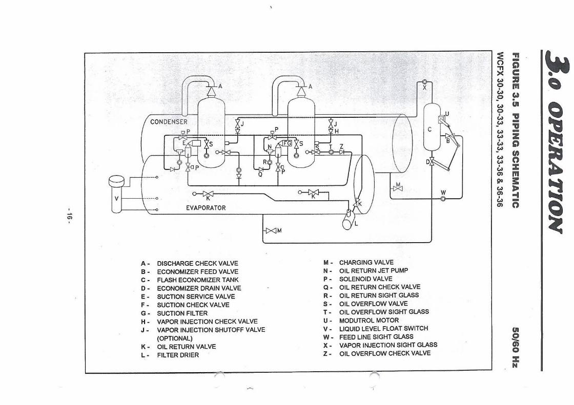
3.5 REFRIGERATION CYCLE
Refer to Figure 3.5 for the piping schematic of one system. Each vertical screw compressor di scharges hot, high pressure gas through a discharge check valve (A) into the condenser, where it condenses outside tubes, rejecting heat to cooling tower water flowing inside the tubes. The liquid refrigerant drains to the bottom of the condenser and exits into the
economizer feed line.
The refrigerant flows through the economizer feed ball valve (B), dropping its pressure, causing it to flash. It then fl ows into the flash economizer tank (C) which is at an intermediate pressure between condenser and evaporator. Liquid is centrifugally separated from the flash gas and the liquid drains to the bottom of the tank, exits via the economizer drain line, and passes through the economizer drain ball valve (D). Both economizer ball valves are actuated by a Modutrol motor (U) that adjusts flow to maintain an appropriate
refrigerant level in the evaporator, determined by a liquid level float switch (V).
From the drain line, liquid refrigerant flows into the flooded evaporator, where it boils,
cooling the water flowing irlside evaporator tubes. Vapor from the boiling refrigerant flows up the suction pipes through a shut-off valve (E), suction check valve (F) and suction filter (G) (inside compressor) into the compressor where it is compressed and starts the cycle again.
Vapor flows from the top of flash economizer into the compressor at the vapor injection port, which feeds it into the compressor part way through the compression process. Check valve . (H) prevents backflow at shutdown in multicompressor units. All compressors operate in parallel on a common evaporator and condenser.
3.6 OIL MANAGEMENT SYSTEMS (SEE FIG. 3.5)
The compressors are oil lubricated and discharge a small amount of oil mist along with
refrigerant. This oil is carried into the evaporator. Oil rich refrigerant is returned from the evaporator through two taps in the shell , a filter-drier (L) between isolation valves (K), and into a manifold that serves all compressors. At each compressor, this oil rich liquid flows through a check valve (Q), sight glass (R), and into a jet pump (N) which feeds into the compressor suction line. Gas from each compressor flows through valve (S), solenoid (P), and then drives the jet pump.
Oil overflow feeds from the C4 port on the
compressor through an overflow valve (S), sightglass (T), and check valve (Z), and is shared between compressors by feeding through the overflow feed solenoid valves (P)
into the operating compressors.
- 15 -
~ ,· ~ . .~ "" ~ ,:. . ·~ ;;;- " -.::_ ,:; . -.,, 0 >< c w 21 ~ 0 Ill I w w Vo . w Cll
~ 0 I ,,
CONDENSER I I \7 I I I \7 I I \ I ~ I ~ -,, w -w z
~ I
0 w w
v
"' w n w I :c w
------0 I '::,/_ "" I I I I I I I en Ill
M~ 90 3:
~ w w J> VI \ .. ........ -0 -K~ ' " I
en ... JlU
I w -
----0 EVAPORATOR en n
.~ ' en I I
M '-.../ I I
A- DISCHARGE CHECK VALVE M - CHARGING VALVE
B- ECONOMIZER FEED VALVE N- OIL RETURN JET PUMP
C- FLASH ECONOMIZER TANK P - SOLENOID VALVE
0- ECONOMIZER DRAIN VALVE Q- OIL RETURN CHECK VALVE
E- SUCTION SERVICE VALVE R- OIL RETURN SIGHT GLASS
F- SUCTION CHECK VALVE S- OIL OVERFLOW VALVE
G- SUCTION FILTER T- OIL OVERFLOW SIGHT GLASS
H - VAPOR INJECTION CHECK VALVE U- MODUTROL MOTOR
J- VAPOR INJECTION SHUTOFF VALVE V- LIQUID LEVEL FLOAT SWITCH Cll (OPTIONAL) W - FEED LINE SIGHT GLASS ~
K- OIL RETURN VALVE X- VAPOR INJECTION SIGHT GLASS en L- FILTER DRIER Z- OIL OVERFLOW CHECK VALVE 0
:c N
........ /
(
(
J.o OPERATION
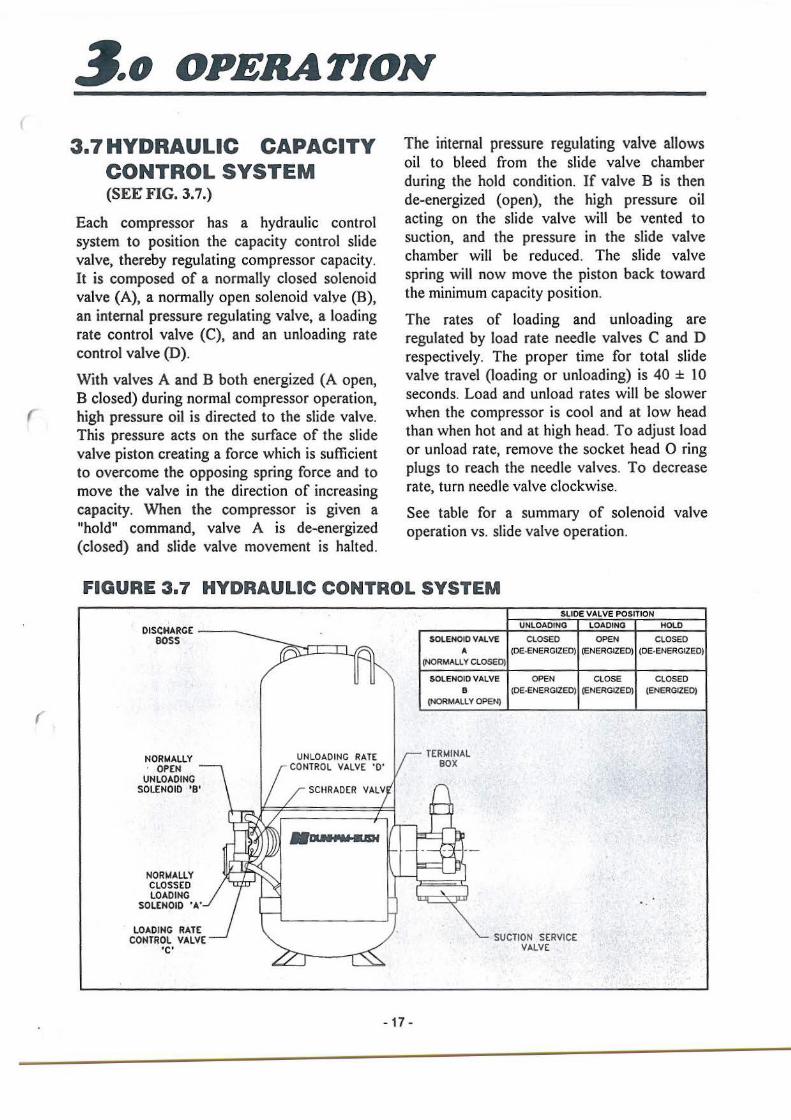
3.7HYDRAULIC CAPACITY CONTROL SYSTEM (SEE FIG. 3.7.)
Each compressor has a hydraulic control system to position the capacity control slide valve, thereby regulating compressor capacity. It is composed of a normally closed solenoid valve (A), a normally open solenoid valve (B), an internal pressure regulating valve, a loading rate control valve (C), and an unloading rate control valve (D).
With valves A and B both energized (A open, B closed) during normal compressor operation, high pressure oil is directed to the slide valve. This pressure acts on the surface of the slide valve piston creating a force which is sufficient to overcome the opposing spring force and to move the valve in the direction of increasing capacity. When the compressor is given a "hold" command, valve A is de-energized (closed) and slide valve movement is halted.
The internal pressure regulating valve allows oil to bleed from the slide valve chamber during the hold condition. If valve B is then de-energized (open}, the high pressure oil acting on the slide valve will be vented to suction, and the pressure in the slide valve chamber will be reduced. The slide valve spring will now move the piston back toward the minimum capacity position.
The rates of loading and unloading are regulated by load rate needle valves C and D respectively. The proper time for total slide valve travel (loading or unloading) is 40 ± 10 seconds. Load and unload rates will be slower when the compressor is cool and at low head than when hot and at high head. To adjust load or unload rate, remove the socket head 0 ring plugs to reach the needle valves. To decrease rate, turn needle valve clockwise.
See table for a summary of solenoid valve operation vs. slide valve operation.
FIGURE 3.7 HYDRAULIC CONTROL SYSTEM
DISCHARGE ----. BOSS
NORMALLY · OPEN
UNLOADING SOLENOID 'B'
NOR"4ALLY CLOSS ED LOADING
SOLENOID 'A'
LOADING RATE CONTROL VALVE
'C'
UNLOADING RATE CONTROL VALVE 'O'
SCHRADER VALV
-17 -
SLIDE VALVE POSITION UNLOADING LOADING HOLD
SOLENOID VALVE CLOSED OPEN CLOSED A (DE·ENERGIZEO) (ENERGIZED) (OE-ENERGIZED)
(NORMALLY ClOSEO)
SOLENOID VALVE OPEN CLOSE CLOSED B (DE·ENERGIZEO) (ENERGIZED) (ENERGIZED)
(NORMALLY OPEN)
TERMINAL BOX
SUCTION SERVICE VALVE
3.o OPERATION
3.8 FREEZE PREVENTION
If water (or brine) is allowed to freeze within the tubes and heads of the evaporator or condenser, severe damage will result; split and leaking tubes and cracked and leaking heads. Since this damage can be extremely costly and is not covered by warranty, it is important to be mindful of freeze preven~ion. Three cases deserve particular attention:
3.8.1 Standby at Low Ambient Temperatures
If the unit is to stand idle at ambient temperatures below 32°F, the water should be drained from evaporator and condenser. A head should be removed from each vessel and the tubes blown dry with compressed air. Gravity draining the vessel through drains in
heads may not be sufficient. If evaporator or condenser are served with a glycol solution, make sure the freeze temperature of the solution is lower than expected minimum ambient temperature.
3 .8.2 In Opera tion
Freezing of water in cooler tubes is a possibility if chilled water flow stops and if the low suction pressure cutout (normally set for 58 psig, or 32°F saturation) and the low water temperature cutout both fail. If the chilled water flow switch and pump interlock are properly applied (See 2.5. l.1 and 2.5. l.2) the unit has four protective devices which must all fail in order to freeze the evaporator in operation. While this is unlikely, it is important to see that all these devices ( are functional and properly calibrated.
3.8.3 During Maintenance
- 18 -
In transferring refrigerant within the unit, or removing refrigerant from the unit for maintenance purposes, it is possible to freeze evaporator or condenser tubes. Remember that whenever the pressure in a vessel is reduced below 58 psig, if water is not flowing, it is possible to freeze tubes. For this reason, it is a good precaution to have water flowing in both vessels whenever transferring refrigerant.
(
(
4o ELECTRICAL
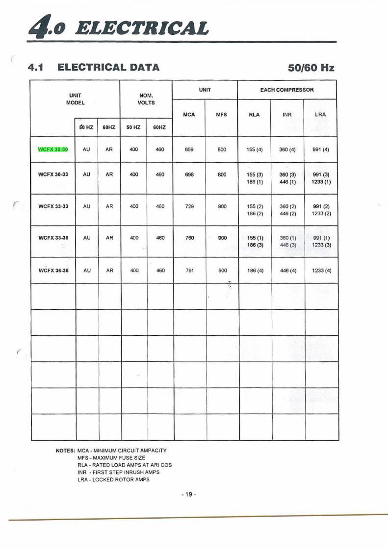
4.1 ELECTRICAL DATA
UNIT NOM. MODEL VOLTS
'l>HZ 60HZ 50 HZ 60HZ
WCFX 30-30 AU AR 400 460
WCFX 30-33 AU AR 400 460
WCFX 33-33 AU AR 400 460
WCFX 33-36 AU AR 400 460
WCFX 36-36 AU AR 400 460
-
NOTES: MCA - MINIMUM CIRCUIT AMPACITY
MFS - MAXIMUM FUSE SIZE
RLA- RATED LOAD AMPS AT ARI COS
INR - FIRST STEP INRUSH AMPS
LRA - LOCKED ROTOR AMPS
UNIT
MCA
6S9
698
729
760
791
- 19 -
50/60 Hz
EACH COMPRESSOR
MFS RLA INR LRA
800 1 SS (4) 360 (4) 991 (4)
800 155 (3) 360 (3) 991 (3)
186 (1) 446 (1) 1233(1)
900 1SS (2) 360 (2) 991 (2)
186 (2) 446 (2) 1233 (2)
900 1 SS (1) 360 (1) 991 (1)
186 (3) 446 (3) 1233 (3)
900 186 (4) 446 (4) 1233 (4)
-.
NL35077
Highlight
4o ELECTRICAL
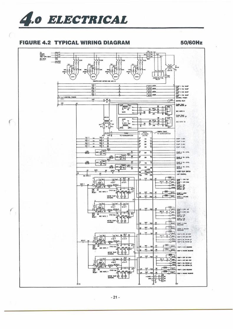
4.2 WIRING DIAGRAM
Figure 4.2 are typical wiring diagrams for a Tandem chiller unit. This may not be an accurate representation of your unit. It is best to use the wiring diagram mounted in the package control panel. A copy of that diagram is furnished with the unit owner's manual.
4.3 TYPICAL OPERATION
In order to start a compressor, the following conditions must be met:
- system voltage above undervoltage relay (UVR) setting
- chilled water pump running
- chilled water flow switch made
- compressor circuit breakers on
- customer unit control contact closed
- control switch and compressor switches on
- reset pressed on microcomputer keypad - power has been on the microcomputer for 15
minutes
- all safety conditions satisfied
- leaving chilled water temperature 2°F or more above setpoint
A compressor is started by first energizing lMl followed by IM2 after I second if step start is activated (see 4.5.4). Otherwise, both contactors energize together. Anti-recycle time of 15 minutes is initiated within the computer at start.
When the compressor starts, the microcomputer monitors amperage by means of ICT, voltage using 3T, .leaving water temperature using TS, and condensing pressure. These inputs are used to control the loading and staging of the compressor. The compressors loading is controlled by pulsing signals to the load and unload solenoids.
If the safety conditions are satisfied for the #2 compressor, at least I minute has elapsed since starting # 1 compressor, and leaving water temperature remains above the deadband; 2Ml and 2M2 will be activated by the microcomputer, (2M2 will close after 1 second delay, if step start is desired.) #2 compressor also has a 15 minute anti-recycle timer built into the microcomputer. Loading of the #2 compressor is controlled the same as compressor #1. Compressors #3 and #4 operate in a similar manner.
To shut down the unit automatically, the customer control contacts must be opened. To shut down the unit manually, simply shut off ( the compressor switches. This will cause a no-run alarm that must be reset to restart the compressor.
4.4 MICROCOMPUTER CONTROLLER
This unit is controlled by a microcomputer control system. The system is composed of four microcomputer boards, a display board and analog and digital sensors. The following sections describe the system and how to operate it.
The display board has a 20-key keypad and a 2 ( x 40 LCD display. The keypad and display can be used to determine the status of the compressor, and refrigeration system. Various setpoints can also be displayed and altered.
The status of the machine can also be monitored by a computer terminal either locally or remotely by a modem. The terminal must be able to handle RS232 communications. For more information, Please contact Dunham-Bush Sales & Services.
- 20 -
(
(
4o ELECTRICAL
FIGURE 4.2 TYPICAL WIRING DIAGRAM 50/60Hz
•A.I '"" k l
~~' -.;~- .;~~f ·~-~ ..
"':'" .. ,.)! ·- )I.I 51,,.l "-l 115V"( rt . , I . • j11• ...... ... ... .. """'" 'VQ..f.U ~·
11(\.t. f
' CDllf"t(UOf llOIOIS att ~ •
t-"1-• ' "'i-• . ,;.;._, 1
~-1 • 11." ' (c:omtol. P'QWU)
,....,, - . "'. .. ... .. ""'A,':' t•V 4' •
' ' . ..... v
tll(AC
~ .... •
" " " • ""' ~ ";;:j v
"" .. "" ' ..... ~ " ,•! ·I t O .. CtOC~•
hll • I tw_:t-2
2if!· • .. llii~-1 ii >Vj-• u ~~ ._.i- 1 J I 41 .. a IO
I
'"" ..... I .. _, n
~ _.,.,-
""' 1 .. - -·- u _,..., l (f ·-1 .... I. ··- ,., .... 0
L-.2.....:.::1 ,_,,. 1..,...1
.a1.t_.. .,.OCt;
.• -- ---~~----- .8---~~ ..
14 • 27 ·----.;,-~-;------
' ... ...... ~ " .,,_t .. . . .~. l .-. .-. -· ""'0-' .... , ..... ;, ......... ltt,..r-1
n.-:a.•" .. . ,,, .. IT•S-1. I !~1 "'.u ·:n ~ Tl l .... SU: NOT( 1 •O<I .. • _}T' ICJll)t TO. -· ' • .. ,,.,,_,
• ' Q.T .. ' • '1\.T . -. .-. .-. I ' COP z ....... ....... .. """"""' IHA. • l .. tl~tl ,. . ,.,
.,, ii lf.a.s· t• I !~, • .. 1; ~ .. " "1 ''" "'""""' ..,.,
...... ·~ l "~·~ 1 ... --... :.!,:~1
~ .''-' st "!l u .-, .-, l ; • (DIP 1 M-O~T ""'"•' " ... .. U OVU!lOAO IU,.l•·l
04 :iotX!l.&. D .. . '" .. lf.t.14 • l:a "' .... ·:o :'1 I~ -IUtf '""'"' :Ul]""
::u~ 2
~! l •UlT
:~:"'-' . . • .1 . .. , • <:Oolfl'• . .... , D Ovtl\.Clo\I
' )ff.t.$ .. 4
, .. aoft_a. ,. .. • ... n ITAS• • • ::. 1 ::-1~. 111 -IDCT "'""'' ·~ ---
"
- 21 -
- • .. ,. =·-..... ,..,. '"'Ill
'"' -I .. I II !1 l.'IO_, • II~ I ~ ~ .. - .. :: I
t; - .... .. . ... .. . tOt ltC:J. ltt
II 1".J II
!! .. .. ... :: I T - .... .. ... ....
..... " --""" Vo ...... , ... _ -. ·~
.. ,,,. ·~ " ... JOO
.. ... ... .. "' ""
.. '"' .. ...
"' "" ,. ..
~~~GIO
..----1~"' .. . .. •<
,.,. "'' " ~ I tv l•I :)6 --,"1
' -.... ' ···-
I I< "'" - ., -· ;;,. -~ - .. ......
-
"' ""' .... !f ~ ' I ...... •7 """." - ·-
I ~.~
I ..~
"' '!':' -~ ~ .. -IC ~ - .. ~ .. -,. "' - .. ~
T ... ~ l' :::: .. ,
I :--~
···-~ - .. .!!!.
~ - ~ -~ ~- ·- !I
T 4111-I " ""' .. , I -.--I : •ttm
... '!?' ..~ .. "'"· •J< ·~ ·- IJ ....... ..
" " jJt ...... ........ .... ..
~·o..,..... ... COM" z °""SI.Ar ... """""Joi. II.Ir# ... QQW 4 OI. Sl.MJ' ... COM"'°" fl'OM;lt --sec "°"" t
S(( "°" 10
•
il#" lC'llt Hf
if# t C1ll 2"0
=-:r.~f:"
-·--..,,~-t!D' ...... , ... ~,t
CO-JtlL~ ft.
L ri. l'....€]'" II .
4o ELECTRICAL
i.c:ulCl.l'•f1 rtJlt.u11t _,.,&tu.o!OC_r_i.
, .. -....... ~ .. ,.., ..... ~tftu'Vll
-::~~"-=-•=",:~. •flllfl•Od'l-••1•'9stl.tef
..
• :::: ~'°''*~~""' rQl:l(Jl(1lf'lll,.tl)ll .,0.-01--..
... .... -... tO Cllc;,TN.. llO~
"fllC)il CAtl.t Al~IH
ti • • .,
on .. ... u- ...... ..... ... -'r-r•,,!!• -~ -··' '" '" ...,, ,,, ... "''' l'tl(UVlt I IN Ill
"' '" •.
CO. ' I ) ... ,., Ill
'"" ••• -. .. ....... .. llJ
~··· "' ..... .. , "'" _. ... .. no ... ...
= "' •lnO••
"'"' "'.,.., .,
CIJ'U> ,., (fl)
.... tllJ
.... =
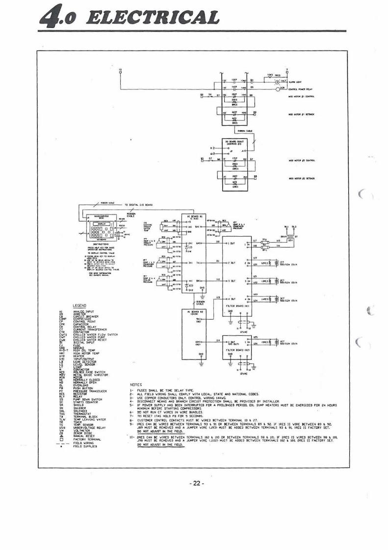
"""' N!)TES
1- rusts S:HALI.. tc TIME DCLAV l't'PC. Z• Al.L rJtLD \/IRING SHALL COMPLY \llTH LOCAL. STAT[ AND NATIONAi. CQD(S. 3• USC CoPPEl! CONDUCTOllS IM.Y. CONTROi. \/IRING l•A\IG.
"'°°~"~
KIO ~foll l"I t{l1ilriCk
.... .., MVW,, ,,.
"" "' ...
llf:U 1c1 )MtO.li'ltYJll
"""' ''" -~"""
..... "" -.,az:• ,, ... ,.
IWS "" ~"''""
• · DISCUNNl:CT H(ANS NID ll!N<CH CIRCUIT PltOlCCTION SHALL I( P1!0VIOCD JY INSTAU.tlt. 5• 1r PQ\l(R SUPPLY HAS ICEN INT[RRVPlCD FOR A PROLONG(D P[RIOD. OIL SUl<P H(AT[RS NVSl rt ENERGIZED FOii Z< IOJltS
MINIMUM BEF'ORE STA~TING COMPACSSORS. , . llO HOT At.I' CT VlR:ES IN \/IRE IMMll..£S. 1· ro REStr ITAS IO.D Pt FOii 5 StCO<DS. 9- CUSl~CR CONff'!OL CONTACTS MUST 8E 'w'IRCD l(T\/£EN TERMINAL 10 L 27. 9· IRES CAN I( \IJR(D BCT\l([N TCRNINAl.S 93 • 91 1111 BETll(.[N t(RNINALS 89 ' 92. rr IR[S IS \llR[ B[T\l((>j 89 • 92,
J89 HUST 11£ RCl'IJV(D AltD A ..IJHP£R \llR( (J9J> HUST 1£ ADDED ICTV((N T(RHINALS 91 &. 91. IRES IS rACTORY SET. 00 NOf AOJIJST IH TKC 11CLO.
10- 2RES CAN 8£ \llA:CO ICf\/(EH TC~HIKALS 102' .. 100 OR BETV£CN TCRMINALS 98 .. 101. IF" 2'RES IS VIREO 8[f\IE['N 98 L 101. J99 MUST 8( RCMOVED NfO A .JUl4P£a !JIRC UJ02) t«JST 8( ADDED 11EJVEEN l ( RMINALS 102 L 100, 2RES IS rACTOA:Y SET. 00 HOT AOJUST IN IH( rcr..o.
- 22 -
(
l
(
(
(
4o ELECTRICAL
4.4.1 To Display Data From The Menu l. Press the l\1ENU key.
2. Use the up or down arrow keys to select the type of information desired. The main menu items are:
2. Use the up or down arrow to select ALARMS.
3. Press ENTER
4. The day, time, and alarm code is displayed. AJarm 1 is the most recent alarm.
5. Press the down arrow to view previous alarms.
6. Determine identity of alarm from alarm codes on computer instruction label.
DATE & TIME SET
CONTROL POINTS
ANALOG SENSORS
DIGIT AL SENSORS
SETPOINTS A & B
ALARMS
AUTHORIZATION 4.4.4 To Become Authorized
3. Press the ENTER key.
4. Use the up or down arrow keys to select the desired data. For control points, additional data such as compressor operating hours and number of starts can be viewed with the right and left arrow keys.
NOTE: When displaying analog sensors, the PAGE MODE key can be pressed to display two new analog inputs after each arrow key is pressed. Press PAGE MODE again to return to displaying one new analog input.
4.4.2 To Reset All Control Points To Computer Control 1. Press the RESET key. The display
will show RESET ALL CPs to COMMODE?N Y
2. Press the right arrow key to select Y.
3. Press the ENTER key. The reset will not be accepted if a lockout control point is active. Resolve the problem and reset again.
4.4.3 To Display Alarms I. Press the l\1ENU key.
I. Select AUTHORIZATION on the main menu. Press ENTER
2. If the current status shown is VIEW, press the authorization code (64) on the number keys.
3. Press ENTER the current status will change to PROG (program) if accepted.
4.4.5 To Alter Setpoint Data 1. You must be authorized and in the
PROG mode. See section 4.4.4.
2. Select SETPOINTS A & B on the main menu. Press ENTER
3. Use the up or down arrow keys to select the setpoint to be changed. Press ENTER. A cursor will flash over the setpoint A value.
4. a.) If you want to change setpoint A, press in the desired new value and press ENTER if the new value is within allowable limits, it will be stored in memory. The cursor will then move to setpoint B.
b.) If you do not want to change setpoint A, press ENT~R.
5. Repeat 4, for Setpoint B.
- 23 -
4o ELECTRICAL
4.4.6 To Calibrate Temperature And Pressure Sensors 1. You must be authorized and in the
PROG mode. See Section 4.4.4. 2. Display the analog sensor to be
calibrated on the top line of the display.
3. Press ENTER to show ZERO CALIBRATION value.
4. Use an accurate gauge to mea~ure the analog value when it is stable and near design conditions.
S. Determine the revised zero calibration required as follows: Meter Reading - AI Display + Zero Calibration = New Zero Calibration. The new zero calibration must be rounded to the nearest whole number.
6. Press ENTER to place the cursor on the zero calibration value.
7. Enter the new value from 5. Negative values are entered by pressing LOWER FUNCTION +/before the number.
8. Press ENTER to store the revised zero calibration.
For example, if a suction pressure gauge shows 58 psig and the computer displays 60.3 psig with a zero calibration of -1, then new calibration would be 58 - 60.3 + (-1)= -3.3(-3). So the zero calibration should be changed to -3. Then the computer will display 58.3.
4.4.7 To Set Date And Time 1. You must be authorized. See
Section 4.4.4. 2. Select DATE & TIME SET on the
main menu. Press ENTER to display current date and time.
3. Press ENTER key to move cursor to each date/time item.
4. As each item flashes, use the number keys to enter revised data if necessary.
S. Press ENTER to continue. The last ENTER will store the new date and time.
WARNING: Setting the clock will cause a system reset. The entire unit will shut down and start over again. If the change was started inadvertently, press MENU key before completing the change.
4.4.8 To Display Data Without Accessing Menu 1. Press LOWER FUNCTION. 2. Press function desired (blue sub
script) 3. Press item number to be displayed. 4. Press ENTER.
EX: To display analog input #5, press LOWER FUNCTION, ANALOG INPUT, S, ENTER.
4.4.9 Unit Schedule Of Operation
-24 -
If a seven day time schedule of unit operation is desired, the internal real time clock of the microcomputer can be used. When the SCHEDULE control point is ON, the compressor is allowed to operate. The following procedure is used to modify the operating schedule.
l. Perform the authorization procedure (See 4.4.4).
2. Press MENU key. 3. Use Up and Down to select
CONTROL POINTS. 4. Press ENTER. S. Use Up and Down to select
SCHEDULE control point.
(
(
(
(
4o ELECTRICAL
6. Use ~ to display the first schedule. The standard display screen would show: CP 17 SCHEDULE GRP: l SCH: I 0000 2400 DAYS: *** ALL DAYS***. This indicates that control point 17 named SCHEDULE is controlled by schedule group (GRP) # 1. The first schedule (SCH: 1) turns on at 0000 hours and off at 2400 hours (military time) every day of the week. Thus it is on all the time.
7. To change this schedule, press ENTER. The cursor will flash over the turn-on time.
8. Use the number keys (0-9) to enter the revised turn on time using military format.
9. Press ENTER. The cursor will move over to the turn-off time.
10. Use the number keys to enter the tum-off time in military format.
11. Press ENTER. The cursor will move to DAYS during which this schedule is active.
12. To change the days for this schedule, press one or more of the following number keys: 0- Clear all current days; 1- Sunday(S); 2-Monday(M); 3- Tuesday(T); 4-Wednesday(W); 5- Thursday(R); 6- Friday(F); 7- Saturday(A); 8-*** ALL DAYS*** .
13 . Press ENTER. The revised schedule number is now stored .
14. To add another schedule, press the right arrow key and repeat steps 7-13.
15. To delete a schedule, clear all of the days by pressing 0 at Step 12. The schedule group turns on when any of the individual schedules turns on. The turn on time does not have to be earlier than the turn off time. Schedules turn on by time
and day, but turn off by time alone. For example, a schedule from 1900 to 0700 Saturdays would turn on at 7:00 PM Saturday (time and day) and turn off at 7:00 AM Sunday (time only).
EXAMPLE: If a unit is to operate at all times except between the hours of 1:00 AM and 6:00 AM, the following schedules would be entered: CP 17 SCHEDULE GRP : I SCH: l 0000 0100 DAYS: ***ALL DAYS*** CP 17 SCHEDULE GRP: I SCH: 2 0600 2400 DAYS: ***ALL DAYS *** ANOTHER EXAMPLE: A typical building may require cooling from 6:00 AM to 7:00 PM Monday - Friday and from 7 :00 AM- 3:00 PM on Saturdays. The schedules would be entered as follows: CP 17 SCHEDULE GRP: 1 SCH: 106001900 DAYS: MTWRF CP IT SCHEDULE GRP: I SCH: 2 0700 1500 DAYS: A .
4.5 CONTROL FUNCTIONS
4.5.1 Chilled Water Pump interlock And Flow
- 25 -
Switch (CWP And CWFS)
These are field installed switches, both of which are used to ensure chilled water flow before the unit is allowed to start. Failure of either one during operation will cause the compressor to shut down.
A water flow alarm will be generated and RESET must be pressed to clear the alarm.
NOTE: The flow switch or pump interlock cannot be used for normal control of the unit. (See 4.5.2).
4o ELECTRICAL
4.5.2 Customer Control interlock Control contacts from an external controller can be used to enable or disable operation of the unit. The wiring diagram specifies the terminals to which the contacts must be wired. To enable the unit, the contacts must be closed. To disable the unit, the contacts must be opened.
4.5.3 Anti-Recycle Timer (Microcomputer) The compressor motor requires an anti-recycle time delay which prevents restart for 15 minutes after a start. The purpose of this feature is to avoid frequent starts which tend to elevate the motor winding temperature and impose undue wear on contactors. The microcomputer will not restart the compressor motor until the 15 minutes have elapsed. COFF is displayed when the compressor control point ( 1 CP, 4CP 7CP or I OCP for compressors I,
' 2, 3 or 4 respectively) is addressed, and when other conditions for compressor start are satisfied. See Section 4.3 .
4.5.4 Part Wind Start Timer (10TR) Each compressor is served by two contactors. If required, a one-second delay between steps can be initiated to give stepped rise of inrush current. Remove the jumpers across 1 OTR if this feature is desired. If stepped start is not required, it is best to leave the jumper in place, which results in across-the-line starting of the compressor. This minimizes wear on compressor and contactors.
4.5.5 Load Control (Microcomputer) The microcomputer controls the leaving water temperature within a narrow deadband by pulsing load and/ or unload solenoids on the compressor. The load and unload solenoids position the slide valve within the compressor to control its capacity. The microcomputer determines a desired level of loading and varies pulse duration depending on difference between load target and actual load. The load target is varied based on rate of approach to desired ( temperature preventing significant temperature oscillations. The current limit function (see Section 4.5.7) overrides the temperature control. The status of the compressor can be observed by displaying the compressor control point (lCP, 4CP, 7CP or l OCP). One of the following messages will be displayed: COMP #LOAD Automatic load COMP #HOLD Automatic hold COMP # UNLD Automatic unload COMP #OFF Off on temperature
or customer control COMP # COFF Off on timer (C lock
off) ( COMP # LOFF Manual off or safety
shutdown Where# is 1, 4, 7 or 10 for compressors 1, 2, 3 or 4 respectively.
4.5.6 Ramp Control (Microcomputer)
- 26 -
Another feature of the microcomputer is ramp control, which is the ability to vary load time of the machine from start. Often when the machine is started, the water in the chilled water circuit is warm, and the unit will go to full load quickly. With ramp control,
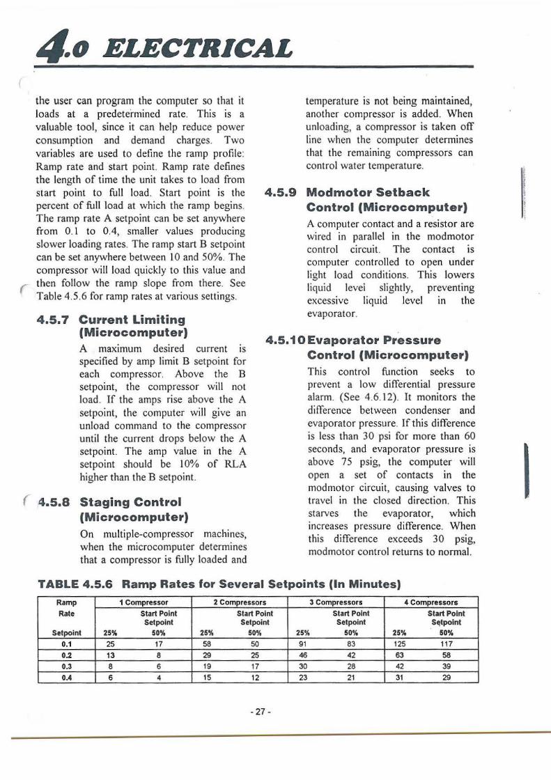
4o ELECTRICAL
the user can program the computer so that it loads at a predetermined rate. This is a valuable tool, since it can help reduce power consumption and demand charges. Two variables are used to define the ramp profile: Ramp rate and start point. Ramp rate defines the length of time the unit takes to load from start point to full load. Start point is the percent of full load at which the ramp begins. The ramp rate A setpoint can be set anywhere from 0.1 to 0.4, smaller values producing slower loading rates. The ramp start B setpoint can be set anywhere between 10 and 50%. The compressor will load quickly to this value and
( then follow the ramp slope from there. See Table 4.5.6 for ramp rates at various settings.
4.5. 7 Current Limiting (Microcomputer) A maximum desired current is specified by amp limit B setpoint for each compressor. Above the B setpoint, the compressor will not load. If the amps rise above the A setpoint, the computer will give an unload command to the compressor until the current drops below the A setpoint. The amp value in the A setpoint should be 10% of RLA higher than the B set point.
( 4.5.8 Staging Control (Microcomputer) On multiple-compressor machines, when the microcomputer determines that a compressor is fully loaded and
temperature is not being maintained, another compressor is added. When unloading, a compressor is taken off line when the computer determines that the remaining compressors can control water temperature.
4.5.9 Modmotor Setback Control (Microcomputer) A computer contact and a resistor are wired in parallel in the modmotor control circuit. The contact is computer controlled to open under light load conditions. This lowers liquid levei slightly, preventing excessive liquid level m the evaporator.
4.5.10 Evaporator Pressure Control (Microcomputer) This control function seeks to prevent a low differential pressure alarm. (See 4.6.12). It monitors the difference between condenser and evaporator pressure. If this difference is less than 30 psi for more than 60 seconds, and evaporator pressure is above 75 psig, the computer will open a set of contacts in the modmotor circuit, causing valves to travel in the closed direction. This starves the evaporator, which increases pressure difference. When this difference exceeds 30 psig, modmotor control returns to normal.
TABLE 4.5.6 Ramp Rates for Several Setpoints (In Minutes)
Ramp 1 Compressor 2 Compressors 3 Compressors 4 Compressors
Rate Start Point Start Point Start Point Start Point Setpoint Set point Setpoint St!tpoint
Setpoint 25% 50% 25% 50% 25% 50% 25% 50%
0.1 25 17 58 50 91 83 125 117 0.2 13 8 29 25 46 42 63 58 0.3 8 6 19 17 30 28 42 39 0.4 6 4 15 12 23 21 31 29
- 27 -
I
4o ELECTRICAL
4.5.11 Manual Lead-Lag Control (Microcomputer) On multi-compressor machines, the lead compressor can be chosen by storjng 0.0, 1.0, 2.0 or 3.0 in the lead setpoint B position. 0.0 is for lead on compressor # I, I. 0 is for lead on compressor #2 and 2.0 is for lead on compressor #3 . 3.0 is for lead on copressor #4.
4.5.12 Manual Load-Unload Control (Mi.crocomputer) Loading of the compressor can be controlled manually. To place computer in manual control, do the following: l . Press RESET if the compressor is
locked out. 2. Obtain authorization per 4.4.4. 3. Select CONTROL POINTS on the
main Menu. Press ENTER. 4. Use up or down arrow to select
the compressor to be controlled manually. Press ENTER.
5. Press up or down arrow to select MAN ON. Press ENTER. The compressor will start and operate on manual control.
6. Use the following keys to control the status of the compressor:
1 - Hold 2 - Load 3 - Unload
Manual control is maintained for 15 minutes after the last manual entry. After this, the compressor reverts to automatic control. To retain manual control, enter a 1, 2, or 3 command to the compressor at least once every 15 minutes. (See Item 5 above) In manual control, to transfer from one compressor to another or to display data, press MENU, then continue as above.
CAUTION: Do not start compressor manually more than once every 15 minutes. Verify that chilled water flow switch is closed.
4.5.13 Chilled Water Reset and Customer Control Interlock (Optional) · The chilled water temperature setpoint can be raised automatically by a 0-5VDC signal provided by an external controller. The reset signal must be between OVDC and 5VDC, with OVDC being no reset and 5VDC being max. reset. The maximum temperature reset (increase) desired ( must be stored in CWR max. B setpoint. For example, to raise the chilled water setpoint from 44°F to 50°F (6.0°F) with a 5VDC input, a 6.0 is stored in CWR max. setpoint.
Control contacts from an external controller can be used enable or disable operation of compressors. The wiring diagram specifies the terminals to which the contacts must be wired. To enable the compressors, the contacts must be closed. To disable the compressors, the contacts 4} must be opened.
4.5.14 Hot Gas Bypass (Factory· ( · Installed Option)
- 28 -
When hot gas bypass has been supplied with the package, an output from the computer controls the solenoid. The solenoid is turned on if the target percent capacity of the compressor drops below the hot gas bypass B setpoint. If the target percent capacity then climbs above the hot gas bypass A setpoint, the solenoid is turned off Typical setpoints are 40% for the B setpoint and 80% for the A setpoint.
4o ELECTRICAL
4.5.15 Sump Heater Control
Each compressor is fitted with an oil sump band-heater. The heater is energized at all times when compressor is off and de-energized when the compressor is running.
Its purpose is to prevent refrigerant migration into the oil during shut down. For this reason, it is essential that heaters be energized for 24 hours before starting a compressor.
( 4.5.16 Low Pressure Load Limit
A low suction pressure limit feature is provided to help prevent low pressure cut-off by preventing the compressor from loading if suction pressure falls below the suction limit hold setpoint B. It suction pressure falls below the suction limit unload setpoint A, the compressor will be
unloaded.
(
4.5.17 High Pressure Load Limit
A high discharge pressure unit feature is provided to help prevent high pressure cut-off by preventing the compressor from loading if discharge pressure rises above the discharge B. If discharge pressure rises above the discharge limit unload setpoint A, the compressor will be unloaded.
4.6 SAFETY FUNCTIONS
4.6.1 Control Power Loss (Microcomputer)
The microcomputer can be set up to
start automatically or manually after a power failure to the microcomputer. The power loss B setpoint is factory set to 0.0 to allow automatic start after a control power Joss. To select manual reset, set power loss B setpoint to 1.0. In this case, a power loss alarm will be stored by the microcomputer and RESET must be pressed to start.
4.6.2 Low Pressure Cut-off (Microcomputer)
This function protects the unit from operating at abnormally low evaporator refrigerant pressure. The microcomputer will shut down the compressor when cooler pressure falls below the low pressure setpoint and turn on the alarm pilot light.
A low pressure alarm will be
recorded by the microcomputer. Reset by pressing the RESET button on the microcomputer. Standard setpoint is 58 psig for water systems.
4.6.3 Evaporator Freeze Shutoff (Microcomputer)
- 29 -
If the leaving chilled water temperature drops below the freeze setpoint, the microcomputer will shut down the unit and store the . freeze alarm. After solving the problem,
press RESET on the microcomputer to clear the alarm.
I
I
4o ELECTRICAL
4.6.4 High Pressure Cut-off (Microcomputer)
This function protects the compressor from operating at abnormally high discharge refrigerant pressures. The microcomputer will shut down the compressor when condenser pressure reaches the high pressure set-point, and turn on the alarm indicator lamp on the control box. The high discharge pressure alarm will be recorded by the microcomputer. Reset by pressing the RESET button on the microcomputer. Setpoint is 250 psig.
4.6.5 Oil LEVEL SENSOR (LS)
An oil level sensor switch is located in each compressor. If low oil indication (digital input is OFF) persists for 60 seconds during compressor operation, the microcomputer will then shut down the compressor. The status of the level sensor can be seen on the computer display or the associated LED of the Digital 1/0 Board. Failure is indicated on the alarm pilot light. The low oil alarm code will be recorded by the computer. Press the RESET key to reset the system. See Section 5.6.2 concerning oil level.
4.6.6 High Oil Temperature Thermostat (12TAS)
A thermostat is located in each compressor which will open the compressor run circuit if oil temperature exceeds 203°F. The high
oil temperature pilot light will indicate an excessive oil temperature and a No-Run error will be recorded by the computer. Reset is activated by pressing the RESET button on microcomputer.
4.6. 7 Motor Temperature Protector (1 TAS)
Three thermistor sensors are embedded in the windings of each compressor motor. They are monitored by a solid state motor temperature protector. If any exceed safe temperature, the protector opens the compressor run circuit and lights the appropriate "high motor temperature" (HMT) pilot light. The microcomputer then stores a No-Run error. To reset the motor temperature protector, press the appropriate "HMT RESET" button on the control panel. Hold reset button for 5 seconds. Then press RESET button on the microcomputer.
4.6.8 Overload Protector (M20L)
- 30 -
A solid state overload protects each compressor by three phase current monitoring to prevent high current draw. The trip setting is factory set and is reset by pressing button on overload after correcting problem. The RESET button on microcomputer must also be pressed to clear the alarm. A no-run error is stored in the microcomputer.
(
(
(
4o ELECTRICAL
4.6.9 Undervoltage Relay (UVA)
The UVR protects the unit from the following electric supply malfunctions: Undervoltage, phase reversal and single phasing. If the UVR trips, a control relay (lCR) will de-energize and open the control circuit. A LFD light, located on the UVR, indicates a good voltage supply. The power loss A setpoint is factory set to 0.0 to allow automatic start after UVR failure. Compressor will not start for 15 minutes after failure. To select manual reset; set power loss A setpoint to 1.0. In this case, a power loss alarm will be stored by the microcomputer and RESET must be pressed to start.
4.6.10 Sensor Alarm (Microcomputer)
If the computer measures an analog value (temperature, pressure, volts.) that is far beyond normal operating values, the associated compressors are shutdown. The computer then stores the alarm code corresponding to the sensor alarm. A sensor alarm
indicates a problem m the analog measurement system.
4.6.11 No-Stop Alarm (Microcomputer)
If the microcomputer turns off a compressor, but the compressor digital input does not turn off, a NoStop alarm is generated. The computer will turn off the control power relay which disables all compressor control circuits and will turn on the alarm light. This alarm indicates a wiring or hardware error.
4.6.12 Low Differential Pressure Alarm (Microcomputer)
- 31 -
For proper lubrication, a compressor requires a 30 psi differential pressure between condenser and evaporator pressures. If the differential pressure is less than 30 psi for 3 minutes while a compressor is operating, all compressors will be shut down. The microcomputer will store the low differential pressure alarm code and turn on the alarm light. The RESET key must be pressed to clear the alarm.
I )'
t
~o MAINTENANCE
5.1 GENERAL As with all mechanical equipment, a program of regular inspection, cleaning and preventive maintenance- by trained personnel will contribute greatly to the long satisfactory service life of this product. Some of this care can easily be provided by owner personnel. However, a Dunham-Bush authorized service mechanic should inspect the unit at least annually and evaluate unit performance.
5.2 PERIODIC INSPECTION Read essential temperatures and pressures periodically to see that they indicate normal operation. It is a good idea to record these readings on a log sheet. See sample, Section 5.8. If any abnormal operation is observed, try to determine cause and remedy it. See Trouble-shooting Guide, Section 5.7.
5.3 MONTHLY INSPECTION Check cooling tower water treatment system. Wipe down external surfaces of unit. Shut unit down, open main disconnect, inspect control panel, checking for loose wires, burned contacts, signs of overheated wires, etc. Restart unit and check performance of controls. Put compressor in manual control and time rate of loading and unloading. Adjust needle valves as necessary to get load and unload time of 40± l 0 sec., then return to automatic control. Check feed line sight glass (W) for proper refrigerant charge level See Charging, Section 5.6.
5.4 WATER SIDE CLEANING OF VESSELS
See Section 1.4.3 Condensing Water Treatment. The effects of fouling of the cooler or condenser heat transfer surfaces can be detected by recording full load performance data on the log sheet. The best measure of performance of cooler and condenser is approach. which is the difference between
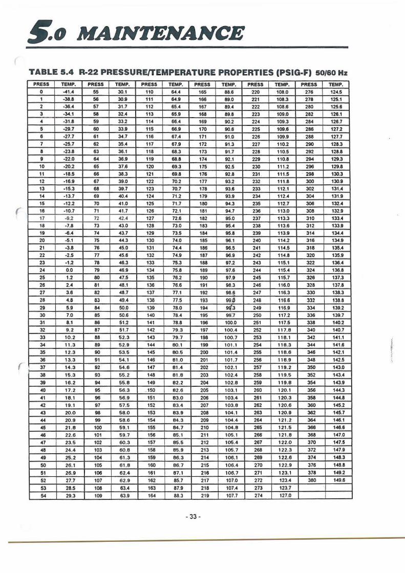
leaving water temperature and saturated refrigerant temperature at the pressure in the vessel. At full load, read cooler and condenser pressures on the computer. Then use Table 5.4 to find corresponding saturated temp. for each. Read leaving chilled water temperature on the computer. Read leaving condenser water temperature on computer if option is provided, or with field installed thermometer. Then calculate approaches as follows: Condenser Approach = T sat condenser - T lvg
cond. water ---. Cooler Approach = T lvg chilled water - T sat
cooler If the approach for either vessel increases by more than 2°F above the approach recorded at ( clean conditions, the tubes should be cleaned. It is generally advisable to clean the water side surfaces at least annually and more often if severely foul water is used. This cleaning can be done chemically or physically. In chemical cleaning, a caustic solution is pumped through the heat exchanger, which attacks dirt, slime and mineral deposits and flushes them away. Chemicals can be recommended by water treatment specialists, but it is important to rinse the system thoroughly after cleaning to remove the chemicals before they attack the
• J metal surfaces. ~
Vessel tubes may be physically cleaned by first draining the water, then removing the heads and brushing each tube individually with a tube ( cleaning brush until clean. The brush should have stiff nylon bristles. Brush kits are available from D/B North American Service. For best results, always remove both heads before cleaning the tubes. Replace the heads, being careful to properly position gaskets, and refill the system with water. Head gaskets need not be renewed after each head disassembly operation. Gaskets should and must be renewed if they are physically disfigured or otherwise deteriorated. (New gaskets are available from the factory. See Repair Parts List.). INSPECT CAREFULLY.
- 32 -
(
(
,.o MAINTENANCE
TABLE 5.4 R-22 PRESSUREfTEMPERATURE PROPERTIES (PSIG·F) 50/60 Hz
PRESS TEMP. PRESS TEMP. PRESS TEMP. PRESS TEMP. PRESS TEMP. PRESS TEMP. 0 -41 .4 55 30.1 110 64.4 165 88.6 220 108.0 276 124.5
1 -38.8 56 30.9 111 64.9 166 89.0 221 108.3 278 125.1
2 ·36.4 57 31.7 112 65.4 167 89.4 222 108.6 280 125.6
3 ·34.1 58 32.4 113 65.9 168 89.8 223 109.0 282 126.1 .. ·31 .8 59 33.2 114 66."4 169 90 .. 2 22"4 109.3 284 126.7
5 ·29.7 60 33.9 115 66.9 170 90.6 225 109.15 286 1272
6 ·27.7 61 3-4.7 116 67.4 171 91 .0 226 109.9 288 127.7
7 ·25.7 62 35.4 117 67.9 172 91 .3 227 110.2 290 128.3
8 ·23.8 63 36.1 118 68.3 173 91.7 228 110.5 292 128.8
9 ·22.0 64 36.9 119 68.8 174 92.1 229 110.8 294 129.3
10 ·20.2 65 37.6 120 69.3 175 92.5 230 111.2 296 129.8
11 ·18.5 66 38.3 121 69.8 176 92.8 231 111 .5 298 130.3
12 ·16.9 67 39.0 122 70.2 177 93.2 232 111.8 300 130.9
13 ·15.3 68 39.7 123 70.7 178 93.15 233 112.1 302 131.4
14 ·13.7 69 40.4 124 71 .2 179 93.9 234 112.4 304 131.9
15 ·12.2 70 "41 .0 125 71 .7 180 94.3 235 112.7 306 132.4
16 -10.7 71 "41 .7 126 72.1 181 9-4.7 236 113.0 308 132.9
17 -9.2 72 42.4 127 72.6 182 95.0 237 113.3 310 133.4
18 ·7.8 73 43.0 128 73.0 183 95..C 238 11 3.6 312 133.9
19 -6.4 74 "43.7 129 73.5 184 95.8 239 113.9 314 134.4
20 ·5.1 75 44.3 130 74.0 185 96.1 240 114.2 316 134.9
21 ·3.8 76 45.0 131 74.4 186 96.5 241 114.5 318 135.4
22 ·2.5 77 45.6 132 74.9 187 96.9 242 114.8 320 135.9
23 ·1.2 78 46.3 133 75.3 188 97.2 243 115.1 322 136.4
24 0.0 79 46.9 134 75.8 189 97.6 244 115.4 324 136.8
25 1 .. 2 80 47.5 135 76.2 190 97.9 245 115.7 326 137.3
26 2.4 81 48.1 136 76.6 191 98.3 246 116.0 328 137.8
27 3.6 82 48.7 137 77.1 192 98.6 247 116.3 330 138.3
28 4.8 83 49."4 138 77.5 193 99.0 248 116.6 332 1l8.8 29 5.9 84 50.0 139 78.0 194 W'.3 249 116.9 334 139.2
30 7.0 85 50.6 140 78.4 195 99'.7 250 117.2 336 139.7
31 8.1 86 51.2 1-41 78.8 196 100.0 251 117.5 338 1-40.2
32 9.2 87 51 .7 142 79.3 197 100.4 252 117.8 340 140.7
33 10.2 88 62.3 143 79.7 198 100.7 253 118.1 342 1-41.1
34 11 .3 89 52.9 144 80.1 199 101 .1 254 118.3 344 141.6
35 12.3 90 53.5 145 80.5 200 101 .4 255 118.6 346 142.1
36 13.3 91 54.1 146 81 .0 201 101 .7 256 118.9 348 142.5
37 14.3 92 54.6 147 81 .4 202 102.1 257 119.2 350 143.0
38 15.3 93 55.2 148 81.8 203 102.4 258 119.5 352 143.4
39 16.2 94 55.8 149 82.2 204 102.8 259 119.8 354 143.9
40 17. 2 95 56.3 . 150 82.6 205 103.1 260 120.1 356 144.3
41 18.1 96 56.9 151 83.0 206 103.4 261 120.3 358 144.8
42 19.1 97 57.5 152 83.4 207 103.8 262 120.6 360 145.2
43 20.0 98 58.0 153 83.9 208 104.1 263 120.9 362 145.7
44 20.9 99 58.6 154 84.3 209 104.4 264 121.2 364 146.1
45 21 .8 100 59.1 155 84.7 210 104.8 265 121 .5 366 146.6
46 22.6 101 59.7 156 85.1 211 105.1 266 121.8 368 147.0
47 23.5 102 60.3 157 85.6 212 106.4 267 122.0 370 147.5
48 24.4 103 60.8 158 85.9 213 105.7 268 122.3 372 147.9
49 25.2 104 61.3 159 86.3 214 106.1 269 122.6 374 148.3
50 26.1 105 61 .8 160 86.7 215 106.4 270 122.9 376 148.8
51 26.9 106 62.4 161 87.1 216 106.7 271 123.1 378 149.2
52 27.7 107 62.9 162 85.7 217 107.0 272 123.4 380 149.6
53 28.5 108 63.4 163 87.9 218 107.4 273 123.7
54 29.3 109 63.9 164 88.3 219 107.7 274 127.0
. 33 -
i f, I r ' '
g_o MAINTENANCE
5.5 ELECTRICAL MALFUNCTION
The unit has five devices designed to protect the compressor motor from electrical malfunctions: computer current limiting function, motor overload relay, undervoltage relay, motor over-temperature protector, and circuit breaker.
If the undervoltage relay trips, it is a sign of trouble in incoming power. ~f it trips again after resetting, call your electric utility to investigate the problem. If the circuit breaker or motor overload relay trips, this is a sign of possible motor trouble. DO NOT reset and try to run compressor again. Call authorized service representative to check for motor trouble. Resetting these safety devices and repeated starting could turn a minor motor problem into a costly major motor burnout.
5.6 CHARGING
5.6.1 Refrigerant Charge
The WCFX Tandem unit is given a complete charge of refrigerant at the factory. AJI standard units use refrigerant R22 and the amount necessary to charge the unit can be found in the physical specifications, Figure 2.1.
If the unit must be charged on the jobsite, it
should be done by a qualified refrigeration mechanic.
In order to check proper refrigerant charge,
check feed line sightglass (Figure 3.5, item W)
during unit operation. If bubbles are visible in sightglass, unit is undercharged. Refrigerant should be added through the charging valve on the cooler feed line until the condenser drain sightglass clears. Sight glass should be clear at all operating conditions. When operating at full load, the cooler tube bundle (visible through sightglass on cooler shell) should be covered. At light load, tubes may be visible. To add refrigerant, connect a refrigerant vessel to the liquid line charging valve under the cooler. Purge the air from the tube. With the unit running, open the refrigerant vessel liquid connection slightly. If the refrigerant vessel is ( warmer than the cooler, refrigerant will flow from the vessel into the unit. The need for additional refrigerant is indication of refrigerant leakage. In the interest of environmental protection as well as economy, the leak should be found and corrected.
5.6.2 Oil Charge
The proper oil charge is in the unit as supplied from the factory. The compressor should show oil return at all times. If for some reason, the compressor runs low on oil, a low oil level switch in the compressor will shut it down before any damage is done. In the event of a low oil shutdown, call a D/B authorized service agent to correct the problem. DO NOT ADD OIL TO THE SYSTEM.
NOTE: Only Suniso 4GS oil may b.e used in this package. Use of other oil is not approved by Dunham-Bush, and will result in poor performance of the package.
- 34 -
( )
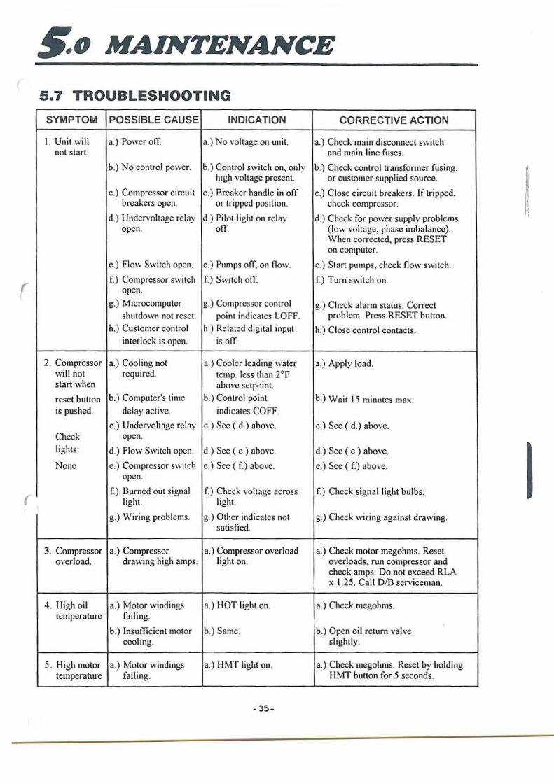
~o MAINTENANCE
5.7 TROUBLESHOOTING
SYMPTOM POSSIBLE CAUSE INDICATION CORRECTIVE ACTION
l . Unit will a.) Power olT. a.) No voltage on unit. a.) Check main disconnect switch not start. and main line fuses .
b.) No control power. b.) Control switch on, only b.) Check control transformer fusing. high voltage present. or customer supplied source.
c.) Compressor circuit c.) Breaker handle in off c.) Close circuit breakers. If tripped, breakers open. or tripped position. check compressor.
d.) Undervoltage relay d.) Pilot light on relay d.) Check for power supply problems open. olT. (low voltage, phase imbalance).
When corrected, press RESET on computer.
e.) Flow Switch open. e.) Pumps off, on flow. e.) Start pumps, check flow switch.
( f.) Compressor switch f.) Switch ofI. f.) Tum switch on.
open.
g.) Microcomputer g.) Compressor control g.) Check alarm statUs. Correct shutdown not reset. point indicates LOFF. problem. Press RESET button.
h.) Customer control h.) Related digital input h.) Close control contacts. interlock is open. is olT.
2 . Compressor a.) Cooling not a.) Cooler leading water a.) Apply load. will not required. temp. less than 2°F start when above setpoint.
reset button b.) Computer's time b.) Control point b.) Wait 15 minutes max. is pushed. delay active. indicates COFF.
c.) Undervoltage relay c.) Sec ( d.) above. c.) Sec ( d.) above. Check open.
lights: d.) Flow Switch open. d.) See ( c.) above. d.) See ( e.) above.
None e.) Compressor switch e.) See ( f.) above. e.) See ( f.) above. open.
f.) Burned out signal f.) Check voltage across f.) Check signal light bulbs. light. light. (
g.) Wiring problems. g.) Other indicates not g.) Check wiring against drawing. satisfied.
3 . Compressor a.) Compressor a.) Compressor overload a.) Check motor megohms. Reset overload. drawing high amps. light on. overloads, run compressor and
check amps. Do not exceed RLA x l.25 . Call D/B serviceman.
4 . High oil a.) Motor windings a.) HOT light on. a.) Check megohms. temperature failing.
b.) Insufficient motor b.) Same. b.) Open oil return valve cooling. slightly.
5. High motor a.) Motor windings a.) HMT light on. a.) Check megohms. Reset by holding temperature failing. HMT button for 5 seconds.
- 35-
I r l
I
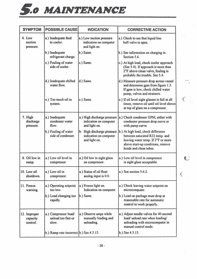
~o MAINTENANCE
SYMPTOM POSSIBLE CAUSE INDICATION CORRECTIVE ACTION
6. Low a.) Inadequate feed a.) Low suction pressure a.) Check to see that liquid line suction to cooler. indication on computer ball valve is open. pressure. and light on.
b.) Inadequate b.) Same. b.) See infonnation on charging in refrigerant charge. Section 5.6.
c.) fouling of water c.) Same. c.) At high load, check cooler approach side of cooler. (See 5.4). If approach is more than
2°F above clean valve, fouling is probably the trouble. See 5.4.
d.) Inadequate chilled d.) Same. d.) Measure pressure drop across vessel water flow. and determine gpm from figure l.3.
If gpm is low, check chilled water pump, valves and strainers.
e.) Too much oil in e.) Same. e.) If oil level sight glasses is full at all system. times, remove oil until oil level shows
at top of glass on a compressor.
7. High a.) Inadequate a.) High discharge pressure a.) Check condenser GPM, either with discharge condenser water indication on computer condenser pressure drop curve or pressure. flow. and light on. with pump curve.
b.) Fouling of water b. High discharge presswe b.) At high load, check difference side of condenser. indication on computer between saturated R22 temp. and
and light on. leaving water temp. If 2°F or more above start-up conditions, remove heads and clean tubes.
8. Oil low in a.) Low oil level in a.) Oil low in sight glass a.) Low oil level in compressor ' i
sump. compressor. on compressor. is sight glass acceptable.
10. Low oil a.) Low oil in a.) Status of oil float a.) See section 5.6.2. shutdown. compressor. analog input is 0.0. (
11. Freeze a.) Operating setpoint a.) Freeze light on. a.) Check leaving water setpoint on warning. too low. Indication on computer. microcomputer.
b.) Load changing too b.) Same. b.) Load on package must drop at rapidly. reasonable rate for automatic
control to work properly.
12. Improper a.) Compressor load/ a.) Observe amps while a.) Adjust needle valves for 40 second capacity unload too fast or manually loading and load/ unload rate when loading/ control. slow. unloading. unloading with microcomputer in
manual control mode.
b.) Ramp rate incorrect. b.) See 4.5.13. b.) See 4.5.15.
- 36 -
6.o RENEWAL PARTS
6.3 UNIT MODEL NUMBER CODE
WC F X 36-36 AU V3 T3 NN B
Water Cooled Chiller _J Flooded Evaporator -----'
Screw Compressor _ ____ ___,
Tons ~-------------'
Voltage Code: AU 400/3/50 ______ __, AR 460/3/60
EV APO RA TORS
PIN CODE L2
Tube H012368A1 x
Gasket, 2.Pass A6
H013774
CONDENSERS
P/N CODE J3
Tube H007014A2 x
Gasket, 2.Pass A4
H013774
L Generation
'-------- Heat Recovery
'------- Condenser Code
.__ _ ______ Evaporator Code
L3 M1
x x
A6 A7
K1 K2
x x
AS AS
Note: When ordering gaskets for 2-Pass vessel, order (1) 2-pass and (1) 1-Pass gaskets
(
~
MANUFACTURER RESERVES THE RIGHT TO CHANGE SPECIFICATION OR DESIGN AT ANY TIME WITHOUT PRIOR NOTICE.
Products That Perform ... By people Wlo Care

(
( .
6.o RENEWAL PARTS
6.2 WCFX TANDEM ELECTRICAL PARTS
Unit Voltage Codes AU 400V AR 460V
DESCRIPTION PART NO. MODEL NUMBER
30-30 30-33
Circuit Breaker
250A H014457C1 (4)AU.(4)AR (3)AU.(3)AR 300A H014457C2 (1}AU.(1)AR
Circuit Breaker Handle Kit
250AC/B H013832A1 (4)AU,(4)AR (3)AU,(3)AR 300AC/B H013832A2 (1)AU,(1)AR
Contactor
120A HCTR012N10 (8)AU.(8)AR (6)AU,(6)AR 150A HCTR015N10 (2)AU,(2)AR
Under Voltage Relay
335-405V H005183B2 (2)AU (2)AU 425- soov H005183B3 (2)AR (2)AR
Solid State Overload
95A H053676A5 (4)AU,(4)AR (3)AU,(4)AR 140A H053676A6 (1)AU
Fuses
5 AMP FNQ HFUS308 (4)AR (4)AR 6.25 AMP FNQ H004292C7 (4)AU (4)AU 12AMP FRN HFUS34 (2)AU.(2)AR (2)AU,(2}AR 5 AMP ABC HFUS266 4 4 4 AMP ABC H013362A1 4 4
Transformer
1.) Control Panel 2T
1.0KVA 400V HT SES (2)AU (2)AU 1.0KVA 230/480V HTSF6 (2) AR (2) AR
2.) Current TSF CT
500:0.1 l"Oia H009640A1 (4)AU.(4)AR I (4)AU.(4)AR
3.) Computer Power
Transformer 2T H009638A2 2 ' 2
4.) Voltage Signal
Transformer 3T H009639A2 2 I 2
Computer Components
Computer Board H009635A3 2 I 2 Chip, Data Base • H014409 2 2 Digital input/ output Board H009636A5 2 2 Analog Input Board H009637A1 2 2 Filter Board H009645A1 2 2 Power Cable H009644A2 6 6 Ribbon Cable Connector H009643A1 8 8
Control Components
Relay OPOT (1CR) H000879A1 2 2 Timer, 1 sec (10TR) H004981A1 4 4
Pressure Transducers
Cooter H009510A5 2 2 Condenser H009510A6 2 2 Motor Temp Protector (1TAS) HCNT137T3 4 4 Water Temp Sensor (TS) H009509A3 2 2 3 phase Toqqle Switch H014405A1 2 2
·suffix depends on logic. Need factory order# to identify. Note: All voltages 3 phase, 50 Hz
- 39 -
33-33
(2)AU.(2)AR (2)AU,(2)AR
(2)AU,(2)AR (2)AU.(2}AR
(4}AU,(4)AR (4)AU,(4)AR
(2)AU (2)AR
(2)AU, (4)AR (2)AU
(4)AR (4)AU
(2)AU,(2)AR 4 4
I (2)AU I (2)AR I
I (4)AU.(4)AR 1
I 2 I
I 2 I
2
2 2 2 2 6 8
2 4
2 2 4
2 2
50/GOHZ
50Hz 60Hz
33-36 36-36
(1)AU,(1)AR
(3)AU,(3)AR (4)AU,(4)AR
(1)AU,(1)AR (3)AU.(3)AR (4)AU,(4)AR
(2)AU,(2)AR (4)AR (6)AU.(6)AR (8)AU,(8)AR
(2)AU (2)AU ( (2)AR (2)AR
(1)AU,(2)AR (3)AU (4)AU
(4)AR (4)AR
(4)AU (4)AU
(2)AU,(2)AR (2)AU,(2)AR
4 4
4 4
(2)AU . (2)AU
(2) AR I (2\AR
(4)AU.(4\AR I i 4lAU.(4)AR
2 I 2
2 I 2 ( 2 I 2
2 2 2 i 2 2 2 2 2 6 6 8 8
2 2 4 4
2 2 2 2 4 4
2 2
2 2

(
c
6.o RENEWAL PARTS
6.1 COMPRESSOR & COMPRESSOR PARTS
Electrical Code (from Model No.)
*Compressor Code (insert Comp. PIN)
P/N MODEL 30-30 30-33
Compressor
H1215NHF6W4K_" _ oc 4 3
H1218NHF6W4K_._oc 1
Suction Gasket
HGKT64 4 4
Discharge Gasket
HGKT63 4 4
Load Control Solenoid Coil
H063800A1
Oil Sight Glass
H00458P29
O·Ring
HGLS3
Suction Filter Kit for 1215, 1218
H0054145A6
Note: For flanged compressor, substitute "B" for "N" in compressor part number.
- 38 -
AU
BJ
33-33
2
2
4
4
8
4
8
4
50/60 Hz
AR
BJ
33-36 36-36
1
3 4
(
4 4
4 4
I(

(
c
(
~o MAINTENANCE
5.8 SAMPLE LOG SHEET SHEET NO.
DUNHAM-BUSH WATER COO LED ROTARY SCREW TANDEM WATER CH ILLERS
NAMEPLATE DATA:
UNIT MODEL NO. WCFX : UNIT NO.: VOLTS: Hz
UNIT SERIAL NO.:
JOB NAME: LOCATION:
DATE
TIME
ELAPSED TIME METERS
COMPRESSORS OPERATING
EVAPORATOR PRESSURE
CONDENSER PRESSURE
1.
DISCHARGE TEMPERATURE 2.
3.
4.
CONDENSER REFRIGERANT DRAIN TEMPERATURE
CONDENSER WATER TEMPERATURE-IN
CONDENSER WATER TEMPERATURE-OUT
COOLER WATER TEMPERATURE.JN
COOLER WATER TEMPERA TU RE-OUT
COOLER PRESSURE DROP PSI/IN WATER
COOLER WATER FLOW {GPM)
CONDENSER PRESSURE DROP PSI/IN WATER
CONDENSER WATER FLOW (GPM)
ACTUAL VOLTAGE (NOT NOMINAL)
1.
COMPRESSOR AMPS 2.
3.
4.
TONS= GPME X ~TE 24
NOTE: COMPRESSOR ARE NUMBERED FROM LEFT TO RIGHT AS YOU FACE CONTROL I STARTER PANEL. THIS LOG SHEET IS PROVIDED AS A RECOMMENDATION OF THE READINGS THAT SHOULD BE TAKEN ON A PERIODIC BASIS. THE ACTUAL READINGS TAKEN AND THE FREQUENCY WILL DEPEND UPON THE UNITS APPLICATION. HOURS OF USE, ETC. THIS TYPE OF INFORMATION CAN PROVE VERY USEFUL IN PREVENTING AND/ OR SOLVING PROBLEMS THAT MIGHT OCCUR DURING THE LIFE OF THE UNIT.
- 37 -
(
(

(
(
Related Documents


