Water cooled condensers Shell and tube condensers for fresh and sea water applications

Welcome message from author
This document is posted to help you gain knowledge. Please leave a comment to let me know what you think about it! Share it to your friends and learn new things together.
Transcript
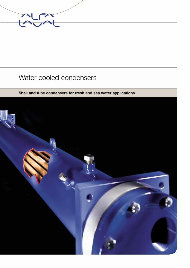
Water cooled condensers
Shell and tube condensers for fresh and sea water applications
Cat_CONDENSERS (Gb) 20-05-2003 11:32 Pagina 2

Cat_CONDENSERS (Gb) 20-05-2003 11:32 Pagina 3
Water cooled condensers
The widest range
A world of applications
Features & Benefits
CDEW: The perfect solution for R407C
CDEW: Performance on a wide range
Highest level in component design and manufacturing quality
Quality tests and pressure vessel approvals
Versions
Sea water for a trouble-free condensation
Where the water flows
The ideal choice, when maintenance is needed
Fittings
Technical data: Fresh water models
Technical data: Sea water models
CDEW dimensions
CPS dimensions
CFC dimensions
CFL dimensions
CRS dimensions
ACFC dimensions
ACFL dimensions
Refrigerant connections
CDEW refrigerant connections
Water connections
4
5
6
7
8
9
10
11
12
13-14
15
16
17
18
19-20
21
22
23
Cat_CONDENSERS (Gb) 20-05-2003 11:32 Pagina 4
4 Water cooled condensers
Alfa Laval’s shell and tube production includes a wide rangeof condensers and desuperheaters with 9 different series pro-viding individual solutions for each conditioning, refrigerationand cooling application. Standard models fulfil condensationcapacities ranging from 3 to 900 kW and 1680 kW can easilybe reached with the extension of the new CDEW series.The different condenser series have been carefully optimisedfor the most used HFC refrigerants. All condenser modelscan be opened for inspection and maintenance purposes.CFC, CRS, CPLUS, ACFL and CDEW series are designed tooperate with fresh water and CFC/M, CFL/M, ACFC/M and
ACFL/M series are dedicate to sea water applications thanksto material selection and correct sizing in order to preventfouling and corrosion. All condenser models can be suppliedin HR desuperheater version for water heating in a partial ortotal heat recovery system. Thanks to HRC configuration,CDEW and CPLUS can be supplied with two heat exchangerassembled in one shell. This configuration allows to operatealternatively the condenser and the total heat recovery functions.Alfa Laval quality systems are certified in accordance withISO9001 from TÜV-D, a further warranty of the shell and tubecondenser’s high quality level.
The widest range
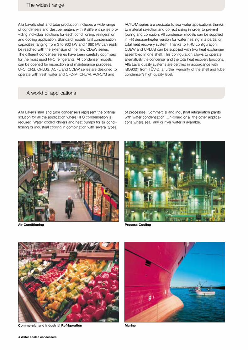
Alfa Laval’s shell and tube condensers represent the optimalsolution for all the application where HFC condensation isrequired. Water cooled chillers and heat pumps for air condi-tioning or industrial cooling in combination with several types
of processes. Commercial and industrial refrigeration plantswith water condensation. On-board or all the other applica-tions where sea, lake or river water is available.
A world of applications
Air Conditioning Process Cooling
Commercial and Industrial Refrigeration Marine
Cat_CONDENSERS (Gb) 20-05-2003 11:32 Pagina 5
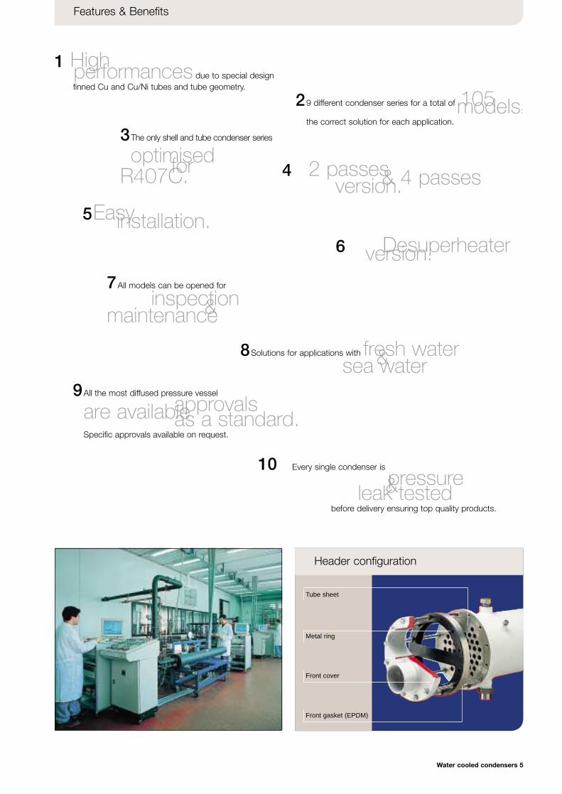
Tube sheet
Metal ring
Front gasket (EPDM)
Front cover
Water cooled condensers 5
Features & Benefits
Header configuration
1 High performances due to special design finned Cu and Cu/Ni tubes and tube geometry.
3The only shell and tube condenser series
optimised for R407C. 4 2 passes & 4 passes version.5Easyinstallation.
6 Desuperheater version.
29 different condenser series for a total of 105 models:the correct solution for each application.
9All the most diffused pressure vessel
approvals are available as a standard.Specific approvals available on request.
10 Every single condenser is
pressure & leak testedbefore delivery ensuring top quality products.
7All models can be opened for
inspection & maintenance
8Solutions for applications with fresh water & sea water
Cat_CONDENSERS (Gb) 20-05-2003 11:32 Pagina 6
6 Water cooled condensers
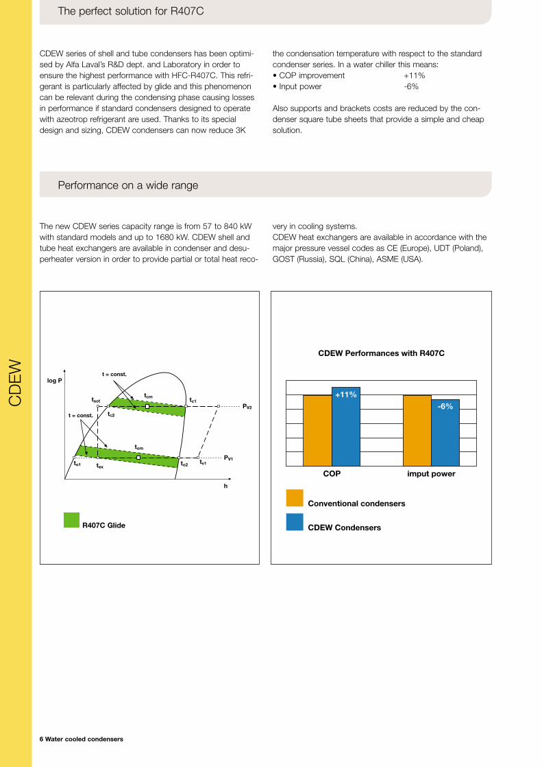
CDEW series of shell and tube condensers has been optimi-sed by Alfa Laval’s R&D dept. and Laboratory in order toensure the highest performance with HFC-R407C. This refri-gerant is particularly affected by glide and this phenomenoncan be relevant during the condensing phase causing lossesin performance if standard condensers designed to operatewith azeotrop refrigerant are used. Thanks to its specialdesign and sizing, CDEW condensers can now reduce 3K
the condensation temperature with respect to the standardcondenser series. In a water chiller this means:• COP improvement +11%• Input power -6%
Also supports and brackets costs are reduced by the con-denser square tube sheets that provide a simple and cheapsolution.
The perfect solution for R407C
The new CDEW series capacity range is from 57 to 840 kWwith standard models and up to 1680 kW. CDEW shell andtube heat exchangers are available in condenser and desu-perheater version in order to provide partial or total heat reco-
very in cooling systems.CDEW heat exchangers are available in accordance with themajor pressure vessel codes as CE (Europe), UDT (Poland),GOST (Russia), SQL (China), ASME (USA).
Performance on a wide range
COP imput power
CDEW Performances with R407C
+11%-6%
Conventional condensers
CDEW Condensers
log Pt = const.
t = const.
PV2
PV1
h
tom
tex
tsot
tc2
tcm
tv1
tc1
to2to1
CD
EW
R407C Glide
Cat_CONDENSERS (Gb) 20-05-2003 11:32 Pagina 7
NOMINAL DATA
Water cooled condensers 7
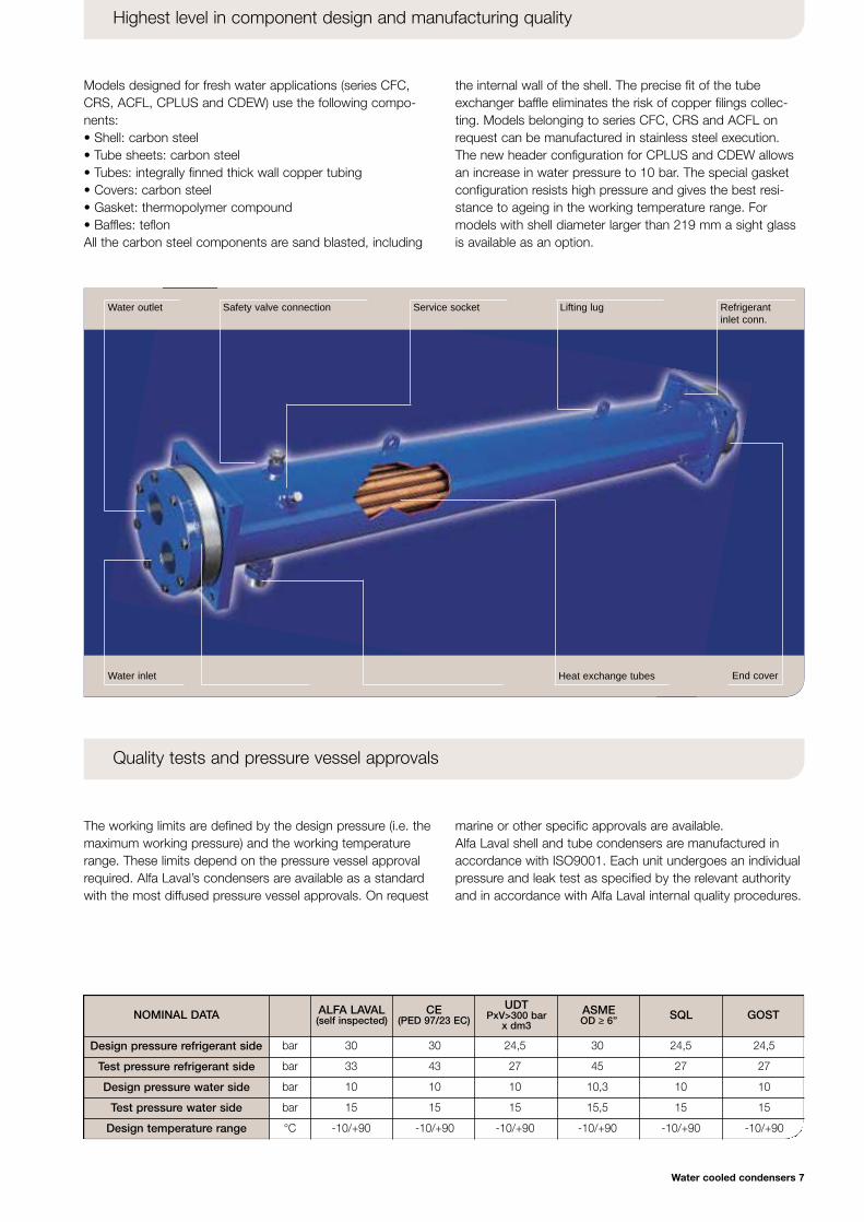
Models designed for fresh water applications (series CFC,CRS, ACFL, CPLUS and CDEW) use the following compo-nents:• Shell: carbon steel• Tube sheets: carbon steel• Tubes: integrally finned thick wall copper tubing• Covers: carbon steel• Gasket: thermopolymer compound• Baffles: teflonAll the carbon steel components are sand blasted, including
the internal wall of the shell. The precise fit of the tubeexchanger baffle eliminates the risk of copper filings collec-ting. Models belonging to series CFC, CRS and ACFL onrequest can be manufactured in stainless steel execution.The new header configuration for CPLUS and CDEW allowsan increase in water pressure to 10 bar. The special gasketconfiguration resists high pressure and gives the best resi-stance to ageing in the working temperature range. Formodels with shell diameter larger than 219 mm a sight glassis available as an option.
Highest level in component design and manufacturing quality
The working limits are defined by the design pressure (i.e. themaximum working pressure) and the working temperaturerange. These limits depend on the pressure vessel approvalrequired. Alfa Laval’s condensers are available as a standardwith the most diffused pressure vessel approvals. On request
marine or other specific approvals are available. Alfa Laval shell and tube condensers are manufactured inaccordance with ISO9001. Each unit undergoes an individualpressure and leak test as specified by the relevant authorityand in accordance with Alfa Laval internal quality procedures.
Quality tests and pressure vessel approvals
Water inlet Heat exchange tubes End cover
Water outlet Safety valve connection Service socket Lifting lug Refrigerantinlet conn.
ALFA LAVAL(self inspected)
CE(PED 97/23 EC)
UDTPxV>300 bar
x dm3
ASMEOD ≥ 6” SQL GOST
Design pressure refrigerant side
Test pressure refrigerant side
Design pressure water side
Test pressure water side
Design temperature range
bar 30 30 24,5 30 24,5 24,5
bar 33 43 27 45 27 27
bar 10 10 10 10,3 10 10
bar 15 15 15 15,5 15 15
°C -10/+90 -10/+90 -10/+90 -10/+90 -10/+90 -10/+90
Cat_CONDENSERS (Gb) 20-05-2003 11:32 Pagina 8
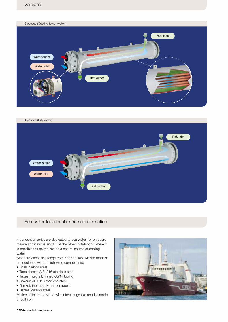
2 passes (Cooling tower water)
8 Water cooled condensers
Versions
4 condenser series are dedicated to sea water, for on boardmarine applications and for all the other installations where itis possible to use the sea as a natural source of coolingwater.Standard capacities range from 7 to 900 kW. Marine modelsare equipped with the following components:• Shell: carbon steel• Tube sheets: AISI 316 stainless steel• Tubes: integrally finned Cu/Ni tubing• Covers: AISI 316 stainless steel• Gasket: thermopolymer compound• Baffles: carbon steelMarine units are provided with interchangeable anodes madeof soft iron.
Sea water for a trouble-free condensation
Water outlet
Ref. inlet
Water inlet
Water outlet
Water inlet
Ref. outlet
Ref. inlet
Ref. outlet
4 passes (City water)
Cat_CONDENSERS (Gb) 20-05-2003 11:32 Pagina 9
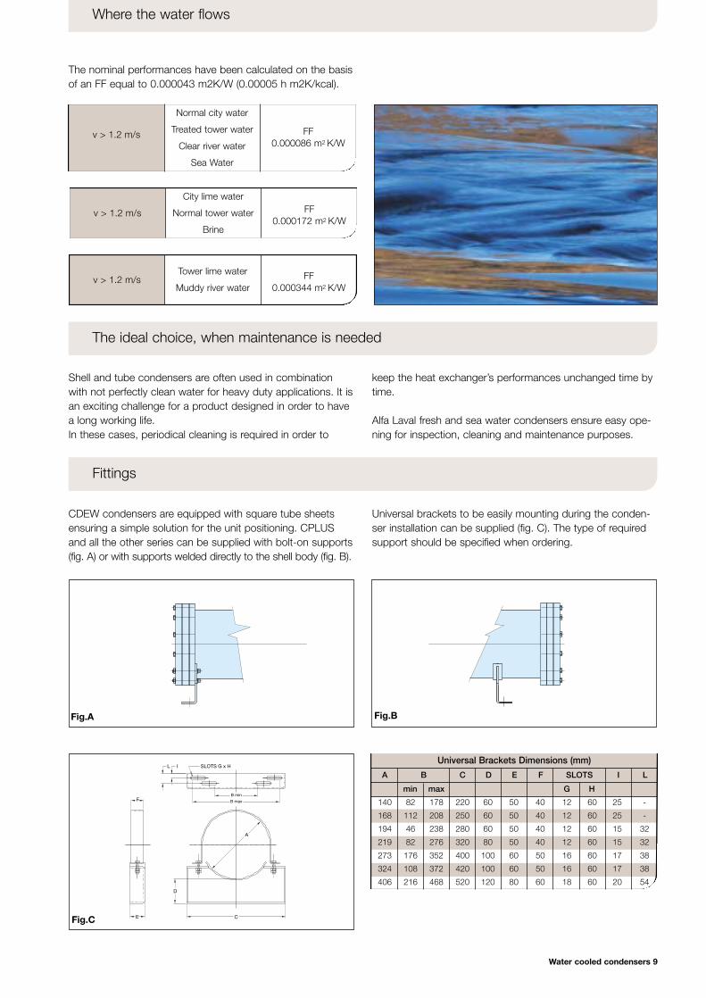
Tower lime water
Muddy river waterv > 1.2 m/s FF
0.000344 m2 K/W
Universal Brackets Dimensions (mm)
Water cooled condensers 9
The nominal performances have been calculated on the basisof an FF equal to 0.000043 m2K/W (0.00005 h m2K/kcal).
Where the water flows
CDEW condensers are equipped with square tube sheetsensuring a simple solution for the unit positioning. CPLUSand all the other series can be supplied with bolt-on supports(fig. A) or with supports welded directly to the shell body (fig. B).
Universal brackets to be easily mounting during the conden-ser installation can be supplied (fig. C). The type of requiredsupport should be specified when ordering.
Fittings
Shell and tube condensers are often used in combinationwith not perfectly clean water for heavy duty applications. It isan exciting challenge for a product designed in order to havea long working life.In these cases, periodical cleaning is required in order to
keep the heat exchanger’s performances unchanged time bytime.
Alfa Laval fresh and sea water condensers ensure easy ope-ning for inspection, cleaning and maintenance purposes.
The ideal choice, when maintenance is needed
City lime water
Normal tower water
Brine
v > 1.2 m/s FF0.000172 m2 K/W
Normal city water
Treated tower water
Clear river water
Sea Water
v > 1.2 m/s FF0.000086 m2 K/W
Fig.A Fig.B
SLOTS G x HL I
B min
B maxF
E
D
C
A
Fig.C
140 82 178 220 60 50 40 12 60 25 -
168 112 208 250 60 50 40 12 60 25 -
194 46 238 280 60 50 40 12 60 15 32
219 82 276 320 80 50 40 12 60 15 32
273 176 352 400 100 60 50 16 60 17 38
324 108 372 420 100 60 50 16 60 17 38
406 216 468 520 120 80 60 18 60 20 54
A B C D E F SLOTS I L
min max G H
Cat_CONDENSERS (Gb) 20-05-2003 11:32 Pagina 10
Model CRS 3 6 8 12 15 20 25
Model CDEW 60 80 100 120 135 165 190 215 240 260 300 360 400 450 470 520 550 610 680 760 840
Model CFC 8 12 15 20 25 30 40 50 60
Model ACFL 450/360 450/414 450/468 450/522 450/576 750/648 750/738 750/828 750/900
Model CPS 35 45 60 80 70 100 120 145 160 180 210 235 260 285 335 390 440 520
10 Water cooled condensers
R22 refrigerant Qn (kW) 3.2 6.5 8.1 12.2 15.2 20.3 25.3
Tc = 40.6°C Wn (m3/h) 0.8 1.6 1.5 2.2 2.2 3 3.7
Ti = 29.4°C Wm (m3/h) 0.9 1.8 1.7 2.6 2.6 3.4 4.3
FF = 0.000043 m2 K/W Dpn (bar) 0.22 0.22 0.38 0.38 0.43 0.43 0.43
R22 refrigerant Qn (kW) 3.8 7.7 9.1 13.6 15.7 21 26.2
Tc = 35°C Wn (m3/h) 0.3 0.6 0.6 0.9 0.9 1.2 1.5
Ti = 15°C Wm (m3/h) 0.5 0.9 0.8 1.3 1.3 1.7 2.1
FF = 0.000043 m2 K/W Dpn (bar) 0.28 0.28 0.48 0.48 0.54 0.54 0.54
Cooling tower water (2 passes CRS 3-6 • 4 passes CRS 8-25)
City water (4 passes CRS 3-6 • 8 passes CRS 8-25)
R22 refrigerant Qn (kW) 8.1 12.2 15.2 20.3 25.3 30.4 40.5 50.6 60.8
Tc = 40.6°C Wn (m3/h) 1.5 2.2 2.2 3 3.7 4.5 6 7.5 9
Ti = 29.4°C Wm (m3/h) 1.7 2.6 2.6 3.4 4.3 5.1 6.8 8.6 10.3
FF = 0.000043 m2 K/W Dpn (bar) 0.38 0.38 0.43 0.43 0.43 0.43 0.43 0.43 0.43
R22 refrigerant Qn (kW) 9.1 13.6 15.7 21 26.2 31.5 42 52.5 63
Tc = 35°C Wn (m3/h) 0.6 0.9 0.9 1.2 1.5 1.7 2.3 2.9 3.5
Ti = 15°C Wm (m3/h) 0.8 1.3 1.3 1.7 2.1 2.6 3.4 4.3 5.1
FF = 0.000043 m2 K/W Dpn (bar) 0.48 0.48 0.54 0.54 0.54 0.54 0.54 0.54 0.54
City water (8 passes)
Cooling tower water (4 passes)
City water (4 passes)
Cooling tower water (2 passes)
City water (4 passes)
Cooling tower water (2 passes)
R22 refrigerant Qn (kW) 360 414 468 522 576 648 738 828 900
Tc = 40.6°C Wn (m3/h) 48.9 56.2 63.5 70.9 78.2 88 100 112 122
Ti = 29.4°C Wm (m3/h) 55.5 63.9 72.2 80.5 88.9 99 113 127 138
FF = 0.000043 m2 K/W Dpn (bar) 0.33 0.33 0.33 0.33 0.33 0.33 0.33 0.33 0.33
R22 refrigerant Qn (kW) 360 414 468 522 576 - - - -
Tc = 35°C Wn (m3/h) 18.9 21.7 24.5 27.4 30.2 - - - -
Ti = 15°C Wm (m3/h) 27.8 31.9 36.1 40.3 44.4 - - - -
FF = 0.000043 m2 K/W Dpn (bar) 0.43 0.43 0.43 0.43 0.43 - - - -
City water (4 passes)
Cooling tower water (2 passes)
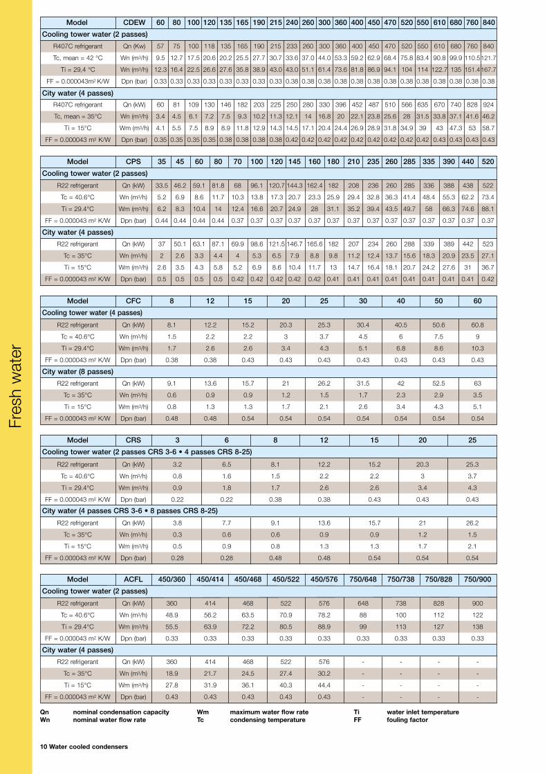
Qn nominal condensation capacityWn nominal water flow rate
Wm maximum water flow rateTc condensing temperature
Ti water inlet temperatureFF fouling factor
Fres
h w
ater
R22 refrigerant Qn (kW) 33.5 46.2 59.1 81.8 68 96.1 120.7 144.3 162.4 182 208 236 260 285 336 388 438 522
Tc = 40.6°C Wn (m3/h) 5.2 6.9 8.6 11.7 10.3 13.8 17.3 20.7 23.3 25.9 29.4 32.8 36.3 41.4 48.4 55.3 62.2 73.4
Ti = 29.4°C Wm (m3/h) 6.2 8.3 10.4 14 12.4 16.6 20.7 24.9 28 31.1 35.2 39.4 43.5 49.7 58 66.3 74.6 88.1
FF = 0.000043 m2 K/W Dpn (bar) 0.44 0.44 0.44 0.44 0.37 0.37 0.37 0.37 0.37 0.37 0.37 0.37 0.37 0.37 0.37 0.37 0.37 0.37
R22 refrigerant Qn (kW) 37 50.1 63.1 87.1 69.9 98.6 121.5 146.7 165.6 182 207 234 260 288 339 389 442 523
Tc = 35°C Wn (m3/h) 2 2.6 3.3 4.4 4 5.3 6.5 7.9 8.8 9.8 11.2 12.4 13.7 15.6 18.3 20.9 23.5 27.1
Ti = 15°C Wm (m3/h) 2.6 3.5 4.3 5.8 5.2 6.9 8.6 10.4 11.7 13 14.7 16.4 18.1 20.7 24.2 27.6 31 36.7
FF = 0.000043 m2 K/W Dpn (bar) 0.5 0.5 0.5 0.5 0.42 0.42 0.42 0.42 0.42 0.41 0.41 0.41 0.41 0.41 0.41 0.41 0.41 0.42
R407C refrigerant Qn (Kw) 57 75 100 118 135 165 190 215 233 260 300 360 400 450 470 520 550 610 680 760 840
Tc, mean = 42 °C Wn (m3/h) 9.5 12.7 17.5 20.6 20.2 25.5 27.7 30.7 33.6 37.0 44.0 53.3 59.2 62.9 68.4 75.8 83.4 90.8 99.9 110.5121.7
Ti = 29,4 °C Wn (m3/h) 12.3 16.4 22.5 26.6 27.6 35.8 38.9 43.0 43.0 51.1 61.4 73.6 81.8 86.9 94.1 104 114 122.7 135 151.4167.7
FF = 0.000043m2 K/W Dpn (bar) 0.33 0.33 0.33 0.33 0.33 0.33 0.33 0.33 0.38 0.38 0.38 0.38 0.38 0.38 0.38 0.38 0.38 0.38 0.38 0.38 0.38
R407C refrigerant Qn (kW) 60 81 109 130 146 182 203 225 250 280 330 396 452 487 510 566 635 670 740 828 924
Tc, mean = 35°C Wn (m3/h) 3.4 4.5 6.1 7.2 7.5 9.3 10.2 11.3 12.1 14 16.8 20 22.1 23.8 25.6 28 31.5 33.8 37.1 41.6 46.2
Ti = 15°C Wm (m3/h) 4.1 5.5 7.5 8.9 8.9 11.8 12.9 14.3 14.5 17.1 20.4 24.4 26.9 28.9 31.8 34.9 39 43 47.3 53 58.7
FF = 0.000043 m2 K/W Dpn (bar) 0.35 0.35 0.35 0.35 0.38 0.38 0.38 0.38 0.42 0.42 0.42 0.42 0.42 0.42 0.42 0.42 0.42 0.43 0.43 0.43 0.43
Cat_CONDENSERS (Gb) 20-05-2003 11:32 Pagina 11
Model CFC/M 8 12 15 20 25 30 40 50 60
Water cooled condensers 11
Model ACFL/M 450/360 450/414 450/468 450/522 450/576 750/648 750/738 750/828 750/900
Sea Water (2 passes)
Model ACFL/M 180/162 180/207 300/207 300/252 300/306 300/360
Model ACFC/M 150/122 150/152 150/183 240/183 240/213 240/244 240/274 240/337
Sea Water (2 passes)
Model CFL/M 42 50 56 75 95 110 125 145 165
R22 refrigerant Qn (kW) 7.6 11.3 13.5 18 22.5 27 36.4 45.5 54.7
Tc = 40.6°C Wn (m3/h) 1.2 1.8 1.8 2.6 3.1 3.7 4.9 6.1 7.4
Ti = 29.4°C Wm (m3/h) 1.4 2.0 2.1 2.9 4.3 4.2 4.5 6.9 8.4
FF = 0.000043 m2 K/W Dpn (bar) 0.27 0.27 0.30 0.33 0.33 0.33 0.33 0.33 0.33
R22 refrigerant Qn (kW) 8.6 12.9 14.9 19.9 24.9 29.9 39.9 49.9 59.8
Tc = 35°C Wn (m3/h) 0.6 0.9 0.9 1.2 1.5 1.7 2.3 2.9 3.5
Ti = 15°C Wm (m3/h) 0.8 1.3 1.3 1.7 2.1 2.6 3.4 4.3 5.1
FF = 0.000043 m2 K/W Dpn (bar) 0.53 0.51 0.58 0.57 0.59 0.52 0.52 0.54 0.55
Sea Water (8 passes)
Sea Water (4 passes)
Sea Water (4 passes)
Sea Water (2 passes)
R22 refrigerant Qn (kW) 38 45.6 50.9 67.8 84.9 101.6 111.1 129.7 149.4
Tc = 40.6°C Wn (m3/h) 6.2 7.4 7.4 9.8 12.3 14.8 14.8 17.3 18.5
Ti = 29.4°C Wm (m3/h) 7.0 8.4 8.4 11.1 13.9 16.7 16.7 19.6 20.9
FF = 0.000043 m2 K/W Dpn (bar) 0.27 0.27 0.29 0.29 0.29 0.29 0.31 0.31 0.34
R22 refrigerant Qn (kW) 38 50.1 54.4 72.5 90.6 108.7 115.6 134.7 156.8
Tc = 35°C Wn (m3/h) 3.1 3.7 3.7 4.9 6.2 7.4 7.4 8.6 9.3
Ti = 15°C Wm (m3/h) 3.5 4.2 4.2 5.5 7.0 8.4 8.4 9.7 10.5
FF = 0.000043 m2 K/W Dpn (bar) 0.38 0.38 0.38 0.42 0.42 0.42 0.45 0.46 0.49
Sea Water (4 passes)
Sea Water (2 passes)
Sea Water (4 passes)
R22 refrigerant Qn (kW) 110.5 138.8 166.5 166.5 194.2 222 249.8 305
Tc = 40.6°C Wn (m3/h) 14.8 18.5 22.2 22.2 25.8 29.5 33.3 37.6
Ti = 29.4°C Wm (m3/h) 16.7 20.9 25.1 25.1 29.2 33.3 37.6 42.5
FF = 0.000043 m2 K/W Dpn (bar) 0.31 0.31 0.31 0.31 0.31 0.31 0.31 0.34
R22 refrigerant Qn (kW) 118 145.5 171.5 171.5 200.7 229.3 258 318.5
Tc = 35°C Wn (m3/h) 7 8.75 10.5 10.5 12 14 15.8 17.8
Ti = 15°C Wm (m3/h) 10.3 12.8 15 15 18 20.5 23.1 26
FF = 0.000043 m2 K/W Dpn (bar) 0.41 0.41 0.39 0.39 0.39 0.41 0.41 0.44
Sea Water (4 passes)
R22 refrigerant Qn (kW) 146.2 186.2 186.2 226.3 278.5 323
Tc = 40.6°C Wn (m3/h) 18 23 23 27.9 33.8 39.8
Ti = 29.4°C Wm (m3/h) 20.3 26 26 31.5 38.2 45
FF = 0.000043 m2 K/W Dpn (bar) 0.33 0.33 0.33 0.33 0.33 0.33
R22 refrigerant Qn (kW) 162 207 207 252 306 360
Tc = 35°C Wn (m3/h) 9 11.4 11.4 13.9 16.9 20
Ti = 15°C Wm (m3/h) 10.2 12.9 12.9 15.7 19.1 22.6
FF = 0.000043 m2 K/W Dpn (bar) 0.49 0.48 0.48 0.48 0.48 0.49
R22 refrigerant Qn (kW) 323.1 372.5 420.8 468.5 517 583.5 664.2 760 808.5
Tc = 40.6°C Wn (m3/h) 39.8 45.9 51.8 57.8 63.7 72 81.9 91.8 99.7
Ti = 29.4°C Wm (m3/h) 45 51.9 58.5 65.3 72 81.4 92.6 103.7 112.7
FF = 0.000043 m2 K/W Dpn (bar) 0.33 0.33 0.33 0.33 0.33 0.33 0.33 0.33 0.33
R22 refrigerant Qn (kW) 344 394 445 497.5 547.5 - - - -
Tc = 35°C Wn (m3/h) 18.9 21.7 24.5 27.4 30.2 - - - -
Ti = 15°C Wm (m3/h) 27.8 31.9 36.1 40.3 44.4 - - - -
FF = 0.000043 m2 K/W Dpn (bar) 0.44 0.44 0.44 0.44 0.44 - - - -
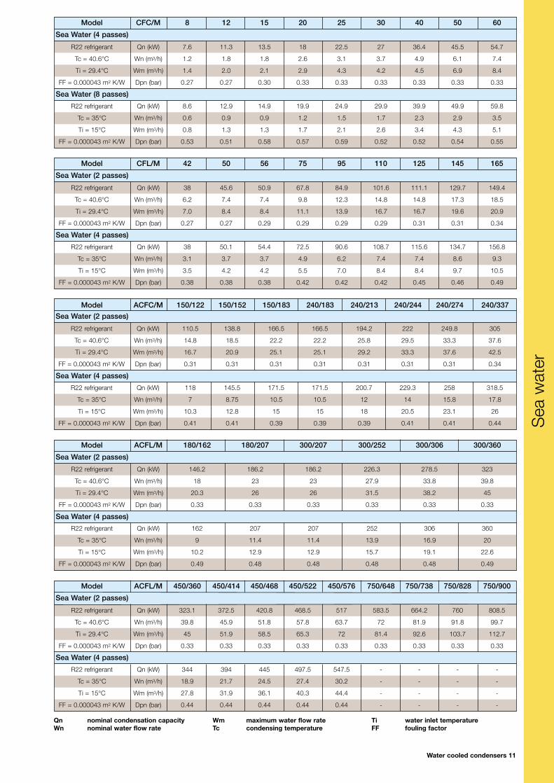
Qn nominal condensation capacityWn nominal water flow rate
Wm maximum water flow rateTc condensing temperature
Ti water inlet temperatureFF fouling factor
Sea
wat
er
Cat_CONDENSERS (Gb) 20-05-2003 11:32 Pagina 12
Model CDEWDimensions
Connections (Tower)
Connections (City)
Volumes
Weight
12 Water cooled condensers
B
d5
==
d6
A
ØC
d7
d4
300
20
20
N° 4 x Ø13d2
d1
d1
60
50
D
45°
d3
300
d4
CDEW
168 194 273 324 406
215 245 325 380 480
RC35 WA42 WA54 WA54 WA80
RC28 RC35 WA42 WA42 WA54
T2 T21 T3 T4 T5
- - - 1 1
1/2 3/4 1 1 1
1/4 1/4 1/4 1/4 1/4
1/4 1/4 1/4 1/4 1/4
RC35 WA42 WA54 WA54 WA80
RC28 RC35 WA42 WA42 WA54
T11 T2 T21 T3 T4
60 80 100 120 135 165 190 215 240 260 300 360 400 450 470 520 550 610 680 760 840
22.3 20.8 19.4 18.1 20.1 24.9 23.7 21.9 24.9 70.6 66.1 57 53.1 50.6 90.5 86.1 81.7 152.1 146 137.8 129.6
3.8 3.8 3.4 3.1 0.9 7.1 6.7 3.2 3.1 10 10 8.4 8.4 3.4 5.2 5.2 4.7 14.8 14.8 14.8 14.8
4.8 5.9 7.3 8.2 10.1 13.3 14.2 15.4 17.1 24.7 27.7 31.2 33.9 35.7 41 44.1 47.5 52.4 57.7 64.7 71.7
58 61 64.5 67.5 85 105 108 111 121 194.7 203 215 222 227 293 304 313 441 452 467 482
1500 1700 1740 1940 1970 1980 1980
1400 1600 1600 1800 1800 1800 1800
A [mm]
B [mm]
C [mm]
D [mm]
d1 [mm]
d2 [mm]
d3 [mm]
d4 [in-NPT]
d5 [in-NPT]
d6 [in-NPT]
d7 [in-G]
d1 [mm]
d2 [mm]
d3 [mm]
Vr [dm3]
Lreserve [dm3]
VH2O [dm3]
P [kg]
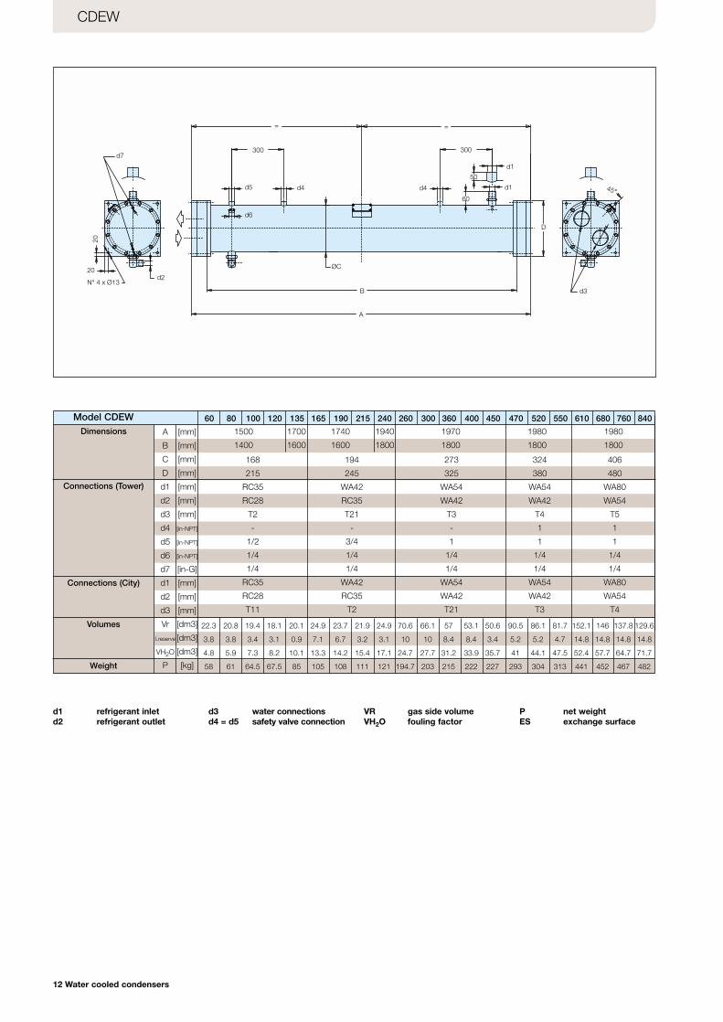
d1 refrigerant inletd2 refrigerant outlet
d3 water connectionsd4 = d5 safety valve connection
VR gas side volumeVH2O fouling factor
P net weightES exchange surface
Cat_CONDENSERS (Gb) 20-05-2003 11:32 Pagina 13
Model
Water cooled condensers 13
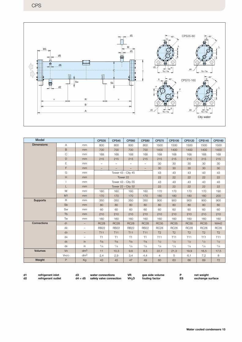
CPS
Dimensions
Supports
Volumes
Weight
Connections
R
M1
d5
d6
A
M
D
d1
d2
B
C
==
Sw
d1 45°
L
I
G
.d4
45°G
H
I
45°
L
I
G
H.d4
45°E
Ed3
FF
L
d3
Tb / Tw
Tb / TwTb / Tw
Tb / Tw
Sb
City water
CPS70-160
CPS35-80
A mm
B mm
C mm
D mm
E mm
F mm
G mm
H mm
I mm
L mm
M mm
M1 mm
R mm
Sb mm
Sw mm
Tb mm
Tw mm
d1 –
d2 –
d3 –
d4 –
d5 in
d6 in
VR dm3
VH2O dm3
P Kg
CPS35 CPS45 CPS60 CPS80 CPS70 CPS100 CPS120 CPS145 CPS160
800 800 800 800 1500 1500 1500 1500 1500
700 700 700 700 1400 1400 1400 1400 1400
168 168 168 168 168 168 168 168 168
215 215 215 215 215 215 215 215 215
– – – – 30 30 30 30 30
– – – – 30 30 30 30 30
43 43 43 43 43
22 22 22 22 22
43 43 43 43 43
22 22 22 22 22
160 160 160 160 170 170 170 170 190
170 170 170 170 180 180 180 180 200
350 350 350 350 900 900 900 900 900
80 80 80 80 80 80 80 80 80
60 60 60 60 60 60 60 60 60
210 210 210 210 210 210 210 210 210
160 160 160 160 160 160 160 160 160
RC28 RC28 RC28 RC28 RC35 RC35 RC35 RC35 WA42
RB22 RB22 RB22 RB22 RC28 RC28 RC28 RC28 RC35
T11 T11 T11 T11 T2 T2 T2 T2 T2
T1 T1 T1 T1 T11 T11 T11 T11 T113/8 3/8 3/8 3/8 1/2 1/2 1/2 1/2 1/21/4 1/4 1/4 1/4 1/4 1/4 1/4 1/4 1/4
11 10,3 9,6 8,5 22,7 21,3 19,9 16,5 17,5
2,4 2,9 3,4 4,4 4 5 6,1 7,2 8
43 45 47 49 60 63 66 69 72
Tower 43 - City 45
Tower 22
Tower 43 - City 55
Tower 22 - City 32
d1 refrigerant inletd2 refrigerant outlet
d3 water connectionsd4 = d5 safety valve connection
VR gas side volumeVH2O fouling factor
P net weightES exchange surface
Cat_CONDENSERS (Gb) 20-05-2003 11:32 Pagina 14
14 Water cooled condensers
R
M1
d5
d6
A
45°M
d1 E
E
45°
L
I
G
H
.d4d3
Tb / Tw
D
d1
d2
FF
B
C
==
Sw
d2
Sb
Tb / Tw
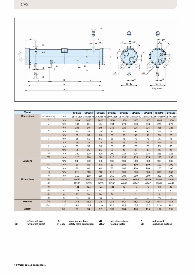
CPS
City water
Dimensions
Supports
Volumes
Weight
Connections
Model
A Tower/City mm
B mm
C mm
D mm
E mm
F mm
G mm
H mm
I mm
L mm
M mm
M1 mm
R mm
Sb mm
Sw mm
Tb mm
Tw mm
d1 –
d2 –
d3 –
d4 –
d5 in
d6 in
VR dm3
VH2O dm3
P Kg
CPS180 CPS210 CPS235 CPS260 CPS285 CPS335 CPS390 CPS440 CPS520
1540/1535 1540/1535 1540/1535 1540/1535 1570/1560 1570/1560 1570/1560 1570/1560 1570/1560
1400 1400 1400 1400 1400 1400 1400 1400 1400
194 194 194 194 273 273 273 273 273
245 245 245 245 325 325 325 325 325
35 35 35 35 55 55 55 55 55
35 35 35 35 55 55 55 55 55
55 55 55 55 75 75 75 75 75
25 25 25 25 45 45 45 45 45
55 55 55 55 75 75 75 75 75
25 25 25 25 45 45 45 45 45
200 200 200 200 225 225 225 225 225
210 210 210 210 235 235 235 235 235
900 900 900 900 900 900 900 900 900
80 80 80 80 100 100 100 100 100
60 60 60 60 100 100 100 100 100
210 210 210 210 300 300 300 300 300
160 160 160 160 300 300 300 300 300
WA42 WA42 WA54 WA54 WA54 WA54 WA54 WA54 WA54
RC35 RC35 RC35 RC35 WA42 WA42 WA42 WA42 WA42
T21 T21 T21 T21 T3 T3 T3 T3 T3
T11 T11 T11 T11 T2 T2 T2 T2 T23/4 3/4 3/4 3/4 1 1 1 1 11/4 1/4 1/4 1/4 1/4 1/4 1/4 1/4 1/4
24,8 23,4 22 20,6 54,7 51,9 49,1 46,3 41,8
9,4 10,5 11,6 12,6 16,2 18,3 20,5 22,6 26,1
91 94 97 100 164 170 176 182 195
d1 refrigerant inletd2 refrigerant outlet
d3 water connectionsd4 = d5 safety valve connection
VR gas side volumeVH2O fouling factor
P net weightES exchange surface
Cat_CONDENSERS (Gb) 20-05-2003 11:32 Pagina 15
Water cooled condensers 15
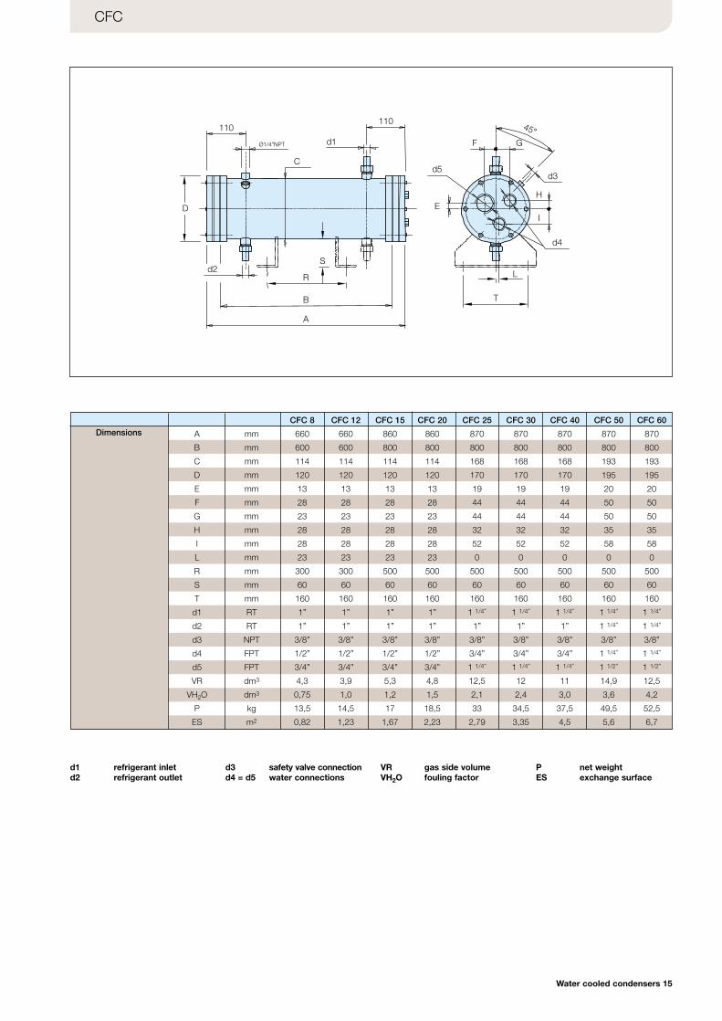
CFC
Dimensions
110110
d1
C
D
d2
B
A
R
S
Ø1/4”NPT
d5d3
d4
F G
E
T
L
I
H
45°
CFC 8 CFC 12 CFC 15 CFC 20 CFC 25 CFC 30 CFC 40 CFC 50 CFC 60
A mm 660 660 860 860 870 870 870 870 870
B mm 600 600 800 800 800 800 800 800 800
C mm 114 114 114 114 168 168 168 193 193
D mm 120 120 120 120 170 170 170 195 195
E mm 13 13 13 13 19 19 19 20 20
F mm 28 28 28 28 44 44 44 50 50
G mm 23 23 23 23 44 44 44 50 50
H mm 28 28 28 28 32 32 32 35 35
I mm 28 28 28 28 52 52 52 58 58
L mm 23 23 23 23 0 0 0 0 0
R mm 300 300 500 500 500 500 500 500 500
S mm 60 60 60 60 60 60 60 60 60
T mm 160 160 160 160 160 160 160 160 160
d1 RT 1” 1” 1” 1” 1 1/4” 1 1/4” 1 1/4” 1 1/4” 1 1/4”
d2 RT 1” 1” 1” 1” 1” 1” 1” 1 1/4” 1 1/4”
d3 NPT 3/8” 3/8” 3/8” 3/8” 3/8” 3/8” 3/8” 3/8” 3/8”
d4 FPT 1/2” 1/2” 1/2” 1/2” 3/4” 3/4” 3/4” 1 1/4” 1 1/4”
d5 FPT 3/4” 3/4” 3/4” 3/4” 1 1/4” 1 1/4” 1 1/4” 1 1/2” 1 1/2”
VR dm3 4,3 3,9 5,3 4,8 12,5 12 11 14,9 12,5
VH2O dm3 0,75 1,0 1,2 1,5 2,1 2,4 3,0 3,6 4,2
P kg 13,5 14,5 17 18,5 33 34,5 37,5 49,5 52,5
ES m2 0,82 1,23 1,67 2,23 2,79 3,35 4,5 5,6 6,7
d1 refrigerant inletd2 refrigerant outlet
d3 safety valve connectiond4 = d5 water connections
VR gas side volumeVH2O fouling factor
P net weightES exchange surface
Cat_CONDENSERS (Gb) 20-05-2003 11:32 Pagina 16
16 Water cooled condensers
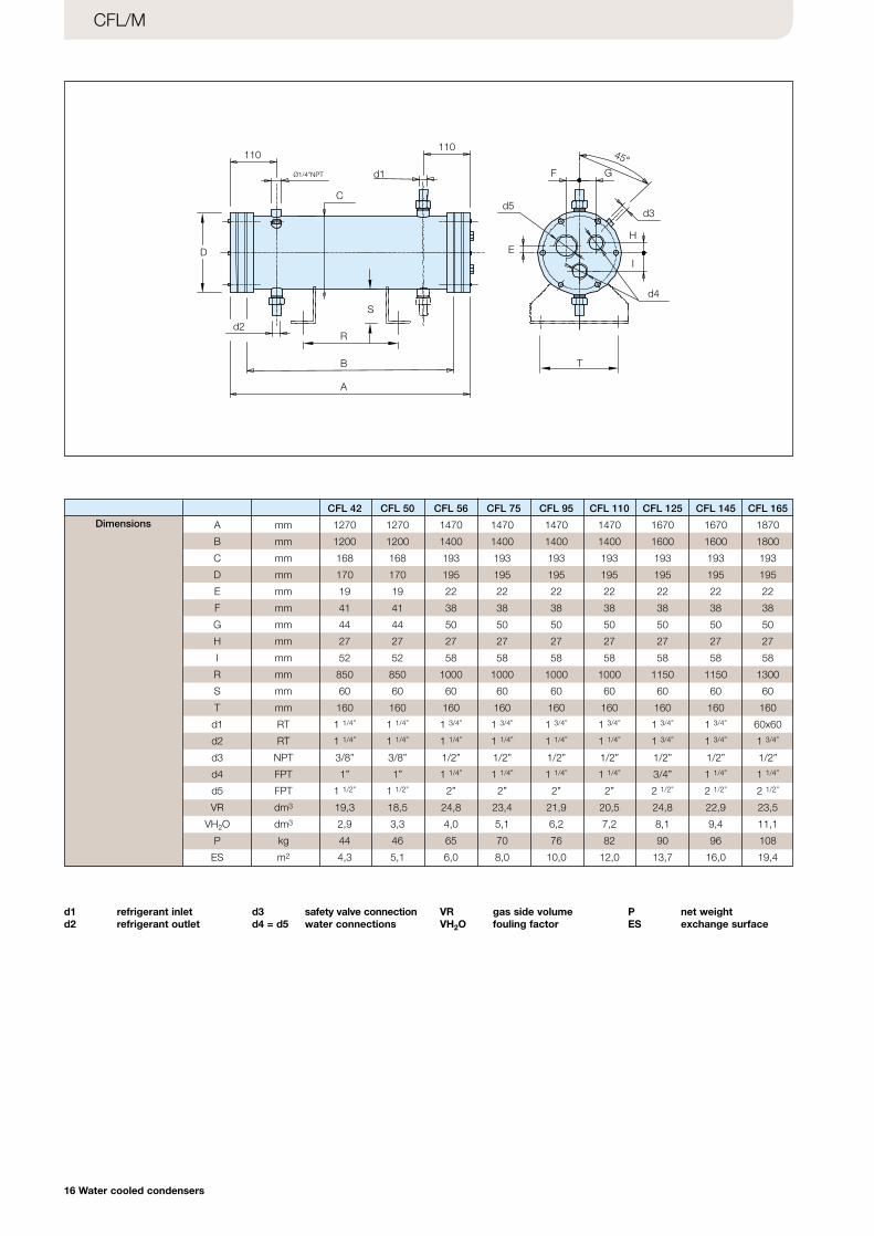
CFL/M
Dimensions
110110
d1
C
D
d2
B
A
R
S
Ø1/4”NPT
d5d3
d4
F G
E
T
I
H
45°
CFL 42 CFL 50 CFL 56 CFL 75 CFL 95 CFL 110 CFL 125 CFL 145 CFL 165
A mm 1270 1270 1470 1470 1470 1470 1670 1670 1870
B mm 1200 1200 1400 1400 1400 1400 1600 1600 1800
C mm 168 168 193 193 193 193 193 193 193
D mm 170 170 195 195 195 195 195 195 195
E mm 19 19 22 22 22 22 22 22 22
F mm 41 41 38 38 38 38 38 38 38
G mm 44 44 50 50 50 50 50 50 50
H mm 27 27 27 27 27 27 27 27 27
I mm 52 52 58 58 58 58 58 58 58
R mm 850 850 1000 1000 1000 1000 1150 1150 1300
S mm 60 60 60 60 60 60 60 60 60
T mm 160 160 160 160 160 160 160 160 160
d1 RT 1 1/4” 1 1/4” 1 3/4” 1 3/4” 1 3/4” 1 3/4” 1 3/4” 1 3/4” 60x60
d2 RT 1 1/4” 1 1/4” 1 1/4” 1 1/4” 1 1/4” 1 1/4” 1 3/4” 1 3/4” 1 3/4”
d3 NPT 3/8” 3/8” 1/2” 1/2” 1/2” 1/2” 1/2” 1/2” 1/2”
d4 FPT 1” 1” 1 1/4” 1 1/4” 1 1/4” 1 1/4” 3/4” 1 1/4” 1 1/4”
d5 FPT 1 1/2” 1 1/2” 2” 2” 2” 2” 2 1/2” 2 1/2” 2 1/2”
VR dm3 19,3 18,5 24,8 23,4 21,9 20,5 24,8 22,9 23,5
VH2O dm3 2,9 3,3 4,0 5,1 6,2 7,2 8,1 9,4 11,1
P kg 44 46 65 70 76 82 90 96 108
ES m2 4,3 5,1 6,0 8,0 10,0 12,0 13,7 16,0 19,4
d1 refrigerant inletd2 refrigerant outlet
d3 safety valve connectiond4 = d5 water connections
VR gas side volumeVH2O fouling factor
P net weightES exchange surface
Cat_CONDENSERS (Gb) 20-05-2003 11:32 Pagina 17
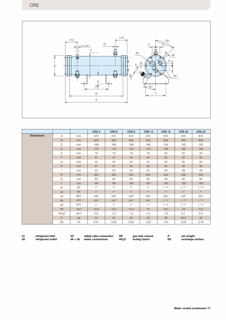
Water cooled condensers 17
CRS
110110
d1
C
Ø1/4”NPT
S
R
B
A
D
d5
F G
d3
H
IE
d4
T
d2
45°
30°
DimensionsCRS 3 CRS 6 CRS 8 CRS 12 CRS 15 CRS 20 CRS 25
A mm 670 670 670 670 870 870 870
B mm 600 600 600 600 800 800 800
C mm 168 168 168 168 193 193 193
D mm 170 170 170 170 195 195 195
E mm 19 19 19 19 20 20 20
F mm 41 41 44 44 50 50 50
G mm 44 44 44 44 50 50 50
H mm 27 27 32 32 35 35 35
I mm 52 52 52 52 58 58 58
R mm 300 300 300 300 500 500 500
S mm 60 60 60 60 60 60 60
T mm 160 160 160 160 160 160 160
d1 RT 1” 1” 1” 1” 1 1/4” 1 1/4” 1 1/4”
d2 RT 1” 1” 1” 1” 1” 1” 1”
d3 NPT 3/8” 3/8” 3/8” 3/8” 3/8” 3/8” 3/8”
d4 FPT 3/4” 3/4” 3/4” 3/4” 1 1/4” 1 1/4” 1 1/4”
d5 FPT 1” 1” 1” 1” 1 1/2” 1 1/2” 1 1/2”
VR dm3 10,8 10,4 10,4 10 18,5 18 17,5
VH2O dm3 0,8 1,0 1,2 1,4 1,8 2,1 2,4
P kg 23 24 24 25 39 40,5 42
ES m2 0,41 0,82 0,82 1,23 1,67 2,23 2,79
d1 refrigerant inletd2 refrigerant outlet
d3 safety valve connectiond4 = d5 water connections
VR gas side volumeVH2O fouling factor
P net weightES exchange surface
Cat_CONDENSERS (Gb) 20-05-2003 11:32 Pagina 18
18 Water cooled condensers
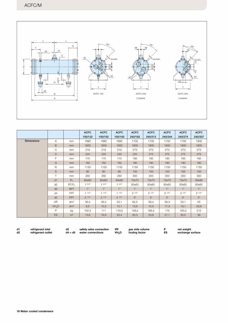
ACFC/M
Dimensions
=
F
=
G
d3 d1
Cd5
58 58
45°
T
d4
5050
Ø1/4”NPT
S
R
B
A
d2
D
Ø1/4”NPT
45°
4242
d5
T
Ø1/4”NPT
65
45°
43
d4
4754
ACFC 150 ACFC 240
2 passes
ACFC 240
4 passes
T
d1 refrigerant inletd2 refrigerant outlet
d3 safety valve connectiond4 = d5 water connections
VR gas side volumeVH2O fouling factor
P net weightES exchange surface
ACFC ACFC ACFC ACFC ACFC ACFC ACFC ACFC
150/122 150/152 150/183 240/183 240/213 240/244 240/274 240/337
A mm 1680 1680 1680 1700 1700 1700 1700 1900
B mm 1600 1600 1600 1600 1600 1600 1600 1800
C mm 219 219 219 273 273 273 273 273
D mm 220 220 220 220 275 275 275 275
F mm 170 170 170 185 185 185 185 185
G mm 162 162 162 180 180 180 180 180
R mm 1150 1150 1150 1150 1150 1150 1150 1150
S mm 80 80 80 100 100 100 100 100
T mm 260 260 260 300 300 300 300 300
d1 FL 60x60 60x60 60x60 70x70 70x70 70x70 70x70 90x90
d2 RT-FL 1 3/4” 1 3/4” 1 3/4” 60x60 60x60 60x60 60x60 60x60
d3 NPT 1” 1” 1” 1” 1” 1” 1” 1”
d4 FPT 1 1/2” 1 1/2” 1 1/2” 2 1/2” 2 1/2” 2 1/2” 2 1/2” 2 1/2”
d5 FPT 2 1/2” 2 1/2” 2 1/2” 3” 3” 3” 3” 3”
VR dm3 39,4 36,3 33,1 62,5 59,4 56,3 53,1 55
VH2O dm3 8,5 10,3 12,1 13,6 15,5 17,3 19,1 23,8
P kg 102,5 111 119,5 158,5 166,5 175 183,5 212
ES m2 13,6 16,9 20,4 20,3 23,8 27,1 30,5 39
Cat_CONDENSERS (Gb) 20-05-2003 11:32 Pagina 19
Water cooled condensers 19
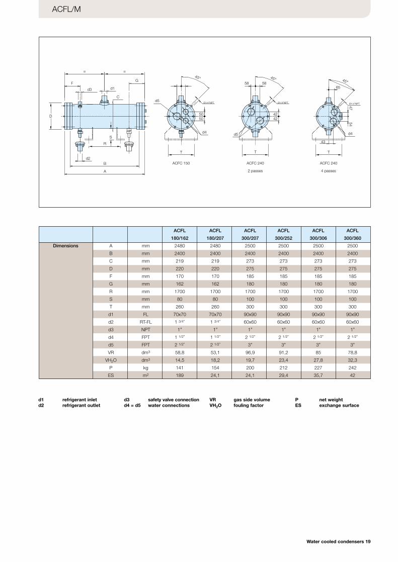
ACFL/M
Dimensions
=
F
=
G
d3 d1
Cd5
58 58
45°
T
d4
5050
Ø1/4”NPT
S
R
B
A
d2
D
Ø1/4”NPT
45°
4242
d5
T
Ø1/4”NPT
65
45°
43
d4
4754
ACFC 150 ACFC 240
2 passes
ACFC 240
4 passes
T
d1 refrigerant inletd2 refrigerant outlet
d3 safety valve connectiond4 = d5 water connections
VR gas side volumeVH2O fouling factor
P net weightES exchange surface
ACFL ACFL ACFL ACFL ACFL ACFL
180/162 180/207 300/207 300/252 300/306 300/360
A mm 2480 2480 2500 2500 2500 2500
B mm 2400 2400 2400 2400 2400 2400
C mm 219 219 273 273 273 273
D mm 220 220 275 275 275 275
F mm 170 170 185 185 185 185
G mm 162 162 180 180 180 180
R mm 1700 1700 1700 1700 1700 1700
S mm 80 80 100 100 100 100
T mm 260 260 300 300 300 300
d1 FL 70x70 70x70 90x90 90x90 90x90 90x90
d2 RT-FL 1 3/4” 1 3/4” 60x60 60x60 60x60 60x60
d3 NPT 1” 1” 1” 1” 1” 1”
d4 FPT 1 1/2” 1 1/2” 2 1/2” 2 1/2” 2 1/2” 2 1/2”
d5 FPT 2 1/2” 2 1/2” 3” 3” 3” 3”
VR dm3 58,8 53,1 96,9 91,2 85 78,8
VH2O dm3 14,5 18,2 19,7 23,4 27,8 32,3
P kg 141 154 200 212 227 242
ES m2 189 24,1 24,1 29,4 35,7 42
Cat_CONDENSERS (Gb) 20-05-2003 11:32 Pagina 20
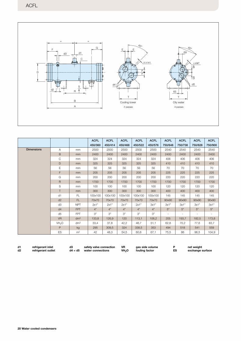
ACFL
F
= =
d3 d1
C
G
D
d2S
R
B
A
d4
E E
FF
45°
Ø1/4”NPT
69
4865
T
d5
65
T
45°
Cooling tower City water
20 Water cooled condensers
Dimensions
d1 refrigerant inletd2 refrigerant outlet
d3 safety valve connectiond4 = d5 water connections
VR gas side volumeVH2O fouling factor
P net weightES exchange surface
ACFL ACFL ACFL ACFL ACFL ACFL ACFL ACFL ACFL
450/360 450/414 450/468 450/522 450/576 750/648 750/738 750/828 750/900
A mm 2500 2500 2500 2500 2500 2540 2540 2540 2540
B mm 2400 2400 2400 2400 2400 2400 2400 2400 2400
C mm 324 324 324 324 324 406 406 406 406
D mm 325 325 325 325 325 410 410 410 410
E mm 56 56 56 56 56 70 70 70 70
F mm 205 205 205 205 205 225 225 225 225
G mm 200 200 200 200 200 220 220 220 220
R mm 1700 1700 1700 1700 1700 1700 1700 1700 1700
S mm 100 100 100 100 100 120 120 120 120
T mm 300 300 300 300 300 400 400 400 400
d1 FL 100x100 100x100 100x100 100x100 100x100 145 145 145 145
d2 FL 70x70 70x70 70x70 70x70 70x70 90x90 90x90 90x90 90x90
d3 NPT 2x1” 2x1” 2x1” 2x1” 3x1” 3x1” 3x1” 3x1” 3x1”
d4 FPT 4” 4” 4” 4” 4” 5” 5” 5” 5”
d5 FPT 3” 3” 3” 3” 3” - - - -
VR dm3 133,8 126,9 120 113,1 106,2 205 193,7 182,5 173,8
VH2O dm3 33,4 37,8 42,2 46,7 51,1 62,8 70,2 77,6 83,7
P kg 295 309,5 324 338,5 353 494 518 541 559
ES m2 42 48,3 54,5 60,8 67,1 75,5 86 96,5 104,9
2 passes 4 passes
Cat_CONDENSERS (Gb) 20-05-2003 11:32 Pagina 21
Flange ( CPLUS )
Welding ( CPLUS )
Rotalock ( CPLUS )
CPS
Flange (• CFC • CRS • CFL • ACFC • ACFL)
Type
NPT (• CFC • CRS • CFL • ACFC •ACFL)
Rotalock (• CFC • CRS • CFL • ACFC • ACFL)
Type
B
C
A B C RT Name ODS ID
[mm] [mm] [mm] [mm] [mm]
20 80 36 11/4" -12UNF RB22 22 22,5
20 80 50 13/4" -12UNF RC28 28 28,3
20 80 50 13/4" -12UNF RC35 35 35,3
D 1/4” 3/8” 1/2” 1”
d (mm) 20 24 30 40
H (mm) 22 22 25 25
Water cooled condensers 21
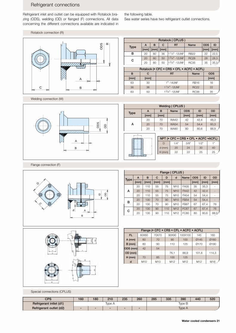
Refrigerant connections
Refrigerant inlet and outlet can be equipped with Rotalock bra-zing (ODS), welding (OD) or flanged (F) connections. All dataconcerning the different connections available are indicated in
the following table.Sea water series have two refrigerant outlet connections.
Rotalock connection (R)
Welding connection (W)O
DS R
B
A
C
B
A
OD
OD
S
B C RT Name ODS
[mm] [mm] [mm]
63 30 1" -14UNF RB16 16
36 36 11/4" -12UNF RC22 22
63 50 13/4" -12UNF RC38 35
Type
A
Flange connection (F)
OD
A
ID
B
C
D
d
A
B
C
Special connections (CPLUS)
Refrigerant outlet (d2)Refrigerant intlet (d1) Type A Type B
Type A
160 180 210 235 260
- - - - -
285 335 390 440 520
FL 60X60 70X70 90X90 100X100 145 160
A (mm) 60 70 90 100 Ø145 Ø160
B (mm) 80 90 110 125 Ø170 Ø190
ODS (mm) 42 54 - -
OD (mm) 76,1 88,9 101,6 114,3
H (mm) 70 85 100 125
d M10 M10 M12 M12 M12 M16
A B C D d Name ODS ID OD
[mm] [mm] [mm] [mm] [mm] [mm] [mm]
20 110 55 75 M10 FA35 35 35,3 -
20 110 55 75 M10 FA42 42 42,4 -
20 110 55 75 M10 FA54 54 54,4 -
20 130 70 90 M10 FB54 54 54,4 -
20 130 70 90 M10 FB67 67 67,4 76
20 130 90 110 M12 FC67 67 67,4 76
20 130 90 110 M12 FC80 80 80,6 88,9
A B Name ODS ID OD
[mm] [mm] [mm] [mm] [mm]
20 70 WA42 42 42,4 48,3
20 70 WA54 54 54,4 60,3
20 70 WA80 80 80,6 88,9
Cat_CONDENSERS (Gb) 20-05-2003 11:32 Pagina 22
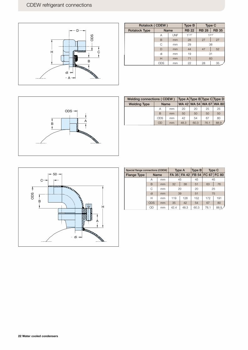
Welding connections ( CDEW )
Welding Type
A UNF 11/4”
B mm 28
C mm 29
D mm 44
di mm 19
H mm 71
ODS mm 22
13/4”
27 27
38
47 52
31
83
28 35
CDEW refrigerant connections
ODS
BA
Rotalock Type
Rotalock ( CDEW ) Type B Type C
Name RB 22 RB 28 RB 35
A mm 45 45 45
B mm 32 38 51 63 76
C mm 20 20 25
di mm 39 51 75
H mm 119 128 152 172 191
ODS mm 35 42 54 67 80
OD mm 42.4 48.3 60.3 76.1 88.9
D
H C
B
A
di
OD
S
Flange Type
Special flange connections (CDEW)
Name FA 35Type A Type B Type C
FA 42 FB 54 FC 67 FC 80
A mm 20 20 25 25
B mm 50 50 50 50
ODS mm 42 54 67 80
OD mm 48.3 60.3 76.1 88.9
di
B
C
50
A
H
OD
S
Type C Type DType BType A
Name WA 42 WA 54 WA 67 WA 80
22 Water cooled condensers
Cat_CONDENSERS (Gb) 20-05-2003 11:32 Pagina 23
Model
Threaded connections (T)CITYTOWER
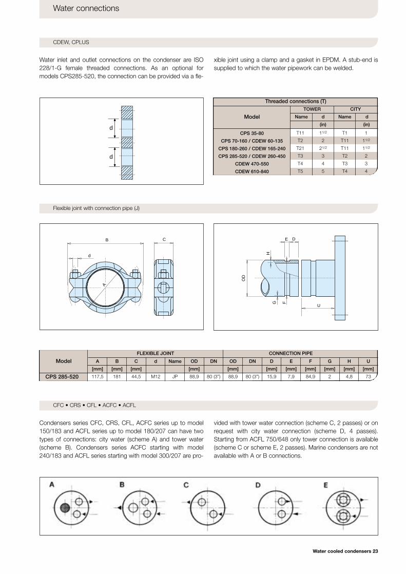
Water connections
CDEW, CPLUS
Flexible joint with connection pipe (J)
Water inlet and outlet connections on the condenser are ISO228/1-G female threaded connections. As an optional formodels CPS285-520, the connection can be provided via a fle-
xible joint using a clamp and a gasket in EPDM. A stub-end issupplied to which the water pipework can be welded.
CFC • CRS • CFL • ACFC • ACFL
Condensers series CFC, CRS, CFL, ACFC series up to model150/183 and ACFL series up to model 180/207 can have twotypes of connections: city water (scheme A) and tower water(scheme B). Condensers series ACFC starting with model240/183 and ACFL series starting with model 300/207 are pro-
vided with tower water connection (scheme C, 2 passes) or onrequest with city water connection (scheme D, 4 passes).Starting from ACFL 750/648 only tower connection is available(scheme C or scheme E, 2 passes). Marine condensers are notavailable with A or B connections.
d
d
CB
A
d
OD
D E
H
G
U F
CPS 285-520
FLEXIBLE JOINT
A B C d Name OD DN OD DN D E F G H U
[mm] [mm] [mm] [mm] [mm] [mm] [mm] [mm] [mm] [mm] [mm]
117,5 181 44,5 M12 JP 88,9 80 (3”) 88,9 80 (3”) 15,9 7,9 84,9 2 4,8 73
CONNECTION PIPE
Model Name d
(in)
Name d
(in)
CPS 35-80
CPS 70-160 / CDEW 60-135
CPS 180-260 / CDEW 165-240
CPS 285-520 / CDEW 260-450
CDEW 470-550
CDEW 610-840
T11 11/2 T1 1
T2 2 T11 11/2
T21 21/2 T11 11/2
T3 3 T2 2
T4 4 T3 3
T5 5 T4 4
Water cooled condensers 23
Cat_CONDENSERS (Gb) 20-05-2003 11:32 Pagina 24
Alfa Laval in briefAlfa Laval is leading global provider ofspecialized products and engineeringsolutions.Our equipment, systems and services are dedicated to assisting customers in optimizing the performance of theirprocesses. Time and time again.We help them heat, cool, separate andtrasport products such as oil, water,chemicals, beverages, foodstuff, starchand pharmaceuticals.Our worldwide organization works closelywith customers in almost 100 countries tohelp them stay ahead.
www.alfalaval.comCod
. 11
1004
04 E
N -
Ed
iton
04/0
2
ww
w.s
tp.it
Cat_CONDENSERS (Gb) 20-05-2003 11:32 Pagina 1
Related Documents