arXiv:1304.4383v2 [cs.NI] 1 Sep 2013 1 Convolutional Network-Coded Cooperation in Multi-Source Networks with a Multi-Antenna Relay Alireza Karbalay-Ghareh, Masoumeh Nasiri-Kenari, Senior Member, IEEE, and Mohsen Hejazi Abstract We propose a novel cooperative transmission scheme called Convolutional Network-Coded Cooperation (CNCC) for a network including N sources, one M -antenna relay, and one common destination. The source-relay (S-R) channels are assumed to be Nakagami-m fading, while the source-destination (S-D) and the relay-destination (R-D) channels are considered Rayleigh fading. The CNCC scheme exploits the generator matrix of a good (N +M ′ ,N,ν ) systematic convolutional code, with the free distance of d free designed over GF (2), as the network coding matrix which is run by the network’s nodes, such that the systematic symbols are directly transmitted from the sources, and the parity symbols are sent by the best antenna of the relay. An upper bound on the BER of the sources, and consequently, the achieved diversity orders are obtained. The numerical results indicate that the CNCC scheme outperforms the other cooperative schemes considered, in terms of the diversity order and the network throughput. The simulation results confirm the accuracy of the theoretical analysis. Index Terms Cooperative networks, linear network coding, convolutional network-coded cooperation, diversity order, network throughput. I. I NTRODUCTION O NE of the most important and intrinsic features of the wireless networks is fading. This phenomenon induces many adverse effects in the networks, and considerably reduces the performance. Diversity is a well-known technique to deal with fading, which is used in the various domains such as time, frequency, and space. Cooperative relay-based networks have been proposed to combat fading, by benefiting from the spatial diversity through the relays or the antennas of a multi-antenna relay [1-4]. The traditional The authors are with the Wireless Research Laboratory (WRL), Department of Electrical Engineering, Sharif University of Technology, Tehran, Iran (email: {karbalayghareh, mhejazi} @ee.sharif.edu, [email protected]).

Welcome message from author
This document is posted to help you gain knowledge. Please leave a comment to let me know what you think about it! Share it to your friends and learn new things together.
Transcript
arX
iv:1
304.
4383
v2 [
cs.N
I] 1
Sep
201
31
Convolutional Network-Coded Cooperation in
Multi-Source Networks with a Multi-Antenna Relay
Alireza Karbalay-Ghareh, Masoumeh Nasiri-Kenari,Senior Member, IEEE, and
Mohsen Hejazi
Abstract
We propose a novel cooperative transmission scheme calledConvolutional Network-Coded Cooperation (CNCC)
for a network includingN sources, oneM -antenna relay, and one common destination. The source-relay (S-R)
channels are assumed to be Nakagami-m fading, while the source-destination (S-D) and the relay-destination (R-D)
channels are considered Rayleigh fading. The CNCC scheme exploits the generator matrix of a good(N+M′
, N, ν)
systematic convolutional code, with the free distance ofdfree designed overGF (2), as the network coding matrix
which is run by the network’s nodes, such that the systematicsymbols are directly transmitted from the sources,
and the parity symbols are sent by the best antenna of the relay. An upper bound on the BER of the sources, and
consequently, the achieved diversity orders are obtained.The numerical results indicate that the CNCC scheme
outperforms the other cooperative schemes considered, in terms of the diversity order and the network throughput.
The simulation results confirm the accuracy of the theoretical analysis.
Index Terms
Cooperative networks, linear network coding, convolutional network-coded cooperation, diversity order, network
throughput.
I. INTRODUCTION
ONE of the most important and intrinsic features of the wireless networks is fading. This phenomenon
induces many adverse effects in the networks, and considerably reduces the performance. Diversity
is a well-known technique to deal with fading, which is used in the various domains such as time,
frequency, and space. Cooperative relay-based networks have been proposed to combat fading, by benefiting
from the spatial diversity through the relays or the antennas of a multi-antenna relay [1-4]. The traditional
The authors are with the Wireless Research Laboratory (WRL), Department of Electrical Engineering, Sharif Universityof Technology,Tehran, Iran (email:{karbalayghareh, mhejazi} @ee.sharif.edu, [email protected]).
2
cooperative transmission schemes, such as Amplify-and-Forward (AF) and Decode-and-Forward (DF),
have been introduced and evaluated in the the numerous papers like [4-8]. The basic and common
shortcoming of these schemes is the reduction of the networkthroughput in the multi-sources networks
[9], [10]. To eliminate this problem, the idea of using network coding in the cooperative networks has
been suggested in the recent years.
Network Coding was first introduced by Ahlswede et al. in the seminal work [11], and then proposed
as Linear Network Coding (LNC) in [12]. The main idea of the LNC is that in a multi-hop network, the
intermediate nodes combine linearly the received data fromthe source nodes, and transmit them to the
next hops, instead of transmitting each received data separately. This approach can dramatically reduce the
delay, and consequently, increase the network throughput.The initial researches on network coding were
related to the wired networks, but it was gradually generalized to the wireless networks [13], [14]. The
network codes were first considered in the network layer withthe assumption of an ideal and error-free
physical layer, but afterwards were extended to the physical layer by considering the effects of fading
and noise. The most spectrally efficient Physical Layer Network Coding (PLNC) was proposed in [15-
17], in which the nodes simultaneously transmit their own data, and the other nodes receive the linear
combinations of the data transmitted plus the noise during just one time slot; nonetheless, a high level of
synchronization must be hold in order this scheme to be viable.
Recently, the network coding has been exploited in the cooperative relay networks due to its capability
to increase the network throughput. Quite a few of these works have somehow demonstrated that utilizing
the linear network coding in the multi-source cooperative networks instead of the traditional schemes leads
to the same diversity order, while improves the network throughput. [18] has investigated the network
coding in a double-source cooperative network, where each node creates a linear combination of its own
symbol and its partner’s correctly decoded symbol onGF (2). In [20], a cooperative transmission scheme
based on the network coding along with the multi-user detection has been proposed to improve the users’
Bit Error Rate (BER). [21] has introduced a cooperative scheme based on the network coding and the best
relay selection technique in a network withN source-destination pairs andM intermediate relays. In [21],
each destination must correctly decode the other sources’ symbols in order to recover its own symbol, and
without this assumption the diversity order decreases fromM + 1 to 2. The aforementioned papers have
used the binary fieldGF (2) to build the linear combinations. Nevertheless, some papers considered using
the higher fieldsGF (q). Specifically, [23] showed that in the multi-source networks with the error-prone
3
source-relay channels, the network coding onGF (2) can not lead to the full diversity order. Furthermore,
[25] considered a network withM sources where each source acts as a relay for the other sources, and a
(M2,M) maximum distance separable (MDS) linear block code is utilized by the relays. The scheme of
[25] leads to the network throughput equal to1/M symbol per channel use (spcu) and diversity order of
2M −1. Although based on the Singleton bound [32], the diversity order ofM2−M +1 was expected in
[25], but due to the error possibility in the inter-source channels this expectation had not been realized.
[27] has generalized the idea of [25], in which a(αM2, αM) (α ≥ 2) MDS linear block code is used
as the network coding matrix, which leads to the improved Singleton boundα(M2 − M) + 1 with the
same throughput of1/M spcu. Although these schemes have boosted the diversity order, but they are
still suffering from low network throughput. To address this problem, [28] has introduced Complex Field
Network Coding (CFNC) scheme in a network includingN sources, which reaches to the diversity order
of N , as well as the network throughput of approximately1 spcu. In [29], the CFNC has been also utilized
in a network includingNS sources,NR relays, and one common destination, which reaches to the full
diversity order ofNR + 1 along with the network throughput of1/2 symbol per source per channel use
(spspcu) (or equivalentlyNS/2 spcu), while the network throughput of the traditional (AF and DF) and the
finite field linear network coding schemes in such a network are respectively equal to1/(NR+1) spcu and
NS/(NS +NR) spcu. The main reason for the higher throughput of the CFNC schemes in [28] and [29]
is the utilization of the complex fields instead of the finite fields, in which the symbols of different nodes,
similar to the PLNC, are simultaneously transmitted and their linear combinations in the complex field are
received in the other nodes; as a result, this scheme possesses highly complicated synchronization concerns
of the PLNC. Furthermore, in [30], a cooperative transmission scheme based on the linear network codes
designed overGF (q) has been introduced for improving the Diversity-Multiplexing Trade-off (DMT) in
a network consisting ofN source-destination pairs, andM intermediate relays, which reaches the full
diversity order ofM +1 as well as the network throughput ofN/(N +M) spcu. In [30], the parity check
matrix of a (N +M,M,N + 1) MDS linear block code is used as the network coding matrix. However,
the field size required for such MDS codes increases exponentially with the values ofN andM , which
can significantly enhance the system complexity.
In this paper, to increase the diversity order without the degradation of the network throughput, we
propose a new cooperative transmission scheme called “Convolutional Network-Coded Cooperation”
(CNCC) in a network includingN sources, one relay withM antenna, and one common destination.
4
The CNCC scheme uses the generator matrix of a systematic convolutional code designed onGF (2)
throughout the network as the network coding matrix. In thisscheme, the systematic packets of the
sources are directly transmitted from the sources to the destination, which are simultaneously received
and decoded by the relay. If the relay correctly decodes all the packets, it will generate the parity packets
by using the underlying convolutional code, and finally willtransmit the parity packets by its best antenna
(the strongest R-D channel) to the destination. In contrastto the linear network coding scheme, in our
proposed CNCC scheme, the diversity order can be enhanced without the reduction of the network
throughput, by the increase of the underlying convolutional code’s constraint length. It will be shown
that the proposed scheme improves the network throughput, and its diversity order at the worst scenarios
(weak S-R channels) is equal toM + 1, and at the best scenarios (strong enough S-R channels) can be
much greater thanM + 1. In fact, when the relay is located close to the sources, the diversity order can
reach toD⋆, whereD⋆ ≥ dfree + M − 1, and dfree is the free distance of the exploited convolutional
code. It should be noted that the free distance of the convolutional code is increased by the constraint
length at the expense of the decoder’s complexity. In contrast to the linear network coding scheme, in
our proposed scheme, the network throughput does not dependon the number of antennas, but on the
number of parity bits of the convolutional codes.
The rest of this paper is organized as follows. In Section II,the system model is described. In Section
III, the proposed CNCC scheme is introduced. In Section IV, the performance of the CNCC scheme is
analyzed in terms of the sources’ BER and the diversity order. Four examples for the CNCC scheme
are presented in Section V. The numerical results are provided in Section VI. Ultimately, Section VII
concludes the paper, and suggests some future works.
II. SYSTEM MODEL
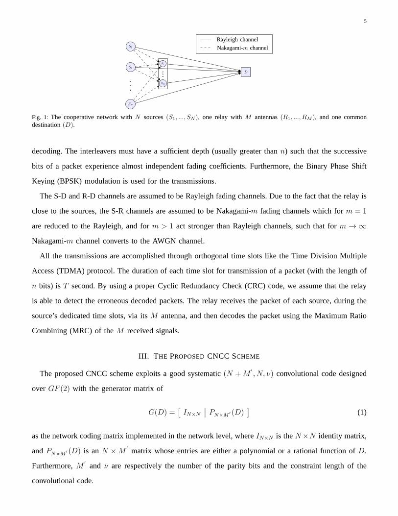
We consider a cooperative network consisting ofN single-antenna sources, oneM-antenna relay, and
one common single-antenna destination, as shown in Fig. 1. The relay’sM antennas are omnidirectional
which can be used for both the reception and the transmission. All the S-D, R-D, and S-R channels
are assumed to be block fading channels with the depth ofn bit transmission intervals, which change
independently and identically from one block to another block. Each source hasL information bits for
transmission which is divided to thel packets of lengthn bits, whereL = nl. We assume a perfect
interleaving process throughout the network. That is, the packets in the sources and the relay are interleaved
before transmissions, and the received packets at the relayand the destination are deinterleaved before
5
SN
S2
S1
RM
R1
D
v7
v8
v9
v10
v11
v12
Rayleigh channel
Nakagami-m channel
Fig. 1: The cooperative network withN sources(S1, ..., SN ), one relay withM antennas(R1, ..., RM ), and one commondestination(D).
decoding. The interleavers must have a sufficient depth (usually greater thann) such that the successive
bits of a packet experience almost independent fading coefficients. Furthermore, the Binary Phase Shift
Keying (BPSK) modulation is used for the transmissions.
The S-D and R-D channels are assumed to be Rayleigh fading channels. Due to the fact that the relay is
close to the sources, the S-R channels are assumed to be Nakagami-m fading channels which form = 1
are reduced to the Rayleigh, and form > 1 act stronger than Rayleigh channels, such that form → ∞
Nakagami-m channel converts to the AWGN channel.
All the transmissions are accomplished through orthogonaltime slots like the Time Division Multiple
Access (TDMA) protocol. The duration of each time slot for transmission of a packet (with the length of
n bits) isT second. By using a proper Cyclic Redundancy Check (CRC) code, we assume that the relay
is able to detect the erroneous decoded packets. The relay receives the packet of each source, during the
source’s dedicated time slots, via itsM antenna, and then decodes the packet using the Maximum Ratio
Combining (MRC) of theM received signals.
III. T HE PROPOSEDCNCC SCHEME
The proposed CNCC scheme exploits a good systematic(N +M′
, N, ν) convolutional code designed
overGF (2) with the generator matrix of
G(D) =[
IN×N
∣
∣ PN×M′ (D)
]
(1)
as the network coding matrix implemented in the network level, whereIN×N is theN×N identity matrix,
andPN×M′ (D) is anN ×M
′
matrix whose entries are either a polynomial or a rational function ofD.
Furthermore,M′
and ν are respectively the number of the parity bits and the constraint length of the
convolutional code.
6
The encoder of the convolutional codeG(D) in (1) is minimally realized in the relay. That is, the relay
containsν memories (shift registers). TheN systematic packets, related to the first section of theG(D),
i.e., IN×N , are directly transmitted from theN sources to the destination within the firstN time slots. The
M′
parity packets are generated from theN correctly decoded sources’ packets in the relay, pertaining
to the second section of theG(D), i.e., PN×M′ (D), and then are transmitted from the best antennas of
the relay to the destination during the consequentM′
time slots. The best antenna of the relay at each
time slot is defined as the antenna that possesses the strongest R-D channel, which is recognized by the
destination.
Specifically, the transmission strategy in the CNCC scheme is as follows. The sources transmit their
own interleaved packets of the lengthn during their dedicated time slots to the destination, wherethe relay
simultaneously receives them through itsM antenna, and after deinterleaving the packets, decodes each
packet by the MRC method. If the relay correctly decodes all the i-th (i ∈ {1, ..., l}) N sources’ packets
(success(s) situation), it will produce the correspondingM′
parity packets by using the convolutional
codeG(D) in (1), and after interleaving, will transmit them from its best antennas to the destination
during the dedicated time slots. However, if the relay failsto correctly decode all theN packets (failure
(f) situation), it will not generate any parity packets, and will inform the destination. In the failure
situations, the sources’ packets are merely decoded based on the signals received through the direct S-D
paths without the help of the relay. But, in the success situations, the destination uses both the sources’
systematic packets and the parity packets received from therelay, and after deinterleaving, runs the Viterbi
algorithm to decode all the packets of the sources.
Due to the proximity of the relay to the sources, the number ofthe failure situations is negligible
compared with the number of the success situations. Hence, the network throughput in the proposed
CNCC scheme is tightly lower bounded asR ≥ N/(N + M′
) spcu (symbol per channel use). We are
interested in the lower value forM′
to increase the network throughput. Accordingly, by selecting the
number of parity outputs of convolutional codes less than (or equal to) the number of the relay’s antennas
(M′
≤ M), the network throughput of the CNCC scheme (N/(N + M′
) spcu) will be greater than (or
equal to) that of the LNC scheme withM single-antenna relays (N/(N +M) spcu). That is, the network
throughput of the CNCC scheme is not a function ofM , and consequently, it remains constant and does
not decrease with the increase of the number of antennas.
7
IV. PERFORMANCE ANALYSIS
In this section, we first analyze the the BER of the proposed scheme, and then determine the achieved
diversity order. As mentioned previously, there is two situations (s and f ) in the relay that must be
considered in the BER analysis. Hence, the end-to-end BER ofthe network’s sources can be written as
Pb = P b|sPs + P b|fPf = P b|s (1− Pf ) + P b|fPf (2)
wherePb is the BER of the sources.Pf is the probability of the failure situation in which the relay fails
to correctly decode all theN packets of theN sources.Ps is the probability of the success situation
in which the relay correctly decodes all theN sources’ packets, wherePs + Pf = 1. P b|f andP b|s are
respectively the BER of the sources in the failure and the success situations.
A. Computation of Pf
The t-th received signal from thei-th source (si) at thej-th antenna of the relay (rj) is as
ysi,rj (t) =√
Eb hsi,rj (t) xsi (t) + nsi,rj (t) (3)
where i = 1, ..., N , j = 1, ...,M , and t = 1, ..., L. hsi,rj(t)s are Nakagami-m fading coefficients from
the si to the rj. xsi (t) is the BPSK signal transmitted from thesi. Moreover,nsi,rj (t) is the additive
white Gaussian noise with the zero mean and the variance ofN0/2. Eb is the transmitted energy per
bit. We assume that all the S-R channels have the same averageenergy; that is,E{
h2si,rj
}
= h2sr, ∀i ∈
{1, . . . , N} , ∀j ∈ {1, . . . ,M}. Hence, the probability density functions (pdf) of the coefficients are as
fhsi,rj
(
hsi,rj
)
= 2
(
m
h2sr
)mhsi,rj2m−1
Γ (m)e−m
hsi,rj2
h2sr , (4)
whereΓ (m) =∫∞
0xm−1e−xdx is the Gamma function, and for integer values ofm is equal toΓ (m) =
(m− 1)!.
First, we calculate the bit error probabilityPe at the relay. By using the MRC, the conditional bit error
probability of a BPSK signal is as
Pe|γsi,r= Q
(√
2γsi,r)
, (5)
8
γsi,r =Eb
N0
M∑
j=1
h2si,rj
, (6)
whereγsi,r is the received SNR of the transmitted signal from the sourcesi at the relay. By defining
h′
si,rj= h2
si,rj, and due to the fact thathsi,rj is the Nakagami-m random variable, given in (4),h
′
si,rjwill
be a Chi Square random variable with2m degrees of freedom as
fh′
si,rj
(
h′
si,rj
)
=
(
m
h2sr
)mh′
si,rj
m−1
Γ (m)e−m
h′
si,rj
h2sr (7)
∀i ∈ {1, . . . , N} , ∀j ∈ {1, . . . ,M}. Hence,γsi,r in (6), which is the sum ofM independent Chi Square
random variables each of which with2m degrees of freedom, has the Chi Square pdf with2Mm degrees
of freedom. By definingγsr =Eb
N0
h2sr as the average received SNR of the S-R channels, we have
fγsi,r (γsi,r) =
(
m
γsr
)Mmγsi,r
Mm−1
Γ (Mm)e−m
γsi,r
γsr . (8)
As a result, the unconditional bit error probability,Pe, can be easily obtained from (5) and (8) as
Pe =
∫ ∞
γsi,r=0
Pe|γsi,rfγsi,r (γsi,r) dγsi,r, (9)
Pe =
[
1
2(1− µsr)
]Mm Mm−1∑
w=0
(
Mm− 1 + w
w
)[
1
2(1 + µsr)
]w
, (10)
whereµsr =√
γsr
m+γsr.
Now, we compute the failure probability,Pf . Because of assuming a perfect interleaving, the successive
bits within each sources’ packets experience independent fadings. As a result, the probability that one
packet of a specific source can be correctly decoded in the relay is equal to(1 − Pe)n. In (2), Ps is
the probability that all theN packets of theN sources corresponding to theN successive slots can be
correctly decoded in the relay. Therefore, the success probability at the relay is as follows
Ps = (1− Pe)Nn. (11)
As a result,Pf in (2) is computed as
Pf = 1− Ps = 1− (1− Pe)Nn, (12)
9
wherePe is given by (10).
At the high SNRs (γsr → ∞), Pe andPf can be respectively approximated as
Pe ≈
(
2Mm− 1
Mm
)(
m
4γsr
)Mm
, (13)
Pf ≈ nNPe ≈ K
(
1
γsr
)Mm
, (14)
whereK = nN(
2Mm−1Mm
) (
m4
)Mmis a constant coefficient.
B. Computation of P b|f
When the relay fails to correctly decode theN packets of the sources, it does not participate in the
cooperation phase, and consequently, these packets are decoded only based on the received signals through
the direct S-D channels. Hence, the bit error probability ofthe sources in the failure situation is simply
obtained similar to (10) by settingm = 1 andM = 1, and substitutingγsd instead ofγsr. As a result,
we have
P b|f =1
2
(
1−
√
γsd
1 + γsd
)
, (15)
whereγsd is defined as the average received SNR from the S-D channels atthe destination. Similar to
(13), at the high SNRs (γsd → ∞), P b|f can be approximated as
P b|f ≈1
4γsd
. (16)
C. Computation of P b|s
In the s situation, based on theN packets of the sources, the relay produces the corresponding M′
parity packets using the systematic(N + M′
, N, ν) convolutional code given in (1). Finally, the parity
packets are transmitted through the best antenna of the relay during their dedicatedM′
time slots. The
destination runs the Viterbi algorithm to decode the sources’ packets. Hence, the BER of the sources in
this situation is equal to the BER of the exploited convolutional code described byG(D) in (1) whose
systematic and parity packets are respectively transmitted through the Rayleigh fading S-D channels, and
the best ofM available Rayleigh fading R-D channels.
Due to interleaving with sufficient depth, the successive bits of each packet sent by the sources and the
relay are well assumed to experience independent fadings. The received signals from theN sources and
10
the best selected antennas of the relay in the destination are respectively as follows
ysi,d(t) =√
Ebhsi,d(t)xsi,d(t) + zsi,d(t), (17)
yrsel,d(t′
) =√
Ebhrsel,d(t′
)xrsel,d(t′
) + zrsel,d(t′
), (18)
where i ∈ {1, ..., N}, t ∈ {1, ..., L}, and t′
∈ {1, ...,M′
L}. The parameters in (17) and (18) are as
follows. Eb: the transmitted energy per bit.xsi,d(t): the t-th transmitted bit from thei-th source.hsi,d(t)
andzsi,d(t): respectively, the Rayleigh fading coefficient, and the Gaussian noise with zero mean and the
variance ofN0/2. xrsel,d(t′
): the t′
-th parity bit transmitted from the best selected antenna ofthe relay.
hrsel,d(t′
) and zrsel,d(t′
): respectively, the Rayleigh fading coefficient, and the Gaussian noise with zero
mean and the variance ofN0/2.
The BER of a(N +M′
, N, ν) convolutional code with the free distance ofdfree is upper bounded as
Pbconv.<
1
N
∞∑
d=dfree
BdPd, (19)
whereBds are the coefficients of the Bit Weight Enumerating Function(BWEF) of the convolutional code
as
B(X) =∞∑
d=dfree
BdXd =
∂A(W,X)
∂W
∣
∣
W=1. (20)
A(W,X) is the Input-Output Weight Enumeration Function (IOWEF) ofthe code, which can be easily
computed from the state diagram of the convolutional code. Furthermore,Pd in (19) is the Pairwise Error
Probability (PEP) with the Hamming weight ofd. It must be noticed thatPd only depends on the S-D
and R-D channels.
1) Computation of PEP: The destination uses the Maximum Likelihood criterion to decode the sequence
transmitted by the sources as well as the best antennas of therelay. Hence, according to (17) and (18),
the conditional PEP can be easily obtained as [34]
Pd|{γsd,γrsel,d} = Q
√
√
√
√2
d1∑
k=1
γsd(tk) + 2
d2∑
k=1
γrsel,d(t′
k)
, (21)
where d1 + d2 = d. tk and t′
k are the error positions related to the transmitted bits respectively from
the sources and the relay. Moreover,γsd(tk) =Eb
N0
h2sd(tk) andγrsel,d(t
′
k) =Eb
N0
h2rsel,d
(t′
k) are, respectively,
the instantaneous received SNRs from the sources and the best antennas of the relay. Theγsd(tk)s are
11
independent for differentk, and have the exponential pdf as
fγsd(tk) (γsd(tk)) =1
γsd
exp−γsd(tk)
γsd
, (22)
whereγsd =Eb
N0
h2sd is the average received SNR from the S-D channels. Furthermore, γrsel,d(t
′
k) is as
γrsel,d(t′
k) = maxj=1,...,M
γrj ,d(t′
k), (23)
whereγrj ,d(t′
k) =Eb
N0
h2rj ,d
(t′
k) is the received SNR from thej-th antenna of the relay at the destination,
and has the exponential pdf and cdf, respectively, as
fγrj ,d(t
′
k)
(
γrj ,d(t′
k))
=1
γrd
exp−γrj ,d(t
′
k)
γrd
(24)
Fγrj ,d(t
′
k)
(
γrj ,d(t′
k))
= 1− exp−γrj ,d(t
′
k)
γrd
(25)
∀j ∈ {1, ...,M}, whereγrd = Eb
N0
h2rd is the average received SNR from the R-D channels. Then, from
(23)-(25), the pdf ofγrsel,d(t′
k) is easily obtained as
fγrsel,d(t
′
k)
(
γrsel,d(t′
k))
= M
[
1− exp−γrsel,d(t
′
k)
γrd
]M−11
γrd
exp−γrsel,d(t
′
k)
γrd
(26)
Now, we can computePd by averagingPd|{γsd,γrsel,d} in (21) over the distributions ofγsd(tk) and
γrsel,d(t′
k) given respectively in (22) and (26) as
Pd =
∫ ∞
0
...
∫ ∞
0
Q
√
√
√
√2
d1∑
k=1
γsd(tk) + 2
d2∑
k=1
γrsel,d(t′
k)
(
d1∏
k=1
1
γsd
exp−γsd(tk)
γsd
)
×
(
d2∏
k=1
M
[
1− exp−γrsel,d(t
′
k)
γrd
]M−11
γrd
exp−γrsel,d(t
′
k)
γrd
)
d1∏
k=1
dγsd(tk)
d2∏
k=1
dγrsel,d(t′
k). (27)
By using the upper boundQ(x) ≤ 12e
−x2
2 , x ≥ 0 and the Binomial expansion,(1 + x)n =∑n
w=0
(
n
w
)
xw,
and after some straightforward simplifications, the upper bound forPd is obtained as
Pd ≤1
2
(
1
1 + γsd
)d1(
MM−1∑
w=0
(
M − 1
w
)
(−1)w1
1 + w + γrd
)d2
, (28)
12
whered1 + d2 = d. It can be easily demonstrated that the following inequality holds
M
M−1∑
w=0
(
M − 1
w
)
(−1)w1
1 + w + γrd
<M(M − 1)!
γ Mrd
. (29)
Hence, from (28) and (29), we also have
Pd ≤1
2
(
1
1 + γsd
)d1(
M(M − 1)!
γ Mrd
)d2
, (30)
whered1 + d2 = d.
From (28) and (30),Pd is not an explicit function ofd, but a function ofd1 andd2 such thatd1+d2 = d.
Hence, we can not directly use the equations (19) and (20) to compute the BER of the sources in the
success situations, because the given BWEF is an explicit function of d. For the problem on hand, we
define a modified IOWEF,AMod(W,Y, Z), which is the function ofd1 andd2 as follows
AMod(W,Y, Z) =∑
w,d1,d2
Aw,d1,d2WwY d1Zd2 , (31)
whered1 + d2 = d and d ≥ dfree. In this equation, the exponents ofW , Y , andZ denote respectively
the Hamming weights of the input bits, the systematic outputbits, and the parity output bits of the
convolutional code. Furthermore,Aw,d1,d2 is the number of paths in the state diagram of the code, which
originate from the zero state, and finally return to the zero state, such that their numbers of nonzero
input bits, nonzero systematic output bits, and nonzero parity output bits are respectively equal tow,
d1, andd2. Since the exploited convolutional code in the CNCC scheme is systematic, we always have
w = d1. To deriveAMod(W,Y, Z), in the state diagram of the exploited codeG(D) in (1), we assign a
gainW αbY βbZζb to each branchb, such thatαb, βb, andζb are respectively the Hamming weights of the
input block (amongN input bits), the systematic output block (among the firstN output bits), and the
parity output block (among the lastM′
output bits) of the branchb. Again, we haveαb = βb. With this
dedicated gain to each branch, the transfer function from the initial zero state to the final zero state in the
modified state diagram yields theAMod(W,Y, Z). Similar to (20), the modified BWEF is obtained from
the modified IOWEF as
BMod(Y, Z) =∑
d1,d2
Bd1,d2Yd1Zd2 =
∂AMod(W,Y, Z)
∂W
∣
∣
W=1, (32)
13
whered1 + d2 = d and d ≥ dfree. Bd1,d2 is the total number of the nonzero input bits in the paths of
the modified state diagram with the number of the nonzero systematic output bits equal tod1, and the
number of the nonzero parity output bits equal tod2.
Now, similar to (19), the BER of the sources in the success situations can be expressed as
P b|s <1
N
∑
d1,d2
Bd1,d2Pd. (33)
Ultimately, from (28) and (30)-(33), the closed form upper bounds for theP b|s are obtained as
P b|s <1
2NBMod
(
Y =1
1 + γsd
, Z = MM−1∑
w=0
(
M − 1
w
)
(−1)w1
1 + w + γrd
)
, (34)
and
P b|s <1
2NBMod
(
Y =1
1 + γsd
, Z =M(M − 1)!
γ Mrd
)
. (35)
D. End-to-end BER and the achieved diversity order
Taking the path loss effect into account leads to the following relationships:γsr =(
dsddsr
)η
γsd and
γrd =(
dsddrd
)η
γsd, wheredsr, dsd, and drd denote respectively the S-R, S-D, and R-D distances, and
η is the path loss exponent. Without loss of generality, we assume that the relationdsd = dsr + drd
approximately holds. Therefore, we haveγsr = βηγsd andγrd =(
β
β−1
)η
γsd, whereβ = dsddsr
. We define
γ , γsd as the average received SNR in the destination. Hence, from (2), (10), (12), (15), and (34), the
upper bound of the end-to-end BER of the network’s sources isobtained as
Pb <1
2NBMod
(
Y =1
1 + γ, Z = M
M−1∑
w=0
(
M − 1
w
)
(−1)w1
1 + w + γrd
)
×
(
1−
[
1
2(1− µsr)
]Mm Mm−1∑
w=0
(
Mm− 1 + w
w
)[
1
2(1 + µsr)
]w)nN
+1
2
(
1−
√
γ
1 + γ
)
×
1−
(
1−
[
1
2(1− µsr)
]Mm Mm−1∑
w=0
(
Mm − 1 + w
w
)[
1
2(1 + µsr)
]w)nN
(36)
whereµsr =√
γsr
m+γsr, γsr = βηγ, γrd =
(
β
β−1
)η
γ, andβ = dsddsr
.
Now, we aim to compute the diversity order of the CNCC scheme as
D , − limγ→∞
logPb(γ)
log γ. (37)
14
To this end, we first analyze the achieved diversity order in the success situation from (35) and (32). Let’s
introduce the setF as
F ={
(d1, d2)∣
∣ Y d1Zd2 exists in the series expression of BMod(Y, Z)}
. (38)
We then define
(d⋆1, d⋆2) = arg min
(d1,d2)d1 +Md2 s.t. (d1, d2) ∈ F . (39)
It would be worthy to mention that the pair(d⋆1, d⋆2) is not necessarily unique. Then, from (32), (35), and
(37)-(39), it can be easily observed that the diversity order in the success situation is equal to
D⋆ = d⋆1 +Md⋆2, (40)
which can be rewritten as
D⋆ = d⋆1 + d⋆2 + (M − 1)d⋆2. (41)
Due to the fact thatd⋆1 andd⋆2 are respectively related to the error patterns of the sources and the relay,
d⋆1 ≥ 1 andd⋆2 ≥ 1. Moreover, we haved⋆1 + d⋆2 ≥ dfree. Hence, from (41),D⋆ can be lower bounded as
D⋆ ≥ dfree +M − 1. (42)
Finally, from (1), (14), (16), (35), (38), and (39), at high SNRs (γ → ∞), Pb is approximated as
Pb ≈ K′
(
1
γ
)d⋆1
(
M(M − 1)!
γM
)d⋆2
+K′′
(
1
γ
)Mm+1
(43)
whereK′
andK′′
are the constant terms. According to (37), (40), and (43), the achieved diversity order
of the sources in the CNCC scheme is equal to
DCNCC = min (D⋆,Mm+ 1). (44)
By a proper value ofν in the exploited(N +M′
, N, ν) convolutional code, we can always havedfree ≥
M + 1, and consequently,D⋆ ≥ M + 1. We consider two special cases.
1) Weak S-R channels: In this case, we consider the Rayleigh fading channels (Nakagami-m with
m = 1), the same as the S-D and the R-D channels. Hence, the diversity order will beDCNCC = M + 1.
15
2) Strong S-R channels: For this case which is more likely to happen, according to theassumption
that the relay is close to the sources, the Nakagami-m S-R channels withm > 1 are well assumed. As a
result, the diversity order up toDCNCC = D⋆ can be achieved, which is much more thanM + 1, as will
be shown in the examples of the next section.
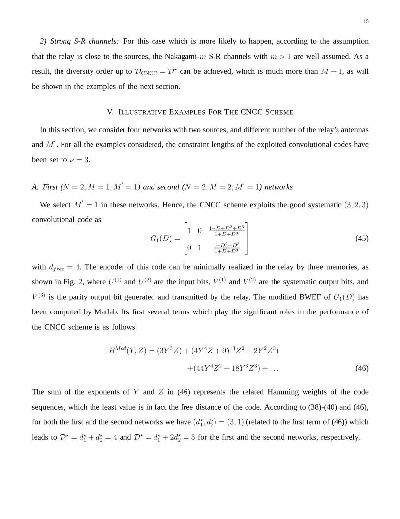
V. ILLUSTRATIVE EXAMPLES FOR THE CNCC SCHEME
In this section, we consider four networks with two sources,and different number of the relay’s antennas
andM′
. For all the examples considered, the constraint lengths ofthe exploited convolutional codes have
been set toν = 3.
A. First (N = 2,M = 1,M′
= 1) and second (N = 2,M = 2,M′
= 1) networks
We selectM′
= 1 in these networks. Hence, the CNCC scheme exploits the good systematic(3, 2, 3)
convolutional code as
G1(D) =
1 0 1+D+D2+D3
1+D+D3
0 1 1+D2+D3
1+D+D3
(45)
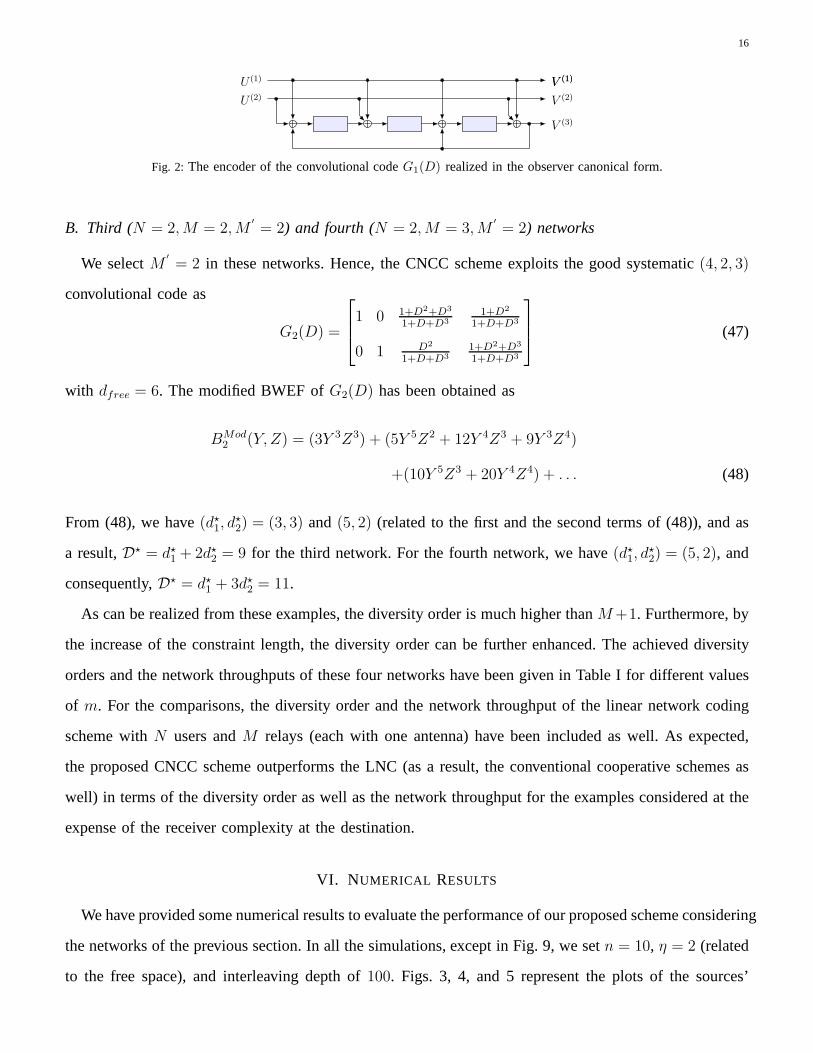
with dfree = 4. The encoder of this code can be minimally realized in the relay by three memories, as
shown in Fig. 2, whereU (1) andU (2) are the input bits,V (1) andV (2) are the systematic output bits, and
V (3) is the parity output bit generated and transmitted by the relay. The modified BWEF ofG1(D) has
been computed by Matlab. Its first several terms which play the significant roles in the performance of
the CNCC scheme is as follows
BMod1 (Y, Z) = (3Y 3Z) + (4Y 4Z + 9Y 3Z2 + 2Y 2Z3)
+(44Y 4Z2 + 18Y 3Z3) + . . . (46)
The sum of the exponents ofY and Z in (46) represents the related Hamming weights of the code
sequences, which the least value is in fact the free distanceof the code. According to (38)-(40) and (46),
for both the first and the second networks we have(d⋆1, d⋆2) = (3, 1) (related to the first term of (46)) which
leads toD⋆ = d⋆1 + d⋆2 = 4 andD⋆ = d⋆1 + 2d⋆2 = 5 for the first and the second networks, respectively.
16
V (1)
V (2)
V (3)
V (1)U (1)
U (2)
Fig. 2: The encoder of the convolutional codeG1(D) realized in the observer canonical form.
B. Third (N = 2,M = 2,M′
= 2) and fourth (N = 2,M = 3,M′
= 2) networks
We selectM′
= 2 in these networks. Hence, the CNCC scheme exploits the good systematic(4, 2, 3)
convolutional code as
G2(D) =
1 0 1+D2+D3
1+D+D3
1+D2
1+D+D3
0 1 D2
1+D+D3
1+D2+D3
1+D+D3
(47)
with dfree = 6. The modified BWEF ofG2(D) has been obtained as
BMod2 (Y, Z) = (3Y 3Z3) + (5Y 5Z2 + 12Y 4Z3 + 9Y 3Z4)
+(10Y 5Z3 + 20Y 4Z4) + . . . (48)
From (48), we have(d⋆1, d⋆2) = (3, 3) and (5, 2) (related to the first and the second terms of (48)), and as
a result,D⋆ = d⋆1 + 2d⋆2 = 9 for the third network. For the fourth network, we have(d⋆1, d⋆2) = (5, 2), and
consequently,D⋆ = d⋆1 + 3d⋆2 = 11.
As can be realized from these examples, the diversity order is much higher thanM+1. Furthermore, by
the increase of the constraint length, the diversity order can be further enhanced. The achieved diversity
orders and the network throughputs of these four networks have been given in Table I for different values
of m. For the comparisons, the diversity order and the network throughput of the linear network coding
scheme withN users andM relays (each with one antenna) have been included as well. Asexpected,
the proposed CNCC scheme outperforms the LNC (as a result, the conventional cooperative schemes as
well) in terms of the diversity order as well as the network throughput for the examples considered at the
expense of the receiver complexity at the destination.
VI. NUMERICAL RESULTS
We have provided some numerical results to evaluate the performance of our proposed scheme considering
the networks of the previous section. In all the simulations, except in Fig. 9, we setn = 10, η = 2 (related
to the free space), and interleaving depth of100. Figs. 3, 4, and 5 represent the plots of the sources’
17
TABLE I: The achieved diversity orders and the network throughputs in the four example networks
Network M′
CNCC
withD⋆
Diversity order
(CNCC, LNC)
m = 1 m = 2 m = 3 m = 4
Network
throughput (spcu)
CNCC LNC1st: N = 2,M = 1 1 G1(D) 4 (2, 2) (3, 2) (4, 2) (4, 2) 2/3 2/32nd: N = 2,M = 2 1 G1(D) 5 (3, 3) (5, 3) (5, 3) (5, 3) 2/3 1/23rd: N = 2,M = 2 2 G2(D) 9 (3, 3) (5, 3) (7, 3) (9, 3) 1/2 1/24th: N = 2,M = 3 2 G2(D) 11 (4, 4) (7, 4) (10, 4) (11, 4) 1/2 2/5
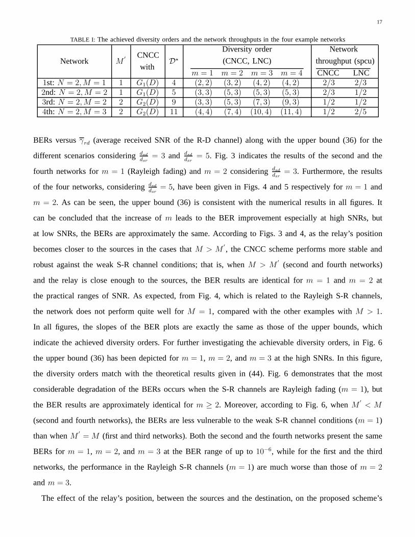
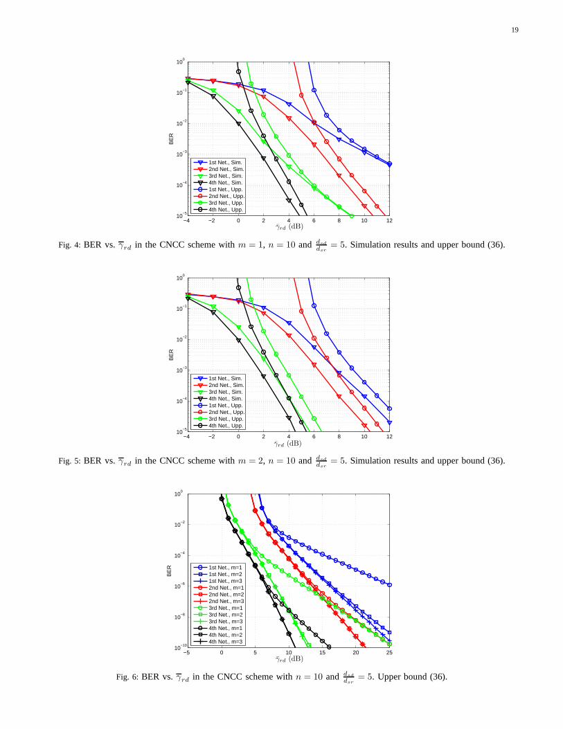
BERs versusγrd (average received SNR of the R-D channel) along with the upper bound (36) for the
different scenarios consideringdsddsr
= 3 and dsddsr
= 5. Fig. 3 indicates the results of the second and the
fourth networks form = 1 (Rayleigh fading) andm = 2 consideringdsddsr
= 3. Furthermore, the results
of the four networks, consideringdsddsr
= 5, have been given in Figs. 4 and 5 respectively form = 1 and
m = 2. As can be seen, the upper bound (36) is consistent with the numerical results in all figures. It
can be concluded that the increase ofm leads to the BER improvement especially at high SNRs, but
at low SNRs, the BERs are approximately the same. According to Figs. 3 and 4, as the relay’s position
becomes closer to the sources in the cases thatM > M′
, the CNCC scheme performs more stable and
robust against the weak S-R channel conditions; that is, when M > M′
(second and fourth networks)
and the relay is close enough to the sources, the BER results are identical form = 1 and m = 2 at
the practical ranges of SNR. As expected, from Fig. 4, which is related to the Rayleigh S-R channels,
the network does not perform quite well forM = 1, compared with the other examples withM > 1.
In all figures, the slopes of the BER plots are exactly the sameas those of the upper bounds, which
indicate the achieved diversity orders. For further investigating the achievable diversity orders, in Fig. 6
the upper bound (36) has been depicted form = 1, m = 2, andm = 3 at the high SNRs. In this figure,
the diversity orders match with the theoretical results given in (44). Fig. 6 demonstrates that the most
considerable degradation of the BERs occurs when the S-R channels are Rayleigh fading (m = 1), but
the BER results are approximately identical form ≥ 2. Moreover, according to Fig. 6, whenM′
< M
(second and fourth networks), the BERs are less vulnerable to the weak S-R channel conditions (m = 1)
than whenM′
= M (first and third networks). Both the second and the fourth networks present the same
BERs form = 1, m = 2, andm = 3 at the BER range of up to10−6, while for the first and the third
networks, the performance in the Rayleigh S-R channels (m = 1) are much worse than those ofm = 2
andm = 3.
The effect of the relay’s position, between the sources and the destination, on the proposed scheme’s
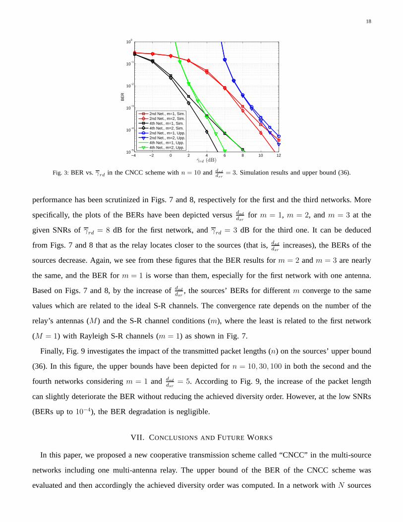
18
−4 −2 0 2 4 6 8 10 1210
−5
10−4
10−3
10−2
10−1
100
γ̄rd (dB)
BE
R
2nd Net., m=1, Sim.2nd Net., m=2, Sim.4th Net., m=1, Sim.4th Net., m=2, Sim.2nd Net., m=1, Upp.2nd Net., m=2, Upp.4th Net., m=1, Upp.4th Net., m=2, Upp.
Fig. 3: BER vs.γrd in the CNCC scheme withn = 10 and dsd
dsr
= 3. Simulation results and upper bound (36).
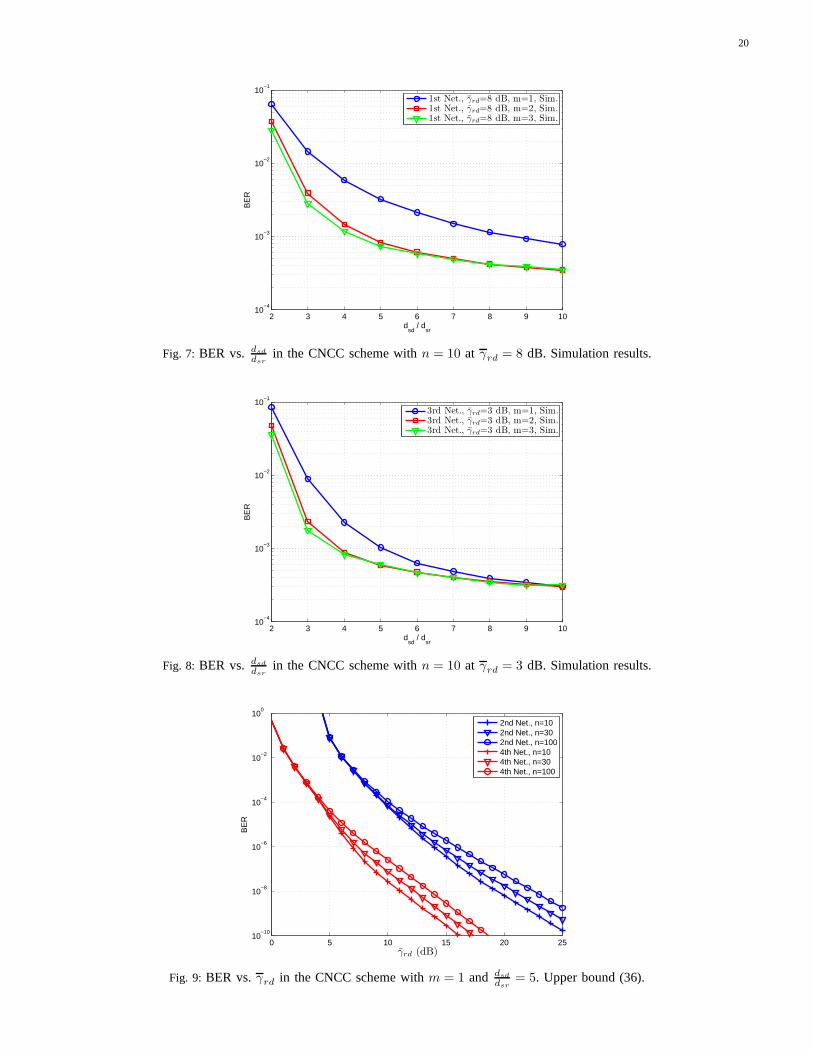
performance has been scrutinized in Figs. 7 and 8, respectively for the first and the third networks. More
specifically, the plots of the BERs have been depicted versusdsddsr
for m = 1, m = 2, andm = 3 at the
given SNRs ofγrd = 8 dB for the first network, andγrd = 3 dB for the third one. It can be deduced
from Figs. 7 and 8 that as the relay locates closer to the sources (that is,dsddsr
increases), the BERs of the
sources decrease. Again, we see from these figures that the BER results form = 2 andm = 3 are nearly
the same, and the BER form = 1 is worse than them, especially for the first network with one antenna.
Based on Figs. 7 and 8, by the increase ofdsddsr
, the sources’ BERs for differentm converge to the same
values which are related to the ideal S-R channels. The convergence rate depends on the number of the
relay’s antennas (M) and the S-R channel conditions (m), where the least is related to the first network
(M = 1) with Rayleigh S-R channels (m = 1) as shown in Fig. 7.
Finally, Fig. 9 investigates the impact of the transmitted packet lengths (n) on the sources’ upper bound
(36). In this figure, the upper bounds have been depicted forn = 10, 30, 100 in both the second and the
fourth networks consideringm = 1 and dsddsr
= 5. According to Fig. 9, the increase of the packet length
can slightly deteriorate the BER without reducing the achieved diversity order. However, at the low SNRs
(BERs up to10−4), the BER degradation is negligible.
VII. CONCLUSIONS AND FUTURE WORKS
In this paper, we proposed a new cooperative transmission scheme called “CNCC” in the multi-source
networks including one multi-antenna relay. The upper bound of the BER of the CNCC scheme was
evaluated and then accordingly the achieved diversity order was computed. In a network withN sources
19
−4 −2 0 2 4 6 8 10 1210
−5
10−4
10−3
10−2
10−1
100
γ̄rd (dB)
BE
R
1st Net., Sim.2nd Net., Sim.3rd Net., Sim.4th Net., Sim.1st Net., Upp.2nd Net., Upp.3rd Net., Upp.4th Net., Upp.
Fig. 4: BER vs.γrd in the CNCC scheme withm = 1, n = 10 and dsd
dsr= 5. Simulation results and upper bound (36).
−4 −2 0 2 4 6 8 10 1210
−5
10−4
10−3
10−2
10−1
100
γ̄rd (dB)
BE
R
1st Net., Sim.2nd Net., Sim.3rd Net., Sim.4th Net., Sim.1st Net., Upp.2nd Net., Upp.3rd Net., Upp.4th Net., Upp.
Fig. 5: BER vs.γrd in the CNCC scheme withm = 2, n = 10 and dsd
dsr= 5. Simulation results and upper bound (36).
−5 0 5 10 15 20 2510
−10
10−8
10−6
10−4
10−2
100
γ̄rd (dB)
BE
R
1st Net., m=11st Net., m=21st Net., m=32nd Net., m=12nd Net., m=22nd Net., m=33rd Net., m=13rd Net., m=23rd Net., m=34th Net., m=14th Net., m=24th Net., m=3
Fig. 6: BER vs.γrd in the CNCC scheme withn = 10 and dsd
dsr= 5. Upper bound (36).
20
2 3 4 5 6 7 8 9 1010
−4
10−3
10−2
10−1
dsd
/ dsr
BE
R
1st Net., γ̄rd=8 dB, m=1, Sim.1st Net., γ̄rd=8 dB, m=2, Sim.1st Net., γ̄rd=8 dB, m=3, Sim.
Fig. 7: BER vs. dsd
dsrin the CNCC scheme withn = 10 at γrd = 8 dB. Simulation results.
2 3 4 5 6 7 8 9 1010
−4
10−3
10−2
10−1
dsd
/ dsr
BE
R
3rd Net., γ̄rd=3 dB, m=1, Sim.3rd Net., γ̄rd=3 dB, m=2, Sim.3rd Net., γ̄rd=3 dB, m=3, Sim.
Fig. 8: BER vs. dsd
dsrin the CNCC scheme withn = 10 at γrd = 3 dB. Simulation results.
0 5 10 15 20 2510
−10
10−8
10−6
10−4
10−2
100
γ̄rd (dB)
BE
R
2nd Net., n=102nd Net., n=302nd Net., n=1004th Net., n=104th Net., n=304th Net., n=100
Fig. 9: BER vs.γrd in the CNCC scheme withm = 1 and dsd
dsr= 5. Upper bound (36).
21
and oneM-antenna relay, the CNCC scheme exploits a good systematic(N + M′
, N, ν) convolutional
code overGF (2) as the network coding matrix which is run at the network level. It was realized that
the proposed CNCC scheme can simultaneously enhance the network throughput as well as the diversity
order compared to the traditional AF and DF, and the LNC-based cooperative schemes. This is because
the CNCC’s network throughput is approximately equal toN/(N + M′
) spcu, which forM′
≤ M is
greater than (or equal to) the network throughputs of LNC (N/(N +M) spcu) and traditional (1/(1+M)
spcu) schemes withM single-antenna relays. Furthermore, it was demonstrated that although the diversity
order of the CNCC at the worst scenario (Rayleigh S-R channels) reduces toM +1 which is equal to the
diversity order of the LNC and the traditional schemes, but the CNCC can have better performance due to
using the convolutional codes. However, at the most practical scenarios (strong S-R channels), the diversity
order of the CNCC scheme reaches toD⋆ which can be much more thanM+1 (D⋆ ≥ dfree+M−1 where
dfree is the free distance of the used convolutional code) by the increase of the underlying convolutional
code’s constraint length. In addition, the provided simulation results for the four considered examples
verified the accuracy of the theoretical analysis.
It has been realized that the failure situation in which the relay fails to correctly decode all the sources’
packets restricts the diversity order. As a suggestion to overcome this problem, in the failure situation,
instead of not cooperating, the relay can simply amplify themaximum ratio combined signal corresponding
to each packet, and transmit it to the destination, which canlead to the improvement of the diversity order
in the weak S-R channel conditions.
REFERENCES
[1] J. N. Laneman and G. W. Wornell, “Distributed space-time-coded protocols for exploiting cooperative diversity in wireless networks,”
IEEE Trans. Inf. Theory , vol. 49, no. 10, pp. 2415-2425, Oct. 2003.
[2] A. Sendonaris, E. Erkip, and B. Aazhang, “User cooperation diversity. Part I. System description,”IEEE Trans. Commun., vol. 51, no.
11, pp. 1927-1938, Nov. 2003.
[3] A. Sendonaris, E. Erkip, and B. Aazhang, “User cooperation diversity. Part II. Implementation aspects and performance analysis,”IEEE
Trans. Commun., vol. 51, no. 11, pp. 1939-1948, Nov. 2003.
[4] J. N. Laneman, D. N. C. Tse, and G. W. Wornell, “Cooperative diversity in wireless networks: Efficient protocols and outage behavior,”
IEEE Trans. Inf. Theory, vol. 50, no. 12, pp. 3062-3080, Dec. 2004.
[5] R. U. Nabar, H. Bolcskei, and F. W. Kneubuhler, “Fading relay channels: performance limits and space-time signal design,” IEEE J.
Sel. Areas Commun., vol. 22, no. 6, pp. 1099-1109, Aug. 2004.
[6] K. Azarian, H. El-Gamal, and P. Schniter, “On the achievable diversity-multiplexing tradeoff in half-duplex cooperative channels,”IEEE
Trans. Inf. Theory, vol. 51, no. 12, pp. 4152-4172, Dec. 2005.
22
[7] A. Bletsas, S. Hyundong, and M. Z. Win, “Cooperative Communications with Outage-Optimal Opportunistic Relaying,”IEEE Trans.
Wireless Commun., vol. 6, no. 9, pp. 3450-3460, Sep. 2007.
[8] B. Rankov and A. Wittneben, “Spectral efficient protocols for half-duplex fading relay channels,”IEEE J. Sel. Areas Commun., vol. 25,
no. 2, pp. 379-389, Feb. 2007.
[9] A. Nosratinia, T. E. Hunter, and A. Hedayat, “Cooperative communication in wireless networks,”IEEE Commun. Mag., vol. 42, no. 10,
pp. 74-80, Oct. 2004.
[10] A. Ribeiro, R. Wang, and G. B. Giannakis, “Multi-sourcecooperation with full-diversity spectral-efficiency and controllable-complexity,”
IEEE J. Sel. Areas Commun., vol. 25, no. 2, pp. 415-425, Feb. 2007.
[11] R. Ahlswede, C. Ning, S. Y. R. Li, and R. W. Yeung, “Network information flow,” IEEE Trans. Inf. Theory, vol. 46, no. 4, pp.
1204-1216, Jul. 2000.
[12] S. Y. R. Li, R. W. Yeung, and C. Ning, “Linear network coding,” IEEE Trans. Inf. Theory, vol. 49, no. 2, pp. 371-381, Feb. 2003.
[13] P. A. Chou and Y. Wu, “Network Coding for the Internet andWireless Networks,”IEEE Signal Process. Mag., vol. 24, no. 5, pp.
77-85, Sep. 2007.
[14] S. Katti, H. Rahul, H. Wenjun, D. Katabi, M. Medard, and J. Crowcroft, “XORs in the Air: Practical Wireless Network Coding,”
IEEE/ACM Trans. Netw., vol. 16, no. 3, pp. 497-510, Jun. 2008.
[15] S. Zhang, S. C. Liew, and P. Lam, “Physical layer networkcoding,” inProc. 12th Ann. Int. Conf. Mobile Comput. Netw. (ACM MobiCom
2006), Sep. 2006, pp. 63-68.
[16] S. Zhang and S. C Liew, “Channel coding and decoding in a relay system operated with physical-layer network coding,”IEEE J. Sel.
Areas Commun., vol. 27, no. 5, pp. 788-796, Jun. 2009.
[17] B. Nazer and M. Gastpar, “Reliable Physical Layer Network Coding,” Proc. IEEE, vol. 99, no. 3, pp. 438-460, Mar. 2011.
[18] X. Lei, T. E. Fuja, J. Kliewer, and D. J. Costello, “A Network Coding Approach to Cooperative Diversity,”IEEE Trans. Inf. Theory,
vol. 53, no. 10, pp. 3714-3722, Oct. 2007.
[19] B. Xingkai and L. Jing, “Adaptive network coded cooperation (ANCC) for wireless relay networks: matching code-on-graph with
network-on-graph,”IEEE Trans. Wireless Commun., vol. 7, no. 2, pp. 574-583, Feb. 2008.
[20] H. Zhu, Z. Xin, and H. V. Poor, “High performance cooperative transmission protocols based on multiuser detection and network
coding,” IEEE Trans. Wireless Commun., vol. 8, no. 5, pp. 2352-2361, May 2009.
[21] P. Cong, Z. Qian, Z. Ming, Y. Yan, and J. Weijia, “On the Performance Analysis of Network-Coded Cooperation in Wireless Networks,”
IEEE Trans. Wireless Commun., vol. 7, no. 8, pp. 3090-3097, Aug. 2008.
[22] T. Koike-Akino, P. Popovski, and V. Tarokh, “Optimizedconstellations for two-way wireless relaying with physical network coding,”
IEEE J. Sel. Areas Commun., vol. 27, no. 5, pp. 773-787, Jun. 2009.
[23] X. Ming and M. Skoglund, “M-user cooperative wireless communications based on nonbinary network codes,”IEEE Inf. Theory
Workshop on Netw. and Inf. Theory, Jun. 2009, pp. 316-320.
[24] X. Ming and M. Skoglund, “Design of network codes for multiple-user multiple-relay wireless networks,”IEEE Int. Symp. on Inf.
Theory, Jul. 2009, pp. 2562-2566.
[25] X. Ming and M. Skoglund, “Multiple-User Cooperative Communications Based on Linear Network Coding,”IEEE Trans. Commun.,
vol. 58, no. 12, pp. 3345-3351, Dec. 2010.
[26] X. Ming, J. Kliewer, and M. Skoglund, “Design of NetworkCodes for Multiple-User Multiple-Relay Wireless Network,” IEEE Trans.
Commun., vol. 60, no. 12, pp. 3755-3766, Dec. 2012.
[27] J. L. Rebelatto, B. F. Uchoa-Filho, L. Yonghui, and B. Vucetic, “Multiuser Cooperative Diversity Through Network Coding Based on
Classical Coding Theory,”IEEE Trans. Signal Process., vol. 60, no. 2, pp. 916-926, Feb. 2012.
23
[28] L. Guobing, A. Cano, J. Gomez-Vilardebo, G. B. Giannakis, and A. I. Perez-Neira, “High-Throughput Multi-Source Cooperation via
Complex-Field Network Coding,”IEEE Trans. Wireless Commun., vol. 10, no. 5, pp. 1606-1617, May 2011.
[29] T. Wang and G. B. Giannakis, “Complex Field Network Coding for Multiuser Cooperative Communications,”IEEE J. Sel. Areas
Commun., vol. 26, no. 3, pp. 561-571, Apr. 2008.
[30] H. Topakkaya and W. Zhengdao, “Wireless Network Code Design and Performance Analysis Using Diversity-Multiplexing Tradeoff,”
IEEE Trans. Commun., vol. 59, no. 2, pp. 488-496, Feb. 2011.
[31] J. Proakis and M. Salehi, Digital Communications: McGraw-Hill Education, 2007.
[32] S. Lin and D. J. Costello, Error Control Coding: Fundamentals and Applications: Pearson-Prentice Hall, 2004.
[33] A. Papoulis and S. U. Pillai, Probability, random variables, and stochastic processes: McGraw-Hill, 2002.
[34] T. E. Hunter and A. Nosratinia, “Diversity through coded cooperation,”IEEE Trans. Wireless Commun., vol. 5, no. 2, pp. 283-289,
Feb. 2006.
Related Documents