ISO 9001 : 2001 ZAM-SERVIS s.r.o. Ostrava, tel.: +420 596 135 422, email: [email protected] www.zam.cz V100713 The catalogue has only those selected important parameters for your final decision. For project designs always ask for the user’s guide for this product and any engineering consultation about possible uses. THE EUROPEAN REGIONAL DEVELOPMENT FUND AND THE MINISTRY OF INDUSTRY AND TRADE OF CZECH REPUBLIC SUPPORT INVESTMENT IN YOUR FUTURE Use: Conveyor belt swing switches are deployed at belt conveyors to minimize the danger of damage of destruction of the belt when it swings aside from its trajectory. Description: The LHPE-10/2-L50V switches are intended for being deployed along a conveyor belt. They are distributed in pairs on the right and left side. In the event of the belt swinging from its presumed trajectory, the belt edge affects a belt cylindrical lever of the sensor and pushes against the self-aligning force of an inside spring. Swing switches marked “V” have two types of contacts A and B which switch on under two swing angles. At the angle of swing above 15° contacts B switch over. At the angle of swing above 25° contacts A switch over. The maximum swing of the cylindrical lever id 75°. As soon as the swing drops under the above-mentioned angles, respective contacts switch back. For this model of the switch a blocking device for locking the swing switch position is not used. This type of a switch is not used for emergency stop circuits. This type of connection is common in the control system circuits which records partial swinging of the belt from its trajectory (15° angle of switching) but does not switch off the conveyor. If the following contact (25° angle of switching) is switched over, the conveyor is immediately switched off. Movements of the first switch serve for warning the operator and subsequent correction in the quantity of transported material on the conveyor. According to the frequency of switching on the first contact it can be evaluated when an intervention of the machine maintenance is necessary to adjust the conveyor. The contacts of A and B switches are only manufactured in this series in the economy version (with “E” economy in the name). A synchronizing module has no meaning in this model. Every module of A and B contacts is equipped with a disconnecting and a connecting contact with forced guiding. The switch cabinet is made of colour glass-fibre reinforced polyester (LPH). The protection is at the level of IP67. Small cylinders with ball bearings of the L50 switch swing sensing lever are made of VA stainless steel. The L50 lever is attached to the axis of the switch in the required angle and tightened with a tie-bolt. An advantage of free setting the lever angle is that the switch can be attached in other positions according to the conveyor structure layout. A disadvantage is that the lever attachment to the switch axis must be more frequently checked, whether it has not loosen thus losing its function. The effect of the sensing lever to the switch axis is only guaranteed for type “L” (LHPw-10/2-L). For this type the lever angle is set in the production. To align the correct lever angle toward the belt, the whole switch must be turned and fixed at the position. Recommended distribution: Swing switches are usually placed at the end of a conveyer behind the hopper and in front of the transfer point. For long conveyors above 30 m these switches should also be located in the middle of the trajectory. Switches are also suitable for inclined conveyers and conveyers with a movable hopper, e.g. propellers with carriages etc. For impact skid platform of belt conveyers swing switches must be used although the conveyor is equipped with a mechanical alignment of the belt trajectory. Conveyor Belt Swing Switch LHPE-10/2-L50V 25° 15° 75° Switching angle - contact A - contact B Maximum lever swinging Load-bearing capacity 400 V AC/ 6 A, 230 V AC/ 8 A, 24 V DC / 10 A, 80 V DC / 3 A Weight 2.6 kg Cylindrical lever VA steel, two ball bearings Meets standards ČSN EN 60947 ČSN EN 60204 ČSN EN 60529 ČSN EN 620 Cable input 2 holes for M25x1.5 with a blank flange Protection Cabinet material Cabinet colour By two M10 belts -40°C - +85°C Protection class IP 67 yellow RAL 1003 glass fibre reinforces polyester Working temperature Attachment Technical parameters: Class I A 1 disconnecting and 1 connecting B 1 disconnecting and 1 connecting Number and function of contacts

Welcome message from author
This document is posted to help you gain knowledge. Please leave a comment to let me know what you think about it! Share it to your friends and learn new things together.
Transcript

ISO 9001 : 2001 ZAM-SERVIS s.r.o. Ostrava, tel.: +420 596 135 422, email: [email protected] www.zam.czV100713
The catalogue has only those selected important parameters for your final decision. For project designs always ask for the user’s guide for this product and any engineering consultation about possible uses.
THE EUROPEAN REGIONAL DEVELOPMENT FUND AND THE MINISTRY OF INDUSTRY AND TRADE OF CZECH REPUBLIC SUPPORT INVESTMENT IN YOUR FUTURE
Use:Conveyor belt swing switches are deployed at belt conveyors to minimize the danger of damage of destruction of the belt when it swings aside from its trajectory.
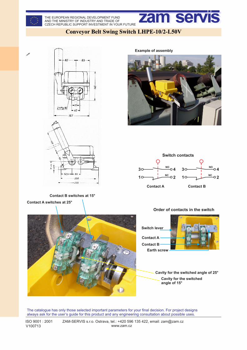
Description:The LHPE-10/2-L50V switches are intended for being deployed along a conveyor belt. They are distributed in pairs on the right and left side. In the event of the belt swinging from its presumed trajectory, the belt edge affects a belt cylindrical lever of the sensor and pushes against the self-aligning force of an inside spring.
Swing switches marked “V” have two types of contacts A and B which switch on under two swing angles. At the angle of swing above 15° contacts B switch over. At the angle of swing above 25° contacts A switch over. The maximum swing of the cylindrical lever id 75°. As soon as the swing drops under the above-mentioned angles, respective contacts switch back. For this model of the switch a blocking device for locking the swing switch position is not used.
This type of a switch is not used for emergency stop circuits. This type of connection is common in the control system circuits which records partial swinging of the belt from its trajectory (15° angle of switching) but does not switch off the conveyor. If the following contact (25° angle of switching) is switched over, the conveyor is immediately switched off. Movements of the first switch serve for warning the operator and subsequent correction in the quantity of transported material on the conveyor. According to the frequency of switching on the first contact it can be evaluated when an intervention of the machine maintenance is necessary to adjust the conveyor.
The contacts of A and B switches are only manufactured in this series in the economy version (with “E” economy in the name). A synchronizing module has no meaning in this model.
Every module of A and B contacts is equipped with a disconnecting and a connecting contact with forced guiding.
The switch cabinet is made of colour glass-fibre reinforced polyester (LPH). The protection is at the level of IP67.
Small cylinders with ball bearings of the L50 switch swing sensing lever are made of VA stainless steel. The L50 lever is attached to the axis of the switch in the required angle and tightened with a tie-bolt. An advantage of free setting the lever angle is that the switch can be attached in other positions according to the conveyor structure layout. A disadvantage is that the lever attachment to the switch axis must be more frequently checked, whether it has not loosen thus losing its function.
The effect of the sensing lever to the switch axis is only guaranteed for type “L” (LHPw-10/2-L). For this type the lever angle is set in the production. To align the correct lever angle toward the belt, the whole switch must be turned and fixed at the position.
Recommended distribution:Swing switches are usually placed at the end of a conveyer behind the hopper and in front of the transfer point. For long conveyors above 30 m these switches should also be located in the middle of the trajectory. Switches are also suitable for inclined conveyers and conveyers with a movable hopper, e.g. propellers with carriages etc. For impact skid platform of belt conveyers swing switches must be used although the conveyor is equipped with a mechanical alignment of the belt trajectory.
Conveyor Belt Swing Switch LHPE-10/2-L50V
25°15°
75°
Switching angle - contact A - contact B
Maximum lever swinging
Load-bearing capacity400 V AC/ 6 A, 230 V AC/ 8 A, 24 V DC / 10 A, 80 V DC / 3 A
Weight 2.6 kg
Cylindrical lever VA steel, two ball bearings
Meets standards
ČSN EN 60947ČSN EN 60204ČSN EN 60529ČSN EN 620
Cable input2 holes for M25x1.5 with a blank flange
Protection
Cabinet material
Cabinet colour
By two M10 belts
-40°C - +85°C
Protection class
IP 67
yellow RAL 1003
glass fibre reinforces polyester
Working temperature
Attachment
Technical parameters:
Class I
A 1 disconnecting and 1 connectingB 1 disconnecting and 1 connecting
Number and function of contacts
ISO 9001 : 2001 ZAM-SERVIS s.r.o. Ostrava, tel.: +420 596 135 422, email: [email protected] www.zam.czV100713
The catalogue has only those selected important parameters for your final decision. For project designs always ask for the user’s guide for this product and any engineering consultation about possible uses.
THE EUROPEAN REGIONAL DEVELOPMENT FUND AND THE MINISTRY OF INDUSTRY AND TRADE OF CZECH REPUBLIC SUPPORT INVESTMENT IN YOUR FUTURE
!
Conveyor Belt Swing Switch LHPE-10/2-L50V
NC
NO
1
Switch contacts
3
2
4
Order of contacts in the switch
Contact A
Contact B
Switch lever
NC
NO
1
3
2
4
Contact A Contact B
Contact B switches at 15°
Cavity for the switched angle of 15°
Example of assembly
Earth screw
Contact A switches at 25°
Cavity for the switched angle of 25°
Related Documents