ConveyLinx ERSC Complete Guide Version 5.1 — 15 April 2022 Copyright © 2022 PULSEROLLER

Welcome message from author
This document is posted to help you gain knowledge. Please leave a comment to let me know what you think about it! Share it to your friends and learn new things together.
Transcript

ConveyLinx ERSCComplete Guide
Version 5.1 — 15 April 2022
Copyright © 2022 PULSEROLLER

Table of Contents1.1. About This ManualAbout This Manual ................................................................................................................................................................................................................................ 88
2.2. Glossary of TGlossary of Terermsms ................................................................................................................................................................................................................................1212
3.3. Getting StartedGetting Started........................................................................................................................................................................................................................................1616
4.4. Module HarModule Hardwardwaree..................................................................................................................................................................................................................................18184.1. Identifying Module Components ..................................................................................194.2. Mounting Dimensions ..................................................................................................214.3. Motor Ports .................................................................................................................244.4. Sensor & Control Ports ................................................................................................254.5. Ethernet Ports .............................................................................................................274.6. Module Internal Fusing ................................................................................................284.7. Over-Voltage Protection...............................................................................................294.8. LED Status Indicators ..................................................................................................304.9. Power and Network Connections .................................................................................344.10. Power Supply Sizing ..................................................................................................354.11. Technical Specifications.............................................................................................36
5.5. AutoAuto-Configuration-Configuration..............................................................................................................................................................................................................................41415.1. Linear Conveyor ..........................................................................................................42
5.1.1. Device Connections to Modules ...........................................................................435.1.2. Examples that will generate errors ......................................................................455.1.3. Motor Rotation Definition .....................................................................................46
5.2. Procedure....................................................................................................................475.3. Auto-Configuration Examples ......................................................................................505.4. Expected Results.........................................................................................................515.5. What to do if things go wrong .....................................................................................53
6.6. Default Settings and OperationDefault Settings and Operation........................................................................................................................................................................................54546.1. Singulation Release Mode ...........................................................................................556.2. Flex Zone Recognition .................................................................................................566.3. Jam Conditions ............................................................................................................58
6.3.1. Arrival Jam...........................................................................................................596.3.2. Sensor Jam ..........................................................................................................61
6.4. Hard-Wired Interlocks..................................................................................................636.4.1. Upstream Interlock (Wake Up) .............................................................................646.4.2. Downstream Interlock (Lane Full) ........................................................................676.4.3. Local Zone Accumulate........................................................................................696.4.4. Interlocks with Single Zone Module .....................................................................706.4.5. Interlock Input versus Local Accumulate Input .....................................................726.4.6. Using a Photoeye for Wake-Up .............................................................................74

6.4.7. Using a Photoeye for Lane Full.............................................................................756.4.8. SE Breakout Module.............................................................................................77
6.5. Automatic Module Replacement ..................................................................................806.6. Reset to Factory Default Settings ................................................................................82
7.7. SE BrSE Breakeakout Moduleout Module ..........................................................................................................................................................................................................................84847.1. Typical Output Connection...........................................................................................867.2. Typical Input Connections............................................................................................877.3. Input Circuit Blocking Diode Jumpers...........................................................................887.4. Notes on SE Module Revisions .....................................................................................90
8.8. EasyREasyRoll Sofoll Softwartwaree ................................................................................................................................................................................................................................93938.1. Installing EasyRoll on your PC .....................................................................................948.2. ConveyLinx Ethernet Definition ...................................................................................958.3. Connecting your PC to ConveyLinx ..............................................................................978.4. Using Discover Function ..............................................................................................998.5. Main Screen .............................................................................................................. 100
8.5.1. Node Navigation ................................................................................................1028.5.2. Node Identification ............................................................................................1038.5.3. ZPA Upstream/Downstream Zone Settings .........................................................104
8.5.3.1. ZPA Release Mode......................................................................................1058.5.3.1.1. Singulation Release ............................................................................1068.5.3.1.2. Train Release......................................................................................1078.5.3.1.3. GAP Train Release ..............................................................................108
8.5.3.2. T-Zone Settings..........................................................................................1098.5.3.3. ZPA Error and Information ..........................................................................1128.5.3.4. Accumulate Control from Main Screen........................................................1138.5.3.5. Settings Checkboxes ..................................................................................114
8.5.3.5.1. Disable Reset Delays ..........................................................................1158.5.3.5.2. Disable Sensor Jam Auto Clear ...........................................................1168.5.3.5.3. Disable Arrival Timeout ......................................................................1178.5.3.5.4. Disable Manual Operation ..................................................................1188.5.3.5.5. Dynamic Release................................................................................120
8.5.4. Motor Settings ...................................................................................................1228.5.4.1. Motor Type .................................................................................................1238.5.4.2. Brake Method.............................................................................................1248.5.4.3. Speed Control Method................................................................................1268.5.4.4. Speed ........................................................................................................ 1288.5.4.5. Rotation Direction ......................................................................................1308.5.4.6. Acceleration/Deceleration ..........................................................................1318.5.4.7. Motor Jog and Error Indicators....................................................................1338.5.4.8. Motor Pulse to Distance Calculation ...........................................................136
8.5.5. Diagnostic Window ............................................................................................137

8.6. Advanced Dialog ....................................................................................................... 1398.6.1. Look Ahead and Timing Tab ...............................................................................140
8.6.1.1. Look Ahead Slowdown Feature ...................................................................1418.6.1.2. Jam Auto Clear Timers................................................................................1448.6.1.3. Run After Time/Distance.............................................................................1458.6.1.4. Induct Forward Time/Distance ....................................................................1478.6.1.5. Induct Reverse Time/Distance ....................................................................1498.6.1.6. Sensor Debounce.......................................................................................1518.6.1.7. Reversing Control in ZPA Mode...................................................................153
8.6.2. Upgrade Tab ...................................................................................................... 1568.6.3. Connections Tab ................................................................................................1598.6.4. Network Services Tab ........................................................................................162
8.6.4.1. Discover and IP Address Set.......................................................................1638.6.4.2. Position and DHCP .....................................................................................1668.6.4.3. Network Lock Feature ................................................................................1698.6.4.4. Backup and Restore ...................................................................................171
8.6.5. Special Services Tab ..........................................................................................1748.6.5.1. Motor Slave Function .................................................................................177
8.6.6. Control Ports Tab ...............................................................................................1828.6.6.1. Control Port Inputs .....................................................................................1838.6.6.2. Control Port Outputs ..................................................................................1858.6.6.3. Upstream/Downstream Accumulation.........................................................1878.6.6.4. Lane Full Interface .....................................................................................1888.6.6.5. PLC Control of Control Ports .......................................................................189
8.6.7. Flex Zone Tab ....................................................................................................1908.6.8. Sensors Tab ....................................................................................................... 1938.6.9. Extensions Tab...................................................................................................194
9.9. ConveyMerConveyMergege..........................................................................................................................................................................................................................................1981989.1. ConveyMerge Prerequisites and Requirements ..........................................................2009.2. Network Architecture ................................................................................................2019.3. Sensor Placement .....................................................................................................2039.4. Merge Zone Module ..................................................................................................2059.5. Merging Lines............................................................................................................ 2089.6. Merge Configurations ................................................................................................2109.7. Merge Priority ........................................................................................................... 2119.8. T-Merge Settings ....................................................................................................... 2129.9. Configuring Dynamic Priority Release ........................................................................2149.10. Enabling ConveyMerge from EasyRoll ......................................................................2179.11. Conventional Spur Merge Example ..........................................................................2199.12. T-Merge Example.....................................................................................................2219.13. Merge Line Full Example..........................................................................................223

10.10. ConveyStopConveyStop ..........................................................................................................................................................................................................................................22522510.1. Benefits of ConveyStop ...........................................................................................22810.2. Using ConveyStop in an Integrated Stop System .....................................................22910.3. ConveyStop Architecture .........................................................................................23310.4. ConveyStop Software ..............................................................................................235
10.4.1. User Accounts .................................................................................................23610.4.2. Creating a New Project ....................................................................................23710.4.3. Discovering Modules........................................................................................23810.4.4. Creating Stop Groups.......................................................................................24010.4.5. Add Stop and Start Buttons .............................................................................24310.4.6. Commit All Button ...........................................................................................24510.4.7. Status Monitoring ............................................................................................247
10.5. Issuing a Stop Command.........................................................................................24810.5.1. Other Conditions that cause Stop ....................................................................25010.5.2. Indications a Stop is Active ..............................................................................25210.5.3. ERSC Functions Affected by Stop Command.....................................................25410.5.4. CNIP Functions Affected by Stop Command......................................................256
10.6. ConveyLinx Function at Stop Group Boundaries.......................................................25710.7. Issuing a Start Command ........................................................................................258
10.7.1. Indications Start is Active ................................................................................26010.8. Using a PLC with ConveyStop ..................................................................................261
10.8.1. ConveyStop Status Register.............................................................................26310.8.2. ConveyStop Command Register .......................................................................264
10.9. Wiring Examples .....................................................................................................26510.9.1. ERSC with Stop Button.....................................................................................26610.9.2. ERSC with Start Button ....................................................................................26710.9.3. CNIP with Stop Button......................................................................................26810.9.4. CNIP with Start Button .....................................................................................269
11.11. ERSC PLC Developers GuideERSC PLC Developers Guide..........................................................................................................................................................................................27027011.1. Network Architecture ..............................................................................................27111.2. Understanding Assemblies ......................................................................................272
11.2.1. Modbus Assembly Instance Structure ..............................................................27311.2.2. Ethernet I/P Assembly Instance Structure ........................................................27511.2.3. Profinet IO Assembly Instance Structrure .........................................................27611.2.4. Assembly Register Chart Legend .....................................................................277
11.3. ZPA Mode Control ....................................................................................................27811.3.1. PLC Inputs for ZPA Mode..................................................................................279
11.3.1.1. Local Zone Status ....................................................................................28311.3.1.2. Arrival/Departure Counts..........................................................................28511.3.1.3. Module Status ..........................................................................................28611.3.1.4. Tracking and Release Counts....................................................................28811.3.1.5. Forward and Reverse Tracking..................................................................289

11.3.1.6. Port Inputs and ConveyStop Status ..........................................................29011.3.2. PLC Outputs for ZPA Mode ...............................................................................291
11.3.2.1. Set Local Tracking ....................................................................................29611.3.2.2. Accumulation Control ...............................................................................29811.3.2.3. Speed Control ..........................................................................................30011.3.2.4. Release and Status ..................................................................................30111.3.2.5. Induct Tracking Forward and Reverse .......................................................30211.3.2.6. Set Outputs and Motor Clear ....................................................................30311.3.2.7. ConveyStop and Clear Jams .....................................................................30511.3.2.8. Direction and Accumulation Mode ............................................................30611.3.2.9. ConveyMerge Interface ............................................................................308
11.3.3. ZPA Examples..................................................................................................30911.3.3.1. Basic Accumulate and Release with Tracking Data ...................................31011.3.3.2. Conveyor Setup for Simple Bar Code Reader ............................................31311.3.3.3. Upstream Accept Interface.......................................................................31511.3.3.4. Downstream Discharge Interface .............................................................31711.3.3.5. Simple Divert Example.............................................................................31911.3.3.6. Merge onto ZPA Main Line ........................................................................321
11.3.4. Reduced Size ZPA Mode Assemblies.................................................................32311.4. PLC I/O Mode Control...............................................................................................326
11.4.1. Setting PLC I/O Mode in EasyRoll .....................................................................32711.4.2. Optional Clear Connections Choice ..................................................................32811.4.3. Configuring Action for Loss of Communication .................................................33011.4.4. Lock PLC Mode ................................................................................................33111.4.5. Load ConveyLogix Program..............................................................................33211.4.6. PLC Inputs for PLC I/O Mode.............................................................................334
11.4.6.1. ConveyStop Status...................................................................................33811.4.6.2. Sensor & Control Ports .............................................................................33911.4.6.3. Left Motor Status .....................................................................................34011.4.6.4. Right Motor Status ...................................................................................34211.4.6.5. Motor Ports Digital Status ........................................................................34311.4.6.6. Upstream / Downstream Status & Tracking...............................................34411.4.6.7. Servo Control Status ................................................................................345
11.4.7. PLC Outputs for PLC I/O Mode ..........................................................................34611.4.7.1. ConveyStop Command & Clear Motor Error ..............................................35111.4.7.2. Motor & Control Port Digital Output ..........................................................35211.4.7.3. Left Motor Control ....................................................................................35311.4.7.4. Right Motor Control ..................................................................................35511.4.7.5. Set Status & Tracking ...............................................................................35711.4.7.6. Set Sensor & Control Port Input Mask .......................................................35911.4.7.7. Servo Control ...........................................................................................361
11.4.7.7.1. Servo Control Example .....................................................................363

11.4.8. Reduced Size PLC I/O Mode Assemblies ...........................................................36811.5. ConveyLogix Interface.............................................................................................370
11.5.1. ConveyLogix Assembly Inputs to PLC ...............................................................37111.5.2. ConveyLogix Assembly Outputs from PLC ........................................................372
11.6. Assemblies with Reset Protection ............................................................................37311.6.1. ZPA Mode Assembly Inputs with Reset Protection ............................................37411.6.2. ZPA Mode Assembly Outputs with Reset Protection..........................................37511.6.3. Reduced Size ZPA Mode Assemblies with Reset Protection ...............................37711.6.4. PLC I/O Mode Assembly Inputs with Reset Protection .......................................37911.6.5. PLC I/O Mode Assembly Outputs with Reset Protection.....................................38111.6.6. Reduced Size PLC I/O Mode Assemblies with Reset Protection..........................38311.6.7. How to use Assemblies with Reset Protection ..................................................384
11.7. Motor Port as Digital I/O ..........................................................................................38511.8. ODVA Compliant Cross-Reference............................................................................387
11.8.1. ZPA Mode Assembly Inputs ..............................................................................38811.8.2. ZPA Mode Assembly Outputs ...........................................................................38911.8.3. ZPA Mode Reduced Size...................................................................................39111.8.4. PLC I/O Mode Assembly Inputs .........................................................................39311.8.5. PLC I/O Mode Assembly Outputs ......................................................................39411.8.6. PLC I/O Mode Reduced Size..............................................................................39611.8.7. Reset Protection for ZPA Mode Assembly Inputs...............................................39711.8.8. Reset Protection for ZPA Mode Assembly Outputs ............................................39811.8.9. Reset Protection for Reduced Size ZPA Assemblies ..........................................40011.8.10. Reset Protection for PLC I/O Mode Assembly Inputs........................................40211.8.11. Reset Protection for PLC I/O Mode Assembly Outputs .....................................40411.8.12. Reset Protection for PLC I/O Mode Reduced Size ............................................406
12.12. Setting Up Dual Motor ZonesSetting Up Dual Motor Zones ......................................................................................................................................................................................40740712.1. 2 MDRs Mechanically Coupled .................................................................................408
12.1.1. ZPA Mode ........................................................................................................ 40912.1.1.1. For Firmware 4.25/5.02 ............................................................................41012.1.1.2. For Firmware 4.27/5.07 and EasyRoll 4.21 ................................................414
12.1.2. PLC I/O Mode ...................................................................................................41512.1.2.1. For Firmware 4.25/5.02 ............................................................................41612.1.2.2. For Firmware 4.27/5.07 and EasyRoll 4.21 ................................................418
12.1.3. ConveyLogix Program ......................................................................................41912.2. Two Motors in One Roller Tube .................................................................................420
12.2.1. ZPA Mode ........................................................................................................ 42212.2.2. PLC I/O Mode ...................................................................................................42312.2.3. ConveyLogix Program ......................................................................................424
12.3. Two Motor Rollers in One Logical Zone Not Coupled.................................................425
13.13. Connecting to RConnecting to Rockwell PLCs with Etherockwell PLCs with Ethernet I/Pnet I/P ..................................................................................................................................426426

13.1. Selecting Your Connection Method based upon Assembly ........................................42813.2. Using Generic Ethernet Module Method ...................................................................42913.3. Procedure for Connecting using Generic Ethernet Module........................................431
13.3.1. Parameters for Each Assembly.........................................................................43213.4. Procedure for using EDS Method .............................................................................43513.5. Using ERSC Add On Instructions (AOI) with RSLogix 5000 ........................................437
13.5.1. AOI Tag Descriptions ........................................................................................43913.5.1.1. ZPA Mode Inputs ......................................................................................44013.5.1.2. ZPA Mode Outputs ...................................................................................44213.5.1.3. PLC I/O Mode Inputs .................................................................................44513.5.1.4. PLC I/O Mode Outputs ..............................................................................448
13.6. Using Logix 5000 MSG Instruction ...........................................................................45113.6.1. Read MSG Instruction ......................................................................................45213.6.2. Write MSG Instruction ......................................................................................45413.6.3. Reading ERSC Input Assembly with MSG Instruction ........................................456
13.7. EDS Module Data Type Cross Reference...................................................................458
14.14. Connecting to Siemens PLC with PConnecting to Siemens PLC with Prrofinet IOofinet IO..........................................................................................................................................46046014.1. Preparing Your Programming Environment...............................................................46214.2. Modes of Operation .................................................................................................46314.3. Understanding the Two Configuration Methods ........................................................46514.4. Separate ConveyLinx Auto-Configuration ................................................................467
14.4.1. Profinet Name..................................................................................................46814.4.2. Examples of Adding Modules ...........................................................................469
14.4.2.1. Full ZPA....................................................................................................47014.4.2.2. Full PLC Controlled ...................................................................................47314.4.2.3. Reduced ZPA............................................................................................47514.4.2.4. Reduced PLC ............................................................................................47714.4.2.5. Merger Mode............................................................................................47914.4.2.6. PLC Controlled with ConveyLogix Interface ..............................................480
14.5. Integrated PLC Topology Configuration ....................................................................48314.5.1. Profinet Name..................................................................................................48414.5.2. Adding Modules ...............................................................................................48514.5.3. Topology Example............................................................................................486
14.5.3.1. Connecting 1st Subnet of Modules ...........................................................48914.5.3.2. Connecting 2nd Subnet of Modules ..........................................................490
14.5.4. Module Configuration.......................................................................................49114.5.4.1. ZPA/Reduced ZPA Modes ..........................................................................492
14.5.4.1.1. Upstream/Downstream Zones...........................................................49414.5.4.1.2. Upstream/Downstream Zone Timing .................................................49614.5.4.1.3. Connection to Merger Module ...........................................................497
14.5.4.2. PLC/Reduced PLC Mode ............................................................................49814.5.4.3. Merger Mode............................................................................................500

14.5.4.4. ConveyLogix Mode ...................................................................................50114.6. Accessing Data from ConveyLinx Modules ...............................................................502
14.6.1. Raw Unmapped Data Direct from Module.........................................................50414.6.2. Module Data Elements Mapped to Tags............................................................50714.6.3. Module Data Instances Mapped to User Defined Types (UDTs)..........................511
14.6.3.1. Installing UDTs into Programming Environment ........................................51214.6.3.2. Selecting the correct UDT for the Module’s Assigned DAP ........................51414.6.3.3. UDT Assignment Example ........................................................................517
14.6.3.3.1. Add feeder Module ...........................................................................51914.6.3.3.2. Add workstation Module ...................................................................52114.6.3.3.3. Add remaining Modules ....................................................................523
14.7. User Data Types (UDTs) ...........................................................................................52514.7.1. UDTs for ConveyLinx-ERSC Family ....................................................................526
14.7.1.1. Full ZPA Mode Inputs ................................................................................52814.7.1.2. Full ZPA Mode Outputs .............................................................................53214.7.1.3. Reduced ZPA Mode Inputs ........................................................................53514.7.1.4. Reduced ZPA Mode Outputs .....................................................................53814.7.1.5. Full PLC I/O Mode Inputs...........................................................................54114.7.1.6. Full PLC I/O Mode Outputs ........................................................................54614.7.1.7. Reduced PLC I/O Mode Inputs...................................................................55114.7.1.8. Reduced PLC I/O Mode Outputs ................................................................554

1.1. About This ManualAbout This Manual
PPrroducts Coveroducts Covered in this Manualed in this Manual
ConveyLinx-ConveyLinx-ERSCERSCArticle NumberArticle Number3010-00003010-0000
ConveyLinxConveyLinx ERSCERSC Complete Guide VComplete Guide Version 5.1 includesersion 5.1 includesfunctionality for Conveylinx-functionality for Conveylinx-ERSCERSC FFirirmwarmware versions 4.27 /e versions 4.27 /5.07.5.07.FFor ConveyLinx-or ConveyLinx-ERSCERSC FFirirmwarmware versions 4.25 / 5.02 pleasee versions 4.25 / 5.02 pleaserrefer to ConveyLinxefer to ConveyLinx ERSCERSC Complete Guide Manual VComplete Guide Manual Versionersion5.05.0
*
PULSEROLLER ConveyLinx ERSC Complete Guide - 5.1_en
Page 8 of 557

ConveyLinx-ConveyLinx-HTFHTFArticle NumberArticle Number3010-30003010-3000
ConveyLinx-ConveyLinx-ERSCERSC-E-EArticle NumberArticle Number3110-00003110-0000
ConveyLinx-ConveyLinx-HTFHTF-E-EArticle NumberArticle Number3110-30003110-3000
Symbol ConventionsSymbol Conventions
This symbol indicates that special attention should be paid in order to ensurecorrect use as well as to avoid danger, incorrect application of product, orpotential for unexpected results
!
This symbol indicates important directions, notes, or other useful information forthe proper use of the products and software described herein*
PULSEROLLER ConveyLinx ERSC Complete Guide - 5.1_en
Page 9 of 557

Important User InforImportant User Informationmation
Not Included in this ManualNot Included in this Manual
Modules contain ESD (Electrostatic Discharge) sensitive parts and components.Static control precautions are required when installing, testing, servicing orreplacing these modules. Component damage may result if ESD controlprocedures are not followed. If you are not familiar with static controlprocedures, reference any applicable ESD protection handbook. Basic guidelinesare:
• Touch a grounded object to discharge potential static• Wear an approved grounding wrist strap• Do not touch connectors or pins on component boards• Do not touch circuit components inside the equipment• Use a static-safe workstation, if available• Store the equipment in appropriate static-safe packaging when not in use
!
Because of the variety of uses for the products described in this publication,those responsible for the application and use of this control equipment mustsatisfy themselves that all necessary steps have been taken to assure that eachapplication and use meets all performance and safety requirements, includingany applicable laws, regulations, codes, and standards
!
The illustrations, charts, sample programs and layout examples shown in thisguide are intended solely for purposes of example. Since there are manyvariables and requirements associated with any particular installation, Pulserollerdoes not assume responsibility or liability (to include intellectual propertyliability) for actual use based on the examples shown in this publication
!
Reproduction of the contents of this manual, in whole or in part, without writtenpermission of Pulseroller is prohibited!
Because system applications vary; this manual assumes users and applicationengineers have properly sized their power distribution capacity per expectedmotor loading and expected operational duty cycle. Please refer to conveyorequipment and/or motor roller manufacturer’s documentation for power supplysizing recommendations
!
PULSEROLLER ConveyLinx ERSC Complete Guide - 5.1_en
Page 10 of 557

How to Contact UsHow to Contact UsTechnical Support North & South America: [email protected] Support North & South America: [email protected] Support Global: [email protected] Support Global: [email protected] Site: www.pulseroller.com
PULSEROLLER ConveyLinx ERSC Complete Guide - 5.1_en
Page 11 of 557

2.2. Glossary of TGlossary of TerermsmsTTerermm DefinitionDefinition
CartonCartonA separate (usually wrapped or boxed) object to be transported by theconveyor. The terms tray, tote, load, or product may also be usedinterchangeably in this document.
ConveyLinxConveyLinx Conveyor controls architecture based upon modular distributed devicesconnected via Ethernet network.
ConveyLinx-Ai /ConveyLinx-Ai /ConveyLinx-Ai2 /ConveyLinx-Ai2 /ConveyLInx-Ai3ConveyLInx-Ai3
Conveyor control module that is part of the ConveyLinx family. Each modulecan accommodate up to 2 MDR conveyor zones. The modules allowconnection for Senergy-Ai platform motor rollers and gear drives. The termModule will be used within this document and will refer to the ConveyLinx-Ai2device
DHCPDHCPDynamic Host Configuration Protocol A protocol for assigning IP addresses todevices on a network from a pool of available IP’s. A dynamic IP addresschanges each time the device connects to the network
ERSCERSC
Ethernet Roller Speed Control module – Conveyor control module that is partof the ConveyLinx family. Each ERSC can accommodate up to 2 MDRconveyor zones. In this document the term module will be synonymous withERSC
ERSCERSC-SE4-SE4
Designed to “break-out” the RJ11 connection for easy installation. Themodule has an amplifier to the output giving it up to 100mA outputcapabilities. Configurable diodes for the inputs to minimize leakage current toand from the ERSC. Module also allows for external power source connectionfor auxiliary devices.
Hall Effect SensorHall Effect Sensor Special sensor embedded within the brushless DC motor of an MDR used toprovide motor rotor position feedback to the motor controller
IP54IP54
The IP Code (International Protection Marking) specifies the device’s degreeof resistance to intrusions, dust and water. IP54 certified device must be fullyprotected from splashed water, dust particles and completely protected fromcontact
JSTJST
This is the name of a particular connector manufacturer that produces aspecific plug/socket arrangement for MDR connection to control cards. Thisname is accepted within the conveyor and MDR industry as a simpledescription of the particular socket style used on ERSC hardware.
LEDLED Light Emitting Diode – In the context of this document, LED’s are used on theConveyLinx-Ai2 to provide visual indication of module status
PULSEROLLER ConveyLinx ERSC Complete Guide - 5.1_en
Page 12 of 557

Light / DarkLight / DarkEnerEnergizedgized
Term used to describe how the signaling output circuit of a photo-sensor isconfigured when it detects its reflected light. A photo-sensor that is lightenergized will activate its output circuit when it detects its reflected light. Adark energized photo-sensor will activate its output circuit when it does notdetect its reflected light
M8M8 This is the type of a connector, which has four connector pins and is used onthe ConveyLinx Ai2 modules for both sensor connectors and MDR connectors
MDRMDR Motorized Drive Roller or Motor Driven Roller – Brushless DC motor andgearbox assembly integrated into a single conveyor roller
PULSEROLLER ConveyLinx ERSC Complete Guide - 5.1_en
Page 13 of 557

NorNormally Open /mally Open /NorNormally Closedmally Closed
Control logic terminology to define the state of the output of a Boolean “on”or “off” device. The term specifically describes the state of the output circuitwhen the device’s sensing circuit is un-energized. In the context of photo-sensors; a normally open wired sensor would have its output circuitenergized when it detected its reflected light and its output circuit would bede-energized when it did not detect its reflected light. Conversely a photo-sensor wired normally closed would energize its output circuit when it did notsee its reflected light and it would de-energize its output circuit when it diddetect its reflected light
NPNNPN // PNPPNP
Electronics term that indicates the type of transistor circuit used for a logicalinput or output for controllers. NPN devices will provide a common or groundconnection when activated and a PNP device will provide a logic voltageconnection when activated
PhotoPhoto-sensor-sensor A device, mounted near the end of the conveyor zone to sense the presenceof a carton on the zone
PLCPLC Programmable Logic Controller – A wide variety of industrial computingdevices that control automatic equipment
PWMPWMPulse Width Modulation – a control scheme that utilizes high speed switchingtransistors to efficiently deliver power in a controlled fashion from theConveyLinx controller to MDR
RRetretroo-r-reflective /eflective /RRefleeflexx
Term used to describe the two basic types of photo-sensors. Retro-reflectivephoto-sensors utilize a reflective target that must be aligned with the photo-sensor such that the light emitted by the photo-sensor is reflected back to it.‘Reflex (or sometimes known as proximity) type photo-sensors emit light tobe reflected back from an object located sufficiently close to the sensor. ‘Forboth types of photo-sensors, when they detect their reflected light source,their signaling output circuit changes state.
RJRJ-11 / RJ-11 / RJ-12-12
Registered Jack Style 11 / 12 – Standard connector / receptacle formatutilizing 4 or 6 pin connections. The typical standard connection fortelephones. RJ-11 utilizes 4 pins and RJ-12 utilizes 6 pins but both styles usethe same physical size.
RJRJ-45-45Registered Jack Style 45 – Standard connector / receptacle format utilizing 8pin connections. The typical standard for computer network cableconnections
SenerSenergygy-Ai-Ai
PulseRoller brand proprietary motor control platform that provides electronicintelligence inside the motor that can be read by ConveyLinx-Ai Family andMotionLinx-Ai Family control modules. The connection from the motor to thecontroller is via 4-Pin M8 style connector
PULSEROLLER ConveyLinx ERSC Complete Guide - 5.1_en
Page 14 of 557

SingulationSingulationRReleaseelease
Conveyor control method for zoned controlled conveyor that dictates thatwhen a zone is discharging its carton, the upstream carton waiting to entermust wait until the discharged carton is completely clear before it is allowedto enter
Slave RSlave Rollersollers
A set of non-motorized conveyor rollers mechanically linked to an MDR. TheMDR and slave rollers make up a physical zone. All of the slave rollers in azone rotate at the same speed and direction as the MDR because of theirmechanical linkage
TTCPCP/IP/IP
Transport Control Protocol / Internet Protocol – IP is the protocol whichoversees the transmission of information packets from device to device on anEthernet network. TCP makes sure the packets have arrived and that themessage is complete. These two protocols are the basic language of theInternet and are often referred to together as TCP/IP.
TTrain Rrain ReleaseeleaseConveyor control method for zone configured conveyor that dictates thatwhen a zone is discharging, the upstream zone’s carton can move in unisonwith the discharging carton.
ZoneZone A basic (linear or curved) cell of the conveyor consisting of a set of slaverollers driven by one or more MDR’s and a single photo-sensor.
ZPZPAAZero Pressure Accumulation – Term that describes the conveyor controls andmechanical scheme that will cause loads to queue on a conveyor in discretezones such that loads do not touch each other
PULSEROLLER ConveyLinx ERSC Complete Guide - 5.1_en
Page 15 of 557

3.3. Getting StartedGetting StartedPPurpose of this Manualurpose of this Manual
The purpose of this manual is to:
• Identify the components and ports available on a module• Provide guidelines for proper installation and wiring• Provide examples on basic inter-module connections for linear conveyor• Introduce the EasyRoll software tool and provide instructions to configure and modify
parameters
Who Should Use this Manual?Who Should Use this Manual?
This manual is intended for users who need basic product information and simple applicationprocedures to implement Modules to control simple linear conveyor.You should have a basic understanding of electrical circuitry and familiarity with relay logic,conveyor equipment, photo-sensors, etc. If you do not, obtain the proper training before usingthis product.
What do you want to do?What do you want to do?
The BasicsThe Basics
Learn about module hardware portsLearn about power supply sizingHow to Auto-Configure your network of modulesFind out about what all the LED states meanLearn about the different release modes and how to change themLearn about Flex ZoneLearn about jam conditionsHow to reset a module back to factory defaultHow to wire up a Hardwired InterlockHow to Auto-Replace a module
Basic things you can do with EasyRBasic things you can do with EasyRolloll
Learn about basic navigation through EasyRollLearn about ZPA settings and how to change themHow to change motor direction, speed, accel/decel, etc.Learn about motor status and error indicatorsHow to change Jam Timers and Auto-Clear TimersHow to change how the module logic uses the block/clear output from your sensors
PULSEROLLER ConveyLinx ERSC Complete Guide - 5.1_en
Page 16 of 557

How to change your Control Port Inputs to match the signals you are using
Some advanced things you can do with EasyRSome advanced things you can do with EasyRolloll
Learn how to discover modules on your network and change IP addressesHow to set up Look Ahead Slow Down featureHow to disable Flex Zone Recognition and why you may want toHow to set up an Extension or slave moduleHow to connect two separate networks together to operate in ZPAHow to backup and restore module settingsHow to upgrade module firmware
PULSEROLLER ConveyLinx ERSC Complete Guide - 5.1_en
Page 17 of 557

4.4. Module HarModule HardwardwareeConveyLinx ModulesConveyLinx Modules are designed to be installed and integrated into the conveyor’smechanical side frame assembly. The ConveyLinx ModuleConveyLinx Module is a controller for up to 2 MotorizedDrive Roller (MDR) conveyor zones. Each ConveyLinx ModuleConveyLinx Module provides connection points for 2MDR units with their corresponding 2 photo-sensors as well as upstream and downstreamnetwork and discreet interconnections to form a complete control system for zoned MDRconveyors.
Learn more:
IdentifIdentifying ConveyLinx Module Componentsying ConveyLinx Module ComponentsMounting DimensionsMounting DimensionsMotor PMotor PortsortsSensor & ContrSensor & Control Pol PortsortsEtherEthernet Pnet PortsortsConveyLinx Module InterConveyLinx Module Internal Fnal FusingusingLEDLED Status IndicatorsStatus Indicators
The “left” and “right” naming convention for the module ports is based uponfacing the front of the ConveyLinx Module and is not to be confused withdirection of product flow on the conveyor. Product flow will be designated as“upstream” and “downstream”
*
PULSEROLLER ConveyLinx ERSC Complete Guide - 5.1_en
Page 18 of 557

4.1.4.1. IdentifIdentifying Module Componentsying Module Components
ItemItem DescriptionDescription
24VDC Power Connector
Install Button – Used for Auto-Configuration Procedure and Auto ModuleReplacement
& Motor Left and Motor Right 9-pin JST style header for MDR/PGD connection
&Left Sensor Port and Right Sensor Port RJ-12 style jack for zone photo-sensorconnection
&Link Left and Link Right RJ-45 style Ethernet network communicationconnection between modules
&Left Control Port and Right Control Port RJ-12 style ports for discreet hard-wired signal connections for non-networked interface interlocks and zonecontrol
PULSEROLLER ConveyLinx ERSC Complete Guide - 5.1_en
Page 19 of 557

& Motor Left LED & Motor Right LED – Motor status indicators
Module Status LED Indicator
Module Network Status LED Indicator
& Left Link & Right Link Status LED Indicators
& Left Sensor & Right Sensor Status LED Indicators
& Control Port Left & Control Port Right Status LED Indicators
PULSEROLLER ConveyLinx ERSC Complete Guide - 5.1_en
Page 20 of 557

4.2.4.2. Mounting DimensionsMounting DimensionsConveyLinx (3010-0000) and ConveyLinxE (3110-0000)ConveyLinx (3010-0000) and ConveyLinxE (3110-0000)
PULSEROLLER ConveyLinx ERSC Complete Guide - 5.1_en
Page 21 of 557

ConveyLinx-ConveyLinx-HTFHTF (3010-3000) and ConveyLinxE-(3010-3000) and ConveyLinxE-HTFHTF(3110-3000)(3110-3000)
Conveyor FConveyor Frame Prame Prreforations Dimensionseforations Dimensions
PULSEROLLER ConveyLinx ERSC Complete Guide - 5.1_en
Page 22 of 557

Optional Mounting BrackOptional Mounting BracketetPulseroller Order Type: BRKBRKTT--UNIVUNIV Order Code: 099-1002099-1002
PULSEROLLER ConveyLinx ERSC Complete Guide - 5.1_en
Page 23 of 557

4.3.4.3. Motor PMotor PortsortsBoth the Left and the Right Motor Ports utilize a 9-pin JST brand female receptacle. Eachreceptacle is mechanically keyed to assure proper orientation upon plugging in. The motorconnector pin-outs are as shown
PPinin DescriptionDescription
1 GND
2 Vcc – Hall Effect Sensor Power
3 Motor Winding U
4 Motor Winding V
5 Motor Winding W
6 Hall Effect Sensor U
7 Hall Effect Sensor V
8 Hall Effect Sensor W
9 Optional – Mechanical Holding Brake Control
Please note the JST connector is keyed so you cannot plug it in upside down*
PULSEROLLER ConveyLinx ERSC Complete Guide - 5.1_en
Page 24 of 557

4.4.4.4. Sensor & ContrSensor & Control Pol Portsorts
Each Sensor and Control Port is a standard RJ-12 style jack.
Sensor PSensor Port Port Pin Outin OutPPinin SignalSignal DescriptionDescription
1 Not Used
2 GND Module DC Common
3 Sensor Error Digital Input for Sensor’s error output – Auto detect for NPN orPNP
4 Sensor State Digital Input for Sensor’s state output – Auto detect for NPN orPNP
5 Vcc Module 24VDC Supply
6 Not Used
Shorting Pins 2 & 5 (Vcc and Gnd) may damage the port’s Sensor Detect circuit.If this circuit is damaged, the module will no longer properly detect a connectedsensor and will not properly Auto-Configure.
!
PULSEROLLER ConveyLinx ERSC Complete Guide - 5.1_en
Page 25 of 557

ContrControl Pol Port Port Pin Outin OutPPinin SignalSignal DescriptionDescription
1 Output E Digital Output for Upstream/Downstream Interlock, SE Modulerecommended
2 GND Module DC Common
3 P3 Input Optional Local Accumulate Digital Input – Auto detect for NPNor PNP
4 P4 Input Optional Interlock Digital Input – Auto detect for NPN or PNP
5 Vcc Module 24VDC Supply
6 Output C Digital Output for Upstream/Downstream Interlock, SE Modulerecommended
Single output signal flows between Pin 1 and Pin 6. This signal is very low power(@ 2mA). An SE Breakout Module is recommended when using of this signal.!
PULSEROLLER ConveyLinx ERSC Complete Guide - 5.1_en
Page 26 of 557

RJ-45 Cable and Ethernet Port RJ-45 Cable Plugged in
Both Left & Right RJ-45 Cables Plugged In
4.5.4.5. EtherEthernet Pnet PortsortsBoth of these ports are standard RJ-45 jacks conforming to standard Ethernet connection pin-out.
All Hardware Revision 1 ConveyLinx Module must use Ethernet shieldedcrossover style cables. Hardware Revision 2 and later modules can use straightor crossover shielded Ethernet cables. Failure to use SHIELDED cables may resultin data loss and unexpected results
!
PULSEROLLER ConveyLinx ERSC Complete Guide - 5.1_en
Page 27 of 557

4.6.4.6. Module InterModule Internal Fnal FusingusingBecause the ConveyLinx Module utilizes a single external power connection for both controlpower and MDR power; the ConveyLinx Module includes internal re-settable fusing to protectthe control power from the MDR power. The overall control power fuse is rated at 300 mA andthis is the source for CPU, LED’s, sensor ports, control ports, etc. From this circuit, the Sensorand Control port pairs share their own separate 100 mA fuses.
ConveyLinx-ERSC Internal Fusing Diagram
User’s must take care in the types of sensors and devices that need to connectto a given ConveyLinx Module and assure that the current draw on any Sensor/Control port pair does not exceed the fuse ratings. If any of the 100 mA fusestrips, there is no direct indication of this state. An indirect indication could be tosee if a connected sensor is powered when plugged into either port.
!
If the 300 mA fuse trips, upon the automatic reset of the fuse, the ConveyLinxModule should reboot on its own. However, the ConveyLinx Module may requirethe power to be cycled manually to fully restart
!
PULSEROLLER ConveyLinx ERSC Complete Guide - 5.1_en
Page 28 of 557

4.7.4.7. OverOver-V-Voltage Poltage PrrotectionotectionThere are two sources of potential excess voltage:
1. Over-voltage coming from the power supply2. Over-voltage generated by an over-driven motor
PPower Supplyower SupplyThe ConveyLinx Module utilizes an SMBJ30A “clamp down” chip on the power input to detectany voltage coming in that is greater than 33.3V. If this is detected, it shorts the +24V to GNDto protect the remaining electronics on the module. This chip serves a dual function as it alsohelps filter ESD voltage spikes as well.
OverOver-Driven Motor-Driven MotorThe ConveyLinx Module firmware monitors the motor voltage and if it rises above 30V, itautomatically shunts the motor driver transistors together (the same as in normal braking) sothat the energy is contained within the motor coils and away from the controller electronics.The inherent nature of motor coil geometry and construction allow for this driven state to betolerated for several seconds or even minutes before there is any potential damage to themotor coil circuit. When the voltage drops below 29V, the ConveyLinx Module firmware allowsthe motor power transistors to switch back to their normal operation.
PULSEROLLER ConveyLinx ERSC Complete Guide - 5.1_en
Page 29 of 557

4.8.4.8. LED Status IndicatorsLED Status IndicatorsConveyLinx Module status is indicated by several LED’s. All LED’s with the exception of theEthernet Link and Activity LEDs are multi-colored and context sensitive. The following sectionsindicate the various meanings of all LED indicators.
If you need help finding where LED Items are located on the ConveyLinx Module
CommunicationsCommunicationsIndicatorIndicator ItemItem LEDLED StateState DescriptionDescription
EtherEthernet Lnet LefefttLinkLink
OFF No connection established
Solid Green Connection is established
Blinking Green When data transmission activity is occurring
EtherEthernetnetRight LinkRight Link
OFF No connection established
Solid Green Connection is established
Blinking Green When data transmission activity is occurring
MotorsMotorsIndicatorIndicator ItemItem LEDLED StateState DescriptionDescription
Motor Left &Motor Right &
OFF Motor is not running and no faults detected
Solid Green Motor is running
Flashing Green(intermittent)
Motor is being moved or rotated by externalforce
Solid Red Motor is not connected or motor is stalled
Blinking Red Motor is overloaded or over-heated
Flashing Red Motor Stopped: Short circuit detected betweenat least two of the phase windings
By definition BlinkingBlinking is approximately 1⁄2 second on/off cycle and FlashingFlashing isapproximately 1⁄4 second on/off cycle.*
PULSEROLLER ConveyLinx ERSC Complete Guide - 5.1_en
Page 30 of 557

Motor Running: Over-current condition
Network & Module StatusNetwork & Module StatusIndicatorIndicator ItemItem LEDLED StateState DescriptionDescription
ModuleModuleStatusStatus
Solid RedModule is booting up or during Auto-Replacement procedure, module is attemptingto retrieve data from neighbor module(s)
Blinking Red Module is starting task processes
Blinking Green Module is ready
Flashing Green &Blinking Red
Auto-replace procedure has been properlytriggered
Flashing Red &Blinking Green Failsafe Mode
Flashing Red Auto Configure Mode is active
Blinking Amber Performing firmware upgrade check
Solid Amber Firmware upgrade in progress
NetworkNetworkStatusStatus
Solid Red Starting Inter-module communications
Blinking Red Establishing inter-module connections
Blinking Green Inter-module communications established
SensorsSensorsIndicatorIndicator ItemItem LEDLED StateState DescriptionDescription
Sensor LSensor Lefeftt& Right& Right &
Solid Green Sensor is Blocked
Solid Red Sensor Error State (Pin 3) is Active
Blinking Red Arrival Jam or missing sensor
Blinking Green/Amber Sensor Jam
PULSEROLLER ConveyLinx ERSC Complete Guide - 5.1_en
Page 31 of 557

Flashing GreenWhen Sensor is blocked, indicates externaldevice (PLC/PC controller or EasyRoll) hasaccumulated the zone and inhibiting release
PULSEROLLER ConveyLinx ERSC Complete Guide - 5.1_en
Page 32 of 557

ContrControl Pol PortsortsIndicatorIndicator ItemItem LEDLED StateState DescriptionDescription
ContrControl Pol PortortLLefeft & Rightt & Right &
Solid Green
If acting as Upstream Port: Wake-up signal islogically enabled on Pin 4
If acting as Downstream Port: Lane Full signal islogically enabled
If Module is in PLC I/O Mode: Signal on Pin 4 islogically enabled
Solid Red Local Accumulate signal (Pin 3) is logicallyenabled
Flashing Red Module configuration error
Special CasesSpecial CasesIndicatorIndicator ItemItem LEDLED StateState DescriptionDescription
All Sensor,Control Port
& MotorFlashing Red Module in stopped state
Left Sensor,Left ControlPort, & Left
Motor
Flashing Green ZPA zone on left side of module is inMaintenance Mode*
RightSensor,
Right ControlPort, & Right
Motor
Flashing Green ZPA zone on right side of module is inMaintenance Mode*
*Maintenance mode only accessible via remote PLC.*
PULSEROLLER ConveyLinx ERSC Complete Guide - 5.1_en
Page 33 of 557

4.9.4.9. PPower and Network Connectionsower and Network ConnectionsOnce MDR’s and photo-sensors have been connected based upon the desired conveyorarrangement (1 zone, 2 zone, dual motor zone, etc.); all the ConveyLinx Modules that make upthe linear conveyor arrangement need to be interconnected with shielded Ethernet cables(Hardware Rev.1 modules must use shielded crossover Ethernet cables) and each moduleneeds to receive a 24VDC power connection. The Power Plug connection is the power source forall logic, photo-sensors, and MDR’s.Multiple power supplies should have their DC Common terminals connected together as shown:
Learn about power supply sizing
This document assumes the user is aware of MDR power requirements for theapplication and that the user and/or installer have properly sized 24VDC powersupplies and wiring based upon all applicable codes and standards. Thisdocument also assumes installation will follow proper equipment groundingpractices. “DC common or -”on all power supplies should always be connected toground. Improper power supply sizing and/or improper grounding practices willproduce unexpected results.
!
PULSEROLLER ConveyLinx ERSC Complete Guide - 5.1_en
Page 34 of 557

4.10.4.10. PPower Supply Sizingower Supply SizingThe current loading on the power supply for a group of ConveyLinx Modules depends upon theMotor Type selected. Each of the motor types available has an associated rated current that themotor will draw at rated torque and maximum speed. Each motor type also has an associatedallowed current draw that is available for a period of time upon the initial starting of the motor.Theses current values and starting times are shown in the following chart:
ECOECO BBOOSTOOST BBOOSTOOST88
Power supply load per Motor Pper Motor Portort at rated torque at maximumspeed 2.5 A 3.5 A 3.5 A
Power supply load per Motor Pper Motor Portort during motor starting period 3.0 A 5.0 A 8.0 A
Duration of motor starting period 5.0 sec 1.5 sec 3.0 sec
Please note that BOOST 8 is only available on ConveyLinx-ERSC-HTF module. Youcan select BOOST 8 in EasyRoll for a ConveyLinx-ERSC module, but it will notdeliver the BOOST 8 current*
Please note that the current values shown are per Motor Port, so if both MotorPorts are being used on a given ConveyLinx Module, the current load seen by thepower supply for that module will be double the value shown.*
The current values are at rated speed and at rated torque. The current will beless if rated torque is not required by the motor.*
PULSEROLLER ConveyLinx ERSC Complete Guide - 5.1_en
Page 35 of 557

4.11.4.11. TTechnical Specificationsechnical SpecificationsThese specifications cover ConveyLinx ERSC Hardware Revisions 3 and above and Serialnumbers 137101 and higher.
PPower Connectorower ConnectorPower connector is included with the ConveyLinx Module when shipped from the factory
ERSC Phoenix Contact PN: 1827127 MCVR 1,5/2-ST-3,81
ERSC-HTF Phoenix Contact PN: 1912841 MVSTBW 2,5 HC/ 2-ST-5,08
Electrical RElectrical RatingsatingsPower supply voltage 24.0V +/- 10%
Standby current consumption < 120mA
Motor Starting Current ≤ 5.5A ERSC / ≤ 8A ERSC-HTF
Motor Rated Current ≤ 4A ERSC / ≤ 5A ERSC-HTF
Motor PWM Frequency 10 kHz +/- 0.1%
Maximum RMaximum Ratingsatings
Minimum Operating Voltage 21V
Maximum Operating Voltage 30V
Storage temperature -40ºC to 150º C ( -40ºF to 300ºF)
Ambient Operating temperature (ERSC) 0ºC to 40ºC ( 32°F to 104°F)
Ambient Operating temperature (HTF) -30ºC to 45ºC ( -22ºF to 113°F)
Operating outside these parameters may result in permanent ConveyLinx Modulefailure or unexpected device behavior!
PULSEROLLER ConveyLinx ERSC Complete Guide - 5.1_en
Page 36 of 557

Humidity 5% to 95% non-condensing
Vibration 0.152 mm (0.006 in.) displacement, 1G peak
Mechanical Shock 20G peak for 10ms duration (1.0 ms)
Enclosure IP Rating IP20
Maximum peak current 21.5A*
Maximum motor start current 12A
*This is the maximum current that will be allowed by the hardware over current protectioncircuitry. On board firmware limits the amount of current based on the quantity and motortypes connected
Certifications & StandarCertifications & Standardsds
BDS EN 61131-2:2008 Programmable controllers — Part 2: Equipment requirements andtests
BDS EN 61000-6-2:2006 Electromagnetic compatibility (EMC) — Part 6-2: Generic standards– Immunity for industrial environments
BDS EN 61000-6-4:2007 Electromagnetic compatibility (EMC) — Part 6-4: Generic standards– Emission standard for industrial environments
BDS EN55016-2-1+A1:2006
Specification for radio disturbance and immunity measuringapparatus and methods Part 2-1 Methods of measurement ofdisturbances and immunity. Conducted disturbance measurements
BDS EN 55014-1:2007 Electromagnetic compatibility – Requirements for householdappliances, electric tools and similar apparatus — Part 1: Emission
BDS EN61000-4-2+A1+A2:2004
Electromagnetic compatibility (EMC) Part 4-2: Electromagneticdischarge Immunity test
BDS EN 61000-4-3/A1:2008 Electromagnetic compatibility (EMC) Part 4-3 Radiated radio-frequency, electromagnetic field immunity test.
BDS EN 61000-4-4:2006 Electromagnetic compatibility (EMC) Part 4-4 Electrical fasttransient/burst immunity test.
BDS EN 61000-4-5:2007 Electromagnetic compatibility (EMC) Part 4-5 Surge immunity test.
BDS EN 61000-4-6:2007 Electromagnetic compatibility (EMC) Part 4-6 Immunity toconducted disturbances, induced by radio-frequency field
PULSEROLLER ConveyLinx ERSC Complete Guide - 5.1_en
Page 37 of 557

BDS EN 61000-4-11:2006 Electromagnetic compatibility (EMC) Part 4-11 Voltage dips, shortinterruptions and voltage variations immunity tests
Sensor & ContrSensor & Control Pol Port I/Oort I/OInputsInputsThe Sensor and Control portboth have 2 inputs each.Sensor and Control portinputs are auto-sensing forthe connected circuit type.Input function as either PNPor NPN. Please note thatboth sourcing and sinkingcurrent will activate theinput
Minimum ON current 1.5 mA
Maximum OFF current 0.4 mA
OutputsOutputs
The Control Port output isan NPN transistor whoseEmitter (Pin 1) and Collector(Pin 6) are made availableto be connected either assourcing or sinking device inthe user’s input circuit
Minimum ON current 2 mA
Maximum ON current 8 mA
OFF current < 100 nA
PULSEROLLER ConveyLinx ERSC Complete Guide - 5.1_en
Page 38 of 557

Sensor & ContrSensor & Control Pol Port Port Power Power Pinsins
Pin 5 of all RJ-12 ports provides 24V for powering up a photo-eye or for biasing the outputtransistor found on the control port. The current that those pins can supply is limited internally.Each side of the module is fused separately and each side’s control port and sensor port sharea solid-state fuse rated at 100 mA. For example, If there is one photo-eye plugged into the leftsensor port and one photo-eye plugged in the left control port, then the combined consumptionof the two photo eyes must not exceed 100mA.
Motor PMotor PortortSupported motor types 3 phase BLDC motors with 3 Hall Effect sensors
PWM frequency 10 kHz +/- 0.1%
Maximum starting current 8A
Maximum rated current 5A
Motor Protection* Coil-to-coil short, coil-to-Vcc short, overheating, over-voltage,under-voltage, stall sensing and protection
Brake output type PNP (high side switch)
Brake output current 0.5A (1 A peak)
Motor PMotor Ports in Digital IO Mode as Outputsorts in Digital IO Mode as Outputs
Motor Coil PMotor Coil Pins 3, 4, & 5ins 3, 4, & 5
In certain modes of operation (PLC I/O and ConveyLogix PLC), Pins 3,4, and 5 can each beindependently switched on and off as general purpose digital outputs. Any individual pin canAny individual pin can
Current in excess of 100mA drawn from the sensor port’s 24V pin may causepermanent damage to the sensor detection circuit. Care should be taken to avoidexcess loads, short circuits and miss-wiring of the sensor port
!
*During normal operation as an MDR port, the internal protection circuitry is notcapable of detecting a short-circuit between a BLDC coil output and ground. Sucha short-circuit will cause damage to the high-side bridge transistors. Whenoperating these outputs as general purpose outputs, the high-side transistors aredisabled, so a pin-to-ground short-circuit is not an issue
!
PULSEROLLER ConveyLinx ERSC Complete Guide - 5.1_en
Page 39 of 557

sink up to 1A to grsink up to 1A to ground in these modes, but the total for all 3 pins combined cannot eound in these modes, but the total for all 3 pins combined cannot exxceedceed1.5A1.5A. In general purpose I/O mode, these pins cannot source current.
BrakBrake Output Pe Output Pin 9in 9
As of firmware version 4.19 and later, the brake output pin can be configured through remotePLC to operate as a general purpose output even if an MDR is connected to the port. Thissituation requires a special cable or break-out board to be used and the MDR in use cannothave and internal mechanical brake, as that mechanical brake requires a connection to pin 9for proper operation. The brake-output pin 9 is a 24V high side switch (PNP) that can source upto 0.5A continuously and 1A peak.
EtherEthernetnet• 3 port integrated switch ( 2 external ports and 1 port for the on-board processor)• Automatic speed setup (10Base-T / 100Base-TX)• Automatic duplex configuration (Full / Half)• Automatic straight/crossover cable detection ( Auto MDI/MDI-X)• PAUSE frame support• Back pressure flow control support• Maximum segment length: 100m / 328ft
Supported PSupported Prrotocolsotocols
• Modbus/TCP• EtherNet/IP• Profinet IO• CC-Link IE Field Basic (FW 4.27 and later and ODVA FW 5.07 and later)
PULSEROLLER ConveyLinx ERSC Complete Guide - 5.1_en
Page 40 of 557

5.5. AutoAuto-Configuration-ConfigurationThe purpose of AutoAuto-Configuration-Configuration for networked ConveyLinx controls is to provide a simpleand easy procedure for linear conveyor system commissioning that does not require a PC or PCbased software to implement. The AutoAuto-Configuration-Configuration of Linear Conveyor feature of ConveyLinxrequires only the proper interconnection of each module and the press of a button on the mostupstream module to complete.
LLearearn about:n about:Linear ConveyorLinear ConveyorAutoAuto-Configuration Examples-Configuration ExamplesAutoAuto-Configuration P-Configuration PrrocedurocedureeExpected AutoExpected Auto-Configuration R-Configuration ResultsesultsWhat to do if things go wrWhat to do if things go wrong with Autoong with Auto-Configuration-Configuration
A networked ConveyLinx solution is capable of controlling more complexconveyor paths that include diverting and merging equipment. However, thisrequires configuration with a PC and software.*
PULSEROLLER ConveyLinx ERSC Complete Guide - 5.1_en
Page 41 of 557

5.1.5.1. Linear ConveyorLinear ConveyorA Linear Conveyor arrangement is defined as a single uninterrupted path of conveyor with nomerge or diverts mechanisms. A Linear Conveyor can include curved sections, but the flow ofcartons or totes on the conveyor is continuous from in-feed zone to discharge zone.
Example of a Linear Conveyor
LLearearn about:n about:
Device Connections to ModulesExamples that will generate errorsMotor rotation definition
PULSEROLLER ConveyLinx ERSC Complete Guide - 5.1_en
Page 42 of 557

5.1.1.5.1.1. Device Connections to ModulesDevice Connections to ModulesBefore the AutoAuto-Configuration P-Configuration Prroceduroceduree can be performed; each individual ConveyLinx Moduleneeds to have its associated MDR’s and photo-sensors connected in the proper way forexpected operational results.In general, each ConveyLinx Module detects which Sensor PSensor Portsorts have a device connected andwill use this to determine its specific configuration once it has been instructed to self-configureby the AutoAuto-Configuration P-Configuration Prroceduroceduree.Before starting to configure your system to operate, each MDR and photo-sensor needs to beproperly connected to the ConveyLinx Modules mounted on the conveyor. Modules willdetermine how to operate based upon how the photo-sensors and MDR’s are connected.
A single ConveyLinx Module can operate as a:A single ConveyLinx Module can operate as a:
2 zone contr2 zone controllerollerwith 2with 2 MDRMDR’s and’s and2 photo2 photo-sensors-sensors
1 zone contr1 zone controllerollerwith 1with 1 MDRMDR and 1and 1photophoto-sensor on-sensor onLLefeft or Right Sidet or Right Side
The number of SensorsSensors connected will determine the total number of ZonesZones.Once AutoAuto-Configuration-Configuration is complete, this number of ZonesZones cannot be modifiedor over-ridden without performing another AutoAuto-Configuration P-Configuration Prroceduroceduree.*
PULSEROLLER ConveyLinx ERSC Complete Guide - 5.1_en
Page 43 of 557

1 zone contr1 zone controllerollerwith 2with 2 MDRMDR’s and’s and1 photo1 photo-sensor-sensorwith Sensor onwith Sensor onLLefeft or Right Sidet or Right Side
PULSEROLLER ConveyLinx ERSC Complete Guide - 5.1_en
Page 44 of 557

5.1.2.5.1.2. Examples that will generate erExamples that will generate errrorsors
This module willconfigure as atwo zone modulebut will generatea motorconnection errorfor the missingmotor on theRight side
This module willconfigure as atwo zone modulebut will generatea motorconnection errorfor the missingmotor on theLeft side
This module willconfigure as asingle zonemodule on theRight side butwill generate amotorconnection errorfor the missingmotor on theRight Side
This module willconfigure as asingle zonemodule on theLeft side but willgenerate amotorconnection errorfor the missingmotor on theLeft Side
These examples are not necessarily invalid and will not cause the AutoAutoConfiguration PConfiguration Prroceduroceduree to fail or abort, but they will result in module errors orcause interruption in the flow of items on the conveyor.*
PULSEROLLER ConveyLinx ERSC Complete Guide - 5.1_en
Page 45 of 557
5.1.3.5.1.3. Motor RMotor Rotation Definitionotation DefinitionThe ConveyLinx Module uses a Clock-WClock-Wise (CW)ise (CW) and Counter Clock-WCounter Clock-Wise (ise (CCWCCW)) motor rotationdefinition. The reference for this distinction is based upon viewing the MDR from the cable exitend of the roller.
Motor Rotation Definition
Auto Configuration will automatically adjust the motor rotation direction basedupon the flow established by the procedure as long as the cable end of the rolleris on the same side of the conveyorsame side of the conveyor as the ConveyLinx Module. If the rotationdirection is not correct after the AutoAuto-Configuration P-Configuration Prroceduroceduree completes, youcan change it in EasyREasyRolloll. How to change the motor rotation direction
*
PULSEROLLER ConveyLinx ERSC Complete Guide - 5.1_en
Page 46 of 557

5.2.5.2. PPrrocedurocedureeThe ConveyLinx AutoAuto-Configuration P-Configuration Prroceduroceduree routine will detect which photo-sensors areconnected in order to configure a given ConveyLinx Module as a 1 or 2 zone controller. Thephysical order of module connections; from upstream to downstream, dictate the MDR directionand product flow logic.
BeforBefore Ye You Beginou Begin• All sensors should be clear. AutoAuto-Configuration-Configuration assumes taktakes for grantedes for granted that the state
of each sensor is the “zone empty” state so that the module can auto-learn the block/clear states for both retro-reflective and diffuse type sensors
• Make sure you have no more than 221 ConveyLinx Modules connected. AutoAuto--ConfigurationConfiguration will not configure past 221 ConveyLinx Modules in one network
• Make sure that there are no other Ethernet devices or switches connected in your stringof ConveyLinx Modules. After AutoAuto-Configuration-Configuration is complete and successful, you caninterrupt the Ethernet string with other devices and/or switches as needed.
The direction of flow of the conveyor dictates where to begin the AutoAuto-Configuration P-Configuration Prroceduroceduree.The ConveyLinx Module located at the most upstream or in-feed end of the conveyor is themodule where the procedure must be initiated.. Because of its physical location on theconveyor path and physical location in the Ethernet connection chain; the most upstream
PULSEROLLER ConveyLinx ERSC Complete Guide - 5.1_en
Page 47 of 557

ConveyLinx Module will automatically connect to all downstream ConveyLinx Modules and settheir I.P. address for communication. Then the routine automatically sets the direction of flow.
AutoAuto-Configuration P-Configuration Prroceduroceduree
1. Press and hold INSTALL button on the most upstream/in-feed end ConveyLinx Module andkeep it held for 5 seconds
2. After 5 seconds the Module Status LED will flash RED3. Once Module Status LED begins flashing RED, the INSTALL button must be released within
2 seconds. If held for longer than 2 seconds; the procedure is cancelled4. Once the INSTALL button has been released within the 2 second time window, the
ConveyLinx Module will be initiated as most upstream module and the Auto-ConfigurationProcedure routine will begin.
5. Observe that all of the LED’s (with the exception of the Left Link and Right Link LEDs) willflash on and off RED on all the ConveyLinx Modules in the network string
PULSEROLLER ConveyLinx ERSC Complete Guide - 5.1_en
Page 48 of 557

https://www.youtube.com/embed/XDJkC8jpZIM?rel=0
In order for the Auto-Configuration to work properly, all loads, totes, product,containers, cartons, etc. must be removed from the entire conveyor path and allphoto-sensors must be aligned and adjusted so that none are detecting that theirrespective zone is occupied. Failure to meet these conditions will produceunexpected results.
!
Please note that once a network has been configured; pressing and holding theInstall button on any module that has neighboring ConveyLinx Modules on bothsides of it will not initiate a new Auto-Configuration Procedure. The module willdetect that it is not the most upstream unit and abort the procedure. However,the ConveyLinx Module will perform its local re-booting procedure. Thisprocedure will take a few seconds to complete
*
Please note that pressing and holding the Install button on the mostDOWNSTREAMDOWNSTREAM ConveyLinx Module WILLWILL initiate a new Auto-ConfigurationProcedure and attempt to establish the flow in the opposite direction
!
PULSEROLLER ConveyLinx ERSC Complete Guide - 5.1_en
Page 49 of 557

5.3.5.3. AutoAuto-Configuration Examples-Configuration Examples
LLefeft to Rightt to RightFlow ExampleFlow Example
Right to LRight to LefefttFlow ExampleFlow Example
LLefeft to Rightt to RightFlow withFlow with
Opposite SideOpposite SideModule ExampleModule Example
Please note that the FlowFlow is based upon the Ethernet cable routing during theAutoAuto-Configur-Configure Pe Prroceduroceduree. The FlowFlow direction cannot be changed or over-ridden.The only way to change the FlowFlow direction is to perform another AutoAuto--Configuration PConfiguration Prroceduroceduree
*
PULSEROLLER ConveyLinx ERSC Complete Guide - 5.1_en
Page 50 of 557

5.4.5.4. Expected RExpected ResultsesultsWhen the AutoAuto-Configuration P-Configuration Prroceduroceduree routine is complete, each ConveyLinx Module willautomatically reboot. When a ConveyLinx Module has been successfully configured andrebooted, its ModuleModule and Network StatusNetwork Status LEDLED’s’s will blink on and off green.
When the module has beenWhen the module has beenprproperly configuroperly configured and ised and isoperational, both itsoperational, both its ModuleModuleandand NetworkNetwork StatusStatus LEDLEDsswill blink on and offwill blink on and off GrGreeneen
How to verifHow to verify successy successConveyor OperationConveyor Operation
Place a carton on your empty conveyor so that it blocks the most upstream zone’s sensor. Itshould convey all the way to the discharge end and the last most downstream zone should tryto convey it off the end of its zone. If this does not happen, then at the point where the cartonstops, check that module’s motor connection is sound and that the zone’s sensor is properlyaligned. If the sensor was not properly plugged in and powered when the AutoAuto-Configuration-ConfigurationPPrroceduroceduree was performed, you will have to perform the procedure again. If the sensor waspowered but is misaligned when the AutoAuto-Configuration P-Configuration Prroceduroceduree was performed, you caneither perform the procedure again or use EasyREasyRolloll to change the logical polarity of thatparticular sensor.
Examine the NetworkExamine the Network
While the AutoAuto-Configuration P-Configuration Prroceduroceduree is in process, you should see all of your modules’ LEDs
Please note that the time to complete the AutoAuto-Configuration P-Configuration Prroceduroceduree isdependent on the number of ConveyLinx Modules being configured. Largernetworks will take more time than smaller networks*
PULSEROLLER ConveyLinx ERSC Complete Guide - 5.1_en
Page 51 of 557

flashing on and off red. If this is not the case, then check your Ethernet cables and connectionsand power connections.
To verify that all the modules you expected to be configured are in fact configured, withEasyREasyRolloll you can connect to your newly configured ConveyLinx Module network and perform aDiscoverDiscover function. The DiscoverDiscover function will display all modules that it finds and from the listyour most upstream ConveyLinx Module should have the 4th octet of its IP Address as .20 andyou should see each module you configured in the list.
PULSEROLLER ConveyLinx ERSC Complete Guide - 5.1_en
Page 52 of 557

5.5.5.5. What to do if things go wrWhat to do if things go wrongongHere are some troubleshooting tips:
UneUnexpected Motor Behaviorxpected Motor Behavior
• If ConveyLinx Module was previously configured and its motor settings were changedin EasyRoll including rotation direction, these setting are not changed to default whena new Auto-Configuration procedure is performed.
• Make sure you have the correct motor type setting in EasyRoll. How to change MotorType
• Make sure that there are no motor errors. How to jog motor and look for errors
Network and Module StatusNetwork and Module Status LEDLEDs Blinking Grs Blinking Green with uneeen with unexpected rxpected resultsesults
• Check that all sensors are operational and that all zones are clear then performprocedure again. How to change block/clear sensor logic without having to performanother Auto-Configuration
• Check all network and power connections and make sure there is 24V on eachConveyLinx Module then try the Auto-Configuration procedure again
• Verify that all of the module sensor/motor combinations are valid. Check here to findout what module set-ups are invalid
Either or both Network and Module StatusEither or both Network and Module Status LEDLEDs ars are Blinking or Flashing Re Blinking or Flashing Reded
• Make sure there are no other Ethernet devices (PC’s, Switches, Scanners, etc.)connected between any of the module on your network. The Auto-Configurationprocedure aborts when it encounters a non ConveyLinx device along the network pathbefore reaching the last module. ConveyLinx Module up to that point should beconfigured properly but the remaining modules will not.
• When removing a ConveyLinx Module from an existing configured network that isalready operational; be sure to wait 1 or 2 minutes to allow the Ethernet Switches onthe modules to reset their MAC Address ARP table before attempting a new Auto-Configuration procedure
PULSEROLLER ConveyLinx ERSC Complete Guide - 5.1_en
Page 53 of 557

6.6. Default Settings and OperationDefault Settings and OperationAfter Auto-Configuration, the modules on your newly configured network are in ZPA mode andset to Singluation Release.
If all module and/or Network Status LED’s are blinking green; then to fully verify configurationis to place a single carton onto the most upstream zone and see that it conveys to thedischarge zone. If it does, then the Auto-Configuration Procedure is successful.
LLearearn About:n About:
Singulation RSingulation Release Modeelease ModeFleFlex Zone Rx Zone RecognitionecognitionJam ConditionsJam ConditionsHarHard-Wd-Wirired Interlocksed InterlocksAutomatic Module RAutomatic Module ReplacementeplacementHow to RHow to Reset to Feset to Factory Defaultsactory Defaults
PULSEROLLER ConveyLinx ERSC Complete Guide - 5.1_en
Page 54 of 557

6.1.6.1. Singulation RSingulation Release Modeelease ModeSingulation Release is the mode where the ConveyLinx Module requires that its neighboringdownstream zone must be clear before it releases an item.
All 3 Cartons arAll 3 Cartons are accumulatede accumulated
Carton 1 rCarton 1 releases – Cartons 2eleases – Cartons 2and 3 rand 3 remain accumulatedemain accumulated
When Carton 1 clears PE1When Carton 1 clears PE1then Carton 2 rthen Carton 2 releaseseleases
View other ZPA Release Modes and how to change them*
PULSEROLLER ConveyLinx ERSC Complete Guide - 5.1_en
Page 55 of 557

6.2.6.2. FleFlex Zone Rx Zone RecognitionecognitionConveyLinx Modules will automatically detect that a given carton is longer than one zonelength and automatically adjust accumulation control so that the longer carton occupies twological zones and will keep the next upstream carton from conveying into the longer carton.
All 3 Cartons arAll 3 Cartons are accumulated and the Zone at PE3 has Flee accumulated and the Zone at PE3 has Flex Zone enabledx Zone enabled
Carton 1 RCarton 1 Releases – Even though PE3 is clear, because it has Fleeleases – Even though PE3 is clear, because it has Flex Zone enabled, Carton 2 rx Zone enabled, Carton 2 remainsemainsaccumulatedaccumulated
When Carton 1’s leading edge rWhen Carton 1’s leading edge reaches PE1, Fleeaches PE1, Flex Zone is clearx Zone is cleared fred from the Zone at PE3 and Cartonom the Zone at PE3 and Carton2 r2 releaseseleases
Flex Zone mode only functions in singulation release mode!
PULSEROLLER ConveyLinx ERSC Complete Guide - 5.1_en
Page 56 of 557

How to disable Flex Zone operation with EasyRoll
Please note that Flex Zone mode operates for carton lengths up to 2 zonelengths only. Operating conveyor system with cartons whose lengths are inexcess of 2 zone lengths may produce undesirable results such as excessivedetected jam conditions and faults.
!
PULSEROLLER ConveyLinx ERSC Complete Guide - 5.1_en
Page 57 of 557

6.3.6.3. Jam ConditionsJam ConditionsThere are two (2) types of Jam conditions detected by the ConveyLinx Module:
Sensor JamSensor Jam
ArArrival Jamrival Jam
Both of these Jam conditions utilize a single Jam Timer that has to expire in orderfor the condition to be active. Once either of these jam conditions becomesactive; they will automatically clear in the logic after the Auto Clear Time hasexpired. Both the Jam Time and Auto Clear Time values are 5 seconds each bydefault. Please see How to Change Jam and Auto Clear Timers
*
PULSEROLLER ConveyLinx ERSC Complete Guide - 5.1_en
Page 58 of 557

6.3.1.6.3.1. ArArrival Jamrival JamWhen a carton leaves an upstream zone and is conveyed to its next downstream zone, thisupstream zone expects positive confirmation of carton arrival from the downstream zone. Thiscommunication occurs automatically along the ConveyLinx network. If a new carton arrives atthis upstream zone while this upstream zone is waiting for a downstream arrival confirmation,the new carton will accumulate on this upstream zone. If the upstream zone does not receivethis confirmation within the Jam TJam Timerimer interval, the ConveyLinx Module will produce an ArArrivalrivalJamJam fault. Once an Arrival Jam occurs, the ConveyLinx Module will automatically hold any newcarton at the upstream zone for a pre-determined Auto Clear TAuto Clear Timeime Timer value and thenresume normal ZPA function. By default, the Jam TJam Timerimer and the Auto ClearAuto Clear Timer values are setto 5 seconds for each. This condition will be indicated on the corresponding Sensor LED on themodule
Carton 1 has lefCarton 1 has left PE1 and is on its wayt PE1 and is on its wayto PE2 and because PE1 is clear,to PE2 and because PE1 is clear,Carton 2 is entering Zone 1Carton 2 is entering Zone 1
Carton 1 disappears but the Zone 2Carton 1 disappears but the Zone 2motor continues to run for the Jammotor continues to run for the JamTTime period (5 sec. by default).ime period (5 sec. by default).During this time Carton 2 arDuring this time Carton 2 arrives atrives atPE1 but Zone 1 stops because JamPE1 but Zone 1 stops because JamTTimer is still timingimer is still timing
When the Jam TWhen the Jam Timer eimer expirxpires, thees, theSensorSensor LEDLED blinks to indicate anblinks to indicate anArArrival Jam and krival Jam and keeps blinking for theeeps blinking for theAuto Clear TAuto Clear Time (5 sec. by default).ime (5 sec. by default).When Auto Clear TWhen Auto Clear Time eime expirxpires, thees, theArArrival Jam is rrival Jam is reset and Carton 2 willeset and Carton 2 willrrelease if Zone 2 is emptyelease if Zone 2 is empty
PULSEROLLER ConveyLinx ERSC Complete Guide - 5.1_en
Page 59 of 557

How to Disable Arrival Jam*How to change the Jam and Auto Clear Timers*
PULSEROLLER ConveyLinx ERSC Complete Guide - 5.1_en
Page 60 of 557

6.3.2.6.3.2. Sensor JamSensor JamWhile a zone is releasing a carton; if this carton remains blocking the photo-sensor for the JamJamTTimerimer period (default of 5 seconds), the ConveyLinx Module will detect a Sensor JamSensor Jam. This willbe indicated on the corresponding Sensor LED on the module as shown here.
Carton 1 is leaving Zone 1 but has gotCarton 1 is leaving Zone 1 but has gotstuck. Zone 1 and Zone 2 motors arstuck. Zone 1 and Zone 2 motors areerunning but PE1 is rrunning but PE1 is remaining blockemaining blockeded
When the Jam TWhen the Jam Timer has eimer has expirxpired (5ed (5sec. by default) Zone 1 and Zone 2sec. by default) Zone 1 and Zone 2motors stop and Zone 1 Sensormotors stop and Zone 1 Sensor LEDLEDflashes grflashes green/amber for the Autoeen/amber for the AutoClear TClear Time (5 sec. by default)ime (5 sec. by default)
When the Auto Clear TWhen the Auto Clear Timer hasimer haseexpirxpired, Zone 1 will start perfored, Zone 1 will start performingmingthe Sensor Jam Auto Clear prthe Sensor Jam Auto Clear proceduroceduree
HerHere is what happens when Sensor Jam Auto Clear pre is what happens when Sensor Jam Auto Clear procedurocedure occurse occurs
1. Run the zone motor in reverse until the sensor is clear or 1 second has elapsed,whichever happens first
2. Wait for the Auto Clear Timer to expire3. Run the zone motor forward to attempt discharge to the downstream zone (Attempt
#1 complete)4. If sensor is still blocked after discharge attempt, the zone motor runs in reverse until
PULSEROLLER ConveyLinx ERSC Complete Guide - 5.1_en
Page 61 of 557

the sensor is clear or 1 second has elapsed, whichever happens first5. Wait for the Auto Clear Timer to expire6. Run the zone motor forward to attempt discharge to the downstream zone (Attempt
#2 complete)7. If sensor is still blocked after discharge attempt, the zone motor runs in reverse until
the sensor is clear or 1 second has elapsed, whichever happens first8. Wait for the Auto Clear Timer to expire9. Run the zone motor forward to attempt discharge to the downstream zone (Attempt
#3 complete)10. If sensor is still blocked after Attempt #3, the sensor must be cleared manually to
reset the Sensor Jam condition. Please note that if any of the discharge todownstream attempts (steps 3, 6, or 9) are successful, the Sensor Jam condition isautomatically reset.
If item is still blocking the sensor after Sensor Jam Auto Clear procedure iscomplete you have to physically clear the jam by removing the item or you canattempt another Auto Clear procedure*
The 5 second Jam Timer and Auto Clear Timer values are default settings. How tochange Jam and Auto Clear Timers in EasyRoll*How to Disable Sensor Auto Clear Function*
PULSEROLLER ConveyLinx ERSC Complete Guide - 5.1_en
Page 62 of 557

6.4.6.4. HarHard-Wd-Wirired Interlocksed InterlocksOnce your linear conveyor has been Auto-Configured and running in ZPA mode; the ConveyLinxModules will attempt to convey all items from upstream to downstream in the direction of flow.The next logical step that you will want to do is Interlock with the most upstream and/ordownstream zones and perhaps interrupt flow in a zone somewhere in the middle.
ContrControl Pol Ports Ports Prrovide Interlock Fovide Interlock Functionunction
By default after configuration, each control port provides:
• An input for an Interlock Signal (PPin 4in 4)• An input for Local Zone Accumulate (PPin 3in 3)• An output that indicates if zone is occupied (Pins 1/6 Circuit)
LLearearn About:n About:
UpstrUpstream Interlock (Weam Interlock (Wakake Up)e Up)DownstrDownstream Interlock (Lane Feam Interlock (Lane Full)ull)LLocal Zone Aocal Zone AccumulateccumulateInterlocks with a Single Zone ModuleInterlocks with a Single Zone ModuleInterlock Input versus LInterlock Input versus Local Aocal Accumulate Inputccumulate InputUsing a Photoeye for WUsing a Photoeye for Wakake Upe UpUsing a Photoeye for Lane FUsing a Photoeye for Lane FullullSE-4 BrSE-4 Breakeakout Moduleout Module
The Interlock Input (PPin 4in 4) will act as either a WWakake Upe Up or a Lane FLane Fullull dependingon whether the Control Port is configured on the Upstream or Downstream side ofthe module. When each ConveyLinx Module has been Auto-Configured, either itsLeft or Right side will be configured as the Upstream side and the other will bethe Downstream side depending on the flow established during Auto-Configuration.
*
WWakake Upe Up interlock should only be used on the MOSTMOST UpstrUpstreameam zone and the LaneLaneFFullull interlock should only be used on then MOSTMOST DownstrDownstreameam zone of any givensubnet.
!
PULSEROLLER ConveyLinx ERSC Complete Guide - 5.1_en
Page 63 of 557

6.4.1.6.4.1. UpstrUpstream Interlock (Weam Interlock (Wakake Up)e Up)
Interlock with the most upstream zone to get an input to see if is clear and then turn on anoutput (WWakake Upe Up) to tell it to run to accept a new item
Whichever Control Port (Left or Right) is on the UpstrUpstream Sideeam Side of the module will accept a WWakakeeUpUp signal input on its interlock input PPin 4in 4. If the zone is unoccupied, when a digital signal isapplied to PPin 4in 4, the zone will run its motor to accept an item.
For an Upstream Side Control Port the motor will continue to run as long as thesignal is being applied to PPin 4in 4 and the zone sensor remains unblocked. If thesignal is removed, the zone will continue to run for Jam Timer setting (5 secondsby default) and then stop
!
PULSEROLLER ConveyLinx ERSC Complete Guide - 5.1_en
Page 64 of 557

WhenWhen NOTNOT to use Pto use Pin 4 as ain 4 as a WWakake Upe Up
Only use the Interlock PPin 4in 4 signal for WWakake Upe Up on the most upstrmost upstream zoneeam zone of a network. Donot use the PPin 4in 4 signal on any of the other zones on modules with an upstream connection toanother ConveyLinx Module – You may get unexpected results because signal may or may notover-ride the status coming from upstream over the network.
WWakake Up Interlock with Handshake Up Interlock with Handshakee
The external controls providing the WWakake Upe Up signal to PPin 4in 4 will sometimes also require anoutput signal from the ConveyLinx Module that will indicate when this upstream zone isoccupied in order to implement a handshake. This zone occupied signal is provided by theControl Port’s output signal.
UpstrUpstream Contream Control Pol Port Output isort Output is OFFOFFandand PLCPLC signal to Upstrsignal to Upstream Contream ContrololPPort Port Pin 4 isin 4 is OFFOFF. When Carton 1. When Carton 1rreacheseaches PLCPLC connected PEx, theconnected PEx, the PLCPLCenerenergizes its output signal togizes its output signal toUpstrUpstream Contream Control Pol Port Port Pin 4 andin 4 andZone 1 Motor starts to runZone 1 Motor starts to run
PULSEROLLER ConveyLinx ERSC Complete Guide - 5.1_en
Page 65 of 557

When Carton 1 clearsWhen Carton 1 clears PLCPLCconnected PEx, theconnected PEx, the PLCPLC turturns off itsns off itsoutput signal to Upstroutput signal to Upstream Contream ContrololPPort Port Pin 4in 4
When Carton arWhen Carton arrives at Zone 1 PE1,rives at Zone 1 PE1,the Upstrthe Upstream Contream Control Pol Port Output isort Output isON to indicate that Zone 1 isON to indicate that Zone 1 isoccupied. Theoccupied. The PLCPLC can connect thiscan connect thissignal to a digital input to use in itssignal to a digital input to use in itslogic to stop its conveyor if anotherlogic to stop its conveyor if anothercarton arcarton arrives at PExrives at PEx
How to hook up PLC I/O to Control Port*How to Wake Up the Upstream zone with a single sensor*
PULSEROLLER ConveyLinx ERSC Complete Guide - 5.1_en
Page 66 of 557

6.4.2.6.4.2. DownstrDownstream Interlock (Lane Feam Interlock (Lane Full)ull)
Interlock with the most downstream zone to turn on an output tell it to stop when something showsup (Lane FLane Fullull) and then get an input to see if the last downstream zone is occupied
On a newly Auto-Configured linear conveyor without any intervention from external signals, ifan item is on the conveyor, it will convey to the last downstream zone and try to continue on.Whichever Control Port (Left or Right) is on the Downstream Side of the ConveyLinx Module willaccept a Lane FLane Fullull signal input on its interlock input PPin 4in 4. When a digital signal is applied to PPinin44, the zone will still run its motor to accept an item but it will stop and accumulate when theitem reaches the sensor.
PLCPLC output signal to Downstroutput signal to DownstreameamContrControl Pol Portort PPin 4in 4 is ON because PExis ON because PExis blockis blocked. Becauseed. Because PPin 4in 4 is ON, whenis ON, whenCarton 1 arCarton 1 arrives at PE1 it will stop andrives at PE1 it will stop andaccumulate. Downstraccumulate. Downstream Contream Control Pol PortortOutputOutput is ON when Carton 1 isis ON when Carton 1 isblocking PE1blocking PE1
PULSEROLLER ConveyLinx ERSC Complete Guide - 5.1_en
Page 67 of 557

WhenWhen PLCPLC output signal tooutput signal to PPin 4in 4 isisOFFOFF, Zone 1 motor runs and Carton 1, Zone 1 motor runs and Carton 1dischardischarges. Module is waiting forges. Module is waiting for PPin 4in 4to turto turn ON in orn ON in order to avoid an Arder to avoid an ArrivalrivalJam. When PE1 is clear, DownstrJam. When PE1 is clear, DownstreameamContrControl Pol Portort OutputOutput isis OFFOFF
When Carton 1 arWhen Carton 1 arrives at PEx, therives at PEx, the PLCPLCturturns ON its output signal tons ON its output signal to PPin 4in 4indicating to the module that Carton 1indicating to the module that Carton 1ararrived so Zone 1 will not generate anrived so Zone 1 will not generate anArArrival Jam. If another carton conveysrival Jam. If another carton conveysinto Zone 1, it will accumulate as longinto Zone 1, it will accumulate as longasas PPin 4in 4 signal is ONsignal is ON
When PPin 4in 4 is used on a Downstream Control Port the cycling off and on of thissignal generates an “Arrival” in the module logic and thus prevents an ArrivalJam*
How to hook up PLC I/O to Control Port*How to add Lane Full to the most Downstream zone with a single sensor*
PULSEROLLER ConveyLinx ERSC Complete Guide - 5.1_en
Page 68 of 557

6.4.3.6.4.3. LLocal Zone Aocal Zone AccumulateccumulateOn a newly Auto-Configured linear conveyor without any intervention from external signals,items will not stop on any zones in the middle unless the next downstream zone is occupied.
To cause either the upstream or downstream zone on a ConveyLinx Module to accumulate anitem when it arrives in a zone, you energize the LLocal Zone Aocal Zone Accumulateccumulate signal on PPin 3in 3 of theControl Port for the zone.
If you re-energize the PPin 3in 3 signal while the item is in transit and still blockingthe zone sensor, the item will stop and if left like this, the zone will eventuallygenerate an Arrival Jam. You can modify the function of the PPin 3in 3 operation bymaking it active only upon leading edge of the zone sensor
!
PULSEROLLER ConveyLinx ERSC Complete Guide - 5.1_en
Page 69 of 557

6.4.4.6.4.4. Interlocks with Single Zone ModuleInterlocks with Single Zone ModuleWhen you have a single zone ConveyLinx Modulesingle zone ConveyLinx Module (one sensor and one or two motors);whichever side of the ConveyLinx Module (Left or Right) that has the SensorSensor attached willalways be the Upstralways be the Upstream Zoneeam Zone of the ConveyLinx Module and that same side’s Control Port PPin 4in 4will provide the WWakake Upe Up function.
Single Zone ConveyLinx Module with Sensor onSingle Zone ConveyLinx Module with Sensor on RIGHTRIGHT SideSide
Single Zone ConveyLinx Module with Sensor onSingle Zone ConveyLinx Module with Sensor on LEFLEFTT SideSide
PULSEROLLER ConveyLinx ERSC Complete Guide - 5.1_en
Page 70 of 557

PULSEROLLER ConveyLinx ERSC Complete Guide - 5.1_en
Page 71 of 557

6.4.5.6.4.5. Interlock Input versus LInterlock Input versus LocalocalAAccumulate Inputccumulate InputBy default, energizing the Interlock Signal PPin 4in 4 on a Control Port on the Downstream side of aConveyLinx Module will cause that zone to accumulate an item when it arrives on the zonesensor. You get the same result if you energize the Local Accumulate Signal on PPin 3in 3. So if allyou want to do is accumulate a zone, which signal should you use and does it make anydifference? The answer is yes it can makThe answer is yes it can make a differe a differenceence
What happens if you use PWhat happens if you use Pin 3 when you should use Pin 3 when you should use Pin 4?in 4?
Suppose you want to control the release of multiple items by toggling the PPin 3in 3 signal. Afteryou release the first one, you will get an Arrival Jam because the module is looking for the PPin 4in 4signal to be energized in order to “confirm the downstream arrival” of the item. So, by usingPPin 3in 3 in this case, you will have to wait the Jam Time plus the Auto Clear Time between releaseof each item.
TTo accumulate the most downstro accumulate the most downstream zone, use the Interlock Input Peam zone, use the Interlock Input Pin 4in 4*TTo accumulate any other zone, use the Lo accumulate any other zone, use the Local Aocal Accumulate Input Pccumulate Input Pin 3in 3*
PULSEROLLER ConveyLinx ERSC Complete Guide - 5.1_en
Page 72 of 557

DownstrDownstream Contream Control Pol Portort PPin 3in 3 is ONis ONand Carton 1 accumulates when itand Carton 1 accumulates when itararrivesrives
WhenWhen PPin 3in 3 is turis turnedned OFFOFF, Zone 1, Zone 1will run to convey Carton 1 onwill run to convey Carton 1 ondownstrdownstreameam
When Carton 1 clears PE1,When Carton 1 clears PE1, PPin 3in 3signal is tursignal is turned back ON. Becausened back ON. BecausePPin 3in 3 is ON, Carton 2 will stop uponis ON, Carton 2 will stop uponararrival at PE1rival at PE1 however becausehowever becausetherthere is no signal to Pe is no signal to Pin 4 to indicatein 4 to indicateararrival downstrrival downstream,eam, Zone 1 willZone 1 willgenerate an Argenerate an Arrival Jam !!!rival Jam !!!
PULSEROLLER ConveyLinx ERSC Complete Guide - 5.1_en
Page 73 of 557

6.4.6.6.4.6. Using a Photoeye for WUsing a Photoeye for Wakake-Upe-Up
Because standarBecause standard RJd RJ-11/12-11/12Sensors put their blockSensors put their blocked/ed/clear output on Pclear output on Pin 4; thisin 4; thistype of Sensor can betype of Sensor can beplugged into the Upstrplugged into the UpstreameamContrControl Pol Port and prort and provideovidethe Pthe Pin 4 Win 4 Wakake Up signale Up signal
When PEx is plugged intoWhen PEx is plugged intothe Right Contrthe Right Control Pol Port andort andits output is ON, Zone 1its output is ON, Zone 1will Wwill Wakake Up if it ise Up if it isunoccupied. If Zone 1 isunoccupied. If Zone 1 isoccupied, Zone 1 will notoccupied, Zone 1 will notwakwake up and rune up and run
If you do not have a Sensor with RJ-11/12 connector; you can use an SE-4 moduleto wire you sensor to the Control Port*By default, your Sensor has to energize its output when it is blocked. You canchange PPin 4in 4 to accommodate a Sensor that de-energizes its output when it isblocked*
If your sensor has an Error or Health Output signal, you need to cut the signalwire for this on the RJ-12 connector in order to keep this signal frominadvertently energizing Pin 3
!
PULSEROLLER ConveyLinx ERSC Complete Guide - 5.1_en
Page 74 of 557

6.4.7.6.4.7. Using a Photoeye for Lane FUsing a Photoeye for Lane Fullull
Because standarBecause standard RJd RJ-11/12-11/12Sensors put their blockSensors put their blocked/ed/clear output on Pclear output on Pin 4; thisin 4; thistype of Sensor can betype of Sensor can beplugged into theplugged into theDownstrDownstream Contream Control Pol Portortand prand provide the Povide the Pin 4 Lanein 4 LaneFFull signal.ull signal.
When PEx is plugged intoWhen PEx is plugged intothe Right Contrthe Right Control Pol Port andort andits output is ON, Zone 1its output is ON, Zone 1will see a Lane Fwill see a Lane Fullullcondition and stop anycondition and stop anyitem that aritem that arrives at PE1. Ifrives at PE1. IfPEx output isPEx output is OFFOFF, Zone 1, Zone 1will continue to run andwill continue to run andconvey item downstrconvey item downstreameam
If you do not have a Sensor with RJ-11/12 connector; you can use an SE moduleto wire you sensor to the Control Port*Block and Clear Timer function for the Lane Full Sensor*By default, your Sensor has to energize its output when it is blocked to makeLane FLane Fullull operate. You can change PPin 4in 4 to accommodate a Sensor that de-energizes its output when it is blocked*
PULSEROLLER ConveyLinx ERSC Complete Guide - 5.1_en
Page 75 of 557

If your sensor has an Error or Health Output signal, you need to cut the signalwire for this on the RJ-12 connector in order to keep this signal frominadvertently energizing Pin 3
!
PULSEROLLER ConveyLinx ERSC Complete Guide - 5.1_en
Page 76 of 557

6.4.8.6.4.8. SE BrSE Breakeakout Moduleout ModuleThe SE breakout module provides convenient wiring terminals for access to PPin 3in 3 and PPin 4in 4inputs as well as the Control Port’s output. SE Inputs (Pin 3 and Pin 4) are PNP-NPN auto-sensing so you can use sourcing or sinking PLC output modules. The terminals P3P3 and P4P4 on theSE-4 correspond to PPin 3in 3 and PPin 4in 4 respectively
PLCPLC SourSourcing Output to P3 or P4cing Output to P3 or P4
PULSEROLLER ConveyLinx ERSC Complete Guide - 5.1_en
Page 77 of 557

PLCPLC Sinking Output to P3 or P4Sinking Output to P3 or P4
SESE OUTOUT toto PLCPLC Sinking InputSinking Input
Please note that the Control Port output (OUTOUT) signal on the SE is always PNP andis subject to the power limitations of the module’s internal fusing!
PULSEROLLER ConveyLinx ERSC Complete Guide - 5.1_en
Page 78 of 557

SESE OUTOUT with Exterwith External Pnal PowerowerPULSEROLLER ConveyLinx ERSC Complete Guide - 5.1_en
Page 79 of 557

6.5.6.5. Automatic Module RAutomatic Module ReplacementeplacementOnce a linear conveyor has been commissioned by AutoAuto-Configuration P-Configuration Prroceduroceduree, theConveyLinx Module store configuration data about its upstream and downstream neighboringmodules. This configuration data is automatically updated even if the linear conveyor has hadits parameters modified by the EasyRoll software. The ConveyLinx Module firmware uses thisfeature to allow for easy module replacement so that the entire linear conveyor does not haveto be Auto-Configured again in order to replace a single ConveyLinx Module.
Module Auto RModule Auto Replacement Peplacement Prroceduroceduree
1. Disconnect existing module’s motor(s), network, photo-sensor(s), hardware, andpower connections. The order of disconnection does not matter.
2. Connect new module’s motor(s), sensor(s), hardware, and network connections only.DO NOT CONNECT POWER YET.
3. Press and hold INSTALL button. While holding the INSTALL button pressed; connectmodule power.
4. Observe the Module Status LED. About 1 second after applying power; the ModuleStatus LED will start blinking red. DO NOT RELEASE THE INSTALL BUTTON YET. Afteranother second, you will see that the Module Status LED will start to blink both REDand GREEN. This is the indication that the Auto Replace Procedure is starting and youMUST release the Install Button NOW. Releasing the Install Button before you see theModule Status LED flashing both red and green will result in cancelling the AutoReplace Procedure.
5. To tell if the Auto RAuto Replace Peplace Prroceduroceduree has been properly initiated, the replaced modulewill turn its Sensor and Control Port LEDs on solid red. Also, all modules on thenetwork will briefly flash their sensor and control port LEDs. This is normal and theywill return to normal operation within a few seconds.
FFor Automatic Module Ror Automatic Module Replacement to work:eplacement to work:● The modules initially must have been prThe modules initially must have been properly Autooperly Auto--
ConfigurConfigureded● None of the modules have had their I.PNone of the modules have had their I.P. A. Addrddressesesses
changed manuallychanged manually● None of the EtherNone of the Ethernet cables have been rnet cables have been re-re-routedouted
since initial Autosince initial Auto-Configuration-Configuration
!
PULSEROLLER ConveyLinx ERSC Complete Guide - 5.1_en
Page 80 of 557

6. Wait for at least 3 minutes before using the system or cycling power or plugging orunplugging any Ethernet connections. The module being replaced will automaticallyupgrade or downgrade its firmware if needed and restore its configuration settings.This will involve multiple automatic restarts of the module. Do NOT cycle power to themodule during this 3-minute period.
7. When both the Module Status and Network LED’s are blinking green, then the modulereplacement has been a success.
Once the Auto Replacement procedure has started; if power is lost on thereplacing module, it may become inoperable. In this case, you may need to resetit back to factory default settings before attempting to use it as a replacementmodule. If it does not return to factory default settings, you may need to return itto PULSEROLLER to be repaired. How to reset a module back to factory defaultsettings
!
PULSEROLLER ConveyLinx ERSC Complete Guide - 5.1_en
Page 81 of 557

6.6.6.6. RReset to Feset to Factory Default Settingsactory Default SettingsThere may be instances when you want to return a ConveyLinx Module to its “factory default”state. The procedure to do this is the following:
1. Unplug all sensors, devices, motors, and network cables such that the only thingconnected is power
2. Press and hold the Install Button until the Module LED begins to flash3. When the Module Status and Network Status LEDs both blink green, the procedure is
complete
How to unlock a module with EasyRoll
FFactory Default Settingsactory Default SettingsItemItem VValue or Settingalue or Setting
IP Address Settings
IP: 192.168.202.20
Subnet Mask: 255.255.128.0
Default Gateway: 192.168.202.1
Left & Right Motor Settings
Senergy ECO
Normal Braking
Closed Loop
100% Speed
CW Direction
100 Pulses Acceleration
50 Pulses Deceleration
Module Mode
ZPA – 2 Zone – Left to Right Flow
Singulation Release Mode
All Settings Options Unchecked
If the module you wish to reset was installed in a subnet that was subsequentlyLocked from EasyRoll; then this module must first be Unlocked using EasyRollbefore you can perform the procedure to reset to factory default setting.
!
PULSEROLLER ConveyLinx ERSC Complete Guide - 5.1_en
Page 82 of 557

Look Ahead & TimingSettings
JAM Timer = 5.00
Auto Clear Timer = 5.00
Run After Timer = 5.00
Sensor Debounce = 0.10
All Induct Timers = 0.00
Control Ports All Options Unchecked
SensorsSensors are “ON is Blocked”
Sensor Health are “ON is Error”
Connections All are Cleared
PULSEROLLER ConveyLinx ERSC Complete Guide - 5.1_en
Page 83 of 557

7.7. SE BrSE Breakeakout Moduleout ModuleThe SE BrSE Breakeakout Moduleout Module is used to provide convenient screw terminal wiring access to theRJ-12 ports (Sensor and Control) on the ConveyLinx Module. The SE BrSE Breakeakout Moduleout Module utilizes anRJ-12 to RJ-12 interface cable to connect to the ConveyLinx Module.
AAdditional Fdditional FunctionalityunctionalityBlocking DiodesBlocking Diodes
In addition to providing simple wiring connectivity to the ConveyLinx Module RJ-12 pins, the SE
This module is typically sold as the SE BrSE Breakeakout Module Kitout Module Kit (Order Code8087-0017). This kit includes the modules and an 8 inch RJ-12 cable to connectthe SE to the ConveyLinx Module*
PULSEROLLER ConveyLinx ERSC Complete Guide - 5.1_en
Page 84 of 557

Breakout Module also provides blocking diodes for both the Local Zone Accumulate input signal(Pin 3) and the Interlock input signal (Pin 4). The SE module’s diodes are equipped with usersettable jumpers to allow configurations for both sourcing and sinking solid state PLC outputmodules.
Output Amplifier with Optional ExterOutput Amplifier with Optional External Pnal Power Sourower Sourcece
The SE Breakout Module also includes an amplifier for the Control Port’s output circuit (Pin 1and Pin 6) to allow up to 100mA of current load. This feature will allow the Control Port outputto drive a small inductive load such as a relay coil as well as a PLC input. Because of currentrestrictions on each pair of Sensor and Control Ports, you can optionally connect an external+24V power source to the “+24V” terminal on the SE Breakout Module to provide power toconnected devices. The SE Module’s output can accommodate up to 500 mA with this externalpower. The SE Module also contains circuitry to prevent a connected external power sourcefrom back-feeding into the ConveyLinx Module’s power bus.
PULSEROLLER ConveyLinx ERSC Complete Guide - 5.1_en
Page 85 of 557

7.1.7.1. TTypical Output Connectionypical Output Connection
If using optional external power supply, this external supply’s DC common MUSTbe connected to ERSC power supply DC common!
PULSEROLLER ConveyLinx ERSC Complete Guide - 5.1_en
Page 86 of 557

7.2.7.2. TTypical Input Connectionsypical Input ConnectionsPULSEROLLER ConveyLinx ERSC Complete Guide - 5.1_en
Page 87 of 557

7.3.7.3. Input CirInput Circuit Blocking Diode Jumperscuit Blocking Diode JumpersA typical situation for using an SE breakout Module is to connect a PLC’s digital output to oneof the ERSC’s input signals for interlock control. Some solid state digital output circuits forsome PLC models can provide false inputs to the ERSC module because of the module’sPNP/NPN auto-detection circuitry. Some PLC solid state digital outputs can provide an electricalpath to ground when powered off. This can result in the ERSC module’s NPN auto-detectioncircuit to interpret this condition as a positive NPN signal and thus energize its input circuit.The SE Breakout module provides jumper selectable diodes in order to block this opposite flowin order to keep from false triggering an ERSC input.
Both the P3 and P4 inputs on the SE Breakout Module has a pair of user removable jumpers toallow configuration to block a ground path when connecting a PNP input signal and to block avoltage when connecting an NPN input signal.
Please note that NOT ALL PLC SOLID STATE OUTPUTS present this behavior.*For relay or dry contact signals to the P3/P4 inputs, leave both jumpers installed!
PULSEROLLER ConveyLinx ERSC Complete Guide - 5.1_en
Page 88 of 557

ExamplesExamplesFFor a solid stateor a solid state PLCPLC output moduleoutput module SOURSOURCINGCING 24V24V::
For P4 – remove Jumper 1 and leave Jumper 2 installedFor P3 – remove Jumper 3 and leave Jumper 4 installed
FFor a solid stateor a solid state PLCPLC Output moduleOutput module SINKINGSINKING 0V0V::
For P4 – remove Jumper 2 and leave Jumper 1 installedFor P3 – remove Jumper 4 and leave Jumper 3 installed
Please note that if both jumpers remain installed, the ERSC Module will autodetect PNP/NPN operation and there will be no protection from reverse currentpath from Solid State devices*
At least one jumper MUST remain installed. If BOTH jumpers are removed thenthere will be NO SIGNAL (PNP nor NPN) connected to the ERSC!
PULSEROLLER ConveyLinx ERSC Complete Guide - 5.1_en
Page 89 of 557

7.4.7.4. Notes on SE Module RNotes on SE Module RevisionsevisionsBecause there have been a handful of revisions to the SE breakout module since itsintroduction, this section documents the changes and updates made for each revision.
PPart Number and Cirart Number and Circuit Boarcuit Board Rd RevisionevisionCustomers have been confused (and rightly so) because initially Pulseroller changed the PartNumber for the SE module upon each revision because these revisions changed thefunctionality of the module. It was often interpreted by customers that the markings on thePrinted Circuit Board (PCB) were the part number. Actually, the markings on the PCB are thePCB’s revision level. For part numbers SE-2, SE-3, and SE-4; the PCB revision matched the partnumber because there were functional changes with each revision. However since the SE-4However since the SE-4 PCBPCBrrevision therevision there have been no functional changes to the SE bre have been no functional changes to the SE breakeakout module and no part numberout module and no part numberchangechange.
PCB revisions greater than SE-4 are functionally equivalent to the SE-4 partnumber. As of the date of this publication the current PCB revision is SE-6. This*
PULSEROLLER ConveyLinx ERSC Complete Guide - 5.1_en
Page 90 of 557

RRevision Historyevision HistoryIn order to support previous revisions to the SE Breakout Module, the following items describethe functionality and possible limitations of each revision.
PPart Numberart Number ERSCERSC-SE2-SE2
Original design providing bias diodes for the Pin 3 and Pin 4 inputs to allow solid state PLCoutput modules to operate without inadvertently triggering the PNP/NPN auto detect feature ofthe ERSC. This design also provided the Control Port Output amplifier to allow higher currentdevices to be connected to this output. The OUT signal is PNP only.
PPart Numberart Number ERSCERSC-SE3-SE3
This version contains a modification to block the OUT signal from energizing during the ERSC’sinitial power-up or re-boot sequence. Thus, users no longer have to worry about an inadvertentOUT signal being energized during initialization or reboot of the ERSC. For convenience; an LEDhas been added that illuminates when the OUT signal is being energized.
PCB revision is functionally equivalent to SE-4functionally equivalent to SE-4.
Because the Control Port Output is in an indeterminate state upon ERSC boot up;the OUT signal could possibly momentarily energize upon initial power up or re-boot of the ERSC. Users must take proper care when using the OUT signal in theircontrol system logic.
!
The 24V terminal on the ERSC-SE2 is directly connected to the ERSC’s Controlport power. If users connect an external power source to the 24V terminal on theSE2; this will back-feed power into the ERSC. If this is done, when the mainpower to the ERSC is disconnected; the ERSC could still power up. User musttake care to not connect external power source to the 24V terminal.
!
The 24V terminal on the ERSC-SE3 is directly connected to the ERSC’s Controlport power. If users connect an external power source to the 24V terminal on theSE3; this will back-feed power into the ERSC. If this is done, when the mainpower to the ERSC is disconnected; the ERSC could still power up. User musttake care to not connect external power source to the 24V terminal.
!
PULSEROLLER ConveyLinx ERSC Complete Guide - 5.1_en
Page 91 of 557

PPart Numberart Number ERSCERSC-SE4-SE4
This version contains a diode circuit that blocks an external power source from back-feedinginto the ERSC’s Control Port power. Users can now provide external power for devicesconnected to the Control Port in cases where these device’s power requirements exceed themaximum limits of the port.
PULSEROLLER ConveyLinx ERSC Complete Guide - 5.1_en
Page 92 of 557

8.8. EasyREasyRoll Sofoll SoftwartwareeThe EasyRoll Software Configuration Tool is a PC based application that provides the ability tochange each module’s default parameters that are otherwise not accessible from the module’sbuilt-in Auto-Configuration routine.
LLearearn About:n About:
How to Install EasyRHow to Install EasyRollollGetting to know the Main ScrGetting to know the Main ScreeneenZPZPAA UpstrUpstream/Downstream/Downstream Settingseam SettingsMotor SettingsMotor SettingsDiagnostic WDiagnostic WindowindowAAdvanced Dialogdvanced Dialog
PULSEROLLER ConveyLinx ERSC Complete Guide - 5.1_en
Page 93 of 557

8.1.8.1. Installing EasyRInstalling EasyRoll on your PColl on your PCThe files for EasyREasyRolloll can be download for free at wwwwww.pulser.pulserolleroller.com.com and will be typically in acompressed (i.e. “.zip”) format. Once you have extracted the contents of the compressed file;the result will be a folder named with the format “EasyRoll_Vx_nn” where x is the main versionnumber and the nn is the revision level. Inside this folder is a file named “Setup.exe”. Doubleclick this file to begin the install procedure. EasyRoll installs like any standard Windowsapplication and you will be prompted for typical Windows prompts. By accepting the defaultsfor the prompts; EasyRoll will install on your local Operating System drive under the “ \ProgramFiles (x86)\Industrial Software\EasyRoll\” or “ \Program Files\Industrial Software\EasyRoll\
Please note that some anti-virus and/or security updates block the usage ofWinPcap utility which is used by EasyRoll. It is recommended that when you run“Setup.exe” that you “Run as Administrator”
!
PULSEROLLER ConveyLinx ERSC Complete Guide - 5.1_en
Page 94 of 557

8.2.8.2. ConveyLinx EtherConveyLinx Ethernet Definitionnet DefinitionAll ConveyLinx Modules communicate over Ethernet network and use TCP/IP based protocols fornormal function. All TCP/IP protocols require that each device on a network have a unique I.P.address assigned to it in order to function properly.An I.P. address is in the format of: AAAAAA.BBB.CCC.DDD.BBB.CCC.DDD where AAAAAA, BBBBBB, CCCCCC, and DDDDDD arenumerical values between 0 and 255.
For example; if a module has an I.P. address of “192.168.25.20” then its SubnetSubnet address is“192.168.25” and its NodeNode is 1 (i.e. 20-19 = 1)
At the factory, each and every module is assigned an I.P. address that is used by automatedtesting equipment and fixtures so that every module is verified prior to shipment. When amodule is taken “out of the box” it will still have this I.P. address stored in its memory.
When the Auto Configuration PAuto Configuration Prroceduroceduree is initiated; one of the many things that occur is thateach module is automatically assigned a new I.P. address. This I.P. address for all modules isdetermined by the SubnetSubnet of the I.P. address already stored inside the most upstream module.Even if all downstream modules from the most upstream have the same or different SubnetSubnet orNodeNode values; these downstream modules will have their SubnetSubnet changed to the existing SubnetSubnetof the most upstream module. Furthermore, when the Auto Configuration Procedure occurs; themost upstream module will also have its DDDDDD octet value changed to 20. All downstreamModules will then have their respective DDDDDD values automatically set beginning with 21.
For the purposes of ConveyLinx; the AAAAAA.BBB.CCC.BBB.CCC portion of the I.P. addresstaken together is defined as the SubnetSubnet. The DDDDDD value of the address minus 19is defined as the NodeNode.*
PULSEROLLER ConveyLinx ERSC Complete Guide - 5.1_en
Page 95 of 557

An ExampleAn Example
Here is a 4-module network with possible I.P. addresses that could have been on the modulefrom the factory. Note that their SubnetsSubnets could be different as well as there could be duplicateaddresses.
Once the Most UpstrMost Upstream Moduleeam Module is identified and the AutoAuto-Configuration P-Configuration Prroceduroceduree isperformed; all 4 modules will have their I.P. address configured as shown.
The AutoAuto-Configuration P-Configuration Prroceduroceduree will assign NodesNodes up to and including DDDDDDoctet 240. Therefore, each SubnetSubnet is limited to 221221 module NodesNodes*
PULSEROLLER ConveyLinx ERSC Complete Guide - 5.1_en
Page 96 of 557

8.3.8.3. Connecting your PC to ConveyLinxConnecting your PC to ConveyLinxYou can connect your PC to a ConveyLinx network with a standard RJ-45 Ethernet cable ateither end of the string of modules.
OROR
What do you want to do neWhat do you want to do next?xt?
The Subnet has alrThe Subnet has already been Autoeady been Auto-Configur-Configured, my PC gets IP addred, my PC gets IP address foress formm DHCPDHCP server, and Iserver, and Iwant to connect with EasyRwant to connect with EasyRoll and change default settingsoll and change default settings
• If you know the SubnetSubnet address of you modules, go to the Main Screen and enter in
PULSEROLLER ConveyLinx ERSC Complete Guide - 5.1_en
Page 97 of 557

the SubnetSubnet address at the top and click Refresh.• If you do not know the SubnetSubnet address of your modules, go to the Advanced Dialog
and use the DiscoverDiscover function to view all connected modules to see which SubnetSubnetaddress you want to connect to and then go to the Main Screen and enter the SubnetSubnetaddress at the top and click Refresh
The Subnet has alrThe Subnet has already been Autoeady been Auto-Configur-Configured, I need to manually set my IP addred, I need to manually set my IP address on myess on myPC, and I want to connect with EasyRPC, and I want to connect with EasyRoll and change default settingsoll and change default settingsIf you know the SubnetSubnet address of you modules, set your PC’s IP Address withing the samesubnet and subnet mask as your modules. Then go to the Main Screen and enter in the SubnetSubnetaddress at the top and click Refresh. If you do not know the SubnetSubnet address of your modules,go to the Advanced Dialog and use the DiscoverDiscover function to view all connected modules to seewhich SubnetSubnet address you want to connect and set you PC’s IP Address within the same subnetand subnet mask. Then go to the Main Screen and enter the SubnetSubnet address at the top andclick Refresh
I want to change the IP addrI want to change the IP address of my Autoess of my Auto-Configuration master module and then perfor-Configuration master module and then perform anm anAutoAuto-Configuration P-Configuration PrrocedurocedureeGo to the Advanced Dialog and use the DiscoverDiscover function to view all connected modules. Youwill need to locate the specific module whose address you want to change. Double click thismodule from the list and its information will appear to the right side of the dialog. Enter in theIP Address and Subnet Mask you want to use and then click the SetSet button
PULSEROLLER ConveyLinx ERSC Complete Guide - 5.1_en
Page 98 of 557

8.4.8.4. Using Discover FUsing Discover FunctionunctionThe DiscoverDiscover function is often one of the first activities you will need or want to do when youconnect to your ConveyLinx network with EasyRoll. The DiscoverDiscover function tells EasyRoll to lookout on the network and report back a list of all ConveyLinx modules it finds, regardless of whatsubnet they are in or their IP address.
What you can do with the Discover Function
• See the IP address, serial number, and firmware version of each connected module• Change the IP address and Subnet Mask for any module• Enable/Disable DHCP server for Auto Configuration Master module
Because the DiscoverDiscover function does not use TCP/IP connections to findConveyLinx modules, your PC does not have to have its IP address and subnetmask set to match any ConveyLinx module IP addresses. However, in order toeventually connect to any module and make any changes with EasyRoll, you willneed to make sure your PC and the ConveyLinx network you want to connect toare in the same IP address subnet.
*
PULSEROLLER ConveyLinx ERSC Complete Guide - 5.1_en
Page 99 of 557

8.5.8.5. Main ScrMain Screeneen
IndicatorIndicator DescriptionDescription
Network IP – This is where you enter the Subnet of the particular ConveyLinxnetwork you wish to connect
Node No. – This is where you enter a range of Nodes in which to connect.Entering values here will cause the “Refresh” button to enable. Clicking thisbutton will cause the rest of the items (3, 4, and 5) to be populated
PULSEROLLER ConveyLinx ERSC Complete Guide - 5.1_en
Page 100 of 557

Upstream Zone / Downstream Zone – These selections allow you to changethe ZPA mode of the particular zone as well as several check boxes to changethe default operation of certain jam conditions, etc.
Upstream Zone / Downstream Zone – Selector to cause the local zone toAccumulate if a carton arrives and to cause the local zone to be inAccumulate mode upon power up of the module
Left MDR / Right MDR – Selections for MDR type, speed control, acceleration,deceleration, etc.
Left MDR / Right MDR – Selector to click to jog the MDR, click again to stop
Left MDR / Right MDR – Visual indicators for various MDR status anddiagnostics information
Diagnostic Window – Click the graphic image to open a details Diagnosticswindow
Please note that some of the detailed information shown in this figure may bedifferent for your particular system and that most of these fields will be blankuntil you actually initiate communications*
PULSEROLLER ConveyLinx ERSC Complete Guide - 5.1_en
Page 101 of 557

8.5.1.8.5.1. Node NavigationNode NavigationWhatever value is entered in the FFrrom Node #om Node #box will be the particular module Node datashown in the remainder of the main screen.
The value entered in the TTo Node #o Node # box doesnot have to be the actual “last” Node of thenetwork, it can define a range of Nodes youwant to work with.
Clicking the ++ and –– buttons will increment /decrement the Node value in the FFrrom Node #om Node #box and display the module data for the newNode selected. Please note that if youincrement past the value of the last physicalNode installed, you will receive an errormessage
Anywhere on the Main Screen where you see a Set AllSet All button next to aparameter or data entry selection, all the nodes in the range entered in the FFrromomNode #Node # and TTo Node #o Node # will be updated with the same parameter or data entryselection when you click the associated Set AllSet All button. A dialog box will appearto confirm your selection.
*
PULSEROLLER ConveyLinx ERSC Complete Guide - 5.1_en
Page 102 of 557

8.5.2.8.5.2. Node IdentificationNode Identification
If a valid Node is selected in the FFrrom Node #om Node #text box and its information is displayed on themain screen; clicking the Blink & WBlink & Winkink switchicon will signal the selected module to blink onand off all of its LED indicators. Click the Blink &Blink &WWinkink switch again to turn this off
EasyRoll main screen has a feature identified as “Blink & Wink” that allows youto visually verify the Node you have selected*
Please note that when Blink & Wink is active, the module stops all motors!
PULSEROLLER ConveyLinx ERSC Complete Guide - 5.1_en
Page 103 of 557

8.5.3.8.5.3. ZPZPA UpstrA Upstream/Downstream/Downstream Zoneeam ZoneSettingsSettingsOn the main screen there are areas to configure the Upstream and Downstream Zone settings.The Upstream and Downstream settings are set independent of one another so you cancustomize your ZPA functionality based upon your specific needs.
ZPZPAA RRelease Modeelease ModeTT-Zone Settings-Zone SettingsZPZPAA ErErrror and Inforor and InformationmationAAccumulate Contrccumulate Control frol fromomMain ScrMain ScreeneenSettings CheckboSettings Checkboxxeses
PULSEROLLER ConveyLinx ERSC Complete Guide - 5.1_en
Page 104 of 557

8.5.3.1.8.5.3.1. ZPZPA RA Release Modeelease Mode
Selecting the pull-down boSelecting the pull-down boxxforfor ZPZPAA Mode will show theMode will show theavailable selections.available selections.Singulation is the defaultSingulation is the defaultconfigurationconfiguration
Selecting a new setting from the ZPA Mode drop down box immediately changesthe zone’s mode. If you want to set all Upstream zones for the range of nodesentered in the Node No. text boxes, then click the Set All button. Similarly, youcan do the same operation in the “Downstream Zone” portion of the mainscreen.
*
Singulation Release Mode is the default setting and it is described in the DefaultSettings and Operation section*Please note that Singulation and Train Release Modes are configurable per Zoneand can be mixed on the same network*
PULSEROLLER ConveyLinx ERSC Complete Guide - 5.1_en
Page 105 of 557

8.5.3.1.1.8.5.3.1.1. Singulation RSingulation ReleaseeleaseSingulation Mode is the default setting and it is described in the Default Settingsand Operation section*
PULSEROLLER ConveyLinx ERSC Complete Guide - 5.1_en
Page 106 of 557

8.5.3.1.2.8.5.3.1.2. TTrain Rrain Releaseelease
All 3 Cartons arAll 3 Cartons areeAAccumulatedccumulated
When Carton 1When Carton 1rreleases –eleases –Cartons 2 and 3Cartons 2 and 3also ralso release atelease atthe same timethe same time
SelectSelect TTrainrain frfromomthe pull-down bothe pull-down boxxfor Tfor Train Moderain Mode
Please note that starting many zones in Train Release mode particularly withheavy loads can cause voltage drops on your power supplies. Be sure to takecare in sizing your power supply needs. You should consider GAP Train ReleaseMode if power supply sizing is a concern
!
PULSEROLLER ConveyLinx ERSC Complete Guide - 5.1_en
Page 107 of 557

8.5.3.1.3.8.5.3.1.3. GAP TGAP Train Rrain Releaseelease
All 3 Cartons arAll 3 Cartons are Ae Accumulatedccumulated
When Carton 1 rWhen Carton 1 releases and Zoneeleases and Zone2’s2’s GAPGAP time has etime has expirxpired, Carton 2ed, Carton 2will begin to rwill begin to release. Carton 3elease. Carton 3rremains accumulatedemains accumulated
When Carton 2 rWhen Carton 2 releases and Zoneeleases and Zone3’s3’s GAPGAP timer has etimer has expirxpired, Carton 3ed, Carton 3will begin to rwill begin to releaseelease
When you select Gap TWhen you select Gap Train frrain from theom theZPZPAA Mode drMode drop-down boop-down box; the Gapx; the GapTTimer data entry boimer data entry box and Set buttonx and Set buttonarare enabled. Simply enter the desire enabled. Simply enter the desirededtime value and click the Set button totime value and click the Set button toupdate the value in the selectedupdate the value in the selectedNode. In this eNode. In this example we enterxample we entereded0.35 seconds.0.35 seconds.
Please note the GAP time does not create a gap or cause any delay when itemsare in transportation. The gap timer is only activated when a given zoneaccumulates an item and then it is allowed to release
!
If more than one consecutive zone is configured as Gap Train; then each of thesezones will in turn require that their respective gap timers expire. If the time valueis long enough, the result may appear to be Singulation Release mode or evenSingluation Release with extra time delay. 0.2 to 0.3 seconds are typical valuesused when you want to help balance the loading on your power supplies but stillhave the operation be very close to Train Release Mode
*
PULSEROLLER ConveyLinx ERSC Complete Guide - 5.1_en
Page 108 of 557

8.5.3.2.8.5.3.2. TT-Zone Settings-Zone SettingsIn conveyor applications, transferring a carton at a right angle from one conveyor to anotheroften requires special lifting and lowering mechanisms. In certain applications, one conveyorcan simply drive its carton off of its downstream zone directly onto the upstream zone ofanother conveyor that is perpendicularly oriented. This type configuration is commonly definedas a T-Zone arrangement. ConveyLinx contains the logic to control a T-Zone arrangementwithout requiring any external control interface or programming.
Material handling considerations such as discharge conveyor speed and loadweight have to be analysed prior to implementing a T-Zone configuration. Besure to verify your mechanical design and carton characteristics before utilizinga T-Zone arrangement.
!
PULSEROLLER ConveyLinx ERSC Complete Guide - 5.1_en
Page 109 of 557

TT-Zone Between 2 Separate Modules-Zone Between 2 Separate Modules
This example assumes both Module A and Module B are in the same SubnetSubnet.Otherwise you will need to use EasyRoll to establish connections betweenModule A and Module B.
!
PULSEROLLER ConveyLinx ERSC Complete Guide - 5.1_en
Page 110 of 557

TT-Zone on a Single Module-Zone on a Single Module
Enter the value, for eEnter the value, for example 0.200 forxample 0.200 for200 milliseconds and click the Set200 milliseconds and click the Setbutton. Whether to change thebutton. Whether to change theUpstrUpstream Zone or Downstream Zone or Downstream Zoneeam Zonevalue on the main scrvalue on the main screen iseen isdependent upon which zone is thedependent upon which zone is theaccepting zoneaccepting zone. In our e. In our example wexample weenterentered 1.5 secondsed 1.5 seconds
The T-zone Accept time is always applied to the accepting zone!
PULSEROLLER ConveyLinx ERSC Complete Guide - 5.1_en
Page 111 of 557

8.5.3.3.8.5.3.3. ZPZPA ErA Errror and Inforor and InformationmationThere is an ErErrror and Inforor and Informationmation area in the upper right corner in both the Upstream andDownstream Zone areas of the Main ScrMain Screeneen. There is an indicator that shows if a Jam conditionis active (either ArArrival Jamrival Jam or Sensor JamSensor Jam). There is a numerical indicator of all occurrences ofany Jam conditions since the last module power cycle. There is also a Clear buttonClear button to allow youto clear a Sensor JamSensor Jam if it is active.
The Clear button is a convenience so you do not have to go the zone in questionand remove or otherwise clear the item from the zone sensor. If Sensor Jam AutoClear is enabled, clicking the Clear button will re-initiate this procedure.*
PULSEROLLER ConveyLinx ERSC Complete Guide - 5.1_en
Page 112 of 557

8.5.3.4.8.5.3.4. AAccumulate Contrccumulate Control frol from Mainom MainScrScreeneenClicking the AAccumulateccumulate switch icon will place the zone in accumulation mode and the nextcarton that arrives at that zone will stop and remain until you click the switch again to turn offthe accumulation mode
Clicking the icon will initiateClicking the icon will initiatethe Athe Accumulate functionccumulate functionand the icon will highlightand the icon will highlightand change stateand change state
Clicking the icon again willClicking the icon again willturturn off the An off the Accumulateccumulatefunctionfunction
When you set AAccumulateccumulate from EasyRoll, this is saved to the module’s flashmemory so that when you cycle power on the module, it will power up in theaccumulated state.*
PULSEROLLER ConveyLinx ERSC Complete Guide - 5.1_en
Page 113 of 557

8.5.3.5.8.5.3.5. Settings CheckboSettings CheckboxxesesBoth the Upstream and Downstream ZPA Zones have Settings check boxes to allow you tocustomize some of the ZPA behavior. These settings can apply to only the zone you areconnected to and viewing or you can apply the same settings to multiple modules in a range ofmodule nodes.
Disable RDisable Reset Delayseset DelaysDisable Sensor Jam Auto ClearDisable Sensor Jam Auto ClearDisable ArDisable Arrival Trival TimeoutimeoutDisable Manual OperationDisable Manual OperationDynamic RDynamic Release Contrelease Controlol
PULSEROLLER ConveyLinx ERSC Complete Guide - 5.1_en
Page 114 of 557

8.5.3.5.1.8.5.3.5.1. Disable RDisable Reset Delayseset DelaysAny individual zone or group of zones can be configured to ignore the Auto Clear Time delay foreither or both of the Arrival Jam and Sensor Jam.
Clicking either or bothClicking either or bothcheck-bocheck-boxxes will cause thees will cause thezone’s logic to ignorzone’s logic to ignore thee theAuto Clear TAuto Clear Timeime delay fordelay forthe particular jam conditionthe particular jam condition
Selecting either of these options will not eliminate the detection of the particularjam condition; it simply eliminates the default Auto Clear Time delay the logicutilizes before automatically clearing the condition.
!
PULSEROLLER ConveyLinx ERSC Complete Guide - 5.1_en
Page 115 of 557

8.5.3.5.2.8.5.3.5.2. Disable Sensor Jam Auto ClearDisable Sensor Jam Auto ClearSensor Jam Auto Clear Procedure describes how the logic will make 3 attempts to clear aSensor Jam if one occurs. There may be instances at specific zones or range of zones whereyou do not want this functionality to happen. There is a check box that allows you to disablethis functionality
Clicking theClicking the Disable SensorDisable SensorJam Auto ClearJam Auto Clear check bocheck boxxwill disable the 3 attemptswill disable the 3 attemptsto clear theto clear the Sensor JamSensor Jam andandwill cause the zone towill cause the zone torremain in the jam state untilemain in the jam state untilthe sensor is clearthe sensor is clearededmanuallymanually
You can also attempt to clear a Sensor Jam using the Clear button for the Zone*
PULSEROLLER ConveyLinx ERSC Complete Guide - 5.1_en
Page 116 of 557

8.5.3.5.3.8.5.3.5.3. Disable ArDisable Arrival Trival TimeoutimeoutArrival Jam describes how default zone to zone logic utilizes the Jam Time value for thedischarging zone to wait for the accepting zone to indicate successful arrival of the carton intothe accepting zone. In certain applications for a given zone, you may want to disable thisfunctionality
Clicking theClicking the Disable ArDisable ArrivalrivalTTimeoutimeout check bocheck box willx willprprevent the discharevent the discharginggingzone frzone from rom registering anegistering anArArrival Jamrival Jam condition.condition.UpstrUpstream cartons will noteam cartons will notwait to enter thewait to enter thedischardischarging zone once aging zone once acarton has lefcarton has left thet thedischardischarging zoneging zone
PULSEROLLER ConveyLinx ERSC Complete Guide - 5.1_en
Page 117 of 557

8.5.3.5.4.8.5.3.5.4. Disable Manual OperationDisable Manual OperationIn normal ZPA operation, if a zone is in Accumulation (either by external device or Local ZoneAccumulation control by Pin 3 on the Control Port) and the carton is subsequently manuallyremoved from the conveyor; the zone downstream of the accumulated zone will run in anattempt to “find the lost carton”. In certain applications or situations where manually removingcartons from accumulated zones is expected; you can disable the running of the downstreamzone to “find the lost carton”
Carton accumulated inCarton accumulated inUpstrUpstream Zone by Leam Zone by LocalocalAAccumulate signal on Pccumulate signal on Pin 3in 3or eor exterxternal network signalnal network signal
If carton is rIf carton is removed fremoved fromomUpstrUpstream Zone, theeam Zone, theDownstrDownstream Zone will runeam Zone will runto “find the missing cartonto “find the missing carton”.”.RRun time is the duration ofun time is the duration ofthe Jam Tthe Jam Timer setting (5imer setting (5sec. by default)sec. by default)
If you check theIf you check the DisableDisableManual OperationsManual Operations check-check-bobox for the Downstrx for the DownstreameamZone, then it will not runZone, then it will not runwhen upstrwhen upstream carton iseam carton isrremovedemoved
PULSEROLLER ConveyLinx ERSC Complete Guide - 5.1_en
Page 118 of 557

YYou first navigate the main scrou first navigate the main screen toeen tothethe zone you want to przone you want to prevent frevent fromomrunningrunning when it’s upstrwhen it’s upstreameamneighboring zone has its cartonneighboring zone has its cartonrremoved. Clicking theemoved. Clicking the Disable ManualDisable ManualOperationsOperations check bocheck box will prx will prevent thisevent thiszone frzone from running when its upstrom running when its upstreameamneighbor has an accumulated cartonneighbor has an accumulated cartonmanually rmanually removedemoved
PULSEROLLER ConveyLinx ERSC Complete Guide - 5.1_en
Page 119 of 557

8.5.3.5.5.8.5.3.5.5. Dynamic RDynamic ReleaseeleaseSome conveyor applications may require that you be able to switch a defined quantity of zonesbetween singulation and train release modes depending on operational conditions. DynamicDynamicRReleaseelease allows you to utilize ContrControl Pol Portort signals to remotely perform this switching. There aretwo zones that require configuration in order to use Dynamic RDynamic Releaseelease. The most downstreamzone in the range of zones you wish to control is the Dynamic RDynamic Release Contrelease Controlol zone and themost upstream zone in the range of zones you wish to control is the Dynamic RDynamic ReleaseeleaseTTererminationmination zone. The Dynamic RDynamic Release Contrelease Controlol zone requires you to energize its ContrControl Pol PortortPPin 3in 3 signal to toggle between release modes. If the default release mode for the range isSingulation, then energizing PPin 3in 3 will switch the range to Train. If the default release mode isTrain, then energizing PPin 3in 3 will switch the range to Singulation.
5 Zone Dynamic R5 Zone Dynamic Release Exampleelease Example
For our example, we want to dynamically switch Zones A through E between SingulationSingulationRReleaseelease and TTrain Rrain Releaseelease modes. All Zone’s default setting in our example is SingulationRelease mode. Zone A will be the Dynamic RDynamic Release Contrelease Controlol zone and Zone E will be theDynamic RDynamic Release Telease Tererminationmination zone. We will wire our signal to Zone A Control Port Pin 3 to tomake this work. When we energize the signal, Zones A thru E will operate in Train ReleaseMode and when the signal is de-energized, Zones A thru E will operate in Singulation Releasemode.
YYou first navigate the mainou first navigate the mainscrscreen to the mosteen to the mostdownstrdownstream zone of theeam zone of theDynamic RDynamic Releaseelease rangerange(Zone A). Clicking the(Zone A). Clicking theDynamic RDynamic Release Contrelease Contrololcheck-bocheck-box will set thisx will set thiszone’s Contrzone’s Control Pol Port to lookort to lookforfor PPin 3in 3 enerenergized to switchgized to switchthe rthe release modeelease mode
PULSEROLLER ConveyLinx ERSC Complete Guide - 5.1_en
Page 120 of 557

Then you navigate the mainThen you navigate the mainscrscreen to the upstreen to the upstreameamzone of the Dynamiczone of the DynamicRRelease range (Zone E).elease range (Zone E).Clicking theClicking the DynamicDynamicRRelease Telease Tererminationmination check-check-bobox will set this zone as thex will set this zone as the“ter“terminationmination” of the” of theDynamic RDynamic Release rangeelease range
PULSEROLLER ConveyLinx ERSC Complete Guide - 5.1_en
Page 121 of 557

8.5.4.8.5.4. Motor SettingsMotor SettingsThe motor settings for the current selected module can be modified on the Main ScrMain Screeneen
Change Motor TChange Motor TypeypeChange BrakChange Brake Methode MethodChange Speed ContrChange Speed Control Methodol MethodChange Speed SettingChange Speed SettingChange RChange Rotation Dirotation DirectionectionChange AChange Acceleration/cceleration/DecelerationDeceleration
Please note that the Motor Settings grouped by motor plugged into the physicalLeft and Right sides of the module and are not based upon Upstream orDownstream product flow.*
PULSEROLLER ConveyLinx ERSC Complete Guide - 5.1_en
Page 122 of 557

8.5.4.1.8.5.4.1. Motor TMotor TypeypeThe Motor TMotor Typeype drop-down box lists all motor brand and types whose profiles are available forthe module. SenerSenergygy ECOECO is the default setting upon completion of the AutoAuto-Configuration-ConfigurationPPrroceduroceduree. The new settings are downloaded to the selected Node upon selecting a new itemfrom the list.
Selecting a Motor TMotor Typeype from the dropdown box immediately makes thechange for the current Node.Clicking Set AllSet All will download theselected setting to the Left MDR ofall modules entered in the range ofNodes at the top of the main screenin the FFrrom Node # / Tom Node # / To Node #o Node #boxes. In our example, the FFrromomNode # / TNode # / To Node #o Node # boxes have thevalues of 2 and 6. Changing theselection in the Motor TMotor Typeype dropdown will change Node 2 and thenby clicking Set AllSet All it will changeNodes 3 thru 12 to the same settingas Node 2
Please note that if you change the Motor TMotor Typeype and this module goes throughanother Auto ConfigurationAuto Configuration procedure, the Motor TMotor Typeype setting will notwill not reset backto default. It will remain unchanged at the last selected setting.*
Please consult your particular MDR’s documentation and review your applicationif you are unsure as to which motor-type setting to use!
PULSEROLLER ConveyLinx ERSC Complete Guide - 5.1_en
Page 123 of 557

8.5.4.2.8.5.4.2. BrakBrake Methode MethodThe BrakBrake Methode Method drop-down box lists all the holding brake methods available for the module.NorNormalmal is the default setting upon completion of the AutoAuto-Configuration P-Configuration Prroceduroceduree. The newsettings are downloaded to the selected Node upon selecting a new item from the list.
Selecting a BrakBrake Methode Method from thedrop down box immediately makesthe change for the current Node.Clicking Set AllSet All will download theselected setting to the Left MDR ofall modules entered in the range ofNodes at the top of the main screenin the FFrrom Node # / Tom Node # / To Node #o Node #boxes. In our example, the FFrromomNode # / TNode # / To Node #o Node # boxes have thevalues of 2 and 6. Changing theselection in the BrakBrake Methode Method dropdown will change Node 2 and thenby clicking Set AllSet All it will changeNodes 3 thru 12 to the same settingas Node 2
MethodMethod >Description>Description
NorNormalmal
Once the controls have decelerated the rotor to a stop, the motor coil are internallyconnected. The permanent magnet forces in the rotor and the mechanical inertia of thegearbox holds the rotor in place. This is the MDR industry standard holding brakemethod and is often termed short circuit or shunt. NorNormalmal is the default factory settingfor all module zones from the Auto-Configuration Procedure
FFrreeee Once the controls have decelerated the rotor to a stop, the motor coils are internallydisconnected and only the mechanical gearbox inertia holds the rotor in place
ServoServoBrakBrake 1e 1
When the controls have decelerated the rotor to a stop, the processor notes the HallEffect sensor status. If the Hall Effect sensor status changes indicating a change inposition of the rotor, the controls will inject current into 2 of the 3 motor coils in theproper sequence to move the rotor back to its original stop position
ServoServoBrakBrake 2e 2
When the controls have decelerated the rotor to a stop, the processor notes the HallEffect sensor status. If the Hall Effect sensor status changes indicating a change inposition of the rotor, the controls will inject current into all 3 of the motor coils in theproper sequence to move the rotor back to its original stop position
PULSEROLLER ConveyLinx ERSC Complete Guide - 5.1_en
Page 124 of 557

Please note that if you change the BrakBrake Methode Method and this module goes throughanother Auto ConfigurationAuto Configuration procedure, the BrakBrake Methode Method setting will notwill not resetback to default. It will remain unchanged at the last selected setting.*
Servo Brake 1 and 2 are functionally equivalent. Servo Brake 2 utilizes morepower and provides more holding torque. Consequently, because Servo 2 usesmore current, the potential for heat build-up is present depending on yourapplication. If Servo Brake 1 provides enough holding torque for the application,it is recommended using it in lieu of Servo Brake 2. Servo Brake 2 should only beused when Servo Brake 1 does not provide enough holding torque for theapplication
!
PULSEROLLER ConveyLinx ERSC Complete Guide - 5.1_en
Page 125 of 557

8.5.4.3.8.5.4.3. Speed ContrSpeed Control Methodol MethodYou can change the Speed Control Method between Open LOpen Loopoop and Closed LClosed Loopoop
Closed LClosed LoopoopClosed LClosed Loopoop speed control utilizes a proportional – integral (PI) algorithm to regulate MDRspeed. When enabled, the module motor control processor accepts the input from the HallEffect sensors to measure rotor speed and will adjust the motor output accordingly to attemptto regulate speed. The value entered is in percent of the motor’s rated speed. Closed LClosed Loopoopspeed regulation can be used for applications where you need to maintain constant speed withvarying carton weights. The default setting is for Closed LClosed Loopoop to be enabled.
Checking the Closed LClosed Loopoop check boxenables Closed LClosed Loopoop speed controlmethod. You can also use the Set AllSet Allbutton to set the selected speedcontrol method for each motor in theFFrrom Node # / Tom Node # / To Node #o Node # boxes. Inthis example the Left MDRs fromnodes 2 thru 12 will each get thesame Speed Control Method speedsetting.
Also note that when Closed Loop is enabled; the units for Acceleration andDeceleration change from time-based (seconds) to distance-based (pulses).Motor pulses can be converted to linear distance based upon knowing theparticular speed code of your MDR and its tube diameter. Please refer to MotorPulse to Distance Calculation for details and an example of calculating thisdistance.
*
Closed Loop speed control will provide PWM voltage to the MDR up to the limit ofthe particular MDR’s selected profile and/or the current limits allowed by themodule’s built in protection algorithms and circuitry. To avoid unexpected results,
!
PULSEROLLER ConveyLinx ERSC Complete Guide - 5.1_en
Page 126 of 557

Open LOpen LoopoopOpen LOpen Loopoop speed control does not utilize any such feedback to regulate speed. The valueentered is the percent PWM waveform (or “throttle”) that is output to the motor and the actualrotor speed will fluctuate depending on the mechanical loading on the motor
Unchecking the Closed LClosed Loopoop checkbox disables Closed Loop speedcontrol method and enables OpenOpenLLoopoop speed control method. You canalso use the Set AllSet All button to set theselected speed control method toeach motor in the FFrrom Node # / Tom Node # / TooNode #Node # boxes. In this example, all ofthe Left MDRs from nodes 2 thru 12will each get the same SpeedControl Method speed setting.
please review your particular mechanical application along with the publishedMDR performance data prior to implementing Closed Loop speed control
Please note that if you change the Speed ContrSpeed Control Methodol Method and this module goesthrough another Auto ConfigurationAuto Configuration procedure, the Speed ContrSpeed Control Methodol Method settingwill notwill not reset back to default. It will remain unchanged at the last selectedsetting.
*
PULSEROLLER ConveyLinx ERSC Complete Guide - 5.1_en
Page 127 of 557

8.5.4.4.8.5.4.4. SpeedSpeedThe definition of the SpeedSpeed setting value depends upon the Speed ContrSpeed Control Methodol Method and MotorMotorTTypeype selected:
Closed LClosed Loopoop
Closed LClosed Loopoop is the default Speed ContrSpeed Control Methodol Method and the value entered is in percent of themotor rated speed based upon the Motor TMotor Typeype selected. The ConveyLinx module will adjust themotor output based upon fluctuating motor loading in order to maintain this set speed.
Type in the desired speed as apercentage. Valid values are from 1to 100. You can also use the Set Allbutton to set the entered speed toeach motor in the FFrrom Node # / Tom Node # / TooNode #Node # boxes. In this example weset the speed to be 80% for Node 2and when we click the Set All button,the Left MDRs from nodes 2 thru 12will each get the same speed setting
Open LOpen Loopoop
Open LOpen Loopoop value entered is in % of the selected Motor TMotor Type’sype’s rated PPulse WWidth MModulation(PWM) voltage. With this Speed ContrSpeed Control Methodol Method, the PWM voltage being fed to the motorremains constant and the actual measured motor speed will fluctuate depending upon motorload.
PULSEROLLER ConveyLinx ERSC Complete Guide - 5.1_en
Page 128 of 557

Type in the desired speed as apercentage. Valid values are from 1to 100. You can also use the Set Allbutton to set the entered speed toeach motor in the FFrrom Node # / Tom Node # / TooNode #Node # boxes. In this example weset the speed to be 80% for Node 2and when we click the Set All button,the Left MDRs from nodes 2 thru 12will each get the same speed setting
Please note that if you change the SpeedSpeed and this module goes through anotherAuto ConfigurationAuto Configuration procedure, the SpeedSpeed setting will notwill not reset back to default. Itwill remain unchanged at the last selected setting.*
Please consult your particular motor brand and model’s documentation fordetermining the actual speed of the MDR’s for your application. The actualmechanical speed of the MDR is determined by the mechanical gearing attachedto the motor. All Senergy MDR’s have identical motors but will run at verydifferent speeds and have very different torque characteristics depending on themechanical gearing used.
!
PULSEROLLER ConveyLinx ERSC Complete Guide - 5.1_en
Page 129 of 557

8.5.4.5.8.5.4.5. RRotation Dirotation DirectionectionThis setting is either Clock-Wise (CWCW) or Counter-Clock Wise (CCWCCW)and is determined for eachmodule based upon the Auto-Configuration Procedure results. Please refer to section MotorRotation Definition for details on how to determine rotation direction with respect to MDRinstalled orientation.
Selecting a direction from the drop-down box immediately sets therotation direction. You can also usethe Set AllSet All button to set the selectedrotation direction to each motor inthe FFrrom Node # / Tom Node # / To Node #o Node # boxes.In this example the Left MDRs fromnodes 2 thru 6 will each get thesame CW/CCWCW/CCW rotation directionsetting
Please note that if you change the RRotation Dirotation Directionection and this module goesthrough another Auto ConfigurationAuto Configuration procedure, the RRotation Dirotation Directionection setting willwillnotnot reset back to default. It will remain unchanged at the last selected setting.*
PULSEROLLER ConveyLinx ERSC Complete Guide - 5.1_en
Page 130 of 557

8.5.4.6.8.5.4.6. AAcceleration/Decelerationcceleration/DecelerationAAccelerationcceleration and Deceleration settingsDeceleration settings are fields you enter values similar to Speed. The units ofthe value you enter are dependent upon which Speed ContrSpeed Control Methodol Method you have selected.
When in Closed LWhen in Closed LoopoopIn Closed LClosed Loopoop, the units shown are Motor PMotor Pulsesulses which means the control will accelerate anddecelerate in terms of motor rotor distance based upon Hall Effect sensor state change and thecontroller’s current limits and the mechanical limits of the connected drive train. Because themodule does not have any data regarding the gear reduction ratio of the installed MDR, youwill need to work with the Motor Pulse to Distance Calculation to find out the amount of lineardistance the particular acceleration or deceleration will take
Type in the desired accel and decelvalues in motor pulsesmotor pulses. You can alsouse the Set All button to set theentered values to each motor in theFFrrom Node # / Tom Node # / To Node #o Node # boxes. Inthis example we set the accel to 300and the decel to 0 for Node 2 andwhen we click the Set All button, theLeft MDRs from nodes 2 thru 12 willeach get the same speed setting
PULSEROLLER ConveyLinx ERSC Complete Guide - 5.1_en
Page 131 of 557

When in Open LWhen in Open LoopoopUnits shown are seconds which means that the control will accelerate and decelerate for thetime specified within the controller’s current limits and the mechanical limits of the connecteddrive train
Type in the desired accel and decelvalues in secondsseconds. You can also usethe Set All button to set the enteredvalues to each motor in the FFrromomNode # / TNode # / To Node #o Node # boxes. In thisexample we set the accel to 0.30and the decel to 0 for Node 2 andwhen we click the Set All button, theLeft MDRs from nodes 3 thru 12 willeach get the same speed setting
Please note that if you change either of the AAccel/Decelccel/Decel values and this modulegoes through another Auto ConfigurationAuto Configuration procedure, the AAccel/Decelccel/Decel settings willwillnotnot reset back to default. They will remain unchanged at their last selectedsettings.
*
Please note that very small deceleration values can cause the module to indicatea Short Circuit Error. This can happen at speeds greater than 75% anddeceleration values less than 0.1 seconds (in Open Loop) or 50 pulses (in ClosedLoop) with Servo Brake 1 or Servo Brake 2 enabled.
!
PULSEROLLER ConveyLinx ERSC Complete Guide - 5.1_en
Page 132 of 557

8.5.4.7.8.5.4.7. Motor Jog and ErMotor Jog and Errror Indicatorsor IndicatorsMotor Jog (RMotor Jog (Run) Fun) FunctionunctionIn EasyRoll, the Left and Right motors have their own RRunun buttons on the Main Screen. Theseare used to temporarily run the motors for verification of function and diagnostics.
Click the RClick the Run icon to turun icon to turn onn onthe motorthe motor
When RWhen Run is activated theun is activated theicon highlights. Click theicon highlights. Click theicon again to turicon again to turn the motorn the motoroffoff
PULSEROLLER ConveyLinx ERSC Complete Guide - 5.1_en
Page 133 of 557

ErErrror Indicatorsor IndicatorsIn EasyRoll, the Left and Right motors have their own status indicators on the Main Screen.These are used to provide visual indication of certain conditions. There are also statusindicators for the Sensors connected to the Left and Right sides of the modules.
Indicators arIndicators are Gre Green wheneen whenthe condition does not ethe condition does not existxistand will be Rand will be Red when theed when thecondition does econdition does exist.xist.
IndicatorIndicator DescriptionDescription
Sensor ConnectionError
Occurs when the particular side of the module was Auto Configured as azone and the sensor is unplugged or otherwise not drawing power
Sensor Gain Error Occurs when the sensor health/gain signal on pin 3 of the Sensor portchanges state from its Auto-Configuration state
Error Counter A running numerical counter that increments for each occurrence ofconnection or gain errors. Counter resets to 0 upon power cycle
Motor ConnectionError
Occurs when a motor that is expected to be connected becomesdisconnected by either unplugging or internal damage
Voltage drop [<18V] Occurs if the incoming power to the module drops below 18 volts
Motor short circuit Occurs if the module detects a short circuit condition
Please note the Motor Jog (RMotor Jog (Run) Fun) Functionunction rotates the motor in the directionindicated by the RRotation Dirotation Directionection selection which may or may not be thedirection of flow established by the Auto ConfigurationAuto Configuration procedure.*
PULSEROLLER ConveyLinx ERSC Complete Guide - 5.1_en
Page 134 of 557

Max. Torque Indicator turns Yellow if the motor is delivering the maximum torqueaccording to the selected motor profile
Overload Occurs if motor is commanded to run and is not rotating sufficiently forat least 20 seconds
Motor Stalled Occurs when the motor is commanded to run and the rotor is notturning
Motor Sensor Error Occurs if one or more of the 3 Hall Effect Sensors does not produce asignal or does not change state when motor is running
Overheat Occurs when the calculated motor temperature has exceeded 105°C orthe module temperature has exceeded 90°C
Motor Error Counter A running numerical counter that increments for each occurrence of anyof the motor error conditions. Counter resets to 0 upon power cycle
Overvoltage [>30V] Occurs when the incoming power to the module exceeds 30V
PULSEROLLER ConveyLinx ERSC Complete Guide - 5.1_en
Page 135 of 557

8.5.4.8.8.5.4.8. Motor PMotor Pulse to Distance Calculationulse to Distance CalculationFor the Senergy motor there are 30 pulses per revolution of the motor shaft. The formula tocalculate the linear distance the roller would turn in one pulse is:
mm/pulsemm/pulse = (π ×= (π × RRoller Diameteroller Diameter) / () / (3030 ×× Gear RGear Ratioatio))
For example, we have a standard Senergy roller with a diameter of 48.6 mm (standard 1.9”tube) and our speed code is 60. From the chart on page 10 (2019 edition of the Catalog)indicates that the Gear ratio for a 60-speed code is 11. From this information we plug in thevalues into our formula:
(π × 48.6) / (30 × 11) = 0.463 mm per pulse
For this 60-speed code Senergy roller, when you set the Deceleration in Closed Loop mode to50 pulses; the roller will decelerate for a distance of:
0.463 _ mm/pulse_ × 50 pulses ≅ 23 mm
Roller Diameter and Gear Ratio values for specific roller diameters and speedcodes are found in our Pulseroller Global Motor Roller Technologies ProductCatalog available at www.pulseroller.com*
PULSEROLLER ConveyLinx ERSC Complete Guide - 5.1_en
Page 136 of 557

8.5.5.8.5.5. Diagnostic WDiagnostic Windowindow
IndicatorIndicator DescriptionDescription
You can navigate to the next or previous module’s Diagnostic Window by clickingthe + and – buttons
Displays the current ZPA status of the zone and the state of the sensor
Displays the status of the upstream and downstream zones to the selectedmodule. Note that the values depicted below the text (“00 00” in the example)indicate the contents of the Tracking Registers. Please refer to ConveyLinx ERSCPLC Developers Guide for details on how to use the Tracking Registers
Displays the current input voltage to the module as well as the count of thenumber of times the power supply went below 18 volts but did not completelyshut off. This is useful for diagnosing possible power supply issues
Displays the current state of each Sensor Port and Control Port input signals
Displays current status of each motor. Please note that this data is also shown onthe main screen as well
PULSEROLLER ConveyLinx ERSC Complete Guide - 5.1_en
Page 137 of 557

AAccumulation Statusccumulation Status
If a carton is accumulated on a particular zone, the Diagnostic Window will indicate a reason forthe accumulated state. Also note that in situations where an external device (PLC or PCcontroller) or the Accumulate icon on the Main Screen has been activated; the Sensor LED onthe module for the stopped carton’s zone will be fast blinking green. You can then consult theDiagnostic Window for more detailed information on the exact reason
As shown in this eAs shown in this example,xample,for the downstrfor the downstream zoneeam zoneon the selected Module, iton the selected Module, itshows “shows “PPin3 Contrin3 Control Pol PortortAAccumulationccumulation” as the” as therreason a carton is stoppedeason a carton is stoppedat this zone even thoughat this zone even thoughthe zone that isthe zone that isdownstrdownstream of thiseam of thismodule is emptymodule is empty
PULSEROLLER ConveyLinx ERSC Complete Guide - 5.1_en
Page 138 of 557

8.6.8.6. AAdvanced Dialogdvanced DialogThe Advanced Dialog is where you can make further changes to module operation and accessutilities to help maintain your system of modules.
To invoke the ConveyLinx Advanced Dialog you can do any of the following:
• Click AAdvanced Dialogdvanced Dialog button• Press F2• Simultaneously press [Ctrl] [Shift] U
TheThe ConveyLinxConveyLinxAAdvanced Dialogdvanced Dialogpops up over thepops up over theMainMain scrscreeneendisplay anddisplay anddefaults to showdefaults to showthethe LLook Ahead &ook Ahead &TTimingiming tabtab
PULSEROLLER ConveyLinx ERSC Complete Guide - 5.1_en
Page 139 of 557

8.6.1.8.6.1. LLook Ahead and Took Ahead and Timing Timing TababThe Look Ahead and Timing Tab contains 4 sections of settings pertaining to ZPA functionality:
LLook Aheadook AheadJam & Auto Clear TJam & Auto Clear TimersimersRRun Aun Affter & Inductter & InductSensor DebounceSensor Debounce*
PULSEROLLER ConveyLinx ERSC Complete Guide - 5.1_en
Page 140 of 557

8.6.1.1.8.6.1.1. LLook Ahead Slowdown Fook Ahead Slowdown FeatureatureeThe LLook Aheadook Ahead feature configures the logic to “look ahead” to its next downstream zone and ifit is occupied when a carton is entering its zone, the module will dynamically adjust the MDR tothe selected speed. This feature in intended to be used in higher speed applications wereincreased stopping distance is required to keep cartons from over-travelling their stoppositions. This function can be applied per zone or for multiple zones
A carton isA carton isaccumulatedaccumulatedand stopped atand stopped atZone 1 andZone 1 andanother carton isanother carton isconveying atconveying atnornormal setmal setspeedspeed
When cartonWhen cartonrreaches end ofeaches end ofZone 3, Zone 2Zone 3, Zone 2will wakwill wake up ande up andrun at the Lrun at the LookookAhead SpeedAhead Speed
Click the checkbox to enable the LLook Aheadook Ahead feature for the selected Node.Clicking the Set buttons will download the setting to the respective zone on theselected Node. The value entered for the slowdown speed is in percent of theNode’s normal speed as set on the main screen. In this example, the LookAhead speed will be proportional to 80% of 90% PWM current. If the PWMspeed on the main screen was set to 70% PWM, then the slowdown speedwould be “80% of 70% PWM”. Also note there is a Set All button that will applythe settings to the range of Nodes entered
PULSEROLLER ConveyLinx ERSC Complete Guide - 5.1_en
Page 141 of 557

FFast Rast Release Telease Timeime
The FFast Rast Release Telease Timeime option allows you to set a delay before the LLook Ahead Slowdownook Ahead Slowdown speedis engaged for the slow-down zone
When Zone 2When Zone 2wakwakes up it willes up it willrun at norrun at normalmalset speed untilset speed untilthe Fthe Fast Rast ReleaseeleaseTTime hasime haseexpirxpired, then ited, then itwill switch to runwill switch to runat the Lat the LookookAhead SlowdownAhead Slowdownspeedspeed
PULSEROLLER ConveyLinx ERSC Complete Guide - 5.1_en
Page 142 of 557

To use the FFastastRResponse Tesponse Timeimeoption, click theFast ReleaseTime checkboxand enter a timevalue (inseconds) intothe value entrybox. In thisexample weentered 0.5seconds. ClickSet to write thechanges to themodule and usethe Set Allfeature asdesired
PULSEROLLER ConveyLinx ERSC Complete Guide - 5.1_en
Page 143 of 557

8.6.1.2.8.6.1.2. Jam Auto Clear TJam Auto Clear TimersimersThe Jam TJam Timerimer for a given Upstream or Downstream zone is used for both detecting an ArrivalJam and a Sensor Jam. The Jam TJam Timerimer should be set as the maximum expected time it takes fora carton to travel from one zone to the next plus a small addition to prevent nuisance jamoccurrences. The default value for the Jam Timer is 5 seconds and the valid range of values isfrom 1 seconds to 65 seconds.
The Auto Clear TAuto Clear Timerimer is the amount of times that the logic maintains the jam condition beforeauto resetting the jam. The default value for the Auto Clear Timer is 5 seconds and the validrange of values is from 0 seconds to 65 seconds
Enter new values for either orboth the Jam TJam Timerimer and/or AutoAutoClear TClear Timerimer and click thecorresponding Set button foreach. The Set All button willapply these same settings forthe range of modules indicatedat the top of the dialog
PULSEROLLER ConveyLinx ERSC Complete Guide - 5.1_en
Page 144 of 557

8.6.1.3.8.6.1.3. RRun Aun Affter Tter Time/Distanceime/DistanceThe RRun Aun Affterter time value is used by the logic for normal zone discharge. This is the amount oftime the zone’s MDR will continue run after its photo-sensor has been clear when dischargingto the next downstream zone.
This extra run time allows the zone torun so that the trailing edge of thecarton can completely pass the photo-sensor and fully enter the next zone.This value is adjustable tocompensate for special conditionswhere a zone photo-sensor is requiredto be placed farther upstream ordownstream
RRun Aun Affter Tter Timeime
Enter new values for upstream and/or downstream RRun Aun Affterter time andclick the corresponding Set button.The default is 5 seconds and thevalid range is 0 to 65 seconds. TheSet All button will apply these samesettings for the range of modulesindicated at the top of the dialog
Please note that Run After does not affect throughput rate. A longer Run Aftertime will not prevent an upstream item from entering the zone.*
PULSEROLLER ConveyLinx ERSC Complete Guide - 5.1_en
Page 145 of 557

RRun Aun Affter Distanceter Distance
EasyRoll provides the option to change the RRun Aun Affterter metric to be distance based instead oftime based. When the metric is distance, the value entered is motor pulses instead of seconds
Select DistanceDistance from the drop-downbox and enter new values forupstream and/or downstream RRununAAffterter pulses and click thecorresponding Set button. Thedefault is 5000 pulses and the validrange is 0 to 65,535. The Set Allbutton will apply these samesettings for the range of modulesindicated at the top of the dialog
See Motor Pulse to Distance Calculation for details on figuring out the distancetraveled*
PULSEROLLER ConveyLinx ERSC Complete Guide - 5.1_en
Page 146 of 557

8.6.1.4.8.6.1.4. Induct FInduct Forwarorward Td Time/Distanceime/DistanceInduct FInduct Forwarorwardd value is used to cause the MDR to continue to run after the zone’s photo-sensorhas been blocked when receiving a carton from upstream.
This value is adjustable per zone tocompensate for special conditionswhen for example a zone’s photo-sensor needs to be placed fartherupstream from the discharge end ofthe zone
Induct FInduct Forwarorward Td Timeime
Enter new values for upstream and/or downstream Induct FInduct Forwarorwardd timeand click the corresponding Setbutton. The default is 0 seconds andthe valid range is 0 to 65 seconds. Inopur example we entered 0.5seconds. The Set All button willapply these same settings for therange of modules indicated at thetop of the dialog
PULSEROLLER ConveyLinx ERSC Complete Guide - 5.1_en
Page 147 of 557

Induct FInduct Forwarorward Distanced Distance
Select Distance from the drop downbox and enter new values forupstream and/or downstream InductInductFForwarorwardd pulses and click thecorresponding Set button. Thedefault is 0 pulses and the validrange is 0 to 65,535 pulses. In ourexample we entered 300 pulses. TheSet All button will apply these samesettings for the range of modulesindicated at the top of the dialog
See Motor Pulse to Distance Calculation for details on figuring out the distancetraveled*
PULSEROLLER ConveyLinx ERSC Complete Guide - 5.1_en
Page 148 of 557

8.6.1.5.8.6.1.5. Induct RInduct Reverse Teverse Time/Distanceime/Distance
Induct RInduct Reverseeverse value is used in conjunction with Induct Forward when you are setting upReversing Conveyor in ZPA Mode to cause the MDR to continue to run after the zone’s photo-sensor has been blocked when receiving a carton from upstream with reference to the“reverse” direction.
Induct RInduct Reverse Teverse Timeime
Enter new values for upstream and/or downstream Induct RInduct Reverseeverse timeand click the corresponding Setbutton. The default is 0 seconds andthe valid range is 0 to 65 seconds. Inour example we entered 0.5seconds. The Set All button willapply these same settings for therange of modules indicated at thetop of the dialog
Induct RInduct Reverseeverse is only applicable for Reversing Control in ZPA Mode*
Typically for Reversing Control, the Sensor is mounted in the center of the zoneand the Induct RInduct Reverse Teverse Time/Distanceime/Distance is equalequal to the Induct FInduct Forwarorward Td Time/ime/DistanceDistance. These are adjusted separately so you can compensate for situationswhen you cannot put the Sensor in the center of the zone
*
PULSEROLLER ConveyLinx ERSC Complete Guide - 5.1_en
Page 149 of 557

Induct RInduct Reverse Distanceeverse Distance
Select Distance from the drop downbox and enter new values forupstream and/or downstream InductInductRReverseeverse pulses and click thecorresponding Set button. Thedefault is 0 pulses and the validrange is 0 to 65,535 pulses. In ourexample we entered 300 pulses. TheSet All button will apply these samesettings for the range of modulesindicated at the top of the dialog
See Motor Pulse to Distance Calculation for details on figuring out the distancetraveled*
PULSEROLLER ConveyLinx ERSC Complete Guide - 5.1_en
Page 150 of 557

8.6.1.6.8.6.1.6. Sensor DebounceSensor DebounceSensor DebounceSensor Debounce setting is the time the logic holds the state of its Sensor inputs after achange of state. Keep in mind this is not a delay prior to detecting a cartonnot a delay prior to detecting a carton when it first blocksthe sensor.
The module will detect the leading edge of a carton and hold this state for theSensor DebounceSensor Debounce time period. Similarly, when the trailing edge of the cartonclears the sensor, the logic holds this state for the Sensor DebounceSensor Debounce timeperiod
PULSEROLLER ConveyLinx ERSC Complete Guide - 5.1_en
Page 151 of 557

Enter the desired value in secondsand click the Set button. The defaultis 0.1 seconds and the valid range is0 to 2 seconds. Please note thissetting applies to bothboth the LLefeft andt andRight SensorRight Sensor ports. In our examplewe entered 0.2 seconds. The Set Allbutton will apply these samesettings for the range of modulesindicated at the top of the dialog
PULSEROLLER ConveyLinx ERSC Complete Guide - 5.1_en
Page 152 of 557

8.6.1.7.8.6.1.7. RReversing Contreversing Control in ZPol in ZPA ModeA ModeThere is a checkbox on the LLook Ahead & Took Ahead & Timingiming tab for Enable REnable Reversing Conveyor Contreversing Conveyor Control onol onDownstrDownstream Contream Control Pol Portort located at the bottom of the dialog. Reversing conveyor controlapplies to an entire subnet of modules and the Control Port used for this functionality is alwaysassigned to the Downstream zone of the most Upstrmost Upstream moduleeam module.
This checkboxshould only bechecked on themodule that is themost upstrmost upstream ineam ina subneta subnet
PPractical Practical Prrererequisites for Requisites for Reversingeversing ZPZPAA ContrControlol• Sensors should be located very close to or in the center of each zone• LLengthength of all products should be identicalidentical or very close to identicalclose to identical• Induct FInduct Forwarorwardd and Induct RInduct Reverseeverse need to be set
RReversing Contreversing Control Exampleol Example
Reversing conveyor utilizing hard-wired signal to Control Ports is enabled in EasyRoll asindicated in section Reversing Control on page 91. Figure 61 depicts a simple 8 zone example
PULSEROLLER ConveyLinx ERSC Complete Guide - 5.1_en
Page 153 of 557

and indicates which signals on which Control Ports will provide the control. Reversing functionapplies to all modules in a subnet will work for any number of zones up to the maximum thatcan be included in a single subnet.
Sequence of OperationSequence of Operation
FForwarorward Dird Directionection
• All signals are OFF on Downstream Control Port – A of the xxx.xxx.xxx.20 module• You can use the Upstream Control Port to wake up the most upstream zone• You can use the Downstream Control Port-B to hold and accumulate the most
downstream zone
Please note that you can utilize reversing control for a portion of a subnet byutilizing a remote PLC via the Ethernet network. See how to use a PLC forreversing ZPA control*
PULSEROLLER ConveyLinx ERSC Complete Guide - 5.1_en
Page 154 of 557

Switching to RSwitching to Reverse Direverse DirectionectionEnergize Pin 3 on Downstream Control Port-A to cause all zones in the subnet to accumulateWait for all zones to stop and accumulate (time value dependent upon zone length and speed –2 or 3 seconds is typical) Energize Pin 4 on Downstream Control Port-A to logically switch thedirection to Reverse De-energize Pin 3 on the Downstream Control Port-A to removeaccumulation for all zones in subnet to start reversing operation Note that the UpstreamControl Port and Downstream Control Port-B have also reversed their respective functions.Upstream Control Port now provides the Downstream Interlock (lane full) function and theDownstream Control Port-B provides the Upstream Interlock (wake-up) function
Switching Back to FSwitching Back to Forwarorward Dird DirectionectionEnergize Pin 3 on Downstream Control Port-A to cause all zones in the subnet to accumulateWait for all zones to stop and accumulate (time value dependent upon zone length and speed –2 or 3 seconds is typical) De-energize Pin 4 on Downstream Control Port-A to logically switchthe direction to Forward De-energize Pin 3 on the Downstream Control Port-A to removeaccumulation for all zones in subnet to start forward operation
PULSEROLLER ConveyLinx ERSC Complete Guide - 5.1_en
Page 155 of 557

8.6.2.8.6.2. Upgrade TUpgrade TababThe UpgradeUpgrade tab screen gives access to the module firmware utility. Over time, enhancementsand features may be added to the ConveyLinx family of products. These features andenhancements are typically made available to customers in the form of firmware upgrade filesthat need to be uploaded to your modules. These files are available for download from ourwebsite. Once you have downloaded the desired file, the Upgrade utility allows you to browsefor it and then select a single Node or group of Nodes to upload
Upon selecting the UpgradeUpgrade screentab, EasyRoll fills in the I.P. addressof the range of Nodes entered on themain screen. Click the Browsebutton to open a file selection dialogwindow
VERVERYY COOLCOOL:: Please note that if you upgrade firmware, all of each module’ssettings (motors, speeds, ZPA options, etc.) are preserved*Please note that if module power is lost during a firPlease note that if module power is lost during a firmwarmware upgrade,e upgrade,the module may become inoperable.the module may become inoperable.If this occurs, the module must be rIf this occurs, the module must be retureturned to the factory in orned to the factory in order toder tobe rbe recoverecovered.ed.
!
PULSEROLLER ConveyLinx ERSC Complete Guide - 5.1_en
Page 156 of 557

With the Open dialog displayed,navigate to the location on your PCwhere you placed the firmwareupgrade file you received. Select thefile and click Open
In this example, we clicked UploadALL so the selected firmwareupgrade file will be sent to all 6Nodes. The Output window willupdate the progress of the fileuploading process. The time it takesfor this process will vary dependingupon how many Nodes are beinguploaded
PULSEROLLER ConveyLinx ERSC Complete Guide - 5.1_en
Page 157 of 557

When all Nodes report back to theOutput window with a status ofDone; then the upload is completeand you can close the ConveyLinxAdvanced Dialog window
Please note that you typically arrive at the UpgradeUpgrade tab from the NetworkNetworkServicesServices tab where you select the modules first and click the Upgrade buttonthere. That will automatically take you to the UpgradeUpgrade tab and populate theSelected Devices list box on the Upgrade tab with your selection from theNetwork Services tab
*
PULSEROLLER ConveyLinx ERSC Complete Guide - 5.1_en
Page 158 of 557

8.6.3.8.6.3. Connections TConnections TababThe ConnectionsConnections utility uses EasyRoll to instruct a given module to make a logical connectionto another module that it otherwise would not have made during the Auto-ConfigurationProcedure. For applications where you have more than one Subnet, this would be the way tologically connect the most downstream Node of one Subnet to the most upstream Node ofanother Subnet
Connecting TConnecting Two Subnets Two Subnets TogetherogetherHere is a typical boundary between two Subnets. The most downstream Nodeof the first Subnet has an I.P. address of 192.168.25.34 and the most upstreamNode of the second Subnet has an I.P. address of 192.168.26.20.
By simply connecting an Ethernet cable between these two boundary Nodesand then using EasyRoll to establish the “logical” connection between the twoSubnets; you can achieve seamless flow between the two networks. Theprocedure requires that you have to instruct Node at 192.168.25.34 to conveycartons to Node at 192.168.26.20, and likewise you have to instruct Node at192.168.26.20 to accept cartons from Node at 192.168.25.34
PULSEROLLER ConveyLinx ERSC Complete Guide - 5.1_en
Page 159 of 557

Navigate to Node 15 of the192.168.25 subnet (i.e.192.168.20.34). Notice that themodule’s network data appears inthe center. Also notice that theDownstream connection for thisNode is None
Enter 192.168.26.20 as the I.P.address for Node 15’s newDownstream connection. Click Applyto make the change. Please notethat it will take a few seconds forthis to complete
PULSEROLLER ConveyLinx ERSC Complete Guide - 5.1_en
Page 160 of 557

Navigate to Node 1 of the192.168.26 subnet (i.e.192.168.26.20). Notice that themodule’s network data appears inthe center. Also notice that theUpstream connection for this Node isNone
Enter 192.168.25.34 as the I.P.address for Node 1’s new Upstreamconnection. Click Apply to make thechange. Please note that it will takea few seconds for this to complete
PULSEROLLER ConveyLinx ERSC Complete Guide - 5.1_en
Page 161 of 557

8.6.4.8.6.4. Network Services TNetwork Services TababThe Network Services screen provides multiple functions related to module and networkmanagement. These functions are:
• Discover and IP Address Set• Network Lock/Unlock• Backup and Restore• Firmware Upgrade
PULSEROLLER ConveyLinx ERSC Complete Guide - 5.1_en
Page 162 of 557

8.6.4.1.8.6.4.1. Discover and IP ADiscover and IP Addrddress Setess SetOne of the features of EasyRoll is that it has a utility called DiscoverDiscover that allows your PC to goand find any modules that may be physically connected to you network regardless of the I.P.address settings of your PC or the I.P. address settings of the modules
Clicking the DiscoverDiscover buttonwill cause the list box topopulate with all the modules inall SubnetsSubnets that your PC cansee out on the network. In thisexample you can see that 112Nodes were discovered.
PULSEROLLER ConveyLinx ERSC Complete Guide - 5.1_en
Page 163 of 557
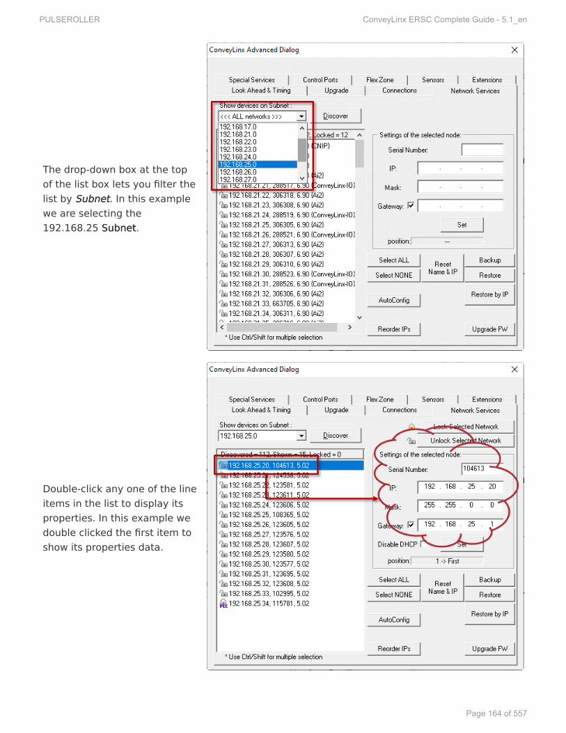
The drop-down box at the topof the list box lets you filter thelist by SubnetSubnet. In this examplewe are selecting the192.168.25 SubnetSubnet.
Double-click any one of the lineitems in the list to display itsproperties. In this example wedouble clicked the first item toshow its properties data.
PULSEROLLER ConveyLinx ERSC Complete Guide - 5.1_en
Page 164 of 557

Once a modules data has beenselected, you can change itsproperties. In this example wechanged the 3rd octet of the I.P.address from 25 to 37. Onceyou have edited the data, clickthe SetSet button and the changesare sent to the module.
PULSEROLLER ConveyLinx ERSC Complete Guide - 5.1_en
Page 165 of 557

8.6.4.2.8.6.4.2. PPosition and DHCPosition and DHCPPPosition Identifierosition IdentifierWithin the “Settings of the selected node” area, at the bottom, is a read-only box that showsthe position of the selected module within the network. This information is provided so you cancheck the integrity of your SubnetSubnet. The data shown is a position indicator or FlagFlag. The possiblevalues are 1 -> First, 2 -> Last, and 0 -> unknown.
For a properly configured SubnetSubnet you must have:
• Only one Module with a 1 -> First position FlagFlag• Only one Module with a 2 -> Last position FlagFlag• All modules with the exception of the First and Last should indicate 0 -> unknown
With your list filtered so that itshows only one SubnetSubnet , thefirst item in the list should bethe .20 module of the SubnetSubnetand its position FlagFlag shouldalways indicate 1 -> First. Inour example we selected the192.168.26.20 node and itsFlagFlag is shown as_1 -> First_.
PULSEROLLER ConveyLinx ERSC Complete Guide - 5.1_en
Page 166 of 557

The last module in the SubnetSubnetshould have a position FlagFlagvalue of 2 -> Last. In ourexample we selected module192.168.26.30 and we can seeits position FlagFlag is 2 -> Last asshown.
Any module that is not the Firstor Last module in the SubnetSubnetshould have a FlagFlag value of 0-> unknown. In our example weselected module 192.168.26.24and we can see its position FlagFlagis 0 -> unknown as shown.
PULSEROLLER ConveyLinx ERSC Complete Guide - 5.1_en
Page 167 of 557

DHCPDHCP ServerServerBy default, the most upstream module of every Subnet (I.P. Address xxx.xxx.xxx.20) enables asimple DHCP server as a convenience so that if your PC is set up to receive an IP address fromthe network, your ConveyLinx Subnet will issue one. On larger systems with perhaps multipleSubnets and/or customer managed network infrastructures, this DHCP server may interferewith the function of the network. You can disable this DHCP server from the Network Servicestab.
Once you have double clickedthe module form the list, youcan check the DisableDisable DHCPDHCPcheckbox to disable the DHCPserver. You have to click the SetSetbutton to make the change tothe module.
If you have more than one module in a Subnet with a First or Last Flag, or if thereis no First or Last module in the Subnet, your network will not properly preserveits data for Automatic Module Replacement and the Subnet may have problemsnegotiating Ethernet switches and routers for PLC connectivity. You MUSTproperly Auto-Configure all Subnets so that these position Flags are correct!
!
PULSEROLLER ConveyLinx ERSC Complete Guide - 5.1_en
Page 168 of 557

8.6.4.3.8.6.4.3. Network LNetwork Lock Fock FeatureatureeThe LLock Fock Featureaturee allows you to “lock” a specific SubnetSubnet so that no accidental pressing of theInstall button on any of the modules will inadvertently cause an Auto Configuration Procedureto be activated.
In this example, the 192.168.29SubnetSubnet is selected and you can seeby the icons next to each moduleentry in the list that they are“Unlocked”
PULSEROLLER ConveyLinx ERSC Complete Guide - 5.1_en
Page 169 of 557

By clicking the LLock Selectedock SelectedNetworkNetwork button, all modules in theSubnetSubnet listed will be “Locked” asindicated by the icons in the list.Clicking the Unlock SelectedUnlock SelectedNetworkNetwork button will “Unlock” all themodules in the list
Please note that this function applies to all the modules within a selected SubnetSubnetand cannot be activated for an individual module!
PULSEROLLER ConveyLinx ERSC Complete Guide - 5.1_en
Page 170 of 557

8.6.4.4.8.6.4.4. BackBackup and Rup and RestorestoreeYou have the ability to select a SubnetSubnet or all SubnetsSubnets discovered and generate a BackBackupup filethat will contain all the parameters and settings for each module included in the selection. Thismeans all motor settings (speed, acceleration, deceleration, braking, etc.), ZPA settings,Advanced Dialog settings, etc. are captured in this file that can be saved on your PC.Conversely you can use this BackBackupup file to RRestorestoree settings to a SubnetSubnet or all SubnetsSubnets in theevent settings are inadvertently modified or you simply want to return your modules to apreviously known state
To perform a backup, click the SelectSelectALLALL button to select all the items inthe list. In this example we are goingto backup SubnetSubnet 192.168.29. Onceall modules are highlighted, click theBackBackupup button. A “Save As” filedialog will appear and you provide afilename and location to save the file
A Save AsSave As dialog will appear and youprovide a filename and location tosave the file
PULSEROLLER ConveyLinx ERSC Complete Guide - 5.1_en
Page 171 of 557

Conversely, if you have a BackBackupup filethat you want to use to get yourSubnet’sSubnet’s settings restored; click theSelectSelect ALLALL button and then click theRRestorestore buttone button. An “Open File”dialog will appear for you tonavigate to the location of yourbackup file
An “Open File” dialog will appear foryou to navigate to the location ofyour backup file, select it and click“Open”.
RRestorestore by IP Fe by IP Functionunction
Because the default RRestorestoree function restores settings by module Serial Number only, insituations such as duplicating a SubnetSubnet or restoring functionality from an older backup wheresome of the modules were replaced since the BackBackupup file was generated, you need to restore
Please note that the RRestorestoree function will only restore settings to modules thathave a matching Serial Number in the BackBackupup file. For situations where moduleserial number are different but functionality still needs to be restored, you willneed to use the RRestorestore by IPe by IP function
*
PULSEROLLER ConveyLinx ERSC Complete Guide - 5.1_en
Page 172 of 557

the settings by IP address instead of by module Serial Number. To do this you follow the samerestore procedure as previously shown except you click the RRestorestore by IPe by IP button instead of theRestore button
BackBackup and Rup and Restorestore Re Recommendations and Tecommendations and Tipsips
Sometimes there are situations where just because a software application will allow you to dosomething does not always mean that you should. The BackBackupup and RRestorestoree functions inEasyRoll can fall into this scenario. Even though you can technically create a backup file for afew or even a single module from within a SubnetSubnet of many modules, it is not recommendedthat you do so. ConveyLinx support engineer’s experience to date has indicated that whencustomers perform BackBackupup and RRestorestoree functions for, at a minimum, all modules in a SubnetSubnet,you will have fewer or no problems with your ConveyLinx networks. Systems that were onceworking and then start producing unexpected results often stem from performing a RRestorestoreefunction to a small portion of modules instead of the entire Subnet and/or starting with abackup file that did not include all modules in the SubnetSubnet. So, here is a list of tips:
• When you perform a BackBackupup; at a minimum, select all modules in a given SubnetSubnet• When you perform a RRestorestoree; at a minimum, select all modules in a given SubnetSubnet• Perform a new BackBackupup after you make any settings changes to one or more modules in a
SubnetSubnet• Perform a new BackBackupup after every time you perform an Auto Configure Procedure
PULSEROLLER ConveyLinx ERSC Complete Guide - 5.1_en
Page 173 of 557

8.6.5.8.6.5. Special Services TSpecial Services TababRReset Operating Teset Operating Timeime
Each module maintains a non-volatile data register for each MDRwhose value is the number ofminutes the motor has been run.This value is displayed as OperatingTime on the Main Screen. Thisscreen on the ConveyLinx AdvancedDialog allows you to reset this meterin the event you have to replace agiven MDR. Click either the LeftMotor or Right Motor buttons in theReset Operating Time area to resetthe corresponding value to 0.
PULSEROLLER ConveyLinx ERSC Complete Guide - 5.1_en
Page 174 of 557

Clear Motor Short CirClear Motor Short Circuit Ercuit Errroror
Another function on the SpecialServices tab is a button used toclear an MDR short circuit error. Thisparticular error is not logicallycleared based upon an elapsedperiod timeout or other such reset.An MDR short circuit error requiresthat either the module be powereddown and then powered back up orby clicking the Reset button on thistab. This function is made availablein EasyRoll as a convenience so youdon’t have to cycle the power on themodule.
PULSEROLLER ConveyLinx ERSC Complete Guide - 5.1_en
Page 175 of 557

TTouch & Goouch & Go
The Touch & Go function is availablein ZPA mode and when activatedcauses the MDR in the activatedzone to sense rotational movementof the MDR in its default direction. Ifthis rotational movement (such assomeone pushing a carton onto thezone) is of sufficient duration andspeed; the zone will “wake up” as ifits upstream interlock had beenenergized. You enable this functionby checking the appropriateUpstream or Downstream checkboxin the Touch & Go area.
Touch & Go is only applicable for ZPA mode. Do NOT use Touch & Go with ServoBraking!
If you are using Firmware 4.27 and later or ODVA Firmware 5.07 and later andEasyRoll version 4.21 or later; there is a Motor SlaveMotor Slave function available on thisscreen tab*
PULSEROLLER ConveyLinx ERSC Complete Guide - 5.1_en
Page 176 of 557

8.6.5.1.8.6.5.1. Motor Slave FMotor Slave Functionunction
The purpose of the Slave FSlave Functionunction is to select one of the two motors (Left or Right) to be themaster and the other to to follow the run/stop and speed of the opposite motor. When youselect one of the motors to be the master, only its settings are accessible in EasyRoll andwhatever setting you modify (Speed, Accel, Decel, etc.) will also apply to the slave motor.
From the Special ServicesSpecial Services Tab, if youhave selected a Node that has beenAutoAuto-Configur-Configureded as a Single ZoneSingle ZoneZPZPAA , then the Slave FSlave Functionunction dropdown box is enabled for selection.
The functionality in this topic requires Firmware 4.27 and later or ODVA Firmware5.07 and later as well as EasyRoll version 4.21 or later!
The Motor SlaveMotor Slave function from EasyRoll is only applicable to modules in ZPZPAAmodemode that have been Auto-Configured as a single zonesingle zone (only one sensorconnected) and two motors connected.*
Motor SlaveMotor Slave function automaticallyautomatically adjusts slave motor’s speed and performancein Closed LClosed Loopoop mode to properly assist the master motor*
PULSEROLLER ConveyLinx ERSC Complete Guide - 5.1_en
Page 177 of 557

Slave FSlave Function Selectionsunction SelectionsSelectionSelection DescriptionDescription
NoneNo Slave Function is applied and Node functions as Auto-Configured as single zoneZPA. Both motors run together when the zone is activated and the two motorshave their settings independently accessible from EasyRoll
right isslaved to left
Left motor becomes the master and the Right motor becomes the slave. Only theLeft motor’s settings are accessible in EasyRoll and the Right motor will utilize allthe settings made to the Left motor
right is inoppositedirection
Identical to right is slaved to left except that when the Left motor runs, the Rightmotor runs in the opposite direction of the Left motor. This function is used forDual DriveDual Drive MDRs
left is slavedto right
Right motor becomes the master and the Left motor becomes the slave. Only theRight motor’s settings are accessible in EasyRoll and the Left motor will utilize allthe settings made to the Right motor
left is inoppositedirection
Identical to left is slaved to right except that when the Right motor runs, the Leftmotor runs in the opposite direction of the Right motor. This function is used forDual DriveDual Drive MDRs
PULSEROLLER ConveyLinx ERSC Complete Guide - 5.1_en
Page 178 of 557

ExampleExample
You have a single zonesingle zoneZPZPAA module where theflow is from LLefeft to Rightt to Right,so lets make the RightRightmotor the mastermaster and theLLefeftt motor the slaveslave
PULSEROLLER ConveyLinx ERSC Complete Guide - 5.1_en
Page 179 of 557

From the Slave FSlave Functionunctiondrop down selector, selectlefleft is slaved to rightt is slaved to right
PULSEROLLER ConveyLinx ERSC Complete Guide - 5.1_en
Page 180 of 557

When you go back to theMain ScrMain Screeneen, you can seethat the Left motorparameters are greyed outand not accessible. Anychanges you make to theRight motor willautomatically be appliedto the Left motor
PULSEROLLER ConveyLinx ERSC Complete Guide - 5.1_en
Page 181 of 557

8.6.6.8.6.6. ContrControl Pol Ports Torts TababThe Control Ports tab provides you with the ability modify the function of one or both of theControl Ports. This tab is organized in the following areas:
• Control Port Inputs• Control Port Outputs• Upstream/Downstream Accumulation• Lane Full Interface• PLC Control of Control Ports
PULSEROLLER ConveyLinx ERSC Complete Guide - 5.1_en
Page 182 of 557

8.6.6.1.8.6.6.1. ContrControl Pol Port Inputsort InputsEach of the two Control Ports on the module has a 2 input signals: Local Accumulation andInfeed/Discharge Interlock. Each of these inputs has a default logical state (on or off) thatenables the function. The ContrControl Pol Port Inputsort Inputs area contains check boxes to invert the logicalstate of these inputs to accommodate your particular needs. Please note that these checkboxesare for LLefeftt and RightRight ports on the module and notnot the logical UpstrUpstreameam or DownstrDownstreameam zones
By default, the module interprets theInfeed/Discharge input signal(Interlock Pin 4 on RJ-12 Control Portor P4 on a SE-4) when energized orON to mean a logical “1”. By clickingthe check box to invert the Infeed/Discharge input signal, a de-energized or “OFF” condition willmean a logical “1” to the module forthe Interlock Pin 4 Control Port signal
PULSEROLLER ConveyLinx ERSC Complete Guide - 5.1_en
Page 183 of 557

By default, the module interprets theAccumulation input signal (Pin 3 onRJ-12 Control Port or P3 on a SE-4)when energized or ON to mean alogical “1”. By clicking the check boxto invert the Accumulation inputsignal, a de-energized or “OFF”condition will mean a logical “1” tothe module for the Pin 3 Control Portsignal
PULSEROLLER ConveyLinx ERSC Complete Guide - 5.1_en
Page 184 of 557

8.6.6.2.8.6.6.2. ContrControl Pol Port Outputsort Outputs
The default ContrControl Pol Port Outputort Outputconfiguration signal is “ON” orlogical “1” to indicate to externalcontrols that it is associated zone isoccupied. By clicking the associatedInvertInvert check box, the module willmake the output “OFF” or logical “0”when its associated zone is occupied
Control Port outputs are very low power. You need to use an SE Module toconnect your external device.!
PULSEROLLER ConveyLinx ERSC Complete Guide - 5.1_en
Page 185 of 557

The default operation of eachContrControl Pol Port Outputort Output signal is toindicate whether the zone isblocked. You can change thisoperation to indicate that the motoris running instead of zone blockedby clicking the Motor StateMotor Statecheckbox. Please note that theInvertInvert function applies to this optionas well
Please note that if you select the Motor State option on a module that is anExtension of another module, the Control Port Output will not energize. TheMotor State output only energizes on the module with the zone that is controllingthe Extension. See the Extensions Tab topic for more details.
!
PULSEROLLER ConveyLinx ERSC Complete Guide - 5.1_en
Page 186 of 557

8.6.6.3.8.6.6.3. UpstrUpstream/Downstream/DownstreameamAAccumulationccumulationOne of the Control Port input signals previously mentioned above is the Local Accumulatesignal (Pin 3 on RJ-12 Control Port or P3 on a SE-4). By default, this signal causes the local zoneto accumulate when its zone sensor is blocked. If this signal is removed when a carton isblocking the sensor, the carton will discharge to the next downstream zone (if of course it isclear). While the carton is discharging and still blocking the zone sensor, if the Accumulatesignal is re-energized, the zone will stop.
AAccumulate on Sensor Tccumulate on Sensor Triggerrigger
In situations (like an operator workstation) where you for example want every carton toaccumulate upon its arrival, you would leave the Accumulate signal energized all the time andthen have an operator momentarily de-energize the signal to cause the carton to discharge. Inthis situation you probably do not want the operator to have to watch and wait for the carton tofully discharge from the zone in order for them to re-energize the Accumulate signal so that thenext carton will stop at the zone. The AAccumulate on Sensorccumulate on Sensor Trigger checkboxes for theUpstream and Downstream zones allow you to tell either or both the Upstream or Downstreamzones on the module to remember that the Accumulate signal was momentarily de-energizedso the carton will discharge without any further operator intervention and automatically knowto accumulate the zone upon the arrival of the next carton.
Click the AAccumulate on Sensorccumulate on SensorTTriggerrigger checkbox so that amomentary removal of the PPin 3in 3signal will release the carton fromthe zone. If the PPin 3in 3 signal comesback on and the sensor is stillblocked, the control will still releasethe carton and will not accumulateagain until the sensor becomes clearand then blocked again
PULSEROLLER ConveyLinx ERSC Complete Guide - 5.1_en
Page 187 of 557

8.6.6.4.8.6.6.4. Lane FLane Full Interfaceull InterfaceThe Control Ports tab provides selection and adjustment to the PPin 4in 4 Interlock Signal on themost Downstream zone to provide a Lane FLane Full Interfaceull Interface that is typical in conveyor applications.With Lane FLane Full Interfaceull Interface checkbox checked; the Downstream Interlock will change its defaultfunctionality to ignore the confirmation signal from the downstream controls and thus eliminatethe logical Arrival Jam condition. This will allow the downstream zone to continually release aslong as the sensor signal is OFF (default). This option also allows the user to set a block andclear time for the PPin 4in 4 signal for added flexibility
When a sensor is plugged into thedownstrdownstreameam Control Port, you cancheck the Lane FLane Full Interfaceull Interfacecheckbox. This will cause the zone tono longer require a downstreamarrival interlock (i.e. Ignore ArrivalJam) and use the sensor signal tostop and start releasing from thezone. Block and Clear TBlock and Clear Timersimers areprovided to adjust the behavior ofproduct flow based upon theblocking and clearing of the sensor.In this example we entered 4seconds for Block Time and 5seconds for Clear Time.
The Lane FLane Full Interfaceull Interface Block and Clear Timer capability is designed so you canplug a Sensor direct into the Control Port*
PULSEROLLER ConveyLinx ERSC Complete Guide - 5.1_en
Page 188 of 557

8.6.6.5.8.6.6.5. PLC ContrPLC Control of Control of Control Pol PortsortsIf you have a PLC connected to a module while it is in ZPA mode, you have the option ofdisabling the default ZPA functionality of either Control Port (or both) and allow your externalPLC to access the 2 input signals and the one output signal available on each port. This meansthat when selected for a given zone’s Control Port; energizing either input signal will notindicate Local Accumulation or Infeed/Discharge Interlock functions and the output signal willnot become energized when the zone is occupied. Your PLC program will have access to theseinputs and output to use as remote I/O over the ConveyLinx Ethernet network
You can select either or both theUpstream and/or DownstreamControl Ports to be controlled byyour remote PLC over theConveyLinx Ethernet network.Checking the appropriate checkboxwill immediately make the change. Ifa checkbox is already checked,unchecking it will return theassociated port back to its ZPAfunctionality
PULSEROLLER ConveyLinx ERSC Complete Guide - 5.1_en
Page 189 of 557

8.6.7.8.6.7. FleFlex Zone Tx Zone TababThe FleFlex Zonex Zone feature is enabled by default when you perform the Auto Configure Procedure.There can be certain situations such as higher speed applications and/or applications where alarge percentage of cartons are at a length very close to the zone length where a “falsetriggering” of a flex zone condition can occur. In these situations, when product needs toaccumulate, you may see several zones unoccupied because of this false triggering. For theseapplications where accumulation density is paramount, you can disable Flex Zone to eliminatethis false triggering situation.
Click the appropriate button toeither Disable or Enable Flex Zonebased upon the subnet’s currentstatus as indicated. Because thisfunction applies to all modules in theSubnetSubnet, it does not matter whatmodule you were connected to whenyou invoked the Advance Dialog inorder to disable or enable Flex Zone
Inter Module Communication TInter Module Communication TimeimeThe Inter Module Communication TInter Module Communication Timeime value is used to adjust the behavior of the Flex Zoneoperation. In situations where carton lengths can be close to the length of the zones (i.e.distance between photoeyes), you may want to adjust Flex Zone operation so that it eitherengages or not in these situations.
Please note that Flex Zone function has to be enabled or disabled for the entireSubnetSubnet. It cannot be disabled or enabled on a per zone basis or for a group ofzones within the same subnet.
!
PULSEROLLER ConveyLinx ERSC Complete Guide - 5.1_en
Page 190 of 557

Typically there are one or two driven rollers past the sensor in a Zone. If youhave cartons that encroach upon these rollers when accumulated in thedownstream zone, you may want FleFlex Zonex Zone to engage so that the nextupstream carton will not enter the zone (Zone A in the example), thus notrunning these rollers underneath the accumulated carton.
PULSEROLLER ConveyLinx ERSC Complete Guide - 5.1_en
Page 191 of 557

The value entered is in msec and itcan be thought of as an amount oftime added to the logic after thetrailing edge of the sensor in orderto simulate increasing the cartonlength. Please note that this valuewill be set the same for each modulein the SubnetSubnet.
Please note this value has nothing to do with speeding up or slowing down thePlease note this value has nothing to do with speeding up or slowing down theactual speed of communications between modulesactual speed of communications between modules*
PULSEROLLER ConveyLinx ERSC Complete Guide - 5.1_en
Page 192 of 557

8.6.8.8.6.8. Sensors TSensors TababThe SensorsSensors tab displays the status of how the two sensor signals were configured during theAuto Configuration Procedure. If for some reason one or more of the sensors was not configuredproperly during the Auto Configuration Procedure; for example they were not aligned with theirreflector or there was an obstruction blocking the sensor at the time the procedure wasperformed, the SensorsSensors Tab will allow you to change the sensor’s configuration withoutrequiring you to re-perform the Auto Configuration PAuto Configuration Prroceduroceduree for the entire subnet. Forexample, if all the sensors on the system are light energized normally open then thecorresponding zone’s sensor graphic on this tab will show Off Blocked. Similarly, if the sensor isequipped with a separate health or low gain signal and this signal is on when there is no error,the graphic on this tab will show Off Gain Error.
Click the appropriate icon to changethe sensor’s blocked and/or gainerror signal state. Note that you canmake the same change for a groupof modules by clicking the Set AllSensors this Way button
PULSEROLLER ConveyLinx ERSC Complete Guide - 5.1_en
Page 193 of 557

8.6.9.8.6.9. Extensions TExtensions TababThe ExtensionsExtensions Tab allows you to extend or “slave” single or multiple zones to one “master”zone. An example situation could be that you have for example certain length zones and on agiven conveyor line there is a need for an extra partial zone that is too short to be a functionalzone that accumulates a carton, but at the same time it is long enough that mechanically youneed to have an MDR in that zone. In this situation you would like to provide a module and anMDR but no sensor and you want this zone to run its MDR when either its adjacent upstream ordownstream zone is also running. In essence you want to make this partial zone a logicalextension to one of its neighbors.
Example for Using Extensions for a LifExample for Using Extensions for a Lift Gatet Gate
A common use of the Extension mode configuration available from the Connections tabselection is for a powered lift gate.
In this example the module on the lifting or gate portion of conveyor has anMDR and no photo-sensors. Normal operation when the gate is down is for theMDR on the gate to run when its immediate downstream zone runs so as tocreate “one long logical zone”. This means that if a carton is accumulated onthe upstream zone of Node 192.168.26.24; a carton arriving at the downstreamzone of Node 192.168.26.22 will stop and accumulate and no loads will ever belogically accumulated or stopped on the gate portion. In order to accomplishthis, all we need to do is instruct Node 192.168.26.23 to be an Extension of itsdownstream neighbor Node 192.168.26.24
PULSEROLLER ConveyLinx ERSC Complete Guide - 5.1_en
Page 194 of 557

In the Advanced Dialog, navigate toNode 4 and click the ExtensionsExtensions Tab.Notice that Node 4’s IP address192.168.20.24 is filled in. In thedrop-down box, select Downstreamand click Apply. Note that this maytake a few seconds to complete
After clicking Apply, the screen willupdate and show you that themodule has been configured as anextension or “slave” of itsdownstream neighbor
!
PULSEROLLER ConveyLinx ERSC Complete Guide - 5.1_en
Page 195 of 557

Now if you navigate back to Node 3and look at the Connections Tab, youcan see that the downstreamconnection of Node 3 is now Node 5instead of Node 4
And then when you navigate toNode 5, you can see that itsupstream connection is now Node 3instead of Node 4
PULSEROLLER ConveyLinx ERSC Complete Guide - 5.1_en
Page 196 of 557

And when you navigate to Node 4,you can see that it is configured asan Extension of Node 5
PULSEROLLER ConveyLinx ERSC Complete Guide - 5.1_en
Page 197 of 557

9.9. ConveyMerConveyMergegeConveyMerConveyMergege is an optional functionality layer built on top of ConveyLinx’sConveyLinx’s ZPZPAA logic. Users canenable and configure it using EasyREasyRolloll software. ConveyMerConveyMergege behaves the same as ZPA logic,but allows you to define a special MerMerge Zonege Zone that can have up to three upstream zonesconnected to it. ConveyMerConveyMergege also has simple priority schemes for the multiple upstream zonesas well as the ability to dynamically change those priorities on-the-fly by utilizing the MerMergegeLine FLine Fullull option. It also takes care of passing tracking information properly and has JamJamConditionCondition detection.
ConveyMerConveyMerge Componentsge ComponentsConveyMerConveyMergege can accommodate product merge control from one or two conveyor paths onto asingle take-away conveyor path as shown:
ComponentComponent DescriptionDescription
MerMerge Zonege Zone Powered conveyor section that accepts an item from any one of the 3possible upstream sources
Main LineMain Line Term to describe the 3 in-line conveyor sections – Center LineCenter Line, MerMerge Zonege Zoneand DischarDischarge Zonege Zone
Center LineCenter Line
Part of Center LineCenter Line that is one of three possible sources of items that can flowinto the MerMerge Zonege Zone. This term is used in the configuration screen of EasyREasyRollollto designate the network that serves as the trunk line that contains theMerMerge Zonege Zone
PULSEROLLER ConveyLinx ERSC Complete Guide - 5.1_en
Page 198 of 557

DischarDischarge Zonege Zone Part of the Center LineCenter Line that is downstream of the MerMerge Zonege Zone. This conveyorsection accepts the item from the MerMerge Zonege Zone
LLefeft Linet Line One of the three possible conveyor sections that can discharge items into theMerMerge Zonege Zone
Right LineRight Line One of the three possible conveyor sections that can discharge items into theMerMerge Zonege Zone
PULSEROLLER ConveyLinx ERSC Complete Guide - 5.1_en
Page 199 of 557

9.1.9.1. ConveyMerConveyMerge Pge Prrererequisites andequisites andRRequirequirementsementsPlease Note – ConveyMerPlease Note – ConveyMerge works forge works for ALLALL ConveyLinxConveyLinxFFamily Modulesamily Modules
ModuleModule FFirirmwarmwaree
ConveyLinx-ERSC 4.25 and later
ConveyLinx-HTF 4.25 and later
ConveyLinx-Ai2 4.20 and later
ConveyLinx-Ai3-24-xx 4.20 and later
The following items are the prerequisites and constraints required to provide a fully functioningautomatic conveyor merge:
• EasyREasyRolloll version 4.19 or greater• Only (1) one MerMerge Zonege Zone is allowed for any given single module• MerMerge Zonege Zone cannot have any Extension (slaved) zoneExtension (slaved) zone• MerMerge Zonege Zone must be in ZPZPAA mode. LLefeft Linet Line discharge, Right LineRight Line discharge, and CenterCenter
LineLine discharge can be in either ZPZPAA mode or PLCPLC I/OI/O mode• Left, Right, and Center Lines discharges cannot also be included in another instance of
ConveyMerConveyMergege
If LLefeft Linet Line discharge, Right LineRight Line discharge, or Center LineCenter Line discharge modules arein PLC I/O mode, you are responsible for programming logic to recognize andrespond to ZPA zone status values between the MerMerge Zonege Zone module for properjam free singulation control
*
PULSEROLLER ConveyLinx ERSC Complete Guide - 5.1_en
Page 200 of 557

9.2.9.2. Network ArNetwork ArchitecturchitectureeAll lines (CenterCenter, LLefeftt, and RightRight) should be on separate subnetssubnets of modules, as shown. Eachsubnetsubnet should be AutoAuto-Configur-Configureded separately and then connected together with an Ethernetswitch. Keep in mind that the separate subnetssubnets will have to be able to communicate with eachother so special care must be taken when setting up the IP Network MaskIP Network Mask before performingthe AutoAuto-Configuration P-Configuration Prroceduroceduree.
ArArchitecturchitecture Summarye Summary• The Center LineCenter Line is a separate subnetsubnet of modules that have been AutoAuto-Configur-Configureded. The
A good starting point is the default mask of 255.255.128.0. With this setting youcan vary the third octet in the ranges 0-127 and 128-254 and all three lines willbe able to communicate with each other as long as the third octets of their IPaddresses are in the same range (either 0-127 or 128-254).
*
Even though ConveyMerConveyMergege can work with all lines being in the same subnetsame subnet, caremust be taken during AutoAuto-Configuration-Configuration to assure proper zone flow for all lines.We recommend separate subnetsseparate subnets in order to assure proper zone flow for all lines.*
PULSEROLLER ConveyLinx ERSC Complete Guide - 5.1_en
Page 201 of 557

MerMerge Zonege Zone and the DischarDischarge Zonege Zone are part of this subnetsubnet. The Center LineCenter Line can consistof any number of ConveyLinx ModulesConveyLinx Modules and the actual position of the MerMerging Zoneging Zone can beon any ConveyLinx ModuleConveyLinx Module within the subnetsubnet
• The DischarDischarge Zonege Zone has to be the zone immediately downstream of the MerMerge Zonege Zone.However, the DischarDischarge Zonege Zone can be on either the same ConveyLinx Module as the MerMergegeZoneZone or on the adjacent downstream ConveyLinx Module from the MerMerge Zone’sge Zone’sConveyLinx Module
• The LLefeft Linet Line is a separate subnetsubnet of modules and its most downstream zone has tophysically discharge on to the MerMerge Zonege Zone
• The Right LineRight Line is a separate_* subnet*_ of modules and its most downstream zone has tophysically discharge on to the MerMerge Zonege Zone
• All three subnetssubnets must be connected to a common Ethernet switch only after each subnetsubnethas been AutoAuto-Configur-Configureded.
*
PULSEROLLER ConveyLinx ERSC Complete Guide - 5.1_en
Page 202 of 557

9.3.9.3. Sensor PlacementSensor Placement
Conventional Spur MerConventional Spur Merge Sensor Placementge Sensor Placement
It is very important for the internal ConveyMerConveyMergege logic, that the product is seenby only one sensor at a time!
PULSEROLLER ConveyLinx ERSC Complete Guide - 5.1_en
Page 203 of 557

90° T90° T-Mer-Merge Sensor Placementge Sensor PlacementPULSEROLLER ConveyLinx ERSC Complete Guide - 5.1_en
Page 204 of 557

9.4.9.4. MerMerge Zone Modulege Zone ModuleDepending on the physical arrangement of actual zones on the Center LineCenter Line, the MerMerge Zonege Zonecan be assigned to either the Upstream or Downstream zone of its particular ConveyLinxModule. It can also be assigned to a ConveyLinx Module that is configured as a single zone ZPAcontroller.
In all 4 of these eIn all 4 of these examples,xamples, Node 2Node 2 is the Meris the Merge Zone’s contrge Zone’s controllingollingConveyLinx ModuleConveyLinx Module
MerMerge Zone on Upstrge Zone on Upstream Zoneeam Zone
Images show ConveyLinx-ERSC modules but functions are applicable to allConveyLinx Family modules*
PULSEROLLER ConveyLinx ERSC Complete Guide - 5.1_en
Page 205 of 557

MerMerge Zone on Downstrge Zone on Downstream Zoneeam ZonePULSEROLLER ConveyLinx ERSC Complete Guide - 5.1_en
Page 206 of 557

Single Zone ModuleSingle Zone ModuleWhenever an ConveyLinx Module has been AutoAuto-Configur-Configureded as a single zonesingle zone; regardless ofwhether the single zone is connected to the right side or left side of the ConveyLinx Module,the logical designation for the zone on the this module is always the Upstream Zone. Shownbelow are examples of a single zone module using the left and right sides of the modulerespectively.
Merge Zone on a Single Zone Module's Left Side
Merge Zone on a Single Zone Module's Right Side
PULSEROLLER ConveyLinx ERSC Complete Guide - 5.1_en
Page 207 of 557

9.5.9.5. MerMerging Linesging LinesThe LLefeft Linet Line and Right LineRight Line are set up in a similar fashion to the Center LineCenter Line. Each of theselines are in their own separate subnetsubnet that is both different from each other and different fromthe Center LineCenter Line. Regardless of whether these merging lines are an Conventional Spurarrangement or a 90˚ T-Merge arrangement; the conveyor zone that discharges product ontothe MerMerge Zonege Zone must be the most downstream zone if its particular subnet. The followingfigures illustrate this for an ConventionalConventional Spur Left Line and a 90˚ TT-Mer-Mergege Left Linerespectively. The same would apply if these were Right LineRight Line examples as well.
Images show ConveyLinx-ERSC modules but functions are applicable to allConveyLinx Family modules*
PULSEROLLER ConveyLinx ERSC Complete Guide - 5.1_en
Page 208 of 557

PULSEROLLER ConveyLinx ERSC Complete Guide - 5.1_en
Page 209 of 557

9.6.9.6. MerMerge Configurationsge ConfigurationsThe MerMerge Configurationsge Configurations available from within in EasyREasyRolloll are:
• LLefeft Linet Line Only with either ConventionalConventional (spur discharge) or TT-Mer-Mergege (90˚ discharge)• Right LineRight Line Only with either ConventionalConventional (spur discharge) or TT-Mer-Mergege (90˚ discharge)• Both LLefeftt and RightRight Lines with either ConventionalConventional (spur discharge) or TT-Mer-Mergege (90˚
discharge) for each
PULSEROLLER ConveyLinx ERSC Complete Guide - 5.1_en
Page 210 of 557

9.7.9.7. MerMerge Pge PriorityriorityEasyREasyRolloll provides the ability to adjust which of the merging lines receives priority.
EasyREasyRoll Poll PriorityrioritySelectionSelection DescriptionDescription
FFirst Come First Come FirstirstServedServed
The logic monitors the arrival status in each of the zones that discharge in tothe MerMergeZonegeZone. The first product that arrives at any of these lines will beallowed to convey into the MerMergeZonegeZone. When the MerMergeZonegeZone is clear, thenext line that has had a product arrive will be allowed to convey into theMerMergeZonegeZone
Center LineCenter LinePPriorityriority
The Center LineCenter Line will be allowed to release as long as product arrives at theCenter Line’sCenter Line’s zone sensor prior to the previously released product having notcleared the MerMergeZonegeZone. When the MerMerge Zonege Zone is clear and if there is noproduct sensed on the center line zone; then the LLefeftt and/or Right LinesRight Lines willbe allowed to release if product has arrived at their respective sensors. Aslong as no product is arriving on the Center LineCenter Line, if LLefeftt and Right LinesRight Lines areenabled, these will operate as FFirst Come First Come First Servedirst Served between them
LLefeft Line Pt Line Priorityriority
The LLefeft Linet Line will be allowed to release as long as product arrives at the LLefefttLine’sLine’s most downstream sensor prior to the previously released producthaving not cleared the MerMergeZonegeZone. When the MerMerge Zonege Zone is clear and if thereis no product sensed on the LLefeft Line’st Line’s most downstream sensor; then theCenterCenter and/or Right LineRight Line will be allowed to release if product has arrived attheir respective sensors. As long as no product is arriving on the LLefeft Linet Line, ifthe Right LineRight Line is enabled, the CenterCenter and RightRight will operate as FFirst Comeirst ComeFFirst Servedirst Served between them
Right Line PRight Line Priorityriority
The Right LineRight Line will be allowed to release as long as product arrives at theRight Line’sRight Line’s most downstream sensor prior to the previously released producthaving not cleared the MerMergeZonegeZone. When the MerMerge Zonege Zone is clear and if thereis no product sensed on the Right Line’sRight Line’s most downstream sensor; then theCenterCenter and/or LLefeft Linet Line will be allowed to release if product has arrived attheir respective sensors. As long as no product is arriving on the Right LineRight Line, ifthe LLefeft Linet Line is enabled, the CenterCenter and LLefeftt will operate as FFirst Come First Come FirstirstServedServed between them
PULSEROLLER ConveyLinx ERSC Complete Guide - 5.1_en
Page 211 of 557

9.8.9.8. TT-Mer-Merge Settingsge SettingsFor a TT-Mer-Mergege, the discharging conveyor is arranged perpendicular to the MerMerge Zonege Zone and thisdischarging conveyor needs to “throw” the product across the Merge Zone’s rollers. In order tomitigate carton alignment issues, the logic controls need to make sure that it keeps the MerMergegeZone’sZone’s rollers stopped until the discharging conveyor has completely finished “throwing” theproduct onto the MerMerge Zonege Zone. In order to accommodate various conveyor speeds and materialhandling situations; EasyREasyRolloll provides some timer adjustments to facilitate proper TT-Mer-Mergegefunctionality.
AAccept Tccept Timeoutimeout
This timer specifies how much time the MerMerge Zonege Zone will wait after its sensor is blocked until thelogic allows it’s motor to run. Once the timer has expired, the Merge Zone’s motor will beallowed to run. Keep in mind that conditions downstream of the MerMerge Zonege Zone also dictate if themotor is allowed to run.
Send TSend Timeoutimeout
This timer specifies how much time the discharging zone has to wait after the MerMerge Zonege Zonesensor is clear before it is allowed to release the next product into the MerMerge Zonege Zone. This timerhelps ensure that the MerMerge Zonege Zone is clear when sensor placement cannot guarantee that thezone is clear.
PULSEROLLER ConveyLinx ERSC Complete Guide - 5.1_en
Page 212 of 557

PULSEROLLER ConveyLinx ERSC Complete Guide - 5.1_en
Page 213 of 557

9.9.9.9. Configuring Dynamic PConfiguring Dynamic Priority Rriority ReleaseeleaseIn situations where the full status of a given merge line needs to determine merge priority,ConveyMerConveyMergege provides the ability to monitor the status of one or all merging lines and base therelease priority accordingly. EasyREasyRolloll provides the option to select a given upstream zone on agiven line as the Monitor ZoneMonitor Zone. When the Monitor ZoneMonitor Zone becomes occupied for a given timevalue; its line will be given release priority into the MerMerge Zonege Zone. There are two adjustable timevalues for this function:
EasyREasyRoll Selectionoll Selection DescriptionDescription
Block TBlock Timeoutimeout
Specified the amount of time the Monitor ZoneMonitor Zone must be occupied before theMonitor Zone’s line will receive priority to release into the MerMerge Zonege Zone. Thistimer starts when the Monitor ZoneMonitor Zone first becomes accumulated (sensorblocked and motor stopped) and continues to time as long as the MonitorMonitorZoneZone stays accumulated
Clear TClear TimeoutimeoutSpecified amount of time that the priority release will continue to be activeonce the priority release has begun. When this time value expires, thepriority setting will return to its original EasyREasyRolloll configured setting
Dynamic PDynamic Priority Rriority Release Exampleelease ExamplePlease refer to Figure A and Figure B below. In EasyREasyRolloll, Node 2 upstream zone of the CenterCenterLineLine has been selected as the MerMerge Zonege Zone and the merge type is Up Left. The EasyREasyRolloll settingfor priority is Center Line PCenter Line Priorityriority. Also in EasyRoll, the MerMerge Line Fge Line Fullull function has beenenabled as assigned to Node 3 downstream zone of the LLefeft Linet Line.With the MerMerge Line Fge Line Fullull feature enabled on the LLefeft Linet Line; once Left Line Node 3 downstreamzone remains accumulated for the Block TBlock Timer’simer’s timeout (Figure A); priority will dynamicallychange to the LLefeft Linet Line. This Left Line priority will remain in effect until the Clear TClear Timer’simer’stimeout has expired (Figure B). When this occurs, the priority will automatically revert to theEasyREasyRolloll configured priority (Center LineCenter Line in this example).
In this example, if we did not enable the MerMerge Line Fge Line Fullull function for the LLefeft Linet Line and if therewas a steady flow of product on the Center LineCenter Line; the LLefeft Linet Line would never be able to releasebecause the default priority in EasyRoll was set to Center LineCenter Line.
If multiple lines are configured for Dynamic PDynamic Priorityriority and each of their respectiveBlock TBlock Timersimers have expired; ConveyMerConveyMergege logic will revert to the FFirst Come First Come FirstirstServeServe release mode until one or more of the releasing lines’ Clear TClear Timerimer hasexpired
*
PULSEROLLER ConveyLinx ERSC Complete Guide - 5.1_en
Page 214 of 557

Figure A - Merge Line Full Block Timer
Images show ConveyLinx-ERSC modules but functions are applicable to allConveyLinx Family modules*
PULSEROLLER ConveyLinx ERSC Complete Guide - 5.1_en
Page 215 of 557

Figure B - Merge Line Full Clear Timer
PULSEROLLER ConveyLinx ERSC Complete Guide - 5.1_en
Page 216 of 557

9.10.9.10. Enabling ConveyMerEnabling ConveyMerge frge from EasyRom EasyRolloll• Open EasyREasyRolloll• Connect and navigate to the ConveyLinx Module that will control the MerMerge Zonege Zone.• Press CTRLCTRL+SHIF+SHIFT+MT+M to open the ConveyMerConveyMerge Configuration Scrge Configuration Screeneen
ItemItem DescriptionDescription
Navigation Buttons for Node selection
PULSEROLLER ConveyLinx ERSC Complete Guide - 5.1_en
Page 217 of 557

Drop down selector for MerMerge Tge Typeype – Left, Right, or Both
Drop down for MerMerge Pge Priorityriority
Display of IP Address for the ConveyLinx Module selected that will contain the MerMergegeZoneZone
User button to click to apply the settings to the affected modules
User button to cancel any changes made and close the screen
Field to enter the IP Address of the LLefeft Line’st Line’s most downstream ConveyLinx Module
Checkbox to enable MerMerge Line Fge Line Fullull functions
IP Address of the ConveyLinx Module that contains the zone being defined as theMonitor ZoneMonitor Zone for the MerMerge Line Fge Line Fullull function
Radio buttons to select whether the upstream or downstream zone of the ConveyLinxModule identified in Item 9 will be used as the Monitor ZoneMonitor Zone
Field to enter the IP Address of the Right Line’sRight Line’s most downstream ConveyLinx Module
User checkbox to select TT-Mer-Mergege type
Graphical representation of the merge. Please note this will update and change assettings and configuration is modified
MerMerge Line Fge Line Full Block Tull Block Timerimer preset value
MerMerge Line Fge Line Full Clear Tull Clear Timerimer preset value
TT-Mer-Merge Age Accept Tccept Timerimer preset value
TT-Mer-Merge Send Tge Send Timerimer preset value
PULSEROLLER ConveyLinx ERSC Complete Guide - 5.1_en
Page 218 of 557

9.11.9.11. Conventional Spur MerConventional Spur Merge Examplege ExampleIn this example we are going to configure the LLefeft Linet Line to be standard spur angle merge ontothe Center LineCenter Line and we will set the MerMerge Pge Priorityriority to be FFirst Come First Come First Servedirst Served
The MerMerge Zonege Zone is the upstream zone of the module at 192.168.25.28 and the mostdownstream ConveyLinx Module for the LLefeft Linet Line is at 192.168.24.31. Here is the ConveyMerConveyMergegeConfiguration ScrConfiguration Screeneen with these values entered
Images show ConveyLinx-ERSC modules but functions are applicable to allConveyLinx Family modules*
PULSEROLLER ConveyLinx ERSC Complete Guide - 5.1_en
Page 219 of 557

The last step is to click the ApplyApply button to send the changes to the affected ConveyLinxModules
Please note that after clicking the “Apply” button, if the configuration haschanged, the affected modules will reboot. It will take a few seconds for thereboot to finish and some or all of the affected zones may briefly run theirmotors
*
PULSEROLLER ConveyLinx ERSC Complete Guide - 5.1_en
Page 220 of 557

9.12.9.12. TT-Mer-Merge Examplege ExampleIn this example we are going to configure the Right LineRight Line to be a TT-Mer-Mergege onto the Center LineCenter Lineand we will set the MerMerge Pge Priorityriority to be FFirst Come First Come First Servedirst Served
The MerMerge Zonege Zone is the upstream zone of the module at 192.168.25.28 and the mostdownstream ConveyLinx Module for the Right LineRight Line is at 192.168.26.58. Here is theConveyMerConveyMerge Configuration Scrge Configuration Screeneen with these values entered
Images show ConveyLinx-ERSC modules but functions are applicable to allConveyLinx Family modules*
PULSEROLLER ConveyLinx ERSC Complete Guide - 5.1_en
Page 221 of 557

PULSEROLLER ConveyLinx ERSC Complete Guide - 5.1_en
Page 222 of 557

9.13.9.13. MerMerge Line Fge Line Full Exampleull ExampleIn this example we have the LLefeft Linet Line configured as standard spur angle merge and the MerMergegePPriorityriority to be Center LineCenter Line
The MerMerge Zonege Zone is the upstream zone of ConveyLinx Module 192.168.25.28 and the LLefeft Line’st Line’smost downstream node is 192.168.24.31 and we want this line to have the MerMerge Line Fge Line Fullullfunction enabled. On the LLefeft Linet Line, we would like for the upstream zone of ConveyLinx Module192.168.24.25 to be the Merge Line Full function’s Monitor ZoneMonitor Zone. We would also like that oncethe Monitor ZoneMonitor Zone has been accumulated (or blocked) for 5 seconds, we want the LLefeft Linet Line torelease for 5 seconds and then return the priority to the Center Line. Here is the ConveyMerConveyMergegeConfiguration ScrConfiguration Screeneen with the values entered for this example:
Images show ConveyLinx-ERSC modules but functions are applicable to allConveyLinx Family modules*
PULSEROLLER ConveyLinx ERSC Complete Guide - 5.1_en
Page 223 of 557

PULSEROLLER ConveyLinx ERSC Complete Guide - 5.1_en
Page 224 of 557

10.10. ConveyStopConveyStopConveyStopConveyStop is a ConveyLinxConveyLinx function that establishes a network based means to signal allConveyLinx ModulesConveyLinx Modules with a Stop CommandStop Command in order to physically stop their motion and/oroutput functions and remain in a stopped state until a separate Start CommandStart Command network signalis received to return all connected modules back to their normal function. This is accomplishedby utilizing the built-in Ethernet network that already inter-connects the ConveyLinx controlsystem
Single Physical Network with 2 Stop Groups
In a similar fashion to how ConveyLinx modules establish logical connections based uponconveyor flow; ConveyStopConveyStop, when applied, establishes Stop GrStop Groupoup connections betweenmodules such that only modules within a given Stop GrStop Groupoup are affected by STOP and STARTnetwork commands. With ConveyStop, any given system can be segregated into as many StopStopGrGroupsoups as desired as long as all modules within a Stop GrStop Groupoup are physically connected overEthernet.
PULSEROLLER ConveyLinx ERSC Complete Guide - 5.1_en
Page 225 of 557

Typical STOP Command Sources
Typical START Command Sources
Each Stop GrStop Groupoup is independent in that a Stop CommandStop Command or Start CommandStart Command occurring in oneStop GrStop Groupoup does not affect the modules in another Stop GrStop Groupoup even if they are on the sameEthernet network. In fact, modules within the same subnet that have logical conveyor flowconnections can be in different Stop GrStop Groupsoups. This means that a ConveyLinx-ERSC module in a
PULSEROLLER ConveyLinx ERSC Complete Guide - 5.1_en
Page 226 of 557

non-stopped Stop GrStop Groupoup will automatically detect if it is discharging into a stopped Stop GrStop Groupoupand automatically inhibit product flow.
PULSEROLLER ConveyLinx ERSC Complete Guide - 5.1_en
Page 227 of 557

10.1.10.1. Benefits of ConveyStopBenefits of ConveyStopRReplaces Separate Stop Cireplaces Separate Stop CircuitcuitOne important feature of a ConveryLinxConveryLinx control system with ConveyStopConveyStop enabled is that localoperator buttons or switches can wire directly to a nearby ERSCERSC or CNIPCNIP module. With theselocally wired devices, anyone can initiate a controlled stop of a given Stop GrStop Groupoup withoutrequiring a separately wired stop circuit. Depending on system size and complexity, this canresult in substantial savings in both installation cost and implementation time.
Detects Network Connectivity LDetects Network Connectivity LossossAnother important feature of a ConveyStopConveyStop enabled system is that loss of networkcommunication and/or loss of connection to a PLC (if originally connected) will automaticallycause a Stop CommandStop Command to be initiated. Very often in large and/or complex network basedcontrol systems; the loss of communications is not easily detected nor does adjacentunaffected devices react in predictable ways. With ConveyStopConveyStop, not only does every devicestop upon communication loss, there can be information taken from the modules to help pin-point where the communication loss occurred.
PPrrovides Morovides More Re Reliable Reliable RecoveryecoveryWhen any Stop CommandStop Command is initiated in an ERSCERSC module, not only is all motor commutationstopped, but the ERSCERSC retains pertinent data on its status at the time the Stop CommandStop Command wasinitiated. The ERSCERSC will remember that it was discharging or accepting a package along withthe packages tracking data. Upon getting a Start CommandStart Command, the ERSCERSC will pick up where it leftoff and attempt to finish what it was doing prior to the Stop CommandStop Command.This same scenario applies to situations when power is disconnected to all modules within aStop GrStop Groupoup. As part of the power loss procedure in all ERSCERSC modules with ConveyStopConveyStop enabled;certain pertinent data regarding module status and package tracking is saved to flash memorysuch that upon power-up and subsequent Start CommandStart Command, each ERSCERSC will attempt to completewhat it was doing at the time of initial power loss.
PULSEROLLER ConveyLinx ERSC Complete Guide - 5.1_en
Page 228 of 557

10.2.10.2. Using ConveyStop in an IntegratedUsing ConveyStop in an IntegratedStop SystemStop SystemThe means and methods of stopping automated equipment in an integrated material handlingsystem are governed by many factors including, but not limited to:
• Location and usage of the equipment per the application• Operator or non-maintenance personnel access to moving equipment• Federal, State, and/or local ordinance or code• Accepted electrical design practice• Customer or end user preference
With all of these variables in play; ConveyStopConveyStop cannot claim or be advertised as a de facto“approved” stopping method for all conveyor system stopping situations including anemergency stop situation. The purpose of this section is to define a recognized standard forcontrol system stop classifications or categories and describe how ConveyStopConveyStop can be appliedfor each.It is the responsibility of the integrator of a ConveyLinx equipped system utilizing ConveyStopConveyStopto assess all of the aforementioned factors before deeming a ConveyStopConveyStop generated StopStopCommandCommand as being applicable and suited for an emergency stop situation.
NFPNFPA® 79A® 79The National Fire Protection Association (NFPA®) 79 Electrical Standard for Industrial Machinery2012 Edition contains accepted definitions for stopping functionality and emergency operationsthat are, in general, applicable to the conveyor and material handling industry.
EmerEmergency Operationsgency OperationsNFPA® 79 section 9.2.5.4 Emergency Operations is as follows:
(1) This section specifies the r(1) This section specifies the requirequirements for the emerements for the emergency stop and thegency stop and theemeremergency switching-off functions of the emergency switching-off functions of the emergency operations, both of which argency operations, both of which areeinitiated by a single human actioninitiated by a single human action
(2) Once active operation of an emer(2) Once active operation of an emergency stop or emergency stop or emergency switching off actuatorgency switching off actuatorhas ceased following a command, the effect of this command shall be sustained untilhas ceased following a command, the effect of this command shall be sustained untilit is rit is reset. This reset. This reset shall beeset shall be
possible only at the location wherpossible only at the location where the command has been initiated. The re the command has been initiated. The reset ofeset ofthe command shall not rthe command shall not restart the machinery but only perestart the machinery but only permit rmit restartingestarting
(3) It shall not be possible to r(3) It shall not be possible to restart the machinery until all emerestart the machinery until all emergency stopgency stop
PULSEROLLER ConveyLinx ERSC Complete Guide - 5.1_en
Page 229 of 557

commands have been rcommands have been reset. It shall not be possible to reset. It shall not be possible to re-enere-energize the machinery untilgize the machinery untilall emerall emergency switching off commands havegency switching off commands have
been rbeen reset.eset.
How ConveyStop Applies to EmerHow ConveyStop Applies to Emergency Operationsgency OperationsThe section 9.2.5.4 Item (1) criterion is met when physical buttons or switches are assignedand enabled with ConveyStopConveyStop. Please note that a networked PLC or PC can generate a StopStopCommandCommand and as such can occur programmatically and not necessarily by “single humanaction”. In this case, the integrator would be responsible for assuring that the PLC or PC basedStop CommandStop Command is always initiated from a “single human action” integrated with said PLC or PCcontrols.The section 9.2.5.4 Item (2) criterion is met when physical buttons or switches are assignedand enabled with ConveyStopConveyStop and these devices are proper maintained contact type. As longas the button or switch is in its “emergency” position; ConveyStopConveyStop will not issue or respond toany Start CommandStart Command regardless of source (hard-wired button or networked PLC or PC). Also,resetting the physical device to its “non-emergency” state will not restart the modules tooperation nor will this resetting of the device initiate any Start CommandStart Command.The section 9.2.5.4 Item (3) criterion is met in ConveyStopConveyStop by design. If multiple physicalbuttons or switches are assigned and enabled with ConveyStopConveyStop; all have to be placed into their“non-emergency” state before ConveyStopConveyStop will issue or respond to any Start CommandStart Commandregardless of source. This is true regardless of which device first initiated the stop.
Stop FStop FunctionunctionNFPA® 79 section 9.2.2 Stop Functions defines stop functionality as:
Stop functions shall operate by de-enerStop functions shall operate by de-energizing that rgizing that relevant cirelevant circuit and shall overcuit and shall override rride relatedelatedstart functions. The rstart functions. The reset of the stop functions shall not initiate any hazareset of the stop functions shall not initiate any hazardous conditions.dous conditions.
This section further defines three (3) Categories for stop functionality:
Category 0 – An uncontrCategory 0 – An uncontrolled stop by immediately rolled stop by immediately removing power to the machines actuatorsemoving power to the machines actuatorsCategory 1 – A contrCategory 1 – A controlled stop with power to the machine actuators available to achieve theolled stop with power to the machine actuators available to achieve thestop then rstop then remove power when the stop is achievedemove power when the stop is achievedCategory 2 – A contrCategory 2 – A controlled stop with power lefolled stop with power left available to the machine actuatorst available to the machine actuators
ConveyStop and Stop FConveyStop and Stop Function Definitionunction Definition
In general, ConveyStopConveyStop follows the intent of the Stop Function definition for section 9.2.2. Themanner in which “de-energizing that relevant circuit” it is accomplished differs between theERSCERSC and CNIPCNIP modules.
PULSEROLLER ConveyLinx ERSC Complete Guide - 5.1_en
Page 230 of 557

CNIPCNIP and Stop Fand Stop Functionunction
Four of the six digital output circuits on the CNIPCNIP modules have their control power sourceinternally wired to a contact relay. When a Stop Command is active, this relay is de-energizedand control power is disconnected. In this state, the digital output circuit is de-energizedregardless of the state of the logical output. This is a common stop circuit design for PLC basedI/O systems.
ERSCERSC and Stop Fand Stop Functionunction
In situations where a Stop Command is active and control power is maintained to an ERSCERSC, thede-energizing of the relevant circuit is accomplished by the on board processor. The ERSCERSCutilizes a single processor and this processor directly controls (among other things) the powerMOSFET transistor gates that commutate the motor. When a Stop Command is active, theprocessor places all MOSFET gates in their open or non-conductive state and then by-passesthe task in the processor that produces motor commutation.
ConveyStop and Stop FConveyStop and Stop Function Categoriesunction Categories
Category 2Category 2
Utilizing ConveyStopConveyStop as designed and intended adheres to the criterion of Category 2.Maintaining control power to all ConveyLinx modules is desirable because they maintain their“pre stopped” state making for faster and more reliable recovery. Another added benefit ofmaintaining control power to all ConveyLinx modules is that the diagnostic features of bothConveyLinx and ConveyStopConveyStop are available to PLC and/or PC (including the ConveyStopConveyStop PCsoftware monitoring capability) as an aid in troubleshooting and event logging.
Category 1 And Category 0Category 1 And Category 0
Both of these categories involve disconnecting power to ConveyLinx modules and either ofthese can be implemented on a ConveyLinx system with or without ConveyStopConveyStop being enabled.If ConveyStopConveyStop is implemented, the behavior would essentially be as described in section 0Power Loss. ERSCERSC modules will retain their state to flash memory as power is being dropped.When power is restored; each Stop GrStop Groupoup affected by the power disconnect will have to receivea Start CommandStart Command from either an assigned and enabled button or switch or from a networksource (PLC or PC).For CNIPCNIP modules, each is equipped with separate power terminals. One set of terminals is formodule logic and input bus power and the other set powers only the output bus. In a Category1 or Category 0 system, the motion producing control power can be disconnected from theCNIPCNIP’s’s output bus while leaving logic and input control power on. This is a typical strategyapplied to PLC I/O systems and can be implemented with CNIPCNIP modules with or withoutConveyStopConveyStop installed and enabled. It must be noted that this strategy requires 2 separatepower systems to be field wired.
PULSEROLLER ConveyLinx ERSC Complete Guide - 5.1_en
Page 231 of 557

What Happens When YWhat Happens When You Do Not Useou Do Not UseConveyStop?ConveyStop?Operationally, ConveyStopConveyStop is not required for any ConveyLinx system to function. IfConveyStopConveyStop is not implemented, disconnecting power does cause all motor motion to stop forERSCERSC’s and all outputs to be de-energized for CNIP’s. However it is important to note thatwithout ConveyStopConveyStop enabled and when power is restored; ERSCERSC modules will be enabled to runand if conveyor conditions dictate, motors will run and packages will begin to move with noother or separate start signal or command.Another important note is that ConveyLinx devices are Ethernet based, and upon cycle ofpower, modules will individually reinitialize at different rates making exact power up behaviorunpredictable.
Integrator RIntegrator ResponsibilityesponsibilityBy no means is NFPA® 79 the only specification or criteria for defining the stop function of anautomated system. The NFPA® 79 is a general standard for the USA and the descriptionsabove are based upon general experience for US installations.The bottom line is that it is always up to the integrator to understand and adhere to theapplicable specifications, codes, and standards on a per system basis. ConveyStopConveyStop can be avaluable tool to achieve desired system stop functionality, enhanced diagnostics, and lowerinstalled cost.
PULSEROLLER ConveyLinx ERSC Complete Guide - 5.1_en
Page 232 of 557

10.3.10.3. ConveyStop ArConveyStop ArchitecturchitectureeThe ability to respond to StopStop Commands and Start CommandsStart Commands is built in to every ERSCERSC andCNIPCNIP module. The activation of the ConveyStopConveyStop function requires the ConveyStopConveyStop PC softwarepackage to first define one or more Stop GrStop Groupsoups of modules and then enable the ConveyStopConveyStopfunctions in these modules. When enabled, the modules create 2 logical network connectionrings within their configured Stop GrStop Groupoup as shown:
These connections create two logical rings. Each module expects to get data and heartbeatkeep-alive messages every 200 ms over both connection rings. If any single module in thegroup does not receive data or heartbeat message either of its neighbors; the module willimmediately disable the gates of its MOSFET transistors and sends a message to all othermodule over the 2 connection rings to do the same. The disabling of the MOSFET gatesimmediately halts any possible commutation and rotation of connected motors.
For ConveyLinx ERSC modules, the ConveyStop StopStop Command causes all motor commutationto immediately stop. For ConveyLinx ConveyNet I/P (CNIPCNIP)) modules, the _*Stop* Commandcauses the CNIPCNIP processor to de-energize the output bus relay, thus disconnecting controlpower to the affected discrete outputs.
Please note this is only a logical group of connections between modules.ConveyLinx modules within a Stop GrStop Groupoup are NOT physically connected in aclosed loop
!
PULSEROLLER ConveyLinx ERSC Complete Guide - 5.1_en
Page 233 of 557

Once a Stop GrStop Groupoup has been stopped and any and all conditions that caused the StopStopCommandCommand have been cleared; the Stop GrStop Groupoup has to be given a StartStart command to restart thefunction of the logical ring connections.
PULSEROLLER ConveyLinx ERSC Complete Guide - 5.1_en
Page 234 of 557

10.4.10.4. ConveyStop SofConveyStop SoftwartwareeBefore any ConveyStopConveyStop functionality can be realized; you must first configure one or more StopStopGrGroup*_s on your system. In oroup*_s on your system. In order to do this, you must have the _*ConveyStopder to do this, you must have the _*ConveyStop Software. Thissection details how to:
• Install and enable the software• Create a new Project• Create Stop GrStop Groupsoups• Assign STOPSTOP Command inputs• Assign STSTARARTT Command inputs• Utilize monitoring functions
The ConveyStopConveyStop PC software connects to a ConveyLinx network and shows all available ERSCERSCand CNIPCNIP devices. From this list, the system integrator creates and populates one or more StopStopGrGroupsoups. Within each Stop GrStop Groupoup, one or more ERSCERSC’s can be configured to have either its Leftor Right Control Port assigned to contain a hard-wired button or switch to issue a STOPSTOPCommand. Similarly, any CNIPCNIP module can be similarly assigned a hard-wired button or switchto a specific dedicated input to issue a STOPSTOP Command. Also within each Stop GrStop Groupoup, one ormore ERSCERSC’s can be configured to have either its Left or Right Control Port assigned to containa hard-wired button or switch to issue a STSTARARTT Command. Similarly, any CNIPCNIP module can besimilarly assigned a hard-wired button or switch to a specific dedicated input to issue a STSTARARTTCommand.
PULSEROLLER ConveyLinx ERSC Complete Guide - 5.1_en
Page 235 of 557

10.4.1.10.4.1. User AUser AccountsccountsGuestGuestGuest access allows access to ConveyStopConveyStop software monitoring capabilities only and does notallow any access to add, delete, or modify any items
AAdministratordministratorOnly AAdministratordministrator accounts are allowed to modify any configuration or assignments.Administrator access is required to:
• Add or remove modules from a Stop GrStop Groupoup• Add or Remove Stop GrStop Groupsoups• Add or Remove STOPSTOP Command inputs• Add or Remove STSTARARTT Command inputs
PULSEROLLER ConveyLinx ERSC Complete Guide - 5.1_en
Page 236 of 557

10.4.2.10.4.2. CrCreating a New Peating a New PrrojectojectCreate a new blank project by selecting “New” from the File menu.
PULSEROLLER ConveyLinx ERSC Complete Guide - 5.1_en
Page 237 of 557

10.4.3.10.4.3. Discovering ModulesDiscovering ModulesStarting with a blank project as shown below, click the “Discover and Redraw” button will causeConveyStopConveyStop to search for any and all ConveyLinx devices it can find.
After a few seconds depending on the number of devices located, a list of discovered deviceswill be displayed in the window on the far left. ConveyStopConveyStop will also create a graphical image ofits discovery as shown:
PULSEROLLER ConveyLinx ERSC Complete Guide - 5.1_en
Page 238 of 557

PULSEROLLER ConveyLinx ERSC Complete Guide - 5.1_en
Page 239 of 557

10.4.4.10.4.4. CrCreating Stop Greating Stop GroupsoupsIn this example, there are 3 subnetssubnets – one with 10 ERSCERSC modules, one with 14 ERSCERSC modules,and one with 2 CNIPCNIP modules. We want to create 2 Stop GrStop Groupsoups – one with the 10 ERSCERSC subnetand the other one with the 14 ERSCERSC subnet combined with the 2 CNIPCNIP subnet.
FFirst Stop Grirst Stop Groupoup
First we use the “Show devices on Subnet” to filter the list for the 10 ERSC subnet. Then weselect all the items in the list as shown:
Then drag the selection into the ConveyStop Groups list window as shown. This creates a StopStopGrGroupoup from the selected modules and automatically generates a group name.
PULSEROLLER ConveyLinx ERSC Complete Guide - 5.1_en
Page 240 of 557

Right click on this name to give it as meaningful name for your project. In this example we willcall it “Line A”. You can also expand and collapse the detail of a Stop GrStop Groupoup by clicking the + or– icon to the left of the group name:
PULSEROLLER ConveyLinx ERSC Complete Guide - 5.1_en
Page 241 of 557

PULSEROLLER ConveyLinx ERSC Complete Guide - 5.1_en
Page 242 of 557

10.4.5.10.4.5. AAdd Stop and Start Buttonsdd Stop and Start ButtonsStop ButtonStop Button
In our example, we want to add a StopStop Button to node 8 at address 192.168.26.27 and we wantthe button to connect to the Left Control Port. You do this by right clicking on the desired nodeand selecting the option from the pop-up menu as shown:
Start ButtonStart Button
In our example we want to add a StartStart button to the Right Control Port of the same node. Rightclick on the node and select the desired option from the pop-up menu as shown:
PULSEROLLER ConveyLinx ERSC Complete Guide - 5.1_en
Page 243 of 557

PULSEROLLER ConveyLinx ERSC Complete Guide - 5.1_en
Page 244 of 557

10.4.6.10.4.6. Commit All ButtonCommit All ButtonCompleting Our ExampleCompleting Our Example
By repeating the same procedures, we want to add a 2nd Stop GrStop Groupoup consisting of theremaining unused devices from the Discover window. We want to rename this Stop GrStop Groupoup as“Line_B”. We then want a STOPSTOP Button on node 1 at I.P. Address 192.168.25.20 connected tothe Left Control Port and a STSTARARTT Button on the same node connected to the Right Control Port.When this is complete it should look like as shown:
Commit All ButtonCommit All Button
The process is not complete because we have only configured ConveyStopConveyStop within the software;we still need to CommitCommit the functionality to the physical ConveyLinx modules. Clicking the“Commit All” button sends the current configuration of Stop GrStop Groupsoups, buttons, etc. to the actualdevices. When complete, ConveyStopConveyStop screen displays the status of the connected devices.Shown below is what the screen should look like for our example when both Stop GrStop Groupsoups areoperational and have no stop conditions active and no stop groups awaiting Start:
PULSEROLLER ConveyLinx ERSC Complete Guide - 5.1_en
Page 245 of 557

PULSEROLLER ConveyLinx ERSC Complete Guide - 5.1_en
Page 246 of 557

10.4.7.10.4.7. Status MonitoringStatus MonitoringThe ConveyStopConveyStop screen gives indication when there is a Stop active and the individual node(s)where the Stop was initiated. The System State area on the screen provides quick status at aglance as to whether any group is in an active stopped state with the stop condition still true,in a stopped state with the condition reset and awaiting Start, and whether at least one StopGroup is started. Below shows our example system with Line_A in both a stopped state and thestop condition is still active. It also shows Line_B in a started state with no stop conditionsactive:
PULSEROLLER ConveyLinx ERSC Complete Guide - 5.1_en
Page 247 of 557

10.5.10.5. Issuing a Stop CommandIssuing a Stop CommandTypical methods for an operator or the control system to issue a StopStop Command is either viahardwired Stop push-button or via network command from PLC as shown:
HarHard-Wd-Wirired Ped Push-Buttonush-ButtonERSCERSC ModuleModule
You can connect Stop CommandStop Command buttons to either the Left or Right Control Ports on an ERSC inthe Stop GrStop Groupoup. StopStop buttons require 2 sets of contacts and connect to the 2 inputs on thecontrol port. If ANY of these contacts become opened on a given module; it will generate aSTOPSTOP CommandCommand to ALL modules within the group over the 2 communication rings.
CNIPCNIP ModuleModule
For the CNIPCNIP module, there are dedicated inputs to use to connect a Stop CommandStop Command button.See Wiring Examples for details on the inputs reserved for this function
RRemoteemote PLCPLCIf a PLC is connected to at least one module in a Stop GrStop Groupoup; it can issue a Stop CommandStop Command tothat module and all modules within that group will recognize this as a Stop CommandStop Command. Even ifthe PLC is connected to more than one module in a Stop GrStop Groupoup, it only has to issue the StopStop
PULSEROLLER ConveyLinx ERSC Complete Guide - 5.1_en
Page 248 of 557

CommandCommand to only one module in order to StopStop the whole Stop GrStop Groupoup.
PULSEROLLER ConveyLinx ERSC Complete Guide - 5.1_en
Page 249 of 557

10.5.1.10.5.1. Other Conditions that cause StopOther Conditions that cause StopThere are other conditions, not necessarily initiated by an operator or the control system, thatwill cause a Stop CommandStop Command to be interpreted by a given Stop GrStop Groupoup
Missing ConnectionMissing ConnectionIf any single device (ERSC or ConveyNet I/P) is missing from a configured Stop GrStop Groupoup due to forexample unplugged or damaged cable; a Stop CommandStop Command will be issued to all modules in theStop GrStop Groupoup
MissingMissing PLCPLCIf a PLC establishes a structurstructured instanceed instance connection to any single device (ERSC or ConveyNetI/P) within a Stop GrStop Groupoup and that connection is subsequently lost to the PLC, a Stop CommandStop Commandwill be issued to all modules in the Stop GrStop Groupoup
PULSEROLLER ConveyLinx ERSC Complete Guide - 5.1_en
Page 250 of 557

PPower Lower LossossIf any individual or multiple modules within a Stop GrStop Groupoup has its power disconnected; allremaining powered modules within that Stop GrStop Groupoup will recognize this as a Stop CommandStop Command
PULSEROLLER ConveyLinx ERSC Complete Guide - 5.1_en
Page 251 of 557

10.5.2.10.5.2. Indications a Stop is AIndications a Stop is ActivectiveERSCERSC IndicatorsIndicatorsAny powered ERSC modules within a Stop GrStop Groupoup that has an active Stop CommandStop Command will flashRed LEDs on the Motor, Sensor, and Control Ports. Please note that the Link, Network, andStatus LEDs will be unaffected by the Stop CommandStop Command
If a given ERSC within a Stop GrStop Groupoup has a Stop ButtonStop Button assigned; when a Stop CommandStop Command isactive, the digital output on the Control Port for which the stop button is assigned will toggle onand off. This signal can be used to illuminate an indicator light or be used as an input to aremote PLC. See Wiring Examples for more details.
CNIPCNIP IndicatorsIndicatorsAny powered CNIPCNIP modules within a Stop GrStop Groupoup that has an active Stop CommandStop Command will flashtheir Module and Network Status LEDs in Red. All other LEDs will remain unaffected.
PULSEROLLER ConveyLinx ERSC Complete Guide - 5.1_en
Page 252 of 557

PLCPLC IndicationIndicationIn order for a PLC to be able to either initiate a Stop or Start CommandStop or Start Command; it has to establish aninstance connection to at least one ERSCERSC or CNIPCNIP within a given Stop GrStop Groupoup. Each instanceassembly available for both the ERSC and CNIP provides an input register for ConveyStopConveyStopStatusStatus and an output register to issue ConveyStop StopStop and Start CommandsStart Commands.If the PLC is connected to multiple ERSC’s or CNIP’s in a given Stop GrStop Groupoup; any connected ERSCor CNIP can provide ConveyStop status and can accept StopStop and Start CommandsStart Commands from the PLC.
PULSEROLLER ConveyLinx ERSC Complete Guide - 5.1_en
Page 253 of 557

10.5.3.10.5.3. ERSC FERSC Functions Affected by Stopunctions Affected by StopCommandCommandRegardless of mode (ZPA, PLC I/O, ConveyLogix program); a Stop CommandStop Command completely inhibitsany rotation of a motor connected to either Motor Port.
How the module’s digital outputs respond to a Stop CommandStop Command is dependent upon what modethe module is in and its settings in EasyREasyRolloll. When placing a module into PLC I/O Mode from theConnections tab from the Advanced Dialog; there is a drop down box for the user to select howto respond when there is a communications loss with the PLC. The choices are to turn off theoutputs of leave them in their last state. This setting also affects how the outputs respondduring a Stop CommandStop Command
EasyRoll Connections Tab with PLC Disconnect Option
PULSEROLLER ConveyLinx ERSC Complete Guide - 5.1_en
Page 254 of 557

ContrControl Pol Port Outputsort OutputsThe state of the Control Port digital outputs during a Stop Command depends upon thefollowing:
Whether the module is in ZPZPAA ModeMode or PLCPLC I/O ModeI/O ModeWhether or not a Stop ButtonStop Button was assigned during ConveyStop Stop GrStop Groupoup configurationThe selection of the * On PLC Disconnected* option from the Connections Tab in EasyREasyRolloll
The following chart indicates the state of the corresponding Left or Right Control Port digitaloutput while a Stop Command is Active based upon these factors:
ERSCERSC ModeModeStopStop
Button onButton onPPortort
PPort Output Stateort Output State
ZPA No Unaffected by Stop CommandStop Command. Output willreflect the blocked/clear status of the zone
ZPA Yes Energized while Stop CommandStop Command is Active,otherwise OFF
ZPA with PLC control of ControlPort option enabled in EasyREasyRolloll N/A State determined by OnOn PLCPLC DisconnectedDisconnected
option setting in EasyREasyRolloll
PLC I/O No State determined by OnOn PLCPLC DisconnectedDisconnectedoption setting in EasyREasyRolloll
PLC I/O Mode Yes Energized while Stop CommandStop Command is Active,otherwise OFF
Motor PMotor Ports in Digital I/O Modeorts in Digital I/O ModeFor the Left and Right Motor Ports in Digital Mode, the state of these outputs is determined bythe OnOn PLCPLC DisconnectedDisconnected setting on the Connections Tab in EasyRoll
WARNING !!! Motor Port in Digital Mode output state upon STOP Command isdetermined by On PLC Disconnected setting in EasyRoll and that these outputscould remain energized during a STOP Command. In any case where output stateis determined by EasyRoll setting; it is up to the Integrator to insure that controlsystem programming understands that a STOP Command has no effect on theseoutputs. It is possible that based upon this setting, any given digital output couldremain energized even though there is STOP Command active.
!
PULSEROLLER ConveyLinx ERSC Complete Guide - 5.1_en
Page 255 of 557

10.5.4.10.5.4. CNIP FCNIP Functions Affected by Stopunctions Affected by StopCommandCommandUpon a Stop CommandStop Command, the on-board relay is de-energized which in turn disconnects thecontrol power bus that feeds Outputs O2 through O5. This ensures that Outputs O2 thru O5 de-energize during a Stop CommandStop Command regardless of any logic instructing these outputs to remainenergized.
Outputs O0 and O1 are unaffected by a Stop CommandStop Command and will still respond toany logic from either a remote PLC or on-board ConveyLogix program!
PULSEROLLER ConveyLinx ERSC Complete Guide - 5.1_en
Page 256 of 557

10.6.10.6. ConveyLinx FConveyLinx Function at Stop Grunction at Stop GroupoupBoundariesBoundariesIf a given system application utilizes multiple Stop GrStop Groupsoups (or non-ConveyStop configuredmodules) that are physically and logically connected such as a conveyor system; ConveyLinxhas built in mechanisms for flow control. If the upstream or in feed end of a Stop GrStop Groupoup is beingfed by the discharge of ConveyLinx controlled conveyor; a Stop ConditionStop Condition will cause the mostupstream module of the Stop GrStop Groupoup to indicate to its upstream zone to not allow any item to beconveyed into the Stop GrStop Group’soup’s in feed zone.
PULSEROLLER ConveyLinx ERSC Complete Guide - 5.1_en
Page 257 of 557

10.7.10.7. Issuing a Start CommandIssuing a Start CommandTypical methods for an operator or the control system to issue a StartStart Command is either viahardwired Start push-button or via network command from PLC as shown:
BeforBefore a Start Command will work you must make a Start Command will work you must make sure sure:e:• All modules in the Stop GrStop Groupoup must be powered• All Stop ButtonsStop Buttons must be physically reset• All expected communications between modules must be present• All expected PLC connections to modules must be present
HarHard-Wd-Wirired Ped Push-Buttonush-ButtonERSCERSC ModuleModule
You can connect Start CommandStart Command buttons to either the Left or Right Control Ports on an ERSC inthe Stop GrStop Groupoup. StartStart buttons require a single momentary normally open (N.O.) contact. Oncethe contact is closed, if all Start CommandStart Command criteria are met, the Stop GrStop Groupoup will resume itsnormal function.
PULSEROLLER ConveyLinx ERSC Complete Guide - 5.1_en
Page 258 of 557

CNIPCNIP ModuleModule
For the CNIPCNIP module, there are dedicated inputs to use to connect a Start CommandStart Command button.See Wiring Examples for details on the inputs reserved for this function
RRemoteemote PLCPLCIf a PLC is connected to at least one module in a Stop GrStop Groupoup; it can issue a Start CommandStart Command tothat module and all modules within that group will recognize this as a Start CommandStart Command. Even ifthe PLC is connected to more than one module in a Stop GrStop Groupoup, it only has to issue the StartStartCommandCommand to only one module in order to StartStart the whole Stop GrStop Groupoup.
PULSEROLLER ConveyLinx ERSC Complete Guide - 5.1_en
Page 259 of 557

10.7.1.10.7.1. Indications Start is AIndications Start is ActivectiveERSCERSC IndicationIndicationOnly ERSC modules that have Start ButtonsStart Buttons assigned will give an active indication thatConveyStopConveyStop has been started. If a given ERSC has a Start ButtonStart Button assigned to a given ControlPort, then the digital output signal of that Control Port will energize when ConveyStopConveyStop is startedand the Stop GrStop Groupoup is functioning. If any Stop ConditionStop Condition exists, then this output is de-energized
CNIPCNIP IndicationIndicationThere are no active indicators on a CNIP module that ConveyStopConveyStop has been started. Even formodules that have a Start ButtonStart Button assigned; there is not default digital output on the module toindicate a started condition
PULSEROLLER ConveyLinx ERSC Complete Guide - 5.1_en
Page 260 of 557

10.8.10.8. Using a PLC with ConveyStopUsing a PLC with ConveyStopAll PLC communications assemblies for ConveyLinx modules include a reserved set of registersfor ConveyStopConveyStop command output and status input. Please refer to Appendix B – PLC InstanceUsage for details on the particular PLC and instance connection you want to use.Regardless of which network the PLC uses (Ethernet I/P, Modbus TCP, or Profinet), the datatransfer between ConveyLinx modules (ERSC or CNIP) is organized in blocks of registersdefined as AssembilesAssembiles. Each AssemblyAssembly is part of an input / output pair. The input assemblyprovides status input data to the PLC to read and the output assembly is used by the PLC towrite data to the ConveyLinx module.Within each Input AssemblyInput Assembly is a ConveyStop Status RConveyStop Status Registeregister and within each Output AssemblyOutput Assemblyis a ConveyStop Command RConveyStop Command Registeregister. Regardless of PLC, each register is a 16-bit value.
EtherEthernet I/Pnet I/PIf a PLC establishes an Ethernet I/P assembly instance connection to at least one ERSC or CNIPmodule within a Stop GrStop Groupoup, then the ConveyStopConveyStop control within the Stop GrStop Groupoup will expect thisconnection to always be present. If this connection is ever lost, then a Stop ConditionStop Condition istriggered for the Stop GrStop Groupoup. If the PLC has established connections to multiple modules withina Stop GrStop Groupoup; the loss of connection to any one of these connections will trigger a StopStopConditionCondition for the Stop GrStop Groupoup.Please Note: ERSC and CNIP modules will also respond to unsolicited MSG instruction requestsfrom the PLC. This form of communication does not require the ERSC or CNIP to be configuredas a “permanent” Ethernet module on the PLC’s logic Ethernet backplane. If the PLCestablishes communication with an ERSC or CNIP within a Stop GrStop Groupoup with a MSG instructionrequest; the ConveyStopConveyStop control does not treat this as an expected connection and does notgenerate a Stop ConditionStop Condition for any MSG instruction communication presence or loss.
ModbusModbus TTCPCPModbus TCP is a request/response type protocol and each ERSC or CNIP module acts as aModbus TCP server and will respond to holding register read/write requests. Holding Registeraddresses 4:1000 and above are reserved for assembly instances. If a PLC establishescommunications to at least one module in a Stop GrStop Groupoup to read/write to any block of holdingregisters at address 4:1000 or above and these read/write communication requests from thePLC is missing for more than 100 msec; a Stop ConditionStop Condition will be generated.If a PLC establishes a connection to read/write to Holding Registers whose addresses are in therange of 4:0001 thru 4:999; a loss of connection for this communication will not result in a StopStopConditionCondition
PULSEROLLER ConveyLinx ERSC Complete Guide - 5.1_en
Page 261 of 557

PPrrofinet I/Oofinet I/OProfinet I/O connection works similarly to Ethernet I/P with ConveyStopConveyStop. If a PLC establishes aconnection to one or more modules within a Stop GrStop Groupoup; then the ConveyStop control withinthe Stop GrStop Groupoup will expect all of these connections to always be present. If any one of theseconnections is lost, then a Stop ConditionStop Condition is triggered for the Stop GrStop Groupoup
PULSEROLLER ConveyLinx ERSC Complete Guide - 5.1_en
Page 262 of 557

10.8.1.10.8.1. ConveyStop Status RConveyStop Status RegisteregisterThe data in this register is to be interpreted bit wise regardless of the PLC protocol used. Thefollowing chart lists the bit definitions for the ConveyStop Status RConveyStop Status Registeregister:
BitBit DescriptionDescription
0 thru 4 Reserved
5 1 = Stop CommandStop Command issued from a hardwired button on a module in the Stop GrStop Groupoup0 = No Stop CommandStop Command issued from a hardwired button on a module in the Stop GrStop Groupoup
6 1 = Stop CommandStop Command issues because of loss of Ethernet connectivity0 = Ethernet connectivity is OK
7 1 = Stop CommandStop Command issued because of loss of connection to PLC0 = PLC connectivity is OK
81 = Stop CommandStop Command issued because Stop Button on local module’s LLefeftt Control Port (orCNIP I0/I1)0 = Stop button OK on local module’s Left Control Port(or CNIP I0/I1)
91 = Stop CommandStop Command issued because Stop Button on local module’s RightRight Control Port(or CNIP I0/I1)0 = Stop button OK on local module’s Left Control Port(or CNIP I0/I1)
10 1 = Stop CommandStop Command issued from PLC0 = PLC is not issuing a stop command
11 thru15 Reserved
If all bits are reset (0) in the ConveyStop Status RConveyStop Status Registeregister then there is no StopStopConditionCondition active within the Stop GrStop Groupoup*
PULSEROLLER ConveyLinx ERSC Complete Guide - 5.1_en
Page 263 of 557

10.8.2.10.8.2. ConveyStop Command RConveyStop Command RegisteregisterThe PLC writes integer values to the ConveyStop Command RConveyStop Command Registeregister to issue either a StopStopCommandCommand or a Start CommandStart Command .
Stop CommandStop CommandWriting a value of “1” to the ConveyStop Command RConveyStop Command Registeregister will cause a Stop CommandStop Command to beissued to the STOP Group. In any module (ERSC or CNIP) that is connected to the PLC, bit10 willbe set in their corresponding ConveyStop Status RConveyStop Status Registeregister.
Start CommandStart CommandBefore issuing a Start CommandStart Command, the PLC should first verify that the ConveyStop StatusConveyStop StatusRRegisteregister is “0” indicating there is not an active STOP condition. One of these conditions isindicated in Bit 10 of the ConveyStop Status RConveyStop Status Registeregister. So the procedure for issuing a StartStartCommandCommand is:
1. Write a 0 to the ConveyStop Command RConveyStop Command Registeregister2. Verify that the ConveyStop Status RConveyStop Status Registeregister is equal to 03. Write a 2 to the ConveyStop Command RConveyStop Command Registeregister to issue the Start CommandStart Command4. Wait at least 500 msec and then write a 0 to the ConveyStop Command RConveyStop Command Registeregister
PULSEROLLER ConveyLinx ERSC Complete Guide - 5.1_en
Page 264 of 557

10.9.10.9. WWiring Examplesiring ExamplesPULSEROLLER ConveyLinx ERSC Complete Guide - 5.1_en
Page 265 of 557

10.9.1.10.9.1. ERSC with Stop ButtonERSC with Stop ButtonStop Button with SE BrStop Button with SE Breakeakout Moduleout Module
Stop Button with RJStop Button with RJ-12 P-12 Pigtail Cableigtail Cable
Please note that you cannot use an indicator light with RJ-12 pigtail cable. Youmust use SE BrSE Breakeakout Moduleout Module for an indicator light!
PULSEROLLER ConveyLinx ERSC Complete Guide - 5.1_en
Page 266 of 557

10.9.2.10.9.2. ERSC with Start ButtonERSC with Start ButtonStart Button with SE BrStart Button with SE Breakeakout Moduleout Module
Start Button with RJStart Button with RJ-12 P-12 Pigtail Cableigtail Cable
Please note that you cannot use an indicator light with RJ-12 pigtail cable. Youmust use SE BrSE Breakeakout Moduleout Module for an indicator light!
PULSEROLLER ConveyLinx ERSC Complete Guide - 5.1_en
Page 267 of 557

10.9.3.10.9.3. CNIP with Stop ButtonCNIP with Stop ButtonStop Button on Inputs I0 and I1Stop Button on Inputs I0 and I1
Stop Button on Inputs I2 and I3Stop Button on Inputs I2 and I3
Indicator Light option is not available on CNIP Module!
PULSEROLLER ConveyLinx ERSC Complete Guide - 5.1_en
Page 268 of 557

10.9.4.10.9.4. CNIP with Start ButtonCNIP with Start ButtonStart Button on Input I0Start Button on Input I0
Start Button on Inputs I2Start Button on Inputs I2
Indicator Light option is not available on CNIP Module!
PULSEROLLER ConveyLinx ERSC Complete Guide - 5.1_en
Page 269 of 557

11.11. ERSC PLC Developers GuideERSC PLC Developers GuideThis section defines the data connectivity available between ConveyLinx Modules and remotecontrol devices such as PLCPLCss and PCsPCs
Click Links to LClick Links to Learearn Morn Moree
Network ArNetwork ArchitecturchitectureeUnderstanding AssembliesUnderstanding AssembliesZPZPAA Mode ContrMode ContrololPLCPLC I/O Mode ContrI/O Mode ContrololConveyLConveyLogix Interfaceogix InterfaceAssemblies with RAssemblies with Reset Peset PrrotectionotectionMotor PMotor Port as Digital I/Oort as Digital I/OODODVVAA Compliant CrCompliant Cross-Ross-Refereferenceence
PULSEROLLER ConveyLinx ERSC Complete Guide - 5.1_en
Page 270 of 557

11.1.11.1. Network ArNetwork ArchitecturchitectureeEach ConveyLinx ModuleConveyLinx Module communicates to its adjacent modules and to any connected PC orPLC via Ethernet physical media. ConveyLinx Modules recognize (3) TCP/IP based protocols:ModbusModbus TTCPCP, P, Prrofinet I/O, and Etherofinet I/O, and Ethernet I/Pnet I/P. Modbus TCP is the “native” protocol forcommunications between ConveyLinx ModulesConveyLinx Modules and the EasyREasyRolloll PC software. When ConveyLinxModules are used even for basic ZPA control with no external connections to a PC or PLC, theyutilize Modbus TCP for inter-module communication. EtherEthernet I/Pnet I/P is recognized by ConveyLinxModules and any given ConveyLinx Module can be attached to an Ethernet I/P capable PLC(Allen-Bradley ControlLogix or CompactLogix platforms) and be recognized as a GenericGenericEtherEthernet Modulenet Module or explicitly as an ConveyLinx Module by using a Pulseroller provided EDSEDS filefile.PPrrofinet I/Oofinet I/O is recognized by ConveyLinx Modules and can be attached to any Profinet I/Ocapable PLC (applicable Siemens platforms) using a Pulseroller provided GSDXMLGSDXML filefile.
Each ConveyLinx Module’s internal data structure is arranged and addressed as ModbusModbusHolding RHolding Registersegisters. The on-board communication and control processes attach logical meaningsto each holding register and read and write data to specific registers to initiate and/or react toevents. Certain registers contain information as to how the ConveyLinx Module is configured(MDR type, speed, direction, etc.) for its local controls. Other registers are used for inter-module communications for conveyor operation. For example, when an upstream ConveyLinxModule has a Carton ready to discharge to its neighboring downstream ConveyLinx Module, theupstream ConveyLinx Module will write a specific value to a specific address in the downstreamConveyLinx Module’s internal registers. The downstream ConveyLinx Module’s on board logicmonitors these registers and knows that a specific value means that an upstream Carton iscoming and to engage the proper control logic to convey the Carton.Because ConveyLinx utilizes an open architecture (Modbus TCP) for inter-modulecommunications; with proper definition and expected usage of certain register addresslocations, external control devices (PC’s and PLC’s) can easily interact with ConveyLinxModules to monitor and control various points along the conveyor path.
All protocols access the same internal data locations on a given ConveyLinxModule.*
PULSEROLLER ConveyLinx ERSC Complete Guide - 5.1_en
Page 271 of 557

11.2.11.2. Understanding AssembliesUnderstanding AssembliesThe Modbus Holding Registers described above will be defined as Module RModule Register Aegister Addrddressesessesand are used for the function of the ConveyLinx Module regardless of if any remote PLC or PC isconnected. There are 512 Module Register Addresses that are used for the operation of theConveyLinx Module and these can be thought of as “physical” module address locations.However, many of these are not applicable, required, or should even be made available to aremote PLC.
An AssemblyAssembly is a grouping of some subset of these 512 Module registers based upon therelevance of the data. For example, the ZPA Input Assembly groups together 21 Moduleregisters out of the 512 that are relevant for ZPA Inputs. This relevant data from within theModule’s 512 registers are not necessarily in consecutive address locations and are scatteredthroughout the 512 addresses. The AssemblyAssembly groups them together so they can be readefficiently all at once.
PULSEROLLER ConveyLinx ERSC Complete Guide - 5.1_en
Page 272 of 557

11.2.1.11.2.1. Modbus Assembly InstanceModbus Assembly InstanceStructurStructureeEach ConveyLinx Module utilizes Modbus register architecture for remote data access overEthernet. Modbus TCP is a simple protocol for data exchange based upon a query/responsemechanism. Each ConveyLinx Module’s memory structure contains a fixed array of internaldata locations that are constructed as Modbus Holding RModbus Holding Registersegisters. Each ConveyLinx Module hasa fixed reserve of Holding RHolding Registersegisters with each capable of holding a 16-bit numerical integervalue. Modbus TCP protocol provides for read/write access to any available Holding RHolding Registeregister.The structure of these registers allows for individual ConveyLinx Module’s to read from andwrite to specific register address locations to achieve inter-module communications. Certainregisters are read from and written to by the EasyREasyRolloll software in order to monitor and/orchange default configuration values such as MDR speed, direction, type, etc.
Supported ModbusSupported Modbus TTCPCP Service CodesService CodesAny Modbus TCP capable PC or PLC can connect to any ERSC visible on its network and accessInput and Output Holding Register Assemblies. The ERSC supports the following Modbus TCPService Codes:• Service Code 3 – Read Holding Register (up to 45 registers per instruction)• Service Code 6 – Write Single Register• Service Code 16 – Write Multiple Registers (up to 45 registers per instruction)• Service Code 23 – Read/Write Multiple Registers (up to 45 registers per instruction)
PPrroperly Aoperly Addrddressing Assembly Ressing Assembly RegistersegistersIn the ConveyLinx Module, the Assembly Registers are “virtual” in that they are not “physical”Module Register Addresses and as such are not directly addressable. The ConveyLinx Modulefirmware intercepts the request and builds the assembly data in order to transmit it to therequesting device. Because of this, you must always address an Assembly by using the firstaddress in the assembly in order for the ConveyLinx Module to return any data.
Modbus TCP addressing convention utilizes a “4:xxxx” notation. The “4:” inModbus protocol designates that the address is a Holding Register and the xxxxis a numerical value representing the offset or index for a specific location. The“xxxx” values used in this document are to be interpreted as if they are for aModbus PLC which means that the first register address is “4:0001” and thatthere is no “4:0000” register. Some PLC data structures and PC developmentenvironments utilize the “4:0000” designation and their indexes will be offset by1. Please refer to your PLC or PC application documentation for the Modbusconvention used on their platforms.
*
PULSEROLLER ConveyLinx ERSC Complete Guide - 5.1_en
Page 273 of 557

For example, for ZPA Mode Assembly Inputs, if you only need to read register 4:1504; your I/Oconnection set-up in your PLC must use the starting address of 4:1500 and a sufficient lengthof registers to read (in this example at least 5 registers) in order to get to the desired register.If you set up your PLC to start reading at 4:1504, the ConveyLinx Module will return an error
When using Input and Output Assemblies with Modbus TCP PLC, it is important toalways use the first address shown in the assembly group as the beginningregister to read or write regardless of which register in the assembly is neededby the PLC. Trying to access Input or Output Assemblies starting with anyregister in the assembly other than the first register will cause the ConveyLinxModule to return an error
!
PULSEROLLER ConveyLinx ERSC Complete Guide - 5.1_en
Page 274 of 557

11.2.2.11.2.2. EtherEthernet I/P Assembly Instancenet I/P Assembly InstanceStructurStructureeWhen an ConveyLinx Module is attached to an external Ethernet I/P controller (Logix 5000based PLC), it is done so as a Generic Ethernet I/O device or by installing EDS file(s) providedby Pulseroller.
Part of this procedure in the PLC is to instruct the Generic device as to which data configurationor instance of Ethernet I/P the Generic device is to use to report and respond to data to andfrom the PLC. From this point forward, it is assumed the reader is familiar with Allen-BradleyLogix platform addressing notation:
:O:O.Data[Inde.Data[Index].Bitx].Bit:I.Data[Inde:I.Data[Index].Bitx].Bit
Where:• ModuleName is the user-defined name of the device• “O.Data” indicates data written by the PLC to the device• “I.Data” indicates data read by the PLC from the device• “[Index].Bit” indicates the word and bit within the image. If the bit notation is absent thenotation refers to the entire word data type
These Assembly Instances group the appropriate Module RModule Register Aegister Addrddressess registers intocontiguous Input and Output array images that fit into the Allen-Bradley Logix 5000 controllertags
Learn more about connecting to Rockwell PLCs
For purposes of working with assemblies, we will be describing them in terms ofthem connected as Generic Ethernet I/O devices. For details on how to use EDSfiles and Add On Instructions (AOIs), you can go to Connecting to Rockwell PLCssection
*
PULSEROLLER ConveyLinx ERSC Complete Guide - 5.1_en
Page 275 of 557

11.2.3.11.2.3. PPrrofinet IO Assembly Instanceofinet IO Assembly InstanceStructrurStructrureePrior to connecting any modules to a Profinet IO capable (Siemens) PLC, a GSDXMLGSDXMLconfiguration file needs to be installed in your PLC programming software (i.e. STEP 7 or TIAPortal). The GSDXMLGSDXML file contains, among other things, the definition of memory size requiredwhen connecting a module to a Siemens PLC with Profinet IO. When assigning an individualmodule to a PLC, you decide what memory address to use. The GSDXMLGSDXML file stipulates thateach module requires 64 bytes of input data from the module to the PLC and 64 bytes of outputdata from the PLC to the module. When assigning an individual module to a PLC, you decidewhat physical PLC memory address to use as the beginning of these 64-byte blocks.In all of the charts showing module data registers and their assigned function, for Profinet IOthese are indicated as “Byte 0, Byte 1,…Byte 32”, etc. These are offsets from the startingaddress in the Siemens PLC memory assigned by the Siemens programming software when themodule was installed into the network. For example, if a module’s inputs are installedbeginning at %IB256, then from our charts, the data for “Byte 6 and Byte 7” would be ataddresses %IB262 and %IB263 respectively.
Learn more about connecting to Siemens PLCs
PULSEROLLER ConveyLinx ERSC Complete Guide - 5.1_en
Page 276 of 557

11.2.4.11.2.4. Assembly RAssembly Register Chart Legister Chart LegendegendAll of the Assemblies are organized in charts that show:
• The Name of the register and its Module Address• The Assembled Address for Modbus TCP, Ethernet IP, and Profinet• Description of the register’s usage
The Assembled Addresses are shown in specific notation familiar to the specific protocol perthe following examples:
M: 4:1500M: 4:1500 Indicates ModbusIndicates Modbus TTCPCP addraddressing notation for Holding Ressing notation for Holding Registersegisters
E: I.Data [0]E: I.Data [0] Indicates EtherIndicates Ethernet IP addrnet IP addressing notation for Ressing notation for Rockwellockwell RSLRSLogix Togix Tagsags
P: Byte 0 (Hi) Byte 1 (LP: Byte 0 (Hi) Byte 1 (Lo)o) Indicates PIndicates Prrofinet I/O addrofinet I/O addressing notation for Pessing notation for Prrofinet IO memoryofinet IO memorylocation offsetlocation offset
PULSEROLLER ConveyLinx ERSC Complete Guide - 5.1_en
Page 277 of 557

11.3.11.3. ZPZPA Mode ContrA Mode ContrololWhen an ERSC is in its default ZPA mode, an external networked PLC or PC controller canconnect to the ERSC and perform the following:
• Instruct either or both the upstream and downstream zone to accumulate the next Cartonthat arrives• Receive indication that a new Carton has arrived at either zone• Receive indication that a Carton has departed from either zone• Read tracking data associated with Carton at accumulated zone• Update tracking data associated with Carton at accumulated zone• Instruct accumulated zone to release Carton and accumulate on next Carton arrival• Change the MDR speed for either zone• Remove accumulation control and return zone to normal operation• Read fault and error status of either zone or motor• Optionally take over control of either or both Control Ports
Notes about Assemblies inNotes about Assemblies in ZPZPAA ModeModeWhen an ERSC is in ZPA Mode, its primary task is to operate its local conveyor zones andrespond to its immediate upstream and downstream conditions. External PLC controllerinteraction with an ERSC in ZPA mode is intended to be for decision point monitoring andgeneral status data gathering. Upstream and Downstream zones work exactly the same forzone control, only the register addresses are different depending on which zone (or both) thatneed to be controlled
In general, when utilizing ZPA Mode registers; “upstream” and “downstream”registers are logically determined by conveyor flow after the system has beenAuto-Configured and will not necessarily be associated with the ERSC’s physical“left” or “right” side’s connections. For motor and port specific I/O items,register’s description will explicitly indicate “left” or “right”.
*
For ERSC modules that are auto-configured as single zone, regardless of whetherthe left or right side is physically used as the single zone; external controllermust use the “Upstream” control registers to interface with the single zone*
PULSEROLLER ConveyLinx ERSC Complete Guide - 5.1_en
Page 278 of 557

11.3.1.11.3.1. PLC Inputs for ZPPLC Inputs for ZPA ModeA ModeThis Assembly contains the output from the ERSC in ZPA Mode that is provided as input to thePLC.
RRegisteregisterName /Name /ModuleModuleAAddrddressess
AssembledAssembledAAddrddress foress for
PLCPLCLinksLinks
Local StatusUpstream
Zone4:01164:0116
M: 4:1500M: 4:1500E: I.Data[0]E: I.Data[0]P: Byte 0P: Byte 0(Hi)(Hi)
Byte 1Byte 1(L(Lo)o)
LLocal Zone Statusocal Zone Status
Local StatusDownstream
Zone4:01964:0196
M: 4:1501M: 4:1501E: I.Data[1]E: I.Data[1]P: Byte 2P: Byte 2(Hi)(Hi)
Byte 3Byte 3(L(Lo)o)
LLocal Zone Statusocal Zone Status
Arrival CountLocal
UpstreamZone
4:01064:0106
M: 4:1502M: 4:1502E: I.Data[2]E: I.Data[2]P: Byte 4P: Byte 4(Hi)(Hi)
Byte 5Byte 5(L(Lo)o)
ArArrival/Departurrival/DepartureeCountsCounts
DepartureCount LocalUpstream
Zone4:01074:0107
M: 4:1503M: 4:1503E: I.Data[3]E: I.Data[3]P: Byte 6P: Byte 6(Hi)(Hi)
Byte 7Byte 7(L(Lo)o)
ArArrival/Departurrival/DepartureeCountsCounts
Arrival CountLocal
DownstreamZone
4:01864:0186
M: 4:1504M: 4:1504E: I.Data[4]E: I.Data[4]P: Byte 8P: Byte 8(Hi)(Hi)
Byte 9Byte 9(L(Lo)o)
ArArrival/Departurrival/DepartureeCountsCounts
PULSEROLLER ConveyLinx ERSC Complete Guide - 5.1_en
Page 279 of 557

DepartureCount LocalDownstream
Zone4:01874:0187
M: 4:1505M: 4:1505E: I.Data[5]E: I.Data[5]P: Byte 10P: Byte 10(Hi)(Hi)
Byte 11Byte 11(L(Lo)o)
ArArrival/Departurrival/DepartureeCountsCounts
ModuleStatus Word
14:00884:0088
M: 4:1506M: 4:1506E: I.Data[6]E: I.Data[6]P: Byte 12P: Byte 12(Hi)(Hi)
Byte 13Byte 13(L(Lo)o)
Module StatusModule Status
ModuleStatus Word
24:00894:0089
M: 4:1507M: 4:1507E: I.Data[7]E: I.Data[7]P: Byte 14P: Byte 14(Hi)(Hi)
Byte 15Byte 15(L(Lo)o)
Module StatusModule Status
CurrentUpstream
ZoneTrackingWord 14:01194:0119
M: 4:1508M: 4:1508E: I.Data[8]E: I.Data[8]P: Byte 16P: Byte 16(Hi)(Hi)
Byte 17Byte 17(L(Lo)o)
TTracking andracking andRRelease Countselease Counts
CurrentUpstream
ZoneTrackingWord 24:01204:0120
M: 4:1509M: 4:1509E: I.Data[9]E: I.Data[9]P: Byte 18P: Byte 18(Hi)(Hi)
Byte 19Byte 19(L(Lo)o)
TTracking andracking andRRelease Countselease Counts
CurrentDownstream
ZoneTrackingWord 14:01994:0199
M: 4:1510M: 4:1510E: I.Data[10]E: I.Data[10]P: Byte 20P: Byte 20(Hi)(Hi)
Byte 21Byte 21(L(Lo)o)
TTracking andracking andRRelease Countselease Counts
CurrentDownstream
ZoneTracking
M: 4:1511M: 4:1511E: I.Data[11]E: I.Data[11]P: Byte 22P: Byte 22(Hi)(Hi)
TTracking andracking andRRelease Countselease Counts
PULSEROLLER ConveyLinx ERSC Complete Guide - 5.1_en
Page 280 of 557

Word 24:02004:0200
Byte 23Byte 23(L(Lo)o)
CurrentRelease
Count forUpstream
Zone4:01054:0105
M: 4:1512M: 4:1512E: I.Data[12]E: I.Data[12]P: Byte 24P: Byte 24(Hi)(Hi)
Byte 25Byte 25(L(Lo)o)
TTracking andracking andRRelease Countselease Counts
CurrentRelease
Count forDownstream
Zone4:01854:0185
M: 4:1513M: 4:1513E: I.Data[13]E: I.Data[13]P: Byte 26P: Byte 26(Hi)(Hi)
Byte 27Byte 27(L(Lo)o)
TTracking andracking andRRelease Countselease Counts
Get TrackingForwardDirectionWord 14:02014:0201
M: 4:1514M: 4:1514E: I.Data[14]E: I.Data[14]P: Byte 28P: Byte 28(Hi)(Hi)
Byte 29Byte 29(L(Lo)o)
FForwarorward andd andRReverse Teverse Trackingracking
Get TrackingForwardDirectionWord 24:02024:0202
M: 4:1515M: 4:1515E: I.Data[15]E: I.Data[15]P: Byte 30P: Byte 30(Hi)(Hi)
Byte 31Byte 31(L(Lo)o)
FForwarorward andd andRReverse Teverse Trackingracking
Get TrackingReverseDirectionWord 14:01214:0121
M: 4:1516M: 4:1516E: I.Data[16]E: I.Data[16]P: Byte 32P: Byte 32(Hi)(Hi)
Byte 33Byte 33(L(Lo)o)
FForwarorward andd andRReverse Teverse Trackingracking
Get TrackingReverseDirectionWord 24:01224:0122
M: 4:1517M: 4:1517E: I.Data[17]E: I.Data[17]P: Byte 34P: Byte 34(Hi)(Hi)
Byte 35Byte 35(L(Lo)o)
FForwarorward andd andRReverse Teverse Trackingracking
Sensor &Control Port
M: 4:1518M: 4:1518E: I.Data[18]E: I.Data[18]
PPort Inputs andort Inputs andConveyStopConveyStop
PULSEROLLER ConveyLinx ERSC Complete Guide - 5.1_en
Page 281 of 557

Inputs4:00354:0035
P: Byte 36P: Byte 36(Hi)(Hi)
Byte 37Byte 37(L(Lo)o)
StatusStatus
ReservedN/AN/A
M: 4:1519M: 4:1519E: I.Data[19]E: I.Data[19]P: Byte 38P: Byte 38(Hi)(Hi)
Byte 39Byte 39(L(Lo)o)
ConveyStopStatus4:00194:0019
M: 4:1520M: 4:1520E: I.Data[20]E: I.Data[20]P: Byte 40P: Byte 40(Hi)(Hi)
Byte 41Byte 41(L(Lo)o)
PPort Inputs andort Inputs andConveyStopConveyStop
StatusStatus
PULSEROLLER ConveyLinx ERSC Complete Guide - 5.1_en
Page 282 of 557

11.3.1.1.11.3.1.1. LLocal Zone Statusocal Zone StatusRRegister Name /egister Name /Module AModule Addrddressess
Assembled AAssembled Addrddress foress forPLCPLC DescriptionDescription
Local StatusUpstream Zone
Forward Direction4:01164:0116
M: 4:1500 (LM: 4:1500 (Lo Byte)o Byte)E: I.Data [0] (LE: I.Data [0] (Lo Byte)o Byte)P: Byte 1P: Byte 1 Unsigned Value of Byte:
0×01 = Zone sensor clear and motor stopped
0×02 = Zone sensor clear, motor running,accepting from upstream zone
0×04 = Zone sensor blocked, motor running,discharging to downstream zone
0×05 = Zone sensor blocked and motor stopped
0×06 = Busy (state during ConveyStop activemode)
Local StatusUpstream Zone
Reverse Direction4:01164:0116
M: 4:1500 (Hi Byte)M: 4:1500 (Hi Byte)E: I.Data [0] (Hi Byte)E: I.Data [0] (Hi Byte)P: Byte 0P: Byte 0
Local StatusDownstreamZone Forward
Direction4:01964:0196
M: 4:1501 (LM: 4:1501 (Lo Byte)o Byte)E: I.Data [1] (LE: I.Data [1] (Lo Byte)o Byte)P: Byte 3P: Byte 3
Local StatusDownstreamZone Reverse
Direction4:01964:0196
M: 4:1501 (Hi Byte)M: 4:1501 (Hi Byte)E: I.Data [1] (Hi Byte)E: I.Data [1] (Hi Byte)P: Byte 2P: Byte 2
The values 0xXX01 thru 0xXX06 are shown because these are the possible logical values usedfor inter-module communication. External networked devices (PLC or PC) monitoring theseregisters may; depending on their scan rate, not actually see each of these values change insequence as a Carton is conveyed from zone to zone, even though the inter-modulecommunications and ZPA is functioning normally.
IMPORTANT NOTE: Status register values utilize both the HIGH BYTE and the LOWBYTE of the 16-Bit integer value. The HIGH BYTE is used for zone status forreversing conveyor applications and MAY CONTAIN DATA. PLC/PC programmersworking with single direction conveyor applications who also are working withthe entire 16-bit register data MUST MASK THE HIGH BYTE or otherwise ignorethe high byte in processing status data from these registers.
*
For PLC/PC programming purposes, you can only depend on seeing values0xXX01 and 0xXX05 in program logic for determining zone status. The values0xXX02 and 0xXX04 may not always be visible to PLC/PC from inter-module*
PULSEROLLER ConveyLinx ERSC Complete Guide - 5.1_en
Page 283 of 557

communication depending upon speed of the conveyor, length of the zone, and/or location of the zone sensors.
PULSEROLLER ConveyLinx ERSC Complete Guide - 5.1_en
Page 284 of 557

11.3.1.2.11.3.1.2. ArArrival/Departurrival/Departure Countse CountsRRegister Name /egister Name /Module AModule Addrddressess
AssembledAssembledAAddrddress foress for PLCPLC DescriptionDescription
Arrival CountLocal Upstream
Zone4:01064:0106
M: 4:1502M: 4:1502E: I.Data [2]E: I.Data [2]P: Byte 4 (Hi)P: Byte 4 (Hi)
Byte 5 (LByte 5 (Lo)o)Unsigned Integer Value:
• Increments by 1 each time a Carton ararrivesrives in thezone
• Value rolls over from 65,535 back to 0
Arrival CountLocal
DownstreamZone
4:01864:0186
M: 4:1504M: 4:1504E: I.Data [4]E: I.Data [4]P: Byte 8 (Hi)P: Byte 8 (Hi)
Byte 9 (LByte 9 (Lo)o)
Departure CountLocal Upstream
Zone4:01074:0107
M: 4:1503M: 4:1503E: I.Data [3]E: I.Data [3]P: Byte 6 (Hi)P: Byte 6 (Hi)
Byte 7 (LByte 7 (Lo)o) Unsigned Integer Value:
• Increments by 1 each time a Carton departsdeparts the zone• Value rolls over from 65,535 back to 0
Departure CountLocal
DownstreamZone
4:01874:0187
M: 4:1505M: 4:1505E: I.Data [5]E: I.Data [5]P: Byte 10 (Hi)P: Byte 10 (Hi)
Byte 11 (LByte 11 (Lo)o)
PULSEROLLER ConveyLinx ERSC Complete Guide - 5.1_en
Page 285 of 557

11.3.1.3.11.3.1.3. Module StatusModule StatusRRegister Name /egister Name /Module AModule Addrddressess
AssembledAssembledAAddrddress foress for PLCPLC DescriptionDescription
Module StatusWord 14:00884:0088
M: 4:1506M: 4:1506E: I.Data [6]E: I.Data [6]P: Byte 12 (Hi)P: Byte 12 (Hi)
Byte 13 (LByte 13 (Lo)o)
Bitwise Value – Read Onlybit 0 = Module Reset Flag – 1 when module resets, 0
when PLC connectedbit 1 = Upstream Zone Flow Direction – 0 = Configured
Dir, 1 = Opposite of Configured Dirbit 2 = Over-Voltage – Input Power > 30Vbit 3 = Left Motor Error – bit is set if any of the
following bits are set: 7,8,10 thru 14bit 4 = Ethernet Connections NOT OKbit 5 = Upstream Jam Errorbit 6 = Left Sensor Errorbit 7 = Low Voltage Error – Input Power < 18Vbit 8 = Left Motor Over-heated – Calculated
temperature over 120°Cbit 9 = Left Motor Over-current – Over limit for selected
MDRbit 10 = Left Motor Short Circuitbit 11 = Left Motor Not Connectedbit 12 = Left Motor Overload –Motor has been stalled
for more than 20 secondsbit 13 = Left Motor Stalled – MDR slower than 10% of
selected speedbit 14 = Left Motor Hall Sensor Errorbit 15 = Left Motor Not Used
Module StatusWord 24:00894:0089
M: 4:1507M: 4:1507E: I.Data [7]E: I.Data [7]P: Byte 14 (Hi)P: Byte 14 (Hi)
Byte 15 (LByte 15 (Lo)o)
Bitwise Value – Read Onlybit 0 = Reservedbit 1 = Downstream Zone Flow Direction – 0 =
Configured Dir, 1 = Opposite of Configured Dirbit 2 = Over-Voltage – Input Power > 30Vbit 3 = Right Motor Error – bit is set if any of the
following bits are set: 7,8,10 thru 14bit 4 = Reservedbit 5 = Downstream Jam Errorbit 6 = Right Sensor Errorbit 7 = Low Voltage Error – Input Power < 18Vbit 8 = Right Motor Over-heated – Calculated
temperature over 120°Cbit 9 = Right Motor Over-current – Over limit for
PULSEROLLER ConveyLinx ERSC Complete Guide - 5.1_en
Page 286 of 557

selected MDRbit 10 = Right Motor Short Circuitbit 11 = Right Motor Not Connectedbit 12 = Right Motor Overload – Motor has been stalled
for more than 20 secondsbit 13 = Right Motor Stalled – MDR slower than 10% of
selected speedbit 14 = Right Motor Hall Sensor Errorbit 15 = Right Motor Not Used
PULSEROLLER ConveyLinx ERSC Complete Guide - 5.1_en
Page 287 of 557

11.3.1.4.11.3.1.4. TTracking and Rracking and Release Countselease CountsRRegister Name /egister Name /Module AModule Addrddressess
AssembledAssembledAAddrddress foress for PLCPLC DescriptionDescription
Current UpstreamZone Tracking
Word 14:01194:0119
M: 4:1508M: 4:1508E: I.Data [8]E: I.Data [8]P: Byte 16 (Hi)P: Byte 16 (Hi)
Byte 17 (LByte 17 (Lo)o)
When Carton is accumulated in UPSTREAM zone:
Value = Tracking data word #1 (16-bit integer) for theCarton currently accumulated and stopped in themodule’s Upstream zone
Current UpstreamZone Tracking
Word 24:01204:0120
M: 4:1509M: 4:1509E: I.Data [9]E: I.Data [9]P: Byte 18 (Hi)P: Byte 18 (Hi)
Byte 19 (LByte 19 (Lo)o)
When Carton is accumulated in UPSTREAM zone:
Value = Tracking data word #2 (16-bit integer) for theCarton currently accumulated and stopped in themodule’s Upstream zone
CurrentDownstream
Zone TrackingWord 14:01994:0199
M: 4:1510M: 4:1510E: I.Data [10]E: I.Data [10]P: Byte 20 (Hi)P: Byte 20 (Hi)
Byte 21 (LByte 21 (Lo)o)
When Carton is accumulated in DOWNSTREAM zone:
Value = Tracking data word #1 (16-bit integer) for theCarton currently accumulated and stopped in themodule’s Downstream zone
CurrentDownstream
Zone TrackingWord 24:02004:0200
M: 4:1511M: 4:1511E: I.Data [11]E: I.Data [11]P: Byte 22 (Hi)P: Byte 22 (Hi)
Byte 23 (LByte 23 (Lo)o)
When Carton is accumulated in DOWNSTREAM zone:
Value = Tracking data word #2 (16-bit integer) for theCarton currently accumulated and stopped in themodule’s Downstream zone
Current ReleaseCount for
Upstream Zone4:01054:0105
M: 4:1512M: 4:1512E: I.Data [12]E: I.Data [12]P: Byte 24 (Hi)P: Byte 24 (Hi)
Byte 25 (LByte 25 (Lo)o)
Copy of the current value in the Release Upstream outputregister which can be used by PLC logic to confirmrelease count prior to writing new data to the ReleaseUpstream output register
Current ReleaseCount for
DownstreamZone
4:01854:0185
M: 4:1513M: 4:1513E: I.Data [13]E: I.Data [13]P: Byte 26 (Hi)P: Byte 26 (Hi)
Byte 27 (LByte 27 (Lo)o)
Copy of the current value in the Release Downstreamoutput register which can be used by PLC logic to confirmrelease count prior to writing new data to the ReleaseDownstream output register
PULSEROLLER ConveyLinx ERSC Complete Guide - 5.1_en
Page 288 of 557

11.3.1.5.11.3.1.5. FForwarorward and Rd and Reverse Teverse TrackingrackingRRegister Name /egister Name /Module AModule Addrddressess
AssembledAssembledAAddrddress foress for PLCPLC DescriptionDescription
Get TrackingForward Direction
Word 14:02014:0201
M: 4:1514M: 4:1514E: I.Data [14]E: I.Data [14]P: Byte 28 (Hi)P: Byte 28 (Hi)
Byte 29 (LByte 29 (Lo)o)
When ERSC is discharging to Non-ConveyLinx controlledconveyor:
Value = Tracking data word #1 (16-bit integer) for theCarton that has just discharged from the localdownstream zone when local conveyor is operating indefault or “forward” direction
Get TrackingForward Direction
Word 24:02024:0202
M: 4:1515M: 4:1515E: I.Data [15]E: I.Data [15]P: Byte 30 (Hi)P: Byte 30 (Hi)
Byte 31 (LByte 31 (Lo)o)
When ERSC is discharging to Non-ConveyLinx controlledconveyor:
Value = Tracking data word #2 (16-bit integer) for theCarton that has just discharged from the localdownstream zone when local conveyor is operating indefault or “forward” direction
Get TrackingReverse Direction
Word 14:01214:0121
M: 4:1516M: 4:1516E: I.Data [16]E: I.Data [16]P: Byte 32 (Hi)P: Byte 32 (Hi)
Byte 33 (LByte 33 (Lo)o)
When ERSC is discharging to Non-ConveyLinx controlledconveyor:
Value = Tracking data word #1 (16-bit integer) for theCarton that has just discharged from the localdownstream zone when local conveyor is operating inopposite of default or “reverse” direction
Get TrackingReverse Direction
Word 24:01224:0122
M: 4:1517M: 4:1517E: I.Data [17]E: I.Data [17]P: Byte 34 (Hi)P: Byte 34 (Hi)
Byte 35 (LByte 35 (Lo)o)
When ERSC is discharging to Non-ConveyLinx controlledconveyor:
Value = Tracking data word #2 (16-bit integer) for theCarton that has just discharged from the localdownstream zone when local conveyor is operating inopposite of default or “reverse” direction
PULSEROLLER ConveyLinx ERSC Complete Guide - 5.1_en
Page 289 of 557

11.3.1.6.11.3.1.6. PPort Inputs and ConveyStoport Inputs and ConveyStopStatusStatus
RRegister Name /egister Name /Module AModule Addrddressess
AssembledAssembledAAddrddress foress for PLCPLC DescriptionDescription
Sensor & ControlPort Inputs
4:00354:0035
M: 4:1518M: 4:1518E: I.Data [18]E: I.Data [18]P: Byte 36 (Hi)P: Byte 36 (Hi)
Byte 37 (LByte 37 (Lo)o)
Bitwise Value – Read Only:bit 0 = Left Sensor Port – Pin 3bit 1 = Left Control Port – Pin 3bit 2 = Right Sensor Port – Pin 3bit 3 = Right Control Port – Pin 3bit 4 = Left Sensor Port – Pin 4bit 5 = Left Control Port – Pin 4bit 6 = Right Sensor Port – Pin 4bit 7 = Right Control Port – Pin 4bit 8 – 14 Reservedbit 15 = 2 sec on / 2 sec off heatbeat
Reserved
M: 4:1519M: 4:1519E: I.Data [19]E: I.Data [19]P: Byte 38 (Hi)P: Byte 38 (Hi)
Byte 39 (LByte 39 (Lo)o)
ConveyStopStatus4:00194:0019
M: 4:1520M: 4:1520E: I.Data [20]E: I.Data [20]P: Byte 40 (Hi)P: Byte 40 (Hi)
Byte 41 (LByte 41 (Lo)o)
Bitwise Value – Read Only:bit 0 – 4 Reservedbit 5 = Stop active on another module in Stop Groupbit 6 = Stop active due to lost communication
connectionbit 7 = Stop active due to lost PLC connectionbit 8 = Stop active on local module’s Left Control Portbit 9 = Stop active on local module’s Right Control Portbit 10 = Stop active due to Stop Command from PLCbit 11 – 15 Reserved
The values for the signals on the Sensor ports (bit 0, bit 2, bit 4, and bit 6) aredetermined by the module’s initial Auto-Configuration results and the bit valuesare set to a 1 when sensor is blocked and 0 when sensor is clear regardless ofthe sensor type used. For example, each Sensor port Pin 4 signal is for thesensor’s output. If the sensor is light energized, N.O. then the electrical signal onPin 4 is ON when the sensor is clear and OFF when the sensor is blocked.However, when reading bit 4 or bit 6 in this register, the bit will be a 1 when thesensor is blocked and 0 when the sensor is clear
*
PULSEROLLER ConveyLinx ERSC Complete Guide - 5.1_en
Page 290 of 557

11.3.2.11.3.2. PLC Outputs for ZPPLC Outputs for ZPA ModeA ModeThis Assembly contains the output from the PLC that is provided as input to the ERSC when inZPA Mode.
RRegisteregisterName /Name /ModuleModuleAAddrddressess
AssembledAssembledAAddrddress foress for
PLCPLCLinksLinks
Set LocalUpstream
ZoneTrackingWord 14:01324:0132
M: 4:1600M: 4:1600E: OE: O.Data[0].Data[0]P: Byte 0P: Byte 0(Hi)(Hi)
Byte 1Byte 1(L(Lo)o)
Set LSet LocalocalTTrackingracking
Set LocalUpstream
ZoneTrackingWord 24:01334:0133
M: 4:1601M: 4:1601E: OE: O.Data[1].Data[1]P: Byte 2P: Byte 2(Hi)(Hi)
Byte 3Byte 3(L(Lo)o)
Set LSet LocalocalTTrackingracking
Set LocalDownstream
ZoneTrackingWord 14:02124:0212
M: 4:1602M: 4:1602E: OE: O.Data[2].Data[2]P: Byte 4P: Byte 4(Hi)(Hi)
Byte 5Byte 5(L(Lo)o)
Set LSet LocalocalTTrackingracking
Set LocalDownstream
ZoneTrackingWord 24:02134:0213
M: 4:1603M: 4:1603E: OE: O.Data[3].Data[3]P: Byte 6P: Byte 6(Hi)(Hi)
Byte 7Byte 7(L(Lo)o)
Set LSet LocalocalTTrackingracking
AccumulationControl for
LocalUpstream
Zone4:01044:0104
M: 4:1604M: 4:1604E: OE: O.Data[4].Data[4]P: Byte 8P: Byte 8(Hi)(Hi)
Byte 9Byte 9(L(Lo)o)
AAccumulationccumulationContrControlol
PULSEROLLER ConveyLinx ERSC Complete Guide - 5.1_en
Page 291 of 557

AccumulationControl for
LocalDownstream
Zone4:01844:0184
M: 4:1605M: 4:1605E: OE: O.Data[5].Data[5]P: Byte 10P: Byte 10(Hi)(Hi)
Byte 11Byte 11(L(Lo)o)
AAccumulationccumulationContrControlol
Set Left MDRSpeed4:00404:0040
M: 4:1606M: 4:1606E: OE: O.Data[6].Data[6]P: Byte 12P: Byte 12(Hi)(Hi)
Byte 13Byte 13(L(Lo)o)
Speed ContrSpeed Controlol
Set RightMDR Speed
4:00644:0064
M: 4:1607M: 4:1607E: OE: O.Data[7].Data[7]P: Byte 14P: Byte 14(Hi)(Hi)
Byte 15Byte 15(L(Lo)o)
Speed ContrSpeed Controlol
Release andAccumulate
on NextArrival for
LocalUpstream
Zone4:01054:0105
M: 4:1608M: 4:1608E: OE: O.Data[8].Data[8]P: Byte 16P: Byte 16(Hi)(Hi)
Byte 17Byte 17(L(Lo)o)
RRelease andelease andStatusStatus
Release andAccumulate
on NextArrival for
LocalDownstream
Zone4:01854:0185
M: 4:1609M: 4:1609E: OE: O.Data[9].Data[9]P: Byte 18P: Byte 18(Hi)(Hi)
Byte 19Byte 19(L(Lo)o)
RRelease andelease andStatusStatus
Set Status forUpstream
Induct4:01344:0134
M: 4:1610M: 4:1610E:E:OO.Data[10].Data[10]P: Byte 20P: Byte 20(Hi)(Hi)
Byte 21Byte 21(L(Lo)o)
RRelease andelease andStatusStatus
PULSEROLLER ConveyLinx ERSC Complete Guide - 5.1_en
Page 292 of 557

Set Status forDownstream
Discharge4:02324:0232
M: 4:1611M: 4:1611E:E:OO.Data[11].Data[11]P: Byte 22P: Byte 22(Hi)(Hi)
Byte 23Byte 23(L(Lo)o)
RRelease andelease andStatusStatus
Set InductTrackingForwardDirectionWord 14:01394:0139
M: 4:1612M: 4:1612E:E:OO.Data[12].Data[12]P: Byte 24P: Byte 24(Hi)(Hi)
Byte 25Byte 25(L(Lo)o)
Induct TInduct TrackingrackingFForwarorward andd and
RReverseeverse
Set InductTrackingForwardDirectionWord 24:01404:0140
M: 4:1613M: 4:1613E:E:OO.Data[13].Data[13]P: Byte 26P: Byte 26(Hi)(Hi)
Byte 27Byte 27(L(Lo)o)
Induct TInduct TrackingrackingFForwarorward andd and
RReverseeverse
Set InductTrackingReverseDirectionWord 14:02374:0237
M: 4:1614M: 4:1614E:E:OO.Data[14].Data[14]P: Byte 28P: Byte 28(Hi)(Hi)
Byte 29Byte 29(L(Lo)o)
Induct TInduct TrackingrackingFForwarorward andd and
RReverseeverse
Set InductTrackingForwardDirectionWord 24:02384:0238
M: 4:1615M: 4:1615E:E:OO.Data[15].Data[15]P: Byte 30P: Byte 30(Hi)(Hi)
Byte 31Byte 31(L(Lo)o)
Induct TInduct TrackingrackingFForwarorward andd and
RReverseeverse
Clear MotorError
4:00224:0022
M: 4:1616M: 4:1616E:E:OO.Data[16].Data[16]P: Byte 32P: Byte 32(Hi)(Hi)
Byte 33Byte 33
Set Outputs andSet Outputs andMotor ClearMotor Clear
PULSEROLLER ConveyLinx ERSC Complete Guide - 5.1_en
Page 293 of 557

(L(Lo)o)
Set ControlPort Outputs
4:00634:0063
M: 4:1617M: 4:1617E:E:OO.Data[17].Data[17]P: Byte 34P: Byte 34(Hi)(Hi)
Byte 35Byte 35(L(Lo)o)
Set Outputs andSet Outputs andMotor ClearMotor Clear
ReservedN/AN/A
M: 4:1618M: 4:1618E:E:OO.Data[18].Data[18]P: Byte 36P: Byte 36(Hi)(Hi)
Byte 37Byte 37(L(Lo)o)
ConveyStopCommand
4:00204:0020
M: 4:1619M: 4:1619E:E:OO.Data[19].Data[19]P: Byte 38P: Byte 38(Hi)(Hi)
Byte 39Byte 39(L(Lo)o)
ConveyStop andConveyStop andClear JamsClear Jams
Clear SensorJam
Command forLocal
UpstreamZone
4:01094:0109
M: 4:1620M: 4:1620E:E:OO.Data[20].Data[20]P: Byte 40P: Byte 40(Hi)(Hi)
Byte 41Byte 41(L(Lo)o)
ConveyStop andConveyStop andClear JamsClear Jams
Clear SensorJam
Command forLocal
DownstreamZone
4:01894:0189
M: 4:1621M: 4:1621E:E:OO.Data[21].Data[21]P: Byte 42P: Byte 42(Hi)(Hi)
Byte 43Byte 43(L(Lo)o)
ConveyStop andConveyStop andClear JamsClear Jams
Direction &AccumulationMode Control
for Local
M: 4:1622M: 4:1622E:E:OO.Data[22].Data[22]P: Byte 44P: Byte 44
DirDirection andection andAAccumulationccumulation
ModeMode
PULSEROLLER ConveyLinx ERSC Complete Guide - 5.1_en
Page 294 of 557

UpstreamZone
4:03654:0365
(Hi)(Hi)Byte 45Byte 45
(L(Lo)o)
Direction &AccumulationMode Control
for LocalDownstream
Zone4:03754:0375
M: 4:1623M: 4:1623E:E:OO.Data[23].Data[23]P: Byte 46P: Byte 46(Hi)(Hi)
Byte 47Byte 47(L(Lo)o)
DirDirection andection andAAccumulationccumulation
ModeMode
ConveyMergeInterface4:03874:0387
M: 4:1624M: 4:1624E:E:OO.Data[24].Data[24]P: Byte 48P: Byte 48(Hi)(Hi)
Byte 49Byte 49(L(Lo)o)
ConveyMerConveyMergegeInterfaceInterface
PULSEROLLER ConveyLinx ERSC Complete Guide - 5.1_en
Page 295 of 557

11.3.2.1.11.3.2.1. Set LSet Local Tocal TrackingrackingRRegister Name /egister Name /Module AModule Addrddressess
AssembledAssembledAAddrddress foress for PLCPLC DescriptionDescription
Set LocalUpstream ZoneTracking Word 1
4:01324:0132
M: 4:1600M: 4:1600E: OE: O.Data [0].Data [0]P: Byte 0 (Hi)P: Byte 0 (Hi)
Byte 1 (LByte 1 (Lo)o)
Write value for 16-bit integer tracking data word #1 forthe Carton accumulated in the Upstream Zone
Set LocalUpstream ZoneTracking Word 2
4:01334:0133
M: 4:1601M: 4:1601E: OE: O.Data [1].Data [1]P: Byte 2 (Hi)P: Byte 2 (Hi)
Byte 3 (LByte 3 (Lo)o)
Write value for 16-bit integer tracking data word #2 forthe Carton accumulated in the Upstream Zone
Set LocalDownstream
Zone TrackingWord 14:02124:0212
M: 4:1602M: 4:1602E: OE: O.Data [2].Data [2]P: Byte 4 (Hi)P: Byte 4 (Hi)
Byte 5 (LByte 5 (Lo)o)
Write value for 16-bit integer tracking data word #1 forthe Carton accumulated in the Downstream Zone
Set LocalDownstream
Zone TrackingWord 24:02134:0213
M: 4:1603M: 4:1603E: OE: O.Data [3].Data [3]P: Byte 6 (Hi)P: Byte 6 (Hi)
Byte 7 (LByte 7 (Lo)o)
Write value for 16-bit integer tracking data word #2 forthe Carton accumulated in the Downstream Zone
WWriting Triting Tracking Detailsracking DetailsBecause the ERSC is connected as I/O, the PLC inherently is always trying to update the Outputimage on (at least) RPI intervals. In order to prevent the PLC from inadvertently overwriting the“real” tracking data registers; the Assembly Output implementation utilizes the holding registerlocations shown and automatically updates the “real” tracking registers with this new data onlyupon release of the Carton from the zone. Included in this automatic functionality are twospecial reserved values that can be used for convenience:
• Set both tracking rSet both tracking registers shown to 0:egisters shown to 0: This will instruct the ERSC to not modify theexisting “real” tracking data and allow it to continue downstream “as-is” when the Cartonis released.
• Set both tracking rSet both tracking registers shown to 0xFFFFegisters shown to 0xFFFF:: This will instruct the ERSC to clear the “real”tracking data and when the Carton is released, the “real” tracking data will be “0” in bothregisters.
PULSEROLLER ConveyLinx ERSC Complete Guide - 5.1_en
Page 296 of 557

Both word 1 and word 2 of the tracking data in question must have 0xFFFFwritten to it in order to signal the ERSC to clear the tracking data. If only oneword has 0xFFFF written to it and the other does not, the value of 0xFFFF will bethe new tracking data for that word.
!
PULSEROLLER ConveyLinx ERSC Complete Guide - 5.1_en
Page 297 of 557

11.3.2.2.11.3.2.2. AAccumulation Contrccumulation ContrololRRegister Name /egister Name /Module AModule Addrddressess
AssembledAssembledAAddrddress foress for PLCPLC DescriptionDescription
AccumulationControl for LocalUpstream Zone
4:01044:0104
M: 4:1604M: 4:1604E: OE: O.Data [4].Data [4]P: Byte 8 (Hi)P: Byte 8 (Hi)
Byte 9 (LByte 9 (Lo)o)
Bitwise Values:bit 0 = Set/Clear Accumulation Mode for Local Zonebit 8 = Accumulate adjacent upstream zonebit 9 = Set Arrival Confirmation for Local zonebit 10 = Jog zone in default directionbit 11 = Jog zone in opposite of default directionbit 12 = Wake up Local Zonebit 13 = Enable Maintenance ModeAll other bits reserved
AccumulationControl for Local
DownstreamZone
4:01844:0184
M: 4:1605M: 4:1605E: OE: O.Data [5].Data [5]P: Byte 10 (Hi)P: Byte 10 (Hi)
Byte 11 (LByte 11 (Lo)o)
Notes for ANotes for Accumulation Contrccumulation Control Bitsol Bits
Bit 8 – ABit 8 – Accumulate Accumulate Adjacent Upstrdjacent Upstream Zoneeam Zone
Setting this bit will cause the next upstream zone of the local module to accumulate. This nextupstream zone can be either on the local module or the downstream zone of the adjacentupstream module.
Bit 9 – Set ArBit 9 – Set Arrival Confirrival Confirmation for Downstrmation for Downstream Zoneeam Zone
By default, for ZPA operation, ConveyLinx requires a confirmation from the downstream zonewhen a Carton is discharged. Without this confirmation, the releasing zone will detect a jamcondition. This bit is used in applications where the Carton is removed from the conveyor(either manually or say by a PLC controlled external mechanism such as a pusher or diverter)and the PLC needs to “confirm” the removal of the Carton in order to satisfy the ZPAconfirmation logic.
Bits 10 & 11 – Jog ContrBits 10 & 11 – Jog Controlsols
These bits can be used by the PLC to jog the local zone for specialized applications when localmovement of the Carton on a zone is required. An example would be once a Carton has arrivedin the local zone, the PLC determines that the Carton needs to be re-positioned or perhaps
Beginning with ConveyLinx firmware 3.45 and later; the function of this registerhas been expanded to include separate bit-wise functionality. Previous tofirmware 3.45, only bit 0 function was available*
PULSEROLLER ConveyLinx ERSC Complete Guide - 5.1_en
Page 298 of 557

squared up against a PLC controlled pop-up stop.
Bit 12 – WBit 12 – Wakake Up Le Up Local Zoneocal Zone
Setting this bit will cause the local zone to “wake up” and run to accept a carton the same as ifit’s upstream ERSC had written a status value of “4”. This function would be useful for a mergeonto a main line of ZPA conveyor.
Bit 13 – Enable Maintenance ModeBit 13 – Enable Maintenance Mode
Setting this bit will place the local zone in maintenance mode. In this mode the motor will notrun regardless of zone conditions. The zone upstream of this local zone will receive a “busy”status to inhibit release of any item into this local zone. While in this state, the SEN and MotorLEDs will flash on and off in green color.
Jog control bits overover-ride-ride ZPZPAA logiclogic control and should be used with caution!Improper usage of jog controls can produce unexpected results and/or damage toproduct and equipment
!
Wake up Local Zone functionality available in ERSC firmware versions 4.1 andhigher*
PULSEROLLER ConveyLinx ERSC Complete Guide - 5.1_en
Page 299 of 557

11.3.2.3.11.3.2.3. Speed ContrSpeed ContrololRRegister Name /egister Name /Module AModule Addrddressess
AssembledAssembledAAddrddress foress for PLCPLC DescriptionDescription
Set Left MotorSpeed4:00404:0040
M: 4:1606M: 4:1606E: OE: O.Data [6].Data [6]P: Byte 12 (Hi)P: Byte 12 (Hi)
Byte 13 (LByte 13 (Lo)o)Value in % PWM:
Range: 0 to 1000Example: 400 = 40%0 = Remain at last non-zero value enteredSet Right Motor
Speed4:00644:0064
M: 4:1607M: 4:1607E: OE: O.Data [7].Data [7]P: Byte 14 (Hi)P: Byte 14 (Hi)
Byte 15 (LByte 15 (Lo)o)
Leaving these registers at “0” will instruct the module to use its configuredspeed. Any non-zero value will instruct the nodule to use this non zero value asthe speed reference. The speed will stay at this reference until this register ischanged to a new non zero value or set to “0”. When this register is set to “0”,the module will continue to use the last non zero value it was given. Setting thisSetting thisvalue to “0” will not cause the motor to run at “0” speedvalue to “0” will not cause the motor to run at “0” speed
*
PULSEROLLER ConveyLinx ERSC Complete Guide - 5.1_en
Page 300 of 557

11.3.2.4.11.3.2.4. RRelease and Statuselease and StatusRRegister Name /egister Name /Module AModule Addrddressess
AssembledAssembledAAddrddress foress for PLCPLC DescriptionDescription
Release andAccumulate onNext Arrival forLocal Upstream
Zone4:01054:0105
M: 4:1608M: 4:1608E: OE: O.Data [8].Data [8]P: Byte 16 (Hi)P: Byte 16 (Hi)
Byte 17 (LByte 17 (Lo)o)
When bit 0 of Accumulation Control for Local UpstreamZone is set:
Changing the value in this register will cause theCarton accumulated in this zone to release and thezone will be armed to automatically accumulate thenext Carton that arrives
Release andAccumulate onNext Arrival for
LocalDownstream
Zone4:01854:0185
M: 4:1609M: 4:1609E: OE: O.Data [9].Data [9]P: Byte 18 (Hi)P: Byte 18 (Hi)
Byte 19 (LByte 19 (Lo)o)
When bit 0 of Accumulation Control for Local DownstreamZone is set:
Changing the value in this register will cause theCarton accumulated in this zone to release and thezone will be armed to automatically accumulate thenext Carton that arrives
Set Status forUpstream Induct
4:01344:0134
M: 4:1610M: 4:1610E: OE: O.Data [10].Data [10]P: Byte 20 (Hi)P: Byte 20 (Hi)
Byte 21 (LByte 21 (Lo)o)
Only used when local module is accepting loads fromNon-ConveyLinx controlled conveyor:
Set value to 4 to cause the local upstream zone to runto accept the Carton being delivered by the non-ConveyLinx controlled conveyor. Set value to 1 tocause the local upstream zone to accept the trackingdata written in Set Induct Tracking Word 1 / Word 2
Set Status forDownstream
Discharge4:02324:0232
M: 4:1611M: 4:1611E: OE: O.Data [11].Data [11]P: Byte 22 (Hi)P: Byte 22 (Hi)
Byte 23 (LByte 23 (Lo)o)
Only used when local module is discharging loads to Non-ConveyLinx controlled conveyor:
• Set value to 5 to cause the local downstream zoneto accumulate and hold any Carton that arrives
• Set value to 1 to allow the local downstream zone torelease the Carton
PULSEROLLER ConveyLinx ERSC Complete Guide - 5.1_en
Page 301 of 557

11.3.2.5.11.3.2.5. Induct TInduct Tracking Fracking Forwarorward andd andRReverseeverse
RRegister Name /egister Name /Module AModule Addrddressess
AssembledAssembledAAddrddress foress for PLCPLC DescriptionDescription
Set InductTracking ForwardDirection Word 1
4:01394:0139
M: 4:1612M: 4:1612E: OE: O.Data [12].Data [12]P: Byte 24 (Hi)P: Byte 24 (Hi)
Byte 25 (LByte 25 (Lo)o)
Only used when local module is accepting loads fromNon-ConveyLinx controlled conveyor:
Set value for 16-bit integer tracking word #1 forCarton leaving non-ConveyLinx controlled conveyor thatis in transit to arrive on the local upstream zone whenconveyor is running in default or “forward” direction
Set InductTracking ForwardDirection Word 2
4:01404:0140
M: 4:1613M: 4:1613E: OE: O.Data [13].Data [13]P: Byte 26 (Hi)P: Byte 26 (Hi)
Byte 27 (LByte 27 (Lo)o)
Only used when local module is accepting loads fromNon-ConveyLinx controlled conveyor:
Set value for 16-bit integer tracking word #2 forCarton leaving non-ConveyLinx controlled conveyor thatis in transit to arrive on the local upstream zone whenconveyor is running in default or “forward” direction
Set InductTracking ReverseDirection Word 1
4:02374:0237
M: 4:1614M: 4:1614E: OE: O.Data [14].Data [14]P: Byte 28 (Hi)P: Byte 28 (Hi)
Byte 29 (LByte 29 (Lo)o)
Only used when local module is accepting loads fromNon-ConveyLinx controlled conveyor:
Set value for 16-bit integer tracking word #1 forCarton leaving non-ConveyLinx controlled conveyor thatis in transit to arrive on the local upstream zone whenconveyor is running in opposite of default or “reverse”direction
Set InductTracking ReverseDirection Word 2
4:02384:0238
M: 4:1615M: 4:1615E: OE: O.Data [15].Data [15]P: Byte 30 (Hi)P: Byte 30 (Hi)
Byte 31 (LByte 31 (Lo)o)
Only used when local module is accepting loads fromNon-ConveyLinx controlled conveyor:
Set value for 16-bit integer tracking word #2 forCarton leaving non-ConveyLinx controlled conveyor thatis in transit to arrive on the local upstream zone whenconveyor is running in opposite of default or “reverse”direction
PULSEROLLER ConveyLinx ERSC Complete Guide - 5.1_en
Page 302 of 557

11.3.2.6.11.3.2.6. Set Outputs and Motor ClearSet Outputs and Motor ClearRRegister Name /egister Name /Module AModule Addrddressess
AssembledAssembledAAddrddress foress for PLCPLC DescriptionDescription
Clear Motor Error4:00224:0022
M: 4:1616M: 4:1616E: OE: O.Data [16].Data [16]P: Byte 32 (Hi)P: Byte 32 (Hi)
Byte 33 (LByte 33 (Lo)o)
Logical 1 or 0:1 = send reset command0 = clear reset command
Set Control PortOutputs4:00634:0063
M: 4:1617M: 4:1617E: OE: O.Data [17].Data [17]P: Byte 34 (Hi)P: Byte 34 (Hi)
Byte 35 (LByte 35 (Lo)o)
Bitwise Value: 1 energizes Outputbit 1 = Left Control Portbit 3 = Right Control Port
Reserved
M: 4:1618M: 4:1618E: OE: O.Data [18].Data [18]P: Byte 36 (Hi)P: Byte 36 (Hi)
Byte 37 (LByte 37 (Lo)o)
Clear Motor ErClear Motor Errroror
Errors deemed “fatal” for the ERSC (motor short circuit and Hall Effect sensor fault) requireeither removal of power to reset or remote reset by PLC. Setting bit 0 of this register to 1 willinitiate this remote error reset from the PLC to the local ERSC. Setting this bit will reset a fatalerror on either (or both) the left or right MDR.
ContrControl Pol Port Outputsort Outputs
By default, in ZPA mode, the PLC does not have control of the local connected module’s ControlPort output signals. The default function of the Control Port output signals is to be energizedwhen the Control Port’s corresponding zone is occupied. In certain applications, it may bedesired to have the PLC actuate a device along the conveyor (i.e. illuminate a light or energizea solenoid coil, etc.). With the ConveyLinx network this can be done without installing aseparate PLC I/O system to do this. Using EasyRoll software, one or both Control Ports can havetheir function switched from internal ZPA logic control to be controlled by the PLC. See EasyRollsoftware Advanced Screen|Control Ports| Checkboxes for Enable PLC Controls
PLC must continuously set bit 0 = 1 in the Clear Motor Error register for at least500 msec for the ERSC to recognize the reset command!
PULSEROLLER ConveyLinx ERSC Complete Guide - 5.1_en
Page 303 of 557

Please note that the checkboxes in EasyRoll for selecting PLC control of ControlPorts is based upon upstream or downstream configuration of the ERSCdetermined during Auto-Configuration and NOT by “left” or “right” Control Portdesignation
*PULSEROLLER ConveyLinx ERSC Complete Guide - 5.1_en
Page 304 of 557

11.3.2.7.11.3.2.7. ConveyStop and Clear JamsConveyStop and Clear JamsRRegister Name /egister Name /Module AModule Addrddressess
AssembledAssembledAAddrddress foress for PLCPLC DescriptionDescription
ConveyStopCommand Word
4:00204:0020
M: 4:1619M: 4:1619E: OE: O.Data [19].Data [19]P: Byte 38 (Hi)P: Byte 38 (Hi)
Byte 39 (LByte 39 (Lo)o)
Integer Value:0 = No Command1 = Command local module’s Stop Group to
go to Stopped State2 = Command Local Module’s Stop Group to
Clear Stopped State
Clear Sensor Jamfor Local
Upstream Zone4:01094:0109
M: 4:1620M: 4:1620E: OE: O.Data [20].Data [20]P: Byte 40 (Hi)P: Byte 40 (Hi)
Byte 41 (LByte 41 (Lo)o)
Use when PLC detects a local Upstream jam in ModuleStatus Word #1 Bit 5:
PLC creates transition from 0 to 1 to send command tolocal upstream zone to clear the jam condition
Clear Sensor Jamfor Local
DownstreamZone
4:01894:0189
M: 4:1621M: 4:1621E: OE: O.Data [21].Data [21]P: Byte 42 (Hi)P: Byte 42 (Hi)
Byte 43 (LByte 43 (Lo)o)
Use when PLC detects a local Downstream jam in ModuleStatus Word #2 Bit 5:
PLC creates transition from 0 to 1 to send command tolocal downstream zone to clear the jam condition
Sensor Jam Clear CommandsSensor Jam Clear Commands
These registers are applicable only to a Sensor Jam condition. By default, in ZPA mode, theERSC will attempt 3 times to automatically clear a sensor jam and if the sensor is still blocked,the ERSC will stop the zone. To reset this condition the Carton must be manually removed afterthe 3rd attempt and the sensor cleared before the zone will return to normal operation.These registers allow the PLC to remotely attempt another auto-clear cycle in an attempt toclear the jam condition. Please note that this function requires the PLC to make a transitionfrom 0 to 1 in the register to initiate another auto-clear cycle. Holding the value to 1 will notcause the retry to continue indefinitely. Each attempt requires a new transition from 0 to 1
Refer to Pulseroller publication ERSC-1800 ConveyStop User’s Guide for detailson using ConveyStop*
PULSEROLLER ConveyLinx ERSC Complete Guide - 5.1_en
Page 305 of 557

11.3.2.8.11.3.2.8. DirDirection and Aection and Accumulation Modeccumulation ModeRRegister Name /egister Name /Module AModule Addrddressess
AssembledAssembledAAddrddress foress for PLCPLC DescriptionDescription
Direction &Accumulation
Mode Control forLocal Upstream
Zone4:03654:0365
M: 4:1622M: 4:1622E: OE: O.Data [22].Data [22]P: Byte 44 (Hi)P: Byte 44 (Hi)
Byte 45 (LByte 45 (Lo)o)
Used to change direction of flow or accumulation modefor a contiguous group of zones beginning with the localupstream / downstream zone
Value for Low Byte of Register:
0 = Normal Function
1 = Accumulate Zones
2 = Accumulate Zones
3 = Change Accumulation Release Mode
4 = Return Release Mode to Configured Default
5 = Run All FWD Direction
Direction &Accumulation
Mode Control forLocal
DownstreamZone
4:03754:0375
M: 4:1623M: 4:1623E: OE: O.Data [23].Data [23]P: Byte 46 (Hi)P: Byte 46 (Hi)
Byte 47 (LByte 47 (Lo)o)
6 = Run All REV Direction
7 = Place All in Maintenance Mode
10 = Set Direction to Configured Default (Forward)
11 = Set Direction to opposite of Configured default(Reverse)
Value for High Byte of Register:
Number of ZONES beginning with the local Upstream /Downstream Zone for which the Low Byte value isapplied – from 1 to 220. If ALL ZONES in the subnetneed to be controlled then leave the High Byte = “0”
Notes on ANotes on Accumulate Zones Fccumulate Zones FunctionalityunctionalityThe AAccumulate Zonesccumulate Zones function (Low Byte values 1 or 2) expects all zones to be empty or inthe process of releasing downstream when the function is initiated. Once the AAccumulateccumulateZonesZones function has been initiated, the logic is expecting to see the zone status change fromclear to blocked before the zone accumulates.
This can produce uneunexpected rxpected resultsesults if the AAccumulate Zonesccumulate Zones function is initiated on a linewhere some or all zones are already occupied and accumulated.
PULSEROLLER ConveyLinx ERSC Complete Guide - 5.1_en
Page 306 of 557

LLet’s say that weet’s say that wehave a conveyorhave a conveyorline wherline where alle allcartons arcartons areestopped andstopped andaccumulated. Ifaccumulated. Ifthethe AAccumulateccumulateZonesZones function isfunction isinitiated; nothinginitiated; nothingwill happen andwill happen andit will appearit will appearthat all zonesthat all zonesarare beinge beingcommanded tocommanded toaccumulate.accumulate.
However, eachHowever, eachzone needs tozone needs tosee a transitionsee a transitionfrfrom empty toom empty tofull again for thefull again for thefunction to befunction to beinitiated. So ininitiated. So inthis case, ifthis case, ifsomeonesomeonerremoves aemoves acarton frcarton from aom azone, the cartonzone, the cartonupstrupstream willeam willstill convey to fillstill convey to fillthe empty zone,the empty zone,as well as anyas well as anyother upstrother upstreameamcartons. If acartons. If agiven zone wasgiven zone wasalralready emptyeady emptywhen thewhen thefunction wasfunction wasinitiated; theinitiated; thenenext carton thatxt carton thatararrives willrives willaccumulate.accumulate.
PULSEROLLER ConveyLinx ERSC Complete Guide - 5.1_en
Page 307 of 557

11.3.2.9.11.3.2.9. ConveyMerConveyMerge Interfacege InterfaceRRegister Name /egister Name /Module AModule Addrddressess
AssembledAssembledAAddrddress foress for PLCPLC DescriptionDescription
ConveyMergeInterface4:03874:0387
M: 4:1624M: 4:1624E: OE: O.Data [24].Data [24]P: Byte 48 (Hi)P: Byte 48 (Hi)
Byte 49 (LByte 49 (Lo)o)
ONLONLYY AAVVAILAILABLEABLE forfor FIRMWFIRMWAREARE 4.25 and4.25 and HIGHERHIGHER
Used to dynamically modify a ConveyMerge configurationalready established with EasyRoll
Bitwise Values:
Bit 15: Set to enable PLC control of ConveyMerge
Bit 4: Set to disable release from Center line
Bit 5: Set to disable release from Left line
Bit 6: Set to disable release from Right line
Bits 0 thru 3 are interpreted as a numerical value tochange the release priority:
Value:
0 = First come, first served release
1 = Center Line has priority
2 = Left Line has priority
3 = Right Line has priority
Please refer to publication ERSC-1005 User’s Guide Supplement for ConveyMergefor details on configuring merging sections with EasyRoll software*
PULSEROLLER ConveyLinx ERSC Complete Guide - 5.1_en
Page 308 of 557

11.3.3.11.3.3. ZPZPA ExamplesA ExamplesPULSEROLLER ConveyLinx ERSC Complete Guide - 5.1_en
Page 309 of 557

11.3.3.1.11.3.3.1. Basic ABasic Accumulate and Rccumulate and Releaseeleasewith Twith Tracking Dataracking DataHere is a typical arrangement of an upstream or downstream zone on an ERSC in ZPA modethat is not the most upstream or most downstream zone in a given network. This example willshow how to cause a Carton to accumulate, how to detect a Carton has arrived, how to writetracking data, and finally how to release the Carton. For this example, the PLC must establishZPA Mode Assembly Input/Output connections to Module B as shown
UpstrUpstream Zone Exampleeam Zone Example
First, let’s assume we want to accumulate any Carton that arrives on the upstream zone ofModule B. With the PLC:
1. Set bit 0 in AAccumulation Contrccumulation Control for Lol for Local Upstrocal Upstream Zoneeam Zone register to instruct thiszone to accumulate any Carton that arrives.
2. Monitor ArArrival Count Lrival Count Local Upstrocal Upstream Zoneeam Zone and DeparturDeparture Count Le Count Local Upstrocal UpstreameamZoneZone registers. On the leading edge when these two values become not equal, thePLC knows there is a new arrival. Note that as long as a Carton is physicallyoccupying the upstream zone, these two values will not be equal.
PULSEROLLER ConveyLinx ERSC Complete Guide - 5.1_en
Page 310 of 557

3. Upon a successful arrival of a Carton in the upstream zone, then tracking data inCurCurrrent Upstrent Upstream Zone Team Zone Tracking Wracking Worord 1d 1 and CurCurrrent Upstrent Upstream Zone Team Zone Tracking Wracking Worord 2d 2will be valid for the newly arrived Carton.
4. The PLC may then decide that this tracking data is to be updated. The PLC can thenwrite new tracking data to registers Set LSet Local Upstrocal Upstream Zone Team Zone Tracking Wracking Worord 1d 1 and SetSetLLocal Upstrocal Upstream Zone Team Zone Tracking Wracking Worord 2d 2
5. When the PLC is ready to release the Carton in the upstream zone, it should read thevalue in the CurCurrrent Rent Release Count for Upstrelease Count for Upstream Zoneeam Zone register, add 1 to this value,and then write this new value to RRelease and Aelease and Accumulate on Neccumulate on Next Arxt Arrival for Lrival for LocalocalUpstrUpstream Zoneeam Zone register. When Module B sees this new value in this register, it willrelease the Carton in the upstream zone and automatically accumulate the next newCarton that arrives. Please note that if the downstream conditions from Module B arefull when this new value is written, Module B will remember that it was instructed torelease and will release the Carton when downstream conditions become clearwithout any further signal from the PLC.
6. The PLC can detect when the Carton has departed the sensor on Module B upstreamzone by examining the values in ArArrival Count Lrival Count Local Upstrocal Upstream Zoneeam Zone and DeparturDepartureeCount LCount Local Upstrocal Upstream Zoneeam Zone registers. On the leading edge of when these two valuesare equal, the PLC will know that the Carton has departed the zone sensor in ModuleB upstream zone.
If the PLC wants to cancel the accumulation control for Module B upstream zone:PLC can reset bit 0 in AAccumulation Contrccumulation Control for Lol for Local Upstrocal Upstream Zoneeam Zone register. This willsignal Module B to release any Carton accumulated and not accumulate the next Cartonthat arrives at Module B upstream zone.
DownstrDownstream Zone Exampleeam Zone Example
First, let’s assume we want to accumulate any Carton that arrives on the upstream zone ofModule B. With the PLC:
1. Set bit 0 in AAccumulation Contrccumulation Control for Lol for Local Downstrocal Downstream Zoneeam Zone register to instruct thiszone to accumulate any Carton that arrives.
2. Monitor ArArrival Count Lrival Count Local Downstrocal Downstream Zoneeam Zone and DeparturDeparture Count Le Count LocalocalDownstrDownstream Zoneeam Zone registers. On the leading edge when these two values become notequal, the PLC knows there is a new arrival. Note that as long as a Carton isphysically occupying the downstream zone, these two values will not be equal.
3. Upon a successful arrival of a Carton in the downstream zone, then tracking data in
Please note that if any new tracking data has been written to Set LSet LocalocalUpstrUpstream Zone Team Zone Tracking Wracking Worord 1d 1 and/or Set LSet Local Upstrocal Upstream Zone Team Zone TrackingrackingWWorord 2d 2 and accumulation control is then canceled by resetting bit 0, thisdata will NOT be assigned to the Carton when it is released. TheThe ONLONLYY way toway topass tracking data to a Carton is by following Step 5 abovepass tracking data to a Carton is by following Step 5 above
*
PULSEROLLER ConveyLinx ERSC Complete Guide - 5.1_en
Page 311 of 557

CurCurrrent Downstrent Downstream Zone Team Zone Tracking Wracking Worord 1d 1 and CurCurrrent Downstrent Downstream Zone Team Zone TrackingrackingWWorord 2d 2 will be valid for the newly arrived Carton.
4. The PLC may then decide that this tracking data is to be updated. The PLC can thenwrite new tracking data to registers Set LSet Local Downstrocal Downstream Zone Team Zone Tracking Wracking Worord 1d 1 andSet LSet Local Downstrocal Downstream Zone Team Zone Tracking Wracking Worord 2d 2.
5. When the PLC is ready to release the Carton in the downstream zone, it should readthe value in the CurCurrrent Rent Release Count for Downstrelease Count for Downstream Zoneeam Zone register, add 1 to thisvalue, and then write this new value to RRelease and Aelease and Accumulate on Neccumulate on Next Arxt Arrival forrival forLLocal Downstrocal Downstream Zoneeam Zone register. When Module B sees this new value in this register,it will release the Carton in the upstream zone and automatically accumulate the nextnew Carton that arrives. Please note that if the downstream conditions from Module Bare full when this new value is written, Module B will remember that it was instructedto release and will release the Carton when downstream conditions become clearwithout any further signal from the PLC.
6. The PLC can detect when the Carton has departed the sensor on Module Bdownstream zone by examining the values in ArArrival Count Lrival Count Local Downstrocal Downstream Zoneeam Zoneand DeparturDeparture Count Le Count Local Downstrocal Downstream Zoneeam Zone registers. On the leading edge of whenthese two values are equal, the PLC will know that the Carton has departed the zonesensor in Module B downstream zone.
If the PLC wants to cancel the accumulation control for Module B downstream zone:PLC can reset bit 0 in AAccumulation Contrccumulation Control for Lol for Local Downstrocal Downstream Zoneeam Zone register. This willsignal Module B to release any Carton accumulated and not accumulate the next Cartonthat arrives at Module B downstream zone.
Please note that if any new tracking data has been written to Set LSet LocalocalDownstrDownstream Zone Team Zone Tracking Wracking Worord 1d 1 and/or Set LSet Local Downstrocal Downstream Zoneeam ZoneTTracking Wracking Worord 2d 2 and accumulation control is then canceled by resetting bit 0,this data will NOT be assigned to the Carton when it is released. TheThe ONLONLYYway to pass tracking data to a Carton is by following Step 5 aboveway to pass tracking data to a Carton is by following Step 5 above
*
PULSEROLLER ConveyLinx ERSC Complete Guide - 5.1_en
Page 312 of 557

11.3.3.2.11.3.3.2. Conveyor Setup for Simple BarConveyor Setup for Simple BarCode RCode ReadereaderThis example shows how to set up the conveyor control to easily singulate cartons through abar code scanning region
In this example, Module B must be logically configured as a single zone. This can be either asingle long zone with one MDR and one sensor, or a single long zone with 2 MDRs and onesensor.
For this example to work properly; the discharging zone of Module AModule A and the single zone ofModule BModule B must be in the default singluation release mode (not Train mode). Module AModule A must alsonot have its Arrival Jam disableddisabled.
PULSEROLLER ConveyLinx ERSC Complete Guide - 5.1_en
Page 313 of 557

Because of built-in ZPA functionality, when a Carton leaves Module AModule A discharge zone, Module AModule Awaits until it receives confirmation from Module BModule B that the Carton arrived. If a new Cartonarrives at Module AModule A, it will accumulate until this arrival confirmation occurs. Because Module BModule Bis a single long zone, the space for what would have been the upstream zone for Module BModule B (if itwas configured as two zones) will now essentially be left clear when a Carton is accumulatedon Module BModule B. This is the area where the bar code scanner is located. In this configuration, anynew arrival at Module BModule B will be assured to be the Carton associated with the last scan from thebar code reader. For this example, the PLC must establish a connection with Module BModule B and thensimply follow the zone control as described for basic accumulate and release
PULSEROLLER ConveyLinx ERSC Complete Guide - 5.1_en
Page 314 of 557

11.3.3.3.11.3.3.3. UpstrUpstream Aeam Accept Interfaceccept InterfaceThis example describes how to use a PLC to control the “wake-up” and passing of tracking datato the most upstream zone of a ConveyLinx controlled conveyor
For this example, the PLC must establish a connection with Module AModule A. When PLC is ready totransfer a Carton from the PLC controlled conveyor to the Upstream Zone of the MDR Conveyor,the PLC logic must:
1. Write a “4” into Set Status for UpstrSet Status for Upstream Inducteam Induct register. This will cause the upstream zoneof Module AModule A to run to accept Carton.
2. When Carton clears PE-1PE-1, write tracking data to Set Induct TSet Induct Tracking Fracking Forwarorward Dird DirectionectionWWorord 1d 1 and Set Induct TSet Induct Tracking Fracking Forwarorward Dird Direction Wection Worord 2d 2
3. When Carton clears PE-1PE-1, write a “1” to Set Status for UpstrSet Status for Upstream Inducteam Induct register. WhenModule AModule A sees this register change to “1”, it knows that the tracking data written to SetSetInduct TInduct Tracking Fracking Forwarorward Wd Worord 1d 1 and Set Induct TSet Induct Tracking Fracking Forwarorward Wd Worord 2d 2 is valid and whenthe Carton reaches the sensor in its upstream zone, the tracking data will be correctlyinducted
Module AModule A must see the Set Status for UpstrSet Status for Upstream Inducteam Induct register change from 4 to1 in order to recognize the tracking data written to Set Induct TSet Induct Tracking Fracking ForwarorwarddWWorordd registers. If using the clearing of PE-1PE-1 to initiate the write of “1” the SetSetStatus for UpstrStatus for Upstream Inducteam Induct register in the PLC logic; the physical length of theCarton must be less that the distance between PE-1 and Module A’s upstreamzone sensor because Module AModule A inducts the tracking data upon the Carton arrivingat its upstream sensor and if Set Status for UpstrSet Status for Upstream Inducteam Induct has not changedfrom 4 to 1, the tracking data will not be valid.
*
PULSEROLLER ConveyLinx ERSC Complete Guide - 5.1_en
Page 315 of 557

If a value of “4” is in the Set Status for UpstrSet Status for Upstream Inducteam Induct register at the sametime the Carton reaches the local upstream zone’s sensor; the local upstreamzone will assume the Carton is physically longer than one zone and will invokeit’s on board FleFlex Zonex Zone logic and behave accordingly. Please refer to theConveyLinx User’s Guide for description of Flex Zone operation. To reliablytransfer tracking data and ensure single Carton induction to the local upstreamzone, the PLC programmer must ensure proper use of the Set Status forSet Status forUpstrUpstream Inducteam Induct register
!
PULSEROLLER ConveyLinx ERSC Complete Guide - 5.1_en
Page 316 of 557

11.3.3.4.11.3.3.4. DownstrDownstream Dischaream Discharge Interfacege InterfaceThis example shows how to control the discharge of a Carton from the most downstream zoneof a ConveyLinx controlled conveyor. This example also shows how to properly accept thetracking data from the ConveyLinx module. For this example, the PLC must establish aconnection with Module XModule X.
1. To hold any Carton that arrives at Module XModule X downstream zone, the PLC writes a “5” to SetSetStatus for DownstrStatus for Downstream Dischaream Dischargege register. This tells Module XModule X that downstream conditionsare “full and stopped” so it will not try to release any loads downstream.
2. When the PLC controlled conveyor is ready to accept a Carton from the MDR downstreamzone, it writes a “1” to Set Status for DownstrSet Status for Downstream Dischaream Dischargege register. This tells Module XModule Xthat downstream conditions are clear and if it has a Carton on its downstream zone, it willrun to release it downstream.
3. When the Carton clears the local sensor in Module XModule X Downstream Zone, the tracking datafor that Carton will be populated in Get TGet Tracking Fracking Forwarorward Dird Direction Wection Worord 1d 1 and GetGetTTracking Fracking Forwarorward Dird Direction Wection Worord 2d 2 registers.
4. When Carton arrives at PE-2, the PLC writes a “5” to Set Status for DownstrSet Status for Downstream Dischaream Dischargegeregister. This tells Module XModule X that the Carton successfully transferred. If this is not done,then Module XModule X will produce an ArArrival Jamrival Jam condition.
Optional Step:If the application is such that the PLC would like to inhibit a new Carton from entering Module XModule Xdownstream zone for whatever reason, there is a way to accumulate the next upstream zone tothe Module XModule X downstream zone. The PLC can set bit 8 in the AAccumulation Contrccumulation Control for Lol for LocalocalDownstrDownstream Zoneeam Zone and this will cause the adjacent upstream zone to accumulate (whether thiszone is on Module XModule X or next adjacent upstream ConveyLinx Module). To return the accumulatedupstream zone to normal operation; the PLC simply resets bit 8 in this register
PULSEROLLER ConveyLinx ERSC Complete Guide - 5.1_en
Page 317 of 557

Please note that if Module XModule X is configured as a single zonesingle zone, then you must set bit8 in the AAccumulation Contrccumulation Control for Lol for Local Upstrocal Upstream Zoneeam Zone register because a singlea singlezone module only has an upstrzone module only has an upstream zone and no downstream zone and no downstream zoneeam zone.*
PULSEROLLER ConveyLinx ERSC Complete Guide - 5.1_en
Page 318 of 557

11.3.3.5.11.3.3.5. Simple Divert ExampleSimple Divert ExampleThis example shows how to use a PLC to control a simple divert mechanism to divert a Cartonfrom a ZPA zone and capture its tracking. This example also illustrates how to use the setdownstream arrival function with the PLC to keep the discharging ERSC from generating a jamcondition when the Carton is moved from the ZPA zone to the divert lane. The PLC will beconnected to Module BModule B.
Prepare Module B Upstream Zone:
1. Set bit 0Set bit 0 in AAccumulation Contrccumulation Control for Lol for Local Upstrocal Upstream Zoneeam Zone register to instruct this zone toaccumulate any Carton that arrives.
2. Monitor ArArrival Count Lrival Count Local Upstrocal Upstream Zoneeam Zone and DeparturDeparture Count Le Count Local Upstrocal Upstream Zoneeam Zoneregisters. On the leading edge when these two values become not equal, the PLC knowsthere is a new arrival. Note that as long as a Carton is physically occupying the upstreamzone, these two values will not be equal.
3. Upon a successful arrival of a Carton in the upstream zone, then tracking data in CurCurrrentent
This example assumes that the tracking data arriving from each new Cartonarrival at Module B Upstream Zone contains a value that will indicate to the PLCthat a Carton does or does not need to divert. However, it is not required thatthe PLC use Carton tracking data be used to determine when to divert a Carton.The PLC can use whatever criteria it needs to make a divert decision.
*
PULSEROLLER ConveyLinx ERSC Complete Guide - 5.1_en
Page 319 of 557

UpstrUpstream Zone Team Zone Tracking Wracking Worord 1d 1 and CurCurrrent Upstrent Upstream Zone Team Zone Tracking Wracking Worord 2d 2 will be validfor the newly arrived Carton
If the PLC determines that the newly arrived carton needs to divert:
1. Set bit 8Set bit 8 of AAccumulation Contrccumulation Control for Lol for Local Upstrocal Upstream Zoneeam Zone register. This will keep ModuleModuleAA from releasing a Carton to Module BModule B while the divert operation is in progress.
2. PLC will then initiate it’s divert mechanism.3. When carton reaches PE-1PE-1, the PLC will then set bit 9set bit 9 of the AAccumulation Contrccumulation Control forol for
LLocal Upstrocal Upstream Zoneeam Zone register. This will tell Module BModule B that the carton “successfully arrivedat its downstream position”.
4. Once carton has cleared PE-1PE-1, then the PLC should clear bit 9clear bit 9 of the AAccumulation Contrccumulation Contrololfor Lfor Local Upstrocal Upstream Zoneeam Zone register.
5. PLC then can clear bit 8clear bit 8 of the AAccumulation Contrccumulation Control for Lol for Local Upstrocal Upstream Zoneeam Zone register toinstruct Module AModule A that it is OK to allow the next carton to enter Module B’s upstrModule B’s upstreameamzonezone.
If the PLC determines that the newly arrived carton does not need to divert:
The PLC can simply modify Carton’s tracking data if desired and release the Carton asdescribed in Basic ABasic Accumulate and Rccumulate and Releaseelease section
Do not release the Carton by clearing bit 0 of AAccumulation Contrccumulation Control for Lol for LocalocalUpstrUpstream Zoneeam Zone in your PLC program. Follow the procedure in the “BasicBasicAAccumulate and Rccumulate and Releaseelease” example*
PULSEROLLER ConveyLinx ERSC Complete Guide - 5.1_en
Page 320 of 557

11.3.3.6.11.3.3.6. MerMerge onto ZPge onto ZPA Main LineA Main LineThis example shows how to perform a simple merge with only a single ERSC connection to thePLC. In this example the PLC only needs to connect to Module CModule C and from this connection, thePLC can monitor conditions on Module AModule A as well as “wake-up” Module C / Module BModule C / Module B zone toaccept a carton from the merging curve section.
1. With no PLC intervention, as long as cartons arrive into Module AModule A they will be conveyed toModule C/BModule C/B and onto Module DModule D in normal ZPA fashion.
2. To verify that Module CModule C (and by extension Module BModule B) is ready to accept a carton from themerge curve; the PLC needs to know that Module CModule C’s zone is clear and stopped byexamining LLocal Status Upstrocal Status Upstream Zone Feam Zone Forwarorward Dird Directionection register (Low Byte). When thelow byte of this register equals 1, the zone is clear and stopped.
3. When the PLC needs to convey a carton from the merging curve, the PLC needs to set bitset bit88 in AAccumulation Contrccumulation Control for Lol for Local Upstrocal Upstream Zoneeam Zone register to accumulate the adjacentupstream zone, in this example setting bit 8setting bit 8 will cause Module A downstrModule A downstream zoneeam zone toaccumulate any carton that arrives.
4. When the PLC is ready to release a carton from the PLCPLC ContrControlled Conveyorolled Conveyor spur, the PLCsets bit 12sets bit 12 in the AAccumulation Contrccumulation Control for Lol for Local Upstrocal Upstream Zoneeam Zone register to wake up theModule CModule C zone (along with Module B’s zones because Module BModule B is an extension of ModuleModuleCC).
5. When the PLC sees the low byte of the LLocal Status Upstrocal Status Upstream Zone Feam Zone Forwarorward Dird Directionectionregister change to a value of 4 or 5, the PLC knows that the carton made it to Module C’szone sensor and must then rreset bit 12eset bit 12 in the AAccumulation Contrccumulation Control for Lol for Local Upstrocal Upstreameam
PULSEROLLER ConveyLinx ERSC Complete Guide - 5.1_en
Page 321 of 557

ZoneZone register. Either of these values will indicate a successful arrival at Module CModule C6. Upon rreset of bit 12eset of bit 12 of the AAccumulation Contrccumulation Control for Lol for Local Upstrocal Upstream Zoneeam Zone register, the
PLC can rreset bit 8eset bit 8 of the same register to indicate to Module AModule A that it is OK to continuenormal ZPA function
PULSEROLLER ConveyLinx ERSC Complete Guide - 5.1_en
Page 322 of 557

11.3.4.11.3.4. RReduced Size ZPeduced Size ZPA Mode AssembliesA Mode AssembliesFor some PLC controllers, the data size footprint required for a given assembly can be a limitingfactor on how many devices can connect to a given controller. ConveyLinx includes input/output assemblies with fewer registers that contain basic functions in applications where thefull functionality of the Standard ZPA Mode Assemblies is not required. The Reduced SizeAssemblies provide basic accumulation and release control along with module diagnostic datawhile removing the interfaces for reading/writing tracking data.
ZPZPAA Mode Inputs toMode Inputs to PLCPLC
ModuleModuleAAddrddressess RRegister Nameegister Name
AssembledAssembledModbusModbusAAddrddressess
AssembledAssembledEIPEIP
AAddrddressess
AssembledAssembledPPrrofinetofinetAAddrddressess
4:01164:0116 Local Status Upstream Zone 4:29004:2900 I.Data [0]I.Data [0] Byte 0 (Hi)Byte 0 (Hi)Byte 1 (LByte 1 (Lo)o)
4:01964:0196 Local Status Downstream Zone 4:29014:2901 I.Data [1]I.Data [1] Byte 2 (Hi)Byte 2 (Hi)Byte 3 (LByte 3 (Lo)o)
4:01064:0106 Arrival Count Local Upstream Zone 4:29024:2902 I.Data [2]I.Data [2] Byte 4 (Hi)Byte 4 (Hi)Byte 5 (LByte 5 (Lo)o)
4:01074:0107 Departure Count Local Upstream Zone 4:29034:2903 I.Data [3]I.Data [3] Byte 6 (Hi)Byte 6 (Hi)Byte 7 (LByte 7 (Lo)o)
4:01864:0186 Arrival Count Local Downstream Zone 4:29044:2904 I.Data [4]I.Data [4] Byte 8 (Hi)Byte 8 (Hi)Byte 9 (LByte 9 (Lo)o)
4:01874:0187 Departure Count Local Downstream Zone 4:29054:2905 I.Data [5]I.Data [5] Byte 10 (Hi)Byte 10 (Hi)Byte 11 (LByte 11 (Lo)o)
4:00884:0088 Module Status Word 1 4:29064:2906 I.Data [6]I.Data [6] Byte 12 (Hi)Byte 12 (Hi)Byte 13 (LByte 13 (Lo)o)
4:00894:0089 Module Status Word 2 4:29074:2907 I.Data [7]I.Data [7] Byte 14 (Hi)Byte 14 (Hi)Byte 15 (LByte 15 (Lo)o)
4:01054:0105 Current Release Count for Upstream Zone 4:29084:2908 I.Data [8]I.Data [8] Byte 16 (Hi)Byte 16 (Hi)Byte 17 (LByte 17 (Lo)o)
4:01854:0185 Current Release Count for Downstream Zone 4:29094:2909 I.Data [9]I.Data [9] Byte 18 (Hi)Byte 18 (Hi)Byte 19 (LByte 19 (Lo)o)
4:00354:0035 Sensor & Control Port Inputs 4:29104:2910 I.Data [10]I.Data [10] Byte 20 (Hi)Byte 20 (Hi)Byte 21 (LByte 21 (Lo)o)
PULSEROLLER ConveyLinx ERSC Complete Guide - 5.1_en
Page 323 of 557

Reserved 4:29114:2911 I.Data [11]I.Data [11] Byte 22 (Hi)Byte 22 (Hi)Byte 23 (LByte 23 (Lo)o)
ZPZPAA Mode Outputs frMode Outputs fromom PLCPLC
ModuleModuleAAddrddressess RRegister Nameegister Name
AssembledAssembledModbusModbusAAddrddressess
AssembledAssembledEIPEIP
AAddrddressess
AssembledAssembledPPrrofinetofinetAAddrddressess
4:01044:0104 Accumulation Control for Local Upstream Zone 4:30004:3000 OO.Data [0].Data [0] Byte 0 (Hi)Byte 0 (Hi)Byte 1 (LByte 1 (Lo)o)
4:01844:0184 Accumulation Control for Local DownstreamZone 4:30014:3001 OO.Data [1].Data [1] Byte 2 (Hi)Byte 2 (Hi)
Byte 3 (LByte 3 (Lo)o)
4:00404:0040 Set Left MDR Speed 4:30024:3002 OO.Data [2].Data [2] Byte 4 (Hi)Byte 4 (Hi)Byte 5 (LByte 5 (Lo)o)
4:00644:0064 Set Right MDR Speed 4:30034:3003 OO.Data [3].Data [3] Byte 6 (Hi)Byte 6 (Hi)Byte 7 (LByte 7 (Lo)o)
4:01054:0105 Release and Accumulate on Next Arrival forLocal Upstream Zone 4:30044:3004 OO.Data [4].Data [4] Byte 8 (Hi)Byte 8 (Hi)
Byte 9 (LByte 9 (Lo)o)
4:01854:0185 Release and Accumulate on Next Arrival forLocal Downstream Zone 4:30054:3005 OO.Data [5].Data [5] Byte 10 (Hi)Byte 10 (Hi)
Byte 11 (LByte 11 (Lo)o)
4:01344:0134 Set Status for Upstream Induct 4:30064:3006 OO.Data [6].Data [6] Byte 12 (Hi)Byte 12 (Hi)Byte 13 (LByte 13 (Lo)o)
4:02324:0232 Set Status for Downstream Discharge 4:30074:3007 OO.Data [7].Data [7] Byte 14 (Hi)Byte 14 (Hi)Byte 15 (LByte 15 (Lo)o)
4:00224:0022 Clear Motor Error 4:30084:3008 OO.Data [8].Data [8] Byte 16 (Hi)Byte 16 (Hi)Byte 17 (LByte 17 (Lo)o)
4:00634:0063 Set Control Port Outputs 4:30094:3009 OO.Data [9].Data [9] Byte 18 (Hi)Byte 18 (Hi)Byte 19 (LByte 19 (Lo)o)
Reserved 4:30104:3010 OO.Data.Data[10][10]
Byte 20 (Hi)Byte 20 (Hi)Byte 21 (LByte 21 (Lo)o)
4:01094:0109 Clear Sensor Jam Command for LocalUpstream Zone 4:30114:3011 OO.Data.Data
[11][11]Byte 22 (Hi)Byte 22 (Hi)Byte 23 (LByte 23 (Lo)o)
4:01894:0189 Clear Sensor Jam Command for LocalDownstream Zone 4:30124:3012 OO.Data.Data
[12][12]Byte 24 (Hi)Byte 24 (Hi)Byte 25 (LByte 25 (Lo)o)
4:03654:0365 Direction & Accumulation Mode Control for 4:30134:3013 OO.Data.Data Byte 26 (Hi)Byte 26 (Hi)
PULSEROLLER ConveyLinx ERSC Complete Guide - 5.1_en
Page 324 of 557

Local Upstream Zone [13][13] Byte 27 (LByte 27 (Lo)o)
4:03754:0375 Direction & Accumulation Mode Control forLocal Downstream Zone 4:30144:3014 OO.Data.Data
[14][14]Byte 28 (Hi)Byte 28 (Hi)Byte 29 (LByte 29 (Lo)o)
PULSEROLLER ConveyLinx ERSC Complete Guide - 5.1_en
Page 325 of 557

11.4.11.4. PLC I/O Mode ContrPLC I/O Mode ContrololWhen an ConveyLinx Module is in PLC I/O mode, all automatic functions of detecting loads andrunning motors are suspended by the local ConveyLinx Module’s on-board logic and theexternal controller must explicitly read inputs and write data output to cause motors to run.The following items are available for external controller when the ConveyLinx Module is in PLCI/O Mode:
• Status of all available digital inputs on Sensor and Control ports (8 total inputs)• Module voltage reading• Left and Right motor status of frequency, current, and calculated temperature• Left and Right motor diagnostic error status word• Control of Control Port digital outputs• Ability to independently run both Left and Right motors• Ability to set speed, acceleration, deceleration, PI Mode, and Braking method for Left and
Right motors• Ability to configure one or both motor ports to digital output mode• Ability to remotely clear fatal motor error condition• Ability to instruct module to stop motor outputs• Ability to interface with upstream and downstream ZPA modules for status and tracking
When an ERSC is placed in PLC I/O mode; it suspends all of its internal ZPA logiccontrol. Any sensors or motors connected to the ERSC require explicit interactionwith an external controller. The external controller will have typical Ethernet-based remote I/O performance from an ERSC when in PLC I/O mode
*
PULSEROLLER ConveyLinx ERSC Complete Guide - 5.1_en
Page 326 of 557

11.4.1.11.4.1. Setting PLC I/O Mode in EasyRSetting PLC I/O Mode in EasyRollollIndividual ERSC’s must be placed into PLC I/O Mode from the EasyREasyRolloll software tool. This isdone by invoking the AAdvanced Dialogdvanced Dialog and using the ConnectionsConnections tab
From the main screen, first enter thecorrect Subnet into the “Network IP”boxes and the correct Node you wantto connect. Invoke the ConveyLinxAdvanced Dialog and select theConnections tab. Note that the Nodeis being viewed is in the center and itis greyed out. Select the “PLC I/OControlled” checkbox. With thischecked the “Clear Connections”checkbox becomes enabled. Check orCheck orUncheck the “Uncheck the “Clear Connections”Clear Connections”checkbocheckbox depending upon yourx depending upon yourapplicationapplication. Click “Apply” to initiatethe change. The ERSC will restart andthis may take several seconds tocomplete
IMPORTANT NOTE: Once a given ERSC has been placed in PLC I/O mode, the ONLYway to return it to ZPA mode is to perform an Auto-Configuration procedure orRestore from a backup file with EasyRoll. There is no “undo” or “reset” functionfor this action
!
PULSEROLLER ConveyLinx ERSC Complete Guide - 5.1_en
Page 327 of 557

11.4.2.11.4.2. Optional Clear Connections ChoiceOptional Clear Connections ChoiceThe decision to “Clear Connections” is based upon the application. When a string of ERSCmodules are Auto-Configured, each successive ERSC in the string establishes a logicalupstream / downstream connection with its neighbor ERSC’s. These connections provide thebasis for the logical flow of inter-module status data for ZPA functionality. However, if a singleERSC node within a string of ZPA configured nodes needs to be utilized in PLC I/O mode, theselogical connections can remain in place and be used to PLC programmer’s advantage.
When YWhen Youou DODO NOTNOT Clear ConnectionsClear Connections
By NOT clearing the connections, the ERSC in PLC I/O will maintain its inter-module dataexchange. This could be advantageous for applications where you want to control a specializedconveyor section such as a right angle transfer or merge conveyor with an ERSC in PLC I/Omode. For example, if the PLC I/O mode ERSC is being either fed or feeds conveyors controlledby ERSC’s in standard ZPA mode, these ERSC’s will populate PLC I/O configured module’sregisters with their respective status data. Likewise, the PLC can manipulate the PLC I/Oconfigured module’s zone status registers and these registers will automatically be written tothe adjacent ERSC’s by virtue of these already established connections without requiring thePLC to explicitly perform the messaging.
PULSEROLLER ConveyLinx ERSC Complete Guide - 5.1_en
Page 328 of 557

When YWhen Youou DODO Clear ConnectionsClear Connections
If you choose the option to “Clear Connections”, this automatic data transfer of status isinhibited. This means that for an ERSC module in PLC I/O mode whose connections have beencleared; its status registers are not automatically written to its adjacent neighbors. Clearing theconnections could be advantageous when utilizing several ERSC’s in a row configured as PLC I/O where having this additional inter-module communication is not required and would only addto unnecessary communication bandwidth usage.
PULSEROLLER ConveyLinx ERSC Complete Guide - 5.1_en
Page 329 of 557

11.4.3.11.4.3. Configuring AConfiguring Action for Lction for Loss ofoss ofCommunicationCommunicationWhen changing the mode of a given ConveyLinx Module to PLC I/O mode in EasyRoll, you aregiven the option to select the behavior of the ConveyLinx Module’s outputs upon loss ofcommunications with the PLC.
Select “Don’t Change” if you wantmodule’s logical outputs and MDR’s toremain in the state they were in at thetime of the communication loss
Select “All OFF” to instruct theConveyLinx Module to turn off alllogical outputs and stop all MDR’s atthe time of communication loss.
Upon re-establishing communicationswith the PLC, the ConveyLinx Modulewill automatically resume having itsoutputs and MDR’s controlled by PLCcommand
PULSEROLLER ConveyLinx ERSC Complete Guide - 5.1_en
Page 330 of 557

11.4.4.11.4.4. LLock PLC Modeock PLC ModeBy default, anytime the AutoAuto-Configuration-Configuration procedure is performed, each ERSC on the networkis placed in ZPZPAA ModeMode regardless of what mode it was in prior to the procedure. In certainsituations, such commissioning a larger system, you may need to perform the Auto-Configuration procedure multiple times as you perhaps add to or modify your network. Forexample, let’s say you need to add some more modules to the beginning of a network you havealready configured and this network has several modules in PLC I/O mode. When you performthe Auto-Configuration procedure, not only will the I.P. address change for all of the existingmodules, but the modules previously in PLC I/O mode will revert back to ZPA mode. In order tokeep from having to individually go back and place those module back into PLC I/O mode, theLLockock PLCPLC ModeMode checkbox allow you to lock the module into PLC I/.O mode so that if a new Auto-Configuration procedure is performed, the module will stay in PLC I/O mode, even if it positionin the network (I.P. address) needs to change.
When you check the PLCPLC I/O ModeI/O Modecheckbox, the LLockock PLCPLC ModeModecheckbox will enable. Once you click“Apply” and the module is placed intoPLC I/O mode, it will also be locked sothat it will not go back into ZPA modeupon an AutoAuto-Configuration-Configurationprocedure.
To allow a locked module to able to be placed into ZPZPAA ModeMode upon an AutoAuto--ConfigurationConfiguration procedure; you either need to uncheck the LLockock PLCPLC ModeModecheckbox and click “Apply” or perform a Reset to Factory Default Settings.*
PULSEROLLER ConveyLinx ERSC Complete Guide - 5.1_en
Page 331 of 557

11.4.5.11.4.5. LLoad ConveyLoad ConveyLogix Pogix PrrogramogramAs a convenience, EasyRoll provides an easy way to download an already compiledConveyLogix program to one or mode modules without having to use the ConveyLogixapplication. If you need to load the same identical program into multiple module in a range,you can set the range at the top of the Advanced Dialog.
Clicking the button will open a fileselection dialog box. Select thecompiled ConveyLogix program file(.bin). When you click “Apply”, thecompiled file will be downloaded to allmodules in the node range at the topof the Advanced Dialog.
Please note the ConveyLogix program file used in this dialog is the compiled“.bin” file. It will not accept the ConveyLogix native “.clp” format source file.!
PULSEROLLER ConveyLinx ERSC Complete Guide - 5.1_en
Page 332 of 557

Clear ConveyLClear ConveyLogix Pogix Prrogram and kogram and keepeep PLCPLC I/O ModeI/O Mode
With a module selected that currentlycontains a ConveyLogix program,check the “Delete PLC Program”checkbox. When you click “Apply”, theConveyLogix program will be deletedand the module will remain in PLC I/OMode
PULSEROLLER ConveyLinx ERSC Complete Guide - 5.1_en
Page 333 of 557

11.4.6.11.4.6. PLC Inputs for PLC I/O ModePLC Inputs for PLC I/O ModeThis chart shows the assembled registers for the data coming from the ConveyLinx Module inPLC I/O Mode and provided as input to the PLC:
RRegisteregisterName /Name /ModuleModuleAAddrddressess
AssembledAssembledAAddrddress foress for
PLCPLCLinksLinks
ConveyStopStatus Word
4:00194:0019
M: 4:1700M: 4:1700E: I.Data[0]E: I.Data[0]P: Byte 0P: Byte 0(Hi)(Hi)
Byte 1Byte 1(L(Lo)o)
ConveyStopConveyStopStatusStatus
Sensor &Control Port
Inputs4:00354:0035
M: 4:1701M: 4:1701E: I.Data[1]E: I.Data[1]P: Byte 2P: Byte 2(Hi)(Hi)
Byte 3Byte 3(L(Lo)o)
Sensor & ContrSensor & ContrololPPortsorts
SensorDetect4:00364:0036
M: 4:1702M: 4:1702E: I.Data[2]E: I.Data[2]P: Byte 4P: Byte 4(Hi)(Hi)
Byte 5Byte 5(L(Lo)o)
Sensor & ContrSensor & ContrololPPortsorts
ModuleVoltage4:00244:0024
M: 4:1703M: 4:1703E: I.Data[3]E: I.Data[3]P: Byte 6P: Byte 6(Hi)(Hi)
Byte 7Byte 7(L(Lo)o)
Sensor & ContrSensor & ContrololPPortsorts
Left MotorCurrent4:00554:0055
M: 4:1704M: 4:1704E: I.Data[4]E: I.Data[4]P: Byte 8P: Byte 8(Hi)(Hi)
Byte 9Byte 9(L(Lo)o)
LLefeft Motor Statust Motor Status
PULSEROLLER ConveyLinx ERSC Complete Guide - 5.1_en
Page 334 of 557

Left MotorFrequency
4:00564:0056
M: 4:1705M: 4:1705E: I.Data[5]E: I.Data[5]P: Byte 10P: Byte 10(Hi)(Hi)
Byte 11Byte 11(L(Lo)o)
LLefeft Motor Statust Motor Status
Left MotorTemperature
4:00574:0057
M: 4:1706M: 4:1706E: I.Data[6]E: I.Data[6]P: Byte 12P: Byte 12(Hi)(Hi)
Byte 13Byte 13(L(Lo)o)
LLefeft Motor Statust Motor Status
Left MotorStatus4:00584:0058
M: 4:1707M: 4:1707E: I.Data[7]E: I.Data[7]P: Byte 14P: Byte 14(Hi)(Hi)
Byte 15Byte 15(L(Lo)o)
LLefeft Motor Statust Motor Status
Right MotorCurrent4:00794:0079
M: 4:1708M: 4:1708E: I.Data[8]E: I.Data[8]P: Byte 16P: Byte 16(Hi)(Hi)
Byte 17Byte 17(L(Lo)o)
Right MotorRight MotorStatusStatus
Right MotorFrequency
4:00804:0080
M: 4:1709M: 4:1709E: I.Data[9]E: I.Data[9]P: Byte 18P: Byte 18(Hi)(Hi)
Byte 19Byte 19(L(Lo)o)
Right MotorRight MotorStatusStatus
Right MotorTemperature
4:00814:0081
M: 4:1710M: 4:1710E: I.Data[10]E: I.Data[10]P: Byte 20P: Byte 20(Hi)(Hi)
Byte 21Byte 21(L(Lo)o)
Right MotorRight MotorStatusStatus
Right MotorStatus4:00824:0082
M: 4:1711M: 4:1711E: I.Data[11]E: I.Data[11]P: Byte 22P: Byte 22(Hi)(Hi)
Right MotorRight MotorStatusStatus
PULSEROLLER ConveyLinx ERSC Complete Guide - 5.1_en
Page 335 of 557

Byte 23Byte 23(L(Lo)o)
Left MotorPort Digital I/
O Status4:00604:0060
M: 4:1712M: 4:1712E: I.Data[12]E: I.Data[12]P: Byte 24P: Byte 24(Hi)(Hi)
Byte 25Byte 25(L(Lo)o)
Motor PMotor PortsortsDigital StatusDigital Status
Right MotorPort Digital I/
O Status4:00844:0084
M: 4:1713M: 4:1713E: I.Data[13]E: I.Data[13]P: Byte 26P: Byte 26(Hi)(Hi)
Byte 27Byte 27(L(Lo)o)
Motor PMotor PortsortsDigital StatusDigital Status
UpstreamModuleStatus4:01344:0134
M: 4:1714M: 4:1714E: I.Data[14]E: I.Data[14]P: Byte 28P: Byte 28(Hi)(Hi)
Byte 29Byte 29(L(Lo)o)
UpstrUpstream /eam /DownstrDownstreameam
Status & TStatus & Trackingracking
DownstreamModuleStatus4:02324:0232
M: 4:1715M: 4:1715E: I.Data[15]E: I.Data[15]P: Byte 30P: Byte 30(Hi)(Hi)
Byte 31Byte 31(L(Lo)o)
UpstrUpstream /eam /DownstrDownstreameam
Status & TStatus & Trackingracking
CurrentTracking
Word 1 forAdjacentUpstreamModule4:01394:0139
M: 4:1716M: 4:1716E: I.Data[16]E: I.Data[16]P: Byte 32P: Byte 32(Hi)(Hi)
Byte 33Byte 33(L(Lo)o)
UpstrUpstream /eam /DownstrDownstreameam
Status & TStatus & Trackingracking
CurrentTracking
Word 2 forAdjacentUpstreamModule4:01404:0140
M: 4:1717M: 4:1717E: I.Data[17]E: I.Data[17]P: Byte 34P: Byte 34(Hi)(Hi)
Byte 35Byte 35(L(Lo)o)
UpstrUpstream /eam /DownstrDownstreameam
Status & TStatus & Trackingracking
PULSEROLLER ConveyLinx ERSC Complete Guide - 5.1_en
Page 336 of 557

CurrentModuleReset
CounterN/AN/A
M: 4:1718M: 4:1718E: I.Data[18]E: I.Data[18]P: Byte 36P: Byte 36(Hi)(Hi)
Byte 37Byte 37(L(Lo)o)
UpstrUpstream /eam /DownstrDownstreameam
Status & TStatus & Trackingracking
Left MotorServo
Position4:00624:0062
M: 4:1719M: 4:1719E: I.Data[19]E: I.Data[19]P: Byte 38P: Byte 38(Hi)(Hi)
Byte 39Byte 39(L(Lo)o)
Servo ContrServo ContrololStatusStatus
Right MotorServo
Position4:00864:0086
M: 4:1720M: 4:1720E: I.Data[20]E: I.Data[20]P: Byte 40P: Byte 40(Hi)(Hi)
Byte 41Byte 41(L(Lo)o)
Servo ContrServo ContrololStatusStatus
Left MotorServo Status
4:00114:0011
M: 4:1721M: 4:1721E: I.Data[21]E: I.Data[21]P: Byte 42P: Byte 42(Hi)(Hi)
Byte 43Byte 43(L(Lo)o)
Servo ContrServo ContrololStatusStatus
Right MotorServo Status
4:00164:0016
M: 4:1722M: 4:1722E: I.Data[22]E: I.Data[22]P: Byte 44P: Byte 44(Hi)(Hi)
Byte 45Byte 45(L(Lo)o)
Servo ContrServo ContrololStatusStatus
PULSEROLLER ConveyLinx ERSC Complete Guide - 5.1_en
Page 337 of 557

11.4.6.1.11.4.6.1. ConveyStop StatusConveyStop StatusRRegister Name /egister Name /Module AModule Addrddressess
AssembledAssembledAAddrddress foress for PLCPLC DescriptionDescription
ConveyStopStatus Word
4:00194:0019
M: 4:1700M: 4:1700E: I.Data [0]E: I.Data [0]P: Byte 0 (Hi)P: Byte 0 (Hi)
Byte 1 (LByte 1 (Lo)o)
Bitwise Value – Read Only:bit 0 – 4 Reservedbit 5 = Stop active on another module in Stop Groupbit 6 = Stop active due to lost communication
connectionbit 7 = Stop active due to lost PLC connectionbit 8 = Stop active on local module’s Left Control Portbit 9 = Stop active on local module’s Right Control Portbit 10 = Stop active due to Stop Command from PLCbit 11 – 15 Reserved
Refer to Pulseroller publication ERSC-1800 ConveyStop User’s Guide for detailson using ConveyStop*
PULSEROLLER ConveyLinx ERSC Complete Guide - 5.1_en
Page 338 of 557

11.4.6.2.11.4.6.2. Sensor & ContrSensor & Control Pol PortsortsRRegister Name /egister Name /Module AModule Addrddressess
AssembledAssembledAAddrddress foress for PLCPLC DescriptionDescription
Sensor & ControlPort Inputs
4:00354:0035
M: 4:1701M: 4:1701E: I.Data [1]E: I.Data [1]P: Byte 2 (Hi)P: Byte 2 (Hi)
Byte 3 (LByte 3 (Lo)o)
Bitwise Value – Read Onlybit 0 = Left Sensor Port – Pin 3bit 1 = Left Control Port – Pin 3bit 2 = Right Sensor Port – Pin 3bit 3 = Right Control Port – Pin 3bit 4 = Left Sensor Port – Pin 4bit 5 = Left Control Port – Pin 4bit 6 = Right Sensor Port – Pin 4bit 7 = Right Control Port – Pin 4bit bit 8 – 14 Reservedbit 15 = 2 sec on / 2 sec off heartbeat
Sensor Detect4:00364:0036
M: 4:1702M: 4:1702E: I.Data [2]E: I.Data [2]P: Byte 4 (Hi)P: Byte 4 (Hi)
Byte 5 (LByte 5 (Lo)o)
Bitwise Value – Read Onlybit 0 = Device is connected to Right Sensor Portbit 1 = Device is connected to Left Sensor Port
Module Voltage4:00244:0024
M: 4:1703M: 4:1703E: I.Data [3]E: I.Data [3]P: Byte 6 (Hi)P: Byte 6 (Hi)
Byte 7 (LByte 7 (Lo)o)
Value in mV of Module Power SupplyRange: 0 to 35000Example: 23500 = 23.5 Volts
The electrical logic state of the signal on the Sensor/Control Port pins are bit-wiseexclusive OR (XOR) with the bits set in the Sensor & ContrSensor & Control Pol Port Input Signalort Input SignalCondition MaskCondition Mask register to arrive at the bit values seen in the Sensor & ContrSensor & ContrololPPort Inputsort Inputs register. This allows the PLC programmer to control whether anelectrically energized condition results in a logical 1 or a logical 0 in the Sensor &Sensor &ContrControl Pol Port Inputsort Inputs register. This same relationship is also mirrored by the stateof the input’s corresponding LED indicator
*
PULSEROLLER ConveyLinx ERSC Complete Guide - 5.1_en
Page 339 of 557

11.4.6.3.11.4.6.3. LLefeft Motor Statust Motor StatusRRegister Name /egister Name /Module AModule Addrddressess Assembled AAssembled Addrddress foress for PLCPLC DescriptionDescription
Left MotorCurrent4:0055
M: 4:1704M: 4:1704E: I.Data [4]E: I.Data [4]P: Byte 8 (Hi)P: Byte 8 (Hi)
Byte 9 (LByte 9 (Lo)o)
Integer Value in mA for the current the motor isdrawing
Example: 1900 = 1.9 Amps
Left MotorFrequency
4:0056
M: 4:1705M: 4:1705E: I.Data [5]E: I.Data [5]P: Byte 10 (Hi)P: Byte 10 (Hi)
Byte 11 (LByte 11 (Lo)o)
Integer value in Hz for the electrical frequencythe motor is running
Example: 300 = 300 Hz
Left MotorTemperature
4:0057
M: 4:1706M: 4:1706E: I.Data [6]E: I.Data [6]P: Byte 12 (Hi)P: Byte 12 (Hi)
Byte 13 (LByte 13 (Lo)o)
High Byte / Low Byte of temperatures in °CHigh Byte = Calculated motor temperatureLow Byte = Temperature reading from the on
board sensor
Left Motor Status4:0058
M: 4:1707M: 4:1707E: I.Data [7]E: I.Data [7]P: Byte 14 (Hi)P: Byte 14 (Hi)
Byte 15 (LByte 15 (Lo)o)
Bitwise Value – Read Only:bit 0 = Motor Rotation Statusbit 1 = Motor Rotation Statusbit 2 = Port in Digital Modebit 3 = Reservedbit 4 = Reservedbit 5 = Board Overheatbit 6 = Over-voltagebit 7 = Low Voltagebit 8 = Over-heatedbit 9 = Over-currentbit 10 = Short Circuitbit 11 = Motor Not Connectedbit 12 = Overloadedbit 13 = Stalledbit 14 = Sensor Errorbit 15 = Motor Not Used
Motor RMotor Rotation Statusotation Status
Bits 0 and 1 are used in combination to provide 4 possible states. The following chart definesthe bit values for these states:
Bit 1Bit 1 Bit 0Bit 0 DescriptionDescription
PULSEROLLER ConveyLinx ERSC Complete Guide - 5.1_en
Page 340 of 557

0 0 Motor not running, Normal or Servo Braking Mode applied
0 1 Motor running in CCW Direction
1 0 Motor running in CW Direction
1 1 Motor not running and Free Braking Mode applied
Motor FMotor Frrequencyequency
This contains the current value of the electrical frequency of the motor if it is running. ForSenergy motors, electrical frequency divided by 5 = mechanical frequency. The mechanicalfrequency is the number of motor rotations per second. You can use this value along with themechanical gear ratio of the gearbox to calculate the actual running motor RPM. Please consultyour Pulseroller catalog for the gear ratio value for the particular part number you are using.
PULSEROLLER ConveyLinx ERSC Complete Guide - 5.1_en
Page 341 of 557

11.4.6.4.11.4.6.4. Right Motor StatusRight Motor StatusRRegister Name /egister Name /Module AModule Addrddressess
AssembledAssembledAAddrddress foress for PLCPLC DescriptionDescription
Right MotorCurrent4:0079
M: 4:1708M: 4:1708E: I.Data [8]E: I.Data [8]P: Byte 16 (Hi)P: Byte 16 (Hi)
Byte 17 (LByte 17 (Lo)o)
Integer Value in mA for the current the motor is drawingExample: 1900 = 1.9 Amps
Right MotorFrequency
4:0080
M: 4:1709M: 4:1709E: I.Data [9]E: I.Data [9]P: Byte 18 (Hi)P: Byte 18 (Hi)
Byte 19 (LByte 19 (Lo)o)
Integer value in Hz for the electrical frequency the motoris running
Example: 300 = 300 Hz
Right MotorTemperature
4:0081
M: 4:1710M: 4:1710E: I.Data [10]E: I.Data [10]P: Byte 20 (Hi)P: Byte 20 (Hi)
Byte 21 (LByte 21 (Lo)o)
High Byte / Low Byte of temperatures in °C
High Byte = Calculated motor temperatureLow Byte = Temperature reading from the on board
sensor
Right MotorStatus4:0082
M: 4:1711M: 4:1711E: I.Data [11]E: I.Data [11]P: Byte 22 (Hi)P: Byte 22 (Hi)
Byte 23 (LByte 23 (Lo)o)
Bitwise Value – Read Only:bit 0 = Motor Rotation Statusbit 1 = Motor Rotation Statusbit 2 = Port in Digital Modebit 3 = Reservedbit 4 = Reservedbit 5 = Board Overheatbit 6 = Over-voltagebit 7 = Low Voltagebit 8 = Over-heatedbit 9 = Over-currentbit 10 = Short Circuitbit 11 = Motor Not Connectedbit 12 = Overloadedbit 13 = Stalledbit 14 = Sensor Errorbit 15 = Motor Not Used
Motor RMotor Rotation Statusotation Status
Motor FMotor Frrequencyequency
PULSEROLLER ConveyLinx ERSC Complete Guide - 5.1_en
Page 342 of 557

11.4.6.5.11.4.6.5. Motor PMotor Ports Digital Statusorts Digital StatusRRegister Name /egister Name /Module AModule Addrddressess
AssembledAssembledAAddrddress foress for PLCPLC DescriptionDescription
Left Motor PortDigital I/O Status
4:0060
M: 4:1712M: 4:1712E: I.Data [12]E: I.Data [12]P: Byte 24 (Hi)P: Byte 24 (Hi)
Byte 25 (LByte 25 (Lo)o)Bitwise Value – Read Only:
bit 12 = Short Circuit Error on one or more outputsbit 14 = Over Current – More than 1A detected on
one or more outputsRight Motor PortDigital I/O Status
4:0084
M: 4:1713M: 4:1713E: I.Data [13]E: I.Data [13]P: Byte 26 (Hi)P: Byte 26 (Hi)
Byte 27 (LByte 27 (Lo)o)
How to wire Motor Port for Digital Output Control
PULSEROLLER ConveyLinx ERSC Complete Guide - 5.1_en
Page 343 of 557

11.4.6.6.11.4.6.6. UpstrUpstream / Downstream / Downstream Status &eam Status &TTrackingracking
RRegister Name /egister Name /Module AModule Addrddressess
AssembledAssembledAAddrddress foress for PLCPLC DescriptionDescription
Upstream ModuleStatus4:0134
M: 4:1714M: 4:1714E: I.Data [14]E: I.Data [14]P: Byte 28 (Hi)P: Byte 28 (Hi)
Byte 29 (LByte 29 (Lo)o)
Interger Value of Low or High Byte:
0×01 = Zone sensor clear and motor stopped0×02 = Zone sensor clear, motor running, accepting
from upstream zone0×04 = Zone sensor blocked, motor running,
dischargingto downstream zone
0×05 = Zone sensor blocked and motor stopped0×06 = Busy (state during ConveyStop active mode)
DownstreamModule Status
4:0232
M: 4:1715M: 4:1715E: I.Data [15]E: I.Data [15]P: Byte 30 (Hi)P: Byte 30 (Hi)
Byte 31 (LByte 31 (Lo)o)
Current TrackingWord 1 forAdjacent
Upstream Module4:0139
M: 4:1716M: 4:1716E: I.Data [16]E: I.Data [16]P: Byte 32 (Hi)P: Byte 32 (Hi)
Byte 33 (LByte 33 (Lo)o)
Value = Tracking data word #1 (16-bit integer) for theCarton that has just discharged from the ERSC Adjacentto this local ERSC module
Current TrackingWord 2 forAdjacent
Upstream Module4:0140
M: 4:1717M: 4:1717E: I.Data [17]E: I.Data [17]P: Byte 34 (Hi)P: Byte 34 (Hi)
Byte 35 (LByte 35 (Lo)o)
Value = Tracking data word #2 (16-bit integer) for theCarton that has just discharged from the ERSC Adjacentto this local ERSC module
Reserved
M: 4:1718M: 4:1718E: I.Data [18]E: I.Data [18]P: Byte 36 (Hi)P: Byte 36 (Hi)
Byte 37 (LByte 37 (Lo)o)
Understanding AUnderstanding Adjacent Modulesdjacent Modules
These registers only contain meaningful data if the ConveyLinx connections between upstreamand/or downstream ERSC’s are preserved when placing the local ERSC into PLC I/O mode fromwithin EasyRoll. If connections are cleared in EasyRoll, these registers will not contain anypertinent data and will not be updated by adjacent ERSC’s. Learn about clearing connections.
PULSEROLLER ConveyLinx ERSC Complete Guide - 5.1_en
Page 344 of 557

11.4.6.7.11.4.6.7. Servo ContrServo Control Statusol StatusRRegister Name /egister Name /Module AModule Addrddressess
AssembledAssembledAAddrddress foress for PLCPLC DescriptionDescription
Left Motor ServoPosition4:0062
M: 4:1719M: 4:1719E: I.Data [19]E: I.Data [19]P: Byte 38 (Hi)P: Byte 38 (Hi)
Byte 39 (LByte 39 (Lo)o)
Signed integer value that indicates the current position ofthe Left Motor in relation to its “0” position
Right Motor ServoPosition4:0086
M: 4:1720M: 4:1720E: I.Data [20]E: I.Data [20]P: Byte 40 (Hi)P: Byte 40 (Hi)
Byte 41 (LByte 41 (Lo)o)
Signed integer value that indicates the current position ofthe Right Motor in relation to its “0” position
Left Motor ServoStatus4:0011
M: 4:1721M: 4:1721E: I.Data [21]E: I.Data [21]P: Byte 42 (Hi)P: Byte 42 (Hi)
Byte 43 (LByte 43 (Lo)o)
Bit 0: Servo Command Status1 = Last Servo Run Command Complete0 = Servo Command in Process
Bit 1: Servo Reset StatusEchoes state of Motor Servo Command bit 0
Bit 2: Servo Command StatusEchoes state of Motor Servo Command bit 1
Right Motor ServoStatus4:0016
M: 4:1722M: 4:1722E: I.Data [22]E: I.Data [22]P: Byte 44 (Hi)P: Byte 44 (Hi)
Byte 45 (LByte 45 (Lo)o)
See Servo Move example
PULSEROLLER ConveyLinx ERSC Complete Guide - 5.1_en
Page 345 of 557

11.4.7.11.4.7. PLC Outputs for PLC I/O ModePLC Outputs for PLC I/O ModeThis chart shows the assembled registers for the data from the PLC to the ConveyLinx Modulein PLC I/O Mode:
RRegisteregisterName /Name /ModuleModuleAAddrddressess
AssembledAssembledAAddrddress foress for
PLCPLCLinksLinks
ConveyStopCommand
4:00204:0020
M: 4:1800M: 4:1800E:E:OO.Data[0].Data[0]P: Byte 0P: Byte 0(Hi)(Hi)
Byte 1Byte 1(L(Lo)o)
ConveyStopConveyStopCommand & ClearCommand & Clear
Motor ErMotor Errroror
Set Left MotorPort Digital
Control4:00604:0060
M: 4:1801M: 4:1801E:E:OO.Data[1].Data[1]P: Byte 2P: Byte 2(Hi)(Hi)
Byte 3Byte 3(L(Lo)o)
Motor & ContrMotor & Control Pol PortortDigital OutputDigital Output
Set RightMotor Port
Digital Control4:00844:0084
M: 4:1802M: 4:1802E:E:OO.Data[2].Data[2]P: Byte 4P: Byte 4(Hi)(Hi)
Byte 5Byte 5(L(Lo)o)
Motor & ContrMotor & Control Pol PortortDigital OutputDigital Output
Control PortDigital Output
Control4:00374:0037
M: 4:1803M: 4:1803E:E:OO.Data[3].Data[3]P: Byte 6P: Byte 6(Hi)(Hi)
Byte 7Byte 7(L(Lo)o)
Motor & ContrMotor & Control Pol PortortDigital OutputDigital Output
Left MotorRun / Reverse
4:02604:0260
M: 4:1804M: 4:1804E:E:OO.Data[4].Data[4]
LLefeft Motor Contrt Motor Controlol
PULSEROLLER ConveyLinx ERSC Complete Guide - 5.1_en
Page 346 of 557

P: Byte 8P: Byte 8(Hi)(Hi)
Byte 9Byte 9(L(Lo)o)
Left MotorBrake Method
4:02614:0261
M: 4:1805M: 4:1805E:E:OO.Data[5].Data[5]P: Byte 10P: Byte 10(Hi)(Hi)
Byte 11Byte 11(L(Lo)o)
LLefeft Motor Contrt Motor Controlol
Left MotorSpeed Control
Method4:02624:0262
M: 4:1806M: 4:1806E:E:OO.Data[6].Data[6]P: Byte 12P: Byte 12(Hi)(Hi)
Byte 13Byte 13(L(Lo)o)
LLefeft Motor Contrt Motor Controlol
Right MotorRun / Reverse
4:02704:0270
M: 4:1807M: 4:1807E:E:OO.Data[7].Data[7]P: Byte 14P: Byte 14(Hi)(Hi)
Byte 15Byte 15(L(Lo)o)
Right Motor ContrRight Motor Controlol
Right MotorBrake Method
4:02714:0271
M: 4:1808M: 4:1808E:E:OO.Data[8].Data[8]P: Byte 16P: Byte 16(Hi)(Hi)
Byte 17Byte 17(L(Lo)o)
Right Motor ContrRight Motor Controlol
Right MotorSpeed Control
Method4:02724:0272
M: 4:1809M: 4:1809E:E:OO.Data[9].Data[9]P: Byte 18P: Byte 18(Hi)(Hi)
Byte 19Byte 19(L(Lo)o)
Right Motor ContrRight Motor Controlol
Left Motor M: 4:1810M: 4:1810 LLefeft Motor Contrt Motor Controlol
PULSEROLLER ConveyLinx ERSC Complete Guide - 5.1_en
Page 347 of 557

SpeedReference
4:00404:0040
E:E:OO.Data[10].Data[10]P: Byte 20P: Byte 20(Hi)(Hi)
Byte 21Byte 21(L(Lo)o)
Right MotorSpeed
Reference4:00644:0064
M: 4:1811M: 4:1811E:E:OO.Data[11].Data[11]P: Byte 22P: Byte 22(Hi)(Hi)
Byte 23Byte 23(L(Lo)o)
Right Motor ContrRight Motor Controlol
Left MotorAcceleration
Ramp4:00434:0043
M: 4:1812M: 4:1812E:E:OO.Data[12].Data[12]P: Byte 24P: Byte 24(Hi)(Hi)
Byte 25Byte 25(L(Lo)o)
LLefeft Motor Contrt Motor Controlol
Left MotorDeceleration
Ramp4:00444:0044
M: 4:1813M: 4:1813E:E:OO.Data[13].Data[13]P: Byte 26P: Byte 26(Hi)(Hi)
Byte 27Byte 27(L(Lo)o)
LLefeft Motor Contrt Motor Controlol
Right MotorAcceleration
Ramp4:00674:0067
M: 4:1814M: 4:1814E:E:OO.Data[14].Data[14]P: Byte 28P: Byte 28(Hi)(Hi)
Byte 29Byte 29(L(Lo)o)
Right Motor ContrRight Motor Controlol
Right MotorDeceleration
Ramp4:00684:0068
M: 4:1815M: 4:1815E:E:OO.Data[15].Data[15]P: Byte 30P: Byte 30(Hi)(Hi)
Byte 31Byte 31(L(Lo)o)
Right Motor ContrRight Motor Controlol
PULSEROLLER ConveyLinx ERSC Complete Guide - 5.1_en
Page 348 of 557

Clear MotorError
4:00224:0022
M: 4:1816M: 4:1816E:E:OO.Data[16].Data[16]P: Byte 32P: Byte 32(Hi)(Hi)
Byte 33Byte 33(L(Lo)o)
ConveyStopConveyStopCommand & ClearCommand & Clear
Motor ErMotor Errroror
Set Status toDownstream
Module4:01964:0196
M: 4:1817M: 4:1817E:E:OO.Data[17].Data[17]P: Byte 34P: Byte 34(Hi)(Hi)
Byte 35Byte 35(L(Lo)o)
Set Status & TSet Status & Trackingracking
Set Status toUpstreamModule4:01164:0116
M: 4:1818M: 4:1818E:E:OO.Data[18].Data[18]P: Byte 36P: Byte 36(Hi)(Hi)
Byte 37Byte 37(L(Lo)o)
Set Status & TSet Status & Trackingracking
Sensor PortInput SignalCondition
Mask4:00344:0034
M: 4:1819M: 4:1819E:E:OO.Data[19].Data[19]P: Byte 38P: Byte 38(Hi)(Hi)
Byte 39Byte 39(L(Lo)o)
Set Sensor & ContrSet Sensor & ContrololPPort Input Maskort Input Mask
Set DischargeTracking Word
14:02014:0201
M: 4:1820M: 4:1820E:E:OO.Data[20].Data[20]P: Byte 40P: Byte 40(Hi)(Hi)
Byte 41Byte 41(L(Lo)o)
Set Status & TSet Status & Trackingracking
Set DischargeTracking Word
24:02024:0202
M: 4:1821M: 4:1821E:E:OO.Data[21].Data[21]P: Byte 42P: Byte 42(Hi)(Hi)
Byte 43Byte 43
Set Status & TSet Status & Trackingracking
PULSEROLLER ConveyLinx ERSC Complete Guide - 5.1_en
Page 349 of 557

(L(Lo)o)
Set ModuleReset Count
N/AN/A
M: 4:1822M: 4:1822E:E:OO.Data[22].Data[22]P: Byte 44P: Byte 44(Hi)(Hi)
Byte 45Byte 45(L(Lo)o)
Left MotorServo
CommandPulses4:00084:0008
M: 4:1823M: 4:1823E:E:OO.Data[23].Data[23]P: Byte 46P: Byte 46(Hi)(Hi)
Byte 47Byte 47(L(Lo)o)
Servo ContrServo Controlol
Left MotorServo
CommandWord
4:00094:0009
M: 4:1824M: 4:1824E:E:OO.Data[24].Data[24]P: Byte 48P: Byte 48(Hi)(Hi)
Byte 49Byte 49(L(Lo)o)
Servo ContrServo Controlol
Right MotorServo
CommandPulses4:00134:0013
M: 4:1825M: 4:1825E:E:OO.Data[25].Data[25]P: Byte 50P: Byte 50(Hi)(Hi)
Byte 51Byte 51(L(Lo)o)
Servo ContrServo Controlol
Right MotorServo
CommandWord
4:00144:0014
M: 4:1826M: 4:1826E:E:OO.Data[26].Data[26]P: Byte 52P: Byte 52(Hi)(Hi)
Byte 53Byte 53(L(Lo)o)
Servo ContrServo Controlol
PULSEROLLER ConveyLinx ERSC Complete Guide - 5.1_en
Page 350 of 557

11.4.7.1.11.4.7.1. ConveyStop Command & ClearConveyStop Command & ClearMotor ErMotor Errroror
RRegister Name /egister Name /Module AModule Addrddressess
AssembledAssembledAAddrddress foress for PLCPLC DescriptionDescription
ConveyStopCommand Word
4:0020
M: 4:1800M: 4:1800E: OE: O.Data [0].Data [0]P: Byte 0 (Hi)P: Byte 0 (Hi)
Byte 1 (LByte 1 (Lo)o)
Integer Value0= No Command1 = Command local module’s Stop Group to go to
Stopped State2 = Command local module’s Stop Group to Clear
Stopped State
Clear Motor Error4:0022
M: 4:1816M: 4:1816E: OE: O.Data [16].Data [16]P: Byte 32 (Hi)P: Byte 32 (Hi)
Byte 33 (LByte 33 (Lo)o)
Logical 1 or 0:1 = send reset command0 = clear reset command
Learn more about Clear Motor Error
Refer to Pulseroller publication ERSC-1800 ConveyStop User’s Guide for detailson using ConveyStop*
PULSEROLLER ConveyLinx ERSC Complete Guide - 5.1_en
Page 351 of 557

11.4.7.2.11.4.7.2. Motor & ContrMotor & Control Pol Port Digitalort DigitalOutputOutput
RRegister Name /egister Name /Module AModule Addrddressess
AssembledAssembledAAddrddress foress for PLCPLC DescriptionDescription
Set Left MotorPort Digital
Control4:0060
M: 4:1801M: 4:1801E: OE: O.Data [1].Data [1]P: Byte 2 (Hi)P: Byte 2 (Hi)
Byte 3 (LByte 3 (Lo)o)
Bitwise value – “1” Energizes Output:bit 0 = Motor Port Pin 3bit 1 = Motor Port Pin 4bit 2 = Motor Port Pin 5bit 3 thru bit 5 = Reservedbit 6 = Brake Output Pin 9bit 7 = Enable Brake Pin 9 when Motor Port is NOT in
Digital modebit 8 = Clear over-current errorbit 9 thru 14 = Reservedbit 15 = Digital Output Enable
0 = Use Port as Motor Control1 = Use Port as Digital Outputs
Set Right MotorPort Digital
Control4:0048
M: 4:1802M: 4:1802E: OE: O.Data [2].Data [2]P: Byte 4 (Hi)P: Byte 4 (Hi)
Byte 5 (LByte 5 (Lo)o)
Control PortDigital Output
Control4:0037
M: 4:1803M: 4:1803E: OE: O.Data [3].Data [3]P: Byte 6 (Hi)P: Byte 6 (Hi)
Byte 7 (LByte 7 (Lo)o)
Bitwise Value – “1” Energizes Output:bit 0 = bit 0 = Reservedbit 1 = Left Control Portbit 2 = Reservedbit 3 = Right Control PortAll other bits reserved
Learn more about using Motor Ports for Digital Outputs
PULSEROLLER ConveyLinx ERSC Complete Guide - 5.1_en
Page 352 of 557

11.4.7.3.11.4.7.3. LLefeft Motor Contrt Motor ContrololRRegister Name /egister Name /Module AModule Addrddressess
AssembledAssembledAAddrddress foress for PLCPLC DescriptionDescription
Left Motor Run /Reverse4:0260
M: 4:1804M: 4:1804E: OE: O.Data [4].Data [4]P: Byte 8 (Hi)P: Byte 8 (Hi)
Byte 9 (LByte 9 (Lo)o)
Bit 0:1 = Run Command0 = Stop Command
Bit 8:0 = Run in Configured Direction1 = Run opposite of Configured Direction
Left Motor BrakeMethod4:0261
M: 4:1805M: 4:1805E: OE: O.Data [5].Data [5]P: Byte 10 (Hi)P: Byte 10 (Hi)
Byte 11 (LByte 11 (Lo)o)
Integer Value:1 = Use Standard Brake Method2 = Use Free Coast Brake Method3 = Use Servo 1 Brake Method4 = Use Servo 2 Brake Method0 = Remain at last configured or last value entered
Left Motor SpeedControl Method
4:0262
M: 4:1806M: 4:1806E: OE: O.Data [6].Data [6]P: Byte 12 (Hi)P: Byte 12 (Hi)
Byte 13 (LByte 13 (Lo)o)
Low Byte Value:0 = Remain at last configured or last value entered1 = Use Open Loop2 = Use Closed Loop
Hi Byte Value (requires FW 4.27/5.07 or later):0 = Ignore1 = Independent Control2 = Slave Mode ON, Left motor mirrors Right motor3 = Slave Mode ON, Left motor runs opposite direction
of Right motor
Left Motor SpeedReference
4:0040
M: 4:1810M: 4:1810E: OE: O.Data [10].Data [10]P: Byte 20 (Hi)P: Byte 20 (Hi)
Byte 21 (LByte 21 (Lo)o)
Value in % PWM:Range: 0 to 1000Example: 400 = 40%0 = Remain at last non zero value entered
Left MotorAcceleration
4:0043
M: 4:1812M: 4:1812E: OE: O.Data [12].Data [12]P: Byte 24 (Hi)P: Byte 24 (Hi)
Byte 25 (LByte 25 (Lo)o)
When Speed Control Method is in Open Loop:Value in millisecondsRange: 0 to 10000 (Deceleration)Range: 30 to 10000 (Acceleration)Example: 900 = 0.9 sec
When Speed Control Method is in Closed Loop:Value in motor pulsesRange: 0 to 10000 (Deceleration)Range: 30 to 10000 (Acceleration)
Left MotorDeceleration
4:0044
M: 4:1813M: 4:1813E: OE: O.Data [13].Data [13]P: Byte 26 (Hi)P: Byte 26 (Hi)
Byte 27 (LByte 27 (Lo)o)
PULSEROLLER ConveyLinx ERSC Complete Guide - 5.1_en
Page 353 of 557

For Either Open or Closed Loop0 = Remain at last non-zero value entered
PULSEROLLER ConveyLinx ERSC Complete Guide - 5.1_en
Page 354 of 557

11.4.7.4.11.4.7.4. Right Motor ContrRight Motor ContrololRRegister Name /egister Name /Module AModule Addrddressess
AssembledAssembledAAddrddress foress for PLCPLC DescriptionDescription
Right Motor Run /Reverse4:0270
M: 4:1807M: 4:1807E: OE: O.Data [7].Data [7]P: Byte 14 (Hi)P: Byte 14 (Hi)
Byte 15 (LByte 15 (Lo)o)
Bit 0:1 = Run Command0 = Stop Command
Bit 8:0 = Run in Configured Direction1 = Run opposite of Configured Direction
Right Motor BrakeMethod4:0271
M: 4:1808M: 4:1808E: OE: O.Data [8].Data [8]P: Byte 16 (Hi)P: Byte 16 (Hi)
Byte 17 (LByte 17 (Lo)o)
Integer Value:1 = Use Standard Brake Method2 = Use Free Coast Brake Method3 = Use Servo 1 Brake Method4 = Use Servo 2 Brake Method0 = Remain at last configured or last value entered
Right MotorSpeed Control
Method4:0272
M: 4:1809M: 4:1809E: OE: O.Data [9].Data [9]P: Byte 18 (Hi)P: Byte 18 (Hi)
Byte 19 (LByte 19 (Lo)o)
Low Byte Value:0 = Remain at last configured or last value entered1 = Use Open Loop2 = Use Closed Loop
Hi Byte Value (requires FW 4.27/5.07 or later):0 = Ignore1 = Independent Control2 = Slave Mode ON, Right motor mirrors Left motor3 = Slave Mode ON, Right motor runs opposite
direction of Left motor
Right MotorSpeed Reference
4:0064
M: 4:1811M: 4:1811E: OE: O.Data [11].Data [11]P: Byte 22 (Hi)P: Byte 22 (Hi)
Byte 23 (LByte 23 (Lo)o)
Value in % PWM:Range: 0 to 1000Example: 400 = 40%0 = Remain at last non zero value entered
Right MotorAcceleration
4:0067
M: 4:1814M: 4:1814E: OE: O.Data [14].Data [14]P: Byte 28 (Hi)P: Byte 28 (Hi)
Byte 29 (LByte 29 (Lo)o)
When Speed Control Method is in Open Loop:Value in millisecondsRange: 0 to 10000 (Deceleration)Range: 30 to 10000 (Acceleration)Example: 900 = 0.9 sec
When Speed Control Method is in Closed Loop:Value in motor pulsesRange: 0 to 10000 (Deceleration)Range: 30 to 10000 (Acceleration)
Right MotorDeceleration
4:0068
M: 4:1815M: 4:1815E: OE: O.Data [15].Data [15]P: Byte 30 (Hi)P: Byte 30 (Hi)
Byte 31 (LByte 31 (Lo)o)
PULSEROLLER ConveyLinx ERSC Complete Guide - 5.1_en
Page 355 of 557

For Either Open or Closed Loop0 = Remain at last non-zero value entered
PULSEROLLER ConveyLinx ERSC Complete Guide - 5.1_en
Page 356 of 557

11.4.7.5.11.4.7.5. Set Status & TSet Status & TrackingrackingRRegister Name /egister Name /Module AModule Addrddressess
AssembledAssembledAAddrddress foress for PLCPLC DescriptionDescription
Set Status toDownstream
Module4:0196
M: 4:1817M: 4:1817E: OE: O.Data [17].Data [17]P: Byte 34 (Hi)P: Byte 34 (Hi)
Byte 35 (LByte 35 (Lo)o)
Used to write ConveyLinx Module ZPA Status toDownstream ERSC:
4 = Instruct Downstream ConveyLinx Module to“wake-up” and run its most upstream zone
1 = Instructs Downstream ConveyLinx Module thatcarton has exited local zone and to accept anytracking data written in Set Discharge Tracking Word 1/ Word 2 registers when carton arrives
Set Status toUpstream Module
4:0116
M: 4:1818M: 4:1818E: OE: O.Data [18].Data [18]P: Byte 36 (Hi)P: Byte 36 (Hi)
Byte 37 (LByte 37 (Lo)o)
Used to write ConveyLinx Module’s ZPA Status toUpstream ConveyLinx Module:
5 = Instructs Upstream ConveyLinx Module’sdischarge zone to accumulate and hold any cartonthat arrives at its discharge zone.
1 = Instructs Upstream ConveyLinx Module’sdischarge zone to release any carton that arrives atits discharge zone
Set DischargeTracking Word 1
4:0201
M: 4:1820M: 4:1820E: OE: O.Data [20].Data [20]P: Byte 40 (Hi)P: Byte 40 (Hi)
Byte 41 (LByte 41 (Lo)o)Only used when local PLC I/O Mode ConveyLinx Moduleneeds to pass tracking data to a downstream connectedConveyLinx Module. Used in conjunction with Set Statusto Downstream Module registerSet Discharge
Tracking Word 24:0202
M: 4:1821M: 4:1821E: OE: O.Data [21].Data [21]P: Byte 42 (Hi)P: Byte 42 (Hi)
Byte 43 (LByte 43 (Lo)o)
Reserved
M: 4:1822M: 4:1822E: OE: O.Data [22].Data [22]P: Byte 44 (Hi)P: Byte 44 (Hi)
Byte 45 (LByte 45 (Lo)o)
For registers involving status and tracking to upstream or downstreamConveyLinx Module’s that are in ZPA mode, the connections must NOT be clearedwhen placing this ConveyLinx Module into PLC I/O mode from within EasyRoll.*
PULSEROLLER ConveyLinx ERSC Complete Guide - 5.1_en
Page 357 of 557

Learn more about Clearing Connection Options
PULSEROLLER ConveyLinx ERSC Complete Guide - 5.1_en
Page 358 of 557

11.4.7.6.11.4.7.6. Set Sensor & ContrSet Sensor & Control Pol Port Inputort InputMaskMask
RRegister Name /egister Name /Module AModule Addrddressess
AssembledAssembledAAddrddress foress for PLCPLC DescriptionDescription
Sensor Port InputSignal Condition
Mask4:0034
M: 4:1819M: 4:1819E: OE: O.Data [19].Data [19]P: Byte 38 (Hi)P: Byte 38 (Hi)
Byte 39 (LByte 39 (Lo)o)
Bitwise Value:bit 00 = Left Sensor Port – Pin 3bit 01 = Left Control Port – Pin 3bit 02 = Right Sensor Port – Pin 3bit 03 = Right Control Port – Pin 3bit 04 = Left Sensor Port – Pin 4bit 05 = Left Control Port – Pin 4bit 06 = Right Sensor Port – Pin 4bit 07 = Right Control Port – Pin 4bit 08 thru bit 15 = Reserved
How Input signals arHow Input signals are conditioned ine conditioned in ZPZPAA ModeMode
For an ConveyLinx Module in standard ZPA mode, the Auto-Configuration procedure sets valuesin this register to allow the ConveyLinx Module to correctly display the Sensor and Control portInput circuit LEDs to facilitate diagnostics. This is done, for example, to make visual LEDdiagnostics the same for “zone blocked” regardless of the sensor type.For example, suppose the zone photo sensors used are “Light Operate, Normally Open”. Thismeans that the sensor’s output is energizing the ConveyLinx Module’s sensor input pin 4 whenthe zone is clear. The ConveyLinx Module’s Sensor port LED indicator for pin 4 (green) shouldilluminate when the zone is blocked; so the Auto-Configuration procedure sets a bit in theSensor & ContrSensor & Control Pol Port Input Signal Condition Maskort Input Signal Condition Mask register to correspond to the pin 4 signal onthe appropriate sensor port. If the sensor is electrically opposite such that its output energizespin 4 of the sensor port when the zone is blocked, then the bit corresponding to pin 4 for thissensor port is clear such that the sensor port’s LED illuminates green when pin 4 is energized.
How Input signals arHow Input signals are conditioned ine conditioned in PLCPLC I/O ModeI/O Mode
When an ConveyLinx Module is placed in PLC I/O mode; the Sensor & Control Port Input SignalCondition Mask register is cleared of the values set during the Auto-Configure procedure. TheSensor & Control Port Input Signal Condition Mask register is made available for PLC I/O modeSensor and Control port inputs to give the PLC programmer the same flexibility for configuringwhich electrical state (on or off) of the input will cause a logical 1 to appear in the Sensor &Control Port Inputs register and illuminate the pin’s corresponding LED. By setting or clearingthe corresponding bit for a given port’s pin 3 or 4 signal, the PLC programmer can determine
PULSEROLLER ConveyLinx ERSC Complete Guide - 5.1_en
Page 359 of 557

which physical state (on or off) of the input signal will cause its corresponding pin’s bit in theSensor & Control Port Inputs register to be set and its corresponding LED to illuminate. Thefollowing are two examples that show the bit patterns and signals for one of the ConveyLinxModule’s inputs. The same pattern applies to all 8 available ERSC inputs:
Example: Right Sensor PExample: Right Sensor Port – Port – Pin 4 Signalin 4 Signal
Electrical SignalElectrical Signal Sensor & ContrSensor & Control Pol Port Input Signalort Input SignalCondition MaskCondition Mask RRegister bit 6egister bit 6
Sensor & ContrSensor & ContrololPPort Inputsort Inputs
RRegister bit 6egister bit 6LEDLED StateState
OFF 0 0 Green = OFF
ON 0 1 Green = ON
OFF 1 1 Green = ON
ON 1 0 Green = OFF
Example: LExample: Lefeft Contrt Control Pol Port – Port – Pin 3 Signalin 3 Signal
Electrical SignalElectrical Signal Sensor & ContrSensor & Control Pol Port Input Signalort Input SignalCondition MaskCondition Mask RRegister bit 1egister bit 1
Sensor & ContrSensor & ContrololPPort Inputsort Inputs
RRegister bit 1egister bit 1LEDLED StateState
OFF 0 0 Red = OFF
ON 0 1 Red = ON
OFF 1 1 Red = ON
ON 1 0 Red = OFF
Be careful when changing the Sensor & Control Port Input Signal ConditionMask in your Ethernet I/P PLC program. The input bit values in the Sensor &Control Port Inputs register can show unexpected or opposite values fromexpected until the PLC has updated the Sensor & Control Port Input SignalCondition Mask data. This update could take several program scansdepending upon the Ethernet IP RPI settings. Take care to be sure that theSensor & Control Port Input Signal Condition Mask data is written to the ERSCBefore acting on any input values in the Sensor & Control Port Inputs register
!
Please note that the Sensor/Control Port LEDs are tri-colored. In applicationswhere both Pin 4 and Pin 3 are used on the same Sensor/Control Port; whenthe green and red LEDs are illuminated at the same time, the color will beamber
*
PULSEROLLER ConveyLinx ERSC Complete Guide - 5.1_en
Page 360 of 557

11.4.7.7.11.4.7.7. Servo ContrServo ContrololRRegister Name /egister Name /Module AModule Addrddressess
AssembledAssembledAAddrddress foress for PLCPLC DescriptionDescription
Left Motor ServoCommand Word
4:0009
M: 4:1824M: 4:1824E: OE: O.Data [24].Data [24]P: Byte 48 (Hi)P: Byte 48 (Hi)
Byte 49 (LByte 49 (Lo)o)
Bit 0: Reset Command1 = Set Current Pulse Count to “0”
Bit 1: Servo Run Command1 = Run in Motor from current pulse count to set
pulse count in Left Motor Servo CommandPulses Register
Right Motor ServoCommand Word
4:0014
M: 4:1826M: 4:1826E: OE: O.Data [26].Data [26]P: Byte 52 (Hi)P: Byte 52 (Hi)
Byte 53 (LByte 53 (Lo)o)
Left Motor ServoCommand Pulses
4:0008
M: 4:1823M: 4:1823E: OE: O.Data [23].Data [23]P: Byte 46 (Hi)P: Byte 46 (Hi)
Byte 47 (LByte 47 (Lo)o)Signed integer value in motor pulses of the position tomove to on the next Servo Run Command
Valid values are from -32767 to +32767Right Motor ServoCommand Pulses
4:0013
M: 4:1825M: 4:1825E: OE: O.Data [25].Data [25]P: Byte 50 (Hi)P: Byte 50 (Hi)
Byte 51 (LByte 51 (Lo)o)
Servo Motor Control requires ConveyLinx firmware 4.14 or later!
Servo Control functionality requires that the Closed Loop option be enabled forthe motor port in question. This can be done either by selecting the check box inEasyRoll or using the PLC to write a value of “2” in the appropriate Motor SpeedControl register for the motor in question
!
The Servo Motor Control function utilizes the existing motor speed, acceleration,and deceleration registers. The existing starting, stopping, and direction controlregisters are not used and these functions are incorporated into the ServoControl registers
*
Servo Control functionality utilizes motor pulses as generated by the BLDCmotor’s Hall Effect Sensors as the metric for movement and positioning. Thequantity of pulses per revolution of the BLDC motor is based upon the number of*
PULSEROLLER ConveyLinx ERSC Complete Guide - 5.1_en
Page 361 of 557

motor poles X 3. The actual number of pulses per revolution of the MDR tube isbased upon the gear reduction ratio of the gearbox in the MDR and the diameterof the tube. Learn about Motor Pulse to Distance Calculation
PULSEROLLER ConveyLinx ERSC Complete Guide - 5.1_en
Page 362 of 557

11.4.7.7.1.11.4.7.7.1. Servo ContrServo Control Exampleol ExampleFor our example, we want to perform the following cycle using PLC control of the Left MDR onan ConveyLinx Module:
• Establish a zero or home position by external input to PLC (sensor or operator button)• Rotate in the CCW direction for 7000 pulses at a speed of 80% PWM with acceleration
ramp of 100 pulses and a deceleration ramp of 50 pulses• Rotate the CW direction for 9000 pulses at a speed of 100% PWM with acceleration ramp
of 50 pulses and a deceleration ramp of 10 pulses.• Rotate CCW back to the zero or home position at a speed of 80% PWM with acceleration
ramp of 50 pulses and a deceleration ramp of 10 pulses.• Wait for a cycle dwell time of 4 seconds and then repeat the rotation cycles
DefineDefine PLCPLC TTagsags
TTag Nameag Name Data TData Typeype Assembly RAssembly Register (/bit)egister (/bit)
ZERO Boolean Left Servo Command Word – bit 0
ZERO_ACK Boolean Left Motor Servo Status – bit 1
RUN Boolean Left Servo Command Word – bit 1
READY Boolean Left Motor Servo Status – bit 0
POSITION Integer Left Servo Command Pulses
SPEED Integer Left Motor Speed Reference
ACCEL Integer Left Motor Acceleration Ramp
DECEL Integer Left Motor Deceleration Ramp
MODE Integer Left Motor Speed Control Method
Sequence of OperationSequence of Operation
Step #1:Step #1: Place Left Motor in Closed Loop Mode by writing a “2” to MODE
Rotation from 0 to a positive value always causes rotation in CCW direction androtation from 0 to a negative value always causes rotation in CW direction. ServoMotor Control ignores the CW/CCW direction setting in EasyRoll and/or anyconfigured or default direction that may exist in the ConveyLinx Module’sconfiguration
!
PULSEROLLER ConveyLinx ERSC Complete Guide - 5.1_en
Page 363 of 557

Step #2:Step #2: Upon external signal from sensor or button, set ZERO bit to establish zero or “home”position. When PLC sees that the ZERO_ACK bit is set, then the PLC resets the ZERO bit.
Step #3:Step #3: To make the first rotation, we need write the speed, ramp values, and distance torotate to the appropriate registers:
• Write 800 to SPEED• Write 100 to ACCEL• Write 50 to DECEL• Write 7000 to POSITION
Step #4:Step #4: If READY is reset, then the PLC can set the RUN bit to begin the rotation. When therotation is complete, the ERSC sets the READY bit. This will be the signal to the PLC to reset theRUN bit. Once the ERSC sees that the RUN bit has been reset, it will reset the READY bit.
Step #5:Step #5: For the second rotation, we need to write the speed and ramp values to theappropriate registers:
• Write 1000 to SPEED• Write 50 to ACCEL• Write 10 to DECEL
Because we want to rotate in the opposite direction, we need to determine the new locationbased upon the zero or “home” position. In this case, we know we went 700 pulses “forward”and we want to move 900 pulses “backward”. The position we want to end up is 7000-9000 =-2000.
• Write -2000 to POSITION
Step #6:Step #6: Repeat Step #4Step #4
Step #7:Step #7: For the 3rd rotation, we keep the ramp values from the 2nd rotation, but we need toset the speed and the position to rotate. In this case we want to go to the zero or “homeposition.
• Write 800 to SPEED• Write 0 to POSITION
Step #8:Step #8: Repeat Step #4Step #4
PLCPLC Ladder DiagramLadder Diagram
PULSEROLLER ConveyLinx ERSC Complete Guide - 5.1_en
Page 364 of 557

PULSEROLLER ConveyLinx ERSC Complete Guide - 5.1_en
Page 365 of 557

PULSEROLLER ConveyLinx ERSC Complete Guide - 5.1_en
Page 366 of 557

PULSEROLLER ConveyLinx ERSC Complete Guide - 5.1_en
Page 367 of 557

11.4.8.11.4.8. RReduced Size PLC I/O Modeeduced Size PLC I/O ModeAssembliesAssembliesFor some PLC controllers, the data size footprint required for a given assembly can be a limitingfactor on how many devices can connect to a given controller. ConveyLinx includes input/output assemblies with fewer registers that contain basic functions in applications where thefull functionality of the PLC I/O Mode Assemblies is not required. The RReduced Size Assemblieseduced Size Assembliesprovide basic I/O and motor control while removing the interfaces for servo moves, upstream/downstream data, tracking data, etc.
PLCPLC I/O Mode Inputs toI/O Mode Inputs to PLCPLC
ModuleModuleAAddrddressess RRegister Nameegister Name
AssembledAssembledModbusModbusAAddrddressess
AssembledAssembledEIPEIP
AAddrddressess
AssembledAssembledPPrrofinetofinetAAddrddressess
4:0035 Sensor & Control Port Inputs 4:27004:2700 I.Data [0]I.Data [0] Byte 0 (Hi)Byte 0 (Hi)Byte 1 (LByte 1 (Lo)o)
4:0036 Sensor Detect 4:27014:2701 I.Data [1]I.Data [1] Byte 2 (Hi)Byte 2 (Hi)Byte 3 (LByte 3 (Lo)o)
4:0057 Left Motor Temperature 4:27024:2702 I.Data [2]I.Data [2] Byte 4 (Hi)Byte 4 (Hi)Byte 5 (LByte 5 (Lo)o)
4:0058 Left Motor Status 4:27034:2703 I.Data [3]I.Data [3] Byte 6 (Hi)Byte 6 (Hi)Byte 7 (LByte 7 (Lo)o)
4:0081 Right Motor Temperature 4:27044:2704 I.Data [4]I.Data [4] Byte 8 (Hi)Byte 8 (Hi)Byte 9 (LByte 9 (Lo)o)
4:0082 Right Motor Status 4:27054:2705 I.Data [5]I.Data [5] Byte 10 (Hi)Byte 10 (Hi)Byte 11 (LByte 11 (Lo)o)
4:0060 Left Motor Port Digital I/O Status 4:27064:2706 I.Data [6]I.Data [6] Byte 12 (Hi)Byte 12 (Hi)Byte 13 (LByte 13 (Lo)o)
4:0084 Right Motor Port Digital I/O Status 4:27074:2707 I.Data [7]I.Data [7] Byte 14 (Hi)Byte 14 (Hi)Byte 15 (LByte 15 (Lo)o)
Reserved 4:27084:2708 I.Data [8]I.Data [8] Byte 16 (Hi)Byte 16 (Hi)Byte 17 (LByte 17 (Lo)o)
PULSEROLLER ConveyLinx ERSC Complete Guide - 5.1_en
Page 368 of 557

PLCPLC I/O Mode Outputs frI/O Mode Outputs fromom PLCPLC
ModuleModuleAAddrddressess RRegister Nameegister Name
AssembledAssembledModbusModbusAAddrddressess
AssembledAssembledEIPEIP
AAddrddressess
AssembledAssembledPPrrofinetofinetAAddrddressess
4:0060 Set Left Motor Port Digital Control 4:28004:2800 OO.Data [0].Data [0] Byte 0 (Hi)Byte 0 (Hi)Byte 1 (LByte 1 (Lo)o)
4:0084 Set Right Motor Port Digital Control 4:28014:2801 OO.Data [1].Data [1] Byte 2 (Hi)Byte 2 (Hi)Byte 3 (LByte 3 (Lo)o)
4:0037 Control Port Digital Output Control 4:28024:2802 OO.Data [2].Data [2] Byte 4 (Hi)Byte 4 (Hi)Byte 5 (LByte 5 (Lo)o)
4:0260 Left Motor Run / Reverse 4:28034:2803 OO.Data [3].Data [3] Byte 6 (Hi)Byte 6 (Hi)Byte 7 (LByte 7 (Lo)o)
4:0270 Right Motor Run / Reverse 4:28044:2804 OO.Data [4].Data [4] Byte 8 (Hi)Byte 8 (Hi)Byte 9 (LByte 9 (Lo)o)
4:0040 Left Motor Speed Reference 4:28054:2805 OO.Data [5].Data [5] Byte 10 (Hi)Byte 10 (Hi)Byte 11 (LByte 11 (Lo)o)
4:0064 Right Motor Speed Reference 4:28064:2806 OO.Data [6].Data [6] Byte 12 (Hi)Byte 12 (Hi)Byte 13 (LByte 13 (Lo)o)
4:0022 Clear Motor Error 4:28074:2807 OO.Data [7].Data [7] Byte 14 (Hi)Byte 14 (Hi)Byte 15 (LByte 15 (Lo)o)
Reserved 4:28084:2808 OO.Data [8].Data [8] Byte 16 (Hi)Byte 16 (Hi)Byte 17 (LByte 17 (Lo)o)
PULSEROLLER ConveyLinx ERSC Complete Guide - 5.1_en
Page 369 of 557

11.5.11.5. ConveyLConveyLogix Interfaceogix InterfaceConveyLinx Modules in PLC I/O mode allow for download of a user program generated with theConveyLogix programming tool. There may be instances when you would like for an externalPLC to be able to interface with an ConveyLinx Module that is running a ConveyLogix program.
When using ConveyLogix programming software version 2.2 and later, the environmentprovides predefined controlled input and output register tags that can be used by theprogrammer to interface with an external PLC. The Assemblies described in this section arethose that the external PLC would connect and use to access the data in the ConveyLogixprogram.
This data is divided into 16 Integer Input words and 16 Integer output words. It is left to theConveyLogix programmer and the PLC programmer to utilize as much or as little of these datablocks as needed for their particular application.
With ConveyLogix, because a custom user generated program is running in theConveyLinx Module, the previously defined existing Assemblies for ZPA and PLOI/O modes are no longer valid and if used, could produce unexpected results*
Refer to Pulseroller publication ERSC-1200 ConveyLogix Programmer’s Guide fordetails on how to create and download a program to your ConveyLinx Module*
These assemblies are only available for ConveyLinx Module firmware 4.25 andlater and ConveyLogix version 2.02 or later is required to create programs thatcan access these assemblies
!
PULSEROLLER ConveyLinx ERSC Complete Guide - 5.1_en
Page 370 of 557

11.5.1.11.5.1. ConveyLConveyLogix Assembly Inputs toogix Assembly Inputs toPLCPLC
ConveyLConveyLogixogixContrController Toller Tagag EtherEthernet I/P Tnet I/P Tagag ModbusModbus PLCPLC
Holding RHolding Registeregister PPrrofinet I/O Byte Offsetofinet I/O Byte Offset
TToPLCAroPLCArray [0]ray [0] E: I.Data [0]E: I.Data [0] M: 4:13100M: 4:13100 P: Byte 0 (Hi) Byte 1 (LP: Byte 0 (Hi) Byte 1 (Lo)o)
TToPLCAroPLCArray [1]ray [1] E: I.Data [1]E: I.Data [1] M: 4:13101M: 4:13101 P: Byte 2 (Hi) Byte 3 (LP: Byte 2 (Hi) Byte 3 (Lo)o)
TToPLCAroPLCArray [2]ray [2] E: I.Data [2]E: I.Data [2] M: 4:13102M: 4:13102 P: Byte 4 (Hi) Byte 5 (LP: Byte 4 (Hi) Byte 5 (Lo)o)
TToPLCAroPLCArray [3]ray [3] E: I.Data [3]E: I.Data [3] M: 4:13103M: 4:13103 P: Byte 6 (Hi) Byte 7 (LP: Byte 6 (Hi) Byte 7 (Lo)o)
TToPLCAroPLCArray [4]ray [4] E: I.Data [4]E: I.Data [4] M: 4:13104M: 4:13104 P: Byte 8 (Hi) Byte 9 (LP: Byte 8 (Hi) Byte 9 (Lo)o)
TToPLCAroPLCArray [5]ray [5] E: I.Data [5]E: I.Data [5] M: 4:13105M: 4:13105 P: Byte 10 (Hi) Byte 11 (LP: Byte 10 (Hi) Byte 11 (Lo)o)
TToPLCAroPLCArray [6]ray [6] E: I.Data [6]E: I.Data [6] M: 4:13106M: 4:13106 P: Byte 12 (Hi) Byte 13 (LP: Byte 12 (Hi) Byte 13 (Lo)o)
TToPLCAroPLCArray [7]ray [7] E: I.Data [7]E: I.Data [7] M: 4:13107M: 4:13107 P: Byte 14 (Hi) Byte 15 (LP: Byte 14 (Hi) Byte 15 (Lo)o)
TToPLCAroPLCArray [8]ray [8] E: I.Data [8]E: I.Data [8] M: 4:13108M: 4:13108 P: Byte 16 (Hi) Byte 17 (LP: Byte 16 (Hi) Byte 17 (Lo)o)
TToPLCAroPLCArray [9]ray [9] E: I.Data [9]E: I.Data [9] M: 4:13109M: 4:13109 P: Byte 18 (Hi) Byte 19 (LP: Byte 18 (Hi) Byte 19 (Lo)o)
TToPLCAroPLCArray [10]ray [10] E: I.Data [10]E: I.Data [10] M: 4:13110M: 4:13110 P: Byte 20 (Hi) Byte 21 (LP: Byte 20 (Hi) Byte 21 (Lo)o)
TToPLCAroPLCArray [11]ray [11] E: I.Data [11]E: I.Data [11] M: 4:13111M: 4:13111 P: Byte 22 (Hi) Byte 23 (LP: Byte 22 (Hi) Byte 23 (Lo)o)
TToPLCAroPLCArray [12]ray [12] E: I.Data [12]E: I.Data [12] M: 4:13112M: 4:13112 P: Byte 24 (Hi) Byte 25 (LP: Byte 24 (Hi) Byte 25 (Lo)o)
TToPLCAroPLCArray [13]ray [13] E: I.Data [13]E: I.Data [13] M: 4:13113M: 4:13113 P: Byte 26 (Hi) Byte 27 (LP: Byte 26 (Hi) Byte 27 (Lo)o)
TToPLCAroPLCArray [14]ray [14] E: I.Data [14]E: I.Data [14] M: 4:13114M: 4:13114 P: Byte 28 (Hi) Byte 29 (LP: Byte 28 (Hi) Byte 29 (Lo)o)
TToPLCAroPLCArray [15]ray [15] E: I.Data [15]E: I.Data [15] M: 4:13115M: 4:13115 P: Byte 30 (Hi) Byte 31 (LP: Byte 30 (Hi) Byte 31 (Lo)o)
PULSEROLLER ConveyLinx ERSC Complete Guide - 5.1_en
Page 371 of 557

11.5.2.11.5.2. ConveyLConveyLogix Assembly Outputsogix Assembly Outputsfrfrom PLCom PLC
ConveyLConveyLogixogixContrController Toller Tagag EtherEthernet I/P Tnet I/P Tagag ModbusModbus PLCPLC
Holding RHolding Registeregister PPrrofinet I/O Byte Offsetofinet I/O Byte Offset
FFrromPLCAromPLCArray [0]ray [0] E: OE: O.Data [0].Data [0] M: 4:13200M: 4:13200 P: Byte 0 (Hi) Byte 1 (LP: Byte 0 (Hi) Byte 1 (Lo)o)
FFrromPLCAromPLCArray [1]ray [1] E: OE: O.Data [1].Data [1] M: 4:13201M: 4:13201 P: Byte 2 (Hi) Byte 3 (LP: Byte 2 (Hi) Byte 3 (Lo)o)
FFrromPLCAromPLCArray [2]ray [2] E: OE: O.Data [2].Data [2] M: 4:13202M: 4:13202 P: Byte 4 (Hi) Byte 5 (LP: Byte 4 (Hi) Byte 5 (Lo)o)
FFrromPLCAromPLCArray [3]ray [3] E: OE: O.Data [3].Data [3] M: 4:13203M: 4:13203 P: Byte 6 (Hi) Byte 7 (LP: Byte 6 (Hi) Byte 7 (Lo)o)
FFrromPLCAromPLCArray [4]ray [4] E: OE: O.Data [4].Data [4] M: 4:13204M: 4:13204 P: Byte 8 (Hi) Byte 9 (LP: Byte 8 (Hi) Byte 9 (Lo)o)
FFrromPLCAromPLCArray [5]ray [5] E: OE: O.Data [5].Data [5] M: 4:13205M: 4:13205 P: Byte 10 (Hi) Byte 11 (LP: Byte 10 (Hi) Byte 11 (Lo)o)
FFrromPLCAromPLCArray [6]ray [6] E: OE: O.Data [6].Data [6] M: 4:13206M: 4:13206 P: Byte 12 (Hi) Byte 13 (LP: Byte 12 (Hi) Byte 13 (Lo)o)
FFrromPLCAromPLCArray [7]ray [7] E: OE: O.Data [7].Data [7] M: 4:13207M: 4:13207 P: Byte 14 (Hi) Byte 15 (LP: Byte 14 (Hi) Byte 15 (Lo)o)
FFrromPLCAromPLCArray [8]ray [8] E: OE: O.Data [8].Data [8] M: 4:13208M: 4:13208 P: Byte 16 (Hi) Byte 17 (LP: Byte 16 (Hi) Byte 17 (Lo)o)
FFrromPLCAromPLCArray [9]ray [9] E: OE: O.Data [9].Data [9] M: 4:13209M: 4:13209 P: Byte 18 (Hi) Byte 19 (LP: Byte 18 (Hi) Byte 19 (Lo)o)
FFrromPLCAromPLCArrayray[10][10] E: OE: O.Data [10].Data [10] M: 4:13210M: 4:13210 P: Byte 20 (Hi) Byte 21 (LP: Byte 20 (Hi) Byte 21 (Lo)o)
FFrromPLCAromPLCArrayray[11][11] E: OE: O.Data [11].Data [11] M: 4:13211M: 4:13211 P: Byte 22 (Hi) Byte 23 (LP: Byte 22 (Hi) Byte 23 (Lo)o)
FFrromPLCAromPLCArrayray[12][12] E: OE: O.Data [12].Data [12] M: 4:13212M: 4:13212 P: Byte 24 (Hi) Byte 25 (LP: Byte 24 (Hi) Byte 25 (Lo)o)
FFrromPLCAromPLCArrayray[13][13] E: OE: O.Data [13].Data [13] M: 4:13213M: 4:13213 P: Byte 26 (Hi) Byte 27 (LP: Byte 26 (Hi) Byte 27 (Lo)o)
FFrromPLCAromPLCArrayray[14][14] E: OE: O.Data [14].Data [14] M: 4:13214M: 4:13214 P: Byte 28 (Hi) Byte 29 (LP: Byte 28 (Hi) Byte 29 (Lo)o)
FFrromPLCAromPLCArrayray[15][15] E: OE: O.Data [15].Data [15] M: 4:13215M: 4:13215 P: Byte 30 (Hi) Byte 31 (LP: Byte 30 (Hi) Byte 31 (Lo)o)
PULSEROLLER ConveyLinx ERSC Complete Guide - 5.1_en
Page 372 of 557

11.6.11.6. Assemblies with RAssemblies with Reset Peset PrrotectionotectionFor control system applications where the Ethernet I/P PLC needs to take specific action torecover from a loss of communications due to an ERSC module that has had its power cycledoff and on; there is an additional set of instances implemented that provides 2 new registersthat allows the PLC to manipulate the function of the ERSC module for recovery.
When an ERSC in ZPA Mode has lost power and then is powered back up, due to perhaps asystem E-stop that disconnects control power, some of the ERSC’s working register values arereset to 0. Among these are the arrival counters, departure counters, and the accumulatecommands for each configured zone(s) on the ERSC. Upon power cycle to the ERSC, if the PLCcan establish its full Ethernet I/P connection prior to the ZPA task becoming fully functional, thepreceding PLC programming examples would still function as expected. However, because PLCEthernet I/P connection time is variable and not fixed; a robust control system design cannotcount on the PLC establishing Ethernet I/P connection prior to the ERSC’s ZPA task commandingthe module as if no PLC was connected. A consequence of this in the previous programmingexample is that if a load happens to be accumulated in a PLC controlled zone at the time ofpower loss, upon powering back up, the load can release without the PLC commanding it to doso. This release could be caused by the PLC logic detecting a change in arrival count and thusincrementing the release or it could be caused by the fact that the accumulate command iscleared in the ERSC due to power cycle and because the PLC has not establishedcommunications to set the accumulate command bit, the ERSC releases the zone becausethere is no command present to accumulate.
For ERSC’s in PLC I/O mode, Reset Protection may not be as much a concern as for a module inZPA mode, however reset protection assemblies are available for PLC I/O mode. Some itemssuch as current servo position, etc. are reset upon restoration of power and thus the PLCprogrammer may want to detect this condition and act accordingly.
Reset Protection assemblies are used for applications where the ERSC remains ina “hold” state until the PLC has established communications. Otherwise, theregister mappings for these assemblies are the same as their non-protectedcounterparts.
*
Please note that the Modbus TCP starting addresses for each assembly with resetprotection is different from their non-protected counterparts.!
PULSEROLLER ConveyLinx ERSC Complete Guide - 5.1_en
Page 373 of 557

11.6.1.11.6.1. ZPZPA Mode Assembly Inputs withA Mode Assembly Inputs withRReset Peset Prrotectionotection
ModuleModuleAAddrddressess RRegister Nameegister Name EtherEthernet I/P Tnet I/P Tagag
ModbusModbus PLCPLCHoldingHoldingRRegisteregister
4:0116 Local Status Upstream Zone E: I.Data [0] M: 4:3500
4:0196 Local Status Downstream Zone E: I.Data [1] M: 4:3501
4:0106 Arrival Count Local Upstream Zone E: I.Data [2] M: 4:3502
4:0107 Departure Count Local Upstream Zone E: I.Data [3] M: 4:3503
4:0186 Arrival Count Local Downstream Zone E: I.Data [4] M: 4:3504
4:0187 Departure Count Local Downstream Zone E: I.Data [5] M: 4:3505
4:0088 Module Status Word 1 E: I.Data [6] M: 4:3506
4:0089 Module Status Word 2 E: I.Data [7] M: 4:3507
4:0119 Current Upstream Zone Tracking Word 1 E: I.Data [8] M: 4:3508
4:0120 Current Upstream Zone Tracking Word 2 E: I.Data [9] M: 4:3509
4:0199 Current Downstream Zone Tracking Word 1 E: I.Data [10] M: 4:3510
4:0200 Current Downstream Zone Tracking Word 2 E: I.Data [11] M: 4:3511
4:0105 Current Release Count for Upstream Zone E: I.Data [12] M: 4:3512
4:0185 Current Release Count for Downstream Zone E: I.Data [13] M: 4:3513
4:0201 Get Tracking Forward Direction Word 1 E: I.Data [14] M: 4:3514
4:0202 Get Tracking Forward Direction Word 2 E: I.Data [15] M: 4:3515
4:0237 Get Tracking Reverse Direction Word 1 E: I.Data [16] M: 4:3516
4:0238 Get Tracking Reverse Direction Word 2 E: I.Data [17] M: 4:3517
4:0035 Sensor & Control Port Inputs E: I.Data [18] M: 4:3518
N/AN/A CurCurrrent Module Rent Module Reset Counteset Count E: I.Data [19]E: I.Data [19] M: 4:3519M: 4:3519
4:0019 ConveyStop Status E: I.Data [20] M: 4:3520
PULSEROLLER ConveyLinx ERSC Complete Guide - 5.1_en
Page 374 of 557

11.6.2.11.6.2. ZPZPA Mode Assembly Outputs withA Mode Assembly Outputs withRReset Peset Prrotectionotection
ModuleModuleAAddrddressess RRegister Nameegister Name EtherEthernet I/Pnet I/P
TTagag
ModbusModbus PLCPLCHoldingHoldingRRegisteregister
4:0132 Set Local Upstream Zone Tracking Word 1 E: I.Data [0] M: 4:3600
4:0133 Set Local Upstream Zone Tracking Word 2 E: I.Data [1] M: 4:3601
4:0212 Set Local Downstream Zone Tracking Word 1 E: I.Data [2] M: 4:3602
4:0213 Set Local Downstream Zone Tracking Word 2 E: I.Data [3] M: 4:3603
4:0104 Accumulation Control for Local Upstream Zone E: I.Data [4] M: 4:3604
4:0184 Accumulation Control for Local Downstream Zone E: I.Data [5] M: 4:3605
4:0040 Set Left MDR Speed E: I.Data [6] M: 4:3606
4:0064 Set Right MDR Speed E: I.Data [7] M: 4:3607
4:0105 Release and Accumulate on Next Arrival for LocalUpstream Zone E: I.Data [8] M: 4:3608
4:0185 Release and Accumulate on Next Arrival for LocalUpstream Zone E: I.Data [9] M: 4:3609
4:0134 Set Status for Upstream Induct E: I.Data[10] M: 4:3610
4:0232 Set Status for Downstream Discharge E: I.Data[11] M: 4:3611
4:0139 Set Induct Tracking Forward Direction Word 1 E: I.Data[12] M: 4:3612
4:0140 Set Induct Tracking Forward Direction Word 2 E: I.Data[13] M: 4:3613
4:0237 Set Induct Tracking Reverse Direction Word 1 E: I.Data[14] M: 4:3614
4:0238 Set Induct Tracking Reverse Direction Word 2 E: I.Data[15] M: 4:3615
4:0022 Clear Motor Error E: I.Data[16] M: 4:3616
PULSEROLLER ConveyLinx ERSC Complete Guide - 5.1_en
Page 375 of 557

4:0063 Set Control Port Outputs E: I.Data[17] M: 4:3617
N/AN/A Set Module RSet Module Reset Counteset Count E: I.DataE: I.Data[18][18] M: 4:3618M: 4:3618
4:0020 ConveyStop Command E: I.Data[19] M: 4:3619
4:0109 Clear Sensor Jam Command for Local Upstream Zone E: I.Data[20] M: 4:3620
4:0189 Clear Sensor Jam Command for Local Downstream Zone E: I.Data[21] M: 4:3621
4:0365 Direction & Accumulation Mode Control for LocalUpstream Zone
E: I.Data[22] M: 4:3622
4:0375 Direction & Accumulation Mode Control for LocalDownstream Zone
E: I.Data[23] M: 4:3623
4:0387 ConveyMerge Interface E: I.Data[24] M: 4:3624
PULSEROLLER ConveyLinx ERSC Complete Guide - 5.1_en
Page 376 of 557

11.6.3.11.6.3. RReduced Size ZPeduced Size ZPA Mode AssembliesA Mode Assemblieswith Rwith Reset Peset PrrotectionotectionInputs toInputs to PLCPLC
ModuleModuleAAddrddressess RRegister Nameegister Name EtherEthernet I/Pnet I/P
TTagag
ModbusModbus PLCPLCHoldingHoldingRRegisteregister
4:0116 Local Status Upstream Zone E: I.Data [0] M: 4:4900
4:0196 Local Status Downstream Zone E: I.Data [1] M: 4:4901
4:0106 Arrival Count Local Upstream Zone E: I.Data [2] M: 4:4902
4:0107 Departure Count Local Upstream Zone E: I.Data [3] M: 4:4903
4:0186 Arrival Count Local Downstream Zone E: I.Data [4] M: 4:4904
4:0187 Departure Count Local Downstream Zone E: I.Data [5] M: 4:4905
4:0088 Module Status Word 1 E: I.Data [6] M: 4:4906
4:0089 Module Status Word 2 E: I.Data [7] M: 4:4907
4:0105 Current Release Count for Upstream Zone E: I.Data [8] M: 4:4908
4:0185 Current Release Count for Downstream Zone E: I.Data [9] M: 4:4909
4:0035 Sensor & Control Port Inputs E: I.Data [10] M: 4:4010
N/AN/A CurCurrrent Module Rent Module Reset Counteset Count E: I.Data [11]E: I.Data [11] M: 4:4911M: 4:4911
Outputs frOutputs fromom PLCPLC
ModuleModuleAAddrddressess RRegister Nameegister Name EtherEthernet I/Pnet I/P
TTagag
ModbusModbus PLCPLCHoldingHoldingRRegisteregister
4:0104 Accumulation Control for Local Upstream Zone E: O.Data [0] M: 4:5000
4:0184 Accumulation Control for Local Downstream Zone E: O.Data [0] M: 4:5001
4:0040 Set Left MDR Speed E: O.Data [2] M: 4:5002
4:0064 Set Right MDR Speed E: O.Data [3] M: 4:5003
4:0105 Release and Accumulate on Next Arrival for LocalUpstream Zone E: O.Data [4] M: 4:5004
PULSEROLLER ConveyLinx ERSC Complete Guide - 5.1_en
Page 377 of 557

4:0185 Release and Accumulate on Next Arrival for LocalUpstream Zone E: O.Data [5] M: 4:5005
4:0134 Set Status for Upstream Induct E: O.Data [6] M: 4:5006
4:0232 Set Status for Downstream Discharge E: O.Data [7] M: 4:5007
4:0022 Clear Motor Error E: O.Data [8] M: 4:5008
4:0063 Set Control Port Outputs E: O.Data [9] M: 4:5009
N/AN/A Set Module RSet Module Reset Counteset Count E: OE: O.Data [10].Data [10] M: 4:5010M: 4:5010
4:0109 Clear Sensor Jam Command for Local Upstream Zone E: O.Data [11] M: 4:5011
4:0189 Clear Sensor Jam Command for Local DownstreamZone E: O.Data [12] M: 4:5012
4:0365 Direction & Accumulation Mode Control for LocalUpstream Zone E: O.Data [13] M: 4:5013
4:0375 Direction & Accumulation Mode Control for LocalDownstream Zone E: O.Data [14] M: 4:5014
PULSEROLLER ConveyLinx ERSC Complete Guide - 5.1_en
Page 378 of 557

11.6.4.11.6.4. PLC I/O Mode Assembly Inputs withPLC I/O Mode Assembly Inputs withRReset Peset Prrotectionotection
ModuleModuleAAddrddressess RRegister Nameegister Name EtherEthernet I/P Tnet I/P Tagag
ModbusModbus PLCPLCHoldingHoldingRRegisteregister
4:0019 ConveyStop Status E: I.Data [0] M: 4:3700
4:0035 Sensor & Control Port Inputs E: I.Data [1] M: 4:3701
4:0036 Sensor Detect E: I.Data [2] M: 4:3702
4:0024 Module Voltage E: I.Data [3] M: 4:3703
4:0055 Left Motor Current E: I.Data [4] M: 4:3704
4:0056 Left Motor Frequency E: I.Data [5] M: 4:3705
4:0057 Left Motor Temperature E: I.Data [6] M: 4:3706
4:0058 Left Motor Status E: I.Data [7] M: 4:3707
4:0079 Right Motor Current E: I.Data [8] M: 4:3708
4:0080 Right Motor Frequency E: I.Data [9] M: 4:3709
4:0081 Right Motor Temperature E: I.Data [10] M: 4:3710
4:0082 Right Motor Status E: I.Data [11] M: 4:3711
4:0060 Left Motor Port Digital I/O Status E: I.Data [12] M: 4:3712
4:0084 Right Motor Port Digital I/O Status E: I.Data [13] M: 4:3713
4:0134 Upstream Module Status E: I.Data [14] M: 4:3714
4:0232 Downstream Module Status E: I.Data [15] M: 4:3715
4:0139 Current Tracking Word 1 for AdjacentUpstream Module E: I.Data [16] M: 4:3716
4:0140 Current Tracking Word 2 for AdjacentUpstream Module E: I.Data [17] M: 4:3717
N/AN/A CurCurrrent Module Rent Module Reset Countereset Counter E: I.Data [18]E: I.Data [18] M: 4:3718M: 4:3718
4:0062 Left Motor Servo Position E: I.Data [19] M: 4:3719
4:0086 Right Motor Servo Position E: I.Data [20] M: 4:3720
4:0011 Left Motor Servo Status E: I.Data [21] M: 4:3721
PULSEROLLER ConveyLinx ERSC Complete Guide - 5.1_en
Page 379 of 557

4:0016 Right Motor Servo Status E: I.Data [22] M: 4:3722
PULSEROLLER ConveyLinx ERSC Complete Guide - 5.1_en
Page 380 of 557

11.6.5.11.6.5. PLC I/O Mode Assembly OutputsPLC I/O Mode Assembly Outputswith Rwith Reset Peset Prrotectionotection
ModuleModuleAAddrddressess RRegister Nameegister Name EtherEthernet I/P Tnet I/P Tagag
ModbusModbus PLCPLCHoldingHoldingRRegisteregister
4:0020 ConveyStop Command E: O.Data [0] M: 4:3800
4:0060 Set Left Motor Port Digital Control E: O.Data [1] M: 4:3801
4:0084 Set Right Motor Port Digital Control E: O.Data [2] M: 4:3802
4:0037 Control Port Digital Output Control E: O.Data [3] M: 4:3803
4:0260 Left Motor Run / Reverse E: O.Data [4] M: 4:3804
4:0261 Left Motor Brake Method E: O.Data [5] M: 4:3805
4:0262 Left Motor Speed Control Method E: O.Data [6] M: 4:3806
4:0270 Right Motor Run / Reverse E: O.Data [7] M: 4:3807
4:0271 Right Motor Brake Method E: O.Data [8] M: 4:3808
4:0272 Right Motor Speed Control Method E: O.Data [9] M: 4:3809
4:0040 Left Motor Speed Reference E: O.Data [10] M: 4:3810
4:0064 Right Motor Speed Reference E: O.Data [11] M: 4:3811
4:0043 Left Motor Acceleration Ramp E: O.Data [12] M: 4:3812
4:0044 Left Motor Deceleration Ramp E: O.Data [13] M: 4:3813
4:0067 Right Motor Acceleration Ramp E: O.Data [14] M: 4:3814
4:0068 Right Motor Deceleration Ramp E: O.Data [15] M: 4:3815
4:0022 Clear Motor Error E: O.Data [16] M: 4:3816
4:0196 Set Status to Downstream Module E: O.Data [17] M: 4:3817
4:0116 Set Status to Upstream Module E: O.Data [18] M: 4:3818
4:0034 Sensor Port Input Signal Condition Mask E: O.Data [19] M: 4:3819
4:0201 Set Discharge Tracking Word 1 E: O.Data [20] M: 4:3820
4:0202 Set Discharge Tracking Word 2 E: O.Data [21] M: 4:3821
N/AN/A Set Module RSet Module Reset Counteset Count E: OE: O.Data [22].Data [22] M: 4:3822M: 4:3822
PULSEROLLER ConveyLinx ERSC Complete Guide - 5.1_en
Page 381 of 557

4:0008 Left Motor Servo Command Pulses E: O.Data [23] M: 4:3823
4:0009 Left Motor Servo Command Word E: O.Data [24] M: 4:3824
4:0013 Right Motor Servo Command Pulses E: O.Data [25] M: 4:3825
4:0014 Right Motor Servo Command Word E: O.Data [26] M: 4:3826
PULSEROLLER ConveyLinx ERSC Complete Guide - 5.1_en
Page 382 of 557

11.6.6.11.6.6. RReduced Size PLC I/O Modeeduced Size PLC I/O ModeAssemblies with RAssemblies with Reset Peset PrrotectionotectionInputs toInputs to PLCPLC
ModuleModuleAAddrddressess RRegister Nameegister Name EtherEthernet I/Pnet I/P
TTagag
ModbusModbus PLCPLCHoldingHoldingRRegisteregister
4:0035 Sensor & Control Port Inputs E: I.Data [0] M: 4:4700
4:0036 Sensor Detect E: I.Data [1] M: 4:4701
4:0057 Left Motor Temperature E: I.Data [2] M: 4:4702
4:0058 Left Motor Status E: I.Data [3] M: 4:4703
4:0081 Right Motor Temperature E: I.Data [4] M: 4:4704
4:0082 Right Motor Status E: I.Data [5] M: 4:4705
4:0060 Left Motor Port Digital I/O Status E: I.Data [6] M: 4:4706
4:0084 Right Motor Port Digital I/O Status E: I.Data [7] M: 4:4707
N/AN/A CurCurrrent Module Rent Module Reset Counteset Count E: I.Data [8]E: I.Data [8] M: 4:4708M: 4:4708
Outputs frOutputs fromom PLCPLC
ModuleModuleAAddrddressess RRegister Nameegister Name EtherEthernet I/Pnet I/P
TTagag
ModbusModbus PLCPLCHoldingHoldingRRegisteregister
4:0060 Set Left Motor Port Digital Control E: O.Data [0] M: 4:4800
4:0084 Set Right Motor Port Digital Control E: O.Data [1] M: 4:4801
4:0037 Control Port Digital Output Control E: O.Data [2] M: 4:4802
4:0260 Left Motor Run / Reverse E: O.Data [3] M: 4:4803
4:0270 Right Motor Run / Reverse E: O.Data [4] M: 4:4804
4:0040 Left Motor Speed Reference E: O.Data [5] M: 4:4805
4:0064 Right Motor Speed Reference E: O.Data [6] M: 4:4806
4:0022 Clear Motor Error E: O.Data [7] M: 4:4807
N/AN/A Set Module RSet Module Reset Counteset Count E: OE: O.Data [8].Data [8] M: 4:4808M: 4:4808
PULSEROLLER ConveyLinx ERSC Complete Guide - 5.1_en
Page 383 of 557

11.6.7.11.6.7. How to use Assemblies with RHow to use Assemblies with ResetesetPPrrotectionotectionWhen the PLC determines that it has a valid connection to the ConveyLinx Module in questionand is ready for it to respond to output data being written by the PLC:
• Your PLC program needs to move the value in the CurCurrrent Module Rent Module Reset Countereset Counter registerinto the Set Module RSet Module Reset Countereset Counter register
• When the ConveyLinx Module detects that the value in Set Module RSet Module Reset Countereset Counter registeris equal to the value in the CurCurrrent Module Rent Module Reset Countereset Counter register; the ConveyLinx Modulewill respond to data being written by the PLC to the remaining output assembly registers.
Please note that when the value in CurCurrrent Module Rent Module Reset Countereset Counter register is notnotequalequal to the value in the Set Module RSet Module Reset Countereset Counter register; the values in theInput registers will updated by the ConveyLinx Module and will be valid in yourPLC program. In this state, even though the PLC may be writing data to Outputregisters, the ConveyLinx Module will ignorConveyLinx Module will ignore ite it
*
To make sure a given ZPA zone accumulates upon power up, use EasyRollconfiguration tool software to set the zone to “Accumulate”. When set fromEasyRoll, this setting will be retained in the flash memory of the ConveyLinxModule so that the zone will initially accumulate if a load happens to be in thezone at the time of power up. Learn about Accumulate function in EasyRoll
*
When a ZPA zone is commanded to accumulate with a PLC and you happen toconnect to that ConveyLinx Module with EasyRoll; the “Accumulate” switch iconon the main screen will visibly indicate that the zone is accumulated. This visibleicon will look the same as if it was clicked ON from EasyRoll.Keep in mind that a PLCPLC command to accumulate IScommand to accumulate IS NOTNOT rretained upon poweretained upon powerloss to the ConveyLinx Moduleloss to the ConveyLinx Module. Only if the “Accumulate” switch is toggled “ON”with the EasyRoll is the accumulate condition for the zone retained in flashmemory for use upon power-up
*
PULSEROLLER ConveyLinx ERSC Complete Guide - 5.1_en
Page 384 of 557

11.7.11.7. Motor PMotor Port as Digital I/Oort as Digital I/O
External controller must first set bit 15 = 1 in the Set LSet Lefeft/Right Motor Pt/Right Motor Port Digital Contrort Digital Contrololregister for the motor port (Left or Right) that is to be used as digital output. If bit 15 = 0, thenthe ERSC ignores the bit 0 thru bit 2 commands and will not provide meaningful status on bits12 and 14 in the corresponding LLefeft/Right Motor Pt/Right Motor Port Digital I/O Statusort Digital I/O Status register for the port inquestion. Bit 0, bit 1, and bit 2 can be independently set and reset by the PLC and all 3 digitaloutputs can be energized simultaneously.
Motor Phases as Digital Outputs
Motor port as digital I/O is only applicable for an ERSC in PLC I/O Mode!
Please note that the ERSC switches to GND to complete the circuit*Short Circuit Error on bit 12 is classified as a “fatal” error that will require eithera cycle of power on the ERSC or an explicit Motor Fault Reset command fromexternal controller the same as if the port was being used as a motor port.External controller must continuously write “1” to the Motor Fault Reset registerfor at least 500 msec for reset to occur
!
PULSEROLLER ConveyLinx ERSC Complete Guide - 5.1_en
Page 385 of 557

Using the BrakUsing the Brake Output Pe Output Pin on the Motor Pin on the Motor Portort
You can also utilize the Brake Output (Pin 9 on the JST connector) as a +24V output signalcontrolled from your PLC program when the ERSC is in PLC I/O mode. This signal sources +24Vand is limited to 0.5A load.
When using the Brake Output when the port is actually running a motor, you must set bit 7in the appropriate left or right “Set Motor Port Digital Control” output word in order toenable the Brake Output functionality. Once you do this, then bit 6 in the same wordcontrols the on/off state of the digital signal. If you have enabled the motor port for digitalcontrol by setting bit 15, you do not have to also set bit 7 to enable the Brake Output. It isalready enabled when you set bit 15
Brake Output Pin as Digital Output
Unlike the motor phases (Pins 3, 4, and 5), the Brake Output is available whenthe motor port is not in digital mode and is actually running a motor.*
PULSEROLLER ConveyLinx ERSC Complete Guide - 5.1_en
Page 386 of 557

11.8.11.8. ODODVVA Compliant CrA Compliant Cross-Ross-RefereferenceenceFirmware 5.2 was developed to be 100% compliant with the ODVA specification for Ethernet I/P.In generating this firmware, we found that the numbering system we used to identify ourEthernet I/P assembly instances encroached on reserved values in the ODVA specification. Inorder for Firmware 5.2 to be ODVA compliant requires that our previous assembly instanceidentification numbers be reassigned. In so doing, this also had an effect on our Modbusaddressing for the contiguous blocks of registers used for accessing assembled data overModbus TCP
PULSEROLLER ConveyLinx ERSC Complete Guide - 5.1_en
Page 387 of 557

11.8.1.11.8.1. ZPZPA Mode Assembly InputsA Mode Assembly InputsModuleModuleAAddrddressess RRegister Nameegister Name
AssembledAssembledAAddrddress for FWess for FW
5.25.2
AssembledAssembledAAddrddress for FWess for FW4.25 and earlier4.25 and earlier
4:0116 Local Status Upstream Zone 4:115004:11500 4:1500
4:0196 Local Status Downstream Zone 4:115014:11501 4:1501
4:0106 Arrival Count Local Upstream Zone 4:115024:11502 4:1502
4:0107 Departure Count Local Upstream Zone 4:115034:11503 4:1503
4:0186 Arrival Count Local Downstream Zone 4:115044:11504 4:1504
4:0187 Departure Count Local Downstream Zone 4:115054:11505 4:1505
4:0088 Module Status Word 1 4:115064:11506 4:1506
4:0089 Module Status Word 2 4:115074:11507 4:1507
4:0119 Current Upstream Zone Tracking Word 1 4:115084:11508 4:1508
4:0120 Current Upstream Zone Tracking Word 2 4:115094:11509 4:1509
4:0199 Current Downstream Zone Tracking Word 1 4:115104:11510 4:1510
4:0200 Current Downstream Zone Tracking Word 2 4:115114:11511 4:1511
4:0105 Current Release Count for Upstream Zone 4:115124:11512 4:1512
4:0185 Current Release Count for Downstream Zone 4:115134:11513 4:1513
4:0201 Get Tracking Forward Direction Word 1 4:115144:11514 4:1514
4:0202 Get Tracking Forward Direction Word 2 4:115154:11515 4:1515
4:0237 Get Tracking Reverse Direction Word 1 4:115164:11516 4:1516
4:0238 Get Tracking Reverse Direction Word 2 4:115174:11517 4:1517
4:0035 Sensor & Control Port Inputs 4:115184:11518 4:1518
N/A Reserved 4:115194:11519 4:1519
4:0019 ConveyStop Status 4:115204:11520 4:1520
PULSEROLLER ConveyLinx ERSC Complete Guide - 5.1_en
Page 388 of 557

11.8.2.11.8.2. ZPZPA Mode Assembly OutputsA Mode Assembly OutputsModuleModuleAAddrddressess RRegister Nameegister Name
AssembledAssembledAAddrddress for FWess for FW
5.25.2
AssembledAssembledAAddrddress for FWess for FW4.25 and earlier4.25 and earlier
4:0132 Set Local Upstream Zone Tracking Word 1 4:116004:11600 4:1600
4:0133 Set Local Upstream Zone Tracking Word 2 4:116014:11601 4:1601
4:0212 Set Local Downstream Zone Tracking Word 1 4:116024:11602 4:1602
4:0213 Set Local Downstream Zone Tracking Word 2 4:116034:11603 4:1603
4:0104 Accumulation Control for Local Upstream Zone 4:116044:11604 4:1604
4:0184 Accumulation Control for Local DownstreamZone 4:116054:11605 4:1605
4:0040 Set Left MDR Speed 4:116064:11606 4:1606
4:0064 Set Right MDR Speed 4:116074:11607 4:1607
4:0105 Release and Accumulate on Next Arrival forLocal Upstream Zone 4:116084:11608 4:1608
4:0185 Release and Accumulate on Next Arrival forLocal Downstream Zone 4:116094:11609 4:1609
4:0134 Set Status for Upstream Induct 4:116104:11610 4:1610
4:0232 Set Status for Downstream Discharge 4:116114:11611 4:1611
4:0139 Set Induct Tracking Forward Direction Word 1 4:116124:11612 4:1612
4:0140 Set Induct Tracking Forward Direction Word 2 4:116134:11613 4:1613
4:0237 Set Induct Tracking Reverse Direction Word 1 4:116144:11614 4:1614
4:0238 Set Induct Tracking Forward Direction Word 2 4:116154:11615 4:1615
4:0022 Clear Motor Error 4:116164:11616 4:1616
4:0063 Set Control Port Outputs 4:116174:11617 4:1617
N/A Reserved 4:116184:11618 4:1618
4:0020 ConveyStop Command 4:116194:11619 4:1619
4:0109 Clear Sensor Jam Command for LocalUpstream Zone 4:116204:11620 4:1620
PULSEROLLER ConveyLinx ERSC Complete Guide - 5.1_en
Page 389 of 557

4:0189 Clear Sensor Jam Command for LocalDownstream Zone 4:116214:11621 4:1621
4:0365 Direction & Accumulation Mode Control forLocal Upstream Zone 4:116224:11622 4:1622
4:0375 Direction & Accumulation Mode Control forLocal Downstream Zone 4:116234:11623 4:1623
4:0387 ConveyMerge Interface 4:116244:11624 4:1624
PULSEROLLER ConveyLinx ERSC Complete Guide - 5.1_en
Page 390 of 557

11.8.3.11.8.3. ZPZPA Mode RA Mode Reduced Sizeeduced SizeZPZPAA Mode InputsMode Inputs
ModuleModuleAAddrddressess RRegister Nameegister Name
AssembledAssembledAAddrddress for FWess for FW
5.25.2
AssembledAssembledAAddrddress for FWess for FW4.25 and earlier4.25 and earlier
4:0116 Local Status Upstream Zone 4:129004:12900 4:2900
4:0196 Local Status Downstream Zone 4:129014:12901 4:2901
4:0106 Arrival Count Local Upstream Zone 4:129024:12902 4:2902
4:0107 Departure Count Local Upstream Zone 4:129034:12903 4:2903
4:0186 Arrival Count Local Downstream Zone 4:129044:12904 4:2904
4:0187 Departure Count Local Downstream Zone 4:129054:12905 4:2905
4:0088 Module Status Word 1 4:129064:12906 4:2906
4:0089 Module Status Word 2 4:129074:12907 4:2907
4:0105 Current Release Count for Upstream Zone 4:129084:12908 4:2908
4:0185 Current Release Count for Downstream Zone 4:129094:12909 4:2909
4:0035 Sensor & Control Port Inputs 4:129104:12910 4:2910
N/A Reserved 4:129114:12911 4:2911
ZPZPAA Mode OutputsMode Outputs
ModuleModuleAAddrddressess RRegister Nameegister Name
AssembledAssembledAAddrddress for FWess for FW
5.25.2
AssembledAssembledAAddrddress for FWess for FW4.25 and earlier4.25 and earlier
4:0104 Accumulation Control for Local Upstream Zone 4:130004:13000 4:3000
4:0184 Accumulation Control for Local DownstreamZone 4:130014:13001 4:3001
4:0040 Set Left MDR Speed 4:130024:13002 4:3002
4:0064 Set Right MDR Speed 4:130034:13003 4:3003
4:0105 Release and Accumulate on Next Arrival forLocal Upstream Zone 4:130044:13004 4:3004
PULSEROLLER ConveyLinx ERSC Complete Guide - 5.1_en
Page 391 of 557

4:0185 Release and Accumulate on Next Arrival forLocal Downstream Zone 4:130054:13005 4:3005
4:0134 Set Status for Upstream Induct 4:130064:13006 4:3006
4:0232 Set Status for Downstream Discharge 4:130074:13007 4:3007
4:0022 Clear Motor Error 4:130084:13008 4:3008
4:0063 Set Control Port Outputs 4:130094:13009 4:3009
N/A Reserved 4:130104:13010 4:3010
4:0109 Clear Sensor Jam Command for LocalUpstream Zone 4:130114:13011 4:3011
4:0189 Clear Sensor Jam Command for LocalDownstream Zone 4:130124:13012 4:3012
4:0365 Direction & Accumulation Mode Control forLocal Upstream Zone 4:130134:13013 4:3013
4:0375 Direction & Accumulation Mode Control forLocal Upstream Zone 4:130144:13014 4:3014
PULSEROLLER ConveyLinx ERSC Complete Guide - 5.1_en
Page 392 of 557

11.8.4.11.8.4. PLC I/O Mode Assembly InputsPLC I/O Mode Assembly InputsModuleModuleAAddrddressess RRegister Nameegister Name
AssembledAssembledAAddrddress for FWess for FW
5.25.2
AssembledAssembledAAddrddress for FWess for FW4.25 and earlier4.25 and earlier
4:0019 ConveyStop Status 4:117004:11700 4:1700
4:0035 Sensor & Control Port Inputs 4:117014:11701 4:1701
4:0036 Sensor Detect 4:117024:11702 4:1702
4:0024 Module Voltage 4:117034:11703 4:1703
4:0055 Left Motor Current 4:117044:11704 4:1704
4:0056 Left Motor Frequency 4:117054:11705 4:1705
4:0057 Left Motor Temperature 4:117064:11706 4:1706
4:0058 Left Motor Status 4:117074:11707 4:1707
4:0079 Right Motor Current 4:117084:11708 4:1708
4:0080 Right Motor Frequency 4:117094:11709 4:1709
4:0081 Right Motor Temperature 4:117104:11710 4:1710
4:0082 Right Motor Status 4:117114:11711 4:1711
4:0060 Left Motor Port Digital I/O Status 4:117124:11712 4:1712
4:0084 Right Motor Port Digital I/O Status 4:117134:11713 4:1713
4:0134 Upstream Module Status 4:117144:11714 4:1714
4:0232 Downstream Module Status 4:117154:11715 4:1715
4:0139 Current Tracking Word 1 for AdjacentUpstream Module 4:117164:11716 4:1716
4:0140 Current Tracking Word 2 for AdjacentUpstream Module 4:117174:11717 4:1717
N/A Reserved 4:117184:11718 4:1718
4:0062 Left Motor Servo Position 4:117194:11719 4:1719
4:0086 Right Motor Servo Position 4:117204:11720 4:1720
4:0011 Left Motor Servo Status 4:117214:11721 4:1721
4:0016 Right Motor Servo Status 4:117224:11722 4:1722
PULSEROLLER ConveyLinx ERSC Complete Guide - 5.1_en
Page 393 of 557

11.8.5.11.8.5. PLC I/O Mode Assembly OutputsPLC I/O Mode Assembly OutputsModuleModuleAAddrddressess RRegister Nameegister Name
AssembledAssembledAAddrddress for FWess for FW
5.25.2
AssembledAssembledAAddrddress for FWess for FW4.25 and earlier4.25 and earlier
4:0020 ConveyStop Command 4:118004:11800 4:1800
4:0060 Set Left Motor Port Digital Control 4:118014:11801 4:1801
4:0084 Set Right Motor Port Digital Control 4:118024:11802 4:1802
4:0037 Control Port Digital Output Control 4:118034:11803 4:1803
4:0260 Left Motor Run / Reverse 4:118044:11804 4:1804
4:0261 Left Motor Brake Method 4:118054:11805 4:1805
4:0262 Left Motor Speed Control Method 4:118064:11806 4:1806
4:0270 Right Motor Run / Reverse 4:118074:11807 4:1807
4:0271 Right Motor Brake Method 4:118084:11808 4:1808
4:0272 Right Motor Speed Control Method 4:118094:11809 4:1809
4:0040 Left Motor Speed Reference 4:118104:11810 4:1810
4:0064 Right Motor Speed Reference 4:118114:11811 4:1811
4:0043 Left Motor Acceleration Ramp 4:118124:11812 4:1812
4:0044 Left Motor Deceleration Ramp 4:118134:11813 4:1813
4:0067 Right Motor Acceleration Ramp 4:118144:11814 4:1814
4:0068 Right Motor Deceleration Ramp 4:118154:11815 4:1815
4:0022 Clear Motor Error 4:118164:11816 4:1816
4:0196 Set Status to Downstream Module 4:118174:11817 4:1817
4:0116 Set Status to Upstream Module 4:118184:11818 4:1818
4:0034 Sensor Port Input Signal Condition Mask 4:118194:11819 4:1819
4:0201 Set Discharge Tracking Word 1 4:118204:11820 4:1820
4:0202 Set Discharge Tracking Word 2 4:118214:11821 4:1821
N/A Reserved 4:118224:11822 4:1822
4:0008 Left Motor Servo Command Pulses 4:118234:11823 4:1823
PULSEROLLER ConveyLinx ERSC Complete Guide - 5.1_en
Page 394 of 557

4:0009 Left Motor Servo Command Word 4:118244:11824 4:1824
4:0013 Right Motor Servo Command Pulses 4:118254:11825 4:1825
4:0014 Right Motor Servo Command Word 4:118264:11826 4:1826
PULSEROLLER ConveyLinx ERSC Complete Guide - 5.1_en
Page 395 of 557

11.8.6.11.8.6. PLC I/O Mode RPLC I/O Mode Reduced Sizeeduced SizePLCPLC I/O Mode InputsI/O Mode Inputs
ModuleModuleAAddrddressess RRegister Nameegister Name
AssembledAssembledAAddrddress for FWess for FW
5.25.2
AssembledAssembledAAddrddress for FWess for FW4.25 and earlier4.25 and earlier
4:0035 Sensor & Control Port Inputs 4:127004:12700 4:2700
4:0036 Sensor Detect 4:127014:12701 4:2701
4:0057 Left Motor Temperature 4:127024:12702 4:2702
4:0058 Left Motor Status 4:127034:12703 4:2703
4:0081 Right Motor Temperature 4:127044:12704 4:2704
4:0082 Right Motor Status 4:127054:12705 4:2705
4:0060 Left Motor Port Digital I/O Status 4:127064:12706 4:2706
4:0084 Right Motor Port Digital I/O Status 4:127074:12707 4:2707
N/A Reserved 4:127084:12708 4:2708
PLCPLC I/O Mode OutputsI/O Mode Outputs
ModuleModuleAAddrddressess RRegister Nameegister Name
AssembledAssembledAAddrddress for FWess for FW
5.25.2
AssembledAssembledAAddrddress for FWess for FW4.25 and earlier4.25 and earlier
4:0060 Set Left Motor Port Digital Control 4:128004:12800 4:2800
4:0084 Set Right Motor Port Digital Control 4:128014:12801 4:2801
4:0037 Control Port Digital Output Control 4:128024:12802 4:2802
4:0260 Left Motor Run / Reverse 4:128034:12803 4:2803
4:0270 Right Motor Run / Reverse 4:128044:12804 4:2804
4:0040 Left Motor Speed Reference 4:128054:12805 4:2805
4:0064 Right Motor Speed Reference 4:128064:12806 4:2806
4:0022 Clear Motor Error 4:128074:12807 4:2807
N/A Reserved 4:128084:12808 4:2808
PULSEROLLER ConveyLinx ERSC Complete Guide - 5.1_en
Page 396 of 557

11.8.7.11.8.7. RReset Peset Prrotection for ZPotection for ZPA ModeA ModeAssembly InputsAssembly Inputs
ModuleModuleAAddrddressess RRegister Nameegister Name
AssembledAssembledAAddrddress for FWess for FW
5.25.2
AssembledAssembledAAddrddress for FWess for FW4.25 and earlier4.25 and earlier
4:0116 Local Status Upstream Zone 4:315004:31500 4:3500
4:0196 Local Status Downstream Zone 4:315014:31501 4:3501
4:0106 Arrival Count Local Upstream Zone 4:315024:31502 4:3502
4:0107 Departure Count Local Upstream Zone 4:315034:31503 4:3503
4:0186 Arrival Count Local Downstream Zone 4:315044:31504 4:3504
4:0187 Departure Count Local Downstream Zone 4:315054:31505 4:3505
4:0088 Module Status Word 1 4:315064:31506 4:3506
4:0089 Module Status Word 2 4:315074:31507 4:3507
4:0119 Current Upstream Zone Tracking Word 1 4:315084:31508 4:3508
4:0120 Current Upstream Zone Tracking Word 2 4:315094:31509 4:3509
4:0199 Current Downstream Zone Tracking Word 1 4:315104:31510 4:3510
4:0200 Current Downstream Zone Tracking Word 2 4:315114:31511 4:3511
4:0105 Current Release Count for Upstream Zone 4:315124:31512 4:3512
4:0185 Current Release Count for Downstream Zone 4:315134:31513 4:3513
4:0201 Get Tracking Forward Direction Word 1 4:315144:31514 4:3514
4:0202 Get Tracking Forward Direction Word 2 4:315154:31515 4:3515
4:0237 Get Tracking Reverse Direction Word 1 4:315164:31516 4:3516
4:0238 Get Tracking Reverse Direction Word 2 4:315174:31517 4:3517
4:0035 Sensor & Control Port Inputs 4:315184:31518 4:3518
N/A Current Module Reset Count 4:315194:31519 4:3519
4:0019 ConveyStop Status 4:315204:31520 4:3520
PULSEROLLER ConveyLinx ERSC Complete Guide - 5.1_en
Page 397 of 557

11.8.8.11.8.8. RReset Peset Prrotection for ZPotection for ZPA ModeA ModeAssembly OutputsAssembly Outputs
ModuleModuleAAddrddressess RRegister Nameegister Name
AssembledAssembledAAddrddress for FWess for FW
5.25.2
AssembledAssembledAAddrddress for FWess for FW4.25 and earlier4.25 and earlier
4:0132 Set Local Upstream Zone Tracking Word 1 4:316004:31600 4:3600
4:0133 Set Local Upstream Zone Tracking Word 2 4:316014:31601 4:3601
4:0212 Set Local Downstream Zone Tracking Word 1 4:316024:31602 4:3602
4:0213 Set Local Downstream Zone Tracking Word 2 4:316034:31603 4:3603
4:0104 Accumulation Control for Local Upstream Zone 4:316044:31604 4:3604
4:0184 Accumulation Control for Local DownstreamZone 4:316054:31605 4:3605
4:0040 Set Left MDR Speed 4:316064:31606 4:3606
4:0064 Set Right MDR Speed 4:316074:31607 4:3607
4:0105 Release and Accumulate on Next Arrival forLocal Upstream Zone 4:316084:31608 4:3608
4:0185 Release and Accumulate on Next Arrival forLocal Downstream Zone 4:316094:31609 4:3609
4:0134 Set Status for Upstream Induct 4:316104:31610 4:3610
4:0232 Set Status for Downstream Discharge 4:316114:31611 4:3611
4:0139 Set Induct Tracking Forward Direction Word 1 4:316124:31612 4:3612
4:0140 Set Induct Tracking Forward Direction Word 2 4:316134:31613 4:3613
4:0237 Set Induct Tracking Reverse Direction Word 1 4:316144:31614 4:3614
4:0238 Set Induct Tracking Forward Direction Word 2 4:316154:31615 4:3615
4:0022 Clear Motor Error 4:316164:31616 4:3616
4:0063 Set Control Port Outputs 4:316174:31617 4:3617
N/A Set Module Reset Counter 4:316184:31618 4:3618
4:0020 ConveyStop Command 4:316194:31619 4:3619
4:0109 Clear Sensor Jam Command for Local 4:316204:31620 4:3620
PULSEROLLER ConveyLinx ERSC Complete Guide - 5.1_en
Page 398 of 557

Upstream Zone
4:0189 Clear Sensor Jam Command for LocalDownstream Zone 4:316214:31621 4:3621
4:0365 Direction & Accumulation Mode Control forLocal Upstream Zone 4:316224:31622 4:3622
4:0375 Direction & Accumulation Mode Control forLocal Downstream Zone 4:316234:31623 4:3623
4:0387 ConveyMerge Interface 4:316244:31624 4:3624
PULSEROLLER ConveyLinx ERSC Complete Guide - 5.1_en
Page 399 of 557

11.8.9.11.8.9. RReset Peset Prrotection for Rotection for Reduced Sizeeduced SizeZPZPA AssembliesA AssembliesZPZPAA Mode InputsMode Inputs
ModuleModuleAAddrddressess RRegister Nameegister Name
AssembledAssembledAAddrddress for FWess for FW
5.25.2
AssembledAssembledAAddrddress for FWess for FW4.25 and earlier4.25 and earlier
4:0116 Local Status Upstream Zone Forward Direction 4:329004:32900 4:4900
4:0196 Local Status Downstream Zone ForwardDirection 4:329014:32901 4:4901
4:0106 Arrival Count Local Upstream Zone 4:329024:32902 4:4902
4:0107 Departure Count Local Upstream Zone 4:329034:32903 4:4903
4:0186 Arrival Count Local Downstream Zone 4:329044:32904 4:4904
4:0187 Departure Count Local Downstream Zone 4:329054:32905 4:4905
4:0088 Module Status Word 1 4:329064:32906 4:4906
4:0089 Module Status Word 2 4:329074:32907 4:4907
4:0105 Current Release Count for Upstream Zone 4:329084:32908 4:4908
4:0185 Current Release Count for Downstream Zone 4:329094:32909 4:4909
4:0035 Sensor & Control Port Inputs 4:329104:32910 4:4910
N/A Current Module Reset Count 4:329114:32911 4:4911
ZPZPAA Mode OutputsMode Outputs
ModuleModuleAAddrddressess RRegister Nameegister Name
AssembledAssembledAAddrddress for FWess for FW
5.25.2
AssembledAssembledAAddrddress for FWess for FW4.25 and earlier4.25 and earlier
4:0104 Accumulation Control for Local Upstream Zone 4:330004:33000 4:5000
4:0184 Accumulation Control for Local DownstreamZone 4:330014:33001 4:5001
4:0040 Set Left MDR Speed 4:330024:33002 4:5002
4:0064 Set Right MDR Speed 4:330034:33003 4:5003
PULSEROLLER ConveyLinx ERSC Complete Guide - 5.1_en
Page 400 of 557

4:0105 Release and Accumulate on Next Arrival forLocal Upstream Zone 4:330044:33004 4:5004
4:0185 Release and Accumulate on Next Arrival forLocal Downstream Zone 4:330054:33005 4:5005
4:0134 Set Status for Upstream Induct 4:330064:33006 4:5006
4:0232 Set Status for Downstream Discharge 4:330074:33007 4:5007
4:0022 Clear Motor Error 4:330084:33008 4:5008
4:0063 Set Control Port Outputs 4:330094:33009 4:5009
N/A Set Module Reset Counter 4:330104:33010 4:5010
4:0109 Clear Sensor Jam Command for LocalUpstream Zone 4:330114:33011 4:5011
4:0189 Clear Sensor Jam Command for LocalDownstream Zone 4:330124:33012 4:5012
4:0365 Direction & Accumulation Mode Control forLocal Upstream Zone 4:330134:33013 4:5013
4:0375 Direction & Accumulation Mode Control forLocal Upstream Zone 4:330144:33014 4:5014
PULSEROLLER ConveyLinx ERSC Complete Guide - 5.1_en
Page 401 of 557

11.8.10.11.8.10. RReset Peset Prrotection for PLC I/O Modeotection for PLC I/O ModeAssembly InputsAssembly Inputs
ModuleModuleAAddrddressess RRegister Nameegister Name
AssembledAssembledAAddrddress for FWess for FW
5.25.2
AssembledAssembledAAddrddress for FWess for FW4.25 and earlier4.25 and earlier
4:0019 ConveyStop Status 4:317004:31700 4:3700
4:0035 Sensor & Control Port Inputs 4:317014:31701 4:3701
4:0036 Sensor Detect 4:317024:31702 4:3702
4:0024 Module Voltage 4:317034:31703 4:3703
4:0055 Left Motor Current 4:317044:31704 4:3704
4:0056 Left Motor Frequency 4:317054:31705 4:3705
4:0057 Left Motor Temperature 4:317064:31706 4:3706
4:0058 Left Motor Status 4:317074:31707 4:3707
4:0079 Right Motor Current 4:317084:31708 4:3708
4:0080 Right Motor Frequency 4:317094:31709 4:3709
4:0081 Right Motor Temperature 4:317104:31710 4:3710
4:0082 Right Motor Status 4:317114:31711 4:3711
4:0060 Left Motor Port Digital I/O Status 4:317124:31712 4:3712
4:0084 Right Motor Port Digital I/O Status 4:317134:31713 4:3713
4:0134 Upstream Module Status 4:317144:31714 4:3714
4:0232 Downstream Module Status 4:317154:31715 4:3715
4:0139 Current Tracking Word 1 for AdjacentUpstream Module 4:317164:31716 4:3716
4:0140 Current Tracking Word 2 for AdjacentUpstream Module 4:317174:31717 4:3717
N/A Current Module Reset Counter 4:317184:31718 4:3718
4:0062 Left Motor Servo Position 4:317194:31719 4:3719
4:0086 Right Motor Servo Position 4:317204:31720 4:3720
4:0011 Left Motor Servo Status 4:317214:31721 4:3721
PULSEROLLER ConveyLinx ERSC Complete Guide - 5.1_en
Page 402 of 557

4:0016 Right Motor Servo Status 4:317224:31722 4:3722
PULSEROLLER ConveyLinx ERSC Complete Guide - 5.1_en
Page 403 of 557

11.8.11.11.8.11. RReset Peset Prrotection for PLC I/O Modeotection for PLC I/O ModeAssembly OutputsAssembly Outputs
ModuleModuleAAddrddressess RRegister Nameegister Name
AssembledAssembledAAddrddress for FWess for FW
5.25.2
AssembledAssembledAAddrddress for FWess for FW4.25 and earlier4.25 and earlier
4:0020 ConveyStop Command 4:318004:31800 4:3800
4:0060 Set Left Motor Port Digital Control 4:318014:31801 4:3801
4:0084 Set Right Motor Port Digital Control 4:318024:31802 4:3802
4:0037 Control Port Digital Output Control 4:318034:31803 4:3803
4:0260 Left Motor Run / Reverse 4:318044:31804 4:3804
4:0261 Left Motor Brake Method 4:318054:31805 4:3805
4:0262 Left Motor Speed Control Method 4:318064:31806 4:3806
4:0270 Right Motor Run / Reverse 4:318074:31807 4:3807
4:0271 Right Motor Brake Method 4:318084:31808 4:3808
4:0272 Right Motor Speed Control Method 4:318094:31809 4:3809
4:0040 Left Motor Speed Reference 4:318104:31810 4:3810
4:0064 Right Motor Speed Reference 4:318114:31811 4:3811
4:0043 Left Motor Acceleration Ramp 4:318124:31812 4:3812
4:0044 Left Motor Deceleration Ramp 4:318134:31813 4:3813
4:0067 Right Motor Acceleration Ramp 4:318144:31814 4:3814
4:0068 Right Motor Deceleration Ramp 4:318154:31815 4:3815
4:0022 Clear Motor Error 4:318164:31816 4:3816
4:0196 Set Status to Downstream Module 4:318174:31817 4:3817
4:0116 Set Status to Upstream Module 4:318184:31818 4:3818
4:0034 Sensor Port Input Signal Condition Mask 4:318194:31819 4:3819
4:0201 Set Discharge Tracking Word 1 4:318204:31820 4:3820
4:0202 Set Discharge Tracking Word 2 4:318214:31821 4:3821
N/A Set Module Reset Count 4:318224:31822 4:3822
PULSEROLLER ConveyLinx ERSC Complete Guide - 5.1_en
Page 404 of 557

4:0008 Left Motor Servo Command Pulses 4:318234:31823 4:3823
4:0009 Left Motor Servo Command Word 4:318244:31824 4:3824
4:0013 Right Motor Servo Command Pulses 4:318254:31825 4:3825
4:0014 Right Motor Servo Command Word 4:318264:31826 4:3826
PULSEROLLER ConveyLinx ERSC Complete Guide - 5.1_en
Page 405 of 557

11.8.12.11.8.12. RReset Peset Prrotection for PLC I/O Modeotection for PLC I/O ModeRReduced Sizeeduced SizePLCPLC I/O Mode InputsI/O Mode Inputs
ModuleModuleAAddrddressess RRegister Nameegister Name
AssembledAssembledAAddrddress for FWess for FW
5.25.2
AssembledAssembledAAddrddress for FWess for FW4.25 and earlier4.25 and earlier
4:0035 Sensor & Control Port Inputs 4:327004:32700 4:4700
4:0036 Sensor Detect 4:327014:32701 4:4701
4:0057 Left Motor Temperature 4:327024:32702 4:4702
4:0058 Left Motor Status 4:327034:32703 4:4703
4:0081 Right Motor Temperature 4:327044:32704 4:4704
4:0082 Right Motor Status 4:327054:32705 4:4705
4:0060 Left Motor Port Digital I/O Status 4:327064:32706 4:4706
4:0084 Right Motor Port Digital I/O Status 4:327074:32707 4:4707
N/A Current Module Reset Count 4:327084:32708 4:4708
PLCPLC I/O Mode OutputsI/O Mode Outputs
ModuleModuleAAddrddressess RRegister Nameegister Name
AssembledAssembledAAddrddress for FWess for FW
5.25.2
AssembledAssembledAAddrddress for FWess for FW4.25 and earlier4.25 and earlier
4:0060 Set Left Motor Port Digital Control 4:328004:32800 4:4800
4:0084 Set Right Motor Port Digital Control 4:328014:32801 4:4801
4:0037 Control Port Digital Output Control 4:328024:32802 4:4802
4:0260 Left Motor Run / Reverse 4:328034:32803 4:4803
4:0270 Right Motor Run / Reverse 4:328044:32804 4:4804
4:0040 Left Motor Speed Reference 4:328054:32805 4:4805
4:0064 Right Motor Speed Reference 4:328064:32806 4:4806
4:0022 Clear Motor Error 4:328074:32807 4:4807
N/A Set Module Reset Count 4:328084:32808 4:4808
PULSEROLLER ConveyLinx ERSC Complete Guide - 5.1_en
Page 406 of 557

12.12. Setting Up Dual Motor ZonesSetting Up Dual Motor Zones
This section describes how to set up conveyor zones with two motor rollers in scenariosinvolving ZPA Mode, PLC I/O Mode, and ConveyLogix program control. The details of the set upare also governed by the mechanical construction of the conveyor zone.
Solution Matrix for ConveyLinx-Solution Matrix for ConveyLinx-ERSCERSC FFamily Modulesamily ModulesZone TZone Typeype Operational ModeOperational Mode SolutionSolution
2 MDRs – Coupled
ZPA Requires set-up in EasyRoll
PLC I/O Requires program code to set up proper PLC OutputAssembly values
ConveyLogix Requires program code to set up proper internal registervalues
2 MDRs – Non-Coupled
ZPA Not required to be set-up in Easy-Roll, but can be
PLC I/O No special adjustments required – Use program code torun independently or together as desired
ConveyLogix No special adjustments required – Use program code torun independently or together as desired
2 Motors in 1MDR Tube
ZPA Requires set-up in EasyRoll
PLC I/O Requires program code to set up proper PLC OutputAssembly values
ConveyLogix Requires program code to set up proper internal registervalues
THIS SECTION ONLY APPLIES TO FIRMWARE 4.25 AND OLDER AND 5.02 ANDOLDER. FOR FIRMWARE 4.27 / 5.07 AND NEWER THIS FUNCTIONALITY ISPROVIDED AUTOMATICALLY THROUGH SET UP IN EASYROLL
!
PULSEROLLER ConveyLinx ERSC Complete Guide - 5.1_en
Page 407 of 557

12.1.12.1. 2 MDRs Mechanically Coupled2 MDRs Mechanically Coupled
This scenario is perhaps the most common in that this would be the case for a two-motor rollerbelted zone used in an incline or decline application as shown. Please note that mechanicallythe two motor rollers can be coupled with just O-bands, Poly-V belts, etc. The concept is thatthe upstream motor roller is there to assist the downstream motor roller.
THIS SECTION ONLY APPLIES TO FIRMWARE 4.25 AND OLDER AND 5.02 ANDOLDER. FOR FIRMWARE 4.27 / 5.07 AND NEWER THIS FUNCTIONALITY ISPROVIDED AUTOMATICALLY THROUGH SET UP IN EASYROLL
!
PULSEROLLER ConveyLinx ERSC Complete Guide - 5.1_en
Page 408 of 557

12.1.1.12.1.1. ZPZPA ModeA ModeIn general, when you perform an AutoAuto-Configur-Configuree procedure, ConveyLinx Modules will configurein ZPZPAA modemode. If one sensor is connected (either Left or Right) and two motors are connected,the module is automatically configured as a single logical zonesingle logical zone and will run both motors at thesame time. If the modules are at factory default, both motors will be at factory default settings.Otherwise, the motor settings will be the ones last set by EasyRoll.
FFor For Firirmwarmware 4.25 ore 4.25 or ODODVVAA FFirirmwarmware 5.02 and EasyRe 5.02 and EasyRoll version 4.19oll version 4.19
FFor For Firirmwarmware 4.27 and later ore 4.27 and later or ODODVVAA FFirirmwarmware 5.07 and later and EasyRe 5.07 and later and EasyRollollversion 4.21version 4.21
Auto-Configuration of a two motor roller logical zone with an ERSC does notdoes notautomatically cause both motors to adopt the same motor settings.!
PULSEROLLER ConveyLinx ERSC Complete Guide - 5.1_en
Page 409 of 557

12.1.1.1.12.1.1.1. FFor For Firirmwarmware 4.25/5.02e 4.25/5.02Open LOpen LoopoopIf open loop speed control is desired; then set both motors to the same settings in EasyRoll
Closed LClosed LoopoopWhen using closed loop control, it is important to never place both motors into closed loopnever place both motors into closed loopcontrol because they will “fight” each other particularly when accelerating and decelerating.Perform the following basic steps in EasyRoll for the selected ERSC module:
Placedischargeend motorin closedloop andinfeed endmotor inopen loop
Force Runand bothmotorsshould run
Enterdesiredspeed forthe zonefor theclosed loopmotor
Enter slowspeed inopen loopmotor
Verify thatthe openloop motor
PULSEROLLER ConveyLinx ERSC Complete Guide - 5.1_en
Page 410 of 557

current isnon zeroand thatclosed loopcurrent isin therange ofthe ratedcurrent
Adjust theopen loopmotor’s speeduntil theclosed loopmotor’scurrent isapproximately500 to 800mA
Please Notethat thespeed valuesshown areexamplesonly. Theactual speedand currentvalues yousee may bedifferent
PULSEROLLER ConveyLinx ERSC Complete Guide - 5.1_en
Page 411 of 557

It isimportant tonotnot set theOpen Loopmotor’sspeed sosohighhigh as tomake theClosed Loopmotor’scurrent drawbe 0 mA
In ourexample,previouslyour setting of65% speedon the OpenLoop motorresulted in@500 mAdraw on theClosed Loopmotor. Butanadjustmentto 70%speed on theOpen Loopmotor resultsin 0 mAcurrent drawon theClosed Loopmotor. Thiswilleventuallycause anoverheaterror on the
PULSEROLLER ConveyLinx ERSC Complete Guide - 5.1_en
Page 412 of 557

Closed Loopmotor.
PULSEROLLER ConveyLinx ERSC Complete Guide - 5.1_en
Page 413 of 557

12.1.1.2.12.1.1.2. FFor For Firirmwarmware 4.27/5.07 ande 4.27/5.07 andEasyREasyRoll 4.21oll 4.21This is automatically handled when you utilize the Slave FSlave Functionunction in EasyRoll
PULSEROLLER ConveyLinx ERSC Complete Guide - 5.1_en
Page 414 of 557

12.1.2.12.1.2. PLC I/O ModePLC I/O ModeIn PLC I/O mode there is no ZPA logic operating in the module, so the motors are independentlycontrolled by default when the module is placed in PLC I/O mode. With a remote PLC you canconnect to the PLC I/O Assemblies and either control each motor independently with your logicor utilize some specific specialized programming to couple the motors together so that the on-board firmware manages the master/slave control of the motors.
FFor For Firirmwarmware 4.25 ore 4.25 or ODODVVAA FFirirmwarmware 5.02e 5.02
FFor For Firirmwarmware 4.27 and later ore 4.27 and later or ODODVVAA FFirirmwarmware 5.07 and later and EasyRe 5.07 and later and EasyRolloll4.21 and later4.21 and later
PULSEROLLER ConveyLinx ERSC Complete Guide - 5.1_en
Page 415 of 557

12.1.2.1.12.1.2.1. FFor For Firirmwarmware 4.25/5.02e 4.25/5.02Open LOpen LoopoopIf open loop control is acceptable for your application, simply set both motors to open loop anduse the same settings in EasyRoll and write your PLC logic to run both motors at the same timeand in the same direction.
Closed LClosed LoopoopYou have two choices if you wish to used closed loop speed control: IndependentIndependent and Master/Master/SlaveSlave.
IndependentIndependent
With this method you set up closed loop as described above for ZPZPAA modemode. In your PLC logic,you must run both motors at the same time and in the same direction.
Master / SlaveMaster / Slave
The ConveyLinx Module firmware has the capability when in PLC I/O mode to operate bothmotors at the same time by setting one motor as a master and its settings will be used for bothmotors. With this method, your PLC logic first configures the functionality and then onlylogically controls the master motor.
Unfortunately, the register to configure this functionality (4:0015) is not included in any of thePLC I/O mode assemblies. Your PLC code must utilize a MSG instruction to write to thisconfiguration register.
The data is to be written to Register 4:0015 based on the following:
• Bit 0: Set for Left motor to be Master• Bit 1: Set to make Right motor rotate opposite direction when Left is Master• Bit 2: Set Right motor to be Master• Bit 3: Set to make Left motor rotate opposite direction when Right is Master• Bit 4: Always set to enable the functionality
Programming Tip: You can set up your MSG instruction to continually write toRegister 15, even though the ConveyLinx Module only needs to get written toonce. If continually sending a MSG instruction is of concern for conservation ofPLC resources; you can monitor the module’s Reset Counter register or AOIModule Enable bit to trigger the MSG write to register 15 only when you detect
*
PULSEROLLER ConveyLinx ERSC Complete Guide - 5.1_en
Page 416 of 557

You should use these bits as pairs. Either use bits 0 and 1 or use bits 2 and 3. Setting both bits0 and 2 will not workwill not work.For example, if you set bit 0, then your program logic only needs to control the Left motor inthe PLC I/O instance assembly and the Right motor will have its settings internally controlled bythe module.
the module has power cycled or re-booted
Please note when using Master/Slave motor control, the ConveyLinx Moduleignores the EasyRoll settings for the slave motor!
In 2 motor coupled conveyor application, always remember to never set bits 1 or3!
PULSEROLLER ConveyLinx ERSC Complete Guide - 5.1_en
Page 417 of 557

12.1.2.2.12.1.2.2. FFor For Firirmwarmware 4.27/5.07 ande 4.27/5.07 andEasyREasyRoll 4.21oll 4.21Functionality is provided within the defined PLCPLC I/O AssemblyI/O Assembly. See the LLefeft Motor Contrt Motor Controlol topicto configure the Left Motor as a slave and see the Right Motor ContrRight Motor Controlol topic to configure theRight Motor as a slave.
PULSEROLLER ConveyLinx ERSC Complete Guide - 5.1_en
Page 418 of 557

12.1.3.12.1.3. ConveyLConveyLogix Pogix PrrogramogramYou follow the same procedure as described for PLC I/O mode. You use the FFirstLadderExirstLadderExececcontroller tag Boolean in a rung that executes a WRWRCC block that writes the desired data toRegister 4:0015. By using the FirstLadderExec in this rung, it makes sure the data is writtenupon any power up or re-boot of the ConveyLinx Module and that it is not continuously writingthe data every program scan and using up unnecessary module resources.
PULSEROLLER ConveyLinx ERSC Complete Guide - 5.1_en
Page 419 of 557

12.2.12.2. TTwo Motors in One Rwo Motors in One Roller Toller Tubeube
Some Pulseroller models are available with two motors in one tube as shown.
THIS SECTION ONLY APPLIES TO FIRMWARE 4.25 AND OLDER AND 5.02 ANDOLDER. FOR FIRMWARE 4.27 / 5.07 AND NEWER THIS FUNCTIONALITY ISPROVIDED AUTOMATICALLY THROUGH SET UP IN EASYROLL
!
Regardless of which mode you will use, prior to performing the AutoAuto--Configuration PConfiguration Prroceduroceduree, unplug the motor cable opposite the ConveyLinxModule
!
PULSEROLLER ConveyLinx ERSC Complete Guide - 5.1_en
Page 420 of 557

During the AutoAuto-Configur-ConfigureePPrroceduroceduree, all zonesbecome ZPZPAA modemode andmotors will run. TheConveyLinx Module doesnot know the oppositemotor is in the same tubeand will try to rotate themotors in the samedirection and they will bein a mechanical bind.Unplugging the oppositemotor will keep this fromhappening
PULSEROLLER ConveyLinx ERSC Complete Guide - 5.1_en
Page 421 of 557

12.2.1.12.2.1. ZPZPA ModeA ModeOnce AutoAuto-Configur-Configuree is complete with the opposite motor cable unplugged, you can reconnectthis motor cable.
FFor For Firirmwarmware 4.25 ore 4.25 or ODODVVAA FFirirmwarmware 5.02e 5.02You follow the same procedures as described for ZPA Mode in section Mechanically Coupled 2Motor Roller – ZPA Mode for both Open Loop and Closed Loop control.
FFor For Firirmwarmware 4.27 and later ore 4.27 and later or ODODVVAA FFirirmwarmware 5.07 ande 5.07 andlater and EasyRlater and EasyRoll 4.21oll 4.21This is handled by the Motor Slave FMotor Slave Functionunction in EasyRoll
Be sure to change the rotation direction in EasyRoll for the opposite motor!
Be sure to select the appropriate “opposite dir.” selection from the Motor Slavedrop down selector!
PULSEROLLER ConveyLinx ERSC Complete Guide - 5.1_en
Page 422 of 557

12.2.2.12.2.2. PLC I/O ModePLC I/O ModeAfter AutoAuto-Configuration-Configuration is complete, you can reconnect the opposite motor cable and placethe ConveyLinx Module into PLCPLC I/OI/O mode with EasyREasyRolloll.
FFor For Firirmwarmware 4.25 ore 4.25 or ODODVVAA FFirirmwarmware 5.02e 5.02You have the same options as described in section Mechanically Coupled 2 Motor Roller – PLC I/O Mode. For Open Loop control and Closed Loop – Independent control, remember to changethe direction of the opposite motor in EasyREasyRolloll. For Master/Slave control, be sure to rememberto set either bit 1 or bit 3 in Register 4:0015 to change the direction of the slave motor.
FFor For Firirmwarmware 4.27 and later ore 4.27 and later or ODODVVAA FFirirmwarmware 5.07 ande 5.07 andlater and EasyRlater and EasyRoll 4.21oll 4.21Functionality is provided within the defined PLCPLC I/O AssemblyI/O Assembly. See the LLefeft Motor Contrt Motor Controlol topicto configure the Left Motor as a slave and see the Right Motor ContrRight Motor Controlol topic to configure theRight Motor as a slave.
Be sure to change the opposite motor’s direction either in EasyRoll or Register 15depending on the method you choose!
Be sure to use the appropriate “opposite direction” value for the Hi Byte in theregister!
PULSEROLLER ConveyLinx ERSC Complete Guide - 5.1_en
Page 423 of 557

12.2.3.12.2.3. ConveyLConveyLogix Pogix PrrogramogramFollow the exact procedure as described in section Mechanically Coupled 2 Motor RMechanically Coupled 2 Motor Roller –oller –ConveyLConveyLogix Pogix Prrogramogram
PULSEROLLER ConveyLinx ERSC Complete Guide - 5.1_en
Page 424 of 557

12.3.12.3. TTwo Motor Rwo Motor Rollers in One Lollers in One Logical Zoneogical ZoneNot CoupledNot CoupledIn this mechanical scenario, the motor rollers are not coupled together as shown.
Because the motors are not mechanically coupled, set the motor settings thesame in EasyREasyRolloll and there are no other special things to do regardless of ZPA orPLC I/O mode*
PULSEROLLER ConveyLinx ERSC Complete Guide - 5.1_en
Page 425 of 557

13.13. Connecting to RConnecting to Rockwell PLCs withockwell PLCs withEtherEthernet I/Pnet I/PThis manual will provide instructions on how to connect your Rockwell Ethernet I/P capable PLCto a network of ConveyLinx modules. There are three basic methods for connecting ConveyLinxto Rockwell PLCs:
• Use Generic EtherUse Generic Ethernet Devicenet Device• ImportImport EDSEDS and optionally import and useand optionally import and use AAOIOIss• UseUse MSGMSG InstructionInstruction
All three methods can be used for ConveyLinx modules in ZPA mode and in PLC I/O mode.However, the MSG Instruction method does not maintain a constant connection to aConveyLinx module and should not be used for “time critical” operations.
EtherEthernet I/P Guidelinesnet I/P GuidelinesEach Allen-Bradley PLC has 2 metrics for limiting maintained Ethernet I/P communications toremote devices:
• Fixed quantity of TCP connections available on its Ethernet Port• Fixed quantity of I/O data table memory available for connected devices
If the limit of either of these quantities is reached, the PLC processor will indicate I/Ocommunications fault on one or more instances of device declaration. For ConveyLinx devicedeclarations utilizing either ZPA or PLC I/O Mode instances, in general the PLC limitation on TCPconnections will be reached before I/O data table memory limit is realized.For example, for a CompactLogix L3x series processor, the documented quantity of TCPconnections available on its Ethernet Port is 32. The processor always keeps one TCPconnection in reserve for programming terminal access, etc. An L3x series processor canaccept 31 full-time ConveyLinx Connections as generic I/O modules utilizing any combination ofZPA mode and PLC I/O Mode instances.When a ConveyLinx module is attached as a “full-time generic I/O module” to the PLC, theconnection is continually maintained and data is exchanged at a minimum RPI value (referredto as an implicit connection). If the PLC cannot communicate with the ConveyLinx module forany reason, the PLC’s I/O tree will register a fault. It is possible for the PLC to communicate viaEthernet I/P with any ConveyLinx module it can physically reach over its Ethernet port withoutthe module being “full-time connected as a generic I/O module”. This is accomplished with aLogix5000 MSG instruction (referred to as explicit connection).
Reserve Ethernet I/P TCP connections for ConveyLinx modules in PLC I/O Mode*
PULSEROLLER ConveyLinx ERSC Complete Guide - 5.1_en
Page 426 of 557

and for key ZPA Mode modules where permanent accumulate/query/releasefunctionality is required
Use MSG Instruction to gather less time-critical data for things such as statusand diagnostics*
PULSEROLLER ConveyLinx ERSC Complete Guide - 5.1_en
Page 427 of 557

13.1.13.1. Selecting YSelecting Your Connection Methodour Connection Methodbased upon Assemblybased upon AssemblyAs described in our PLC Developer’s Guide, the data that you exchange with your PLC and agiven ConveyLinx module depends on the mode of the module and how you want to use it. TheI/O data to be exchanged are arranged in register AssembliesAssemblies and depending on the assembly,will dictate whether you can connect using the EDS file method or the Generic Ethernet Modulemethod.All available assemblies can be connected utilizing the Generic Ethernet Module method andonly selected assemblies are available from the EDS file installation
Assembly PAssembly PairairAAvailablevailable
frfromom EDSEDS FFileileInstallationInstallation
AAvailable asvailable asGenericGenericEtherEthernetnetModuleModule
ZPA Mode Assembly InputsZPA Mode Assembly Outputs ✔✔ ✔✔
ZPA Mode Assembly Inputs with Reset ProtectionZPA Mode Assembly Outputs with Reset Protection ✔✔ ✔✔
Reduced Size ZPA Mode Assembly InputsReduced Size ZPA Mode Assembly Outputs ✔✔
Reduced Size ZPA Mode Assembly Inputs with Reset ProtectionReduced Size ZPA Mode Assembly Outputs with Reset Protection ✔✔
PLC I/O Mode Assembly InputsPLC I/O Mode Assembly Outputs ✔✔ ✔✔
PLC I/O Mode Assembly Inputs with Reset ProtectionPLC I/O Mode Assembly Outputs with Reset Protection ✔✔ ✔✔
Reduced Size PLC I/O Mode Assembly InputsReduced Size PLC I/O Mode Assembly Outputs ✔✔
Reduced Size PLC I/O Mode Assembly Inputs with Reset ProtectionReduced Size PLC I/O Mode Assembly Outputs with Reset Protection ✔✔
ConveyLogix Assembly InputsConveyLogix Assembly Outputs ✔✔ ✔✔
PULSEROLLER ConveyLinx ERSC Complete Guide - 5.1_en
Page 428 of 557

13.2.13.2. Using Generic EtherUsing Generic Ethernet Modulenet ModuleMethodMethodWhen using the Generic Ethernet Module construct in RSLogix 5000, you must supplyconfiguration information about the device you are trying to connect. The following sectionsshow the step by step procedure to connect a module for each set of Input and OutputAssemblies described in the PLC Developer’s Guide.
ODODVVAA Compliant FCompliant Firirmwarmware 5.xx fore 5.xx for ERSCERSCPulseroller has been granted a Certificate of Conformity from ODVA for ConveyLinx ERSCfirmware version 5.02. The main difference between firmware 5.xx and previous versions (4.xx,3.xx) as it pertains to connecting to ODVA compliant Ethernet I/P (EIP) PLC devices is that theseprevious versions utilized Instance Identifiers that were classified as “reserved” by the ODVAspecification.
All Firmware 5.xx versions have re-assigned these identifiers into the allowable range for ODVAcompliance. The actual data registers and functionality of all EIP assemblies has remainedunchanged from the published assemblies in our PLC Developer’s Guide. The only thing thathas changed in version 5.xx is the value used for the Instance Identifiers when connecting tothe PLC. Firmware 4.25/4.27 recognizes both the previous and ODVA values for backwardcompatibility if you happen to upgrade ERSC firmware from 4.24 (or earlier) to 4.25 or 4.27.The following chart is a reference showing all the available assemblies and their respectiveInstance Values used when connecting as a Generic Ethernet Device.
AssemblyAssemblyRRecognized Instance Vecognized Instance Valuesalues
PPrre 4.25e 4.25 4.25/4.274.25/4.27 5.xx5.xx
ZPA Mode Assembly Inputs 55 5 & 1055 & 105 105105
ZPA Mode Assembly Inputs 55 5 & 1055 & 105 105105
ZPA Mode Assembly Outputs 66 6 & 1066 & 106 106106
ZPA Mode Assembly Inputs with Reset Protection 2525 25 & 30525 & 305 305305
ZPA Mode Assembly Outputs with Reset Protection 2626 26 & 30626 & 306 306306
Reduced Size ZPA Mode Assembly Inputs 1919 19 & 11919 & 119 119119
Reduced Size ZPA Mode Assembly Outputs 2020 20 & 12020 & 120 120120
Reduced Size ZPA Mode Assembly Inputs with ResetProtection 3939 39 & 31939 & 319 319319
PULSEROLLER ConveyLinx ERSC Complete Guide - 5.1_en
Page 429 of 557

Reduced Size ZPA Mode Assembly Outputs with ResetProtection 4040 40 & 32040 & 320 320320
PLC I/O Mode Assembly Inputs 77 7 & 1077 & 107 107107
PLC I/O Mode Assembly Outputs 88 8 & 1088 & 108 108108
PLC I/O Mode Assembly Inputs with Reset Protection 2727 27 & 30727 & 307 307307
PLC I/O Mode Assembly Outputs with Reset Protection 2828 28 & 30828 & 308 308308
Reduced Size PLC I/O Mode Assembly Inputs 1717 17 & 11717 & 117 117117
Reduced Size PLC I/O Mode Assembly Outputs 1818 18 & 11818 & 118 118118
Reduced Size PLC I/O Mode Assembly Inputs with ResetProtection 3737 37 & 31737 & 317 317317
Reduced Size PLC I/O Mode Assembly Outputs with ResetProtection 3838 38 & 31838 & 318 318318
ConveyLogix Assembly Inputs NotNotAAvailablevailable 121121 121121
ConveyLogix Assembly Outputs NotNotAAvailablevailable 122122 122122
PULSEROLLER ConveyLinx ERSC Complete Guide - 5.1_en
Page 430 of 557

13.3.13.3. PPrrocedurocedure for Connecting usinge for Connecting usingGeneric EtherGeneric Ethernet Modulenet ModuleAll assembly pairs can be connected to a single ERSC using the same procedure within RSLogix5000 environment:
1. Create a New Module in your Ethernet Tree2. Select Generic Ethernet Module from the list of devices3. Enter name and I.P. Address4. Select the correct Comm Data type5. Enter Input Assembly Instance Value and Size6. Enter Output Assembly Instance Value and Size7. Enter desired RPI value
For example if you need to attach to 5 ERSC modules that are in ZPA Mode, each module willhave to have a unique name and I.P. address (step 3) and steps 4, 5, 6, and 7 will use the samevalues for each ERSC.
https://www.youtube.com/embed/21vxtPUUWv8?rel=0
PULSEROLLER ConveyLinx ERSC Complete Guide - 5.1_en
Page 431 of 557

13.3.1.13.3.1. PParameters for Each Assemblyarameters for Each Assembly
FFor For Firirmwarmware 4.24 and Earliere 4.24 and Earlier
AssemblyAssembly TTypeype Instance VInstance Valuealue Size VSize Valuealue
ZPZPAA Mode AssemblyMode AssemblyInputInput 55 2121
OutputOutput 66 2424
ZPZPAA Mode Assembly with RMode Assembly with Reset Peset PrrotectionotectionInputInput 2525 2121
OutputOutput 2626 2424
PLCPLC I/O Mode AssemblyI/O Mode AssemblyInputInput 77 2323
OutputOutput 88 2727
PLCPLC I/O Mode Assembly with RI/O Mode Assembly with Reset Peset PrrotectionotectionInputInput 2727 2323
OutputOutput 2828 2727
FFor For Firirmwarmware 4.25 and 4.27e 4.25 and 4.27
AssemblyAssembly TTypeype Instance VInstance Valuealue Size VSize Valuealue
ZPZPAA Mode AssemblyMode AssemblyInputInput 55 2121
OutputOutput 66 2525
ZPZPAA Mode Assembly with RMode Assembly with Reset Peset PrrotectionotectionInputInput 2525 2121
OutputOutput 2626 2525
RReduced Sizeeduced Size ZPZPAA Mode AssemblyMode AssemblyInputInput 1919 1212
OutputOutput 2020 1515
RReduced Sizeeduced Size ZPZPAA Mode Assembly with RMode Assembly with ResetesetPPrrotectionotection
InputInput 3939 1212
OutputOutput 4040 1515
PLCPLC I/O Mode AssemblyI/O Mode AssemblyInputInput 77 2323
OutputOutput 88 2727
Please note that for all Assemblies and all versions of firmware the Instancevalue for the “Configuration” parameter is always “1” and its size is always “0”*
PULSEROLLER ConveyLinx ERSC Complete Guide - 5.1_en
Page 432 of 557

PLCPLC I/O Mode Assembly with RI/O Mode Assembly with Reset Peset PrrotectionotectionInputInput 2727 2323
OutputOutput 2828 2727
PULSEROLLER ConveyLinx ERSC Complete Guide - 5.1_en
Page 433 of 557

RReduced Sizeeduced Size PLCPLC I/O Mode AssemblyI/O Mode AssemblyInputInput 1717 99
OutputOutput 1818 99
RReduced Sizeeduced Size PLCPLC I/O Mode Assembly withI/O Mode Assembly withRReset Peset Prrotectionotection
InputInput 3737 99
OutputOutput 3838 99
ConveyLConveyLogix Assemblyogix AssemblyInputInput 121121 1616
OutputOutput 122122 1616
FFor For Firirmwarmware 5.02 and Highere 5.02 and Higher
AssemblyAssembly TTypeype Instance VInstance Valuealue Size VSize Valuealue
ZPZPAA Mode AssemblyMode AssemblyInputInput 105105 2121
OutputOutput 106106 2525
ZPZPAA Mode Assembly with RMode Assembly with Reset Peset PrrotectionotectionInputInput 305305 2121
OutputOutput 306306 2525
RReduced Sizeeduced Size ZPZPAA Mode AssemblyMode AssemblyInputInput 119119 1212
OutputOutput 120120 1515
RReduced Sizeeduced Size ZPZPAA Mode Assembly with RMode Assembly with ResetesetPPrrotectionotection
InputInput 319319 1212
OutputOutput 320320 1515
PLCPLC I/O Mode AssemblyI/O Mode AssemblyInputInput 107107 2323
OutputOutput 108108 2727
PLCPLC I/O Mode Assembly with RI/O Mode Assembly with Reset Peset PrrotectionotectionInputInput 307307 2323
OutputOutput 308308 2727
RReduced Sizeeduced Size PLCPLC I/O Mode AssemblyI/O Mode AssemblyInputInput 117117 99
OutputOutput 118118 99
RReduced Sizeeduced Size PLCPLC I/O Mode Assembly withI/O Mode Assembly withRReset Peset Prrotectionotection
InputInput 317317 99
OutputOutput 318318 99
ConveyLConveyLogix Assemblyogix AssemblyInputInput 121121 1616
OutputOutput 122122 1616
PULSEROLLER ConveyLinx ERSC Complete Guide - 5.1_en
Page 434 of 557

13.4.13.4. PPrrocedurocedure for using EDS Methode for using EDS MethodSelecting the PSelecting the Prroperoper EDSEDS FFileile
The first step is to select the proper EDS file based upon the firmware version of yourConveyLinx ERSC modules. Our Pulseroller.com website contains all EDS files for downloadincluding older versions. The following chart lists firmware version, operation mode, and EDSfile cross-reference information:
ERSCERSC FFirirmwarmwaree ERSCERSC ModeMode EDSEDS FFileile
4.24 and Earlier4.24 and Earlier ZPZPAA Mode OnlyMode Only ConveyLinx_ZPConveyLinx_ZPA_Instance_1.edsA_Instance_1.eds
4.24 and Earlier4.24 and Earlier PLCPLC I/O Mode OnlyI/O Mode Only ConveyLinx_PLC_IO_Instance_1.edsConveyLinx_PLC_IO_Instance_1.eds
4.25 and 4.274.25 and 4.27 ZPZPAA && PLCPLC I/O ModeI/O Mode ConveyLinx_V5_6.edsConveyLinx_V5_6.eds
5.02 and Later5.02 and Later ZPZPAA && PLCPLC I/O ModeI/O Mode ConveyLinx_V5_6.edsConveyLinx_V5_6.eds
Installing the EDS file provided by Pulseroller into your RSLogix 5000 environment will allowyou to select the ERSC module from your list of known devices without having to use theGeneric Ethernet Module method. The EDS file contains the Instance and size parameters soyou do not have to fill in this information. When you connect to an ERSC, the data is arrangedin assembled registers with the data appearing in your Controller Tags similarly to how the dataappears when you connect to an ERSC as a Generic Ethernet Module.
For best results, you should remove any previous ERSC EDS file(s) you may haveinstalled in your RSLogix 5000 environment before installing a version from thislist
!
Delete all unused module data types from your program especially if you aremodifying or starting with an existing program!
PULSEROLLER ConveyLinx ERSC Complete Guide - 5.1_en
Page 435 of 557

https://www.youtube.com/embed/z28iBdmeRyg?rel=0
PULSEROLLER ConveyLinx ERSC Complete Guide - 5.1_en
Page 436 of 557

13.5.13.5. Using ERSC AUsing ERSC Add On Instructions (Add On Instructions (AOI)OI)with RSLwith RSLogix 5000ogix 5000Pulseroller has authored and made available Add On Instructions (AOI) in order to make yourprogramming easier to follow. In this document up until this section, when connecting to anERSC module regardless of mode; your PLC program needs to directly access the register dataarray tags created when you created the ERSC instance. The AOIs attach to created ERSC’sregister data arrays and maps the data into user tags and functions with meaningful names.There are two separate AOIs for use depending on the mode of the ERSC you want to connect:a ZPA mode AOI and a PLC I/O AOI
Selecting the PSelecting the Prroperoper AAOIOI InstructionInstruction
AOI are imported to your specific PLC program file and not into the RSLogix 5000 environmentlike an EDS file. The following chart provides a cross-reference for selecting the proper AOI filebased upon the ERSC firmware version and mode of operation
ERSCERSC FFirirmwarmwaree ERSCERSC ModeMode EDSEDS FFileile AAOIOI FFileile
4.24 and Earlier4.24 and Earlier ZPZPAA ModeMode ConveyLinx_ZPConveyLinx_ZPA_Instance_1.edsA_Instance_1.eds ERSCERSC_ZP_ZPA_424.L5XA_424.L5X
4.24 and Earlier4.24 and Earlier PLCPLC I/OI/OModeMode ConveyLinx_PLC_IO_Instance_1.edsConveyLinx_PLC_IO_Instance_1.eds ERSCERSC_PLCIO_424.L5X_PLCIO_424.L5X
4.254.25 ZPZPAA ModeMode ConveyLinx_V5_6.edsConveyLinx_V5_6.eds ERSCERSC_ZP_ZPA_425_5xx.L5XA_425_5xx.L5X
4.254.25 PLCPLC I/OI/OModeMode ConveyLinx_V5_6.edsConveyLinx_V5_6.eds ERSCERSC_PLCIO_425_5xx.L5X_PLCIO_425_5xx.L5X
5.025.02 ZPZPAA ModeMode ConveyLinx_V5_6.edsConveyLinx_V5_6.eds ERSCERSC_ZP_ZPA_425_5xx.L5XA_425_5xx.L5X
5.025.02 PLCPLC I/OI/OModeMode ConveyLinx_V5_6.edsConveyLinx_V5_6.eds ERSCERSC_PLCIO_425_5xx.L5X_PLCIO_425_5xx.L5X
4.27/5.074.27/5.07 ZPZPAA ModeMode ConveyLinx_V5_6.edsConveyLinx_V5_6.eds ERSCERSC_ZP_ZPA_427_507.L5XA_427_507.L5X
4.27/5.074.27/5.07 PLCPLC I/OI/OModeMode ConveyLinx_V5_6.edsConveyLinx_V5_6.eds ERSCERSC_PLCIO_425_507.L5X_PLCIO_425_507.L5X
Please note that the use of AOI is purpurely optionalely optional. However, you must install themust install theEDSEDS filefile as previously described before you can use any AOI*
Please refer to the downloads section of Pulseroller.com for the latest updates to*
PULSEROLLER ConveyLinx ERSC Complete Guide - 5.1_en
Page 437 of 557

EDS and/or AOI files
https://www.youtube.com/embed/dvkgMVEocoI?rel=0
PULSEROLLER ConveyLinx ERSC Complete Guide - 5.1_en
Page 438 of 557

13.5.1.13.5.1. AAOI TOI Tag Descriptionsag DescriptionsThe following links take you to the listings for each tag made available in the both theERSC-ZPA AOI and the PLC I/O AOI.
ZPA Mode InputsZPA Mode OutputsPLC I/O InputsPLC I/O Outputs
PULSEROLLER ConveyLinx ERSC Complete Guide - 5.1_en
Page 439 of 557

13.5.1.1.13.5.1.1. ZPZPA Mode InputsA Mode Inputs
TTag Nameag Name DataDataTTypeype
ModuleModuleRRegisteregister BitBit DescriptionDescription
I_ArI_ArrivalUPZnrivalUPZn BOOL 4:0116 AOILogic
Arrival at Local Upstream Zone –Only active if zone becomesoccupied and it has been set toaccumulate
I_ArI_ArrivalDNZnrivalDNZn BOOL 4:0196 AOILogic
Arrival at Local Downstream Zone– Only active if zone becomesoccupied and it has been set toaccumulate
I_ContrI_ControlPolPortPortPin3_Lin3_Lefeftt BOOL 4:0035 1 Left Control Port Pin 3 Energized
I_ContrI_ControlPolPortPortPin3_Rightin3_Right BOOL 4:0035 3 Right Control Port Pin 3 Energized
I_ContrI_ControlPolPortPortPin4_Lin4_Lefeftt BOOL 4:0035 5 Left Control Port Pin 4 Energized
I_ContrI_ControlPolPortPortPin4_Rightin4_Right BOOL 4:0035 7 Right Control Port Pin 4 Energized
I_ConveyStopByLI_ConveyStopByLefeftContrtControlPolPortort BOOL 4:0020 8 ConveyStop Activated at Local LeftControl Port
I_ConveyStopByLI_ConveyStopByLostConnectionostConnection BOOL 4:0020 6 ConveyStop Activated because ofLost Connection
I_ConveyStopByPLCCmdI_ConveyStopByPLCCmd BOOL 4:0020 7 ConveyStop Activated because ofPLC Command
I_ConveyStopByPLCDisconnectI_ConveyStopByPLCDisconnect BOOL 4:0020 10 ConveyStop Activated because ofLost PLC Connection
I_ConveyStopByRI_ConveyStopByRemoteModuleemoteModule BOOL 4:0020 5 ConveyStop Activated by anothermodule in Stop Group
I_ConveyStopByRightContrI_ConveyStopByRightControlPolPortort BOOL 4:0020 9 ConveyStop Activated at LocalRight Control Port
I_GetFI_GetForwarorwardTdTrackingracking DINT
4:0201(MSW)4:0202(LSW)
- Current Forward Tracking Value atInduct to Local Upstream Zone
These tags arThese tags are fore for AAOIOI filefile ERSCERSC_ZP_ZPA_427_507.L5XA_427_507.L5X*
PULSEROLLER ConveyLinx ERSC Complete Guide - 5.1_en
Page 440 of 557

I_HeartbeatI_Heartbeat BOOL 4:0035 15 Module Heartbeat
I_JamAI_JamAtUPZntUPZn BOOL 4:0088 5 Sensor Jam at Local UpstreamZone
I_JamAI_JamAtDNZntDNZn BOOL 4:0089 5 Sensor Jam at Local DownstreamZone
I_ModuleEnabledI_ModuleEnabled BOOL - - Local ERSC Module Output areEnabled
I_ModuleFI_ModuleFaultault BOOL 4:00884:0089
AOILogic
Module Fault Active (Logical OR ofbits 2,4,and 7 from 5-6 and bits 2and 7 from 5-7
I_ModuleStatusI_ModuleStatus DINT
4:0088(MSW)4:0089(LSW)
Modules Status Words 1 and 2
I_MtrErI_MtrErrror_Lor_Lefeftt BOOL 4:0088 3 Left Motor Error is Active
I_MtrErI_MtrErrror_Rightor_Right BOOL 4:0089 3 Right Motor Error is Active
I_SensorPI_SensorPortPortPin3_Lin3_Lefeftt BOOL 4:0035 0 Left Sensor Port Pin 3 Energized
I_SensorPI_SensorPortPortPin3_Rightin3_Right BOOL 4:0035 2 Right Sensor Port Pin 3 Energized
I_SensorPI_SensorPortPortPin4_Lin4_Lefeftt BOOL 4:0035 4 Left Sensor Port Pin 4 Energized
I_SensorPI_SensorPortPortPin4_Rightin4_Right BOOL 4:0035 6 Right Sensor Port Pin 4 Energized
I_TI_TrackingDNZnrackingDNZn DINT
4:0199(MSW)4:0200(LSW)
- Current Tracking Value for Arrivalat Local Downstream Zone
I_TI_TrackingUPZnrackingUPZn DINT
4:0119(MSW)4:0120(LSW)
- Current Tracking Value for Arrivalat Local Upstream Zone
I_ZoneStatusDnZnI_ZoneStatusDnZn SINT 4:0196 Lo Byte Zone Status Local DownstreamZone Forward Direction
I_ZoneStatusUpZnI_ZoneStatusUpZn SINT 4:0116 Lo Byte Zone Status Local Uptream ZoneForward Direction
PULSEROLLER ConveyLinx ERSC Complete Guide - 5.1_en
Page 441 of 557

13.5.1.2.13.5.1.2. ZPZPA Mode OutputsA Mode Outputs
TTag Nameag Name DataDataTTypeype
ModuleModuleRRegisteregister BitBit DescriptionDescription
O_AO_AccFccForArorArrivalDNZnrivalDNZn BOOL 4:0184 0 Set Local Downstream Zone toAccumulate
O_AO_AccFccForArorArrivalUPZnrivalUPZn BOOL 4:0104 0 Set Local Upstream Zone toAccumulate
O_AO_AccumAccumAdjUpstrdjUpstreamTeamToDNZnoDNZn BOOL 4:0184 8 Accumulate Adjacent Upstreamto Local Downstream Zone
O_AO_AccumAccumAdjUpstrdjUpstreamTeamToUPZnoUPZn BOOL 4:0104 8 Accumulate Adjacent Upstreamto Local Upstream Zone
O_ClearJamDNZnO_ClearJamDNZn BOOL 4:0189 0 Clear Jam at Local UpstreamZone
O_ClearJamUPZnO_ClearJamUPZn BOOL 4:0109 0 Clear Jam at Local DownstreamZone
O_ClearMotorErO_ClearMotorErrroror BOOL 4:0022 0 Clear Motor Error Left & Right
O_ConfArO_ConfArrivalArivalAdjDownstrdjDownstreamTeamToDNZnoDNZn BOOL 4:0184 9 Confirm Downstream Arrival forLocal Downstream Zone
O_ConfArO_ConfArrivalArivalAdjDownstrdjDownstreamTeamToUPZnoUPZn BOOL 4:0104 9 Confirm Downstream Arrival forLocal Upstream Zone
O_ContrO_ControlPolPortOutputLortOutputLefeftt BOOL 4:0063 1 Set Left Control Port Output
O_ContrO_ControlPolPortOutputRightortOutputRight BOOL 4:0063 3 Set Right COntrol Port Output
O_ConveyMerO_ConveyMerge_DisableCenterge_DisableCenter BOOL 4:0387 4 Set to disable center release
O_ConveyMerO_ConveyMerge_DisableLge_DisableLefeftt BOOL 4:0387 5 Set to disable left release
O_ConveyMerO_ConveyMerge_DisableRightge_DisableRight BOOL 4:0387 6 Set to disable right release
O_ConveyMerO_ConveyMerge_EnablePLCCtrlge_EnablePLCCtrl BOOL 4:0387 15 Set to enable PLC over-ride ofconfigured ConveyMerge
O_ConveyMerO_ConveyMergePgePriorityriority SINT 4:0387 - Numerical value to set mergepriority
These tags arThese tags are fore for AAOIOI filefile ERSCERSC_ZP_ZPA_427_507.L5XA_427_507.L5X*
PULSEROLLER ConveyLinx ERSC Complete Guide - 5.1_en
Page 442 of 557

O_ConveyStopCommandO_ConveyStopCommand INT 4:0020 - Set Local ConveyStopCommand Word
O_DO_DAModeCmdDNZnAModeCmdDNZn SINT 4:0375 LoByte
Direction & Accumulation ModeCommand Byte for DownstreamZone
O_DO_DAModeCmdUPZnAModeCmdUPZn SINT 4:0365 LoByte
Direction & Accumulation ModeCommand Byte for UpstreamZone
O_DO_DAModeVAModeValueDNZnalueDNZn SINT 4:0375 HiByte
Direction & Accumulation ModeData Byte for DownstreamZone
O_DO_DAModeVAModeValueUPZnalueUPZn SINT 4:0365 HiByte
Direction & Accumulation ModeData Byte for Upstream Zone
O_EnableModuleO_EnableModule BOOL - AOILogic Enable Output to ERSC
O_JogFwdDNZnO_JogFwdDNZn BOOL 4:0184 10 Jog Forward for LocalDownstream Zone
O_JogFwdUpZnO_JogFwdUpZn BOOL 4:0104 10 Jog Forward for Local UpstreamZone
O_JogRO_JogRevDNZnevDNZn BOOL 4:0184 11 Jog Reverse for LocalDownstream Zone
O_JogRO_JogRevUPZnevUPZn BOOL 4:0104 11 Jog Reverse for Local UpstreamZone
O_RO_ReleaseDNZneleaseDNZn BOOL 4:0105 AOILogic
Release and Accumulate onNext at Downstream Zone –Automatically incrementsrelease counter
O_RO_ReleaseUPZneleaseUPZn BOOL 4:0185 AOILogic
Release and Accumulate onNext at Upstream Zone –Automatically incrementsrelease counter
O_SpeedLO_SpeedLefeftMtrtMtr INT 4:0040 - Set Left Motor Speed Reference
O_SpeedRightMtrO_SpeedRightMtr INT 4:0064 - Set Right Motor SpeedReference
O_StatusDownstrO_StatusDownstreamDischareamDischargege INT 4:0232 - Set Downstream DischargeZone Status Value
PULSEROLLER ConveyLinx ERSC Complete Guide - 5.1_en
Page 443 of 557
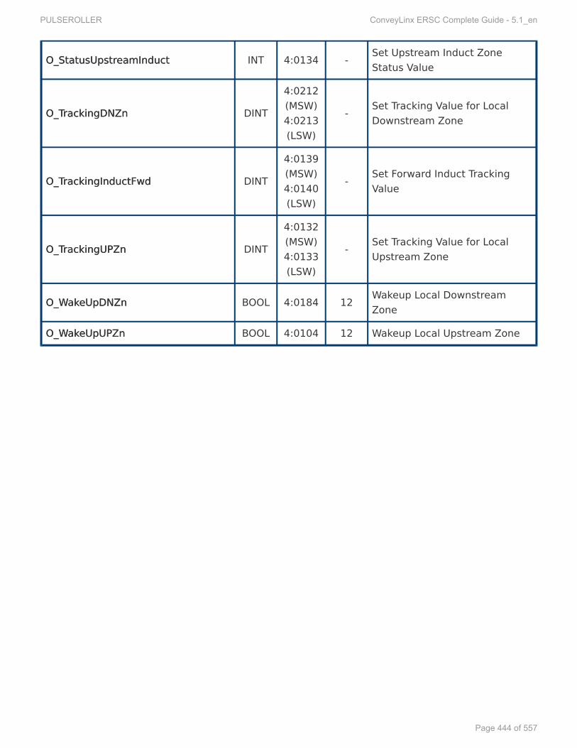
O_StatusUpstrO_StatusUpstreamInducteamInduct INT 4:0134 - Set Upstream Induct ZoneStatus Value
O_TO_TrackingDNZnrackingDNZn DINT
4:0212(MSW)4:0213(LSW)
- Set Tracking Value for LocalDownstream Zone
O_TO_TrackingInductFwdrackingInductFwd DINT
4:0139(MSW)4:0140(LSW)
- Set Forward Induct TrackingValue
O_TO_TrackingUPZnrackingUPZn DINT
4:0132(MSW)4:0133(LSW)
- Set Tracking Value for LocalUpstream Zone
O_WO_WakakeUpDNZneUpDNZn BOOL 4:0184 12 Wakeup Local DownstreamZone
O_WO_WakakeUpUPZneUpUPZn BOOL 4:0104 12 Wakeup Local Upstream Zone
PULSEROLLER ConveyLinx ERSC Complete Guide - 5.1_en
Page 444 of 557

13.5.1.3.13.5.1.3. PLC I/O Mode InputsPLC I/O Mode Inputs
TTag Nameag Name DataDataTTypeype
ModuleModuleRRegisteregister BitBit DescriptionDescription
I_ContrI_ControlPolPortPortPin3_Lin3_Lefeftt BOOL 4:0019 1 Port Inputs
I_ContrI_ControlPolPortPortPin3_Rightin3_Right BOOL 4:0035 3 Port Inputs
I_ContrI_ControlPolPortPortPin4_Lin4_Lefeftt BOOL 4:0035 5 Port Inputs
I_ContrI_ControlPolPortPortPin4_Rightin4_Right BOOL 4:0035 7 Port Inputs
I_ConveyStopByLI_ConveyStopByLefeftContrtControlPolPortort BOOL 4:0019 8 ConveyStop
I_ConveyStopByLI_ConveyStopByLostConnectionostConnection BOOL 4:0019 6 ConveyStop
I_ConveyStopByPLCDisconnectI_ConveyStopByPLCDisconnect BOOL 4:0019 7 ConveyStop
I_ConveyStopByPLCCmdI_ConveyStopByPLCCmd BOOL 4:0019 10 ConveyStop
I_ConveyStopByRI_ConveyStopByRemoteModuleemoteModule BOOL 4:0019 5 ConveyStop
I_ConveyStopByRightContrI_ConveyStopByRightControlPolPortort BOOL 4:0019 9 ConveyStop
I_DigitalMtrOverCurI_DigitalMtrOverCurrrent_Lent_Lefeftt BOOL 4:0060 14 Left Motor Port as Digital
I_DigitalMtrOverCurI_DigitalMtrOverCurrrent_Rightent_Right BOOL 4:0084 14 Right Motor Port as Digital
I_DigitalMtrShortCkt_LI_DigitalMtrShortCkt_Lefeftt BOOL 4:0060 12 Left Motor Port as Digital
I_DigitalMtrtShortCkt_RightI_DigitalMtrtShortCkt_Right BOOL 4:0084 12 Right Motor Port as Digital
I_DownstrI_DownstreamModuleStatuseamModuleStatus SINT 4:0232 Lo Byte Module Status
I_HeartbeatI_Heartbeat BOOL 4:0035 15 Port Inputs
I_ModuleEnabledI_ModuleEnabled BOOL - - Module Status
I_ModuleVI_ModuleVoltageoltage REAL 4:0024 - Module Status
I_MtrCurI_MtrCurrrent_Lent_Lefeftt REAL 4:0055 - Left Motor Status
I_MtrCurI_MtrCurrrent_Rightent_Right REAL 4:0079 - Right Motor Status
I_MtrFI_MtrFrreq_Leq_Lefeftt INT 4:0056 - Left Motor Status
I_MtrFI_MtrFrreq_Righteq_Right INT 4:0080 - Right Motor Status
These tags arThese tags are fore for AAOIOI filefile ERSCERSC_PLCIO_427_507.L5X_PLCIO_427_507.L5X*
PULSEROLLER ConveyLinx ERSC Complete Guide - 5.1_en
Page 445 of 557

I_MtrRI_MtrRunningCCW_LunningCCW_Lefeftt BOOL 4:0058 AOILogic Left Motor Status
I_MtrRI_MtrRunningCCW_RightunningCCW_Right BOOL 4:0082 AOILogic Right Motor Status
I_MtrRI_MtrRunningCW_LunningCW_Lefeftt BOOL 4:0058 AOILogic Left Motor Status
I_MtrRI_MtrRunningCW_RightunningCW_Right BOOL 4:0082 AOILogic Right Motor Status
I_MtrStatus_LI_MtrStatus_Lefeftt INT 4:0058 - Left Motor Status
I_MtrStatus_RightI_MtrStatus_Right INT 4:0082 - Right Motor Status
I_SensorDetectLI_SensorDetectLefeftPtPortort BOOL 4:0036 1 Sensor Port Status
I_SensorDetectRightPI_SensorDetectRightPortort BOOL 4:0036 0 Sensor Port Status
I_SensorPI_SensorPortPortPin3_Lin3_Lefeftt BOOL 4:0035 0 Port Inputs
I_SensorPI_SensorPortPortPin3_Rightin3_Right BOOL 4:0035 2 Port Inputs
I_SensorPI_SensorPortPortPin4_Lin4_Lefeftt BOOL 4:0035 4 Port Inputs
I_SensorPI_SensorPortPortPin4_Rightin4_Right BOOL 4:0035 6 Port Inputs
I_ServoCmdStatus_LI_ServoCmdStatus_Lefeftt BOOL 4:0011 2 Left Servo Function
I_ServoCmdStatus_RightI_ServoCmdStatus_Right BOOL 4:0016 2 Right Servo Function
I_ServoLastCmdComplete_LI_ServoLastCmdComplete_Lefeftt BOOL 4:0011 0 Left Servo Function
I_ServoLastCmdComplete_RightI_ServoLastCmdComplete_Right BOOL 4:0016 0 Right Servo Function
I_ServoPI_ServoPosition_Losition_Lefeftt INT 4:0062 - Left Servo Function
I_ServoPI_ServoPosition_Rightosition_Right INT 4:0086 - Right Servo Function
I_ServoRI_ServoResetStatus_LesetStatus_Lefeftt BOOL 4:0011 1 Left Servo Function
I_ServoRI_ServoResetStatus_RightesetStatus_Right BOOL 4:0016 1 Right Servo Function
I_TI_TemperaturemperatureCalculated_LeCalculated_Lefeftt SINT 4:0057 Hi Byte Left Motor Status
I_TI_TemperaturemperatureCalculated_RighteCalculated_Right SINT 4:0081 Hi Byte Right Motor Status
I_TI_TemperaturemperatureOnBoareOnBoard_Ld_Lefeftt SINT 4:0057 Lo Byte Left Motor Status
I_TI_TemperaturemperatureOnBoareOnBoard_Rightd_Right SINT 4:0081 Lo Byte Right Motor Status
I_UpstrI_UpstreamModuleStatuseamModuleStatus SINT 4:0134 Lo Byte ZPA Status
PULSEROLLER ConveyLinx ERSC Complete Guide - 5.1_en
Page 446 of 557

I_UpstrI_UpstreamTeamTrackingracking DINT
4:0139(MSW)4:0140(LSW)
- ZPA Tracking
PULSEROLLER ConveyLinx ERSC Complete Guide - 5.1_en
Page 447 of 557

13.5.1.4.13.5.1.4. PLC I/O Mode OutputsPLC I/O Mode Outputs
TTag Nameag Name DataDataTTypeype
ModuleModuleRRegisteregister BitBit DescriptionDescription
O_BrakO_BrakeMethod_LeMethod_Lefeftt SINT 4:0261 LoByte Left Motor Control
O_BrakO_BrakeMethod_RighteMethod_Right SINT 4:0271 LoByte Right Motor Control
O_ClearMotorErO_ClearMotorErrroror BOOL 4:0022 Motor Control
O_ContrO_ControlPolPortOutput_LortOutput_Lefeftt BOOL 4:0037 1 Left Motor Control
O_ContrO_ControlPolPortOutput_RightortOutput_Right BOOL 4:0037 3 Right Motor Control
O_ContrO_ControlPolPortPortPin3Mask_Lin3Mask_Lefeftt BOOL 4:0034 1 Sensor/Control PortConfiguration
O_ContrO_ControlPolPortPortPin3Mask_Rightin3Mask_Right BOOL 4:0034 3 Sensor/Control PortConfiguration
O_ContrO_ControlPolPortPortPin4Mask_Lin4Mask_Lefeftt BOOL 4:0034 5 Sensor/Control PortConfiguration
O_ContrO_ControlPolPortPortPin4Mask_Rightin4Mask_Right BOOL 4:0034 7 Sensor/Control PortConfiguration
O_ConveyStopCommandO_ConveyStopCommand INT 4:0020 ConveyStop
O_DischarO_DischargeTgeTrackingracking DINT
4:0201(MSW)4:0202(LSW)
ZPA Tracking
O_DownstrO_DownstreamStatuseamStatus SINT 4:0196 LoByte ZPA Status
O_EnableModuleO_EnableModule BOOL - - Module Control
O_LO_LefeftMtrDigitalPtMtrDigitalPin3in3 BOOL 4:0060 0 Left Motor Port Digital Control
O_LO_LefeftMtrDigitalPtMtrDigitalPin4in4 BOOL 4:0060 1 Left Motor Port Digital Control
O_LO_LefeftMtrDigitalPtMtrDigitalPin5in5 BOOL 4:0060 2 Left Motor Port Digital Control
These tags arThese tags are fore for AAOIOI filefile ERSCERSC_PLCIO_427_507.L5X_PLCIO_427_507.L5X*
PULSEROLLER ConveyLinx ERSC Complete Guide - 5.1_en
Page 448 of 557

O_MtrAO_MtrAccel_Lccel_Lefeftt INT 4:0043 Left Motor Control
O_MtrAO_MtrAccel_Rightccel_Right INT 4:0067 Right Motor Control
O_MtrDecel_LO_MtrDecel_Lefeftt INT 4:0044 Left Motor Control
O_MtrDecel_RightO_MtrDecel_Right INT 4:0068 Right Motor Control
O_RightMtrDigitalPO_RightMtrDigitalPin3in3 BOOL 4:0084 0 Right Motor Port DigitalControl
O_RightMtrDigitalPO_RightMtrDigitalPin4in4 BOOL 4:0084 1 Right Motor Port DigitalControl
O_RightMtrDigitalPO_RightMtrDigitalPin5in5 BOOL 4:0084 2 Right Motor Port DigitalControl
O_Mtr_RO_Mtr_Run_Lun_Lefeftt BOOL 4:0260 0 Left Motor Control
O_Mtr_RO_Mtr_Run_Rightun_Right BOOL 4:0270 0 Right Motor Control
O_Mtr_Dir_LO_Mtr_Dir_Lefeftt BOOL 4:0260 8 Left Motor Control
O_Mtr_Dir_RightO_Mtr_Dir_Right BOOL 4:0270 8 Right Motor Control
O_Mtr_Slave_Mode_LO_Mtr_Slave_Mode_Lefeftt SINT 4:0260 HiByte Left Motor Control
O_Mtr_Slave_Mode_RightO_Mtr_Slave_Mode_Right SINT 4:0260 HiByte Right Motor Control
O_SensorPO_SensorPortPortPin3Mask_Lin3Mask_Lefeftt BOOL 4:0034 0 Sensor/Control PortConfiguration
O_SensorPO_SensorPortPortPin3Mask_Rightin3Mask_Right BOOL 4:0034 2 Sensor/Control PortConfiguration
O_SensorPO_SensorPortPortPin4Mask_Lin4Mask_Lefeftt BOOL 4:0034 4 Sensor/Control PortConfiguration
O_SensorPO_SensorPortPortPin4Mask_Rightin4Mask_Right BOOL 4:0034 6 Sensor/Control PortConfiguration
O_ServoCmdPO_ServoCmdPulses_Lulses_Lefeftt INT 4:0008 Left Servo Function
O_ServoCmdPO_ServoCmdPulses_Rightulses_Right INT 4:0013 Right Servo Function
O_ServoGoCmd_LO_ServoGoCmd_Lefeftt BOOL 4:0009 1 Left Servo Function
O_ServoGoCmd_RightO_ServoGoCmd_Right BOOL 4:0014 1 Right Servo Function
O_ServoZerO_ServoZero_Lo_Lefeftt BOOL 4:0009 0 Left Servo Function
PULSEROLLER ConveyLinx ERSC Complete Guide - 5.1_en
Page 449 of 557

O_ServoZerO_ServoZero_Righto_Right BOOL 4:0014 0 Right Servo Function
O_LO_LefeftMtrDigital_EnabletMtrDigital_Enable BOOL 4:0060 15 Left Motor Port Digital Control
O_RightMtrDigital_EnableO_RightMtrDigital_Enable BOOL 4:0084 15 Right Motor Port DigitalControl
O_SpeedMethod_LO_SpeedMethod_Lefeftt SINT 4:0262 LoByte Left Motor Control
O_SpeedMethod_RightO_SpeedMethod_Right SINT 4:0272 LoByte Right Motor Control
O_SpeedRO_SpeedRefereference_Lence_Lefeftt INT 4:0040 Left Motor Control
O_SpeedRO_SpeedRefereference_Rightence_Right INT 4:0064 Right Motor Control
O_UpstrO_UpstreamStatuseamStatus SINT 4:0116 LoByte ZPA Status
O_LO_LefeftMtrDigital_BraktMtrDigital_BrakePePinEnable_NoDinEnable_NoD BOOL 4:0060 7 Enable the Left Motor PortBrake pin digital output
O_LO_LefeftMtrDigital_BraktMtrDigital_BrakePePinin BOOL 4:0060 6 Left Motor Brake Pin DigitalControl
O_LO_LefeftMtrDigital_ClearOCtMtrDigital_ClearOC BOOL 4:0060 8 Left Motor Digital Clear Over-current Error
O_RightMtrDigital_BrakO_RightMtrDigital_BrakePePinEnable_NoDinEnable_NoD BOOL 4:0084 7 Enable the Right Motor PortBrake pin digital output
O_RightMtrDigital_BrakO_RightMtrDigital_BrakePePinin BOOL 4:0084 6 Right Motor Brake Pin DigitalControl
O_RightMtrDigital_ClearOCO_RightMtrDigital_ClearOC BOOL 4:0084 8 Right Motor Digital Clear Over-current Error
PULSEROLLER ConveyLinx ERSC Complete Guide - 5.1_en
Page 450 of 557

13.6.13.6. Using LUsing Logix 5000 MSG Instructionogix 5000 MSG InstructionAccess to ConveyLinx ERSC modules is also available utilizing the Logix 5000 MSGMSG instruction.The MSGMSG instruction utilizes CIP Explicit Messaging. This means that the connection is notmaintained as an implicit connection. Generic Ethernet Module and EDS connections areimplicit and thus must be maintained at all times or there will be a communication fault.Explicit Messaging opens the connection, reads/writes data, and then closes the connectionthus freeing up communications resources for the PLC.
When to useWhen to use MSGMSG InstructionsInstructions
Because the MSGMSG instruction is executed asynchronous to program scan and is not subject toimplicit messaging RPI restrictions; the response time between requesting data and receivingdata is not deterministic and can vary between separate requests for the same data from thesame device. Therefore, we rwe recommend thatecommend that MSGMSG instructions should not be used for dedicatedinstructions should not be used for dedicated““rreal time” contreal time” control of equipmentol of equipment. For ConveyLinx ERSC modules, MSGMSG instructions are intendedto gather “low priority” status information and/or to send infrequent parameter changes.Please note that this is only a recommendation. Your particular application’s specifics, PLC’scapacity, available network bandwidth, etc. may allow you to get expected results with “realtime” control utilizing MSGMSG instructions to interface with ERSC modules.
Module VS. Assembly AModule VS. Assembly Addrddresses withesses with MSGMSG InstructionInstruction
Module Addresses are the 512 “actual” registers in the module and and Assemblies are“virtual” registers grouped based upon function. There are certain restrictions on what you cando with a MSG Instruction:
• You can us a single MSG instruction to rreadead one and up to 30 consecutive Moduleregisters
• You can use a single MSG instruction to writewrite to one (an only one) of the Module registers• You can use a single MSG instruction to rreadead any of the available Input AssemblyInput Assembly registers
in their entirety• You CANNOTCANNOT use any MSG instruction to writewrite to any Output AssemblyOutput Assembly registers.
PULSEROLLER ConveyLinx ERSC Complete Guide - 5.1_en
Page 451 of 557

13.6.1.13.6.1. RRead MSG Instructionead MSG InstructionFor this example, we have created an ERSC module in our Ethernet Tree and added a MSGInstruction to a ladder rung. We named this MSG block “ReadStatus” and created the ControllerTag for it. With this MSG Instruction we are going to read Module Address 4:0088 and 4:0089which are Module Status Word 1 and 2. We also created a Controller Tag of data type DINT wenamed “TempDiagStatus” to hold this data. Data from 4:0088 will be in the High Word of theDINT and 4:0089 will be in the low word of the DINT.
From the Message Type drop down, select CIP Generic
From the Service Type drop down, select Get Attribute Single
For the Instance Field, enter “88”
PULSEROLLER ConveyLinx ERSC Complete Guide - 5.1_en
Page 452 of 557

For the Class Field, enter “64”
For the Attribute Field, enter “2” because we want to read 4:0088 and 4:0089
For the Destination Element, use the Tag Browser drop down to select TempDiagStatus
PULSEROLLER ConveyLinx ERSC Complete Guide - 5.1_en
Page 453 of 557

13.6.2.13.6.2. WWrite MSG Instructionrite MSG InstructionFor this example, we have created an ERSC module in our Ethernet Tree and added a MSGInstruction to a ladder rung. We named this MSG block “WriteSpeed” and created the ControllerTag for it. With this MSG Instruction we are going to write a value for the Left Motor Speed atModule Address 4:0040. We also created a Controller Tag of data type INT we named“NewSpeed” which will hold the speed value we want to write to the module when we executethe MSG Instruction.
From the Message Type drop down, select CIP Generic
From the Service Type drop down, select Set Attribute Single
For the Instance Field, enter “40”
PULSEROLLER ConveyLinx ERSC Complete Guide - 5.1_en
Page 454 of 557

For the Class Field, enter “64”
For the Attribute Field, enter “1”
For the Source Element, use the Tag Browser drop down to select NewSpeed
For the Source Length, enter “2” (2 bytes = 1 INT)
PULSEROLLER ConveyLinx ERSC Complete Guide - 5.1_en
Page 455 of 557

13.6.3.13.6.3. RReading ERSC Input Assembly witheading ERSC Input Assembly withMSG InstructionMSG Instruction
For this example, we have created an ERSC module in our Ethernet Tree and added a MSGInstruction to a ladder rung. We named this MSG block “ReadZPA” and created the ControllerTag for it. With this MSG Instruction we are going to read all 21 registers from PLC Inputs forZPA Mode. We also created a Controller Tag called “ZPA_Inputs” which is an INT array of 21elements in order to hold the data.
This functionality is only available in firmware versions 4.25 and higher!
When reading any input Assembly with a MSG Instruction, be sure you create theDestination Element Controller Tag an array of INT with the number of elementsthat match the number of registers in the Assembly*
PULSEROLLER ConveyLinx ERSC Complete Guide - 5.1_en
Page 456 of 557

From the Message Type drop down, select CIP Generic
From the Service Type drop down, select Get Attribute Single
For the Instance Field, enter “105” which is the Assembly vale for the ZPA Mode inputs
For the Class Field, enter “4”
For the Attribute Field, enter “3”
For the Destination Element, use the Tag Browser drop down to select ZPA_Inputs andexpand to select the [0] element
PULSEROLLER ConveyLinx ERSC Complete Guide - 5.1_en
Page 457 of 557

13.7.13.7. EDS Module Data TEDS Module Data Type Crype CrossossRRefereferenceenceWhen you create an instance of a device from an EDS file in your RSLogix 5000 environment;the EDS file provides a Module Defined Data Type for the inputs and outputs of the device. ThisModule Defined Data Type’s name is automatically generated by the EDS file creation’ssoftware and is based upon (among other things) a checksum of the items in the file. This oftencreates a somewhat cryptic alpha-numeric string for the name.
In situations where you may inherit an existing program and your RSLogix 5000 environment ismissing the EDS file used for this program; you will need to determine which version of EDS filewas used and then go find it on our Pulseroller.com web site. Similarly, you may also have thesituation where you need to be able to match your AOI version to its correct EDS file. Thefollowing chart cross references the most common EDS files, AOI files, and Module Data Types
EDSEDS FFileile AAOIOI FFileile FFirirmwarmwaree Module Data TModule Data Typeype
ConveyLinx_ZPA_Instance_1.eds ERSC_ZPA_424.L5X 4.24 andolder
_055C:ERSC_ZPA_84EED4D3:I:0
_055C:ERSC_ZPA_FB496954:O:0
ConveyLinx_PLC_IO_Instance_1.eds ERSC_PLCIO_424.L5X 4.24 andolder
_055C:ERSC_PLCIO_C92675D8:I:0
_055C:ERSC_PLCIO_7DDD1BFA:O:0
ConveyLinx_V5_4.eds
ERSC_ZPA_5_2.L5X4.25 /
5.02 andnewer
_055C:ERSC_84EED4D3:I:0
_055C:ERSC_3015BAF1:O:0
ERSC_PLCIO_5_2.L5X4.25 /
5.02 andnewer
_055C:ERSC_C92675D8:I:0
_055C:ERSC_7DDD1BFA:O:0
ConveyLinx_V5_6.eds
ERSC_ZPA_425_5xx.L5X4.25 /
5.02 andnewer
_055C:ERSC_84EED4D3:I:0
_055C:ERSC_3015BAF1:O:0
ERSC_PLCIO_425_5xx.L5X4.25 /
5.02 andnewer
_055C:ERSC_C92675D8:I:0
_055C:ERSC_7DDD1BFA:O:0
ConveyLinx_ZPA_Instance.eds ERSC_ZPA_424.L5X 4.24 andolder
_055C:ERSC_ZPA_84EED4D3:I:0
_055C:ERSC_ZPA_FB496954:O:0
ConveyLinx_PLC_IO_Instance.eds ERSC_PLCIO_424.L5X 4.24 andolder _055C:ERSC_PLCIO_C92675D8:I:0
PULSEROLLER ConveyLinx ERSC Complete Guide - 5.1_en
Page 458 of 557

_055C:ERSC_PLCIO_7DDD1BFA:O:0
For versions or Module Data Types not shown, please [email protected]*
PULSEROLLER ConveyLinx ERSC Complete Guide - 5.1_en
Page 459 of 557

14.14. Connecting to Siemens PLC withConnecting to Siemens PLC withPPrrofinet IOofinet IO
S7 PLCs from Siemens can use ConveyLinxConveyLinx modules because they support PROFINETPROFINET IOIOcommunication protocol and can act as PROFINET IO-devices with the S7 PLC acting as aPROFINET IO controller. The PLC can connect in different ways to the same ConveyLinxConveyLinx modulebased upon how you want to use it. Each of these different ways that the PLC can connect to agiven module is called a Device ADevice Access Pccess Point (oint (DDAPAP)). For a given ConveyLinxConveyLinx module type orfamily, your PLC programming environment needs a GSDMLGSDML filefile installed so your environmentcan display each of the DDAPAP’s’s available for that given module type or family. Each ConveyLinxConveyLinxmodule family (ConveyLinx-ERSC, ConveyLinx-Ai, and ConveyLinx-ECO) has their own GSDMLGSDMLfilefile that contains all of its DDAPAP information. Each DDAPAP corresponds to a Mode of OperationMode of Operation of theConveyLinx module.
PPrreparing your Peparing your Prrogramming Envirogramming EnvironmentonmentUnderstanding the ConveyLinx Module’s Modes of OperationUnderstanding the ConveyLinx Module’s Modes of Operation
Device ADevice Access Pccess Points (oints (DDAPAP))The ProfiNet protocol allows for multiple access ways for a single physical device. This is calleda Device ADevice Access Pccess Pointoint or DDAPAP. In essence each DAP allows the PLC to connect to the samephysical device in a different way from the other DAPs for that device. The number of DAPs adevice supports is vendor specific so every manufacturer decides how many access ways toprovide for their device.
After you install the appropriate GSDMLGSDML file into your programming environment based uponthe ConveyLinx Family you are using, there will be two directories (or folders) of DDAPAPss:
1. Contains the DAPs that are used when you want to use Separate ConveyLinx AutoSeparate ConveyLinx Auto--ConfigurationConfiguration by either Install Button (ConveyLinx-ERSC Family) or by EasyRoll(ConveyLinx-Ai Family and ConveyLinx-ECO)
2. Contains DAPs that are used when you want to use Integrated Configuration DirIntegrated Configuration Direct frect fromomPLCPLC TTopologyopology to detect the topology of your ConveyLinx network and configure all
This section assumes you have a solid working knowledge of both Siemens PLC’sand the TIA Portal or Step7 manager development environments.!
This section applies to all ConveyLinx Family modules. Figures and softwarescreenshots may only show ConveyLinx-Ai Family examples, but the concepts areapplicable to all ConveyLinx modules
!
PULSEROLLER ConveyLinx ERSC Complete Guide - 5.1_en
Page 460 of 557

modules
PULSEROLLER ConveyLinx ERSC Complete Guide - 5.1_en
Page 461 of 557

14.1.14.1. PPrreparing Yeparing Your Pour PrrogrammingogrammingEnvirEnvironmentonmentIn order to use ConveyLinx with your PLC, you need to install the proper configuration filesconfiguration files intoyour TIATIA PPortalortal or STEPSTEP 77 programming environment. The files required will be included in adownloadable .zip ar.zip archive frchive from our site and will include an xml with the filename structurom our site and will include an xml with the filename structuree““GSDMLGSDML--V2.xx-IndustrialSofV2.xx-IndustrialSoftwartware-ConveyLinx-yyyymmdd.xml” and at least 1 bitmap file (e-ConveyLinx-yyyymmdd.xml” and at least 1 bitmap file (.bmp)with the graphic image of the particular module(s) for which the xml file specifies for yourSiemens programming environment.
There are also optional (but highly recommended) User Data TUser Data Type (ype (UDTUDT)) files specific for eachmodule type and Mode of OperationMode of Operation you wish to use.
The files you will need are dependent on the specific Conveylinx module andmodule firmware version you are using.*
PULSEROLLER ConveyLinx ERSC Complete Guide - 5.1_en
Page 462 of 557

14.2.14.2. Modes of OperationModes of OperationWhen installed, ConveyLinx modules can be configured as one of the following 6 basic modes:
FFullull ZPZPAA ModeModen this mode, ConveyLinx works as a one or two zoneone or two zone ZPZPAA contrcontrolleroller. When communicating withmodule in this mode, the S7-300 PLC can control mainly material handling properties such asaccumulation, release, wake-up/full stop, read/write tracking, MDR parameters (speed,acceleration and deceleration), and ConveyStop. In this mode the PLC does not have access todirectly control start/stop of MDRs because internal ZPA logic is operating the module. Whencommunicating with ConveyLinx in ZPA mode, the PLC does not require fast reaction time aswould be expected for a remote I/O device. Typically, 32 ms to 256 ms is the range of responsetime utilized between the PLC and a ConveyLinx module in ZPA mode. The data array instancelengths for input and output data mode are 64 bytes.
RReducededuced ZPZPAA ModeModeIn this mode, the ConveyLinx modules operates as a one or two zoneone or two zone ZPZPAA contrcontrolleroller just like theFull ZPA Mode. However, the instance data presented to the S7-300 PLC is limited to basicmaterial handling properties such as accumulation, release, wake-up/full stop, and MDR speed.In this mode, because the instances length is reduced to 30 bytes; the PLC may be able toaccommodate more modules especially in applications where all ZPA features (such astracking) are not required. Similarly to the Full ZPA Mode, the 32 ms to 256 ms response time istypical for this mode.
MerMerger Modeger ModeIn this mode, the module is running in ZPZPAA modemode and exchanging 64 bytes of data with the PLC.In addition to the ZPA logic, the module now runs the Merger task on one of their zones.Configuring the Merger zone, differs between the two configuration methods (see Configurationmethods chapter). Similarly to the Full ZPA Mode, the 32 ms to 256 ms response time is typicalfor this mode. The exchanged data is the same as for the Full ZPA mode.
FFullull PLCPLC ContrControlled Modeolled ModeIn this mode, the ConveyLinx module is placed into PLCPLC I/O modeI/O mode with the EasyRoll softwaretool. When the module is in PLC I/O mode, all interall internalnal ZPZPAA logic is suspendedlogic is suspended and the modulerequires an external PLC to read port inputs and run/stop MDRs connected to the module. ThePLC contains any and all logic to process inputs from sensor/control ports, run stop MDRs, setdirection/speed/accel/decel of MDRs, and more. Also, in this mode the PLC has access toregisters in the PLC I/O module that can interface to neighboring ZPA modules for material
PULSEROLLER ConveyLinx ERSC Complete Guide - 5.1_en
Page 463 of 557

handling control and tracking data support. A ConveyLinx module in PLC I/O mode is alsocapable of Servo functionsServo functions that are made available to the PLC. In this mode, the ConveyLinxmodule responds as would be expected for a remote I/O device. ConveyLinx will connect to thePLC with a 4 ms communication response time. The data array instance lengths for input andoutput data in this mode are 64 bytes.
RReducededuced PLCPLC ContrControlled Modeolled ModeIn this mode, the ConveyLinx module is configured and operates withoutwithout ZPZPAA logiclogic the same asit does in Full PLC Controlled Mode. However in this mode, only port I/O and MDR run/stop/speed functions are available to the PLC. In this mode, because the instances length isreduced; the PLC may be able to accommodate more modules especially in applications whereall the features in Full PLC Controlled Mode are not required. ConveyLinx modules in this modecommunicate at the same 4 ms response time as the Full PLC Controlled Mode. The data arrayinstance lengths for input and output data in this mode are 16 bytes
PLCPLC ContrControlled Mode with ConveyLolled Mode with ConveyLogix Pogix PrrogramogramIn this mode, the ConveyLinx module has been programmed with ConveyLogix and thisprogram is running inside. ConveyLogix allows you to write your own programs and download itto the ConveyLinx module turning it into a small PLC. The ToPLCArray(WORD [16] ) andFromPLCArray(WORD [16]) are exchanged with the PLC. What data is exchanged in those dataarrays, is programmed by the engineer in the ConveyLogix program and in the PLC. Thecommunication response time should be adjusted by the programmer, based on the size andcomplexity of the ConveyLogix program. The bigger it is, the higher update speeds should beselected.
PULSEROLLER ConveyLinx ERSC Complete Guide - 5.1_en
Page 464 of 557

14.3.14.3. Understanding the TUnderstanding the Two Configurationwo ConfigurationMethodsMethods
In general, a network of ConveyLinx modules must be AutoAuto-Configur-Configureded before they can worktogether in ZPA mode or exchange any data with each other when in PLC I/O mode. The typicalmethod is to utilize the Install ButtonInstall Button (on ERSC family modules) or EasyREasyRolloll (for ConveyLinx-AiFamily and ConveyLinx-ECO). When you use Siemens S7 PLCs and TIA Portal or Step 7 Manager,you can have the ConveyLinx modules automatically configurconfigured fred from theom the PLCPLC based upon thebased upon thetopologytopology you create at design time in your Siemens PLC programming environment.
Separate ConveyLinx AutoSeparate ConveyLinx Auto-Configuration-ConfigurationWhen using this method, the configuration of a module or group of modules is initiated with theInstall ButtonInstall Button or EasyREasyRolloll software. All of the module parameters such as motor modes(ECO/BOOST etc.), module mode (PLC/ZPA), inter-module connections, Merger zone, IPaddresses and all other general parameters are assigned during the AutoAuto-Configuration-Configurationprocedure. The Profinet name is formed by the module during the Auto-Configuration procedureas well. In order write your program in the PLC, you will need to know the eyou will need to know the exact Pxact Prrofinet nameofinet nameof each module you wish to connect and you do not have the fleof each module you wish to connect and you do not have the flexibility to change these names.xibility to change these names.
AAdvantages of Separate ConveyLinx Autodvantages of Separate ConveyLinx Auto-Configuration-Configuration
* Changing parameters like motor settings, ZPA functionality, etc. can be donefor multiple modules all at once with EasyRoll* Your PLC only has to connect to modules it needs to interface with and notevery module in the network* ZPA Extension function is able to be configured
Disadvantages to Separate ConveyLinx AutoDisadvantages to Separate ConveyLinx Auto-Configuraton:-Configuraton:
* Profinet name of the module is set during Auto-Configuration and cannot bemodified* Your PLC must use the exact syntax of the module’s Profinet name in order toconnect* You have to know in advance your exact network topology and I.P. addressingprior to programming your PLC
Before going further, you will need to decide which of these two methods you aregoing to use!!
PULSEROLLER ConveyLinx ERSC Complete Guide - 5.1_en
Page 465 of 557

Integrated Configuration DirIntegrated Configuration Direct frect fromom PLCPLC TTopologyopology
When using this method, you create your network topology within the Siemens PLCprogramming environment (TIA Portal or STEP 7). All pertinent module parameters becomeavailable within your environment and can be configured at design time. As long as yourphysical installed network topology of control modules matches your designed topology in yourPLC programming environment; when you download your project to your PLC, the PLC takescare of all of the ConveyLinx control module configuration.
AAdvantages of Configuration frdvantages of Configuration fromom PLCPLC TTopologyopology::
* No module naming restrictions* No need to use separate EasyRoll software* Module replacement is true plug and play because PLC handles the procedure* All module parameters are integrated into the Siemens PLC programmingenvironment
Disadvantages to Configuration frDisadvantages to Configuration fromom PLCPLC TTopologyopology::
* You have to include all ConveyLinx modules in your topology regardless ofwhether you need to interact with them with your PLC logic for your system* No built in ability to change parameters for multiple modules at the sametime; you have to construct own PLC logic to do this* ZPA Extension function is not available
This method is only available for ConveyLinx-ERSC Family for 4 series firmware4.27 and higher and 5 series firmware 5.03 and higher!
PULSEROLLER ConveyLinx ERSC Complete Guide - 5.1_en
Page 466 of 557

14.4.14.4. Separate ConveyLinx AutoSeparate ConveyLinx Auto--ConfigurationConfiguration
AAdding ConveyLinx Modules to Ydding ConveyLinx Modules to Your Pour PrrojectojectOnce you have installed the GSDXMLGSDXML file into your environment, ConveyLinx devices areavailable to be used in your project. You can find ConveyLinx devices in the HarHardwardware Cataloge Catalogwindow
Drill down the treestructure to get to the
folder Conveyor ContrConveyor Contrololwith EasyRwith EasyRoll configurationoll configuration
to see the available DAPs
This section applies ONLY when you use Separate ConveyLinx Auto-Configuration(EasyRoll or ConveyLinx module Install button)!
The Mode of OperationMode of Operation of a given ConveyLinx module will determine which of theDDAPAPss to drag and drop from the HarHardwardware Cataloge Catalog window into your project*
PULSEROLLER ConveyLinx ERSC Complete Guide - 5.1_en
Page 467 of 557

14.4.1.14.4.1. PPrrofinet Nameofinet NameWhen ConveyLinx modules are AutoAuto-Configur-Configureded from either EasyREasyRolloll or by Install buttonInstall button, eachmodule automatically generates its own specific PPrrofinet Namesofinet Names each with an eexact syntaxxact syntax thatcorresponds to the Mode of OperationMode of Operation (ZPZPAA or PLCPLC I/OI/O) determined during Auto-Configuration. Ifyou performed Auto-Configuration with an Install button, each module defaults to ZPZPAA ModeModeand the ZPZPAA PPrrofinet Namesofinet Names will be automatically generated. If you use EasyREasyRolloll to change amodule from ZPA to PLCPLC I/O ModeI/O Mode, the PPrrofinet Namesofinet Names are automatically updated for PLCPLC I/OI/OModeMode
The following chart shows the exact syntax for Profinet Names:
ModeMode SyntaxSyntax RRemarksemarks
Full ZPA conveylinxzpa-xxx-yyy xxx = 3rd Octet
of I.P. Address
yyy = 4th Octetof I.P. Address
Reduced ZPA
Full PLCControlled conveylinxplc-
xxx-yyyReduced PLCControlled
With ConveyLinx Auto-Configured modules, you cannot change the ProfinetName in the module and you MUST use the EXACT Profinet Name in yourSiemens programming environment in order to communicate with a givenmodule.
!
Please do not confuse the module’s General NameGeneral Name or PPrroject Nameoject Name that youassign for a given device with its PPrrofinet Nameofinet Name. The PPrrofinet Nameofinet Name is required tobe in the proper syntax or the module will not connect to the PLC. The module’sPPrroject Nameoject Name is completely user’s choice to identify the module in the yourSiemens programming environment and is what is displayed in your project’sNetwork View(s) and Project Tree.
*
PULSEROLLER ConveyLinx ERSC Complete Guide - 5.1_en
Page 468 of 557

14.4.2.14.4.2. Examples of AExamples of Adding Modulesdding ModulesIn this section we will provide an example that will add a single module of each Mode to aproject. This will require a combination of selecting the proper DDAPAP from the Hardware catalogcoupled with using the correct PPrrofinet Nameofinet Name to achieve our desired result. The following chartlists the 6 modules we want to add to our project and the proper Device and Profinet Namesyntax needed.
ModuleModuleModeMode I.PI.P. A. Addrddressess
DDAPAP frfromomHarHardwardwareeCatalogCatalog
PPrrofinet Nameofinet Name
Full ZPA 192.168.0.20 ConveyLinx-Ai conveylinxzpa-0-20
Full PLCControlled 192.168.101.21 ConveyLinx-Ai conveylinxplc-101-21
ReducedZPA 192.168.101.22
ConveyLinx-Ai inreduced ZPAmode
conveylinxzpa-101-22
ReducedPLCControlled
192.168.20.123ConveyLinx-Ai inreduced PLCmode
conveylinxplc-20-123
Full ZPA withMerger 192.168.0.21 ConveyLinx-Ai conveylinxzpa-0-21
ConveyLogixInterface 192.168.0.22
ConveyLinx-Ai inPLC mode withConveyLogix
conveylogix-0-22
The following sections will show the details of adding each of these items to youTIA Portal environment*
PULSEROLLER ConveyLinx ERSC Complete Guide - 5.1_en
Page 469 of 557

14.4.2.1.14.4.2.1. FFull ZPull ZPAASTEPSTEP 1: A1: Add the Module to thedd the Module to the PLCPLC NetworkNetwork
From the CatalogCatalog window,drag and drop the
ConveyLinx-AiConveyLinx-Ai DAP intothe Network VNetwork Viewiew window
To attach the module tothe PLC, click on the NotAssigned link and select
the desired ProfinetInterface of the PLC
When attached, you willsee the green graphic
linking the PLC and themodule together
PULSEROLLER ConveyLinx ERSC Complete Guide - 5.1_en
Page 470 of 557

STEPSTEP 2: Assign the2: Assign the EXAEXACTCT PPrrofinet Name to the Moduleofinet Name to the Module
In the PPrroject Toject Trreeee locateyour newly created
module under theUngrUngrouped devicesouped devices folder.
Right Click on your moduleto show a pop-up menu
and select PPrropertiesoperties
A new window will open.Select GeneralGeneral from themenu on the left. In the
NameName field enter therequired name for the
device. In our example it isconveylinxzpa-0-20 from
the Example Table
Type in the EXAEXACTCT ProfinetName and press enter to
make the change
PULSEROLLER ConveyLinx ERSC Complete Guide - 5.1_en
Page 471 of 557

STEPSTEP 3: Enter the I.P3: Enter the I.P. A. Addrddressess
In the same propertiesarea that you changed the
PPrrofinet Nameofinet Name, click onEtherEthernet addrnet addressesesses andenter the I.P. address. In
our example it is192.168.0.20 from the
Example Table
STEPSTEP 4: Select Update T4: Select Update Time Intervalime IntervalIn the same properties
area that you changed thePPrrofinet Nameofinet Name, click onAAdvanced optionsdvanced options andselect a proper UpdateTime. For a ConveyLinx
module in ZPA mode, therecommended Update
time should be between32ms and 512ms.
PULSEROLLER ConveyLinx ERSC Complete Guide - 5.1_en
Page 472 of 557

14.4.2.2.14.4.2.2. FFull PLC Contrull PLC ControlledolledSTEPSTEP 1: A1: Add the Module to thedd the Module to the PLCPLC NetworkNetwork
From the CatalogCatalog window,drag and drop the
ConveyLinx-AiConveyLinx-Ai DAP intothe Network VNetwork Viewiew window
To attach the module tothe PLC, click on the NotAssigned link and select
the desired ProfinetInterface of the PLC
When attached, you willsee the green graphic
linking the PLC and themodule together
STEPSTEP 2: Assign the2: Assign the EXAEXACTCT PPrrofinet Name to the Moduleofinet Name to the ModuleFollow the same STEP 2 as in Full ZPA Example. For this example the correct PPrrofinet Nameofinet Name perour Example Table is conveylinxplc-101-21
STEPSTEP 3: Enter the I.P3: Enter the I.P. A. AddrddressessFollow the same STEP 3 as in Full ZPA Example. For this example the correct I.P. Address perour Example Table is 192.168.101.21
PULSEROLLER ConveyLinx ERSC Complete Guide - 5.1_en
Page 473 of 557

STEPSTEP 4: Select Update T4: Select Update Time Intervalime IntervalFollow the same STEP 4 as in Full ZPA Example. Because this module’s I/O and motors areunder complete PLC control, the fastest Update time of 4ms is recommended.
PULSEROLLER ConveyLinx ERSC Complete Guide - 5.1_en
Page 474 of 557

14.4.2.3.14.4.2.3. RReduced ZPeduced ZPAASTEPSTEP 1: A1: Add the Module to thedd the Module to the PLCPLC NetworkNetwork
From the CatalogCatalog window,drag and drop the
ConveyLinx-Ai in rConveyLinx-Ai in reducededucedZPZPAA modemode DAP into theNetwork VNetwork Viewiew window
To attach the module tothe PLC, click on the NotAssigned link and select
the desired ProfinetInterface of the PLC
When attached, you willsee the green graphic
linking the PLC and themodule together
PULSEROLLER ConveyLinx ERSC Complete Guide - 5.1_en
Page 475 of 557

STEPSTEP 2: Assign the2: Assign the EXAEXACTCT PPrrofinet Name to the Moduleofinet Name to the ModuleFollow the same STEP 2 as in Full ZPA Example. For this example the correct PPrrofinet Nameofinet Name perour Example Table is conveylinxzpa-101-22
STEPSTEP 3: Enter the I.P3: Enter the I.P. A. AddrddressessFollow the same STEP 3 as in Full ZPA Example. For this example the correct I.P. Address perour Example Table is 192.168.101.22
STEPSTEP 4: Select Update T4: Select Update Time Intervalime IntervalFollow the same STEP 4 as in Full ZPA Example. Because this module is in ZPA mode, therecommended Update time to be between 32ms and 512ms.
PULSEROLLER ConveyLinx ERSC Complete Guide - 5.1_en
Page 476 of 557

14.4.2.4.14.4.2.4. RReduced PLCeduced PLCSTEPSTEP 1: A1: Add the Module to thedd the Module to the PLCPLC NetworkNetwork
From the CatalogCatalog window,drag and drop the
ConveyLinx-Ai in rConveyLinx-Ai in reducededucedZPZPAA modemode DAP into theNetwork VNetwork Viewiew window
To attach the module tothe PLC, click on the NotAssigned link and select
the desired ProfinetInterface of the PLC
PULSEROLLER ConveyLinx ERSC Complete Guide - 5.1_en
Page 477 of 557

When attached, you willsee the green graphic
linking the PLC and themodule together
STEPSTEP 2: Assign the2: Assign the EXAEXACTCT PPrrofinet Name to the Moduleofinet Name to the ModuleFollow the same STEP 2 as in Full ZPA Example. For this example the correct PPrrofinet Nameofinet Name perour Example Table is conveylinxplc-20-123
STEPSTEP 3: Enter the I.P3: Enter the I.P. A. AddrddressessFollow the same STEP 3 as in Full ZPA Example. For this example the correct I.P. Address perour Example Table is 192.168.20.123
STEPSTEP 4: Select Update T4: Select Update Time Intervalime IntervalFollow the same STEP 4 as in Full ZPA Example. Because this module’s I/O and motors areunder complete PLC control, the fastest Update time of 4ms is recommended.
PULSEROLLER ConveyLinx ERSC Complete Guide - 5.1_en
Page 478 of 557

14.4.2.5.14.4.2.5. MerMerger Modeger ModeThe MerMergege function is configured in EasyREasyRolloll. Follow the exact same steps as for a Full ZPAmodule to add a module that will eventually be configured as merging zone in EasyREasyRolloll
PULSEROLLER ConveyLinx ERSC Complete Guide - 5.1_en
Page 479 of 557

14.4.2.6.14.4.2.6. PLC ContrPLC Controlled with ConveyLolled with ConveyLogixogixInterfaceInterfaceSTEPSTEP 1: A1: Add the Module to thedd the Module to the PLCPLC NetworkNetwork
From the CatalogCatalog window,drag and drop the
ConveyLinx-Ai inConveyLinx-Ai in PLCPLCmode with ConveyLmode with ConveyLogixogix
DAP into the Network VNetwork Viewiewwindow
To attach the module tothe PLC, click on the NotAssigned link and select
the desired ProfinetInterface of the PLC
PULSEROLLER ConveyLinx ERSC Complete Guide - 5.1_en
Page 480 of 557

When attached, you willsee the green graphic
linking the PLC and themodule together
STEPSTEP 2: Assign the2: Assign the EXAEXACTCT PPrrofinet Name to the Moduleofinet Name to the ModuleFollow the same STEP 2 as in Full ZPA Example. For this example the correct PPrrofinet Nameofinet Name perour Example Table is conveylogix-0-22
STEPSTEP 3: Enter the I.P3: Enter the I.P. A. AddrddressessFollow the same STEP 3 as in Full ZPA Example. For this example the correct I.P. Address perour Example Table is 192.168.0.22
STEPSTEP 4: Select Update T4: Select Update Time Intervalime IntervalFollow the same STEP 4 as in Full ZPA Example. Because this module is running a ConveyLogixprogram, the Update time interval is recommended to be set based upon the CPU usage theConveyLogix program is causing on the module.
CPUCPU Usage and RUsage and Recommended Update Tecommended Update Timesimes
The following table provides the recommended Update times based upon CPU usage of yourConveyLogix program.
The CPU usage on a ConveyLinx module can be viewed when you go on-line withthe ConveyLogix programming software*
PULSEROLLER ConveyLinx ERSC Complete Guide - 5.1_en
Page 481 of 557

CPUCPU UsageUsageMinimumMinimum
RRecommendedecommendedUpdate TUpdate Timeime
< 50% 8ms
50% – 60% 16ms
60% – 70% 32ms
70% – 80% 64ms
80% – 90% 128ms
Using a faster than recommended Update Time may produce unexpected results.!
It is recommended that you do not operate ConveyLinx modules withConveyLogix programs that utilize more that 90% CPU usage. ConveyLinxmodule CPU usages above 90% can result in compromised module performance.
!
PULSEROLLER ConveyLinx ERSC Complete Guide - 5.1_en
Page 482 of 557

14.5.14.5. Integrated PLC TIntegrated PLC TopologyopologyConfigurationConfiguration
AAdding ConveyLinx Modules to Ydding ConveyLinx Modules to Your Pour PrrojectojectOnce you have installed the GSDXMLGSDXML file into your environment, ConveyLinx devices areavailable to be used in your project. You can find ConveyLinx devices in the HarHardwardware Cataloge Catalogwindow
Drill down the treestructure to get to the
folder Conveyor ContrConveyor Contrololwith topology and fullwith topology and full PLCPLC
ConfigurationConfiguration to see theavailable DAPs
This section applies ONLY when you use TIA Portal or STEP 7 Manager Topology toconfigure your ConveyLinx modules!
ConveyLinx-ERSC Family of modules require firmware 5.07 or later for PLCTopology configuration!
The Mode of OperationMode of Operation of a given ConveyLinx module will determine which of theDDAPAPss to drag and drop from the HarHardwardware Cataloge Catalog window into your project*
PULSEROLLER ConveyLinx ERSC Complete Guide - 5.1_en
Page 483 of 557

14.5.1.14.5.1. PPrrofinet Nameofinet NameThere are no module-specific name conventions when you use IntegratedIntegrated PLCPLC TTopologyopologyConfigurationConfiguration from the PLC. The name of the device can be whatever you want. TIA Portal willauto-correct if the name is outside of Profinet limitations.
For users new to ConveyLinx and are familiar with the Siemens platform shouldfind the Integrated PLC Topology Configuration quicker and easier to implement.*Please note that Step7 Manager will not auto-correct if you enter a non-compliant name. A frequent mistake is using upper case letters which are notallowed according to the Profinet standard. TIA Portal will autocorrect upper case,but Step7 Manager will not auto-correct and will eventually result in programerror.
!
PULSEROLLER ConveyLinx ERSC Complete Guide - 5.1_en
Page 484 of 557

14.5.2.14.5.2. AAdding Modulesdding ModulesYou add modules using the exact same procedures as depicted in the Separate ConveyLinxAuto Configuration section. The main difference is that you must use the DAPs created forIntegrated PLC Topology Configuration.
Update TUpdate TimeimeThe DAPs for Integrated PLC Topology Configuration are already pre-configured with the lowestrecommended Update time for the given functionality. This means that you can skip STEP 4when adding your modules.
The Update time willdefault to the CalculateCalculate
update time automaticallyupdate time automaticallysetting. You can always
manually enter a longertime if needed.
PULSEROLLER ConveyLinx ERSC Complete Guide - 5.1_en
Page 485 of 557

14.5.3.14.5.3. TTopology Exampleopology ExampleAn example of a conveyor layout is a great way to illustrate the Integrated PLC TopologyConfiguration method.
ModuleModuleModeMode I.PI.P. A. Addrddressess
DDAPAP frfromomHarHardwardwareeCatalogCatalog
PPrrofinetofinetNameName
Full ZPA 192.168.0.20ConveyLinx-Ai in ZPAmode
feeder
Full ZPA withMerger 192.168.0.21 ConveyLinx-
Ai merger merge
ConveyLogixInterface 192.168.0.22
ConveyLinx-Ai in PLCmode withConveyLogix
divert
Full PLCControlled 192.168.0.23 ConveyLinx-
Ai in PLC workstation
PULSEROLLER ConveyLinx ERSC Complete Guide - 5.1_en
Page 486 of 557

mode
ReducedZPA 192.168.10.20
ConveyLinx-Ai inreduced ZPAmode
spur
ReducedPLCControlled
192.168.15.20
ConveyLinx-Ai inreduced PLCmode
reject
For this example, add these to your network in the same fashion as described earlier in theExamples of Adding Modules section. Because our example is using a switch, you need toselect a Profinet switch from the Catalog. In our example we selected a SCLANCE XF204 fourport switch. Here is a view showing all the items added to our topology including the Profinetswitch and ConveyLinx modules.
ConnectingConnecting PLCPLC and Switchand SwitchTo make a topology connection, click and drag from the small connection square on the PLC toone of the ports on the switch.
PULSEROLLER ConveyLinx ERSC Complete Guide - 5.1_en
Page 487 of 557

PULSEROLLER ConveyLinx ERSC Complete Guide - 5.1_en
Page 488 of 557

14.5.3.1.14.5.3.1. Connecting 1st Subnet of ModulesConnecting 1st Subnet of ModulesClick and drag from one of the Profinet switch ports to the divert ConveyLinx module’s left port.Repeat the process to connect the divert module to the workstation module, and then theworkstation module to the reject module.
When you are done with the 1st subnet of modules, it should look like the following:
PULSEROLLER ConveyLinx ERSC Complete Guide - 5.1_en
Page 489 of 557

14.5.3.2.14.5.3.2. Connecting 2nd Subnet ofConnecting 2nd Subnet ofModulesModulesSame as for the 1st Subnet, click and drag connection from switch to spur module and spurmodule to the right port on the merge module. Connect the left port of the merge module tothe left port of the feeder module.
When you are done with the 2nd subnet of modules, it should look like the following:
Note which port on the merge module is connected to which specific port on itsneighbor modules.*
PULSEROLLER ConveyLinx ERSC Complete Guide - 5.1_en
Page 490 of 557

14.5.4.14.5.4. Module ConfigurationModule ConfigurationWith IntegratedIntegrated PLCPLC TTopology Configurationopology Configuration, you do not need EasyREasyRolloll for initial moduleconfiguration or changing ConveyLinx module parameters. The PLC programming environmentprovides the ability to configure most all the parameters and settings you can access withEasyRoll.
The following sections show the various parameters you have access to for each of the DAPsalong with links to the corresponding EasyRoll explanations of the particular parameter:
ZPA/Reduced ZPA ModesPLC/Reduced PLC ModesMerger ModeConveyLogix Mode
PULSEROLLER ConveyLinx ERSC Complete Guide - 5.1_en
Page 491 of 557

14.5.4.1.14.5.4.1. ZPZPA/RA/Reduced ZPeduced ZPA ModesA ModesGeneralGeneral
There is no equivalent setting in EasyREasyRollollbecause these are determined by the AutoAuto--ConfigurationConfiguration procedure
Set up for master/slave motor rollers in abelted zone. There is no equivalent settingin EasyREasyRolloll
Sensor Debounce setting
Enable/Disable FlexZone operation
Change UpstrUpstreameam ConveyLinx Connection.If you want to perform the EasyREasyRollollequivalent of selecting “None” for theconnection, select the drop down option“Connect the the module with the below IPaddress” and enter “0” for each IP addressoctet.
PULSEROLLER ConveyLinx ERSC Complete Guide - 5.1_en
Page 492 of 557

Change DownstrDownstreameam ConveyLinxConnection. If you want to perform theEasyREasyRolloll equivalent of selecting “None” forthe connection, select the drop downoption “Connect the the module with thebelow IP address” and enter “0” for each IPaddress octet.
PULSEROLLER ConveyLinx ERSC Complete Guide - 5.1_en
Page 493 of 557

14.5.4.1.1.14.5.4.1.1. UpstrUpstream/Downstream/Downstream Zoneseam Zones
Set zone’srelease modeof operation
TimervaluewhenusingGAPTrainRelease
Changethelogicalpolarityof theSensor
ConfigureSensor port toaccept PushPull typesensor
Changemotor’s DefaultRotationDirection
Enable/Disablevarious zoneoptions
Set zone’sMotor Type
PULSEROLLER ConveyLinx ERSC Complete Guide - 5.1_en
Page 494 of 557

Enter desiredMotor Speed
Changemotor’s BrakeMethod
Enter desiredmotor Accel/Decel values
These settings are identical for the Downstream Zone*
PULSEROLLER ConveyLinx ERSC Complete Guide - 5.1_en
Page 495 of 557

14.5.4.1.2.14.5.4.1.2. UpstrUpstream/Downstream/Downstream Zoneeam ZoneTTimingiming
Change zone’s Run After Timer from itsdefault value
Change zone’s Induct Forward and ReverseTimer values
Change zone’s Jam Timer from its defaultvalue
Configure zone’s Look Ahead Slowdownfeature operation
These settings are identical for the Downstream Zone*
PULSEROLLER ConveyLinx ERSC Complete Guide - 5.1_en
Page 496 of 557

14.5.4.1.3.14.5.4.1.3. Connection to MerConnection to Merger Moduleger Module
These settings are only used if this given module is discharging onto another ConveyLinxmodule that is configured as a MerMergerger. In EasyREasyRolloll this operation is performed when connectedto the Merger module’s MerMerge Zonege Zone. The difference here is that you enter the I.P. address ofthe MerMergerger module where the MerMerge Zonege Zone is located. In the EasyREasyRolloll example you areconnected to the MerMergerger module’s MerMerge Zonege Zone and you enter the I.P. address of the ZPAmodule that is feeding the MerMerge Zonege Zone. This function is depicted in an example in theConveyMerConveyMergege section.
PULSEROLLER ConveyLinx ERSC Complete Guide - 5.1_en
Page 497 of 557

14.5.4.2.14.5.4.2. PLC/RPLC/Reduced PLC Modeeduced PLC ModeGeneralGeneral
There is no equivalent setting in EasyREasyRollollbecause these are determined by the AutoAuto--ConfigurationConfiguration procedure
Change UpstrUpstreameam ConveyLinx Connection.If you want to perform the EasyREasyRollollequivalent of selecting “None” for theconnection, select the drop down option“Connect the the module with the below IPaddress” and enter “0” for each IP addressoctet.
Change DownstrDownstreameam ConveyLinxConnection. If you want to perform theEasyREasyRolloll equivalent of selecting “None” forthe connection, select the drop downoption “Connect the the module with thebelow IP address” and enter “0” for each IPaddress octet.
PULSEROLLER ConveyLinx ERSC Complete Guide - 5.1_en
Page 498 of 557

LLefeft / Right Side Configurationt / Right Side Configuration
For PLC mode, this function is not set inEasyREasyRolloll but with populating data in theSet Sensor Port Input Mask register fromthe PLC. When you use IntegratedIntegrated PLCPLCTTopology Configurationopology Configuration, you set thisfunction here and you do not need to writedata from your PLC logic
There is not an equivalent function inEasyRoll
Change motor’s Default Rotation Direction
Set zone’s Motor Type
Enter desired Motor Speed
Change motor’s Brake Method
Enter desired motor Accel/Decel values
These settings are identical for the Right side*
PULSEROLLER ConveyLinx ERSC Complete Guide - 5.1_en
Page 499 of 557

14.5.4.3.14.5.4.3. MerMerger Modeger ModeThe MerMergerger DDAPAP is essentially a FFullull ZPZPAA mode module with an added parameter to configurethe mermergerger. So the General, Upstream/Downstream Zones, and Upstream/Downstream ZoneTiming parameters are the same as previously described.
MerMerger Configurationger Configuration
An example of using these parameters in _*EasyRoll* is shown in section Conventional SpurMerge from the ConveyMerge topic.
For complete information about setting up and using ConveyMerConveyMergege, please referto the ConveyMerge section*
PULSEROLLER ConveyLinx ERSC Complete Guide - 5.1_en
Page 500 of 557

14.5.4.4.14.5.4.4. ConveyLConveyLogix Modeogix ModeThe ConveyLConveyLogixogix DDAPAP is essentially the same as a Full PLC mode module, so the previous topicfor PLC/Reduced PLC Mode is identical for the ConveyLogix DAP.
PULSEROLLER ConveyLinx ERSC Complete Guide - 5.1_en
Page 501 of 557

14.6.14.6. AAccessing Data frccessing Data from ConveyLinxom ConveyLinxModulesModulesThere are 3 methods to access data from your modules:
1. R1. Raw Unmapped Diraw Unmapped Direct frect from the Moduleom the Module
This method allows you to access the raw data to/from the array of I/O data defined in the DAPdirectly from within one of you program blocks. You then initiate the communications usingGETIO/SETIO functions within your block. This method is typically only used by advancedprogrammers or programmers who do not want to use tags or UDTs. This method is notrecommended for new users.
2. Module Data Elements Mapped to T2. Module Data Elements Mapped to Tagsags
With this method, you create separate program tags for the particular word/integer arrayelement you want to read or write to on a given module. This method would maybe bedesirable if you know you only need to access a small number of items from a given moduleand not all available data. This method also requires that you have detailed knowledge of thestructure of the given module’s Input/Output Assembly Instances and operational mode asdefined in the Developer’s Guide. Also, this method does not allow for simple access to sub-element items such as Boolean bits within a Word element.
3. Module Data Instances Mapped to User Defined T3. Module Data Instances Mapped to User Defined Types (ypes (UDTUDTs)s)
With this method, you import a UDT file provided by Pulseroller that has pre-defined tags andstructures that match up with each operational mode available for the module. You then usethese intuitively named tags directly in your PLC program. This method allows you to haveaccess to all of the data that is made available to/from the module based upon its assignedDAP and operational mode.
This method is not recommended for new users or applications where multipleprogrammers have to edit and understand the same program*
This method is not recommended in applications where you need to access morethan one or two data elements from a module because you have to manuallycreate individual tags for each element you want to access and it is not very sub-element friendly.
*
PULSEROLLER ConveyLinx ERSC Complete Guide - 5.1_en
Page 502 of 557

Using the UDTs is the recommended method of data access with ConveyLinxmodules because these have been tested and verified by Pulseroller.*
PULSEROLLER ConveyLinx ERSC Complete Guide - 5.1_en
Page 503 of 557

14.6.1.14.6.1. RRaw Unmapped Data Diraw Unmapped Data Direct frect fromomModuleModule
With this method of data access, you are copying data to/from the module’s I/O memorydirectly to your function block’s local variables by using the GETIO/SETIO instructions. The I/Omemory addresses for you module were assigned when you added the module to your project.The memory locations are dependent upon the order you added them to you project and theamount of memory used as defined in the DAP.
ExampleExampleYou are creating a function block called Block_1 and you want to read the input data from andwrite output data to the ConveyLinx module we created called workstation from our TopologyExample. For your local static variables in your Block_1, you need to set the Data types for yourin and out variables to be ArArray[0..31] of Wray[0..31] of Worordd. To read data to the local in variable you need touse the GETIOGETIO function and to write data to the local out variable you need to use the SETIOSETIOfunction. Both the GETIO and SETIO functions require an IDID parameter which corresponds to thespecific module’s input and output memory.
Create your Block_1 andset the Data typeData type for the ininand outout variables. Weknow the workstationworkstationmodule is in FFullull PLCPLC ModeModeso it requires 64 Bytes (32Words) of input and outputdata
This method is not recommended for new users or applications where multipleprogrammers have to edit and understand the same program*
PULSEROLLER ConveyLinx ERSC Complete Guide - 5.1_en
Page 504 of 557

We need to find theHarHardwardware Identifiere Identifier for theinputs for the workstationworkstationmodule. Go to UngrUngroupedoupeddevicesdevices in the project tree,select the workstationworkstationmodule, select virtualvirtualinput moduleinput module, and selectPPrropertiesoperties
From here you can seethat the HarHardwardwareeidentifieridentifier for the inputsinputs forthe workstationworkstation module is274274. Note this valuebecause you will need itlater when you configureyour GETIOGETIO function.
Follow the same procedurefrom the project tree toselect the virtual outputvirtual outputmodulemodule. From here youcan see that the HarHardwardwareeidentifieridentifier for the outputsoutputsfor the workstationworkstation moduleis 275275. Note this valuebecause you will need itlater when you configureyour SETIOSETIO function.
PULSEROLLER ConveyLinx ERSC Complete Guide - 5.1_en
Page 505 of 557

Here is the Block_1Block_1program code showing theGETIOGETIO function utilizingthe HarHardwardware identifiere identifiervalue of 274274 and puttingthe data to the inin localtag. There is also codeshowing the SETIOSETIOfunction utilizing theHarHardwardware identifiere identifier valueof 275275 and using the outoutlocal tag.
PULSEROLLER ConveyLinx ERSC Complete Guide - 5.1_en
Page 506 of 557

14.6.2.14.6.2. Module Data Elements Mapped toModule Data Elements Mapped toTTagsags
This method allows you to create your own global tagsglobal tags with meaningful names and map themto a specific WWorordd address within a given module. To use this method you will have to be veryfamiliar with the Instance Assembly structure for the ConveyLinx Module
ExampleExampleIn this example we want to read the sensor port inputs and be able to send a clear jamcommand to the upstream zone on the ConveyLinx module we named feederfeeder in our TopologyExample. We also want to read the sensor port inputs and control the left motor on theConveyLinx module we named workstationworkstation in our Topology Example.
CrCreate Teate Tags for ourags for our feederfeeder ModuleModuleFrom Network VNetwork Viewiew, locatethe module feederfeeder, rightclick and select DeviceDeviceconfigurationconfiguration and fromDevice viewDevice view expand thewindow from the right todisplay the DeviceDeviceoverviewoverview. This will showyou the I and Q addressbyte locations in memorythat were assigned whenyou added the module toyou project. As you cansee, the feederfeeder module’s IIand QQ are located in bytes0 thru 630 thru 63 respectively.
We want to read the Sensor PSensor Port Inputsort Inputs register from the feederfeeder module. As shown in the PortInputs and ConveyStop Status description from the PLC Developer’s Guide section, we can seethat the Sensor PSensor Port Inputsort Inputs data is at worword rd register offset 01egister offset 01 within the ZPA Mode assemblyinstance. To point our new tag to the correct starting byte, we take our word address x 2 to get
This method is not recommended in applications where you need to access morethan one or two data elements from a module because you have to manuallycreate individual tags for each element you want to access*
PULSEROLLER ConveyLinx ERSC Complete Guide - 5.1_en
Page 507 of 557

the starting byte offset address. In our example, this means that the Sensor Port Inputs wordregister data will be located at I address bytes 36 and 37. When we declare our tag with the Wsyntax, it will know that the tag requires the 2 bytes beginning at I address 36.
From our Default tag tableDefault tag table,create a new tag and let’scall itfeeder_SensorPortInputs.Select Word as the DataDatatypetype and enter %IW36 forthe AAddrddressess.
We want to write a command to the Clear Jam for LClear Jam for Local Upstrocal Upstream Zoneeam Zone register to the feederfeedermodule. As shown in the ConveyStop and Clear Jams description from the PLC Developer’sGuide section, we can see that the Clear Jam for LClear Jam for Local Upstrocal Upstream Zoneeam Zone data is at worword rd registeregisteroffset 20offset 20 within the ZPA Mode assembly instance. To point our new tag to the correct startingbyte, we take our word address x 2 to get the starting byte offset address. In our example, thismeans that the Sensor Port Inputs word register data will be located at Q address bytes 40 and41. When we declare our tag with the W syntax, it will know that the tag requires the 2 bytesbeginning at Q address 40.
From our Default tag tableDefault tag table,create a new tag and let’s callitfeeder_ClearJamUpstreamZone.Select Word as the Data typeData typeand enter %QW40 for theAAddrddressess.
CrCreate Teate Tags for ourags for our workstationworkstation ModuleModuleFrom Network VNetwork Viewiew, locatethe module workstationworkstation,right click and selectDevice configurationDevice configuration andfrom Device viewDevice view expandthe window from the rightto display the DeviceDeviceoverviewoverview. This will showyou the I and Q addressbyte locations in memorythat were assigned when
PULSEROLLER ConveyLinx ERSC Complete Guide - 5.1_en
Page 508 of 557

you added the workstationworkstationmodule to you project. Asyou can see, theworkstationworkstation module’s II andQQ are located in bytes 6464thru 127thru 127 respectively.
We want to read the Sensor PSensor Port Inputsort Inputs register from the workstationworkstation module. As shown in theSensor Ports description from the PLC Developer’s Guide section, we can see that the SensorSensorPPort Inputsort Inputs data is at worword rd register offset 1egister offset 1 within the PLC I/O Mode assembly instance. To pointour new tag to the correct starting byte, we take our word address x 2 to get the starting byteoffset address. In our example, this means that the Sensor Port Inputs word register data willbe located at I address bytes 2 and 3 within the workstation modulewithin the workstation module. We also need to accountfor where the workstation module is located within the entire I/O memory. We know that theworkstation module starts at %I64 / %Q64, so we need to add our offset of 2 to the startingstartingpoint of the workstation modules memorypoint of the workstation modules memory. This results in an offset of 66 (64 + 2). When wedeclare our tag with the W syntax, it will know that the tag requires the 2 bytes beginning at Iaddress 66.
From our Default tag tableDefault tag table,create a new tag and let’s callitworkstation_SensorPortInputs.Select Word as the Data typeData typeand enter %IW66 for theAAddrddressess.
We want to write a command to the LLefeft Motor Contrt Motor Controlol register to the workstationworkstation module. Asshown in the Left Motor Control description from the PLC Developer’s Guide section, we can seethat the LLefeft Motor Rt Motor Run / Run / Reverseeverse data is at worword rd register offset 4egister offset 4 within the PLC I/O Modeassembly instance. To point our new tag to the correct starting byte, we take our word addressx 2 to get the starting byte offset address. In our example, this means that the Left Motor Run /Reverse word register data will be located at Q address bytes 8 and 9 within the workstationwithin the workstationmodulemodule. We also need to account for where the workstation module is located within the entireI/O memory. We know that the workstationworkstation module starts at %I64 / %Q64, so we need to addour offset of 2 to the starting point of the workstation modules memorystarting point of the workstation modules memory. This results in anoffset of 72 (64 + 8). When we declare our tag with the W syntax, it will know that the tagrequires the 2 bytes beginning at Q address 72.
PULSEROLLER ConveyLinx ERSC Complete Guide - 5.1_en
Page 509 of 557

From our Default tag tableDefault tag table,create a new tag and let’scall itworkstation_LeftMotorControl.Select Word as the Data typeData typeand enter %QW72 for theAAddrddressess.
PULSEROLLER ConveyLinx ERSC Complete Guide - 5.1_en
Page 510 of 557

14.6.3.14.6.3. Module Data Instances Mapped toModule Data Instances Mapped toUser Defined TUser Defined Types (UDTypes (UDTs)s)
User Data Types (UDTUDTss) are used to generate structured data type blocks within the PLCprogramming environment for each DDAPAP’s’s inputs and outputs. When you create tags to use inyour program, you can then assign the appropriate data typesdata types for the given ConveyLinxmodule’s inputsinputs and outputsoutputs.
Each given DDAPAP consumes some number of input memory bytes and output memory bytes.When you use UDTUDTss and create tags with the UDT data types; the PLCPLC’s I/O memory’s I/O memory is properlyallocated and the memory boundaries between modules are easily established.
Using the UDTs is the recommended method of data access with ConveyLinxmodules because these have been tested and verified by Pulseroller.*
PULSEROLLER ConveyLinx ERSC Complete Guide - 5.1_en
Page 511 of 557

14.6.3.1.14.6.3.1. Installing UDTInstalling UDTs into Ps into PrrogrammingogrammingEnvirEnvironmentonmentIn your PPrroject troject treeee,expand ExterExternal sournal sourcecefilesfiles and select AAdd newdd neweexterxternal filenal file. Browse to thelocation on your PC whereyou saved the UDT file youdownloaded fromPulseroller.com. In thisexample we are usingConveyLinx-Ai Familymodules so we select thecorresponding file.
Once you select the file, itwill appear as an item inthe ExterExternal sournal source filesce filesfolder. Select the file, rightclick, and select GenerateGenerateblocks frblocks from sourom sourcece.
PULSEROLLER ConveyLinx ERSC Complete Guide - 5.1_en
Page 512 of 557

Once the blocks have beengenerated, you can go tothe PLCPLC data typesdata types folderin the PPrroject troject treeee andexpand the folder to seethe UDTUDTss generated. Inthis example, all of theUDTs required for theConveyLinx-Ai Family havebeen generated.
PULSEROLLER ConveyLinx ERSC Complete Guide - 5.1_en
Page 513 of 557

14.6.3.2.14.6.3.2. Selecting the corSelecting the corrrect UDT for theect UDT for theModule’s Assigned DModule’s Assigned DAPAPThe UDT’s are structured based upon the I/O memory being utilized by the ConveyLinxmodule’s mode of operation. The DAP selected for you module is dependent upon what youwant to do with it and which of the two configuration methods you are going to use. Thesesections indicate the combinations of functionality, the DAP to select, it memory requirements,and the UDT to use.
Ai FAi Familyamily DDAPAPs when using Separate ConveyLinx Autos when using Separate ConveyLinx Auto--ConfigurationConfiguration
ModuleModuleModeMode
ModuleModuleModeMode
InputInputBytesBytes InputInput UDTUDT OutputOutput
BytesBytes OutputOutput UDTUDT
Full ZPA ConveyLinxAi 64 CLXAiZPA_IN 64 CLXAiZPA_OUT
Full ZPA withMerger
ConveyLinxAi 64 CLXAiZPA_IN 64 CLXAiZPA_OUT
ReducedZPA
ConveyLinxAi inreduced ZPAmode
30 CLXAiZPAmini_IN 30 CLXAiZPAmini_OUT
Full PLC ConveyLinxAi 64 CLXAiPLC_IN 64 CLXAiPLC_OUT
ReducedPLC
ConveyLinxAi inreduced PLCmode
16 CLXAiPLCmini_IN 16 CLXAiPLCmini_OUT
PLC withConveyLogix
ConveyLinxAi in PLCmode withConveyLogix
32 N/A 32 N/A
Ai FAi Familyamily DDAPAPs when using Ts when using Topology Configurationopology ConfigurationModuleModuleModeMode
ModuleModuleModeMode
InputInputBytesBytes InputInput UDTUDT OutputOutput
BytesBytes OutputOutput UDTUDT
PULSEROLLER ConveyLinx ERSC Complete Guide - 5.1_en
Page 514 of 557

Full ZPAConveyLinxAi in ZPAmode
64 CLXAiZPA_IN 64 CLXAiZPA_OUT
Full ZPA withMerger
ConveyLinxAi Merger 64 CLXAiZPA_IN 64 CLXAiZPA_OUT
ReducedZPA
ConveyLinxAi inreduced ZPAmode
30 CLXAiZPAmini_IN 30 CLXAiZPAmini_OUT
Full PLCConveyLinxAi in PLCmode
64 CLXAiPLC_IN 64 CLXAiPLC_OUT
ReducedPLC
ConveyLinxAi inreduced PLCmode
16 CLXAiPLCmini_IN 16 CLXAiPLCmini_OUT
PLC withConveyLogix
ConveyLinxAi in PLCmode withConveyLogix
32 N/A 32 N/A
ERSCERSC FFamilyamily DDAPAPs when using Separate ConveyLinx Autos when using Separate ConveyLinx Auto--ConfigurationConfiguration
ModuleModuleModeMode
ModuleModuleModeMode
InputInputBytesBytes InputInput UDTUDT OutputOutput
BytesBytes OutputOutput UDTUDT
Full ZPA ConveyLinxin ZPA mode 64 CLXERSCZPA_IN 64 CLXERSCZPA_OUT
Full ZPA withMerger
ConveyLinxin ZPA mode 64 CLXERSCZPA_IN 64 CLXERSCZPA_OUT
ReducedZPA
ConveyLinxin reducedZPA mode
30 CLXERSCZPAmini_IN 30 CLXERSCZPAmini_OUT
Full PLC ConveyLinxin PLC mode 64 CLXERSCPLC_IN 64 CLXERSCPLC_OUT
Reduced ConveyLinx 16 CLXERSCPLCmini_IN 16 CLXERSCPLCmini_OUT
PULSEROLLER ConveyLinx ERSC Complete Guide - 5.1_en
Page 515 of 557

PLC in reducedPLC mode
PLC withConveyLogix
ConveyLinxin PLC modewithConveyLogix
32 N/A 32 N/A
ERSCERSC FFamilyamily DDAPAPs when using Ts when using Topology Configurationopology ConfigurationModuleModuleModeMode
ModuleModuleModeMode
InputInputBytesBytes InputInput UDTUDT OutputOutput
BytesBytes OutputOutput UDTUDT
Full ZPA ConveyLinxin ZPA mode 64 CLXERSCZPA_IN 64 CLXERSCZPA_OUT
Full ZPA withMerger
ConveyLinxMerger 64 CLXERSCZPA_IN 64 CLXERSCZPA_OUT
ReducedZPA
ConveyLinxin reducedZPA mode
30 CLXERSCZPAmini_IN 30 CLXERSCZPAmini_OUT
Full PLC ConveyLinxin PLC mode 64 CLXERSCPLC_IN 64 CLXERSCPLC_OUT
ReducedPLC
ConveyLinxin reducedPLC mode
16 CLXERSCPLCmini_IN 16 CLXERSCPLCmini_OUT
PLC withConveyLogix
ConveyLinxin PLC modewithConveyLogix
32 N/A 32 N/A
PULSEROLLER ConveyLinx ERSC Complete Guide - 5.1_en
Page 516 of 557

14.6.3.3.14.6.3.3. UDT Assignment ExampleUDT Assignment ExampleTo use UDTs, you create your own tag in the Default tag table as shown in the previous sectionand instead of using one of the elementary Data types, you select one of the UDTUDTss wegenerated. So for the feeder module, we know from the previous section that its startingaddress for both Inputs and outputs is byte 0. So, we are going to create a tag to store all ofthe feeder module’s inputs and a tag to write to all of the feeder module’s outputs.
Example Modules andExample Modules and UDTUDT AssignmentAssignmentUsing the modules we defined in the Topology Example section, we are going to assign eachmodule’s input and output data to the UDTs we generated in the previous section.
PPrrofinetofinetNameName
ModuleModuleModeMode
DDAPAP frfromomHarHardwardwareeCatalogCatalog
InputInput UDTUDT NameName OutputOutput UDTUDT NameName
feeder Full ZPAConveyLinx-Ai in ZPAmode
CLXAiZPA_IN CLXAiZPA_OUT
merge Full ZPA withMerger
ConveyLinx-Ai merger CLXAiZPA_IN CLXAiZPA_OUT
divert ConveyLogixInterface
ConveyLinx-Ai in PLCmode withConveyLogix
N/A N/A
workstation Full PLCControlled
ConveyLinx-Ai in PLCmode
CLXAiPLC_IN CLXAiPLC_OUT
spur ReducedZPA
ConveyLinx-Ai inreduced ZPAmode
CLXAiZPAmini_IN CLXAiZPAmini_OUT
rejectReducedPLCControlled
ConveyLinx-Ai inreduced PLCmode
CLXAiPLCmini_IN CLXAiPLCmini_OUT
AAddingdding feederfeeder ModuleModuleAAddingdding workstationworkstation ModuleModule
PULSEROLLER ConveyLinx ERSC Complete Guide - 5.1_en
Page 517 of 557

AAdding Rdding Remaining Modulesemaining Modules
What about ConveyLWhat about ConveyLogix Interface?ogix Interface?There is no UDT required for the ConveyLConveyLogixogix interface because the input and output data haveno pre-defined meanings or operations. The I/O data for a module using ConveyLConveyLogixogix is a“blank” block of 32 input and 32 output bytes (16 input and 16 output Words) that is availablefor the programmer to use as needed based upon the application.
For this example, you can access the divert module by either the Raw Unmapped Data Directfrom Module or Module Data Elements Mapped to Tags method previously described.
PULSEROLLER ConveyLinx ERSC Complete Guide - 5.1_en
Page 518 of 557

14.6.3.3.1.14.6.3.3.1. AAdd feeder Moduledd feeder Module
From our Default tag tableDefault tag table,create a new tag and let’scall it feeder_Inputs. SelectCLXAiZPA_IN as the DataDatatypetype.
Because we know fromModule Data ElementsMapped to Tags sectionexample that the feedermodule starts at Inputbyte offset 0, we knowwhat to enter for theaddress.
From our Default tag tableDefault tag table,create a new tag for theoutputs and let’s call itfeeder_Inputs. SelectCLXAiZPA_OUT as the DataDatatypetype.
PULSEROLLER ConveyLinx ERSC Complete Guide - 5.1_en
Page 519 of 557

Because we know fromModule Data ElementsMapped to Tags sectionexample that the outputsfor the feeder modulestarts at Output byteoffset 0, we know what toenter for the address.
To continue and add theworkstation module, fromour Default tag tableDefault tag table,create a new tag and let’scall it workstation_Inputs.Select CLXAiPLC_IN as theData typeData type.
PULSEROLLER ConveyLinx ERSC Complete Guide - 5.1_en
Page 520 of 557

14.6.3.3.2.14.6.3.3.2. AAdd workstation Moduledd workstation Module
From our Default tag tableDefault tag table,create a new tag and let’scall it workstation_Inputs.From the chart in the UDTAssignment Exampletopic, we know that theworkstation module is inFull PLC I/O mode. SelectCLXAiPLC_IN as the DataDatatypetype.
Because we know fromModule Data ElementsMapped to Tags sectionexample that theworkstation module startsat Input byte offset 64, weknow what to enter for theaddress.
From our Default tag tableDefault tag table,create a new tag for theoutputs and let’s call itworkstation_Outputs.Because we know that theworkstation module is inFull PLC I/O mode, selectCLXAiPLC_OUT as the DataDatatypetype.
PULSEROLLER ConveyLinx ERSC Complete Guide - 5.1_en
Page 521 of 557

Because we know fromModule Data ElementsMapped to Tags sectionexample that the outputsfor the workstation modulestarts at Output byteoffset 64, we know what toenter for the address.
PULSEROLLER ConveyLinx ERSC Complete Guide - 5.1_en
Page 522 of 557

14.6.3.3.3.14.6.3.3.3. AAdd rdd remaining Modulesemaining ModulesThe remaining modules are added in similar fashion. We go to the Device viewDevice view for each of themodules to see the starting byte addresses for their respective input and output data and usethis when we create our tags for these modules.
For the spur module, whenwe look at its Device viewDevice viewwe see that its startinginput and output byteoffset is 128128. From thechart in the UDTAssignment Exampletopic, we know that thespur module is in ReducedZPA mode.
For the reject module,when we look at its DeviceDeviceviewview we see that itsstarting input and outputbyte offset is 158158. Fromthe chart in the UDTAssignment Exampletopic, we know that thespur module is in ReducedPLC mode.
For the reject module,when we look at its DeviceDeviceviewview we see that itsstarting input and outputbyte offset is 174174. Fromthe chart in the UDTAssignment Exampletopic, we know that thespur module is in ReducedPLC mode.
PULSEROLLER ConveyLinx ERSC Complete Guide - 5.1_en
Page 523 of 557

With all starting byteoffsets known andfollowing the namingconvention we used forthe feeder and workstationmodules, we can completecreating our tags mappedto UDTs
PULSEROLLER ConveyLinx ERSC Complete Guide - 5.1_en
Page 524 of 557

14.7.14.7. User Data TUser Data Types (UDTypes (UDTs)s)User Data Types (UDTUDTss) are used to generate structured data type blocks within the PLCprogramming environment for each DDAPAP’s’s inputs and outputs. When you create tags to use inyour program, you can then assign the appropriate data typesdata types for the given ConveyLinxmodule’s inputsinputs and outputsoutputs.
Each given DDAPAP consumes some number of input memory bytes and output memory bytes.When you use UDTUDTss and create tags with the UDT data types; the PLCPLC’s I/O memory’s I/O memory is properlyallocated and the memory boundaries between modules are easily established.
PULSEROLLER ConveyLinx ERSC Complete Guide - 5.1_en
Page 525 of 557

14.7.1.14.7.1. UDTUDTs for ConveyLinx-ERSC Fs for ConveyLinx-ERSC FamilyamilyConveyor ContrConveyor Controlol DDAPAPs for Separate ConveyLinx Autos for Separate ConveyLinx Auto--ConfigurationConfiguration
ConveyLinxConveyLinxModeMode DDAPAP frfrom Catalogom Catalog InputInput
BytesBytesOutputOutputBytesBytes
Full ZPA ConveyLinx inZPA mode 64 64
Full PLC ConveyLinx inPLC mode 64 64
Full ZPA withMerger
ConveyLinx inZPA mode 64 64
PLC withConveyLogix
ConveyLinx inPLC mode withConveyLogix
32 32
ReducedPLC
ConveyLinx inreduced PLCmode
16 16
ReducedZPA
ConveyLinx inreduced ZPAmode
30 30
Conveyor ContrConveyor Controlol DDAPAPs for Integrateds for Integrated PLCPLC TTopologyopologyConfigurationConfiguration
ConveyLinxConveyLinxModeMode DDAPAP frfrom Catalogom Catalog InputInput
BytesBytesOutputOutputBytesBytes
Full PLC ConveyLinx inPLC Mode 64 64
PLC withConveyLogix
ConveyLinx inPLC mode withConveyLogix
32 32
ReducedPLC
ConveyLinx inreduced PLC 16 16
PULSEROLLER ConveyLinx ERSC Complete Guide - 5.1_en
Page 526 of 557
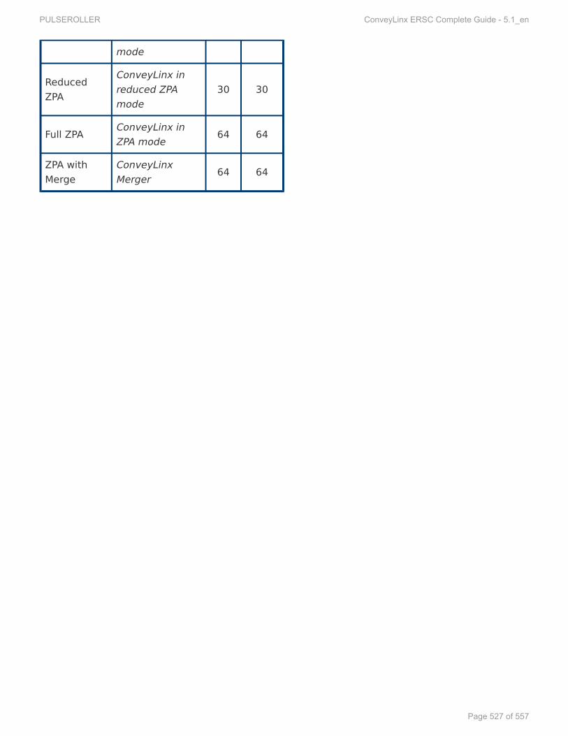
mode
ReducedZPA
ConveyLinx inreduced ZPAmode
30 30
Full ZPA ConveyLinx inZPA mode 64 64
ZPA withMerge
ConveyLinxMerger 64 64
PULSEROLLER ConveyLinx ERSC Complete Guide - 5.1_en
Page 527 of 557

14.7.1.1.14.7.1.1. FFull ZPull ZPA Mode InputsA Mode InputsCLXCLX_ERSC_ZP_ERSC_ZPA_INA_IN
Element NameElement Name Sub ElementSub Element Data TData Typeype LinkLink
LLocalUpstrocalUpstreamZoneStatus_ReamZoneStatus_Revev Byte
MoreInfo
LLocalUpstrocalUpstreamZoneStatus_FwdeamZoneStatus_Fwd Byte
LLocalDownstrocalDownstreamZoneStatus_ReamZoneStatus_Revev Byte
LLocalDownstrocalDownstreamZoneStatus_FwdeamZoneStatus_Fwd Byte
ArArrivalCountUpstrrivalCountUpstreamZoneeamZone Int
MoreInfo
DeparturDepartureCountUpstreCountUpstreamZoneeamZone Int
ArArrivalCountDownstrrivalCountDownstreamZoneeamZone Int
DeparturDepartureCountDownstreCountDownstreamZoneeamZone Int
DiagnosticDiagnostic
LLefeftMotorOvertMotorOverheatheat Bool
MoreInfo
LLefeftMotorMaxTtMotorMaxTororqueque Bool
LLefeftMotorShorttMotorShort Bool
LLefeftMotorNotConntMotorNotConn Bool
LLefeftMotorOverloadtMotorOverload Bool
LLefeftMotorStalledtMotorStalled Bool
LLefeftMotorBadHalltMotorBadHall Bool
LLefeftMotorNotUsedtMotorNotUsed Bool
ModuleRModuleResetFlagesetFlag Bool
IndeIndex06Bit01x06Bit01 Bool
OverVOverVoltageoltage Bool
LLefeftMotorAnyErtMotorAnyErrr Bool
ConnectionsNotOKConnectionsNotOK Bool
UpstrUpstreamJamEreamJamErrr Bool
LLefeftSensLtSensLowGainowGain Bool
LLowVowVoltageoltage Bool
PULSEROLLER ConveyLinx ERSC Complete Guide - 5.1_en
Page 528 of 557

RightMotorOverRightMotorOverheatheat Bool
RightMotorMaxTRightMotorMaxTororqueque Bool
RightMotorShortRightMotorShort Bool
RightMotorNotConnRightMotorNotConn Bool
RightMotorOverloadRightMotorOverload Bool
RightMotorStalledRightMotorStalled Bool
RightMotorBadHallRightMotorBadHall Bool
RightMotorNotUsedRightMotorNotUsed Bool
IndeIndex07Bit00x07Bit00 Bool
IndeIndex07Bit01x07Bit01 Bool
OverVOverVoltage1oltage1 Bool
RightMotorAnyErRightMotorAnyErrr Bool
IndeIndex07Bit04x07Bit04 Bool
DownstrDownstreamJamEreamJamErrr Bool
RightSensLRightSensLowGainowGain Bool
LLowVowVoltage1oltage1 Bool
TTrackingUpstrrackingUpstreamZoneeamZone DWord MoreInfoTTrackingDownstrrackingDownstreamZoneeamZone DWord
RReleaseCounterUpstreleaseCounterUpstreamZoneeamZone Int MoreInfoRReleaseCounterDownstreleaseCounterDownstreamZoneeamZone Int
GetDischarGetDischargeTgeTracking_Fwdracking_Fwd DWord MoreInfoGetDischarGetDischargeTgeTracking_Rracking_Revev DWord
PPortInputsortInputs
Bit08Bit08 Bool
MoreInfo
Bit09Bit09 Bool
Bit10Bit10 Bool
Bit11Bit11 Bool
Bit12Bit12 Bool
Bit13Bit13 Bool
PULSEROLLER ConveyLinx ERSC Complete Guide - 5.1_en
Page 529 of 557

Bit14Bit14 Bool
HeartbeatHeartbeat Bool
LLefeftSensorPtSensorPin3in3 Bool
LLefeftContrtControlPolPin3in3 Bool
RightSensorPRightSensorPin3in3 Bool
RightContrRightControlPolPin3in3 Bool
LLefeftSensorPtSensorPin4in4 Bool
LLefeftContrtControlPolPin4in4 Bool
RightSensorPRightSensorPin4in4 Bool
RightContrRightControlPolPin4in4 Bool
IndeIndex19x19 Word
ConveyStopStatusConveyStopStatus
StopOnLStopOnLefeftt Bool
MoreInfo
StopOnRightStopOnRight Bool
StopAStopActiveCommandPLCctiveCommandPLC Bool
Bit11Bit11 Bool
Bit12Bit12 Bool
Bit13Bit13 Bool
Bit14Bit14 Bool
Bit15Bit15 Bool
Bit00Bit00 Bool
Bit01Bit01 Bool
Bit02Bit02 Bool
Bit03Bit03 Bool
Bit04Bit04 Bool
StopAStopActiveOtherModulectiveOtherModule Bool
StopAStopActiveLctiveLostConnostConn Bool
StopAStopActiveLctiveLostPLCostPLC Bool
FFuturuturee Array[21..31]
PULSEROLLER ConveyLinx ERSC Complete Guide - 5.1_en
Page 530 of 557

of Word
PULSEROLLER ConveyLinx ERSC Complete Guide - 5.1_en
Page 531 of 557

14.7.1.2.14.7.1.2. FFull ZPull ZPA Mode OutputsA Mode OutputsCLXCLX_ERSC_ZP_ERSC_ZPA_OUTA_OUT
Element NameElement Name Sub ElementSub Element Data TData Typeype LinkLink
InductTInductTrackingOnUpstrrackingOnUpstreamZoneeamZone DWord MoreInfoInductTInductTrackingOnDownstrrackingOnDownstreamZoneeamZone DWord
AAccumulateContrccumulateControlUpstrolUpstreameam
AAccumUpstrccumUpstreamTeamToThisZoneoThisZone Bool
MoreInfo
SetArSetArrivalrival Bool
JogZoneFwdJogZoneFwd Bool
JogZoneRJogZoneRevev Bool
WWakakeUpeUp Bool
MaintEnableMaintEnable Bool
Bit14Bit14 Bool
Bit15Bit15 Bool
AAccumulateccumulate Bool
Bit01Bit01 Bool
Bit02Bit02 Bool
Bit03Bit03 Bool
Bit04Bit04 Bool
Bit05Bit05 Bool
Bit06Bit06 Bool
Bit07Bit07 Bool
AAccumulateContrccumulateControlDownstrolDownstreameam
AAccumUpstrccumUpstreamTeamToThisZoneoThisZone Bool
MoreInfo
SetArSetArrivalrival Bool
JogZoneFwdJogZoneFwd Bool
JogZoneRJogZoneRevev Bool
WWakakeUpeUp Bool
MaintEnableMaintEnable Bool
PULSEROLLER ConveyLinx ERSC Complete Guide - 5.1_en
Page 532 of 557
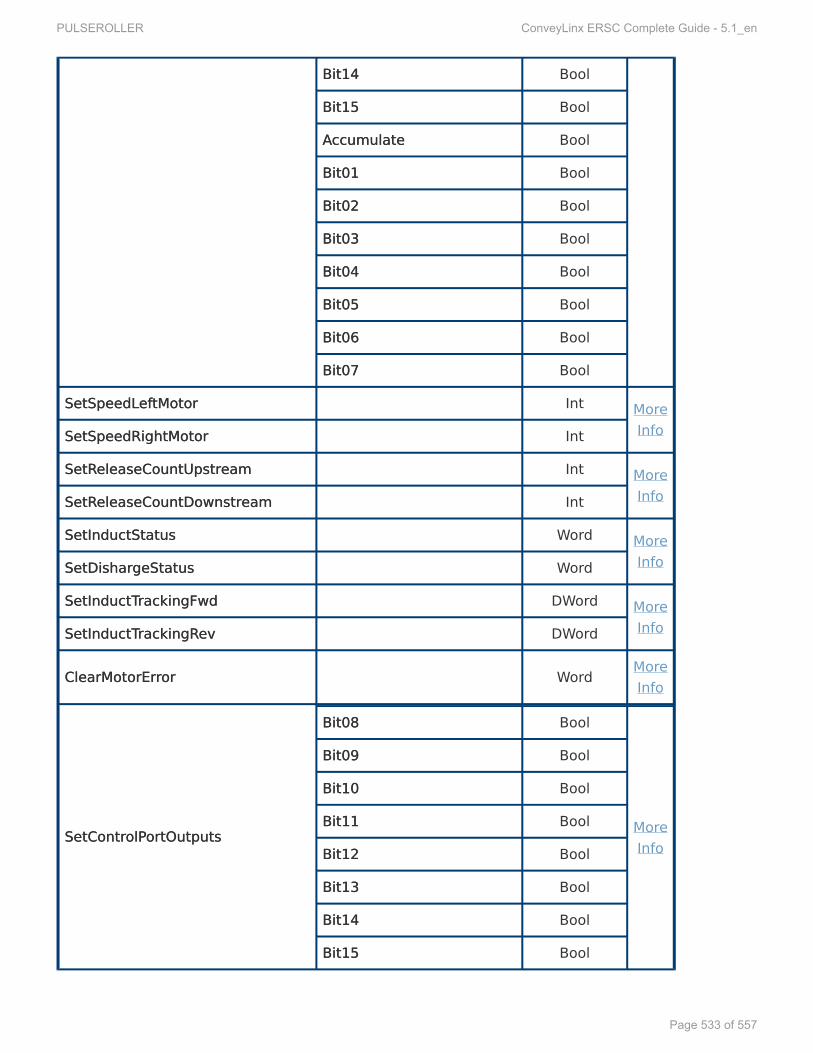
Bit14Bit14 Bool
Bit15Bit15 Bool
AAccumulateccumulate Bool
Bit01Bit01 Bool
Bit02Bit02 Bool
Bit03Bit03 Bool
Bit04Bit04 Bool
Bit05Bit05 Bool
Bit06Bit06 Bool
Bit07Bit07 Bool
SetSpeedLSetSpeedLefeftMotortMotor Int MoreInfoSetSpeedRightMotorSetSpeedRightMotor Int
SetRSetReleaseCountUpstreleaseCountUpstreameam Int MoreInfoSetRSetReleaseCountDownstreleaseCountDownstreameam Int
SetInductStatusSetInductStatus Word MoreInfoSetDisharSetDishargeStatusgeStatus Word
SetInductTSetInductTrackingFwdrackingFwd DWord MoreInfoSetInductTSetInductTrackingRrackingRevev DWord
ClearMotorErClearMotorErrroror Word MoreInfo
SetContrSetControlPolPortOutputsortOutputs
Bit08Bit08 Bool
MoreInfo
Bit09Bit09 Bool
Bit10Bit10 Bool
Bit11Bit11 Bool
Bit12Bit12 Bool
Bit13Bit13 Bool
Bit14Bit14 Bool
Bit15Bit15 Bool
PULSEROLLER ConveyLinx ERSC Complete Guide - 5.1_en
Page 533 of 557

Bit00Bit00 Bool
EnerEnergizeLgizeLefeftt Bool
Bit02Bit02 Bool
EnerEnergizeRightgizeRight Bool
Bit04Bit04 Bool
Bit05Bit05 Bool
Bit06Bit06 Bool
Bit07Bit07 Bool
IndeIndex18x18 Word
ConveyStopContrConveyStopControlol Word MoreInfo
ClearJamUpstrClearJamUpstreameam Word MoreInfoClearJamDownstrClearJamDownstreameam Word
SetDirSetDirectionContrectionControlUpstrolUpstreameam Word MoreInfoSetDirSetDirectionContrectionControlDownstrolDownstreameam Word
ConveyMerConveyMergege Word MoreInfo
FFuturuturee Array[25..31]of Word
PULSEROLLER ConveyLinx ERSC Complete Guide - 5.1_en
Page 534 of 557

14.7.1.3.14.7.1.3. RReduced ZPeduced ZPA Mode InputsA Mode InputsCLXCLX_ERSC_ZP_ERSC_ZPA_RA_Reduced_INeduced_IN
Element NameElement Name Sub ElementSub Element Data TData Typeype LinkLink
LLocalUpstrocalUpstreamZoneStatus_ReamZoneStatus_Revev Byte
MoreInfo
LLocalUpstrocalUpstreamZoneStatus_FwdeamZoneStatus_Fwd Byte
LLocalDownstrocalDownstreamZoneStatus_ReamZoneStatus_Revev Byte
LLocalDownstrocalDownstreamZoneStatus_FwdeamZoneStatus_Fwd Byte
ArArrivalCountUpstrrivalCountUpstreamZoneeamZone Int
MoreInfo
DeparturDepartureCountUpstreCountUpstreamZoneeamZone Int
ArArrivalCountDownstrrivalCountDownstreamZoneeamZone Int
DeparturDepartureCountDownstreCountDownstreamZoneeamZone Int
DiagnosticDiagnostic
LLefeftMotorOvertMotorOverheatheat Bool
MoreInfo
LLefeftMotorMaxTtMotorMaxTororqueque Bool
LLefeftMotorShorttMotorShort Bool
LLefeftMotorNotConntMotorNotConn Bool
LLefeftMotorOverloadtMotorOverload Bool
LLefeftMotorStalledtMotorStalled Bool
LLefeftMotorBadHalltMotorBadHall Bool
LLefeftMotorNotUsedtMotorNotUsed Bool
ModuleRModuleResetFlagesetFlag Bool
IndeIndex06Bit01x06Bit01 Bool
OverVOverVoltageoltage Bool
LLefeftMotorAnyErtMotorAnyErrr Bool
ConnectionsNotOKConnectionsNotOK Bool
UpstrUpstreamJamEreamJamErrr Bool
LLefeftSensLtSensLowGainowGain Bool
LLowVowVoltageoltage Bool
PULSEROLLER ConveyLinx ERSC Complete Guide - 5.1_en
Page 535 of 557

RightMotorOverRightMotorOverheatheat Bool
RightMotorMaxTRightMotorMaxTororqueque Bool
RightMotorShortRightMotorShort Bool
RightMotorNotConnRightMotorNotConn Bool
RightMotorOverloadRightMotorOverload Bool
RightMotorStalledRightMotorStalled Bool
RightMotorBadHallRightMotorBadHall Bool
RightMotorNotUsedRightMotorNotUsed Bool
IndeIndex07Bit00x07Bit00 Bool
IndeIndex07Bit01x07Bit01 Bool
OverVOverVoltage1oltage1 Bool
RightMotorAnyErRightMotorAnyErrr Bool
IndeIndex07Bit04x07Bit04 Bool
DownstrDownstreamJamEreamJamErrr Bool
RightSensLRightSensLowGainowGain Bool
LLowVowVoltage1oltage1 Bool
RReleaseCounterUpstreleaseCounterUpstreamZoneeamZone Int MoreInfoRReleaseCounterDownstreleaseCounterDownstreamZoneeamZone Int
PPortInputsortInputs
Bit08Bit08 Bool
MoreInfo
Bit09Bit09 Bool
Bit10Bit10 Bool
Bit11Bit11 Bool
Bit12Bit12 Bool
Bit13Bit13 Bool
Bit14Bit14 Bool
HeartbeatHeartbeat Bool
LLefeftSensorPtSensorPin3in3 Bool
LLefeftContrtControlPolPin3in3 Bool
PULSEROLLER ConveyLinx ERSC Complete Guide - 5.1_en
Page 536 of 557

RightSensorPRightSensorPin3in3 Bool
RightContrRightControlPolPin3in3 Bool
LLefeftSensorPtSensorPin4in4 Bool
LLefeftContrtControlPolPin4in4 Bool
RightSensorPRightSensorPin4in4 Bool
RightContrRightControlPolPin4in4 Bool
FFuturuturee Array[11..14]of Word
PULSEROLLER ConveyLinx ERSC Complete Guide - 5.1_en
Page 537 of 557

14.7.1.4.14.7.1.4. RReduced ZPeduced ZPA Mode OutputsA Mode OutputsCLXCLX_ERSC_ZP_ERSC_ZPA_RA_Reduced_OUTeduced_OUT
Element NameElement Name Sub ElementSub Element DataDataTTypeype LinkLink
AAccumulateContrccumulateControlUpstrolUpstreameam
AAccumUpstrccumUpstreamTeamToThisZoneoThisZone Bool
MoreInfo
SetArSetArrivalrival Bool
JogZoneFwdJogZoneFwd Bool
JogZoneRJogZoneRevev Bool
WWakakeUpeUp Bool
MaintEnableMaintEnable Bool
Bit14Bit14 Bool
Bit15Bit15 Bool
AAccumulateccumulate Bool
Bit01Bit01 Bool
Bit02Bit02 Bool
Bit03Bit03 Bool
Bit04Bit04 Bool
Bit05Bit05 Bool
Bit06Bit06 Bool
Bit07Bit07 Bool
AAccumulateContrccumulateControlDownstrolDownstreameam
AAccumUpstrccumUpstreamTeamToThisZoneoThisZone Bool
MoreInfo
SetArSetArrivalrival Bool
JogZoneFwdJogZoneFwd Bool
JogZoneRJogZoneRevev Bool
WWakakeUpeUp Bool
MaintEnableMaintEnable Bool
Bit14Bit14 Bool
PULSEROLLER ConveyLinx ERSC Complete Guide - 5.1_en
Page 538 of 557

Bit15Bit15 Bool
AAccumulateccumulate Bool
Bit01Bit01 Bool
Bit02Bit02 Bool
Bit03Bit03 Bool
Bit04Bit04 Bool
Bit05Bit05 Bool
Bit06Bit06 Bool
Bit07Bit07 Bool
SetSpeedLSetSpeedLefeftMotortMotor Int MoreInfoSetSpeedRightMotorSetSpeedRightMotor Int
SetRSetReleaseCountUpstreleaseCountUpstreameam Int MoreInfoSetRSetReleaseCountDownstreleaseCountDownstreameam Int
SetInductStatusSetInductStatus Word MoreInfoSetDisharSetDishargeStatusgeStatus Word
ClearMotorErClearMotorErrroror Word MoreInfo
SetContrSetControlPolPortOutputsortOutputs
Bit08Bit08 Bool
MoreInfo
Bit09Bit09 Bool
Bit10Bit10 Bool
Bit11Bit11 Bool
Bit12Bit12 Bool
Bit13Bit13 Bool
Bit14Bit14 Bool
Bit15Bit15 Bool
Bit00Bit00 Bool
EnerEnergizeLgizeLefeftt Bool
Bit02Bit02 Bool
PULSEROLLER ConveyLinx ERSC Complete Guide - 5.1_en
Page 539 of 557

EnerEnergizeRightgizeRight Bool
Bit04Bit04 Bool
Bit05Bit05 Bool
Bit06Bit06 Bool
Bit07Bit07 Bool
IndeIndex10x10 Word
ClearJamUpstrClearJamUpstreameam Word MoreInfoClearJamDownstrClearJamDownstreameam Word
SetDirSetDirectionContrectionControlUpstrolUpstreameam Word MoreInfoSetDirSetDirectionContrectionControlDownstrolDownstreameam Word
PULSEROLLER ConveyLinx ERSC Complete Guide - 5.1_en
Page 540 of 557

14.7.1.5.14.7.1.5. FFull PLC I/O Mode Inputsull PLC I/O Mode InputsCLXCLX_ERSC_PLC_IN_ERSC_PLC_IN
Element NameElement Name Sub ElementSub Element Data TData Typeype LinkLink
ConveyStopStatusConveyStopStatus
StopOnLStopOnLefeftt Bool
MoreInfo
StopOnRightStopOnRight Bool
StopAStopActiveCommandPLCctiveCommandPLC Bool
Bit11Bit11 Bool
Bit12Bit12 Bool
Bit13Bit13 Bool
Bit14Bit14 Bool
Bit15Bit15 Bool
Bit00Bit00 Bool
Bit01Bit01 Bool
Bit02Bit02 Bool
Bit03Bit03 Bool
Bit04Bit04 Bool
StopAStopActiveOtherModulectiveOtherModule Bool
StopAStopActiveLctiveLostConnostConn Bool
StopAStopActiveLctiveLostPLCostPLC Bool
PPortInputsortInputs
Bit08Bit08 Bool
MoreInfo
Bit09Bit09 Bool
Bit10Bit10 Bool
Bit11Bit11 Bool
Bit12Bit12 Bool
Bit13Bit13 Bool
Bit14Bit14 Bool
HeartbeatHeartbeat Bool
PULSEROLLER ConveyLinx ERSC Complete Guide - 5.1_en
Page 541 of 557

LLefeftSensorPtSensorPin3in3 Bool
LLefeftContrtControlPolPin3in3 Bool
RightSensorPRightSensorPin3in3 Bool
RightContrRightControlPolPin3in3 Bool
LLefeftSensorPtSensorPin4in4 Bool
LLefeftContrtControlPolPin4in4 Bool
RightSensorPRightSensorPin4in4 Bool
RightContrRightControlPolPin4in4 Bool
SensorDetectSensorDetect
Bits08_15Bits08_15 Byte
MoreInfo
RightSensorDetectRightSensorDetect Bool
LLefeftSensorDetecttSensorDetect Bool
Bit02Bit02 Bool
Bit03Bit03 Bool
Bit04Bit04 Bool
Bit05Bit05 Bool
Bit06Bit06 Bool
Bit07Bit07 Bool
ModuleVModuleVoltageoltage Int MoreInfo
LLefeftMotorCurtMotorCurrrentent Int
MoreInfo
LLefeftMotorFtMotorFrreqeq Int
LLefeftMotorCalcTtMotorCalcTempemp Byte
LLefeftModuleTtModuleTempemp Byte
LLefeftMotorDiagnostictMotorDiagnostic
OverOverheatheat Bool
MoreInfo
MaxTMaxTororqueque Bool
ShortCirShortCircuitcuit Bool
MotorNotConnectedMotorNotConnected Bool
OverloadOverload Bool
PULSEROLLER ConveyLinx ERSC Complete Guide - 5.1_en
Page 542 of 557
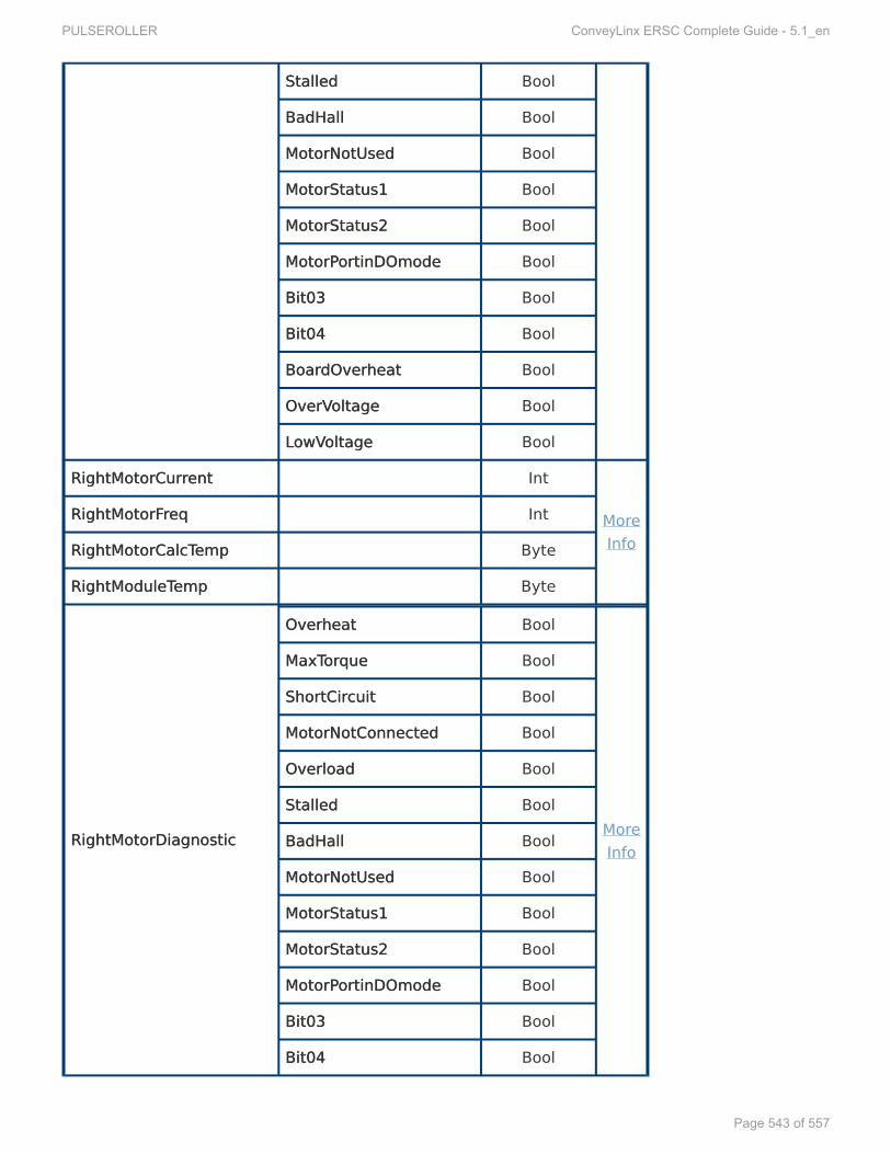
StalledStalled Bool
BadHallBadHall Bool
MotorNotUsedMotorNotUsed Bool
MotorStatus1MotorStatus1 Bool
MotorStatus2MotorStatus2 Bool
MotorPMotorPortinDOmodeortinDOmode Bool
Bit03Bit03 Bool
Bit04Bit04 Bool
BoarBoardOverdOverheatheat Bool
OverVOverVoltageoltage Bool
LLowVowVoltageoltage Bool
RightMotorCurRightMotorCurrrentent Int
MoreInfo
RightMotorFRightMotorFrreqeq Int
RightMotorCalcTRightMotorCalcTempemp Byte
RightModuleTRightModuleTempemp Byte
RightMotorDiagnosticRightMotorDiagnostic
OverOverheatheat Bool
MoreInfo
MaxTMaxTororqueque Bool
ShortCirShortCircuitcuit Bool
MotorNotConnectedMotorNotConnected Bool
OverloadOverload Bool
StalledStalled Bool
BadHallBadHall Bool
MotorNotUsedMotorNotUsed Bool
MotorStatus1MotorStatus1 Bool
MotorStatus2MotorStatus2 Bool
MotorPMotorPortinDOmodeortinDOmode Bool
Bit03Bit03 Bool
Bit04Bit04 Bool
PULSEROLLER ConveyLinx ERSC Complete Guide - 5.1_en
Page 543 of 557

Bit05Bit05 Bool
OverVOverVoltageoltage Bool
LLowVowVoltageoltage Bool
LLefeftMotorDIOstatustMotorDIOstatus
Bit08Bit08 Bool
MoreInfo
Bit09Bit09 Bool
Bit10Bit10 Bool
Bit11Bit11 Bool
ShortCirShortCircuitcuit Bool
Bit13Bit13 Bool
OverCurOverCurrrentent Bool
Bit15Bit15 Bool
Bits00_07Bits00_07 Byte
RightMotorDIOstatusRightMotorDIOstatus
Bit08Bit08 Bool
MoreInfo
Bit09Bit09 Bool
Bit10Bit10 Bool
Bit11Bit11 Bool
ShortCirShortCircuitcuit Bool
Bit13Bit13 Bool
OverCurOverCurrrentent Bool
Bit15Bit15 Bool
Bits00_07Bits00_07 Byte
UpstrUpstreamModuleStatuseamModuleStatus WordMoreInfoDownstrDownstreamModuleStatuseamModuleStatus Word
TTrackingFrackingFrromUpstromUpstreameam DWord
IndeIndex18x18 Word
ServoLServoLocationLocationLefeftt IntMoreInfoServoLServoLocationRightocationRight Int
ServoStatusLServoStatusLefeftt Word
PULSEROLLER ConveyLinx ERSC Complete Guide - 5.1_en
Page 544 of 557

ServoStatusRightServoStatusRight Word
FFuturuturee Array[23..31]of Word
PULSEROLLER ConveyLinx ERSC Complete Guide - 5.1_en
Page 545 of 557

14.7.1.6.14.7.1.6. FFull PLC I/O Mode Outputsull PLC I/O Mode OutputsCLXCLX_ERSC_PLC_OUT_ERSC_PLC_OUT
Element NameElement Name Sub ElementSub Element Data TData Typeype LinkLink
ConveyStopContrConveyStopControlol Word MoreInfo
LLefeftMotorAsDIOtMotorAsDIO
ClearPClearPortErortErrroror Bool
MoreInfo
Bit09Bit09 Bool
Bit10Bit10 Bool
Bit11Bit11 Bool
Bit12Bit12 Bool
Bit13Bit13 Bool
Bit14Bit14 Bool
EnableDIOEnableDIO Bool
EnerEnergizeJSTPgizeJSTPin3in3 Bool
EnerEnergizeJSTPgizeJSTPin4in4 Bool
EnerEnergizeJSTPgizeJSTPin5in5 Bool
Bit03Bit03 Bool
Bit04Bit04 Bool
Bit05Bit05 Bool
EnerEnergizeJSTPgizeJSTPin9in9 Bool
EnableJSTPEnableJSTPin9in9 Bool
RightMotorAsDIORightMotorAsDIO
ClearPClearPortErortErrroror Bool
MoreInfo
Bit09Bit09 Bool
Bit10Bit10 Bool
Bit11Bit11 Bool
Bit12Bit12 Bool
Bit13Bit13 Bool
PULSEROLLER ConveyLinx ERSC Complete Guide - 5.1_en
Page 546 of 557

Bit14Bit14 Bool
EnableMotDIOEnableMotDIO Bool
EnerEnergizeJSTPgizeJSTPin3in3 Bool
EnerEnergizeJSTPgizeJSTPin4in4 Bool
EnerEnergizeJSTPgizeJSTPin5in5 Bool
Bit03Bit03 Bool
Bit04Bit04 Bool
Bit05Bit05 Bool
EnerEnergizeJSTPgizeJSTPin9in9 Bool
EnableJSTPEnableJSTPin9in9 Bool
ContrControlPolPortsDOortsDO
Bit08Bit08 Bool
MoreInfo
Bit09Bit09 Bool
Bit10Bit10 Bool
Bit11Bit11 Bool
Bit12Bit12 Bool
Bit13Bit13 Bool
Bit14Bit14 Bool
Bit15Bit15 Bool
Bit00Bit00 Bool
EnerEnergizeLgizeLefeftPtPortort Bool
Bit02Bit02 Bool
EnerEnergizeRightPgizeRightPortort Bool
Bit04Bit04 Bool
Bit05Bit05 Bool
Bit06Bit06 Bool
Bit07Bit07 Bool
LLefeftMotorContrtMotorContrololDirDirectionection Bool More
InfoBit09Bit09 Bool
PULSEROLLER ConveyLinx ERSC Complete Guide - 5.1_en
Page 547 of 557

Bit10Bit10 Bool
Bit11Bit11 Bool
Bit12Bit12 Bool
Bit13Bit13 Bool
Bit14Bit14 Bool
Bit15Bit15 Bool
RRunun Bool
Bit01Bit01 Bool
Bit02Bit02 Bool
Bit03Bit03 Bool
Bit04Bit04 Bool
Bit05Bit05 Bool
Bit06Bit06 Bool
Bit07Bit07 Bool
SetLSetLefeftMotorBraktMotorBrakeModeeMode Word MoreInfoSetLSetLefeftMotorSpeedModetMotorSpeedMode Word
RightMotorContrRightMotorControlol
DirDirectionection Bool
MoreInfo
Bit09Bit09 Bool
Bit10Bit10 Bool
Bit11Bit11 Bool
Bit12Bit12 Bool
Bit13Bit13 Bool
Bit14Bit14 Bool
Bit15Bit15 Bool
RRunun Bool
Bit01Bit01 Bool
Bit02Bit02 Bool
Bit03Bit03 Bool
PULSEROLLER ConveyLinx ERSC Complete Guide - 5.1_en
Page 548 of 557

Bit04Bit04 Bool
Bit05Bit05 Bool
Bit06Bit06 Bool
Bit07Bit07 Bool
SetRightMotorBrakSetRightMotorBrakeModeeMode Word MoreInfoSetRightMotorSpeedModeSetRightMotorSpeedMode Word
SetSpeedLSetSpeedLefeftMotortMotor Int MoreInfo
SetSpeedRightMotorSetSpeedRightMotor Int MoreInfo
SetLSetLefeftMotorAtMotorAccelccel Int MoreInfoSetLSetLefeftMotorDecceltMotorDeccel Int
SetRightMotorASetRightMotorAccelccel Int MoreInfoSetRightMotorDeccelSetRightMotorDeccel Int
ClearMotorErClearMotorErrroror Word MoreInfo
SendStatusTSendStatusToDownstroDownstreameam Word MoreInfoSendStatusTSendStatusToUpstroUpstreameam Word
SetSensorPSetSensorPolarityolarity
Bit08Bit08 Bool
MoreInfo
Bit09Bit09 Bool
Bit10Bit10 Bool
Bit11Bit11 Bool
Bit12Bit12 Bool
Bit13Bit13 Bool
Bit14Bit14 Bool
Bit15Bit15 Bool
LLefeftSensorPtSensorPin3in3 Bool
LLefeftContrtControlPolPin3in3 Bool
RightSensorPRightSensorPin3in3 Bool
PULSEROLLER ConveyLinx ERSC Complete Guide - 5.1_en
Page 549 of 557

RightContrRightControlPolPin3in3 Bool
LLefeftSensorPtSensorPin4in4 Bool
LLefeftContrtControlPolPin4in4 Bool
RightSensorPRightSensorPin4in4 Bool
RightContrRightControlPolPin4in4 Bool
TTrackingTrackingToDownstroDownstreameam DWord MoreInfo
IndeIndex22x22 Word
ServoContrServoControlDistanceLolDistanceLefeftt Int
MoreInfo
ServoContrServoControlCommandLolCommandLefeftt Word
ServoContrServoControlDistanceRightolDistanceRight Int
ServoContrServoControlCommandRightolCommandRight Word
FFuturuturee Array[27..31]of Word
PULSEROLLER ConveyLinx ERSC Complete Guide - 5.1_en
Page 550 of 557

14.7.1.7.14.7.1.7. RReduced PLC I/O Mode Inputseduced PLC I/O Mode InputsCLXCLX_ERSC_PLC_R_ERSC_PLC_Reduced_INeduced_IN
Element NameElement Name Sub ElementSub Element DataDataTTypeype LinkLink
PPortInputsortInputs
Bit08Bit08 Bool
MoreInfo
Bit09Bit09 Bool
Bit10Bit10 Bool
Bit11Bit11 Bool
Bit12Bit12 Bool
Bit13Bit13 Bool
Bit14Bit14 Bool
HeartbeatHeartbeat Bool
LLefeftSensorPtSensorPin3in3 Bool
LLefeftContrtControlPolPin3in3 Bool
RightSensorPRightSensorPin3in3 Bool
RightContrRightControlPolPin3in3 Bool
LLefeftSensorPtSensorPin4in4 Bool
LLefeftContrtControlPolPin4in4 Bool
RightSensorPRightSensorPin4in4 Bool
RightContrRightControlPolPin4in4 Bool
SensorDetectSensorDetect
Bits08_15Bits08_15 Byte
MoreInfo
RightSensorDetectRightSensorDetect Bool
LLefeftSensorDetecttSensorDetect Bool
Bit02Bit02 Bool
Bit03Bit03 Bool
Bit04Bit04 Bool
Bit05Bit05 Bool
PULSEROLLER ConveyLinx ERSC Complete Guide - 5.1_en
Page 551 of 557

Bit06Bit06 Bool
Bit07Bit07 Bool
LLefeftMotorCalcTtMotorCalcTempemp Byte MoreInfoLLefeftModuleTtModuleTempemp Byte
LLefeftMotorDiagnostictMotorDiagnostic
OverOverheatheat Bool
MoreInfo
MaxTMaxTororqueque Bool
ShortCirShortCircuitcuit Bool
MotorNotConnectedMotorNotConnected Bool
OverloadOverload Bool
StalledStalled Bool
BadHallBadHall Bool
MotorNotUsedMotorNotUsed Bool
MotorStatus1MotorStatus1 Bool
MotorStatus2MotorStatus2 Bool
MotorPMotorPortinDOmodeortinDOmode Bool
Bit03Bit03 Bool
Bit04Bit04 Bool
BoarBoardOverdOverheatheat Bool
OverVOverVoltageoltage Bool
LLowVowVoltageoltage Bool
RightMotorCalcTRightMotorCalcTempemp Byte MoreInfoRightModuleTRightModuleTempemp Byte
RightMotorDiagnosticRightMotorDiagnostic
OverOverheatheat Bool
MoreInfo
MaxTMaxTororqueque Bool
ShortCirShortCircuitcuit Bool
MotorNotConnectedMotorNotConnected Bool
OverloadOverload Bool
StalledStalled Bool
PULSEROLLER ConveyLinx ERSC Complete Guide - 5.1_en
Page 552 of 557

BadHallBadHall Bool
MotorNotUsedMotorNotUsed Bool
MotorStatus1MotorStatus1 Bool
MotorStatus2MotorStatus2 Bool
MotorPMotorPortinDOmodeortinDOmode Bool
Bit03Bit03 Bool
Bit04Bit04 Bool
Bit05Bit05 Bool
OverVOverVoltageoltage Bool
LLowVowVoltageoltage Bool
LLefeftMotorDIOstatustMotorDIOstatus
Bit08Bit08 Bool
MoreInfo
Bit09Bit09 Bool
Bit10Bit10 Bool
Bit11Bit11 Bool
ShortCirShortCircuitcuit Bool
Bit13Bit13 Bool
OverCurOverCurrrentent Bool
Bit15Bit15 Bool
Bits00_07Bits00_07 Byte
RightMotorDIOstatusRightMotorDIOstatus
Bit08Bit08 Bool
MoreInfo
Bit09Bit09 Bool
Bit10Bit10 Bool
Bit11Bit11 Bool
ShortCirShortCircuitcuit Bool
Bit13Bit13 Bool
OverCurOverCurrrentent Bool
Bit15Bit15 Bool
Bits00_07Bits00_07 Byte
PULSEROLLER ConveyLinx ERSC Complete Guide - 5.1_en
Page 553 of 557

14.7.1.8.14.7.1.8. RReduced PLC I/O Mode Outputseduced PLC I/O Mode OutputsCLXCLX_ERSC_PLC_R_ERSC_PLC_Reduced_OUTeduced_OUT
Element NameElement Name Sub ElementSub Element DataDataTTypeype LinkLink
LLefeftMotorAsDIOtMotorAsDIO
ClearPClearPortErortErrroror Bool
MoreInfo
Bit09Bit09 Bool
Bit10Bit10 Bool
Bit11Bit11 Bool
Bit12Bit12 Bool
Bit13Bit13 Bool
Bit14Bit14 Bool
EnableDIOEnableDIO Bool
EnerEnergizeJSTPgizeJSTPin3in3 Bool
EnerEnergizeJSTPgizeJSTPin4in4 Bool
EnerEnergizeJSTPgizeJSTPin5in5 Bool
Bit03Bit03 Bool
Bit04Bit04 Bool
Bit05Bit05 Bool
EnerEnergizeJSTPgizeJSTPin9in9 Bool
EnableJSTPEnableJSTPin9in9 Bool
RightMotorAsDIORightMotorAsDIO
ClearPClearPortErortErrroror Bool
MoreInfo
Bit09Bit09 Bool
Bit10Bit10 Bool
Bit11Bit11 Bool
Bit12Bit12 Bool
Bit13Bit13 Bool
Bit14Bit14 Bool
PULSEROLLER ConveyLinx ERSC Complete Guide - 5.1_en
Page 554 of 557

EnableMotDIOEnableMotDIO Bool
EnerEnergizeJSTPgizeJSTPin3in3 Bool
EnerEnergizeJSTPgizeJSTPin4in4 Bool
EnerEnergizeJSTPgizeJSTPin5in5 Bool
Bit03Bit03 Bool
Bit04Bit04 Bool
Bit05Bit05 Bool
EnerEnergizeJSTPgizeJSTPin9in9 Bool
EnableJSTPEnableJSTPin9in9 Bool
ContrControlPolPortsDOortsDO
Bit08Bit08 Bool
MoreInfo
Bit09Bit09 Bool
Bit10Bit10 Bool
Bit11Bit11 Bool
Bit12Bit12 Bool
Bit13Bit13 Bool
Bit14Bit14 Bool
Bit15Bit15 Bool
Bit00Bit00 Bool
EnerEnergizeLgizeLefeftPtPortort Bool
Bit02Bit02 Bool
EnerEnergizeRightPgizeRightPortort Bool
Bit04Bit04 Bool
Bit05Bit05 Bool
Bit06Bit06 Bool
Bit07Bit07 Bool
LLefeftMotorContrtMotorControlol
DirDirectionection BoolMoreInfoBit09Bit09 Bool
Bit10Bit10 Bool
PULSEROLLER ConveyLinx ERSC Complete Guide - 5.1_en
Page 555 of 557

Bit11Bit11 Bool
Bit12Bit12 Bool
Bit13Bit13 Bool
Bit14Bit14 Bool
Bit15Bit15 Bool
RRunun Bool
Bit01Bit01 Bool
Bit02Bit02 Bool
Bit03Bit03 Bool
Bit04Bit04 Bool
Bit05Bit05 Bool
Bit06Bit06 Bool
Bit07Bit07 Bool
RightMotorContrRightMotorControlol
DirDirectionection Bool
MoreInfo
Bit09Bit09 Bool
Bit10Bit10 Bool
Bit11Bit11 Bool
Bit12Bit12 Bool
Bit13Bit13 Bool
Bit14Bit14 Bool
Bit15Bit15 Bool
RRunun Bool
Bit01Bit01 Bool
Bit02Bit02 Bool
Bit03Bit03 Bool
Bit04Bit04 Bool
Bit05Bit05 Bool
Bit06Bit06 Bool
PULSEROLLER ConveyLinx ERSC Complete Guide - 5.1_en
Page 556 of 557

Bit07Bit07 Bool
SetSpeedLSetSpeedLefeftMotortMotor Int MoreInfo
SetSpeedRightMotorSetSpeedRightMotor Int MoreInfo
ClearMotorErClearMotorErrroror Word MoreInfo
PULSEROLLER ConveyLinx ERSC Complete Guide - 5.1_en
Page 557 of 557
Related Documents