Document: AV-DOC-02-V3.00--Converged AV Deployment Guide.Doc Author: Nikesh Kapadia Save date: 4/05/2018 — Design Standards Audio Visual Converged AV Platform – Deployment Guide Version: 3.00 Date: 4 May 2018

Welcome message from author
This document is posted to help you gain knowledge. Please leave a comment to let me know what you think about it! Share it to your friends and learn new things together.
Transcript

Document: AV-DOC-02-V3.00--Converged AV Deployment Guide.Doc
Author: Nikesh Kapadia
Save date: 4/05/2018 Page 1 of 46
— Design Standards Audio Visual Converged AV Platform – Deployment Guide Version: 3.00 Date: 4 May 2018
Document: AV-DOC-02-V3.00--Converged AV Deployment Guide.Doc
Author: Nikesh Kapadia
Save date: 4/05/2018 Page 2 of 46
Table of Contents
1. GENERAL INFORMATION ............................................................................................. 5
1.1. Version Control ............................................................................................................... 5
1.2. Document Change History .............................................................................................. 5
1.3. Intent ............................................................................................................................... 5
1.4. Review ............................................................................................................................ 5
2. INTRODUCTION ............................................................................................................ 6
3. CONVERGED AV DEPLOYMENT GUIDE ..................................................................... 7
3.1. Equipment Summary ...................................................................................................... 7
3.2. Equipment For Configuration Prior to Installation ........................................................... 7
3.3. Equipment For Configuration Once Installed .................................................................. 7
3.4. Network Audio Appliance (QSC Q-Sys I/O8-Flex) .......................................................... 7
3.4.1. Configure Field Hardware ........................................................................................ 7
3.4.2. Procedure Steps ....................................................................................................... 8
3.4.3. Configure Test Hardware ......................................................................................... 9
3.4.4. Connect to the Core ............................................................................................... 10
3.4.5. Configure Inputs ..................................................................................................... 11
3.4.6. Adjust Signal Processing ........................................................................................ 12
3.4.7. Commission Front of House Sound System (FOH) ................................................ 13
3.4.8. Commission Speech Sound System (PA) .............................................................. 15
3.4.9. Commission Lapel Microphone (PA) ...................................................................... 17
3.4.10. Measure System Noise ....................................................................................... 17
3.4.11. File Management ................................................................................................ 18
3.5. SVSI .............................................................................................................................. 18
3.5.1. Establishing Connection ......................................................................................... 18
3.5.2. Connecting Decoder/Encoder to the Network ........................................................ 19
3.5.3. SVSI Settings ......................................................................................................... 20
3.5.4. Encoder Settings .................................................................................................... 20
3.5.5. Decoder Settings .................................................................................................... 22
3.6. Touch Panel .................................................................................................................. 25
3.6.1. Initial Deployment ................................................................................................... 25
3.6.2. Procedure ............................................................................................................... 25
3.7. IP Camera ..................................................................................................................... 26
Document: AV-DOC-02-V3.00--Converged AV Deployment Guide.Doc
Author: Nikesh Kapadia
Save date: 4/05/2018 Page 3 of 46
3.7.1. Establishing Connection ......................................................................................... 26
3.7.2. Assigning an IP address ......................................................................................... 26
3.7.3. Updating Password ................................................................................................ 27
3.7.4. Add Banner Information ......................................................................................... 27
3.7.5. Updating Time, Date and NTP Server .................................................................... 28
3.7.6. Domain Name Configuration .................................................................................. 28
3.7.7. DNS Configuration ................................................................................................. 28
3.7.8. Assigning an IP address ......................................................................................... 29
3.7.9. Aligning Camera Image .......................................................................................... 29
3.7.10. Stream Profile Settings ....................................................................................... 29
3.7.11. View Area ............................................................................................................ 30
3.8. HDMI Switcher .............................................................................................................. 31
3.8.1. Log On ................................................................................................................... 31
3.8.2. Host Name ............................................................................................................. 31
3.8.3. Username and Password ....................................................................................... 31
3.8.4. Input Settings ......................................................................................................... 32
3.8.5. Disable Buttons ...................................................................................................... 32
3.9. HDMI Scaler ................................................................................................................. 33
3.10. Display Settings ............................................................................................................ 34
3.10.1. Hitachi Settings update ....................................................................................... 34
3.10.2. Epson Projector Settings update ......................................................................... 34
3.10.3. NEC LCD Settings update .................................................................................. 34
4. AUDIO MEASUREMENT STANDARDS & GUIDELINES ............................................. 35
4.1. Installed Audio System Standards – Summary of Criteria ............................................ 35
4.2. Installed Audio System Standards – Measurement Guidelines .................................... 35
4.3. System Noise ................................................................................................................ 35
4.4. Measurement Locations ................................................................................................ 36
4.5. Measured Internal Ambient Noise ................................................................................. 36
4.6. Reported Noise Level ................................................................................................... 36
4.7. Measurement Conditions - Inclusion of Noise Sources ................................................. 36
4.8. Sound Level Measurements ......................................................................................... 36
4.9. System SPL – Program and Speech ............................................................................ 36
4.10. Measurement Locations ................................................................................................ 37
4.11. Reported SPLs.............................................................................................................. 37
Document: AV-DOC-02-V3.00--Converged AV Deployment Guide.Doc
Author: Nikesh Kapadia
Save date: 4/05/2018 Page 4 of 46
4.12. Measurement Conditions – Input Signals ..................................................................... 37
4.13. Sound Level Measurements ......................................................................................... 37
4.14. Frequency Response – Program and Speech .............................................................. 37
4.15. Measurement Locations ................................................................................................ 38
4.16. Reported Frequency Response .................................................................................... 38
4.17. Measurement Conditions – Operating Loudspeakers ................................................... 38
4.18. Measurement Conditions – Input Signals ..................................................................... 39
4.19. Frequency Response Measurements ........................................................................... 39
4.20. Coverage Uniformity ..................................................................................................... 39
4.21. Measurement Locations ................................................................................................ 39
4.22. Reported SPLs.............................................................................................................. 40
4.23. Measurement Conditions – Input Signals ..................................................................... 40
4.24. Measurement Conditions – Program and Speech Systems .......................................... 40
4.25. Measurement Conditions – Operating Loudspeakers ................................................... 41
4.26. Sound Level Measurements ......................................................................................... 41
4.27. Speech Transmission Index (STI) ................................................................................. 41
4.28. Measurement Locations ................................................................................................ 41
4.29. Reported STI ................................................................................................................ 41
4.30. Measurement Conditions – Input Signals ..................................................................... 42
4.31. Measurement Conditions – Program and Speech Systems .......................................... 42
4.32. Measurement Conditions – Operating Loudspeakers ................................................... 42
5. FLAT-FLOOR TEACHING – AUDIO BLOCK DIAGRAM .............................................. 43
6. ROOM COMMISSIONING CONTROLS UCI ................................................................ 44
7. INTEGRATOR TEST TOOLS UCI ................................................................................ 45
8. SUGGESTED TEST TOOLS HARDWARE CONFIGURAITON ................................... 46
Document: AV-DOC-02-V3.00--Converged AV Deployment Guide.Doc
Author: Nikesh Kapadia
Save date: 4/05/2018 Page 5 of 46
1. GENERAL INFORMATION
1.1. Version Control
This document will be updated and re-issued to reflect approved change to the content, and is subject to version control. The version record and status is documented below
1.2. Document Change History
1.3. Intent
This document details the processes to install new equipment to create a new converged teaching space.
1.4. Review
This document is reviewed quarterly from introduction for 12 months. After this period review is conducted every six months.
The most current version of the AV standards can be found on the RMIT University website: http://www1.rmit.edu.au/propertyservices/dsb
Version Date Author Comments
0.1 19/05/2017 Adam Attana Initial Draft
0.2 27/03/2018 Adam Attana Update - Added Touch Panel Setup Procedure, Hiatchi Display Settings & IP Camera Setup
3.00 04/05/2018 Adam Attana Issue for AV Standards V3.00
Document: AV-DOC-02-V3.00--Converged AV Deployment Guide.Doc
Author: Nikesh Kapadia
Save date: 4/05/2018 Page 6 of 46
2. INTRODUCTION
The converged AV design is built on the SVSi and QSC Q-SYS platforms.
For this reason, it is imperative that settings and configurations follow the procedures outlined herein, as any non-compliance have the potential to affect other spaces connected to the servers and cores.
The procedures outlined in this document do not provide detailed instructions for N-Able and Q-SYS designer. Operators carrying out procedures should be familiar with the basics of the software. It is a requirement that all staff have completed SVSi Technician training and achieved a minimum of Level 1 Q-SYS certification.
Please refer to the Installation Measurement Guidelines – Converged AV appendix attached to this document. All audio testing and measurements are to be complete in reference to this document and recorded accordingly. Once documented these are to form part of the deliverables.
Document: AV-DOC-02-V3.00--Converged AV Deployment Guide.Doc
Author: Nikesh Kapadia
Save date: 4/05/2018 Page 7 of 46
3. CONVERGED AV DEPLOYMENT GUIDE
3.1. Equipment Summary
Submit MAC addresses and port numbers to RMIT ITS project manager for the following devices
QSC I/O8 Flex
SVSi Encoder
SVSI Decoder(s)
HDMI Switcher
Display device(s)
IP Camera
Motorised screen(s)
Wireless presenter
Touch screen
3.2. Equipment For Configuration Prior to Installation
Configure the following hardware prior to installation using the information listed within this document
QSC I/O8 FLEX (Section 1)
SVSi Encoder (Section 2,3 &4)
SVSI Decoder (Section 2,3 &4)
Touch Panel (Section 3.6)
IP Camera (Section 3.7)
HDMI Switcher (Section 3.8)
HDMI Scaler (Section 3.9)
Display Device(s) (Section 3.10)
3.3. Equipment For Configuration Once Installed
Configure Hardware once installed
IP Camera (Section 3.7)
Wireless Microphone (Section 3.4.5)
Wireless Presenter
3.4. Network Audio Appliance (QSC Q-Sys I/O8-Flex)
3.4.1. Configure Field Hardware
Preparation Steps
1. Connect the new field hardware to a PC running Q-SYS Designer software over a temporary network (i.e. not the RMIT production network). (Note I/O8 FLEX devices require PoE, so a PoE switch or PoE power supply will be required)
2. Unconfigured Q-SYS hardware will be set to Auto IP (DHCP) by default, so the temporary network can either:
have a DHCP server configured (PC’s network interface must also set to Auto IP), or
have no DHCP server and rely on link-local addressing.
Document: AV-DOC-02-V3.00--Converged AV Deployment Guide.Doc
Author: Nikesh Kapadia
Save date: 4/05/2018 Page 8 of 46
Note: if a reset is required insert a paperclip or similar device into the reset hole and hold for 10 seconds. The status light will turn off once reset is complete. This resets all network settings to their factory defaults: IP Addresses, hostname, etc
3.4.2. Procedure Steps
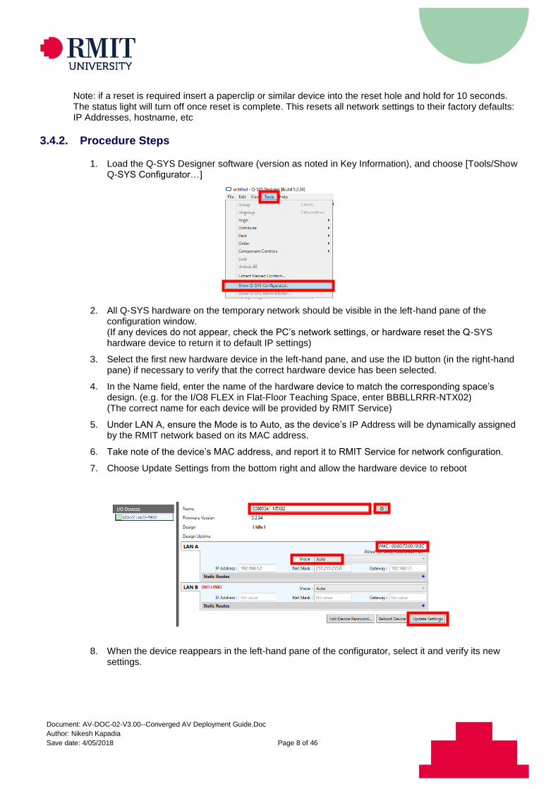
1. Load the Q-SYS Designer software (version as noted in Key Information), and choose [Tools/Show Q-SYS Configurator…]
2. All Q-SYS hardware on the temporary network should be visible in the left-hand pane of the configuration window. (If any devices do not appear, check the PC’s network settings, or hardware reset the Q-SYS hardware device to return it to default IP settings)
3. Select the first new hardware device in the left-hand pane, and use the ID button (in the right-hand pane) if necessary to verify that the correct hardware device has been selected.
4. In the Name field, enter the name of the hardware device to match the corresponding space’s design. (e.g. for the I/O8 FLEX in Flat-Floor Teaching Space, enter BBBLLRRR-NTX02) (The correct name for each device will be provided by RMIT Service)
5. Under LAN A, ensure the Mode is to Auto, as the device’s IP Address will be dynamically assigned by the RMIT network based on its MAC address.
6. Take note of the device’s MAC address, and report it to RMIT Service for network configuration.
7. Choose Update Settings from the bottom right and allow the hardware device to reboot
8. When the device reappears in the left-hand pane of the configurator, select it and verify its new settings.
Document: AV-DOC-02-V3.00--Converged AV Deployment Guide.Doc
Author: Nikesh Kapadia
Save date: 4/05/2018 Page 9 of 46
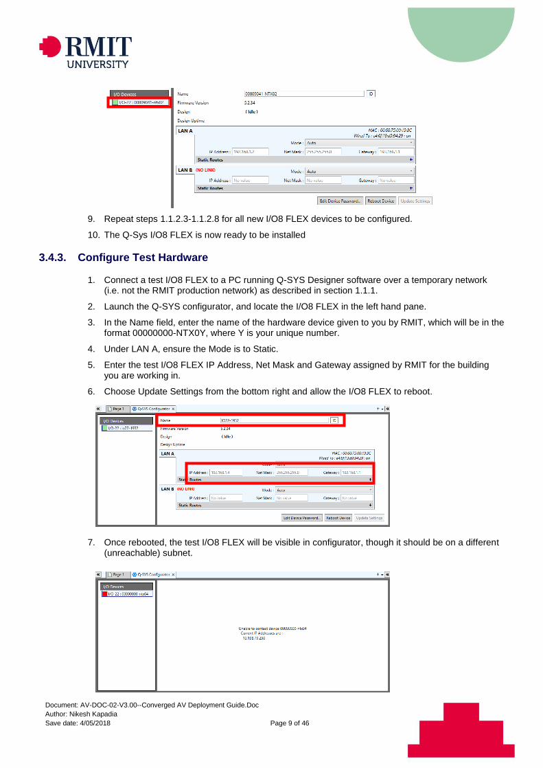
9. Repeat steps 1.1.2.3-1.1.2.8 for all new I/O8 FLEX devices to be configured.
10. The Q-Sys I/O8 FLEX is now ready to be installed
3.4.3. Configure Test Hardware
1. Connect a test I/O8 FLEX to a PC running Q-SYS Designer software over a temporary network (i.e. not the RMIT production network) as described in section 1.1.1.
2. Launch the Q-SYS configurator, and locate the I/O8 FLEX in the left hand pane.
3. In the Name field, enter the name of the hardware device given to you by RMIT, which will be in the format 00000000-NTX0Y, where Y is your unique number.
4. Under LAN A, ensure the Mode is to Static.
5. Enter the test I/O8 FLEX IP Address, Net Mask and Gateway assigned by RMIT for the building you are working in.
6. Choose Update Settings from the bottom right and allow the I/O8 FLEX to reboot.
7. Once rebooted, the test I/O8 FLEX will be visible in configurator, though it should be on a different (unreachable) subnet.
Document: AV-DOC-02-V3.00--Converged AV Deployment Guide.Doc
Author: Nikesh Kapadia
Save date: 4/05/2018 Page 10 of 46
8. Connect the test I/O8 FLEX to the RMIT network on an AV VLAN port where it will be discoverable by the core.
It may be necessary to temporarily disconnect another AV device; e.g. wireless presenter.
3.4.4. Connect to the Core
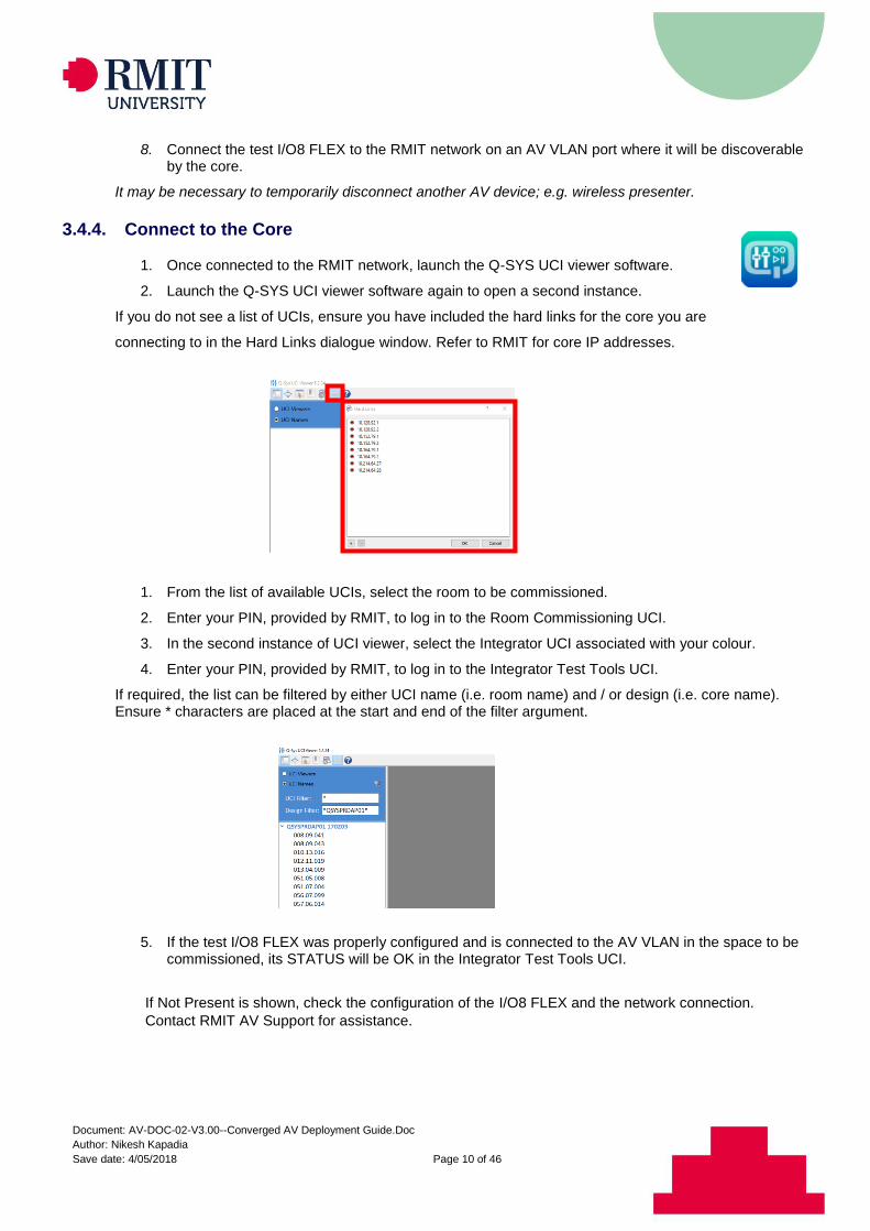
1. Once connected to the RMIT network, launch the Q-SYS UCI viewer software.
2. Launch the Q-SYS UCI viewer software again to open a second instance.
If you do not see a list of UCIs, ensure you have included the hard links for the core you are
connecting to in the Hard Links dialogue window. Refer to RMIT for core IP addresses.
1. From the list of available UCIs, select the room to be commissioned.
2. Enter your PIN, provided by RMIT, to log in to the Room Commissioning UCI.
3. In the second instance of UCI viewer, select the Integrator UCI associated with your colour.
4. Enter your PIN, provided by RMIT, to log in to the Integrator Test Tools UCI.
If required, the list can be filtered by either UCI name (i.e. room name) and / or design (i.e. core name). Ensure * characters are placed at the start and end of the filter argument.
5. If the test I/O8 FLEX was properly configured and is connected to the AV VLAN in the space to be commissioned, its STATUS will be OK in the Integrator Test Tools UCI.
If Not Present is shown, check the configuration of the I/O8 FLEX and the network connection.
Contact RMIT AV Support for assistance.
Document: AV-DOC-02-V3.00--Converged AV Deployment Guide.Doc
Author: Nikesh Kapadia
Save date: 4/05/2018 Page 11 of 46
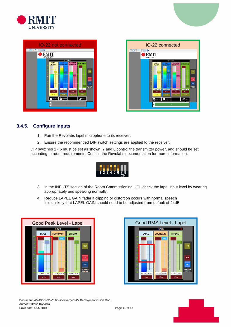
3.4.5. Configure Inputs
1. Pair the Revolabs lapel microphone to its receiver.
2. Ensure the recommended DIP switch settings are applied to the receiver.
DIP switches 1 - 6 must be set as shown. 7 and 8 control the transmitter power, and should be set according to room requirements. Consult the Revolabs documentation for more information.
3. In the INPUTS section of the Room Commissioning UCI, check the lapel input level by wearing appropriately and speaking normally.
4. Reduce LAPEL GAIN fader if clipping or distortion occurs with normal speech It is unlikely that LAPEL GAIN should need to be adjusted from default of 24dB
Good Peak Level - Lapel Good RMS Level - Lapel
IO-22 not connected IO-22 connected
Document: AV-DOC-02-V3.00--Converged AV Deployment Guide.Doc
Author: Nikesh Kapadia
Save date: 4/05/2018 Page 12 of 46
5. Ensure the boundary microphone is connected and that 48V phantom power is on.
6. Check boundary input level by speaking normally from the lectern position.
7. Adjust BOUNDARY GAIN as required to achieve good level, and avoid clipping or distortion with normal speech.
8. Check stream input level by passing signal from room PC or laptop with PC volume at maximum. Peak values of near 0dBFS can occur, but should not clip. It is unlikely that STREAM GAIN should need to be adjusted from the default of 0dB
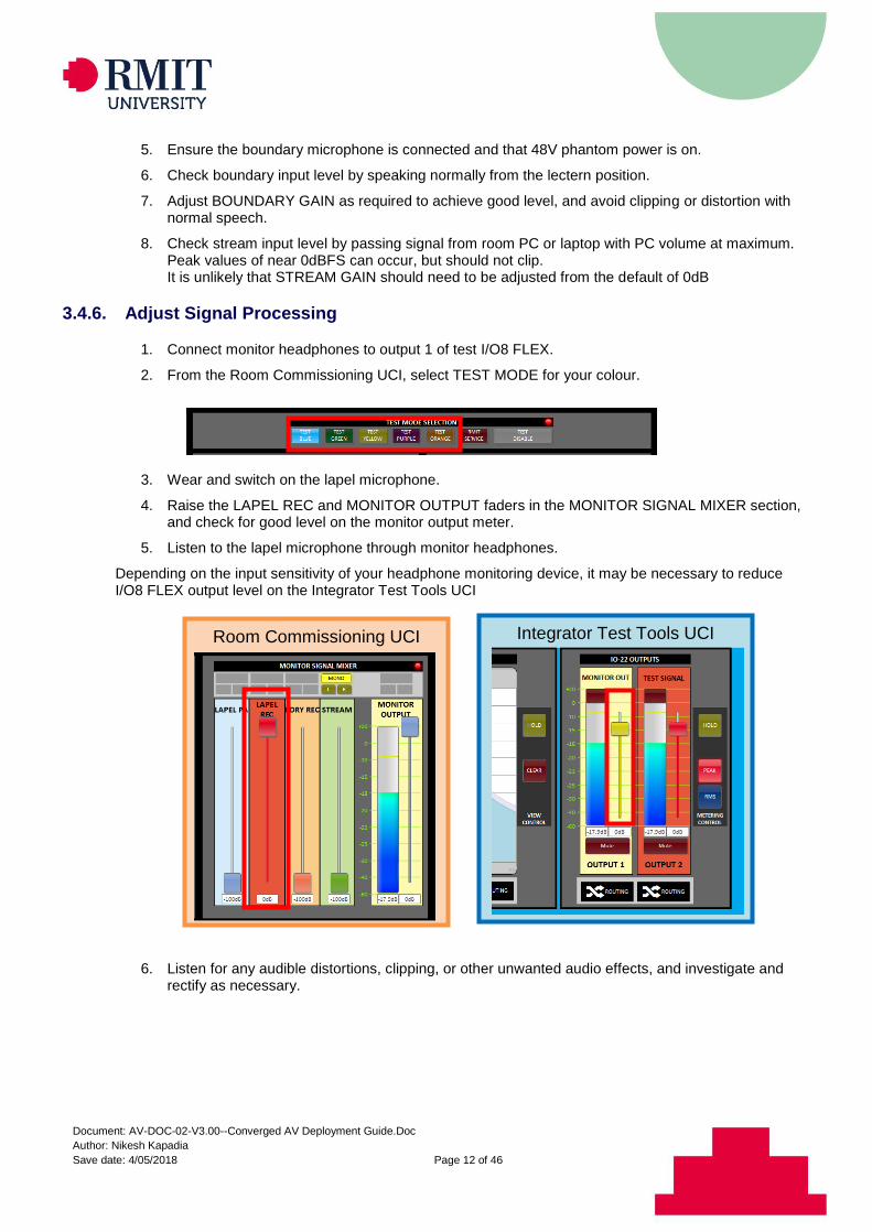
3.4.6. Adjust Signal Processing
1. Connect monitor headphones to output 1 of test I/O8 FLEX.
2. From the Room Commissioning UCI, select TEST MODE for your colour.
3. Wear and switch on the lapel microphone.
4. Raise the LAPEL REC and MONITOR OUTPUT faders in the MONITOR SIGNAL MIXER section, and check for good level on the monitor output meter.
5. Listen to the lapel microphone through monitor headphones.
Depending on the input sensitivity of your headphone monitoring device, it may be necessary to reduce I/O8 FLEX output level on the Integrator Test Tools UCI
6. Listen for any audible distortions, clipping, or other unwanted audio effects, and investigate and rectify as necessary.
Integrator Test Tools UCI Room Commissioning UCI
Document: AV-DOC-02-V3.00--Converged AV Deployment Guide.Doc
Author: Nikesh Kapadia
Save date: 4/05/2018 Page 13 of 46
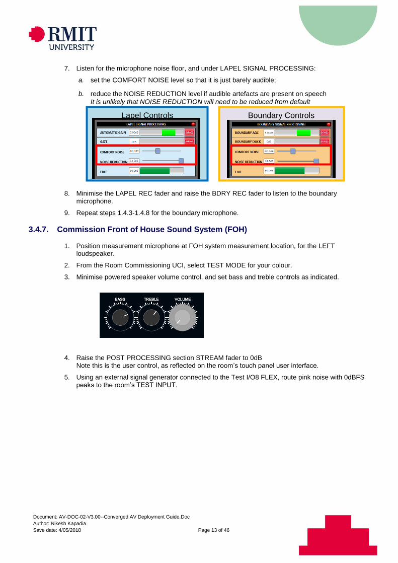
7. Listen for the microphone noise floor, and under LAPEL SIGNAL PROCESSING:
a. set the COMFORT NOISE level so that it is just barely audible;
b. reduce the NOISE REDUCTION level if audible artefacts are present on speech
It is unlikely that NOISE REDUCTION will need to be reduced from default
8. Minimise the LAPEL REC fader and raise the BDRY REC fader to listen to the boundary microphone.
9. Repeat steps 1.4.3-1.4.8 for the boundary microphone.
3.4.7. Commission Front of House Sound System (FOH)
1. Position measurement microphone at FOH system measurement location, for the LEFT loudspeaker.
2. From the Room Commissioning UCI, select TEST MODE for your colour.
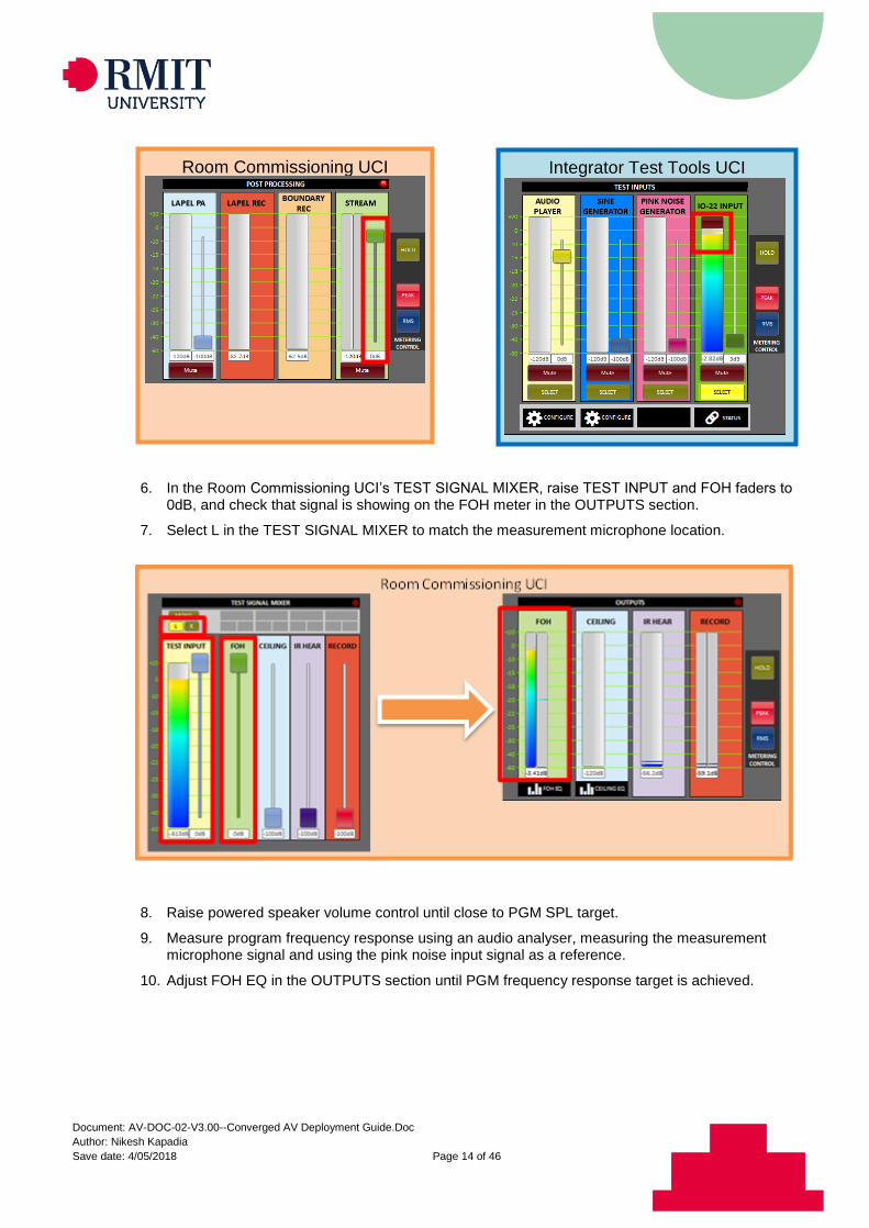
3. Minimise powered speaker volume control, and set bass and treble controls as indicated.
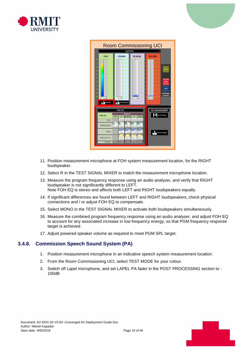
4. Raise the POST PROCESSING section STREAM fader to 0dB Note this is the user control, as reflected on the room’s touch panel user interface.
5. Using an external signal generator connected to the Test I/O8 FLEX, route pink noise with 0dBFS peaks to the room’s TEST INPUT.
Boundary Controls Lapel Controls
Document: AV-DOC-02-V3.00--Converged AV Deployment Guide.Doc
Author: Nikesh Kapadia
Save date: 4/05/2018 Page 14 of 46
6. In the Room Commissioning UCI’s TEST SIGNAL MIXER, raise TEST INPUT and FOH faders to 0dB, and check that signal is showing on the FOH meter in the OUTPUTS section.
7. Select L in the TEST SIGNAL MIXER to match the measurement microphone location.
8. Raise powered speaker volume control until close to PGM SPL target.
9. Measure program frequency response using an audio analyser, measuring the measurement microphone signal and using the pink noise input signal as a reference.
10. Adjust FOH EQ in the OUTPUTS section until PGM frequency response target is achieved.
Room Commissioning UCI Integrator Test Tools UCI
Document: AV-DOC-02-V3.00--Converged AV Deployment Guide.Doc
Author: Nikesh Kapadia
Save date: 4/05/2018 Page 15 of 46
11. Position measurement microphone at FOH system measurement location, for the RIGHT loudspeaker.
12. Select R in the TEST SIGNAL MIXER to match the measurement microphone location.
13. Measure the program frequency response using an audio analyser, and verify that RIGHT loudspeaker is not significantly different to LEFT. Note FOH EQ is stereo and affects both LEFT and RIGHT loudspeakers equally.
14. If significant differences are found between LEFT and RIGHT loudspeakers, check physical connections and / or adjust FOH EQ to compensate.
15. Select MONO in the TEST SIGNAL MIXER to activate both loudspeakers simultaneously.
16. Measure the combined program frequency response using an audio analyser, and adjust FOH EQ to account for any associated increase in low frequency energy, so that PGM frequency response target is achieved.
17. Adjust powered speaker volume as required to meet PGM SPL target.
3.4.8. Commission Speech Sound System (PA)
1. Position measurement microphone in an indicative speech system measurement location.
2. From the Room Commissioning UCI, select TEST MODE for your colour.
3. Switch off Lapel microphone, and set LAPEL PA fader in the POST PROCESSING section to -100dB
Room Commissioning UCI
Document: AV-DOC-02-V3.00--Converged AV Deployment Guide.Doc
Author: Nikesh Kapadia
Save date: 4/05/2018 Page 16 of 46
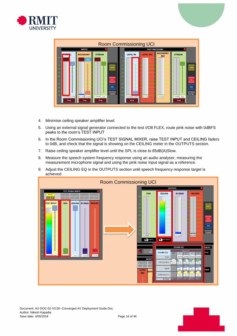
4. Minimise ceiling speaker amplifier level.
5. Using an external signal generator connected to the test I/O8 FLEX, route pink noise with 0dBFS peaks to the room’s TEST INPUT
6. In the Room Commissioning UCI’s TEST SIGNAL MIXER, raise TEST INPUT and CEILING faders to 0dB, and check that the signal is showing on the CEILING meter in the OUTPUTS section.
7. Raise ceiling speaker amplifier level until the SPL is close to 85dB(A)Slow.
8. Measure the speech system frequency response using an audio analyser, measuring the measurement microphone signal and using the pink noise input signal as a reference.
9. Adjust the CEILING EQ in the OUTPUTS section until speech frequency response target is achieved
Room Commissioning UCI
Room Commissioning UCI
Document: AV-DOC-02-V3.00--Converged AV Deployment Guide.Doc
Author: Nikesh Kapadia
Save date: 4/05/2018 Page 17 of 46
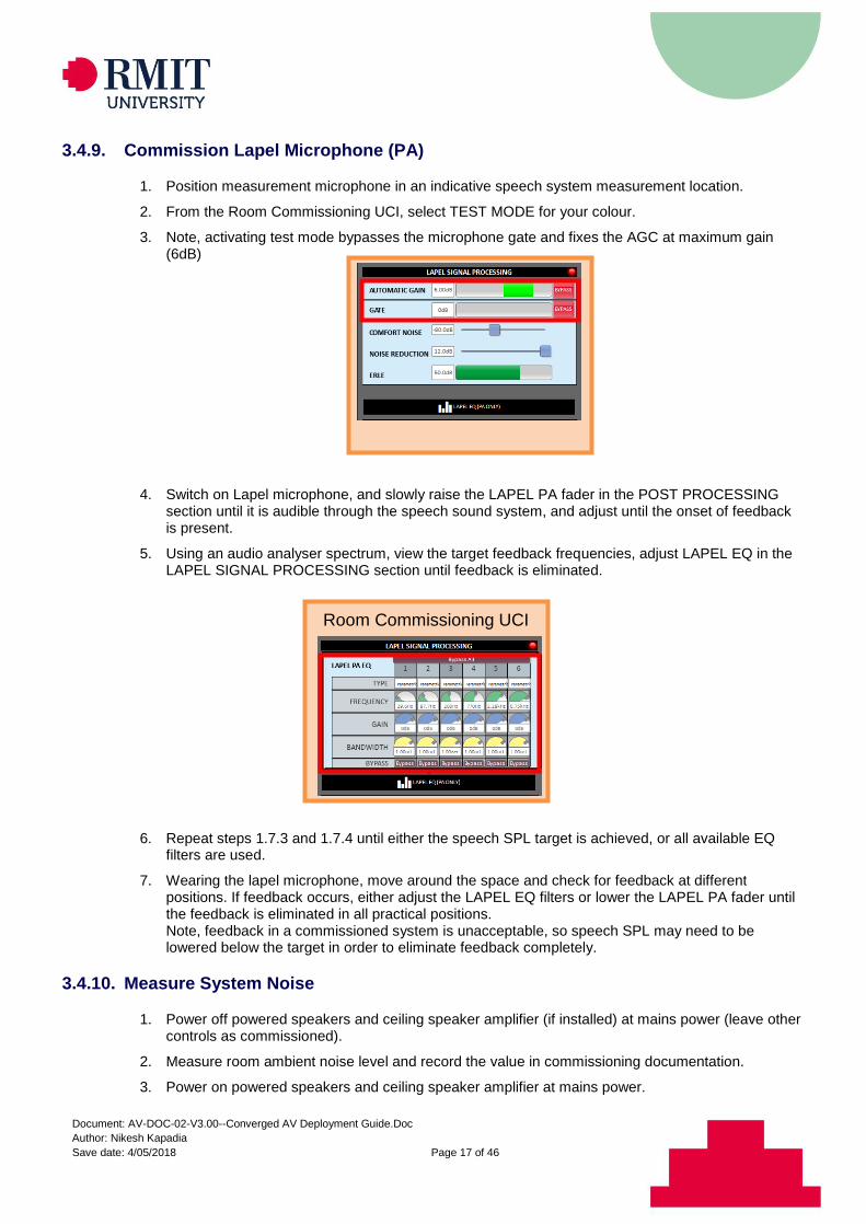
3.4.9. Commission Lapel Microphone (PA)
1. Position measurement microphone in an indicative speech system measurement location.
2. From the Room Commissioning UCI, select TEST MODE for your colour.
3. Note, activating test mode bypasses the microphone gate and fixes the AGC at maximum gain (6dB)
4. Switch on Lapel microphone, and slowly raise the LAPEL PA fader in the POST PROCESSING section until it is audible through the speech sound system, and adjust until the onset of feedback is present.
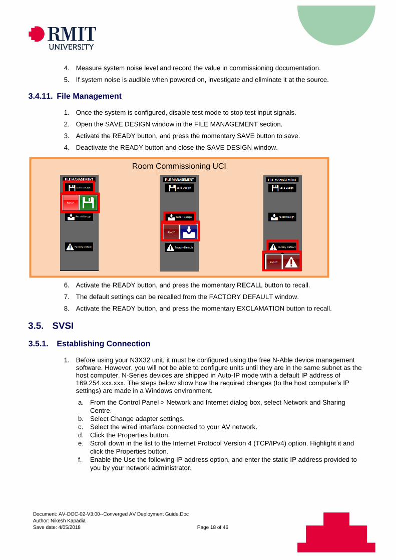
5. Using an audio analyser spectrum, view the target feedback frequencies, adjust LAPEL EQ in the LAPEL SIGNAL PROCESSING section until feedback is eliminated.
6. Repeat steps 1.7.3 and 1.7.4 until either the speech SPL target is achieved, or all available EQ filters are used.
7. Wearing the lapel microphone, move around the space and check for feedback at different positions. If feedback occurs, either adjust the LAPEL EQ filters or lower the LAPEL PA fader until the feedback is eliminated in all practical positions. Note, feedback in a commissioned system is unacceptable, so speech SPL may need to be lowered below the target in order to eliminate feedback completely.
3.4.10. Measure System Noise
1. Power off powered speakers and ceiling speaker amplifier (if installed) at mains power (leave other controls as commissioned).
2. Measure room ambient noise level and record the value in commissioning documentation.
3. Power on powered speakers and ceiling speaker amplifier at mains power.
Room Commissioning UCI
Room Commissioning UCI
Document: AV-DOC-02-V3.00--Converged AV Deployment Guide.Doc
Author: Nikesh Kapadia
Save date: 4/05/2018 Page 18 of 46
4. Measure system noise level and record the value in commissioning documentation.
5. If system noise is audible when powered on, investigate and eliminate it at the source.
3.4.11. File Management
1. Once the system is configured, disable test mode to stop test input signals.
2. Open the SAVE DESIGN window in the FILE MANAGEMENT section.
3. Activate the READY button, and press the momentary SAVE button to save.
4. Deactivate the READY button and close the SAVE DESIGN window.
5. The saved design can be recalled from the RECALL DESIGN window.
6. Activate the READY button, and press the momentary RECALL button to recall.
7. The default settings can be recalled from the FACTORY DEFAULT window.
8. Activate the READY button, and press the momentary EXCLAMATION button to recall.
3.5. SVSI
3.5.1. Establishing Connection
1. Before using your N3X32 unit, it must be configured using the free N-Able device management software. However, you will not be able to configure units until they are in the same subnet as the host computer. N-Series devices are shipped in Auto-IP mode with a default IP address of 169.254.xxx.xxx. The steps below show how the required changes (to the host computer’s IP settings) are made in a Windows environment.
a. From the Control Panel > Network and Internet dialog box, select Network and Sharing
Centre.
b. Select Change adapter settings.
c. Select the wired interface connected to your AV network.
d. Click the Properties button.
e. Scroll down in the list to the Internet Protocol Version 4 (TCP/IPv4) option. Highlight it and
click the Properties button.
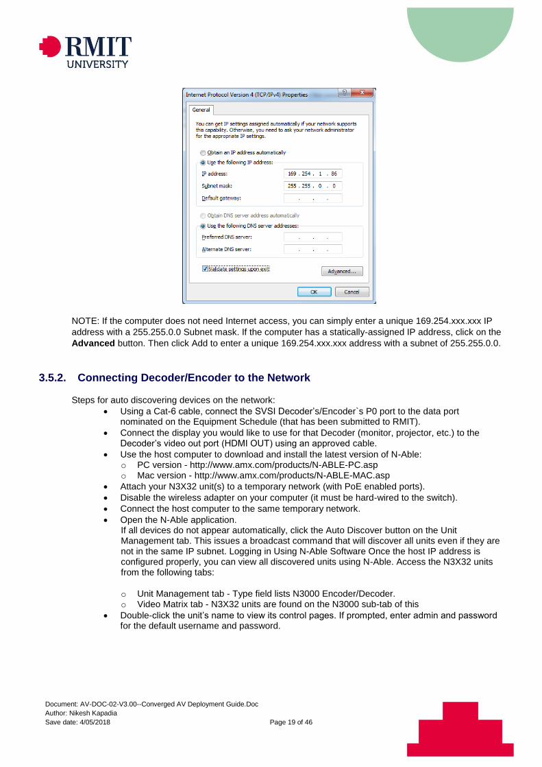
f. Enable the Use the following IP address option, and enter the static IP address provided to
you by your network administrator.
Room Commissioning UCI
Document: AV-DOC-02-V3.00--Converged AV Deployment Guide.Doc
Author: Nikesh Kapadia
Save date: 4/05/2018 Page 19 of 46
NOTE: If the computer does not need Internet access, you can simply enter a unique 169.254.xxx.xxx IP
address with a 255.255.0.0 Subnet mask. If the computer has a statically-assigned IP address, click on the
Advanced button. Then click Add to enter a unique 169.254.xxx.xxx address with a subnet of 255.255.0.0.
3.5.2. Connecting Decoder/Encoder to the Network
Steps for auto discovering devices on the network:
Using a Cat-6 cable, connect the SVSI Decoder’s/Encoder`s P0 port to the data port nominated on the Equipment Schedule (that has been submitted to RMIT).
Connect the display you would like to use for that Decoder (monitor, projector, etc.) to the Decoder’s video out port (HDMI OUT) using an approved cable.
Use the host computer to download and install the latest version of N-Able: o PC version - http://www.amx.com/products/N-ABLE-PC.asp o Mac version - http://www.amx.com/products/N-ABLE-MAC.asp
Attach your N3X32 unit(s) to a temporary network (with PoE enabled ports).
Disable the wireless adapter on your computer (it must be hard-wired to the switch).
Connect the host computer to the same temporary network.
Open the N-Able application. If all devices do not appear automatically, click the Auto Discover button on the Unit Management tab. This issues a broadcast command that will discover all units even if they are not in the same IP subnet. Logging in Using N-Able Software Once the host IP address is configured properly, you can view all discovered units using N-Able. Access the N3X32 units from the following tabs:
o Unit Management tab - Type field lists N3000 Encoder/Decoder. o Video Matrix tab - N3X32 units are found on the N3000 sub-tab of this
Double-click the unit’s name to view its control pages. If prompted, enter admin and password for the default username and password.
Document: AV-DOC-02-V3.00--Converged AV Deployment Guide.Doc
Author: Nikesh Kapadia
Save date: 4/05/2018 Page 20 of 46
3.5.3. SVSI Settings
In Device Name field, enter the name of the hardware device given to you by RMIT, which will be in the format BBBLLRRR-NTX0Y (Encoder) or BBBLLRRR-NRX0Y (Decoder), where Y is the devices unique number
1. Connect the host computer to RMIT`s network.
2. Open the N-Able application.
3. Double-click the unit’s name to edit each device as listed below.
If prompted, enter admin and password for the default username and password.
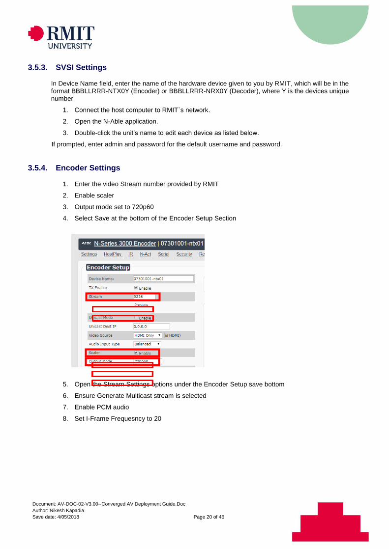
3.5.4. Encoder Settings
1. Enter the video Stream number provided by RMIT
2. Enable scaler
3. Output mode set to 720p60
4. Select Save at the bottom of the Encoder Setup Section
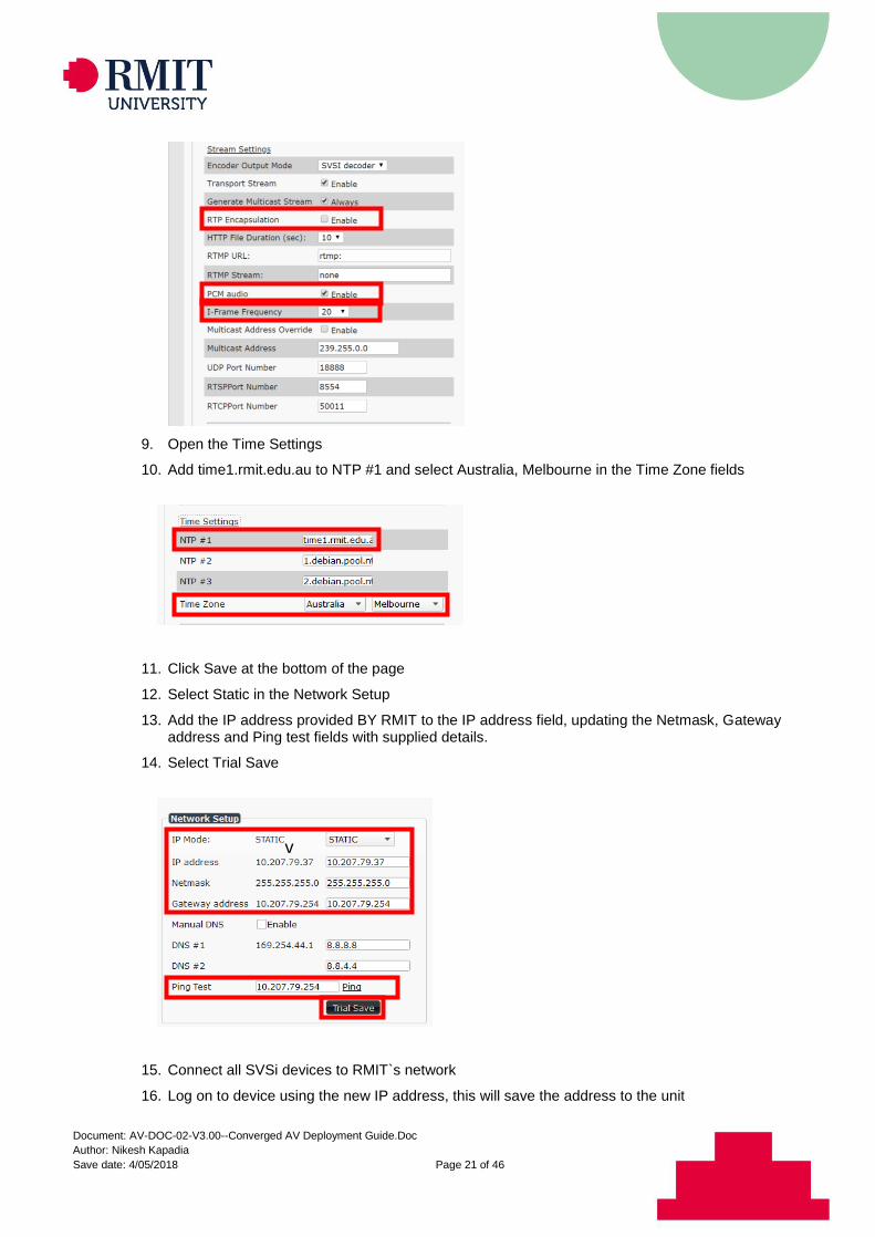
5. Open the Stream Settings options under the Encoder Setup save bottom
6. Ensure Generate Multicast stream is selected
7. Enable PCM audio
8. Set I-Frame Frequesncy to 20
v
v
v
Document: AV-DOC-02-V3.00--Converged AV Deployment Guide.Doc
Author: Nikesh Kapadia
Save date: 4/05/2018 Page 21 of 46
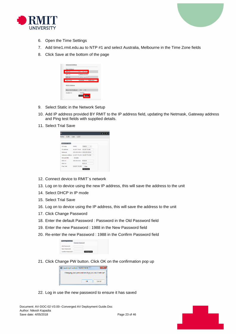
9. Open the Time Settings
10. Add time1.rmit.edu.au to NTP #1 and select Australia, Melbourne in the Time Zone fields
11. Click Save at the bottom of the page
12. Select Static in the Network Setup
13. Add the IP address provided BY RMIT to the IP address field, updating the Netmask, Gateway address and Ping test fields with supplied details.
14. Select Trial Save
15. Connect all SVSi devices to RMIT`s network
16. Log on to device using the new IP address, this will save the address to the unit
v
v
v
v
v v
v
v
Document: AV-DOC-02-V3.00--Converged AV Deployment Guide.Doc
Author: Nikesh Kapadia
Save date: 4/05/2018 Page 22 of 46
17. Select DHCP in IP mode
18. Select Trial Save
19. Log on to device using the IP address, this will save the address to the unit
20. Click Change Password
21. Enter the default Password : Password in the Old Password field
22. Enter the new Password : 1988 in the New Password field
23. Re-enter the new Password : 1988 in the Confirm Password field
24. Click Change PW button. Click OK on the confirmation pop up
25. Log in use the new password to ensure it has saved
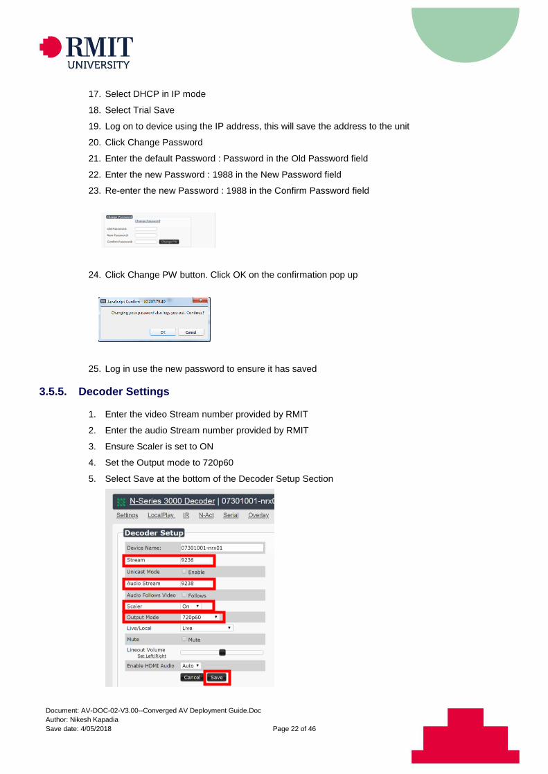
3.5.5. Decoder Settings
1. Enter the video Stream number provided by RMIT
2. Enter the audio Stream number provided by RMIT
3. Ensure Scaler is set to ON
4. Set the Output mode to 720p60
5. Select Save at the bottom of the Decoder Setup Section
Document: AV-DOC-02-V3.00--Converged AV Deployment Guide.Doc
Author: Nikesh Kapadia
Save date: 4/05/2018 Page 23 of 46
6. Open the Time Settings
7. Add time1.rmit.edu.au to NTP #1 and select Australia, Melbourne in the Time Zone fields
8. Click Save at the bottom of the page
9. Select Static in the Network Setup
10. Add IP address provided BY RMIT to the IP address field, updating the Netmask, Gateway address and Ping test fields with supplied details.
11. Select Trial Save
12. Connect device to RMIT`s network
13. Log on to device using the new IP address, this will save the address to the unit
14. Select DHCP in IP mode
15. Select Trial Save
16. Log on to device using the IP address, this will save the address to the unit
17. Click Change Password
18. Enter the default Password : Password in the Old Password field
19. Enter the new Password : 1988 in the New Password field
20. Re-enter the new Password : 1988 in the Confirm Password field
21. Click Change PW button. Click OK on the confirmation pop up
22. Log in use the new password to ensure it has saved
Document: AV-DOC-02-V3.00--Converged AV Deployment Guide.Doc
Author: Nikesh Kapadia
Save date: 4/05/2018 Page 24 of 46
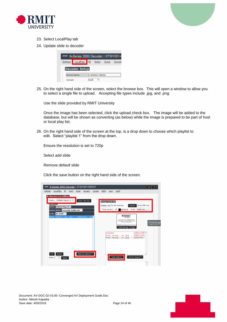
23. Select LocalPlay tab
24. Update slide to decoder
25. On the right hand side of the screen, select the browse box. This will open a window to allow you to select a single file to upload. Accepting file types include .jpg, and .png.
Use the slide provided by RMIT University
Once the image has been selected, click the upload check box. The image will be added to the database, but will be shown as converting (as below) while the image is prepared to be part of host or local play list.
26. On the right hand side of the screen at the top, is a drop down to choose which playlist to edit. Select “playlist 1” from the drop down.
Ensure the resolution is set to 720p
Select add slide
Remove default slide
Click the save button on the right hand side of the screen.

Document: AV-DOC-02-V3.00--Converged AV Deployment Guide.Doc
Author: Nikesh Kapadia
Save date: 4/05/2018 Page 25 of 46
3.6. Touch Panel
3.6.1. Initial Deployment
Requirements
Network to be active in the room with Crestron MAC address registered in infoblox
Laptop/PC with the following software o Telnet program (Putty recommended) o Internet browser (Chrome recommended)
Firmware and project files o Contact RMIT AV Design for access to the current version files
3.6.2. Procedure
Set touch panel IP address
1. Power up the touch panel via POE and ensure DHCP is enabled on the network switch it is connected to.
2. Once device boot, the touch panel should display the IP address on the screen.
Update firmware
1. Open filezilla and type in the IP address of the Touch panel into the Host field.
Click QuickConnect.
2. In the lower left pane, navigate to the folder containing the firmware 2.000.0018
3. In the lower right pane, navigate to the firmware folder.
4. Drag the firmware.puf file into the firmware folder.
5. Wait until the file appears into the firmware folder. This may take up to a minute.
6. Once uploaded, telnet to the IP address of the touch panel (telnet to 192.168.1.X) and type in: puf and press enter
7. Monitor the firmware progress on the touch panel screen, this part will take around 20 minutes.
Configure device parameters
1. Telnet to the touch panel IP address again.
2. Type the following commands into the console (pressing Enter after each line)
ECHO ON
BROWSERKEYS OFF
BROWSERMODE FULLSCREEN
STBY TO 0
BROWSERHOMEPAGE http://10.69.201.24/panels/?project=1256590101&roomID=xxx.xx.xxx Note: xxx.xx.xxx is the RMIT room number ie 515.03.006
REBOOT Note: This will save all changes trigger a reboot to the touch panel
3. Using Chrome, browse to the IP address of the touch panel.
4. In the top right corner, click the down arrow next to the Actions button
5. Select Upload User Project.
6. Browse to the location of the project (.vtz file) and select it, then click load
Document: AV-DOC-02-V3.00--Converged AV Deployment Guide.Doc
Author: Nikesh Kapadia
Save date: 4/05/2018 Page 26 of 46
Note: Wait until this has completed before the next step. Navigate to the settings tab on that main web page.
1. Set auto brightness to off
Brightness setting – 80%
2. Set Auto backlight to off
Backlight set to 80%
Wait 1 minute then click the refresh button
Click the page button and enter the above credentials
3. Set the hardkey setting to Backlight disable
4. Open the system setup section
Update the Host Name to xxxxxxxx-AXP01 Note: xxx.xx.xxx is the RMIT room number ie 515.03.006
5. Authentication setting to on
Username: admin
Password: 1988
6. Set the domain name to: av.its.rmit.edu.au
7. Save and click yes when prompted to reboot
The panel will now display the RMIT Converged AV interface. Please test all room functions as per the RMIT Converged Test Script (refer: AV-SCH-07-V3.00—AV
Test Script (Converged AV).
3.7. IP Camera
3.7.1. Establishing Connection
1. The Axis camera must be configured using the free Axis Camera Management Client software. However, you will not be able to configure units until they are in the same subnet as the host computer. Axis Cameras are shipped with a default IP address of 192.168.0.90.
3.7.2. Assigning an IP address
1. Check that the Axis product is connected to an isolated network and has powered up.
2. Start AXIS Camera Management.
3. Connect to a server running locally on your computer, select this computer.
4. Click Log On to log on as the current computer user, or de-select Log on as current user and enter the user name and password to log on with.
5. The first time AXIS Camera Management runs it automatically searches for Axis products on the network. To manually search for products, select Configuration > Add Devices. The software displays a list of the products found.
6. In the list of devices, click on the address to open the product’s web pages.

Document: AV-DOC-02-V3.00--Converged AV Deployment Guide.Doc
Author: Nikesh Kapadia
Save date: 4/05/2018 Page 27 of 46
3.7.3. Updating Password
To set the password via a standard HTTP connection, follow these steps:
1. Connect to the IP camera using the IP address provided by RMIT using the default user name and password (Username: root, Password: password).
2. Select the Settings tab (bottom right corner).
3. In the System, choose “Users”.
4. Select the user from the User List and select Modify.
5. A dialog box will open, add the user name “LectureCapture” enter the password “1988” then re-enter it to confirm the spelling.
6. Adjust the users role to “Viewer”
7. Click “Save”. The user name and password has now been configured.
3.7.4. Add Banner Information
1. Under the Overlay tab, add the following details as per the screen grab below
2. BBB.LL.RRR is to be replaced with the Building, Level and Room number as per the standard RMIT format
Document: AV-DOC-02-V3.00--Converged AV Deployment Guide.Doc
Author: Nikesh Kapadia
Save date: 4/05/2018 Page 28 of 46
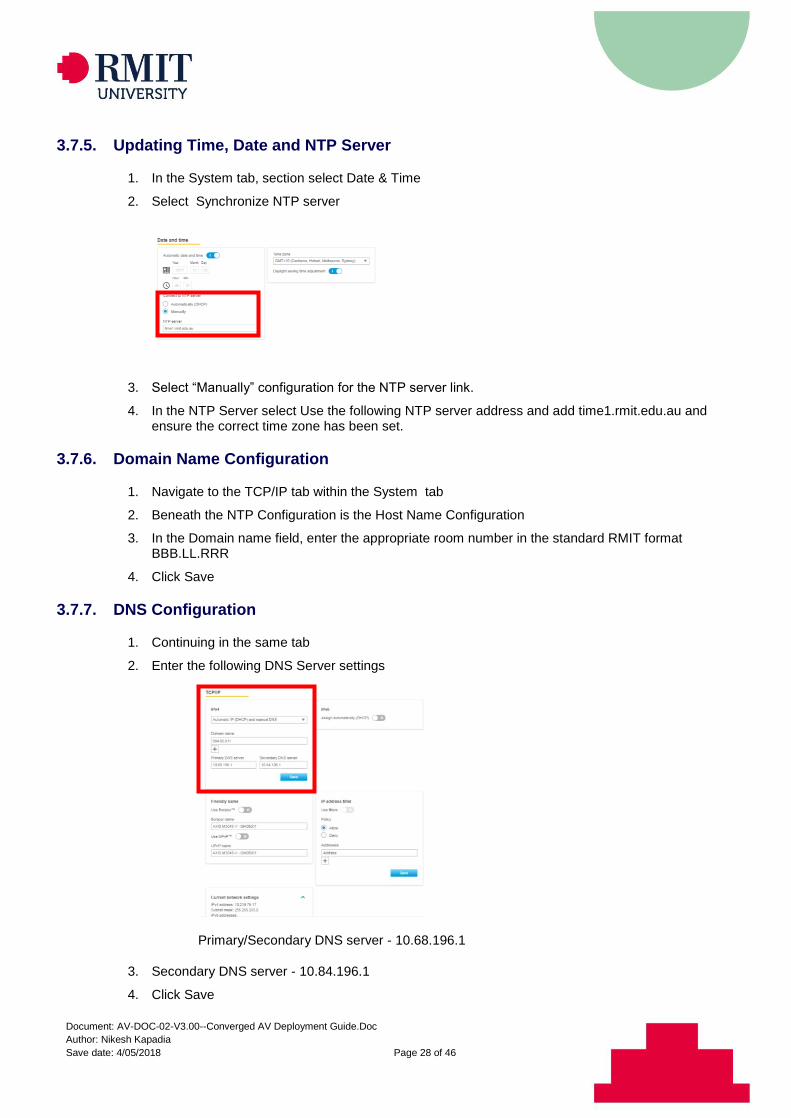
3.7.5. Updating Time, Date and NTP Server
1. In the System tab, section select Date & Time
2. Select Synchronize NTP server
3. Select “Manually” configuration for the NTP server link.
4. In the NTP Server select Use the following NTP server address and add time1.rmit.edu.au and ensure the correct time zone has been set.
3.7.6. Domain Name Configuration
1. Navigate to the TCP/IP tab within the System tab
2. Beneath the NTP Configuration is the Host Name Configuration
3. In the Domain name field, enter the appropriate room number in the standard RMIT format BBB.LL.RRR
4. Click Save
3.7.7. DNS Configuration
1. Continuing in the same tab
2. Enter the following DNS Server settings
Primary/Secondary DNS server - 10.68.196.1
3. Secondary DNS server - 10.84.196.1
4. Click Save
Document: AV-DOC-02-V3.00--Converged AV Deployment Guide.Doc
Author: Nikesh Kapadia
Save date: 4/05/2018 Page 29 of 46
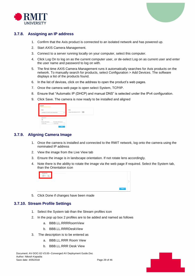
3.7.8. Assigning an IP address
1. Confirm that the Axis product is connected to an isolated network and has powered up.
2. Start AXIS Camera Management.
3. Connect to a server running locally on your computer, select this computer.
4. Click Log On to log on as the current computer user, or de-select Log on as current user and enter the user name and password to log on with.
5. The first time AXIS Camera Management runs it automatically searches for Axis products on the network. To manually search for products, select Configuration > Add Devices. The software displays a list of the products found.
6. In the list of devices, click on the address to open the product’s web pages.
7. Once the camera web page is open select System, TCP/IP.
8. Ensure that “Automatic IP (DHCP) and manual DNS” is selected under the IPv4 configuration.
9. Click Save. The camera is now ready to be installed and aligned
3.7.9. Aligning Camera Image
1. Once the camera is installed and connected to the RMIT network, log onto the camera using the nominated IP address
2. View the image from the Live View tab
3. Ensure the image is in landscape orientation. If not rotate lens accordingly.
4. Note there is the ability to rotate the image via the web page if required. Select the System tab, than the Orientation icon
5. Click Done if changes have been made
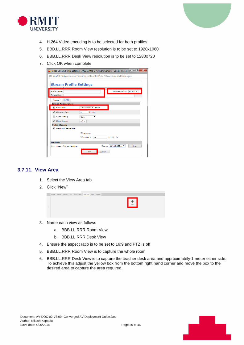
3.7.10. Stream Profile Settings
1. Select the System tab than the Stream profiles icon
2. In the pop up box 2 profiles are to be added and named as follows
a. BBB.LL.RRRRoomView
b. BBB.LL.RRRDeskView
3. The description is to be entered as
a. BBB.LL.RRR Room View
b. BBB.LL.RRR Desk View
Document: AV-DOC-02-V3.00--Converged AV Deployment Guide.Doc
Author: Nikesh Kapadia
Save date: 4/05/2018 Page 30 of 46
4. H.264 Video encoding is to be selected for both profiles
5. BBB.LL.RRR Room View resolution is to be set to 1920x1080
6. BBB.LL.RRR Desk View resolution is to be set to 1280x720
7. Click OK when complete
3.7.11. View Area
1. Select the View Area tab
2. Click “New”
3. Name each view as follows
a. BBB.LL.RRR Room View
b. BBB.LL.RRR Desk View
4. Ensure the aspect ratio is to be set to 16:9 and PTZ is off
5. BBB.LL.RRR Room View is to capture the whole room
6. BBB.LL.RRR Desk View is to capture the teacher desk area and approximately 1 meter either side. To achieve this adjust the yellow box from the bottom right hand corner and move the box to the desired area to capture the area required.
Document: AV-DOC-02-V3.00--Converged AV Deployment Guide.Doc
Author: Nikesh Kapadia
Save date: 4/05/2018 Page 31 of 46
3.8. HDMI Switcher
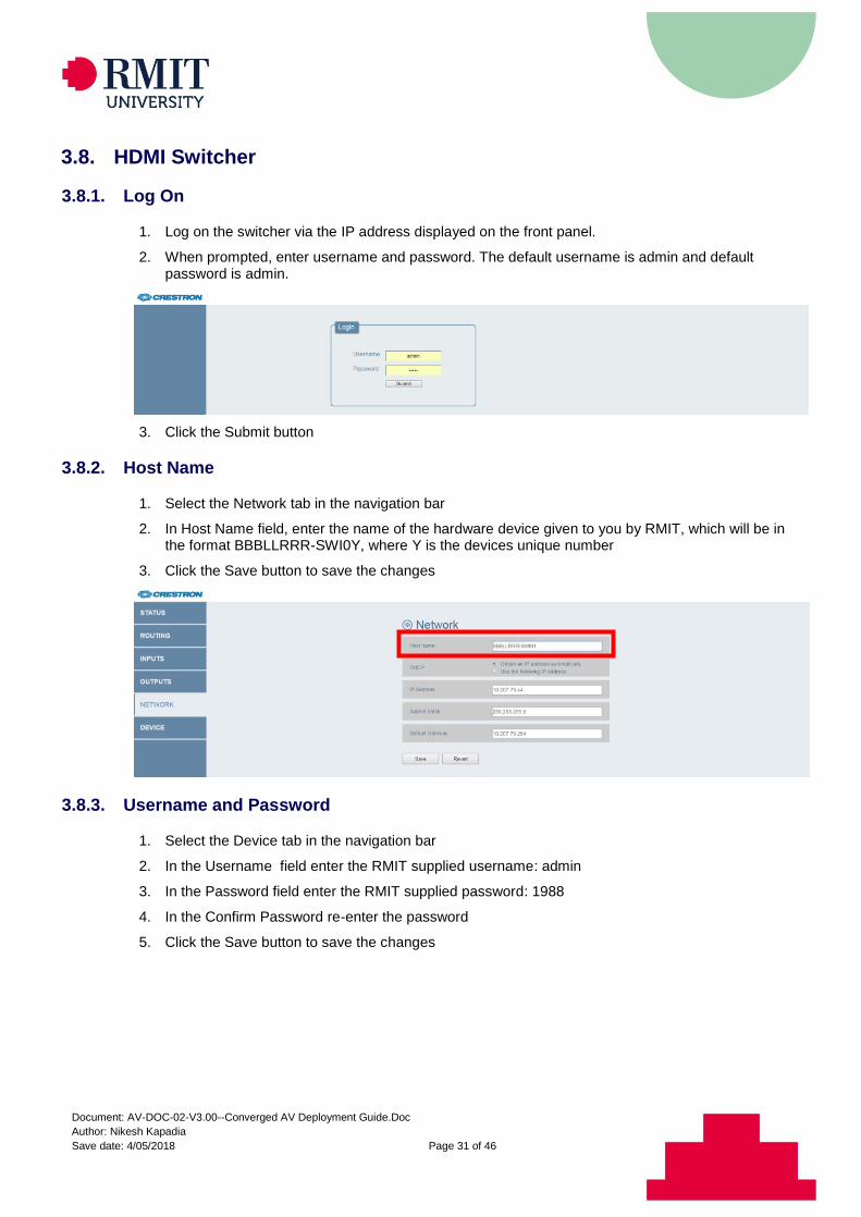
3.8.1. Log On
1. Log on the switcher via the IP address displayed on the front panel.
2. When prompted, enter username and password. The default username is admin and default password is admin.
3. Click the Submit button
3.8.2. Host Name
1. Select the Network tab in the navigation bar
2. In Host Name field, enter the name of the hardware device given to you by RMIT, which will be in the format BBBLLRRR-SWI0Y, where Y is the devices unique number
3. Click the Save button to save the changes
3.8.3. Username and Password
1. Select the Device tab in the navigation bar
2. In the Username field enter the RMIT supplied username: admin
3. In the Password field enter the RMIT supplied password: 1988
4. In the Confirm Password re-enter the password
5. Click the Save button to save the changes
Document: AV-DOC-02-V3.00--Converged AV Deployment Guide.Doc
Author: Nikesh Kapadia
Save date: 4/05/2018 Page 32 of 46
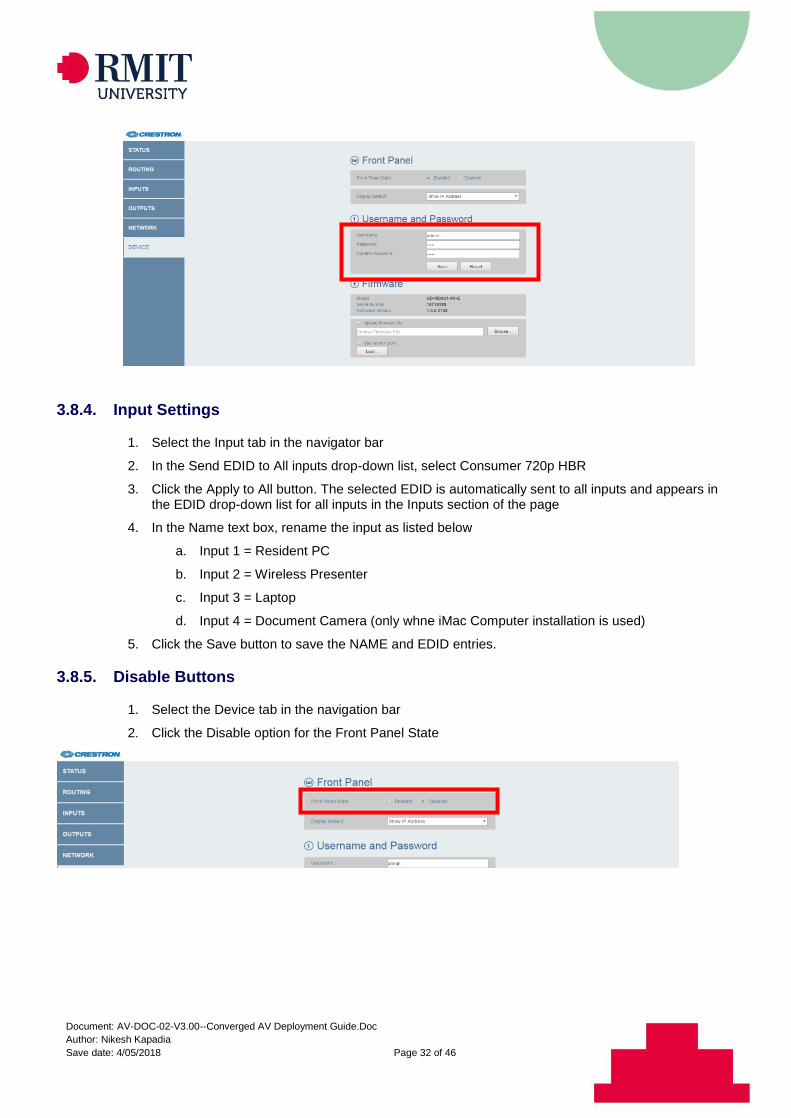
3.8.4. Input Settings
1. Select the Input tab in the navigator bar
2. In the Send EDID to All inputs drop-down list, select Consumer 720p HBR
3. Click the Apply to All button. The selected EDID is automatically sent to all inputs and appears in the EDID drop-down list for all inputs in the Inputs section of the page
4. In the Name text box, rename the input as listed below
a. Input 1 = Resident PC
b. Input 2 = Wireless Presenter
c. Input 3 = Laptop
d. Input 4 = Document Camera (only whne iMac Computer installation is used)
5. Click the Save button to save the NAME and EDID entries.
3.8.5. Disable Buttons
1. Select the Device tab in the navigation bar
2. Click the Disable option for the Front Panel State
Document: AV-DOC-02-V3.00--Converged AV Deployment Guide.Doc
Author: Nikesh Kapadia
Save date: 4/05/2018 Page 33 of 46
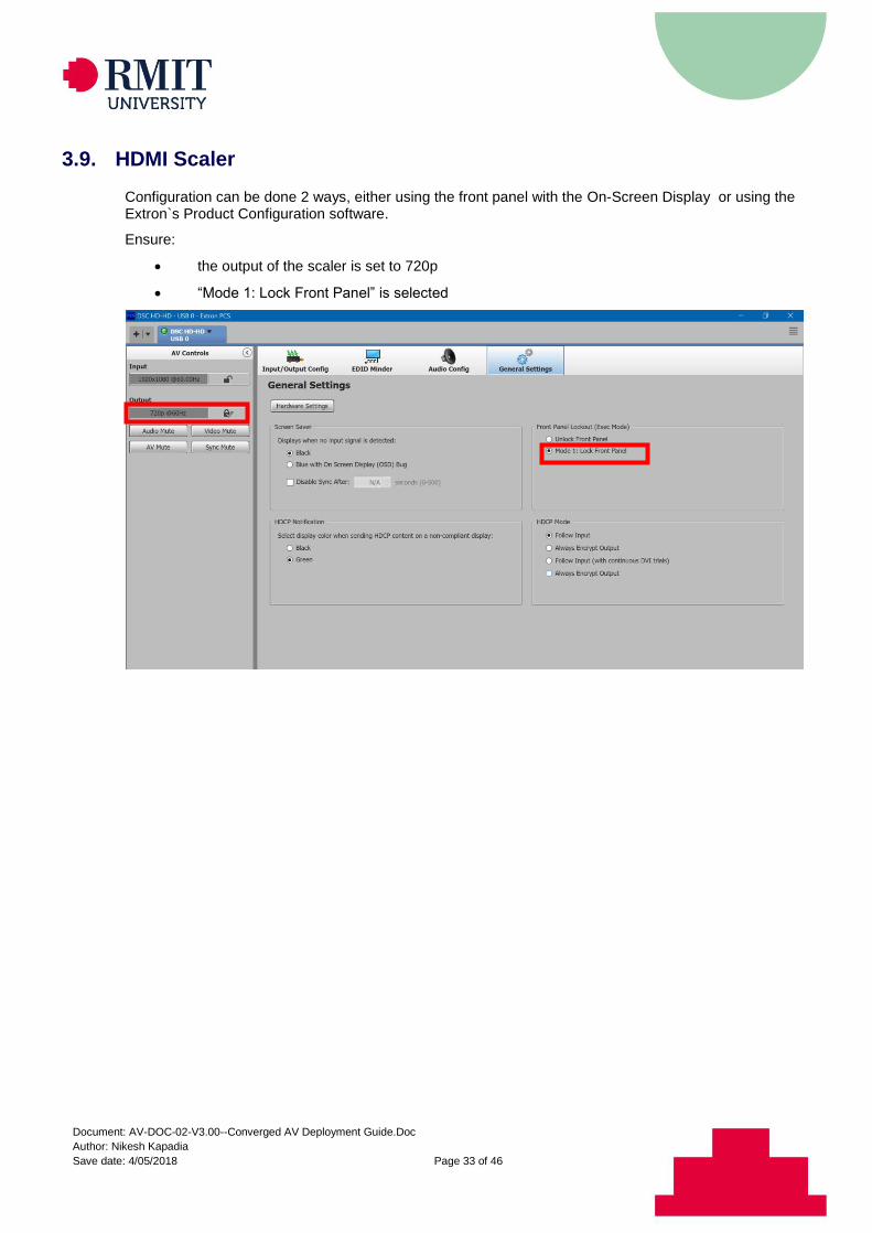
3.9. HDMI Scaler
Configuration can be done 2 ways, either using the front panel with the On-Screen Display or using the Extron`s Product Configuration software.
Ensure:
the output of the scaler is set to 720p
“Mode 1: Lock Front Panel” is selected
Document: AV-DOC-02-V3.00--Converged AV Deployment Guide.Doc
Author: Nikesh Kapadia
Save date: 4/05/2018 Page 34 of 46
3.10. Display Settings
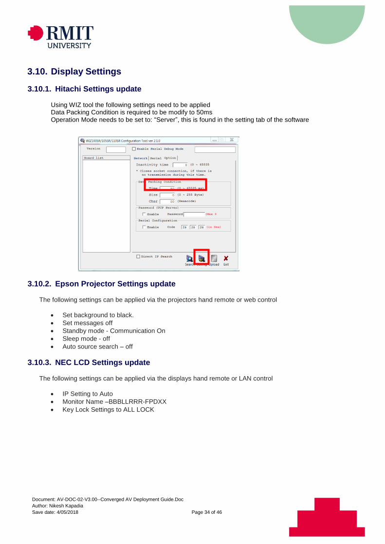
3.10.1. Hitachi Settings update
Using WIZ tool the following settings need to be applied Data Packing Condition is required to be modify to 50ms Operation Mode needs to be set to: “Server”, this is found in the setting tab of the software
3.10.2. Epson Projector Settings update
The following settings can be applied via the projectors hand remote or web control
Set background to black.
Set messages off
Standby mode - Communication On
Sleep mode - off
Auto source search – off
3.10.3. NEC LCD Settings update
The following settings can be applied via the displays hand remote or LAN control
IP Setting to Auto
Monitor Name –BBBLLRRR-FPDXX
Key Lock Settings to ALL LOCK
Document: AV-DOC-02-V3.00--Converged AV Deployment Guide.Doc
Author: Nikesh Kapadia
Save date: 4/05/2018 Page 35 of 46
4. AUDIO MEASUREMENT STANDARDS & GUIDELINES
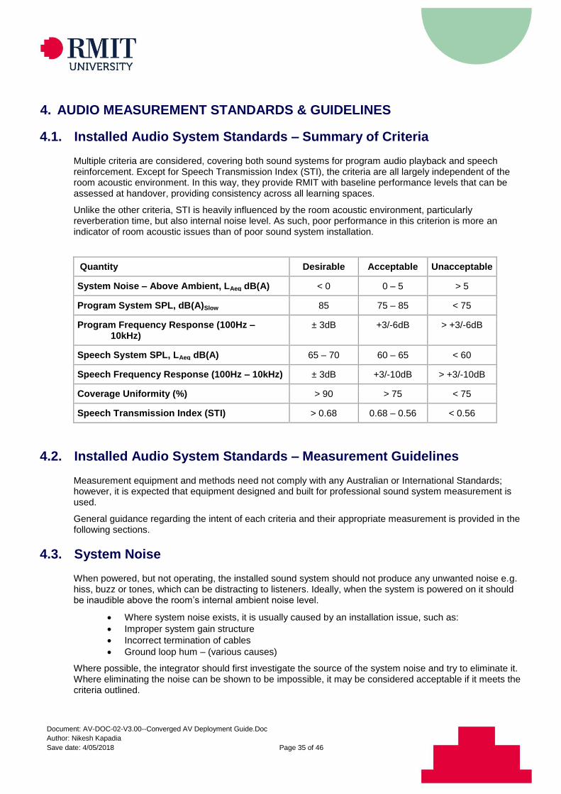
4.1. Installed Audio System Standards – Summary of Criteria
Multiple criteria are considered, covering both sound systems for program audio playback and speech reinforcement. Except for Speech Transmission Index (STI), the criteria are all largely independent of the room acoustic environment. In this way, they provide RMIT with baseline performance levels that can be assessed at handover, providing consistency across all learning spaces.
Unlike the other criteria, STI is heavily influenced by the room acoustic environment, particularly reverberation time, but also internal noise level. As such, poor performance in this criterion is more an indicator of room acoustic issues than of poor sound system installation.
Quantity Desirable Acceptable Unacceptable
System Noise – Above Ambient, LAeq dB(A) < 0 0 – 5 > 5
Program System SPL, dB(A)Slow 85 75 – 85 < 75
Program Frequency Response (100Hz – 10kHz)
± 3dB +3/-6dB > +3/-6dB
Speech System SPL, LAeq dB(A) 65 – 70 60 – 65 < 60
Speech Frequency Response (100Hz – 10kHz) ± 3dB +3/-10dB > +3/-10dB
Coverage Uniformity (%) > 90 > 75 < 75
Speech Transmission Index (STI) > 0.68 0.68 – 0.56 < 0.56
4.2. Installed Audio System Standards – Measurement Guidelines
Measurement equipment and methods need not comply with any Australian or International Standards; however, it is expected that equipment designed and built for professional sound system measurement is used.
General guidance regarding the intent of each criteria and their appropriate measurement is provided in the following sections.
4.3. System Noise
When powered, but not operating, the installed sound system should not produce any unwanted noise e.g. hiss, buzz or tones, which can be distracting to listeners. Ideally, when the system is powered on it should be inaudible above the room’s internal ambient noise level.
Where system noise exists, it is usually caused by an installation issue, such as:
Improper system gain structure
Incorrect termination of cables
Ground loop hum – (various causes)
Where possible, the integrator should first investigate the source of the system noise and try to eliminate it. Where eliminating the noise can be shown to be impossible, it may be considered acceptable if it meets the criteria outlined.
Document: AV-DOC-02-V3.00--Converged AV Deployment Guide.Doc
Author: Nikesh Kapadia
Save date: 4/05/2018 Page 36 of 46
4.4. Measurement Locations
System noise measurements should be taken at the expected occupancy positions throughout the space, at approximate ear height for either seated or standing persons as appropriate for the space – i.e. 1200 or 1600mm AFFL respectively.
An indicative sample position can be chosen where there is little spatial variation in system noise level. Where significant spatial variation exists (e.g. close to a buzzing speaker) the location should be chosen to reflect the maximum recorded level.
4.5. Measured Internal Ambient Noise
The internal ambient noise level must first be measured to assess the system noise level. Internal ambient noise measurements should be taken at the same location as the corresponding system noise measurement.
4.6. Reported Noise Level
The reported system noise level should be the maximum found across the expected occupancy positions in the space. The system noise level is:
Acceptable, if it is indistinguishable from the internal ambient noise level;
Unacceptable, if it exceeds the internal ambient by more than 5dB.
4.7. Measurement Conditions - Inclusion of Noise Sources
Measurements should be made under the typically expected operating conditions of the space, i.e. with all heating, ventilation and air conditioning (HVAC) equipment operating, road traffic and building occupancy noise present.
Where an ambient noise source is known to be out of the ordinary, (e.g. building construction works) the measurement should be scheduled for a time when it is not present.
4.8. Sound Level Measurements
Both internal ambient and system noise levels must be measured with an integrating sound level meter, capable of measuring the Equivalent Continuous A-weighted sound pressure level (LAeq), over a 30s period.
4.9. System SPL – Program and Speech
Within a certain tolerance, system sound pressure levels (SPLs) should be consistent from space to space, regardless of their size. i.e. a lecture theatre’s sound system should not necessarily be louder than a classroom just because it is a larger space. Larger spaces require more attention to evenness of coverage, but not necessarily more SPL.
For this reason, the system SPL criteria apply to all spaces equipped with program playback and / or speech reinforcement systems.
For program audio playback in learning environments, sound systems should be capable of maximum SPLs commensurate with a foreground music reproduction system. i.e. the loudest one might comfortably operate a home Hi-Fi system.
For speech reproduction in learning environments, sound systems should be capable of average levels similar to unaided conversational speech at 1m. The system does not need to increase speech SPLs above human levels, but should aim to deliver a similar level to all listeners.
Document: AV-DOC-02-V3.00--Converged AV Deployment Guide.Doc
Author: Nikesh Kapadia
Save date: 4/05/2018 Page 37 of 46
4.10. Measurement Locations
Program SPL measurements should be taken at a location not too close, and not too far from each loudspeaker. The exact position will vary with loudspeaker and room, but generally:
Outside the ‘near-field’ of the loudspeaker (at least 3x the height of the loudspeaker)
Inside the critical distance (DC) of the loudspeaker in the room
On-axis of the high frequency device in the loudspeaker system
At ear height of either seated or standing listeners as appropriate
An appropriate position is typically between 3m and 6m from the loudspeaker, on-axis.
Speech SPL measurements should be taken at the expected occupancy positions throughout the space, at approximate ear height for either seated or standing persons as appropriate for the space – i.e. 1200 or 1600mm AFFL respectively.
An indicative sample position can be chosen, representing the ‘worst case’ listener. i.e. typically the furthest occupancy position from the presenter and furthest from the closest sound reinforcement loudspeaker.
4.11. Reported SPLs
The reported program SPL should be the maximum achieved by the system at the measurement position. i.e. the user volume control should be at maximum during the measurement.
The reported speech SPL should be the average level achieved by the system at the ‘worst case’ listener position, over a 30s period of continuous speech.
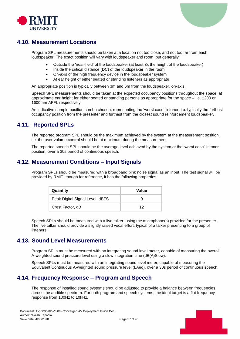
4.12. Measurement Conditions – Input Signals
Program SPLs should be measured with a broadband pink noise signal as an input. The test signal will be provided by RMIT, though for reference, it has the following properties.
Quantity Value
Peak Digital Signal Level, dBFS 0
Crest Factor, dB 12
Speech SPLs should be measured with a live talker, using the microphone(s) provided for the presenter. The live talker should provide a slightly raised vocal effort, typical of a talker presenting to a group of listeners.
4.13. Sound Level Measurements
Program SPLs must be measured with an integrating sound level meter, capable of measuring the overall A-weighted sound pressure level using a slow integration time (dB(A)Slow).
Speech SPLs must be measured with an integrating sound level meter, capable of measuring the Equivalent Continuous A-weighted sound pressure level (LAeq), over a 30s period of continuous speech.
4.14. Frequency Response – Program and Speech
The response of installed sound systems should be adjusted to provide a balance between frequencies across the audible spectrum. For both program and speech systems, the ideal target is a flat frequency response from 100Hz to 10kHz.
Document: AV-DOC-02-V3.00--Converged AV Deployment Guide.Doc
Author: Nikesh Kapadia
Save date: 4/05/2018 Page 38 of 46
Although other target responses could be adopted – e.g. a more ‘Hi-Fi’ sounding response with boosted low and high frequencies – a flat frequency response is chosen as it is most appropriate for speech reproduction; the primary use of sound systems in learning environments.
4.15. Measurement Locations
Program frequency response measurements should be taken at the same position used to measure the program SPL from each loudspeaker.
Speech frequency response measurements should be taken at the same position used to measure speech SPL. The same ‘worst case’ listener position should be used.
4.16. Reported Frequency Response
The reported program frequency response should be that achieved by the system at 75% volume, at the measurement position. i.e. the user volume control should be at 75% during the measurement.
The program frequency response is:
Desirable, when all deviations fall within ±3dB;
Acceptable, when all deviations fall within +3/-6dB;
Unacceptable, when any deviations fall outside +3/-6dB; over the range 100Hz to 10kHz. The reported speech frequency response should be that achieved by the system at nominal volume – as speech systems have no volume control – at the ‘worst case’ listener position. The speech frequency response is:
Desirable, when all deviations fall within ±3dB;
Acceptable, when all deviations fall within +3/-10dB;
Unacceptable, when any deviations fall outside +3/-10dB; over the range 100Hz to 10kHz.
Note: the speech frequency response criteria allows for greater negative deviations to account for the expected roll-off in high frequency from ceiling speaker systems when measuring at the ‘worst case’ position, off-axis.
Care should be taken to ensure dips in measured frequency response due to measurement conditions – e.g. floor bounce, side wall reflection, loudspeaker crossover etc – are excluded from the assessment of frequency response.
4.17. Measurement Conditions – Operating Loudspeakers
For program frequency response measurements, one loudspeaker should be measured at a time (i.e. left / right speakers separately).
For speech frequency response measurements, all loudspeakers should be active during the measurement.
Document: AV-DOC-02-V3.00--Converged AV Deployment Guide.Doc
Author: Nikesh Kapadia
Save date: 4/05/2018 Page 39 of 46
4.18. Measurement Conditions – Input Signals
Program and speech frequency response measurements can be made with any signal suitable for 2-channel Transfer Function (TF) measurements as an input. E.g.:
Broadband pink noise
Swept sine signals
Pre-recorded speech or music
Note: if using speech or music as a stimulus signal, ensure the track has sufficient energy in all frequencies between 100Hz and 10kHz to achieve a valid measurement.
4.19. Frequency Response Measurements
Program and speech frequency response measurements should be made as 2-channel, Transfer Function (TF) measurements, using a Fast-Fourier-Transform (FFT) based analyser.
4.20. Coverage Uniformity
Detailed guidance regarding audio coverage uniformity (ACU) is provided in ANSI/InfoComm Standard 1M-2009. Refer to 1m-2009 and its references for a complete description of ACU, its measurement and application.
In implementing ACU criteria, RMIT has adopted the intent of 1M-2009, but modified sections of its application. In particular, determining the ACU plan, which establishes the location and quantity of measurement locations. The major change is the inclusion of the entire floor area of the space in the calculations, as the flexible nature of learning spaces at RMIT means listeners may be seated almost anywhere.
With these modifications, the acceptable range of ACU has also been adjusted, from the threshold of 90% mandated by 1M-2009, to a more modest 75%.
For program audio playback from stereo loudspeakers at the front of a typical classroom, the 1M-2009 ACU specification of 90% can be difficult to achieve. The natural variation of SPL over distance, in a space where listeners at the front can be very close to the loudspeakers, relative to listeners at the back, can easily create an SPL differential that exceeds the 6dB allowed.
Similarly, in classrooms with typical ceiling heights of around 2.7m and an array of flush ceiling speakers, the natural variation in SPL between directly below a loudspeaker (i.e. on-axis) and off to one side (i.e. off-axis) can exceed the 1M-2009 ACU specification of 90%.
For these reasons, the more achievable 75% tolerance has been adopted.
4.21. Measurement Locations
ACU measurement locations should be arranged in a rectangular grid, relative to the length and width of the space. For non-rectangular spaces, approximate a rectangular grid, as close as possible to the major perpendicular axes of the space.
For highly irregular shaped spaces, overlay a rectangular grid and add / omit measurements as required to cover the majority of the space.
The quantity and location of measurement locations should be determined as per the following guidelines:
Quantity
Spaces with floor areas up to 50m2 should have 9 test points
Spaces with floor areas up to 100m2 should have 12 test points
Spaces with floor areas up to 150m2 should have 16 test points
Spaces with floor areas larger than 150m2 should follow the complete 1M-2009 method
Document: AV-DOC-02-V3.00--Converged AV Deployment Guide.Doc
Author: Nikesh Kapadia
Save date: 4/05/2018 Page 40 of 46
Note: for the purposes of floor area calculation, the entire length and width of the space should be used; not just the seating area.
Locations
Measurement positions should include the corners and perimeter of the grid
No measurement position should be closer than 500mm to any boundary
Internal grid positions spaced such that the required points fit evenly into a regular pattern across the floor area
Grid spacing length and width-wise can be slightly different to accommodate the space Each measurement should be taken at the approximate ear height for either seated or standing persons as appropriate for the space – i.e. 1200 or 1600mm AFFL respectively.
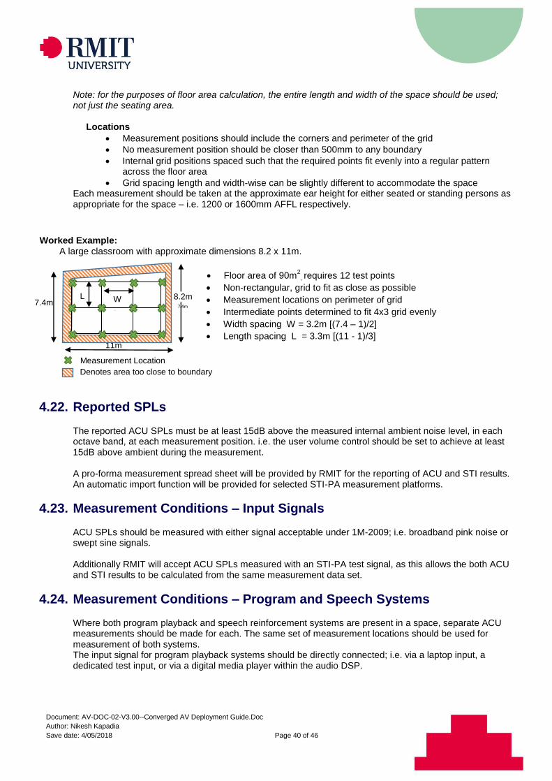
Worked Example:
A large classroom with approximate dimensions 8.2 x 11m.
Floor area of 90m
2, requires 12 test points
Non-rectangular, grid to fit as close as possible
Measurement locations on perimeter of grid
Intermediate points determined to fit 4x3 grid evenly
Width spacing W = 3.2m [(7.4 – 1)/2]
Length spacing L = 3.3m [(11 - 1)/3]
4.22. Reported SPLs
The reported ACU SPLs must be at least 15dB above the measured internal ambient noise level, in each octave band, at each measurement position. i.e. the user volume control should be set to achieve at least 15dB above ambient during the measurement. A pro-forma measurement spread sheet will be provided by RMIT for the reporting of ACU and STI results. An automatic import function will be provided for selected STI-PA measurement platforms.
4.23. Measurement Conditions – Input Signals
ACU SPLs should be measured with either signal acceptable under 1M-2009; i.e. broadband pink noise or swept sine signals. Additionally RMIT will accept ACU SPLs measured with an STI-PA test signal, as this allows the both ACU and STI results to be calculated from the same measurement data set.
4.24. Measurement Conditions – Program and Speech Systems
Where both program playback and speech reinforcement systems are present in a space, separate ACU measurements should be made for each. The same set of measurement locations should be used for measurement of both systems. The input signal for program playback systems should be directly connected; i.e. via a laptop input, a dedicated test input, or via a digital media player within the audio DSP.
11m
W 11m
8.2m 7.4m
m
Denotes area too close to boundary
Measurement Location
7.4m
L 11m
Document: AV-DOC-02-V3.00--Converged AV Deployment Guide.Doc
Author: Nikesh Kapadia
Save date: 4/05/2018 Page 41 of 46
The input signal for speech reinforcement systems must be the user microphone. The input signal must therefore be reproduced by a suitable loudspeaker, positioned to act as an artificial talker. IEC 60268-16:2001 section 7.2 provides guidance for the requirements of such a loudspeaker.
4.25. Measurement Conditions – Operating Loudspeakers
For program ACU measurements, both loudspeakers should be measured simultaneously (i.e. left / right speakers together). For speech ACU measurements, all loudspeakers should be active during the measurement.
4.26. Sound Level Measurements
ACU SPLs must be measured with an integrating sound level meter, capable of measuring the octave band, un-weighted sound pressure level using a slow integration time (dB(Z)Slow).
4.27. Speech Transmission Index (STI)
Detailed guidance regarding Speech Transmission Index (STI) is provided in IEC Standard 60268-16:2011. Refer to IEC 60268-16:2011 and its references for a complete description of STI, its measurement and application. Sound systems for both program playback and sound reinforcement should be adjusted to yield acceptable speech intelligibility, as accurate reproduction of speech is the primary use of sound systems in learning environments. With the exception of RASTI, any of the methods outlined in IEC 60268-16:2011 is suitable for measuring STI. The STI-PA method is recommended for its convenience, as it is fast, and can be implemented using a hand-held device. Full STI calculated from analysis of a system impulse response is also possible, but typically requires more time on-site and in post-processing.
4.28. Measurement Locations
STI measurements should be taken at the same positions used for Audio Coverage Uniformity (ACU), as it is recommended that STI results are taken from the same measurement data set as ACU. See section on ACU for details.
4.29. Reported STI
The reported STI values should be that achieved by the system at the level required for ACU, at each measurement position. i.e. the user volume control should be at set as required for ACU during the measurement. As per IEC 60268-16:2001, at least three STI measurements should be taken at each measurement location. If the variance between the first three measurements is greater than 0.03, another three (for a total of six) should be taken. A pro-forma measurement spreadsheet will be provided by RMIT for the reporting of ACU and STI results. An automatic import function will be provided for selected STI-PA measurement platforms.
Document: AV-DOC-02-V3.00--Converged AV Deployment Guide.Doc
Author: Nikesh Kapadia
Save date: 4/05/2018 Page 42 of 46
4.30. Measurement Conditions – Input Signals
As STI can be measured by several methods as defined in IEC 60268-16:2001, there are numerous appropriate input signals. Signals for the two recommended methods are discussed below. If using the STI-PA method, use the specific STI-PA test tone supplied with your measurement device. If calculating STI from a system impulse response, use any signal suitable for 2-channel Transfer Function (TF) measurements as an input. E.g.:
Broadband pink noise
Swept sine signals
Pre-recorded speech or music Note: if using speech or music as a stimulus source, ensure the track has sufficient energy in all frequencies between 100Hz and 10kHz to achieve a valid measurement.
4.31. Measurement Conditions – Program and Speech Systems
Where both program playback and speech reinforcement systems are present in a space, separate STI measurements should be made for each. The same set of measurement locations should be used for measurement of both systems. The input signal for program playback systems should be directly connected; i.e. via a laptop input, a dedicated test input, or via a digital media player within the audio DSP. The input signal for speech reinforcement systems must be the user microphone. The input signal must therefore be reproduced by a suitable loudspeaker, positioned to act as an artificial talker. IEC 60268-16:2001 section 7.2 provides guidance for the requirements of such a loudspeaker.
4.32. Measurement Conditions – Operating Loudspeakers
For program STI measurements, one loudspeaker should be measured at a time (i.e. left / right speakers separately).
Document: AV-DOC-02-V3.00--Converged AV Deployment Guide.Doc
Author: Nikesh Kapadia
Save date: 4/05/2018 Page 43 of 46
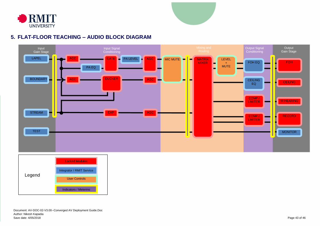
5. FLAT-FLOOR TEACHING – AUDIO BLOCK DIAGRAM
Output Gain Stage
Input Signal Conditioning
Mixing and Routing
Input Gain Stage
Output Signal Conditioning
FOH
CEILING
AEC GATE AGC
PA EQ
DUCKER AGC
IR HEARING
MIC MUTE LAPEL
BOUNDARY AEC
FOH EQ
CEILING EQ
MATRIX MIXER
LEVEL +
MUTE
RECORD
MONITOR
AGC EXP STREAM
TEST
COMP / LIMITER
COMP / LIMITER
PA LEVEL
Locked Modules
Integrator / RMIT Service
Indicators / Metering
User Controls Legend
Document: AV-DOC-02-V3.00--Converged AV Deployment Guide.Doc
Author: Nikesh Kapadia
Save date: 4/05/2018 Page 44 of 46
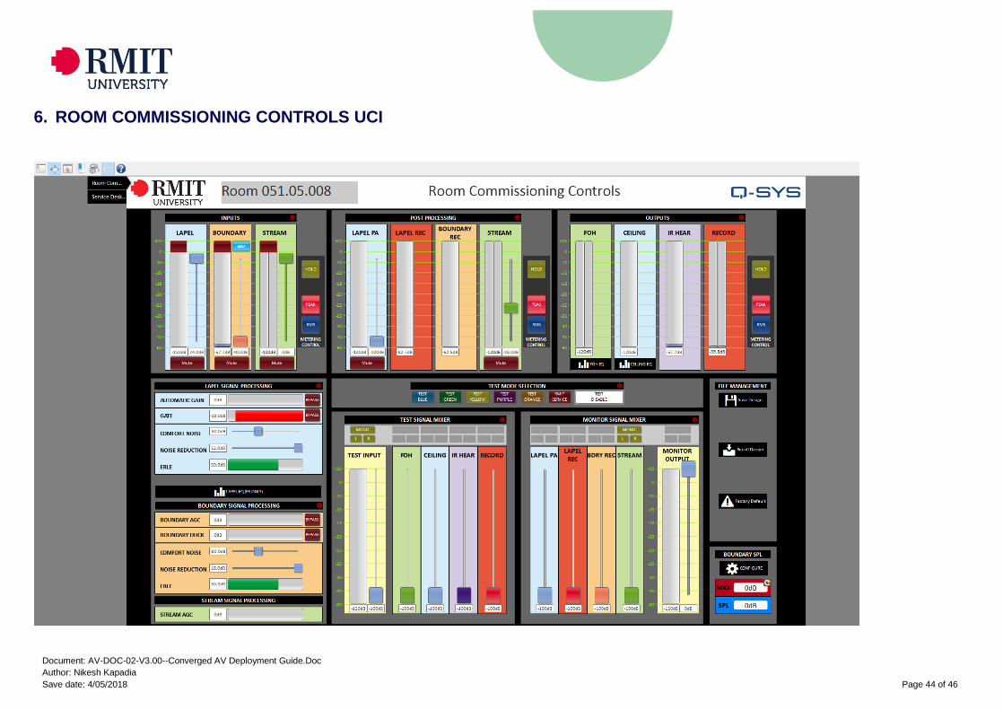
6. ROOM COMMISSIONING CONTROLS UCI
Document: AV-DOC-02-V3.00--Converged AV Deployment Guide.Doc
Author: Nikesh Kapadia
Save date: 4/05/2018 Page 45 of 46
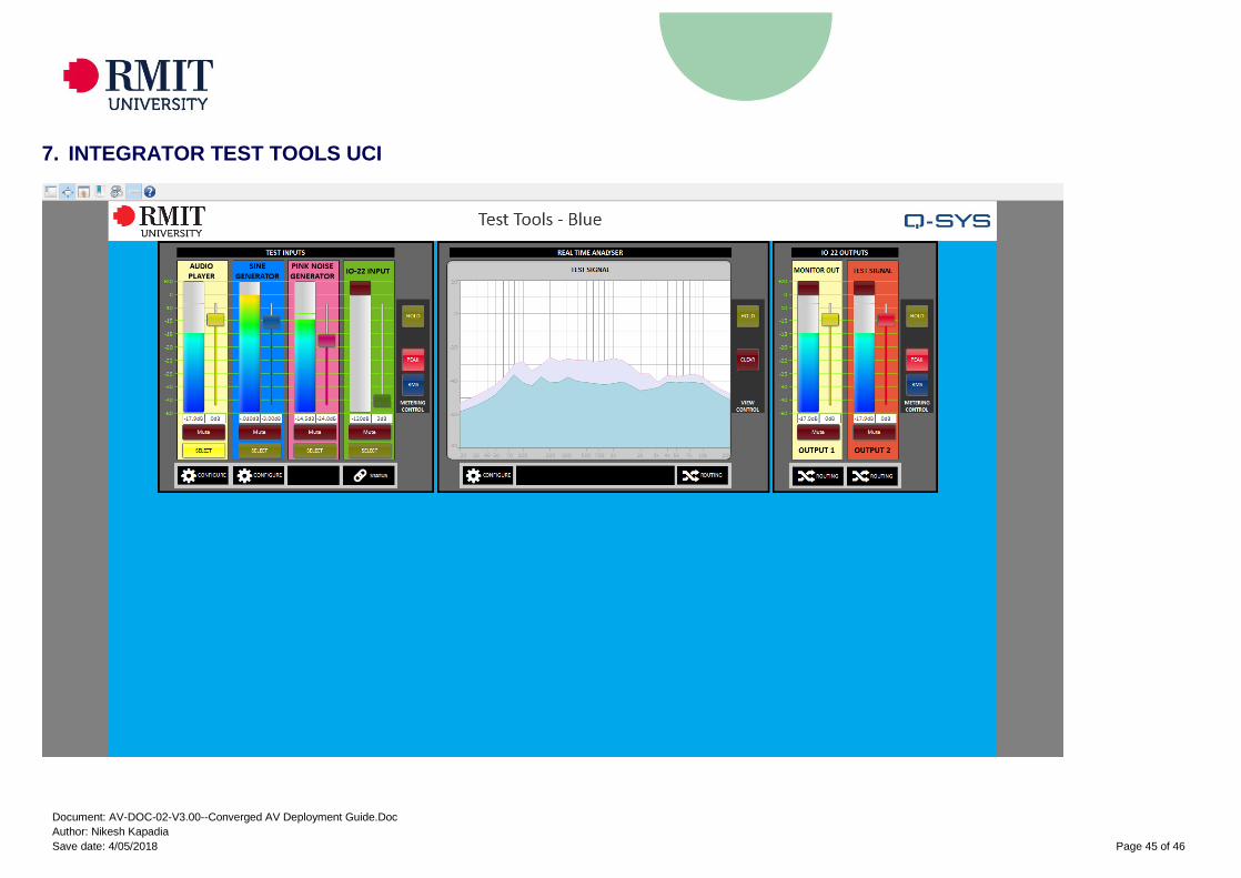
7. INTEGRATOR TEST TOOLS UCI
Document: AV-DOC-02-V3.00--Converged AV Deployment Guide.Doc
Author: Nikesh Kapadia
Save date: 4/05/2018 Page 46 of 46
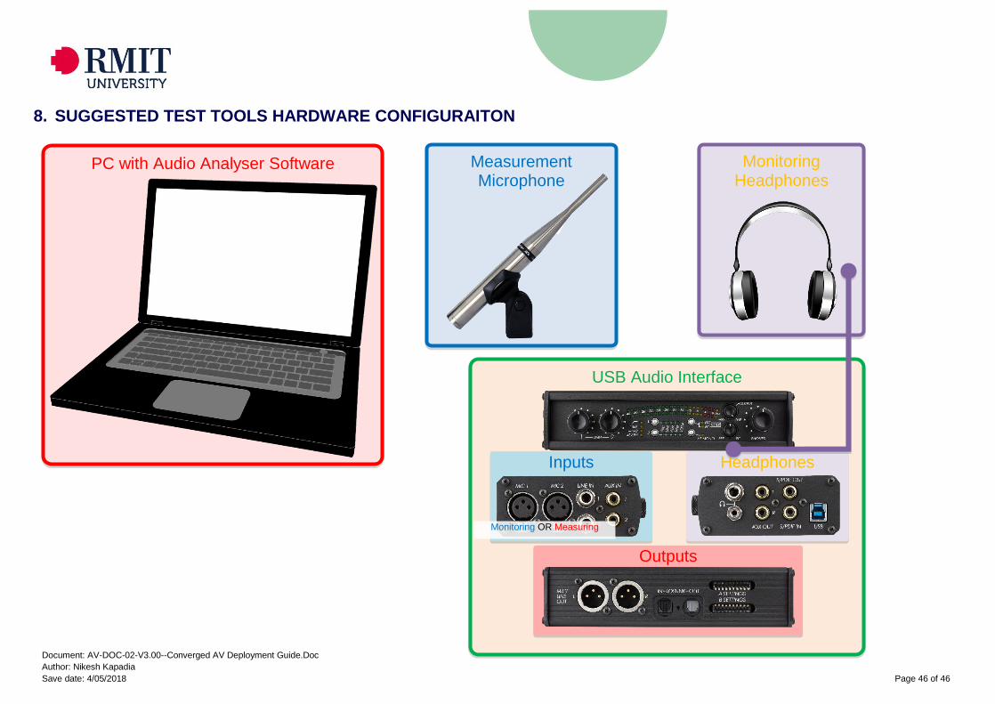
8. SUGGESTED TEST TOOLS HARDWARE CONFIGURAITON
Monitoring Headphones
Measurement Microphone
PC with Audio Analyser Software
USB Audio Interface
Inputs
Outputs
Headphones
Monitoring OR Measuring
Related Documents