Report ITU-R M.2474-0 (09/2019) Conventional digital land mobile radio systems M Series Mobile, radiodetermination, amateur and related satellite services

Welcome message from author
This document is posted to help you gain knowledge. Please leave a comment to let me know what you think about it! Share it to your friends and learn new things together.
Transcript

Report ITU-R M.2474-0 (09/2019)
Conventional digital land mobile radio systems
M Series
Mobile, radiodetermination, amateur
and related satellite services
ii Rep. ITU-R M.2474-0
Foreword
The role of the Radiocommunication Sector is to ensure the rational, equitable, efficient and economical use of the radio-
frequency spectrum by all radiocommunication services, including satellite services, and carry out studies without limit
of frequency range on the basis of which Recommendations are adopted.
The regulatory and policy functions of the Radiocommunication Sector are performed by World and Regional
Radiocommunication Conferences and Radiocommunication Assemblies supported by Study Groups.
Policy on Intellectual Property Right (IPR)
ITU-R policy on IPR is described in the Common Patent Policy for ITU-T/ITU-R/ISO/IEC referenced in Resolution ITU-
R 1. Forms to be used for the submission of patent statements and licensing declarations by patent holders are available
from http://www.itu.int/ITU-R/go/patents/en where the Guidelines for Implementation of the Common Patent Policy for
ITU-T/ITU-R/ISO/IEC and the ITU-R patent information database can also be found.
Series of ITU-R Reports
(Also available online at http://www.itu.int/publ/R-REP/en)
Series Title
BO Satellite delivery
BR Recording for production, archival and play-out; film for television
BS Broadcasting service (sound)
BT Broadcasting service (television)
F Fixed service
M Mobile, radiodetermination, amateur and related satellite services
P Radiowave propagation
RA Radio astronomy
RS Remote sensing systems
S Fixed-satellite service
SA Space applications and meteorology
SF Frequency sharing and coordination between fixed-satellite and fixed service systems
SM Spectrum management
Note: This ITU-R Report was approved in English by the Study Group under the procedure detailed in
Resolution ITU-R 1.
Electronic Publication
Geneva, 2019
ITU 2019
All rights reserved. No part of this publication may be reproduced, by any means whatsoever, without written permission of ITU.
Rep. ITU-R M.2474-0 1
REPORT ITU-R M.2474-0
Conventional digital land mobile radio systems
(2019)
TABLE OF CONTENTS
Page
1 Summary ......................................................................................................................... 2
2 Related Recommendations and Reports ......................................................................... 2
3 Acronyms and Definitions .............................................................................................. 3
4 Introduction .................................................................................................................... 4
4.1 Typical CLMR system architecture .................................................................... 4
4.2 CDLMR .............................................................................................................. 7
5 General technical and operational considerations .......................................................... 9
6 Systems technical characteristics and operational features and standards ..................... 10
6.1 Systems technical characteristics and operational features ................................ 10
6.2 Standards ............................................................................................................. 11
6.3 Summary of Conventional DLMR systems features .......................................... 14
7 Frequency bands ............................................................................................................. 14
7.1 Frequency bands ................................................................................................. 14
7.2 Channel spacing and centre frequencies ............................................................. 14
7.3 Channel arrangements ........................................................................................ 15
8 Frequency selection and assignment .............................................................................. 15
8.1 Examples of frequency assignment methods ...................................................... 16
9 Analogue to digital transition ......................................................................................... 16
9.1 Digital Voice and Data ....................................................................................... 17
9.2 Transition analogue to digital ............................................................................. 17
10 Interleaved and offset channelling arrangements ........................................................... 18
10.1 Interleaved channel plans ................................................................................... 18
10.2 Offset channel plans ........................................................................................... 18
2 Rep. ITU-R M.2474-0
Page
Annex 1 – An example of frequency bands and channel spacings for CLMR systems .......... 19
1 Introduction .................................................................................................................... 19
2 Example of frequency bands and channelling ................................................................ 19
Annex 2 – An example of frequency channel selection for CLMR systems using
Frequency-Distance Criteria ........................................................................................... 20
1 Introduction .................................................................................................................... 20
2 Frequency – Distance criteria ......................................................................................... 21
2.1 Deployment model .............................................................................................. 21
2.2 Minimum distance separation between two CLMR system type A ................... 21
2.3 Minimum distance separation between two CLMR system type B ................... 23
2.4 Minimum distance separation between two CLMR system type C ................... 25
2.5 Minimum distance separation between a CLMR system type A and type B ..... 27
Annex 3 – An example of frequency assignment plan for 25 kHz channels that are separated
by 10 channels from each other in a group ..................................................................... 29
1 Summary
This Report deals with the technical and operational characteristics of conventional (non-cellular)
digital land mobile radio (CDLMR) systems that provide capabilities required for specific user
groups/applications, such as governmental, mining, health, hospitality, transportations, disaster relief,
industrial, manufacturing, construction, etc. This report also includes information on approaches to
frequency assignments for CDLMR.
Digital Cellular Land Mobile Telecommunication Systems, including IMT systems, are addressed in
other ITU documents.
Digital Land Mobile Radiocommunication Systems for specific applications, such as PPDR and
trunked systems for dispatch, are addressed in other ITU documents.
2 Related Recommendations and Reports
Recommendation ITU-R M.1073 – Digital Cellular Land Mobile Telecommunication Systems
Recommendation ITU-R M.2009 – Radio interface standards for use by public protection and disaster
relief operations in accordance with Resolution 646 (Rev.WRC-15)
Recommendation ITU-R M.2015 – Frequency arrangements for public protection and disaster relief
radiocommunication systems in accordance with Resolution 646 (Rev.WRC-15)
Rep. ITU-R M.2474-0 3
Report ITU-R M.2014 – Digital land mobile systems for dispatch traffic
Report ITU-R M.2377 – Radiocommunication objectives and requirements for Public Protection and
Disaster Relief
Report ITU-R M.2415 – Spectrum needs for Public Protection and Disaster Relief (PPDR)
3 Acronyms and Definitions
AES Advanced encryption standard
AMBE+2 Advanced multi-band excitation
CDLMR Conventional digital land mobile radio
CLMR Conventional land mobile radio
CTCSS Continuous tone-coded squelch system
DCS Digital code squelch
DES Data encryption standard
DMO Direct mode operation
ECC Electronic Communications Committee
ETSI European Telecommunication Standards Institute
FDMA Frequency division multiple access
FSK Frequency shift keying
GPS Global Positioning System
IMBE Improved multi-band excitation
IPv4 Internet Protocol V4
IPv6 Internet Protocol V6
LBT Listen before talk
LMR Land mobile radio
PLMR Private land mobile radio
PPDR Public protection and disaster relief
PTT Push to talk
R Receiver
RF Radio Frequency
SMS Short Message Service
T Transmitter
TDMA Time division multiple access
Conventional Digital Land Mobile Radio (CDLMR) System: CLMR system that transmits and
receives using digital modulation techniques.
Conventional Land Mobile Radio (CLMR) System: Non-cellular radiocommunications system where
two or more LMR stations communicate on a predetermined frequency channel(s), without the use

4 Rep. ITU-R M.2474-0
of any controlling station and/or control frequency channel, with push-to-talk and group
communications capabilities.
Land Mobile Radio (LMR) System: Analogue or digital two-way conventional or trunked radio
communications system in which two or more fixed or mobile radio stations in the land mobile service
communicate on one or more frequency (ies).
Private Land Mobile Radio (PLMR or PMR) System: LMR system utilized by a closed group of users
to meet specific radiocommunication requirements.
Trunked Land Mobile Radio (TLMR) System: Radiocommunications system where two or more
LMR stations communicate on frequency channels assigned by a controlling station automatically
from a set of defined frequencies in real time using a radiocommunication protocol.
4 Introduction
This Report addresses non-cellular private land mobile radio (PLMR) communications systems that
have been providing two way communications for many industries for decades and are expected to
continue to serve millions of businesses and industries around the world. These systems enable
flexibility in deployment and can utilise limited spectrum resources to meet the needs of different
users. Applications for PLMR include schools, seaports, construction sites, convention halls,
factories, retailers and delivery services, etc.
PLMR systems could be trunked or conventional. Trunked LMR systems are described in Report
ITU-R M.2014.
The characteristics of digital cellular land mobile telecommunication systems are given in
Recommendation ITU-R M.1073.
4.1 Typical CLMR system architecture
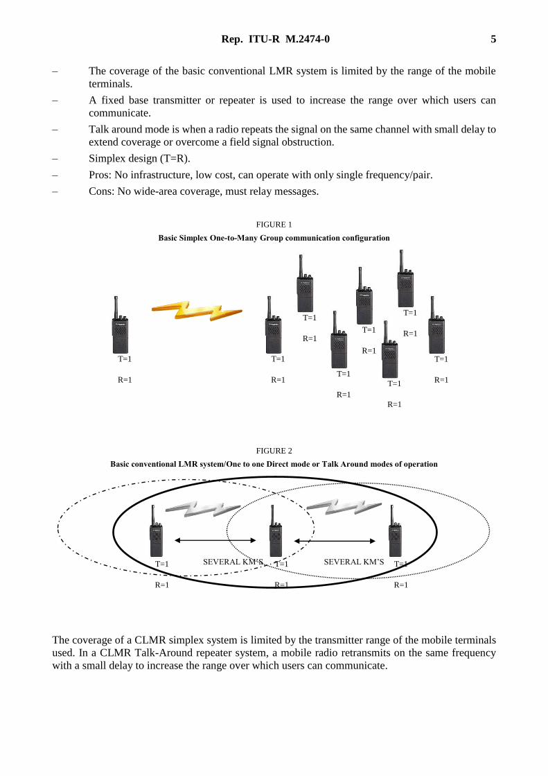
CLMR systems can be as basic and simple as a group of users (minimum two sets) operating on an
assigned frequency (or frequencies) to communicate in one-to-one or one-to-group mode of
communication as shown in Fig. 1 below. A conventional radio system is the most basic and simplest
two-way radio system for the user. Two-way radio systems can be configured in many different ways
to allow for one one-to-one and one-to-many communication.
CLMR have a common functionality of one-to-one or one-to-many (group) communication by a
simple Push-to-Talk. CLMR systems were developed for business users who need to communicate
over limited geographical areas but are also widely used for emergency services.
CLMR systems can be categorized into two types: simplex operation for direct peer-to-peer
communications; and repeater operation where repeater(s) is (are) used to extend the communication
reach.
A CLMR system for simplex operation for a group of users using a common assigned frequency (or
set of frequencies) to communicate is shown in Figs 1 and 2 below.
Basic Simplex (Direct mode) or Simplex with Talk around CLMR system
– There is no automated processing of the calls.
– Users simply ‘push-to-talk’ (PTT) on the channel (frequency) they have selected on their
mobile or handheld terminals.
– Users have immediate access to selected channel(s) at any time and must listen for a clear
channel before transmitting to avoid causing interference to another user in the group.
Rep. ITU-R M.2474-0 5
– The coverage of the basic conventional LMR system is limited by the range of the mobile
terminals.
– A fixed base transmitter or repeater is used to increase the range over which users can
communicate.
– Talk around mode is when a radio repeats the signal on the same channel with small delay to
extend coverage or overcome a field signal obstruction.
– Simplex design (T=R).
– Pros: No infrastructure, low cost, can operate with only single frequency/pair.
– Cons: No wide-area coverage, must relay messages.
FIGURE 1
Basic Simplex One-to-Many Group communication configuration
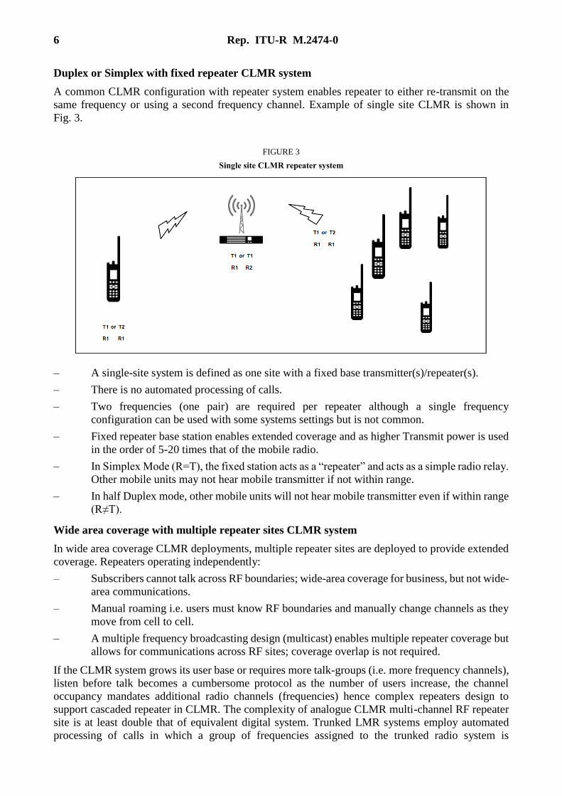
FIGURE 2
Basic conventional LMR system/One to one Direct mode or Talk Around modes of operation
The coverage of a CLMR simplex system is limited by the transmitter range of the mobile terminals
used. In a CLMR Talk-Around repeater system, a mobile radio retransmits on the same frequency
with a small delay to increase the range over which users can communicate.
T=1
R=1
T=1
R=1
T=1
R=1
T=1
R=1
T=1
R=1
T=1
R=1
T=1
R=1
T=1
R=1
T=1
R=1
T=1
R=1
T=1
R=1
SEVERAL KM’S
SEVERAL KM’S
6 Rep. ITU-R M.2474-0
Duplex or Simplex with fixed repeater CLMR system
A common CLMR configuration with repeater system enables repeater to either re-transmit on the
same frequency or using a second frequency channel. Example of single site CLMR is shown in
Fig. 3.
FIGURE 3
Single site CLMR repeater system
– A single-site system is defined as one site with a fixed base transmitter(s)/repeater(s).
– There is no automated processing of calls.
– Two frequencies (one pair) are required per repeater although a single frequency
configuration can be used with some systems settings but is not common.
– Fixed repeater base station enables extended coverage and as higher Transmit power is used
in the order of 5-20 times that of the mobile radio.
– In Simplex Mode (R=T), the fixed station acts as a “repeater” and acts as a simple radio relay.
Other mobile units may not hear mobile transmitter if not within range.
– In half Duplex mode, other mobile units will not hear mobile transmitter even if within range
(R≠T).
Wide area coverage with multiple repeater sites CLMR system
In wide area coverage CLMR deployments, multiple repeater sites are deployed to provide extended
coverage. Repeaters operating independently:
– Subscribers cannot talk across RF boundaries; wide-area coverage for business, but not wide-
area communications.
– Manual roaming i.e. users must know RF boundaries and manually change channels as they
move from cell to cell.
– A multiple frequency broadcasting design (multicast) enables multiple repeater coverage but
allows for communications across RF sites; coverage overlap is not required.
If the CLMR system grows its user base or requires more talk-groups (i.e. more frequency channels),
listen before talk becomes a cumbersome protocol as the number of users increase, the channel
occupancy mandates additional radio channels (frequencies) hence complex repeaters design to
support cascaded repeater in CLMR. The complexity of analogue CLMR multi-channel RF repeater
site is at least double that of equivalent digital system. Trunked LMR systems employ automated
processing of calls in which a group of frequencies assigned to the trunked radio system is
Rep. ITU-R M.2474-0 7
electronically shared among a large number of users. Trunked systems use access control schemes to
share channel capacity among many users. The control channel enables users to take advantage of the
fact that some time/frequency channels are idle at a particular time while others are busy and allocate
them in a way to maximize utilization.
From their early designs, CLMR systems have developed into ‘trunked’ systems.
The technique also enables multiple base stations to be connected and to provide coverage across a
wider area than with a single base station. Report ITU-R M.2014 provides the technical and
operational characteristics for spectrum efficient digital trunked systems and also provides details of
systems being introduced throughout the world.
4.2 CDLMR
The global trend towards digitalisation of LMR started in the 1990s1 in radio systems for public safety
users, followed by non-public safety users. The adoption of digital LMR technology has grown
rapidly in the 2010s and the number of DLMR users exceeded the number of users of analogue LMR
for the first time in 2017.
While supporting the introduction of DLMR, consideration also needed to be given to the impact on
the large number of existing users employing analogue technology. A 2018 study for global installed
base of analogue radios indicates that there is an excess of 20 million subscribers based on analogue
LMR.
Many administrations around the world have mandated that PLMR applicants use DLMR systems
when applying for new authorizing or renewing existing ones.
4.2.1 Benefits of CDLMR
a) More spectrum efficient than analogue CLMR
Current digital CLMR technology can support one voice path per 6.25 kHz compared to the 25 kHz
or 12.5 kHz per voice path of analogue CLMR.
b) Improved audio quality
In a normal analogue radio, every sound that is picked up by the microphone is transmitted. If there’s
a lot of background noise, it can be very difficult to understand the message. Digital technology uses
software that focuses purely on voice or data, paying no attention to the machine clatter or the crowd
noise around the users. The result is exceptional voice clarity. Radio interference creates static on an
analogue radio and makes the conversation less intelligible. Voice gets garbled and the message must
be repeated. Because a digital radio has automatic error correction, it rebuilds voice sounds and
maintains the clarity of the voice, even if a signal is badly corrupted. And since speech is digitally-
encoded, the users benefit from smarter capabilities, such as advanced software algorithms that can
deliver clear voice in the most extreme conditions. See Fig. 4 below.
1 Example: APCO P25, TETRA, TETRAPOLE; followed by DMR, dPMR in the 2000s.

8 Rep. ITU-R M.2474-0
FIGURE 4
Audio quality: Digital vs. Analogue
For any given audio quality, digital radios provide greater usable range than analogue radios, when
all other factors are considered equal (for example, transmit power level, antenna height, receiver
noise figures, intermediate frequency (IF) filter bandwidths, no additional audio processing, on the
analogue radios, terrain, antenna combining equipment, and others), as shown in Fig. 5 below.
FIGURE 5
Conceptual diagram showing improvements in audio quality with digital PLMR

Rep. ITU-R M.2474-0 9
c) Enhanced communication security
A typical analogue radio require an ancillary encryption hardware to provide voice encryption
whereas a digital radio can be configured and programmed to provide voice encryption. Digital voice
encryption has become much more secure and efficient. For example, digital LMR standards such as
TETRA and P25 have built-in support for air interface encryption.
d) Longer battery life
Digital radios employing TDMA have longer battery performance compared to analogue radios. In
TDMA a channel is divided into two or more timeslots and the radio only transmit on one of the
timeslots. This allows a digital radio to deliver a longer battery life than an equivalent analogue radio
on a single charge.
e) Applications for additional functions
Software applications can be installed in digital radios for additional functional features, such as, for
enhanced encryption, dispatch, work order management, location tracking, worker safety and
integration with IP networks.
5 General technical and operational considerations
As is the case with other mobile radiocommunication systems (e.g. mobile cellular) the; the
operational requirements of professional users have evolved. In addition to spectrum efficiency,
digital radio technologies provide: improved audio quality; longer battery performance; and better
communication security.
In general the underlying technologies to digital radio protocols used in CDLMR are:
– TDMA: Typically occupies a channel width of 12.5 kHz and divides each 12.5 kHz channel
into two timeslots (two logical channels), with each time slot providing a separate
communication path.
– FDMA: In contrast to TDMA, FDMA radio protocols provide one communication path per
physical channel. For example a 6.25 kHz FDMA radio will operate in a 6.25 kHz channel
and provides one communication path.
In the case of CDLMR radios employing 12.5 kHz, these radios have been specified with the intention
of allowing the replacement of analogue 12.5 kHz radios in existing LMR bands.
10 Rep. ITU-R M.2474-0
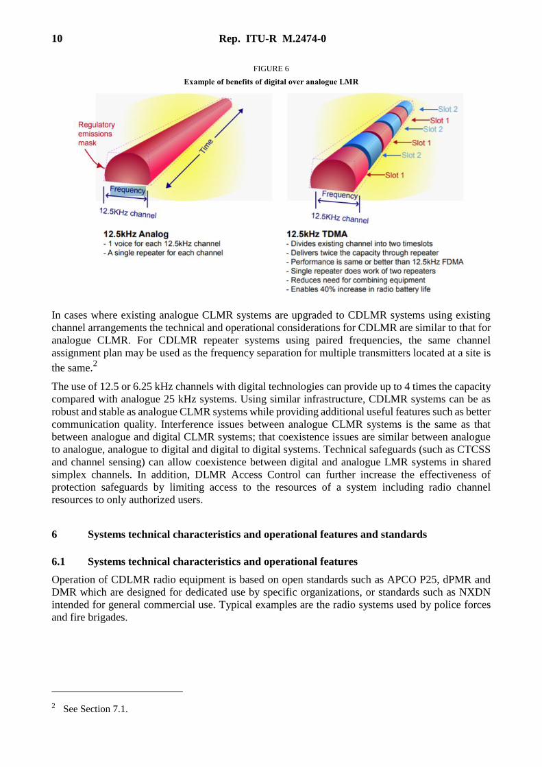
FIGURE 6
Example of benefits of digital over analogue LMR
In cases where existing analogue CLMR systems are upgraded to CDLMR systems using existing
channel arrangements the technical and operational considerations for CDLMR are similar to that for
analogue CLMR. For CDLMR repeater systems using paired frequencies, the same channel
assignment plan may be used as the frequency separation for multiple transmitters located at a site is
the same.2
The use of 12.5 or 6.25 kHz channels with digital technologies can provide up to 4 times the capacity
compared with analogue 25 kHz systems. Using similar infrastructure, CDLMR systems can be as
robust and stable as analogue CLMR systems while providing additional useful features such as better
communication quality. Interference issues between analogue CLMR systems is the same as that
between analogue and digital CLMR systems; that coexistence issues are similar between analogue
to analogue, analogue to digital and digital to digital systems. Technical safeguards (such as CTCSS
and channel sensing) can allow coexistence between digital and analogue LMR systems in shared
simplex channels. In addition, DLMR Access Control can further increase the effectiveness of
protection safeguards by limiting access to the resources of a system including radio channel
resources to only authorized users.
6 Systems technical characteristics and operational features and standards
6.1 Systems technical characteristics and operational features
Operation of CDLMR radio equipment is based on open standards such as APCO P25, dPMR and
DMR which are designed for dedicated use by specific organizations, or standards such as NXDN
intended for general commercial use. Typical examples are the radio systems used by police forces
and fire brigades.
2 See Section 7.1.
Rep. ITU-R M.2474-0 11
Key features of CDLMR systems include:
– Push-To-Talk (PTT): Is a functionality that is common to all CLMR radios. It is a method in
which a single button is pressed to open communication (i.e. transmit mode) and the button
is released to listen (i.e. receive mode).CLMR systems are available in two modes:
• Simplex mode: A single frequency is used for transmit and receive among a talk-group,
through PTT. A talk-group here is a frequency channel.
• Repeater mode: A pair of frequencies are used, one frequency is used for transmitting
and the other is used for receiving. PTT ensures that only one frequency is active at a
time, for mobile stations.
– Point to multi-point communications, group communications (as opposed to cell phones
which are point to point communications).
– Large coverage areas.
– Closed user groups.
– Use of VHF or UHF frequency bands.
When CLMR first started the systems simply consisted of a single base station with a number of
mobiles that could communicate with this single base station. These systems are still in widespread
use today with taxi firms and many others using them for communication. Many systems operate with
the remote or mobile stations being able to hear all the calls being made. This may not always be
satisfactory and a system of selective calling may be needed. There are several ways of achieving
this, including Dual Tone Multiple Frequency (DTMF) signalling and Continuous Tone Coded
Squelch System (CTCSS).
Now facilities such as DTMF and CTCSS provide additional calling selection. Because the base
station’ antenna may be mounted on a high tower, coverage may extend up to distances of fifty
kilometres. This is helpful especially when there is no signal in a public cellular mobile phone.
Assignments can be made for operation on a particular channel or channels. The user can then have
use of these channels to contact the mobile stations in their fleet.
In general narrow band frequency modulation is the chosen form of modulation, although airport
services use amplitude modulation. Typically a deviation of 2.5 kHz is used for FM and this enables
a channel spacing of 12.5 kHz to be implemented.
6.2 Standards
The worldwide adoption of open standards optimises economies of scale in equipment supply for
many countries. Also, open standards provide increased technical robustness, as they are periodically
reviewed by industry.
In general, DLMR systems using open standards helps to ensure backwards compatibility with
analogue LMR.
There are a number of standards and technologies that support conventional digital PLMR
applications. A short summary of three main DLMR standards are described below:
6.2.1 Project 25 (P25 or APCO-25)
P25 may be used in "talk around" mode without any intervening equipment between two or more
radios, in conventional mode where two or more radios communicate through a repeater or base
station without trunking or in a trunked mode where traffic is automatically assigned to one or more
voice channels by a Repeater or Base Station.
P25 is a suite of standards for digital radio communications. P25 was established to address the need
for common digital public safety radio communications standards for first-responders and homeland

12 Rep. ITU-R M.2474-0
security/emergency response professionals. The P25 suite of standards involves digital Land Mobile
Radio (PLMR) services for local, state/provincial and national public safety organizations and
agencies. Although developed primarily for North American public safety services, P25 technology
and products are not limited to public safety alone and have also been selected and deployed in other
private system application, worldwide. P25-compliant systems are being increasingly adopted and
deployed in many countries. Radios can communicate in analogue mode with legacy radios, and in
either digital or analogue mode with other P25 radios. Additionally, the deployment of P25-compliant
systems will allow for a high degree of equipment interoperability and compatibility. P25 standards
use the proprietary Improved Multi-Band Excitation (IMBE) and Advanced Multi-Band Excitation
(AMBE+2) voice codecs which were designed by Digital Voice Systems, Inc. to encode/decode the
analogue audio signals. The protocol supports the use of Data Encryption Standard (DES) encryption
(56 bit), 2-key Triple-DES encryption, three-key Triple-DES encryption, Advanced Encryption
Standard (AES) encryption at up to 256 bits keylength, RC4 (40 bits, sold by Motorola as Advanced
Digital Privacy), or no encryption.
6.2.2 TETRA in CDLMR operations
TETRA is a high-performance mobile radio system which has been developed primarily for
professional users such as the emergency services and public transport. The TETRA suite of mobile
radio specifications provide a comprehensive radio capability encompassing trunked, non-trunked
and direct mobile-to-mobile communication with a range of facilities including voice, circuit mode
data, short data messages and packet mode services. TETRA supports an especially wide range of
supplementary services, many of which are exclusive to TETRA.
TETRA is designed to operate in the bands below 1 GHz with 25 kHz channel bandwidth.
When operated in Direct Mode Operation (DMO), TETRA works as a CDLMR enabling direct
mobile-to-mobile communications, mobile repeater outside the coverage of the network or can be
used as a secure communication channel within the network coverage area.
6.2.3 DMR
Digital Mobile Radio (DMR) is an open digital mobile radio standard defined in the European
Telecommunications Standards Institute (ETSI) Standard and used in commercial products around
the world. DMR, along with P25 and TETRA are the main PLMR technologies in achieving 6.25 kHz
equivalent spectrum efficiency. DMR was designed with three tiers. DMR tiers I and II (conventional)
were first published in 2005, and DMR III (trunked) was published in 2012, with manufacturers
producing products within a few years of each publication. The primary goal of the standard is to
specify a digital system with low complexity, low cost and interoperability across brands, so radio
communications purchasers are not locked into a proprietary solution. In practice, many brands have
not adhered to this open standard and have introduced proprietary features that make their product
offerings non-interoperable.
The DMR standard specifies two-slot TDMA in 12.5 kHz channels spacing i.e. two voice channels
per frequency channel. The standard is still under development with revisions being made regularly
as more systems are deployed and improvements that can be made discovered. It is very likely that
further refinements will be made to the standard, which will necessitate firmware upgrades to
terminals and infrastructure in the future to take advantage of these new improvements, with potential
incompatibility issues arising if this is not done. DMR covers the RF range 66 MHz to 960 MHz.
DMR Tier I products (also commonly known as PMR 446) are harmonized for licence-exempt use in
the 446.0-446.2 MHz band across Europe3 and in many countries across Africa and Asia. Tier I
3 https://www.ecodocdb.dk/download/b8797390-4577/ECCDec1505.pdf.

Rep. ITU-R M.2474-0 13
products are specified for non-infrastructure use only without the use of repeaters. This part of the
standard provides for consumer applications and low-power commercial applications, using a
maximum of 0.5 watt RF power.
DMR Tier II covers conventional radio systems, mobiles and hand portables operating in PMR
frequency bands up to 960 MHz. The ETSI DMR Tier II standard is targeted at those users who need
spectral efficiency, advanced voice features and integrated IP data services for high-power
communications. A number of manufacturers have DMR Tier II compliant products on the market.
ETSI DMR specifies two slot TDMA in 12.5 kHz channels for Tier II and III.
DMR Tier III covers trunking operation in frequency bands up to 960 MHz. Tier III supports voice
and short messaging handling similar to TETRA with built-in 128 character status messaging and
short messaging with up to 288 bits of data in a variety of formats. It also supports packet data service
in a variety of formats, including support for IPv4 and IPv6. Tier III compliant products were
launched in 2012.
6.2.4 dPMR
Digital Private Mobile Radio (dPMR) , is an air interface for CDLMR. dPMR is an open, non-
proprietary standard that was developed by the European Telecommunications Standards Institute
(ETSI) and published under the reference ETSI TS 102 658. A simplified version of the dPMR
protocol intended for licence-exempt applications was also published by ETSI under the reference
TS 102 490.
dPMR major specification:
– Access method: FDMA.
– Transmission rate: 4,800 bit/s.
– Modulation: four-level FSK.
This is achieved in a 6.25 kHz channel.
dPMR equipment complies with the relevant European standard ETSI EN 301 166..
dPMR supports several voice coding algorithms. Equipment with different voice coding algorithms
are not interoperable in digital mode and must revert to analogue FM mode.
dPMR446 radios are licence-exempt products for use in the 446.1-446.2 MHz band within Europe.
These are digital only versions of PMR446 radios. dPMR446 radios comply with the ETSI
TS 102 490 technical specification and are limited to 500 mW RF power with fixed antennas per ECC
Decision (05)12. They are suitable for recreational and professional users over short range. dPMR446
equipment is capable of voice, data and voice+data modes of operation. This means that dPMR446
can provide voice calls, text messaging (SMS), status and embedded data such as GPS position etc.
dPMR Mode 1 is the peer to peer mode of dPMR (without repeaters or infrastructure) but without the
limitations of the low power counterpart. It can operate all typical PMR frequency bands and without
the RF power limits of dPMR446. As well as offering voice and data, dPMR446 Mode 1 also supports
combined voice+data so it is possible to embed data into a voice call or automatically append it at the
end of a call.
dPMR Mode 2 operations include repeaters and other infrastructure. This brings extra functionality
such as analogue or digital system interfaces which can be IP based. Inclusion of repeaters and base
stations means that wide area coverage is possible even more so when multiple repeaters are used.
Such multiple repeaters can be managed by dynamic channel selection or they can be part of a
co-channel wide area system.
dPMR Mode 3 can offer multichannel, multisite trunked radio systems. This enables better utilization
of spectrum and management of radio traffic. Management of the radio system starts from the

14 Rep. ITU-R M.2474-0
authentication of radios that wish to connect. Calls are set up by the infrastructure when both parties
have responded to the call request ensuring optimum use of the radio resource. Calls may be diverted
to other radios, landline numbers or even IP addresses. The infrastructure managing these beacon
channels would be capable of placing a call to another radio whether that radio is using the same site
or another site within the system.
6.3 Summary of Conventional DLMR systems features
TETRA Project 25
Phase 2 DMR dPMR
Standardisation body ETSI TIA ETSI ETSI
Single frequency repeater mode Yes No Yes No
Direct mode (walkie talkie) Yes Yes Yes Yes
Channel access TDMA
(4-slot)
TDMA
(2-slot)
TDMA
(2-slot)
FDMA
Channel width 25 kHz 12.5 kHz 12.5 kHz 6.25 kHz
Effective (equivalent) traffic channel bandwidth 6.25 kHz 6.25 kHz 6.25 kHz 6.25 kHz
Frequency ranges that can be supported (MHz) < 1 000
Currently
350-470
806 – 869
136-869 66-900 < 1 000
7 Frequency bands
7.1 Frequency bands
PLMR utilizes various frequency bands across regions in the mobile service, subject to regional
harmonization measures and national conditions.
In certain countries the frequency bands used for CLMR are 136 to 144 MHz, 146 to 174 MHz, 350 to
470 MHz, 806 to 869 MHz.
7.2 Channel spacing and centre frequencies
Channel raster or channel spacing for CLMR may be 25 kHz, 20 kHz, 12.5 kHz, 10 kHz and 6.25 kHz.
For every sub-band of above frequency bands, centre frequency can be calculated as follows:
Fn = F1 + (n-1) × Channel spacing
where:
Fn: Centre frequency of channel n
F1: Centre frequency of first channel
Channel spacing: frequency difference between two adjacent channels
n: channel number; n = 1, 2, … and n < (Fhigher-edge – Flower-edge)/Channel spacing.

Rep. ITU-R M.2474-0 15
7.3 Channel arrangements
There are two type of arrangements between two channel spacing, i.e. between 25 kHz and 12.5 kHz
channels or 12.5 kHz and 6.25 kHz channels, as illustrate below:
a) Narrow channel located in the centre and the edge of wider channel
b) Two narrow channel located inside one wider channel
In practice, channelling arrangements for 25, 12.5 and 6.25 kHz could belong to one type or mixed
between the above two types.
An example of channelization plan is provided in Annex 1 to this Report.
Channel raster should be compatible with existing channelization and must be technology inclusive
to accommodate both TDMA and FDMA technologies, and legacy analogue radios (which have not
yet upgraded to digital); and have a well-defined structure for channel frequency spacing. Under this
the centre of the channel should remain on the same repeat pattern or “on centre” in the spectrum
regardless of the channel bandwidth assigned. Figure 7 below shows how assignments using 25 kHz,
12.5 kHz and 6.25 kHz channelling fit into this general channel structure.
FIGURE 7
Channel structure for LMR bands showing unified channel centre spacing
An example of channelization plan is provided in Annex 1 to this Report.
8 Frequency selection and assignment
This section aims to deal with frequency selection for systems operating in intra-Land Mobile Radio
Service scenario: methodology, criteria, practice.
Frequency selection criteria across various scenarios is considered: when a new DPLMR system share
the frequency with existing PLMR systems; when existing DPLMR require additional channels; and
sharing and interference analysis between PLMR system with C/I or I/N.
Technical and operational characteristics of conventional and trunked land mobile systems operating
in the mobile service allocations below 869 MHz to be used in sharing studies are found in
Recommendation ITU-R M.1808.
12.5 KHz 12.5 KHz
6.25 KHz 6.25 KHz 6.25 KHz 6.25 KHz 6.25 KHz
25 KHz
12.5 KHz 12.5 KHz
25 KHz 25 KHz
12.5 KHz 12.5 KHz 12.5 KHz
12.5 KHz
12.5 KHz 12.5 KHz 12.5 KHz 12.5 KHz 12.5 KHz 12.5 KHz 6.25 KHz 6.25 KHz 6.25 KHz 6.25 KHz 6.25 KHz 6.25 KHz
25 KHz25 KHz 25 KHz 12.5 KHz 12.5 KHz 12.5 KHz

16 Rep. ITU-R M.2474-0
8.1 Examples of frequency assignment methods
One method of assignment of frequencies for PLMR systems is through an administrative method,
which results in an apparatus assignment.
Apparatus assignments are issued on a first-come-first-served basis and it usually includes RF
technical conditions to mitigate interference between radio systems within a band and in adjacent
bands.
One method used to reduce intermodulation products and near-far interference issues between
systems and within a system is the use of channels that are grouped, with each channel separated from
the others in the group by a fixed number of channels.
Annex 3 provides an example of a frequency assignment plan for 25 kHz channels that are separated
by 10 channels from each other in a group.
Recommendation ITU-R SM.337 provides the procedures for calculating distance and frequency
separations for an acceptable interference level.
The distances between systems for frequency reuse can be calculated using procedures given in
Recommendation ITU-R SM.337. Annex 2 provides an example of frequency channel selection based
on Frequency-Distance criteria.
To operate digital LMR systems, and where frequency arrangements are based on 12.5 kHz channels,
25 kHz assignments being considered for migration to 12.5 kHz will have to take into account whether
the centre frequency of 12.5 kHz channels are aligned with the 25 kHz channels assigned or whether
it is interleaved. This is illustrated in Fig. 8 below.
FIGURE 8
Effect of using TDMA technology in an existing 12.5 kHz and 25 kHz channel
A two for one channel capacity increase is gained using TDMA technology, and possible interference
issues are reduced (in contrast to the increased potential for interference resulting from splitting a
25 kHz channel assignment into three adjacent 6.25 kHz channels).
9 Analogue to digital transition
When planning to introduce digital PLMR for the first time, considerations for both data and voice
applications, channelling plans, type approval and regulatory requirements need to be considered and
to ensure the operation of digital radio in existing (or planned) LMR frequency bands.
Rep. ITU-R M.2474-0 17
9.1 Digital Voice and Data
Digital PLMR systems support both voice and data services, in time or in frequency domain. Data
applications in PLMR are becoming an important aspect of PLMR applications. In scenarios where
analogue only radio interface are included in the national PLMR radio interface requirements, PLMR
systems that support both data and voice or improved voice channel will have to wait for changes to
benefit from the improved channel usage or to benefit from both data and voice capabilities.
9.2 Transition analogue to digital
The transition of a PLMR frequency band from analogue to digital is straightforward if the existing
arrangements (transmit power, channel assignment plan, channel raster, etc.) remain unchanged.
Some administration may wish to re-band an existing PLMR frequency band to use a narrower
channel spacing. For example, from existing 25 kHz channel spacing to 12.5 kHz channel space. In
this case the transition will include the additional step of re-banding.
9.2.1 Analogue to digital transition in PLMR bands with existing channel arrangements
Digital PLMR equipment that use 25 kHz or 12.5 kHz channel can operate in existing PLMR
frequency bands using existing 25 kHz or 12.5 kHz channel arrangements (transmit power, channel
assignment plan, channel raster, etc.) In this transition scenario the probability of interference is no
worse than for analogue radio.
The table below provides a summary of which category of digital PLMR radio can migrate in existing
PLMR bands.
Existing PLMR bandwidth Category of digital PLMR radio that can migrate into
existing PLMR band
12.5 kHz channel arrangements 12.5 kHz digital PLMR
25 kHz channel arrangements 25 kHz digital PLMR
As this transition only involve the upgrade of analogue systems to digital PLMR systems using the
same frequencies, much of the existing site infrastructure (e.g. combiner, cabling, etc.) can be re-used.
9.2.2 Analogue to digital transition with re-banding from 25 kHz to 12.5 kHz channel spacing
In this transition scenario a frequency band with 25 kHz channel spacing for analogue PLMR is re-
banded to 12.5 kHz channel spacing for digital PLMR.
This type of transition usually implemented in phases. The following transition method consists of
two phases. The first phase involves the migration of existing 25 kHz analogue PLMR systems to
12.5 kHz digital PLMR systems using their existing frequency assignments. The second phase
involve the retrieving of new 12.5 kHz channels with the completion 25 kHz to 12.5 kHz migration.
The migration may take some time before the new channels can be retrieved and reassigned. However
it provides a smooth migration without affecting systems that had upgraded to digital PLMR in the
first phase.
Figure 9 below illustrates the different phases of the transition.

18 Rep. ITU-R M.2474-0
FIGURE 9
10 Interleaved and offset channelling arrangements
Bands with interleaved channel plans are often suitable for the immediate introduction of DLMR
systems, while bands with offset channel plans may require segmentation or transition plans.
10.1 Interleaved channel plans
Interleaved channel plans can provide for the introduction of digital services designed to operate in
12.5 kHz and 6.25 kHz channels without the need for band migrations, provided the selected
technology standards are compatible with existing analogue land mobile equipment.
FIGURE 10
Interleaved channel plan
10.2 Offset channel plans
Analogue emissions tend to concentrate their power closer to the centre frequency and within a
narrower bandwidth than the channel space assigned in the band (i.e. the effective emission
bandwidth in a 25 kHz analogue LMR channel only occupies approximately 16 kHz). Since analogue
LMR channels do not spread their power across the entire allocated channel space, it is possible to

Rep. ITU-R M.2474-0 19
assign narrower 12.5 kHz analogue channels (which also concentrate their power in the same way)
in the offset gap between 25 kHz analogue channels, without causing harmful interference (as shown
in Fig. 11).
Unlike analogue emissions, digital emissions tend to spread their power across the entire channel,
and therefore mixing digital and analogue emissions in offset bands can cause adjacent channel
interference (from digital into analogue). Therefore, offset bands require either band segmentation or
migration plans to be implemented to protect existing analogue services.
FIGURE 11
Offset channel plan
The use of transition plans is seen as an appropriate approach for offset channel plans.
Annex 1
An example of frequency bands and channel spacings for CLMR systems
1 Introduction
The selection of frequency bands for CLMR systems is subject to regional harmonization measures
and national needs. CLMR systems are typically found below 1 GHz in the VHF and UHF bands. Of
the channel spacings: 6.25 kHz, 10, 12.5 kHz, 20 and 25 kHz; the more common ones in use are 6.25,
12.5 and 25 kHz.
2 Example of frequency bands and channelling
The frequency band 138-174 MHz in the VHF range and 406-470 MHz in UHF range are widely use
around the world for CLMR. Channel spacing in those bands are 25/20/12.5/10/6.25 kHz. An
example of channelization of CLMR frequency bands is given below.
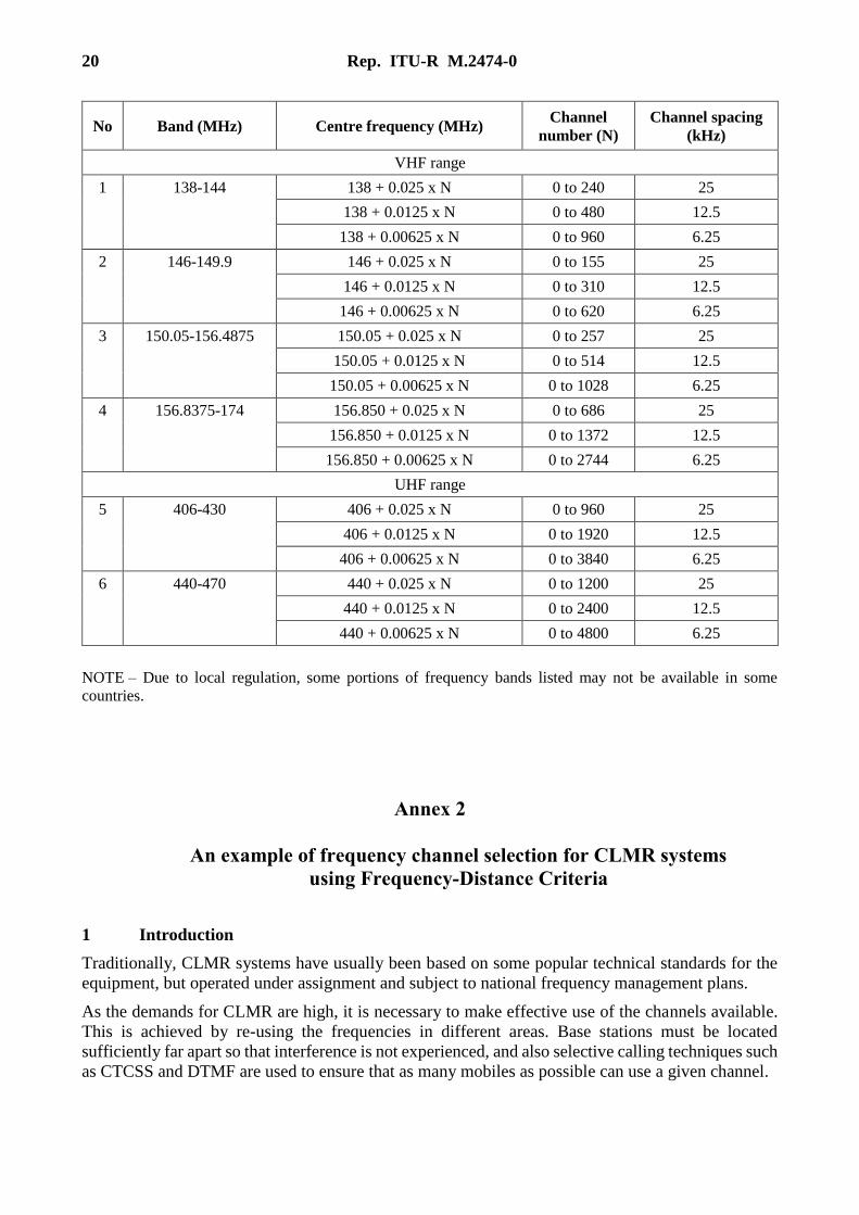
20 Rep. ITU-R M.2474-0
No Band (MHz) Centre frequency (MHz) Channel
number (N)
Channel spacing
(kHz)
VHF range
1 138-144 138 + 0.025 x N 0 to 240 25
138 + 0.0125 x N 0 to 480 12.5
138 + 0.00625 x N 0 to 960 6.25
2 146-149.9 146 + 0.025 x N 0 to 155 25
146 + 0.0125 x N 0 to 310 12.5
146 + 0.00625 x N 0 to 620 6.25
3 150.05-156.4875 150.05 + 0.025 x N 0 to 257 25
150.05 + 0.0125 x N 0 to 514 12.5
150.05 + 0.00625 x N 0 to 1028 6.25
4 156.8375-174 156.850 + 0.025 x N 0 to 686 25
156.850 + 0.0125 x N 0 to 1372 12.5
156.850 + 0.00625 x N 0 to 2744 6.25
UHF range
5 406-430 406 + 0.025 x N 0 to 960 25
406 + 0.0125 x N 0 to 1920 12.5
406 + 0.00625 x N 0 to 3840 6.25
6 440-470 440 + 0.025 x N 0 to 1200 25
440 + 0.0125 x N 0 to 2400 12.5
440 + 0.00625 x N 0 to 4800 6.25
NOTE – Due to local regulation, some portions of frequency bands listed may not be available in some
countries.
Annex 2
An example of frequency channel selection for CLMR systems
using Frequency-Distance Criteria
1 Introduction
Traditionally, CLMR systems have usually been based on some popular technical standards for the
equipment, but operated under assignment and subject to national frequency management plans.
As the demands for CLMR are high, it is necessary to make effective use of the channels available.
This is achieved by re-using the frequencies in different areas. Base stations must be located
sufficiently far apart so that interference is not experienced, and also selective calling techniques such
as CTCSS and DTMF are used to ensure that as many mobiles as possible can use a given channel.

Rep. ITU-R M.2474-0 21
Selection of a frequency channel for a CLMR system involves the determination of a frequency
channel that can be used without causing interference to or receive interference from existing CLMR
systems.
One method used is the frequency and distance separations method (F-D method) described in
Recommendation ITU-R SM.337. The F-D method is used to assess the potential for interference
between the proposed frequency and the frequencies used by existing systems, with intermodulation
interference taken into account, when assigning a frequency channel to CLMR system.
The frequency channel that satisfies the F-D criteria and meet the proposed network’s operating
frequency requirements as far as practicable is assigned.
2 Frequency – Distance criteria
2.1 Deployment model
There are three popular types of CLMR deployment:
a) Type A:
– Only handheld transceivers
– Low output power: typical maximum 5 W to 10 W
– Single frequency, simplex: transmit and receive in same frequency
b) Type B:
– With repeater station(s) and mobile stations
– Height output power: typical maximum 25 W to 50 W
– Single frequency, simplex: transmit and receive in same frequency
c) Type C:
– With repeater stations and mobile stations
– Height output power: typical maximum 25 W to 50 W
– Two frequency, semi-duplex: transmit and receive in difference frequencies
2.2 Minimum distance separation between two CLMR system type A
a) For VHF range
Δf between
new 6.25 kHz
and existing
Distance separation (km)
Existing
6.25 kHz
Existing
12.5 kHz
Existing
25 kHz
0 kHz 10 10 10
6.25 kHz 1.9 10 10
12.5 kHz 0.3 0.5 10
18.75 kHz 0.3 0.3 0.8
25 kHz 0.3 0 0.4
31.25 kHz 0 0 0
37.5 kHz 0 0 0
43.75 kHz 0 0 0
50 kHz 0 0 0

22 Rep. ITU-R M.2474-0
Δf between
new 12.5 kHz
and existing
Distance separation (km)
Existing
6.25 kHz
Existing
12.5 kHz
Existing
25 kHz
0 kHz 10 10 10
6.25 kHz 10 10 10
12.5 kHz 0.5 1.2 10
18.75 kHz 0.3 0 1.2
25 kHz 0 0 0.4
31.25 kHz 0 0 0.3
37.5 kHz 0 0 0.3
43.75 kHz 0 0 0.3
50 kHz 0 0 0.3
Δf between
new 25 kHz
and existing
Distance separation (km)
Existing
6.25 kHz
Existing
12.5 kHz
Existing
25 kHz
0 kHz 10 10 10
6.25 kHz 10 10 10
12.5 kHz 10 10 10
18.75 kHz 0.8 1.2 10
25 kHz 0.4 0.4 0.6
31.25 kHz 0.4 0.4 0.5
37.5 kHz 0.4 0.4 0.5
43.75 kHz 0.4 0.4 0.5
50 kHz 0.4 0.4 0.5
b) For UHF range
Δf between
new 6.25 kHz
and existing
Distance separation (km)
Existing
6.25 kHz
Existing
12.5 kHz
Existing
25 kHz
0 kHz 10 10 10
6.25 kHz 1.9 10 10
12.5 kHz 0.3 0.5 10
18.75 kHz 0.3 0.3 0.8
25 kHz 0.3 0 0.4
31.25 kHz 0 0 0
37.5 kHz 0 0 0
43.75 kHz 0 0 0
50 kHz 0 0 0

Rep. ITU-R M.2474-0 23
Δf between
new 12.5 kHz
and existing
Distance separation (km)
Existing
6.25 kHz
Existing
12.5 kHz
Existing
25 kHz
0 kHz 10 10 10
6.25 kHz 10 10 10
12.5 kHz 0.5 1.2 10
18.75 kHz 0.3 0 1.2
25 kHz 0 0 0.4
31.25 kHz 0 0 0
37.5 kHz 0 0 0
43.75 kHz 0 0 0
50 kHz 0 0 0
Δf between
new 25 kHz
and existing
Distance separation (km)
Existing
6.25 kHz
Existing
12.5 kHz
Existing
25 kHz
0 kHz 10 10 10
6.25 kHz 10 10 10
12.5 kHz 10 10 10
18.75 kHz 0.8 1.2 10
25 kHz 0.4 0.4 0.5
31.25 kHz 0 0 0
37.5 kHz 0 0 0
43.75 kHz 0 0 0
50 kHz 0 0 0
2.3 Minimum distance separation between two CLMR system type B
a) For VHF range
Δf between
new 6.25 kHz
and existing
Distance separation (km)
Existing
6.25 kHz
Existing
12.5 kHz
Existing
25 kHz
0 kHz 140 140 140
6.25 kHz 90 130 136
12.5 kHz 33 51 106
18.75 kHz 33 30 64
25 kHz 26 23 48
31.25 kHz 17 15 47
37.5 kHz 17 15 47
43.75 kHz 17 15 47
50 kHz 17 15 47

24 Rep. ITU-R M.2474-0
Δf between
new 12.5 kHz
and existing
Distance separation (km)
Existing
6.25 kHz
Existing
12.5 kHz
Existing
25 kHz
0 kHz 140 140 140
6.25 kHz 130 130 135
12.5 kHz 51 76 118
18.75 kHz 30 22 76
25 kHz 23 16 48
31.25 kHz 15 8.6 46
37.5 kHz 15 8.6 46
43.75 kHz 15 8.6 46
50 kHz 15 8.6 46
Δf between
new 25 kHz
and existing
Distance separation (km)
Existing
6.25 kHz
Existing
12.5 kHz
Existing
25 kHz
0 kHz 140 140 140
6.25 kHz 136 135 135
12.5 kHz 106 118 118
18.75 kHz 64 76 82
25 kHz 48 48 56
31.25 kHz 47 46 51
37.5 kHz 47 46 51
43.75 kHz 47 46 51
50 kHz 47 46 51
b) For UHF range
Δf between
new 6.25 kHz
and existing
Distance separation (km)
Existing
6.25 kHz
Existing
12.5 kHz
Existing
25 kHz
0 kHz 120 120 120
6.25 kHz 70 110 116
12.5 kHz 8.1 19 86
18.75 kHz 8.1 7.5 44
25 kHz 6.4 5.7 12
31.25 kHz 4.1 3.6 5.1
37.5 kHz 4.1 3.6 4.7
43.75 kHz 4.1 3.6 4.7
50 kHz 4.1 3.6 4.7
Rep. ITU-R M.2474-0 25
Δf between
new 12.5 kHz
and existing
Distance separation (km)
Existing
6.25 kHz
Existing
12.5 kHz
Existing
25 kHz
0 kHz 120 120 120
6.25 kHz 110 110 115
12.5 kHz 19 57 98
18.75 kHz 7.5 5.4 56
25 kHz 5.7 4.1 13
31.25 kHz 3.6 2.1 4.6
37.5 kHz 3.6 2.1 3.6
43.75 kHz 3.6 2.1 2.4
50 kHz 3.6 2.1 2.4
Δf between
new 25 kHz
and existing
Distance separation (km)
Existing
6.25 kHz
Existing
12.5 kHz
Existing
25 kHz
0 kHz 120 120 120
6.25 kHz 116 115 115
12.5 kHz 86 98 98
18.75 kHz 44 56 62
25 kHz 12 13 23
31.25 kHz 5.1 4.6 7.9
37.5 kHz 4.7 3.6 4.6
43.75 kHz 4.7 2.4 2.8
50 kHz 4.7 2.4 2.4
2.4 Minimum distance separation between two CLMR system type C
a) For VHF range
Δf between
new 6.25 kHz
and existing
Distance separation (km)
Existing
6.25 kHz
Existing
12.5 kHz
Existing
25 kHz
0 kHz 100 100 100
6.25 kHz 52 86 94
12.5 kHz 0 0 63
18.75 kHz 0 0 0
25 kHz 0 0 0
31.25 kHz 0 0 0
37.5 kHz 0 0 0
43.75 kHz 0 0 0
50 kHz 0 0 0
26 Rep. ITU-R M.2474-0
Δf between
new 12.5 kHz
and existing
Distance separation (km)
Existing
6.25 kHz
Existing
12.5 kHz
Existing
25 kHz
0 kHz 100 100 100
6.25 kHz 86 87 94
12.5 kHz 0 0 74
18.75 kHz 0 0 47
25 kHz 0 0 0
31.25 kHz 0 0 0
37.5 kHz 0 0 0
43.75 kHz 0 0 0
50 kHz 0 0 0
Δf between
new 25 kHz
and existing
Distance separation (km)
Existing
6.25 kHz
Existing
12.5 kHz
Existing
25 kHz
0 kHz 100 100 100
6.25 kHz 94 94 94
12.5 kHz 63 74 74
18.75 kHz 0 47 48
25 kHz 0 0 0
31.25 kHz 0 0 0
37.5 kHz 0 0 0
43.75 kHz 0 0 0
50 kHz 0 0 0
b) For UHF range
Δf between
new 6.25 kHz
and existing
Distance separation (km)
Existing
6.25 kHz
Existing
12.5 kHz
Existing
25 kHz
0 kHz 100 100 100
6.25 kHz 54 87 95
12.5 kHz 0 0 65
18.75 kHz 0 0 0
25 kHz 0 0 0
31.25 kHz 0 0 0
37.5 kHz 0 0 0
43.75 kHz 0 0 0
50 kHz 0 0 0

Rep. ITU-R M.2474-0 27
Δf between
New 12.5 kHz
and existing
Distance separation (km)
Existing
6.25 kHz
Existing
12.5 kHz
Existing
25 kHz
0 kHz 100 100 100
6.25 kHz 87 88 94
12.5 kHz 0 0 75
18.75 kHz 0 0 47
25 kHz 0 0 0
31.25 kHz 0 0 0
37.5 kHz 0 0 0
43.75 kHz 0 0 0
50 kHz 0 0 0
Δf between
new 25 kHz
and existing
Distance separation (km)
Existing
6.25 kHz
Existing
12.5 kHz
Existing
25 kHz
0 kHz 100 100 100
6.25 kHz 95 94 94
12.5 kHz 65 75 75
18.75 kHz 0 47 49
25 kHz 0 0 0
31.25 kHz 0 0 0
37.5 kHz 0 0 0
43.75 kHz 0 0 0
50 kHz 0 0 0
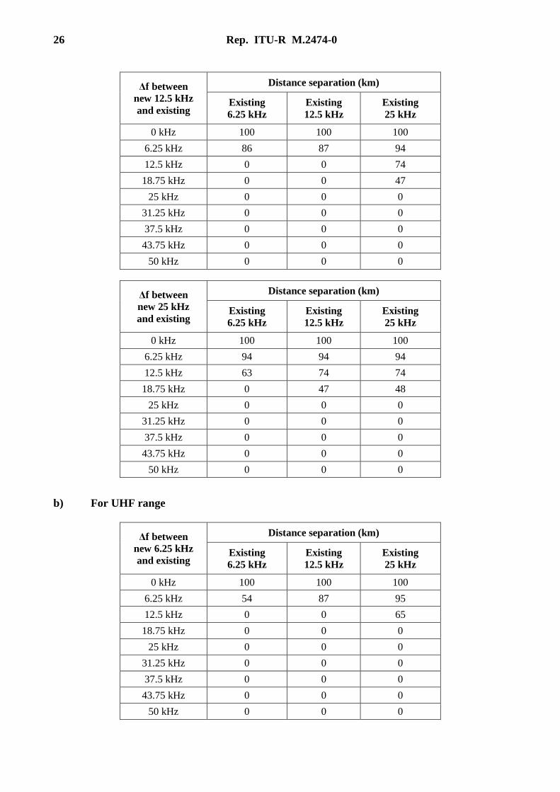
2.5 Minimum distance separation between a CLMR system type A and type B
a) For VHF range
Δf between
new 6.25 kHz
and existing
Distance separation (km)
Existing
6.25 kHz
Existing
12.5 kHz
Existing
25 kHz
0 kHz 116 111 111
6.25 kHz 35 91 103
12.5 kHz 4.5 8 54
18.75 kHz 4.5 4.3 14
25 kHz 3.9 3.5 7
31.25 kHz 2.9 2.6 6.7
37.5 kHz 2.9 2.6 6.7
43.75 kHz 2.9 2.6 6.7
50 kHz 2.9 2.6 6.7

28 Rep. ITU-R M.2474-0
Δf between
new 12.5 kHz
and existing
Distance separation (km)
Existing
6.25 kHz
Existing
12.5 kHz
Existing
25 kHz
0 kHz 111 105 111
6.25 kHz 91 92 102
12.5 kHz 8 23 70
18.75 kHz 4.3 3.4 23
25 kHz 3.5 2.8 7
31.25 kHz 2.6 1.8 6.4
37.5 kHz 2.6 1.8 5.2
43.75 kHz 2.6 1.8 5.2
50 kHz 2.6 1.8 5.2
Δf between
new 25 kHz
and existing
Distance separation (km)
Existing
6.25 kHz
Existing
12.5 kHz
Existing
25 kHz
0 kHz 111 111 111
6.25 kHz 103 102 102
12.5 kHz 54 70 71
18.75 kHz 14 23 27
25 kHz 7 7 10
31.25 kHz 6.7 6.4 7.9
37.5 kHz 6.7 6.4 7.8
43.75 kHz 6.7 6.4 7.8
50 kHz 6.7 6.4 7.8
b) For UHF range
Δf between
new 6.25 kHz
and existing
Distance separation (km)
Existing
6.25 kHz
Existing
12.5 kHz
Existing
25 kHz
0 kHz 107 103 103
6.25 kHz 34 85 96
12.5 kHz 4.5 8 52
18.75 kHz 4.5 4.3 14
25 kHz 3.9 3.5 6
31.25 kHz 2.9 2.6 3.3
37.5 kHz 2.9 2.6 3.1
43.75 kHz 2.9 2.6 3.1
50 kHz 2.9 2.6 3.1
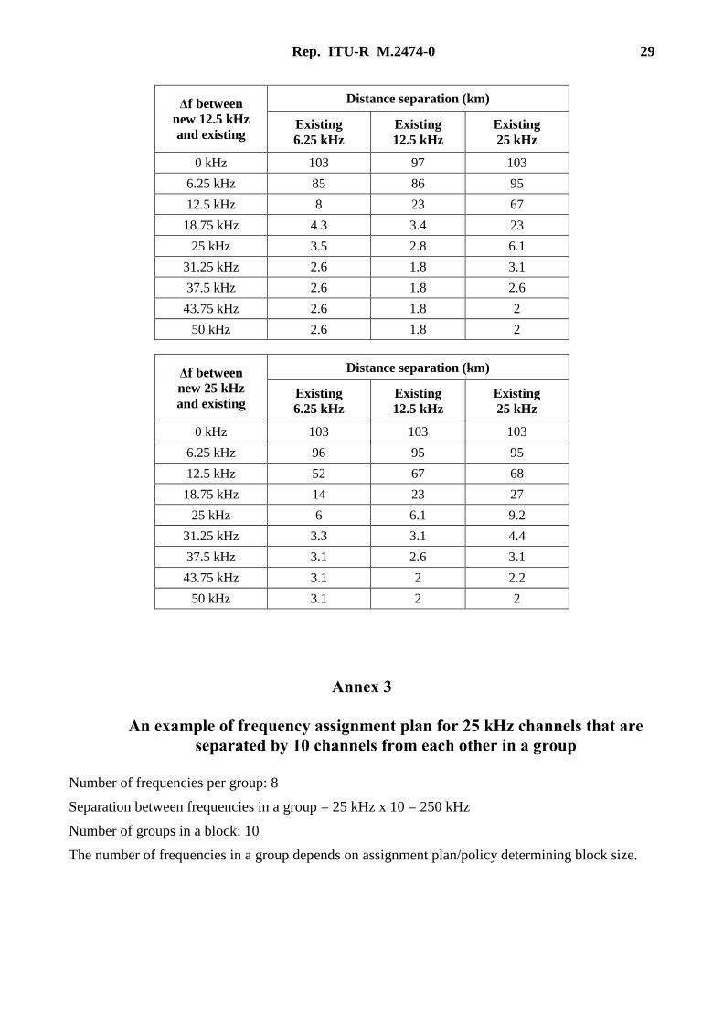
Rep. ITU-R M.2474-0 29
Δf between
new 12.5 kHz
and existing
Distance separation (km)
Existing
6.25 kHz
Existing
12.5 kHz
Existing
25 kHz
0 kHz 103 97 103
6.25 kHz 85 86 95
12.5 kHz 8 23 67
18.75 kHz 4.3 3.4 23
25 kHz 3.5 2.8 6.1
31.25 kHz 2.6 1.8 3.1
37.5 kHz 2.6 1.8 2.6
43.75 kHz 2.6 1.8 2
50 kHz 2.6 1.8 2
Δf between
new 25 kHz
and existing
Distance separation (km)
Existing
6.25 kHz
Existing
12.5 kHz
Existing
25 kHz
0 kHz 103 103 103
6.25 kHz 96 95 95
12.5 kHz 52 67 68
18.75 kHz 14 23 27
25 kHz 6 6.1 9.2
31.25 kHz 3.3 3.1 4.4
37.5 kHz 3.1 2.6 3.1
43.75 kHz 3.1 2 2.2
50 kHz 3.1 2 2
Annex 3
An example of frequency assignment plan for 25 kHz channels that are
separated by 10 channels from each other in a group
Number of frequencies per group: 8
Separation between frequencies in a group = 25 kHz x 10 = 250 kHz
Number of groups in a block: 10
The number of frequencies in a group depends on assignment plan/policy determining block size.

30 Rep. ITU-R M.2474-0
Group 1 1 11 21 31 41 51 61 71
Group 2 2 12 22 32 42 52 62 72
Group 3 3 13 23 33 43 53 63 73
Group 4 4 14 24 34 44 54 64 74
Group 5 5 15 25 35 45 55 65 75
Group 6 6 16 26 36 46 56 66 76
Group 7 7 17 27 37 47 57 67 77
Group 8 8 18 28 38 48 58 68 78
Group 9 9 19 29 39 49 59 69 79
Group 10 10 20 30 40 50 60 70 80
______________
Related Documents

![Radio Monitoring ITU Measurement Request[1]](https://static.cupdf.com/doc/110x72/563dba33550346aa9aa38d49/radio-monitoring-itu-measurement-request1.jpg)


![[ITU-ML5G-PS-036] Radio Link Failure Prediction](https://static.cupdf.com/doc/110x72/6267997e6cfd3e6d654ad1f8/itu-ml5g-ps-036-radio-link-failure-prediction.jpg)


