Spokane Convention Center Completion Study LMN + ALSC Concept Design Report February 22, 2011

Welcome message from author
This document is posted to help you gain knowledge. Please leave a comment to let me know what you think about it! Share it to your friends and learn new things together.
Transcript
SpokaneConvention Center Completion Study
LMN + ALSC
Concept Design Report
February 22, 2011

Spokane Convention Center Completion Study LMN + ALSC Concept Design Report
February 22, 2011 Page 1
Table of Contents
Introduction Executive Summary Scope of Study Sustainable Design Design Team Programming Summary – CW Stakeholders
Convention Center Completion RiverBank State Agencies
Design Narratives Architectural Landscape Structural
Civil Mechanical, Electrical & Plumbing
Concept Design Plan Diagrams Landscape Diagrams Perspective Views
Cost Model Executive Summary
Appendix A – Program Summary Report B – CC Completion Study Community Stakeholders & RiverBank
Stakeholders Meeting Notes C – Fire Department Access, Department of Wildlife, Department of Ecology, City Planning Department & WSDOT D – Issues for Consideration E – Civil Diagrams F – Preliminary Cost Model Back-up

IntroductionExecutive Summary
Scope of StudySustainable Design
Design TeamProgramming Summary
Stakeholders
Spokane Convention Center Completion Study LMN + ALSC Concept Design Report
February 22, 2011 Page 1
INTRODUCTION
Executive Summary
The Spokane Convention Center Completion Study represents a unique opportunity to strengthen the identity of the “East Campus” of the Spokane Convention Center Campus. The project is intended to fully build out the program originally envisioned for the 2005 expansion, while addressing the needs of facility users, meeting planners and reflecting current trends in the convention center industry. Above all, the facility will create a signature experience for visitors, delegates and the general public. The Completion Study has been approached with a single objective in mind: to achieve the most cost-effective, operationally efficient and programmatically balanced project possible. Recognizing the likelihood of continuing challenges to the economic environment, the study has been conducted with a strict emphasis on careful consideration of cost impacts and functional benefits. The resulting recommendations in the Concept Design Report represent a practical, buildable and aesthetically integrated facility that will strongly support the continued success of the Spokane Convention Center. Building on the success of the Expansion’s engagement with the Spokane River, the new spaces seek to capitalize on the direct connection to the Centennial Trail and Riverfront Park in a way never before possible. Incorporating feedback from critical stakeholder and agency groups, and adhering to the tenets of the Shoreline Master Plan, the Completion Project will improve the experience of visitors and the general public along the Trail. By adhering closely to the Spokane Public Facilities District’s Sustainable Practices Policy, this design respects the spectacular natural setting within which it is sited.
Scope of Study
The District is considering the completion of the Spokane Convention Center to include additional exhibition hall, meeting room and support space. The proposed project site is on the north side of the existing facility in the area where the C.I. Shenanigan’s Restaurant and parking lot are currently located. The Completion Project is intended to provide additional program spaces not included in the previous expansion and to enhance the overall building to meet the latest trends in convention facilities.
The Study is planned to run from October 2010 into early 2011 and conclude with the development of a Concept Design Report. The Report will include a summary of the proposed Design Concept in Narrative and Diagram format. Additionally, the report includes a Probable Cost Summary for the project.
As part of the Completion Study, the District is studying opportunities to make improvements to the adjacent Centennial Trail, public open spaces and restoration of the adjacent the river bank. The goal is to improve access and recreational use opportunities, while also improving the health of the river ecosystem. Work involving the Centennial Trail and riverbank is a separate project from the Convention Center Completion Project.
Spokane Convention Center Completion Study LMN + ALSC Concept Design Report
February 22, 2011 Page 2
Sustainable Design
Consistent with the District’s Sustainability Goals within their Sustainable Practices Policy, the LMN+ALSC team promotes environmental responsibility through our practice of sustainable design and the application of “green” measures. Our process goes beyond the LEED evaluation system to ensure that environmental principles are carefully integrated into the entire process. The Conceptual Design approach outlined in this report anticipates being able to achieve a LEED Silver Certification for the Completion Project. Elements of our sustainable strategies are discussed within the Design Narrative that follows.
Design Team
To assist the Spokane Public Facilities District in developing a Concept Design & Probable Cost Estimate for the project, the design team of LMN+ALSC was selected. Assisting LMN+ALSC are the following consultants:
Landscape – Murase Associates Civil – DCI Engineers Structural – Magnusson Klemencic Associates Mechanical / Electrical – MW Consulting Engineers Cost Estimating – Davis Langdon
Assisting the Spokane Public Facilities District are the following consultants: Programming / Market Trends - Conventional Wisdom Land Use - Jim Kolva Associates
Program Summary
Executive Summary (by Conventional Wisdom): The challenge facing the design team is finding the balance between the amount of contiguous exhibition space desirable to meet near-term market demand and the reasonable capacity of the expansion site, given riverfront development guidelines and the urban context. The Programmer’s role is to ensure that the combination of exhibition, meeting and multipurpose space provides a balanced facility from the user perspective and has the right amount of public and service areas to provide an exceptional guest experience while improving operational efficiency.
Computer modeling examines how an audience of a given size would use the existing Convention Center, and then compares that audience to the function space available with the Completion Project. This approach identifies the demand for space for different types of event functions – banquet, plenary session, breakout meetings and exhibition – and compares the demand to the available space.
Improvements to functional efficiency are of equal importance to the marketability of the Convention Center. The back of house service areas include adequate storage for staging and setup equipment, tables and chairs; dedicated service corridors behind meeting rooms; a satellite pantry- warming kitchen
Spokane Convention Center Completion Study LMN + ALSC Concept Design Report
February 22, 2011 Page 3
that supports new banquet spaces; and a service connection linking the existing to the new areas to minimize disruption to ongoing events and overlaps with public circulation paths.
The recommended facility program adds 18,000 sf of new prime exhibition space, a 13,500 sf divisible multipurpose room for large meetings, banquets and receptions, a 10,500 sf of flexible meeting space, a satellite pantry-warming kitchen and large storage area for the setup equipment to be used in the north half of the building. The multipurpose room should have a high ceiling, improved acoustics and the production-intensive audiovisual/lighting/power systems needed to support plenary sessions, Web-casting and multimedia presentations.
Conventional Wisdom’s preliminary analysis indicates the proposed expansion will improve the marketability of the Convention Center by providing a better mix of space that is more attractive to a wider audience. While the new construction will not significantly increase the size of groups to be attracted to the facility, the greatest opportunity will be to market conventions with banquets for groups from 1,000 to 1,500 attendees.
The full Program Summary Report can be found in Appendix A at the back of this document.
Stakeholders
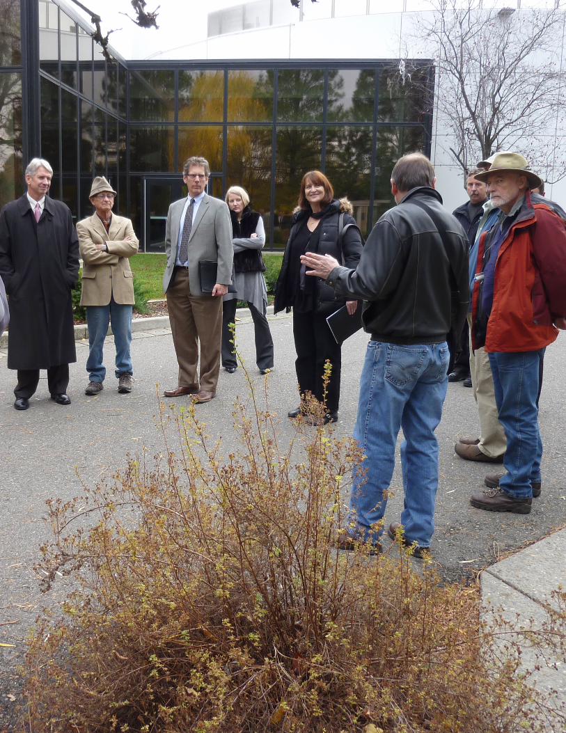
Community Groups: the District feels that it is critical in its planning process for expansion of the Convention Center, that public input be solicited early and continuously throughout the process. The District identified individuals and organizations that would potentially be impacted by or have a strong interest in the Convention Center Completion Project. Two groups were formed and included city and other agency staff, adjacent property owners, Convention Center users, river protection and recreation advocates and Friends of the Centennial Trail. Two separate groups of meetings were held. One was the River Bank Restoration Group, focusing on the space between the Centennial Trail markers and the water’s edge. The other was the Convention Center Expansion Group, focusing on the programming and design of the structure as well as the surrounding area. Both groups shared common interests particularly with public access and interface of the building and the shoreline/Centennial Trail environment. In these meetings, the project goals and design concepts were presented. The groups were given the opportunity to present their ideas and concerns related to the Convention Center Completion Project as well as its impact on the river front. Minutes of these meetings and a list of those who attended are included in Appendix B of this report.
Many of the concerns and ideas raised in the meetings were integrated into the design concept. The following are some key reoccurring themes that came from the meetings:
• Improve the connection of the Convention Center to the RiverBank/Centennial Trail. • Meet set-back requirements of the recently adopted Shoreline Master Plan. • Provide interior and exterior spaces with views of the river. • Locate meeting rooms adjacent to the Exhibition Hall. • Soften façade of the building that faces the river.
Spokane Convention Center Completion Study LMN + ALSC Concept Design Report
February 22, 2011 Page 4
• Improve access for pedestrians arriving from the north on Division Street. • Improve access to river and Centennial Trail from Spokane Falls Boulevard. • Provide public amenities and activities along the Centennial Trail to encourage day and evening
use. • Provide safe river access for boating. • Limit access to river bank from Centennial Trail. • Maintain adequate width of Centennial Trail.
Fire Department: the Design Team met with Chief Bobby Williams and Dave Kokot of the Spokane Fire Department on December 14, 2010 to discuss their issues and concerns regarding the proposed Convention Center Completion Project. Fire trucks need to get within 150 feet of any point of the building. The Centennial Trail currently serves as the fire lane for this purpose. Primary Fire Department access points are the Convention Center breezeway and the Marriott Courtyard Hotel parking lot. The existing secondary access point between the Ag Trade Center and the Doubletree pool must be maintained. The fire lane must have a minimum clear width of 20 feet with a minimum of 15 feet of that width paved. Minutes of this meeting are included in Appendix C of this report.
State Agencies: Members of the Design Team met with Mike Maher of the Department of Ecology and Karin Divens with the Department of Fish and Wildlife January 7. 2011. The purpose of the meeting was to get a clear understanding of these agencies concerns about modifications to the river bank and the Centennial Trail directly north of the Convention Center. The key issues/concerns are as follows:
• Basalt river bank armament is okay in specific areas where justified if placed naturally and combined with plantings.
• A boat launch under the Division Street Bridge is acceptable. Placement of rocks in the river for this purpose will require a “Hydraulic Project Approval” from the DFW.
• A dock or pier in the river will require a “Hydraulic Project Approval” from the DFW. • The City of Spokane Planning Department will review the project for compliance with the
Shorelines Master Program. Minutes of these meetings and a list of those who attended are included in Appendix C of this report.
Key Points to be considered in Shoreline Approvals: The design team held several stakeholder meetings, and reviewed the project with the City Planning Department, City Fire Department, City Parks and Recreation, City Arts Commission, Department of Transportation, Department of Ecology and Department of Fish and Wildlife. A summary of key issues and requirements raised at those meetings is included in the Appendix D of this report.
Design NarrativesArchitectural
LandscapeStructural
CivilMechanical, Electrical & Plumbing
Spokane Convention Center Completion Study LMN + ALSC Concept Design Report
February 22, 2011 Page 1
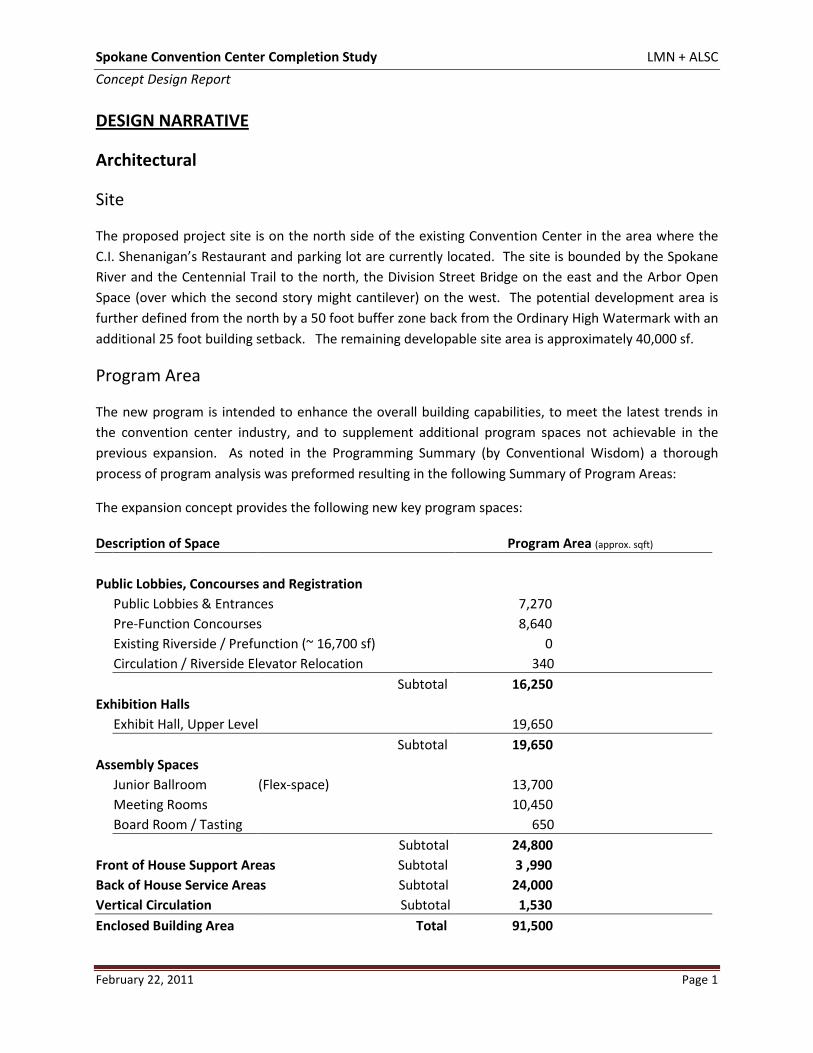
DESIGN NARRATIVE
Architectural
Site
The proposed project site is on the north side of the existing Convention Center in the area where the C.I. Shenanigan’s Restaurant and parking lot are currently located. The site is bounded by the Spokane River and the Centennial Trail to the north, the Division Street Bridge on the east and the Arbor Open Space (over which the second story might cantilever) on the west. The potential development area is further defined from the north by a 50 foot buffer zone back from the Ordinary High Watermark with an additional 25 foot building setback. The remaining developable site area is approximately 40,000 sf.
Program Area
The new program is intended to enhance the overall building capabilities, to meet the latest trends in the convention center industry, and to supplement additional program spaces not achievable in the previous expansion. As noted in the Programming Summary (by Conventional Wisdom) a thorough process of program analysis was preformed resulting in the following Summary of Program Areas:
The expansion concept provides the following new key program spaces:
Description of Space Program Area (approx. sqft)
Public Lobbies, Concourses and Registration
Public Lobbies & Entrances 7,270
Pre-Function Concourses 8,640
Existing Riverside / Prefunction (~ 16,700 sf) 0
Circulation / Riverside Elevator Relocation 340
Subtotal 16,250
Exhibition Halls
Exhibit Hall, Upper Level 19,650
Subtotal 19,650
Assembly Spaces
Junior Ballroom (Flex-space) 13,700
Meeting Rooms 10,450
Board Room / Tasting
650
Subtotal 24,800
Front of House Support Areas Subtotal 3 ,990 Back of House Service Areas Subtotal 24,000 Vertical Circulation Subtotal 1,530 Enclosed Building Area Total 91,500
Spokane Convention Center Completion Study LMN + ALSC Concept Design Report
February 22, 2011 Page 2
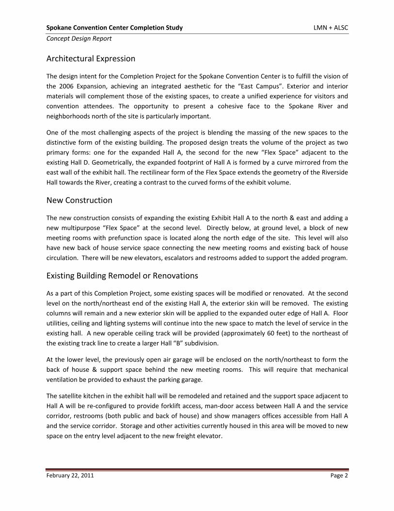
Architectural Expression
The design intent for the Completion Project for the Spokane Convention Center is to fulfill the vision of the 2006 Expansion, achieving an integrated aesthetic for the “East Campus”. Exterior and interior materials will complement those of the existing spaces, to create a unified experience for visitors and convention attendees. The opportunity to present a cohesive face to the Spokane River and neighborhoods north of the site is particularly important.
One of the most challenging aspects of the project is blending the massing of the new spaces to the distinctive form of the existing building. The proposed design treats the volume of the project as two primary forms: one for the expanded Hall A, the second for the new “Flex Space” adjacent to the existing Hall D. Geometrically, the expanded footprint of Hall A is formed by a curve mirrored from the east wall of the exhibit hall. The rectilinear form of the Flex Space extends the geometry of the Riverside Hall towards the River, creating a contrast to the curved forms of the exhibit volume.
New Construction
The new construction consists of expanding the existing Exhibit Hall A to the north & east and adding a new multipurpose “Flex Space” at the second level. Directly below, at ground level, a block of new meeting rooms with prefunction space is located along the north edge of the site. This level will also have new back of house service space connecting the new meeting rooms and existing back of house circulation. There will be new elevators, escalators and restrooms added to support the added program.
Existing Building Remodel or Renovations
As a part of this Completion Project, some existing spaces will be modified or renovated. At the second level on the north/northeast end of the existing Hall A, the exterior skin will be removed. The existing columns will remain and a new exterior skin will be applied to the expanded outer edge of Hall A. Floor utilities, ceiling and lighting systems will continue into the new space to match the level of service in the existing hall. A new operable ceiling track will be provided (approximately 60 feet) to the northeast of the existing track line to create a larger Hall “B” subdivision.
At the lower level, the previously open air garage will be enclosed on the north/northeast to form the back of house & support space behind the new meeting rooms. This will require that mechanical ventilation be provided to exhaust the parking garage.
The satellite kitchen in the exhibit hall will be remodeled and retained and the support space adjacent to Hall A will be re-configured to provide forklift access, man-door access between Hall A and the service corridor, restrooms (both public and back of house) and show managers offices accessible from Hall A and the service corridor. Storage and other activities currently housed in this area will be moved to new space on the entry level adjacent to the new freight elevator.
Spokane Convention Center Completion Study LMN + ALSC Concept Design Report
February 22, 2011 Page 3
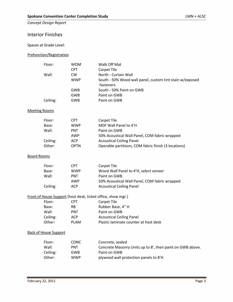
Interior Finishes
Spaces at Grade Level:
Prefunction/Registration
Floor: WOM Walk Off Mat CPT Carpet Tile Wall: CW North - Curtain Wall WWP South - 50% Wood wall panel, custom tint stain w/exposed
fasteners GWB South - 50% Paint on GWB GWB Paint on GWB Ceiling: GWB Paint on GWB
Meeting Rooms
Floor: CPT Carpet Tile Base: WWP MDF Wall Panel to 4’H Wall: PNT Paint on GWB AWP 50% Acoustical Wall Panel, COM fabric wrapped Ceiling: ACP Acoustical Ceiling Panel Other: OPTN Operable partitions, COM fabric finish (3 locations)
Board Rooms
Floor: CPT Carpet Tile Base: WWP Wood Wall Panel to 4’H, select veneer Wall: PNT Paint on GWB AWP 50% Acoustical Wall Panel, COM fabric wrapped Ceiling: ACP Acoustical Ceiling Panel
Front of House SupportFloor: CPT Carpet Tile
(host desk, ticket office, show mgr.)
Base: RB Rubber Base, 4” H Wall: PNT Paint on GWB Ceiling: ACP Acoustical Ceiling Panel Other: PLAM Plastic laminate counter at host desk
Back of House Support
Floor: CONC Concrete, sealed Wall: PNT Concrete Masonry Units up to 8’, then paint on GWB above. Ceiling: GWB Paint on GWB Other: WWP plywood wall protection panels to 8’H
Spokane Convention Center Completion Study LMN + ALSC Concept Design Report
February 22, 2011 Page 4
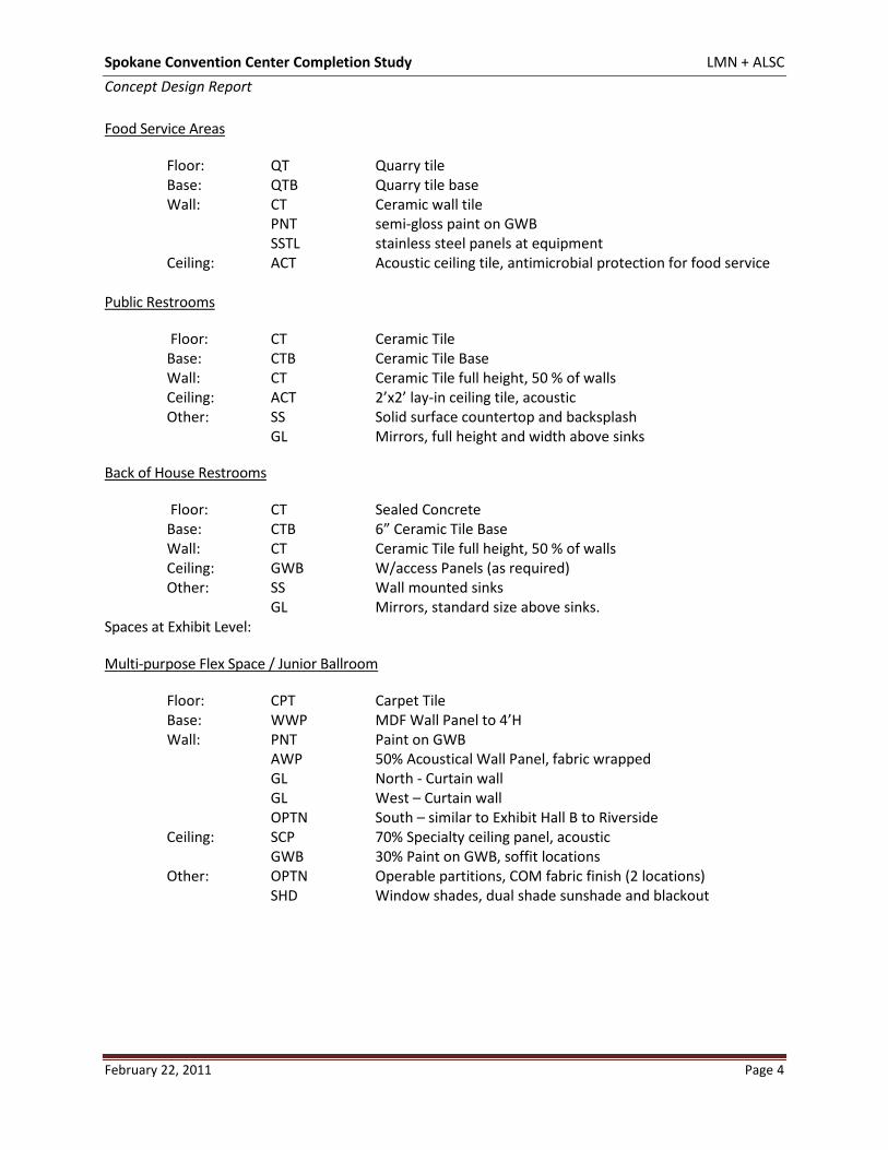
Food Service Areas
Floor: QT Quarry tile Base: QTB Quarry tile base Wall: CT Ceramic wall tile PNT semi-gloss paint on GWB SSTL stainless steel panels at equipment Ceiling: ACT Acoustic ceiling tile, antimicrobial protection for food service
Public Restrooms
Floor: CT Ceramic Tile Base: CTB Ceramic Tile Base Wall: CT Ceramic Tile full height, 50 % of walls Ceiling: ACT 2’x2’ lay-in ceiling tile, acoustic Other: SS Solid surface countertop and backsplash GL Mirrors, full height and width above sinks
Back of House Restrooms
Floor: CT Sealed Concrete Base: CTB 6” Ceramic Tile Base Wall: CT Ceramic Tile full height, 50 % of walls Ceiling: GWB W/access Panels (as required) Other: SS Wall mounted sinks GL Mirrors, standard size above sinks.
Spaces at Exhibit Level:
Multi-purpose Flex Space / Junior Ballroom
Floor: CPT Carpet Tile Base: WWP MDF Wall Panel to 4’H Wall: PNT Paint on GWB AWP 50% Acoustical Wall Panel, fabric wrapped GL North - Curtain wall GL West – Curtain wall OPTN South – similar to Exhibit Hall B to Riverside Ceiling: SCP 70% Specialty ceiling panel, acoustic GWB 30% Paint on GWB, soffit locations Other: OPTN Operable partitions, COM fabric finish (2 locations) SHD Window shades, dual shade sunshade and blackout
Spokane Convention Center Completion Study LMN + ALSC Concept Design Report
February 22, 2011 Page 5
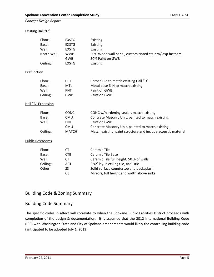
Existing Hall “D”
Floor: EXSTG Existing Base: EXSTG Existing Wall: EXSTG Existing North Wall: WWP 50% Wood wall panel, custom tinted stain w/ exp fastners GWB 50% Paint on GWB Ceiling: EXSTG Existing
Prefunction
Floor: CPT Carpet Tile to match existing Hall “D” Base: MTL Metal base 6”H to match existing Wall: PNT Paint on GWB Ceiling: GWB Paint on GWB
Hall “A” Expansion
Floor: CONC CONC w/hardening sealer, match existing Base: CMU Concrete Masonry Unit, painted to match existing Wall: PNT Paint on GWB CMU Concrete Masonry Unit, painted to match existing Ceiling: MATCH Match existing, paint structure and include acoustic material
Public Restrooms
Floor: CT Ceramic Tile Base: CTB Ceramic Tile Base Wall: CT Ceramic Tile full height, 50 % of walls Ceiling: ACT 2’x2’ lay-in ceiling tile, acoustic Other: SS Solid surface countertop and backsplash GL Mirrors, full height and width above sinks
Building Code & Zoning Summary
Building Code Summary
The specific codes in affect will correlate to when the Spokane Public Facilities District proceeds with completion of the design & documentation. It is assumed that the 2012 International Building Code (IBC) with Washington State and City of Spokane amendments would likely the controlling building code (anticipated to be adopted July 1, 2013).
Spokane Convention Center Completion Study LMN + ALSC Concept Design Report
February 22, 2011 Page 6
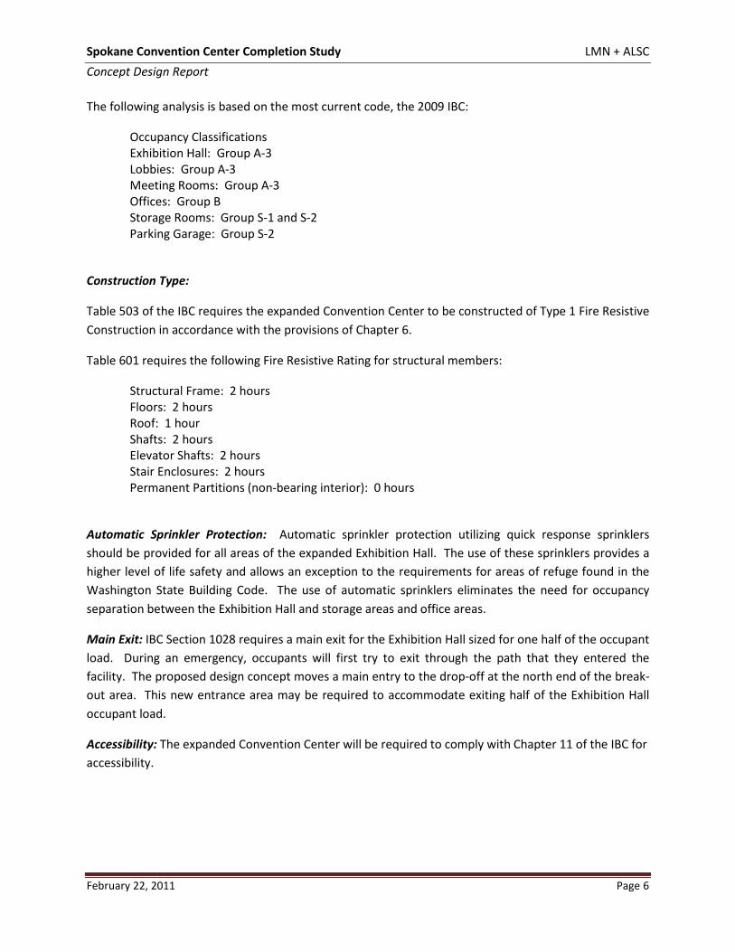
The following analysis is based on the most current code, the 2009 IBC:
Occupancy Classifications Exhibition Hall: Group A-3 Lobbies: Group A-3 Meeting Rooms: Group A-3 Offices: Group B Storage Rooms: Group S-1 and S-2 Parking Garage: Group S-2
Construction Type:
Table 503 of the IBC requires the expanded Convention Center to be constructed of Type 1 Fire Resistive Construction in accordance with the provisions of Chapter 6.
Table 601 requires the following Fire Resistive Rating for structural members:
Structural Frame: 2 hours Floors: 2 hours Roof: 1 hour Shafts: 2 hours Elevator Shafts: 2 hours Stair Enclosures: 2 hours Permanent Partitions (non-bearing interior): 0 hours
Automatic Sprinkler Protection: Automatic sprinkler protection utilizing quick response sprinklers should be provided for all areas of the expanded Exhibition Hall. The use of these sprinklers provides a higher level of life safety and allows an exception to the requirements for areas of refuge found in the Washington State Building Code. The use of automatic sprinklers eliminates the need for occupancy separation between the Exhibition Hall and storage areas and office areas.
Main Exit: IBC Section 1028 requires a main exit for the Exhibition Hall sized for one half of the occupant load. During an emergency, occupants will first try to exit through the path that they entered the facility. The proposed design concept moves a main entry to the drop-off at the north end of the break-out area. This new entrance area may be required to accommodate exiting half of the Exhibition Hall occupant load.
Accessibility: The expanded Convention Center will be required to comply with Chapter 11 of the IBC for accessibility.
Spokane Convention Center Completion Study LMN + ALSC Concept Design Report
February 22, 2011 Page 7
General Zoning and Land Use
Zoning District: DTG (Downtown General)
Land Use: Downtown, Conservation Open Space
Overlay Zone/Height District: Multi-family Tax Exempt (not applicable to convention center use)
Community Empowerment Zone: Yes
Shoreline Designation: Downtown, Urban Intensive Environment – 50’ Buffer,
Critical Areas: Zone 2 Riparian Habitat Area, 100 – Year FEMA Flood Zone
Adjacent Street Designations:
Division: Type III Complete Street (City-Regional Connector)
Spokane Falls Blvd.: Type II Complete Street (Community Connector)
Proposed Use – Exhibit Hall and Meeting room expansion.
General Zoning Development Standards for DTG Zone: Reference SMC 17C.124
Shoreline Regulations: Reference SMC 17E.060, Shoreline Regulations
Landscaping: Reference SMC 17C.200
Required Permits, Reviews & Documentation
Piers and Docks: Reference SMC 17E.060.430.
SEPA Review: Will be required.
Shoreline Permits/JARPA: A Shoreline Conditional Use Permit is required and a Shoreline Variance may also be required due to work in buffer; project must comply with the City’s SMP. Shoreline Conditional Use Permits include a public hearing before the City’s Hearing Examiner.
Critical Area Checklist: City of Spokane, Critical Areas Checklist must be completed at time of application. Fish & Wildlife Conservation area (17E.020).
Floodplain Development Permit: Reference SMC 17E.030.060, Must be obtained at time of building permit application. Although the floodplain development permit need not be issued until time of building permit; the applicant is required to illustrate ability to obtain a floodplain development permit at time of submittal for Shoreline Conditional Use Permit.
Habitat Management Plan: Reference SMC 17E.020.090, Any vegetation removal and replacement within the 200 foot Shoreline Jurisdiction and Riparian Habitat Area and will require a Habitat Management Plan.
Formal Design Review: Reference Section 17E.060.340, Shoreline Design Review. Design review is required. Shoreline design review is subject to the procedures established in SMC Chapter 17G.030, Chapter 17G.040 and Chapter 17G.060.
Boundary Line Adjustment: Required to aggregate parcels.
Spokane Convention Center Completion Study LMN + ALSC Concept Design Report
February 22, 2011 Page 8
Landscape
The District views the expansion of the Spokane Convention Center as an opportunity to improve the existing Spokane Riverfront Landscape, enhance connections to the Spokane Riverfront, and expand recreational opportunities for Spokane residents and visitors. Currently, the landscape consists of a linear band between the existing Convention Center building and the Spokane River. The Centennial Trail is a public path that connects pedestrians and cyclists to the site and is the most important landscape feature within the Spokane Convention Center campus. As an asset to the community, the Centennial Trail is part of an extensive trail system that links the site to many city amenities and recreational opportunities. The Trail is lined with large trees on both sides, which provide shade during summer months and helps to maintain the river bank. The existing trail is a twenty foot wide asphalt lane and is located on what was previously a railroad bed. Between the Trail and the Spokane River, a steep bank is eroding into the River. The eroding river bank is a potential public safety hazard because the edge of the trail is located near the top of the steep embankment. Additionally, the Spokane River is not safe for swimming because of its proximity to the Upper Falls Control Works Spillway Dam. The existing landscape situated south of the trail is an underused area of lawn and display beds which will be redesigned to coordinate with the proposed Convention Center Expansion and plans to screen views of the loading dock for the Doubletree Hotel. A public open space is adjacent to the west side of the C.I. Shenanigans property. Pedestrian connections between the river front and Spokane Falls Boulevard (a major arterial) exist on the east and west sides of the Doubletree Hotel, but are not visible or well signed. The Division Street Bridge is located on the east side of the Convention Center, providing another potential connection to the river front and Convention Center. Incorporation of a comprehensive wayfinding and interpretive signage program would improve the user experience on the campus. Likewise, use of artists to work with signage, pathway definition and street furniture could enhance the site as a public destination.
The proposed Landscape Master Plan Concept is the result of site and programming analysis and meetings with community stakeholder groups to discuss concerns and potential opportunities for changes to the existing Centennial Trail, river bank and landscape. The Master Plan Concept consists of the following components: River Bank, Trails, Plaza, and Native Garden. (Refer to Concept Design, Landscape Diagrams).
River Bank
In an effort to reduce and prevent further erosion of the river bank, the Master Plan proposes restoration with native shoreline plants and the installation of a low barrier to help prevent foot traffic on the steep slope and discourage waterfowl from entering the Centennial Trail and open space areas. In addition to improving the appearance of the bank, this will have added benefits upon the existing river ecosystem and improve fish and wildlife habitat. A water-efficient irrigation system will be installed to establish and maintain the shoreline plans. A possible small boat access could be located under Division Street Bridge. Further safety studies should be completed due to proximity of the Spillway Dam. (Refer to Concept Design, Landscape Diagrams)
Spokane Convention Center Completion Study LMN + ALSC Concept Design Report
February 22, 2011 Page 9
Trails
The existing Centennial Trail varies in width, but is approximately 20 ft wide. The Master Plan proposes to reduce the width of the trail to seventeen feet, decreasing the slope on the river bank and holding the edge of the trail further back from the top of the slope. Existing large trees along the trail are to be saved. The Fire Department will still require a full twenty foot unobstructed width for access. The existing bronze donor plaques along the south side of the Centennial Trail will remain untouched. To help reduce congestion on the Centennial Trail, smaller secondary paths will run parallel alongside the main trail. These secondary paths will meander through the Native Garden and provide small seating areas. Interpretive signage and plaques could be added at key locations to tell the history of the river, the development of its bank, and the development of the site. (Refer to Concept Design, Landscape Diagrams)
Plaza
A plaza has been proposed near the Convention Center Drop-off/Entry to provide a programmable outdoor space for the Convention Center and future public events. This public space will provide open sight lines and views between the Convention Center Entry and the Spokane River. A river overlook will further draw Convention Center users to the river front, providing vital connections to the river. The plaza could incorporate a small stage and seating for events. Larger events can overflow into the adjacent Native Garden. The plaza area could provide infrastructure and space configuration to accommodate food vendors for special events. (Refer to Concept Design, Landscape Diagrams).
Native Garden
A native garden has been proposed for the space between the Convention Center and the Centennial Trail. The native garden will have trails for exploration throughout the garden and provide many seating opportunities for individuals or small groups. Plants native to the natural landscape of Spokane will be displayed throughout the garden, alongside interpretive graphics and signage to explain the native plants. Plants can be selected to enhance wildlife habitat for birds and butterflies. The garden will also provide areas for the infiltration of storm water collected from the Convention Center roof. The loading area on the north side of the Doubletree Hotel will be reconfigured and screened. A water-efficient irrigation system will be installed to establish and maintain native vegetation.
Codes, Zoning & Land Use
All landscape improvements will need to comply with the District’s Sustainable Practices and the City’s Shoreline Management Plan, and meet the requirements of the Department of Ecology and Department of Fish and Wildlife.
Shoreline Designation: Downtown, Urban Intensive Environment – 50’ Buffer
Shoreline Regulations: Reference SMC 17E.060, Shoreline Regulations
Spokane Convention Center Completion Study LMN + ALSC Concept Design Report
February 22, 2011 Page 10
Landscaping: Reference SMC 17C.200
Structural
Project Description
The most recent Spokane Convention Center expansion was completed in 2006. The proposed expansion involves approximately 115,000 sf of new construction. The program areas included in the proposed expansion are public lobby/concourse/registration spaces, exhibition hall spaces, ballroom spaces, meeting room spaces, food service spaces, and front-of-house support and back of house service spaces.
The program areas included within the proposed expansion are located on two primary levels. The meeting room program is proposed to be located at Grade Level and the exhibition hall and ballroom program is proposed to be located at the existing Exhibition Hall elevation.
Geotechnical Considerations and Assumptions
A site-specific geotechnical investigation has not yet been completed for this project. Based on a review of the geotechnical report that was prepared for the last expansion project (prepared by GeoEngineers and dated September 25, 2002), the key geotechnical considerations and assumptions are as follows:
• Groundwater is present at depths ranging from 5 to 8 feet below Grade Level.
• Contaminated soils are anticipated to be widespread across the site and could be present in the site soils to a depth of at least six feet below Grade Level. Reference the Civil section of this report for additional information regarding the types of contamination and possible remediation strategies.
• New foundations will bear on competent basalt rock that is located at depths that range from 2 to 23 feet below Grade Level.
• Spread footing, pier, and drilled shaft foundations will be used, and the maximum net bearing pressure on the rock is 40 kips per square foot.
• Spread footings will be used when the rock is located near Grade Level. Piers will be used when the rock is at a depth between 8 and 16 feet below Grade level. When the rock is located more than 16 feet below Grade Level, drilled shafts will be used.
• The minimum diameter for pier and drilled shaft foundations will be 3 feet.
• To resist lateral forces, a coefficient of friction of 0.45 will be used to determine sliding resistance. To determine the passive resistance at the face of footings or other embedded foundation elements, an equivalent fluid density of 300 pounds per cubic foot (pcf) will be used.
Spokane Convention Center Completion Study LMN + ALSC Concept Design Report
February 22, 2011 Page 11
• The lateral pressure against below-grade basement walls will be determined using an equivalent fluid density of 40 pcf for cantilevered walls and 65 pcf for restrained walls. These densities are based on the assumption that free-draining conditions exist behind the walls.
Interface between Existing and New Structural Systems
The primary interface conditions between the existing structural systems and those associated with the expansion are located at Grids CC, RA, 21, and E. An additional and important interface condition also occurs near the elevator and stair located near Grid CC-50. A brief description of the existing structural elements along these interface conditions follows:
• At Grid CC, concrete columns supported by drilled piers are located at Grids 41, 42, 44, 46, and 48. At Ground Level, concrete grade beams frame between and interconnect the drilled piers. At Level 2, concrete beams span between these columns. The columns located at Grids 41 and 42 stop at Level 2 whereas those at Grids 44, 46, and 48 extend above Level 2 to the existing low roof above.
• At the stair and elevator located near Grid CC-50, the four walls surrounding the elevator and one of the walls adjacent to the stair shaft are cast-in-place concrete walls. At Level 2, concrete beams frame into and are supported by these walls. If, as part of the expansion these elevators and stairs are re-located, it is recommended that the concrete walls remain in-place between Ground Level and Level 2 so as to maintain the support of the Level 2 framing.
• At Grid RA, concrete columns supported by drilled piers are located at Grids 16, 17, 18, 20, and 21. At Ground Level, concrete grade beams frame between and interconnect the drilled piers. At Level 2, concrete beams span between these columns. The column located at Grid 17 stops at Level 2 whereas those at Grids 16, 18, 20, and 21 extend above Level 2 to the main roof above.
• At Grid 21, concrete columns supported by drilled piers are located at Grids C, D, and E. At Ground Level, concrete grade beams frame between and interconnect the drilled piers. At Level 2, concrete beams span between these columns, all of which extend above Level 2 to the intermediate roof above.
• At Grid E, concrete columns supported by drilled piers are located at Grids 22, 23, and 24. At Ground Level, concrete grade beams frame between and interconnect the drilled piers. At Level 2, concrete beams span between these columns, all of which stop at Level 2.
In terms of the interface between the existing and new structural systems along these interface conditions, a two-step strategy will be implemented. Wherever adequate capacity exists within the existing concrete columns and drilled piers, the new structural systems will frame into and be supported by the existing columns/piers. When inadequate capacity exists and new structural supports are required, new columns and piers will be located so as to avoid conflict with the existing columns, piers,
Spokane Convention Center Completion Study LMN + ALSC Concept Design Report
February 22, 2011 Page 12
and grade beams. By making use of existing structural elements and minimizing the need for new elements at the interface conditions, this strategy will both minimize construction costs and maximize constructability.
At Level 2, the existing structural slab typically extends beyond the outside face of concrete beam along each of the interface conditions. In order to facilitate the connection of new beams to existing columns/beams and to allow for the proper connection between existing and new concrete slabs, it is anticipated that the existing slab cantilevers will be cut back to the outside face of existing beams.
Foundation Systems
The foundation system for the expansion is anticipated to be similar in nature to the foundation system that supports the existing building. It is anticipated that columns and shear walls will be supported on drilled piers that will typically be 4'-0" diameter. Spanning between the piers to both brace the piers and support walls where present will be concrete grade beams.
It is anticipated that the program at Grade Level will be supported by a soil-supported slab on grade that is anticipated to be 6 inches thick.
Gravity Framing Systems
The structural system of the existing building makes use of cast-in-place concrete framing (columns, beams, and slabs) at all levels at and below the Exhibit Hall Level and steel framing (roof deck, beams, and trusses) at the Roof Levels. It is anticipated that the same approach to structural system selection will be incorporated in the expansion to facilitate the connection between new and existing framing.
At the Exhibit Hall Level of the expansion, a system of concrete slab and beam framing supported by concrete columns is anticipated. At the Roof Level of the expansion, a system of steel roof deck and steel beam and girder framing supported by steel columns is anticipated.
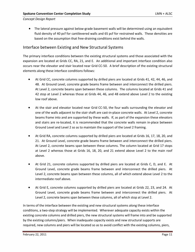
Figures S-1 and S-2 below illustrate the conceptual gravity framing system layouts at Ground Level and Level 2. Figure S-1. Conceptual Ground Level Framing Layout
Spokane Convention Center Completion Study LMN + ALSC Concept Design Report
February 22, 2011 Page 13
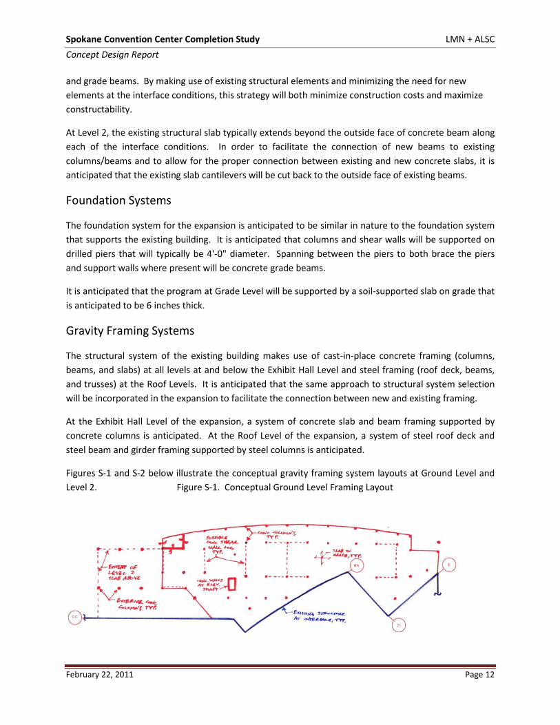
Figure S-2. Conceptual Level 2 Framing Layout
Lateral Force-Resisting Systems
The lateral force-resisting system of the existing building makes use of steel braced frames that brace all levels at and below the Exhibit Hall Level and cantilevered concrete columns that brace the Roof levels above.
In order to be similar in stiffness to the existing building, it is anticipated that concrete shear walls will be used at and below the Exhibit Hall Level for the expansion project. These shear walls will likely be located within the walls of the meeting rooms. Figure S-1 above illustrates possible locations for these walls. Above the Exhibit Hall Level, the roof of the expansion will be braced either by the existing cantilevered column system or, if inadequate capacity exists in the existing columns, by additional cantilevered columns, braced frames, or moment frames that will be incorporated into the design of the expansion.
Building and Material Codes
The project is anticipated to be designed in accordance with the following building and material codes:
Building Code
• International Building Code, 2006 Edition (IBC) with reference to American Society of Civil Engineers, Minimum Design Loads for Buildings and Other Structures, 2005 Edition (ASCE 7).
Material Codes
• Reinforced Concrete: American Concrete Institute, Building Code Requirements for Structural Concrete and Commentary, 2005 Edition (ACI 318).
• Structural Steel: American Institute of Steel Construction, Load and Resistance Factor Design Specification for Structural Steel Buildings, Third Edition (AISC 2003).
Spokane Convention Center Completion Study LMN + ALSC Concept Design Report
February 22, 2011 Page 14
Loading Criteria
A summary of the anticipated project-specific loading criteria follows. This loading meets or exceeds the requirements of the IBC and incorporates loading requirements specific to this project.
Gravity Loading
The following loads are in addition to the self weight of the structure. The minimum loading requirements have been taken from Table 1607.1 of the IBC. Live loads are reduced where permitted in accordance with Section 1607.9 of the IBC. Loads are given in pounds per square foot (psf).
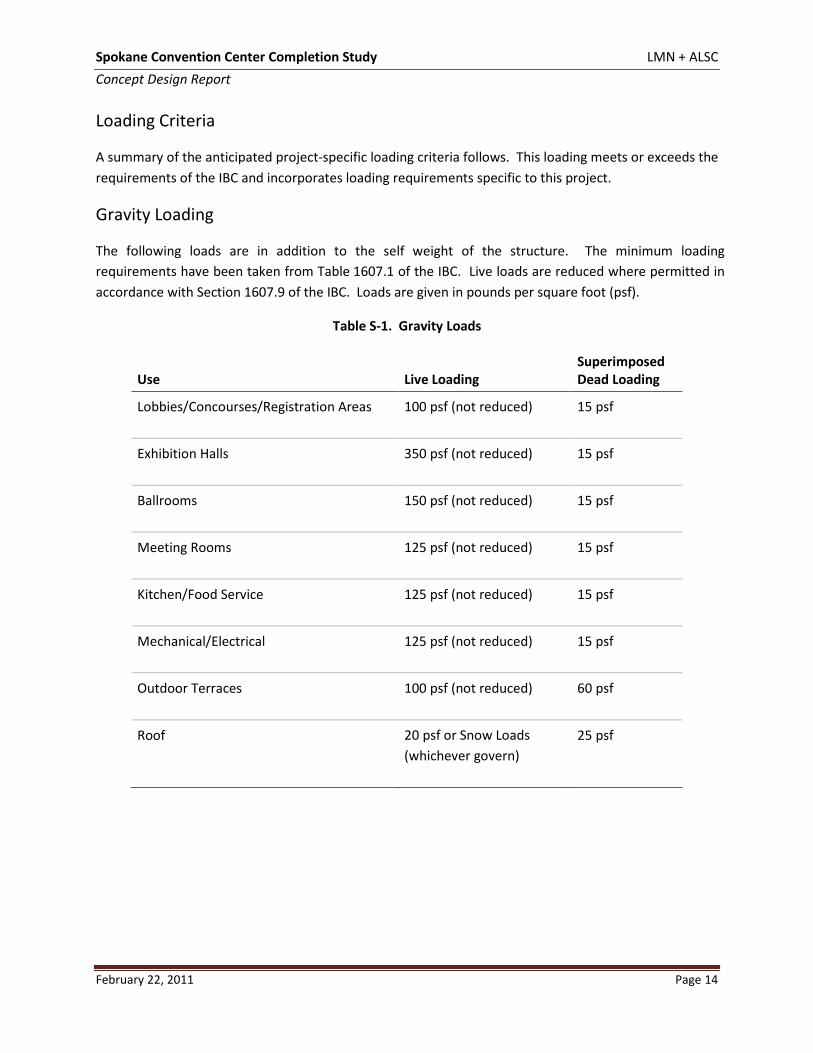
Table S-1. Gravity Loads
Use Live Loading Superimposed Dead Loading
Lobbies/Concourses/Registration Areas 100 psf (not reduced) 15 psf
Exhibition Halls 350 psf (not reduced) 15 psf
Ballrooms 150 psf (not reduced) 15 psf
Meeting Rooms 125 psf (not reduced) 15 psf
Kitchen/Food Service 125 psf (not reduced) 15 psf
Mechanical/Electrical 125 psf (not reduced) 15 psf
Outdoor Terraces 100 psf (not reduced) 60 psf
Roof 20 psf or Snow Loads (whichever govern)
25 psf
Spokane Convention Center Completion Study LMN + ALSC Concept Design Report
February 22, 2011 Page 15
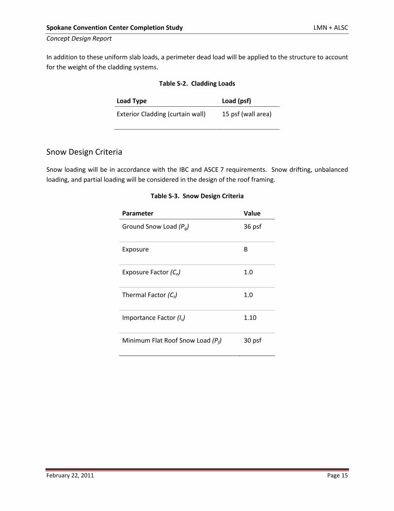
In addition to these uniform slab loads, a perimeter dead load will be applied to the structure to account for the weight of the cladding systems.
Table S-2. Cladding Loads
Load Type Load (psf)
Exterior Cladding (curtain wall) 15 psf (wall area)
Snow Design Criteria
Snow loading will be in accordance with the IBC and ASCE 7 requirements. Snow drifting, unbalanced loading, and partial loading will be considered in the design of the roof framing.
Table S-3. Snow Design Criteria
Parameter Value
Ground Snow Load (Pg) 36 psf
Exposure B
Exposure Factor (Ce) 1.0
Thermal Factor (Ct) 1.0
Importance Factor (Is) 1.10
Minimum Flat Roof Snow Load (Pf) 30 psf
Spokane Convention Center Completion Study LMN + ALSC Concept Design Report
February 22, 2011 Page 16
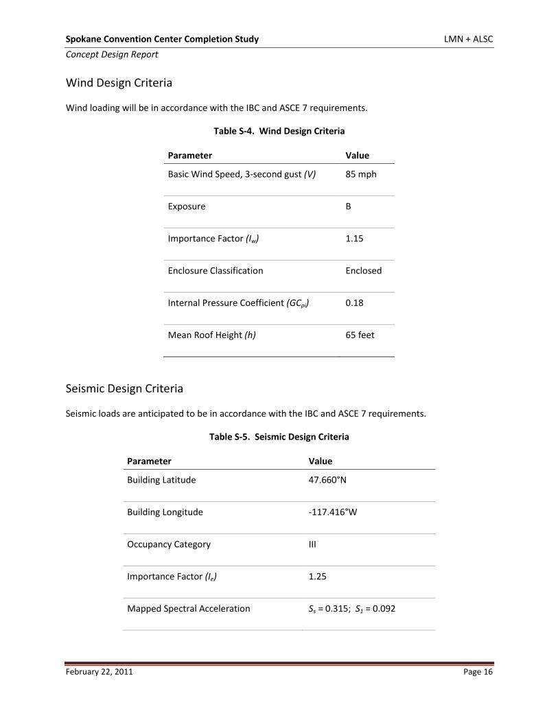
Wind Design Criteria
Wind loading will be in accordance with the IBC and ASCE 7 requirements.
Table S-4. Wind Design Criteria
Parameter Value
Basic Wind Speed, 3-second gust (V) 85 mph
Exposure B
Importance Factor (Iw) 1.15
Enclosure Classification Enclosed
Internal Pressure Coefficient (GCpi) 0.18
Mean Roof Height (h) 65 feet
Seismic Design Criteria
Seismic loads are anticipated to be in accordance with the IBC and ASCE 7 requirements.
Table S-5. Seismic Design Criteria
Parameter Value
Building Latitude 47.660°N
Building Longitude -117.416°W
Occupancy Category III
Importance Factor (Ie) 1.25
Mapped Spectral Acceleration Ss = 0.315; S1 = 0.092
Spokane Convention Center Completion Study LMN + ALSC Concept Design Report
February 22, 2011 Page 17
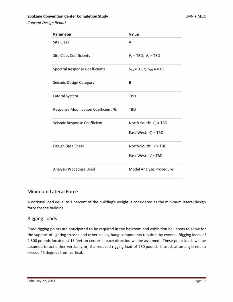
Parameter Value
Site Class A
Site Class Coefficients Fa = TBD; Fv = TBD
Spectral Response Coefficients SDS = 0.17; SD1 = 0.05
Seismic Design Category B
Lateral System TBD
Response Modification Coefficient (R) TBD
Seismic Response Coefficient North-South: Cs = TBD
East-West: Cs = TBD
Design Base Shear North-South: V = TBD
East-West: V = TBD
Analysis Procedure Used Modal Analysis Procedure
Minimum Lateral Force
A notional load equal to 1 percent of the building's weight is considered as the minimum lateral design force for the building.
Rigging Loads
Fixed rigging points are anticipated to be required in the ballroom and exhibition hall areas to allow for the support of lighting trusses and other ceiling hung components required by events. Rigging loads of 2,500 pounds located at 15 feet on center in each direction will be assumed. These point loads will be assumed to act either vertically or, if a reduced rigging load of 750 pounds is used, at an angle not to exceed 45 degrees from vertical.
Spokane Convention Center Completion Study LMN + ALSC Concept Design Report
February 22, 2011 Page 18
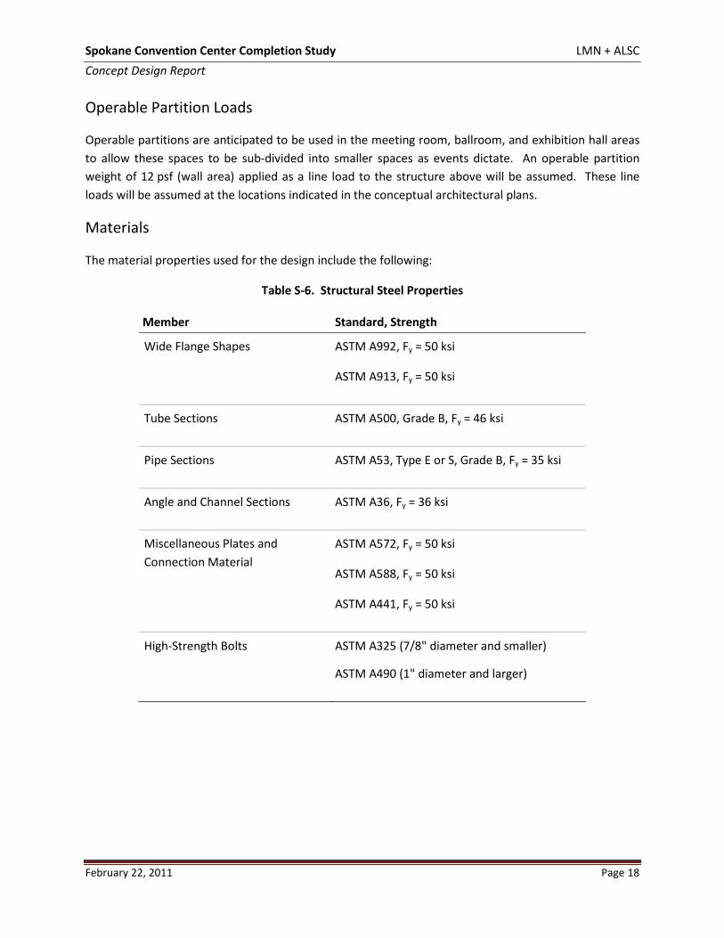
Operable Partition Loads
Operable partitions are anticipated to be used in the meeting room, ballroom, and exhibition hall areas to allow these spaces to be sub-divided into smaller spaces as events dictate. An operable partition weight of 12 psf (wall area) applied as a line load to the structure above will be assumed. These line loads will be assumed at the locations indicated in the conceptual architectural plans.
Materials
The material properties used for the design include the following:
Table S-6. Structural Steel Properties
Member Standard, Strength
Wide Flange Shapes ASTM A992, Fy = 50 ksi
ASTM A913, Fy = 50 ksi
Tube Sections ASTM A500, Grade B, Fy = 46 ksi
Pipe Sections ASTM A53, Type E or S, Grade B, Fy = 35 ksi
Angle and Channel Sections ASTM A36, Fy = 36 ksi
Miscellaneous Plates and Connection Material
ASTM A572, Fy = 50 ksi
ASTM A588, Fy = 50 ksi
ASTM A441, Fy = 50 ksi
High-Strength Bolts ASTM A325 (7/8" diameter and smaller)
ASTM A490 (1" diameter and larger)
Spokane Convention Center Completion Study LMN + ALSC Concept Design Report
February 22, 2011 Page 19
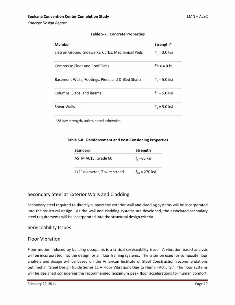
Table S-7. Concrete Properties
Member Strength*
Slab on Ground, Sidewalks, Curbs, Mechanical Pads f'c = 3.0 ksi
Composite Floor and Roof Slabs f'c = 4.0 ksi
Basement Walls, Footings, Piers, and Drilled Shafts f'c = 5.0 ksi
Columns, Slabs, and Beams f'c = 5.0 ksi
Shear Walls f'c = 5.0 ksi
*28-day strength, unless noted otherwise.
Table S-8. Reinforcement and Post-Tensioning Properties
Standard Strength
ASTM A615, Grade 60 fy =60 ksi
1/2" diameter, 7-wire strand fpu = 270 ksi
Secondary Steel at Exterior Walls and Cladding
Secondary steel required to directly support the exterior wall and cladding systems will be incorporated into the structural design. As the wall and cladding systems are developed, the associated secondary steel requirements will be incorporated into the structural design criteria.
Serviceability Issues
Floor Vibration
Floor motion induced by building occupants is a critical serviceability issue. A vibration-based analysis will be incorporated into the design for all floor framing systems. The criterion used for composite floor analysis and design will be based on the American Institute of Steel Construction recommendations outlined in "Steel Design Guide Series 11 – Floor Vibrations Due to Human Activity." The floor systems will be designed considering the recommended maximum peak floor accelerations for human comfort.
Spokane Convention Center Completion Study LMN + ALSC Concept Design Report
February 22, 2011 Page 20
The analysis will take into account the framing members and layout as a system, not simply individual members.
All floor areas except the Ballroom will be investigated for vibration sensitivity associated with walking excitation (normal walking activities). The Ballroom will be investigated for vibration sensitivity associated with rhythmic excitation (dining and dancing). Note that rhythmic activities such as aerobics and dancing have been considered only in the Ballroom area. If these activities are anticipated to occur elsewhere in the building, that information needs to be incorporated into the structural design criteria accordingly.
The vibration-based analysis and design approach will not eliminate floor vibrations. The recommended peak acceleration limits are based on human sensitivity and perception levels to floor motions in particular environments. The resulting vibration levels will be perceptible but within the comfort level of most occupants.
Floor Deflections and Camber
Allowable floor deflections will be based on generally recognized values. Maximum live-load deflections are limited to the span length in inches divided by 360. Maximum total deflections (due to dead loads and live loads) are limited to the span length in inches divided by 240. Beams that support curtain walls, elevator sills, and other deflection-critical elements will be stiffened to further reduce live load deflections as necessary.
Cambering of the steel and concrete beams that support the floor will be incorporated into the design. It is not good practice to camber 100 percent of all possible construction deflections since this could lead to a crowning effect for the floor or reduced concrete thickness. Cambers specified for this project will be adjusted for end conditions and connection stiffness based on prior experience and testing of in-place floors. This fine-tuning of the specified camber is not intended to provide a perfectly level floor; it is intended to limit the amount of expected deflections to within the maximum values outlined above.
Floor Finish Specifications
Floor flatness and levelness are specified using industry standard "F" numbers. Ff indicates the degree of floor flatness—a measure of a floor's local surface bumpiness, which is controlled mainly by the type and degree of finishing used. Fl indicates the degree of floor levelness—a measure of a floor's conformance to the specified design elevations, which is controlled mainly by the type and amount of forming and strikeoff used.
For slabs on grade and for shored construction, both the Ff number and Fl number can be specified. For elevated decks of unshored composite steel floor systems, American Concrete Institute specifications do not allow levelness numbers to be specified; only Ff numbers can be specified, since the tolerances for erected steel frames are not consistent with those for formwork in cast-in-place concrete frames.
Spokane Convention Center Completion Study LMN + ALSC Concept Design Report
February 22, 2011 Page 21
For composite floors, cambering the steel floor members as noted above most economically controls levelness.
It is recommended that a standard Ff number of 25 be specified. This degree of flatness is consistent with industry practice for composite floor systems.
Concrete floor hardener/sealer shall be applied at the time of concrete placement for exposed slabs in the exhibit space and back-of-house areas. The product selected shall be such that it matches the finish at the existing spaces to the greatest degree possible.
Acoustical Issues
The architectural layout of the program elements creates some issues that require acoustical consideration and investigation. The Exhibition Hall Level is located over meeting rooms. When the occupancy of the exhibition hall is being changed out, there will be significant noise generating activity. The potential transmission of this noise down through the structure and into the Ballroom and meeting room spaces should be investigated further. Solutions such as an isolation layer between the structural slab and a topping slab, which have not been considered in the structural design to date, may be required.
Architectural and Structural Interaction
The weights of fixed partitions, exterior walls, operable walls, and the like will be specifically accommodated in the structural design. Beams that support slab edges will be designed to support curtain wall attachments, railings, and the like depending on the actual condition at each location. Beams that support curtain wall elements are typically stiffened to reduce deflections and minimize joint sizes. This coordination between structure and architecture is critical to the functionality and durability of the structure over time.
Compatibility with Other Trades
The structural floor depth will vary from area to area and floor to floor due to the architectural space planning. Typically, a zone beneath the beam and slab and above the ceiling and lighting system is allocated for mechanical, electrical, and plumbing runs. In certain areas where large ducts are required, either the beams will be haunched at the ends or beam penetrations will be incorporated into the design. All duct runs shall be coordinated with the structural framing during the design phase.
Adjacent Construction
The proposed expansion project is anticipated to include new construction that is immediately adjacent and connected to construction that was part of the last expansion project, primarily at the interface along Grid RA. Along this interface condition, new loads are anticipated to be imposed onto the existing structural system (columns and foundations). These existing elements will be evaluated to determine if
Spokane Convention Center Completion Study LMN + ALSC Concept Design Report
February 22, 2011 Page 22
their structural capacity is adequate to support the combination of the existing and new loads and, if it is not adequate, what strengthening modifications are required.
Because both the proposed expansion and the existing building are located at and above Grade Level, the construction of new foundations is not anticipated to impose any surcharge loads upon the existing foundations. Furthermore, the excavation for the new foundations is not anticipated to require any shoring or underpinning of existing foundations during construction.
Future Expansion
At this time, the design of the structural systems that are part of this expansion project is not anticipated to include any allowance for additional loads associated with a future expansion.
Spokane Convention Center Completion Study LMN + ALSC Concept Design Report
February 22, 2011 Page 23
Civil
The proposed site currently has numerous utilities many of which will conflict with the proposed expansion of the Convention Center. Civil Exhibit #1 (in Appendix E) shows the known existing utilities and how they relate to the proposed building outline. The location of these utilities was established through a number of sources including, topographic survey performed for the last expansion, record drawings from the last expansion, and numerous City of Spokane drawings and sketches. Civil Exhibit #2 (in Appendix E) shows what the site utilities would likely look like after this project is completed. The following paragraphs discuss the existing utilities on the site and how the noted conflicts could be resolved.
Sewer
An 18” sanitary sewer runs east/west and conflicts with the proposed building. This sewer was relocated to its current location during the last expansion project and due to the existing sewer line elevations the slope of the pipe became a significant issue. The proposed building will sit directly over this sewer line including the upstream manhole located on the west side of Division Street. The primary constraints in resolving this situation are:
• A manhole is required at all changes in direction and slope of the sewer line. • A manhole is not allowed to within any building • The City of Spokane must have proper access to maintain the sewer line and manholes • The sewer line must remain in service since it serves upstream properties • An existing 8” sewer line to the upstream manhole will likely need to be maintained • Open-cutting Division Street is not desirable and probably not cost effective • The sewer line relocation should be as far from the Spokane River as possible • The sewer line should not be too close to the building • The relocation of the sewer should be cost effective • The relocation of the sewer should minimize potential impacts with other utilities • Maintain the existing trees along the Centennial Trail
Based on these constraints it was determined that the preferred solution would be to reroute the sewer from the east side of Division Street to the west side of the proposed expansion. To avoid open-cutting or boring under Division Street the sewer would be relocated under the Division Street bridge along the Centennial Trail alignment and then between the Spokane River and the building expansion. The sewer would tie back into the existing sanitary sewer line on the west side of the building expansion. This approach will allow the relocated sewer line to be placed using open-cut methods and would reduce the length of the sewer pipe. By reducing the sewer pipe length the slope of the pipe could actually be increased, effectively negating the previous pipe slope issues. However, the available pipe elevation (pipe invert) information was limited and we recommend that a surveyor verify the existing manhole elevations as part of the next step in this project. In addition, a potential conflict with the existing 36” storm line on the west side of the expansion has been identified. The current sewer line does cross the storm line but further to the south. Existing elevation data for the storm line was not available for this
Spokane Convention Center Completion Study LMN + ALSC Concept Design Report
February 22, 2011 Page 24
study and therefore should be surveyed as part of the sewer line verification recommended above. Based on the available information it is thought that the sewer line will go under the existing storm line.
The preferred sewer alignment is about 7’ from the proposed building at the closest point. This location was selected to allow the water line to be located just to the north of the sewer line and protect the existing trees along the Centennial Trail. The sewer is anticipated to be approximately 8’ deep and it is expected that shoring (trench box etc.) may be required during construction and possible future maintenance needs. The water line will be located 5’ to the north of the sewer line which is acceptable per the City of Spokane Standard Drawings. However, some cross-connection control measures may be required. These measures could include sleeving the water line or using ductile iron water pipe for the sewer line. During the design phase of this project the designers should further investigate and refine the exact location of the sewer and water line within the corridor between the tress and building expansion.
The proposed relocation also keeps all public sewer facilities from being under the building, which can become a maintenance issue for the City of Spokane and the Spokane Public Facilities District. The existing 8” stub located near Division Street would be extended north under the building expansion (since it is considered part of the existing interior building sewer) to the relocated sewer line. It is possible that this sewer line is no longer active and the extension may not be needed. This should be verified prior to or during the design of the building expansion. A sketch of the proposed sewer work is shown in Civil Exhibit #3 (in Appendix E).
An alternate sewer relocation route is shown in Civil Exhibit #2 (in Appendix E). This route is further to the north and would be located under the existing Centennial Trail. The alternate is slightly longer than the preferred route discussed above, but the existing elevation differences at the sewer tie in points should provide adequate slope. The primary advantage to this alignment is that it maximizes the distance from the proposed building and any potential future expansions toward the river. Secondarily, the alignment maximizes the distance from the potable water line relocation
The disadvantages of the alternative sewer relocation are substantial. First, available records indicate that an existing power, telephone/fiber optic line currently exist on or near this alignment. Second, the proximity to the river could increase construction problems due to high ground water (increase dewatering etc.). Third, the propose route does miss the drip line for the trees on the south side of the trial, but at the expense of increased river bank disturbance and likely removal of several trees along the river bank. Fourth, the trail area is understood to be an old railroad bed and therefore the chances of soil contamination are increased. Based on these reasons the alternative sewer relocation route is not recommended.
The sewer services to the existing C. I. Shenanigans building have changed several times over the last few decades. These service lines would no longer be needed and would be removed as part of this project. The sewer service for the expansion will tie into the relocated sewer line north of the expansion. It is anticipated that the sewer from the kitchen area will be routed through a grease trap located just north of the kitchen area.
Spokane Convention Center Completion Study LMN + ALSC Concept Design Report
February 22, 2011 Page 25
Water
An existing 8” water line runs between C. I. Shenanigans and the Convention Center to serve an existing fire hydrant. The water line and fire hydrant would be located to the north side of the expansion approximately 10’ north of the relocated sewer line. The fire hydrant would be located near the trail edge to allow easy fire department access (the trail is currently the fire access route to the back side of the building).
The water meter vaults and service to C. I. Shenanigans is located on the west side of the existing building and would be removed. It appears that there are at least two water meter vaults but only one has an active water meter in it.
See Plumbing section of this report for information on water service to the expansion.
Gas
An existing gas line or service is shown coming from Division Street near the existing 18” sewer line. The gas line or service branches into two separate gas lines. One line appears to be the gas line service to C.I. Shenanigans and the other routes through the existing ground level parking. The service to C.I. Shenanigans would be removed. Avista Utilities has informed us that the gas line through the Convention Center ground level parking area has been abandoned. Therefore any portions of the gas line that remain could be removed as needed. See Plumbing section of this report for information on gas service to the expansion.
Telephone
An existing telephone line appears to be located under the C. I. Shenanigans parking lot. This telephone line would need to be relocated or removed. An existing fiber optic line exists along the Centennial Trail and should not need relocation as part of this project. The design of the site should minimize excavations around the fiber optic line to the extent practical. See Electrical section of this report for information on telephone service to the expansion.
Power
The only conflicting power lines noted in our research are along the east side of the site (Division Street) and the power to the C. I. Shenanigans building (location unknown). It is anticipated that both of these power lines can be abandoned.
See Electrical section of this report for information on electrical service to the expansion.
Storm
The onsite drainage facilities (drywells, catch basin, rain water leaders etc.) will be removed. No documentation of the existing storm water system was found. Since the project is removing the existing
Spokane Convention Center Completion Study LMN + ALSC Concept Design Report
February 22, 2011 Page 26
asphalt parking lot and replacing it with a building, it is anticipated that no stormwater treatment will be required for the project. However, depending on the roofing material and location of mechanical units on the roof, it is possible that some stormwater treatment will be required. The proposed design includes a rain garden or wetland located between the Centennial Trail and the building expansion. Roof water could be discharged to this facility for treatment and any required detention. The geotechnical report for the last expansion (GeoEngineer’s dated Sept. 25, 2002) indicated that infiltrating stormwater was likely not a feasible option on this site due to high ground water. The storm water from this site would likely be routed to the existing 36” storm line located on the west side of the expansion which discharges to the river. We understand that this line was installed as part of the last expansion project and that it is dedicated to runoff from non-pollution generating roofs. Based on this limitation we recommend that the roof be designed with a non-pollution generating material and that any mechanical units be isolated by curbing or other means. This approach will allow roof runoff to be directed into the existing 36” stormwater line for direct discharge to the river. The proposed wetland or rain garden can be used to dampen the peak flow rates being discharged into the 36” pipe (and ultimately the river. In addition, the wetland or rain garden could potentially become an educational outreach site that educates the public about stormwater pollution and treatment.
Trenching/Excavation
The geotechnical report for the last expansion (GeoEngineers dated Sept. 25, 2002) indicated that shallow ground water and bedrock exist in this area. Trenching for utility lines (sewer and water especially) will likely encounter groundwater. Bedrock excavation is also a possibility on the site.
Environmental Site Assessment and Remediation
GeoEngineers reviewed previous environmental and geotechnical reports for the Spokane Convention Center property. For the purpose of this study environmental and subsurface conditions on the expansion properties are assumed to be similar to those observed during prior environmental assessment and construction of the last Convention Center expansion. Under this scenario, a relatively minimal amount of contaminated material would be removed from the site with remaining contamination being capped by new structures. This approach was previously accepted by the Washington State Department of Ecology to obtain a ‘no further action’ determination on the Convention Center site after the last expansion.
The primary contaminate of concern (COC) is expected to be carcinogenic polycyclic aromatic hydrocarbons (cPAH) and metals (arsenic, cadmium, mercury, and lead). Previous environmental assessment data indicates COC contamination likely will be widespread across the site and could be present in site soil to at least 6 feet below current grade. Soil that is excavated from the site that cannot be re-used onsite, either because of poor structural or environmental characteristics, likely will require disposal at a Resource Conservation and Recovery Act (RCRA) Subtitle D landfill (Graham Road).
A Phase II Environmental Site Assessment should be conducted well in advance of construction so that documentation can be submitted to Ecology for review and comment prior to breaking ground.
Spokane Convention Center Completion Study LMN + ALSC Concept Design Report
February 22, 2011 Page 27
Mechanical, Electrical & Plumbing
Plumbing
New Building Systems
Domestic Cold Water
Water is available on the north side of the site in close proximity to the new addition. A new water service with double-check valve backflow prevention assemblies will be provided in the plumbing utility room. A water softener will be provided (if required) for the kitchen. Water pressures in the downtown Spokane area are adequate (70 psi range). Neither a booster pump nor a pressure reducing assembly is required at the building water service.
Domestic Hot Water
Hot water will be primarily provided from new high efficiency (95%) sealed combustion gas fired water heaters in the new addition. The primary water heaters will deliver 120 degree water to all areas except the kitchen.
A hot water recirculation system will be provided and distributed at low velocities to within 5 feet of the fixtures to ensure fixtures and equipment requiring hot water will have hot water readily available through the use of "in-line" all-bronze circulating pumps. The hot water/storage tanks’ pump, controlled by a water temperature sensor located in the storage tank will shut down the re-circulating pump when hot water within the tanks is at the proper temperature. The second pump for the recirculation system will be controlled through the building energy management to shut down when the building is unoccupied. Balancing valves will be placed in return loops at connections of the hot water piping.
Natural Gas
Natural gas at 2 psi will be piped through the garage to the addition from the existing Avista gas service located near the south lobby of the existing convention hall (approx. 450 feet away) to the new water heaters, boilers and kitchen equipment. Natural gas is available on the south side of the site near the expansion; however, the utility companies prefer to maintain a single gas so that the building gas can be isolated from a single location in an emergency.
Sanitary Sewer
A gravity drainage system will be provided to serve all plumbing fixtures, equipment and Exhibit Hall drains. Sanitary sewer is available on the north side of the site in close proximity to the new addition and the addition’s sanitary sewer will terminate within 5 feet of the building where it will be picked up and routed to the sanitary sewer system in the Civil Scope of work.
Spokane Convention Center Completion Study LMN + ALSC Concept Design Report
February 22, 2011 Page 28
Roof drainage
Gravity primary and overflow storm drainage systems will be provided to serve the Roof Levels with each system piped separately outside of the building. Rain leaders will be located within the heated portion of the building to prevent freezing of the pipe and will be insulated to prevent condensation from developing on the pipe. Overflow drains will terminate at Grade Level in splash blocks and primary drains will terminate within five feet of the building exterior for final termination by the Civil Engineer in the site scope of work.
Fixtures
Toilet room water closets, urinals and lavatories will be constructed of commercial grade vitreous china. Water closets will be wall hung. Hands free sensor operated electric faucets with integral thermostatic mixing controls will be provided on toilet room lavatories. Sensor operated electric flush valves will be used for water closets and urinals. Urinals will be waterless. Lavatory traps and supplies will be insulated per ADA requirements. Custodial sinks will be provided with wall faucet and lever handles. Valves will be provided at all branch take-offs to individual fixture groups. Zone valves will also be provided.
Exhibition Hall Utilities
Exhibitor drains will be provided in the exhibition floor with a minimum of one per each sub dividable Exhibit Hall space. If drain construction matches the existing building, the drains will be large concrete sumps built into the floor system with a heavy duty traffic rated cover. The indirect waste from the drains will terminate to the building sewer. Exhibitor water will be provided around the perimeter of the ex-hall. Each exhibitor station will consist of a ¾” reduced pressure backflow device with a ¾” hose bibb accessed via a wall access panel. A minimum of two exhibitor water stations for the 17,285 sf Exhibition Hall expansion are anticipated with a minimum of one for each sub-dividable Exhibit Hall.
Water Conservation
The following items will be reviewed by the design team and the Spokane Public Facilities District in the design phase for Water Conservation and Long Term Standardization /Maintenance considerations: Dual flush (1.6/1.0 GPF) water closets, ultra-low flow water closets (1.28 GPF), and waterless urinals. Lavatory faucets will deliver 0.5 GPM.
Fire Protection
Engineering Criteria
Class II standpipes are not required. Such standpipes are required only for A-1 and A-2 occupancy groups and for stages.
Spokane Convention Center Completion Study LMN + ALSC Concept Design Report
February 22, 2011 Page 29
If any horizontal exits are provided, Class I standpipes would be required on each side of the horizontal exit.
If any Class I standpipe is required, system flow and pressure requirements will be provided from the fire department inlet Siamese (pumper) connections. No fire pump would be required for the standpipe system.
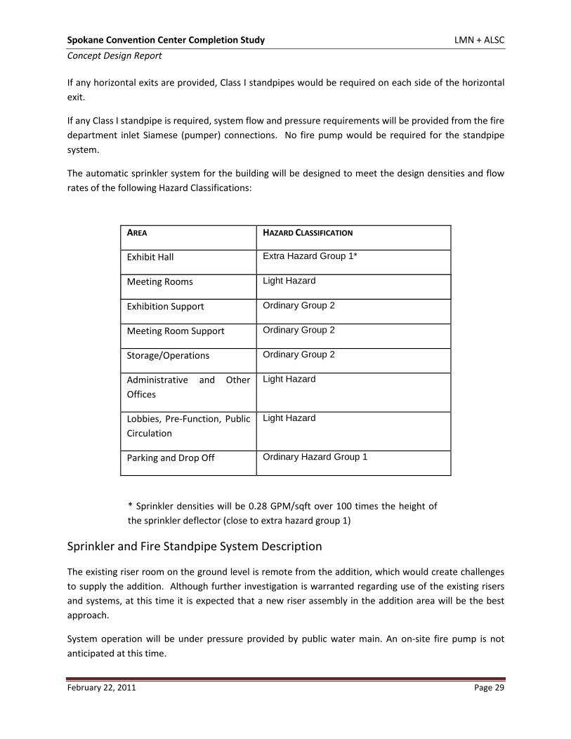
The automatic sprinkler system for the building will be designed to meet the design densities and flow rates of the following Hazard Classifications:
AREA HAZARD CLASSIFICATION
Exhibit Hall Extra Hazard Group 1*
Meeting Rooms Light Hazard
Exhibition Support Ordinary Group 2
Meeting Room Support Ordinary Group 2
Storage/Operations Ordinary Group 2
Administrative and Other Offices
Light Hazard
Lobbies, Pre-Function, Public Circulation
Light Hazard
Parking and Drop Off Ordinary Hazard Group 1
* Sprinkler densities will be 0.28 GPM/sqft over 100 times the height of the sprinkler deflector (close to extra hazard group 1)
Sprinkler and Fire Standpipe System Description
The existing riser room on the ground level is remote from the addition, which would create challenges to supply the addition. Although further investigation is warranted regarding use of the existing risers and systems, at this time it is expected that a new riser assembly in the addition area will be the best approach.
System operation will be under pressure provided by public water main. An on-site fire pump is not anticipated at this time.
Spokane Convention Center Completion Study LMN + ALSC Concept Design Report
February 22, 2011 Page 30
Siamese (pumper) connections will be provided at the backflow preventer vault to enable the Fire Department to pump water directly into the system
Any Class I standpipes necessary will be supplied by connections to the sprinkler system.
System will be wet pipe inside the building and dry pipe in the parking/drop of area.
Individual sprinkler systems will be provided with monitored control valves and water flow switches as well as a system drain/test connection. All control valves and water flow switches will be annunciated at the life safety control panel.
All isolating and sectionalizing valves on the fire protection system will be provided with tamper switches that will be annunciated at the life safety control panel.
Fire extinguishers will be located throughout the building and around the perimeter of the Exhibit Hall areas. ABC dry powder extinguishers will be provided with the exhibit areas, meeting rooms, general areas, and mechanical rooms, loading docks and kitchen areas.
Any type I range hood in the kitchen will be provided with a wet-chemical fire extinguishing system.
Codes and Standards
The Fire Protection systems will be designed to conform, as a minimum, to the following codes and standards:
International Building Code International Mechanical Code International Fire Code The National Fire Protection Association (NFPA). Underwriters Laboratories (UL).
Spokane Convention Center Completion Study LMN + ALSC Concept Design Report
February 22, 2011 Page 31
Mechanical
General
Summary
The recently installed systems provide in the existing convention center building have been working well for the Spokane Public Facilities District so a similar approach will be utilized for the new proposed expansion. Fan rooms will be located on a mezzanine level. The existing central plant will be expanded in capacity to meet the increased heating and cooling needs for the new addition. A new water and fire service will be introduced within the new addition. Building systems such as air distribution, plumbing, fire and controls will be similar to systems in the existing building. The new systems shall interface to existing building systems where appropriate for ease of maintenance and operations where applicable.
Outdoor Design Conditions • Heating Systems shall be sized for the ASHRAE median of extremes for Spokane, Washington
which is -9°F. • Cooling systems shall be sized for the ASHRAE 0.1% design condition temperature for Spokane,
Washington which is 96°F dry bulb and 67°F wet bulb. Indoor Design Conditions
• In cooling mode, the occupied spaces shall be designed to control to 74 to 76°F during occupied mode. Telecommunication rooms will control to 68-75°F 24 hours per day, 7 days per week. Mechanical and electrical spaces will control to 85-90°F
• In the heating mode, the occupied spaces shall be designed to control to 68-70°F during occupied mode. Telecommunication rooms will control to 68-75°F 24 hours per day, 7 days per week. Mechanical and electrical spaces will control to 55°F
• The lower level back of the house operations are considered “partially” occupied and will have heat only (no cooling).
• If the thermal comfort LEED credit is pursued for this project, the heating mode conditions may need to be increased to 71 to 72°F to meet published comfort standards established in ASHRAE Standard 55 for low humidity regions.
Exterior Envelope Requirements
Components of the building envelope will be insulated to meet or exceed the Washington State Energy Code for Spokane County located in Washington State Climate Zone 2. The values listed below are minimum values and higher values may be considered to meet the project’s energy conservation goals. These values are based upon the 2009 state energy code.
• Roof, R-30 Insulation Entirely over Deck (U=0.034) • Wall-above grade-steel framed, R-13 metal stud plus R-7.5 continuous rigid insulation (U=0.064) • Wall-Above grade-mass wall, R-7.6 continuous rigid insulation (U=0.123) • Slab on Grade, R-10 rigid at footings for 24 inch minimum (with thermal break), (F=0.54)
Spokane Convention Center Completion Study LMN + ALSC Concept Design Report
February 22, 2011 Page 32
• Opaque Doors, U=0.60 • Glazing, U=0.32 for non-metal framed windows, U=0.40 for metal framed windows, and U=0.60
for metal framed windows at entrance doors. SHGF=0.40 on all glazing
Equipment Access
Mechanical mezzanines should have vertical access via a hoist from the exhibit hall space for service of large items such as motors and possibly demountable wall sections to allow for a possible (but unlikely) coil pull.
Existing Building Modifications
Heat Generation
The existing heating plant consists of (4) 3,000 mbh hot water boilers that fire at 83 percent efficiency. The system is sufficiently sized for the existing exhibit hall but in cold weather does not have sufficient reserve capacity to service the new addition. This system will require additional capacity to service the new addition as described later in this narrative.
The existing plant will be expanded with approximately 8,000 mbh of high efficiency sealed combustion boilers that operate with 94 percent peak efficiency. These boilers may be located in the existing boiler room or the room directly east of the existing boiler room. These boilers would be the lead boilers, particularly in low load conditions and would significantly improve the thermal efficiency and reduce operating costs. Pumps would be added to the boiler room and would pump 350 GPM of hot water from the existing boiler room to the new addition through the garage with 5” distribution pipe (approximately 400 feet away).
Refrigeration
The existing cooling plant consists of (2) 405 ton water cooled chillers. There is some reserve capacity in this system that can be used to service the addition. The exact amount of reserve capacity will be reviewed by the facility control technician during the next cooling season but for purpose of this analysis, it is assumed to be 200 tons. It is anticipated that the new addition would require 400 tons of cooling capacity. The existing cooling plant will require additional capacity to service the new addition as described later in this narrative.
A 200 ton chiller (water cooled) will be provided to supplement the existing water cooled chillers. This smaller chiller would improve the operation of the existing plant and will improve the chiller performance during times when lower cooling loads are experienced. Pumps would be added to the chiller room and would pump 600 GPM of chilled water from the existing plant to the new addition with 6” distribution pipe (approximately 400 feet away). The chiller would be located within the existing chiller room with its cooling tower located on the loading dock near the existing emergency generator.
Spokane Convention Center Completion Study LMN + ALSC Concept Design Report
February 22, 2011 Page 33
Garage
The existing parking garage is currently classified as an open parking structure and has natural ventilation. The construction of a new addition against this garage obstructs the garage requiring that it now be classified as a closed garage. This closed garage will require the addition of an exhaust system that exhausts the garage at a rate of 1.5 cfm per square foot for the approximately 102,000 sf of lower level garage parking and 72,000 sf of parking in the upper garage level.
The new garage exhaust system would operate continuously between minimum and maximum levels depending upon detection of fuel contaminants in the garage.
Moveable Wall Modification
The moveable wall that separates exhibition hall A from exhibition hall B is being relocated approximately 30 east from grid 14 to 16. This curtain storage retracts into room on both the Exhibit Hall and upper mezzanine level and will require that the 33,000 cfm air handling unit (AH-3A) be relocated and reconfigured within the existing fan mezzanine area and the return ducts and returns grilles reconfigured for the exhibition hall space. The outside air intake louvers will also require reconfiguration. Some relief ducts that service exhibit hall A will need to be extended to the new moveable wall location.
Associated with the movable wall modification are some expected mechanical and electrical improvements to the adjacent concession and storage areas to relocate the security booth and add a men’s restroom.
Exhibition Hall Relief Fans
The increase in size of the expansion hall will also require an increase in the relief fans serving the exhibition hall. One new relief fan will be added near grids 21 and F in the existing mezzanine fan room (30-35,000 cfm).
New Building Systems
Air Distribution
Exhibit and Flex space: The 31,325 sf of exhibit and lobby flex space will require approximately 1.85 cfm/sqft to meet the peak cooling loads. One 32,000 cfm unit will service the exhibit space and three smaller 8,000 cfm units will service the flex space that is sub dividable into 3 spaces. The air distribution will be overhead and approximately 24 to 30 feet above the floor. To allow for circulation down to the floor level, air systems will be constant air volume with low return grilles. Return grilles will be strategically placed so that they are not obstructed by exhibit pipe and drape. Air handling units will be modular with filtration, hot water heating and chilled water cooling and full modulating air-side
Spokane Convention Center Completion Study LMN + ALSC Concept Design Report
February 22, 2011 Page 34
economizer to allow cooling with outside air when ambient conditions allow. VFD controlled relief fans will be provided for economizer relief.
Meeting Rooms and Lobbies and Front of House: The 31,110 sf of meeting room, lobby, and front of house space will require approximately 1.3 cfm/sqft (40,000 cfm) to meet the peak cooling loads. These space will be serviced from a central variable volume style air handling units that has a supply fan, return fan, filters, chilled water cooling coil, hot water heating coil and mixing boxes for minimum outside and economizer cooling capabilities. Local space temperature control would be provided from
variable air volume terminal units with hot water heating coils.
Back of House: It is assumed that these spaces will have only heating and minimum fresh air for code purposes.
Food Service: The addition will have a coffee and beverage service in addition to a “Tasting Room”. A full service kitchen is not anticipated within the addition.
Ventilation
Ventilation will be provided in accordance with ASHRAE Standard 62 (Ventilation for Acceptable Indoor Air Quality). Each programmed space will be designed to accommodate the appropriate occupancy requirements based on ASHRAE Standards and other applicable codes and standards in terms of minimum outdoor air volumes, as well as make up and exhaust air requirements. Fresh air intakes will be located away from sources of pollutants such as loading docks, building exhaust, and other pollution generating sources.
Fresh air quantities will be measured and trended at the air handling units in support of the District’s recent LEED EB program where all fresh air is measured. Fresh air will be reduced when buildings are not fully occupied based upon space carbon dioxide levels to promote energy conservation.
Acoustics
Systems will be designed and installed to meet the maximum noise criteria (NC) established for each building use. Special acoustical considerations of the mechanical systems will include locating chillers and air handling units away from acoustically sensitive areas. Where this is not possible, acoustically treated walls will be required.
Additional acoustical considerations will include limitation of duct velocities through ductwork, terminal units and air inlets/outlets to achieve space NC, use of sound attenuators in the duct systems, and vibration isolation of mechanical equipment with spring isolators and flexible connections.
It is recommended that an acoustic consultant be retained in the design phase to provide acoustical recommendations and design criteria to achieve a sound level that is acceptable to the use of each space. It is anticipated that the meeting rooms will have two-way conferencing capabilities and will
Spokane Convention Center Completion Study LMN + ALSC Concept Design Report
February 22, 2011 Page 35
require a higher level of acoustical performance than the Spokane Public Facilities Districts existing meeting rooms so that the microphones do not pick up stray noise in the room.
HVAC Instrumentation and Controls
The project will utilize a Direct Digital Control (DDC) for the control of the HVAC systems. System shall provide for heating and cooling control, peak load demand limiting and start/stop optimization. Damper and valve actuators shall be electronic. Room thermostats shall be electronic adjustable type with override switch for occupant activation to occupied mode during unoccupied periods.
The energy management control system will be compatible with the existing BACnet system serving the existing convention hall. This building shall interface and communicate with the existing Alerton control network and remote operator’s terminal for the purpose of remote operation and maintenance.
To aid the Spokane Public Facilities District with energy and water conservation, energy and water consumption for the building will be measured and trended so that abnormalities can be investigated by the district and potential operational problems remedied.
Testing, Adjusting and Balancing
Air systems (supply, return, and exhaust), hydronic and domestic hot water recirculation systems shall be completely balanced in accordance with Associated Air Balance Council or National Environmental Balancing Bureau. The Contractor shall secure the services of an independent Testing, Adjusting and Balancing (TAB) agency for the TAB of the mechanical systems
Codes and Standards
The building mechanical systems will be designed in accordance with the latest revised edition of the following codes and standards: International Building Code (IBC) International Mechanical Code (IMC) NFPA 90A Standard for the Installation of Air Conditioning and Ventilating Systems WAC 51-13 - Washington State Ventilation and Indoor Air Quality Code Americans with Disabilities Act (ADA) Washington State Non Residential Energy Code American Society of Civil Engineers Min Design Loads for Bldgs and Other Structures ASCE 7-02 (seismic) Local Building By-Laws State of Washington IBC Amendments ASHRAE Standard 62.1-Ventilation for Acceptable Indoor Air Quality ASRHAE Standard 55-Thermal Comfort American Society of Heating, Refrigeration and Air Conditioning Engineers (ASHRAE) Sheet Metal Contractors Association of North America (SMACNA) Spokane Public Facilities District Sustainable Practices
Spokane Convention Center Completion Study LMN + ALSC Concept Design Report
February 22, 2011 Page 36
Electrical
General Summary
Service utilities to the expansion for power and telecommunications shall be provided from the existing convention center building services. Building systems such as lighting, lighting controls, fire alarm, access control, A/V, paging, audio and other low voltage systems will follow the like and kind of similar systems in the existing building. The aforementioned systems shall interface to existing building systems for ease of use and functionality where applicable.
Existing Utilities/Building Systems
Power & Lighting
The existing Convention Center is served from (2) main switchboards rated at 3000 amps each. The (2) main switchboards, MSB1 & MSB2, deliver power to the existing building at 480V, 3 Phase, 4 Wire. MSB1 is dedicated to equipment loads including elevators, chillers and motor control centers. MSB2 is dedicated to all remaining 480V loads including lighting and other miscellaneous loads. To derive 208V power, the existing building utilizes distributed dry type transformers at various locations throughout the building. Distribution switchboards distribute power to branch circuit panel boards for 208V equipment, receptacles and other miscellaneous loads. Emergency power is supplied to the existing building from a single 150kW, 480V, outdoor diesel gen-set. Generally, fluorescent lighting with low voltage relay based controls is utilized throughout the existing building. Dimming systems with HID and Incandescent lamp sources is installed in the exhibition halls for special event use.
Telecommunications & Low Voltage Systems
The existing Convention Center telecommunications systems consist of a main MDF room serving distributed IDF rooms throughout the building. Telecommunications is distributed via fiber riser cabling in conduit/cable tray between the MDF and each IDF. Communication devices are served via horizontal station cabling in conduit/cable tray from the MDF/IDF to each device location. Other low voltage systems housed within the existing building include Fire Alarm, Access Control, Video Surveillance, A/V, CATV, Paging and Audio.
Existing Modifications
Power & Lighting
To accommodate a new electrical service feeder to the expansion, a sub feed circuit breaker will be added within the existing building main switchboard. This breaker rating is estimated to be 1600 Amps. The new service feeder will be routed through the existing convention center parking garage structure via exposed conduit, approximately 500 feet. Existing lighting control panels will be upgraded with accessories to enable interface to new building lighting control systems.
Spokane Convention Center Completion Study LMN + ALSC Concept Design Report
February 22, 2011 Page 37
Telecommunications & Low Voltage Systems
Telecommunications riser pathway and cabling will be added from the existing building MDF to the Expansion MDF via exposed conduit through the existing parking garage, approximately 500 feet. Telecommunications distribution equipment in the existing building MDF will be upgraded to support Communication distribution systems within the new building. Existing head-end equipment for low voltage systems including Fire Alarm, Access Control, Video Surveillance, A/V, CATV, Digital Signage, Paging and Audio will be upgraded to allow for interconnection to new building systems. To accommodate the relocation of the exhibition hall divider wall, reprogramming of zoned audio systems and lighting controls will be required.
New Utilities/Building Systems
Power & Lighting
Building Distribution: The building electrical distribution will originate from a main electrical room on the main floor and smaller electrical room located on the upper floor. It is estimated that the main switchboard rating will be 1600 amps. The building electrical distribution will be designed to provide separation of lighting, mechanical, computer and miscellaneous equipment loads. Because the building is being served from a 480/277V source, it will be necessary to distribute dry type step down transformers throughout the building for 208/120V power distribution. Circuit breaker panel boards shall be provided throughout the building as required to adequately serve the associated building loads. Motor control centers will be provided where mechanical equipment has been densely located, such as mechanical rooms. Loads serving sensitive electronic equipment will be isolated from other loads through the use of isolation transformers. Large capacity combination utility floor boxes will be provided in the exhibition hall and flex space for power, telecommunications and other utilities. An estimated (20) large capacity combined utility floor boxes will be required for the aforementioned spaces.
Engine/Generator: It is estimated that the existing building emergency generator may not have sufficient capacity to support the new building addition. Therefore, it is proposed that an outdoor diesel gen-set be provided and shall be sized to supply the new building emergency loads. Generator set shall include a weather proof sound attenuating enclosure and sub base tank for outdoor installation. Operation of the generator will be monitored on a multi-function system designed to report most normal failures such as low cooling fluid temperature, low starting batteries, overcrank, overload, high water temperature, etc.
UPS Backed Standby Electrical Distribution System: It is possible that centralized or distributed uninterruptible power supplies may be needed in order to support specific computer work stations and telecommunications equipment. Specific UPS requirements will need to be closely coordinated with SPFD as the project design progresses.
Spokane Convention Center Completion Study LMN + ALSC Concept Design Report
February 22, 2011 Page 38
General Branch Wiring and Pathways: A complete raceway and wiring system will be provided in conformance with NEC code requirements and District standards. All wiring shall be copper, minimum size #12 AWG. All feeder conductors and branch circuit conductors shall be installed in conduit. Minimum conduit size for power is 3/4” unless otherwise noted. Minimum conduit size for telecommunications and other low voltage systems is 1” unless otherwise noted.
General Interior Lighting: Lighting throughout the interior building spaces will respond to the primary use of each space while maintaining a level of flexibility to react to future use of each space. Uniform ambient lighting will establish a basic minimum lighting level throughout each individual space with task, display and accent lighting used to establish contrast and interest. Specific attention will be given to the lighting for areas with computer workstations in order to minimize glare. Lighting within the building will be primarily fluorescent. Fluorescent lamps shall be primarily T8, T5 and compact fluorescent. LED lighting may also utilized within the building where deemed appropriate. The use of incandescent lamp sources will be minimized and used only in special instances and as required for unique spaces or functions. Lighting system design foot candle levels will be in accordance with IES standards and District standards. In general, areas within the building will be illuminated to the following light levels:
Building Area Exhibition Halls 100-130 (Dependent on Use)
Foot-Candles
Offices 40-50 Meeting Rooms 50-60 (Dependent on Use) Restrooms 30 Corridors 10-20 Janitor Rooms 30 Storage Rooms 20
Egress & Exit Lighting: Exit lighting will be LED type with integral battery backup. Emergency egress lighting will be provided throughout the path of egress, and will be supplied with power from the emergency generator system in the event of a failure on the normal power system.
General Lighting Controls: A programmable low voltage lighting control system shall be provided for automatic control of lighting in corridors / common areas, offices, meeting rooms and exterior building/site lighting. The low voltage lighting control system shall also be interfaced to the building energy management system (EMS) to allow EMS control of the exterior lighting. Programmable dimming lighting controls shall also be utilized within appropriate areas, such as exhibition halls. Exhibit Halls shall be zoned to allow independent control of each of the (3) zones. Automatic dimmable or step-dimmed lighting controls shall be considered for the purpose of daylight harvesting within areas where adequate natural daylight is present within the building. Within utility spaces, manual switching will be provided in conjunction with local occupancy sensors.
Spokane Convention Center Completion Study LMN + ALSC Concept Design Report
February 22, 2011 Page 39
General Exterior Lighting: Exterior lighting will be selected to match the architectural building exterior and District standards. Exterior entry lighting which illuminates the path of egress will be supplied with power from the emergency generator system in the event of a failure on the normal power system. Exterior lighting will utilize full cut off light fixtures in order to avoid light trespass and meet associated dark sky lighting requirements. In general, exterior areas will be illuminated to the following light levels:
Exterior Area
Exterior Entry 5
Foot-Candles
Exterior Walkways 2
Telecommunications & Low Voltage Systems
Telecommunications Building Distribution: A complete telecommunications distribution pathway and cabling system will be provided in accordance with the District construction standards. Telecommunication rooms will be located throughout the facility in accordance with EIA/TIA 568 and 569. The main telecom MDF room will be located on the main floor of the building, in a centralized location. Secondary IDF communication rooms are to be located on each floor and stacked above the main telecommunication room if possible. Some floors may require more than one telecommunication room to reduce overall horizontal station cable lengths. Horizontal station cable pathways will be provided and routed to the telecommunication rooms located on each floor. Telecommunications riser cabling pathways will be provided from the entrance location to the telecommunications room on each floor. Cable trays will be installed at back of house areas and accessible corridor ceilings with conduits provided at hard (inaccessible) ceilings and where wall and floor penetrations are required.
Telecommunication Outlet Distribution: Telecommunications devices will typically be located at floor boxes, flex spaces, exhibition halls, computer work stations and required system equipment locations. Offices shall typically be provided with two telecommunication outlet locations per room. Large capacity combination utility floor boxes will be provided the in the exhibition and flex space hall for power, telecommunications and other utilities. Refer to Electrical section above for further floor box information.
Fire Alarm: A complete battery backed addressable fire alarm system with manual pull stations, automatic detection and ADA compliant horn/strobes will be provided throughout the facility. Smoke detector and heat detectors will be installed as required by the governing codes, and in accordance with District standards.
Access Control System: A complete access control system will be provided for the building. Required locations for miscellaneous access control devices will be closely coordinated with the District. Typical spaces which will include access controls are main entries, office suites and utility rooms.
Video Surveillance: Video Surveillance Systems (VSS) will be provided as requested by the SPFD. General locations include main entries, lobbies, corridors and service entries.
Spokane Convention Center Completion Study LMN + ALSC Concept Design Report
February 22, 2011 Page 40
Audio / Video Systems: A/V systems will be provided for specific spaces and use. Required locations for AV devices and equipment will be closely coordinated with the Ditrict, but will typically include meeting rooms. Video projectors, sound reinforcement systems, cabling and all active electronic AV equipment will be provided for a fully functional system.
Community Antenna Television (CATV) System: CATV systems will be provided and required locations for CATV outlets will be closely coordinated with SPFD.
Paging and Audio Systems: Network paging and audio systems will be provided in a similar manner as the existing convention center building. Generally, paging will be provided in lobbies, corridors and at exterior entry points. Audio systems will be provided in exhibition halls, flex spaces and other spaces as requested by the SPFD. Network paging and audio systems will be zoned according to the use and function of each space. Systems will utilize a Digital Signal Processor and will be fully compatible with the existing building QSC Audio systems.
Digital Signage: Digital signage and associated multimedia systems will be provided throughout the building. Typical spaces for digital signage include lobbies, corridors and main entry points. Required locations for digital signage will be closely coordinated with the District.
Code References
The building electrical systems will be designed in accordance with the latest revised edition of the following codes and standards:
National Electrical Code International Building Code (IBC) International Fire Code (IFC) Regulations of the State Fire Marshal Electrical Safety Order of the Washington State Department of Labor and Industries Washington Administrative Code Americans with Disabilities Act (ADA) Washington State Non Residential Energy Code
1. Requirements of Washington State Industrial Safety & Health Administration (WISHA)
Spokane Public Facilities District Sustainable Practices The building lighting systems will be designed in accordance with the following standards:
Illuminating Engineers Society of North America (IESNA) Spokane Public Facilities District Sustainable Practices
Concept DesignPlan Diagrams
Landscape DiagramsPerspective Views

Plan Diagrams

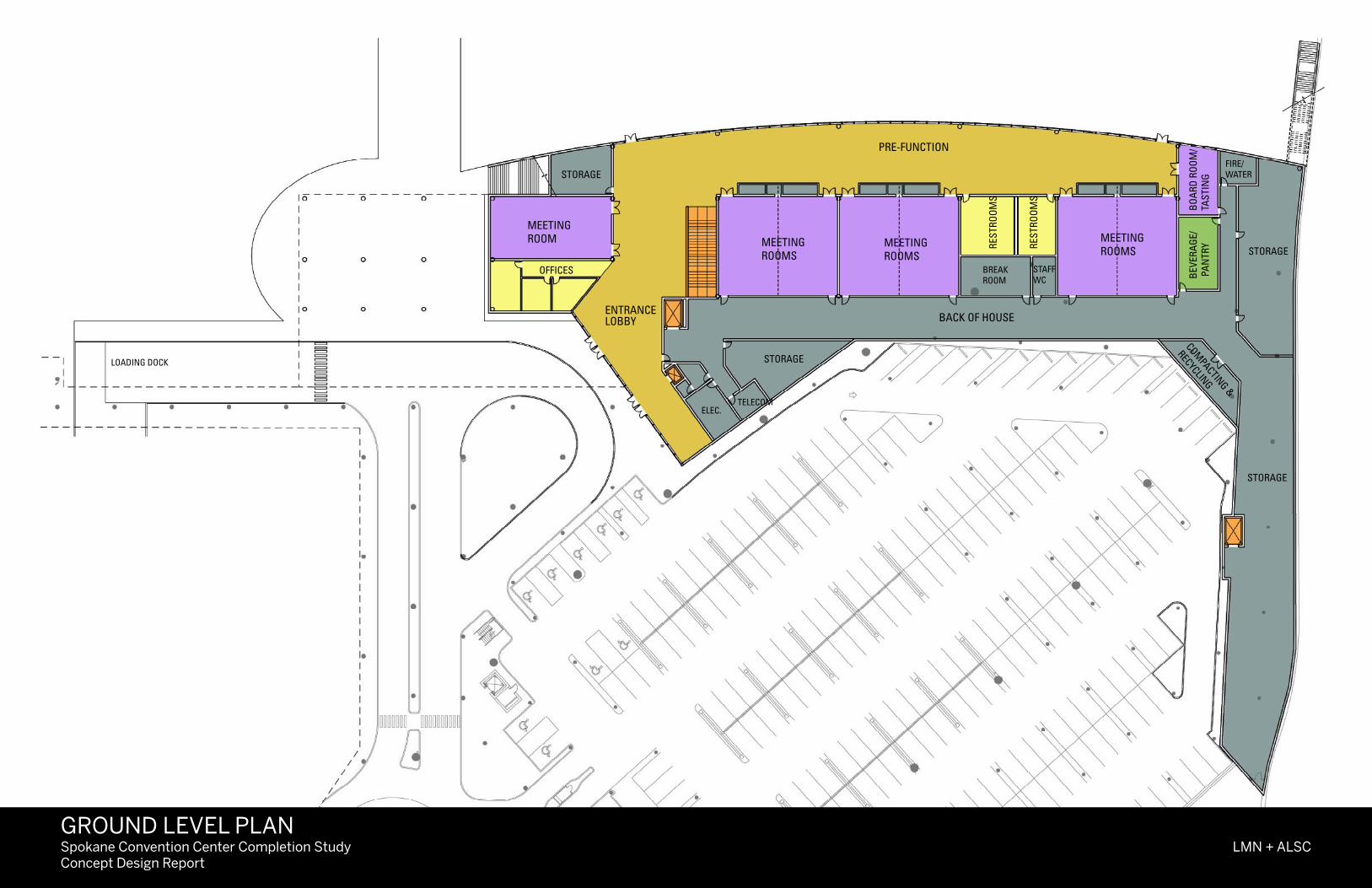
Spokane Convention Center Completion StudyConcept Design Report
LMN + ALSCGROUND LEVEL PLAN
MEETINGROOMS
MEETINGROOMS
MEETINGROOMS
BREAKROOM
PRE-FUNCTION
STORAGE
BEV
ERA
GE/
PA
NTR
Y
FIRE/WATER
STAFFWC
MEETINGROOM
REST
ROO
MS
REST
ROO
MS
BACK OF HOUSE
TELECOMELEC.
STORAGE
OFFICES
ENTRANCELOBBY
STORAGE
STORAGE
BO
ARD
RO
OM
/TA
STIN
G
LOADING DOCK
COMPACTING &
RECYCLING
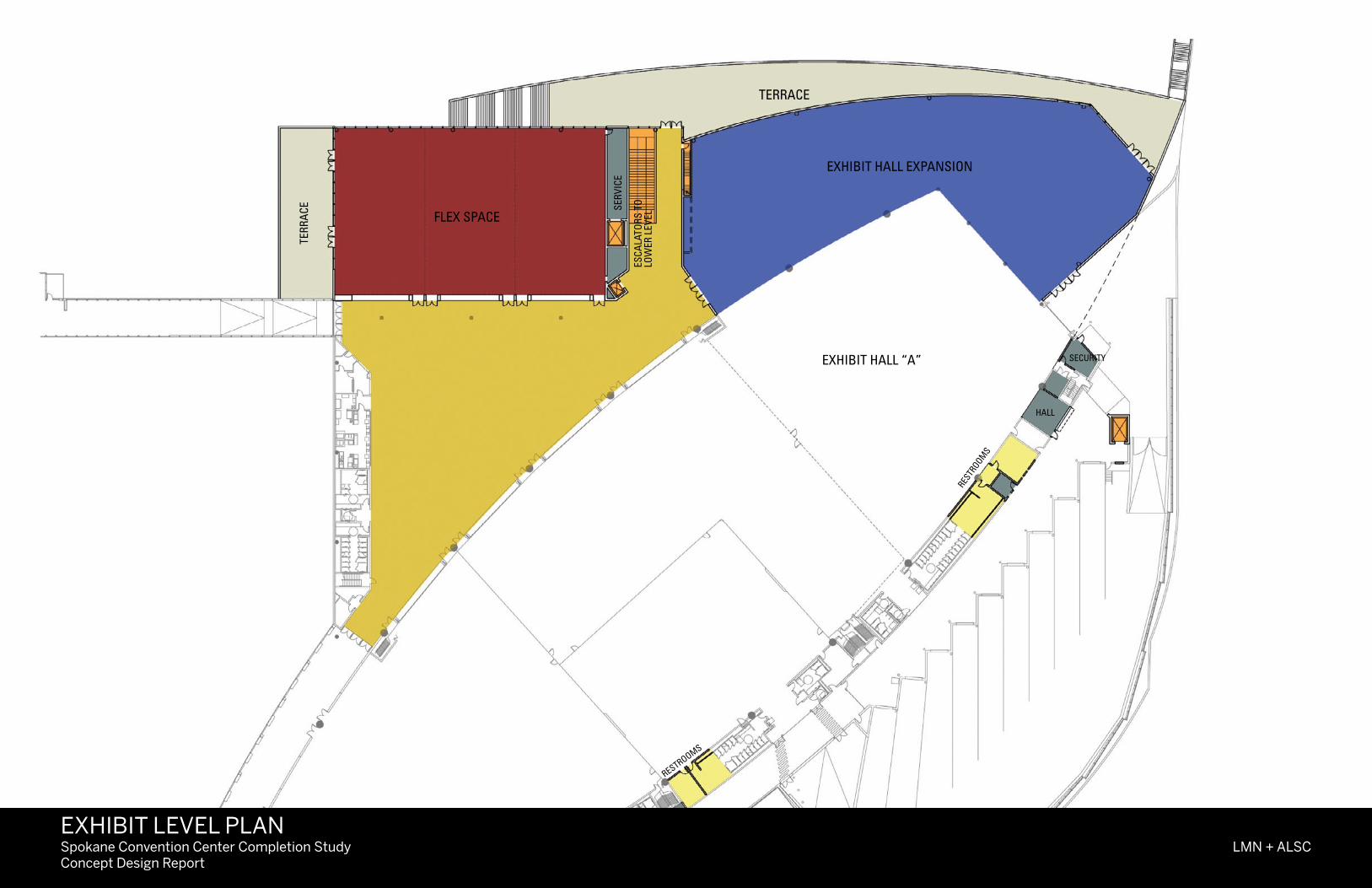
Spokane Convention Center Completion StudyConcept Design Report
LMN + ALSC
EXHIBIT HALL “A”
FLEX SPACE
RESTR
OOMS
SERV
ICE
EXHIBIT HALL EXPANSION
TERRACE
TERR
ACE
ESCA
LATO
RS T
OLO
WER
LEV
EL
SECURITY
HALL
RESTROOMS
EXHIBIT LEVEL PLAN
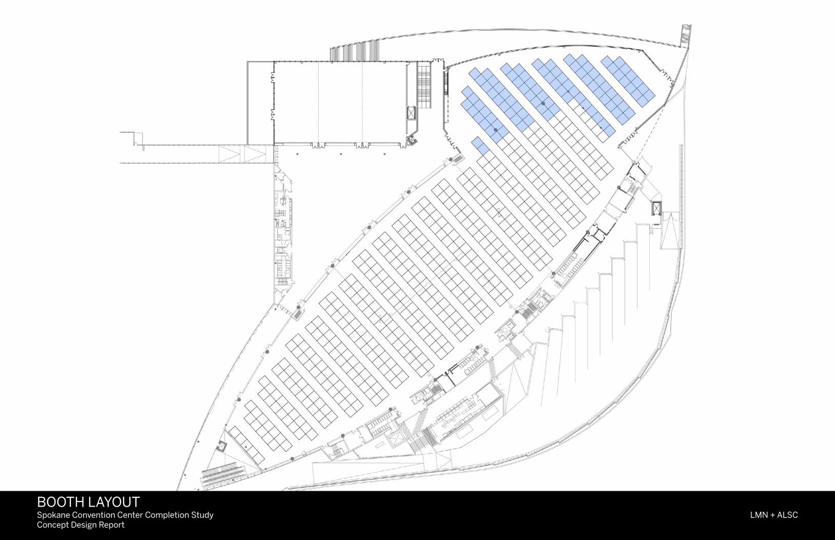
Spokane Convention Center Completion StudyConcept Design Report
LMN + ALSCBOOTH LAYOUT

Landscape Diagrams


Perspective Views

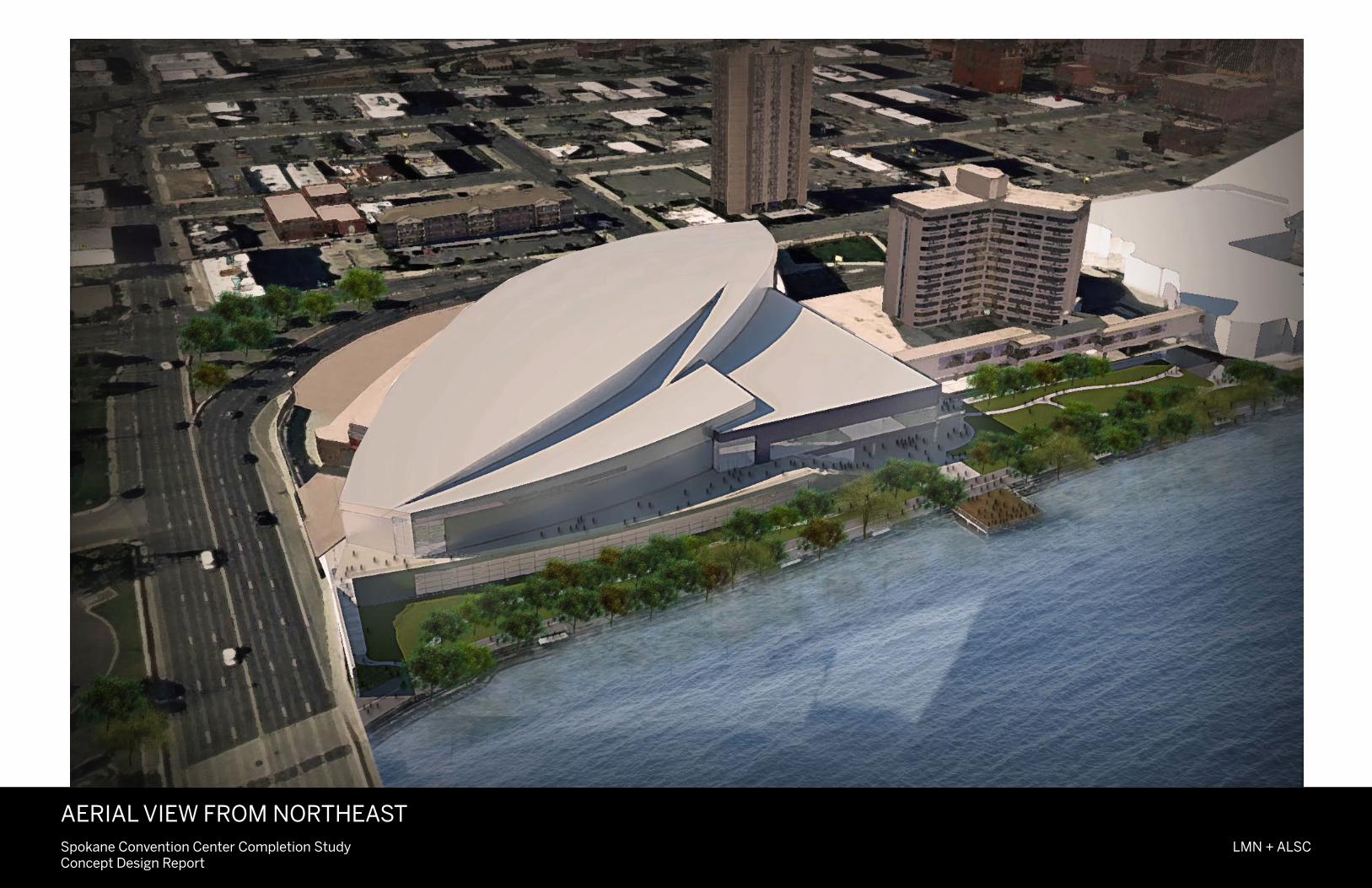
Spokane Convention Center Completion StudyConcept Design Report
LMN + ALSC
AERIAL VIEW FROM NORTHEAST
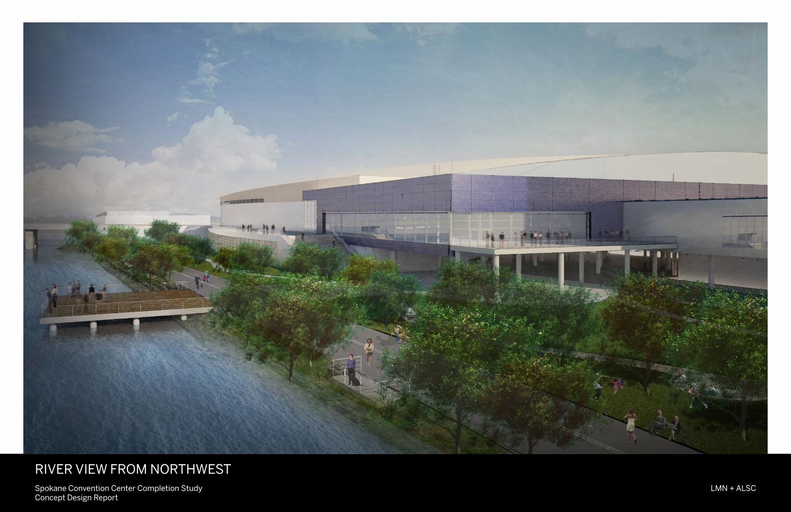
Spokane Convention Center Completion StudyConcept Design Report
LMN + ALSC
RIVER VIEW FROM NORTHWEST
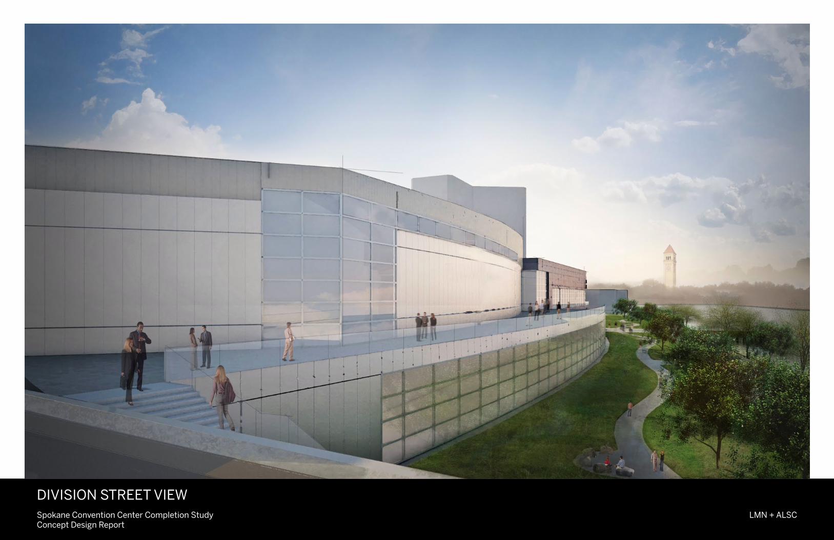
Spokane Convention Center Completion StudyConcept Design Report
LMN + ALSC
DIVISION STREET VIEW

Cost ModelExecutive Summary
Davis Langdon
719 Second Avenue
Suite 400
Seattle, WA 98104
www.davislangdon.com
www.aecom.com
206.343.8119 tel
206.343.8541 fax
Spokane Convention Center Addition Study
Preliminary Cost Model
Executive Summary
From September 2010 to January 2011, Davis Langdon assisted the design team in developing and refining a Cost Model for this Concept Study Report. The costs are primarily focused on the New Addition, but recognize some associated remodel and renovation costs. Preparation of the quantities for this cost model was facilitated by measurement from preliminary concept plans and the application of program areas developed by Conventional Wisdom and refined by LMN. Quality standards and specification levels were derived from the design team's preliminary Design Narratives.
Pricing for the cost model is based on our understanding of the local market gained through our participation in projects in the Spokane/Cheney/Pullman area (most recently reconciling with Bouten Construction on WSU’s Global Animal Health project) augmented by analysis of the data available from the 2004 expansion pricing process We solicited feedback from the design team on four draft versions of this cost plan to ensure that our interpretation of the available information was consistent with their intent and vision.
To accommodate development of the design and to mitigate the risks and issues which will be uncovered as a result, we have applied a design contingency of 15% to the costs determined via the foregoing process. This is a normal component of our preliminary cost plans.
This process derived the following cost conclusions:
Building Cost $40,121,000.
Site Cost $ 3,721,000.
Off Site Costs $ 338,000.
Total Construction Cost $44,180,000.
Using a "project cost multiplier" of 40% to determine how this construction cost translates to a Total Project Cost produced the following result:
Total Development Cost (Incl. WSST) $61,852,000
Consistent with an Addition to an existing facility, the derived cost is slightly higher than a “new construction only” project would produce. This is typical for expansion projects and preliminary costs identified are appropriate with the new program proposed in this Concept Design Report. The full Preliminary Cost Model is provided as an Appendix in the Concept Report. It contains more detail and the back-up data to this summary.

AppendixA. Program Summary Report
B. CC Completion Study Community Stakeholders& Riverbank Stakeholders Meeting Notes
C. Fire Dept. Access, Dept. of Fish & Wildlife, Dept. of EcologyD. Issues for Consideration
E. Civil DiagramsF. Preliminary Cost Model Back-up
A. Program Summary Report

Spokane Convention Center Completion Study Conventional Wisdom
Program Update Report
February 22, 2011 Page 1
INTRODUCTION
The challenge facing the design team is finding the balance between the amount of contiguous
exhibition space desirable to meet near-term market demand and the reasonable capacity of the
expansion site, given riverfront development guidelines and the urban context. As the program
consultant, Conventional Wisdom’s role is to ensure that the combination of exhibition, meeting and
multipurpose space provides a balanced facility from the user perspective and has the right amount of
public and service areas to provide an exceptional customer experience while improving operational
efficiency.
The present Riverside Room (Hall D) overlooks the city’s Spokane River against the northern skyline and
is a popular space for receptions and banquets. The ambience of this space is an architectural statement
that reinforces the CVB’s tag line” Near Nature, Near Perfect”. Expansion of the convention center must
maintain the visual appeal of this space or provide an equivalent space should the Riverside Room be
converted to other purposes such as traditional exhibition and/or prefunction space.
Marketability
In the recently completed Vision 20|20 report, meeting planners noted two relative weaknesses in the
Spokane Convention Center that dampened their enthusiasm for booking conventions and trade shows:
having less than 100,000 square feet of prime exhibition space and the apparent remoteness of meeting
and banquet space from the exhibition halls. The expansion goal is to remedy these concerns.
Qualitative improvements to the space include enhancing the arrival sequence, general orientation and
wayfinding; better support for banquets along with nearby service and storage space; and space that
has power, lighting, audiovisual and acoustical enhancements for keynote speakers and general
sessions.
CW’s preliminary analysis indicates the proposed expansion will improve the marketability of the
convention center by providing a better mix of space that is more attractive to a wider audience. While
the new construction will not significantly increase the size of groups to be attracted to the facility, the
greatest opportunity will be to market conventions with banquets for groups from 1,000 to 1,500
attendees. Specific details on these effects are provided later in this report.
Functionality
Improvements to functional efficiency are of equal importance to the marketability of the convention
center. The back-of-house service areas include adequate storage for staging and setup equipment,
tables and chairs; dedicated service corridors behind meeting rooms; a satellite pantry- warming kitchen
rvinoly
Typewritten Text
rvinoly
Typewritten Text
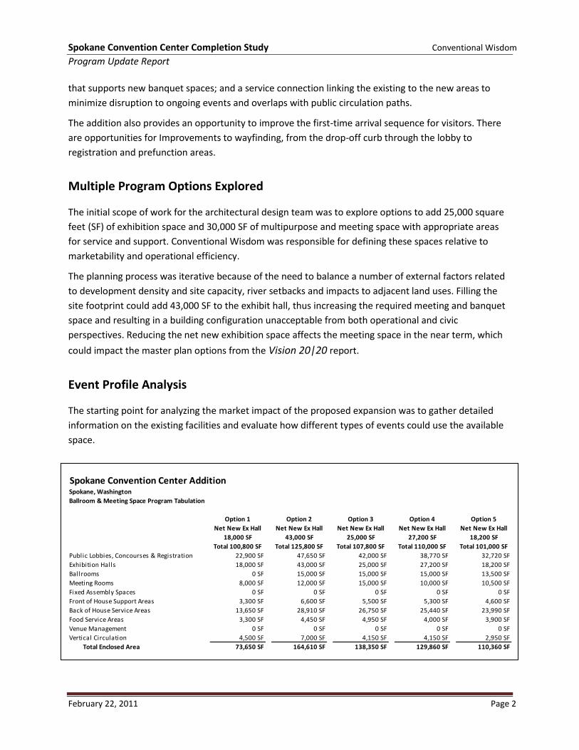
Spokane Convention Center Completion Study Conventional Wisdom
Program Update Report
February 22, 2011 Page 2
that supports new banquet spaces; and a service connection linking the existing to the new areas to
minimize disruption to ongoing events and overlaps with public circulation paths.
The addition also provides an opportunity to improve the first-time arrival sequence for visitors. There
are opportunities for Improvements to wayfinding, from the drop-off curb through the lobby to
registration and prefunction areas.
Multiple Program Options Explored
The initial scope of work for the architectural design team was to explore options to add 25,000 square
feet (SF) of exhibition space and 30,000 SF of multipurpose and meeting space with appropriate areas
for service and support. Conventional Wisdom was responsible for defining these spaces relative to
marketability and operational efficiency.
The planning process was iterative because of the need to balance a number of external factors related
to development density and site capacity, river setbacks and impacts to adjacent land uses. Filling the
site footprint could add 43,000 SF to the exhibit hall, thus increasing the required meeting and banquet
space and resulting in a building configuration unacceptable from both operational and civic
perspectives. Reducing the net new exhibition space affects the meeting space in the near term, which
could impact the master plan options from the Vision 20|20 report.
Event Profile Analysis
The starting point for analyzing the market impact of the proposed expansion was to gather detailed
information on the existing facilities and evaluate how different types of events could use the available
space.
Spokane Convention Center AdditionSpokane, Washington
Ballroom & Meeting Space Program Tabulation
Option 1 Option 2 Option 3 Option 4 Option 5
Net New Ex Hall Net New Ex Hall Net New Ex Hall Net New Ex Hall Net New Ex Hall
18,000 SF 43,000 SF 25,000 SF 27,200 SF 18,200 SF
Total 100,800 SF Total 125,800 SF Total 107,800 SF Total 110,000 SF Total 101,000 SF
Public Lobbies, Concourses & Registration 22,900 SF 47,650 SF 42,000 SF 38,770 SF 32,720 SF
Exhibition Halls 18,000 SF 43,000 SF 25,000 SF 27,200 SF 18,200 SF
Ballrooms 0 SF 15,000 SF 15,000 SF 15,000 SF 13,500 SF
Meeting Rooms 8,000 SF 12,000 SF 15,000 SF 10,000 SF 10,500 SF
Fixed Assembly Spaces 0 SF 0 SF 0 SF 0 SF 0 SF
Front of House Support Areas 3,300 SF 6,600 SF 5,500 SF 5,300 SF 4,600 SF
Back of House Service Areas 13,650 SF 28,910 SF 26,750 SF 25,440 SF 23,990 SF
Food Service Areas 3,300 SF 4,450 SF 4,950 SF 4,000 SF 3,900 SF
Venue Management 0 SF 0 SF 0 SF 0 SF 0 SF
Vertical Circulation 4,500 SF 7,000 SF 4,150 SF 4,150 SF 2,950 SF
Total Enclosed Area 73,650 SF 164,610 SF 138,350 SF 129,860 SF 110,360 SF
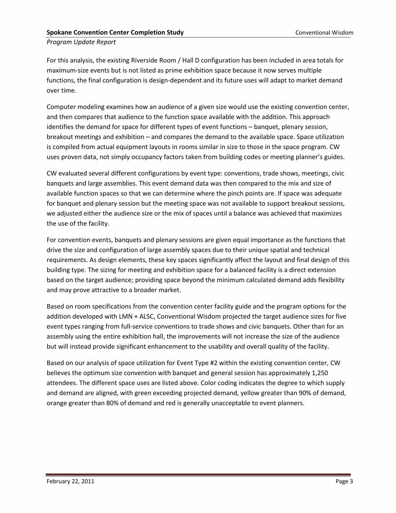
Spokane Convention Center Completion Study Conventional Wisdom
Program Update Report
February 22, 2011 Page 3
For this analysis, the existing Riverside Room / Hall D configuration has been included in area totals for
maximum-size events but is not listed as prime exhibition space because it now serves multiple
functions, the final configuration is design-dependent and its future uses will adapt to market demand
over time.
Computer modeling examines how an audience of a given size would use the existing convention center,
and then compares that audience to the function space available with the addition. This approach
identifies the demand for space for different types of event functions – banquet, plenary session,
breakout meetings and exhibition – and compares the demand to the available space. Space utilization
is compiled from actual equipment layouts in rooms similar in size to those in the space program. CW
uses proven data, not simply occupancy factors taken from building codes or meeting planner’s guides.
CW evaluated several different configurations by event type: conventions, trade shows, meetings, civic
banquets and large assemblies. This event demand data was then compared to the mix and size of
available function spaces so that we can determine where the pinch points are. If space was adequate
for banquet and plenary session but the meeting space was not available to support breakout sessions,
we adjusted either the audience size or the mix of spaces until a balance was achieved that maximizes
the use of the facility.
For convention events, banquets and plenary sessions are given equal importance as the functions that
drive the size and configuration of large assembly spaces due to their unique spatial and technical
requirements. As design elements, these key spaces significantly affect the layout and final design of this
building type. The sizing for meeting and exhibition space for a balanced facility is a direct extension
based on the target audience; providing space beyond the minimum calculated demand adds flexibility
and may prove attractive to a broader market.
Based on room specifications from the convention center facility guide and the program options for the
addition developed with LMN + ALSC, Conventional Wisdom projected the target audience sizes for five
event types ranging from full-service conventions to trade shows and civic banquets. Other than for an
assembly using the entire exhibition hall, the improvements will not increase the size of the audience
but will instead provide significant enhancement to the usability and overall quality of the facility.
Based on our analysis of space utilization for Event Type #2 within the existing convention center, CW
believes the optimum size convention with banquet and general session has approximately 1,250
attendees. The different space uses are listed above. Color coding indicates the degree to which supply
and demand are aligned, with green exceeding projected demand, yellow greater than 90% of demand,
orange greater than 80% of demand and red is generally unacceptable to event planners.
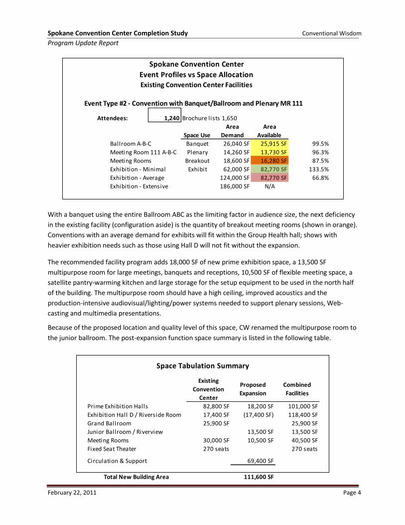
Spokane Convention Center Completion Study Conventional Wisdom
Program Update Report
February 22, 2011 Page 4
With a banquet using the entire Ballroom ABC as the limiting factor in audience size, the next deficiency
in the existing facility (configuration aside) is the quantity of breakout meeting rooms (shown in orange).
Conventions with an average demand for exhibits will fit within the Group Health hall; shows with
heavier exhibition needs such as those using Hall D will not fit without the expansion.
The recommended facility program adds 18,000 SF of new prime exhibition space, a 13,500 SF
multipurpose room for large meetings, banquets and receptions, 10,500 SF of flexible meeting space, a
satellite pantry-warming kitchen and large storage for the setup equipment to be used in the north half
of the building. The multipurpose room should have a high ceiling, improved acoustics and the
production-intensive audiovisual/lighting/power systems needed to support plenary sessions, Web-
casting and multimedia presentations.
Because of the proposed location and quality level of this space, CW renamed the multipurpose room to
the junior ballroom. The post-expansion function space summary is listed in the following table.
Event Type #2 - Convention with Banquet/Ballroom and Plenary MR 111
Attendees: 1,240 Brochure lists 1,650
Space Use
Area
Demand
Area
Available
Ballroom A-B-C Banquet 26,040 SF 25,915 SF 99.5%
Meeting Room 111 A-B-C Plenary 14,260 SF 13,730 SF 96.3%
Meeting Rooms Breakout 18,600 SF 16,280 SF 87.5%
Exhibition - Minimal Exhibit 62,000 SF 82,770 SF 133.5%
Exhibition - Average 124,000 SF 82,770 SF 66.8%
Exhibition - Extensive 186,000 SF N/A
Spokane Convention Center
Event Profiles vs Space AllocationExisting Convention Center Facilities
Existing
Convention
Center
Proposed
Expansion
Combined
Facilities
Prime Exhibition Halls 82,800 SF 18,200 SF 101,000 SF
Exhibition Hall D / Riverside Room 17,400 SF (17,400 SF) 118,400 SF
Grand Ballroom 25,900 SF 25,900 SF
Junior Ballroom / Riverview 13,500 SF 13,500 SF
Meeting Rooms 30,000 SF 10,500 SF 40,500 SF
Fixed Seat Theater 270 seats 270 seats
Circulation & Support 69,400 SF
Total New Building Area 111,600 SF
Space Tabulation Summary
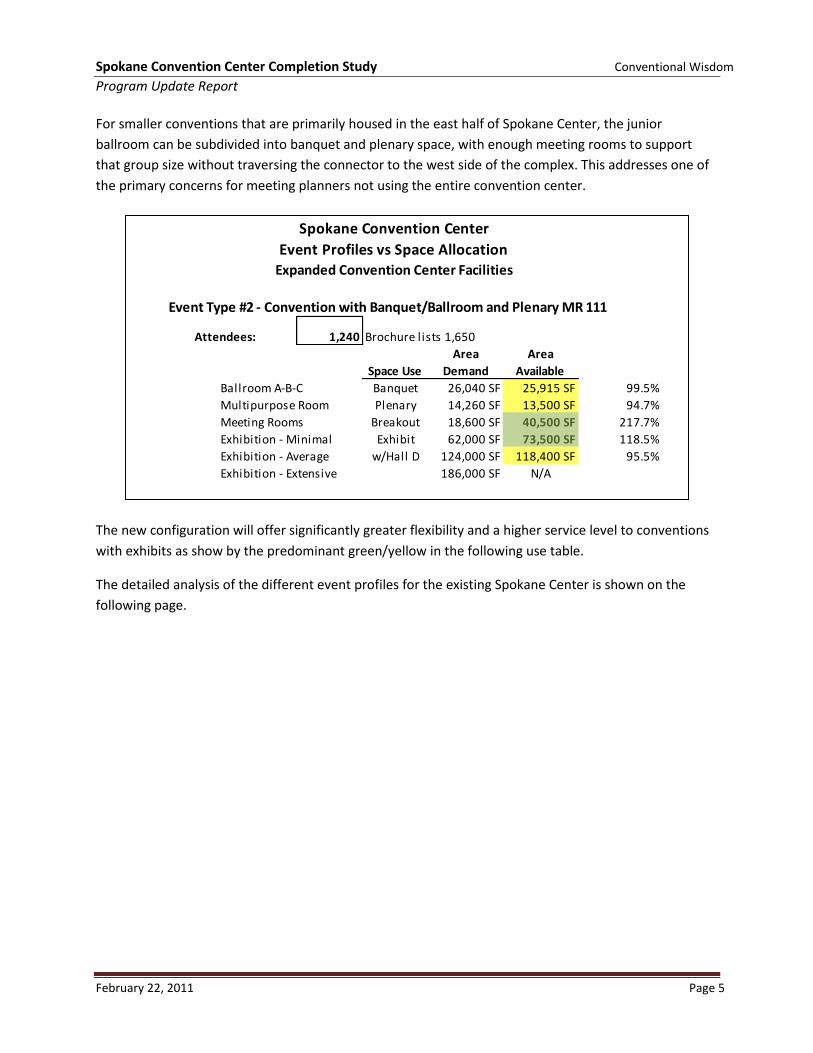
Spokane Convention Center Completion Study Conventional Wisdom
Program Update Report
February 22, 2011 Page 5
For smaller conventions that are primarily housed in the east half of Spokane Center, the junior
ballroom can be subdivided into banquet and plenary space, with enough meeting rooms to support
that group size without traversing the connector to the west side of the complex. This addresses one of
the primary concerns for meeting planners not using the entire convention center.
The new configuration will offer significantly greater flexibility and a higher service level to conventions
with exhibits as show by the predominant green/yellow in the following use table.
The detailed analysis of the different event profiles for the existing Spokane Center is shown on the
following page.
Event Type #2 - Convention with Banquet/Ballroom and Plenary MR 111
Attendees: 1,240 Brochure lists 1,650
Space Use
Area
Demand
Area
Available
Ballroom A-B-C Banquet 26,040 SF 25,915 SF 99.5%
Multipurpose Room Plenary 14,260 SF 13,500 SF 94.7%
Meeting Rooms Breakout 18,600 SF 40,500 SF 217.7%
Exhibition - Minimal Exhibit 62,000 SF 73,500 SF 118.5%
Exhibition - Average w/Hall D 124,000 SF 118,400 SF 95.5%
Exhibition - Extensive 186,000 SF N/A
Spokane Convention Center
Event Profiles vs Space AllocationExpanded Convention Center Facilities
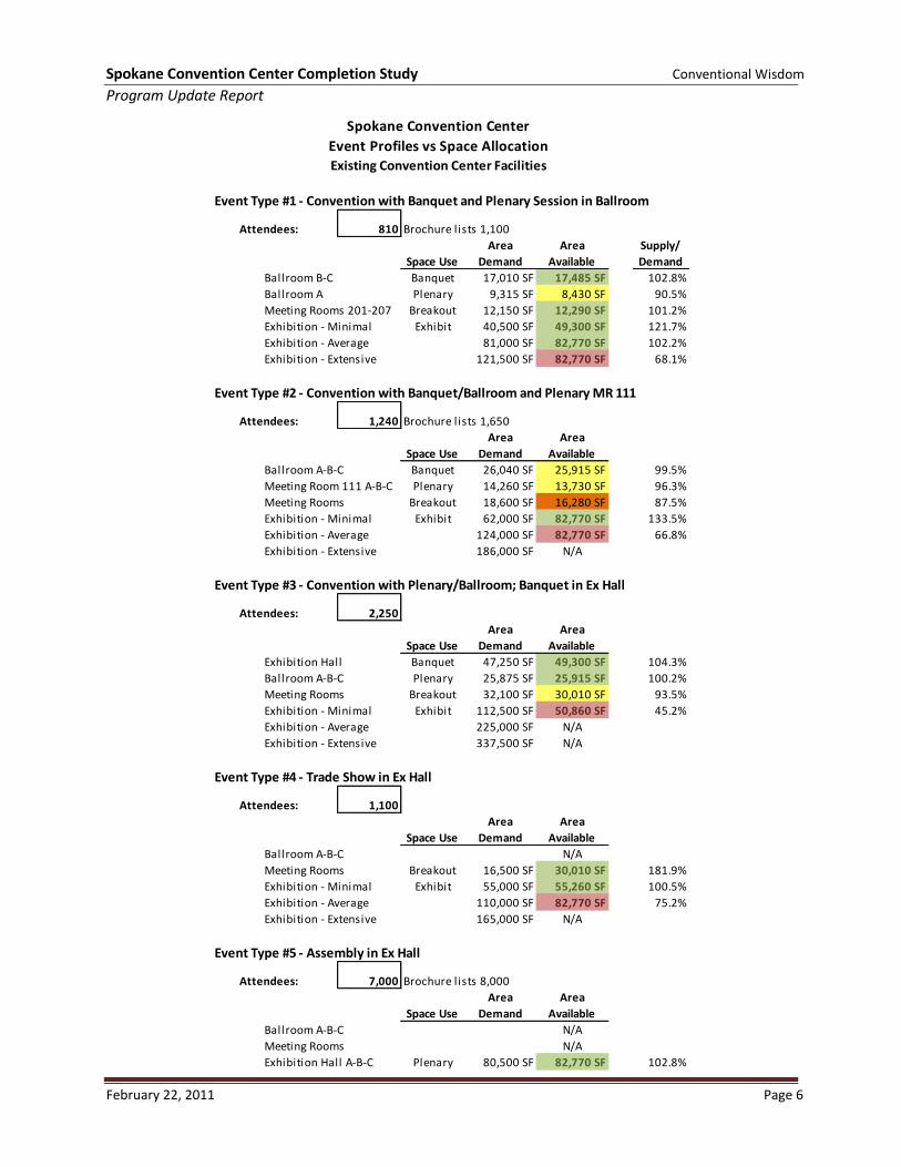
Spokane Convention Center Completion Study Conventional Wisdom
Program Update Report
February 22, 2011 Page 6
Event Type #1 - Convention with Banquet and Plenary Session in Ballroom
Attendees: 810 Brochure lists 1,100
Space Use
Area
Demand
Area
Available
Supply/
Demand
Ballroom B-C Banquet 17,010 SF 17,485 SF 102.8%
Ballroom A Plenary 9,315 SF 8,430 SF 90.5%
Meeting Rooms 201-207 Breakout 12,150 SF 12,290 SF 101.2%
Exhibition - Minimal Exhibit 40,500 SF 49,300 SF 121.7%
Exhibition - Average 81,000 SF 82,770 SF 102.2%
Exhibition - Extensive 121,500 SF 82,770 SF 68.1%
Event Type #2 - Convention with Banquet/Ballroom and Plenary MR 111
Attendees: 1,240 Brochure lists 1,650
Space Use
Area
Demand
Area
Available
Ballroom A-B-C Banquet 26,040 SF 25,915 SF 99.5%
Meeting Room 111 A-B-C Plenary 14,260 SF 13,730 SF 96.3%
Meeting Rooms Breakout 18,600 SF 16,280 SF 87.5%
Exhibition - Minimal Exhibit 62,000 SF 82,770 SF 133.5%
Exhibition - Average 124,000 SF 82,770 SF 66.8%
Exhibition - Extensive 186,000 SF N/A
Event Type #3 - Convention with Plenary/Ballroom; Banquet in Ex Hall
Attendees: 2,250
Space Use
Area
Demand
Area
Available
Exhibition Hall Banquet 47,250 SF 49,300 SF 104.3%
Ballroom A-B-C Plenary 25,875 SF 25,915 SF 100.2%
Meeting Rooms Breakout 32,100 SF 30,010 SF 93.5%
Exhibition - Minimal Exhibit 112,500 SF 50,860 SF 45.2%
Exhibition - Average 225,000 SF N/A
Exhibition - Extensive 337,500 SF N/A
Event Type #4 - Trade Show in Ex Hall
Attendees: 1,100
Space Use
Area
Demand
Area
Available
Ballroom A-B-C N/A
Meeting Rooms Breakout 16,500 SF 30,010 SF 181.9%
Exhibition - Minimal Exhibit 55,000 SF 55,260 SF 100.5%
Exhibition - Average 110,000 SF 82,770 SF 75.2%
Exhibition - Extensive 165,000 SF N/A
Event Type #5 - Assembly in Ex Hall
Attendees: 7,000 Brochure lists 8,000
Space Use
Area
Demand
Area
Available
Ballroom A-B-C N/A
Meeting Rooms N/A
Exhibition Hall A-B-C Plenary 80,500 SF 82,770 SF 102.8%
Spokane Convention Center
Event Profiles vs Space Allocation
Existing Convention Center Facilities
B. Convention Center Completion Study Community Stakeholders &
RiverBank Stakeholders Meeting Notes

2010-062.SPFD Convention Center Exp Study.CommunityMM 11-17-10. 1
Project No.: 2010-062 Project Name: SPFD Convention Center Expansion Study Community Stakeholder Meeting Subject: Meeting Minutes
November 17, 2010 By: Jeff Warner Those Present Representing See attached sign-in sheets This report is not intended to provide a transcript of proceedings, but rather to record the general content of the discussion that took place. Action Item Spokane Public Facilities District is considering options for expanding the Spokane Convention Center Exhibit Hall
and adding meeting rooms. The addition will likely occur on the north side of the existing facility in the area where Shenanigan’s Restaurant is located.
As part of this project, the Spokane Public Facilities District hosted a work session to solicit input, suggestions and
advice from stakeholders who may be impacted or influenced by this project. The session began with a presentation by LMN on the project goals and programming requirements. The project is in the early phases of design and there are no design concepts to be presented at this time.
The following is a record of the comments and suggestions made in the work session: Riverfront Improvements:
Make river more accessible. Provide dock in river for small boats. Allow for movement on trail; avoid congestion due to increased conventioneers on the trail. Make Centennial Trail Division Street underpass friendlier. Improve access to Centennial Trail and north side of Convention Center from Division Street.
o People on east side of Division do not know the stairway provides access to the Centennial Trail on the west side of Division
o People on the west side of Division try to enter the Convention Center by the loading dock Provide Centennial Trail Access from the West Side of Division Street. Convention Center Expansion Opportunities and Suggestions:
Provide rooftop function space with view to river. This space should not be accessible by the general public. Maintain service access to Doubletree and provide screening from the river and Centennial Trail. Provide turn-around for vehicles and pedestrians out by river’s edge similar to the way some roads terminate
at ocean beaches. Provide central access point for the Convention Center. This point should have vehicle drop-off and
gathering area. Multiple entrances are a management challenge. Incorporate art into the facility expansion. Incorporate visitor information center into the expansion.
2010-062.SPFD Convention Center Exp Study.CommunityMM 11-17-10. 2
Action Item
The arbor space area has been difficult to program for any kind of convention events. Utilize existing wall space for art display. Provide area for hotel shuttle drop-off. Put pre-function space on Riverside with view of river. Parking in the area appears to be adequate. Create smoking area for Convention Center and hotel staff employees. Provide different levels of green on river side of building. The Division Street loading area is the first impression for people approaching from hotels on the north side
of the river. Make a better impression. Incorporate original design features into the next addition. Provide access from Centennial Trail to lobby gift shop/coffee shop. Important to connect the east side of the Convention Center to the west with activities along the promenade. Soften the look of the Convention Center on the side facing the river.
Ideas for Providing Broader Community Benefit:
Provide for interests of all in the community. With Shenanigans Restaurant being removed, the public is losing a public eating and drinking space along
the river. o How is this replaced?
Keep activity on the river bank. Create public use in the evening. Allow for food and beverage vendors on the river’s edge. Add retail to the north side. Provide Division Street access to the Convention Center and/or Centennial Trail. Hold free public performances in spaces that are part of the Convention Center. Provide more public access to the building and its amenities. Provide terraced connections to the river that are publicly accessible open space. Improve the appearance of the Division Street/Spokane Falls Boulevard traffic island. Existing green space is not very accessible and under-utilized. Consider other options for off-setting loss of
open space. Project Funding:
The project will need to go to the voters for approval: o Consider other community needs when going to the voters. o Possibly extend existing tax. o Avoid competing with other bond votes.
Other: Consider tram/transportation to north side hotels.
If you have any additions or corrections to these minutes, please bring them to the attention of the editor within two weeks of the date of this meeting. JJW:gam:2010-062 Distribution:
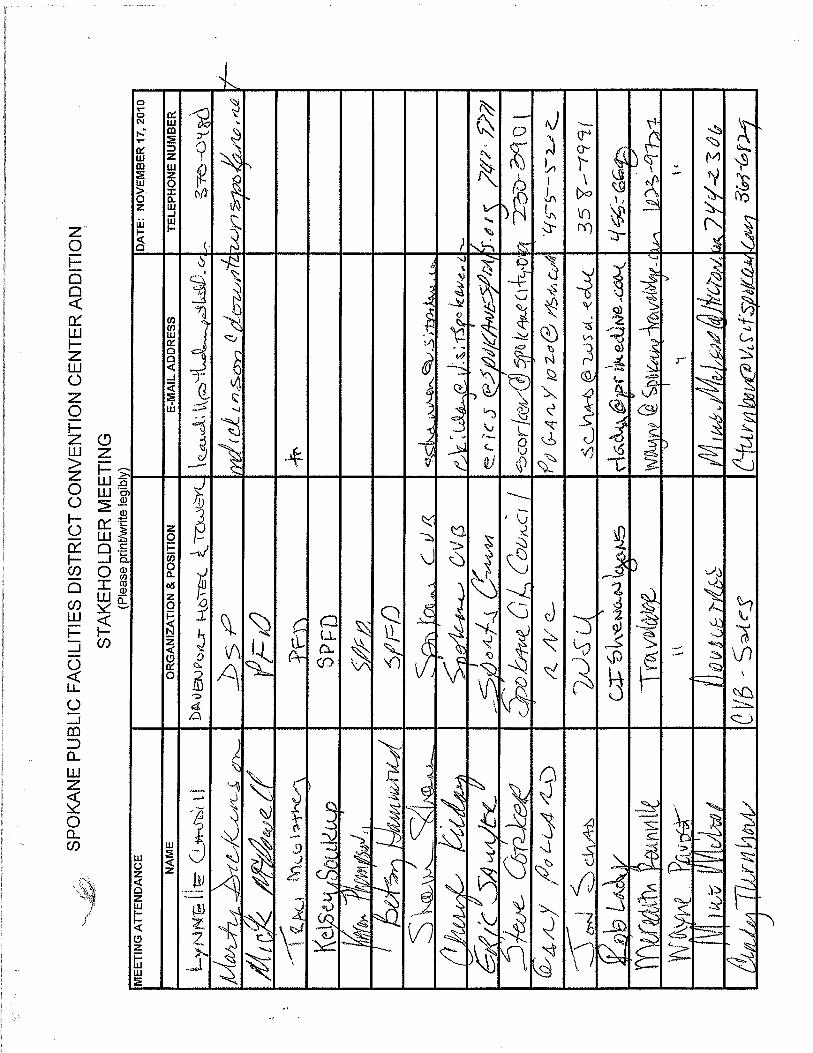
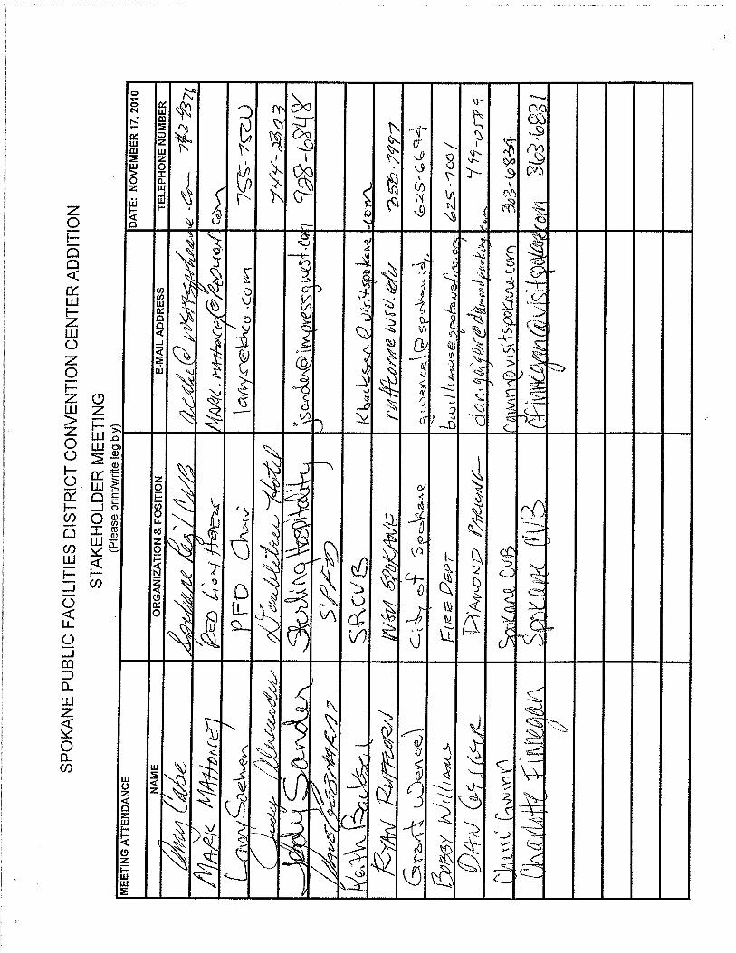
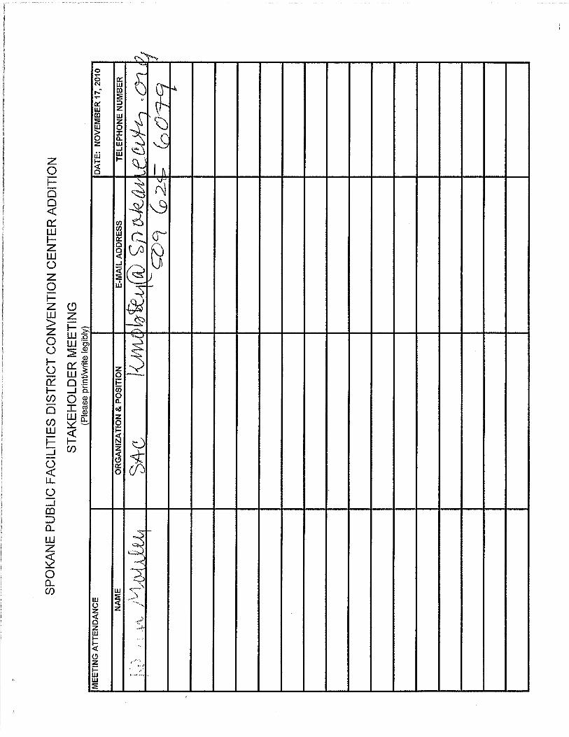
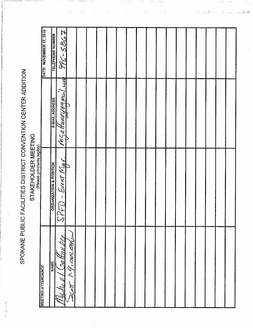
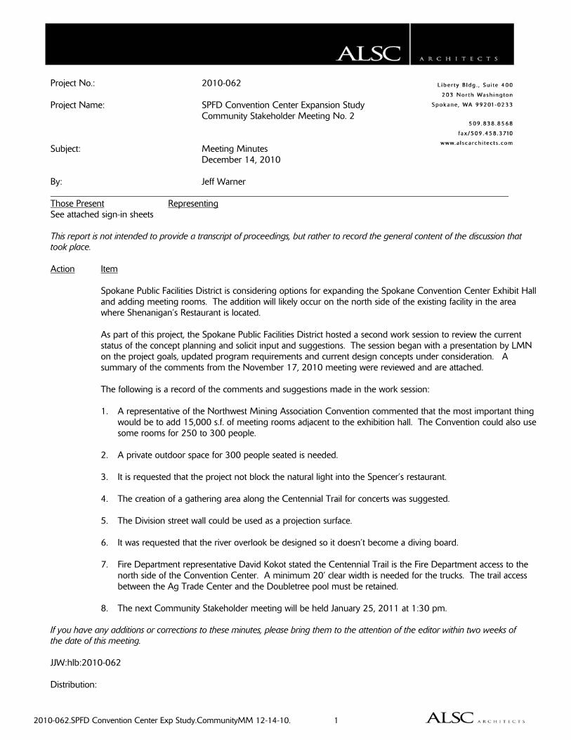
2010-062.SPFD Convention Center Exp Study.CommunityMM 12-14-10. 1
Project No.: 2010-062 Project Name: SPFD Convention Center Expansion Study Community Stakeholder Meeting No. 2 Subject: Meeting Minutes December 14, 2010 By: Jeff Warner Those Present Representing See attached sign-in sheets This report is not intended to provide a transcript of proceedings, but rather to record the general content of the discussion that took place. Action Item Spokane Public Facilities District is considering options for expanding the Spokane Convention Center Exhibit Hall
and adding meeting rooms. The addition will likely occur on the north side of the existing facility in the area where Shenanigan’s Restaurant is located.
As part of this project, the Spokane Public Facilities District hosted a second work session to review the current
status of the concept planning and solicit input and suggestions. The session began with a presentation by LMN on the project goals, updated program requirements and current design concepts under consideration. A summary of the comments from the November 17, 2010 meeting were reviewed and are attached.
The following is a record of the comments and suggestions made in the work session: 1. A representative of the Northwest Mining Association Convention commented that the most important thing
would be to add 15,000 s.f. of meeting rooms adjacent to the exhibition hall. The Convention could also use some rooms for 250 to 300 people.
2. A private outdoor space for 300 people seated is needed. 3. It is requested that the project not block the natural light into the Spencer’s restaurant. 4. The creation of a gathering area along the Centennial Trail for concerts was suggested. 5. The Division street wall could be used as a projection surface. 6. It was requested that the river overlook be designed so it doesn’t become a diving board. 7. Fire Department representative David Kokot stated the Centennial Trail is the Fire Department access to the
north side of the Convention Center. A minimum 20’ clear width is needed for the trucks. The trail access between the Ag Trade Center and the Doubletree pool must be retained.
8. The next Community Stakeholder meeting will be held January 25, 2011 at 1:30 pm. If you have any additions or corrections to these minutes, please bring them to the attention of the editor within two weeks of the date of this meeting. JJW:hlb:2010-062 Distribution:
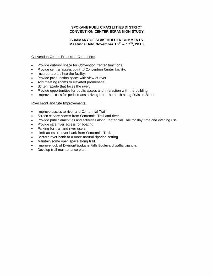
SPOKANE PUBLIC FACILITIES DISTRICT CONVENTION CENTER EXPANSION STUDY
SUMMARY OF STAKEHOLDER COMMENTS Meetings Held November 16th & 17th, 2010
Convention Center Expansion Comments: Provide outdoor space for Convention Center functions. Provide central access point to Convention Center facility. Incorporate art into the facility. Provide pre-function space with view of river. Add meeting rooms to elevated promenade. Soften facade that faces the river. Provide opportunities for public access and interaction with the building. Improve access for pedestrians arriving from the north along Division Street. River Front and Site Improvements: Improve access to river and Centennial Trail. Screen service access from Centennial Trail and river. Provide public amenities and activities along Centennial Trail for day time and evening use. Provide safe river access for boating. Parking for trail and river users. Limit access to river bank from Centennial Trail. Restore river bank to a more natural riparian setting. Maintain some open space along trail. Improve look of Division/Spokane Falls Boulevard traffic triangle. Develop trail maintenance plan.
C. Fire Department Access, Department of Wildlife,
Department of Ecology, City Planning Department & WSDOT

2010-062.SPFD Convention Center Exp Study. MM 12-14-10. 1
Project No.: 2010-062 Project Name: SPFD Convention Center Expansion Study Subject: Fire Department Access to the proposed Expansion Area Meeting Minutes December 14, 2010 By: Jeff Warner Those Present Representing Dave Kokot Spokane Fire Department Bobby Williams Spokane Fire Department Tom Burgess LMN Jeff Warner ALSC Architects This report is not intended to provide a transcript of proceedings, but rather to record the general content of the discussion that took place. Action Item Mr. Kokot and Chief Williams attended the presentation on the concept study and offered the following
comments. 1. Fire trucks need to get within 150 feet of any point on the building. 2. Access must be a paved fire lane minimum 15 feet wide with minimum 20’ wide unobstructed area for
outriggers and access to the sides of the fire trucks. 3. The Centennial Trail currently serves as this Fire Department access. The primary access points are the
Convention Center Breezeway and the Marriott Courtyard Hotel parking lot. Secondary access points are provided through the Shenanigan’s parking lot and the sidewalk between the Ag Trade Center and the Doubletree pool.
4. The access point between the Ag Trade Center and the Doubletree pool must be retained. 5. The Fire Department needs some access closer to the building to provide rescue from designated areas of
refuge at the exhibition hall level. There are currently two of these areas of refuge on the promenade. This access must accommodate a ladder truck.
6. The access under the building will likely be used for medical emergencies only and not for fire fighting. 7. It was suggested that the Spokane Public Facilities District consider providing a First Aid room for treating
medical emergencies on site. If you have any additions or corrections to these minutes, please bring them to the attention of the editor within two weeks of the date of this meeting. JJW:hlb:2010-062 Distribution:
2010-062.SPFD Convention Center Exp Study. MM 01-07-11. 1
Project No.: 2010-062
Project Name: SPFD Convention Center
Expansion Study
Subject: Meeting Minutes
January 7, 2011
By: Jeff Warner
Those Present Representing
Jim Kolva
Karin Divens Washington State Department of Fish & Wildlife
Mike Maher Department of Ecology
Jeff Warner ALSC Architects
This report is not intended to provide a transcript of proceedings, but rather to
record the general content of the discussion that took place.
Action Item
The purpose of the meeting was to discuss proposed improvements to the river
bank as part of the Convention Center addition project.
1. General Shoreline Improvements:
A. Because the project is part of an urban center, the two departments
are flexible with how that area is developed.
B. Armament of the river bank with basalt is okay if it is justified for
the particular conditions. They would like to see this type of
armament combined with plantings.
C. The Fish & Wildlife website has resources for appropriate river bank
planting materials.
2. A dock or pier on the river as shown in the Conceptual Plan will require a
Hydraulic Project Approval (HPA) from the Department of Fish & Wildlife.
A Conditional Use Permit issued by the City of Spokane may also be
required.
3. Development of small boat launch near Division Street Bridge:
A. Hardening of the shoreline under the Division Street Bridge for this
purpose is okay. A Hydraulic Project Approval and Conditional Use
Permit will likely be required for this improvement.
4. The City of Spokane Planning Department has primary responsibility for
approval of river bank development. The Department of Ecology can appeal
decisions made by the City.
5. Mike and Karin were generally comfortable with what was being proposed by
the Conceptual Plan. Any further reviews of project proposals should go
to the City of Spokane Planning Department. The City would include
Ecology and Fish and Wildlife in its permit review processes.
If you have any additions or corrections to these minutes, please bring them to the
attention of the editor within two weeks of the date of this meeting.
2010-062.SPFD Convention Center Exp Study. MM 01-07-11. 2
JJW:gam:2010-062
Distribution: Mike Maher Tom Burgess
Karin Divens Kevin Twohig
Jim Kolva JJW/File
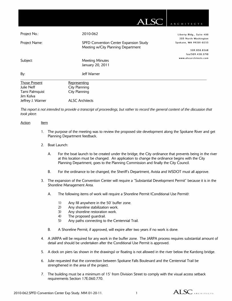
2010-062.SPFD Convention Center Exp Study. MM 01-20-11. 1
Project No.: 2010-062 Project Name: SPFD Convention Center Expansion Study Meeting w/City Planning Department Subject: Meeting Minutes January 20, 2011
By: Jeff Warner Those Present Representing Julie Neff City Planning Tami Palmquist City Planning Jim Kolva Jeffrey J. Warner ALSC Architects This report is not intended to provide a transcript of proceedings, but rather to record the general content of the discussion that took place. Action Item 1. The purpose of the meeting was to review the proposed site development along the Spokane River and get
Planning Department feedback. 2. Boat Launch: A. For the boat launch to be created under the bridge, the City ordinance that prevents being in the river
at this location must be changed. An application to change the ordinance begins with the City Planning Department, goes to the Planning Commission and finally the City Council.
B. For the ordinance to be changed, the Sheriff’s Department, Avista and WSDOT must all approve. 3. The expansion of the Convention Center will require a “Substantial Development Permit” because it is in the
Shoreline Management Area. A. The following items of work will require a Shoreline Permit (Conditional Use Permit): 1) Any fill anywhere in the 50’ buffer zone. 2) Any shoreline stabilization work. 3) Any shoreline restoration work. 4) The proposed guardrail. 5) Any paths connecting to the Centennial Trail. B. A Shoreline Permit, if approved, will expire after two years if no work is done. 4. A JARPA will be required for any work in the buffer zone. The JARPA process requires substantial amount of
detail and should be undertaken after the Conditional Use Permit is approved. 5. A dock on piers (as shown in the drawings) or floating is not allowed in the river below the Kardong bridge. 6. Julie requested that the connection between Spokane Falls Boulevard and the Centennial Trail be
strengthened in the area of the project. 7. The building must be a minimum of 15’ from Division Street to comply with the visual access setback
requirements Section 17E.060.770.
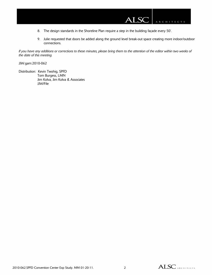
2010-062.SPFD Convention Center Exp Study. MM 01-20-11. 2
8. The design standards in the Shoreline Plan require a step in the building façade every 50’. 9. Julie requested that doors be added along the ground level break-out space creating more indoor/outdoor
connections. If you have any additions or corrections to these minutes, please bring them to the attention of the editor within two weeks of the date of this meeting. JJW:gam:2010-062 Distribution: Kevin Twohig, SPFD Tom Burgess, LMN Jim Kolva, Jim Kolva & Associates JJW/File
2010-062.SPFD Convention Center Exp Study. MM 01-27-11. 1
Project No.: 2010-062 Project Name: SPFD Convention Center Expansion Study Subject: Meeting Minutes January 27, 2011 By: Jeff Warner
Those Present Representing Ken Olson WSDOT Greg Fig WSDOT Mike Britton City of Spokane Ray Wright City of Spokane Jim Kolva Jeffrey J. Warner ALSC Architects This report is not intended to provide a transcript of proceedings, but rather to record the general content of the discussion that took place. Action Item 1. The purpose of the meeting was to discuss opportunities for improvements under the Division Street Bridge
and improvements to the traffic island at Spokane Falls Boulevard and Division. 2. If a stairway is added connecting the west side of the Division Street Bridge to the river level, an ADA access
may be required. 3. The State of Washington owns the Division Street Bridge, but the City of Spokane owns the property
underneath. 4. Traffic Island: A. It is important to know if people will be on the island or not. B. The jersey barriers currently on the island are not required to meet road design standards. The only
possible exception is the northern-most tree on the island may be too close to the roadway, thus requiring a barrier. There is no problem with removing that tree.
C. The island currently has mature trees and irrigation in place. If you have any additions or corrections to these minutes, please bring them to the attention of the editor within two weeks of the date of this meeting. JJW:gam:2010-062 Distribution: Kevin Twohig, SPFD Tom Burgess, LMN Jim Kolva, JKA JJW/File
D. Issues for Consideration

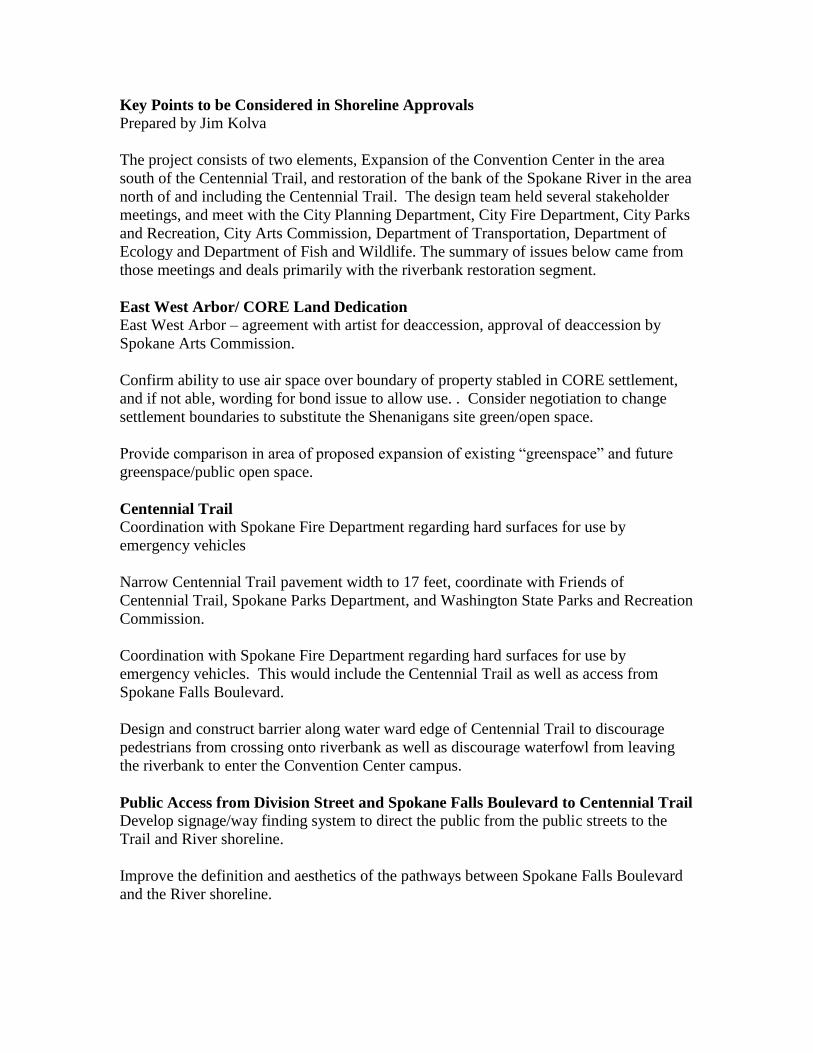
Key Points to be Considered in Shoreline Approvals Prepared by Jim Kolva
The project consists of two elements, Expansion of the Convention Center in the area
south of the Centennial Trail, and restoration of the bank of the Spokane River in the area
north of and including the Centennial Trail. The design team held several stakeholder
meetings, and meet with the City Planning Department, City Fire Department, City Parks
and Recreation, City Arts Commission, Department of Transportation, Department of
Ecology and Department of Fish and Wildlife. The summary of issues below came from
those meetings and deals primarily with the riverbank restoration segment.
East West Arbor/ CORE Land Dedication
East West Arbor – agreement with artist for deaccession, approval of deaccession by
Spokane Arts Commission.
Confirm ability to use air space over boundary of property stabled in CORE settlement,
and if not able, wording for bond issue to allow use. . Consider negotiation to change
settlement boundaries to substitute the Shenanigans site green/open space.
Provide comparison in area of proposed expansion of existing “greenspace” and future
greenspace/public open space.
Centennial Trail
Coordination with Spokane Fire Department regarding hard surfaces for use by
emergency vehicles
Narrow Centennial Trail pavement width to 17 feet, coordinate with Friends of
Centennial Trail, Spokane Parks Department, and Washington State Parks and Recreation
Commission.
Coordination with Spokane Fire Department regarding hard surfaces for use by
emergency vehicles. This would include the Centennial Trail as well as access from
Spokane Falls Boulevard.
Design and construct barrier along water ward edge of Centennial Trail to discourage
pedestrians from crossing onto riverbank as well as discourage waterfowl from leaving
the riverbank to enter the Convention Center campus.
Public Access from Division Street and Spokane Falls Boulevard to Centennial Trail
Develop signage/way finding system to direct the public from the public streets to the
Trail and River shoreline.
Improve the definition and aesthetics of the pathways between Spokane Falls Boulevard
and the River shoreline.
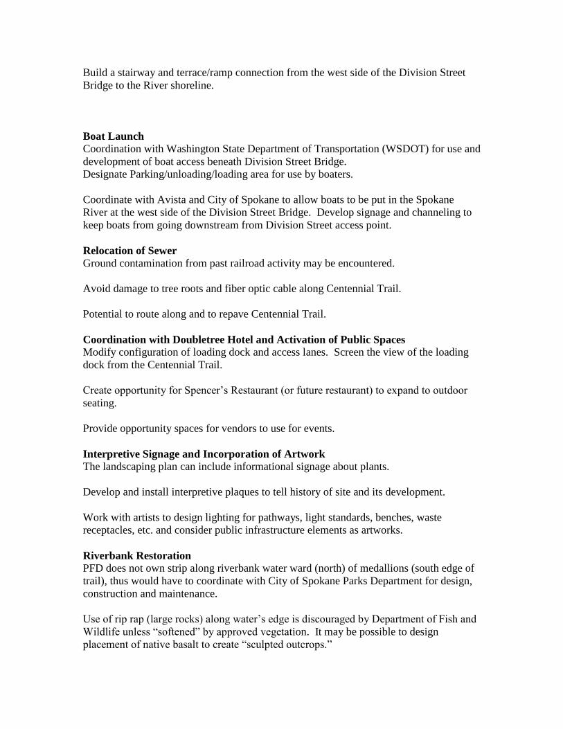
Build a stairway and terrace/ramp connection from the west side of the Division Street
Bridge to the River shoreline.
Boat Launch
Coordination with Washington State Department of Transportation (WSDOT) for use and
development of boat access beneath Division Street Bridge.
Designate Parking/unloading/loading area for use by boaters.
Coordinate with Avista and City of Spokane to allow boats to be put in the Spokane
River at the west side of the Division Street Bridge. Develop signage and channeling to
keep boats from going downstream from Division Street access point.
Relocation of Sewer
Ground contamination from past railroad activity may be encountered.
Avoid damage to tree roots and fiber optic cable along Centennial Trail.
Potential to route along and to repave Centennial Trail.
Coordination with Doubletree Hotel and Activation of Public Spaces
Modify configuration of loading dock and access lanes. Screen the view of the loading
dock from the Centennial Trail.
Create opportunity for Spencer’s Restaurant (or future restaurant) to expand to outdoor
seating.
Provide opportunity spaces for vendors to use for events.
Interpretive Signage and Incorporation of Artwork
The landscaping plan can include informational signage about plants.
Develop and install interpretive plaques to tell history of site and its development.
Work with artists to design lighting for pathways, light standards, benches, waste
receptacles, etc. and consider public infrastructure elements as artworks.
Riverbank Restoration
PFD does not own strip along riverbank water ward (north) of medallions (south edge of
trail), thus would have to coordinate with City of Spokane Parks Department for design,
construction and maintenance.
Use of rip rap (large rocks) along water’s edge is discouraged by Department of Fish and
Wildlife unless “softened” by approved vegetation. It may be possible to design
placement of native basalt to create “sculpted outcrops.”
Develop inventory of existing plants/ecosystem to be impacted by development, and a
plant palette that is appropriate for the shoreline per Department of Ecology and
Department of Fish and Wildlife guidelines.
Regulatory/Agency Coordination
The City of Spokane will require a Shorelines Permit for the construction of the
Convention Center Expansion and riverbank restoration. Design review will be required
as part of that process. Other documents/permits likely to be required include SEPA,
Critical Area Checklist, Floodplain Development Permit and Habitat Management Plan.
All work in contact with the water’s edge would require a Joint Aquatic Resource Permit
Application filed with city of Spokane, reviewed by Department of Ecology and
Department of Fish and Wildlife, with possible review by Army Corps of Engineers.
Extension of concrete bulkhead for viewing platform will require coordination with City
of Spokane Shorelines Master Program and a Hydraulic Project Approval from the
Department of Fish and Wildlife. Extent of encroachment into water will likely be
limited.
Addition of access point on Division Street Bridge, and use of area beneath bridge for
boat access will require approval by WSDOT and a Hydraulic Project Approval from the
Department of Fish and Wildlife.
Development of boat access will also require coordination with Avista, and may require
a change in the river access ordinance by the City of Spokane. This work would be
coordinated by river advocacy groups.

E. Civil Diagrams

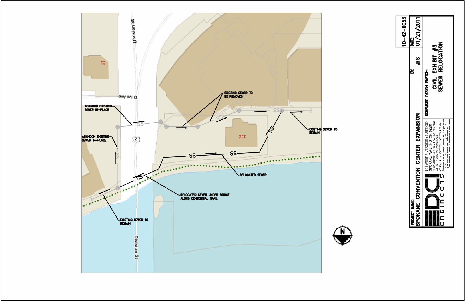
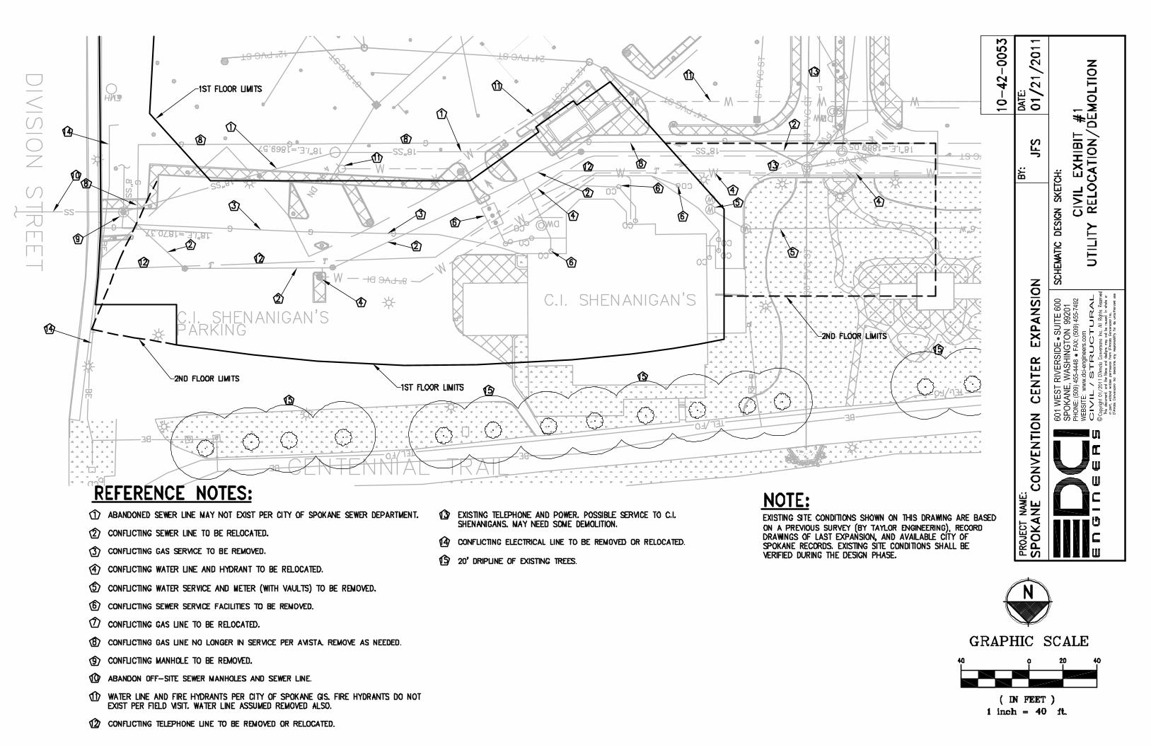
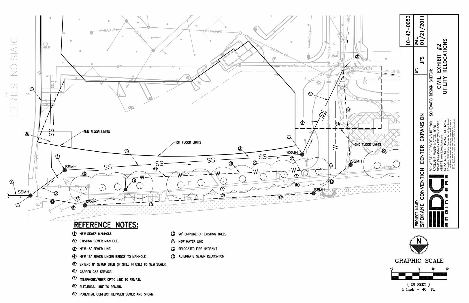

F. Preliminary Cost Model Back-up

PRELIMINARYCOST MODEL
for
Spokane Convention CenterExpansion
Spokane, Washington
January 24, 2011
PRELIMINARY COST MODEL
for
Spokane Convention CenterExpansionSpokane, Washington
LMN Architects801 Second AvenueSuite 501Seattle, WA 98104
Tel: (206) 682-3460Fax: (206) 343-9388
January 24, 2011 719 Second Avenue
Suite 400
Seattle
Washington 98104
Tel: 206.343.8119
Fax: 206.343.8541
www.davislangdon.com
www.aecom.com
Spokane Convention Center Preliminary Cost ModelExpansion January 24, 2011Spokane, Washington 027-07778.110
CONTENTS
Page Nos.
Basis of Cost Model 1
Inclusions 3
Exclusions 5
Overall Summary 6
Building Component Summary 8
SIte Component Summary 17
Separate Price 20
Comparison Summary 21
Spokane Convention Center Preliminary Cost ModelExpansion January 24, 2011Spokane, Washington 027-07778.110
BASIS OF COST MODEL
Cost Model Prepared From Dated Received
Drawings issued for cost model
Level 1 & 2 Floor plans Undated 01.18.11Design narratives 02.02.11 01.11.11
Discussions with the Project Architect and Engineers
Page 1
Spokane Convention Center Preliminary Cost ModelExpansion January 24, 2011Spokane, Washington 027-07778.110
BASIS OF COST MODEL
Conditions of Construction
The pricing is based on the following general conditions of construction
A start date of June 2012
A construction period of 15 months
The contractor will be required to pay prevailing wages
The general contractor will have full access to the site during normal business
There are no phasing requirements
A GC/CM procurement process
There will not be small business set aside requirements
Page 2
Spokane Convention Center Preliminary Cost ModelExpansion January 24, 2011Spokane, Washington 027-07778.110
EXCLUSIONS
Owner supplied and installed furniture, fixtures and equipment
Loose furniture and equipment except as specifically identified
Compression of schedule, premium or shift work, and restrictions on the contractor's working hours
Testing and inspection fees
Architectural, design and construction management fees
Scope change and post contract contingencies
Assessments, taxes, finance, legal and development charges
Environmental impact mitigation
Builder's risk, project wrap-up and other owner provided insurance program
Land and easement acquisition
Cost escalation beyond a construction midpoint of January 2013
Page 5
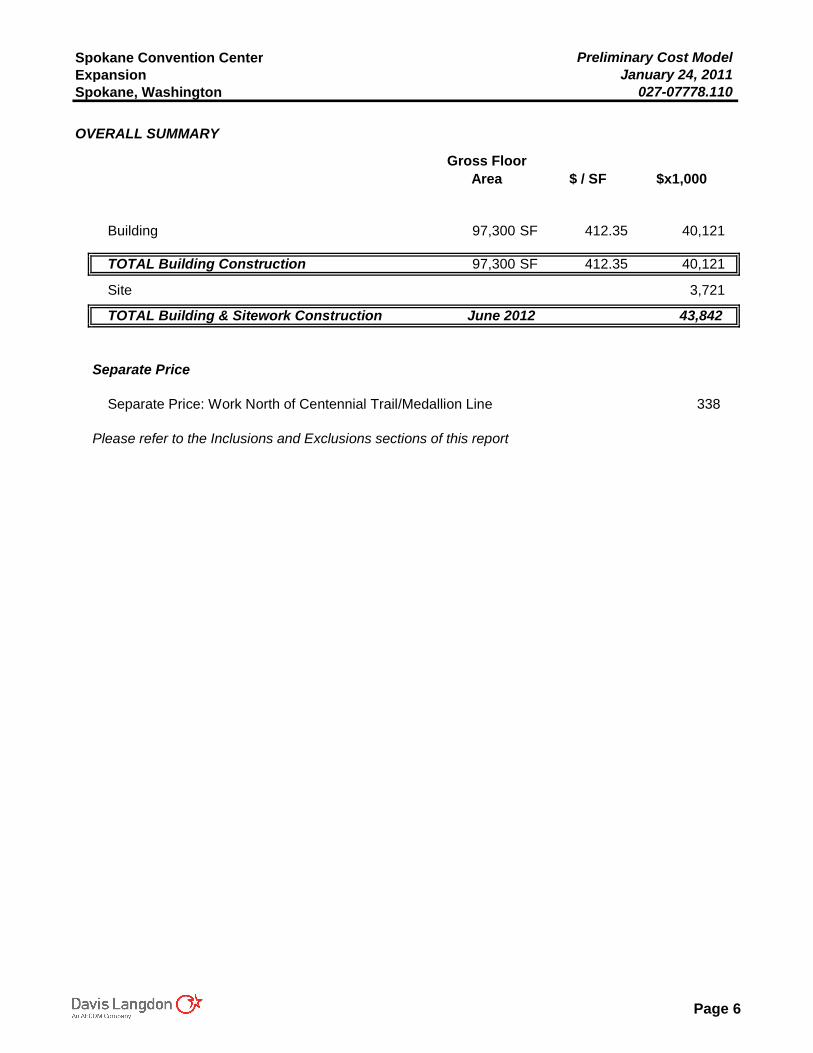
Spokane Convention Center Preliminary Cost ModelExpansion January 24, 2011Spokane, Washington 027-07778.110
OVERALL SUMMARY
Gross Floor Area $ / SF $x1,000
Building 97,300 SF 412.35 40,121
TOTAL Building Construction 97,300 SF 412.35 40,121
Site 3,721
TOTAL Building & Sitework Construction June 2012 43,842
Separate Price
Separate Price: Work North of Centennial Trail/Medallion Line 338
Please refer to the Inclusions and Exclusions sections of this report
Page 6
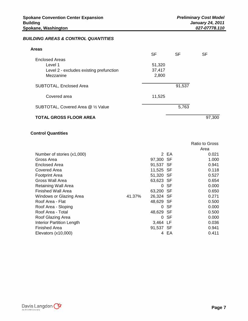
Spokane Convention Center Expansion Preliminary Cost ModelBuilding January 24, 2011Spokane, Washington 027-07778.110
BUILDING AREAS & CONTROL QUANTITIES
AreasSF SF SF
Enclosed AreasLevel 1 51,320 Level 2 - excludes existing prefunction 37,417 Mezzanine 2,800
SUBTOTAL, Enclosed Area 91,537
Covered area 11,525
SUBTOTAL, Covered Area @ ½ Value 5,763
TOTAL GROSS FLOOR AREA 97,300
Control Quantities
Ratio to Gross Area
Number of stories (x1,000) 2 EA 0.021Gross Area 97,300 SF 1.000Enclosed Area 91,537 SF 0.941Covered Area 11,525 SF 0.118Footprint Area 51,320 SF 0.527Gross Wall Area 63,623 SF 0.654Retaining Wall Area 0 SF 0.000Finished Wall Area 63,200 SF 0.650Windows or Glazing Area 41.37% 26,324 SF 0.271Roof Area - Flat 48,629 SF 0.500Roof Area - Sloping 0 SF 0.000Roof Area - Total 48,629 SF 0.500Roof Glazing Area 0 SF 0.000Interior Partition Length 3,464 LF 0.036Finished Area 91,537 SF 0.941Elevators (x10,000) 4 EA 0.411
Page 7
Spokane Convention Center Expansion Preliminary Cost ModelBuilding January 24, 2011Spokane, Washington 027-07778.110
BUILDING COMPONENT SUMMARYGross Area: 97,300 SF
$/SF $x1,000
1. Foundations 8.25 802 2. Vertical Structure 8.39 816 3. Floor & Roof Structures 33.62 3,271 4. Exterior Cladding 59.28 5,768 5. Roofing, Waterproofing & Skylights 12.84 1,250
Shell (1-5) 122.38 11,907
6. Interior Partitions, Doors & Glazing 16.40 1,596 7. Floor, Wall & Ceiling Finishes 29.88 2,907
Interiors (6-7) 46.28 4,503
8. Function Equipment & Specialties 22.39 2,179 9. Stairs & Vertical Transportation 10.29 1,002
Equipment & Vertical Transportation (8-9) 32.69 3,181
10.Plumbing Systems 7.62 742 11.Heating, Ventilating & Air Conditioning 41.25 4,014 12.Electric Lighting, Power & Communications 37.05 3,605 13.Fire Protection Systems 3.38 328
Mechanical & Electrical (10-13) 89.30 8,689
Total Building Construction (1-13) 290.65 28,280 14.Site Preparation & Demolition 0.00 0 15.Site Paving, Structures & Landscaping 0.00 0 16.Utilities on Site 0.00 0
Total Site Construction (14-16) 0.00 0 TOTAL BUILDING & SITE (1-16) 290.65 28,280
Contingency for Development of Design 15.00% 43.60 4,242
PLANNED CONSTRUCTION COST January 2011 334.24 32,522
Subcontractor Bonds 1.00% 3.34 325MACC Contingency 5.00% 16.88 1,642Reimbursables / General Requirement 8.00% 28.09 2,733 \
RECOMMENDED BUDGET June 2012 382.55 37,222
Preconstruction Services - allow 250GC/CM Fee 4.00% 15.40 1,499
RECOMMENDED BUDGET 400.53 38,971
Escalation to Midpoint (January 2013) 2.95% 11.82 1,150
RECOMMENDED BUDGET June 2012 412.35 40,121
Page 8
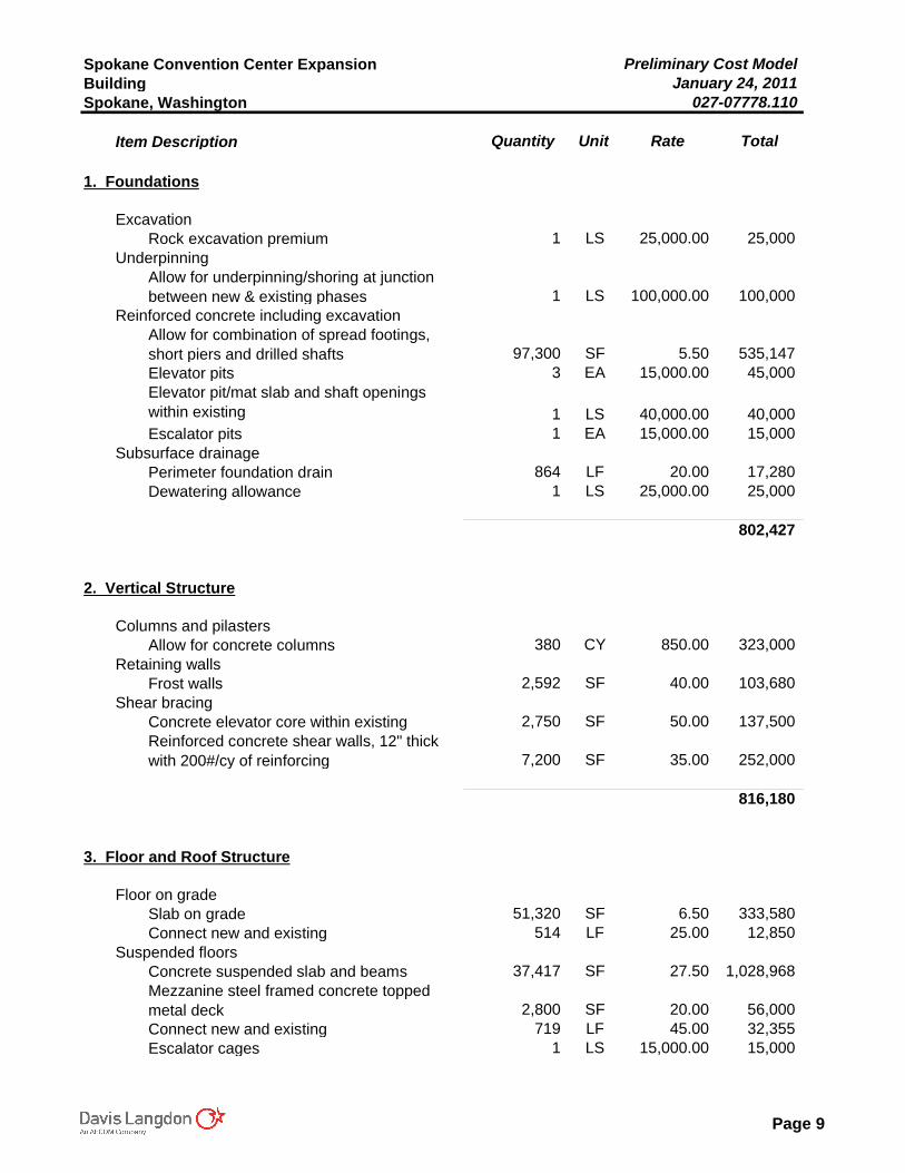
Spokane Convention Center Expansion Preliminary Cost ModelBuilding January 24, 2011Spokane, Washington 027-07778.110
Item Description Quantity Unit Rate Total
1. Foundations
ExcavationRock excavation premium 1 LS 25,000.00 25,000
UnderpinningAllow for underpinning/shoring at junction between new & existing phases 1 LS 100,000.00 100,000
Reinforced concrete including excavationAllow for combination of spread footings, short piers and drilled shafts 97,300 SF 5.50 535,147Elevator pits 3 EA 15,000.00 45,000Elevator pit/mat slab and shaft openings within existing 1 LS 40,000.00 40,000Escalator pits 1 EA 15,000.00 15,000
Subsurface drainagePerimeter foundation drain 864 LF 20.00 17,280Dewatering allowance 1 LS 25,000.00 25,000
802,427
2. Vertical Structure
Columns and pilastersAllow for concrete columns 380 CY 850.00 323,000
Retaining wallsFrost walls 2,592 SF 40.00 103,680
Shear bracingConcrete elevator core within existing 2,750 SF 50.00 137,500Reinforced concrete shear walls, 12" thick with 200#/cy of reinforcing 7,200 SF 35.00 252,000
816,180
3. Floor and Roof Structure
Floor on gradeSlab on grade 51,320 SF 6.50 333,580Connect new and existing 514 LF 25.00 12,850
Suspended floorsConcrete suspended slab and beams 37,417 SF 27.50 1,028,968Mezzanine steel framed concrete topped metal deck 2,800 SF 20.00 56,000Connect new and existing 719 LF 45.00 32,355Escalator cages 1 LS 15,000.00 15,000
Page 9
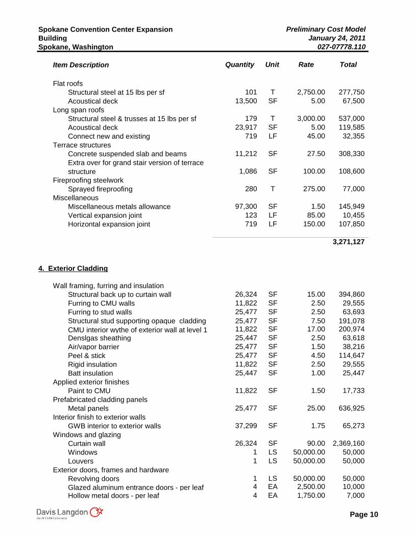
Spokane Convention Center Expansion Preliminary Cost ModelBuilding January 24, 2011Spokane, Washington 027-07778.110
Item Description Quantity Unit Rate Total
Flat roofsStructural steel at 15 lbs per sf 101 T 2,750.00 277,750Acoustical deck 13,500 SF 5.00 67,500
Long span roofsStructural steel & trusses at 15 lbs per sf 179 T 3,000.00 537,000Acoustical deck 23,917 SF 5.00 119,585Connect new and existing 719 LF 45.00 32,355
Terrace structuresConcrete suspended slab and beams 11,212 SF 27.50 308,330Extra over for grand stair version of terrace structure 1,086 SF 100.00 108,600
Fireproofing steelworkSprayed fireproofing 280 T 275.00 77,000
MiscellaneousMiscellaneous metals allowance 97,300 SF 1.50 145,949Vertical expansion joint 123 LF 85.00 10,455Horizontal expansion joint 719 LF 150.00 107,850
3,271,127
4. Exterior Cladding
Wall framing, furring and insulationStructural back up to curtain wall 26,324 SF 15.00 394,860Furring to CMU walls 11,822 SF 2.50 29,555Furring to stud walls 25,477 SF 2.50 63,693Structural stud supporting opaque cladding 25,477 SF 7.50 191,078CMU interior wythe of exterior wall at level 1 11,822 SF 17.00 200,974Denslgas sheathing 25,447 SF 2.50 63,618Air/vapor barrier 25,477 SF 1.50 38,216Peel & stick 25,477 SF 4.50 114,647Rigid insulation 11,822 SF 2.50 29,555Batt insulation 25,447 SF 1.00 25,447
Applied exterior finishesPaint to CMU 11,822 SF 1.50 17,733
Prefabricated cladding panelsMetal panels 25,477 SF 25.00 636,925
Interior finish to exterior wallsGWB interior to exterior walls 37,299 SF 1.75 65,273
Windows and glazingCurtain wall 26,324 SF 90.00 2,369,160Windows 1 LS 50,000.00 50,000Louvers 1 LS 50,000.00 50,000
Exterior doors, frames and hardwareRevolving doors 1 LS 50,000.00 50,000Glazed aluminum entrance doors - per leaf 4 EA 2,500.00 10,000Hollow metal doors - per leaf 4 EA 1,750.00 7,000
Page 10
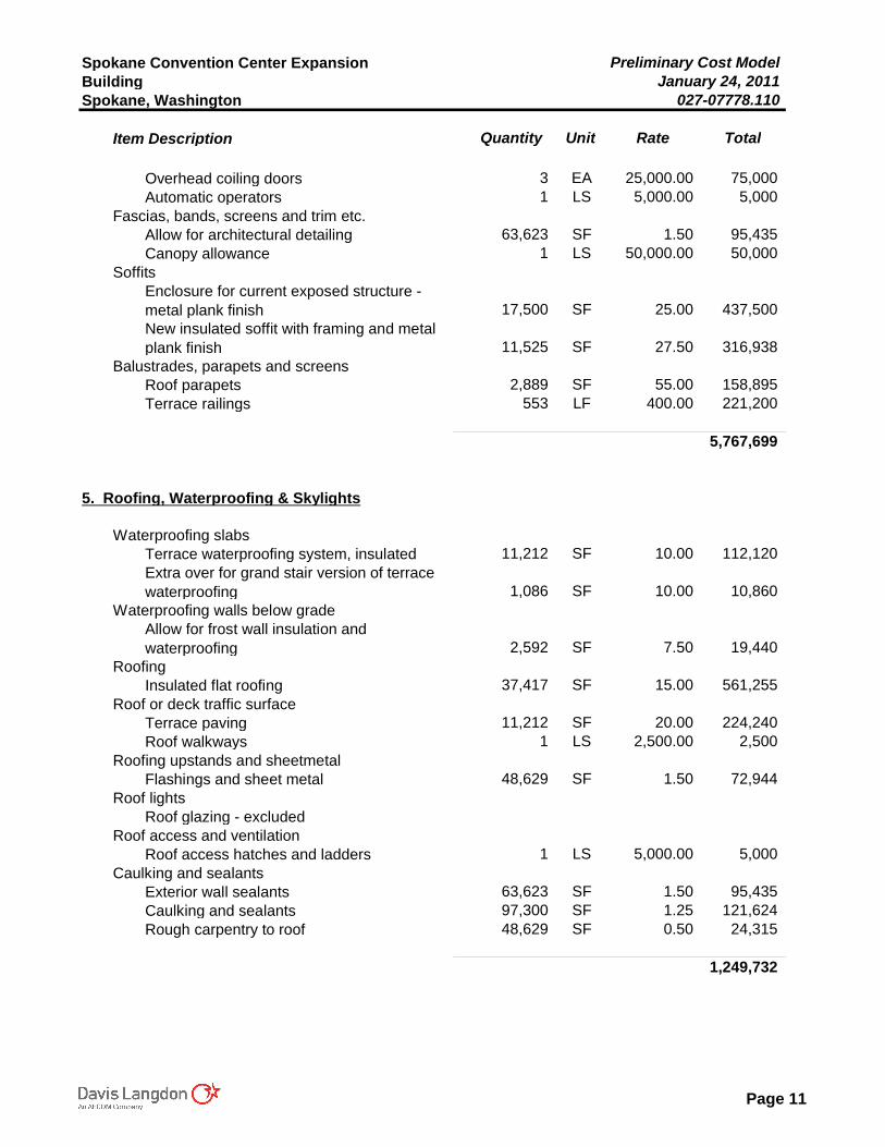
Spokane Convention Center Expansion Preliminary Cost ModelBuilding January 24, 2011Spokane, Washington 027-07778.110
Item Description Quantity Unit Rate Total
Overhead coiling doors 3 EA 25,000.00 75,000Automatic operators 1 LS 5,000.00 5,000
Fascias, bands, screens and trim etc.Allow for architectural detailing 63,623 SF 1.50 95,435Canopy allowance 1 LS 50,000.00 50,000
SoffitsEnclosure for current exposed structure - metal plank finish 17,500 SF 25.00 437,500New insulated soffit with framing and metal plank finish 11,525 SF 27.50 316,938
Balustrades, parapets and screensRoof parapets 2,889 SF 55.00 158,895Terrace railings 553 LF 400.00 221,200
5,767,699
5. Roofing, Waterproofing & Skylights
Waterproofing slabsTerrace waterproofing system, insulated 11,212 SF 10.00 112,120Extra over for grand stair version of terrace waterproofing 1,086 SF 10.00 10,860
Waterproofing walls below gradeAllow for frost wall insulation and waterproofing 2,592 SF 7.50 19,440
RoofingInsulated flat roofing 37,417 SF 15.00 561,255
Roof or deck traffic surfaceTerrace paving 11,212 SF 20.00 224,240Roof walkways 1 LS 2,500.00 2,500
Roofing upstands and sheetmetalFlashings and sheet metal 48,629 SF 1.50 72,944
Roof lightsRoof glazing - excluded
Roof access and ventilationRoof access hatches and ladders 1 LS 5,000.00 5,000
Caulking and sealantsExterior wall sealants 63,623 SF 1.50 95,435Caulking and sealants 97,300 SF 1.25 121,624Rough carpentry to roof 48,629 SF 0.50 24,315
1,249,732
Page 11
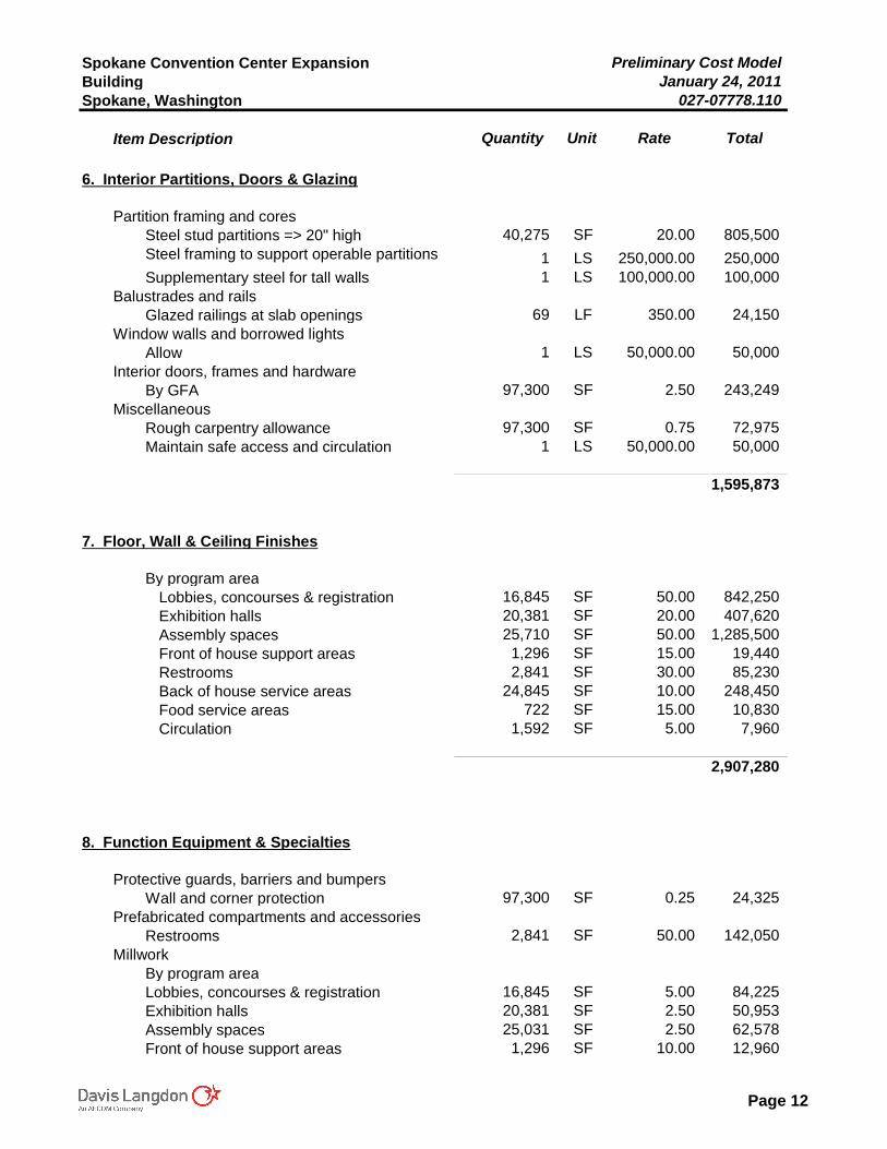
Spokane Convention Center Expansion Preliminary Cost ModelBuilding January 24, 2011Spokane, Washington 027-07778.110
Item Description Quantity Unit Rate Total
6. Interior Partitions, Doors & Glazing
Partition framing and coresSteel stud partitions => 20" high 40,275 SF 20.00 805,500Steel framing to support operable partitions 1 LS 250,000.00 250,000Supplementary steel for tall walls 1 LS 100,000.00 100,000
Balustrades and railsGlazed railings at slab openings 69 LF 350.00 24,150
Window walls and borrowed lightsAllow 1 LS 50,000.00 50,000
Interior doors, frames and hardwareBy GFA 97,300 SF 2.50 243,249
MiscellaneousRough carpentry allowance 97,300 SF 0.75 72,975Maintain safe access and circulation 1 LS 50,000.00 50,000
1,595,873
7. Floor, Wall & Ceiling Finishes
By program areaLobbies, concourses & registration 16,845 SF 50.00 842,250Exhibition halls 20,381 SF 20.00 407,620Assembly spaces 25,710 SF 50.00 1,285,500Front of house support areas 1,296 SF 15.00 19,440Restrooms 2,841 SF 30.00 85,230Back of house service areas 24,845 SF 10.00 248,450Food service areas 722 SF 15.00 10,830Circulation 1,592 SF 5.00 7,960
2,907,280
8. Function Equipment & Specialties
Protective guards, barriers and bumpersWall and corner protection 97,300 SF 0.25 24,325
Prefabricated compartments and accessoriesRestrooms 2,841 SF 50.00 142,050
MillworkBy program areaLobbies, concourses & registration 16,845 SF 5.00 84,225Exhibition halls 20,381 SF 2.50 50,953Assembly spaces 25,031 SF 2.50 62,578Front of house support areas 1,296 SF 10.00 12,960
Page 12
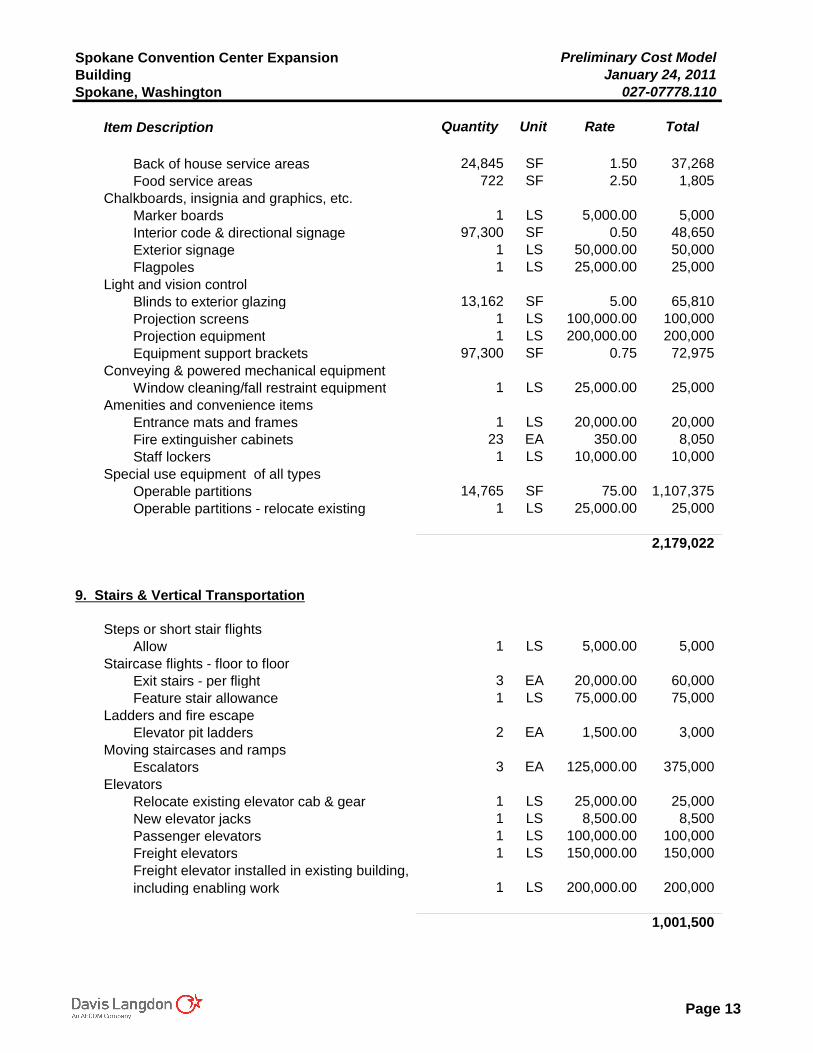
Spokane Convention Center Expansion Preliminary Cost ModelBuilding January 24, 2011Spokane, Washington 027-07778.110
Item Description Quantity Unit Rate Total
Back of house service areas 24,845 SF 1.50 37,268Food service areas 722 SF 2.50 1,805
Chalkboards, insignia and graphics, etc.Marker boards 1 LS 5,000.00 5,000Interior code & directional signage 97,300 SF 0.50 48,650Exterior signage 1 LS 50,000.00 50,000Flagpoles 1 LS 25,000.00 25,000
Light and vision controlBlinds to exterior glazing 13,162 SF 5.00 65,810Projection screens 1 LS 100,000.00 100,000Projection equipment 1 LS 200,000.00 200,000Equipment support brackets 97,300 SF 0.75 72,975
Conveying & powered mechanical equipmentWindow cleaning/fall restraint equipment 1 LS 25,000.00 25,000
Amenities and convenience itemsEntrance mats and frames 1 LS 20,000.00 20,000Fire extinguisher cabinets 23 EA 350.00 8,050Staff lockers 1 LS 10,000.00 10,000
Special use equipment of all typesOperable partitions 14,765 SF 75.00 1,107,375Operable partitions - relocate existing 1 LS 25,000.00 25,000
2,179,022
9. Stairs & Vertical Transportation
Steps or short stair flightsAllow 1 LS 5,000.00 5,000
Staircase flights - floor to floorExit stairs - per flight 3 EA 20,000.00 60,000Feature stair allowance 1 LS 75,000.00 75,000
Ladders and fire escapeElevator pit ladders 2 EA 1,500.00 3,000
Moving staircases and rampsEscalators 3 EA 125,000.00 375,000
ElevatorsRelocate existing elevator cab & gear 1 LS 25,000.00 25,000New elevator jacks 1 LS 8,500.00 8,500Passenger elevators 1 LS 100,000.00 100,000Freight elevators 1 LS 150,000.00 150,000Freight elevator installed in existing building, including enabling work 1 LS 200,000.00 200,000
1,001,500
Page 13
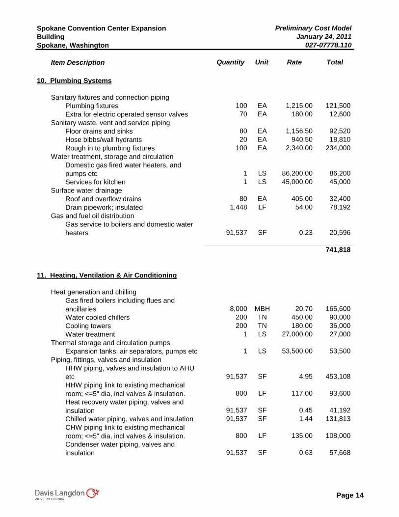
Spokane Convention Center Expansion Preliminary Cost ModelBuilding January 24, 2011Spokane, Washington 027-07778.110
Item Description Quantity Unit Rate Total
10. Plumbing Systems
Sanitary fixtures and connection pipingPlumbing fixtures 100 EA 1,215.00 121,500Extra for electric operated sensor valves 70 EA 180.00 12,600
Sanitary waste, vent and service pipingFloor drains and sinks 80 EA 1,156.50 92,520Hose bibbs/wall hydrants 20 EA 940.50 18,810Rough in to plumbing fixtures 100 EA 2,340.00 234,000
Water treatment, storage and circulationDomestic gas fired water heaters, and pumps etc 1 LS 86,200.00 86,200Services for kitchen 1 LS 45,000.00 45,000
Surface water drainageRoof and overflow drains 80 EA 405.00 32,400Drain pipework; insulated 1,448 LF 54.00 78,192
Gas and fuel oil distributionGas service to boilers and domestic water heaters 91,537 SF 0.23 20,596
741,818
11. Heating, Ventilation & Air Conditioning
Heat generation and chillingGas fired boilers including flues and ancillaries 8,000 MBH 20.70 165,600Water cooled chillers 200 TN 450.00 90,000Cooling towers 200 TN 180.00 36,000Water treatment 1 LS 27,000.00 27,000
Thermal storage and circulation pumpsExpansion tanks, air separators, pumps etc 1 LS 53,500.00 53,500
Piping, fittings, valves and insulationHHW piping, valves and insulation to AHU etc 91,537 SF 4.95 453,108HHW piping link to existing mechanical room; <=5" dia, incl valves & insulation. 800 LF 117.00 93,600Heat recovery water piping, valves and insulation 91,537 SF 0.45 41,192Chilled water piping, valves and insulation 91,537 SF 1.44 131,813CHW piping link to existing mechanical room; <=5" dia, incl valves & insulation. 800 LF 135.00 108,000Condenser water piping, valves and insulation 91,537 SF 0.63 57,668
Page 14
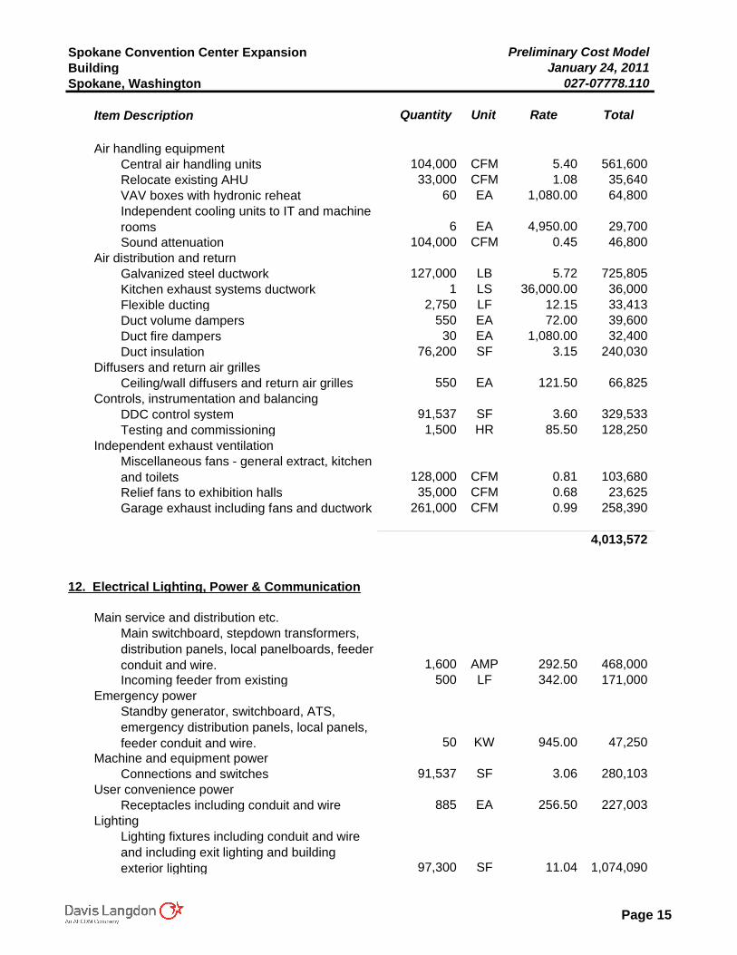
Spokane Convention Center Expansion Preliminary Cost ModelBuilding January 24, 2011Spokane, Washington 027-07778.110
Item Description Quantity Unit Rate Total
Air handling equipmentCentral air handling units 104,000 CFM 5.40 561,600Relocate existing AHU 33,000 CFM 1.08 35,640VAV boxes with hydronic reheat 60 EA 1,080.00 64,800Independent cooling units to IT and machine rooms 6 EA 4,950.00 29,700Sound attenuation 104,000 CFM 0.45 46,800
Air distribution and returnGalvanized steel ductwork 127,000 LB 5.72 725,805Kitchen exhaust systems ductwork 1 LS 36,000.00 36,000Flexible ducting 2,750 LF 12.15 33,413Duct volume dampers 550 EA 72.00 39,600Duct fire dampers 30 EA 1,080.00 32,400Duct insulation 76,200 SF 3.15 240,030
Diffusers and return air grillesCeiling/wall diffusers and return air grilles 550 EA 121.50 66,825
Controls, instrumentation and balancingDDC control system 91,537 SF 3.60 329,533Testing and commissioning 1,500 HR 85.50 128,250
Independent exhaust ventilationMiscellaneous fans - general extract, kitchen and toilets 128,000 CFM 0.81 103,680Relief fans to exhibition halls 35,000 CFM 0.68 23,625Garage exhaust including fans and ductwork 261,000 CFM 0.99 258,390
4,013,572
12. Electrical Lighting, Power & Communication
Main service and distribution etc.Main switchboard, stepdown transformers, distribution panels, local panelboards, feeder conduit and wire. 1,600 AMP 292.50 468,000Incoming feeder from existing 500 LF 342.00 171,000
Emergency powerStandby generator, switchboard, ATS, emergency distribution panels, local panels, feeder conduit and wire. 50 KW 945.00 47,250
Machine and equipment powerConnections and switches 91,537 SF 3.06 280,103
User convenience powerReceptacles including conduit and wire 885 EA 256.50 227,003
LightingLighting fixtures including conduit and wire and including exit lighting and building exterior lighting 97,300 SF 11.04 1,074,090
Page 15
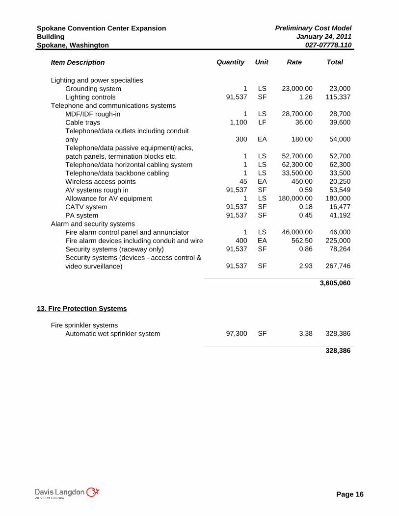
Spokane Convention Center Expansion Preliminary Cost ModelBuilding January 24, 2011Spokane, Washington 027-07778.110
Item Description Quantity Unit Rate Total
Lighting and power specialtiesGrounding system 1 LS 23,000.00 23,000Lighting controls 91,537 SF 1.26 115,337
Telephone and communications systemsMDF/IDF rough-in 1 LS 28,700.00 28,700Cable trays 1,100 LF 36.00 39,600Telephone/data outlets including conduit only 300 EA 180.00 54,000Telephone/data passive equipment(racks, patch panels, termination blocks etc. 1 LS 52,700.00 52,700Telephone/data horizontal cabling system 1 LS 62,300.00 62,300Telephone/data backbone cabling 1 LS 33,500.00 33,500Wireless access points 45 EA 450.00 20,250AV systems rough in 91,537 SF 0.59 53,549Allowance for AV equipment 1 LS 180,000.00 180,000CATV system 91,537 SF 0.18 16,477PA system 91,537 SF 0.45 41,192
Alarm and security systemsFire alarm control panel and annunciator 1 LS 46,000.00 46,000Fire alarm devices including conduit and wire 400 EA 562.50 225,000Security systems (raceway only) 91,537 SF 0.86 78,264Security systems (devices - access control & video surveillance) 91,537 SF 2.93 267,746
3,605,060
13. Fire Protection Systems
Fire sprinkler systems Automatic wet sprinkler system 97,300 SF 3.38 328,386
328,386
Page 16
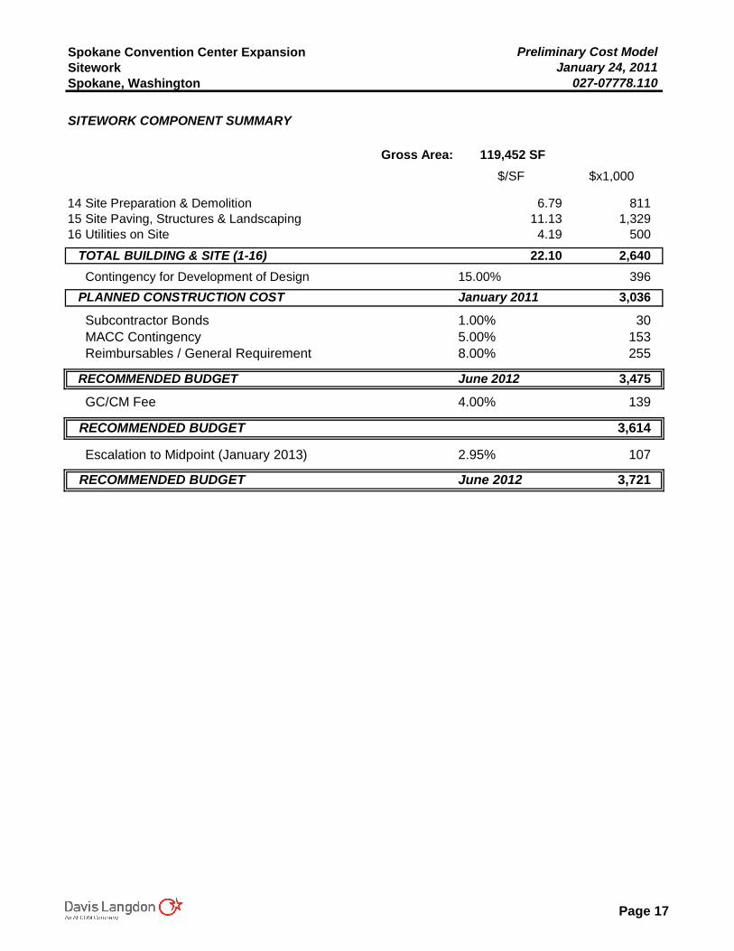
Spokane Convention Center Expansion Preliminary Cost ModelSitework January 24, 2011Spokane, Washington 027-07778.110
SITEWORK COMPONENT SUMMARY
Gross Area: 119,452 SF$/SF $x1,000
14.Site Preparation & Demolition 6.79 811 15.Site Paving, Structures & Landscaping 11.13 1,329 16.Utilities on Site 4.19 500
TOTAL BUILDING & SITE (1-16) 22.10 2,640Contingency for Development of Design 15.00% 396
PLANNED CONSTRUCTION COST January 2011 3,036
Subcontractor Bonds 1.00% 30MACC Contingency 5.00% 153Reimbursables / General Requirement 8.00% 255
RECOMMENDED BUDGET June 2012 3,475
GC/CM Fee 4.00% 139
RECOMMENDED BUDGET 3,614
Escalation to Midpoint (January 2013) 2.95% 107
RECOMMENDED BUDGET June 2012 3,721
Page 17
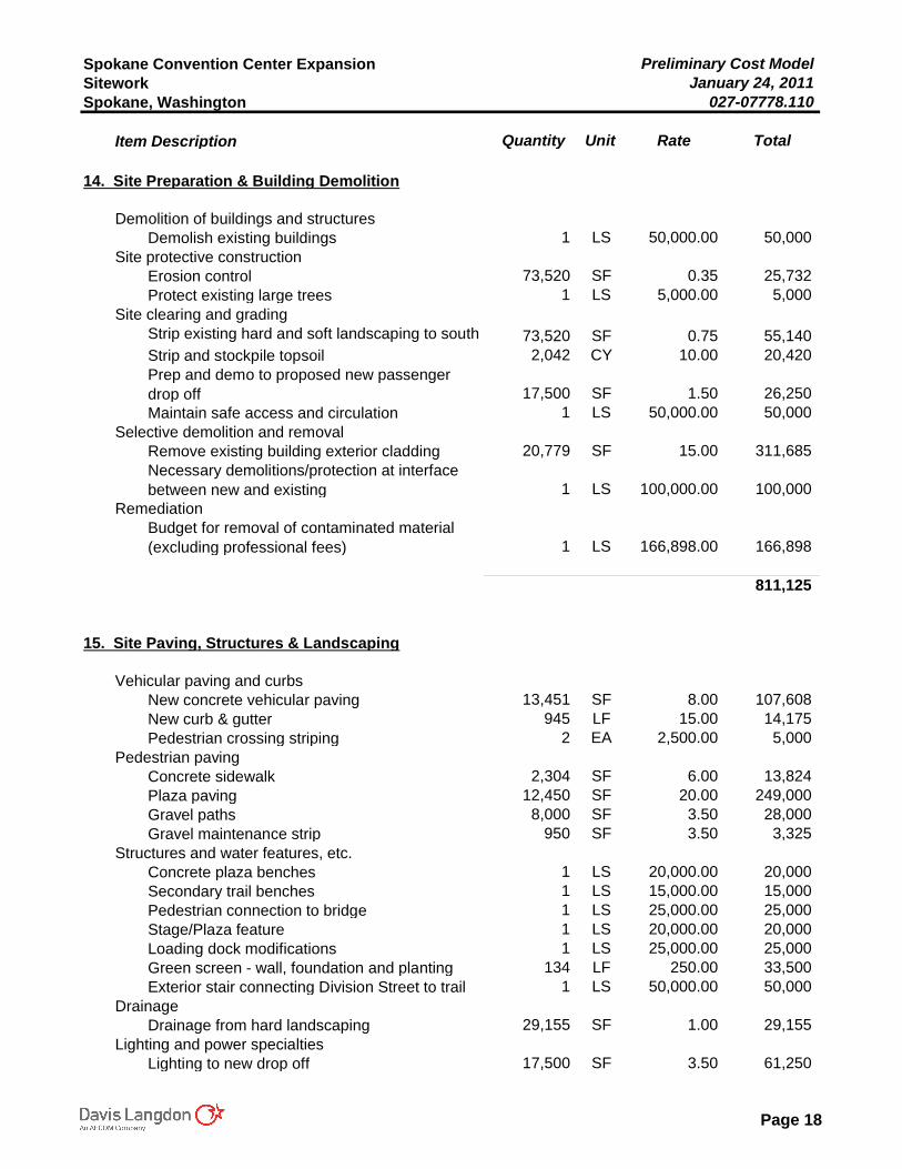
Spokane Convention Center Expansion Preliminary Cost ModelSitework January 24, 2011Spokane, Washington 027-07778.110
Item Description Quantity Unit Rate Total
14. Site Preparation & Building Demolition
Demolition of buildings and structuresDemolish existing buildings 1 LS 50,000.00 50,000
Site protective construction Erosion control 73,520 SF 0.35 25,732Protect existing large trees 1 LS 5,000.00 5,000
Site clearing and gradingStrip existing hard and soft landscaping to south 73,520 SF 0.75 55,140Strip and stockpile topsoil 2,042 CY 10.00 20,420Prep and demo to proposed new passenger drop off 17,500 SF 1.50 26,250Maintain safe access and circulation 1 LS 50,000.00 50,000
Selective demolition and removalRemove existing building exterior cladding 20,779 SF 15.00 311,685Necessary demolitions/protection at interface between new and existing 1 LS 100,000.00 100,000
RemediationBudget for removal of contaminated material (excluding professional fees) 1 LS 166,898.00 166,898
811,125
15. Site Paving, Structures & Landscaping
Vehicular paving and curbsNew concrete vehicular paving 13,451 SF 8.00 107,608New curb & gutter 945 LF 15.00 14,175Pedestrian crossing striping 2 EA 2,500.00 5,000
Pedestrian pavingConcrete sidewalk 2,304 SF 6.00 13,824Plaza paving 12,450 SF 20.00 249,000Gravel paths 8,000 SF 3.50 28,000Gravel maintenance strip 950 SF 3.50 3,325
Structures and water features, etc.Concrete plaza benches 1 LS 20,000.00 20,000Secondary trail benches 1 LS 15,000.00 15,000Pedestrian connection to bridge 1 LS 25,000.00 25,000Stage/Plaza feature 1 LS 20,000.00 20,000Loading dock modifications 1 LS 25,000.00 25,000Green screen - wall, foundation and planting 134 LF 250.00 33,500Exterior stair connecting Division Street to trail 1 LS 50,000.00 50,000
DrainageDrainage from hard landscaping 29,155 SF 1.00 29,155
Lighting and power specialtiesLighting to new drop off 17,500 SF 3.50 61,250
Page 18
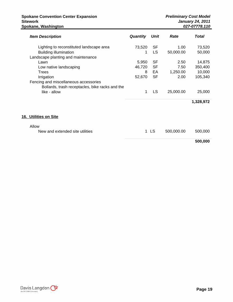
Spokane Convention Center Expansion Preliminary Cost ModelSitework January 24, 2011Spokane, Washington 027-07778.110
Item Description Quantity Unit Rate Total
Lighting to reconstituted landscape area 73,520 SF 1.00 73,520Building illumination 1 LS 50,000.00 50,000
Landscape planting and maintenanceLawn 5,950 SF 2.50 14,875Low native landscaping 46,720 SF 7.50 350,400Trees 8 EA 1,250.00 10,000Irrigation 52,670 SF 2.00 105,340
Fencing and miscellaneous accessoriesBollards, trash receptacles, bike racks and the like - allow 1 LS 25,000.00 25,000
1,328,972
16. Utilities on Site
AllowNew and extended site utilities 1 LS 500,000.00 500,000
500,000
Page 19
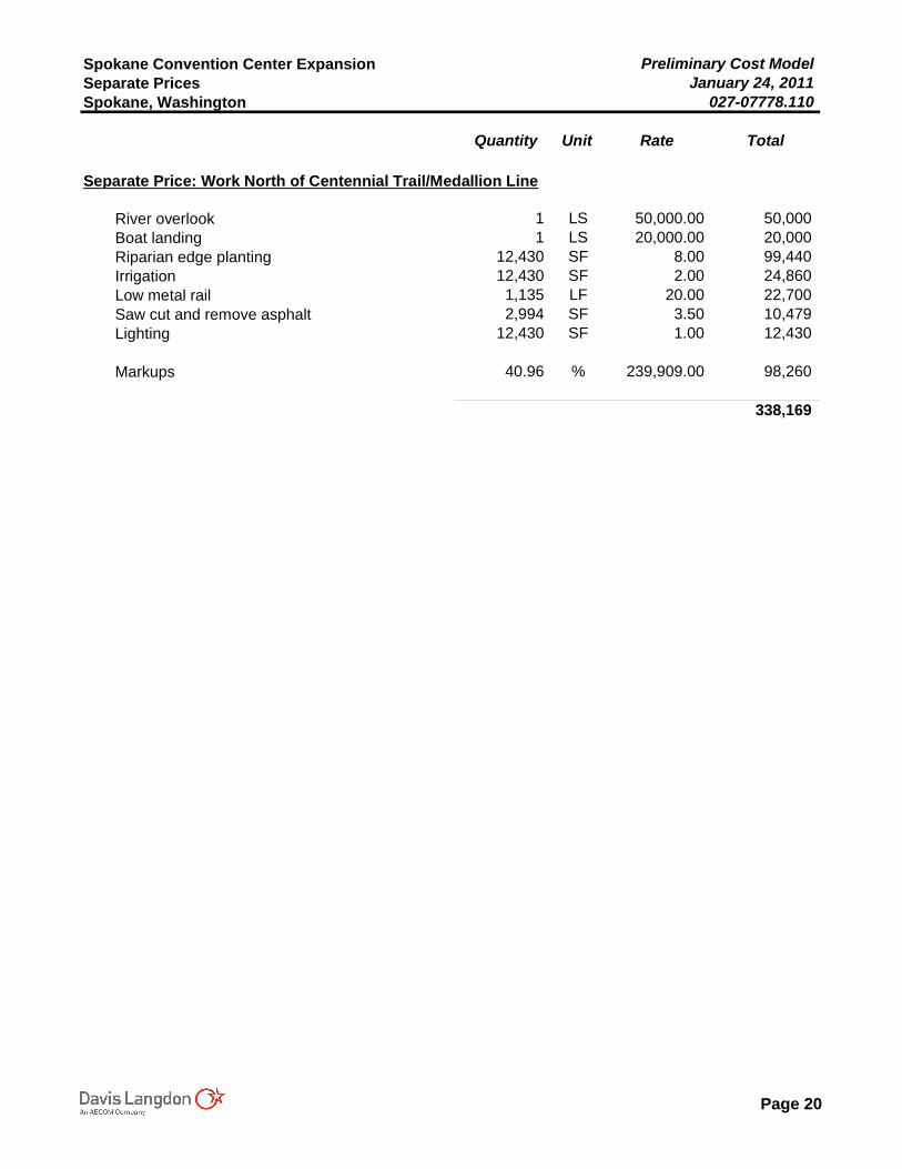
Spokane Convention Center Expansion Preliminary Cost ModelSeparate Prices January 24, 2011Spokane, Washington 027-07778.110
Quantity Unit Rate Total
Separate Price: Work North of Centennial Trail/Medallion Line
River overlook 1 LS 50,000.00 50,000Boat landing 1 LS 20,000.00 20,000Riparian edge planting 12,430 SF 8.00 99,440Irrigation 12,430 SF 2.00 24,860Low metal rail 1,135 LF 20.00 22,700Saw cut and remove asphalt 2,994 SF 3.50 10,479Lighting 12,430 SF 1.00 12,430
Markups 40.96 % 239,909.00 98,260
338,169
Page 20
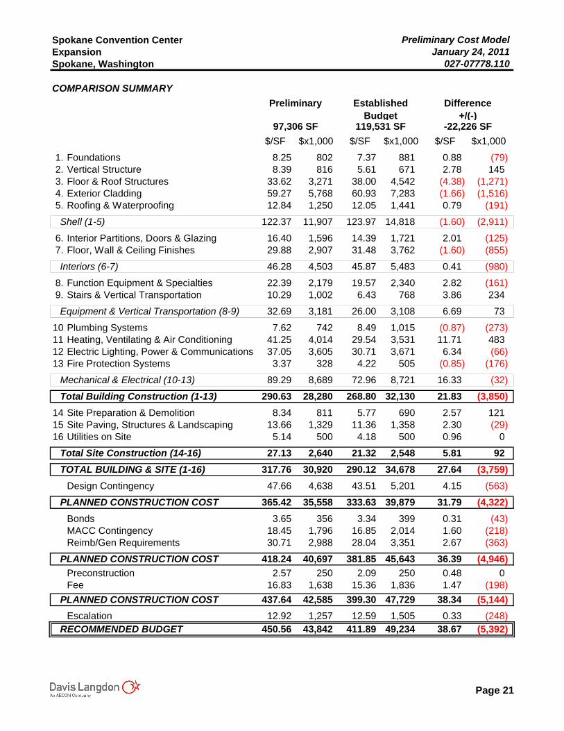
Spokane Convention Center Preliminary Cost ModelExpansion January 24, 2011Spokane, Washington 027-07778.110
COMPARISON SUMMARYPreliminary Established
BudgetDifference
+/(-)
$/SF $x1,000 $/SF $x1,000 $/SF $x1,000
1. Foundations 8.25 802 7.37 881 0.88 (79) 2. Vertical Structure 8.39 816 5.61 671 2.78 145 3. Floor & Roof Structures 33.62 3,271 38.00 4,542 (4.38) (1,271) 4. Exterior Cladding 59.27 5,768 60.93 7,283 (1.66) (1,516) 5. Roofing & Waterproofing 12.84 1,250 12.05 1,441 0.79 (191)
Shell (1-5) 122.37 11,907 123.97 14,818 (1.60) (2,911)
6. Interior Partitions, Doors & Glazing 16.40 1,596 14.39 1,721 2.01 (125) 7. Floor, Wall & Ceiling Finishes 29.88 2,907 31.48 3,762 (1.60) (855)
Interiors (6-7) 46.28 4,503 45.87 5,483 0.41 (980)
8. Function Equipment & Specialties 22.39 2,179 19.57 2,340 2.82 (161) 9. Stairs & Vertical Transportation 10.29 1,002 6.43 768 3.86 234
Equipment & Vertical Transportation (8-9) 32.69 3,181 26.00 3,108 6.69 73
10.Plumbing Systems 7.62 742 8.49 1,015 (0.87) (273) 11.Heating, Ventilating & Air Conditioning 41.25 4,014 29.54 3,531 11.71 483 12.Electric Lighting, Power & Communications 37.05 3,605 30.71 3,671 6.34 (66) 13.Fire Protection Systems 3.37 328 4.22 505 (0.85) (176)
Mechanical & Electrical (10-13) 89.29 8,689 72.96 8,721 16.33 (32)
Total Building Construction (1-13) 290.63 28,280 268.80 32,130 21.83 (3,850) 14.Site Preparation & Demolition 8.34 811 5.77 690 2.57 121 15.Site Paving, Structures & Landscaping 13.66 1,329 11.36 1,358 2.30 (29) 16.Utilities on Site 5.14 500 4.18 500 0.96 0
Total Site Construction (14-16) 27.13 2,640 21.32 2,548 5.81 92 TOTAL BUILDING & SITE (1-16) 317.76 30,920 290.12 34,678 27.64 (3,759)
Design Contingency 47.66 4,638 43.51 5,201 4.15 (563)
PLANNED CONSTRUCTION COST 365.42 35,558 333.63 39,879 31.79 (4,322)Bonds 3.65 356 3.34 399 0.31 (43)MACC Contingency 18.45 1,796 16.85 2,014 1.60 (218)Reimb/Gen Requirements 30.71 2,988 28.04 3,351 2.67 (363)
PLANNED CONSTRUCTION COST 418.24 40,697 381.85 45,643 36.39 (4,946)Preconstruction 2.57 250 2.09 250 0.48 0Fee 16.83 1,638 15.36 1,836 1.47 (198)
PLANNED CONSTRUCTION COST 437.64 42,585 399.30 47,729 38.34 (5,144)Escalation 12.92 1,257 12.59 1,505 0.33 (248)
RECOMMENDED BUDGET 450.56 43,842 411.89 49,234 38.67 (5,392)
119,531 SF97,306 SF -22,226 SF
Page 21


801 Second Avenue, Suite 501 Seattle, Washington 98104
T 206 682 3460 F 206 343 9388
www.lmnarchitects.com
203 N Washington, Suite 400 Spokane, Washington 99201
T 509 838 8568 F 509 458 3710
www.alscarchitects.com
Related Documents