CONTROLS Division of A-T Controls, Inc. ® THD Pneumatic Actuators for Quarter-Turn Valves and Dampers Torques to 1,600,000 In-lbs Double Acting and Spring Return Symmetric and Canted Yoke Design See www.atcontrols.com for Canted Yoke product specifications Heavy Duty Actuators Series

Welcome message from author
This document is posted to help you gain knowledge. Please leave a comment to let me know what you think about it! Share it to your friends and learn new things together.
Transcript

1
CONTROLSDivision of A-T Controls, Inc.
®
THD
Pneumatic Actuatorsfor Quarter-Turn Valvesand Dampers
Torques to 1,600,000 In-lbs
Double Acting and Spring Return
Symmetric and Canted Yoke Design See www.atcontrols.com for Canted Yoke product specifications
Hea
vy D
uty
Act
uato
rs
Series
2
THDS E R I E S
7
8
2
34
12
51
6
11
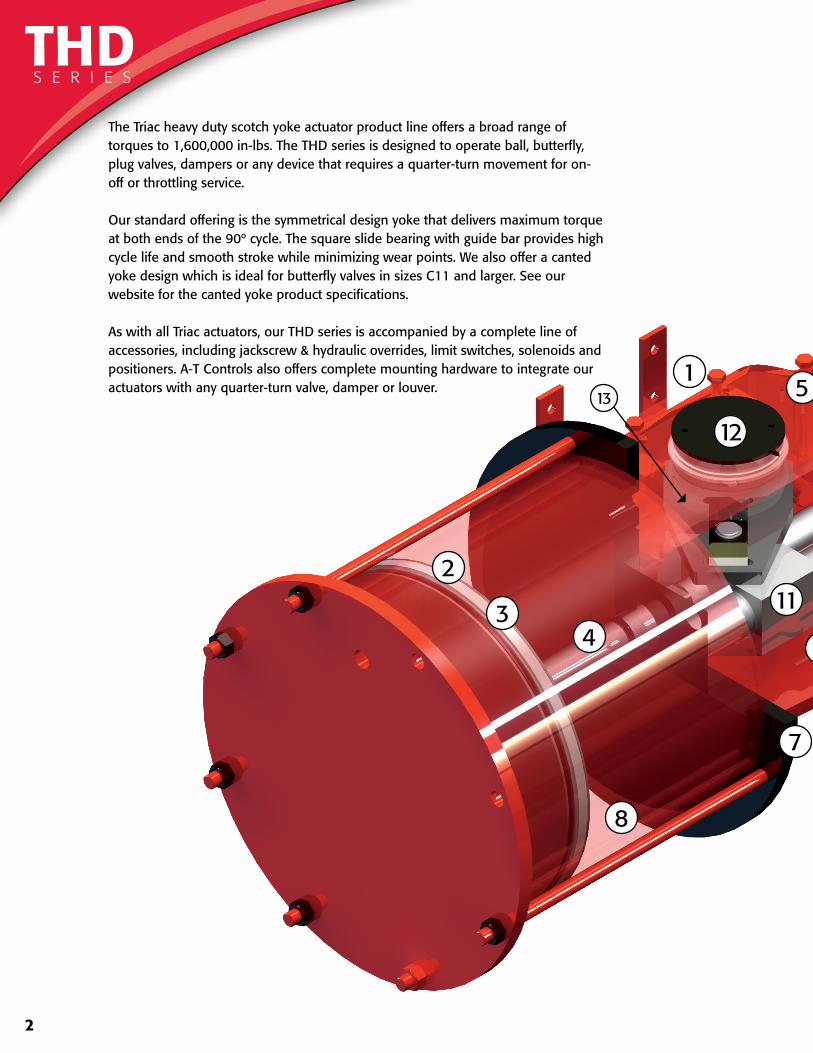
The Triac heavy duty scotch yoke actuator product line offers a broad range of torques to 1,600,000 in-lbs. The THD series is designed to operate ball, butterfly, plug valves, dampers or any device that requires a quarter-turn movement for on-off or throttling service.
Our standard offering is the symmetrical design yoke that delivers maximum torque at both ends of the 90º cycle. The square slide bearing with guide bar provides high cycle life and smooth stroke while minimizing wear points. We also offer a canted yoke design which is ideal for butterfly valves in sizes C11 and larger. See our website for the canted yoke product specifications.
As with all Triac actuators, our THD series is accompanied by a complete line of accessories, including jackscrew & hydraulic overrides, limit switches, solenoids and positioners. A-T Controls also offers complete mounting hardware to integrate our actuators with any quarter-turn valve, damper or louver.
13
3
10
7
7
5
6
9
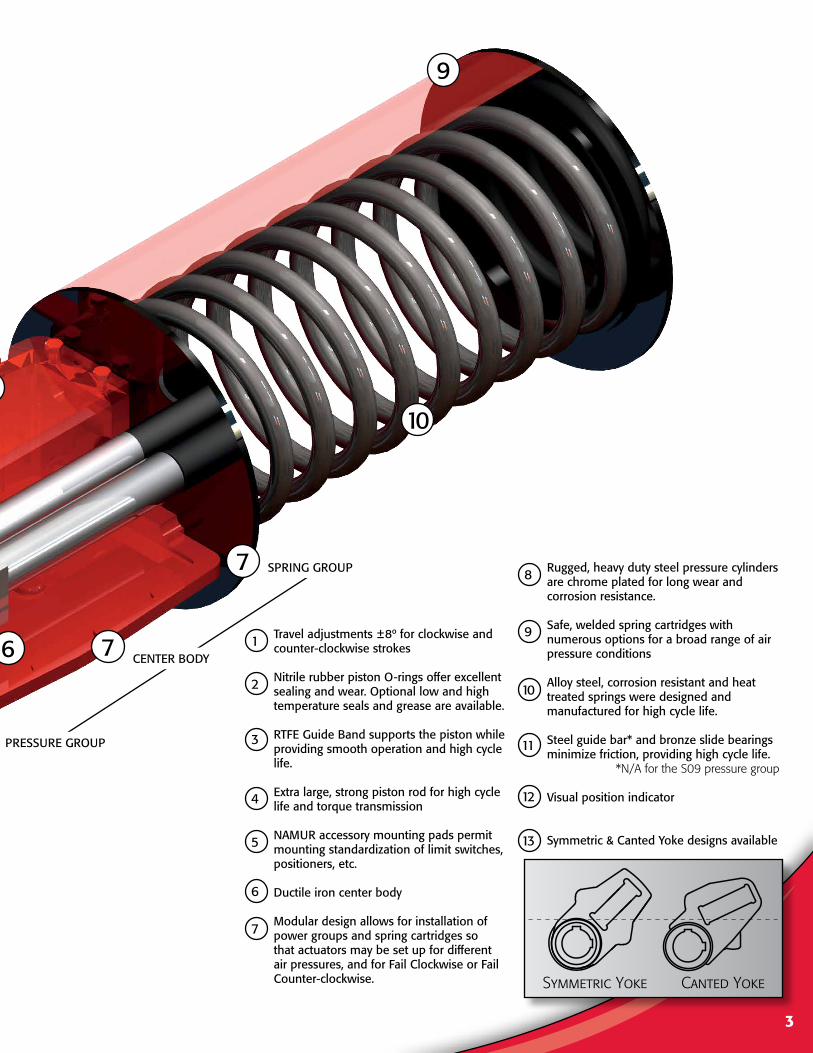
SPRING GROUP
CENTER BODY
PRESSURE GROUP
10
11
12
9
8
1
2
3
4
5
6
7
Travel adjustments ±8º for clockwise and counter-clockwise strokes
Nitrile rubber piston O-rings offer excellent sealing and wear. Optional low and high temperature seals and grease are available.
RTFE Guide Band supports the piston while providing smooth operation and high cycle life.
Extra large, strong piston rod for high cycle life and torque transmission
NAMUR accessory mounting pads permit mounting standardization of limit switches, positioners, etc.
Ductile iron center body
Modular design allows for installation of power groups and spring cartridges so that actuators may be set up for different air pressures, and for Fail Clockwise or Fail Counter-clockwise.
Rugged, heavy duty steel pressure cylinders are chrome plated for long wear and corrosion resistance.
Safe, welded spring cartridges with numerous options for a broad range of air pressure conditions
Alloy steel, corrosion resistant and heat treated springs were designed and manufactured for high cycle life.
Steel guide bar* and bronze slide bearings minimize friction, providing high cycle life.
* N/A for the S09 pressure group
Visual position indicator
Symmetric & Canted Yoke designs available
Symmetric Yoke Canted Yoke
13
4
TORQUE OUT PUT IN-LBS
MODELNUMBER
40 PSI 60 PSI 80 PSI 100 PSIMOP* MAWP**
SWEPT VOLUME
CU. IN. ***
WEIGHTLBSStart Min Start Min Start Min Start Min
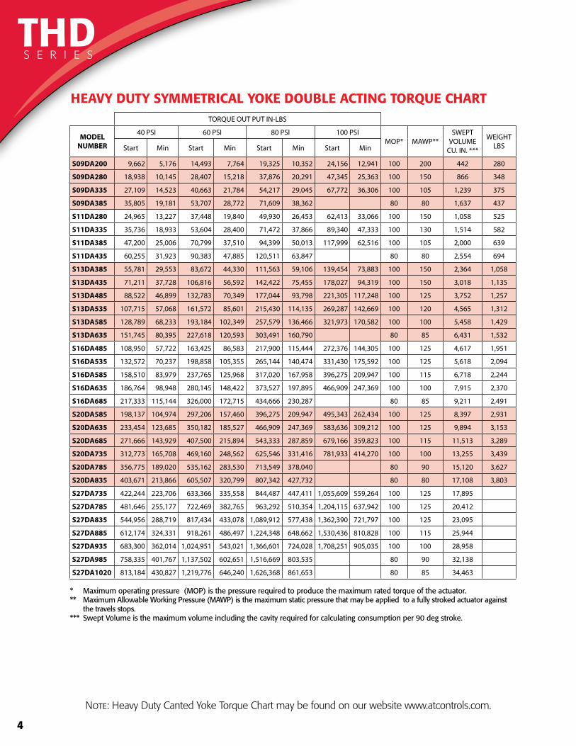
S09DA200 9,662 5,176 14,493 7,764 19,325 10,352 24,156 12,941 100 200 442 280
S09DA280 18,938 10,145 28,407 15,218 37,876 20,291 47,345 25,363 100 150 866 348
S09DA335 27,109 14,523 40,663 21,784 54,217 29,045 67,772 36,306 100 105 1,239 375
S09DA385 35,805 19,181 53,707 28,772 71,609 38,362 80 80 1,637 437
S11DA280 24,965 13,227 37,448 19,840 49,930 26,453 62,413 33,066 100 150 1,058 525
S11DA335 35,736 18,933 53,604 28,400 71,472 37,866 89,340 47,333 100 130 1,514 582
S11DA385 47,200 25,006 70,799 37,510 94,399 50,013 117,999 62,516 100 105 2,000 639
S11DA435 60,255 31,923 90,383 47,885 120,511 63,847 80 80 2,554 694
S13DA385 55,781 29,553 83,672 44,330 111,563 59,106 139,454 73,883 100 150 2,364 1,058
S13DA435 71,211 37,728 106,816 56,592 142,422 75,455 178,027 94,319 100 150 3,018 1,135
S13DA485 88,522 46,899 132,783 70,349 177,044 93,798 221,305 117,248 100 125 3,752 1,257
S13DA535 107,715 57,068 161,572 85,601 215,430 114,135 269,287 142,669 100 120 4,565 1,312
S13DA585 128,789 68,233 193,184 102,349 257,579 136,466 321,973 170,582 100 100 5,458 1,429
S13DA635 151,745 80,395 227,618 120,593 303,491 160,790 80 85 6,431 1,532
S16DA485 108,950 57,722 163,425 86,583 217,900 115,444 272,376 144,305 100 125 4,617 1,951
S16DA535 132,572 70,237 198,858 105,355 265,144 140,474 331,430 175,592 100 125 5,618 2,094
S16DA585 158,510 83,979 237,765 125,968 317,020 167,958 396,275 209,947 100 115 6,718 2,244
S16DA635 186,764 98,948 280,145 148,422 373,527 197,895 466,909 247,369 100 100 7,915 2,370
S16DA685 217,333 115,144 326,000 172,715 434,666 230,287 80 85 9,211 2,491
S20DA585 198,137 104,974 297,206 157,460 396,275 209,947 495,343 262,434 100 125 8,397 2,931
S20DA635 233,454 123,685 350,182 185,527 466,909 247,369 583,636 309,212 100 125 9,894 3,153
S20DA685 271,666 143,929 407,500 215,894 543,333 287,859 679,166 359,823 100 115 11,513 3,289
S20DA735 312,773 165,708 469,160 248,562 625,546 331,416 781,933 414,270 100 100 13,255 3,439
S20DA785 356,775 189,020 535,162 283,530 713,549 378,040 80 90 15,120 3,627
S20DA835 403,671 213,866 605,507 320,799 807,342 427,732 80 80 17,108 3,803
S27DA735 422,244 223,706 633,366 335,558 844,487 447,411 1,055,609 559,264 100 125 17,895
S27DA785 481,646 255,177 722,469 382,765 963,292 510,354 1,204,115 637,942 100 125 20,412
S27DA835 544,956 288,719 817,434 433,078 1,089,912 577,438 1,362,390 721,797 100 125 23,095
S27DA885 612,174 324,331 918,261 486,497 1,224,348 648,662 1,530,436 810,828 100 115 25,944
S27DA935 683,300 362,014 1,024,951 543,021 1,366,601 724,028 1,708,251 905,035 100 100 28,958
S27DA985 758,335 401,767 1,137,502 602,651 1,516,669 803,535 80 90 32,138
S27DA1020 813,184 430,827 1,219,776 646,240 1,626,368 861,653 80 85 34,463
* Maximum operating pressure (MOP) is the pressure required to produce the maximum rated torque of the actuator. ** Maximum Allowable Working Pressure (MAWP) is the maximum static pressure that may be applied to a fully stroked actuator against the travels stops.*** Swept Volume is the maximum volume including the cavity required for calculating consumption per 90 deg stroke.
HEAVY DUTY SYMMETRICAL YOKE DOUBLE ACTING TORQUE CHART
THDS E R I E S
Note: Heavy Duty Canted Yoke Torque Chart may be found on our website www.atcontrols.com.

5
TORQUE OUTPUT IN-LBS
MODEL SPRING CODE SPRING 40 PSI 60 PSI 80 PSI 100 PSI MOP* MAWP** SWEPT VOLUME
CU. IN. ***WEIGHT
LBS
S09SR200 AA START 6,307 5,991 10,823 15,654 20,485 100 200 442 390
MIN 2,368 2,289 4,780 7,271 9,761END 3,671 3,355 8,186 13,017 17,848
AB START 9,971 8,987 13,818 18,649 100 200 442 401MIN 3,645 3,279 5,770 8,261END 5,506 4,523 9,354 14,185
AC START 12,615 7,152 11,983 16,814 100 200 442 406MIN 4,737 2,088 4,579 7,069END 7,342 1,879 6,710 11,541
AD START 15,681 10,147 14,978 100 200 442 434MIN 5,905 3,259 5,750END 9,177 3,644 8,475
AE START 17,686 9,021 13,852 100 200 442 419MIN 6,644 2,412 4,903END 10,303 1,639 6,470
AF START 18,704 13,361 100 200 442 419MIN 6,993 4,490END 10,794 5,452
S09SR280 AB START 9,971 13,432 22,901 32,370 41,839 100 150 866 470MIN 3,645 4,612 10,453 15,334 20,216END 5,506 5,803 18,436 27,905 37,374
AC START 12,615 11,596 21,065 30,534 40,003 100 150 866 474MIN 4,737 4,379 9,261 14,143 19,025END 7,342 6,323 15,792 25,261 34,730
AD START 15,681 9,761 19,230 28,699 38,168 100 150 866 503MIN 5,905 3,060 7,942 12,824 17,705END 9,177 3,257 12,726 22,195 31,664
AE START 17,686 8,635 18,104 27,573 37,042 100 150 866 487MIN 6,644 2,213 7,095 11,977 16,858END 10,303 1,252 10,721 20,190 29,659
AF START 18,704 17,613 27,082 36,551 100 150 866 487MIN 6,993 6,682 11,563 16,445END 10,794 9,703 19,172 28,641
AG START 24,585 23,485 32,954 100 150 866 496MIN 9,259 9,016 13,898END 14,391 13,291 22,760
AH START 30,643 19,889 29,358 100 150 866 525MIN 11,557 6,416 11,298END 17,987 7,233 16,702
AJ START 35,015 26,744 100 150 866 525MIN 13,223 9,417END 20,601 12,330
AK START 43,860 21,589 100 150 866 538MIN 16,546 5,641END 25,756 3,485
* Maximum operating pressure (MOP) is the pressure required to produce the maximum rated torque of the actuator. ** Maximum Allowable Working Pressure (MAWP) is the maximum static pressure that may be applied to a fully stroked actuator against the travels stops.*** Swept Volume is the maximum volume including the cavity required for calculating consumption per 90 deg stroke.
HEAVY DUTY SYMMETRICAL YOKE SPRING RETURN TORQUE CHART
S09T H D S E R I E S
Note: Heavy Duty Canted Yoke Torque Chart may be found on our website www.atcontrols.com.
6
TORQUE OUTPUT IN-LBS
MODEL SPRING CODE SPRING 40 PSI 60 PSI 80 PSI 100 PSI MOP* MAWP** SWEPT VOLUME
CU. IN. ***WEIGHT
LBS
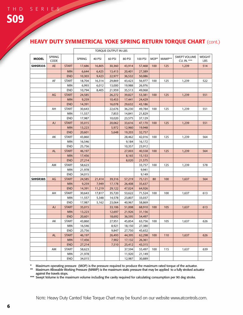
S09SR335 AE START 17,686 16,805 30,360 43,914 57,468 100 125 1,239 514
MIN 6,644 6,425 13,413 20,401 27,389END 10,303 9,423 22,977 36,532 50,086
AF START 18,704 16,314 29,869 43,423 56,977 100 125 1,239 522MIN 6,993 6,012 13,000 19,988 26,976END 10,794 8,405 21,959 35,513 49,068
AG START 24,585 26,272 39,827 53,381 100 125 1,239 551MIN 9,259 10,453 17,441 24,429END 14,391 16,078 29,632 43,186
AH START 30,643 22,676 36,230 49,784 100 125 1,239 551MIN 11,557 7,853 14,841 21,829END 17,987 10,020 23,575 37,129
AJ START 35,015 20,062 33,616 47,170 100 125 1,239 551MIN 13,223 5,972 12,960 19,948END 20,601 5,648 19,203 32,757
AK START 43,860 28,462 42,016 100 125 1,239 564MIN 16,546 9,184 16,172END 25,756 10,357 23,912
AL START 46,197 27,003 40,558 100 125 1,239 564MIN 17,456 8,165 15,153END 27,214 8,020 21,575
AM START 58,623 33,757 100 125 1,239 578MIN 21,978 9,941END 34,015 9,149
S09SR385 AG START 24,585 21,414 39,316 57,219 75,121 80 100 1,637 564MIN 9,259 7,949 17,178 26,408 35,637END 14,391 11,219 29,122 47,024 64,926
AH START 30,643 17,817 35,720 53,622 71,524 100 100 1,637 613MIN 11,557 5,348 14,578 23,807 33,037END 17,987 5,162 23,064 40,967 58,869
AJ START 35,015 33,106 51,008 68,910 100 105 1,637 613MIN 13,223 12,697 21,926 31,156END 20,601 18,692 36,595 54,497
AK START 43,860 27,951 45,854 63,756 100 105 1,637 626MIN 16,546 8,921 18,150 27,380END 25,756 9,847 27,750 45,652
AL START 46,197 26,493 44,395 62,298 100 110 1,637 626MIN 17,456 7,902 17,132 26,361END 27,214 7,510 25,412 43,315
AM START 58,623 37,594 55,497 100 115 1,637 639MIN 21,978 11,920 21,149END 34,015 12,987 30,889
* Maximum operating pressure (MOP) is the pressure required to produce the maximum rated torque of the actuator. ** Maximum Allowable Working Pressure (MAWP) is the maximum static pressure that may be applied to a fully stroked actuator against the travels stops.*** Swept Volume is the maximum volume including the cavity required for calculating consumption per 90 deg stroke.
HEAVY DUTY SYMMETRICAL YOKE SPRING RETURN TORQUE CHART (cont.)
S09T H D S E R I E S
Note: Heavy Duty Canted Yoke Torque Chart may be found on our website www.atcontrols.com.

7
S11T H D S E R I E S
TORQUE OUTPUT IN-LBS
MODEL SPRING CODE SPRING 40 PSI 60 PSI 80 PSI 100 PSI MOP* MAWP** SWEPT VOLUME
CU. IN. ***WEIGHT
LBS
S11SR280 BA START 16,279 15,483 27,966 40,448 52,931 100 150 1,058 827
MIN 6,318 6,117 12,766 19,414 26,063END 9,482 8,686 21,169 33,651 46,134
BB START 23,205 11,389 23,872 36,355 48,837 100 150 1,058 838MIN 9,026 3,050 9,698 16,347 22,995END 13,576 1,761 14,243 26,726 39,208
BC START 30,681 19,510 31,993 44,475 100 150 1,058 884MIN 11,930 6,399 13,048 19,696END 17,937 6,766 19,249 31,731
BD START 35,097 17,078 29,560 42,043 100 150 1,058 884MIN 13,596 4,483 11,131 17,779END 20,370 2,351 14,834 27,316
BE START 39,320 27,036 39,518 100 150 1,058 983MIN 15,257 9,254 15,903END 22,894 10,610 23,093
BF START 47,010 23,027 35,510 100 150 1,058 983MIN 18,078 5,966 12,614END 26,903 2,920 15,403
BG START 61,073 26,544 100 150 1,058 999MIN 23,804 6,242END 35,868 1,340
S11SR335 BB START 23,205 22,160 40,028 57,896 75,765 100 150 1,514 895MIN 9,026 8,787 18,303 27,820 37,337END 13,576 12,532 30,400 48,268 66,136
BC START 30,681 17,799 35,667 53,535 71,403 100 150 1,514 941MIN 11,930 5,488 15,004 24,521 34,038END 17,937 5,055 22,923 40,791 58,659
BD START 35,097 33,234 51,102 68,970 100 150 1,514 941MIN 13,596 13,088 22,605 32,121END 20,370 18,508 36,376 54,244
BE START 39,320 30,710 48,578 66,446 100 150 1,514 1,041MIN 15,257 11,211 20,728 30,245END 22,894 14,284 32,152 50,020
BF START 47,010 26,701 44,569 62,437 100 150 1,514 1,041MIN 18,078 7,923 17,439 26,956END 26,903 6,594 24,462 42,330
BG START 61,073 35,604 53,472 100 150 1,514 1,056MIN 23,804 11,067 20,584END 35,868 10,399 28,267
BH START 77,797 43,545 100 150 1,514 1,074MIN 30,359 13,168END 45,795 11,543
* Maximum operating pressure (MOP) is the pressure required to produce the maximum rated torque of the actuator. ** Maximum Allowable Working Pressure (MAWP) is the maximum static pressure that may be applied to a fully stroked actuator against the travels stops.*** Swept Volume is the maximum volume including the cavity required for calculating consumption per 90 deg stroke.
HEAVY DUTY SYMMETRICAL YOKE SPRING RETURN TORQUE CHART
Note: Heavy Duty Canted Yoke Torque Chart may be found on our website www.atcontrols.com.
8
TORQUE OUTPUT IN-LBS
MODEL SPRING CODE SPRING 40 PSI 60 PSI 80 PSI 100 PSI MOP* MAWP** SWEPT VOLUME
CU. IN. ***WEIGHT
LBS
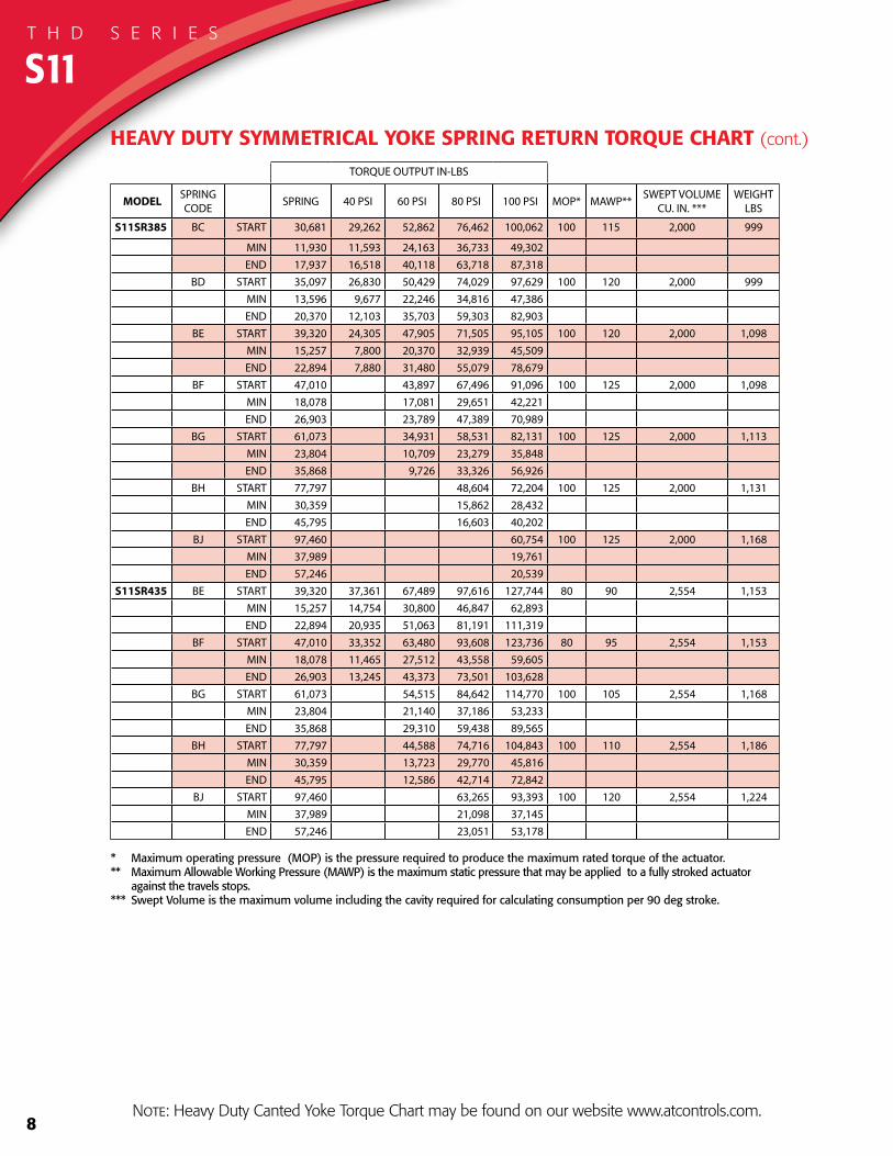
S11SR385 BC START 30,681 29,262 52,862 76,462 100,062 100 115 2,000 999
MIN 11,930 11,593 24,163 36,733 49,302END 17,937 16,518 40,118 63,718 87,318
BD START 35,097 26,830 50,429 74,029 97,629 100 120 2,000 999MIN 13,596 9,677 22,246 34,816 47,386END 20,370 12,103 35,703 59,303 82,903
BE START 39,320 24,305 47,905 71,505 95,105 100 120 2,000 1,098MIN 15,257 7,800 20,370 32,939 45,509END 22,894 7,880 31,480 55,079 78,679
BF START 47,010 43,897 67,496 91,096 100 125 2,000 1,098MIN 18,078 17,081 29,651 42,221END 26,903 23,789 47,389 70,989
BG START 61,073 34,931 58,531 82,131 100 125 2,000 1,113MIN 23,804 10,709 23,279 35,848END 35,868 9,726 33,326 56,926
BH START 77,797 48,604 72,204 100 125 2,000 1,131MIN 30,359 15,862 28,432END 45,795 16,603 40,202
BJ START 97,460 60,754 100 125 2,000 1,168MIN 37,989 19,761END 57,246 20,539
S11SR435 BE START 39,320 37,361 67,489 97,616 127,744 80 90 2,554 1,153MIN 15,257 14,754 30,800 46,847 62,893END 22,894 20,935 51,063 81,191 111,319
BF START 47,010 33,352 63,480 93,608 123,736 80 95 2,554 1,153MIN 18,078 11,465 27,512 43,558 59,605END 26,903 13,245 43,373 73,501 103,628
BG START 61,073 54,515 84,642 114,770 100 105 2,554 1,168MIN 23,804 21,140 37,186 53,233END 35,868 29,310 59,438 89,565
BH START 77,797 44,588 74,716 104,843 100 110 2,554 1,186MIN 30,359 13,723 29,770 45,816END 45,795 12,586 42,714 72,842
BJ START 97,460 63,265 93,393 100 120 2,554 1,224MIN 37,989 21,098 37,145END 57,246 23,051 53,178
* Maximum operating pressure (MOP) is the pressure required to produce the maximum rated torque of the actuator. ** Maximum Allowable Working Pressure (MAWP) is the maximum static pressure that may be applied to a fully stroked actuator against the travels stops.*** Swept Volume is the maximum volume including the cavity required for calculating consumption per 90 deg stroke.
HEAVY DUTY SYMMETRICAL YOKE SPRING RETURN TORQUE CHART (cont.)
S11T H D S E R I E S
Note: Heavy Duty Canted Yoke Torque Chart may be found on our website www.atcontrols.com.
9
TORQUE OUTPUT IN-LBS
MODEL SPRING CODE SPRING 40 PSI 60 PSI 80 PSI 100 PSI MOP* MAWP** SWEPT VOLUME
CU. IN. ***WEIGHT
LBS
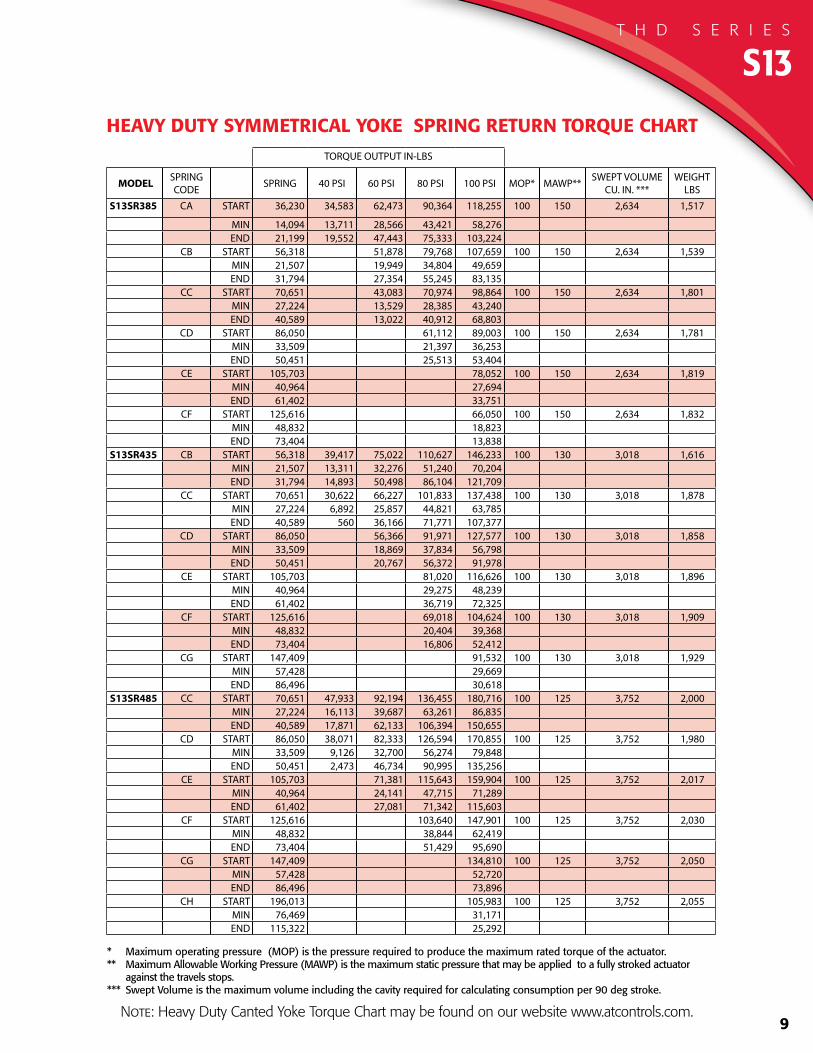
S13SR385 CA START 36,230 34,583 62,473 90,364 118,255 100 150 2,634 1,517
MIN 14,094 13,711 28,566 43,421 58,276END 21,199 19,552 47,443 75,333 103,224
CB START 56,318 51,878 79,768 107,659 100 150 2,634 1,539MIN 21,507 19,949 34,804 49,659END 31,794 27,354 55,245 83,135
CC START 70,651 43,083 70,974 98,864 100 150 2,634 1,801MIN 27,224 13,529 28,385 43,240END 40,589 13,022 40,912 68,803
CD START 86,050 61,112 89,003 100 150 2,634 1,781MIN 33,509 21,397 36,253END 50,451 25,513 53,404
CE START 105,703 78,052 100 150 2,634 1,819MIN 40,964 27,694END 61,402 33,751
CF START 125,616 66,050 100 150 2,634 1,832MIN 48,832 18,823END 73,404 13,838
S13SR435 CB START 56,318 39,417 75,022 110,627 146,233 100 130 3,018 1,616MIN 21,507 13,311 32,276 51,240 70,204END 31,794 14,893 50,498 86,104 121,709
CC START 70,651 30,622 66,227 101,833 137,438 100 130 3,018 1,878MIN 27,224 6,892 25,857 44,821 63,785END 40,589 560 36,166 71,771 107,377
CD START 86,050 56,366 91,971 127,577 100 130 3,018 1,858MIN 33,509 18,869 37,834 56,798END 50,451 20,767 56,372 91,978
CE START 105,703 81,020 116,626 100 130 3,018 1,896MIN 40,964 29,275 48,239END 61,402 36,719 72,325
CF START 125,616 69,018 104,624 100 130 3,018 1,909MIN 48,832 20,404 39,368END 73,404 16,806 52,412
CG START 147,409 91,532 100 130 3,018 1,929MIN 57,428 29,669END 86,496 30,618
S13SR485 CC START 70,651 47,933 92,194 136,455 180,716 100 125 3,752 2,000MIN 27,224 16,113 39,687 63,261 86,835END 40,589 17,871 62,133 106,394 150,655
CD START 86,050 38,071 82,333 126,594 170,855 100 125 3,752 1,980MIN 33,509 9,126 32,700 56,274 79,848END 50,451 2,473 46,734 90,995 135,256
CE START 105,703 71,381 115,643 159,904 100 125 3,752 2,017MIN 40,964 24,141 47,715 71,289END 61,402 27,081 71,342 115,603
CF START 125,616 103,640 147,901 100 125 3,752 2,030MIN 48,832 38,844 62,419END 73,404 51,429 95,690
CG START 147,409 134,810 100 125 3,752 2,050MIN 57,428 52,720END 86,496 73,896
CH START 196,013 105,983 100 125 3,752 2,055MIN 76,469 31,171END 115,322 25,292
* Maximum operating pressure (MOP) is the pressure required to produce the maximum rated torque of the actuator. ** Maximum Allowable Working Pressure (MAWP) is the maximum static pressure that may be applied to a fully stroked actuator against the travels stops.*** Swept Volume is the maximum volume including the cavity required for calculating consumption per 90 deg stroke.
HEAVY DUTY SYMMETRICAL YOKE SPRING RETURN TORQUE CHART
S13T H D S E R I E S
Note: Heavy Duty Canted Yoke Torque Chart may be found on our website www.atcontrols.com.
10
TORQUE OUTPUT IN-LBS
MODEL SPRING CODE SPRING 40 PSI 60 PSI 80 PSI 100 PSI MOP* MAWP** SWEPT VOLUME
CU. IN. ***WEIGHT
LBS
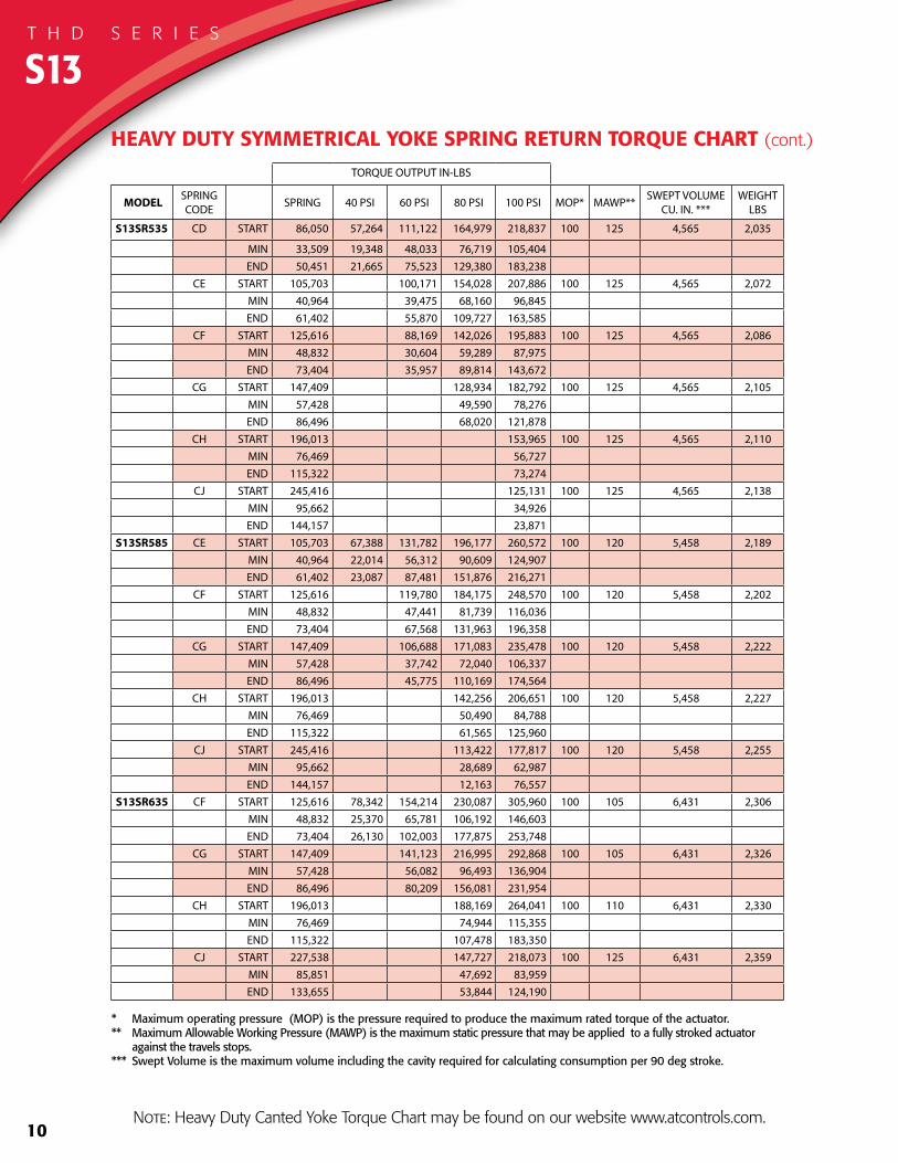
S13SR535 CD START 86,050 57,264 111,122 164,979 218,837 100 125 4,565 2,035
MIN 33,509 19,348 48,033 76,719 105,404END 50,451 21,665 75,523 129,380 183,238
CE START 105,703 100,171 154,028 207,886 100 125 4,565 2,072MIN 40,964 39,475 68,160 96,845END 61,402 55,870 109,727 163,585
CF START 125,616 88,169 142,026 195,883 100 125 4,565 2,086MIN 48,832 30,604 59,289 87,975END 73,404 35,957 89,814 143,672
CG START 147,409 128,934 182,792 100 125 4,565 2,105MIN 57,428 49,590 78,276END 86,496 68,020 121,878
CH START 196,013 153,965 100 125 4,565 2,110MIN 76,469 56,727END 115,322 73,274
CJ START 245,416 125,131 100 125 4,565 2,138MIN 95,662 34,926END 144,157 23,871
S13SR585 CE START 105,703 67,388 131,782 196,177 260,572 100 120 5,458 2,189MIN 40,964 22,014 56,312 90,609 124,907END 61,402 23,087 87,481 151,876 216,271
CF START 125,616 119,780 184,175 248,570 100 120 5,458 2,202MIN 48,832 47,441 81,739 116,036END 73,404 67,568 131,963 196,358
CG START 147,409 106,688 171,083 235,478 100 120 5,458 2,222MIN 57,428 37,742 72,040 106,337END 86,496 45,775 110,169 174,564
CH START 196,013 142,256 206,651 100 120 5,458 2,227MIN 76,469 50,490 84,788END 115,322 61,565 125,960
CJ START 245,416 113,422 177,817 100 120 5,458 2,255MIN 95,662 28,689 62,987END 144,157 12,163 76,557
S13SR635 CF START 125,616 78,342 154,214 230,087 305,960 100 105 6,431 2,306MIN 48,832 25,370 65,781 106,192 146,603END 73,404 26,130 102,003 177,875 253,748
CG START 147,409 141,123 216,995 292,868 100 105 6,431 2,326MIN 57,428 56,082 96,493 136,904END 86,496 80,209 156,081 231,954
CH START 196,013 188,169 264,041 100 110 6,431 2,330MIN 76,469 74,944 115,355END 115,322 107,478 183,350
CJ START 227,538 147,727 218,073 100 125 6,431 2,359MIN 85,851 47,692 83,959END 133,655 53,844 124,190
* Maximum operating pressure (MOP) is the pressure required to produce the maximum rated torque of the actuator. ** Maximum Allowable Working Pressure (MAWP) is the maximum static pressure that may be applied to a fully stroked actuator against the travels stops.*** Swept Volume is the maximum volume including the cavity required for calculating consumption per 90 deg stroke.
HEAVY DUTY SYMMETRICAL YOKE SPRING RETURN TORQUE CHART (cont.)
S13T H D S E R I E S
Note: Heavy Duty Canted Yoke Torque Chart may be found on our website www.atcontrols.com.

11
TORQUE OUTPUT IN-LBS
MODEL SPRING CODE SPRING 40 PSI 60 PSI 80 PSI 100 PSI MOP* MAWP** SWEPT VOLUME
CU. IN. ***WEIGHT
LBS
S16SR485 DA START 71,354 67,555 122,030 176,505 230,980 100 125 4,617 2,725
MIN 27,634 26,596 55,610 84,625 113,639END 41,395 37,597 92,072 146,547 201,022
DB START 106,431 101,332 155,807 210,283 100 125 4,617 2,738MIN 41,340 40,082 69,096 98,110END 62,093 56,994 111,469 165,944
DC START 129,487 87,864 142,339 196,814 100 125 4,617 2,767MIN 50,301 29,905 58,919 87,934END 75,562 33,939 88,414 142,889
DD START 155,652 127,557 182,033 100 125 4,617 2,780MIN 60,297 47,480 76,495END 90,343 62,248 116,723
DE START 180,743 111,454 165,929 100 125 4,617 2,791MIN 70,549 36,088 65,102END 106,447 37,157 91,632
DF START 210,751 94,028 148,503 100 125 4,617 2,800MIN 82,177 22,865 51,879END 123,872 7,149 61,624
S16SR535 DB START 106,431 70,479 136,765 203,051 269,337 100 125 5,618 2,881MIN 41,340 23,649 58,954 94,259 129,564END 62,093 26,141 92,427 158,713 224,999
DC START 129,487 123,296 189,583 255,869 100 125 5,618 2,910MIN 50,301 48,777 84,082 119,387END 75,562 69,371 135,657 201,944
DD START 155,652 108,515 174,801 241,087 100 125 5,618 2,923MIN 60,297 37,338 72,643 107,948END 90,343 43,206 109,492 175,778
DE START 180,743 92,412 158,698 224,984 100 125 5,618 2,934MIN 70,549 25,945 61,251 96,556END 106,447 18,115 84,401 150,687
DF START 210,751 141,272 207,558 100 125 5,618 2,943MIN 82,177 48,028 83,333END 123,872 54,393 120,679
DG START 280,812 166,258 100 125 5,618 2,956MIN 109,537 52,326END 165,172 50,619
S16SR585 DC START 129,487 82,948 162,203 241,458 320,713 100 125 6,718 3,060MIN 50,301 27,287 69,499 111,712 153,924END 75,562 29,023 108,278 187,533 266,788
DD START 155,652 147,422 226,677 305,932 100 125 6,718 3,073MIN 60,297 58,060 100,273 142,485END 90,343 82,113 161,368 240,622
DE START 180,743 131,318 210,573 289,828 100 125 6,718 3,084MIN 70,549 46,668 88,880 131,093END 106,447 57,022 136,277 215,531
DF START 210,751 113,893 193,148 272,403 100 125 6,718 3,093MIN 82,177 33,445 75,657 117,870END 123,872 27,013 106,268 185,523
DG START 280,812 151,847 231,102 100 125 6,718 3,106MIN 109,537 44,651 86,863END 165,172 36,208 115,463
DH START 353,858 189,812 100 125 6,718 3,122MIN 137,451 54,923END 206,463 42,416
* Maximum operating pressure (MOP) is the pressure required to produce the maximum rated torque of the actuator. ** Maximum Allowable Working Pressure (MAWP) is the maximum static pressure that may be applied to a fully stroked actuator against the travels stops.*** Swept Volume is the maximum volume including the cavity required for calculating consumption per 90 deg stroke.
HEAVY DUTY SYMMETRICAL YOKE SPRING RETURN TORQUE CHART
S16T H D S E R I E S
Note: Heavy Duty Canted Yoke Torque Chart may be found on our website www.atcontrols.com.
12
TORQUE OUTPUT IN-LBS
MODEL SPRING CODE SPRING 40 PSI 60 PSI 80 PSI 100 PSI MOP* MAWP** SWEPT VOLUME
CU. IN. ***WEIGHT
LBS
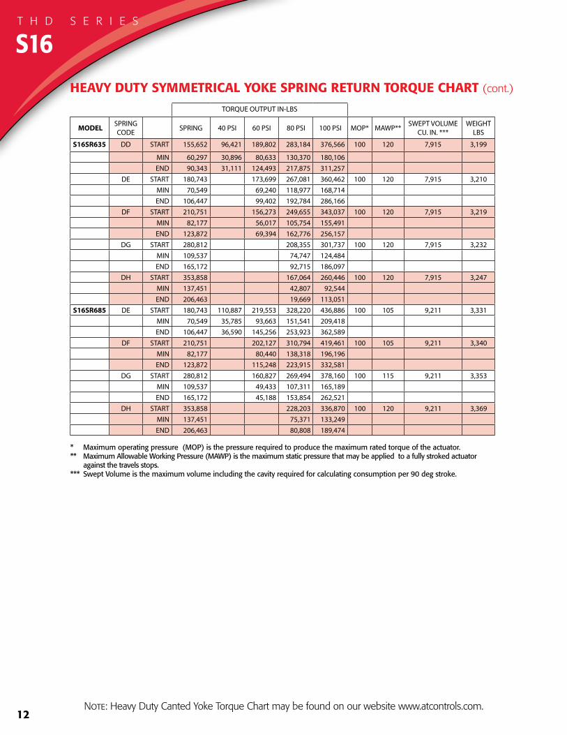
S16SR635 DD START 155,652 96,421 189,802 283,184 376,566 100 120 7,915 3,199
MIN 60,297 30,896 80,633 130,370 180,106END 90,343 31,111 124,493 217,875 311,257
DE START 180,743 173,699 267,081 360,462 100 120 7,915 3,210MIN 70,549 69,240 118,977 168,714END 106,447 99,402 192,784 286,166
DF START 210,751 156,273 249,655 343,037 100 120 7,915 3,219MIN 82,177 56,017 105,754 155,491END 123,872 69,394 162,776 256,157
DG START 280,812 208,355 301,737 100 120 7,915 3,232MIN 109,537 74,747 124,484END 165,172 92,715 186,097
DH START 353,858 167,064 260,446 100 120 7,915 3,247MIN 137,451 42,807 92,544END 206,463 19,669 113,051
S16SR685 DE START 180,743 110,887 219,553 328,220 436,886 100 105 9,211 3,331MIN 70,549 35,785 93,663 151,541 209,418END 106,447 36,590 145,256 253,923 362,589
DF START 210,751 202,127 310,794 419,461 100 105 9,211 3,340MIN 82,177 80,440 138,318 196,196END 123,872 115,248 223,915 332,581
DG START 280,812 160,827 269,494 378,160 100 115 9,211 3,353MIN 109,537 49,433 107,311 165,189END 165,172 45,188 153,854 262,521
DH START 353,858 228,203 336,870 100 120 9,211 3,369MIN 137,451 75,371 133,249END 206,463 80,808 189,474
* Maximum operating pressure (MOP) is the pressure required to produce the maximum rated torque of the actuator. ** Maximum Allowable Working Pressure (MAWP) is the maximum static pressure that may be applied to a fully stroked actuator against the travels stops.*** Swept Volume is the maximum volume including the cavity required for calculating consumption per 90 deg stroke.
HEAVY DUTY SYMMETRICAL YOKE SPRING RETURN TORQUE CHART (cont.)
S16T H D S E R I E S
Note: Heavy Duty Canted Yoke Torque Chart may be found on our website www.atcontrols.com.
13
TORQUE OUTPUT IN-LBS
MODEL SPRING CODE SPRING 40 PSI 60 PSI 80 PSI 100 PSI MOP* MAWP** SWEPT VOLUME
CU. IN. ***WEIGHT
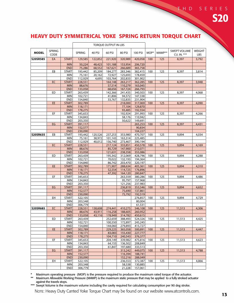
LBSS20SR585 EA START 129,585 122,852 221,920 320,989 420,058 100 125 8,397 3,792
MIN 50,224 48,423 101,188 153,954 206,720END 75,286 68,552 167,621 266,689 365,758
EB START 193,442 85,209 184,277 283,346 382,415 100 125 8,397 3,814MIN 75,161 20,162 72,927 125,693 178,459END 112,929 4,695 103,764 202,833 301,902
EC START 228,551 164,148 263,217 362,285 100 125 8,397 3,948MIN 88,676 57,514 110,279 163,045END 133,058 68,656 167,724 266,793
ED START 263,439 142,366 241,435 340,503 100 125 8,397 4,068MIN 102,721 41,806 94,572 147,338END 154,840 33,767 132,835 231,904
EE START 302,789 218,000 317,069 100 125 8,397 4,090MIN 118,171 77,104 129,870END 178,275 93,485 192,554
EF START 345,653 192,924 291,993 100 125 8,397 4,266MIN 134,843 58,176 110,942END 203,350 50,622 149,691
EG START 391,117 265,253 100 125 8,397 4,431MIN 152,577 90,834END 230,090 104,227
S20SR635 EB START 193,442 120,526 237,253 353,980 470,707 100 125 9,894 4,034MIN 75,161 38,972 101,143 163,314 225,485END 112,929 40,012 156,740 273,467 390,194
EC START 228,551 217,124 333,851 450,578 100 125 9,894 4,169MIN 88,676 85,729 147,900 210,071END 133,058 121,631 238,358 355,086
ED START 263,439 195,342 312,069 428,796 100 125 9,894 4,288MIN 102,721 70,022 132,193 194,364END 154,840 86,742 203,470 320,197
EE START 302,789 171,907 288,634 405,361 100 125 9,894 4,310MIN 118,171 52,554 114,725 176,896END 178,275 47,392 164,120 280,847
EF START 345,653 263,559 380,286 100 125 9,894 4,486MIN 134,843 95,797 157,968END 203,350 121,256 237,983
EG START 391,117 236,819 353,546 100 125 9,894 4,652MIN 152,577 75,690 137,861END 230,090 75,792 192,519
EH START 522,105 276,857 100 125 9,894 4,729 MIN 203,548 80,004
END 306,779 61,531S20SR685 EC START 228,551 138,608 274,441 410,275 546,108 100 125 11,513 4,306
MIN 88,676 43,911 116,258 188,605 260,952END 133,058 43,116 178,949 314,782 450,615
ED START 263,439 252,659 388,493 524,326 100 125 11,513 4,425MIN 102,721 100,550 172,897 245,245END 154,840 144,060 279,893 415,727
EE START 302,789 229,225 365,058 500,891 100 125 11,513 4,447MIN 118,171 83,083 155,430 227,777END 178,275 104,710 240,543 376,377
EF START 345,653 204,149 339,982 475,816 100 125 11,513 4,623MIN 134,843 64,155 136,502 208,849END 203,350 61,847 197,680 333,513
EG START 391,117 313,242 449,075 100 125 11,513 4,788MIN 152,577 116,394 188,741END 230,090 152,216 288,049
EH START 522,105 236,553 372,387 100 125 11,513 4,866MIN 203,548 58,538 130,885END 306,779 21,228 157,061
* Maximum operating pressure (MOP) is the pressure required to produce the maximum rated torque of the actuator. ** Maximum Allowable Working Pressure (MAWP) is the maximum static pressure that may be applied to a fully stroked actuator against the travels stops.*** Swept Volume is the maximum volume including the cavity required for calculating consumption per 90 deg stroke.
HEAVY DUTY SYMMETRICAL YOKE SPRING RETURN TORQUE CHART
S20T H D S E R I E S
Note: Heavy Duty Canted Yoke Torque Chart may be found on our website www.atcontrols.com.
14
TORQUE OUTPUT IN-LBS
MODEL SPRING CODE SPRING 40 PSI 60 PSI 80 PSI 100 PSI MOP* MAWP** SWEPT VOLUME
CU. IN. ***WEIGHT
LBS
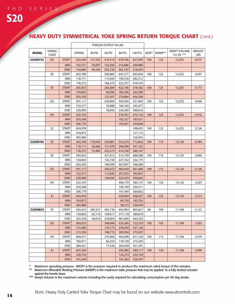
S20SR735 ED START 263,439 157,933 314,319 470,706 627,093 100 120 13,255 4,575
MIN 102,721 50,097 133,392 216,686 299,980END 154,840 49,334 205,720 362,107 518,493
EE START 302,789 290,885 447,271 603,658 100 125 13,255 4,597MIN 118,171 115,924 199,218 282,512END 178,275 166,370 322,757 479,143
EF START 345,653 265,809 422,196 578,582 100 125 13,255 4,773MIN 134,843 96,996 180,290 263,585END 203,350 123,507 279,894 436,280
EG START 391,117 239,069 395,456 551,842 100 125 13,255 4,938MIN 152,577 76,888 160,183 243,477END 230,090 78,043 234,430 390,816
EH START 522,105 318,767 475,153 100 125 13,255 5,016MIN 203,548 102,327 185,621END 306,779 103,441 259,828
EJ START 654,978 398,453 100 125 13,255 5,126MIN 254,875 127,172END 383,480 126,955
S20SR785 EE START 302,789 178,500 356,887 535,274 713,662 100 110 15,120 4,784MIN 118,171 56,066 151,078 246,090 341,102END 178,275 53,985 232,373 410,760 589,147
EF START 345,653 331,812 510,199 688,586 100 110 15,120 4,960MIN 134,843 132,150 227,162 322,175END 203,350 189,509 367,897 546,284
EG START 391,117 305,072 483,459 661,846 100 115 15,120 5,126MIN 152,577 112,042 207,055 302,067END 230,090 144,045 322,433 500,820
EH START 522,105 406,770 585,157 100 120 15,120 5,203MIN 203,548 149,199 244,211END 306,779 191,444 369,832
EJ START 654,978 330,069 508,457 100 125 15,120 5,313MIN 254,875 90,750 185,762END 383,480 58,572 236,959
S20SR835 EF START 345,653 200,321 402,156 603,992 805,827 80 100 17,108 5,137MIN 134,843 62,116 169,617 277,118 389,619 END 203,350 58,018 259,854 461,690 663,525
EG START 362,625 348,068 535,200 722,333 100 105 17,108 5,302MIN 141,680 134,175 230,650 327,126END 213,329 198,772 385,904 573,037
EH START 484,071 276,966 464,098 651,230 100 115 17,108 5,379MIN 182,671 82,253 178,728 275,203END 284,431 77,326 264,458 451,591
EJ START 607,264 392,985 580,117 100 120 17,108 5,490MIN 228,734 126,274 222,749END 355,544 141,265 328,397
* Maximum operating pressure (MOP) is the pressure required to produce the maximum rated torque of the actuator. ** Maximum Allowable Working Pressure (MAWP) is the maximum static pressure that may be applied to a fully stroked actuator against the travels stops.*** Swept Volume is the maximum volume including the cavity required for calculating consumption per 90 deg stroke.
HEAVY DUTY SYMMETRICAL YOKE SPRING RETURN TORQUE CHART (cont.)
S20T H D S E R I E S
Note: Heavy Duty Canted Yoke Torque Chart may be found on our website www.atcontrols.com.

15
TORQUE OUTPUT IN-LBS
MODEL SPRING CODE SPRING 40 PSI 60 PSI 80 PSI 100 PSI MOP* MAWP** SWEPT VOLUME
CU. IN. ***WEIGHT
LBS
S27SR735 FA START 276,471 261,796 472,918 684,040 895,162 100 125 17,895 CF
MIN 107,092 103,091 215,538 327,985 440,433 END 160,447 145,773 356,895 568,017 779,139
FB START 411,293 392,694 603,816 814,938 100 125 17,895 CFMIN 160,002 155,706 268,153 380,600 END 240,671 222,072 433,194 644,316
FC START 552,941 312,471 523,593 734,714 100 125 17,895 CFMIN 214,184 93,735 206,182 318,629 END 320,895 80,424 291,546 502,668
FD START 680,939 443,369 654,491 100 125 17,895 CFMIN 265,821 148,488 260,935 END 401,118 163,548 374,670
S27SR785 FE START 314,395 298,631 539,453 780,276 1,021,099 100 125 20,412 CFMIN 121,976 117,899 246,166 374,432 502,699 END 183,015 167,251 408,074 648,897 889,720
FF START 472,445 447,946 688,769 929,592 100 125 20,412 CFMIN 183,122 176,581 304,848 433,114 END 274,523 250,024 490,847 731,670
FG START 621,980 356,422 597,245 838,068 100 125 20,412 CFMIN 242,687 109,661 237,928 366,194 END 366,047 100,489 341,311 582,134
FH START 778,324 505,737 746,560 100 125 20,412 CFMIN 303,516 168,878 297,145 END 457,554 184,967 425,790
S27SR835 FJ START 353,811 337,880 610,358 882,836 1,155,314 100 125 23,095 CFMIN 137,654 133,994 279,120 424,247 569,373 END 207,076 191,145 463,623 736,101 1,008,579
FK START 532,431 234,334 506,812 779,290 1,051,768 100 125 23,095 CFMIN 206,804 55,325 200,452 345,578 490,705 END 310,622 12,525 285,003 557,481 829,959
FL START 711,035 403,282 675,760 948,238 100 125 23,095 CFMIN 275,945 121,792 266,918 412,045 END 414,152 106,399 378,877 651,355
FM START 886,242 572,214 844,692 100 125 23,095 CFMIN 344,458 189,319 334,445 END 517,698 203,670 476,148
S27SR885 FN START 399,823 379,561 685,648 991,735 1,297,822 100 115 25,944 CFMIN 155,074 149,779 312,807 475,834 638,861 END 232,613 212,351 518,438 824,525 1,130,612
FO START 603,163 569,325 875,412 1,181,499 100 115 25,944 CF MIN 233,256 223,592 386,619 549,646
END 348,936 315,098 621,185 927,272 FP START 792,838 453,018 759,106 1,065,193 100 115 25,944 CF
MIN 308,883 138,661 301,688 464,716 END 465,243 125,424 431,511 737,598
FR START 1,001,281 642,799 948,886 100 115 25,944 CFMIN 388,011 210,878 373,906 END 581,550 223,068 529,155
* Maximum operating pressure (MOP) is the pressure required to produce the maximum rated torque of the actuator. ** Maximum Allowable Working Pressure (MAWP) is the maximum static pressure that may be applied to a fully stroked actuator against the travels stops.*** Swept Volume is the maximum volume including the cavity required for calculating consumption per 90 deg stroke.
HEAVY DUTY SYMMETRICAL YOKE SPRING RETURN TORQUE CHART
S27T H D S E R I E S
Note: Heavy Duty Canted Yoke Torque Chart may be found on our website www.atcontrols.com.
16
TORQUE OUTPUT IN-LBS
MODEL SPRING CODE SPRING 40 PSI 60 PSI 80 PSI 100 PSI MOP* MAWP** SWEPT VOLUME
CU. IN. ***WEIGHT
LBS
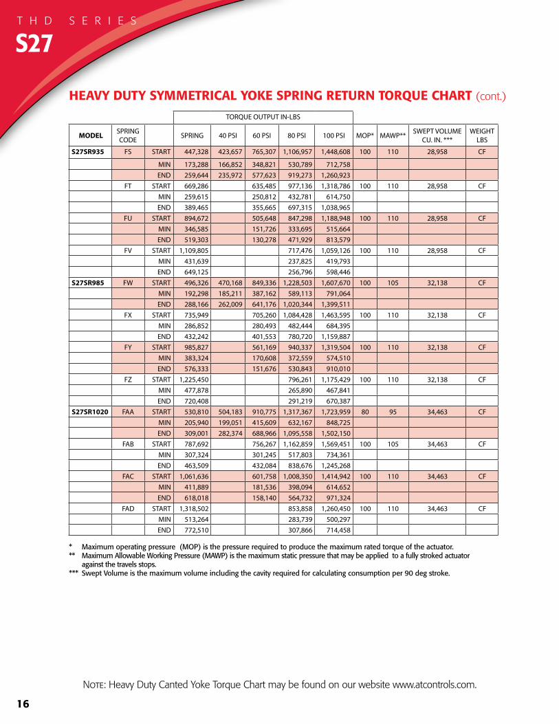
S27SR935 FS START 447,328 423,657 765,307 1,106,957 1,448,608 100 110 28,958 CF
MIN 173,288 166,852 348,821 530,789 712,758 END 259,644 235,972 577,623 919,273 1,260,923
FT START 669,286 635,485 977,136 1,318,786 100 110 28,958 CFMIN 259,615 250,812 432,781 614,750 END 389,465 355,665 697,315 1,038,965
FU START 894,672 505,648 847,298 1,188,948 100 110 28,958 CFMIN 346,585 151,726 333,695 515,664 END 519,303 130,278 471,929 813,579
FV START 1,109,805 717,476 1,059,126 100 110 28,958 CFMIN 431,639 237,825 419,793 END 649,125 256,796 598,446
S27SR985 FW START 496,326 470,168 849,336 1,228,503 1,607,670 100 105 32,138 CFMIN 192,298 185,211 387,162 589,113 791,064 END 288,166 262,009 641,176 1,020,344 1,399,511
FX START 735,949 705,260 1,084,428 1,463,595 100 110 32,138 CFMIN 286,852 280,493 482,444 684,395 END 432,242 401,553 780,720 1,159,887
FY START 985,827 561,169 940,337 1,319,504 100 110 32,138 CFMIN 383,324 170,608 372,559 574,510 END 576,333 151,676 530,843 910,010
FZ START 1,225,450 796,261 1,175,429 100 110 32,138 CFMIN 477,878 265,890 467,841 END 720,408 291,219 670,387
S27SR1020 FAA START 530,810 504,183 910,775 1,317,367 1,723,959 80 95 34,463 CFMIN 205,940 199,051 415,609 632,167 848,725END 309,001 282,374 688,966 1,095,558 1,502,150
FAB START 787,692 756,267 1,162,859 1,569,451 100 105 34,463 CFMIN 307,324 301,245 517,803 734,361 END 463,509 432,084 838,676 1,245,268
FAC START 1,061,636 601,758 1,008,350 1,414,942 100 110 34,463 CFMIN 411,889 181,536 398,094 614,652 END 618,018 158,140 564,732 971,324
FAD START 1,318,502 853,858 1,260,450 100 110 34,463 CFMIN 513,264 283,739 500,297 END 772,510 307,866 714,458
* Maximum operating pressure (MOP) is the pressure required to produce the maximum rated torque of the actuator. ** Maximum Allowable Working Pressure (MAWP) is the maximum static pressure that may be applied to a fully stroked actuator against the travels stops.*** Swept Volume is the maximum volume including the cavity required for calculating consumption per 90 deg stroke.
S27T H D S E R I E S
HEAVY DUTY SYMMETRICAL YOKE SPRING RETURN TORQUE CHART (cont.)
Note: Heavy Duty Canted Yoke Torque Chart may be found on our website www.atcontrols.com.
17
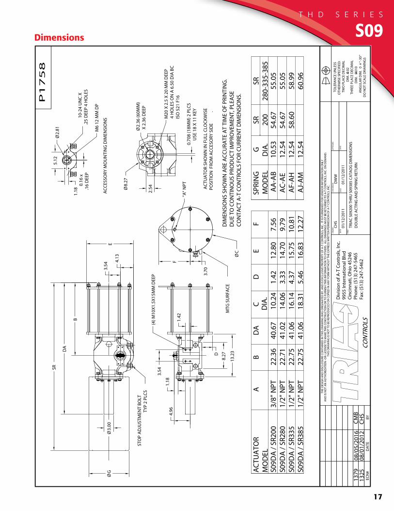
Dimensions S09T H D S E R I E S
18
Div
isio
n o
f A-T
Con
trol
s, I
nc.
9955 I
nte
rnat
ional
Blv
d.
Cin
cinnat
i, O
H 4
5246
Phon
e: (
513)
247-5
465
Fax:
(513)
247-5
462
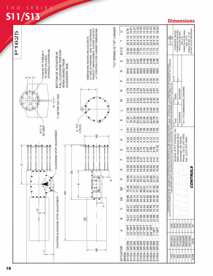
DimensionsS11/S13T H D S E R I E S
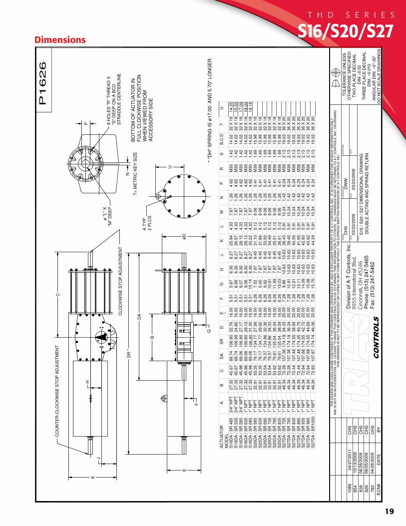
S16/S20/S27
19
Dimensions
T H D S E R I E S
10
6.9
0
10
6.9
0
10
6.9
0
*
* "
DH
" S
PR
ING
IS
17
.00
A
ND
5.7
0"
LO
NG
ER
20
.00
20
.00
22
.00
22
.00
22
.00
22
.00
22
.00
36 X
20
19.0
22.1
3M
36
6.2
41.4
210
.24
5.9
14
4.2
91
0.6
310
.63
15.7
57.2
846
.06
17
4.7
41
07
.87
72
.83
46.3
41"
NP
TS
27
DA
/ S
R10
20
36 X
20
19.0
22.1
3M
36
6.2
41.4
210
.24
5.9
14
3.6
21
0.6
310
.63
15.0
87.2
844
.69
17
4.5
51
07
.68
72
.64
46.3
41"
NP
TS
27
DA
/ S
R 9
85
36 X
20
19.0
22.1
3M
36
6.2
41.4
210
.24
5.9
14
2.6
01
0.6
310
.63
14.0
97.2
842
.72
17
4.5
51
07
.68
72
.64
46.3
41"
NP
TS
27
DA
/ S
R 9
35
36 X
20
19.0
22.1
3M
36
6.2
41.4
210
.24
5.9
14
1.6
51
0.6
310
.63
13.1
17.2
840
.75
17
4.3
51
07
.48
72
.44
46.3
41"
NP
TS
27
DA
/ S
R 8
85
36 X
20
19.0
22.1
3M
36
6.2
41.4
210
.24
5.9
14
0.5
51
0.6
310
.63
12.0
17.2
838
.58
17
4.3
51
07
.48
72
.44
46.3
41"
NP
TS
27
DA
/ S
R 8
35
36 X
20
19.0
22.1
3M
36
6.2
41.4
210
.24
5.9
13
9.4
51
0.6
310
.63
10.9
17.2
836
.34
17
4.1
91
07
.36
72
.28
46.3
41"
NP
TS
27
DA
/ S
R 7
85
36 X
20
19.0
22.1
3M
36
6.2
41.4
210
.24
5.9
13
8.4
31
0.6
310
.63
9.8
87.2
834
.33
17
4.1
91
07
.36
72
.28
46.3
41"
NP
TS
27
DA
/ S
R 7
35
32 X
18
15.9
81.6
9M
36
5.4
11.2
69
.06
5.1
23
6.6
19
.45
7.8
71
3.0
36.2
618
.00
38
.58
13
5.0
479
.61
53
.62
32.9
11"
NP
TS
20
DA
/ S
R 8
35
32 X
18
15.9
81.6
9M
36
5.4
11.2
69
.06
5.1
23
5.5
19
.45
7.8
71
1.8
96.2
618
.00
36
.34
13
5.0
479
.61
53
.62
32.9
11"
NP
TS
20
DA
/ S
R 7
85
32 X
18
15.9
81.6
9M
36
5.4
11.2
69
.06
5.1
23
4.4
99
.45
7.8
71
0.9
16.2
618
.00
34
.33
13
4.9
679
.37
53
.54
32.9
11"
NP
TS
20
DA
/ S
R 7
35
32 X
18
15.9
81.6
9M
36
5.4
11.2
69
.06
5.1
23
3.5
09
.45
7.8
79
.92
6.2
618
.00
32
.36
13
4.9
679
.37
53
.54
32.9
11"
NP
TS
20
DA
/ S
R 6
85
32 X
18
15.9
81.6
9M
36
5.4
11.2
69
.06
5.1
23
1.8
99
.45
7.8
70
.00
6.2
618
.00
29
.92
13
4.7
779
.17
53
.35
32.9
11"
NP
TS
20
DA
/ S
R 6
35
32 X
18
15.9
81.6
9M
36
5.4
11.2
69
.06
5.1
23
1.1
09
.45
7.8
77
.52
6.2
618
.00
27
.56
13
4.7
779
.17
53
.35
32.9
11"
NP
TS
20
DA
/ S
R 5
85
32 X
18
14.0
21.4
2M
30
4.6
21.2
67
.87
4.3
33
0.2
28
.27
6.3
010
.14
5.5
116
.00
31
.30
69
.06
45
.98
27.3
21"
NP
TS
16
DA
/ S
R 6
85
32 X
18
14.0
21.4
2M
30
4.6
21.2
67
.87
4.3
32
9.1
38
.27
6.3
09
.06
5.5
116
.00
29
.13
10
6.9
069
.06
45
.98
27.3
21"
NP
TS
16
DA
/ S
R 6
35
32 X
18
14.0
21.4
2M
30
4.6
21.2
67
.87
4.3
32
8.1
58
.27
6.3
08
.07
5.5
116
.00
27
.17
69
.06
45
.98
27.3
23/4
" N
PT
S16
DA
/ S
R 5
85
32 X
18
14.0
21.4
2M
30
4.6
21.2
67
.87
4.3
32
6.9
78
.27
6.3
06
.89
5.5
116
.00
24
.80
68
.74
45
.67
27.3
23/4
" N
PT
S16
DA
/ S
R 5
35
32 X
18
14.0
21.4
2M
30
4.6
21.2
67
.87
4.3
32
5.9
48
.27
6.3
05
.87
5.5
116
.00
22
.76
10
6.9
068
.74
45
.67
27.3
23/4
" N
PT
S16
DA
/ S
R 4
85
MO
DE
L
TB
.C.D
SR
PN
ML
KJ
HG
FE
DS
RD
AC
BA
AC
TU
AT
OR
J
H
CL
OC
KW
ISE
ST
OP
AD
JU
ST
ME
NT
CO
UN
TE
R-C
LO
CK
WIS
E S
TO
P A
DJU
ST
ME
NT
E
SR
*
DA
F
C
BO
TT
OM
OF
AC
TU
AT
OR
IN
FU
LL
CL
OC
KW
ISE
PO
SIT
ION
WH
EN
VIE
WE
D F
RO
M
AC
CE
SS
OR
Y S
IDE
D
B
K
G
A T
YP
2 P
LC
S
U
P
N
T=
ME
TR
IC K
EY
SIZ
E
"L
" X
"M"
DE
EP
8 H
OL
ES
"R
" T
HR
EA
D X
"S"
DE
EP
ON
A B
CD
ST
RA
DD
LE
CE
NT
ER
LIN
E
U
14
.25
15
.53
17
.09
18
.04
19
.18
78
30
4/2
8/2
00
9C
HS
82
80
8/0
5/2
00
9C
HS
839
08/2
8/2
00
9C
HS
854
10/1
3/2
00
9C
HS
10
89
04
/27/2
01
1C
HS
P1
62
6
CH
S
03
/23/2
00
9
DW
W
03
/23/2
00
9
S1
6 /
S2
0 /
S2
7 D
IME
NS
ION
AL
DR
AW
ING
DO
UB
LE
AC
TIN
G A
ND
SP
RIN
G R
ET
UR
N+
++
DO
NO
T S
CA
LE
DR
AW
ING
S
TH
E D
ES
IGN
AN
D D
ISC
LO
SU
RE
CO
NT
AIN
ED
IN
TH
IS D
RA
WIN
G W
AS
OR
IGIN
AT
ED
BY
, A
ND
IS
EX
CLU
SIV
E P
RO
PE
RT
Y O
F A
-T C
ON
TR
OLS
, IN
C. IT
IS
FU
RN
ISH
ED
FO
R V
EN
DO
R I
NF
OR
MA
TIO
N O
NLY
AP
PR
OV
ED
DA
TE
DA
TE
CH
EC
KE
D B
Y
TIT
LE
DA
TE
DR
AW
N
Div
isio
n o
f A
-T C
on
tro
ls,
Inc.
11
36
3 D
ee
rfie
ld R
oa
dC
incin
na
ti,
Oh
io 4
52
42
Ph
on
e:
(51
3)
24
7-5
46
5F
ax:
(51
3)
24
7-5
462
EC
N#
DA
TE
BY
AN
D IS
NO
T A
N A
UT
HO
RIZ
AT
ION
-O
R-
LIC
EN
SE
TO
MA
KE
TH
IS C
ON
ST
RU
CT
ION
OR
TO
FU
RN
ISH
TH
IS IN
FO
RM
AT
ION
TO
OT
HE
RS
. A
LL
DR
AW
ING
S M
US
T B
E R
ET
UR
NE
D T
O A
-T C
ON
TR
OLS
, IN
C. O
N D
EM
AN
D.
TH
IS D
RA
WIN
G IS
NO
T T
O B
E R
EP
RO
DU
CE
D O
R C
OP
IED
IN
AN
Y F
OR
M W
ITH
OU
T T
HE
EX
PR
ES
S W
RIT
TE
N P
ER
MIS
SIO
N O
F A
-T C
ON
TR
OLS
, IN
C.
TO
LE
RA
NC
E U
NLE
SS
OT
HE
RW
ISE
SP
EC
IFIE
D:
TW
O P
LA
CE
DE
CIM
AL
DIM
. 0
.02
TH
RE
E P
LA
CE
DE
CIM
AL
DIM
.
0.0
10
AN
GU
LA
R D
IM.
0-
30
9955
Inte
rnat
iona
l Blv
d.C
inci
nnat
i, O
H 4
5246
10
6.9
0
10
6.9
0
10
6.9
0
*
* "
DH
" S
PR
ING
IS
17
.00
A
ND
5.7
0"
LO
NG
ER
20
.00
20
.00
22
.00
22
.00
22
.00
22
.00
22
.00
36 X
20
19.0
22.1
3M
36
6.2
41.4
210
.24
5.9
14
4.2
91
0.6
310
.63
15.7
57.2
846
.06
17
4.7
41
07
.87
72
.83
46.3
41"
NP
TS
27
DA
/ S
R10
20
36 X
20
19.0
22.1
3M
36
6.2
41.4
210
.24
5.9
14
3.6
21
0.6
310
.63
15.0
87.2
844
.69
17
4.5
51
07
.68
72
.64
46.3
41"
NP
TS
27
DA
/ S
R 9
85
36 X
20
19.0
22.1
3M
36
6.2
41.4
210
.24
5.9
14
2.6
01
0.6
310
.63
14.0
97.2
842
.72
17
4.5
51
07
.68
72
.64
46.3
41"
NP
TS
27
DA
/ S
R 9
35
36 X
20
19.0
22.1
3M
36
6.2
41.4
210
.24
5.9
14
1.6
51
0.6
310
.63
13.1
17.2
840
.75
17
4.3
51
07
.48
72
.44
46.3
41"
NP
TS
27
DA
/ S
R 8
85
36 X
20
19.0
22.1
3M
36
6.2
41.4
210
.24
5.9
14
0.5
51
0.6
310
.63
12.0
17.2
838
.58
17
4.3
51
07
.48
72
.44
46.3
41"
NP
TS
27
DA
/ S
R 8
35
36 X
20
19.0
22.1
3M
36
6.2
41.4
210
.24
5.9
13
9.4
51
0.6
310
.63
10.9
17.2
836
.34
17
4.1
91
07
.36
72
.28
46.3
41"
NP
TS
27
DA
/ S
R 7
85
36 X
20
19.0
22.1
3M
36
6.2
41.4
210
.24
5.9
13
8.4
31
0.6
310
.63
9.8
87.2
834
.33
17
4.1
91
07
.36
72
.28
46.3
41"
NP
TS
27
DA
/ S
R 7
35
32 X
18
15.9
81.6
9M
36
5.4
11.2
69
.06
5.1
23
6.6
19
.45
7.8
71
3.0
36.2
618
.00
38
.58
13
5.0
479
.61
53
.62
32.9
11"
NP
TS
20
DA
/ S
R 8
35
32 X
18
15.9
81.6
9M
36
5.4
11.2
69
.06
5.1
23
5.5
19
.45
7.8
71
1.8
96.2
618
.00
36
.34
13
5.0
479
.61
53
.62
32.9
11"
NP
TS
20
DA
/ S
R 7
85
32 X
18
15.9
81.6
9M
36
5.4
11.2
69
.06
5.1
23
4.4
99
.45
7.8
71
0.9
16.2
618
.00
34
.33
13
4.9
679
.37
53
.54
32.9
11"
NP
TS
20
DA
/ S
R 7
35
32 X
18
15.9
81.6
9M
36
5.4
11.2
69
.06
5.1
23
3.5
09
.45
7.8
79
.92
6.2
618
.00
32
.36
13
4.9
679
.37
53
.54
32.9
11"
NP
TS
20
DA
/ S
R 6
85
32 X
18
15.9
81.6
9M
36
5.4
11.2
69
.06
5.1
23
1.8
99
.45
7.8
70
.00
6.2
618
.00
29
.92
13
4.7
779
.17
53
.35
32.9
11"
NP
TS
20
DA
/ S
R 6
35
32 X
18
15.9
81.6
9M
36
5.4
11.2
69
.06
5.1
23
1.1
09
.45
7.8
77
.52
6.2
618
.00
27
.56
13
4.7
779
.17
53
.35
32.9
11"
NP
TS
20
DA
/ S
R 5
85
32 X
18
14.0
21.4
2M
30
4.6
21.2
67
.87
4.3
33
0.2
28
.27
6.3
010
.14
5.5
116
.00
31
.30
69
.06
45
.98
27.3
21"
NP
TS
16
DA
/ S
R 6
85
32 X
18
14.0
21.4
2M
30
4.6
21.2
67
.87
4.3
32
9.1
38
.27
6.3
09
.06
5.5
116
.00
29
.13
10
6.9
069
.06
45
.98
27.3
21"
NP
TS
16
DA
/ S
R 6
35
32 X
18
14.0
21.4
2M
30
4.6
21.2
67
.87
4.3
32
8.1
58
.27
6.3
08
.07
5.5
116
.00
27
.17
69
.06
45
.98
27.3
23/4
" N
PT
S16
DA
/ S
R 5
85
32 X
18
14.0
21.4
2M
30
4.6
21.2
67
.87
4.3
32
6.9
78
.27
6.3
06
.89
5.5
116
.00
24
.80
68
.74
45
.67
27.3
23/4
" N
PT
S16
DA
/ S
R 5
35
32 X
18
14.0
21.4
2M
30
4.6
21.2
67
.87
4.3
32
5.9
48
.27
6.3
05
.87
5.5
116
.00
22
.76
10
6.9
068
.74
45
.67
27.3
23/4
" N
PT
S16
DA
/ S
R 4
85
MO
DE
L
TB
.C.D
SR
PN
ML
KJ
HG
FE
DS
RD
AC
BA
AC
TU
AT
OR
J
H
CL
OC
KW
ISE
ST
OP
AD
JU
ST
ME
NT
CO
UN
TE
R-C
LO
CK
WIS
E S
TO
P A
DJU
ST
ME
NT
E
SR
*
DA
F
C
BO
TT
OM
OF
AC
TU
AT
OR
IN
FU
LL
CL
OC
KW
ISE
PO
SIT
ION
WH
EN
VIE
WE
D F
RO
M
AC
CE
SS
OR
Y S
IDE
D
B
K
G
A T
YP
2 P
LC
S
U
P
N
T=
ME
TR
IC K
EY
SIZ
E
"L
" X
"M"
DE
EP
8 H
OL
ES
"R
" T
HR
EA
D X
"S"
DE
EP
ON
A B
CD
ST
RA
DD
LE
CE
NT
ER
LIN
E
U
14
.25
15
.53
17
.09
18
.04
19
.18
78
30
4/2
8/2
00
9C
HS
82
80
8/0
5/2
00
9C
HS
839
08/2
8/2
00
9C
HS
854
10/1
3/2
00
9C
HS
10
89
04
/27/2
01
1C
HS
P1
62
6
CH
S
03
/23/2
00
9
DW
W
03
/23/2
00
9
S1
6 /
S2
0 /
S2
7 D
IME
NS
ION
AL
DR
AW
ING
DO
UB
LE
AC
TIN
G A
ND
SP
RIN
G R
ET
UR
N+
++
DO
NO
T S
CA
LE
DR
AW
ING
S
TH
E D
ES
IGN
AN
D D
ISC
LO
SU
RE
CO
NT
AIN
ED
IN
TH
IS D
RA
WIN
G W
AS
OR
IGIN
AT
ED
BY
, A
ND
IS
EX
CLU
SIV
E P
RO
PE
RT
Y O
F A
-T C
ON
TR
OLS
, IN
C. IT
IS
FU
RN
ISH
ED
FO
R V
EN
DO
R I
NF
OR
MA
TIO
N O
NLY
AP
PR
OV
ED
DA
TE
DA
TE
CH
EC
KE
D B
Y
TIT
LE
DA
TE
DR
AW
N
Div
isio
n o
f A
-T C
on
tro
ls,
Inc.
11
36
3 D
ee
rfie
ld R
oa
dC
incin
na
ti,
Oh
io 4
52
42
Ph
on
e:
(51
3)
24
7-5
46
5F
ax:
(51
3)
24
7-5
462
EC
N#
DA
TE
BY
AN
D IS
NO
T A
N A
UT
HO
RIZ
AT
ION
-O
R-
LIC
EN
SE
TO
MA
KE
TH
IS C
ON
ST
RU
CT
ION
OR
TO
FU
RN
ISH
TH
IS IN
FO
RM
AT
ION
TO
OT
HE
RS
. A
LL
DR
AW
ING
S M
US
T B
E R
ET
UR
NE
D T
O A
-T C
ON
TR
OLS
, IN
C. O
N D
EM
AN
D.
TH
IS D
RA
WIN
G IS
NO
T T
O B
E R
EP
RO
DU
CE
D O
R C
OP
IED
IN
AN
Y F
OR
M W
ITH
OU
T T
HE
EX
PR
ES
S W
RIT
TE
N P
ER
MIS
SIO
N O
F A
-T C
ON
TR
OLS
, IN
C.
TO
LE
RA
NC
E U
NLE
SS
OT
HE
RW
ISE
SP
EC
IFIE
D:
TW
O P
LA
CE
DE
CIM
AL
DIM
. 0
.02
TH
RE
E P
LA
CE
DE
CIM
AL
DIM
.
0.0
10
AN
GU
LA
R D
IM.
0-
30
20
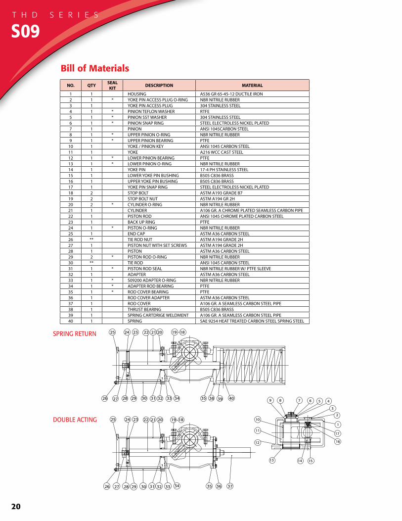
Bill of Materials
NO. QTY SEAL KIT DESCRIPTION MATERIAL
1 1 HOUSING A536 GR 65-45-12 DUCTILE IRON2 1 * YOKE PIN ACCESS PLUG O-RING NBR NITRILE RUBBER3 1 YOKE PIN ACCESS PLUG 304 STAINLESS STEEL4 1 * PINION TEFLON WASHER RTFE5 1 * PINION SST WASHER 304 STAINLESS STEEL6 1 * PINION SNAP RING STEEL ELECTROLESS NICKEL PLATED7 1 PINION ANSI 1045CARBON STEEL8 1 * UPPER PINION O-RING NBR NITRILE RUBBER9 1 * UPPER PINION BEARING PTFE
10 1 YOKE / PINION KEY ANSI 1045 CARBON STEEL11 1 YOKE A216 WCC CAST STEEL12 1 * LOWER PINION BEARING PTFE13 1 * LOWER PINION O-RING NBR NITRILE RUBBER14 1 YOKE PIN 17-4 PH STAINLESS STEEL15 1 LOWER YOKE PIN BUSHING B505 C836 BRASS16 1 UPPER YOKE PIN BUSHING B505 C836 BRASS17 1 YOKE PIN SNAP RING STEEL ELECTROLESS NICKEL PLATED18 2 STOP BOLT ASTM A193 GRADE B719 2 STOP BOLT NUT ASTM A194 GR 2H20 2 * CYLINDER O-RING NBR NITRILE RUBBER21 1 CYLINDER A106 GR. A CHROME PLATED SEAMLESS CARBON PIPE22 1 PISTON ROD ANSI 1045 CHROME PLATED CARBON STEEL23 1 BACK UP RING PTFE24 1 * PISTON O-RING NBR NITRILE RUBBER25 1 END CAP ASTM A36 CARBON STEEL26 ** TIE ROD NUT ASTM A194 GRADE 2H27 1 PISTON NUT WITH SET SCREWS ASTM A194 GRADE 2H28 1 PISTON ASTM A36 CARBON STEEL29 2 * PISTON ROD O-RING NBR NITRILE RUBBER30 ** TIE ROD ANSI 1045 CARBON STEEL31 1 * PISTON ROD SEAL NBR NITRILE RUBBER W/ PTFE SLEEVE32 1 ADAPTER ASTM A36 CARBON STEEL33 1 * S09200 ADAPTER O-RING NBR NITRILE RUBBER34 1 * ADAPTER ROD BEARING PTFE35 1 * ROD COVER BEARING PTFE36 1 ROD COVER ADAPTER ASTM A36 CARBON STEEL37 1 ROD COVER A106 GR. A SEAMLESS CARBON STEEL PIPE38 1 THRUST BEARING B505 C836 BRASS39 1 SPRING CARTDRIGE WELDMENT A106 GR. A SEAMLESS CARBON STEEL PIPE40 1 SPRING SAE 9254 HEAT TREATED CARBON STEEL SPRING STEEL
S09T H D S E R I E S
DOUBLE ACTING
SPRING RETURN
151413
12
11
10
9 8
1
7 6 5 4
2
3
16
17
111.06 [2821MM]
스프링 와셔 M12 2 S45C
육각 머리 볼트 M12x1.75 45L S45C
스프링 와셔 M12 2 S45C
육각 머리 볼트 M12x1.75 45L S45C
202324 22 21 19 1825
3829 39 40333231282726 30 3534
202324 22 21 19 1825
29 36 37333231282726 30 3534
21
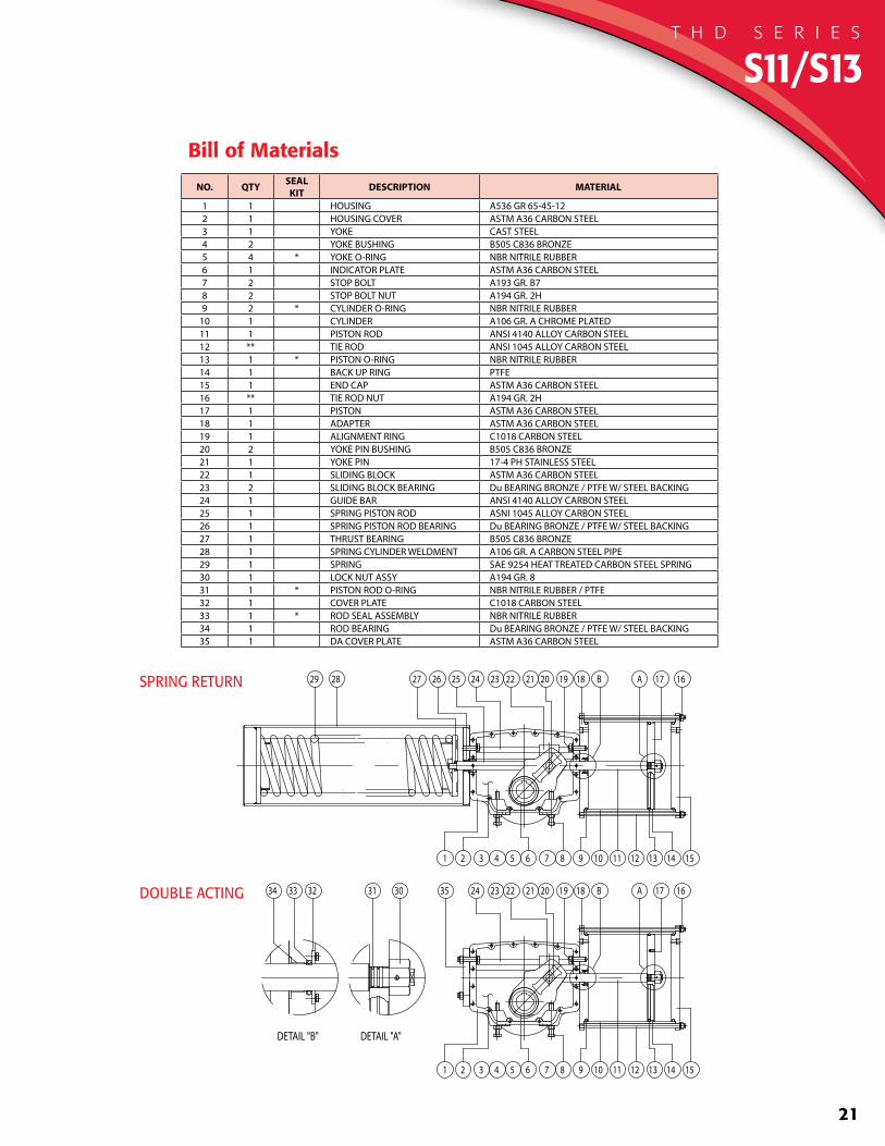
SPRING RETURN
DOUBLE ACTING
16
1 2 3 4 5 6 7 8 9 10 11
17A
12 13 14 15
B181920212223242526272829
16
1 2 3 4 5 6 7 8 9 10 11
17A
12 13 14 15
B18192021222324353031323334
DETAIL "B" DETAIL "A"
Bill of Materials
NO. QTY SEAL KIT DESCRIPTION MATERIAL
1 1 HOUSING A536 GR 65-45-122 1 HOUSING COVER ASTM A36 CARBON STEEL3 1 YOKE CAST STEEL4 2 YOKE BUSHING B505 C836 BRONZE5 4 * YOKE O-RING NBR NITRILE RUBBER6 1 INDICATOR PLATE ASTM A36 CARBON STEEL7 2 STOP BOLT A193 GR. B78 2 STOP BOLT NUT A194 GR. 2H9 2 * CYLINDER O-RING NBR NITRILE RUBBER
10 1 CYLINDER A106 GR. A CHROME PLATED11 1 PISTON ROD ANSI 4140 ALLOY CARBON STEEL12 ** TIE ROD ANSI 1045 ALLOY CARBON STEEL13 1 * PISTON O-RING NBR NITRILE RUBBER14 1 BACK UP RING PTFE15 1 END CAP ASTM A36 CARBON STEEL16 ** TIE ROD NUT A194 GR. 2H17 1 PISTON ASTM A36 CARBON STEEL18 1 ADAPTER ASTM A36 CARBON STEEL19 1 ALIGNMENT RING C1018 CARBON STEEL20 2 YOKE PIN BUSHING B505 C836 BRONZE21 1 YOKE PIN 17-4 PH STAINLESS STEEL22 1 SLIDING BLOCK ASTM A36 CARBON STEEL23 2 SLIDING BLOCK BEARING Du BEARING BRONZE / PTFE W/ STEEL BACKING24 1 GUIDE BAR ANSI 4140 ALLOY CARBON STEEL25 1 SPRING PISTON ROD ASNI 1045 ALLOY CARBON STEEL26 1 SPRING PISTON ROD BEARING Du BEARING BRONZE / PTFE W/ STEEL BACKING27 1 THRUST BEARING B505 C836 BRONZE28 1 SPRING CYLINDER WELDMENT A106 GR. A CARBON STEEL PIPE29 1 SPRING SAE 9254 HEAT TREATED CARBON STEEL SPRING30 1 LOCK NUT ASSY A194 GR. 831 1 * PISTON ROD O-RING NBR NITRILE RUBBER / PTFE32 1 COVER PLATE C1018 CARBON STEEL33 1 * ROD SEAL ASSEMBLY NBR NITRILE RUBBER34 1 ROD BEARING Du BEARING BRONZE / PTFE W/ STEEL BACKING35 1 DA COVER PLATE ASTM A36 CARBON STEEL
S11/S13T H D S E R I E S
22
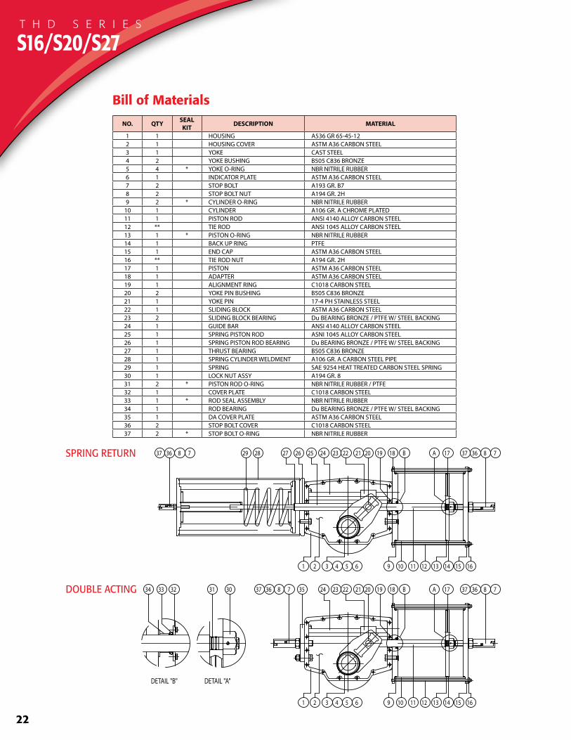
S16/S20/S27
Bill of Materials
NO. QTY SEAL KIT DESCRIPTION MATERIAL
1 1 HOUSING A536 GR 65-45-122 1 HOUSING COVER ASTM A36 CARBON STEEL3 1 YOKE CAST STEEL4 2 YOKE BUSHING B505 C836 BRONZE5 4 * YOKE O-RING NBR NITRILE RUBBER6 1 INDICATOR PLATE ASTM A36 CARBON STEEL7 2 STOP BOLT A193 GR. B78 2 STOP BOLT NUT A194 GR. 2H9 2 * CYLINDER O-RING NBR NITRILE RUBBER
10 1 CYLINDER A106 GR. A CHROME PLATED11 1 PISTON ROD ANSI 4140 ALLOY CARBON STEEL12 ** TIE ROD ANSI 1045 ALLOY CARBON STEEL13 1 * PISTON O-RING NBR NITRILE RUBBER14 1 BACK UP RING PTFE15 1 END CAP ASTM A36 CARBON STEEL16 ** TIE ROD NUT A194 GR. 2H17 1 PISTON ASTM A36 CARBON STEEL18 1 ADAPTER ASTM A36 CARBON STEEL19 1 ALIGNMENT RING C1018 CARBON STEEL20 2 YOKE PIN BUSHING B505 C836 BRONZE21 1 YOKE PIN 17-4 PH STAINLESS STEEL22 1 SLIDING BLOCK ASTM A36 CARBON STEEL23 2 SLIDING BLOCK BEARING Du BEARING BRONZE / PTFE W/ STEEL BACKING24 1 GUIDE BAR ANSI 4140 ALLOY CARBON STEEL25 1 SPRING PISTON ROD ASNI 1045 ALLOY CARBON STEEL26 1 SPRING PISTON ROD BEARING Du BEARING BRONZE / PTFE W/ STEEL BACKING27 1 THRUST BEARING B505 C836 BRONZE28 1 SPRING CYLINDER WELDMENT A106 GR. A CARBON STEEL PIPE29 1 SPRING SAE 9254 HEAT TREATED CARBON STEEL SPRING30 1 LOCK NUT ASSY A194 GR. 831 2 * PISTON ROD O-RING NBR NITRILE RUBBER / PTFE32 1 COVER PLATE C1018 CARBON STEEL33 1 * ROD SEAL ASSEMBLY NBR NITRILE RUBBER34 1 ROD BEARING Du BEARING BRONZE / PTFE W/ STEEL BACKING35 1 DA COVER PLATE ASTM A36 CARBON STEEL36 2 STOP BOLT COVER C1018 CARBON STEEL37 2 * STOP BOLT O-RING NBR NITRILE RUBBER
SPRING RETURN
1 2 3 4 5 6 9 10 11
17A
12 13 14 15
B181920212223242526272829
16
783637783637
DOUBLE ACTING 3031323334
DETAIL "B" DETAIL "A"
1 2 3 4 5 6 9 10 11
17A
12 13 14 15
B18192021222324
16
78363735783637
T H D S E R I E S
23
육각 머리 볼트 납작끝 M12 x 1.75 x 18L S45C
육각 머리 볼트 납작끝 M12 x 1.75 x 18L S45C
육각 머리 볼트 납작끝 M12 x 1.75 x 18L S45C육각 머리 볼트 납작끝 M12 x 1.75 x 18L S45C
육각 머리 볼트 납작끝 M12 x 1.75 x 18L S45C
육각 머리 볼트 납작끝 M12 x 1.75 x 18L S45C
육각 머리 볼트 납작끝 M12 x 1.75 x 18L S45C
육각 머리 볼트 납작끝 M12 x 1.75 x 18L S45C
육각 머리 볼트 납작끝 M12 x 1.75 x 18L S45C
육각 머리 볼트 납작끝 M12 x 1.75 x 18L S45C
육각 머리 볼트 납작끝 M12 x 1.75 x 18L S45C
육각 머리 볼트 납작끝 M12 x 1.75 x 18L S45C
육각 머리 볼트 납작끝 M12 x 1.75 x 18L S45C
육각 머리 볼트 납작끝 M12 x 1.75 x 18L S45C
육각 머리 볼트 납작끝 M12 x 1.75 x 18L S45C
육각 머리 볼트 납작끝M12 x 1.75 x 18LS45C
B
35.04
A
10.44
18.00
18.0
10.44
육각 머리 볼트 납작끝M12 x 1.75 x 18LS45C
육각 머리 볼트 납작끝 M12 x 1.75 x 18L S45C
육각 머리 볼트 납작끝 M12 x 1.75 x 18L S45C
육각 머리 볼트 납작끝 M12 x 1.75 x 18L S45C
육각 머리 볼트 납작끝 M12 x 1.75 x 18L S45C
육각 머리 볼트 납작끝 M12 x 1.75 x 18L S45C
육각 머리 볼트 납작끝 M12 x 1.75 x 18L S45C
육각 머리 볼트 납작끝 M12 x 1.75 x 18L S45C
육각 머리 볼트 납작끝 M12 x 1.75 x 18L S45C
육각 머리 볼트 납작끝 M12 x 1.75 x 18L S45C
육각 머리 볼트 납작끝 M12 x 1.75 x 18L S45C
육각 머리 볼트 납작끝 M12 x 1.75 x 18L S45C
육각 머리 볼트 납작끝 M12 x 1.75 x 18L S45C 육각 머리 볼트 납작끝 M12 x 1.75 x 18L S45C
육각 머리 볼트 납작끝 M12 x 1.75 x 18L S45C
육각 머리 볼트 납작끝 M12 x 1.75 x 18L S45C
B
A
35.04
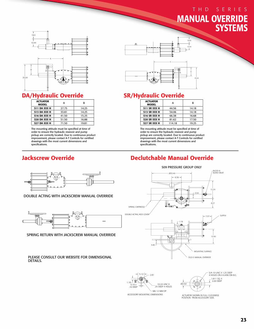
SR/Hydraulic Override
Jackscrew Override Declutchable Manual Override
DA/Hydraulic OverrideACTUATOR
MODEL A B
S11 SR XXX H 44.56 14.18S13 SR XXX H 54.06 14.18S16 SR XXX H 66.38 16.68S20 SR XXX H 81.62 17.50S27 SR XXX H 114.18 19.25
The mounting attitude must be specified at time of order to ensure the hydraulic resevoir and pump pickup are correctly located. Due to continuous product improvement, please contact A-T Controls for certified drawings with the most current dimensions and specifications.
ACTUATORMODEL A B
S11 DA XXX H 27.75 14.25S13 DA XXX H 33.81 14.25S16 DA XXX H 41.50 15.25S20 DA XXX H 51.50 16.88S27 DA XXX H 71.50 19.81
The mounting attitude must be specified at time of order to ensure the hydraulic resevoir and pump pickup are correctly located. Due to continuous product improvement, please contact A-T Controls for certified drawings with the most current dimensions and specifications.
S09 PRESSURE GROUP ONLY
M6 12 MM DP
10-24 UNC X .25 DEEP 4 HOLES
0.16 x.16 DEEP
5.12
1.18
2.81
ACTUATOR SHOWN IN FULL CLOCKWISEPOSITION FROM ACCESSORY SIDE.
ACCESSORY MOUNTING DIMENSIONS
3.54
3/4-10 UNC X 1.25 DEEP4 HOLES ON A 6.496 DIA B.C.
1.811 SQ. X 2.00 DEEP
Ø2.50
15.34
8.27
8.38
Ø33.46
3.40
SUPPLY
DGO-5 MANUAL OVERRIDE
MOUNTING SURFACE
12.50
7.37
BLOCK &BLEED VALVE
1.18
SPRING CARTRIDGE
DOUBLE ACTING ROD COVER
DOUBLE ACTING WITH JACKSCREW MANUAL OVERRIDE
SPRING RETURN WITH JACKSCREW MANUAL OVERRIDE
PLEASE CONSULT OUR WEBSITE FOR DIMENSIONALDETAILS.
MANUAL OVERRIDE SYSTEMS
T H D S E R I E S
24
ACCESSORIEST H D S E R I E S

25
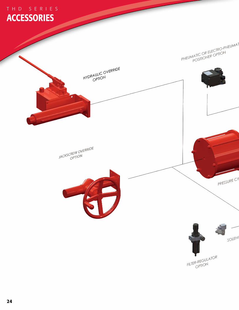
TRIAC Heavy Duty Actuators are available with numerous options and accessories including:• Solenoid Valves• Digital and Analog Positioners• AS-Interface (AS-i)• Spring Return - FCW and FCCW• Filter Regulators• Flow Control Valves• Air Lockup Valves• Air Failsafe Accumulator Systems• Declutchable Gear Overrides
• Hydraulic Overrides• Jackscrew Overrides• Quick Open, Quick Close Circuits• Low Temp and High Temp Seals and Grease• Special Coatings Including Marine and High-Build
Epoxy• Control Boxes• Limit Switches• Position Transmitters
26
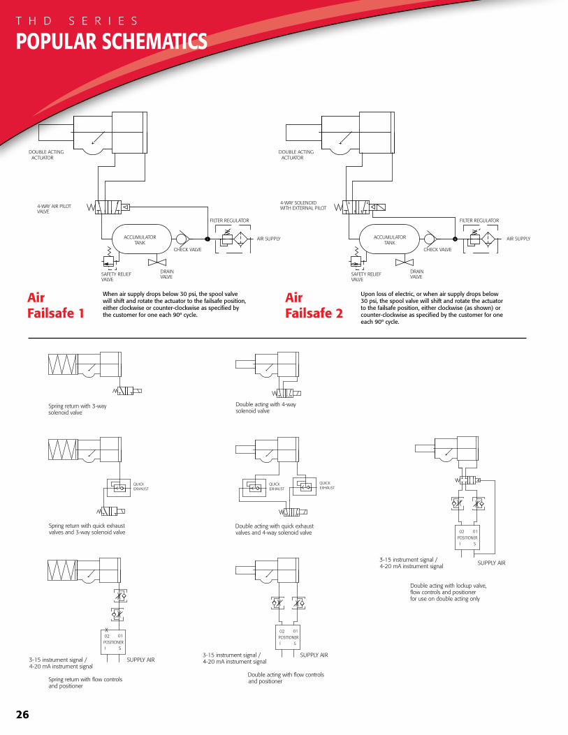
AirFailsafe 1
AirFailsafe 2
TANKACCUMULATOR AIR SUPPLY
CHECK VALVE
ACTUATOR
4-WAY AIR PILOTVALVE
SAFETY RELIEFVALVE
DOUBLE ACTING
DRAINVALVE
FILTER REGULATOR
TANKACCUMULATOR AIR SUPPLY
CHECK VALVE
ACTUATOR
SAFETY RELIEFVALVE
DOUBLE ACTING
DRAINVALVE
FILTER REGULATOR
WITH EXTERNAL PILOT4-WAY SOLENOID
When air supply drops below 30 psi, the spool valve will shift and rotate the actuator to the failsafe position, either clockwise or counter-clockwise as specified by the customer for one each 90º cycle.
Upon loss of electric, or when air supply drops below 30 psi, the spool valve will shift and rotate the actuator to the failsafe position, either clockwise (as shown) or counter-clockwise as specified by the customer for one each 90º cycle.
X02
I
01
SPOSITIONER
3-15 instrument signal /4-20 mA instrument signal
SUPPLY AIR
QUICKEXHAUST EXHAUST
QUICK QUICKEXHAUST
SUPPLY AIR3-15 instrument signal /4-20 mA instrument signal
POSITIONERS
01
I
02
02
I
01
SPOSITIONER
3-15 instrument signal /4-20 mA instrument signal SUPPLY AIR
Double acting with lockup valve,flow controls and positionerfor use on double acting only
Double acting with flow controls and positioner
Double acting with quick exhaust valves and 4-way solenoid valve
Double acting with 4-way solenoid valve
Spring return with 3-way solenoid valve
Spring return with quick exhaust valves and 3-way solenoid valve
Spring return with flow controls and positioner
POPULAR SCHEMATICST H D S E R I E S
27
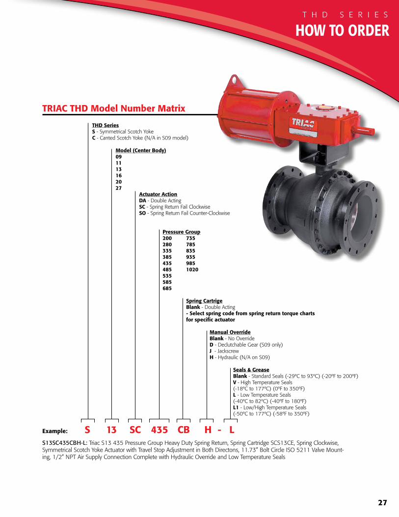
Example: S 13 SC 435 CB H - L S13SC435CBH-L: Triac S13 435 Pressure Group Heavy Duty Spring Return, Spring Cartridge SCS13CE, Spring Clockwise, Symmetrical Scotch Yoke Actuator with Travel Stop Adjustment in Both Directons, 11.73” Bolt Circle ISO 5211 Valve Mount-ing, 1/2” NPT Air Supply Connection Complete with Hydraulic Override and Low Temperature Seals
THD SeriesS - Symmetrical Scotch YokeC - Canted Scotch Yoke (N/A in S09 model)
Model (Center Body) 09 11 13 16 20 27 Actuator Action DA - Double Acting SC - Spring Return Fail Clockwise SO - Spring Return Fail Counter-Clockwise
Pressure Group 200 735 280 785 335 835 385 935 435 985 485 1020 535 585 685
Spring Cartrige Blank - Double Acting - Select spring code from spring return torque charts for specific actuator
Manual Override Blank - No Override D - Declutchable Gear (S09 only) J - Jackscrew H - Hydraulic (N/A on S09)
Seals & Grease Blank - Standard Seals (-29ºC to 93ºC) (-20ºF to 200ºF) V - High Temperature Seals (-18ºC to 177ºC) (0ºF to 350ºF) L - Low Temperature Seals (-40ºC to 82ºC) (-40ºF to 180ºF) L1 - Low/High Temperature Seals (-50ºC to 177ºC) (-58ºF to 350ºF)
TRIAC THD Model Number Matrix
HOW TO ORDERT H D S E R I E S
28
Other A-T Controls products include:
Rack and Pinion Actuators
Gear OperatorsElectric Actuators
Automated Ball Valve Packages
THDS E R I E S
A-T Controls, Inc.9955 International Blvd.Cincinnati, OH 45246PH: 513 - 247- 5465FAX: 513 - 247 - [email protected]
www.atcontrols.com
THD-20201209Copyright 2013 A-T Controls, Inc.LIT0006
Related Documents


