Manufacturer reserves the right to discontinue, or change at any time, specifications or designs without notice and without incurring obligations. Catalog No. 04-53190058-01 Printed in U.S.A. Form 19XR-CLT-5T Pg 1 9-19 Replaces: NEW Controls Operation and Troubleshooting SAFETY CONSIDERATIONS . . . . . . . . . . . . . . . . . . . . 1 GENERAL . . . . . . . . . . . . . . . . . . . . . . . . . . . . . . . . . . . 2 Abbreviations Used in This Manual . . . . . . . . . . . . . . 2 HARDWARE . . . . . . . . . . . . . . . . . . . . . . . . . . . . . . . . . 2 Main Control Board . . . . . . . . . . . . . . . . . . . . . . . . . . . 2 ISM (Integrated Starter Module) — Option. . . . . . . . . 2 IOB (Input/Output Board) . . . . . . . . . . . . . . . . . . . . . . 4 • IOB CONFIGURATION • IOB COMPONENTS AND WIRING Communication Cables . . . . . . . . . . . . . . . . . . . . . . . . 4 • IOB LAYOUT Sensors . . . . . . . . . . . . . . . . . . . . . . . . . . . . . . . . . . . . 21 • PRESSURE TRANSDUCERS • TEMPERATURE SENSORS Controls Outputs . . . . . . . . . . . . . . . . . . . . . . . . . . . . 21 • EVAPORATOR/CONDENSER WATER PUMP • INLET GUIDE VANE • ECONOMIZER DAMPER VALVE • ENVELOP CONTROL/HGBP VALVE • ECONOMIZER BYPASS VALVE • VFD PIC 6 USER INTERFACE . . . . . . . . . . . . . . . . . . . . . . 21 Web Connection . . . . . . . . . . . . . . . . . . . . . . . . . . . . . 21 General Interface Features . . . . . . . . . . . . . . . . . . . . 22 • ICONS • SCREENS PIC 6 CONTROL OPERATION . . . . . . . . . . . . . . . . . . 26 Start-Stop Control . . . . . . . . . . . . . . . . . . . . . . . . . . . 26 • LOCAL • LOCAL SCHEDULE • REMOTE • NETWORK Compressor Run Status . . . . . . . . . . . . . . . . . . . . . . 26 Chiller Start-Up Sequence . . . . . . . . . . . . . . . . . . . . . 26 • PRE-START CHECK • START-UP Chiller Shutdown Sequence . . . . . . . . . . . . . . . . . . . 27 Oil Lubrication Control . . . . . . . . . . . . . . . . . . . . . . . 27 Control Points . . . . . . . . . . . . . . . . . . . . . . . . . . . . . . 28 • SET POINT • CONTROL POINT TEMPERATURE • TEMPERATURE RESET • CAPACITY CONTROL • RAMP LOADING • SURGE CORRECTION CONTROL • ENVELOP/HOT GAS BYPASS (HGBP) CONTROL • ECONOMIZER DAMPER VALVE CONTROL (FOR APPLICABLE UNITS) • DEMAND LIMIT • OVERRIDE CONTROL • RECYCLE CONTROL • RUNNING TIMERS AND COUNTERS • WATER PUMPS CONTROL (FREEZE PREVENTION) • CONTROL TEST • SWIFT RESTART (CAPACITY RECOVERY™) • COOLING TOWER CONTROL • HEAD PRESSURE CONTROL • ICE BUILD OPTION • TIME SCHEDULE • BLACK BOX • PRESSURE TRANSDUCER CALIBRATION • TEMPERATURE SENSOR CALIBRATION • ISM VFD INPUT/OUTPUT CALIBRATION • ALARM EMAIL • PROGNOSTICS • MASTER SLAVE CONTROL Oil EXV Option . . . . . . . . . . . . . . . . . . . . . . . . . . . . . . 36 Pumpdown/Lockout . . . . . . . . . . . . . . . . . . . . . . . . . . 36 Displaying Data Trends . . . . . . . . . . . . . . . . . . . . . . . 37 Hydraulic Option . . . . . . . . . . . . . . . . . . . . . . . . . . . . . 37 • WATER FLOW MEASUREMENT • WATER PRESSURE DIFFERENCE MEASUREMENT • MARINE OPTION(S) DIAGNOSTICS AND TROUBLESHOOTING. . . . . . . . 38 Displaying Alarms. . . . . . . . . . . . . . . . . . . . . . . . . . . . 38 Resetting Alarms . . . . . . . . . . . . . . . . . . . . . . . . . . . . 38 Alarm/Alert Codes. . . . . . . . . . . . . . . . . . . . . . . . . . . . 38 Event States . . . . . . . . . . . . . . . . . . . . . . . . . . . . . . . . 56 SETTINGS FOR THE CONTROLLER . . . . . . . . . . . . . 56 Unit IP Address . . . . . . . . . . . . . . . . . . . . . . . . . . . . . . 56 • TOUCH SCREEN CALIBRATION Touch Screen Configuration Language and Units . 57 COMMUNICATION PROBLEMS . . . . . . . . . . . . . . . . . 57 Hardware Problems . . . . . . . . . . . . . . . . . . . . . . . . . . 57 Web Interface Problems . . . . . . . . . . . . . . . . . . . . . . . 57 Ethernet/IP Connection Problems . . . . . . . . . . . . . . . 57 • UNIT IS POINT-TO-POINT CONNECTED TO A PC • UNIT IS CONNECTED TO THE LOCAL NETWORK • ETHERNET CONNECTION ON THE PC • JAVA APPLICATION CONFIGURATION APPENDIX A — PIC 6 SCREEN AND TABLE STRUCTURE . . . . . . . . . . . . . . . . . . . . . . . . . . . . . . 60 APPENDIX B — INPUT/OUTPUT BOARD (IOB) AND HUMAN MACHINE INTERFACE (HMI) DIP SWITCH SETTINGS . . . . . . . . . . . . . . . . . . . . . 98 APPENDIX C — INPUT/OUTPUT BOARD (IOB) STATUS INDICATORS . . . . . . . . . . . . . . . . . . . . . . 99 APPENDIX D — PROTOCOL CONFIGURATION. . .100 SAFETY CONSIDERATIONS Installing, starting up, and servicing this equipment can be hazard- ous due to system pressures, electrical components, and equip- ment location (roof, elevated structures, etc.). Only trained, quali- fied installers and service mechanics should install, start up, and service this equipment. When working on this equipment, observe precautions in the literature, and on tags, stickers, and labels at- tached to the equipment, and any other safety precautions that ap- ply. Follow all safety codes. Wear safety glasses and work gloves. Use care in handling, rigging, and setting this equipment, and in handling all electrical components. AquaEdge ® 19XR Single-Stage and Two-Stage High-Efficiency Semi-Hermetic Centrifugal Liquid Chillers with PIC 6 Controls Version 2.0

Welcome message from author
This document is posted to help you gain knowledge. Please leave a comment to let me know what you think about it! Share it to your friends and learn new things together.
Transcript
Manufacturer reserves the right to discontinue, or change at any time, specifications or designs without notice and without incurring obligations.Catalog No. 04-53190058-01 Printed in U.S.A. Form 19XR-CLT-5T Pg 1 9-19 Replaces: NEW
Controls Operation and TroubleshootingSAFETY CONSIDERATIONS . . . . . . . . . . . . . . . . . . . . 1GENERAL . . . . . . . . . . . . . . . . . . . . . . . . . . . . . . . . . . . 2Abbreviations Used in This Manual . . . . . . . . . . . . . . 2HARDWARE . . . . . . . . . . . . . . . . . . . . . . . . . . . . . . . . . 2Main Control Board . . . . . . . . . . . . . . . . . . . . . . . . . . . 2ISM (Integrated Starter Module) — Option. . . . . . . . . 2IOB (Input/Output Board) . . . . . . . . . . . . . . . . . . . . . . 4• IOB CONFIGURATION• IOB COMPONENTS AND WIRINGCommunication Cables . . . . . . . . . . . . . . . . . . . . . . . . 4• IOB LAYOUTSensors . . . . . . . . . . . . . . . . . . . . . . . . . . . . . . . . . . . . 21• PRESSURE TRANSDUCERS• TEMPERATURE SENSORSControls Outputs . . . . . . . . . . . . . . . . . . . . . . . . . . . . 21• EVAPORATOR/CONDENSER WATER PUMP• INLET GUIDE VANE• ECONOMIZER DAMPER VALVE• ENVELOP CONTROL/HGBP VALVE• ECONOMIZER BYPASS VALVE• VFDPIC 6 USER INTERFACE . . . . . . . . . . . . . . . . . . . . . . 21Web Connection. . . . . . . . . . . . . . . . . . . . . . . . . . . . . 21General Interface Features . . . . . . . . . . . . . . . . . . . . 22• ICONS• SCREENSPIC 6 CONTROL OPERATION . . . . . . . . . . . . . . . . . . 26Start-Stop Control . . . . . . . . . . . . . . . . . . . . . . . . . . . 26• LOCAL• LOCAL SCHEDULE• REMOTE• NETWORKCompressor Run Status . . . . . . . . . . . . . . . . . . . . . . 26Chiller Start-Up Sequence. . . . . . . . . . . . . . . . . . . . . 26• PRE-START CHECK• START-UPChiller Shutdown Sequence . . . . . . . . . . . . . . . . . . . 27Oil Lubrication Control . . . . . . . . . . . . . . . . . . . . . . . 27Control Points . . . . . . . . . . . . . . . . . . . . . . . . . . . . . . 28• SET POINT• CONTROL POINT TEMPERATURE• TEMPERATURE RESET• CAPACITY CONTROL• RAMP LOADING• SURGE CORRECTION CONTROL• ENVELOP/HOT GAS BYPASS (HGBP) CONTROL• ECONOMIZER DAMPER VALVE CONTROL (FOR
APPLICABLE UNITS)• DEMAND LIMIT• OVERRIDE CONTROL• RECYCLE CONTROL• RUNNING TIMERS AND COUNTERS• WATER PUMPS CONTROL (FREEZE PREVENTION)• CONTROL TEST• SWIFT RESTART (CAPACITY RECOVERY™)• COOLING TOWER CONTROL
• HEAD PRESSURE CONTROL• ICE BUILD OPTION• TIME SCHEDULE• BLACK BOX• PRESSURE TRANSDUCER CALIBRATION• TEMPERATURE SENSOR CALIBRATION• ISM VFD INPUT/OUTPUT CALIBRATION• ALARM EMAIL• PROGNOSTICS• MASTER SLAVE CONTROLOil EXV Option . . . . . . . . . . . . . . . . . . . . . . . . . . . . . .36Pumpdown/Lockout . . . . . . . . . . . . . . . . . . . . . . . . . .36Displaying Data Trends . . . . . . . . . . . . . . . . . . . . . . .37Hydraulic Option. . . . . . . . . . . . . . . . . . . . . . . . . . . . .37• WATER FLOW MEASUREMENT• WATER PRESSURE DIFFERENCE MEASUREMENT• MARINE OPTION(S)DIAGNOSTICS AND TROUBLESHOOTING. . . . . . . .38Displaying Alarms. . . . . . . . . . . . . . . . . . . . . . . . . . . .38Resetting Alarms . . . . . . . . . . . . . . . . . . . . . . . . . . . .38Alarm/Alert Codes. . . . . . . . . . . . . . . . . . . . . . . . . . . .38Event States . . . . . . . . . . . . . . . . . . . . . . . . . . . . . . . .56SETTINGS FOR THE CONTROLLER . . . . . . . . . . . . .56Unit IP Address . . . . . . . . . . . . . . . . . . . . . . . . . . . . . .56• TOUCH SCREEN CALIBRATIONTouch Screen Configuration Language and Units . 57COMMUNICATION PROBLEMS . . . . . . . . . . . . . . . . .57Hardware Problems . . . . . . . . . . . . . . . . . . . . . . . . . .57Web Interface Problems. . . . . . . . . . . . . . . . . . . . . . .57Ethernet/IP Connection Problems. . . . . . . . . . . . . . .57• UNIT IS POINT-TO-POINT CONNECTED TO A PC• UNIT IS CONNECTED TO THE LOCAL NETWORK• ETHERNET CONNECTION ON THE PC• JAVA APPLICATION CONFIGURATIONAPPENDIX A — PIC 6 SCREEN AND TABLE
STRUCTURE . . . . . . . . . . . . . . . . . . . . . . . . . . . . . .60APPENDIX B — INPUT/OUTPUT BOARD (IOB)
AND HUMAN MACHINE INTERFACE (HMI)DIP SWITCH SETTINGS . . . . . . . . . . . . . . . . . . . . .98
APPENDIX C — INPUT/OUTPUT BOARD (IOB) STATUS INDICATORS . . . . . . . . . . . . . . . . . . . . . .99
APPENDIX D — PROTOCOL CONFIGURATION. . .100
SAFETY CONSIDERATIONSInstalling, starting up, and servicing this equipment can be hazard-ous due to system pressures, electrical components, and equip-ment location (roof, elevated structures, etc.). Only trained, quali-fied installers and service mechanics should install, start up, andservice this equipment. When working on this equipment, observeprecautions in the literature, and on tags, stickers, and labels at-tached to the equipment, and any other safety precautions that ap-ply. Follow all safety codes. Wear safety glasses and work gloves.Use care in handling, rigging, and setting this equipment, and inhandling all electrical components.
AquaEdge®
19XR Single-Stage and Two-Stage High-EfficiencySemi-Hermetic Centrifugal Liquid Chillers
with PIC 6 Controls Version 2.0
2
GENERAL
This publication contains operation and troubleshooting infor-mation for PIC (Product Integrated Control) 6, a system forcontrolling 19XR semi-hermetic centrifugal liquid chillers.This publication is based on 19XR PIC 6 Version 2.0 software(SCG-SR-20S200200).The PIC 6 control system monitors and controls all operations ofthe chiller. The microprocessor control system matches the capac-ity of the chiller to the cooling load while providing state-of-the-art chiller protection. The system controls cooling load within theset point plus or minus the dead band by sensing the water or brinetemperature and regulating the inlet guide vane via a mechanicallylinked actuator motor, and regulating VFD (variable frequencydrive) speed if the compressor is powered by a variable speeddrive. The guide vane is a variable flow pre-whirl assembly thatcontrols the refrigeration effect in the cooler by regulating theamount of refrigerant vapor flow into the compressor. An increase
in guide vane opening increases capacity. A decrease in guidevane opening decreases capacity. The microprocessor-based con-trol center protects the chiller by monitoring the digital and analoginputs and executing capacity overrides or safety shutdowns asnecessary.The PIC 6 control system also provides access to a Control Testfunction covering all outputs except compressor relay outputs.
Abbreviations Used in This Manual The following abbreviations are used in this manual:
HARDWAREThe PIC 6 control system consists of one main control boardand up to four IOBs (input/output board modules). All boardscommunicate via an internal LEN bus. PIC 6 is compatiblewith unit-mounted VFD/starter options that do not utilize anISM (integrated starter module). For this application LEN isconverted to Modbus protocol for starter communication. De-pending upon option the conversion is either native to PIC 6 oran converter module is used.
Main Control Board The main control board is supplied from a 24 VAC supply refer-ence to earth ground. In the event of a power supply interrupt,the unit restarts automatically without the need for an externalcommand. However, any faults active when the supply is inter-rupted are saved, and may in certain cases prevent a circuit orunit from restarting. Figure 1 shows the main controller interfaceand connectors.
ISM (Integrated Starter Module) — Option The ISM is the motor control module, used for starters/VFDswhich do not have direct communication via Modbus. Ifequipped the ISM is located in the starter enclosure and is the in-terface between the starter and the PIC 6 controls; its function isto provide motor protection and starter control. The ISM is pow-ered by single phase 115 VAC, 50 Hz or 60 Hz source. Table 1lists ISM inputs and outputs. Figure 2 shows the ISM physicallayout.
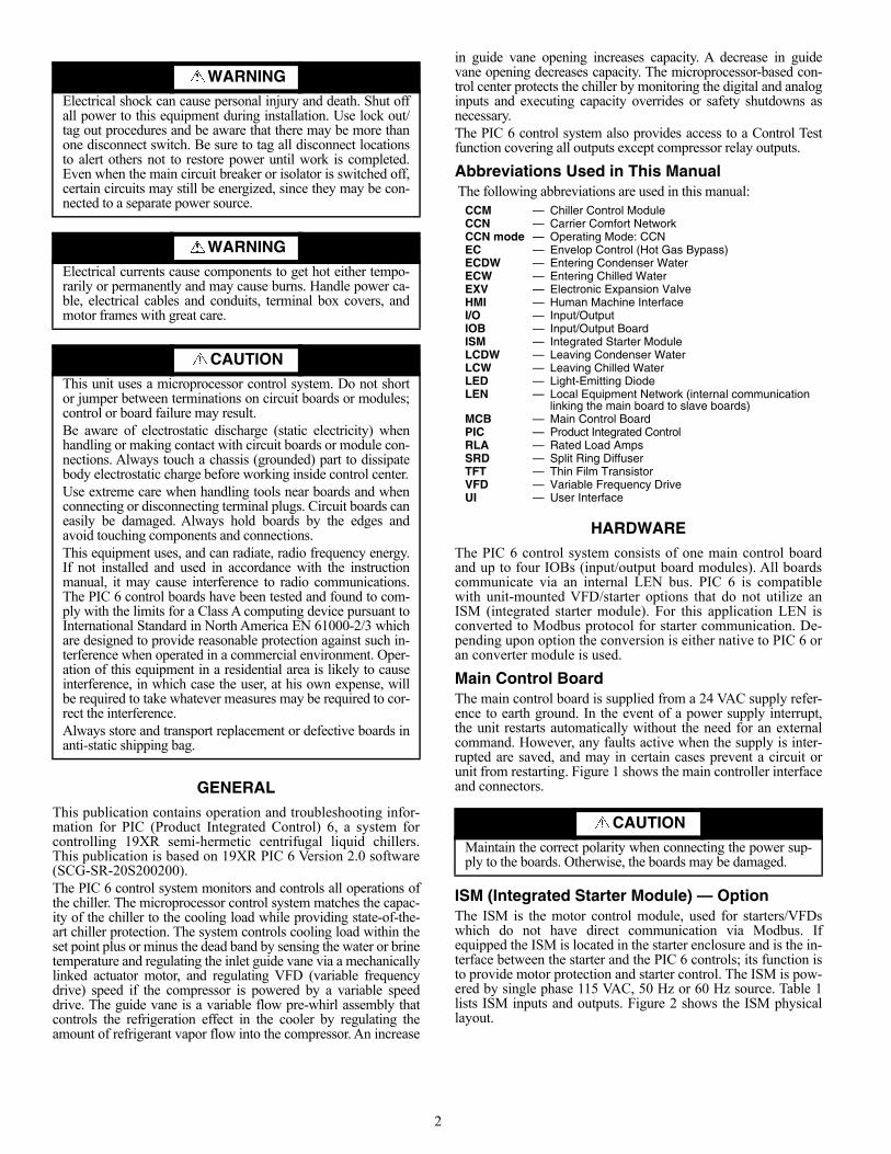
WARNINGElectrical shock can cause personal injury and death. Shut offall power to this equipment during installation. Use lock out/tag out procedures and be aware that there may be more thanone disconnect switch. Be sure to tag all disconnect locationsto alert others not to restore power until work is completed.Even when the main circuit breaker or isolator is switched off,certain circuits may still be energized, since they may be con-nected to a separate power source.
WARNINGElectrical currents cause components to get hot either tempo-rarily or permanently and may cause burns. Handle power ca-ble, electrical cables and conduits, terminal box covers, andmotor frames with great care.
CAUTIONThis unit uses a microprocessor control system. Do not shortor jumper between terminations on circuit boards or modules;control or board failure may result.Be aware of electrostatic discharge (static electricity) whenhandling or making contact with circuit boards or module con-nections. Always touch a chassis (grounded) part to dissipatebody electrostatic charge before working inside control center.Use extreme care when handling tools near boards and whenconnecting or disconnecting terminal plugs. Circuit boards caneasily be damaged. Always hold boards by the edges andavoid touching components and connections.This equipment uses, and can radiate, radio frequency energy.If not installed and used in accordance with the instructionmanual, it may cause interference to radio communications.The PIC 6 control boards have been tested and found to com-ply with the limits for a Class A computing device pursuant toInternational Standard in North America EN 61000-2/3 whichare designed to provide reasonable protection against such in-terference when operated in a commercial environment. Oper-ation of this equipment in a residential area is likely to causeinterference, in which case the user, at his own expense, willbe required to take whatever measures may be required to cor-rect the interference.Always store and transport replacement or defective boards inanti-static shipping bag.
CCM — Chiller Control ModuleCCN — Carrier Comfort NetworkCCN mode — Operating Mode: CCNEC — Envelop Control (Hot Gas Bypass)ECDW — Entering Condenser WaterECW — Entering Chilled Water EXV — Electronic Expansion ValveHMI — Human Machine InterfaceI/O — Input/OutputIOB — Input/Output BoardISM — Integrated Starter ModuleLCDW — Leaving Condenser WaterLCW — Leaving Chilled WaterLED — Light-Emitting DiodeLEN — Local Equipment Network (internal communication
linking the main board to slave boards)MCB — Main Control BoardPIC — Product Integrated ControlRLA — Rated Load AmpsSRD — Split Ring DiffuserTFT — Thin Film TransistorVFD — Variable Frequency DriveUI — User Interface
CAUTION
Maintain the correct polarity when connecting the power sup-ply to the boards. Otherwise, the boards may be damaged.
3
Fig. 1 — PIC 6 Connectors
Table 1 — ISM Input/Output Descriptions
Fig. 2 — Integrated Starter Module (ISM)
J1: USBJ5: USB ConnectorJ6: LEN ConnectorJ7: CCN ConnectorJ8: BACnet MS/TP or Modbus RTUJ9: RNETJ10: RS485, Modbus/RTU Comm to VFD StarterJ11: USBJ14: Power Supply Connector (24 VAC)J15: Ethernet Connector (Port 0, default IP169.254.0.1, mask 255.255.0.0). BACnet/IP orModbus TCP/IP. J16: Ethernet Connector (Port 1, default IP:192.168.100.100, mask 255.255.255.0)
PIC 6 SIDE VIEW
PIC 6 BOTTOM VIEW
NOTES:1. Either BACnet/MSTP or BACnet/IP can be enabled
and either Modbus/RTU or Modbus/TCP/IP can beenabled. Controller does not allow both to beenabled at the same time.
2. Modbus RTU can be configured simultaneouslywith BACnet IP.
3. BACnet MS/TP can be configured simultaneouslywith Modbus TCP/IP.
J1
J11
J15
DESCRIPTION POINT NAME TYPE PIN NUMBER INPUT/OUTPUTCommunication COMM Dry contact J7-A,B,C Input/OutputCompressor Run Contact RUN_AUX Dry contact J2-11,12 InputCompressor Start Contact STAR_AUX Dry contact J2-9,10 InputCompressor Start Relay COMP_SR Relay J9-1,2 OutputCompressor Transition Relay TRANS Relay J9-3,4 OutputGround Fault Phase 1 GRFLT_31 0 to 5 V J5-1,2 InputGround Fault Phase 2 GRFLT_23 0 to 5 V J5-3,4 InputGround Fault Phase 3 GRFLT_12 0 to 5 V J5-5,6 InputLine Current C1 LN_AMPS1 0 to 5 A (RMS) J4-1,2 InputLine Current C2 LN_AMPS2 0 to 5 A (RMS) J4-3,4 InputLine Current C3 LN_AMPS3 0 to 5 A (RMS) J4-5,6 InputLine Voltage V1 LN_VOLT1 0 to 575 VAC J3-1 InputLine Voltage V2 LN_VOLT2 0 to 575 VAC J3-2 InputLine Voltage V3 LN_VOLT3 0 to 575 VAC J3-3 InputShunt Trip Relay TRIPR Relay J9-5,6 OutputStarter Fault STARTFELT Dry contact J2-7,8 Input
VFD Speed Feedback VFD_IN 0 to 5 V (default), or0 to 10 V (selectable) J6-1,2 Input
VFD Target Speed VFD_OUT 0 to 20 mA J8-1,2 Output
115 VACLL1 LL2 1A
CONTACT INPUTS
SPAR ICE REM STRT 1M 2MSFTY BLD STRT FLT AUX AUX
FUSE LINE VOLTAGESL1 L2 L3 IL1
LINE CURRENTSGROUND FAULTS
IL2 IL3 1/4 2/5 3/6VFD HZ
INT
ER
GR
AT
ED
STA
RT
ER
MO
DU
LE
1A
J11 1 + C + C + C + C + C + C
J2
J3-1 J3-2 J3-3
J4
1 + - + - + -
J5
1 + G + G + G + G1
J6
STATCOM
-J7
- G +1G + G +
J8
1J9
1
COMM
C B A4-20 MA OUTSPARE VFD
TRIPALARM
HIFAN
LOFAN
CONDPUMP
EVAPPUMP
SHUNTTRIP
DISCRETE CONTROL CONTACTS
TRANS1CR
R
WA
RN
ING
HIG
H V
OLTA
GE
DIS
CO
NN
EC
T P
OW
ER
BE
FO
RE
SE
RV
ICIN
G
ISM
19XR
04012201 9925C
EP
L13025901 PC
B05
CE
PP
130173-03-04-0100001328
WA
RN
ING
HIG
H V
OLT
AG
ED
ISC
ON
NE
CT
PO
WE
R B
EF
OR
E S
ER
VIC
ING
INTEGRATED STARTER MODULE
4
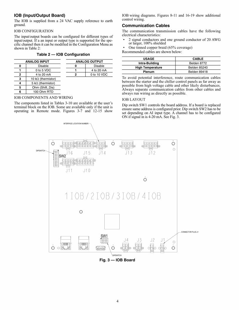
IOB (Input/Output Board) The IOB is supplied from a 24 VAC supply reference to earthground.
IOB CONFIGURATION
The input/output boards can be configured for different types ofinput/output. If a an input or output type is supported for the spe-cific channel then it can be modified in the Configuration Menu asshown in Table 2:
Table 2 — IOB Configuration
IOB COMPONENTS AND WIRING
The components listed in Tables 3-10 are available at the user’sterminal block on the IOB. Some are available only if the unit isoperating in Remote mode. Figures 3-7 and 12-15 show
IOB wiring diagrams. Figures 8-11 and 16-19 show additionalcontrol wiring.
Communication Cables The communication transmission cables have the followingelectrical characteristics:• 2 signal conductors and one ground conductor of 20 AWG
or larger, 100% shielded• One tinned copper braid (65% coverage)
Recommended cables are shown below:
To avoid potential interference, route communication cablesbetween the starter and the chiller control panels as far away aspossible from high voltage cable and other likely disturbances.Always separate communication cables from other cables andalways run wiring as directly as possible.
IOB LAYOUT
Dip switch SW1 controls the board address. If a board is replacedensure same address is configured prior. Dip switch SW2 has to beset depending on AI input type. A channel has to be configuredON if signal in is 4-20 mA. See Fig. 3.
Fig. 3 — IOB Board
ANALOG INPUT ANALOG OUTPUT0 Disable 0 Disable1 0 to 5 VDC 1 4 to 20 mA2 4 to 20 mA 2 0 to 10 VDC3 10 k (thermistor)4 5 k (thermistor)5 Ohm (Shift_Dis)6 100 Ohm RTD
USAGE CABLEIntra-Building Belden 8772
High Temperature Belden 85240Plenum Belden 89418
INTERFACE LOCATION NUMBER
SW2
SW1
DIPSWITCH
DIPSWITCH
CONNECTOR PLUG J1
5
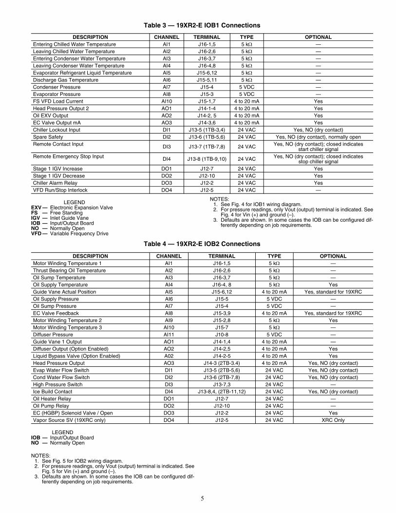
Table 3 — 19XR2-E IOB1 Connections
NOTES:1. See Fig. 4 for IOB1 wiring diagram.2. For pressure readings, only Vout (output) terminal is indicated. See
Fig. 4 for Vin (+) and ground (–).3. Defaults are shown. In some cases the IOB can be configured dif-
ferently depending on job requirements.
Table 4 — 19XR2-E IOB2 Connections
NOTES:1. See Fig. 5 for IOB2 wiring diagram.2. For pressure readings, only Vout (output) terminal is indicated. See
Fig. 5 for Vin (+) and ground (–).3. Defaults are shown. In some cases the IOB can be configured dif-
ferently depending on job requirements.
DESCRIPTION CHANNEL TERMINAL TYPE OPTIONALEntering Chilled Water Temperature AI1 J16-1,5 5 k —Leaving Chilled Water Temperature AI2 J16-2,6 5 k —Entering Condenser Water Temperature AI3 J16-3,7 5 k —Leaving Condenser Water Temperature AI4 J16-4,8 5 k —Evaporator Refrigerant Liquid Temperature AI5 J15-6,12 5 k —Discharge Gas Temperature AI6 J15-5,11 5 k —Condenser Pressure AI7 J15-4 5 VDC —Evaporator Pressure AI8 J15-3 5 VDC —FS VFD Load Current AI10 J15-1,7 4 to 20 mA YesHead Pressure Output 2 AO1 J14-1-4 4 to 20 mA YesOil EXV Output AO2 J14-2, 5 4 to 20 mA YesEC Valve Output mA AO3 J14-3,6 4 to 20 mA YesChiller Lockout Input DI1 J13-5 (1TB-3,4) 24 VAC Yes, NO (dry contact)Spare Safety DI2 J13-6 (1TB-5,6) 24 VAC Yes, NO (dry contact), normally openRemote Contact Input DI3 J13-7 (1TB-7,8) 24 VAC Yes, NO (dry contact); closed indicates
start chiller signalRemote Emergency Stop Input DI4 J13-8 (1TB-9,10) 24 VAC Yes, NO (dry contact); closed indicates
stop chiller signalStage 1 IGV Increase DO1 J12-7 24 VAC YesStage 1 IGV Decrease DO2 J12-10 24 VAC YesChiller Alarm Relay DO3 J12-2 24 VAC YesVFD Run/Stop Interlock DO4 J12-5 24 VAC —
LEGENDEXV — Electronic Expansion ValveFS — Free StandingIGV — Inlet Guide VaneIOB — Input/Output BoardNO — Normally OpenVFD — Variable Frequency Drive
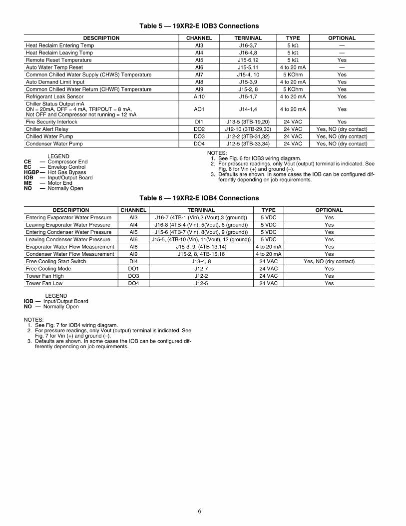
DESCRIPTION CHANNEL TERMINAL TYPE OPTIONALMotor Winding Temperature 1 AI1 J16-1,5 5 k —Thrust Bearing Oil Temperature AI2 J16-2,6 5 k —Oil Sump Temperature AI3 J16-3,7 5 k —Oil Supply Temperature AI4 J16-4, 8 5 k YesGuide Vane Actual Position AI5 J15-6,12 4 to 20 mA Yes, standard for 19XRCOil Supply Pressure AI6 J15-5 5 VDC —Oil Sump Pressure AI7 J15-4 5 VDC —EC Valve Feedback AI8 J15-3,9 4 to 20 mA Yes, standard for 19XRCMotor Winding Temperature 2 AI9 J15-2,8 5 k YesMotor Winding Temperature 3 AI10 J15-7 5 k —Diffuser Pressure AI11 J10-8 5 VDC —Guide Vane 1 Output AO1 J14-1,4 4 to 20 mA —Diffuser Output (Option Enabled) AO2 J14-2,5 4 to 20 mA YesLiquid Bypass Valve (Option Enabled) A02 J14-2-5 4 to 20 mA YesHead Pressure Output AO3 J14-3 (2TB-3.4) 4 to 20 mA Yes, NO (dry contact)Evap Water Flow Switch DI1 J13-5 (2TB-5,6) 24 VAC Yes, NO (dry contact)Cond Water Flow Switch DI2 J13-6 (2TB-7,8) 24 VAC Yes, NO (dry contact)High Pressure Switch DI3 J13-7,3 24 VAC —Ice Build Contact DI4 J13-8,4, (2TB-11,12) 24 VAC Yes, NO (dry contact)Oil Heater Relay DO1 J12-7 24 VAC —Oil Pump Relay DO2 J12-10 24 VAC —EC (HGBP) Solenoid Valve / Open DO3 J12-2 24 VAC YesVapor Source SV (19XRC only) DO4 J12-5 24 VAC XRC Only
LEGENDIOB — Input/Output BoardNO — Normally Open
6
Table 5 — 19XR2-E IOB3 Connections
NOTES:1. See Fig. 6 for IOB3 wiring diagram.2. For pressure readings, only Vout (output) terminal is indicated. See
Fig. 6 for Vin (+) and ground (–).3. Defaults are shown. In some cases the IOB can be configured dif-
ferently depending on job requirements.
Table 6 — 19XR2-E IOB4 Connections
NOTES:1. See Fig. 7 for IOB4 wiring diagram.2. For pressure readings, only Vout (output) terminal is indicated. See
Fig. 7 for Vin (+) and ground (–).3. Defaults are shown. In some cases the IOB can be configured dif-
ferently depending on job requirements.
DESCRIPTION CHANNEL TERMINAL TYPE OPTIONALHeat Reclaim Entering Temp AI3 J16-3,7 5 k —Heat Reclaim Leaving Temp AI4 J16-4,8 5 k —Remote Reset Temperature AI5 J15-6,12 5 k YesAuto Water Temp Reset AI6 J15-5,11 4 to 20 mA —Common Chilled Water Supply (CHWS) Temperature AI7 J15-4, 10 5 KOhm YesAuto Demand Limit Input AI8 J15-3,9 4 to 20 mA YesCommon Chilled Water Return (CHWR) Temperature AI9 J15-2, 8 5 KOhm YesRefrigerant Leak Sensor AI10 J15-1,7 4 to 20 mA YesChiller Status Output mAON = 20mA, OFF = 4 mA, TRIPOUT = 8 mA,Not OFF and Compressor not running = 12 mA
AO1 J14-1,4 4 to 20 mA Yes
Fire Security Interlock DI1 J13-5 (3TB-19,20) 24 VAC YesChiller Alert Relay DO2 J12-10 (3TB-29,30) 24 VAC Yes, NO (dry contact)Chilled Water Pump DO3 J12-2 (3TB-31,32) 24 VAC Yes, NO (dry contact)Condenser Water Pump DO4 J12-5 (3TB-33,34) 24 VAC Yes, NO (dry contact)
LEGENDCE — Compressor EndEC — Envelop ControlHGBP— Hot Gas BypassIOB — Input/Output BoardME — Motor EndNO — Normally Open
DESCRIPTION CHANNEL TERMINAL TYPE OPTIONALEntering Evaporator Water Pressure AI3 J16-7 (4TB-1 (Vin),2 (Vout),3 (ground)) 5 VDC YesLeaving Evaporator Water Pressure AI4 J16-8 (4TB-4 (Vin), 5(Vout), 6 (ground)) 5 VDC YesEntering Condenser Water Pressure AI5 J15-6 (4TB-7 (Vin), 8(Vout), 9 (ground)) 5 VDC YesLeaving Condenser Water Pressure AI6 J15-5, (4TB-10 (Vin), 11(Vout), 12 (ground)) 5 VDC YesEvaporator Water Flow Measurement AI8 J15-3, 9, (4TB-13,14) 4 to 20 mA YesCondenser Water Flow Measurement AI9 J15-2, 8, 4TB-15,16 4 to 20 mA YesFree Cooling Start Switch DI4 J13-4, 8 24 VAC Yes, NO (dry contact)Free Cooling Mode DO1 J12-7 24 VAC YesTower Fan High DO3 J12-2 24 VAC YesTower Fan Low DO4 J12-5 24 VAC Yes
LEGENDIOB — Input/Output BoardNO — Normally Open
7
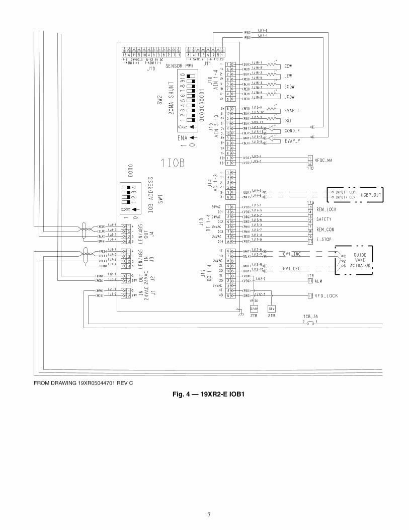
Fig. 4 — 19XR2-E IOB1
FROM DRAWING 19XR05044701 REV C
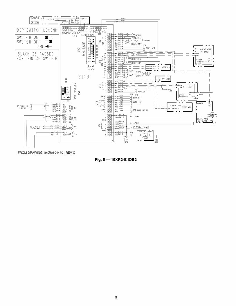
8
Fig. 5 — 19XR2-E IOB2
FROM DRAWING 19XR05044701 REV C
HP_SW
9
Fig. 6 — 19XR2-E IOB3
FROM DRAWING 19XR05044701 REV C
10
Fig. 7 — 19XR2-E IOB4
FROM DRAWING 19XR05044701 REV C
11
Fig. 8 — 19XR2-E Control Wiring
12
Fig. 9 — 19XR2-E Control Panel Front View Fig. 10 — 19XR2-E Control Panel Layout
Fig. 11 — 19XR2-E Power Panel Layout
13
Table 7 — 19XR6/7 IOB1 Connections
NOTES:1. See Fig. 12 for IOB1 wiring diagram.2. For pressure readings, only Vout (output) terminal is indicated. See
Fig. 12 for Vin (+) and ground (–).3. Defaults are shown. In some cases the IOB can be configured dif-
ferently depending on job requirements.
Table 8 — 19XR6/7 IOB2 Connections
NOTES:1. See Fig. 13 for IOB2 wiring diagram.2. For pressure readings, only Vout (output) terminal is indicated. See
Fig. 13 for Vin (+) and ground (–).3. Defaults are shown. In some cases the IOB can be configured dif-
ferently depending on job requirements.
DESCRIPTION CHANNEL TERMINAL TYPE OPTIONALEntering Chilled Water Temperature AI1 J16-1,5 5 k —Leaving Chilled Water Temperature AI2 J16-2,6 5 k —Entering Condenser Water Temperature AI3 J16-3,7 5 k —Leaving Condenser Water Temperature AI4 J16-4,8 5 k —Evaporator Refrigerant Liquid Temperature AI5 J15-6,12 5 k —Discharge Gas Temperature AI6 J15-5,11 5 k —Condenser Pressure AI7 J15-4 5 VDC —Evaporator Pressure AI8 J15-3 5 VDC —Economizer Pressure AI9 J15-2 5 VDC —FS VFD Load Current AI10 J15-1,7 4 to 20 mA YesChiller Status Output (ON=20mA, OFF=4mA, TRIPOUT=8mA, Not Off and Compressor not running=12mA) AO1 J14-1,4 4 to 20 mA Yes
Oil EXV Output AO2 J14-2, 5 4 to 20 mA YesEvaporator Water Flow Switch DI1 J13-5 (4TB-1,2) 24 VAC Yes, NO (dry contact)Condenser Water Flow Switch DI2 J13-6 (4TB-3,4) 24 VAC Yes, NO (dry contact)Remote Contact Input DI3 J13-7 (4TB-5,6) 24 VAC Yes, NO (dry contact);
closed indicates start chiller signalRemote Emergency Stop Input DI4 J13-8 (4TB-7,8) 24 VAC Yes, NO (dry contact);
closed indicates stop chiller signalStage 1 IGV Increase DO1 J12-7 24 VAC YesStage 1 IGV Decrease DO2 J12-10 24 VAC YesChiller Alarm Relay DO3 J12-2 24 VAC YesChiller Alert Relay DO4 J12-5 24 VAC Yes
LEGENDEXV — Electronic Expansion ValveFS — Fire SecurityIGV — Inlet Guide VaneIOB — Input/Output BoardNO — Normally OpenVFD — Variable Frequency Drive
DESCRIPTION CHANNEL TERMINAL TYPE OPTIONALMotor Winding Temperature 1 AI1 J16-1,5 5 k —Motor Winding Temperature 2 AI2 J16-2,6 5 k —Motor Winding Temperature 3 AI3 J16-3,7 5 k —Oil Supply Temperature AI4 J16-4, 8 5 k YesOil Sump Temperature AI5 J15-6,12 5 k —Oil Supply Pressure AI6 J15-5 5 VDC —Oil Sump Pressure AI7 J15-4 5 VDC —Auto Demand Limit Input AI8 J15-3,9 4 to 20 mA YesEnvelope Valve (HGBP) Feedback AI9 J15-2,8 4 to 20 mA YesDisplacement Switch AI10 J15-7 Ohm —Guide Vane 1 Output AO1 J14-1,4 4 to 20 mA —Damper Valve Feedback Fully Open DI1 J13-5 24 VAC —Damper Valve Feedback Fully Close DI2 J13-6 24 VAC —High Pressure Switch DI3 J13-7,3 24 VAC —Ice Build Contact DI4 J13-8,4 (4TB-12) 24 VAC Yes, NO (dry contact)Oil Heater Relay DO1 J12-7 24 VAC —Oil Pump Relay DO2 J12-10 24 VAC —Economizer Damper Valve Open DO3 J12-2 24 VAC —Economizer Damper Valve Close DO4 J12-5 24 VAC —
LEGENDIOB — Input/Output BoardNO — Normally Open
14
Table 9 — 19XR6/7 IOB3 Connections
NOTES:1. See Fig. 14 for IOB3 wiring diagram.2. For pressure readings, only Vout (output) terminal is indicated. See
Fig. 14 for Vin (+) and ground (–).3. Defaults are shown. In some cases the IOB can be configured dif-
ferently depending on job requirements.
Table 10 — 19XR6/7 IOB4 Connections
NOTES:1. See Fig. 15 for IOB4 wiring diagram.2. For pressure readings, only Vout (output) terminal is indicated. See
Fig. 15 for Vin (+) and ground (–).3. Defaults are shown. In some cases the IOB can be configured dif-
ferently depending on job requirements.
DESCRIPTION CHANNEL TERMINAL TYPE OPTIONALLow Speed ME Bearing Temperature AI1 J16-1,5 5 k —Low Speed CE Bearing Temperature AI2 J16-2,6 5 k —High Speed ME Bearing Temperature AI3 J16-3,7 5 k —High Speed CE Bearing Temperature AI4 J16-4,8 5 k —Remote Reset Temperature AI5 J15-6,12 5 k YesGuide Vane 1 Actual Position AI6 J15-5,11 4 to 20 mA —Common Chilled Water Supply (CHWS) Temperature AI7 J15-4, 10 5 KOhm YesAuto Water Temperature Reset AI8 J15-3,9 4 to 20 mA YesCommon Chilled Water Return (CHWR) Temperature AI9 J15-2, 8 5 KOhm YesHead Pressure Output AO1 J14-1,4 4 to 20 mA YesHead Pressure Output 2 AO2 J14-2,5 2 to 20 mA YesEC/HGBP Valve Feedback Fully Open DI1 J13-5 24 VAC —EC/HGBP Valve Feedback Fully Close DI2 J13-6 24 VAC —Spare Safety DI3 J13-7 (4TB-11,12) 24 VAC Yes, NO (dry contact), normally openEC/HGBP Solenoid / Open DO1 J12-7 24 VAC —EC/HGBP Close DO2 J12-10 24 VAC —Chilled Water Pump DO3 J12-2 24 VAC —Condenser Water Pump DO4 J12-5 24 VAC —
LEGENDCE — Compressor EndEC — Envelop ControlHGBP— Hot Gas BypassIOB — Input/Output BoardME — Motor EndNO — Normally Open
DESCRIPTION CHANNEL TERMINAL TYPE OPTIONALHeat Reclaim Entering Temp AI1 J16-1,5 5 VDC YesHeat Reclaim Leaving Temp AI2 J16-2,6 5 VDC YesEntering Evaporator Water Pressure AI3 J16-7 5 VDC YesLeaving Evaporator Water Pressure AI4 J16-8 5 VDC YesEntering Condenser Water Pressure AI5 J15-6 5 VDC YesLeaving Condenser Water Pressure AI6 J15-5 5 VDC YesRefrigerant Leak Sensor AI7 J15-4,10 4 to 20 mA YesEvaporator Water Flow Measurement AI8 J15-3, 9 4 to 20 mA YesCondenser Water Flow Measurement AI9 J15-2, 8 4 to 20 mA YesCustomer Alert DI3 J13-3, 7 24 VAC Yes, NO (dry contact)Free Cooling Start Switch DI4 J13-4, 8 24 VAC Yes, NO (dry contact)Free Cooling Mode DO1 J12-7 24 VAC YesTower Fan High DO3 J12-2 24 VAC YesTower Fan Low DO4 J12-5 24 VAC Yes
LEGENDIOB — Input/Output BoardNO — Normally Open
15
Fig. 12 — 19XR6/7 IOB1
19XV05005503 BASE DIMENSIONS(REFERENCE)
DIMENSIONS IN INCHES [MM]
A19-2265
NOTE: A suitable 24 VAC relay is Carrier part number19XV05005503. Carrier recommends using a relay witha contact rating of 10 amp sealed RMS or greater.
LEGEND FOR FIG. 12-15
PART NO. NO. OF PIN19X4003501 2 PIN19X4003502 4 PIN19X4003503 6 PIN19X4003504 8 PIN19X4003505 10 PIN19X4003506 12 PIN
16
Fig. 13 — 19XR6/7 IOB2
17
Fig. 14 — 19XR6/7 IOB3
18
Fig. 15 — 19XR6/7 IOB4
19
Fig. 16 — 19XR6/7 Control Wiring
Fig. 17 — HMI Panel
a19-2251
7TB IN HMI PANELFOR CUSTOMERCOMMUNICATIONCCN CONNECTIONA (+)C (G)B (-)
20
Fig. 18 — 19XR6/7 Control Panel, IOB Layer
Fig. 19 — 19XR6/7 Control Panel, Bottom Layer
1TB — CUSTOMER 3-PHASE POWER CONNECTION FOR CONTROL PANEL
2TB — FIELD WIRING CONNECTION FROM STARTER
1TB
2TB
21
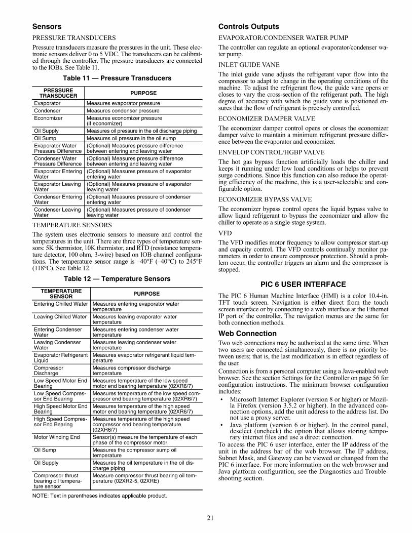
SensorsPRESSURE TRANSDUCERS
Pressure transducers measure the pressures in the unit. These elec-tronic sensors deliver 0 to 5 VDC. The transducers can be calibrat-ed through the controller. The pressure transducers are connectedto the IOBs. See Table 11.
Table 11 — Pressure Transducers
TEMPERATURE SENSORS
The system uses electronic sensors to measure and control thetemperatures in the unit. There are three types of temperature sen-sors: 5K thermistor, 10K thermistor, and RTD (resistance tempera-ture detector, 100 ohm, 3-wire) based on IOB channel configura-tions. The temperature sensor range is –40°F (–40°C) to 245°F(118°C). See Table 12.
Table 12 — Temperature Sensors
NOTE: Text in parentheses indicates applicable product.
Controls OutputsEVAPORATOR/CONDENSER WATER PUMP
The controller can regulate an optional evaporator/condenser wa-ter pump.
INLET GUIDE VANE
The inlet guide vane adjusts the refrigerant vapor flow into thecompressor to adapt to change in the operating conditions of themachine. To adjust the refrigerant flow, the guide vane opens orcloses to vary the cross-section of the refrigerant path. The highdegree of accuracy with which the guide vane is positioned en-sures that the flow of refrigerant is precisely controlled.
ECONOMIZER DAMPER VALVE
The economizer damper control opens or closes the economizerdamper valve to maintain a minimum refrigerant pressure differ-ence between the evaporator and economizer.
ENVELOP CONTROL/HGBP VALVE
The hot gas bypass function artificially loads the chiller andkeeps it running under low load conditions or helps to preventsurge conditions. Since this function can also reduce the operat-ing efficiency of the machine, this is a user-selectable and con-figurable option.
ECONOMIZER BYPASS VALVE
The economizer bypass control opens the liquid bypass valve toallow liquid refrigerant to bypass the economizer and allow thechiller to operate as a single-stage system.
VFD
The VFD modifies motor frequency to allow compressor start-upand capacity control. The VFD controls continually monitor pa-rameters in order to ensure compressor protection. Should a prob-lem occur, the controller triggers an alarm and the compressor isstopped.
PIC 6 USER INTERFACEThe PIC 6 Human Machine Interface (HMI) is a color 10.4-in.TFT touch screen. Navigation is either direct from the touchscreen interface or by connecting to a web interface at the EthernetIP port of the controller. The navigation menus are the same forboth connection methods.
Web ConnectionTwo web connections may be authorized at the same time. Whentwo users are connected simultaneously, there is no priority be-tween users; that is, the last modification is in effect regardless ofthe user.Connection is from a personal computer using a Java-enabled webbrowser. See the section Settings for the Controller on page 56 forconfiguration instructions. The minimum browser configurationincludes:• Microsoft Internet Explorer (version 8 or higher) or Mozil-
la Firefox (version 3.5.2 or higher). In the advanced con-nection options, add the unit address to the address list. Donot use a proxy server.
• Java platform (version 6 or higher). In the control panel,deselect (uncheck) the option that allows storing tempo-rary internet files and use a direct connection.
To access the PIC 6 user interface, enter the IP address of theunit in the address bar of the web browser. The IP address,Subnet Mask, and Gateway can be viewed or changed from thePIC 6 interface. For more information on the web browser andJava platform configuration, see the Diagnostics and Trouble-shooting section.
PRESSURE TRANSDUCER PURPOSE
Evaporator Measures evaporator pressureCondenser Measures condenser pressureEconomizer Measures economizer pressure
(if economizer)Oil Supply Measures oil pressure in the oil discharge pipingOil Sump Measures oil pressure in the oil sumpEvaporator WaterPressure Difference
(Optional) Measures pressure difference between entering and leaving water
Condenser WaterPressure Difference
(Optional) Measures pressure difference between entering and leaving water
Evaporator EnteringWater
(Optional) Measures pressure of evaporator entering water
Evaporator LeavingWater
(Optional) Measures pressure of evaporator leaving water
Condenser EnteringWater
(Optional) Measures pressure of condenser entering water
Condenser LeavingWater
(Optional) Measures pressure of condenser leaving water
TEMPERATURE SENSOR PURPOSE
Entering Chilled Water Measures entering evaporator water temperature
Leaving Chilled Water Measures leaving evaporator water temperature
Entering Condenser Water
Measures entering condenser water temperature
Leaving Condenser Water
Measures leaving condenser water temperature
Evaporator Refrigerant Liquid
Measures evaporator refrigerant liquid tem-perature
Compressor Discharge
Measures compressor discharge temperature
Low Speed Motor End Bearing
Measures temperature of the low speed motor end bearing temperature (02XR6/7)
Low Speed Compres-sor End Bearing
Measures temperature of the low speed com-pressor end bearing temperature (02XR6/7)
High Speed Motor End Bearing
Measures temperature of the high speed motor end bearing temperature (02XR6/7)
High Speed Compres-sor End Bearing
Measures temperature of the high speed compressor end bearing temperature (02XR6/7)
Motor Winding End Sensor(s) measure the temperature of each phase of the compressor motor
Oil Sump Measures the compressor sump oil temperature
Oil Supply Measures the oil temperature in the oil dis-charge piping
Compressor thrust bearing oil tempera-ture sensor
Measure compressor thrust bearing oil tem-perature (02XR2-5, 02XRE)
22
General Interface FeaturesICONS
Table 13 shows general interface icons.
Table 13 — Interface Icons
SCREENS
The Human Machine Interface includes the following screens:• Home screen, which displays the main parameters• Menu screens for navigation• Data/configuration screens, which list the parameters by type• Operating mode selection screen• Password entry and language selection screen• Parameter modification screen• Time schedule screen
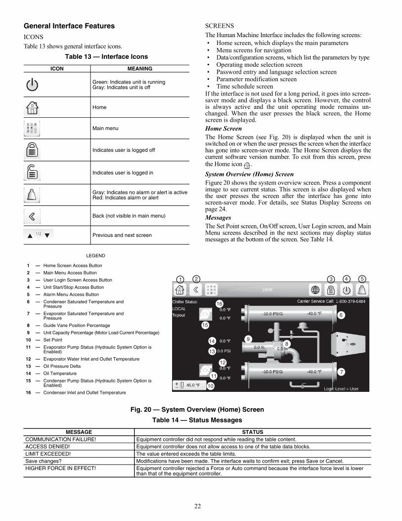
If the interface is not used for a long period, it goes into screen-saver mode and displays a black screen. However, the controlis always active and the unit operating mode remains un-changed. When the user presses the black screen, the Homescreen is displayed. Home ScreenThe Home Screen (see Fig. 20) is displayed when the unit isswitched on or when the user presses the screen when the interfacehas gone into screen-saver mode. The Home Screen displays thecurrent software version number. To exit from this screen, pressthe Home icon .
System Overview (Home) ScreenFigure 20 shows the system overview screen. Press a componentimage to see current status. This screen is also displayed whenthe user presses the screen after the interface has gone intoscreen-saver mode. For details, see Status Display Screens onpage 24.MessagesThe Set Point screen, On/Off screen, User Login screen, and MainMenu screens described in the next sections may display statusmessages at the bottom of the screen. See Table 14.
Fig. 20 — System Overview (Home) Screen
Table 14 — Status Messages
ICON MEANING
Green: Indicates unit is runningGray: Indicates unit is off
Home
Main menu
Indicates user is logged off
Indicates user is logged in
Gray: Indicates no alarm or alert is activeRed: Indicates alarm or alert
Back (not visible in main menu)
Previous and next screen
MESSAGE STATUSCOMMUNICATION FAILURE! Equipment controller did not respond while reading the table content.ACCESS DENIED! Equipment controller does not allow access to one of the table data blocks.LIMIT EXCEEDED! The value entered exceeds the table limits.Save changes? Modifications have been made. The interface waits to confirm exit; press Save or Cancel.HIGHER FORCE IN EFFECT! Equipment controller rejected a Force or Auto command because the interface force level is lower
than that of the equipment controller.
1
13
14
15
16
2 3 54
6
7
89
10
12
11
LEGEND
1 — Home Screen Access Button
2 — Main Menu Access Button
3 — User Login Screen Access Button
4 — Unit Start/Stop Access Button
5 — Alarm Menu Access Button
6 — Condenser Saturated Temperature andPressure
7 — Evaporator Saturated Temperature and Pressure
8 — Guide Vane Position Percentage
9 — Unit Capacity Percentage (Motor Load Current Percentage)
10 — Set Point
11 — Evaporator Pump Status (Hydraulic System Option is Enabled)
12 — Evaporator Water Inlet and Outlet Temperature
13 — Oil Pressure Delta
14 — Oil Temperature
15 — Condenser Pump Status (Hydraulic System Option is Enabled)
16 — Condenser Inlet and Outlet Temperature
23
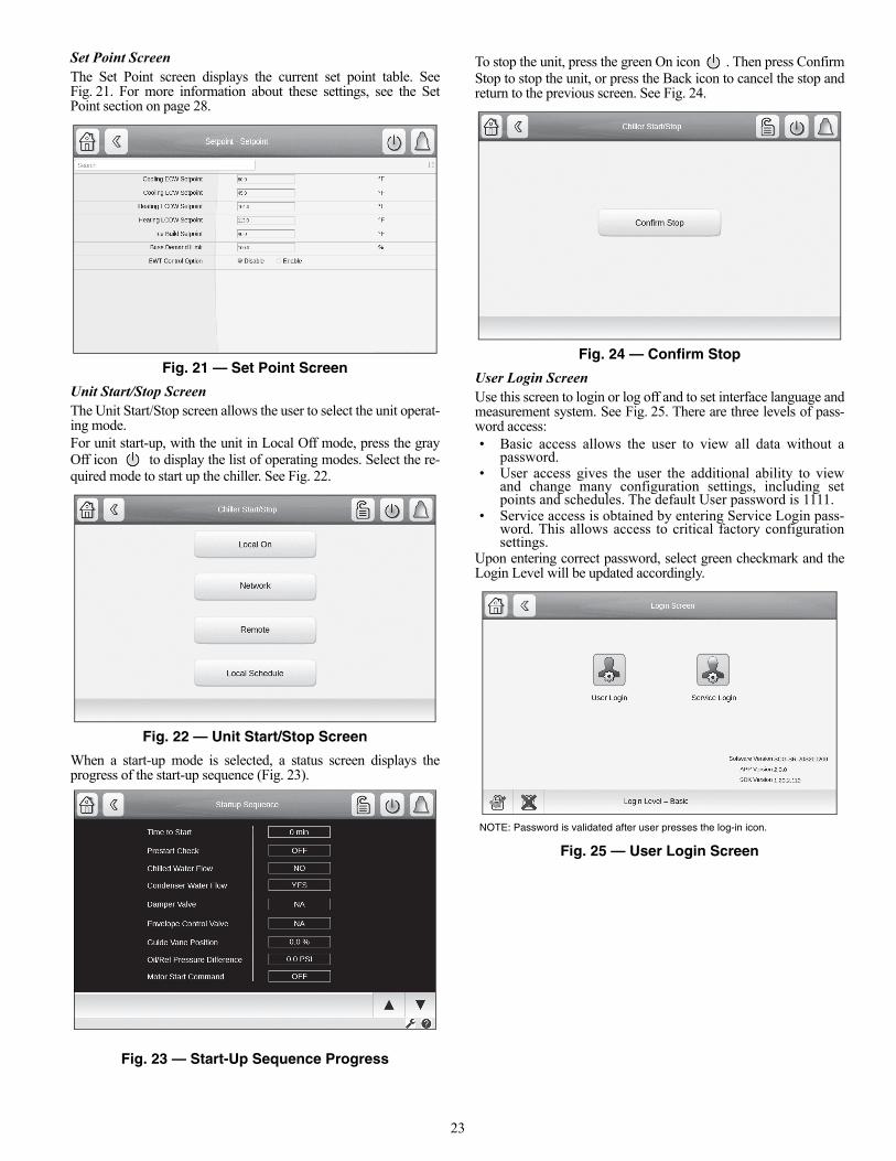
Set Point ScreenThe Set Point screen displays the current set point table. SeeFig. 21. For more information about these settings, see the SetPoint section on page 28.
Fig. 21 — Set Point Screen
Unit Start/Stop ScreenThe Unit Start/Stop screen allows the user to select the unit operat-ing mode.For unit start-up, with the unit in Local Off mode, press the grayOff icon to display the list of operating modes. Select the re-quired mode to start up the chiller. See Fig. 22.
Fig. 22 — Unit Start/Stop Screen
When a start-up mode is selected, a status screen displays theprogress of the start-up sequence (Fig. 23).
Fig. 23 — Start-Up Sequence Progress
To stop the unit, press the green On icon . Then press ConfirmStop to stop the unit, or press the Back icon to cancel the stop andreturn to the previous screen. See Fig. 24.
Fig. 24 — Confirm Stop
User Login ScreenUse this screen to login or log off and to set interface language andmeasurement system. See Fig. 25. There are three levels of pass-word access:• Basic access allows the user to view all data without a
password.• User access gives the user the additional ability to view
and change many configuration settings, including setpoints and schedules. The default User password is 1111.
• Service access is obtained by entering Service Login pass-word. This allows access to critical factory configurationsettings.
Upon entering correct password, select green checkmark and theLogin Level will be updated accordingly.
Fig. 25 — User Login Screen
NOTE: Password is validated after user presses the log-in icon.
24
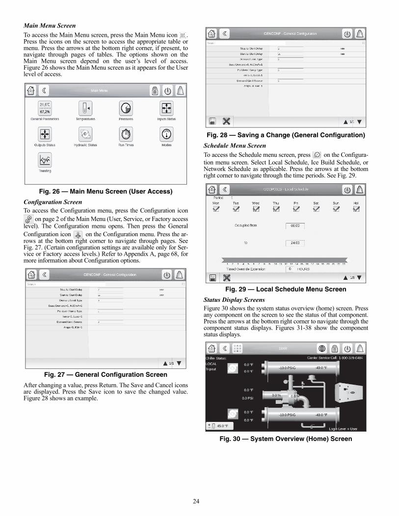
Main Menu Screen
To access the Main Menu screen, press the Main Menu icon .Press the icons on the screen to access the appropriate table ormenu. Press the arrows at the bottom right corner, if present, tonavigate through pages of tables. The options shown on theMain Menu screen depend on the user’s level of access.Figure 26 shows the Main Menu screen as it appears for the Userlevel of access.
Fig. 26 — Main Menu Screen (User Access)
Configuration ScreenTo access the Configuration menu, press the Configuration icon
on page 2 of the Main Menu (User, Service, or Factory accesslevel). The Configuration menu opens. Then press the GeneralConfiguration icon on the Configuration menu. Press the ar-rows at the bottom right corner to navigate through pages. SeeFig. 27. (Certain configuration settings are available only for Ser-vice or Factory access levels.) Refer to Appendix A, page 68, formore information about Configuration options.
Fig. 27 — General Configuration Screen
After changing a value, press Return. The Save and Cancel iconsare displayed. Press the Save icon to save the changed value.Figure 28 shows an example.
Fig. 28 — Saving a Change (General Configuration)
Schedule Menu Screen
To access the Schedule menu screen, press on the Configura-tion menu screen. Select Local Schedule, Ice Build Schedule, orNetwork Schedule as applicable. Press the arrows at the bottomright corner to navigate through the time periods. See Fig. 29.
Fig. 29 — Local Schedule Menu Screen
Status Display ScreensFigure 30 shows the system status overview (home) screen. Pressany component on the screen to see the status of that component.Press the arrows at the bottom right corner to navigate through thecomponent status displays. Figures 31-38 show the componentstatus displays.
Fig. 30 — System Overview (Home) Screen
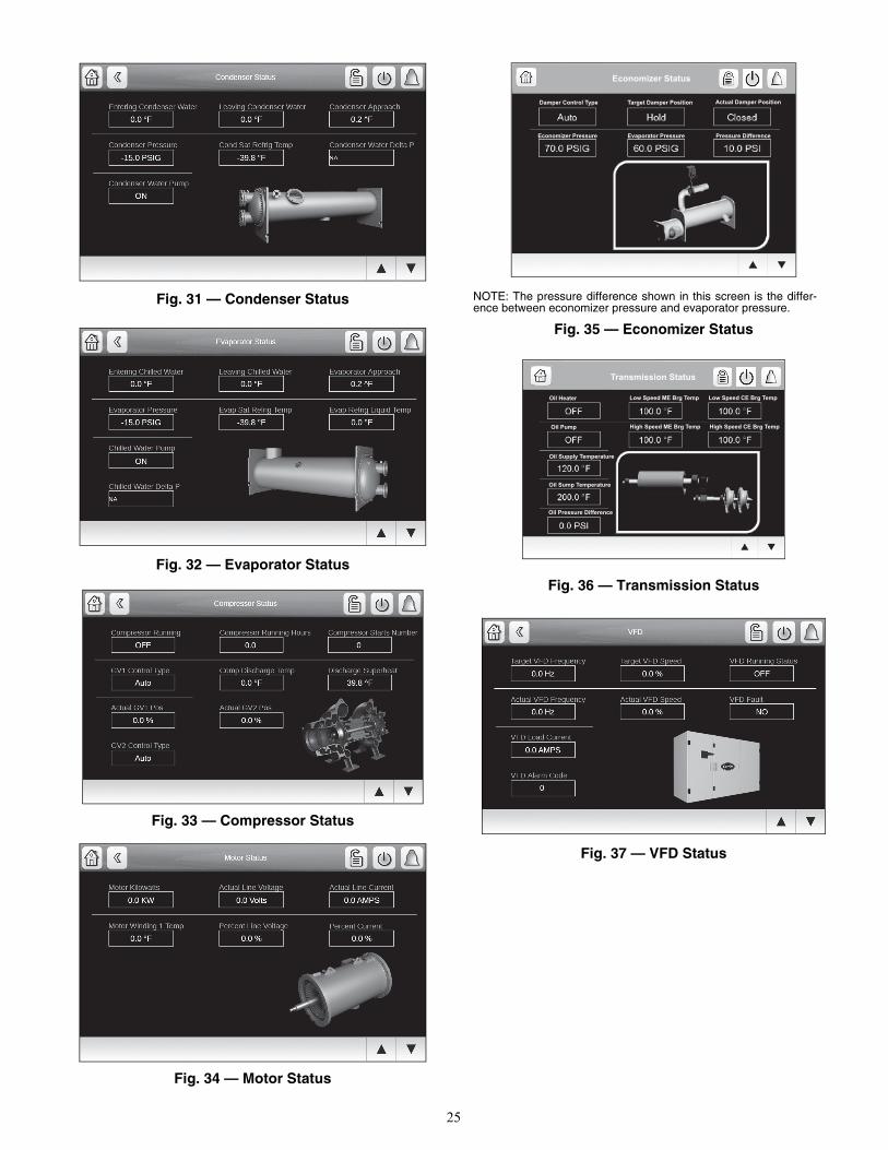
25
Fig. 31 — Condenser Status
Fig. 32 — Evaporator Status
Fig. 33 — Compressor Status
Fig. 34 — Motor Status
Fig. 35 — Economizer Status
Fig. 36 — Transmission Status
Fig. 37 — VFD Status
Economizer Status
Damper Control Type Target Damper Position Actual Damper Position
Economizer Pressure Evaporator Pressure Pressure Difference
a19-2310
NOTE: The pressure difference shown in this screen is the differ-ence between economizer pressure and evaporator pressure.
Transmission Status
Oil Sump Temperature
Oil Pressure Difference
Oil Pump
Oil Supply Temperature
Oil Heater Low Speed ME Brg Temp
High Speed ME Brg Temp
Low Speed CE Brg Temp
High Speed CE Brg Temp
a19-2305
26
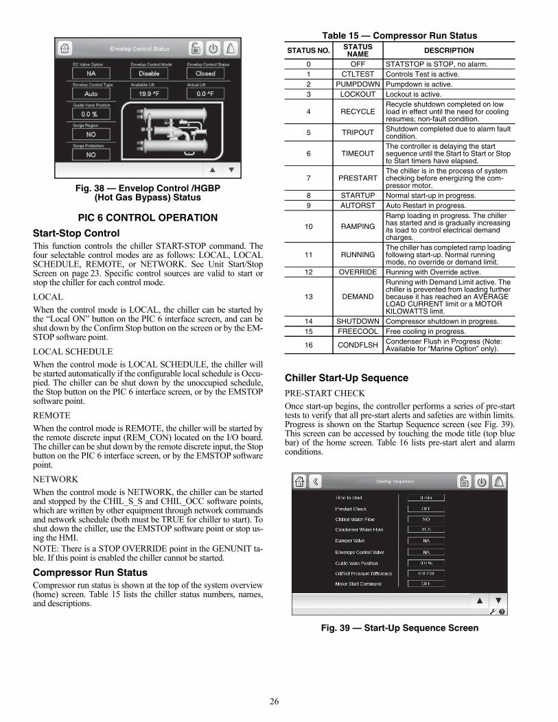
Fig. 38 — Envelop Control /HGBP (Hot Gas Bypass) Status
PIC 6 CONTROL OPERATION
Start-Stop ControlThis function controls the chiller START-STOP command. Thefour selectable control modes are as follows: LOCAL, LOCALSCHEDULE, REMOTE, or NETWORK. See Unit Start/StopScreen on page 23. Specific control sources are valid to start orstop the chiller for each control mode.
LOCAL
When the control mode is LOCAL, the chiller can be started bythe “Local ON” button on the PIC 6 interface screen, and can beshut down by the Confirm Stop button on the screen or by the EM-STOP software point.
LOCAL SCHEDULE
When the control mode is LOCAL SCHEDULE, the chiller willbe started automatically if the configurable local schedule is Occu-pied. The chiller can be shut down by the unoccupied schedule,the Stop button on the PIC 6 interface screen, or by the EMSTOPsoftware point.
REMOTE
When the control mode is REMOTE, the chiller will be started bythe remote discrete input (REM_CON) located on the I/O board.The chiller can be shut down by the remote discrete input, the Stopbutton on the PIC 6 interface screen, or by the EMSTOP softwarepoint.
NETWORK
When the control mode is NETWORK, the chiller can be startedand stopped by the CHIL_S_S and CHIL_OCC software points,which are written by other equipment through network commandsand network schedule (both must be TRUE for chiller to start). Toshut down the chiller, use the EMSTOP software point or stop us-ing the HMI.NOTE: There is a STOP OVERRIDE point in the GENUNIT ta-ble. If this point is enabled the chiller cannot be started.
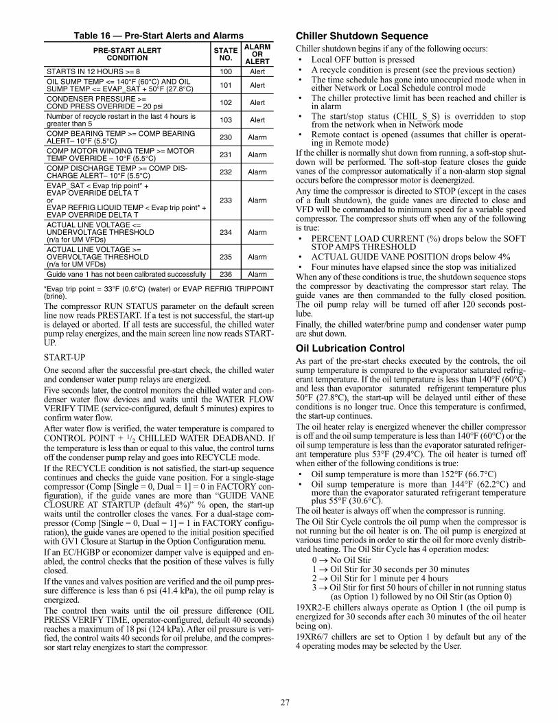
Compressor Run StatusCompressor run status is shown at the top of the system overview(home) screen. Table 15 lists the chiller status numbers, names,and descriptions.
Table 15 — Compressor Run Status
Chiller Start-Up SequencePRE-START CHECK
Once start-up begins, the controller performs a series of pre-starttests to verify that all pre-start alerts and safeties are within limits.Progress is shown on the Startup Sequence screen (see Fig. 39).This screen can be accessed by touching the mode title (top bluebar) of the home screen. Table 16 lists pre-start alert and alarmconditions.
Fig. 39 — Start-Up Sequence Screen
STATUS NO. STATUS NAME DESCRIPTION
0 OFF STATSTOP is STOP, no alarm.1 CTLTEST Controls Test is active.2 PUMPDOWN Pumpdown is active.3 LOCKOUT Lockout is active.
4 RECYCLERecycle shutdown completed on low load in effect until the need for cooling resumes; non-fault condition.
5 TRIPOUT Shutdown completed due to alarm fault condition.
6 TIMEOUTThe controller is delaying the start sequence until the Start to Start or Stop to Start timers have elapsed.
7 PRESTARTThe chiller is in the process of system checking before energizing the com-pressor motor.
8 STARTUP Normal start-up in progress.9 AUTORST Auto Restart in progress.
10 RAMPING
Ramp loading in progress. The chiller has started and is gradually increasing its load to control electrical demand charges.
11 RUNNINGThe chiller has completed ramp loading following start-up. Normal running mode, no override or demand limit.
12 OVERRIDE Running with Override active.
13 DEMAND
Running with Demand Limit active. The chiller is prevented from loading further because it has reached an AVERAGE LOAD CURRENT limit or a MOTOR KILOWATTS limit.
14 SHUTDOWN Compressor shutdown in progress.15 FREECOOL Free cooling in progress.
16 CONDFLSH Condenser Flush in Progress (Note: Available for “Marine Option” only).
27
Table 16 — Pre-Start Alerts and Alarms
*Evap trip point = 33°F (0.6°C) (water) or EVAP REFRIG TRIPPOINT(brine).The compressor RUN STATUS parameter on the default screenline now reads PRESTART. If a test is not successful, the start-upis delayed or aborted. If all tests are successful, the chilled waterpump relay energizes, and the main screen line now reads START-UP.
START-UP
One second after the successful pre-start check, the chilled waterand condenser water pump relays are energized.Five seconds later, the control monitors the chilled water and con-denser water flow devices and waits until the WATER FLOWVERIFY TIME (service-configured, default 5 minutes) expires toconfirm water flow. After water flow is verified, the water temperature is compared toCONTROL POINT + 1/2 CHILLED WATER DEADBAND. Ifthe temperature is less than or equal to this value, the control turnsoff the condenser pump relay and goes into RECYCLE mode.If the RECYCLE condition is not satisfied, the start-up sequencecontinues and checks the guide vane position. For a single-stagecompressor (Comp [Single = 0, Dual = 1] = 0 in FACTORY con-figuration), if the guide vanes are more than “GUIDE VANECLOSURE AT STARTUP (default 4%)” % open, the start-upwaits until the controller closes the vanes. For a dual-stage com-pressor (Comp [Single = 0, Dual = 1] = 1 in FACTORY configu-ration), the guide vanes are opened to the initial position specifiedwith GV1 Closure at Startup in the Option Configuration menu.If an EC/HGBP or economizer damper valve is equipped and en-abled, the control checks that the position of these valves is fullyclosed.If the vanes and valves position are verified and the oil pump pres-sure difference is less than 6 psi (41.4 kPa), the oil pump relay isenergized.The control then waits until the oil pressure difference (OILPRESS VERIFY TIME, operator-configured, default 40 seconds)reaches a maximum of 18 psi (124 kPa). After oil pressure is veri-fied, the control waits 40 seconds for oil prelube, and the compres-sor start relay energizes to start the compressor.
Chiller Shutdown SequenceChiller shutdown begins if any of the following occurs:• Local OFF button is pressed• A recycle condition is present (see the previous section)• The time schedule has gone into unoccupied mode when in
either Network or Local Schedule control mode• The chiller protective limit has been reached and chiller is
in alarm• The start/stop status (CHIL_S_S) is overridden to stop
from the network when in Network mode• Remote contact is opened (assumes that chiller is operat-
ing in Remote mode)If the chiller is normally shut down from running, a soft-stop shut-down will be performed. The soft-stop feature closes the guidevanes of the compressor automatically if a non-alarm stop signaloccurs before the compressor motor is deenergized.Any time the compressor is directed to STOP (except in the casesof a fault shutdown), the guide vanes are directed to close andVFD will be commanded to minimum speed for a variable speedcompressor. The compressor shuts off when any of the followingis true:• PERCENT LOAD CURRENT (%) drops below the SOFT
STOP AMPS THRESHOLD• ACTUAL GUIDE VANE POSITION drops below 4%• Four minutes have elapsed since the stop was initialized
When any of these conditions is true, the shutdown sequence stopsthe compressor by deactivating the compressor start relay. Theguide vanes are then commanded to the fully closed position.The oil pump relay will be turned off after 120 seconds post-lube.Finally, the chilled water/brine pump and condenser water pumpare shut down.
Oil Lubrication ControlAs part of the pre-start checks executed by the controls, the oilsump temperature is compared to the evaporator saturated refrig-erant temperature. If the oil temperature is less than 140°F (60°C)and less than evaporator saturated refrigerant temperature plus50°F (27.8°C), the start-up will be delayed until either of theseconditions is no longer true. Once this temperature is confirmed,the start-up continues.The oil heater relay is energized whenever the chiller compressoris off and the oil sump temperature is less than 140°F (60°C) or theoil sump temperature is less than the evaporator saturated refriger-ant temperature plus 53°F (29.4°C). The oil heater is turned offwhen either of the following conditions is true:• Oil sump temperature is more than 152°F (66.7°C) • Oil sump temperature is more than 144°F (62.2°C) and
more than the evaporator saturated refrigerant temperatureplus 55°F (30.6°C).
The oil heater is always off when the compressor is running. The Oil Stir Cycle controls the oil pump when the compressor isnot running but the oil heater is on. The oil pump is energized atvarious time periods in order to stir the oil for more evenly distrib-uted heating. The Oil Stir Cycle has 4 operation modes:
0 No Oil Stir1 Oil Stir for 30 seconds per 30 minutes2 Oil Stir for 1 minute per 4 hours3 Oil Stir for first 50 hours of chiller in not running status
(as Option 1) followed by no Oil Stir (as Option 0)19XR2-E chillers always operate as Option 1 (the oil pump isenergized for 30 seconds after each 30 minutes of the oil heaterbeing on).19XR6/7 chillers are set to Option 1 by default but any of the4 operating modes may be selected by the User.
PRE-START ALERTCONDITION
STATENO.
ALARM OR
ALERTSTARTS IN 12 HOURS >= 8 100 AlertOIL SUMP TEMP <= 140°F (60°C) AND OIL SUMP TEMP <= EVAP_SAT + 50°F (27.8°C) 101 Alert
CONDENSER PRESSURE >= COND PRESS OVERRIDE – 20 psi 102 Alert
Number of recycle restart in the last 4 hours is greater than 5 103 Alert
COMP BEARING TEMP >= COMP BEARING ALERT– 10°F (5.5°C) 230 Alarm
COMP MOTOR WINDING TEMP >= MOTOR TEMP OVERRIDE – 10°F (5.5°C) 231 Alarm
COMP DISCHARGE TEMP >= COMP DIS-CHARGE ALERT– 10°F (5.5°C) 232 Alarm
EVAP_SAT < Evap trip point* + EVAP OVERRIDE DELTA TorEVAP REFRIG LIQUID TEMP < Evap trip point* + EVAP OVERRIDE DELTA T
233 Alarm
ACTUAL LINE VOLTAGE <= UNDERVOLTAGE THRESHOLD (n/a for UM VFDs)
234 Alarm
ACTUAL LINE VOLTAGE >= OVERVOLTAGE THRESHOLD (n/a for UM VFDs)
235 Alarm
Guide vane 1 has not been calibrated successfully 236 Alarm
28
Control PointsSET POINT
The set point can be configured at the Setpoint menu (“USER” ac-cess level).The set point is determined by the heat/cool mode, EWT (enteringwater temperature) option, and ice build option. See Table 17.
Table 17 — Set Point Determination
NOTES:1. The ice build option is disabled when heat/cool mode is set to
Heating.2. When the ice build option is enabled and ice build is active, the
control point is the Ice Build Set Point and the controlled water tem-perature is the leaving chilled water temperature.
CONTROL POINT TEMPERATURE
Capacity control is based on achieving and maintaining a controlpoint temperature, which is the sum of a valid set point (from theSETPOINT screen) and a temperature reset value. In Coolingmode, the control point temperature is equal to the set point plustemperature reset. In Heating mode, the control point temperatureis equal to the set point minus temperature reset.The control point can be viewed directly on the main screen or theGeneral Parameters menu.
TEMPERATURE RESET
Three types of chilled water or brine reset are available and can beviewed or modified on the Reset Configuration screen.The default screen indicates when the chilled water reset is active.The control point Reset on the General Parameters screen indi-cates the amount of reset. To activate a reset type, access the Reset Configuration(RESETCFG) screen and input all configuration informa-tion for that reset type.
Reset Type 1: 4 to 20 mA Temperature ResetReset Type 1 is an automatic reset utilizing a 4 to 20 mA analoginput signal provided from any external sensor, controller, or otherdevice which is appropriately configured. For this type, DegreesReset At 20 mA is configured in the RESETCFG table.Reset Type 2: Remote Temperature ResetReset Type 2 is an automatic water temperature reset based on aremote temperature sensor input signal. This function can be ac-cessed by setting the following configurations:1. Configure the remote temperature at which no reset occurs
(Remote temp NO RESET). 2. Configure the remote temperature at which full reset
occurs (Remote temp FULL RESET). 3. Enter the amount of reset (Deg Reset Water DT Full).
Reset Type 3: Controlled Water Temp Delta ResetReset Type 3 is an automatic controlled water temperature resetbased on heat exchanger temperature difference. This function canbe accessed by setting the following configurations:1. Configure the controlled water temperature delta T at
which no reset occurs (Controlled Water DELTA T NO RESET).
2. Configure the controlled water temperature delta T atwhich full reset occurs (Controlled Water DELTA T FULL RESET).
3. Enter the amount of reset (Deg Reset Water DT Full).
CAPACITY CONTROL
Capacity control provides chilled or condenser water temperaturecontrol by modulating the position of the inlet guide vane 1, andVFD speed for variable speed compressors.If VFD OPTION is set to VFD and increased capacity is needed,the control will first try to increase IGV TARGET POSITION ifit has not reached the travel limit; if the travel limit has beenreached, the control increases VFD TARGET SPEED. If de-creased capacity is needed, the control first tries to decreaseVFD TARGET SPEED if it has not reached the minimum VFDspeed; if the minimum VFD speed has been reached, the controldecreases IGV TARGET POSITION instead. See Fig. 40.
Fig. 40 — Guide Vane Position and VFD Speed
EWT CONTROL OPTION
HEAT/COOL MODECOOLING HEATING
Disabled Cooling LCW Set Point Heating LCDW Set PointEnabled Cooling ECW Set Point Heating ECDW Set Point
GUIDE VANES AT MAX.MODULATE VFD
GUIDE VANES
VFD AT START-UP SPEED,MODULATE GUIDE VANES
VFD
STARTUP:VFD TO START-UP SPEED,GUIDE VANES CLOSED
MAX.
START
MIN.
VFD % SPEED
0 TRAVEL LIMIT 100
GUIDE VANES % POSITION
a19-2129
29
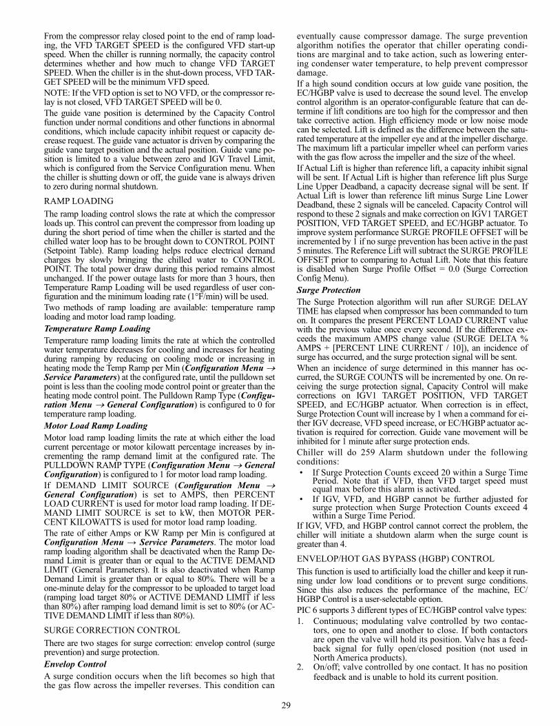
From the compressor relay closed point to the end of ramp load-ing, the VFD TARGET SPEED is the configured VFD start-upspeed. When the chiller is running normally, the capacity controldetermines whether and how much to change VFD TARGETSPEED. When the chiller is in the shut-down process, VFD TAR-GET SPEED will be the minimum VFD speed.NOTE: If the VFD option is set to NO VFD, or the compressor re-lay is not closed, VFD TARGET SPEED will be 0.The guide vane position is determined by the Capacity Controlfunction under normal conditions and other functions in abnormalconditions, which include capacity inhibit request or capacity de-crease request. The guide vane actuator is driven by comparing theguide vane target position and the actual position. Guide vane po-sition is limited to a value between zero and IGV Travel Limit,which is configured from the Service Configuration menu. Whenthe chiller is shutting down or off, the guide vane is always drivento zero during normal shutdown.
RAMP LOADING
The ramp loading control slows the rate at which the compressorloads up. This control can prevent the compressor from loading upduring the short period of time when the chiller is started and thechilled water loop has to be brought down to CONTROL POINT(Setpoint Table). Ramp loading helps reduce electrical demandcharges by slowly bringing the chilled water to CONTROLPOINT. The total power draw during this period remains almostunchanged. If the power outage lasts for more than 3 hours, thenTemperature Ramp Loading will be used regardless of user con-figuration and the minimum loading rate (1°F/min) will be used.Two methods of ramp loading are available: temperature ramploading and motor load ramp loading.Temperature Ramp LoadingTemperature ramp loading limits the rate at which the controlledwater temperature decreases for cooling and increases for heatingduring ramping by reducing on cooling mode or increasing inheating mode the Temp Ramp per Min (Configuration Menu Service Parameters) at the configured rate, until the pulldown setpoint is less than the cooling mode control point or greater than theheating mode control point. The Pulldown Ramp Type (Configu-ration Menu General Configuration) is configured to 0 fortemperature ramp loading.Motor Load Ramp LoadingMotor load ramp loading limits the rate at which either the loadcurrent percentage or motor kilowatt percentage increases by in-crementing the ramp demand limit at the configured rate. ThePULLDOWN RAMP TYPE (Configuration Menu GeneralConfiguration) is configured to 1 for motor load ramp loading.If DEMAND LIMIT SOURCE (Configuration Menu General Configuration) is set to AMPS, then PERCENTLOAD CURRENT is used for motor load ramp loading. If DE-MAND LIMIT SOURCE is set to kW, then MOTOR PER-CENT KILOWATTS is used for motor load ramp loading. The rate of either Amps or KW Ramp per Min is configured atConfiguration Menu → Service Parameters. The motor loadramp loading algorithm shall be deactivated when the Ramp De-mand Limit is greater than or equal to the ACTIVE DEMANDLIMIT (General Parameters). It is also deactivated when RampDemand Limit is greater than or equal to 80%. There will be aone-minute delay for the compressor to be uploaded to target load(ramping load target 80% or ACTIVE DEMAND LIMIT if lessthan 80%) after ramping load demand limit is set to 80% (or AC-TIVE DEMAND LIMIT if less than 80%).
SURGE CORRECTION CONTROL
There are two stages for surge correction: envelop control (surgeprevention) and surge protection.Envelop ControlA surge condition occurs when the lift becomes so high thatthe gas flow across the impeller reverses. This condition can
eventually cause compressor damage. The surge preventionalgorithm notifies the operator that chiller operating condi-tions are marginal and to take action, such as lowering enter-ing condenser water temperature, to help prevent compressordamage.If a high sound condition occurs at low guide vane position, theEC/HGBP valve is used to decrease the sound level. The envelopcontrol algorithm is an operator-configurable feature that can de-termine if lift conditions are too high for the compressor and thentake corrective action. High efficiency mode or low noise modecan be selected. Lift is defined as the difference between the satu-rated temperature at the impeller eye and at the impeller discharge.The maximum lift a particular impeller wheel can perform varieswith the gas flow across the impeller and the size of the wheel.If Actual Lift is higher than reference lift, a capacity inhibit signalwill be sent. If Actual Lift is higher than reference lift plus SurgeLine Upper Deadband, a capacity decrease signal will be sent. IfActual Lift is lower than reference lift minus Surge Line LowerDeadband, these 2 signals will be canceled. Capacity Control willrespond to these 2 signals and make correction on IGV1 TARGETPOSITION, VFD TARGET SPEED, and EC/HGBP actuator. Toimprove system performance SURGE PROFILE OFFSET will beincremented by 1 if no surge prevention has been active in the past5 minutes. The Reference Lift will subtract the SURGE PROFILEOFFSET prior to comparing to Actual Lift. Note that this featureis disabled when Surge Profile Offset = 0.0 (Surge CorrectionConfig Menu). Surge ProtectionThe Surge Protection algorithm will run after SURGE DELAYTIME has elapsed when compressor has been commanded to turnon. It compares the present PERCENT LOAD CURRENT valuewith the previous value once every second. If the difference ex-ceeds the maximum AMPS change value (SURGE DELTA %AMPS + [PERCENT LINE CURRENT / 10]), an incidence ofsurge has occurred, and the surge protection signal will be sent.When an incidence of surge determined in this manner has oc-curred, the SURGE COUNTS will be incremented by one. On re-ceiving the surge protection signal, Capacity Control will makecorrections on IGV1 TARGET POSITION, VFD TARGETSPEED, and EC/HGBP actuator. When correction is in effect,Surge Protection Count will increase by 1 when a command for ei-ther IGV decrease, VFD speed increase, or EC/HGBP actuator ac-tivation is required for correction. Guide vane movement will beinhibited for 1 minute after surge protection ends.Chiller will do 259 Alarm shutdown under the followingconditions:• If Surge Protection Counts exceed 20 within a Surge Time
Period. Note that if VFD, then VFD target speed mustequal max before this alarm is activated.
• If IGV, VFD, and HGBP cannot be further adjusted forsurge protection when Surge Protection Counts exceed 4within a Surge Time Period.
If IGV, VFD, and HGBP control cannot correct the problem, thechiller will initiate a shutdown alarm when the surge count isgreater than 4.
ENVELOP/HOT GAS BYPASS (HGBP) CONTROL
This function is used to artificially load the chiller and keep it run-ning under low load conditions or to prevent surge conditions.Since this also reduces the performance of the machine, EC/HGBP Control is a user-selectable option. PIC 6 supports 3 different types of EC/HGBP control valve types:1. Continuous; modulating valve controlled by two contac-
tors, one to open and another to close. If both contactorsare open the valve will hold its position. Valve has a feed-back signal for fully open/closed position (not used inNorth America products).
2. On/off; valve controlled by one contact. It has no positionfeedback and is unable to hold its current position.
30
3. mA; valve controlled by 4 to 20 mA signal. The type canbe configured in the Option Configuration menu.
Envelop/hot gas bypass operation has three different modes wheninstalled (hgbp_opt > 0) and enabled (hgbp_sel > 0): • Envelop control and surge protection — Each compressor
has unique lift characteristics that can be plotted to deter-mine performance. The controller will determine operatingconditions that could result in compressor surge and acti-vate the bypass valve to prevent surge until the chiller op-erating parameters are in a safe area on the curve where thevalve may be closed again.
• Envelop (HGBP) low load operation — In this condition,the valve will be opened to prevent a recycle shutdownfrom occurring. The valve will remain open until this min-imal loading condition has passed and there is no surgecondition present.
• Combination for envelop control and surge correction, aswell as low load operation — When this option is selected,both EC for envelop control/surge protection and EC forlow load operation will be performed. Surge protectionwill take higher priority if both conditions are satisfied.
ECONOMIZER DAMPER VALVE CONTROL (FOR APPLI-CABLE UNITS)
The economizer maintains the difference between evaporatorpressure and economizer pressure. Economizer pressure shouldalways be higher than evaporator pressure.When the chiller is initially powered on, or when the compressorshuts down, the damper valve will be commanded to close. Theseand other conditions are shown in Table 18.
Table 18 — Economizer Damper Valve Status
If the damper valve has been commanded to open for a continuous5 minutes, and the Damper Valve Full Opened condition is still notTRUE, the control system generates an alert 154. Similarly, if thedamper valve has been commanded to close for a continuous 5minutes, and the Damper Valve Full Closed condition is still notTRUE, the control system generates an alert 154.If the compressor is running and if economizer pressure becomesless than or equal to evaporator pressure, an alarm 268 will betripped and compressor will be shut down.
DEMAND LIMIT
The PIC 6 controls provide a feature for limiting AVERAGELOAD CURRENT or MOTOR KILOWATTS by limiting ca-pacity via guide vane control/VFD control. The limit may be ap-plied in two ways. The first is called ACTIVE DEMAND LIM-IT, which is equal to a BASE DEMAND LIMIT value (set in theSETPOINT screen, default value 100%). ACTIVE DEMANDLIMIT may also be forced to be different from BASE DE-MAND LIMIT by manually overriding (forcing) the value via aCCN network device. If the DEMAND LIMIT SOURCE ex-ceeds the ACTIVE DEMAND LIMIT by 5% or less, capacity
will be inhibited. If the DEMAND LIMIT SOURCE exceeds theACTIVE DEMAND LIMIT by more than 5%, capacity will bedecreased.Alternatively, the limit may be applied by AUTO DEMANDLIMIT INPUT, an optional 4 to 20 mA input. This demandlimit control option (4 to 20 mA DEMAND LIMIT TYPE) isexternally controlled by a 4 to 20 mA signal. The option is setup on the Configuration Menu GENERAL CONFIGURA-TION screen. When enabled, 4 mA will set ACTIVE DE-MAND LIMIT to 100% of the DEMAND LIMIT SOURCE(regardless of the value of BASE DEMAND LIMIT), and20 mA will set ACTIVE DEMAND LIMIT to the value con-figured for DEMAND LIMIT AT 20 mA in the ConfigurationMenu SERVICE PARAMETERS screen.
OVERRIDE CONTROL
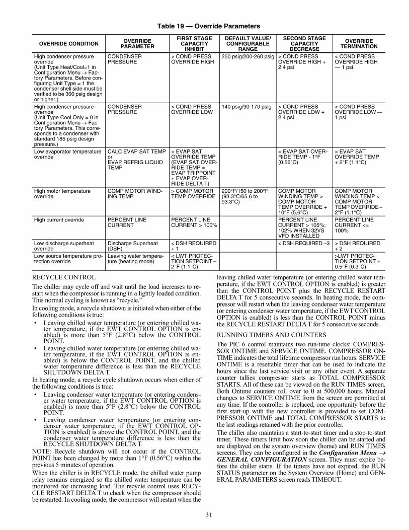
Capacity overrides can prevent some safety shutdowns caused byexceeding the motor amperage limit, evaporator refrigerant lowtemperature safety limit, motor high temperature safety limit, andcondenser high pressure limit. In these cases there are two stagesof capacity control:1. When the value of interest crosses the first stage set point
into the override region, the capacity is prevented fromincreasing further, and the status line on the PIC 6 control-ler indicates the reason for the override. Normal capacitycontrol operation is restored when the value crosses backover the first stage set point, leaving the override region.
2. When the value of interest is in the override region andfurther crosses the second stage set point, the capacity isdecreased until the value meets the override terminationcondition. The PIC 6 controls resume normal capacitycontrol operation after the override termination conditionhas been satisfied. (In the case of high discharge super-heat, there is an intermediate stage.)
Table 19 summarizes these override parameters.Other types of override events do not override control guide vaneor VFD operation, but are reported:• High compressor discharge temperature override — For
compressor/frame 6 and 7, if the COMP DISCHARGETEMP is greater than the COMP DISCHARGE ALERTthreshold, then high discharge temperature override will bedisplayed in the main screen until the COMP DIS-CHARGE TEMP is less than the COMP DISCHARGEALERT threshold – 2°F (1.1°C).
• High compressor bearing temperature override — Forcompressor/frame 6 and 7, if one of the compressor bear-ing temperatures is greater than the compressor bearingtemperature Alert (Configuration Menu ProtectiveLimit Config) threshold, then High Bearing Temp Over-ride shall be active until all of the compressor bearing tem-peratures are less than Comp Bearing Temp Alert minus2°F (1.1°C). For compressors 2-5, C, and E, if the calculat-ed compressor bearing temperature is greater than thebearing temperature alert threshold, then high bearing tem-perature override will be active until the calculated bearingtemperature is less than the threshold minus 2°F (1.1°C).
• Low Discharge Superheat Temperature Override — Thisoverride is ignored during the first 5 minutes after chillerstart-up. There are additional requirements for normaloverride function after start-up. For compressor E, con-denser pressure must be 10 psi greater than cooler pres-sure; for compressor/frame 6 and 7, the damper must havebeen open for 20 consecutive seconds.
SYSTEM CONDITION ECONOMIZER DAMPER VALVE STATUS
Chiller initially powered on Fully closedCompressor shut down Fully closedDuring damper valve action delay Fully closedEconomizer pressure > evaporator pressure + Damper valve open DB
Open
Economizer pressure < evaporator pressure + Damper valve close DB
Closed
All other conditions Current position maintained
31
Table 19 — Override Parameters
RECYCLE CONTROL
The chiller may cycle off and wait until the load increases to re-start when the compressor is running in a lightly loaded condition.This normal cycling is known as “recycle.” In cooling mode, a recycle shutdown is initiated when either of thefollowing conditions is true: • Leaving chilled water temperature (or entering chilled wa-
ter temperature, if the EWT CONTROL OPTION is en-abled) is more than 5°F (2.8°C) below the CONTROLPOINT.
• Leaving chilled water temperature (or entering chilled wa-ter temperature, if the EWT CONTROL OPTION is en-abled) is below the CONTROL POINT, and the chilledwater temperature difference is less than the RECYCLESHUTDOWN DELTA T.
In heating mode, a recycle cycle shutdown occurs when either ofthe following conditions is true:• Leaving condenser water temperature (or entering condens-
er water temperature, if the EWT CONTROL OPTION isenabled) is more than 5°F (2.8°C) below the CONTROLPOINT.
• Leaving condenser water temperature (or entering con-denser water temperature, if the EWT CONTROL OP-TION is enabled) is above the CONTROL POINT, and thecondenser water temperature difference is less than theRECYCLE SHUTDOWN DELTA T.
NOTE: Recycle shutdown will not occur if the CONTROLPOINT has been changed by more than 1°F (0.56°C) within theprevious 5 minutes of operation. When the chiller is in RECYCLE mode, the chilled water pumprelay remains energized so the chilled water temperature can bemonitored for increasing load. The recycle control uses RECY-CLE RESTART DELTA T to check when the compressor shouldbe restarted. In cooling mode, the compressor will restart when the
leaving chilled water temperature (or entering chilled water tem-perature, if the EWT CONTROL OPTION is enabled) is greaterthan the CONTROL POINT plus the RECYCLE RESTARTDELTA T for 5 consecutive seconds. In heating mode, the com-pressor will restart when the leaving condenser water temperature(or entering condenser water temperature, if the EWT CONTROLOPTION is enabled) is less than the CONTROL POINT minusthe RECYCLE RESTART DELTA T for 5 consecutive seconds.
RUNNING TIMERS AND COUNTERS
The PIC 6 control maintains two run-time clocks: COMPRES-SOR ONTIME and SERVICE ONTIME. COMPRESSOR ON-TIME indicates the total lifetime compressor run hours. SERVICEONTIME is a resettable timer that can be used to indicate thehours since the last service visit or any other event. A separatecounter tallies compressor starts as TOTAL COMPRESSORSTARTS. All of these can be viewed on the RUN TIMES screen.Both Ontime counters roll over to 0 at 500,000 hours. Manualchanges to SERVICE ONTIME from the screen are permitted atany time. If the controller is replaced, one opportunity before thefirst start-up with the new controller is provided to set COM-PRESSOR ONTIME and TOTAL COMPRESSOR STARTS tothe last readings retained with the prior controller. The chiller also maintains a start-to-start timer and a stop-to-starttimer. These timers limit how soon the chiller can be started andare displayed on the system overview (home) and RUN TIMESscreens. They can be configured in the Configuration Menu GENERAL CONFIGURATION screen. They must expire be-fore the chiller starts. If the timers have not expired, the RUNSTATUS parameter on the System Overview (Home) and GEN-ERAL PARAMETERS screen reads TIMEOUT.
OVERRIDE CONDITION OVERRIDE PARAMETER
FIRST STAGE CAPACITY
INHIBIT
DEFAULT VALUE/CONFIGURABLE
RANGE
SECOND STAGE CAPACITY DECREASE
OVERRIDE TERMINATION
High condenser pressure override (Unit Type Heat/Cool=1 in Configuration Menu Fac-tory Parameters. Before con-figuring Unit Type = 1 the condenser shell side must be verified to be 300 psig design or higher.)
CONDENSERPRESSURE
> COND PRESS OVERRIDE HIGH
250 psig/200-260 psig > COND PRESS OVERRIDE HIGH + 2.4 psi
< COND PRESS OVERRIDE HIGH — 1 psi
High condenser pressure override (Unit Type Cool Only = 0 in Configuration Menu Fac-tory Parameters. This corre-sponds to a condenser with standard 185 psig design pressure.)
CONDENSERPRESSURE
> COND PRESS OVERRIDE LOW
140 psig/90-170 psig > COND PRESS OVERRIDE LOW + 2.4 psi
< COND PRESS OVERRIDE LOW — 1 psi
Low evaporator temperature override
CALC EVAP SAT TEMPorEVAP REFRIG LIQUID TEMP
< EVAP SAT OVERRIDE TEMP (EVAP SAT OVER-RIDE TEMP = EVAP TRIPPOINT + EVAP OVER-RIDE DELTA T)
< EVAP SAT OVER-RIDE TEMP - 1°F (0.56°C)
> EVAP SAT OVERRIDE TEMP + 2°F (1.1°C)
High motor temperature override
COMP MOTOR WIND-ING TEMP
> COMP MOTOR TEMP OVERRIDE
200°F/150 to 200°F(93.3°C/65.6 to 93.3°C)
COMP MOTOR WINDING TEMP > COMP MOTOR TEMP OVERRIDE + 10°F (5.6°C)
COMP MOTOR WINDING TEMP < COMP MOTOR TEMP OVERRIDE – 2°F (1.1°C)
High current override PERCENT LINECURRENT
PERCENT LINE CURRENT > 100%
PERCENT LINE CURRENT > 105%; 102% WHEN 32VS VFD INSTALLED
PERCENT LINE CURRENT <= 100%
Low discharge superheat override
Discharge Superheat (DSH)
< DSH REQUIRED + 1
< DSH REQUIRED –3 > DSH REQUIRED + 2
Low source temperature pro-tection override
Leaving water tempera-ture (heating mode)
< LWT PROTEC-TION SETPOINT – 2°F (1.1°C)
>LWT PROTEC-TION SETPOINT + 0.5°F (0.3°C)
32
WATER PUMPS CONTROL (FREEZE PREVENTION)
Evaporator Freeze PreventionWhen the evaporator saturated refrigerant temperature or evapora-tor refrigerant temperature is less than the EVAP REFRIG TRIP-POINT + REFRIG OVERRIDE DELTA T (configurable from2°F to 5°F (1.1°C to 2.8°C) in the Configuration Menu PROTECTIVE LIMIT CONFIG screen), an OVERRIDE—LOW EVAP REFRIG TEMP event will occur. For any running status, if either of the conditions below is truethen unit will shut down under Alarm PROTECTIVE LIMIT -EVAPORATOR FREEZE (State 261):• Evaporator saturated refrigerant temperature or evaporator
refrigerant temperature is equal to or less than the EVAPREFRIG TRIPPOINT (33°F [0.6°C] for water, (configu-rable for brine in Configuration Menu PROTECTIVELIMIT CONFIG screen) plus 1°F (0.56°C).
• Leaving chilled water temperature or entering chilled wa-ter temperature is less than EVAP REFRIG TRIPPOINTplus 1°F (0.56°C).
NOTE: If the chiller is in recycle mode, it will transition toTRIPOUT, and the CHILLED WATER PUMP will remain on.The alarm will be clearable when the evaporator saturated refrig-erant temperature, evaporator refrigerant temperature, leavingchilled water temperature, and entering chilled water temperaturerise 5°F (2.8°C) above the EVAP REFRIG TRIPPOINT.Condenser Pump ControlThe chiller will monitor the condenser pressure and may turn onthe condenser pump. If the condenser pressure is greater than orequal to the COND PRESS OVERRIDE, and the entering con-denser water temperature is less than 115°F (46.1°C), the condens-er pump will energize to try to decrease the pressure and ProcessAlert - High Condenser Pressure Chiller Off (Alert 157) will begenerated. The pump will turn off when the condenser pressure is3.5 psi (24.1 kPa) less than the pressure override and the condens-er refrigerant temperature is less than or equal to the entering con-denser water temperature plus 3°F (1.7°C).NOTE: COND PRESS OVERRIDE is found in the Configura-tion Menu PROTECTIVE LIMIT CONFIG screen.Condenser Freeze PreventionThis control helps prevent condenser tube freezing by energizingthe condenser pump relay. The PIC 6 module controls the pumpand, by starting it, helps to prevent the water in the condenser fromfreezing. When the chiller is off and condenser saturated refrigerant tem-perature is less than or equal to the condenser freeze point, thecondenser water pump will be energized (Alarm State 262, PRO-TECTIVE LIMIT - CONDENSER FREEZE). The fault state willclear and the pump will turn off when the condenser saturated re-frigerant temperature is more than 5°F (2.7°C) above the condens-er freeze point and the entering condenser water temperature isgreater than the condenser freeze point. If the chiller is in recycleshutdown mode when the condition occurs, the controls will tran-sition to a non-recycle shutdown.
CONTROL TEST
This feature allows the operator to quick-test the controls and re-lated hardware, including all unit-controlled outputs except com-pressor output. Test of components with position feedback re-quires calibration in Quick Calibration prior to control test.The compressor must be off to run the test function. If the unit ison, the test function cannot be accessed. The compressor can onlybe started after the control test is finished. The test function alsorequires the user to enter the User password if it has not alreadybeen entered. All control test parameters are accessible throughthe Quick Test table. To perform the control test function, set thefirst item Quick Test Enable in the Quick Test table to Enable.Unless otherwise noted, all protective limits remain active duringthe controls test.
Discrete OutputsWhen the control test is enabled, discrete outputs can be enabledusing the Quick Test table. Discrete valves that can be tested inQuick test are: GV1 Open, GV1 Close, Oil Pump Relay, HGBPOpen, HGBP Close, Damper Open, Damper Close, CondenserPump Relay, Evaporator Pump Relay, Alarm Relay, and AlertRelay.NOTE: The following outputs cannot be enabled at the same timeGuide Vane Increase and Guide Vane Decrease are enabled: EC/HGBP Valve Open and EC/HGBP Valve Close; EconomizerDamper Valve Open and Economizer Damper Valve Close.NOTE: For oil pressure, a value 18 psi within 40 seconds afterthe oil pump is turned on indicates a confirmation of pressure (OilPres Test Passed=YES). Analog OutputWhen the control test is enabled, the following analog outputs canbe enabled by entering the positions in the QCK_TST table:• Head Pressure Valve• Diffuser Actuator• Oil EXV (electronic expansion valve)• Chiller Status Output (Q_CHST)
Guide Vane CalibrationThe guide vane position should be calibrated before starting thechiller. Guide vane calibration can be started by setting Quick TestEnable to Enable and GV1 Calibration Enable to Enable in theQuick Calibration menu.If the actuator type is digital 0, then:• The fully closed guide vane feedback resistance will be in
the range of 62.5 ohms to 688 ohms (350 ± 75 ohms targetsetting).
• The fully opened guide vane feedback resistance will be inthe range of 6190 ohms to 11,496 ohms (10,000 ohms tar-get setting).
If the actuator type is analog (1):• The fully closed guide vane feedback mA value will be in
the range of 3 mA to 5 mA.• The fully opened guide vane feedback mA value will be in
the range of 19 mA to 20.8 mA.
SWIFT RESTART (CAPACITY RECOVERY™)
This function is designed for data center or other applications. Itallows the chiller to be restarted quickly to meet building loadrequirements.To enable this function, the AUTO RESTART OPTION point inthe CONF_OPT table should be set to ENABLE.The water flow verification time, oil prelube time and other delayswill be decreased compared to a normal start-up.
COOLING TOWER CONTROL
If WATER PRESSURE OPTION in the CONF_OPT table is setto 1 or 2, there will be another optional hydraulic control I/O boardin the PIC 6 control system to allow PIC 6 control for the waterpumps and cooling tower fans (high speed and low speed).The cooling tower fans are controlled by the pressure differencebetween condenser and evaporator and entering water temperatureof condenser. The objective is to maintain the entering condenserwater temperature in the optimal range.
HEAD PRESSURE CONTROL
If the chiller system is equipped with a head pressure con-trol valve or other device to modulate the condenser waterflow, and the HEAD PRESSURE VALVE option in theCONF_OPT table is ENABLED, the PIC 6 control systemwill control the opening of the head pressure valve to main-tain the pressure difference between condenser and evapora-tor. The output of this valve is 4 to 20 mA type.
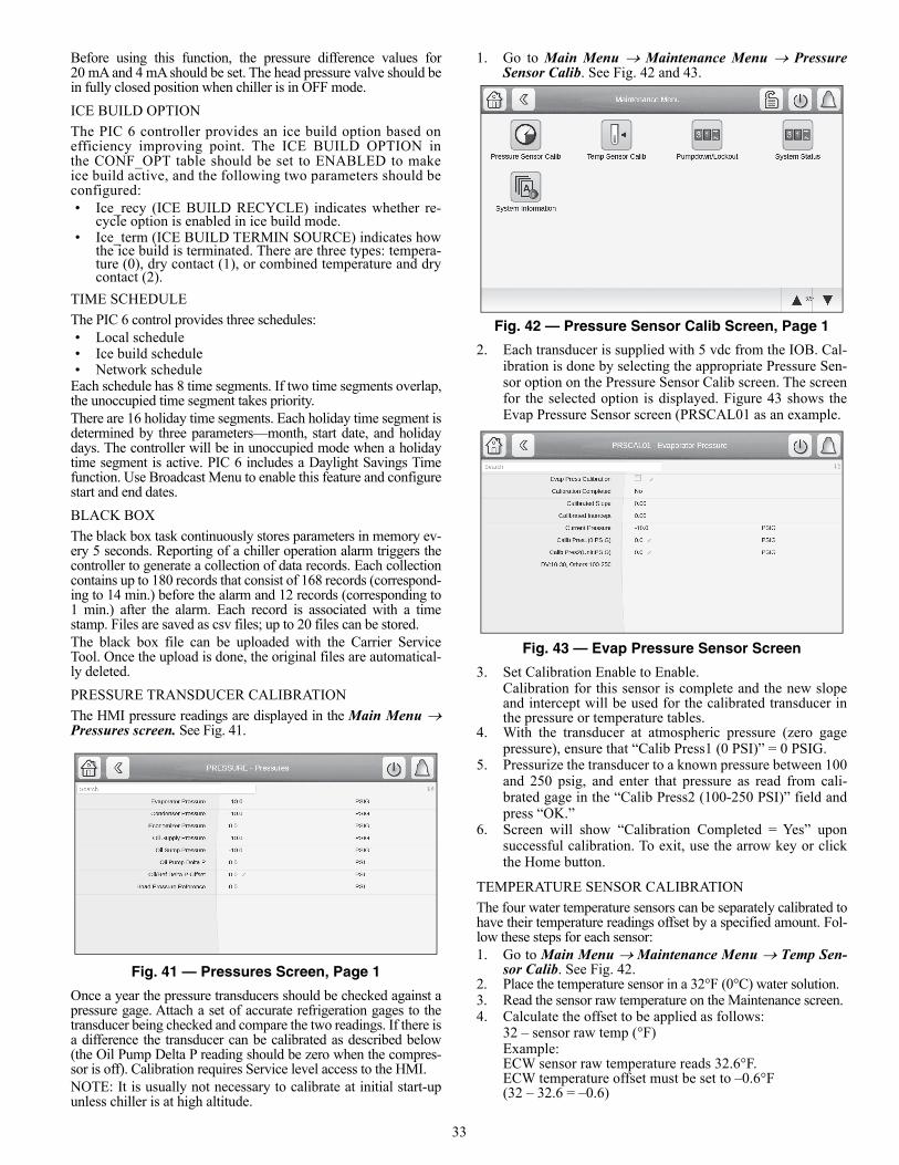
33
Before using this function, the pressure difference values for20 mA and 4 mA should be set. The head pressure valve should bein fully closed position when chiller is in OFF mode.
ICE BUILD OPTION
The PIC 6 controller provides an ice build option based onefficiency improving point. The ICE BUILD OPTION inthe CONF_OPT table should be set to ENABLED to makeice build active, and the following two parameters should beconfigured:• Ice_recy (ICE BUILD RECYCLE) indicates whether re-
cycle option is enabled in ice build mode.• Ice_term (ICE BUILD TERMIN SOURCE) indicates how
the ice build is terminated. There are three types: tempera-ture (0), dry contact (1), or combined temperature and drycontact (2).
TIME SCHEDULE
The PIC 6 control provides three schedules: • Local schedule• Ice build schedule• Network schedule
Each schedule has 8 time segments. If two time segments overlap,the unoccupied time segment takes priority.There are 16 holiday time segments. Each holiday time segment isdetermined by three parameters—month, start date, and holidaydays. The controller will be in unoccupied mode when a holidaytime segment is active. PIC 6 includes a Daylight Savings Timefunction. Use Broadcast Menu to enable this feature and configurestart and end dates.
BLACK BOX
The black box task continuously stores parameters in memory ev-ery 5 seconds. Reporting of a chiller operation alarm triggers thecontroller to generate a collection of data records. Each collectioncontains up to 180 records that consist of 168 records (correspond-ing to 14 min.) before the alarm and 12 records (corresponding to1 min.) after the alarm. Each record is associated with a timestamp. Files are saved as csv files; up to 20 files can be stored. The black box file can be uploaded with the Carrier ServiceTool. Once the upload is done, the original files are automatical-ly deleted.
PRESSURE TRANSDUCER CALIBRATION
The HMI pressure readings are displayed in the Main Menu Pressures screen. See Fig. 41.
Fig. 41 — Pressures Screen, Page 1
Once a year the pressure transducers should be checked against apressure gage. Attach a set of accurate refrigeration gages to thetransducer being checked and compare the two readings. If there isa difference the transducer can be calibrated as described below(the Oil Pump Delta P reading should be zero when the compres-sor is off). Calibration requires Service level access to the HMI.NOTE: It is usually not necessary to calibrate at initial start-upunless chiller is at high altitude.
1. Go to Main Menu Maintenance Menu PressureSensor Calib. See Fig. 42 and 43.
Fig. 42 — Pressure Sensor Calib Screen, Page 1
2. Each transducer is supplied with 5 vdc from the IOB. Cal-ibration is done by selecting the appropriate Pressure Sen-sor option on the Pressure Sensor Calib screen. The screenfor the selected option is displayed. Figure 43 shows theEvap Pressure Sensor screen (PRSCAL01 as an example.
Fig. 43 — Evap Pressure Sensor Screen
3. Set Calibration Enable to Enable.Calibration for this sensor is complete and the new slopeand intercept will be used for the calibrated transducer inthe pressure or temperature tables.
4. With the transducer at atmospheric pressure (zero gagepressure), ensure that “Calib Press1 (0 PSI)” = 0 PSIG.
5. Pressurize the transducer to a known pressure between 100and 250 psig, and enter that pressure as read from cali-brated gage in the “Calib Press2 (100-250 PSI)” field andpress “OK.”
6. Screen will show “Calibration Completed = Yes” uponsuccessful calibration. To exit, use the arrow key or clickthe Home button.
TEMPERATURE SENSOR CALIBRATION
The four water temperature sensors can be separately calibrated tohave their temperature readings offset by a specified amount. Fol-low these steps for each sensor:1. Go to Main Menu Maintenance Menu Temp Sen-
sor Calib. See Fig. 42.2. Place the temperature sensor in a 32°F (0°C) water solution.3. Read the sensor raw temperature on the Maintenance screen.4. Calculate the offset to be applied as follows:
32 – sensor raw temp (°F)Example:ECW sensor raw temperature reads 32.6°F.ECW temperature offset must be set to –0.6°F(32 – 32.6 = –0.6)
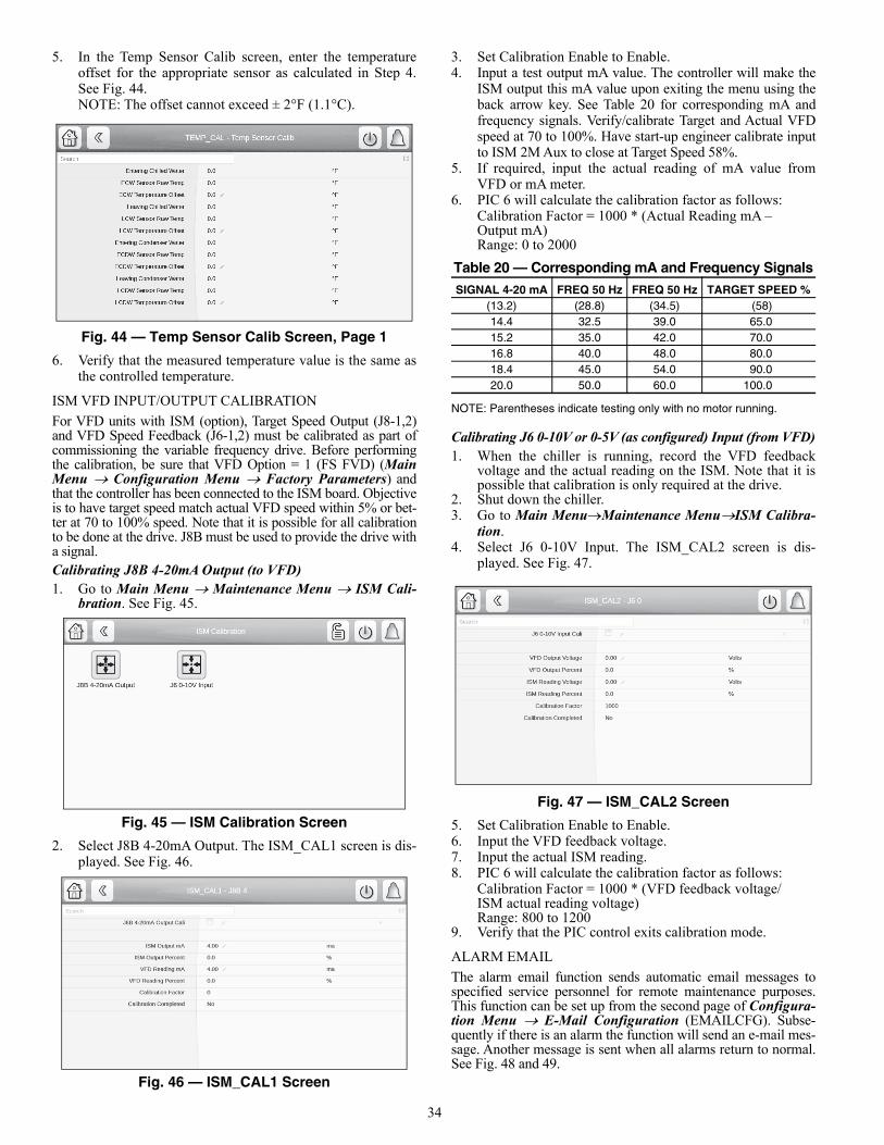
34
5. In the Temp Sensor Calib screen, enter the temperatureoffset for the appropriate sensor as calculated in Step 4.See Fig. 44.NOTE: The offset cannot exceed ± 2°F (1.1°C).
Fig. 44 — Temp Sensor Calib Screen, Page 1
6. Verify that the measured temperature value is the same asthe controlled temperature.
ISM VFD INPUT/OUTPUT CALIBRATION
For VFD units with ISM (option), Target Speed Output (J8-1,2)and VFD Speed Feedback (J6-1,2) must be calibrated as part ofcommissioning the variable frequency drive. Before performingthe calibration, be sure that VFD Option = 1 (FS FVD) (MainMenu Configuration Menu Factory Parameters) andthat the controller has been connected to the ISM board. Objectiveis to have target speed match actual VFD speed within 5% or bet-ter at 70 to 100% speed. Note that it is possible for all calibrationto be done at the drive. J8B must be used to provide the drive witha signal.Calibrating J8B 4-20mA Output (to VFD)1. Go to Main Menu Maintenance Menu ISM Cali-
bration. See Fig. 45.
Fig. 45 — ISM Calibration Screen
2. Select J8B 4-20mA Output. The ISM_CAL1 screen is dis-played. See Fig. 46.
Fig. 46 — ISM_CAL1 Screen
3. Set Calibration Enable to Enable.4. Input a test output mA value. The controller will make the
ISM output this mA value upon exiting the menu using theback arrow key. See Table 20 for corresponding mA andfrequency signals. Verify/calibrate Target and Actual VFDspeed at 70 to 100%. Have start-up engineer calibrate inputto ISM 2M Aux to close at Target Speed 58%.
5. If required, input the actual reading of mA value fromVFD or mA meter.
6. PIC 6 will calculate the calibration factor as follows:Calibration Factor = 1000 * (Actual Reading mA –Output mA)Range: 0 to 2000
Table 20 — Corresponding mA and Frequency Signals
NOTE: Parentheses indicate testing only with no motor running.
Calibrating J6 0-10V or 0-5V (as configured) Input (from VFD)1. When the chiller is running, record the VFD feedback
voltage and the actual reading on the ISM. Note that it ispossible that calibration is only required at the drive.
2. Shut down the chiller.3. Go to Main MenuMaintenance MenuISM Calibra-
tion.4. Select J6 0-10V Input. The ISM_CAL2 screen is dis-
played. See Fig. 47.
Fig. 47 — ISM_CAL2 Screen
5. Set Calibration Enable to Enable.6. Input the VFD feedback voltage.7. Input the actual ISM reading.8. PIC 6 will calculate the calibration factor as follows:
Calibration Factor = 1000 * (VFD feedback voltage/ISM actual reading voltage)Range: 800 to 1200
9. Verify that the PIC control exits calibration mode.
ALARM EMAIL
The alarm email function sends automatic email messages tospecified service personnel for remote maintenance purposes.This function can be set up from the second page of Configura-tion Menu E-Mail Configuration (EMAILCFG). Subse-quently if there is an alarm the function will send an e-mail mes-sage. Another message is sent when all alarms return to normal.See Fig. 48 and 49.
SIGNAL 4-20 mA FREQ 50 Hz FREQ 50 Hz TARGET SPEED %(13.2) (28.8) (34.5) (58)14.4 32.5 39.0 65.015.2 35.0 42.0 70.016.8 40.0 48.0 80.018.4 45.0 54.0 90.020.0 50.0 60.0 100.0
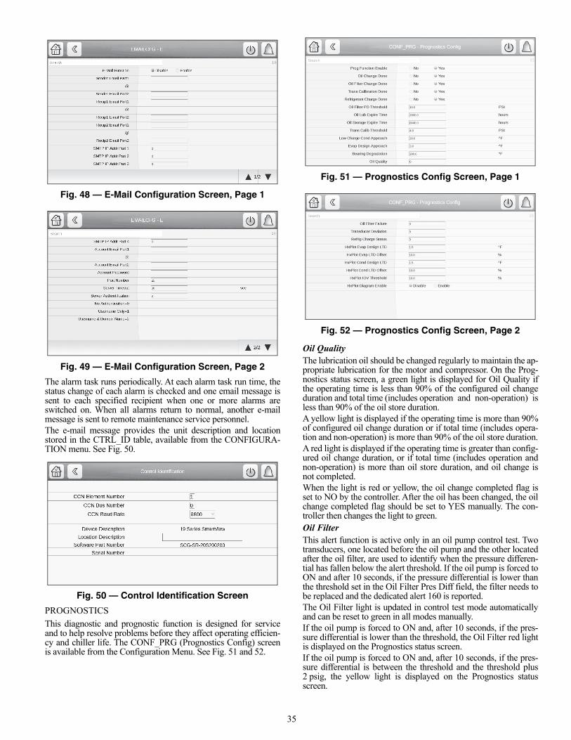
35
Fig. 48 — E-Mail Configuration Screen, Page 1
Fig. 49 — E-Mail Configuration Screen, Page 2
The alarm task runs periodically. At each alarm task run time, thestatus change of each alarm is checked and one email message issent to each specified recipient when one or more alarms areswitched on. When all alarms return to normal, another e-mailmessage is sent to remote maintenance service personnel.The e-mail message provides the unit description and locationstored in the CTRL_ID table, available from the CONFIGURA-TION menu. See Fig. 50.
Fig. 50 — Control Identification Screen
PROGNOSTICS
This diagnostic and prognostic function is designed for serviceand to help resolve problems before they affect operating efficien-cy and chiller life. The CONF_PRG (Prognostics Config) screenis available from the Configuration Menu. See Fig. 51 and 52.
Fig. 51 — Prognostics Config Screen, Page 1
Fig. 52 — Prognostics Config Screen, Page 2
Oil QualityThe lubrication oil should be changed regularly to maintain the ap-propriate lubrication for the motor and compressor. On the Prog-nostics status screen, a green light is displayed for Oil Quality ifthe operating time is less than 90% of the configured oil changeduration and total time (includes operation and non-operation) isless than 90% of the oil store duration.A yellow light is displayed if the operating time is more than 90%of configured oil change duration or if total time (includes opera-tion and non-operation) is more than 90% of the oil store duration.A red light is displayed if the operating time is greater than config-ured oil change duration, or if total time (includes operation andnon-operation) is more than oil store duration, and oil change isnot completed. When the light is red or yellow, the oil change completed flag isset to NO by the controller. After the oil has been changed, the oilchange completed flag should be set to YES manually. The con-troller then changes the light to green. Oil Filter This alert function is active only in an oil pump control test. Twotransducers, one located before the oil pump and the other locatedafter the oil filter, are used to identify when the pressure differen-tial has fallen below the alert threshold. If the oil pump is forced toON and after 10 seconds, if the pressure differential is lower thanthe threshold set in the Oil Filter Pres Diff field, the filter needs tobe replaced and the dedicated alert 160 is reported.The Oil Filter light is updated in control test mode automaticallyand can be reset to green in all modes manually.If the oil pump is forced to ON and, after 10 seconds, if the pres-sure differential is lower than the threshold, the Oil Filter red lightis displayed on the Prognostics status screen.If the oil pump is forced to ON and, after 10 seconds, if the pres-sure differential is between the threshold and the threshold plus2 psig, the yellow light is displayed on the Prognostics statusscreen.
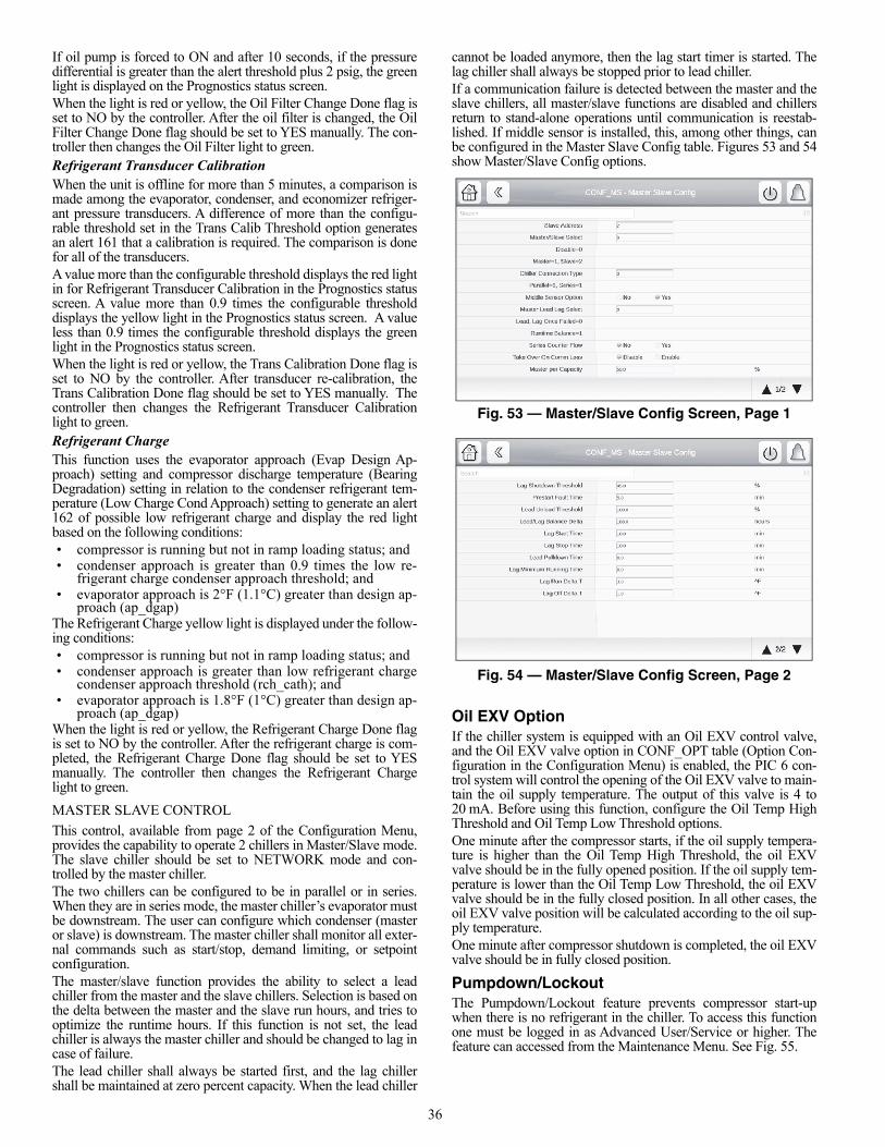
36
If oil pump is forced to ON and after 10 seconds, if the pressuredifferential is greater than the alert threshold plus 2 psig, the greenlight is displayed on the Prognostics status screen.When the light is red or yellow, the Oil Filter Change Done flag isset to NO by the controller. After the oil filter is changed, the OilFilter Change Done flag should be set to YES manually. The con-troller then changes the Oil Filter light to green.Refrigerant Transducer CalibrationWhen the unit is offline for more than 5 minutes, a comparison ismade among the evaporator, condenser, and economizer refriger-ant pressure transducers. A difference of more than the configu-rable threshold set in the Trans Calib Threshold option generatesan alert 161 that a calibration is required. The comparison is donefor all of the transducers. A value more than the configurable threshold displays the red lightin for Refrigerant Transducer Calibration in the Prognostics statusscreen. A value more than 0.9 times the configurable thresholddisplays the yellow light in the Prognostics status screen. A valueless than 0.9 times the configurable threshold displays the greenlight in the Prognostics status screen.When the light is red or yellow, the Trans Calibration Done flag isset to NO by the controller. After transducer re-calibration, theTrans Calibration Done flag should be set to YES manually. Thecontroller then changes the Refrigerant Transducer Calibrationlight to green.Refrigerant ChargeThis function uses the evaporator approach (Evap Design Ap-proach) setting and compressor discharge temperature (BearingDegradation) setting in relation to the condenser refrigerant tem-perature (Low Charge Cond Approach) setting to generate an alert162 of possible low refrigerant charge and display the red lightbased on the following conditions:• compressor is running but not in ramp loading status; and• condenser approach is greater than 0.9 times the low re-
frigerant charge condenser approach threshold; and• evaporator approach is 2°F (1.1°C) greater than design ap-
proach (ap_dgap)The Refrigerant Charge yellow light is displayed under the follow-ing conditions:• compressor is running but not in ramp loading status; and• condenser approach is greater than low refrigerant charge
condenser approach threshold (rch_cath); and• evaporator approach is 1.8°F (1°C) greater than design ap-
proach (ap_dgap)When the light is red or yellow, the Refrigerant Charge Done flagis set to NO by the controller. After the refrigerant charge is com-pleted, the Refrigerant Charge Done flag should be set to YESmanually. The controller then changes the Refrigerant Chargelight to green.
MASTER SLAVE CONTROL
This control, available from page 2 of the Configuration Menu,provides the capability to operate 2 chillers in Master/Slave mode.The slave chiller should be set to NETWORK mode and con-trolled by the master chiller.The two chillers can be configured to be in parallel or in series.When they are in series mode, the master chiller’s evaporator mustbe downstream. The user can configure which condenser (masteror slave) is downstream. The master chiller shall monitor all exter-nal commands such as start/stop, demand limiting, or setpointconfiguration.The master/slave function provides the ability to select a leadchiller from the master and the slave chillers. Selection is based onthe delta between the master and the slave run hours, and tries tooptimize the runtime hours. If this function is not set, the leadchiller is always the master chiller and should be changed to lag incase of failure. The lead chiller shall always be started first, and the lag chillershall be maintained at zero percent capacity. When the lead chiller
cannot be loaded anymore, then the lag start timer is started. Thelag chiller shall always be stopped prior to lead chiller.If a communication failure is detected between the master and theslave chillers, all master/slave functions are disabled and chillersreturn to stand-alone operations until communication is reestab-lished. If middle sensor is installed, this, among other things, canbe configured in the Master Slave Config table. Figures 53 and 54show Master/Slave Config options.
Fig. 53 — Master/Slave Config Screen, Page 1
Fig. 54 — Master/Slave Config Screen, Page 2
Oil EXV OptionIf the chiller system is equipped with an Oil EXV control valve,and the Oil EXV valve option in CONF_OPT table (Option Con-figuration in the Configuration Menu) is enabled, the PIC 6 con-trol system will control the opening of the Oil EXV valve to main-tain the oil supply temperature. The output of this valve is 4 to20 mA. Before using this function, configure the Oil Temp HighThreshold and Oil Temp Low Threshold options.One minute after the compressor starts, if the oil supply tempera-ture is higher than the Oil Temp High Threshold, the oil EXVvalve should be in the fully opened position. If the oil supply tem-perature is lower than the Oil Temp Low Threshold, the oil EXVvalve should be in the fully closed position. In all other cases, theoil EXV valve position will be calculated according to the oil sup-ply temperature.One minute after compressor shutdown is completed, the oil EXVvalve should be in fully closed position.
Pumpdown/LockoutThe Pumpdown/Lockout feature prevents compressor start-upwhen there is no refrigerant in the chiller. To access this functionone must be logged in as Advanced User/Service or higher. Thefeature can accessed from the Maintenance Menu. See Fig. 55.
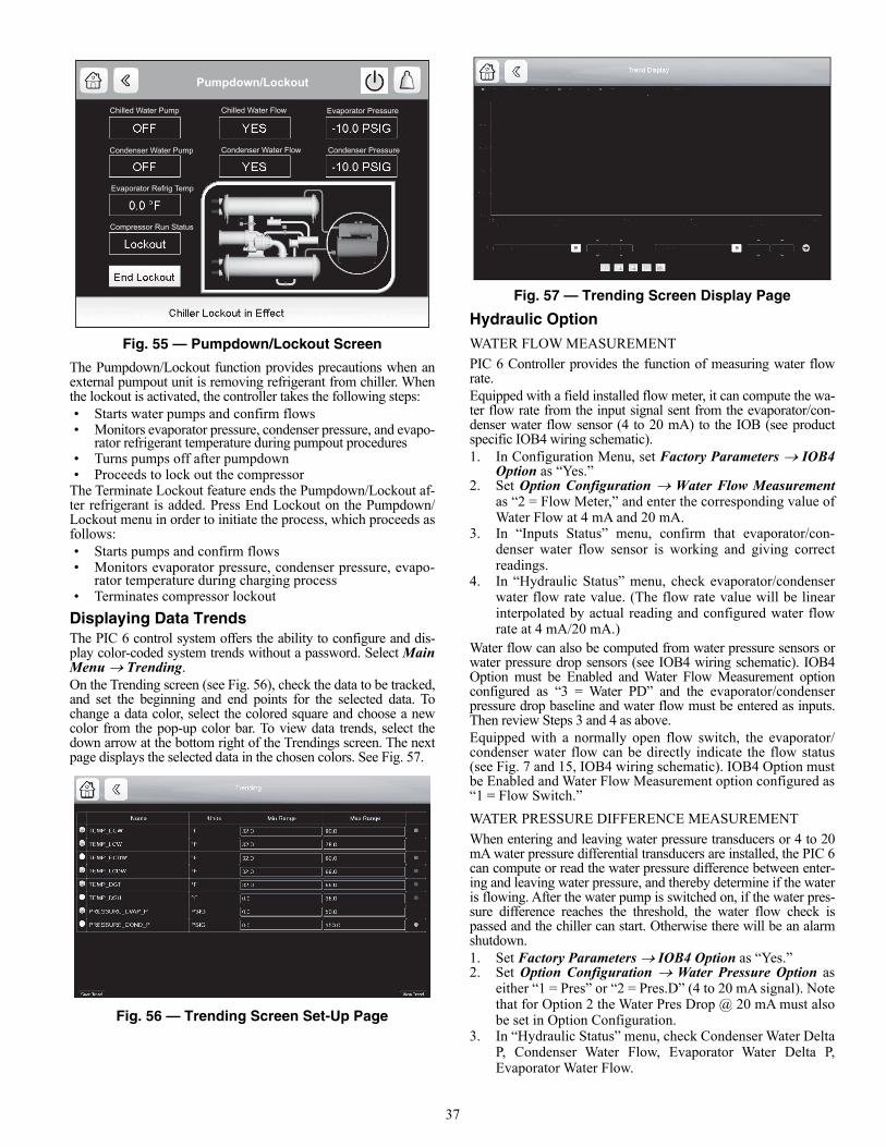
37
Fig. 55 — Pumpdown/Lockout Screen
The Pumpdown/Lockout function provides precautions when anexternal pumpout unit is removing refrigerant from chiller. Whenthe lockout is activated, the controller takes the following steps:• Starts water pumps and confirm flows• Monitors evaporator pressure, condenser pressure, and evapo-
rator refrigerant temperature during pumpout procedures• Turns pumps off after pumpdown• Proceeds to lock out the compressor
The Terminate Lockout feature ends the Pumpdown/Lockout af-ter refrigerant is added. Press End Lockout on the Pumpdown/Lockout menu in order to initiate the process, which proceeds asfollows:• Starts pumps and confirm flows• Monitors evaporator pressure, condenser pressure, evapo-
rator temperature during charging process• Terminates compressor lockout
Displaying Data Trends The PIC 6 control system offers the ability to configure and dis-play color-coded system trends without a password. Select MainMenu Trending.On the Trending screen (see Fig. 56), check the data to be tracked,and set the beginning and end points for the selected data. Tochange a data color, select the colored square and choose a newcolor from the pop-up color bar. To view data trends, select thedown arrow at the bottom right of the Trendings screen. The nextpage displays the selected data in the chosen colors. See Fig. 57.
Fig. 56 — Trending Screen Set-Up Page
Fig. 57 — Trending Screen Display Page
Hydraulic Option
WATER FLOW MEASUREMENT
PIC 6 Controller provides the function of measuring water flowrate. Equipped with a field installed flow meter, it can compute the wa-ter flow rate from the input signal sent from the evaporator/con-denser water flow sensor (4 to 20 mA) to the IOB (see productspecific IOB4 wiring schematic).1. In Configuration Menu, set Factory Parameters IOB4
Option as “Yes.”2. Set Option Configuration Water Flow Measurement
as “2 = Flow Meter,” and enter the corresponding value ofWater Flow at 4 mA and 20 mA.
3. In “Inputs Status” menu, confirm that evaporator/con-denser water flow sensor is working and giving correctreadings.
4. In “Hydraulic Status” menu, check evaporator/condenserwater flow rate value. (The flow rate value will be linearinterpolated by actual reading and configured water flowrate at 4 mA/20 mA.)
Water flow can also be computed from water pressure sensors orwater pressure drop sensors (see IOB4 wiring schematic). IOB4Option must be Enabled and Water Flow Measurement optionconfigured as “3 = Water PD” and the evaporator/condenserpressure drop baseline and water flow must be entered as inputs.Then review Steps 3 and 4 as above.Equipped with a normally open flow switch, the evaporator/condenser water flow can be directly indicate the flow status(see Fig. 7 and 15, IOB4 wiring schematic). IOB4 Option mustbe Enabled and Water Flow Measurement option configured as“1 = Flow Switch.”
WATER PRESSURE DIFFERENCE MEASUREMENT
When entering and leaving water pressure transducers or 4 to 20mA water pressure differential transducers are installed, the PIC 6can compute or read the water pressure difference between enter-ing and leaving water pressure, and thereby determine if the wateris flowing. After the water pump is switched on, if the water pres-sure difference reaches the threshold, the water flow check ispassed and the chiller can start. Otherwise there will be an alarmshutdown.1. Set Factory Parameters IOB4 Option as “Yes.”2. Set Option Configuration Water Pressure Option as
either “1 = Pres” or “2 = Pres.D” (4 to 20 mA signal). Notethat for Option 2 the Water Pres Drop @ 20 mA must alsobe set in Option Configuration.
3. In “Hydraulic Status” menu, check Condenser Water DeltaP, Condenser Water Flow, Evaporator Water Delta P,Evaporator Water Flow.
Pumpdown/Lockout
Chilled Water Pump Chilled Water Flow Evaporator Pressure
Condenser Water Pump Condenser Water Flow Condenser Pressure
Evaporator Refrig Temp
Compressor Run Status
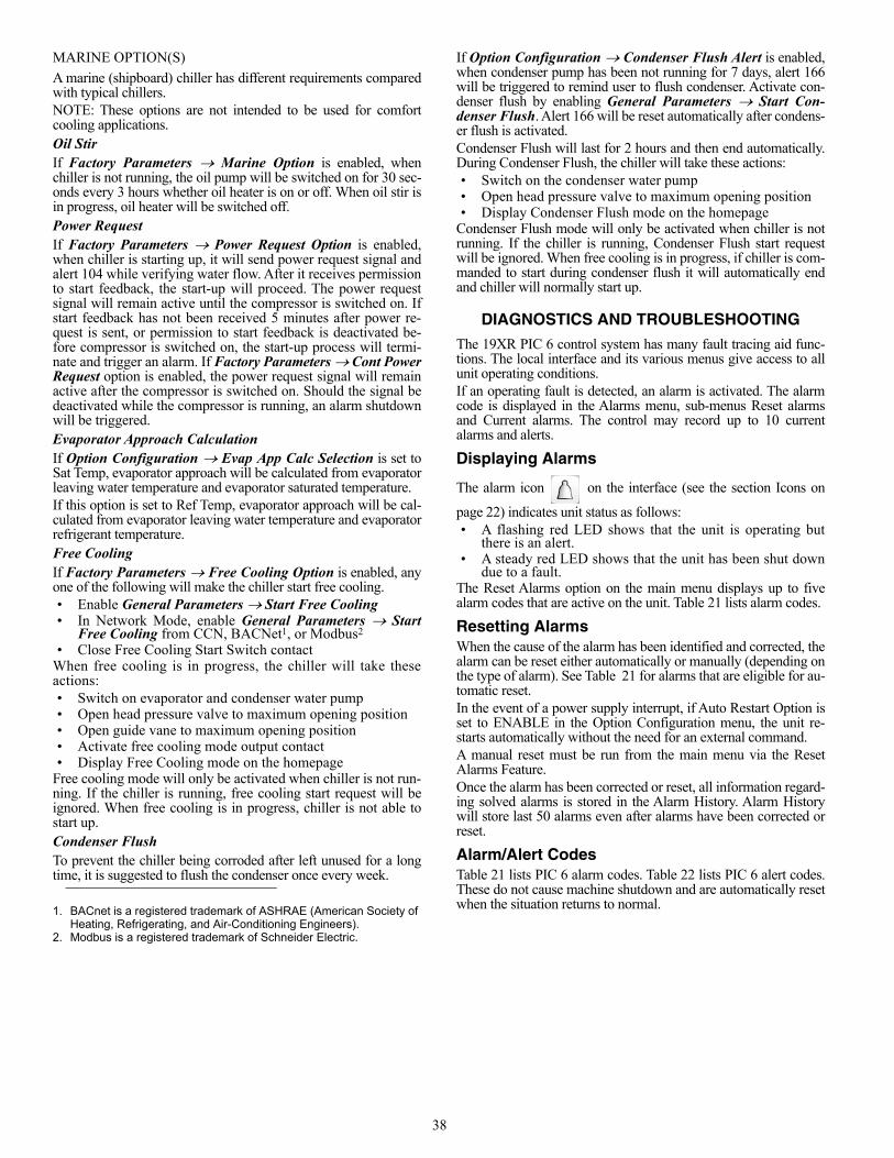
38
MARINE OPTION(S)
A marine (shipboard) chiller has different requirements comparedwith typical chillers. NOTE: These options are not intended to be used for comfortcooling applications.Oil StirIf Factory Parameters Marine Option is enabled, whenchiller is not running, the oil pump will be switched on for 30 sec-onds every 3 hours whether oil heater is on or off. When oil stir isin progress, oil heater will be switched off.Power RequestIf Factory Parameters Power Request Option is enabled,when chiller is starting up, it will send power request signal andalert 104 while verifying water flow. After it receives permissionto start feedback, the start-up will proceed. The power requestsignal will remain active until the compressor is switched on. Ifstart feedback has not been received 5 minutes after power re-quest is sent, or permission to start feedback is deactivated be-fore compressor is switched on, the start-up process will termi-nate and trigger an alarm. If Factory Parameters Cont PowerRequest option is enabled, the power request signal will remainactive after the compressor is switched on. Should the signal bedeactivated while the compressor is running, an alarm shutdownwill be triggered. Evaporator Approach CalculationIf Option Configuration Evap App Calc Selection is set toSat Temp, evaporator approach will be calculated from evaporatorleaving water temperature and evaporator saturated temperature.If this option is set to Ref Temp, evaporator approach will be cal-culated from evaporator leaving water temperature and evaporatorrefrigerant temperature.Free CoolingIf Factory Parameters Free Cooling Option is enabled, anyone of the following will make the chiller start free cooling.• Enable General Parameters Start Free Cooling• In Network Mode, enable General Parameters Start
Free Cooling from CCN, BACNet1, or Modbus2
• Close Free Cooling Start Switch contactWhen free cooling is in progress, the chiller will take theseactions:• Switch on evaporator and condenser water pump• Open head pressure valve to maximum opening position• Open guide vane to maximum opening position• Activate free cooling mode output contact• Display Free Cooling mode on the homepage
Free cooling mode will only be activated when chiller is not run-ning. If the chiller is running, free cooling start request will beignored. When free cooling is in progress, chiller is not able tostart up.Condenser FlushTo prevent the chiller being corroded after left unused for a longtime, it is suggested to flush the condenser once every week.
If Option Configuration Condenser Flush Alert is enabled,when condenser pump has been not running for 7 days, alert 166will be triggered to remind user to flush condenser. Activate con-denser flush by enabling General Parameters Start Con-denser Flush. Alert 166 will be reset automatically after condens-er flush is activated.Condenser Flush will last for 2 hours and then end automatically.During Condenser Flush, the chiller will take these actions:• Switch on the condenser water pump• Open head pressure valve to maximum opening position• Display Condenser Flush mode on the homepage
Condenser Flush mode will only be activated when chiller is notrunning. If the chiller is running, Condenser Flush start requestwill be ignored. When free cooling is in progress, if chiller is com-manded to start during condenser flush it will automatically endand chiller will normally start up.
DIAGNOSTICS AND TROUBLESHOOTING
The 19XR PIC 6 control system has many fault tracing aid func-tions. The local interface and its various menus give access to allunit operating conditions.If an operating fault is detected, an alarm is activated. The alarmcode is displayed in the Alarms menu, sub-menus Reset alarmsand Current alarms. The control may record up to 10 currentalarms and alerts.
Displaying Alarms
The alarm icon on the interface (see the section Icons on
page 22) indicates unit status as follows:• A flashing red LED shows that the unit is operating but
there is an alert.• A steady red LED shows that the unit has been shut down
due to a fault.The Reset Alarms option on the main menu displays up to fivealarm codes that are active on the unit. Table 21 lists alarm codes.
Resetting AlarmsWhen the cause of the alarm has been identified and corrected, thealarm can be reset either automatically or manually (depending onthe type of alarm). See Table 21 for alarms that are eligible for au-tomatic reset.In the event of a power supply interrupt, if Auto Restart Option isset to ENABLE in the Option Configuration menu, the unit re-starts automatically without the need for an external command.A manual reset must be run from the main menu via the ResetAlarms Feature. Once the alarm has been corrected or reset, all information regard-ing solved alarms is stored in the Alarm History. Alarm Historywill store last 50 alarms even after alarms have been corrected orreset.
Alarm/Alert CodesTable 21 lists PIC 6 alarm codes. Table 22 lists PIC 6 alert codes.These do not cause machine shutdown and are automatically resetwhen the situation returns to normal.1. BACnet is a registered trademark of ASHRAE (American Society of
Heating, Refrigerating, and Air-Conditioning Engineers).2. Modbus is a registered trademark of Schneider Electric.
39
Table 21 — PIC 6 Alarm Codes
ALARM CODE(ALARMRST)
ALARM TEXT DESCRIPTION RESET TYPE ACTION TAKEN
BY CONTROL POSSIBLE CAUSE
TEMPERATURE SENSOR FAULTS
Alm-200 ALM-200 Sensor Fault — Leaving Chilled Water
Automatic if the temperature mea-sured by the sensor returns to normal Unit shuts down
Check sensor resistance.Check for proper wiring between leaving chilled water temperature sensor and IOB connector. Check for disconnected, grounded, or shorted wiring.Check IOB channel type configurations.
Alm-201 ALM-201 Sensor Fault — Entering Chilled Water
Automatic if the temperature mea-sured by the sensor returns to normal Unit shuts down
Check sensor resistance.Check for proper wiring between entering chilled water temperature sensor and IOB connector. Check for disconnected, grounded, or shorted wiring.Check IOB channel type configurations.
Alm-202 ALM-202 Sensor Fault —Leaving Cond Water Temp
Automatic if the temperature mea-sured by the sensor returns to normal Unit shuts down
Check sensor resistance.Check for proper wiring between leaving condenser water temperature sensor and IOB connector. Check for disconnected, grounded, or shorted wiring.Check IOB channel type configurations.
Alm-203 ALM-203 Sensor Fault —Entering Cond Water Temp
Automatic if the temperature mea-sured by the sensor returns to normal Unit shuts down
Check sensor resistance.Check for proper wiring between entering condenser water temperature sensor and IOB connector. Check for disconnected, grounded, or shorted wiring.Check IOB channel type configurations.
Alm-204 ALM-204 Sensor Fault — Comp Discharge Temp
Automatic if the temperature mea-sured by the sensor returns to normal Unit shuts down
Check sensor resistance.Check for proper wiring between compressor discharge temperature sensor and connector. Check for disconnected, grounded, or shorted wiring.
Alm-205 ALM-205 Sensor Fault — Oil Sump Temp
Automatic if the temperature mea-sured by the sensor returns to normal Unit shuts down
Check sensor resistance.Check for proper wiring between oil sump temperature sensor and IOB connector.Check for disconnected, grounded, or shorted wiring.
Alm-206 ALM-206 Sensor Fault — Oil Supply Temp
Automatic if the temperature mea-sured by the sensor returns to normal Unit shuts down
Check sensor resistance.Check for proper wiring between oil supply temperature sensor and IOB connector.Check for disconnected, grounded, or shorted wiring.
Alm-207 ALM-207 Sensor Fault — Evap Refrig Liquid Temp
Automatic if the temperature mea-sured by the sensor returns to normal Unit shuts down
Check sensor resistance.Check for proper wiring between evaporator refrigerant liquid temperature sensor and IOB connector.Check for disconnected, grounded, or shorted wiring.
Alm-208ALM-208 Sensor Fault — Low Speed Motor End Bearing Temp
Automatic if the temperature mea-sured by the sensor returns to normal Unit shuts down
Check sensor resistance.Check for proper wiring between low speed motor end bearing temperature sensor and IOB connector.Check for disconnected, grounded, or shorted wiring.Check IOB channel type configurations.
Alm-209ALM-209 Sensor Fault — Low Speed Comp End Bearing Temp
Automatic if the temperature mea-sured by the sensor returns to normal Unit shuts down
Check sensor resistance.Check for proper wiring between low speed compressor end bearing temperature sen-sor and IOB connector. Check for disconnected, grounded, or shorted wiring.Check IOB channel type configurations.
Alm-210ALM-210 Sensor Fault — High Speed Motor End Bearing Temp
Automatic if the temperature mea-sured by the sensor returns to normal Unit shuts down
Check sensor resistance.Check for proper wiring between high speed motor end bearing temperature sensor and IOB connector. Check for disconnected, grounded, or shorted wiring.Check IOB channel type configurations.
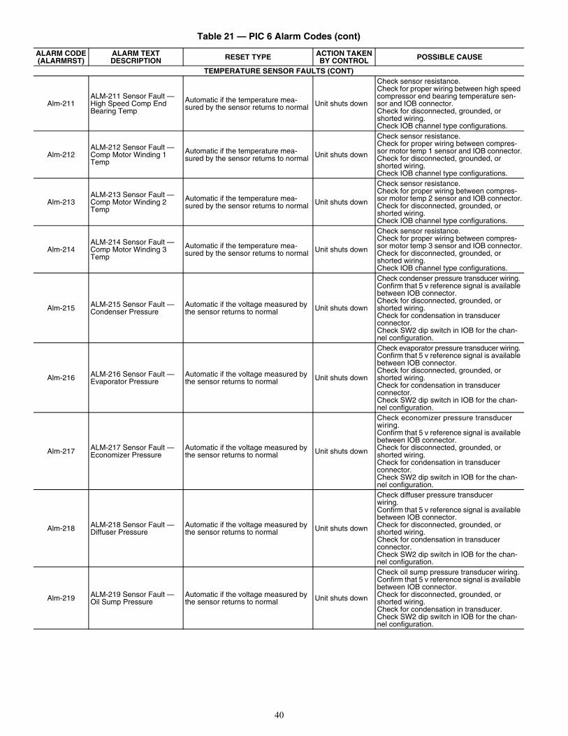
40
TEMPERATURE SENSOR FAULTS (CONT)
Alm-211ALM-211 Sensor Fault — High Speed Comp End Bearing Temp
Automatic if the temperature mea-sured by the sensor returns to normal Unit shuts down
Check sensor resistance.Check for proper wiring between high speed compressor end bearing temperature sen-sor and IOB connector.Check for disconnected, grounded, or shorted wiring.Check IOB channel type configurations.
Alm-212ALM-212 Sensor Fault — Comp Motor Winding 1 Temp
Automatic if the temperature mea-sured by the sensor returns to normal Unit shuts down
Check sensor resistance.Check for proper wiring between compres-sor motor temp 1 sensor and IOB connector.Check for disconnected, grounded, or shorted wiring.Check IOB channel type configurations.
Alm-213ALM-213 Sensor Fault — Comp Motor Winding 2 Temp
Automatic if the temperature mea-sured by the sensor returns to normal Unit shuts down
Check sensor resistance.Check for proper wiring between compres-sor motor temp 2 sensor and IOB connector.Check for disconnected, grounded, or shorted wiring.Check IOB channel type configurations.
Alm-214ALM-214 Sensor Fault — Comp Motor Winding 3 Temp
Automatic if the temperature mea-sured by the sensor returns to normal Unit shuts down
Check sensor resistance.Check for proper wiring between compres-sor motor temp 3 sensor and IOB connector.Check for disconnected, grounded, or shorted wiring.Check IOB channel type configurations.
Alm-215 ALM-215 Sensor Fault — Condenser Pressure
Automatic if the voltage measured by the sensor returns to normal Unit shuts down
Check condenser pressure transducer wiring. Confirm that 5 v reference signal is available between IOB connector. Check for disconnected, grounded, or shorted wiring. Check for condensation in transducer connector. Check SW2 dip switch in IOB for the chan-nel configuration.
Alm-216 ALM-216 Sensor Fault — Evaporator Pressure
Automatic if the voltage measured by the sensor returns to normal Unit shuts down
Check evaporator pressure transducer wiring. Confirm that 5 v reference signal is available between IOB connector.Check for disconnected, grounded, or shorted wiring.Check for condensation in transducer connector. Check SW2 dip switch in IOB for the chan-nel configuration.
Alm-217 ALM-217 Sensor Fault — Economizer Pressure
Automatic if the voltage measured by the sensor returns to normal Unit shuts down
Check economizer pressure transducer wiring.Confirm that 5 v reference signal is available between IOB connector. Check for disconnected, grounded, or shorted wiring. Check for condensation in transducer connector. Check SW2 dip switch in IOB for the chan-nel configuration.
Alm-218 ALM-218 Sensor Fault — Diffuser Pressure
Automatic if the voltage measured by the sensor returns to normal Unit shuts down
Check diffuser pressure transducer wiring. Confirm that 5 v reference signal is available between IOB connector. Check for disconnected, grounded, or shorted wiring. Check for condensation in transducer connector. Check SW2 dip switch in IOB for the chan-nel configuration.
Alm-219 ALM-219 Sensor Fault — Oil Sump Pressure
Automatic if the voltage measured by the sensor returns to normal Unit shuts down
Check oil sump pressure transducer wiring. Confirm that 5 v reference signal is available between IOB connector. Check for disconnected, grounded, or shorted wiring. Check for condensation in transducer. Check SW2 dip switch in IOB for the chan-nel configuration.
Table 21 — PIC 6 Alarm Codes (cont)
ALARM CODE(ALARMRST)
ALARM TEXT DESCRIPTION RESET TYPE ACTION TAKEN
BY CONTROL POSSIBLE CAUSE
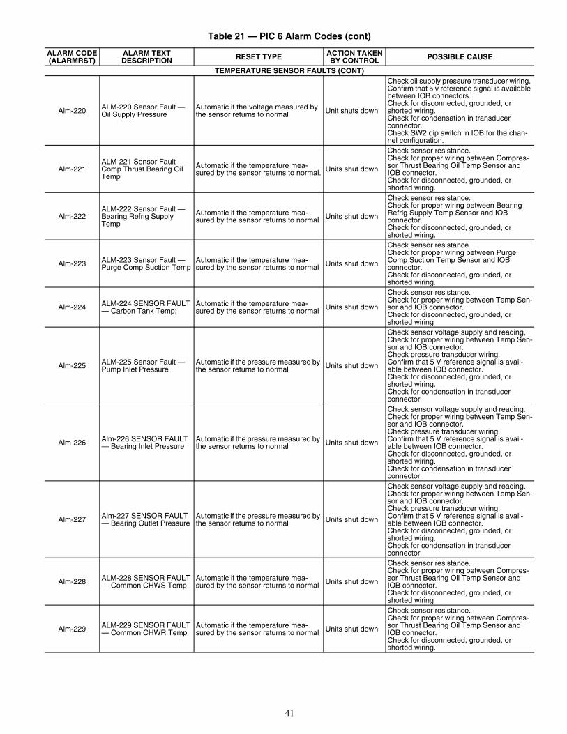
41
TEMPERATURE SENSOR FAULTS (CONT)
Alm-220 ALM-220 Sensor Fault — Oil Supply Pressure
Automatic if the voltage measured by the sensor returns to normal Unit shuts down
Check oil supply pressure transducer wiring. Confirm that 5 v reference signal is available between IOB connectors. Check for disconnected, grounded, or shorted wiring. Check for condensation in transducer connector. Check SW2 dip switch in IOB for the chan-nel configuration.
Alm-221ALM-221 Sensor Fault — Comp Thrust Bearing Oil Temp
Automatic if the temperature mea-sured by the sensor returns to normal. Units shut down
Check sensor resistance. Check for proper wiring between Compres-sor Thrust Bearing Oil Temp Sensor and IOB connector.Check for disconnected, grounded, or shorted wiring.
Alm-222ALM-222 Sensor Fault — Bearing Refrig Supply Temp
Automatic if the temperature mea-sured by the sensor returns to normal Units shut down
Check sensor resistance. Check for proper wiring between Bearing Refrig Supply Temp Sensor and IOB connector.Check for disconnected, grounded, or shorted wiring.
Alm-223 ALM-223 Sensor Fault — Purge Comp Suction Temp
Automatic if the temperature mea-sured by the sensor returns to normal Units shut down
Check sensor resistance. Check for proper wiring between Purge Comp Suction Temp Sensor and IOB connector.Check for disconnected, grounded, or shorted wiring.
Alm-224 ALM-224 SENSOR FAULT — Carbon Tank Temp;
Automatic if the temperature mea-sured by the sensor returns to normal Units shut down
Check sensor resistance. Check for proper wiring between Temp Sen-sor and IOB connector. Check for disconnected, grounded, or shorted wiring
Alm-225 ALM-225 Sensor Fault — Pump Inlet Pressure
Automatic if the pressure measured by the sensor returns to normal Units shut down
Check sensor voltage supply and reading,Check for proper wiring between Temp Sen-sor and IOB connector. Check pressure transducer wiring. Confirm that 5 V reference signal is avail-able between IOB connector. Check for disconnected, grounded, or shorted wiring. Check for condensation in transducer connector
Alm-226 Alm-226 SENSOR FAULT — Bearing Inlet Pressure
Automatic if the pressure measured by the sensor returns to normal Units shut down
Check sensor voltage supply and reading.Check for proper wiring between Temp Sen-sor and IOB connector. Check pressure transducer wiring. Confirm that 5 V reference signal is avail-able between IOB connector. Check for disconnected, grounded, or shorted wiring. Check for condensation in transducer connector
Alm-227 Alm-227 SENSOR FAULT — Bearing Outlet Pressure
Automatic if the pressure measured by the sensor returns to normal Units shut down
Check sensor voltage supply and reading.Check for proper wiring between Temp Sen-sor and IOB connector. Check pressure transducer wiring. Confirm that 5 V reference signal is avail-able between IOB connector. Check for disconnected, grounded, or shorted wiring. Check for condensation in transducer connector
Alm-228 ALM-228 SENSOR FAULT — Common CHWS Temp
Automatic if the temperature mea-sured by the sensor returns to normal Units shut down
Check sensor resistance. Check for proper wiring between Compres-sor Thrust Bearing Oil Temp Sensor and IOB connector. Check for disconnected, grounded, or shorted wiring
Alm-229 ALM-229 SENSOR FAULT — Common CHWR Temp
Automatic if the temperature mea-sured by the sensor returns to normal Units shut down
Check sensor resistance. Check for proper wiring between Compres-sor Thrust Bearing Oil Temp Sensor and IOB connector. Check for disconnected, grounded, or shorted wiring.
Table 21 — PIC 6 Alarm Codes (cont)
ALARM CODE(ALARMRST)
ALARM TEXT DESCRIPTION RESET TYPE ACTION TAKEN
BY CONTROL POSSIBLE CAUSE
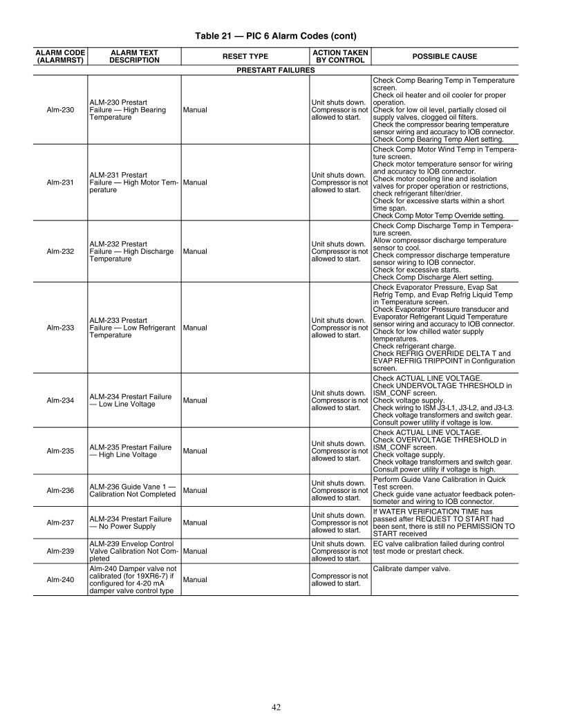
42
PRESTART FAILURES
Alm-230ALM-230 Prestart Failure — High Bearing Temperature
ManualUnit shuts down.Compressor is not allowed to start.
Check Comp Bearing Temp in Temperature screen.Check oil heater and oil cooler for proper operation.Check for low oil level, partially closed oil supply valves, clogged oil filters.Check the compressor bearing temperature sensor wiring and accuracy to IOB connector. Check Comp Bearing Temp Alert setting.
Alm-231ALM-231 Prestart Failure — High Motor Tem-perature
ManualUnit shuts down.Compressor is not allowed to start.
Check Comp Motor Wind Temp in Tempera-ture screen.Check motor temperature sensor for wiring and accuracy to IOB connector. Check motor cooling line and isolation valves for proper operation or restrictions, check refrigerant filter/drier.Check for excessive starts within a short time span.Check Comp Motor Temp Override setting.
Alm-232ALM-232 Prestart Failure — High Discharge Temperature
ManualUnit shuts down.Compressor is not allowed to start.
Check Comp Discharge Temp in Tempera-ture screen.Allow compressor discharge temperature sensor to cool. Check compressor discharge temperature sensor wiring to IOB connector.Check for excessive starts.Check Comp Discharge Alert setting.
Alm-233ALM-233 Prestart Failure — Low Refrigerant Temperature
ManualUnit shuts down.Compressor is not allowed to start.
Check Evaporator Pressure, Evap Sat Refrig Temp, and Evap Refrig Liquid Temp in Temperature screen.Check Evaporator Pressure transducer and Evaporator Refrigerant Liquid Temperature sensor wiring and accuracy to IOB connector. Check for low chilled water supply temperatures.Check refrigerant charge. Check REFRIG OVERRIDE DELTA T and EVAP REFRIG TRIPPOINT in Configuration screen.
Alm-234 ALM-234 Prestart Failure — Low Line Voltage Manual
Unit shuts down.Compressor is not allowed to start.
Check ACTUAL LINE VOLTAGE.Check UNDERVOLTAGE THRESHOLD in ISM_CONF screen.Check voltage supply. Check wiring to ISM J3-L1, J3-L2, and J3-L3.Check voltage transformers and switch gear.Consult power utility if voltage is low.
Alm-235 ALM-235 Prestart Failure — High Line Voltage Manual
Unit shuts down.Compressor is not allowed to start.
Check ACTUAL LINE VOLTAGE. Check OVERVOLTAGE THRESHOLD in ISM_CONF screen.Check voltage supply.Check voltage transformers and switch gear.Consult power utility if voltage is high.
Alm-236 ALM-236 Guide Vane 1 — Calibration Not Completed Manual
Unit shuts down.Compressor is not allowed to start.
Perform Guide Vane Calibration in Quick Test screen.Check guide vane actuator feedback poten-tiometer and wiring to IOB connector.
Alm-237 ALM-234 Prestart Failure — No Power Supply Manual
Unit shuts down.Compressor is not allowed to start.
If WATER VERIFICATION TIME has passed after REQUEST TO START had been sent, there is still no PERMISSION TO START received
Alm-239ALM-239 Envelop Control Valve Calibration Not Com-pleted
ManualUnit shuts down.Compressor is not allowed to start.
EC valve calibration failed during control test mode or prestart check.
Alm-240
Alm-240 Damper valve not calibrated (for 19XR6-7) if configured for 4-20 mA damper valve control type
Manual Compressor is not allowed to start.
Calibrate damper valve.
Table 21 — PIC 6 Alarm Codes (cont)
ALARM CODE(ALARMRST)
ALARM TEXT DESCRIPTION RESET TYPE ACTION TAKEN
BY CONTROL POSSIBLE CAUSE
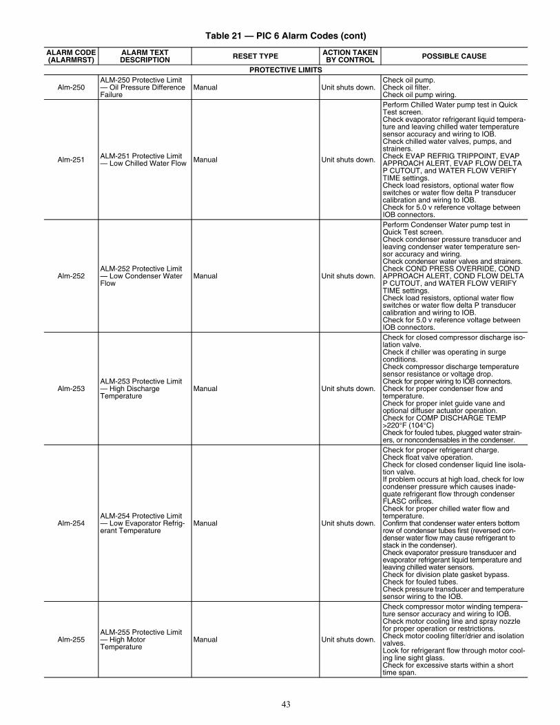
43
PROTECTIVE LIMITS
Alm-250ALM-250 Protective Limit — Oil Pressure Difference Failure
Manual Unit shuts down.Check oil pump.Check oil filter.Check oil pump wiring.
Alm-251 ALM-251 Protective Limit — Low Chilled Water Flow Manual Unit shuts down.
Perform Chilled Water pump test in Quick Test screen.Check evaporator refrigerant liquid tempera-ture and leaving chilled water temperature sensor accuracy and wiring to IOB.Check chilled water valves, pumps, and strainers. Check EVAP REFRIG TRIPPOINT, EVAP APPROACH ALERT, EVAP FLOW DELTA P CUTOUT, and WATER FLOW VERIFY TIME settings.Check load resistors, optional water flow switches or water flow delta P transducer calibration and wiring to IOB.Check for 5.0 v reference voltage between IOB connectors.
Alm-252ALM-252 Protective Limit — Low Condenser Water Flow
Manual Unit shuts down.
Perform Condenser Water pump test in Quick Test screen.Check condenser pressure transducer and leaving condenser water temperature sen-sor accuracy and wiring.Check condenser water valves and strainers.Check COND PRESS OVERRIDE, COND APPROACH ALERT, COND FLOW DELTA P CUTOUT, and WATER FLOW VERIFY TIME settings.Check load resistors, optional water flow switches or water flow delta P transducer calibration and wiring to IOB.Check for 5.0 v reference voltage between IOB connectors.
Alm-253ALM-253 Protective Limit — High Discharge Temperature
Manual Unit shuts down.
Check for closed compressor discharge iso-lation valve.Check if chiller was operating in surge conditions.Check compressor discharge temperature sensor resistance or voltage drop. Check for proper wiring to IOB connectors. Check for proper condenser flow and temperature. Check for proper inlet guide vane and optional diffuser actuator operation. Check for COMP DISCHARGE TEMP >220°F (104°C)Check for fouled tubes, plugged water strain-ers, or noncondensables in the condenser.
Alm-254ALM-254 Protective Limit — Low Evaporator Refrig-erant Temperature
Manual Unit shuts down.
Check for proper refrigerant charge.Check float valve operation. Check for closed condenser liquid line isola-tion valve.If problem occurs at high load, check for low condenser pressure which causes inade-quate refrigerant flow through condenser FLASC orifices. Check for proper chilled water flow and temperature.Confirm that condenser water enters bottom row of condenser tubes first (reversed con-denser water flow may cause refrigerant to stack in the condenser).Check evaporator pressure transducer and evaporator refrigerant liquid temperature and leaving chilled water sensors.Check for division plate gasket bypass.Check for fouled tubes.Check pressure transducer and temperature sensor wiring to the IOB.
Alm-255ALM-255 Protective Limit — High Motor Temperature
Manual Unit shuts down.
Check compressor motor winding tempera-ture sensor accuracy and wiring to IOB.Check motor cooling line and spray nozzle for proper operation or restrictions.Check motor cooling filter/drier and isolation valves.Look for refrigerant flow through motor cool-ing line sight glass.Check for excessive starts within a short time span.
Table 21 — PIC 6 Alarm Codes (cont)
ALARM CODE(ALARMRST)
ALARM TEXT DESCRIPTION RESET TYPE ACTION TAKEN
BY CONTROL POSSIBLE CAUSE
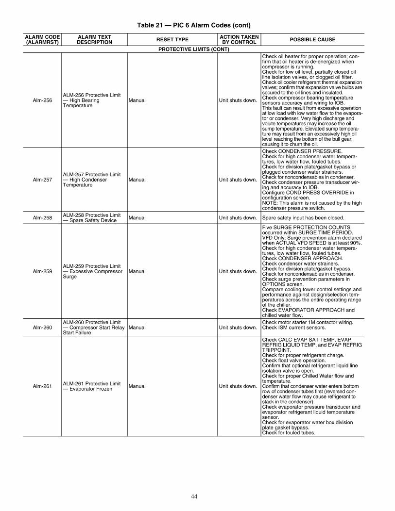
44
PROTECTIVE LIMITS (CONT)
Alm-256ALM-256 Protective Limit — High Bearing Temperature
Manual Unit shuts down.
Check oil heater for proper operation; con-firm that oil heater is de-energized when compressor is running.Check for low oil level, partially closed oil line isolation valves, or clogged oil filter. Check oil cooler refrigerant thermal expansion valves; confirm that expansion valve bulbs are secured to the oil lines and insulated.Check compressor bearing temperature sensors accuracy and wiring to IOB. This fault can result from excessive operation at low load with low water flow to the evapora-tor or condenser. Very high discharge and volute temperatures may increase the oil sump temperature. Elevated sump tempera-ture may result from an excessively high oil level reaching the bottom of the bull gear, causing it to churn the oil.
Alm-257ALM-257 Protective Limit — High Condenser Temperature
Manual Unit shuts down.
Check CONDENSER PRESSURE.Check for high condenser water tempera-tures, low water flow, fouled tubes.Check for division plate/gasket bypass or plugged condenser water strainers.Check for noncondensables in condenser.Check condenser pressure transducer wir-ing and accuracy to IOB. Configure COND PRESS OVERRIDE in configuration screen.NOTE: This alarm is not caused by the high condenser pressure switch.
Alm-258 ALM-258 Protective Limit — Spare Safety Device Manual Unit shuts down. Spare safety input has been closed.
Alm-259ALM-259 Protective Limit — Excessive Compressor Surge
Manual Unit shuts down.
Five SURGE PROTECTION COUNTS occurred within SURGE TIME PERIOD. VFD Only: Surge prevention alarm declared when ACTUAL VFD SPEED is at least 90%. Check for high condenser water tempera-tures, low water flow, fouled tubes.Check CONDENSER APPROACH. Check condenser water strainers. Check for division plate/gasket bypass.Check for noncondensables in condenser.Check surge prevention parameters in OPTIONS screen.Compare cooling tower control settings and performance against design/selection tem-peratures across the entire operating range of the chiller.Check EVAPORATOR APPROACH and chilled water flow.
Alm-260ALM-260 Protective Limit — Compressor Start Relay Start Failure
Manual Unit shuts down.Check motor starter 1M contactor wiring.Check ISM current sensors.
Alm-261 ALM-261 Protective Limit — Evaporator Frozen Manual Unit shuts down.
Check CALC EVAP SAT TEMP, EVAP REFRIG LIQUID TEMP, and EVAP REFRIG TRIPPOINT.Check for proper refrigerant charge. Check float valve operation.Confirm that optional refrigerant liquid line isolation valve is open.Check for proper Chilled Water flow and temperature.Confirm that condenser water enters bottom row of condenser tubes first (reversed con-denser water flow may cause refrigerant to stack in the condenser).Check evaporator pressure transducer and evaporator refrigerant liquid temperature sensor.Check for evaporator water box division plate gasket bypass.Check for fouled tubes.
Table 21 — PIC 6 Alarm Codes (cont)
ALARM CODE(ALARMRST)
ALARM TEXT DESCRIPTION RESET TYPE ACTION TAKEN
BY CONTROL POSSIBLE CAUSE
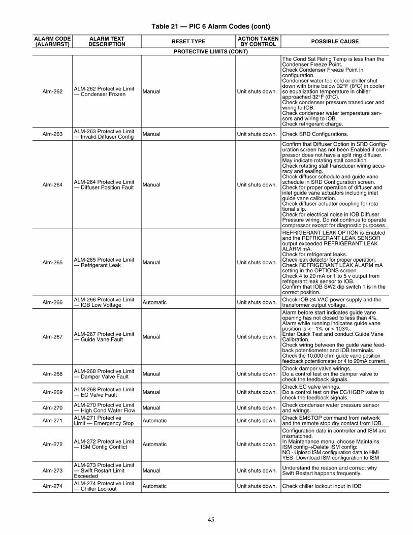
45
PROTECTIVE LIMITS (CONT)
Alm-262 ALM-262 Protective Limit — Condenser Frozen Manual Unit shuts down.
The Cond Sat Refrig Temp is less than the Condenser Freeze Point. Check Condenser Freeze Point in configuration.Condenser water too cold or chiller shut down with brine below 32°F (0°C) in cooler so equalization temperature in chiller approached 32°F (0°C).Check condenser pressure transducer and wiring to IOB.Check condenser water temperature sen-sors and wiring to IOB.Check refrigerant charge.
Alm-263 ALM-263 Protective Limit — Invalid Diffuser Config Manual Unit shuts down. Check SRD Configurations.
Alm-264 ALM-264 Protective Limit — Diffuser Position Fault Manual Unit shuts down.
Confirm that Diffuser Option in SRD Config-uration screen has not been Enabled if com-pressor does not have a split ring diffuser. May indicate rotating stall condition.Check rotating stall transducer wiring accu-racy and sealing.Check diffuser schedule and guide vane schedule in SRD Configuration screen.Check for proper operation of diffuser and inlet guide vane actuators including inlet guide vane calibration.Check diffuser actuator coupling for rota-tional slip.Check for electrical noise in IOB Diffuser Pressure wiring. Do not continue to operate compressor except for diagnostic purposes..
Alm-265 ALM-265 Protective Limit — Refrigerant Leak Manual Unit shuts down.
REFRIGERANT LEAK OPTION is Enabled and the REFRIGERANT LEAK SENSOR output exceeded REFRIGERANT LEAK ALARM mA.Check for refrigerant leaks.Check leak detector for proper operation.Check REFRIGERANT LEAK ALARM mA setting in the OPTIONS screen.Check 4 to 20 mA or 1 to 5 v output from refrigerant leak sensor to IOB.Confirm that IOB SW2 dip switch 1 is in the correct position.
Alm-266 ALM-266 Protective Limit — IOB Low Voltage Automatic Unit shuts down. Check IOB 24 VAC power supply and the
transformer output voltage.
Alm-267 ALM-267 Protective Limit — Guide Vane Fault Manual Unit shuts down.
Alarm before start indicates guide vane opening has not closed to less than 4%.Alarm while running indicates guide vane position is < –1% or > 103%.Enter Quick Test and conduct Guide Vane Calibration.Check wiring between the guide vane feed-back potentiometer and IOB terminals.Check the 10,000 ohm guide vane position feedback potentiometer or 4 to 20mA current.
Alm-268 ALM-268 Protective Limit — Damper Valve Fault Manual Unit shuts down.
Check damper valve wirings.Do a control test on the damper valve to check the feedback signals.
Alm-269 ALM-268 Protective Limit — EC Valve Fault Manual Unit shuts down.
Check EC valve wirings.Do a control test on the EC/HGBP valve to check the feedback signals.
Alm-270 ALM-270 Protective Limit — High Cond Water Flow Manual Unit shuts down. Check condenser water pressure sensor
and wirings.
Alm-271 ALM-271 Protective Limit — Emergency Stop Automatic Unit shuts down. Check EMSTOP command from network
and the remote stop dry contact from IOB.
Alm-272 ALM-272 Protective Limit — ISM Config Conflict Automatic Unit shuts down.
Configuration data in controller and ISM are mismatched.In Maintenance menu, choose Maintains ISM configDelete ISM config:NO - Upload ISM configuration data to HMIYES- Download ISM configuration to ISM
Alm-273ALM-273 Protective Limit — Swift Restart Limit Exceeded
Manual Unit shuts down. Understand the reason and correct why Swift Restart happens frequently.
Alm-274 ALM-274 Protective Limit — Chiller Lockout Automatic Unit shuts down. Check chiller lockout input in IOB
Table 21 — PIC 6 Alarm Codes (cont)
ALARM CODE(ALARMRST)
ALARM TEXT DESCRIPTION RESET TYPE ACTION TAKEN
BY CONTROL POSSIBLE CAUSE
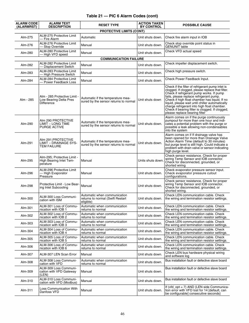
46
PROTECTIVE LIMITS (CONT)
Alm-275 ALM-275 Protective Limit — Fire Alarm Automatic Unit shuts down. Check fire alarm input in IOB
Alm-276 ALM-276 Protective Limit — Stop Override Manual Unit shuts down. Check stop override point status in
GENUNIT table
Alm-280 ALM-280 Protective Limit — High VFD speed Manual Unit shuts down. Check VFD actual speed
COMMUNICATION FAILURE
Alm-282 ALM-282 Protective Limit — Displacement Switch Manual Unit shuts down. Check impeller displacement switch.
Alm-283 ALM-283 Protective Limit — High Pressure Switch Manual Unit shuts down. Check high pressure switch.
Alm-284 ALM-284 Protective Limit — Power Feedback Loss Manual Unit shuts down. Check Power Feedback Input.
Alm - 285Alm - 285 Protective Limit - Low Bearing Delta Pres Difference
Automatic if the temperature mea-sured by the sensor returns to normal Unit shuts down
Check if the filter of refrigerant pump inlet is clogged. If clogged, please replace that filter. Check if refrigerant pump works. If pump fails, please replace refrigerant pump. Check if high float chamber has liquid. If no liquid, please wait until chiller automatically charge refrigerant into high float chamber. Check if bearing filter is clogged. If clogged, please replace bearing filter
Alm-290Alm 290 PROTECTIVE LIMIT – LONG TIME PURGE ACTIVE
Automatic if the temperature mea-sured by the sensor returns to normal Unit shuts down.
Alarm comes on if the purge continuously pumpout for more than one hour and indi-cates a potential problem with the purge or possible a leak allowing non-condensables into the system
Alm-291Alm 291;PROTECTIVE LIMIT – DRAINAGE SYS-TEM FAILURE
Automatic if the temperature mea-sured by the sensor returns to normal Unit shuts down.
Alarm comes on if If drainage valve has been opened for more than Drainage Valve Action Alarm Time (default to 30 minutes) but purge level is still high. Could indicate a problem with drain valve or sensor indicating high purge level.
Alm-295Alm-295; Protective Limit - High Bearing Inlet Tem-perature
Manual Units shuts down.
Check sensor resistance. Check for proper wiring Temp Sensor and IOB connector. Check for disconnected, grounded, or shorted wiring
Alm-296ALM-296 Protective Limit — High Evaporator Pressure
Manual Unit shuts down.Check evaporator pressure sensor input.Check evaporator pressure cutout configurations.
Alm-298 Protective Limit - Low Bear-ing Inlet Subcooling Manual Unit shuts down.
Check sensor resistance. Check for proper wiring Temp Sensor and IOB connector. Check for disconnected, grounded, or shorted wiring.
Alm-300 ALM-300 Loss Communi-cation with ISM
Automatic when communication returns to normal (Swift Restarteligible)
Unit shuts down.Check LEN communication cable. Check the wiring and termination resistor settings.
Alm-301 ALM-301 Loss of Commu-nication with IOB 1
Automatic when communication returns to normal Unit shuts down. Check LEN communication cable. Check
the wiring and termination resistor settings.
Alm-302 ALM-302 Loss of Commu-nication with IOB 2
Automatic when communication returns to normal Unit shuts down. Check LEN communication cable. Check
the wiring and termination resistor settings.
Alm-303 ALM-303 Loss of Commu-nication with IOB 3
Automatic when communication returns to normal Unit shuts down. Check LEN communication cable. Check
the wiring and termination resistor settings.
Alm-304 ALM-304 Loss of Commu-nication with IOB 4
Automatic when communication returns to normal Unit shuts down. Check LEN communication cable. Check
the wiring and termination resistor settings.
Alm-305 ALM-305 Loss of Commu-nication with IOB 5
Automatic when communication returns to normal Unit shuts down. Check LEN communication cable. Check
the wiring and termination resistor settings.
Alm-306 ALM-306 Loss of Commu-nication with IOB 6
Automatic when communication returns to normal Unit shuts down. Check LEN communication cable. Check
the wiring and termination resistor settings.
Alm-307 ALM-307 LEN Scan Error Manual Unit shuts down. Check LEN bus hardware physical wiring and software log
Alm-308 ALM-308 Loss Communi-cation with VFD
Automatic when communication returns to normal Unit shuts down. Bus installation fault or defective slave board
Alm-309ALM-309 Loss Communi-cation with VFD Gateway (LEN)
Manual Unit shuts down.Bus installation fault or defective slave board
Alm-310 ALM-310 Loss Communi-cation with VFD (Modbus) Manual Unit shuts down. Bus installation fault or defective slave board
Alm-311 Loss Communication With Danfoss VFD Manual Unit shuts down.
If (vfd_opt = 7) AND {LEN side Communica-tion error with VFD lost for 14 [default, can be configurable] consecutive seconds}
Table 21 — PIC 6 Alarm Codes (cont)
ALARM CODE(ALARMRST)
ALARM TEXT DESCRIPTION RESET TYPE ACTION TAKEN
BY CONTROL POSSIBLE CAUSE
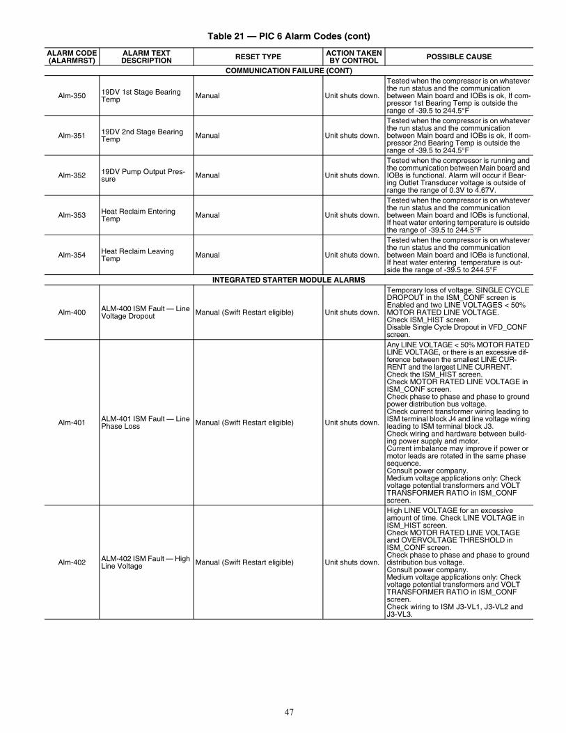
47
COMMUNICATION FAILURE (CONT)
Alm-350 19DV 1st Stage Bearing Temp Manual Unit shuts down.
Tested when the compressor is on whatever the run status and the communication between Main board and IOBs is ok, If com-pressor 1st Bearing Temp is outside the range of -39.5 to 244.5°F
Alm-351 19DV 2nd Stage Bearing Temp Manual Unit shuts down.
Tested when the compressor is on whatever the run status and the communication between Main board and IOBs is ok, If com-pressor 2nd Bearing Temp is outside the range of -39.5 to 244.5°F
Alm-352 19DV Pump Output Pres-sure Manual Unit shuts down.
Tested when the compressor is running and the communication between Main board and IOBs is functional. Alarm will occur if Bear-ing Outlet Transducer voltage is outside of range the range of 0.3V to 4.67V.
Alm-353 Heat Reclaim Entering Temp Manual Unit shuts down.
Tested when the compressor is on whatever the run status and the communication between Main board and IOBs is functional, If heat water entering temperature is outside the range of -39.5 to 244.5°F
Alm-354 Heat Reclaim Leaving Temp Manual Unit shuts down.
Tested when the compressor is on whatever the run status and the communication between Main board and IOBs is functional, If heat water entering temperature is out-side the range of -39.5 to 244.5°F
INTEGRATED STARTER MODULE ALARMS
Alm-400 ALM-400 ISM Fault — Line Voltage Dropout Manual (Swift Restart eligible) Unit shuts down.
Temporary loss of voltage. SINGLE CYCLE DROPOUT in the ISM_CONF screen is Enabled and two LINE VOLTAGES < 50% MOTOR RATED LINE VOLTAGE. Check ISM_HIST screen.Disable Single Cycle Dropout in VFD_CONF screen.
Alm-401 ALM-401 ISM Fault — Line Phase Loss Manual (Swift Restart eligible) Unit shuts down.
Any LINE VOLTAGE < 50% MOTOR RATED LINE VOLTAGE, or there is an excessive dif-ference between the smallest LINE CUR-RENT and the largest LINE CURRENT.Check the ISM_HIST screen.Check MOTOR RATED LINE VOLTAGE in ISM_CONF screen.Check phase to phase and phase to ground power distribution bus voltage.Check current transformer wiring leading to ISM terminal block J4 and line voltage wiring leading to ISM terminal block J3.Check wiring and hardware between build-ing power supply and motor.Current imbalance may improve if power or motor leads are rotated in the same phase sequence.Consult power company.Medium voltage applications only: Check voltage potential transformers and VOLT TRANSFORMER RATIO in ISM_CONF screen.
Alm-402 ALM-402 ISM Fault — High Line Voltage Manual (Swift Restart eligible) Unit shuts down.
High LINE VOLTAGE for an excessive amount of time. Check LINE VOLTAGE in ISM_HIST screen.Check MOTOR RATED LINE VOLTAGE and OVERVOLTAGE THRESHOLD in ISM_CONF screen.Check phase to phase and phase to ground distribution bus voltage.Consult power company.Medium voltage applications only: Check voltage potential transformers and VOLT TRANSFORMER RATIO in ISM_CONF screen. Check wiring to ISM J3-VL1, J3-VL2 and J3-VL3.
Table 21 — PIC 6 Alarm Codes (cont)
ALARM CODE(ALARMRST)
ALARM TEXT DESCRIPTION RESET TYPE ACTION TAKEN
BY CONTROL POSSIBLE CAUSE
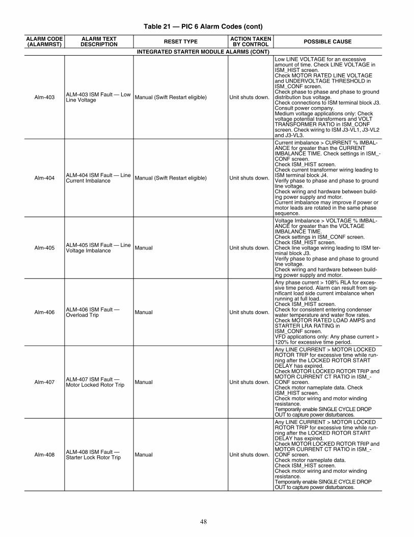
48
INTEGRATED STARTER MODULE ALARMS (CONT)
Alm-403 ALM-403 ISM Fault — Low Line Voltage Manual (Swift Restart eligible) Unit shuts down.
Low LINE VOLTAGE for an excessive amount of time. Check LINE VOLTAGE in ISM_HIST screen.Check MOTOR RATED LINE VOLTAGE and UNDERVOLTAGE THRESHOLD in ISM_CONF screen.Check phase to phase and phase to ground distribution bus voltage. Check connections to ISM terminal block J3.Consult power company.Medium voltage applications only: Check voltage potential transformers and VOLT TRANSFORMER RATIO in ISM_CONF screen. Check wiring to ISM J3-VL1, J3-VL2 and J3-VL3.
Alm-404 ALM-404 ISM Fault — Line Current Imbalance Manual (Swift Restart eligible) Unit shuts down.
Current imbalance > CURRENT % IMBAL-ANCE for greater than the CURRENT IMBALANCE TIME. Check settings in ISM_-CONF screen.Check ISM_HIST screen.Check current transformer wiring leading to ISM terminal block J4.Verify phase to phase and phase to ground line voltage.Check wiring and hardware between build-ing power supply and motor.Current imbalance may improve if power or motor leads are rotated in the same phase sequence.
Alm-405 ALM-405 ISM Fault — Line Voltage Imbalance Manual Unit shuts down.
Voltage Imbalance > VOLTAGE % IMBAL-ANCE for greater than the VOLTAGE IMBALANCE TIME.Check settings in ISM_CONF screen.Check ISM_HIST screen.Check line voltage wiring leading to ISM ter-minal block J3. Verify phase to phase and phase to ground line voltage.Check wiring and hardware between build-ing power supply and motor.
Alm-406 ALM-406 ISM Fault — Overload Trip Manual Unit shuts down.
Any phase current > 108% RLA for exces-sive time period. Alarm can result from sig-nificant load side current imbalance when running at full load.Check ISM_HIST screen.Check for consistent entering condenser water temperature and water flow rates.Check MOTOR RATED LOAD AMPS and STARTER LRA RATING in ISM_CONF screen.VFD applications only: Any phase current > 120% for excessive time period.
Alm-407 ALM-407 ISM Fault — Motor Locked Rotor Trip Manual Unit shuts down.
Any LINE CURRENT > MOTOR LOCKED ROTOR TRIP for excessive time while run-ning after the LOCKED ROTOR START DELAY has expired.Check MOTOR LOCKED ROTOR TRIP and MOTOR CURRENT CT RATIO in ISM_-CONF screen.Check motor nameplate data. Check ISM_HIST screen.Check motor wiring and motor winding resistance.Temporarily enable SINGLE CYCLE DROP OUT to capture power disturbances.
Alm-408 ALM-408 ISM Fault — Starter Lock Rotor Trip Manual Unit shuts down.
Any LINE CURRENT > MOTOR LOCKED ROTOR TRIP for excessive time while run-ning after the LOCKED ROTOR START DELAY has expired.Check MOTOR LOCKED ROTOR TRIP and MOTOR CURRENT CT RATIO in ISM_-CONF screen.Check motor nameplate data.Check ISM_HIST screen.Check motor wiring and motor winding resistance.Temporarily enable SINGLE CYCLE DROP OUT to capture power disturbances.
Table 21 — PIC 6 Alarm Codes (cont)
ALARM CODE(ALARMRST)
ALARM TEXT DESCRIPTION RESET TYPE ACTION TAKEN
BY CONTROL POSSIBLE CAUSE
49
INTEGRATED STARTER MODULE ALARMS (CONT)
Alm-409 ALM-409 ISM Fault — Ground Fault Manual Unit shuts down.
Any GROUND FAULT current > GROUND FAULT CURRENT threshold for a duration > GROUND FAULT PERSISTENCE after the GROUND FAULT START DELAY has expired. Check these settings and GROUND FAULT CT RATIO in ISM_CONF screen.Check ISM_HIST screen.Confirm that ground fault current trans-former orientation is correct, and that the correct motor leads have been routed through the ground fault current transform-ers in the right direction.Check for condensation on motor terminals or inside motor leads.Check motor power leads for phase to phase or phase to ground shorts. Disconnect motor from starter and merger motor windings to ground and phase to phase. Call Carrier Service.
Alm-410 ALM-410 ISM Fault — Phase Reversal Trip Manual Unit shuts down.
The ISM has detected that the input power is phased BAC instead of ABC. Confirm that the phase sequence wired to ISM terminal block J3 is consistent with the power wiring to the starter. Swap two power leads at the starter. Check ISM Status under the Mainte-nance Menu.
Alm-411 ALM-411 ISM Fault — Line Frequency Trip Manual Unit shuts down.
LINE FREQUENCY FAULTING in ISM_-CONF screen is enabled and the LINE FRE-QUENCY has deviated approximately 7% from nominal value. Check ISM_HIST screen. Check FREQUENCY = 60 HZ? in ISM_CONF screen.Check line frequency.If operating from a generator, check genera-tor size and speed.
Alm-412 ALM-412 ISM Fault — Starter Module Reset Manual (Swift Restart eligible) Unit shuts down.
AUTO RESTART OPTION in OPTIONS screen is disabled and there was a tempo-rary loss of 115 v ISM control voltage sup-ply. Check ISM_HIST screen.Check wiring leading to ISM terminals J1-LL1 and J1-LL2.Check control power circuit breaker, control power transformer and control power circuit fuses.Monitor chiller utility power for disruptions.Improve ISM ground connection; apply mea-sures to reduce electrical noise to ISM.Consult power company.
Alm-413 ALM-413 ISM Fault — Start Contact Fault Manual Unit shuts down. Check 1M dry contact input.
Alm-414 ALM-414 ISM Fault — Transition Contact Fault Manual Unit shuts down. Check 2M dry contact input.
Alm-415ALM-415 ISM Fault — Oil Pump/High Pressure Switch Failure
Manual Unit shuts down. Check high pressure switch and oil pump.
Alm-416 ALM-416 ISM Fault — Starter Fault Manual Unit shuts down.
The ISM has received a start command and the starter has declared a Fault. The dry contacts connected to ISM J2-7 and J2-8 are open. See starter display for starter Fault Code.For Benshaw Inc. RediStart starters, view RediStart MICRO display.For VFD, check VFD display Fault History. Clear VFD faults with VFD keypad.For Allen-Bradley wye delta starters with RLA > 718 A, the TR3 timer may have expired as a result of a delayed transition.
Table 21 — PIC 6 Alarm Codes (cont)
ALARM CODE(ALARMRST)
ALARM TEXT DESCRIPTION RESET TYPE ACTION TAKEN
BY CONTROL POSSIBLE CAUSE
50
INTEGRATED STARTER MODULE ALARMS (CONT)
Alm-417 ALM-417 ISM Fault — Motor Amps Not Sensed Manual Unit shuts down.
The ISM has not sensed sufficient current for an excessive delay after 1M has closed.Check ISM_HIST screenCheck the MOTOR CURRENT CT RATIO and the MOTOR RATED LOAD AMPS in the ISM_CONF screen.Check VFD OPTION configuration.Check for wiring of current transformers to the J4 ISM terminals.Check if main circuit breaker has tripped.Check ISM History under the Maintenance Menu.
Alm-418ALM-418 ISM Fault — Excessive Acceleration Time
Manual Unit shuts down.
Any line current remains high for an exces-sive time duration following 1M aux and either 2M aux or transition contact closure.Check that inlet guide vanes are fully closed at start-up.Check ISM_HIST screen.Check Motor Rated Load Amps in ISM_CONF screen.Reduce condenser pressure if possible.
Alm-419 ALM-419 ISM Fault — Excessive Motor Amps Manual Unit shuts down.
AVERAGE LINE CURRENT > 110% for an excessive amount of time. Check MOTOR RATED LOAD AMPS and MOTOR CUR-RENT CT RATIO in ISM_CONF time.Check ISM_HIST screen.Check for conditions that cause excessive lift.Check guide vane actuator for proper opera-tion. Confirm that guide vanes will fully close prior to start-up.
Alm-420 ALM-420 ISM Fault — Start Transition Contact Failure Manual Unit shuts down. Check 1M and 2M dry contact inputs
Alm-421 ALM-421 ISM Fault — Motor Amps When Stopped Manual Unit shuts down.
High line current measured on any phase after power up or STOP command. Check the MOTOR CURRENT CT RATIO and the MOTOR RATED LOAD AMPS in the ISM_-CONF screen.Check VFD OPTION in SETUP 2 screen.Check ISM_HIST screen.Check for high inrush current during power-up.Confirm that the starter de-energizes the motor when the ISM removes 115 v from ISM J9-2.Confirm that the correct STARTER TYPE has been selected in the ISM_CONF screen.
Alm-422 ALM-422 ISM Fault — Starter Module Failure Manual Unit shuts down. Check ISM Hardware.
Alm-423 ALM-423 ISM Fault — Calibration Factor Error Manual Unit shuts down. Check ISM Calibration Values.
Alm-424 ALM-424 ISM Fault — Invalid Configuration Error Manual Unit shuts down. Check ISM Configurations.
Alm-425 ALM-425 VFD Fault — Single Cycle Dropout Manual Unit shuts down. Temporary loss of voltage. Disable Single
Cycle Dropout in CFGUMVFD screen.
Alm-426 ALM-426 VFD Fault — Line Current Imbalance Manual Unit shuts down.
Check phase to phase and phase to ground power distribution bus voltage.Check Line Current Imbalance% in CFGUMVFD screen. Consult power company.
Alm-427 ALM-427 VFD Fault — High Line Voltage Manual Unit shuts down.
Check phase to phase and phase to ground distribution bus voltage. Consult power company.
Alm-428 ALM-428 VFD Fault — Low Line Voltage Manual Unit shuts down.
Check phase to phase and phase to ground distribution bus voltage. Consult power company.
Alm-429 ALM-429 VFD Fault — Low DC Bus Voltage Manual Unit shuts down.
Verify phase-to-phase and phase-to-ground line voltage. VFD Circuit Board malfunction.Call Carrier Service.
Alm-430 ALM-430 VFD Fault — High DC Bus Voltage Manual Unit shuts down.
Verify phase to phase and phase to ground line voltage. Monitor AC line for high transient voltage conditions. VFD Circuit Board malfunction.Call Carrier Service.
Table 21 — PIC 6 Alarm Codes (cont)
ALARM CODE(ALARMRST)
ALARM TEXT DESCRIPTION RESET TYPE ACTION TAKEN
BY CONTROL POSSIBLE CAUSE
51
INTEGRATED STARTER MODULE ALARMS (CONT)
Alm-431 ALM-431 VFD Fault — VFD Power On Reset Manual Unit shuts down.
Temporary loss of VFD control voltage. Check VFD control power breaker, trans-former, and fuses.
Alm-432 ALM-432 VFD Fault — Ground Fault Manual Unit shuts down.
Check for condensation on motor terminals.Check motor power leads for phase to phase or phase to ground shorts. Disconnect motor from VFD and megger motor.Call Carrier Service.
Alm-433 ALM-433 VFD Fault — Line Phase Reversal Manual Unit shuts down. Reverse connections of any two line con-
ductors to circuit breaker.
Alm-434 ALM-434 VFD Fault — Motor Overload Trip Manual Unit shuts down.
Check VFD configurations.Any phase current > 106% RLA. Can result from significant load side current imbalance when running at full load.Check entering condenser water tempera-ture and water flow rate.Check Motor Rated Load Amps in CFGUM-VFD screen.
Alm-435 ALM-435 VFD Fault — Rectifier Power Fault Manual Unit shuts down.
Check VFD status.Malfunction within VFD Power Module.Call Carrier Service.
Alm-436 ALM-436 VFD Fault — Inverter Power Fault Manual Unit shuts down.
Check VFD status.Malfunction within VFD Power Module.Call Carrier Service.
Alm-437 ALM-437 VFD Fault — Rectifier Overcurrent Manual Unit shuts down.
Check VFD status.Check for high water temperatures or changes in water flow rates.
Alm-438 ALM-438 VFD Fault — Inverter Overcurrent Manual Unit shuts down.
Check VFD status.Check for high entering water temperature or low condenser water flow.Check current settings in CFGUMVFD screen.
Alm-439 ALM-439 VFD Fault — Condenser High Pressure Manual Unit shuts down.
Check Compressor Discharge High Pres-sure switch wiring and accuracy.Check for high condenser water tempera-tures, low water flow, fouled tubes.Check for division plate/gasket bypass.Check for noncondensables in refrigerant.
Alm-440 ALM-440 VFD Fault — Motor Amps Not Sensed Manual Unit shuts down.
Check main circuit breaker for trip.Increase Current % Imbalance in CFGUM-VFD screen.
Alm-441 ALM-441 VFD Fault — Motor Acceleration Fault Manual Unit shuts down.
Check that inlet guide vanes are fully closed at start-up.Check Motor Rated Load Amps in CFGUM-VFD screen. Reduce unit pressure if possible.
Alm-442 ALM-442 VFD Fault — Stop Fault Manual Unit shuts down.
Check Inverter power unit.VFD Circuit Board malfunction.Call Carrier Service.
Alm-443 ALM-443 VFD Fault — Rectifier Overtemp Manual Unit shuts down.
Check Cooling and VFD Config.Check that VFD refrigerant isolation valves are open.Check VFD refrigerant cooling solenoid and refrigerant strainer.Check for proper VFD cooling fan operation and blockage.
Alm-444 ALM-444 VFD Fault — Inverter Overtemp Manual Unit shuts down.
Check Cooling and VFD Config.Check that VFD refrigerant isolation valves are open.Check VFD refrigerant cooling solenoid and refrigerant strainer.Check for proper VFD cooling fan operation and blockage.
Alm-445 ALM-445 VFD Fault — Motor Current Imbalance Manual Unit shuts down. Check Motor Current Imbalance% in
CFGUMVFD screen.
Alm-446 ALM-446 VFD Fault — Line Voltage Imbalance Manual Unit shuts down.
Check phase-to-phase and phase-to-ground distribution bus voltage. Increase Line Voltage Imbalance% in CFGUMVFD screen.
Alm-447 ALM-447 VFD Fault — Frequency Fault Manual Unit shuts down.
Check power supply.If operating from a generator, check genera-tor size and speed.Check utility power supply.
Table 21 — PIC 6 Alarm Codes (cont)
ALARM CODE(ALARMRST)
ALARM TEXT DESCRIPTION RESET TYPE ACTION TAKEN
BY CONTROL POSSIBLE CAUSE
52
NOTE: Some alarm codes (identified in the Reset Type column) are eli-gible for Swift Restart when the Auto Restart option is enabled. TheSwift Restart algorithm allows for quicker restart and decreases the nor-mal start-up delays and verification times.
INTEGRATED STARTER MODULE ALARMS (CONT)
Alm-448 ALM-448 VFD Fault — VFD Comm Fail Manual Unit shuts down.
Check VFD communication wiring and connectors.Check status lights on DPI Communications Interface Board.Call Carrier Service.
Alm-449 ALM-449 VFD Fault — VFD Fault Manual Unit shuts down.
Check fault code and possible cause in corre-sponding type of VFD user manuals.Call Carrier Service.
Alm-450 ALM-450 VFD Fault — VFD Start Inhibit Manual Unit shuts down.
The VFD Start Inhibit is derived from the Alarm bit being set in the VFD. The condi-tions causing the alarm must be corrected in the VFD to enable subsequent starts and operation.
Alm-451 ALM-451 VFD Fault — VFD Checksum Error Manual Unit shuts down.
Press Reset to Restore Configuration.Actual VFD checksum does not match cal-culated value.
Alm-452 ALM-452 VFD Fault — Inductor Overtemp Switch Manual Unit shuts down. Check Temp Switch and Cooling Fans.
Check for cooling fan air flow obstructions.
Alm-453 ALM-453 VFD Fault — Incompatibility Fault Manual Unit shuts down. Load compatible version files into drive.
Table 21 — PIC 6 Alarm Codes (cont)
ALARM CODE(ALARMRST)
ALARM TEXT DESCRIPTION RESET TYPE ACTION TAKEN
BY CONTROL POSSIBLE CAUSE
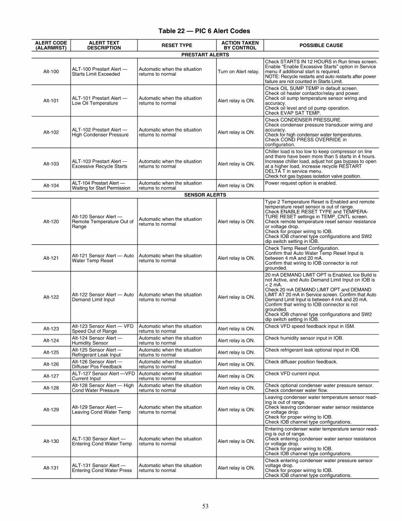
53
Table 22 — PIC 6 Alert Codes
ALERT CODE(ALARMRST)
ALERT TEXT DESCRIPTION RESET TYPE ACTION TAKEN
BY CONTROL POSSIBLE CAUSE
PRESTART ALERTS
Alt-100 ALT-100 Prestart Alert — Starts Limit Exceeded
Automatic when the situation returns to normal Turn on Alert relay.
Check STARTS IN 12 HOURS in Run times screen.Enable “Enable Excessive Starts” option in Service menu if additional start is required.NOTE: Recycle restarts and auto restarts after power failure are not counted in Starts Limit.
Alt-101 ALT-101 Prestart Alert — Low Oil Temperature
Automatic when the situation returns to normal Alert relay is ON.
Check OIL SUMP TEMP in default screen.Check oil heater contactor/relay and power.Check oil sump temperature sensor wiring and accuracy.Check oil level and oil pump operation.Check EVAP SAT TEMP.
Alt-102 ALT-102 Prestart Alert — High Condenser Pressure
Automatic when the situation returns to normal Alert relay is ON.
Check CONDENSER PRESSURE. Check condenser pressure transducer wiring and accuracy. Check for high condenser water temperatures.Check COND PRESS OVERRIDE in configuration.
Alt-103 ALT-103 Prestart Alert — Excessive Recycle Starts
Automatic when the situation returns to normal Alert relay is ON.
Chiller load is too low to keep compressor on line and there have been more than 5 starts in 4 hours.Increase chiller load, adjust hot gas bypass to open at a higher load, increase recycle RESTART DELTA T in service menu.Check hot gas bypass isolation valve position.
Alt-104 ALT-104 Prestart Alert — Waiting for Start Permission
Automatic when the situation returns to normal Alert relay is ON. Power request option is enabled.
SENSOR ALERTS
Alt-120Alt-120 Sensor Alert — Remote Temperature Out of Range
Automatic when the situation returns to normal Alert relay is ON.
Type 2 Temperature Reset is Enabled and remote temperature reset sensor is out of range. Check ENABLE RESET TYPE and TEMPERA-TURE RESET settings in TEMP_CNTL screen. Check remote temperature reset sensor resistance or voltage drop.Check for proper wiring to IOB.Check IOB channel type configurations and SW2 dip switch setting in IOB.
Alt-121 Alt-121 Sensor Alert — Auto Water Temp Reset
Automatic when the situation returns to normal Alert relay is ON.
Check Temp Reset Configuration.Confirm that Auto Water Temp Reset Input is between 4 mA and 20 mA. Confirm that wiring to IOB connector is not grounded.
Alt-122 Alt-122 Sensor Alert — Auto Demand Limit Input
Automatic when the situation returns to normal Alert relay is ON.
20 mA DEMAND LIMIT OPT is Enabled, Ice Build is not Active, and Auto Demand Limit Input on IOB is < 2 mA.Check 20 mA DEMAND LIMIT OPT and DEMAND LIMIT AT 20 mA in Service screen. Confirm that Auto Demand Limit Input is between 4 mA and 20 mA.Confirm that wiring to IOB connector is not grounded.Check IOB channel type configurations and SW2 dip switch setting in IOB.
Alt-123 Alt-123 Sensor Alert — VFD Speed Out of Range
Automatic when the situation returns to normal Alert relay is ON. Check VFD speed feedback input in ISM.
Alt-124 Alt-124 Sensor Alert — Humidity Sensor
Automatic when the situation returns to normal Alert relay is ON. Check humidity sensor input in IOB.
Alt-125 Alt-125 Sensor Alert — Refrigerant Leak Input
Automatic when the situation returns to normal Alert relay is ON. Check refrigerant leak optional input in IOB.
Alt-126 Alt-126 Sensor Alert — Diffuser Pos Feedback
Automatic when the situation returns to normal Alert relay is ON. Check diffuser position feedback.
Alt-127 ALT-127 Sensor Alert —VFD Current Input
Automatic when the situation returns to normal Alert relay is ON. Check VFD current input.
Alt-128 Alt-128 Sensor Alert — High Cond Water Pressure
Automatic when the situation returns to normal Alert relay is ON. Check optional condenser water pressure sensor.
Check condenser water flow.
Alt-129 Alt-129 Sensor Alert — Leaving Cond Water Temp
Automatic when the situation returns to normal Alert relay is ON.
Leaving condenser water temperature sensor read-ing is out of range.Check leaving condenser water sensor resistance or voltage drop.Check for proper wiring to IOB.Check IOB channel type configurations.
Alt-130 ALT-130 Sensor Alert — Entering Cond Water Temp
Automatic when the situation returns to normal Alert relay is ON.
Entering condenser water temperature sensor read-ing is out of range. Check entering condenser water sensor resistance or voltage drop.Check for proper wiring to IOB.Check IOB channel type configurations.
Alt-131 ALT-131 Sensor Alert — Entering Cond Water Press
Automatic when the situation returns to normal Alert relay is ON.
Check entering condenser water pressure sensor voltage drop.Check for proper wiring to IOB.Check IOB channel type configurations.
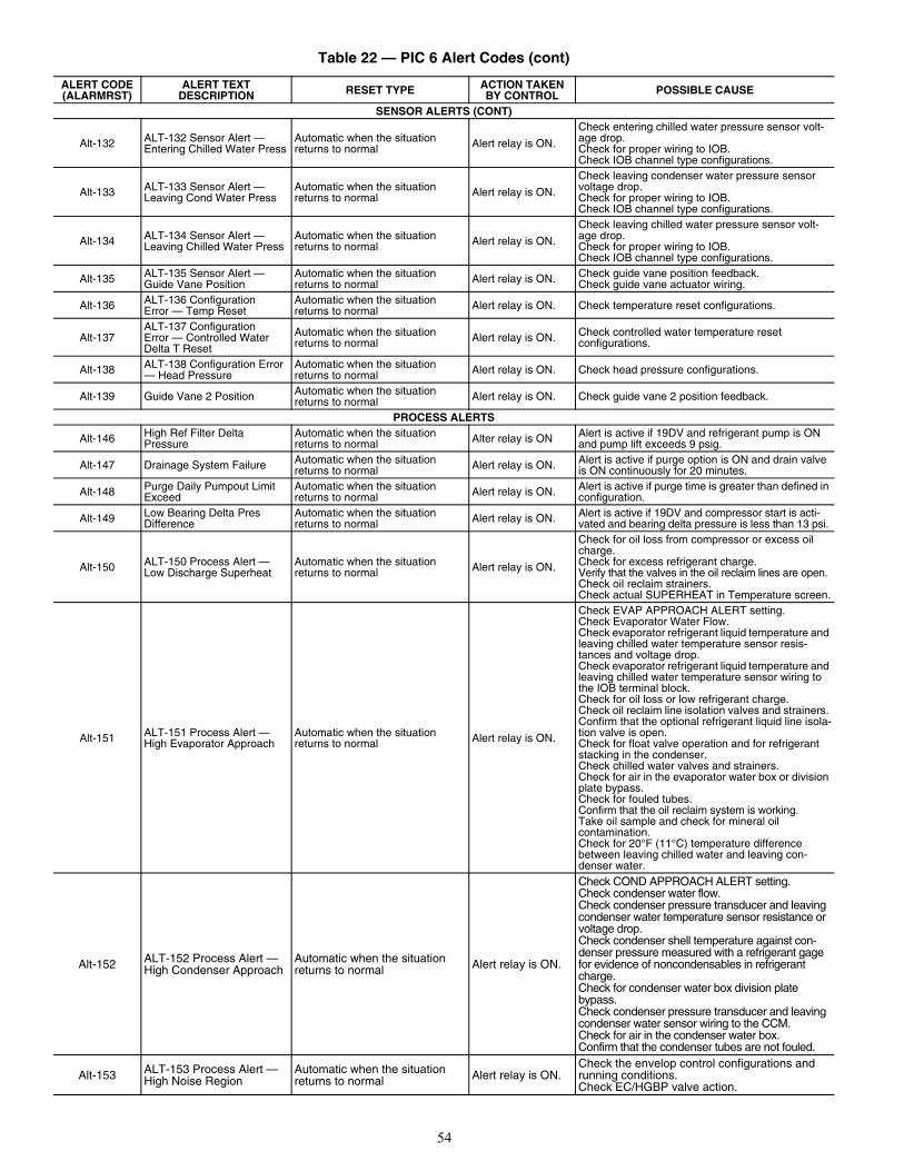
54
SENSOR ALERTS (CONT)
Alt-132 ALT-132 Sensor Alert — Entering Chilled Water Press
Automatic when the situation returns to normal Alert relay is ON.
Check entering chilled water pressure sensor volt-age drop.Check for proper wiring to IOB.Check IOB channel type configurations.
Alt-133 ALT-133 Sensor Alert — Leaving Cond Water Press
Automatic when the situation returns to normal Alert relay is ON.
Check leaving condenser water pressure sensor voltage drop.Check for proper wiring to IOB.Check IOB channel type configurations.
Alt-134 ALT-134 Sensor Alert — Leaving Chilled Water Press
Automatic when the situation returns to normal Alert relay is ON.
Check leaving chilled water pressure sensor volt-age drop.Check for proper wiring to IOB.Check IOB channel type configurations.
Alt-135 ALT-135 Sensor Alert — Guide Vane Position
Automatic when the situation returns to normal Alert relay is ON. Check guide vane position feedback.
Check guide vane actuator wiring.
Alt-136 ALT-136 ConfigurationError — Temp Reset
Automatic when the situation returns to normal Alert relay is ON. Check temperature reset configurations.
Alt-137ALT-137 ConfigurationError — Controlled Water Delta T Reset
Automatic when the situation returns to normal Alert relay is ON. Check controlled water temperature reset
configurations.
Alt-138 ALT-138 Configuration Error — Head Pressure
Automatic when the situation returns to normal Alert relay is ON. Check head pressure configurations.
Alt-139 Guide Vane 2 Position Automatic when the situation returns to normal Alert relay is ON. Check guide vane 2 position feedback.
PROCESS ALERTS
Alt-146 High Ref Filter Delta Pressure
Automatic when the situation returns to normal Alter relay is ON Alert is active if 19DV and refrigerant pump is ON
and pump lift exceeds 9 psig.
Alt-147 Drainage System Failure Automatic when the situation returns to normal Alert relay is ON. Alert is active if purge option is ON and drain valve
is ON continuously for 20 minutes.
Alt-148 Purge Daily Pumpout Limit Exceed
Automatic when the situation returns to normal Alert relay is ON. Alert is active if purge time is greater than defined in
configuration.
Alt-149 Low Bearing Delta Pres Difference
Automatic when the situation returns to normal Alert relay is ON. Alert is active if 19DV and compressor start is acti-
vated and bearing delta pressure is less than 13 psi.
Alt-150 ALT-150 Process Alert — Low Discharge Superheat
Automatic when the situation returns to normal Alert relay is ON.
Check for oil loss from compressor or excess oil charge.Check for excess refrigerant charge. Verify that the valves in the oil reclaim lines are open.Check oil reclaim strainers.Check actual SUPERHEAT in Temperature screen.
Alt-151 ALT-151 Process Alert — High Evaporator Approach
Automatic when the situation returns to normal Alert relay is ON.
Check EVAP APPROACH ALERT setting.Check Evaporator Water Flow.Check evaporator refrigerant liquid temperature and leaving chilled water temperature sensor resis-tances and voltage drop.Check evaporator refrigerant liquid temperature and leaving chilled water temperature sensor wiring to the IOB terminal block.Check for oil loss or low refrigerant charge.Check oil reclaim line isolation valves and strainers. Confirm that the optional refrigerant liquid line isola-tion valve is open. Check for float valve operation and for refrigerant stacking in the condenser.Check chilled water valves and strainers.Check for air in the evaporator water box or division plate bypass. Check for fouled tubes.Confirm that the oil reclaim system is working.Take oil sample and check for mineral oil contamination. Check for 20°F (11°C) temperature difference between leaving chilled water and leaving con-denser water.
Alt-152 ALT-152 Process Alert — High Condenser Approach
Automatic when the situation returns to normal Alert relay is ON.
Check COND APPROACH ALERT setting.Check condenser water flow. Check condenser pressure transducer and leaving condenser water temperature sensor resistance or voltage drop. Check condenser shell temperature against con-denser pressure measured with a refrigerant gage for evidence of noncondensables in refrigerant charge.Check for condenser water box division plate bypass.Check condenser pressure transducer and leaving condenser water sensor wiring to the CCM.Check for air in the condenser water box. Confirm that the condenser tubes are not fouled.
Alt-153 ALT-153 Process Alert — High Noise Region
Automatic when the situation returns to normal Alert relay is ON.
Check the envelop control configurations and running conditions.Check EC/HGBP valve action.
Table 22 — PIC 6 Alert Codes (cont)
ALERT CODE(ALARMRST)
ALERT TEXT DESCRIPTION RESET TYPE ACTION TAKEN
BY CONTROL POSSIBLE CAUSE
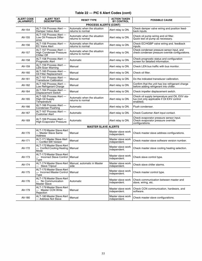
55
PROCESS ALERTS (CONT)
Alt-154 ALT-154 Process Alert — Damper Valve Alert
Automatic when the situation returns to normal Alert relay is ON. Check damper valve wiring and position feed-
back inputs.
Alt-155ALT-155 Process Alert — Low Oil Pressure Differ-ence
Automatic when the situation returns to normal Alert relay is ON. Check oil pump wiring and oil filter.
Quick test oil pump as necessary.
Alt-156 ALT-156 Process Alert —EC Valve Alert
Automatic when the situation returns to normal Alert relay is ON. Check EC/HGBP valve wiring and. feedback
inputs.
Alt-157ALT-157 Process Alert — High Condenser Pressure Chiller Off
Automatic when the situation returns to normal Alert relay is ON.
Check condenser pressure sensor input, and check condenser pressure override configurations.
Alt-158 ALT-158 Process Alert — Prognostic Alert Automatic Alert relay is ON. Check prognostic status and configuration
screen for detailed information.
Alt-159 ALT-159 Process Alert — LEN Scan Warning Manual Alert relay is ON. Check LEN bus traffic with bus monitor.
Alt-160 ALT-160 Process Alert — Oil Filter Replacement Manual Alert relay is ON. Check oil filter.
Alt-161 ALT-161 Process Alert — Transducer Calibration Manual Alert relay is ON. Do the indicated transducer calibration.
Alt-162 ALT-162 Process Alert —Low Refrigerant Charge Manual Alert relay is ON. Confirm that the unit has low refrigerant charge
before adding refrigerant into chiller.
Alt-164 ALT-164 Process Alert —Displacement Switch Manual Alert relay is ON. Check impeller displacement switch.
Alt-165ALT-165 Process Alert —High Oil Supply Temperature
Automatic when the situation returns to normal Alert relay is ON.
Check oil supply temperature and OIL EXV sta-tus (not only applicable if Oil EXV control enabled).
Alt-166 ALT-166 Process Alert —Condenser Flushing Automatic Alert relay is ON. Flush condenser.
Alt-167 ALT-167 Process Alert —Customer Alert Automatic Alert relay is ON. Check Customer Alert input contact.
Alt-169 ALT-169 Process Alert —High Evaporator Pressure Automatic Alert relay is ON.
Check evaporator pressure sensor input.Check evaporator pressure override configurations.
MASTER SLAVE ALERTS
Alt-170ALT-170 Master Slave Alert — Master Slave Same Address
Manual Master slave work independent. Check master slave address configurations.
Alt-171 ALT-171 Master Slave Alert — Conflict SW Version Manual Master slave work
independent. Check master slave software version number.
Alt-172ALT-172 Master Slave Alert — Conflict Cooling Heating Mode
Manual Master slave work independent. Check master slave cooling heating selection.
Alt-173ALT-173 Master Slave Alert — Incorrect Slave Control Type
Manual Master slave work independent. Check slave control type.
Alt-174 ALT-174 Master Slave Alert — Slave Tripout
Manual, automatic in Master side
Master slave work independent. Check slave chiller alarms.
Alt-175ALT-175 Master Slave Alert — Incorrect Master Control Type
Manual Master slave work independent. Check master control type.
Alt-176ALT-176 Master Slave Alert — No Communication Master Slave
Automatic Master slave work independent.
Check communication between master and slave, wiring, etc.
Alt-179ALT-179 Master Slave Alert — Master CCN Write Rejection
Manual Master slave work independent.
Check CCN communication, hardware, and software.
Alt-180 ALT-180 Master Slave Alert — Address Not Slave Manual Master slave work
independent. Check master slave configurations.
Table 22 — PIC 6 Alert Codes (cont)
ALERT CODE(ALARMRST)
ALERT TEXT DESCRIPTION RESET TYPE ACTION TAKEN
BY CONTROL POSSIBLE CAUSE
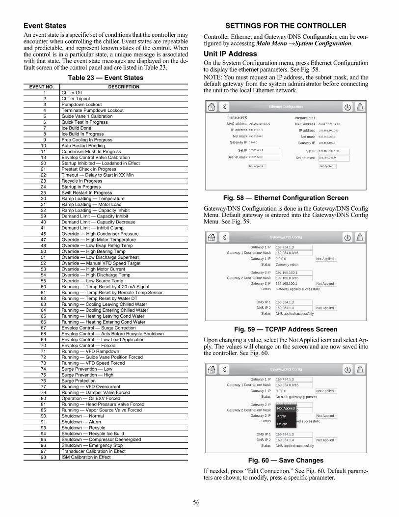
56
Event StatesAn event state is a specific set of conditions that the controller mayencounter when controlling the chiller. Event states are repeatableand predictable, and represent known states of the control. Whenthe control is in a particular state, a unique message is associatedwith that state. The event state messages are displayed on the de-fault screen of the control panel and are listed in Table 23.
Table 23 — Event States
SETTINGS FOR THE CONTROLLERController Ethernet and Gateway/DNS Configuration can be con-figured by accessing Main Menu →System Configuration.
Unit IP AddressOn the System Configuration menu, press Ethernet Configurationto display the ethernet parameters. See Fig. 58.NOTE: You must request an IP address, the subnet mask, and thedefault gateway from the system administrator before connectingthe unit to the local Ethernet network.
Fig. 58 — Ethernet Configuration Screen
Gateway/DNS Configuration is done in the Gateway/DNS ConfigMenu. Default gateway is entered into the Gateway/DNS ConfigMenu. See Fig. 59.
Fig. 59 — TCP/IP Address Screen
Upon changing a value, select the Not Applied icon and select Ap-ply. The values will change on the screen and are now saved intothe controller. See Fig. 60.
Fig. 60 — Save Changes
If needed, press “Edit Connection.” See Fig. 60. Default parame-ters are shown; to modify, press a specific parameter.
EVENT NO. DESCRIPTION1 Chiller Off2 Chiller Tripout3 Pumpdown Lockout4 Terminate Pumpdown Lockout5 Guide Vane 1 Calibration6 Quick Test in Progress7 Ice Build Done8 Ice Build In Progress9 Free Cooling In Progress
10 Auto Restart Pending11 Condenser Flush In Progress13 Envelop Control Valve Calibration20 Startup Inhibited — Loadshed in Effect21 Prestart Check in Progress22 Timeout — Delay to Start in XX Min23 Recycle in Progress24 Startup in Progress25 Swift Restart In Progress30 Ramp Loading — Temperature31 Ramp Loading — Motor Load32 Ramp Loading — Capacity Inhibit39 Demand Limit — Capacity Inhibit40 Demand Limit — Capacity Decrease41 Demand Limit — Inhibit Clamp45 Override — High Condenser Pressure47 Override — High Motor Temperature48 Override — Low Evap Refrig Temp50 Override — High Bearing Temp51 Override — Low Discharge Superheat52 Override — Manual VFD Speed Target53 Override — High Motor Current54 Override — High Discharge Temp55 Override — Low Source Temp60 Running — Temp Reset by 4-20 mA Signal61 Running — Temp Reset by Remote Temp Sensor62 Running — Temp Reset by Water DT63 Running — Cooling Leaving Chilled Water64 Running — Cooling Entering Chilled Water65 Running — Heating Leaving Cond Water66 Running — Heating Entering Cond Water67 Envelop Control — Surge Correction68 Envelop Control — Acts Before Recycle Shutdown69 Envelop Control — Low Load Application70 Envelop Control — Forced71 Running — VFD Rampdown72 Running — Guide Vane Position Forced73 Running — VFD Speed Forced74 Surge Prevention — Low75 Surge Prevention — High76 Surge Protection77 Running — VFD Overcurrent79 Running — Damper Valve Forced80 Operation — Oil EXV Forced81 Running — Head Pressure Valve Forced85 Running — Vapor Source Valve Forced90 Shutdown — Normal91 Shutdown — Alarm93 Shutdown — Recycle94 Shutdown — Recycle Ice Build95 Shutdown — Compressor Deenergized96 Shutdown — Emergency Stop97 Transducer Calibration in Effect98 ISM Calibration in Effect
a19-2162
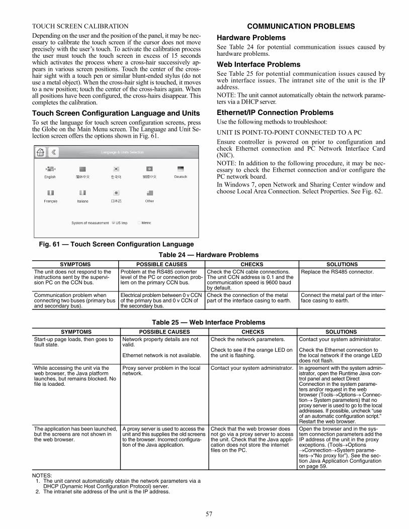
57
TOUCH SCREEN CALIBRATION
Depending on the user and the position of the panel, it may be nec-essary to calibrate the touch screen if the cursor does not moveprecisely with the user’s touch. To activate the calibration processthe user must touch the touch screen in excess of 15 secondswhich activates the process where a cross-hair successively ap-pears in various screen positions. Touch the center of the cross-hair sight with a touch pen or similar blunt-ended stylus (do notuse a metal object). When the cross-hair sight is touched, it movesto a new position; touch the center of the cross-hairs again. Whenall positions have been configured, the cross-hairs disappear. Thiscompletes the calibration.
Touch Screen Configuration Language and UnitsTo set the language for touch screen configuration screens, pressthe Globe on the Main Menu screen. The Language and Unit Se-lection screen offers the options shown in Fig. 61.
Fig. 61 — Touch Screen Configuration Language
COMMUNICATION PROBLEMS
Hardware ProblemsSee Table 24 for potential communication issues caused byhardware problems.
Web Interface ProblemsSee Table 25 for potential communication issues caused byweb interface issues. The intranet site of the unit is the IPaddress.NOTE: The unit cannot automatically obtain the network parame-ters via a DHCP server.
Ethernet/IP Connection Problems Use the following methods to troubleshoot:
UNIT IS POINT-TO-POINT CONNECTED TO A PC
Ensure controller is powered on prior to configuration andcheck Ethernet connection and PC Network Interface Card(NIC).NOTE: In addition to the following procedure, it may be nec-essary to check the Ethernet connection and/or configure thePC network board.In Windows 7, open Network and Sharing Center window andchoose Local Area Connection. Select Properties. See Fig. 62.
Table 24 — Hardware Problems
Table 25 — Web Interface Problems
NOTES:1. The unit cannot automatically obtain the network parameters via a
DHCP (Dynamic Host Configuration Protocol) server.2. The intranet site address of the unit is the IP address.
a19-2170
SYMPTOMS POSSIBLE CAUSES CHECKS SOLUTIONSThe unit does not respond to the instructions sent by the supervi-sion PC on the CCN bus.
Problem at the RS485 converter level of the PC or connection prob-lem on the primary CCN bus.
Check the CCN cable connections. The unit CCN address is 0.1 and the communication speed is 9600 baud by default.
Replace the RS485 connector.
Communication problem when connecting two buses (primary bus and secondary bus).
Electrical problem between 0 v CCN of the primary bus and 0 v CCN of the secondary bus.
Check the connection of the metal part of the interface casing to earth.
Connect the metal part of the inter-face casing to earth.
SYMPTOMS POSSIBLE CAUSES CHECKS SOLUTIONSStart-up page loads, then goes to fault state.
Network property details are not valid.
Ethernet network is not available.
Check the network parameters. Check to see if the orange LED on the unit is flashing.
Contact your system administrator.
Check the Ethernet connection to the local network if the orange LED does not flash.
While accessing the unit via the web browser, the Java platform launches, but remains blocked. No file is loaded.
Proxy server problem in the local network.
Contact your system administrator. In agreement with the system admin-istrator, open the Runtime Java con-trol panel and select Direct Connection in the system parame-ters and/or request in the web browser (ToolsOptions Connec-tion System parameters) that no proxy server is used to go to the local addresses. If possible, uncheck “use of an automatic configuration script.” Restart the web browser.
The application has been launched, but the screens are not shown in the web browser.
A proxy server is used to access the unit and this supplies the old screens to the browser. Incorrect configura-tion of the Java application.
Check that the web browser does not go via a proxy server to access the unit. Check that the Java appli-cation does not store the internet files on the PC.
Open the browser and in the sys-tem connection parameters add the IP address of the unit in the proxy exceptions. (ToolsOptions ConnectionSystem parame-ters“No proxy for”). See the sec-tion Java Application Configuration on page 59.
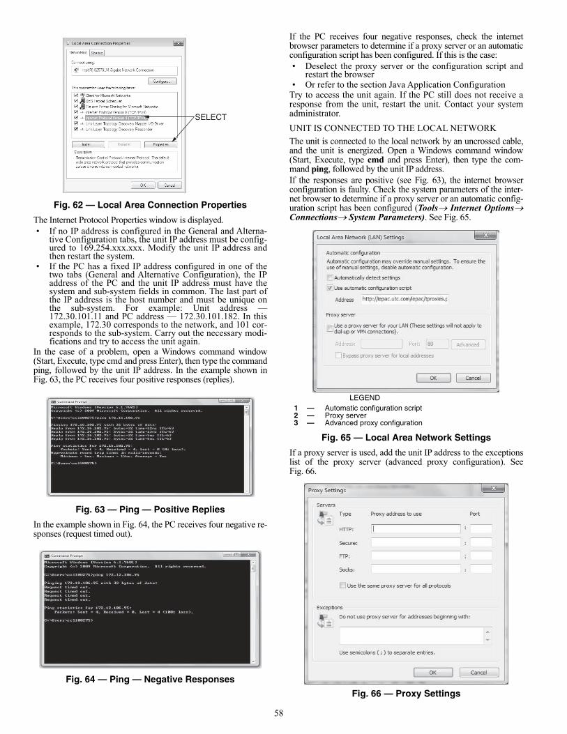
58
Fig. 62 — Local Area Connection Properties
The Internet Protocol Properties window is displayed.• If no IP address is configured in the General and Alterna-
tive Configuration tabs, the unit IP address must be config-ured to 169.254.xxx.xxx. Modify the unit IP address andthen restart the system.
• If the PC has a fixed IP address configured in one of thetwo tabs (General and Alternative Configuration), the IPaddress of the PC and the unit IP address must have thesystem and sub-system fields in common. The last part ofthe IP address is the host number and must be unique onthe sub-system. For example: Unit address —172.30.101.11 and PC address — 172.30.101.182. In thisexample, 172.30 corresponds to the network, and 101 cor-responds to the sub-system. Carry out the necessary modi-fications and try to access the unit again.
In the case of a problem, open a Windows command window(Start, Execute, type cmd and press Enter), then type the commandping, followed by the unit IP address. In the example shown inFig. 63, the PC receives four positive responses (replies).
Fig. 63 — Ping — Positive Replies
In the example shown in Fig. 64, the PC receives four negative re-sponses (request timed out).
Fig. 64 — Ping — Negative Responses
If the PC receives four negative responses, check the internetbrowser parameters to determine if a proxy server or an automaticconfiguration script has been configured. If this is the case: • Deselect the proxy server or the configuration script and
restart the browser• Or refer to the section Java Application Configuration
Try to access the unit again. If the PC still does not receive aresponse from the unit, restart the unit. Contact your systemadministrator.
UNIT IS CONNECTED TO THE LOCAL NETWORK
The unit is connected to the local network by an uncrossed cable,and the unit is energized. Open a Windows command window(Start, Execute, type cmd and press Enter), then type the com-mand ping, followed by the unit IP address.If the responses are positive (see Fig. 63), the internet browserconfiguration is faulty. Check the system parameters of the inter-net browser to determine if a proxy server or an automatic config-uration script has been configured (ToolsInternet OptionsConnectionsSystem Parameters). See Fig. 65.
Fig. 65 — Local Area Network Settings
If a proxy server is used, add the unit IP address to the exceptionslist of the proxy server (advanced proxy configuration). SeeFig. 66.
Fig. 66 — Proxy Settings
SELECT
a30-5898
LEGEND1 — Automatic configuration script2 — Proxy server3 — Advanced proxy configuration
a19-2175
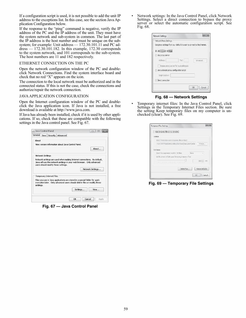
59
If a configuration script is used, it is not possible to add the unit IPaddress to the exceptions list. In this case, see the section Java Ap-plication Configuration below.If the response to the “ping” command is negative, verify the IPaddress of the PC and the IP address of the unit. They must havethe system network and sub-system in common. The last part ofthe IP address is the host number and must be unique on the sub-system; for example: Unit address — 172.30.101.11 and PC ad-dress — 172.30.101.182. In this example, 172.30 correspondsto the system network, and 101 corresponds to the sub-system.The host numbers are 11 and 182 respectively.
ETHERNET CONNECTION ON THE PC
Open the network configuration window of the PC and double-click Network Connections. Find the system interface board andcheck that no red “X” appears on the icon.The connection to the local network must be authorized and in theconnected status. If this is not the case, check the connections andauthorize/repair the network connection.
JAVA APPLICATION CONFIGURATION
Open the Internet configuration window of the PC and double-click the Java application icon. If Java is not installed, a freedownload is available at http://www.java.com.If Java has already been installed, check if it is used by other appli-cations. If so, check that these are compatible with the followingsettings in the Java control panel. See Fig. 67.
Fig. 67 — Java Control Panel
• Network settings: In the Java Control Panel, click NetworkSettings. Select a direct connection to bypass the proxyserver or select the automatic configuration script. SeeFig. 68.
Fig. 68 — Network Settings
• Temporary internet files: In the Java Control Panel, clickSettings in the Temporary Internet Files section. Be surethe setting Keep temporary files on my computer is un-checked (clear). See Fig. 69.
Fig. 69 — Temporary File Settings
a19-2176
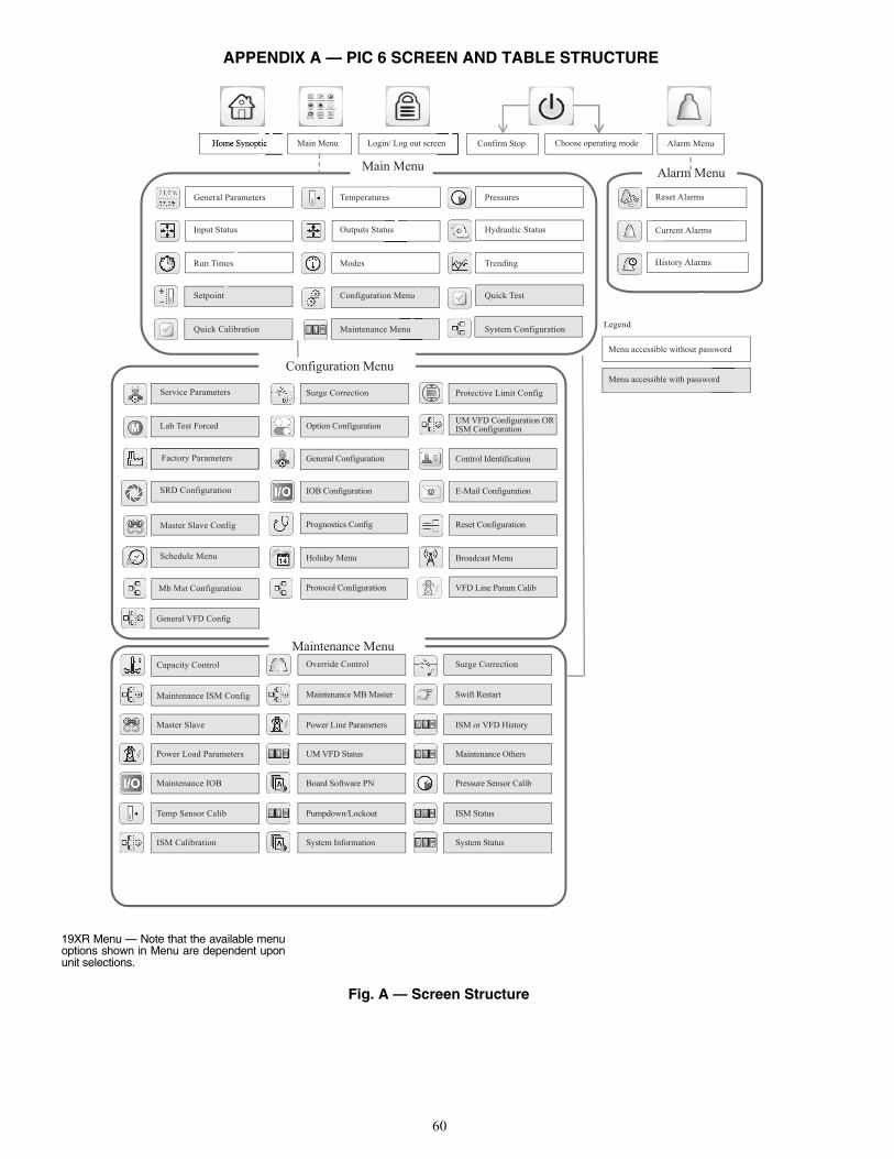
60
APPENDIX A — PIC 6 SCREEN AND TABLE STRUCTURE
Fig. A — Screen Structure
19XR Menu — Note that the available menuoptions shown in Menu are dependent uponunit selections.
General VFD Config
Lab Test Forced
Service Parameters
Factory Parameters
SRD Configuration
Master Slave Config
Schedule Menu
Mb Mst Configuration
General Parameters
Input Status
Run Times
Setpoint
Quick Calibration
Temperatures
Outputs Status
Modes
Configuration Menu
Maintenance Menu
Pressures
Hydraulic Status
Trending
Quick Test
System Configuration
Protective Limit Config
UM VFD Configuration ORISM Configuration
Control Identification
E-Mail Configuration
Reset Configuration
Broadcast Menu
VFD Line Param Calib
Surge Correction
Option Configuration
General Configuration
IOB Configuration
Prognostics Config
Holiday Menu
Protocol Configuration
Maintenance ISM Config
Capacity Control
Master Slave
Power Load Parameters
Maintenance IOB
Temp Sensor Calib
ISM Calibration
Surge Correction
ISM or VFD History
Maintenance Others
Pressure Sensor Calib
ISM Status
System Status
Override Control
Maintenance MB Master
Power Line Parameters
UM VFD Status
Board Software PN
Pumpdown/Lockout
System Information
Swift Restart
Maintenance Menu
Configuration Menu
Main MenuAlarm Menu
Reset Alarms
Current Alarms
History Alarms
Alarm MenuChoose operating modeConfirm StopLogin/ Log out screenMain MenuHome Synoptic
Legend
Menu accessible without password
Menu accessible with password
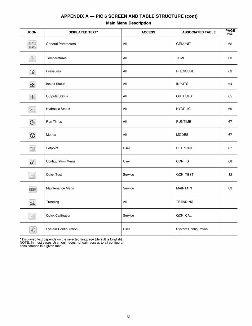
61
APPENDIX A — PIC 6 SCREEN AND TABLE STRUCTURE (cont)Main Menu Description
* Displayed text depends on the selected language (default is English).NOTE: In most cases User login does not gain access to all configura-tions screens in a given menu.
ICON DISPLAYED TEXT* ACCESS ASSOCIATED TABLE PAGENO.
General Parameters All GENUNIT 62
Temperatures All TEMP 63
Pressures All PRESSURE 63
Inputs Status All INPUTS 64
Outputs Status All OUTPUTS 65
Hydraulic Status All HYDRLIC 66
Run Times All RUNTIME 67
Modes All MODES 67
Setpoint User SETPOINT 67
Configuration Menu User CONFIG 68
Quick Test Service QCK_TEST 82
Maintenance Menu Service MAINTAIN 83
Trending All TRENDING —
Quick Calibration Service QCK_CAL
System Configuration User System Configuration
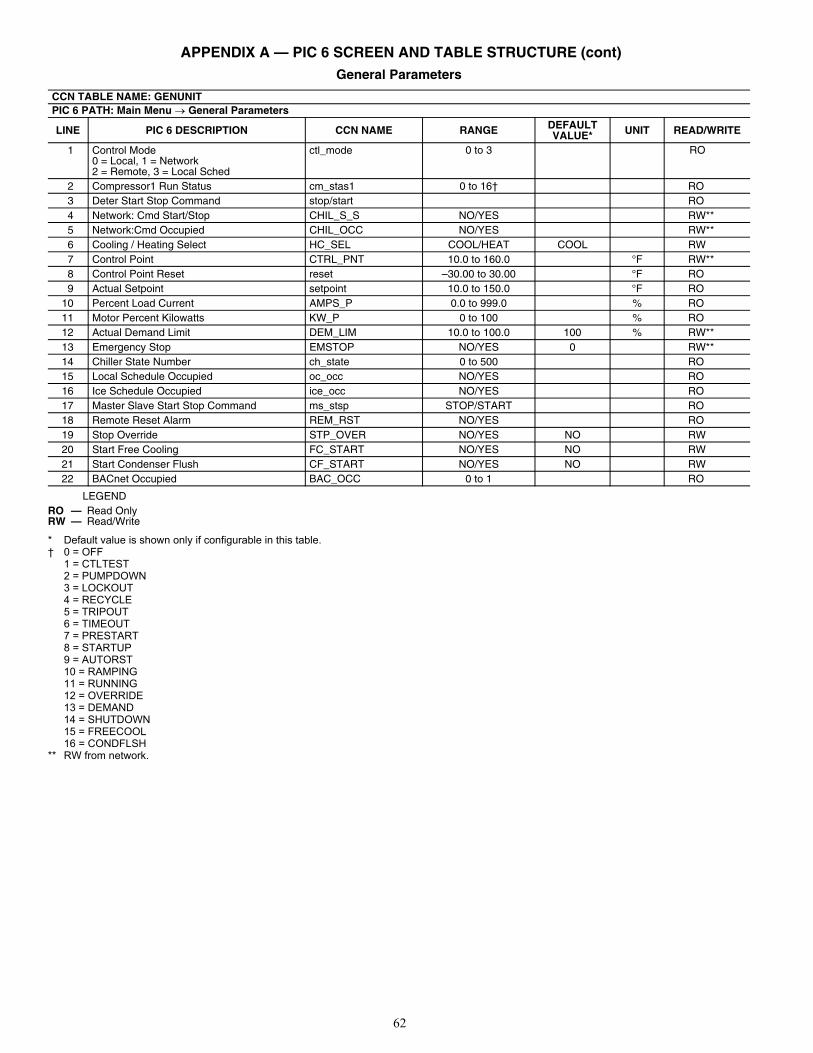
62
APPENDIX A — PIC 6 SCREEN AND TABLE STRUCTURE (cont)General Parameters
LEGEND
* Default value is shown only if configurable in this table.† 0 = OFF
1 = CTLTEST2 = PUMPDOWN3 = LOCKOUT4 = RECYCLE5 = TRIPOUT6 = TIMEOUT7 = PRESTART8 = STARTUP9 = AUTORST10 = RAMPING11 = RUNNING12 = OVERRIDE13 = DEMAND14 = SHUTDOWN15 = FREECOOL16 = CONDFLSH
** RW from network.
CCN TABLE NAME: GENUNITPIC 6 PATH: Main Menu General Parameters
LINE PIC 6 DESCRIPTION CCN NAME RANGE DEFAULT VALUE* UNIT READ/WRITE
1 Control Mode0 = Local, 1 = Network2 = Remote, 3 = Local Sched
ctl_mode 0 to 3 RO
2 Compressor1 Run Status cm_stas1 0 to 16† RO3 Deter Start Stop Command stop/start RO4 Network: Cmd Start/Stop CHIL_S_S NO/YES RW**5 Network:Cmd Occupied CHIL_OCC NO/YES RW**6 Cooling / Heating Select HC_SEL COOL/HEAT COOL RW7 Control Point CTRL_PNT 10.0 to 160.0 °F RW**8 Control Point Reset reset –30.00 to 30.00 °F RO9 Actual Setpoint setpoint 10.0 to 150.0 °F RO
10 Percent Load Current AMPS_P 0.0 to 999.0 % RO11 Motor Percent Kilowatts KW_P 0 to 100 % RO12 Actual Demand Limit DEM_LIM 10.0 to 100.0 100 % RW**13 Emergency Stop EMSTOP NO/YES 0 RW**14 Chiller State Number ch_state 0 to 500 RO15 Local Schedule Occupied oc_occ NO/YES RO16 Ice Schedule Occupied ice_occ NO/YES RO17 Master Slave Start Stop Command ms_stsp STOP/START RO18 Remote Reset Alarm REM_RST NO/YES RO19 Stop Override STP_OVER NO/YES NO RW20 Start Free Cooling FC_START NO/YES NO RW21 Start Condenser Flush CF_START NO/YES NO RW22 BACnet Occupied BAC_OCC 0 to 1 RO
RO — Read OnlyRW — Read/Write
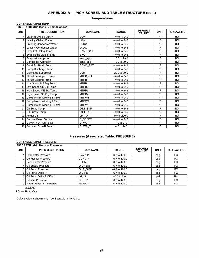
63
APPENDIX A — PIC 6 SCREEN AND TABLE STRUCTURE (cont) Temperatures
Pressures (Associated Table: PRESSURE)
LEGEND
*Default value is shown only if configurable in this table.
CCN TABLE NAME: TEMPPIC 6 PATH: Main Menu Temperatures
LINE PIC 6 DESCRIPTION CCN NAME RANGE DEFAULT VALUE* UNIT READ/WRITE
1 Entering Chilled Water ECW –40.0 to 245 °F RO2 Leaving Chilled Water LCW –40.0 to 245 °F RO3 Entering Condenser Water ECDW –40.0 to 245 °F RO4 Leaving Condenser Water LCDW –40.0 to 245 °F RO5 Evap Sat Refrig Temp EVAP_SAT –40.0 to 245 °F RO6 Evap Refrig Liquid Temp EVAP_T –40.0 to 245 °F RO7 Evaporator Approach evap_app 0.0 to 99.0 °F RO8 Condenser Approach cond_app 0.0 to 99.0 °F RO9 Cond Sat Refrig Temp COND_SAT –40.0 to 245 °F RO
10 Comp Discharge Temp DGT –40.0 to 245 °F RO11 Discharge Superheat DSH –20.0 to 99.0 °F RO12 Thrust Bearing Oil Temp MTRB_OIL –40.0 to 245 °F RO13 Thrust Bearing Temp MTRB –40.0 to 245 °F RO14 Low Speed ME Brg Temp MTRB1 –40.0 to 245 °F RO15 Low Speed CE Brg Temp MTRB2 –40.0 to 245 °F RO16 High Speed ME Brg Temp MTRB3 –40.0 to 245 °F RO17 High Speed CE Brg Temp MTRB4 –40.0 to 245 °F RO18 Comp Motor Winding 1 Temp MTRW1 –40.0 to 245 °F RO19 Comp Motor Winding 2 Temp MTRW2 –40.0 to 245 °F RO20 Comp Motor Winding 3 Temp MTRW3 –40.0 to 245 °F RO21 Oil Sump Temp OILT_SMP –40.0 to 245 °F RO22 Oil Supply Temp OILT_DIS –40.0 to 245 °F RO23 Actual Lift LIFT_A 0.0 to 200.0 °F RO24 Remote Reset Sensor R_RESET –40.0 to 245 °F RO25 Common CHWS Temp CHWS_T –40 to 245 °F RO26 Common CHWR Temp CHWR_T –40 to 245 °F RO
CCN TABLE NAME: PRESSUREPIC 6 PATH: Main Menu Pressures
LINE PIC 6 DESCRIPTION CCN NAME RANGE DEFAULT VALUE* UNIT READ/WRITE
1 Evaporator Pressure EVAP_P –6.7 to 420.0 psig RO2 Condenser Pressure COND_P –6.7 to 420.0 psig RO3 Economizer Pressure ECON_P –6.7 to 420.0 psig RO4 Oil Supply Pressure OILP_DIS –6.7 to 420.0 psig RO5 Oil Sump Pressure OILP_SMP –6.7 to 420.0 psig RO6 Oil Pump Delta P OIL_PD –6.7 to 420.0 psig RO7 Oil Pump Delta P Offset pd_off –5.0 to 5.0 psi RW8 Diffuser Pressure DIFF_P –6.7 to 420.0 psig RO9 Head Pressure Reference HEAD_P –6.7 to 420.0 psig RO
RO — Read Only
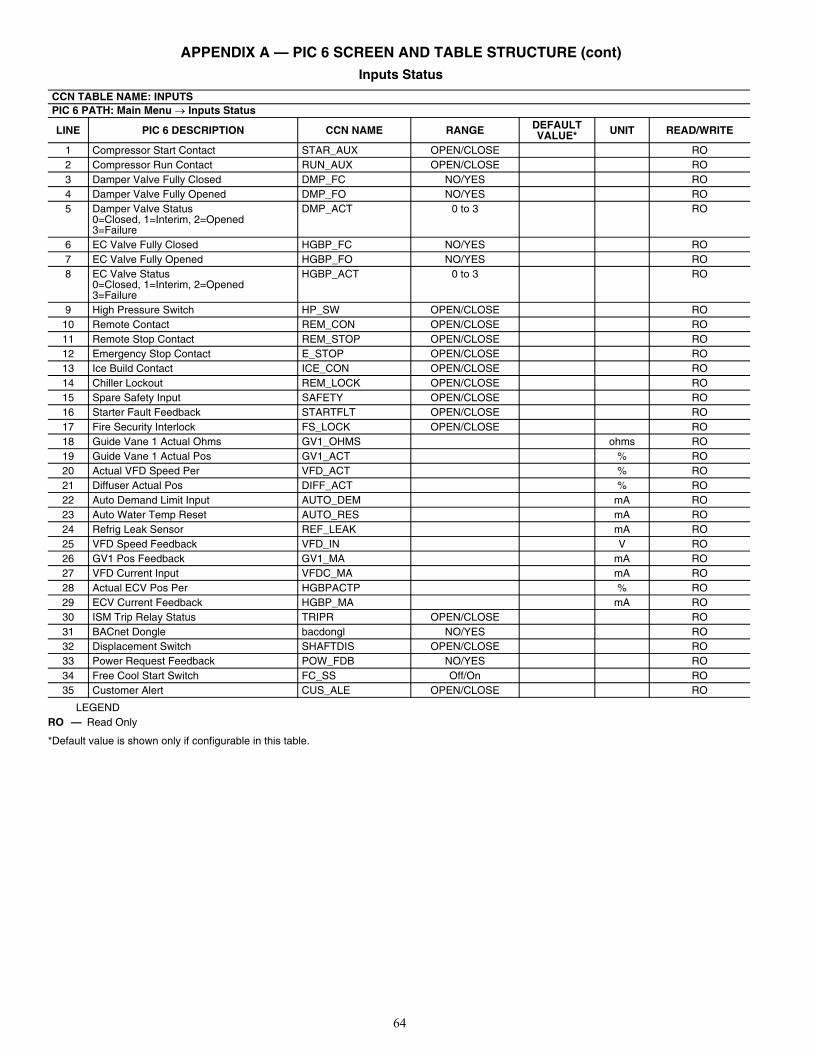
64
APPENDIX A — PIC 6 SCREEN AND TABLE STRUCTURE (cont) Inputs Status
LEGEND
*Default value is shown only if configurable in this table.
CCN TABLE NAME: INPUTSPIC 6 PATH: Main Menu Inputs Status
LINE PIC 6 DESCRIPTION CCN NAME RANGE DEFAULT VALUE* UNIT READ/WRITE
1 Compressor Start Contact STAR_AUX OPEN/CLOSE RO2 Compressor Run Contact RUN_AUX OPEN/CLOSE RO3 Damper Valve Fully Closed DMP_FC NO/YES RO4 Damper Valve Fully Opened DMP_FO NO/YES RO5 Damper Valve Status
0=Closed, 1=Interim, 2=Opened3=Failure
DMP_ACT 0 to 3 RO
6 EC Valve Fully Closed HGBP_FC NO/YES RO7 EC Valve Fully Opened HGBP_FO NO/YES RO8 EC Valve Status
0=Closed, 1=Interim, 2=Opened3=Failure
HGBP_ACT 0 to 3 RO
9 High Pressure Switch HP_SW OPEN/CLOSE RO10 Remote Contact REM_CON OPEN/CLOSE RO11 Remote Stop Contact REM_STOP OPEN/CLOSE RO12 Emergency Stop Contact E_STOP OPEN/CLOSE RO13 Ice Build Contact ICE_CON OPEN/CLOSE RO14 Chiller Lockout REM_LOCK OPEN/CLOSE RO15 Spare Safety Input SAFETY OPEN/CLOSE RO16 Starter Fault Feedback STARTFLT OPEN/CLOSE RO17 Fire Security Interlock FS_LOCK OPEN/CLOSE RO18 Guide Vane 1 Actual Ohms GV1_OHMS ohms RO19 Guide Vane 1 Actual Pos GV1_ACT % RO20 Actual VFD Speed Per VFD_ACT % RO21 Diffuser Actual Pos DIFF_ACT % RO22 Auto Demand Limit Input AUTO_DEM mA RO23 Auto Water Temp Reset AUTO_RES mA RO24 Refrig Leak Sensor REF_LEAK mA RO25 VFD Speed Feedback VFD_IN V RO26 GV1 Pos Feedback GV1_MA mA RO27 VFD Current Input VFDC_MA mA RO28 Actual ECV Pos Per HGBPACTP % RO29 ECV Current Feedback HGBP_MA mA RO30 ISM Trip Relay Status TRIPR OPEN/CLOSE RO31 BACnet Dongle bacdongl NO/YES RO32 Displacement Switch SHAFTDIS OPEN/CLOSE RO33 Power Request Feedback POW_FDB NO/YES RO34 Free Cool Start Switch FC_SS Off/On RO35 Customer Alert CUS_ALE OPEN/CLOSE RO
RO — Read Only
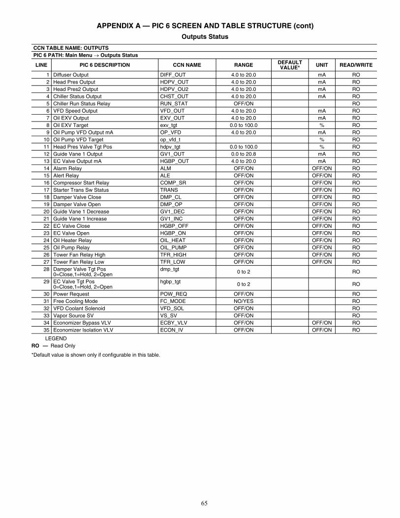
65
APPENDIX A — PIC 6 SCREEN AND TABLE STRUCTURE (cont) Outputs Status
LEGEND
*Default value is shown only if configurable in this table.
CCN TABLE NAME: OUTPUTSPIC 6 PATH: Main Menu Outputs Status
LINE PIC 6 DESCRIPTION CCN NAME RANGE DEFAULT VALUE* UNIT READ/WRITE
1 Diffuser Output DIFF_OUT 4.0 to 20.0 mA RO2 Head Pres Output HDPV_OUT 4.0 to 20.0 mA RO3 Head Pres2 Output HDPV_OU2 4.0 to 20.0 mA RO4 Chiller Status Output CHST_OUT 4.0 to 20.0 mA RO5 Chiller Run Status Relay RUN_STAT OFF/ON RO6 VFD Speed Output VFD_OUT 4.0 to 20.0 mA RO7 Oil EXV Output EXV_OUT 4.0 to 20.0 mA RO8 Oil EXV Target exv_tgt 0.0 to 100.0 % RO9 Oil Pump VFD Output mA OP_VFD 4.0 to 20.0 mA RO
10 Oil Pump VFD Target op_vfd_t % RO 11 Head Pres Valve Tgt Pos hdpv_tgt 0.0 to 100.0 % RO12 Guide Vane 1 Output GV1_OUT 0.0 to 20.8 mA RO13 EC Valve Output mA HGBP_OUT 4.0 to 20.0 mA RO14 Alarm Relay ALM OFF/ON OFF/ON RO15 Alert Relay ALE OFF/ON OFF/ON RO16 Compressor Start Relay COMP_SR OFF/ON OFF/ON RO17 Starter Trans Sw Status TRANS OFF/ON OFF/ON RO18 Damper Valve Close DMP_CL OFF/ON OFF/ON RO19 Damper Valve Open DMP_OP OFF/ON OFF/ON RO20 Guide Vane 1 Decrease GV1_DEC OFF/ON OFF/ON RO21 Guide Vane 1 Increase GV1_INC OFF/ON OFF/ON RO22 EC Valve Close HGBP_OFF OFF/ON OFF/ON RO23 EC Valve Open HGBP_ON OFF/ON OFF/ON RO24 Oil Heater Relay OIL_HEAT OFF/ON OFF/ON RO25 Oil Pump Relay OIL_PUMP OFF/ON OFF/ON RO26 Tower Fan Relay High TFR_HIGH OFF/ON OFF/ON RO27 Tower Fan Relay Low TFR_LOW OFF/ON OFF/ON RO28 Damper Valve Tgt Pos
0=Close,1=Hold, 2=Opendmp_tgt 0 to 2 RO
29 EC Valve Tgt Pos0=Close,1=Hold, 2=Open
hgbp_tgt 0 to 2 RO
30 Power Request POW_REQ OFF/ON RO31 Free Cooling Mode FC_MODE NO/YES RO32 VFD Coolant Solenoid VFD_SOL OFF/ON RO33 Vapor Source SV VS_SV OFF/ON RO34 Economizer Bypass VLV ECBY_VLV OFF/ON OFF/ON RO35 Economizer Isolation VLV ECON_IV OFF/ON OFF/ON RO
RO — Read Only
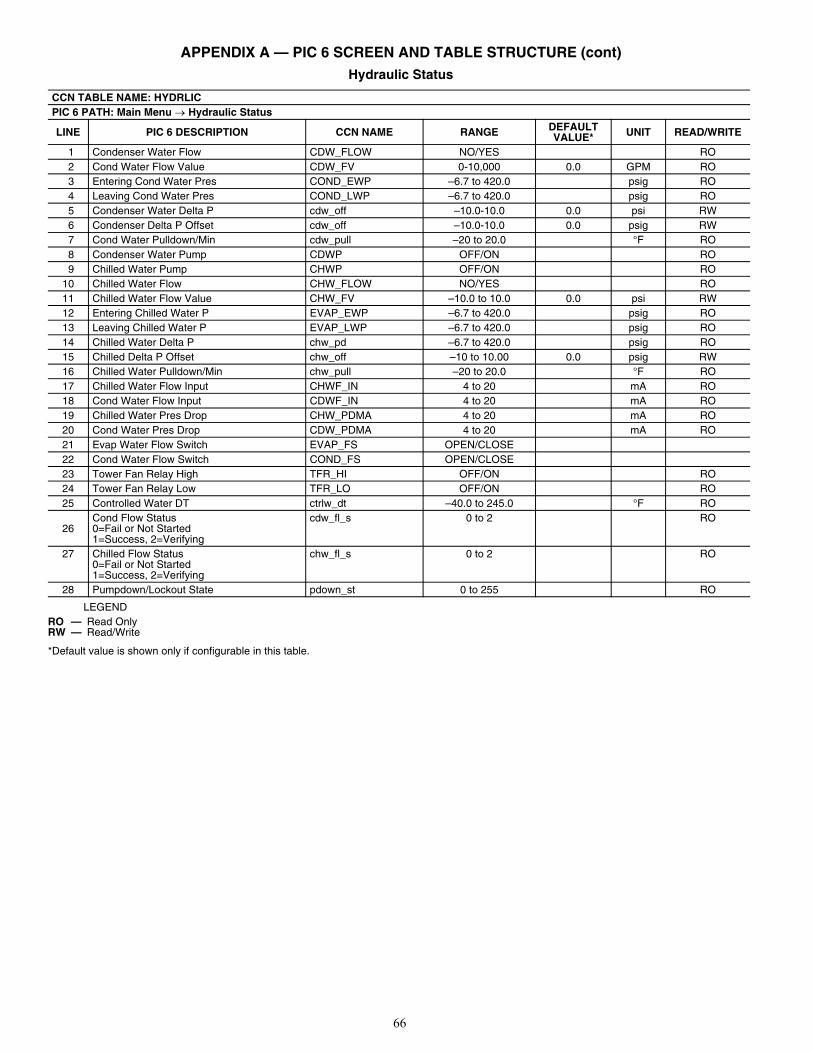
66
APPENDIX A — PIC 6 SCREEN AND TABLE STRUCTURE (cont) Hydraulic Status
LEGEND
*Default value is shown only if configurable in this table.
CCN TABLE NAME: HYDRLICPIC 6 PATH: Main Menu Hydraulic Status
LINE PIC 6 DESCRIPTION CCN NAME RANGE DEFAULT VALUE* UNIT READ/WRITE
1 Condenser Water Flow CDW_FLOW NO/YES RO 2 Cond Water Flow Value CDW_FV 0-10,000 0.0 GPM RO 3 Entering Cond Water Pres COND_EWP –6.7 to 420.0 psig RO 4 Leaving Cond Water Pres COND_LWP –6.7 to 420.0 psig RO 5 Condenser Water Delta P cdw_off –10.0-10.0 0.0 psi RW 6 Condenser Delta P Offset cdw_off –10.0-10.0 0.0 psig RW 7 Cond Water Pulldown/Min cdw_pull –20 to 20.0 °F RO 8 Condenser Water Pump CDWP OFF/ON RO 9 Chilled Water Pump CHWP OFF/ON RO10 Chilled Water Flow CHW_FLOW NO/YES RO11 Chilled Water Flow Value CHW_FV –10.0 to 10.0 0.0 psi RW12 Entering Chilled Water P EVAP_EWP –6.7 to 420.0 psig RO13 Leaving Chilled Water P EVAP_LWP –6.7 to 420.0 psig RO14 Chilled Water Delta P chw_pd –6.7 to 420.0 psig RO15 Chilled Delta P Offset chw_off –10 to 10.00 0.0 psig RW16 Chilled Water Pulldown/Min chw_pull –20 to 20.0 °F RO17 Chilled Water Flow Input CHWF_IN 4 to 20 mA RO18 Cond Water Flow Input CDWF_IN 4 to 20 mA RO19 Chilled Water Pres Drop CHW_PDMA 4 to 20 mA RO20 Cond Water Pres Drop CDW_PDMA 4 to 20 mA RO21 Evap Water Flow Switch EVAP_FS OPEN/CLOSE22 Cond Water Flow Switch COND_FS OPEN/CLOSE23 Tower Fan Relay High TFR_HI OFF/ON RO24 Tower Fan Relay Low TFR_LO OFF/ON RO25 Controlled Water DT ctrlw_dt –40.0 to 245.0 °F RO
26Cond Flow Status0=Fail or Not Started1=Success, 2=Verifying
cdw_fl_s 0 to 2 RO
27 Chilled Flow Status0=Fail or Not Started1=Success, 2=Verifying
chw_fl_s 0 to 2 RO
28 Pumpdown/Lockout State pdown_st 0 to 255 RO
RO — Read OnlyRW — Read/Write
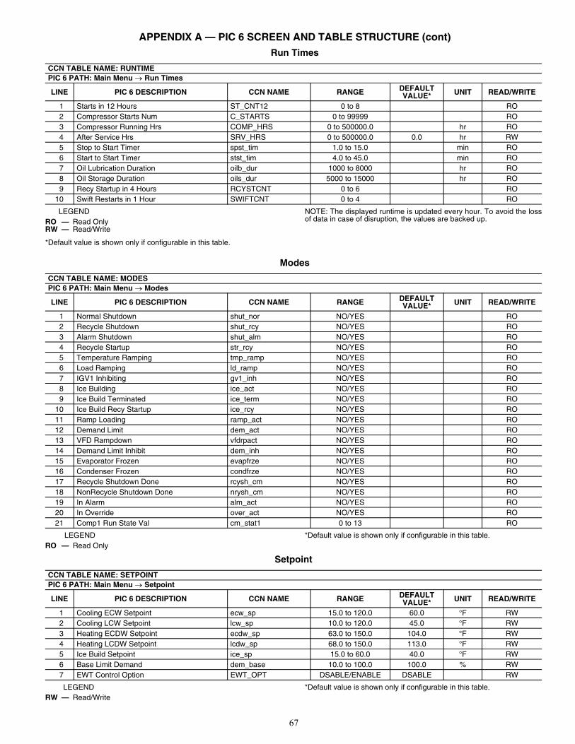
67
APPENDIX A — PIC 6 SCREEN AND TABLE STRUCTURE (cont) Run Times
LEGEND
*Default value is shown only if configurable in this table.
NOTE: The displayed runtime is updated every hour. To avoid the lossof data in case of disruption, the values are backed up.
Modes
LEGEND *Default value is shown only if configurable in this table.
Setpoint
LEGEND *Default value is shown only if configurable in this table.
CCN TABLE NAME: RUNTIMEPIC 6 PATH: Main Menu Run Times
LINE PIC 6 DESCRIPTION CCN NAME RANGE DEFAULT VALUE* UNIT READ/WRITE
1 Starts in 12 Hours ST_CNT12 0 to 8 RO2 Compressor Starts Num C_STARTS 0 to 99999 RO3 Compressor Running Hrs COMP_HRS 0 to 500000.0 hr RO4 After Service Hrs SRV_HRS 0 to 500000.0 0.0 hr RW5 Stop to Start Timer spst_tim 1.0 to 15.0 min RO6 Start to Start Timer stst_tim 4.0 to 45.0 min RO7 Oil Lubrication Duration oilb_dur 1000 to 8000 hr RO8 Oil Storage Duration oils_dur 5000 to 15000 hr RO9 Recy Startup in 4 Hours RCYSTCNT 0 to 6 RO
10 Swift Restarts in 1 Hour SWIFTCNT 0 to 4 RO
RO — Read OnlyRW — Read/Write
CCN TABLE NAME: MODESPIC 6 PATH: Main Menu Modes
LINE PIC 6 DESCRIPTION CCN NAME RANGE DEFAULT VALUE* UNIT READ/WRITE
1 Normal Shutdown shut_nor NO/YES RO2 Recycle Shutdown shut_rcy NO/YES RO3 Alarm Shutdown shut_alm NO/YES RO4 Recycle Startup str_rcy NO/YES RO5 Temperature Ramping tmp_ramp NO/YES RO6 Load Ramping ld_ramp NO/YES RO7 IGV1 Inhibiting gv1_inh NO/YES RO8 Ice Building ice_act NO/YES RO9 Ice Build Terminated ice_term NO/YES RO
10 Ice Build Recy Startup ice_rcy NO/YES RO11 Ramp Loading ramp_act NO/YES RO12 Demand Limit dem_act NO/YES RO13 VFD Rampdown vfdrpact NO/YES RO14 Demand Limit Inhibit dem_inh NO/YES RO15 Evaporator Frozen evapfrze NO/YES RO16 Condenser Frozen condfrze NO/YES RO17 Recycle Shutdown Done rcysh_cm NO/YES RO18 NonRecycle Shutdown Done nrysh_cm NO/YES RO19 In Alarm alm_act NO/YES RO20 In Override over_act NO/YES RO21 Comp1 Run State Val cm_stat1 0 to 13 RO
RO — Read Only
CCN TABLE NAME: SETPOINTPIC 6 PATH: Main Menu Setpoint
LINE PIC 6 DESCRIPTION CCN NAME RANGE DEFAULT VALUE* UNIT READ/WRITE
1 Cooling ECW Setpoint ecw_sp 15.0 to 120.0 60.0 °F RW2 Cooling LCW Setpoint lcw_sp 10.0 to 120.0 45.0 °F RW3 Heating ECDW Setpoint ecdw_sp 63.0 to 150.0 104.0 °F RW4 Heating LCDW Setpoint lcdw_sp 68.0 to 150.0 113.0 °F RW5 Ice Build Setpoint ice_sp 15.0 to 60.0 40.0 °F RW6 Base Limit Demand dem_base 10.0 to 100.0 100.0 % RW7 EWT Control Option EWT_OPT DSABLE/ENABLE DSABLE RW
RW — Read/Write
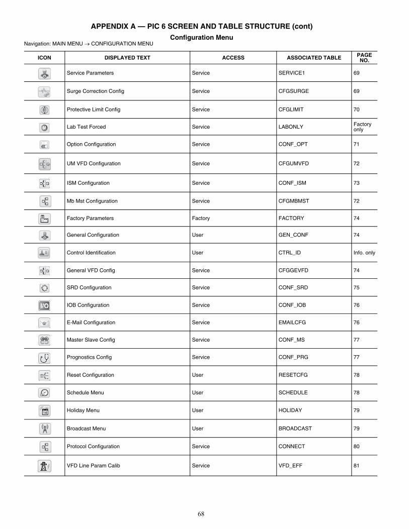
68
APPENDIX A — PIC 6 SCREEN AND TABLE STRUCTURE (cont) Configuration Menu
Navigation: MAIN MENU CONFIGURATION MENU
ICON DISPLAYED TEXT ACCESS ASSOCIATED TABLE PAGE NO.
Service Parameters Service SERVICE1 69
Surge Correction Config Service CFGSURGE 69
Protective Limit Config Service CFGLIMIT 70
Lab Test Forced Service LABONLY Factory only
Option Configuration Service CONF_OPT 71
UM VFD Configuration Service CFGUMVFD 72
ISM Configuration Service CONF_ISM 73
Mb Mst Configuration Service CFGMBMST 72
Factory Parameters Factory FACTORY 74
General Configuration User GEN_CONF 74
Control Identification User CTRL_ID Info. only
General VFD Config Service CFGGEVFD 74
SRD Configuration Service CONF_SRD 75
IOB Configuration Service CONF_IOB 76
E-Mail Configuration Service EMAILCFG 76
Master Slave Config Service CONF_MS 77
Prognostics Config Service CONF_PRG 77
Reset Configuration User RESETCFG 78
Schedule Menu User SCHEDULE 78
Holiday Menu User HOLIDAY 79
Broadcast Menu User BROADCAST 79
Protocol Configuration Service CONNECT 80
VFD Line Param Calib Service VFD_EFF 81
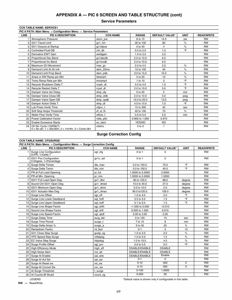
69
APPENDIX A — PIC 6 SCREEN AND TABLE STRUCTURE (cont) Service Parameters
Surge Correction Config
LEGEND *Default value is shown only if configurable in this table.
CCN TABLE NAME: SERVICE1PIC 6 PATH: Main Menu Configuration Menu Service Parameters
LINE PIC 6 DESCRIPTION CCN NAME RANGE DEFAULT VALUE* UNIT READ/WRITE1 Atmospheric Pressure atom_pre 8 to 15 14.5 psi RW2 GV1 Travel Limit gv1_lim 30 to 100 80 % RW3 GV1 Closure at Startup gv1stpos 0 to 40 4 % RW4 Controlled Fluid DB ctrl_db 0.5 to 2.0 1.0 °F RW5 Derivative EWT Gain ewtdgain 1.0 to 3.0 2.0 RW6 Proportional Dec Band gv1decdb 2.0 to 10.0 6.0 RW7 Proportional Inc Band gv1incdb 2.0 to 10.0 6.5 RW8 Maximum GV Movement max_gv 2.0 to 4.0 2.0 % RW9 Demand Limit At 20 mA dem_20ma 10 to 100 40 % RW
10 Demand Limit Prop Band dem_pdb 3.0 to 15.0 10.0 % RW11 Amps or KW Ramp per Min ldramprt 5 to 20 10 % RW12 Temp Ramp Rate per Min tmramprt 1 to 10 3 °F RW13 Recycle Shutdown Delta T rcysh_dt 0.5 to 4.0 1.0 °F RW14 Recycle Restart Delta T rcyst_dt 2.0 to 10.0 5.0 °F RW15 Damper Valve Act Delay dmp_dly 0 to 20 5 min RW16 Damper Valve Close DB dmp_cldb 2.0 to 10.0 5.0 psig RW17 Damper Valve Open DB dmp_opdb 10.0 to 20.0 13.0 psig RW18 Damper Action Delta T dmp_dt 4.0 to 10.0 7.0 ^F RW19 Lub Press Verify Time oilpvr_t 15 to 300 40 sec RW20 Soft Stop Amps Threshold sf_st_th 40 to 100 70 % RW21 Water Flow Verify Time wflow_t 0.5 to 5.0 5.0 min RW22 Power Calibration Factor mbb_pfcl 0.900 to 1.000 0.970 RW23 Enable Excessive Starts ex_start YES/NO NO RW24 Oil Stir Cycle (19XR6/7)
0 = No stir, 1 = 30s/30m, 2 = 1m/4hr, 3 = Comb 0&1oilstiro 0 to 3 1 RW
CCN TABLE NAME: CFGSURGEPIC 6 PATH: Main Menu Configuration Menu Surge Correction Config
LINE PIC 6 DESCRIPTION CCN NAME RANGE DEFAULT VALUE* UNIT READ/WRITE1 Surge Line Configuration
0=PR, 1=Delta Tsgl_cfg 0 to 1 0 RW
2 IGV1 Pos Configuration0-Degree, 1=Percentage
gv1c_sel 0 to 1 0 RW
3 Surge Delta Tsmax dts_max 0.0 to 150.0 70.0 °F RW4 Surge Delta Tsmin dts_min 0.0 to 150.0 45.0 °F RW5 PR at Full Load Opening pr_ful 1.0000 to 5.0000 3.0000 RW6 PR at Min. Opening pr_min 1.0000 to 5.0000 1.5000 RW7 IGV1 Full Load Open Deg gv1_dful 90 to 120.0 88.0 degree RW8 Sound Ctrl IGV1 Open Deg gv1_dmed 10.0 to 40.0 27.0 degree RW9 IGV1 Minimum Open Deg gv1_dmin 0.0 to 10.0 2.0 degree RW
10 IGV1 Actuator Max Deg gv1_dmax 90.0 to120.0 109.0 degree RW11 Surge Line Offset sgl_off 1.0 to 3.0 2.0 °F RW12 Surge Line Lower Deadband sql_hoff 0.5 to 3.0 1.5 °F RW13 Surge Line Upper Deadband sql_hoff 0.1 to 3.0 1.5 °F RW14 Surge Line Shape Factor sgl_shfh –1.000 to 0.000 –0.010 RW15 Sound Line Shape Factor sgl_shfl 0.000 to 1.000 0.010 RW16 Surge Line Speed Factor sgl_spdf 0.00 to 3.00 2.00 RW17 Surge Delay Time surg_del 0 to 120 15 sec RW18 Surge Time Period surge_t 7 to 10 8 min RW19 Surge Delta Amps % surge_a 5 to 40 20 % RW20 Rampdown Factor rd_fact 0-1 0 10 RW21 GV1 Close Step Surge gvstp_sg 1.0 to 3.0 2.0 % RW22 VFD Speed Step Surge vfdstpsg 1.0 to 5.0 1.5 % RW23 EC Valve Step Surge hbpstsg 1.0 to 10.0 4.0 % RW24 Surge Profile Offset sgl_pro 0.0 to 5.0 0.0 ^F RW25 High Efficiency Mode high_eff DSABLE/ENABLE DSABLE RW26 High Noise Alert noi_alt DSABLE/ENABLE DSABLE RW27 Surge AI Enable sal_enb DSABLE/ENABLE Enable RW
28 Surge AI Act Sw sal_sw 0-1 0 RW
29 Surge AI Reset sw ret_sw 0-10 000 0 RW
30 Surge AI Correct Sw cor_sw 0-10 000 0 RW
31 AI Surge Threshold t_surge 0-100 1.0500 RW
32 AI Counts Bf Shutd count_sg 0-200 30 RW
RW — Read/Write
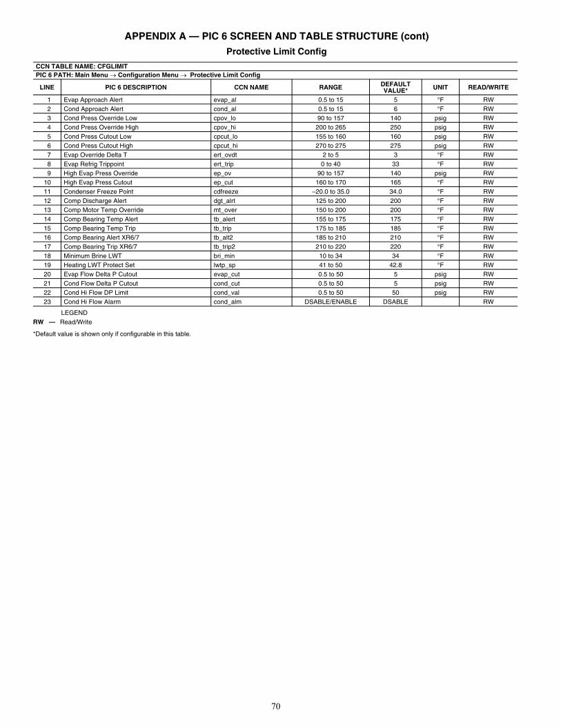
70
APPENDIX A — PIC 6 SCREEN AND TABLE STRUCTURE (cont) Protective Limit Config
LEGEND
*Default value is shown only if configurable in this table.
CCN TABLE NAME: CFGLIMITPIC 6 PATH: Main Menu Configuration Menu Protective Limit Config
LINE PIC 6 DESCRIPTION CCN NAME RANGE DEFAULT VALUE* UNIT READ/WRITE
1 Evap Approach Alert evap_al 0.5 to 15 5 °F RW2 Cond Approach Alert cond_al 0.5 to 15 6 °F RW3 Cond Press Override Low cpov_lo 90 to 157 140 psig RW4 Cond Press Override High cpov_hi 200 to 265 250 psig RW5 Cond Press Cutout Low cpcut_lo 155 to 160 160 psig RW6 Cond Press Cutout High cpcut_hi 270 to 275 275 psig RW7 Evap Override Delta T ert_ovdt 2 to 5 3 °F RW8 Evap Refrig Trippoint ert_trip 0 to 40 33 °F RW9 High Evap Press Override ep_ov 90 to 157 140 psig RW
10 High Evap Press Cutout ep_cut 160 to 170 165 °F RW11 Condenser Freeze Point cdfreeze –20.0 to 35.0 34.0 °F RW12 Comp Discharge Alert dgt_alrt 125 to 200 200 °F RW13 Comp Motor Temp Override mt_over 150 to 200 200 °F RW14 Comp Bearing Temp Alert tb_alert 155 to 175 175 °F RW15 Comp Bearing Temp Trip tb_trip 175 to 185 185 °F RW16 Comp Bearing Alert XR6/7 tb_alt2 185 to 210 210 °F RW17 Comp Bearing Trip XR6/7 tb_trip2 210 to 220 220 °F RW18 Minimum Brine LWT bri_min 10 to 34 34 °F RW19 Heating LWT Protect Set lwtp_sp 41 to 50 42.8 °F RW20 Evap Flow Delta P Cutout evap_cut 0.5 to 50 5 psig RW21 Cond Flow Delta P Cutout cond_cut 0.5 to 50 5 psig RW22 Cond Hi Flow DP Limit cond_val 0.5 to 50 50 psig RW23 Cond Hi Flow Alarm cond_alm DSABLE/ENABLE DSABLE RW
RW — Read/Write
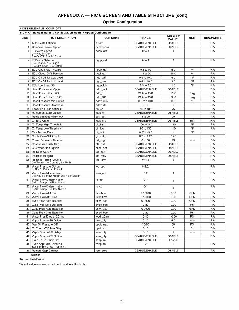
71
APPENDIX A — PIC 6 SCREEN AND TABLE STRUCTURE (cont) Option Configuration
LEGEND
*Default value is shown only if configurable in this table.
CCN TABLE NAME: CONF_OPTPIC 6 PATH: Main Menu Configuration Menu Option Configuration
LINE PIC 6 DESCRIPTION CCN NAME RANGE DEFAULT VALUE* UNIT READ/WRITE
1 Auto Restart Option astart DSABLE/ENABLE DSABLE RW2 Common Sensor Option commsens DSABLE/ENABLE DSABLE RW3 EC Valve Option
0 = No, 1= Cont2 = On/Off, 3 = 4-20 mA
hgbp_opt 0 to 3 0 RW
4 EC Valve Selection0 = Disable, 1 = Surge2 = Low Load, 3 = Comb
hgbp_sel 0 to 3 0 RW
5 ECV Open IGV1 Position hpop_gv1 0.5 to 10 5.0 % RW6 ECV Close IGV1 Position hgcl_gv1 1.5 to 20 10.0 % RW7 ECV Off DT for Low Load hgb_toff 0.5 to 10.0 4.0 ^F RW8 ECV On DT for Low Load hgb_ton 0.5 to 10.0 2.0 ^F RW9 ECV Low Load DB hgbp_ldb 0.5 to 2.0 1.0 ^F RW
10 Head Pres Valve Option hdpv_opt DSABLE/ENABLE DSABLE RW11 Head Pres Delta P 0% hdp_0 20.0 to 85.0 25.0 psig RW12 Head Pres Delta P 100% hdp_100 20.0 to 85.0 50.0 psig RW13 Head Pressure Min Output hdpv_min 0.0 to 100.0 0.0 % RW14 Head Pressure Deadband, hdpv_db 0-10 1 RW15 Tower Fan High set point tfh_sp 55 to 105 75 RW16 Refrigerant Leak Option leak_en DSABLE/ENABLE DSABLE RW17 Refrig Leakage Alarm mA exv_opt 4 to 20 20 RW18 Oil EXV Option leak_ma DSABLE/ENABLE DSABLE mA RW19 Oil Temp High Threshold oil_high 100 to 140 120 °F RW20 Oil Temp Low Threshold oil_low 90 to 130 110 °F RW21 Gas Torque Factor gt_fact 0.25 to 3.0 1 °F22 Guide Vane/SRD Factor gv_srd_f 0.7 to 1.20 0.95 RW23 Power Recovery Timeout pd_tcfg 0 to 60 15 min RW24 Condenser Flush Alert cfa_opt DSABLE/ENABLE DSABLE RW25 Customer Alert Option cusa_opt DSABLE/ENABLE DSABLE RW26 Ice Build Option ice_opt DSABLE/ENABLE DSABLE RW27 Ice Build Recycle ice_recy DSABLE/ENABLE DSABLE RW28 Ice Build Termin Source
0 = Temp, 1 = Contact, 2 = Bothice_term 0 to 2 0 RW
29 Water Pressure Option0=No, 1=Pres., 2=Pres. D
wp_opt 0-2,0, RW
30 Water Flow Measurement0 = No, 1 = Flow Meter, 2 = Flow Switch
wfm_opt 0-2 0 RW
31 Water Flow Determination0=Sat Temp, 1=Flow Switch
fs_opt 0-1 0 RW
32 Water Flow Determination0=Sat Temp, 1=Flow Switch
fs_opt 0-1 0 RW
33 Water Flow at 4 mA flow4ma 0-12000 0.00 GPM RW34 Water Flow at 20 mA flow20ma 0-12000 0.00 GPM RW35 Evap Flow Rate Baseline chwf_bas 0-9000 0.00 GPM RW36 Evap Pres Drop Baseline evpd_bas 0-20 0.00 PSI RW37 Cond Flow Rate Baseline cdwf_bas 0-9000 0.00 GPM RW38 Cond Pres Drop Baseline cdpd_bas 0-20 0.00 PSI RW41 Water Pres Drop at 20 mA wpd_20ma 0-40 10.00 PSI RW42 Vapor Source SV Delay vssv_dly 0-10 5.0 min RW43 Max Oil Pressure Diff opvfdmax 35-60 50 PSI RW44 Oil Pump VFD Max Step opvfdstp 0-10 7 % RW45 Vapor Source SV Delay vssv_dly 0-10 5 min RW46 Vapor Source SV Option vssv_dly DSABLE/ENABLE DSABLE RW47 Evap Liquid Temp Opt evap_ref DSABLE/ENABLE Enable48 Evap App Calc Selection
Sat Temp = 0, Ref Temp = 1evap_ref 0/1 1 RW
49 Remote Stop Contact rem_stop DSABLE/ENABLE DSABLE RW
RW — Read/Write
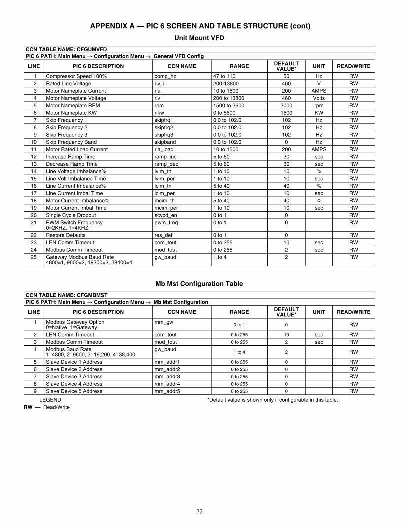
72
APPENDIX A — PIC 6 SCREEN AND TABLE STRUCTURE (cont)
Unit Mount VFD
Mb Mst Configuration Table
LEGEND *Default value is shown only if configurable in this table.
CCN TABLE NAME: CFGUMVFDPIC 6 PATH: Main Menu Configuration Menu General VFD Config
LINE PIC 6 DESCRIPTION CCN NAME RANGE DEFAULT VALUE* UNIT READ/WRITE
1 Compressor Speed 100% comp_hz 47 to 110 50 Hz RW2 Rated Line Voltage rlv_i 200-13800 460 V RW3 Motor Nameplate Current rla 10 to 1500 200 AMPS RW4 Motor Nameplate Voltage rlv 200 to 13800 460 Volts RW5 Motor Nameplate RPM rpm 1500 to 3600 3000 rpm RW6 Motor Nameplate KW rlkw 0 to 5600 1500 KW RW7 Skip Frequency 1 skipfrq1 0.0 to 102.0 102 Hz RW8 Skip Frequency 2 skipfrq2 0.0 to 102.0 102 Hz RW9 Skip Frequency 3 skipfrq3 0.0 to 102.0 102 Hz RW
10 Skip Frequency Band skipband 0.0 to 102.0 0 Hz RW11 Motor Rated Load Current rla_load 10 to 1500 200 AMPS RW12 Increase Ramp Time ramp_inc 5 to 60 30 sec RW13 Decrease Ramp Time ramp_dec 5 to 60 30 sec RW14 Line Voltage Imbalance% lvim_th 1 to 10 10 % RW15 Line Volt Imbalance Time lvim_per 1 to 10 10 sec RW16 Line Current Imbalance% lcim_th 5 to 40 40 % RW17 Line Current Imbal Time lcim_per 1 to 10 10 sec RW18 Motor Current Imbalance% mcim_th 5 to 40 40 % RW19 Motor Current Imbal Time mcim_per 1 to 10 10 sec RW20 Single Cycle Dropout scycd_en 0 to 1 0 RW21 PWM Switch Frequency
0=2KHZ, 1=4KHZpwm_freq 0 to 1 0 RW
22 Restore Defaults res_def 0 to 1 0 RW23 LEN Comm Timeout com_tout 0 to 255 10 sec RW24 Modbus Comm Timeout mod_tout 0 to 255 2 sec RW25 Gateway Modbus Baud Rate
4800=1, 9600=2, 19200=3, 38400=4gw_baud 1 to 4 2 RW
CCN TABLE NAME: CFGMBMSTPIC 6 PATH: Main Menu Configuration Menu Mb Mst Configuration
LINE PIC 6 DESCRIPTION CCN NAME RANGE DEFAULT VALUE* UNIT READ/WRITE
1 Modbus Gateway Option0=Native, 1=Gateway
mm_gw 0 to 1 0 RW
2 LEN Comm Timeout com_tout 0 to 255 10 sec RW3 Modbus Comm Timeout mod_tout 0 to 255 2 sec RW4 Modbus Baud Rate
1=4800, 2=9600, 3=19,200, 4=38,400gw_baud 1 to 4 2 RW
5 Slave Device 1 Address mm_addr1 0 to 255 0 RW6 Slave Device 2 Address mm_addr2 0 to 255 0 RW7 Slave Device 3 Address mm_addr3 0 to 255 0 RW8 Slave Device 4 Address mm_addr4 0 to 255 0 RW9 Slave Device 5 Address mm_addr5 0 to 255 0 RW
RW — Read/Write
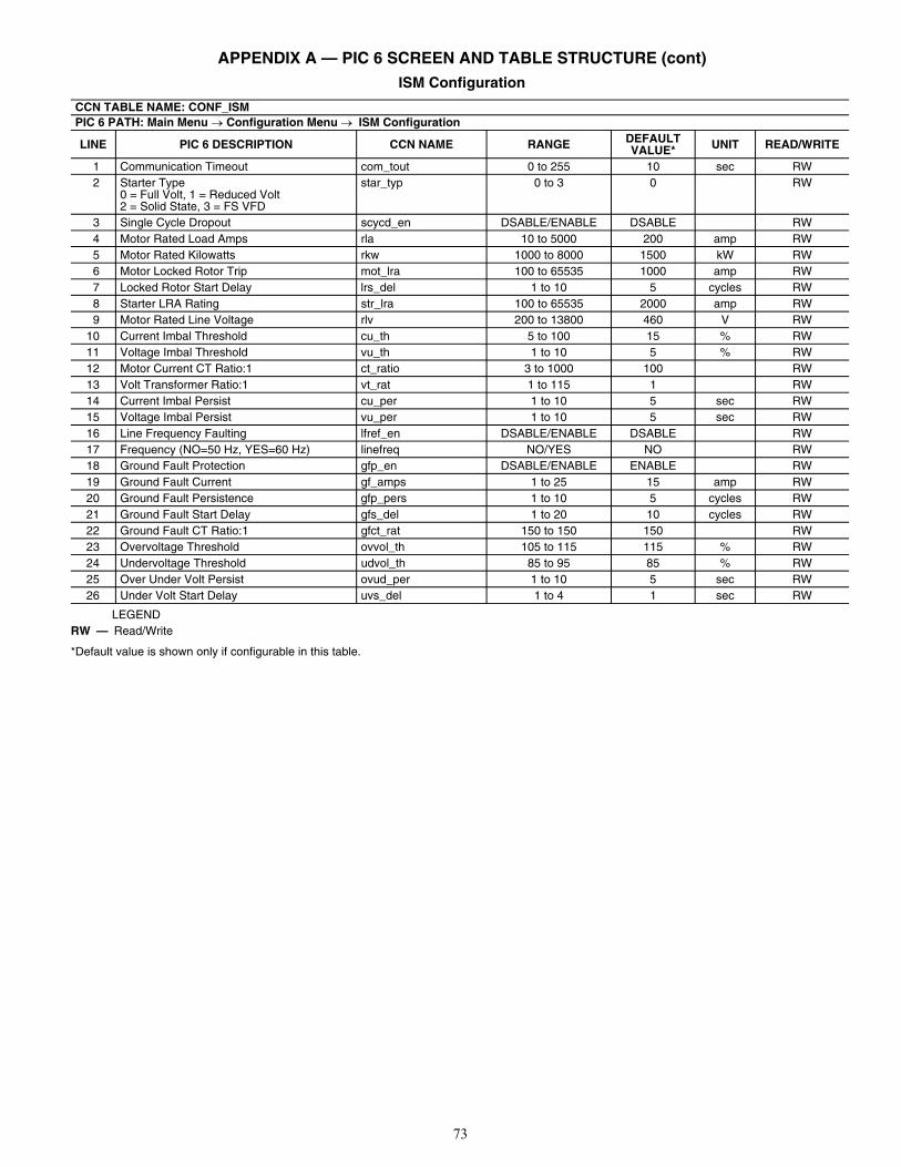
73
APPENDIX A — PIC 6 SCREEN AND TABLE STRUCTURE (cont) ISM Configuration
LEGEND
*Default value is shown only if configurable in this table.
CCN TABLE NAME: CONF_ISMPIC 6 PATH: Main Menu Configuration Menu ISM Configuration
LINE PIC 6 DESCRIPTION CCN NAME RANGE DEFAULT VALUE* UNIT READ/WRITE
1 Communication Timeout com_tout 0 to 255 10 sec RW2 Starter Type
0 = Full Volt, 1 = Reduced Volt2 = Solid State, 3 = FS VFD
star_typ 0 to 3 0 RW
3 Single Cycle Dropout scycd_en DSABLE/ENABLE DSABLE RW4 Motor Rated Load Amps rla 10 to 5000 200 amp RW5 Motor Rated Kilowatts rkw 1000 to 8000 1500 kW RW6 Motor Locked Rotor Trip mot_lra 100 to 65535 1000 amp RW7 Locked Rotor Start Delay lrs_del 1 to 10 5 cycles RW8 Starter LRA Rating str_lra 100 to 65535 2000 amp RW9 Motor Rated Line Voltage rlv 200 to 13800 460 V RW
10 Current Imbal Threshold cu_th 5 to 100 15 % RW11 Voltage Imbal Threshold vu_th 1 to 10 5 % RW12 Motor Current CT Ratio:1 ct_ratio 3 to 1000 100 RW13 Volt Transformer Ratio:1 vt_rat 1 to 115 1 RW14 Current Imbal Persist cu_per 1 to 10 5 sec RW15 Voltage Imbal Persist vu_per 1 to 10 5 sec RW16 Line Frequency Faulting lfref_en DSABLE/ENABLE DSABLE RW17 Frequency (NO=50 Hz, YES=60 Hz) linefreq NO/YES NO RW18 Ground Fault Protection gfp_en DSABLE/ENABLE ENABLE RW19 Ground Fault Current gf_amps 1 to 25 15 amp RW20 Ground Fault Persistence gfp_pers 1 to 10 5 cycles RW21 Ground Fault Start Delay gfs_del 1 to 20 10 cycles RW22 Ground Fault CT Ratio:1 gfct_rat 150 to 150 150 RW23 Overvoltage Threshold ovvol_th 105 to 115 115 % RW24 Undervoltage Threshold udvol_th 85 to 95 85 % RW25 Over Under Volt Persist ovud_per 1 to 10 5 sec RW26 Under Volt Start Delay uvs_del 1 to 4 1 sec RW
RW — Read/Write
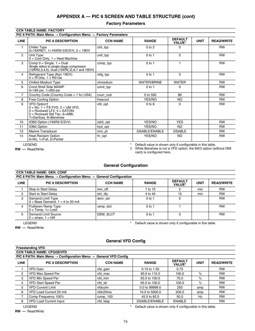
74
APPENDIX A — PIC 6 SCREEN AND TABLE STRUCTURE (cont) Factory Parameters
LEGEND * Default value is shown only if configurable in this table.† While Benshaw is not a VFD option, the MX3 option (without ISM
card) is configured here.
General Configuration
LEGEND * Default value is shown only if configurable in this table.
General VFD Config
LEGEND * Default value is shown only if configurable in this table.
CCN TABLE NAME: FACTORYPIC 6 PATH: Main Menu Configuration Menu Factory Parameters
LINE PIC 6 DESCRIPTION CCN NAME RANGE DEFAULT VALUE* UNIT READ/WRITE
1 Chiller Type0=19XR6/7, 1=19XR2-5/E/D/V, 2 = 19DV
chil_typ 0 to 2 0 RW
2 Unit Type0 = Cool Only, 1 = Heat Machine
unit_typ 0 to 1 0 RW
3 Comp 0 = Single, 1 = DualSingle refers to single stage compressor (19XR2,3,4,5). Dual (19XRC,E,6,7 and 19DV)
comp_typ 0 to 1 1 RW
4 Refrigerant Type (Non 19DV)0 = R134a, 1 = R513a
refg_typ 0 to 1 0 RW
5 Chilled Medium Type chmedium WATER/BRINE WATER RW6 Cond Shell Side MAWP
0=185 psi, 1=300 psicond_typ 0 to 1 0 RW
7 Country Code (Country Code = 1 for USA) coun_cod 0 to 500 86 RW8 Free Cooling Option freecool YES/NO NO RW9 VFD Option†
0 = No, 1 = FS FVD, 2 = UM VFD, 3 = Rockwell LF2, 4 = EATON, 5 = Rockwell Std Tier, 6=ABB, 7=Danfoss, 8=Benshaw
vfd_opt 0 to 8 0 RW
10 IOB3 Option (19XR2-E/D/V) iob3_opt YES/NO YES RW11 IOB4 Option hyd_opt YES/NO NO RW13 Marine Transducer mrn_pt DSABLE/ENABLE DSABLE RW14 Heat Reclaim Option
0=No, 1=Full, 2=Partialhr_opt YES/NO NO RW
RW — Read/Write
CCN TABLE NAME: GEN_CONFPIC 6 PATH: Main Menu Configuration Menu General Configuration
LINE PIC 6 DESCRIPTION CCN NAME RANGE DEFAULT VALUE* UNIT READ/WRITE
1 Stop to Start Delay min_off 1 to 15 2 min RW2 Start to Start Delay strt_dly 4 to 45 15 min RW3 Demand Limit Type
0 = Base Demand, 1 = 4 to 20 mAdem_sel 0 to 1 0 RW
4 Pulldown Ramp Type0 = Temp, 1= Load
ramp_slct 0 to 1 1 RW
5 Demand Limit Source0 = amps, 1 = kW
DEM_SLCT 0 to 1 0 RW
RW — Read/Write
Freestanding VFDCCN TABLE NAME: CFGGEVFDPIC 6 PATH: Main Menu Configuration Menu General VFD Config
LINE PIC 6 DESCRIPTION CCN NAME RANGE DEFAULT VALUE* UNIT READ/WRITE
1 VFD Gain vfd_gain 0.10 to 1.50 0.75 RW2 VFD Max Speed Per vfd_max 90.0 to 110.0 100.0 % RW3 VFD Min Speed Per vfd_min 65.0 to 100.0 70.0 % RW4 VFD Start Speed Per vfd_str 65.0 to 100.0 100.0 % RW5 VFD Current Limit vfdculm 0.0 to 99999.0 250 amp RW6 VFD Load Current 20 mA vfdc20ma 10.0 to 5000.0 200.0 amp RW7 Comp Frequency 100% comp_100 45.0 to 62.0 50.0 Hz RW8 VFD Load Current Input vfd_ldap DSABLE/ENABLE ENABLE RW
RW — Read/Write
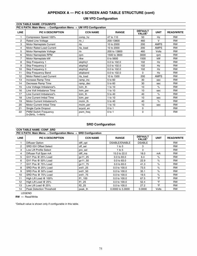
75
APPENDIX A — PIC 6 SCREEN AND TABLE STRUCTURE (cont)
UM VFD Configuration
SRD Configuration
LEGEND
*Default value is shown only if configurable in this table.
CCN TABLE NAME: CFGUMVFDPIC 6 PATH: Main Menu Configuration Menu UM VFD Configuration
LINE PIC 6 DESCRIPTION CCN NAME RANGE DEFAULT VALUE* UNIT READ/WRITE
1 Compressor Speed 100% comp_hz 47 to 110 50 Hz RW2 Rated Line Voltage rlv_i 200-13800 460 V RW3 Motor Nameplate Current rla 10 to 2000 200 AMPS RW4 Motor Rated Load Current rla_load 10 to 2000 200 AMPS RW5 Motor Nameplate Voltage rlv 200 to 13800 460 Volts RW6 Motor Nameplate RPM rpm 1500 to 3600 3000 rpm RW7 Motor Nameplate kW rlkw 0 to 5600 1500 kW RW8 Skip Frequency 1 skipfrq1 0.0 to 102.0 102 Hz RW9 Skip Frequency 2 skipfrq2 0.0 to 102.0 102 Hz RW
10 Skip Frequency 3 skipfrq3 0.0 to 102.0 102 Hz RW11 Skip Frequency Band skipband 0.0 to 102.0 0 Hz RW12 Motor Rated Load Current rla_load 10 to 1500 200 AMPS RW13 Increase Ramp Time ramp_inc 5 to 60 30 sec RW14 Decrease Ramp Time ramp_dec 5 to 60 30 sec RW15 Line Voltage Imbalance% lvim_th 1 to 10 10 % RW16 Line Volt Imbalance Time lvim_per 1 to 10 10 sec RW17 Line Current Imbalance% lcim_th 5 to 40 40 % RW18 Line Current Imbal Time lcim_per 1 to 10 10 sec RW19 Motor Current Imbalance% mcim_th 5 to 40 40 % RW20 Motor Current Imbal Time mcim_per 1 to 10 10 sec RW21 Single Cycle Dropout scycd_en 0 to 1 0 RW22 PWM Switch Frequency
0=2kHz, 1=4kHzpwm_freq 0 to 1 0 RW
CCN TABLE NAME: CONF_SRDPIC 6 PATH: Main Menu Configuration Menu SRD Configuration
LINE PIC 6 DESCRIPTION CCN NAME RANGE DEFAULT VALUE* UNIT READ/WRITE
1 Diffuser Option diff_opt DSABLE/ENABLE DSABLE RW2 SRD IGV Offset Select off_sel 1 to 5 3 RW3 Low Lift Profile Select pro_sel 1 to 5 3 RW4 Diffuser Full Span mA diff_ma 15.0 to 22.0 18.0 mA RW5 GV1 Pos @ 25% Load gv11_25 0.0 to 83.0 6.4 % RW6 GV1 Pos @ 50% Load gv11_50 0.0 to 83.0 22.9 % RW7 GV1 Pos @ 75% Load gv11_75 0.0 to 83.0 41.3 % RW8 SRD Pos @ 25% Load srd1_25 0.0 to 100.0 73.5 % RW9 SRD Pos @ 50% Load srd1_50 0.0 to 100.0 35.1 % RW
10 SRD Pos @ 75% Load srd1_75 0.0 to 100.0 19.5 % RW11 High Lift Load @ 100% lf1_100 0.0 to 100.0 67.5 °F RW12 High Lift Load @ 25% lf1_25 0.0 to 100.0 52.4 °F RW13 Low Lift Load @ 25% lf2_25 0.0 to 100.0 27.2 °F RW14 Peak Detection Threshold peak_th 0.0000 to 5.0000 0.0000 Volts RW
RW — Read/Write
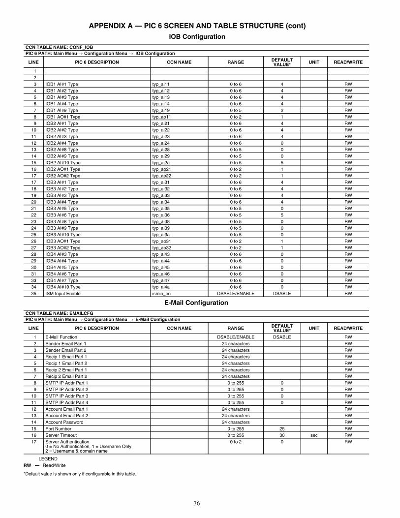
76
APPENDIX A — PIC 6 SCREEN AND TABLE STRUCTURE (cont) IOB Configuration
E-Mail Configuration
LEGEND
*Default value is shown only if configurable in this table.
CCN TABLE NAME: CONF_IOBPIC 6 PATH: Main Menu Configuration Menu IOB Configuration
LINE PIC 6 DESCRIPTION CCN NAME RANGE DEFAULT VALUE* UNIT READ/WRITE
123 IOB1 AI#1 Type typ_ai11 0 to 6 4 RW4 IOB1 AI#2 Type typ_ai12 0 to 6 4 RW5 IOB1 AI#3 Type typ_ai13 0 to 6 4 RW6 IOB1 AI#4 Type typ_ai14 0 to 6 4 RW7 IOB1 AI#9 Type typ_ai19 0 to 5 2 RW8 IOB1 AO#1 Type typ_ao11 0 to 2 1 RW9 IOB2 AI#1 Type typ_ai21 0 to 6 4 RW
10 IOB2 AI#2 Type typ_ai22 0 to 6 4 RW11 IOB2 AI#3 Type typ_ai23 0 to 6 4 RW12 IOB2 AI#4 Type typ_ai24 0 to 6 0 RW13 IOB2 AI#8 Type typ_ai28 0 to 5 0 RW14 IOB2 AI#9 Type typ_ai29 0 to 5 0 RW15 IOB2 AI#10 Type typ_ai2a 0 to 5 5 RW16 IOB2 AO#1 Type typ_ao21 0 to 2 1 RW17 IOB2 AO#2 Type typ_ao22 0 to 2 1 RW17 IOB3 AI#1 Type typ_ai31 0 to 6 4 RW18 IOB3 AI#2 Type typ_ai32 0 to 6 4 RW19 IOB3 AI#3 Type typ_ai33 0 to 6 4 RW20 IOB3 AI#4 Type typ_ai34 0 to 6 4 RW21 IOB3 AI#5 Type typ_ai35 0 to 5 0 RW22 IOB3 AI#6 Type typ_ai36 0 to 5 5 RW23 IOB3 AI#8 Type typ_ai38 0 to 5 0 RW24 IOB3 AI#9 Type typ_ai39 0 to 5 0 RW25 IOB3 AI#10 Type typ_ai3a 0 to 5 0 RW26 IOB3 AO#1 Type typ_ao31 0 to 2 1 RW27 IOB3 AO#2 Type typ_ao32 0 to 2 1 RW28 IOB4 AI#3 Type typ_ai43 0 to 6 0 RW29 IOB4 AI#4 Type typ_ai44 0 to 6 0 RW30 IOB4 AI#5 Type typ_ai45 0 to 6 0 RW31 IOB4 AI#6 Type typ_ai46 0 to 6 0 RW33 IOB4 AI#7 Type typ_ai47 0 to 6 0 RW34 IOB4 AI#10 Type typ_ai4a 0 to 6 0 RW35 ISM Input Enable ismin_en DSABLE/ENABLE DSABLE RW
CCN TABLE NAME: EMAILCFGPIC 6 PATH: Main Menu Configuration Menu E-Mail Configuration
LINE PIC 6 DESCRIPTION CCN NAME RANGE DEFAULT VALUE* UNIT READ/WRITE
1 E-Mail Function DSABLE/ENABLE DSABLE RW2 Sender Email Part 1 24 characters RW3 Sender Email Part 2 24 characters RW4 Recip 1 Email Part 1 24 characters RW5 Recip 1 Email Part 2 24 characters RW6 Recip 2 Email Part 1 24 characters RW7 Recip 2 Email Part 2 24 characters RW8 SMTP IP Addr Part 1 0 to 255 0 RW9 SMTP IP Addr Part 2 0 to 255 0 RW
10 SMTP IP Addr Part 3 0 to 255 0 RW11 SMTP IP Addr Part 4 0 to 255 0 RW12 Account Email Part 1 24 characters RW13 Account Email Part 2 24 characters RW14 Account Password 24 characters RW15 Port Number 0 to 255 25 RW16 Server Timeout 0 to 255 30 sec RW17 Server Authentication
0 = No Authentication, 1 = Username Only2 = Username & domain name
0 to 2 0 RW
RW — Read/Write
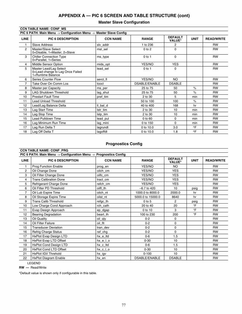
77
APPENDIX A — PIC 6 SCREEN AND TABLE STRUCTURE (cont) Master Slave Configuration
Prognostics Config
LEGEND
*Default value is shown only if configurable in this table.
CCN TABLE NAME: CONF_MSPIC 6 PATH: Main Menu Configuration Menu Master Slave Config
LINE PIC 6 DESCRIPTION CCN NAME RANGE DEFAULT VALUE* UNIT READ/WRITE
1 Slave Address slv_addr 1 to 236 2 RW2 Master/Slave Select
0=Disable, 1=Master, 2=Slavemsl_sel 0 to 2 0 RW
3 Chiller Connection Type0=Parallel, 1=Series
ms_type 0 to 1 0 RW
4 Middle Sensor Option mids_opt YES/NO YES RW5 Master Lead/Lag Select
0=Lead change to Lag Once Failed1=Runtime Balance
lead_sel 0 to 1 0 RW
6 Series Counter Flow serct_fl YES/NO NO RW7 Take Over On Comm Los toocl DSABLE/ENABLE DSABLE RW8 Master per Capacity ms_per 25 to 75 50 % RW9 LAG Shutdown Threshold lag_shut 25 to 75 50 % RW
10 Prestart Fault Time pref_tim 2 to 30 5 min RW11 Lead Unload Threshold 50 to 100 100 % RW12 Lead/Lag Balance Delta ll_bal_d 40 to 400 168 hr RW13 Lag Start Time lstr_tim 2 to 30 10 min RW14 Lag Stop Time lstp_tim 2 to 30 10 min RW15 Lead Pulldown Time lead_pul 0 to 60 0 min RW16 Lag Minimum Run Time lag_mini 0 to 150 0 min RW17 Lag Run Delta T lagrundt 0 to 10.0 3.0 ^F RW18 Lag Off Delta T lagoffdt 0 to 10.0 1.8 ^F RW
CCN TABLE NAME: CONF_PRGPIC 6 PATH: Main Menu Configuration Menu Prognostics Config
LINE PIC 6 DESCRIPTION CCN NAME RANGE DEFAULT VALUE* UNIT READ/WRITE
1 Prog Function Enable prog_en YES/NO NO RW2 Oil Change Done oilch_cm YES/NO YES RW3 Oil Filter Change Done oilfc_cm YES/NO YES RW4 Trans Calibration Done tracl_cm YES/NO YES RW5 Refrigerant Charge Done refch_cm YES/NO YES RW6 Oil Filter PD Threshold oilfl_th –6.7 to 420 10 psig RW7 Oil Lub Expire Time oilch_nt 1000.0 to 8000.0 2000.0 hr RW8 Oil Storage Expire Time oilst_nt 5000.0 to 15000.0 8640 hr RW9 Trans Calib Threshold refgc_th 0 to 5 2 psig RW
10 Low Charge Cond Approach rch_cath 20 to 40 20 °F RW11 Evap Design Approach ep_dgap 0 to 10 3 °F RW12 Bearing Degradation beart_th 100 to 230 200 °F RW13 Oil Quality oil_qly 0-2 0 RW14 Oil Filter Failure oil_flt 0-2 0 RW15 Transducer Deviation tran_dev 0-2 0 RW16 Refrig Charge Status ref_chg 0-2 0 RW17 HxPlot Evap Design LTD hx_e_ltd 0-6 1.5 RW18 HxPlot Evap LTD Offset hx_e_l_o 0-30 10 RW19 HxPlot Cond Design LTD hx_c_ltd 0-6 1.5 RW20 HxPlot Cond LTD Offset hx_c_l_o 0-30 10 RW21 HxPlot IGV Threhold hx_igv 0-100 10 RW22 HxPlot Diagram Enable hx_en DSABLE/ENABLE DSABLE RW
RW — Read/Write
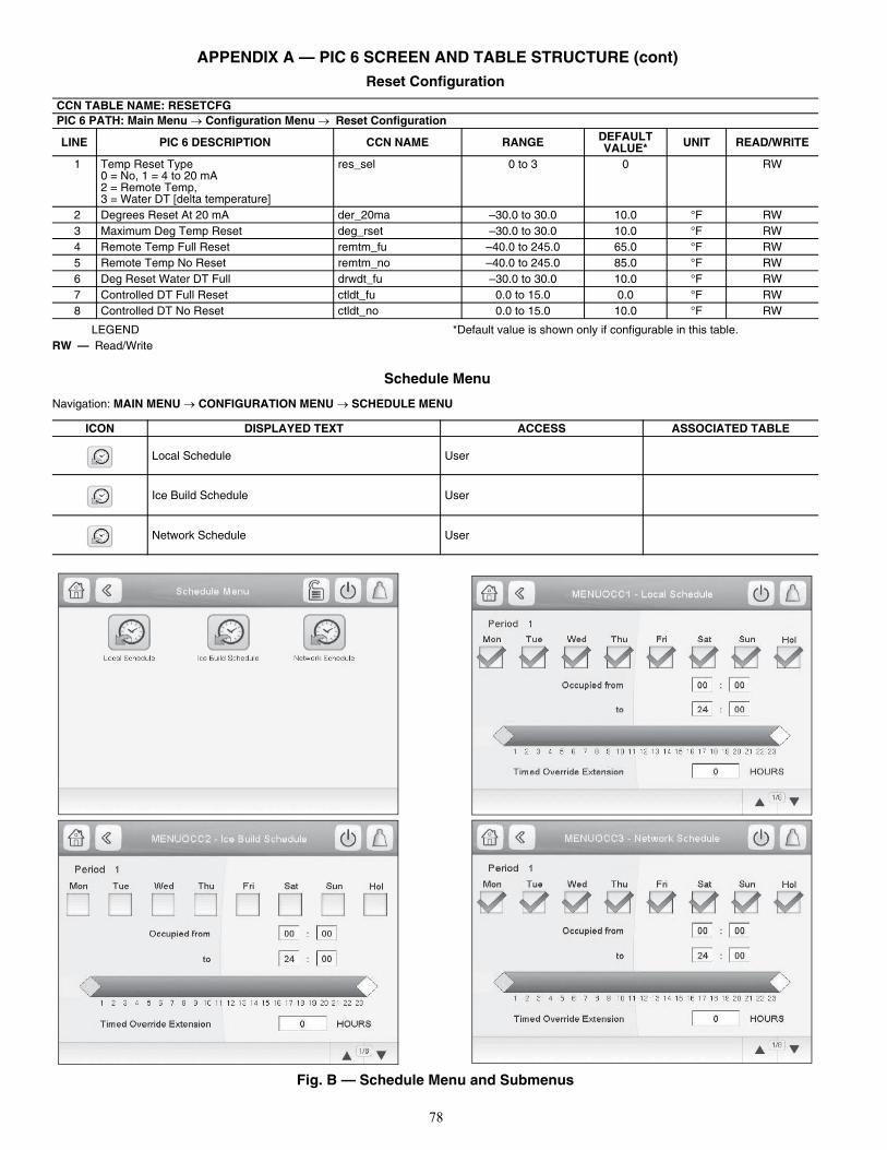
78
APPENDIX A — PIC 6 SCREEN AND TABLE STRUCTURE (cont)Reset Configuration
LEGEND *Default value is shown only if configurable in this table.
Schedule Menu
Navigation: MAIN MENU CONFIGURATION MENU SCHEDULE MENU
Fig. B — Schedule Menu and Submenus
CCN TABLE NAME: RESETCFGPIC 6 PATH: Main Menu Configuration Menu Reset Configuration
LINE PIC 6 DESCRIPTION CCN NAME RANGE DEFAULT VALUE* UNIT READ/WRITE
1 Temp Reset Type0 = No, 1 = 4 to 20 mA2 = Remote Temp, 3 = Water DT [delta temperature]
res_sel 0 to 3 0 RW
2 Degrees Reset At 20 mA der_20ma –30.0 to 30.0 10.0 °F RW3 Maximum Deg Temp Reset deg_rset –30.0 to 30.0 10.0 °F RW4 Remote Temp Full Reset remtm_fu –40.0 to 245.0 65.0 °F RW5 Remote Temp No Reset remtm_no –40.0 to 245.0 85.0 °F RW6 Deg Reset Water DT Full drwdt_fu –30.0 to 30.0 10.0 °F RW7 Controlled DT Full Reset ctldt_fu 0.0 to 15.0 0.0 °F RW8 Controlled DT No Reset ctldt_no 0.0 to 15.0 10.0 °F RW
RW — Read/Write
ICON DISPLAYED TEXT ACCESS ASSOCIATED TABLE
Local Schedule User
Ice Build Schedule User
Network Schedule User
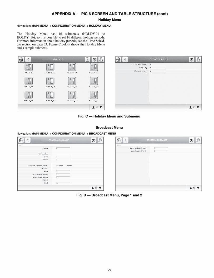
79
APPENDIX A — PIC 6 SCREEN AND TABLE STRUCTURE (cont) Holiday Menu
Navigation: MAIN MENU CONFIGURATION MENU HOLIDAY MENU
The Holiday Menu has 16 submenus (HOLDY-01 toHOLDY_16), so it is possible to set 16 different holiday periods.For more information about holiday periods, see the Time Sched-ule section on page 33. Figure C below shows the Holiday Menuand a sample submenu.
Fig. C — Holiday Menu and Submenu
Broadcast Menu
Navigation: MAIN MENU CONFIGURATION MENU BROADCAST MENU
Fig. D — Broadcast Menu, Page 1 and 2
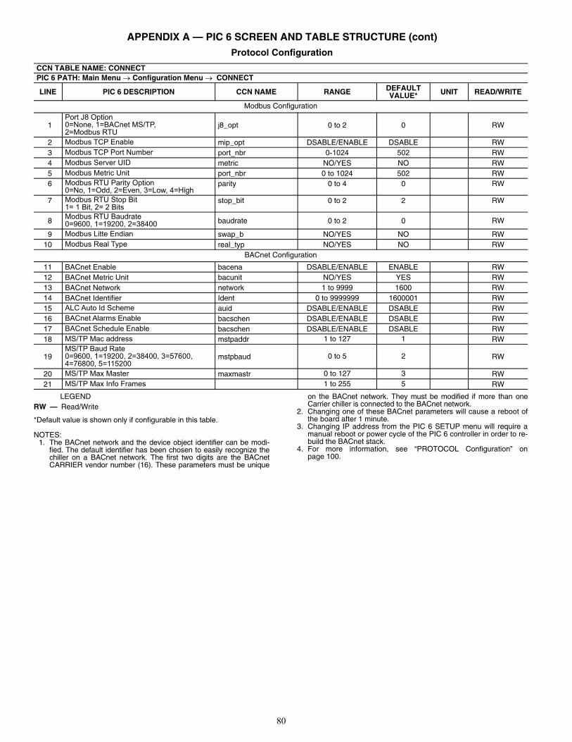
80
APPENDIX A — PIC 6 SCREEN AND TABLE STRUCTURE (cont) Protocol Configuration
LEGEND
*Default value is shown only if configurable in this table.
NOTES:1. The BACnet network and the device object identifier can be modi-
fied. The default identifier has been chosen to easily recognize thechiller on a BACnet network. The first two digits are the BACnetCARRIER vendor number (16). These parameters must be unique
on the BACnet network. They must be modified if more than oneCarrier chiller is connected to the BACnet network.
2. Changing one of these BACnet parameters will cause a reboot ofthe board after 1 minute.
3. Changing IP address from the PIC 6 SETUP menu will require amanual reboot or power cycle of the PIC 6 controller in order to re-build the BACnet stack.
4. For more information, see “PROTOCOL Configuration” onpage 100.
CCN TABLE NAME: CONNECTPIC 6 PATH: Main Menu Configuration Menu CONNECT
LINE PIC 6 DESCRIPTION CCN NAME RANGE DEFAULT VALUE* UNIT READ/WRITE
Modbus Configuration
1Port J8 Option0=None, 1=BACnet MS/TP, 2=Modbus RTU
j8_opt 0 to 2 0 RW
2 Modbus TCP Enable mip_opt DSABLE/ENABLE DSABLE RW3 Modbus TCP Port Number port_nbr 0-1024 502 RW4 Modbus Server UID metric NO/YES NO RW5 Modbus Metric Unit port_nbr 0 to 1024 502 RW6 Modbus RTU Parity Option
0=No, 1=Odd, 2=Even, 3=Low, 4=Highparity 0 to 4 0 RW
7 Modbus RTU Stop Bit1= 1 Bit, 2= 2 Bits
stop_bit 0 to 2 2 RW
8 Modbus RTU Baudrate0=9600, 1=19200, 2=38400 baudrate 0 to 2 0 RW
9 Modbus Litte Endian swap_b NO/YES NO RW10 Modbus Real Type real_typ NO/YES NO RW
BACnet Configuration
11 BACnet Enable bacena DSABLE/ENABLE ENABLE RW12 BACnet Metric Unit bacunit NO/YES YES RW13 BACnet Network network 1 to 9999 1600 RW14 BACnet Identifier Ident 0 to 9999999 1600001 RW15 ALC Auto Id Scheme auid DSABLE/ENABLE DSABLE RW16 BACnet Alarms Enable bacschen DSABLE/ENABLE DSABLE RW17 BACnet Schedule Enable bacschen DSABLE/ENABLE DSABLE RW18 MS/TP Mac address mstpaddr 1 to 127 1 RW
19MS/TP Baud Rate0=9600, 1=19200, 2=38400, 3=57600, 4=76800, 5=115200
mstpbaud 0 to 5 2 RW
20 MS/TP Max Master maxmastr 0 to 127 3 RW21 MS/TP Max Info Frames 1 to 255 5 RW
RW — Read/Write
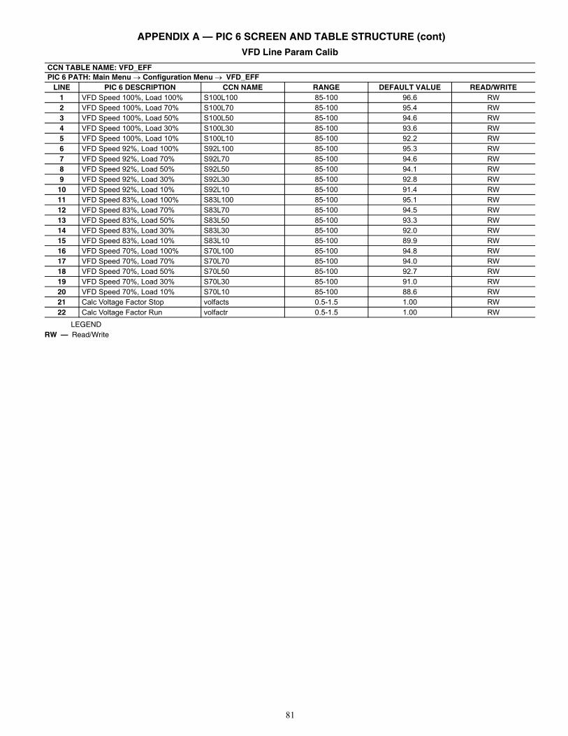
81
APPENDIX A — PIC 6 SCREEN AND TABLE STRUCTURE (cont)VFD Line Param Calib
LEGEND
CCN TABLE NAME: VFD_EFFPIC 6 PATH: Main Menu Configuration Menu VFD_EFF
LINE PIC 6 DESCRIPTION CCN NAME RANGE DEFAULT VALUE READ/WRITE1 VFD Speed 100%, Load 100% S100L100 85-100 96.6 RW2 VFD Speed 100%, Load 70% S100L70 85-100 95.4 RW3 VFD Speed 100%, Load 50% S100L50 85-100 94.6 RW4 VFD Speed 100%, Load 30% S100L30 85-100 93.6 RW5 VFD Speed 100%, Load 10% S100L10 85-100 92.2 RW6 VFD Speed 92%, Load 100% S92L100 85-100 95.3 RW7 VFD Speed 92%, Load 70% S92L70 85-100 94.6 RW8 VFD Speed 92%, Load 50% S92L50 85-100 94.1 RW9 VFD Speed 92%, Load 30% S92L30 85-100 92.8 RW
10 VFD Speed 92%, Load 10% S92L10 85-100 91.4 RW11 VFD Speed 83%, Load 100% S83L100 85-100 95.1 RW12 VFD Speed 83%, Load 70% S83L70 85-100 94.5 RW13 VFD Speed 83%, Load 50% S83L50 85-100 93.3 RW14 VFD Speed 83%, Load 30% S83L30 85-100 92.0 RW15 VFD Speed 83%, Load 10% S83L10 85-100 89.9 RW16 VFD Speed 70%, Load 100% S70L100 85-100 94.8 RW17 VFD Speed 70%, Load 70% S70L70 85-100 94.0 RW18 VFD Speed 70%, Load 50% S70L50 85-100 92.7 RW19 VFD Speed 70%, Load 30% S70L30 85-100 91.0 RW20 VFD Speed 70%, Load 10% S70L10 85-100 88.6 RW21 Calc Voltage Factor Stop volfacts 0.5-1.5 1.00 RW22 Calc Voltage Factor Run volfactr 0.5-1.5 1.00 RW
RW — Read/Write
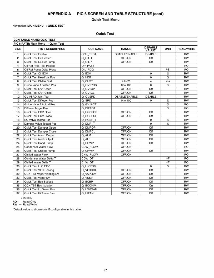
82
APPENDIX A — PIC 6 SCREEN AND TABLE STRUCTURE (cont) Quick Test Menu
Navigation: MAIN MENU QUICK TEST
Quick Test
LEGEND
*Default value is shown only if configurable in this table.
CCN TABLE NAME: QCK_TESTPIC 6 PATH: Main Menu Quick Test
LINE PIC 6 DESCRIPTION CCN NAME RANGE DEFAULT VALUE* UNIT READ/WRITE
1 Quick Test Enable QCK_TEST DSABLE/ENABLE DSABLE RW2 Quick Test Oil Heater Q_OILH OFF/ON Off RW3 Quick Test Oil/Ref Pump Q_OILP OFF/ON Off RW4 Oil/Ref Pres Test Passed OP_PASS RO5 Oil/Ref Pump Delta Press OIL_PDQ PSI RO6 Quick Test Oil EXV Q_EXV 0 % RW7 Quick Test Head Val Pos Q_HDP 0 % RW8 Quick Test Chiller Stat Q_CHST 4 to 20 4 ma RW9 Guide Vane 1 Tested Pos Q_GV1POS 0 to 100 0 % RW
10 Quick Test GV1 Open Q_GV1OP OFF/ON Off RW11 Quick Test GV1 Close Q_GV1CL OFF/ON Off RW12 GV1/SRD Joint Test Q_GVSRD DSABLE/ENABLE DSABLE RW13 Quick Test Diffuser Pos Q_SRD 0 to 100 0 % RW14 Guide Vane 1 Actual Pos Q_GV1ACT % RO15 Diffuser Target Pos Q_DIFTGT % RO16 Quick Test ECV Open Q_HGBPOP OFF/ON Off RW17 Quick Test ECV Close Q_HGBPCL OFF/ON Off RW18 EC Valve Tested Pos Q_HGBP_T 0 % RW19 Damper Valve Tested Pos Q_DMP_T 0 % RW20 Quick Test Damper Open Q_DMPOP OFF/ON Off RW21 Quick Test Damper Close Q_DMPCL OFF/ON Off RW22 Quick Test Alarm Output Q_ALM OFF/ON Off RW23 Quick Test Alert Output Q_ALE OFF/ON Off RW24 Quick Test Cond Pump Q_CDWP OFF/ON Off RW25 Condenser Water Flow CDW_FLOW OFF/ON RO26 Quick Test Chilled Pump Q_CHWP OFF/ON Off RW27 Chilled Water Flow CHW_FLOW OFF/ON RO28 Condenser Water Delta T CDW_DT ^F RO29 Chilled Water Delta T CHW_DT ^F RO30 Quick Test LLC EXV Q_LLCEXV 0 % RW31 Quick Test VFD Cooling Q_VFDCOL OFF/ON Off RW32 QCK TST Vapor Venting SV Q_VAPLSV OFF/ON Off RW33 Quick Test Vapor SV Q_VSSV OFF/ON Off RW34 Quick Test Eco Bypass Q_ECBP OFF/ON Off RW35 QCK TST Eco Isolation Q_ECONIV OFF/ON On RW36 Quick Test Lo Tower Fan Q_LOWFAN OFF/ON Off RW37 Quick Test Hi Tower Fan Q_HIFAN OFF/ON Off RW
RO — Read OnlyRW — Read/Write
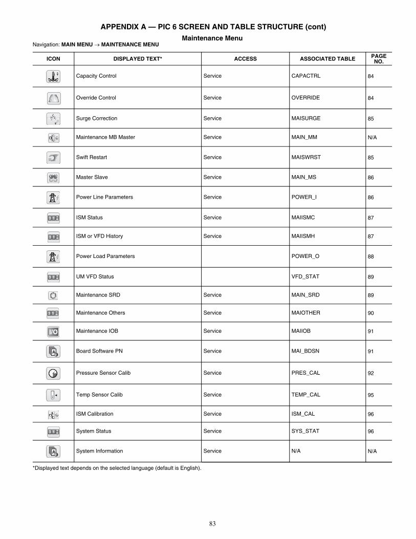
83
APPENDIX A — PIC 6 SCREEN AND TABLE STRUCTURE (cont)Maintenance Menu
Navigation: MAIN MENU MAINTENANCE MENU
*Displayed text depends on the selected language (default is English).
ICON DISPLAYED TEXT* ACCESS ASSOCIATED TABLE PAGE NO.
Capacity Control Service CAPACTRL 84
Override Control Service OVERRIDE 84
Surge Correction Service MAISURGE 85
Maintenance MB Master Service MAIN_MM N/A
Swift Restart Service MAISWRST 85
Master Slave Service MAIN_MS 86
Power Line Parameters Service POWER_I 86
ISM Status Service MAIISMC 87
ISM or VFD History Service MAIISMH 87
Power Load Parameters POWER_O 88
UM VFD Status VFD_STAT 89
Maintenance SRD Service MAIN_SRD 89
Maintenance Others Service MAIOTHER 90
Maintenance IOB Service MAIIOB 91
Board Software PN Service MAI_BDSN 91
Pressure Sensor Calib Service PRES_CAL 92
Temp Sensor Calib Service TEMP_CAL 95
ISM Calibration Service ISM_CAL 96
System Status Service SYS_STAT 96
System Information Service N/A N/A
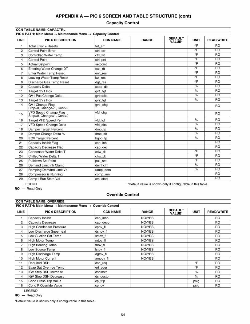
84
APPENDIX A — PIC 6 SCREEN AND TABLE STRUCTURE (cont)Capacity Control
LEGEND *Default value is shown only if configurable in this table.
Override Control
LEGEND
*Default value is shown only if configurable in this table.
CCN TABLE NAME: CAPACTRLPIC 6 PATH: Main Menu Maintenance Menu Capacity Control
LINE PIC 6 DESCRIPTION CCN NAME RANGE DEFAULT VALUE* UNIT READ/WRITE
1 Total Error + Resets tot_err ^F RO
2 Control Point Error ctrl_err ^F RO
3 Controlled Water Temp ctrl_wt °F RO
4 Control Point ctrl_pnt °F RO
5 Actual Setpoint setpoint °F RO
6 Entering Water Change DT ewt_dt ^F RO
7 Enter Water Temp Reset ewt_res ^F RO
8 Leaving Water Temp Reset lwt_res ^F RO
9 Discharge Gas Temp Reset dgt_res ^F RO
10 Capacity Delta capa_dlt % RO
11 Target GV1 Pos gv1_tgt % RO
12 GV1 Pos Change Delta gv1delta % RO
13 Target GV2 Pos gv2_tgt % RO
14 GV1 Change Flag Stop=0, Change=1, Cont=2
gv1_chg RO
15 VFD Speed Change Flag Stop=0, Change=1, Cont=2
vfd_chg RO
16 Target VFD Speed Per vfd_tgt % RO
17 VFD Speed Change Delta vfd_dlta % RO
18 Damper Target Percent dmp_tp % RO
19 Damper Change Delta % dmp_dlt % RO
20 ECV Target Percent hgbp_tp % RO
21 Capacity Inhibit Flag cap_inh RO
22 Capacity Decrease Flag cap_dec RO
23 Condenser Water Delta T cdw_dt ^F RO
24 Chilled Water Delta T chw_dt ^F RO
25 Pulldown Set Point pull_set °F RO
26 Demand Limit Inh Clamp deinhclm % RO
27 Ramping Demand Limit Val ramp_dem % RO
28 Compressor is Running comp_run RO
29 Comp1 Run State Val cm_stat1 RO
RO — Read Only
CCN TABLE NAME: OVERRIDEPIC 6 PATH: Main Menu Maintenance Menu Override Control
LINE PIC 6 DESCRIPTION CCN NAME RANGE DEFAULT VALUE* UNIT READ/WRITE
1 Capacity Inhibit cap_inho NO/YES RO2 Capacity Decrease cap_deco NO/YES RO3 High Condenser Pressure cpov_fl NO/YES RO4 Low Discharge Superheat dshov_fl NO/YES RO5 Low Suction Sat Temp sstov_fl NO/YES RO6 High Motor Temp mtov_fl NO/YES RO7 High Bearing Temp tbov_fl NO/YES RO8 Low Source Temp lstov_fl NO/YES RO9 High Discharge Temp dgtov_fl NO/YES RO
10 High Motor Current ampov_fl NO/YES RO11 Required DSH dsh_req °F RO12 Evap Sat Override Temp ert_over °F RO13 IGV Step DSH Increase dshinstp % RO14 IGV Step DSH Decrease dshdestp % RO15 Cond Press Trip Value cp_trip psig RO16 Cond P Override Value cp_ov psig RO
RO — Read Only
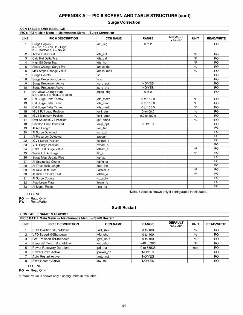
85
APPENDIX A — PIC 6 SCREEN AND TABLE STRUCTURE (cont)Surge Correction
LEGEND*Default value is shown only if configurable in this table.
Swift Restart
LEGEND
*Default value is shown only if configurable in this table.
CCN TABLE NAME: MAISURGEPIC 6 PATH: Main Menu Maintenance Menu Surge Correction
LINE PIC 6 DESCRIPTION CCN NAME RANGE DEFAULT VALUE* UNIT READ/WRITE
1 Surge Region0 = No, 1 = Low, 2 = High, 3 = Deadband, 4 = Noise
act_reg 0 to 2 RO
2 Active Delta Tsat dts_act °F RO3 Calc Ref Delta Tsat dts_cal °F RO4 High Eff Delta Tsat dts_he °F RO5 Amps Change Surge Prot amps_dta % RO6 Max Amps Change Value amch_max % RO7 Surge Counts sc RO8 Surge Protection Counts spc RO9 Surge Prevention Active surg_act NO/YES RO
10 Surge Protection Active surg_pro NO/YES RO11 EC Vlave Change Flag
0 = Close, 1 = Hold, 2 = Openhgbp_chg 0 to 2 RO
12 Cal Surge Delta Tsmax dts_maxc 0 to 150.0 °F RO13 Cal Surge Delta Tsmin dts_minc 0 to 150.0 °F RO14 Cal Surge Delta Tsmed dts_medc 0 to 150.0 ^F RO15 IGV1 Full Load Position gv1_sful 0 to100.0 % RO16 IGV1 Minimum Position gv1_smin 0.0 to 100.0 % RO17 Opti-Sound IGV1 Position gvi_smed % RO18 Envelop Line Optimized enlp_opt NO/YES RO19 Al Arc Length arc_len RO
20 Al Surge Detected surg_al RO
21 Al Precursor Detected precur RO
22 IGV1 Surge Position gv1act_s RO
23 VFD Surge Position vfdact_s RO
24 Delta Tsat Surge Value dtsact_s ^F RO
25 Water Lift At Surge lift_s ^F RO
26 Surge Map Update Flag upflag RO
27 Al Updateflag Counts upflg_ct RO
28 Al Traceback Length trce_len RO
29 Al Calc Delta Tsat dtscal_a ^F RO
30 Al High Eff Delta Tsat dtshe_a ^F RO
31 Al Surge Counts sc_auto RO
32 Auto Learn Flag learn_fg RO
33 Al Signal Reset sig_rst RO
RO — Read OnlyRW — Read/Write
CCN TABLE NAME: MAISWRSTPIC 6 PATH: Main Menu Maintenance Menu Swift Restart
LINE PIC 6 DESCRIPTION CCN NAME RANGE DEFAULT VALUE* UNIT READ/WRITE
1 SRD Position @Shutdown srd_shut 0 to 100 % RO2 VFD Speed @Shutdown vfd_shut 0 to 100 % RO3 GV1 Position @Shutdown gv1_shut 0 to 100 % RO4 Evap Sat Temp @Shutdown est_shut –40 to 280 °F RO5 Power Recovery Duration pd_dur 0 to 65535 min RO6 Power Down Active power_dn NO/YES RO7 Auto Restart Active auto_rst NO/YES RO8 Swift Restart Active sw_rst NO/YES RO
RO — Read Only
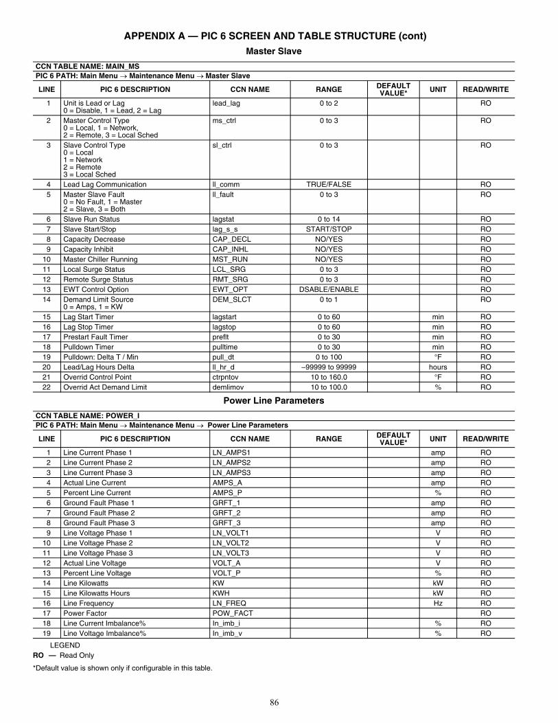
86
APPENDIX A — PIC 6 SCREEN AND TABLE STRUCTURE (cont)Master Slave
Power Line Parameters
LEGEND
*Default value is shown only if configurable in this table.
CCN TABLE NAME: MAIN_MSPIC 6 PATH: Main Menu Maintenance Menu Master Slave
LINE PIC 6 DESCRIPTION CCN NAME RANGE DEFAULT VALUE* UNIT READ/WRITE
1 Unit is Lead or Lag0 = Disable, 1 = Lead, 2 = Lag
lead_lag 0 to 2 RO
2 Master Control Type0 = Local, 1 = Network, 2 = Remote, 3 = Local Sched
ms_ctrl 0 to 3 RO
3 Slave Control Type0 = Local1 = Network2 = Remote3 = Local Sched
sl_ctrl 0 to 3 RO
4 Lead Lag Communication ll_comm TRUE/FALSE RO5 Master Slave Fault
0 = No Fault, 1 = Master2 = Slave, 3 = Both
ll_fault 0 to 3 RO
6 Slave Run Status lagstat 0 to 14 RO7 Slave Start/Stop lag_s_s START/STOP RO8 Capacity Decrease CAP_DECL NO/YES RO9 Capacity Inhibit CAP_INHL NO/YES RO
10 Master Chiller Running MST_RUN NO/YES RO11 Local Surge Status LCL_SRG 0 to 3 RO12 Remote Surge Status RMT_SRG 0 to 3 RO13 EWT Control Option EWT_OPT DSABLE/ENABLE RO14 Demand Limit Source
0 = Amps, 1 = KWDEM_SLCT 0 to 1 RO
15 Lag Start Timer lagstart 0 to 60 min RO16 Lag Stop Timer lagstop 0 to 60 min RO17 Prestart Fault Timer preflt 0 to 30 min RO18 Pulldown Timer pulltime 0 to 30 min RO19 Pulldown: Delta T / Min pull_dt 0 to 100 °F RO20 Lead/Lag Hours Delta ll_hr_d –99999 to 99999 hours RO21 Overrid Control Point ctrpntov 10 to 160.0 °F RO22 Overrid Act Demand Limit demlimov 10 to 100.0 % RO
CCN TABLE NAME: POWER_IPIC 6 PATH: Main Menu Maintenance Menu Power Line Parameters
LINE PIC 6 DESCRIPTION CCN NAME RANGE DEFAULT VALUE* UNIT READ/WRITE
1 Line Current Phase 1 LN_AMPS1 amp RO2 Line Current Phase 2 LN_AMPS2 amp RO3 Line Current Phase 3 LN_AMPS3 amp RO4 Actual Line Current AMPS_A amp RO5 Percent Line Current AMPS_P % RO6 Ground Fault Phase 1 GRFT_1 amp RO7 Ground Fault Phase 2 GRFT_2 amp RO8 Ground Fault Phase 3 GRFT_3 amp RO9 Line Voltage Phase 1 LN_VOLT1 V RO
10 Line Voltage Phase 2 LN_VOLT2 V RO11 Line Voltage Phase 3 LN_VOLT3 V RO12 Actual Line Voltage VOLT_A V RO13 Percent Line Voltage VOLT_P % RO14 Line Kilowatts KW kW RO15 Line Kilowatts Hours KWH kW RO16 Line Frequency LN_FREQ Hz RO17 Power Factor POW_FACT RO18 Line Current Imbalance% In_imb_i % RO19 Line Voltage Imbalance% In_imb_v % RO
RO — Read Only
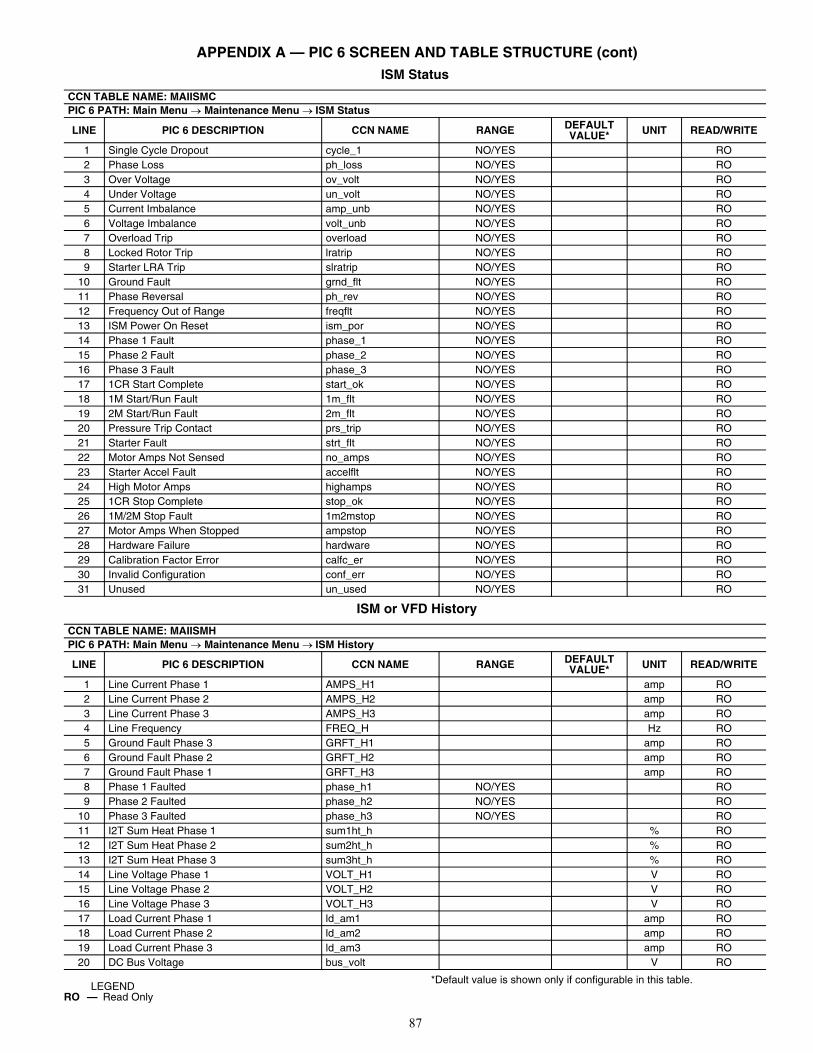
87
APPENDIX A — PIC 6 SCREEN AND TABLE STRUCTURE (cont)ISM Status
ISM or VFD History
*Default value is shown only if configurable in this table.
CCN TABLE NAME: MAIISMCPIC 6 PATH: Main Menu Maintenance Menu ISM Status
LINE PIC 6 DESCRIPTION CCN NAME RANGE DEFAULT VALUE* UNIT READ/WRITE
1 Single Cycle Dropout cycle_1 NO/YES RO2 Phase Loss ph_loss NO/YES RO3 Over Voltage ov_volt NO/YES RO4 Under Voltage un_volt NO/YES RO5 Current Imbalance amp_unb NO/YES RO6 Voltage Imbalance volt_unb NO/YES RO7 Overload Trip overload NO/YES RO8 Locked Rotor Trip lratrip NO/YES RO9 Starter LRA Trip slratrip NO/YES RO
10 Ground Fault grnd_flt NO/YES RO11 Phase Reversal ph_rev NO/YES RO12 Frequency Out of Range freqflt NO/YES RO13 ISM Power On Reset ism_por NO/YES RO14 Phase 1 Fault phase_1 NO/YES RO15 Phase 2 Fault phase_2 NO/YES RO16 Phase 3 Fault phase_3 NO/YES RO17 1CR Start Complete start_ok NO/YES RO18 1M Start/Run Fault 1m_flt NO/YES RO19 2M Start/Run Fault 2m_flt NO/YES RO20 Pressure Trip Contact prs_trip NO/YES RO21 Starter Fault strt_flt NO/YES RO22 Motor Amps Not Sensed no_amps NO/YES RO23 Starter Accel Fault accelflt NO/YES RO24 High Motor Amps highamps NO/YES RO25 1CR Stop Complete stop_ok NO/YES RO26 1M/2M Stop Fault 1m2mstop NO/YES RO27 Motor Amps When Stopped ampstop NO/YES RO28 Hardware Failure hardware NO/YES RO29 Calibration Factor Error calfc_er NO/YES RO30 Invalid Configuration conf_err NO/YES RO31 Unused un_used NO/YES RO
CCN TABLE NAME: MAIISMHPIC 6 PATH: Main Menu Maintenance Menu ISM History
LINE PIC 6 DESCRIPTION CCN NAME RANGE DEFAULT VALUE* UNIT READ/WRITE
1 Line Current Phase 1 AMPS_H1 amp RO2 Line Current Phase 2 AMPS_H2 amp RO3 Line Current Phase 3 AMPS_H3 amp RO4 Line Frequency FREQ_H Hz RO5 Ground Fault Phase 3 GRFT_H1 amp RO6 Ground Fault Phase 2 GRFT_H2 amp RO7 Ground Fault Phase 1 GRFT_H3 amp RO8 Phase 1 Faulted phase_h1 NO/YES RO9 Phase 2 Faulted phase_h2 NO/YES RO
10 Phase 3 Faulted phase_h3 NO/YES RO11 I2T Sum Heat Phase 1 sum1ht_h % RO12 I2T Sum Heat Phase 2 sum2ht_h % RO13 I2T Sum Heat Phase 3 sum3ht_h % RO14 Line Voltage Phase 1 VOLT_H1 V RO15 Line Voltage Phase 2 VOLT_H2 V RO16 Line Voltage Phase 3 VOLT_H3 V RO17 Load Current Phase 1 ld_am1 amp RO18 Load Current Phase 2 ld_am2 amp RO19 Load Current Phase 3 ld_am3 amp RO20 DC Bus Voltage bus_volt V RO
LEGENDRO — Read Only
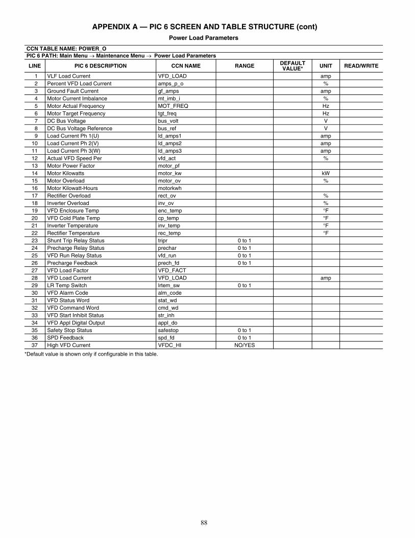
88
APPENDIX A — PIC 6 SCREEN AND TABLE STRUCTURE (cont)Power Load Parameters
*Default value is shown only if configurable in this table.
CCN TABLE NAME: POWER_OPIC 6 PATH: Main Menu Maintenance Menu Power Load Parameters
LINE PIC 6 DESCRIPTION CCN NAME RANGE DEFAULT VALUE* UNIT READ/WRITE
1 VLF Load Current VFD_LOAD amp2 Percent VFD Load Current amps_p_o %3 Ground Fault Current gf_amps amp4 Motor Current Imbalance mt_imb_i %5 Motor Actual Frequency MOT_FREQ Hz6 Motor Target Frequency tgt_freq Hz7 DC Bus Voltage bus_volt V8 DC Bus Voltage Reference bus_ref V9 Load Current Ph 1(U) ld_amps1 amp
10 Load Current Ph 2(V) ld_amps2 amp11 Load Current Ph 3(W) ld_amps3 amp12 Actual VFD Speed Per vfd_act %13 Motor Power Factor motor_pf14 Motor Kilowatts motor_kw kW15 Motor Overload motor_ov %16 Motor Kilowatt-Hours motorkwh17 Rectifier Overload rect_ov %18 Inverter Overload inv_ov %19 VFD Enclosure Temp enc_temp °F20 VFD Cold Plate Temp cp_temp °F21 Inverter Temperature inv_temp °F22 Rectifier Temperature rec_temp °F23 Shunt Trip Relay Status tripr 0 to 124 Precharge Relay Status prechar 0 to 125 VFD Run Relay Status vfd_run 0 to 126 Precharge Feedback prech_fd 0 to 127 VFD Load Factor VFD_FACT28 VFD Load Current VFD_LOAD amp29 LR Temp Switch lrtem_sw 0 to 130 VFD Alarm Code alm_code31 VFD Status Word stat_wd32 VFD Command Word cmd_wd33 VFD Start Inhibit Status str_inh34 VFD Appl Digital Output appl_do35 Safety Stop Status safestop 0 to 136 SPD Feedback spd_fd 0 to 137 High VFD Current VFDC_HI NO/YES
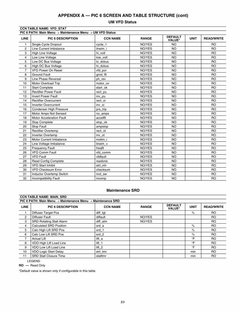
89
APPENDIX A — PIC 6 SCREEN AND TABLE STRUCTURE (cont)UM VFD Status
Maintenance SRD
LEGEND
*Default value is shown only if configurable in this table.
CCN TABLE NAME: VFD_STATPIC 6 PATH: Main Menu Maintenance Menu UM VFD Status
LINE PIC 6 DESCRIPTION CCN NAME RANGE DEFAULT VALUE* UNIT READ/WRITE
1 Single Cycle Dropout cycle_1 NO/YES NO RO2 Line Current Imbalance lineim_i NO/YES NO RO3 High Line Voltage hi_volt NO/YES NO RO4 Low Line Voltage low_volt NO/YES NO RO5 Low DC Bus Voltage lo_dcbus NO/YES NO RO6 High DC Bus Voltage hi_dcbus NO/YES NO RO7 VFD Power On Reset vfd_por NO/YES NO RO8 Ground Fault grnd_flt NO/YES NO RO9 Line Phase Reversal ph_rev NO/YES NO RO
10 Motor Overload Trip motor_ov NO/YES NO RO11 Start Complete start_ok NO/YES NO RO12 Rectifier Power Fault rect_pu NO/YES NO RO13 Invert Power Fault inv_pu NO/YES NO RO14 Rectifier Overcurrent rect_oi NO/YES NO RO15 Inverter Overcurrent inv_oi NO/YES NO RO16 Condenser High Pressure prs_trip NO/YES NO RO17 Motor Amps Not Sensed no_amps NO/YES NO RO18 Motor Acceleration Fault accelflt NO/YES NO RO19 Stop Complete stop_ok NO/YES NO RO20 Stop Fault ampstop NO/YES NO RO21 Rectifier Overtemp rect_ot NO/YES NO RO22 Inverter Overtemp inv_ot NO/YES NO RO23 Motor Current Imbalance motim_i NO/YES NO RO24 Line Voltage Imbalance lineim_v NO/YES NO RO25 Frequency Fault freqflt NO/YES NO RO26 VFD Comm Fault vfd_comm NO/YES NO RO27 VFD Fault vfdfault NO/YES NO RO28 Read Config Complete readone NO/YES NO RO29 VFD Start Inhibit strt_inh NO/YES NO RO30 VFD Checksum Error checksum NO/YES NO RO31 Inductor Overtemp Switch inot_sw NO/YES NO RO32 Incompatibility Fault incomp NO/YES NO RO
CCN TABLE NAME: MAIN_SRDPIC 6 PATH: Main Menu Maintenance Menu Maintenance SRD
LINE PIC 6 DESCRIPTION CCN NAME RANGE DEFAULT VALUE* UNIT READ/WRITE
1 Diffuser Target Pos diff_tgt % RO2 Diffuser Fault diffault NO/YES RO3 SRD Rotating Stall Alarm diff_alm NO/YES RO4 Calculated SRD Position srd_a % RO5 Calc High Lift SRD Pos srd_1 % RO6 Calc Low Lift SRD Pos srd_2 % RO7 Actual Lift lift_a °F RO8 VDO High Lift Load Line lift_1 °F RO9 VDO Low Lift Load Line lift_2 °F RO
10 VDO Logic Start Delay strt_tmr min RO11 SRD Stall Closure Time stalltmr min RO
RO — Read Only
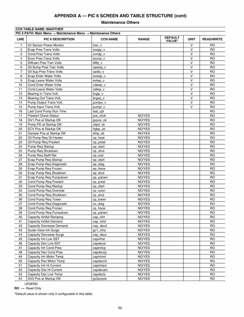
90
APPENDIX A — PIC 6 SCREEN AND TABLE STRUCTURE (cont) Maintenance Others
LEGEND
*Default value is shown only if configurable in this table.
CCN TABLE NAME: MAIOTHERPIC 6 PATH: Main Menu Maintenance Menu Maintenance Others
LINE PIC 6 DESCRIPTION CCN NAME RANGE DEFAULT VALUE* UNIT READ/WRITE
1 5V Sensor Power Monitor tran_v V RO2 Evap Pres Trans Volts evapp_v V RO3 Cond Pres Trans Volts condp_v V RO4 Econ Pres Trans Volts econp_v V RO5 Diffuser Pres Tran Volts diffp_v V RO6 Oil Sump Pres Tran Volts opsmp_v V RO7 Oil Sup Pres Trans Volts opdis_v V RO8 Evap Enter Water Volts evewp_v V RO9 Evap Leave Water Volts evlwp_v V RO
10 Cond Enter Water Volts cdewp_v V RO11 Cond Leave Water Volts cdlwp_v V RO12 Bearing In Trans Volt, brgip_v V RO13 Bearing Out Trans Volt, brgop_v V RO14 Pump Output Trans Volt, pumpo_v V RO15 Pump Input Trans Volt, pumpi_v V RO16 Last Cond Pump Run Time last_cpt RO17 Prestart Check Status pre_chck NO/YES RO18 GV1 Pos at Startup OK gvpos_ok NO/YES RO19 Pump PD at Startup OK oilpd_ok NO/YES RO20 ECV Pos at Startup OK hgbp_ok NO/YES RO21 Damper Pos at Startup OK dmp_ok NO/YES RO22 Oil Pump Req Oil Heater op_heat NO/YES RO23 Oil Pump Req Prestart op_prest NO/YES RO24 Pump Req Startup op_start NO/YES RO25 Pump Req Shutdown op_shut NO/YES RO26 Pump Req Swift Rst op_srst NO/YES RO27 Evap Pump Req Startup ep_start NO/YES RO28 Evap Pump Req Diagnostic ep_diag NO/YES RO29 Evap Pump Req Frozen ep_freze NO/YES RO30 Evap Pump Req Shutdown ep_shut NO/YES RO31 Evap Pump Req Pumpdown ep_pdown NO/YES RO32 Cond Pump Req Prestart cp_prest NO/YES RO33 Cond Pump Req Startup cp_start NO/YES RO34 Cond Pump Req Override cp_overr NO/YES RO35 Cond Pump Req Shutdown cp_shut NO/YES RO36 Cond Pump Req Tower cp_tower NO/YES RO37 Cond Pump Req Diagnostic co_diag NO/YES RO38 Cond Pump Req Frozen cp_freze NO/YES RO39 Cond Pump Req Pumpdown cp_pdown NO/YES RO40 Capacity Inhibit Ramping cap_inhr NO/YES RO41 Capacity Inhibit Demand cap_inhd NO/YES RO42 Capacity Decrease Demand cap_decd NO/YES RO43 Guide Vane Inh Surge gv1_inhs NO/YES RO44 Capacity Decrease Surge cap_decs NO/YES RO45 Capacity Inh Low SST capinhst NO/YES RO46 Capacity Dec Low SST capdecst NO/YES RO47 Capacity Inh Cond Pres capinhcp NO/YES RO48 Capacity Dec Cond Pres capdeccp NO/YES RO49 Capacity Inh Motor Temp capinhmt NO/YES RO50 Capacity Dec Motor Temp capdecmt NO/YES RO51 Capacity Inh Hi Current capinham NO/YES RO52 Capacity Dec Hi Current capdecam NO/YES RO53 Capacity Dec Low Temp capdecls NO/YES RO54 GV2 Pos at Startup OK gv2posok NO/YES RO
RO — Read Only
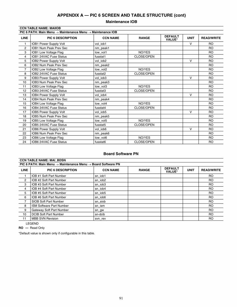
91
APPENDIX A — PIC 6 SCREEN AND TABLE STRUCTURE (cont) Maintenance IOB
Board Software PN
LEGEND
*Default value is shown only if configurable in this table.
CCN TABLE NAME: MAIIOBPIC 6 PATH: Main Menu Maintenance Menu Maintenance IOB
LINE PIC 6 DESCRIPTION CCN NAME RANGE DEFAULT VALUE* UNIT READ/WRITE
1 IOB1 Power Supply Volt vol_iob1 V RO2 IOB1 Num Peak Prev Sec nm_peak1 RO3 IOB1 Low Voltage Flag low_vol1 NO/YES RO4 IOB1 24VAC Fuse Status fusstat1 CLOSE/OPEN RO5 IOB2 Power Supply Volt vol_iob2 V RO6 IOB2 Num Peak Prev Sec nm_peak2 RO7 IOB2 Low Voltage Flag low_vol2 NO/YES RO8 IOB2 24VAC Fuse Status fusstat2 CLOSE/OPEN RO9 IOB3 Power Supply Volt vol_iob3 V RO
10 IOB3 Num Peak Prev Sec nm_peak3 RO11 IOB3 Low Voltage Flag low_vol3 NO/YES RO12 IOB3 24VAC Fuse Status fusstat3 CLOSE/OPEN RO13 IOB4 Power Supply Volt vol_iob4 V RO14 IOB4 Num Peak Prev Sec nm_peak4 RO15 IOB4 Low Voltage Flag low_vol4 NO/YES RO16 IOB4 24VAC Fuse Status fusstat4 CLOSE/OPEN RO17 IOB5 Power Supply Volt vol_iob5 V RO18 IOB5 Num Peak Prev Sec nm_peak5 RO19 IOB5 Low Voltage Flag low_vol5 NO/YES RO20 IOB5 24VAC Fuse Status fusstat5 CLOSE/OPEN RO21 IOB6 Power Supply Volt vol_iob6 V RO22 IOB6 Num Peak Prev Sec nm_peak6 RO23 IOB6 Low Voltage Flag low_vol6 NO/YES RO24 IOB6 24VAC Fuse Status fusstat6 CLOSE/OPEN RO
CCN TABLE NAME: MAI_BDSNPIC 6 PATH: Main Menu Maintenance Menu Board Software PN
LINE PIC 6 DESCRIPTION CCN NAME RANGE DEFAULT VALUE* UNIT READ/WRITE
1 IOB #1 Soft Part Number sn_iob1 RO2 IOB #2 Soft Part Number sn_iob2 RO3 IOB #3 Soft Part Number sn_iob3 RO4 IOB #4 Soft Part Number sn_iob4 RO5 IOB #5 Soft Part Number sn_iob5 RO6 IOB #6 Soft Part Number sn_iob6 RO7 SIOB Soft Part Number sn_siob RO8 ISM Software Part Number sn_ism RO9 Gateway Soft Part Number sn_gw RO
10 DCIB Soft Part Number sn-dcib RO11 MBB SVN Revision svn_rev RO
RO — Read Only
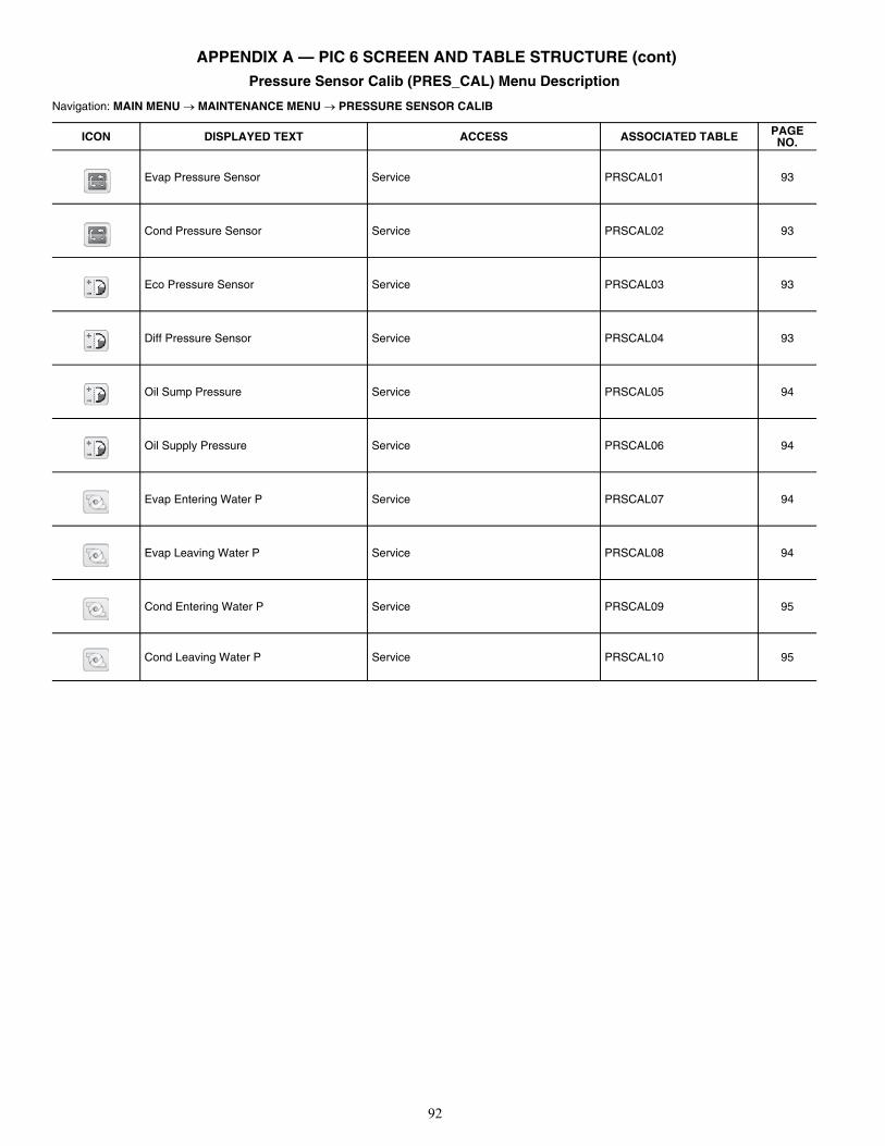
92
APPENDIX A — PIC 6 SCREEN AND TABLE STRUCTURE (cont)Pressure Sensor Calib (PRES_CAL) Menu Description
Navigation: MAIN MENU MAINTENANCE MENU PRESSURE SENSOR CALIB
ICON DISPLAYED TEXT ACCESS ASSOCIATED TABLE PAGE NO.
Evap Pressure Sensor Service PRSCAL01 93
Cond Pressure Sensor Service PRSCAL02 93
Eco Pressure Sensor Service PRSCAL03 93
Diff Pressure Sensor Service PRSCAL04 93
Oil Sump Pressure Service PRSCAL05 94
Oil Supply Pressure Service PRSCAL06 94
Evap Entering Water P Service PRSCAL07 94
Evap Leaving Water P Service PRSCAL08 94
Cond Entering Water P Service PRSCAL09 95
Cond Leaving Water P Service PRSCAL10 95
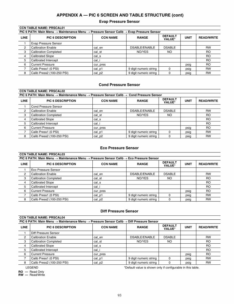
93
APPENDIX A — PIC 6 SCREEN AND TABLE STRUCTURE (cont)Evap Pressure Sensor
Cond Pressure Sensor
Eco Pressure Sensor
Diff Pressure Sensor
LEGEND *Default value is shown only if configurable in this table.
CCN TABLE NAME: PRSCAL01PIC 6 PATH: Main Menu Maintenance Menu Pressure Sensor Calib Evap Pressure Sensor
LINE PIC 6 DESCRIPTION CCN NAME RANGE DEFAULT VALUE* UNIT READ/WRITE
1 Evap Pressure Sensor2 Calibration Enable cal_en DSABLE/ENABLE DSABLE RW3 Calibration Completed cal_st NO/YES NO RO4 Calibrated Slope cal_s RO5 Calibrated Intercept cal_i RO6 Current Pressure cur_pres psig RO7 Calib Press1 (0 PSI) cal_p1 9 digit numeric string 0 psig RW8 Calib Press2 (100-250 PSI) cal_p2 9 digit numeric string 0 psig RW
CCN TABLE NAME: PRSCAL02PIC 6 PATH: Main Menu Maintenance Menu Pressure Sensor Calib Cond Pressure Sensor
LINE PIC 6 DESCRIPTION CCN NAME RANGE DEFAULT VALUE* UNIT READ/WRITE
1 Cond Pressure Sensor2 Calibration Enable cal_en DSABLE/ENABLE DSABLE RW3 Calibration Completed cal_st NO/YES NO RO4 Calibrated Slope cal_s RO5 Calibrated Intercept cal_i RO6 Current Pressure cur_pres psig RO7 Calib Press1 (0 PSI) cal_p1 9 digit numeric string 0 psig RW8 Calib Press2 (100-250 PSI) cal_p2 9 digit numeric string 0 psig RW
CCN TABLE NAME: PRSCAL03PIC 6 PATH: Main Menu Maintenance Menu Pressure Sensor Calib Eco Pressure Sensor
LINE PIC 6 DESCRIPTION CCN NAME RANGE DEFAULT VALUE* UNIT READ/WRITE
1 Eco Pressure Sensor2 Calibration Enable cal_en DSABLE/ENABLE DSABLE RW3 Calibration Completed cal_st NO/YES NO RO4 Calibrated Slope cal_s RO5 Calibrated Intercept cal_i RO6 Current Pressure cur_pres psig RO7 Calib Press1 (0 PSI) cal_p1 9 digit numeric string 0 psig RW8 Calib Press2 (100-250 PSI) cal_p2 9 digit numeric string 0 psig RW
CCN TABLE NAME: PRSCAL04PIC 6 PATH: Main Menu Maintenance Menu Pressure Sensor Calib Diff Pressure Sensor
LINE PIC 6 DESCRIPTION CCN NAME RANGE DEFAULT VALUE* UNIT READ/WRITE
1 Diff Pressure Sensor2 Calibration Enable cal_en DSABLE/ENABLE DSABLE RW3 Calibration Completed cal_st NO/YES NO RO4 Calibrated Slope cal_s RO5 Calibrated Intercept cal_i RO6 Current Pressure cur_pres psig RO7 Calib Press1 (0 PSI) cal_p1 9 digit numeric string 0 psig RW8 Calib Press2 (100-250 PSI) cal_p2 9 digit numeric string 0 psig RW
RO — Read OnlyRW — Read/Write
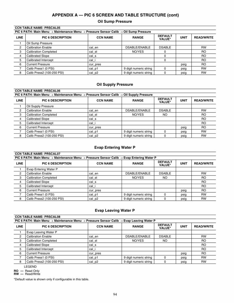
94
APPENDIX A — PIC 6 SCREEN AND TABLE STRUCTURE (cont)Oil Sump Pressure
Oil Supply Pressure
Evap Entering Water P
Evap Leaving Water P
LEGEND
*Default value is shown only if configurable in this table.
CCN TABLE NAME: PRSCAL05PIC 6 PATH: Main Menu Maintenance Menu Pressure Sensor Calib Oil Sump Pressure
LINE PIC 6 DESCRIPTION CCN NAME RANGE DEFAULT VALUE* UNIT READ/WRITE
1 Oil Sump Pressure2 Calibration Enable cal_en DSABLE/ENABLE DSABLE RW3 Calibration Completed cal_st NO/YES 0 RO4 Calibrated Slope cal_s 0 RO5 Calibrated Intercept cal_i 0 RO6 Current Pressure cur_pres psig RO7 Calib Press1 (0 PSI) cal_p1 9 digit numeric string 0 psig RW8 Calib Press2 (100-250 PSI) cal_p2 9 digit numeric string 0 psig RW
CCN TABLE NAME: PRSCAL06PIC 6 PATH: Main Menu Maintenance Menu Pressure Sensor Calib Oil Supply Pressure
LINE PIC 6 DESCRIPTION CCN NAME RANGE DEFAULT VALUE* UNIT READ/WRITE
1 Oil Supply Pressure2 Calibration Enable cal_en DSABLE/ENABLE DSABLE RW3 Calibration Completed cal_st NO/YES NO RO4 Calibrated Slope cal_s RO5 Calibrated Intercept cal_i RO6 Current Pressure cur_pres psig RO7 Calib Press1 (0 PSI) cal_p1 9 digit numeric string 0 psig RW8 Calib Press2 (100-250 PSI) cal_p2 9 digit numeric string 0 psig RW
CCN TABLE NAME: PRSCAL07PIC 6 PATH: Main Menu Maintenance Menu Pressure Sensor Calib Evap Entering Water P
LINE PIC 6 DESCRIPTION CCN NAME RANGE DEFAULT VALUE* UNIT READ/WRITE
1 Evap Entering Water P2 Calibration Enable cal_en DSABLE/ENABLE DSABLE RW3 Calibration Completed cal_st NO/YES NO RO4 Calibrated Slope cal_s RO5 Calibrated Intercept cal_i RO6 Current Pressure cur_pres psig RO7 Calib Press1 (0 PSI) cal_p1 9 digit numeric string 0 psig RW8 Calib Press2 (100-250 PSI) cal_p2 9 digit numeric string 0 psig RW
CCN TABLE NAME: PRSCAL08PIC 6 PATH: Main Menu Maintenance Menu Pressure Sensor Calib Evap Leaving Water P
LINE PIC 6 DESCRIPTION CCN NAME RANGE DEFAULT VALUE* UNIT READ/WRITE
1 Evap Leaving Water P2 Calibration Enable cal_en DSABLE/ENABLE DSABLE RW3 Calibration Completed cal_st NO/YES NO RO4 Calibrated Slope cal_s RO5 Calibrated Intercept cal_i RO6 Current Pressure cur_pres psig RO7 Calib Press1 (0 PSI) cal_p1 9 digit numeric string 0 psig RW8 Calib Press2 (100-250 PSI) cal_p2 9 digit numeric string 0 psig RW
RO — Read OnlyRW — Read/Write
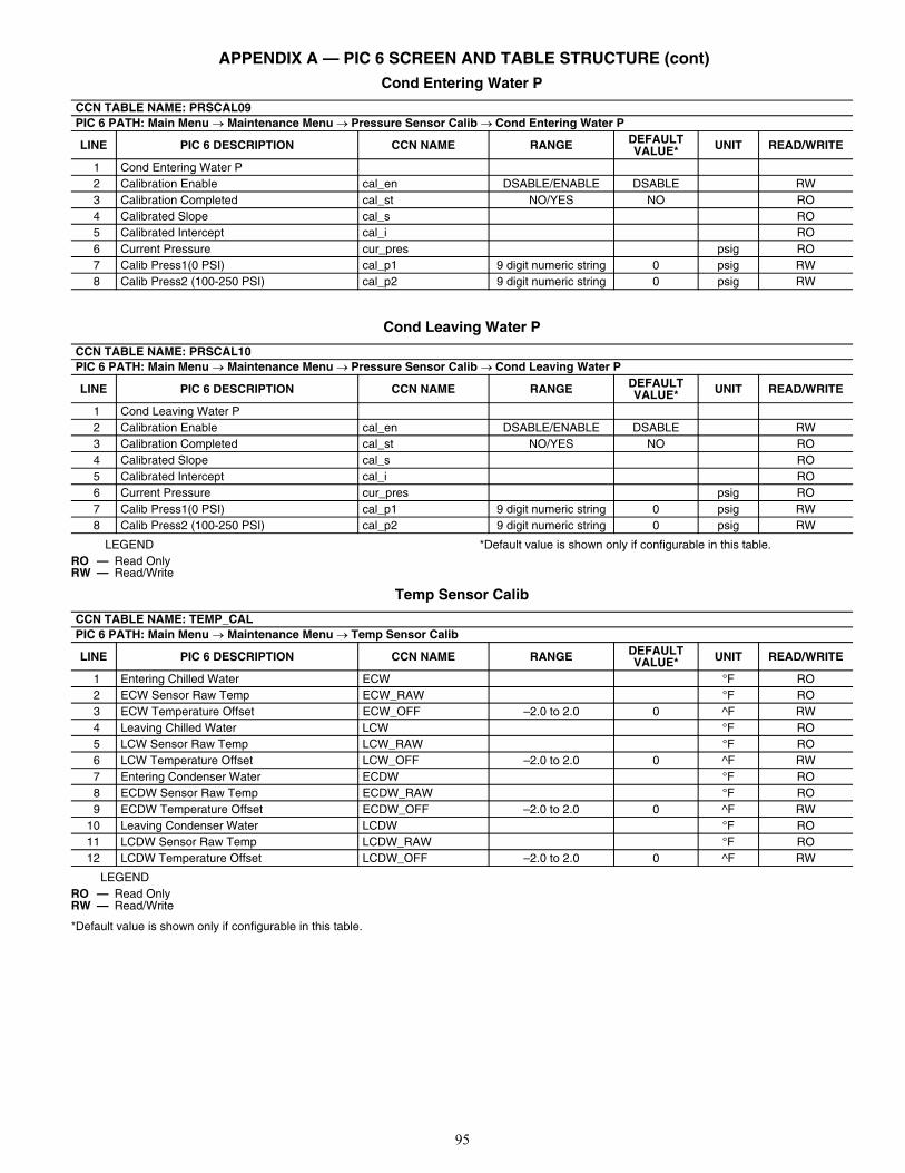
95
APPENDIX A — PIC 6 SCREEN AND TABLE STRUCTURE (cont)Cond Entering Water P
Cond Leaving Water P
LEGEND *Default value is shown only if configurable in this table.
Temp Sensor Calib
LEGEND
*Default value is shown only if configurable in this table.
CCN TABLE NAME: PRSCAL09PIC 6 PATH: Main Menu Maintenance Menu Pressure Sensor Calib Cond Entering Water P
LINE PIC 6 DESCRIPTION CCN NAME RANGE DEFAULT VALUE* UNIT READ/WRITE
1 Cond Entering Water P2 Calibration Enable cal_en DSABLE/ENABLE DSABLE RW3 Calibration Completed cal_st NO/YES NO RO4 Calibrated Slope cal_s RO5 Calibrated Intercept cal_i RO6 Current Pressure cur_pres psig RO7 Calib Press1(0 PSI) cal_p1 9 digit numeric string 0 psig RW8 Calib Press2 (100-250 PSI) cal_p2 9 digit numeric string 0 psig RW
CCN TABLE NAME: PRSCAL10PIC 6 PATH: Main Menu Maintenance Menu Pressure Sensor Calib Cond Leaving Water P
LINE PIC 6 DESCRIPTION CCN NAME RANGE DEFAULT VALUE* UNIT READ/WRITE
1 Cond Leaving Water P2 Calibration Enable cal_en DSABLE/ENABLE DSABLE RW3 Calibration Completed cal_st NO/YES NO RO4 Calibrated Slope cal_s RO5 Calibrated Intercept cal_i RO6 Current Pressure cur_pres psig RO7 Calib Press1(0 PSI) cal_p1 9 digit numeric string 0 psig RW8 Calib Press2 (100-250 PSI) cal_p2 9 digit numeric string 0 psig RW
RO — Read OnlyRW — Read/Write
CCN TABLE NAME: TEMP_CALPIC 6 PATH: Main Menu Maintenance Menu Temp Sensor Calib
LINE PIC 6 DESCRIPTION CCN NAME RANGE DEFAULT VALUE* UNIT READ/WRITE
1 Entering Chilled Water ECW °F RO2 ECW Sensor Raw Temp ECW_RAW °F RO3 ECW Temperature Offset ECW_OFF –2.0 to 2.0 0 ^F RW4 Leaving Chilled Water LCW °F RO5 LCW Sensor Raw Temp LCW_RAW °F RO6 LCW Temperature Offset LCW_OFF –2.0 to 2.0 0 ^F RW7 Entering Condenser Water ECDW °F RO8 ECDW Sensor Raw Temp ECDW_RAW °F RO9 ECDW Temperature Offset ECDW_OFF –2.0 to 2.0 0 ^F RW
10 Leaving Condenser Water LCDW °F RO11 LCDW Sensor Raw Temp LCDW_RAW °F RO12 LCDW Temperature Offset LCDW_OFF –2.0 to 2.0 0 ^F RW
RO — Read OnlyRW — Read/Write
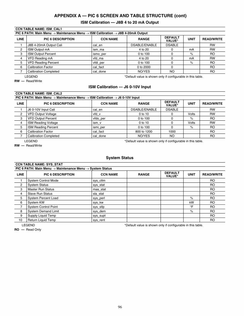
96
APPENDIX A — PIC 6 SCREEN AND TABLE STRUCTURE (cont)ISM Calibration — J8B 4 to 20 mA Output
LEGEND *Default value is shown only if configurable in this table.
ISM Calibration — J6 0-10V Input
LEGEND *Default value is shown only if configurable in this table.
System Status
LEGEND *Default value is shown only if configurable in this table.
CCN TABLE NAME: ISM_CAL1PIC 6 PATH: Main Menu Maintenance Menu ISM Calibration J8B 4-20mA Output
LINE PIC 6 DESCRIPTION CCN NAME RANGE DEFAULT VALUE* UNIT READ/WRITE
1 J8B 4-20mA Output Cali cal_en DSABLE/ENABLE DSABLE RW2 ISM Output mA ism_ma 4 to 20 0 mA RW3 ISM Output Percent ismo_per 0 to 100 0 % RO4 VFD Reading mA vfd_ma 4 to 20 0 mA RW5 VFD Reading Percent vfdi_per 0 to 100 0 % RO6 Calibration Factor cal_fact 0 to 2000 0 RO7 Calibration Completed cal_done NO/YES NO RO
RW — Read/Write
CCN TABLE NAME: ISM_CAL2PIC 6 PATH: Main Menu Maintenance Menu ISM Calibration J6 0-10V Input
LINE PIC 6 DESCRIPTION CCN NAME RANGE DEFAULT VALUE* UNIT READ/WRITE
1 J6 0-10V Input Cali cal_en DSABLE/ENABLE DSABLE RW2 VFD Output Voltage vfd_v 0 to 10 0 Volts RW3 VFD Output Percent vfdo_per 0 to 100 0 % RO4 ISM Reading Voltage ism_v 0 to 10 0 Volts RW5 ISM Reading Percent ismi_per 0 to 100 0 % RO6 Calibration Factor cal_fact 800 to 1200 1000 RO7 Calibration Completed cal_done NO/YES NO RO
RW — Read/Write
CCN TABLE NAME: SYS_STATPIC 6 PATH: Main Menu Maintenance Menu System Status
LINE PIC 6 DESCRIPTION CCN NAME RANGE DEFAULT VALUE* UNIT READ/WRITE
1 System Control Mode sys_ctlm RO2 System Status sys_stat RO3 Master Run Status mas_stat RO4 Slave Run Status sla_stat RO5 System Percent Load sys_perl % RO6 System KW sys_kw kW RO7 System Control Point sys_stlp °F RO8 System Demand Limit sys_dem % RO9 Supply Liquid Temp sys_supt RO
10 Return Liquid Temp sys_rent RO
RO — Read Only
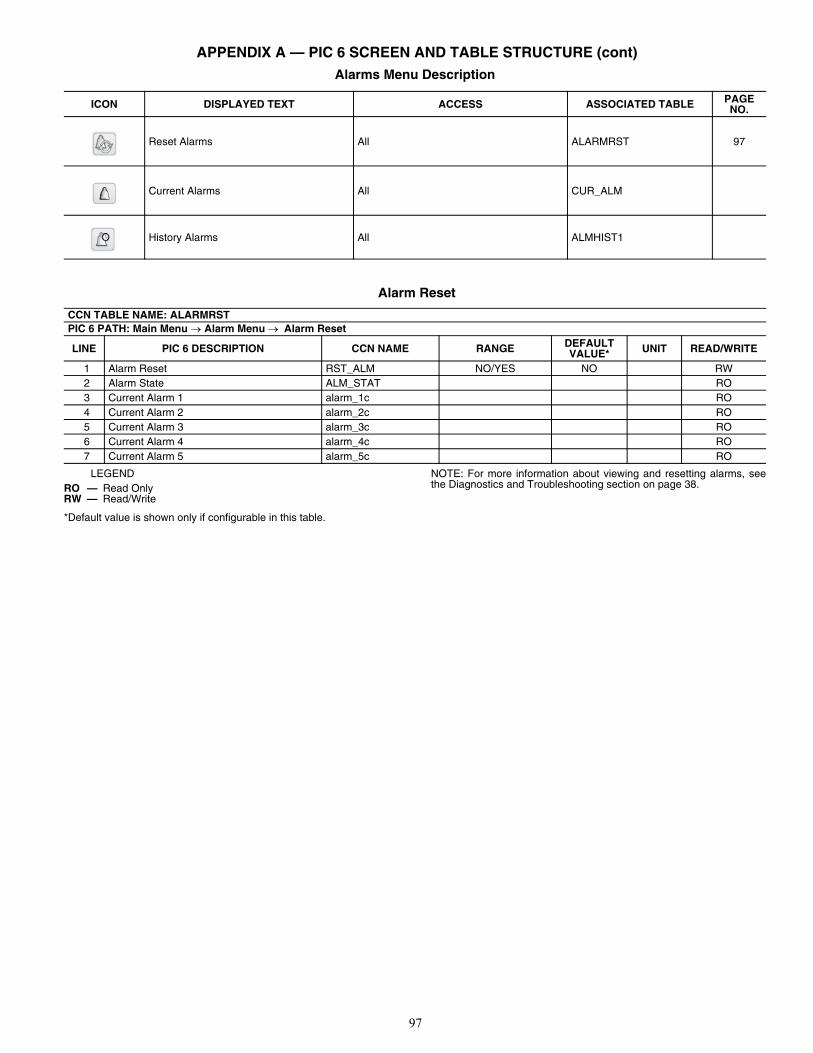
97
APPENDIX A — PIC 6 SCREEN AND TABLE STRUCTURE (cont)Alarms Menu Description
Alarm Reset
LEGEND
*Default value is shown only if configurable in this table.
NOTE: For more information about viewing and resetting alarms, seethe Diagnostics and Troubleshooting section on page 38.
ICON DISPLAYED TEXT ACCESS ASSOCIATED TABLE PAGE NO.
Reset Alarms All ALARMRST 97
Current Alarms All CUR_ALM
History Alarms All ALMHIST1
CCN TABLE NAME: ALARMRSTPIC 6 PATH: Main Menu Alarm Menu Alarm Reset
LINE PIC 6 DESCRIPTION CCN NAME RANGE DEFAULT VALUE* UNIT READ/WRITE
1 Alarm Reset RST_ALM NO/YES NO RW2 Alarm State ALM_STAT RO3 Current Alarm 1 alarm_1c RO4 Current Alarm 2 alarm_2c RO5 Current Alarm 3 alarm_3c RO6 Current Alarm 4 alarm_4c RO7 Current Alarm 5 alarm_5c RO
RO — Read OnlyRW — Read/Write
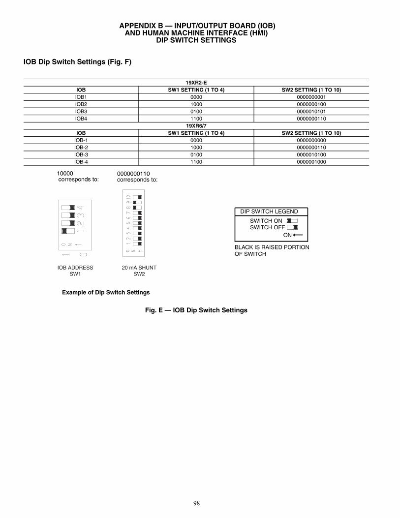
98
APPENDIX B — INPUT/OUTPUT BOARD (IOB) AND HUMAN MACHINE INTERFACE (HMI)
DIP SWITCH SETTINGS
IOB Dip Switch Settings (Fig. F)
Fig. E — IOB Dip Switch Settings
19XR2-EIOB SW1 SETTING (1 TO 4) SW2 SETTING (1 TO 10)IOB1 0000 0000000001IOB2 1000 0000000100IOB3 0100 0000010101IOB4 1100 0000000110
19XR6/7IOB SW1 SETTING (1 TO 4) SW2 SETTING (1 TO 10)
IOB-1 0000 0000000000IOB-2 1000 0000000110IOB-3 0100 0000010100IOB-4 1100 0000001000
IOB ADDRESSSW1
20 mA SHUNTSW2
Example of Dip Switch Settings
a19-2134
0000000110corresponds to:
10000 corresponds to:
DIP SWITCH LEGEND
SWITCH ONSWITCH OFF
BLACK IS RAISED PORTIONOF SWITCH
ON
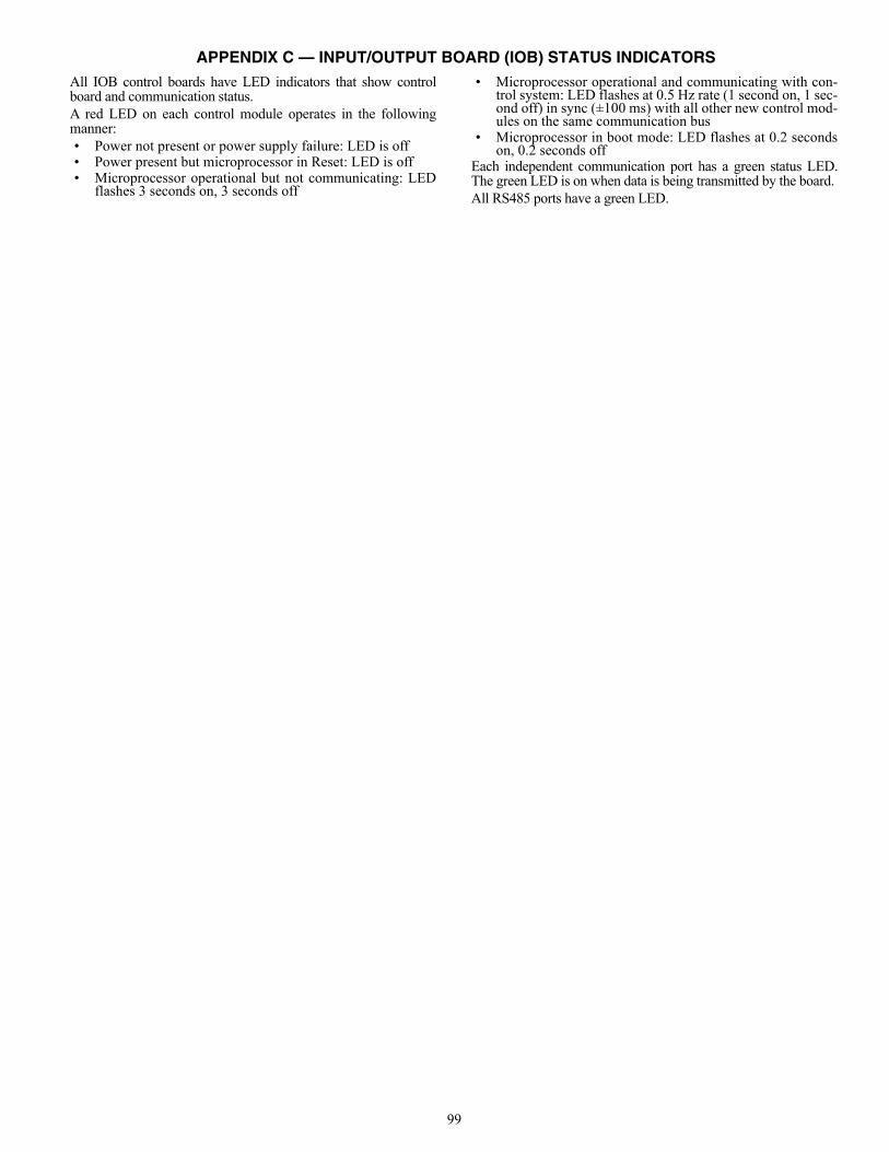
99
APPENDIX C — INPUT/OUTPUT BOARD (IOB) STATUS INDICATORSAll IOB control boards have LED indicators that show controlboard and communication status.A red LED on each control module operates in the followingmanner:• Power not present or power supply failure: LED is off• Power present but microprocessor in Reset: LED is off• Microprocessor operational but not communicating: LED
flashes 3 seconds on, 3 seconds off
• Microprocessor operational and communicating with con-trol system: LED flashes at 0.5 Hz rate (1 second on, 1 sec-ond off) in sync (±100 ms) with all other new control mod-ules on the same communication bus
• Microprocessor in boot mode: LED flashes at 0.2 secondson, 0.2 seconds off
Each independent communication port has a green status LED.The green LED is on when data is being transmitted by the board. All RS485 ports have a green LED.
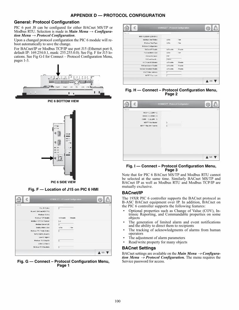
100
APPENDIX D — PROTOCOL CONFIGURATION
General: Protocol ConfigurationPIC 6 port J8 can be configured for either BACnet MS/TP orModbus RTU. Selection is made in Main Menu → Configura-tion Menu → Protocol Configuration. Upon a changed protocol configuration the PIC 6 module will re-boot automatically to save the change.For BACnet/IP or Modbus TCP/IP use port J15 (Ethernet port 0,default IP: 169.254.0.1, mask: 255.255.0.0). See Fig. F for J15 lo-cations. See Fig G-I for Connect – Protocol Configuration Menu,pages 1-3.
Fig. F — Location of J15 on PIC 6 HMI
Fig. G — Connect – Protocol Configuration Menu, Page 1
Fig. H — Connect – Protocol Configuration Menu, Page 2
Fig. I — Connect – Protocol Configuration Menu, Page 3
Note that for PIC 6 BACnet MS/TP and Modbus RTU cannotbe selected at the same time. Similarly BACnet MS/TP andBACnet IP as well as Modbus RTU and Modbus TCP/IP aremutually exclusive.
BACnet/IPThe 19XR PIC 6 controller supports the BACnet protocol asB-ASC BACnet equipment over IP. In addition, BACnet onthe PIC 6 controller supports the following features:• Optional properties such as Change of Value (COV), In-
trinsic Reporting, and Commandable properties on someobjects
• The generation of limited alarm and event notificationsand the ability to direct them to recipients
• The tracking of acknowledgments of alarms from humanoperators
• The adjustment of alarm parameters • Read/write property for many objects
BACnet SettingsBACnet settings are available on the Main Menu Configura-tion Menu Protocol Configuration. The menu requires theService password for access.
PIC 6 SIDE VIEW
PIC 6 BOTTOM VIEW
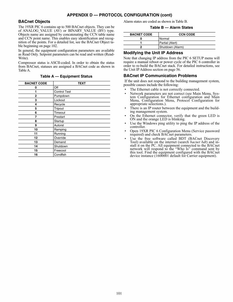
101
APPENDIX D — PROTOCOL CONFIGURATION (cont)
BACnet Objects The 19XR PIC 6 contains up to 500 BACnet objects. They can beof ANALOG_VALUE (AV) or BINARY_VALUE (BV) type.Objects name are assigned by concatenating the CCN table nameand CCN point name. This enables easy identification and recog-nition of the points. For a detailed list, see the BACnet Object ta-ble beginning on page 102.In general, the equipment configuration parameters are availableas Read Only. Setpoint parameters can be read and written (Read-Write).Compressor status is ASCII-coded. In order to obtain the statusfrom BACnet, statuses are assigned a BACnet code as shown inTable A.
Table A — Equipment Status
Alarm states are coded as shown in Table B.
Table B — Alarm States
Modifying the Unit IP AddressNote that changing IP address from the PIC 6 SETUP menu willrequire a manual reboot or power cycle of the PIC 6 controller inorder to re-build the BACnet stack. For detailed instructions, seethe Unit IP Address section on page 56.
BACnet IP Communication Problems If the unit does not respond to the building management system,possible causes include the following:• The Ethernet cable is not correctly connected.• Network parameters are not correct (see Main Menu, Sys-
tem Configuration for Ethernet configuration and MainMenu, Configuration Menu, Protocol Configuration forappropriate selections.).
• There is an IP router between the equipment and the build-ing management system.
• On the Ethernet connector, verify that the green LED isON and the orange LED is blinking.
• Use the Windows ping utility to ping the IP address of thecontroller.
• Open 19XR PIC 6 Configuration Menu (Service passwordrequired) and check BACnet parameters.
• Use the free software called BDT (BACnet DiscoveryTool) available on the internet (search bacnet bdt) and in-stall it on the PC. All equipment connected to the BACnetnetwork will respond to the “Who Is” command sent bythis tool. Find the equipment configured with the BACnetdevice instance (1600001 default for Carrier equipment).
BACNET CODE TEXT0 Off1 Control Test2 Pumpdown3 Lockout4 Recycle5 Tripout6 Timeout7 Prestart8 Startup9 Autorst
10 Ramping11 Running12 Override13 Demand14 Shutdown15 Freecool16 Condflsh
BACNET CODE CCN CODE0 Normal1 Partial (Alert)2 Shutdown (Alarm)
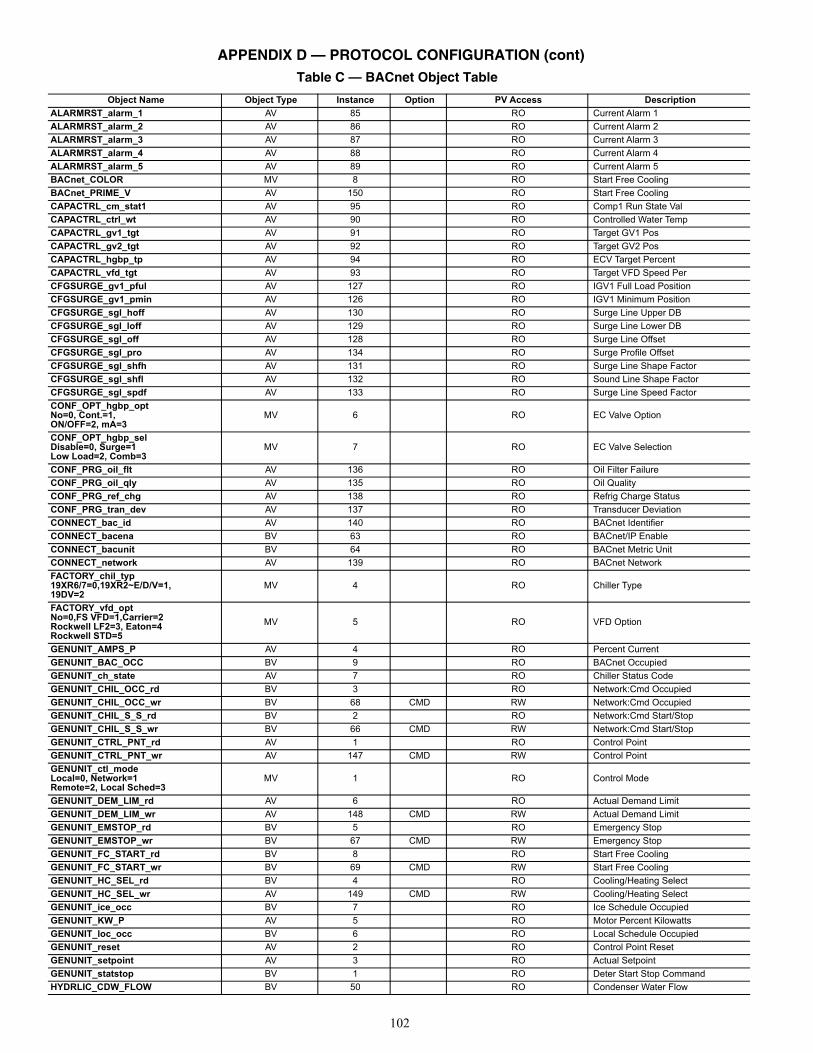
102
APPENDIX D — PROTOCOL CONFIGURATION (cont)
Table C — BACnet Object Table
Object Name Object Type Instance Option PV Access Description
ALARMRST_alarm_1 AV 85 RO Current Alarm 1
ALARMRST_alarm_2 AV 86 RO Current Alarm 2
ALARMRST_alarm_3 AV 87 RO Current Alarm 3
ALARMRST_alarm_4 AV 88 RO Current Alarm 4
ALARMRST_alarm_5 AV 89 RO Current Alarm 5
BACnet_COLOR MV 8 RO Start Free Cooling
BACnet_PRIME_V AV 150 RO Start Free Cooling
CAPACTRL_cm_stat1 AV 95 RO Comp1 Run State Val
CAPACTRL_ctrl_wt AV 90 RO Controlled Water Temp
CAPACTRL_gv1_tgt AV 91 RO Target GV1 Pos
CAPACTRL_gv2_tgt AV 92 RO Target GV2 Pos
CAPACTRL_hgbp_tp AV 94 RO ECV Target Percent
CAPACTRL_vfd_tgt AV 93 RO Target VFD Speed Per
CFGSURGE_gv1_pful AV 127 RO IGV1 Full Load Position
CFGSURGE_gv1_pmin AV 126 RO IGV1 Minimum Position
CFGSURGE_sgl_hoff AV 130 RO Surge Line Upper DB
CFGSURGE_sgl_loff AV 129 RO Surge Line Lower DB
CFGSURGE_sgl_off AV 128 RO Surge Line Offset
CFGSURGE_sgl_pro AV 134 RO Surge Profile Offset
CFGSURGE_sgl_shfh AV 131 RO Surge Line Shape Factor
CFGSURGE_sgl_shfl AV 132 RO Sound Line Shape Factor
CFGSURGE_sgl_spdf AV 133 RO Surge Line Speed Factor
CONF_OPT_hgbp_optNo=0, Cont.=1,ON/OFF=2, mA=3
MV 6 RO EC Valve Option
CONF_OPT_hgbp_selDisable=0, Surge=1Low Load=2, Comb=3
MV 7 RO EC Valve Selection
CONF_PRG_oil_flt AV 136 RO Oil Filter Failure
CONF_PRG_oil_qly AV 135 RO Oil Quality
CONF_PRG_ref_chg AV 138 RO Refrig Charge Status
CONF_PRG_tran_dev AV 137 RO Transducer Deviation
CONNECT_bac_id AV 140 RO BACnet Identifier
CONNECT_bacena BV 63 RO BACnet/IP Enable
CONNECT_bacunit BV 64 RO BACnet Metric Unit
CONNECT_network AV 139 RO BACnet Network
FACTORY_chil_typ19XR6/7=0,19XR2~E/D/V=1,19DV=2
MV 4 RO Chiller Type
FACTORY_vfd_optNo=0,FS VFD=1,Carrier=2Rockwell LF2=3, Eaton=4Rockwell STD=5
MV 5 RO VFD Option
GENUNIT_AMPS_P AV 4 RO Percent Current
GENUNIT_BAC_OCC BV 9 RO BACnet Occupied
GENUNIT_ch_state AV 7 RO Chiller Status Code
GENUNIT_CHIL_OCC_rd BV 3 RO Network:Cmd Occupied
GENUNIT_CHIL_OCC_wr BV 68 CMD RW Network:Cmd Occupied
GENUNIT_CHIL_S_S_rd BV 2 RO Network:Cmd Start/Stop
GENUNIT_CHIL_S_S_wr BV 66 CMD RW Network:Cmd Start/Stop
GENUNIT_CTRL_PNT_rd AV 1 RO Control Point
GENUNIT_CTRL_PNT_wr AV 147 CMD RW Control Point
GENUNIT_ctl_modeLocal=0, Network=1Remote=2, Local Sched=3
MV 1 RO Control Mode
GENUNIT_DEM_LIM_rd AV 6 RO Actual Demand Limit
GENUNIT_DEM_LIM_wr AV 148 CMD RW Actual Demand Limit
GENUNIT_EMSTOP_rd BV 5 RO Emergency Stop
GENUNIT_EMSTOP_wr BV 67 CMD RW Emergency Stop
GENUNIT_FC_START_rd BV 8 RO Start Free Cooling
GENUNIT_FC_START_wr BV 69 CMD RW Start Free Cooling
GENUNIT_HC_SEL_rd BV 4 RO Cooling/Heating Select
GENUNIT_HC_SEL_wr AV 149 CMD RW Cooling/Heating Select
GENUNIT_ice_occ BV 7 RO Ice Schedule Occupied
GENUNIT_KW_P AV 5 RO Motor Percent Kilowatts
GENUNIT_loc_occ BV 6 RO Local Schedule Occupied
GENUNIT_reset AV 2 RO Control Point Reset
GENUNIT_setpoint AV 3 RO Actual Setpoint
GENUNIT_statstop BV 1 RO Deter Start Stop Command
HYDRLIC_CDW_FLOW BV 50 RO Condenser Water Flow
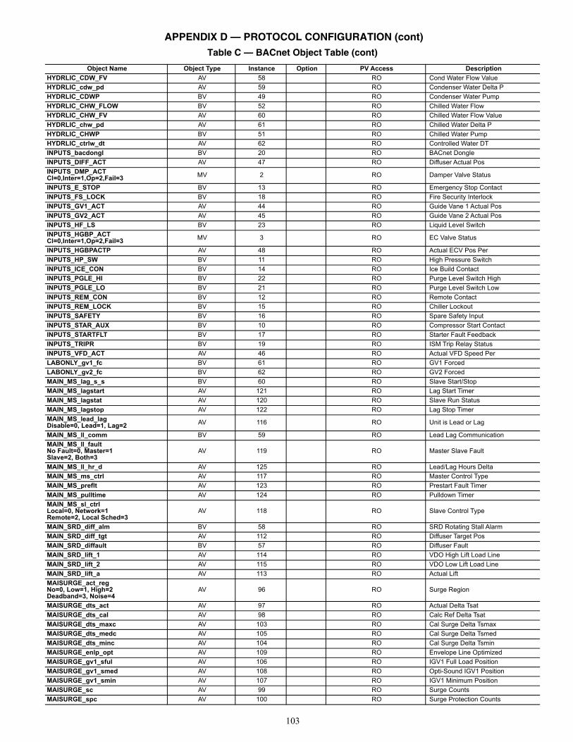
103
HYDRLIC_CDW_FV AV 58 RO Cond Water Flow Value
HYDRLIC_cdw_pd AV 59 RO Condenser Water Delta P
HYDRLIC_CDWP BV 49 RO Condenser Water Pump
HYDRLIC_CHW_FLOW BV 52 RO Chilled Water Flow
HYDRLIC_CHW_FV AV 60 RO Chilled Water Flow Value
HYDRLIC_chw_pd AV 61 RO Chilled Water Delta P
HYDRLIC_CHWP BV 51 RO Chilled Water Pump
HYDRLIC_ctrlw_dt AV 62 RO Controlled Water DT
INPUTS_bacdongl BV 20 RO BACnet Dongle
INPUTS_DIFF_ACT AV 47 RO Diffuser Actual Pos
INPUTS_DMP_ACTCl=0,Inter=1,Op=2,Fail=3 MV 2 RO Damper Valve Status
INPUTS_E_STOP BV 13 RO Emergency Stop Contact
INPUTS_FS_LOCK BV 18 RO Fire Security Interlock
INPUTS_GV1_ACT AV 44 RO Guide Vane 1 Actual Pos
INPUTS_GV2_ACT AV 45 RO Guide Vane 2 Actual Pos
INPUTS_HF_LS BV 23 RO Liquid Level Switch
INPUTS_HGBP_ACTCl=0,Inter=1,Op=2,Fail=3 MV 3 RO EC Valve Status
INPUTS_HGBPACTP AV 48 RO Actual ECV Pos Per
INPUTS_HP_SW BV 11 RO High Pressure Switch
INPUTS_ICE_CON BV 14 RO Ice Build Contact
INPUTS_PGLE_HI BV 22 RO Purge Level Switch High
INPUTS_PGLE_LO BV 21 RO Purge Level Switch Low
INPUTS_REM_CON BV 12 RO Remote Contact
INPUTS_REM_LOCK BV 15 RO Chiller Lockout
INPUTS_SAFETY BV 16 RO Spare Safety Input
INPUTS_STAR_AUX BV 10 RO Compressor Start Contact
INPUTS_STARTFLT BV 17 RO Starter Fault Feedback
INPUTS_TRIPR BV 19 RO ISM Trip Relay Status
INPUTS_VFD_ACT AV 46 RO Actual VFD Speed Per
LABONLY_gv1_fc BV 61 RO GV1 Forced
LABONLY_gv2_fc BV 62 RO GV2 Forced
MAIN_MS_lag_s_s BV 60 RO Slave Start/Stop
MAIN_MS_lagstart AV 121 RO Lag Start Timer
MAIN_MS_lagstat AV 120 RO Slave Run Status
MAIN_MS_lagstop AV 122 RO Lag Stop Timer
MAIN_MS_lead_lagDisable=0, Lead=1, Lag=2 AV 116 RO Unit is Lead or Lag
MAIN_MS_ll_comm BV 59 RO Lead Lag Communication
MAIN_MS_ll_faultNo Fault=0, Master=1Slave=2, Both=3
AV 119 RO Master Slave Fault
MAIN_MS_ll_hr_d AV 125 RO Lead/Lag Hours Delta
MAIN_MS_ms_ctrl AV 117 RO Master Control Type
MAIN_MS_preflt AV 123 RO Prestart Fault Timer
MAIN_MS_pulltime AV 124 RO Pulldown Timer
MAIN_MS_sl_ctrlLocal=0, Network=1Remote=2, Local Sched=3
AV 118 RO Slave Control Type
MAIN_SRD_diff_alm BV 58 RO SRD Rotating Stall Alarm
MAIN_SRD_diff_tgt AV 112 RO Diffuser Target Pos
MAIN_SRD_diffault BV 57 RO Diffuser Fault
MAIN_SRD_lift_1 AV 114 RO VDO High Lift Load Line
MAIN_SRD_lift_2 AV 115 RO VDO Low Lift Load Line
MAIN_SRD_lift_a AV 113 RO Actual Lift
MAISURGE_act_regNo=0, Low=1, High=2Deadband=3, Noise=4
AV 96 RO Surge Region
MAISURGE_dts_act AV 97 RO Actual Delta Tsat
MAISURGE_dts_cal AV 98 RO Calc Ref Delta Tsat
MAISURGE_dts_maxc AV 103 RO Cal Surge Delta Tsmax
MAISURGE_dts_medc AV 105 RO Cal Surge Delta Tsmed
MAISURGE_dts_minc AV 104 RO Cal Surge Delta Tsmin
MAISURGE_enlp_opt AV 109 RO Envelope Line Optimized
MAISURGE_gv1_sful AV 106 RO IGV1 Full Load Position
MAISURGE_gv1_smed AV 108 RO Opti-Sound IGV1 Position
MAISURGE_gv1_smin AV 107 RO IGV1 Minimum Position
MAISURGE_sc AV 99 RO Surge Counts
MAISURGE_spc AV 100 RO Surge Protection Counts
APPENDIX D — PROTOCOL CONFIGURATION (cont)Table C — BACnet Object Table (cont)
Object Name Object Type Instance Option PV Access Description
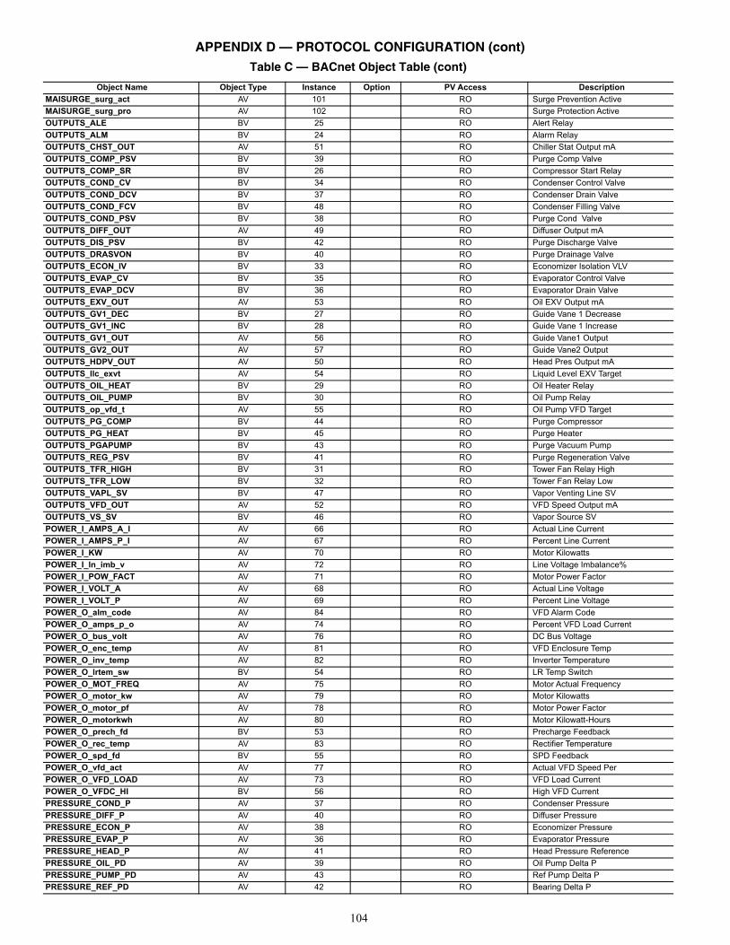
104
MAISURGE_surg_act AV 101 RO Surge Prevention Active
MAISURGE_surg_pro AV 102 RO Surge Protection Active
OUTPUTS_ALE BV 25 RO Alert Relay
OUTPUTS_ALM BV 24 RO Alarm Relay
OUTPUTS_CHST_OUT AV 51 RO Chiller Stat Output mA
OUTPUTS_COMP_PSV BV 39 RO Purge Comp Valve
OUTPUTS_COMP_SR BV 26 RO Compressor Start Relay
OUTPUTS_COND_CV BV 34 RO Condenser Control Valve
OUTPUTS_COND_DCV BV 37 RO Condenser Drain Valve
OUTPUTS_COND_FCV BV 48 RO Condenser Filling Valve
OUTPUTS_COND_PSV BV 38 RO Purge Cond Valve
OUTPUTS_DIFF_OUT AV 49 RO Diffuser Output mA
OUTPUTS_DIS_PSV BV 42 RO Purge Discharge Valve
OUTPUTS_DRASVON BV 40 RO Purge Drainage Valve
OUTPUTS_ECON_IV BV 33 RO Economizer Isolation VLV
OUTPUTS_EVAP_CV BV 35 RO Evaporator Control Valve
OUTPUTS_EVAP_DCV BV 36 RO Evaporator Drain Valve
OUTPUTS_EXV_OUT AV 53 RO Oil EXV Output mA
OUTPUTS_GV1_DEC BV 27 RO Guide Vane 1 Decrease
OUTPUTS_GV1_INC BV 28 RO Guide Vane 1 Increase
OUTPUTS_GV1_OUT AV 56 RO Guide Vane1 Output
OUTPUTS_GV2_OUT AV 57 RO Guide Vane2 Output
OUTPUTS_HDPV_OUT AV 50 RO Head Pres Output mA
OUTPUTS_llc_exvt AV 54 RO Liquid Level EXV Target
OUTPUTS_OIL_HEAT BV 29 RO Oil Heater Relay
OUTPUTS_OIL_PUMP BV 30 RO Oil Pump Relay
OUTPUTS_op_vfd_t AV 55 RO Oil Pump VFD Target
OUTPUTS_PG_COMP BV 44 RO Purge Compressor
OUTPUTS_PG_HEAT BV 45 RO Purge Heater
OUTPUTS_PGAPUMP BV 43 RO Purge Vacuum Pump
OUTPUTS_REG_PSV BV 41 RO Purge Regeneration Valve
OUTPUTS_TFR_HIGH BV 31 RO Tower Fan Relay High
OUTPUTS_TFR_LOW BV 32 RO Tower Fan Relay Low
OUTPUTS_VAPL_SV BV 47 RO Vapor Venting Line SV
OUTPUTS_VFD_OUT AV 52 RO VFD Speed Output mA
OUTPUTS_VS_SV BV 46 RO Vapor Source SV
POWER_I_AMPS_A_I AV 66 RO Actual Line Current
POWER_I_AMPS_P_I AV 67 RO Percent Line Current
POWER_I_KW AV 70 RO Motor Kilowatts
POWER_I_ln_imb_v AV 72 RO Line Voltage Imbalance%
POWER_I_POW_FACT AV 71 RO Motor Power Factor
POWER_I_VOLT_A AV 68 RO Actual Line Voltage
POWER_I_VOLT_P AV 69 RO Percent Line Voltage
POWER_O_alm_code AV 84 RO VFD Alarm Code
POWER_O_amps_p_o AV 74 RO Percent VFD Load Current
POWER_O_bus_volt AV 76 RO DC Bus Voltage
POWER_O_enc_temp AV 81 RO VFD Enclosure Temp
POWER_O_inv_temp AV 82 RO Inverter Temperature
POWER_O_lrtem_sw BV 54 RO LR Temp Switch
POWER_O_MOT_FREQ AV 75 RO Motor Actual Frequency
POWER_O_motor_kw AV 79 RO Motor Kilowatts
POWER_O_motor_pf AV 78 RO Motor Power Factor
POWER_O_motorkwh AV 80 RO Motor Kilowatt-Hours
POWER_O_prech_fd BV 53 RO Precharge Feedback
POWER_O_rec_temp AV 83 RO Rectifier Temperature
POWER_O_spd_fd BV 55 RO SPD Feedback
POWER_O_vfd_act AV 77 RO Actual VFD Speed Per
POWER_O_VFD_LOAD AV 73 RO VFD Load Current
POWER_O_VFDC_HI BV 56 RO High VFD Current
PRESSURE_COND_P AV 37 RO Condenser Pressure
PRESSURE_DIFF_P AV 40 RO Diffuser Pressure
PRESSURE_ECON_P AV 38 RO Economizer Pressure
PRESSURE_EVAP_P AV 36 RO Evaporator Pressure
PRESSURE_HEAD_P AV 41 RO Head Pressure Reference
PRESSURE_OIL_PD AV 39 RO Oil Pump Delta P
PRESSURE_PUMP_PD AV 43 RO Ref Pump Delta P
PRESSURE_REF_PD AV 42 RO Bearing Delta P
APPENDIX D — PROTOCOL CONFIGURATION (cont)Table C — BACnet Object Table (cont)
Object Name Object Type Instance Option PV Access Description
105
QCK_TEST_Q_DIFTGT AV 111 RO Diffuser Target Pos
QCK_TEST_Q_GV1ACT AV 110 RO Guide Vane 1 Actual Pos
RUNTIME_C_STARTS AV 63 RO Compressor Starts Num
RUNTIME_COMP_HRS AV 64 RO Compressor Running Hrs
RUNTIME_SRV_HRS AV 65 RO After Service Hrs
SETPOINT_dem_base AV 146 RW Base Demand Limit
SETPOINT_ecdw_sp AV 143 RW Heating ECDW Setpoint
SETPOINT_ecw_sp AV 141 RW Cooling ECW Setpoint
SETPOINT_EWT_OPT BV 65 RW EWT Control Option
SETPOINT_ice_sp AV 145 RW Ice Build Setpoint
SETPOINT_lcdw_sp AV 144 RW Heating LCDW Setpoint
SETPOINT_lcw_sp AV 142 RW Cooling LCW Setpoint
TEMP_BRGI_T AV 35 RO Bearing Ref Supply Temp
TEMP_CBH1_T AV 33 RO 1st Stage Bearing Temp
TEMP_CBH2_T AV 34 RO 2nd Stage Bearing Temp
TEMP_cond_app AV 17 RO Condenser Approach
TEMP_COND_SAT AV 18 RO Cond Sat Refrig Temp
TEMP_DGT AV 19 RO Comp Discharge Temp
TEMP_DSH AV 20 RO Discharge Superheat
TEMP_ECDW AV 10 RO Entering Condenser Water
TEMP_ECW AV 8 RO Entering Chilled Water
TEMP_evap_app AV 16 RO Evaporator Approach
TEMP_EVAP_SAT AV 14 RO Evap Sat Refrig Temp
TEMP_EVAP_T AV 15 RO Evap Refrig Liquid Temp
TEMP_HR_EWT AV 12 RO Heat Recl Entering Temp
TEMP_HR_LWT AV 13 RO Heat Recl Leaving Temp
TEMP_LCDW AV 11 RO Leaving Condenser Water
TEMP_LCW AV 9 RO Leaving Chilled Water
TEMP_MTRB AV 22 RO Thrust Bearing Temp
TEMP_MTRB_OIL AV 21 RO Thrust Bearing Oil Temp
TEMP_MTRB1 AV 23 RO Low Speed ME Brg Temp
TEMP_MTRB2 AV 24 RO Low Speed CE Brg Temp
TEMP_MTRB3 AV 25 RO High Speed ME Brg Temp
TEMP_MTRB4 AV 26 RO High Speed CE Brg Temp
TEMP_MTRW1 AV 27 RO Motor Winding 1 Temp
TEMP_MTRW2 AV 28 RO Motor Winding 2 Temp
TEMP_MTRW3 AV 29 RO Motor Winding 3 Temp
TEMP_OILT_DIS AV 31 RO Oil Supply Temp
TEMP_OILT_SMP AV 30 RO Oil Sump Temp
TEMP_PGC_SUCT AV 32 RO Purge Comp Suction Temp
APPENDIX D — PROTOCOL CONFIGURATION (cont)Table C — BACnet Object Table (cont)
Object Name Object Type Instance Option PV Access Description
LEGENDAV — Analog ValueBV — Binary ValueCMD — CommandableCOV — Change of ValueIR — Intrinsic ReportingRO — Read OnlyRW — Read/Write


Manufacturer reserves the right to discontinue, or change at any time, specifications or designs without notice and without incurring obligations.Catalog No. 04-53190058-01 Printed in U.S.A. Form 19XR-CLT-5T Pg 108 9-19 Replaces: NEW
© 2019 Carrier Corporation
Related Documents


