2004/10 – Subject to change – Products 2004/2005 4 / 7.1-15 Controllers FEC, Standard Sturdy control rack requiring a minimum of space Analogue inputs/outputs and Ethernet optional Quick installation using the SAC sensor/actuator connector system User-oriented software – programming the way you think or according to standard Electronic control systems Front End Controllers 7.1

Welcome message from author
This document is posted to help you gain knowledge. Please leave a comment to let me know what you think about it! Share it to your friends and learn new things together.
Transcript

2004/10 – Subject to change – Products 2004/2005 4 / 7.1-15
Controllers FEC, Standard
�Sturdy control rack requiring a
minimum of space
�Analogue inputs/outputs and
Ethernet optional
�Quick installation using the SAC
sensor/actuator connector
system
�User-oriented software –
programming the way you think
or according to standard
Electroniccontrolsystem
s
FrontEndControllers
7.1
Products 2004/2005 – Subject to change – 2004/104 / 7.1-16
Controllers FEC, StandardKey features
The installation-saving controller
The FEC Standard is not just a new
mini controller. It shows that there is
still room for innovation in mini
controllers at the start of the new
millennium.
With its robust extruded aluminium
housing, it demonstrates that
compact design and toughness can go
hand in hand.
Its connector system is accessible
from the front, ensuring no wastage of
space within control cabinets. And the
sensor/actuator connector system
SAC, making its world premiere in this
product, very largely replaces terminal
strips in the I/O area.
This means that control cabinets with
FEC Standard have a decisive
advantage: Up to 50% less space
required, and up to 40% less time.
Thanks to the integration of a high-
speed counter into every CPU, this
mini controller is well able to carry out
counting and simple positioning
operations. Additionally, the optional
analogue inputs/outputs turn a smart
mini controller into a smart process
controller.
The two serial interfaces in every CPU
make the FEC Standard into a talented
communicator which allows program-
ming via one interface and operation
and monitoring via the other, at the
same time. The leading concept in
communication today is Ethernet, the
“network of networks”. This can of
course be integrated into
FEC Standard as an option. After all,
smart automation technology
demands smart network technology.
With Ethernet and a web server, the
FEC Standard paves the way for the
visualisation technology of tomorrow:
Controller surfing.
Electroniccontrolsystem
s
FrontEndControllers
7.1

2004/10 – Subject to change – Products 2004/2005 4 / 7.1-17
Controllers FEC, StandardKey features
Hardware
The FEC Standard has a clip for a top-
hat rail and corner holes for bolt-
mounting using a mounting plate. All
connections are accessible from the
front; there is no need for additional
space for connections from above or
below.
Power supply
The FEC Standard is powered
exclusively via 24 V DC as per modern
control cabinet technology.
24 V DC (+25%/-15%) power supply
for the controller itself,
24 V DC (+/–25%) power supply for
the input signals, positive switching,
24 V DC output signals 400 mA, proof
against short-circuits and low-
resistance loads.
The analogue inputs/outputs are
0(4) ... 20 mA I/Os, 12 bit resolution.
Serial interfaces
Every FEC Standard is equipped with
two serial interfaces – COM and EXT.
These are universal TTL interfaces
with a maximum data transmission
rate of 115 kbits/s. Depending on
requirements, the interfaces can be
used as RS232c (SM14 or SM15) or
RS485 (SM35) interfaces. Adapters
should be ordered separately. The
COM interface is generally used
together with the SM14 for program-
ming, while the EXT interface can be
used for an MMI device, a modem or
other devices with a serial interface.
Ethernet interface
The FEC Standard versions with an
Ethernet interface incorporate an
Ethernet 10BaseT interface with an
RJ45 connection and a data
transmission rate of 10 Mbits/s.
A combined “Link/Active” LED
indicates the connection status. The
FEC Standard supports data
communication and programming/
troubleshooting via the Ethernet
interface.
Programming
The FEC Standard is programmed
using either FST or MULTIPROG.
FST is a unique programming
language which is rich in tradition
and very easy to use, allowing
“programming the way you think”:
IF ... THEN ... ELSE
FST also supports STEP operation for
sequence programming. FST can be
used for programming via Ethernet; a
web server is also available.
MULTIPROG is a programming system
in accordance with IEC 6 1131-3 for
all 5 standard programming
languages. MWT facilitates
standardised programming with its
integrated facilities for operations,
modules and variables management.
MWT provides ideal support for the
programming of complete networks
within a project.Electroniccontrolsystem
s
FrontEndControllers
7.1
Products 2004/2005 – Subject to change – 2004/104 / 7.1-18
Controllers FEC, StandardKey features
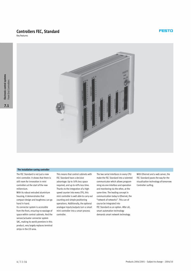
The sensor/actuator connector
Together with the FEC Standard, we
are introducing an innovative new
installation concept, the sensor/
actuator connector SAC. This
connector combines three functions
in a very compact design:
� Connection of inputs, outputs and
power supply
� Status signal by means of an LED
� Replaces terminal strip for sensors
and actuators
The three-wire version of the
connector has internally connected
straps for 0 V and 24 V DC. This
allows any sensor (up to 3 wires) or
actuator (up to the maximum
permissible output current) to be fed
directly to the connector. There is no
need for a terminal strip for sensors
and actuators. This allows space
savings in control cabinets of up to
50%.
The SAC uses a tension-spring contact
system. This means no need for screw
connections. Solid wires can simply
be pushed into the connector, while
in the case of finely-stranded wire, all
that is necessary is to open the
contact by pressing on the relevant
pin and then introduce the wire.
Cable end sleeves can be used if
desired but are not essential. The
tension-spring system and the fact
that no terminal strip between the
controller and sensors/actuator is
required means that a time saving of
up to 40% can be achieved during
installation.
The pin assignment for the I/O panel
is simple and is always the same:
Pin 1 +24 V DC
Pin 2 Bit 0
Pin 3 Bit 1
Pin 4 Bit 2
Pin 5 Bit 3
Pin 6 Bit 4
Pin 7 Bit 5
Pin 8 Bit 6
Pin 9 Bit 7
Pin 10 0 V
The power supply for the LEDs is
taken from the signal pins in the
connector. This means that the entire
input assignment can be checked
without a controller.
Electroniccontrolsystem
s
FrontEndControllers
7.1
2004/10 – Subject to change – Products 2004/2005 4 / 7.1-19
Controllers FEC, StandardKey features
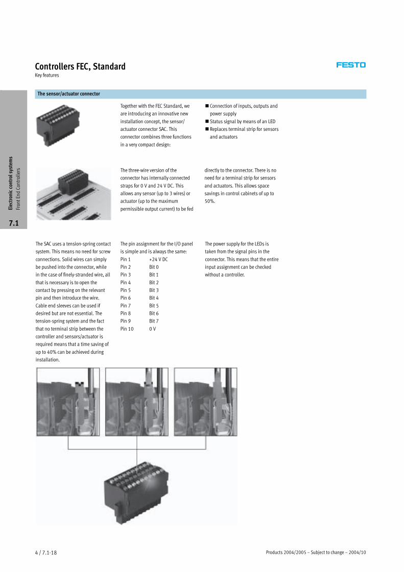
Programming with FST
Programming the way you think
How do we describe a machine?
“When a workpiece reaches here, this
cylinder should advance.”
How does the software interpret this?
Or does your machine work through a
sequence step by step?
“First, this cylinder must advance and
stop the workpiece, and then the
workpiece must be clamped, and then
finally...”
How, for example, can we sub-divide
a task?
Program 0: Organisation
Program 1: Set-up program
Program 2: Automation
program
Program 3: Fault monitoring
Program 4: Manual operation
.
.
.
Program 63: Troubleshooting
program
How does one controller
communicate with another?
Every controller with Ethernet can
send and receive data from every
other controller within a network – no
matter whether this data relates to
inputs, outputs, flags or registers.
Central programming of distributed
controllers
Every controller within a network can
be programmed from any desired
network interface.
A controller on the World Wide Web
FST incorporates a web server – the
Internet and the world of automation
meet.
Programming just couldn’t be easier.
Programming with MWT
Programming based on
the international standard
DIN IEC 6 1131-3 is the international
standard for PLC programming.
MULTIPROG supports all the
5 programming languages defined by
this standard:
� Text-based languages:
statement list and
structured text
� The graphical languages:
ladder diagram and
function block diagram
� The language for organisation:
sequential function chart
MWT makes everything easy
MULTIPROG offers assistance and
dialogues to ensure that programming
in accordance with IEC 6 1131-3 is
easy even with mini controllers.
Ready-made templates support direct
access to controller equipment.
Network
With MWT, you can link up any
desired number of controllers. This
allows all the controllers in a network
to be dealt with as a single project.
Similarly, it means that programs and
modules can be written just once and
used in a large number of stations –
software re-usability is a central
feature of IEC 6 1131-3.
Central programming of distributed
controllers
Every controller within a network can
be programmed from any desired
network interface.
MULTIPROG MWT
MWT is based on MULTIPROG from
KW-Software. For more information
about our software partner
KW-Software
� www.kw-software.com
Electroniccontrolsystem
s
FrontEndControllers
7.1
Products 2004/2005 – Subject to change – 2004/104 / 7.1-20
Controllers FEC, StandardProduct range overview
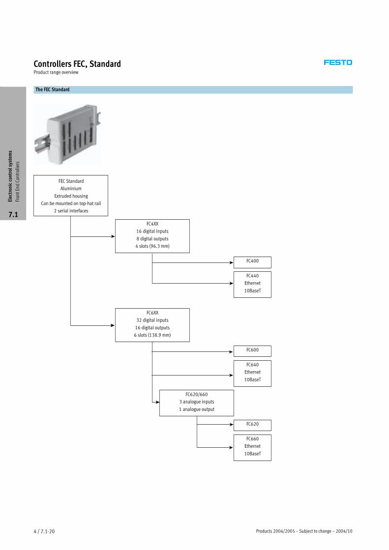
The FEC Standard
FEC Standard
Aluminium
Extruded housing
Can be mounted on top-hat rail
2 serial interfaces
FC4XX
16 digital inputs
8 digital outputs
4 slots (96.3 mm)
FC400
FC440
Ethernet
10BaseT
FC6XX
32 digital inputs
16 digital outputs
6 slots (138.9 mm)
FC600
FC640
Ethernet
10BaseT
FC620/660
3 analogue inputs
1 analogue output
FC620
FC660
Ethernet
10BaseT
Electroniccontrolsystem
s
FrontEndControllers
7.1
2004/10 – Subject to change – Products 2004/2005 4 / 7.1-21
Controllers FEC, StandardProduct range overview
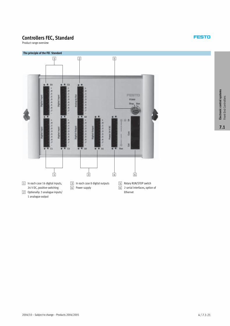
The principle of the FEC Standard
1
1
2
3
5
4 6
1 In each case 16 digital inputs,
24 V DC, positive-switching
2 Optionally: 3 analogue inputs/
1 analogue output
3 In each case 8 digital outputs
4 Power supply
5 Rotary RUN/STOP switch
6 2 serial interfaces, option of
Ethernet
Electroniccontrolsystem
s
FrontEndControllers
7.1
Products 2004/2005 – Subject to change – 2004/104 / 7.1-22
Controllers FEC, StandardTechnical data
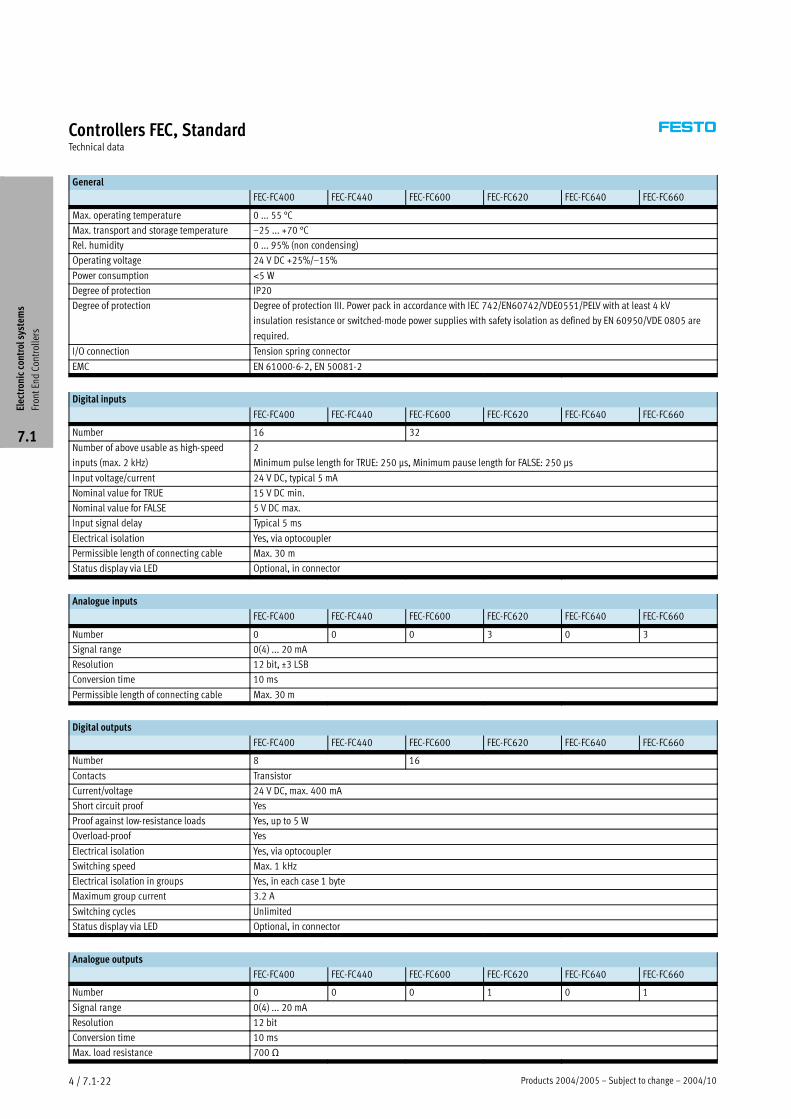
General
FEC-FC400 FEC-FC440 FEC-FC600 FEC-FC620 FEC-FC640 FEC-FC660
Max. operating temperature 0 ... 55 °C
Max. transport and storage temperature –25 ... +70 °C
Rel. humidity 0 ... 95% (non condensing)
Operating voltage 24 V DC +25%/–15%
Power consumption <5 W
Degree of protection IP20
Degree of protection Degree of protection III. Power pack in accordance with IEC 742/EN60742/VDE0551/PELV with at least 4 kV
insulation resistance or switched-mode power supplies with safety isolation as defined by EN 60950/VDE 0805 are
required.
I/O connection Tension spring connector
EMC EN 61000-6-2, EN 50081-2
Digital inputs
FEC-FC400 FEC-FC440 FEC-FC600 FEC-FC620 FEC-FC640 FEC-FC660
Number 16 32
Number of above usable as high-speed
inputs (max. 2 kHz)
2
Minimum pulse length for TRUE: 250 µs, Minimum pause length for FALSE: 250 µs
Input voltage/current 24 V DC, typical 5 mA
Nominal value for TRUE 15 V DC min.
Nominal value for FALSE 5 V DC max.
Input signal delay Typical 5 ms
Electrical isolation Yes, via optocoupler
Permissible length of connecting cable Max. 30 m
Status display via LED Optional, in connector
Analogue inputs
FEC-FC400 FEC-FC440 FEC-FC600 FEC-FC620 FEC-FC640 FEC-FC660
Number 0 0 0 3 0 3
Signal range 0(4) ... 20 mA
Resolution 12 bit, ±3 LSB
Conversion time 10 ms
Permissible length of connecting cable Max. 30 m
Digital outputs
FEC-FC400 FEC-FC440 FEC-FC600 FEC-FC620 FEC-FC640 FEC-FC660
Number 8 16
Contacts Transistor
Current/voltage 24 V DC, max. 400 mA
Short circuit proof Yes
Proof against low-resistance loads Yes, up to 5 W
Overload-proof Yes
Electrical isolation Yes, via optocoupler
Switching speed Max. 1 kHz
Electrical isolation in groups Yes, in each case 1 byte
Maximum group current 3.2 A
Switching cycles Unlimited
Status display via LED Optional, in connector
Analogue outputs
FEC-FC400 FEC-FC440 FEC-FC600 FEC-FC620 FEC-FC640 FEC-FC660
Number 0 0 0 1 0 1
Signal range 0(4) ... 20 mA
Resolution 12 bit
Conversion time 10 ms
Max. load resistance 700 �
Electroniccontrolsystem
s
FrontEndControllers
7.1
2004/10 – Subject to change – Products 2004/2005 4 / 7.1-23
Controllers FEC, StandardTechnical data
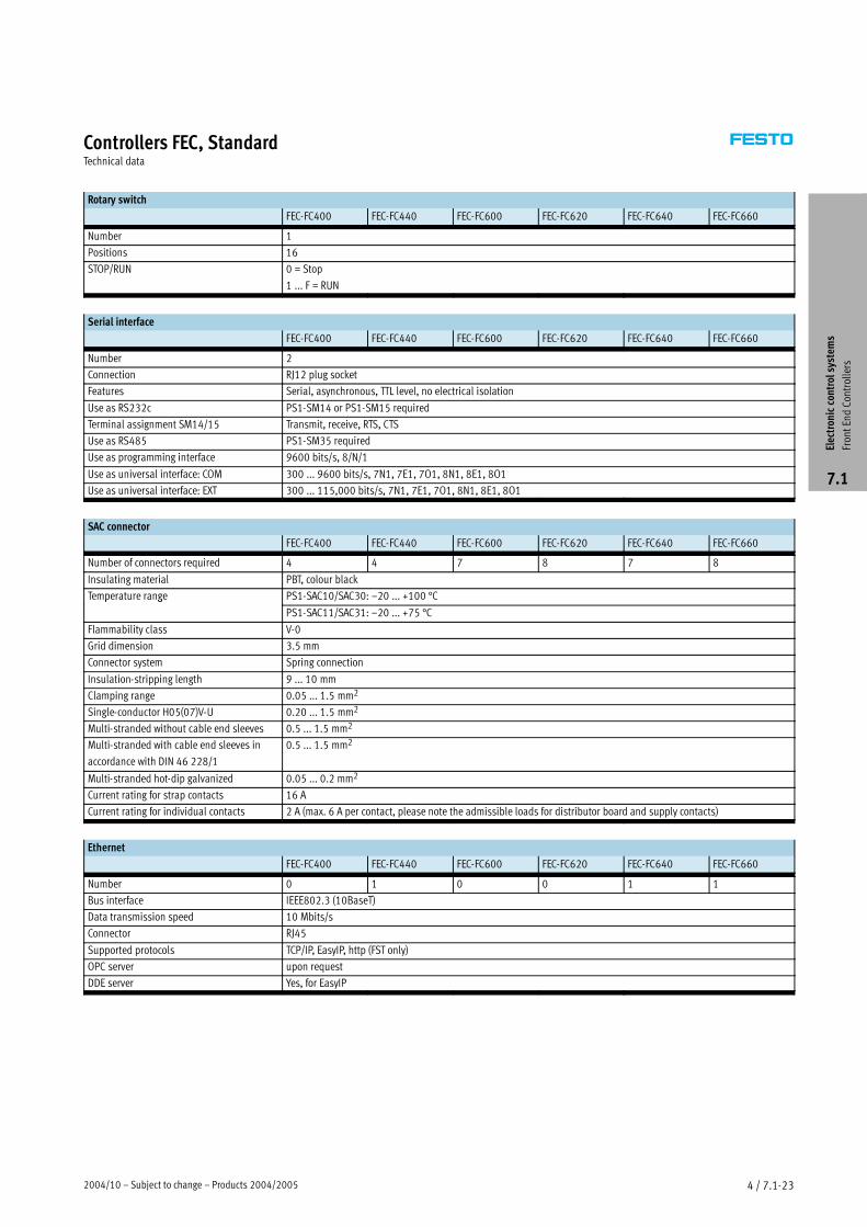
Rotary switch
FEC-FC400 FEC-FC440 FEC-FC600 FEC-FC620 FEC-FC640 FEC-FC660
Number 1
Positions 16
STOP/RUN 0 = Stop
1 ... F = RUN
Serial interface
FEC-FC400 FEC-FC440 FEC-FC600 FEC-FC620 FEC-FC640 FEC-FC660
Number 2
Connection RJ12 plug socket
Features Serial, asynchronous, TTL level, no electrical isolation
Use as RS232c PS1-SM14 or PS1-SM15 required
Terminal assignment SM14/15 Transmit, receive, RTS, CTS
Use as RS485 PS1-SM35 required
Use as programming interface 9600 bits/s, 8/N/1
Use as universal interface: COM 300 ... 9600 bits/s, 7N1, 7E1, 7O1, 8N1, 8E1, 8O1
Use as universal interface: EXT 300 ... 115,000 bits/s, 7N1, 7E1, 7O1, 8N1, 8E1, 8O1
SAC connector
FEC-FC400 FEC-FC440 FEC-FC600 FEC-FC620 FEC-FC640 FEC-FC660
Number of connectors required 4 4 7 8 7 8
Insulating material PBT, colour black
Temperature range PS1-SAC10/SAC30: –20 ... +100 °Cp g
PS1-SAC11/SAC31: –20 ... +75 °C
Flammability class V-0
Grid dimension 3.5 mm
Connector system Spring connection
Insulation-stripping length 9 ... 10 mm
Clamping range 0.05 ... 1.5 mm2
Single-conductor H05(07)V-U 0.20 ... 1.5 mm2
Multi-stranded without cable end sleeves 0.5 ... 1.5 mm2
Multi-stranded with cable end sleeves in
accordance with DIN 46 228/1
0.5 ... 1.5 mm2
Multi-stranded hot-dip galvanized 0.05 ... 0.2 mm2
Current rating for strap contacts 16 A
Current rating for individual contacts 2 A (max. 6 A per contact, please note the admissible loads for distributor board and supply contacts)
Ethernet
FEC-FC400 FEC-FC440 FEC-FC600 FEC-FC620 FEC-FC640 FEC-FC660
Number 0 1 0 0 1 1
Bus interface IEEE802.3 (10BaseT)
Data transmission speed 10 Mbits/s
Connector RJ45
Supported protocols TCP/IP, EasyIP, http (FST only)
OPC server upon request
DDE server Yes, for EasyIP
Electroniccontrolsystem
s
FrontEndControllers
7.1
Products 2004/2005 – Subject to change – 2004/104 / 7.1-24
Controllers FEC, StandardTechnical data
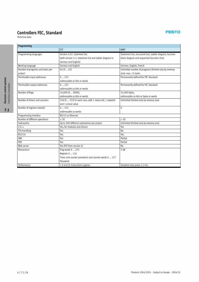
Programming
FST MWT
Programming languages Version 4.02: statement list
(with version 3.2: statement list and ladder diagram in
German and English)
Statement list, structured text, ladder diagram, function
block diagram and sequential function chart
Working language German and English German, English, French
Number of programs and tasks per
project
64 (0 ... 63) Unlimited number of programs (limited only by memory
size), max. 15 tasks
Permissible input addresses 0 ... 255
addressable as bits or words
Permanently defined for FEC Standard
Permissible output addresses 0 ... 255
addressable as bits or words
Permanently defined for FEC Standard
Number of flags 10,000 (0 ... 9999),
addressable as bits or words
32,000 bytes,
addressable as bits or bytes or words
Number of timers and counters 256 (0 ... 255) in each case, with 1 status bit, 1 setpoint
and 1 actual value
Unlimited (limited only by memory size)
Number of registers (words) 0 ... 255
addressable as words
0
Programming interface RS232 or Ethernet
Number of different operations > 28 > 50
Subroutine Up to 200 different subroutines per project Unlimited (limited only by memory size)
C/C++ Yes, for modules and drivers Yes
File handling Yes No
RS232c Yes Yes
ABG Yes Partial
FED Yes Partial
Web server Yes (FST from version 4) No
Remanence Flag words 0 ... 255
Register 0 ... 126
Timer and counter preselects and counter words 0 ... 127
Password
2 kB
Performance 1.6 ms/1k instructions approx. Smallest task pulse: 4.3 ms
Electroniccontrolsystem
s
FrontEndControllers
7.1
2004/10 – Subject to change – Products 2004/2005 4 / 7.1-25
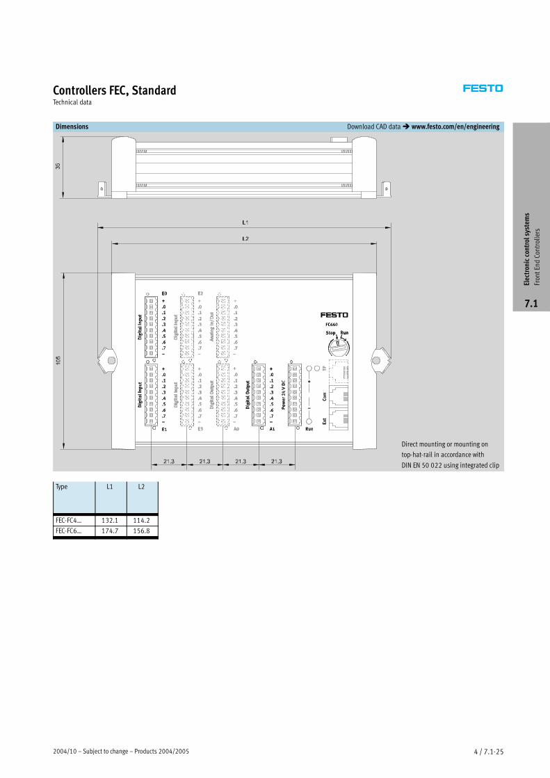
Controllers FEC, StandardTechnical data
Dimensions Download CAD data� www.festo.com/en/engineering
Direct mounting or mounting on
top-hat-rail in accordance with
DIN EN 50 022 using integrated clip
Type L1 L2
FEC-FC4… 132.1 114.2
FEC-FC6… 174.7 156.8Electroniccontrolsystem
s
FrontEndControllers
7.1

Products 2004/2005 – Subject to change – 2004/104 / 7.1-26
Controllers FEC, StandardTechnical data
Ordering data – The FEC Standard with FST programming
Type Part No. Designation Features
FEC-FC400-FST 183 862 IPC controller 16 I/8 O
FEC-FC440-FST 185 205 16 I/8 O, Ethernet
FEC-FC600-FST 191 449 32 I/16 O
FEC-FC620-FST 197 154 32 I/16 O, 3/1 analogue I/Os
FEC-FC640-FST 191 450 32 I/16 O, Ethernet
FEC-FC660-FST 197 157 32 I/16 O, 3/1 analogue I/Os, Ethernet
Ordering data – The FEC Standard with MWT programming
Type Part No. Designation Features
FEC-FC400-MWT 185 200 IPC controller 16 I/8 O
FEC-FC440-MWT 185 206 16 I/8 O, Ethernet
FEC-FC600-MWT 197 153 32 I/16 O
FEC-FC620-MWT 197 155 32 I/16 O, 3/1 analogue I/Os
FEC-FC640-MWT 197 156 32 I/16 O, Ethernet
FEC-FC660-MWT 197 158 32 I/16 O, 3/1 analogue I/Os, Ethernet
Ordering data – Connectors for the FEC Standard
Type Part No. Designation Features
PS1-SAC10-10POL 197 159 Plug 1-row, no LED, tension-spring system
PS1-SAC11-10POL+LED 197 160 Plug 1-row, with LED, tension-spring system
PS1-SAC30-30POL 197 161 Plug 3-row, no LED, tension-spring system
PS1-SAC31-30POL+LED 197 162 Plug 3-row, with LED, tension-spring system
-H- Note Connectors must be ordered separately.
Ordering data – Cables for the FEC Standard
Type Part No. Designation Features
PS1-SM14-RS232 188 935 Programming cable RS232 adapter for programming from PC, complete with neutral modem cable
PS1-SM15-RS232 192 681 Converter RS232 adapter for connection of any desired devices with a serial interface, with
top-hat-rail clip, no neutral modem or RS232 cable
PS1-SM35-RS485 193 390 Converter RS485 adapter, with top-hat-rail clip
PS1-ZK11-NULLMODEM-1,5M 160 786 Cable Neutral modem cable
FEC-ZE30 526 683 Earthing set Earthing set for earthing of cable screening via the H-rail
-H- Note For programming from a PC via RS232, a PS1-SM14 must be ordered separately. For programming via Ethernet, the necessary
drivers must first be loaded via RS232 (PS1-SM14).
Electroniccontrolsystem
s
FrontEndControllers
7.1
2004/10 – Subject to change – Products 2004/2005 4 / 7.1-27
Controllers FEC, StandardTechnical data
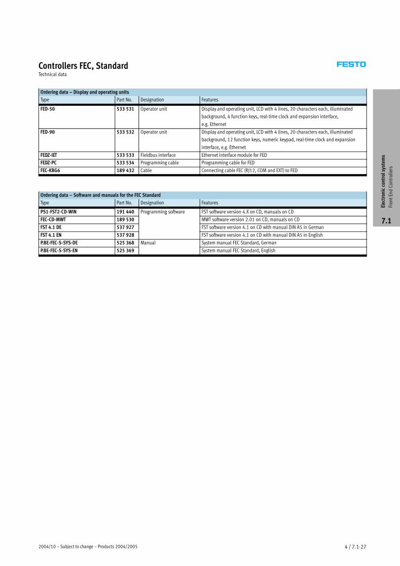
Ordering data – Display and operating units
Type Part No. Designation Features
FED-50 533 531 Operator unit Display and operating unit, LCD with 4 lines, 20 characters each, illuminated
background, 4 function keys, real-time clock and expansion interface,
e.g. Ethernet
FED-90 533 532 Operator unit Display and operating unit, LCD with 4 lines, 20 characters each, illuminated
background, 12 function keys, numeric keypad, real-time clock and expansion
interface, e.g. Ethernet
FEDZ-IET 533 533 Fieldbus interface Ethernet interface module for FED
FEDZ-PC 533 534 Programming cable Programming cable for FED
FEC-KBG6 189 432 Cable Connecting cable FEC (RJ12, COM and EXT) to FED
Ordering data – Software and manuals for the FEC Standard
Type Part No. Designation Features
PS1-FST2-CD-WIN 191 440 Programming software FST software version 4.X on CD, manuals on CD
FEC-CD-MWT 189 530
g g
MWT software version 2.01 on CD, manuals on CD
FST 4.1 DE 537 927 FST software version 4.1 on CD with manual DIN A5 in German
FST 4.1 EN 537 928 FST software version 4.1 on CD with manual DIN A5 in English
P.BE-FEC-S-SYS-DE 525 368 Manual System manual FEC Standard, German
P.BE-FEC-S-SYS-EN 525 369 System manual FEC Standard, English
Electroniccontrolsystem
s
FrontEndControllers
7.1
2003/10 – Subject to change – Products 2004/2005 4 / 2.1-3
Valve terminal type 10 CPV, Compact PerformanceKey features
Equipment options
The CPV valve terminal is available
with the following valve functions:
� 2x 2/2-way, open and closed
� 2x 2/2-way, closed
� 2x 3/2-way, open
� 2x 3/2-way, closed
� 2x 3/2-way, open and closed
� 5/2-way, single solenoid
� 5/2-way, double solenoid
� 5/3-way valve, mid-position
pressurised
� 5/3-way valve, mid-position
exhausted
� 5/3-way valve, mid-position closed
� Vacuum generator and 2/2-way
valve for ejector pulse
� Vacuum generator
Certain terminals allow the choice of a
relay slice with two floating contacts
in place of a valve slice.
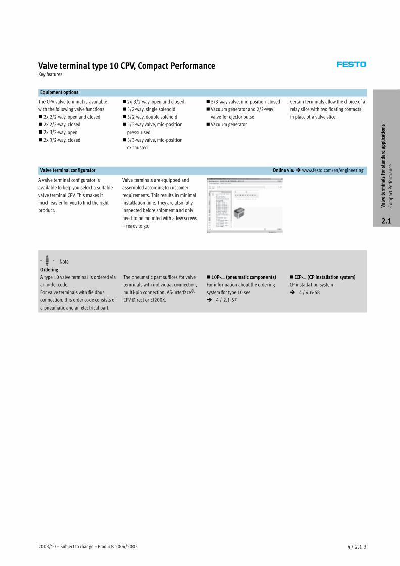
Valve terminal configurator Online via:� www.festo.com/en/engineering
A valve terminal configurator is
available to help you select a suitable
valve terminal CPV. This makes it
much easier for you to find the right
product.
Valve terminals are equipped and
assembled according to customer
requirements. This results in minimal
installation time. They are also fully
inspected before shipment and only
need to be mounted with a few screws
– ready to go.
-H- Note
Ordering
A type 10 valve terminal is ordered via
an order code.
For valve terminals with fieldbus
connection, this order code consists of
a pneumatic and an electrical part.
The pneumatic part suffices for valve
terminals with individual connection,
multi-pin connection, AS-interface®,
CPV Direct or ET200X.
� 10P-… (pneumatic components)
For information about the ordering
system for type 10 see
� 4 / 2.1-57
� ECP-… (CP installation system)
CP installation system
� 4 / 4.6-68
Valve
term
inalsforstandardapplications
Com
pactPerformance
2.1
Products 2004/2005 – Subject to change – 2003/104 / 2.1-4
Valve terminal type 10 CPV, Compact PerformancePeripherals overview
CPV – The benefits at a glance
The CPV valve terminal is of unique
design. It permits the flexible com-
bination of pneumatic performance,
electrical connection technologies and
a wide range of mounting options. The
generously dimensioned flow ducts
and powerful surface mounted
silencers ensure high flow rates. This
means that even comparatively large
pneumatic cylinders can be driven
with ease.
All valves are in the form of valve
slices. They are optimised for flow
performance and are also extremely
compact. Two functions per valve slice
(e.g. 2x 3/2-way valves) mean that
twice the component density can be
achieved. This saves space and
reduces costs.
The cubic design permits exceptional
performance yet a comparatively low
weight. The benefits of this design are
obvious when the valve terminal is
used on a moving installation.
However robustness must not be
sacrificed in favour of compactness.
The connecting thread and mounting
attachments are metallic.
The manual override for the valves can
be adapted for different operating
situations. If, for example, a detenting
manual override is required for
setting-up mode, the manual override
can be easily converted for that
application in a way that rules out
operational errors. The clear, large
labelling system also contributes to
the safe operation of the valve
terminal.
A particular plus is the range of elec-
trical connection technologies sup-
ported. All types of valve actuation are
possible, from individual valve con-
nections up to bus systems with versa-
tile expansion options. The integration
of electrical input and output modules
permits cost-effective solutions within
the different installation concepts.
A PC-based software configurator that
selects the correct CPV valve terminal
is provided. This makes it much easier
for you to find the right product.
The design principle
The cubic design provides a clearly
assigned function on each side. Thus,
for example, the electrical connection
is mounted on the top surface. An
optional inscription label holder can
be placed on the front of the valve
terminal. The different combination
options ensure the optimum solution
for the task at hand.
� Pneumatic supply connections on
the left, right or underneath
� Pneumatic working lines and func-
tional modules (vertical stacking)
on the bottom
�Manual operation/identification on
the front
� Electrical connection surface on the
top
�Mounting surface at the back or
even at the front via a pneumatic
multi-connector plate
Valve
term
inalsforstandardapplications
Com
pactPerformance
2.1
2003/10 – Subject to change – Products 2004/2005 4 / 2.1-5
Valve terminal type 10 CPV, Compact PerformancePeripherals overview
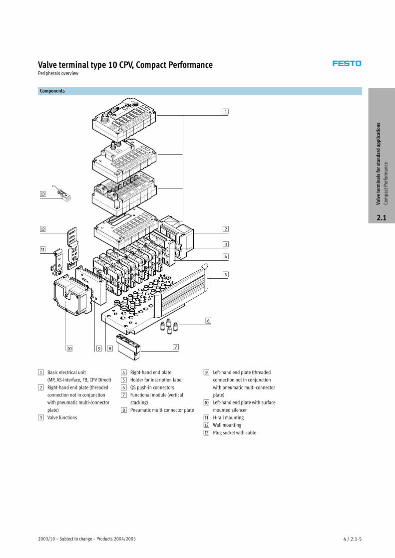
Components
9
2
5
4
6
78
3
1
aJ
aA
aB
aC
1 Basic electrical unit
(MP, AS-interface, FB, CPV Direct)
2 Right-hand end plate (threaded
connection not in conjunction
with pneumatic multi-connector
plate)
3 Valve functions
4 Right-hand end plate
5 Holder for inscription label
6 QS push-in connectors
7 Functional module (vertical
stacking)
8 Pneumatic multi-connector plate
9 Left-hand end plate (threaded
connection not in conjunction
with pneumatic multi-connector
plate)
aJ Left-hand end plate with surface
mounted silencer
aA H-rail mounting
aB Wall mounting
aC Plug socket with cable
Valve
term
inalsforstandardapplications
Com
pactPerformance
2.1

Products 2004/2005 – Subject to change – 2003/104 / 2.1-6
Valve terminal type 10 CPV, Compact PerformancePeripherals overview
Individual connection
Connection is independent of the
control technology used. This ensures
correct polarity during installation.
The connector plug is equipped with
an LED which indicates switching
status, and a voltage overload
protective circuit. It also features a
built-in current reduction circuit.
Individual connection permits the
selection of 2 to 16 solenoid coils
(divided between two to eight valve
slices, including in uneven stages).
Multi-pin connection
Control signals from the controller to
the valve terminal are transmitted via
a pre-assembled multi-core cable,
which substantially reduces installa-
tion time. The current reduction
circuit for the valves is also integrated
in the multi-pin connection.
This valve terminal can be equipped
with 4 to 16 solenoid coils (4, 6 or
8 valve slices).
AS-interface connection
A special feature of AS-interface is its
ability to simultaneously transmit
data and supply power via a two-core
cable. The encoded cable profile pre-
vents connection with incorrect
polarity. If the valves have to be
disconnected from mains power in an
emergency, they can be supplied with
electrical power via a separate
connection.
The valve terminal with AS-interface
can be configured as follows:
�without inputs, with two or four
valve slices (max. 4 solenoid coils)
�without inputs, with two or four
valve slices (max. 4 solenoid coils)
and additional power supply
�with four or eight inputs and four or
eight valve slices (max. 8 solenoid
coils)
�with four or eight inputs and four or
eight valve slices (max. 8 solenoid
coils) and additional power supply
�with four or eight inputs and four or
eight valve slices (max. 6 solenoid
coils) and additional power supply
for A/B operation to SPEC. 2.1
Further information
� 4 / 4.9-2
Valve
term
inalsforstandardapplications
Com
pactPerformance
2.1
2004/10 – Subject to change – Products 2004/2005 1 / 7.5-7
Parallel grippers HGPTechnical data
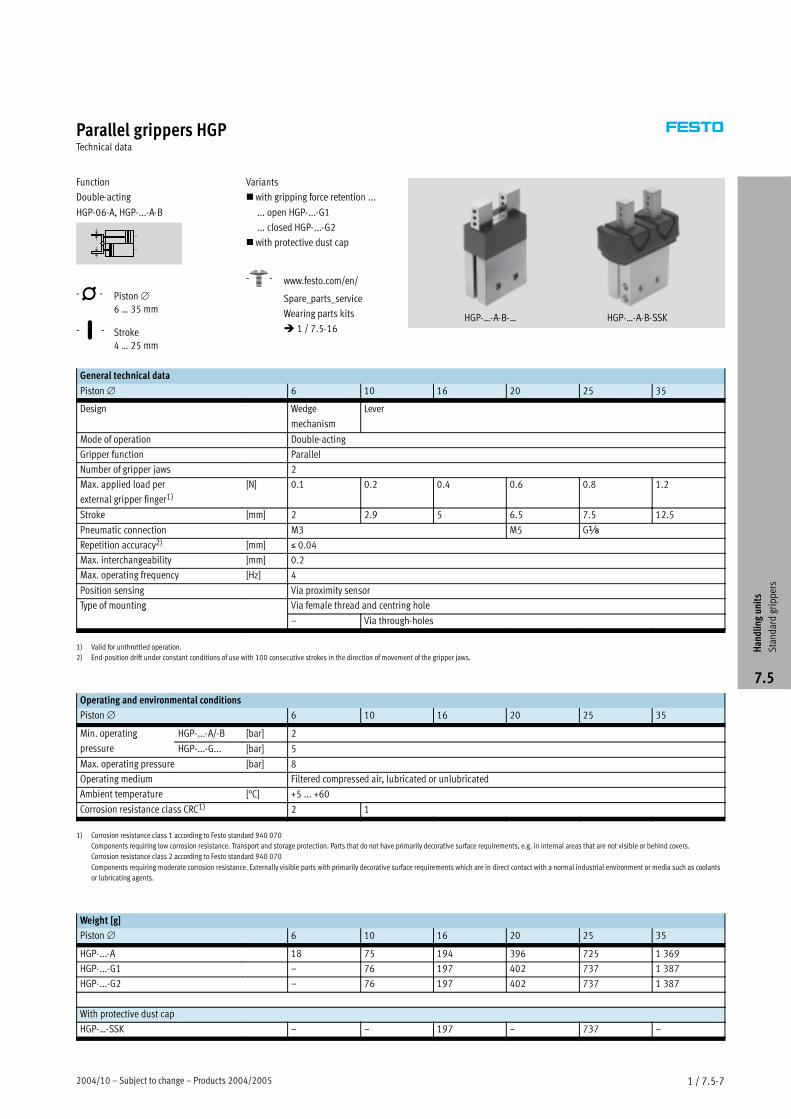
Function
Double-acting
HGP-06-A, HGP-...-A-B
-N- Piston∅
6 … 35 mm
-T- Stroke
4 … 25 mm
Variants
�with gripping force retention ...
... open HGP-...-G1
... closed HGP-...-G2
�with protective dust cap
-W- www.festo.com/en/
Spare_parts_service
Wearing parts kits
� 1 / 7.5-16HGP-…-A-B-… HGP-…-A-B-SSK
General technical data
Piston∅ 6 10 16 20 25 35
Design Wedge
mechanism
Lever
Mode of operation Double-acting
Gripper function Parallel
Number of gripper jaws 2
Max. applied load per
external gripper finger1)[N] 0.1 0.2 0.4 0.6 0.8 1.2
Stroke [mm] 2 2.9 5 6.5 7.5 12.5
Pneumatic connection M3 M5 G�
Repetition accuracy2) [mm] � 0.04
Max. interchangeability [mm] 0.2
Max. operating frequency [Hz] 4
Position sensing Via proximity sensor
Type of mounting Via female thread and centring holeyp g
– Via through-holes
1) Valid for unthrottled operation.
2) End-position drift under constant conditions of use with 100 consecutive strokes in the direction of movement of the gripper jaws.
Operating and environmental conditions
Piston∅ 6 10 16 20 25 35
Min. operating HGP-...-A/-B [bar] 2p g
pressure HGP-...-G... [bar] 5
Max. operating pressure [bar] 8
Operating medium Filtered compressed air, lubricated or unlubricated
Ambient temperature [°C] +5 ... +60
Corrosion resistance class CRC1) 2 1
1) Corrosion resistance class 1 according to Festo standard 940 070
Components requiring low corrosion resistance. Transport and storage protection. Parts that do not have primarily decorative surface requirements, e.g. in internal areas that are not visible or behind covers.
Corrosion resistance class 2 according to Festo standard 940 070
Components requiring moderate corrosion resistance. Externally visible parts with primarily decorative surface requirements which are in direct contact with a normal industrial environment or media such as coolants
or lubricating agents.
Weight [g]
Piston∅ 6 10 16 20 25 35
HGP-...-A 18 75 194 396 725 1 369
HGP-...-G1 – 76 197 402 737 1 387
HGP-...-G2 – 76 197 402 737 1 387
With protective dust cap
HGP-…-SSK – – 197 – 737 –
Handlingunits
Standardgrippers
7.5
Products 2004/2005 – Subject to change – 2004/101 / 7.5-8
Parallel grippers HGPTechnical data
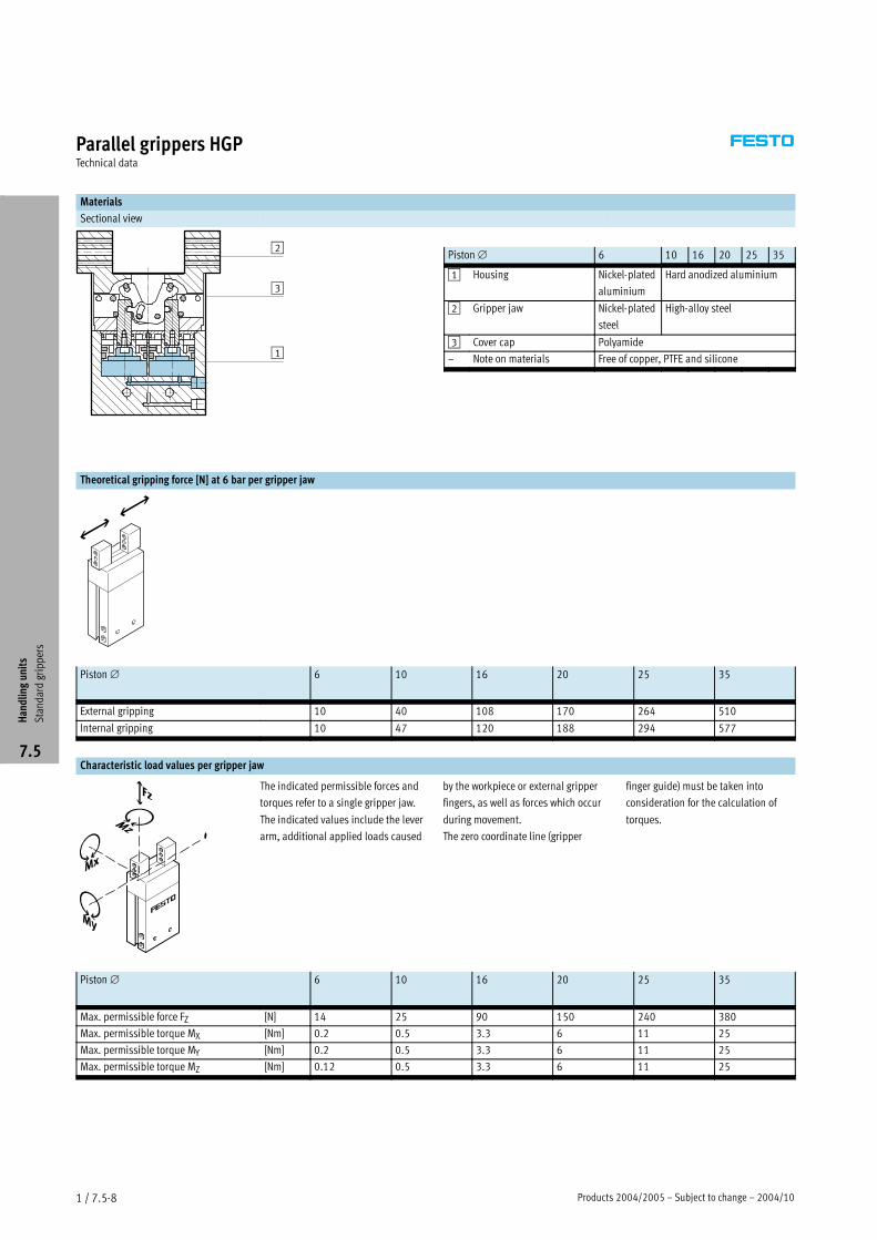
Materials
Sectional view
Piston∅ 6 10 16 20 25 35
1 Housing Nickel-plated
aluminium
Hard anodized aluminium
2 Gripper jaw Nickel-plated
steel
High-alloy steel
3 Cover cap Polyamide
– Note on materials Free of copper, PTFE and silicone
Theoretical gripping force [N] at 6 bar per gripper jaw
Piston∅ 6 10 16 20 25 35
External gripping 10 40 108 170 264 510
Internal gripping 10 47 120 188 294 577
Characteristic load values per gripper jaw
The indicated permissible forces and
torques refer to a single gripper jaw.
The indicated values include the lever
arm, additional applied loads caused
by the workpiece or external gripper
fingers, as well as forces which occur
during movement.
The zero coordinate line (gripper
finger guide) must be taken into
consideration for the calculation of
torques.
Piston∅ 6 10 16 20 25 35
Max. permissible force FZ [N] 14 25 90 150 240 380
Max. permissible torque MX [Nm] 0.2 0.5 3.3 6 11 25
Max. permissible torque MY [Nm] 0.2 0.5 3.3 6 11 25
Max. permissible torque MZ [Nm] 0.12 0.5 3.3 6 11 25
Handlingunits
Standardgrippers
7.5
1
2
3
2004/10 – Subject to change – Products 2004/2005 1 / 7.5-9
Parallel grippers HGPTechnical data
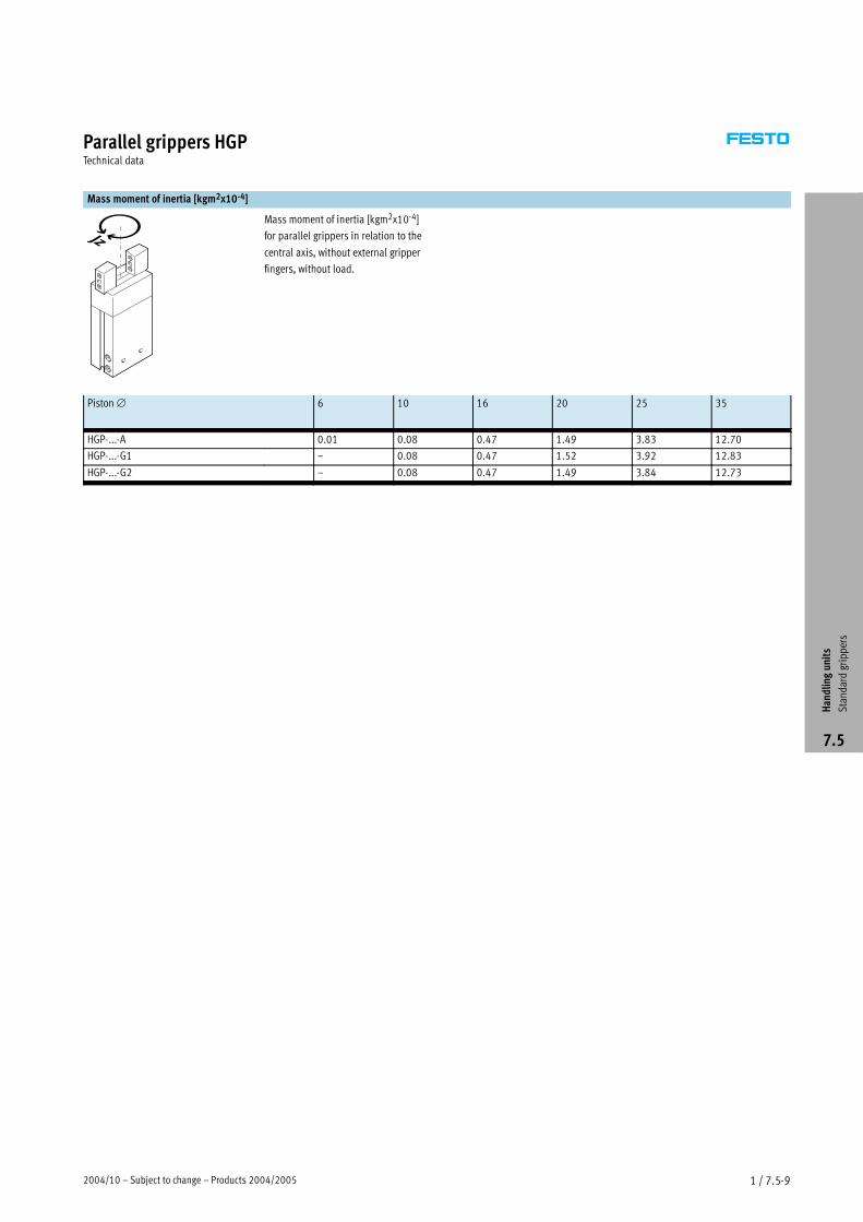
Mass moment of inertia [kgm2x10-4]
Mass moment of inertia [kgm2x10-4]
for parallel grippers in relation to the
central axis, without external gripper
fingers, without load.
Piston∅ 6 10 16 20 25 35
HGP-...-A 0.01 0.08 0.47 1.49 3.83 12.70
HGP-...-G1 – 0.08 0.47 1.52 3.92 12.83
HGP-...-G2 – 0.08 0.47 1.49 3.84 12.73
Handlingunits
Standardgrippers
7.5
Products 2004/2005 – Subject to change – 2004/101 / 7.5-10
Parallel grippers HGPTechnical data
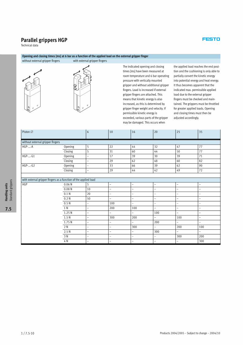
Opening and closing times [ms] at 6 bar as a function of the applied load on the external gripper finger
without external gripper fingers with external gripper fingers
The indicated opening and closing
times [ms] have been measured at
room temperature and 6 bar operating
pressure with vertically mounted
gripper and without additional gripper
fingers. Load is increased if external
gripper fingers are attached. This
means that kinetic energy is also
increased, as this is determined by
gripper finger weight and velocity. If
permissible kinetic energy is
exceeded, various parts of the gripper
may be damaged. This occurs when
the applied load reaches the end posi-
tion and the cushioning is only able to
partially convert the kinetic energy
into potential energy and heat energy.
It thus becomes apparent that the
indicated max. permissible applied
load due to the external gripper
fingers must be checked and main-
tained. The grippers must be throttled
for greater applied loads. Opening
and closing times must then be
adjusted accordingly.
Piston∅ 6 10 16 20 25 35
without external gripper fingers
HGP-...-A Opening 5 22 44 32 47 77
Closing 5 31 60 44 50 77
HGP-...-G1 Opening – 17 39 30 39 71
Closing – 29 62 48 60 82
HGP-...-G2 Opening – 33 66 39 62 90
Closing – 29 44 42 49 72
with external gripper fingers as a function of the applied load
HGP 0.06 N 5 – – – – –
0.08 N 10 – – – – –
0.1 N 20 – – – – –
0.2 N 50 – – – – –
0.5 N – 100 – – – –
1 N – 200 100 – – –
1.25 N – – – 100 – –
1.5 N – 300 200 – 100 –
1.75 N – – – 200 – –
2 N – – 300 – 200 100
2.5 N – – – 300 – –
3 N – – – – 300 200
4 N – – – – – 300
Handlingunits
Standardgrippers
7.5
Products 2004/2005 – Subject to change – 2004/102 / 5.6-20
Flow control valves and one-way flow control valvesTechnical data – Standard flow control valve with QS push-in connector, series B
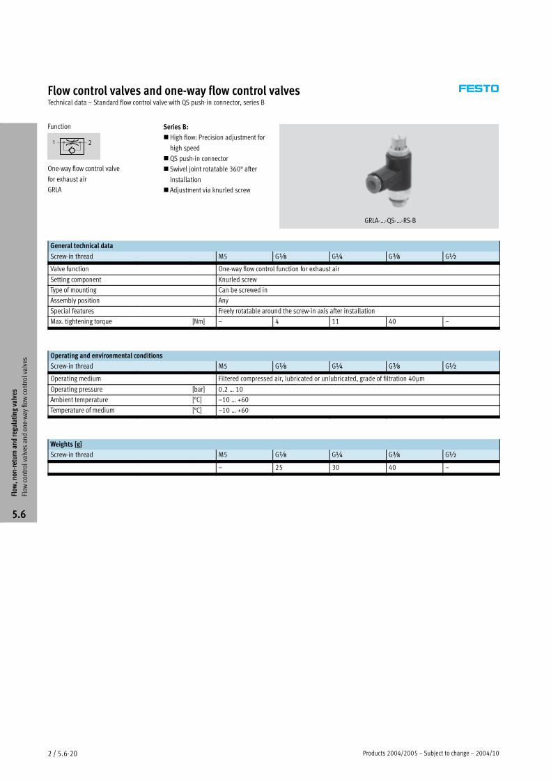
Function
One-way flow control valve
for exhaust air
GRLA
Series B:
�High flow: Precision adjustment for
high speed
�QS push-in connector
� Swivel joint rotatable 360° after
installation
� Adjustment via knurled screw
GRLA-…-QS-…-RS-B
General technical data
Screw-in thread M5 G� G� G� G�
Valve function One-way flow control function for exhaust air
Setting component Knurled screw
Type of mounting Can be screwed in
Assembly position Any
Special features Freely rotatable around the screw-in axis after installation
Max. tightening torque [Nm] – 4 11 40 –
Operating and environmental conditions
Screw-in thread M5 G� G� G� G�
Operating medium Filtered compressed air, lubricated or unlubricated, grade of filtration 40µm
Operating pressure [bar] 0.2 … 10
Ambient temperature [°C] –10 … +60
Temperature of medium [°C] –10 … +60
Weights [g]
Screw-in thread M5 G� G� G� G�
– 25 30 40 –
Flow
,non-returnandregulatingvalves
Flow
controlvalves
andone-way
flow
controlvalves
5.6
2004/10 – Subject to change – Products 2004/2005 2 / 5.6-21
Flow control valves and one-way flow control valvesTechnical data – Standard flow control valve with QS push-in connector, series B
Standard nominal flow rate qnN [l/min] at 6 bar> 5 bar
Screw-in thread G� G� G�
One-way flow control function for exhaust air
QS-6 D1) 0 … 520 0 … 520 0 … 530Q
R2) 400 … 550 400 … 550 400 … 550
QS-8 D 0 … 650 0 … 650 0 … 650Q
R 600 … 750 600 … 750 600 … 750
1) D: Flow control direction
2) R: Non-return direction
Standard flow rate qn [l/min] at 6 bar> 0 bar
Screw-in thread G� G� G�
One-way flow control function for exhaust air
QS-6 D1) 0 … 720 0 … 740 0 … 740Q
R2) 600 … 750 620 … 760 620 … 760
QS-8 D 0 … 1,080 0 … 1,130 0 … 1,130Q
R 800 … 1,250 900 … 1,260 900 … 1,260
1) D: Flow control direction
2) R: Non-return direction
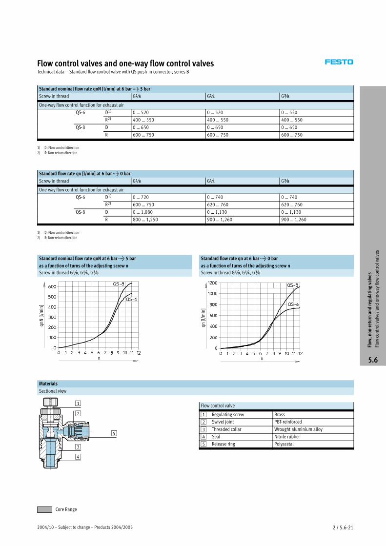
Standard nominal flow rate qnN at 6 bar> 5 bar
as a function of turns of the adjusting screw n
Standard flow rate qn at 6 bar> 0 bar
as a function of turns of the adjusting screw n
Screw-in thread G�, G�, G� Screw-in thread G�, G�, G�
qnN[l/m
in]
n n
qn[l/m
in]
Materials
Sectional view
Flow control valve
1 Regulating screw Brass
2 Swivel joint PBT-reinforced
3 Threaded collar Wrought aluminium alloy
4 Seal Nitrile rubber
5 Release ring Polyacetal
Flow
,non-returnandregulatingvalves
Flow
controlvalves
andone-way
flow
controlvalves
5.6
Core Range
2
4
3
1
5
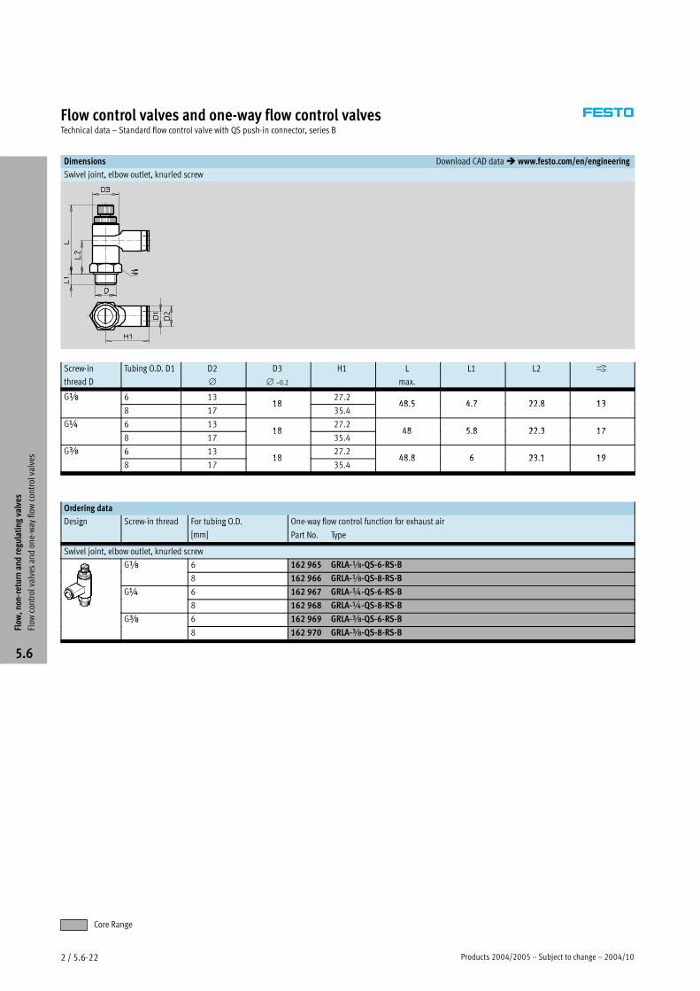
Products 2004/2005 – Subject to change – 2004/102 / 5.6-22
Flow control valves and one-way flow control valvesTechnical data – Standard flow control valve with QS push-in connector, series B
Dimensions Download CAD data� www.festo.com/en/engineering
Swivel joint, elbow outlet, knurled screw
Screw-in
thread D
Tubing O.D. D1 D2
∅
D3
∅ –0.2
H1 L
max.
L1 L2 �
G� 6 1318
27.248 5 4 7 22 8 13
�
8 1718
35.448.5 4.7 22.8 13
G� 6 1318
27.248 5 8 22 3 17
�
8 1718
35.448 5.8 22.3 17
G� 6 1318
27.248 8 6 23 1 19
�
8 1718
35.448.8 6 23.1 19
Ordering data
Design Screw-in thread For tubing O.D. One-way flow control function for exhaust airg g
[mm] Part No. Type
Swivel joint, elbow outlet, knurled screw
G� 6 162 965 GRLA-�-QS-6-RS-B�
8 162 966 GRLA-�-QS-8-RS-B
G� 6 162 967 GRLA-�-QS-6-RS-B�
8 162 968 GRLA-�-QS-8-RS-B
G� 6 162 969 GRLA-�-QS-6-RS-B�
8 162 970 GRLA-�-QS-8-RS-B
Flow
,non-returnandregulatingvalves
Flow
controlvalves
andone-way
flow
controlvalves
5.6
Core Range
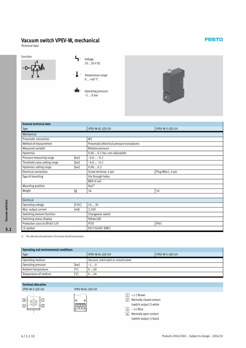
Products 2004/2005 – Subject to change – 2004/106 / 5.1-10
Vacuum switch VPEV-W, mechanicalTechnical data
Function -P- Voltage10 …30 V DC
-Q- Temperature range0 … +60 °C
-L- Operating pressure–1 … 0 bar
General technical data
Type VPEV-W-KL-LED-GH VPEV-W-S-LED-GH
Mechanical
Pneumatic connection M5
Method of measurement Pneumatic/electrical pressure transducers
Measured variable Relative pressure
Hysteresis 0.08 … 0.2 bar, non-adjustable
Pressure measuring range [bar] –0.8 … –0.2
Threshold value setting range [bar] –0.8 … –0.2
Hysteresis setting range [bar] 0.08 … 0.2
Electrical connection Screw terminal, 4-pin Plug M8x1, 4-pin
Type of mounting Via through-holesyp g
With H-rail
Mounting position Any1)
Weight [g] 56 56
Electrical
Operating voltage [V DC] 10 … 30
Max. output current [mA] 2,500
Switching element function Changeover switch
Switching status display Yellow LED
Protection class to EN 60 529 IP20 IP65
CE symbol 89/336/EEC (EMC)
1) The collection of condensate in the sensor should be prevented.
Operating and environmental conditions
Type VPEV-W-KL-LED-GH VPEV-W-S-LED-GH
Operating medium Vacuum, lubricated or unlubricated
Operating pressure [bar] –1 … 0
Ambient temperature [°C] 0 … 60
Temperature of medium [°C] 0 … 60
Terminal allocation
VPEV-W-S-LED-GH VPEV-W-KL-LED-GH
1 + (–) Brown
2 Normally closed contact
(switch output 2) white
3 – (+) Blue
4 Normally open contact
(switch output 1) black
Vacuumsw
itches
5.1

2004/10 – Subject to change – Products 2004/2005 6 / 5.1-11
Vacuum switch VPEV-W, mechanicalTechnical data
Dimensions
for control cabinet assembly with screw-in, push-in fitting
1 Slot for inscription label
2 Foot mounting (included in
scope of delivery)
3 Clamping foot for G/H rail
(available as accessory)
4 Switching status display,
yellow
5 Switching point adjustment
screw
6 Manual override facility
7 Integral plug fits plug sockets
to DIN EN 60 947-5-2,
M8, 4-pin
SIM-K-4-…/SIM-M8-…
8 Cable terminals
Ordering data
Electrical connection Part No. Type
Screw terminal, 4-pin 152 619 VPEV-W-KL-LED-GH
Plug M8x1, 4-pin 152 617 VPEV-W-S-LED-GH
Vacuumsw
itches
5.1

Products 2004/2005 – Subject to change – 2004/103 / 1.2-4
Filter regulators LFR/LFRS, D seriesTechnical data
Function
LFR/LFRS-…-D-…
Condensate drain
turned manually
semi- or fully automatic
-M- Flow rate
110 … 11000 l/min
-Q- Temperature range
–10 … +60 °C
-L- Input pressure
1 … 16 bar
LFR/LFRS-…-D-DI-MAXI
Condensate drain
turned manually
fully automatic
� Two pressure regulation ranges:
0.5 … 7 bar and 0.5 … 12 bar
� Two pressure gauge connections for
flexible installation
� Choice of filter cartridges: 5 µm or
40 µm
�With manual, semi-automatic or
fully automatic condensate drain
� Space-saving design with filter and
regulator in a single unit
�Good particle separation and high
flow rate
�Good regulating characteristics
with minimal hysteresis
� Setting values are secured by
locking the rotary knob
� Pressure sensor (optional)
� 3 / 1.8-15
General technical data
Size Micro Mini Midi Maxi
Pneumatic connection M5 M7 G� QS4 QS6 G� G� G� G� G� G� G� G� G� G1
Operating medium Compressed air Compressed air
Design Directly actuated diaphragm
regulator
Directly actuated diaphragm regulator Pilot actuated piston
regulatorregulator
Directly actuated diaphragm
regulator
Type of mounting Via accessories Via accessoriesyp g
In-line installation In-line installation
Front panel mounting Front panel mounting
Assembly position Vertical ±5° Vertical ±5°
Grade of filtration [µm] 5 5 or 40
Max. hysteresis [bar] 0.3 0.2 0.4
Pressure regulation range [bar] 0.5 … 7 0.5 … 7g g [ ] 5 7
0.5 … 12
Pressure indication Via pressure gauge Via pressure gauge
M5 prepared G� prepared G� prepared G� prepared
Max. condensate volume [cm3] 3 22 43 801)
Input pressure [bar]
Condensate drain turned manually 1 … 10 1 … 16
semi-automatic 1 … 10 –
fully automatic – 1.5 … 12
1) The max. condensate volume for the LFR/LFRS-…-DI-MAXI is 43 cm3.
Dseries
serviceunits
Filterregulators
1.2

2004/10 – Subject to change – Products 2004/2005 3 / 1.2-5
Filter regulators LFR/LFRS, D seriesTechnical data
Standard nominal flow rate1) qnN [l/min]
Connection Female thread Connecting plate
M5 M7 G� QS4 QS6
Micro
LFR 110 280 410 150 410
1) Measured at p1 = 10 bar, p2 = 6 bar and �p = 1 bar.
Standard nominal flow rate1) qnN [l/min]
Connection G� G� G� G� G� G1
Mini
LFR/LFRS-…-D-… 750 1400 1600 – – –
LFR/LFRS-…-D-7-… 900 1500 1700 – – –
LFR/LFRS-…-D-5M-… 650 1200 1350 – – –
Midi
LFR/LFRS-…-D-… – 2000 3100 3400 3400 –
LFR/LFRS-…-D-7-… – 2100 3200 3900 4000 –
LFR/LFRS-…-D-5M-… – 1600 2400 2600 2600 –
Maxi
LFR/LFRS-…-D-… – – – 9400 9700 10000
LFR/LFRS-…-D-7-… – – – 9500 10000 11000
LFR/LFRS-…-D-5M-… – – – 7500 7600 8000
Maxi – Directly actuated diaphragm regulator with integrated return flow function
LFR/LFRS-…-D-…-DI – – – 4500 6800 7000
LFR/LFRS-…-D-7-…-DI – – – 7600 7700 7800
LFR/LFRS-…-D-5M-…-DI – – – 4000 5800 6000
1) Measured at p1 = 10 bar, p2 = 6 bar and �p = 1 bar.
Screw-in depth of connecting thread [mm]
Connection M5 M7 G� QS4 QS6
Micro
In housing 5 6 – – –
In connecting plates – – 8 – –
Ambient conditions
Size Micro Mini Midi Maxi
Ambient temperature [°C] –10 … +60
Temperature of medium [°C] –10 … +60
Corrosion resistance class CRC1) 2
1) Corrosion resistance class 2 according to Festo standard 940 070
Components requiring moderate corrosion resistance. Externally visible parts with primarily decorative surface requirements which are in direct contact with a normal industrial environment or media such as coolants
or lubricating agents.
Dseries
serviceunits
Filterregulators
1.2
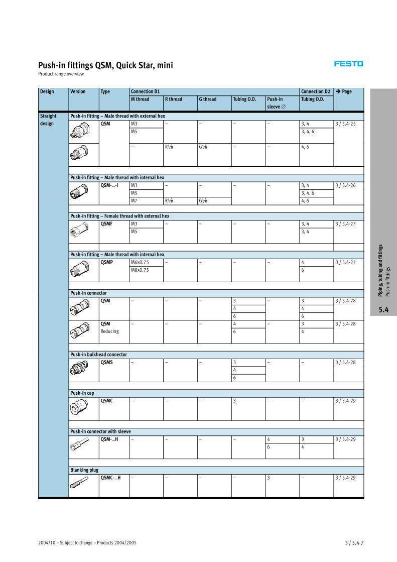
2004/10 – Subject to change – Products 2004/2005 3 / 5.4-7
Push-in fittings QSM, Quick Star, miniProduct range overview
Design Version Type Connection D1 Connection D2 � Pageg yp
M thread R thread G thread Tubing O.D. Push-in
sleeve∅
Tubing O.D.
g
Straight Push-in fitting – Male thread with external hexg
design QSM M3 – – – – 3, 4 3 / 5.4-25g Q
M5 3, 4, 6
3 / 5 5
– R� G� – – 4, 6
Push-in fitting – Male thread with internal hex
QSM-…-I M3 – – – – 3, 4 3 / 5.4-26Q
M5 3, 4, 6
3 / 5
M7 R� G� 4, 6
Push-in fitting – Female thread with external hex
QSMF M3 – – – – 3, 4 3 / 5.4-27Q
M5 3, 4
3 / 5 7
Push-in fitting – Male thread with internal hex
QSMP M6x0.75 – – – – 4 3 / 5.4-27Q
M8x0.75 6
3 / 5 7
Push-in connector
QSM – – – 3 – 3 3 / 5.4-28Q
4 4
3 / 5
6 6
QSM – – – 4 – 3 3 / 5.4-28Q
Reducing 6 4
3 / 5
Push-in bulkhead connector
QSMS – – – 3 – – 3 / 5.4-28Q
4
3 / 5
6
Push-in cap
QSMC – – – 3 – – 3 / 5.4-29
Push-in connector with sleeve
QSM-…H – – – – 4 3 3 / 5.4-29Q
6 4
3 / 5 9
Blanking plug
QSMC-…H – – – – 3 – 3 / 5.4-29
Piping,tubingandfittings
Push-infittings
5.4
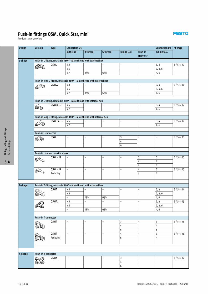
Products 2004/2005 – Subject to change – 2004/103 / 5.4-8
Push-in fittings QSM, Quick Star, miniProduct range overview
Design Version Type Connection D1 Connection D2 � Pageg yp
M thread R thread G thread Tubing O.D. Push-in
sleeve∅
Tubing O.D.
g
L-shape Push-in L-fitting, rotatable 360° – Male thread with external hexp
QSML M3 – – – – 3, 4 3 / 5.4-30Q
M5 3, 4, 6
3 / 5 3
M7 R� G� 4, 6
Push-in long L-fitting, rotatable 360° – Male thread with external hex
QSMLL M3 – – – – 3, 4 3 / 5.4-31Q
M5 3, 4, 6
3 / 5 3
M7 R� G� 4, 6
Push-in L-fitting, rotatable 360° – Male thread with internal hex
QSMLV-…-I M5 – – – – 3, 4 3 / 5.4-32Q
M7 4, 6
3 / 5 3
Push-in long L-fitting, rotatable 360° – Male thread with internal hex
QSMLLV-…-I M5 – – – – 3, 4 3 / 5.4-32Q
M7 4, 6
3 / 5 3
Push-in L-connector
QSML – – – 3 – – 3 / 5.4-33Q
4
3 / 5 33
6
Push-in L-connector with sleeve
QSML-…H – – – – 3 3 3 / 5.4-33Q
4 4
3 / 5 33
6 6
QSML-…H – – – – 4 3 3 / 5.4-33Q
Reducing 6 4
3 / 5 33
T-shape Push-in T-fitting, rotatable 360° – Male thread with external hexp
QSMT M3 – – – – 3, 4 3 / 5.4-34Q
M5 3, 4, 6
3 / 5 3
– R� G� 4, 6
QSMTL M3 – – – – 3, 4 3 / 5.4-35Q
M5 3, 4, 6
3 / 5 35
– R� G� 4, 6
Push-in T-connector
QSMT – – – 3 – 3 3 / 5.4-36Q
4 4
3 / 5 3
6 6
QSMT – – – 4 – 3 3 / 5.4-36Q
Reducing 6 4
3 / 5 3
X-shape Push-in X-connectorp
QSMX – – – 3 – – 3 / 5.4-37Q
4
3 / 5 37
6
Piping,tubingandfittings
Push-infittings
5.4
2004/10 – Subject to change – Products 2004/2005 3 / 5.7-7
Quick coupling sockets/plugs KD/KS, shut-off on one sideTechnical data
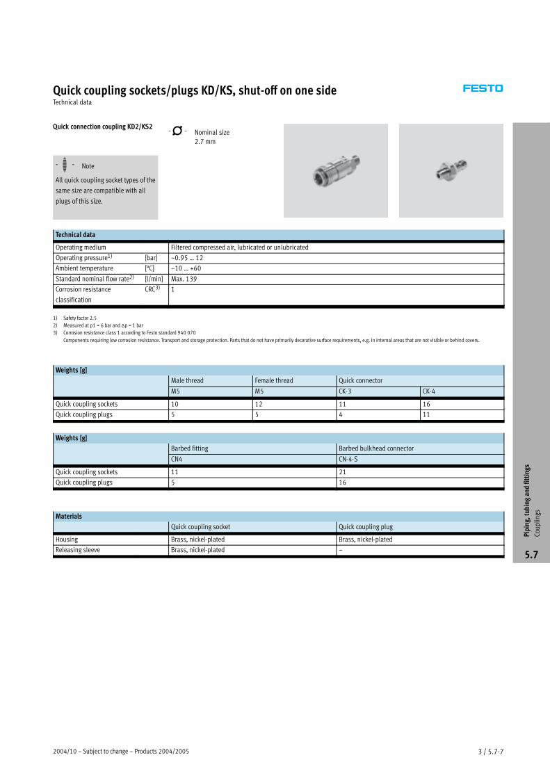
Quick connection coupling KD2/KS2 -N- Nominal size
2.7 mm
-H- Note
All quick coupling socket types of the
same size are compatible with all
plugs of this size.
Technical data
Operating medium Filtered compressed air, lubricated or unlubricated
Operating pressure1) [bar] –0.95 … 12
Ambient temperature [°C] –10 … +60
Standard nominal flow rate2) [l/min] Max. 139
Corrosion resistance
classification
CRC3) 1
1) Safety factor 2.5
2) Measured at p1 = 6 bar and �p = 1 bar
3) Corrosion resistance class 1 according to Festo standard 940 070
Components requiring low corrosion resistance. Transport and storage protection. Parts that do not have primarily decorative surface requirements, e.g. in internal areas that are not visible or behind covers.
Weights [g]
Male thread Female thread Quick connector
M5 M5 CK-3 CK-4
Quick coupling sockets 10 12 11 16
Quick coupling plugs 5 5 4 11
Weights [g]
Barbed fitting Barbed bulkhead connector
CN4 CN-4-S
Quick coupling sockets 11 21
Quick coupling plugs 5 16
Materials
Quick coupling socket Quick coupling plug
Housing Brass, nickel-plated Brass, nickel-plated
Releasing sleeve Brass, nickel-plated –
Piping,tubingandfittings
Couplings
5.7
Products 2004/2005 – Subject to change – 2004/103 / 5.7-8
Quick coupling sockets/plugs KD/KS, shut-off on one sideTechnical data
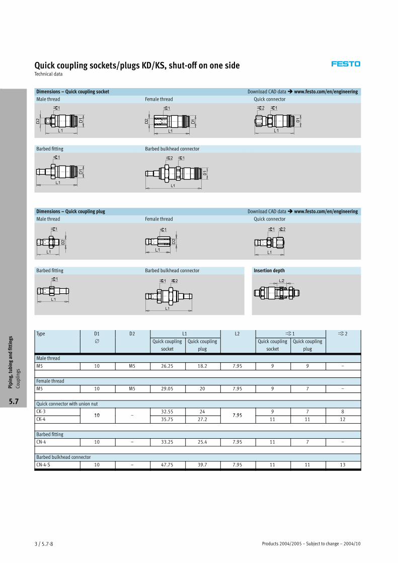
Dimensions – Quick coupling socket Download CAD data� www.festo.com/en/engineering
Male thread Female thread Quick connector
Barbed fitting Barbed bulkhead connector
Dimensions – Quick coupling plug Download CAD data� www.festo.com/en/engineering
Male thread Female thread Quick connector
Barbed fitting Barbed bulkhead connector Insertion depth
Type D1 D2 L1 L2 � 1 � 2yp
∅ Quick coupling
socket
Quick coupling
plug
Quick coupling
socket
Quick coupling
plug
Male thread
M5 10 M5 26.25 18.2 7.95 9 9 –
Female thread
M5 10 M5 29.05 20 7.95 9 7 –
Quick connector with union nut
CK-310 –
32.55 247 95
9 7 8
CK-410 –
35.75 27.27.95
11 11 12
Barbed fitting
CN-4 10 – 33.25 25.4 7.95 11 7 –
Barbed bulkhead connector
CN-4-S 10 – 47.75 39.7 7.95 11 11 13
Piping,tubingandfittings
Couplings
5.7
Products 2004/2005 – Subject to change – 2004/105 / 2.1-30
Toothed belt axes DGE-ZR-KF, with recirculating ball bearing guideTechnical data
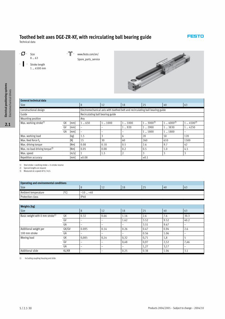
-N- Size
8 … 63
-T- Stroke length
1 … 4500 mm
-W- www.festo.com/en/
Spare_parts_service
General technical data
Size 8 12 18 25 40 63
Constructional design Electromechanical axis with toothed belt and recirculating ball bearing guide
Guide Recirculating ball bearing guide
Mounting position Any
Max. working stroke1) GK [mm] 1 … 650 1 … 1000 1 … 1000 1 … 30002) 1 … 40002) 1 … 45002)g
GV [mm] – – 1 … 920 1 … 2900 1 … 3830 1 … 4250
GA [mm] – – – 1 … 1800 1 … 1800 –
Max. working load [kg] 1.5 3 6 20 50 120
Max. feed force Fx [N] 15 30 60 260 610 1500
Max. driving torque [Nm] 0.08 0.18 0.5 2.6 9.7 42
Max. no-load driving torque3) [Nm] 0.05 0.08 0.2 0.5 1.0 4.5
Max. speed [m/s] 1 1.5 2 3 3 3
Repetition accuracy [mm] ±0.08 ±0.1
1) Total stroke = working stroke + 2x stroke reserve
2) Special lengths on request
3) Measured at a speed of 0.2 m/s
Operating and environmental conditions
Size 8 12 18 25 40 63
Ambient temperature [°C] –10 … +40
Protection class IP40
Weights [kg]
Size 8 12 18 25 40 63
Basic weight with 0 mm stroke1) GK 0.32 0.66 1.16 2.6 7.6 30.3g
GV – – 1.62 3.52 9.52 40.2
GA – – – 3.51 9.67 –
Additional weight per GK/GV 0.095 0.14 0.26 0.47 0.94 2.6g p
100 mm stroke GA – – – 0.56 1.06 –
Moving load GK 0,085 0,14 0,32 0,71 1,8 5g
GV – – 0,48 0,97 2,52 7,46
GA – – – 1,27 3,17 –
Additional slide KL/KR – – 0.25 0.38 1.06 3.1
1) Including coupling housing and slide
Electricalpositioningsystem
s
Electrom
echanicaldrives
2.1
2004/10 – Subject to change – Products 2004/2005 5 / 2.1-31
Toothed belt axes DGE-ZR-KF, with recirculating ball bearing guideTechnical data
Mass moment of inertia
Size 8 12 18 25 40 63
JO GK [kg cm2] 0.025 0.058 0.247 0.81 5.25 50.7JO
GV [kg cm2] – – 0.355 1.08 7.14 70.9
GA [kg cm2] – – – 1.37 8.71 –
JH per metre stroke [kg cm2/m] 0.003 0.009 0.021 0.078 0.45 3.6
JL per kg working load [kg cm2/kg] 0.259 0.365 0.685 1 2.53 7.85
The mass moment of inertia JA of the
entire axis is calculated as follows:
JA = JO + JH x working stroke [m] +
JL x mworking load [kg]
Toothed belt
Size 8 12 18 25 40 63
Tensile stress1) [%] 0.04 0.1 0.2 0.11 0.1 0.15
Pitch [mm] 2 2 2 3 5 8
Effective radius;
effective diameter
[mm] 10.18 12.09 16.55 20.05 31.83 56.02
Feed constant [mm/rev.] 32 38 52 63 100 176
1) At max. feed force
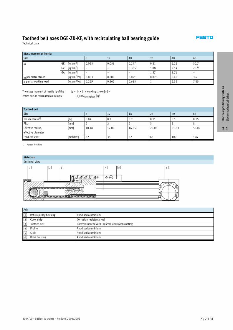
Materials
Sectional view
1 3 4 652
Axis
1 Return pulley housing Anodised aluminium
2 Cover strip Corrosion resistant steel
3 Toothed belt Polychloroprene with Glascord and nylon coating
4 Profile Anodised aluminium
5 Slide Anodised aluminium
6 Drive housing Anodised aluminium
Electricalpositioningsystem
s
Electrom
echanicaldrives
2.1
2004/10 – Subject to change – Products 2004/2005 5 / 2.1-73
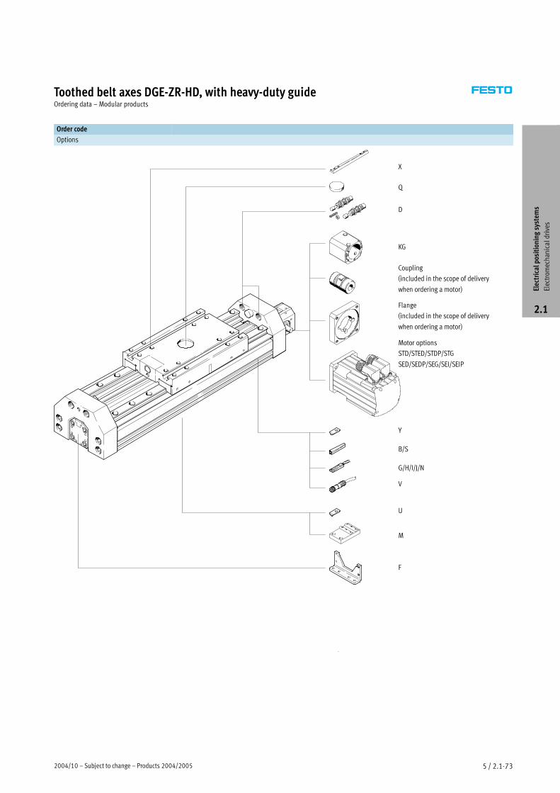
Toothed belt axes DGE-ZR-HD, with heavy-duty guideOrdering data – Modular products
Order code
Options
D
Motor options
STD/STED/STDP/STG
SED/SEDP/SEG/SEI/SEIP
B/S
U
M
F
Coupling
(included in the scope of delivery
when ordering a motor)
Flange
(included in the scope of delivery
when ordering a motor)
G/H/I/J/N
V
X
Q
KG
Y
Electricalpositioningsystem
s
Electrom
echanicaldrives
2.1
Products 2004/2005 – Subject to change – 2004/105 / 2.1-74
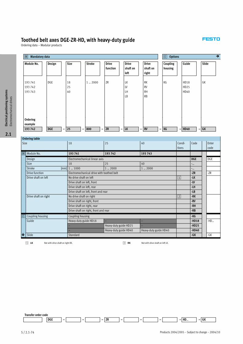
Toothed belt axes DGE-ZR-HD, with heavy-duty guideOrdering data – Modular products
Mandatory data�M Options�O �
Module No. Design Size Stroke Drive
function
Drive
shaft on
left
Drive
shaft on
right
Coupling
housing
Guide Slide
193 741
193 742
193 743
DGE 18
25
40
1 … 2000 ZR LK
LV
LH
LB
RK
RV
RH
RB
KG HD18
HD25
HD40
GK
Ordering
example
193 742 DGE – 25 – 800 – ZR – LK – RV – KG – HD40 – GK
Ordering table
Size 18 25 40 Condi-
tions
Code Enter
code
�M Module No. 193 741 193 742 193 743
Design Electromechanical linear axis DGE DGE
Size 18 25 40 -…
Stroke [mm] 1 … 1000 1 … 2000 1 … 2000 -…
Drive function Electromechanical drive with toothed belt -ZR -ZR
Drive shaft on left No drive shaft on left 1 -LK
Drive shaft on left, front -LV
Drive shaft on left, rear -LH
Drive shaft on left, front and rear -LB
Drive shaft on right No drive shaft on right 2 -RKg
Drive shaft on right, front -RV
Drive shaft on right, rear -RH
Drive shaft on right, front and rear -RB
�O Coupling housing Coupling housing -KG
Guide Heavy-duty guide HD18 – – -HD18 -HD…
– Heavy-duty guide HD25 – -HD25
– Heavy-duty guide HD40 Heavy-duty guide HD40 -HD40
� Slide Standard -GK -GK
1 LK Not with drive shaft on right RK. 2 RK Not with drive shaft on left LK.
Transfer order code
DGE – – – ZR – – – – HD… – GK
Electricalpositioningsystem
s
Electrom
echanicaldrives
2.1
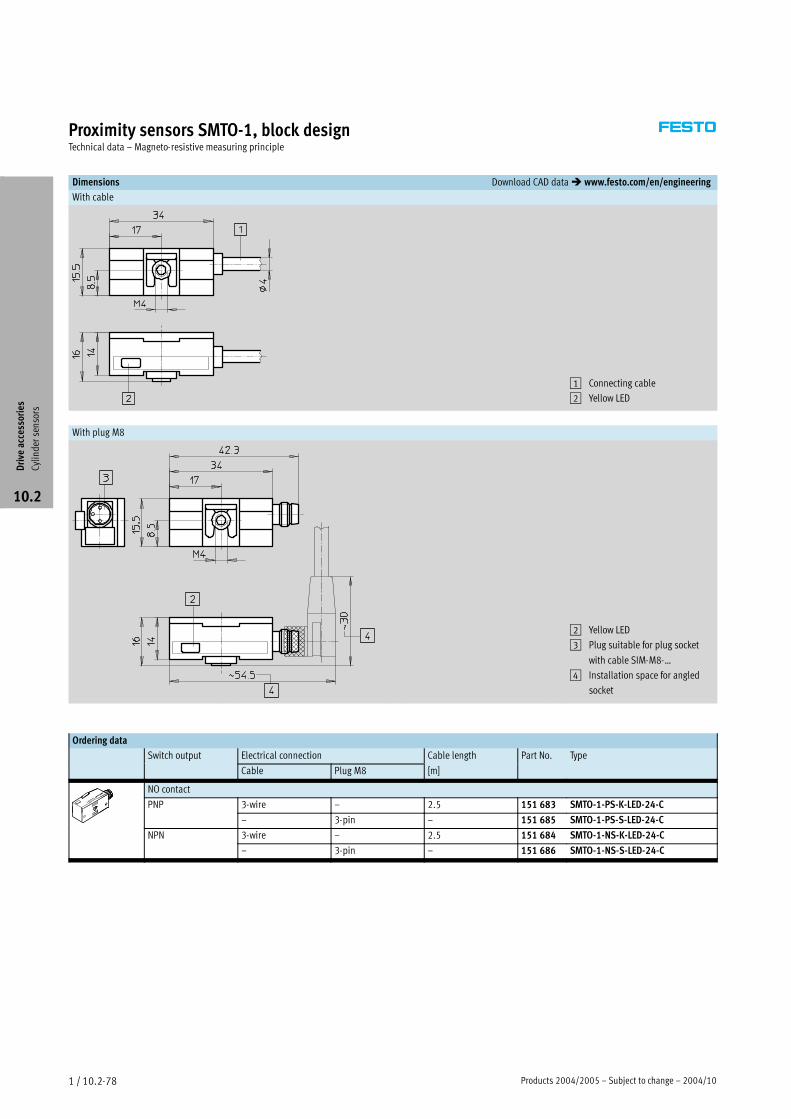
Products 2004/2005 – Subject to change – 2004/101 / 10.2-78
Proximity sensors SMTO-1, block designTechnical data – Magneto-resistive measuring principle
Dimensions Download CAD data� www.festo.com/en/engineering
With cable
1 Connecting cable
2 Yellow LED
With plug M8
2 Yellow LED
3 Plug suitable for plug socket
with cable SIM-M8-…
4 Installation space for angled
socket
Ordering data
Switch output Electrical connection Cable length Part No. Typep
Cable Plug M8 [m]
yp
NO contact
PNP 3-wire – 2.5 151 683 SMTO-1-PS-K-LED-24-C
– 3-pin – 151 685 SMTO-1-PS-S-LED-24-C
NPN 3-wire – 2.5 151 684 SMTO-1-NS-K-LED-24-C
– 3-pin – 151 686 SMTO-1-NS-S-LED-24-C
Driveaccessories
Cylindersensors
10.2
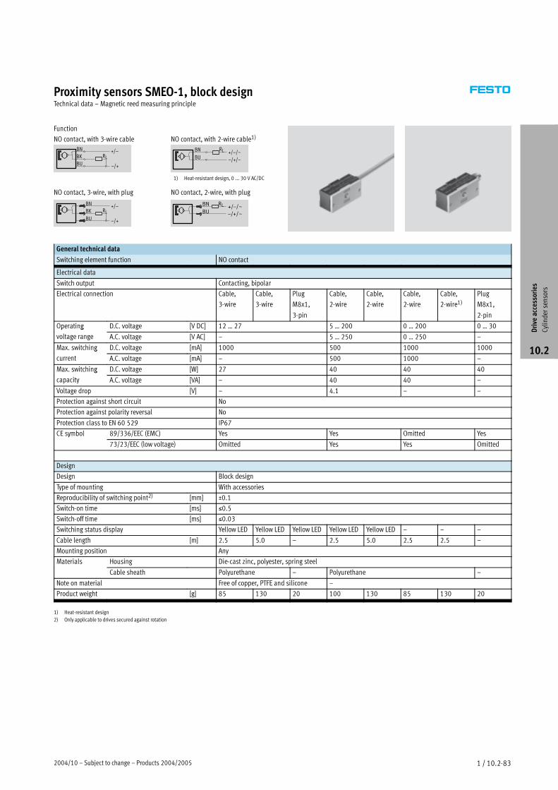
2004/10 – Subject to change – Products 2004/2005 1 / 10.2-83
Proximity sensors SMEO-1, block designTechnical data – Magnetic reed measuring principle
Function
NO contact, with 3-wire cable
NO contact, 3-wire, with plug
RLBU
+/–
–/+
BN
BK
RL
BU
+/–BK
BN
–/+
NO contact, with 2-wire cable1)
BN
BU
RL +/–/~
–/+/~
NO contact, 2-wire, with plug
1) Heat-resistant design, 0 ... 30 V AC/DC
BN
BU
RL +/–/~
–/+/~
General technical data
Switching element function NO contact
Electrical data
Switch output Contacting, bipolar
Electrical connection Cable,
3-wire
Cable,
3-wire
Plug
M8x1,
3-pin
Cable,
2-wire
Cable,
2-wire
Cable,
2-wire
Cable,
2-wire1)Plug
M8x1,
2-pin
Operating D.C. voltage [V DC] 12 … 27 5 … 200 0 … 200 0 … 30p g
voltage range A.C. voltage [V AC] – 5 … 250 0 … 250 –
Max. switching D.C. voltage [mA] 1000 500 1000 1000g
current A.C. voltage [mA] – 500 1000 –
Max. switching D.C. voltage [W] 27 40 40 40g
capacity A.C. voltage [VA] – 40 40 –
Voltage drop [V] – 4.1 – –
Protection against short circuit No
Protection against polarity reversal No
Protection class to EN 60 529 IP67
CE symbol 89/336/EEC (EMC) Yes Yes Omitted Yesy
73/23/EEC (low voltage) Omitted Yes Yes Omitted
Design
Design Block design
Type of mounting With accessories
Reproducibility of switching point2) [mm] ±0.1
Switch-on time [ms] �0.5
Switch-off time [ms] �0.03
Switching status display Yellow LED Yellow LED Yellow LED Yellow LED Yellow LED – – –
Cable length [m] 2.5 5.0 – 2.5 5.0 2.5 2.5 –
Mounting position Any
Materials Housing Die-cast zinc, polyester, spring steel
Cable sheath Polyurethane – Polyurethane –
Note on material Free of copper, PTFE and silicone –
Product weight [g] 85 130 20 100 130 85 130 20
1) Heat-resistant design
2) Only applicable to drives secured against rotation
Driveaccessories
Cylindersensors
10.2
2004/10 – Subject to change – Products 2004/2005 1 / 10.2-25
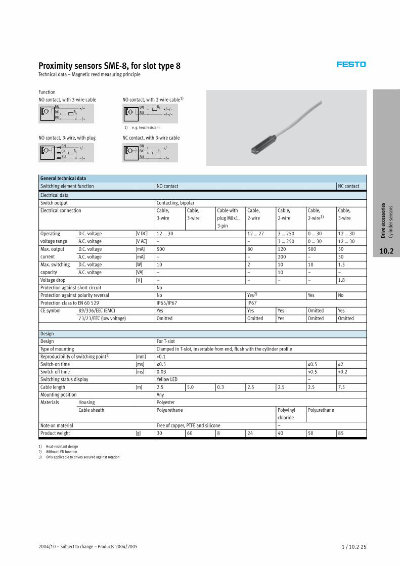
Proximity sensors SME-8, for slot type 8Technical data – Magnetic reed measuring principle
Function
NO contact, with 3-wire cable
NO contact, 3-wire, with plug
RLBU
+/–
–/+
BN
BK
RL
BU
+/–BK
BN
–/+
NO contact, with 2-wire cable1)
NC contact, with 3-wire cable
BN
BU
RL +/–/~
–/+/~
RL
BN +/–
BU
BK
–/+
1) e. g. heat resistant
General technical data
Switching element function NO contact NC contact
Electrical data
Switch output Contacting, bipolar
Electrical connection Cable,
3-wire
Cable,
3-wire
Cable with
plug M8x1,
3-pin
Cable,
2-wire
Cable,
2-wire
Cable,
2-wire1)Cable,
3-wire
Operating D.C. voltage [V DC] 12 … 30 12 … 27 3 … 250 0 … 30 12 … 30p g
voltage range A.C. voltage [V AC] – – 3 … 250 0 … 30 12 … 30
Max. output D.C. voltage [mA] 500 80 120 500 50p
current A.C. voltage [mA] – – 200 – 50
Max. switching D.C. voltage [W] 10 2 10 10 1.5g
capacity A.C. voltage [VA] – – 10 – –
Voltage drop [V] – – – – 1.8
Protection against short circuit No
Protection against polarity reversal No Yes2) Yes No
Protection class to EN 60 529 IP65/IP67 IP67
CE symbol 89/336/EEC (EMC) Yes Yes Yes Omitted Yesy
73/23/EEC (low voltage) Omitted Omitted Yes Omitted Omitted
Design
Design For T-slot
Type of mounting Clamped in T-slot, insertable from end, flush with the cylinder profile
Reproducibility of switching point3) [mm] ±0.1
Switch-on time [ms] �0.5 �0.5 �2
Switch-off time [ms] 0.03 �0.5 �0.2
Switching status display Yellow LED –
Cable length [m] 2.5 5.0 0.3 2.5 2.5 2.5 7.5
Mounting position Any
Materials Housing Polyester
Cable sheath Polyurethane Polyvinyl
chloride
Polyurethane
Note on material Free of copper, PTFE and silicone –
Product weight [g] 30 60 8 24 40 50 85
1) Heat-resistant design
2) Without LED function
3) Only applicable to drives secured against rotation
Driveaccessories
Cylindersensors
10.2
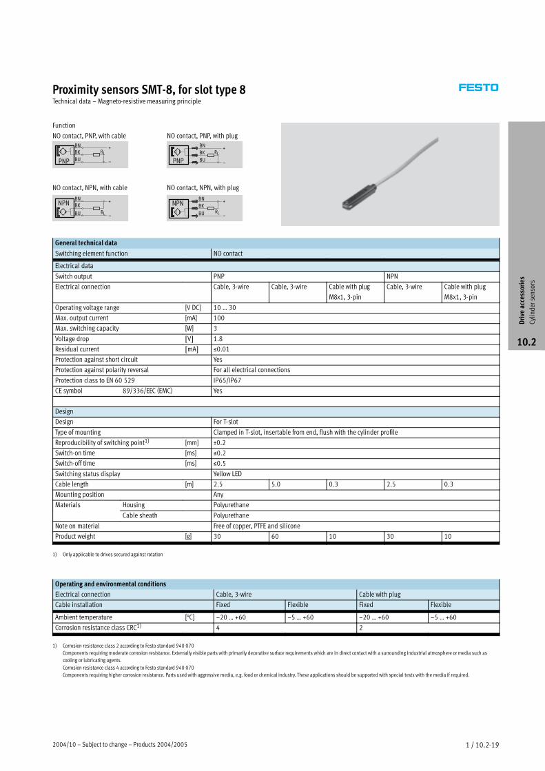
2004/10 – Subject to change – Products 2004/2005 1 / 10.2-19
Proximity sensors SMT-8, for slot type 8Technical data – Magneto-resistive measuring principle
Function
NO contact, PNP, with cable
NO contact, NPN, with cable
+
RL
BKBN
BU
NPN
–
RL
–BU
BKBN
PNP
+
NO contact, PNP, with plug
NO contact, NPN, with plug
–RLBU
BN
BK+NPN
RLBU
BN
BK+
–PNP
General technical data
Switching element function NO contact
Electrical data
Switch output PNP NPN
Electrical connection Cable, 3-wire Cable, 3-wire Cable with plug
M8x1, 3-pin
Cable, 3-wire Cable with plug
M8x1, 3-pin
Operating voltage range [V DC] 10 … 30
Max. output current [mA] 100
Max. switching capacity [W] 3
Voltage drop [V] 1.8
Residual current [mA] �0.01
Protection against short circuit Yes
Protection against polarity reversal For all electrical connections
Protection class to EN 60 529 IP65/IP67
CE symbol 89/336/EEC (EMC) Yes
Design
Design For T-slot
Type of mounting Clamped in T-slot, insertable from end, flush with the cylinder profile
Reproducibility of switching point1) [mm] ±0.2
Switch-on time [ms] �0.2
Switch-off time [ms] �0.5
Switching status display Yellow LED
Cable length [m] 2.5 5.0 0.3 2.5 0.3
Mounting position Any
Materials Housing Polyurethane
Cable sheath Polyurethane
Note on material Free of copper, PTFE and silicone
Product weight [g] 30 60 10 30 10
1) Only applicable to drives secured against rotation
Operating and environmental conditions
Electrical connection Cable, 3-wire Cable with plug
Cable installation Fixed Flexible Fixed Flexible
Ambient temperature [°C] –20 … +60 –5 … +60 –20 … +60 –5 … +60
Corrosion resistance class CRC1) 4 2
1) Corrosion resistance class 2 according to Festo standard 940 070
Components requiring moderate corrosion resistance. Externally visible parts with primarily decorative surface requirements which are in direct contact with a surrounding industrial atmosphere or media such as
cooling or lubricating agents.
Corrosion resistance class 4 according to Festo standard 940 070
Components requiring higher corrosion resistance. Parts used with aggressive media, e.g. food or chemical industry. These applications should be supported with special tests with the media if required.
Driveaccessories
Cylindersensors
10.2
Products 2004/2005 – Subject to change – 2004/104 / 8.2-18
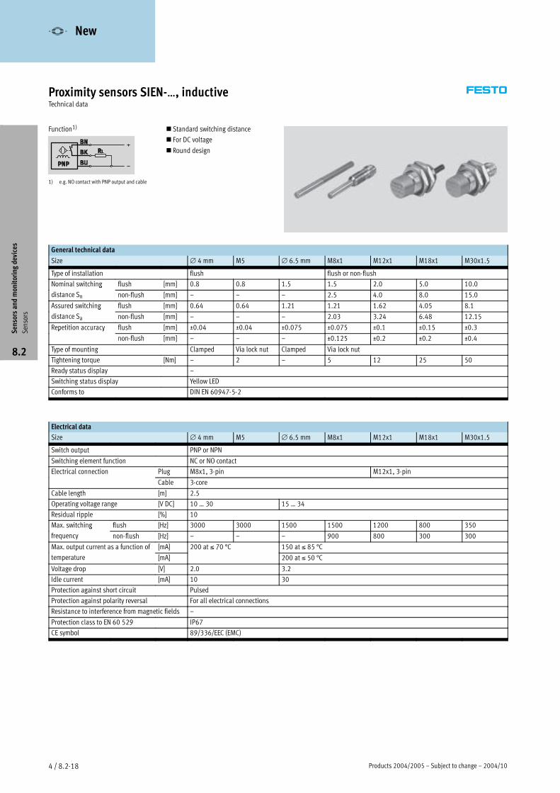
Proximity sensors SIEN-…, inductiveTechnical data
Function1)
1) e.g. NO contact with PNP output and cable
� Standard switching distance
� For DC voltage
� Round design
General technical data
Size ∅ 4 mm M5 ∅ 6.5 mm M8x1 M12x1 M18x1 M30x1.5
Type of installation flush flush or non-flush
Nominal switching flush [mm] 0.8 0.8 1.5 1.5 2.0 5.0 10.0g
distance Sn non-flush [mm] – – – 2.5 4.0 8.0 15.0
Assured switching flush [mm] 0.64 0.64 1.21 1.21 1.62 4.05 8.1g
distance Sa non-flush [mm] – – – 2.03 3.24 6.48 12.15
Repetition accuracy flush [mm] ±0.04 ±0.04 ±0.075 ±0.075 ±0.1 ±0.15 ±0.3p y
non-flush [mm] – – – ±0.125 ±0.2 ±0.2 ±0.4
Type of mounting Clamped Via lock nut Clamped Via lock nut
Tightening torque [Nm] – 2 – 5 12 25 50
Ready status display –
Switching status display Yellow LED
Conforms to DIN EN 60947-5-2
Electrical data
Size ∅ 4 mm M5 ∅ 6.5 mm M8x1 M12x1 M18x1 M30x1.5
Switch output PNP or NPN
Switching element function NC or NO contact
Electrical connection Plug M8x1, 3-pin M12x1, 3-pin
Cable 3-core
Cable length [m] 2.5
Operating voltage range [V DC] 10 … 30 15 … 34
Residual ripple [%] 10
Max. switching flush [Hz] 3000 3000 1500 1500 1200 800 350g
frequency non-flush [Hz] – – – 900 800 300 300
Max. output current as a function of [mA] 200 at ≤ 70 °C 150 at ≤ 85 °Cp
temperature [mA]
7
200 at ≤ 50 °C
Voltage drop [V] 2.0 3.2
Idle current [mA] 10 30
Protection against short circuit Pulsed
Protection against polarity reversal For all electrical connections
Resistance to interference from magnetic fields –
Protection class to EN 60 529 IP67
CE symbol 89/336/EEC (EMC)
Sensorsandmonitoringdevices
Sensors
8.2
-V- New
2004/10 – Subject to change – Products 2004/2005 4 / 8.2-19
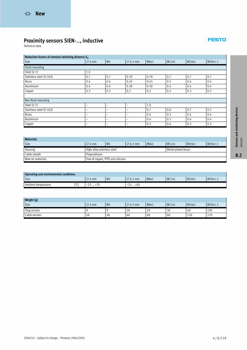
Proximity sensors SIEN-…, inductiveTechnical data
Reduction factors of nominal switching distance Sn
Size ∅ 4 mm M5 ∅ 6.5 mm M8x1 M12x1 M18x1 M30x1.5
Flush mounting
Steel St 37 1.0
Stainless steel St 18/8 0.7 0.7 0.78 0.78 0.7 0.7 0.7
Brass 0.4 0.4 0.45 0.45 0.5 0.4 0.4
Aluminium 0.4 0.4 0.38 0.38 0.4 0.4 0.4
Copper 0.3 0.3 0.2 0.2 0.2 0.3 0.3
Non-flush mounting
Steel St 37 – – – 1.0
Stainless steel St 18/8 – – – 0.7 0.8 0.7 0.7
Brass – – – 0.4 0.5 0.4 0.4
Aluminium – – – 0.4 0.5 0.4 0.4
Copper – – – 0.3 0.4 0.3 0.3
Materials
Size ∅ 4 mm M5 ∅ 6.5 mm M8x1 M12x1 M18x1 M30x1.5
Housing High-alloy stainless steel Nickel plated brass
Cable sheath Polyurethane
Note on materials Free of copper, PTFE and silicone
Operating and environmental conditions
Size ∅ 4 mm M5 ∅ 6.5 mm M8x1 M12x1 M18x1 M30x1.5
Ambient temperature [°C] –25 … +70 –25 … +85
Weight [g]
Size ∅ 4 mm M5 ∅ 6.5 mm M8x1 M12x1 M18x1 M30x1.5
Plug version 9 9 20 20 30 40 100
Cable version 48 48 60 60 80 120 170
Sensorsandmonitoringdevices
Sensors
8.2
-V- New
Products 2004/2005 – Subject to change – 2004/104 / 8.2-20
Proximity sensors SIEN-…, inductiveTechnical data
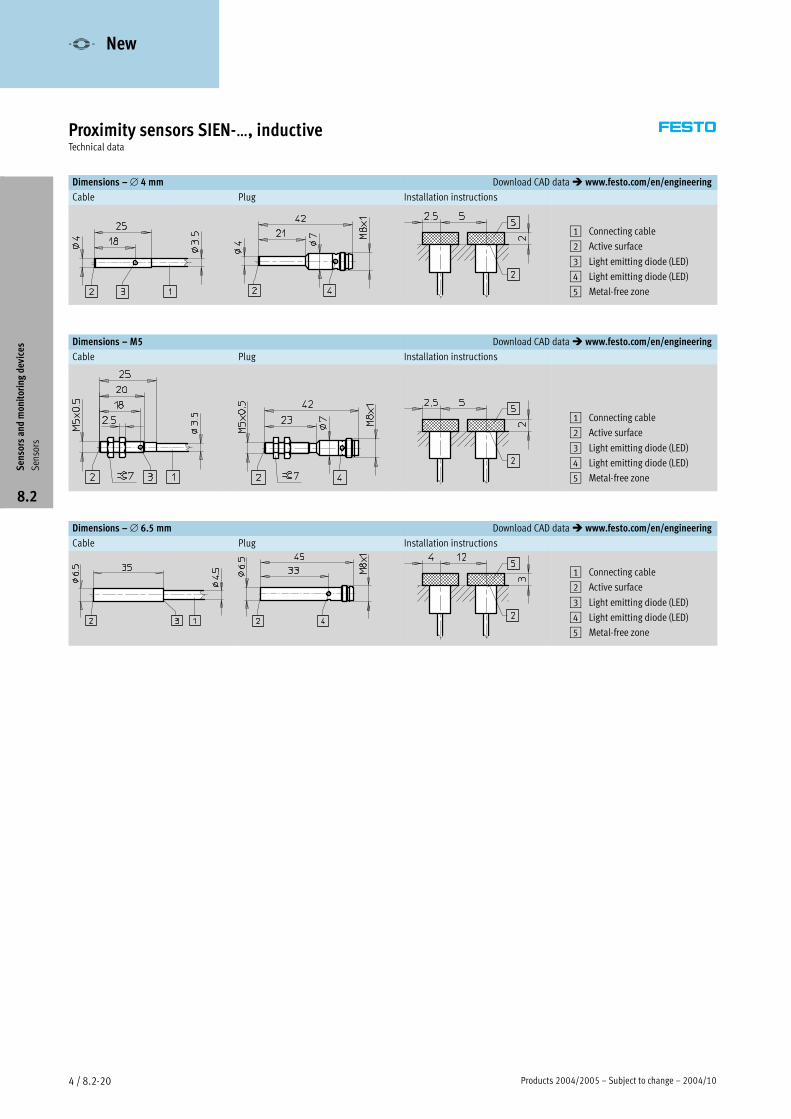
Dimensions –∅ 4 mm Download CAD data� www.festo.com/en/engineering
Cable Plug Installation instructions
1 Connecting cable
2 Active surface
3 Light emitting diode (LED)
4 Light emitting diode (LED)
5 Metal-free zone
Dimensions – M5 Download CAD data� www.festo.com/en/engineering
Cable Plug Installation instructions
1 Connecting cable
2 Active surface
3 Light emitting diode (LED)
4 Light emitting diode (LED)
5 Metal-free zone
Dimensions –∅ 6.5 mm Download CAD data� www.festo.com/en/engineering
Cable Plug Installation instructions
1 Connecting cable
2 Active surface
3 Light emitting diode (LED)
4 Light emitting diode (LED)
5 Metal-free zone
Sensorsandmonitoringdevices
Sensors
8.2
-V- New
2004/10 – Subject to change – Products 2004/2005 4 / 8.2-21
Proximity sensors SIEN-…, inductiveTechnical data
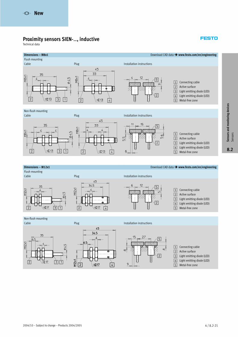
Dimensions – M8x1 Download CAD data� www.festo.com/en/engineering
Flush mounting
Cable Plug Installation instructions
1 Connecting cable
2 Active surface
3 Light emitting diode (LED)
4 Light emitting diode (LED)
5 Metal-free zone
Non-flush mounting
Cable Plug Installation instructions
1 Connecting cable
2 Active surface
3 Light emitting diode (LED)
4 Light emitting diode (LED)
5 Metal-free zone
Dimensions – M12x1 Download CAD data� www.festo.com/en/engineering
Flush mounting
Cable Plug Installation instructions
1 Connecting cable
2 Active surface
3 Light emitting diode (LED)
4 Light emitting diode (LED)
5 Metal-free zone
Non-flush mounting
Cable Plug Installation instructions
1 Connecting cable
2 Active surface
3 Light emitting diode (LED)
4 Light emitting diode (LED)
5 Metal-free zone
Sensorsandmonitoringdevices
Sensors
8.2
-V- New
Products 2004/2005 – Subject to change – 2004/104 / 8.2-22
Proximity sensors SIEN-…, inductiveTechnical data
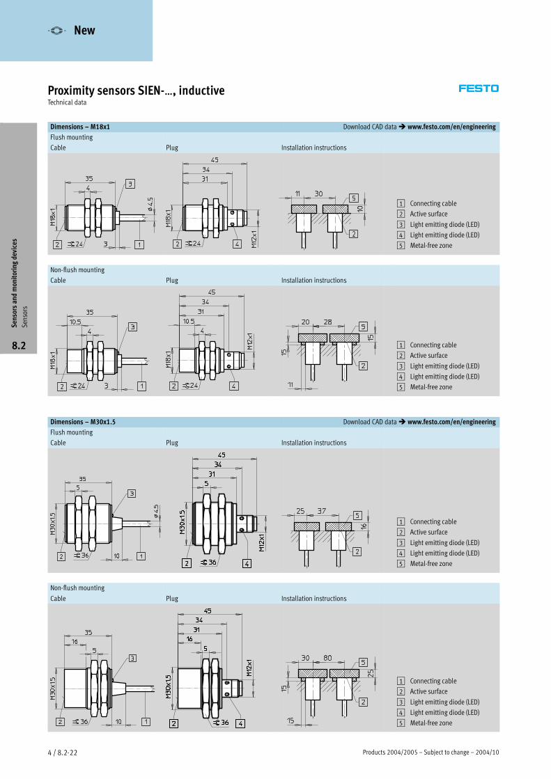
Dimensions – M18x1 Download CAD data� www.festo.com/en/engineering
Flush mounting
Cable Plug Installation instructions
1 Connecting cable
2 Active surface
3 Light emitting diode (LED)
4 Light emitting diode (LED)
5 Metal-free zone
Non-flush mounting
Cable Plug Installation instructions
1 Connecting cable
2 Active surface
3 Light emitting diode (LED)
4 Light emitting diode (LED)
5 Metal-free zone
Dimensions – M30x1.5 Download CAD data� www.festo.com/en/engineering
Flush mounting
Cable Plug Installation instructions
1 Connecting cable
2 Active surface
3 Light emitting diode (LED)
4 Light emitting diode (LED)
5 Metal-free zone
Non-flush mounting
Cable Plug Installation instructions
1 Connecting cable
2 Active surface
3 Light emitting diode (LED)
4 Light emitting diode (LED)
5 Metal-free zone
Sensorsandmonitoringdevices
Sensors
8.2
-V- New
Products 2004/2005 – Subject to change – 2004/104 / 8.2-14
Diffuse sensor SOEG-RTTechnical data
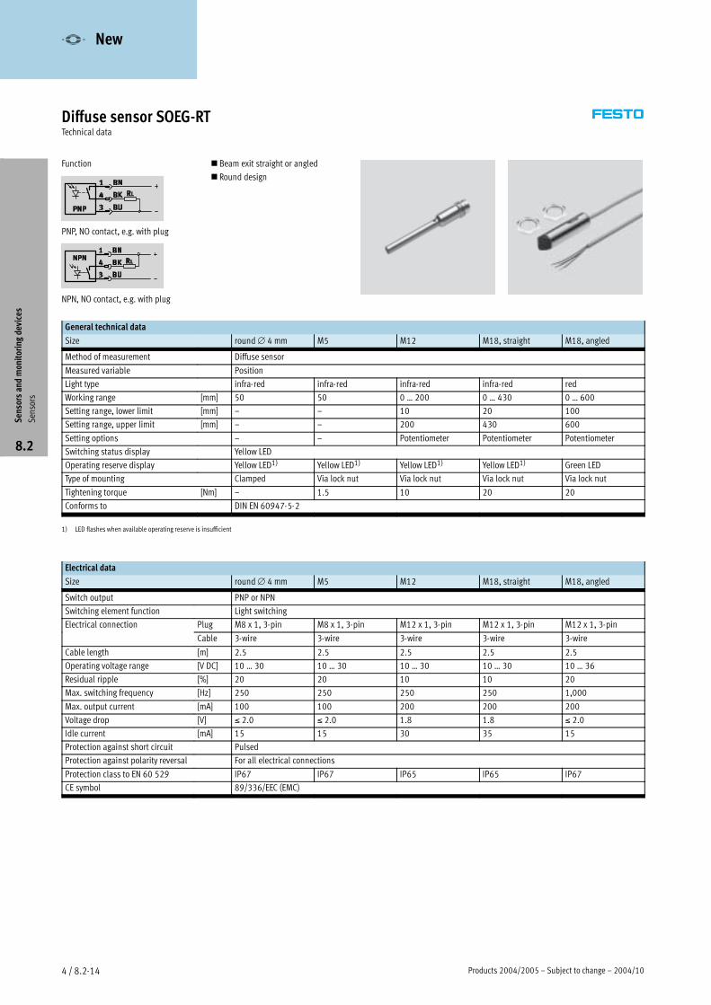
Function
PNP, NO contact, e.g. with plug
NPN, NO contact, e.g. with plug
� Beam exit straight or angled
� Round design
General technical data
Size round∅ 4 mm M5 M12 M18, straight M18, angled
Method of measurement Diffuse sensor
Measured variable Position
Light type infra-red infra-red infra-red infra-red red
Working range [mm] 50 50 0 … 200 0 … 430 0 … 600
Setting range, lower limit [mm] – – 10 20 100
Setting range, upper limit [mm] – – 200 430 600
Setting options – – Potentiometer Potentiometer Potentiometer
Switching status display Yellow LED
Operating reserve display Yellow LED1) Yellow LED1) Yellow LED1) Yellow LED1) Green LED
Type of mounting Clamped Via lock nut Via lock nut Via lock nut Via lock nut
Tightening torque [Nm] – 1.5 10 20 20
Conforms to DIN EN 60947-5-2
1) LED flashes when available operating reserve is insufficient
Electrical data
Size round∅ 4 mm M5 M12 M18, straight M18, angled
Switch output PNP or NPN
Switching element function Light switching
Electrical connection Plug M8 x 1, 3-pin M8 x 1, 3-pin M12 x 1, 3-pin M12 x 1, 3-pin M12 x 1, 3-pin
Cable 3-wire 3-wire 3-wire 3-wire 3-wire
Cable length [m] 2.5 2.5 2.5 2.5 2.5
Operating voltage range [V DC] 10 … 30 10 … 30 10 … 30 10 … 30 10 … 36
Residual ripple [%] 20 20 10 10 20
Max. switching frequency [Hz] 250 250 250 250 1,000
Max. output current [mA] 100 100 200 200 200
Voltage drop [V] ≤ 2.0 ≤ 2.0 1.8 1.8 ≤ 2.0
Idle current [mA] 15 15 30 35 15
Protection against short circuit Pulsed
Protection against polarity reversal For all electrical connections
Protection class to EN 60 529 IP67 IP67 IP65 IP65 IP67
CE symbol 89/336/EEC (EMC)
Sensorsandmonitoringdevices
Sensors
8.2
-V- New
2004/10 – Subject to change – Products 2004/2005 4 / 8.2-15
Diffuse sensor SOEG-RTTechnical data
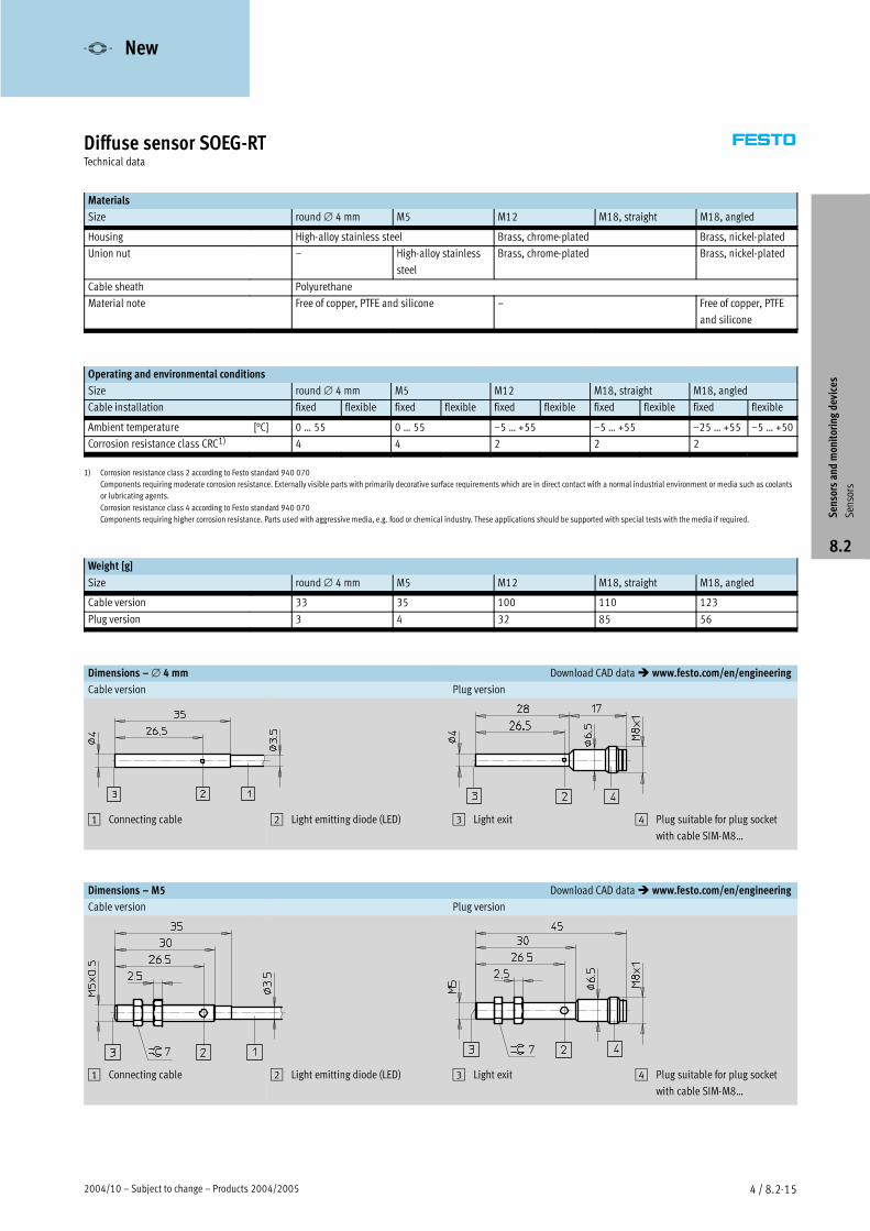
Materials
Size round∅ 4 mm M5 M12 M18, straight M18, angled
Housing High-alloy stainless steel Brass, chrome-plated Brass, nickel-plated
Union nut – High-alloy stainless
steel
Brass, chrome-plated Brass, nickel-plated
Cable sheath Polyurethane
Material note Free of copper, PTFE and silicone – Free of copper, PTFE
and silicone
Operating and environmental conditions
Size round∅ 4 mm M5 M12 M18, straight M18, angled
Cable installation fixed flexible fixed flexible fixed flexible fixed flexible fixed flexible
Ambient temperature [°C] 0 … 55 0 … 55 –5 … +55 –5 … +55 –25 … +55 –5 … +50
Corrosion resistance class CRC1) 4 4 2 2 2
1) Corrosion resistance class 2 according to Festo standard 940 070
Components requiring moderate corrosion resistance. Externally visible parts with primarily decorative surface requirements which are in direct contact with a normal industrial environment or media such as coolants
or lubricating agents.
Corrosion resistance class 4 according to Festo standard 940 070
Components requiring higher corrosion resistance. Parts used with aggressive media, e.g. food or chemical industry. These applications should be supported with special tests with the media if required.
Weight [g]
Size round∅ 4 mm M5 M12 M18, straight M18, angled
Cable version 33 35 100 110 123
Plug version 3 4 32 85 56
Dimensions –∅ 4 mm Download CAD data� www.festo.com/en/engineering
Cable version Plug version
1 Connecting cable 2 Light emitting diode (LED) 3 Light exit 4 Plug suitable for plug socket
with cable SIM-M8…
Dimensions – M5 Download CAD data� www.festo.com/en/engineering
Cable version Plug version
1 Connecting cable 2 Light emitting diode (LED) 3 Light exit 4 Plug suitable for plug socket
with cable SIM-M8…
Sensorsandmonitoringdevices
Sensors
8.2
-V- New
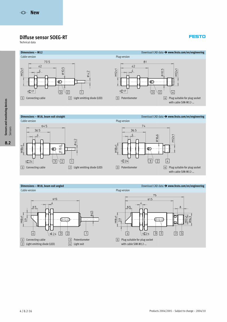
Products 2004/2005 – Subject to change – 2004/104 / 8.2-16
Diffuse sensor SOEG-RTTechnical data
Dimensions – M12 Download CAD data� www.festo.com/en/engineering
Cable version Plug version
1 Connecting cable 2 Light emitting diode (LED) 3 Potentiometer 4 Plug suitable for plug socket
with cable SIM-M12-…
Dimensions – M18, beam exit straight Download CAD data� www.festo.com/en/engineering
Cable version Plug version
1 Connecting cable 2 Light emitting diode (LED) 3 Potentiometer 4 Plug suitable for plug socket
with cable SIM-M12-…
Dimensions – M18, beam exit angled Download CAD data� www.festo.com/en/engineering
Cable version Plug version
1 Connecting cable
2 Light emitting diode (LED)
3 Potentiometer
4 Light exit
5 Plug suitable for plug socket
with cable SIM-M12-…
Sensorsandmonitoringdevices
Sensors
8.2
-V- New

2004/10 – Subject to change – Products 2004/2005 4 / 8.2-17
Diffuse sensor SOEG-RTTechnical data
Design Working range Switch output Electrical connection Free of copper, Part No. Typeg
[mm]
p
Cable Plug
pp ,
PTFE and silicone
yp
Round design,∅ 4 mm
50 PNP, light switching � – � 537 671 SOEG-RT-4-PS-K-L5 , g g
– � � 537 673 SOEG-RT-4-PS-S-L
NPN, light switching � – � 537 674 SOEG-RT-4-NS-K-L, g g
– � � 537 676 SOEG-RT-4-NS-S-L
Round design, male thread M5
50 PNP, light switching � – � 537 677 SOEG-RT-M5-PS-K-L5 , g g
– � � 537 679 SOEG-RT-M5-PS-S-L
NPN, light switching � – � 537 680 SOEG-RT-M5-NS-K-L, g g
– � � 537 682 SOEG-RT-M5-NS-S-L
Round design, male thread M12
0 … 200 PNP, light switching � – – 165 338 SOEG-RT-M12-PS-K-L, g g
– � – 165 339 SOEG-RT-M12-PS-S-L
NPN, light switching � – – 165 336 SOEG-RT-M12-NS-K-L, g g
– � – 165 337 SOEG-RT-M12-NS-S-L
Round design, male thread M18, beam exit straight
0 … 430 PNP, light switching � – – 165 342 SOEG-RT-M18-PS-K-L3 , g g
– � – 165 343 SOEG-RT-M18-PS-S-L
NPN, light switching � – – 165 340 SOEG-RT-M18-NS-K-L, g g
– � – 165 341 SOEG-RT-M18-NS-S-L
Round design, male thread M18, beam exit angled
0 … 600 PNP, light switching � – � 537 701 SOEG-RT-M18W-PS-K-2L, g g
– � � 537 702 SOEG-RT-M18W-PS-S-2L
NPN, light switching � – � 537 717 SOEG-RT-M18W-NS-K-2L, g g
– � � 537 718 SOEG-RT-M18W-NS-S-2L
Sensorsandmonitoringdevices
Sensors
8.2
-V- New
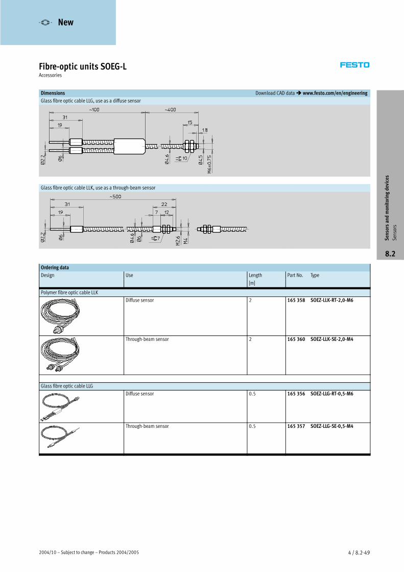
2004/10 – Subject to change – Products 2004/2005 4 / 8.2-49
Fibre-optic units SOEG-LAccessories
Dimensions Download CAD data� www.festo.com/en/engineering
Glass fibre optic cable LLG, use as a diffuse sensor
Glass fibre optic cable LLK, use as a through-beam sensor
Ordering data
Design Use Length Part No. Typeg
[m]
yp
Polymer fibre optic cable LLK
Diffuse sensor 2 165 358 SOEZ-LLK-RT-2,0-M6
Through-beam sensor 2 165 360 SOEZ-LLK-SE-2,0-M4
Glass fibre optic cable LLG
Diffuse sensor 0.5 165 356 SOEZ-LLG-RT-0,5-M6
Through-beam sensor 0.5 165 357 SOEZ-LLG-SE-0,5-M4
Sensorsandmonitoringdevices
Sensors
8.2
-V- New
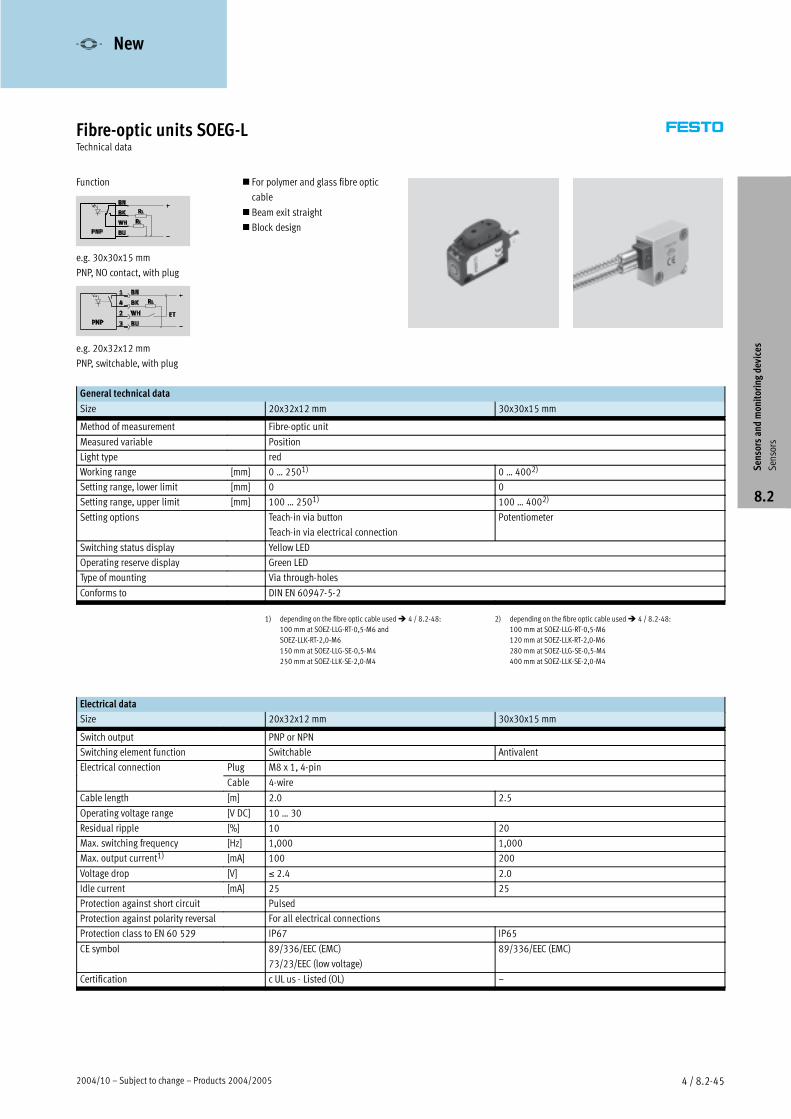
2004/10 – Subject to change – Products 2004/2005 4 / 8.2-45
Fibre-optic units SOEG-LTechnical data
Function
e.g. 30x30x15 mm
PNP, NO contact, with plug
e.g. 20x32x12 mm
PNP, switchable, with plug
� For polymer and glass fibre optic
cable
� Beam exit straight
� Block design
General technical data
Size 20x32x12 mm 30x30x15 mm
Method of measurement Fibre-optic unit
Measured variable Position
Light type red
Working range [mm] 0 … 2501) 0 … 4002)
Setting range, lower limit [mm] 0 0
Setting range, upper limit [mm] 100 … 2501) 100 … 4002)
Setting options Teach-in via button
Teach-in via electrical connection
Potentiometer
Switching status display Yellow LED
Operating reserve display Green LED
Type of mounting Via through-holes
Conforms to DIN EN 60947-5-2
1) depending on the fibre optic cable used� 4 / 8.2-48:
100 mm at SOEZ-LLG-RT-0,5-M6 and
SOEZ-LLK-RT-2,0-M6
150 mm at SOEZ-LLG-SE-0,5-M4
250 mm at SOEZ-LLK-SE-2,0-M4
2) depending on the fibre optic cable used� 4 / 8.2-48:
100 mm at SOEZ-LLG-RT-0,5-M6
120 mm at SOEZ-LLK-RT-2,0-M6
280 mm at SOEZ-LLG-SE-0,5-M4
400 mm at SOEZ-LLK-SE-2,0-M4
Electrical data
Size 20x32x12 mm 30x30x15 mm
Switch output PNP or NPN
Switching element function Switchable Antivalent
Electrical connection Plug M8 x 1, 4-pin
Cable 4-wire
Cable length [m] 2.0 2.5
Operating voltage range [V DC] 10 … 30
Residual ripple [%] 10 20
Max. switching frequency [Hz] 1,000 1,000
Max. output current1) [mA] 100 200
Voltage drop [V] ≤ 2.4 2.0
Idle current [mA] 25 25
Protection against short circuit Pulsed
Protection against polarity reversal For all electrical connections
Protection class to EN 60 529 IP67 IP65
CE symbol 89/336/EEC (EMC)
73/23/EEC (low voltage)
89/336/EEC (EMC)
Certification c UL us - Listed (OL) –
Sensorsandmonitoringdevices
Sensors
8.2
-V- New
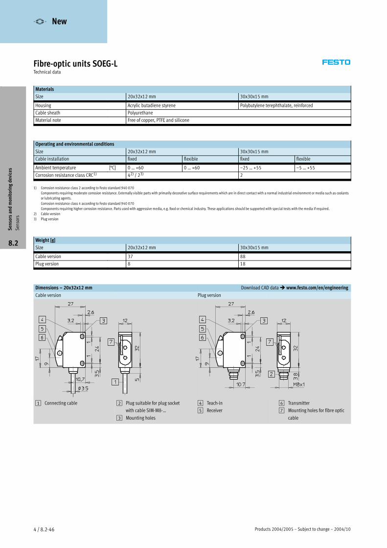
Products 2004/2005 – Subject to change – 2004/104 / 8.2-46
Fibre-optic units SOEG-LTechnical data
Materials
Size 20x32x12 mm 30x30x15 mm
Housing Acrylic butadiene styrene Polybutylene terephthalate, reinforced
Cable sheath Polyurethane
Material note Free of copper, PTFE and silicone
Operating and environmental conditions
Size 20x32x12 mm 30x30x15 mm
Cable installation fixed flexible fixed flexible
Ambient temperature [°C] 0 … +60 0 … +60 –25 … +55 –5 … +55
Corrosion resistance class CRC1) 42) / 23) 2
1) Corrosion resistance class 2 according to Festo standard 940 070
Components requiring moderate corrosion resistance. Externally visible parts with primarily decorative surface requirements which are in direct contact with a normal industrial environment or media such as coolants
or lubricating agents.
Corrosion resistance class 4 according to Festo standard 940 070
Components requiring higher corrosion resistance. Parts used with aggressive media, e.g. food or chemical industry. These applications should be supported with special tests with the media if required.
2) Cable version
3) Plug version
Weight [g]
Size 20x32x12 mm 30x30x15 mm
Cable version 37 88
Plug version 8 18
Dimensions – 20x32x12 mm Download CAD data� www.festo.com/en/engineering
Cable version Plug version
1 Connecting cable 2 Plug suitable for plug socket
with cable SIM-M8-…
3 Mounting holes
4 Teach-in
5 Receiver
6 Transmitter
7 Mounting holes for fibre optic
cable
Sensorsandmonitoringdevices
Sensors
8.2
-V- New
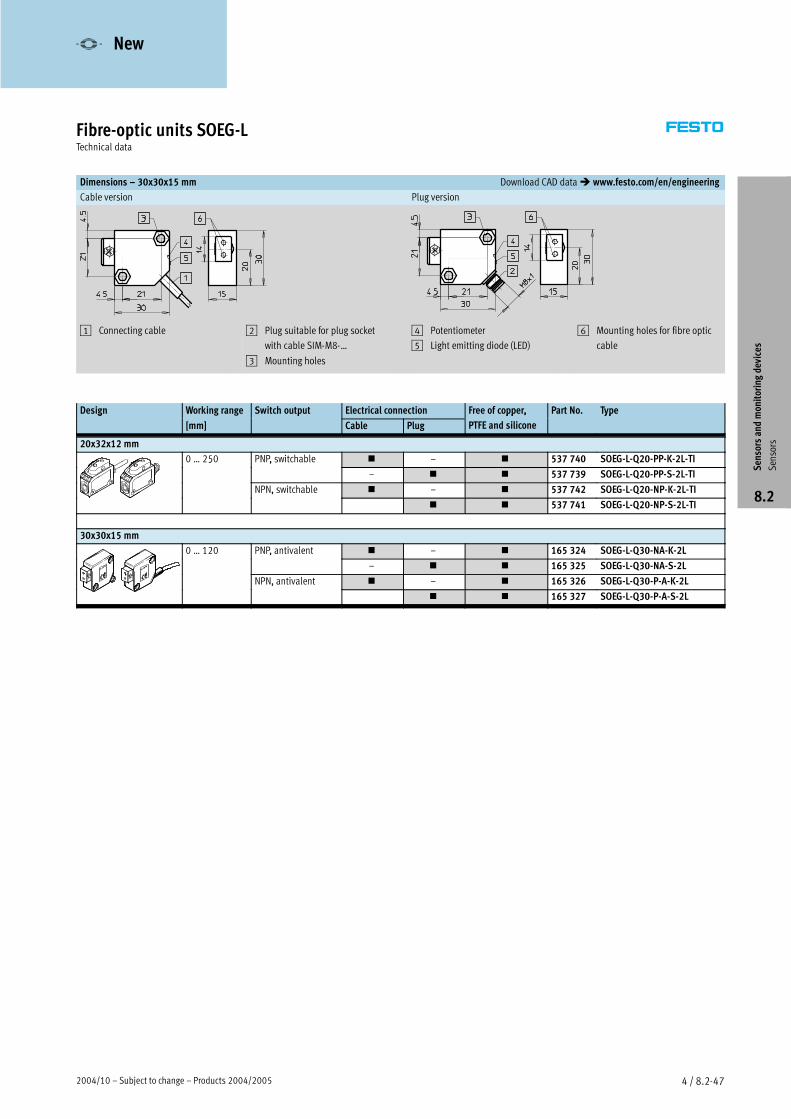
2004/10 – Subject to change – Products 2004/2005 4 / 8.2-47
Fibre-optic units SOEG-LTechnical data
Dimensions – 30x30x15 mm Download CAD data� www.festo.com/en/engineering
Cable version Plug version
1 Connecting cable 2 Plug suitable for plug socket
with cable SIM-M8-…
3 Mounting holes
4 Potentiometer
5 Light emitting diode (LED)
6 Mounting holes for fibre optic
cable
Design Working range Switch output Electrical connection Free of copper, Part No. Typeg
[mm]
p
Cable Plug
pp ,
PTFE and silicone
yp
20x32x12 mm
0 … 250 PNP, switchable � – � 537 740 SOEG-L-Q20-PP-K-2L-TI5 ,
– � � 537 739 SOEG-L-Q20-PP-S-2L-TI
NPN, switchable � – � 537 742 SOEG-L-Q20-NP-K-2L-TI,
� � 537 741 SOEG-L-Q20-NP-S-2L-TI
30x30x15 mm
0 … 120 PNP, antivalent � – � 165 324 SOEG-L-Q30-NA-K-2L,
– � � 165 325 SOEG-L-Q30-NA-S-2L
NPN, antivalent � – � 165 326 SOEG-L-Q30-P-A-K-2L,
� � 165 327 SOEG-L-Q30-P-A-S-2L
Sensorsandmonitoringdevices
Sensors
8.2
-V- New
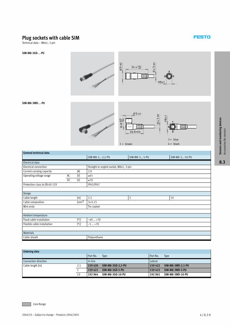
2004/10 – Subject to change – Products 2004/2005 4 / 8.3-9
Plug sockets with cable SIMTechnical data – M8x1, 3-pin
SIM-M8-3GD-…-PU
SIM-M8-3WD-…-PU
1 = brown
3 = blue
4 = black
General technical data
SIM-M8-3…-2,5-PU SIM-M8-3…-5-PU SIM-M8-3…-10-PU
Electrical data
Electrical connection Straight or angled socket, M8x1, 3-pin
Current-carrying capacity [A] 2.8
Operating voltage range AC [V] ≤45p g g g
DC [V] ≤70
Protection class to EN 60 529 IP65/IP67
Design
Cable length [m] 2.5 5 10
Cable composition [mm2] 3x 0.25
Wire ends Tin-coated
Ambient temperature
Fixed cable installation [°C] –40 … +70
Flexible cable installation [°C] –5 … +70
Materials
Cable sheath Polyurethane
Ordering data
Part No. Type Part No. Type
Connection direction In-line Lateral
Cable length [m] 2.5 159 420 SIM-M8-3GD-2,5-PU 159 422 SIM-M8-3WD-2,5-PUg [ ]
5 159 421 SIM-M8-3GD-5-PU 159 423 SIM-M8-3WD-5-PU
10 192 964 SIM-M8-3GD-10-PU 192 965 SIM-M8-3WD-10-PU
Sensorsandmonitoringdevices
Accessories
forsensors
8.3
Core Range
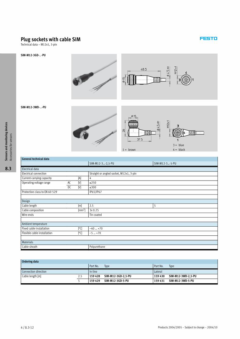
Products 2004/2005 – Subject to change – 2004/104 / 8.3-12
Plug sockets with cable SIMTechnical data – M12x1, 3-pin
SIM-M12-3GD-…-PU
SIM-M12-3WD-…-PU
1 = brown
3 = blue
4 = black
General technical data
SIM-M12-3…-2,5-PU SIM-M12-3…-5-PU
Electrical data
Electrical connection Straight or angled socket, M12x1, 3-pin
Current-carrying capacity [A] 4
Operating voltage range AC [V] ≤250p g g g
DC [V] ≤300
Protection class to EN 60 529 IP65/IP67
Design
Cable length [m] 2.5 5
Cable composition [mm2] 3x 0.25
Wire ends Tin-coated
Ambient temperature
Fixed cable installation [°C] –40 … +70
Flexible cable installation [°C] –5 … +70
Materials
Cable sheath Polyurethane
Ordering data
Part No. Type Part No. Type
Connection direction In-line Lateral
Cable length [m] 2.5 159 428 SIM-M12-3GD-2,5-PU 159 430 SIM-M12-3WD-2,5-PUg [ ]
5 159 429 SIM-M12-3GD-5-PU 159 431 SIM-M12-3WD-5-PU
Sensorsandmonitoringdevices
Accessories
forsensors
8.3
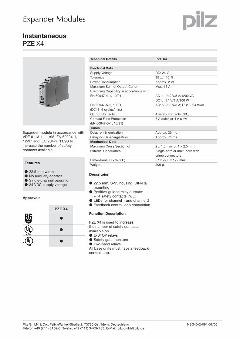
6
Expander Modules
InstantaneousPZE X4
Expander module in accordance withVDE 0113-1, 11/98, EN 60204-1,12/97 and IEC 204-1, 11/98 toincrease the number of safetycontacts available.
Features
● 22.5 mm width● No auxiliary contact● Single-channel operation● 24 VDC supply voltage
Approvals
Technical Details PZE X4
Electrical DataSupply Voltage DC: 24 VTolerance 85 ... 110 %Power Consumption Approx. 2 WMaximum Sum of Output Current Max. 16 ASwitching Capability in accordance withEN 60947-4-1, 10/91 AC1: 240 V/5 A/1200 VA
DC1: 24 V/4 A/100 WEN 60947-5-1, 10/91 AC15: 230 V/5 A; DC13: 24 V/4A(DC13: 6 cycles/min.)Output Contacts 4 safety contacts (N/O)Contact Fuse Protection 6 A quick or 4 A slow(EN 60947-5-1, 10/91)TimesDelay-on Energisation Approx. 25 msDelay-on De-energisation Approx. 75 msMechanical DataMaximum Cross Section of 2 x 1.5 mm2 or 1 x 2.5 mm2
External Conductors Single-core or multi-core withcrimp connectors
Dimensions (H x W x D) 87 x 22.5 x 122 mmWeight 200 g
Descritpion
● 22.5 mm, S-95 housing, DIN-Railmounting
● Positive-guided relay outputs:– 4 safety contacts (N/O)
● LEDs for channel 1 and channel 2● Feedback control loop connection
Function Description
PZE X4 is used to increasethe number of safety contactsavailable on● E-STOP relays● Safety gate monitors● Two-hand relaysAll base units must have a feedbackcontrol loop.
PZE X4
●
●
●
Pilz GmbH & Co., Felix-Wankel-Straße 2, 73760 Ostfildern, Deutschland NSG-D-2-091-07/00Telefon +49 (7 11) 34 09-0, Telefax +49 (7 11) 34 09-1 33, E-Mail: [email protected]

6
Expander Modules
InstantaneousPZE X4
Internal Wiring Diagram
External Wiring
– Connection to the base unit with feedback control loop
0 V
A1 Y1 Y2
A2
PZE X4
14 Y2 Y113
Base unit
24 VDC
A2 13 23 33
14
K2 K1
43
24 34 44
Y1Y2A1
K2
K1
Feedbackcontrol loop Safety contactsUB
Pilz GmbH & Co., Felix-Wankel-Straße 2, 73760 Ostfildern, Deutschland NSG-D-2-091-07/00Telefon +49 (7 11) 34 09-0, Telefax +49 (7 11) 34 09-1 33, E-Mail: [email protected]
6
Expander Modules
InstantaneousPZE X4
Pilz GmbH & Co., Felix-Wankel-Straße 2, 73760 Ostfildern, Deutschland NSG-D-2-091-07/00Telefon +49 (7 11) 34 09-0, Telefax +49 (7 11) 34 09-1 33, E-Mail: [email protected]
General Technical Data
Unless stated otherwise in the technical details for the specific unit
Electrical DataFrequency Range AC 50 ... 60 HzResidual Ripple DC 160 %Contact Material AgSnO2
Continuous Duty 100 %Environmental DataEMC EN 50081-1, 01/92, EN 50082-2, 03/95Vibration in accordance with Frequency: 10 ... 55 Hz,EN 60068-2-6, 04/95 Amplitude: 0.35 mmClimatic Suitability DIN IEC 60068-2-3, 12/86Airgap Creepage DIN VDE 0110 part 1, 04/97Ambient Temperature -10 ... +55 °CStorage Temperature -40 ... +85 °CMechanical DataTorque Setting on Connection Terminals 0.6 Nm (screws)Mounting Position AnyHousing Material Thermoplast Noryl SE 100Protection Mounting: IP 54
Housing: IP 40Terminal Range: IP 20
The units were tested in accordance with the relevant standards current atthe time of development.
Order References
Type UB Order No.PZE X4 24 V DC 774 585
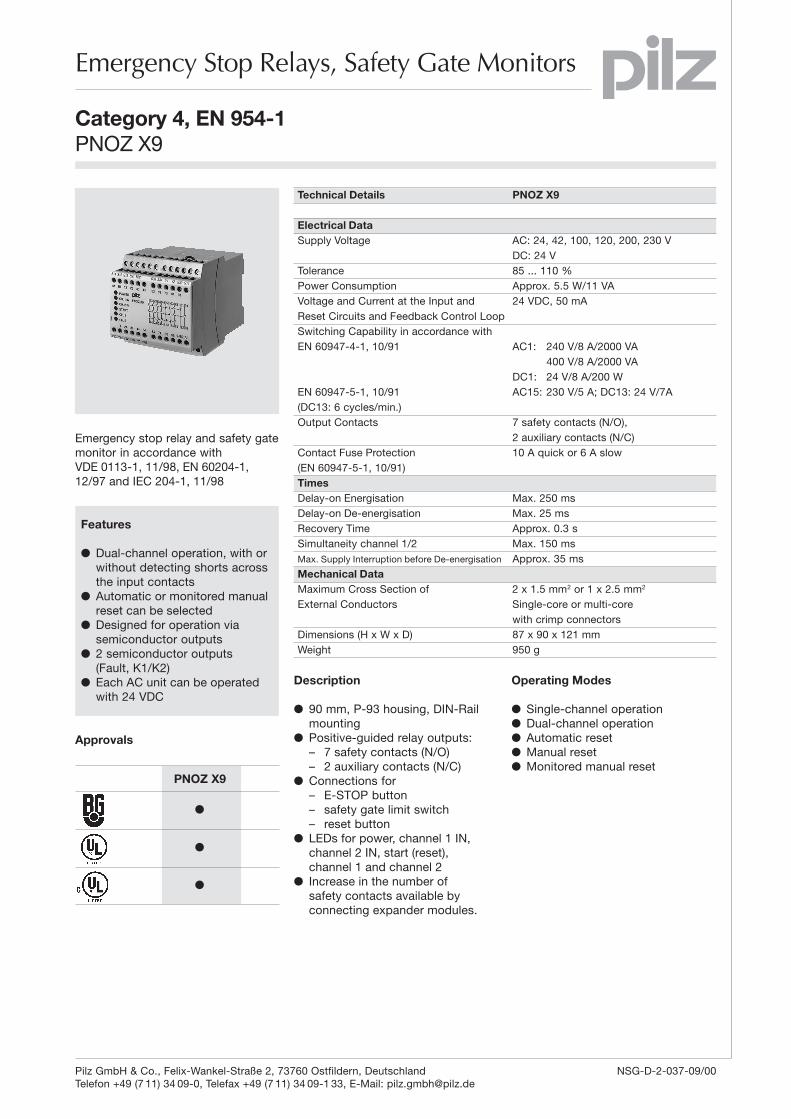
1-1
1
Emergency Stop Relays, Safety Gate Monitors
Category 4, EN 954-1PNOZ X9
Emergency stop relay and safety gatemonitor in accordance withVDE 0113-1, 11/98, EN 60204-1,12/97 and IEC 204-1, 11/98
Features
� Dual-channel operation, with orwithout detecting shorts acrossthe input contacts
� Automatic or monitored manualreset can be selected
� Designed for operation viasemiconductor outputs
� 2 semiconductor outputs(Fault, K1/K2)
� Each AC unit can be operatedwith 24 VDC
Approvals
Technical Details PNOZ X9
Electrical DataSupply Voltage AC: 24, 42, 100, 120, 200, 230 V
DC: 24 VTolerance 85 ... 110 %Power Consumption Approx. 5.5 W/11 VAVoltage and Current at the Input and 24 VDC, 50 mAReset Circuits and Feedback Control LoopSwitching Capability in accordance withEN 60947-4-1, 10/91 AC1: 240 V/8 A/2000 VA
400 V/8 A/2000 VADC1: 24 V/8 A/200 W
EN 60947-5-1, 10/91 AC15: 230 V/5 A; DC13: 24 V/7A(DC13: 6 cycles/min.)Output Contacts 7 safety contacts (N/O),
2 auxiliary contacts (N/C)Contact Fuse Protection 10 A quick or 6 A slow(EN 60947-5-1, 10/91)TimesDelay-on Energisation Max. 250 msDelay-on De-energisation Max. 25 msRecovery Time Approx. 0.3 sSimultaneity channel 1/2 Max. 150 msMax. Supply Interruption before De-energisation Approx. 35 msMechanical DataMaximum Cross Section of 2 x 1.5 mm2 or 1 x 2.5 mm2
External Conductors Single-core or multi-corewith crimp connectors
Dimensions (H x W x D) 87 x 90 x 121 mmWeight 950 g
Description
� 90 mm, P-93 housing, DIN-Railmounting
� Positive-guided relay outputs:– 7 safety contacts (N/O)– 2 auxiliary contacts (N/C)
� Connections for– E-STOP button– safety gate limit switch– reset button
� LEDs for power, channel 1 IN,channel 2 IN, start (reset),channel 1 and channel 2
� Increase in the number ofsafety contacts available byconnecting expander modules.
PNOZ X9
�
�
�
Operating Modes
� Single-channel operation� Dual-channel operation� Automatic reset� Manual reset� Monitored manual reset
Pilz GmbH & Co., Felix-Wankel-Straße 2, 73760 Ostfildern, Deutschland NSG-D-2-037-09/00Telefon +49 (7 11) 34 09-0, Telefax +49 (7 11) 34 09-1 33, E-Mail: [email protected]
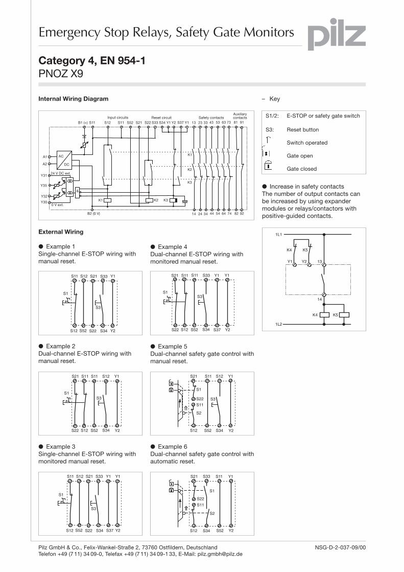
1
��
��
��
��
������
������
����
��
�� �� �� �� � �� ��
��
��
������������� � � �������������� �� �� �� �� � �� �� ��
��
��
���
��
��� �� ������
��
�����������
������
��������� ����!�"�#$#�%��� ����!& '"���#%�"#�! (�!����#%�"#�
Emergency Stop Relays, Safety Gate Monitors
Category 4, EN 954-1PNOZ X9
Internal Wiring Diagram
External Wiring
� Example 1Single-channel E-STOP wiring withmanual reset.
� Example 2Dual-channel E-STOP wiring withmanual reset.
� Example 3Single-channel E-STOP wiring withmonitored manual reset.
� Example 4Dual-channel E-STOP wiring withmonitored manual reset.
� Example 5Dual-channel safety gate control withmanual reset.
S11 S12 S33
S12 S34S52
S21
S22
Y1
Y2
S1
S3
S11 S12 S33
S12 S34S52
S21
S22
Y1
S37
Y1
Y2
S1
S3
� Example 6Dual-channel safety gate control withautomatic reset.
S52S34
S33 S11S21
S12
S22
S1
S2
S11
Y2
Y1
14
K4 K5
13Y1 Y2
K4 K5
1L1
1L2
� Increase in safety contactsThe number of output contacts canbe increased by using expandermodules or relays/contactors withpositive-guided contacts.
– Key
S1/2: E-STOP or safety gate switch
S3: Reset button
Switch operated
Gate open
Gate closed
S21
S22 S52 S34S12
S12S11S11
Y2
Y1
S1S3
S52 S34
S12S11S21
S12
S22
S11
Y2
Y1
S1
S2
S3
S21
S22 S52 S34S12
S33S11S11
S1S3
S37
Y1
Y2
Y1
Pilz GmbH & Co., Felix-Wankel-Straße 2, 73760 Ostfildern, Deutschland NSG-D-2-037-09/00Telefon +49 (7 11) 34 09-0, Telefax +49 (7 11) 34 09-1 33, E-Mail: [email protected]

1-3
1
Emergency Stop Relays, Safety Gate Monitors
Category 4, EN 954-1PNOZ X9
General Technical Data
Unless stated otherwise in the technical details for the specific unit
Electrical DataFrequency Range AC 50 ... 60 HzResidual Ripple DC 160 %Contact Material AgSnO2
Continuous Duty 100 %Environmental DataEMC EN 50081-1, 01/92, EN 50082-2, 03/95Vibration in accordance with Frequency: 10 ... 55 Hz,EN 60068-2-6, 04/95 Amplitude: 0.35 mmClimatic Suitability DIN IEC 60068-2-3, 12/86Airgap Creepage DIN VDE 0110 part 1, 04/97Ambient Temperature -10 ... +55 °CStorage Temperature -40 ... +85 °CMechanical DataTorque Setting on Connection Terminals 0.6 Nm (screws)Mounting Position AnyHousing Material Thermoplast Noryl SE 100Protection Mounting: IP 54
Housing: IP 40Terminal Range: IP 20
The units were tested in accordance with the relevant standards current atthe time of development.
Order References
Type UB Order No.PNOZ X9 24 V AC/DC 774 609PNOZ X9 42 V AC/ 24 V DC 774 601PNOZ X9 100 V AC/24 V DC 774 602PNOZ X9 120 V AC/24 V DC 774 605PNOZ X9 200 V AC/ 24 V DC 774 608PNOZ X9 230 V AC/ 24 V DC 774 606
Pilz GmbH & Co., Felix-Wankel-Straße 2, 73760 Ostfildern, Deutschland NSG-D-2-037-09/00Telefon +49 (7 11) 34 09-0, Telefax +49 (7 11) 34 09-1 33, E-Mail: [email protected]
Related Documents