CONTROL VALVE SOURCEBOOK REFINING

Welcome message from author
This document is posted to help you gain knowledge. Please leave a comment to let me know what you think about it! Share it to your friends and learn new things together.
Transcript
CONTROL VALVE SOURCEBOOK
REFINING

Copyright © 2004 Fisher Controls International LLC All Rights Reserved.
easy-e, edisc, eplug, Fisher, NotchFlo, POSI-SEAL, WHISPER TRIM, and VEE-BALL aremarks owned by Fisher Controls International LLC, a business of Emerson Process Manage-ment. The Emerson logo is a trademark and service mark of Emerson Electric Co. All othermarks are the property of their respective owners.
This publication may not be reproduced, stored in a retrieval system, or transmitted in wholeor in part, in any form or by any means, electronic, mechanical, photocopying, recording orotherwise, without the written permission of Fisher Controls International LLC.
Emerson Process Management gratefully acknowledges the contribution made to this bookby Key Control, Inc. and the contributions made by Emerson Process Management em-ployees:
Justin E. Trawny – Refining-Petrochemical Industry Manager (Fisher Valve Division)Tim Olsen – Process & Performance Consultant-Advanced Applied Technologies (Process Solutions Division)
Printed in U.S.A., First Edition
ii
Table of Contents
Contents at a Glance
Introduction ix. . . . . . . . . . . . . . . . . . . . . . . . . . . . . . . . . . . . . . . . . . . . .
Furnace, Chapter 1 1–1. . . . . . . . . . . . . . . . . . . . . . . . . . . . . . . . . . . . .
Distillation Column, Chapter 2 2–1. . . . . . . . . . . . . . . . . . . . . . . . . .
Gas Plant, Chapter 3 3–1. . . . . . . . . . . . . . . . . . . . . . . . . . . . . . . . . . .
Crude Distillation, Chapter 4 4–1. . . . . . . . . . . . . . . . . . . . . . . . . . . .
Vacuum Distillation, Chapter 5 5–1. . . . . . . . . . . . . . . . . . . . . . . . . .
Delayed Coking Unit, Chapter 6 6–1. . . . . . . . . . . . . . . . . . . . . . . . .
Hydrotreater, Chapter 7 7–1. . . . . . . . . . . . . . . . . . . . . . . . . . . . . . . . .
Hydrocracker, Chapter 8 8–1. . . . . . . . . . . . . . . . . . . . . . . . . . . . . . . .
Catalytic Reformer Unit, Chapter 9 9–1. . . . . . . . . . . . . . . . . . . . . .
Fluid Catalytic Cracker, Chapter 10 10–1. . . . . . . . . . . . . . . . . . . . .
Alkylation Unit, Chapter 11 11–1. . . . . . . . . . . . . . . . . . . . . . . . . . . .
Amine Unit, Chapter 12 12–1. . . . . . . . . . . . . . . . . . . . . . . . . . . . . . . .
Sulfur Recovery Unit, Chapter 13 13–1. . . . . . . . . . . . . . . . . . . . . . .
Blending Unit, Chapter 14 14–1. . . . . . . . . . . . . . . . . . . . . . . . . . . . .

iii
Complete Contents
Refinery Control ValvesIntroduction ix. . . . . . . . . . . . . . . . . . . . . . . . . . . . . . . . . . . . . . . . . . . . . . . . . . . . . . . Other Names x. . . . . . . . . . . . . . . . . . . . . . . . . . . . . . . . . . . . . . . . . . . . . . . . . . . . . . Process Descriptions xi. . . . . . . . . . . . . . . . . . . . . . . . . . . . . . . . . . . . . . . . . . . . . . Valve Selection xi. . . . . . . . . . . . . . . . . . . . . . . . . . . . . . . . . . . . . . . . . . . . . . . . . . . Control Valves xi. . . . . . . . . . . . . . . . . . . . . . . . . . . . . . . . . . . . . . . . . . . . . . . . . . . . Process Drawing xii. . . . . . . . . . . . . . . . . . . . . . . . . . . . . . . . . . . . . . . . . . . . . . . . . . Problem Valves xii. . . . . . . . . . . . . . . . . . . . . . . . . . . . . . . . . . . . . . . . . . . . . . . . . . . Abbreviations xii. . . . . . . . . . . . . . . . . . . . . . . . . . . . . . . . . . . . . . . . . . . . . . . . . . . . .
1 FurnaceOther Names 1–1. . . . . . . . . . . . . . . . . . . . . . . . . . . . . . . . . . . . . . . . . . . . . . . . . . . . Description 1–1. . . . . . . . . . . . . . . . . . . . . . . . . . . . . . . . . . . . . . . . . . . . . . . . . . . . . . Control Valves 1–3. . . . . . . . . . . . . . . . . . . . . . . . . . . . . . . . . . . . . . . . . . . . . . . . . . .
Feed Valve 1–3. . . . . . . . . . . . . . . . . . . . . . . . . . . . . . . . . . . . . . . . . . . . . . . . . . . Fuel Gas Valve 1–4. . . . . . . . . . . . . . . . . . . . . . . . . . . . . . . . . . . . . . . . . . . . . . . .
2 Distillation ColumnOther Names 2–1. . . . . . . . . . . . . . . . . . . . . . . . . . . . . . . . . . . . . . . . . . . . . . . . . . . . Description 2–1. . . . . . . . . . . . . . . . . . . . . . . . . . . . . . . . . . . . . . . . . . . . . . . . . . . . . . Control Valves 2–3. . . . . . . . . . . . . . . . . . . . . . . . . . . . . . . . . . . . . . . . . . . . . . . . . . .
Feed Valve 2–3. . . . . . . . . . . . . . . . . . . . . . . . . . . . . . . . . . . . . . . . . . . . . . . . . . . Reflux Valve 2–4. . . . . . . . . . . . . . . . . . . . . . . . . . . . . . . . . . . . . . . . . . . . . . . . . . Bottom Product Valve 2–5. . . . . . . . . . . . . . . . . . . . . . . . . . . . . . . . . . . . . . . . . . Pressure Control Valve 2–6. . . . . . . . . . . . . . . . . . . . . . . . . . . . . . . . . . . . . . . . . Overhead Product Valve 2–8. . . . . . . . . . . . . . . . . . . . . . . . . . . . . . . . . . . . . . . . Reboil Valve 2–9. . . . . . . . . . . . . . . . . . . . . . . . . . . . . . . . . . . . . . . . . . . . . . . . . .
3 Gas PlantOther Names 3–1. . . . . . . . . . . . . . . . . . . . . . . . . . . . . . . . . . . . . . . . . . . . . . . . . . . . Description 3–1. . . . . . . . . . . . . . . . . . . . . . . . . . . . . . . . . . . . . . . . . . . . . . . . . . . . . . Control Valves 3–3. . . . . . . . . . . . . . . . . . . . . . . . . . . . . . . . . . . . . . . . . . . . . . . . . . .
Lean Sponge Oil Valve 3–3. . . . . . . . . . . . . . . . . . . . . . . . . . . . . . . . . . . . . . . . . Absorber/Deethanizer Reboil Valve 3–4. . . . . . . . . . . . . . . . . . . . . . . . . . . . . . Fractionator Overhead Valve 3–5. . . . . . . . . . . . . . . . . . . . . . . . . . . . . . . . . . . . Sponge Absorber Overhead Valve 3–6. . . . . . . . . . . . . . . . . . . . . . . . . . . . . . . Absorber/Deethanizer Bottom Product Valve 3–8. . . . . . . . . . . . . . . . . . . . . . Absorber Lean Oil Valve 3–9. . . . . . . . . . . . . . . . . . . . . . . . . . . . . . . . . . . . . . . . Debutanizer Bottom Product Valve 3–10. . . . . . . . . . . . . . . . . . . . . . . . . . . . . Debutanizer Reflux Valve 3–11. . . . . . . . . . . . . . . . . . . . . . . . . . . . . . . . . . . . . Debutanizer Reboil Valve 3–12. . . . . . . . . . . . . . . . . . . . . . . . . . . . . . . . . . . . . Debutanizer Overhead Product Valve 3–13. . . . . . . . . . . . . . . . . . . . . . . . . . C3/C4 Splitter Bottom Product Valve 3–14. . . . . . . . . . . . . . . . . . . . . . . . . . . . C3/C4 Splitter Reflux Valve 3–15. . . . . . . . . . . . . . . . . . . . . . . . . . . . . . . . . . . . C3/C4 Splitter Overhead Product Valve 3–16. . . . . . . . . . . . . . . . . . . . . . . . . C3/C4 Splitter Reboil Valve 3–17. . . . . . . . . . . . . . . . . . . . . . . . . . . . . . . . . . . .

iv
4 Crude DistillationOther Names 4–1. . . . . . . . . . . . . . . . . . . . . . . . . . . . . . . . . . . . . . . . . . . . . . . . . . . . Description 4–1. . . . . . . . . . . . . . . . . . . . . . . . . . . . . . . . . . . . . . . . . . . . . . . . . . . . . . Control Valves 4–3. . . . . . . . . . . . . . . . . . . . . . . . . . . . . . . . . . . . . . . . . . . . . . . . . . .
Feed Valve 4–3. . . . . . . . . . . . . . . . . . . . . . . . . . . . . . . . . . . . . . . . . . . . . . . . . . . Pump-Around Valve 4–4. . . . . . . . . . . . . . . . . . . . . . . . . . . . . . . . . . . . . . . . . . . . Fuel Valve 4–5. . . . . . . . . . . . . . . . . . . . . . . . . . . . . . . . . . . . . . . . . . . . . . . . . . . . Bottoms Valve 4–6. . . . . . . . . . . . . . . . . . . . . . . . . . . . . . . . . . . . . . . . . . . . . . . . Reflux Valves 4–7. . . . . . . . . . . . . . . . . . . . . . . . . . . . . . . . . . . . . . . . . . . . . . . . . Fractionator Stripping Steam Valve 4–8. . . . . . . . . . . . . . . . . . . . . . . . . . . . . . Stripping Steam Valve 4–9. . . . . . . . . . . . . . . . . . . . . . . . . . . . . . . . . . . . . . . . . . Stripper Bottoms (Product) Valve 4–10. . . . . . . . . . . . . . . . . . . . . . . . . . . . . . Overhead Pressure Control Valve 4–11. . . . . . . . . . . . . . . . . . . . . . . . . . . . . . Overhead Product Valve 4–12. . . . . . . . . . . . . . . . . . . . . . . . . . . . . . . . . . . . . .
5 Vacuum DistillationOther Names 5–1. . . . . . . . . . . . . . . . . . . . . . . . . . . . . . . . . . . . . . . . . . . . . . . . . . . . Description 5–1. . . . . . . . . . . . . . . . . . . . . . . . . . . . . . . . . . . . . . . . . . . . . . . . . . . . . . Control Valves 5–3. . . . . . . . . . . . . . . . . . . . . . . . . . . . . . . . . . . . . . . . . . . . . . . . . . .
Feed Valve 5–3. . . . . . . . . . . . . . . . . . . . . . . . . . . . . . . . . . . . . . . . . . . . . . . . . . . Fuel Valve 5–4. . . . . . . . . . . . . . . . . . . . . . . . . . . . . . . . . . . . . . . . . . . . . . . . . . . . Pump-Around Valve 5–5. . . . . . . . . . . . . . . . . . . . . . . . . . . . . . . . . . . . . . . . . . . . Stripping Steam Valve 5–6. . . . . . . . . . . . . . . . . . . . . . . . . . . . . . . . . . . . . . . . . . Vacuum Resid Valve 5–7. . . . . . . . . . . . . . . . . . . . . . . . . . . . . . . . . . . . . . . . . . . Stripper Bottoms (Product) Valve 5–8. . . . . . . . . . . . . . . . . . . . . . . . . . . . . . . . Gas Oil Valve 5–9. . . . . . . . . . . . . . . . . . . . . . . . . . . . . . . . . . . . . . . . . . . . . . . . . Stripping Steam Valve 5–10. . . . . . . . . . . . . . . . . . . . . . . . . . . . . . . . . . . . . . . .
6 Delayed Coking UnitOther Names 6–1. . . . . . . . . . . . . . . . . . . . . . . . . . . . . . . . . . . . . . . . . . . . . . . . . . . . Description 6–1. . . . . . . . . . . . . . . . . . . . . . . . . . . . . . . . . . . . . . . . . . . . . . . . . . . . . . Control Valves 6–3. . . . . . . . . . . . . . . . . . . . . . . . . . . . . . . . . . . . . . . . . . . . . . . . . . .
Decoke Water Valve 6–3. . . . . . . . . . . . . . . . . . . . . . . . . . . . . . . . . . . . . . . . . . . Decoke Steam Valve 6–4. . . . . . . . . . . . . . . . . . . . . . . . . . . . . . . . . . . . . . . . . . . Unit Feed Valve 6–5. . . . . . . . . . . . . . . . . . . . . . . . . . . . . . . . . . . . . . . . . . . . . . . Drum Decoke Block Valve 6–6. . . . . . . . . . . . . . . . . . . . . . . . . . . . . . . . . . . . . . Drum Switch Valve 6–6. . . . . . . . . . . . . . . . . . . . . . . . . . . . . . . . . . . . . . . . . . . . Fuel Valve 6–7. . . . . . . . . . . . . . . . . . . . . . . . . . . . . . . . . . . . . . . . . . . . . . . . . . . . Furnace Feed Valve 6–8. . . . . . . . . . . . . . . . . . . . . . . . . . . . . . . . . . . . . . . . . . . Fractionator Pump-Around Valve 6–9. . . . . . . . . . . . . . . . . . . . . . . . . . . . . . . . Fractionator Reflux Valve 6–10. . . . . . . . . . . . . . . . . . . . . . . . . . . . . . . . . . . . . Fractionator Heavy Gas Oil Product Valve 6–11. . . . . . . . . . . . . . . . . . . . . . Fractionator Stripper Steam Valve 6–12. . . . . . . . . . . . . . . . . . . . . . . . . . . . . Fractionator Light-Ends Product Valve 6–13. . . . . . . . . . . . . . . . . . . . . . . . . . Fractionator Light Gas Oil Product Valve 6–14. . . . . . . . . . . . . . . . . . . . . . . . Fractionator Naphtha Valve 6–15. . . . . . . . . . . . . . . . . . . . . . . . . . . . . . . . . . .

v
7 HydrotreaterOther Names 7–1. . . . . . . . . . . . . . . . . . . . . . . . . . . . . . . . . . . . . . . . . . . . . . . . . . . . Description 7–1. . . . . . . . . . . . . . . . . . . . . . . . . . . . . . . . . . . . . . . . . . . . . . . . . . . . . . Control Valves 7–3. . . . . . . . . . . . . . . . . . . . . . . . . . . . . . . . . . . . . . . . . . . . . . . . . . .
Unit Feed Valve 7–3. . . . . . . . . . . . . . . . . . . . . . . . . . . . . . . . . . . . . . . . . . . . . . . Fuel Valve 7–4. . . . . . . . . . . . . . . . . . . . . . . . . . . . . . . . . . . . . . . . . . . . . . . . . . . . Recycle Hydrogen Valve 7–5. . . . . . . . . . . . . . . . . . . . . . . . . . . . . . . . . . . . . . . . Reactor Hydrogen Valve 7–6. . . . . . . . . . . . . . . . . . . . . . . . . . . . . . . . . . . . . . . . Separator Overhead Valve 7–7. . . . . . . . . . . . . . . . . . . . . . . . . . . . . . . . . . . . . . Makeup Hydrogen Valve 7–8. . . . . . . . . . . . . . . . . . . . . . . . . . . . . . . . . . . . . . . . Recycle Purge Valve 7–9. . . . . . . . . . . . . . . . . . . . . . . . . . . . . . . . . . . . . . . . . . . Stripper Reflux Valve 7–10. . . . . . . . . . . . . . . . . . . . . . . . . . . . . . . . . . . . . . . . . Stripper Bottoms Valve 7–11. . . . . . . . . . . . . . . . . . . . . . . . . . . . . . . . . . . . . . . Stripper Light-Ends Valve 7–12. . . . . . . . . . . . . . . . . . . . . . . . . . . . . . . . . . . . . Stripper Naphtha Valve 7–14. . . . . . . . . . . . . . . . . . . . . . . . . . . . . . . . . . . . . . . Reactor Let-Down Valve 7–15. . . . . . . . . . . . . . . . . . . . . . . . . . . . . . . . . . . . . . Hot and Cold High-Pressure Separator Let-Down Valve 7–16. . . . . . . . . . .
8 HydrocrackerOther Names 8–1. . . . . . . . . . . . . . . . . . . . . . . . . . . . . . . . . . . . . . . . . . . . . . . . . . . . Description 8–1. . . . . . . . . . . . . . . . . . . . . . . . . . . . . . . . . . . . . . . . . . . . . . . . . . . . . . Control Valves 8–3. . . . . . . . . . . . . . . . . . . . . . . . . . . . . . . . . . . . . . . . . . . . . . . . . . .
Feed Valve 8–3. . . . . . . . . . . . . . . . . . . . . . . . . . . . . . . . . . . . . . . . . . . . . . . . . . . Fuel Valve 8–4. . . . . . . . . . . . . . . . . . . . . . . . . . . . . . . . . . . . . . . . . . . . . . . . . . . . Recycle Hydrogen Valve 8–5. . . . . . . . . . . . . . . . . . . . . . . . . . . . . . . . . . . . . . . . Reactor Hydrogen Valve 8–6. . . . . . . . . . . . . . . . . . . . . . . . . . . . . . . . . . . . . . . . High-Pressure Separator Valve 8–7. . . . . . . . . . . . . . . . . . . . . . . . . . . . . . . . . . Low-Pressure Separator Valve 8–8. . . . . . . . . . . . . . . . . . . . . . . . . . . . . . . . . . Makeup Hydrogen Valve 8–9. . . . . . . . . . . . . . . . . . . . . . . . . . . . . . . . . . . . . . . . Recycle Purge Valve 8–10. . . . . . . . . . . . . . . . . . . . . . . . . . . . . . . . . . . . . . . . . Fractionator Pump-Around Valve 8–11. . . . . . . . . . . . . . . . . . . . . . . . . . . . . . Fractionator Bottom Valve 8–12. . . . . . . . . . . . . . . . . . . . . . . . . . . . . . . . . . . . Fractionator Reflux Valve 8–13. . . . . . . . . . . . . . . . . . . . . . . . . . . . . . . . . . . . . Fractionator Heavy Naphtha Valve 8–14. . . . . . . . . . . . . . . . . . . . . . . . . . . . . Fractionator Distillate Valve 8–15. . . . . . . . . . . . . . . . . . . . . . . . . . . . . . . . . . . Fractionator Vent Gas Valve 8–16. . . . . . . . . . . . . . . . . . . . . . . . . . . . . . . . . . Fractionator Light Naphtha Valve 8–17. . . . . . . . . . . . . . . . . . . . . . . . . . . . . . High-Pressure Separator Let-Down Valve 8–18. . . . . . . . . . . . . . . . . . . . . . . Low-Pressure Separator Let-Down Valve 8–18. . . . . . . . . . . . . . . . . . . . . . .
9 Catalytic Reformer UnitOther Names 9–1. . . . . . . . . . . . . . . . . . . . . . . . . . . . . . . . . . . . . . . . . . . . . . . . . . . . Description 9–1. . . . . . . . . . . . . . . . . . . . . . . . . . . . . . . . . . . . . . . . . . . . . . . . . . . . . . Control Valves 9–3. . . . . . . . . . . . . . . . . . . . . . . . . . . . . . . . . . . . . . . . . . . . . . . . . . .
Feed Valve 9–3. . . . . . . . . . . . . . . . . . . . . . . . . . . . . . . . . . . . . . . . . . . . . . . . . . . Fuel Valve 9–4. . . . . . . . . . . . . . . . . . . . . . . . . . . . . . . . . . . . . . . . . . . . . . . . . . . . Recycle Hydrogen Valve 9–5. . . . . . . . . . . . . . . . . . . . . . . . . . . . . . . . . . . . . . . . Separator Vapor Valve 9–6. . . . . . . . . . . . . . . . . . . . . . . . . . . . . . . . . . . . . . . . . Net Hydrogen Valve 9–7. . . . . . . . . . . . . . . . . . . . . . . . . . . . . . . . . . . . . . . . . . . . Separator Liquid Valve 9–8. . . . . . . . . . . . . . . . . . . . . . . . . . . . . . . . . . . . . . . . . Stabilizer Reboil Valve 9–9. . . . . . . . . . . . . . . . . . . . . . . . . . . . . . . . . . . . . . . . . Stabilizer Reflux Valve 9–10. . . . . . . . . . . . . . . . . . . . . . . . . . . . . . . . . . . . . . . Stabilizer Reformate Valve 9–11. . . . . . . . . . . . . . . . . . . . . . . . . . . . . . . . . . . . Stabilizer Vent Gas Valve 9–12. . . . . . . . . . . . . . . . . . . . . . . . . . . . . . . . . . . . . Stabilizer Light-Ends Valve 9–14. . . . . . . . . . . . . . . . . . . . . . . . . . . . . . . . . . . .

vi
10 Fluid Catalytic CrackerOther Names 10–1. . . . . . . . . . . . . . . . . . . . . . . . . . . . . . . . . . . . . . . . . . . . . . . . . . Description 10–1. . . . . . . . . . . . . . . . . . . . . . . . . . . . . . . . . . . . . . . . . . . . . . . . . . . . Control Valves 10–3. . . . . . . . . . . . . . . . . . . . . . . . . . . . . . . . . . . . . . . . . . . . . . . . .
Air Valve 10–3. . . . . . . . . . . . . . . . . . . . . . . . . . . . . . . . . . . . . . . . . . . . . . . . . . . Feed Valve 10–4. . . . . . . . . . . . . . . . . . . . . . . . . . . . . . . . . . . . . . . . . . . . . . . . . Fuel Valve 10–5. . . . . . . . . . . . . . . . . . . . . . . . . . . . . . . . . . . . . . . . . . . . . . . . . . Flue Gas Valve 10–6. . . . . . . . . . . . . . . . . . . . . . . . . . . . . . . . . . . . . . . . . . . . . . Regenerated Catalyst Valve 10–7. . . . . . . . . . . . . . . . . . . . . . . . . . . . . . . . . . . Spent Catalyst Valve 10–7. . . . . . . . . . . . . . . . . . . . . . . . . . . . . . . . . . . . . . . . . Fractionator Pump-Around Valve 10–8. . . . . . . . . . . . . . . . . . . . . . . . . . . . . . Fractionator Slurry Recycle Valve 10–9. . . . . . . . . . . . . . . . . . . . . . . . . . . . . . Fractionator Reflux Valve 10–10. . . . . . . . . . . . . . . . . . . . . . . . . . . . . . . . . . . . Fractionator LCO (Light Cycle Oil) Product Valve 10–11. . . . . . . . . . . . . . . Fractionator HCO (Heavy Cycle Oil) Product Valve 10–12. . . . . . . . . . . . . . Fractionator Reboil Circuit Valve 10–13. . . . . . . . . . . . . . . . . . . . . . . . . . . . . . Fractionator Wet Gas Valve 10–14. . . . . . . . . . . . . . . . . . . . . . . . . . . . . . . . . . Fractionator Distillate Valve 10–15. . . . . . . . . . . . . . . . . . . . . . . . . . . . . . . . . .
11 Alkylation UnitOther Names 11–1. . . . . . . . . . . . . . . . . . . . . . . . . . . . . . . . . . . . . . . . . . . . . . . . . . Description 11–1. . . . . . . . . . . . . . . . . . . . . . . . . . . . . . . . . . . . . . . . . . . . . . . . . . . . Control Valves 11–3. . . . . . . . . . . . . . . . . . . . . . . . . . . . . . . . . . . . . . . . . . . . . . . . .
Feed Valve 11–3. . . . . . . . . . . . . . . . . . . . . . . . . . . . . . . . . . . . . . . . . . . . . . . . . Makeup Acid Valve 11–4. . . . . . . . . . . . . . . . . . . . . . . . . . . . . . . . . . . . . . . . . . Caustic Wash Valve 11–5. . . . . . . . . . . . . . . . . . . . . . . . . . . . . . . . . . . . . . . . . Water Wash Valve 11–6. . . . . . . . . . . . . . . . . . . . . . . . . . . . . . . . . . . . . . . . . . . Depropanizer Bottom Valve 11–7. . . . . . . . . . . . . . . . . . . . . . . . . . . . . . . . . . . Depropanizer Reflux Valve 11–8. . . . . . . . . . . . . . . . . . . . . . . . . . . . . . . . . . . . DIB (Deisobutanizer) Isobutane Valve 11–9. . . . . . . . . . . . . . . . . . . . . . . . . . Makeup Isobutane Valve 11–10. . . . . . . . . . . . . . . . . . . . . . . . . . . . . . . . . . . . Depropanizer Reboil Valve 11–11. . . . . . . . . . . . . . . . . . . . . . . . . . . . . . . . . . . DIB Reboil Valve 11–12. . . . . . . . . . . . . . . . . . . . . . . . . . . . . . . . . . . . . . . . . . . Depropanizer Propane Product Valve 11–13. . . . . . . . . . . . . . . . . . . . . . . . . DIB Reflux Valve 11–14. . . . . . . . . . . . . . . . . . . . . . . . . . . . . . . . . . . . . . . . . . . DIB Bottom Valve 11–15. . . . . . . . . . . . . . . . . . . . . . . . . . . . . . . . . . . . . . . . . . . Debutanizer Alkylate Valve 11–16. . . . . . . . . . . . . . . . . . . . . . . . . . . . . . . . . . . Debutanizer Reflux Valve 11–17. . . . . . . . . . . . . . . . . . . . . . . . . . . . . . . . . . . . Debutanizer Butane Valve 11–18. . . . . . . . . . . . . . . . . . . . . . . . . . . . . . . . . . . Debutanizer Reboil Valve 11–19. . . . . . . . . . . . . . . . . . . . . . . . . . . . . . . . . . . .
12 Amine UnitOther Names 12–1. . . . . . . . . . . . . . . . . . . . . . . . . . . . . . . . . . . . . . . . . . . . . . . . . . Description 12–1. . . . . . . . . . . . . . . . . . . . . . . . . . . . . . . . . . . . . . . . . . . . . . . . . . . . Control Valves 12–3. . . . . . . . . . . . . . . . . . . . . . . . . . . . . . . . . . . . . . . . . . . . . . . . .
Scrubber Bottom Valve 12–3. . . . . . . . . . . . . . . . . . . . . . . . . . . . . . . . . . . . . . . Scrubber Lean Amine Valve 12–4. . . . . . . . . . . . . . . . . . . . . . . . . . . . . . . . . . . Amine Makeup Valve 12–5. . . . . . . . . . . . . . . . . . . . . . . . . . . . . . . . . . . . . . . . . Regenerator Bottom Recycle Valve 12–6. . . . . . . . . . . . . . . . . . . . . . . . . . . . Regenerator Reflux Valve 12–7. . . . . . . . . . . . . . . . . . . . . . . . . . . . . . . . . . . . . Regenerator Bottom-to-Storage Unit Valve 12–8. . . . . . . . . . . . . . . . . . . . . . Regenerator Reboil Valve 12–9. . . . . . . . . . . . . . . . . . . . . . . . . . . . . . . . . . . . . Regenerator Sulfur Gas Valve 12–10. . . . . . . . . . . . . . . . . . . . . . . . . . . . . . . .

vii
13 Sulfur Recovery UnitOther Names 13–1. . . . . . . . . . . . . . . . . . . . . . . . . . . . . . . . . . . . . . . . . . . . . . . . . . Description 13–1. . . . . . . . . . . . . . . . . . . . . . . . . . . . . . . . . . . . . . . . . . . . . . . . . . . . Control Valves 13–3. . . . . . . . . . . . . . . . . . . . . . . . . . . . . . . . . . . . . . . . . . . . . . . . .
Fuel Gas Valve 13–3. . . . . . . . . . . . . . . . . . . . . . . . . . . . . . . . . . . . . . . . . . . . . . Oxygen Valve 13–4. . . . . . . . . . . . . . . . . . . . . . . . . . . . . . . . . . . . . . . . . . . . . . . Main Air Valve 13–5. . . . . . . . . . . . . . . . . . . . . . . . . . . . . . . . . . . . . . . . . . . . . . Trim Air Valve 13–6. . . . . . . . . . . . . . . . . . . . . . . . . . . . . . . . . . . . . . . . . . . . . . . Acid Gas from Amine Valve 13–7. . . . . . . . . . . . . . . . . . . . . . . . . . . . . . . . . . . Sour Gas from SWS (Sour Gas Stripper) Valve 13–8. . . . . . . . . . . . . . . . . . Reheater Steam Valve 13–9. . . . . . . . . . . . . . . . . . . . . . . . . . . . . . . . . . . . . . .
14 Blending UnitOther Names 14–1. . . . . . . . . . . . . . . . . . . . . . . . . . . . . . . . . . . . . . . . . . . . . . . . . . Description 14–1. . . . . . . . . . . . . . . . . . . . . . . . . . . . . . . . . . . . . . . . . . . . . . . . . . . . Control Valves 14–3. . . . . . . . . . . . . . . . . . . . . . . . . . . . . . . . . . . . . . . . . . . . . . . . .
Component Valve 14–3. . . . . . . . . . . . . . . . . . . . . . . . . . . . . . . . . . . . . . . . . . . .

viii
ix
Refinery Control Valves
Introduction
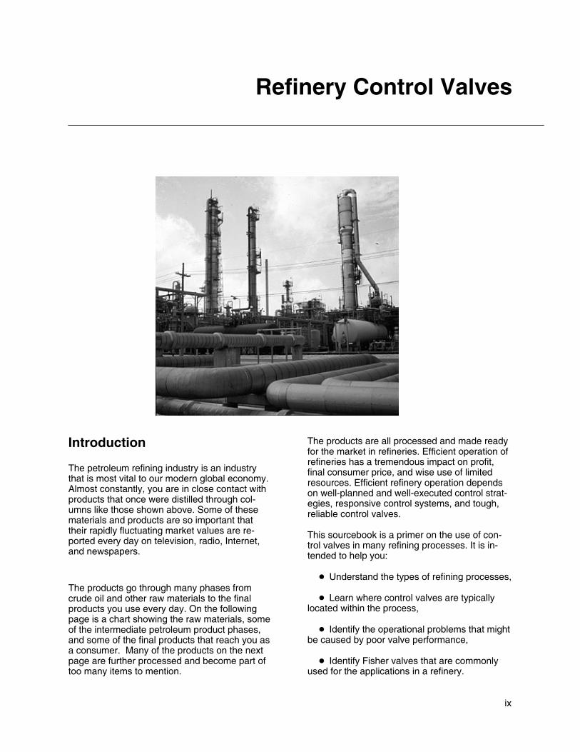
The petroleum refining industry is an industrythat is most vital to our modern global economy.Almost constantly, you are in close contact withproducts that once were distilled through col-umns like those shown above. Some of thesematerials and products are so important thattheir rapidly fluctuating market values are re-ported every day on television, radio, Internet,and newspapers.
The products go through many phases fromcrude oil and other raw materials to the finalproducts you use every day. On the followingpage is a chart showing the raw materials, someof the intermediate petroleum product phases,and some of the final products that reach you asa consumer. Many of the products on the nextpage are further processed and become part oftoo many items to mention.
The products are all processed and made readyfor the market in refineries. Efficient operation ofrefineries has a tremendous impact on profit,final consumer price, and wise use of limitedresources. Efficient refinery operation dependson well-planned and well-executed control strat-egies, responsive control systems, and tough,reliable control valves.
This sourcebook is a primer on the use of con-trol valves in many refining processes. It is in-tended to help you:
� Understand the types of refining processes,
� Learn where control valves are typicallylocated within the process,
� Identify the operational problems that mightbe caused by poor valve performance,
� Identify Fisher valves that are commonlyused for the applications in a refinery.

x
Product Streams in the Refining Industry(Reprinted by Permission of HYDROCARBON PROCESSING Magazine, Gulf Publishing Company, Houston, Texas)
RAW MATERIALS INDUSTRIAL AND CONSUMER PRODUCTSINTERMEDIATE PRODUCTS
A standard format is used to present the infor-mation on each refining process. The informa-tion provided is:
� Other commonly-used names for the de-scribed process
� The basis (feed rate) for the example pro-cess
� A short description of the process
� A list and description of each important pro-cess valve in the unit
� A functional drawing of the process
� Typical process conditions
� Names of Fisher valves that can be con-sidered for each process
� Potential process impacts and special con-siderations for each valve
Other NamesIt is not possible to make an all-inclusive list ofcommonly-used process names. Many refinerieshave developed specific process names basedon local preference or the preferences of thelicensor or designer that developed the process.

xi
Process Descriptions
Many processing units within a refinery containfurnaces and distillation columns, which makesthese pieces of equipment and their operationfairly universal. The valve requirements for theseunits are presented in Chapters 1 and 2, respec-tively, and are not repeated in the chapters thatfollow.
Chapters 3 through 14 discuss refining pro-cesses, with the valve information presented ineach chapter applying directly to the specificprocess being described.
Valve Selection
The information presented in this sourcebook isintended to assist in understanding the controlvalve requirements of general refining pro-cesses.
Since every refinery is different in its unit make-up and the technologies it utilizes, the controlvalve requirements and recommendations pre-sented by this sourcebook should be consideredas general guidelines.
The information in this sourcebook is intended toassist with understanding general refining pro-cess requirements and general control valveconsiderations.
Under no circumstances should this informationalone be used to select a control valve withoutensuring that the proper valve construction isidentified for the application and process condi-tions.
All valve considerations should be reviewed withyour Fisher sales office or representative as partof any valve selection or specification activity.
Control Valves
Typical Control Valve (easy-e� Valve)
W8119
Valves described within a chapter are labeledand numbered corresponding to the identifica-tion used in the process flow chart for that chap-ter. The order in which they are discussed isfrom left-to-right and top-to-bottom.
If a valve is controlling feed, intermediate or finalproduct streams, the U.S. dollar value of thatstream (as recorded at the time of sourcebookpublication) and typical feed rate are provided.The valve function also is described, and a spec-ification section gives added information on pro-cess conditions, names of Fisher valves that canbe considered, process impact of the valve andany special considerations.

xii
Process Drawing
Typical Process Drawing
E0922
The process drawing within each chapter showsmajor equipment items, their typical placementwithin the processing system and process flowdirection. Utilities, pumps and most heat ex-changers are not shown. Valves are numberedin sequence from left-to-right and top-to-bottom.
Problem ValvesOften there are references to valve-causedproblems or difficulties. The litany of problemsincludes valve stickiness caused by excessivefriction (called “stiction”), excessive play in valve-to-actuator linkages (typically in rotary valves)that causes deadband, excessive valve stempacking leakage, and valve materials that areincompatible with the flowing medium. Any oneor a combination of these difficulties can affect
process quality and throughput, with a resultingnegative impact on refinery profitability.
Many of these problems can be avoided or mini-mized through proper valve selection. Consider-ation should be given to valve style and size,actuator capabilities, analog vs. digital instru-mentation, materials of construction and the like.Although not being all-inclusive, the informationthat this sourcebook provides should facilitatethe valve selection process.
Abbreviations
BBL Barrels
BPD Barrels per day
CCR Continuous catalytic reformer
DIB Deisobutanizer
FCC Fluid catalytic cracker
Gal Gallons
GPM Gallons per minute
HCO Heavy cycle oil
HDS Hydrodesulfizer
HVGO Heavy vacuum gas oil
LCO Light cycle oil
LVGO Light vacuum gas oil
LPG Liquified petroleum gas
MBPD Thousand barrels per day
MCF Thousand cubic feet
MCFD Thousand cubic feet per day
MMCF Million cubic feet
MMCFD Million cubic feet per day
MGPY Thousand gallons per year
MLB Thousand pounds
MLBD Thousand pounds per day
SRU Sulfur recovery unit
SWS Sour water stripper

www.Fisher.com
Chapter 1
Furnace
Other NamesHeater, cracking furnace, steam cracker, steamre-former, reboiler heater
DescriptionFurnaces are used to heat process feed material.Heat is created by burning fuel in burners on thefloor and/or walls of the furnace. There are manydifferent types of fuel that can be used by a furnace,such as natural gas, liquified petroleum gas (LPG),refinery waste gas and fuel oil.
The process feed stream to a furnace is usuallybroken into multiple tube passes to improve heattransfer. The most common configurations are two-and four-pass furnaces. The passes are recombinedinto a single effluent stream after they exit thefurnace.
The outlet temperature of a furnace is normallydictated by the requirements of a downstreamprocess, usually a reactor or distillation column.Adjusting the amount of fuel burned controls theoutlet temperature.
In some cases, the furnace will provide enough heatto crack the feed stream thermally from largehydrocarbon molecules to smaller molecules. Inthese cases, the outlet temperature is used tocontrol the amount of cracked components in theeffluent stream.

1–2 FURNACE
Typical Furnace

FURNACE 1–3
Control Valves
easy-e� Valve
W8119
W2966 W3962
Feed Valve Function (#1, #2, #3, #4)Feed valves are usually set up as flow-control loops.They are configured to fail open so that a valvefailure will protect the furnace radiant section tubes.If a radiant tube loses flow or has insufficient flow,the tube can quickly become so hot that the metalcan melt. This can have disastrous consequences,as most process feeds make excellent fuels. Afurnace can be destroyed very quickly if a rupturedtube is dumping into the firebox of the furnace.
Problem valves can lead to difficulties withcontrolling the outlet temperature of the furnaces.Also, many process feeds slowly build layers of cokeon the inside of the radiant tubes. Coking is a
non-linear reaction, and in some processes even afew extra degrees of temperature can lead toexcessive coke buildup. If a flow valve is alternatelyprovided too much and then too little flow, thetemperature will also swing and will usually lead toexcessive coke buildup. This will shorten the furnacecycle time between decoking procedures, which willnormally require the process unit downstream toshutdown.
Feed valves can easily be bypassed whennecessary. A combination of the measured flow andany available pass temperatures can be used toregulate the bypass valve.
Feed Valve Specification (#1, #2, #3, #4)
Process MediaMedia Pressure Range Temperature Range
Heavier gas oilNaphtha
Dependent on process design
Valve Types
Heavy duty general purpose globe valves easy e� valvesUnbalanced, cageless EZ
Heavy-duty, general-purpose globe valves easy-e� valvesBalanced with graphite cage-plug seal ED
Process Impact
� Control is critical to maintaining integrity ofinternal furnace tubes, such as preventing cokelay-down.
� Valve performance is critical to overall reliabilityof furnace.
� Critical to furnace safety; process fluid flow isrequired at all times through the tubes while thefurnace is firing.
Special Considerations
� Sour feed stocks might require NACE trimmaterials

1–4 FURNACE
Fuel Gas Valve Function (#5)
easy-e� Valve Vee-Ball� ValveW8119
W8192
W7435
Depending on the furnace service and configurationthis valve will normally be part of a loop that controlseither the fuel flow or pressure. These valves arespecified as fail closed so that a control loop failurewill not allow excessive fuel to be dumped into a hotfurnace. A fuel valve failure will almost always shutdown the processing unit downstream. Althoughmany fuel valves have bypass circuits, refineryoperations personnel are usually reluctant to run afurnace on bypass for any significant time becauseof safety concerns.
The preferred control loop configuration for the outlettemperature is a cascade to the set point of the loopcontrolling the fuel valve. Many furnaces will be setup such that the temperature control loop directly
manipulates the fuel valve. This direct connectionusually provides control performance that is inferiorto a cascade configuration. It is extremelysusceptible to any valve dead band such as thatcaused by a sticking valve. This can be detected byexcessive oscillation in the outlet temperature.
When the fuel valve is manipulated by thetemperature loop or by a flow control loop, there willoften be a pressure control valve upstream of thefuel valve. This valve will also fail closed and willhave the same consequences as a failure of the fuelvalve. However, with this configuration, Refineryoperations personnel will be more willing to run afuel valve in bypass as they still have a way toquickly shut off the fuel in an emergency.
Fuel Gas Valve Specification (#5)
Process MediaMedia Pressure Range Temperature Range
Natural gas-fuel gas mixtureFuel oil with atomizing steam
Dependent on process design
Valve TypesUnbalanced, cageless EZ
Heavy-duty, general-purpose globe valves easy-e� valves Balanced with graphite cage-plug seal EDHeavy duty, general purpose globe valves easy e valvesBalanced with polymer cage-plug seal ET
High-capacity, high-rangeability V-notchVee Ball� valves
Class 150 V150High capacity, high rangeability V notchrotary ball valves Vee-Ball� valves
Class 300 V300
Process Impact
� Performance is critical to controlling furnacetemperature.
� Performance is critical to reducing energy costsassociated with furnace.
Special Considerations
� Potential for acidic fouling gases (for example,H2S, HCL)

www.Fisher.com
Chapter 2
Distillation Column
Other NamesTower, stripper, stabilizer, splitter, demethanizer,deethanizer, depropanizer, debutanizer, DIB(deisobutanizer) tower, precut tower
DescriptionDistillation columns are a basic building block forevery refinery. The objective for any distillationcolumn is to separate a feed stream intolight-component and heavy-component productstreams.
The distillation process relies on the relative volatilitybetween the components that make up the feedstream. The high-volatility (lighter) components willboil at a lower temperature than will the low-volatility(heavier) components. Therefore, when heat isadded to the column through a bottom reboiler, thelighter materials are vaporized and rise to the top ofthe column. The overhead vapors are cooled untilthey condense and become a liquid again.
The efficiency of the distillation depends on theamount of contact between the vapor rising and theliquid falling down through a column. Therefore,
some of the overhead liquid product is sent back(refluxed) to the top of the column. Increasing thereflux will improve the purity of the overheadproduct. However, it also requires more heat fromthe reboiler to re-vaporize the lighter components inthe reflux stream. The operation of a distillationcolumn is a balancing act between product purityand energy use.
If the amount of vapor and liquid traveling throughthe column (often referred to as “traffic”) becomestoo great, the column can ”flood.” Too much refluxflow or too much reboil heat resulting in too muchvapor, (or both) can cause flooding. When floodingoccurs, the efficiency of the distillation column isdramatically reduced, with corresponding drops inproduct purities.

2–2 DISTILLATION COLUMN
Typical Distillation Column

DISTILLATION COLUMN 2–3
Control Valves
Feed Valve Function (#1)
easy-e� Valve Vee-Ball� Valve
W8119
W8192
W7435
Feed valves are usually set up as flow or levelcontrol loops. An upstream unit or process oftencontrols the valve.
Unstable feed flow will make the distillation columndifficult to control. A problem valve will often causethe feed flow to oscillate. As a result, the column willalternate between too little and too much reboil heat.Depending on the size and number of trays in the
column, the effect of a swing in the feed will takeanywhere from several minutes to more than anhour to reach the ends of the column. Sometimes,the reboil and reflux controls will amplify the swings.The final result is that meeting product purity targetsbecomes more difficult. Refinery operationspersonnel will normally respond by over-purifying theproducts, wasting energy to compensate for theproblematic feed control valve.
Feed Valve Specification (#1)
Process MediaMedia Pressure Range Temperature Range
Primarily reactor effluent Dependent on process design Dependent on material being distilled
Valve Types
Lower flow rates (line sizes Heavy duty general purpose globeUnbalanced, cageless EZ
Lower flow rates (line sizes4 inches and smaller)
Heavy-duty, general-purpose globevalves easy-e� valves Balanced with graphite cage-plug seal ED
4 inches and smaller) valves easy e valvesBalanced with polymer cage-plug seal ET
Higher flow rates (line sizes High-capacity, high-rangeability V-notchVee Ball� valves
Class 150 V150Higher flow rates (line sizes6 inches and larger)
High capacity, high rangeability V notchrotary ball valves Vee-Ball� valves
Class 300 V300
Process Impact
� Minimal impact to process
Special Considerations
� Flashing might be present depending on theprocess variables.

2–4 DISTILLATION COLUMN
Reflux Valve Function (#2)
easy-e� Valve Vee-Ball� ValveW8119
W8192
edisc� Valve
W6234
The reflux valve is typically either a flow or columntemperature-control loop. It is used to adjust thepurity of the overhead product. The higher the refluxrate, the purer the overhead product will become.However, raising the reflux rate also will require
more reboil heat and eventually will flood the tower.
A poorly operating reflux valve will have the sameeffects as a bad feed valve. Product purities willoscillate, and the column will be difficult to control.
Reflux Valve Specification (#2)
Process MediaMedia Pressure Range Temperature Range
Dependent on distillation process Dependent on process design Dependent on material being distilled
Valve Types
High-capacity, high-rangeability V-notch rotaryVee Ball� valves
Class 150 V150High capacity, high rangeability V notch rotaryball valves Vee-Ball� valves
Class 300 V300
edisc� valvesThrough 12 inches 8560
edisc� valvesThrough 24 inches 8532
High-performance butterfly valves Class 150, 300 through 12 inches A41High performance butterfly valves
POSI-SEAL� valves Larger sizes A31APOSI SEAL valvesHigh pressure A11
Unbalanced, cageless EZ
�
Balanced with graphite cage-plug seal EDHeavy-duty, general-purpose globe valves easy-e� valves Balanced with polymer cage-plug seal ETy y g g y
Larger sizes; expanded ends; balanced orunbalanced
EW
Process Impact� Critical to maintaining vapor/liquid balance in
the column, ultimately affecting the efficiency of thecolumn
Special Considerations
� Typically none

DISTILLATION COLUMN 2–5
Bottom Product Valve Function (#3)
Vee-Ball� Valve
W8192W5791
eplug� Valve
W5793
The bottom product valve is typically used to controlthe level in the bottom of the column. It normally has
no effect on column operation unless it causes thelevel to change quickly and dramatically.
Bottom Product Valve Specification (#3)
Process MediaMedia Pressure Range Temperature Range
Dependent on distillation process Dependent on process design Dependent on material being distilled
Valve Types
High capacity high rangeability V notch rotary ball valves Vee Ball� valvesClass 150 V150
High-capacity, high-rangeability V-notch rotary ball valves Vee-Ball� valvesClass 300 V300
General and severe service eccentric rotary plug valves eplug� valvesHigh capacity, rugged CV500
General- and severe-service eccentric rotary-plug valves eplug� valvesMore rugged construction V500
Process Impact
� Dependent on downstream destination
Special Considerations
� Could encounter higher viscosity materials,sludge and process media with entrained particles
� Ball valves or eccentric plug valves mightrequire Stellite (Alloy 6) or ceramic trim materials.
� Low-flow, clean fluids or small line-sizeapplications could use globe valves.

2–6 DISTILLATION COLUMN
Pressure Control Valve Function (#4, #4a)
easy-e� Valve Vee-Ball� ValveW8119 W8192
W3162
The pressure control valves are used to control thecolumn pressure. Higher column pressures will yieldbetter product purities, but require more energy tooperate. Normal operating procedure is to minimizethe pressure to lower energy costs while maintainingproduct specifications. There is a low limit becauselower pressures reduce the amount of vapor/liquidtraffic the column can handle and can make it morelikely to flood.
The simplest way to control pressures is tocontinuously vent gas from the system (valve #4).This sizing of this valve is critical. If the valve is toolarge, a small valve movement will cause a largepressure swing. If the valve is too small, thepressure response will be very sluggish. It is likelythat a valve that is too small will operate fromcompletely closed to completely open. In eitherscenario, oscillating column pressure and difficultcolumn control result. A sticking pressure controlvalve presents the same problem. A sticking valve isa common concern on vent gas service because thevalve packing is normally tight to prevent fugitiveemissions.
Many distillation columns also use what is known asa “hot vapor bypass” valve (#4a) to control pressure.In these instances, some of the hot overhead vaporsare bypassed around the overhead condenser heatexchanger. The amount of bypass will control thepressure. This eliminates the constant venting of
process gas, which usually goes to a low-valuerefinery waste fuel gas system. Unfortunately, thepressure response on a hot vapor bypass valve isnormally very sluggish due to slow process responsetime. Like the vent gas valve, this valve is a concernfor fugitive emissions, and the packing is likely to betight. A sticking valve causes wide, slow oscillationsin column pressure, and product purities likewiseswing widely and slowly. The response of refineryoperations personnel is usually to over-purify.
A majority of columns with hot-vapor bypass valvesalso utilize a vent gas valve. In these cases, a singlepressure control loop manipulates both valves. Atlower pressures, the hot vapor bypass valve is used.As the pressure rises, there is a transition pointwhere the hot vapor bypass valve closes fully andthe vent gas valve starts to open.
At high pressures, the vent gas valve controls thepressure. This configuration often leads to pressurecontrol problems, as the hot vapor bypass and ventgas valves have different control characteristics.Also, it is unlikely that one valve will close preciselyat the same time the other valve opens. If thecolumn is constantly making a transition betweenusing the hot vapor bypass and vent gas valves, thepressure will normally oscillate. This is a tuningrather than a valve problem, but it should be kept inmind for column design or valve resizing.

DISTILLATION COLUMN 2–7
Pressure Control Valve Specification (#4, #4a)
Process MediaMedia Pressure Range Temperature Range
Dependent on distillation process Dependent on process design Dependent on material being distilled
Valve TypesUnbalanced, cageless EZ
Heavy-duty, general-purpose globe valves easy-e� valves Balanced with graphite cage-plug seal EDHeavy duty, general purpose globe valves easy e valvesBalanced with polymer cage-plug seal ET
High-capacity, high-rangeability V-notch rotaryVee Ball� valves
Class 150 V150High capacity, high rangeability V notch rotaryball valves Vee-Ball� valves
Class 300 V300
Process Impact
� Controls the back pressure to the distillationcolumn and is very important in controlling thestability of the tower. Many columns use traytemperature to control overhead composition, thusstable pressure is required to ensure thattemperature changes reflect composition changesnot pressure changes.
Special Considerations
� Packing on these valves is important to reducefugitive emissions.
� Consider using special materials on valve #4 toaddress acid gas environment.

2–8 DISTILLATION COLUMN
Overhead Product Valve Function (#5)
easy-e� Valve Vee-Ball� Valve
W8119
W8192
W7435
The overhead product valve is typically used tocontrol the level in the overhead receiver. It normally
has no effect on column operation unless it causesthe level to change quickly and dramatically.
Overhead Product Valve Specification (#5)
Process MediaMedia Pressure Range Temperature Range
Dependent on distillation process Dependent on process design Dependent on material being distilled
Valve TypesUnbalanced, cageless EZ
Heavy duty, general-purpose globe valves easy-e� valves Balanced with graphite cage-plug seal EDHeavy duty, general purpose globe valves easy e valvesBalanced with polymer cage-plug seal ET
High-capacity, high-rangeability V-notch rotaryVee Ball� valves
Class 150 V150High capacity, high rangeability V notch rotaryball valves Vee-Ball� valves
Class 300 V300
Process Impact� Typically no critical impact
� Dependent on downstream destination
Special Considerations
� None

DISTILLATION COLUMN 2–9
Reboil Valve Function (#6)
easy-e� ValveW8119
W2966 W3162 W0451
The reboil valve controls the amount of heat put intothe column by the reboiler. In many cases, steam isused as a heat source. The service is very clean,and fugitive emissions are not a concern. Steamvalves are usually very reliable. However, aproblematic valve will make the column difficult tocontrol precisely. This will be especially true if thecolumn feed is subject to frequent changes.
Not all reboilers use steam as a heat source. Tosave energy, many refineries have integrated theirunits so that higher-temperature process streamsare used to provide heat for lower-temperatureprocesses. In these cases, the reboil valve will foulmore easily and might create fugitive emissionconcerns.
Reboil Valve Specification (#6)
Process MediaMedia Pressure Range Temperature Range
Steam Dependent on process design, typically 10.3bar (150 psig) saturated steam
Dependent on material being distilled
Valve TypesUnbalanced, cageless EZ
Heavy-duty, general-purpose globe valves easy-e� valves Balanced with graphite cage-plug seal EDHeavy duty, general purpose globe valves easy e valvesBalanced with polymer cage-plug seal ET
Process Impact� This valve is important because it drives the
vapor back up through the column. Vapor throughthe column affects column efficiency. Reboiler steamwill have a direct effect on overhead reflux flow.
Special Considerations
� Consideration of materials for steam application

2–10 DISTILLATION COLUMN
www.Fisher.com
Chapter 3
Gas Plant
Other NamesLight ends unit, sat. (saturated) gas plant
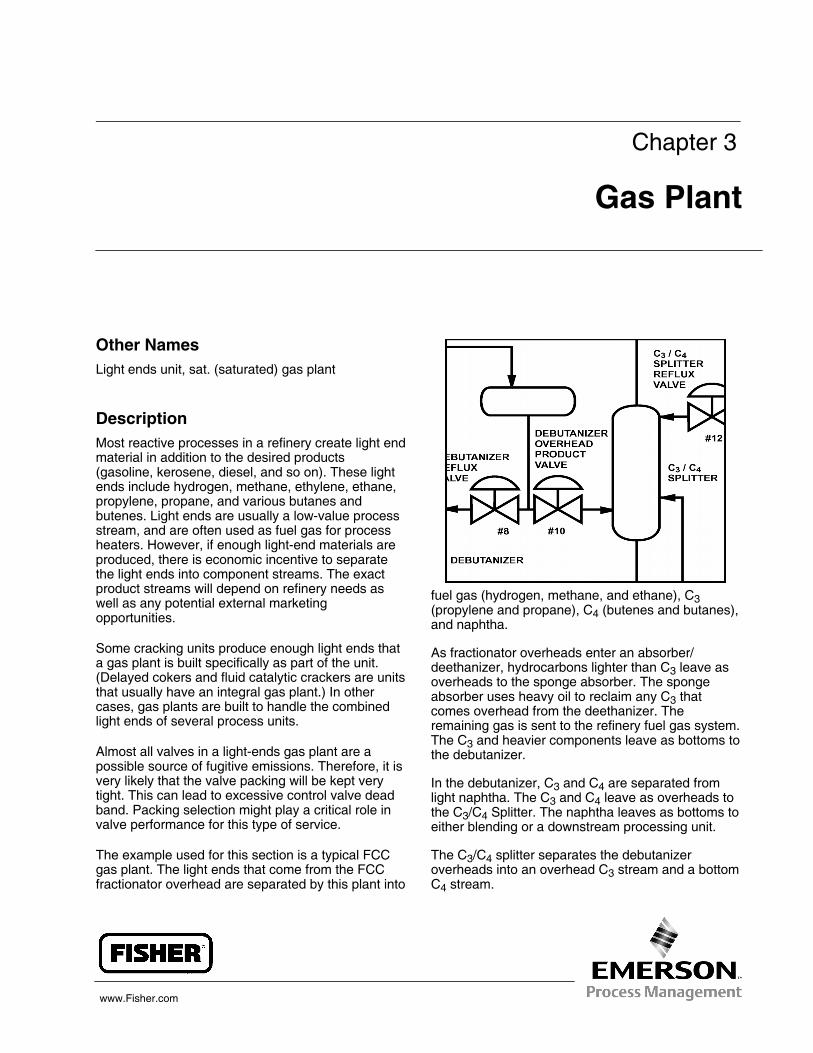
DescriptionMost reactive processes in a refinery create light endmaterial in addition to the desired products(gasoline, kerosene, diesel, and so on). These lightends include hydrogen, methane, ethylene, ethane,propylene, propane, and various butanes andbutenes. Light ends are usually a low-value processstream, and are often used as fuel gas for processheaters. However, if enough light-end materials areproduced, there is economic incentive to separatethe light ends into component streams. The exactproduct streams will depend on refinery needs aswell as any potential external marketingopportunities.
Some cracking units produce enough light ends thata gas plant is built specifically as part of the unit.(Delayed cokers and fluid catalytic crackers are unitsthat usually have an integral gas plant.) In othercases, gas plants are built to handle the combinedlight ends of several process units.
Almost all valves in a light-ends gas plant are apossible source of fugitive emissions. Therefore, it isvery likely that the valve packing will be kept verytight. This can lead to excessive control valve deadband. Packing selection might play a critical role invalve performance for this type of service.
The example used for this section is a typical FCCgas plant. The light ends that come from the FCCfractionator overhead are separated by this plant into
fuel gas (hydrogen, methane, and ethane), C3(propylene and propane), C4 (butenes and butanes),and naphtha.
As fractionator overheads enter an absorber/deethanizer, hydrocarbons lighter than C3 leave asoverheads to the sponge absorber. The spongeabsorber uses heavy oil to reclaim any C3 thatcomes overhead from the deethanizer. Theremaining gas is sent to the refinery fuel gas system.The C3 and heavier components leave as bottoms tothe debutanizer.
In the debutanizer, C3 and C4 are separated fromlight naphtha. The C3 and C4 leave as overheads tothe C3/C4 Splitter. The naphtha leaves as bottoms toeither blending or a downstream processing unit.
The C3/C4 splitter separates the debutanizeroverheads into an overhead C3 stream and a bottomC4 stream.

3–2 GAS PLANT
Typical Gas Plant
GAS PLANT 3–3
Control Valves
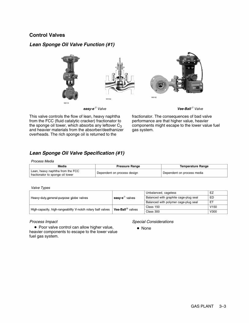
Lean Sponge Oil Valve Function (#1)
easy-e� Valve Vee-Ball� Valve
W8119
W8192W3162
This valve controls the flow of lean, heavy naphthafrom the FCC (fluid catalytic cracker) fractionator tothe sponge oil tower, which absorbs any leftover C3and heavier materials from the absorber/deethanizeroverheads. The rich sponge oil is returned to the
fractionator. The consequences of bad valveperformance are that higher value, heaviercomponents might escape to the lower value fuelgas system.
Lean Sponge Oil Valve Specification (#1)
Process MediaMedia Pressure Range Temperature Range
Lean, heavy naphtha from the FCCfractionator to sponge oil tower
Dependent on process design Dependent on process media
Valve TypesUnbalanced, cageless EZ
Heavy-duty,general-purpose globe valves easy-e� valves Balanced with graphite cage-plug seal EDHeavy duty,general purpose globe valves easy e valvesBalanced with polymer cage-plug seal ET
High capacity high rangeability V notch rotary ball valves Vee Ball� valvesClass 150 V150
High-capacity, high-rangeability V-notch rotary ball valves Vee-Ball� valvesClass 300 V300
Process Impact� Poor valve control can allow higher value,
heavier components to escape to the lower valuefuel gas system.
Special Considerations
� None

3–4 GAS PLANT
Absorber/Deethanizer Reboil Valve Function (#2)
easy-e� ValveW8119
W2966 W3162 W0451
The reboil valve controls the amount of heat put intothe column by the reboiler. In many cases, steam isused as a heat source. Steam valves are usuallyvery reliable. The service is very clean, and fugitiveemissions are not a concern. However, a problemvalve will make the column difficult to controlprecisely. This will be especially true if the columnfeed is subject to frequent changes.
Not all reboilers use steam as a heat source. Tosave energy, many refineries have integrated theirunits so that higher-temperature process streamsare used to provide heat for lower temperatureprocesses. In these cases, the reboil valve will foulmore easily and might be a concern for fugitiveemissions.
Absorber/Deethanizer Reboil Valve Specification (#2)
Process MediaMedia Pressure Range Temperature Range
Steam Dependent on process, typically 10.3 bar (150psig) saturated steam
Dependent on process design
Valve TypesUnbalanced, cageless EZ
Heavy-duty, general-purpose globe valves easy-e� valves Balanced with graphite cage-plug seal EDHeavy duty, general purpose globe valves easy e valvesBalanced with polymer cage-plug seal ET
Process Impact� This valve is important because it drives the
vapor back up through the column. Vapor though thecolumn affects column efficiency.
Special Considerations
� Consideration of materials for steam application

GAS PLANT 3–5
Fractionator Overhead Valve Function (#3)
easy-e� Valve Vee-Ball� ValveW8119
W8192
W7435
This is the feed valve to the absorber/deethanizer.However, it also is the fractionator overhead productvalve. The flow through this valve will normally beset to control the fractionator overhead receiverlevel. Therefore, any control problems with thefractionator overheads will ripple through the gasplant.
Feed valves are usually set up as flow or levelcontrol loops. An upstream unit or process oftencontrols the valve.
Unstable feed flow will make the distillation columndifficult to control. A problem valve will often causethe feed flow to oscillate. As a result, the column willalternate between too little and too much reboil heat.Depending on the size and number of trays in thecolumn the effect of a swing in the feed will takeanywhere from several minutes to more than anhour to reach the ends of the column. Sometimes,the reboil and reflux controls will amplify the swings.The final result is that meeting product purity targetsbecomes more difficult. Operations will normallyrespond by over-purifying the products, wastingenergy to compensate for the bad feed control valve.
Fractionator Overhead Valve Specification (#3)
Process MediaMedia Pressure Range Temperature Range
Primarily reactor effluent Typically less than 34.5 bar (500 psig) Dependent on material being distilled
Valve TypesUnbalanced, cageless EZ
Lower flow rates (line size 4 inchesand smaller)
Heavy-duty, general-purposeglobe valves easy-e� valves
Balanced with graphite cage-plugseal
EDand smaller) globe valves easy e valves
Balanced with polymer cage-plugseal
ET
Higher flow rates (line size 6 High-capacity, high-rangeabilityVee Ball� valves
Class 150 V150Higher flow rates (line size 6inches and larger)
High capacity, high rangeabilityV-notch rotary ball valves Vee-Ball� valves
Class 300 V300
Process Impact
� Control problems with this valve will produce aripple effect through the rest of the gas plant.
Special Considerations
� None
3–6 GAS PLANT
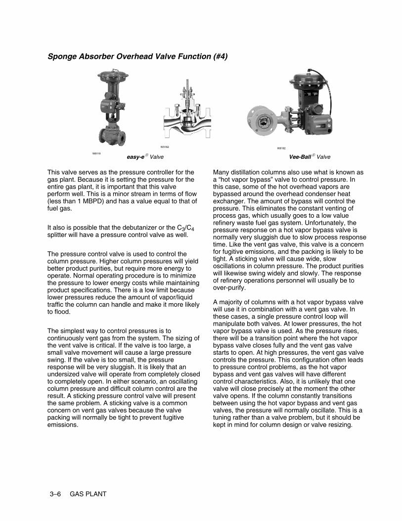
Sponge Absorber Overhead Valve Function (#4)
easy-e� Valve Vee-Ball� ValveW8119
W8192W3162
This valve serves as the pressure controller for thegas plant. Because it is setting the pressure for theentire gas plant, it is important that this valveperform well. This is a minor stream in terms of flow(less than 1 MBPD) and has a value equal to that offuel gas.
It also is possible that the debutanizer or the C3/C4splitter will have a pressure control valve as well.
The pressure control valve is used to control thecolumn pressure. Higher column pressures will yieldbetter product purities, but require more energy tooperate. Normal operating procedure is to minimizethe pressure to lower energy costs while maintainingproduct specifications. There is a low limit becauselower pressures reduce the amount of vapor/liquidtraffic the column can handle and make it more likelyto flood.
The simplest way to control pressures is tocontinuously vent gas from the system. The sizing ofthe vent valve is critical. If the valve is too large, asmall valve movement will cause a large pressureswing. If the valve is too small, the pressureresponse will be very sluggish. It is likely that anundersized valve will operate from completely closedto completely open. In either scenario, an oscillatingcolumn pressure and difficult column control are theresult. A sticking pressure control valve will presentthe same problem. A sticking valve is a commonconcern on vent gas valves because the valvepacking will normally be tight to prevent fugitiveemissions.
Many distillation columns also use what is known asa “hot vapor bypass” valve to control pressure. Inthis case, some of the hot overhead vapors arebypassed around the overhead condenser heatexchanger. The amount of bypass will control thepressure. This eliminates the constant venting ofprocess gas, which usually goes to a low valuerefinery waste fuel gas system. Unfortunately, thepressure response on a hot vapor bypass valve isnormally very sluggish due to slow process responsetime. Like the vent gas valve, this valve is a concernfor fugitive emissions, and the packing is likely to betight. A sticking valve will cause wide, slowoscillations in column pressure. The product puritieswill likewise swing widely and slowly. The responseof refinery operations personnel will usually be toover-purify.
A majority of columns with a hot vapor bypass valvewill use it in combination with a vent gas valve. Inthese cases, a single pressure control loop willmanipulate both valves. At lower pressures, the hotvapor bypass valve is used. As the pressure rises,there will be a transition point where the hot vaporbypass valve closes fully and the vent gas valvestarts to open. At high pressures, the vent gas valvecontrols the pressure. This configuration often leadsto pressure control problems, as the hot vaporbypass and vent gas valves will have differentcontrol characteristics. Also, it is unlikely that onevalve will close precisely at the moment the othervalve opens. If the column constantly transitionsbetween using the hot vapor bypass and vent gasvalves, the pressure will normally oscillate. This is atuning rather than a valve problem, but it should bekept in mind for column design or valve resizing.

GAS PLANT 3–7
Sponge Absorber Overhead Valve Specification (#4)
Process MediaMedia Pressure Range Temperature Range
Distillate light-end hydrocarbon liquid andnoncondensible gas
Dependent on process design Less than 93�C (200�F)
Valve TypesUnbalanced, cageless EZ
Heavy-duty, general-purpose globe valves easy-e� valves Balanced with graphite cage-plug seal EDHeavy duty, general purpose globe valves easy e valvesBalanced with polymer cage-plug seal ET
High-capacity, high-rangeability V-notch rotaryVee Ball� valves
Class 150 V150High capacity, high rangeability V notch rotaryball valves Vee-Ball� valves
Class 300 V300
Process Impact
� Controls the back pressure to the distillationcolumn
Special Considerations� Packing on these valves is important to reduce
fugitive emissions.
� Consider using special materials for the spongeabsorber overhead valve if there is an acid gasenvironment.

3–8 GAS PLANT
Absorber/Deethanizer Bottom Product Valve Function (#5)
Vee-Ball� Valve
W8192W5791
eplug� Valve
W5793
The bottom product valve is typically used to controlthe level in the bottom of the column. It normally has
no effect on column operation unless it causes thelevel to change quickly and dramatically.
Absorber/Deethanizer Bottom Product Valve Specification (#5)
Process MediaMedia Pressure Range Temperature Range
Light-end, lower boiling point hydrocarbon Dependent on process design Less than 343�C (650�F)
Valve Types
High-capacity, high-rangeability V-notch rotaryVee Ball� valves
Class 150 V150High capacity, high rangeability V notch rotaryball valves Vee-Ball� valves
Class 300 V300
General- and severe-service eccentric rotary-eplug� valves
High capacity, rugged CV500General and severe service eccentric rotaryplug valves eplug� valves
More rugged construction V500
Process Impact
� Dependent on downstream destination.
Special Considerations� Ball valves or eccentric plug valves might
require Stellite (Alloy 6) or ceramic trim materials
� Low-flow, clean fluids or small line sizeapplications could use globe valves

GAS PLANT 3–9
Absorber Lean Oil Valve Function (#6)
Vee-Ball� Valve
W8192 W5791
eplug� Valveeasy-e� Valve
W8119
Some of the debutanizer bottoms is returned as leanoil to the absorber/deethanizer to absorb heaviercomponents out of the deethanizer overheadstream. If the lean oil valve has problems, such as
sticking, then some of the C3 and heavier materialmight be lost to the lower value fuel gas system.However, the performance of the deethanizer shouldstill be stable.
Absorber Lean Oil Valve Specification (#6)
Process MediaMedia Pressure Range Temperature Range
Light-end, lower boiling point hydrocarbon Dependent on process design Less than 343�C (650�F)
Valve Types
High-capacity, high-rangeability V-notch rotaryVee Ball� valves
Class 150 V150High capacity, high rangeability V notch rotaryball valves Vee-Ball� valves
Class 300 V300
General- and severe-service eccentric rotary-eplug� valves
High capacity, rugged CV500General and severe service eccentric rotaryplug valves eplug� valves
More rugged construction V500
Unbalanced, cageless EZ
Heavy-duty, general-purpose globe valves easy-e� valves Balanced with graphite cage-plug seal EDHeavy duty, general purpose globe valves easy e valvesBalanced with polymer cage-plug seal ET
Process Impact
� Dependent on downstream destination
Special Considerations� Ball valves or eccentric plug valves might
require Stellite (Alloy 6) or ceramic trim materials.
� Low-flow, clean fluids or small line-sizeapplications could use globe valves

3–10 GAS PLANT
Debutanizer Bottom Product Valve Function (#7)
Vee-Ball� Valve
W8192 W5791
eplug� Valveeasy-e� Valve
W3162
The bottom product valve is typically used to controlthe level in the bottom of the column. It normally has
no effect on column operation unless it causes thelevel to change quickly and dramatically.
Debutanizer Bottom Product Valve Specification (#7)
Process MediaMedia Pressure Range Temperature Range
Heavier, higher boiling boiling pointhydrocarbon (typically naphtha)
Dependent on process design Less than 343�C (650�F)
Valve Types
High-capacity, high-rangeability V-notch rotaryVee Ball� valves
Class 150 V150High capacity, high rangeability V notch rotaryball valves Vee-Ball� valves
Class 300 V300
General- and severe-service eccentric rotary-eplug� valves
High capacity, rugged CV500General and severe service eccentric rotaryplug valves eplug� valves
More rugged construction V500
Unbalanced, cageless EZ
Heavy-duty, general-purpose globe valves easy-e� valves Balanced with graphite cage-plug seal EDHeavy duty, general purpose globe valves easy e valvesBalanced with polymer cage-plug seal ET
Process Impact
� Dependent on downstream destination.
Special Considerations� Ball valves or eccentric plug valves might
require Stellite (Alloy 6) or ceramic trim materials.
� Low-flow, clean fluids or small line-sizeapplications could use globe valves
GAS PLANT 3–11
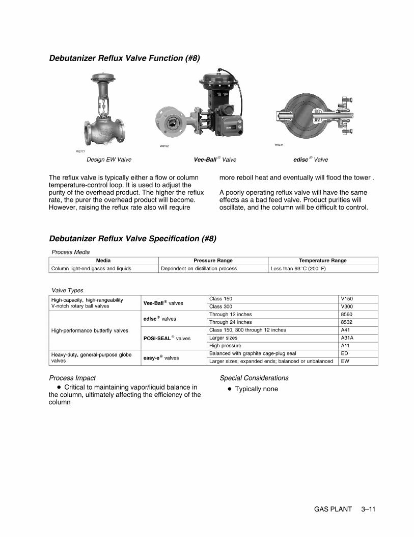
Debutanizer Reflux Valve Function (#8)
Design EW Valve Vee-Ball� Valve
W2777
W8192
edisc� Valve
W6234
The reflux valve is typically either a flow or columntemperature-control loop. It is used to adjust thepurity of the overhead product. The higher the refluxrate, the purer the overhead product will become.However, raising the reflux rate also will require
more reboil heat and eventually will flood the tower .
A poorly operating reflux valve will have the sameeffects as a bad feed valve. Product purities willoscillate, and the column will be difficult to control.
Debutanizer Reflux Valve Specification (#8)
Process MediaMedia Pressure Range Temperature Range
Column light-end gases and liquids Dependent on distillation process Less than 93�C (200�F)
Valve Types
High-capacity, high-rangeabilityVee Ball� valves
Class 150 V150High capacity, high rangeabilityV-notch rotary ball valves Vee-Ball� valves
Class 300 V300
edisc� valvesThrough 12 inches 8560
edisc� valvesThrough 24 inches 8532
High-performance butterfly valves Class 150, 300 through 12 inches A41High performance butterfly valves
POSI-SEAL� valves Larger sizes A31APOSI SEAL valvesHigh pressure A11
Heavy-duty, general-purpose globeeasy e� valves
Balanced with graphite cage-plug seal EDHeavy duty, general purpose globevalves easy-e� valves
Larger sizes; expanded ends; balanced or unbalanced EW
Process Impact� Critical to maintaining vapor/liquid balance in
the column, ultimately affecting the efficiency of thecolumn
Special Considerations
� Typically none

3–12 GAS PLANT
Debutanizer Reboil Valve Function (#9)
easy-e� ValveW8119
W2966 W3162 W0451
The reboil valve controls the amount of heat put intothe column by the reboiler. In many cases, steam isused as a heat source. Steam valves are usuallyvery reliable. The service is very clean, and fugitiveemissions are not a concern. However, a problemvalve will make the column difficult to controlprecisely. This will be especially true if the columnfeed is subject to frequent changes.
Not all reboilers use steam as a heat source. Tosave energy, many refineries have integrated theirunits so that higher-temperature process streamsare used to provide heat for lower temperatureprocesses. In these cases, the reboil valve will foulmore easily and might have fugitive emissionconcerns.
Debutanizer Reboil Valve Specification (#9)
Process MediaMedia Pressure Range Temperature Range
Steam Dependent on process, typically 10.3 bar (150psig) saturated steam
Dependent on process design
Valve TypesUnbalanced, cageless EZ
Heavy-duty, general-purpose globe valves easy-e� valves Balanced with graphite cage-plug seal EDHeavy duty, general purpose globe valves easy e valvesBalanced with polymer cage-plug seal ET
Process Impact� This valve is important because it drives the
vapor back up through the column. Vapor throughthe column affects column efficiency.
Special Considerations
� Consideration of materials for steam application

GAS PLANT 3–13
Debutanizer Overhead Product Valve Function (#10)
easy-e� Valve Vee-Ball� ValveW8119
W8192
W7435
The overhead product valve is typically used tocontrol the level in the overhead receiver. It normally
has no effect on column operation unless it causesthe level to change quickly and dramatically.
Debutanizer Overhead Product Valve Specification (#10)
Media Pressure Range Temperature Range
Distilled light-end liquids Dependent on process design Less than 93�C (200�F)
Valve TypesUnbalanced, cageless EZ
Heavy-duty, general-purpose globe valves easy-e� valves Balanced with graphite cage-plug seal EDHeavy duty, general purpose globe valves easy e valvesBalanced with polymer cage-plug seal ET
High-capacity, high-rangeability V-notch rotaryVee Ball� valves
Class 150 V150High capacity, high rangeability V notch rotaryball valves Vee-Ball� valves
Class 300 V300
Process Impact� Typically no critical impact
� Dependent on downstream destination
Special Considerations
� None

3–14 GAS PLANT
C3/C4 Splitter Bottom Product Valve Function (#11)
Vee-Ball� Valve
W8192 W5791
eplug� Valveeasy-e� Valve
W8119
The bottom product valve is typically used to controlthe level in the bottom of the column. It normally has
no effect on column operation unless it causes thelevel to change quickly and dramatically.
C3/C4 Splitter Bottom Product Valve Specification (#11)
Process MediaMedia Pressure Range Temperature Range
Heavier, higher boiling boiling pointhydrocarbon
Dependent on process design Less than 343�C (650�F)
Valve Types
High-capacity, high-rangeability V-notch rotaryVee Ball� valves
Class 150 V150High capacity, high rangeability V notch rotaryball valves Vee-Ball� valves
Class 300 V300
General- and severe-service eccentric rotary-eplug� valves
High capacity, rugged construction CV500General and severe service eccentric rotaryplug valves eplug� valves
More rugged construction V500
Unbalanced, cageless EZ
Heavy-duty, general-purpose globe valves easy-e� valves Balanced with graphite cage-plug seal EDHeavy duty, general purpose globe valves easy e valvesBalanced with polymer cage-plug seal ET
Process Impact
� Dependent on downstream destination
Special Considerations� Ball valves or eccentric plug valves might
require Stellite (Alloy 6) or ceramic trim materials.
� Low-flow, clean fluids or small line-sizeapplications could use globe valves

GAS PLANT 3–15
C3/C4 Splitter Reflux Valve Function ( #12)
POSI-SEAL� Valve Vee-Ball� Valve
W5811 W8192
edisc� Valve
W8299
The reflux valve is typically either a flow or columntemperature control loop. It is used to adjust thepurity of the overhead product. The higher the refluxrate, the purer the overhead product will become.However, raising the reflux rate also will requiremore reboil heat and eventually will flood the tower.
A poorly operating reflux valve will have the sameeffects as a bad feed valve. Product purities willoscillate and the column will be difficult to control.
C3/C4 Splitter Reflux Valve Specification (#12)
Process MediaMedia Pressure Range Temperature Range
Column light-end gases and liquids Dependent on distillation process Less than 93�C (200�F)
Valve Types
High-capacity, high-rangeabilityVee Ball� valves
Class 150 V150High capacity, high rangeabilityV-notch rotary ball valves Vee-Ball� valves
Class 300 V300
edisc� valvesThrough 12 inches 8560
edisc� valvesThrough 24 inches 8532
High-performance butterfly valves Class 150, 300 through 12 inches A41High performance butterfly valves
POSI-SEAL� valves Larger sizes A31APOSI SEAL valvesHigh pressure A11
Heavy-duty, general-purpose globeeasy e� valves
Balanced with graphite cage-plug seal EDHeavy duty, general purpose globevalves easy-e� valves
Larger sizes; expanded ends; balanced or unbalanced EW
Process Impact� Critical to maintaining vapor/liquid balance in
the column, ultimately affecting the efficiency of thecolumn
Special Considerations
� Typically none

3–16 GAS PLANT
C3/C4 Splitter Overhead Product Valve Function (#13)
easy-e� Valve Vee-Ball� ValveW8119
W8192W3162
The overhead product valve is typically used tocontrol the level in the overhead receiver. It normally
has no effect on column operation unless it causesthe level to change quickly and dramatically.
C3/C4 Splitter Overhead Product Valve Specification (#13)
Process MediaMedia Pressure Range Temperature Range
Distilled light-end liquids Dependent on process design Less than 93�C (200�F)
Valve TypesUnbalanced, cageless EZ
Heavy-duty, general-purpose globe valves easy-e� valves Balanced with graphite cage-plug seal EDHeavy duty, general purpose globe valves easy e valvesBalanced with polymer cage-plug seal ET
High-capacity, high-rangeability V-notch rotaryVee Ball� valves
Class 150 V150High capacity, high rangeability V notch rotaryball valves Vee-Ball� valves
Class 300 V300
Process Impact� Typically no critical impact
� Dependent on downstream destination
Special Considerations
� None

GAS PLANT 3–17
C3/C4 Splitter Reboil Valve Function (#14)
easy-e� ValveW8119
W2966 W3162 W0451
The reboil valve controls the amount of heat put intothe column by the reboiler. In many cases, steam isused as a heat source. The service is very clean,and fugitive emissions are not a concern. Steamvalves are usually very reliable. However, a problemvalve will make the column difficult to controlprecisely. This will be especially true if the columnfeed is subject to frequent changes.
Not all reboilers use steam as a heat source. Tosave energy, many refineries have integrated theirunits so that higher temperature process streamsare used to provide heat for lower temperatureprocesses. In these cases, the reboil valve will foulmore easily and might have fugitive emissionsconcerns.
C3/C4 Splitter Reboil Valve Specification (#14)
Process MediaMedia Pressure Range Temperature Range
Steam Dependent on process, typically 10.3 bar (150psig) saturated steam
Dependent on process design
Valve TypesUnbalanced, cageless EZ
Heavy-duty, general-purpose globe valves easy-e� valves Balanced with graphite cage-plug seal EDHeavy duty, general purpose globe valves easy e valvesBalanced with polymer cage-plug seal ET
Process Impact� This valve is important because it drives the
vapor back up through the column. Vapor throughthe column affects column efficiency.
Special Considerations
� Consideration of materials for steam application

3–18 GAS PLANT
www.Fisher.com
Chapter 4
Crude Distillation
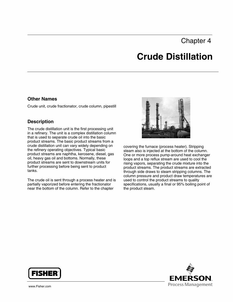
Other NamesCrude unit, crude fractionator, crude column, pipestill
DescriptionThe crude distillation unit is the first processing unitin a refinery. The unit is a complex distillation columnthat is used to separate crude oil into the basicproduct streams. The basic product streams from acrude distillation unit can vary widely depending onthe refinery operating objectives. Typical basicproduct streams are naphtha, kerosene, diesel, gasoil, heavy gas oil and bottoms. Normally, theseproduct streams are sent to downstream units forfurther processing before being sent to producttanks.
The crude oil is sent through a process heater and ispartially vaporized before entering the fractionatornear the bottom of the column. Refer to the chapter
covering the furnace (process heater). Strippingsteam also is injected at the bottom of the column.One or more process pump-around heat exchangerloops and a top reflux stream are used to cool therising vapors, separating the crude mixture into theproduct streams. The product streams are extractedthrough side draws to steam stripping columns. Thecolumn pressure and product draw temperatures areused to control the product streams to qualityspecifications, usually a final or 95% boiling point ofthe product steam.

4–2 CRUDE DISTILLATION
Typical Crude Distillation Column
CRUDE DISTILLATION 4–3
Control Valves
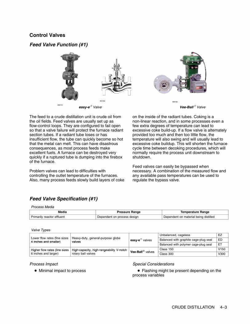
Feed Valve Function (#1)
easy-e� Valve Vee-Ball� ValveW8119
W8192W3162
The feed to a crude distillation unit is crude oil fromthe oil fields. Feed valves are usually set up asflow-control loops. They are configured to fail openso that a valve failure will protect the furnace radiantsection tubes. If a radiant tube loses or hasinsufficient flow, the tube can quickly become so hotthat the metal can melt. This can have disastrousconsequences, as most process feeds makeexcellent fuels. A furnace can be destroyed veryquickly if a ruptured tube is dumping into the fireboxof the furnace.
Problem valves can lead to difficulties withcontrolling the outlet temperature of the furnaces.Also, many process feeds slowly build layers of coke
on the inside of the radiant tubes. Coking is anon-linear reaction, and in some processes even afew extra degrees of temperature can lead toexcessive coke build-up. If a flow valve is alternatelyprovided too much and then too little flow, thetemperature will also swing and will usually lead toexcessive coke buildup. This will shorten the furnacecycle time between decoking procedures, which willnormally require the process unit downstream toshutdown.
Feed valves can easily be bypassed whennecessary. A combination of the measured flow andany available pass temperatures can be used toregulate the bypass valve.
Feed Valve Specification (#1)
Process MediaMedia Pressure Range Temperature Range
Primarily reactor effluent Dependent on process design Dependent on material being distilled
Valve Types
Lower flow rates (line sizes Heavy duty general purpose globeUnbalanced, cageless EZ
Lower flow rates (line sizes4 inches and smaller)
Heavy-duty, general-purpose globevalves easy-e� valves Balanced with graphite cage-plug seal ED
4 inches and smaller) valves easy e valvesBalanced with polymer cage-plug seal ET
Higher flow rates (line sizes High-capacity, high-rangeability V-notchVee Ball� valves
Class 150 V150Higher flow rates (line sizes6 inches and larger)
High capacity, high rangeability V notchrotary ball valves Vee-Ball� valves
Class 300 V300
Process Impact
� Minimal impact to process
Special Considerations
� Flashing might be present depending on theprocess variables

4–4 CRUDE DISTILLATION
Pump-Around Valve Function (#2, #3)
easy-e� Valve Vee-Ball� ValveW8119
W8192
W7435
A crude fractionator will always have at least onepump-around heat exchanger loop for controlling theheat balance. Most fractionators will have more thanone pump-around loop. The pump-around loop isused to extract heat from the column, creating theseparation between the product draws immediatelyabove and below the pump-around loop. Thepump-around valves are usually flow controllers.
A poorly performing or bypassed pump-around valvewill increase the variability in the qualityspecifications of the product draws. A valve failuremost likely will create an upset lasting from 30minutes to a few hours depending on the severity ofthe failure.
Pump-Around Valve Specification (#2, #3)
Process MediaMedia Pressure Range Temperature Range
Hydrocarbon liquid Dependent on distillation column pressure Dependent on where steam is taken from thecolumn: 93 to 316�C (200 to 600�F)
Valve TypesUnbalanced, cageless EZ
Heavy-duty, general-purpose globe valves easy-e� valves Balanced with graphite cage-plug seal EDHeavy duty, general purpose globe valves easy e valvesBalanced with polymer cage-plug seal ET
High-capacity, high-rangeability V-notch rotaryVee Ball� valves
Class 150 V150High capacity, high rangeability V notch rotaryball valves Vee-Ball� valves
Class 300 V300
Process Impact
� Critical to maintaining heat balance around thecolumn
Special Considerations� Typically none: dependent on distillation unit
and process
� NACE materials

CRUDE DISTILLATION 4–5
Fuel Valve Function (#4)
easy-e� Valve Vee-Ball� ValveW8119
W8192W3162
Depending on the furnace service and configuration,this valve will normally be part of a loop that controlseither the fuel flow or pressure. These valves arespecified as fail closed so that a control loop failurewill not allow an excessive amount of fuel to bedumped into a hot furnace. A fuel valve failure willalmost always shut down the processing unitdownstream. Although many fuel valves havebypass circuits, Refinery operations personnel areusually reluctant to run a furnace on bypass for anylength of time because of safety concerns.
The preferred control loop configuration for the outlettemperature is a cascade to the set point of the loopcontrolling the fuel valve. Many furnaces will be setup such that the temperature control loop directly
manipulates the fuel valve. This direct connectionusually provides inferior control performance to acascade configuration. It is extremely susceptible toany valve dead band, such as that caused by asticking valve. This can be detected by excessiveoscillation in the outlet temperature.
When the fuel valve is manipulated by thetemperature loop or by a flow control loop, thereoften will be a pressure control valve upstream of thefuel valve. This valve also will fail closed and willhave the same consequences as a failure of the fuelvalve. However, with this configuration, operationspersonnel will be more willing to run a fuel valve inbypass as they still have a way to shut off the fuelquickly in an emergency.
Fuel Valve Specification (#4)
Process MediaMedia Pressure Range Temperature Range
Natural gas-fuel gas mixtureFuel oil with atomizing steam
Dependent on process design
Valve TypesUnbalanced, cageless EZ
Heavy-duty, general-purpose globe valves easy-e� valves Balanced with graphite cage-plug seal EDHeavy duty, general purpose globe valves easy e valvesBalanced with polymer cage-plug seal ET
High-capacity, high-rangeability V-notchVee Ball� valves
Class 150 V150High capacity, high rangeability V notchrotary ball valves Vee-Ball� valves
Class 300 V300
Process Impact� Performance is critical to controlling furnace
temperature
� Performance is critical to reducing energy costsassociated with the furnace
Special Considerations
� Potential for acidic fouling gases (for example,H2S, HCL)

4–6 CRUDE DISTILLATION
Bottoms Valve Function (#5)
Vee-Ball� Valve
W8192W5791
eplug� Valve
W5793
The bottom material becomes the vacuum distillationunit charge.
The bottoms flow does not usually have any impacton the operation of the crude fractionator unless a
failure causes the liquid level of the bottoms tooverfill or empty. Usually, level alarms on the unitallow the operator to catch this before it causes anupset.
Bottoms Valve Specification (#5)
Process MediaMedia Pressure Range Temperature Range
Dependent on distillation process Dependent on process design Dependent on material being distilled
Valve Types
High-capacity, high-rangeability V-notch rotaryVee Ball� valves
Class 150 V150High capacity, high rangeability V notch rotaryball valves Vee-Ball� valves
Class 300 V300
General- and severe-service eccentriceplug� valves
High capacity, rugged construction CV500General and severe service eccentricrotary-plug valves eplug� valves
More rugged construction V500
Process Impact
� Dependent on downstream destination
Special Considerations
� Could encounter higher viscosity materials,sludge and process media with entrained particles
� Ball valves or eccentric plug valves mightrequire Stellite (Alloy 6) or ceramic trim materials.
� Low-flow, clean fluids or small line-sizeapplications could use globe valves.

CRUDE DISTILLATION 4–7
Reflux Valve Function (#6)
Design EW Valve Vee-Ball� Valve
W2777
W8192
edisc� Valve
W6234
The reflux valve is used to control the separationbetween the top product (usually naphtha) and thehighest-side draw product. The reflux valve can beeither a flow or a temperature controller.
A poorly performing or bypassed reflux valve willincrease the variability in the quality specifications ofthe overhead product and the top side draw. A valvefailure will most likely create an upset lasting from 30minutes to a few hours, depending on the severity ofthe failure.
Reflux Valve Specification (#6)
Process MediaMedia Pressure Range Temperature Range
Dependent on distillation process Dependent on process design Dependent on material being distilled
Valve Types
High-capacity, high-rangeability V-notch rotaryVee Ball� valves
Class 150 V150High capacity, high rangeability V notch rotaryball valves Vee-Ball� valves
Class 300 V300
edisc� valvesThrough 12 inches 8560
edisc� valvesThrough 24 inches 8532
High-performance butterfly valves Class 150, 300 through 12 inches A41High performance butterfly valves
POSI-SEAL� valves Larger sizes A31APOSI SEAL valvesHigh pressure A11
Unbalanced, cageless EZ
�
Balanced with graphite cage-plug seal EDHeavy-duty, general-purpose globe valves easy-e� valves Balanced with polymer cage-plug seal ETy y g g y
Larger sizes; expanded ends; balanced orunbalanced
EW
Process Impact
� Critical to maintaining vapor/liquid balance inthe column, ultimately affecting the efficiency of thecolumn
Special Considerations
� Typically none

4–8 CRUDE DISTILLATION
Fractionator Stripping Steam Valve Function (#7)
easy-e� ValveW8119
W2966 W3162 W0451
Stripping steam is injected into the bottoms of thefractionator to strip out lighter components from thecrude bottoms stream. The amount of strippingsteam also affects the separation efficiency of the
crude fractionator. A valve failure most likely willcreate an upset lasting from 30 minutes to a fewhours depending on the severity of the failure.
Fractionator Stripping Steam Valve Specification (#7)
Process MediaMedia Pressure Range Temperature Range
Steam Dependent on process design, typically 10.3bar (150 psig) saturated steam
Dependent on material being distilled
Valve TypesUnbalanced, cageless EZ
Heavy-duty, general-purpose globe valves easy-e� valves Balanced with graphite cage-plug seal EDHeavy duty, general purpose globe valves easy e valvesBalanced with polymer cage-plug seal ET
Process Impact� This valve is important because it drives the
vapor back up through the column. Vapor throughthe column affects column efficiency. Reboiler steamwill have a direct effect on overhead reflux flow.
Special Considerations
� Consideration of materials for steam application
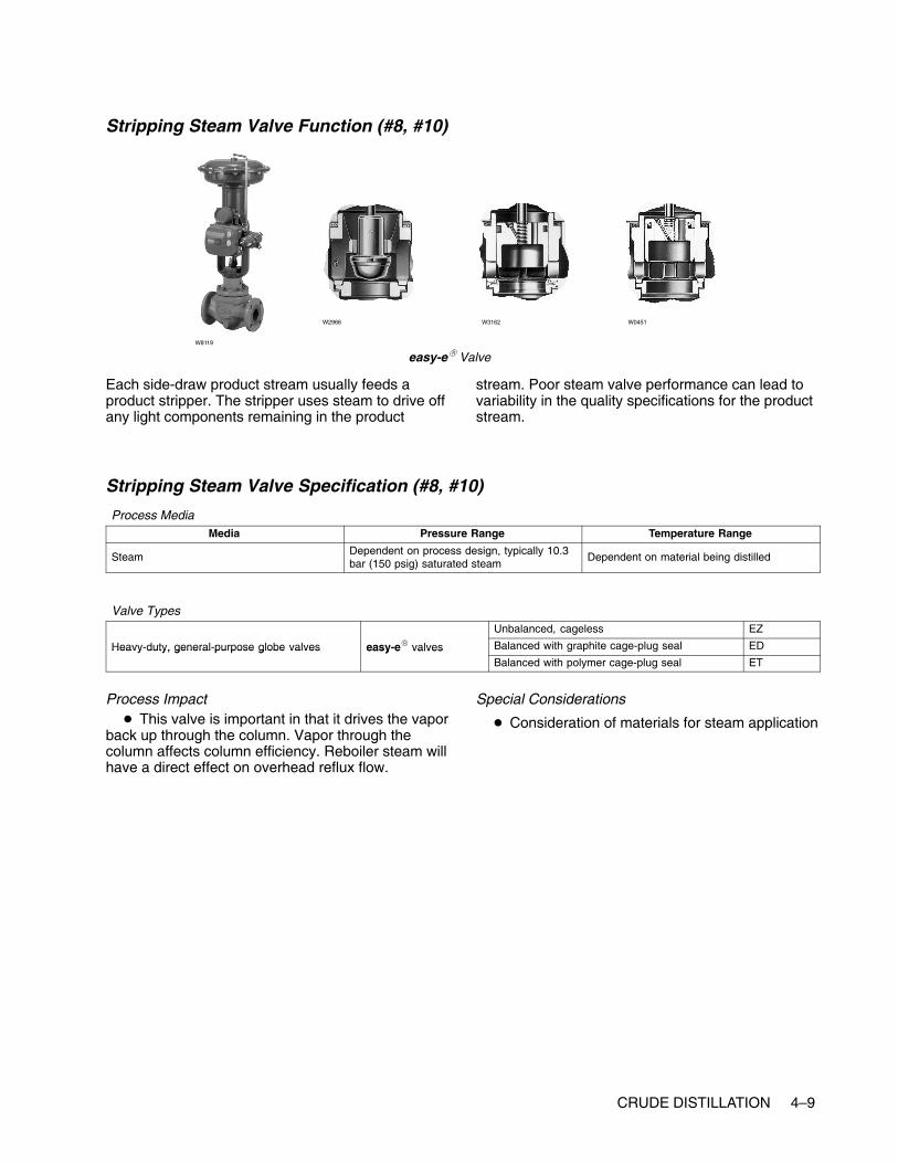
CRUDE DISTILLATION 4–9
Stripping Steam Valve Function (#8, #10)
easy-e� ValveW8119
W2966 W3162 W0451
Each side-draw product stream usually feeds aproduct stripper. The stripper uses steam to drive offany light components remaining in the product
stream. Poor steam valve performance can lead tovariability in the quality specifications for the productstream.
Stripping Steam Valve Specification (#8, #10)
Process MediaMedia Pressure Range Temperature Range
Steam Dependent on process design, typically 10.3bar (150 psig) saturated steam
Dependent on material being distilled
Valve TypesUnbalanced, cageless EZ
Heavy-duty, general-purpose globe valves easy-e� valves Balanced with graphite cage-plug seal EDHeavy duty, general purpose globe valves easy e valvesBalanced with polymer cage-plug seal ET
Process Impact� This valve is important in that it drives the vapor
back up through the column. Vapor through thecolumn affects column efficiency. Reboiler steam willhave a direct effect on overhead reflux flow.
Special Considerations
� Consideration of materials for steam application

4–10 CRUDE DISTILLATION
Stripper Bottoms (Product) Valves Function (#9, #11)
Vee-Ball� Valve
W8192 W5791
eplug� Valve
W7435
The stripper products are kerosene and diesel.
The stripper bottoms valves are used to control thebottoms level in the strippers. These valves do notusually have any impact on the operation of the
strippers unless a failure causes the liquid level ofthe bottoms to overfill or empty. Usually, level alarmson the unit allows the operator to catch this before itcauses an upset.
Stripper Bottoms (Product) Valves Specification (#9, #11)
Process MediaMedia Pressure Range Temperature Range
Dependent on distillation process Dependent on process design Dependent on material being distilled
Valve Types
High capacity high rangeability V notch rotary ball valves Vee Ball� valvesClass 150 V150
High-capacity, high-rangeability V-notch rotary ball valves Vee-Ball� valvesClass 300 V300
General and severe service eccentric rotary plug valves eplug� valvesHigh capacity, rugged CV500
General- and severe-service eccentric rotary-plug valves eplug� valvesMore rugged construction V500
Process Impact
� Dependent on downstream destination
Special Considerations
� Could encounter higher viscosity materials,sludge, and process media with entrained particles.
� Ball valves or eccentric plug valves mightrequire Stellite (Alloy 6) or ceramic trim materials.
� Low-flow, clean fluids or small line-sizeapplications could use globe valves

CRUDE DISTILLATION 4–11
Overhead Pressure Control Valve Function (#12)
easy-e� Valve Vee-Ball� Valve
W8119
W8192
W7435
The overhead pressure control valve releases gasesincluding H2, H2S, methane, ethane, propane, andbutane. This stream is very normally very small (1 to3% of feed).
The column pressure has a significant effect onfractionator operation. A valve failure that allows thecolumn to over or under pressure can cause an
upset that might take hours of recovery time. Aproblem valve can create pressure oscillations thatprevent the fractionator from being operatedoptimally. Valve sizing is critical for this service. Ifthe valve is too large, the column pressure will beprone to rapid swings. If the value is too small andhas a large response time, it can cause long slowswings.
Overhead Pressure Control Valve Specification (#12)
Process MediaMedia Pressure Range Temperature Range
Dependent on distillation process Dependent on process design Dependent on material being distilled
Valve TypesUnbalanced, cageless EZ
Heavy-duty, general-purpose globe valves easy-e� valves Balanced with graphite cage-plug seal EDHeavy duty, general purpose globe valves easy e valvesBalanced with polymer cage-plug seal ET
High-capacity, high-rangeability V-notch rotaryVee Ball� valves
Class 150 V150High capacity, high rangeability V notch rotaryball valves Vee-Ball� valves
Class 300 V300
Process Impact
� Controls the pressure to the distillation columnand is very important in controlling the stability of thetower. Many columns use tray temperature to controloverhead composition, thus stable pressure isrequired to ensure that temperature changes reflectcomposition changes, not pressure changes.
Special Considerations
� Packing on these valves is important to reducefugitive emissions.
� Consider using special materials if there is anacid gas environment.

4–12 CRUDE DISTILLATION
Overhead Product Valve Function (#13)
easy-e� Valve Vee-Ball� ValveW8119
W8192W3162
The overhead product is naphtha, a blendingcomponent in gasoline.
The overhead product valve is usually on levelcontrol from the overhead receiver. This valve doesnot usually have any impact on the operation of thecrude fractionator unless a failure causes the liquidlevel in the overhead receiver to over fill or empty. Inthis case, the column pressure would be affected,
and the fractionator would experience an upset untilthe pressure stabilized. Usually, level alarms on theunit would allow the operator to catch this before itbecomes an upset.
It is more likely that a poorly performing productvalve could cause stability problems to adownstream processing unit in configurations wherethere is no surge tank between the units.
Overhead Product Valve Specification (#13)
Process MediaMedia Pressure Range Temperature Range
Dependent on distillation process Dependent on process design Dependent on material being distilled
Valve Types
Lower flow rates (line size Heavy duty general purpose globeUnbalanced, cageless EZ
Lower flow rates (line size4 inches and smaller)
Heavy duty, general-purpose globevalves easy-e� valves Balanced with graphite cage-plug seal ED
4 inches and smaller) valves easy e valvesBalanced with polymer cage-plug seal ET
Higher flow rates (line High- capacity, high- rangeabilityVee Ball� valves
Class 150 V150Higher flow rates (linesize 6 inches and larger)
High capacity, high rangeabilityV-notch rotary ball valves Vee-Ball� valves
Class 300 V300
Process Impact� Typically no critical impact
� Dependent on downstream destination
Special Considerations
� None

www.Fisher.com
Chapter 5
Vacuum Distillation
Other NamesVacuum tower, vacuum flash
DescriptionThe vacuum distillation unit is fed the bottoms fromthe crude unit. The unit is a complex distillationcolumn that fractionates the crude bottoms under avacuum to improve separation into basic productstreams. The basic product streams from a vacuumdistillation unit can vary widely depending on therefinery operating objectives. Typical basic productstreams are gas oil, LVGO (light vacuum gas oil),HVGO (heavy vacuum gas oil), and residual (resid)bottoms. Normally, these product streams are senton to downstream units for further processing.
The crude bottom stream is sent through a processcharge heater and is partially vaporized beforeentering the vacuum fractionator near the bottom ofthe column. Refer to the chapter covering the
furnace (also called a process heater). Strippingsteam is also injected at the bottom of the column.One or more process pump-around exchanger loopsare used to cool the rising vapors, separating thecrude bottom mixture into the product streams. Theproduct streams are extracted through side draws tosteam stripping columns. The column vacuum iscontrolled by an overhead ejector system. Thecolumn vacuum pressure and product drawtemperatures are used to control the productstreams to quality specifications, usually viscosity orflash point.

5–2 VACUUM DISTILLATION
Typical Vacuum Distillation Column

VACUUM DISTILLATION 5–3
Control ValvesNote: Valve applications in this process might require alternative packing orientations to account for vacuumpressure conditions.
Feed Valve Function (#1)
easy-e� Valve Vee-Ball� Valve
W8119
W8192
W7435
The feed to a vacuum distillation unit is crude oilfrom the oil fields.
Feed valves are usually set up as flow-control loops.They are configured to fail open so that a valvefailure protects the furnace radiant section tubes. If aradiant tube loses or has insufficient flow, the tubecan quickly become so hot that the metal can melt.This can have disastrous consequences as mostprocess feeds make excellent fuels. A furnace canbe destroyed very quickly if a ruptured tube isdumping into the firebox of the furnace.
Problem valves can lead to difficulties withcontrolling the outlet temperature of the furnaces.Also, many process feeds slowly build layers of coke
on the inside of the radiant tubes. Coking is anon-linear reaction, and in some processes even afew extra degrees of temperature can lead toexcessive coke build-up. If a flow valve is alternatelyprovided too much and then too little flow, thetemperature will also swing and will usually lead toexcessive coke buildup. This typically shortens thefurnace cycle time between decoking procedures,which normally requires the process unitdownstream to shutdown.
Feed valves can easily be bypassed whennecessary. A combination of the measured flow andany available pass temperatures can be used toregulate the bypass valve.
Feed Valve Specification (#1)
Process MediaMedia Pressure Range Temperature Range
Primarily reactor effluent Dependent on process design Dependent on material being distilled
Valve Types
Lower flow rates (line sizes Heavy duty general purpose globeUnbalanced, cageless EZ
Lower flow rates (line sizes4 inches and smaller)
Heavy-duty, general-purpose globevalves easy-e� valves Balanced with graphite cage-plug seal ED
4 inches and smaller) valves easy e valvesBalanced with polymer cage-plug seal ET
Higher flow rates (line sizes High-capacity, high-rangeability V-notchVee Ball� valves
Class 150 V150Higher flow rates (line sizes6 inches and larger)
High capacity, high rangeability V notchrotary ball valves Vee-Ball� valves
Class 300 V300
Process Impact
� Minimal impact to process
Special Considerations
� Flashing might be present depending on theprocess variables

5–4 VACUUM DISTILLATION
Fuel Valve Function (#2)
easy-e� Valve Vee-Ball� ValveW8119
W8192W3162
Depending on the furnace service and configurationthis valve will normally be part of a loop that controlseither the fuel flow or pressure. These valves arespecified as fail closed so that a control loop failurewill not allow an excessive amount of fuel to bedumped into a hot furnace. A fuel valve failure willalmost always shut down the processing unitdownstream. Although many fuel valves havebypass circuits, refinery operations personnel areusually reluctant to run a furnace on bypass for anysignificant time because of safety concerns.
The preferred control loop configuration for the outlettemperature is a cascade to the setpoint of the loopcontrolling the fuel valve. Many furnaces will be setup such that the temperature control loop directly
manipulates the fuel valve. This direct connectionusually provides inferior control performance to acascade configuration. It is extremely susceptible toany valve dead band such as that caused by asticking valve. This can be detected by excessiveoscillation in the outlet temperature.
When the fuel valve is manipulated by thetemperature loop or by a flow control loop, there willoften be a pressure control valve upstream of thefuel valve. This valve will also fail closed and willhave the same consequences as a failure of the fuelvalve. However, with this configuration, Operationswill be more willing to run a fuel valve in bypass asthey still have a way to quickly shut off the fuel in anemergency.
Fuel Valve Specification (#2)
Process MediaMedia Pressure Range Temperature Range
Natural gas-fuel gas mixtureFuel oil with atomizing steam
Dependent on process design
Valve TypesUnbalanced, cageless EZ
Heavy-duty, general-purpose globe valves easy-e� valves Balanced with graphite cage-plug seal EDHeavy duty, general purpose globe valves easy e valvesBalanced with polymer cage-plug seal ET
High-capacity, high-rangeability V-notchVee Ball� valves
Class 150 V150High capacity, high rangeability V notchrotary ball valves Vee-Ball� valves
Class 300 V300
Process Impact� Performance is critical to controlling furnace
temperature
� Performance is critical to reducing energy costsassociated with furnace
Special Considerations
� Potential for acidic fouling gases (for example,H2S, HCL)
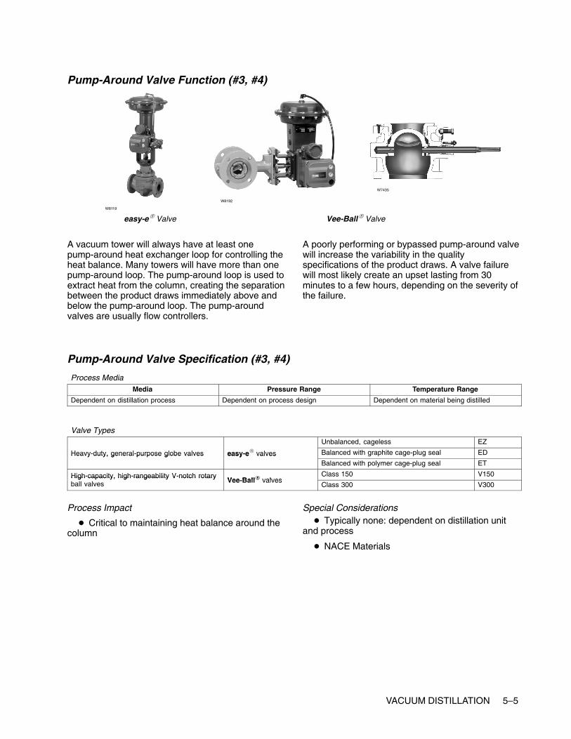
VACUUM DISTILLATION 5–5
Pump-Around Valve Function (#3, #4)
easy-e� Valve Vee-Ball� Valve
W8119
W8192
W7435
A vacuum tower will always have at least onepump-around heat exchanger loop for controlling theheat balance. Many towers will have more than onepump-around loop. The pump-around loop is used toextract heat from the column, creating the separationbetween the product draws immediately above andbelow the pump-around loop. The pump-aroundvalves are usually flow controllers.
A poorly performing or bypassed pump-around valvewill increase the variability in the qualityspecifications of the product draws. A valve failurewill most likely create an upset lasting from 30minutes to a few hours, depending on the severity ofthe failure.
Pump-Around Valve Specification (#3, #4)
Process MediaMedia Pressure Range Temperature Range
Dependent on distillation process Dependent on process design Dependent on material being distilled
Valve TypesUnbalanced, cageless EZ
Heavy-duty, general-purpose globe valves easy-e� valves Balanced with graphite cage-plug seal EDHeavy duty, general purpose globe valves easy e valvesBalanced with polymer cage-plug seal ET
High-capacity, high-rangeability V-notch rotaryVee Ball� valves
Class 150 V150High capacity, high rangeability V notch rotaryball valves Vee-Ball� valves
Class 300 V300
Process Impact
� Critical to maintaining heat balance around thecolumn
Special Considerations� Typically none: dependent on distillation unit
and process
� NACE Materials

5–6 VACUUM DISTILLATION
Stripping Steam Valve Function (#5)
easy-e� ValveW8119
W2966 W3162 W0451
Stripping steam is injected into the bottoms of thetower to strip out lighter components from the crudebottom stream. The amount of stripping steam alsoaffects the separation efficiency of the vacuum
tower. A valve failure will most likely create an upsetlasting from 30 minutes to a few hours depending onthe severity of the failure.
Stripping Steam Valve Specification (#5)
Process MediaMedia Pressure Range Temperature Range
Steam Dependent on process design, typically 10.3bar (150 psig) saturated steam
Dependent on material being distilled
Valve TypesUnbalanced, cageless EZ
Heavy-duty, general-purpose globe valves easy-e� valves Balanced with graphite cage-plug seal EDHeavy duty, general purpose globe valves easy e valvesBalanced with polymer cage-plug seal ET
Process Impact� This valve is important because it drives the
vapor back up through the column. Vapor throughthe column affects column efficiency. Reboiler steamwill have a direct effect on overhead reflux flow.
Special Considerations
� Consideration of materials for steam application

VACUUM DISTILLATION 5–7
Vacuum Resid Valve Function (#6)
Vee-Ball� Valve
W8192 W5791
eplug� Valve
W7435
The bottom material is vacuum resid.
The bottoms do not usually have any impact on theoperation of the vacuum tower unless a failure
causes the liquid level of the bottoms to overfill orempty. Usually, level alarms on the unit allow theoperator to catch this before it causes an upset.
Vacuum Resid Valve Specification (#6)
Process MediaMedia Pressure Range Temperature Range
Dependent on distillation process Dependent on process design Dependent on material being distilled
Valve Types
High-capacity, high-rangeability V-notch rotaryVee Ball� valves
Class 150 V150High capacity, high rangeability V notch rotaryball valves Vee-Ball� valves
Class 300 V300
General- and severe-service eccentriceplug� valves
High capacity, rugged construction CV500General and severe service eccentricrotary-plug valves eplug� valves
More rugged construction V500
Process Impact
� Dependent on downstream destination
Special Considerations
� Could encounter higher-viscosity materials,sludge and process media with entrained particles
� Ball valves or eccentric plug valves mightrequire Stellite (Alloy 6) or ceramic trim materials.
� Low-flow, clean fluids or small line-sizeapplications could use globe valves
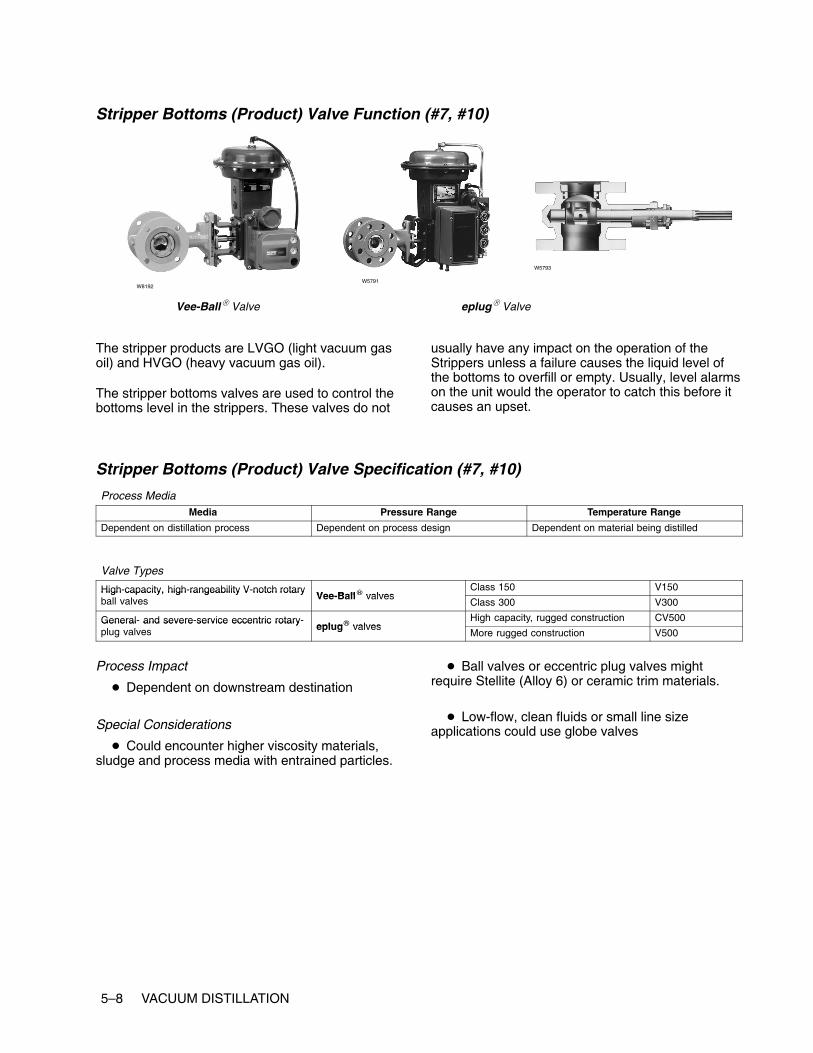
5–8 VACUUM DISTILLATION
Stripper Bottoms (Product) Valve Function (#7, #10)
Vee-Ball� Valve
W8192W5791
eplug� Valve
W5793
The stripper products are LVGO (light vacuum gasoil) and HVGO (heavy vacuum gas oil).
The stripper bottoms valves are used to control thebottoms level in the strippers. These valves do not
usually have any impact on the operation of theStrippers unless a failure causes the liquid level ofthe bottoms to overfill or empty. Usually, level alarmson the unit would the operator to catch this before itcauses an upset.
Stripper Bottoms (Product) Valve Specification (#7, #10)
Process MediaMedia Pressure Range Temperature Range
Dependent on distillation process Dependent on process design Dependent on material being distilled
Valve Types
High-capacity, high-rangeability V-notch rotaryVee Ball� valves
Class 150 V150High capacity, high rangeability V notch rotaryball valves Vee-Ball� valves
Class 300 V300
General- and severe-service eccentric rotary-eplug� valves
High capacity, rugged construction CV500General and severe service eccentric rotaryplug valves eplug� valves
More rugged construction V500
Process Impact
� Dependent on downstream destination
Special Considerations
� Could encounter higher viscosity materials,sludge and process media with entrained particles.
� Ball valves or eccentric plug valves mightrequire Stellite (Alloy 6) or ceramic trim materials.
� Low-flow, clean fluids or small line sizeapplications could use globe valves

VACUUM DISTILLATION 5–9
Gas Oil Valve Function (#8)
easy-e� Valve Vee-Ball� ValveW8119
W8192W3162
The top product is gas oil. Normal production rate isusually minor.
Gas Oil Valve Specification (#8)
Process MediaMedia Pressure Range Temperature Range
Dependent on distillation process Dependent on process design Dependent on material being distilled
Valve TypesUnbalanced, cageless EZ
Heavy duty, general-purpose globe valves easy-e� valves Balanced with graphite cage-plug seal EDHeavy duty, general purpose globe valves easy e valvesBalanced with polymer cage-plug seal ET
High-capacity, high-rangeability V-notch rotaryVee Ball� valves
Class 150 V150High capacity, high rangeability V notch rotaryball valves Vee-Ball� valves
Class 300 V300
Process Impact� Typically no critical impact
� Dependent on downstream destination
Special Considerations
� None

5–10 VACUUM DISTILLATION
Stripping Steam Valve Function (#9, #11)
easy-e� ValveW8119
W2966 W3162 W0451
Each side draw product stream usually feeds aproduct stripper. The stripper uses steam to drive offany light components remaining in the product
stream. Poor steam valve performance can lead tovariability in the quality specifications for the productstream.
Stripping Steam Valve Specification (#9, #11)
Process MediaMedia Pressure Range Temperature Range
Steam Dependent on process design, typically 10.3bar (150 psig) saturated steam
Dependent on material being distilled
Valve TypesUnbalanced, cageless EZ
Heavy-duty, general-purpose globe valves easy-e� valves Balanced with graphite cage-plug seal EDHeavy duty, general purpose globe valves easy e valvesBalanced with polymer cage-plug seal ET
Process Impact� This valve is important because it drives the
vapor back up through the column. Vapor throughthe column affects column efficiency. Reboiler steamwill have a direct effect on overhead reflux flow.
Special Considerations
� Consideration of materials for steam application

www.Fisher.com
Chapter 6
Delayed Coking Unit
Other NamesCoker
DescriptionThe delayed coking unit process thermally cracksheavy feedstocks such as crude unit bottoms,vacuum unit bottoms or other heavy gas oils. Theproducts are sponge or needle coke, gas oil,naphtha, and light ends.
The incoming feed is sent, along with coke drumvapors, to the bottom of a fractionator. Thefractionator bottoms are sent to the coking furnace.In this furnace, the feed is rapidly heated andpartially vaporized. Steam is often injected into thefeed oils to control the furnace residence time. Thevapor-liquid mixture leaves the furnace and entersthe bottom of a coke drum. In the coke drum theentrained liquid is thermally cracked to coke andother vapor products. The vapors leave the top ofthe coke drum and enter the bottom of thefractionator.
Over the course of several hours, the coke drum willfill with coke. When a drum is full, the furnaceeffluent will be switched to another drum. The filleddrum is cooled, then hydraulically drilled to removethe coke. Once empty, it is put back into service
when the other drum is filled. Typical drum cycletimes are 12 to 18 hours depending on the unitdesign.
The fractionator separates the drum vapors intotypical product streams. For this example, thestreams are light ends, naphtha, light gas oil, andheavy gas oil. All fractionator bottom materials aretypically sent back through the coking furnace.

6–2 DELAYED COKING UNIT
Typical Delayed Coking Unit
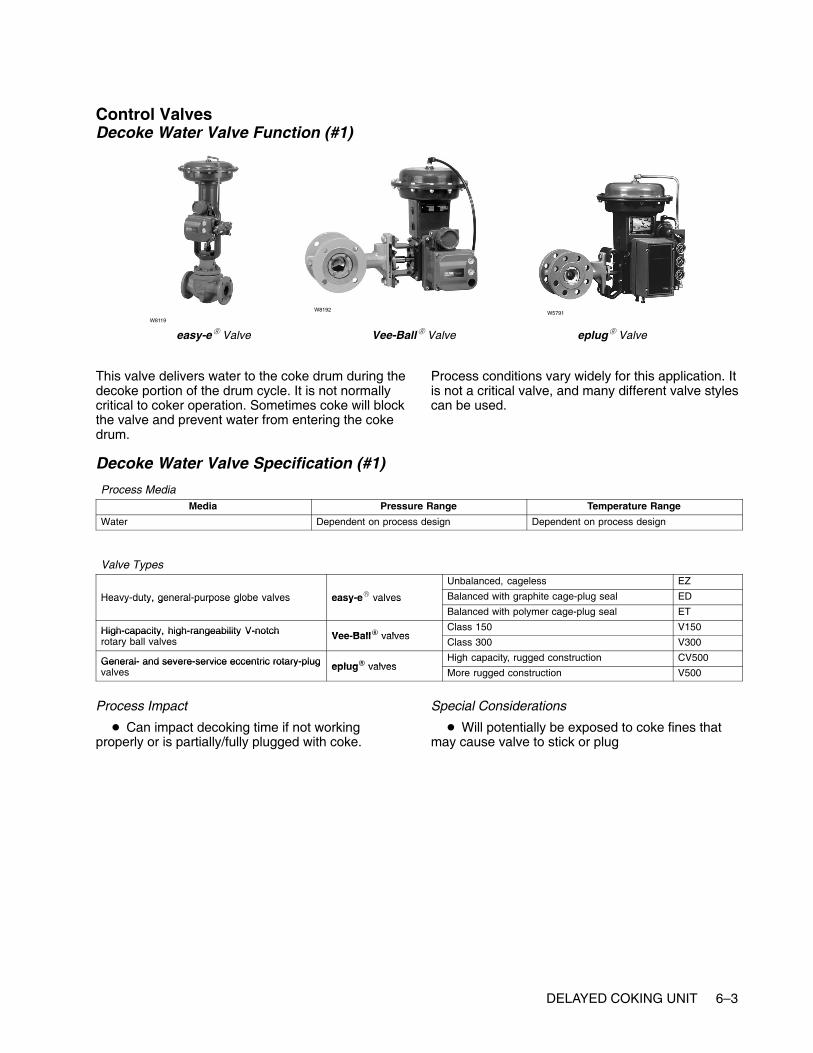
DELAYED COKING UNIT 6–3
Control ValvesDecoke Water Valve Function (#1)
easy-e� Valve Vee-Ball� Valve
W8119
W8192W5791
eplug� Valve
This valve delivers water to the coke drum during thedecoke portion of the drum cycle. It is not normallycritical to coker operation. Sometimes coke will blockthe valve and prevent water from entering the cokedrum.
Process conditions vary widely for this application. Itis not a critical valve, and many different valve stylescan be used.
Decoke Water Valve Specification (#1)
Process MediaMedia Pressure Range Temperature Range
Water Dependent on process design Dependent on process design
Valve TypesUnbalanced, cageless EZ
Heavy-duty, general-purpose globe valves easy-e� valves Balanced with graphite cage-plug seal EDHeavy duty, general purpose globe valves easy e valvesBalanced with polymer cage-plug seal ET
High-capacity, high-rangeability V-notch Vee Ball� valvesClass 150 V150High-capacity, high-rangeability V-notch
rotary ball valves Vee-Ball� valvesClass 300 V300
General- and severe-service eccentric rotary-plug eplug� valvesHigh capacity, rugged construction CV500General- and severe-service eccentric rotary-plug
valves eplug� valvesMore rugged construction V500
Process Impact
� Can impact decoking time if not workingproperly or is partially/fully plugged with coke.
Special Considerations
� Will potentially be exposed to coke fines thatmay cause valve to stick or plug

6–4 DELAYED COKING UNIT
Decoke Steam Valve Function (#2)
easy-e� ValveW8119
W2966 W3162 W0451
This valve delivers steam to the coke drum duringthe decoker portion of the drum cycle. It is not criticalto coker operation.
Decoke Steam Valve Specification (#2)
Process MediaMedia Pressure Range Temperature Range
Steam Dependent on process design, typically 10.3bar (150 psig) saturated steam
Dependent on process design
Valve TypesUnbalanced, cageless EZ
Heavy-duty, general-purpose globe valves easy-e� valves Balanced with graphite cage-plug seal EDHeavy duty, general purpose globe valves easy e valvesBalanced with polymer cage-plug seal ET
Process Impact� This valve is important because it drives the
vapor back up through the column. Vapor throughthe column affects column efficiency. Reboiler steamwill have a direct effect on overhead reflux flow.
Special Considerations
� Utilize materials suited to steam application
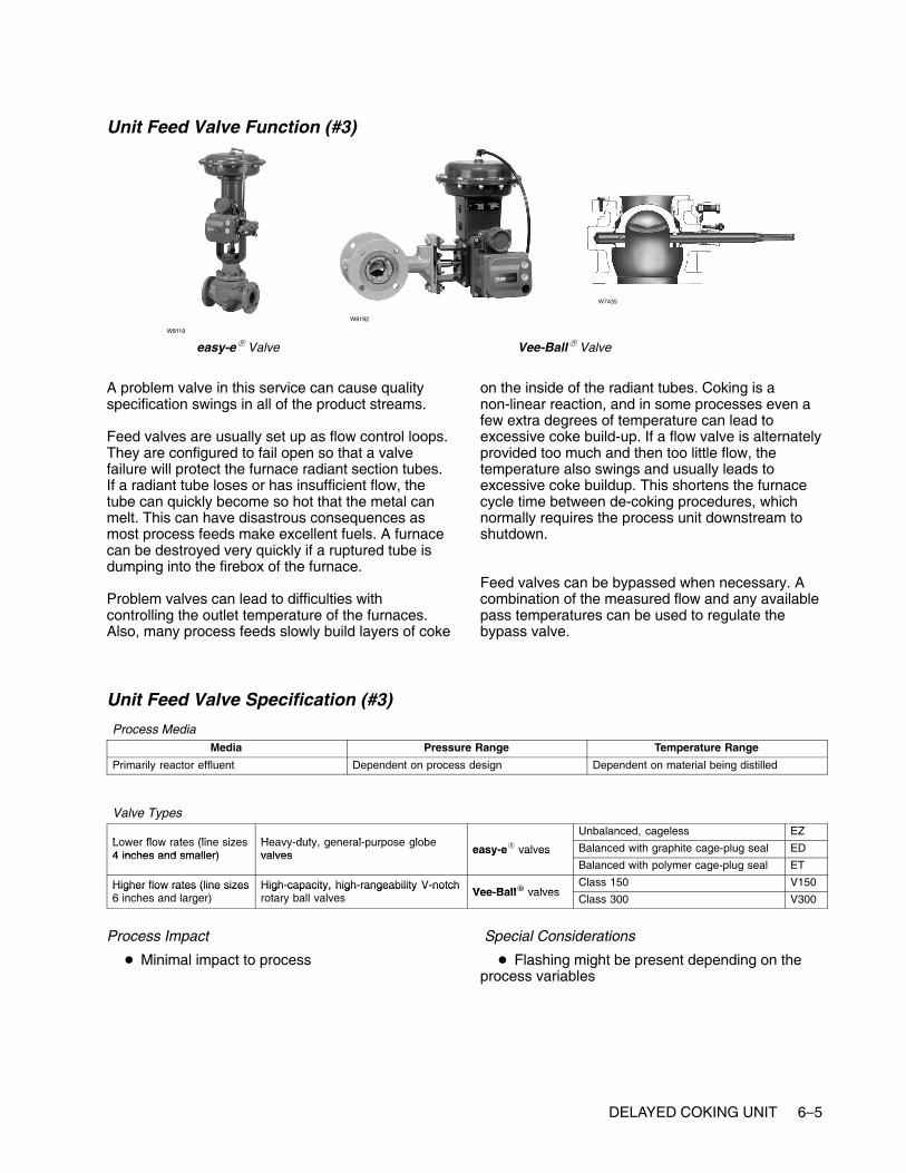
DELAYED COKING UNIT 6–5
Unit Feed Valve Function (#3)
easy-e� Valve Vee-Ball� Valve
W8119
W8192
W7435
A problem valve in this service can cause qualityspecification swings in all of the product streams.
Feed valves are usually set up as flow control loops.They are configured to fail open so that a valvefailure will protect the furnace radiant section tubes.If a radiant tube loses or has insufficient flow, thetube can quickly become so hot that the metal canmelt. This can have disastrous consequences asmost process feeds make excellent fuels. A furnacecan be destroyed very quickly if a ruptured tube isdumping into the firebox of the furnace.
Problem valves can lead to difficulties withcontrolling the outlet temperature of the furnaces.Also, many process feeds slowly build layers of coke
on the inside of the radiant tubes. Coking is anon-linear reaction, and in some processes even afew extra degrees of temperature can lead toexcessive coke build-up. If a flow valve is alternatelyprovided too much and then too little flow, thetemperature also swings and usually leads toexcessive coke buildup. This shortens the furnacecycle time between de-coking procedures, whichnormally requires the process unit downstream toshutdown.
Feed valves can be bypassed when necessary. Acombination of the measured flow and any availablepass temperatures can be used to regulate thebypass valve.
Unit Feed Valve Specification (#3)
Process MediaMedia Pressure Range Temperature Range
Primarily reactor effluent Dependent on process design Dependent on material being distilled
Valve Types
Lower flow rates (line sizes Heavy duty general purpose globeUnbalanced, cageless EZ
Lower flow rates (line sizes4 inches and smaller)
Heavy-duty, general-purpose globevalves easy-e� valves Balanced with graphite cage-plug seal ED
4 inches and smaller) valves easy e valvesBalanced with polymer cage-plug seal ET
Higher flow rates (line sizes High-capacity, high-rangeability V-notchVee Ball� valves
Class 150 V150Higher flow rates (line sizes6 inches and larger)
High capacity, high rangeability V notchrotary ball valves Vee-Ball� valves
Class 300 V300
Process Impact
� Minimal impact to process
Special Considerations
� Flashing might be present depending on theprocess variables

6–6 DELAYED COKING UNIT
Drum Decoke Block Valve Function (#4, #8)These are actually block valves, not control valves.However, if they are leaking through into a hot drumthey can cause a significant upset to the fractionatoras steam will cause the column pressure to rise orfluctuate.
Drum Decoke Block Valve Specification (#4, #8)Fisher does not offer a block valve.
Drum Switch Valve Function (#5a, #5b, #6a, #6b)
Vee-Ball� Valve
W8192 W5791
eplug� Valve
W7435
These valves are used to switch the process streamfrom one drum to another. If one these valves fails orleaks through, immediate maintenance will be
required. If not corrected quickly, it is likely that thecoker will have to be shut down, and upstream unitswill have to cut back on production.
Drum Switch Valve Specification (#5a, #5b, #6a, #6b)
Process MediaMedia Pressure Range Temperature Range
Bottom-of-the-barrel material such as heavyhydrocarbon slug
Dependent on process design Approximately 371�C (700�F)
Valve Types
High-capacity, high-rangeability V-notch Vee Ball� valvesClass 150 V150High-capacity, high-rangeability V-notch
rotary ball valves Vee-Ball� valvesClass 300 V300
General- and severe-service eccentric rotary- eplug� valvesHigh capacity, rugged construction CV500General- and severe-service eccentric rotary-
plug valves eplug� valvesMore rugged construction V500
Process Impact:
� Important that the valve opens and shuts whenrequired
Special Considerations
� Materials that best hold up under corrosive,high-temperature, erosive applications

DELAYED COKING UNIT 6–7
Fuel Valve Function (#7)
easy-e� Valve Vee-Ball� ValveW8119
W8192W3162
Depending on the furnace service and configurationthis valve normally will be part of a loop that controlseither the fuel flow or pressure. These valves arespecified as fail–closed so that a control loop failurewill not allow an excessive amount of fuel to bedumped into a hot furnace. A fuel valve failure willalmost always shut down the processing unitdownstream. Although many fuel valves havebypass circuits, refinery operations personnel areusually reluctant to run a furnace on bypass for anysignificant time because of safety concerns.
The preferred control loop configuration for the outlettemperature is a cascade to the setpoint of the loopcontrolling the fuel valve. Many furnaces will be setup such that the temperature control loop directly
manipulates the fuel valve. This direct connectionusually provides inferior control performance to acascade configuration. It is extremely susceptible toany valve dead band such as that caused by asticking valve. This can be detected by excessiveoscillation in the outlet temperature.
When the fuel valve is manipulated by thetemperature loop or by a flow control loop, there willoften be a pressure control valve upstream of thefuel valve. This valve will also fail closed and willhave the same consequences as a failure of the fuelvalve. However, with this configuration, operationspersonnel will be more willing to run a fuel valve inbypass as they still have a way to quickly shut off thefuel in an emergency.
Fuel Valve Specification (#7)
Process MediaMedia Pressure Range Temperature Range
Natural gas-fuel gas mixtureFuel oil with atomizing steam
Dependent on process design Dependent on process design
Valve TypesUnbalanced, cageless EZ
Heavy-duty, general-purpose globe valves easy-e� valves Balanced with graphite cage-plug seal EDHeavy duty, general purpose globe valves easy e valvesBalanced with polymer cage-plug seal ET
High-capacity, high-rangeability V-notchVee Ball� valves
Class 150 V150High capacity, high rangeability V notchrotary ball valves Vee-Ball� valves
Class 300 V300
Process Impact
� Performance is critical to controlling furnacetemperature.
� Performance is critical to reducing energy costsassociated with the furnace.
Special Considerations
� Potential for acidic fouling gases (for example,H2S, HCL)

6–8 DELAYED COKING UNIT
Furnace Feed Valve Function (#9)
easy-e� Valve Vee-Ball� Valve
W8119
W8192
W7435
Feed valves are usually set up as flow-control loops.They are configured to fail open so that a valvefailure will protect the furnace radiant section tubes.If a radiant tube loses or has insufficient flow, thetube can quickly become so hot that the metal canmelt. This can have disastrous consequences, asmost process feeds make excellent fuels. A furnacecan be destroyed very quickly if a ruptured tube isdumping into the firebox of the furnace.
Problem valves can lead to difficulties withcontrolling the outlet temperature of the furnaces.Also, many process feeds slowly build layers of cokeon the inside of the radiant tubes. Coking is a
non-linear reaction, and in some processes even afew extra degrees of temperature can lead toexcessive coke build-up. If a flow valve is alternatelyprovided too much and then too little flow, thetemperature also swings and usually leads toexcessive coke buildup. This shortens the furnacecycle time between decoking procedures, whichnormally requires the process unit downstream toshut down.
Feed valves can easily be bypassed whennecessary. A combination of the measured flow andany available pass temperatures can be used toregulate the bypass valve.
Furnace Feed Valve Specification (#9)
Process MediaMedia Pressure Range Temperature Range
Primarily reactor effluent Dependent on process design Dependent on process design
Valve Types
Lower flow rates (line sizes Heavy duty general purpose globeUnbalanced, cageless EZ
Lower flow rates (line sizes4 inches and smaller)
Heavy-duty, general-purpose globevalves easy-e� valves Balanced with graphite cage-plug seal ED
4 inches and smaller) valves easy e valvesBalanced with polymer cage-plug seal ET
Higher flow rates (line sizes High-capacity, high-rangeability V-notchVee Ball� valves
Class 150 V150Higher flow rates (line sizes6 inches and larger)
High capacity, high rangeability V notchrotary ball valves Vee-Ball� valves
Class 300 V300
Process Impact
� Minimal impact to process
Special Considerations
� Flashing might be present depending on theprocess variables

DELAYED COKING UNIT 6–9
Fractionator Pump-Around Valve Function (#10)
easy-e� Valve Vee-Ball� ValveW8119
W8192W3162
A crude fractionator will always have at least onepump-around heat exchanger loop for controlling theheat balance. Most fractionators will have more thanone pump-around loop. The pump-around loopextracts heat from the column, creating theseparation between the product draws immediatelyabove and below the pump-around loop. Thepump-around valves are usually flow controllers.
A poorly performing or bypassed pump-around valvewill increase the variability in the qualityspecifications of the product draws. A valve failurewill most likely create an upset lasting from 30minutes to a few hours depending on the severity ofthe failure.
Fractionator Pump-Around Valve Specification (#10)
Process MediaMedia Pressure Range Temperature Range
Hydrocarbon liquid Dependent on distillation column pressure Dependent on where steam is taken from thecolumn, 93 to 316�C (200 to 600�F)
Valve TypesUnbalanced, cageless EZ
Heavy-duty, general-purpose globe valves easy-e� valves Balanced with graphite cage-plug seal EDHeavy duty, general purpose globe valves easy e valvesBalanced with polymer cage-plug seal ET
High-capacity, high-rangeability V-notch rotaryVee Ball� valves
Class 150 V150High capacity, high rangeability V notch rotaryball valves Vee-Ball� valves
Class 300 V300
Process Impact
� Critical to maintaining heat balance around thecolumn
Special Considerations� Typically none; dependent on distillation unit
and process
� NACE Materials

6–10 DELAYED COKING UNIT
Fractionator Reflux Valve Function (#11)
Design EW Valve Vee-Ball� Valve
W2777
W8192
edisc� Valve
W6234
The reflux valve is used to control the separationbetween the top product (usually naphtha), and thehighest-side draw product. The reflux valve can beeither a flow or a temperature controller.
A poorly performing or bypassed reflux valve willincrease the variability in the quality specifications ofthe overhead product and the top-side draw. A valvefailure will most likely create an upset lasting from 30minutes to a few hours, depending on the severity ofthe failure.
Fractionator Reflux Valve Specification (#11)
Process MediaMedia Pressure Range Temperature Range
Dependent on distillation process Dependent on process design Dependent on material being distilled
Valve Types
High-capacity, high-rangeability V-notch rotaryVee Ball� valves
Class 150 V150High capacity, high rangeability V notch rotaryball valves Vee-Ball� valves
Class 300 V300
edisc� valvesThrough 12 inches 8560
edisc� valvesThrough 24 inches 8532
High- performance butterfly valves Class 150, 300 through 12 inches A41High performance butterfly valves
POSI-SEAL� valves Larger sizes A31APOSI SEAL valvesHigh pressure A11
Unbalanced, cageless EZ
�
Balanced with graphite cage-plug seal EDHeavy-duty, general-purpose globe valves easy-e� valves Balanced with polymer cage-plug seal ETy y g g y
Larger sizes; expanded ends; balanced orunbalanced
EW
Process Impact
� Critical to maintaining vapor/liquid balance inthe column, ultimately affecting the efficiency of thecolumn
Special Considerations
� Typically none
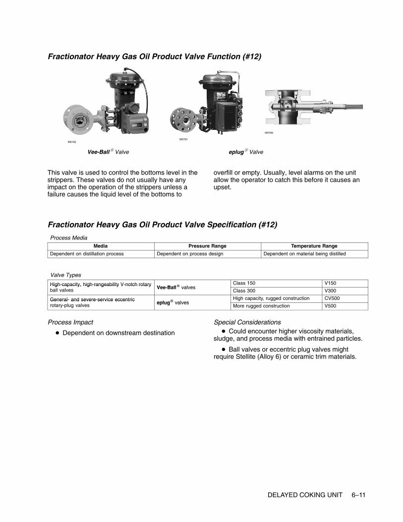
DELAYED COKING UNIT 6–11
Fractionator Heavy Gas Oil Product Valve Function (#12)
Vee-Ball� Valve
W8192W5791
eplug� Valve
W5793
This valve is used to control the bottoms level in thestrippers. These valves do not usually have anyimpact on the operation of the strippers unless afailure causes the liquid level of the bottoms to
overfill or empty. Usually, level alarms on the unitallow the operator to catch this before it causes anupset.
Fractionator Heavy Gas Oil Product Valve Specification (#12)
Process MediaMedia Pressure Range Temperature Range
Dependent on distillation process Dependent on process design Dependent on material being distilled
Valve Types
High-capacity, high-rangeability V-notch rotaryVee Ball� valves
Class 150 V150High capacity, high rangeability V notch rotaryball valves Vee-Ball� valves
Class 300 V300
General- and severe-service eccentriceplug� valves
High capacity, rugged construction CV500General and severe service eccentricrotary-plug valves eplug� valves
More rugged construction V500
Process Impact
� Dependent on downstream destination
Special Considerations� Could encounter higher viscosity materials,
sludge, and process media with entrained particles.
� Ball valves or eccentric plug valves mightrequire Stellite (Alloy 6) or ceramic trim materials.

6–12 DELAYED COKING UNIT
Fractionator Stripper Steam Valve Function (#13, #17)
easy-e� ValveW8119
W2966 W3162 W0451
Each side-draw product stream usually feeds aproduct stripper. The stripper uses steam to drive offany light components remaining in the product
stream. Poor steam valve performance can lead tovariability in the quality specifications for the productstream.
Fractionator Stripping Steam Valve Specification (#13 & #17)
Process MediaMedia Pressure Range Temperature Range
Steam Dependent on process design, typically 10.3bar (150 psig) saturated steam
Dependent on material being distilled
Valve TypesUnbalanced, cageless EZ
Heavy-duty, general-purpose globe valves easy-e� valves Balanced with graphite cage-plug seal EDHeavy duty, general purpose globe valves easy e valvesBalanced with polymer cage-plug seal ET
Process Impact� This valve is important because it drives the
vapor back up through the column. Vapor throughthe column affects column efficiency. Reboiler steamwill have a direct effect on overhead reflux flow.
Special Considerations
� Utilize materials suited to steam application
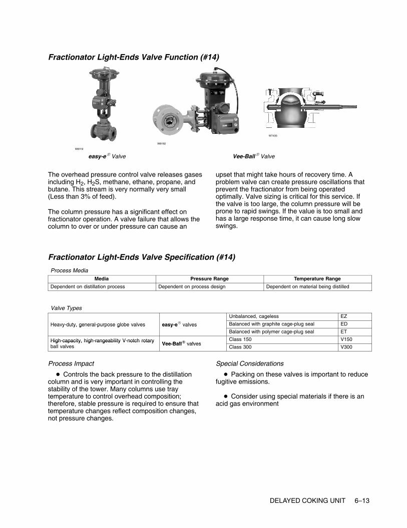
DELAYED COKING UNIT 6–13
Fractionator Light-Ends Valve Function (#14)
easy-e� Valve Vee-Ball� Valve
W8119
W8192
W7435
The overhead pressure control valve releases gasesincluding H2, H2S, methane, ethane, propane, andbutane. This stream is very normally very small(Less than 3% of feed).
The column pressure has a significant effect onfractionator operation. A valve failure that allows thecolumn to over or under pressure can cause an
upset that might take hours of recovery time. Aproblem valve can create pressure oscillations thatprevent the fractionator from being operatedoptimally. Valve sizing is critical for this service. Ifthe valve is too large, the column pressure will beprone to rapid swings. If the value is too small andhas a large response time, it can cause long slowswings.
Fractionator Light-Ends Valve Specification (#14)
Process MediaMedia Pressure Range Temperature Range
Dependent on distillation process Dependent on process design Dependent on material being distilled
Valve TypesUnbalanced, cageless EZ
Heavy-duty, general-purpose globe valves easy-e� valves Balanced with graphite cage-plug seal EDHeavy duty, general purpose globe valves easy e valvesBalanced with polymer cage-plug seal ET
High-capacity, high-rangeability V-notch rotaryVee Ball� valves
Class 150 V150High capacity, high rangeability V notch rotaryball valves Vee-Ball� valves
Class 300 V300
Process Impact
� Controls the back pressure to the distillationcolumn and is very important in controlling thestability of the tower. Many columns use traytemperature to control overhead composition;therefore, stable pressure is required to ensure thattemperature changes reflect composition changes,not pressure changes.
Special Considerations
� Packing on these valves is important to reducefugitive emissions.
� Consider using special materials if there is anacid gas environment

6–14 DELAYED COKING UNIT
Fractionator Light Gas Oil Product Valve Function (#15)
Vee-Ball� Valve
W8192 W5791
eplug� Valve
W7435
The stripper bottoms valves are used to control thebottoms level in the strippers. These valves do notusually have any impact on the operation of thestrippers unless a failure caused the liquid level of
the bottoms to overfill or empty. Usually, level alarmson the unit allow the operator to catch this before itcauses an upset.
Fractionator Light Gas Oil Product Valve Specification (#15)
Process MediaMedia Pressure Range Temperature Range
Dependent on distillation process Dependent on process design Dependent on material being distilled
Valve Types
High-capacity, high-rangeability V-notch rotaryVee Ball� valves
Class 150 V150High capacity, high rangeability V notch rotaryball valves Vee-Ball� valves
Class 300 V300
General- and severe-service eccentric rotary-eplug� valves
High capacity, rugged construction CV500General and severe service eccentric rotaryplug valves eplug� valves
More rugged construction V500
Process Impact
� Dependent on downstream destination
Special Considerations
� Could encounter higher viscosity materials,sludge, and process media with entrained particles
� Ball valves or eccentric plug valves mightrequire Stellite (Alloy 6) or ceramic trim materials.
� Low-flow, clean fluids or small line-sizeapplications could use globe valves.

DELAYED COKING UNIT 6–15
Fractionator Naphtha Valve Function (#16)
easy-e� Valve Vee-Ball� ValveW8119
W8192W3162
The overhead product valve is usually on levelcontrol from the overhead receiver. This valve doesnot usually have any impact on the operation of thecrude fractionator unless a failure causes the liquidlevel in the overhead receiver to over fill or empty. Inthis case, the column pressure would be affected,and the fractionator would experience an upset untilthe pressure became stable again. Usually, level
alarms on the unit allow the operator to catch thisbefore it becomes an upset.
It is more likely that a poorly performing productvalve could cause stability problems to adownstream processing unit in configurations wherethere is no surge tank between the units.
Fractionator Naphtha Valve Specification (#16)
Process MediaMedia Pressure Range Temperature Range
Dependent on distillation process Dependent on process design Dependent on material being distilled
Valve Types
Lower flow rates (line size Heavy duty general purpose globeUnbalanced, cageless EZ
Lower flow rates (line size4 inches and smaller)
Heavy-duty, general- purpose globevalves easy-e� valves Balanced with graphite cage-plug seal ED
4 inches and smaller) valves easy e valvesBalanced with polymer cage-plug seal ET
Higher flow rates (line High-capacity, high- rangeabilityVee Ball� valves
Class 150 V150Higher flow rates (linesize 6 inches and larger)
High capacity, high rangeabilityV-notch rotary ball valves Vee-Ball� valves
Class 300 V300
Process Impact� Typically no critical impact
� Dependent on downstream destination
Special Considerations
� None

6–16 DELAYED COKING UNIT

www.Fisher.com
Chapter 7
Hydrotreater
Other NamesHydroprocesser, unionfining, unifiner, desulfurizer,HDS (hydrodesulfurizer)
DescriptionThe Hydrotreating process removes undesirablematerials from a feedstock by selective reactionswith hydrogen in a heated catalyst bed. Sulfur,nitrogen, and certain metal contaminants areremoved from the feed. Olefins and aromatics areconverted to saturated hydrocarbons. Hydrotreatingis often used to remove catalyst poisons from afeedstock before downstream processing. It also isused to remove contaminants from product streamsto meet environmental standards.
The incoming feed is assumed to be distillate for thisdescription. The gas oil is heated in a furnace toreaction temperature. It is combined with a recyclehydrogen stream before flowing through the reactorwith one or more catalyst beds. The reactor effluentis sent to a separator. The vapor from the separatoris recycled through a compressor back to the feed.Makeup hydrogen is added to this stream asnecessary. The liquid from the separator is sent to astripper. In the stripper, hydrogen sulfide, ammonia,and light ends are sent overhead as vapors.Naphtha is produced as the overhead liquid product.The stripper bottom is treated, desulfurized distillate.

7–2 HYDROTREATER
Typical Hydrotreater

HYDROTREATER 7–3
Control Valves
Unit Feed Valve Function (#1)
easy-e� ValveW8119
W2966 W3162 W0451
A problem valve in this service can cause swings inthe amount of conversion through the unit. If theswings are wide enough, this will actually limit unitthroughput and will lead to increased coke laydownon the catalyst, potentially shortening reactor life.
Feed valves usually are set up as flow-control loops.They are configured to fail open so that a valvefailure will protect the furnace radiant section tubes.If a radiant tube loses or has insufficient flow, thetube can quickly become so hot that the metal canmelt. This can have disastrous consequences, asmost process feeds make excellent fuels. A furnacecan be destroyed very quickly if a ruptured tube isdumping into the firebox of the furnace.
Problem valves can lead to difficulties withcontrolling the outlet temperature of the furnaces.Also, many process feeds slowly build layers of cokeon the inside of the radiant tubes. Coking is anon-linear reaction, and in some processes even afew extra degrees of temperature can lead toexcessive coke buildup. If a flow valve is alternatelyprovided too much and then too little flow, thetemperature also swings and usually leads toexcessive coke buildup. This shortens the furnacecycle time between decoking procedures, whichnormally require the process unit downstream toshut down.
Feed valves can easily be bypassed whennecessary. A combination of the measured flow andany available pass temperatures can be used toregulate the bypass valve.
Unit Feed Valve Specification (#1)
Process MediaMedia Pressure Range Temperature Range
Heavier gas and oilNaphtha
Dependent on process design
Valve Types
Heavy duty general purpose globe valves easy e� valvesUnbalanced, cageless EZ
Heavy-duty, general-purpose globe valves easy-e� valvesBalanced with graphite cage-plug seal ED
Process Impact
� Control is critical to maintaining integrity ofinternal furnace tubes, such as preventing cokelaydown
� Valve performance is critical to overall reliabilityof the furnace
� Critical to furnace safety; process fluid flow isrequired at all times through the tubes while thefurnace is firing
Special Considerations
� Sour feed stocks could require NACE trimmaterials.
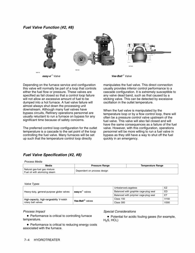
7–4 HYDROTREATER
Fuel Valve Function (#2, #8)
easy-e� Valve Vee-Ball� Valve
W8119
W8192
W7435
Depending on the furnace service and configurationthis valve will normally be part of a loop that controlseither the fuel flow or pressure. These valves arespecified as fail closed so that a control loop failurewill not allow an excessive amount of fuel to bedumped into a hot furnace. A fuel valve failure willalmost always shut down the processing unitdownstream. Although many fuel valves havebypass circuits, Refinery operations personnel areusually reluctant to run a furnace on bypass for anysignificant time because of safety concerns.
The preferred control loop configuration for the outlettemperature is a cascade to the set point of the loopcontrolling the fuel valve. Many furnaces will be setup such that the temperature control loop directly
manipulates the fuel valve. This direct connectionusually provides inferior control performance to acascade configuration. It is extremely susceptible toany valve dead band, such as that caused by asticking valve. This can be detected by excessiveoscillation in the outlet temperature.
When the fuel valve is manipulated by thetemperature loop or by a flow control loop, there willoften be a pressure control valve upstream of thefuel valve. This valve will also fail closed and willhave the same consequences as a failure of the fuelvalve. However, with this configuration, operationspersonnel will be more willing to run a fuel valve inbypass as they still have a way to shut off the fuelquickly in an emergency.
Fuel Valve Specification (#2, #8)
Process MediaMedia Pressure Range Temperature Range
Natural gas-fuel gas mixtureFuel oil with atomizing steam
Dependent on process design
Valve TypesUnbalanced,cageless EZ
Heavy-duty, general-purpose globe valves easy-e� valves Balanced with graphite cage-plug seal EDHeavy duty, general purpose globe valves easy e valvesBalanced with polymer cage-plug seal ET
High-capacity, high-rangeability V-notchVee Ball� valves
Class 150 V150High capacity, high rangeability V notchrotary ball valves Vee-Ball� valves
Class 300 V300
Process Impact� Performance is critical to controlling furnace
temperature.
� Performance is critical to reducing energy costsassociated with the furnace.
Special Considerations
� Potential for acidic fouling gases (for example,H2S, HCL)

HYDROTREATER 7–5
Recycle Hydrogen Valve Function (#3)
easy-e� Valve Design HP ValveW8119
W6848
W5815
The amount of hydrogen delivered to thehydrotreater often limits the unit throughput. Thehydrogen/oil ratio is a major parameter fordetermining the treating conversion of the unit. If theratio is too low, an excessive amount of coke canbuild upon the catalyst, shortening reactor life. If theratio is too high, throughput on the unit is wasted.
The hydrogen flow can be set manually or through abypass if necessary. If swings in the hydrogen arewide enough, this will not only limit unit throughput,but also lead to increased coke laydown on thecatalyst, potentially shortening reactor life.
Recycle Hydrogen Valve Specification (#3)
Process MediaMedia Pressure Range Temperature Range
Hydrogen 69 to 138 bar (1000 to 2000 psig) Dependent on process design
Valve TypesUnbalanced, cageless EZ
Heavy-duty, general-purpose globe valves easy-e� valves Balanced with graphite cage-plug seal EDHeavy duty, general purpose globe valves easy e valvesBalanced with polymer cage-plug seal ET
High pressure severe service globe valvesBalanced with graphite cage-plug seal HPD, EHD
High-pressure, severe-service globe valvesBalanced with PTFE cage-plug seal HPT, EHT
Process Impact� Important to maintaining back pressure on the
compressor
� Important to maintain hydrogen/feed ratio
� Critical to overall reliability and efficiency ofhydrotreater unit
Special Considerations
� H2S with hydrogen in a high-pressure service;always a concern for sulfur stress cracking(metallurgy considerations).

7–6 HYDROTREATER
Reactor Hydrogen Valve Function (#4)
easy-e� Valve Design HP ValveW8119
W6848
W3379
Design EH Valve
This valve is used to control the reactor bedtemperature. The reactor bed temperatures areanother major parameter in determining the unittreating conversion. If the temperatures are allowed
to get too high, then the reactor catalyst life will beshortened, as excessive amounts of coking willoccur. Therefore, it is important that this valvefunction properly.
Reactor Hydrogen Valve Specification (#4)
Process Media:Media Pressure Range Temperature Range
Hydrogen 69 to 138 bar (1000 to 2000 psig) Dependent on process design
Valve TypesUnbalanced, cageless EZ
Heavy-duty, general-purpose globe valves easy-e� valves Balanced with graphite cage-plug seal EDHeavy duty, general purpose globe valves easy e valvesBalanced with polymer cage-plug seal ET
High pressure severe service globe valvesBalanced with graphite cage-plug seal HPD, EHD
High-pressure, severe-service globe valvesBalanced with PTFE HPT, EHT
Process Impact
� Critical to maintaining reactor temperature
Special Considerations
� None

HYDROTREATER 7–7
Separator Overhead Valve Function (#5)
easy-e� Valve Design HP ValveW8119
W5815
W3379
Design EH Valve
A poorly performing separator overhead valve willaffect the recovery of the recycle gas, possiblycausing pressure swings in the recycle gas system.
It can also pulse light gases into the liquid enteringthe stripper, where these gases can cause thestripper to pressure up, making separations difficult.
Separator Overhead Valve Specification (#5)
Process Media:Media Pressure Range Temperature Range
Hydrocarbon gasHydrogen gas
69 to 138 bar (1000 to 2000 psig) 38 to 93�C (100 to 200�F)
Valve TypesUnbalanced, cageless EZ
Heavy-duty, general-purpose globe valves easy-e� valves Balanced with graphite cage-plug seal EDHeavy duty, general purpose globe valves easy e valvesBalanced with polymer cage-plug seal ET
High pressure severe service globe valvesBalanced with graphite cage-plug seal HPD, EHD
High-pressure, severe-service globe valvesBalanced with PTFE HPT, EHT
Process Impact
� Critical to recovery of recycle gas and reactorefficiency
� Poor performance can cause pressure swingsin recycle gas system and can create instability.
� Poor performance can cause reactor topressure up and inhibit separation efficiency.
Special Considerations
� Will have entrained H2S in process media

7–8 HYDROTREATER
Makeup Hydrogen Valve Function (#6)
easy-e� Valve Design HP Valve
W6848
W5815W3162
Design EH Valve
This valve, along with the recycle purge valve, isused to control hydrogen purity. Makeup hydrogen ishigh purity, usually above 90% hydrogen. This valve
is usually not critical to short-term operation becausethe unit can run totally on recycle gas for shortperiods.
Makeup Hydrogen Valve Specification (#6)
Process MediaMedia Pressure Range Temperature Range
Hydrogen 69 to 138 bar (1000 to 2000 psig) Less than 38�C (100�F)
Valve TypesUnbalanced, cageless EZ
Heavy-duty, general-purpose globe valves easy-e� valves Balanced with graphite cage-plug seal EDHeavy duty, general purpose globe valves easy e valvesBalanced with polymer cage-plug seal ET
High pressure severe service globe valvesBalanced with graphite cage-plug seal HPD, EHD
High-pressure, severe-service globe valvesBalanced with PTFE cage-plug seal HPT, EHT
Process Impact
� Critical to maintaining reactor temperature
Special Considerations
� None

HYDROTREATER 7–9
Recycle Purge Valve Function (#7)
easy-e� Valve Design HP ValveW8119 W6848
W5815
Design EH Valve
This valve, along with the makeup valve, is used tocontrol hydrogen purity. As the hydrogen is recycledthrough the unit, it eventually becomes dirty withlight hydrocarbons such as methane and ethane. Acontinuous purge is taken from the recycle gas andis replaced with makeup hydrogen to prevent therecycle gas from becoming too heavy.
Generally this valve is not critical to unit operationsince it is possible to run the unit on total recyclewithout makeup or purge for short periods of time. Itwould be possible if the valve were sticking badly tocause pressure swings that could affect theconversion reaction and catalyst coking rate.
Recycle Purge Valve Specification (#7)
Process Media:Media Pressure Range Temperature Range
Hydrogen 69 to 138 bar (1000 to 2000 psig) Less than 38�C (100�F)
Valve TypesUnbalanced, cageless EZ
Heavy-duty, general-purpose globe valves easy-e� valves Balanced with graphite cage-plug seal EDHeavy duty, general purpose globe valves easy e valvesBalanced with polymer cage-plug seal ET
High pressure severe service globe valvesBalanced with graphite cage-plug seal HPD, EHD
High-pressure, severe-service globe valvesBalanced with PTFE cage-plug seal HPT, EHT
Process Impact
� Critical to maintaining reactor temperature
Special Considerations� Could experience high pressure drop
� Will have entrained H2S in process media

7–10 HYDROTREATER
Stripper Reflux Valve Function (#9)
POSI-SEAL� Valve Vee-Ball� Valve
W5811 W8192
edisc� Valve
W8299
The reflux valve is typically either a flow or columntemperature-control loop. It is used to adjust thepurity of the overhead product. The higher the refluxrate, the purer the overhead product will become.However, raising the reflux rate also will requiremore reboil heat and will eventually flood the tower.
A poorly operating reflux valve will have the sameeffects as a bad feed valve. Product purities willoscillate, and the column will be difficult to control.
Stripper Reflux Valve Specification (#9)
Process MediaMedia Pressure Range Temperature Range
Dependent on distillation process Dependent on process design Dependent on material being distilled
Valve Types
High-capacity, high-rangeability V-notch rotaryVee Ball� valves
Class 150 V150High capacity, high rangeability V notch rotaryball valves Vee-Ball� valves
Class 300 V300
edisc� valvesThrough 12 inches 8560
edisc� valvesThrough 24 inches 8532
High-performance butterfly valves Class 150, 300 through 12 inches A41High performance butterfly valves
POSI-SEAL� valves Larger sizes A31APOSI SEAL valvesHigh pressure A11
Unbalanced, cageless EZ
�
Balanced with graphite cage-plug seal EDHeavy-duty, general-purpose globe valves easy-e� valves Balanced with polymer cage-plug seal ETy y g g y
Larger sizes; expanded ends; balanced orunbalanced
EW
Process Impact� Critical to maintaining vapor/liquid balance in
the column, ultimately affecting the efficiency of thecolumn
Special Considerations
� Typically none
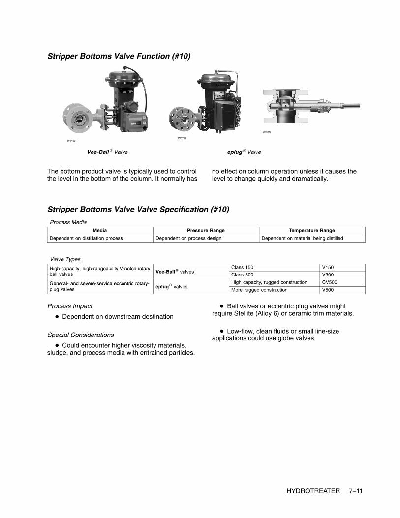
HYDROTREATER 7–11
Stripper Bottoms Valve Function (#10)
Vee-Ball� Valve
W8192W5791
eplug� Valve
W5793
The bottom product valve is typically used to controlthe level in the bottom of the column. It normally has
no effect on column operation unless it causes thelevel to change quickly and dramatically.
Stripper Bottoms Valve Valve Specification (#10)
Process MediaMedia Pressure Range Temperature Range
Dependent on distillation process Dependent on process design Dependent on material being distilled
Valve Types
High-capacity, high-rangeability V-notch rotaryVee Ball� valves
Class 150 V150High capacity, high rangeability V notch rotaryball valves Vee-Ball� valves
Class 300 V300
General- and severe-service eccentric rotary-eplug� valves
High capacity, rugged construction CV500General and severe service eccentric rotaryplug valves eplug� valves
More rugged construction V500
Process Impact
� Dependent on downstream destination
Special Considerations
� Could encounter higher viscosity materials,sludge, and process media with entrained particles.
� Ball valves or eccentric plug valves mightrequire Stellite (Alloy 6) or ceramic trim materials.
� Low-flow, clean fluids or small line-sizeapplications could use globe valves

7–12 HYDROTREATER
Stripper Light-Ends Valve Function (#11)
easy-e� Valve Vee-Ball� ValveW8119
W8192W3162
Stripper light-ends valves are used to control thecolumn pressure. Higher column pressures yieldbetter product purities, but require more energy tooperate. Normal operating procedure is to minimizethe pressure to lower energy costs while maintainingproduct specifications. There is a low limit becauselower pressures reduce the amount of vapor/liquidtraffic the column can handle and can make it morelikely to flood.
The simplest way to control pressures is tocontinuously vent gas from the system. Sizing of thisvalve is critical. If the valve is too large, a small valvemovement will cause a large pressure swing. If thevalve is too small, the pressure response will be verysluggish. It is likely that a valve that is too small willoperate from completely closed to completely open.In either scenario, an oscillating column pressureand difficult column control are the result. A stickingpressure control valve will present the sameproblem. A sticking valve is a common concern onvent gas valves because the valve packing willnormally be tight to prevent fugitive emissions.
Many distillation columns also use what is known asa “hot vapor bypass” valve to control pressure. Inthis case, some of the hot overhead vapors arebypassed around the overhead condenser heatexchanger. The amount of bypass will control thepressure. This eliminates the constant venting ofprocess gas, which usually goes to a low-value
refinery waste fuel gas system. Unfortunately, thepressure response on a hot vapor bypass valve isnormally very sluggish due to slow process responsetime. Like the vent gas valve, this valve is a concernfor fugitive emissions, and the packing is likely to betight. A sticking valve will cause wide, slowoscillations in column pressure. The product puritieswill likewise swing widely and slowly. The responseof refinery operations personnel will usually be toover-purify.
A majority of columns with hot-vapor bypass valveswill use it in combination with a vent gas valve. Inthese cases, a single pressure control loop willmanipulate both valves. At lower pressures, the hotvapor bypass valve is used. As the pressure rises,there will be a transition point where the hot vaporbypass valve closes fully and the vent gas valvestarts to open. At high pressures, the vent gas valvecontrols the pressure. This configuration often leadsto pressure control problems, as the hot vaporbypass and vent gas valves will have differentcontrol characteristics. Also, it is unlikely that onevalve will close precisely at the same time the othervalve opens. If the column is constantly making atransition between using the hot vapor bypass andvent gas valves, the pressure will normally oscillate.This is a tuning problem rather than a valve problem,but it should be kept in mind for column design orvalve resizing.

HYDROTREATER 7–13
Stripper Light-Ends Valve Specification (#11)
Process MediaMedia Pressure Range Temperature Range
Dependent on distillation process Dependent on process design Dependent on material being distilled
Valve TypesUnbalanced, cageless EZ
Heavy-duty, general-purpose globe valves easy-e� valves Balanced with graphite cage-plug seal EDHeavy duty, general purpose globe valves easy e valvesBalanced with polymer cage-plug seal ET
High-capacity, high-rangeability V-notch rotaryVee Ball� valves
Class 150 V150High capacity, high rangeability V notch rotaryball valves Vee-Ball� valves
Class 300 V300
Process Impact
� Controls the back pressure to the distillationcolumn and is very important in controlling thestability of the tower. Many columns use traytemperature to control overhead composition, thusstable pressure is required to ensure temperaturechanges reflect composition changes not pressurechanges.
Special Considerations
� Packing on these valves is important to reducefugitive emissions.
� Consider using special materials on valves thatwill encounter an acid gas environment.

7–14 HYDROTREATER
Stripper Naphtha Valve Function (#12)
easy-e� Valve Vee-Ball� ValveW8119
W8192
W7435
This valve is typically used to control the level in theoverhead receiver. It normally has no effect on
column operation unless it causes the level tochange quickly and dramatically.
Stripper Naphtha Valve Specification (#12)
Process MediaMedia Pressure Range Temperature Range
Dependent on distillation process Dependent on process design Dependent on material being distilled
Valve TypesUnbalanced, cageless EZ
Heavy-duty, general-purpose globe valves easy-e� valves Balanced with graphite cage-plug seal EDHeavy duty, general purpose globe valves easy e valvesBalanced with polymer cage-plug seal ET
High- capacity, high-rangeability V-notch rotaryVee Ball� valves
Class 150 V150High capacity, high rangeability V notch rotaryball valves Vee-Ball� valves
Class 300 V300
Process Impact� Typically no critical impact
� Dependent on downstream destination
Special Considerations
� None

HYDROTREATER 7–15
Reactor Let-Down Valve Function (#13)
DST
Design HPAValve
W6020
DST (Dirty Service Trim) andValve with NotchFlo� DST Trim
W6787
W8433
Design DST-GValve
W8961
461 ValveW0514
The reactor let-down valve controls the liquid level inthe high pressure separator. In the accompanyingdiagram, this valve dumps the liquid effluent from thehigh pressure separator to the low pressureseparator. This application will have high pressuredrops where erosion, flowing particulate or flashingcan cause severe valve damage.
Normally, two valves are used in this application.Both valves will be piped with bypass valves and can
be rapidly switched between to ensure continuousprocess operation in the likely event one of thevalves requires repair.
Valves used in this application are normally anglestyle with ANSI Class 900/1500 pressure ratings.The angle design helps protect the valve body fromerosion due to flashing, cavitation, outgassing andflowing particulate.
Reactor Let-Down Valve Specification (#13)
Process MediaMedia Pressure Range Temperature Range
Hydrocarbon gases and liquidsHydrogen
69 to 138 bar (1000 to 2000 psig) Greater than 260�C (500�F)
Valve Types
High pressure severe service angle valves with DST trimBalanced with graphite cage-plug seal HPAD, EHAD
Cold high-pressureseparator let down
High-pressure, severe-service angle valves with DST trimBalanced with PTFE cage-plug seal HPAT, EHAT
separator let-downvalve High-pressure, severe-service angle valves with Balanced with graphite cage-plug seal HPADvalve High pressure, severe service angle valves with
NotchFlo� DST trim Balanced with PTFE cage-plug seal HPAT
DST-G forged valveHot high-pressureseparator let down
High-pressure, severe-service angle valves with DST trim Balanced with graphite cage-plug seal HPAD, EHADseparator let-downvalve
High pressure, severe service angle valves with DST trimBalanced with PTFE cage-plug seal HPAT, EHATvalve
High-pressure, severe-service angle valve Cylinder-guided contour valve plug 461
Process Impact
� Impacts volume and quality of recycle gas
Special Considerations� Will more than likely see flashing across this
valve
� Will have entrained H2S gas in process media
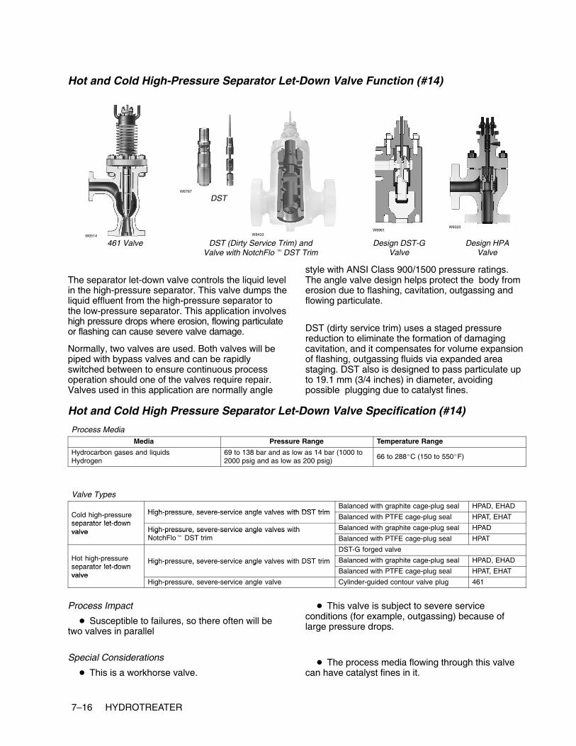
7–16 HYDROTREATER
Hot and Cold High-Pressure Separator Let-Down Valve Function (#14)
DST
Design HPAValve
W6020
DST (Dirty Service Trim) andValve with NotchFlo� DST Trim
W6787
W8433
Design DST-GValve
W8961
461 ValveW0514
The separator let-down valve controls the liquid levelin the high-pressure separator. This valve dumps theliquid effluent from the high-pressure separator tothe low-pressure separator. This application involveshigh pressure drops where erosion, flowing particulateor flashing can cause severe valve damage.
Normally, two valves are used. Both valves will bepiped with bypass valves and can be rapidlyswitched between to ensure continuous processoperation should one of the valves require repair.Valves used in this application are normally angle
style with ANSI Class 900/1500 pressure ratings.The angle valve design helps protect the body fromerosion due to flashing, cavitation, outgassing andflowing particulate.
DST (dirty service trim) uses a staged pressurereduction to eliminate the formation of damagingcavitation, and it compensates for volume expansionof flashing, outgassing fluids via expanded areastaging. DST also is designed to pass particulate upto 19.1 mm (3/4 inches) in diameter, avoidingpossible plugging due to catalyst fines.
Hot and Cold High Pressure Separator Let-Down Valve Specification (#14)
Process MediaMedia Pressure Range Temperature Range
Hydrocarbon gases and liquidsHydrogen
69 to 138 bar and as low as 14 bar (1000 to2000 psig and as low as 200 psig)
66 to 288�C (150 to 550�F)
Valve Types
High pressure severe service angle valves with DST trimBalanced with graphite cage-plug seal HPAD, EHAD
Cold high-pressureseparator let down
High-pressure, severe-service angle valves with DST trimBalanced with PTFE cage-plug seal HPAT, EHAT
separator let-downvalve High-pressure, severe-service angle valves with Balanced with graphite cage-plug seal HPADvalve High pressure, severe service angle valves with
NotchFlo� DST trim Balanced with PTFE cage-plug seal HPAT
DST-G forged valveHot high-pressureseparator let down
High-pressure, severe-service angle valves with DST trim Balanced with graphite cage-plug seal HPAD, EHADseparator let-downvalve
High pressure, severe service angle valves with DST trimBalanced with PTFE cage-plug seal HPAT, EHATvalve
High-pressure, severe-service angle valve Cylinder-guided contour valve plug 461
Process Impact
� Susceptible to failures, so there often will betwo valves in parallel
Special Considerations
� This is a workhorse valve.
� This valve is subject to severe serviceconditions (for example, outgassing) because oflarge pressure drops.
� The process media flowing through this valvecan have catalyst fines in it.

www.Fisher.com
Chapter 8
Hydrocracker
Other NamesUnicracker
DescriptionThe hydrocracking process converts (or cracks)heavy feedstocks into lighter components byselective reactions with hydrogen in multiple heatedcatalyst beds. The process is most commonly usedto create gasoline or diesel product streams.
The incoming gas oil feed is heated in a furnace toreaction temperature. It is combined with a recyclehydrogen stream before flowing through the reactorwith multiple catalyst beds. Additional recyclehydrogen is added between each bed to control thecracking conversion. The reactor effluent is sent tohigh-pressure, then low-pressure separators. Thevapor from the separators is recycled through acompressor back to the feed. Makeup hydrogen isadded to this stream as necessary. The liquid fromthe low pressure separator is sent to a fractionatorwhere the reactor effluent is separated intocomponent product streams.

8–2 HYDROCRACKER
Typical Hydrocracker
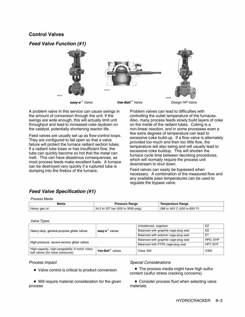
HYDROCRACKER 8–3
Control Valves
Feed Valve Function (#1)
easy-e� Valve Design HP Valve
W8119W6848
Vee-Ball� Valve
W7435
A problem valve in this service can cause swings inthe amount of conversion through the unit. If theswings are wide enough, this will actually limit unitthroughput and lead to increased coke laydown onthe catalyst, potentially shortening reactor life.
Feed valves are usually set up as flow-control loops.They are configured to fail open so that a valvefailure will protect the furnace radiant section tubes.If a radiant tube loses or has insufficient flow, thetube can quickly become so hot that the metal canmelt. This can have disastrous consequences, asmost process feeds make excellent fuels. A furnacecan be destroyed very quickly if a ruptured tube isdumping into the firebox of the furnace.
Problem valves can lead to difficulties withcontrolling the outlet temperature of the furnaces.Also, many process feeds slowly build layers of cokeon the inside of the radiant tubes. Coking is anon-linear reaction, and in some processes even afew extra degrees of temperature can lead toexcessive coke build-up. If a flow valve is alternatelyprovided too much and then too little flow, thetemperature will also swing and will usually lead toexcessive coke buildup. This will shorten thefurnace cycle time between decoking procedures,which will normally require the process unitdownstream to shut down.Feed valves can easily be bypassed whennecessary. A combination of the measured flow andany available pass temperatures can be used toregulate the bypass valve.
Feed Valve Specification (#1)Process Media
Media Pressure Range Temperature Range
Heavy gas oil 34.5 to 207 bar (500 to 3000 psig) 288 to 343�C (550 to 650�F)
Valve TypesUnbalanced, cageless EZ
Heavy-duty, general-purpose globe valves easy-e� valves Balanced with graphite cage-plug seal EDHeavy duty, general purpose globe valves easy e valvesBalanced with polymer cage-plug seal ET
High pressure severe service globe valvesBalanced with graphite cage-plug seal HPD, EHP
High-pressure, severe-service globe valvesBalanced with PTFE cage-plug seal HPT, EHT
High-capacity, high-rangeability V-notch rotaryball valves (for lower pressures)
Vee-Ball� valves Class 300 V300
Process Impact
� Valve control is critical to product conversion
� Will require material consideration for the givenprocess
Special Considerations
� The process media might have high sulfurcontent (sulfur stress cracking concerns).
� Consider process fluid when selecting valvematerials.

8–4 HYDROCRACKER
Fuel Valve Function ( #2)
easy-e� Valve Vee-Ball� Valve
W8119
W8192
W7435
Depending on the furnace service and configuration,this valve will normally be part of a loop that controlseither the fuel flow or pressure. These valves arespecified as fail closed so that a control loop failurewill not allow an excessive amount of fuel to bedumped into a hot furnace. A fuel valve failure willalmost always shut down the processing unitdownstream. Although many fuel valves havebypass circuits, refinery operations personnel areusually reluctant to run a furnace on bypass for anylength of time because of safety concerns.
The preferred control loop configuration for the outlettemperature is a cascade to the set point of the loopcontrolling the fuel valve. Many furnaces will be setup such that the temperature control loop directly
manipulates the fuel valve. This direct connectionusually provides inferior control performance to acascade configuration. It is extremely susceptible toany valve dead band, such as that caused by asticking valve. This can be detected by excessiveoscillation in the outlet temperature.
When the fuel valve is manipulated by thetemperature loop or by a flow control loop, there willoften be a pressure control valve upstream of thefuel valve. This valve will also fail closed and willhave the same consequences as a failure of the fuelvalve. However, with this configuration, operationspersonnel will be more willing to run a fuel valve inbypass as they still have a way to shut off the fuelquickly in an emergency.
Fuel Valve Specification (#2)
Process MediaMedia Pressure Range Temperature Range
Natural gas-fuel gas mixtureFuel oil with atomizing steam
Dependent on process design Dependent on process design
Valve TypesUnbalanced, cageless EZ
Heavy-duty, general-purpose globe valves easy-e� valves Balanced with graphite cage-plug seal EDHeavy duty, general purpose globe valves easy e valvesBalanced with polymer cage-plug seal ET
High-capacity, high-rangeability V-notchVee Ball� valves
Class 150 V150High capacity, high rangeability V notchrotary ball valves Vee-Ball� valves
Class 300 V300
Process Impact� Performance is critical to controlling furnace
temperature.
� Performance is critical to reducing energy costsassociated with furnace.
Special Considerations
� Potential for acidic fouling gases (for example,H2S, HCL)

HYDROCRACKER 8–5
Recycle Hydrogen Valve Function (#3)
easy-e� Valve Design HP ValveW8119
W6848
W5815
Design EH Valve
The amount of hydrogen delivered to thehydrocracker often limits the unit throughput. Thehydrogen/oil ratio is an important parameter fordetermining the cracking conversion of the unit. Ifthe ratio is too low, an excessive amount of coke canbuild up on the catalyst, shortening reactor life. If theratio is too high, throughput on the unit is wasted.
The hydrogen flow can be set manually or through abypass if necessary. If swings in the hydrogen arewide enough, this will not only limit unit throughput,but also lead to increased coke laydown on thecatalyst, potentially shortening reactor life.
Recycle Hydrogen Valve Specification (#3)
Process MediaMedia Pressure Range Temperature Range
HydrogenHydrogen sulfide
69.0 to 207 bar (1000 to 3000 psig) 288 to 343�C (550 to 650�F)
Valve TypesUnbalanced, cageless EZ
Heavy-duty, general-purpose globe valves easy-e� valves Balanced with graphite cage-plug seal EDHeavy duty, general purpose globe valves easy e valvesBalanced with polymer cage-plug seal ET
High pressure severe service globe valvesBalanced with graphite cage-plug seal HPD, EHD
High-pressure, severe-service globe valvesBalanced with PTFE cage-plug seal HPT, EHT
Process Impact
� Valve control influences the pressure on thehydrocracking unit.
� Valve control affects the hydrogen/oil ratio thatis critical to maintaining on-spec product.
Special Considerations
� The process media might have high sulfurcontent.
� Will require material consideration for the givenprocess

8–6 HYDROCRACKER
Reactor Hydrogen Valve Function (#4, #5, #6)
easy-e� Valve Design HP Valve
W8119 W6848
W3379
Design EH Valve
These valves are used to control the reactor bedtemperatures. These temperatures are anothermajor parameter in determining the unit crackingconversion. If the temperatures are allowed to gettoo high, a runaway reaction may occur. Therefore, itis important that these valves function properly.
A sticking valve will cause the bed temperatureoscillate. Depending on the severity of theoscillations, this can lead to accelerated coking onthe affected bed.
Reactor Hydrogen Valve Specification (#4, #5, #6)
Process MediaMedia Pressure Range Temperature Range
HydrogenHydrogen sulfide
69.0 to 207 bar (1000 to 3000 psig) 288 to 343�C (550 to 650�F)
Valve TypesUnbalanced, cageless EZ
Heavy-duty, general-purpose globe valves easy-e� valves Balanced with graphite cage-plug seal EDHeavy duty, general purpose globe valves easy e valvesBalanced with polymer cage-plug seal ET
High pressure severe service globe valvesBalanced with graphite cage-plug seal HPD, EHD
High-pressure, severe-service globe valvesBalanced with PTFE cage-plug seal HPT, EHT
Process Impact
� Valve control influences the temperature on thehydrocracking unit (very important valves here!).
� Valve control affects the hydrogen/oil ratio thatis critical to maintaining on-spec product.
Special Considerations
� The process media might have high sulfurcontent.
� Will require material consideration for the givenprocess

HYDROCRACKER 8–7
High-Pressure Separator Valve Function (#7)
DSTW6787
Design DST-G ValveW0514
Design 461 Valve
W8433
DST (Dirty Service Trim) andValve with NotchFlo� DST Trim
W8961
A poorly performing separator overhead valve willaffect the recovery of the recycle gas. It can alsocause pressure swings in the recycle gas system. Ifthe valve is sticking badly or is stuck it can
conceivably overload the low pressure separator,sending light gases to the fractionator, causing it topressure up.
High-Pressure Separator Valve Specification (#7)
Process MediaMedia Pressure Range Temperature Range
Processed hydrocarbon liquid that is lighterthan straight gas oil and cleaner (for example,gasoline and diesel)
103 to 241 bar (1500 to 3500 psig) 204 to 454�C (400 to 850�F)
Valve TypesHigh-pressure, severe service angle valve Cylinder-guided contour valve plug 461
DST-G forged valve
High-pressure, severe service angle valves with DST trim Balanced with graphite cage-plug seal HPAD, EHADHigh pressure, severe service angle valves with DST trimBalanced with PTFE cage-plug seal HPAT, EHAT
High pressure severe service angle valves with NotchFlo� DST trimBalanced with graphite cage-plug seal HPAD
High-pressure, severe service angle valves with NotchFlo� DST trimBalanced with PTFE cage-plug seal HPAT
Process Impact
� Valve control has significant influence on thepressure of the high-pressure separator and thelow-pressure separator.
� Poor performing valve in this application canrestrict flow to the low-pressure separator becauseof uncontrolled outgassing.
Special Considerations
� Severe service valve (high pressure drops,outgassing, corrosive caused by entrained sulfur andH2S)
� NACE materials might be required.

8–8 HYDROCRACKER
Low-Pressure Separator Valve Function (#8)
Design HPA Valve
W6020
Design EHA Valve
W5028-1
DSTW6787
W8433
DST (Dirty Service Trim) andValve with NotchFlo� DST Trim
A poorly performing separator overhead valve willaffect the recovery of the recycle gas, possiblycausing pressure swings in the recycle gas system.It can also pulse light gases into the liquid entering
the fractionator, where these gases can cause thefractionator to pressure up, making separationsdifficult.
Low-Pressure Separator Valve Specification (#8)
Process MediaMedia Pressure Range Temperature Range
Processed hydrocarbon liquid that is lighterthan straight gas oil and cleaner (for example,gasoline and diesel)
62.1 to 103 bar (900 to 1500 psig) 93 to 260�C (200 to 500�F)
Valve Types
High-pressure, severe-service angle valves Balanced with graphite cage-plug seal HPADHigh pressure, severe service angle valveswith NotchFlo DST (dirty-service trim) Balanced with PTFE cage-plug seal HPAT
High-pressure, severe-service angle valves Balanced with graphite cage-plug seal HPAD, EHADHigh pressure, severe service angle valveswith DST (dirty-service trim) Balanced with PTFE cage-plug seal HPAT, EHAT
Process Impact
� Valve control has significant influence on thepressure of the high-pressure separator and thelow-pressure separator.
� Poor performing valve in this application canrestrict flow to the low-pressure separator becauseof uncontrolled outgassing.
Special Considerations
� Severe service valve (high pressure drops,outgassing, corrosion caused by entrained sulfurand H2S)
� NACE materials might be required.

HYDROCRACKER 8–9
Makeup Hydrogen Valve Function (#9)
easy-e� Valve Design HP Valve
W8119 W6848
Design EH Valve
W3379
This valve, along with the recycle purge valve, isused to control hydrogen purity. Makeup hydrogen ishigh purity, usually above 90% hydrogen. This valve
is usually not critical to operation because the unitcan run totally on recycle gas for short periods oftime.
Makeup Hydrogen Valve Specification (#9)
Process MediaMedia Pressure Range Temperature Range
Hydrogen 69.0 to 138 bar (1000 to 2000 psig) Less than 38�C (less than 100�F)
Valve TypesUnbalanced, cageless EZ
Heavy-duty, general-purpose globe valves easy-e� valves Balanced with graphite cage-plug seal EDHeavy duty, general purpose globe valves easy e valvesBalanced with polymer cage-plug seal ET
High pressure severe service globe valvesBalanced with graphite cage-plug seal HPD, EHD
High-pressure, severe-service globe valvesBalanced with PTFE cage-plug seal HPT, EHT
Process Impact
� Critical to maintaining reactor temperature.
Special Considerations
� None

8–10 HYDROCRACKER
Recycle Purge Valve Function ( #10)
easy-e� Valve
W3162
W8119
Design HP Valve
W6848
This valve, along with the makeup valve, is used tocontrol hydrogen purity. As the hydrogen is recycledthrough the unit, it eventually becomes dirty withlight hydrocarbons, such as methane and ethane. Acontinuous purge is taken from the recycle gas andis replaced with makeup hydrogen to prevent therecycle gas from becoming too heavy.
Generally this valve is not critical to unit operationbecause it is possible to run the unit on total recyclewithout makeup or purge for short periods of time. Itwould be possible if the valve were sticking badly tocause pressure swings that could affect theconversion reaction.
Recycle Purge Valve Specification (#10)
Process MediaMedia Pressure Range Temperature
Hydrogen 69.0 to 138 bar (1000 to 2000 psig) Less than 38�C (100�F)
Valve TypesUnbalanced, cageless EZ
Heavy-duty, general-purpose globe valves easy-e� valves Balanced with graphite cage-plug seal EDHeavy duty, general purpose globe valves easy e valvesBalanced with polymer cage-plug seal ET
High pressure severe service globe valvesBalanced with graphite cage-plug seal HPD, EHD
High-pressure, severe-service globe valvesBalanced with PTFE cage-plug seal HPT, EHT
Process Impact
� Critical to maintaining reactor temperature
Special Considerations� Could experience high pressure drop across
this valve
� Will have entrained H2S in process media
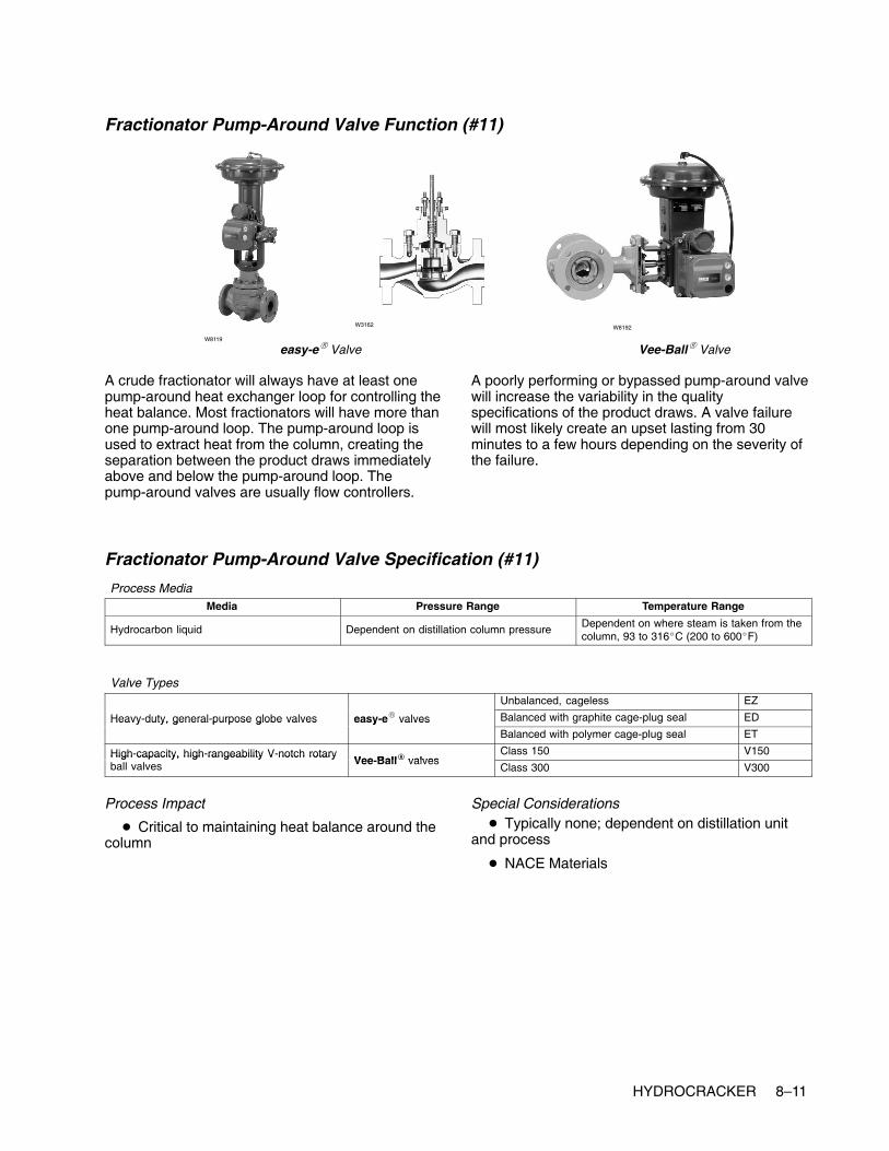
HYDROCRACKER 8–11
Fractionator Pump-Around Valve Function (#11)
easy-e� Valve Vee-Ball� ValveW8119
W8192W3162
A crude fractionator will always have at least onepump-around heat exchanger loop for controlling theheat balance. Most fractionators will have more thanone pump-around loop. The pump-around loop isused to extract heat from the column, creating theseparation between the product draws immediatelyabove and below the pump-around loop. Thepump-around valves are usually flow controllers.
A poorly performing or bypassed pump-around valvewill increase the variability in the qualityspecifications of the product draws. A valve failurewill most likely create an upset lasting from 30minutes to a few hours depending on the severity ofthe failure.
Fractionator Pump-Around Valve Specification (#11)
Process MediaMedia Pressure Range Temperature Range
Hydrocarbon liquid Dependent on distillation column pressure Dependent on where steam is taken from thecolumn, 93 to 316�C (200 to 600�F)
Valve TypesUnbalanced, cageless EZ
Heavy-duty, general-purpose globe valves easy-e� valves Balanced with graphite cage-plug seal EDHeavy duty, general purpose globe valves easy e valvesBalanced with polymer cage-plug seal ET
High-capacity, high-rangeability V-notch rotaryVee Ball� valves
Class 150 V150High capacity, high rangeability V notch rotaryball valves Vee-Ball� valves
Class 300 V300
Process Impact
� Critical to maintaining heat balance around thecolumn
Special Considerations� Typically none; dependent on distillation unit
and process
� NACE Materials

8–12 HYDROCRACKER
Fractionator Bottom Valve Function (#12)
Vee-Ball� Valve
W8192W5791
eplug� Valve
W5793
The bottom material becomes the vacuum distillationunit charge.
The bottoms flow does not usually have any impacton the operation of the crude fractionator unless afailure causes the liquid level of the bottoms tooverfill or empty. Usually, level alarms on the unitallow the operator to catch this before it causes anupset.
Fractionator Bottom Valve Specification (#12)
Process MediaMedia Pressure Range Temperature Range
Dependent on distillation process Dependent on process design Dependent on material being distilled
Valve Types
High-capacity, high-rangeability V-notch rotaryVee Ball� valves
Class 150 V150High capacity, high rangeability V notch rotaryball valves Vee-Ball� valves
Class 300 V300
General- and severe-service eccentriceplug� valves
High capacity, rugged construction CV500General and severe service eccentricrotary-plug valves eplug� valves
More rugged construction V500
Process Impact
� Dependent on downstream destination
Special Considerations
� Could encounter higher viscosity materials,sludge, and process media with entrained particles.
� Ball valves or eccentric plug valves mightrequire Stellite (Alloy 6) or ceramic trim materials.
� Low-flow, clean fluids or small line-sizeapplications could use globe valves.

HYDROCRACKER 8–13
Fractionator Reflux Valve Function (#13)
POSI-SEAL� Valve Vee-Ball� Valve
W5811 W8192
edisc� Valve
W8299
The reflux valve is used to control the separationbetween the top product, (usually naphtha) and thehighest side-draw product. The reflux valve can beeither a flow or a temperature controller.
A poorly performing or bypassed reflux valve willincrease the variability in the quality specifications ofthe overhead product and the top side draw. A valvefailure will most likely create an upset lasting from 30minutes to a few hours, depending on the severity ofthe failure.
Fractionator Reflux Valve Specification (#13)
Process MediaMedia Pressure Range Temperature Range
Dependent on distillation process Dependent on process design Dependent on material being distilled
Valve Types
High-capacity, high-rangeability V-notch rotaryVee Ball� valves
Class 150 V150High capacity, high rangeability V notch rotaryball valves Vee-Ball� valves
Class 300 V300
edisc� valvesThrough 12 inches 8560
edisc� valvesThrough 24 inches 8532
High-performance butterfly valves Class 150, 300 through 12 inches A41High performance butterfly valves
POSI-SEAL� valves Larger sizes A31APOSI SEAL valvesHigh pressure A11
Unbalanced, cageless EZ
�
Balanced with graphite cage-plug seal EDHeavy-duty, general-purpose globe valves easy-e� valves Balanced with polymer cage-plug seal ETy y g g y
Larger sizes; expanded ends; balanced orunbalanced
EW
Process Impact� Critical to maintaining vapor/liquid balance in
the column, ultimately affecting the efficiency of thecolumn
Special Considerations
� Typically none

8–14 HYDROCRACKER
Fractionator Heavy Naphtha Valve Function (#14)
easy-e� Valve Vee-Ball� Valve
W8119 W8192
W7435
The stripper bottoms valves are used to control thebottoms level in the strippers. These valves do notusually have any impact on the operation of thestrippers unless a failure causes the liquid level of
the bottoms to overfill or empty. Usually, level alarmson the unit allow the operator to catch this before itcauses an upset.
Fractionator Heavy Naphtha Valve Specification (#14)
Process MediaMedia Pressure Range Temperature Range
Dependent on distillation process Dependent on process design Dependent on material being distilled
Valve Types
Lower flow rates (line size Heavy duty general purpose globeUnbalanced, cageless EZ
Lower flow rates (line size4 inches and smaller)
Heavy duty, general-purpose globevalves easy-e� valves Balanced with graphite cage-plug seal ED
4 inches and smaller) valves easy e valvesBalanced with polymer cage-plug seal ET
Higher flow rates (line High-capacity, high-rangeabilityVee Ball� valves
Class 150 V150Higher flow rates (linesize 6 inches and larger)
High capacity, high rangeabilityV-notch rotary ball valves Vee-Ball� valves
Class 300 V300
Process Impact� Typically no critical impact
� Dependent on downstream destination
Special Considerations
� None

HYDROCRACKER 8–15
Fractionator Distillate Valve Function ( #15)
easy-e� Valve Vee-Ball� Valve
W8119
W8192
W7435
The stripper bottoms valves are used to control thebottoms level in the strippers. These valves do notusually have any impact on the operation of thestrippers unless a failure caused the liquid level of
the bottoms to overfill or empty. Usually, level alarmson the unit allow the operator to catch this before itcauses an upset.
Fractionator Distillate Valve Specification (#15)
Process MediaMedia Pressure Range Temperature Range
Dependent on distillation process Dependent on process design Dependent on material being distilled
Valve Types
High-capacity, high-rangeability V-notch rotaryVee Ball� valves
Class 150 V150High capacity, high rangeability V notch rotaryball valves Vee-Ball� valves
Class 300 V300
General- and severe-service eccentriceplug� valves
High capacity, rugged construction CV500General and severe service eccentricrotary-plug valves eplug� valves
More rugged construction V500
Process Impact
� Dependent on downstream destination
Special Considerations
� Could encounter higher viscosity materials,sludge and process media with entrained particles.
� Ball valves or eccentric plug valves mightrequire Stellite (Alloy 6) or ceramic trim materials.
� Low flow, clean fluids or small line-sizeapplications could use globe valves.

8–16 HYDROCRACKER
Fractionator Vent Gas Valve Function (#16)
easy-e� Valve Vee-Ball� ValveW8119
W8192W3162
The overhead pressure control valve releases gasesincluding H2, H2S, methane, ethane, propane, andbutane. This stream is very normally very small (1 to3 % of feed).
The column pressure has a significant effect onfractionator operation. A valve failure that allows thecolumn to over or under pressure can cause an
upset that might take hours of recovery time. Aproblem valve can create pressure oscillations thatprevent the fractionator from being operatedoptimally. Valve sizing is critical for this service. Ifthe valve is too large, the column pressure might beprone to rapid swings. If the valve is too small andhas a large response time, it could cause long, slowswings.
Fractionator Vent Gas Valve Specification (#16)
Process MediaMedia Pressure Range Temperature Range
Dependent on distillation process Dependent on process design Dependent on material being distilled
Valve Types
Lower flow rates (line size Heavy duty general purpose globeUnbalanced, cageless EZ
Lower flow rates (line size4 inches and smaller)
Heavy duty, general-purpose globevalves easy-e� valves Balanced with graphite cage-plug seal ED
4 inches and smaller) valves easy e valvesBalanced with polymer cage-plug seal ET
Higher flow rates (line High- capacity, high-rangeabilityVee Ball� valves
Class 150 V150Higher flow rates (linesize 6 inches and larger)
High capacity, high rangeabilityV-notch rotary ball valves Vee-Ball� valves
Class 300 V300
Process Impact� Typically no critical impact
� Dependent on downstream destination
Special Considerations
� None

HYDROCRACKER 8–17
Fractionator Light Naphtha Valve Function (#17)
easy-e� Valve Vee-Ball� Valve
W8119
W8192
W7435
The overhead product valve is usually on levelcontrol from the overhead receiver. This valve doesnot usually have any impact on the operation of thecrude fractionator unless a failure causes the liquidlevel in the overhead receiver to over fill or empty. Inthis case, the column pressure would be affectedand the fractionator would experience an upset untilthe pressure became stable again. Usually, level
alarms on the unit allow the operator to catch thisbefore it becomes an upset.
It is more likely that a poorly performing productvalve could cause stability problems to adownstream processing unit in configurations wherethere is no surge tank between the units.
Fractionator Light Naphtha Valve Specification (#17)
Process MediaMedia Pressure Range Temperature Range
Dependent on distillation process Dependent on process design Dependent on material being distilled
Valve Types
Lower flow rates (line size Heavy duty general purpose globeUnbalanced, cageless EZ
Lower flow rates (line size4 inches and smaller)
Heavy duty, general-purpose globevalves easy-e� valves Balanced with graphite cage-plug seal ED
4 inches and smaller) valves easy e valvesBalanced with polymer cage-plug seal ET
Higher flow rates (line High- capacity, high-rangeabilityVee Ball� valves
Class 150 V150Higher flow rates (linesize 6 inches and larger)
High capacity, high rangeabilityV-notch rotary ball valves Vee-Ball� valves
Class 300 V300
Process Impact� Typically no critical impact
� Dependent on downstream destination
Special Considerations
� None
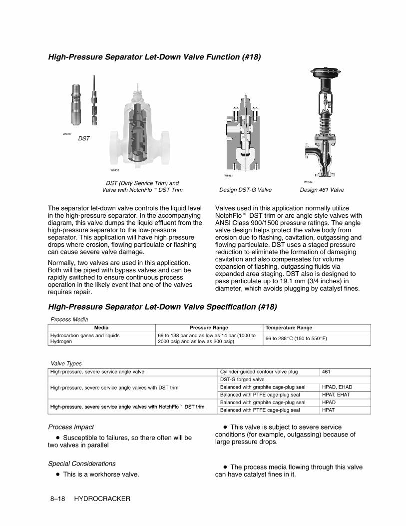
8–18 HYDROCRACKER
High-Pressure Separator Let-Down Valve Function (#18)
Design DST-G Valve
W0514
Design 461 Valve
DSTW6787
W8433
DST (Dirty Service Trim) andValve with NotchFlo� DST Trim
W8961
The separator let-down valve controls the liquid levelin the high-pressure separator. In the accompanyingdiagram, this valve dumps the liquid effluent from thehigh-pressure separator to the low-pressureseparator. This application will have high pressuredrops where erosion, flowing particulate or flashingcan cause severe valve damage.
Normally, two valves are used in this application.Both will be piped with bypass valves and can berapidly switched to ensure continuous processoperation in the likely event that one of the valvesrequires repair.
Valves used in this application normally utilizeNotchFlo� DST trim or are angle style valves withANSI Class 900/1500 pressure ratings. The anglevalve design helps protect the valve body fromerosion due to flashing, cavitation, outgassing andflowing particulate. DST uses a staged pressurereduction to eliminate the formation of damagingcavitation and also compensates for volumeexpansion of flashing, outgassing fluids viaexpanded area staging. DST also is designed topass particulate up to 19.1 mm (3/4 inches) indiameter, which avoids plugging by catalyst fines.
High-Pressure Separator Let-Down Valve Specification (#18)
Process MediaMedia Pressure Range Temperature Range
Hydrocarbon gases and liquidsHydrogen
69 to 138 bar and as low as 14 bar (1000 to2000 psig and as low as 200 psig)
66 to 288�C (150 to 550�F)
Valve TypesHigh-pressure, severe service angle valve Cylinder-guided contour valve plug 461
DST-G forged valve
High-pressure, severe service angle valves with DST trim Balanced with graphite cage-plug seal HPAD, EHADHigh pressure, severe service angle valves with DST trimBalanced with PTFE cage-plug seal HPAT, EHAT
High pressure severe service angle valves with NotchFlo� DST trimBalanced with graphite cage-plug seal HPAD
High-pressure, severe service angle valves with NotchFlo� DST trimBalanced with PTFE cage-plug seal HPAT
Process Impact
� Susceptible to failures, so there often will betwo valves in parallel
Special Considerations
� This is a workhorse valve.
� This valve is subject to severe serviceconditions (for example, outgassing) because oflarge pressure drops.
� The process media flowing through this valvecan have catalyst fines in it.

HYDROCRACKER 8–19
Low-Pressure Separator Let-Down Valve Function (#19)
Design DST-G ValveW0514
Design 461 Valve
DSTW6787
W8433
DST (Dirty Service Trim) andValve with NotchFlo� DST Trim
W8961
Using a low-pressure separator allows for additionalremoval of hydrogen and light hydrocarbons. Thelow-pressure separator let-down valve controls theliquid level in the low–pressure separator flowing tothe fractionalization tower. This application involvesmoderate pressure drops where erosion, flowingparticulate and flashing or outgassing can causesevere valve damage. Normally, two valves areused. Both will be piped with bypass valves and canbe rapidly switched between to ensure continuousprocess operation in the likely event one of thevalves requires repair.
Valves in this application are normally utilizeNotchFlo� trim or are angle-style valves with ANSIClass 600 ratings. The angle valve design protectsthe valve body from erosion caused by flashing andflowing particulate. DST uses a staged pressurereduction to eliminate the formation of damagingcavitation and also compensates for volumeexpansion of flashing fluids via expanded areastaging. DST also is designed to pass particulate upto 19.1 mm (3/4 inches) in diameter, which avoidsplugging by catalyst fines.
Low-Pressure Separator Let-Down Valve Specification (#19)
Process MediaMedia Pressure Range Temperature Range
Hydrocarbon gases and liquidsHydrogen
69 to 138 bar and as low as 14 bar (1000 to2000 psig and as low as 200 psig)
66 to 288�C (150 to 550�F)
Valve TypesHigh-pressure, severe service angle valve Cylinder-guided contour valve plug 461
DST-G forged valve
High-pressure, severe service angle valves with DST trim Balanced with graphite cage-plug seal HPAD, EHADHigh pressure, severe service angle valves with DST trimBalanced with PTFE cage-plug seal HPAT, EHAT
High pressure severe service angle valves with NotchFlo� DST trimBalanced with graphite cage-plug seal HPAD
High-pressure, severe service angle valves with NotchFlo� DST trimBalanced with PTFE cage-plug seal HPAT
Process Impact
� Susceptible to failures, so there often will betwo valves in parallel
Special Considerations� This is a workhorse valve and is subject to
severe service conditions (for example, outgassing)because of large pressure drops.
� The process media flowing through this valvecan have catalyst fines in it.

8–20 HYDROCRACKER
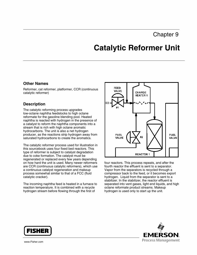
www.Fisher.com
Chapter 9
Catalytic Reformer Unit
Other NamesReformer, cat reformer, platformer, CCR (continuouscatalytic reformer)
DescriptionThe catalytic reforming process upgradeslow-octane naphtha feedstocks to high octanereformate for the gasoline blending pool. Heatednaphtha is reacted with hydrogen in the presence ofa catalyst to reform the naphtha components into astream that is rich with high octane aromatichydrocarbons. The unit is also a net hydrogenproducer, as the reactions strip hydrogen away fromsaturated hydrocarbons to create the aromatics.
The catalytic reformer process used for illustration inthis sourcebook uses four fixed bed reactors. Thistype of reformer is subject to catalyst degradationdue to coke formation. The catalyst must beregenerated or replaced every few years dependingon how hard the unit is used. Many newer reformersare CCR (continuous catalytic reformers), which usea continuous catalyst regeneration and makeupprocess somewhat similar to that of a FCC (fluidcatalytic cracker).
The incoming naphtha feed is heated in a furnace toreaction temperature. It is combined with a recyclehydrogen stream before flowing through the first of
four reactors. This process repeats, and after thefourth reactor the effluent is sent to a separator.Vapor from the separators is recycled through acompressor back to the feed, or it becomes exporthydrogen. Liquid from the separator is sent to astabilizer. In the stabilizer, the reactor effluent isseparated into vent gases, light end liquids, and highoctane reformate product streams. Makeuphydrogen is used only to start up the unit.
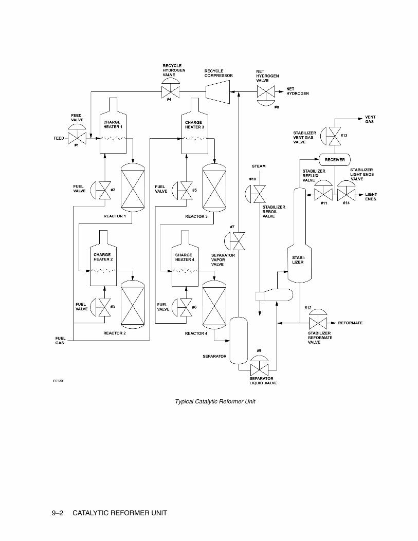
9–2 CATALYTIC REFORMER UNIT
Typical Catalytic Reformer Unit

CATALYTIC REFORMER UNIT 9–3
Control Valves
Feed Valve Function (#1)
easy-e� ValveW8119
W2966
W3162
A problem valve in this service can cause swings inthe amount of conversion through the unit. If theswings are wide enough, this will actually limit unitthroughput and lead to increased coke laydown onthe catalyst, potentially shortening reactor life.
Feed valves are usually set up as flow-control loops.They are configured to fail open so that a valvefailure will protect the furnace radiant section tubes.If a radiant tube loses or has insufficient flow, thetube can quickly become so hot that the metal canmelt. This can have disastrous consequences, asmost process feeds make excellent fuels. A furnacecan be destroyed very quickly if a ruptured tube isdumping into the firebox of the furnace.
Problem valves can lead to difficulties withcontrolling the outlet temperature of the furnaces.Also, many process feeds slowly build layers of cokeon the inside of the radiant tubes. Coking is anon-linear reaction, and in some processes even afew extra degrees of temperature can lead toexcessive coke build-up. If a flow valve is alternatelyprovided too much and then too little flow, thetemperature will also swing and will usually lead toexcessive coke buildup. This will shorten the furnacecycle time between decoking procedures, which willnormally require the process unit downstream toshut down.
Feed valves can easily be bypassed whennecessary. A combination of the measured flow andany available pass temperatures can be used toregulate the bypass valve.
Feed Valve Specification (#1)
Process MediaMedia Pressure Range Temperature Range
Heavier gas oilNaphtha
Dependent on process design Dependent on process design
Valve Types
Heavy duty general purpose globe valves easy e� valvesUnbalanced, cageless EZ
Heavy-duty, general-purpose globe valves easy-e� valvesBalanced with graphite cage-plug seal ED
Process Impact
� Control is critical to maintaining integrity ofinternal furnace tubes, such as preventing cokelay-down.
� Valve performance is critical to overall reliabilityof furnace.
� Critical to furnace safety; process fluid flow isrequired at all times through the tubes while thefurnace is firing.
Special Considerations:
� Sour feed stocks could require NACE trimmaterials.

9–4 CATALYTIC REFORMER UNIT
Fuel Valve Function (#2, #3, #5, #6)
easy-e� Valve Vee-Ball� ValveW8119
W8192W3162
Depending on the furnace service and configuration,this valve will normally be part of a loop that controlseither the fuel flow or pressure. These valves arespecified as fail closed so that a control loop failurewill not allow an excessive amount of fuel to bedumped into a hot furnace. A fuel valve failure willalmost always shut down the processing unitdownstream. While many fuel valves have bypasscircuits, Refinery operations personnel are usuallyreluctant to run a furnace on bypass for any length oftime due to safety concerns.
The preferred control loop configuration for the outlettemperature is a cascade to the setpoint of the loopcontrolling the fuel valve. Many furnaces will be setup such that the temperature control loop directly
manipulates the fuel valve. This direct connectionusually provides control performance that is inferiorto a cascade configuration. It is extremelysusceptible to any valve dead band, such as thatcaused by a sticking valve. This can be detected byexcessive oscillation in the outlet temperature.
When the fuel valve is manipulated by thetemperature loop or by a flow control loop, there willoften be a pressure control valve upstream of thefuel valve. This valve will also fail closed and willhave the same consequences as a failure of the fuelvalve. However, with this configuration, operationspersonnel will be more willing to run a fuel valve inbypass as they still have a way to quickly shut off thefuel in an emergency.
Fuel Valve Specification (#2, #3, #5, #6)
Process MediaMedia Pressure Range Temperature Range
Natural gas-fuel gas mixtureFuel oil with atomizing steam
Dependent on process design Dependent on process design
Valve TypesUnbalanced, cageless EZ
Heavy-duty, general-purpose globe valves easy-e� valves Balanced with graphite cage-plug seal EDHeavy duty, general purpose globe valves easy e valvesBalanced with polymer cage-plug seal ET
High-capacity, high-rangeability V-notchVee Ball� valves
Class 150 V150High capacity, high rangeability V notchrotary ball valves Vee-Ball� valves
Class 300 V300
Process Impact� Performance is critical to controlling furnace
temperature.
� Performance is critical to reducing energy costsassociated with the furnace.
Special Considerations
� Potential for acidic fouling gases (for example,H2S, HCL)

CATALYTIC REFORMER UNIT 9–5
Recycle Hydrogen Valve Function (#4)
easy-e� Valve Design HP ValveW8119
W6848W3379
Design EH Valve
The amount of hydrogen delivered to the reformerhelps to control conversion and catalyst degradationcaused by coking. The hydrogen/oil ratio is a majorparameter for determining the catalyst life of the unit.If the ratio is too low, an excessive amount of cokecan build up on the catalyst, shortening reactor life. Ifthe ratio is too high, throughput of the unit is wastedas yields drop.
The hydrogen flow can be set manually or through abypass if necessary. If swings in the hydrogen arewide enough, this will not only limit unit throughput,but also lead to increased coke laydown on thecatalyst, potentially shortening reactor life.
Recycle Hydrogen Valve Specification (#4)
Process MediaMedia Pressure Range Temperature Range
HydrogenHydrogen sulfide
69.0 to 207 bar (1000 to 3000 psig) 288 to 343�C (550 to 650�F)
Valve TypesUnbalanced, cageless EZ
Heavy-duty, general-purpose globe valves easy-e� valves Balanced with graphite cage-plug seal EDHeavy duty, general purpose globe valves easy e valvesBalanced with polymer cage-plug seal ET
High pressure severe service globe valvesBalanced with graphite cage-plug seal HPD, EHD
High-pressure, severe-service globe valvesBalanced with PTFE cage-plug seal HPT, EHT
Process Impact
� Valve control influences the pressure on thehydrocracking unit.
� Valve control affects the hydrogen/oil ratio thatis critical to maintaining on-spec product.
Special Considerations
� The process media might have high sulfurcontent.
� Will require material consideration for the givenprocess

9–6 CATALYTIC REFORMER UNIT
Separator Vapor Valve Function (#7)
Design HPA Valve
W6020
Design EHA Valve
DSTW6787
W8433
DST (Dirty Service Trim) andValve with NotchFlo� DST Trim
W5028-1
A poorly performing separator overhead valve willaffect the recovery of the recycle hydrogen. It alsocan cause pressure swings in the recycle gas.
system. If the valve becomes stuck it conceivablycan overload the separator, sending light gases tothe stabilizer and causing it to pressure up.
Separator Vapor Valve Specification (#7)
Process MediaMedia Pressure Range Temperature Range
Hydrocarbon gases and liquidsHydrogen
69 to 138 bar and as low as 14 bar (1000 to2000 pig and as low as 200 psig)
66 to 288�C (150 to 550�F)
Valve Types
High-pressure, severe-service angle valves with Balanced with graphite cage-plug seal HPAD, EHAD
Cold high-pressure separator
High pressure, severe service angle valves withDST trim Balanced with PTFE cage-plug seal HPAT, EHATCold high pressure separator
let-down valve High-pressure, severe-service angle valves with Balanced with graphite cage-plug seal HPADHigh pressure, severe service angle valves withNotchFlo� DST trim Balanced with PTFE cage-plug seal HPAT
Hot high pressure separator High pressure severe service angle valves withDST-G forged valve
Hot high-pressure separatorlet-down valve
High-pressure, severe-service angle valves withDST trim
Balanced with graphite cage-plug seal HPAD, EHADlet-down valve DST trim
Balanced with PTFE cage-plug seal HPAT, EHAT
Process Impact
� Susceptible to failures, so there often will betwo valves in parallel
Special Considerations
� This is a workhorse valve.
� This valve is subject to severe serviceconditions (for example, outgassing) because oflarge pressure drops.
� The process media flowing through this valvecan have catalyst fines in it.
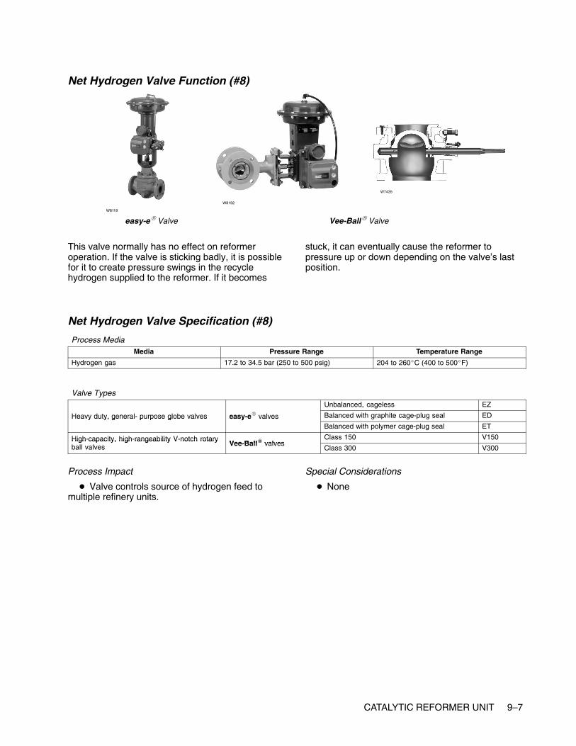
CATALYTIC REFORMER UNIT 9–7
Net Hydrogen Valve Function (#8)
easy-e� Valve Vee-Ball� Valve
W8119
W8192
W7435
This valve normally has no effect on reformeroperation. If the valve is sticking badly, it is possiblefor it to create pressure swings in the recyclehydrogen supplied to the reformer. If it becomes
stuck, it can eventually cause the reformer topressure up or down depending on the valve’s lastposition.
Net Hydrogen Valve Specification (#8)
Process MediaMedia Pressure Range Temperature Range
Hydrogen gas 17.2 to 34.5 bar (250 to 500 psig) 204 to 260�C (400 to 500�F)
Valve TypesUnbalanced, cageless EZ
Heavy duty, general- purpose globe valves easy-e� valves Balanced with graphite cage-plug seal EDHeavy duty, general purpose globe valves easy e valvesBalanced with polymer cage-plug seal ET
High-capacity, high-rangeability V-notch rotaryVee Ball� valves
Class 150 V150High capacity, high rangeability V notch rotaryball valves Vee-Ball� valves
Class 300 V300
Process Impact
� Valve controls source of hydrogen feed tomultiple refinery units.
Special Considerations
� None

9–8 CATALYTIC REFORMER UNIT
Separator Liquid Valve Function (#9)
Design HPA Valve
W6020
Design EHA Valve
W3162
easy-e� Valve
W5028-1
The separator liquid valve controls the separatorlevel and is also the feed valve of the stabilizer. Itnormally does not affect the recovery of the recyclegas. A problem valve can create stability problemsfor the stabilizer.
Feed valves are usually set up as flow or levelcontrol loops. An upstream unit or process oftencontrols the valve.
Unstable feed flow will make the distillation columndifficult to control. A problem valve will often cause
the feed flow to oscillate. As a result, the column willalternate between too little and too much reboil heat.Depending upon the size and number of trays in thecolumn the effect of a swing in the feed will takeanywhere from several minutes to more than anhour to reach the ends of the column. Sometimes,the reboil and reflux controls will amplify the swings.The final result is that meeting product purity targetswill become more difficult. Refinery operationspersonnel will normally respond by over-purifying theproducts, wasting energy to compensate for the badfeed control valve.
Separator Liquid Valve Specification (#9)
Process MediaMedia Pressure Range Temperature Range
Hydrocarbon gases and liquidsHydrogen
69 to 138 bar (1000 to 2000 pig) Greater than 260�C (500�F)
Valve Types
Heavy duty general purpose angle valves easy e� valvesBalanced with graphite cage-plug seal EAD
Heavy-duty, general-purpose angle valves easy-e� valvesBalanced with polymer cage-plug seal EAT
High pressure severe service angle valvesBalanced with graphite cage-plug seal HPAD, EHAD
High-pressure, severe-service angle valvesBalanced with PTFE cage-plug seal HPAT, EHAT
Process Impact
� Impacts volume and quality of recycle gas
Special Considerations� There will more than likely be flashing across
this valve.
� Will have entrained H2S gas in process media

CATALYTIC REFORMER UNIT 9–9
Stabilizer Reboil Valve Function (#10)
easy-e� ValveW8119
W2966 W3162 W0451
The reboil valve controls the amount of heat put intothe column by the reboiler. In many cases steam isused as a heat source. Steam valves are usuallyvery reliable. The service is very clean, and fugitiveemissions are not a concern. However, a problemvalve will make the column difficult to controlprecisely. This will be especially true if the columnfeed is subject to frequent changes.
Not all reboilers use steam as a heat source. Tosave energy, many refineries integrate the units sothat higher-temperature process streams are used toprovide heat for lower temperature processes. Inthese cases, the reboil valve may foul more easilyand might create fugitive emissions concerns.
Stabilizer Reboil Valve Specification (#10)
Process MediaMedia Pressure Range Temperature Range
Steam Dependent on process design, typically 10.3bar (150 psig) saturated steam
Dependent on material being distilled
Valve TypesUnbalanced, cageless EZ
Heavy-duty, general-purpose globe valves easy-e� valves Balanced with graphite cage-plug seal EDHeavy duty, general purpose globe valves easy e valvesBalanced with polymer cage-plug seal ET
Process Impact� This valve is important because it drives the
vapor back up through the column. This affectscolumn efficiency. Reboiler steam will have a directeffect on overhead reflux flow.
Special Considerations
� Consideration of materials for steam application

9–10 CATALYTIC REFORMER UNIT
Stabilizer Reflux Valve Function (#11)
POSI-SEAL� Valve Vee-Ball� Valve
W5811 W8192
edisc� Valve
W8299
The reflux valve is typically either a flow or columntemperature-control loop. It is used to adjust thepurity of the overhead product. The higher the refluxrate, the purer the overhead product will become.However, raising the reflux rate also will requiremore reboil heat and will eventually flood the tower.
A poorly operating reflux valve will have the sameeffects as a bad feed valve. Product purities willoscillate, and the column will be difficult to control.
Stabilizer Reflux Valve Function (#11)
Process MediaMedia Pressure Range Temperature Range
Dependent on distillation process Dependent on process design Dependent on material being distilled
Valve Types
High-capacity, high-rangeability V-notch rotaryVee Ball� valves
Class 150 V150High capacity, high rangeability V notch rotaryball valves Vee-Ball� valves
Class 300 V300
edisc� valvesThrough 12 inches 8560
edisc� valvesThrough 24 inches 8532
High- performance butterfly valves Class 150, 300 through 12 inches A41High performance butterfly valves
POSI-SEAL� valves Larger sizes A31APOSI SEAL valvesHigh pressure A11
Unbalanced, cageless EZ
�
Balanced with graphite cage-plug seal EDHeavy-duty, general-purpose globe valves easy-e� valves Balanced with polymer cage-plug seal ETy y g g y
Larger sizes; expanded ends; balanced orunbalanced
EW
Process Impact� Critical to maintaining vapor/liquid balance in
the column, ultimately affecting the efficiency of thecolumn
Special Considerations
� Typically none

CATALYTIC REFORMER UNIT 9–11
Stabilizer Reformate Valve Function (#12)
Vee-Ball� Valve
W8192W5791
eplug� Valve
W5793
This valve will have no effect on the stabilizeroperation unless it causes level problems. There isno consequence for any downstream unit becausethe reformate is sent to a component blend tank inthe gasoline blender unit. This valve can be run inmanual or bypass without significant problems.
The bottom product valve is typically used to controlthe level in the bottom of the column. It normally hasno effect on column operation unless it causes thelevel to change quickly and dramatically.
Stabilizer Reformate Valve Specification (#12)
Process MediaMedia Pressure Range Temperature Range
Dependent on distillation process Dependent on process design Dependent on material being distilled
Valve Types
High capacity high rangeability V notch rotary ball valves Vee Ball� valvesClass 150 V150
High-capacity, high-rangeability V-notch rotary ball valves Vee-Ball� valvesClass 300 V300
General and severe service eccentric rotary plug valves eplug� valvesHigh capacity, rugged CV500
General- and severe-service eccentric rotary-plug valves eplug� valvesMore rugged construction V500
Process Impact
� Dependent on downstream destination.
Special Considerations
� Could encounter higher viscosity materials,sludge and process media with entrained particles.
� Ball valves or eccentric plug valves mightrequire Stellite (Alloy 6) or ceramic trim materials.
� Low-flow, clean fluids or small line-sizeapplications could use globe valves

9–12 CATALYTIC REFORMER UNIT
Stabilizer Vent Gas Valve Function (#13)
easy-e� Valve Vee-Ball� ValveW8119
W8192W3162
The pressure control valves are used to control thecolumn pressure. Higher column pressures will yieldbetter product purities, but require more energy tooperate. Normal operating procedure is to minimizethe pressure to lower energy costs while maintainingproduct specifications. There is a low limit becauselower pressures reduce the amount of vapor/liquidtraffic the column can handle, which also makes thecolumn more likely to flood.
The simplest way to control pressure is tocontinuously vent gas from the system. Sizing of avent valve is critical. If the valve is too large, a smallvalve movement will cause a large pressure swing. Ifthe valve is too small, the pressure response will bevery sluggish. It is likely that a valve that is too smallwill operate from completely closed to completelyopen. In either scenario, an oscillating columnpressure and difficult column control are the result. Asticking pressure control valve will present the sameproblem. A sticking valve is a common concern onvent gas valves because the valve packing willnormally be tight to prevent fugitive emissions.
Many distillation columns also use what is known asa “hot vapor bypass” valve to control pressure. Inthis case, some of the hot overhead vapors arebypassed around the overhead condenser heatexchanger. The amount of bypass will control thepressure. This eliminates the constant venting of
process gas, which usually goes to a low-valuerefinery waste fuel gas system. Unfortunately, thepressure response on a hot vapor bypass valve isnormally very sluggish due to slow process responsetime. Like the vent gas valve, this valve is a concernfor fugitive emissions, and the packing is likely to betight. A sticking valve will cause wide, slowoscillations in column pressure. The product puritieswill likewise swing widely and slowly. The responseof refinery operations personnel will usually be toover-purify.
A majority of columns with a hot-vapor bypass valvewill use it with a vent gas valve. In these cases, asingle pressure control loop will manipulate bothvalves. At lower pressures, the hot vapor bypassvalve is used. As the pressure rises, there will be atransition point where the hot vapor bypass valvecloses fully and the vent gas valve starts to open. Athigh pressures, the vent gas valve controls thepressure. This configuration often leads to pressurecontrol problems, as the hot vapor bypass and ventgas valves will have different control characteristics.Also, it is unlikely that one valve will close preciselyat the same time the other valve opens. If thecolumn is constantly making a transition betweenusing the hot vapor bypass and vent gas valves, thepressure will normally oscillate. This is a tuningproblem rather than a valve problem, but it should bekept in mind for column design or valve resizing.

CATALYTIC REFORMER UNIT 9–13
Stabilizer Vent Gas Valve Specification (#13)
Process MediaMedia Pressure Range Temperature Range
Dependent on distillation process Dependent on process design Dependent on material being distilled
Valve Types
Lower flow rates (line size 4 Heavy duty general purposeUnbalanced, cageless EZ
Lower flow rates (line size 4inches and smaller)
Heavy-duty, general-purposeglobe valves easy-e� valves Balanced with graphite cage-plug seal ED
inches and smaller) globe valves easy e valvesBalanced with polymer cage-plug seal ET
Higher flow rates (line size 6 High-capacity, high-rangeability V notch rotary ball Vee Ball� valves
Class 150 V150Higher flow rates (line size 6inches and larger) rangeability V-notch rotary ball
valvesVee-Ball� valves
Class 300 V300
Process Impact
� Controls the back pressure to the distillationcolumn and is very important in controlling thestability of the tower. Many columns use traytemperature to control overhead composition;therefore, stable pressure is required to ensuretemperature changes reflect composition changesnot pressure changes.
Special Considerations
� Packing on these valves is important to reducefugitive emissions.
� Consider use of special materials on valves inan acid gas environment.

9–14 CATALYTIC REFORMER UNIT
Stabilizer Light-Ends Valve Function (#14)
easy-e� Valve Vee-Ball� Valve
W8119
W8192
W7435
The overhead product valve is typically used tocontrol the level in the overhead receiver. It normally
has no effect on column operation unless it causesthe level to change quickly and dramatically.
Stabilizer Light-Ends Valve Specification #14
Process MediaMedia Pressure Range Temperature Range
Dependent on distillation process Dependent on process design Dependent on material being distilled
Valve TypesUnbalanced, cageless EZ
Heavy-duty, general-purpose globe valves easy-e� valves Balanced with graphite cage-plug seal EDHeavy duty, general purpose globe valves easy e valvesBalanced with polymer cage-plug seal ET
High-capacity, high-rangeability V-notch rotaryVee Ball� valves
Class 150 V150High capacity, high rangeability V notch rotaryball valves Vee-Ball� valves
Class 300 V300
Process Impact� Typically no critical impact
� Dependent on downstream destination
Special Considerations
� None

www.Fisher.com
Chapter 10
Fluid Catalytic Cracking Unit
Other NamesFCC, “cat cracker,” fluid unit
DescriptionThe FCC (fluid catalytic cracking) process cracksheavy feedstocks such as gas oils, vacuum gas oils,and resid material into gasoline, light fuel oils, andlight ends. The cracked components are producedby selective reactions in a fluidized catalyst bed inthe presence of heat.
The incoming feed is heated in a furnace to thereaction temperature. The feed enters a verticalreactor where it contacts hot catalyst powder. Thefeed vaporizes and cracks as it moves up thereactor, carrying catalyst with it. Coke is formed onthe catalyst as the reactions take place. The catalystand the cracked material are separated. The spentcatalyst is sent to a regenerator where it isregenerated by burning off the coke. Theregenerated coke is recycled to the reactor. Thecracked material continues on to a fractionatingtower, where it is separated into wet gas, distillate,LCO (light cycle oil), HCO (heavy cycle oil), and
slurry. The wet gas continues on to a gas plant. Thedistillate cut might be suitable for use as a gasolineblend component.

10–2 FLUID CATALYTIC CRACKING UNIT
Typical Fluid Catalytic Cracking Unit
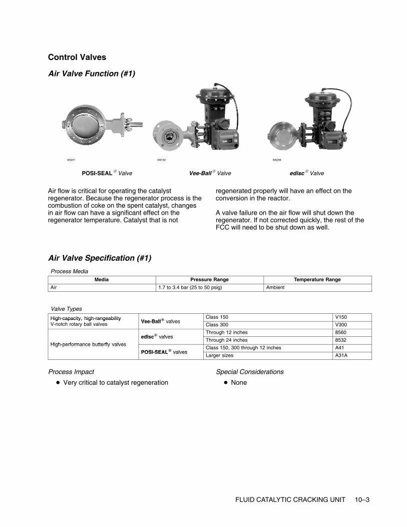
FLUID CATALYTIC CRACKING UNIT 10–3
Control Valves
Air Valve Function (#1)
POSI-SEAL� Valve Vee-Ball� Valve
W5811 W8192
edisc� Valve
W8299
Air flow is critical for operating the catalystregenerator. Because the regenerator process is thecombustion of coke on the spent catalyst, changesin air flow can have a significant effect on theregenerator temperature. Catalyst that is not
regenerated properly will have an effect on theconversion in the reactor.
A valve failure on the air flow will shut down theregenerator. If not corrected quickly, the rest of theFCC will need to be shut down as well.
Air Valve Specification (#1)
Process MediaMedia Pressure Range Temperature Range
Air 1.7 to 3.4 bar (25 to 50 psig) Ambient
Valve Types
High-capacity, high-rangeabilityVee Ball� valves
Class 150 V150High capacity, high rangeabilityV-notch rotary ball valves Vee-Ball� valves
Class 300 V300
edisc� valvesThrough 12 inches 8560
High performance butterfly valves
edisc� valvesThrough 24 inches 8532
High-performance butterfly valves
POSI SEAL� valvesClass 150, 300 through 12 inches A41
POSI-SEAL� valvesLarger sizes A31A
Process Impact
� Very critical to catalyst regeneration
Special Considerations
� None

10–4 FLUID CATALYTIC CRACKING UNIT
Feed Valve Function (#2)
easy-e� ValveW8119
W2966 W3162 W3162
A problem valve in this service can cause swings inthe amount of conversion through the unit. If theswings are wide enough, this can lead to increasedcoke laydown on the catalyst. This will increase theregenerator load, potentially limiting the unitthroughput.
Feed valves are usually set up as flow control loops.They are configured to fail open so that a valvefailure protects the furnace radiant section tubes. If aradiant tube loses or has insufficient flow, the tubecan quickly become so hot that the metal can melt.This can have disastrous consequences as mostprocess feeds make excellent fuels. A furnace canbe destroyed very quickly if a ruptured tube isdumping into the firebox of the furnace.
Problem valves can lead to difficulties in controllingthe outlet temperature of the furnaces. Also, manyprocess feeds slowly build layers of coke on theinside of the radiant tubes. Coking is a non-linearreaction, and in some processes even a few extradegrees of temperature can lead to excessive cokebuild-up. If a flow valve is alternately provided toomuch and then too little flow, the temperature willalso swing and will usually lead to excessive cokebuildup. This will shorten the furnace cycle timebetween decoking procedures, which normally willrequire the process unit downstream to shut down.
Feed valves can easily be bypassed whennecessary. A combination of the measured flow andany available pass temperatures can be used toregulate the bypass valve.
Feed Valve Specification (#2)
Process MediaMedia Pressure Range Temperature Range
Heavier gas and oilNaphtha
Dependent on process design Dependent on process design
Valve Types
Heavy duty general purpose globe valves easy e� valvesUnbalanced, cageless EZ
Heavy-duty, general-purpose globe valves easy-e� valvesBalanced with graphite cage-plug seal ED
Process Impact
� Control is critical to maintaining integrity ofinternal furnace tubes, such as preventing cokelay-down.
� Valve performance is critical to overall reliabilityof furnace.
� Critical to furnace safety; process fluid flow isrequired at all times through the tubes while thefurnace is firing.
Special Considerations
� Sour feed stocks could require NACE trimmaterials

FLUID CATALYTIC CRACKING UNIT 10–5
Fuel Valve Function (#3)
easy-e� Valve Vee-Ball� Valve
W8119
W8192
W7435
Depending on the furnace service and configurationthis valve will normally be part of a loop that controlseither the fuel flow or pressure. It is specified as failclosed so that a control loop failure will not allow anexcessive amount of fuel to be dumped into a hotfurnace. A fuel valve failure will almost always shutdown the processing unit downstream. Althoughmany fuel valves have bypass circuits, refineryoperations personnel are usually reluctant to run afurnace on bypass for any significant time becauseof safety concerns.
The preferred control loop configuration for the outlettemperature is a cascade to the setpoint of the loopcontrolling the fuel valve. Many furnaces will be setup such that the temperature control loop directly
manipulates the fuel valve. This direct connectionusually provides inferior control performance to acascade configuration. It is extremely susceptible toany valve dead band such as that caused by asticking valve. This can be detected by excessiveoscillation in the outlet temperature.
When the fuel valve is manipulated by thetemperature loop or by a flow control loop, there willoften be a pressure control valve upstream of thefuel valve. This valve will also fail closed and willhave the same consequences as a failure of the fuelvalve. However, with this configuration, refineryoperations personnel will be more willing to run afuel valve in bypass as they still have a way toquickly shut off the fuel in an emergency.
Fuel Valve Specification (#3)
Process MediaMedia Pressure Range Pressure Range
Natural gas-fuel gas mixtureFuel oil with atomizing steam
Dependent on process design Dependent on process design
Valve TypesUnbalanced,cageless EZ
Heavy-duty, general-purpose globe valves easy-e� valves Balanced with graphite cage-plug seal EDHeavy duty, general purpose globe valves easy e valvesBalanced with polymer cage-plug seal ET
High-capacity, high-rangeability V-notchVee Ball� valves
Class 150 V150High capacity, high rangeability V notchrotary ball valves Vee-Ball� valves
Class 300 V300
Process Impact� Performance is critical to controlling furnace
temperature
� Performance is critical to reducing energy costsassociated with furnace operation
Special Considerations
� Potential for acidic fouling gases (for example,H2S, HCL)

10–6 FLUID CATALYTIC CRACKING UNIT
Flue Gas Valve Function (#4)
POSI-SEAL� Valve
W5811
W6886
A problem valve in this service will swing theregenerator pressure as well as the feed to the COboiler. If pressure swings are severe, it can causeproblems with regenerator operation.
If the regenerator is designed such that completecombustion is achieved in the regenerator, a COboiler will not be included as part of the unit and theflue gas will be released to the atmosphere.
Flue Gas Valve Specification (#4)
Process MediaMedia Pressure Range Temperature Range
Air, CO, CO2 1.7 bar (25 psig) 538 to 760�C (1000 to 1400�F)
Valve Types
High performance butterfly valves POSI SEAL� valvesClass 150, 300 through 12 inches A41
High-performance butterfly valves POSI-SEAL� valvesLarger sizes A31A
Process Impact
� Critical to controlling the differential pressurebetween the reactor and the regenerator
Special Considerations
� Hot process fluid

FLUID CATALYTIC CRACKING UNIT 10–7
Regenerated Catalyst Valve Function(#5)These valves are extremely critical to the operationof a FCC. These are typically slide valves that canbe controlled very tightly. The reactor temperature isused to control these valves. The most commonvalve problems are hysteresis or sticking. Eitherproblem will make it difficult to control the reactortemperature and subsequently the crackingconversion and coke rate. A valve failure will shutdown the FCC unit.
Regenerated Catalyst ValveSpecification (#5)Special knife gate valves are normally used. FisherControls does not offer a valve of this type.
Spent Catalyst Valve Function (#6)Like the regenerated catalyst valve, this is also aslide valve. Although not as immediately critical asthe fresh catalyst valve, a valve failure will shut downthe FCC unit.
Spent Catalyst Valve Specification (#6)Special knife gate valves are normally used. FisherControls does not offer a valve of this type.

10–8 FLUID CATALYTIC CRACKING UNIT
Fractionator Pump-Around Valve Function (#7)
easy-e� Valve Vee-Ball� ValveW8119
W8192W3162
A fractionator will always have at least onepump-around heat exchanger loop to control theheat balance. Most fractionators will have more thanone pump-around loop. The pump-around loop isused to extract heat from the column, creating theseparation between the product draws immediatelyabove and below the pump-around loop. Thepump-around valves are usually flow controllers.
A poorly performing or bypassed pump-around valvewill increase the variability in the qualityspecifications of the product draws. A valve failurewill most likely create an upset lasting from 30minutes to a few hours, depending on the severity ofthe failure.
Fractionator Pump-around Valve Specification (#7)
Process MediaMedia Pressure Range Temperature Range
Hydrocarbon liquid Dependent on distillation column pressure Dependent on where steam is taken from thecolumn, 93 to 316�C (200 to 600�F)
Valve TypesUnbalanced, cageless EZ
Heavy-duty, general-purpose globe valves easy-e� valves Balanced with graphite cage-plug seal EDHeavy duty, general purpose globe valves easy e valvesBalanced with polymer cage-plug seal ET
High-capacity, high-rangeability V-notch rotaryVee Ball� valves
Class 150 V150High capacity, high rangeability V notch rotaryball valves Vee-Ball� valves
Class 300 V300
Process Impact
� Critical to maintaining heat balance around thecolumn
Special Considerations� Typically none: dependent distillation unit and
process
� NACE materials

FLUID CATALYTIC CRACKING UNIT 10–9
Fractionator Slurry Recycle Valve Function (#8)
Vee-Ball� Valve
W8192
W5791
eplug� Valve
W0514
Design 461 Valve
This valve might not be used on some FCC units. Ifit is not used, then all of the bottoms will become aclarified oil product.
The bottom material becomes the vacuum distillationunit charge.
The bottoms flow does not usually have any impacton the operation of the crude fractionator unless afailure causes the liquid level of the bottoms tooverfill or empty. Usually, level alarms on the unit
would allow the operator to catch this before itcauses an upset.
Although this service is similar to any otherfractionator bottom valve, there is a specific potentialproblem for this valve. If the separation of thecatalyst from the reactor effluent is not complete,then this line will have catalyst fines in it. If enoughfines are present in the slurry oil, then plugging ofthe valve becomes likely.
Fractionator Slurry Recycle Valve Specification (#8)
Process MediaMedia Pressure Range Temperature Range
Heavy, bottom of the barrel oil slurry-greaterthan a 538�C (1000�F) boiling point material
3.4 bar (50 psig) 538�C (1000�F)
Valve Types
High-capacity, high-rangeability V-notch rotaryVee Ball� valves
Class 150 V150High capacity, high rangeability V notch rotaryball valves Vee-Ball� valves
Class 300 V300
General- and severe-service eccentriceplug� valves
High capacity, rugged construction CV500General and severe service eccentricrotary-plug valves eplug� valves
More rugged construction V500
Self-cleaning angle valve Increased outlet size 461
Process Impact
� Not Critical
Special Considerations� Very erosive, corrosive, viscous process
conditions
� Could have concentrated amounts of catalystfines
� Temperatures are very high
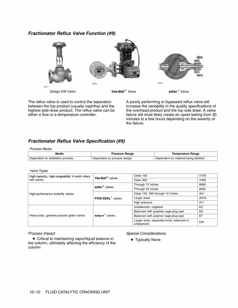
10–10 FLUID CATALYTIC CRACKING UNIT
Fractionator Reflux Valve Function (#9)
Design EW Valve Vee-Ball� Valve
W2777
W8192
edisc� Valve
W6234
The reflux valve is used to control the separationbetween the top product (usually naphtha) and thehighest side-draw product. The reflux valve can beeither a flow or a temperature controller.
A poorly performing or bypassed reflux valve willincrease the variability in the quality specifications ofthe overhead product and the top side draw. A valvefailure will most likely create an upset lasting from 30minutes to a few hours depending on the severity ofthe failure.
Fractionator Reflux Valve Specification (#9)
Process MediaMedia Pressure Range Temperature Range
Dependent on distillation process Dependent on process design Dependent on material being distilled
Valve Types
High-capacity, high-rangeability V-notch rotaryVee Ball� valves
Class 150 V150High capacity, high rangeability V notch rotaryball valves Vee-Ball� valves
Class 300 V300
edisc� valvesThrough 12 inches 8560
edisc� valvesThrough 24 inches 8532
High-performance butterfly valves Class 150, 300 through 12 inches A41High performance butterfly valves
POSI-SEAL� valves Larger sizes A31APOSI SEAL valvesHigh pressure A11
Unbalanced, cageless EZ
�
Balanced with graphite cage-plug seal EDHeavy-duty, general-purpose globe valves easy-e� valves Balanced with polymer cage-plug seal ETy y g g y
Larger sizes; expanded ends; balanced orunbalanced
EW
Process Impact� Critical to maintaining vapor/liquid balance in
the column, ultimately affecting the efficiency of thecolumn
Special Considerations
� Typically None

FLUID CATALYTIC CRACKING UNIT 10–11
Fractionator LCO (Light Cycle Oil) Product Valve Function (#10)
Vee-Ball� Valve
W8192W5791
eplug� Valve
W5793
The stripper bottoms valves are used to control thebottoms level in the strippers. These valves do notusually have any impact on the operation of thestrippers unless a failure causes the liquid level of
the bottoms to overfill or empty. Usually, level alarmson the unit allow the operator to catch this before itcauses an upset.
Fractionator LCO (Light Cycle Oil) Product Valve Specification (#10)
Process MediaMedia Pressure Range Temperature Range
Dependent on distillation process Dependent on process design Dependent on material being distilled
Valve Types
High capacity high rangeability V notch rotary ball valves Vee Ball� valvesClass 150 V150
High-capacity, high-rangeability V-notch rotary ball valves Vee-Ball� valvesClass 300 V300
General and severe service eccentric rotary plug valves eplug� valvesHigh capacity, rugged CV500
General- and severe-service eccentric rotary-plug valves eplug� valvesMore rugged construction V500
Process Impact
� Dependent on downstream destination
Special Considerations
� Could encounter higher viscosity materials,sludge, and process media with entrained particles
� Ball valves or eccentric plug valves mightrequire Stellite (Alloy 6) or ceramic trim materials.
� Low-flow, clean fluids or small line-sizeapplications could use globe valves

10–12 FLUID CATALYTIC CRACKING UNIT
Fractionator HCO (Heavy Cycle Oil) Product Valve Function (#11)
Vee-Ball� Valve
W8192 W5791
eplug� Valve
W7435
The stripper products are kerosene and diesel.
The stripper bottoms valves are used to control thebottoms level in the strippers. Typically, these valvesdo not have any impact on the operation of the
strippers unless a failure caused the liquid level ofthe bottoms to overfill or empty. Usually, level alarmson the unit allow the operator to catch this before itcauses an upset.
Fractionator HCO (Heavy Cycle Oil) Product Valve Specification (#11)
Process MediaMedia Pressure Range Temperature Range
Dependent on distillation process Dependent on process design Dependent on material being distilled
Valve Types
High-capacity, high-rangeability V-notch rotaryVee Ball� valves
Class 150 V150High capacity, high rangeability V notch rotaryball valves Vee-Ball� valves
Class 300 V300
General- and severe-service eccentriceplug� valves
High capacity, rugged construction CV500General and severe service eccentricrotary-plug valves eplug� valves
More rugged construction V500
Process Impact
� Dependent on downstream destination.
Special Considerations
� Could encounter higher viscosity materials,sludge and process media with entrained particles.
� Ball valves or eccentric plug valves mightrequire Stellite (Alloy 6) or ceramic trim materials.
� Low-flow, clean fluids or small line-sizeapplications could use globe valves

FLUID CATALYTIC CRACKING UNIT 10–13
Fractionator Reboil Circuit Valve Function ( #12)
Vee-Ball� Valve
W8192W5791
eplug� Valve
W5793
This valve is shown to represent the reboil circuit onthe bottom of the fractionator (details of the reboilerare not provided in the FCC process diagram.)
Like the slurry reflux valve (#8), this valve mighthave problems caused by catalyst fines in the slurryoil.
Fractionator Reboil Circuit Valve Specification (#12)
Process MediaMedia Pressure Range Temperature Range
Dependent on distillation process Dependent on process design Dependent on material being distilled
Valve Types
High-capacity, high-rangeability V-notch rotaryVee Ball� valves
Class 150 V150High capacity, high rangeability V notch rotaryball valves Vee-Ball� valves
Class 300 V300
General- and severe-service eccentriceplug� valves
High capacity, rugged construction CV500General and severe service eccentricrotary-plug valves eplug� valves
More rugged construction V500
Process Impact
� Dependent on downstream destination
Special Considerations
� Could encounter higher viscosity materials,sludge and process media with entrained particles.
� Ball valves or eccentric plug valves mightrequire Stellite (Alloy 6) or ceramic trim materials.
� Low-flow, clean fluids or small line-sizeapplications could use globe valves
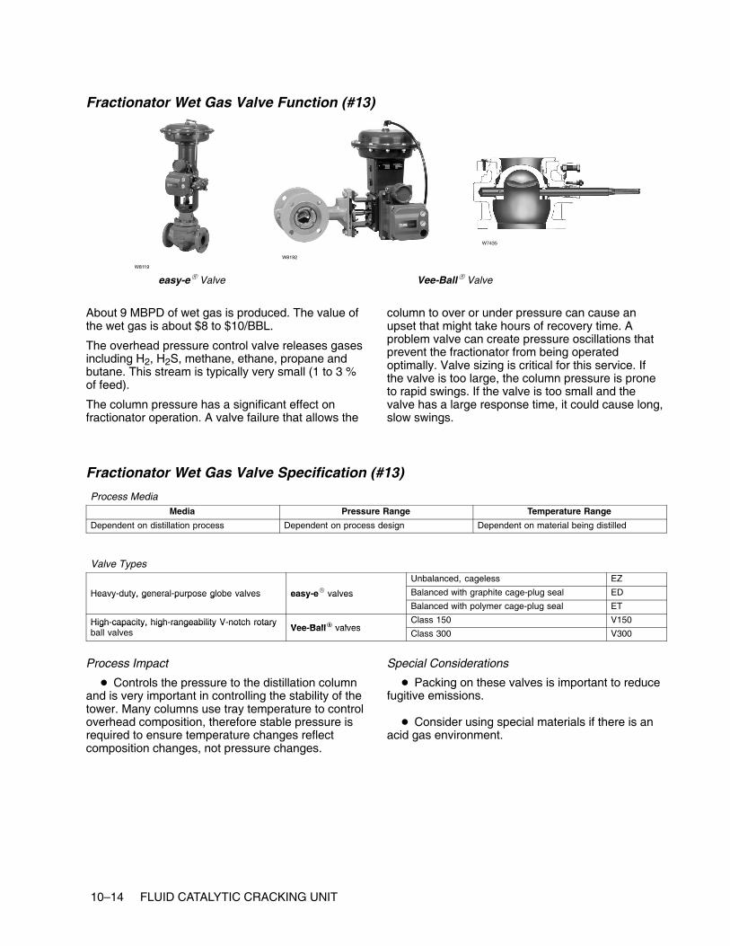
10–14 FLUID CATALYTIC CRACKING UNIT
Fractionator Wet Gas Valve Function (#13)
easy-e� Valve Vee-Ball� Valve
W8119
W8192
W7435
About 9 MBPD of wet gas is produced. The value ofthe wet gas is about $8 to $10/BBL.
The overhead pressure control valve releases gasesincluding H2, H2S, methane, ethane, propane andbutane. This stream is typically very small (1 to 3 %of feed).
The column pressure has a significant effect onfractionator operation. A valve failure that allows the
column to over or under pressure can cause anupset that might take hours of recovery time. Aproblem valve can create pressure oscillations thatprevent the fractionator from being operatedoptimally. Valve sizing is critical for this service. Ifthe valve is too large, the column pressure is proneto rapid swings. If the valve is too small and thevalve has a large response time, it could cause long,slow swings.
Fractionator Wet Gas Valve Specification (#13)
Process MediaMedia Pressure Range Temperature Range
Dependent on distillation process Dependent on process design Dependent on material being distilled
Valve TypesUnbalanced, cageless EZ
Heavy-duty, general-purpose globe valves easy-e� valves Balanced with graphite cage-plug seal EDHeavy duty, general purpose globe valves easy e valvesBalanced with polymer cage-plug seal ET
High-capacity, high-rangeability V-notch rotaryVee Ball� valves
Class 150 V150High capacity, high rangeability V notch rotaryball valves Vee-Ball� valves
Class 300 V300
Process Impact
� Controls the pressure to the distillation columnand is very important in controlling the stability of thetower. Many columns use tray temperature to controloverhead composition, therefore stable pressure isrequired to ensure temperature changes reflectcomposition changes, not pressure changes.
Special Considerations
� Packing on these valves is important to reducefugitive emissions.
� Consider using special materials if there is anacid gas environment.

FLUID CATALYTIC CRACKING UNIT 10–15
Fractionator Distillate Valve Function (#14)
easy-e� Valve Vee-Ball� ValveW8119
W8192W3162
This valve is usually on level control from theoverhead receiver and typically does not impact theoperation of the crude fractionator unless a failurecauses the liquid level in the overhead receiver toover fill or empty. In either case, the columnpressure would be affected, and the fractionatorwould experience an upset until the pressurebecame stable again. Usually, level alarms on the
unit allow the operator to catch this before it becamean upset.
It is more likely that a poorly performing productvalve could cause stability problems to adownstream processing unit in configurations wherethere is no surge tank between the units.
Fractionator Distillate Valve Specification (#14)
Process MediaMedia Pressure Range Temperature Range
Dependent on distillation process Dependent on process design Dependent on material being distilled
Valve Types
Lower flow rates (line size Heavy duty general purpose globeUnbalanced, cageless EZ
Lower flow rates (line size4 inches and smaller)
Heavy duty, general-purpose globevalves easy-e� valves Balanced with graphite cage-plug seal ED
4 inches and smaller) valves easy e valvesBalanced with polymer cage-plug seal ET
Higher flow rates (line High-capacity, high-rangeabilityVee Ball� valves
Class 150 V150Higher flow rates (linesize 6 inches and larger)
High capacity, high rangeabilityV-notch rotary ball valves Vee-Ball� valves
Class 300 V300
Process Impact
� Typically no critical impact
� Dependent on downstream destination
Special Considerations
� None

10–16 FLUID CATALYTIC CRACKING UNIT

www.Fisher.com
Chapter 11
Alkylation Unit
Other Names
Alky
Description
The alkylation unit is used to convert light olefins,usually propylene or butylene, produced by a FCC ordelayed coker unit into a gasoline blendingcomponent called alkylate. Alkylate is one of themore valuable blending components for gasolinebecause it has a high octane rating coupled with alow Reid vapor pressure.
The light olefin feed to an alkylation unit is mixedwith recycled isobutane from the DIB(deisobutanizer) tower overhead and is cooledbefore entering the reactor. The isobutane-olefinmixture, along with sulfuric acid and refrigerant, issent to the stirred reactor. In the presence of theacid, the olefins and isobutane react, forming thealkylate compounds and generating heat.
There are several systems for removing the heat.The process illustrated uses an auto-refrigerationsystem where some of the isobutane is vaporized toprovide cooling. The vapors are routed through acompression section and are condensed beforebeing returned to the reactor.
Any propane that is produced in the reactor isconcentrated in the refrigeration system and, aftercaustic and water washes, is sent to a depropanizer.The depropanizer overhead is a propane product,and the bottom stream is returned to the process.
The reactor effluent is sent to a settler where acid isremoved from the hydrocarbon. The acid is recycledto the reactor. The hydrocarbon continues throughcaustic and water washes before entering the DIBtower. Any makeup isobutane is generally added asfeed to the DIB tower. The DIB overhead stream ismostly isobutane and is returned to the reactor. TheDIB bottom stream becomes the feed to thedebutanizer. The debutanizer overhead is a butaneproduct stream. The debutanizer bottom stream isthe alkylate product for gasoline blending.

11–2 ALKYLATION UNIT
Typical Alkylation Unit

ALKYLATION UNIT 11–3
Control ValvesIt is important to keep in mind that Alloy 20 is apredominate valve trim material used in a sulfuricacid alkylation unit depending upon the processmedia. Also, Monel (high-nickel alloy) is apredominate valve trim material used in an HF(hydrofluoric) acid alkylation unit depending on theprocess media.
Please refer to Fisher PS Sheet 59.1:041(A) for HFalkylation valve specifications on hydrofluoric acidservice.
Note that some applications might not be suitable forcage-guided valves. Refer to the refinery’s acceptedvalve specification for a given application.
Feed Valve Function (#1)
easy-e� Design EZ ValveW8119 W2966
W7027
This is an important valve, as the amount of flow andcomposition of this stream establish the isobutaneand acid makeup requirements. Therefore, it isdesirable to have this flow and composition assteady as possible. Extremely erratic valve
movement such as sticking could make the reactorconversion cycle. However, because the reactor iscontinuously mixed, the effect of any small swings inflow will probably go unnoticed.
Feed Valve Specification (#1)
Process MediaMedia Pressure Range Temperature Range
Olefin feed (C3 and C4) from the FCC and thegas plant
13.8 to 24.1 (200 to 350 psig) 38 to 66�C (100 to 150�F)
Valve TypesHeavy-duty, general-purpose globe valves easy-e� valves Unbalanced, cageless EZ
Process Impact� Avoid high valve friction. To maintain proper
olefin-to-acid ratio, it is important to avoid creatinglarge process swings.
Special Considerations
� None

11–4 ALKYLATION UNIT
Makeup Acid Valve Function (#2)
easy-e� Design EZ Valve
W8119 W2966
W7027
The acid strength effects the octane rating of thealkylate as well as the likelihood of an acid runawayreaction. Increasing the recycle acid strength willincrease octane, but it also increases operatingcosts. Lowering the acid strength will increase the
chance of a runaway reaction. However, as long asthis valve is not swinging wildly, the effect on thereactor conversion will be slow to appear as this is amakeup flow and is mixed with the recycled acidbefore going to the reactor.
Makeup Acid Valve Specification (#2)
Process MediaMedia Pressure Range Temperature Range
Concentrated acid 13.8 to 20.7 bar (200 to 300 psig) 38�C (100�F)
Valve TypesHeavy-duty, general-purpose globe valves easy-e� valves Unbalanced, cageless EZ
Process Impact� It is important that the valve maintain good
control so that acid runaway reaction is minimizedThis is where the octane is boosted. Too much acidcan increase operating costs.
Special Considerations
� Ensure that the valve materials are compatiblewith process media.

ALKYLATION UNIT 11–5
Caustic Wash Valve Function (#3, #5)
easy-e� Design EZ Valve
W8119 W2966
W7027
These valves are typically not adjusted very often.All that is required is that enough caustic is beingdelivered to neutralize the leftover acidic material.
Caustic Wash Valve Specification (#3, #5)
Process MediaMedia Pressure Range Temperature Range
Caustic flow media (typically sodiumhydroxide, NaOH)
6.9 to 10.3 bar (100 to 150 psig) 16 to 52�C (60 to 125�F)
Valve TypesHeavy-duty, general-purpose globe valves easy-e� valves Unbalanced, cageless EZ
Process Impact
� Important for neutralizing acid and keepingcorrosion to a minimum downstream
Special Considerations
� Ensure that the valve materials are compatiblewith process media.

11–6 ALKYLATION UNIT
Water Wash Valve Function (#4, #9)
easy-e� Design EZ Valve
W8119 W2966
W7027
These valves are similar to the caustic valves in thatthey are not adjusted very often and only need to
have enough flow to neutralize any remaining acidiccomponents.
Water Wash Valve Specification (#4, #9)
Process MediaMedia Pressure Range Temperature
Naphtha 6.9 to 10.3 bar (100 to 150 psig) 38�C (100�F)
Valve TypesHeavy-duty, general-purpose globe valves easy-e� valves Unbalanced, cageless EZ
Process Impact
� Important to further neutralize acids in theproduct stream and reduce fowling downstreamcaused by salts.
Special Considerations
� Ensure valve material is compatible withprocess media.

ALKYLATION UNIT 11–7
Depropanizer Bottom Valve Function (#6)
Vee-Ball� Valve
W8192W5791
eplug� Valve
W5793
This is one of the more important valves in the alkyunit. This stream is recycled as part of the isobutanefeed to the reactor and has an effect on the reactorconversion.
The bottom product valve is typically used to controlthe level in the bottom of the column. It normally hasno effect on column operation unless it causes thelevel to change quickly and dramatically.
Depropanizer Bottom Valve Specification (#6)
Process MediaMedia Pressure Range Temperature Range
Dependent on distillation process Dependent on process design Dependent on material being distilled
Valve Types
High-capacity, high-rangeability V-notch rotaryVee Ball� valves
Class 150 V150High capacity, high rangeability V notch rotaryball valves Vee-Ball� valves
Class 300 V300
General- and severe-service eccentric rotary-eplug� valves
High capacity, rugged construction CV500General and severe service eccentric rotaryplug valves eplug� valves
More rugged construction V500
Process Impact
� Dependent on downstream destination
Special Considerations
� Could encounter higher viscosity materials,sludge and process media with entrained particles.
� Ball valves or eccentric plug valves mightrequire Stellite (Alloy 6) or ceramic trim materials.
� Low-flow, clean fluids or small line sizeapplications could use globe valves

11–8 ALKYLATION UNIT
Depropanizer Reflux Valve Function (#7)
Design EW Valve Vee-Ball� Valve
W2777
W8192
edisc� Valve
W6234
The reflux valve is typically either a flow or columntemperature-control loop. It is used to adjust thepurity of the overhead product. The higher the refluxrate, the purer the overhead product will become.However, raising the reflux rate also will requiremore reboil heat and will eventually flood the tower.
A poorly operating reflux valve will have the sameeffects as a bad feed valve. Product purities willoscillate, and the column will be difficult to control.
Depropanizer Reflux Valve Specification (#7)
Process MediaMedia Pressure Range Temperature Range
Dependent on distillation process Dependent on process design Dependent on material being distilled
Valve Types
High-capacity, high-rangeability V-notch rotaryVee Ball� valves
Class 150 V150High capacity, high rangeability V notch rotaryball valves Vee-Ball� valves
Class 300 V300
edisc� valvesThrough 12 inches 8560
edisc� valvesThrough 24 inches 8532
High- performance butterfly valves Class 150, 300 through 12 inches A41High performance butterfly valves
POSI-SEAL� valves Larger sizes A31APOSI SEAL valvesHigh pressure A11
Unbalanced, cageless EZ
�
Balanced with graphite cage-plug seal EDHeavy-duty, general-purpose globe valves easy-e� valves Balanced with polymer cage-plug seal ETy y g g y
Larger sizes; expanded ends; balanced orunbalanced
EW
Process Impact� Critical to maintaining vapor/liquid balance in
the column, ultimately affecting the efficiency of thecolumn
Special Considerations
� Typically none

ALKYLATION UNIT 11–9
DIB Isobutane Valve Function (#8)
easy-e� Valve Vee-Ball� ValveW8119
W8192W3162
This is one of the more important valves in the alkyunit. This stream is recycled as part of the isobutanefeed to the reactor and has an effect on the reactorconversion.
This valve is typically used to control the level in theoverhead receiver. It normally has no effect oncolumn operation unless it causes the level tochange quickly and dramatically.
DIB Isobutane Valve Specification (#8)
Process MediaMedia Pressure Range Temperature Range
Dependent on distillation process Dependent on process design Dependent on material being distilled
Valve TypesUnbalanced, cageless EZ
Heavy-duty, general-purpose globe valves easy-e� valves Balanced with graphite cage-plug seal EDHeavy duty, general purpose globe valves easy e valvesBalanced with polymer cage-plug seal ET
High-capacity, high-rangeability V-notch rotaryVee Ball� valves
Class 150 V150High capacity, high rangeability V notch rotaryball valves Vee-Ball� valves
Class 300 V300
Process Impact� Typically no critical impact
� Dependent on downstream destination
Special Considerations
� None

11–10 ALKYLATION UNIT
Makeup Isobutane Valve Function (#10)
easy-e� Design EZ Valve
W8119 W2966
W7027
The Alkylation unit requires approximately 16 MBPDof isobutane to react with the 10 MBPD of olefinfeed. The isobutane feed to the reactor is acombination of makeup and recycle isobutane
recovered in the DIB and depropanizer towers. Themakeup isobutane is usually added to the DIB towerand sent with the recycle material to the feedcoalescer.
Makeup Isobutane Valve Specification (#10)
Process MediaMedia Pressure Range Temperature Range
Isobutane gas 13.8 to 20.7 (200 to 300 psig) 16 to 66�C (60 to 150�F)
Valve TypesHeavy-duty, general-purpose globe valves easy-e� valves Unbalanced, cageless EZ
Process Impact
� Important to maintaining isobutane to olefinratio
Special Considerations
� None
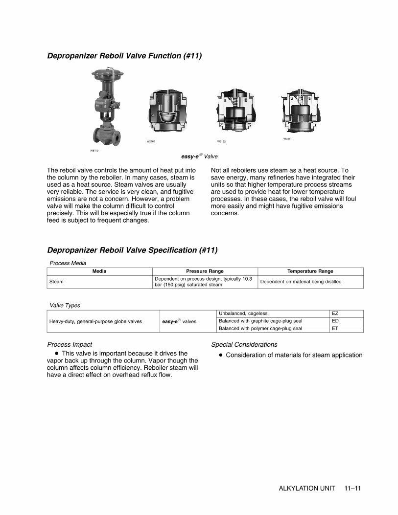
ALKYLATION UNIT 11–11
Depropanizer Reboil Valve Function (#11)
easy-e� ValveW8119
W2966 W3162W0451
The reboil valve controls the amount of heat put intothe column by the reboiler. In many cases, steam isused as a heat source. Steam valves are usuallyvery reliable. The service is very clean, and fugitiveemissions are not a concern. However, a problemvalve will make the column difficult to controlprecisely. This will be especially true if the columnfeed is subject to frequent changes.
Not all reboilers use steam as a heat source. Tosave energy, many refineries have integrated theirunits so that higher temperature process streamsare used to provide heat for lower temperatureprocesses. In these cases, the reboil valve will foulmore easily and might have fugitive emissionsconcerns.
Depropanizer Reboil Valve Specification (#11)
Process MediaMedia Pressure Range Temperature Range
Steam Dependent on process design, typically 10.3bar (150 psig) saturated steam
Dependent on material being distilled
Valve TypesUnbalanced, cageless EZ
Heavy-duty, general-purpose globe valves easy-e� valves Balanced with graphite cage-plug seal EDHeavy duty, general purpose globe valves easy e valvesBalanced with polymer cage-plug seal ET
Process Impact� This valve is important because it drives the
vapor back up through the column. Vapor though thecolumn affects column efficiency. Reboiler steam willhave a direct effect on overhead reflux flow.
Special Considerations
� Consideration of materials for steam application

11–12 ALKYLATION UNIT
DIB Reboil Valve Function (#12)
easy-e� ValveW8119
W2966 W3162 W3162
The reboil valve controls the amount of heat put intothe column by the reboiler. In many cases, steam isused as a heat source. Steam valves are usuallyvery reliable. The service is very clean, and fugitiveemissions are not a concern. However, a problemvalve will make the column difficult to controlprecisely. This will be especially true if the columnfeed is subject to frequent changes.
Not all reboilers use steam as a heat source. Tosave energy, many refineries have integrated theirunits so that higher temperature process streamsare used to provide heat for lower temperatureprocesses. In these cases, the reboil valve will foulmore easily and may have fugitive emissionsconcerns.
DIB Reboil Valve Specification (#12)
Process MediaMedia Pressure Range Temperature Range
Steam Dependent on process design, typically 10.3bar (150 psig) saturated steam
Dependent on material being distilled
Valve TypesUnbalanced, cageless EZ
Heavy-duty, general-purpose globe valves easy-e� valves Balanced with graphite cage-plug seal EDHeavy duty, general purpose globe valves easy e valvesBalanced with polymer cage-plug seal ET
Process Impact� This valve is important in that it drives the vapor
back up through the column. This affects columnefficiency. Reboiler steam will have a direct effect onoverhead reflux flow.
Special Considerations
� Consideration of materials for steamapplication.
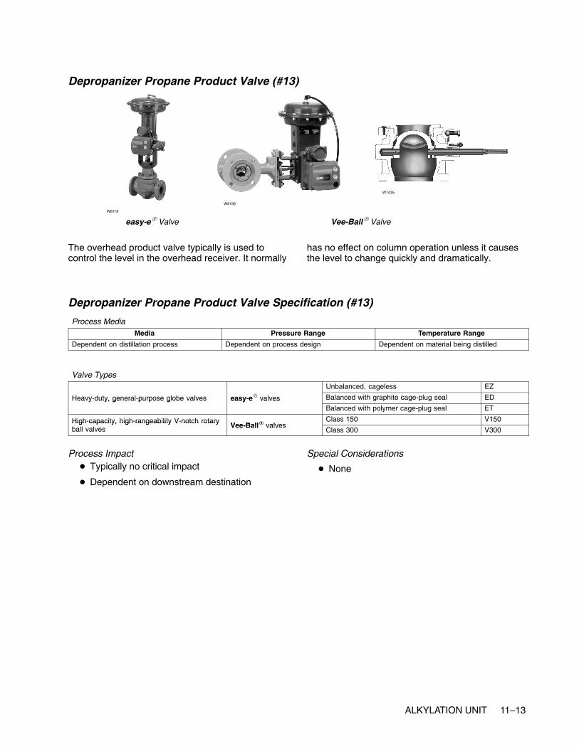
ALKYLATION UNIT 11–13
Depropanizer Propane Product Valve (#13)
easy-e� Valve Vee-Ball� Valve
W8119
W8192
W7435
The overhead product valve typically is used tocontrol the level in the overhead receiver. It normally
has no effect on column operation unless it causesthe level to change quickly and dramatically.
Depropanizer Propane Product Valve Specification (#13)
Process MediaMedia Pressure Range Temperature Range
Dependent on distillation process Dependent on process design Dependent on material being distilled
Valve TypesUnbalanced, cageless EZ
Heavy-duty, general-purpose globe valves easy-e� valves Balanced with graphite cage-plug seal EDHeavy duty, general purpose globe valves easy e valvesBalanced with polymer cage-plug seal ET
High-capacity, high-rangeability V-notch rotaryVee Ball� valves
Class 150 V150High capacity, high rangeability V notch rotaryball valves Vee-Ball� valves
Class 300 V300
Process Impact� Typically no critical impact
� Dependent on downstream destination
Special Considerations
� None

11–14 ALKYLATION UNIT
DIB Reflux Valve Function (#14)
Design EW Valve Vee-Ball� Valve
W2777
W8192
edisc� Valve
W6234
The reflux valve is typically either a flow or columntemperature-control loop. It is used to adjust thepurity of the overhead product. The higher the refluxrate, the purer the overhead product will become.However, raising the reflux rate also will requiremore reboil heat and will eventually flood the tower.
A poorly operating reflux valve will have the sameeffects as a bad feed valve. Product purities willoscillate, and the column will be difficult to control.
DIB Reflux Valve Specification (#14)
Process MediaMedia Pressure Range Temperature Range
Dependent on distillation process Dependent on process design Dependent on material being distilled
Valve Types
High-capacity, high-rangeability V-notch rotaryVee Ball� valves
Class 150 V150High capacity, high rangeability V notch rotaryball valves Vee-Ball� valves
Class 300 V300
edisc� valvesThrough 12 inches 8560
edisc� valvesThrough 24 inches 8532
High-performance butterfly valves Class 150, 300 through 12 inches A41High performance butterfly valves
POSI-SEAL� valves Larger sizes A31APOSI SEAL valvesHigh pressure A11
Unbalanced, cageless EZ
�
Balanced with graphite cage-plug seal EDHeavy-duty, general-purpose globe valves easy-e� valves Balanced with polymer cage-plug seal ETy y g g y
Larger sizes; expanded ends; balanced orunbalanced
EW
Process Impact� Critical to maintaining vapor/liquid balance in
the column, ultimately affecting the efficiency of thecolumn
Special Considerations
� Typically none

ALKYLATION UNIT 11–15
DIB Bottom Valve Function (#15)
Vee-Ball� Valve
W8192 W5791
eplug� Valve
W7435
The bottom product valve is typically used to controlthe level in the bottom of the column. It normally hasno effect on column operation unless it causes thelevel to change quickly and dramatically.
Unstable feed flow will make the distillation columndifficult to control. A problem valve will often causethe feed flow to oscillate. As a result, the column willalternate between too little and too much reboil heat.Depending on the size and number of trays in the
column, the effect of a swing in the feed will takeanywhere from several minutes to more than anhour to reach the ends of the column. Sometimes,the reboil and reflux controls will amplify the swings.The final result is that meeting product purity targetsbecomes more difficult. Refinery operationspersonnel will normally respond by over-purifying theproducts and wasting energy to compensate for thebad feed control valve.
DIB Bottom Valve Specification (#15)
Process MediaMedia Pressure Range Temperature Range
Dependent on distillation process Dependent on process design Dependent on material being distilled
Valve Types
High capacity high rangeability V notch rotary ball valves Vee Ball� valvesClass 150 V150
High-capacity, high-rangeability V-notch rotary ball valves Vee-Ball� valvesClass 300 V300
General and severe service eccentric rotary plug valves eplug� valvesHigh capacity, rugged CV500
General- and severe-service eccentric rotary- plug valves eplug� valvesMore rugged construction V500
Process Impact
� Dependent on downstream destination.
Special Considerations
� Could encounter higher viscosity materials,sludge, and process media with entrained particles.
� Ball valves or eccentric plug valves mightrequire Stellite (Alloy 6) or ceramic trim materials.
� Low-flow, clean fluids or small line-sizeapplications could use globe valves

11–16 ALKYLATION UNIT
Debutanizer Alkylate Valve Function (#16)
easy-e� Valve Vee-Ball� ValveW8119
W8192W3162
The bottom product valve is typically used to controlthe level in the bottom of the column. It normally has
no effect on column operation unless it causes thelevel to change quickly and dramatically.
Debutanizer Alkylate Valve Specification (#16)
Process MediaMedia Pressure Range Temperature Range
Dependent on distillation process Dependent on process design Dependent on material being distilled
Valve TypesUnbalanced, cageless EZ
Heavy-duty, general-purpose globe valves easy-e� valves Balanced with graphite cage-plug seal EDHeavy duty, general purpose globe valves easy e valvesBalanced with polymer cage-plug seal ET
High-capacity, high-rangeability V-notch rotaryVee Ball� valves
Class 150 V150High capacity, high rangeability V notch rotaryball valves Vee-Ball� valves
Class 300 V300
Process Impact� Typically no critical impact
� Dependent on downstream destination
Special Considerations
� None

ALKYLATION UNIT 11–17
Debutanizer Reflux Valve Function (#17)
POSI-SEAL� Valve Vee-Ball� Valve
W5811 W8192
edisc� Valve
W8299
The reflux valve is typically either a flow or columntemperature control loop. It is used to adjust thepurity of the overhead product. The higher the refluxrate, the purer the overhead product will become.However, raising the reflux rate will also requiremore reboil heat and will eventually flood the tower.
A poorly operating reflux valve will have the sameeffects as a bad feed valve. Product purities willoscillate and the column will be difficult to control.
Debutanizer Reflux Valve Specification (#17)
Process MediaMedia Pressure Range Temperature Range
Dependent on distillation process Dependent on process design Dependent on material being distilled
Valve Types
High-capacity, high-rangeability V-notch rotaryVee Ball� valves
Class 150 V150High capacity, high rangeability V notch rotaryball valves Vee-Ball� valves
Class 300 V300
edisc� valvesThrough 12 inches 8560
edisc� valvesThrough 24 inches 8532
High-performance butterfly valves Class 150, 300 through 12 inches A41High performance butterfly valves
POSI-SEAL� valves Larger sizes A31APOSI SEAL valvesHigh pressure A11
Unbalanced, cageless EZ
�
Balanced with graphite cage-plug seal EDHeavy-duty, general-purpose globe valves easy-e� valves Balanced with polymer cage-plug seal ETy y g g y
Larger sizes; expanded ends; balanced orunbalanced
EW
Process Impact� Critical to maintaining vapor/liquid balance in
the column, ultimately affecting the efficiency of thecolumn
Special Considerations
� Typically none

11–18 ALKYLATION UNIT
Debutanizer Butane Valve Function (#18)
easy-e� Valve Vee-Ball� Valve
W8119
W8192
W7435
This valve valve is typically used to control the levelin the overhead receiver. Much of the butane isrecycled back as feed. It normally has no effect on
column operation unless it causes the level tochange quickly and dramatically.
Debutanizer Butane Valve Specification (#18)
Process MediaMedia Pressure Range Temperature Range
Dependent on distillation process Dependent on process design Dependent on material being distilled
Valve TypesUnbalanced, cageless EZ
Heavy-duty, general- purpose globe valves easy-e� valves Balanced with graphite cage-plug seal EDHeavy duty, general purpose globe valves easy e valvesBalanced with polymer cage-plug seal ET
High-capacity, high-rangeability V-notch rotaryVee Ball� valves
Class 150 V150High capacity, high rangeability V notch rotaryball valves Vee-Ball� valves
Class 300 V300
Process Impact� Typically no critical impact
� Dependent on downstream destination
Special Considerations
� None

ALKYLATION UNIT 11–19
Debutanizer Reboil Valve Function (#19)
easy-e� ValveW8119
W2966 W3162W0451
The reboil valve controls the amount of heat put intothe column by the reboiler. In many cases, steam isused as a heat source. Steam valves are usuallyvery reliable. The service is very clean, and fugitiveemissions are not a concern. However, a problemvalve will make the column difficult to controlprecisely. This will be especially true if the columnfeed is subject to frequent changes.
Not all reboilers use steam as a heat source. Tosave energy, many refineries have integrated theirunits so that higher-temperature process streamsare use to provide heat for lower-temperatureprocesses. In these cases, the reboil valve will foulmore easily and might have fugitive emissionsconcerns.
Debutanizer Reboil Valve Specification (#19)
Process MediaMedia Pressure Range Temperature Range
Steam Dependent on process design, typically 10.3bar (150 psig) saturated steam
Dependent on material being distilled
Valve TypesUnbalanced, cageless EZ
Heavy-duty, general-purpose globe valves easy-e� valves Balanced with graphite cage-plug seal EDHeavy duty, general purpose globe valves easy e valvesBalanced with polymer cage-plug seal ET
Process Impact� This valve is important because it drives the
vapor back up through the column. Vapor throughthe column affects column efficiency. Reboiler steamwill have a direct effect on overhead reflux flow.
Special Considerations
� Consideration of materials for steam application

11–20 ALKYLATION UNIT

www.Fisher.com
Chapter 12
Amine Unit
Other Names
Amine contactor, amine scrubber
Description
Amine units are used to clean up the various sourlight-gas streams created by the refinery crackingand treating units. The objective of an amine unit isto strip hydrogen sulfide (H2S), sulfur dioxide (SO2),and other environmental poisons from sour light gasstreams. This prepares the light gas streams to beused in other processing units, to be sold asproducts, or to be burned as fuel gas.
An amine unit, in its simplest form, refers to a singleamine scrubber and an amine regenerator. This isthe unit used for illustration in this document.However, usually several amine scrubbers will beserviced by a single amine regenerator.
The term “amine unit” can be misleading. Rarely isamine treating considered to be a standalone unit ina refinery. In many cases each processing unit willhave a small amine scrubber located within its unitboundaries or will share a scrubber with a few otherunits. Several of these scrubbers will receive andreturn amine to a central regenerator located withinone of the units.
The amine process begins with sour gas enteringthe bottom of an amine scrubber and then risingtowards the top of the scrubber. Lean amine isadded at the top of the scrubber and flows down tothe bottom. As the lean amine drops to the bottom, itstrips H2S and SO2 from the sour gas, becoming
rich amine. The scrubbed gas exits the top of thescrubber and is ready for further use.
The rich amine leaves the bottom of the scrubberand becomes the feed to the amine regenerator. Theamine regenerator is a distillation column where thesulfur gases leave at the top of the column and leanamine leaves the bottom. The sulfur gases are sentto a sulfur recovery unit. The lean amine is eitherrecycled to the scrubbers or sent to storage. Theamine gradually degrades and periodically needs tobe freshened with new amine.

12–2 AMINE UNIT
Typical Amine Unit
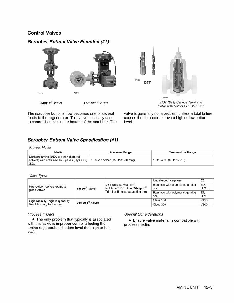
AMINE UNIT 12–3
Control Valves
Scrubber Bottom Valve Function (#1)
easy-e� Valve Vee-Ball� Valve
W8119 W8192
DSTW6787
W8433
DST (Dirty Service Trim) andValve with NotchFlo� DST Trim
The scrubber bottoms flow becomes one of severalfeeds to the regenerator. This valve is usually usedto control the level in the bottom of the scrubber. The
valve is generally not a problem unless a total failurecauses the scrubber to have a high or low bottomlevel.
Scrubber Bottom Valve Specification (#1)
Process MediaMedia Pressure Range Temperature Range
Diethanolamine (DEA or other chemicalsolvent) with entrained sour gases (H2S, CO2,SOx)
10.3 to 172 bar (150 to 2500 psig) 16 to 52�C (60 to 125�F)
Valve TypesUnbalanced, cageless EZ
Heavy-duty, general-purposeglobe valves easy-e� valves
DST (dirty-service trim),NotchFlo� DST trim, Whisper�
Balanced with graphite cage-plugseal
ED,HPAD
globe valves easy e valves , pTrim I or III noise-attunating trim Balanced with polymer cage-plug
sealET,HPAT
High-capacity, high-rangeabilityVee Ball� valves
Class 150 V150High capacity, high rangeabilityV-notch rotary ball valves Vee-Ball� valves
Class 300 V300
Process Impact� The only problem that typically is associated
with this valve is improper control affecting theamine regenerator’s bottom level (too high or toolow).
Special Considerations
� Ensure valve material is compatible withprocess media.

12–4 AMINE UNIT
Scrubber Lean Amine Valve Function (#2)
easy-e� ValveW8119
W2966 W3162 W0451
Lean Amine is normally added to the Scrubber tohold an amine/gas ratio. For 25 MMCFD of gas, thenormal lean amine rate would be 200 to 300 GPM. Ascrubber is much like a distillation column. Too muchvapor or liquid traffic can cause the scrubber to
flood. When this happens, the sulfur compounds areno longer completely stripped from the sour gas. If ascrubber is being operated close to loadingconstraints, and the lean amine valve is stickingbadly, then this could cause the scrubber to flood.
Scrubber Lean Amine Valve Specification (#2)
Process MediaMedia Pressure Range Temperature Range
Regenerated diethanolamine (or otherchemical solvent)
13.8 to 20.7 bar (200 to 300 psig) 38 to 93�C (100 to 200�F)
Valve TypesUnbalanced, cageless EZ
Heavy-duty, general-purpose globe valves easy-e� valves Balanced with graphite cage-plug seal EDHeavy duty, general purpose globe valves easy e valvesBalanced with polymer cage-plug seal ET
Process Impact
� The valve is important to ensure most completegas treatment
Special Considerations
� Ensure valve material is compatible withprocess media.

AMINE UNIT 12–5
Amine Makeup Valve Function (#3)
easy-e� Valve Vee-Ball� ValveW8119
W8192W3162
The amine generally degrades as it is circulated tothe scrubbers. Lab tests are run occasionally tocheck the strength of the amine. When it becomeslow, fresh amine is added to the system to restorethe circulating amine. This valve is not critical, as theamine system can run for long periods of timewithout makeup.
Amine makeup is normally around 50 MGPY. Pooroperation of the scrubber can easily double or triplethe cost of amine to the refinery on an annual basis.
Amine Makeup Valve Specification (#3)
Process MediaMedia Pressure Range Temperature Range
Regenerated diethanolamine (or otherchemical solvent)
10.3 to 20.7 bar (150 to 300 psig) 38 to 93�C (100 to 200�F)
Valve TypesUnbalanced, cageless EZ
Heavy-duty, general-purpose globe valves easy-e� valves Balanced with graphite cage-plug seal EDHeavy duty, general purpose globe valves easy e valvesBalanced with polymer cage-plug seal ET
High-capacity, high-rangeability V-notch rotaryVee Ball� valves
Class 150 V150High capacity, high rangeability V notch rotaryball valves Vee-Ball� valves
Class 300 V300
Process Impact
� Typically none
Special Considerations
� Ensure valve material is compatible withprocess media.

12–6 AMINE UNIT
Regenerator Bottom Recycle Valve Function (#4)
Vee-Ball� Valve
W8192W5791
eplug� Valve
W5793
The flow through this valve is used to set thecirculating amine rate. This valve might not exist inall configurations since the individual scrubber leanamine valves serve almost the same purpose.
The valve typically is used to control the level in thebottom of the column. It normally has no effect oncolumn operation unless it causes the level tochange quickly and dramatically.
Regenerator Bottom Recycle Valve Specification (#4)
Process MediaMedia Pressure Range Temperature Range
Dependent on distillation process Dependent on process design Dependent on material being distilled
Valve Types
High-capacity, high-rangeability V-notch rotaryVee Ball� valves
Class 150 V150High capacity, high rangeability V notch rotaryball valves Vee-Ball� valves
Class 300 V300
General- and severe-service eccentric rotary-eplug� valves
High capacity, rugged construction CV500General and severe service eccentric rotaryplug valves eplug� valves
More rugged construction V500
Process Impact
� Dependent on downstream destination
Special Considerations
� Could encounter higher viscosity materials,sludge and process media with entrained particles
� Ball valves or eccentric plug valves mightrequire Stellite (Alloy 6) or ceramic trim materials.
� Low-flow, clean fluids or small line-sizeapplications could use globe valves.

AMINE UNIT 12–7
Regenerator Reflux Valve Function (#5)
POSI-SEAL� Valve
W5811
edisc� Valve
W8299
Design EW Valve
W2777
The reflux valve is typically either a flow or columntemperature-control loop. It is used to adjust thepurity of the overhead product. The higher the refluxrate, the purer the overhead product will become.However, raising the reflux rate also will requiremore reboil heat and will eventually flood the tower.
A poorly operating reflux valve will have the sameeffects as a bad feed valve. Product purities willoscillate, and the column will be difficult to control.
Regenerator Reflux Valve Specification (#5)
Process MediaMedia Pressure Range Temperature Range
Dependent on distillation process Dependent on process design Dependent on material being distilled
Valve Types
High-capacity, high-rangeability V-notch rotaryVee Ball� valves
Class 150 V150High capacity, high rangeability V notch rotaryball valves Vee-Ball� valves
Class 300 V300
edisc� valvesThrough 12 inches 8560
edisc� valvesThrough 24 inches 8532
High-performance butterfly valves Class 150, 300 through 12 inches A41High performance butterfly valves
POSI-SEAL� valves Larger sizes A31APOSI SEAL valvesHigh pressure A11
Unbalanced, cageless EZ
�
Balanced with graphite cage-plug seal EDHeavy-duty, general-purpose globe valves easy-e� valves Balanced with polymer cage-plug seal ETy y g g y
Larger sizes; expanded ends; balanced orunbalanced
EW
Process Impact� Critical to maintaining vapor/liquid balance in
the column, ultimately affecting the efficiency of thecolumn
Special Considerations
� Typically none

12–8 AMINE UNIT
Regenerator Bottom-to-Storage Valve Function (#6)
Vee-Ball� Valve
W8192 W5791
eplug� Valve
W7435
This valve, along with the amine makeup valve, isused to hold the regenerator bottom level. If ascrubber shuts down, some of the circulating aminewill be sent to storage. Also, if fresh amine is beingadded to the system, the excess amine will beeliminated through this valve.
The valve typically is used to control the level in thebottom of the column. It normally has no effect oncolumn operation unless it causes the level tochange quickly and dramatically.
Regenerator Bottom-to-Storage Valve Specification (#6)
Process MediaMedia Pressure Range Temperature Range
Dependent on distillation process Dependent on process design Dependent on material being distilled
Valve Types
High-capacity, high-rangeability V-notch rotaryVee Ball� valves
Class 150 V150High capacity, high rangeability V notch rotaryball valves Vee-Ball� valves
Class 300 V300
General- and severe-service eccentric rotary-eplug� valves
High capacity, rugged construction CV500General and severe service eccentric rotaryplug valves eplug� valves
More rugged construction V500
Process Impact
� Dependent on downstream destination
Special Considerations
� Could encounter higher viscosity materials,sludge, and process media with entrained particles.
� Ball valves or eccentric plug valves mightrequire Stellite (Alloy 6) or ceramic trim materials.
� Low-flow, clean fluids or small line-sizeapplications could use globe valves.

AMINE UNIT 12–9
Regenerator Reboil Valve Function (#7)
easy-e� ValveW8119
W2966 W3162 W3162
The reboil valve controls the amount of heat put intothe column by the reboiler. In many cases, steam isused as a heat source. Steam valves are usuallyvery reliable. The service is very clean, and fugitiveemissions are not a concern. However, a problemvalve will make the column difficult to controlprecisely. This will be especially true if the columnfeed is subject to frequent changes.
Not all reboilers use steam as a heat source. Tosave energy, many refineries have integrated theirunits so that higher-temperature process streamsare use to provide heat for lower-temperatureprocesses. In these cases, the reboil valve will foulmore easily and might create fugitive emissionsconcerns.
Regenerator Reboil Valve Specification (#7)
Process MediaMedia Pressure Range Temperature Range
Steam Dependent on process design, typically 10.3bar (150 psig) saturated steam
Dependent on material being distilled
Valve TypesUnbalanced, cageless EZ
Heavy-duty, general-purpose globe valves easy-e� valves Balanced with graphite cage-plug seal EDHeavy duty, general purpose globe valves easy e valvesBalanced with polymer cage-plug seal ET
Process Impact� This valve is important because it drives the
vapor back up through the column. Vapor throughthe colum affects column efficiency. Reboiler steamwill have a direct effect on overhead reflux flow.
Special Considerations
� Consideration of materials for steam application
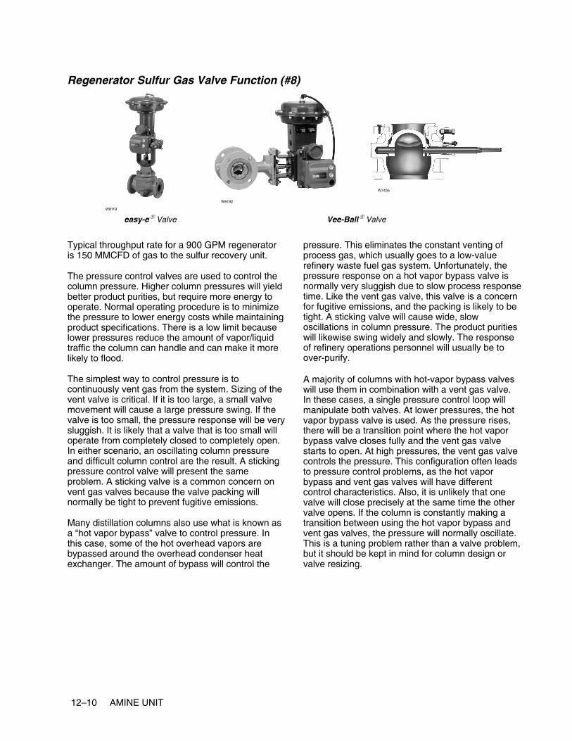
12–10 AMINE UNIT
Regenerator Sulfur Gas Valve Function (#8)
easy-e� Valve Vee-Ball� Valve
W8119
W8192
W7435
Typical throughput rate for a 900 GPM regeneratoris 150 MMCFD of gas to the sulfur recovery unit.
The pressure control valves are used to control thecolumn pressure. Higher column pressures will yieldbetter product purities, but require more energy tooperate. Normal operating procedure is to minimizethe pressure to lower energy costs while maintainingproduct specifications. There is a low limit becauselower pressures reduce the amount of vapor/liquidtraffic the column can handle and can make it morelikely to flood.
The simplest way to control pressure is tocontinuously vent gas from the system. Sizing of thevent valve is critical. If it is too large, a small valvemovement will cause a large pressure swing. If thevalve is too small, the pressure response will be verysluggish. It is likely that a valve that is too small willoperate from completely closed to completely open.In either scenario, an oscillating column pressureand difficult column control are the result. A stickingpressure control valve will present the sameproblem. A sticking valve is a common concern onvent gas valves because the valve packing willnormally be tight to prevent fugitive emissions.
Many distillation columns also use what is known asa “hot vapor bypass” valve to control pressure. Inthis case, some of the hot overhead vapors arebypassed around the overhead condenser heatexchanger. The amount of bypass will control the
pressure. This eliminates the constant venting ofprocess gas, which usually goes to a low-valuerefinery waste fuel gas system. Unfortunately, thepressure response on a hot vapor bypass valve isnormally very sluggish due to slow process responsetime. Like the vent gas valve, this valve is a concernfor fugitive emissions, and the packing is likely to betight. A sticking valve will cause wide, slowoscillations in column pressure. The product puritieswill likewise swing widely and slowly. The responseof refinery operations personnel will usually be toover-purify.
A majority of columns with hot-vapor bypass valveswill use them in combination with a vent gas valve.In these cases, a single pressure control loop willmanipulate both valves. At lower pressures, the hotvapor bypass valve is used. As the pressure rises,there will be a transition point where the hot vaporbypass valve closes fully and the vent gas valvestarts to open. At high pressures, the vent gas valvecontrols the pressure. This configuration often leadsto pressure control problems, as the hot vaporbypass and vent gas valves will have differentcontrol characteristics. Also, it is unlikely that onevalve will close precisely at the same time the othervalve opens. If the column is constantly making atransition between using the hot vapor bypass andvent gas valves, the pressure will normally oscillate.This is a tuning problem rather than a valve problem,but it should be kept in mind for column design orvalve resizing.
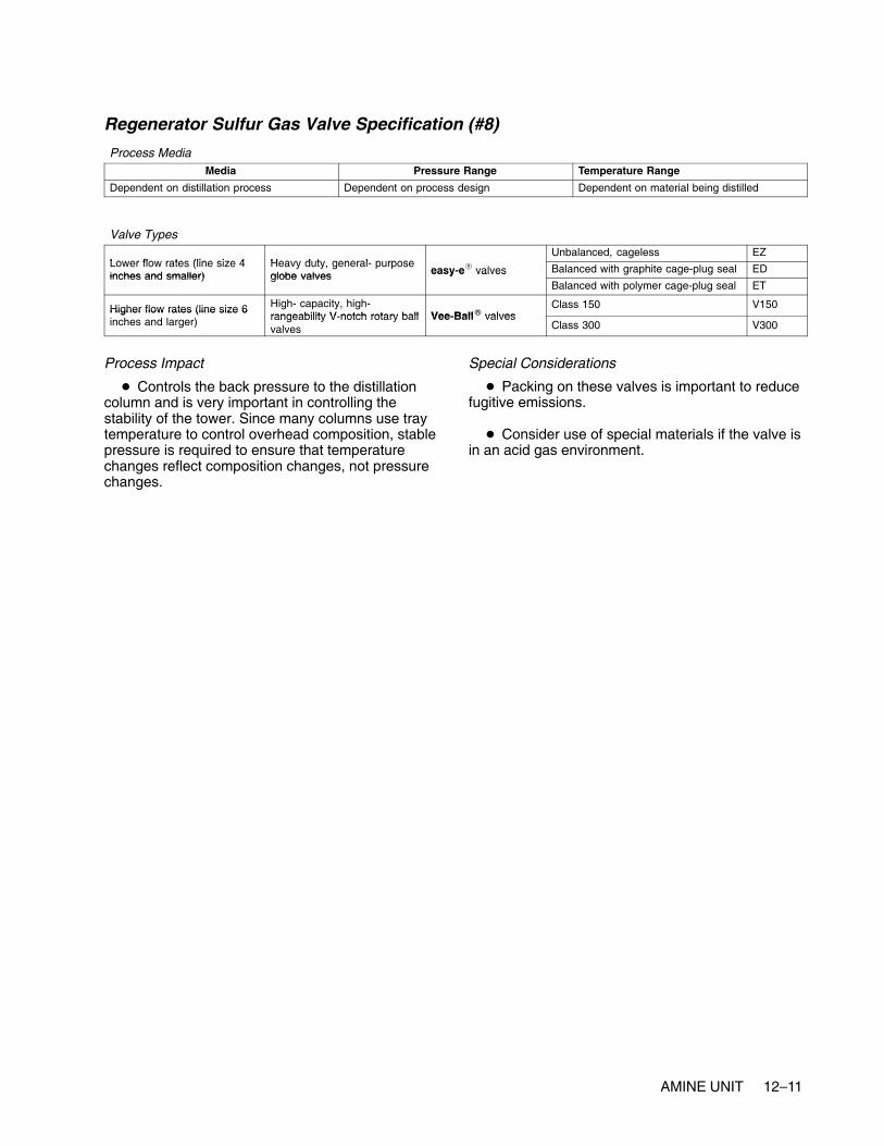
AMINE UNIT 12–11
Regenerator Sulfur Gas Valve Specification (#8)
Process MediaMedia Pressure Range Temperature Range
Dependent on distillation process Dependent on process design Dependent on material being distilled
Valve Types
Lower flow rates (line size 4 Heavy duty general purposeUnbalanced, cageless EZ
Lower flow rates (line size 4inches and smaller)
Heavy duty, general- purposeglobe valves easy-e� valves Balanced with graphite cage-plug seal ED
inches and smaller) globe valves easy e valvesBalanced with polymer cage-plug seal ET
Higher flow rates (line size 6 High- capacity, high-rangeability V notch rotary ball Vee Ball� valves
Class 150 V150Higher flow rates (line size 6inches and larger) rangeability V-notch rotary ball
valvesVee-Ball� valves
Class 300 V300
Process Impact
� Controls the back pressure to the distillationcolumn and is very important in controlling thestability of the tower. Since many columns use traytemperature to control overhead composition, stablepressure is required to ensure that temperaturechanges reflect composition changes, not pressurechanges.
Special Considerations
� Packing on these valves is important to reducefugitive emissions.
� Consider use of special materials if the valve isin an acid gas environment.

12–12 AMINE UNIT

www.Fisher.com
Chapter 13
Sulfur Recovery Unit
Other NamesSRU, Claus unit
DescriptionThe crude oil processed by refineries containsvarying amounts of sulfur. The sulfur is removedduring processing, mostly as hydrogen sulfide (H2S).Environmental regulations restrict the amount of H2Sand other sulfur compounds that can be released tothe environment. The SRU (sulfur recovery unit) isused to convert H2S to elemental sulfur through aseries of reactors. The unit illustrated is a commonmethod known as the Claus process.
The feed sources for a SRU are acid gases from theamine treaters and sour gas from the sour waterstrippers. The acid and sour gases are burned in areaction furnace in the presence of enough air and/or oxygen to combust approximately one third of theincoming H2S plus any remaining hydrocarbons andammonia. The combustion products are cooled in
the waste heater boiler / thermal sulfur condenser.After the thermal reaction and condensation, thereare three catalytic reactor stages. Each reactorstage consists of a reheater, catalytic converter, andcondenser. The elemental sulfur recovered fromeach condenser is run down into a sulfur pit. Thefinal tail gas stream can be sent to an incinerator or,depending on local environmental regulations, a tailgas treating unit.
The SRU is usually viewed by refinery operationspersonnel as an “overhead” or utility unit. However,because of the environmental regulations, this unit isextremely important to total refinery production. Mostrefineries have multiple SRUs so that a shutdowndoes not stop the entire refinery. If an SRU doesshut down, the refinery almost immediately has toback off on production so as to keep from producingmore acid gas than can be processed by theremaining SRUs. Also, the SRU capacity in manyrefineries dictates what types and how much highsulfur crudes can be processed. A small incrementalgain in capacity for these refiners can yieldsignificant profit.

13–2 SULFUR RECOVERY UNIT
Typical Sulfur Recovery Unit

SULFUR RECOVERY UNIT 13–3
Control Valves
Fuel Gas Valve Function (#1)
easy-e� Valve Vee-Ball� ValveW8119
W8192W3162
This valve is typically used only during startup. Itmay be necessary to use fuel gas when there aresignificant amounts of ammonia in the sour gas or
significant amounts of hydrocarbons from either gassource.
Fuel Gas Valve Specification (#1)
Process MediaMedia Pressure Range Temperature Range
Fuel gas 6.9 bar (100 psig) 38�C (100�F)
Valve TypesUnbalanced, cageless EZ
Heavy-duty, general-purpose globe valves easy-e� valves Balanced with graphite cage-plug seal EDHeavy duty, general purpose globe valves easy e valvesBalanced with polymer cage-plug seal ET
High-capacity, high-rangeability V-notch rotaryVee Ball� valves
Class 150 V150High capacity, high rangeability V notch rotaryball valves Vee-Ball� valves
Class 300 V300
Process Impact
� Impacts temperature of thermal reactor
Special Considerations
� None

13–4 SULFUR RECOVERY UNIT
Oxygen Valve Function (#2)
easy-e� Valve Vee-Ball� Valve
W8119
W8192
W7435
This is an optional process stream for an SRU, andtypically this valve is not present. It is sometimes
used to boost the capacity of an SRU when anotherSRU is down.
Oxygen Valve Specification (#2)
Process MediaMedia Pressure Range Temperature Range
Oxygen 6.9 bar (100 psig) 38�C (100�F)
Valve TypesUnbalanced, cageless EZ
Heavy-duty, general-purpose globe valves easy-e� valves Balanced with graphite cage-plug seal EDHeavy duty, general purpose globe valves easy e valvesBalanced with polymer cage-plug seal ET
High-capacity, high-rangeability V-notch rotaryVee Ball� valves
Class 150 V150High capacity, high rangeability V notch rotaryball valves Vee-Ball� valves
Class 300 V300
Process Impact
� Only used if SRU requires additional capacityor throughput
Special Considerations
� Ensure that the valve materials are compatiblewith oxygen service.
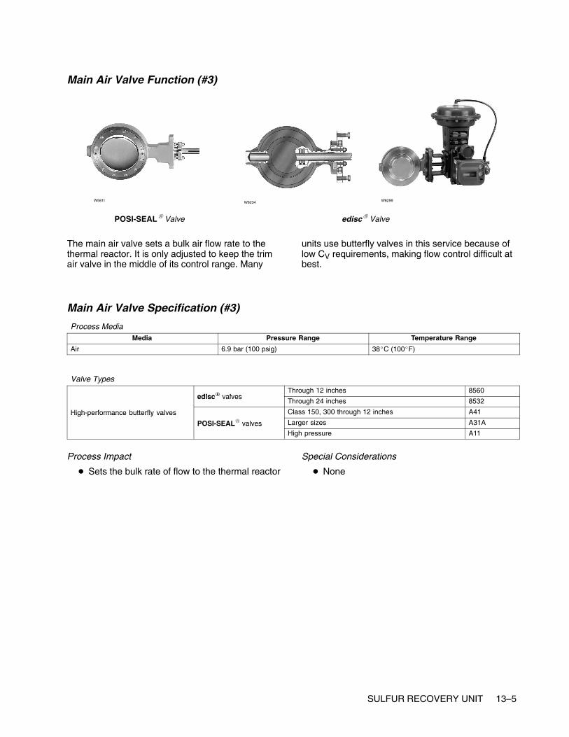
SULFUR RECOVERY UNIT 13–5
Main Air Valve Function (#3)
POSI-SEAL� Valve
W5811 W6234
edisc� Valve
W8299
The main air valve sets a bulk air flow rate to thethermal reactor. It is only adjusted to keep the trimair valve in the middle of its control range. Many
units use butterfly valves in this service because oflow CV requirements, making flow control difficult atbest.
Main Air Valve Specification (#3)
Process MediaMedia Pressure Range Temperature Range
Air 6.9 bar (100 psig) 38�C (100�F)
Valve Types
edisc� valvesThrough 12 inches 8560
edisc� valvesThrough 24 inches 8532
High-performance butterfly valves Class 150, 300 through 12 inches A41High performance butterfly valves
POSI-SEAL� valves Larger sizes A31APOSI SEAL valvesHigh pressure A11
Process Impact
� Sets the bulk rate of flow to the thermal reactor
Special Considerations
� None
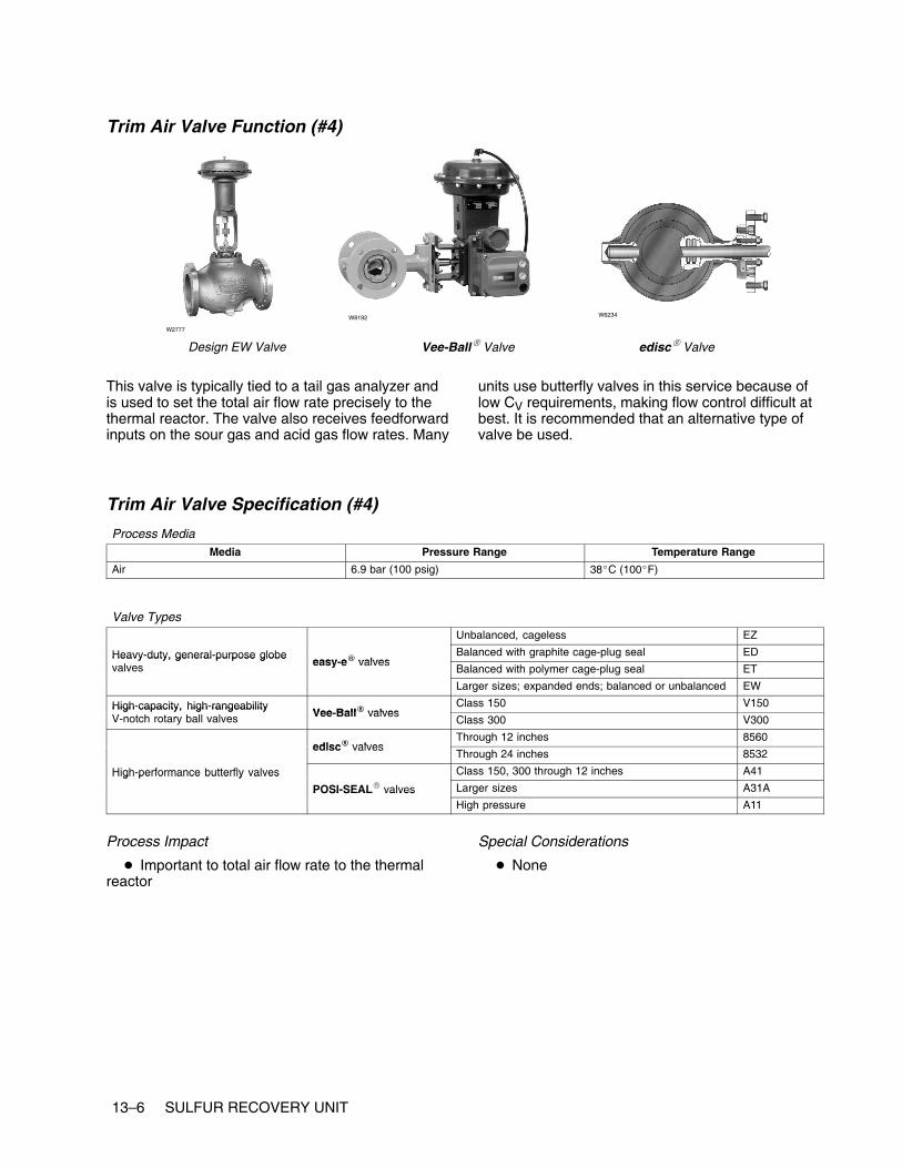
13–6 SULFUR RECOVERY UNIT
Trim Air Valve Function (#4)
Design EW Valve Vee-Ball� Valve
W2777
W8192
edisc� Valve
W6234
This valve is typically tied to a tail gas analyzer andis used to set the total air flow rate precisely to thethermal reactor. The valve also receives feedforwardinputs on the sour gas and acid gas flow rates. Many
units use butterfly valves in this service because oflow CV requirements, making flow control difficult atbest. It is recommended that an alternative type ofvalve be used.
Trim Air Valve Specification (#4)
Process MediaMedia Pressure Range Temperature Range
Air 6.9 bar (100 psig) 38�C (100�F)
Valve TypesUnbalanced, cageless EZ
Heavy-duty, general-purpose globeeasy e� valves
Balanced with graphite cage-plug seal EDHeavy duty, general purpose globevalves easy-e� valves
Balanced with polymer cage-plug seal ET
Larger sizes; expanded ends; balanced or unbalanced EW
High-capacity, high-rangeabilityVee Ball� valves
Class 150 V150High capacity, high rangeabilityV-notch rotary ball valves Vee-Ball� valves
Class 300 V300
edisc� valvesThrough 12 inches 8560
edisc� valvesThrough 24 inches 8532
High-performance butterfly valves Class 150, 300 through 12 inches A41High performance butterfly valves
POSI-SEAL� valves Larger sizes A31APOSI SEAL valvesHigh pressure A11
Process Impact
� Important to total air flow rate to the thermalreactor
Special Considerations
� None

SULFUR RECOVERY UNIT 13–7
Acid Gas from Amine Valve Function (#5)
easy-e� Valve Vee-Ball� ValveW8119
W8192W3162
These valves belong to the various amine contactorslocated throughout the refinery. The SRU normally
has no direct control on the amount of acid gascoming to the SRU.
Acid Gas from Amine Valve Specification (#5)
Process MediaMedia Pressure Range Temperature Range
Sour waste gas Dependent on process design Dependent on process design
Valve TypesUnbalanced, cageless EZ
Heavy-duty, general-purpose globe valves easy-e� valves Balanced with graphite cage-plug seal EDHeavy duty, general purpose globe valves easy e valvesBalanced with polymer cage-plug seal ET
High-capacity, high-rangeability V-notch rotaryVee Ball� valves
Class 150 V150High capacity, high rangeability V notch rotaryball valves Vee-Ball� valves
Class 300 V300
Process Impact
� Important for fueling the reaction in the thermalreactor
Special Considerations
� Be sure that valve materials are compatiblewith process media.

13–8 SULFUR RECOVERY UNIT
Sour Gas from SWS Valve Function (#6)
easy-e� Valve Vee-Ball� Valve
W8119
W8192
W7435
These valves belong to the various sour waterstrippers located throughout the refinery. The SRU
normally has no direct control on the amount of sourgas coming to the SRU.
Sour Gas from SWS Valve Specification (#6)
Process MediaMedia Pressure Range Temperature Range
Dependent on distillation process Dependent on process design Dependent on material being distilled
Valve Types
Lower flow rates (line size 4 Heavy duty general purposeUnbalanced, cageless EZ
Lower flow rates (line size 4inches and smaller)
Heavy duty, general- purposeglobe valves easy-e� valves Balanced with graphite cage-plug seal ED
inches and smaller) globe valves easy e valvesBalanced with polymer cage-plug seal ET
Higher flow rates (line size 6 High- capacity, high-rangeability V notch rotary ball Vee Ball� valves
Class 150 V150Higher flow rates (line size 6inches and larger) rangeability V-notch rotary ball
valvesVee-Ball� valves
Class 300 V300
Process Impact
� Controls the back pressure to the distillationcolumn and is very important in controlling thestability of the tower. Since many columns use traytemperature to control overhead composition, stablepressure is required to ensure that temperaturechanges reflect composition changes, not pressurechanges.
Special Considerations
� Packing on these valves is important to reducefugitive emissions.
� May consider use of special materials onvalves that encounter an acid gas environment.

SULFUR RECOVERY UNIT 13–9
Reheater Steam Valve Function (#7, #8, #9)
easy-e� Valve Vee-Ball� ValveW8119
W8192W3162
These valves are used to control the reactiontemperature to the Claus reactors. If valveperformance is erratic, it can result in swings in the
sulfur conversion, possibly causing an environmentalexcursion or putting more load on the tail gas treater.
Reheater Steam Valve Specification (#7, #8, #9)
Process MediaMedia Pressure Temperature Range
Steam 20.7 bar (300 psig) 149 to 204�C (300 to 400�F)
Valve TypesUnbalanced, cageless EZ
Heavy-duty, general-purpose globe valves easy-e� valves Balanced with graphite cage-plug seal EDHeavy duty, general purpose globe valves easy e valvesBalanced with polymer cage-plug seal ET
High-capacity, high-rangeability V-notch rotaryVee Ball� valves
Class 150 V150High capacity, high rangeability V notch rotaryball valves Vee-Ball� valves
Class 300 V300
Process Impact
� Important in maintaining process temperaturesfor Claus reactors
Special Considerations
� None

13–10 SULFUR RECOVERY UNIT
www.Fisher.com
Chapter 14
Blending Unit
Other NamesBlender
DescriptionA blending unit creates a finished refinery productstream. The most common type is a gasolineblender. However, blenders are also used for otherproducts, such as diesel or jet fuel.
A gasoline blender can create several differentproducts from the same available components. Forexample, most refineries produce three octanegrades of unleaded gasoline. There are differentspecifications on gasoline vapor pressure dependingon whether it is summer or winter. Also, differentregional environmental requirements existdepending on where the gasoline is to be marketed.Each of these considerations require a different mixof the gasoline components produced by therefinery.
For a given gasoline product there will be acalculated recipe for how much of each componentshould go into the product tank. The flow controllerfrom each component tank will be set accordingly.
Note that the most frequent problems encounteredwithin blenders are not usually caused by controlvalves. Inaccurate lab or on-line analyzer results orbiased flow indications pose far greater problems. Inaddition there are lineup valves used to connecttanks that are either opened or closed. The lineupvalves, whether manually or automaticallymanipulated, have the potential for ruining an entiretank (or tanks) of product if not set to the correctposition.
The consequence of poor blending can be severe.Product specification giveaway can easily cost $0.05to $0.10/BBL of gasoline, or $150M to $300M peryear for every 10 MBPD of gasoline produced.

14–2 BLENDING UNIT
Typical Blending Unit

BLENDING UNIT 14–3
Control Valves
Component Valve Function (#1, #2, #3, #4)
easy-e� Valve Vee-Ball� Valve
W8119
W8192
W7435
This example is based on 20 MBPD of gasolineproduction. These valves are manipulated by flowcontrol loops. The flows are set according to productrecipe requirements. Many blenders havesophisticated advanced control algorithms to monitorthe flow through these valves.
A sticking valve is usually of no consequence toblending operation as long as the average flowtarget is met. A stuck valve is a bigger problem if it
goes unnoticed and the blend is being donemanually.
Once discovered, the control valve can be blocked inand bypassed. However, the amount of flow for thatcomponent must be recalculated to make up for thedeviation from flow setpoint by the end of the blendfor that product tank. Most blend control packagescan pick up and correct this particular problem.
Component Valve Specification (#1, #2, #3, #4)
Process MediaMedia Pressure Range Temperature Range
Various hydrocarbon product streams 13.8 to 24.1 bar (200 to 350 psig) 16 to 52�C (60 to 125�F)
Valve TypesUnbalanced, cageless EZ
Heavy-duty, general-purpose globe valves easy-e� valves Balanced with graphite cage-plug seal EDHeavy duty, general purpose globe valves easy e valvesBalanced with polymer cage-plug seal ET
High-capacity, high-rangeability V-notch rotaryVee Ball� valves
Class 150 V150High capacity, high rangeability V notch rotaryball valves Vee-Ball� valves
Class 300 V300
Process Impact� Although problems with valves do not typically
affect the blending process as do improperlyfunctioning analyzers, they can have a significantimpact on the product spec if the valve problem isnot found and corrected within a reasonable time.
Special Considerations
� In selecting a valve, it is probably better to erron the side of better valve performance than onprice.

14–4 BLENDING UNIT


Emerson Process ManagementMarshalltown, Iowa 50158 U.S.A.Cernay 68700 FranceSao Paulo 05424 BrazilSingapore 128461www.Fisher.com
The contents of this publication are presented for informational purposes only, and while every effort hasbeen made to ensure their accuracy, they are not to be construed as warranties or guarantees, expressor implied, regarding the products or services described herein or their use or applicability. All sales aregoverned by our terms and conditions, which are available upon request. We reserve the right to modifyor improve the designs or specifications of such products at any time without notice. Fisher does notassume responsibility for the selection, use or maintenance of any product. Responsibility for properselection, use and maintenance of any Fisher product remains solely with the purchaser and end-user.
D103205X012 Printed in USA / 5M / 8/04 IL
Related Documents