The Royal League in ventilation, control and drive technology Movement by Perfection Control Technology Main Catalogue 06/2021 Edition

Welcome message from author
This document is posted to help you gain knowledge. Please leave a comment to let me know what you think about it! Share it to your friends and learn new things together.
Transcript
The Royal League in ventilation, control and drive technology
M o v e m e n t b y P e r f e c t i o n
Control Technology
Co
nt
ro
l T
ec
hn
olo
gy
Ma
in C
at
alo
gu
e 0
6/
20
21
Ed
itio
n
Main Catalogue 06/2021 Edition
Using air intelligent-ly
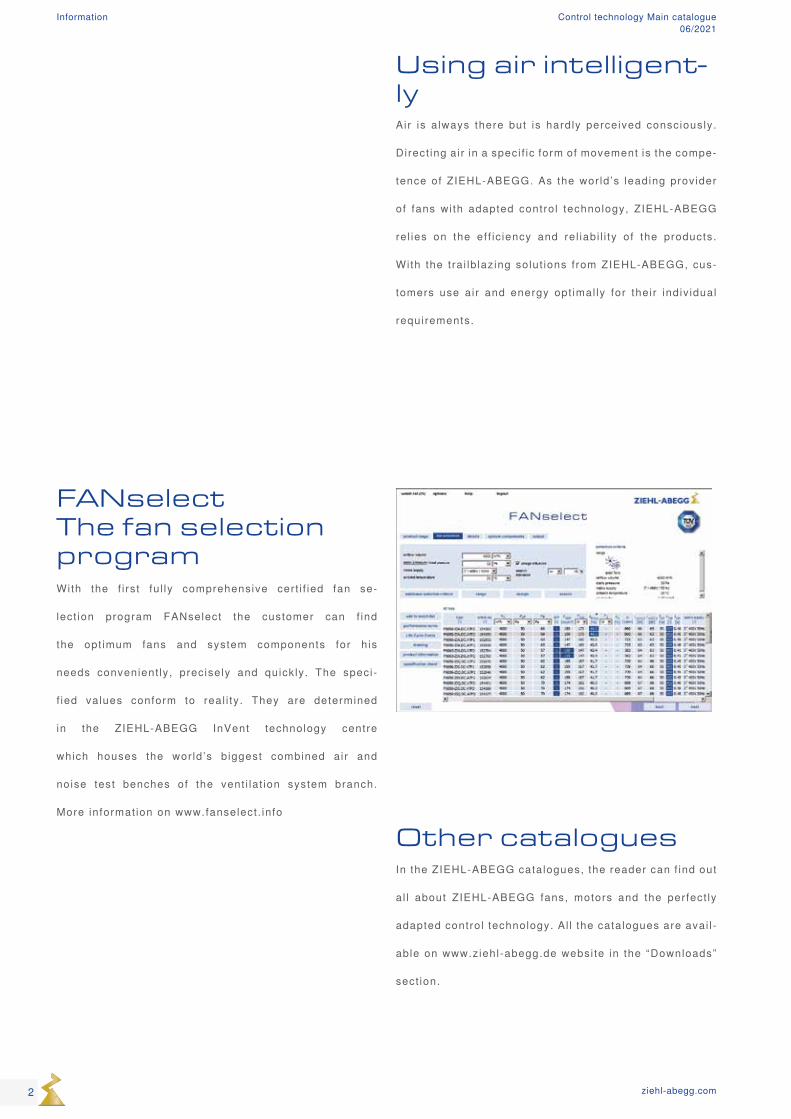
FANselect The fan selection programWith the f i rst fu l ly comprehensive cert i f ied fan se-
lect ion program FANselect the customer can f ind
the opt imum fans and system components for h is
needs convenient ly, precisely and quickly. The speci-
f ied values conform to real i ty. They are determined
in the ZIEHL-ABEGG InVent technology centre
which houses the wor ld ’s biggest combined air and
noise test benches of the vent i lat ion system branch.
More informat ion on www.fanselect . info
Other cataloguesIn the ZIEHL-ABEGG catalogues, the reader can f ind out
al l about ZIEHL-ABEGG fans, motors and the perfect ly
adapted control technology. Al l the catalogues are avai l -
able on www.ziehl-abegg.de websi te in the “Downloads”
sect ion.
Air is a lways there but is hardly perceived consciously.
Direct ing air in a speci f ic form of movement is the compe-
tence of ZIEHL-ABEGG. As the wor ld ’s leading provider
of fans wi th adapted control technology, ZIEHL-ABEGG
rel ies on the ef f ic iency and rel iabi l i ty of the products.
With the t ra i lb lazing solut ions f rom ZIEHL-ABEGG, cus-
tomers use air and energy opt imal ly for their indiv idual
requirements.
2 ziehl-abegg.com
Information Control technology Main catalogue06/2021
The ZIEHL-ABEGG Company Page 4
ZAcode - Products and philosophy Page 12
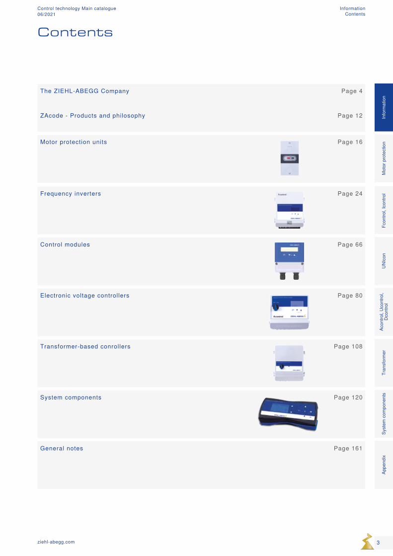
Motor protection units Page 16
Frequency inverters Page 24
Control modules Page 66
Electronic voltage controllers Page 80
Transformer-based conrollers Page 108
System components Page 120
General notes Page 161
Contents
3ziehl-abegg.com
Mot
or p
rote
ctio
nFc
ontro
l, Ic
ontro
lUN
Icon
Acon
trol,
Ucon
trol,
Dcon
trol
Tran
sfor
mer
Syst
em c
ompo
nent
sIn
form
atio
nAp
pend
ix
Information Contents
Control technology Main catalogue06/2021
4 ziehl-abegg.com
Information The ZIEHL-ABEGG Company
Control technology Main catalogue06/2021
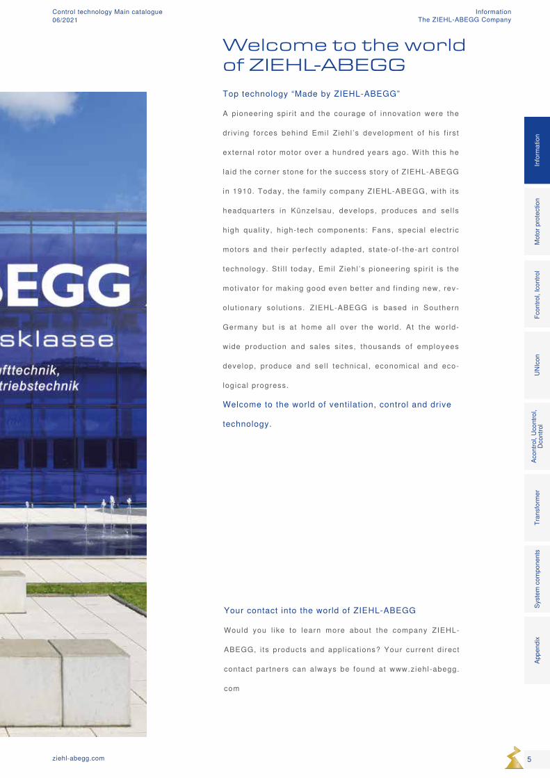
Welcome to the world of ZIEHL-ABEGG
Top technology “Made by ZIEHL-ABEGG”
A pioneer ing spir i t and the courage of innovat ion were the
dr iv ing forces behind Emil Ziehl ’s development of h is f i rst
external rotor motor over a hundred years ago. With th is he
la id the corner stone for the success story of ZIEHL-ABEGG
in 1910. Today, the fami ly company ZIEHL-ABEGG, with i ts
headquarters in Künzelsau, develops, produces and sel ls
high qual i ty, h igh-tech components: Fans, special e lectr ic
motors and their perfect ly adapted, state-of- the-art control
technology. St i l l today, Emi l Ziehl ’s pioneer ing spir i t is the
mot ivator for making good even better and f inding new, rev-
olut ionary solut ions. ZIEHL-ABEGG is based in Southern
Germany but is at home al l over the wor ld. At the wor ld-
wide product ion and sales s i tes, thousands of employees
develop, produce and sel l technical , economical and eco-
logical progress.
Welcome to the world of ventilation, control and drive
technology.
Your contact into the world of ZIEHL-ABEGG
Would you l ike to learn more about the company ZIEHL-
ABEGG, i ts products and appl icat ions? Your current direct
contact partners can always be found at www.ziehl-abegg.
com
5ziehl-abegg.com
Mot
or p
rote
ctio
nFc
ontro
l, Ic
ontro
lUN
Icon
Acon
trol,
Ucon
trol,
Dcon
trol
Tran
sfor
mer
Syst
em c
ompo
nent
sIn
form
atio
nAp
pend
ix
Information The ZIEHL-ABEGG Company
Control technology Main catalogue06/2021
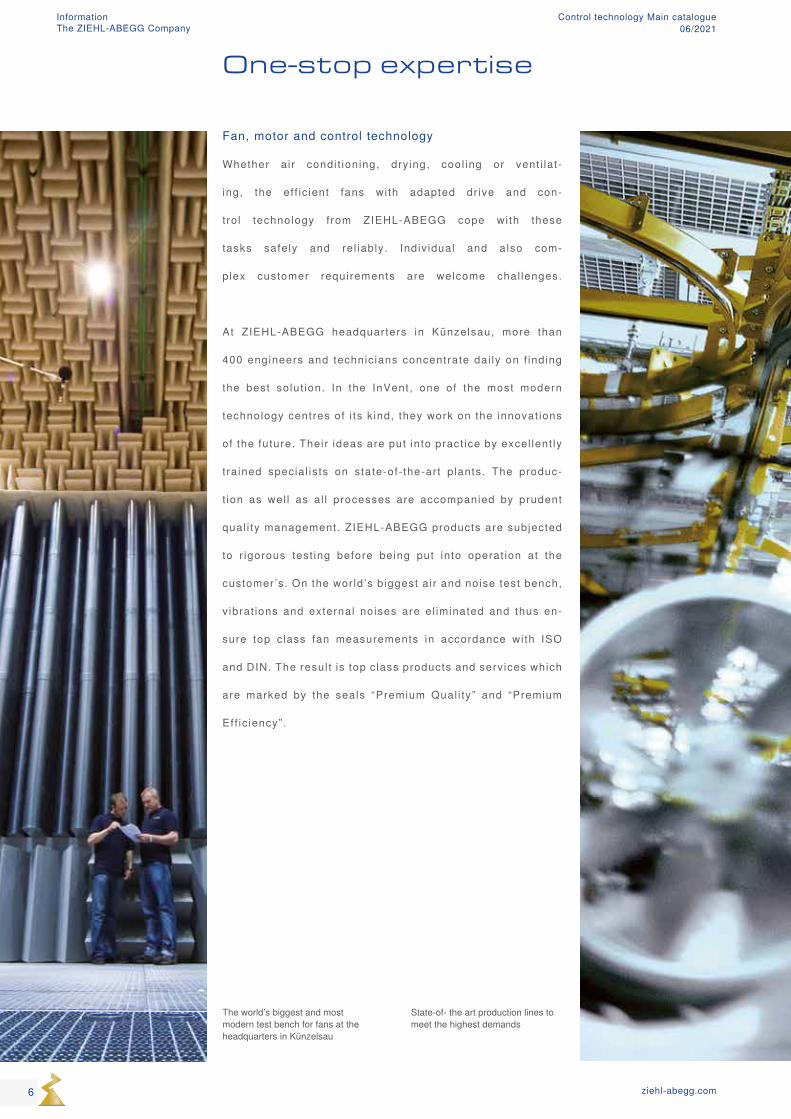
One-stop expertise
Fan, motor and control technology
Whether air condi t ioning, dry ing, cool ing or vent i lat-
ing, the ef f ic ient fans wi th adapted dr ive and con-
trol technology from ZIEHL-ABEGG cope with these
tasks safely and rel iably. Indiv idual and also com-
plex customer requirements are welcome chal lenges.
At ZIEHL-ABEGG headquarters in Künzelsau, more than
400 engineers and technic ians concentrate dai ly on f inding
the best solut ion. In the InVent, one of the most modern
technology centres of i ts k ind, they work on the innovat ions
of the future. Their ideas are put into pract ice by excel lent ly
t ra ined special ists on state-of- the-art p lants. The produc-
t ion as wel l as al l processes are accompanied by prudent
qual i ty management. ZIEHL-ABEGG products are subjected
to r igorous test ing before being put into operat ion at the
customer’s. On the wor ld ’s biggest air and noise test bench,
v ibrat ions and external noises are el iminated and thus en-
sure top c lass fan measurements in accordance with ISO
and DIN. The resul t is top c lass products and services which
are marked by the seals “Premium Qual i ty” and “Premium
Eff ic iency”.
The world’s biggest and most modern test bench for fans at the headquarters in Künzelsau
State-of- the art production lines to meet the highest demands
6 ziehl-abegg.com
Information The ZIEHL-ABEGG Company
Control technology Main catalogue06/2021

7ziehl-abegg.com
Mot
or p
rote
ctio
nFc
ontro
l, Ic
ontro
lUN
Icon
Acon
trol,
Ucon
trol,
Dcon
trol
Tran
sfor
mer
Syst
em c
ompo
nent
sIn
form
atio
nAp
pend
ix
Information The ZIEHL-ABEGG Company
Control technology Main catalogue06/2021
The right control technology
Products with unique advantages
Offer ing our customers special advantages. That is our pr ime
goal which we focus on in the development of our control prod-
ucts. To achieve this, we equip our products wi th special features.
For example, we place special emphasis on ease of operat ion.
ZIEHL-ABEGG is also one of the few manufacturers who produc-
es ser ies f requency inverters equipped with integrated, al l -pole
s inef i l ters. This br ings you, our customers, unique advantages
with regard to EMC and rel iabi l i ty in the combinat ion of these
frequency inverters wi th di f ferent types of motors. I t goes with-
out saying that our products are absolutely energy economical .
The products that are responsible for the intel l igent control
of processes also convince with unique advantages. Some-
t imes i t is not the mult funct ional possibi l i t ies which many of
our products of fer that br ing the decis ive advantage to the ap-
pl icat ion. I t is of ten the reduct ion to the basics that is imple-
mented consistent ly in a product and convinces our customers.
Special ta i lor-made products of fer the best pr ice-performance ra-
t ios.
8 ziehl-abegg.com
Information Control technology Main catalogue06/2021
9ziehl-abegg.com
Mot
or p
rote
ctio
nFc
ontro
l, Ic
ontro
lUN
Icon
Acon
trol,
Ucon
trol,
Dcon
trol
Tran
sfor
mer
Syst
em c
ompo
nent
sIn
form
atio
nAp
pend
ix
Information Control technology Main catalogue06/2021
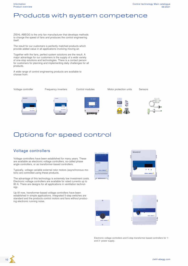
Voltage controller Frequency inverters Control modules Motor protection units Sensors
Products with system competence
Options for speed control
Voltage controllers
Voltage controllers have been established for many years. These are available as electronic voltage controllers, so-called phase angle controllers, or as transformer-based controllers. Typically, voltage variable external rotor motors (asynchronous mo-tors) are controlled using these products. The advantage of this technology is extremely low investment costs. Electronic voltage controllers are available for rated currents up to 80 A. There are designs for all applications in ventilation technol-ogy. Up till now, transformer-based voltage controllers have been established in simple applications. Integrated 5-step switches are standard and the products control motors and fans without produc-ing electronic running noise.
ZIEHL-ABEGG is the only fan manufacturer that develops methods to change the speed of fans and produces the control engineering itself. The result for our customers is perfectly matched products which provide added value in all applications involving moving air. Together with the fans, perfect system solutions are the result. A major advantage for our customers is the supply of a wide variety of one-stop solutions and technologies. There is a contact person for customers for planning and implementing daily challenges for all products. A wide range of control engineering products are available to choose from:
Electronic voltage controllers and 5-step transformer-based controllers for 1~ and 3~ power supply.
10 ziehl-abegg.com
Information Product overview
Control technology Main catalogue06/2021
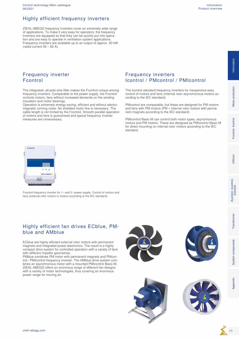
Highly efficient frequency inverters
ZIEHL-ABEGG frequency inverters cover an extremely wide range of applications. To make it very easy for operators, the frequency inverters are equipped so that they can be quickly put into opera-tion and are easy to operate in ventilation system applications. Frequency inverters are available up to an output of approx. 30 kW (rated current 50 – 62 A).
Frequency inverter Fcontrol
The integrated, all-pole sine filter makes the Fcontrol unique among frequency inverters. Comparable to the power supply, the Fcontrol controls motors, fans without increased demands on the winding insulation and motor bearings. Operation is extremely energy-saving, efficient and without electro-magnetic running noise. No shielded motor line is necessary. The cable length is not limited by the Fcontrol. Smooth parallel operation of motors and fans is guaranteed and typical frequency inverter measures are unnecessary.
Frequency inverters Icontrol / PMcontrol / PMIcontrol
The Icontrol standard frequency inverters for inexpensive easy control of motors and fans (internal rotor asynchronous motors ac-cording to the IEC standard). PMcontrol are comparable, but these are designed for PM motors and fans with PM motors (PM = internal rotor motors with perma-nent magnets according to the IEC standard). PMIcontrol Basic-M can control both motor types, asynchronous motors and PM motors. These are designed as PMIcontrol Basic-M for direct mounting on internal rotor motors according to the IEC standard.
Highly efficient fan drives ECblue, PM-blue and AMblue
ECblue are highly efficient external rotor motors with permanent magnets and integrated power electronics. The result is a highly compact drive system for controlled operation with a variety of fans with different impeller geometries. PMblue combines PM motor with permanent magnets and PMcon-trol / PMIcontrol frequency inverter. The AMblue drive system com-bines an asynchronous motor with a mounted PMIcontrol Basic-M. ZIEHL-ABEGG offers an enormous range of different fan designs with a variety of motor technologies, thus covering an enormous power range for moving air.
Fcontrol frequency inverter for 1~ and 3~ power supply. Control of motors and fans (external rotor motors or motors according to the IEC standard).
11ziehl-abegg.com
Mot
or p
rote
ctio
nFc
ontro
l, Ic
ontro
lUN
Icon
Acon
trol,
Ucon
trol,
Dcon
trol
Tran
sfor
mer
Syst
em c
ompo
nent
sIn
form
atio
nAp
pend
ix
Information Product overview
Control technology Main catalogue06/2021
ZAcode
Market challenge
Manufacturers of products which involve moving air are confronted with a variety of products and technologies. In addition to fans with asynchronous motors, which are mainly con-trolled by frequency inverters, the proportion of EC motors (highly efficient motors with permanent magnets and integrated power electronics) is rising. Solutions are increasingly available involving mounting frequency inverters on internal rotor motors according to the IEC standard. That is why companies rely on different manufacturers and tech-nologies to cover the power range of smaller than 1 kW to 30 kW. This involves a great effort in terms of design, documentation and storage of parts as well as employee training. Interface problems, e.g. the interaction of frequency inverters and fans of different manufacturers, involve effort and expenditure which may delay projects and lead to complaints.
ZIEHL-ABEGG’s philosophy
Simple products and solutions. From the planner via production to installation and maintenance - everyone involved with the system should have an easy time and be able to understand it. ZIEHL-ABEGG has been busy with this challenge adapting prod-ucts which cover the decisive power range accordingly. Products have been reduced to the essential, but can be easily expanded to meet requirements at any time. ZIEHL-ABEGG’s products are 100% matched to one another. This means ZIEHL-ABEGG fans and frequency inverters create an energy-saving, quiet and reliably functioning system. The same is true of the combination of control modules with ECblue fans and other products. At ZIEHL-ABEGG, you have only one contact person for fans, mo-tors and the perfectly matching one-stop control engineering. This philosophy makes the effort involved easier in terms of plan-ning, production, installation and maintenance.
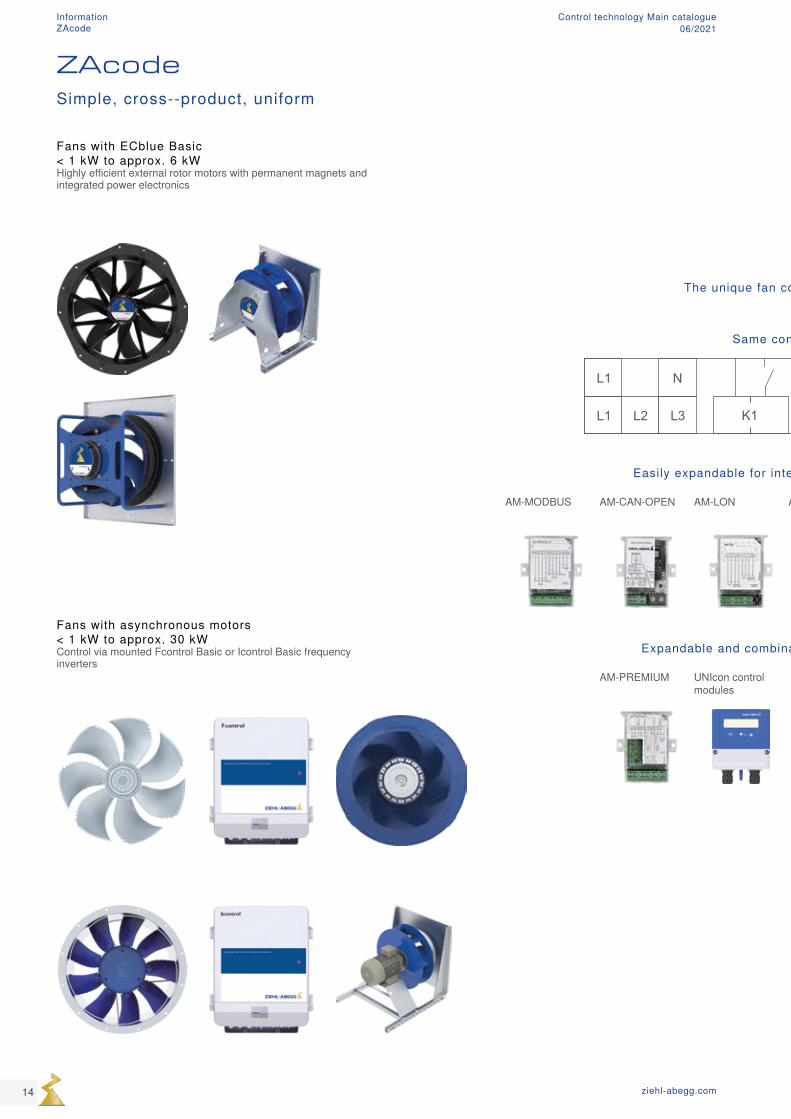
The unique fan control philosophy
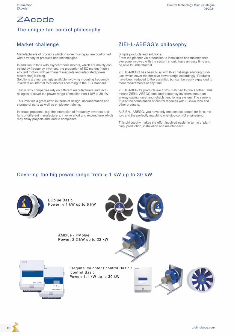
Covering the big power range from < 1 kW up to 30 kW
ECblue Basic Power: < 1 kW up to 6 kW
AMblue / PMblue Power: 2.2 kW up to 22 kW
Frequnzumrichter Fcontrol Basic / Icontrol Basic Power: 1.1 kW up to 30 kW
12 ziehl-abegg.com
Information ZAcode
Control technology Main catalogue06/2021
ZAcode - the solution - your advan-tages
On a cross-product basis - ZAcode encompasses the key technologies on the market
- Axial and centrifugal fans - EC technology and AC technology - Integrated electronics and external electronics for speed control - Communication and control intelligence
Simplicity - Can be operated and understood by everyone
Uniformity - Identical connection concept of the various products and tech-nologies
- Identical communication (add-on modules for required bus systems)
- Identical functionality - Modular expandability, thus providing a cost-effective basis - Expandable on demand - sustainable - Available in a wide power range of smaller than 1 kW to 30 kW
Safety and reliability - courtesy of perfectly matched systems - courtesy of error prevention during installation, start-up, operation and maintenance
Speed - Uniformity ensures speed in relation to engineering. Hence, the short time to market in relation to product development. Fast start-up and service.
Cost savings - Your processes will become more efficient, e.g. with regard to engineering
- Basic equipment of ZIEHL-ABEGG products = Buy basic equip-ment and pay, buy add-ons if necessary - buy only what you need!
Flexibility - Modular system, expandable and customisable - Customisable to current and future bus systems - Basic expandability
13ziehl-abegg.com
Mot
or p
rote
ctio
nFc
ontro
l, Ic
ontro
lUN
Icon
Acon
trol,
Ucon
trol,
Dcon
trol
Tran
sfor
mer
Syst
em c
ompo
nent
sIn
form
atio
nAp
pend
ix
Information ZAcode
Control technology Main catalogue06/2021
The unique fan control philosophy
Same connectivity
L1 L2 L3
N
24VE1 D1 GND 10VK1
L1
Easily expandable for integration into bus systems
AM-MODBUS AM-CAN-OPEN AM-LON AM-PROFIBUS AM-ETHERCAT ...
Expandable and combinable control intelligence
AM-PREMIUM UNIcon control modules
ZAcodeSimple, cross--product, uniform
Fans with ECblue Basic < 1 kW to approx. 6 kWHighly efficient external rotor motors with permanent magnets and integrated power electronics
Fans with asynchronous motors < 1 kW to approx. 30 kWControl via mounted Fcontrol Basic or Icontrol Basic frequency inverters
14 ziehl-abegg.com
Information ZAcode
Control technology Main catalogue06/2021
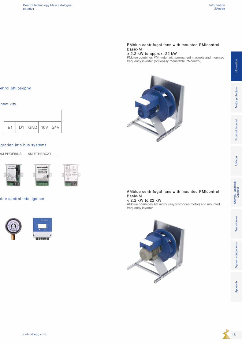
The unique fan control philosophy
Same connectivity
L1 L2 L3
N
24VE1 D1 GND 10VK1
L1
Easily expandable for integration into bus systems
AM-MODBUS AM-CAN-OPEN AM-LON AM-PROFIBUS AM-ETHERCAT ...
Expandable and combinable control intelligence
AM-PREMIUM UNIcon control modules
PMblue centrifugal fans with mounted PMIcontrol Basic-M < 2.2 kW to approx. 22 kWPMblue combines PM motor with permanent magnets and mounted frequency inverter (optionally mountable PMcontrol)
AMblue centrifugal fans with mounted PMIcontrol Basic-M < 2.2 kW to 22 kWAMblue combines AC motor (asynchronous motor) and mounted frequency inverter
15ziehl-abegg.com
Mot
or p
rote
ctio
nFc
ontro
l, Ic
ontro
lUN
Icon
Acon
trol,
Ucon
trol,
Dcon
trol
Tran
sfor
mer
Syst
em c
ompo
nent
sIn
form
atio
nAp
pend
ix
Information ZAcode
Control technology Main catalogue06/2021
16 ziehl-abegg.com
Motor protection Control technology Main catalogue06/2021
Product overview
Motor protection concept Page 18
Motor protection units Page 19
Motor protection
17ziehl-abegg.com
Mot
or p
rote
ctio
nFc
ontro
l, Ic
ontro
lUN
Icon
Acon
trol,
Ucon
trol,
Dcon
trol
Tran
sfor
mer
Syst
em c
ompo
nent
sIn
form
atio
nAp
pend
ix
Motor protectionControl technology Main catalogue06/2021
4mm2
M3~
M3~
ϑ
ϑ
1,5mm2
M3~
M3~
ϑ
ϑ
1,5mm2
M3~
M3~
ϑ
ϑ
1,5mm2
4mm2
M3~
M3~
ϑ
ϑ
1,5mm2
4mm2
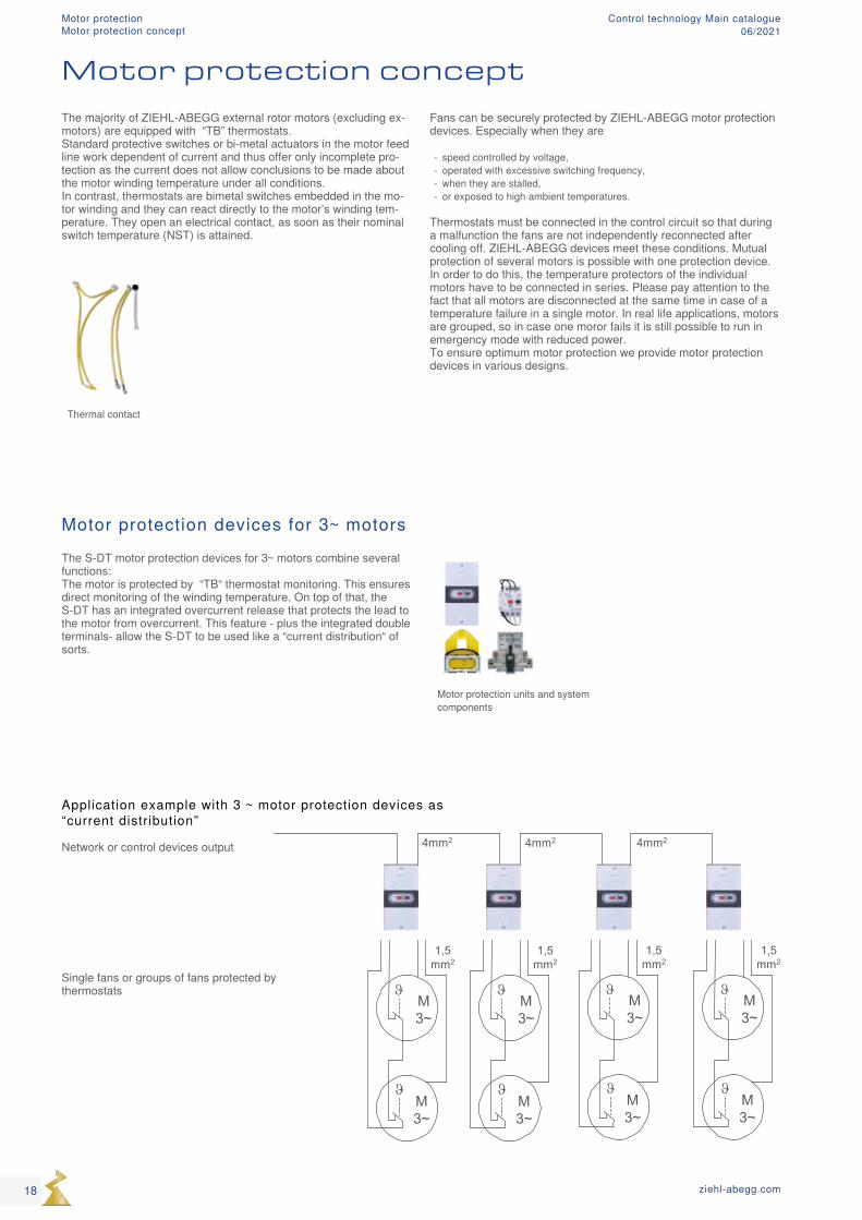
Thermal contact
Motor protection units and system components
Motor protection concept
The majority of ZIEHL-ABEGG external rotor motors (excluding ex-motors) are equipped with “TB” thermostats. Standard protective switches or bi-metal actuators in the motor feed line work dependent of current and thus offer only incomplete pro-tection as the current does not allow conclusions to be made about the motor winding temperature under all conditions. In contrast, thermostats are bimetal switches embedded in the mo-tor winding and they can react directly to the motor’s winding tem-perature. They open an electrical contact, as soon as their nominal switch temperature (NST) is attained.
Fans can be securely protected by ZIEHL-ABEGG motor protection devices. Especially when they are
- speed controlled by voltage, - operated with excessive switching frequency, - when they are stalled, - or exposed to high ambient temperatures.
Thermostats must be connected in the control circuit so that during a malfunction the fans are not independently reconnected after cooling off. ZIEHL-ABEGG devices meet these conditions. Mutual protection of several motors is possible with one protection device. In order to do this, the temperature protectors of the individual motors have to be connected in series. Please pay attention to the fact that all motors are disconnected at the same time in case of a temperature failure in a single motor. In real life applications, motors are grouped, so in case one moror fails it is still possible to run in emergency mode with reduced power. To ensure optimum motor protection we provide motor protection devices in various designs.
Motor protection devices for 3~ motorsThe S-DT motor protection devices for 3~ motors combine several functions: The motor is protected by “TB“ thermostat monitoring. This ensures direct monitoring of the winding temperature. On top of that, the S-DT has an integrated overcurrent release that protects the lead to the motor from overcurrent. This feature - plus the integrated double terminals- allow the S-DT to be used like a “current distribution“ of sorts.
Application example with 3 ~ motor protection devices as “current distribution” Network or control devices output Single fans or groups of fans protected by thermostats
18 ziehl-abegg.com
Motor protectionMotor protection concept
Control technology Main catalogue06/2021
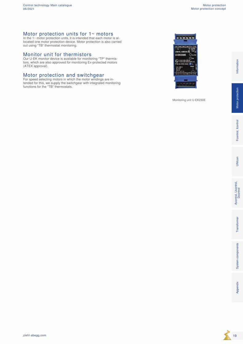
Motor protection units for 1~ motorsIn the 1~ motor protection units, it is intended that each motor is al-located one motor protection device. Motor protection is also carried out using “TB“ thermostat monitoring.
Monitor unit for thermistorsOur U-EK monitor device is available for monitoring “TP“ thermis-tors, which are also approved for monitoring Ex-protected motors (ATEX approval).
Motor protection and switchgearFor speed selecting motors in which the motor windings are in-tended for this, we supply the switchgear with integrated monitoring functions for the “TB“ thermostats.
Monitoring unit U-EK230E
19ziehl-abegg.com
Mot
or p
rote
ctio
nFc
ontro
l, Ic
ontro
lUN
Icon
Acon
trol,
Ucon
trol,
Dcon
trol
Tran
sfor
mer
Syst
em c
ompo
nent
sIn
form
atio
nAp
pend
ix
Motor protectionMotor protection concept
Control technology Main catalogue06/2021
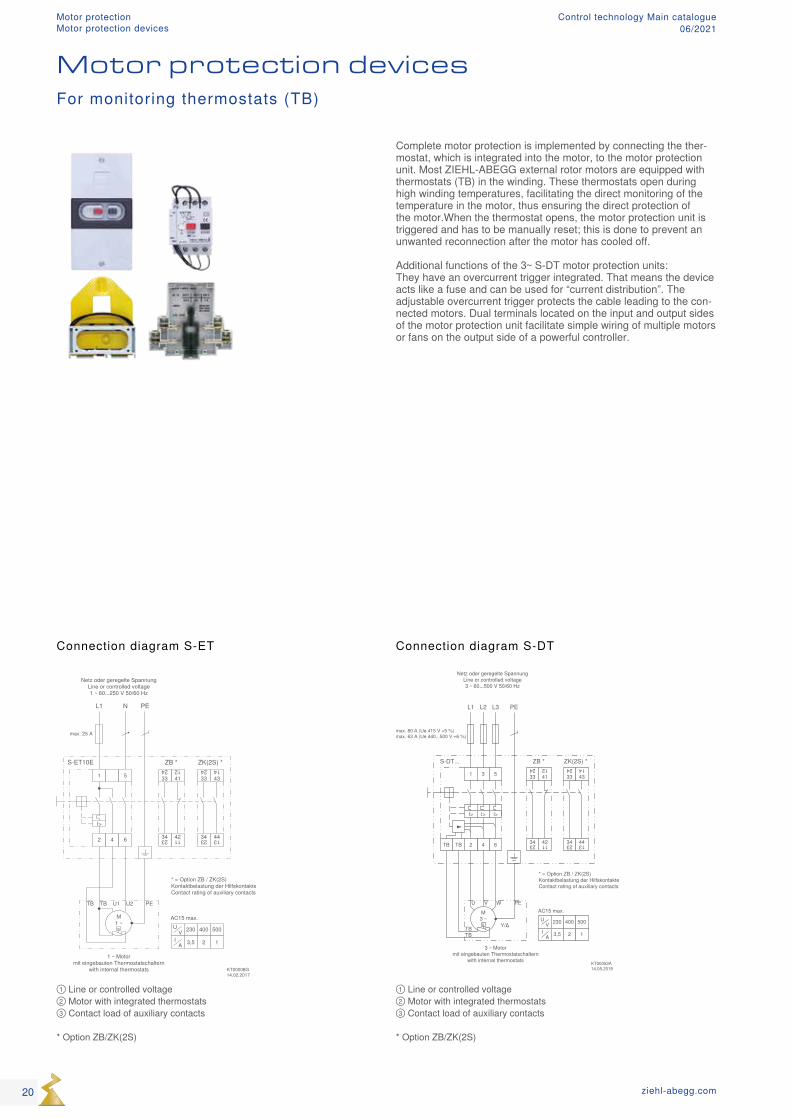
① Line or controlled voltage ② Motor with integrated thermostats ③ Contact load of auxiliary contacts * Option ZB/ZK(2S)
① Line or controlled voltage ② Motor with integrated thermostats ③ Contact load of auxiliary contacts * Option ZB/ZK(2S)
Complete motor protection is implemented by connecting the ther-mostat, which is integrated into the motor, to the motor protection unit. Most ZIEHL-ABEGG external rotor motors are equipped with thermostats (TB) in the winding. These thermostats open during high winding temperatures, facilitating the direct monitoring of the temperature in the motor, thus ensuring the direct protection of the motor.When the thermostat opens, the motor protection unit is triggered and has to be manually reset; this is done to prevent an unwanted reconnection after the motor has cooled off. Additional functions of the 3~ S-DT motor protection units: They have an overcurrent trigger integrated. That means the device acts like a fuse and can be used for “current distribution”. The adjustable overcurrent trigger protects the cable leading to the con-nected motors. Dual terminals located on the input and output sides of the motor protection unit facilitate simple wiring of multiple motors or fans on the output side of a powerful controller.
Connection diagram S-ET Connection diagram S-DT
For monitoring thermostats (TB)
Motor protection devices
20 ziehl-abegg.com
Motor protectionMotor protection devices
Control technology Main catalogue06/2021
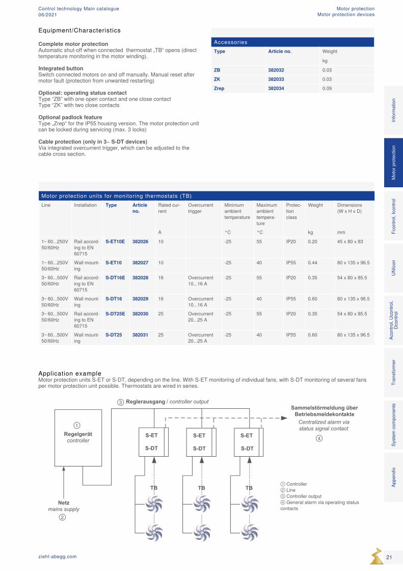
Regelgerätcontroller
Netzmains supply
S-ET
S-DT
S-ET
S-DT
S-ET
S-DT
TB TB TB
Reglerausgang / controller outputSammelstörmeldung über
BetriebsmeldekontakteCentralized alarm viastatus signal contact
① Controller ② Line ③ Controller output ④ General alarm via operating status contacts
Motor protection units for monitoring thermostats (TB)Line Installation Type Article
no.Rated cur-rent
Overcurrent trigger
Minimum ambient temperature
Maximum ambient tempera-ture
Protec-tion class
Weight Dimensions (W x H x D)
A °C °C kg mm
1~ 60...250V 50/60Hz
Rail accord-ing to EN 60715
S-ET10E 382026 10 -25 55 IP20 0.20 45 x 80 x 83
1~ 60...250V 50/60Hz
Wall mount-ing
S-ET10 382027 10 -25 40 IP55 0.44 80 x 135 x 96.5
3~ 60...500V 50/60Hz
Rail accord-ing to EN 60715
S-DT16E 382028 16 Overcurrent 10...16 A
-25 55 IP20 0.35 54 x 80 x 85.5
3~ 60...500V 50/60Hz
Wall mount-ing
S-DT16 382029 16 Overcurrent 10...16 A
-25 40 IP55 0.60 80 x 135 x 96.5
3~ 60...500V 50/60Hz
Rail accord-ing to EN 60715
S-DT25E 382030 25 Overcurrent 20...25 A
-25 55 IP20 0.35 54 x 80 x 85.5
3~ 60...500V 50/60Hz
Wall mount-ing
S-DT25 382031 25 Overcurrent 20...25 A
-25 40 IP55 0.60 80 x 135 x 96.5
AccessoriesType Article no. Weight
kg
ZB 382032 0.03
ZK 382033 0.03
Zrep 382034 0.09
Application exampleMotor protection units S-ET or S-DT, depending on the line. With S-ET monitoring of individual fans, with S-DT monitoring of several fans per motor protection unit possible. Thermostats are wired in series.
Mot
or p
rote
ctio
nFc
ontro
l, Ic
ontro
lUN
Icon
Acon
trol,
Ucon
trol,
Dcon
trol
Tran
sfor
mer
Syst
em c
ompo
nent
sIn
form
atio
nAp
pend
ix
21ziehl-abegg.com
Equipment/Characteristics
Complete motor protection Automatic shut-off when connected thermostat „TB“ opens (direct temperature monitoring in the motor winding).
Integrated button Switch connected motors on and off manually. Manual reset after motor fault (protection from unwanted restarting)
Optional: operating status contact Type “ZB” with one open contact and one close contact Type “ZK” with two close contacts
Optional padlock feature Type „Zrep“ for the IP55 housing version. The motor protection unit can be locked during servicing (max. 3 locks)
Cable protection (only in 3~ S-DT devices) Via integrated overcurrent trigger, which can be adjusted to the cable cross section.
Motor protectionMotor protection devices
Control technology Main catalogue06/2021
S3
AC 220 - 240 V
S2
K1
k1
S1
H1
L3L2L1
1 ... 6 TP
M 3~
K1
F1-F3F4
N
A1
14 11 12 NC Y1 Y2
A2
U-EK230E
T1 T2TP
ResetUe = 250 V Ie = 3 A AC 15
NC NC~ + ~ -
ON
ALARM
PTB 03 ATEX 3045
!
Us
II (2) D [Ex t] [Ex p]II (2) G [Ex e] [Ex d] [Ex px]
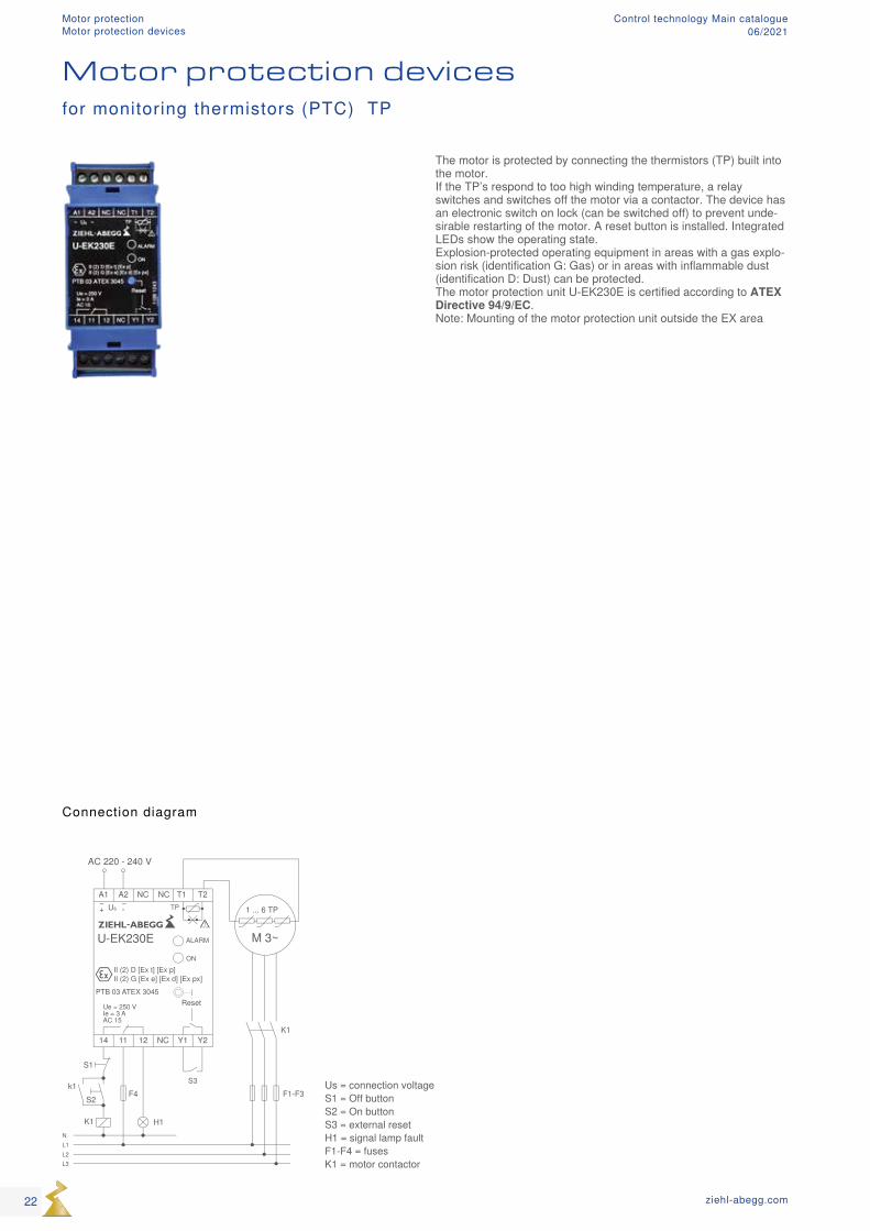
Us = connection voltage S1 = Off button S2 = On button S3 = external reset H1 = signal lamp fault F1-F4 = fuses K1 = motor contactor
Motor protection devicesfor monitoring thermistors (PTC) TP
Connection diagram
The motor is protected by connecting the thermistors (TP) built into the motor. If the TP’s respond to too high winding temperature, a relay switches and switches off the motor via a contactor. The device has an electronic switch on lock (can be switched off) to prevent unde-sirable restarting of the motor. A reset button is installed. Integrated LEDs show the operating state. Explosion-protected operating equipment in areas with a gas explo-sion risk (identification G: Gas) or in areas with inflammable dust (identification D: Dust) can be protected. The motor protection unit U-EK230E is certified according to ATEX Directive 94/9/EC. Note: Mounting of the motor protection unit outside the EX area
22 ziehl-abegg.com
Motor protectionMotor protection devices
Control technology Main catalogue06/2021
Motor protection unit U-EK230E1~ 220...240V 50/60HzType Article no. Protection class Max. heat dis-
sipationMotor protection Maximum
ambient temperature
Weight Dimensions (W x H x D)
W °C kg mm
U-EK230E 382008 IP20 2 TP 55 0.12 35 x 116 x 58
Optional equipment
Plastic housing in IP54 As an accessory a plastic housing with transparent cover for surface mount-ing is available (Article No. 349069). Note: This housing is not pressure-proof. Mounting only permissible outside the EX area.
Equipment/properties
ATEX approval According to directive 94/9/EC
1 digital output (relay) For activating a motor contactor
1 digital input For external reset
23ziehl-abegg.com
Mot
or p
rote
ctio
nFc
ontro
l, Ic
ontro
lUN
Icon
Acon
trol,
Ucon
trol,
Dcon
trol
Tran
sfor
mer
Syst
em c
ompo
nent
sIn
form
atio
nAp
pend
ix
Motor protectionMotor protection devices
Control technology Main catalogue06/2021
24 ziehl-abegg.com
Frequency inverters Control technology Main catalogue06/2021
Frequency inverter
Product overview
1~ Fcontrol Page 26 3~ Fcontrol Page 32 3~ Fcontrol Basic Page 42 3~ Icontrol Page 48 3~ Icontrol Basic Page 54 3~ PMcontrol Basic Page 58 3~ PMIcontrol Basic-M Page 60 Active harmonic fi lter Page 64
Mot
or p
rote
ctio
nFc
ontro
l, Ic
ontro
lUN
Icon
Acon
trol,
Ucon
trol,
Dcon
trol
Tran
sfor
mer
Syst
em c
ompo
nent
sIn
form
atio
nAp
pend
ix
25ziehl-abegg.com
Frequency invertersControl technology Main catalogue06/2021
NNL1
NL1PE
NetzLine
1 ~ 208...277 V 50/60 Hz
L1 U1 U1 U2 U2
+ + 1
K1 K2
KontaktbelastungContact ratingmax. AC 250 V 2 A
A1
GND
E2
GND
E1
GND GND
+ 2
1 ~ Motor mit eingebauten Thermostatschalternwith internal thermostats
M1 ~
PE U2U1 TBTB
AusgangOutput0...10 V
3
EingangInput
0...10 V0...20 mA4...20 mA
EingangInput
0...10 V0...20 mA4...20 mA
5
1
2
D-
D+
GND
24V
Data DataGND+ -
24 V
RS-485
TB
TB
D1
D1
D2
D2
Digital In 1
Digital In 2
Analog Out 1
Analog In 1
Analog In 2
T2
T1 24V
GND
A2
Analog Out 2
Temp1/2
TF..
TF..
Normal
6 Adressierung / Addressing
KTY 81-210PT 1000
UMPO09K008.09.2010
Fcontrol FXET4/6/10AMQ
AusgangOutput+10 V
+ 2
(Imax = 6 mA)
1 4
100
%
Auto
0 100
%
Auto
0
222421121411
3 4
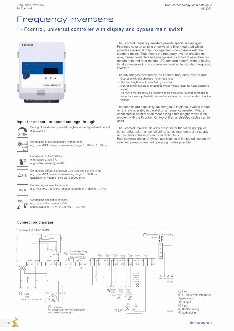
① Line ② 1~ Motor with integrated thermostats ③ Output ④ Input ⑤ Contact rating ⑥ Addressing
Input for sensors or speed settings through
0-10V
Setting of the desired speed through device or by external default, e.g. 0…10 V
0-300-50bar
Connecting pressure sensors (refrigeration), e.g. type MBG.. sensors, measuring range 0...30 bar, 0...50 bar
°CConnection of thermistors, e. g. sensors type TF.. e. g. active sensor type MTG..
PaConnecting differential pressure sensors (air conditioning), e.g. type MPG.. sensors, measuring range 0...6000 Pa, acquisition of volume flows up to 65000 m3/h
m / sConnecting air velocity sensors, e.g. type MAL.. sensors, measuring range 0...1 m/s, 0...10 m/s
CO2
%
°C
Connecting additional sensors, e.g. combination sensors, CO2, sensor signal 0...10 V / 0...20 mA / 4...20 mA
The Fcontrol frequency inverters provide special advantages. Fcontrols have an all pole effective sine filter integrated which provides sinusoidal output voltage that is comparable with the standard mains. That means the frequency inverter enables reli-able, demand-oriented and energy-saving control of asynchronous motors (external rotor motors, IEC standard motors) without having to take measures into consideration required by standard frequency inverters. The advantages provided by the Fcontrol frequency inverter are:
- Operation without shielded motor feed lines - The line length is not restricted by Fcontrol - Operation without electromagnetic motor noises (ideal for noise sensitive areas)
- No risk to motors (they do not have to be frequency inverter compatible) since they are supplied with sinusoidal voltage that corresponds to the line voltage.
The benefits are especially advantageous in plants in which motors or fans are operated in parallel on a frequency inverter. Motors connected in parallel often means long cable lengths which is no problem with the Fcontrol. On top of that, unshielded cables can be used. The Fcontrol universal devices are ideal for the following applica-tions: refrigeration, air conditioning, agriculture, general air supply and ventilation tasks, clean room technology. Fast commissioning for typical applications in the stated sectors by selecting pre-programmed operating modes possible.
Connection diagram
Frequency inverters1~ Fcontrol, universal controller with display and bypass main switch
26 ziehl-abegg.com
Frequency inverters1~ Fcontrol
Control technology Main catalogue06/2021
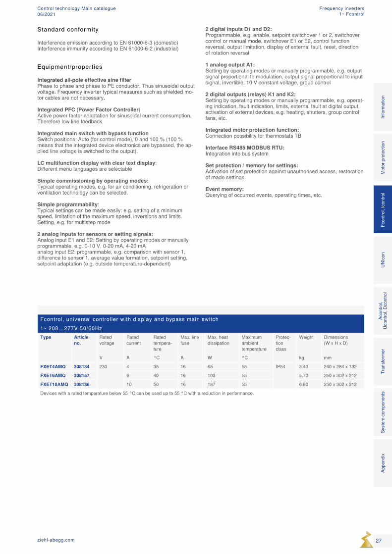
Fcontrol, universal controller with display and bypass main switch1~ 208...277V 50/60HzType Article
no.Rated voltage
Rated current
Rated tempera-ture
Max. line fuse
Max. heat dissipation
Maximum ambient temperature
Protec-tion class
Weight Dimensions (W x H x D)
V A °C A W °C kg mm
FXET4AMQ 308134 230 4 35 16 65 55 IP54 3.40 240 x 284 x 132
FXET6AMQ 308157 6 40 16 103 55 5.70 250 x 302 x 212
FXET10AMQ 308136 10 50 16 187 55 6.80 250 x 302 x 212
Devices with a rated temperature below 55 °C can be used up to 55 °C with a reduction in performance.
Equipment/properties
Integrated all-pole effective sine filter Phase to phase and phase to PE conductor. Thus sinusoidal output voltage. Frequency inverter typical measures such as shielded mo-tor cables are not necessary. Integrated PFC (Power Factor Controller) Active power factor adaptation for sinusoidal current consumption. Therefore low line feedback. Integrated main switch with bypass function Switch positions: Auto (for control mode), 0 and 100 % (100 % means that the integrated device electronics are bypassed, the ap-plied line voltage is switched to the output). LC multifunction display with clear text display: Different menu languages are selectable Simple commissioning by operating modes: Typical operating modes, e.g. for air conditioning, refrigeration or ventilation technology can be selected. Simple programmability: Typical settings can be made easily: e.g. setting of a minimum speed, limitation of the maximum speed, inversions and limits. Setting, e.g. for multistep mode 2 analog inputs for sensors or setting signals: Analog input E1 and E2: Setting by operating modes or manually programmable, e.g. 0-10 V, 0-20 mA, 4-20 mA analog input E2: programmable, e.g. comparison with sensor 1, difference to sensor 1, average value formation, setpoint setting, setpoint adaptation (e.g. outside temperature-dependent)
2 digital inputs D1 and D2: Programmable, e.g. enable, setpoint switchover 1 or 2, switchover control or manual mode, switchover E1 or E2, control function reversal, output limitation, display of external fault, reset, direction of rotation reversal 1 analog output A1: Setting by operating modes or manually programmable, e.g. output signal proportional to modulation, output signal proportional to input signal, invertible, 10 V constant voltage, group control 2 digital outputs (relays) K1 and K2: Setting by operating modes or manually programmable, e.g. operat-ing indication, fault indication, limits, external fault at digital output, activation of external devices, e.g. heating, shutters, group control fans, etc. Integrated motor protection function: Connection possibility for thermostats TB Interface RS485 MODBUS RTU: Integration into bus system Set protection / memory for settings: Activation of set protection against unauthorised access, restoration of made settings Event memory: Querying of occurred events, operating times, etc.
Standard conformity
Interference emission according to EN 61000-6-3 (domestic)Interference immunity according to EN 61000-6-2 (industrial)
27ziehl-abegg.com
Mot
or p
rote
ctio
nFc
ontro
l, Ic
ontro
lUN
Icon
Acon
trol,
Ucon
trol,
Dcon
trol
Tran
sfor
mer
Syst
em c
ompo
nent
sIn
form
atio
nAp
pend
ix
Frequency inverters1~ Fcontrol
Control technology Main catalogue06/2021
NNL1
NL1PENetzLine
1 ~ 208 ... 277 V 50/60 Hz
L1 U1 U1 U2 U2 141211 242221
+
K1 K2
KontaktbelastungContact rating
max. AC 250 V 2 A
A1
GND
E2
GND
E1
GND GND
1 ~ Motor mit eingebauten Thermostatschalternwith internal thermostats
M1 ~
PE U2U1 TBTB
AusgangOutput0...10 V
TB
TB
D1
D1
D2
D2
T2
T1 24V
GND
A2
TF..
TF..1
+AusgangOutput0...10 V
2
Störung / AlarmFault /Indication
HeizungHeating
Klap
peSh
utte
r
Folg
ereg
ler
Slav
e co
ntro
ller
Abte
iltem
pera
tur
Cot t
empe
ratu
re
Anal
og In
2
KTY 81-210PT 1000
UMPO09K102.12.2009
(Imax = 6 mA)
(Imax = 6 mA)
Fcontrol FTET4/6/10AHMQ
Stör
ungs
eing
ang
Faul
t inp
ut
6
3
4 5
1
2
7
8 9
10
100
%
Auto
0 100
%
Auto
0
⑪
⑪
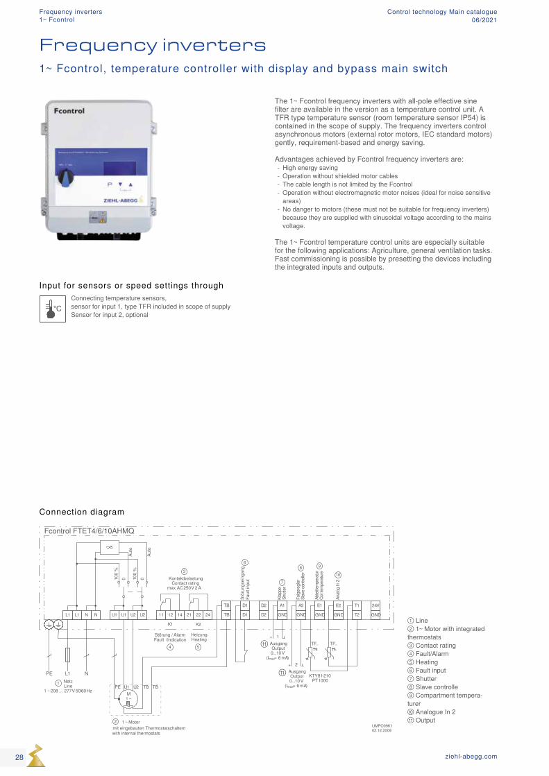
① Line ② 1~ Motor with integrated thermostats ③ Contact rating ④ Fault/Alarm ⑤ Heating ⑥ Fault input ⑦ Shutter ⑧ Slave controlle ⑨ Compartment tempera-turer ⑩ Analogue In 2 ⑪ Output
Input for sensors or speed settings through
°CConnecting temperature sensors, sensor for input 1, type TFR included in scope of supply Sensor for input 2, optional
Frequency inverters1~ Fcontrol, temperature controller with display and bypass main switch
Connection diagram
The 1~ Fcontrol frequency inverters with all-pole effective sine filter are available in the version as a temperature control unit. A TFR type temperature sensor (room temperature sensor IP54) is contained in the scope of supply. The frequency inverters control asynchronous motors (external rotor motors, IEC standard motors) gently, requirement-based and energy saving. Advantages achieved by Fcontrol frequency inverters are:
- High energy saving - Operation without shielded motor cables - The cable length is not limited by the Fcontrol - Operation without electromagnetic motor noises (ideal for noise sensitive areas)
- No danger to motors (these must not be suitable for frequency inverters) because they are supplied with sinusoidal voltage according to the mains voltage.
The 1~ Fcontrol temperature control units are especially suitable for the following applications: Agriculture, general ventilation tasks. Fast commissioning is possible by presetting the devices including the integrated inputs and outputs.
28 ziehl-abegg.com
Frequency inverters1~ Fcontrol
Control technology Main catalogue06/2021
Fcontrol, temperature controller with display and bypass main switch1~ 208...277V 50/60HzType Article
no.Rated voltage
Rated current
Rated tempera-ture
Max. line fuse
Max. heat dissipation
Maximum ambient temperature
Protec-tion class
Weight Dimensions (W x H x D)
V A °C A W °C kg mm
FTET4AHMQ 308131 230 4 35 16 65 55 IP54 3.40 240 x 284 x 132
FTET6AHMQ 308132 6 40 16 103 55 5.70 250 x 302 x 212
FTET10AH-MQ
308133 10 50 16 187 55 6.80 250 x 302 x 212
Devices with a rated temperature below 55 °C can be used up to 55 °C with a reduction in performance.
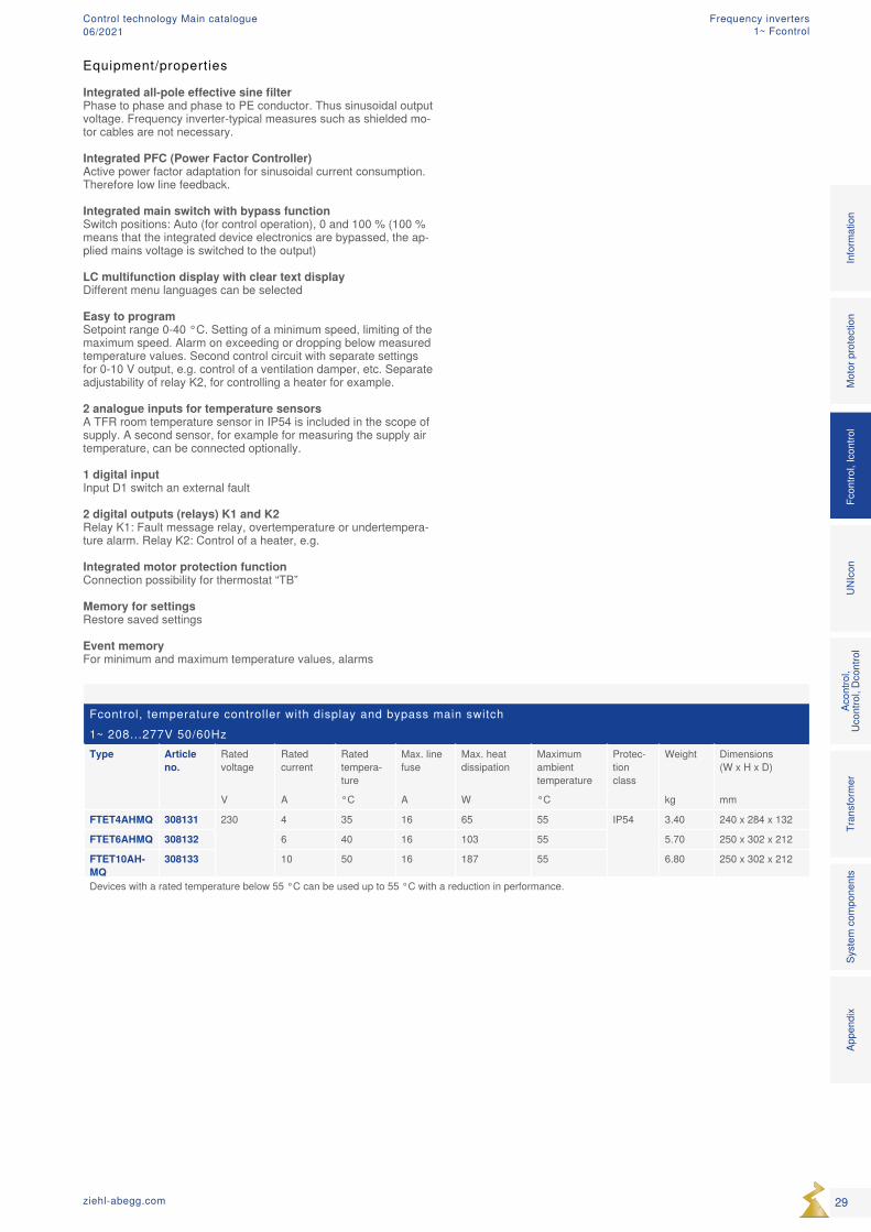
Equipment/properties Integrated all-pole effective sine filter Phase to phase and phase to PE conductor. Thus sinusoidal output voltage. Frequency inverter-typical measures such as shielded mo-tor cables are not necessary. Integrated PFC (Power Factor Controller) Active power factor adaptation for sinusoidal current consumption. Therefore low line feedback. Integrated main switch with bypass function Switch positions: Auto (for control operation), 0 and 100 % (100 % means that the integrated device electronics are bypassed, the ap-plied mains voltage is switched to the output) LC multifunction display with clear text display Different menu languages can be selected Easy to program Setpoint range 0-40 °C. Setting of a minimum speed, limiting of the maximum speed. Alarm on exceeding or dropping below measured temperature values. Second control circuit with separate settings for 0-10 V output, e.g. control of a ventilation damper, etc. Separate adjustability of relay K2, for controlling a heater for example. 2 analogue inputs for temperature sensors A TFR room temperature sensor in IP54 is included in the scope of supply. A second sensor, for example for measuring the supply air temperature, can be connected optionally. 1 digital input Input D1 switch an external fault 2 digital outputs (relays) K1 and K2 Relay K1: Fault message relay, overtemperature or undertempera-ture alarm. Relay K2: Control of a heater, e.g. Integrated motor protection function Connection possibility for thermostat “TB” Memory for settings Restore saved settings Event memory For minimum and maximum temperature values, alarms
29ziehl-abegg.com
Mot
or p
rote
ctio
nFc
ontro
l, Ic
ontro
lUN
Icon
Acon
trol,
Ucon
trol,
Dcon
trol
Tran
sfor
mer
Syst
em c
ompo
nent
sIn
form
atio
nAp
pend
ix
Frequency inverters1~ Fcontrol
Control technology Main catalogue06/2021
M1 ~
U1 U2PE TB
q
1 ~ Motormit eingebauten Thermostatschalternwith internal thermostats
TB
KontaktbelastungContact rating
max. AC 250 V 2 A
UMPO09K204.01.2012
222421
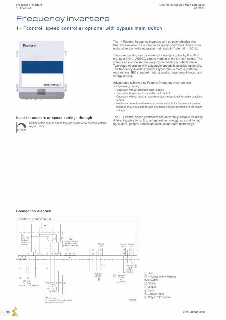
① Line ② 1~ Motor with integrated thermostats ③ Off/On ④ Output ⑤ Input ⑥ Contact rating ⑦ Only in “Q”-Devices
Input for sensors or speed settings through
0-10V
Setting of the desired speed through device or by external default, e.g. 0…10 V
Frequency inverters1~ Fcontrol, speed controller optional with bypass main switch
Connection diagram
The 1~ Fcontrol frequency inverters with all-pole effective sine filter are available in the version as speed controllers. There is an optional version with integrated main switch (Auto – 0 – 100%). The speed setting can be made by a master control by 0 – 10 V, e.g. by a ZIEHL-ABEGG control module of the UNIcon series. The speed can also be set manually by connecting a potentiometer. Two-stage operation with adjustable speeds is possible optionally. The frequency inverters control asynchronous motors (external rotor motors, IEC standard motors) gently, requirement-based and energy saving. Advantages achieved by Fcontrol frequency inverters are:
- High energy saving - Operation without shielded motor cables - The cable length is not limited by the Fcontrol - Operation without electromagnetic motor noises (ideal for noise sensitive areas)
- No danger to motors (these must not be suitable for frequency inverters) because they are supplied with sinusoidal voltage according to the mains voltage.
The 1~ Fcontrol speed controllers are universally suitable for many different applications: E.g. refrigerant technology, air conditioning, agriculture, general ventilation tasks, clean room technology.
30 ziehl-abegg.com
Frequency inverters1~ Fcontrol
Control technology Main catalogue06/2021
Fcontrol as speed controller1~ 208...277V 50/60HzInput Type Article
no.Rated voltage
Rated current
Rated tem-perature
Max. line fuse
Max. heat dissipation
Maximum ambient tempera-ture
Protec-tion class
Weight Dimensions (W x H x D)
V A °C A W °C kg mm
0-10 V FSET4M 308128 230 4 35 16 65 55 IP54 3.20 240 x 284 x 115
FSET6M 308156 6 40 16 103 55 5.50 250 x 302 x 195.5
FSET10M 308130 10 50 16 187 55 6.60 250 x 302 x 195.5
FSET4MQ 308154 4 35 16 65 55 3.30 240 x 284 x 132
FSET6MQ 308155 6 40 16 103 55 5.60 250 x 302 x 212
FSET10MQ 308187 10 50 16 187 55 6.70 250 x 302 x 212
10-0 V FSET4M 308158 4 35 16 65 55 3.20 240 x 284 x 115
FSET6M 308159 6 40 16 103 55 5.50 250 x 302 x 195.5
FSET10M 308160 10 50 16 187 55 6.60 250 x 302 x 195.5
Devices with a rated temperature below 55 °C can be used up to 55 °C with a reduction in performance.
Optional equipment
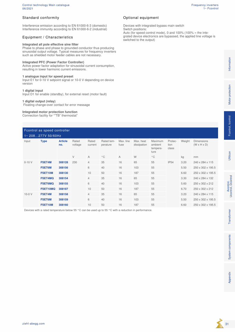
Devices with integrated bypass main switch Switch positions: Auto (for speed control mode), 0 and 100% (100% = the inte-grated device electronics are bypassed, the applied line voltage is switched to the output)
Standard conformity
Interference emission according to EN 61000-6-3 (domestic)Interference immunity according to EN 61000-6-2 (industrial)
Equipment / Characteristics Integrated all pole effective sine filter Phase to phase and phase to grounded conductor thus producing sinusoidal output voltage. Typical measures for frequency inverters such as shielded motor feeder cables are not necessary. Integrated PFC (Power Factor Controller) Active power factor adaptation for sinusoidal current consumption, resulting in lower harmonic current emissions. 1 analogue input for speed preset Input E1 for 0-10 V setpoint signal or 10-0 V depending on device version 1 digital input Input D1 for enable (standby), for external reset (motor fault) 1 digital output (relay) Floating change-over contact for error message Integrated motor protection function Connection facility for “”TB” thermostat”
31ziehl-abegg.com
Mot
or p
rote
ctio
nFc
ontro
l, Ic
ontro
lUN
Icon
Acon
trol,
Ucon
trol,
Dcon
trol
Tran
sfor
mer
Syst
em c
ompo
nent
sIn
form
atio
nAp
pend
ix
Frequency inverters1~ Fcontrol
Control technology Main catalogue06/2021
Input for sensors or speed settings through
0-10V
Setting of the desired speed through device or by external default, e.g. 0…10 V
0-300-50bar
Connecting pressure sensors (refrigeration), e.g. type MBG.. sensors, measuring range 0...30 bar, 0...50 bar
°CConnection of thermistors, e. g. sensors type TF.. e. g. active sensor type MTG..
PaConnecting differential pressure sensors (air conditioning), e.g. type MPG.. sensors, measuring range 0...6000 Pa, acquisition of volume flows up to 65000 m3/h
m / sConnecting air velocity sensors, e.g. type MAL.. sensors, measuring range 0...1 m/s, 0...10 m/s
CO2
%
°C
Connecting additional sensors, e.g. combination sensors, CO2, sensor signal 0...10 V / 0...20 mA / 4...20 mA
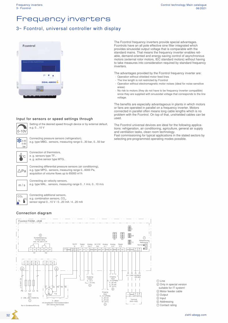
① Line ② Only in special version suitable for IT system! ③ Motor feeder cable ④ Output ⑤ Input ⑥ Addressing ⑦ Contact rating
The Fcontrol frequency inverters provide special advantages. Fcontrols have an all pole effective sine filter integrated which provides sinusoidal output voltage that is comparable with the standard mains. That means the frequency inverter enables reli-able, demand-oriented and energy-saving control of asynchronous motors (external rotor motors, IEC standard motors) without having to take measures into consideration required by standard frequency inverters. The advantages provided by the Fcontrol frequency inverter are:
- Operation without shielded motor feed lines - The line length is not restricted by Fcontrol - Operation without electromagnetic motor noises (ideal for noise sensitive areas)
- No risk to motors (they do not have to be frequency inverter compatible) since they are supplied with sinusoidal voltage that corresponds to the line voltage.
The benefits are especially advantageous in plants in which motors or fans are operated in parallel on a frequency inverter. Motors connected in parallel often means long cable lengths which is no problem with the Fcontrol. On top of that, unshielded cables can be used. The Fcontrol universal devices are ideal for the following applica-tions: refrigeration, air conditioning, agriculture, general air supply and ventilation tasks, clean room technology. Fast commissioning for typical applications in the stated sectors by selecting pre-programmed operating modes possible.
Connection diagram
Frequency inverters3~ Fcontrol, universal controller with display
32 ziehl-abegg.com
Frequency inverters3~ Fcontrol
Control technology Main catalogue06/2021
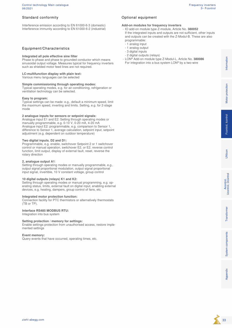
Equipment/Characteristics Integrated all pole effective sine filter Phase to phase and phase to grounded conductor which means sinusoidal output voltage. Measures typical for frequency inverters such as shielded motor feed lines are not required. LC-multifunction display with plain text: Various menu languages can be selected Simple commissioning through operating modes: Typical operating modes, e.g. for air-conditioning, refrigeration or ventilation technology can be selected. Easy to program: Typical settings can be made: e.g., default a minimum speed, limit the maximum speed, inverting and limits. Setting, e.g. for 2-stage mode 2 analogue inputs for sensors or setpoint signals: Analogue input E1 and E2: Setting through operating modes or manually programmable, e.g. 0-10 V, 0-20 mA, 4-20 mA Analogue input E2: programmable, e.g. comparison to Sensor 1, difference to Sensor 1, average calculation, setpoint input, setpoint adjustment (e.g. dependent on outdoor temperature) Two digital inputs. D2 and D1: Programmable, e.g. enable, switchover Setpoint 2 or 1 switchover control or manual operation, switchover E2, or E2, reverse control function, limit output, display of external fault, reset, reverse the rotary direction 2, analogue output A1: Setting through operating modes or manually programmable, e.g., output signal proportional modulation, output signal proportional input signal, invertible, 10 V constant voltage, group control 10 digital outputs (relays) K1 and K2: Setting through operating modes or manual programming, e.g. op-erating status, limits, external fault on digital input, enabling external devices, e.g. heating, dampers, group control of fans, etc. Integrated motor protection function: Connection facility for PTC thermistors or alternatively thermostats (TB or TP). Interface RS485 MODBUS RTU: Integration into bus system Setting protection / memory for settings: Enable settings protection from unauthorised access, restore imple-mented settings Event memory: Query events that have occurred, operating times, etc.
Optional equipment
Add-on modules for frequency inverters - IO add-on module type Z-module, Article No. 380052 If the integrated inputs and outputs are not sufficient, other inputs and outputs can be created with the Z-Modul-B. These are also programmable: - 1 analog input - 1 analog output - 3 digital inputs - 2 digital outputs (relays)
- LON® Add-on module type Z-Modul-L, Article No. 380086 For integration into a bus system LON® by a two-wire
Mot
or p
rote
ctio
nFc
ontro
l, Ic
ontro
lUN
Icon
Acon
trol,
Ucon
trol,
Dcon
trol
Tran
sfor
mer
Syst
em c
ompo
nent
sIn
form
atio
nAp
pend
ix
33ziehl-abegg.com
Standard conformity
Interference emission according to EN 61000-6-3 (domestic)Interference immunity according to EN 61000-6-2 (industrial)
Frequency inverters3~ Fcontrol
Control technology Main catalogue06/2021
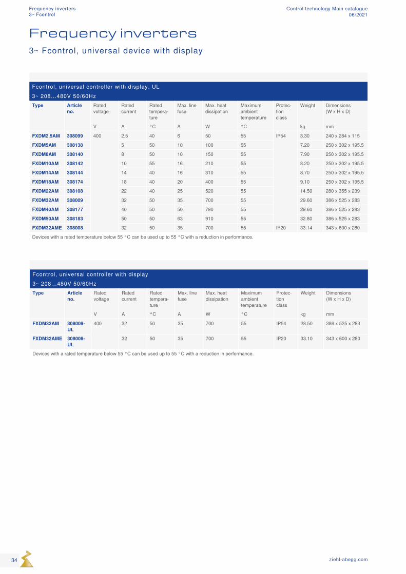
Fcontrol, universal controller with display, UL3~ 208...480V 50/60HzType Article
no.Rated voltage
Rated current
Rated tempera-ture
Max. line fuse
Max. heat dissipation
Maximum ambient temperature
Protec-tion class
Weight Dimensions (W x H x D)
V A °C A W °C kg mm
FXDM2.5AM 308099 400 2.5 40 6 50 55 IP54 3.30 240 x 284 x 115
FXDM5AM 308138 5 50 10 100 55 7.20 250 x 302 x 195.5
FXDM8AM 308140 8 50 10 150 55 7.90 250 x 302 x 195.5
FXDM10AM 308142 10 55 16 210 55 8.20 250 x 302 x 195.5
FXDM14AM 308144 14 40 16 310 55 8.70 250 x 302 x 195.5
FXDM18AM 308174 18 40 20 400 55 9.10 250 x 302 x 195.5
FXDM22AM 308108 22 40 25 520 55 14.50 280 x 355 x 239
FXDM32AM 308009 32 50 35 700 55 29.60 386 x 525 x 283
FXDM40AM 308177 40 50 50 790 55 29.60 386 x 525 x 283
FXDM50AM 308183 50 50 63 910 55 32.80 386 x 525 x 283
FXDM32AME 308008 32 50 35 700 55 IP20 33.14 343 x 600 x 280
Devices with a rated temperature below 55 °C can be used up to 55 °C with a reduction in performance.
Fcontrol, universal controller with display3~ 208...480V 50/60HzType Article
no.Rated voltage
Rated current
Rated tempera-ture
Max. line fuse
Max. heat dissipation
Maximum ambient temperature
Protec-tion class
Weight Dimensions (W x H x D)
V A °C A W °C kg mm
FXDM32AM 308009-UL
400 32 50 35 700 55 IP54 28.50 386 x 525 x 283
FXDM32AME 308008-UL
32 50 35 700 55 IP20 33.10 343 x 600 x 280
Devices with a rated temperature below 55 °C can be used up to 55 °C with a reduction in performance.
Frequency inverters3~ Fcontrol, universal device with display
34 ziehl-abegg.com
Frequency inverters3~ Fcontrol
Control technology Main catalogue06/2021
35ziehl-abegg.com
Mot
or p
rote
ctio
nFc
ontro
l, Ic
ontro
lUN
Icon
Acon
trol,
Ucon
trol,
Dcon
trol
Tran
sfor
mer
Syst
em c
ompo
nent
sIn
form
atio
nAp
pend
ix
Frequency inverters3~ Fcontrol
Control technology Main catalogue06/2021
MCUN14K011.02.2014
11 14 12 21 24 22 TB/TP
TB/TP D1 D1 A GND 24V 24V E1 GND GNDE2 D2 D2
L3L2L1PE
L1 L2 L3
U V W
NetzLine
3 ~ 208...480 V 50/60 Hz1
≥ 10
mm
² / 2
x
Nur in Sonderausführungfür IT-System geeignet!Only in special versionsuitable for IT-System!
2
K1 K2
Fcontrol FXDM...(A)M
KontaktbelastungContact rating
max. AC 250 V 2 A
11
EingangInput
0...10 V(PWM)0...20 mA4...20 mA
+
6
1
EingangInput
0...10 V(PWM)0...20 mA4...20 mA
+
7
2
AusgangOutput0...10 V
(Imax = 10 mA)
+
5
TB/TPIn
DigitalIn 1
AnalogOut 1
DigitalIn 2
AnalogIn 1
AnalogIn 2
24 V DCOut
M3 ~
U V W PE TB
Y/Δq
3 ~ Motormit eingebauten Thermostatschaltern
with internal thermostats3
TB
24V GND
MODBUS(RS-485)
GND24 V
A(D+)
B(D-) ID2
24V GND A(D+)
B(D-) ID1
Addressing
T T
TFIn 1/2
USB(Mini-B)
Serviceparameter load
q
TF..KTY 81-210PT 1000
J110
9
q
TF..Digital
EingangDigitalInput
4
1 2
DigitalEingangDigitalInput
8
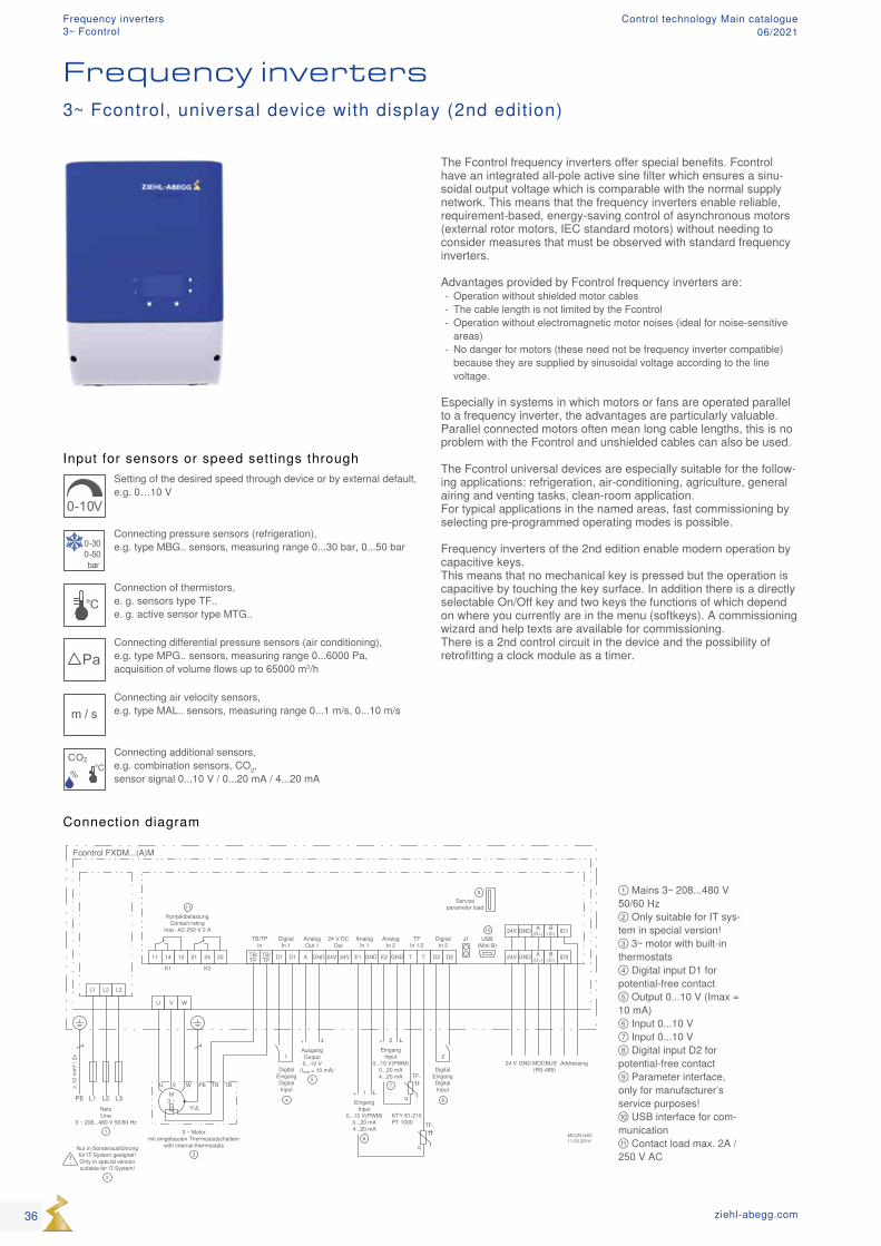
Input for sensors or speed settings through
0-10V
Setting of the desired speed through device or by external default, e.g. 0…10 V
0-300-50bar
Connecting pressure sensors (refrigeration), e.g. type MBG.. sensors, measuring range 0...30 bar, 0...50 bar
°CConnection of thermistors, e. g. sensors type TF.. e. g. active sensor type MTG..
PaConnecting differential pressure sensors (air conditioning), e.g. type MPG.. sensors, measuring range 0...6000 Pa, acquisition of volume flows up to 65000 m3/h
m / sConnecting air velocity sensors, e.g. type MAL.. sensors, measuring range 0...1 m/s, 0...10 m/s
CO2
%
°C
Connecting additional sensors, e.g. combination sensors, CO2, sensor signal 0...10 V / 0...20 mA / 4...20 mA
① Mains 3~ 208...480 V 50/60 Hz ② Only suitable for IT sys-tem in special version! ③ 3~ motor with built-in thermostats ④ Digital input D1 for potential-free contact ⑤ Output 0...10 V (Imax = 10 mA) ⑥ Input 0...10 V ⑦ Input 0...10 V ⑧ Digital input D2 for potential-free contact ⑨ Parameter interface, only for manufacturer’s service purposes! ⑩ USB interface for com-munication ⑪ Contact load max. 2A / 250 V AC
Connection diagram
Frequency inverters
The Fcontrol frequency inverters offer special benefits. Fcontrol have an integrated all-pole active sine filter which ensures a sinu-soidal output voltage which is comparable with the normal supply network. This means that the frequency inverters enable reliable, requirement-based, energy-saving control of asynchronous motors (external rotor motors, IEC standard motors) without needing to consider measures that must be observed with standard frequency inverters. Advantages provided by Fcontrol frequency inverters are:
- Operation without shielded motor cables - The cable length is not limited by the Fcontrol - Operation without electromagnetic motor noises (ideal for noise-sensitive areas)
- No danger for motors (these need not be frequency inverter compatible) because they are supplied by sinusoidal voltage according to the line voltage.
Especially in systems in which motors or fans are operated parallel to a frequency inverter, the advantages are particularly valuable. Parallel connected motors often mean long cable lengths, this is no problem with the Fcontrol and unshielded cables can also be used. The Fcontrol universal devices are especially suitable for the follow-ing applications: refrigeration, air-conditioning, agriculture, general airing and venting tasks, clean-room application. For typical applications in the named areas, fast commissioning by selecting pre-programmed operating modes is possible. Frequency inverters of the 2nd edition enable modern operation by capacitive keys. This means that no mechanical key is pressed but the operation is capacitive by touching the key surface. In addition there is a directly selectable On/Off key and two keys the functions of which depend on where you currently are in the menu (softkeys). A commissioning wizard and help texts are available for commissioning. There is a 2nd control circuit in the device and the possibility of retrofitting a clock module as a timer.
3~ Fcontrol, universal device with display (2nd edition)
36 ziehl-abegg.com
Frequency inverters3~ Fcontrol
Control technology Main catalogue06/2021
Fcontrol, universal controller with display, 2nd edition3~ 208...480V 50/60HzType Article
no.Rated voltage
Rated current
Rated tempera-ture
Max. line fuse
Max. heat dissipation
Maximum ambient temperature
Protec-tion class
Weight Dimensions (W x H x D)
V A °C A W °C kg mm
FXDM25AM 308289 400 25 55 35 550 55 IP54 21.50 279 x 405 x 260
FXDM32AM 308283 32 50 35 700 55 23.10 279 x 405 x 260
Devices with a rated temperature below 55 °C can be used up to 55 °C with a reduction in performance.
Optional equipment
Add-on modules for frequency inverters - IO add-on module type Z-module, Article No. 380052 If the integrated inputs and outputs are not sufficient, other inputs and outputs can be created with the Z-Modul-B. These are also programmable: - 1 analog input - 1 analog output - 3 digital inputs - 2 digital outputs (relays)
- Clock module Z-Modul-RTC, Article No. 380056, for retrofitting real-time clock and timer function. The switching clock can be as-signed the same functions are the digital inputs (D1 and D2).
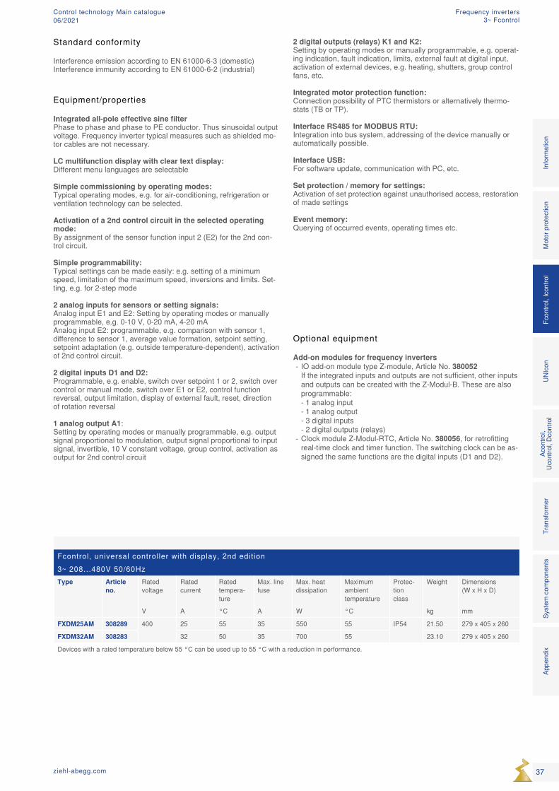
Equipment/properties Integrated all-pole effective sine filter Phase to phase and phase to PE conductor. Thus sinusoidal output voltage. Frequency inverter typical measures such as shielded mo-tor cables are not necessary. LC multifunction display with clear text display: Different menu languages are selectable Simple commissioning by operating modes: Typical operating modes, e.g. for air-conditioning, refrigeration or ventilation technology can be selected. Activation of a 2nd control circuit in the selected operating mode: By assignment of the sensor function input 2 (E2) for the 2nd con-trol circuit. Simple programmability: Typical settings can be made easily: e.g. setting of a minimum speed, limitation of the maximum speed, inversions and limits. Set-ting, e.g. for 2-step mode 2 analog inputs for sensors or setting signals: Analog input E1 and E2: Setting by operating modes or manually programmable, e.g. 0-10 V, 0-20 mA, 4-20 mA Analog input E2: programmable, e.g. comparison with sensor 1, difference to sensor 1, average value formation, setpoint setting, setpoint adaptation (e.g. outside temperature-dependent), activation of 2nd control circuit. 2 digital inputs D1 and D2: Programmable, e.g. enable, switch over setpoint 1 or 2, switch over control or manual mode, switch over E1 or E2, control function reversal, output limitation, display of external fault, reset, direction of rotation reversal 1 analog output A1: Setting by operating modes or manually programmable, e.g. output signal proportional to modulation, output signal proportional to input signal, invertible, 10 V constant voltage, group control, activation as output for 2nd control circuit
2 digital outputs (relays) K1 and K2: Setting by operating modes or manually programmable, e.g. operat-ing indication, fault indication, limits, external fault at digital input, activation of external devices, e.g. heating, shutters, group control fans, etc. Integrated motor protection function: Connection possibility of PTC thermistors or alternatively thermo-stats (TB or TP). Interface RS485 for MODBUS RTU: Integration into bus system, addressing of the device manually or automatically possible. Interface USB: For software update, communication with PC, etc. Set protection / memory for settings: Activation of set protection against unauthorised access, restoration of made settings Event memory: Querying of occurred events, operating times etc.
Mot
or p
rote
ctio
nFc
ontro
l, Ic
ontro
lUN
Icon
Acon
trol,
Ucon
trol,
Dcon
trol
Tran
sfor
mer
Syst
em c
ompo
nent
sIn
form
atio
nAp
pend
ix
37ziehl-abegg.com
Standard conformity
Interference emission according to EN 61000-6-3 (domestic)Interference immunity according to EN 61000-6-2 (industrial)
Frequency inverters3~ Fcontrol
Control technology Main catalogue06/2021
MCUN14K217.09.2014
11 14 12 21 24 22 TB/TP
TB/TP D1 D1 A GND 24V 24V E1 GND GNDE2 D2 D2
L3L2L1PE
L1 L2 L3
U V W
NetzLine
3 ~ 208...480 V 50/60 Hz1
≥ 10
mm
² / 2
x
Nur in Sonderausführungfür IT-System geeignet!Only in special versionsuitable for IT-System!
2
K1 K2
Fcontrol FKDM...AM-C
KontaktbelastungContact rating
max. AC 250 V 2 A
12
EingangInput
0...10 V(PWM)0...20 mA4...20 mA
+
7
1
EingangInput
0...10 V(PWM)0...20 mA4...20 mA
+
8
2
AusgangOutput0...10 V
(Imax = 10 mA)
+
5
TB/TPIn
DigitalIn 1*
AnalogOut 1*
DigitalIn 2*
AnalogIn 1*
AnalogIn 2*
24 V DCOut
24V GND
MODBUS(RS-485)
GND24 V
A(D+)
B(D-) ID2
24V GND A(D+)
B(D-) ID1
Addressing
0 1
T T
TFIn 1/2
USB(Mini-B)
Serviceparameter load
J110
11
Aus / EinOff / On
4
Mode 3.10 - 3.210 = Auto Sensor E11 = 0...10 V Man. E2
9
M3 ~
U V W PE TP
Y/Δ
3 ~ Motormit eingebauten Temperaturfühlern
with internal thermistors3
TP
q
1 3BN GN
MBG..
4...20 mA
DrucksensorPressure sensor
6
01
① Line ② Only suitable for IT sys-tem in special version! ③ 3~ motor with built-in thermostats ④ Off / On ⑤ Output ⑥ - ⑧ Input ⑨ Mode 3.10 - 3.21 ⑩ USB interface ⑪ Adressing ⑫ Contact load
Input for sensors or speed settings through
0-10V
Setting of the desired speed through device or by external default, e.g. 0…10 V
0-300-50bar
Connection of pressure sensors (refrigerant)
Connection diagram
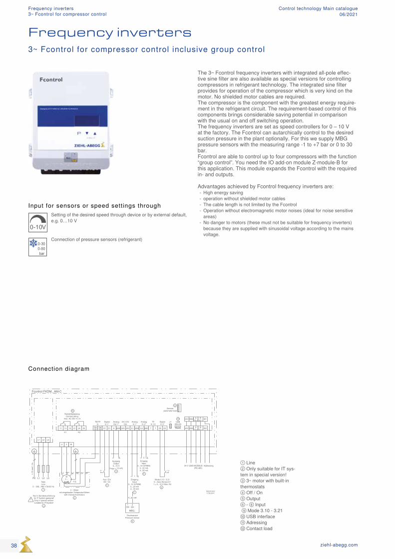
The 3~ Fcontrol frequency inverters with integrated all-pole effec-tive sine filter are also available as special versions for controlling compressors in refrigerant technology. The integrated sine filter provides for operation of the compressor which is very kind on the motor. No shielded motor cables are required. The compressor is the component with the greatest energy require-ment in the refrigerant circuit. The requirement-based control of this components brings considerable saving potential in comparison with the usual on and off switching operation. The frequency inverters are set as speed controllers for 0 – 10 V at the factory. The Fcontrol can autarchically control to the desired suction pressure in the plant optionally. For this we supply MBG pressure sensors with the measuring range -1 to +7 bar or 0 to 30 bar. Fcontrol are able to control up to four compressors with the function “group control”. You need the IO add-on module Z-module-B for this application. This module expands the Fcontrol with the required in- and outputs. Advantages achieved by Fcontrol frequency inverters are:
- High energy saving - operation without shielded motor cables - The cable length is not limited by the Fcontrol - Operation without electromagnetic motor noises (ideal for noise sensitive areas)
- No danger to motors (these must not be suitable for frequency inverters) because they are supplied with sinusoidal voltage according to the mains voltage.
3~ Fcontrol for compressor control inclusive group control
Frequency inverters
38 ziehl-abegg.com
Frequency inverters3~ Fcontrol for compressor control
Control technology Main catalogue06/2021
Equipment/properties
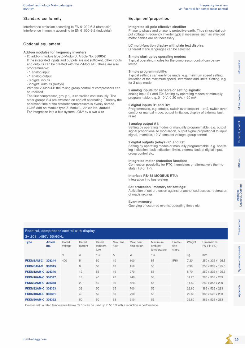
Integrated all-pole effective sinefilter Phase to phase and phase to protective earth. Thus sinusoidal out-put voltage. Frequency inverter typical measures such as shielded motor cables are not necessary. LC multi-function display with plain text display: Different menu languages can be selected Simple start-up by operating modes: Typical operating modes for the compressor control can be se-lected. Simple programmability: Typical settings can easily be made: e.g. minimum speed setting, limitation of the maximum speed, inversions and limits. Setting, e.g. for 2-step mode 2 analog inputs for sensors or setting signals: analog input E1 and E2: Setting by operating modes or manually programmable, e.g. 0-10 V, 0-20 mA, 4-20 mA 2 digital inputs D1 and D2: Programmable, e.g. enable, switch over setpoint 1 or 2, switch over control or manual mode, output limitation, display of external fault, reset 1 analog output A1: Setting by operating modes or manually programmable, e.g. output signal proportional to modulation, output signal proportional to input signal, invertible, 10 V constant voltage, group control 2 digital outputs (relays) K1 and K2: Setting by operating modes or manually programmable, e.g. operat-ing indication, fault indication, limits, external fault at digital input, group control etc. Integrated motor protection function: Connection possibility for PTC thermistors or alternatively thermo-stats (TB or TP). Interface RS485 MODBUS RTU: Integration into bus system Set protection / memory for settings: Activation of set protection against unauthorised access, restoration of made settings Event memory: Querying of occurred events, operating times etc.
Optional equipment
Add-on modules for frequency inverters - IO add-on module type Z-Modul-B, Article No. 380052 If the integrated inputs and outputs are not sufficient, other inputs and outputs can be created with the Z-Modul-B. These are also programmable: - 1 analog input - 1 analog output - 3 digital inputs - 2 digital outputs (relays)
- With the Z-Modul-B the rolling group control of compressors can be realized. The first compressor, group 1, is controlled continuously. The other groups 2-4 are switched on and off alternating. Thereby the operation time of the different compressors is evenly spread.
- LON® Add-on module type Z-Modul-L, Article No. 380086 For integration into a bus system LON® by a two-wire
Standard conformity
Interference emission according to EN 61000-6-3 (domestic)Interference immunity according to EN 61000-6-2 (industrial)
Fcontrol, compressor control with display3~ 208...480V 50/60HzType Article
no.Rated voltage
Rated current
Rated tempera-ture
Max. line fuse
Max. heat dissipation
Maximum ambient temperature
Protec-tion class
Weight Dimensions (W x H x D)
V A °C A W °C kg mm
FKDM5AM-C 308344 400 5 50 10 100 55 IP54 7.20 250 x 302 x 195.5
FKDM8AM-C 308345 8 50 10 150 55 7.90 250 x 302 x 195.5
FKDM12AM-C 308346 12 55 16 270 55 8.70 250 x 302 x 195.5
FKDM18AM-C 308347 18 40 20 440 55 14.20 280 x 355 x 239
FKDM22AM-C 308348 22 40 25 520 55 14.50 280 x 355 x 239
FKDM32AM-C 308353 32 50 35 700 55 29.60 386 x 525 x 283
FKDM40AM-C 308351 40 50 50 790 55 29.60 386 x 525 x 283
FKDM50AM-C 308352 50 50 63 910 55 32.80 386 x 525 x 283
Devices with a rated temperature below 55 °C can be used up to 55 °C with a reduction in performance.
Mot
or p
rote
ctio
nFc
ontro
l, Ic
ontro
lUN
Icon
Acon
trol,
Ucon
trol,
Dcon
trol
Tran
sfor
mer
Syst
em c
ompo
nent
sIn
form
atio
nAp
pend
ix
39ziehl-abegg.com
Frequency inverters3~ Fcontrol for compressor control
Control technology Main catalogue06/2021
MCUN14K217.09.2014
11 14 12 21 24 22 TB/TP
TB/TP D1 D1 A GND 24V 24V E1 GND GNDE2 D2 D2
L3L2L1PE
L1 L2 L3
U V W
NetzLine
3 ~ 208...480 V 50/60 Hz1
≥ 10
mm
² / 2
x
Nur in Sonderausführungfür IT-System geeignet!Only in special versionsuitable for IT-System!
2
K1 K2
Fcontrol FKDM...AM-C
KontaktbelastungContact rating
max. AC 250 V 2 A
12
EingangInput
0...10 V(PWM)0...20 mA4...20 mA
+
7
1
EingangInput
0...10 V(PWM)0...20 mA4...20 mA
+
8
2
AusgangOutput0...10 V
(Imax = 10 mA)
+
5
TB/TPIn
DigitalIn 1*
AnalogOut 1*
DigitalIn 2*
AnalogIn 1*
AnalogIn 2*
24 V DCOut
24V GND
MODBUS(RS-485)
GND24 V
A(D+)
B(D-) ID2
24V GND A(D+)
B(D-) ID1
Addressing
0 1
T T
TFIn 1/2
USB(Mini-B)
Serviceparameter load
J110
11
Aus / EinOff / On
4
Mode 3.10 - 3.210 = Auto Sensor E11 = 0...10 V Man. E2
9
M3 ~
U V W PE TP
Y/Δ
3 ~ Motormit eingebauten Temperaturfühlern
with internal thermistors3
TP
q
1 3BN GN
MBG..
4...20 mA
DrucksensorPressure sensor
6
01
① Line ② Only suitable for IT system in special version! ③ 3~ motor with built-in thermostats ④ Off / On ⑤ Output ⑥ - ⑧ Input ⑨ Mode 3.10 - 3.21 ⑩ USB interface ⑪ Adressing ⑫ Contact load
Input for sensors or speed settings through
0-10V
Setting of the desired speed through device or by external default, e.g. 0…10 V
0-300-50bar
Connection of pressure sensors (refrigerant)
Connection diagram
Frequency inverters
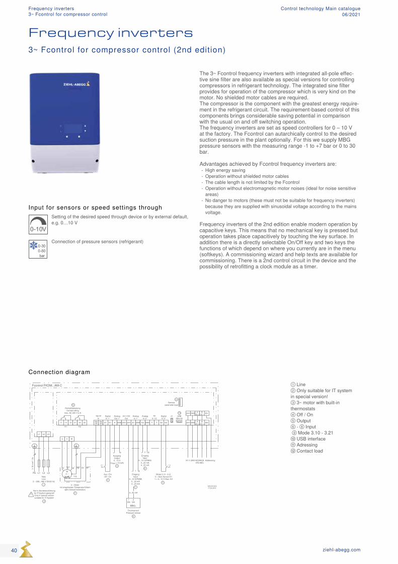
The 3~ Fcontrol frequency inverters with integrated all-pole effec-tive sine filter are also available as special versions for controlling compressors in refrigerant technology. The integrated sine filter provides for operation of the compressor which is very kind on the motor. No shielded motor cables are required. The compressor is the component with the greatest energy require-ment in the refrigerant circuit. The requirement-based control of this components brings considerable saving potential in comparison with the usual on and off switching operation. The frequency inverters are set as speed controllers for 0 – 10 V at the factory. The Fcontrol can autarchically control to the desired suction pressure in the plant optionally. For this we supply MBG pressure sensors with the measuring range -1 to +7 bar or 0 to 30 bar. Advantages achieved by Fcontrol frequency inverters are:
- High energy saving - Operation without shielded motor cables - The cable length is not limited by the Fcontrol - Operation without electromagnetic motor noises (ideal for noise sensitive areas)
- No danger to motors (these must not be suitable for frequency inverters) because they are supplied with sinusoidal voltage according to the mains voltage.
Frequency inverters of the 2nd edition enable modern operation by capacitive keys. This means that no mechanical key is pressed but operation takes place capacitively by touching the key surface. In addition there is a directly selectable On/Off key and two keys the functions of which depend on where you currently are in the menu (softkeys). A commissioning wizard and help texts are available for commissioning. There is a 2nd control circuit in the device and the possibility of retrofitting a clock module as a timer.
3~ Fcontrol for compressor control (2nd edition)
40 ziehl-abegg.com
Frequency inverters3~ Fcontrol for compressor control
Control technology Main catalogue06/2021
Fcontrol for compressor control3~ 208...480V 50/60HzType Article
no.Rated voltage
Rated current
Rated tempera-ture
Max. line fuse
Max. heat dissipation
Maximum ambient temperature
Protec-tion class
Weight Dimensions (W x H x D)
V A °C A W °C kg mm
FKDM25AM-C 308290 400 25 55 35 550 55 IP54 21.50 279 x 405 x 260
FKDM32AM-C 308284 32 50 35 700 55 23.10 279 x 405 x 260
Devices with a rated temperature below 55 °C can be used up to 55 °C with a reduction in performance.
Optional equipment
Add-on modules for frequency inverters- IO add-on module type Z-module, Article No. 380052
If the integrated inputs and outputs are not sufficient, other inputsand outputs can be created with the Z-module-B. These are alsoprogrammable:- 1 analog input- 1 analog output- 3 digital inputs- 2 digital outputs (relays)
- Clock module Z-module-RTC, Article No. 380056, for retrofittingreal-time clock and timer function. The switching clock can be as-signed the same functions are the digital inputs (D1...D2).
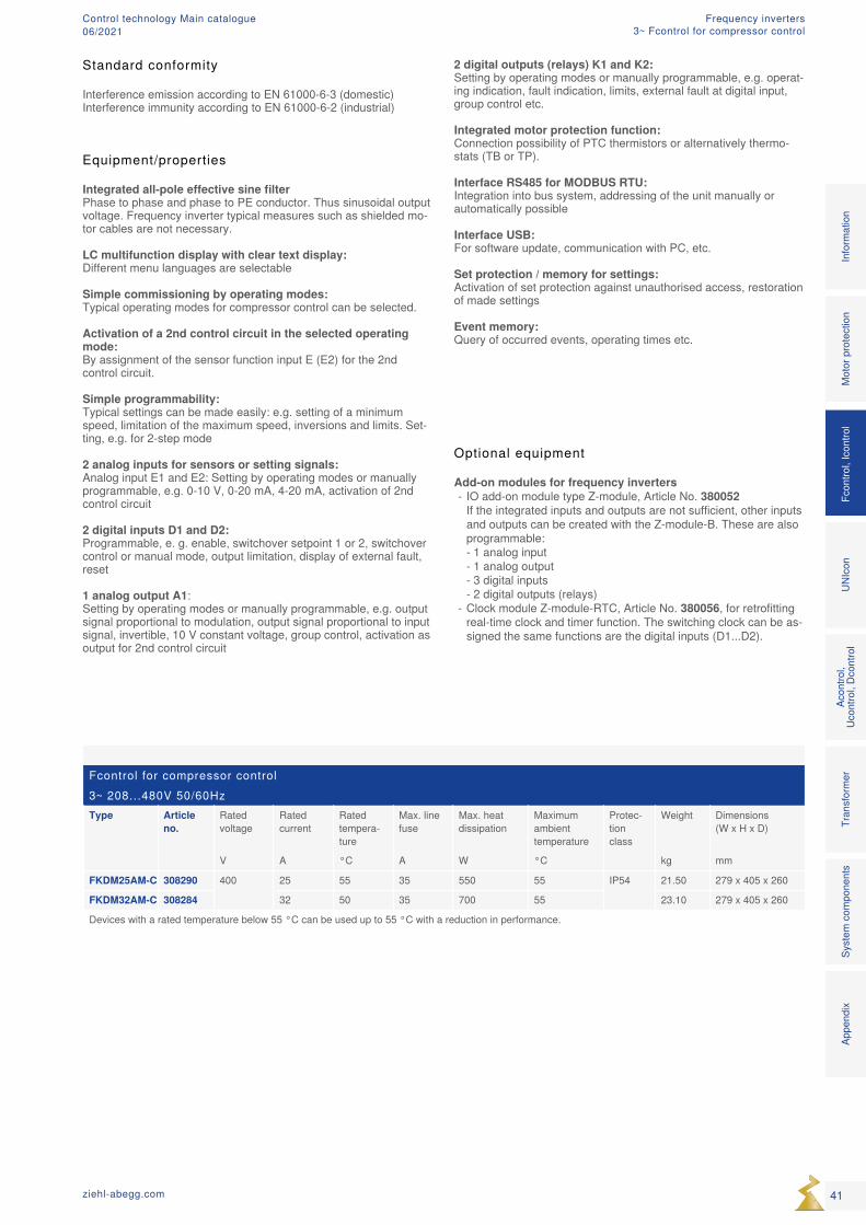
Equipment/properties
Integrated all-pole effective sine filter Phase to phase and phase to PE conductor. Thus sinusoidal output voltage. Frequency inverter typical measures such as shielded mo-tor cables are not necessary.
LC multifunction display with clear text display: Different menu languages are selectable
Simple commissioning by operating modes: Typical operating modes for compressor control can be selected.
Activation of a 2nd control circuit in the selected operating mode: By assignment of the sensor function input E (E2) for the 2nd control circuit.
Simple programmability: Typical settings can be made easily: e.g. setting of a minimum speed, limitation of the maximum speed, inversions and limits. Set-ting, e.g. for 2-step mode
2 analog inputs for sensors or setting signals: Analog input E1 and E2: Setting by operating modes or manually programmable, e.g. 0-10 V, 0-20 mA, 4-20 mA, activation of 2nd control circuit
2 digital inputs D1 and D2: Programmable, e. g. enable, switchover setpoint 1 or 2, switchover control or manual mode, output limitation, display of external fault, reset
1 analog output A1: Setting by operating modes or manually programmable, e.g. output signal proportional to modulation, output signal proportional to input signal, invertible, 10 V constant voltage, group control, activation as output for 2nd control circuit
2 digital outputs (relays) K1 and K2: Setting by operating modes or manually programmable, e.g. operat-ing indication, fault indication, limits, external fault at digital input, group control etc.
Integrated motor protection function: Connection possibility of PTC thermistors or alternatively thermo-stats (TB or TP).
Interface RS485 for MODBUS RTU: Integration into bus system, addressing of the unit manually or automatically possible
Interface USB: For software update, communication with PC, etc.
Set protection / memory for settings: Activation of set protection against unauthorised access, restoration of made settings
Event memory: Query of occurred events, operating times etc.
Mot
or p
rote
ctio
nFc
ontro
l, Ic
ontro
lUN
Icon
Acon
trol,
Ucon
trol,
Dcon
trol
Tran
sfor
mer
Syst
em c
ompo
nent
sIn
form
atio
nAp
pend
ix
41ziehl-abegg.com
Standard conformity
Interference emission according to EN 61000-6-3 (domestic)Interference immunity according to EN 61000-6-2 (industrial)
Frequency inverters3~ Fcontrol for compressor control
Control technology Main catalogue06/2021
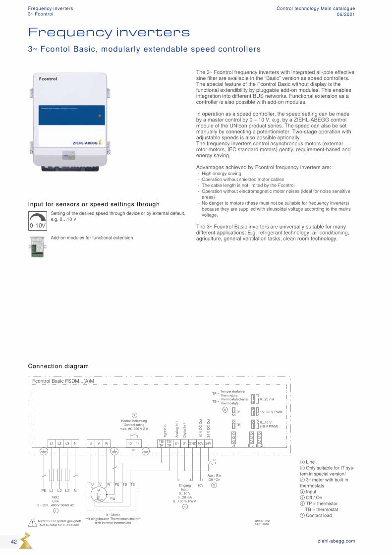
① Line ② Only suitable for IT sys-tem in special version! ③ 3~ motor with built-in thermostats ④ Input ⑤ Off / On ⑥ TP = thermistor TB = thermostat ⑦ Contact load
Input for sensors or speed settings through
0-10V
Setting of the desired speed through device or by external default, e.g. 0…10 V
Add-on modules for functional extension
Connection diagram
Frequency inverters
The 3~ Fcontrol frequency inverters with integrated all-pole effective sine filter are available in the “Basic” version as speed controllers. The special feature of the Fcontrol Basic without display is the functional extendibility by pluggable add-on modules. This enables integration into different BUS networks. Functional extension as a controller is also possible with add-on modules. In operation as a speed controller, the speed setting can be made by a master control by 0 – 10 V, e.g. by a ZIEHL-ABEGG control module of the UNIcon product series. The speed can also be set manually by connecting a potentiometer. Two-stage operation with adjustable speeds is also possible optionally. The frequency inverters control asynchronous motors (external rotor motors, IEC standard motors) gently, requirement-based and energy saving. Advantages achieved by Fcontrol frequency inverters are:
- High energy saving - Operation without shielded motor cables - The cable length is not limited by the Fcontrol - Operation without electromagnetic motor noises (ideal for noise sensitive areas)
- No danger to motors (these must not be suitable for frequency inverters) because they are supplied with sinusoidal voltage according to the mains voltage.
The 3~ Fcontrol Basic inverters are universally suitable for many different applications: E.g. refrigerant technology, air conditioning, agriculture, general ventilation tasks, clean room technology.
3~ Fcontol Basic, modularly extendable speed controllers
42 ziehl-abegg.com
Frequency inverters3~ Fcontrol
Control technology Main catalogue06/2021
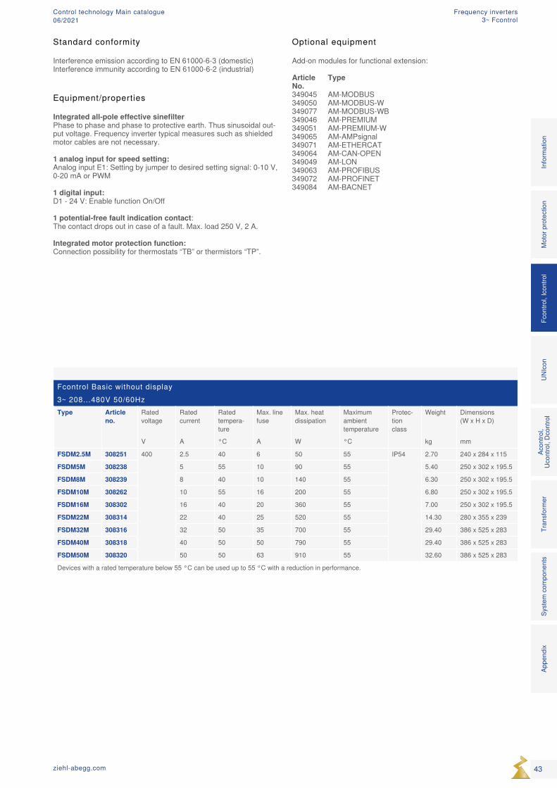
Fcontrol Basic without display3~ 208...480V 50/60HzType Article
no.Rated voltage
Rated current
Rated tempera-ture
Max. line fuse
Max. heat dissipation
Maximum ambient temperature
Protec-tion class
Weight Dimensions (W x H x D)
V A °C A W °C kg mm
FSDM2.5M 308251 400 2.5 40 6 50 55 IP54 2.70 240 x 284 x 115
FSDM5M 308238 5 55 10 90 55 5.40 250 x 302 x 195.5
FSDM8M 308239 8 40 10 140 55 6.30 250 x 302 x 195.5
FSDM10M 308262 10 55 16 200 55 6.80 250 x 302 x 195.5
FSDM16M 308302 16 40 20 360 55 7.00 250 x 302 x 195.5
FSDM22M 308314 22 40 25 520 55 14.30 280 x 355 x 239
FSDM32M 308316 32 50 35 700 55 29.40 386 x 525 x 283
FSDM40M 308318 40 50 50 790 55 29.40 386 x 525 x 283
FSDM50M 308320 50 50 63 910 55 32.60 386 x 525 x 283
Devices with a rated temperature below 55 °C can be used up to 55 °C with a reduction in performance.
Equipment/properties Integrated all-pole effective sinefilter Phase to phase and phase to protective earth. Thus sinusoidal out-put voltage. Frequency inverter typical measures such as shielded motor cables are not necessary. 1 analog input for speed setting: Analog input E1: Setting by jumper to desired setting signal: 0-10 V, 0-20 mA or PWM 1 digital input: D1 - 24 V: Enable function On/Off 1 potential-free fault indication contact: The contact drops out in case of a fault. Max. load 250 V, 2 A. Integrated motor protection function: Connection possibility for thermostats “TB” or thermistors “TP”.
Optional equipment
Add-on modules for functional extension:
Article Type No.349045 AM-MODBUS349050 AM-MODBUS-W349077 AM-MODBUS-WB349046 AM-PREMIUM349051 AM-PREMIUM-W349065 AM-AMPsignal349071 AM-ETHERCAT349064 AM-CAN-OPEN349049 AM-LON349063 AM-PROFIBUS349072 AM-PROFINET349084 AM-BACNET
Mot
or p
rote
ctio
nFc
ontro
l, Ic
ontro
lUN
Icon
Acon
trol,
Ucon
trol,
Dcon
trol
Tran
sfor
mer
Syst
em c
ompo
nent
sIn
form
atio
nAp
pend
ix
43ziehl-abegg.com
Standard conformity
Interference emission according to EN 61000-6-3 (domestic)Interference immunity according to EN 61000-6-2 (industrial)
Frequency inverters3~ Fcontrol
Control technology Main catalogue06/2021
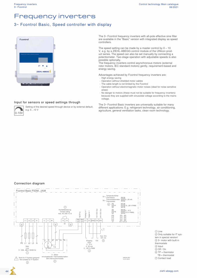
① Line ② Only suitable for IT sys-tem in special version! ③ 3~ motor with built-in thermostats ④ Input ⑤ Off / On ⑥ TP = thermistor TB = thermostat ⑦ Contact load
Input for sensors or speed settings through
0-10V
Setting of the desired speed through device or by external default, e.g. 0…10 V
Connection diagram
Frequency inverters
The 3~ Fcontrol frequency inverters with all-pole effective sine filter are available in the “Basic” version with integrated display as speed controllers. The speed setting can be made by a master control by 0 – 10 V, e.g. by a ZIEHL-ABEGG control module of the UNIcon prod-uct series. The speed can also be set manually by connecting a potentiometer. Two-stage operation with adjustable speeds is also possible optionally. The frequency inverters control asynchronous motors (external rotor motors, IEC standard motors) gently, requirement-based and energy saving. Advantages achieved by Fcontrol frequency inverters are:
- High energy saving - Operation without shielded motor cables - The cable length is not limited by the Fcontrol - Operation without electromagnetic motor noises (ideal for noise sensitive areas)
- No danger to motors (these must not be suitable for frequency inverters) because they are supplied with sinusoidal voltage according to the mains voltage.
The 3~ Fcontrol Basic inverters are universally suitable for many different applications: E.g. refrigerant technology, air conditioning, agriculture, general ventilation tasks, clean room technology.
3~ Fcontrol Basic, Speed controller with display
44 ziehl-abegg.com
Frequency inverters3~ Fcontrol
Control technology Main catalogue06/2021
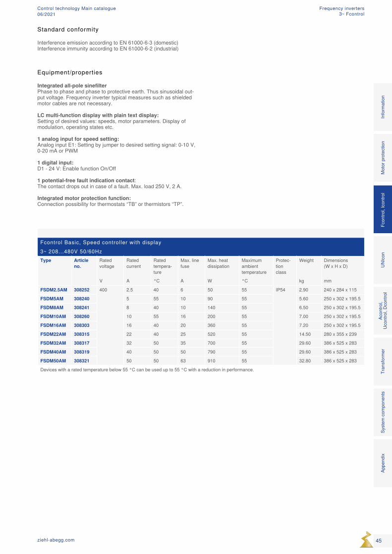
Fcontrol Basic, Speed controller with display3~ 208...480V 50/60HzType Article
no.Rated voltage
Rated current
Rated tempera-ture
Max. line fuse
Max. heat dissipation
Maximum ambient temperature
Protec-tion class
Weight Dimensions (W x H x D)
V A °C A W °C kg mm
FSDM2.5AM 308252 400 2.5 40 6 50 55 IP54 2.90 240 x 284 x 115
FSDM5AM 308240 5 55 10 90 55 5.60 250 x 302 x 195.5
FSDM8AM 308241 8 40 10 140 55 6.50 250 x 302 x 195.5
FSDM10AM 308260 10 55 16 200 55 7.00 250 x 302 x 195.5
FSDM16AM 308303 16 40 20 360 55 7.20 250 x 302 x 195.5
FSDM22AM 308315 22 40 25 520 55 14.50 280 x 355 x 239
FSDM32AM 308317 32 50 35 700 55 29.60 386 x 525 x 283
FSDM40AM 308319 40 50 50 790 55 29.60 386 x 525 x 283
FSDM50AM 308321 50 50 63 910 55 32.80 386 x 525 x 283
Devices with a rated temperature below 55 °C can be used up to 55 °C with a reduction in performance.
Equipment/properties Integrated all-pole sinefilter Phase to phase and phase to protective earth. Thus sinusoidal out-put voltage. Frequency inverter typical measures such as shielded motor cables are not necessary. LC multi-function display with plain text display: Setting of desired values: speeds, motor parameters. Display of modulation, operating states etc. 1 analog input for speed setting: Analog input E1: Setting by jumper to desired setting signal: 0-10 V, 0-20 mA or PWM 1 digital input: D1 - 24 V: Enable function On/Off 1 potential-free fault indication contact: The contact drops out in case of a fault. Max. load 250 V, 2 A. Integrated motor protection function: Connection possibility for thermostats “TB” or thermistors “TP”.
Mot
or p
rote
ctio
nFc
ontro
l, Ic
ontro
lUN
Icon
Acon
trol,
Ucon
trol,
Dcon
trol
Tran
sfor
mer
Syst
em c
ompo
nent
sIn
form
atio
nAp
pend
ix
45ziehl-abegg.com
Standard conformity
Interference emission according to EN 61000-6-3 (domestic)Interference immunity according to EN 61000-6-2 (industrial)
Frequency inverters3~ Fcontrol
Control technology Main catalogue06/2021
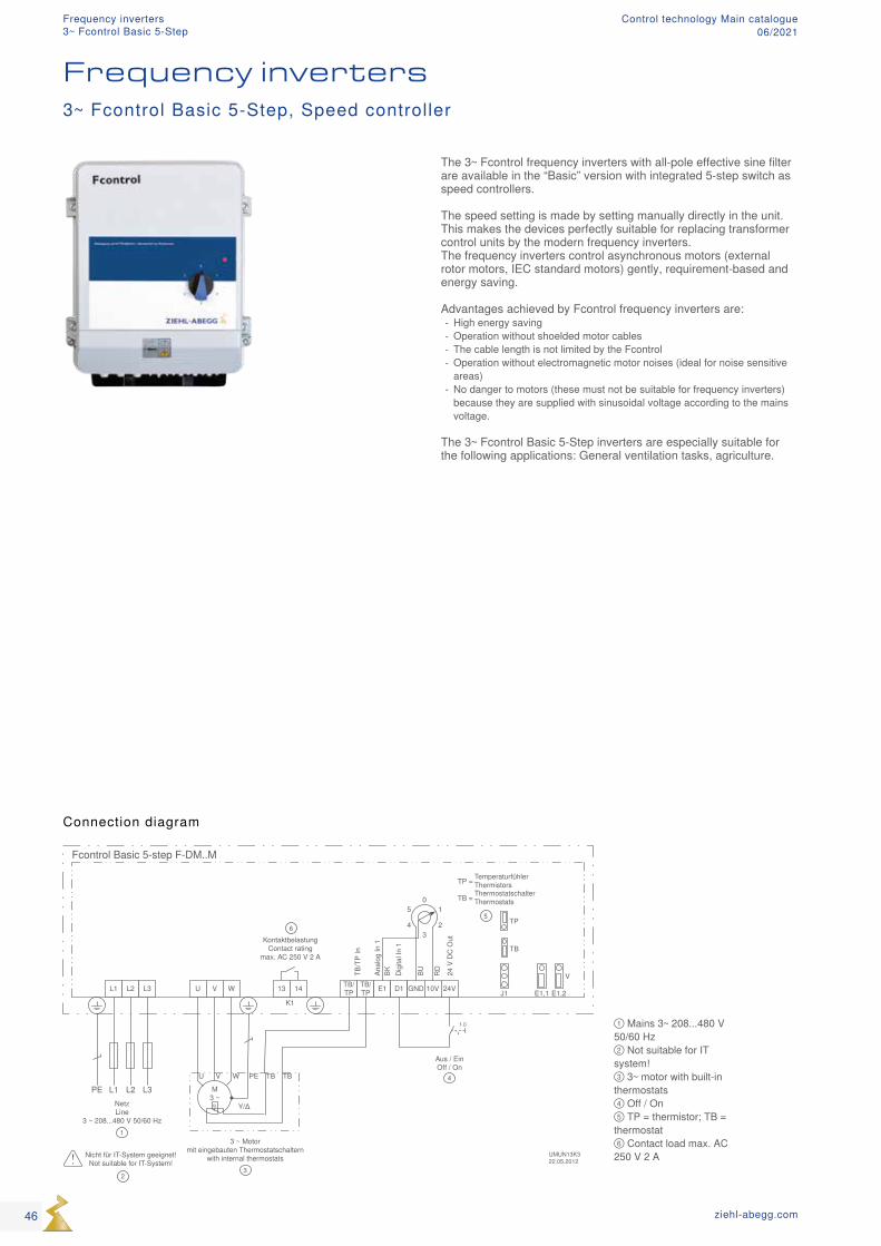
Fcontrol Basic 5-step F-DM..M
L3L2L1PENetzLine
3 ~ 208...480 V 50/60 Hz
L1 L2 L3 U V W TB/TP
TB/TP E1 D1 GND 10V 24V
Dig
ital I
n 1
Anal
og In
1
24 V
DC
Out
01
Aus / EinOff / On
BU RDBK
13 14
K1
KontaktbelastungContact rating
max. AC 250 V 2 A
6
M3 ~
U V W PE TB
Y/Δq
3 ~ Motormit eingebauten Thermostatschaltern
with internal thermostats3
TB
1
J1 E1,1 E1,2
TB
TP
TemperaturfühlerThermistorsTP = ThermostatschalterThermostatsTB =
V
5
4
01
23
5
4
UMUN13K322.05.2012
2
Nicht für IT-System geeignet!Not suitable for IT-System!
TB/T
P In
① Mains 3~ 208...480 V 50/60 Hz ② Not suitable for IT system! ③ 3~ motor with built-in thermostats ④ Off / On ⑤ TP = thermistor; TB = thermostat ⑥ Contact load max. AC 250 V 2 A
Frequency inverters3~ Fcontrol Basic 5-Step, Speed controller
Connection diagram
The 3~ Fcontrol frequency inverters with all-pole effective sine filter are available in the “Basic” version with integrated 5-step switch as speed controllers. The speed setting is made by setting manually directly in the unit. This makes the devices perfectly suitable for replacing transformer control units by the modern frequency inverters. The frequency inverters control asynchronous motors (external rotor motors, IEC standard motors) gently, requirement-based and energy saving. Advantages achieved by Fcontrol frequency inverters are:
- High energy saving - Operation without shoelded motor cables - The cable length is not limited by the Fcontrol - Operation without electromagnetic motor noises (ideal for noise sensitive areas)
- No danger to motors (these must not be suitable for frequency inverters) because they are supplied with sinusoidal voltage according to the mains voltage.
The 3~ Fcontrol Basic 5-Step inverters are especially suitable for the following applications: General ventilation tasks, agriculture.
46 ziehl-abegg.com
3~ Fcontrol Basic 5-StepFrequency inverters Control technology Main catalogue
06/2021
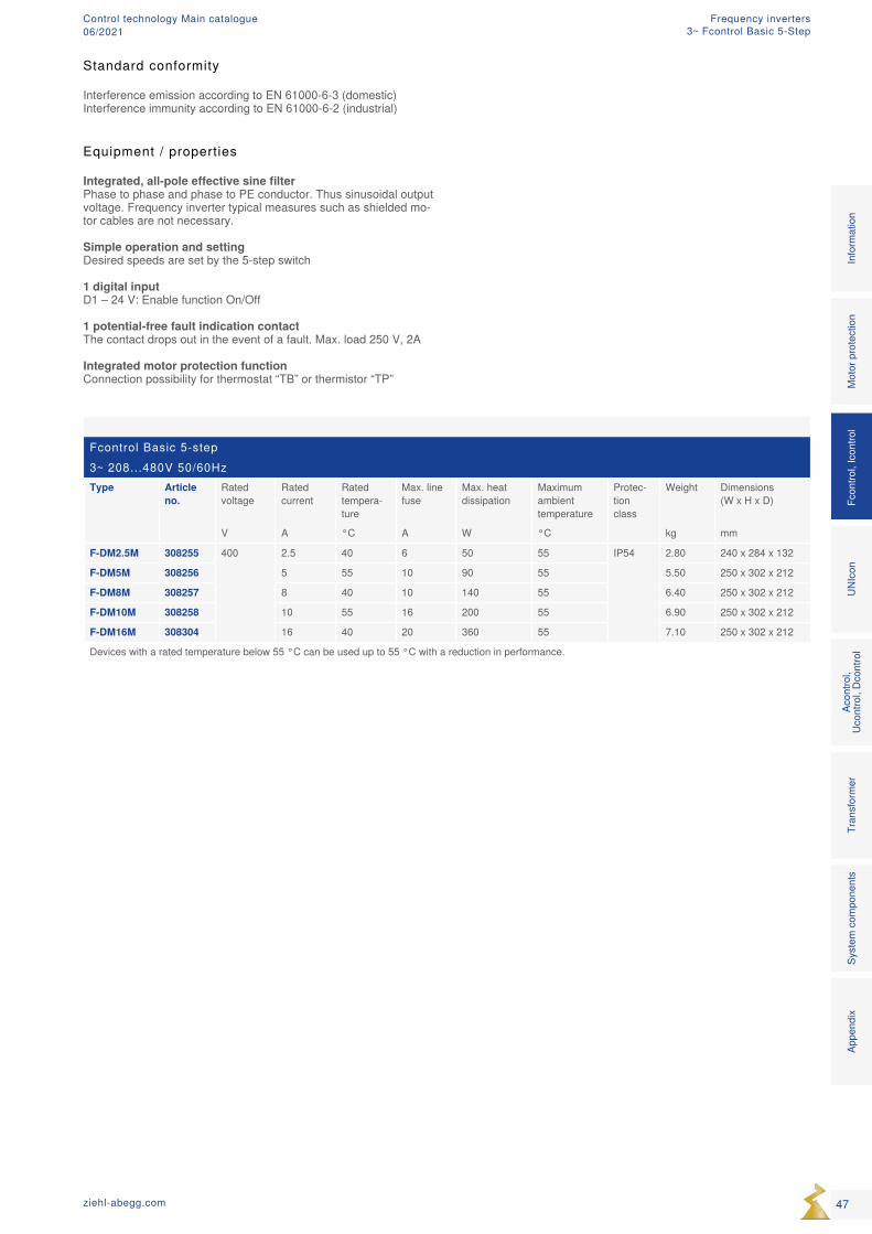
Fcontrol Basic 5-step3~ 208...480V 50/60HzType Article
no.Rated voltage
Rated current
Rated tempera-ture
Max. line fuse
Max. heat dissipation
Maximum ambient temperature
Protec-tion class
Weight Dimensions (W x H x D)
V A °C A W °C kg mm
F-DM2.5M 308255 400 2.5 40 6 50 55 IP54 2.80 240 x 284 x 132
F-DM5M 308256 5 55 10 90 55 5.50 250 x 302 x 212
F-DM8M 308257 8 40 10 140 55 6.40 250 x 302 x 212
F-DM10M 308258 10 55 16 200 55 6.90 250 x 302 x 212
F-DM16M 308304 16 40 20 360 55 7.10 250 x 302 x 212
Devices with a rated temperature below 55 °C can be used up to 55 °C with a reduction in performance.
Equipment / properties
Integrated, all-pole effective sine filterPhase to phase and phase to PE conductor. Thus sinusoidal output voltage. Frequency inverter typical measures such as shielded mo-tor cables are not necessary.
Simple operation and settingDesired speeds are set by the 5-step switch
1 digital inputD1 – 24 V: Enable function On/Off
1 potential-free fault indication contactThe contact drops out in the event of a fault. Max. load 250 V, 2A
Integrated motor protection functionConnection possibility for thermostat “TB” or thermistor “TP” M
otor
pro
tect
ion
Fcon
trol,
Icon
trol
UNIc
onAc
ontro
l, Uc
ontro
l, Dc
ontro
lTr
ansf
orm
erSy
stem
com
pone
nts
Info
rmat
ion
Appe
ndix
47ziehl-abegg.com
Standard conformity
Interference emission according to EN 61000-6-3 (domestic)Interference immunity according to EN 61000-6-2 (industrial)
3~ Fcontrol Basic 5-StepFrequency invertersControl technology Main catalogue
06/2021
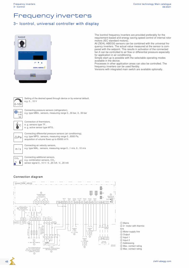
① Mains ② 3~ motor with thermis-tors ③ Motor supply line ④ Output ⑤ Input 1 ⑥ Input 2 ⑦ Addressing ⑧ Max. contact rating ⑨ Max. contact rating
0-10V
Setting of the desired speed through device or by external default, e.g. 0…10 V
0-300-50bar
Connecting pressure sensors (refrigeration), e.g. type MBG.. sensors, measuring range 0...30 bar, 0...50 bar
°CConnection of thermistors, e. g. sensors type TF.. e. g. active sensor type MTG..
PaConnecting differential pressure sensors (air conditioning), e.g. type MPG.. sensors, measuring range 0...6000 Pa, acquisition of volume flows up to 65000 m3/h
m / sConnecting air velocity sensors, e.g. type MAL.. sensors, measuring range 0...1 m/s, 0...10 m/s
CO2
%
°C
Connecting additional sensors, e.g. combination sensors, CO2, sensor signal 0...10 V / 0...20 mA / 4...20 mA
Frequency inverters3~ Icontrol, universal controller with display
Connection diagram
The Icontrol frequency inverters are provided preferably for the requirement-based and energy saving speed control of internal rotor motors (IEC standard motors).All ZIEHL-ABEGG sensors can be combined with the universal fre-quency inverters. The actual value measured at the sensor is com-pared with the setpoint. This results in activation of the connected fan.It can be controlled to air flow or differential pressure especially for application in air conditioning.Simple start-up is possible with the selectable operating modes available in the device.Processes in other application areas can also be controlled. The frequency inverters can be used flexibly.Versions with integrated main switch are available optionally.
48 ziehl-abegg.com
Frequency inverters3~ Icontrol
Control technology Main catalogue06/2021
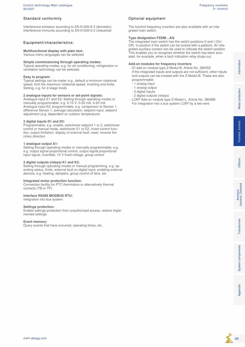
Optional equipment
The Icontrol frequency inverters are also available with an inte-grated main switch.
Type designation FXDM…AQThe integrated main switch has the switch positions 0 and I (On/Off). In position 0 the switch can be locked with a padlock. An inte-grated auxiliary contact can be used to indicate the switch position. This enables you to recognise whether the switch has been actu-ated, for example, when a fault indication relay drops out.
Add-on modules for frequency inverters - IO add-on module type Z-Modul-B, Article No. 380052 If the integrated inputs and outputs are not sufficient, other inputs and outputs can be created with the Z-Modul-B. These are also programmable: - 1 analog input - 1 analog output - 3 digital inputs - 2 digital outputs (relays)
- LON® Add-on module type Z-Modul-L, Article No. 380086 For integration into a bus system LON® by a two-wire
Equipment/characteristics:
Multifunctional display with plain text: Various menu languages can be selected
Simple commissioning through operating modes: Typical operating modes, e.g. for air-conditioning, refrigeration or ventilation technology can be selected.
Easy to program: Typical settings can be made: e.g., default a minimum rotational speed, limit the maximum rotational speed, inverting and limits. Setting, e.g. for 2-stage mode
2 analogue inputs for sensors or set-point signals: Analogue input E1 and E2: Setting through operating modes or manually programmable, e.g. 0-10 V, 0-20 mA, 4-20 mA Analogue input E2: programmable, e.g. comparison to Sensor 1, difference Sensor 1, average calculation, setpoint input, setpoint adjustment (e.g. dependent on outdoor temperature)
2 digital inputs D1 and D2: Programmable, e.g. enable, switchover setpoint 1 or 2, switchover control or manual mode, switchover E1 or E2, invert control func-tion, output limitation, display of external fault, reset, reverse the rotary direction
1 analogue output A1: Setting through operating modes or manually programmable, e.g. e.g. output signal proportional control, output signal proportional input signal, invertible, 10 V fixed voltage, group control
2 digital outputs (relays) K1 and K2: Setting through operating modes or manual programming, e.g. op-erating status, limits, external fault on digital input, enabling external devices, e.g. heating, dampers, group control of fans, etc.
Integrated motor protection function: Connection facility for PTC thermistors or alternatively thermal contacts (TB or TP).
Interface RS485 MODBUS RTU: Integration into bus system
Settings protection: Enable settings protection from unauthorised access, restore imple-mented settings
Event memory: Query events that have occurred, operating times, etc.
Mot
or p
rote
ctio
nFc
ontro
l, Ic
ontro
lUN
Icon
Acon
trol,
Ucon
trol,
Dcon
trol
Tran
sfor
mer
Syst
em c
ompo
nent
sIn
form
atio
nAp
pend
ix
49ziehl-abegg.com
Standard conformity
Interference emission according to EN 61000-6-3 (domestic)Interference immunity according to EN 61000-6-2 (industrial)
Frequency inverters3~ Icontrol
Control technology Main catalogue06/2021
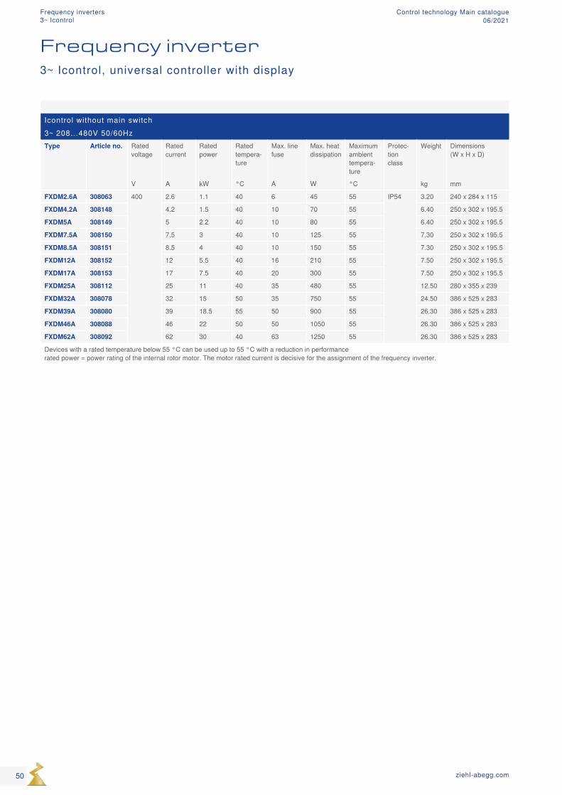
Icontrol without main switch3~ 208...480V 50/60HzType Article no. Rated
voltageRated current
Rated power
Rated tempera-ture
Max. line fuse
Max. heat dissipation
Maximum ambient tempera-ture
Protec-tion class
Weight Dimensions (W x H x D)
V A kW °C A W °C kg mm
FXDM2.6A 308063 400 2.6 1.1 40 6 45 55 IP54 3.20 240 x 284 x 115
FXDM4.2A 308148 4.2 1.5 40 10 70 55 6.40 250 x 302 x 195.5
FXDM5A 308149 5 2.2 40 10 80 55 6.40 250 x 302 x 195.5
FXDM7.5A 308150 7.5 3 40 10 125 55 7.30 250 x 302 x 195.5
FXDM8.5A 308151 8.5 4 40 10 150 55 7.30 250 x 302 x 195.5
FXDM12A 308152 12 5.5 40 16 210 55 7.50 250 x 302 x 195.5
FXDM17A 308153 17 7.5 40 20 300 55 7.50 250 x 302 x 195.5
FXDM25A 308112 25 11 40 35 480 55 12.50 280 x 355 x 239
FXDM32A 308078 32 15 50 35 750 55 24.50 386 x 525 x 283
FXDM39A 308080 39 18.5 55 50 900 55 26.30 386 x 525 x 283
FXDM46A 308088 46 22 50 50 1050 55 26.30 386 x 525 x 283
FXDM62A 308092 62 30 40 63 1250 55 26.30 386 x 525 x 283
Devices with a rated temperature below 55 °C can be used up to 55 °C with a reduction in performance rated power = power rating of the internal rotor motor. The motor rated current is decisive for the assignment of the frequency inverter.
3~ Icontrol, universal controller with display
Frequency inverter
50 ziehl-abegg.com
Frequency inverters3~ Icontrol
Control technology Main catalogue06/2021
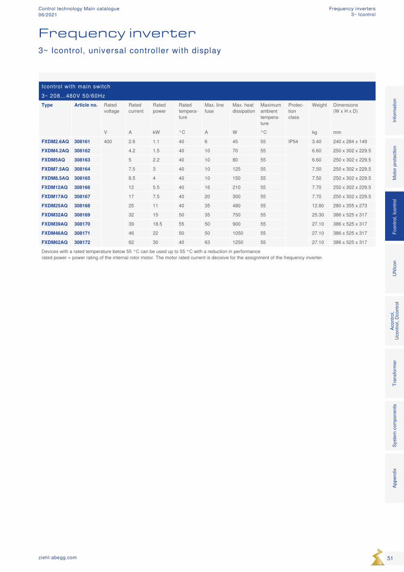
Icontrol with main switch3~ 208...480V 50/60HzType Article no. Rated
voltageRated current
Rated power
Rated tempera-ture
Max. line fuse
Max. heat dissipation
Maximum ambient tempera-ture
Protec-tion class
Weight Dimensions (W x H x D)
V A kW °C A W °C kg mm
FXDM2.6AQ 308161 400 2.6 1.1 40 6 45 55 IP54 3.40 240 x 284 x 149
FXDM4.2AQ 308162 4.2 1.5 40 10 70 55 6.60 250 x 302 x 229.5
FXDM5AQ 308163 5 2.2 40 10 80 55 6.60 250 x 302 x 229.5
FXDM7.5AQ 308164 7.5 3 40 10 125 55 7.50 250 x 302 x 229.5
FXDM8.5AQ 308165 8.5 4 40 10 150 55 7.50 250 x 302 x 229.5
FXDM12AQ 308166 12 5.5 40 16 210 55 7.70 250 x 302 x 229.5
FXDM17AQ 308167 17 7.5 40 20 300 55 7.70 250 x 302 x 229.5
FXDM25AQ 308168 25 11 40 35 480 55 12.80 280 x 355 x 273
FXDM32AQ 308169 32 15 50 35 750 55 25.30 386 x 525 x 317
FXDM39AQ 308170 39 18.5 55 50 900 55 27.10 386 x 525 x 317
FXDM46AQ 308171 46 22 50 50 1050 55 27.10 386 x 525 x 317
FXDM62AQ 308172 62 30 40 63 1250 55 27.10 386 x 525 x 317
Devices with a rated temperature below 55 °C can be used up to 55 °C with a reduction in performance rated power = power rating of the internal rotor motor. The motor rated current is decisive for the assignment of the frequency inverter.
3~ Icontrol, universal controller with display
Frequency inverter
51ziehl-abegg.com
Mot
or p
rote
ctio
nFc
ontro
l, Ic
ontro
lUN
Icon
Acon
trol,
Ucon
trol,
Dcon
trol
Tran
sfor
mer
Syst
em c
ompo
nent
sIn
form
atio
nAp
pend
ix
Frequency inverters3~ Icontrol
Control technology Main catalogue06/2021
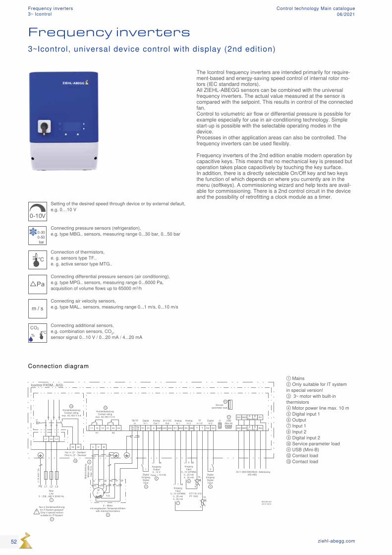
MCUN14K124.07.2014
11 14 12 21 24 22 TB/TP
TB/TP D1 D1 A GND 24V 24V E1 GND GNDE2 D2 D2
L3L2L1PE
L1 L2 L3
U V W
NetzLine
3 ~ 208...480 V 50/60 Hz1
≥ 10
mm
² / 2
x
Nur in Sonderausführungfür IT-System geeignet!Only in special versionsuitable for IT-System!
2
K1 K2
Icontrol FXDM...A(Q)
KontaktbelastungContact rating
max. AC 250 V 2 A
12
EingangInput
0...10 V(PWM)0...20 mA4...20 mA
+
7
1
EingangInput
0...10 V(PWM)0...20 mA4...20 mA
+
8
2
AusgangOutput0...10 V
(Imax = 10 mA)
+
6
TB/TPIn
DigitalIn 1
AnalogOut 1
DigitalIn 2
AnalogIn 1
AnalogIn 2
24 V DCOut
M3 ~
U V W PE TP
Y/Δ
TP
24V GND
MODBUS(RS-485)
GND24 V
A(D+)
B(D-) ID2
24V GND A(D+)
B(D-) ID1
Addressing
T T
TFIn 1/2
USB(Mini-B)
Serviceparameter load
q
TF..KTY 81-210PT 1000
J111
10
q
TF..Digital
EingangDigitalInput
5
1 2
DigitalEingangDigitalInput
9
KontaktbelastungContact rating
max. AC 400 V 4 A
13
3433
Nur in „Q“ - Geräten!Only in „Q“ - Devices!
14
01
q
3 ~ Motormit eingebauten Temperaturfühlern
with internal thermistors3
Mot
orzu
leitu
ngM
otor
cab
lem
ax. 1
0 m
4
① Mains ② Only suitable for IT system in special version! ③ 3~ motor with built-in thermistors ④ Motor power line max. 10 m ⑤ Digital input 1 ⑥ Output ⑦ Input 1 ⑧ Input 2 ⑨ Digital input 2 ⑩ Service parameter load ⑪ USB (Mini-B) ⑫ Contact load ⑬ Contact load
0-10V
Setting of the desired speed through device or by external default, e.g. 0…10 V
0-300-50bar
Connecting pressure sensors (refrigeration), e.g. type MBG.. sensors, measuring range 0...30 bar, 0...50 bar
°CConnection of thermistors, e. g. sensors type TF.. e. g. active sensor type MTG..
PaConnecting differential pressure sensors (air conditioning), e.g. type MPG.. sensors, measuring range 0...6000 Pa, acquisition of volume flows up to 65000 m3/h
m / sConnecting air velocity sensors, e.g. type MAL.. sensors, measuring range 0...1 m/s, 0...10 m/s
CO2
%
°C
Connecting additional sensors, e.g. combination sensors, CO2, sensor signal 0...10 V / 0...20 mA / 4...20 mA
Connection diagram
Frequency inverters
The Icontrol frequency inverters are intended primarily for require-ment-based and energy-saving speed control of internal rotor mo-tors (IEC standard motors). All ZIEHL-ABEGG sensors can be combined with the universal frequency inverters. The actual value measured at the sensor is compared with the setpoint. This results in control of the connected fan. Control to volumetric air flow or differential pressure is possible for example especially for use in air-conditioning technology. Simple start-up is possible with the selectable operating modes in the device. Processes in other application areas can also be controlled. The frequency inverters can be used flexibly. Frequency inverters of the 2nd edition enable modern operation by capacitive keys. This means that no mechanical key is pressed but operation takes place capacitively by touching the key surface. In addition, there is a directly selectable On/Off key and two keys the function of which depends on where you currently are in the menu (softkeys). A commissioning wizard and help texts are avail-able for commissioning. There is a 2nd control circuit in the device and the possibility of retrofitting a clock module as a timer.
3~Icontrol, universal device control with display (2nd edition)
52 ziehl-abegg.com
Frequency inverters3~ Icontrol
Control technology Main catalogue06/2021
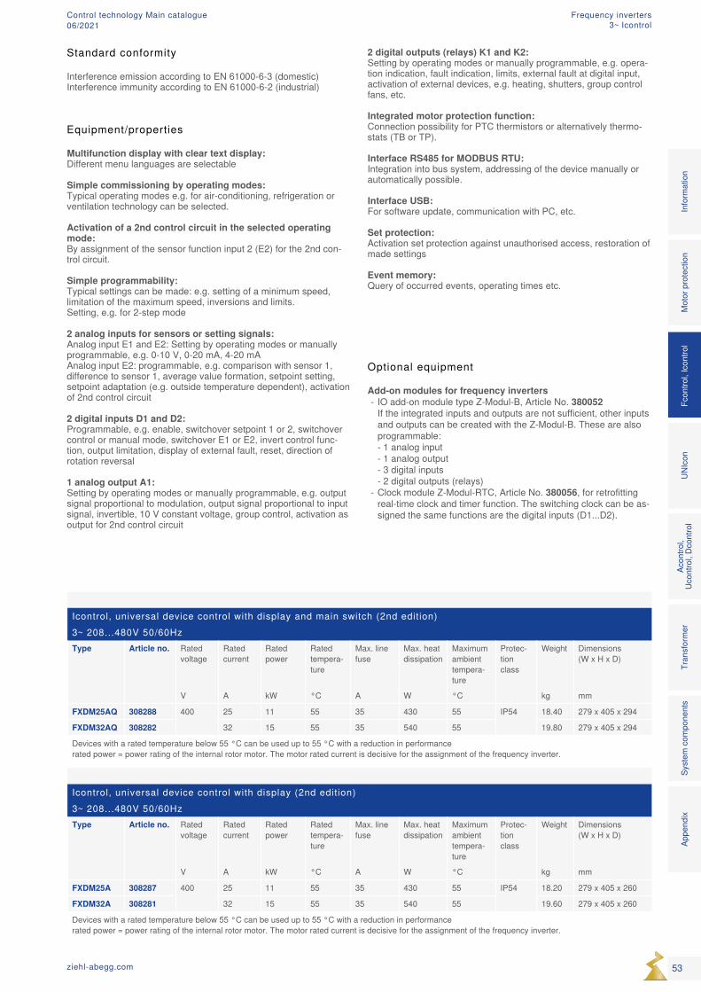
Icontrol, universal device control with display and main switch (2nd edition)3~ 208...480V 50/60HzType Article no. Rated
voltageRated current
Rated power
Rated tempera-ture
Max. line fuse
Max. heat dissipation
Maximum ambient tempera-ture
Protec-tion class
Weight Dimensions (W x H x D)
V A kW °C A W °C kg mm
FXDM25AQ 308288 400 25 11 55 35 430 55 IP54 18.40 279 x 405 x 294
FXDM32AQ 308282 32 15 55 35 540 55 19.80 279 x 405 x 294
Devices with a rated temperature below 55 °C can be used up to 55 °C with a reduction in performance rated power = power rating of the internal rotor motor. The motor rated current is decisive for the assignment of the frequency inverter.
Icontrol, universal device control with display (2nd edition)3~ 208...480V 50/60HzType Article no. Rated
voltageRated current
Rated power
Rated tempera-ture
Max. line fuse
Max. heat dissipation
Maximum ambient tempera-ture
Protec-tion class
Weight Dimensions (W x H x D)
V A kW °C A W °C kg mm
FXDM25A 308287 400 25 11 55 35 430 55 IP54 18.20 279 x 405 x 260
FXDM32A 308281 32 15 55 35 540 55 19.60 279 x 405 x 260
Devices with a rated temperature below 55 °C can be used up to 55 °C with a reduction in performance rated power = power rating of the internal rotor motor. The motor rated current is decisive for the assignment of the frequency inverter.
Optional equipment
Add-on modules for frequency inverters - IO add-on module type Z-Modul-B, Article No. 380052 If the integrated inputs and outputs are not sufficient, other inputs and outputs can be created with the Z-Modul-B. These are also programmable: - 1 analog input - 1 analog output - 3 digital inputs - 2 digital outputs (relays)
- Clock module Z-Modul-RTC, Article No. 380056, for retrofitting real-time clock and timer function. The switching clock can be as-signed the same functions are the digital inputs (D1...D2).
Equipment/properties
Multifunction display with clear text display: Different menu languages are selectable
Simple commissioning by operating modes: Typical operating modes e.g. for air-conditioning, refrigeration or ventilation technology can be selected. Activation of a 2nd control circuit in the selected operating mode: By assignment of the sensor function input 2 (E2) for the 2nd con-trol circuit.
Simple programmability: Typical settings can be made: e.g. setting of a minimum speed, limitation of the maximum speed, inversions and limits. Setting, e.g. for 2-step mode
2 analog inputs for sensors or setting signals: Analog input E1 and E2: Setting by operating modes or manually programmable, e.g. 0-10 V, 0-20 mA, 4-20 mA Analog input E2: programmable, e.g. comparison with sensor 1, difference to sensor 1, average value formation, setpoint setting, setpoint adaptation (e.g. outside temperature dependent), activation of 2nd control circuit
2 digital inputs D1 and D2: Programmable, e.g. enable, switchover setpoint 1 or 2, switchover control or manual mode, switchover E1 or E2, invert control func-tion, output limitation, display of external fault, reset, direction of rotation reversal
1 analog output A1: Setting by operating modes or manually programmable, e.g. output signal proportional to modulation, output signal proportional to input signal, invertible, 10 V constant voltage, group control, activation as output for 2nd control circuit
2 digital outputs (relays) K1 and K2: Setting by operating modes or manually programmable, e.g. opera-tion indication, fault indication, limits, external fault at digital input, activation of external devices, e.g. heating, shutters, group control fans, etc.
Integrated motor protection function: Connection possibility for PTC thermistors or alternatively thermo-stats (TB or TP).
Interface RS485 for MODBUS RTU: Integration into bus system, addressing of the device manually or automatically possible. Interface USB: For software update, communication with PC, etc.
Set protection: Activation set protection against unauthorised access, restoration of made settings
Event memory: Query of occurred events, operating times etc.
Mot
or p
rote
ctio
nFc
ontro
l, Ic
ontro
lUN
Icon
Acon
trol,
Ucon
trol,
Dcon
trol
Tran
sfor
mer
Syst
em c
ompo
nent
sIn
form
atio
nAp
pend
ix
53ziehl-abegg.com
Standard conformity
Interference emission according to EN 61000-6-3 (domestic)Interference immunity according to EN 61000-6-2 (industrial)
Frequency inverters3~ Icontrol
Control technology Main catalogue06/2021
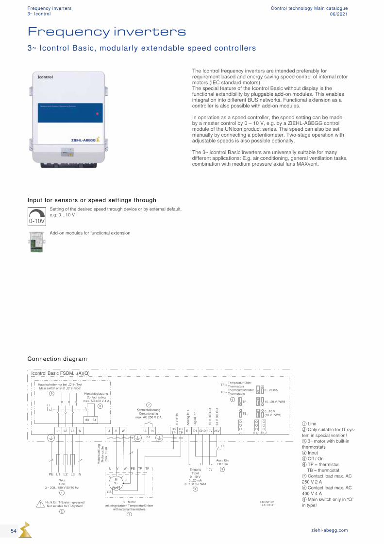
① Line ② Only suitable for IT sys-tem in special version! ③ 3~ motor with built-in thermostats ④ Input ⑤ Off / On ⑥ TP = thermistor TB = thermostat ⑦ Contact load max. AC 250 V 2 A ⑧ Contact load max. AC 400 V 4 A ⑨ Main switch only in “Q” in type!
Input for sensors or speed settings through
0-10V
Setting of the desired speed through device or by external default, e.g. 0…10 V
Add-on modules for functional extension
Connection diagram
Frequency inverters
The Icontrol frequency inverters are intended preferably for requirement-based and energy saving speed control of internal rotor motors (IEC standard motors). The special feature of the Icontrol Basic without display is the functional extendibility by pluggable add-on modules. This enables integration into different BUS networks. Functional extension as a controller is also possible with add-on modules. In operation as a speed controller, the speed setting can be made by a master control by 0 – 10 V, e.g. by a ZIEHL-ABEGG control module of the UNIcon product series. The speed can also be set manually by connecting a potentiometer. Two-stage operation with adjustable speeds is also possible optionally. The 3~ Icontrol Basic inverters are universally suitable for many different applications: E.g. air conditioning, general ventilation tasks, combination with medium pressure axial fans MAXvent.
3~ Icontrol Basic, modularly extendable speed controllers
54 ziehl-abegg.com
Frequency inverters3~ Icontrol
Control technology Main catalogue06/2021
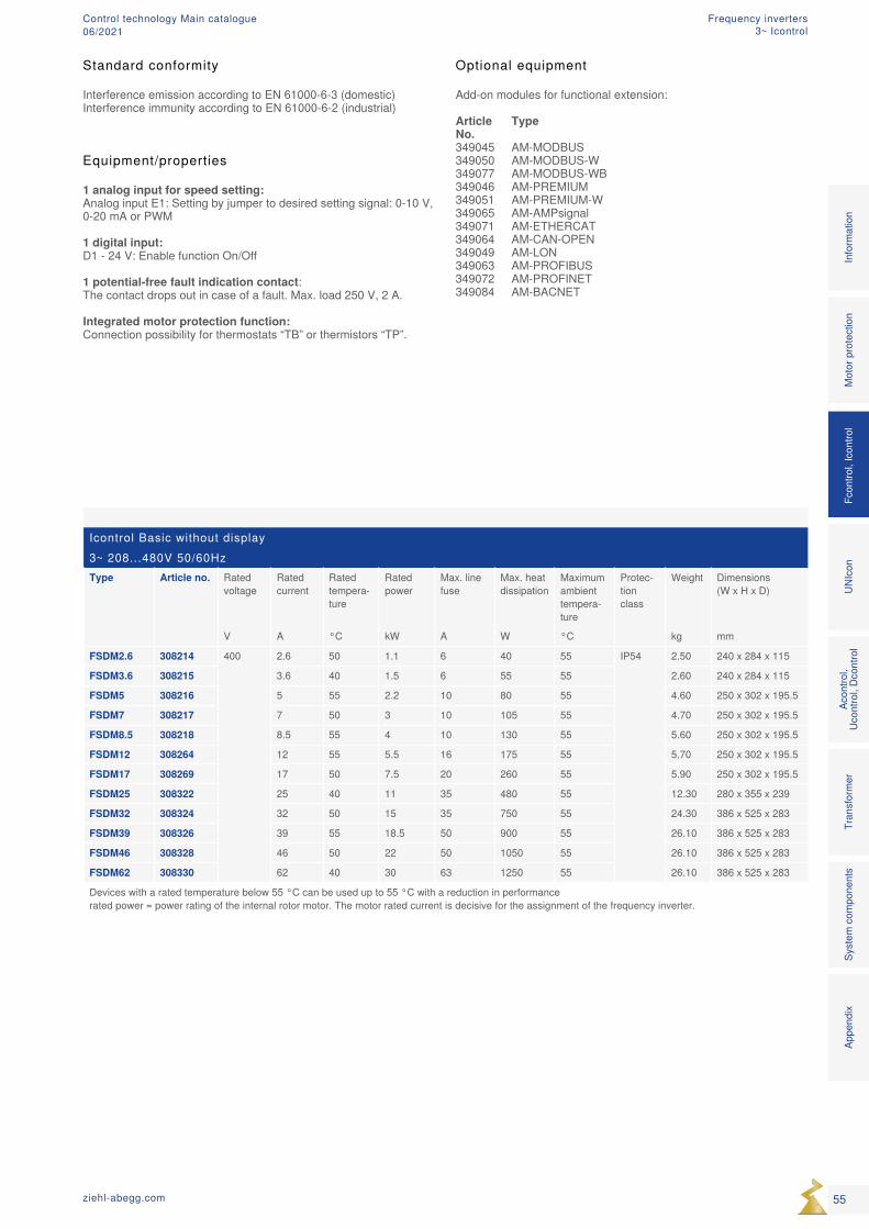
Icontrol Basic without display3~ 208...480V 50/60HzType Article no. Rated
voltageRated current
Rated tempera-ture
Rated power
Max. line fuse
Max. heat dissipation
Maximum ambient tempera-ture
Protec-tion class
Weight Dimensions (W x H x D)
V A °C kW A W °C kg mm
FSDM2.6 308214 400 2.6 50 1.1 6 40 55 IP54 2.50 240 x 284 x 115
FSDM3.6 308215 3.6 40 1.5 6 55 55 2.60 240 x 284 x 115
FSDM5 308216 5 55 2.2 10 80 55 4.60 250 x 302 x 195.5
FSDM7 308217 7 50 3 10 105 55 4.70 250 x 302 x 195.5
FSDM8.5 308218 8.5 55 4 10 130 55 5.60 250 x 302 x 195.5
FSDM12 308264 12 55 5.5 16 175 55 5.70 250 x 302 x 195.5
FSDM17 308269 17 50 7.5 20 260 55 5.90 250 x 302 x 195.5
FSDM25 308322 25 40 11 35 480 55 12.30 280 x 355 x 239
FSDM32 308324 32 50 15 35 750 55 24.30 386 x 525 x 283
FSDM39 308326 39 55 18.5 50 900 55 26.10 386 x 525 x 283
FSDM46 308328 46 50 22 50 1050 55 26.10 386 x 525 x 283
FSDM62 308330 62 40 30 63 1250 55 26.10 386 x 525 x 283
Devices with a rated temperature below 55 °C can be used up to 55 °C with a reduction in performance rated power = power rating of the internal rotor motor. The motor rated current is decisive for the assignment of the frequency inverter.
Equipment/properties 1 analog input for speed setting: Analog input E1: Setting by jumper to desired setting signal: 0-10 V, 0-20 mA or PWM 1 digital input: D1 - 24 V: Enable function On/Off 1 potential-free fault indication contact: The contact drops out in case of a fault. Max. load 250 V, 2 A. Integrated motor protection function: Connection possibility for thermostats “TB” or thermistors “TP”.
Optional equipment
Add-on modules for functional extension:
Article Type No.349045 AM-MODBUS349050 AM-MODBUS-W349077 AM-MODBUS-WB349046 AM-PREMIUM349051 AM-PREMIUM-W349065 AM-AMPsignal349071 AM-ETHERCAT349064 AM-CAN-OPEN349049 AM-LON349063 AM-PROFIBUS349072 AM-PROFINET349084 AM-BACNET
Mot
or p
rote
ctio
nFc
ontro
l, Ic
ontro
lUN
Icon
Acon
trol,
Ucon
trol,
Dcon
trol
Tran
sfor
mer
Syst
em c
ompo
nent
sIn
form
atio
nAp
pend
ix
55ziehl-abegg.com
Standard conformity
Interference emission according to EN 61000-6-3 (domestic)Interference immunity according to EN 61000-6-2 (industrial)
Frequency inverters3~ Icontrol
Control technology Main catalogue06/2021
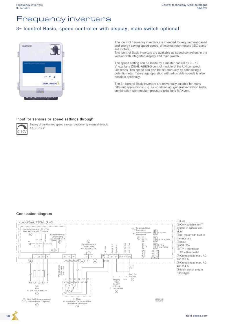
① Line ② Only suitable for IT system in special ver-sion! ③ 3~ motor with built-in thermostats ④ Input ⑤ Off / On ⑥ TP = thermistor TB = thermostat ⑦ Contact load max. AC 250 V 2 A ⑧ Contact load max. AC 400 V 4 A ⑨ Main switch only in “Q” in type!
Input for sensors or speed settings through
0-10V
Setting of the desired speed through device or by external default, e.g. 0…10 V
Connection diagram
Frequency inverters3~ Icontrol Basic, speed controller with display, main switch optional
The Icontrol frequency inverters are intended for requirement-based and energy saving speed control of internal rotor motors (IEC stand-ard motors). The Icontrol Basic inverters are available as speed controllers in the version with integrated display and main switch. The speed setting can be made by a master control by 0 – 10 V, e.g. by a ZIEHL-ABEGG control module of the UNIcon prod-uct series. The speed can also be set manually by connecting a potentiometer. Two-stage operation with adjustable speeds is also possible optionally. The 3~ Icontrol Basic inverters are universally suitable for many different applications: E.g. air conditioning, general ventilation tasks, combination with medium pressure axial fans MAXvent.
56 ziehl-abegg.com
Frequency inverters3~ Icontrol
Control technology Main catalogue06/2021
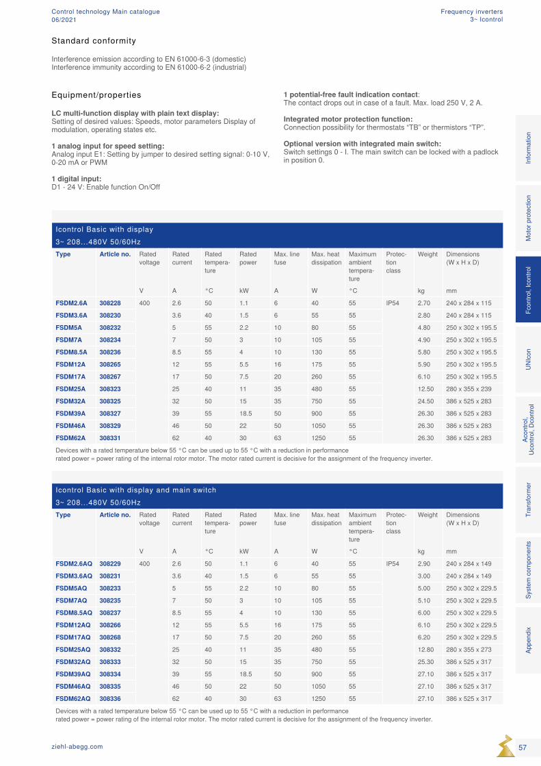
Icontrol Basic with display3~ 208...480V 50/60HzType Article no. Rated
voltageRated current
Rated tempera-ture
Rated power
Max. line fuse
Max. heat dissipation
Maximum ambient tempera-ture
Protec-tion class
Weight Dimensions (W x H x D)
V A °C kW A W °C kg mm
FSDM2.6A 308228 400 2.6 50 1.1 6 40 55 IP54 2.70 240 x 284 x 115
FSDM3.6A 308230 3.6 40 1.5 6 55 55 2.80 240 x 284 x 115
FSDM5A 308232 5 55 2.2 10 80 55 4.80 250 x 302 x 195.5
FSDM7A 308234 7 50 3 10 105 55 4.90 250 x 302 x 195.5
FSDM8.5A 308236 8.5 55 4 10 130 55 5.80 250 x 302 x 195.5
FSDM12A 308265 12 55 5.5 16 175 55 5.90 250 x 302 x 195.5
FSDM17A 308267 17 50 7.5 20 260 55 6.10 250 x 302 x 195.5
FSDM25A 308323 25 40 11 35 480 55 12.50 280 x 355 x 239
FSDM32A 308325 32 50 15 35 750 55 24.50 386 x 525 x 283
FSDM39A 308327 39 55 18.5 50 900 55 26.30 386 x 525 x 283
FSDM46A 308329 46 50 22 50 1050 55 26.30 386 x 525 x 283
FSDM62A 308331 62 40 30 63 1250 55 26.30 386 x 525 x 283
Devices with a rated temperature below 55 °C can be used up to 55 °C with a reduction in performance rated power = power rating of the internal rotor motor. The motor rated current is decisive for the assignment of the frequency inverter.
Icontrol Basic with display and main switch3~ 208...480V 50/60HzType Article no. Rated
voltageRated current
Rated tempera-ture
Rated power
Max. line fuse
Max. heat dissipation
Maximum ambient tempera-ture
Protec-tion class
Weight Dimensions (W x H x D)
V A °C kW A W °C kg mm
FSDM2.6AQ 308229 400 2.6 50 1.1 6 40 55 IP54 2.90 240 x 284 x 149
FSDM3.6AQ 308231 3.6 40 1.5 6 55 55 3.00 240 x 284 x 149
FSDM5AQ 308233 5 55 2.2 10 80 55 5.00 250 x 302 x 229.5
FSDM7AQ 308235 7 50 3 10 105 55 5.10 250 x 302 x 229.5
FSDM8.5AQ 308237 8.5 55 4 10 130 55 6.00 250 x 302 x 229.5
FSDM12AQ 308266 12 55 5.5 16 175 55 6.10 250 x 302 x 229.5
FSDM17AQ 308268 17 50 7.5 20 260 55 6.20 250 x 302 x 229.5
FSDM25AQ 308332 25 40 11 35 480 55 12.80 280 x 355 x 273
FSDM32AQ 308333 32 50 15 35 750 55 25.30 386 x 525 x 317
FSDM39AQ 308334 39 55 18.5 50 900 55 27.10 386 x 525 x 317
FSDM46AQ 308335 46 50 22 50 1050 55 27.10 386 x 525 x 317
FSDM62AQ 308336 62 40 30 63 1250 55 27.10 386 x 525 x 317
Devices with a rated temperature below 55 °C can be used up to 55 °C with a reduction in performance rated power = power rating of the internal rotor motor. The motor rated current is decisive for the assignment of the frequency inverter.
Equipment/properties LC multi-function display with plain text display: Setting of desired values: Speeds, motor parameters Display of modulation, operating states etc. 1 analog input for speed setting: Analog input E1: Setting by jumper to desired setting signal: 0-10 V, 0-20 mA or PWM 1 digital input: D1 - 24 V: Enable function On/Off
1 potential-free fault indication contact: The contact drops out in case of a fault. Max. load 250 V, 2 A. Integrated motor protection function: Connection possibility for thermostats “TB” or thermistors “TP”. Optional version with integrated main switch: Switch settings 0 - I. The main switch can be locked with a padlock in position 0.
Mot
or p
rote
ctio
nFc
ontro
l, Ic
ontro
lUN
Icon
Acon
trol,
Ucon
trol,
Dcon
trol
Tran
sfor
mer
Syst
em c
ompo
nent
sIn
form
atio
nAp
pend
ix
57ziehl-abegg.com
Standard conformity
Interference emission according to EN 61000-6-3 (domestic)Interference immunity according to EN 61000-6-2 (industrial)
Frequency inverters3~ Icontrol
Control technology Main catalogue06/2021

① Line 3~ 208 V...480 V, 50/60 Hz ② Not suitable for IT system! ③ PMblue motor with built-in thermistors ④ Input: 0...10 V, 0...20 mA, 0...100 % PWM ⑤ Enable device off/on ⑥ TP = thermistor TB = thermostat ⑦ Interface for transfer of the motor parameters with ZAstick ⑧ Contact load max. 2 A / 250 V AC
Input for sensors or speed settings through
0-10V
Setting of the desired speed through device or by external default, e.g. 0…10 V
Add-on modules for functional extension
Frequency invertersPMcontrol Basic, modularly extendable speed controllers
Connection diagram
The PMcontrol Basic frequency inverters are intended for requirement-based, energy saving speed control of PM motors (permanent magnet excited synchronous motors). In the “Basic” version the frequency inverters are speed controllers and can be controlled, for example, by 0 - 10 V. The products can also be extended functionally by pluggable add-on modules if necessary. Add-on modules enable integration into different bus networks. Functional extension as a controller is also possible by add-on modules. For fast commissioning, the frequency inverter is equipped with a slot for the ZAstick parameter memory. Necessary operating and motor data for optimum energetic and acoustic operation of the appropriate motor or fan are saved on the pluggable ZAstick parameter memory for the frequency inverter. As soon as voltage is applied to the frequency inverter, the data are loaded and saved as a factory setting.
58 ziehl-abegg.com
Frequency invertersPMcontrol
Control technology Main catalogue06/2021
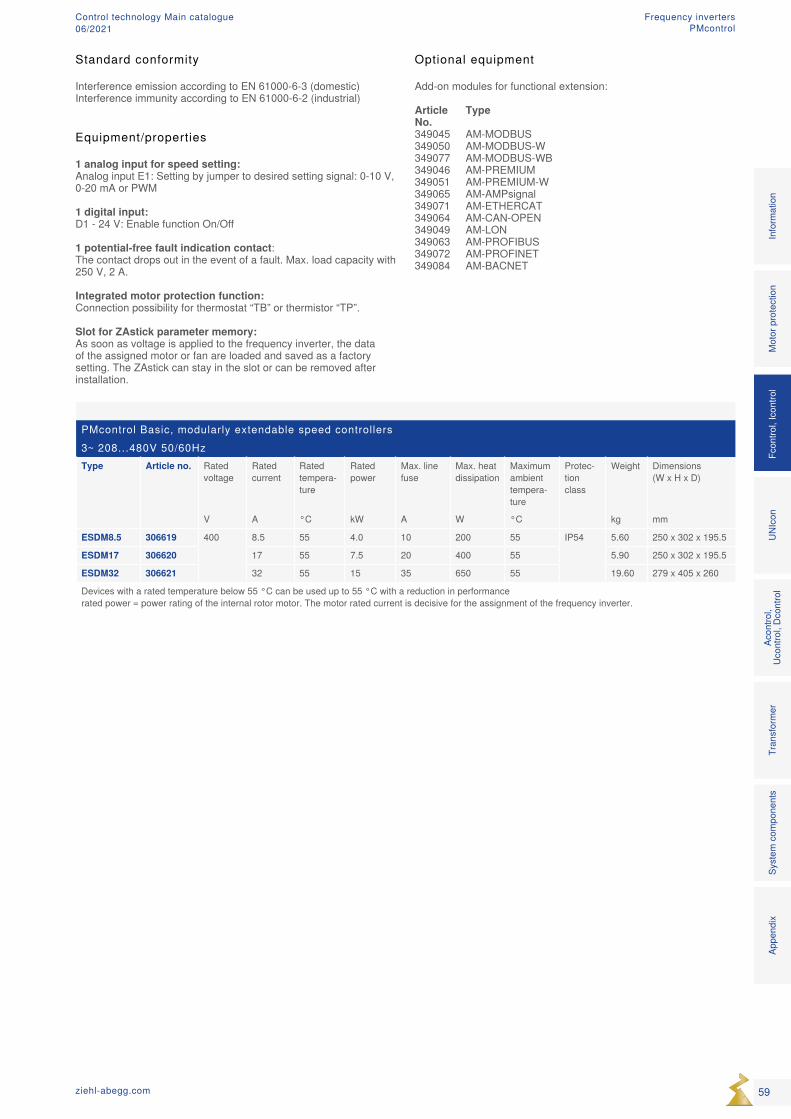
PMcontrol Basic, modularly extendable speed controllers3~ 208...480V 50/60HzType Article no. Rated
voltageRated current
Rated tempera-ture
Rated power
Max. line fuse
Max. heat dissipation
Maximum ambient tempera-ture
Protec-tion class
Weight Dimensions (W x H x D)
V A °C kW A W °C kg mm
ESDM8.5 306619 400 8.5 55 4.0 10 200 55 IP54 5.60 250 x 302 x 195.5
ESDM17 306620 17 55 7.5 20 400 55 5.90 250 x 302 x 195.5
ESDM32 306621 32 55 15 35 650 55 19.60 279 x 405 x 260
Devices with a rated temperature below 55 °C can be used up to 55 °C with a reduction in performance rated power = power rating of the internal rotor motor. The motor rated current is decisive for the assignment of the frequency inverter.
Optional equipment
Add-on modules for functional extension:
Article Type No.349045 AM-MODBUS349050 AM-MODBUS-W349077 AM-MODBUS-WB349046 AM-PREMIUM349051 AM-PREMIUM-W349065 AM-AMPsignal349071 AM-ETHERCAT349064 AM-CAN-OPEN349049 AM-LON349063 AM-PROFIBUS349072 AM-PROFINET349084 AM-BACNET
Equipment/properties 1 analog input for speed setting: Analog input E1: Setting by jumper to desired setting signal: 0-10 V, 0-20 mA or PWM 1 digital input: D1 - 24 V: Enable function On/Off 1 potential-free fault indication contact: The contact drops out in the event of a fault. Max. load capacity with 250 V, 2 A. Integrated motor protection function: Connection possibility for thermostat “TB” or thermistor “TP”. Slot for ZAstick parameter memory: As soon as voltage is applied to the frequency inverter, the data of the assigned motor or fan are loaded and saved as a factory setting. The ZAstick can stay in the slot or can be removed after installation.
Mot
or p
rote
ctio
nFc
ontro
l, Ic
ontro
lUN
Icon
Acon
trol,
Ucon
trol,
Dcon
trol
Tran
sfor
mer
Syst
em c
ompo
nent
sIn
form
atio
nAp
pend
ix
59ziehl-abegg.com
Standard conformity
Interference emission according to EN 61000-6-3 (domestic)Interference immunity according to EN 61000-6-2 (industrial)
Frequency invertersPMcontrol
Control technology Main catalogue06/2021
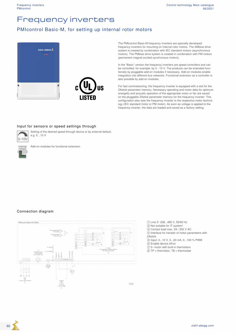
Input for sensors or speed settings through
0-10V
Setting of the desired speed through device or by external default, e.g. 0…10 V
Add-on modules for functional extension
① Line 3~ 208...480 V, 50/60 Hz ② Not suitable for IT system! ③ Contact load max. 2A / 250 V AC ④ Interface for transfer of motor parameters with ZAstick ⑤ Input: 0...10 V, 0...20 mA, 0...100 % PWM ⑥ Enable device off/on ⑦ 3~ motor with built-in thermistors ⑧ TP = thermistor, TB = thermostat
Connection diagram
The PMIcontrol Basic-M frequency inverters are specially developed frequency inverters for mounting on internal rotor motors. The AMblue drive system is created by combination with IEC standard motors (asynchronous motors). The PMblue drive system is created in combination with PM motors (permanent magnet excited synchronous motors). In the “Basic” version the frequency inverters are speed controllers and can be controlled, for example, by 0 - 10 V. The products can be extended func-tionally by pluggable add-on modules if necessary. Add-on modules enable integration into different bus networks. Functional extension as a controller is also possible by add-on modules. For fast commissioning, the frequency inverter is equipped with a slot for the ZAstick parameter memory. Necessary operating and motor data for optimum energetic and acoustic operation of the appropriate motor or fan are saved on the pluggable ZAstick parameter memory for the frequency inverter. This configuration also sets the frequency inverter to the respective motor technol-ogy (IEC standard motor or PM motor). As soon as voltage is applied to the frequency inverter, the data are loaded and saved as a factory setting.
Frequency invertersPMIcontrol Basic-M, for setting up internal rotor motors
60 ziehl-abegg.com
Frequency invertersPMcontrol
Control technology Main catalogue06/2021
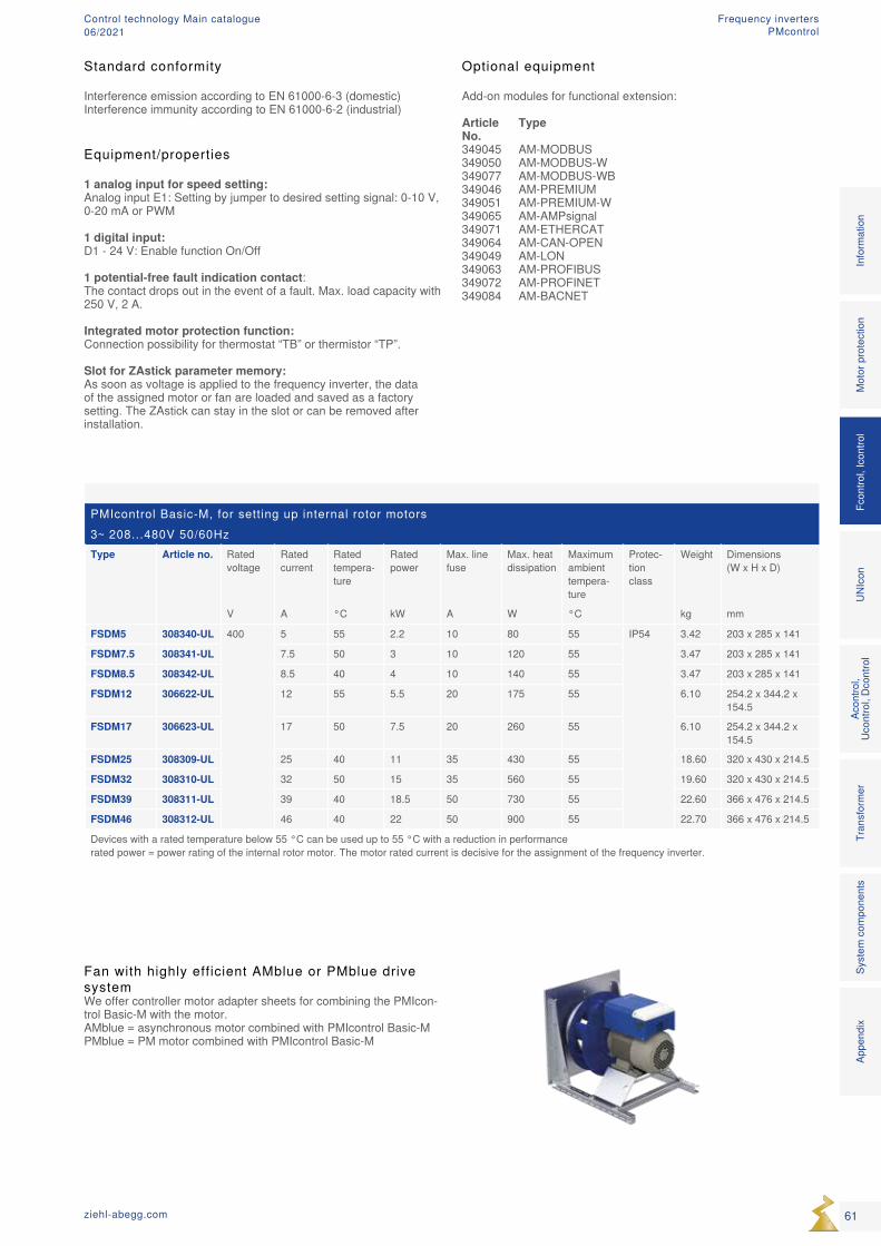
PMIcontrol Basic-M, for setting up internal rotor motors3~ 208...480V 50/60HzType Article no. Rated
voltageRated current
Rated tempera-ture
Rated power
Max. line fuse
Max. heat dissipation
Maximum ambient tempera-ture
Protec-tion class
Weight Dimensions (W x H x D)
V A °C kW A W °C kg mm
FSDM5 308340-UL 400 5 55 2.2 10 80 55 IP54 3.42 203 x 285 x 141
FSDM7.5 308341-UL 7.5 50 3 10 120 55 3.47 203 x 285 x 141
FSDM8.5 308342-UL 8.5 40 4 10 140 55 3.47 203 x 285 x 141
FSDM12 306622-UL 12 55 5.5 20 175 55 6.10 254.2 x 344.2 x 154.5
FSDM17 306623-UL 17 50 7.5 20 260 55 6.10 254.2 x 344.2 x 154.5
FSDM25 308309-UL 25 40 11 35 430 55 18.60 320 x 430 x 214.5
FSDM32 308310-UL 32 50 15 35 560 55 19.60 320 x 430 x 214.5
FSDM39 308311-UL 39 40 18.5 50 730 55 22.60 366 x 476 x 214.5
FSDM46 308312-UL 46 40 22 50 900 55 22.70 366 x 476 x 214.5
Devices with a rated temperature below 55 °C can be used up to 55 °C with a reduction in performance rated power = power rating of the internal rotor motor. The motor rated current is decisive for the assignment of the frequency inverter.
Fan with highly efficient AMblue or PMblue drive systemWe offer controller motor adapter sheets for combining the PMIcon-trol Basic-M with the motor. AMblue = asynchronous motor combined with PMIcontrol Basic-M PMblue = PM motor combined with PMIcontrol Basic-M
Equipment/properties 1 analog input for speed setting: Analog input E1: Setting by jumper to desired setting signal: 0-10 V, 0-20 mA or PWM 1 digital input: D1 - 24 V: Enable function On/Off 1 potential-free fault indication contact: The contact drops out in the event of a fault. Max. load capacity with 250 V, 2 A. Integrated motor protection function: Connection possibility for thermostat “TB” or thermistor “TP”. Slot for ZAstick parameter memory: As soon as voltage is applied to the frequency inverter, the data of the assigned motor or fan are loaded and saved as a factory setting. The ZAstick can stay in the slot or can be removed after installation.
Optional equipment
Add-on modules for functional extension:
Article Type No.349045 AM-MODBUS349050 AM-MODBUS-W349077 AM-MODBUS-WB349046 AM-PREMIUM349051 AM-PREMIUM-W349065 AM-AMPsignal349071 AM-ETHERCAT349064 AM-CAN-OPEN349049 AM-LON349063 AM-PROFIBUS349072 AM-PROFINET349084 AM-BACNET
Mot
or p
rote
ctio
nFc
ontro
l, Ic
ontro
lUN
Icon
Acon
trol,
Ucon
trol,
Dcon
trol
Tran
sfor
mer
Syst
em c
ompo
nent
sIn
form
atio
nAp
pend
ix
61ziehl-abegg.com
Standard conformity
Interference emission according to EN 61000-6-3 (domestic)Interference immunity according to EN 61000-6-2 (industrial)
Frequency invertersPMcontrol
Control technology Main catalogue06/2021
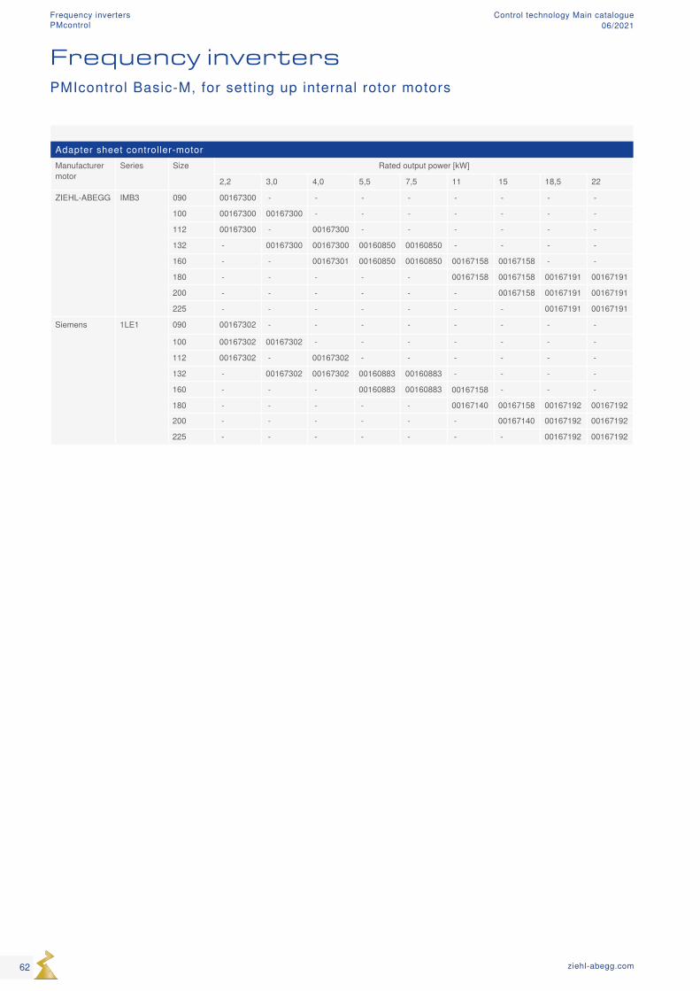
Adapter sheet controller-motorManufacturer motor
Series Size Rated output power [kW]
2,2 3,0 4,0 5,5 7,5 11 15 18,5 22
ZIEHL-ABEGG IMB3 090 00167300 - - - - - - - -
100 00167300 00167300 - - - - - - -
112 00167300 - 00167300 - - - - - -
132 - 00167300 00167300 00160850 00160850 - - - -
160 - - 00167301 00160850 00160850 00167158 00167158 - -
180 - - - - - 00167158 00167158 00167191 00167191
200 - - - - - - 00167158 00167191 00167191
225 - - - - - - - 00167191 00167191
Siemens 1LE1 090 00167302 - - - - - - - -
100 00167302 00167302 - - - - - - -
112 00167302 - 00167302 - - - - - -
132 - 00167302 00167302 00160883 00160883 - - - -
160 - - - 00160883 00160883 00167158 - - -
180 - - - - - 00167140 00167158 00167192 00167192
200 - - - - - - 00167140 00167192 00167192
225 - - - - - - - 00167192 00167192
Frequency invertersPMIcontrol Basic-M, for setting up internal rotor motors
62 ziehl-abegg.com
Frequency invertersPMcontrol
Control technology Main catalogue06/2021

63ziehl-abegg.com
Mot
or p
rote
ctio
nFc
ontro
l, Ic
ontro
lUN
Icon
Acon
trol,
Ucon
trol,
Dcon
trol
Tran
sfor
mer
Syst
em c
ompo
nent
sIn
form
atio
nAp
pend
ix
Frequency invertersPMcontrol
Control technology Main catalogue06/2021
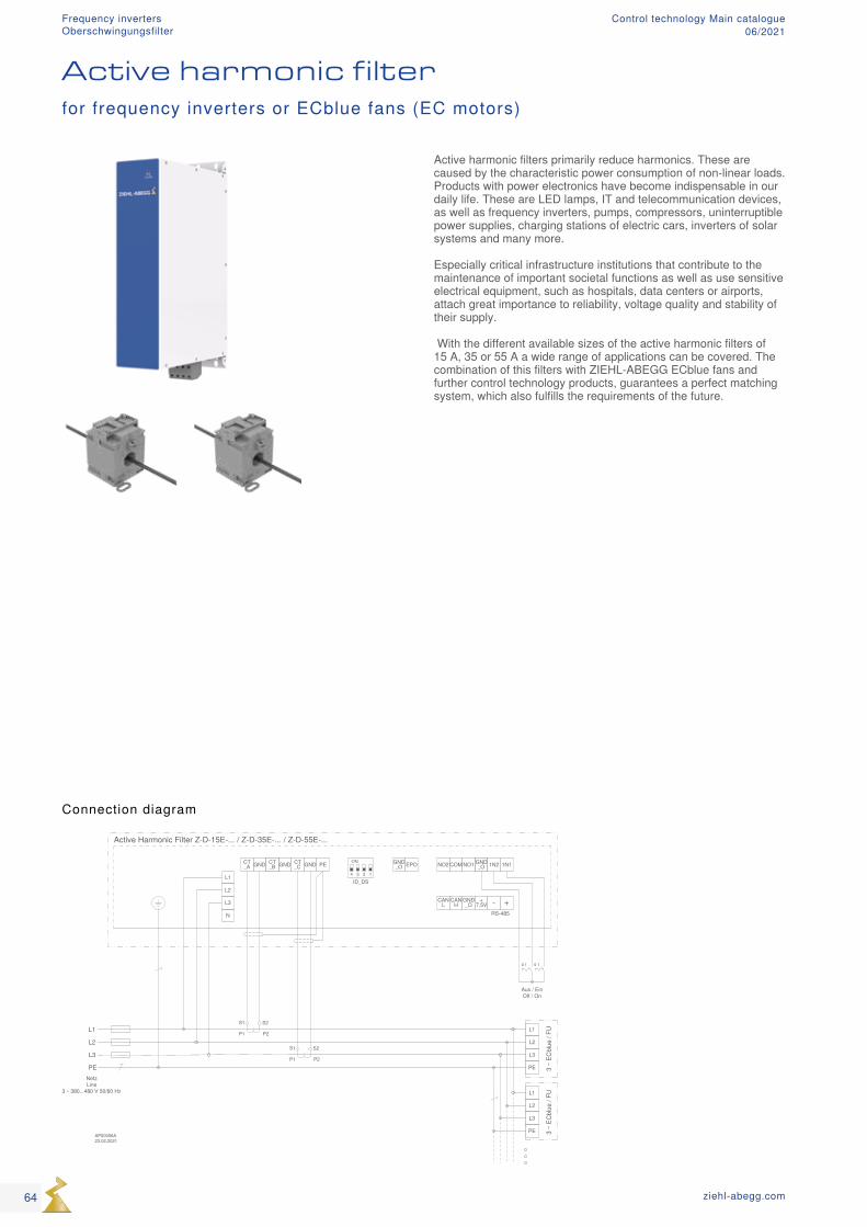
Connection diagram
Active harmonic filter
Active harmonic filters primarily reduce harmonics. These are caused by the characteristic power consumption of non-linear loads. Products with power electronics have become indispensable in our daily life. These are LED lamps, IT and telecommunication devices, as well as frequency inverters, pumps, compressors, uninterruptible power supplies, charging stations of electric cars, inverters of solar systems and many more. Especially critical infrastructure institutions that contribute to the maintenance of important societal functions as well as use sensitive electrical equipment, such as hospitals, data centers or airports, attach great importance to reliability, voltage quality and stability of their supply. With the different available sizes of the active harmonic filters of 15 A, 35 or 55 A a wide range of applications can be covered. The combination of this filters with ZIEHL-ABEGG ECblue fans and further control technology products, guarantees a perfect matching system, which also fulfills the requirements of the future.
for frequency inverters or ECblue fans (EC motors)
64 ziehl-abegg.com
Frequency inverters Control technology Main catalogue06/2021Oberschwingungsfilter
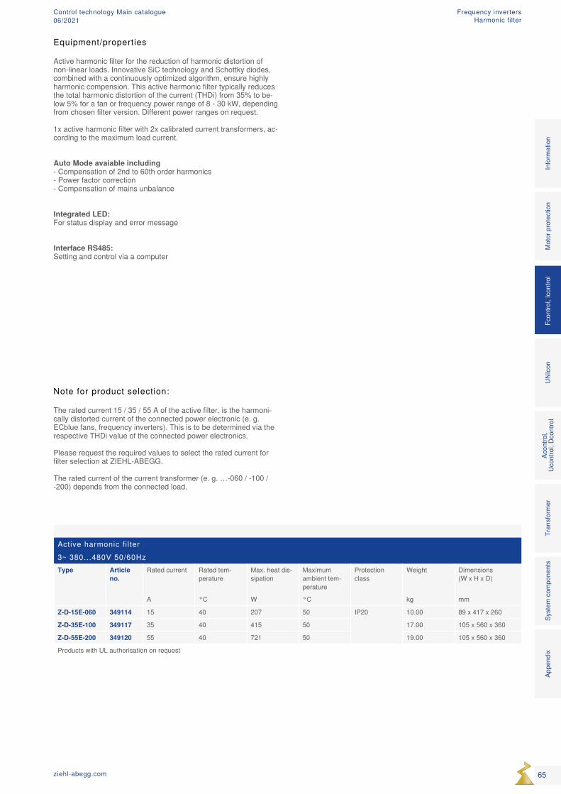
Equipment/properties
Active harmonic filter for the reduction of harmonic distortion of non-linear loads. Innovative SiC technology and Schottky diodes, combined with a continuously optimized algorithm, ensure highly harmonic compension. This active harmonic filter typically reduces the total harmonic distortion of the current (THDi) from 35% to be-low 5% for a fan or frequency power range of 8 - 30 kW, depending from chosen filter version. Different power ranges on request. 1x active harmonic filter with 2x calibrated current transformers, ac-cording to the maximum load current.
Auto Mode avaiable including - Compensation of 2nd to 60th order harmonics - Power factor correction - Compensation of mains unbalance
Integrated LED: For status display and error message
Interface RS485: Setting and control via a computer
Note for product selection:
The rated current 15 / 35 / 55 A of the active filter, is the harmoni-cally distorted current of the connected power electronic (e. g. ECblue fans, frequency inverters). This is to be determined via the respective THDi value of the connected power electronics. Please request the required values to select the rated current for filter selection at ZIEHL-ABEGG. The rated current of the current transformer (e. g. …-060 / -100 / -200) depends from the connected load.
Active harmonic fi lter3~ 380...480V 50/60HzType Article
no.Rated current Rated tem-
peratureMax. heat dis-sipation
Maximum ambient tem-perature
Protection class
Weight Dimensions (W x H x D)
A °C W °C kg mm
Z-D-15E-060 349114 15 40 207 50 IP20 10.00 89 x 417 x 260
Z-D-35E-100 349117 35 40 415 50 17.00 105 x 560 x 360
Z-D-55E-200 349120 55 40 721 50 19.00 105 x 560 x 360
Products with UL authorisation on request
Mot
or p
rote
ctio
nFc
ontro
l, Ic
ontro
lUN
Icon
Acon
trol,
Ucon
trol,
Dcon
trol
Tran
sfor
mer
Syst
em c
ompo
nent
sIn
form
atio
nAp
pend
ix
65ziehl-abegg.com
Frequency invertersControl technology Main catalogue06/2021 Harmonic filter
66 ziehl-abegg.com
Control module Control technology Main catalogue06/2021
Product overview
UNIcon universal control module Page 68 UNIcon sensor control module for pressure Page 74 UNIcon sensor control module for differential pressure / air flow Page 76
UNIcon temperature control module Page 78
Control module
67ziehl-abegg.com
Mot
or p
rote
ctio
nFc
ontro
l, Ic
ontro
lUN
Icon
Acon
trol,
Ucon
trol,
Dcon
trol
Tran
sfor
mer
Syst
em c
ompo
nent
s In
form
atio
n Ap
pend
ix
Control moduleControl technology Main catalogue06/2021
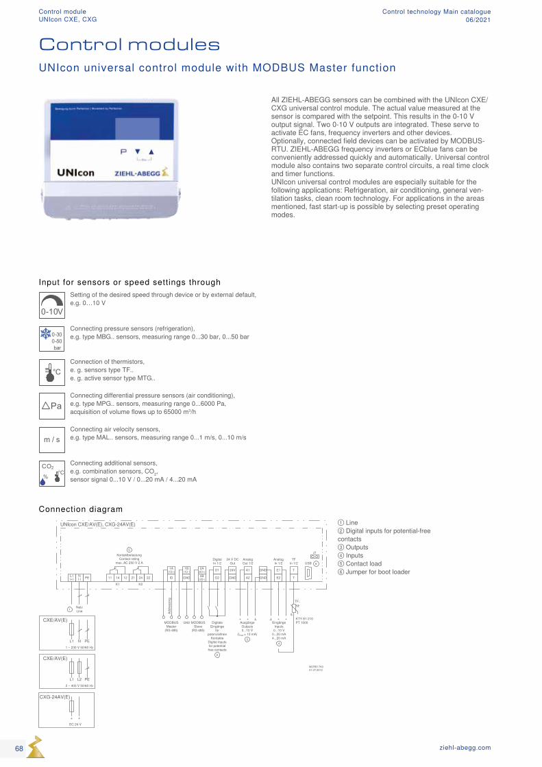
UNIcon CXE/AV(E), CXG-24AV(E)
K1 K2
MCRE17K031.07.2012
NetzLine
N(-)
L1(+) PE GND
24V
GNDID D2
D1
A2
A1
GND
GND
E2
E1
AusgängeOutputs0...10 V
(Imax = 10 mA)
+
3
+
2
1
DigitalIn 1/2
AnalogOut 1/2
AnalogIn 1/2
24 V DCOut
EingängeInputs
0...10 V0...20 mA4...20 mA
+
4
+
11 14 12 21 24 22
KontaktbelastungContact rating
max. AC 250 V 2 A
5
NL1 PE1 ~ 230 V 50/60 Hz
CXE/AV(E)
L2L1 PE2 ~ 400 V 50/60 Hz
CXE/AV(E)
+DC 24 V
CXG-24AV(E)
T
T2A(2D+)2B
(2D-)
1A(1D+)
1B(1D-)
GNDMODBUSMaster
(RS-485)
MODBUSSlave
(RS-485)
q
TF..
KTY 81-210PT 1000Digitale
Eingängefür
potenzialfreieKontakte
Digital inputsfor potentialfree contacts
J1
USB 6TF
In 1/2
Addr
essi
ng
Input for sensors or speed settings through
0-10V
Setting of the desired speed through device or by external default, e.g. 0…10 V
0-300-50bar
Connecting pressure sensors (refrigeration), e.g. type MBG.. sensors, measuring range 0...30 bar, 0...50 bar
°CConnection of thermistors, e. g. sensors type TF.. e. g. active sensor type MTG..
PaConnecting differential pressure sensors (air conditioning), e.g. type MPG.. sensors, measuring range 0...6000 Pa, acquisition of volume flows up to 65000 m3/h
m / sConnecting air velocity sensors, e.g. type MAL.. sensors, measuring range 0...1 m/s, 0...10 m/s
CO2
%
°C
Connecting additional sensors, e.g. combination sensors, CO2, sensor signal 0...10 V / 0...20 mA / 4...20 mA
① Line ② Digital inputs for potential-free contacts ③ Outputs ④ Inputs ⑤ Contact load ⑥ Jumper for boot loader
Connection diagram
All ZIEHL-ABEGG sensors can be combined with the UNIcon CXE/CXG universal control module. The actual value measured at the sensor is compared with the setpoint. This results in the 0-10 V output signal. Two 0-10 V outputs are integrated. These serve to activate EC fans, frequency inverters and other devices. Optionally, connected field devices can be activated by MODBUS-RTU. ZIEHL-ABEGG frequency inverters or ECblue fans can be conveniently addressed quickly and automatically. Universal control module also contains two separate control circuits, a real time clock and timer functions. UNIcon universal control modules are especially suitable for the following applications: Refrigeration, air conditioning, general ven-tilation tasks, clean room technology. For applications in the areas mentioned, fast start-up is possible by selecting preset operating modes.
Control modulesUNIcon universal control module with MODBUS Master function
68 ziehl-abegg.com
Control moduleUNIcon CXE, CXG
Control technology Main catalogue06/2021
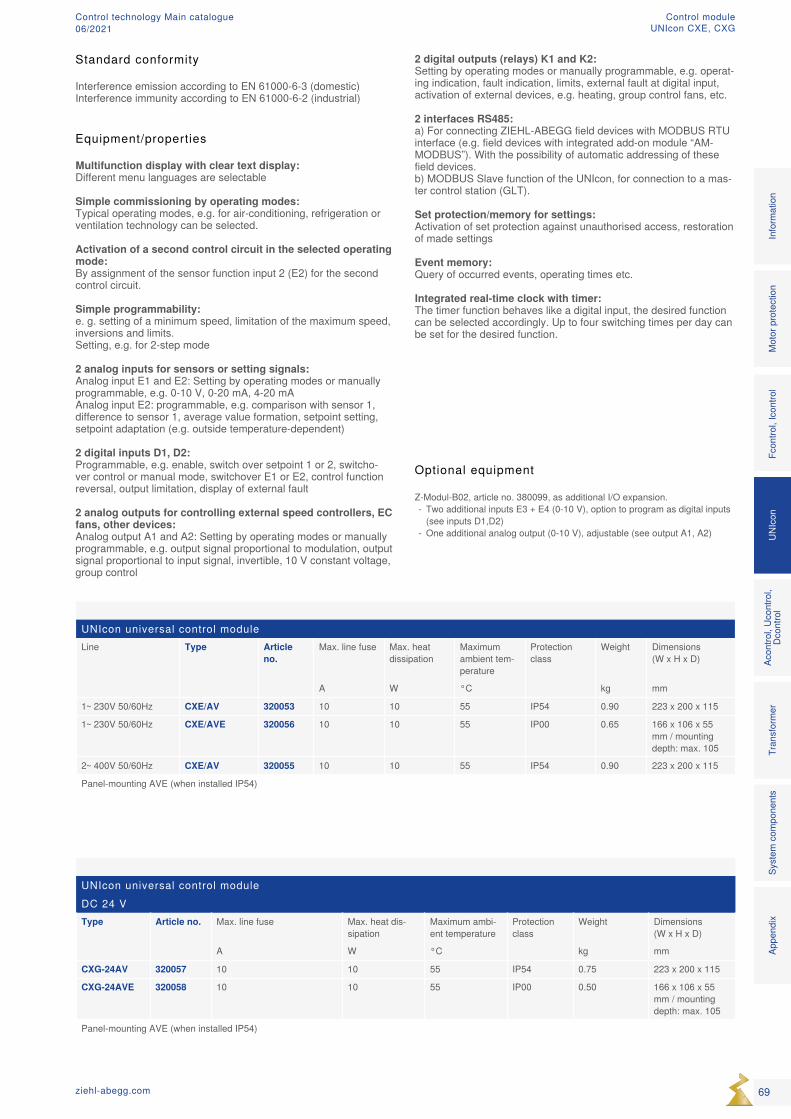
UNIcon universal control moduleLine Type Article
no.Max. line fuse Max. heat
dissipationMaximum ambient tem-perature
Protection class
Weight Dimensions (W x H x D)
A W °C kg mm
1~ 230V 50/60Hz CXE/AV 320053 10 10 55 IP54 0.90 223 x 200 x 115
1~ 230V 50/60Hz CXE/AVE 320056 10 10 55 IP00 0.65 166 x 106 x 55 mm / mounting depth: max. 105
2~ 400V 50/60Hz CXE/AV 320055 10 10 55 IP54 0.90 223 x 200 x 115
Panel-mounting AVE (when installed IP54)
UNIcon universal control moduleDC 24 VType Article no. Max. line fuse Max. heat dis-
sipationMaximum ambi-ent temperature
Protection class
Weight Dimensions (W x H x D)
A W °C kg mm
CXG-24AV 320057 10 10 55 IP54 0.75 223 x 200 x 115
CXG-24AVE 320058 10 10 55 IP00 0.50 166 x 106 x 55 mm / mounting depth: max. 105
Panel-mounting AVE (when installed IP54)
Equipment/properties
Multifunction display with clear text display: Different menu languages are selectable
Simple commissioning by operating modes: Typical operating modes, e.g. for air-conditioning, refrigeration or ventilation technology can be selected.
Activation of a second control circuit in the selected operating mode: By assignment of the sensor function input 2 (E2) for the second control circuit.
Simple programmability: e. g. setting of a minimum speed, limitation of the maximum speed, inversions and limits. Setting, e.g. for 2-step mode
2 analog inputs for sensors or setting signals: Analog input E1 and E2: Setting by operating modes or manually programmable, e.g. 0-10 V, 0-20 mA, 4-20 mA Analog input E2: programmable, e.g. comparison with sensor 1, difference to sensor 1, average value formation, setpoint setting, setpoint adaptation (e.g. outside temperature-dependent)
2 digital inputs D1, D2: Programmable, e.g. enable, switch over setpoint 1 or 2, switcho-ver control or manual mode, switchover E1 or E2, control function reversal, output limitation, display of external fault
2 analog outputs for controlling external speed controllers, EC fans, other devices: Analog output A1 and A2: Setting by operating modes or manually programmable, e.g. output signal proportional to modulation, output signal proportional to input signal, invertible, 10 V constant voltage, group control
Standard conformity
Interference emission according to EN 61000-6-3 (domestic)Interference immunity according to EN 61000-6-2 (industrial)
Optional equipment
Z-Modul-B02, article no. 380099, as additional I/O expansion. - Two additional inputs E3 + E4 (0-10 V), option to program as digital inputs (see inputs D1,D2)
- One additional analog output (0-10 V), adjustable (see output A1, A2)
Mot
or p
rote
ctio
nFc
ontro
l, Ic
ontro
lUN
Icon
Acon
trol,
Ucon
trol,
Dcon
trol
Tran
sfor
mer
Syst
em c
ompo
nent
s In
form
atio
n Ap
pend
ix
69ziehl-abegg.com
2 digital outputs (relays) K1 and K2: Setting by operating modes or manually programmable, e.g. operat-ing indication, fault indication, limits, external fault at digital input, activation of external devices, e.g. heating, group control fans, etc.
2 interfaces RS485: a) For connecting ZIEHL-ABEGG field devices with MODBUS RTU interface (e.g. field devices with integrated add-on module “AM-MODBUS”). With the possibility of automatic addressing of these field devices. b) MODBUS Slave function of the UNIcon, for connection to a mas-ter control station (GLT).
Set protection/memory for settings: Activation of set protection against unauthorised access, restoration of made settings
Event memory: Query of occurred events, operating times etc.
Integrated real-time clock with timer: The timer function behaves like a digital input, the desired function can be selected accordingly. Up to four switching times per day can be set for the desired function.
Control moduleUNIcon CXE, CXG
Control technology Main catalogue06/2021
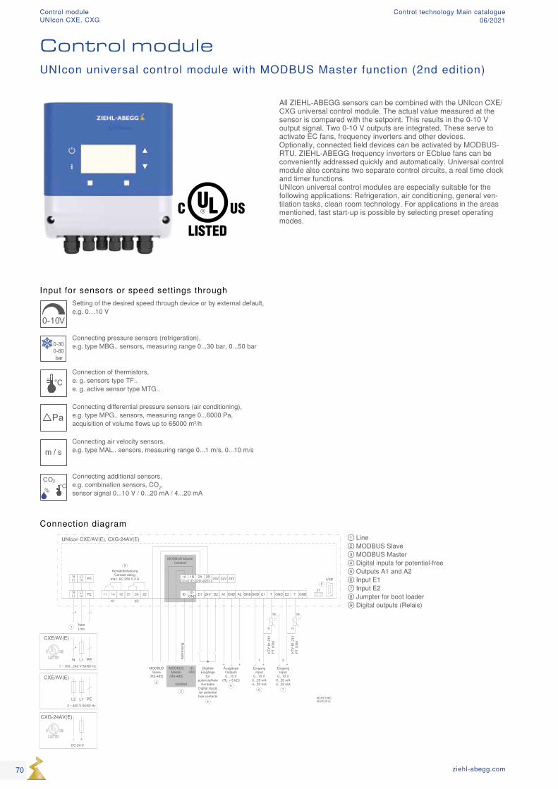
Input for sensors or speed settings through
0-10V
Setting of the desired speed through device or by external default, e.g. 0…10 V
0-300-50bar
Connecting pressure sensors (refrigeration), e.g. type MBG.. sensors, measuring range 0...30 bar, 0...50 bar
°CConnection of thermistors, e. g. sensors type TF.. e. g. active sensor type MTG..
PaConnecting differential pressure sensors (air conditioning), e.g. type MPG.. sensors, measuring range 0...6000 Pa, acquisition of volume flows up to 65000 m3/h
m / sConnecting air velocity sensors, e.g. type MAL.. sensors, measuring range 0...1 m/s, 0...10 m/s
CO2
%
°C
Connecting additional sensors, e.g. combination sensors, CO2, sensor signal 0...10 V / 0...20 mA / 4...20 mA
① Line ② MODBUS Slave ③ MODBUS Master ④ Digital inputs for potential-free ⑤ Outputs A1 and A2 ⑥ Input E1 ⑦ Input E2 ⑧ Jumpter for boot loader ⑨ Digital outputs (Relais)
Connection diagram
All ZIEHL-ABEGG sensors can be combined with the UNIcon CXE/CXG universal control module. The actual value measured at the sensor is compared with the setpoint. This results in the 0-10 V output signal. Two 0-10 V outputs are integrated. These serve to activate EC fans, frequency inverters and other devices. Optionally, connected field devices can be activated by MODBUS-RTU. ZIEHL-ABEGG frequency inverters or ECblue fans can be conveniently addressed quickly and automatically. Universal control module also contains two separate control circuits, a real time clock and timer functions. UNIcon universal control modules are especially suitable for the following applications: Refrigeration, air conditioning, general ven-tilation tasks, clean room technology. For applications in the areas mentioned, fast start-up is possible by selecting preset operating modes.
Control moduleUNIcon universal control module with MODBUS Master function (2nd edition)
70 ziehl-abegg.com
Control moduleUNIcon CXE, CXG
Control technology Main catalogue06/2021
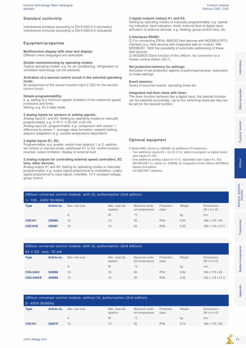
UNIcon universal control module, with UL authorisation (2nd edition)1~ 100...240V 50/60HzType Article no. Max. line fuse Max. heat dis-
sipationMaximum ambi-ent temperature
Protection class
Weight Dimensions (W x H x D)
A W °C kg mm
CXE/AV 320066 10 10 55 IP54 0.63 166 x 175 x 60
CXE/AVE 320067 10 10 55 IP00 0.55 182 x 118 x 57.5
UNIcon universal control module, with UL authorisation (2nd edition)24 V DC, max. 70 mAType Article no. Max. line fuse Max. heat dis-
sipationMaximum ambi-ent temperature
Protection class
Weight Dimensions (W x H x D)
A W °C kg mm
CXG-24AV 320068 10 10 55 IP54 0.60 166 x 175 x 60
CXG-24AVE 320069 10 10 55 IP00 0.52 182 x 118 x 57.5
UNIcon universal control module, without UL authorisation (2nd edition)2~ 400V 50/60HzType Article no. Max. line fuse Max. heat dis-
sipationMaximum ambi-ent temperature
Protection class
Weight Dimensions (W x H x D)
A W °C kg mm
CXE/AV 320070 10 10 55 IP54 0.74 166 x 175 x 60
Equipment/properties
Multifunction display with clear text display: Different menu languages are selectable
Simple commissioning by operating modes: Typical operating modes, e.g. for air-conditioning, refrigeration or ventilation technology can be selected.
Activation of a second control circuit in the selected operating mode: By assignment of the sensor function input 2 (E2) for the second control circuit.
Simple programmability: e. g. setting of a minimum speed, limitation of the maximum speed, inversions and limits. Setting, e.g. for 2-step mode
2 analog inputs for sensors or setting signals: Analog input E1 and E2: Setting by operating modes or manually programmable, e.g. 0-10 V, 0-20 mA, 4-20 mA Analog input E2: programmable, e.g. comparison with sensor 1, difference to sensor 1, average value formation, setpoint setting, setpoint adaptation (e.g. outside temperature-dependent)
2 digital inputs D1, D2: Programmable, e.g. enable, switch over setpoint 1 or 2, switcho-ver control or manual mode, switchover E1 or E2, control function reversal, output limitation, display of external fault
2 analog outputs for controlling external speed controllers, EC fans, other devices: Analog output A1 and A2: Setting by operating modes or manually programmable, e.g. output signal proportional to modulation, output signal proportional to input signal, invertible, 10 V constant voltage, group control
Standard conformity
Interference emission according to EN 61000-6-3 (domestic)Interference immunity according to EN 61000-6-2 (industrial)
Optional equipment
Z-Modul-B02, article no. 380099, as additional I/O expansion. - Two additional inputs E3 + E4 (0-10 V), option to program as digital inputs (see inputs D1,D2)
- One additional analog output (0-10 V), adjustable (see output A1, A2)AM-BACNET-U, article no. 349088, for integration of the UNIcon MODBUS Master 2nd edition into BACNET networks.
Mot
or p
rote
ctio
nFc
ontro
l, Ic
ontro
lUN
Icon
Acon
trol,
Ucon
trol,
Dcon
trol
Tran
sfor
mer
Syst
em c
ompo
nent
s In
form
atio
n Ap
pend
ix
71ziehl-abegg.com
2 digital outputs (relays) K1 and K2: Setting by operating modes or manually programmable, e.g. operat-ing indication, fault indication, limits, external fault at digital input, activation of external devices, e.g. heating, group control fans, etc.
2 interfaces RS485: ③ For connecting ZIEHL-ABEGG field devices with MODBUS RTU interface (e.g. field devices with integrated add-on module “AM-MODBUS”). With the possibility of automatic addressing of these field devices. ② MODBUS Slave function of the UNIcon, for connection to a master control station (GLT).
Set protection/memory for settings: Activation of set protection against unauthorised access, restoration of made settings
Event memory: Query of occurred events, operating times etc.
Integrated real-time clock with timer: The timer function behaves like a digital input, the desired function can be selected accordingly. Up to four switching times per day can be set for the desired function.
Control moduleUNIcon CXE, CXG
Control technology Main catalogue06/2021
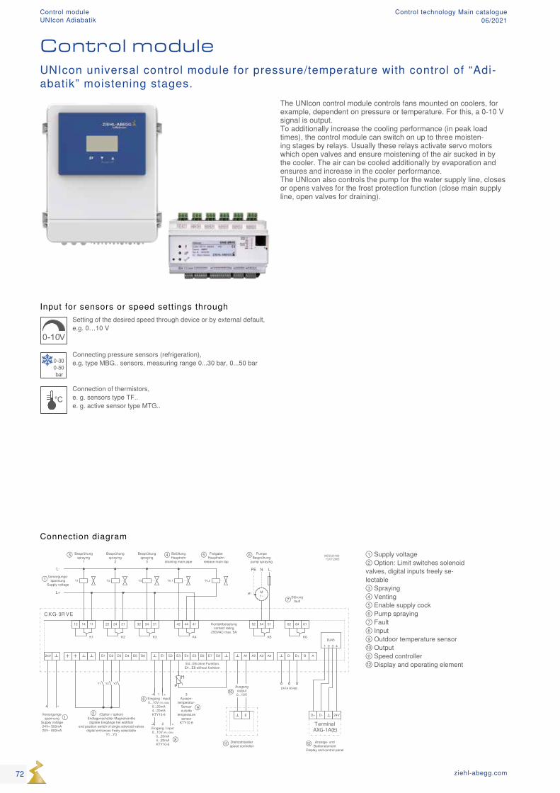
D-D+ 24VVersorgungs-spannung
Supply voltage24V= 500mA20V~ 600mA
Anzeige- und Bedienelement
Display and control panel
D4 D5 D6D1 D3D224V E1 E2 E3 E4 E5 E6 E7 E8 A1 A2 A3 A4 D- D+ AB
12 14 11 22 24 21 32 34 31 42 44 41 52 54 51 62 64 61
Y1 Y2 Y3 Y0.1
M1~
Besprühungspraying
1
Besprühungspraying
3
PumpeBesprühung
pump spraying
Störungfault
Y1 Y2 Y3
Y0.2
E
Besprühungspraying
2
Aussen-temperatur-
Sensoroutside
temperature sensor
KTY10-6
Ausgangoutput0...10V
+Eingang / input0...10V (Ri>100k)
0...20mA4...20mAKTY10-6
2
Eingang / input0...10V (Ri>100k)
0...20mA4...20mAKTY10-6
1 3
M1L+
L- N L
MOCU01K313.07.2005
Versorgungs-spannung
Supply voltage
(Option / option) Endlagenschalter Magnetventile
digitale Eingänge frei wählbarend position switch of single solenoid valves
digital entrances freely selectableY1...Y3
C KG- 3R VE
PE
K1 K2 K3 K4 K5 K6
Kontaktbelastungcontact rating
250VAC max. 5A
+
Drehzahlstellerspeed controller
+
E4...E8 ohne FunktionE4...E8 without funktion
DATA RS485
Terminal
FreigabeHaupthahn
release main tap
BelüftungHauptrohr
draining main pipe
RJ45
1 2 3 4
AXG-1A(E)
①
①
②
③ ④ ⑤ ⑥
⑦
⑧
⑧
⑨
⑩
⑪ ⑫
Input for sensors or speed settings through
0-10V
Setting of the desired speed through device or by external default, e.g. 0…10 V
0-300-50bar
Connecting pressure sensors (refrigeration), e.g. type MBG.. sensors, measuring range 0...30 bar, 0...50 bar
°CConnection of thermistors, e. g. sensors type TF.. e. g. active sensor type MTG..
① Supply voltage ② Option: Limit switches solenoid valves, digital inputs freely se-lectable ③ Spraying ④ Venting ⑤ Enable supply cock ⑥ Pump spraying ⑦ Fault ⑧ Input ⑨ Outdoor temperature sensor ⑩ Output ⑪ Speed controller ⑫ Display and operating element
Connection diagram
The UNIcon control module controls fans mounted on coolers, for example, dependent on pressure or temperature. For this, a 0-10 V signal is output. To additionally increase the cooling performance (in peak load times), the control module can switch on up to three moisten-ing stages by relays. Usually these relays activate servo motors which open valves and ensure moistening of the air sucked in by the cooler. The air can be cooled additionally by evaporation and ensures and increase in the cooler performance. The UNIcon also controls the pump for the water supply line, closes or opens valves for the frost protection function (close main supply line, open valves for draining).
Control moduleUNIcon universal control module for pressure/temperature with control of “Adi-abatik” moistening stages.
72 ziehl-abegg.com
Control moduleUNIcon Adiabatik
Control technology Main catalogue06/2021
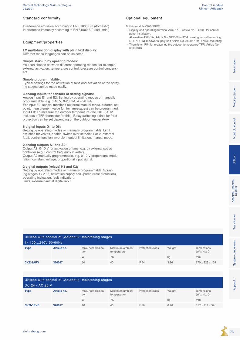
UNIcon with control of „Adiabatik“ moistening stagesDC 24 / AC 20 VType Article no. Max. heat dissipa-
tionMaximum ambient temperature
Protection class Weight Dimensions (W x H x D)
W °C kg mm
CKG-3RVE 320017 10 40 IP20 0.40 157 x 111 x 59
UNIcon with control of „Adiabatik“ moistening stages1~ 100...240V 50/60HzType Article no. Max. heat dissipa-
tionMaximum ambient temperature
Protection class Weight Dimensions (W x H x D)
W °C kg mm
CKE-3ARV 320087 30 40 IP54 3.26 270 x 323 x 154
Optional equipment
Built-in module CKG-3RVE: - Display and operating terminal AXG-1AE, Article No. 349008 for control panel installation. Alternative AXG-1A, Article No. 349008 in IP54 housing for wall mounting.
- STEP POWER power supply unit Article No. 380067 for DIN rail mounting - Thermistor IP54 for measuring the outdoor temperature TFR, Article No. 00089846.
Equipment/properties
LC multi-function display with plain text display: Different menu languages can be selected
Simple start-up by opeating modes: You can choose between different operating modes, for example, external activation, temperature control, pressure control condens-ers.
Simple programmability: Typical settings for the activation of fans and activation of the spray-ing stages can be made easily.
3 analog inputs for sensors or setting signals: Analog input E1 and E2: Setting by operating modes or manually programmable, e.g. 0-10 V, 0-20 mA, 4 – 20 mA. For input E2, special functions (external manual mode, external set-point, measurement value for limit messages) can be programmed. Input E3: To measure the outdoor temperature (the CKE-3ARV includes a TFR thermistor for this). Relay switching points for frost protection can be set depending on the outdoor temperature
6 digital inputs D1 to D6: Setting by operating modes or manually programmable. Limit switches for valves, enable, switch over setpoint 1 or 2, external fault, control function inversion, output limitation, manual mode.
2 analog outputs A1 and A2: Output A1: 0-10 V for activation of fans, e.g. by external speed controller (e.g. Fcontrol frequency inverter). Output A2 manually programmable, e.g. 0-10 V proportional modu-lation, constant voltage, proportional input signal.
2 digital outputs (relays) K1 and K2: Setting by operating modes or manually programmable. Spray-ing stages 1 / 2 / 3, activation supply cock/pump (frost protection), operating indication, fault indication, limits, external fault at digital input.
Standard conformity
Interference emission according to EN 61000-6-3 (domestic)Interference immunity according to EN 61000-6-2 (industrial)
73ziehl-abegg.com
Mot
or p
rote
ctio
nFc
ontro
l, Ic
ontro
lUN
Icon
Acon
trol,
Ucon
trol,
Dcon
trol
Tran
sfor
mer
Syst
em c
ompo
nent
s In
form
atio
n Ap
pend
ix
Control moduleUNIcon Adiabatik
Control technology Main catalogue06/2021
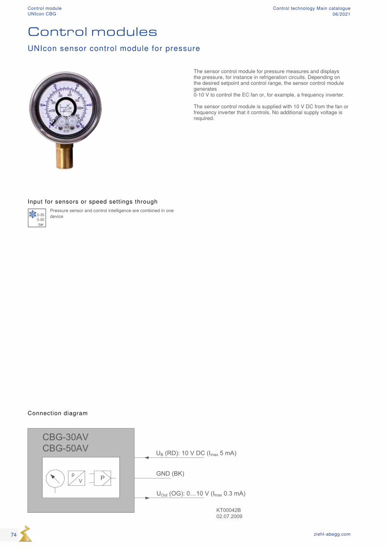
UB (RD): 10 V DC (Imax 5 mA)
UOut (OG): 0…10 V (Imax 0.3 mA)
GND (BK)
CBG-30AVCBG-50AV
Pp V
KT00042B02.07.2009
Input for sensors or speed settings through
0-300-50bar
Pressure sensor and control intelligence are combined in one device
The sensor control module for pressure measures and displays the pressure, for instance in refrigeration circuits. Depending on the desired setpoint and control range, the sensor control module generates 0-10 V to control the EC fan or, for example, a frequency inverter. The sensor control module is supplied with 10 V DC from the fan or frequency inverter that it controls. No additional supply voltage is required.
Connection diagram
UNIcon sensor control module for pressure
Control modules
74 ziehl-abegg.com
Control moduleUNIcon CBG
Control technology Main catalogue06/2021
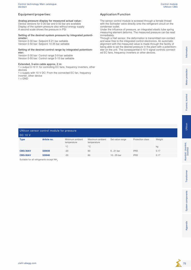
UNIcon sensor control module for pressureDC 10 VType Article no. Minimum ambient
temperatureMaximum ambient temperature
Set value range Protection class Weight
°C °C kg
CBG-30AV 320039 -20 60 6...21 bar IP65 0.17
CBG-50AV 320040 -20 60 10...35 bar IP65 0.17
Suitable for all refrigerants except NH3
Application/Function
The sensor control module is screwed through a female thread with the Schrader valve directly onto the refrigerant circuit on the condenser outlet. Under the influence of pressure, an integrated elastic tube spring measuring element deforms. The measured pressure can be read immediately. Through a Hall sensor, the deformation is transmitted non-contact and wear-free to the integrated control electronics. An automatic alignment with the measured value is made through the facility of being able to set the desired pressure in the plant with a potentiom-eter on the unit. The consequential 0-10 V signal controls connect-ed EC fans, frequency inverters or other devices.
Equipment/properties:
Analog pressure display for measured actual value: Device versions for 0-30 bar and 0-50 bar are available Display of the system pressure also without energy supply A second scale shows the pressure in PSI
Setting of the desired system pressure by integrated potenti-ometer: Version 0-30 bar: Setpoint 6-21 bar settable Version 0-50 bar: Setpoint 10-35 bar settable
Setting of the desired control range by integrated potentiom-eter: Version 0-30 bar: Control range 3-9 bar settable Version 0-50 bar: Control range 5-15 bar settable
Extended, 3-wire cable approx. 2 m: 1 x output 0-10 V: for controlling EC fans, frequency inverters, other devices 1 x supply with 10 V DC: From the connected EC fan, frequency inverter, other device 1 x GND
75ziehl-abegg.com
Mot
or p
rote
ctio
nFc
ontro
l, Ic
ontro
lUN
Icon
Acon
trol,
Ucon
trol,
Dcon
trol
Tran
sfor
mer
Syst
em c
ompo
nent
s In
form
atio
n Ap
pend
ix
Control moduleUNIcon CBG
Control technology Main catalogue06/2021
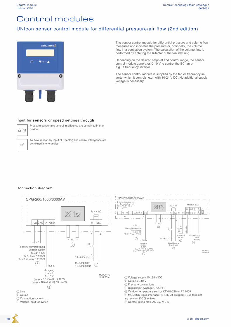
① Line ② Outout ③ Connection sockets ④ Voltage input for switch
Input for sensors or speed settings through
PaPressure sensor and control intelligence are combined in one device
m³ Air flow sensor (by input of K-factor) and control intelligence are combined in one device
① Voltage supply 10...24 V DC ② Output 0...10 V ③ Pressure connections ④ Digital input (voltage ON/OFF) ⑤ Outdoor temperature sensor KTY81-210 or PT 1000 ⑥ MODBUS Slave interface RS-485 (J1 plugged = Bus terminat-ing resistor 150 Ω active) ⑦ Contact rating max. AC 250 V 2 A
Connection diagram
UNIcon sensor control module for differential pressure/air flow (2nd edition)
Control modules
The sensor control module for differential pressure and volume flow measures and indicates the pressure or, optionally, the volume flow in a ventilation system. The calculation of the volume flow is performed by entering the K-factor of the fan inlet ring. Depending on the desired setpoint and control range, the sensor control module generates 0-10 V to control the EC fan or e.g., a frequency inverter. The sensor control module is supplied by the fan or frequency in-verter which it controls, e.g., with 10-24 V DC. No additional supply voltage is necessary.
76 ziehl-abegg.com
Control moduleUNIcon CPG
Control technology Main catalogue06/2021
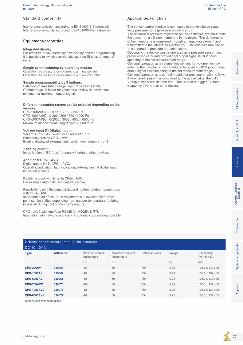
UNIcon sensor control module for pressureDC 10...24 VType Article no. Minimum ambient
temperatureMaximum ambient temperature
Protection class Weight Dimensions (W x H x D)
°C °C kg mm
CPG-200AV 320063 -10 60 IP54 0.23 106.3 x 137 x 56
CPG-1000AV 320064 -10 60 IP54 0.23 106.3 x 137 x 56
CPG-6000AV 320065 -10 60 IP54 0.23 106.3 x 137 x 56
CPG-200AVC 320075 -10 60 IP54 0.25 106.3 x 137 x 56
CPG-1000AVC 320076 -10 60 IP54 0.25 106.3 x 137 x 56
CPG-6000AVC 320077 -10 60 IP54 0.25 106.3 x 137 x 56
Dimensions with cable gland
Equipment/properties
Integrated display: For pressure or volumetric air flow display and for programming It is possible to switch over the display from SI units to Imperial units.
Simple commissioning by operating modes: Operation as pressure or volumetric air flow sensor Operation as pressure or volumetric air flow controller
Simple programmability by 3 buttons: Selection of measuring range, input of setpoints (1/2), Control range, K-factor for volumetric air flow determination, minimum or maximum output signal.
Different measuring ranges can be selected depending on the version: CPG-200AV(C): 0-50 / 100 / 150 / 200 Pa CPG-1000AV(C): 0-200 / 300 / 500 / 1000 Pa CPG-6000AV(C): 0-2000 / 3000 / 4000 / 6000 Pa Maximum air flow measuring range: 65,000 m3/h
Voltage input D1 (digital input): Version CPG-...AV: switch over setpoint 1 or 2 Extended versions CPG-...AVC: Enable, display of external fault, switch over setpoint 1 or 2 1 analog output: for activation of EC fans, frequency inverters, other devices
Additional CPG-...AVC Digital output K1 in CPG-...AVC: Operating indication, fault indication, external fault at digital input, indication of limits. Real-time clock with timer in CPG-...AVC: For example automatic setpoint switch over Possibility to shift the setpoint depanding from outdoor temperature with CPG-...AVC: In operation as pressure- or volumetric air flow controller the set-point can be shifted depending from outdoor temperature (to bring in less air during cold outdoor temperature) CPG-...AVC with interface RS485 für MODBUS RTU: Integration into network, manually or automatic addressing possible.
Standard conformity
Interference emission according to EN 61000-6-3 (domestic)Interference immunity according to EN 61000-6-2 (industrial)
Application/Function
The sensor control module is connected to the ventilation system via 2 pressure ports (pressure socket + and -). The differential pressure registered on the ventilation system affects the sensor on a silicone membrane in the device. The deformation of the membrane is registered through a measuring element and transmitted to the integrated electronics. Function: Pressure rise on +, compared to pressure on - connection. Optionally, the device can be operated as a pressure sensor, i.e., pressure indicator and proportional output signal 0-10 V corre-sponding to the set measurement range. Optional operation as a volume flow sensor, i.e. volume flow (by entering the K-factor of the centrifugal fans) and 0-10 V proportional output signal corresponding to the set measurement range. Optional operation as a control module for pressure or volume flow. The entered setpoint is compared to the actual value; the 0-10 V output signal results from that. That is used to trigger EC fans, frequency inverters or other devices.
77ziehl-abegg.com
Mot
or p
rote
ctio
nFc
ontro
l, Ic
ontro
lUN
Icon
Acon
trol,
Ucon
trol,
Dcon
trol
Tran
sfor
mer
Syst
em c
ompo
nent
s In
form
atio
n Ap
pend
ix
Control moduleUNIcon CPG
Control technology Main catalogue06/2021
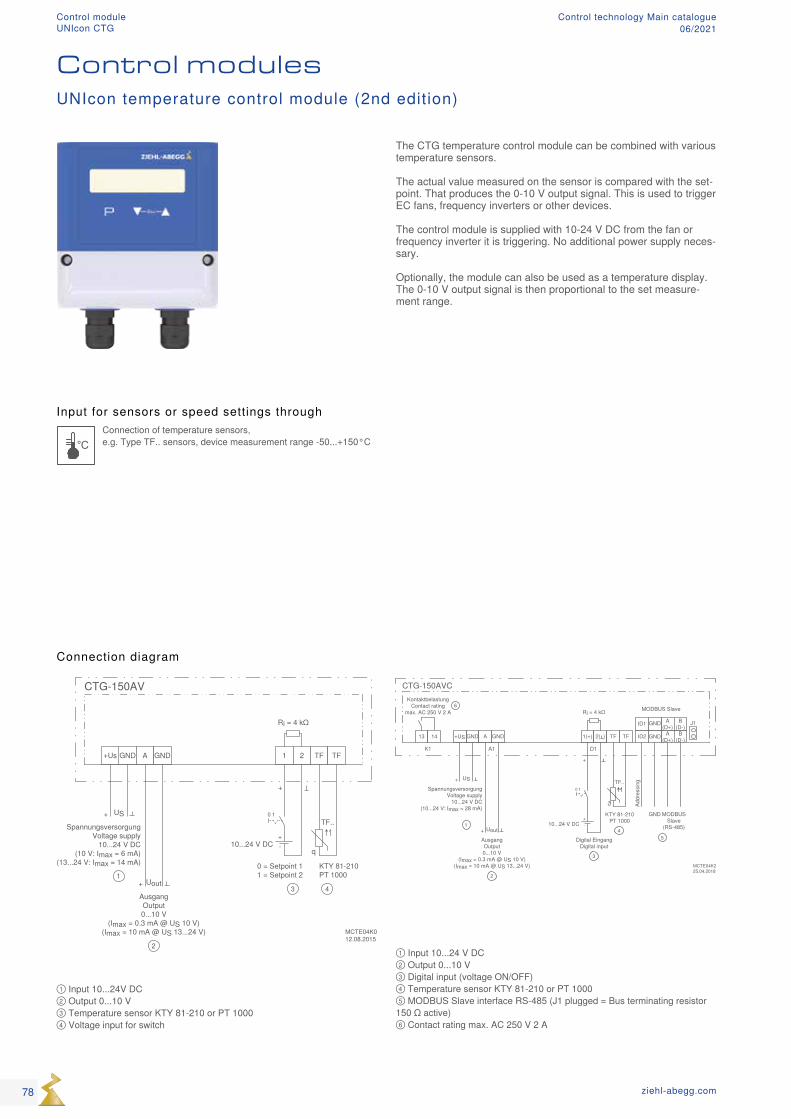
Input for sensors or speed settings through
°CConnection of temperature sensors, e.g. Type TF.. sensors, device measurement range -50...+150°C
① Input 10...24V DC ② Output 0...10 V ③ Temperature sensor KTY 81-210 or PT 1000 ④ Voltage input for switch
① Input 10...24 V DC ② Output 0...10 V ③ Digital input (voltage ON/OFF) ④ Temperature sensor KTY 81-210 or PT 1000 ⑤ MODBUS Slave interface RS-485 (J1 plugged = Bus terminating resistor 150 Ω active) ⑥ Contact rating max. AC 250 V 2 A
Connection diagram
Control modules
The CTG temperature control module can be combined with various temperature sensors. The actual value measured on the sensor is compared with the set-point. That produces the 0-10 V output signal. This is used to trigger EC fans, frequency inverters or other devices. The control module is supplied with 10-24 V DC from the fan or frequency inverter it is triggering. No additional power supply neces-sary. Optionally, the module can also be used as a temperature display. The 0-10 V output signal is then proportional to the set measure-ment range.
UNIcon temperature control module (2nd edition)
78 ziehl-abegg.com
Control moduleUNIcon CTG
Control technology Main catalogue06/2021
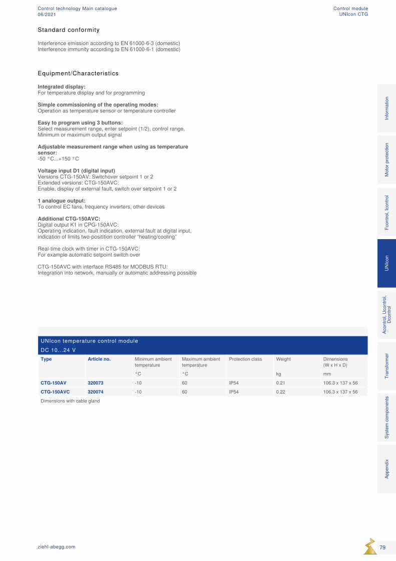
UNIcon temperature control moduleDC 10...24 VType Article no. Minimum ambient
temperatureMaximum ambient temperature
Protection class Weight Dimensions (W x H x D)
°C °C kg mm
CTG-150AV 320073 -10 60 IP54 0.21 106.3 x 137 x 56
CTG-150AVC 320074 -10 60 IP54 0.22 106.3 x 137 x 56
Dimensions with cable gland
Standard conformity
Interference emission according to EN 61000-6-3 (domestic)Interference immunity according to EN 61000-6-1 (domestic)
Equipment/Characteristics
Integrated display: For temperature display and for programming
Simple commissioning of the operating modes: Operation as temperature sensor or temperature controller
Easy to program using 3 buttons: Select measurement range, enter setpoint (1/2), control range, Minimum or maximum output signal
Adjustable measurement range when using as temperature sensor: -50 °C...+150 °C
Voltage input D1 (digital input) Versions CTG-150AV: Switchover setpoint 1 or 2 Extended versions: CTG-150AVC: Enable, display of external fault, switch over setpoint 1 or 2
1 analogue output: To control EC fans, frequency inverters, other devices
Additional CTG-150AVC: Digital output K1 in CPG-150AVC: Operating indication, fault indication, external fault at digital input, indication of limits two-positition controller “heating/cooling” Real-time clock with timer in CTG-150AVC: For example automatic setpoint switch over CTG-150AVC with interface RS485 for MODBUS RTU: Integration into network, manually or automatic addressing possible
79ziehl-abegg.com
Mot
or p
rote
ctio
nFc
ontro
l, Ic
ontro
lUN
Icon
Acon
trol,
Ucon
trol,
Dcon
trol
Tran
sfor
mer
Syst
em c
ompo
nent
s In
form
atio
n Ap
pend
ix
Control moduleUNIcon CTG
Control technology Main catalogue06/2021
80 ziehl-abegg.com
Electronic voltage controllers Control technology Main catalogue06/2021
Product overview
1~ Acontrol Page 82 3~ Ucontrol Page 96 3~ Dcontrol Page 100
Electronic voltage controllers
81ziehl-abegg.com
Mot
or p
rote
ctio
nFc
ontro
l, Ic
ontro
lUN
Icon
Acon
trol,
Ucon
trol,
Dcon
trol
Tran
sfor
mer
Syst
em c
ompo
nent
s In
form
atio
n
Appe
ndix
Electronic voltage controllersControl technology Main catalogue06/2021
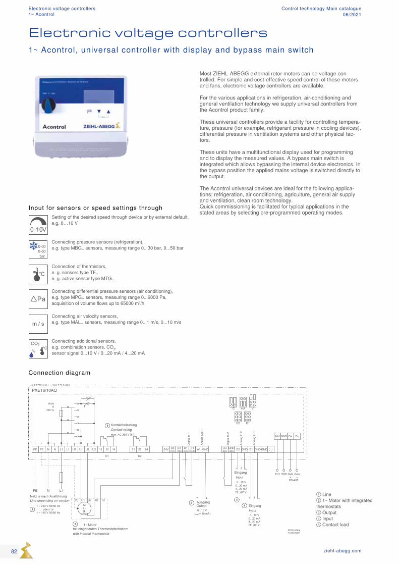
PXET6/10AQ
PEUN16K419.02.2009
PE PE N N L1
N L1PE
L1 U1 U1 U2 U2 141211 242221 24V
+ + 1
Dig
ital I
n 1
Ana
log
In 2
K1 K2
KontaktbelastungContact ratingmax. AC 250 V 5 A
Auto0
100 %
D3(TB)
D3(TB)
D1(E3) A1 GND A3
(D2)GND(D2) E2 GND E1 GND GND
+ 2
D1(GND)
...6 F1=M10 A / ...10 F1=FF20 A
Dig
ital I
n 2
Ana
log
In 1
Ana
log
Out
1
1 ~ Motor mit eingebauten Thermostatschalternwith internal thermostats
M1 ~
PE U2U1 TBTB AusgangOutput0...10 V
(Imax = 10 mA)
3
EingangInput0...10 V
0...20 mA4...20 mATF..(KTY)
4
EingangInput0...10 V
0...20 mA4...20 mATF..(KTY)
1
2
5E1
VmA°C
E2
D-D+GND24V
Data DataGND+ -
24 V
RS-485
Netz je nach AusführungLine depending on version
1 ~ 230 V 50/60 Hzoder / or
1 ~ 115 V 50/60 Hz
4
① Line ② 1~ Motor with integrated thermostats ③ Output ④ Input ⑥ Contact load
Input for sensors or speed settings through
0-10V
Setting of the desired speed through device or by external default, e.g. 0…10 V
0-300-50bar
Connecting pressure sensors (refrigeration), e.g. type MBG.. sensors, measuring range 0...30 bar, 0...50 bar
°CConnection of thermistors, e. g. sensors type TF.. e. g. active sensor type MTG..
PaConnecting differential pressure sensors (air conditioning), e.g. type MPG.. sensors, measuring range 0...6000 Pa, acquisition of volume flows up to 65000 m3/h
m / sConnecting air velocity sensors, e.g. type MAL.. sensors, measuring range 0...1 m/s, 0...10 m/s
CO2
%
°C
Connecting additional sensors, e.g. combination sensors, CO2, sensor signal 0...10 V / 0...20 mA / 4...20 mA
Electronic voltage controllers1~ Acontrol, universal controller with display and bypass main switch
Connection diagram
Most ZIEHL-ABEGG external rotor motors can be voltage con-trolled. For simple and cost-effective speed control of these motors and fans, electronic voltage controllers are available. For the various applications in refrigeration, air-conditioning and general ventilation technology we supply universal controllers from the Acontrol product family. These universal controllers provide a facility for controlling tempera-ture, pressure (for example, refrigerant pressure in cooling devices), differential pressure in ventilation systems and other physical fac-tors. These units have a multifunctional display used for programming and to display the measured values. A bypass main switch is integrated which allows bypassing the internal device electronics. In the bypass position the applied mains voltage is switched directly to the output. The Acontrol universal devices are ideal for the following applica-tions: refrigeration, air conditioning, agriculture, general air supply and ventilation, clean room technology. Quick commissioning is facilitated for typical applications in the stated areas by selecting pre-programmed operating modes.
82 ziehl-abegg.com
Electronic voltage controllers1~ Acontrol
Control technology Main catalogue06/2021
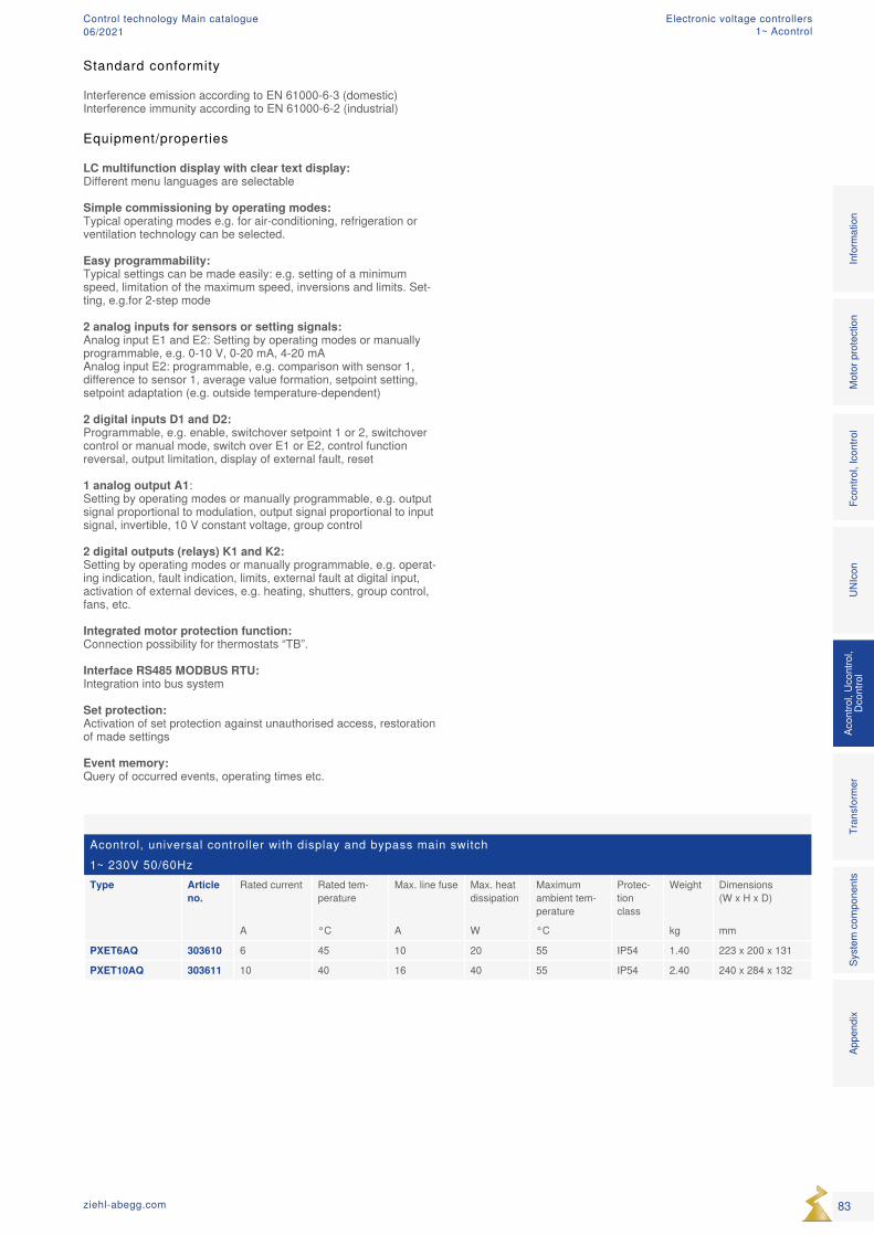
Acontrol, universal controller with display and bypass main switch1~ 230V 50/60HzType Article
no.Rated current Rated tem-
peratureMax. line fuse Max. heat
dissipationMaximum ambient tem-perature
Protec-tion class
Weight Dimensions (W x H x D)
A °C A W °C kg mm
PXET6AQ 303610 6 45 10 20 55 IP54 1.40 223 x 200 x 131
PXET10AQ 303611 10 40 16 40 55 IP54 2.40 240 x 284 x 132
Standard conformity
Interference emission according to EN 61000-6-3 (domestic)Interference immunity according to EN 61000-6-2 (industrial)
Equipment/properties LC multifunction display with clear text display: Different menu languages are selectable Simple commissioning by operating modes: Typical operating modes e.g. for air-conditioning, refrigeration or ventilation technology can be selected. Easy programmability: Typical settings can be made easily: e.g. setting of a minimum speed, limitation of the maximum speed, inversions and limits. Set-ting, e.g.for 2-step mode 2 analog inputs for sensors or setting signals: Analog input E1 and E2: Setting by operating modes or manually programmable, e.g. 0-10 V, 0-20 mA, 4-20 mA Analog input E2: programmable, e.g. comparison with sensor 1, difference to sensor 1, average value formation, setpoint setting, setpoint adaptation (e.g. outside temperature-dependent) 2 digital inputs D1 and D2: Programmable, e.g. enable, switchover setpoint 1 or 2, switchover control or manual mode, switch over E1 or E2, control function reversal, output limitation, display of external fault, reset 1 analog output A1: Setting by operating modes or manually programmable, e.g. output signal proportional to modulation, output signal proportional to input signal, invertible, 10 V constant voltage, group control 2 digital outputs (relays) K1 and K2: Setting by operating modes or manually programmable, e.g. operat-ing indication, fault indication, limits, external fault at digital input, activation of external devices, e.g. heating, shutters, group control, fans, etc. Integrated motor protection function: Connection possibility for thermostats “TB”. Interface RS485 MODBUS RTU: Integration into bus system Set protection: Activation of set protection against unauthorised access, restoration of made settings Event memory: Query of occurred events, operating times etc.
83ziehl-abegg.com
Mot
or p
rote
ctio
nFc
ontro
l, Ic
ontro
lUN
Icon
Acon
trol,
Ucon
trol,
Dcon
trol
Tran
sfor
mer
Syst
em c
ompo
nent
s In
form
atio
n
Appe
ndix
Electronic voltage controllers1~ Acontrol
Control technology Main catalogue06/2021
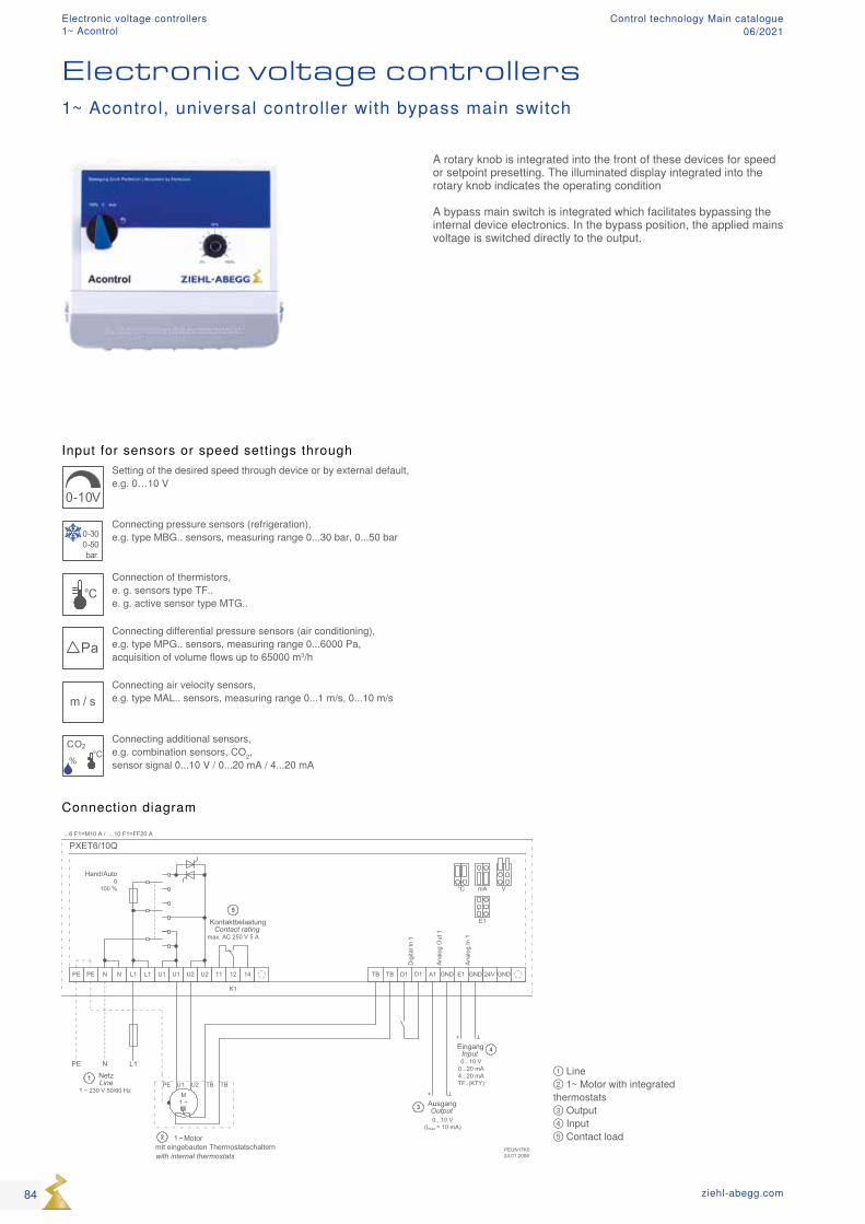
PXET6/10Q
PEUN17K024.01.2008
PE PE N N L1
N L1PE
NetzLine
1 ~ 230 V 50/60 Hz
L1 U1 U1 U2 U2 141211 24V
+
+
Dig
ital I
n 1
K1
KontaktbelastungContact rating
max. AC 250 V 5 A
Hand/Auto0
100 %
TB TB D1 A1 GND E1 GND GNDD1
...6 F1=M10 A / ...10 F1=FF20 A
Ana
log
In 1
Ana
log
Out
1
1 ~ Motor mit eingebauten Thermostatschalternwith internal thermostats
M1 ~
PE U2U1 TBTB
AusgangOutput0...10 V
(Imax = 10 mA)
3
EingangInput0...10 V
0...20 mA4...20 mATF..(KTY)
4
1
2
5
E1
VmA°C
① Line ② 1~ Motor with integrated thermostats ③ Output ④ Input ⑤ Contact load
Input for sensors or speed settings through
0-10V
Setting of the desired speed through device or by external default, e.g. 0…10 V
0-300-50bar
Connecting pressure sensors (refrigeration), e.g. type MBG.. sensors, measuring range 0...30 bar, 0...50 bar
°CConnection of thermistors, e. g. sensors type TF.. e. g. active sensor type MTG..
PaConnecting differential pressure sensors (air conditioning), e.g. type MPG.. sensors, measuring range 0...6000 Pa, acquisition of volume flows up to 65000 m3/h
m / sConnecting air velocity sensors, e.g. type MAL.. sensors, measuring range 0...1 m/s, 0...10 m/s
CO2
%
°C
Connecting additional sensors, e.g. combination sensors, CO2, sensor signal 0...10 V / 0...20 mA / 4...20 mA
Electronic voltage controllers1~ Acontrol, universal controller with bypass main switch
Connection diagram
A rotary knob is integrated into the front of these devices for speed or setpoint presetting. The illuminated display integrated into the rotary knob indicates the operating condition A bypass main switch is integrated which facilitates bypassing the internal device electronics. In the bypass position, the applied mains voltage is switched directly to the output.
84 ziehl-abegg.com
Electronic voltage controllers1~ Acontrol
Control technology Main catalogue06/2021
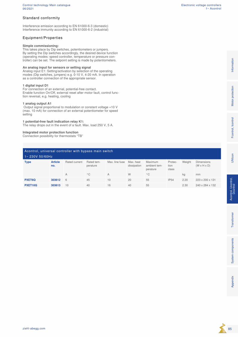
Acontrol, universal controller with bypass main switch1~ 230V 50/60HzType Article
no.Rated current Rated tem-
peratureMax. line fuse Max. heat
dissipationMaximum ambient tem-perature
Protec-tion class
Weight Dimensions (W x H x D)
A °C A W °C kg mm
PXET6Q 303612 6 45 10 20 55 IP54 2.20 223 x 200 x 131
PXET10Q 303613 10 40 16 40 55 2.30 240 x 284 x 132
Standard conformity
Interference emission according to EN 61000-6-3 (domestic)Interference immunity according to EN 61000-6-2 (industrial)
Equipment/Properties
Simple commissioning: This takes place by Dip switches, potentiometers or jumpers. By setting the Dip switches accordingly, the desired device function (operating modes: speed controller, temperature or pressure con-troller) can be set. The setpoint setting is made by potentiometers. An analog input for sensors or setting signal Analog input E1: Setting/activation by selection of the operating modes (Dip switches, jumpers) e.g. 0-10 V, 4-20 mA. In operation as a controller connection of the appropriate sensor. 1 digital input D1 For connection of an external, potential-free contact. Enable function On/Off, external reset after motor fault, control func-tion reversal, e.g. heating, cooling 1 analog output A1 Output signal proportional to modulation or constant voltage +10 V (max. 10 mA) for connection of an external potentiometer for speed setting 1 potential-free fault indication relay K1: The relay drops out in the event of a fault. Max. load 250 V, 5 A. Integrated motor protection function Connection possibility for thermostats “TB”
85ziehl-abegg.com
Mot
or p
rote
ctio
nFc
ontro
l, Ic
ontro
lUN
Icon
Acon
trol,
Ucon
trol,
Dcon
trol
Tran
sfor
mer
Syst
em c
ompo
nent
s In
form
atio
n
Appe
ndix
Electronic voltage controllers1~ Acontrol
Control technology Main catalogue06/2021
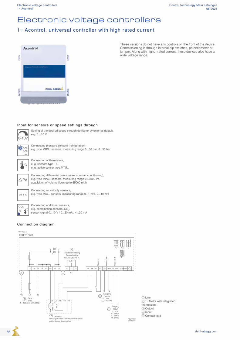
PXET16/20
PEUN19K024.09.2008
L1 L1 N
L1 NPE
NetzLine
1 ~ 120...277 V 50/60 Hz
N U1 U1 U2 U2 141211
+
+
Dig
ital I
n 1
K1
KontaktbelastungContact rating
max. AC 250 V 5 A
A1 GND E1 GND GND
F1=FF30 A
Ana
log
In 1
Ana
log
Out
1
AusgangOutput0...10 V
(Imax = 10 mA)
3
EingangInput
0...10 V0...20 mA4...20 mATF..(KTY)
4
1
5
E1
VmA°C
TBTB D1 D1 24V
1 ~ Motor mit eingebauten Thermostatschalternwith internal thermostats
M1 ~
PEU2U1 TB TB
2
① Line ② 1~ Motor with integrated thermostats ③ Output ④ Input ⑤ Contact load
Input for sensors or speed settings through
0-10V
Setting of the desired speed through device or by external default, e.g. 0…10 V
0-300-50bar
Connecting pressure sensors (refrigeration), e.g. type MBG.. sensors, measuring range 0...30 bar, 0...50 bar
°CConnection of thermistors, e. g. sensors type TF.. e. g. active sensor type MTG..
PaConnecting differential pressure sensors (air conditioning), e.g. type MPG.. sensors, measuring range 0...6000 Pa, acquisition of volume flows up to 65000 m3/h
m / sConnecting air velocity sensors, e.g. type MAL.. sensors, measuring range 0...1 m/s, 0...10 m/s
CO2
%
°C
Connecting additional sensors, e.g. combination sensors, CO2, sensor signal 0...10 V / 0...20 mA / 4...20 mA
Electronic voltage controllers1~ Acontrol, universal controller with high rated current
Connection diagram
These versions do not have any controls on the front of the device. Commissioning is through internal dip switches, potentiometer or jumper. Along with higher rated current, these devices also have a wide voltage range.
86 ziehl-abegg.com
Electronic voltage controllers1~ Acontrol
Control technology Main catalogue06/2021

Acontrol, universal controller with high rated current1~ 120...277V 50/60HzType Article
no.Rated voltage
Rated current
Rated tempera-ture
Max. line fuse
Max. heat dissipation
Maximum ambient temperature
Protec-tion class
Weight Dimensions (W x H x D)
V A °C A W °C kg mm
PXET16 303598 230 16 55 20 25 55 IP54 1.90 240 x 284 x 115
PXET20 303599 230 20 55 25 30 55 2.30 240 x 284 x 115
Standard conformity
Interference emission according to EN 61000-6-3 (domestic)Interference immunity according to EN 61000-6-2 (industrial)
Equipment/Properties
Simple commissioning: This takes place by Dip switches, potentiometers or jumpers. By setting the Dip switches accordingly, the desired device function (operating modes: speed controller, temperature or pressure con-troller) can be set. The setpoint setting is made by potentiometers. An analog input for sensors or setting signal Analog input E1: Setting/activation by selection of the operating mode (Dip switches, jumpers) e.g. 0-10 V, 4-20 mA. In operation as a controller connection of the appropriate sensor. 1 digital input D1 For connection of an external, potential-free contact. Enable function On/Off, external reset after motor fault, control func-tion reversal, e.g. heating, cooling 1 analog output A1 Output signal proportional to modulation or constant voltage +10 V (max. 10 mA) for connection of an external potentiometer for speed setting 1 potential-free fault indication relay K1: The relay drops out in the event of a fault. Max. load 250 V, 5 A. Integrated motor protection function Connection possibility for thermostats “TB”
87ziehl-abegg.com
Mot
or p
rote
ctio
nFc
ontro
l, Ic
ontro
lUN
Icon
Acon
trol,
Ucon
trol,
Dcon
trol
Tran
sfor
mer
Syst
em c
ompo
nent
s In
form
atio
n
Appe
ndix
Electronic voltage controllers1~ Acontrol
Control technology Main catalogue06/2021
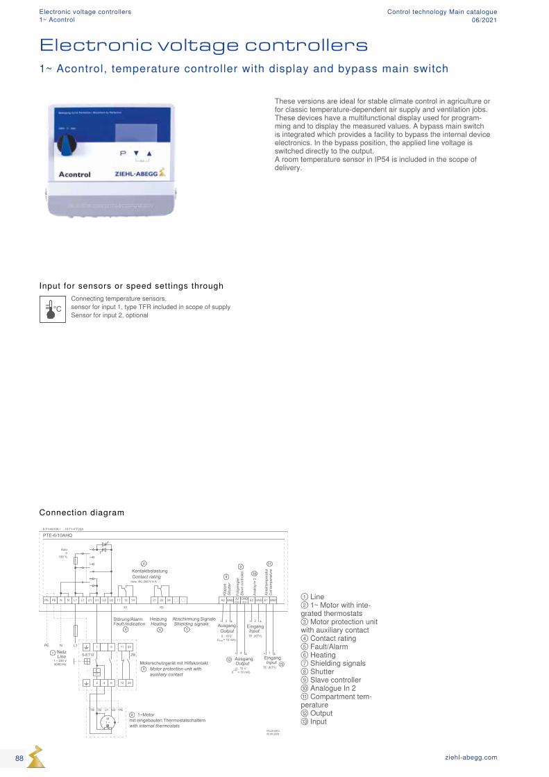
PTE-6/10AHQ
PEUN16K305.08.2008
PE PE N N L1
N L1PE
L1 U1 U1 U2 U2 141211 242221
+ 1
Ana
log
In 2
K1 K2
Auto0
100 %
A2 GND A3(D2)
GND(D2) E2 GND E1 GND
+
+
+ 22
3
Störung/AlarmFault /indication
HeizungHeating
Abschirmung Signale Shielding signals
M1 ~
PEU2U1TBTB
...6 F1=M10A / ...10 F1=FF20A
NetzLine
1 ~ 230 V50/60 Hz
1
KontaktbelastungContact rating
max. AC 250 V 5 A
4
1 ~ Motor mit eingebauten Thermostatschalternwith internal thermostats
2
AusgangOutput0...10 V
(Imax = 10 mA)
AusgangOutput0...10 V
(Imax
= 10 mA)
EingangInputTF..(KTY)
EingangInput
TF..(KTY)
1
2 4 6
11
12
23
24
Motorschutzgerät mit HilfskontaktMotor protection unit with auxiliary contactI>
5
S-ET10 ZB
3
5 6 7
Kla
ppe
Shu
tter
Folg
ereg
ler
Sla
ve c
ontro
ller
Abt
eilte
mpe
ratu
rC
ot te
mpe
ratu
re
8
9
10
11
⑫⑬
① Line ② 1~ Motor with inte-grated thermostats ③ Motor protection unit with auxiliary contact ④ Contact rating ⑤ Fault/Alarm ⑥ Heating ⑦ Shielding signals ⑧ Shutter ⑨ Slave controller ⑩ Analogue In 2 ⑪ Compartment tem-perature ⑫ Output ⑬ Input
Input for sensors or speed settings through
°CConnecting temperature sensors, sensor for input 1, type TFR included in scope of supply Sensor for input 2, optional
Electronic voltage controllers1~ Acontrol, temperature controller with display and bypass main switch
Connection diagram
These versions are ideal for stable climate control in agriculture or for classic temperature-dependent air supply and ventilation jobs. These devices have a multifunctional display used for program-ming and to display the measured values. A bypass main switch is integrated which provides a facility to bypass the internal device electronics. In the bypass position, the applied line voltage is switched directly to the output. A room temperature sensor in IP54 is included in the scope of delivery.
88 ziehl-abegg.com
Electronic voltage controllers1~ Acontrol
Control technology Main catalogue06/2021
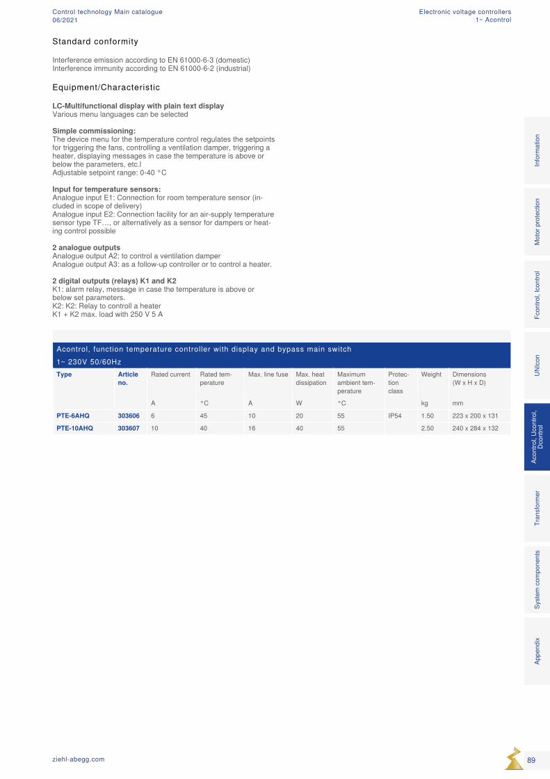
Acontrol, function temperature controller with display and bypass main switch 1~ 230V 50/60HzType Article
no.Rated current Rated tem-
peratureMax. line fuse Max. heat
dissipationMaximum ambient tem-perature
Protec-tion class
Weight Dimensions (W x H x D)
A °C A W °C kg mm
PTE-6AHQ 303606 6 45 10 20 55 IP54 1.50 223 x 200 x 131
PTE-10AHQ 303607 10 40 16 40 55 2.50 240 x 284 x 132
Standard conformity
Interference emission according to EN 61000-6-3 (domestic)Interference immunity according to EN 61000-6-2 (industrial)
Equipment/Characteristic
LC-Multifunctional display with plain text display Various menu languages can be selected Simple commissioning: The device menu for the temperature control regulates the setpoints for triggering the fans, controlling a ventilation damper, triggering a heater, displaying messages in case the temperature is above or below the parameters, etc.l Adjustable setpoint range: 0-40 °C Input for temperature sensors: Analogue input E1: Connection for room temperature sensor (in-cluded in scope of delivery) Analogue input E2: Connection facility for an air-supply temperature sensor type TF…, or alternatively as a sensor for dampers or heat-ing control possible 2 analogue outputs Analogue output A2: to control a ventilation damper Analogue output A3: as a follow-up controller or to control a heater. 2 digital outputs (relays) K1 and K2 K1: alarm relay, message in case the temperature is above or below set parameters. K2: K2: Relay to controll a heater K1 + K2 max. load with 250 V 5 A
89ziehl-abegg.com
Mot
or p
rote
ctio
nFc
ontro
l, Ic
ontro
lUN
Icon
Acon
trol,
Ucon
trol,
Dcon
trol
Tran
sfor
mer
Syst
em c
ompo
nent
s In
form
atio
n
Appe
ndix
Electronic voltage controllers1~ Acontrol
Control technology Main catalogue06/2021
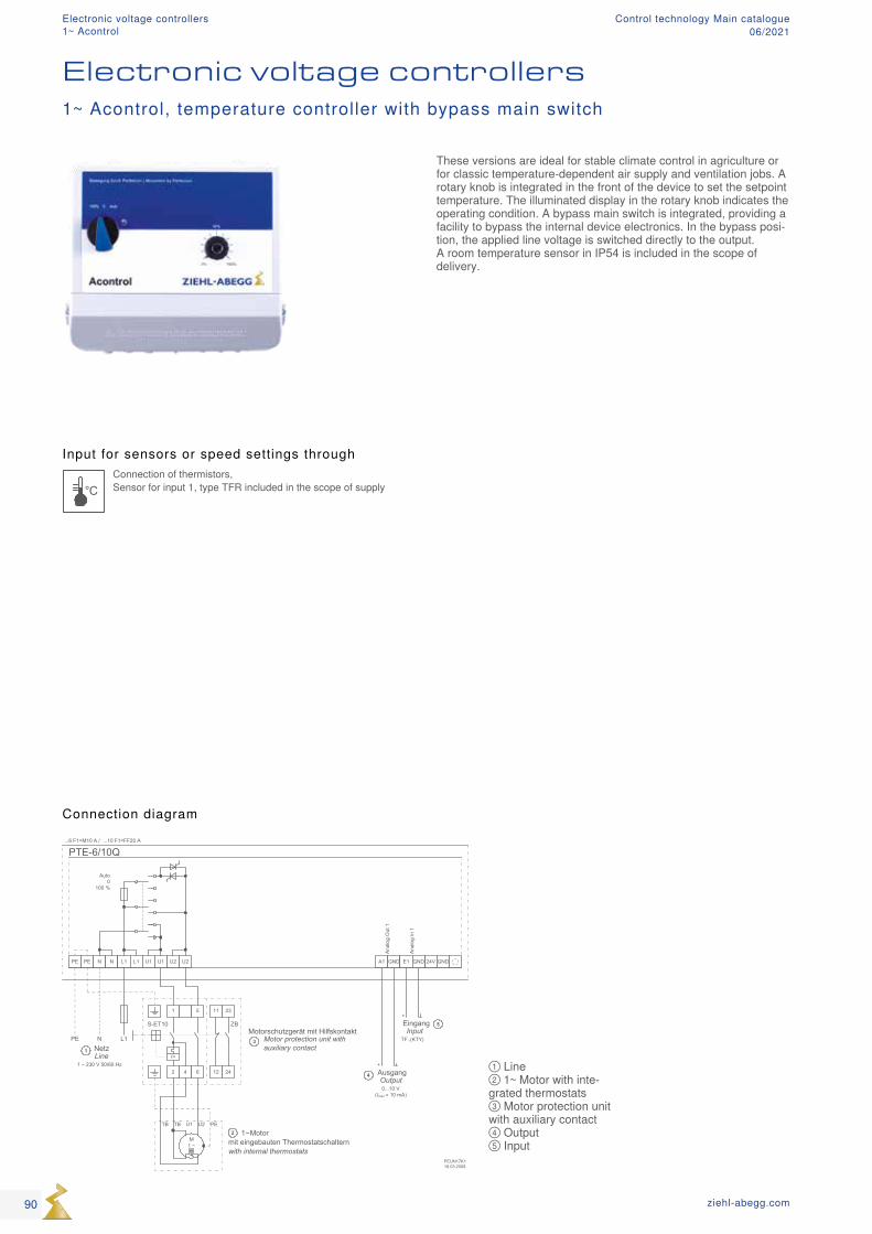
PTE-6/10Q
PEUN17K118.03.2008
PE PE N N L1
N L1PE
NetzLine
1 ~ 230 V 50/60 Hz
L1 U1 U1 U2 U2 24V
+
+
Auto0
100 %
A1 GND E1 GND GND
...6 F1=M10 A / ...10 F1=FF20 A
Ana
log
In 1
Ana
log
Out
1
AusgangOutput0...10 V
(Imax = 10 mA)
4
EingangInput
TF..(KTY)
5
1
1
2 4 6
11
12
23
24
Motorschutzgerät mit HilfskontaktMotor protection unit with auxiliary contact
I>
5
S-ET10 ZB
3
M1 ~
PEU2U1TBTB
1 ~ Motor mit eingebauten Thermostatschalternwith internal thermostats
2
① Line ② 1~ Motor with inte-grated thermostats ③ Motor protection unit with auxiliary contact ④ Output ⑤ Input
Input for sensors or speed settings through
°CConnection of thermistors, Sensor for input 1, type TFR included in the scope of supply
Electronic voltage controllers1~ Acontrol, temperature controller with bypass main switch
Connection diagram
These versions are ideal for stable climate control in agriculture or for classic temperature-dependent air supply and ventilation jobs. A rotary knob is integrated in the front of the device to set the setpoint temperature. The illuminated display in the rotary knob indicates the operating condition. A bypass main switch is integrated, providing a facility to bypass the internal device electronics. In the bypass posi-tion, the applied line voltage is switched directly to the output. A room temperature sensor in IP54 is included in the scope of delivery.
90 ziehl-abegg.com
Electronic voltage controllers1~ Acontrol
Control technology Main catalogue06/2021
Acontrol, temperature controller with bypass main switch1~ 230V 50/60HzType Article
no.Rated current Rated tem-
peratureMax. line fuse Max. heat
dissipationMaximum ambient tem-perature
Protec-tion class
Weight Dimensions (W x H x D)
A °C A W °C kg mm
PTE-6Q 303618 6 45 10 20 55 IP54 1.30 223 x 200 x 131
PTE-10Q 303619 10 40 16 40 55 2.30 240 x 284 x 132
Standard conformity
Interference emission according to EN 61000-6-3 (domestic)Interference immunity according to EN 61000-6-2 (industrial)
Equipment/Characteristics
Simple commissioning: Set the desired temperature setpoint via a rotary knob. Setpoint 0...40 °C (or alternatively -26…+ 76 °C). Additional settings pos-sible with internal potentiometer and dip switch. Input for temperature sensors: Analogue input E1: Connection for room temperature sensor (in-cluded in scope of delivery) 1 analogue output A1 Control for follow-up controller
91ziehl-abegg.com
Mot
or p
rote
ctio
nFc
ontro
l, Ic
ontro
lUN
Icon
Acon
trol,
Ucon
trol,
Dcon
trol
Tran
sfor
mer
Syst
em c
ompo
nent
s In
form
atio
n
Appe
ndix
Electronic voltage controllers1~ Acontrol
Control technology Main catalogue06/2021
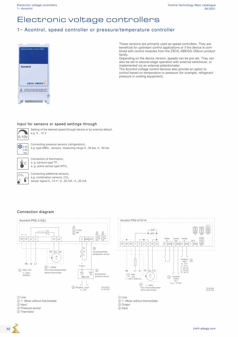
PETE21K024.09.2008
L1N
N L1PE
GNDE
Acontrol PKE-2.5(E)
Drucksensorpressure sensor
Temperaturfühlertemperature sensor
TF..
Netz / line 1~ 230V50/60Hz
4-20mA
13braun
BNgrünGN
MBG-30I
U1 U2
J5J4
AB
AB
M1~
PE U1 U2
1~ Motorohne Thermostatschalterwithout thermostats
PE PE 24V
Eingang input0...10V
+
J1
n-maxSet
/
①②
③
④
⑤
Acontrol PKE-6/10/14
PEUN18K028.08.2008
PE PE PE L1 N
NL1PENetzLine
1 ~ 230 V 50/60 Hz
U1 U1 U2 U2 +
+
Digital In
Analog In
D1 A1 GND E1 GND GND
+
Analog Out
AusgangOutput10 V
(Imax = 10 mA)
3
EingangInput
0...10 V2...10 V
0...20 mA4...20 mATF..(KTY)
4
1
E1
VmA°C
GND
24 V
M1 ~
PE U1 U2
1 ~ Motorohne Thermostatschalterwithout thermostats
2
Input for sensors or speed settings through
0-10V
Setting of the desired speed through device or by external default, e.g. 0…10 V
0-300-50bar
Connecting pressure sensors (refrigeration), e.g. type MBG.. sensors, measuring range 0...30 bar, 0...50 bar
°CConnection of thermistors, e. g. sensors type TF.. e. g. active sensor type MTG..
CO2
%
°C
Connecting additional sensors, e.g. combination sensors, CO2, sensor signal 0...10 V / 0...20 mA / 4...20 mA
① Line ② 1~ Motor without thermostats ③ Input ④ Pressure sensor ⑤ Thermistor
① Line ② 1~ Motor without thermostats ③ Output ④ Input
These versions are primarily used as speed controllers. They are beneficial for upstream control applications or if the device is com-bined with control modules from the ZIEHL-ABEGG UNIcon product family.Depending on the device version, speeds can be pre-set. They can also be set to second stage operation with external switchover, or implemented via an external potentiometer.The Acontrol voltage control devices also provide an option to control based on temperature or pressure (for example, refrigerant pressure in cooling equipment).
Connection diagram
1~ Acontrol, speed controller or pressure/temperature controller
Electronic voltage controllers
92 ziehl-abegg.com
Electronic voltage controllers1~ Acontrol
Control technology Main catalogue06/2021
Acontrol, speed controller or pressure/temperature controller for cooling1~ 230V 50/60HzType Article
no.Rated current Rated tem-
peratureMax. line fuse Max. heat
dissipationMaximum ambient tem-perature
Protec-tion class
Weight Dimensions (W x H x D)
A °C A W °C kg mm
PKE-2.5E 303620 2.5 40 10 10 40 IP20 0.26 93 x 96 x 42
PKE-2.5 303600 2.5 40 10 10 40 IP54 0.45 100 x 190 x 75
PKE-6 303614 6 40 10 15 55 0.60 100 x 190 x 75
PKE-10 303615 10 40 16 25 55 0.90 100 x 190 x 75
PKE-14 303625 14 40 20 35 55 2.00 240 x 284 x 115
Equipment/Characteristics
Simple commissioning: Depending on the device version, commissioning through dip switch, potentiometer or jumper. Set the corresponding dip switch to implement the desired device function (operating modes: speed controller, temperature or pres-sure controller). Set the setpoint default via potentiometer.
One analogue input for sensors or default signal Analogue input E: Set/enable by selecting the operating mode (dip switch, jumper) e.g. 0-10 V, 4-20 mA. When operating as controller connection of corresponding sensor.
1 digital inputs D1 (only for versions 6-14 A): For connecting an external, floating contact. D1: enable function On/Off
1 analogue output A1 (only for versions 6-14 A): Output signal proportional modulation or constant voltage +10 V (max. 10 mA) to connect an external potentiometer for speed preset
Standard conformity
Interference emission according to EN 61000-6-3 (domestic) Motor line not shieldedInterference immunity according to EN 61000-6-2 (industrial)
93ziehl-abegg.com
Mot
or p
rote
ctio
nFc
ontro
l, Ic
ontro
lUN
Icon
Acon
trol,
Ucon
trol,
Dcon
trol
Tran
sfor
mer
Syst
em c
ompo
nent
s In
form
atio
n
Appe
ndix
Electronic voltage controllers1~ Acontrol
Control technology Main catalogue06/2021
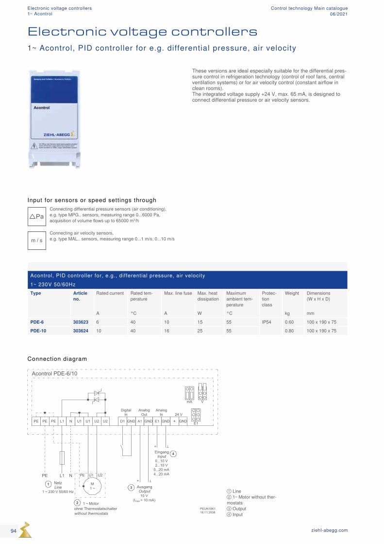
Acontrol PDE-6/10
PEUN18K118.11.2008
PE PE PE L1 N
NL1PENetzLine
1 ~ 230 V 50/60 Hz
U1 U1 U2 U2 +
+
Digital In
Analog In
D1 A1 GND E1 GND GND
+
Analog Out
AusgangOutput10 V
(Imax = 10 mA)
3
EingangInput
0...10 V2...10 V
0...20 mA4...20 mA
4
1
E1
VmA
GND
24 V
M1 ~
PE U1 U2
1 ~ Motorohne Thermostatschalterwithout thermostats
2
Acontrol, PID controller for, e.g., differential pressure, air velocity1~ 230V 50/60HzType Article
no.Rated current Rated tem-
peratureMax. line fuse Max. heat
dissipationMaximum ambient tem-perature
Protec-tion class
Weight Dimensions (W x H x D)
A °C A W °C kg mm
PDE-6 303623 6 40 10 15 55 IP54 0.60 100 x 190 x 75
PDE-10 303624 10 40 16 25 55 0.80 100 x 190 x 75
① Line ② 1~ Motor without ther-mostats ③ Output ④ Input
Input for sensors or speed settings through
PaConnecting differential pressure sensors (air conditioning), e.g. type MPG.. sensors, measuring range 0...6000 Pa, acquisition of volume flows up to 65000 m3/h
m / sConnecting air velocity sensors, e.g. type MAL.. sensors, measuring range 0...1 m/s, 0...10 m/s
Electronic voltage controllers
These versions are ideal especially suitable for the differential pres-sure control in refrigeration technology (control of roof fans, central ventilation systems) or for air velocity control (constant airflow in clean rooms).The integrated voltage supply +24 V, max. 65 mA, is designed to connect differential pressure or air velocity sensors.
1~ Acontrol, PID controller for e.g. differential pressure, air velocity
Connection diagram
94 ziehl-abegg.com
Electronic voltage controllers1~ Acontrol
Control technology Main catalogue06/2021
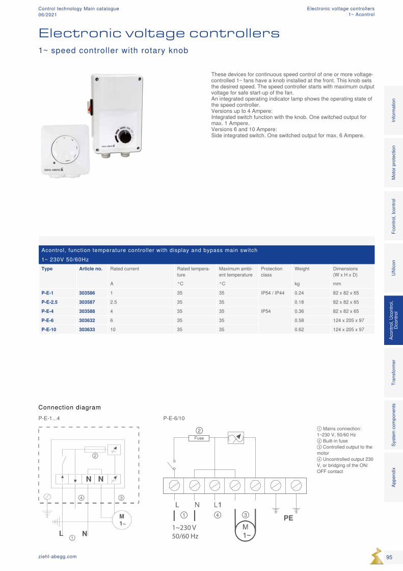
M1~
①
②
③④
N N
1~230 V50/60 Hz
PE①
②
③④
① Mains connection: 1~230 V, 50/60 Hz ② Built-in fuse ③ Controlled output to the motor ④ Uncontrolled output 230 V, or bridging of the ON/OFF contact
Acontrol, function temperature controller with display and bypass main switch 1~ 230V 50/60HzType Article no. Rated current Rated tempera-
tureMaximum ambi-ent temperature
Protection class
Weight Dimensions (W x H x D)
A °C °C kg mm
P-E-1 303586 1 35 35 IP54 / IP44 0.24 82 x 82 x 65
P-E-2.5 303587 2.5 35 35 0.18 82 x 82 x 65
P-E-4 303588 4 35 35 IP54 0.36 82 x 82 x 65
P-E-6 303632 6 35 35 0.58 124 x 205 x 97
P-E-10 303633 10 35 35 0.62 124 x 205 x 97
Electronic voltage controllers1~ speed controller with rotary knob
These devices for continuous speed control of one or more voltage-controlled 1~ fans have a knob installed at the front. This knob sets the desired speed. The speed controller starts with maximum output voltage for safe start-up of the fan. An integrated operating indicator lamp shows the operating state of the speed controller. Versions up to 4 Ampere: Integrated switch function with the knob. One switched output for max. 1 Ampere. Versions 6 and 10 Ampere: Side integrated switch. One switched output for max. 6 Ampere.
Connection diagramP-E-1...4 P-E-6/10
95ziehl-abegg.com
Mot
or p
rote
ctio
nFc
ontro
l, Ic
ontro
lUN
Icon
Acon
trol,
Ucon
trol,
Dcon
trol
Tran
sfor
mer
Syst
em c
ompo
nent
s In
form
atio
n
Appe
ndix
Electronic voltage controllers1~ Acontrol
Control technology Main catalogue06/2021
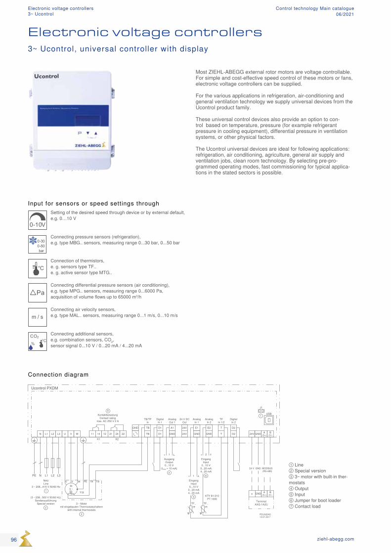
Input for sensors or speed settings through
0-10V
Setting of the desired speed through device or by external default, e.g. 0…10 V
0-300-50bar
Connecting pressure sensors (refrigeration), e.g. type MBG.. sensors, measuring range 0...30 bar, 0...50 bar
°CConnection of thermistors, e. g. sensors type TF.. e. g. active sensor type MTG..
PaConnecting differential pressure sensors (air conditioning), e.g. type MPG.. sensors, measuring range 0...6000 Pa, acquisition of volume flows up to 65000 m3/h
m / sConnecting air velocity sensors, e.g. type MAL.. sensors, measuring range 0...1 m/s, 0...10 m/s
CO2
%
°C
Connecting additional sensors, e.g. combination sensors, CO2, sensor signal 0...10 V / 0...20 mA / 4...20 mA
① Line ② Special version ③ 3~ motor with built-in ther-mostats ④ Output ⑤ Input ⑥ Jumper for boot loader ⑦ Contact load
Most ZIEHL-ABEGG external rotor motors are voltage controllable. For simple and cost-effective speed control of these motors or fans, electronic voltage controllers can be supplied. For the various applications in refrigeration, air-conditioning and general ventilation technology we supply universal devices from the Ucontrol product family. These universal control devices also provide an option to con-trol based on temperature, pressure (for example refrigerant pressure in cooling equipment), differential pressure in ventilation systems, or other physical factors. The Ucontrol universal devices are ideal for following applications: refrigeration, air conditioning, agriculture, general air supply and ventilation jobs, clean room technology. By selecting pre-pro-grammed operating modes, fast commissioning for typical applica-tions in the stated sectors is possible.
Connection diagram
Electronic voltage controllers3~ Ucontrol, universal controller with display
96 ziehl-abegg.com
Electronic voltage controllers3~ Ucontrol
Control technology Main catalogue06/2021
Optional equipment
IO add-on module type Z-Modul-B, Article No. 380052 if the integrated inputs and outputs are not sufficient other inputs and outputs can be created with the Z-Modul-B . These are also programmable: 1 analog input 1 analog output 3 digital inputs 2 digital outputs (relays) LON® Add-on module type Z-Modul-L, Article No. 380086
Equipment/properties
LC multi-function display with plain text display: Different menu languages can be selected Simple start-up by operating modes: Typical operating modes, e.g. for air conditioning, refrigerant or ventilation technology can be selected. Simple programmability: Typical settings can be made easily: e.g. minimum speed setting, limitation of the maximum speed, inversions and limits. Setting, e.g. for 2-step mode 2 analog inputs for sensors or setting signals: analog input E1 and E2: Setting by operating modes or manually programmable, e.g. 0-10 V, 0-20 mA, 4-20 mA analog input E2: programmable, e.g. comparison with sensor 1, difference to sensor 1, average value formation, setpoint setting, setpoint adaptation (e.g. outdoor temperature-dependent) 2 digital inputs D1 und D2: Programmable, e.g. enable, switchover setpoint 1 or 2, switchover control or manual mode, switchover E1 or E2, invert control func-tion, output limitation, display of external fault, reset 1 analog output A1: Setting by operating modes or manually programmable, e.g. output signal proportional to modulation, output signal proportional to input signal, invertible, 10 V constant voltage, group control 2 digital outputs (relays) K1 and K2: Setting by operating modes or manually programmable, e.g. operat-ing indication, fault indication, limits, external fault at digital input, activation of external devices, e.g. heating, shutters, group control, fans, etc. Integrated motor protection function: Connection possibility for PTC thermistors or alternatively thermo-stats (TB or TP). Interface RS485 MODBUS RTU: Integration into bus system Interface USB: For e.g. software update, communication with PC Set protection: Activation set protection against unauthorised access, restoration of made settings Event memory: Querying of occurred events, operating times, etc.
Standard conformity
Interference emission according to EN 61000-6-3 (domestic)Interference immunity according to EN 61000-6-2 (industrial)
97ziehl-abegg.com
Mot
or p
rote
ctio
nFc
ontro
l, Ic
ontro
lUN
Icon
Acon
trol,
Ucon
trol,
Dcon
trol
Tran
sfor
mer
Syst
em c
ompo
nent
s In
form
atio
n
Appe
ndix
Electronic voltage controllers3~ Ucontrol
Control technology Main catalogue06/2021
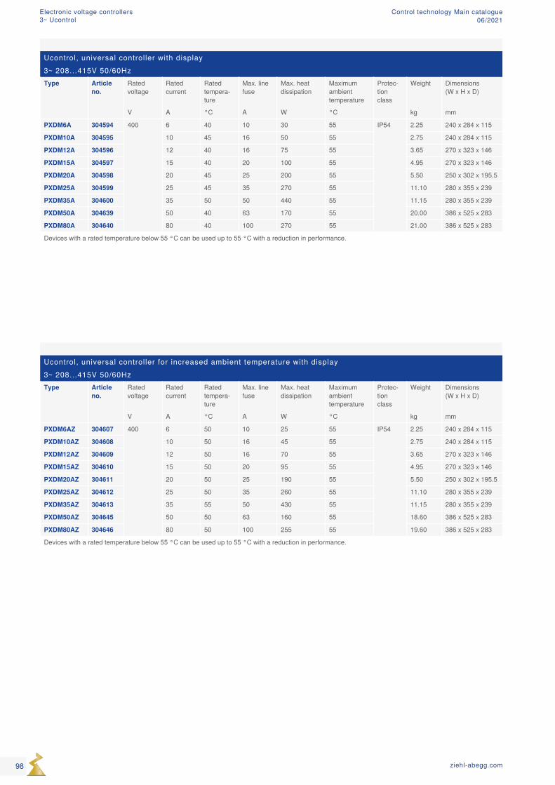
Ucontrol, universal controller for increased ambient temperature with display3~ 208...415V 50/60HzType Article
no.Rated voltage
Rated current
Rated tempera-ture
Max. line fuse
Max. heat dissipation
Maximum ambient temperature
Protec-tion class
Weight Dimensions (W x H x D)
V A °C A W °C kg mm
PXDM6AZ 304607 400 6 50 10 25 55 IP54 2.25 240 x 284 x 115
PXDM10AZ 304608 10 50 16 45 55 2.75 240 x 284 x 115
PXDM12AZ 304609 12 50 16 70 55 3.65 270 x 323 x 146
PXDM15AZ 304610 15 50 20 95 55 4.95 270 x 323 x 146
PXDM20AZ 304611 20 50 25 190 55 5.50 250 x 302 x 195.5
PXDM25AZ 304612 25 50 35 260 55 11.10 280 x 355 x 239
PXDM35AZ 304613 35 55 50 430 55 11.15 280 x 355 x 239
PXDM50AZ 304645 50 50 63 160 55 18.60 386 x 525 x 283
PXDM80AZ 304646 80 50 100 255 55 19.60 386 x 525 x 283
Devices with a rated temperature below 55 °C can be used up to 55 °C with a reduction in performance.
Ucontrol, universal controller with display3~ 208...415V 50/60HzType Article
no.Rated voltage
Rated current
Rated tempera-ture
Max. line fuse
Max. heat dissipation
Maximum ambient temperature
Protec-tion class
Weight Dimensions (W x H x D)
V A °C A W °C kg mm
PXDM6A 304594 400 6 40 10 30 55 IP54 2.25 240 x 284 x 115
PXDM10A 304595 10 45 16 50 55 2.75 240 x 284 x 115
PXDM12A 304596 12 40 16 75 55 3.65 270 x 323 x 146
PXDM15A 304597 15 40 20 100 55 4.95 270 x 323 x 146
PXDM20A 304598 20 45 25 200 55 5.50 250 x 302 x 195.5
PXDM25A 304599 25 45 35 270 55 11.10 280 x 355 x 239
PXDM35A 304600 35 50 50 440 55 11.15 280 x 355 x 239
PXDM50A 304639 50 40 63 170 55 20.00 386 x 525 x 283
PXDM80A 304640 80 40 100 270 55 21.00 386 x 525 x 283
Devices with a rated temperature below 55 °C can be used up to 55 °C with a reduction in performance.
98 ziehl-abegg.com
Electronic voltage controllers3~ Ucontrol
Control technology Main catalogue06/2021
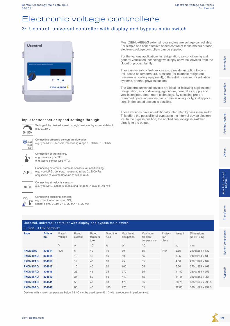
Ucontrol, universal controller with display and bypass main switch3~ 208...415V 50/60HzType Article
no.Rated voltage
Rated current
Rated tempera-ture
Max. line fuse
Max. heat dissipation
Maximum ambient temperature
Protec-tion class
Weight Dimensions (W x H x D)
V A °C A W °C kg mm
PXDM6AQ 304614 400 6 40 10 30 55 IP54 2.55 240 x 284 x 132
PXDM10AQ 304615 10 45 16 50 55 3.05 240 x 284 x 132
PXDM12AQ 304616 12 40 16 75 55 4.00 270 x 323 x 162
PXDM15AQ 304617 15 40 20 100 55 5.30 270 x 323 x 162
PXDM25AQ 304618 25 45 35 270 55 11.40 280 x 355 x 256
PXDM35AQ 304619 35 50 50 440 55 11.45 280 x 355 x 256
PXDM50AQ 304641 50 40 63 170 55 20.70 386 x 525 x 299.5
PXDM80AQ 304642 80 40 100 270 55 22.80 386 x 525 x 299.5
Devices with a rated temperature below 55 °C can be used up to 55 °C with a reduction in performance.
Input for sensors or speed settings through
0-10V
Setting of the desired speed through device or by external default, e.g. 0…10 V
0-300-50bar
Connecting pressure sensors (refrigeration), e.g. type MBG.. sensors, measuring range 0...30 bar, 0...50 bar
°CConnection of thermistors, e. g. sensors type TF.. e. g. active sensor type MTG..
PaConnecting differential pressure sensors (air conditioning), e.g. type MPG.. sensors, measuring range 0...6000 Pa, acquisition of volume flows up to 65000 m3/h
m / sConnecting air velocity sensors, e.g. type MAL.. sensors, measuring range 0...1 m/s, 0...10 m/s
CO2
%
°C
Connecting additional sensors, e.g. combination sensors, CO2, sensor signal 0...10 V / 0...20 mA / 4...20 mA
Electronic voltage controllers3~ Ucontrol, universal controller with display and bypass main switch
Most ZIEHL-ABEGG external rotor motors are voltage controllable. For simple and cost-effective speed control of these motors or fans, electronic voltage controllers can be supplied. For the various applications in refrigeration, air-conditioning and general ventilation technology we supply universal devices from the Ucontrol product family. These universal control devices also provide an option to con-trol based on temperature, pressure (for example refrigerant pressure in cooling equipment), differential pressure in ventilation systems, or other physical factors. The Ucontrol universal devices are ideal for following applications: refrigeration, air conditioning, agriculture, general air supply and ventilation jobs, clean room technology. By selecting pre-pro-grammed operating modes, fast commissioning for typical applica-tions in the stated sectors is possible.
These versions have an additionally integrated bypass main switch. This offers the possibility of bypassing the internal device electron-ics. In the bypass position, the applied line voltage is switched directly to the output.
99ziehl-abegg.com
Mot
or p
rote
ctio
nFc
ontro
l, Ic
ontro
lUN
Icon
Acon
trol,
Ucon
trol,
Dcon
trol
Tran
sfor
mer
Syst
em c
ompo
nent
s In
form
atio
n
Appe
ndix
Electronic voltage controllers3~ Ucontrol
Control technology Main catalogue06/2021
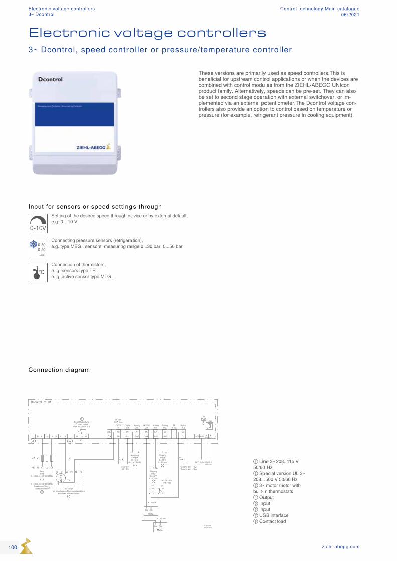
Input for sensors or speed settings through
0-10V
Setting of the desired speed through device or by external default, e.g. 0…10 V
0-300-50bar
Connecting pressure sensors (refrigeration), e.g. type MBG.. sensors, measuring range 0...30 bar, 0...50 bar
°CConnection of thermistors, e. g. sensors type TF.. e. g. active sensor type MTG..
① Line 3~ 208..415 V 50/60 Hz ② Special version UL 3~ 208...500 V 50/60 Hz ③ 3~ motor motor with built-in thermostats ④ Output ⑤ Input ⑥ Input ⑦ USB interface ⑧ Contact load
Connection diagram
These versions are primarily used as speed controllers.This is beneficial for upstream control applications or when the devices are combined with control modules from the ZIEHL-ABEGG UNIcon product family. Alternatively, speeds can be pre-set. They can also be set to second stage operation with external switchover, or im-plemented via an external potentiometer.The Dcontrol voltage con-trollers also provide an option to control based on temperature or pressure (for example, refrigerant pressure in cooling equipment).
3~ Dcontrol, speed controller or pressure/temperature controller
Electronic voltage controllers
100 ziehl-abegg.com
Electronic voltage controllers3~ Dcontrol
Control technology Main catalogue06/2021
Equipment/Characteristics
Simple commissioning with dip switch and potentiometer: The controls are accessible directly in the device terminal compart-ment. Set the dip switch to select the desired device function (oper-ating modes: speed controller, temperature, or pressure controller). The setpoint preset is set with the potentiometer.
Two analogue inputs for sensors or default signal Analogue input E1 and E2: Set/enable by selecting the operating mode (dip switch), e.g., 0-10 V, 4-20 mA. When operating as a controller, e.g. connection of two sensors for controlling the higher value (e.g., two-loop condenser)
2 digital inputs D1 and D2 For connecting an external, floating contact. D1: Enable function On/Off D2: Reverse the control function, e.g. heating, cooling
1 analogue output A1: Output signal proportional modulation or constant voltage +10 V (max. 10 mA) to connect an external potentiometer for speed prese
1 floating alarm relay K1: During a fault, the relay drops out. Max. load 250 V, 2 A.
Integrated motor protection function Connection facility for thermostat “TB” or thermistor “TP”
Interface RS485 MODBUS RTU Connection to bus system
Interface USB e.g. for software update, communication with PC (not on 50, 80 Ampere devices)
Standard conformity
Interference emission according to EN 61000-6-3 (domestic)Interference immunity according to EN 61000-6-2 (industrial)
101ziehl-abegg.com
Mot
or p
rote
ctio
nFc
ontro
l, Ic
ontro
lUN
Icon
Acon
trol,
Ucon
trol,
Dcon
trol
Tran
sfor
mer
Syst
em c
ompo
nent
s In
form
atio
n
Appe
ndix
Electronic voltage controllers3~ Dcontrol
Control technology Main catalogue06/2021
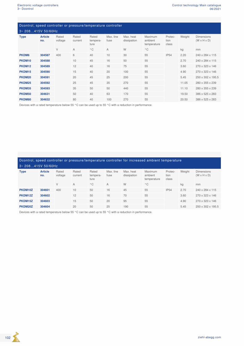
Dcontrol, speed controller or pressure/temperature controller3~ 208...415V 50/60HzType Article
no.Rated voltage
Rated current
Rated tempera-ture
Max. line fuse
Max. heat dissipation
Maximum ambient temperature
Protec-tion class
Weight Dimensions (W x H x D)
V A °C A W °C kg mm
PKDM6 304587 400 6 40 10 30 55 IP54 2.20 240 x 284 x 115
PKDM10 304588 10 45 16 50 55 2.70 240 x 284 x 115
PKDM12 304589 12 40 16 75 55 3.60 270 x 323 x 146
PKDM15 304590 15 40 20 100 55 4.90 270 x 323 x 146
PKDM20 304591 20 45 25 200 55 5.45 250 x 302 x 195.5
PKDM25 304592 25 45 35 270 55 11.05 280 x 355 x 239
PKDM35 304593 35 50 50 440 55 11.10 280 x 355 x 239
PKDM50 304631 50 40 63 170 55 19.50 386 x 525 x 283
PKDM80 304632 80 40 100 270 55 20.50 386 x 525 x 283
Devices with a rated temperature below 55 °C can be used up to 55 °C with a reduction in performance.
Dcontrol, speed controller or pressure/temperature controller for increased ambient temperature3~ 208...415V 50/60HzType Article
no.Rated voltage
Rated current
Rated tempera-ture
Max. line fuse
Max. heat dissipation
Maximum ambient temperature
Protec-tion class
Weight Dimensions (W x H x D)
V A °C A W °C kg mm
PKDM10Z 304601 400 10 50 16 45 55 IP54 2.70 240 x 284 x 115
PKDM12Z 304602 12 50 16 70 55 3.60 270 x 323 x 146
PKDM15Z 304603 15 50 20 95 55 4.90 270 x 323 x 146
PKDM20Z 304604 20 50 25 190 55 5.45 250 x 302 x 195.5
Devices with a rated temperature below 55 °C can be used up to 55 °C with a reduction in performance.
102 ziehl-abegg.com
Electronic voltage controllers3~ Dcontrol
Control technology Main catalogue06/2021

103ziehl-abegg.com
Mot
or p
rote
ctio
nFc
ontro
l, Ic
ontro
lUN
Icon
Acon
trol,
Ucon
trol,
Dcon
trol
Tran
sfor
mer
Syst
em c
ompo
nent
s In
form
atio
n
Appe
ndix
Electronic voltage controllers3~ Dcontrol
Control technology Main catalogue06/2021
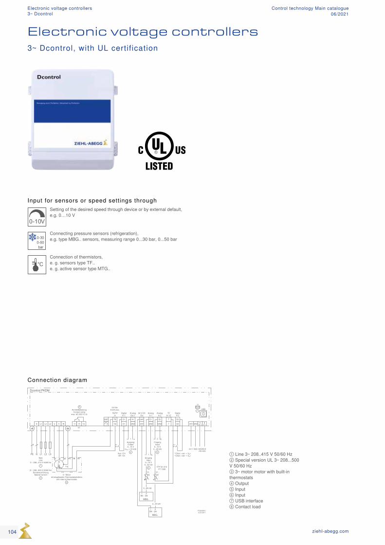
Input for sensors or speed settings through
0-10V
Setting of the desired speed through device or by external default, e.g. 0…10 V
0-300-50bar
Connecting pressure sensors (refrigeration), e.g. type MBG.. sensors, measuring range 0...30 bar, 0...50 bar
°CConnection of thermistors, e. g. sensors type TF.. e. g. active sensor type MTG..
① Line 3~ 208..415 V 50/60 Hz ② Special version UL 3~ 208...500 V 50/60 Hz ③ 3~ motor motor with built-in thermostats ④ Output ⑤ Input ⑥ Input ⑦ USB interface ⑧ Contact load
Connection diagram
Electronic voltage controllers3~ Dcontrol, with UL certification
104 ziehl-abegg.com
Electronic voltage controllers3~ Dcontrol
Control technology Main catalogue06/2021
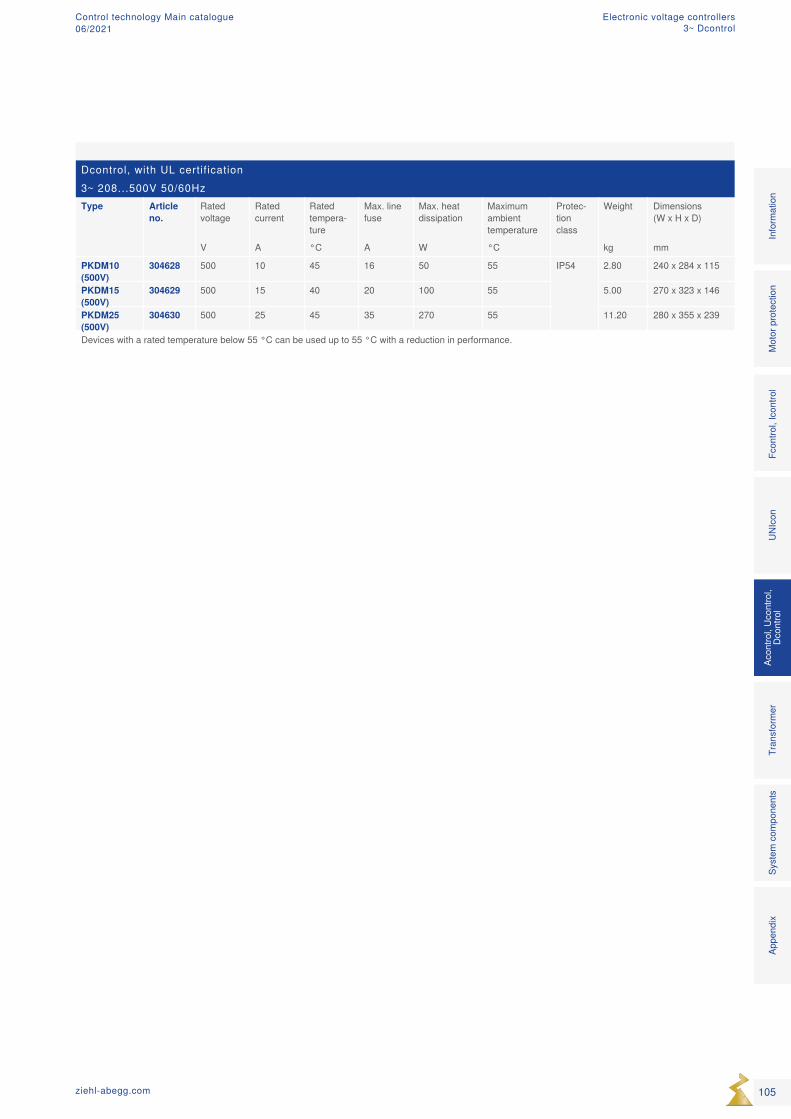
Dcontrol, with UL certification3~ 208...500V 50/60HzType Article
no.Rated voltage
Rated current
Rated tempera-ture
Max. line fuse
Max. heat dissipation
Maximum ambient temperature
Protec-tion class
Weight Dimensions (W x H x D)
V A °C A W °C kg mm
PKDM10 (500V)
304628 500 10 45 16 50 55 IP54 2.80 240 x 284 x 115
PKDM15 (500V)
304629 500 15 40 20 100 55 5.00 270 x 323 x 146
PKDM25 (500V)
304630 500 25 45 35 270 55 11.20 280 x 355 x 239
Devices with a rated temperature below 55 °C can be used up to 55 °C with a reduction in performance.
105ziehl-abegg.com
Mot
or p
rote
ctio
nFc
ontro
l, Ic
ontro
lUN
Icon
Acon
trol,
Ucon
trol,
Dcon
trol
Tran
sfor
mer
Syst
em c
ompo
nent
s In
form
atio
n
Appe
ndix
Electronic voltage controllers3~ Dcontrol
Control technology Main catalogue06/2021
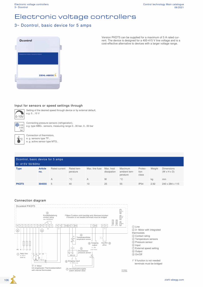
PDTE20K202.05.2006
N L1 L2 L3
L3N L2L1PE
U V W 121411 GNDTKTK AGND24V D1 D1 E1.1E GND
K1
Dcontrol P K DT5
M3~
PEV WU
TBTBY Dbzw.
or
+
E1.2
°C
V
mA
Kontaktbelastung contact ratingmax. 5A/250VAC
3~ Motor mit eingebauten Thermostatschalternwith internal thermostats
Ausgangoutput0...10V
(Imax=10mA)
Aus/Einoff /on
10K
ext . Drehzahlvorgabeextern desired value
Drucksensorpressure sensor
Temperaturfühlertemperature sensor
TF..
1* Wenn Funktion nicht benötigt wird, Klemmen brücken If function is not needed, terminals must be bridged
1* 1*
Netz / line 3~ 415 V50/60 Hz
4-20mA
Eingang / input0...10V (Ri>100k)
1 3braun
BNgrünGN
+
MBG-30I
0 1
PE PE
①
②
③
④
⑤
⑥
⑦
⑧ ⑨
① Line ② 3~ Motor with integrated thermostats ③ Contact rating ④ Temperature sensors ⑤ Pressure sensor ⑥ Input ⑦ External speed setting ⑧ Output ⑨ On/Off 1* If function is not needed terminals must be bridged
Input for sensors or speed settings through
0-10V
Setting of the desired speed through device or by external default, e.g. 0…10 V
0-300-50bar
Connecting pressure sensors (refrigeration), e.g. type MBG.. sensors, measuring range 0...30 bar, 0...50 bar
°CConnection of thermistors, e. g. sensors type TF.. e. g. active sensor type MTG..
Dcontrol, basic device for 5 amps3~ 415V 50/60HzType Article
no.Rated current Rated tem-
peratureMax. line fuse Max. heat
dissipationMaximum ambient tem-perature
Protec-tion class
Weight Dimensions (W x H x D)
A °C A W °C kg mm
PKDT5 304555 5 40 10 25 55 IP54 2.92 240 x 284 x 115
Version PKDT5 can be supplied for a maximum of 5 A rated cur-rent. The device is designed for a 400-415 V line voltage and is a cost-effective alternative to devices with a larger voltage range.
Connection diagram
Electronic voltage controllers3~ Dcontrol, basic device for 5 amps
106 ziehl-abegg.com
Electronic voltage controllers3~ Dcontrol
Control technology Main catalogue06/2021
107ziehl-abegg.com
Mot
or p
rote
ctio
nFc
ontro
l, Ic
ontro
lUN
Icon
Acon
trol,
Ucon
trol,
Dcon
trol
Tran
sfor
mer
Syst
em c
ompo
nent
s In
form
atio
n
Appe
ndix
Electronic voltage controllers3~ Dcontrol
Control technology Main catalogue06/2021
108 ziehl-abegg.com
Transformer-based controllers Control technology Main catalogue06/2021
Product overview
Description Page 110 1~ 5-step switch Page 111 3~ 5-step switch Page 115 Thermostats Page 118
Transformer-based controllers
109ziehl-abegg.com
Mot
or p
rote
ctio
nFc
ontro
l. Ic
ontro
lUN
Icon
Acon
trol,
Ucon
trol,
Dcon
trol
Tran
sfor
mer
Syst
em c
ompo
nent
sIn
form
atio
nAp
pend
ix
Transformer-based controllersControl technology Main catalogue06/2021
Most ZIEHL-ABEGG external rotor motors are voltage controllable. For simple and cost-effective speed control of these motors and fans, transformer-based controllers are available. These can be supplied in various versions. In addition to versions that only generate the corresponding voltage by setting the 5-stage switch, there are also devices that can control dampers or valves. Versions, that switch between two adjustable stages via an external contact, are also available. Versions, that are controlled via a 5-step thermostat, are also available. Another, great advantage of transformer-based control devices is speed control without electromagnetic excitation in the motors. The products are therefore also recommended for areas that are sensitive of noise. Correspondingly, we supply thermostats which can be combined without the need of transformer-based controllers.
Equipment/Characteristics Operating indicator lamp for status indication. Device on/off. Speed setting The desired speed is set via the integrated 5-step switch. Devices with two adjustable speeds or devices with 0-10 V control can also be supplied. Output voltage: 1~ units: 65 - 110 - 135 - 170 - 230 V 3~ units: 95 - 145 - 190 - 240 - 400 V
Please refer to the respective device connection diagram, depending on model. Digitale Input For external, floating contact to issue an authorisation for the preselected step (on/off); e.g. connect room thermostat SRE1G. Digital input for frost protection For external, floating contact. If a frost protection thermostat responds, the device switches off. Resetting to switch position 0 required to restore. Integrated motor protection function Connection facility for thermostat “TB” Switched output in operation Switched phase 1~ 230 V, max. 1 A, e.g. for damper servo-motor. Change-over relay Floating change-over relay, max. load 250 V AC, 2 A, to control external de-vices.
Transformer-based controllersDescription
Optional supply of individual transformers The type of transformers that are predominantly used in our control devices, can also be supplied individuallyPlease note that they are designed as special versions intended for control cabinet integration, including installation pad and connection terminal. There are 1~ 230 V transformers and 3~ 400 V transform-ers. For 3~ 400 V, two transformers are connected in a V-circuit.
110 ziehl-abegg.com
Transformer-based controllersDescription
Control technology Main catalogue06/2021
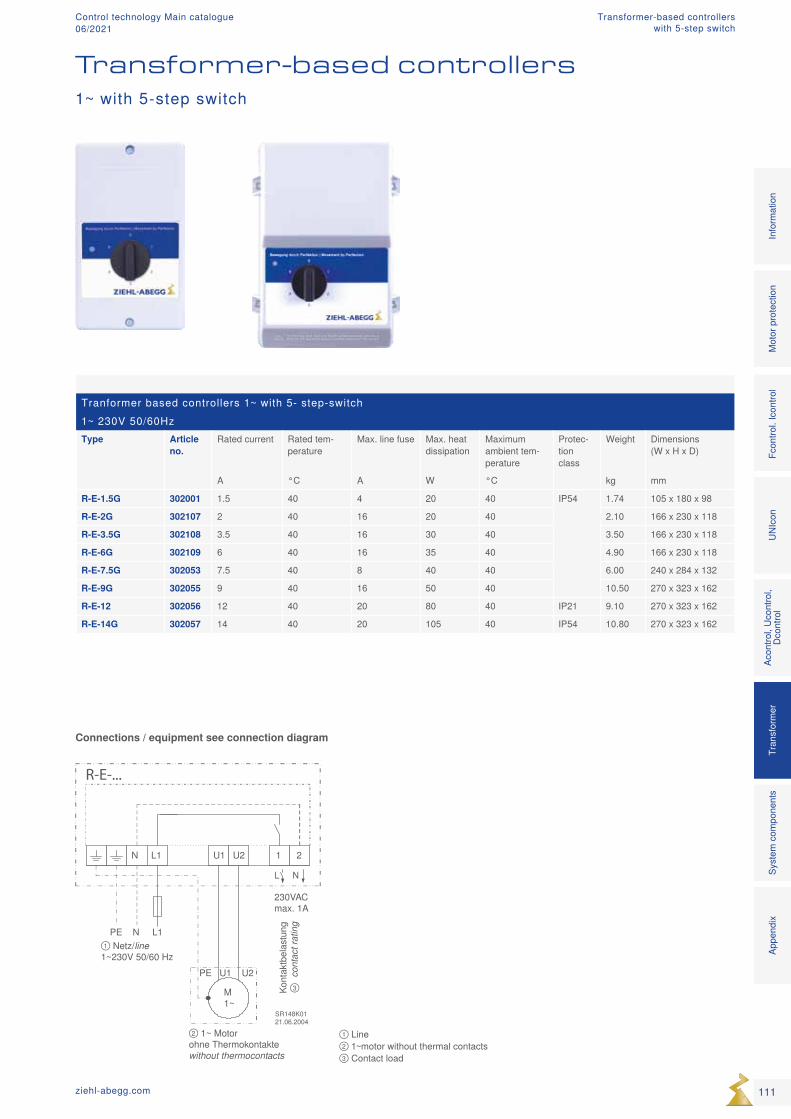
① Netz/line1~230V 50/60 Hz
PE N L1
PE U1 U2
M1~
SR148K0121.06.2004
Kon
takt
bela
stun
gco
ntac
t rat
ing
③
② 1~ Motorohne Thermokontaktewithout thermocontacts
N L1 U1 U2 1 2
230VACmax. 1A
R-E-...
Tranformer based controllers 1~ with 5- step-switch1~ 230V 50/60HzType Article
no.Rated current Rated tem-
peratureMax. line fuse Max. heat
dissipationMaximum ambient tem-perature
Protec-tion class
Weight Dimensions (W x H x D)
A °C A W °C kg mm
R-E-1.5G 302001 1.5 40 4 20 40 IP54 1.74 105 x 180 x 98
R-E-2G 302107 2 40 16 20 40 2.10 166 x 230 x 118
R-E-3.5G 302108 3.5 40 16 30 40 3.50 166 x 230 x 118
R-E-6G 302109 6 40 16 35 40 4.90 166 x 230 x 118
R-E-7.5G 302053 7.5 40 8 40 40 6.00 240 x 284 x 132
R-E-9G 302055 9 40 16 50 40 10.50 270 x 323 x 162
R-E-12 302056 12 40 20 80 40 IP21 9.10 270 x 323 x 162
R-E-14G 302057 14 40 20 105 40 IP54 10.80 270 x 323 x 162
① Line ② 1~motor without thermal contacts ③ Contact load
Connections / equipment see connection diagram
Transformer-based controllers1~ with 5-step switch
111ziehl-abegg.com
Mot
or p
rote
ctio
nFc
ontro
l. Ic
ontro
lUN
Icon
Acon
trol,
Ucon
trol,
Dcon
trol
Tran
sfor
mer
Syst
em c
ompo
nent
sIn
form
atio
nAp
pend
ix
Transformer-based controllerswith 5-step switch
Control technology Main catalogue06/2021
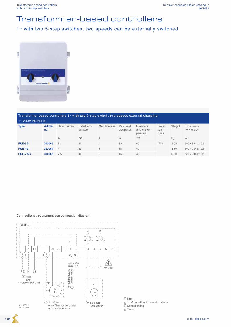
RUE-…
N L1
N L1PE
M1 ~
PE U1 U2
U1 U2 1 2 3 4 5 6 7
230 V AC
L N
SR154K0113.11.2007
Kon
takt
bela
stun
g C
onta
ct ra
ting
230 V ACmax. 1 A
NetzLine
1 ~ 230 V 50/60 Hz
SchaltuhrTime switch
A B
1 ~ Motor ohne Thermostatschalterwithout thermostats
1
3
24
50
1
3
24
50
①
②
③
④① Line ② 1~ Motor without thermal contacts ③ Contact rating ④ Timer
Transformer based controllers 1~ with two 5-step-switch, two speeds external changing1~ 230V 50/60HzType Article
no.Rated current Rated tem-
peratureMax. line fuse Max. heat
dissipationMaximum ambient tem-perature
Protec-tion class
Weight Dimensions (W x H x D)
A °C A W °C kg mm
RUE-2G 302063 2 40 4 25 40 IP54 3.55 240 x 284 x 132
RUE-4G 302064 4 40 6 35 40 4.80 240 x 284 x 132
RUE-7.5G 302065 7.5 40 8 45 40 6.30 240 x 284 x 132
Transformer-based controllers1~ with two 5-step switches, two speeds can be externally switched
Connections / equipment see connection diagram
112 ziehl-abegg.com
Transformer-based controllerswith two 5-step switches
Control technology Main catalogue06/2021
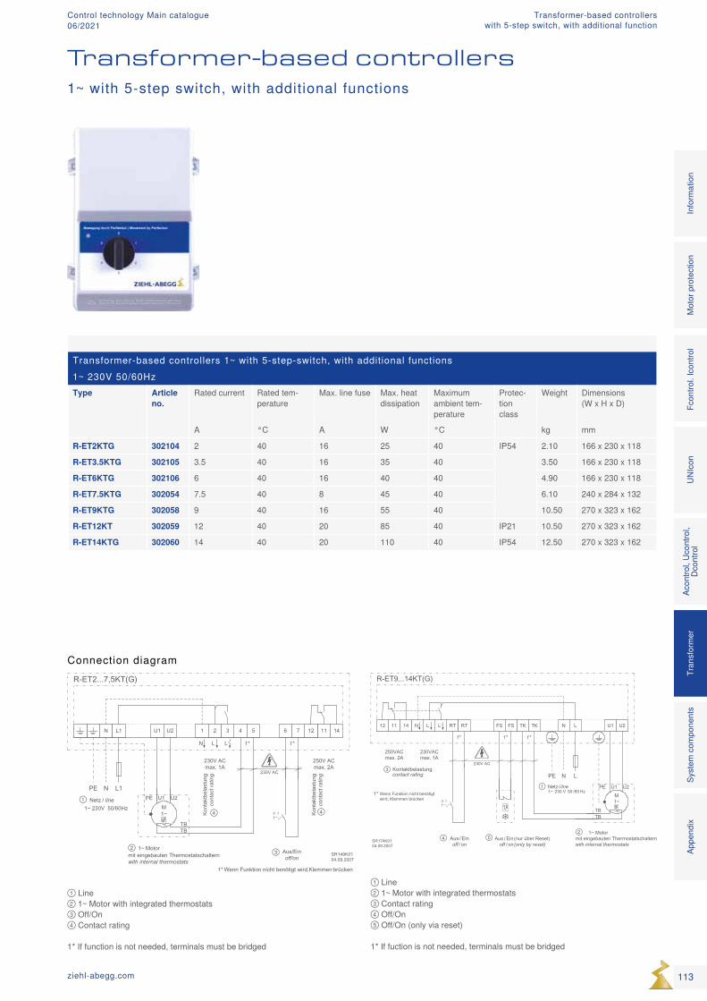
N L
N LPE
Netz / line 1~ 230 V 50 /60 Hz
U1 U211 1412 TK TKRT
SR174K0104.09.2007
L L N
230V ACKontaktbelastung contact rating
RT FS FS
1* Wenn Funktion nicht benötigt wird, Klemmen brücken
1* 1* 1*
250VACmax. 2A
230VACmax. 1A
Aus / Ein (nur über Reset)off / on (only by reset)
Aus/ Einoff / on
0 1M1~
PE U2U1
TBTB
1~ Motor mit eingebauten Thermostatschalternwith internal thermostats
①
②
③
④ ⑤
U1 U2 11 14124 5 6
SR149K0104.09.2007
L L
230V AC
7
1*1*
Aus/Einoff/on
N
1 2 3N L1
N L1PE
Netz / line 1~ 230V 50/60Hz M
1~
PE U2U1
TBTB
Kon
takt
bela
stun
g co
ntac
t rat
ing
230V ACmax. 1A
0 1 Kont
aktb
elas
tung
co
ntac
t rat
ing
250V ACmax. 2A
1* Wenn Funktion nicht benötigt wird, Klemmen brücken
1~ Motor mit eingebauten Thermostatschalternwith internal thermostats
①
② ③
④ ④
Transformer-based controllers 1~ with 5-step-switch, with additional functions1~ 230V 50/60HzType Article
no.Rated current Rated tem-
peratureMax. line fuse Max. heat
dissipationMaximum ambient tem-perature
Protec-tion class
Weight Dimensions (W x H x D)
A °C A W °C kg mm
R-ET2KTG 302104 2 40 16 25 40 IP54 2.10 166 x 230 x 118
R-ET3.5KTG 302105 3.5 40 16 35 40 3.50 166 x 230 x 118
R-ET6KTG 302106 6 40 16 40 40 4.90 166 x 230 x 118
R-ET7.5KTG 302054 7.5 40 8 45 40 6.10 240 x 284 x 132
R-ET9KTG 302058 9 40 16 55 40 10.50 270 x 323 x 162
R-ET12KT 302059 12 40 20 85 40 IP21 10.50 270 x 323 x 162
R-ET14KTG 302060 14 40 20 110 40 IP54 12.50 270 x 323 x 162
① Line ② 1~ Motor with integrated thermostats ③ Contact rating ④ Off/On ⑤ Off/On (only via reset) 1* If fuction is not needed, terminals must be bridged
① Line ② 1~ Motor with integrated thermostats ③ Off/On ④ Contact rating 1* If function is not needed, terminals must be bridged
Transformer-based controllers1~ with 5-step switch, with additional functions
Connection diagram
113ziehl-abegg.com
Mot
or p
rote
ctio
nFc
ontro
l. Ic
ontro
lUN
Icon
Acon
trol,
Ucon
trol,
Dcon
trol
Tran
sfor
mer
Syst
em c
ompo
nent
sIn
form
atio
nAp
pend
ix
Transformer-based controllerswith 5-step switch, with additional function
Control technology Main catalogue06/2021
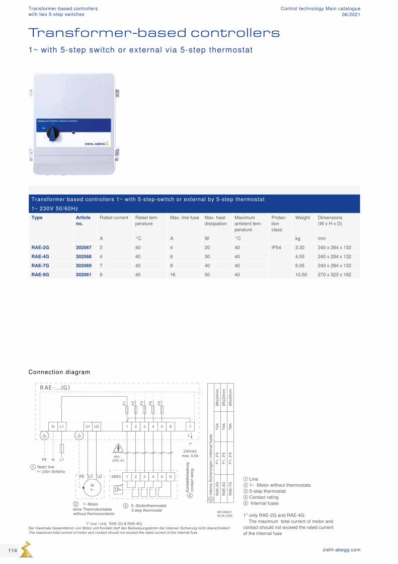
>
R AE -…(G )
1 2 3 4 5 6 7
65V…230V AC
L
SR146K0130.06.2006
F5F4F3F2F1
1 2 3 4 5 6
1*
N L1
N L1PE
1~ Motorohne Thermokontaktewithout thermocontacts
M1~
PE U1 U2
U1 U2
Netz / line 1~ 230V 50/60Hz
Kon
takt
bela
stun
g co
ntac
t rat
ing
230VACmax. 0,5A
Inte
rne
Sic
heru
ngen
/ in
tern
al fu
ses
RA
E-2
G
RA
E-4
G
RA
E-7
G
F1...
F5T2
A
F1...
F5
F1...
F5
T4A
T8A
Ø5x
20m
m
Ø5x
20m
m
Ø5x
20m
m
1* (nur / only RAE-2G & RAE-4G)Der maximale Gesamtstrom von Motor und Kontakt darf den Bemessungsstrom der internen Sicherung nicht überschreiten!The maximum total current of motor and contact should not exceed the rated current of the internal fuse
5- Stufenthermostat5 step thermostat
SRE5
①
② ③
④ ⑤
① Line ② 1~ Motor without thermostats ③ 5-step thermostat ④ Contact rating ⑤ Internal fuses 1* only RAE-2G and RAE-4G: The maximum total current of motor and contact should not exceed the rated current of the internal fuse
Transformer based controllers 1~ with 5-step-switch or external by 5-step thermostat1~ 230V 50/60HzType Article
no.Rated current Rated tem-
peratureMax. line fuse Max. heat
dissipationMaximum ambient tem-perature
Protec-tion class
Weight Dimensions (W x H x D)
A °C A W °C kg mm
RAE-2G 302067 2 40 4 20 40 IP54 3.30 240 x 284 x 132
RAE-4G 302068 4 40 6 30 40 4.55 240 x 284 x 132
RAE-7G 302069 7 40 8 40 40 6.05 240 x 284 x 132
RAE-9G 302061 9 40 16 50 40 10.50 270 x 323 x 162
Transformer-based controllers1~ with 5-step switch or external via 5-step thermostat
Connection diagram
114 ziehl-abegg.com
Transformer-based controllerswith two 5-step switches
Control technology Main catalogue06/2021
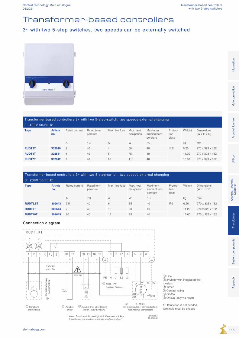
R UDT ...K T
N L1 L2 L3
L3N L2L1PE
Netz / line 3~400V 50/60Hz
U V W2 31 TB TBRT
0 1
RDNT08K116.02.2006
L L N
230V AC
Kon
takt
bela
stun
g co
ntac
t rat
ing
RT FS FS
1* Wenn Funktion nicht benötigt wird, Klemmen brücken If function is not needed, terminals must be bridged
1* 1* 1*
Aus/Einoff/on
230VACmax. 1A
Aus/Ein (nur über Reset)off/on (only by reset)
A B
Schaltuhrtime switch
3~ Motor mit eingebauten Thermoschaltern
with internal thermostats
M3~
PEV WU
TBTB Y Dbzw.
or
1
23
4
50
1
23
4
50
①
②③
④
⑤ ⑥
① Line ② 3~Motor with integrated ther-mostats ③ Timer ④ Contact rating ⑤ Off/On ⑥ Off/On (only via reset) 1* If function is not needed, terminals must be bridged
Transformer based controllers 3~ with two 5-step-switch, two speeds external changing3~ 400V 50/60HzType Article
no.Rated current Rated tem-
peratureMax. line fuse Max. heat
dissipationMaximum ambient tem-perature
Protec-tion class
Weight Dimensions (W x H x D)
A °C A W °C kg mm
RUDT2T 302640 2 40 4 50 40 IP21 6.20 270 x 323 x 162
RUDT4T 302641 4 40 6 75 40 11.20 270 x 323 x 162
RUDT7T 302642 7 40 16 110 40 15.80 270 x 323 x 162
Transformer based controllers 3~ with two 5-step-switch, two speeds external changing3~ 230V 50/60HzType Article
no.Rated current Rated tem-
peratureMax. line fuse Max. heat
dissipationMaximum ambient tem-perature
Protec-tion class
Weight Dimensions (W x H x D)
A °C A W °C kg mm
RUDT3.5T 302643 3.5 40 6 65 40 IP21 6.20 270 x 323 x 162
RUDT7T 302644 7 40 16 80 40 11.20 270 x 323 x 162
RUDT10T 302645 10 40 16 85 40 15.60 270 x 323 x 162
Transformer-based controllers
Connection diagram
3~ with two 5-step switches, two speeds can be externally switched
115ziehl-abegg.com
Mot
or p
rote
ctio
nFc
ontro
l. Ic
ontro
lUN
Icon
Acon
trol,
Ucon
trol,
Dcon
trol
Tran
sfor
mer
Syst
em c
ompo
nent
sIn
form
atio
nAp
pend
ix
Transformer-based controllerswith two 5-step switches
Control technology Main catalogue06/2021
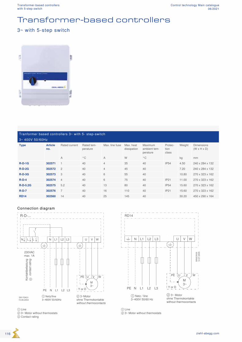
① Netz / line3~400V 50/60 Hz
② 3~ Motorohne Thermokontaktewithout thermocontacts
RD14
N L1 L2 L3 U V W
PE N L1 L2 L3
PE U V W
M3~
Y or D
SR05
7K05
12.0
7.20
05
① Netz/line3~400V 50/60Hz
② 3~Motorohne Thermokontaktewithout thermocontacts
Kont
aktb
elas
tung
cont
act r
atin
g
230VACmax. 1A
R-D-...
SR170K0115.06.2004
N L L N L1 L2 L3 U V W
PE U V W
M3~
Y or DPE N L1 L2 L3
③
Tranformer based controllers 3~ with 5- step-switch3~ 400V 50/60HzType Article
no.Rated current Rated tem-
peratureMax. line fuse Max. heat
dissipationMaximum ambient tem-perature
Protec-tion class
Weight Dimensions (W x H x D)
A °C A W °C kg mm
R-D-1G 302571 1 40 4 35 40 IP54 4.50 240 x 284 x 132
R-D-2G 302572 2 40 4 45 40 7.20 240 x 284 x 132
R-D-3G 302573 3 40 6 55 40 10.80 270 x 323 x 162
R-D-4 302574 4 40 6 75 40 IP21 11.00 270 x 323 x 162
R-D-5.2G 302575 5.2 40 13 80 40 IP54 15.60 270 x 323 x 162
R-D-7 302576 7 40 16 110 40 IP21 15.60 270 x 323 x 162
RD14 302560 14 40 25 145 40 30.20 450 x 290 x 164
① Line ② 3~ Motor without thermostats
① Line ② 3~ Motor without thermostats ③ Contact rating
Transformer-based controllers3~ with 5-step switch
Connection diagram
116 ziehl-abegg.com
Transformer-based controllerswith 5-step switch
Control technology Main catalogue06/2021
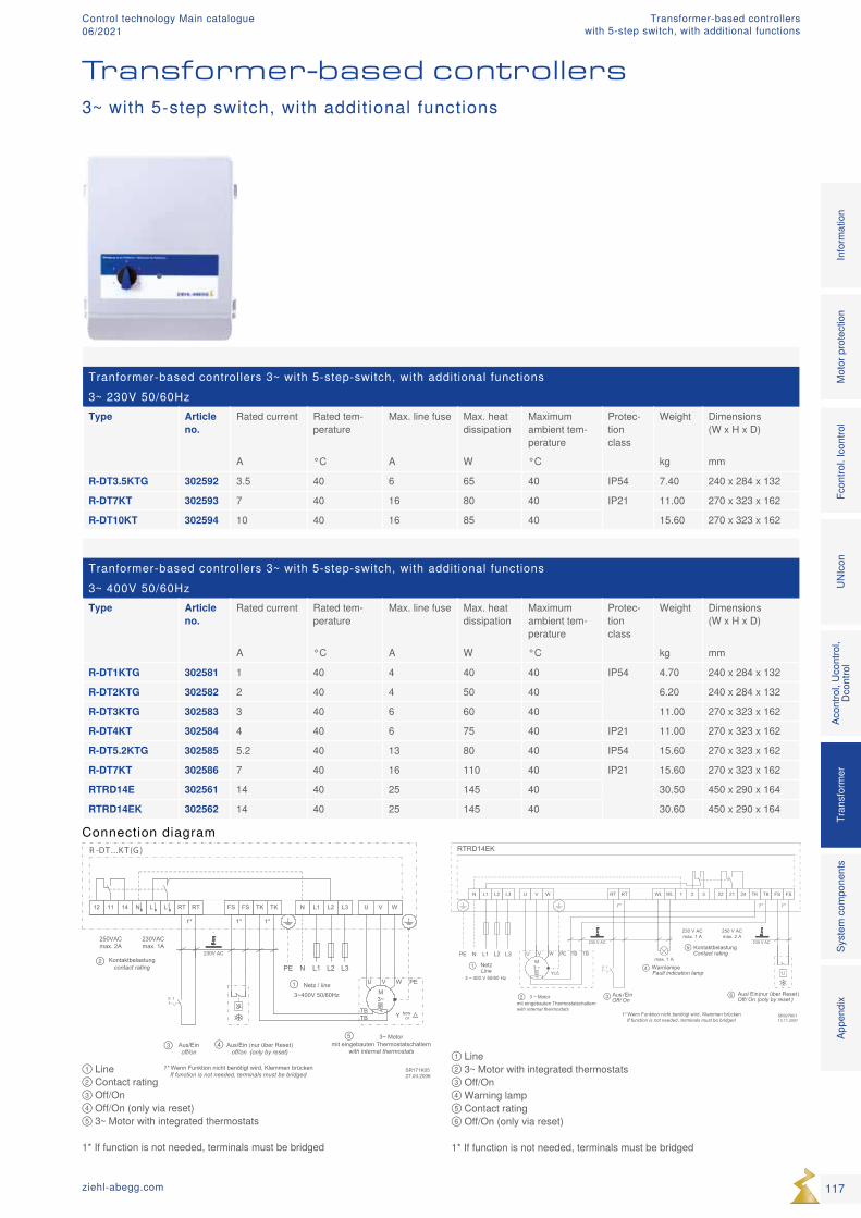
RTRD14EK
N L1 L2 L3
L3N L2L1PE
NetzLine
3 ~ 400 V 50/60 Hz
U V W 21 2422 TK TKRT
SR027K0113.11.2007
230 V ACKontaktbelastung Contact rating
RT FS FS
1* 1*1*
250 V ACmax. 2 A
max. 1 A
2 31
M3 ~
PEV WU TB TB
3 ~ Motor mit eingebauten Thermostatschalternwith internal thermostats
WL WL
WarnlampeFault indication lamp
230 V ACmax. 1 A
230 V AC
Aus / EinOff / On
0 1
Aus / Ein (nur über Reset)Off / On (only by reset )
1* Wenn Funktion nicht benötigt wird, Klemmen brücken If function is not needed, terminals must be bridged
Y/①
② ③
④
⑤
⑥
R -DT ...K T (G )
N L1 L2 L3
L3N L2L1PE
Netz / line 3~400V 50/60Hz
U V W11 1412 TK TKRT
0 1
SR171K0527.04.2006
L L N
230V ACKontaktbelastung
contact rating
RT FS FS
1* Wenn Funktion nicht benötigt wird, Klemmen brücken If function is not needed, terminals must be bridged
1* 1* 1*
Aus/Einoff/on
250VACmax. 2A
230VACmax. 1A
Aus/Ein (nur über Reset)off/on (only by reset)
3~ Motor mit eingebauten Thermostatschaltern
with internal thermostats
M3~
PEV WU
TBTB
bzw.orY
①
②
③ ④⑤
① Line ② 3~ Motor with integrated thermostats ③ Off/On ④ Warning lamp ⑤ Contact rating ⑥ Off/On (only via reset) 1* If function is not needed, terminals must be bridged
① Line ② Contact rating ③ Off/On ④ Off/On (only via reset) ⑤ 3~ Motor with integrated thermostats 1* If function is not needed, terminals must be bridged
Tranformer-based controllers 3~ with 5-step-switch, with additional functions3~ 400V 50/60HzType Article
no.Rated current Rated tem-
peratureMax. line fuse Max. heat
dissipationMaximum ambient tem-perature
Protec-tion class
Weight Dimensions (W x H x D)
A °C A W °C kg mm
R-DT1KTG 302581 1 40 4 40 40 IP54 4.70 240 x 284 x 132
R-DT2KTG 302582 2 40 4 50 40 6.20 240 x 284 x 132
R-DT3KTG 302583 3 40 6 60 40 11.00 270 x 323 x 162
R-DT4KT 302584 4 40 6 75 40 IP21 11.00 270 x 323 x 162
R-DT5.2KTG 302585 5.2 40 13 80 40 IP54 15.60 270 x 323 x 162
R-DT7KT 302586 7 40 16 110 40 IP21 15.60 270 x 323 x 162
RTRD14E 302561 14 40 25 145 40 30.50 450 x 290 x 164
RTRD14EK 302562 14 40 25 145 40 30.60 450 x 290 x 164
Tranformer-based controllers 3~ with 5-step-switch, with additional functions3~ 230V 50/60HzType Article
no.Rated current Rated tem-
peratureMax. line fuse Max. heat
dissipationMaximum ambient tem-perature
Protec-tion class
Weight Dimensions (W x H x D)
A °C A W °C kg mm
R-DT3.5KTG 302592 3.5 40 6 65 40 IP54 7.40 240 x 284 x 132
R-DT7KT 302593 7 40 16 80 40 IP21 11.00 270 x 323 x 162
R-DT10KT 302594 10 40 16 85 40 15.60 270 x 323 x 162
Transformer-based controllers
Connection diagram
3~ with 5-step switch, with additional functions
117ziehl-abegg.com
Mot
or p
rote
ctio
nFc
ontro
l. Ic
ontro
lUN
Icon
Acon
trol,
Ucon
trol,
Dcon
trol
Tran
sfor
mer
Syst
em c
ompo
nent
sIn
form
atio
nAp
pend
ix
Transformer-based controllerswith 5-step switch, with additional functions
Control technology Main catalogue06/2021
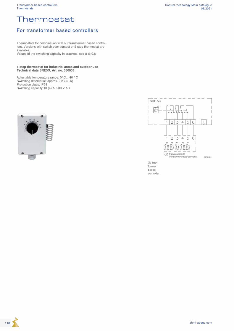
① TrafosteuergerätTransformer based controller
SRE 5G
SGTS0K0
① Tran-former based controller
For transformer based controllers
5-step thermostat for industrial areas and outdoor use Technical data SRE5G, Art. no. 380003 Adjustable temperature range: 0°C... 40 °C Switching differential: approx. 2 K (+/- K) Protection class: IP54 Switching capacity:10 (4) A, 230 V AC
118 ziehl-abegg.com
Thermostat
Thermostats for combination with our transformer-based control-lers. Versions with switch over contact or 5-step thermostat are available. Values of the switching capacity in brackets: cos φ to 0.6
Transformer-based controllersThermostats
Control technology Main catalogue06/2021
119ziehl-abegg.com
Mot
or p
rote
ctio
nFc
ontro
l. Ic
ontro
lUN
Icon
Acon
trol,
Ucon
trol,
Dcon
trol
Tran
sfor
mer
Syst
em c
ompo
nent
sIn
form
atio
nAp
pend
ix
Transformer-based controllersControl technology Main catalogue06/2021
120 ziehl-abegg.com
System components Control technology Main catalogue06/2021
Product overview
Sensors Page 122 Potentiometers Page 132 Expansion module Page 134 Gateway Page 146 Repeater Page 149 Operating terminal Page 150 Selection amplifier Page 154 Main switches Page 156 Empty housing and power supply unit Page 159
System components
121ziehl-abegg.com
Mot
or p
rote
ctio
nFc
ontro
l, Ic
ontro
lUN
Icon
Acon
trol,
Ucon
trol,
Dcon
trol
Tran
sfor
mer
Syst
em c
ompo
nent
s In
form
atio
n Ap
pend
ix
System componentsControl technology Main catalogue06/2021
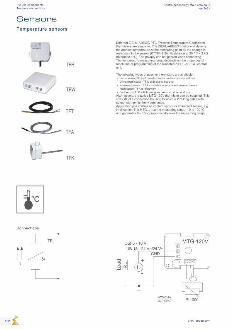
°C
ϑ
TF..
GND
Out 0 - 10 VUB 15 - 24 V=/24 V~
U-
+
RL
Load
Pt1000
MTG-120V
KT00031A20.11.2007
Connections
Different ZIEHL-ABEGG PTC (Positive Temperature Coefficient) thermistors are available. The ZIEHL-ABEGG control unit detects the ambient temperature at the measuring point by the change in resistance in the sensor (KTY81-210). Resistance at 25 °C = 2 kΩ (tolerance 1 %). The polarity can be ignored when connecting. The temperature measuring range depends on the properties of resolution or programming of the allocated ZIEHL-ABEGG control unit. The following types of passive thermistors are available:
- Room sensor TFR with plastic box for outdoor or industrial use - Living room sensor TFW with plastic housing - Immersed sensor TFT for installation in on-site immersed sleeve - Plant sensor TFA for pipework - Duct sensor TFK with housing and sensor rod for air ducts
Alternatively, the active MTG-120V thermistor can be supplied. This consists of a connection housing to which a 2 m long cable with sensor element is firmly connected. Application possibilities as contact sensor or immersed sensor, e.g. in oil cooler. The MTG… has the measuring range -10 to 120°C and generates 0 – 10 V proportionally over the measuring range.
SensorsTemperature sensors
122 ziehl-abegg.com
System componentsTemperature sensors
Control technology Main catalogue06/2021
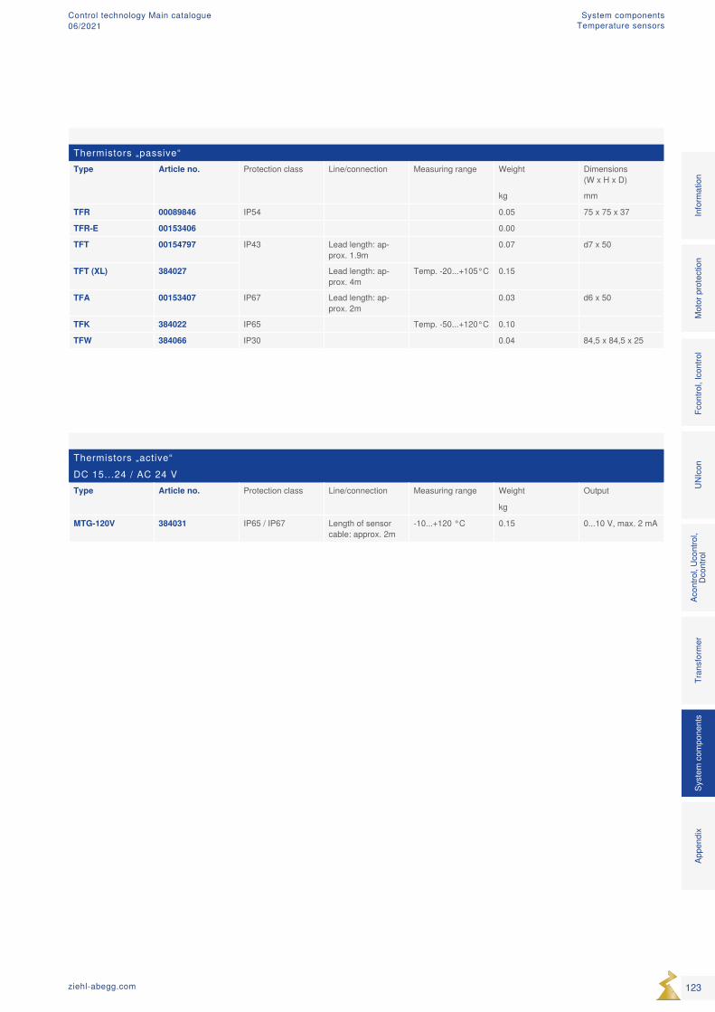
Thermistors „passive“Type Article no. Protection class Line/connection Measuring range Weight Dimensions
(W x H x D)
kg mm
TFR 00089846 IP54 0.05 75 x 75 x 37
TFR-E 00153406 0.00
TFT 00154797 IP43 Lead length: ap-prox. 1.9m
0.07 d7 x 50
TFT (XL) 384027 Lead length: ap-prox. 4m
Temp. -20...+105°C 0.15
TFA 00153407 IP67 Lead length: ap-prox. 2m
0.03 d6 x 50
TFK 384022 IP65 Temp. -50...+120°C 0.10
TFW 384066 IP30 0.04 84,5 x 84,5 x 25
Thermistors „active“DC 15...24 / AC 24 VType Article no. Protection class Line/connection Measuring range Weight Output
kg
MTG-120V 384031 IP65 / IP67 Length of sensor cable: approx. 2m
-10...+120 °C 0.15 0...10 V, max. 2 mA
123ziehl-abegg.com
Mot
or p
rote
ctio
nFc
ontro
l, Ic
ontro
lUN
Icon
Acon
trol,
Ucon
trol,
Dcon
trol
Tran
sfor
mer
Syst
em c
ompo
nent
s In
form
atio
n Ap
pend
ix
System componentsTemperature sensors
Control technology Main catalogue06/2021
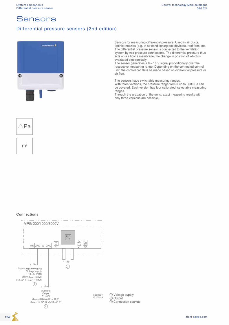
① Voltage supply② Output③ Connection sockets
Pa
m³
SensorsDifferential pressure sensors (2nd edition)
Connections
Sensors for measuring differential pressure. Used in air ducts, faninlet nozzles (e.g. in air conditioning box devices), roof fans, etc. The differential pressure sensor is connected to the ventilation system by two pressure connections. The differential pressure thus acts on a silicone membrane, the change in position of which is evaluated electronically. The sensor generates a 0 – 10 V signal proportionally over the respective measuring range. Depending on the connected control unit, the control can thus be made based on differential pressure or air flow. The sensors have switchable measuring ranges. With three versions, the pressure range from 0 up to 6000 Pa can be covered. Each version has four calibrated, selectable measuring ranges. Through the gradation of the units, exact measuring results with only three versions are possible..
124 ziehl-abegg.com
System componentsDifferential pressure sensor
Control technology Main catalogue06/2021
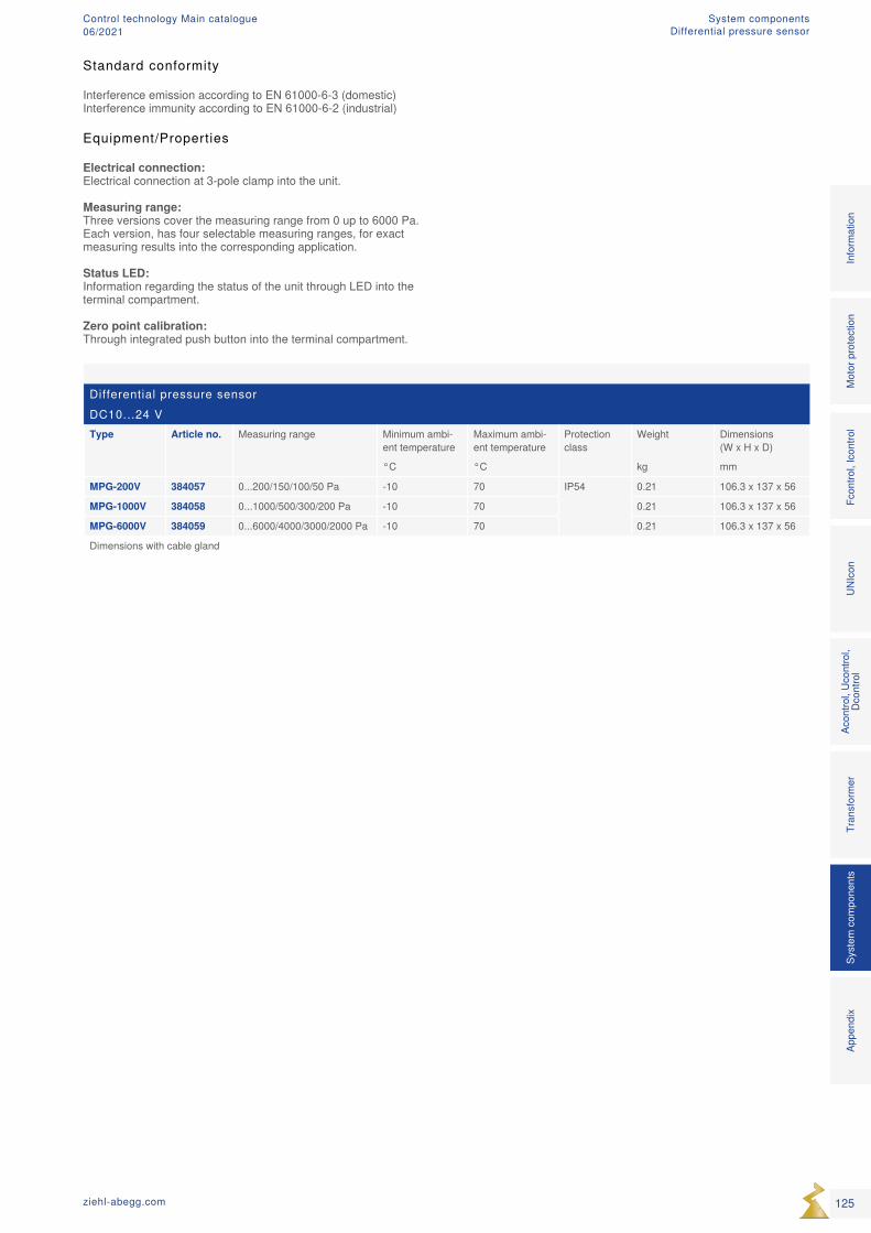
Differential pressure sensorDC10...24 VType Article no. Measuring range Minimum ambi-
ent temperatureMaximum ambi-ent temperature
Protection class
Weight Dimensions (W x H x D)
°C °C kg mm
MPG-200V 384057 0...200/150/100/50 Pa -10 70 IP54 0.21 106.3 x 137 x 56
MPG-1000V 384058 0...1000/500/300/200 Pa -10 70 0.21 106.3 x 137 x 56
MPG-6000V 384059 0...6000/4000/3000/2000 Pa -10 70 0.21 106.3 x 137 x 56
Dimensions with cable gland
Standard conformity
Interference emission according to EN 61000-6-3 (domestic)Interference immunity according to EN 61000-6-2 (industrial)
Equipment/Properties
Electrical connection: Electrical connection at 3-pole clamp into the unit. Measuring range: Three versions cover the measuring range from 0 up to 6000 Pa. Each version, has four selectable measuring ranges, for exact measuring results into the corresponding application. Status LED: Information regarding the status of the unit through LED into the terminal compartment. Zero point calibration: Through integrated push button into the terminal compartment.
125ziehl-abegg.com
Mot
or p
rote
ctio
nFc
ontro
l, Ic
ontro
lUN
Icon
Acon
trol,
Ucon
trol,
Dcon
trol
Tran
sfor
mer
Syst
em c
ompo
nent
s In
form
atio
n Ap
pend
ix
System componentsDifferential pressure sensor
Control technology Main catalogue06/2021
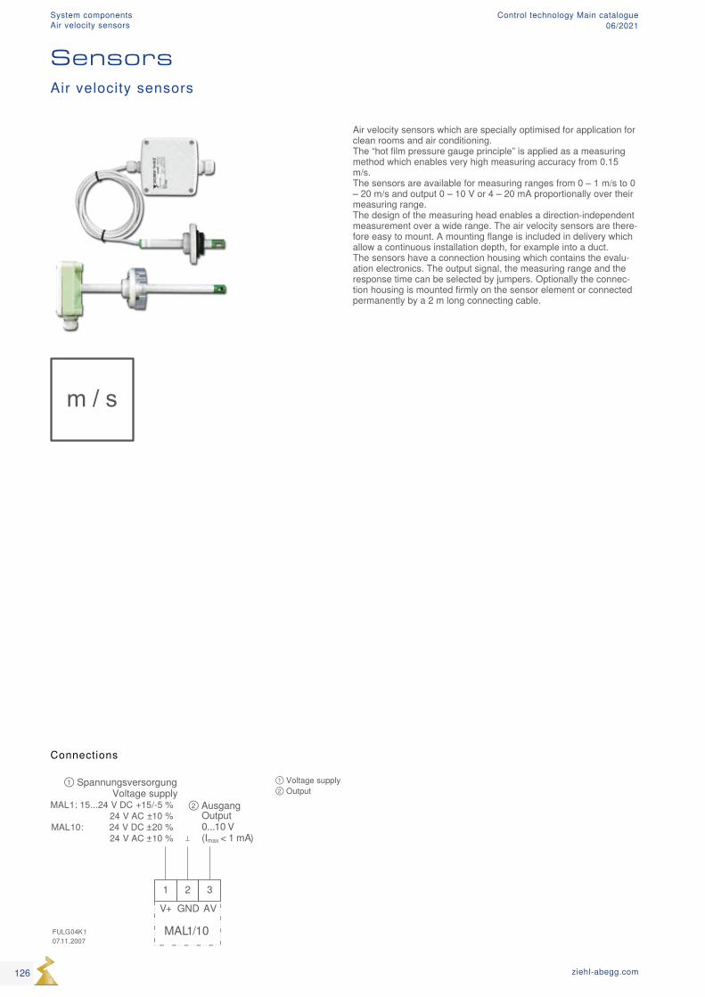
m / s
① Voltage supply ② Output
Connections
Air velocity sensors which are specially optimised for application for clean rooms and air conditioning. The “hot film pressure gauge principle” is applied as a measuring method which enables very high measuring accuracy from 0.15 m/s. The sensors are available for measuring ranges from 0 – 1 m/s to 0 – 20 m/s and output 0 – 10 V or 4 – 20 mA proportionally over their measuring range. The design of the measuring head enables a direction-independent measurement over a wide range. The air velocity sensors are there-fore easy to mount. A mounting flange is included in delivery which allow a continuous installation depth, for example into a duct. The sensors have a connection housing which contains the evalu-ation electronics. The output signal, the measuring range and the response time can be selected by jumpers. Optionally the connec-tion housing is mounted firmly on the sensor element or connected permanently by a 2 m long connecting cable.
Air velocity sensors
Sensors
126 ziehl-abegg.com
System componentsAir velocity sensors
Control technology Main catalogue06/2021
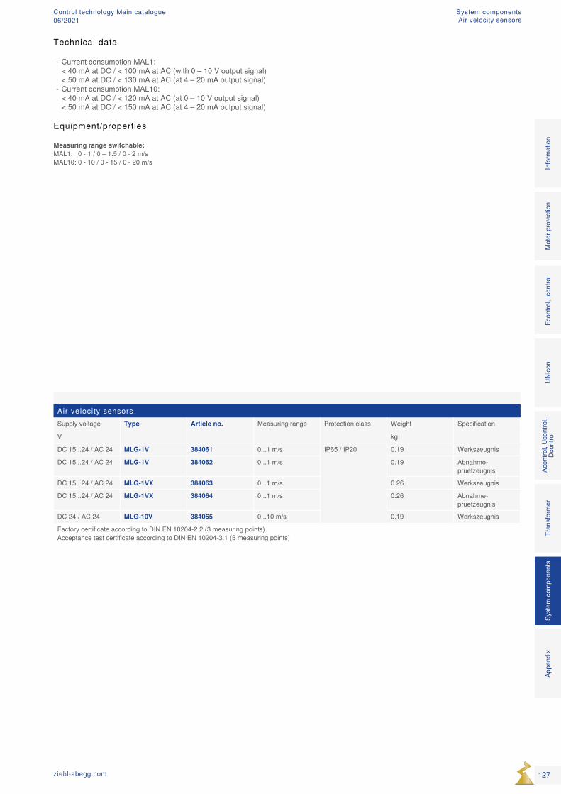
Air velocity sensorsSupply voltage Type Article no. Measuring range Protection class Weight Specification
V kg
DC 15...24 / AC 24 MLG-1V 384061 0...1 m/s IP65 / IP20 0.19 Werkszeugnis
DC 15...24 / AC 24 MLG-1V 384062 0...1 m/s 0.19 Abnahme-pruefzeugnis
DC 15...24 / AC 24 MLG-1VX 384063 0...1 m/s 0.26 Werkszeugnis
DC 15...24 / AC 24 MLG-1VX 384064 0...1 m/s 0.26 Abnahme-pruefzeugnis
DC 24 / AC 24 MLG-10V 384065 0...10 m/s 0.19 Werkszeugnis
Factory certificate according to DIN EN 10204-2.2 (3 measuring points) Acceptance test certificate according to DIN EN 10204-3.1 (5 measuring points)
Technical data
- Current consumption MAL1: < 40 mA at DC / < 100 mA at AC (with 0 – 10 V output signal) < 50 mA at DC / < 130 mA at AC (at 4 – 20 mA output signal)
- Current consumption MAL10: < 40 mA at DC / < 120 mA at AC (at 0 – 10 V output signal) < 50 mA at DC / < 150 mA at AC (at 4 – 20 mA output signal)
Equipment/properties
Measuring range switchable: MAL1: 0 - 1 / 0 – 1.5 / 0 - 2 m/s MAL10: 0 - 10 / 0 - 15 / 0 - 20 m/s
127ziehl-abegg.com
Mot
or p
rote
ctio
nFc
ontro
l, Ic
ontro
lUN
Icon
Acon
trol,
Ucon
trol,
Dcon
trol
Tran
sfor
mer
Syst
em c
ompo
nent
s In
form
atio
n Ap
pend
ix
System componentsAir velocity sensors
Control technology Main catalogue06/2021
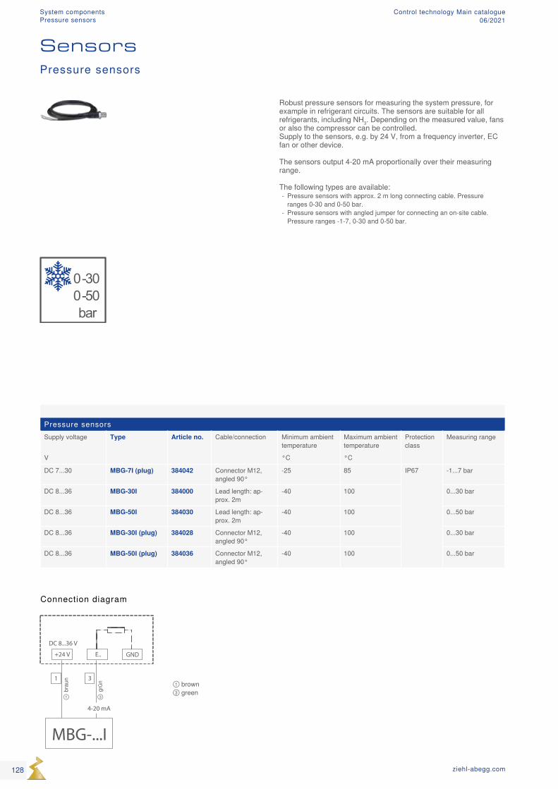
0-300-50bar
MBG-...I
4-20 mA
DC 8...36 V
+24 V E.. GND
1 3
① ③
brau
n
grün ① brown
③ green
Pressure sensorsSupply voltage Type Article no. Cable/connection Minimum ambient
temperatureMaximum ambient temperature
Protection class
Measuring range
V °C °C
DC 7...30 MBG-7I (plug) 384042 Connector M12, angled 90°
-25 85 IP67 -1...7 bar
DC 8...36 MBG-30I 384000 Lead length: ap-prox. 2m
-40 100 0...30 bar
DC 8...36 MBG-50I 384030 Lead length: ap-prox. 2m
-40 100 0...50 bar
DC 8...36 MBG-30I (plug) 384028 Connector M12, angled 90°
-40 100 0...30 bar
DC 8...36 MBG-50I (plug) 384036 Connector M12, angled 90°
-40 100 0...50 bar
Robust pressure sensors for measuring the system pressure, for example in refrigerant circuits. The sensors are suitable for all refrigerants, including NH3. Depending on the measured value, fans or also the compressor can be controlled. Supply to the sensors, e.g. by 24 V, from a frequency inverter, EC fan or other device. The sensors output 4-20 mA proportionally over their measuring range. The following types are available:
- Pressure sensors with approx. 2 m long connecting cable. Pressure ranges 0-30 and 0-50 bar.
- Pressure sensors with angled jumper for connecting an on-site cable. Pressure ranges -1-7, 0-30 and 0-50 bar.
Connection diagram
Pressure sensors
Sensors
128 ziehl-abegg.com
System componentsPressure sensors
Control technology Main catalogue06/2021
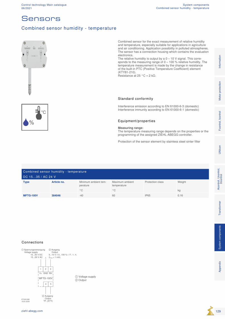
%°C
KT00016M19.03.2008
1 2 3
MFTG-100V
① SpannungsversorgungVoltage supply
15...35 V DC15...29 V AC
② AusgangOutput
0...10 V = 0...100 % r. F. / r. h.(Imax < 1 mA)
4 5
② AusgangOutput
TF..(KTY)
V+ GND RH① Voltage supply ② Output
Combined sensor humidity - temperatureDC 15...35 / AC 24 VType Article no. Minimum ambient tem-
peratureMaximum ambient temperature
Protection class Weight
°C °C kg
MFTG-100V 384046 -40 60 IP65 0.16
Combined sensor for the exact measurement of relative humidity and temperature, especially suitable for applications in agriculture and air conditioning. Application possibility in polluted atmospheres. The sensor has a connection housing which contains the evaluation electronics. The relative humidity is output by a 0 – 10 V signal. This corre-sponds to the measuring range of 0 – 100 % relative humidity. The temperature measurement is made by the change in resistance of the built-in PTC (Positive Temperature Coefficient) element (KTY81-210). Resistance at 25 °C = 2 kΩ.
Equipment/properties Measuring range: The temperature measuring range depends on the properties or the programming of the assigned ZIEHL-ABEGG controller. Protection of the sensor element by stainless steel sinter filter
Connections
Combined sensor humidity - temperature
Sensors
Standard conformity
Interference emission according to EN 61000-6-3 (domestic)Interference immunity according to EN 61000-6-1 (domestic)
129ziehl-abegg.com
Mot
or p
rote
ctio
nFc
ontro
l, Ic
ontro
lUN
Icon
Acon
trol,
Ucon
trol,
Dcon
trol
Tran
sfor
mer
Syst
em c
ompo
nent
s In
form
atio
n Ap
pend
ix
System componentsCombined sensor humidity - temperature
Control technology Main catalogue06/2021
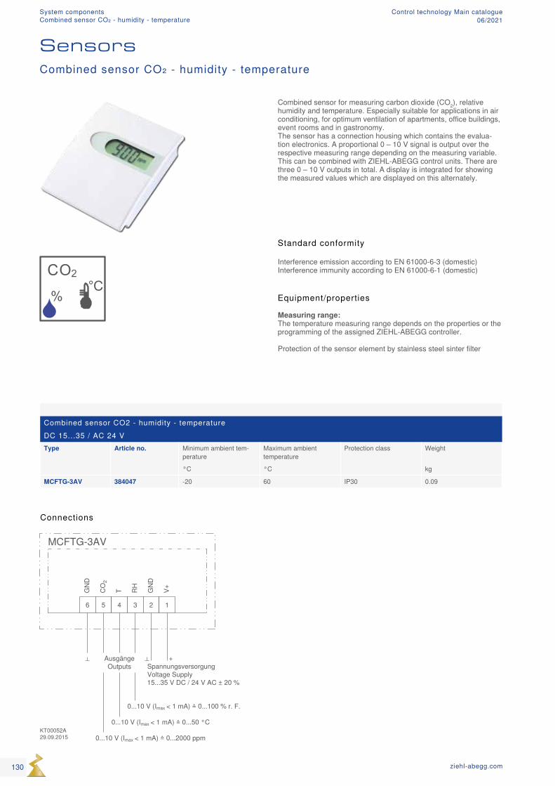
CO2
%
°C
Combined sensor CO2 - humidity - temperatureDC 15...35 / AC 24 VType Article no. Minimum ambient tem-
peratureMaximum ambient temperature
Protection class Weight
°C °C kg
MCFTG-3AV 384047 -20 60 IP30 0.09
Combined sensor CO₂ - humidity - temperature
Sensors
Standard conformity
Interference emission according to EN 61000-6-3 (domestic)Interference immunity according to EN 61000-6-1 (domestic)
Equipment/properties Measuring range: The temperature measuring range depends on the properties or the programming of the assigned ZIEHL-ABEGG controller. Protection of the sensor element by stainless steel sinter filter
Combined sensor for measuring carbon dioxide (CO2), relative humidity and temperature. Especially suitable for applications in air conditioning, for optimum ventilation of apartments, office buildings, event rooms and in gastronomy. The sensor has a connection housing which contains the evalua-tion electronics. A proportional 0 – 10 V signal is output over the respective measuring range depending on the measuring variable. This can be combined with ZIEHL-ABEGG control units. There are three 0 – 10 V outputs in total. A display is integrated for showing the measured values which are displayed on this alternately.
Connections
130 ziehl-abegg.com
System componentsCombined sensor CO₂ - humidity - temperature
Control technology Main catalogue06/2021
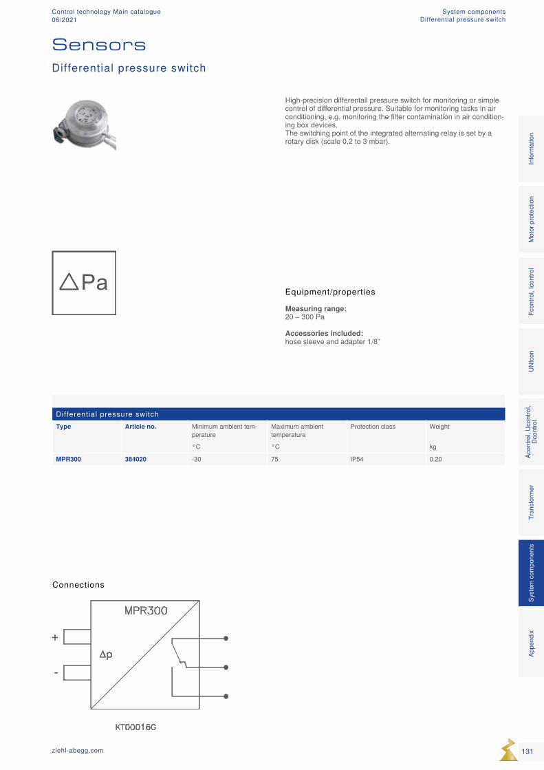
Pa
++
--
∆∆
Differential pressure switchType Article no. Minimum ambient tem-
peratureMaximum ambient temperature
Protection class Weight
°C °C kg
MPR300 384020 -30 75 IP54 0.20
High-precision differentail pressure switch for monitoring or simple control of differential pressure. Suitable for monitoring tasks in air conditioning, e.g. monitoring the filter contamination in air condition-ing box devices. The switching point of the integrated alternating relay is set by a rotary disk (scale 0.2 to 3 mbar).
Equipment/properties Measuring range: 20 – 300 Pa
Accessories included: hose sleeve and adapter 1/8”
Connections
Differential pressure switch
Sensors
131ziehl-abegg.com
Mot
or p
rote
ctio
nFc
ontro
l, Ic
ontro
lUN
Icon
Acon
trol,
Ucon
trol,
Dcon
trol
Tran
sfor
mer
Syst
em c
ompo
nent
s In
form
atio
n Ap
pend
ix
System componentsDifferential pressure switch
Control technology Main catalogue06/2021
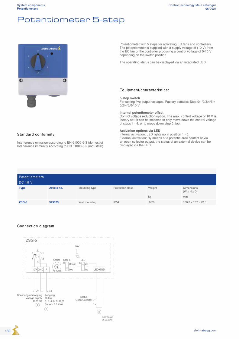
PotentiometersDC 10 VType Article no. Mounting type Protection class Weight Dimensions
(W x H x D)
kg mm
ZSG-5 349073 Wall mounting IP54 0.20 106.3 x 137 x 72.5
Connection diagram
Standard conformity
Interference emission according to EN 61000-6-3 (domestic)Interference immunity according to EN 61000-6-2 (industrial)
Equipment/characteristics:
5-step switch For setting five output voltages. Factory settable: Step 0/1/2/3/4/5 = 0/2/4/6/8/10 V
Internal potentiometer offset Control voltage reduction option. The max. control voltage of 10 V is factory set. It can be selected to only move down the control voltage of steps 1 - 4, or to move down step 5, too.
Activation options via LED Internal activation: LED lights up in position 1 - 5. External activation: By means of a potential-free contact or via an open collector output, the status of an external device can be displayed via the LED.
Potentiometer with 5 steps for activating EC fans and controllers. The potentiometer is supplied with a supply voltage of (10 V) from the EC fan or the controller producing a control voltage of 0-10 V depending on the switch position. The operating status can be displayed via an integrated LED.
Potentiometers
Potentiometer 5-step
132 ziehl-abegg.com
System componentsPotentiometers
Control technology Main catalogue06/2021
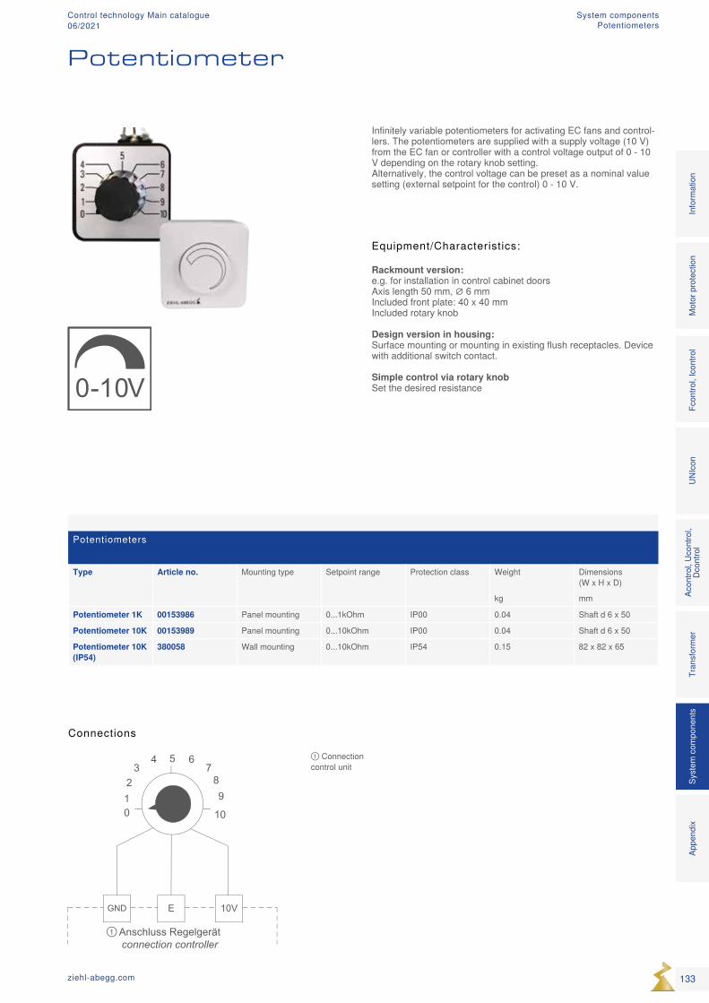
0-10V
0
5
1012
34 6
789
GND E 10V
Anschluss Regelgerätconnection controller
①
① Connection control unit
Potentiometers Type Article no. Mounting type Setpoint range Protection class Weight Dimensions
(W x H x D)
kg mm
Potentiometer 1K 00153986 Panel mounting 0...1kOhm IP00 0.04 Shaft d 6 x 50
Potentiometer 10K 00153989 Panel mounting 0...10kOhm IP00 0.04 Shaft d 6 x 50
Potentiometer 10K (IP54)
380058 Wall mounting 0...10kOhm IP54 0.15 82 x 82 x 65
Infinitely variable potentiometers for activating EC fans and control-lers. The potentiometers are supplied with a supply voltage (10 V) from the EC fan or controller with a control voltage output of 0 - 10 V depending on the rotary knob setting. Alternatively, the control voltage can be preset as a nominal value setting (external setpoint for the control) 0 - 10 V.
Equipment/Characteristics:
Rackmount version: e.g. for installation in control cabinet doors Axis length 50 mm, ∅ 6 mm Included front plate: 40 x 40 mm Included rotary knob
Design version in housing: Surface mounting or mounting in existing flush receptacles. Device with additional switch contact.
Simple control via rotary knob Set the desired resistance
Potentiometer
Connections
133ziehl-abegg.com
Mot
or p
rote
ctio
nFc
ontro
l, Ic
ontro
lUN
Icon
Acon
trol,
Ucon
trol,
Dcon
trol
Tran
sfor
mer
Syst
em c
ompo
nent
s In
form
atio
n Ap
pend
ix
System componentsPotentiometers
Control technology Main catalogue06/2021
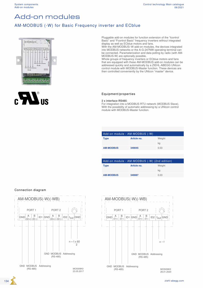
Add-on module - AM-MODBUS (-W)Type Article no. Weight
kg
AM-MODBUS 349045 0.03
Add-on module - AM-MODBUS (-W) (2nd edition)Type Article no. Weight
kg
AM-MODBUS 349087 0.03
Connection diagram
Add-on modulesAM-MODBUS (-W) for Basic Frequency inverter and ECblue
Equipment/properties
2 x interface RS485: For integration into a MODBUS RTU network (MODBUS Slave). With the possibility of automatic addressing by a UNIcon control module with MODBUS-Master function.
Pluggable add-on modules for function extension of the “Icontrol Basic” and “Fcontrol Basic” frequency inverters without integrated display as well as ECblue motors and fans. With the AM-MODBUS/-W add-on modules, the devices integrated into MODBUS networks or the A-G-247NW operating terminal can be connected. Parameterization and data polling by radio (with AM-MODBUS-W) are optionally possible. Whole groups of frequency inverters or ECblue motors and fans that are equipped with these AM-MODBUS add-on modules can be addressed quickly and automatically by a ZIEHL-ABEGG UNIcon control module with MODBUS-Master function. These devices are then controlled conveniently by the UNIcon “master” device.
134 ziehl-abegg.com
System componentsAdd-on modules
Control technology Main catalogue06/2021
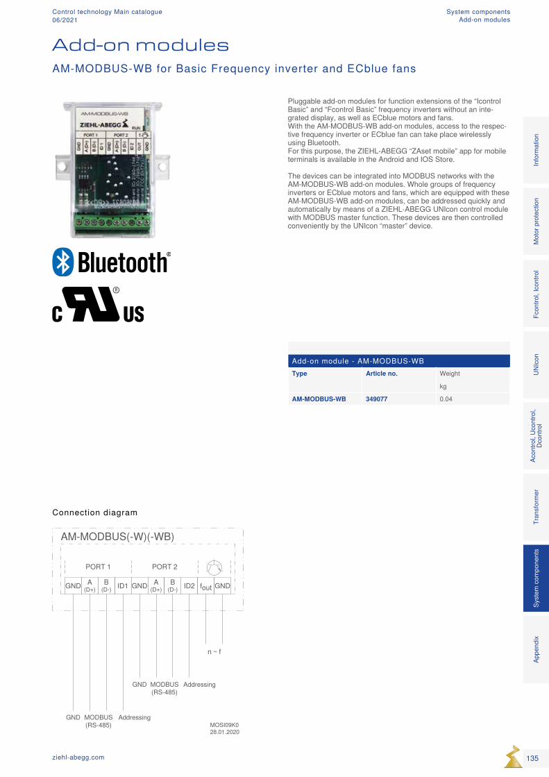
Add-on module - AM-MODBUS-WBType Article no. Weight
kg
AM-MODBUS-WB 349077 0.04
Connection diagram
Add-on modulesAM-MODBUS-WB for Basic Frequency inverter and ECblue fans
Pluggable add-on modules for function extensions of the “Icontrol Basic” and “Fcontrol Basic” frequency inverters without an inte-grated display, as well as ECblue motors and fans. With the AM-MODBUS-WB add-on modules, access to the respec-tive frequency inverter or ECblue fan can take place wirelessly using Bluetooth. For this purpose, the ZIEHL-ABEGG “ZAset mobile” app for mobile terminals is available in the Android and IOS Store. The devices can be integrated into MODBUS networks with the AM-MODBUS-WB add-on modules. Whole groups of frequency inverters or ECblue motors and fans, which are equipped with these AM-MODBUS-WB add-on modules, can be addressed quickly and automatically by means of a ZIEHL-ABEGG UNIcon control module with MODBUS master function. These devices are then controlled conveniently by the UNIcon “master” device.
135ziehl-abegg.com
Mot
or p
rote
ctio
nFc
ontro
l, Ic
ontro
lUN
Icon
Acon
trol,
Ucon
trol,
Dcon
trol
Tran
sfor
mer
Syst
em c
ompo
nent
s In
form
atio
n Ap
pend
ix
System componentsAdd-on modules
Control technology Main catalogue06/2021
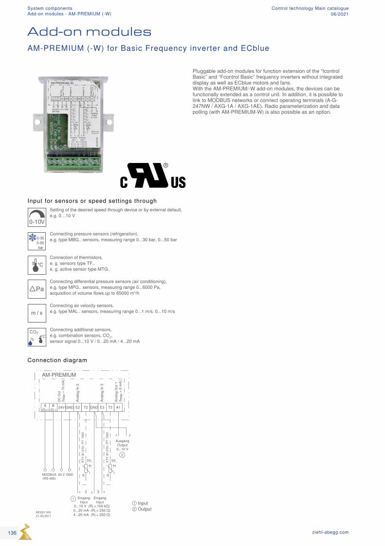
AM-PREMIUM
GND24V E2 T2
MOSI11K021.03.2011
A(D+)
B(D-)
GND24 V
GND
EingangInput
+
1
2
E3 T3 A1
AusgangOutput0...10 V
+
2
+3
q
TF..
DC
Out
(I max
= 7
0 m
A)
q
TF..
Anal
og In
2
Anal
og In
3
Anal
og O
ut 1
(I max
= 6
mA)
EingangInput
KTY
81-2
10 /
PT 1
000
KTY
81-2
10 /
PT 1
000
0...10 V (Ri > 100 kΩ)0...20 mA (Ri = 250 Ω)4...20 mA (Ri = 250 Ω)
MODBUS(RS-485)
① Input ② Output
Input for sensors or speed settings through
0-10V
Setting of the desired speed through device or by external default, e.g. 0…10 V
0-300-50bar
Connecting pressure sensors (refrigeration), e.g. type MBG.. sensors, measuring range 0...30 bar, 0...50 bar
°CConnection of thermistors, e. g. sensors type TF.. e. g. active sensor type MTG..
PaConnecting differential pressure sensors (air conditioning), e.g. type MPG.. sensors, measuring range 0...6000 Pa, acquisition of volume flows up to 65000 m3/h
m / sConnecting air velocity sensors, e.g. type MAL.. sensors, measuring range 0...1 m/s, 0...10 m/s
CO2
%
°C
Connecting additional sensors, e.g. combination sensors, CO2, sensor signal 0...10 V / 0...20 mA / 4...20 mA
Connection diagram
AM-PREMIUM (-W) for Basic Frequency inverter and ECblue
Add-on modules
Pluggable add-on modules for function extension of the “Icontrol Basic” and “Fcontrol Basic” frequency inverters without integrated display as well as ECblue motors and fans. With the AM-PREMIUM/-W add-on modules, the devices can be functionally extended as a control unit. In addition, it is possible to link to MODBUS networks or connect operating terminals (A-G-247NW / AXG-1A / AXG-1AE). Radio parameterization and data polling (with AM-PREMIUM-W) is also possible as an option.
136 ziehl-abegg.com
System componentsAdd-on modules - AM-PREMIUM (-W)
Control technology Main catalogue06/2021
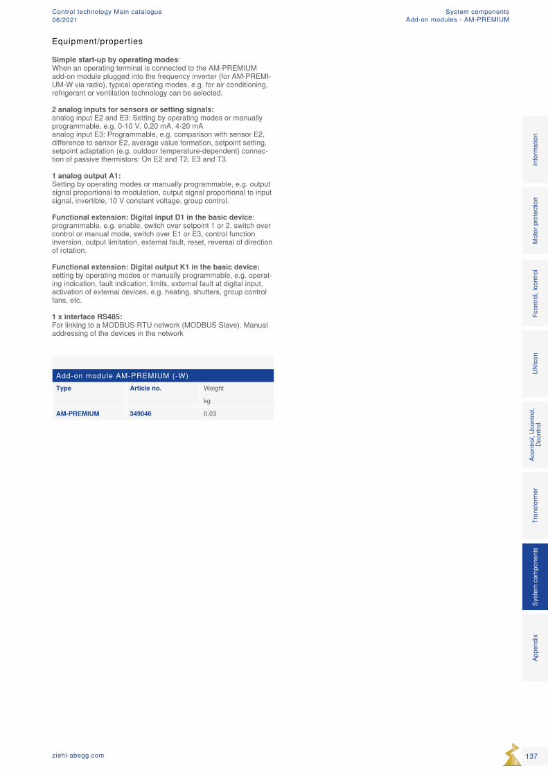
Add-on module AM-PREMIUM (-W)Type Article no. Weight
kg
AM-PREMIUM 349046 0.03
Equipment/properties
Simple start-up by operating modes: When an operating terminal is connected to the AM-PREMIUM add-on module plugged into the frequency inverter (for AM-PREMI-UM-W via radio), typical operating modes, e.g. for air conditioning, refrigerant or ventilation technology can be selected. 2 analog inputs for sensors or setting signals: analog input E2 and E3: Setting by operating modes or manually programmable, e.g. 0-10 V, 0,20 mA, 4-20 mA analog input E3: Programmable, e.g. comparison with sensor E2, difference to sensor E2, average value formation, setpoint setting, setpoint adaptation (e.g. outdoor temperature-dependent) connec-tion of passive thermistors: On E2 and T2, E3 and T3. 1 analog output A1: Setting by operating modes or manually programmable, e.g. output signal proportional to modulation, output signal proportional to input signal, invertible, 10 V constant voltage, group control. Functional extension: Digital input D1 in the basic device: programmable, e.g. enable, switch over setpoint 1 or 2, switch over control or manual mode, switch over E1 or E3, control function inversion, output limitation, external fault, reset, reversal of direction of rotation. Functional extension: Digital output K1 in the basic device: setting by operating modes or manually programmable, e.g. operat-ing indication, fault indication, limits, external fault at digital input, activation of external devices, e.g. heating, shutters, group control fans, etc. 1 x interface RS485: For linking to a MODBUS RTU network (MODBUS Slave). Manual addressing of the devices in the network
137ziehl-abegg.com
Mot
or p
rote
ctio
nFc
ontro
l, Ic
ontro
lUN
Icon
Acon
trol,
Ucon
trol,
Dcon
trol
Tran
sfor
mer
Syst
em c
ompo
nent
s In
form
atio
n Ap
pend
ix
System componentsAdd-on modules - AM-PREMIUM
Control technology Main catalogue06/2021
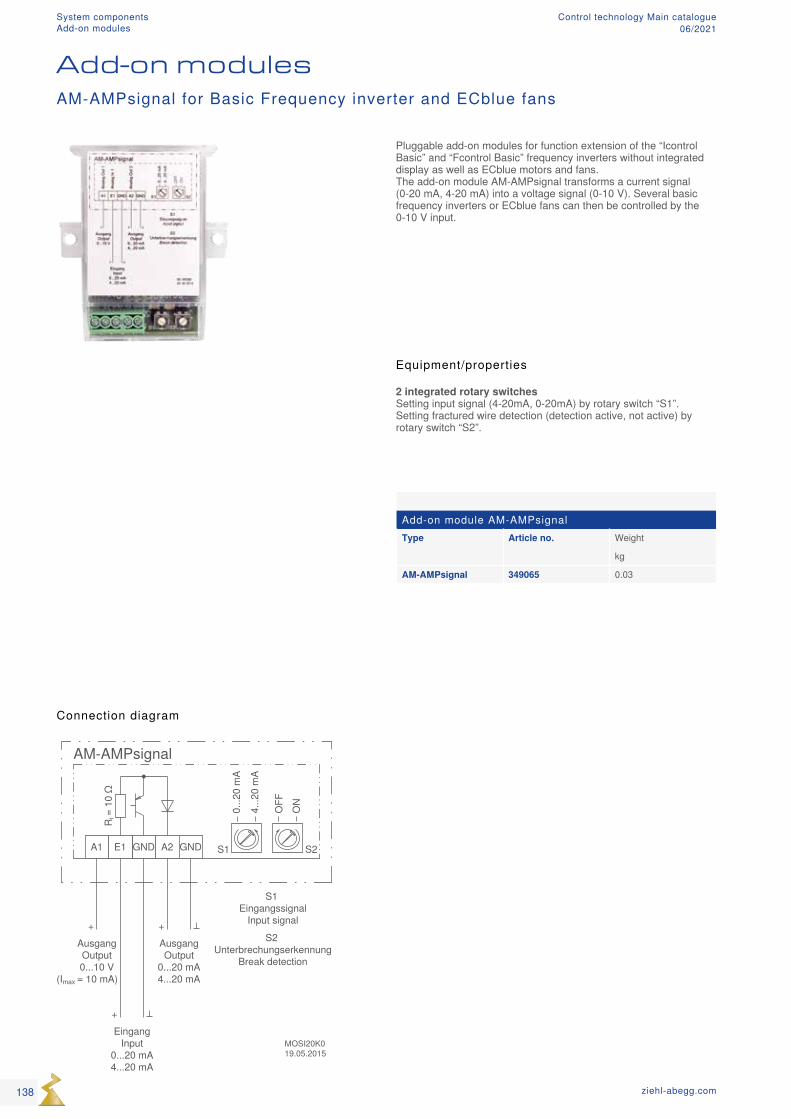
Add-on module AM-AMPsignalType Article no. Weight
kg
AM-AMPsignal 349065 0.03
Connection diagram
Add-on modulesAM-AMPsignal for Basic Frequency inverter and ECblue fans
Equipment/properties
2 integrated rotary switches Setting input signal (4-20mA, 0-20mA) by rotary switch “S1”. Setting fractured wire detection (detection active, not active) by rotary switch “S2”.
Pluggable add-on modules for function extension of the “Icontrol Basic” and “Fcontrol Basic” frequency inverters without integrated display as well as ECblue motors and fans. The add-on module AM-AMPsignal transforms a current signal (0-20 mA, 4-20 mA) into a voltage signal (0-10 V). Several basic frequency inverters or ECblue fans can then be controlled by the 0-10 V input.
138 ziehl-abegg.com
System componentsAdd-on modules
Control technology Main catalogue06/2021
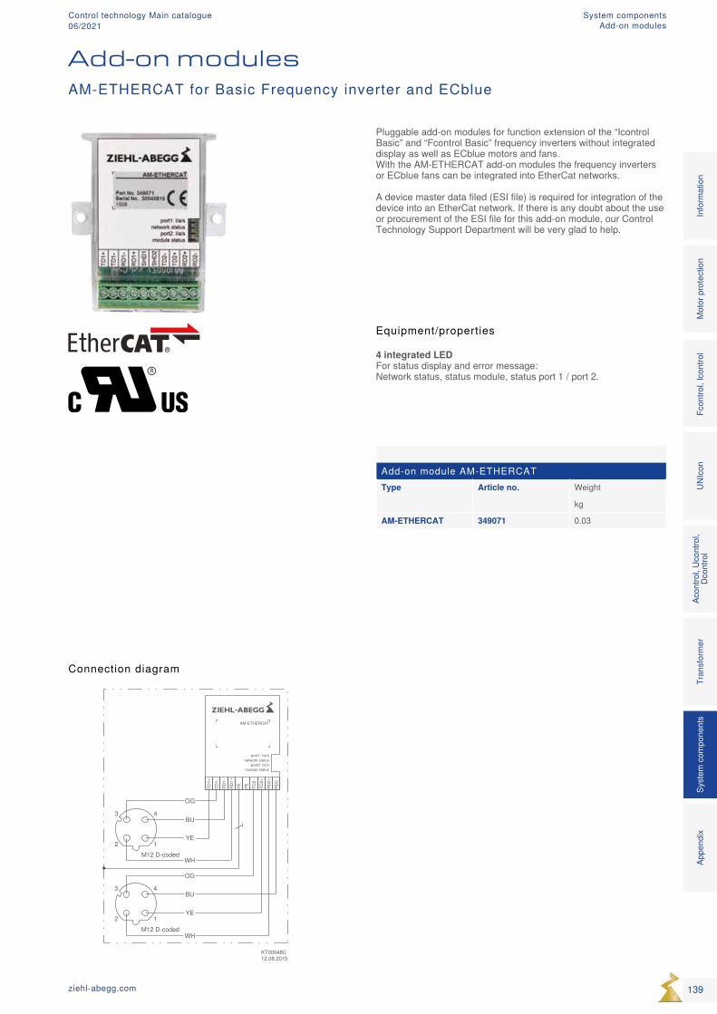
Add-on module AM-ETHERCATType Article no. Weight
kg
AM-ETHERCAT 349071 0.03
Connection diagram
Add-on modules
Equipment/properties
4 integrated LED For status display and error message: Network status, status module, status port 1 / port 2.
Pluggable add-on modules for function extension of the “Icontrol Basic” and “Fcontrol Basic” frequency inverters without integrated display as well as ECblue motors and fans. With the AM-ETHERCAT add-on modules the frequency inverters or ECblue fans can be integrated into EtherCat networks. A device master data filed (ESI file) is required for integration of the device into an EtherCat network. If there is any doubt about the use or procurement of the ESI file for this add-on module, our Control Technology Support Department will be very glad to help.
AM-ETHERCAT for Basic Frequency inverter and ECblue
139ziehl-abegg.com
Mot
or p
rote
ctio
nFc
ontro
l, Ic
ontro
lUN
Icon
Acon
trol,
Ucon
trol,
Dcon
trol
Tran
sfor
mer
Syst
em c
ompo
nent
s In
form
atio
n Ap
pend
ix
System componentsAdd-on modules
Control technology Main catalogue06/2021
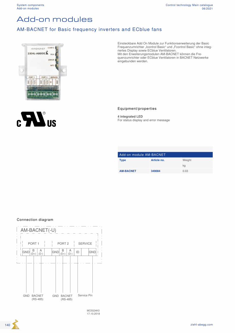
Add-on module AM-BACNETType Article no. Weight
kg
AM-BACNET 349084 0.03
Connection diagram
Add-on modules
Equipment/properties
4 integrated LED For status display and error message
AM-BACNET for Basic frequency inverters and ECblue fans
Einsteckbare Add On Module zur Funktionserweiterung der Basic Frequenzumrichter „Icontrol Basic“ und „Fcontrol Basic“ ohne integ-riertes Display sowie ECblue Ventilatoren. Mit den Erweiterungsmodulen AM-BACNET können die Fre-quenzumrichter oder ECblue Ventilatoren in BACNET Netzwerke eingebunden werden.
140 ziehl-abegg.com
System componentsAdd-on modules
Control technology Main catalogue06/2021
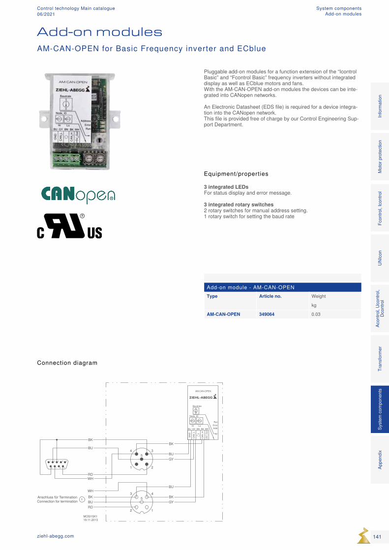
43
2 1
5
54321
9876
34
1 2
5
MOSI15K119.11.2013
Anschluss für TerminationConnection for termination
BKBK
WHBU
BKGY
1
GYBU
BKBURD
BU
RDWH
CAN
_H
+5V_
Out
CAN
_L
GN
D
ErrorRun
Addr
AM-CAN-OPEN
Node_ID
Hi Lo
0
Baudrate
GY BK
0
BU BN WH
0
5
Add-on module - AM-CAN-OPENType Article no. Weight
kg
AM-CAN-OPEN 349064 0.03
Connection diagram
Add-on modules
Pluggable add-on modules for a function extension of the “Icontrol Basic” and “Fcontrol Basic” frequency inverters without integrated display as well as ECblue motors and fans. With the AM-CAN-OPEN add-on modules the devices can be inte-grated into CANopen networks. An Electronic Datasheet (EDS file) is required for a device integra-tion into the CANopen network. This file is provided free of charge by our Control Engineering Sup-port Department.
Equipment/properties
3 integrated LEDs For status display and error message. 3 integrated rotary switches 2 rotary switches for manual address setting. 1 rotary switch for setting the baud rate
AM-CAN-OPEN for Basic Frequency inverter and ECblue
141ziehl-abegg.com
Mot
or p
rote
ctio
nFc
ontro
l, Ic
ontro
lUN
Icon
Acon
trol,
Ucon
trol,
Dcon
trol
Tran
sfor
mer
Syst
em c
ompo
nent
s In
form
atio
n Ap
pend
ix
System componentsAdd-on modules
Control technology Main catalogue06/2021
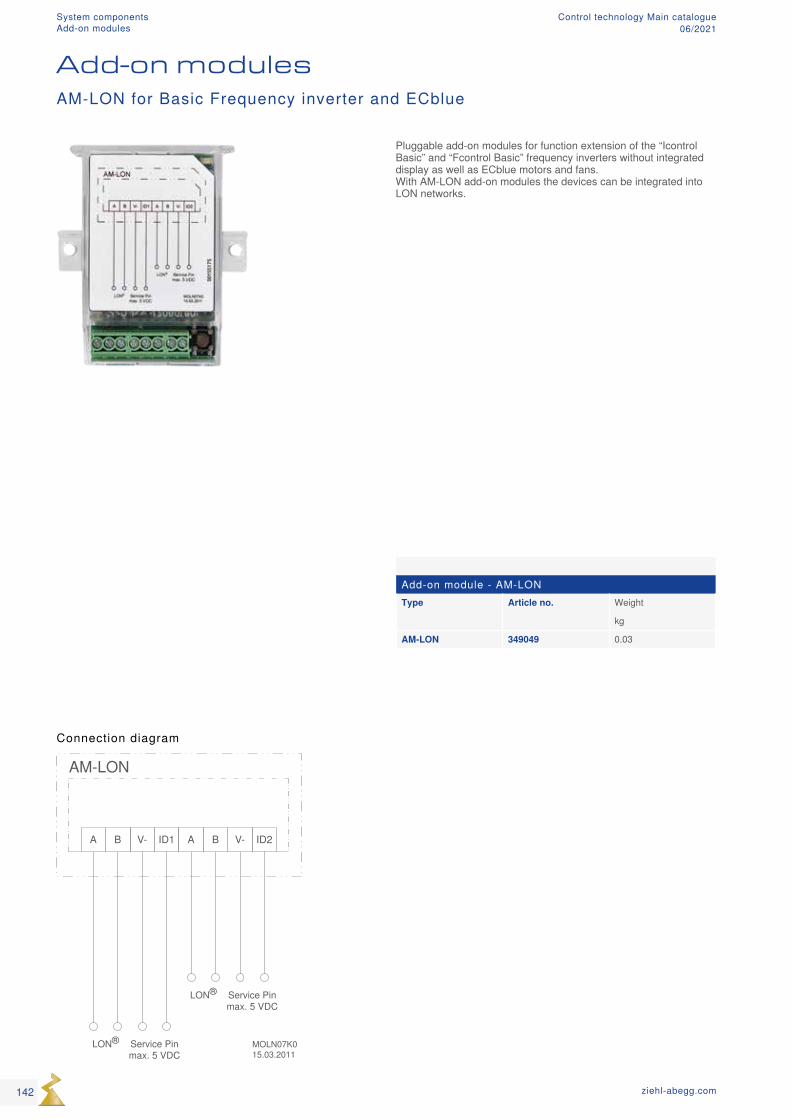
AM-LON
ID1V- ID2
MOLN07K015.03.2011
LON® Service Pinmax. 5 VDC
V-
LON® Service Pinmax. 5 VDC
BA BA
Add-on module - AM-LONType Article no. Weight
kg
AM-LON 349049 0.03
Connection diagram
Add-on modules
Pluggable add-on modules for function extension of the “Icontrol Basic” and “Fcontrol Basic” frequency inverters without integrated display as well as ECblue motors and fans. With AM-LON add-on modules the devices can be integrated into LON networks.
AM-LON for Basic Frequency inverter and ECblue
142 ziehl-abegg.com
System componentsAdd-on modules
Control technology Main catalogue06/2021
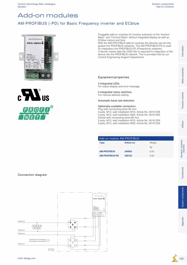
PB_A
+5V_
Out
PB_B
GN
D
ErrorRun
Addr
AM-PROFIBUS
Address
Hi Lo
0
BK WH
0
BU BN
43
2 1
5
54321
9876
34
1 2
5
MOSI15K021.11.2013
Profibus B
Profibus B
Profibus A
Profibus A
Anschluss für TerminationConnection for termination
WH
BK
WH
BU
BK
BN
1
Add-on module AM-PROFIBUSType Article no. Weight
kg
AM-PROFIBUS 349063 0.03
AM-PROFIBUS-PD 349103 0.03
Connection diagram
Add-on modules
Pluggable add-on modules for function extension of the “Icontrol Basic” and “Fcontrol Basic” without integrated display as well as ECblue motors and fans. With the AM-PROFIBUS add-on modules the devices can be inte-grated into PROFIBUS networks. The AM-PROFIBUS-PD is used for integration into PROFIBUS-PD (Powerdrive) networks. A device master data file (GSD file) is required for integration of the device into the PROFIBUS network. This is provided free by our Control Engineering Support Department.
Equipment/properties
3 integrated LEDs For status display and error message. 2 integrated rotary switches For manual address setting. Automatic baud rate detection Optionally available connectors Plug with connecting wires 80 mm: 5-pole, M12, wall installation M16, Article No. 00161258 5-pole, M12, wall installation M20, Article No. 00161263 Socket with connecting wires 80 mm: 5-pole, M12, wall installation M16, Article No. 00161259 5-pole, M12, wall installation M20, Article No. 00161264
AM-PROFIBUS (-PD) for Basic Frequency inverter and ECblue
143ziehl-abegg.com
Mot
or p
rote
ctio
nFc
ontro
l, Ic
ontro
lUN
Icon
Acon
trol,
Ucon
trol,
Dcon
trol
Tran
sfor
mer
Syst
em c
ompo
nent
s In
form
atio
n Ap
pend
ix
System componentsAdd-on modules
Control technology Main catalogue06/2021
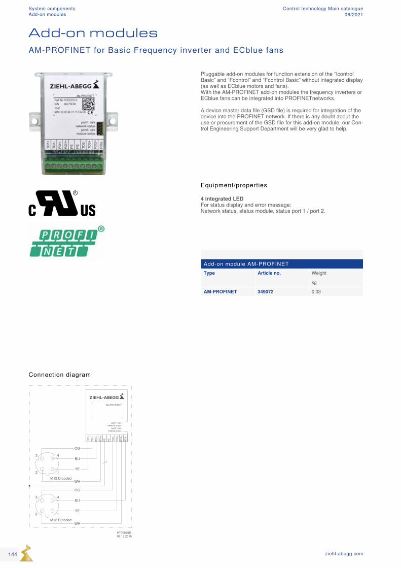
Add-on module AM-PROFINETType Article no. Weight
kg
AM-PROFINET 349072 0.03
Connection diagram
Add-on modules
Equipment/properties
4 integrated LED For status display and error message: Network status, status module, status port 1 / port 2.
Pluggable add-on modules for function extension of the “Icontrol Basic” and “Fcontrol” and “Fcontrol Basic” without integrated display (as well as ECblue motors and fans). With the AM-PROFINET add-on modules the frequency inverters or ECblue fans can be integrated into PROFINETnetworks. A device master data file (GSD file) is required for integration of the device into the PROFINET network. If there is any doubt about the use or procurement of the GSD file for this add-on module, our Con-trol Engineering Support Department will be very glad to help.
AM-PROFINET for Basic Frequency inverter and ECblue fans
144 ziehl-abegg.com
System componentsAdd-on modules
Control technology Main catalogue06/2021

145ziehl-abegg.com
Mot
or p
rote
ctio
nFc
ontro
l, Ic
ontro
lUN
Icon
Acon
trol,
Ucon
trol,
Dcon
trol
Tran
sfor
mer
Syst
em c
ompo
nent
s In
form
atio
n Ap
pend
ix
System componentsAdd-on modules
Control technology Main catalogue06/2021
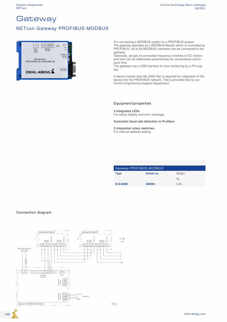
MOSI17K130.01.2013Gateway PROFIBUS-MODBUS
- +
SpannungsversorgungPower supply
24 V DC
V-in V+in
USB
PRO
FIBU
SC
onne
ctor
nc GNDncncnc nc
DGND
VP/+5V
1A(D+)
1B(D-)
MODBUS(RS-485)
PRO
FIBU
SAd
ress
PROFIBUSBA
ECblue MODBUS
GND ID1 GND ID2A(D+)
A(D+)
B(D-)
B(D-)
MODBUS(RS-485) Ad
dres
sing
MODBUS(RS-485) Ad
dres
sing
ECblue MODBUS
GND ID1 GND ID2A(D+)
A(D+)
B(D-)
B(D-)
MODBUS(RS-485) Ad
dres
sing
MODBUS(RS-485) Ad
dres
sing
ID
B
A
GND
1 2 3...64
Hig
hLo
w1
23
45
67
89
Gateway PROFIBUS-MODBUSType Article no. Weight
kg
D-G-64NE 380094 0.08
Connection diagram
For connecting a MODBUS system to a PROFIBUS system The gateway operates as a MODBUS-Master which is controlled by PROFIBUS. Up to 64 MODBUS members can be connected to the gateway. Optionally, groups of connected frequency inverters or EC motors and fans can be addressed automatically for convenience and to save time. The gateway has a USB interface for bus monitoring by a PC/Lap-top. A device master data file (GSD file) is required for integration of the device into the PROFIBUS network. This is provided free by our Control Engineering Support Department.
Equipment/properties
3 integrated LEDs For status display and error message. Automatic baud rate detection in Profibus 2 integrated rotary switches For manual address setting.
GatewayNETcon Gateway PROFIBUS-MODBUS
146 ziehl-abegg.com
System componentsNETcon
Control technology Main catalogue06/2021
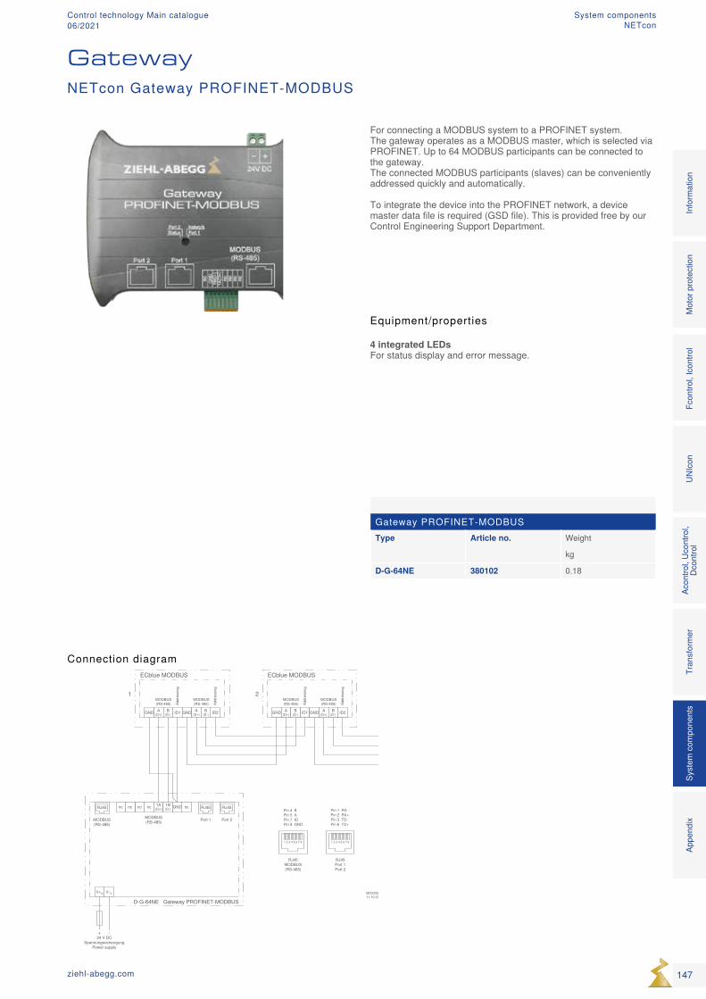
Gateway PROFINET-MODBUSType Article no. Weight
kg
D-G-64NE 380102 0.18
Connection diagram
For connecting a MODBUS system to a PROFINET system. The gateway operates as a MODBUS master, which is selected via PROFINET. Up to 64 MODBUS participants can be connected to the gateway. The connected MODBUS participants (slaves) can be conveniently addressed quickly and automatically. To integrate the device into the PROFINET network, a device master data file is required (GSD file). This is provided free by our Control Engineering Support Department.
Equipment/properties
4 integrated LEDs For status display and error message.
GatewayNETcon Gateway PROFINET-MODBUS
147ziehl-abegg.com
Mot
or p
rote
ctio
nFc
ontro
l, Ic
ontro
lUN
Icon
Acon
trol,
Ucon
trol,
Dcon
trol
Tran
sfor
mer
Syst
em c
ompo
nent
s In
form
atio
n Ap
pend
ix
System componentsNETcon
Control technology Main catalogue06/2021
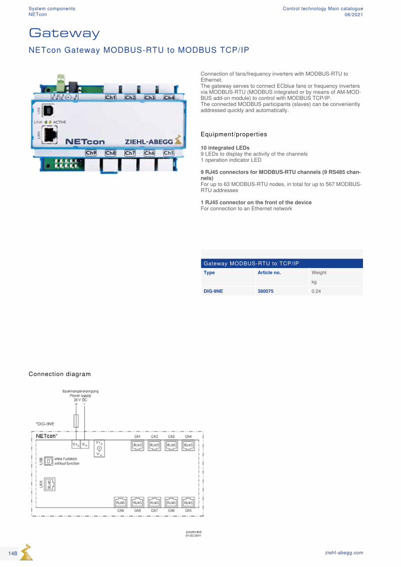
Gateway MODBUS-RTU to TCP/IPType Article no. Weight
kg
DIG-9NE 380075 0.24
Connection diagram
Equipment/properties
10 integrated LEDs 9 LEDs to display the activity of the channels 1 operation indicator LED 9 RJ45 connectors for MODBUS-RTU channels (9 RS485 chan-nels) For up to 63 MODBUS-RTU nodes, in total for up to 567 MODBUS-RTU addresses 1 RJ45 connector on the front of the device For connection to an Ethernet network
Connection of fans/frequency inverters with MODBUS-RTU to Ethernet. The gateway serves to connect ECblue fans or frequency inverters via MODBUS-RTU (MODBUS integrated or by means of AM-MOD-BUS add-on module) to control with MODBUS TCP/IP. The connected MODBUS participants (slaves) can be conveniently addressed quickly and automatically.
GatewayNETcon Gateway MODBUS-RTU to MODBUS TCP/IP
148 ziehl-abegg.com
System components Control technology Main catalogue06/2021NETcon
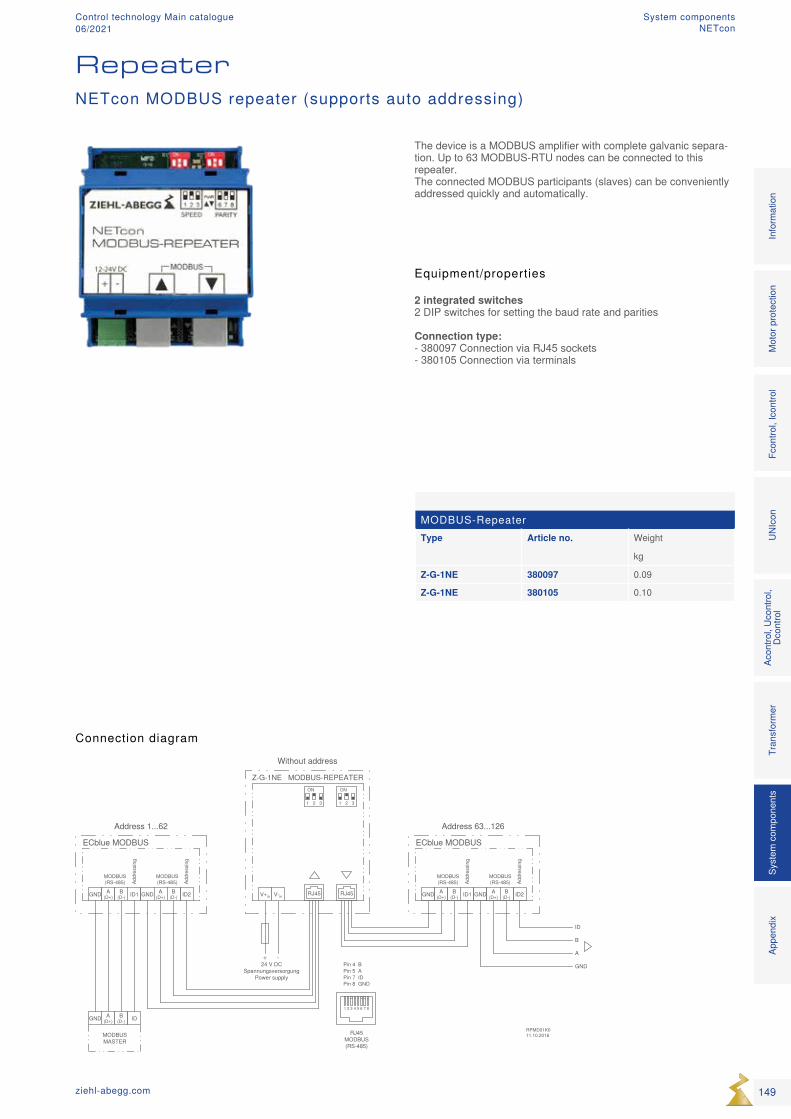
MODBUS-RepeaterType Article no. Weight
kg
Z-G-1NE 380097 0.09
Z-G-1NE 380105 0.10
Connection diagram
Equipment/properties
2 integrated switches 2 DIP switches for setting the baud rate and parities Connection type: - 380097 Connection via RJ45 sockets - 380105 Connection via terminals
The device is a MODBUS amplifier with complete galvanic separa-tion. Up to 63 MODBUS-RTU nodes can be connected to this repeater. The connected MODBUS participants (slaves) can be conveniently addressed quickly and automatically.
RepeaterNETcon MODBUS repeater (supports auto addressing)
149ziehl-abegg.com
Mot
or p
rote
ctio
nFc
ontro
l, Ic
ontro
lUN
Icon
Acon
trol,
Ucon
trol,
Dcon
trol
Tran
sfor
mer
Syst
em c
ompo
nent
s In
form
atio
n Ap
pend
ix
System componentsNETcon
Control technology Main catalogue06/2021
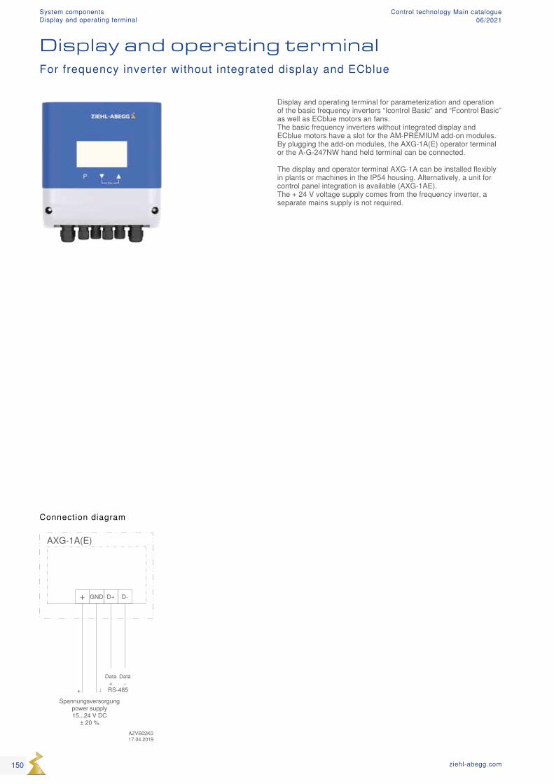
Display and operating terminalFor frequency inverter without integrated display and ECblue
Connection diagram
Display and operating terminal for parameterization and operation of the basic frequency inverters “Icontrol Basic” and “Fcontrol Basic” as well as ECblue motors an fans. The basic frequency inverters without integrated display and ECblue motors have a slot for the AM-PREMIUM add-on modules. By plugging the add-on modules, the AXG-1A(E) operator terminal or the A-G-247NW hand held terminal can be connected. The display and operator terminal AXG-1A can be installed flexibly in plants or machines in the IP54 housing. Alternatively, a unit for control panel integration is available (AXG-1AE). The + 24 V voltage supply comes from the frequency inverter, a separate mains supply is not required.
150 ziehl-abegg.com
System componentsDisplay and operating terminal
Control technology Main catalogue06/2021
Display and operating terminalsDC 15...24 VType Article no. Mounting type Protection class Weight Dimensions
(W x H x D)
kg mm
AXG-1A 349082 Wall mounting IP54 0.56 166 x 175 x 60
AXG-1AE 349083 Panel mounting IP00 0.45 182 x 118 x 57.5
Technical data
- Voltage supply: 15-24 VDC (Imax 24 V: 50 mA / 14 V: 80mA) - Maximum ambient temperature: + 40 °C
Equipment/properties
LC multi-function display with plain text display: Different menu languages can be selected. Display of the con-nected frequency inverter menu.
1 interface RS485: for connection to an AM-PREMIUM add-on module. Frequency inverters as well as ECblue motors and fans can be parameterized and operated with this.
151ziehl-abegg.com
Mot
or p
rote
ctio
nFc
ontro
l, Ic
ontro
lUN
Icon
Acon
trol,
Ucon
trol,
Dcon
trol
Tran
sfor
mer
Syst
em c
ompo
nent
s In
form
atio
n Ap
pend
ix
System componentsDisplay and operating terminal
Control technology Main catalogue06/2021
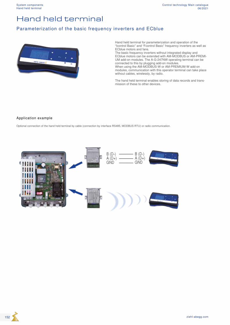
Hand held terminalParameterization of the basic frequency inverters and ECblue
Hand held terminal for parameterization and operation of the “Icontrol Basic” and “Fcontrol Basic” frequency inverters as well as ECblue motors and fans. The basic frequency inverters without integrated display and ECblue motors can be extended with AM-MODBUS or AM-PREMI-UM add-on modules. The A-G-247NW operating terminal can be connected to this by plugging add-on modules. When using the AM-MODBUS-W or AM-PREMIUM-W add-on modules, communication with this operator terminal can take place without cables, wirelessly, by radio. The hand held terminal enables storing of data records and trans-mission of these to other devices.
Application example
Optional connection of the hand held terminal by cable (connection by interface RS485, MODBUS RTU) or radio communication.
152 ziehl-abegg.com
System componentsHand held terminal
Control technology Main catalogue06/2021
Hand held terminalType Article no. Weight
kg
A-G-247NW 380090 0.42
Technical data
- External voltage supply: by plug power pack (1~ 230 V, 50/60 Hz)
- Internal voltage supply: 3 x Mignon rechargeable batteries (NIMh 1.2 V)
Equipment/properties
LC multi-function display with plain text display: Different menu languages can be selected 1 x Mini USB interface: voltage supply / data transfer with a PC 1 x interface RS485: for connection to an AM-MODBUS or AM-Premium add-on module. Frequency inverters, ECblue motors and fans can be parameter-ized and operated with this. It is possible to save data records and transfer them to these devices. Data transmission by radio: for communication with AM-MODBUS-W or AM-Premium-W add-on module.
153ziehl-abegg.com
Mot
or p
rote
ctio
nFc
ontro
l, Ic
ontro
lUN
Icon
Acon
trol,
Ucon
trol,
Dcon
trol
Tran
sfor
mer
Syst
em c
ompo
nent
s In
form
atio
n Ap
pend
ix
System componentsHand held terminal
Control technology Main catalogue06/2021
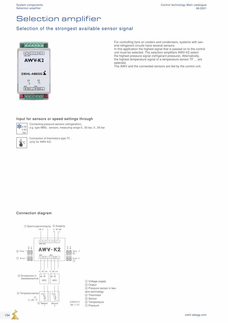
① Voltage supply ② Output ③ Pressure sensor in two-wire technology ④ Thermistor ⑤ Sensor ⑥ Temperature ⑦ Pressure
Input for sensors or speed settings through
0-300-50bar
Connecting pressure sensors (refrigeration), e.g. type MBG.. sensors, measuring range 0...30 bar, 0...50 bar
°CConnection of thermistors type TF... (only for AWV-K2)
Selection amplifierSelection of the strongest available sensor signal
Connection diagram
For controlling fans on coolers and condensers, systems with sev-eral refrigerant circuits have several sensors. In this application the highest signal that is passed on to the control unit must be selected. The selection amplifiers AWV-K2 select the highest pressure signal (refrigerant pressure). Alternatively, the highest temperature signal of a temperature sensor TF ... are selected. The AWV and the connected sensors are fed by the control unit.
154 ziehl-abegg.com
System componentsSelection amplifier
Control technology Main catalogue06/2021
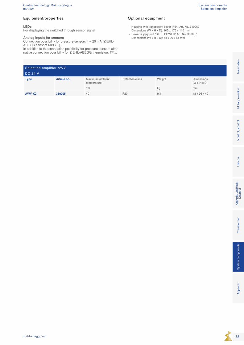
Selection amplifier AWVDC 24 VType Article no. Maximum ambient
temperatureProtection class Weight Dimensions
(W x H x D)
°C kg mm
AWV-K2 380005 40 IP20 0.11 48 x 96 x 42
Optional equipment
- Housing with transparent cover IP54. Art. No. 349069 Dimensions (W x H x D): 105 x 175 x 110 mm
- Power supply unit “STEP POWER” Art. No. 380067 Dimensions (W x H x D): 54 x 90 x 61 mm
Equipment/properties
LEDs For displaying the switched through sensor signal Analog inputs for sensors Connection possibility for pressure sensors 4 – 20 mA (ZIEHL-ABEGG sensors MBG…). In addition to the connection possibility for pressure sensors alter-native connection possibility for ZIEHL-ABEGG thermistors TF…
155ziehl-abegg.com
Mot
or p
rote
ctio
nFc
ontro
l, Ic
ontro
lUN
Icon
Acon
trol,
Ucon
trol,
Dcon
trol
Tran
sfor
mer
Syst
em c
ompo
nent
s In
form
atio
n Ap
pend
ix
System componentsSelection amplifier
Control technology Main catalogue06/2021
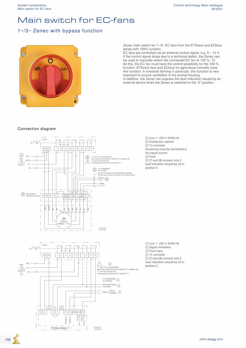
PE PE 1 2 3 4 5 6 7 8 9 10
Auto0100 %
N L1 14 11 E1 D1 GND 10V 24V
ECblue Basic 1 ~
DC
Out
(I max
= 7
0 m
A)
DC
Out
(I max
= 1
0 m
A)
Zenec
L1
N
PE
Dig
ital I
n 1
Anal
og In
1
K1
NetzLine
1 ~ 230 V50/60 Hz
StörungseingangFault input
Signal
zum Regelgerätto controller
LüftungVentilation
KT00019I28.06.2012
“7“ und “8“ nur anschließen,wenn keine Störmeldung in Stellung “0“ erfolgen soll.“7“ and “8“ connect onlyif fault signal should be off in position “0“.1
2
3
4
5
PE PE 1 2 3 4 5 6 7 8 9 10
Auto0100 %Zenec
L1
N
PE 1NetzLine
1 ~ 230 V50/60 Hz
StörungFault
zum Regelgerätto controller
PWM /0...10 V
METAvent
PWM/0 - 10 V
GN
YE
GN
YE
BK BU YE BN WH
GN
PK GY
BK
NL1PE PE FreigabeRelease
StörungFault
VorgabeSetting
AbzweigdoseDistribution cabinet
PE 2
+
Schirm einseitig an der Signalquelle aufgelegtScreening must be connected to the signal-source
KT00019D03.04.2012
“7“ und “8“ nur anschließen,wenn keine Störmeldung in Stellung “0“ erfolgen soll.“7“ and “8“ connect onlyif fault signal should be off in position “0“.
①
②
③
④
⑤
① Line 1~ 230 V 50/60 Hz ② Signal ventilation ③ Fault input ④ To controller ⑤ [7] and [8] connect only if fault indication should be off in position 0
① Line 1~ 230 V 50/60 Hz ② Distribution cabinet ③ To controller Screening must be connected to the signal source ④ Fault ⑤ [7] and [8] connect only if fault indication should be off in position 0
Zenec main switch for 1~/3~ EC fans from the ETAvent and ECblue series with 100% function. EC fans are controlled via an external control signal, e.g. 0 – 10 V. If the control signal drops due to a technical defect, the Zenec can be used to manually switch the connected EC fan to 100 %. To do this, the EC fan must have the control possibility for the 100 % function. ETAvent fans and ECblue for agriculture normally have this function. In livestock farming in particular, this function is very important to ensure ventilation in the animal housing. In addition, the Zenec can supress the fault indication issued by an external device when the Zenec is switched to the “0” position.
Main switch for EC-fans1~/3~ Zenec with bypass function
Connection diagram
156 ziehl-abegg.com
System componentsMain switch for EC-fans
Control technology Main catalogue06/2021
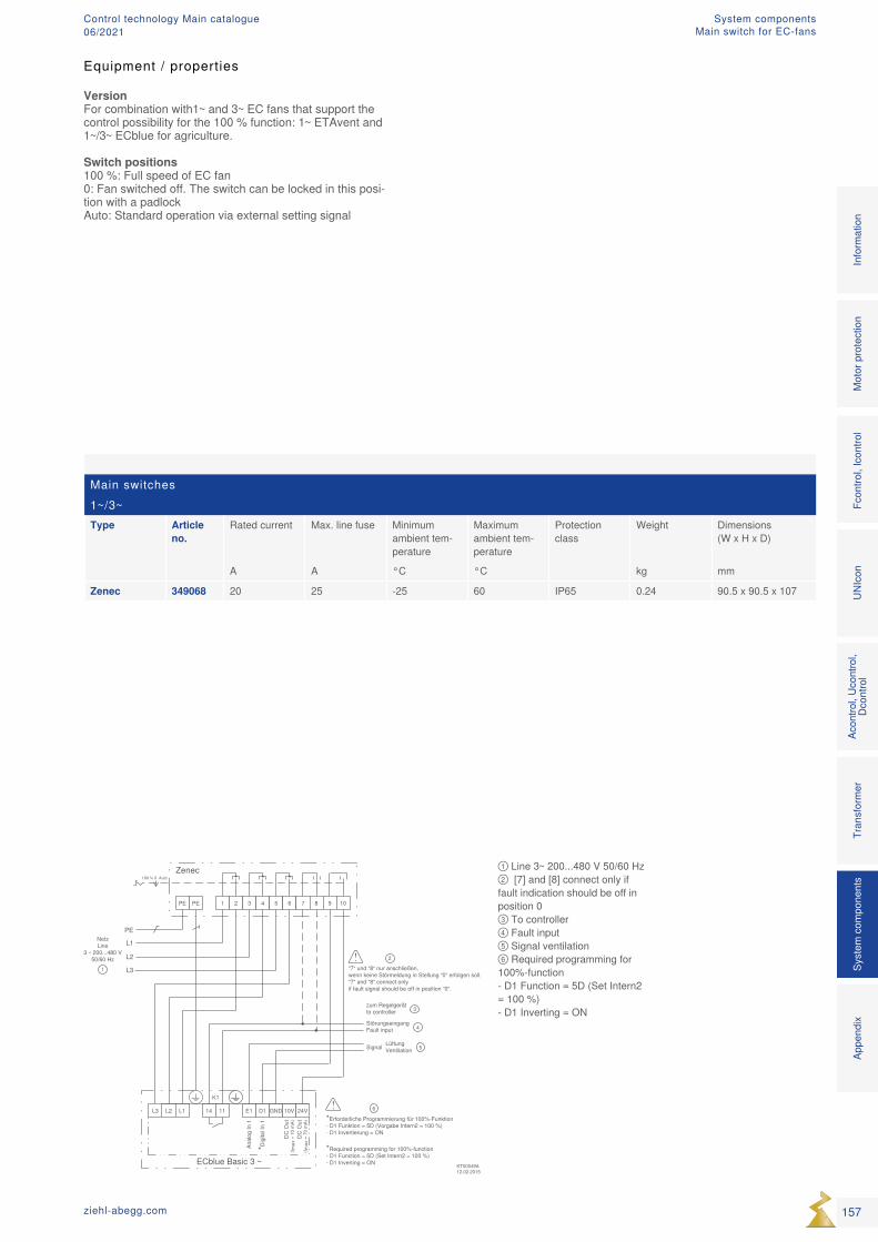
Main switches1~/3~Type Article
no.Rated current Max. line fuse Minimum
ambient tem-perature
Maximum ambient tem-perature
Protection class
Weight Dimensions (W x H x D)
A A °C °C kg mm
Zenec 349068 20 25 -25 60 IP65 0.24 90.5 x 90.5 x 107
① Line 3~ 200...480 V 50/60 Hz ② [7] and [8] connect only if fault indication should be off in position 0 ③ To controller ④ Fault input ⑤ Signal ventilation ⑥ Required programming for 100%-function - D1 Function = 5D (Set Intern2 = 100 %) - D1 Inverting = ON
Equipment / properties
VersionFor combination with1~ and 3~ EC fans that support the control possibility for the 100 % function: 1~ ETAvent and 1~/3~ ECblue for agriculture.
Switch positions100 %: Full speed of EC fan0: Fan switched off. The switch can be locked in this posi-tion with a padlockAuto: Standard operation via external setting signal
157ziehl-abegg.com
Mot
or p
rote
ctio
nFc
ontro
l, Ic
ontro
lUN
Icon
Acon
trol,
Ucon
trol,
Dcon
trol
Tran
sfor
mer
Syst
em c
ompo
nent
s In
form
atio
n Ap
pend
ix
System componentsMain switch for EC-fans
Control technology Main catalogue06/2021
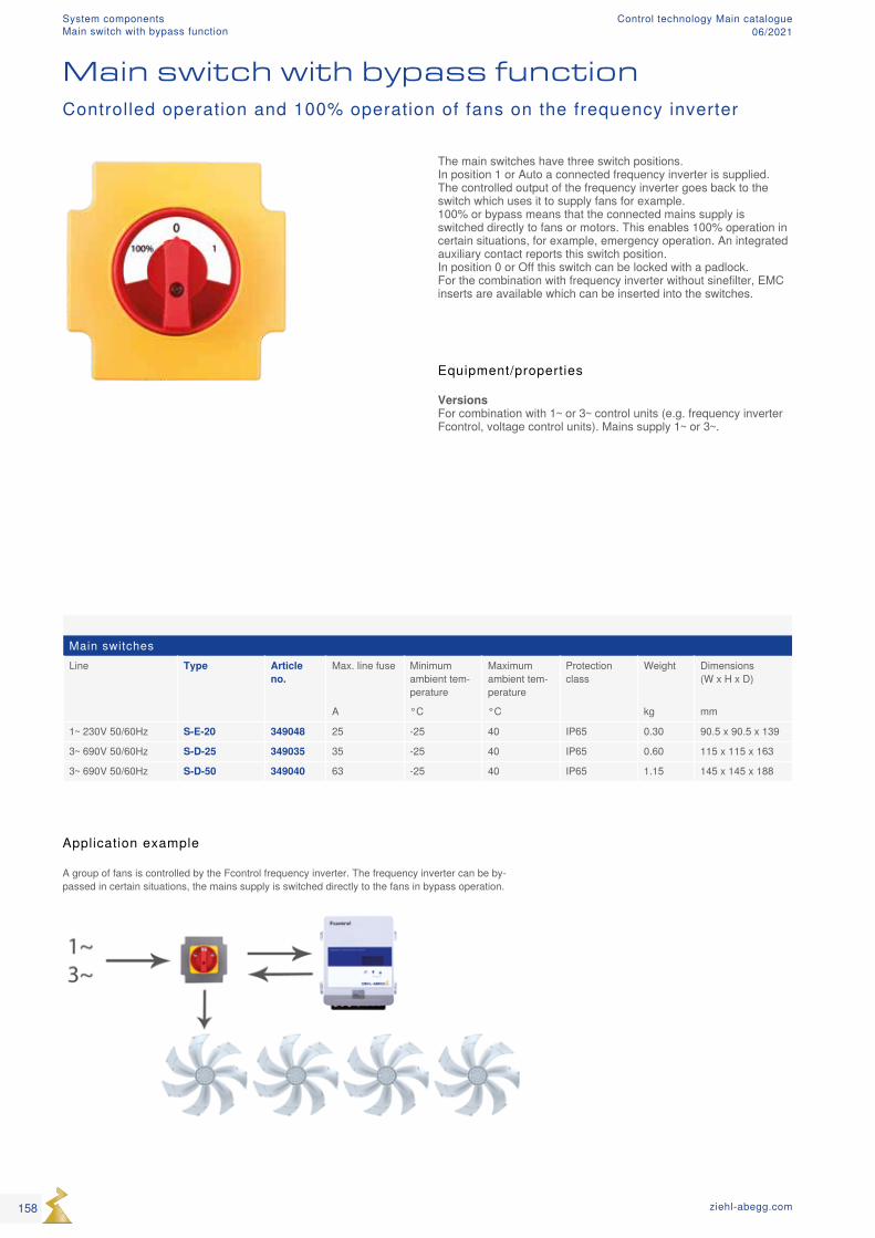
Main switchesLine Type Article
no.Max. line fuse Minimum
ambient tem-perature
Maximum ambient tem-perature
Protection class
Weight Dimensions (W x H x D)
A °C °C kg mm
1~ 230V 50/60Hz S-E-20 349048 25 -25 40 IP65 0.30 90.5 x 90.5 x 139
3~ 690V 50/60Hz S-D-25 349035 35 -25 40 IP65 0.60 115 x 115 x 163
3~ 690V 50/60Hz S-D-50 349040 63 -25 40 IP65 1.15 145 x 145 x 188
Main switch with bypass functionControlled operation and 100% operation of fans on the frequency inverter
The main switches have three switch positions. In position 1 or Auto a connected frequency inverter is supplied. The controlled output of the frequency inverter goes back to the switch which uses it to supply fans for example. 100% or bypass means that the connected mains supply is switched directly to fans or motors. This enables 100% operation in certain situations, for example, emergency operation. An integrated auxiliary contact reports this switch position. In position 0 or Off this switch can be locked with a padlock. For the combination with frequency inverter without sinefilter, EMC inserts are available which can be inserted into the switches.
Equipment/properties
Versions For combination with 1~ or 3~ control units (e.g. frequency inverter Fcontrol, voltage control units). Mains supply 1~ or 3~.
Application example
A group of fans is controlled by the Fcontrol frequency inverter. The frequency inverter can be by-passed in certain situations, the mains supply is switched directly to the fans in bypass operation.
158 ziehl-abegg.com
System componentsMain switch with bypass function
Control technology Main catalogue06/2021
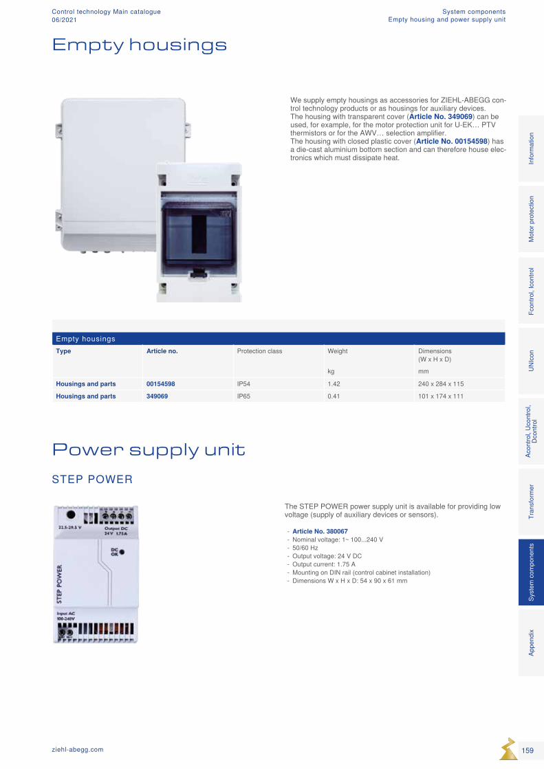
Empty housingsType Article no. Protection class Weight Dimensions
(W x H x D)
kg mm
Housings and parts 00154598 IP54 1.42 240 x 284 x 115
Housings and parts 349069 IP65 0.41 101 x 174 x 111
We supply empty housings as accessories for ZIEHL-ABEGG con-trol technology products or as housings for auxiliary devices. The housing with transparent cover (Article No. 349069) can be used, for example, for the motor protection unit for U-EK… PTV thermistors or for the AWV… selection amplifier. The housing with closed plastic cover (Article No. 00154598) has a die-cast aluminium bottom section and can therefore house elec-tronics which must dissipate heat.
The STEP POWER power supply unit is available for providing low voltage (supply of auxiliary devices or sensors).
- Article No. 380067 - Nominal voltage: 1~ 100...240 V - 50/60 Hz - Output voltage: 24 V DC - Output current: 1.75 A - Mounting on DIN rail (control cabinet installation) - Dimensions W x H x D: 54 x 90 x 61 mm
Empty housings
STEP POWER
Power supply unit
159ziehl-abegg.com
Mot
or p
rote
ctio
nFc
ontro
l, Ic
ontro
lUN
Icon
Acon
trol,
Ucon
trol,
Dcon
trol
Tran
sfor
mer
Syst
em c
ompo
nent
s In
form
atio
n Ap
pend
ix
System componentsEmpty housing and power supply unit
Control technology Main catalogue06/2021

160 ziehl-abegg.com
AppendixCopyright
Control technology Main catalogue06/2021
General notes
The information and data contained in this catalogue were com-posed to the best of our best ability and do not absolve the user from its duty to check the suitability of the products with respect to its intended application. The customer is obligated to inform the supplier about general information concerning the intended use, the type of installation, the operating conditions and any other conditions that need to be taken into consideration if the order is not based on catalogue information. ZIEHL-ABEGG SE reserves the right to make design changes, which are used for continuous technical improvement. This catalogue contains information for your guidance. No guaran-tee is provided with regard to the accuracy of all information and no legal claims may be derived from this. Reproduction of this informa-tion, or extracts thereof, is permitted only with written approval.
Copyright
ZIEHL-ABEGG SE reserves in its entirety the copyright of this cata-logue. The catalogue is intended for proper use as intended and neither the catalogue, its content nor extracts may be passed on to third parties without our express written consent.
161ziehl-abegg.com
Mot
or p
rote
ctio
nFc
ontro
l, Ic
ontro
lUN
Icon
Acon
trol,
Ucon
trol,
Dcon
trol
Tran
sfor
mer
Syst
em c
ompo
nent
sIn
form
atio
nAp
pend
ix
AppendixCopyright
Control technology Main catalogue06/2021

The Royal League
Co
nt
ro
l T
ec
hn
olo
gy
Ma
in C
at
alo
gu
e 0
6/
20
21
Ed
itio
n
© Z
IEH
L-A
BE
GG
SE
- 0
0711
237
- E
N -
MA
- 0
6/20
21 -
- T
his
cata
logu
e co
ntai
ns in
form
atio
n fo
r yo
ur g
uida
nce.
No
guar
ante
e is
pro
vide
d w
ith r
egar
d to
the
accu
racy
of a
ll in
form
atio
n an
d no
lega
l cla
ims
may
be
deriv
ed fr
om th
is.
Rep
rodu
ctio
n of
this
info
rmat
ion,
or
extr
acts
ther
eof,
is p
erm
itted
onl
y w
ith w
ritte
n ap
prov
al.
ZIEHL-ABEGG SE Heinz-Ziehl-Straße 74653 Künzelsau +49 7940 16-0 [email protected] ziehl-abegg.com
Related Documents