Metasys Network Technical Manual 636 Objects Section Technical Bulletin Issue Date 0101 © 2001 Johnson Controls, Inc. 1 Code No. LIT-636102 www.johnsoncontrols.com Introduction Page *3 • Quick Start *3 • Overview of Concepts *6 • Software Models *9 Engineering Overview *15 • Overview of Operation 15 • Hardware Interface *16 • Command Processing 19 • NT Command and Display Attributes 23 • COS Reporting *24 • Triggers 25 • Optional Mapping to AD and BD Objects 25 Database Generation *27 • Overview 27 • Mapping Points in the Controller to Software Model Attributes *27 • Point Mapping Tables *33 • Defining a CS Object with DDL *71 • Defining a CS Object with Online Generation *77 Reference Tables *87 • Attribute Table *87 • Command Table *101 Control System (CS) Object * Indicates those sections where changes occurred since the last printing.

Welcome message from author
This document is posted to help you gain knowledge. Please leave a comment to let me know what you think about it! Share it to your friends and learn new things together.
Transcript

Metasys Network Technical Manual 636Objects Section
Technical BulletinIssue Date 0101
© 2001 Johnson Controls, Inc. 1Code No. LIT-636102 www.johnsoncontrols.com
Introduction Page *3
• Quick Start *3
• Overview of Concepts *6
• Software Models *9
Engineering Overview *15
• Overview of Operation 15
• Hardware Interface *16
• Command Processing 19
• NT Command and Display Attributes 23
• COS Reporting *24
• Triggers 25
• Optional Mapping to AD and BD Objects 25
Database Generation *27
• Overview 27
• Mapping Points in the Controller to Software Model Attributes *27
• Point Mapping Tables *33
• Defining a CS Object with DDL *71
• Defining a CS Object with Online Generation *77
Reference Tables *87
• Attribute Table *87
• Command Table *101
Control System (CS) Object
* Indicates those sections where changes occurred since the last printing.

2 Objects—Control System (CS) Object

Objects—Control System (CS) Object 3
Introduction
The Control System (CS) object is the software representation of selectedhardware and internal points in a controller. The selected points areattributes of the CS object. A CS object typically represents one controlstrategy (e.g., temperature control, static pressure control) located in acontroller, though it may represent the control strategy for the entirecontroller. Currently, CS objects support the following N2OPEN,System 9100, and LONWORKS compatible devices: Air Handling Unit(AHU) controller, Unitary (UNT) controller, Variable Air Volume (VAV)controller, VAV Modular Assembly (VMA), Phoenix Lab and Fume HoodInterface Module (PHX), Metasys Integrator (MIG), Generic VendorDevices (VND), N2 Dialer Module (NDM), Lab and Central Plant (LCP)Controller/DC9100, DX9100, DXECH, XT9100, Expansion Modules(XTM), DR9100, TC9100, LONTCU, LONTCUA, LONVMA,LONVMAA, LONDXA, LONDXAA, LONDXD, LONDXDA.
Note: Some devices are unique to local markets and are not availableglobally.
This section tells you how to quickly define the CS object from theOperator Workstation (OWS). For information on the overall process ofdefining the controller, creating a software model, and then defining a CSobject, see Database Generation later in this document.
The CS object can be defined:
• either online at the OWS using the CS Object Definition window, or
• offline using Data Definition Language (DDL). See the DDLProgrammer’s Manual (FAN 630) for syntax and procedures.
Quick Start
Defining the CSObject
4 Objects—Control System (CS) Object
HVAC PRO software (Release 5.10 or later) and the GX-9100Configuration software (Release 3.0 and later) generate a DDL model filewhen the configuration is saved. For HVAC PRO and GX-9100(Release 4.0 or later), you must select the Generate DDL on Save optionwhen you save the configuration. This creates a model file with a .DDLextension for Application Specific Controllers (ASCs) and .DMOand .DNC extensions for Digital Expansion (DX) units. For GX-9100Release 3.0, the files are generated automatically when you save theconfiguration. The automatically generated model file includes all thedefined points in the controller. To customize the model file, delete andmodify points as needed. For more information, see the appropriateconfiguration tool manual.
To define a CS object online at the workstation:
1. Go to the summary of the system in which you want to add the object.
2. Select Item from the menu bar. Then select New from the Item menu.A dialog box for selecting object type appears.
3. Select Control System from the list of object types. Then, in theHardware System and Hardware Object fields, type the system andobject names of the controller the CS object will be mapped to. Thismust be a defined controller. Click OK. A dialog box for selecting asoftware model appears.
A software model is a template for CS objects. When you define a CSobject, you must reference an already defined software model. If themodel does not exist, you must define it before you define the CSobject. Defining software models is explained in this document, underDatabase Generation.
If you are defining more than one CS object on a controller, eachCS object must reference a different software model. And, if the samepoints are used in more than one model, only one model should allowthe points to be commanded/adjusted. Otherwise, command conflictscan occur.
4. Select the software model and click OK. The CS Object Definitionwindow appears (as shown in Figure 1).
Objects—Control System (CS) Object 5
Control System Definition - AHU - 1
Item Edit View Action Go To Accessory Help
HDQTRSNC-44 GROUP #1B
GROUP2B GROUP #2BHARDWARB Hardware System
System Name
Object NameExpanded ID
HARDWARB
Comm. Disabled n
HARDWARB
Graphic Symbol #
Operator Instr. #
nHardware:System NameObject NameExpanded ID
HARDWARB
N20-2AHU-1
Flags
Auto Dial-up
noneReport TypeOverride
Csobjnew
0
0
Figure 1: Control System Object Definition Window
Note that some of the fields are blank and some are already filled in.You must fill in the blank attribute fields (e.g., Object Name) becausethey do not have defaults. The attribute fields that are already filled incontain default settings, which you can either accept or change. Thefollowing table explains the attributes without default settings. TheAttribute Table section at the end of this document describes allCS object attributes. The Operator Workstation User’s Manual(FAN 634) explains in detail the procedures for entering and changingdata.
Table 1: Attributes without Default SettingsAttribute Description Entry
Object Name Identifies object (e.g., AHU-1,AHUTEMP). The object namecannot already exist in thesystem.
8 alphanumeric characters
Expanded ID(optional)
Further identifies object(e.g., AHU Temperature Control).
24 alphanumeric characters
Display Attribute The attribute whose valueappears as the CS object’sCurrent Value in summaries, inthe CS Object Focus window, andat the Network Terminal (NT).
Use the attributename/number as it appearsin the software model(e.g., AI_1, AI_2, BI_3,BI_4).
NT CommandAttribute
The one attribute that can becommanded from the NT.
Use the attributename/number as it appearsin the software model(e.g., AI_1, AI_2, BI_3).
5. To save the new CS object, select Save from the Item menu. The newCS object is added to the operational database in the NC.
6 Objects—Control System (CS) Object
Once a CS object is defined, you can modify its attributes online using theCS Object Focus window. You also use the Focus window to monitor andcommand the CS object. For more information on modifying andmonitoring the CS Object, refer to the Operator Workstation User’sManual (FAN 634), under Using Object Focus Windows.
This is the end of the Quick Start section. If you need information on theoverall process of defining a controller, a software model, and then aCS object, see the Database Generation section of this document. If youneed information on the purpose and operation of the software model andCS object, continue reading this section, which explains how thesecomponents work together.
These concepts are briefly explained in this overview:
configuration tools and configuration files
CS objects
software models
hardware models
The CS object and software model are explained in greater detailthroughout the document.
The AHU, UNT, VAV, VMA, PHX, NDM, and System 91 devices(LCP/DC9100, DX9100, DXECH, TC9100, XT9100, XTM, DR9100) areall configurable devices, meaning they are not preprogrammed.To program these controllers, you must use the appropriate configurationsoftware. See Table 2.
Modifying andMonitoring theCS Object
Overview ofConcepts
ConfigurationSoftware

Objects—Control System (CS) Object 7
Table 2: Controller and Configuration SoftwareController M-Tool Software Configuration File Protocol
AHU, UNT, VAV, PHX, NDM HVAC PRO Software .PRN file* N2OPEN
VMA HVAC PRO Release 7.0 orhigher
.PRN file* N2B
LCP/DC9100 LCP Configuration Release 3.2or GC-9100 Release 3.2
.GPS configuration file System 9100
DX9100,XT9100
GX-9100 .DXS configuration file System 9100
DXECH(DX912x)
GX-9100 Release 4.01 or higher .DXS configuration file Echelon(N2E)
XTM XTM Configurator Release 3.01 .DBF and .HMCconfiguration files
System 9100
DR9100 SM-9100 Module N/A System 9100
TC9100 HVAC PRO Software .PRN file System 9100
LONDXA, LONDXAA, LONDXD,LONDXDA (DX-9200)**
GX-9100 Release 6.0 or later .DXS configuration file LONWORKS
LONTCU**, LONTCUA** Factory Configured N/A LONWORKS
LONVMA, LONVMAA M-Pro Software .NXE application file.XIF interface file.EXP configuration file
LONWORKS
MIG, VND N/A Vendor-specificapplication note
N2OPEN
* HVAC PRO software produces a .PRN file. DOS versions of HVAC PRO software produce a .SYM file.
** Contact Johnson Controls, Inc. for product availability.
The configuration tools allow the programmer to select from a series ofpaths. Each path corresponds to an application supported by the controller(e.g., air handling unit, roof top unit). For a list of currently availableapplications, see the controller’s technical bulletin.
See the controller’s documentation for information on configuration tools.(For example, for information on generating the .DXS file for a DX9100,see the GX-9100 Software Configuration Tool User’s Guide(LIT-6364060) in the System 9100 Technical Manual (FAN 636.4.)
Configuration Files
Once you configure the device, print a hard copy of the device’sconfiguration. This printout lists the names and addresses of theconfigured hardware and internal points in the device. Use the informationin the printout to create software models. (These files are explained later inthis document, under Database Generation.)
Note: For Metasys Integrator (MIG) devices, the vendor-specificapplication note contains the point mapping information for thecontroller.

8 Objects—Control System (CS) Object
HVAC PRO software (Release 5.10 or later) and the GX-9100Configuration software (Release 3.0 and later) generate a DDL model filewhen the configuration is saved. For HVAC PRO and GX-9100 software(Release 4.0 or later), you must select the Generate DDL on Save optionwhen you save the configuration. This creates a model file with a .DDLextension for ASC and a .DMO extension for DX. For GX-9100, the file isgenerated automatically when you save the configuration, and it has a.DMO extension. The automatically generated model file includes all thedefined points in the controller. To customize the model file, simply deleteand modify points as needed. For more information, see the manual for theconfiguration tool you are using.
Though the controllers have standalone capability, you most likely willwant their points available for monitoring and control from the MetasysOWS and Network Terminal (NT). By mapping to the controller, the CSobject allows you to monitor and control selected points in the ASCs.When you define software models (which are used as templates for CSobjects), you can select exactly which points in the controller to monitorand control. There may be more than 50 points in the ASC; however, youmay want to monitor only 20 of these points at the OWS.
Up to 16 CS objects can reference one device. For example, one CS objectcan represent the points in the controller involved in temperature control.Another CS object can represent the points in the same controller involvedin static pressure control. If more than one CS object is mapped toone device, each CS object must reference its own software model.
IMPORTANT: When more than one CS Object is defined forone controller, each of these CS objects mustreference a separate software model. Otherwise,commands may be lost if the Network ControlModule (NCM) loses power or is downloaded. Also,if the same points are used in more than one model,only one model should allow the points to becommanded/adjusted. Otherwise, command conflictscan occur.
AutomaticCreation ofModel File
CS Objects
Objects—Control System (CS) Object 9
A software model is a template for CS objects. The software modelcontains default values that make the process of defining CS objectsconsistent and efficient. For example, you might be setting up a facilitythat contains 100 VAV controllers that are exactly alike except for theirsystem\object names. You can define one software model for all of theseVAV controllers. Then, when you define the CS object for each controller,you simply reference the appropriate software model and specify a uniquesystem\object name.
Software models are explained in detail in this document, under theSoftware Models section.
Hardware models are internal to the system software; they cannot bechanged by the user, unlike software models, which are user-defined.There is a hardware model for each type of Application Specific Controller(ASC). This model is a list of all the points in the controller and theiraddresses, controller point types (e.g., AI, ADF, BI), and whether or noteach point is commandable.
The hardware model is used internally to check the validity of a softwaremodel (it is not user-defined or user-modifiable). For example, when youdefine a software model for an LCP, you are flagged with an error if youdefine an attribute as commandable when the point it is mapped to is notcommandable in the hardware model.
When you define a CS object, you must reference an already definedsoftware model. The software model specifies exactly which point in thecontroller each CS object attribute is mapped to and whether each attributecan be overridden or adjusted.
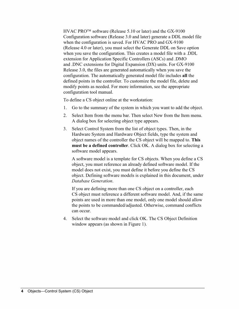
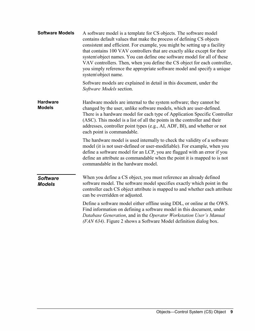
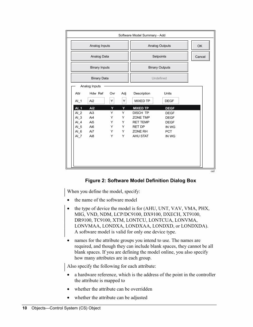
Define a software model either offline using DDL, or online at the OWS.Find information on defining a software model in this document, underDatabase Generation, and in the Operator Workstation User’s Manual(FAN 634). Figure 2 shows a Software Model definition dialog box.
Software Models
HardwareModels
SoftwareModels
10 Objects—Control System (CS) Object
cs2
Software Model Summary - Add
Cancel
OKAnalog Outputs
Setpoints
Binary Outputs
Undefined
Analog Inputs
Analog Data
Binary Inputs
Binary Data
Attr Hdw Ref Ovr Adj Description Units
AI_1 Ai2 Y Y MIXED TP DEGF
AI_1 Ai2 Y Y MIXED TP
AI_2 Ai3 Y Y DISCH TP
AI_3 Ai4 Y Y ZONE TMP
AI_4 Ai5 Y Y RET TEMP
AI_5 Ai6 Y Y RET DP
AI_6 Ai7 Y Y ZONE RH
AI_7 Ai8 Y Y AHU STAT
DEGF
DEGF
DEGF
DEGF
IN WG
PCT
IN WG
Analog Inputs
Figure 2: Software Model Definition Dialog Box
When you define the model, specify:
• the name of the software model
• the type of device the model is for (AHU, UNT, VAV, VMA, PHX,MIG, VND, NDM, LCP/DC9100, DX9100, DXECH, XT9100,DR9100, TC9100, XTM, LONTCU, LONTCUA, LONVMA,LONVMAA, LONDXA, LONDXAA, LONDXD, or LONDXDA).A software model is valid for only one device type.
• names for the attribute groups you intend to use. The names arerequired, and though they can include blank spaces, they cannot be allblank spaces. If you are defining the model online, you also specifyhow many attributes are in each group.
Also specify the following for each attribute:
• a hardware reference, which is the address of the point in the controllerthe attribute is mapped to
• whether the attribute can be overridden
• whether the attribute can be adjusted
Objects—Control System (CS) Object 11
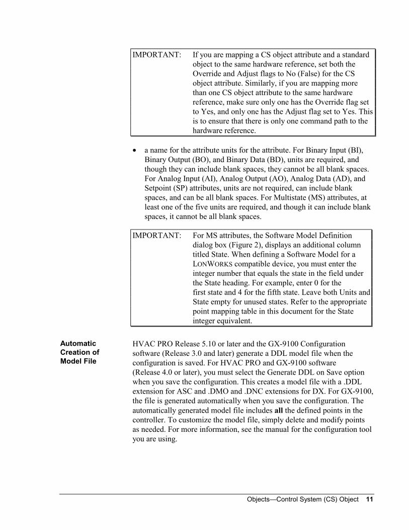
IMPORTANT: If you are mapping a CS object attribute and a standardobject to the same hardware reference, set both theOverride and Adjust flags to No (False) for the CSobject attribute. Similarly, if you are mapping morethan one CS object attribute to the same hardwarereference, make sure only one has the Override flag setto Yes, and only one has the Adjust flag set to Yes. Thisis to ensure that there is only one command path to thehardware reference.
• a name for the attribute units for the attribute. For Binary Input (BI),Binary Output (BO), and Binary Data (BD), units are required, andthough they can include blank spaces, they cannot be all blank spaces.For Analog Input (AI), Analog Output (AO), Analog Data (AD), andSetpoint (SP) attributes, units are not required, can include blankspaces, and can be all blank spaces. For Multistate (MS) attributes, atleast one of the five units are required, and though it can include blankspaces, it cannot be all blank spaces.
IMPORTANT: For MS attributes, the Software Model Definitiondialog box (Figure 2), displays an additional columntitled State. When defining a Software Model for aLONWORKS compatible device, you must enter theinteger number that equals the state in the field underthe State heading. For example, enter 0 for thefirst state and 4 for the fifth state. Leave both Units andState empty for unused states. Refer to the appropriatepoint mapping table in this document for the Stateinteger equivalent.
HVAC PRO Release 5.10 or later and the GX-9100 Configurationsoftware (Release 3.0 and later) generate a DDL model file when theconfiguration is saved. For HVAC PRO and GX-9100 software(Release 4.0 or later), you must select the Generate DDL on Save optionwhen you save the configuration. This creates a model file with a .DDLextension for ASC and .DMO and .DNC extensions for DX. For GX-9100,the file is generated automatically when you save the configuration. Theautomatically generated model file includes all the defined points in thecontroller. To customize the model file, simply delete and modify pointsas needed. For more information, see the manual for the configuration toolyou are using.
AutomaticCreation ofModel File

12 Objects—Control System (CS) Object
The software model is made of eight groups of attributes: AI, AO, BI, BO,AD, BD, SP, MS. A software model can use all or only some of theattribute groups. When you define the model, you name the groups youintend to use. For example, you might name the group of AI attributesAnalog Inputs or Temperatures. These user-defined groupings areprovided to help organize information within the CS object.
The eight attribute groups can be further split into two major types:hardware and internal. Table 3 summarizes the eight groups.
Table 3: Attribute GroupsAttribute Group Maximum Allowed
in Software Model
Hardware
Analog Input (AI) 16
Analog Output (AO) 16
Binary Input (BI) 16
Binary Output (BO) 16
Internal
Analog Data (AD) 32
Binary Data (BD) 32
Setpoint (SP) 32
Multistate (MS) 2
IMPORTANT: Consider the following information on attributesequence carefully. Attributes of CS objects areposition-dependent and are commanded by processesaccording to their sequence. If you change the sequencein the software model referenced by the CS object(e.g., by deleting an attribute), this might change aprocess or Weekly Schedule that references theattribute.
In the software model attribute groups, the attributes are orderedsequentially. For example, the AI attributes are numbered AI_1 throughAI_16, and the BI attributes are numbered BI_1 through BI_16.
The attributes are position-dependent. For example, let’s say you have amodel defined with five AI attributes (AI_1 through AI_5). If, using DDL,you modify a model by deleting attribute AI_3, the point associated withAI_4 moves to position AI_3, and the point associated with AI_5 moves toposition AI_4. In this case, if a process had been commanding AI_5, thecommand does not take effect because the point associated with attributeAI_5 is now associated with attribute AI_4.
Attribute Groups
AttributeSequence

Objects—Control System (CS) Object 13
When you define the software model online at the OWS, this sequencingis clear because the attribute numbers appear on the screen. However,when you define the model with DDL, the sequence is indicated only bythe order in which you define the attributes. For example, the first AIattribute you define is AI_1, and the second you define is AI_2, etc.
Since commands to CS object attributes are based on attribute sequence, itis important that you know the sequence when writing processes. Also, ifyou change the order in the software model (e.g., by deleting a point),make sure you understand the new sequence and make any necessarymodifications to processes or Weekly Schedules.
For the MIG and VND, all controller points can be commanded. Thismeans you can set the Override and Adjust flags to Yes for any attributemapped to any point in these controllers. However, only overrides andadjusts to AO and BO point types are actually sent to the vendorcontroller.
For the AHU, UNT, VAV, VMA, PHX, NDM, System 9100 devices(e.g., LCP, DX9100), and LONWORKS compatible devices(e.g., LONTCU), only some points in the controller can be commanded.When you set the Override and Adjust flags to Yes in the software model,the system checks to make sure the point can be commanded in thecontroller. The point mapping tables in the Database Generation sectionof this document tell you which points can and cannot be commanded.
Software models are part of the archive database, and reside in the@MODEL file on the PC. The @MODEL file must be compiled beforethe @NC file that contains CS objects referencing software models. Infacilities with more than one OWS, make sure all workstations have thesame @MODEL file.
For more information on the software model database, refer to theDDL Programmer’s Manual (FAN 630).
Non-CommandablePoints
Software ModelDatabase

14 Objects—Control System (CS) Object
You can modify the software model online at the workstation, or offlineusing DDL. You must again download the CS objects that reference thesoftware model if you change the model; if you do not download theseagain, the CS objects do not reflect the changes.
Note: Another option is to delete and re-add the CS object. With thisprocedure, there is no need for a new download to the NCM.
IMPORTANT: Remember that attributes in software models areposition-dependent, and that processes and featuresreference attributes according to their positions(e.g., AI_3, AI_4). If you change the sequence ofattributes in a software model (e.g., by deleting anattribute), make sure you make the necessary changesto any processes or Weekly Schedules that referencethe attributes.
Changing the Software Model Database with DDL
If you make changes to the @MODEL file with DDL, you must do thefollowing for these changes to take effect in the CS object that referencesthe model:
1. Make the changes to the @MODEL file.
2. Recompile the @MODEL file.
3. Recompile the @NC file containing the CS object.
4. Do a download to the NC containing the CS object.
Changing the Software Model Online at the Workstation
If you make changes to a software model online using the Software Modeldialog boxes, you must do the following for these changes to be reflectedin the CS object that references the model:
1. Change the model.
2. Upload from the NC containing the CS object.
3. Download to the NC again.
Note: Another method is to delete and then re-add the CS object. Do notuse the Copy feature when re-adding the CS object. Be sure thatthe CS object has the same name as before so no other links arelost (i.e., GPL).
Modifying aSoftware Model

Objects—Control System (CS) Object 15
Engineering Overview
CS object software functions can be divided into six basic categories:
Hardware Interface--The CS object attributes are mapped tohardware and internal points in the controller.
Command Processing--Commands to attributes are processed bysoftware functions such as command prioritization.
Display Attribute--You define one attribute of the CS object to be theDisplay attribute. This attribute’s value is displayed as the CS object’scurrent value in the CS Object Focus window and in summariescontaining the CS object.
Change-of-State (COS) Reporting--Overrides to CS object attributescan generate advisories.
Triggers--The offline state of the CS object and the CS object’s binaryattributes can trigger control processes.
Optional Mapping to AD and BD Objects--To allow COS and alarmnotification and triggers, and to enable Point History for individualCS object attributes, map the attributes to standard AD or BD objects.
Overview ofOperation

16 Objects—Control System (CS) Object
The following flow diagram illustrates the general operation of the CSobject. The blocks represent the functions performed by the software. Eachblock is summarized after the diagram and then explained in detailthroughout the document.
Display Attribute
COS Reporting
Triggers
Optional Mappingto AD and BD
Objects
Point History andother Features
Hardware Interface
CommandProcessing
TriggersCOS Reporting
csflow1
Figure 3: CS Object Functional Flow Diagram
CS objects map to the following devices: AHU, UNT, VAV, VMA, PHX,MIG, VND, NDM, LCP/DC9100, DX9100, DXECH, XT9100, XTM,DR9100, TC9100, and LONWORKS compatible devices. This mappingmeans the attributes of the CS object are associated with specific hardwareand internal points in the controller.
The hardware interface is determined by the:
• device type
• software model you reference when defining the CS object. The modelspecifies which point in the controller each attribute maps to.
Functional FlowDiagram
HardwareInterface
Objects—Control System (CS) Object 17
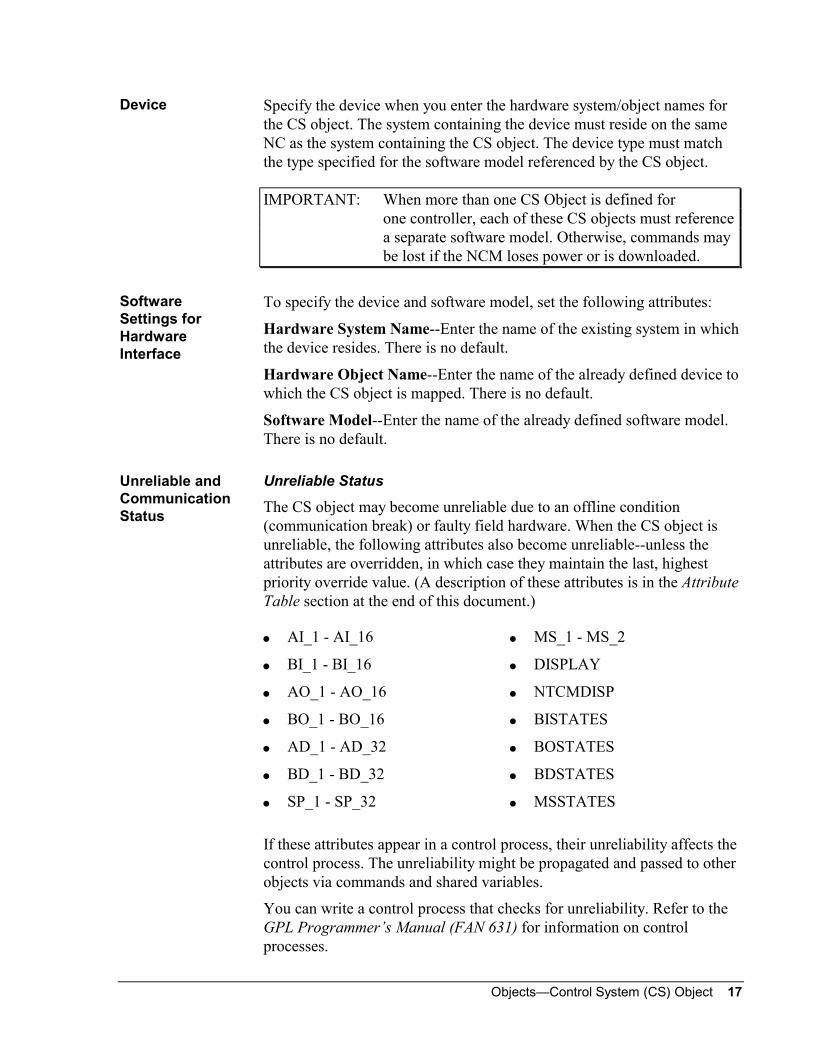
Specify the device when you enter the hardware system/object names forthe CS object. The system containing the device must reside on the sameNC as the system containing the CS object. The device type must matchthe type specified for the software model referenced by the CS object.
IMPORTANT: When more than one CS Object is defined forone controller, each of these CS objects must referencea separate software model. Otherwise, commands maybe lost if the NCM loses power or is downloaded.
To specify the device and software model, set the following attributes:
Hardware System Name--Enter the name of the existing system in whichthe device resides. There is no default.
Hardware Object Name--Enter the name of the already defined device towhich the CS object is mapped. There is no default.
Software Model--Enter the name of the already defined software model.There is no default.
Unreliable Status
The CS object may become unreliable due to an offline condition(communication break) or faulty field hardware. When the CS object isunreliable, the following attributes also become unreliable--unless theattributes are overridden, in which case they maintain the last, highestpriority override value. (A description of these attributes is in the AttributeTable section at the end of this document.)
AI_1 - AI_16
BI_1 - BI_16
AO_1 - AO_16
BO_1 - BO_16
AD_1 - AD_32
BD_1 - BD_32
SP_1 - SP_32
MS_1 - MS_2
DISPLAY
NTCMDISP
BISTATES
BOSTATES
BDSTATES
MSSTATES
If these attributes appear in a control process, their unreliability affects thecontrol process. The unreliability might be propagated and passed to otherobjects via commands and shared variables.
You can write a control process that checks for unreliability. Refer to theGPL Programmer’s Manual (FAN 631) for information on controlprocesses.
Device
SoftwareSettings forHardwareInterface
Unreliable andCommunicationStatus

18 Objects—Control System (CS) Object
To find out if the CS object is unreliable, look at its Focus window orsummaries containing the CS object (e.g., a System Summary). The CurrentValue fields for unreliable and offline CS objects display ???? instead of avalue. (The Current Value for a CS object displays the value of theone attribute that was defined as the object’s Display attribute.)
Communication Status
The Comm. Status field in the object focus window is used for bothonline/offline status and disconnect status. (Disconnect status applies toNDM applications only.)
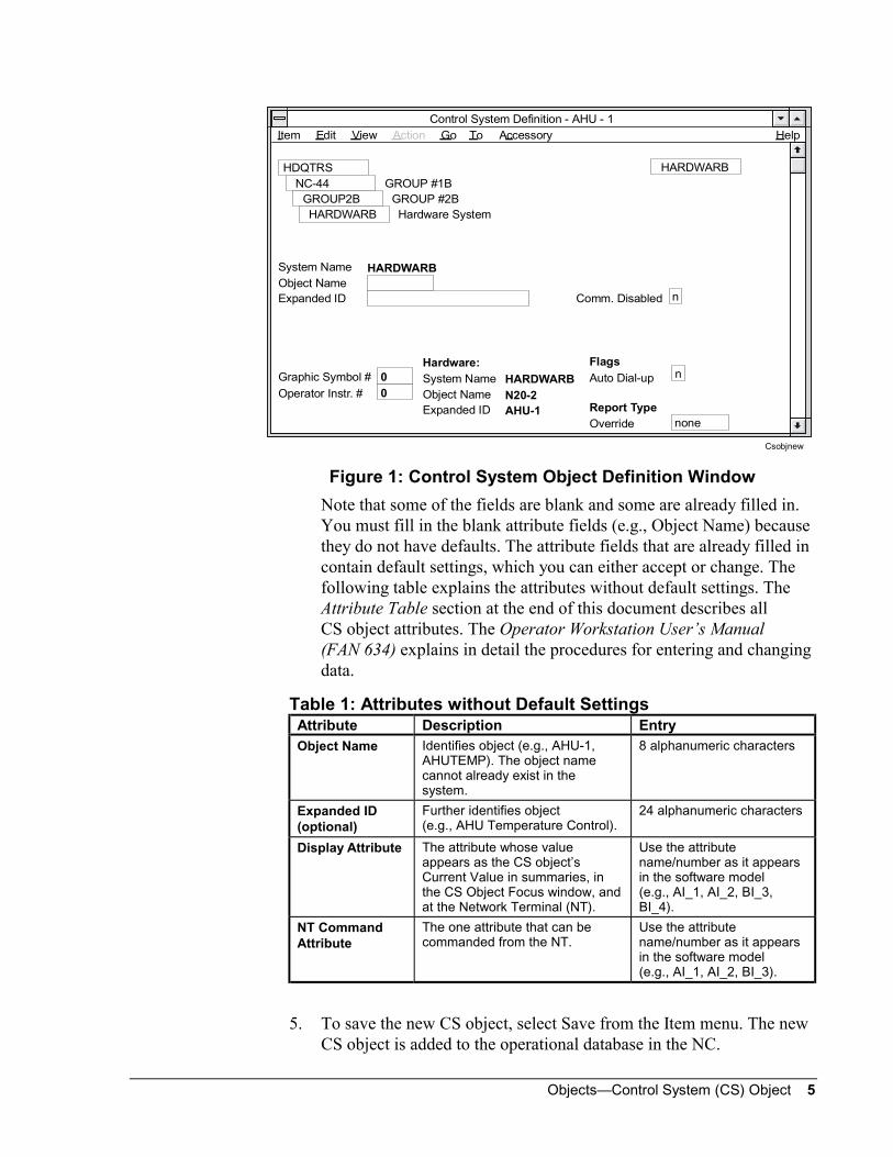
An object is considered offline when there is a communications breakbetween the controller the object is mapped to and the NCM or NDM thecontroller is connected to. If an object is offline, OFFLINE appears in theComm. Status field of the object’s focus window. Figure 4 shows a Focuswindow for an object that is offline and unreliable. In addition, an offlineobject appears in the Offline summary.
If it is an NDM application and the remote NDM is disconnected from thelocal NDM, DISCONCT appears in the Comm. Status field. If the NDMs areconnected, either Online or Offline appears in the field, depending onwhether the controller the object is mapped to is online.
Figure 4 shows an example of a Focus window for an unreliable, offlineCS object. Note that the Current Value field displays ????.
4-Floor
? ? ? ?
NNN
N
Graphic Symbol #Operating Instr. #
Flags
N0
Report TypeOVERRIDE NONE
Item Edit V iew Action G o To Accessory
CS for AHU at Address 10
CS for AHU at Address 10
System NameObject NameExpanded ID
Current Value
CSAHU-10Reports LockedTrigger LockedComm. DisabledComm. StatusS/W Override
134-Floor Auto Dialout
Control System Focus - ahumod2
4-Floor
HDQTRS 4-Floor
CSAHU10
Hardware:
Offline
System NameObject NameModel Name
focunrel
ahumod2
Display Attribute NT Command AttributeDecimal Position
BI_1 BO_1
AHU10
Figure 4: CS Object Focus Window

Objects—Control System (CS) Object 19
IMPORTANT: When more than one CS object is defined forone controller, each of these CS objects must referencea separate software model. Otherwise, commands maybe lost if the NCM loses power or is downloaded. Also,if the same points are used in more than one model,only one model should allow the points to becommanded/adjusted. Otherwise, command conflictscan occur.
The attribute values of the CS object are determined by the:
• value of the controller point (hardware or internal) the attribute ismapped to
• commanded value (a result of an Override, Adjust, or featurecommand)
• change default for N2OPEN/N2B only (an operator entered value thatgoes to the controller’s permanent memory considered at Priority 4).
For all CS object attributes, the software reads the value from thecontroller, unless the attribute has been commanded from the workstationor NT, or by a process or Weekly Scheduling.
IMPORTANT: For a CS object attribute to be adjusted by a process orfeature (at Priority 2 or 3), the attribute’s Adjust flagmust be set to Y (Yes) in the software model referencedby the CS object. For an attribute to be overridden by anoperator at the workstation or NT, the attribute’sOverride flag must be set to Y (Yes) in the softwaremodel.
Commands provide a way for you to change the value of CS objectattributes either from the workstation or NT, through execution of aprocess, or by Weekly Scheduling.
If the NC or controller goes offline, the commands are restored when theNC or controller goes back online.
From the NT, only one attribute from each CS object can be commanded(either overridden or adjusted). This attribute must be defined as theNT Command Attribute when the CS object is defined. Any definedattribute can be overridden or adjusted from the OWS.
CommandProcessing

20 Objects—Control System (CS) Object
There are four levels of commands, with Level 1 having the highestpriority. The following table explains command levels. You’ll findinformation on command syntax for processes in the JC-BASICProgrammer’s Manual (FAN 632) and GPL Programmer’s Manual(FAN 631). You’ll find procedural information on commanding objects inthe Network Terminal User’s Manual (FAN 633) and OperatorWorkstation User’s Manual (FAN 634).
Note: The Weekly Scheduling feature issues commands at Level 3 (to thespecified attribute).
Table 4: Override/Adjust Command LevelsCommandLevel
Workstationand NT Name
Process andMC ObjectCommandName
WorkstationRelease
NTRelease
Process andMC ObjectRelease
1 Override N/A Auto Auto N/A
2 N/A SETCSAN,SETCSBN,SETCSMS atPriority 2(specifyattribute)
N/A N/A REL_CS atPriority 2
(specifyattribute)
3 Adjust SETCSAN,SETCSBN,SETCSMS atPriority 3(specifyattribute)
Release N/A REL_CS atPriority 3
(specifyattribute)
4 Change Default N/A N/A N/A N/A
A Level 1 command is issued at the workstation or NT with the Overridecommand option. To release a Level 1 command, use the Auto commandfrom the workstation or NT.
This is the highest level command; no other command takes effect until anAuto command from the workstation or NT releases the Level 1command.
For an attribute to be commanded at Level 1, its Override flag must be setto Yes in the software model.
Note: If the CS object goes offline, and an attribute is overridden, theattribute maintains the last, highest priority override value (insteadof going unreliable).
Level 1Command(Override)

Objects—Control System (CS) Object 21
A Level 2 command is issued by a process or Multiple Command (MC)object that specifies a SETCSAN, SETCSBN, SETCSSP, or SETCSMScommand, the attribute, and Priority 2. To release a Level 2 command, usethe REL_CS command (in a process or MC object), specify the attribute tobe released, and specify Priority 2.
If the attribute is overridden from the workstation or NT, the Level 2command does not take effect until the attribute is released by an Autocommand from the workstation or NT.
For an attribute to be commanded at Level 2, its Adjust flag must be set toYes in the software model.
The Level 3 command provides a method of changing the initial valuessent to the controller when the NC initially comes online. The adjustedvalue becomes the initial value for the attribute and replaces the valueresident in the controller. If the NC is uploaded after a Level 3 command,the workstation database also contains the new adjusted value as theattribute’s initial value.
If no commands are in effect, the initial value for the attribute is the actualvalue resident in the controller when the NC comes online.
At the workstation, issue a Level 3 command with the Adjust commandoption, or with Weekly Scheduling. At the NT, use the Adjust commandoption. In a process or MC object, use the SETCSAN, SETCSBN,SETCSSP, or SETCSMS commands, and specify the attribute and Priority 3.
Commands from Weekly Scheduling are always issued at Level 3.
To release a Level 3 command from the workstation, use the Releasecommand option. To release a Level 3 command from a process or MCobject, use the REL_CS command, specify the attribute, and specifyPriority 3. A Level 3 command cannot be released from the NT.(However, a Level 3 command issued from an NT can be released by aprocess.)
If the attribute is commanded at Level 1 or 2, the Level 3 command doesnot take effect until the attribute is released.
For an attribute to be commanded at Level 3, its Adjust flag must be set toYes in the software model. You might not want operators to be able tochange the initial values for certain attributes (e.g., those mapped to ADcontroller points) because you want these attributes to always reflect theactual value in the controller. In this case, make sure the Adjust flag forthe attribute is set to No.
Level 2Command(Adjust)
Level 3Command(Adjust)
22 Objects—Control System (CS) Object
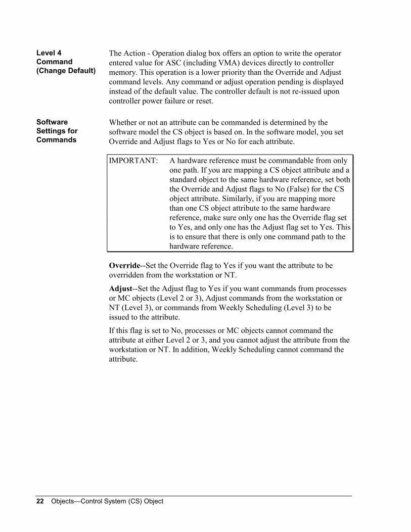
The Action - Operation dialog box offers an option to write the operatorentered value for ASC (including VMA) devices directly to controllermemory. This operation is a lower priority than the Override and Adjustcommand levels. Any command or adjust operation pending is displayedinstead of the default value. The controller default is not re-issued uponcontroller power failure or reset.
Whether or not an attribute can be commanded is determined by thesoftware model the CS object is based on. In the software model, you setOverride and Adjust flags to Yes or No for each attribute.
IMPORTANT: A hardware reference must be commandable from onlyone path. If you are mapping a CS object attribute and astandard object to the same hardware reference, set boththe Override and Adjust flags to No (False) for the CSobject attribute. Similarly, if you are mapping morethan one CS object attribute to the same hardwarereference, make sure only one has the Override flag setto Yes, and only one has the Adjust flag set to Yes. Thisis to ensure that there is only one command path to thehardware reference.
Override--Set the Override flag to Yes if you want the attribute to beoverridden from the workstation or NT.
Adjust--Set the Adjust flag to Yes if you want commands from processesor MC objects (Level 2 or 3), Adjust commands from the workstation orNT (Level 3), or commands from Weekly Scheduling (Level 3) to beissued to the attribute.
If this flag is set to No, processes or MC objects cannot command theattribute at either Level 2 or 3, and you cannot adjust the attribute from theworkstation or NT. In addition, Weekly Scheduling cannot command theattribute.
Level 4Command(Change Default)
SoftwareSettings forCommands

Objects—Control System (CS) Object 23
When you define the CS object (not software model), you specify thefollowing attributes:
NT Command Attribute--At the NT, only one attribute from each CSobject can be overridden or adjusted. Specify the one attribute that youwant to be overridden (Level 1) or adjusted (Level 3) from the NT.
Display Attribute--You define one attribute to be the CS object’s Displayattribute. The value of this attribute appears as the Current Value of the CSobject in its Focus window, in summaries containing the CS object, and atthe NT.
For example, for a CS object representing a temperature control strategy,you might want the attribute measuring room temperature to be theDisplay attribute. Then, when the System Summary containing the CSobject is displayed, the room temperature is displayed as the CS object’svalue.
The value of the Display attribute also appears as the CS object’s value atthe NT. The Display attribute can be different from the NT Commandattribute. This allows you to monitor two attributes at the NT. However,from the NT, you are able to command only the NT Command attribute.
If the CS object is included in a dynamic graphic, it is the Displayattribute’s value that appears as the CS object’s value. (You can alsographically represent other attributes of the CS object. See DefiningGraphics in the Operator Workstation User’s Manual (FAN 634) for moreinformation.)
You specify the Display and NT Command attributes in the CS ObjectDefinition window. Use the attribute name and number as it appears in thesoftware model (e.g., AI_1, AI_2, BI_1, BI_2).
You can modify these attributes in the CS Object Focus window.
NT Commandand DisplayAttributes
SoftwareSettings for NTCommand andDisplayAttributes

24 Objects—Control System (CS) Object
When a CS object first changes into an overridden state (that is, when anattribute is overridden from the workstation or NT and no other attributesare overridden), a report is sent to the destination specified by the reporttype (as long as reports are not locked and communications are notdisabled). Likewise, when the last attribute is released from override, areport is sent. The report type (Critical 1-4, Follow-Up, Status, or None) isspecified when the CS object is defined.
While any attribute of a CS object is overridden from the workstation orNT (Level 1 command), an Override prefix (SWO) appears to the left ofthe CS object in summaries, and the CS object appears in the OverrideSummary. On the NT, an asterisk (*) appears next to the name of anoverridden CS object.
In the CS Object Focus window, an asterisk (*) appears to the left ofattributes commanded at Level 1; a 2 appears to the left of attributescommanded at Level 2; and a 3 appears to the left of attributescommanded at Level 3.
To allow COS reporting for CS object attributes, map the attributes tostandard AD and BD objects. This optional function is described in thisdocument, under Optional Mapping to AD and BD Objects.
This section explains the attributes you set for COS reporting. Forcomplete information on COS reporting, refer to the Report Router/AlarmManagement Technical Bulletin (LIT-636114) in this manual, under theFeature Software tab.
The following attributes affect COS reporting:
Auto Dial-up specifies whether or not (Y or N) critical reports(Crit1-Crit4) force a dial-out to a remote OWS. If Auto Dial-up is notenabled, critical reports are stored at the NC until the buffer is full, atwhich time they are sent to the appropriate remote workstation. To enableAuto Dial-up, set this attribute to Y. To disable Auto Dial-up, set thisattribute to N. N is the default.
Report Type specifies the type of report that generate when the CS objectfirst goes into an overridden state (when a Level 1 command is issuedfrom the workstation or NT), or when the last attribute is released from anoverride. The options are: Crit1-Crit4, Follow-Up, Status, and None. Thedefault is None. If you specify None, the override state change does notgenerate a report.
Report type determines the destination and priority for reports. Forexample, all Follow-Up reports could go to an NCM printer. All Criticalreports could go to both local and remote workstations, depending on howthe report destinations are set up for your system.
COS Reporting
SoftwareSettings for COSReporting

Objects—Control System (CS) Object 25
Reports Locked specifies whether or not (Y or N) the object sends COSreports. You can lock and unlock reports using the Lock and UnlockReports commands. The Reports Locked attribute, displayed in the CSObject Focus window, signifies which command is currently in effect.
The following CS object attributes can trigger control processes:
Offline
DISCONCT (Disconnected)
all binary attributes (BD, BI, BO)
This means that when the CS object changes from online to offline (oroffline to online), it can cause a control process to trigger (execute) if it isnot exempted. Or, when one of the binary attributes of the CS objectchanges from Start to Stop (or On to Off), it can cause a control process tostart (assuming that the trigger has not been exempted or that the attributehas changed state reliably).
For further information on triggers and control processes, refer to theGPL Programmer’s Manual (FAN 631) or the JC-BASIC Programmer’sManual (FAN 632).
You can lock and unlock triggers with the Lock Triggers and UnlockTriggers communication commands. When you lock triggers, triggerableattributes cannot trigger processes. When you unlock triggers, theseattributes can trigger control processes. The Triggers Locked attribute,displayed in the CS Object Focus window, indicates which command iscurrently in effect.
Mapping a CS object attribute to an AD or BD object (as an associatedinput application) is optional and is not actually a part of CS objectfunctionality. However, by mapping attributes to ADs and BDs, you canallow:
alarm analysis and COS reporting
triggers
point history
The following is a general description of the functionality you gain bymapping CS object attributes to AD or BD objects. You’ll find completeinformation in the AD and BD object technical bulletins in this manual.
Triggers
Locking andUnlockingTriggers
OptionalMapping to ADand BD Objects

26 Objects—Control System (CS) Object
Currently, the CS object does not support alarm analysis--it reports offlineand override states only. To allow these functions, map selected attributesto AD and BD objects.
For example, to perform alarm analysis on an AI attribute, map theattribute to an AD object. Then set up limits for the AD object. The AI’svalue becomes the current value of the AD that is used or configured as anassociated input object. If the AD’s value exceeds its limits, a report canbe sent to the appropriate destination. In this way, you are informed whenthe AI attribute exceeds the values specified by the AD limits.
Currently, the triggerable attributes of the CS object are its OFFLINE andDISCONCT attributes, and all of its binary attributes (BD, BI, BO). Youcan enhance trigger functions by mapping attributes of the CS object toAD and BD objects.
For example, to trigger a process as a result of an AI attribute exceeding acertain value (changing state), map the AI attribute to an AD object and setup limits for the AD object. The Status attribute of the AD object istriggerable. If the AD’s value (actually the AI attribute’s value) exceeds itslimits, its Status attribute changes, and this can trigger a control process.
There is no Point History data collection for the CS object. You can set upPoint History for an attribute of the CS object by mapping the attribute toan AD or BD object.
For example, to set up Point History for an AO attribute of the CS object,map the AO attribute to an AD object. Then enable Point History for theAD. The AD object’s Focus window displays Point History and CurrentTrend data for the AD (which is associated with the AO attribute of the CSobject).
Notes: Issuing a command (override or adjust) to an AD or BD objectdoes not cause the associated CS object attribute value to change.If overrides/adjusts are issued to the AD or BD object, this object’spoint history records overrides/adjusts that do not reflectoverrides/adjusts issued to the associated CS object attribute.
Consider that extensive use of AD and BD objects can increaseN2 Bus traffic and slow down COS reporting (because every4 seconds all BD values are read and every 30 seconds all ADsare read.)
Alarm Analysisand COSReporting
Triggers
Point History

Objects—Control System (CS) Object 27
Database Generation
This section provides instructions for the overall process of mapping CSobjects to controllers. This process includes defining the controller,creating a software model, and defining the CS object. Before you define aCS object, make sure you understand the concepts discussed in theIntroduction section.
This section tells you how to map points in the controller to softwaremodel attributes. To do so, you need a printout of the points in thecontroller. Table 5 lists the file or document you need to print for thedifferent controller types.
Table 5: Controller and Configuration SoftwareController M-Tool Software Configuration
FileProtocol
AHU, UNT,VAV, PHX,NDM
HVAC PRO Software .PRN file* N2OPEN
VMA HVAC PRO Release 7.0 orhigher
.PRN file* N2B
LCP/DC9100 LCP ConfigurationRelease 3.2, orGC-9100 Release 3.2
.GPS configurationfile
System 9100
DX9100,XT9100
GX-9100 .DXS configurationfile
System 9100
DXECH(DX-912x)
GX-9100 Release 4.01 orhigher
.DXS configurationfile
Echelon (N2E)
XTM XTM ConfiguratorRelease 3.01
.DBF and .HMCconfiguration files
System 9100
DR9100 SM-9100 Module N/A System 9100
TC9100 HVAC PRO Software .PRN file System 9100
MIG, VND N/A Vendor-specificapplication note
N2OPEN
LONWORKSCompatibleDevices
Refer to device-specificdocumentation.
See devicemapping table
LONWORKS
* HVAC PRO software produces a .PRN file. DOS versions of HVAC PRO softwareproduce a .SYM file.
For the AHU, VAV, VMA, PHX, NDM, and TC9100, refer to theHVAC PRO User’s Manual (FAN 637.5) for information on generatingprintouts.
Overview
Mapping Pointsin theController toSoftware ModelAttributes

28 Objects—Control System (CS) Object
For DX, XTM, and XT9100 controllers, see the configuration toolmanuals for information on printouts (e.g., for information on printing the.DXS file for a DX9100, see the GX-9100 Software Configuration ToolUser’s Guide (LIT-6363060) in the System 9100 Technical Manual(FAN 636.4).
Note: Mapping points in MIG and VND devices (the vendor controllersyou are integrating with the Metasys Integrator unit) is the same asmapping points in any other ASC. For these devices, you’ll alsoneed the vendor-specific application note, which contains pointmapping tables for the vendor’s controller. For example, if thevendor controller is a Fireye device, use the point mapping tablesin the Metasys Integrator Fireye Application Application Note(LIT-6295280).
The specific information you need from the printout and configuration fileis the hardware reference (point type and point number) for the controllerpoint. You’ll use the controller point’s hardware reference when mappinga software model attribute to the controller point.
HVAC PRO software (Release 5.10 or later) and the GX-9100Configuration software (Release 3.0 and later) generate a DDL model filewhen the configuration is saved. For HVAC PRO and GX-9100(Release 4.0 or later) software, you must select the Generate DDL on Saveoption when you save the configuration. This creates a model file with a.DDL extension for ASC and a .DMO file for DX. For GX-9100(Release 3.0), the file is generated automatically when you save theconfiguration, and it has a .DMO extension. The automatically generatedmodel file includes all the defined points in the controller. To customizethe model file, simply delete and modify points as needed. For moreinformation, see the manual for the configuration tool you are using.
For AHU, UNT, VAV, VMA, NDM, TC9100, and PHX controllers, the.PRN file is automatically created when you save the controller’sconfiguration using HVAC PRO software, when the Generate .PRN onSave option is selected. The .PRN file can be printed from any text editor,or from within HVAC PRO software by selecting File, Print. Refer to theHVAC PRO User’s Manual (FAN 637.5) for more information.
Note: If you are using HVAC PRO for DOS software, the file has a.SYM extension.
AutomaticGeneration ofModel File
.PRN Files

Objects—Control System (CS) Object 29
Once you have the hard copy of the .PRN (or .SYM) file:
1. Highlight the points you want to include in the software model. Notethe hardware reference for each point you are including. Thehardware reference is the combination of the point type and pointaddress as shown in the .PRN file.
2. Look at the AHU, UNT, VAV, VMA, NDM, TC-9100, and PHXpoint mapping tables in this document to determine which softwaremodel attributes the hardware references can be mapped to.
For the System 9100 devices, print the file by loading the controller’sconfiguration into the configuration software. For the GX-9100Release 3.0 or later, select the following menu options: FILE, PRINT,ALL ITEMS. (For earlier versions, select SYSTEM, PRINT, ALLDATA.)
Once you have a hard copy of the configuration file:
1. Highlight (e.g., with a yellow marker) the points you want to includein the software model.
2. Note the description of the points you are including. For example,Analog Input #1 is the description of an analog input hardware point.Proportional Band is the description of the proportional band internalpoint of a control module.
3. From the description, use the appropriate point mapping table eitherin this document or in the appropriate technical bulletin to determinethe hardware reference for the point, whether the point can becommanded, and which software model attributes the point can bemapped to.
The following example shows portions of the DX configuration file.
The commentary (in italics) to the left of the sample printout givesadditional information on how to read the descriptions in the file.
System 9100ConfigurationFile

30 Objects—Control System (CS) Object
The hardware references for the analog inputs are simply AI1-8. This iswhere you also find the analog limit low value, which is hardwarereference LOA1-8, and the analog limit high value, hardware referenceHIA1-8. The hardware references AIH1-8 (high alarm) and AIL1-8(low alarm) are flags that indicate whether these limits are exceeded.The hardware references for analog expansion are the AI references withXTn as a prefix (i.e., XTnAI1) (see Table 17 and Table 18).Note: Only XTnAI1-6 are applicable in North America.The hardware references for DIs are DI1-8. For Counters they are CNT1-8(see Table 16 and Table 18). The references for expansion DIs areXTnDI1-8. For expansion counters they are XTnCNT1-8 (see Table 17and Table 18).
ANA IN (ACT) (AI1) - Data
User Name:
Description:
Measurement Units 0
Type of Active Input 1
High Range 100.0000
Low Range 0.0000
High Limit 30.0000
Low Limit 10.0000
Filter Constant (sec) 0.0000
Limit Differential 2.0000
Alarm Unfiltered (0=N) 0
Square Root (0=N) 0
DIGITAL IN (DI1) - Data
User Name:
Description:
Prescaler
Figure 5a: DX Configuration File Example
The hardware reference for AOs are OUT1-2 and OUT9-14(see Table 16). The hardware reference for expansion AOs are XTnAO1-8(see Table 17).
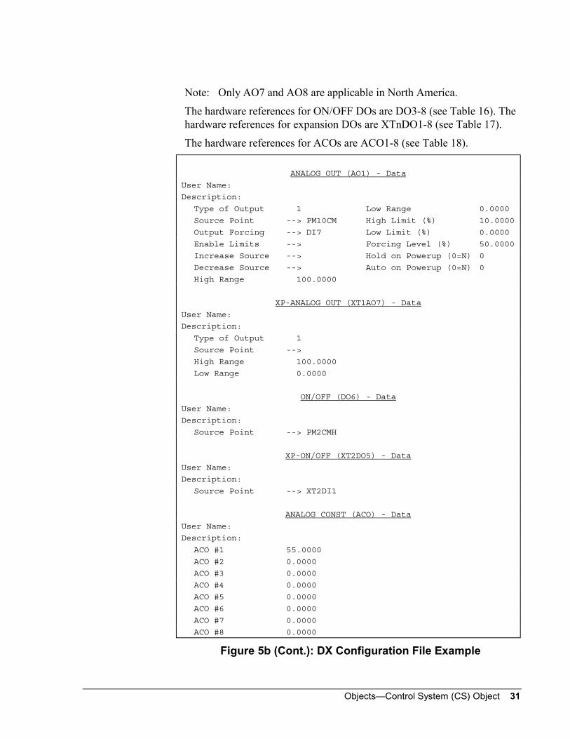
Objects—Control System (CS) Object 31
Note: Only AO7 and AO8 are applicable in North America.
The hardware references for ON/OFF DOs are DO3-8 (see Table 16). Thehardware references for expansion DOs are XTnDO1-8 (see Table 17).
The hardware references for ACOs are ACO1-8 (see Table 18).
ANALOG OUT (AO1) - Data
User Name:
Description:
Type of Output 1 Low Range 0.0000
Source Point --> PM10CM High Limit (%) 10.0000
Output Forcing --> DI7 Low Limit (%) 0.0000
Enable Limits --> Forcing Level (%) 50.0000
Increase Source --> Hold on Powerup (0=N) 0
Decrease Source --> Auto on Powerup (0=N) 0
High Range 100.0000
XP-ANALOG OUT (XT1AO7) - Data
User Name:
Description:
Type of Output 1
Source Point -->
High Range 100.0000
Low Range 0.0000
ON/OFF (DO6) - Data
User Name:
Description:
Source Point --> PM2CMH
XP-ON/OFF (XT2DO5) - Data
User Name:
Description:
Source Point --> XT2DI1
ANALOG CONST (ACO) - Data
User Name:
Description:
ACO #1 55.0000
ACO #2 0.0000
ACO #3 0.0000
ACO #4 0.0000
ACO #5 0.0000
ACO #6 0.0000
ACO #7 0.0000
ACO #8 0.0000
Figure 5b (Cont.): DX Configuration File Example

32 Objects—Control System (CS) Object
The hardware references for DCOs are DCO1-32. The hardware referencesfor LRSs are LRS1-64 (see Table 18).You can map any of the control module’s internal points to softwaremodel attributes. For example, to map the Proportional Band of a PID usehardware reference PMnK2 (see Table 22). The working setpoint ishardware reference PMmOU2, and the output is represented by referencePMmOU1.
DIGITAL CONST (DCO) - DataUser Name:Description:
DCO #1 1 DCO #17 0DCO #2 0 DCO #18 0DCO #3 0 DCO #19 0DCO #4 0 DCO #20 0DCO #5 0 DCO #21 0DCO #6 0 DCO #22 0DCO #7 0 DCO #23 0DCO #8 0 DCO #24 0DCO #9 0 DCO #25 0DCO #10 0 DCO #26 0DCO #11 0 DCO #27 0DCO #12 0 DCO #28 0DCO #13 0 DCO #29 0DCO #14 0 DCO #30 0DCO #15 0 DCO #31 0DCO #16 0 DCO #32 0
LOGIC RES1 (LRS1-32) - DataUser Name:Description:
PID (PID1) - DataUser Name:Description:
Ena Shutoff: 0=N 0 Maximum WSP -->Shutoff Out Level 0.0000 Local Set Pt. (LSP) 0.0000Ena Startup: 0=N 1 Proport. Band (PB) 4.0000Startup Out Level 0.0000 Reset Action (TI) 0.0000Ena Symm Mode: 0=N 0 Rate Action (TI) 0.0000ExtForce Out Level 0.0000 Standby Bias (BSB) 0.0000Ena PID to P: 0=N 0 Off Mode Bias (BOF) 0.0000Remote Mode: 0=N 0 Symmetry Band (SBC) 5.0000Ena OFF Trans: 0=N 0 Err Deadband (EDB) 5.0000Process Variable --> AI1 Output Bias (OB) 0.0000Remote Setpoint --> AC01 Out High Lmt (HIL) 0.0000Reference Variable--> Out Low Lmt (LOL) 0.0000Proportional Band --> Dev H.H. Limit (DHH) 10.0000OFF Mode Control --> Dev High Limit (DH) 5.0000Standby Control --> Dev Low Limit (DL) 5.0000Reverse Action --> Dev L.L. Limit (DLL) 10.0000External Forcing --> /DC01 Minimum WSP (MNWS) -50.0000Output Bias --> Maximum WSP (MXWS) 999.0000Minimum WSP -->
Figure 5c (Cont.): DX Configuration File ExampleThe outputs of the numeric modules can be mapped to a software modelattribute with many different references. In this example, the output of thiscalculation is mapped to hardware reference PMm10OU1 (see Table 23).

Objects—Control System (CS) Object 33
CALC (CALC10) - Data
User Name:
Description:
Input#n ======== Connection ======== K(n)
#0 :::::: 0
#1 --> AI3 1
#2 --> AI4 1
#3 --> 0
#4 --> 0
#5 --> 0
#6 --> 0
#7 --> 0
#8 --> 2
#9 ::::::--> 0
High Limit 100 ::::::
Low Limit 0 ::::::
Eqn (1or2) 1 ::::::
Figure 5d (Cont.): DX Configuration File Example
This section includes point mapping tables for the following devices:
AHU
VAV
MIG
PHX
VND
NDM
LCP/DC9100
DX9100/DXECH
XT9100
XTM
DR9100
TC9100
VMA
LONTCU (Metric units)
LONTCUA (American units)
LONVMA (Metric units)
LONVMAA (American units)
LONDXA (Metric units)
LONDXAA (American units)
LONDXD (Metric units)
LONDXDA (American units)
Once you know the hardware references and point descriptions from theconfiguration file, use the point mapping tables to determine whether thepoint can be commanded (second column) and which software modelattributes the points can be mapped to (last column).
Point MappingTables

34 Objects—Control System (CS) Object
The software model is made up of eight different attribute groups (AI, AO,BI, BO, AD, BD, SP, MS). However, the controllers have more pointtypes than these eight software model attribute groups. Each controllerpoint that is to appear in a given software model must be assigned to oneof the attribute groups. The controller points can be mapped to thesoftware model attribute groups as follows.
Table 6: Controller Point TypesThese Controller Point Types: Can Be Mapped to this Software Model
Attribute Group:
AI, AO, IF, ADF AI
AI, AO, IF, ADF AO
BI, BO, IB, IBy, BD BI
BI, BO, IB, IBy, BD BO
AI, AO, IF, IBy, II, ADF, ADI, BD AD
BI, BO, IB, IBy, BD BD
AI, AO, IF, ADF SP
IBy, II, ADI, BD MS
You can map controller point type ADF to any of the following softwaremodel attributes: AI, AO, AD, SP. You can map controller point type II tothe AD and MS software model attributes only. The last column of thepoint mapping tables shows which attributes each controller point can bemapped to.
Controller PointTypes

Objects—Control System (CS) Object 35
Table 7: AHU Point Mapping TableHardwareReference
Command Flag Controller PointType
Can Be Mappedto SoftwareModel Attributes
AI 1-8 Yes AI AI, AO, AD, SP
AO 1-8 Yes AO AI, AO, AD, SP
BI 1-8 Yes BI BI, BO, BD
BO 1-10 Yes BO BI, BO, BD
IF 1-128 No IF AI, AO, AD, SP
IF 129-256 Yes IF AI, AO, AD, SP
ADF 1-128 No IF AI, AO, AD, SP
ADF 129-256 Yes IF AI, AO, AD, SP
II 1-128 No II AD, MS
II 129-256 Yes II AD, MS
ADI 1-128 No II AD, MS
ADI 129-256 Yes II AD, MS
BD 1-192 No IBY BI, BO, BD, MS
BD 193-256 Yes IBY BI, BO, BD, MS
IBY 1-192 No IBY BI, BO, BD, MS
IBY 193-256 Yes IBY BI, BO, BD, MS
Table 8: UNT/VAV Point Mapping TableHardwareReference
Command Flag Controller PointType
Can Be Mappedto SoftwareModel Attributes
AI 1-6 Yes AI AI, AO, AD, SP
AO 1-8 Yes AO AI, AO, AD, SP
BI 1-5 Yes BI BI, BO, BD
BO 1-8 Yes BO BI, BO, BD
IF 1-128 No IF AI, AO, AD, SP
IF 129-256 Yes IF AI, AO, AD, SP
ADF 1-128 No IF AI, AO, AD, SP
ADF 129-256 Yes IF AI, AO, AD, SP
II 1-224 No II AD, MS
II 225-256 Yes II AD, MS
ADI 1-224 No II AD, MS
ADI 225-256 Yes II AD, MS
BD 1-224 No IBY BI, BO, BD, MS
BD 225-256 Yes IBY BI, BO, BD, MS
IBY 1-224 No IBY BI, BO, BD, MS
IBY 225-256 Yes IBY BI, BO, BD, MS
AHU PointMapping
UNT/VAV PointMapping

36 Objects—Control System (CS) Object
Table 9: VMA Point Mapping TableHardwareReference
CommandFlag
ChangeDefault
ControllerPoint Type
Can BeMapped toSoftwareModelAttributes
AI1-AI5 Yes No AI AI, AO, AD, SP
BI1-BI3 Yes No BI BI, BO, BD
AO1-AO2 Yes No AO AI, AO, AD, SP
BO1-BO6 Yes No BO BI, BO, BD
ADF1-ADF64 No No IF AI, AO, AD, SP
ADF65-ADF160 Yes No IF AI, AO, AD, SP
ADF161-ADF256 Yes Yes IF AI, AO, AD, SP
ADI1-ADI64 No No II AD, MS
ADI65-ADI160 Yes No II AD, MS
ADI161-ADI256 Yes Yes II AD, MS
BD1-BD64 No No IBY BI, BO, BD, MS
BD65-BD160 Yes No IBY BI, BO, BD, MS
BD161-BD256 Yes Yes IBY BI, BO, BD, MS
IF1-IF64 No No IF AI, AO, AD, SP
IF65-IF160 Yes No IF AI, AO, AD, SP
IF161-IF256 Yes Yes IF AI, AO, AD, SP
II1-II64 No No II AD, MS
II65-II160 Yes No II AD, MS
II161-II256 Yes Yes II AD, MS
IBY1-IBY64 No No IBY BI, BO, BD, MS
IBY65-IBY160 Yes No IBY BI, BO, BD, MS
IBY161-IBY256 Yes Yes IBY BI, BO, BD, MS
VMA PointMapping

Objects—Control System (CS) Object 37
Table 10: MIG Point Mapping TableHardwareReference
Command Flag(See Note.)
Can Be Mapped to Software ModelAttributes
AI 1-256 Yes AI, AO, AD, SP
AO 1-256 Yes AI, AO, AD, SP
BI 1-256 Yes BI, BO, BD
BO 1-256 Yes BI, BO, BD
ADF 1-256 Yes AI, AO, AD, SP
ADI 1-256 Yes AD, MS
BD 1-256 Yes BI, BO, BD, MS
Note: Though all points can be commanded, only with AO and BO points are thecommands actually sent to the controller.
Table 11: PHX Point Mapping TableHardwareReference
Command Flag Controller PointType
Can Be Mappedto SoftwareModel Attributes
AI 1-40 Yes AI AI, AO, AD, SP
AO 1-8 Yes AO AI, AO, AD, SP
BI 1-37 Yes BI BI, BO, BD
BO 1-14 Yes BO BI, BO, BD
IF 1-64 No IF AI, AO, AD, SP
IF 65-256 Yes IF AI, AO, AD, SP
ADF 1-64 No IF AI, AO, AD, SP
ADF 65-256 Yes IF AI, AO, AD, SP
II 1-64 No II AD, MS
II 65-256 Yes II AD, MS
ADI 1-64 No II AD, MS
ADI 65-256 Yes II AD, MS
BD 1-64 No IBY BI, BO, BD, MS
BD 65-256 Yes IBY BI, BO, BD, MS
IBY 1-64 No IBY BI, BO, BD, MS
IBY 65-56 Yes IBY BI, BO, BD, MS
MIG PointMapping
PHX PointMapping
38 Objects—Control System (CS) Object
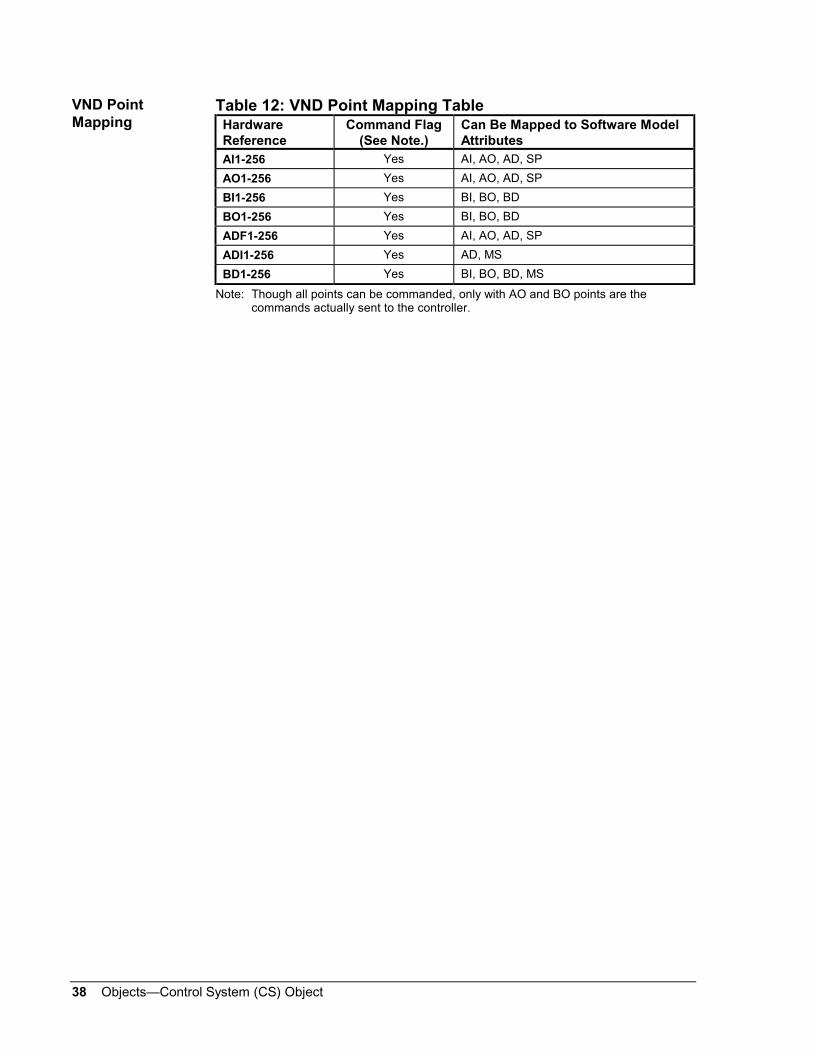
Table 12: VND Point Mapping TableHardwareReference
Command Flag(See Note.)
Can Be Mapped to Software ModelAttributes
AI1-256 Yes AI, AO, AD, SP
AO1-256 Yes AI, AO, AD, SP
BI1-256 Yes BI, BO, BD
BO1-256 Yes BI, BO, BD
ADF1-256 Yes AI, AO, AD, SP
ADI1-256 Yes AD, MS
BD1-256 Yes BI, BO, BD, MS
Note: Though all points can be commanded, only with AO and BO points are thecommands actually sent to the controller.
VND PointMapping

Objects—Control System (CS) Object 39
Note: When mapping software model attributes to NDM points, you mayset the Adjust flag to Yes, but do not set the Override flag to Yes.Overriding these points could result in the displayed value notreflecting the actual value of the point in the controller.
Table 13: NDM Point Mapping TableLocal orRemoteNDM
HardwareReference
CommandFlag
Can Be Mappedto Software
Model Attributes
Description Range
Local ADI1 AD, MS
(advised MS)
Connection Status 0 = idle1 = dialing2 = connected3 = retry4 = failed
Local ADI65 Yes AD, MS
(advised MS)
Dial Command -phone number indexto be dialed (0-50).
-1=remote connect0=disconnect1-50=phone number index
Local ADI66 Yes AD, MS
(advised MS)
Disconnect Control -when to disconnect.
0 = normal disconnectdelay1 = 4.0 hour delay2 = never hang up
Both BD66 Yes AD Number of retries fordialing.
0-100
Both BD67 Yes AD Dial Delay - numberof minutes betweensuccessive retries.
1-30
Local BD68 Yes AD Disconnect Delay -number of minutes towait beforedisconnecting.
1-255
Both BD69 Yes AD Modem Connect Time -maximum time inseconds to wait forthe modem toconnect.
30-255
Remote BD70 Yes AD Online Poll Count -number of onlinedevices to poll beforeoffline devices.
1-255
Remote BD71 Yes AD Offline Poll Count -number of offlinedevices to poll beforeonline devices.
1-255
Remote BD72 Yes AD, BD
(advised BD)
Remote NDM Dial InControl
0 = dial in on alarm COS
1 = no dial in on alarm COS
Remote BD73 Yes AD Idle Timeout - after adial in, the remoteNDM hangs up if noN2 communication isdetected for theduration of the idletimeout.
1-255
NDM PointMapping

40 Objects—Control System (CS) Object
Table 14: LCP/DC9100 Point Mapping Table--Hardware PointsDescription Hardware
ReferenceCommand Flag Controller Point
TypeCan Be Mappedto SoftwareModel Attributes
Analog Input 1-8 AI1-8 No AI AI
Digital Input 1-8 DI1-8 No BI BI
Analog Output 1-2 OUT1-2 Yes1 AO AI, AO
Digital Output 3-8 DO3-8 Yes2 BO BI, BO, BD
Value of AnalogSource DO3-8
OUT3-8 Yes1 AO AI, AO, AD, SP
Notes: 1 Commands also set and reset OUT-HOLD items.2 Commands also set and reset Supervisory Enable items.
LCP/DC9100Point Mapping

Objects—Control System (CS) Object 41
Table 15: LCP/DC9100 Point Mapping Table--Internal PointsDescription Hardware
ReferenceCommand Flag Controller Point
TypeCan Be Mappedto SoftwareModel Attributes
Working SetpointControl Module 1-8
WSP1-8 Yes1 IF AD, SP
Output Control Module 1-8 OCM1-8 Yes2 IF AD, SP
Shut Off SOFF Yes IBy BD
Start Up STUP Yes IBy BD
Local SetpointControl Module 1-8
LSP1-8 Yes IF AD, SP
Output High LimitControl Module 1-8
HIL1-8 Yes IF AD, SP
Output Low LimitControl Module 1-8
LOL1-8 Yes IF AD, SP
Standby STP ChangeControl Module 1-8
BSB1-8 Yes IF AD, SP
Off Mode STP ChangeControl Module 1-8
BOF1-8 Yes IF AD, SP
Proportional BandControl Module 1-8
PB1-8 Yes IF AD, SP
Reset ActionControl Module 1-8
TI1-8 Yes IF AD, SP
Rate ActionControl Module 1-8
TD1-8 Yes IF AD, SP
Deviation Alarm LimitControl Module 1-8
DA1-8 Yes IF AD, SP
Value of High LimitAnalog Input 1-8
HIA1-8 Yes IF AD, SP
Value of Low LimitAnalog Input 1-8
LOA1-8 Yes IF AD, SP
Symmetry BandControl Module 5,6
SBC5-6 Yes IF AD, SP
High Alarm FlagAnalog Input 1-8
AIH1-8 No IBy BD
Low Alarm FlagAnalog Input 1-8
AIL1-8 No IBy BD
Output LogicModule 1-4
LCM1-4 No IBy BD
Analog Constant 1-4 ACO1-4 Yes IF AD, SP
Digital Constant 1-4 DCO1-4 Yes IBy BI, BO, BD
Output NumericModule 1-4
NCM1-4 No IF AD, SP
Timer Module Outputs NCMnm n=1-4,m=1-4
No IBy BD
Maintenance Flag MNT Yes IBy BD
Counter Value 1, 23 TOTAL1-2 Yes II AD
Notes: 1 Commands also set and reset Computer Mode items.2 Commands also set and reset CM-HOLD items.3 DO9100 only.

42 Objects—Control System (CS) Object
Table 16: DX9100/DXECH Hardware PointsDescription Hardware
ReferenceCommand Flag Controller Point
TypeCan Be Mappedto SoftwareModel Attributes
Analog Input 1-8 AI1-8 No AI AI
Digital Input 1-8 DI1-8 No BI BI
Analog Output 1-2 OUT1-2 Yes1 AO AO, AD, SP
Analog Output 9-10 OUT9-10 Yes AO AO, AD, SP
Analog Outputs 11-14 OUT11-14 Yes AO AO, AD, SP
Digital Output 3-8 DO3-8 Yes2,3 BO BI, BO, BD
Value of analog SourceDO3-8
OUT3-8 Yes1 AO AO, AD, SP
Notes: 1 Commands also set and reset OUT-HOLD items.
2 Commands also set and reset Supervisory Enable items.
3 Hardware reference eligible for COS reporting when defined on DXECH.
Table 17: Hardware Points from Extension Bus (from XT9100)Description Hardware
ReferenceCommand Flag Controller Point
TypeCan Be Mappedto SoftwareModel Attributes
XTn Analog Input 1-8 XTnAI1-8 No 3,4 AI AI
XTn Digital Input 1-8 XTnDI1-8 No 3,4 BI BI
XTn Analog Output XtnAO1-8 Yes 1,4 AO AO,AD,SP
XTn Digital Output 1-8 XTnDO1-8 Yes 1,3,4 BO BO
Counter Value XTnDigital Input 1-8
XTnCNT1-8 Yes II AD
XTn Digital Output 1-8 XTnDO1-8 Yes1 BO BO
n = 1-8
Notes: 1 Commands also set and reset OUT-HOLD items.
2 Commands also set and reset Supervisory Enable items.
3 Hardware reference eligible for COS reporting when defined on DX91ECH.
4 For all DX devices with Metasys Release 10.0 or later.
XT-9100 devices connected to a DX-9100 device using an XT Busmust not be mapped to Metasys as hardware objects. Communication andcontrol problems occur if you map an XT-9100 in this manner. XT-9100devices connected to a DXECH (DX-912X) cannot be mapped ashardware devices.
All XT-9100 points must be mapped using the DX-9100/DXECHhardware reference. Refer to Table 17 for valid point mapping.
DX9100/DXECHPoint Mapping
XT9100HardwareMapping
Objects—Control System (CS) Object 43
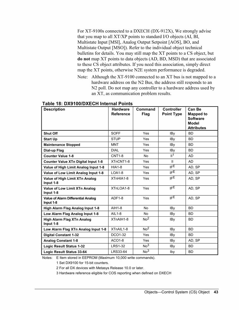
For XT-9100s connected to a DXECH (DX-912X), We strongly advisethat you map to all XT/XP points to standard I/O objects (AI, BI,Multistate Input [MSI], Analog Output Setpoint [AOS], BO, andMultistate Output [MSO]). Refer to the individual object technicalbulletins for details. You may still map the XT points to a CS object, butdo not map XT points to data objects (AD, BD, MSD) that are associatedto these CS object attributes. If you need this association, simply directmap the XT points, otherwise N2E system performance is degraded.
Note: Although the XT-9100 connected to an XT bus is not mapped to ahardware address on the N2 Bus, the address still responds to anN2 poll. Do not map any controller to a hardware address used byan XT, as communication problem results.
Table 18: DX9100/DXECH Internal PointsDescription Hardware
ReferenceCommand
FlagControllerPoint Type
Can BeMapped toSoftwareModelAttributes
Shut Off SOFF Yes IBy BD
Start Up STUP Yes IBy BD
Maintenance Stopped MNT Yes IBy BD
Dial-up Flag DIAL Yes IBy BD
Counter Value 1-8 CNT1-8 No II1 AD
Counter Value XTn Digital Input 1-8 XTnCNT1-8 Yes II AD
Value of High Limit Analog Input 1-8 HIA1-8 Yes IFE AD, SP
Value of Low Limit Analog Input 1-8 LOA1-8 Yes IFE AD, SP
Value of High Limit XTn AnalogInput 1-8
XTnHIA1-8 Yes IFE AD, SP
Value of Low Limit XTn AnalogInput 1-8
XTnLOA1-8 Yes IFE AD, SP
Value of Alarm Differential AnalogInput 1-8
ADF1-8 Yes IFE AD, SP
High Alarm Flag Analog Input 1-8 AIH1-8 No IBy BD
Low Alarm Flag Analog Input 1-8 AIL1-8 No IBy BD
High Alarm Flag XTn AnalogInput 1-8
XTnAIH1-8 No2 IBy BD
Low Alarm Flag XTn Analog Input 1-8 XTnAIL1-8 No2 IBy BD
Digital Constant 1-32 DCO1-32 Yes IBy BD
Analog Constant 1-8 ACO1-8 Yes IBy AD, SP
Logic Result Status 1-32 LRS1-32 No3 IBy BD
Logic Result Status 33-64 LRS33-64 No3 Iby BD
Notes: E Item stored in EEPROM (Maximum 10,000 write commands).
1 Set DX9100 for 15-bit counters.
2 For all DX devices with Metasys Release 10.0 or later.
3 Hardware reference eligible for COS reporting when defined on DXECH
44 Objects—Control System (CS) Object
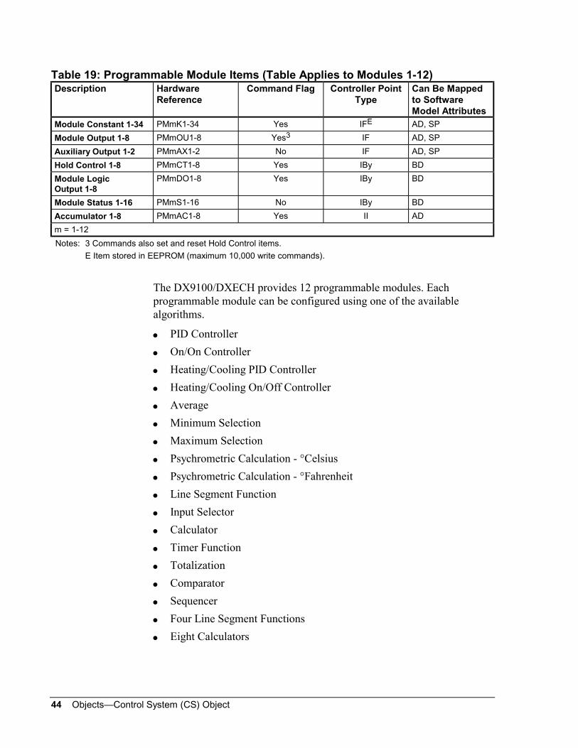
Table 19: Programmable Module Items (Table Applies to Modules 1-12)Description Hardware
ReferenceCommand Flag Controller Point
TypeCan Be Mappedto SoftwareModel Attributes
Module Constant 1-34 PMmK1-34 Yes IFE AD, SP
Module Output 1-8 PMmOU1-8 Yes3 IF AD, SP
Auxiliary Output 1-2 PMmAX1-2 No IF AD, SP
Hold Control 1-8 PMmCT1-8 Yes IBy BD
Module LogicOutput 1-8
PMmDO1-8 Yes IBy BD
Module Status 1-16 PMmS1-16 No IBy BD
Accumulator 1-8 PMmAC1-8 Yes II AD
m = 1-12
Notes: 3 Commands also set and reset Hold Control items.
E Item stored in EEPROM (maximum 10,000 write commands).
The DX9100/DXECH provides 12 programmable modules. Eachprogrammable module can be configured using one of the availablealgorithms.
PID Controller
On/On Controller
Heating/Cooling PID Controller
Heating/Cooling On/Off Controller
Average
Minimum Selection
Maximum Selection
Psychrometric Calculation - °Celsius
Psychrometric Calculation - °Fahrenheit
Line Segment Function
Input Selector
Calculator
Timer Function
Totalization
Comparator
Sequencer
Four Line Segment Functions
Eight Calculators

Objects—Control System (CS) Object 45
The mapping of the items from Table 19 to these algorithms is shown laterin Table 22 and Table 23.
Table 20: Time Scheduling and Optimization Items (DX9100/DXECH)Description Hardware
ReferenceCommand Flag Controller Point
TypeCan Be Mappedto SoftwareModel Attributes
ON Extension TSModule
TSnEXS Yes4 IBy BD
Output Status TSModule
TSnOUTn = 1-8
Yes5 IBy BD
Output Status OSModule
OSxOUT Yes5 IBy BD
Optimizer Status OSModule
OSxPRE No IBy BD
Operating Mode OSModule
OSxHEAT No IBy BD
Optimal Stop Status OSModule
OSxSTO No IBy BD
Zone Temperature SetPoint OS Module
OSxSP Yes IF AD, SP
Zone Temperature OffBias OS Module
OSxOB Yes IF AD, SP
Minimum Heat/CoolTime OS Module
OSxPRG Yes IF AD
Start Mode BuildingFactor (Heating) OSModule
OSxBHK Yes IF AD
Start Mode BuildingFactor (Cooling) OSModule
OSxBCK Yes IF AD
Stop Mode BuildingFactor (Heating) OSModule
OSxSBHK Yes IF AD
Stop Mode BuildingFactor (Cooling) OSModule
OSxSBCK Yes IF AD
Optimal Start-up TimeOS Module
OSxTIMx = 1-2
No IF AD
Notes: 4 Commands also set TSnEXT items.5 Commands also set and reset Hold items.

46 Objects—Control System (CS) Object
Table 21: DXECH (DX-912X) Network VariablesDescription Hardware
ReferenceCommand Flag Controller Point
TypeCan Be Mappedto SoftwareModel Attributes
Network AnalogInput 1-16
NAI1-16 Yes IF AD
Network Digital Inputs NDIm-n Yes IBy BD
Network AnalogOutput 1-16
NAO1-16 No IF AD
Network DigitalOutputs
NDOm-n No IBy BD
m = 1-8 (module),n = 1-16 (input)
Table 22 below is the Item list for the following programmable algorithms(the remaining algorithms are shown in Table 23):
PID Control
On/Off Control
Heating/Cooling PID Control
Heating/Cooling On/Off Control
Average
Minimum Select
Maximum Select
Psychrometric Calculation °C
Psychrometric Calculation °F
Line Segment

Objects—Control System (CS) Object 47
Table 22: DX9100/DXECH Programmable Algorithms, Part 1GeneralItem Name
PID On/Off Dual PID DualOn/Off
Average,Minimum,Maximum
Psychro-metric
LineSegment
Notes
PMmK 1 LSP LSP LSP1 LSP1 K0 - X0
2 PB ACT PB1 ACT1 K1 - Y0
3 TI DIF TI1 DIF1 K2 - X1
4 TD - TD1 - K3 - Y1
5 BSB BSB BSB1 BSB1 K4 - X2
6 BOF BOF BOF1 BOF1 K5 - Y2
7 SBC SBC - - K6 - X3
8 EDB - EDB1 - K7 - Y3
9 OB - OB1 - K8 - X4
10 MNWS MNWS MNWS MNWS - - Y4
11 HIL - HIL1 - HIL HIL1 X5
12 LOL - LOL1 - LOL LOL1 Y5
13 DHH DHH DHH1 DHH1 - ATP1 X6
14 DH DH DH1 DH1 - - Y6
15 DL DL DL1 DL1 - - X7
16 DLL DLL DLL1 DLL1 - - Y7
17 MXWS MXWS MXWS MXWS - - X8
18 - - LSP2 LSP2 - - Y8
19 - - PB2 ACT2 - - X9
20 - - TI2 DIF2 - - Y9
21 - - TD2 - - - X10
22 - - BSB2 BSB2 - - Y10
23 - - BOF2 BOF2 - - X11
24 - - EDB2 - - - Y11
25 - - OB2 - - - X12
26 SOL - SOL - - - Y12
27 STL - STL - - - X13
28 - - HIL2 - - HIL2 Y13
29 - - LOL2 - - LOL2 X14
30 - - DHH2 DHH2 - ATP2 Y14
31 - - DH2 DH2 - - X15
32 - - DL2 DL2 - - Y15
33 - - DLL2 DLL2 - - X16
PMmK34 EFL - EFL - - - Y16
PMmOU1 OCM - OCM - NCM NCM1 NCM 6
2 WSP WSP WSP1 WSP1 - NCM2 - 7
3 - - WSP2 WSP2 - - - 7
4 PV PV PV PV - - -
5 PVS PVS PVS PVS - - -
Continued on next page . . .
Notes: 6 Commands also set and reset HLD items.7 Commands also set and reset CMP items.

48 Objects—Control System (CS) Object
GeneralItem Name(Cont.)
PID On/Off Dual PID DualOn/Off
Average,Minimum,Maximum
Psychro-metric
LineSegment
Notes
6 PVL PVL PVL PVL - - -
7 RSP RSP RSP RSP - - -
PMmOU8 RV RV RV RV - - -
PMmAX1 - - OCM1 - - - -
PMmAX2 - - OCM2 - - - -
PMmCT1 HLD HLD HLD HLD HLD HLD1 HLD
2 CMP CMP CMP CMP - HLD2 -
3 - - - - - - -
4 - - - - - - -
5 - - - - - - -
6 - - - - - - -
7 - - - - - - -
PMmCT8 - - - - - - -
PMmDO1 - OCM - OCM - - -
2 - - - OCM1 - - -
3 - - - OCM2 - - -
4 - - - - - - -
5 - - - - - - -
6 - - - - - - -
7 - - - - - - -
PMmDO8 - - - - - - -
PMmS1 CML CML CML CML NML NML1 NML
2 CMH CMH CMH CMH NMH NMH1 NMH
3 FORC - FORC - - NML2 -
4 - - - - - NMH2 -
5 LLDA LLDA LLDA LLDA - - -
6 LDA LDA LDA LDA - - -
7 HDA HDA HDA HDA - - -
8 HHDA HHDA HHDA HHDA - - -
9 SOF SOF SOF SOF - - -
10 STA STA STA STA - - -
11 EF EF EF EF - - -
12 OF OF OF OF - - -
13 SB SB SB SB - - -
14 RA RA RA RA - - -
15 HEAT HEAT HEAT HEAT - - -
PMmS16 - - - - - - -

Objects—Control System (CS) Object 49
Table 23 is the Item list for the following programmable algorithms:
Input Selector
Calculator
Timer Function
Totalization
Comparator
Sequencer
Four Line Segment Functions
Eight Calculators
Table 23: DX9100/DXECH Programmable Module Algorithms, Part 2GeneralItemName
InputSelector
Calcu-lator
Timer Totali-zation
Compa-rator
Sequencer FourLineSegment
EightCalculators
Notes
PMmK1 K1 K0 T1 FSL1 SP1 OLF1 X0-1 K1-1
2 C1 K1 T2 FSL2 DF1 OLF2 Y0-1 K2-1
3 K2 K2 T3 FSL3 SP2 OLF3 X1-1 K1-2
4 C2 K3 T4 FSL4 DF2 OLF4 Y1-1 K2-2
5 K3 K4 T5 FSL5 SP3 OLF5 X2-1 K1-3
6 C3 K5 T6 FSL6 DF3 OLF6 Y2-1 K2-3
7 K4 K6 T7 FSL7 SP4 OLF7 X3-1 K1-4
8 C4 K7 T8 FSL8 DF4 OLF8 Y3-1 K2-4
9 - K8 - FTC1 SP5 T1 X0-2 K1-5
10 - K9 - FTC2 DF5 T2 Y0-2 K2-5 1
11 HIL HIL - FTC3 SP6 T3 X1-2 K1-6
12 LOL LOL - FTC4 DF6 T4 Y1-2 K2-6
13 - - - FTC5 SP7 T5 X2-2 K1-7
14 - - - FTC6 DF7 T4F Y2-2 K2-7
15 - - - FTC7 SP8 T5F X3-2 K1-8
16 - - - FTC8 DF8 TON Y3-2 K2-8
17 - - - - - TOFF X0-3 -
18 - - - - - MAXC Y0-3 -
19 - - - - - FLR X1-3 -
20 - - - - - LDF Y1-3 -
21 - - - - - - X2-3 -
22 - - - - - - Y2-3 -
23 - - - - - - X3-3 -
24 - - - - - - Y3-3 -
25 - - - - - - X0-4 -
26 - - - - - - Y0-4 -
Continued on next page . . .
Note: 1 Only for Equation 2.

50 Objects—Control System (CS) Object
GeneralItem Name(Cont.)
InputSelector
Calcu-lator
Timer Totali-zation
Compa-rator
Sequencer FourLineSegment
EightCalculators
Notes
27 - - - - - - X1-4 -
28 - - - - - - Y1-4 -
29 - - - - - - X2-4 -
30 - - - - - - Y2-4 -
31 - - - - - - X3-4 -
32 - - - - - - Y3-4 -
33 - - - - - - - -
PMmK34 - - - - - - - -
PMmOU1 NCM NCM TIM1 TOT1 NCM1 OUT NCM1 NCM1 6
2 - - TIM2 TOT2 NCM2 OUTD NCM2 NCM2 6
3 - - TIM3 TOT3 NCM3 OUTS NCM3 NCM3 6
4 - - TIM4 TOT4 NCM4 - NCM4 NCM4 6
5 - - TIM5 TOT5 NCM5 - - NCM5 6
6 - - TIM6 TOT6 NCM6 - - NCM6 6
7 - - TIM7 TOT7 NCM7 - - NCM7 6
PMmOU8 - - TIM8 TOT8 NCM8 - - NCM8 6
PMmAX1 - - - - - - - -
PMmAX2 - - - - - - - -
PMmCT1 HLD HLD HLD1 HLD1 HLD1 HLD1 HLD1 HLD1
2 - - HLD2 HLD2 HLD2 HLD2 HLD2 HLD2
3 - - HLD3 HLD3 HLD3 HLD3 HLD3 HLD3
4 - - HLD4 HLD4 HLD4 HLD4 HLD4 HLD4
5 - - HLD5 HLD5 HLD5 HLD5 - HLD5
6 - - HLD6 HLD6 HLD6 HLD6 - HLD6
7 - - HLD7 HLD7 HLD7 HLD7 - HLD7
PMmCT8 - - HLD8 HLD8 HLD8 HLD8 - HLD8
PMmDO1 - - TDO1 - - STO1 - -
2 - - TDO2 - - STO2 - -
3 - - TDO3 - - STO3 - -
4 - - TDO4 - - STO4 - -
5 - - TDO5 - - STO5 - -
6 - - TDO6 - - STO6 - -
7 - - TDO7 - - STO7 - -
PMmDO8 - - TDO8 - - STO8 - -
PMmS1 NML NML - FSS1 LS1 DIS1 - -
2 NMH NMH - FSS2 LS2 DIS2 - -
3 - - - FSS3 LS3 DIS3 - -
4 - - - FSS4 LS4 DIS4 - -
5 - - - FSS5 LS5 DIS5 - -
Continued on next page . . .
Note: 6 Commands also set and reset HLD items.

Objects—Control System (CS) Object 51
GeneralItem Name(Cont.)
InputSelector
Calcu-lator
Timer Totali-zation
Compa-rator
Sequencer FourLineSegment
EightCalculators
Notes
6 - - - FSS6 LS6 DIS6 - -
7 - - - FSS7 LS7 DIS7 - -
8 - - - FSS8 LS8 DIS8 - -
9 - - - - - MCS1 - -
10 - - - - - MCS2 - -
11 - - - - - MCS3 - -
12 - - - - - MCS4 - -
17 - - - - - MCS5 - -
14 - - - - - MCS6 - -
15 - - - - - MCS7 - -
PMmS16 - - - - - MCS8 - -
PMmAC1 - - - ACT1 - RT1 - -
2 - - - ACT2 - RT2 - -
3 - - - ACT3 - RT3 - -
4 - - - ACT4 - RT4 - -
5 - - - ACT5 - RT5 - -
6 - - - ACT6 - RT6 - -
7 - - - ACT7 - RT7 - -
PMmAC8 - - - ACT8 - RT8 - -
Table 24: XT9100 and XTM Hardware PointsDescription Hardware
ReferenceCommand Flag Controller Point
TypeCan Be Mapped to
Software ModelAttributes
Analog Input 1-8 AI1-8 No AI AI
Digital Input 1-16 1DI1-82DI1-8
No BI BI
Analog Output 1-8 AO1-8 Yes AO AO, AD, SP
Digital Output 1-16 1DO1-82DO1-8
Yes BO BO, BD
XT9100 and XTMPoint Mapping

52 Objects—Control System (CS) Object
Table 25: XT9100 and XTM Internal PointsDescription Hardware
ReferenceCommand Flag Controller Point
TypeCan Be Mapped
to SoftwareModel Attributes
Counter Value 1-8 CNT1-8 Yes II AD
Value of High LimitAnalog Input 1-8
HIA1-8 Yes IFE AD, SP
Value of Low LimitAnalog Input 1-8
LOA1-8 Yes IFE AD, SP
Value of DifferentialAnalog Input 1-8
ADF1-8 Yes IFE AD, SP
High Alarm FlagAnalog Input 1-8
AIH1-8 No IBy BD
Low Alarm Flag AnalogInput 1-8
AIL1-8 No IBy BD
Note: E Item stored in EEPROM (maximum 10,000 write commands).
Table 26: DR9100 Point Mapping Table--Hardware PointsDescription Hardware
ReferenceCommand Flag Controller Point
TypeCan Be Mapped
to SoftwareModel Attributes
Analog Input 1-6 AI1-6 No AI AI
Window Contact WIN No BI BI
Occupancy Sensor OCC No BI BI
Air Quality Sensor AIRQ No BI BI
Digital Output 3-7 DO3-7 Yes1 BO BI, BO, BD
Note: 1 Commands also set and reset Supervisory Enable items.
DR9100 PointMapping

Objects—Control System (CS) Object 53
Table 27: DR9100 Point Mapping Table--Internal PointsDescription Hardware
ReferenceCommand Flag Controller Point
TypeCan Be Mapped
to SoftwareModel Attributes
Working SetpointControl Module 1-6
WSP1-6 Yes2 IF AD, SP
Output ControlModule 1-6
OCM1-6 Yes3 IF AD, SP
Shut Off SOFF Yes IBy BD
Start Up STUP Yes IBy BD
Mode CommandComfort-Standby-Off
MODC Yes IBy MS
Mode StatusComfort-Standby-Off
MODS No IBy MS
Day Mode DAY Yes IBy BD
Manual Mode MAN Yes IBy BD
Local SetpointControl Module 1-6
LSP1-6 Yes IFE AD, SP
Output High LimitControl Module 1-6
HIL1-6 Yes IFE AD, SP
Output Low LimitControl Module 1-6
LOL1-6 Yes IFE AD, SP
Standby STP ChangeControl Module 1-6
BSB1-6 Yes IFE AD, SP
Off Mode STP ChangeControl Module 1-6
BOF1-6 Yes IFE AD, SP
Proportional BandControl Module 1-6
PB1-6 Yes IFE AD, SP
Reset ActionControl Module 1-6
TI1-6 Yes IFE AD, SP
Value of High LimitAnalog Input 1-4
HIA1-4 Yes IFE AD, SP
Value of Low LimitAnalog Input 1-4
LOA1-4 Yes IFE AD, SP
Symmetry BandControl Module 5,6
SBC5-6 Yes IFE AD, SP
High Alarm FlagAnalog Input 1-4
AIH1-4 No IBy BD
Low Alarm FlagAnalog Input 1-4
AIL1-4 No IBy BD
Analog Constant 1-8 ACO1-8 Yes IF AD, SP
Output NumericModule
NCM0 No IF AD, SP
Maintenance Flag MNT Yes IBy BD
Reverse ActionCommand
REVC Yes IBy BD
Reverse Action LocalContact
REVL No IBy BI, BD
Notes: 2 Commands also set and reset Computer Mode items.3 Commands also set and reset CM-HOLD items.E Item stored in EEPROM (maximum 10,000 write commands).

54 Objects—Control System (CS) Object
Table 28: TC9100 Point Mapping Table--Hardware PointsDescription Hardware
ReferenceCommand Flag Controller Point
TypeCan Be Mapped
to SoftwareModel Attributes
Analog Input 1-4 AI1-4 No AI AI
Window Contact WIN No BI BI
Occupancy Sensor OCC No BI BI
Air Quality Sensor AIRQ No BI BI
General Alarm ALM No BI BI
Digital Output 1-7 DO1-7 Yes1 BO BI, BO, BD
Note: 1 Commands also set and reset Supervisory Enable items.
Table 29: TC9100 Point Mapping Table--Internal PointsDescription Hardware
ReferenceCommand Flag Controller Point
TypeCan Be Mapped
to SoftwareModel Attributes
Working SetpointControl Module 1-6
WSP1-6 Yes2 IF AD, SP
Output ControlModule 1-6
OCM1-6 Yes3 IF AD, SP
Shut Off SOFF Yes IBy BD
Start Up STUP Yes IBy BD
Mode CommandOff-Comfort-Stdby-Night
MODC Yes IBy MS
Mode StatusOff-Comfort-Stdby-Night
MODS No IBy MS
Antifreeze Mode Active AFM No IBy BD
Three Speed Fan Ovrd. FOV No IBy BD
Alternate Mode ALT No IBy BD
Manual Mode MAN Yes IBy BD
Constant 1,Control Module n,(n=1-6)
PMnK1 Yes IFE AD, SP
Constant 2,Control Module n,(n=1-6)
PMnK2 Yes IFE AD, SP
Constant 3,Control Module n,(n=1-6)
PMnK3 Yes IFE AD, SP
Constant 4,Control Module n,(n=1-6)
PMnK4 Yes IFE AD, SP
Continued on next page . . .
Notes: 2 Commands also set and reset Computer Mode items.
3 Commands also set and reset CM-HOLD items.
E Item stored in EEPROM (maximum 10,000 write commands).
TC9100 PointMapping
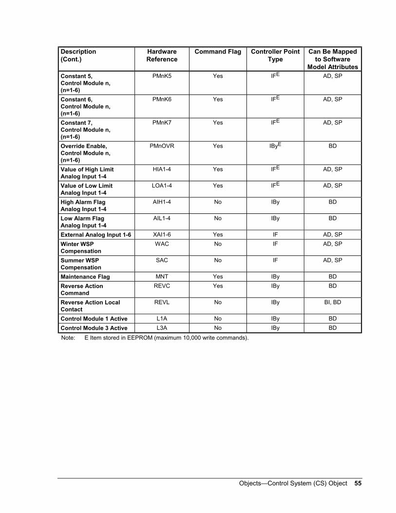
Objects—Control System (CS) Object 55
Description(Cont.)
HardwareReference
Command Flag Controller PointType
Can Be Mappedto Software
Model AttributesConstant 5,Control Module n,(n=1-6)
PMnK5 Yes IFE AD, SP
Constant 6,Control Module n,(n=1-6)
PMnK6 Yes IFE AD, SP
Constant 7,Control Module n,(n=1-6)
PMnK7 Yes IFE AD, SP
Override Enable,Control Module n,(n=1-6)
PMnOVR Yes IByE BD
Value of High LimitAnalog Input 1-4
HIA1-4 Yes IFE AD, SP
Value of Low LimitAnalog Input 1-4
LOA1-4 Yes IFE AD, SP
High Alarm FlagAnalog Input 1-4
AIH1-4 No IBy BD
Low Alarm FlagAnalog Input 1-4
AIL1-4 No IBy BD
External Analog Input 1-6 XAI1-6 Yes IF AD, SP
Winter WSPCompensation
WAC No IF AD, SP
Summer WSPCompensation
SAC No IF AD, SP
Maintenance Flag MNT Yes IBy BD
Reverse ActionCommand
REVC Yes IBy BD
Reverse Action LocalContact
REVL No IBy BI, BD
Control Module 1 Active L1A No IBy BD
Control Module 3 Active L3A No IBy BD
Note: E Item stored in EEPROM (maximum 10,000 write commands).

56 Objects—Control System (CS) Object
Notes: When an input network variable or configuration parameter ismapped to a CS object, and the Command Flag in the SoftwareModel is Yes, the last value of the CS attribute is sent to theLONWORKS compatible device after a power failure, andwhenever the Metasys NCM or LONWORKS compatible devicegoes offline and online, or resets. Do not map variables orparameters to CS object attributes if other network devices or toolsare allowed to change their value. If possible, map these variablesto a Standard Object (e.g., AOS, MSO, etc.), where the AutoRestore flag can be set to No.
When an input network variable is bound to an output networkvariable on the LONWORKS network, any change to the inputnetwork variable commanded by the CS object is overwritten bythe next update from the output network variable.
Table 30: LONTCU/LONTCUA Input Network VariablesDescription Element Name or
Enumeration SetCan Be Mappedto SoftwareModel Attributes
CommandFlag
HardwareReference
Space Temperature Input AI No 01AI01
Space TemperatureSetpoint
SP No 01AI02
(Absolute) SP Yes 01AO02
Space Setpoint Offset SP No 01AI03
Space Setpoint Shift Occupied Cooling Shift SP Yes 01AO041
Standby Cooling Shift SP Yes 01AO042
Unoccupied Cooling Shift SP Yes 01AO043
Occupied Heating Shift SP Yes 01AO044
Standby Heating Shift SP Yes 01AO045
Unoccupied HeatingShift
SP Yes 01AO046
Scheduled OccupancyMode
Set current state only:OccupiedUnoccupiedStandbyNone
MS(State 0)(State 1)(State 2)(State 3)
Yes 01MO051
Occupancy OverrideOccupiedUnoccupiedTemporary OccupiedStandbyNone
MS(State 0)(State 1)(State 2)(State 3)(State 4)
Yes 01MS06
Occupancy Sensor Input Occupied/Unoccupied BI No 01BI07
Continued on next page . . .
LONWORKSCompatibleDevicesPoint Mapping

Objects—Control System (CS) Object 57
Description(Cont.)
Element Name orEnumeration Set
Can Be Mappedto SoftwareModel Attributes
CommandFlag
HardwareReference
Application Mode
Select one HardwareReference only,01MO08A or 01AO08.
Automatic/LocalHeatingCoolingOff
MS(State 0)(State 1)(State 2)(State 3)
Yes 01MO08A
Automatic = 0Heating = 1Cooling = 3Off = 6Emergency Heat = 8Fan Only = 9
AD
(used as integer)
Yes 01AO08
Heat/Cool Mode
Select one HardwareReference only,01MO09A or 01AO09.
Automatic/LocalHeatingCoolingOff
MS(State 0)(State 1)(State 2)(State 3)
Yes 01MO09A
Automatic = 0Heating = 1Cooling = 3Off = 6Emergency Heat = 8Fan Only = 9
AD
(used as integer)
Yes 01AO09
Fan Speed CommandOffSpeed 1Speed 2Speed 3Automatic/Local
MS(State 0)(State 1)(State 2)(State 3)(State 4)
Yes 01MS10
Energy Hold Off Normal/Energy Hold Off BD Yes 01BO14
Water Valve Override
For setting valves, chooseeither Hardware Reference01MO15A or 01AO151, butnot both.
Select:All valvesHeating valvesCooling valves
MS(State 0)(State 1)(State 2)
Yes 01MO15
01MO15 to be usedoptionally with 01MO15A toselect heating or coolingvalves separately. If 01MO15is not used, the default is AllValves.
Set all or selectedvalves:NormalOpenCloseSet to position
MS(State 0)(State 1)(State 2)(State 3)
Yes 01MO15A
Set state:(For the enumerations ofthis variable, refer toTable 31.)
AD Yes 01AO151
Valve position (%) AD Yes 01AO152
Emergency OverrideNormalNot used (Normal)Not used (Normal)Not used (Normal)Emergency Shutdown
MS(State 0)(State 1)(State 2)(State 3)(State 4)
Yes 01MS17
Continued on next page . . .
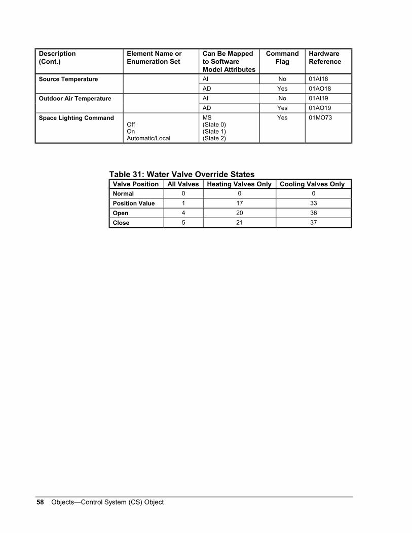
58 Objects—Control System (CS) Object
Description(Cont.)
Element Name orEnumeration Set
Can Be Mappedto SoftwareModel Attributes
CommandFlag
HardwareReference
Source Temperature AI No 01AI18
AD Yes 01AO18
Outdoor Air Temperature AI No 01AI19
AD Yes 01AO19
Space Lighting CommandOffOnAutomatic/Local
MS(State 0)(State 1)(State 2)
Yes 01MO73
Table 31: Water Valve Override StatesValve Position All Valves Heating Valves Only Cooling Valves Only
Normal 0 0 0
Position Value 1 17 33
Open 4 20 36
Close 5 21 37
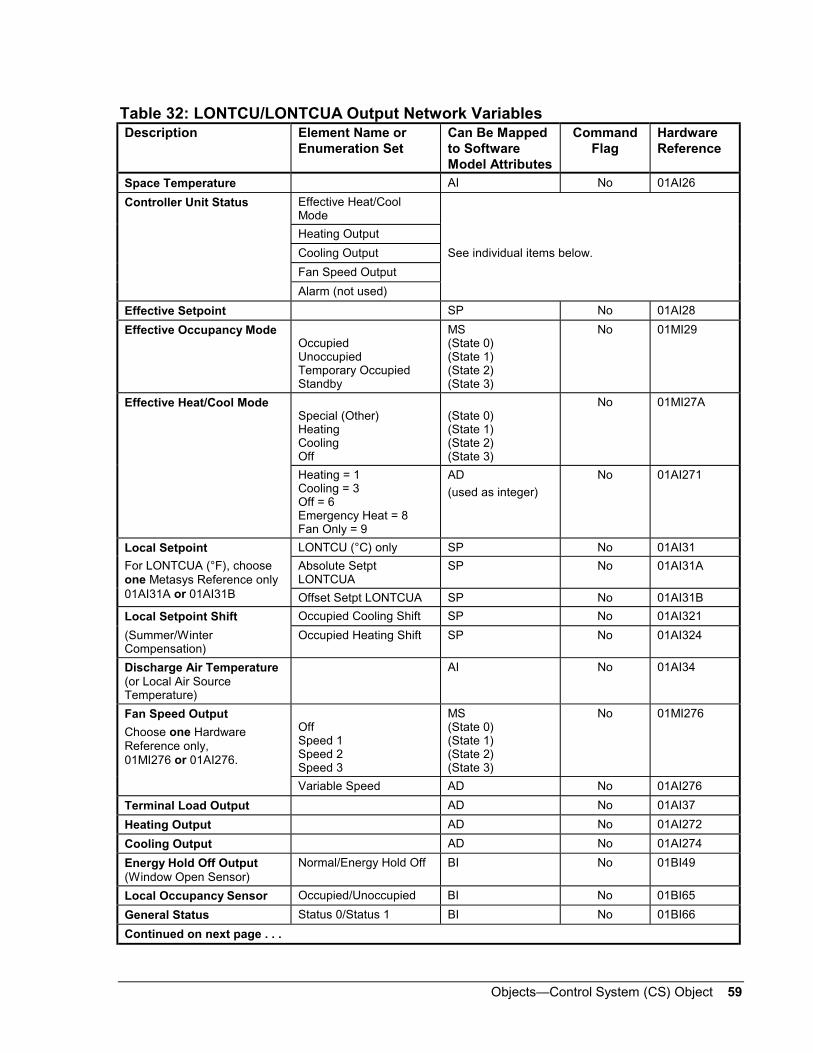
Objects—Control System (CS) Object 59
Table 32: LONTCU/LONTCUA Output Network VariablesDescription Element Name or
Enumeration SetCan Be Mappedto SoftwareModel Attributes
CommandFlag
HardwareReference
Space Temperature AI No 01AI26
Controller Unit Status Effective Heat/CoolMode
Heating Output
Cooling Output See individual items below.
Fan Speed Output
Alarm (not used)
Effective Setpoint SP No 01AI28
Effective Occupancy ModeOccupiedUnoccupiedTemporary OccupiedStandby
MS(State 0)(State 1)(State 2)(State 3)
No 01MI29
Effective Heat/Cool ModeSpecial (Other)HeatingCoolingOff
(State 0)(State 1)(State 2)(State 3)
No 01MI27A
Heating = 1Cooling = 3Off = 6Emergency Heat = 8Fan Only = 9
AD
(used as integer)
No 01AI271
LONTCU (°C) only SP No 01AI31
Absolute SetptLONTCUA
SP No 01AI31A
Local Setpoint
For LONTCUA (°F), chooseone Metasys Reference only01AI31A or 01AI31B Offset Setpt LONTCUA SP No 01AI31B
Local Setpoint Shift Occupied Cooling Shift SP No 01AI321
(Summer/WinterCompensation)
Occupied Heating Shift SP No 01AI324
Discharge Air Temperature(or Local Air SourceTemperature)
AI No 01AI34
Fan Speed Output
Choose one HardwareReference only,01MI276 or 01AI276.
OffSpeed 1Speed 2Speed 3
MS(State 0)(State 1)(State 2)(State 3)
No 01MI276
Variable Speed AD No 01AI276
Terminal Load Output AD No 01AI37
Heating Output AD No 01AI272
Cooling Output AD No 01AI274
Energy Hold Off Output(Window Open Sensor)
Normal/Energy Hold Off BI No 01BI49
Local Occupancy Sensor Occupied/Unoccupied BI No 01BI65
General Status Status 0/Status 1 BI No 01BI66
Continued on next page . . .
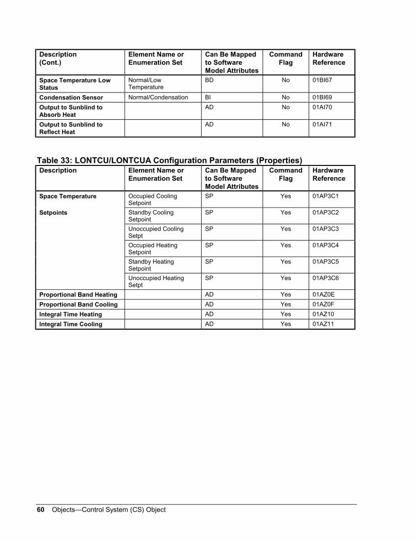
60 Objects—Control System (CS) Object
Description(Cont.)
Element Name orEnumeration Set
Can Be Mappedto SoftwareModel Attributes
CommandFlag
HardwareReference
Space Temperature LowStatus
Normal/LowTemperature
BD No 01BI67
Condensation Sensor Normal/Condensation BI No 01BI69
Output to Sunblind toAbsorb Heat
AD No 01AI70
Output to Sunblind toReflect Heat
AD No 01AI71
Table 33: LONTCU/LONTCUA Configuration Parameters (Properties)Description Element Name or
Enumeration SetCan Be Mappedto SoftwareModel Attributes
CommandFlag
HardwareReference
Space Temperature Occupied CoolingSetpoint
SP Yes 01AP3C1
Setpoints Standby CoolingSetpoint
SP Yes 01AP3C2
Unoccupied CoolingSetpt
SP Yes 01AP3C3
Occupied HeatingSetpoint
SP Yes 01AP3C4
Standby HeatingSetpoint
SP Yes 01AP3C5
Unoccupied HeatingSetpt
SP Yes 01AP3C6
Proportional Band Heating AD Yes 01AZ0E
Proportional Band Cooling AD Yes 01AZ0F
Integral Time Heating AD Yes 01AZ10
Integral Time Cooling AD Yes 01AZ11

Objects—Control System (CS) Object 61
Table 34: LONDXA/LONDXAA Input Network VariablesDescription Element Name or
Enumeration SetCan Be Mappedto SoftwareModel Attributes
CommandFlag
HardwareReference
SNVT_switch
Value AI/AD No xxAI01
State BI, BD No xxBI01
Value AD Yes xxAO01
nviSwitchn
for n = 1 - 4, xx = 25 - 28
State BD Yes xxBO01
SNVT_switch
Value n/a
State BI, BD No xxBI01
Value n/a
nviSwitchn
for n = 5 - 8, xx = 29 - 32
State BD Yes xxBO01
nviOccupancyn
for n = 1 - 4, xx = 33 - 36
SNVT_occupancy
Occupied
Unoccupied
Temporary Occupied
Standby
None
MS
(state 0)
(state 1)
(state 2)
(state 3)
(state 4)
Yes xxMS01
AI, AD No xxAI01nviLevPercentn
for n = 1 - 8, xx = 37 - 40
SNVT_lev_percent
Value AD Yes xxAO01
AI, AD No xxAI01nviTempPn
for n = 1 - 8, xx = 41 - 48
SNVT_temp_p
Value AD Yes xxAO01
Table 35: LONDXA/LONDXAA Output Network VariablesDescription Element Name or
Enumeration SetCan Be Mappedto SoftwareModel Attributes
CommandFlag
HardwareReference
SNVT_switch
Value AI, AD No xxAI01
nvoSwitchn
for n = 1 - 4, xx = 01 - 04
State BI, BD No xxBI01
SNVT_switch
Value n/a
nvoSwitchn
for n = 5 - 8, xx = 05 - 08
State BI, BD No xxBI01
nvoOccupancyn
for n = 1 - 4, xx = 09 - 12
SNVT_occupancy
Occupied
Unoccupied
Temporary Occupied
Standby
None
MS
(state 0)
(state 1)
(state 2)
(state 3)
(state 4)
No xxMS01
Continued on next page . . .

62 Objects—Control System (CS) Object
Description(Cont.)
Element Name orEnumeration Set
Can Be Mappedto SoftwareModel Attributes
CommandFlag
HardwareReference
nvoLevPercentn
for n = 1 - 4, xx = 13 - 16
SNVT_lev_percent
Value AI, AD No xxAI01
SNVT_temp_p
LONDXA ( C) Value AI, AD No xxAI01
nvoTempPn
for n = 1 - 4, xx = 17 - 20
LONDXAA ( F) Value AI, AD No xxAI01A
SNVT_scent
Function:
Recall (0) / Learn (1) BD No xxBI01
nvoScenen
for n = 1 - 4, xx = 21 - 24
Scene Number AD No xxAI01
Table 36: Metasys References for LONDXD (Metric Units: C, Pa, kJ/kg) andLONDXDA (American Units: F, in W.C., Btu/lb) Input Network VariablesDescription Element Name or
Enumeration SetCan Be Mappedto SoftwareModelAttributes
CommandFlag
HardwareReference
nviDuctStatSP SNVT_press_p (Pa, in W.C.) SP, AD Yes 29AO01
nviFanDiffSP SNVT_press_p (Pa, in W.C.) SP, AD Yes 30AO01
nviDACISP SNVT_temp_p SP, AD Yes 31AO01
nviDAHtSP SNVT_temp_p SP, AD Yes 32AO01
nviOutdoorTemp SNVT_temp_p AD Yes 33AO01
nviMATSP SNVT_temp_p SP, AD Yes 34AO01
nviSpaceTemp SNVT_temp_p AD Yes 35AO01
nviSpaceTempSP SNVT_temp_p SP, AD Yes 36AO01
nviCO2ppm SNVT_ppm AD Yes 37AO01
nviCO@ppmSP SNVT_ppm SP, AD Yes 38AO01
nviOAMinPos SNVT_lev_percent SP, AD Yes 39AO01
nviOutdoorRH SNVT_lev_percent AD Yes 40AO01
nviSpaceRH SNVT_lev_percent AD Yes 41AO01
nviSpaceRHSP SNVT_lev_percent SP, AD Yes 42AO01
nviSpaceDehumSP SNVT_lev_percent SP, AD Yes 43AO01
SNVT_switch
Value AD Yes 44AO01V
nviSwitch1
State BD Yes 44BO01S
nviOccSchedule SNVT_tod_event
Set current state only:
Occupied
Unoccupied
Standby
None
MS
(state 0)
(state 1)
(state 2)
(state 3)
Yes 45MO01
Continued on next page . . .

Objects—Control System (CS) Object 63
DescriptionCont.)
Element Name orEnumeration Set
Can Be Mappedto SoftwareModelAttributes
CommandFlag
HardwareReference
nviOccManCmd SNVT_occupancy
Occupied
Unoccupied
Temporary Occupied
Standby
None
MS
(state 0)
(state 1)
(state 2)
(state 3)
(state 4)
Yes 46MS01
SNVT_hvac_mode
Automatic/Local
Heating
Cooling
Off
MS
(state 0)
(state 1)
(state 2)
(state 3)
Yes 47MO01AnviApplicMode
Note:
Select one MetasysReference only, 47MO01A or47AO01
Automatic = 0
Heating = 1
Cooling = 3
Off = 6
…etc
AD
(used as integer)
Yes 47AO01
nviEmergOverride SNVT_hvac_emerg
Normal
Pressurize
Depressurize
Emergency Purge
Emergency Shutdown
MS
(state 0)
(state 1)
(state 2)
(state 3)
(state 4)
Yes 48MS01
nviPriCoolEnable SNVT_switch (state)
Off = 0
On = 1
Auto/Local/Invalid
MS
(state 0)
(state 1)
(state 2)
Yes 52MO01B
nviPriHeatEnable SNVT_switch (state)
Off = 0
On = 1
Auto/Local/Invalid
MS
(state 0)
(state 1)
(state 2)
Yes 53MO01B
nviHumEnable SNVT_switch (state)
Off = 0
On = 1
Auto/Local/Invalid
MS
(state 0)
(state 1)
(state 2)
Yes 54MO01B
nviDehumEnable SNVT_switch (state)
Off = 0
On = 1
Auto/Local/Invalid
MS
(state 0)
(state 1)
(state 2)
Yes 55MO01B

64 Objects—Control System (CS) Object
Table 37: Metasys References for LONDXD (Metric Units: C, Pa, kJ/kg) andLONDXDA (American Units: F, in W.C., Btu/lb) Output Network VariablesDescription Element Name or
Enumeration SetCan Be Mappedto SoftwareModel Attributes
CommandFlag
HardwareReference
nvoDuctStatPress SNVT_press_p (Pa, in W.C.) AI No 01AI01
nvoRetFanPress SNVT_press_p (Pa, in W.C.) AI No 02AI01
nvoOAEnthalpy SNVT_enthalpy (kJ/kg,Btu/lb)
AI No 03AI01
nvoSpaceEnthalpy SNVT_enthalpy (kJ/kg,Btu/lb)
AI No 04AI01
nvoDischAirTemp SNVT_temp_p AI No 05AI01
nvoLocalOATemp SNVT_temp_p AI No 06AI01
nvoMATemp SNVT_temp_p AI No 07AI01
nvoSpaceTemp SNVT_temp_p AI No 08AI01
nvoRATemp SNVT_temp_p AI No 09AI01
nvoOADamper SNVT_lev_percent AI, AD No 10AI01
nvoCoolPrimary SNVT_lev_percent AI, AD No 11AI01
nvoHeatPrimary SNVT_lev_percent AI, AD No 12AI01
nvoSpaceRH SNVT_lev_percent AI No 13AI01
nvoHumidifier SNVT_Lev_percent AI, AD No 14AI01
SNVT_switch
Value AI, AD
No 15AI01nvoSupFanStatus
State BI, BD No 15BI01
SNVT_switch
Value
AI, AD No 16AI01nvoRetFanStatus
State BI, BD No 16BI01
nvoHeatCool SNVT_hvac_mode
Other
Heating
Cooling
Off
MS
(state 0)
(state 1)
(state 2)
(state 3)
No 17MI01A
nvoApplicMode SNVT_hvac_mode
Automatic = 0
Heating = 1
Cooling = 3
Off = 6
…etc.
AD
(used as integer)
No 18AI01
nvoEffectOccup SNVT_occupancy
Occupied
Unoccupied
Temporary Occupied
Standby
MS
(state 0)
(state 1)
(state 2)
(state 3)
No 19MI01
Continued on next page . . .
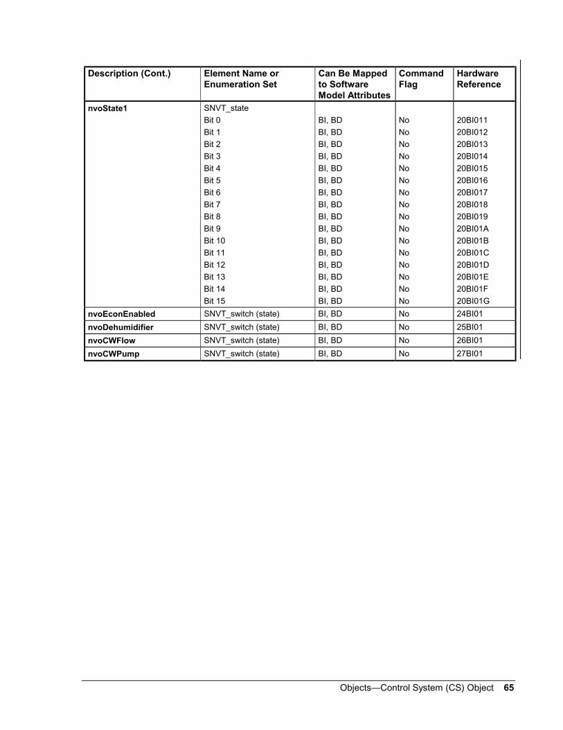
Objects—Control System (CS) Object 65
Description (Cont.) Element Name orEnumeration Set
Can Be Mappedto SoftwareModel Attributes
CommandFlag
HardwareReference
nvoState1 SNVT_state
Bit 0
Bit 1
Bit 2
Bit 3
Bit 4
Bit 5
Bit 6
Bit 7
Bit 8
Bit 9
Bit 10
Bit 11
Bit 12
Bit 13
Bit 14
Bit 15
BI, BD
BI, BD
BI, BD
BI, BD
BI, BD
BI, BD
BI, BD
BI, BD
BI, BD
BI, BD
BI, BD
BI, BD
BI, BD
BI, BD
BI, BD
BI, BD
No
No
No
No
No
No
No
No
No
No
No
No
No
No
No
No
20BI011
20BI012
20BI013
20BI014
20BI015
20BI016
20BI017
20BI018
20BI019
20BI01A
20BI01B
20BI01C
20BI01D
20BI01E
20BI01F
20BI01G
nvoEconEnabled SNVT_switch (state) BI, BD No 24BI01
nvoDehumidifier SNVT_switch (state) BI, BD No 25BI01
nvoCWFlow SNVT_switch (state) BI, BD No 26BI01
nvoCWPump SNVT_switch (state) BI, BD No 27BI01

66 Objects—Control System (CS) Object
Table 38: LONVMA/LONVMAA Input Network VariablesDescription Element Name
or Enumeration SetCan Be Mappedto SoftwareModel Attributes
CommandFlag
HardwareReference
Space Temperature Input AI No 01AI01
Space TemperatureSetpoint
SP No 01AI02
(Absolute) SP Yes 01AO02
Space Setpoint Offset SP No 01AI03
Space Setpoint Shift Occupied Cooling Shift SP Yes 01AO041
Standby Cooling Shift SP Yes 01AO042
Unoccupied CoolingShift
SP Yes 01AO043
Occupied Heating Shift SP Yes 01AO044
Standby Heating Shift SP Yes 01AO045
Unoccupied HeatingShift
SP Yes 01AO046
Scheduled OccupancyMode
Set current state only:OccupiedUnoccupiedStandbyNone
MS(State 0)(State 1)(State 2)(State 3)
Yes 01MO051
Occupancy Override
OccupiedUnoccupiedTemporary OccupiedStandbyNone
MS(State 0)(State 1)(State 2)(State 3)(State 4)
Yes 01MS06
Occupancy Sensor Input Occupied/Unoccupied BI No 01BI07
Automatic/LocalWarm-upPurgePre-cool
MS(State 0)(State 1)(State 2)(State 3)
Yes 01MO08BApplication Mode
Note:Select one MetasysReference only,01MO08B or 01AO08
Automatic = 0Heating = 1Warm-up = 2Cooling = 3Purge = 4Pre-cool = 5Off = 6Emergency Heat = 8Fan Only = 9
AD
(used as integer)
Yes 01AO08
Continued on next page . . .

Objects—Control System (CS) Object 67
Description(Cont.)
Element Nameor Enumeration Set
Can Be Mappedto SoftwareModel Attributes
CommandFlag
HardwareReference
Automatic/LocalHeatingCoolingOff
MS(State 0)(State 1)(State 2)(State 3)
Yes 01MO09AHeat/Cool Mode
Note:Select one MetasysReference only,01MO09A or 01AO09
Automatic = 0Heating = 1Warm-up = 2Cooling = 3Purge = 4Pre-cool = 5Off = 6Emergency Heat = 8Fan Only = 9
AD
(used as integer)
Yes 01AO09
Fan Speed Command
OffOnAutomatic/Local
MS(State 0)(State 1)(State 2)
Yes 01MO10B
Auxiliary Heat Enable
DisableEnable
MS(State 0)(State 1)
Yes 01MO12
Energy Hold Off Normal/Energy Hold Off BD Yes 01BO14
Water Valve Override
Note:
01AO152 is required forSet to Position state.
Set heating valve:Normal controlOpenCloseSet to position
MS(State 0)(State 1)(State 2)(State 3)
Yes 01MO15H
Valve position (%) AD Yes 01AO152
Set damper position:Normal controlOpenCloseSet to position
MS(State 0)(State 1)(State 2)(State 3)
Yes 01MO16P
Set flow rate:Normal controlMinimum flowMaximum flowSet to flow value
MS(State 0)(State 1)(State 2)(State 3)
Yes 01MO16F
Damper position (%) AD Yes 01AO162
Air Flow Override
Notes:
Choose one MetasysReference only,01MO16P or 01MO16F.
01AO162 is required forSet to Position state.
01AO163 is required forSet to Flow Value state.
Flow value (l/s or cfm) AD Yes 01AO163
Continued on next page . . .
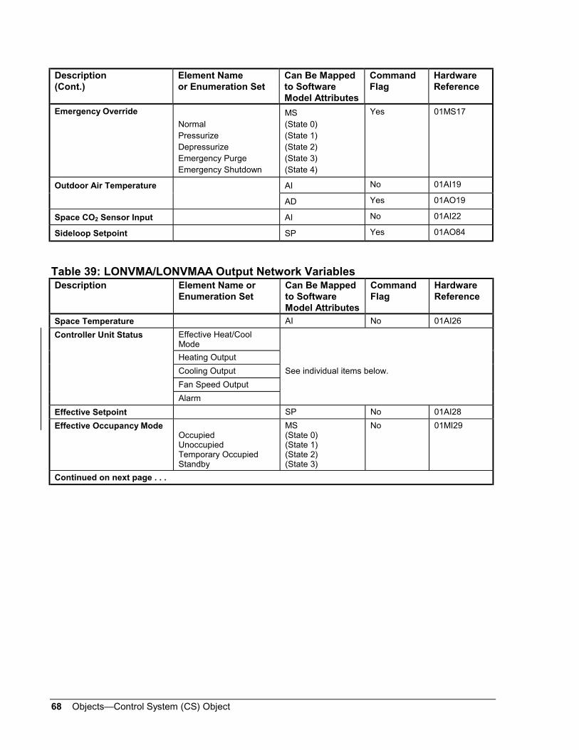
68 Objects—Control System (CS) Object
Description(Cont.)
Element Nameor Enumeration Set
Can Be Mappedto SoftwareModel Attributes
CommandFlag
HardwareReference
Emergency Override
NormalPressurizeDepressurizeEmergency PurgeEmergency Shutdown
MS(State 0)(State 1)(State 2)(State 3)(State 4)
Yes 01MS17
Outdoor Air Temperature AI No 01AI19
AD Yes 01AO19
Space CO2 Sensor Input AI No 01AI22
Sideloop Setpoint SP Yes 01AO84
Table 39: LONVMA/LONVMAA Output Network VariablesDescription Element Name or
Enumeration SetCan Be Mappedto SoftwareModel Attributes
CommandFlag
HardwareReference
Space Temperature AI No 01AI26
Controller Unit Status Effective Heat/CoolMode
Heating Output
Cooling Output See individual items below.
Fan Speed Output
Alarm
Effective Setpoint SP No 01AI28
Effective Occupancy ModeOccupiedUnoccupiedTemporary OccupiedStandby
MS(State 0)(State 1)(State 2)(State 3)
No 01MI29
Continued on next page . . .

Objects—Control System (CS) Object 69
Description(Cont.)
Element Name orEnumeration Set
Can Be Mappedto SoftwareModel Attributes
CommandFlag
HardwareReference
Effective Heat/Cool ModeSpecial (Other)HeatingCoolingOff
MS(State 0)(State 1)(State 2)(State 3)
No 01MI27A
Special (Other)Warm-upPurgePre-cool
MS(State 0)(State 1)(State 2)(State 3)
No 01MI27B
Heating = 1Warm-up = 2Cooling = 3Purge = 4Pre-cool = 5Off = 6Emergency Heat = 8Fan Only = 9
AD
(used as integer)
No 01AI271
LONVMA (°C) only SP No 01AI31
Absolute SetptLONVMAA
SP No 01AI31A
Local Setpoint
For LONVMAA (°F) chooseone Metasys Reference only,01AI31A or 01AI31B. Offset Setpt LONVMAA SP No 01AI31B
Occupied Cooling Shift SP No 01AI321Local Setpoint Shift
(Winter/SummerCompensation)
Occupied Heating Shift SP No 01AI324
Fan Speed Output Off/On BI No 01BI276
Discharge Air Temperature(or Local Air SourceTemperature)
AI No 01AI34
Heating Output AD No 01AI272
Secondary Heating Output AD No 01AI39
Cooling Output AD No 01AI274
Space CO2 AI No 01AI46
Energy Hold Off Output(Window Open Sensor)
Normal/Energy Hold Off BI No 01BI49
Effective Air Flow Setpoint (l/s or cfm) SP No 01AI50
Air Flow (l/s or cfm) AI No 01AI52
EWMA Space TemperatureError
AD No 01AI74
EWMA Space TemperatureError Absolute
AD No 01AI75
EWMA Flow Error (l/s or cfm) AD No 01AI76
Continued on next page . . .

70 Objects—Control System (CS) Object
Description(Cont.)
Element Name orEnumeration Set
Can Be Mappedto SoftwareModel Attributes
CommandFlag
HardwareReference
EWMA Flow Error Absolute (l/s or cfm) AD No 01AI77
Moving Average DamperReversals
AD No 01AI78
Moving Average DamperDuty Cycle
AD No 01AI79
Current Outdoor AirRequirement
(l/s or cfm) AD No 01AI80
Unit Status Alarm (PressureDependent Mode)
Normal/Alarm BI No 01BI277
Table 40: LONVMA/LONVMAA Configuration Parameters (Properties)Description Element Name or
Enumeration SetCan Be Mappedto SoftwareModel Attributes
CommandFlag
HardwareReference
Occupied CoolingSetpoint
SP Yes 01AP3C1Space TemperatureSetpoints
Standby CoolingSetpoint
SP Yes 01AP3C2
Unoccupied CoolingSetpoint
SP Yes 01AP3C3
Occupied HeatingSetpoint
SP Yes 01AP3C4
Standby HeatingSetpoint
SP Yes 01AP3C5
Unoccupied HeatingSetpoint
SP Yes 01AP3C6

Objects—Control System (CS) Object 71
This flowchart shows the procedure used to define a CS object with DDL.The individual steps are explained after the chart.
Compile the DDL source using the
DDL Compiler and check for errors.
Download NC.
End
csflow2a
Using online generation at the workstation,
set up Trend and Weekly Schedulingfor the CS object (optional).
Define the ASC hardware using the
N2OPEN, DCDR, and LON keywords.
Define the CS object using theCS keyword.
Print out the controller's configuration file.
Define the software model using
the CSMODEL keyword. Or modifythe automatically created .DMO file.
Configure the controller using HVAC PRO software.
Using the printout, select the pointsin the controller you want to map to
software model attributes.
Start
Create optional AD and BD objects
mapped to CS object attributes.
Figure 6: Flowchart to Define CS Object with DDL
Defining aCS Objectwith DDL

72 Objects—Control System (CS) Object
This section explains individual steps in the flowchart for defining aCS object with DDL. If you use DDL, select a text editor, such as DFEDIT(which is provided on the DDL diskette). Also, make sure you have a copyof the DDL Programmer’s Manual (FAN 630) on hand.
Configure the Controller Using HVAC PRO Software
Defining a CS object is part of a larger process that includes setting up theASC. First you determine the application for the controller. Then, usingconfiguration software, you:
• configure the controller
• assemble the controller configuration
• load the controller
• commission the controller (if necessary)
For complete information on these procedures in the controller’s technicaldocument (in the Metasys Network Technical Manual [FAN 636] and inthe HVAC PRO User’s Manual [FAN 637.5]).
For information on setting up Metasys Integrator unit and commissioningMIG devices, see the Metasys Integrator 300 Series Installation TechnicalBulletin (LIT-6295122), the Metasys Integrator 300 Series CommissioningTechnical Bulletin (LIT-6295124), and vendor-specific application note inthe Metasys Connectivity Technical Manual (FAN 629.5).
Print the Controller’s Configuration File
The .PRN or configuration file lists the names and addresses of all thepoints in the controller. Use the information from this file to define theattributes in the software model. For the AHU, UNT, VAV, VMA, TC-9100, PHX, and NDM, print the .PRN file (or .SYM file) from any texteditor, or from within HVAC PRO software (refer to the HVAC PROUser’s Manual [FAN 637.5]). For the LCP/DC9100, DX9100, DXECH,and XT9100, load the configuration file in the configuration software.Then select the following menu options: FILE, PRINT, ALL ITEMS (orSYSTEM, PRINT, ALL DATA for earlier DOS versions of the software).For MIG and VND devices, use the vendor-specific application note.
For more information, refer to Mapping Points in the Controller toSoftware Model Attributes in this document.
Explanation ofDDL Flowchart

Objects—Control System (CS) Object 73
Select Points in the Controller
Selected points in the controller become the attributes of the softwaremodel. Most likely, you will not use all the points in the controller inone software model. Instead, select the points that are relevant to theapplication the software model is representing. For example, if thesoftware model you are defining represents a chiller application in thecontroller, select only those points involved in chiller operation.
Using the printout of the controller’s configuration file, highlight(e.g., with a yellow marker) the points you want to include as attributes inthe software model. Note the number of the attribute you want to associatewith the controller point (e.g., AO_1, AO_2, BO_1, BO_2).
Define the Software Model
Define the software model using the CSMODEL keyword. When youdefine the model, specify:
• a model name (e.g., VAVMODEL)
• the type of device the model is used with (e.g., AHU, UNT, VMA,VAV, LCP, DX9100, LONTCU, etc.)
• a name for each of the attribute groups you intend to use. For example,you might name the AI attribute group Analog Inputs or Temperatures.The name is required and, though it can include blank spaces, it cannotbe all blank spaces.
• a hardware reference for each attribute. For example, the hardwarereference for attribute AI_1 might be ADF6. The hardware reference,which is the address of the point in the controller, associates thesoftware model attribute with a specific point in the controller. Tospecify the hardware reference, you must use the configuration fileprintout and the point mapping tables. These are in this document,under Mapping Points in the Controller to Software Model Attributes.
• whether or not the attribute can be overridden
• whether or not the attribute can be adjusted
IMPORTANT: If you are mapping a CS object attribute and a standardobject to the same hardware reference, set both theOverride and Adjust flags to No (False) for the CSobject attribute. Similarly, if you are mapping morethan one CS object attribute to the same hardwarereference, make sure only one has the Override flag setto Yes, and only one has the Adjust flag set to Yes.This is to ensure that there is only one command pathto the hardware reference.

74 Objects—Control System (CS) Object
• a description that further explains the attribute. For example, youmight describe the AI_3 attribute measuring outside air humidity asOA HUMID.
• the units for the attribute (e.g., OFF, ON, DEGF, PCT). For BI, BO,and BD attributes, units are required and, though they can includeblank spaces, they cannot be all blank spaces. For AI, AO, AD, and SPattributes, units are not required, can include blank spaces, and can beall blank spaces. For MS attributes, at least one of the five units mustbe entered and, though it can include blank spaces, it cannot be allblank spaces.
IMPORTANT: Commands from processes are based on attributesequence. Keep this in mind as you define eachattribute. The first AI attribute you define for themodel is AI_1, the second AI attribute you define isAI_2, etc.
The CSMODEL keyword is in the @Model source file. Information onCSMODEL syntax is in the DDL Programmer’s Manual (FAN 630).
Define the ASC Hardware
Define the controller as a hardware object. To define an AHU, UNT,VAV, VMA, MIG, PHX, or NDM, use the N2OPEN keyword. To define aSystem 9100 device (LCP/DC9100, DX9100, DXECH, XT9100, XTM,DR9100, TC9100), use the DCDR keyword. To define a LONWORKS
compatible device (e.g., LONTCU), use the LON keyword. When youdefine the controller, you specify its system\object name, expanded ID,and address on the network.
The N2OPEN and DCDR keywords are in the @NC source file. Thesyntax for these keywords is located in the DDL Programmer’s Manual(FAN 630).

Objects—Control System (CS) Object 75
Define the CS Object Keyword
Define the CS object with the CS keyword. When you define the CSobject, specify:
the CS object’s system\object name and expanded ID
an already defined software model
an already defined device (e.g., AHU, UNT, VAV, VMA, DX9100, etc.)
the display attribute. The display attribute is the attribute that appearsas the CS object’s current value in summaries, in the CS Object Focuswindow, and at the NT.
the NT command attribute. The NT command attribute is theone attribute that can be commanded from an NT.
The CS keyword is in the @NC source file. Refer to CS keyword in theDDL Programmer’s Manual (FAN 630) for syntax.
Create Optional AD and BD Objects
The following information on mapping CS object attributes to AD and BDobjects is optional. However, by mapping CS object attributes to ADs andBDs, you can enhance alarm limit analysis, COS reporting, triggers, pointhistory, and graphic binding.
For example, you can map a CS object’s AI attribute to an AD object. Youcan assign a limit to the AD object. Then, when the AD object’s value(i.e., the associated AI attribute’s value) exceeds the limit, an alarm reportcan be displayed on the workstation screen.
In addition, unlike most objects, the CS object does not have current trendand point history information automatically displayed at the top of itsFocus window. However, you can display this information about a selectedCS object attribute by mapping the attribute to an AD or BD object. Then,when you display the AD or BD Focus window, you’ll see current trendand point history information for the associated CS object attribute.
When you define the AD or BD object, you specify an associated objectand an attribute of the associated object. For the associated object, specifythe CS object’s system\object name. For the attribute, use the attributenumber determined by attribute sequence, e.g., AI_1, AI_2, BI_1, BI_2.
The AD and BD keywords are in the @NC source file. The syntax forthese keywords is in the DDL Programmer’s Manual (FAN 630).
Note: Consider that extensive use of AD and BD objects can increaseN2 Bus traffic and slow down COS reporting (because every4 seconds all BD values are read and every 30 seconds all ADvalues are read.)
76 Objects—Control System (CS) Object
Compile the DDL
Use the DDL Compiler to compile the @Model and @NC source filescontaining the controller, software model and CS object definition.
Make sure you compile the @Model file before the @NC file.
In the @NC file, make sure the DCDR or N2OPEN keywords come beforethe CS keyword that references them. If you defined AD and BD objectsand mapped CS object attributes to them, make sure the CS keywordscome before the AD and BD keywords that reference them.
Make sure you save all the compiled DDL files to floppy diskette for laterdownloading to the network.
Download the NC
Download the NC.
Set Up Trend and Weekly Scheduling
This step is optional. Using online generation at the Metasys OWS, youcan set up Trend and Weekly Scheduling for selected CS object attributes.When you specify the attributes for both features, use the attribute numberas determined by attribute sequence in the software model, e.g., AI_1,AI_2, BI_1, BI_2.
You can trend any CS object attribute. You can schedule Adjust andRelease commands for only those CS object attributes that are defined asadjustable in the software model.

Objects—Control System (CS) Object 77
This flowchart shows the procedure used to define a CS object online atthe OWS. The individual steps are explained after the chart.
Print out the controller's configuration file.
Define the software model usingthe CSMODEL keyword, or modify
the automatically created .DMO or .DDL file.
Define the CS object using theCS Object Definition window.
Create optional AD and BD objectsmapped to CS object attributes.
Configure the controller using HVAC PRO software.
Using the printout, select the pointsin the controller you want to map to
software model attributes.
Endcsflow2
Using online generation at theworkstation, set up Trend and Weekly Scheduling
for the CS object (optional).
Start
Define ASC hardware using the hardwareObject Definition window.
Figure 7: Flowchart to Define CS Object Online at OWS
Defining a CSObject withOnlineGeneration
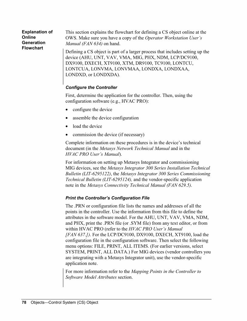
78 Objects—Control System (CS) Object
This section explains the flowchart for defining a CS object online at theOWS. Make sure you have a copy of the Operator Workstation User’sManual (FAN 634) on hand.
Defining a CS object is part of a larger process that includes setting up thedevice (AHU, UNT, VAV, VMA, MIG, PHX, NDM, LCP/DC9100,DX9100, DXECH, XT9100, XTM, DR9100, TC9100, LONTCU,LONTCUA, LONVMA, LONVMAA, LONDXA, LONDXAA,LONDXD, or LONDXDA).
Configure the Controller
First, determine the application for the controller. Then, using theconfiguration software (e.g., HVAC PRO):
• configure the device
• assemble the device configuration
• load the device
• commission the device (if necessary)
Complete information on these procedures is in the device’s technicaldocument (in the Metasys Network Technical Manual and in theHVAC PRO User’s Manual).
For information on setting up Metasys Integrator and commissioningMIG devices, see the Metasys Integrator 300 Series Installation TechnicalBulletin (LIT-6295122), the Metasys Integrator 300 Series CommissioningTechnical Bulletin (LIT-6295124), and the vendor-specific applicationnote in the Metasys Connectivity Technical Manual (FAN 629.5).
Print the Controller’s Configuration File
The .PRN or configuration file lists the names and addresses of all thepoints in the controller. Use the information from this file to define theattributes in the software model. For the AHU, UNT, VAV, VMA, NDM,and PHX, print the .PRN file (or .SYM file) from any text editor, or fromwithin HVAC PRO (refer to the HVAC PRO User’s Manual[FAN 637.]). For the LCP/DC9100, DX9100, DXECH, XT9100, load theconfiguration file in the configuration software. Then select the followingmenu options: FILE, PRINT, ALL ITEMS. (For earlier versions, selectSYSTEM, PRINT, ALL DATA.) For MIG devices (vendor controllers youare integrating with a Metasys Integrator unit), use the vendor-specificapplication note.
For more information refer to the Mapping Points in the Controller toSoftware Model Attributes section.
Explanation ofOnlineGenerationFlowchart

Objects—Control System (CS) Object 79
Select Points in the Controller
Selected points in the controller become the attributes of the softwaremodel. Most likely, you will not use all the points in the controller inone model. Instead, select the points that are relevant to the application themodel is representing. For example, if the software model represents achiller application in the controller, select only those attributes that arerelevant to chiller operation. Using the printout of the controller’sconfiguration file, highlight (e.g., with a yellow marker) the points youwant to include as attributes in the software model. For information onusing configuration file printouts, refer to Mapping Points in theController to Software Model Attributes in this document.
Define the Software Model
First check to see if the software model you need already exists. To dothis, select the Software Model option from the Network Map Setup menu.This displays a summary of all defined software models. To examine aspecific model more closely, select View Model from the Action menu. Ifthe model you need already exists, go on to the next step (Define the ASCHardware).
If you need to define the software model, use the Software ModelDefinition dialog boxes to specify:
• a model name (e.g., VAVMODEL)
• the type of device the model is used with (AHU, UNT, VAV, VMA,MIG, NDM, PHX, LCP/DC9100, DX9100, DXECH, XT9100, XTM,DR9100, TC9100, LONTCU, LONTCUA, LONVMA, LONVMAA,LONDXA, LONDXAA, LONDXD, or LONDXDA)
• a name for each of the attribute groups you intend to use. For example,you might name the AI attribute group Analog Inputs or Temperatures.The name is required and, though it can include blank spaces, it cannotbe all blank spaces.
• the number of attributes in each group
• a hardware reference for each attribute. For example, the hardwarereference for attribute AI_1 might be ADF6. The hardware reference,which is the address of the point in the controller, associates thesoftware model attribute with a specific point in the controller.To specify the hardware reference, use information from theconfiguration file printout and the Point Mapping tables. These areexplained in this document, under Mapping Points in the Controller toSoftware Model Attributes.
• whether or not the attribute can be overridden
• whether or not the attribute can be adjusted

80 Objects—Control System (CS) Object
IMPORTANT: If you are mapping a CS object attribute and a standardobject to the same hardware reference, set both theOverride and Adjust flags to No (False) for theCS object attribute. Similarly, if you are mapping morethan one CS object attribute to the same hardwarereference, make sure only one has the Override flag setto Yes, and only one has the Adjust flag set to Yes.This is to ensure that there is only one command pathto the hardware reference.
• a description that further explains the attribute. For example, youmight describe the AI_3 attribute measuring outside air humidity asOA HUMID.
• the units for the attribute (e.g., ON, OFF, DEGF, PCT). For BI, BO,and BD attributes, units are required and, can include blank spaces,but cannot be all blank spaces. For AI, AO, AD, and SP attributes,units are not required, can include blank spaces, and can be all blankspaces. For MS attributes, at least one of the five units must be enteredand, can include blank spaces, but cannot be all blank spaces.
Refer to the Operator Workstation User’s Manual (FAN 634), DefiningSoftware Models for information about viewing and defining softwaremodels

Objects—Control System (CS) Object 81
Figure 8 and Figure 9 are examples of the two Software Model Definitiondialog boxes.
Software Model Summary - Add
Model Name:
Associated Hardware:
AHU-31
AHU
OK
Cancel
Group Definition
Group Type Description Quantity
Analog Inputs 6
AO Analog Outputs 3
AD
SP Setpoints 26
BI Binary Inputs 8
BO Binary Outputs 4
BD Binary Data 2
MS
cs1
AI float
float
float
float
binary
binary
binary
integer
Figure 8: First Software Model Definition Dialog Box(Used to Name Model, Attribute Groups, and Number of
Attributes in Groups)

82 Objects—Control System (CS) Object
cs2
Software Model Summary - Add
Cancel
OKAnalog Outputs
Setpoints
Binary Outputs
Undefined
Analog Inputs
Analog Data
Binary Inputs
Binary Data
Attr Hdw Ref Ovr Adj Description Units
AI_1 Ai2 Y Y MIXED TP DEGF
AI_1 Ai2 Y Y MIXED TP
AI_2 Ai3 Y Y DISCH TP
AI_3 Ai4 Y Y ZONE TMP
AI_4 Ai5 Y Y RET TEMP
AI_5 Ai6 Y Y RET DP
AI_6 Ai7 Y Y ZONE RH
AI_7 Ai8 Y Y AHU STAT
DEGF
DEGF
DEGF
DEGF
IN WG
PCT
IN WG
Analog Inputs
Figure 9: Second Software Model Definition Dialog Box(Used to Further Define Each Attribute)

Objects—Control System (CS) Object 83
Define the ASC Hardware
Define the controller as a hardware object using the Hardware Definitionwindow. You’ll find complete procedural information under DefiningObjects in the Operator Workstation User’s Manual (FAN 634). Thefollowing figure shows an example of an AHU Definition window.
AHU - DefinitionItem Edit View Action G o To Accessory Help
HDQTRSNC-44 GROUP #1BGROUP2B GROUP #2BGROUP3B GROUP # 3B
System NameObject NameExpanded IDNC Name
Comm. Disabled n
AHUC
Graphic Symbol #Operator Instr. #
nHardware: N2NC Truck NumberDevice AddressPoll PriorityDevice Type
133AHU
FlagsAuto Dialout
hw2
AHUC Third Floor System
AHUCAHU-3AHU CONTROLLERNC44
1010
Figure 10: AHU Definition Window

84 Objects—Control System (CS) Object
Define the CS Object
Define the CS object using the CS Object Definition window. When youdefine the CS object, specify:
• the CS object’s system\object name and expanded ID
• an already defined software model
• an already defined device (AHU, UNT, VAV, VMA, MIG, PHX,NDM, VND, LCP/DC9100, DX9100, DXECH, XT9100, XTM,DR9100, TC9100, or LONWORKS compatible device.
• the display attribute. The display attribute is the attribute that appearsas the CS object’s current value in summaries, in the CS Object Focuswindow, and at the NT.
• the NT command attribute. The NT command attribute is theone attribute that can be commanded from an NT.
Information on defining objects is under Defining Objects in the OperatorWorkstation User’s Manual (FAN 634).
Here is an example of a CS Object Definition window.
Control System Definition - AHU - 1
Item Edit View Action Go To Accessory Help
HDQTRSNC-44 GROUP #1B
GROUP2B GROUP #2BHARDWARB Hardware System
System Name
Object NameExpanded ID
HARDWARB
Comm. Disabled n
HARDWARB
Graphic Symbol #
Operator Instr. #
nHardware:System NameObject NameExpanded ID
HARDWARB
N20-2AHU-1
Flags
Auto Dial-up
noneReport TypeOverride
Csobjnew
0
0
Figure 11: CS Object Definition Window

Objects—Control System (CS) Object 85
Create Optional AD and BD Objects
The following information on mapping CS object attributes to AD andBD objects is optional. However, by mapping CS attributes to AD and BDobjects, you can perform alarm limit analysis on the attributes and detectchanges-of-state. For example, you can map a CS object’s AI attribute toan AD object. You can assign a limit to the AD object. Then, when theAD object’s value (i.e., the associated AI attribute’s value) exceeds thelimit, an alarm report can be displayed on the screen.
In addition, unlike most objects, the CS object does not have current trendand point history information automatically displayed at the top of itsFocus window. However, you can display this information about a selectedCS object attribute by mapping the attribute to an AD or BD object. Then,when you display the AD or BD Focus window, you’ll see current trendand point history information for the associated CS object attribute.
When you define the AD or BD object, you specify an associated objectand an attribute of the associated object. For the associated object, specifythe CS object’s system\object name. For the attribute, use the attributenumber as displayed in the software model dialog box (and as determinedby attribute sequence), e.g., AI_1, AI_2, BI_1, BI_2.
Note: Consider that extensive use of AD and BD objects can increaseN2 Bus traffic and slow down COS reporting (because every4 seconds all BD values are read and every 30 seconds all ADsare read.)
Set Up Trend and Weekly Scheduling
This step is optional. You can set up Trend and Weekly Scheduling forselected CS object attributes. When you specify the attributes for bothfeatures, use the attribute number as it appears in the software modeldialog box (and as determined by attribute sequence), e.g., AI_1, AI_2,BI_1, BI_2.
You can trend any CS object attribute. You can schedule Adjust andRelease commands for only those attributes that are defined as adjustablein the software model.

86 Objects—Control System (CS) Object

Objects—Control System (CS) Object 87
Reference Tables
The attribute table starting on the next page lists, explains, and gives validentries for all the attributes of the CS object in alphabetical order, bysoftware attribute name. The information may be helpful as you define ormodify the object, and as you write control processes that reference theattributes. This page defines the terms used in the table.
Definable You can set a value for the attribute, using DDL, GPL, or theObject Definition window.
Writable You can modify the attribute using the Object Focus window orGPL template.
Object Default A time saving function used in JC-BASIC programming. Allowsyou to omit the attribute name when writing the logic. Whenomitted, the attribute name is assumed by the program.
JC-B Writable A JC-BASIC process can write to the attribute.
Triggerable The attribute can trigger (cause) a control process.
Range Check The software verifies that JC-BASIC has correctly written to(modified) the attribute.
Array The attribute is part of an array.
PMI The attribute appears in the Object Focus window.
[ ] Default.The value in brackets is the default value and remains in effectuntil you change it.
String ASCII alphanumeric characters, such as System\Object name
Boolean 0 or 1, with 0 and 1 representing logical states, such as True andFalse
Integer Whole numbers from -32767 to +32767, such as 22
Floating Point Values that contain decimal places, such as 67.5
The Code/Default column shows numbers and ASCII text. The numbersare used when defining the object in DDL, and the ASCII text is used inDefinition and Focus windows.
For example, for OVR_RPT (Override Report Type):
0 = none
1 = crit1
2 = crit2
3 = crit3, etc.
where:
0 is used in DDL
none is used in Definition window
Attribute Table

88 Objects—Control System (CS) Object
Table 41: Attribute TableAttribute
SoftwareName
PMI Label Description Type/Range
Code/[Default Value]
Usage
ADADJEN Analog DataAdjustEnabled
Flag indicating whether ADattribute is defined asadjustable in software model.
Boolean/
0 or 1
[0 = n = adjust notallowed]
1 = y = adjustallowed
Definable
Array
ADADJS Analog DataAdjusts
Flag indicating whether ADattribute is currently adjusted.
Boolean/
0 or 1
[0 = no adjust]
1 = adjust present
Array
ADDES Analog DataDescription
Name of AD attribute group. string/
24 char.maximum
Definable
ADNAMES Analog DataASCII Names
Name of AD attribute. string/
8 char.maximum
Definable
Array
ADOVREN Analog DataOvr Enabled
Flag indicating whether ADattribute is defined asoverrideable in software model.
Boolean/
0 or 1
[0 = n= override notallowed]
1 = y = overrideallowed
Definable
Array
ADOVRS Analog DataOverrides
Flag indicating whether ADattribute is currently overridden.
integer 0,1,2,3 Array
ADUNITS Analog DataASCII Units
Optional units for AD attributevalue. Helps make value moremeaningful. For example, theattribute’s value can bedisplayed as 73.6 deg. F,20 psi, 45% RH, 310 GPM.
string/
6 char.maximum
Definable
Array
AD1 throughAD32
Value for ADAttributes 1through 32
Current value of each analogdata attribute.
floatingpoint
AIADJEN Analog InputAdjustEnabled
Flag indicating whether AIattribute is defined asadjustable in software model.
Boolean/
0 or 1
[0 = n = adjust notallowed]
1 = y = adjustallowed
Definable
Array
AIADJS Analog InputAdjusts
Flag indicating whether AIattribute is currently adjusted.
Boolean/
0 or 1
[0 = no adjust]
1 = adjust present
Array
AIDES Analog InputDescription
Name of AI attribute group. string/
24 char.maximum
Definable
AINAMES Analog InputASCII Names
Name of AI attribute. string/
8 char.maximum
Definable
Array
Continued on next page . . .

Objects—Control System (CS) Object 89
Attribute (Cont.)SoftwareName
PMI Label Description Type/Range
Code/[Default Value]
Usage
AIOVREN Analog InputOvr Enabled
Flag indicating whether AIattribute is defined asoverrideable in software model.
Boolean/
0 or 1
[0 = n = override notallowed]
1 = y = overrideallowed
Definable
Array
AIOVRS Analog InputOverrides
Flag indicating whether AIattribute is currently overridden.
integer 0,1,2,3 Array
AIUNITS Analog InputASCII Units
Optional units for AI attributevalue. Helps make value moremeaningful. For example, theattribute’s value can bedisplayed as 73.6 deg. F,20 psi, 45% RH, 310 GPM.
string/
6 char.maximum
Definable
Array
AI_1 throughAI_16
Value for AIAttributes 1through 16
Current value of each analoginput attribute.
floatingpoint
AOADJEN Analog OutputAdjustEnabled
Flag indicating whether AOattribute is defined asadjustable in software model.
Boolean/
0 or 1
[0 = n = adjust notallowed]
1 = y = adjustallowed
Definable
Array
AOADJS Analog OutputAdjusts
Flag indicating whether AOattribute is currently adjusted.
Boolean/
0 or 1
[0 = no adjust]
1 = adjust present
Array
AODES Analog OutputDescription
Name of AO attribute group. string/
24 char.maximum
Definable
AONAMES Analog OutputASCII Names
Name of AO attribute. string/
8 char.maximum
Definable
Array
AOOVREN Analog OutputOvr Enabled
Flag indicating whether AOattribute is defined asoverrideable in software model.
Boolean/
0 or 1
[0 = n = override notallowed]
1 = y = overrideallowed
Definable
Array
AOOVRS Analog OutputOverrides
Flag indicating whether AOattribute is currently overridden.
integer 0,1,2,3 Array
AOUNITS Analog OutputASCII Units
Optional units for AO attributevalue. Helps make value moremeaningful. For example, theattribute’s value can bedisplayed as 73.6 deg. F,20 psi, 45% RH, 310 GPM.
string/
6 char.maximum
Definable
Array
AO_1throughAO_16
Value for AOAttributes 1through 16
Current value of each analogoutput attribute.
floatingpoint
Continued on next page . . .

90 Objects—Control System (CS) Object
Attribute (Cont.)SoftwareName
PMI Label Description Type/Range
Code/[Default Value]
Usage
BDADJEN Binary DataAdjustEnabled
Flag indicating whether BDattribute is defined asadjustable in software model.
Boolean/
0 or 1
[0 = n = adjust notallowed]
1 = y = adjustallowed
Definable
Array
BDADJS Binary DataAdjusts
Flag indicating whether BDattribute is currently adjusted.
Boolean/
0 or 1
[0 = no adjust]
1 = adjust present
Array
BDDES Binary DataDescription
Name of BD attribute group. string/
24 char.maximum
Definable
BDNAMES Binary DataASCII Names
Name of BD attribute. string/
8 char.maximum
Definable
Array
BDOVREN Binary DataOvr Enabled
Flag indicating whether BDattribute is defined asoverrideable in software model.
Boolean/
0 or 1
[0 = n = override notallowed]
1 = y = overrideallowed
Definable
Array
BDOVRS Binary DataOverrides
Flag indicating whether BDattribute is currently overridden.
integer 0,1,2,3 Array
BDSTATES Binary DataCurrent States
Current state of BD attributes,in specified units.
string/
6 char.maximum
Definable
Array
BDUNITS0 Binary DataUnits Open
Units for BD attribute openstate. For example, the openstate can be described as Off,Open, or Stop.
string/
6 char.maximum
Definable
Array
BDUNITS1 Binary DataUnits Closed
Units for BD attribute closedstate. For example, the closedstate can be described as On,Closed, or Start.
string/
6 char.maximum
Definable
Array
BD_1throughBD_32
Value for BDAttributes 1through 32
The current value of eachbinary data attribute.
Boolean/
0 or 1
Triggerable
BIADJEN Binary InputAdjustEnabled
Flag indicating whether BIattribute is defined asadjustable in software model.
Boolean/
0 or 1
[0 = n = adjust notallowed]
1 = y = adjustallowed
Definable
Array
BIADJS Binary InputAdjusts
Flag indicating whether BIattribute is currently adjusted.
Boolean/
0 or 1
[0 = no adjust]
1 = adjust present
Array
BIDES Binary InputDescription
Name of BI attribute group. string/
24 char.maximum
Definable
Continued on next page . . .

Objects—Control System (CS) Object 91
Attribute (Cont.)SoftwareName
PMI Label Description Type/Range
Code/[Default Value]
Usage
BINAMES Binary InputASCII Names
Name of BI attribute. string/
8 char.maximum
Definable
Array
BIOVREN Binary InputOvr Enabled
Flag indicating whether BIattribute is defined asoverrideable in software model.
Boolean/
0 or 1
[0 = n = override notallowed]
1 = y = overrideallowed
Definable
Array
BIOVRS Binary InputOverrides
Flag indicating whether BIattribute is currently overridden.
integer 0,1,2,3 Array
BISTATES Binary InputCurrent States
Current state of BI attributes, inthe specified units.
string/
6 char.maximum
Definable
Array
BIUNITS0 Binary InputUnits Open
Units for BI attribute open state.For example, the open statecan be described as Off, Open,or Stop.
string/
6 char.maximum
Definable
Array
BIUNITS1 Binary InputUnits Closed
Units for BI attribute closedstate. For example, the closedstate can be described as On,Closed, or Start.
string/
6 char.maximum
Definable
Array
BI_1 throughBI_16
Value for BIAttributes 1through 32
Current value of each binaryinput attribute.
Boolean/
0 or 1
Triggerable
BOADJEN Binary OutputAdjustEnabled
Flag indicating whether BOattribute is defined asadjustable in software model.
Boolean/
0 or 1
[0 = n = adjust notallowed]
1 = y = adjustallowed
Definable
Array
BOADJS Binary OutputAdjusts
Flag indicating whether BOattribute is currently adjusted.
Boolean/
0 or 1
[0 = no adjust]
1 = adjust present
Array
BODES Binary OutputDescription
Name of BO attribute group. string/
24 char.maximum
Definable
BONAMES Binary OutputASCII Names
Name of BO attribute. string/
8 char.maximum
Definable
Array
BOOVREN Binary OutputOvr Enabled
Flag indicating whether BOattribute is defined asoverrideable in software model.
Boolean/
0 or 1
[0 = n = override notallowed]
1 = y = overrideallowed
Definable
Array
BOOVRS Binary OutputOverrides
Flag indicating whether BOattribute is currently overridden.
integer 0,1,2,3 Array
Continued on next page . . .

92 Objects—Control System (CS) Object
Attribute (Cont.)SoftwareName
PMI Label Description Type/Range
Code/[Default Value]
Usage
BOSTATES Binary OutputCurrent States
Current states of BO attributes,in specified units.
string/
6 char.maximum
Definable
Array
BOUNITS0 Binary OutputUnits Open
Units for BO attribute openstate. For example, the openstate can be described as Off,Open, or Stop.
string/
6 char.maximum
Definable
Array
BOUNITS1 Binary OutputUnits Closed
Units for BO attribute closedstate. For example, the closedstate can be described as On,Closed, or Start.
string/
6 char.maximum
Definable
Array
BO_1throughBO_16
Value for BDAttributes 1through 16
Current value of each binaryoutput attribute.
Boolean/
0 or 1
Triggerable
DIAL_UP AutoDial-out
Flag indicating whether or not(Y or N) critical reports(Crit1-Crit4) force a dial up to aremote OWS.
Boolean/
0 or 1
[0 = no]
1 = yes
JC-BWritable
Definable
Writable
DISCONCT Comm. Status Flag indicating whether there isa communication breakbetween the local NDM and theremote NDM polling the object.Applies only to NDMapplications.
The Comm. Status field in theobject focus window is used forboth disconnect status andonline and offline status. If theremote NDM is disconnectedfrom the local NDM, DISCONCTappears in the field. If theNDMs are connected, eitherONLINE or OFFLINE appearsin the field, depending onwhether the controller theobject is mapped to is online.
Boolean/
0 or 1
0=connected1=disconnected
GPL Menu,Triggerable
DISPLAY DisplayAttribute
The attribute whose valuedisplays as the CS object’svalue in summaries, in the CSObject Focus window, and atthe NT.
string/
8 char.maximum
PMI DisplayDefinable
Continued on next page . . .

Objects—Control System (CS) Object 93
Attribute (Cont.)SoftwareName
PMI Label Description Type/Range
Code/[Default Value]
Usage
FORMAT DecimalDisplayPosition
Number of digits to bedisplayed to the right of thedecimal point. For example,position 2 would display thenumber 72 as 72.00. Thisattribute applies to all floatingpoint attributes of the object.
integer/
0 to 3
[1] DefinableWritableRangeCheck
GRAPHIC GraphicSymbol #
Number of the graphic symbolused to represent the object indrawings. A value of 0 meansno graphic displays.
integer/
0 to32767
[0 = none] JC-BWritableDefinableWritableRangeCheck
HW_OBJCT HardwareObject Name
Name of the ASC the CS objectis mapped to. This object mustbe already defined.
string/
8 char.maximum
Definable
HW_SYSTM HardwareSystem Name
Name of the system containingthe ASC the CS object ismapped to. This system mustbe already defined.
string/
8 char.maximum
Definable
INSTRUCT OperatorInstruction #
Number of the operatinginstruction used to explain theobject. A value of 0 means noinstruction displays.
integer/
0 to32767
[0 = none] JC-BWritableDefinableWritableRangeCheck
MODEL SoftwareModel
Name of the software modelthe CS object is based on. Themodel must exist in thesoftware model database, andmust be for the same type ofcontroller as the hardwareobject the CS object is mappedto.
string/
8 char.maximum
Definable
MSADJEN Multi StateAdjustEnabled
Flag indicating whether MSattribute is defined asadjustable in software model.
Boolean/
0 or 1
[0 = n = adjust notallowed]
1 = y = adjustallowed
Definable
Array
MSADJS Multi StateAdjusts
Flag indicating whether MSattribute is currently adjusted.
Boolean/
0 or 1
[0 = no adjust]
1 = adjust present
Array
MSDES Multi StateDescription
Name of MS attribute group. string/
24 char.maximum
Definable
MSNAMES Multi StateASCII Names
Name of MS attribute. string/
8 char.maximum
Definable
Array
Continued on next page . . .
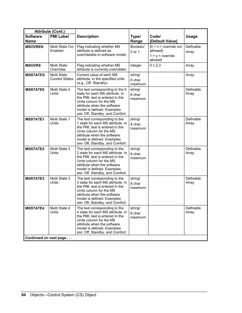
94 Objects—Control System (CS) Object
Attribute (Cont.)SoftwareName
PMI Label Description Type/Range
Code/[Default Value]
Usage
MSOVREN Multi State OvrEnabled
Flag indicating whether MSattribute is defined asoverrideable in software model.
Boolean/
0 or 1
[0 = n = override notallowed]
1 = y = overrideallowed
Definable
Array
MSOVRS Multi StateOverrides
Flag indicating whether MSattribute is currently overridden.
integer 0,1,2,3 Array
MSSTATES Multi StateCurrent States
Current value of each MSattribute, in the specified units(e.g., Off, Standby).
string/
6 char.maximum
Array
MSSTATE0 Multi State 0Units
The text corresponding to the 0state for each MS attribute. Inthe PMI, text is entered in theUnits column for the MSattribute when the softwaremodel is defined. Examplesare: Off, Standby, and Comfort.
string/
8 char.maximum
DefinableArray
MSSTATE1 Multi State 1Units
The text corresponding to the1 state for each MS attribute. Inthe PMI, text is entered in theUnits column for the MSattribute when the softwaremodel is defined. Examplesare: Off, Standby, and Comfort.
string/
8 char.maximum
DefinableArray
MSSTATE2 Multi State 2Units
The text corresponding to the2 state for each MS attribute. Inthe PMI, text is entered in theUnits column for the MSattribute when the softwaremodel is defined. Examplesare: Off, Standby, and Comfort.
string/
8 char.maximum
DefinableArray
MSSTATE3 Multi State 3Units
The text corresponding to the3 state for each MS attribute. Inthe PMI, text is entered in theUnits column for the MSattribute when the softwaremodel is defined. Examplesare: Off, Standby, and Comfort.
string/
8 char.maximum
DefinableArray
MSSTATE4 Multi State 4Units
The text corresponding to the4 state for each MS attribute. Inthe PMI, text is entered in theUnits column for the MSattribute when the softwaremodel is defined. Examplesare: Off, Standby, and Comfort.
string/
8 char.maximum
DefinableArray
Continued on next page . . .

Objects—Control System (CS) Object 95
Attribute (Cont.)SoftwareName
PMI Label Description Type/Range
Code/[Default Value]
Usage
MSVALUE0 Multi State 0Values
The number corresponding tothe 0 state for each MSattribute. In the PMI, this is thevalue entered in the statecolumn when the softwaremodel is defined.
integer Definable
Array
MSVALUE1 Multi State 1Values
The number corresponding tothe 1 state for each MSattribute. In the PMI, this is thevalue entered in the statecolumn when the softwaremodel is defined.
integer Definable
Array
MSVALUE2 Multi State 2Values
The number corresponding tothe 2 state for each MSattribute. In the PMI, this is thevalue entered in the statecolumn when the softwaremodel is defined.
integer Definable
Array
MSVALUE3 Multi State 3Values
The number corresponding tothe 3 state for each MSattribute. In the PMI, this is thevalue entered in the statecolumn when the softwaremodel is defined.
integer Definable
Array
MSVALUE4 Multi State 4Values
The number corresponding tothe 4 state for each MSattribute. In the PMI, this is thevalue entered in the statecolumn when the softwaremodel is defined.
integer Definable
Array
MS_1 andMS_2
Value of MSAttributes1 and 2
The current value of the MSattributes, in the state specifiedby the MSVALUE attribute.
integer
NAME Expanded ID Optional expanded version ofthe object’s name that helps tofurther identify the object. Forexample, AHU TemperatureControl for AHUTEMP.It appears in the Focus window,GPL template, and summaries.
string/
24 char.maximum
Definable
Writable
NTCMDADJ NT CommandAttributeAdjusted Flag
Flag indicating whether the NTcommand attribute is currentlyadjusted.
Boolean/
0 or 1
[0 = no adjust]
1 = adjust present
Continued on next page . . .

96 Objects—Control System (CS) Object
Attribute (Cont.)SoftwareName
PMI Label Description Type/Range
Code/[Default Value]
Usage
NTCMDATR NT CommandAttribute
Number of the one attribute,which can be both monitoredand commanded from the NT.The system converts theattribute name/number as itappears in the software model(AI_1, AI_2, AI_3) to an integer.
integer/
1 to32767
JC-BWritableDefinableRangeCheck
NTCMDISP NT CommandAttribute value
The ASCII representation of thecurrent value of the NTcommand attribute. The valuerounds down according to thedecimal position specified bythe FORMAT attribute.
string/
8 char.maximum
NTCMDNME NT CommandAttribute Name
Name of the attribute chosenby the user to be the oneattribute that can be bothmonitored and commandedfrom the NT.
string/
8 char.maximum
NTCMDST0 NT CommandAttributeState 0
State of the NT commandattribute’s 0 state (e.g., Off).Only applicable if the NTcommand attribute is Booleanor multistate. Otherwise,returns null.
string/
8 char.maximum
NTCMDST1 NT CommandAttributeState 1
State of the NT commandattribute’s 1 state (e.g., Off).Only applicable if the NTcommand attribute is Booleanor multistate. Otherwise,returns null.
string/
8 char.maximum
NTCMDST2 NT CommandAttributeState 2
State of the NT commandattribute’s 2 state (e.g., Off).Only applicable if the NTcommand attribute ismultistate. Otherwise, returnsnull.
string/
8 char.maximum
NTCMDST3 NT CommandAttributeState 3
State of the NT commandattribute’s 3 state (e.g., Off).Only applicable if the NTcommand attribute ismultistate. Otherwise, returnsnull.
string/
8 char.maximum
NTCMDST4 NT CommandAttributeState 4
State of the NT commandattribute’s 4 state (e.g., Off).Only applicable if the NTcommand attribute ismultistate. Otherwise, returnsnull.
string/
8 char.maximum
NTCMDUNT NT CommandAttribute Units
Units for the Commandattribute (the one attribute thatcan be both monitored andcommanded from the NT).
string/
6 char.maximum
Continued on next page . . .

Objects—Control System (CS) Object 97
Attribute (Cont.)SoftwareName
PMI Label Description Type/Range
Code/[Default Value]
Usage
NUMAD Number of ADAttributes
Total number of AD attributesdefined for the CS object.
integer/
0 to 32
Definable
NUMAI Number of AIAttributes
Total number of AI attributesdefined for the CS object.
integer/
0 to 16
Definable
NUMAO Number of AOAttributes
Total number of AO attributesdefined for the CS object.
integer/
0 to 16
Definable
NUMBD Number of BDAttributes
Total number of BD attributesdefined for the CS object.
integer/
0 to 32
Definable
NUMBI Number of BIAttributes
Total number of BI attributesdefined for the CS object.
integer/
0 to 16
Definable
NUMBO Number of BOAttributes
Total number of BO attributesdefined for the CS object.
integer/
0 to 16
Definable
NUMMS Number of MSAttributes
Total number of MS attributesdefined for the CS object.
integer/
0 to 2
Definable
NUMSP Number of SPAttributes
Total number of SP attributesdefined for the CS object.
integer/
0 to 32
Definable
OBJECT Object Name Name of the object, such asAHU-1. This name must beunique in the system.
string/
8 char.maximum
Definable
OBJVAL Object DefaultValue Attribute
Number of the Display attributechosen by the user to representthe CS object in summaries.The user enters the attributename/number as it appears inthe software model (e.g., AI_1,AI_2), and the system convertsthis to an integer.
integer/
1 to32767
JC-BWritableDefinableRangeCheck
OFFLINE Comm. Status Specifies whether the object isoffline or online.
An object is considered offlinewhen there is acommunications break betweenthe controller the object ismapped to and the NCM orNDM the controller isconnected to.
The Comm. Status field In theobject focus window is used forboth disconnect status andonline and offline status. If thelocal and remote NDMs aredisconnected, DISCONCTappears in the field. If theNDMs are connected, eitherONLINE or OFFLINE appearsin the field, depending onwhether the controller theobject is mapped to is online.
Boolean/
0 or 1
[0 = n = online]
1 = y = offline
Triggerable
GPL menu
Continued on next page . . .
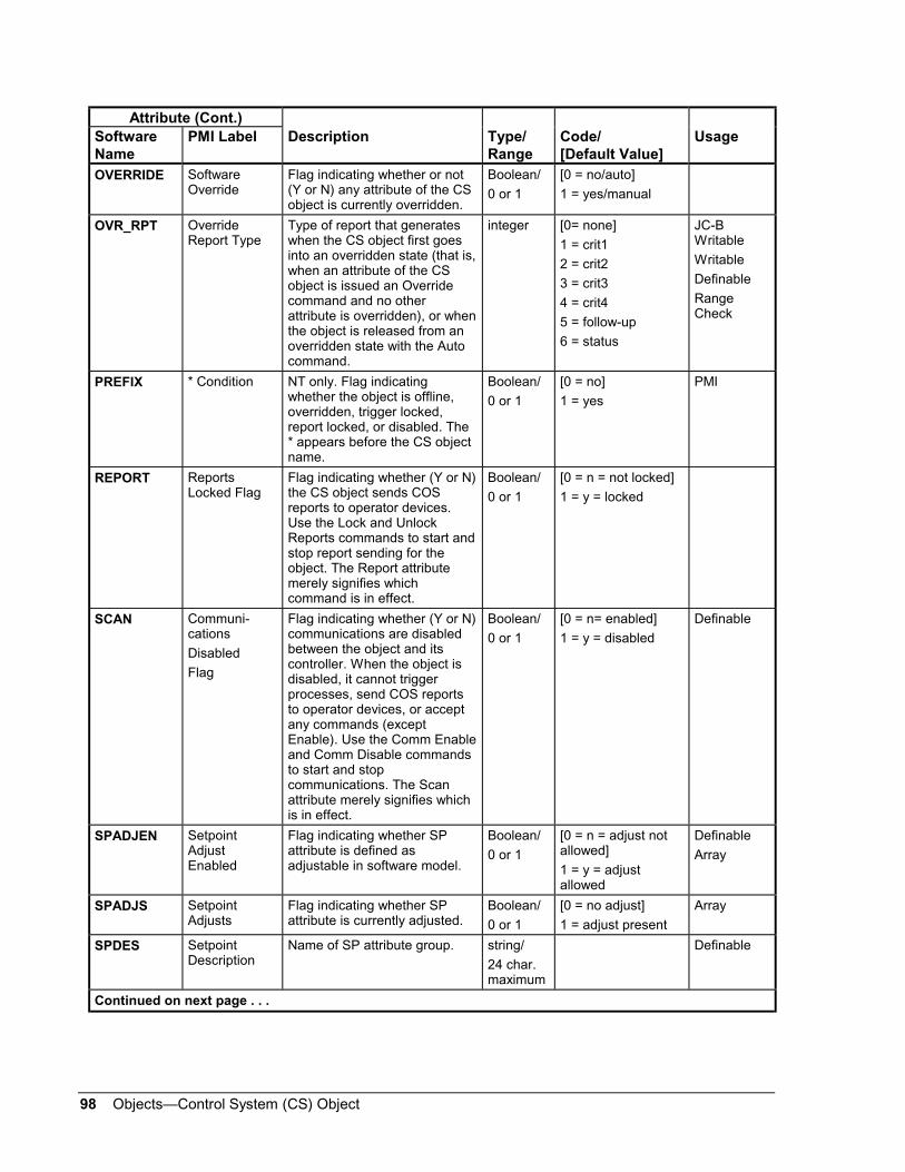
98 Objects—Control System (CS) Object
Attribute (Cont.)SoftwareName
PMI Label Description Type/Range
Code/[Default Value]
Usage
OVERRIDE SoftwareOverride
Flag indicating whether or not(Y or N) any attribute of the CSobject is currently overridden.
Boolean/
0 or 1
[0 = no/auto]
1 = yes/manual
OVR_RPT OverrideReport Type
Type of report that generateswhen the CS object first goesinto an overridden state (that is,when an attribute of the CSobject is issued an Overridecommand and no otherattribute is overridden), or whenthe object is released from anoverridden state with the Autocommand.
integer [0= none]
1 = crit1
2 = crit2
3 = crit3
4 = crit4
5 = follow-up
6 = status
JC-BWritable
Writable
Definable
RangeCheck
PREFIX * Condition NT only. Flag indicatingwhether the object is offline,overridden, trigger locked,report locked, or disabled. The* appears before the CS objectname.
Boolean/
0 or 1
[0 = no]
1 = yes
PMI
REPORT ReportsLocked Flag
Flag indicating whether (Y or N)the CS object sends COSreports to operator devices.Use the Lock and UnlockReports commands to start andstop report sending for theobject. The Report attributemerely signifies whichcommand is in effect.
Boolean/
0 or 1
[0 = n = not locked]
1 = y = locked
SCAN Communi-cations
Disabled
Flag
Flag indicating whether (Y or N)communications are disabledbetween the object and itscontroller. When the object isdisabled, it cannot triggerprocesses, send COS reportsto operator devices, or acceptany commands (exceptEnable). Use the Comm Enableand Comm Disable commandsto start and stopcommunications. The Scanattribute merely signifies whichis in effect.
Boolean/
0 or 1
[0 = n= enabled]
1 = y = disabled
Definable
SPADJEN SetpointAdjustEnabled
Flag indicating whether SPattribute is defined asadjustable in software model.
Boolean/
0 or 1
[0 = n = adjust notallowed]
1 = y = adjustallowed
Definable
Array
SPADJS SetpointAdjusts
Flag indicating whether SPattribute is currently adjusted.
Boolean/
0 or 1
[0 = no adjust]
1 = adjust present
Array
SPDES SetpointDescription
Name of SP attribute group. string/
24 char.maximum
Definable
Continued on next page . . .

Objects—Control System (CS) Object 99
Attribute (Cont.)SoftwareName
PMI Label Description Type/Range
Code/[Default Value]
Usage
SPNAMES Setpoint ASCIINames
Name of SP attribute. string/
8 char.maximum
Definable
Array
SPOVREN Setpoint OvrEnabled
Flag indicating whether SPattribute is defined asoverrideable in software model.
Boolean/
0 or 1
[0 = n = override notallowed]
1 = y = overrideallowed
Definable
Array
SPOVRS SetpointOverrides
Flag indicating whether SPattribute is currently overridden.
integer 0,1,2,3 Array
SPUNITS Setpoint ASCIIUnits
Optional units for SP attributevalue. Helps make value moremeaningful. For example, theattribute’s value can bedisplayed as 73.6 deg. F,20 psi, 45% RH, 310 GPM.
string/
6 char.maximum
Definable
Array
SP_1throughSP_32
Values forSetpointAttributes 1through 32
Current value of each setpointattribute.
floatingpoint
STATDISP Status Prefix Prefix specifying the currentstatus of the CS object: offline,overridden, trigger locked,report locked, disabled, oralarm. The prefix appearsbefore the object name insummaries. No prefix indicatesnormal status.
integer/
0 to 17
[0=normal, blank]2=RPT,report
locked3=TRG, trigger
locked10=SWO,
overridden12=DIS,
communication disabled
14=UNR, unreliable15=OFF,offline16=DCT,disconnect
PMI
Triggerable
SYSTEM System Name System in which the objectbelongs. The system mustalready exist in the network.
string/
8 char.maximum
When you aredefining an object,the PMI defaults tothe current system.
Definable
Continued on next page . . .

100 Objects—Control System (CS) Object
Attribute (Cont.)SoftwareName
PMI Label Description Type/Range
Code/[Default Value]
Usage
TRIGGER TriggersLocked Flag
Flag indicating whether (Y or N)triggers are currently locked forthe CS object. When triggersare locked, the offline state ofthe CS object, and its binaryattributes cannot trigger controlprocesses. Use the Lock andUnlock Triggers commands tostart and stop triggers. TheTriggers attribute merelyindicates which command is ineffect.
Boolean/
0 or 1
[0 = n = unlocked]
1 = y = locked
UNITS DisplayAttribute Units
Units for the Display attribute(which is the one attributeselected to represent the CSobject value in summaries, inthe CS Object Focus window,and at the NT). Makes thevalue of the Display attributemore meaningful. For example,deg F, psi, or GPM can be usedas Units. Only applicable if theDisplay attribute is analog.Otherwise, returns null.
string/
6 char.maximum

Objects—Control System (CS) Object 101
If an object is offline or its communications are disabled, commands to theCS object are not executed, but are stored. Offline means there is aphysical communication break between the CS object and its associatedcontroller. Disabled communications means an operator suppressedcommunications using a Disable command. The commands are issuedwhen the object comes back online, or when communications are enabled.
However, an Enable command is immediately executed if thecommunications for the object have been disabled.
For more information on commands, refer to Command Processing in thisdocument.
Table 42: Command TableCommand Source
SoftwareName
PMILabel
Description Parameters Process/MC[Priority]
PMI[Priority]
Feature[Priority]
AUTO Auto Releases the Override of theselected attribute, and eitherresumes input/outputprocessing between the fieldand NCM, or allows the nexthighest command to takecontrol of the attribute. Autois an abbreviation forautomatic mode ofoperation.
Attribute N.A. OWS
[1]
NT
[1]
N.A.
ChangeDefault
For ASC (including VMA)controllers only. Operatorentered value goes directlyto permanent memory.
Value N.A. LocalControl 4
N.A.
DISABLE Communi-cations
Disabled
Stops the object fromtriggering control processes,sending COS reports, andaccepting commands(except Enable).
None N.A OWS
NT
N.A.
ENABLE Communi-cationsEnable
Allows the object to triggercontrol processes, sendCOS reports, and acceptcommands.
None N.A. OWS
NT
N.A.
LOC_REP LockReports
Stops the CS object fromsending COS reports tooperator devices. Theoverride conditions of theattributes are saved andchecked when reports areunlocked to determinewhether a COS reportshould be sent.
None GPL
JC-BASIC
MC
OWS Scheduling
LOC_TRIG LockTriggers
Prevents the object’striggerable attributes fromtriggering control processes.
None GPL
JC-BASIC
MC
OWS Scheduling
Continued on next page . . .
CommandTable

102 Objects—Control System (CS) Object
Command (Cont.) SourceSoftwareName
PMILabel
Description Parameters Process/MC[Priority]
PMI[Priority]
Feature[Priority]
OVERRIDE Override Lets the operator replacethe current value of theselected attribute with auser-defined value. This is amanual command, onlyavailable to operators at theworkstation or NT.
Attribute
Value
N.A. OWS
[1]
NT
[1]
N.A.
REL_CS Release Releases a Priority 2 orPriority 3 adjust on thespecified attribute, andeither resumes input/outputprocessing between thefield and NCM, or allows thenext highest command totake control of the attribute.
Attribute
Priority
GPL
JC-BASIC
MC
[2 or 3]
OWS
[3]
Scheduling
[3]
SETCSAN Adjust anAnalogAttribute
Defines a value for thespecified analog or setpointattribute.
Attribute
Value
Priority
GPL
JC-BASIC
MC
[2 or 3]
OWS
[3]
NT
[3]
Scheduling
[3]
SETCSBN Adjust aBinaryAttribute
Defines a value for thespecified binary attribute.
Attribute
Value
Priority
GPL
JC-BASIC
MC
[2 or 3]
OWS
[3]
NT
[3]
Scheduling
[3]
SETCSMS Adjust aMultiStateAttribute
Defines a value for thespecified multistateattribute.
Attribute
Value
Priority
GPL
JC-BASIC
MC
[2 or 3]
OWS
[3]
NT
[3]
Scheduling
[3]
UNL_REP UnlockReports
Allows the object to sendCOS reports to operatordevices. The current statesof the unlocked attributesare compared to the stateswhen reports were locked tosee if a COS report shouldbe sent.
None GPL
JC-BASIC
MC
OWS Scheduling
UNL_TRIG UnlockTriggers
Allows the triggerableattributes of the CS objectto trigger control processes.
None GPL
JC-BASIC
MC
OWS Scheduling

Objects—Control System (CS) Object 103
Notes

104 Objects—Control System (CS) Object
Notes
Controls Group www.johnsoncontrols.com507 E. Michigan Street FAN 636P.O. Box 423 Metasys Network Technical ManualMilwaukee, WI 53201 Release 11.00
Printed in U.S.A.
Related Documents