Chemical Engineering and Processing 64 (2013) 57–67 Contents lists available at SciVerse ScienceDirect Chemical Engineering and Processing: Process Intensification jo u rn al hom epage: www.elsevier.com/locate/cep Control structure selection for three-product Petlyuk (dividing-wall) column Deeptanshu Dwivedi a , Ivar J. Halvorsen b , Sigurd Skogestad a,∗ a Department of Chemical Engineering, Norwegian University of Science and Technology, N-7491 Trondheim, Norway b SINTEF ICT, Applied Cybernetics, N-7465 Trondheim, Norway a r t i c l e i n f o Article history: Received 2 August 2012 Received in revised form 21 October 2012 Accepted 14 November 2012 Available online 23 November 2012 Keywords: Energy efficient distillation Thermally coupled distillation Control structure design Dividing-wall columns Petlyuk Column a b s t r a c t This paper deals with selecting control structures for a three-product Petlyuk (dividing-wall) column with an objective to achieve desired product purities with minimum use of energy (V). We consider four alternate control structures with and without the vapor split as a degree of freedom. This work also demonstrates the usefulness of the graphical V min diagram to visualize minimum boilup requirement and choose the appropriate control structure. © 2012 Elsevier B.V. All rights reserved. 1. Introduction For three-product separations, the Petlyuk (see Fig. 1 [23]) or divided-wall arrangements [14] offer significant savings in both energy and capital costs, as also shown by Cahn and DiMiceli [5], and Stupin [28]. The German company, BASF has more than 100 dividing-wall columns [14]. However, operation and control is chal- lenging and this paper proposes some new control schemes which are workable for varying feed composition disturbances. Halvorsen and Skogestad [11,13] have developed a graphical tool, the “V min diagrams”, to visualize the minimum energy require- ment for sharp and non-sharp separations in conventional and thermally coupled columns. This tool can be used for designing such arrangements [7] and we will also demonstrate its use to give some insights into control and operation. In terms of operation, several works have been published. Mutalib and Smith [20] reported simulation studies on the divided- wall columns. In their second work, Mutalib et al. [21] reported experimental studies conducted on a pilot plant and recommended a two point control of the system. Wolff and Skogestad [29] did a steady state study and operability analysis on a three-product Petlyuk column and conclude that the simultaneous specification of both impurities in the side-product is generally infeasible. Fur- ther, the liquid and vapor split ratios between pre-fractionator and the main column should be manipulated to get the optimal energy ∗ Corresponding author. Tel.: +47 735 94154. E-mail address: [email protected] (S. Skogestad). benefits. If the vapor split is not available as a degree of freedom, which is normally the case, one cannot control both ends of the prefractionator at the same time. Christiansen and Skogestad [6], Halvorsen and Skogestad [10] therefore proposed to use the liquid split to control the key impurity in the least pure end of the pre- fractionator. Ling and Luyben [18] explained that the liquid split valve (R L ) must be manipulated and proposed a control structure with the use of four composition loops with the liquid split control- ling the heavy key at the top stage of the prefractionator. In their second work, Ling and Luyben [19] studied the effectiveness of tem- perature control for BTX columns. Similar to Ling and Luyben [18], Kiss and Rewagad [15] and Rewagad and Kiss [24] suggested that control of the heavy key at the prefractionator top together with three composition loops in the main column may be sufficient to yield high-purity products and “implicitly” minimize the energy usage. Niggemann et al. [22] conducted simulation and experi- mental studies for separation of a mixture of fatty alcohols into three high-purity products. They reported that the heat transfer across the dividing wall can be a factor in design and operation. Lestak et al. [16] argued that in some cases the heat transfer across the dividing wall may decrease the overall energy consumptions. In non-beneficial regions however, the wall should be insulated. Some other works on the suitability of Model Predictive Control for dividing-wall columns have also been reported [24,4,1]. Ling et al. [17] suggested a control structure to avoid remixing of the intermediate component for optimal operation. In this paper, we study the separation of a feed with components A (lightest), B and C (heaviest) in a Petlyuk column as shown in Fig. 1. Note that the letter B is also used to denote the bottom product. To 0255-2701/$ – see front matter © 2012 Elsevier B.V. All rights reserved. http://dx.doi.org/10.1016/j.cep.2012.11.006

Welcome message from author
This document is posted to help you gain knowledge. Please leave a comment to let me know what you think about it! Share it to your friends and learn new things together.
Transcript

C
Da
b
a
ARRAA
KETCDP
1
deadla
tmtai
MweaaPott
0h
Chemical Engineering and Processing 64 (2013) 57– 67
Contents lists available at SciVerse ScienceDirect
Chemical Engineering and Processing:Process Intensification
jo u rn al hom epage: www.elsev ier .com/ locate /cep
ontrol structure selection for three-product Petlyuk (dividing-wall) column
eeptanshu Dwivedia, Ivar J. Halvorsenb, Sigurd Skogestada,∗
Department of Chemical Engineering, Norwegian University of Science and Technology, N-7491 Trondheim, NorwaySINTEF ICT, Applied Cybernetics, N-7465 Trondheim, Norway
r t i c l e i n f o
rticle history:eceived 2 August 2012eceived in revised form 21 October 2012ccepted 14 November 2012vailable online 23 November 2012
a b s t r a c t
This paper deals with selecting control structures for a three-product Petlyuk (dividing-wall) columnwith an objective to achieve desired product purities with minimum use of energy (V). We consider fouralternate control structures with and without the vapor split as a degree of freedom. This work alsodemonstrates the usefulness of the graphical Vmin diagram to visualize minimum boilup requirementand choose the appropriate control structure.
eywords:nergy efficient distillationhermally coupled distillationontrol structure designividing-wall columnsetlyuk Column
© 2012 Elsevier B.V. All rights reserved.
. Introduction
For three-product separations, the Petlyuk (see Fig. 1 [23]) orivided-wall arrangements [14] offer significant savings in bothnergy and capital costs, as also shown by Cahn and DiMiceli [5],nd Stupin [28]. The German company, BASF has more than 100ividing-wall columns [14]. However, operation and control is chal-
enging and this paper proposes some new control schemes whichre workable for varying feed composition disturbances.
Halvorsen and Skogestad [11,13] have developed a graphicalool, the “Vmin diagrams”, to visualize the minimum energy require-
ent for sharp and non-sharp separations in conventional andhermally coupled columns. This tool can be used for designing suchrrangements [7] and we will also demonstrate its use to give somensights into control and operation.
In terms of operation, several works have been published.utalib and Smith [20] reported simulation studies on the divided-all columns. In their second work, Mutalib et al. [21] reported
xperimental studies conducted on a pilot plant and recommended two point control of the system. Wolff and Skogestad [29] did steady state study and operability analysis on a three-productetlyuk column and conclude that the simultaneous specification
f both impurities in the side-product is generally infeasible. Fur-her, the liquid and vapor split ratios between pre-fractionator andhe main column should be manipulated to get the optimal energy∗ Corresponding author. Tel.: +47 735 94154.E-mail address: [email protected] (S. Skogestad).
255-2701/$ – see front matter © 2012 Elsevier B.V. All rights reserved.ttp://dx.doi.org/10.1016/j.cep.2012.11.006
benefits. If the vapor split is not available as a degree of freedom,which is normally the case, one cannot control both ends of theprefractionator at the same time. Christiansen and Skogestad [6],Halvorsen and Skogestad [10] therefore proposed to use the liquidsplit to control the key impurity in the least pure end of the pre-fractionator. Ling and Luyben [18] explained that the liquid splitvalve (RL) must be manipulated and proposed a control structurewith the use of four composition loops with the liquid split control-ling the heavy key at the top stage of the prefractionator. In theirsecond work, Ling and Luyben [19] studied the effectiveness of tem-perature control for BTX columns. Similar to Ling and Luyben [18],Kiss and Rewagad [15] and Rewagad and Kiss [24] suggested thatcontrol of the heavy key at the prefractionator top together withthree composition loops in the main column may be sufficient toyield high-purity products and “implicitly” minimize the energyusage. Niggemann et al. [22] conducted simulation and experi-mental studies for separation of a mixture of fatty alcohols intothree high-purity products. They reported that the heat transferacross the dividing wall can be a factor in design and operation.Lestak et al. [16] argued that in some cases the heat transfer acrossthe dividing wall may decrease the overall energy consumptions.In non-beneficial regions however, the wall should be insulated.Some other works on the suitability of Model Predictive Controlfor dividing-wall columns have also been reported [24,4,1]. Linget al. [17] suggested a control structure to avoid remixing of the
intermediate component for optimal operation.In this paper, we study the separation of a feed with componentsA (lightest), B and C (heaviest) in a Petlyuk column as shown in Fig. 1.Note that the letter B is also used to denote the bottom product. To
58 D. Dwivedi et al. / Chemical Engineering and Processing 64 (2013) 57– 67
lementations of three-product Petlyuk column.
asc
hatt[cc
1234
ftpsw
2
issaapvapsmc
Table 1Input data and nominal conditions for the three-product Petlyuk column model.
Relative volatilities [A, B, C] [4.2 2.1 1]Number of stages in C1 20 + 20Number of stages in C21 20 + 20Number of stages in C22 20 + 20Nominal feed flow rate (F) 1 kmol/minNominal feed composition [A, B, C] [33.3 33.3 33.3] (mol%)Nominal liquid reflux (L) 1.0033 kmol/minNominal boilup (V) 1.3381 kmol/minNominal distillate flow rate (D) 0.3348 kmol/minNominal bottom flow rate (B) 0.3333 kmol/minNominal side-product (S) 0.3318 kmol/minNominal liquid split (RL) 0.3465Nominal vapor split (RV) 0.5982Nominal purity of distillate (xD
A ) 99.5 (mol%)Nominal purity of side-product (xS
B) 99.45 (mol%)Nominal light impurity of side-product (xS
A) 0.05 (mol%)Nominal heavy impurity of side-product (xS
C) 0.5 (mol%)Nominal purity of bottom product (xB
C) 99.5 (mol%)Nominal heavy impurity of prefractionator top (xD1
C ) 0.29 (mol%)Nominal light impurity of prefractionator bottoms (xB1
A ) 0.08 (mol%)
0 0.2 0.4 0.6 0.8 11
40
mole fraction
C1
A B C
1
40
80
C22
C21
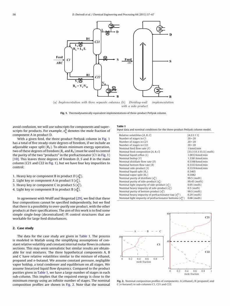
Fig. 1. Thermodynamically equivalent imp
void confusion, we will use subscripts for components and super-cripts for products. For example, xD
A denotes the mole fraction ofomponent A in product D.
With a given feed, the three-product Petlyuk column in Fig. 1as a total of five steady-state degrees of freedom, if we include andjustable vapor split (RV). To obtain minimum energy operation,wo of these degrees of freedom (RL and RV) must be used to controlhe purity of the two “products” in the prefractionator (C1 in Fig. 1)10]. This leaves three degrees of freedom D, S and B in the mainolumn (C21 and C22 in Fig. 1), but we have four key impurities toontrol:
. Heavy key or component B in product D (xDB ).
. Light key or component A in product S (xSA).
. Heavy key or component C in product S (xSC).
. Light key or component B in product B (xBB).
In agreement with Wolff and Skogestad [29], we find that theseour compositions cannot be specified independently, but we findhat there is a possibility to over-purify one product, with the otherroducts at their specifications. The aim of this work is to find someimple single-loop (decentralized) PI control structures that areorkable for large feed disturbances.
. Case study
The data for the case study are given in Table 1. The processs modeled in Matlab using the simplifying assumptions of con-tant relative volatility and constant internal molar flows in columnections. This may seem unrealistic but similar results are obtain-ble for real mixtures. The three hypothetical components A, Bnd C have relative volatilities similar to the mixture of ethanol,ropanol and n-butanol. We assume constant pressure, negligibleapor holdup, a total condenser and equilibrium on all stages. Wessume linearized liquid flow dynamics. Compared to the product
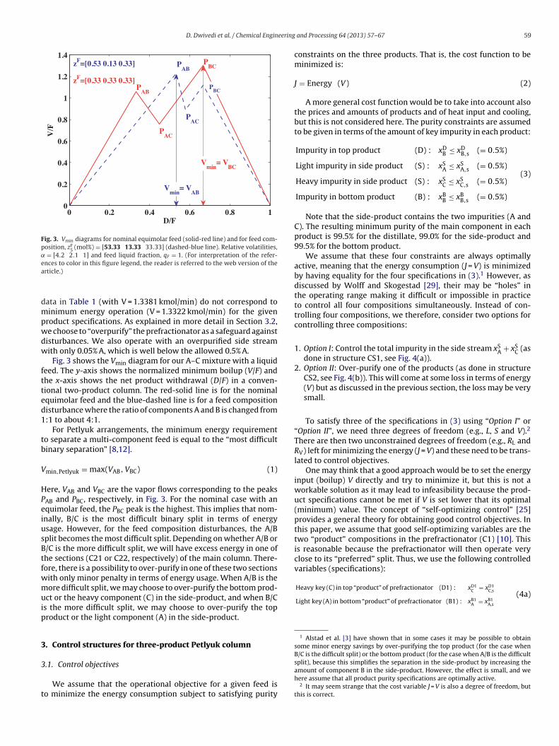
urities given in Table 1, we have a large number of stages in eachub-column. This implies that the required energy is close to theinimum energy using an infinite number of stages. The nominalomposition profiles are shown in Fig. 2. Note that the nominal
0 0.2 0.4 0.6 0.8 1mole fraction
Fig. 2. Nominal composition profiles of components: A (ethanol), B (propanol) andC (n-butanol) in sub-columns C1, C21 and C22.
D. Dwivedi et al. / Chemical Engineering
0 0.2 0.4 0.6 0.8 10
0.2
0.4
0.6
0.8
1
1.2
1.4
D/F
V/F
PAB
PAC
PAC
PAB
PBCzF=[0.53 0.13 0.33]
zF=[0.33 0.33 0.33]P
BC
Vmin
= VBC
Vmin
= VAB
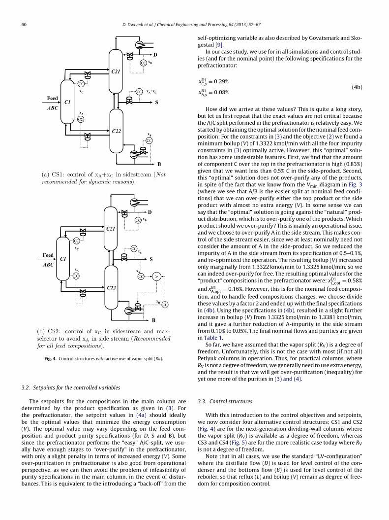
Fig. 3. Vmin diagrams for nominal equimolar feed (solid-red line) and for feed com-position, zF
5 (mol%) = [53.33 13.33 33.33] (dashed-blue line). Relative volatilities,˛ = [4.2 2.1 1] and feed liquid fraction, qF = 1. (For interpretation of the refer-ea
dmpwdw
ftted1
tb
V
HPeiusBtfwmuip
3
3
t
Heavy key (C) in top “product” of prefractionator (D1) : xC = xC,s
Light key (A) in bottom “product” of prefractionator (B1) : xB1A = xB1
A,s
(4a)
1 Alstad et al. [3] have shown that in some cases it may be possible to obtainsome minor energy savings by over-purifying the top product (for the case whenB/C is the difficult split) or the bottom product (for the case when A/B is the difficultsplit), because this simplifies the separation in the side-product by increasing the
nces to color in this figure legend, the reader is referred to the web version of therticle.)
ata in Table 1 (with V = 1.3381 kmol/min) do not correspond toinimum energy operation (V = 1.3322 kmol/min) for the given
roduct specifications. As explained in more detail in Section 3.2,e choose to “overpurify” the prefractionator as a safeguard againstisturbances. We also operate with an overpurified side streamith only 0.05% A, which is well below the allowed 0.5% A.
Fig. 3 shows the Vmin diagram for our A–C mixture with a liquideed. The y-axis shows the normalized minimum boilup (V/F) andhe x-axis shows the net product withdrawal (D/F) in a conven-ional two-product column. The red-solid line is for the nominalquimolar feed and the blue-dashed line is for a feed compositionisturbance where the ratio of components A and B is changed from:1 to about 4:1.
For Petlyuk arrangements, the minimum energy requiremento separate a multi-component feed is equal to the “most difficultinary separation” [8,12].
min,Petlyuk = max(VAB, VBC) (1)
ere, VAB and VBC are the vapor flows corresponding to the peaksAB and PBC, respectively, in Fig. 3. For the nominal case with anquimolar feed, the PBC peak is the highest. This implies that nom-nally, B/C is the most difficult binary split in terms of energysage. However, for the feed composition disturbances, the A/Bplit becomes the most difficult split. Depending on whether A/B or/C is the more difficult split, we will have excess energy in one ofhe sections (C21 or C22, respectively) of the main column. There-ore, there is a possibility to over-purify in one of these two sectionsith only minor penalty in terms of energy usage. When A/B is theore difficult split, we may choose to over-purify the bottom prod-
ct or the heavy component (C) in the side-product, and when B/Cs the more difficult split, we may choose to over-purify the toproduct or the light component (A) in the side-product.
. Control structures for three-product Petlyuk column
.1. Control objectives
We assume that the operational objective for a given feed iso minimize the energy consumption subject to satisfying purity
and Processing 64 (2013) 57– 67 59
constraints on the three products. That is, the cost function to beminimized is:
J = Energy (V) (2)
A more general cost function would be to take into account alsothe prices and amounts of products and of heat input and cooling,but this is not considered here. The purity constraints are assumedto be given in terms of the amount of key impurity in each product:
Impurity in top product (D) : xDB ≤ xD
B,s (= 0.5%)
Light impurity in side product (S) : xSA ≤ xS
A,s (= 0.5%)
Heavy impurity in side product (S) : xSC ≤ xS
C,s (= 0.5%)
Impurity in bottom product (B) : xBB ≤ xB
B,s (= 0.5%)
(3)
Note that the side-product contains the two impurities (A andC). The resulting minimum purity of the main component in eachproduct is 99.5% for the distillate, 99.0% for the side-product and99.5% for the bottom product.
We assume that these four constraints are always optimallyactive, meaning that the energy consumption (J = V) is minimizedby having equality for the four specifications in (3).1 However, asdiscussed by Wolff and Skogestad [29], their may be “holes” inthe operating range making it difficult or impossible in practiceto control all four compositions simultaneously. Instead of con-trolling four compositions, we therefore, consider two options forcontrolling three compositions:
1. Option I: Control the total impurity in the side stream xSA + xS
C (asdone in structure CS1, see Fig. 4(a)).
2. Option II: Over-purify one of the products (as done in structureCS2, see Fig. 4(b)). This will come at some loss in terms of energy(V) but as discussed in the previous section, the loss may be verysmall.
To satisfy three of the specifications in (3) using “Option I” or“Option II”, we need three degrees of freedom (e.g., L, S and V).2
There are then two unconstrained degrees of freedom (e.g., RL andRV) left for minimizing the energy (J = V) and these need to be trans-lated to control objectives.
One may think that a good approach would be to set the energyinput (boilup) V directly and try to minimize it, but this is not aworkable solution as it may lead to infeasibility because the prod-uct specifications cannot be met if V is set lower that its optimal(minimum) value. The concept of “self-optimizing control” [25]provides a general theory for obtaining good control objectives. Inthis paper, we assume that good self-optimizing variables are thetwo “product” compositions in the prefractionator (C1) [10]. Thisis reasonable because the prefractionator will then operate veryclose to its “preferred” split. Thus, we use the following controlledvariables (specifications):
D1 D1
amount of component B in the side-product. However, the effect is small, and wehere assume that all product purity specifications are optimally active.
2 It may seem strange that the cost variable J = V is also a degree of freedom, butthis is correct.
60 D. Dwivedi et al. / Chemical Engineering
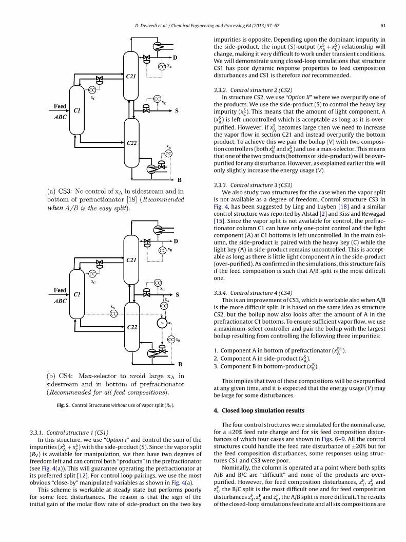
Fig. 4. Control structures with active use of vapor split (R ).
3
dtb(psawoppb
CS3 and CS4 (Fig. 5) are for the more realistic case today where RVis not a degree of freedom.
Note that in all cases, we use the standard “LV-configuration”where the distillate flow (D) is used for level control of the con-
V
.2. Setpoints for the controlled variables
The setpoints for the compositions in the main column areetermined by the product specification as given in (3). Forhe prefractionator, the setpoint values in (4a) should ideallye the optimal values that minimize the energy consumptionV). The optimal value may vary depending on the feed com-osition and product purity specifications (for D, S and B), butince the prefractionator performs the “easy” A/C-split, we usu-lly have enough stages to “over-purify” in the prefractionator,ith only a slight penalty in terms of increased energy (V). Some
ver-purification in prefractionator is also good from operational
erspective, as we can then avoid the problem of infeasibility ofurity specifications in the main column, in the event of distur-ances. This is equivalent to the introducing a “back-off” from theand Processing 64 (2013) 57– 67
self-optimizing variable as also described by Govatsmark and Sko-gestad [9].
In our case study, we use for in all simulations and control stud-ies (and for the nominal point) the following specifications for theprefractionator:
xD1C,s = 0.29%
xB1A,s = 0.08%
(4b)
How did we arrive at these values? This is quite a long story,but let us first repeat that the exact values are not critical becausethe A/C split performed in the prefractionator is relatively easy. Westarted by obtaining the optimal solution for the nominal feed com-position: For the constraints in (3) and the objective (2) we found aminimum boilup (V) of 1.3322 kmol/min with all the four impurityconstraints in (3) optimally active. However, this “optimal” solu-tion has some undesirable features. First, we find that the amountof component C over the top in the prefractionator is high (0.83%)given that we want less than 0.5% C in the side-product. Second,this “optimal” solution does not over-purify any of the products,in spite of the fact that we know from the Vmin diagram in Fig. 3(where we see that A/B is the easier split at nominal feed condi-tions) that we can over-purify either the top product or the sideproduct with almost no extra energy (V). In some sense we cansay that the “optimal” solution is going against the “natural” prod-uct distribution, which is to over-purify one of the products. Whichproduct should we over-purify? This is mainly an operational issue,and we choose to over-purify A in the side stream. This makes con-trol of the side stream easier, since we at least nominally need notconsider the amount of A in the side-product. So we reduced theimpurity of A in the side stream from its specification of 0.5–0.1%,and re-optimized the operation. The resulting boilup (V) increasedonly marginally from 1.3322 kmol/min to 1.3325 kmol/min, so wecan indeed over-purify for free. The resulting optimal values for the“product” compositions in the prefractionator were: xD1
C,opt = 0.58%
and xB1A,opt = 0.16%. However, this is for the nominal feed composi-
tion, and to handle feed compositions changes, we choose dividethese values by a factor 2 and ended up with the final specificationsin (4b). Using the specifications in (4b), resulted in a slight furtherincrease in boilup (V) from 1.3325 kmol/min to 1.3381 kmol/min,and it gave a further reduction of A-impurity in the side streamfrom 0.10% to 0.05%. The final nominal flows and purities are givenin Table 1.
So far, we have assumed that the vapor split (RV) is a degree offreedom. Unfortunately, this is not the case with most (if not all)Petlyuk columns in operation. Thus, for practical columns, whereRV is not a degree of freedom, we generally need to use extra energy,and the result is that we will get over-purification (inequality) foryet one more of the purities in (3) and (4).
3.3. Control structures
With this introduction to the control objectives and setpoints,we now consider four alternative control structures; CS1 and CS2(Fig. 4) are for the next-generation dividing-wall columns wherethe vapor split (RV) is available as a degree of freedom, whereas
denser and the bottoms flow (B) is used for level control of thereboiler, so that reflux (L) and boilup (V) remain as degree of free-dom for composition control.
D. Dwivedi et al. / Chemical Engineering
3
i(f(io
fi
purified. However, for feed composition disturbances, zF, zF and
Fig. 5. Control Structures without use of vapor split (RV).
.3.1. Control structure 1 (CS1)In this structure, we use “Option I” and control the sum of the
mpurities (xSA + xS
C) with the side-product (S). Since the vapor splitRV) is available for manipulation, we then have two degrees ofreedom left and can control both “products” in the prefractionatorsee Fig. 4(a)). This will guarantee operating the prefractionator atts preferred split [12]. For control loop pairings, we use the most
bvious “close-by” manipulated variables as shown in Fig. 4(a).This scheme is workable at steady state but performs poorlyor some feed disturbances. The reason is that the sign of thenitial gain of the molar flow rate of side-product on the two key
and Processing 64 (2013) 57– 67 61
impurities is opposite. Depending upon the dominant impurity inthe side-product, the input (S)-output (xS
A + xSC) relationship will
change, making it very difficult to work under transient conditions.We will demonstrate using closed-loop simulations that structureCS1 has poor dynamic response properties to feed compositiondisturbances and CS1 is therefore not recommended.
3.3.2. Control structure 2 (CS2)In structure CS2, we use “Option II” where we overpurify one of
the products. We use the side-product (S) to control the heavy keyimpurity (xS
C). This means that the amount of light component, A(xS
A) is left uncontrolled which is acceptable as long as it is over-purified. However, if xS
A becomes large then we need to increasethe vapor flow in section C21 and instead overpurify the bottomproduct. To achieve this we pair the boilup (V) with two composi-tion controllers (both xD
B and xSA) and use a max-selector. This means
that one of the two products (bottoms or side-product) will be over-purified for any disturbance. However, as explained earlier this willonly slightly increase the energy usage (V).
3.3.3. Control structure 3 (CS3)We also study two structures for the case when the vapor split
is not available as a degree of freedom. Control structure CS3 inFig. 4, has been suggested by Ling and Luyben [18] and a similarcontrol structure was reported by Alstad [2] and Kiss and Rewagad[15]. Since the vapor split is not available for control, the prefrac-tionator column C1 can have only one-point control and the lightcomponent (A) at C1 bottoms is left uncontrolled. In the main col-umn, the side-product is paired with the heavy key (C) while thelight key (A) in side-product remains uncontrolled. This is accept-able as long as there is little light component A in the side-product(over-purified). As confirmed in the simulations, this structure failsif the feed composition is such that A/B split is the most difficultone.
3.3.4. Control structure 4 (CS4)This is an improvement of CS3, which is workable also when A/B
is the more difficult split. It is based on the same idea as structureCS2, but the boilup now also looks after the amount of A in theprefractionator C1 bottoms. To ensure sufficient vapor flow, we usea maximum-select controller and pair the boilup with the largestboilup resulting from controlling the following three impurities:
1. Component A in bottom of prefractionator (xB1A ).
2. Component A in side-product (xSA).
3. Component B in bottom-product (xBB).
This implies that two of these compositions will be overpurifiedat any given time, and it is expected that the energy usage (V) maybe large for some disturbances.
4. Closed loop simulation results
The four control structures were simulated for the nominal case,for a ±20% feed rate change and for six feed composition distur-bances of which four cases are shown in Figs. 6–9. All the controlstructures could handle the feed rate disturbance of ±20% but forthe feed composition disturbances, some responses using struc-tures CS1 and CS3 were poor.
Nominally, the column is operated at a point where both splitsA/B and B/C are “difficult” and none of the products are over-
1 2zF
3, the B/C split is the most difficult one and for feed compositiondisturbances zF
4, zF5 and zF
6, the A/B split is more difficult. The resultsof the closed-loop simulations feed rate and all six compositions are
62 D. Dwivedi et al. / Chemical Engineering and Processing 64 (2013) 57– 67
F eptabl F F F
sA
Saetsc
uck
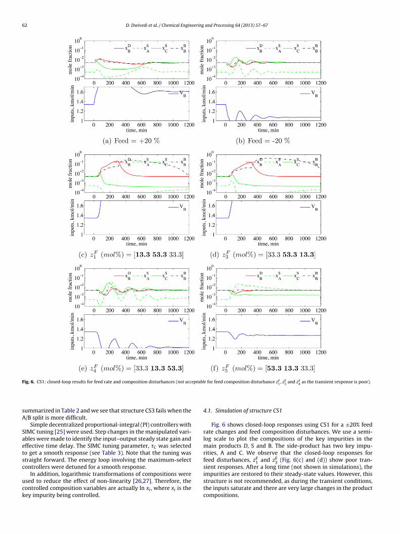
ig. 6. CS1: closed-loop results for feed rate and composition disturbances (not acc
ummarized in Table 2 and we see that structure CS3 fails when the/B split is more difficult.
Simple decentralized proportional-integral (PI) controllers withIMC tuning [25] were used. Step changes in the manipulated vari-bles were made to identify the input–output steady state gain andffective time delay. The SIMC tuning parameter, �C was selectedo get a smooth response (see Table 3). Note that the tuning wastraight forward. The energy loop involving the maximum-selectontrollers were detuned for a smooth response.
In addition, logarithmic transformations of compositions weresed to reduce the effect of non-linearity [26,27]. Therefore, theontrolled composition variables are actually ln xi, where xi is theey impurity being controlled.
e for feed composition disturbance z1, z3 and z4 as the transient response is poor).
4.1. Simulation of structure CS1
Fig. 6 shows closed-loop responses using CS1 for a ±20% feedrate changes and feed composition disturbances. We use a semi-log scale to plot the compositions of the key impurities in themain products D, S and B. The side-product has two key impu-rities, A and C. We observe that the closed-loop responses forfeed disturbances, zF
1 and zF3 (Fig. 6(c) and (d)) show poor tran-
sient responses. After a long time (not shown in simulations), the
impurities are restored to their steady-state values. However, thisstructure is not recommended, as during the transient conditions,the inputs saturate and there are very large changes in the productcompositions.
D. Dwivedi et al. / Chemical Engineering and Processing 64 (2013) 57– 67 63
Fig. 7. CS2: closed-loop results for feed rate and composition disturbances (acceptable for all disturbances).
4
±stsspct
.2. Simulation of structure CS2
Control structure CS2 shows good dynamic responses for the20% feed rate changes and the feed composition disturbances as
hown in Fig. 7. The steady state impurities of the products are bet-er than the specifications (3). For feed compositions when the B/Cplit is more difficult (Fig. 7(c) and (d)), the light impurity (A) in
ide-product is not controlled and is over-purified. For feed com-ositions when A/B is the more difficult split, the maximum-selectontroller pairs the boilup with the light key in side-product andhe bottom product is over-purified (Fig. 7(e) and (f)). Note that forthese cases, both key impurities in the side-product are controlledsimultaneously.
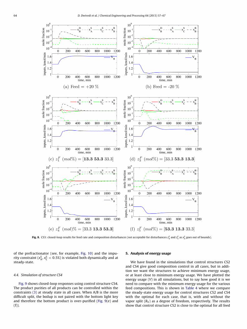
4.3. Simulation of structure CS3
We next consider the case when the vapor split (RV) is not adegree of freedom. Control structure CS3 does not attempt to con-
trol A in the side product and is workable for cases where B/C isthe most difficult split (disturbances zF4 and zF5, see Fig. 8(c) and
(d)). However, for disturbances when A/B is the more difficult split(Fig. 8(e) and (f)). We have “breakthrough” of A in the bottom
64 D. Dwivedi et al. / Chemical Engineering and Processing 64 (2013) 57– 67
ances
ors
4
Tcda(
Fig. 8. CS3: closed-loop results for feed rate and composition disturb
f the prefractionator (see, for example, Fig. 10) and the impu-ity constraint (xS
A, xSC < 0.5%) is violated both dynamically and at
teady-state.
.4. Simulation of structure CS4
Fig. 9 shows closed-loop responses using control structure CS4.he product purities of all products can be controlled within the
onstraints (3) at steady state in all cases. When A/B is the moreifficult split, the boilup is not paired with the bottom light keynd therefore the bottom product is over-purified (Fig. 9(e) andf)).(not acceptable for disturbances zF4 and zF
5 as xSA
goes out of bounds).
5. Analysis of energy usage
We have found in the simulations that control structures CS2and CS4 give good composition control in all cases, but in addi-tion we want the structures to achieve minimum energy usage,or at least close to minimum energy usage. We have plotted theenergy usage (V) in all simulations, but to say how good it is weneed to compare with the minimum energy usage for the variousfeed compositions. This is shown in Table 4 where we compare
the steady-state energy usage for control structures CS2 and CS4with the optimal for each case, that is, with and without thevapor split (RV) as a degree of freedom, respectively. The resultsshow that control structure CS2 is close to the optimal for all feed
D. Dwivedi et al. / Chemical Engineering and Processing 64 (2013) 57– 67 65
Fig. 9. CS4: closed-loop results for feed rate and composition disturbances (acceptable for all disturbances).
cpfchbstniTf
ompositions, with a maximum energy loss of 1.01% for feed com-osition zF
6. Control structure CS4 is also close to the optimal for alleed compositions, with a maximum energy loss of 2.27% for feedomposition zF
6. Note that the optimal energy usage is generallyigher for structure CS4 than for CS2 (up to about 19.88% for zF
5),ut this is an inevitable loss caused by operating with a fixed vaporplit (RV). The reason for the (albeit small) energy losses for con-rol structures CS2 and CS4 is mainly because the prefractionator is
ot operating quite optimally, that is, the prefractionator setpointsn (4b) are not the optimal ones as explained earlier in Section 3.2.his is also why the energy usage is 0.42% above the minimum evenor the nominal feed composition.
6. Discussion
6.1. Change in difficult split
Fig. 3 shows how the Vmin diagram depends on the feed com-position. As explained earlier, the minimum boilup for sharpseparation is set by the “most difficult binary split”, which aregiven in Fig. 3 by the peaks PAB and PBC. For the nominal feed
(red solid line), the peak PBC is highest. This implies that the B/Csplit is more difficult. It is then acceptable to leave A uncontrolledin the side stream as in structure CS3. However, for a feed com-position making A/B the more difficult split (blue dashed line in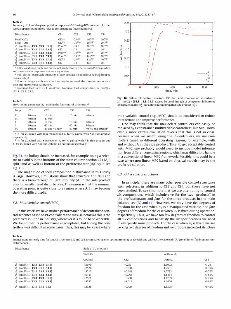
66 D. Dwivedi et al. / Chemical Engineering and Processing 64 (2013) 57– 67
Table 2Summary of closed-loop composition responsesa,b,c ,d using different control struc-tures (superscript numbers refer to corresponding figure numbers).
Disturbance CS1 CS2 CS3 CS4
Feed, +20% OK6(a) OK7(a) OK8(a) OK9(a)
Feed, −20% OK6(b) OK7(b) OK8(b) OK9(b)
zF1 (mol%) = [13.3 53.3 33.3] Poor6(c) OK7(c) OK8(c) OK9(c)
zF2 (mol%) = [13.3 33.3 53.3] OK OK OK OK
zF3 (mol%) = [33.3 53.3 13.3] Poor6(d) OK7(d) OK8(d) OK9(d)
zF4 (mol%) = [33.3 13.3 53.3] Poor6(e) OK7(e) Fail8(e) OK9(e)
zF5 (mol%) = [53.3 13.3 33.3] OK6(f) OK7(f) Fail8(f) OK9(f)
zF6 (mol%) = [53.3 33.3 13.3] OK OK Fail OK
a OK: closed-loop stable and purities all products are either restored/over-purifiedand the transient responses are not very severe.
b Fail: closed-loop stable but purity of side-product is not maintained (xSB dropped
considerably).c Poor: although steady state purities may be restored, the transient response is
poor and shows valve saturation.d Nominal feed rate: F = 1 kmol/min. Nominal feed composition, zF (mol%) =
[33.3 33.3 33.3]
Table 3SIMC tuning parameter (�C) used in the four control structures.a,b
Loop CS1 CS2 CS3 CS4
RL 10 min 10 min 10 min 40 minRV 40 min 40 min – –L 20 min 10 min 10 min 40 minS 80 min 40 min 40 min 10 minVB 10 min 40 and 40 mina 40 min 40, 40 and 10 minb
a �C for VB paired with B in reboiler and �C for VB paired with A in side-productrespectively.
�
FtsF
itaot
6
tpWt
0 200 400 600 8000
0.05
0.1
0.15
0.2
0.25
0.3
0.35
time, min
mol
e fr
actio
n
xAS
xAB1
Fig. 10. Failure of control structure CS3 for feed composition disturbance
respectively. Thus, we have too few degrees of freedom to control
TEd
b �C for VB paired with B in reboiler, �C for VB paired with A in side-product andC for VB paired with A in sub-column C1 bottoms respectively.
ig. 3), the boilup should be increased, for example, using a selec-or to avoid A in the bottoms of the main column section C21 (A/Bplit) and as well as bottom of the prefractionator (A/C split, seeig. 10).
The magnitude of feed composition disturbance in this studys large. However, simulations show that structure CS3 fails andhere is a breakthrough of light impurity (A) in the side productlso for smaller feed disturbances. The reason is that the nominalperating point is quite close to a region where A/B may becomehe more difficult split.
.2. Multivariable control (MPC)
In this work, we have studied performance of decentralized con-rol schemes based on PI-controllers and max-selectors as this is the
referred solution in industry, whenever it is found to be workable.e found that its performance is acceptable, but tuning the con-rollers was difficult in some cases. Thus, this may be a case where
able 4nergy usage at steady state for control structures CS2 and CS4 as compared against optimuisturbances.
Disturbance Boilup (V), kmol/min
With RV
Optimal
zF1 (mol%) = [13.3 53.3 33.3] 1.5070
zF2 (mol%) = [13.3 33.3 53.3] 1.2528
zF3 (mol%) = [33.3 53.3 13.3] 1.5713
zF4 (mol%) = [33.3 13.3 53.3] 1.0151
zF5 (mol%) = [53.3 13.3 33.3] 1.2571
zF6 (mol%) = [53.3 33.3 13.3] 1.4533
zF (mol%) = [33.3 33.3 33.3] 1.3325
zF5 (mol%) = [53.3 13.3 33.3] caused by breakthrough of component in bottoms
of prefractionator (xB1A ) resulting in contaminated side product (xS
A).
multivariable control (e.g., MPC) should be considered to reduceinteractions and improve performance.
One may think that the max-select controllers can easily bereplaced by a constrained multivariable controllers, like MPC. How-ever, a more careful evaluation reveals that this is not so clear,because when we switch using the PI-controllers, we use con-trollers tuned in different operating regions, for example, withand without A in the side product. Thus, to get acceptable controlwith MPC, one probably would need to include model informa-tion from different operating regions, which may difficult to handlein a conventional linear MPC framework. Possibly, this could be acase where non-linear MPC based on physical models may be thepreferred solution.
6.3. Other control structures
In principle, there are many other possible control structureswith selectors, in addition to CS2 and CS4, but these have notbeen studied. To see this, note that we are attempting to controlsix compositions, which include two for the two “products” inthe prefractionator and four for the three products in the maincolumn, see (3) and (4). However, we only have five degrees offreedom for the case when RV is a manipulated variable, and fourdegrees of freedom for the case when RV is fixed during operation,
all six compositions and to satisfy the six specifications we needto overpurify some products. For the case when RV is fixed, we arelacking two degrees of freedom and we propose in control structure
m energy usage with and without the vapor split (RV ) for different feed composition
Without RV
CS2 Optimal CS4
+0.7% 1.5072 +1.2%+0.33% 1.2551 +0.37%+0.68% 1.5722 +0.76%+0.06% 1.1434 +1.88%+0.23% 1.4769 +2.27%+1.01% 1.6406 +0.87%
+0.42% 1.3325 +0.42%
eering
CtiaSdmiAStpibshwe
7
twvColwwwpti(
R
[
[
[
[
[
[
[
[
[
[
[
[
[
[
[
[
[
[
[28] W. Stupin, Thermally coupled distillation – a case history, Chemical Engineering
D. Dwivedi et al. / Chemical Engin
S4 to always control three of the compositions, and to overpurifywo of the remaining three compositions using a selector. However,t is not given which three compositions to include in the selector,nd it is not given that boilup should be used in the selector.pecifically, for the split A/B we may choose to overpurify xD
B (B inistillate) rather than xS
A (A in sidestream), and for the split B/C weay choose to overpurify xS
C (C in side stream) rather than xBB (B
n bottom). Similarly, for the prefractionator, we may for the split/C choose to overpurify xC in the top rather than xA in the bottom.ome of these alternatives may be worthwhile considering, in par-icular, if overpurification of some product is desirable, wheneverossible. Nevertheless, of all these possible alternative structures,
t seems that structure CS4 is a good choice, mainly because theoilup (V) has a direct effect on the three compositions used by theelector, and because the three remaining manipulated variablesave a direct effect on the three remaining compositions. Indeed, itas found to give good composition control with close to minimum
nergy usage for a wide range of feed composition changes.
. Conclusions
In this work, we study decentralized control structures whenhe objective is to achieve desired purities for the three productsith close to minimum use of energy (V). For the case where the
apor split (RV) is a degree of freedom, we propose to use structureS2 as shown in Fig. 4(a). It will generally lead to overpurificationf either the side stream or bottom product, but this will cost veryittle in terms of extra energy usage. For the more realistic case
here the vapor split is not a degree of freedom, the energy usageill be higher for some disturbances. This is inevitable, but other-ise the proposed structure CS4 (see Fig. 5(a)) achieves the desiredurities with use of close to minimum energy. The simpler struc-ure CS3 may be used instead of CS4 for cases where the A/B splits relatively simple so that we always have low concentration of A“overpurification”) in the side stream.
eferences
[1] T. Adrian, H. Schoenmakers, M. Boll, Model predictive control of integratedunit operations: control of a divided wall column, Chemical Engineering andProcessing 43 (3) (2004) 347–355.
[2] V. Alstad, Studies on selection of controlled variables, Ph.D. thesis, NorwegianUniversity of Science and Technology, Department of Chemical Engineering,2005 (Chapter 9).
[3] V. Alstad, I.J. Halvosrsen, S. Skogestad, Optimal operation of a Petlyuk distil-lation column: energy savings by over-fractionating, in: Escape-14, Lisbon,
Portugal, 2004.[4] C. Buck, C. Hiller, G. Fieg, Applying model predictive control to dividing wallcolumns, Chemical Engineering & Technology 34 (5) (2011) 663–672.
[5] R.P. Cahn, A.G. DiMiceli, Separation of multicomponent mixture in single tower,United States Patent Office, US 3,058,893 (1962).
[
and Processing 64 (2013) 57– 67 67
[6] A.C. Christiansen, S. Skogestad, Energy savings in complex distillation arrange-ments: importance of using the preferred separation, in: AIChE Annual Meeting,Los Angeles, November 1997, 1997, paper 199d.
[7] I. Dejanovic, L. Matijasevic, I.J. Halvorsen, S. Skogestad, H. Jansen, B. Kaibel, Z.Olujic, Designing four-product dividing wall columns for separation of a multi-component aromatics mixture, Chemical Engineering Research and Design, 89(8) (2011) 1155–1167.
[8] Z. Fidkowski, L. Królikowski, Minimum energy requirements of thermally cou-pled distillation systems, AIChE Journal 33 (4) (1987) 643–653.
[9] M.S. Govatsmark, S. Skogestad, Selection of controlled variables and robustsetpoints, Industrial & Engineering Chemistry Research 44 (7) (2005)2207–2217.
10] I.J. Halvorsen, S. Skogestad, Optimal operation of Petlyuk distillation: steady-state behavior, Journal of Process Control 9 (5) (1999) 407–424.
11] I.J. Halvorsen, S. Skogestad, Minimum energy consumption in multicomponentdistillation. 1. Vmin diagram for a two-product column, Industrial & EngineeringChemistry Research 42 (3) (2003) 596–604.
12] I.J. Halvorsen, S. Skogestad, Minimum energy consumption in multicomponentdistillation. 2. Three-product Petlyuk arrangements, Industrial & EngineeringChemistry Research 42 (3) (2003) 605–615.
13] I.J. Halvorsen, S. Skogestad, Minimum energy consumption in multicomponentdistillation. 3. More than three products and generalized Petlyuk arrangements,Industrial & Engineering Chemistry Research 42 (3) (2003) 616–629.
14] G. Kaibel, Distillation columns with vertical partitions, Chemical Engineering& Technology 10 (1) (1987) 92–98.
15] A.A. Kiss, R.R. Rewagad, Energy efficient control of a BTX dividing-wall column,Computers & Chemical Engineering 35 (12) (2011) 2896–2904.
16] F. Lestak, R. Smith, V. Dhile, Heat transfer across the wall of dividing wallcolumns, in: Trans. Inst. Chem. Eng., vol. 72A, 1994, pp. 639–644.
17] H. Ling, Z. Cai, H. Wu, J. Wang, B. Shen, Remixing control for divided-wall columns, Industrial & Engineering Chemistry Research 50 (22) (2011)12694–12705.
18] H. Ling, W.L. Luyben, New control structure for divided-wall columns, Industrial& Engineering Chemistry Research 48 (13) (2009) 6034–6049.
19] H. Ling, W.L. Luyben, Temperature control of the BTX divided-wall column,Industrial & Engineering Chemistry Research 49 (1) (2010) 189–203.
20] M.I.A. Mutalib, R. Smith, Operation and control of dividing wall distillationcolumns. Part 1: degrees of freedom and dynamic simulation, Chemical Engi-neering Research and Design 76 (3) (1998) 308–318.
21] M.I.A. Mutalib, A.O. Zeglam, R. Smith, Operation and control of dividing walldistillation columns. Part 2: simulation and pilot plant studies using tem-perature control, Chemical Engineering Research and Design 76 (3) (1998)319–334.
22] G. Niggemann, C. Hiller, G. Fieg, Experimental and theoretical studies of adividing-wall column used for the recovery of high-purity products, Industrial& Engineering Chemistry Research 49 (14) (2010) 6566–6577.
23] F. Petlyuk, V. Platonov, D. Slavinskii, Thermodynamically optimal method forseparating multicomponent mixtures, International Chemical Engineering 5(3) (1965) 555–561.
24] R.R. Rewagad, A.A. Kiss, Dynamic optimization of a dividing wall column usingmodel predictive control, Chemical Engineering Science 68 (1) (2012) 132–142.
25] S. Skogestad, Simple analytic rules for model reduction and pid controllertuning, Journal of Process Control 13 (4) (2003) 291–309.
26] S. Skogestad, The do’s and don’t’s of distillation column control, Chemical Engi-neering Research and Design 85 (1) (2007) 13–23.
27] S. Skogestad, M. Morari, LV-control of a high-purity distillation column, Chem-ical Engineering Science 43 (1) (1988) 33–48.
Progress 68 (10) (1972).29] E.A. Wolff, S. Skogestad, Operation of integrated three-product (Petlyuk) dis-
tillation columns, Industrial & Engineering Chemistry Research 34 (6) (1995)2094–2103.
Related Documents


