69 | Page CONTROL STRATEGY FOR DFIG USING MICROCONTROLLER BASED THREE PHASE BACK TO BACK CONVERTER Pramod Gurav 1 , Anwar Mulla 2 , Rohit Nayakwadi 3 1 PG student, 2 Guide, at ADCET, Ashta 3 UG Student at SETI, Panhala ABSTRACT Wind is one of the most widely used non- conventional sources of energy. A back-to-back PWM converter is used as the excitation power supply for the doubly fed induction generator (DFIG) wind power generation of variable speed constant frequency (VSCF).The paper describes the control DFIG using back-to-back PWM voltage-source converters in the rotor circuit. A vector-control scheme for the supply-side PWM converter results in independent control of active and reactive power drawn from the supply, while ensuring sinusoidal supply currents. Vector control of the rotor-connected converter provides for wide speed-range operation; the vector scheme is embedded in control loops which enable optimal speed tracking for maximum energy capture from the wind. Keywords: Active and reactive power, Back to Back converters, DFIG, IGBT. I. INTRODUCTION Wind energy plays an increasingly important role in the world because it is friendly to the environment during the last decades in industrial applications machines are generally classified into constant speed and variable speed operations. For constant speed applications generally ac machines are preferred, where as for variable speed applications dc machines are used. But due to the disadvantages of dc machines lies mainly with commutators and brushes which limit the machine speed and peak current. As a result for variable speed applications ac machines are gaining more importance than the dc machines recently. In order to meet power needs, taking into account economical and environmental factors, wind energy conversion is gradually gaining interest as a suitable source of renewable energy. With increased penetration of wind power into electrical grids, wind turbines are largely deployed due to their variable speed feature and hence influencing system dynamics. But variations in wind energy are highly impacting the energy conversion and this problem can be overcome by using a Doubly Fed Induction Generator (DFIG). DFIG with vector control is very attractive to the high performance variable speed drive and generating applications. In variable speed drive application, the so called slip power recovery scheme is a common practice here the power due to the rotor slip below or above synchronous speed is recovered to or supplied from the power source resulting in a highly efficient variable speed system. Slip power control can be obtained by using

Welcome message from author
This document is posted to help you gain knowledge. Please leave a comment to let me know what you think about it! Share it to your friends and learn new things together.
Transcript
69 | P a g e
CONTROL STRATEGY FOR DFIG USING
MICROCONTROLLER BASED THREE PHASE BACK
TO BACK CONVERTER
Pramod Gurav1, Anwar Mulla
2, Rohit Nayakwadi
3
1PG student,
2Guide, at ADCET, Ashta
3UG Student at SETI, Panhala
ABSTRACT
Wind is one of the most widely used non- conventional sources of energy. A back-to-back PWM converter is
used as the excitation power supply for the doubly fed induction generator (DFIG) wind power generation of
variable speed constant frequency (VSCF).The paper describes the control DFIG using back-to-back PWM
voltage-source converters in the rotor circuit. A vector-control scheme for the supply-side PWM converter
results in independent control of active and reactive power drawn from the supply, while ensuring sinusoidal
supply currents. Vector control of the rotor-connected converter provides for wide speed-range operation; the
vector scheme is embedded in control loops which enable optimal speed tracking for maximum energy capture
from the wind.
Keywords: Active and reactive power, Back to Back converters, DFIG, IGBT.
I. INTRODUCTION
Wind energy plays an increasingly important role in the world because it is friendly to the environment during
the last decades in industrial applications machines are generally classified into constant speed and variable
speed operations. For constant speed applications generally ac machines are preferred, where as for variable
speed applications dc machines are used. But due to the disadvantages of dc machines lies mainly with
commutators and brushes which limit the machine speed and peak current. As a result for variable speed
applications ac machines are gaining more importance than the dc machines recently. In order to meet power
needs, taking into account economical and environmental factors, wind energy conversion is gradually gaining
interest as a suitable source of renewable energy.
With increased penetration of wind power into electrical grids, wind turbines are largely deployed due to their
variable speed feature and hence influencing system dynamics. But variations in wind energy are highly
impacting the energy conversion and this problem can be overcome by using a Doubly Fed Induction Generator
(DFIG). DFIG with vector control is very attractive to the high performance variable speed drive and generating
applications. In variable speed drive application, the so called slip power recovery scheme is a common practice
here the power due to the rotor slip below or above synchronous speed is recovered to or supplied from the
power source resulting in a highly efficient variable speed system. Slip power control can be obtained by using

70 | P a g e
popular Static Scherbius drive for bi directional power flow. The major advantage of the DFIG is that the power
electronic equipment used i.e. a back to back converter that handles a fraction of (20-30%) total system power.
The back to back converter consists of two converters i.e. Grid Side Converter (GSC) and Rotor Side Converter
(RSC) connected back to back through a dc link capacitor for energy storage purpose. In this paper a control
strategy is presented for DFIG. Stator Active and Reactive power control principle is also presented.
II. STEADY-STATE OPERATION OF THE DFIG
The DFIG is an induction machine with a wound rotor where the rotor and stator are both connected to electrical
sources, hence the term „doubly-fed‟. The rotor has three phase windings which are energized with three-phase
currents. These rotor currents establish the rotor magnetic field. The rotor magnetic field interacts with the stator
magnetic field to develop torque. The magnitude of the torque depends on the strength of the two fields (the
stator field and the rotor field) and the angular displacement between the two fields. Mathematically, the torque
is the vector product of the stator and rotor fields. Conceptually, the torque is developed by magnetic attraction
between magnet poles of opposite polarity where, in this case, each of the rotor and stator magnetic fields
establish a pair of magnet poles, Fig. 1. Clearly, optimum torque is developed when the two vectors are normal
to each other. If the stator winding is fed from a 3-phase balanced source the stator flux will have a constant
magnitude and will rotate at the synchronous speed. We will use the per-phase equivalent circuit of the
induction machine to lay the foundations for the discussion of torque control in the DFIG. The equivalent circuit
of the induction machine is shown in Fig. 2.
The stator side has two „parasitic‟ components, Rs and Ls, which represent the resistance of the stator phase
winding and the leakage inductance of the phase winding respectively. The leakage inductance models all the
flux generated by current in the stator windings that does not cross the air-gap of the machine, it is therefore not
useful for the production of torque. The stator resistance is a natural consequence of the windings being
fabricated from materials that are good conductors but nonetheless have finite conductance (hence resistance).
The magnetizing branch, Lm, models the generation of useful flux in the machine flux that crosses the air-gap
either from stator to rotor or vice-versa. The stator and the rotor field generate a torque that tends to try and
align poles of opposite polarity. In this case, of rotor experiences a clockwise torque.
(1)
Fig.1 Magnetic pole system generated by currents in the stator and rotor windings

71 | P a g e
Fig.2 Per-phase equivalent circuit of an induction machine.
Like the stator circuit, the rotor circuit also has two parasitic elements. The rotor leakage reactance, Lr, and the
rotor resistance Rr. In addition, the rotor circuit models the generated mechanical power by including an
additional rotor resistance component, Rr(1–s)/s. Note that the rotor and stator circuits are linked via a
transformer whose turns ratio depends on the actual turns ratio between the stator and rotor (1:k), and also the
slip, s, of the machine. In an induction machine the slip is defined as
(2)
Where, Ns and Nr are the synchronous speed and the mechanical speed of the rotor respectively. The
synchronous speed is given by
(3)
Where P = number of pole pairs and Fe is the electrical frequency of the applied stator voltage. We will first
consider the operation of the machine as a standard induction motor. If the rotor circuit is left open circuit and
the rotor locked (standstill), when stator excitation is applied, a voltage will be generated at the output terminals
of the rotor circuit, Vr. The frequency of this output will be at the applied stator frequency as slip in this case is
1. If the rotor is turned progressively faster and faster in the sub-synchronous mode, the frequency at the output
terminals of the rotor will decrease as the rotor accelerates towards the synchronous speed. At synchronous
speed the rotor frequency will be zero. As the rotor accelerates beyond synchronous speed (the super-
synchronous mode) the frequency of the rotor voltage begins to increase again, but has the opposite phase
sequence to the sub-synchronous mode. Hence, the frequency of the rotor voltage is
(4)
No rotor currents can flow with the rotor open circuit; hence there is no torque production as there is no rotor
field ψr, Fig 1. If the rotor was short circuited externally, rotor currents can flow, and they will flow at the
frequency given by (4). The rotor currents produce a rotor magnetic field, ψr, which rotates at the same
mechanical speed as the stator field, ψs. The two fields interact to produce torque, Fig. 1.
It is important to recognize that the rotor magnetic field and the stator magnetic field both rotate at the
synchronous speed. The rotor may be turning asynchronously, but the rotor field rotates at the same speed as the
stator field.

72 | P a g e
2.1 Torque generated
The mechanical torque generated by the machine is found by calculating the power absorbed (or generated) by
the rotor resistance component Rr (1–s)/s. This is shown to be
(5)
In an ideal induction machine, we can ignore the rotor and stator phase winding resistance and leakage
inductance. The per-phase equivalent circuit then becomes simple, Fig. 3. The phasor diagram for the machine
is shown. Note that the stator generated flux component is normal to the rotor current (hence rotor flux) phasor
giving the optimum conditions for
Fig. 3 Simplified equivalent circuit of an induction machine assuming low values of slip and
negligible stator and rotor leakage reactance. Phasor diagram demonstrates optimal orientation
of magnetizing current and rotor current.
Torque production (note this is true for low values of slip only). Using this simplified circuit diagram, the
mechanical torque production is then:
(6)
As and (7)
(8)
The key point in this development is to show that the developed torque is controlled by the combination of the
stator generated flux, ψm, and the rotor current magnitude, ir‟, if the two vectors are maintained in quadrature,
Fig. 1. In the DFIG system, torque is controlled by calculating the physical position and magnitude of the stator
generated flux (by monitoring the position and magnitude of the applied stator voltage which in this case is
imposed by the grid voltage magnitude, frequency and phase) and regulating the rotor currents such that they are
normal to the stator flux with a magnitude that will generate the desired torque.
The DFIG system therefore has to control the magnitude, frequency and phase of the applied rotor current. Most
DFIG systems utilize closed-loop current control using a voltage-source inverter (VSI). Therefore, the VSI can
be used to regulate the rotor current. In order to properly position the rotor current knowledge of the physical

73 | P a g e
position of the rotor is required using a mechanical position sensor, for example. In such a way, the rotor current
(hence flux) can be oriented optimally with respect to the stator flux to generate the desired torque.
III. ROTOR POWER CONVERTERS
This section will detail the AC-DC-AC converter used on the rotor which consists of two voltage-sourced
converters, i.e., rotor-side converter (RSC) and grid-side converter (GSC), which are connected “back-to-back.”
Between the two converters a dc-link capacitor is placed, as energy storage, in order to keep the voltage
variations (or ripple) in the dc-link voltage small. With the rotor-side converter it is possible to control the
torque or the speed of the DFIG and also the power factor at the stator terminals, while the main objective for
the grid-side converter is to keep the dc-link voltage constant regardless of the magnitude and direction of the
rotor power. The grid-side converter works at the grid frequency (leading or lagging in order to generate or
absorb a controllable magnitude of reactive power). A transformer may be connected between the grid-side
inverter or the stator, and the grid. The rotor-side converter works at different frequencies, depending on the
wind speed. The back-to-back arrangement of the converters provides a mechanism of converting the variable
voltage, variable frequency output of the generator (as its speed changes) into a fixed frequency, fixed voltage
output compliant with the grid. The DC link capacitance is an energy storage element that provides the energy
buffer required between the generator and the grid.
Fig.4 Typical back-to-back arrangement of inverter and converter circuits to control power
At the current state of development, most DFIG power electronics utilize a two-level six- switch converter, Fig.
4. Two-level refers to the number of voltage levels that can be produced at the output of each bridge leg of the
converter. A two-level converter can typically output zero volts or Vdc, where Vdc is the voltage of the dc link.
Fig. 4 shows two such converters connected in a back-to-back arrangement with a DC link between the two
converters. The switching elements in higher power converters are likely to be Insulated- gate Bipolar
Transistors (IGBTs). The six-switch converter can synthesis a three-phase output voltage which can be of
74 | P a g e
arbitrary magnitude, frequency and phase, within the constraint that the peak line voltage is less than the DC
link voltage. The converter is capable of changing the output voltage almost instantaneously – the limit is
related to the switching frequency of the pulse-width modulated switching devices, and delays introduced by
any filtering on the output (typical on the grid-side converter). The converter switches are switched ON and
OFF with a fixed frequency but with a pulse-width that is varied in order to control the output voltage.
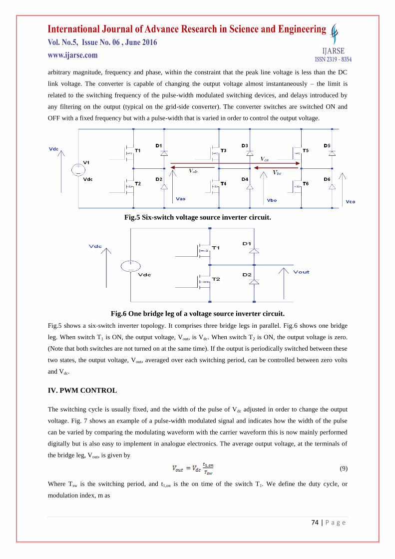
Fig.5 Six-switch voltage source inverter circuit.
Fig.6 One bridge leg of a voltage source inverter circuit.
Fig.5 shows a six-switch inverter topology. It comprises three bridge legs in parallel. Fig.6 shows one bridge
leg. When switch T1 is ON, the output voltage, Vout, is Vdc. When switch T2 is ON, the output voltage is zero.
(Note that both switches are not turned on at the same time). If the output is periodically switched between these
two states, the output voltage, Vout, averaged over each switching period, can be controlled between zero volts
and Vdc.
IV. PWM CONTROL
The switching cycle is usually fixed, and the width of the pulse of Vdc adjusted in order to change the output
voltage. Fig. 7 shows an example of a pulse-width modulated signal and indicates how the width of the pulse
can be varied by comparing the modulating waveform with the carrier waveform this is now mainly performed
digitally but is also easy to implement in analogue electronics. The average output voltage, at the terminals of
the bridge leg, Vout, is given by
(9)
Where Tsw is the switching period, and t1,on is the on time of the switch T1. We define the duty cycle, or
modulation index, m as

75 | P a g e
(10)
Fig.7 Example of carrier-based pulse-width modulated signal generation.
Hence,
(11)
where m must be between 0 (T2 on continuously) and 1 (T1 on continuously). The modulation index, m, can be
varied in time, therefore any desired voltage and frequency can be generated at the output terminals (within the
bounds fixed by the switching frequency and Vdc). In the three-phase converter shown in Fig. 5, there are three
phase legs, hence three modulation indices, ma, mb and mc. The voltages between the mid-point of each phase
leg and the 0V node of the dc link are
(12)
Now if each modulation index varies sinusoidally according to
(13)
Then the resultant output line voltages will take the from
(14)
These are three-phase, balanced output line voltages, whose magnitude is controlled by m and whose output
frequency and phase can be regulated by the frequency and phase of the modulating waveform. The modulating
waveforms can be manipulated digitally using high-performance microcontrollers or digital signal processors.
The VSI is capable of generating any voltage with arbitrary frequency and phase (within the limits of dc link
voltage and switching frequency). Therefore, the VSI can be viewed and modelled as an ideal controllable
voltage source whose bandwidth is usually much higher than the required excitation frequency required by the
system.

76 | P a g e
Fig.8 Doubly-fed induction generation system power flows
In steady-state at fixed turbine speed for a lossless DFIG system, the mechanical power from the wind turbine
applied to the shaft is Pm = Ps + Pr. It follows that:
(15)
where s is defined as the slip of the generator:
Therefore if the maximum slip is limited, say to 0.3, the rotor winding converters can be rated as a fraction of
the induction generator rated power. This is typically around ±30% for DFIG in wind power generation systems
gives a slip range of ±0.3. This is one key advantage of the DFIG system over fully-rated power electronic
systems.
V. THE ROTOR-SIDE CONVERTER (RSC)
The rotor-side converter (RSC) applies the voltage to the rotor windings of the doubly-fed induction generator.
The purpose of the rotor-side converter is to control the rotor currents such that the rotor flux position is
optimally oriented with respect to the stator flux in order that the desired torque is developed at the shaft of the
machine. The rotor-side converter uses a torque controller to regulate the wind turbine output power and the
voltage (or reactive power) measured at the machine stator terminals. The power is controlled in order to follow
a pre-defined turbine power-speed characteristic to track the maximum power point. The actual electrical output
power from the generator terminals, added to the total power losses (mechanical and electrical) is compared
with the reference power obtained from the wind turbine characteristic. Usually, a Proportional-Integral (PI)
regulator is used at the outer control loop to reduce the power error (or rotor speed error) to zero. The output of
this regulator is the reference rotor current irqref that must be injected in the rotor winding by rotor-side
converter. This q-axis component controls the electromagnetic torque Te. The actual irq component of rotor
current is compared with irqref and the error is reduced to zero by a current PI regulator at the inner control loop.
The output of this current controller is the voltage vrq generated by the rotor-side converter. With another
similarly regulated ird and vrd component the required 3-phase voltages applied to the rotor winding are obtained.
The generic power control loop is illustrated in the next section.

77 | P a g e
VI. THE GRID-SIDE CONVERTER (GSC)
The grid-side converter aims to regulate the voltage of the dc bus capacitor. Moreover, it is allowed to generate
or absorb reactive power for voltage support requirements. The function is realized with two control loops as
well: an outer regulation loop consisting of a dc voltage regulator. The output of the dc voltage regulator is the
reference current icdref for the current regulator. The inner current regulation loop consists of a current regulator
controlling the magnitude and phase of the voltage generated by converter from the icdref produced by the dc
voltage regulator and specified q-axis icqref reference.
VII. DC-LINK MODEL
The dc-link model describes the dc-link capacitor voltage variations as a function of the input power to the dc-
link. The energy stored in the dc capacitor is
(16)
Where C is the capacitance, Vdc is the voltage, Wdc is the stored energy, and Pdc is the input power to the dc link.
The voltage and energy derivatives are
(17)
The Pdc is calculated as Pdc = Pin –Pc. Where Pin is the input power from rotor-side converter and Pc is the grid-
side converter output power. The dc-link voltage varies as Pdc and is a constant when Pdc = 0.
VIII. CONTROL OF REAL AND REACTIVE POWER USING THE RSC
The grid side converter is used to partly control the flow of real and reactive power from the turbine system to
the grid. The grid-side converter feeds the grid via a set of interfacing inductors. As previously shown, the grid-
side converter (a voltage source inverter) can generate a balanced set of three-phase voltages at the supply
frequency and that the voltage, E, can have a controllable magnitude and phase. Load angle control is used to
illustrate the basics of real and reactive power control, though in practice, a more sophisticated control is used
which provides superior transient response. Load angle control mimics the operation of a synchronous generator
connected to the network. Essentially, load angle control uses the angle, δ, between the voltage generated by the
grid-side converter, E, and the grid voltage, V, Figure 10, to control the real power, P, injected on to the grid.
Likewise, reactive power, Q, is controlled using the magnitude of the voltage generated by the grid-side
converter. The steady-state equations governing the real and reactive power flow from the grid-side converter to
the grid are
and (18)
where Xs is the reactance of the interfacing inductance. If δ is small the equations can be simplified to
and (19)
Showing that P can be controlled using load angle, δ, and Q can be controlled using the magnitude of E.
Interfacing inductance must be used to couple the output of the grid-side converter shown in Figure 4.2 to the
78 | P a g e
grid. The inductor is sized according to the rating of the converter. Typically, the system will have a transformer
on the turbine side of the point of common coupling (PCC). In addition, at the point of connection there is
usually the need for a substation which includes whatever equipment is required by local network codes, for
example, plant to disconnect the turbine under fault conditions. The combination of control and power
electronics enables the grid-side converter to produce the necessary voltage magnitude, E, and load angle, δ, in
order to meet a required Pc and Qc demand set by the main system controller. The controller has to be able to
synchronies‟ to the grid frequency and phase, in order to connect and supply power. This is typically carried out
using some form of phase-locked loop.
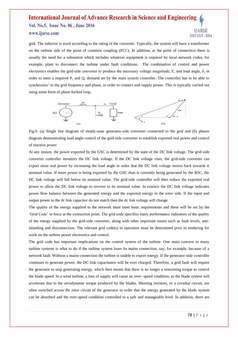
Fig.9. (a) Single line diagram of steady-state generator-side converter connected to the grid and (b) phasor
diagram demonstrating load angle control of the grid-side converter to establish exported real power and control
of reactive power
At any instant, the power exported by the GSC is determined by the state of the DC link voltage. The grid-side
converter controller monitors the DC link voltage. If the DC link voltage rises, the grid-side converter can
export more real power by increasing the load angle in order that the DC link voltage moves back towards it
nominal value. If more power is being exported by the GSC than is currently being generated by the RSC, the
DC link voltage will fall below its nominal value. The grid-side controller will then reduce the exported real
power to allow the DC link voltage to recover to its nominal value. In essence the DC link voltage indicates
power flow balance between the generated energy and the exported energy in the rotor side. If the input and
output power to the dc link capacitor do not match then the dc link voltage will change.
The quality of the energy supplied to the network must meet basic requirements and these will be set by the
„Grid Code‟ in force at the connection point. The grid code specifies many performance indicators of the quality
of the energy supplied by the grid-side converter, along with other important issues such as fault levels, anti-
islanding and disconnection. The relevant grid code(s) in operation must be determined prior to tendering for
work on the turbine power electronics and control.
The grid code has important implications on the control system of the turbine. One main concern in many
turbine systems is what to do if the turbine system loses its mains connection, say, for example, because of a
network fault. Without a mains connection the turbine is unable to export energy. If the generator-side controller
continues to generate power, the DC link capacitance will be over charged. Therefore, a grid fault will require
the generator to stop generating energy, which then means that there is no longer a restraining torque to control
the blade speed. In a wind turbine, a loss of supply will cause an over- speed condition, as the blade system will
accelerate due to the aerodynamic torque produced by the blades. Shorting resistors, or a crowbar circuit, are
often switched across the rotor circuit of the generator in order that the energy generated by the blade system
can be absorbed and the over-speed condition controlled to a safe and manageable level. In addition, there are
79 | P a g e
often aerodynamic (pitch control) and mechanical braking mechanisms included in wind turbines as an
additional over-speed safety measure.
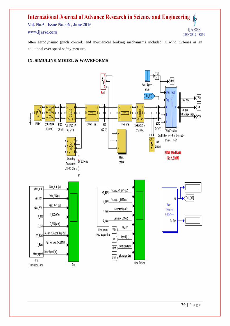
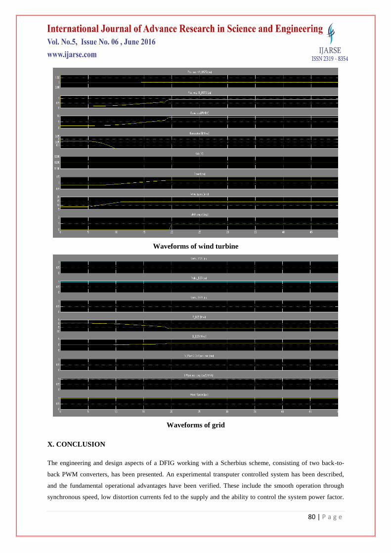
IX. SIMULINK MODEL & WAVEFORMS
80 | P a g e
Waveforms of wind turbine
Waveforms of grid
X. CONCLUSION
The engineering and design aspects of a DFIG working with a Scherbius scheme, consisting of two back-to-
back PWM converters, has been presented. An experimental transputer controlled system has been described,
and the fundamental operational advantages have been verified. These include the smooth operation through
synchronous speed, low distortion currents fed to the supply and the ability to control the system power factor.

81 | P a g e
Vector-control techniques have been applied to both converters. The vector control for the machine has been
embedded in an optimal tracking controller for maximum energy capture in a wind- energy application. Two
such tracking schemes have been described, and experimentally implemented, and the superiority of speed-
mode control for dynamic speed performance has been shown. This scheme employs a torque observer, which
also allows for simple implementation of stall regulation to protect against generator overload. The present
paper has described the back-to-back PWM DFIG scheme with the system grid connected. The scheme can also
be used for supplying an isolated AC load, augmented with a controlled dump load. This will be the subject of a
future paper.
REFERENCES
[1] Chen, Z.; Guerrero, J.M. & Blaabjerg, F. (2009). A review of the state of the art of power electronics for
wind turbines, IEEE Trans. Power Electron., Vol. 24, No. 8, August 2009, 1859-1875, ISSN 0885-8993.
[2] Craig, L.M.; Saad-Saoud, Z. & Jenkins, N. (1998). Electrodynamic braking of wind turbines, IEE Proc.-
Electr. Power Appl., Vol. 145, No. 2, March 1998, 140-146, ISSN.
[3] Ledesma, P. & Usaola, J. (2005). Doubly fed induction generator model for transient stability analysis,
IEEE Trans. Energy Conver., Vol. 20, No. 2, June 2005, 388-397, ISSN 0885-8969.
[4] Muller, S.; Deicke, M. & De Doncker, R.W. (2002). Doubly fed induction generator systems for wind
turbines, IEEE Ind. Appl. Magazine, Vol., No., May/June 2002, 26-33, ISSN 1077-2618/02.
[5] Pena, R.; Clare, J.C. & Asher, G.M. (1996). Doubly fed induction generator using back-to-back PWM
converters and its application to variable-speed wind-energy generation, IEE Proc.-Electr. Power Appl.,
Vol. 143, No. 3, May 1996, 231-241, ISSN.
Related Documents