Products designed for industrial applications. General terms and conditions for sale are available on www.camozzi.com. 2 Series 2 mechanically operated minivalves CONTROL > CATALOGUE > Release 8.7 /4.05.01 2 CONTROL Series 2 mechanically operated minivalves 3/2-way Ports M5, cartridge ø 4 Series 2 mechanically operated miniature valves, 3/2-way normally closed, are available with M5 threaded ports or with an integrated super-rapid fitting for ø 4mm tubes. The devices are actuated by a plunger, roller/lever or a unidirectional lever. GENERAL DATA Construction poppet type Valve group 3-way/2-position Materials aluminium body, brass plunger, NBR seals Mounting by means of screws in the through-holes of the valve body Ports M5, Ø4mm cartridge Room temperature 0°C ÷ 60°C Fluid temperature 0°C ÷ 50°C Operating pressure 0 bar ÷ 10 bar Fluid Filtered air, without lubrication. If lubricated air is used, it is recommended to use ISO VG32 oil. Once applied the lubrication should never be interrupted.

Welcome message from author
This document is posted to help you gain knowledge. Please leave a comment to let me know what you think about it! Share it to your friends and learn new things together.
Transcript
Products designed for industrial applications. General terms and conditions for sale are available on www.camozzi.com.
2
Series 2 mechanically operated minivalvesCONTROL > CATALOGUE > Release 8.7
/4.05.012
CO
NTR
OL
Series 2 mechanically operated minivalves
3/2-way Ports M5, cartridge ø 4
Series 2 mechanically operated miniature valves, 3/2-way normally closed, are available with M5 threaded ports or with an integrated super-rapid fitting for ø 4mm tubes. The devices are actuated by a plunger, roller/lever or a unidirectional lever.
GENERAL DATAConstruction poppet typeValve group 3-way/2-positionMaterials aluminium body, brass plunger, NBR sealsMounting by means of screws in the through-holes of the valve bodyPorts M5, Ø4mm cartridgeRoom temperature 0°C ÷ 60°CFluid temperature 0°C ÷ 50°COperating pressure 0 bar ÷ 10 barFluid Filtered air, without lubrication. If lubricated air is used, it is recommended to use ISO VG32 oil.
Once applied the lubrication should never be interrupted.
Products designed for industrial applications. General terms and conditions for sale are available on www.camozzi.com.
Series 2 mechanically operated minivalvesCATALOGUE
2
/4.05.022
> Release 8.7 CONTROL >
CO
NTR
OL
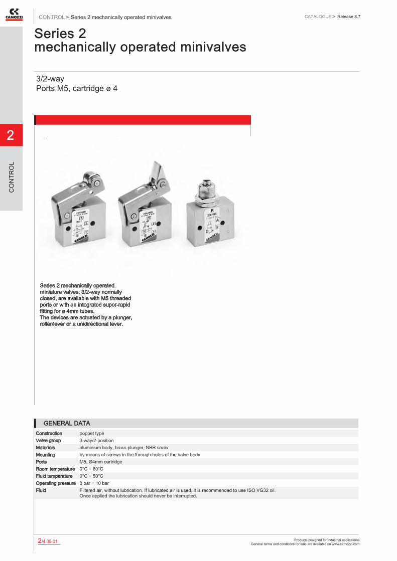
CODING EXAMPLE
2 SERIES
3 FUNCTION 3 = 3/2-way NC 4 = 3/2-way NO
4 PORTS 4 = cartridge ø 4mm 5 = M5
94 ACTUATION 94 = plunger 95 = lever/roller 96 = unidirectional lever 98 = plunger, panel mounting
5 RESETTING 5= spring return
2 3 4 - 94 5
Minivalves with plunger
Mod. Operating pressure (bar) Flow Qn (Nl/min) Actuating force at 6 bar (N) SYMBOL234-945 0 ÷ 10 60 6 VM01235-945 0 ÷ 10 60 6 VM01244-945 0 ÷ 10 60 6 VM03245-945 0 ÷ 10 60 6 VM03
DRAWING LEGEND A = total stroke B = pre-stroke C = effective stroke
Products designed for industrial applications. General terms and conditions for sale are available on www.camozzi.com.
2
Series 2 mechanically operated minivalvesCONTROL > CATALOGUE > Release 8.7
/4.05.032
CO
NTR
OL
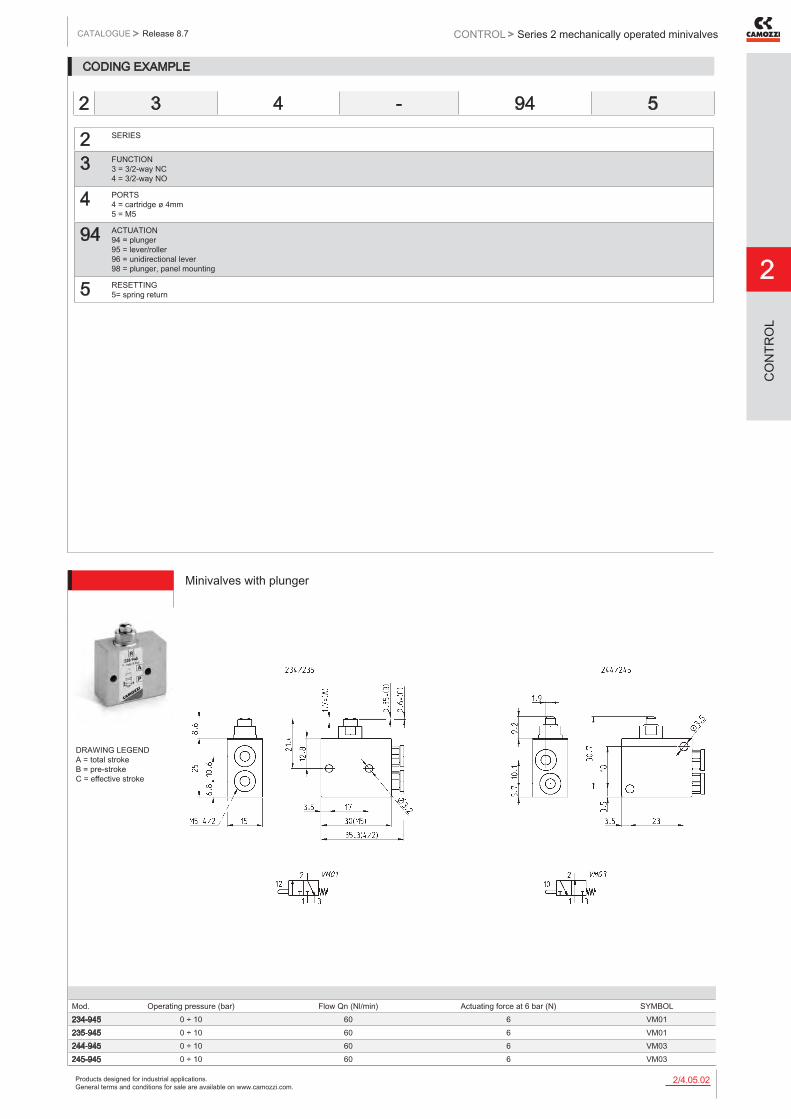
Minivalves with plunger, panel mounting
Mod. Operating pressure (bar) Flow Qn (Nl/min) Actuating force at 6 bar (N) SYMBOL234-985 0 ÷ 10 60 6 VM01235-985 0 ÷ 10 60 6 VM01244-985 0 ÷ 10 60 6 VM03245-985 0 ÷ 10 60 6 VM03
DRAWING LEGEND A = total stroke B = pre-stroke C = effective stroke
Minivalves with lever/roller
Mod. Operating pressure (bar) Flow Qn (Nl/min) Actuating force at 6 bar (N) SYMBOL234-955 0 ÷ 10 60 6 VM04235-955 0 ÷ 10 60 6 VM04244-955 0 ÷ 10 60 6 VM06245-955 0 ÷ 10 60 6 VM06
DRAWING LEGEND A = total stroke B = pre-stroke C = effective stroke

Products designed for industrial applications. General terms and conditions for sale are available on www.camozzi.com.
Series 2 mechanically operated minivalvesCATALOGUE
2
/4.05.042
> Release 8.7 CONTROL >
CO
NTR
OL
Minivalves, unidirectional lever
Mod. Operating pressure (bar) Flow Qn (Nl/min) Actuating force at 6 bar (N) SYMBOL234-965 0 ÷ 10 60 6 VM07235-965 0 ÷ 10 60 6 VM07244-965 0 ÷ 10 60 6 VMA1245-965 0 ÷ 10 60 6 VMA1
DRAWING LEGEND A = total stroke B = pre-stroke C = effective stroke

Products designed for industrial applications. General terms and conditions for sale are available on www.camozzi.com.
2
Series 1 and 3 mechanically operated valvesCONTROL > CATALOGUE > Release 8.7
/4.10.012
CO
NTR
OL
Series 1 and 3 mechanically operated valves
Series 1: 3/2-way and 5/2-way, ports G1/8 and G1/4 Series 3: 3/2-way and 5/2-way, ports G1/8
These mechanically operated valves have been designed with three different types of actuation: - plunger - lever/roller - unidirectional lever/roller In each case, return is triggered by a mechanical spring.
Series 3 3/2-way monostable valves are normally closed in the rest position when pressure is supplied in 1 and are normally open when pressure is supplied on connection 3, the user port 2 remaining unchanged. Series 3 5/2-way valves can be supplied via the ports 3 and 5 with two different pressures if a cylinder has to be operated using a delivery pressure which is different from the return pressure.
GENERAL DATAConstruction spool-type (Series 3), poppet-type (Series 1)Valve group 3/2, 5/2 way/pos.Materials aluminium body, poppet OT58, stainless steel spool, NBR sealsPorts G1/8, G1/4Ambient temperature 0°C÷ 60°CMedium temperature 0°C÷ 50°COperating pressure see modelsFluid Filtered air, without lubrication. If lubricated air is used, it is recommended to use ISO VG32 oil.
Once applied the lubrication should never be interrupted.

Products designed for industrial applications. General terms and conditions for sale are available on www.camozzi.com.
Series 1 and 3 mechanically operated valvesCATALOGUE
2
/4.10.022
> Release 8.7 CONTROL >
CO
NTR
OL
CODING EXAMPLE
3 SERIES: 1 3
3 FUNCTION: 3 = 3/2 ways NC 4 = 3/2 ways NO (only Series 1) 5 = 5/2 ways
8 PORTS: 8 = G1/8 4 = G1/4 (only Series 1)
94 ACTUATION: 94 = plunger 95 = lever/roller 96 = unidirectional roller
5 RESETTING: 5= spring return
3 3 8 - 94 5
Mod.338-945
Valve Mod. 338-945Operating pressure = -0,9 ÷ 10 bar Flow rate = 700 Nl/min. Actuating force = 32N

Products designed for industrial applications. General terms and conditions for sale are available on www.camozzi.com.
2
Series 1 and 3 mechanically operated valvesCONTROL > CATALOGUE > Release 8.7
/4.10.032
CO
NTR
OL
ValveOperating pressure = -0,9 ÷ 10 bar Flow rate = 700 Nl/min. Actuating force = 35N
Mod.358-945
ValveOperating pressure = -0,9 ÷ 10 bar Flow rate = 700 Nl/min. Actuating force = 15N
Mod.338-955
ValveOperating pressure = -0,9 ÷ 10 bar Flow rate = 700 Nl/min. Actuating force = 17N
Mod.358-955
Products designed for industrial applications. General terms and conditions for sale are available on www.camozzi.com.
Series 1 and 3 mechanically operated valvesCATALOGUE
2
/4.10.042
> Release 8.7 CONTROL >
CO
NTR
OL
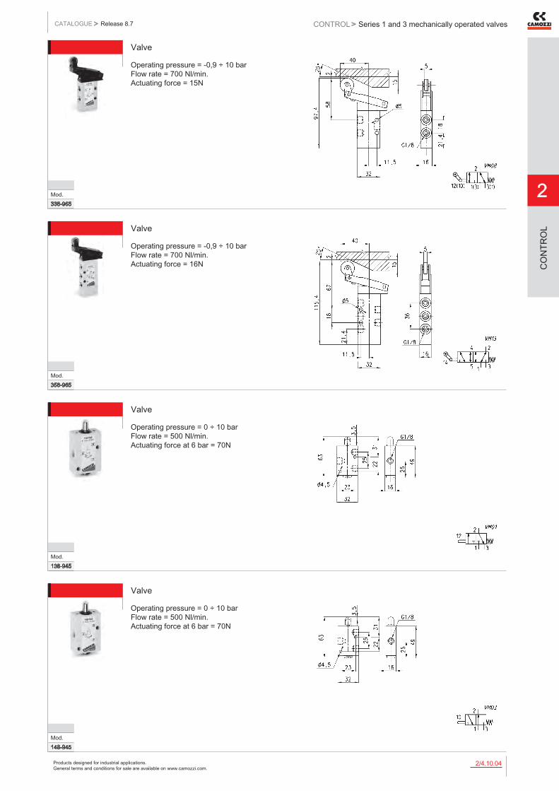
Valve
Operating pressure = -0,9 ÷ 10 bar Flow rate = 700 Nl/min. Actuating force = 15N
Mod.338-965
Valve
Operating pressure = -0,9 ÷ 10 bar Flow rate = 700 Nl/min. Actuating force = 16N
Mod.358-965
Valve
Operating pressure = 0 ÷ 10 bar Flow rate = 500 Nl/min. Actuating force at 6 bar = 70N
Mod.138-945
Valve
Operating pressure = 0 ÷ 10 bar Flow rate = 500 Nl/min. Actuating force at 6 bar = 70N
Mod.148-945

Products designed for industrial applications. General terms and conditions for sale are available on www.camozzi.com.
2
Series 1 and 3 mechanically operated valvesCONTROL > CATALOGUE > Release 8.7
/4.10.052
CO
NTR
OL
Valve
Operating pressure = 0 ÷ 10 bar Flow rate = 500 Nl/min. Actuating force at 6 bar = 120N
Mod.158-945
Valve
Operating pressure = 0 ÷ 10 bar Flow rate = 500 Nl/min. Actuating force at 6 bar = 36N
Mod.138-955
Valve
Operating pressure = 0 ÷ 10 bar Flow rate = 500 Nl/min. Actuating force at 6 bar = 92N
Mod.158-955
Valve
Operating pressure = 0 ÷ 10 bar Flow rate = 500 Nl/min. Actuating force at 6 bar = 41N
Mod.138-965

Products designed for industrial applications. General terms and conditions for sale are available on www.camozzi.com.
Series 1 and 3 mechanically operated valvesCATALOGUE
2
/4.10.062
> Release 8.7 CONTROL >
CO
NTR
OL
Valve
Operating pressure = 0 ÷ 10 bar Flow rate = 1250 Nl/min. Actuating force at 6 bar = 64N
Mod.134-945
Valve
Operating pressure = 0 ÷ 10 bar Flow rate = 1250 Nl/min. Actuating force at 6 bar = 147N
Mod.154-945
Valve
Operating pressure = 0 ÷ 10 bar Flow rate = 1250 Nl/min. Actuating force at 6 bar = 41N
Mod.134-955
Valve
Operating pressure = 0 ÷ 10 bar Flow rate = 1250 Nl/min. Actuating force at 6 bar = 110N
Mod.154-955

Products designed for industrial applications. General terms and conditions for sale are available on www.camozzi.com.
2
Series 3 and 4 mechanically operated sensor valvesCONTROL > CATALOGUE > Release 8.7
/4.15.012
CO
NTR
OL
Series 3 and 4 mechanically operated sensor valves
3/2 and 5/2-way Ports G1/8, G1/4
The particular mechanical device allows these end-stroke valves to operate with very low actuating forces. Series 3 has been designed with a mechanical lever device which works in negative pressure. To increase sensitivity it is possible to add to the lever a steel extension with ø 3 mm.
GENERAL DATAConstruction spool-type (servocontrolled)Valve group 3/2, 5/2 way/pos.Materials aluminium body, stainless steel spool, NBR sealsPorts G1/8, G1/4Ambient temperature 0°C ÷ 60°CMedium temperature 0°C ÷ 50°COperating pressure see modelsFluid Filtered air, without lubrication. If lubricated air is used, it is recommended to use ISO VG32 oil.
Once applied the lubrication should never be interrupted.

Products designed for industrial applications. General terms and conditions for sale are available on www.camozzi.com.
Series 3 and 4 mechanically operated sensor valvesCATALOGUE
2
/4.15.022
> Release 8.7 CONTROL >
CO
NTR
OL
CODING EXAMPLE
3 SERIES: 3 4
3 FUNCTION: 3 = 3/2-way NC 4 = 3/2-way NO 5 = 5/2-way
8 PORTS: 8 = G1/8 4 = G1/4
D15 ACTUATION: D15 = pressure drop/spring 015 = pressure/spring 011 = pressure/pressure
9A5 DEVICES: 9A5 = lever sensor, spring return 194 = plunger sensor, spring return 294 = plunger sensor, bistable 195 = lever/roller, spring return 295 = lever/roller, bistable
3 3 8 - D15 - 9A5
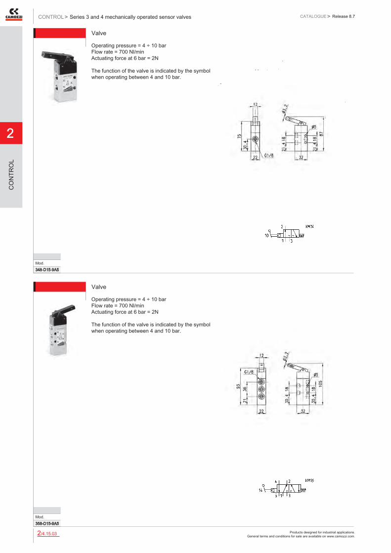
Mod.338-D15-9A5
ValveOperating pressure = 4 ÷ 10 bar. Flow rate = 700 Nl/min. Actuating force at 6 bar = 2N The function of the valve is indicated by the symbol when operating between 4 and 10 bar.
Products designed for industrial applications. General terms and conditions for sale are available on www.camozzi.com.
2
Series 3 and 4 mechanically operated sensor valvesCONTROL > CATALOGUE > Release 8.7
/4.15.032
CO
NTR
OL
Valve
Mod.348-D15-9A5
Operating pressure = 4 ÷ 10 bar Flow rate = 700 Nl/min Actuating force at 6 bar = 2N The function of the valve is indicated by the symbol when operating between 4 and 10 bar.
Valve
Mod.358-D15-9A5
Operating pressure = 4 ÷ 10 bar Flow rate = 700 Nl/min Actuating force at 6 bar = 2N The function of the valve is indicated by the symbol when operating between 4 and 10 bar.

Products designed for industrial applications. General terms and conditions for sale are available on www.camozzi.com.
Series 3 and 4 mechanically operated sensor valvesCATALOGUE
2
/4.15.042
> Release 8.7 CONTROL >
CO
NTR
OL
Valve
Operating pressure = 2.5 ÷ 8 bar Flow rate = 650 Nl/min. Actuating force at 6 bar = 6 N
Mod.458-015-194
Valve
Operating pressure = 2 ÷ 8 bar Flow rate = 650 Nl/min Actuating force at 6 bar = 6 N
Mod.458-011-294
Valve
Operating pressure = 2.5 ÷ 8 bar Flow rate = 1250 Nl/min Actuating force at 6 bar = 6 N
Mod.454-015-194
Valve
Operating pressure: 2 ÷ 8 bar Flow rate = 1250 Nl/min Actuating force at 6 bar = 6 N
DIMENSIONSMod.454-011-294

Products designed for industrial applications. General terms and conditions for sale are available on www.camozzi.com.
2
Series 3 and 4 mechanically operated sensor valvesCONTROL > CATALOGUE > Release 8.7
/4.15.052
CO
NTR
OL
Valve
Operating pressure = 2.5 ÷ 8 bar Flow rate = 650 Nl/min Actuating force at 6 bar = 4 N
Mod.458-015-195
Valve
Operating pressure = 2 ÷ 8 bar Flow rate = 650 Nl/min Actuating force at 6 bar = 4 N
DIMENSIONSMod.458-011-295
Valve
Operating pressure = 2.5 ÷ 8 bar Flow rate = 1250 Nl/min. Actuating force at 6 bar = 4 N
Mod.454-015-195
Valve
Operating pressure = 2 ÷ 8 bar Flow rate = 1250 Nl/min Actuating force at 6 bar = 4 N
Mod.454-011-295

Products designed for industrial applications. General terms and conditions for sale are available on www.camozzi.com.
Series 2 and 3 pedalsCATALOGUE
2
/4.20.012
> Release 8.7 CONTROL >
CO
NTR
OL
Foot operated pedal Electrical and pneumatic - Series 3 Pneumatic - Series 2Series 3: G1/4, 5/2-way - NC / NO contacts Series 2: M5; 4/2 tube; 3/2-way NC
The pedals can be supplied in either a pneumatic or electrical foot operated version. The pneumatic type is available with a 5/2 valve and G1/4 front ports, which allow the fittings and silencers to be assembled conveniently on the front face. A 3/2 operation can be obtained by closing an outlet port. The electrical type is available with a single-pole changeover contact microswitch and a front wire outlet (PG9).
The pedal can be operated as bistable or monostable, by switching the selector placed under the small red protection flap, as shown in the drawing.
GENERAL DATAConstruction spool-typeValve group 5/2, 3/2 NC way/pos.Materials - Series 3: alluminium body - stainless steel spool - NBR seals - plastic casing
- Series 2: alluminium body - OT58 poppet - NBR seals.Ports - Series 3: G1/4 gas
- Series 2: M5; tube 4/2.Ambient temperature 0°C ÷ 50 °C (with dry air at - 10°C)Medium temperature 0°C ÷ 50 °CConstruction single-pole changeover contact microswitchCable entry by means of wire PG9Protection class IP20Fluid Filtered air, without lubrication.
If lubricated air is used, it is recommended to use ISO VG32 oil. Once applied the lubrication should never be interrupted.
Products designed for industrial applications. General terms and conditions for sale are available on www.camozzi.com.
2
Series 2 and 3 pedalsCONTROL > CATALOGUE > Release 8.7
/4.20.022
CO
NTR
OL
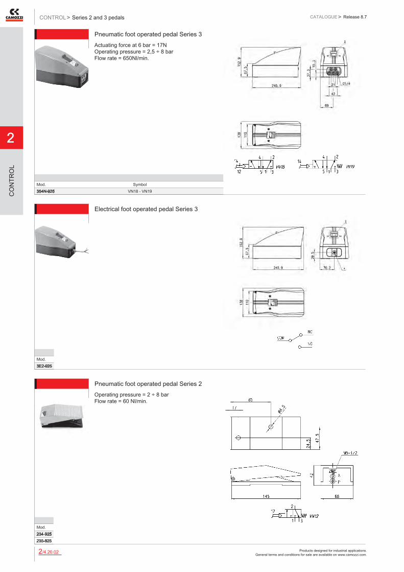
Pneumatic foot operated pedal Series 3Actuating force at 6 bar = 17N Operating pressure = 2,5 ÷ 8 bar Flow rate = 650Nl/min.
Mod. Symbol354N-925 VN18 - VN19
Electrical foot operated pedal Series 3
Mod.3E2-925
Pneumatic foot operated pedal Series 2Operating pressure = 2 ÷ 8 bar Flow rate = 60 Nl/min.
Mod.234-925235-925

Products designed for industrial applications. General terms and conditions for sale are available on www.camozzi.com.
Series 2 manually operated console minivalvesCATALOGUE
2
/4.25.012
> Release 8.7 CONTROL >
CO
NTR
OL
Series 2 manually operated console minivalves
3/2 and 5/3-way CC, CO, CP Ports M5, Cartridge Ø 4
This series of miniature valves has been especially designed to satisfy all the application requirements of the controls industry with particular attention paid to the operating characteristics required from these components: - short operational stroke - small dimensions
GENERAL DATAValve group 3/2-wayConstruction poppet-type (closed centres)Materials aluminium body, brass plunger, NBR sealsMounting panelPorts M5 or cartridge dia. 4Ambient temperature 0°C ÷ 60°CMedium temperature 0°C ÷ 50°COperating pressure see models

Products designed for industrial applications. General terms and conditions for sale are available on www.camozzi.com.
2
Series 2 manually operated console minivalvesCONTROL > CATALOGUE > Release 8.7
/4.25.022
CO
NTR
OL
CODING EXAMPLE
2 SERIES
3 FUNCTION: 3 = 3/2-way NC 4 = 3/2-way NO 8 = 5/3-way CO (function realized with 2x 3/2-way NC valves)
4 PORTS: 4 = cartridge ø 4 5 = M5
97 MODE OF OPERATION: 87 = 3 position selector 89 = push button 97 = palm switch 90 = joystick 99 = 2 position selector 92 = pedal 904 = key
5 RESETTING: 5 = spring return 0 = stable 2 = latching-twist to release 54= joystick
2 3 4 - 97 5
MinivalvesOperating pressure = 2 ÷ 8 bar Flow rate = 60 Nl/min.
Mod. A B234-905 200-905 234-000235-905 200-905 235-000
Products designed for industrial applications. General terms and conditions for sale are available on www.camozzi.com.
Series 2 manually operated console minivalvesCATALOGUE
2
/4.25.032
> Release 8.7 CONTROL >
CO
NTR
OL
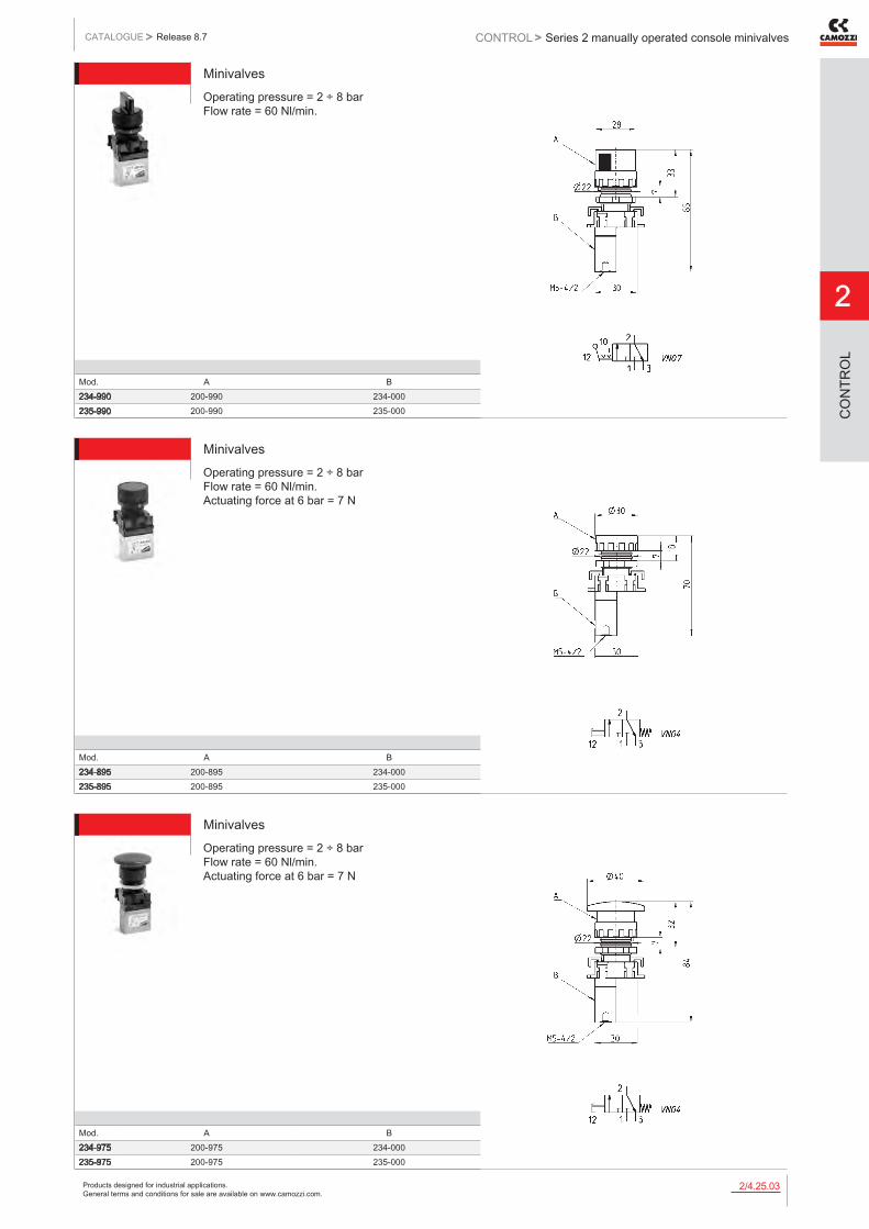
MinivalvesOperating pressure = 2 ÷ 8 bar Flow rate = 60 Nl/min.
Mod. A B234-990 200-990 234-000235-990 200-990 235-000
MinivalvesOperating pressure = 2 ÷ 8 bar Flow rate = 60 Nl/min. Actuating force at 6 bar = 7 N
Mod. A B234-895 200-895 234-000235-895 200-895 235-000
MinivalvesOperating pressure = 2 ÷ 8 bar Flow rate = 60 Nl/min. Actuating force at 6 bar = 7 N
Mod. A B234-975 200-975 234-000235-975 200-975 235-000

Products designed for industrial applications. General terms and conditions for sale are available on www.camozzi.com.
2
Series 2 manually operated console minivalvesCONTROL > CATALOGUE > Release 8.7
/4.25.042
CO
NTR
OL
MinivalvesOperating pressure = 2 ÷ 8 bar Flow rate = 60 Nl/min. Actuating force at 6 bar = 7 N
Mod. A B234-972 200-972 234-000235-972 200-972 235-000
MinivalvesOperating pressure = 2 ÷ 8 bar Flow rate = 60 Nl/min.
Mod. A B284-870 200-870 284-000285-870 200-870 285-000
MinivalvesOperating pressure = 2 ÷ 8 bar Flow rate = 60 Nl/min.
Mod. A B234-904 200-904 234-000235-904 200-904 235-000

Products designed for industrial applications. General terms and conditions for sale are available on www.camozzi.com.
Series 2 manually operated console minivalvesCATALOGUE
2
/4.25.052
> Release 8.7 CONTROL >
CO
NTR
OL
Joystick valvesMinimum pressure = 2 bar
Mod.234-9054235-9054
MinivalvesOperating pressure = 2 ÷ 8 bar Flow rate = 60 Nl/min.
Mod.234-000235-000
MinivalvesOperating pressure = 2 ÷ 8 bar Flow rate = 60 Nl/min. The codes shown in the table are composed by two 3/2-way valves NC which can be operated with the control device Mod. 200-870 only.
Mod.284-000285-000
Products designed for industrial applications. General terms and conditions for sale are available on www.camozzi.com.
2
Series 2 manually operated console minivalvesCONTROL > CATALOGUE > Release 8.7
/4.25.062
CO
NTR
OL
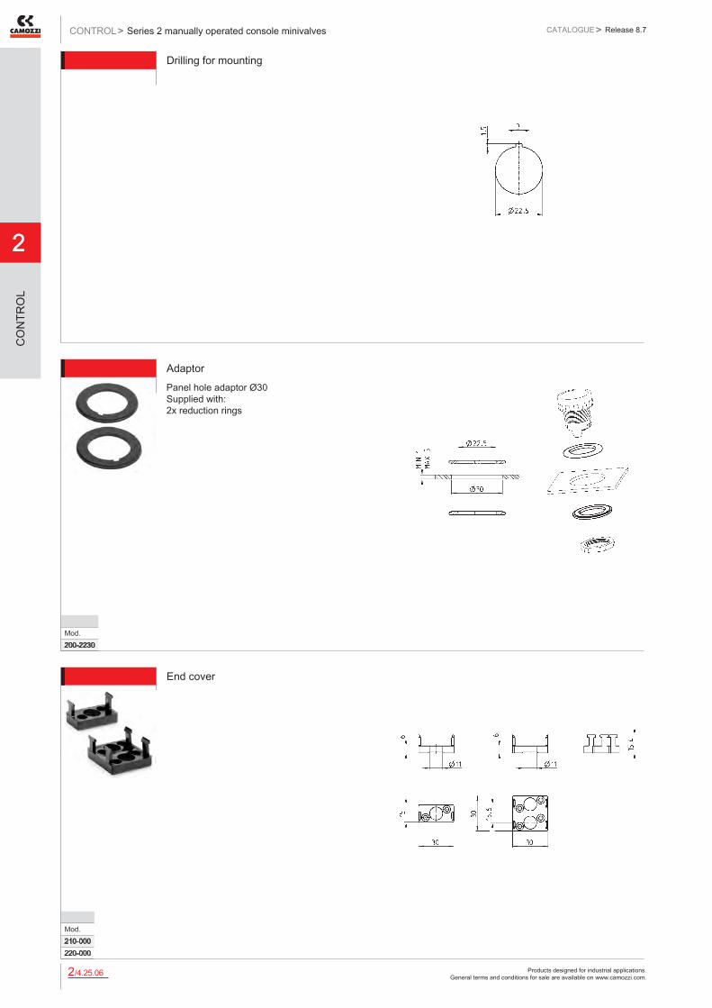
Drilling for mounting
AdaptorPanel hole adaptor Ø30 Supplied with: 2x reduction rings
Mod.200-2230
End cover
Mod.210-000220-000
Products designed for industrial applications. General terms and conditions for sale are available on www.camozzi.com.
Series 1, 3, 4 and VMS manually operated valvesCATALOGUE
2
/4.30.012
> Release 8.7 CONTROL >
CO
NTR
OL
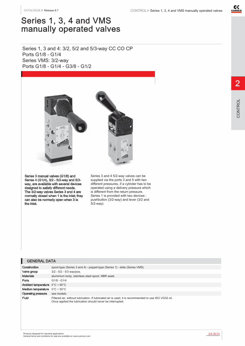
Series 1, 3, 4 and VMS manually operated valves
Series 1, 3 and 4: 3/2, 5/2 and 5/3-way CC CO CP Ports G1/8 - G1/4 Series VMS: 3/2-way Ports G1/8 - G1/4 - G3/8 - G1/2
Series 3 manual valves (G1/8) and Series 4 (G1/4), 3/2 - 5/2-way and 5/3-way, are available with several devices designed to satisfy different needs. The 3/2-way valves Series 3 and 4 are normally closed when 1 is the inlet; they can also be normally open when 3 is the inlet.
Series 3 and 4 5/2-way valves can be supplied via the ports 3 and 5 with two different pressures, if a cylinder has to be operated using a delivery pressure which is different from the return pressure. Series 1 is provided with two devices : pushbutton (3/2-way) and lever (3/2 and 5/2-way).
GENERAL DATAConstruction spool-type (Series 3 and 4) - poppet-type (Series 1) - slide (Series VMS)Valve group 3/2 - 5/2 - 5/3 way/pos.Materials aluminium body, stainless steel spool, NBR sealsPorts G1/8 - G1/4Ambient temperature 0°C ÷ 60°CMedium temperature 0°C ÷ 50°COperating pressure see modelsFluid Filtered air, without lubrication. If lubricated air is used, it is recommended to use ISO VG32 oil.
Once applied the lubrication should never be interrupted.
Products designed for industrial applications. General terms and conditions for sale are available on www.camozzi.com.
2
Series 1, 3, 4 and VMS manually operated valvesCONTROL > CATALOGUE > Release 8.7
/4.30.022
CO
NTR
OL
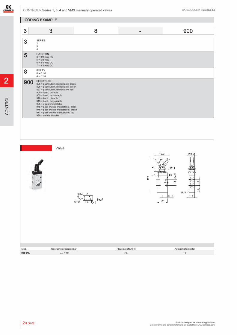
CODING EXAMPLE
3 SERIES: 1 3 4
5 FUNCTION: 3 = 3/2-way NC 5 = 5/2-way 6 = 5/3-way CC 7 = 5/3-way CO
8 PORTS: 8 = G1/8 4 = G1/4
900 RESETTING: 895 = pushbutton, monostable, black 896 = pushbutton, monostable, green 897 = pushbutton, monostable, red 900 = lever, bistable 905 = lever, monostable 910 = knob, bistable 915 = knob, monostable 935 = digital monostable 975 = palm-switch, monostable, black 976 = palm-switch, monostable, green 977 = palm-switch, monostable, red 990 = switch, bistable
3 3 8 - 900
Mod. Operating pressure (bar) Flow rate (Nl/min) Actuating force (N)338-990 0.9 ÷ 10 700 18
Valve

Products designed for industrial applications. General terms and conditions for sale are available on www.camozzi.com.
Series 1, 3, 4 and VMS manually operated valvesCATALOGUE
2
/4.30.032
> Release 8.7 CONTROL >
CO
NTR
OL
Valve
Actuating force = 18N Operating pressure = -0,9 ÷ 10 bar Flow rate = 700 Nl/min.
Mod.358-990
Valves
Actuating force = 35N Operating pressure = -0,9 ÷ 10 bar Flow rate = 700 Nl/min.
Mod. Colors338-895 Black338-896 Green338-897 Red
Valves
Actuating force = 35N Operating pressure = -0,9 ÷ 10 bar Flow rate = 700 Nl/min.
Mod. Colors358-895 Black358-896 Green358-897 Red
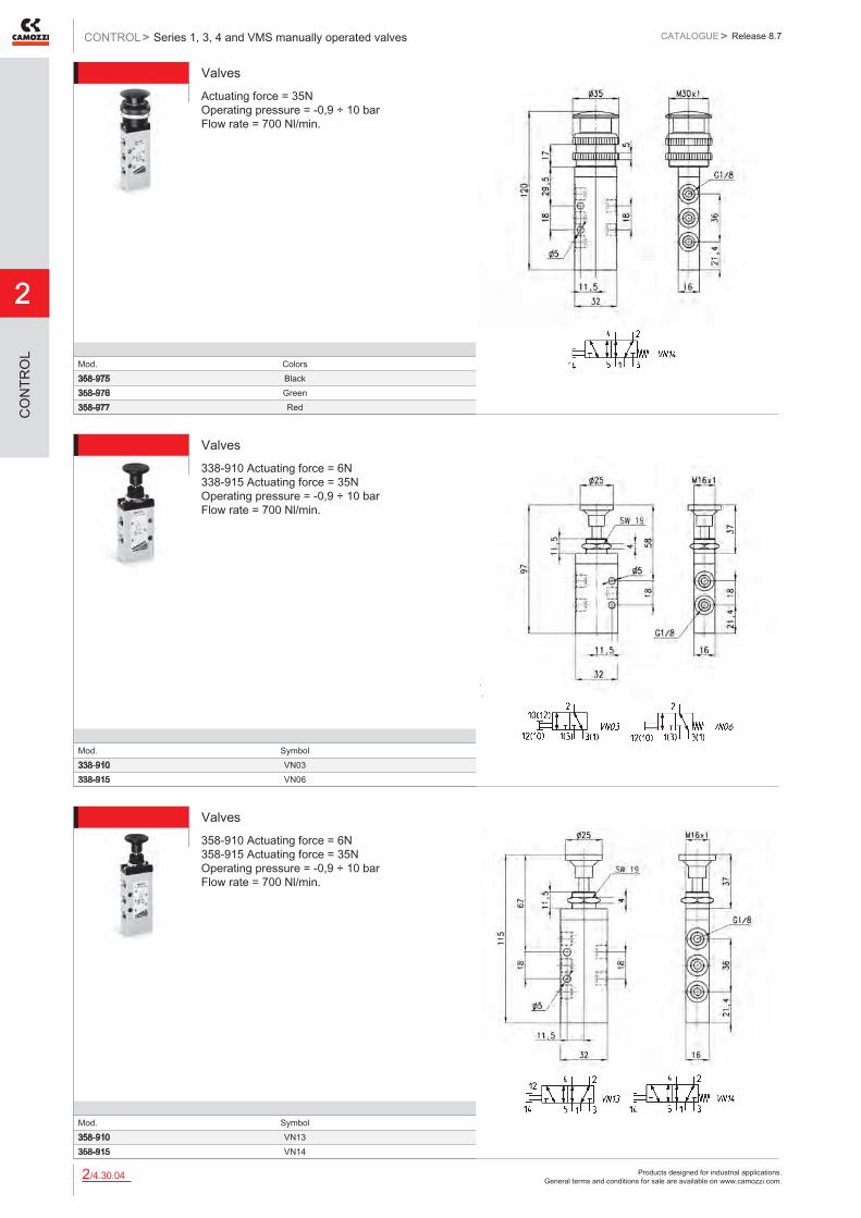
Valves
Actuating force = 35N Operating pressure = -0,9 ÷ 10 bar Flow rate = 700 Nl/min.
Mod. Colors338-975 Black338-976 Green338-977 Red
Products designed for industrial applications. General terms and conditions for sale are available on www.camozzi.com.
2
Series 1, 3, 4 and VMS manually operated valvesCONTROL > CATALOGUE > Release 8.7
/4.30.042
CO
NTR
OL
ValvesActuating force = 35N Operating pressure = -0,9 ÷ 10 bar Flow rate = 700 Nl/min.
Mod. Colors358-975 Black358-976 Green358-977 Red
Valves338-910 Actuating force = 6N 338-915 Actuating force = 35N Operating pressure = -0,9 ÷ 10 bar Flow rate = 700 Nl/min.
Mod. Symbol338-910 VN03338-915 VN06
Valves358-910 Actuating force = 6N 358-915 Actuating force = 35N Operating pressure = -0,9 ÷ 10 bar Flow rate = 700 Nl/min.
Mod. Symbol358-910 VN13358-915 VN14

Products designed for industrial applications. General terms and conditions for sale are available on www.camozzi.com.
Series 1, 3, 4 and VMS manually operated valvesCATALOGUE
2
/4.30.052
> Release 8.7 CONTROL >
CO
NTR
OL
Valves338-910 Actuating force = 6N 338-915 Actuating force = 35N Operating pressure = -0,9 ÷ 10 bar Flow rate = 700 Nl/min.
Mod. Symbol338-900 VN08338-905 VN11
Valves358-900 Actuating force = 5N 358-905 Actuating force = 22N Operating pressure = -0,9 ÷ 10 bar Flow rate = 700 Nl/min.
Mod. Symbol358-900 VN16358-905 VN17
ValveActuating force = 5N Operating pressure = -0,9 ÷ 10 bar Flow rate = 500 Nl/min.
Mod.368-900

Products designed for industrial applications. General terms and conditions for sale are available on www.camozzi.com.
2
Series 1, 3, 4 and VMS manually operated valvesCONTROL > CATALOGUE > Release 8.7
/4.30.062
CO
NTR
OL
ValveActuating force = 20N Operating pressure = -0,9 ÷ 10 bar Flow rate = 500 Nl/min.
Mod.368-905
ValveActuating force = 5N Operating pressure = -0,9 ÷ 10 bar Flow rate = 500 Nl/min.
Mod.378-900
ValveActuating force = 20N Operating pressure = -0,9 ÷ 10 bar Flow rate = 500 Nl/min.
Mod.378-905
Products designed for industrial applications. General terms and conditions for sale are available on www.camozzi.com.
Series 1, 3, 4 and VMS manually operated valvesCATALOGUE
2
/4.30.072
> Release 8.7 CONTROL >
CO
NTR
OL
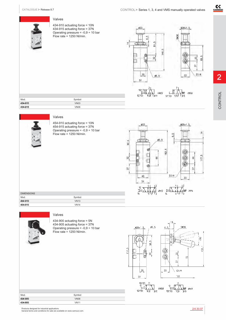
Valves434-910 actuating force = 10N 434-915 actuating force = 37N Operating pressure = -0,9 ÷ 10 bar Flow rate = 1250 Nl/min.
Mod. Symbol434-910 VN03434-915 VN06
Valves454-910 actuating force = 10N 454-915 actuating force = 37N Operating pressure = -0,9 ÷ 10 bar Flow rate = 1250 Nl/min.
DIMENSIONSMod. Symbol454-910 VN13454-915 VN14
Valves434-900 actuating force = 5N 434-905 actuating force = 37N Operating pressure = -0,9 ÷ 10 bar Flow rate = 1250 Nl/min.
Mod. Symbol434-900 VN08434-905 VN11

Products designed for industrial applications. General terms and conditions for sale are available on www.camozzi.com.
2
Series 1, 3, 4 and VMS manually operated valvesCONTROL > CATALOGUE > Release 8.7
/4.30.082
CO
NTR
OL
Valves454-900 actuating force = 5N 454-905 actuating force = 37N Operating pressure = -0,9 ÷ 10 bar Flow rate = 1250 Nl/min.
Mod. Symbol454-900 VN16454-905 VN17
ValveActuating force = 5N Operating pressure = -0,9 ÷ 10 bar Flow rate = 1250 Nl/min.
Mod.464-900
ValveActuating force = 10N Operating pressure = -0,9 ÷ 10 bar Flow rate = 1250 Nl/min.
Mod.464-905
Products designed for industrial applications. General terms and conditions for sale are available on www.camozzi.com.
Series 1, 3, 4 and VMS manually operated valvesCATALOGUE
2
/4.30.092
> Release 8.7 CONTROL >
CO
NTR
OL
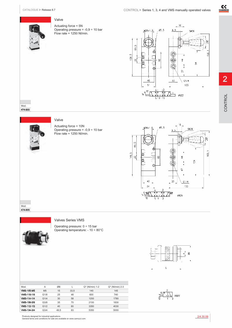
ValveActuating force = 5N Operating pressure = -0,9 ÷ 10 bar Flow rate = 1250 Nl/min.
Mod.474-900
ValveActuating force = 10N Operating pressure = -0,9 ÷ 10 bar Flow rate = 1250 Nl/min.
Mod.474-905
Valves Series VMSOperating pressure: 0 ÷ 15 bar Operating temperature: - 10 ÷ 80°C
Mod. A ØB L Q* (Nl/min) 1-2 Q* (Nl/min) 2-3VMS-105-M5 M5 15 33,5 140 145VMS-118-1/8 G1/8 25 48 600 740VMS-114-1/4 G1/4 30 58 1200 1780VMS-138-3/8 G3/8 35 70 2100 1830VMS-112-1/2 G1/2 40 80 3350 4030VMS-134-3/4 G3/4 49,5 83 5350 5000

Products designed for industrial applications. General terms and conditions for sale are available on www.camozzi.com.
2
Series 1, 3, 4 and VMS manually operated valvesCONTROL > CATALOGUE > Release 8.7
/4.30.102
CO
NTR
OL
ValveActuating force at 6 bar = 38N Operating pressure = 0 ÷ 10 bar Flow rate = 500 Nl/min.
Mod.138-935
ValveActuating force at 6 bar = 25N Operating pressure = 0 ÷ 10 bar Flow rate = 500 Nl/min.
Mod.138-900
ValveActuating force at 6 bar = 45N Operating pressure = 0 ÷ 10 bar Flow rate = 500 Nl/min.
Mod.158-900

Products designed for industrial applications. General terms and conditions for sale are available on www.camozzi.com.
Series 1, 3, 4 and VMS manually operated valvesCATALOGUE
2
/4.30.112
> Release 8.7 CONTROL >
CO
NTR
OL
ValveActuating force at 6 bar = 40N Operating pressure = 0 ÷ 10 bar Flow rate = 1250 Nl/min.
Mod.134-935
ValveActuating force at 6 bar = 30N Operating pressure = 0 ÷ 10 bar Flow rate = 1250 Nl/min.
Mod.134-900
ValveActuating force at 6 bar = 55N Operating pressure = 0 ÷ 10 bar Flow rate = 1250 Nl/min.
Mod.154-900

Products designed for industrial applications. General terms and conditions for sale are available on www.camozzi.com.
2
Series 2 mini-handle valvesCONTROL > CATALOGUE > Release 8.7
/4.35.012
CO
NTR
OL
Series 2 mini-handle valves
Handle with incorporated micro valve 3/2 NC and NO Handle with incorporated micro switch
Manual handle with integrated pneumatic micro valve 3/2 or with an electrical micro switch with single pole changeover contacts. Rugged construction particularly suited to be incorporated in to other equipment.
GENERAL DATA
Construction poppet-type (closed centres)Valve group way/pos. 3/2 way NC and NONominal diameter 2,5 mmFixing N°2 holes M5Ports push in cartdrige Ø4Installation in any positionOperating temperature 0 ÷ +70°C (-20°C with dry air)Operating pressure 2 ÷ 8 barNominal flow rate Qn 60 Nl/min. (6 bar ∆ p1)Fluid Filtered air, without lubrication. If lubricated air is used, it is recommended
to use ISO VG32 oil. Once applied the lubrication should never be interrupted.Actuating force at 6 bar 13NConstruction switch deviceElectrical connections 3 wires Ø external 2,2 mm internal section 0,5 length 30 cm
NC = black wire NO = blue wire
Fixing N° 2 holes M5Mounting in any positionOperating temperature 0 ÷ +70°CProtection class IP40Activation stroke 2 mmActuating force 5 N
Products designed for industrial applications. General terms and conditions for sale are available on www.camozzi.com.
Series 2 mini-handle valvesCATALOGUE
2
/4.35.022
> Release 8.7 CONTROL >
CO
NTR
OL
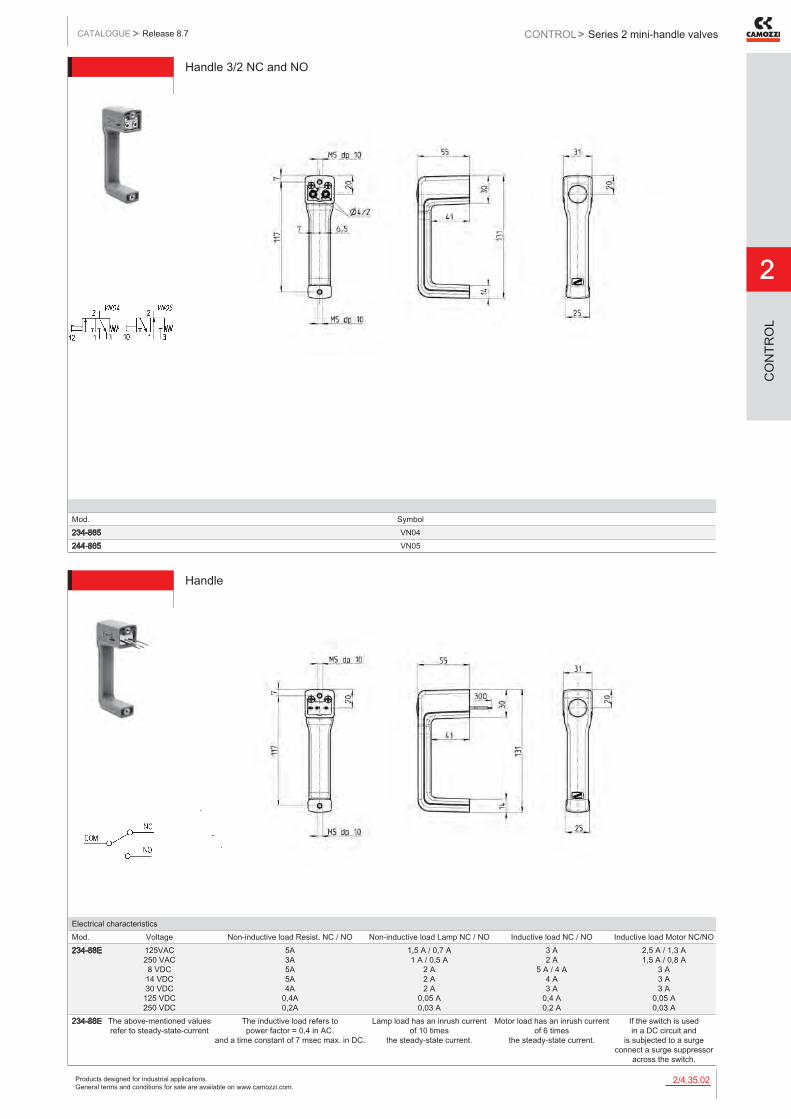
Handle 3/2 NC and NO
Mod. Symbol234-885 VN04244-885 VN05
Handle
Electrical characteristicsMod. Voltage Non-inductive load Resist. NC / NO Non-inductive load Lamp NC / NO Inductive load NC / NO Inductive load Motor NC/NO234-88E 125VAC
250 VAC 8 VDC 14 VDC 30 VDC 125 VDC 250 VDC
5A 3A 5A 5A 4A
0,4A 0,2A
1,5 A / 0,7 A 1 A / 0,5 A
2 A 2 A 2 A
0,05 A 0,03 A
3 A 2 A
5 A / 4 A 4 A 3 A
0,4 A 0,2 A
2,5 A / 1,3 A 1,5 A / 0,8 A
3 A 3 A 3 A
0,05 A 0,03 A
234-88E The above-mentioned values refer to steady-state-current
The inductive load refers to power factor = 0,4 in AC.
and a time constant of 7 msec max. in DC.
Lamp load has an inrush current of 10 times
the steady-state current.
Motor load has an inrush current of 6 times
the steady-state current.
If the switch is used in a DC circuit and
is subjected to a surge connect a surge suppressor
across the switch.

Products designed for industrial applications. General terms and conditions for sale are available on www.camozzi.com.
2
Series 2L basic logic valvesCONTROL > CATALOGUE > Release 8.7
/5.05.012
CO
NTR
OL
Series 2L basic logic valves
Cartridge Ø 4 mm. or - and - yes - not - memory
Series 2L basic logic functions are available in 5 different models and can be mounted separately by means of 2 passing holes in the body. Bracket Mod. 2LQ-8A allows to have the inlets and outlets on the front side, facilitating the mounting of the connection tubes.
All models are constructed with the pressure window incorporated, which allows an easy detection of any problems. Moreover the fittings are incorporated into the valve body and are super-rapid ø4. The “NOT” element has an actuating pressure of 0,3 bar.
GENERAL DATAConstruction poppet (spool memory)Materials aluminium body; NBR seals; OT58 brassValve group automatic valves (logic units)Ports cartridge ø 4Operating temperature 0°C ÷ 60°C (-20°C with dry air)Operating pressure 2 bar ÷ 10 barNominal flowrate 100 Nl/min. (6 bar ∆P = 1)Fluid filtered air, without lubricant.
If lubricated air is used, it is recommended to use oil ISO VG32. Once applied the lubrication should never be interrupted.

Products designed for industrial applications. General terms and conditions for sale are available on www.camozzi.com.
Series 2L basic logic valvesCATALOGUE
2
/5.05.022
> Release 8.7 CONTROL >
CO
NTR
OL
Basic logic valves AND / OR
Mod. Function Pneumatic symbol Logic symbol2LD-SB4-B AND AND1 AND22LR-SB4-B OR OR01 OR02
Basic logic valves YES / NOT
Mod. Function Pneumatic symbol Logic symbol2LS-SB4-B YES YES1 YES22LT-SB4-B NOT NOT1 NOT2
Basic logic valves “Memory”
Mod. Function Pneumatic symbol Logic symbol2LM-SB4-B Memory MEM1 MEM2

Products designed for industrial applications. General terms and conditions for sale are available on www.camozzi.com.
2
Series 2L basic logic valvesCONTROL > CATALOGUE > Release 8.7
/5.05.032
CO
NTR
OL
Right-angled bracket
Mod.2LQ-8A
Pneumatically operated 3/2 NC amplifier valve - G1/8 ports
The amplifier valve Mod. 2LA-AM is able to change low pressure signals into signals with pressure from 2 to 8 bar. The poppet type construction shows a minimum permanent air consumption at rest. Mounting: with M5 screws Installation: in any position Fluid: filtered air, without lubricant
Mod. Working pressure (bar) Min/max operating pressure (bar) Permanent air consumption at rest (Nl/min) Nominal flow (Nl/min ΔP 1)2LA-AM 2 ÷ 8 0.03 / 0.6 3.3 120
Materials: - AL body - NBR seals

Products designed for industrial applications. General terms and conditions for sale are available on www.camozzi.com.
Series 2L basic logic valvesCATALOGUE
2
/5.05.042
> Release 8.7 CONTROL >
CO
NTR
OL
Materials: aluminium - brass Construction: nozzle without moving parts Threading mounting: M22 x 1 Mounting diameter: 22.5 mm Mounting bracket: B20-25, E20-25 Max air consumption: P 2 bar ≅ 45 Nl/min Fluid: filtered air, without lubricant Conditions of functioning: the receiver pressure (2LB-SR) has to be lower or equal compared with the sender pressure (2LB-SE) The receiver nozzle (2LB-SR) is supplied to ensure the self-cleaning. The air jet of the sender (2LB-SE) avoids the free outflow of the air jet from the receiver. A back pressure is thus produced that generates at outlet A a pilot pressure which is sent to the amplifier drive. When an object interrupts the air jet between the two sensors, this signal becomes zero.
Sender and receiver sensor Series 2L - M5 ports
Mod. Type Min. pressure Max pressure Temperature Symbol2LB-SE Sender 0.3 bar 2 bar -20°C ÷ +60°C 2LB12LB-SR Receiver 0.3 bar 0.6 bar -20°C ÷ +60°C 2LB2
DISTANCE DIAGRAM between SENDER (2LB-SE) and RECEIVER (2LB-SR) according to the supply pressures
X = distance between nozzles (30 mm ÷ 80 mm)
SENDER AND RECEIVER SENSORS SERIES 2L
Products designed for industrial applications. General terms and conditions for sale are available on www.camozzi.com.
2
Series SCS, VNR, VSO, VSC and VMR automatic valvesCONTROL > CATALOGUE > Release 8.7
/6.05.012
CO
NTR
OL
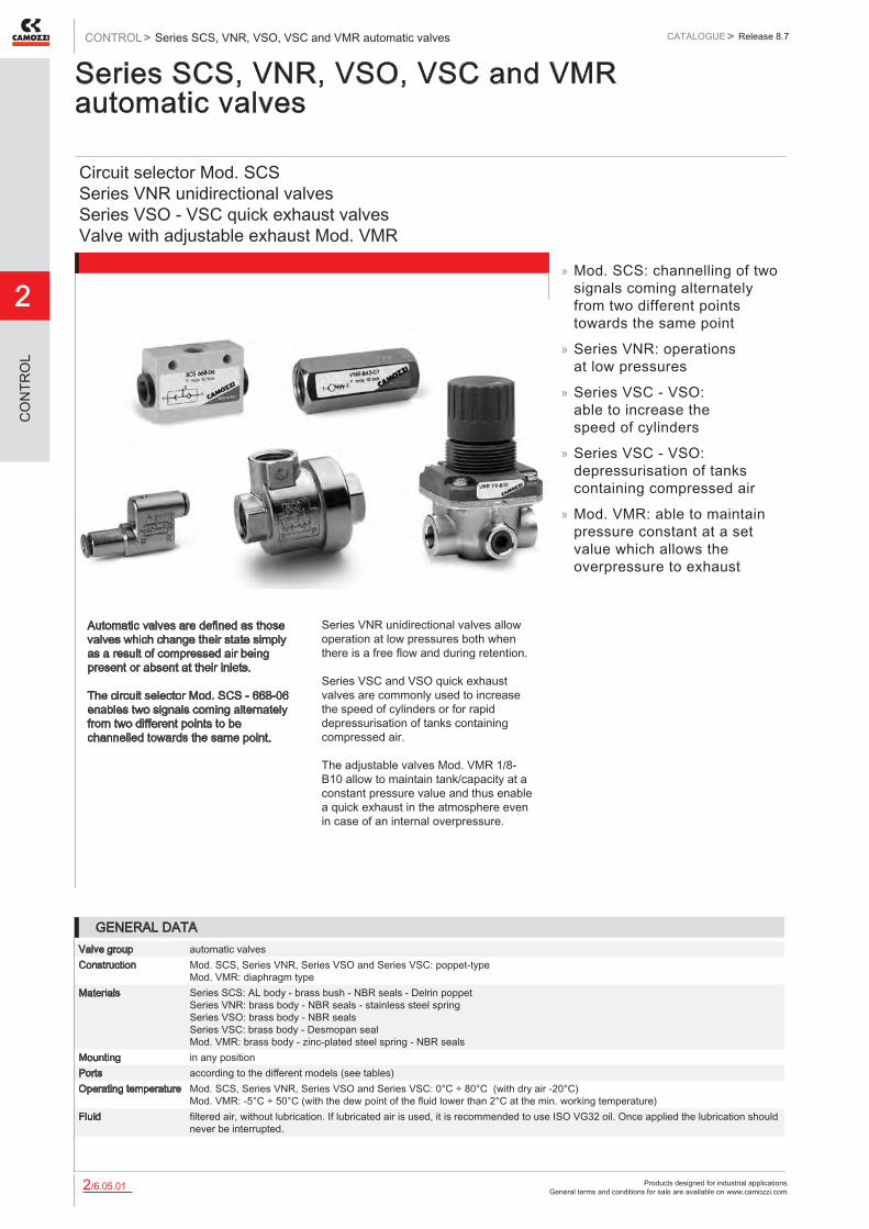
Series SCS, VNR, VSO, VSC and VMR automatic valves
Circuit selector Mod. SCS Series VNR unidirectional valves Series VSO - VSC quick exhaust valves Valve with adjustable exhaust Mod. VMR
Automatic valves are defined as those valves which change their state simply as a result of compressed air being present or absent at their inlets. The circuit selector Mod. SCS - 668-06 enables two signals coming alternately from two different points to be channelled towards the same point.
Series VNR unidirectional valves allow operation at low pressures both when there is a free flow and during retention. Series VSC and VSO quick exhaust valves are commonly used to increase the speed of cylinders or for rapid depressurisation of tanks containing compressed air. The adjustable valves Mod. VMR 1/8-B10 allow to maintain tank/capacity at a constant pressure value and thus enable a quick exhaust in the atmosphere even in case of an internal overpressure.
» Mod. SCS: channelling of two signals coming alternately from two different points towards the same point
» Series VNR: operations at low pressures
» Series VSC - VSO: able to increase the speed of cylinders
» Series VSC - VSO: depressurisation of tanks containing compressed air
» Mod. VMR: able to maintain pressure constant at a set value which allows the overpressure to exhaust
GENERAL DATAValve group automatic valvesConstruction Mod. SCS, Series VNR, Series VSO and Series VSC: poppet-type
Mod. VMR: diaphragm typeMaterials Series SCS: AL body - brass bush - NBR seals - Delrin poppet
Series VNR: brass body - NBR seals - stainless steel spring Series VSO: brass body - NBR seals Series VSC: brass body - Desmopan seal Mod. VMR: brass body - zinc-plated steel spring - NBR seals
Mounting in any positionPorts according to the different models (see tables)Operating temperature Mod. SCS, Series VNR, Series VSO and Series VSC: 0°C ÷ 80°C (with dry air -20°C)
Mod. VMR: -5°C ÷ 50°C (with the dew point of the fluid lower than 2°C at the min. working temperature)Fluid filtered air, without lubrication. If lubricated air is used, it is recommended to use ISO VG32 oil. Once applied the lubrication should
never be interrupted.

Products designed for industrial applications. General terms and conditions for sale are available on www.camozzi.com.
Series SCS, VNR, VSO, VSC and VMR automatic valvesCATALOGUE
2
/6.05.022
> Release 8.7 CONTROL >
CO
NTR
OL
Circuit selector Mod. SCS
The selector is mounted by through holes in the body. Materials used: - AL body - brass bush - NBR seals - Delrin poppet
Mod. Flow (Nl/min) Min. operating pressure (bar) Max working pressure (bar)SCS-668-06 800 0.2 10
Series VNR unidirectional valves
The poppet-type construction of these valves allow operation at low pressures both when there is a free flow and during retention. Ports: M5 - G1/8 - G1/4 - G3/8 - G1/2 - G3/4 Materials used: - brass body - NBR seals - stainless steel spring
DIMENSIONSMod. R L SW D Flow (Nl/min) Min. operating pressure (bar) Max working pressure (bar)VNR-205-M5 M5 25 8 9 50 1 10VNR-210-1/8 G1/8 34 13 15 600 0.2 10VNR-843-07 G1/4 43 17 20 1400 0.2 10VNR-238-3/8 G3/8 55 23 34.5 3000 0.02 25VNR-212-1/2 G1/2 58.5 27 34.5 5800 0.02 25VNR-234-3/4 G3/4 65 33 41.5 8000 0.06 25
Products designed for industrial applications. General terms and conditions for sale are available on www.camozzi.com.
2
Series SCS, VNR, VSO, VSC and VMR automatic valvesCONTROL > CATALOGUE > Release 8.7
/6.05.032
CO
NTR
OL
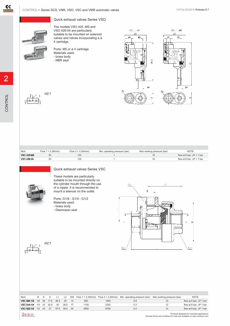
Quick exhaust valves Series VSO
The models VSO 425 -M5 and VSO 426-04 are particularly suitable to be mounted on solenoid valves and valves incorporating a ø 4 cartridge. Ports: M5 or ø 4 cartridge Materials used: - brass body - NBR seal
Mod. Flow 1 > 2 (Nl/min) Flow 2 > 3 (Nl/min) Min. operating pressure (bar) Max working pressure (bar) NOTEVSO 425-M5 50 100 1 16 flow at 6 bar, ∆P = 1 barVSO 426-04 50 100 1 16 flow at 6 bar, ∆P = 1 bar
Quick exhaust valves Series VSC
These models are particularly suitable to be mounted directly on the cylinder mouth through the use of a nipple. It is recommended to mount a silencer on the outlet. Ports: G1/8 - G1/4 - G1/2 Materials used: - brass body - Desmopan seal
Mod. B D E L1 L2 SW Flow 1 > 2 (Nl/min) Flow 2 > 3 (Nl/min) Min. operating pressure (bar) Max working pressure (bar) NOTEVSC 588-1/8 1/8 28 17.5 36.5 25 14 650 1000 0.5 12 flow at 6 bar, ∆P 1 barVSC 544-1/4 1/4 33 20.5 42 28.5 17 1100 2300 0.3 12 flow at 6 bar, ∆P 1 barVSC 522-1/2 1/2 43 27 57.5 39.5 24 4500 6700 0.2 12 flow at 6 bar, ∆P 1 bar

Products designed for industrial applications. General terms and conditions for sale are available on www.camozzi.com.
Series SCS, VNR, VSO, VSC and VMR automatic valvesCATALOGUE
2
/6.05.042
> Release 8.7 CONTROL >
CO
NTR
OL
Working pressure: 1 bar ÷ 8 bar
Valve with maximum adjustable pressure Mod. VMR 1/8-B10
Mod.VMR 1/8-B10
FLOW DIAGRAM Pa = Inlet pressure Pr = Regulated pressure Q = Flow
FUNCTIONING SCHEME 1: overpressure exhaust in a cylinder chamber or in a tank when the set value has been exceeded. FUNCTIONING SCHEME 2: VMR valve with maximum adjust-able pressure allows pressure in a cylinder chamber or in tank to exhaust in the atmosphere every time the set regulation value is exceeded.
VALVE Mod. VMR 1/8-B10 - FLOW DIAGRAM and FUNCTIONING SCHEMES

Products designed for industrial applications. General terms and conditions for sale are available on www.camozzi.com.
2
Series VBO and VBU blocking valvesCONTROL > CATALOGUE > Release 8.7
/6.10.012
CO
NTR
OL
Series VBO - VBU blocking valves
Unidirectional valves (VBU) and bidirectional valves (VBO) Ports G1/8, G1/4, G3/8 and G1/2
These unidirectional and bidirectional blocking valves have been realised in order to enable mounting directly on cylinders. The inner design of the blocking valves Series VBO and VBU allows a very high flow rate and reliable operation.
These valves can be mounted directly also on distribution and fluid control blocks.
» Series VBU: unidirectional valves with operating pressure from 0.3 to 10 bar
» Series VBO: bidirectional valves with operating pressure from 0 to 10 bar
» Direct mounting on cylinders or on distribution and fluid control blocks
GENERAL DATAConstruction poppet typeValve group unidirectional and bidirectional blocking valveMaterials Brass - NBR seals - stainless steel springs - PTFEMounting by male threadPorts G1/8 - G1/4 - G3/8 - G1/2Position in any positionOperating temperature 0°C ÷ 80°C (with dry air -20°C)Operating pressure VBU: 0,3 ÷ 10 bar, VBO: 0 ÷ 10 barNominal pressure 6 barNominal flow see graphNominal diam. G1/8 ø 5,5 mm - G1/4 ø 8 mm - G3/8 ø 11 mm - G1/2 ø 15 mmFluid filtered air, without lubrication. If lubricated air is used, it is recommended to use oil ISO VG32. Once applied, the lubrication
should never be interrupted.

Products designed for industrial applications. General terms and conditions for sale are available on www.camozzi.com.
Series VBO and VBU blocking valvesCATALOGUE
2
/6.10.022
> Release 8.7 CONTROL >
CO
NTR
OL
CODING EXAMPLE
VB SERIES: VB
U VERSIONS: U = unidirectional O = bidirectional
1/8 PORTS: G1/8 G1/4 G3/8 G1/2
VB U 1/8
6512 DIAGRAM OF THE PILOT PRESSURE
This diagram shows the relation between working pressure (Px) and pilot pressure required in order to operate the valve (Py). The opening pressure of the unidirectional valve is 0,3 bar.
Products designed for industrial applications. General terms and conditions for sale are available on www.camozzi.com.
2
Series VBO and VBU blocking valvesCONTROL > CATALOGUE > Release 8.7
/6.10.032
CO
NTR
OL
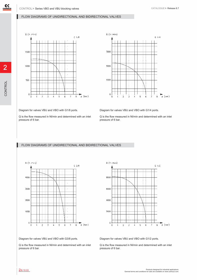
Diagram for valves VBU and VBO with G1/8 ports. Q is the flow measured in Nl/min and determined with an inlet pressure of 6 bar.
Diagram for valves VBU and VBO with G1/4 ports. Q is the flow measured in Nl/min and determined with an inlet pressure of 6 bar.
FLOW DIAGRAMS OF UNIDIRECTIONAL AND BIDIRECTIONAL VALVES
Diagram for valves VBU and VBO with G3/8 ports. Q is the flow measured in Nl/min and determined with an inlet pressure of 6 bar.
Diagram for valves VBU and VBO with G1/2 ports. Q is the flow measured in Nl/min and determined with an inlet pressure of 6 bar.
FLOW DIAGRAMS OF UNIDIRECTIONAL AND BIDIRECTIONAL VALVES
Products designed for industrial applications. General terms and conditions for sale are available on www.camozzi.com.
Series VBO and VBU blocking valvesCATALOGUE
2
/6.10.042
> Release 8.7 CONTROL >
CO
NTR
OL
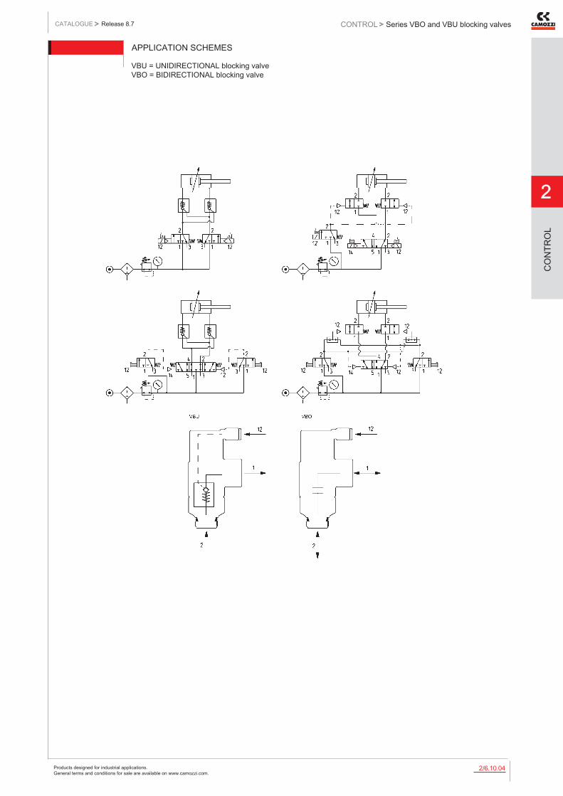
APPLICATION SCHEMES
VBU = UNIDIRECTIONAL blocking valve VBO = BIDIRECTIONAL blocking valve

Products designed for industrial applications. General terms and conditions for sale are available on www.camozzi.com.
2
Series VBO and VBU blocking valvesCONTROL > CATALOGUE > Release 8.7
/6.10.052
CO
NTR
OL
Unidirectional blocking valve
DIMENSIONSMod. A B C F H L M N SWVBU 1/8 1/8 1/8 16,9 20 5,5 43 24,5 30 15VBU 1/4 1/4 1/4 20,5 25 7 50 32,2 33,5 19VBU 3/8 3/8 3/8 26,8 33 8 67 40 39,5 24VBU 1/2 1/2 1/2 30 45,5 9 85,7 52 48 27
Bidirectional blocking valve
DIMENSIONSMod. A B C F H L M N SWVBO 1/8 1/8 1/8 16,9 20 5,5 43 24,5 30 15VBO 1/4 1/4 1/4 20,5 25 7 50 32,2 33,5 19VBO 3/8 3/8 3/8 26,8 33 8 67 40 39,5 24VBO 1/2 1/2 1/2 30 45,5 9 85,7 52 48 27

Products designed for industrial applications. General terms and conditions for sale are available on www.camozzi.com.
Series SCU, MCU, SVU, MVU, SCO, MCO valvesCATALOGUE
2
/7.05.012
> Release 8.7 CONTROL >
CO
NTR
OL
Series SCU, MCU, SVU, MVU, SCO, MCO flow control valves
Unidirectional and bidirectional flow control valves Banjo flow control regulators Ports M5, G1/8, G1/4, G3/8, G1/2
These unidirectional and bidirectional flow controllers have been designed as small as possible so as to be mounted directly on valves or cylinders. The great variety of adjustable fittings makes it possible to complete the regulator with the most suitable system in relation to the available tube.
Only the G1/2 model is supplied complete with banjo flow controllers. For the other models the banjo flow controller is to be requested separately.
GENERAL DATAConstruction needle typeValve group unidirectional and bidirectional controllerMaterials body and regulation screw: M5 = stainless steel; 1/8 - 1/4 - 3/8 - 1/2 = OT;
seals = NBRMounting by male threadPorts M5 - G1/8 - G1/4 - G3/8 - G1/2Installation in any positionOperating temperature 0°C ÷ 80°C (with dry air - 20°C)Operating pressure 1 ÷ 10 barNominal pressure 6 barNominal flow see graphNominal diameter M5 = 1,5 mm - G1/8 = 2 mm - G1/4 = 4 mm - G3/8 = 7 mm - G1/2 = 12 mmFluid filtered air
Products designed for industrial applications. General terms and conditions for sale are available on www.camozzi.com.
2
Series SCU, MCU, SVU, MVU, SCO, MCO valvesCONTROL > CATALOGUE > Release 8.7
/7.05.022
CO
NTR
OL
CODING EXAMPLE
M ACTUATION: M = Manual S = Screwdriver
CU ASSEMBLY: CU = on cylinders unidirectional VU = on valves unidirectional CO = bidirectional
7 VERSIONS: 6 = needle (screwdriver operated) 7 = needle (manual operated)
02 NOMINAL DIAMETER: 02 = ø 1,5 max 04 = ø 2 max 06 = ø 4 max 08 = ø 7 max 10 = ø 12 max
M5 PORTS: M5 = M5 1/8 = G1/8 1/4 = G1/4 3/8 = G3/8 1/2 = G1/2
To ensure the right choice of unidirectional flow controller, proceed as follows: calculate the quantity of air in Nl/min (see cylinder Table); determine the stroke time of the cylinder; refer to graph to see which controller is the right type.
M CU 7 02 - M5
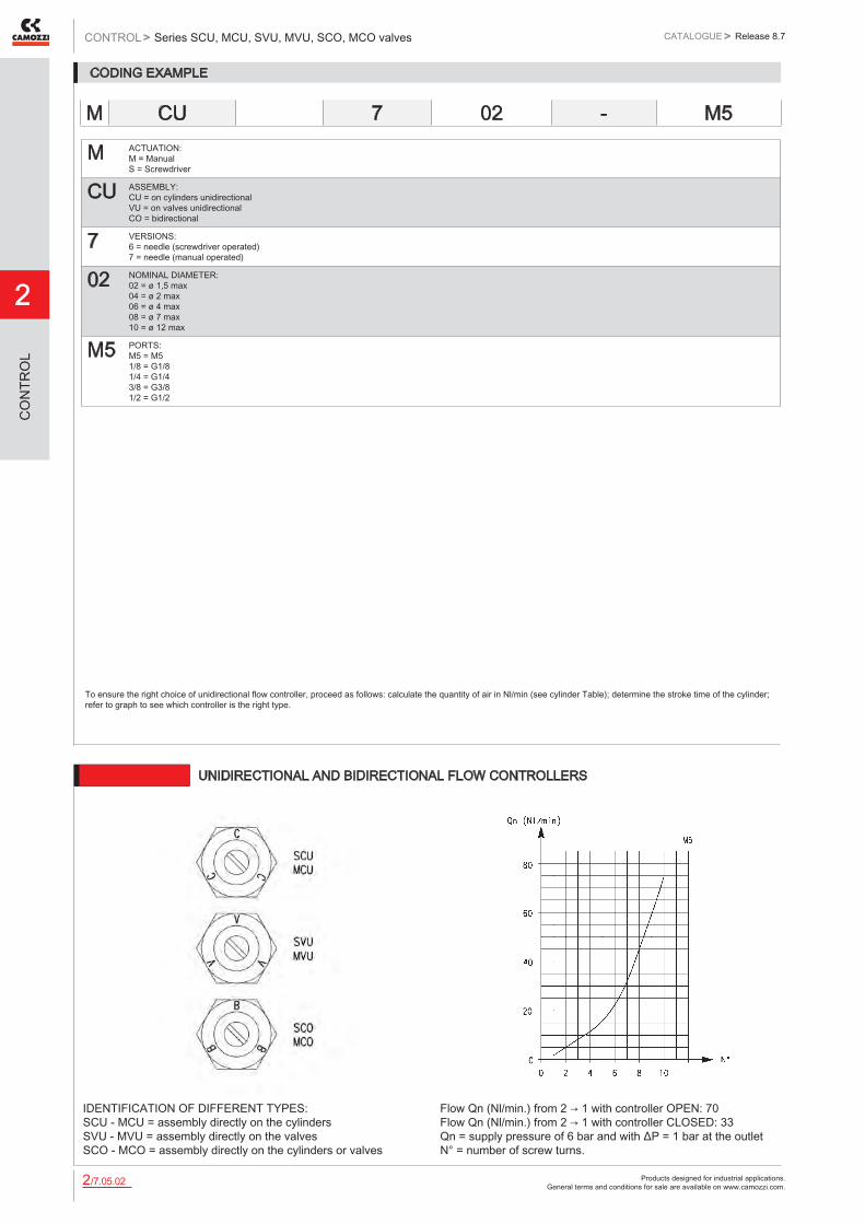
6512 UNIDIRECTIONAL AND BIDIRECTIONAL FLOW CONTROLLERS
IDENTIFICATION OF DIFFERENT TYPES: SCU - MCU = assembly directly on the cylinders SVU - MVU = assembly directly on the valves SCO - MCO = assembly directly on the cylinders or valves
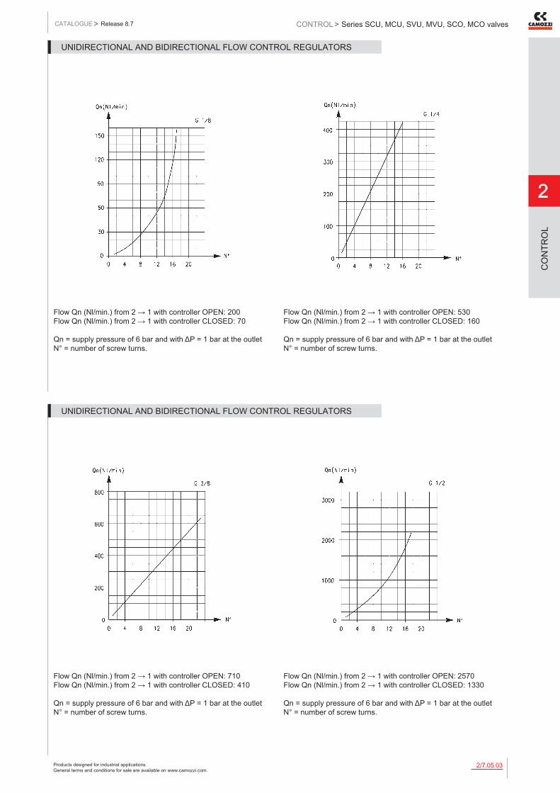
Flow Qn (Nl/min.) from 2 → 1 with controller OPEN: 70 Flow Qn (Nl/min.) from 2 → 1 with controller CLOSED: 33 Qn = supply pressure of 6 bar and with ΔP = 1 bar at the outlet N° = number of screw turns.
Products designed for industrial applications. General terms and conditions for sale are available on www.camozzi.com.
Series SCU, MCU, SVU, MVU, SCO, MCO valvesCATALOGUE
2
/7.05.032
> Release 8.7 CONTROL >
CO
NTR
OL
Flow Qn (Nl/min.) from 2 → 1 with controller OPEN: 200 Flow Qn (Nl/min.) from 2 → 1 with controller CLOSED: 70 Qn = supply pressure of 6 bar and with ΔP = 1 bar at the outlet N° = number of screw turns.
Flow Qn (Nl/min.) from 2 → 1 with controller OPEN: 530 Flow Qn (Nl/min.) from 2 → 1 with controller CLOSED: 160 Qn = supply pressure of 6 bar and with ΔP = 1 bar at the outlet N° = number of screw turns.
UNIDIRECTIONAL AND BIDIRECTIONAL FLOW CONTROL REGULATORS
Flow Qn (Nl/min.) from 2 → 1 with controller OPEN: 710 Flow Qn (Nl/min.) from 2 → 1 with controller CLOSED: 410 Qn = supply pressure of 6 bar and with ΔP = 1 bar at the outlet N° = number of screw turns.
Flow Qn (Nl/min.) from 2 → 1 with controller OPEN: 2570 Flow Qn (Nl/min.) from 2 → 1 with controller CLOSED: 1330 Qn = supply pressure of 6 bar and with ΔP = 1 bar at the outlet N° = number of screw turns.
UNIDIRECTIONAL AND BIDIRECTIONAL FLOW CONTROL REGULATORS
Products designed for industrial applications. General terms and conditions for sale are available on www.camozzi.com.
2
Series SCU, MCU, SVU, MVU, SCO, MCO valvesCONTROL > CATALOGUE > Release 8.7
/7.05.042
CO
NTR
OL
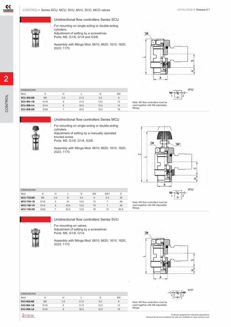
Unidirectional flow controllers Series SCUFor mounting on single-acting or double-acting cylinders. Adjustment of setting by a screwdriver. Ports: M5, G1/8, G1/4 and G3/8. Assembly with fittings Mod. 6610; 6620; 1610; 1620; 2023; 1170.
DIMENSIONSMod. A H L S SWSCU 602-M5 M5 3,5 21,5 5,5 8SCU 604-1/8 G1/8 5 31,5 12,5 12SCU 606-1/4 G1/4 6 32,5 12,5 15SCU 608-3/8 G3/8 7 40,5 12,5 18
Note: M5 flow controllers must be used together with M6 adjustable fittings.
Unidirectional flow controllers Series MCUFor mounting on single-acting or double-acting cylinders. Adjustment of setting by a manually operated knurled screw. Ports: M5, G1/8, G1/4, G3/8. Assembly with fittings Mod. 6610; 6620; 1610; 1620; 2023; 1170.
DIMENSIONSMod. A H L S SW SW1 ZMCU 702-M5 M5 3,5 31 5,5 8 5,5 35MCU 704-1/8 G1/8 5 41 12,5 12 7 46MCU 706-1/4 G1/4 6 43,5 12,5 15 7 49MCU 708-3/8 G3/8 7 52,5 12,5 18 10 60,5
Note: M5 flow controllers must be used together with M6 adjustable fittings.
Unidirectional flow controllers Series SVUFor mounting on valves. Adjustment of setting by a screwdriver. Ports: M5, G1/8, G1/4. Assembly with fittings Mod. 6610; 6620; 1610; 1620; 2023; 1170.
DIMENSIONSMod. A H L S SWSVU 602-M5 M5 3,5 21,5 5,5 8SVU 604-1/8 G1/8 5 31,5 12,5 12SVU 606-1/4 G1/4 6 32,5 12,5 15
Note: M5 flow controllers must be used together with M6 adjustable fittings.

Products designed for industrial applications. General terms and conditions for sale are available on www.camozzi.com.
Series SCU, MCU, SVU, MVU, SCO, MCO valvesCATALOGUE
2
/7.05.052
> Release 8.7 CONTROL >
CO
NTR
OL
Unidirectional flow controllers Series MVUFor mounting on valve. Adjustment of setting by a manually operated knurled screw. Ports: M5, G1/8, G1/4. Assembly with fittings Mod. 6610; 6620; 1610; 1620; 2023; 1170.
DIMENSIONSMod. A H L S SW SW1 ZMVU 702-M5 M5 3,5 31 5,5 8 5,5 35MVU 704-1/8 G1/8 5 41 12,5 12 7 46MVU 706-1/4 G1/4 6 43,5 12,5 15 7 49
Note: M5 flow controllers must be used together with M6 adjustable fittings.
Bidirectional flow controllers Series SCOAdjustment of setting by a screwdriver. Ports: M5, G1/8, G1/4. Assembly with fittings Mod. 6610; 6620; 1610; 1620; 2023; 1170; 2905.
DIMENSIONSMod. A H L S SWSCO 602-M5 M5 3,5 21,5 5,5 8SCO 604-1/8 G1/8 5 31,5 12,5 12SCO 606-1/4 G1/4 6 32,5 12,5 15
Note: M5 flow controllers must be used together with M6 adjustable fittings.
Bidirectional flow controllers Series MCOAdjustment of setting by a manually operated knurled screw. Ports: M5, G1/8, G1/4. Assembly with fittings Mod. 6610; 6620; 1610; 1620; 2023; 1170; 2905.
DIMENSIONSMod. A H L S SW SW1 ZMCO 702-M5 M5 3,5 31 5,5 8 5,5 35MCO 704-1/8 G1/8 5 41 12,5 12 7 46MCO 706-1/4 G1/4 6 43,5 12,5 15 7 49
Note: M5 flow controllers must be used together with M6 adjustable fittings.

Products designed for industrial applications. General terms and conditions for sale are available on www.camozzi.com.
2
Series SCU, MCU, SVU, MVU, SCO, MCO valvesCONTROL > CATALOGUE > Release 8.7
/7.05.062
CO
NTR
OL
Unidirectional flow controllers Series SCUFor mounting on single-acting or double-acting cylinders. Screwdriver adjustment.
Mod.SCU 610-1/2
Unidirectional flow controllers Series MCUFor mounting on single-acting or double-acting cylinders. Adjustment of setting by a manually operated knurled screw.
Mod.MCU 710-1/2
Unidirectional flow controllers Series SVUFor mounting on valves. Screwdriver adjustment.
Mod.SVU 610-1/2

Products designed for industrial applications. General terms and conditions for sale are available on www.camozzi.com.
Series SCU, MCU, SVU, MVU, SCO, MCO valvesCATALOGUE
2
/7.05.072
> Release 8.7 CONTROL >
CO
NTR
OL
Unidirectional flow controllers Series MVUFor mounting on valve. Adjustment of setting by a manually operated knurled screw.
Mod.MVU 710-1/2
Bidirectional flow controllers Series SCOScrewdriver adjustment.
Mod.SCO 610-1/2
Bidirectional flow controllers Series MCOAdjustment of setting by a manually operated knurled screw.
Mod.MCO 710-1/2
Products designed for industrial applications. General terms and conditions for sale are available on www.camozzi.com.
2
Series SCU, MCU, SVU, MVU, SCO, MCO valvesCONTROL > CATALOGUE > Release 8.7
/7.05.082
CO
NTR
OL
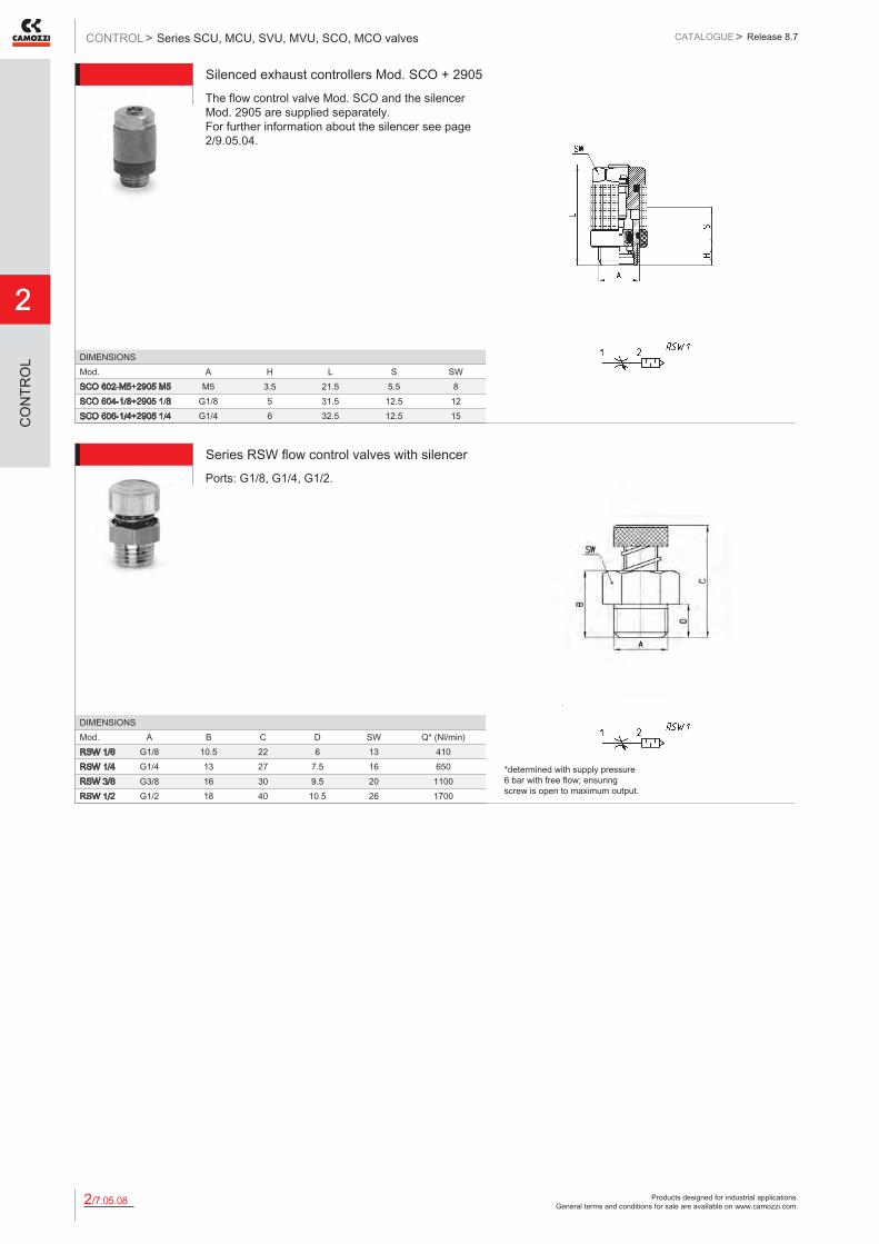
Silenced exhaust controllers Mod. SCO + 2905The flow control valve Mod. SCO and the silencer Mod. 2905 are supplied separately. For further information about the silencer see page 2/9.05.04.
DIMENSIONSMod. A H L S SWSCO 602-M5+2905 M5 M5 3.5 21.5 5.5 8SCO 604-1/8+2905 1/8 G1/8 5 31.5 12.5 12SCO 606-1/4+2905 1/4 G1/4 6 32.5 12.5 15
Series RSW flow control valves with silencerPorts: G1/8, G1/4, G1/2.
DIMENSIONSMod. A B C D SW Q* (Nl/min)RSW 1/8 G1/8 10.5 22 6 13 410RSW 1/4 G1/4 13 27 7.5 16 650RSW 3/8 G3/8 16 30 9.5 20 1100RSW 1/2 G1/2 18 40 10.5 26 1700
*determined with supply pressure 6 bar with free flow; ensuring screw is open to maximum output.
Products designed for industrial applications. General terms and conditions for sale are available on www.camozzi.com.
Series PSCU, PMCU, PSVU, PMVU, PSCO, PMCO valvesCATALOGUE
2
/7.07.012
> Release 8.7 CONTROL >
CO
NTR
OL
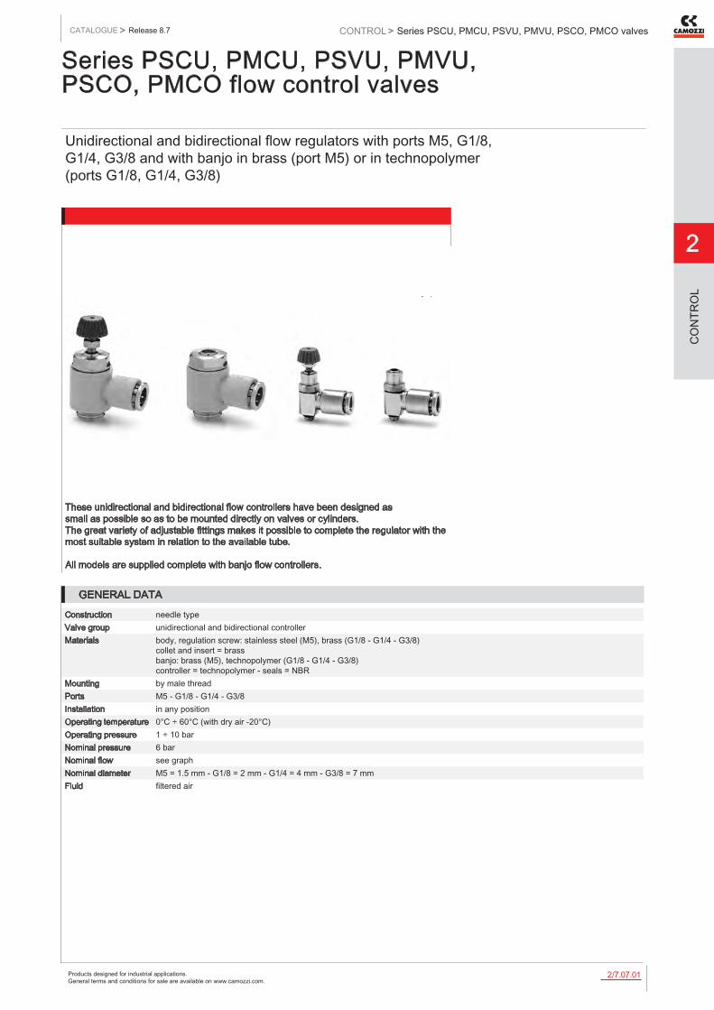
Series PSCU, PMCU, PSVU, PMVU, PSCO, PMCO flow control valves
Unidirectional and bidirectional flow regulators with ports M5, G1/8, G1/4, G3/8 and with banjo in brass (port M5) or in technopolymer (ports G1/8, G1/4, G3/8)
These unidirectional and bidirectional flow controllers have been designed as small as possible so as to be mounted directly on valves or cylinders. The great variety of adjustable fittings makes it possible to complete the regulator with the most suitable system in relation to the available tube. All models are supplied complete with banjo flow controllers.
GENERAL DATA
Construction needle typeValve group unidirectional and bidirectional controllerMaterials body, regulation screw: stainless steel (M5), brass (G1/8 - G1/4 - G3/8)
collet and insert = brass banjo: brass (M5), technopolymer (G1/8 - G1/4 - G3/8) controller = technopolymer - seals = NBR
Mounting by male threadPorts M5 - G1/8 - G1/4 - G3/8Installation in any positionOperating temperature 0°C ÷ 60°C (with dry air -20°C)Operating pressure 1 ÷ 10 barNominal pressure 6 barNominal flow see graphNominal diameter M5 = 1.5 mm - G1/8 = 2 mm - G1/4 = 4 mm - G3/8 = 7 mmFluid filtered air
Products designed for industrial applications. General terms and conditions for sale are available on www.camozzi.com.
2
Series PSCU, PMCU, PSVU, PMVU, PSCO, PMCO valvesCONTROL > CATALOGUE > Release 8.7
/7.07.022
CO
NTR
OL
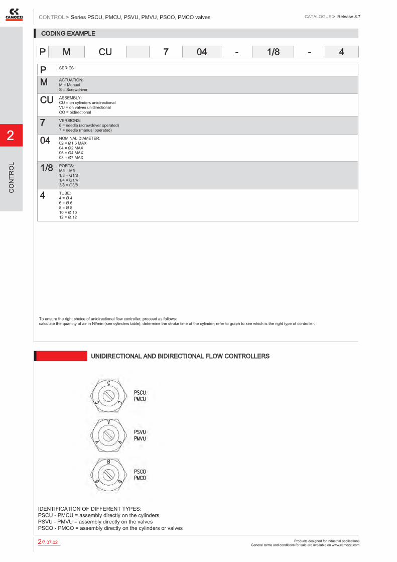
CODING EXAMPLE
P SERIES
M ACTUATION: M = Manual S = Screwdriver
CU ASSEMBLY: CU = on cylinders unidirectional VU = on valves unidirectional CO = bidirectional
7 VERSIONS: 6 = needle (screwdriver operated) 7 = needle (manual operated)
04 NOMINAL DIAMETER: 02 = Ø1.5 MAX 04 = Ø2 MAX 06 = Ø4 MAX 08 = Ø7 MAX
1/8 PORTS: M5 = M5 1/8 = G1/8 1/4 = G1/4 3/8 = G3/8
4 TUBE: 4 = Ø 4 6 = Ø 6 8 = Ø 8 10 = Ø 10 12 = Ø 12
To ensure the right choice of unidirectional flow controller, proceed as follows: calculate the quantity of air in Nl/min (see cylinders table); determine the stroke time of the cylinder; refer to graph to see which is the right type of controller.
P M CU 7 04 - 1/8 - 4
6512 UNIDIRECTIONAL AND BIDIRECTIONAL FLOW CONTROLLERS
IDENTIFICATION OF DIFFERENT TYPES: PSCU - PMCU = assembly directly on the cylinders PSVU - PMVU = assembly directly on the valves PSCO - PMCO = assembly directly on the cylinders or valves

Products designed for industrial applications. General terms and conditions for sale are available on www.camozzi.com.
Series PSCU, PMCU, PSVU, PMVU, PSCO, PMCO valvesCATALOGUE
2
/7.07.032
> Release 8.7 CONTROL >
CO
NTR
OL
Flow Qn (Nl/min.) from 2 → 1 with controller OPEN: 70 Flow Qn (Nl/min.) from 2 → 1 with controller CLOSED: 33 Qn = supply pressure of 6 bar and with ΔP = 1 bar at the outlet N° = number of screw turns
Flow Qn (Nl/min.) from 2 → 1 with controller OPEN: 200 Flow Qn (Nl/min.) from 2 → 1 with controller CLOSED: 70 Qn = supply pressure of 6 bar and with ΔP = 1 bar at the outlet N° = number of screw turns
UNIDIRECTIONAL AND BIDIRECTIONAL FLOW CONTROL REGULATORS
Flow Qn (Nl/min.) from 2 → 1 with controller OPEN: 530 Flow Qn (Nl/min.) from 2 → 1 with controller CLOSED: 160 Qn = supply pressure of 6 bar and with ΔP = 1 bar at the outlet N° = number of screw turns
Flow Qn (Nl/min.) from 2 → 1 with controller OPEN: 710 Flow Qn (Nl/min.) from 2 → 1 with controller CLOSED: 410 Qn = supply pressure of 6 bar and with ΔP = 1 bar at the outlet N° = number of screw turns
UNIDIRECTIONAL AND BIDIRECTIONAL FLOW CONTROL REGULATORS

Products designed for industrial applications. General terms and conditions for sale are available on www.camozzi.com.
2
Series PSCU, PMCU, PSVU, PMVU, PSCO, PMCO valvesCONTROL > CATALOGUE > Release 8.7
/7.07.042
CO
NTR
OL
Unidirectional flow controllers Series PSCUFor mounting on single-acting or double-acting cylinders. A screwdriver must be used to adjust the registration setting. Ports: M5, G1/8, G1/4 and G3/8. Port M5: banjo in brass
DIMENSIONSMod. A B G H L N S W SWPSCU 602-M5-4 M5 4 8.6 3.5 21.5 18 5.7 8 8PSCU 602-M5-6 M5 6 10.4 3.5 21.5 19 5.7 8 8PSCU 604-1/8-4 G1/8 4 11.6 5 27 21 7.75 14 12PSCU 604-1/8-6 G1/8 6 11.6 5 27 21 7.75 14 12PSCU 604-1/8-8 G1/8 8 13.9 5 27 22.5 7.75 14 12PSCU 606-1/4-6 G1/4 6 13.9 6 30.5 24.5 9.25 18.6 15PSCU 606-1/4-8 G1/4 8 13.9 6 30.5 24.5 9.25 18.6 15PSCU 606-1/4-10 G1/4 10 16.1 6 30.5 27 9.25 18.6 15PSCU 608-3/8-10 G3/8 10 20.2 7 36.5 29 11 22 18PSCU 608-3/8-12 G3/8 12 20.2 7 36.5 29 11 22 18
Unidirectional flow controllers Series PMCUFor mounting on single-acting or double-acting cylinders. A manually operated knurled screw must be used to adjust the registration setting. Ports: M5, G1/8, G1/4 and G3/8. Port M5: banjo in brass
DIMENSIONSMod. A B G H L N S W SW SW1 ZPMCU 702-M5-4 M5 4 8.6 3.5 31 18 5.7 8 8 5.5 35PMCU 702-M5-6 M5 6 10.4 3.5 31 19 5.7 8 8 5.5 35PMCU 704-1/8-4 G1/8 4 11.6 5 36.5 21 7.75 14 12 7 42.5PMCU 704-1/8-6 G1/8 6 11.6 5 36.5 21 7.75 14 12 7 42.5PMCU 704-1/8-8 G1/8 8 13.9 5 36.5 22.5 7.75 14 12 7 42.5PMCU 706-1/4-6 G1/4 6 13.9 6 42 24.5 9.25 18.6 15 7 48PMCU 706-1/4-8 G1/4 8 13.9 6 42 24.5 9.25 18.6 15 7 48PMCU 706-1/4-10 G1/4 10 16.1 6 42 27 9.25 18.6 15 7 48PMCU 708-3/8-10 G3/8 10 20.2 7 48.5 29 11 22 18 10 56.5PMCU 708-3/8-12 G3/8 12 20.2 7 48.5 29 11 22 18 10 56.5
Unidirectional flow controllers Series PSVUFor mounting on valves. A screwdriver must be used to adjust the registration setting. Ports: M5, G1/8, G1/4 and G3/8. Port M5: banjo in brass
DIMENSIONSMod. A B G H L N S W SWPSVU 602-M5-4 M5 4 8.6 3.5 21.5 18 5.7 8 8PSVU 602 M5-6 M5 6 10.4 3.5 21.5 19 5.7 8 8PSVU 604-1/8-4 G1/8 4 11.6 5 27 21 7.75 14 12PSVU 604-1/8-6 G1/8 6 11.6 5 27 21 7.75 14 12PSVU 604-1/8-8 G1/8 8 13.9 5 27 22.5 7.75 14 12PSVU 606-1/4-6 G1/4 6 13.9 6 30.5 24.5 9.25 18.6 15PSVU 606-1/4-8 G1/4 8 13.9 6 30.5 24.5 9.25 18.6 15PSVU 606-1/4-10 G1/4 10 16.1 6 30.5 27 9.25 18.6 15PSVU 608-3/8-10 G3/8 10 20.2 7 36.5 29 11 22 18PSVU 608-3/8-12 G3/8 12 20.2 7 36.5 29 11 22 18

Products designed for industrial applications. General terms and conditions for sale are available on www.camozzi.com.
Series PSCU, PMCU, PSVU, PMVU, PSCO, PMCO valvesCATALOGUE
2
/7.07.052
> Release 8.7 CONTROL >
CO
NTR
OL
Unidirectional flow controllers Series PMVUFor mounting on valve. A manually operated knurled screw must be used to adjust the registration setting. Ports: M5, G1/8, G1/4 and G3/8. Port M5: banjo in brass
DIMENSIONSMod. A B G H L N S W SW SW1 ZPMVU 702-M5-4 M5 4 8.6 3.5 31 18 5.7 8 8 5.5 35PMVU 702-M5-6 M5 6 10.4 3.5 31 19 5.7 8 8 5.5 35PMVU 704-1/8-4 G1/8 4 11.6 5 36.5 21 7.75 14 12 7 42.5PMVU 704-1/8-6 G1/8 6 11.6 5 36.5 21 7.75 14 12 7 42.5PMVU 704-1/8-8 G1/8 8 13.9 5 36.5 22.5 7.75 14 12 7 42.5PMVU 706-1/4-6 G1/4 6 13.9 6 42 24.5 9.25 18.6 15 7 48PMVU 706-1/4-8 G1/4 8 13.9 6 42 24.5 9.25 18.6 15 7 48PMVU 706-1/4-10 G1/4 10 16.1 6 42 27 9.25 18.6 15 7 48PMVU 708-3/8-10 G3/8 10 20.2 7 48.5 29 11 22 18 10 56.5PMVU 708-3/8-12 G3/8 12 20.2 7 48.5 29 11 22 18 10 56.5
Bidirectional flow controllers Series PSCOA screwdriver must be used to adjust the registration setting. Ports: M5, G1/8, G1/4 and G3/8. Port M5: banjo in brass
DIMENSIONSMod. A B G H L N S W SWPSCO 602-M5-4 M5 4 8.6 3.5 21.5 18 5.7 8 8PSCO 602-M5-6 M5 6 10.4 3.5 21.5 19 5.7 8 8PSCO 604-1/8-4 G1/8 4 11.6 5 27 21 7.75 14 12PSCO 604-1/8-6 G1/8 6 11.6 5 27 21 7.75 14 12PSCO 604-1/8-8 G1/8 8 13.9 5 27 22.5 7.75 14 12PSCO 606-1/4-6 G1/4 6 13.9 6 30.5 24.5 9,25 18.6 15PSCO 606-1/4-8 G1/4 8 13.9 6 30.5 24.5 9.25 18.6 15PSCO 606-1/4-10 G1/4 10 16.1 6 30.5 27 9.25 18.6 15PSCO 608-3/8-10 G3/8 10 20.2 7 36.5 29 11 22 18PSCO 608-3/8-12 G3/8 12 20.2 7 36.5 29 11 22 18
Bidirectional flow controllers Series PMCOA manually operated knurled screw must be used to adjust the registration setting. Ports: M5, G1/8, G1/4 and G3/8. Port M5: banjo in brass
DIMENSIONSMod. A B G H L N S W SW SW1 ZPMCO 702-M5-4 M5 4 8.6 3.5 31 18 5.7 8 8 5.5 35PMCO 702-M5-6 M5 6 10.4 3.5 31 19 5.7 8 8 5.5 35PMCO 704-1/8-4 G1/8 4 11.6 5 36.5 21 7.75 14 12 7 42.5PMCO 704-1/8-6 G1/8 6 11.6 5 36.5 21 7.75 14 12 7 42.5PMCO 704-1/8-8 G1/8 8 13.9 5 36.5 22.5 7.75 14 12 7 42.5PMCO 706-1/4-6 G1/4 6 13.9 6 42 24.5 9.25 18.6 15 7 48PMCO 706-1/4-8 G1/4 8 13.9 6 42 24.5 9.25 18.6 15 7 48PMCO 706-1/4-10 G1/4 10 16.1 6 42 27 9.25 18.6 15 7 48PMCO 708-3/8-10 G3/8 10 20.2 7 48.5 29 11 22 18 10 56.5PMCO 708-3/8-12 G3/8 12 20.2 7 48.5 29 11 22 18 10 56.5

Products designed for industrial applications. General terms and conditions for sale are available on www.camozzi.com.
2
Series TMCU, TMVU, TMCO valvesCONTROL > CATALOGUE > Release 8.7
/7.10.012
CO
NTR
OL
Series TMCU, TMVU, TMCO flow control valves
Unidirectional and bidirectional flow control valves Banjo flow controllers nominal diameters ø 2 - 3,8 - 5,8 - 8 mm Ports G1/8, G1/4, G3/8, G1/2
Series TMCU, TMVU, TMCO unidirectional and bidirectional flow controllers have been revised in order to decrease their dimensions and improve their flow rate characteristics. Their construction allows for easy assembly to cylinders and valves and allows the regulation adjustment to be precise and gradual.
GENERAL DATAConstruction needle - typeValve group unidirectional and bidirectional controllerMaterials brass - technopolymer - NBRMounting by male threadedThreaded ports G1/8 - G1/4 - G3/8 - G1/2Installation in any positionOperating temperature 0°C ÷ 60°C (with dry air -20°C)Operating pressure 0,5 ÷ 10 barNominal pressure 6 barNominal flow see graphNominal dia. Tube 4 Ø2 - Tube 6 Ø3,8 - Tube 8 Ø5,8 - Tube 10 and 12 Ø8Fluid filtered air
If lubricated air is used, it is recommended to use ISOVG 32 oil. Once applied the lubrication should never be interrupted.

Products designed for industrial applications. General terms and conditions for sale are available on www.camozzi.com.
Series TMCU, TMVU, TMCO valvesCATALOGUE
2
/7.10.022
> Release 8.7 CONTROL >
CO
NTR
OL
CODING EXAMPLE
TM ACTUATION: TM = manual
CU ASSEMBLY: CU = on cylinders unidirectional VU = on valves unidirectional CO = bidirectional
9 VERSIONS: 9 = manual needle
74 REGULATION: step - ø tube 72 = 2 4 74 = 3.8 6 76 = 5.8 8 78 = 8 10
1/8 PORTS: 1/8 1/4 3/8 1/2
6 Ø TUBE: 4 6 8 10
To ensure the right choice of unidirectional flow controller, proceed as follows: calculate the quantity of air in Nl/min (see cylinder Table); determine the stroke time of the cylinder; refer to graph to see which controller is the right type.
TM CU 9 74 - 1/8 - 6
Products designed for industrial applications. General terms and conditions for sale are available on www.camozzi.com.
2
Series TMCU, TMVU, TMCO valvesCONTROL > CATALOGUE > Release 8.7
/7.10.032
CO
NTR
OL
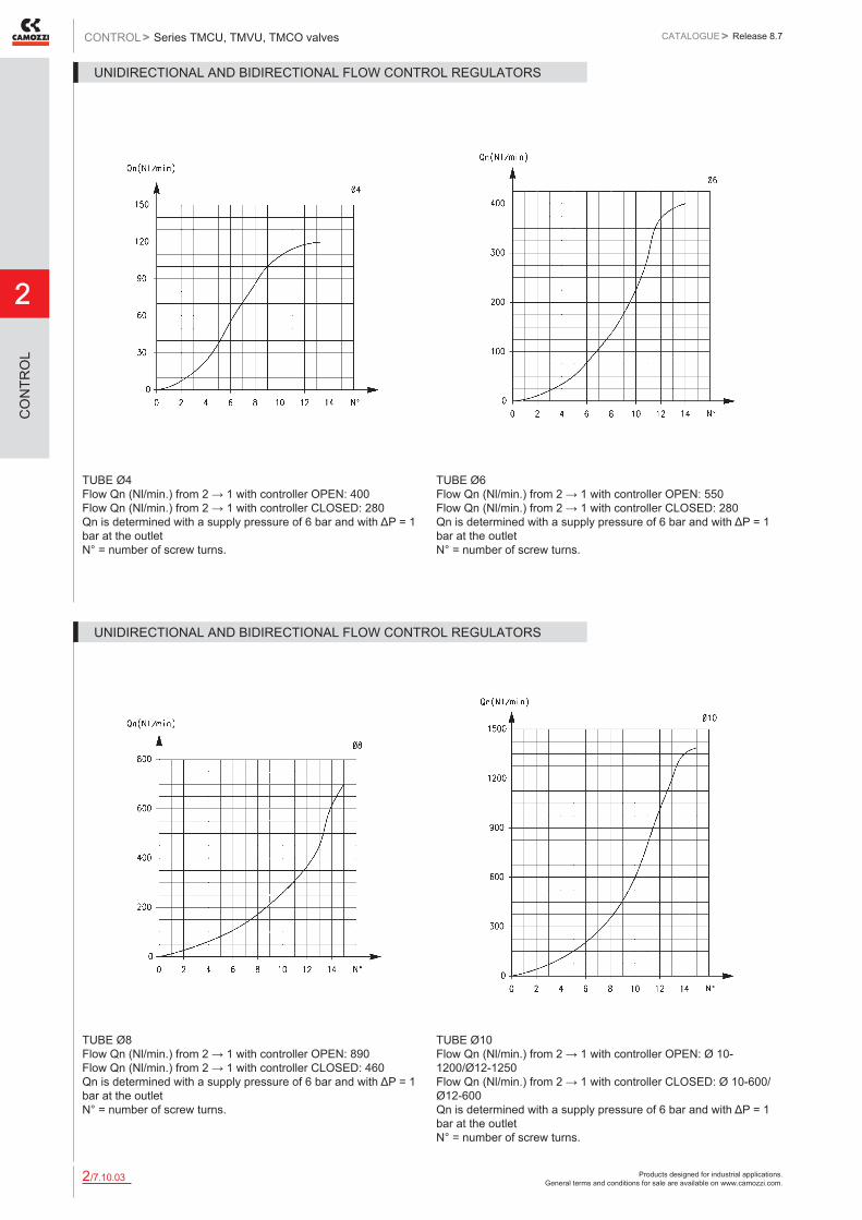
TUBE Ø4 Flow Qn (Nl/min.) from 2 → 1 with controller OPEN: 400 Flow Qn (Nl/min.) from 2 → 1 with controller CLOSED: 280 Qn is determined with a supply pressure of 6 bar and with ΔP = 1 bar at the outlet N° = number of screw turns.
TUBE Ø6 Flow Qn (Nl/min.) from 2 → 1 with controller OPEN: 550 Flow Qn (Nl/min.) from 2 → 1 with controller CLOSED: 280 Qn is determined with a supply pressure of 6 bar and with ΔP = 1 bar at the outlet N° = number of screw turns.
UNIDIRECTIONAL AND BIDIRECTIONAL FLOW CONTROL REGULATORS
TUBE Ø8 Flow Qn (Nl/min.) from 2 → 1 with controller OPEN: 890 Flow Qn (Nl/min.) from 2 → 1 with controller CLOSED: 460 Qn is determined with a supply pressure of 6 bar and with ΔP = 1 bar at the outlet N° = number of screw turns.
TUBE Ø10 Flow Qn (Nl/min.) from 2 → 1 with controller OPEN: Ø 10- 1200/Ø12-1250 Flow Qn (Nl/min.) from 2 → 1 with controller CLOSED: Ø 10-600/Ø12-600 Qn is determined with a supply pressure of 6 bar and with ΔP = 1 bar at the outlet N° = number of screw turns.
UNIDIRECTIONAL AND BIDIRECTIONAL FLOW CONTROL REGULATORS

Products designed for industrial applications. General terms and conditions for sale are available on www.camozzi.com.
Series TMCU, TMVU, TMCO valvesCATALOGUE
2
/7.10.042
> Release 8.7 CONTROL >
CO
NTR
OL
Series TMCU valvesUnidirectional flow controller for mounting on single-acting or double-acting cylinders. Adjustment of setting by a hexagonal male key or a manually operated knurled screw. Ports: G1/8, G1/4, G3/8, G1/2
DIMENSIONSMod. A B F H L M S SW SW1 ZTMCU 972-1/8-4 G1/8 4 11,5 5 43 21,5 16,5 16 1,5 50TMCU 974-1/8-6 G1/8 6 11,5 5 43 21,5 16,5 16 1,5 50TMCU 974-1/4-6 G1/4 6 11,5 6 44 21,5 16,5 17 1,5 51TMCU 976-1/8-8 G1/8 8 13,5 5 47 25 17,5 19 2,5 54TMCU 976-1/4-8 G1/4 8 13,5 6 48,5 25 18 19 2,5 55,5TMCU 976-3/8-8 G3/8 8 13,5 7 49,5 25 18 20 2,5 56,5TMCU 978-3/8-10 G3/8 10 16 7 51 29 17 25 2,5 59,5TMCU 978-1/2-10 G1/2 10 16 8 52 29 17 25 2,5 60,5
Series TMVU valvesUnidirectional flow controller for mounting on valves. Adjustment of setting by a hexagonal male key or a manually operated knurled screw. Ports: G1/8, G1/4, G3/8, G1/2
DIMENSIONSMod. A B F H L M S SW SW1 ZTMVU 972-1/8-4 G1/8 4 11,5 5 43 21,5 16,5 16 1,5 50TMVU 974-1/8-6 G1/8 6 11,5 5 43 21,5 16,5 16 1,5 50TMVU 974-1/4-6 G1/4 6 11,5 6 44 21,5 16,5 17 1,5 51TMVU 976-1/8-8 G1/8 8 13,5 5 47 25 17,5 19 2,5 54TMVU 976-1/4-8 G1/4 8 13,5 6 48,5 25 18 19 2,5 55,5TMVU 976-3/8-8 G3/8 8 13,5 7 49,5 25 18 20 2,5 56,5TMVU 978-3/8-10 G3/8 10 16 7 51 29 17 25 2,5 59,5TMVU 978-1/2-10 G1/2 10 18 8 52 29 17 25 2,5 60,5
Series TMCO valvesBidirectional flow controller. Adjustment of setting by a hexagonal male key or a manually operated knurled screw. Ports: G1/8, G1/4, G3/8, G1/2
DIMENSIONSMod. A B F H L M S SW SW1 ZTMCO 972-1/8-4 G1/8 4 11,5 5 43 21,5 16,5 16 1,5 50TMCO 974-1/8-6 G1/8 6 11,5 5 43 21,5 16,5 16 1,5 50TMCO 974-1/4-6 G1/4 6 11,5 6 44 21,5 16,5 17 1,5 51TMCO 976-1/8-8 G1/8 8 13,5 5 47 25 17,5 19 2,5 54TMCO 976-1/4-8 G1/4 8 13,5 6 48,5 25 18 19 2,5 55,5TMCO 976-3/8-8 G3/8 8 13,5 7 49,5 25 18 20 2,5 56,5TMCO 978-3/8-10 G3/8 10 16 7 51 29 17 25 2,5 59,5TMCO 978-1/2-10 G1/2 10 16 8 52 29 17 25 2,5 60,5
Products designed for industrial applications. General terms and conditions for sale are available on www.camozzi.com.
2
Series GSCU, GMCU, GSCO, GMCO valvesCONTROL > CATALOGUE > Release 8.7
/7.15.012
CO
NTR
OL
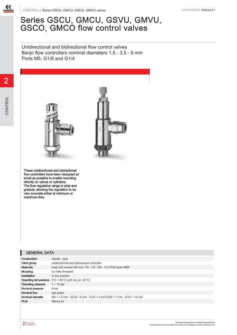
Series GSCU, GMCU, GSVU, GMVU, GSCO, GMCO flow control valves
Unidirectional and bidirectional flow control valves Banjo flow controllers nominal diameters 1,5 - 3,5 - 5 mm Ports M5, G1/8 and G1/4
These unidirectional and bidirectional flow controllers have been designed as small as possible to enable mounting directly on valves or cylinders. The flow regulation range is wide and gradual, allowing the regulation to be very accurate either at minimum or maximum flow.
GENERAL DATAConstruction needle - typeValve group unidirectional and bidirectional controllerMaterials body and screws M5 inox; 1/8 - 1/4 - 3/8 - 1/2 OT58 seals NBRMounting by male threadedInstallation in any positionOperating temperature 0°C ÷ 80°C (with dry air -20°C)Operating pressure 1 ÷ 10 barNominal pressure 6 barNominal flow see graphNominal diameter M5 = 1.5 mm - G1/8 = 2 mm - G1/4 = 4 mm G3/8 = 7 mm - G1/2 = 12 mmFluid filtered air

Products designed for industrial applications. General terms and conditions for sale are available on www.camozzi.com.
Series GSCU, GMCU, GSCO, GMCO valvesCATALOGUE
2
/7.15.022
> Release 8.7 CONTROL >
CO
NTR
OL
CODING EXAMPLE
GM ACTUATION: GM = manual GS = screwdriver
CU ASSEMBLY: CU = on cylinders unidirectional VU = on valves unidirectional CO = bidirectional
9 VERSIONS: 8 = needle (screwdriver operated) 9 = needle (manually operated)
03 FLOW CONTROL RANGE: size ø tube 13 = 1.5 3 14 = 1.5 4 03 = 3.5 6 04 = 3.5 8 05 = 5 8 06 = 5 10
1/8 PORTS: M5 1/8 1/4
6 Ø TUBE: 3 4 6 8 10
To ensure the right choice of unidirectional flow controller, proceed as follows: calculate the quantity of air in Nl/min (see cylinder Table); determine the stroke time of the cylinder; refer to graph to see which controller is the right type.
GM CU 9 03 - 1/8 - 6

Products designed for industrial applications. General terms and conditions for sale are available on www.camozzi.com.
2
Series GSCU, GMCU, GSCO, GMCO valvesCONTROL > CATALOGUE > Release 8.7
/7.15.032
CO
NTR
OL
To ensure the right choice of unidirectional flow controller, proceed as follows: calculate the quantity of air in Nl/min (see cylinder Table); determine the stroke time of the cylinder; refer to graph to see which controller is the right type. In the case of bidirectional regulators, refer to the graph and check whether the flow control range is suitable for the work required.
M5 Flow Qn (Nl/min.) from 2 → 1 with controller OPEN: 70 Flow Qn (Nl/min.) from 2 → 1 with controller CLOSED: 33 N° = number of screw turns NB: Qn is determined with a supply pressure of 6 bar and with ΔP = 1 bar at the outlet.
UNIDIRECTIONAL AND BIDIRECTIONAL FLOW CONTROL REGULATORS
G1/8 Flow Qn (Nl/min.) from 2 → 1 with controller OPEN: 440 Flow Qn (Nl/min.) from 2 → 1 with controller CLOSED: 170 N° = number of screw turns NB: Qn is determined with a supply pressure of 6 bar and with ΔP = 1 bar at the outlet.
G1/4 Flow Qn (Nl/min.) from 2 → 1 with controller OPEN: 790 Flow Qn (Nl/min.) from 2 → 1 with controller CLOSED: 460 N° = number of screw turns NB: Qn is determined with a supply pressure of 6 bar and with ΔP = 1 bar at the outlet.
UNIDIRECTIONAL AND BIDIRECTIONAL FLOW CONTROL REGULATORS
Products designed for industrial applications. General terms and conditions for sale are available on www.camozzi.com.
Series GSCU, GMCU, GSCO, GMCO valvesCATALOGUE
2
/7.15.042
> Release 8.7 CONTROL >
CO
NTR
OL
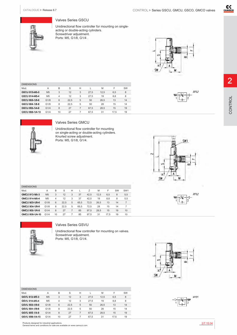
Valves Series GSCUUnidirectional flow controller for mounting on single-acting or double-acting cylinders. Screwdriver adjustment. Ports: M5, G1/8, G1/4 .
DIMENSIONSMod. A B S H L M F SWGSCU 813-M5-3 M5 3 12 3 27,5 12,5 6,5 8GSCU 814-M5-4 M5 4 12 3 27,5 19 8,8 8GSCU 803-1/8-6 G1/8 6 22,5 5 50 26,5 13 14GSCU 804-1/8-8 G1/8 8 22,5 5 50 28 15 14GSCU 805-1/4-8 G1/4 8 27 7 67,5 28,5 15 19GSCU 806-1/4-10 G1/4 10 27 7 67,5 31 17,5 19
Valves Series GMCUUnidirectional flow controller for mounting on single-acting or double-acting cylinders. Knurled screw adjustment. Ports: M5, G1/8, G1/4.
DIMENSIONSMod. A B S H L Z M F SW SW1GMCU 913-M5-3 M5 3 12 3 37 42,5 12,5 6,5 8 5,5GMCU 914-M5-4 M5 4 12 3 37 42,5 19 8,8 8 5,5GMCU 903-1/8-6 G1/8 6 22,5 5 65,5 72,5 26,5 13 14 7GMCU 904-1/8-8 G1/8 8 22,5 5 65,5 72,5 28 15 14 7GMCU 905-1/4-8 G1/4 8 27 7 85 97,5 28,5 15 19 10GMCU 906-1/4-10 G1/4 10 27 7 85 97,5 31 17,5 19 10
Valves Series GSVUUnidirectional flow controller for mounting on valves. Screwdriver adjustment. Ports: M5, G1/8, G1/4.
DIMENSIONSMod. A B S H L M F SWGSVU 813-M5-3 M5 3 12 3 27,5 12,5 6,5 8GSVU 814-M5-4 M5 4 12 3 27,5 19 8,8 8GSVU 803-1/8-6 G1/8 6 22,5 5 50 26,5 13 14GSVU 804-1/8-8 G1/8 8 22,5 5 50 28 15 14GSVU 805-1/4-8 G1/4 8 27 7 67,5 28,5 15 19GSVU 806-1/4-10 G1/4 10 27 7 67,5 31 17,5 19
Products designed for industrial applications. General terms and conditions for sale are available on www.camozzi.com.
2
Series GSCU, GMCU, GSCO, GMCO valvesCONTROL > CATALOGUE > Release 8.7
/7.15.052
CO
NTR
OL
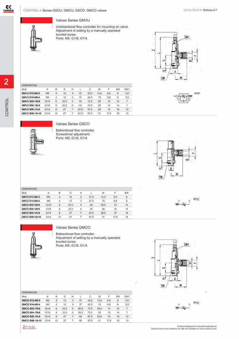
Valves Series GMVUUnidirectional flow controller for mounting on valve. Adjustment of setting by a manually operated knurled screw. Ports: M5, G1/8, G1/4.
DIMENSIONSMod. A B S H L Z M F SW SW1GMVU 913-M5-3 M5 3 12 3 37 42,5 12,5 6,5 8 5,5GMVU 914-M5-4 M5 4 12 3 37 42,5 19 8,8 8 5,5GMVU 903-1/8-6 G1/8 6 22,5 5 50 72,5 26 13 14 7GMVU 904-1/8-8 G1/8 8 22,5 5 50 72,5 28 15 14 7GMVU 905-1/4-8 G1/4 8 27 7 67,5 97,5 29 15 19 10GMVU 906-1/4-10 G1/4 10 27 7 67,5 97,5 31 17,5 19 10
Valves Series GSCOBidirectional flow controller. Screwdriver adjustment. Ports: M5, G1/8, G1/4.
DIMENSIONSMod. A B S H L M F SWGSCO 813-M5-3 M5 3 12 3 27,5 12,5 6,5 8GSCO 814-M5-4 M5 4 12 3 27,5 19 8,8 8GSCO 803-1/8-6 G1/8 6 22,5 5 50 26,5 13 14GSCO 804-1/8-8 G1/8 8 22,5 5 50 28 15 14GSCO 805-1/4-8 G1/4 8 27 7 67,5 28,5 15 19GSCO 806-1/4-10 G1/4 10 27 7 67,5 31 17,5 19
Valves Series GMCOBidirectional flow controller. Adjustment of setting by a manually operated knurled screw. Ports: M5, G1/8, G1/4.
DIMENSIONSMod. A B S H L Z M F SW SW1GMCO 913-M5-3 M5 3 12 3 37 42,5 12,5 6,5 8 5,5GMCO 914-M5-4 M5 4 12 3 37 42,5 19 8,8 8 5,5GMCO 903-1/8-6 G1/8 6 22,5 5 65,5 72,5 26,5 13 14 7GMCO 904-1/8-8 G1/8 8 22,5 5 65,5 72,5 28 15 14 7GMCO 905-1/4-8 G1/4 8 27 7 85 97,5 28,5 15 19 10GMCO 906-1/4-10 G1/4 10 27 7 85 97,5 31 17,5 19 10

Products designed for industrial applications. General terms and conditions for sale are available on www.camozzi.com.
Series RFU and RFO valvesCATALOGUE
2
/7.20.012
> Release 8.7 CONTROL >
CO
NTR
OL
Series RFU - RFO flow control valves
Unidirectional and bidirectional flow control valves Ports: M5, G1/8, G1/4, G3/8 and G1/2 Nominal diameter: M5 = 1,5 mm; G1/8 = 2 and 3 mm; G1/4 = 4 and 6 mm; G3/8 and G1/2 = 7 mm
The unidirectional flow controllers are equipped with M5, G1/8, G1/4, G3/8 and G1/2 ports. G1/8 and G1/4 ports are available with two different types of adjustment (see diagrams), whereas M5, G3/8 and G1/2 ports have just one type of adjustment. All models can be panel or wall mounted or they can be mounted on cylinders, as required.
To choose the most suitable model, it is recommended to: 1. calculate the quantity of air in Nl/min (see the cylinders tables in the catalogue appendix); 2. determine the stroke time of the cylinder; 3. check the flow diagrams (see pages 2/7.20.03 and 2/7.20.04).
» Series RFU: unidirectional flow control valves for the speed regulation of a cylinder
» Series RFO: bidirectional flow control valves for the air flow regulation in both directions and for the pressurization or depressurization of a container.
GENERAL DATAConstruction needle-typeValve group unidirectional and bidirectional controllerMaterials AL body - brass needle (not nickel-plated) - NBR sealsMounting with screws in the holes of the valve body or panel mountedThreaded ports M5 - G1/8 - G1/4 - G3/8 - G1/2Installation as requiredOperating temperature 0°C ÷ 80°C (with dry air - 20°C)Operating pressure 1 ÷ 10 bar (for models with M5 - G1/8 - G1/4 ports)
2 ÷ 10 bar (for models with G3/8 - G1/2 ports)Nominal pressure 6 barNominal flow see graphNominal diameter M5 = 1,5 - G1/8 = 2 or 3 mm - G1/4 = 4 or 6 mm - G3/8 and G1/2 = 7 mmFluid filtered air

Products designed for industrial applications. General terms and conditions for sale are available on www.camozzi.com.
2
Series RFU and RFO valvesCONTROL > CATALOGUE > Release 8.7
/7.20.022
CO
NTR
OL
CODING EXAMPLE
RF SERIES
U 4 FUNCTION: U 4 = unidirectional O 3 = bidirectional
8 PORTS: 4 = G1/4 5 = M5 6 = G3/8 7 = G1/2 8 = G1/8
2 FLOW CONTROL RANGE: 2 = ø 1.5 mm max (for ports M5) ø 2 mm max (for ports 1/8 only) 3 = ø 3 mm max (for ports 1/8 only) 4 = ø 4 mm max (for ports 1/4 only) 6 = ø 6 mm max (for ports 1/4 only) 7 = ø 7 mm max (for ports 3/8, 1/2 only)
1/8 PORTS: M5 1/8 1/4 3/8 1/2
RF U 4 8 2 - 1/8
6512 EXAMPLES OF SERIES RFO - RFU VALVES ASSEMBLY

Products designed for industrial applications. General terms and conditions for sale are available on www.camozzi.com.
Series RFU and RFO valvesCATALOGUE
2
/7.20.032
> Release 8.7 CONTROL >
CO
NTR
OL
RFU 452-M5: flow from 2 → 1 needle type OPEN = 55 Nl/min CLOSED = 41 Nl/min N° = number of screw turns Note: the flow (Qn) is determined with a pressure of 6 bar at the inlet and ΔP = 1 bar at the outlet.
RFO 352-M5 N° = number of screw turns Note: the flow (Qn) is determined with a pressure of 6 bar at the inlet and ΔP = 1 bar at the outlet.
FLOW DIAGRAMS (1 → 2) - VALVES SERIES RFU / RFO - M5 PORTS
RFU 482-1/8: flow from 2 → 1 needle type OPEN = 149 Nl/min CLOSED = 130,5 Nl/min RFU 483-1/8: flow from 2 → 1 needle type OPEN = 180 Nl/min CLOSED = 140 Nl/min N° = number of screw turns Note: the flow (Qn) is determined with a pressure of 6 bar at the inlet and ΔP = 1 bar at the outlet.
RFO 382-1/8 - RFO 383-1/8 N° = number of screw turns Note: the flow (Qn) is determined with a pressure of 6 bar at the inlet and ΔP = 1 bar at the outlet.
FLOW DIAGRAMS (1 → 2) - VALVES SERIES RFU / RFO - G1/8 PORTS

Products designed for industrial applications. General terms and conditions for sale are available on www.camozzi.com.
2
Series RFU and RFO valvesCONTROL > CATALOGUE > Release 8.7
/7.20.042
CO
NTR
OL
RFU 444-1/4: flow from 2 → 1 needle type OPEN = 680 Nl/min CLOSED = 534 Nl/min RFU 446-1/4: flow from 2 → 1 needle type OPEN = 680 Nl/min CLOSED = 534 Nl/min N° = number of screw turns Note: the flow (Qn) is determined with a pressure of 6 bar at the inlet and ΔP = 1 bar at the outlet.
RFO 344-1/4 - RFO 346-1/4 N° = number of screw turns. Note: the flow (Qn) is determined with a pressure of 6 bar at the inlet and ΔP = 1 bar at the outlet.
FLOW DIAGRAMS (1 → 2) - VALVES SERIES RFU / RFO - G1/4 PORTS
RFU 467-3/8: flow from 2 → 1 needle type OPEN = 1700 Nl/min CLOSED = 1700 Nl/min RFU 477-1/2: flow from 2 → 1 needle type OPEN = 1700 Nl/min CLOSED = 1700 Nl/min N° = number of screw turns Note: the flow (Qn) is determined with a pressure of 6 bar at the inlet and ΔP = 1 bar at the outlet.
RFO 367-3/8 - RFO 377-1/2 N° = number of screw turns Note: the flow (Qn) is determined with a pressure of 6 bar at the inlet and ΔP = 1 bar at the outlet.
FLOW DIAGRAMS (1 → 2) - VALVES SERIES RFU / RFO - G3/8, G1/2 PORTS

Products designed for industrial applications. General terms and conditions for sale are available on www.camozzi.com.
Series RFU and RFO valvesCATALOGUE
2
/7.20.052
> Release 8.7 CONTROL >
CO
NTR
OL
Unidirectional flow control valves Series RFU
To regulate the cylinder speed, the discharging chamber air flow has to be controlled. Therefore, it is recommended to connect the valve threaded outlet 1 to the cylinder inlet and the outlet 2 to the valve user port.
DIMENSIONSMod. Ø A B D F G L M1 M2 M3 M4 T Z SMax SW SW1 SW2RFU 452-M5 1,5 M10x1 M5 4,2 14 16 26 18,5 13,2 7 13,2 39 44,5 3 12 14 8RFU 482-1/8 2 M12x1 G1/8 4,5 16 21 34 24,5 16,5 8 16,5 46 51 4 14 17 9RFU 483-1/8 3 M12x1 G1/8 4,5 16 21 34 24,5 16,5 8 16,5 46 51 4 14 17 9RFU 444-1/4 4 M20x1,5 G1/4 6,5 25 30 52 35 24 12 24 60 69 7 22 24 14RFU 446-1/4 6 M20x1,5 G1/4 6,5 25 30 52 35 24 12 24 60 69 7 22 24 14RFU 467-3/8 7 M18x1 G3/8 6,5 27 42 56 43 34,5 28 7,5 75 85 8 22 22 *RFU 477-1/2 7 M18x1 G1/2 6,5 27 42 56 43 34,5 28 7,5 75 85 8 22 22 *
TABLE NOTE: * knurled ring nut
Bidirectional flow control valves Series RFO
DIMENSIONSMod. Ø A B D F G L M1 M2 M3 M4 T Z SMax SW SW1 SW2RFO 352-M5 1,5 M10x1 M5 4,2 14 16 26 18,5 13,2 7 13,2 39 44,5 3 12 14 8RFO 382-1/8 2 M12x1 G1/8 4,2 16 21 34 24,5 16,5 8 16,5 46 51 4 14 17 9RFO 383-1/8 3 M12x1 G1/8 4,5 16 21 34 24,5 16,5 8 16,5 46 51 4 14 17 9RFO 344-1/4 4 M20x1,5 G1/4 6,5 25 30 52 35 24 12 24 60 69 7 22 24 14RFO 346-1/4 6 M20x1,5 G1/4 6,5 25 30 52 35 24 12 24 60 69 7 22 24 14RFO 367-3/8 7 M18x1 G3/8 6,5 27 42 56 43 34,5 28 7,5 75 85 8 22 22 *RFO 377-1/2 7 M18x1 G1/2 6,5 27 42 56 43 34,5 28 7,5 75 85 8 22 22 *
TABLE NOTE: * knurled ring nut
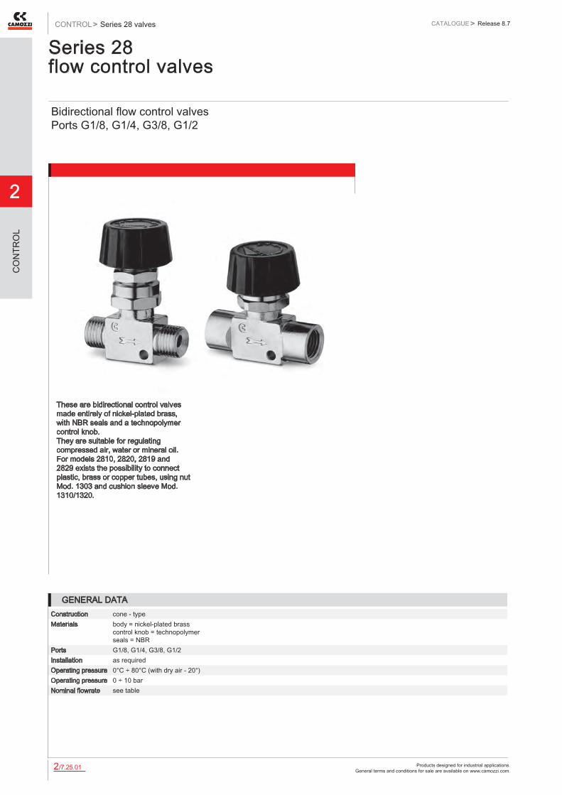
Products designed for industrial applications. General terms and conditions for sale are available on www.camozzi.com.
2
Series 28 valvesCONTROL > CATALOGUE > Release 8.7
/7.25.012
CO
NTR
OL
Series 28 flow control valves
Bidirectional flow control valves Ports G1/8, G1/4, G3/8, G1/2
These are bidirectional control valves made entirely of nickel-plated brass, with NBR seals and a technopolymer control knob. They are suitable for regulating compressed air, water or mineral oil. For models 2810, 2820, 2819 and 2829 exists the possibility to connect plastic, brass or copper tubes, using nut Mod. 1303 and cushion sleeve Mod. 1310/1320.
GENERAL DATAConstruction cone - typeMaterials body = nickel-plated brass
control knob = technopolymer seals = NBR
Ports G1/8, G1/4, G3/8, G1/2Installation as requiredOperating pressure 0°C ÷ 80°C (with dry air - 20°)Operating pressure 0 ÷ 10 barNominal flowrate see table

Products designed for industrial applications. General terms and conditions for sale are available on www.camozzi.com.
Series 28 valvesCATALOGUE
2
/7.25.022
> Release 8.7 CONTROL >
CO
NTR
OL
Valve Mod. 2810
DIMENSIONSMod. A L T Z SW2 Δ1bar Nl/min Free flow Nl/min2810 1/8 G1/8 40 37 42,5 19 415 5902810 1/4 G1/4 42 37 42,5 19 508 7402810 3/8 G3/8 42 37 42,5 19 620 9002810 1/2 G1/2 54 42 48 22 1540 2080
Valve Mod. 2820
DIMENSIONSMod. A B L T Z SW2 Δ1bar Nl/min Free flow Nl/min2820 1/8 G1/8 G1/8 41 37 42,5 19 400 6402820 1/4 G1/4 G1/4 44 37 42,5 19 530 8402820 3/8 G3/8 G3/8 55,5 41,5 48 22 1415 19902820 1/2 G1/2 G1/2 59 42 49 22 1520 2150
Valve Mod. 2830
DIMENSIONSMod. B L T Z SW2 Δ1bar Nl/min Free flow Nl/min2830 1/8 G1/8 42 37 42,5 19 415 6352830 1/4 G1/4 46 37 42,5 19 530 8502830 3/8 G3/8 62 41,4 48 22 1415 19802830 1/2 G1/2 64 42 49 22 1520 2100

Products designed for industrial applications. General terms and conditions for sale are available on www.camozzi.com.
2
Series 28 valvesCONTROL > CATALOGUE > Release 8.7
/7.25.032
CO
NTR
OL
Valve Mod. 2819
DIMENSIONSMod. A L P S T Z SMax SW2 SW32819 1/8 G1/8 40 1/4 23 47 52,5 7 19 172819 1/4 G1/4 42 1/4 23 47 52,5 7 19 17
Valve Mod. 2829
DIMENSIONSMod. A B L P S T Z S max SW2 SW32829 1/8 G1/8 G1/8 41 1/4 23 47 52,5 7 19 172829 1/4 G1/4 G1/4 44 1/4 23 47 52,5 7 19 17
Valve Mod. 2839
DIMENSIONSMod. A L P S T Z S max SW2 SW32839 1/8 G1/8 42 1/4 23 47 52,5 7 19 172839 1/4 G1/4 46 1/4 23 47 52,5 7 19 172839 3/8 G3/8 62 14X1 28 56,5 63 7 22 172839 1/2 G1/2 64 14X1 29 57 64 7 22 17
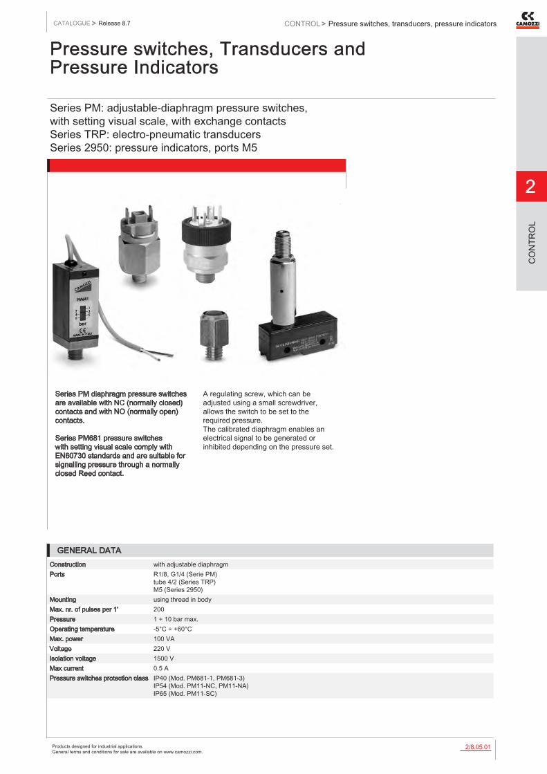
Products designed for industrial applications. General terms and conditions for sale are available on www.camozzi.com.
Pressure switches, transducers, pressure indicatorsCATALOGUE
2
/8.05.012
> Release 8.7 CONTROL >
CO
NTR
OL
Pressure switches, Transducers and Pressure Indicators
Series PM: adjustable-diaphragm pressure switches, with setting visual scale, with exchange contacts Series TRP: electro-pneumatic transducers Series 2950: pressure indicators, ports M5
Series PM diaphragm pressure switches are available with NC (normally closed) contacts and with NO (normally open) contacts. Series PM681 pressure switches with setting visual scale comply with EN60730 standards and are suitable for signaliing pressure through a normally closed Reed contact.
A regulating screw, which can be adjusted using a small screwdriver, allows the switch to be set to the required pressure. The calibrated diaphragm enables an electrical signal to be generated or inhibited depending on the pressure set.
GENERAL DATAConstruction with adjustable diaphragmPorts R1/8, G1/4 (Serie PM)
tube 4/2 (Series TRP) M5 (Series 2950)
Mounting using thread in bodyMax. nr. of pulses per 1’ 200Pressure 1 ÷ 10 bar max.Operating temperature -5°C ÷ +60°CMax. power 100 VAVoltage 220 VIsolation voltage 1500 VMax current 0.5 APressure switches protection class IP40 (Mod. PM681-1, PM681-3)
IP54 (Mod. PM11-NC, PM11-NA) IP65 (Mod. PM11-SC)

Products designed for industrial applications. General terms and conditions for sale are available on www.camozzi.com.
2
Pressure switches, transducers, pressure indicatorsCONTROL > CATALOGUE > Release 8.7
/8.05.022
CO
NTR
OL
Series PM adjustable-diaphragm pressure switchesSupplied with a rubber cap providing protection class IP54.
Mod. Function Max Voltage Max Power Service Type Insulation voltage SymbolPM11-NC NC = normally closed 48 V AC DC 24 VA Heavy 500 V PMNCPM11-NA NA = normally open 48 V AC DC 24 VA Heavy 500 V PMNO
PMNC = normally closed PMNO = normally open
Series PM681-... - pressure switches with setting visual scaleIn compliance with EN60730 standard Protection class IP40 Electric connection: PVC cable 2 x 0.22 mm Electric contact: Reed SPST NO Body in anodized aluminium and threaded fitting in brass Hysteresis: 0.8 bar max
Mod. L Max switch
voltageMax switch
currentMax switch
capacityMax fluid
temperatureMax
pressureSetting range
Weight
PM681-1 1 m 48 V 0.5 A 10 W 60°C 20 bar 1 ÷ 6 bar 95 gPM681-3 3 m 48 V 0.5 A 10 W 60°C 20 bar 1 ÷ 6 bar 95 g
A = SETTING GRAIN LOCKING
B = ADJUSTMENT SCREW
Pressure switch with exchange contacts Mod. PM11-SCProtection class IP65 (with connector Mod. 124-830)
DIMENSIONSMod. Function Max Voltage Operating
TemperatureActuation time Setting
rangeMax Hysteresis
PM11-SC SC (*) 250V AC - 30V DC
-25°C +85°C > 0,1 ms 2 ÷ 10 bar 0.8 bar
(*) SC = exchange contacts
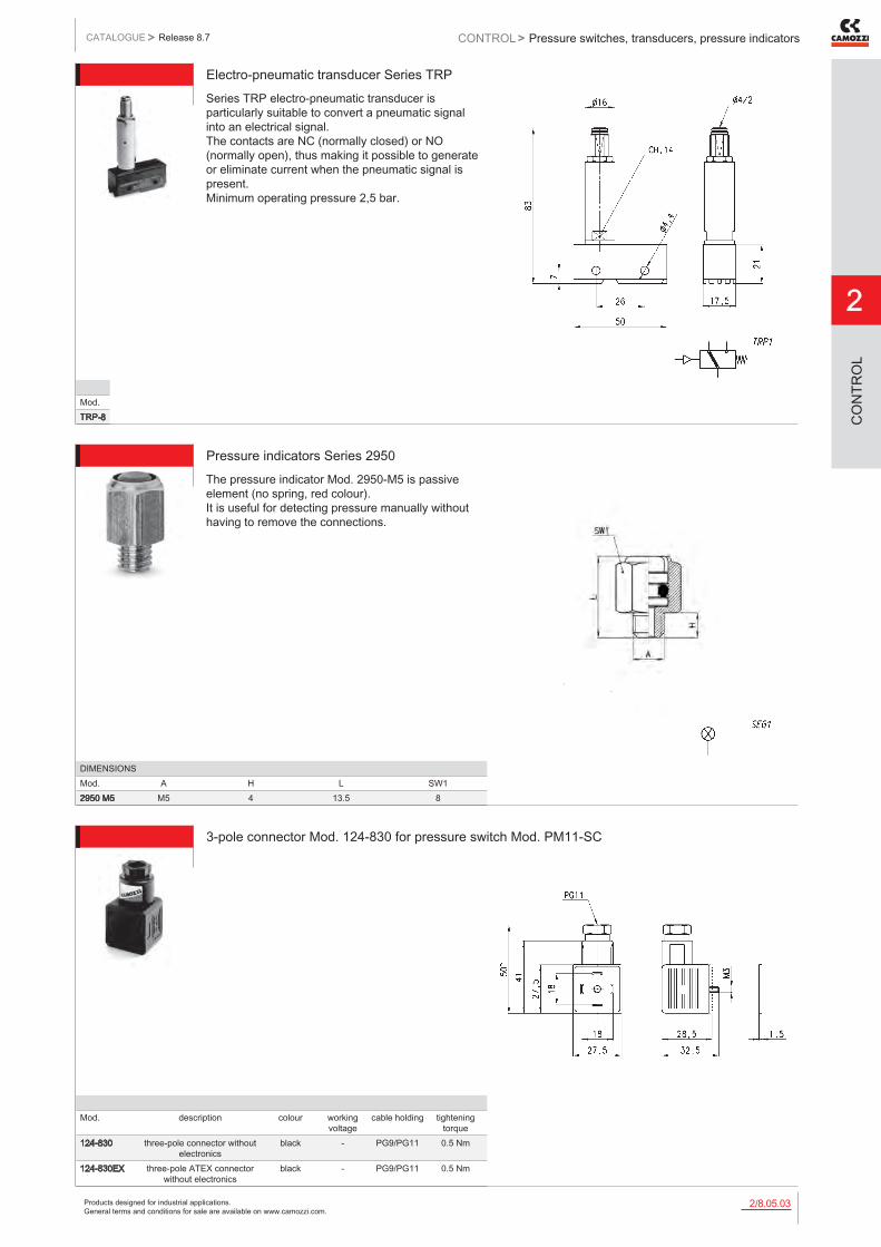
Products designed for industrial applications. General terms and conditions for sale are available on www.camozzi.com.
Pressure switches, transducers, pressure indicatorsCATALOGUE
2
/8.05.032
> Release 8.7 CONTROL >
CO
NTR
OL
Electro-pneumatic transducer Series TRPSeries TRP electro-pneumatic transducer is particularly suitable to convert a pneumatic signal into an electrical signal. The contacts are NC (normally closed) or NO (normally open), thus making it possible to generate or eliminate current when the pneumatic signal is present. Minimum operating pressure 2,5 bar.
Mod.TRP-8
Pressure indicators Series 2950The pressure indicator Mod. 2950-M5 is passive element (no spring, red colour). It is useful for detecting pressure manually without having to remove the connections.
DIMENSIONSMod. A H L SW12950 M5 M5 4 13.5 8
3-pole connector Mod. 124-830 for pressure switch Mod. PM11-SC
Mod. description colour working voltage
cable holding tightening torque
124-830 three-pole connector without electronics
black - PG9/PG11 0.5 Nm
124-830EX three-pole ATEX connector without electronics
black - PG9/PG11 0.5 Nm

Products designed for industrial applications. General terms and conditions for sale are available on www.camozzi.com.
2
Series SWM electronic miniature vacuum switchesCONTROL > CATALOGUE > Release 8.7
/8.10.012
CO
NTR
OL
Series SWM electronic miniature vacuum switches
These vacuum switches are used in measuring ranges between -1 and 0 bar.
Applications: - Measurement of vacuum values close to the suction pad - Electric output signal
These vacuum switches can be mounted directly at the gripping point of a handling system, also when subject to high acceleration forces.
» Small dimension and reduced weight
» Available with analog or digital output
» High measuring accuracy
» Possibility to connect with M5 thread or 6 mm plug-in tubes
GENERAL DATAType of vacuum switch electronic, mini
sensor and connectionConnection - M5 thread
- plug-in tubesOutput signal analog or digital

Products designed for industrial applications. General terms and conditions for sale are available on www.camozzi.com.
Series SWM electronic miniature vacuum switchesCATALOGUE
2
/8.10.022
> Release 8.7 CONTROL >
CO
NTR
OL
CODING EXAMPLE
SW SERIES SW = transducer
M VERSION m = Micro
VA0 OUTPUT SIGNAL VA0 = analog output VD6 = digital output with switching point set to -600 mbar
T 6 CONNECTION T6 = with diam. 6 mm plung in tube M5 = male thread M5
SW M - VA0 - T6
DIMENSIONSMod. B D G1 H H1 L LG1 SW1SWM-VA0-M5 9,5 - M5 16,9 - 21 5 8SWM-VA0-T6 9,5 6 17,2 37,2 21 - -SWM-VD6-M5 9,5 - M5 16,9 - 21 5 8SWM-VD6-T6 9,5 6 17,2 37,2 21 - -
Vacuum switches Series SWM
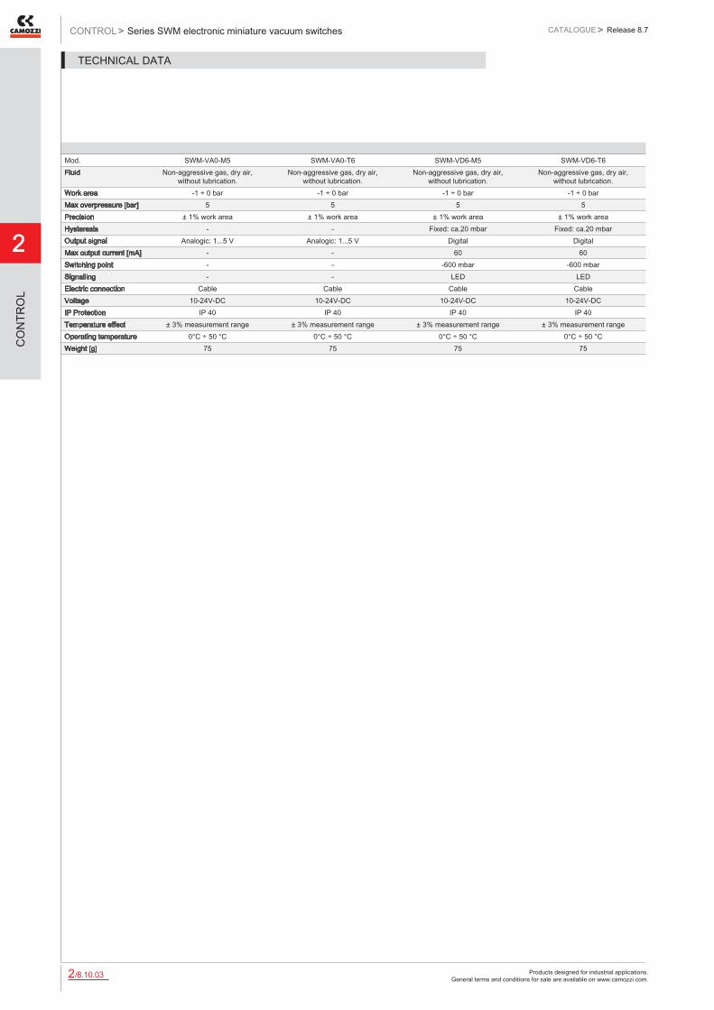
Products designed for industrial applications. General terms and conditions for sale are available on www.camozzi.com.
2
Series SWM electronic miniature vacuum switchesCONTROL > CATALOGUE > Release 8.7
/8.10.032
CO
NTR
OL
Mod. SWM-VA0-M5 SWM-VA0-T6 SWM-VD6-M5 SWM-VD6-T6Fluid Non-aggressive gas, dry air,
without lubrication.Non-aggressive gas, dry air,
without lubrication.Non-aggressive gas, dry air,
without lubrication.Non-aggressive gas, dry air,
without lubrication.Work area -1 ÷ 0 bar -1 ÷ 0 bar -1 ÷ 0 bar -1 ÷ 0 barMax overpressure [bar] 5 5 5 5Precision ± 1% work area ± 1% work area ± 1% work area ± 1% work areaHysteresis - - Fixed: ca.20 mbar Fixed: ca.20 mbarOutput signal Analogic: 1...5 V Analogic: 1...5 V Digital DigitalMax output current [mA] - - 60 60Switching point - - -600 mbar -600 mbarSignalling - - LED LEDElectric connection Cable Cable Cable CableVoltage 10-24V-DC 10-24V-DC 10-24V-DC 10-24V-DCIP Protection IP 40 IP 40 IP 40 IP 40Temperature effect ± 3% measurement range ± 3% measurement range ± 3% measurement range ± 3% measurement rangeOperating temperature 0°C ÷ 50 °C 0°C ÷ 50 °C 0°C ÷ 50 °C 0°C ÷ 50 °CWeight [g] 75 75 75 75
TECHNICAL DATA

Products designed for industrial applications. General terms and conditions for sale are available on www.camozzi.com.
Series SWE electronic vacuum/pressure switchesCATALOGUE
2
/8.15.012
> Release 8.7 CONTROL >
CO
NTR
OL
Series SWE electronic vacuum/pressure switches
These vacuum sensors are available with analog and digital output.
Applications: universal electronic vacuum/pressure switch for safety monitoring, optimization of the cycle time or energy saving devices. Thanks to the switching point and the adjustable hysteresis, this electronic vacuum/pressure switch is able to satisfy the user’s needs. Analog and digital output: adjustable vacuum limit value and continuous vacuum monitoring.
Electric connection: - This device functions correctly with a connector Mod. CS-DF04EG-E500 or CS-DR04EG- E500 which should be ordered separately.
» Electronically precise measuring
» Switching point and adjustable hysteresis
» Analog and digital output
GENERAL DATAType of vacuum/pressure switch electronic with polycarbonate housingConnection with G1/8 male thread and M5 female threadSwitching point and hysteresis adjustable through regulation screwsLED integrated for visual indication of the switch stateElectric connection supply voltage via 4-pin M8 connector
Running out of stock
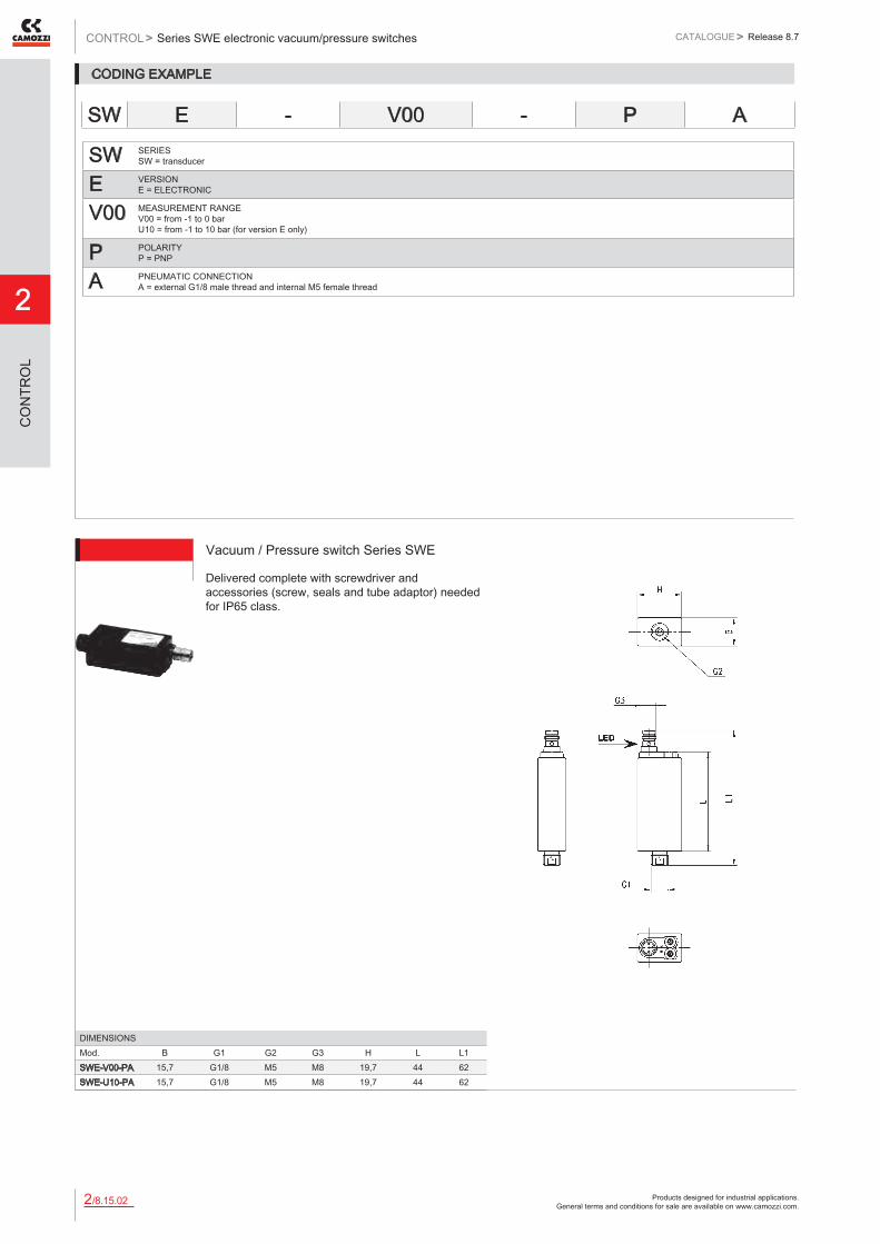
Products designed for industrial applications. General terms and conditions for sale are available on www.camozzi.com.
2
Series SWE electronic vacuum/pressure switchesCONTROL > CATALOGUE > Release 8.7
/8.15.022
CO
NTR
OL
CODING EXAMPLE
SW SERIES SW = transducer
E VERSION E = ELECTRONIC
V00 MEASUREMENT RANGE V00 = from -1 to 0 bar U10 = from -1 to 10 bar (for version E only)
P POLARITY P = PNP
A PNEUMATIC CONNECTION A = external G1/8 male thread and internal M5 female thread
SW E - V00 - P A
Vacuum / Pressure switch Series SWE
DIMENSIONSMod. B G1 G2 G3 H L L1SWE-V00-PA 15,7 G1/8 M5 M8 19,7 44 62SWE-U10-PA 15,7 G1/8 M5 M8 19,7 44 62
Delivered complete with screwdriver and accessories (screw, seals and tube adaptor) needed for IP65 class.

Products designed for industrial applications. General terms and conditions for sale are available on www.camozzi.com.
Series SWE electronic vacuum/pressure switchesCATALOGUE
2
/8.15.032
> Release 8.7 CONTROL >
CO
NTR
OL
Mod. SWE-V00 PA SWE-U10-PAFluid Non-aggressive gas, dry air,
without lubricationNon-aggressive gas, dry air,
without lubricationMeasurement range -1 ÷ 0 bar -1 ÷ 10 barMax overpressure [bar] 5 16Repetition Precision ± 1% measurement range ± 1% measurement rangeHysteresis Settable: from 3 to 25 %
set value.Settable: from 3 to 25 %
set value.Output signal 1 Analogic(1...5 V)
and 1 digital settable.1 Analogic (1...5 V)
ed 1 digital settable.Max output current [mA] 125 125Switching time [ms] 5 5Signalling LED LEDElectric connection Connector M8 4 pins Connector M8 4 pinsPneumatic connection G1/8 male and M5 female G1/8 male and M5 femaleVoltage 10.8 - 30 V - DC 10.8 - 30 V - DCInput current [mA] 30 30IP Protection IP 40/65 (with flexible cable) IP 40/65 (with flexible cable)Temperature effect ± 3% measurement range ± 3% measurement rangeOperating temperature 0°C ÷ 50°C 0°C ÷ 50°CWeight [g] 30 30
TECHNICAL DATA
Circular M8 4-pole connectors, Female
Mod. Type of connector Cable length (m)CS-DF04EG-E200 straight 2CS-DF04EG-E500 straight 5CS-DR04EG-E200 right angle (90 degrees) 2CS-DR04EG-E500 right angle (90 degrees) 5
With PU sheathing, non shielded cable. Protection class: IP65
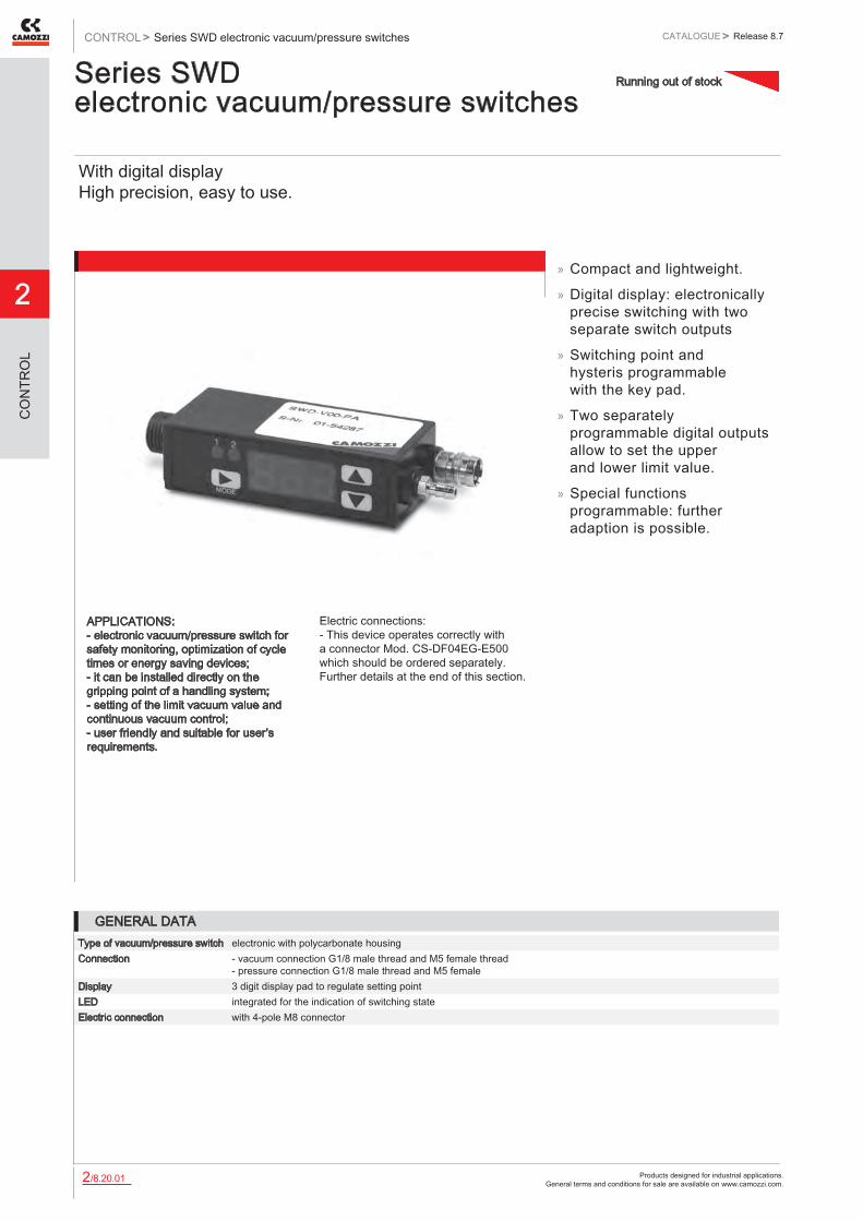
Products designed for industrial applications. General terms and conditions for sale are available on www.camozzi.com.
2
Series SWD electronic vacuum/pressure switchesCONTROL > CATALOGUE > Release 8.7
/8.20.012
CO
NTR
OL
Series SWD electronic vacuum/pressure switches
With digital display High precision, easy to use.
APPLICATIONS: - electronic vacuum/pressure switch for safety monitoring, optimization of cycle times or energy saving devices; - it can be installed directly on the gripping point of a handling system; - setting of the limit vacuum value and continuous vacuum control; - user friendly and suitable for user’s requirements.
Electric connections: - This device operates correctly with a connector Mod. CS-DF04EG-E500 which should be ordered separately. Further details at the end of this section.
» Compact and lightweight.
» Digital display: electronically precise switching with two separate switch outputs
» Switching point and hysteris programmable with the key pad.
» Two separately programmable digital outputs allow to set the upper and lower limit value.
» Special functions programmable: further adaption is possible.
GENERAL DATAType of vacuum/pressure switch electronic with polycarbonate housingConnection - vacuum connection G1/8 male thread and M5 female thread
- pressure connection G1/8 male thread and M5 femaleDisplay 3 digit display pad to regulate setting pointLED integrated for the indication of switching stateElectric connection with 4-pole M8 connector
Running out of stock
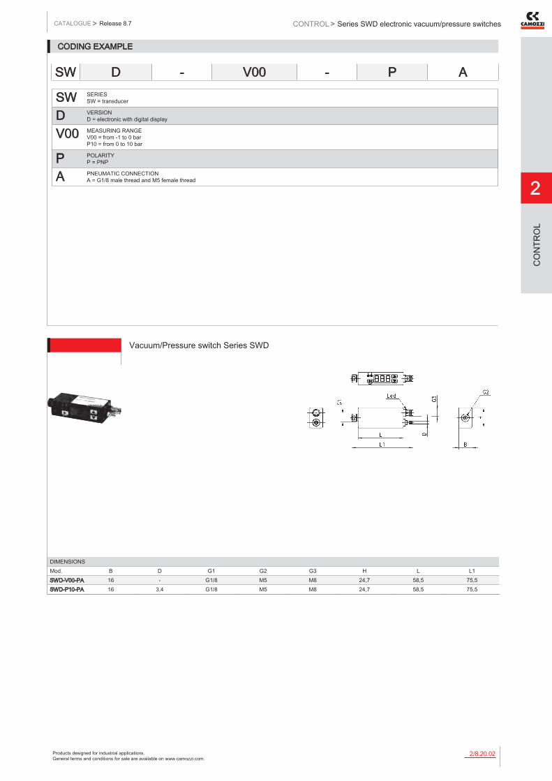
Products designed for industrial applications. General terms and conditions for sale are available on www.camozzi.com.
Series SWD electronic vacuum/pressure switchesCATALOGUE
2
/8.20.022
> Release 8.7 CONTROL >
CO
NTR
OL
CODING EXAMPLE
SW SERIES SW = transducer
D VERSION D = electronic with digital display
V00 MEASURING RANGE V00 = from -1 to 0 bar P10 = from 0 to 10 bar
P POLARITY P = PNP
A PNEUMATIC CONNECTION A = G1/8 male thread and M5 female thread
SW D - V00 - P A
DIMENSIONSMod. B D G1 G2 G3 H L L1SWD-V00-PA 16 - G1/8 M5 M8 24,7 58,5 75,5SWD-P10-PA 16 3,4 G1/8 M5 M8 24,7 58,5 75,5
Vacuum/Pressure switch Series SWD
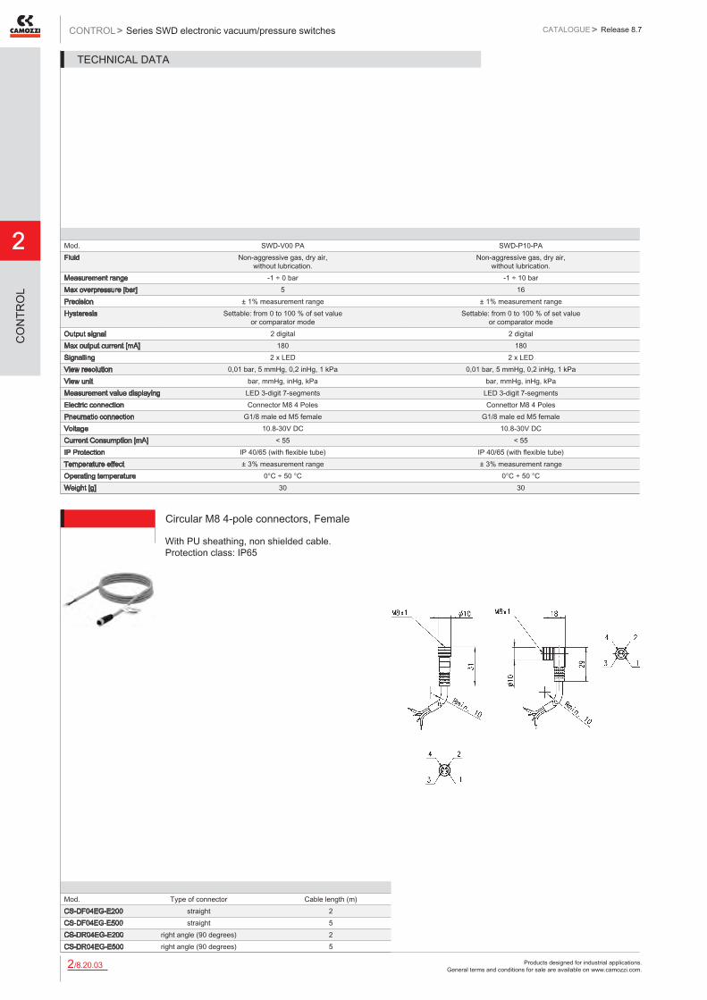
Products designed for industrial applications. General terms and conditions for sale are available on www.camozzi.com.
2
Series SWD electronic vacuum/pressure switchesCONTROL > CATALOGUE > Release 8.7
/8.20.032
CO
NTR
OL
Mod. SWD-V00 PA SWD-P10-PAFluid Non-aggressive gas, dry air,
without lubrication.Non-aggressive gas, dry air,
without lubrication.Measurement range -1 ÷ 0 bar -1 ÷ 10 barMax overpressure [bar] 5 16Precision ± 1% measurement range ± 1% measurement rangeHysteresis Settable: from 0 to 100 % of set value
or comparator modeSettable: from 0 to 100 % of set value
or comparator modeOutput signal 2 digital 2 digitalMax output current [mA] 180 180Signalling 2 x LED 2 x LEDView resolution 0,01 bar, 5 mmHg, 0,2 inHg, 1 kPa 0,01 bar, 5 mmHg, 0,2 inHg, 1 kPaView unit bar, mmHg, inHg, kPa bar, mmHg, inHg, kPaMeasurement value displaying LED 3-digit 7-segments LED 3-digit 7-segmentsElectric connection Connector M8 4 Poles Connettor M8 4 PolesPneumatic connection G1/8 male ed M5 female G1/8 male ed M5 femaleVoltage 10.8-30V DC 10.8-30V DCCurrent Consumption [mA] < 55 < 55IP Protection IP 40/65 (with flexible tube) IP 40/65 (with flexible tube)Temperature effect ± 3% measurement range ± 3% measurement rangeOperating temperature 0°C ÷ 50 °C 0°C ÷ 50 °CWeight [g] 30 30
TECHNICAL DATA
Circular M8 4-pole connectors, Female
Mod. Type of connector Cable length (m)CS-DF04EG-E200 straight 2CS-DF04EG-E500 straight 5CS-DR04EG-E200 right angle (90 degrees) 2CS-DR04EG-E500 right angle (90 degrees) 5
With PU sheathing, non shielded cable. Protection class: IP65

Products designed for industrial applications. General terms and conditions for sale are available on www.camozzi.com.
Series SWD electronic vacuum/pressure switchesCATALOGUE
2
/8.20.042
> Release 8.7 CONTROL >
CO
NTR
OL
Accessories
Mod.SWD-B

Products designed for industrial applications. General terms and conditions for sale are available on www.camozzi.com.
2
Series SWDN electronic vacuum/pressure switchesCONTROL > CATALOGUE > Release 8.7
/8.22.012
CO
NTR
OL
Series SWDN electronic vacuum/pressure switches
With digital display High precision, easy to use
APPLICATIONS: - electronic vacuum/pressure switch for safety monitoring, optimization of cycle times or energy saving devices; - it can be installed directly on the gripping point of a handling system; - setting of the limit vacuum value and continuous vacuum control; - perfectly suitable for customer needs.
ELECTRIC CONNECTION: the device is available with hardwired cable of 2 meters or can be supplied with M8 connector. Accessories and extensions have to be ordered separately. Codes can be found at the end of this section.
» Compact and lightweight
» Digital indicator: precision electronic insertion with two separated switch outputs
» Switching point and hysteresis can be programmed with a membrane keypad.
GENERAL DATAType of pressure/vacuum switch electronic with polycarbonate housingPort with external thread G1/8 and internal thread M5Display 3 digit display with membrane keypad for the values set upLED integrated LED indicators for switching stateElectric connection with M8 4-pole connector or pre-wired cable of 2 meters

Products designed for industrial applications. General terms and conditions for sale are available on www.camozzi.com.
Series SWDN electronic vacuum/pressure switchesCATALOGUE
2
/8.22.022
> Release 8.7 CONTROL >
CO
NTR
OL
CODING EXAMPLE
SWDN SERIES
V01 SET PRESSURE RANGE: V01 = from -1 bar to 1 bar P10 = from 0 bar to 10 bar
P3 TYPE OF ELECTRIC CONNECTION: P3 = 2 PNP outputs + 1 analog output 1 - 5 V DC (this version is available with 5-pole cable only) P4 = 2 PNP outputs
2 ELECTRIC CONNECTION: 2 = cable of 2 meters M = M8 4 pin connector
SWDN - V01 - P3 - 2
Mod.SWDN-V01-P3-2SWDN-V01-P4-2SWDN-V01-P4-MSWDN-P10-P3-2SWDN-P10-P4-2SWDN-P10-P4-M
Vacuum/Pressure switch Series SWDN 1 = brown (+) 2 = white (OUT 2) 3 = blue (-) 4 = black (OUT 1)
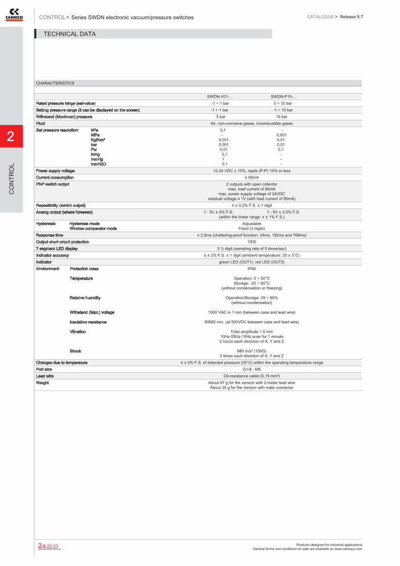
Products designed for industrial applications. General terms and conditions for sale are available on www.camozzi.com.
2
Series SWDN electronic vacuum/pressure switchesCONTROL > CATALOGUE > Release 8.7
/8.22.032
CO
NTR
OL
CHARACTERISTICS
SWDN-V01-... SWDN-P10-...Rated pressure range (set-value) -1 ÷ 1 bar 0 ÷ 10 barSetting pressure range (it can be displayed on the screen) -1 ÷ 1 bar -1 ÷ 10 barWithstand (Maximum) pressure 3 bar 15 barFluid Air, non-corrosive gases, incombustible gasesSet pressure resolution: kPa MPa Kgf/cm² bar Psi InHg mmHg mmH2O
0,1 - - 0,001 0,001 0,01 0,001 0,01 0,01 0,1 0,1 - 1 - 0,1 -
Power supply voltage 12-24 VDC ± 10%, ripple (P-P) 10% or lessCurrent consumption ≤ 55mAPNP switch output 2 outputs with open collector
max. load current of 80mA max. power supply voltage of 24VDC
residual voltage ≤ 1V (with load current of 80mA)Repeatibility (switch output) ≤ ± 0,2% F.S. ± 1 digitAnalog output (where foreseen) 1 - 5V ± 5% F.S. 1 - 5V ± 2,5% F.S.
(within the linear range: ≤ ± 1% F.S.)Hysteresis: Hysteresis mode Window comparator mode
Adjustable Fixed (3 digits)
Response time ≤ 2,5ms (chattering-proof function: 24ms, 192ms and 768ms)Output short circuit protection YES7 segment LED display 3 ½ digit (sampling rate of 5 times/sec)Indicator accuracy ≤ ± 2% F.S. ± 1 digit (ambient temperature: 25 ± 3°C)Indicator green LED (OUT1), red LED (OUT2)Environment: Protection class Temperature Relative humidity Withstand (Max.) voltage Insulation resistance Vibration Shock
IP40
Operation: 0 ÷ 50°C Storage: -20 ÷ 60°C
(without condensation or freezing)
Operation/Storage: 35 ÷ 85% (without condensation)
1000 VAC in 1 min (between case and lead wire)
50MΩ min. (at 500VDC between case and lead wire)
Total amplitude 1.5 mm
10Hz-55Hz-10Hz scan for 1 minute 2 hours each direction of X, Y and Z
980 m/s² (100G)
3 times each direction of X, Y and ZChanges due to temperature ≤ ± 2% F.S. of detected pressure (25°C) within the operating temperature rangePort size G1/8 - M5Lead wire Oil-resistance cable (0,15 mm²)Weight About 67 g for the version with 2-meter lead wire
About 35 g for the version with male connector
TECHNICAL DATA

Products designed for industrial applications. General terms and conditions for sale are available on www.camozzi.com.
Series SWDN electronic vacuum/pressure switchesCATALOGUE
2
/8.22.042
> Release 8.7 CONTROL >
CO
NTR
OL
Circular M8 4-pole connectors, FemaleProtection class: IP65 Materials: PU non shielded cable
Mod. Type of connector Cable length (m)CS-DF04EG-E200 straight 2CS-DF04EG-E500 straight 5CS-DR04EG-E200 90° 2CS-DR04EG-E500 90° 5

Products designed for industrial applications. General terms and conditions for sale are available on www.camozzi.com.
2
Series SWC electronic vacuum/pressure switchesCONTROL > CATALOGUE > Release 8.7
/8.25.012
CO
NTR
OL
Series SWC electronic vacuum/pressure switches
With digital display High precision, easy to use
Applications: - electronic vacuum/pressure switch for safety monitoring, optimization of cycle times or energy saving devices; - it can be installed directly on the gripping point of a handling system; - setting of the limit vacuum value and continuous vacuum control; - user friendly and suitable for user’s requirements.
Electric connections: - This device functions correctly with a connector Mod. CS-DFO4EG-E500 or CS-DR04EG-E500 which should be ordered separately. Further details at the end of this section.
» Compact and lightweight
» Digital display: electronically precise switching with two separate switching outputs.
» Switching point and hysteresis progammable with the key pad.
» Two separately programmable digital outputs allow to set the upper and lower limit value.
» Special functions programmable: further adaptation is possible.
GENERAL DATAType of vacuum/pressure switch electronic with polycarbonate housingVacuum switch connection Pressure switch
- vacuum connection with G1/8 male thread - pressure connection G1/8 male thread
Display 3 digit display and key pad to regulate the setting pointsLED integrated LED for the indication of the switching stateElectric connection with 4-pin M8 connector
Running out of stock

Products designed for industrial applications. General terms and conditions for sale are available on www.camozzi.com.
Series SWC electronic vacuum/pressure switchesCATALOGUE
2
/8.25.022
> Release 8.7 CONTROL >
CO
NTR
OL
CODING EXAMPLE
SW SERIES SW = transducer
C VERSION C = cube shape with digital display
V00 MEASURING RANGE V00 = from -1 to 0 bar P10 = from 0 to 10 bar
P POLARITY P = PNP
SW C - V00 - P
DIMENSIONSMod. B D G1 G3 H H1 LSWC-V00-P 29 3,4 G1/8 M8 30 40 30SWC-P10-P 29 3,4 G1/8 M8 30 40 30
Vacuum/pressure switch Series SWC

Products designed for industrial applications. General terms and conditions for sale are available on www.camozzi.com.
2
Series SWC electronic vacuum/pressure switchesCONTROL > CATALOGUE > Release 8.7
/8.25.032
CO
NTR
OL
Mod. SWC-V00-P SWC-P10-PFluid Non-aggressive gas, dry air,
without lubricationNon-aggressive gas, dry air,
without lubricationMeasurement range -1 ÷ 0 bar 0 ÷ 10 barMax overpressure [bar] 5 16Precision ± 1% measurement range ± 1% measurement rangeHysteresis settable: from 0 to 100 % of set value
or comparator modesettable: from 0 to 100 % of set value
or comparator modeOutput signal 2 digital 2 digitalMax output current [mA] 180 180Signalling 2 x LED 2 x LEDView resolution 0,01 bar, 5 mmHg, 0,2 inHg, 1 kPa 0,01 bar, 5 mmHg, 0,2 inHg, 1 kPaView unit bar, mmHg, inHg, kPa bar, mmHg, inHg, kPaMeasurement value displaying LED 3-digit 7-segments LED 3-digit 7-segmentsElectric connection Connector M8 4 Poles Connector M8 4 PolesPneumatic connection G1/8 female G1/8 femaleVoltage 10.8 - 30 V DC 10.8 - 30 V DCCurrent consumption [mA] < 55 < 55IP Protection IP 40/65 (with flexible tube) IP 40/65 (with flexible tube)Temperature effect ± 3% measurement range from 0 to 50°C ± 3% measurement range from 0 to 50°COperating temperature 0°C ÷ 50 °C 0°C ÷ 50 °CWeight [g] 35 35
TECHNICAL DATA
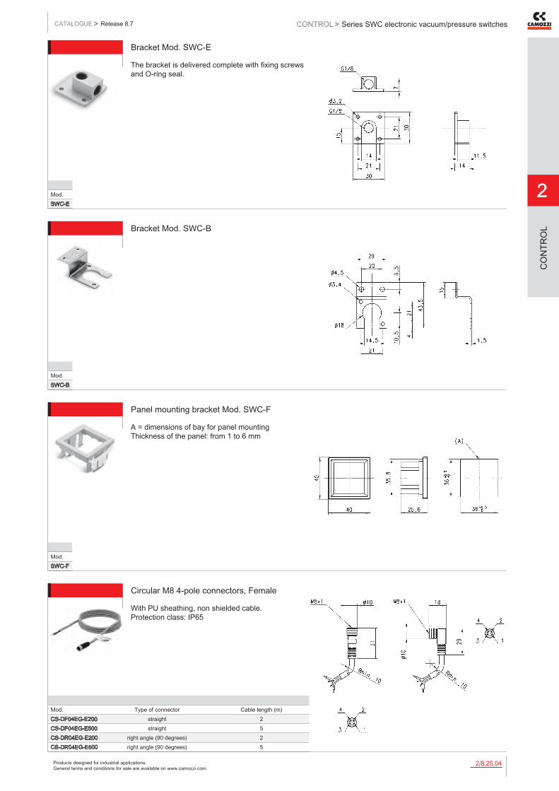
Products designed for industrial applications. General terms and conditions for sale are available on www.camozzi.com.
Series SWC electronic vacuum/pressure switchesCATALOGUE
2
/8.25.042
> Release 8.7 CONTROL >
CO
NTR
OL
Bracket Mod. SWC-E
The bracket is delivered complete with fixing screws and O-ring seal.
Mod.SWC-E
Bracket Mod. SWC-B
Mod.SWC-B
Panel mounting bracket Mod. SWC-F
A = dimensions of bay for panel mounting Thickness of the panel: from 1 to 6 mm
Mod.SWC-F
Circular M8 4-pole connectors, Female
With PU sheathing, non shielded cable. Protection class: IP65
Mod. Type of connector Cable length (m)CS-DF04EG-E200 straight 2CS-DF04EG-E500 straight 5CS-DR04EG-E200 right angle (90 degrees) 2CS-DR04EG-E500 right angle (90 degrees) 5

Products designed for industrial applications. General terms and conditions for sale are available on www.camozzi.com.
2
Series SWCN electronic vacuum/pressure switchesCONTROL > CATALOGUE > Release 8.7
/8.27.012
CO
NTR
OL
Series SWCN electronic vacuum/pressure switches
With digital display High precision, easy to use
APPLICATIONS: - electronic vacuum/pressure switch for safety monitoring, optimization of cycle times or energy saving devices; - it can be installed directly on the gripping point of a handling system; - setting of the limit vacuum value and continuous vacuum control; - perfectly suitable for customer needs.
ELECTRIC CONNECTION: the device is available with hardwired cable of 2 meters or can be supplied with M8 connector. Accessories and extensions have to be ordered separately. Codes can be found at the end of this section.
» Compact and lightweight
» Digital indicator: precised electronic insertion with two separated switch outputs
» Switching point and hysteresis can be programmed with a membrane keypad
» Upper and lower limit values can be programmed through two PNP switch outputs
GENERAL DATAType of pressure/vacuum switch electronic with polycarbonate housingPort with external thread G1/8 and internal thread M5Display 3 digit display with membrane keypad for the values set upLED integrated LED indicators for switching stateElectric connection with M8 4-pole connector or pre-wired cable of 2 meters

Products designed for industrial applications. General terms and conditions for sale are available on www.camozzi.com.
Series SWCN electronic vacuum/pressure switchesCATALOGUE
2
/8.27.022
> Release 8.7 CONTROL >
CO
NTR
OL
CODING EXAMPLE
SWCN SERIES
V01 SET PRESSURE RANGE: V01 = from -1 bar to 1 bar P10 = from 0 bar to 10 bar
P3 TYPE OF ELECTRIC CONNECTION: P3 = 2 PNP outputs + 1 analog output 1 - 5 V DC (this version is available with 5-pole cable only) P4 = 2 PNP outputs
2 ELECTRIC CONNECTION: 2 = cable of 2 meters M = M8 4 pin connector
SWCN - V01 - P3 - 2
Mod.SWCN-V01-P3-2SWCN-V01-P4-2SWCN-V01-P4-MSWCN-P10-P3-2SWCN-P10-P4-2SWCN-P10-P4-M
Vacuum/Pressure switch Series SWCN 1 = brown (+) 2 = white (OUT 2) 3 = blue (-) 4 = black (OUT 1)

Products designed for industrial applications. General terms and conditions for sale are available on www.camozzi.com.
2
Series SWCN electronic vacuum/pressure switchesCONTROL > CATALOGUE > Release 8.7
/8.27.032
CO
NTR
OL
CHARACTERISTICS
SWCN-V01-... SWCN-P10-...Rated pressure range (set-value) -1 ÷ 1 bar 0 ÷ 10 barSetting pressure range (it can be displayed on the screen) -1 ÷ 1 bar -1 ÷ 10 barWithstand (Maximum) pressure 3 bar 15 barFluid Air, non-corrosive gases, incombustible gasesSet pressure resolution: kPa MPa Kgf/cm² bar Psi InHg mmHg mmH2O
0,1 - - 0,001 0,001 0,01 0,001 0,01 0,01 0,1 0,1 - 1 - 0,1 -
Power supply voltage 12-24 VDC ± 10%, ripple (P-P) 10% or lessCurrent consumption ≤ 55mAPNP switch output 2 outputs with open collector
max. load current of 80mA max. power supply voltage of 24VDC
residual voltage ≤ 1V (with load current of 80mA)Repeatibility (switch output) ≤ ± 0,2% F.S. ± 1 digitAnalog output (where foreseen) 1 - 5V ± 5% F.S. 1 - 5V ± 2,5% F.S.
((within the linearity range: ≤ ± 1% F.S.)Hysteresis: Hysteresis mode Window comparator mode
Adjustable Fixed (3 digits)
Response time ≤ 2,5ms (chattering-proof function: 24ms, 192ms and 768ms)Output short circuit protection YES7 segment LED display 3 ½ digit (sampling rate of 5 times/sec)Indicator accuracy ≤ ± 2% F.S. ± 1 digit (ambient temperature: 25 ± 3°C)Indicator green LED (OUT1), red LED (OUT2)Environment: Protection class Temperature Relative humidity Withstand (Max.) voltage Insulation resistance Vibration Shock
IP65
Operation: 0 ÷ 50°C Storage: -20 ÷ 60°C
(without condensation or freezing)
Operation/Storage: 35 ÷ 85% (without condensation)
1000 VAC in 1 min ((between case and lead wire)
50MΩ min. (at 500VDC between case and lead wire)
Total amplitude 1.5 mm
10Hz-55Hz-10Hz scan for 1 minute 2 hours each direction of X, Y and Z
980 m/s² (100G)
3 times each direction of X, Y and ZChanges due to temperature ≤ ± 2% F.S. of detected pressure (25°C) within the operating temperature rangePort size G1/8 - M5Lead wire Oil-resistance cable(0,15 mm²)Weight About 105 g for the version with 2-meter lead wire
About 71 g for the version with male connector
TECHNICAL DATA

Products designed for industrial applications. General terms and conditions for sale are available on www.camozzi.com.
Series SWCN electronic vacuum/pressure switchesCATALOGUE
2
/8.27.042
> Release 8.7 CONTROL >
CO
NTR
OL
Mounting bracket Mod. SWCN-B
Supplied with: - 4 fixing screws M4x5 ISO 724 (fine pitch) - 1 fixing bracket for surface mounting (A) - 1 fixing bracket for wall mounting (B)
Mod.SWCN-B
Panel mounting set Mod. SWCN-F
Supplied with: - 1 pressure switch holder (A) - 2 panel mounting brackets (B)
Mod.SWCN-F
Panel mounting set + transparent cover Mod. SWCN-FP
Supplied with: - 1 pressure switch holder (A) - 2 panel mounting brackets (B) - 1 transparent cover (C)
Mod.SWCN-FP
Circular M8 4-pole connectors, Female
With PU sheathing, non shielded cable. Protection class: IP65
Mod. Type of connector Cable length (m)CS-DF04EG-E200 straight 2CS-DF04EG-E500 straight 5CS-DR04EG-E200 right angle (90 degrees) 2CS-DR04EG-E500 right angle (90 degrees) 5

Products designed for industrial applications. General terms and conditions for sale are available on www.camozzi.com.
2
Series SWCN electronic vacuum/pressure switchesCONTROL > CATALOGUE > Release 8.7
/8.27.052
CO
NTR
OL
A: ADDITIONAL POWER SUPPLY In case of use, please unscrew plug A from one side and mount it on the other one. B: Use of the AIR FILTER TUBE to reach the IP 65 protection class.
Example of mounting with bracket Mod. SWCN-B and standard accessories
A = PANEL MOUNTING SET MOD. SWCN-F B = PRESSURE SWITCH MOD. SWCN-... C = PANEL
Example of mounting with panel mounting set Mod. SWCN-F

Products designed for industrial applications. General terms and conditions for sale are available on www.camozzi.com.
SilencersCATALOGUE
2
/9.05.012
> Release 8.7 CONTROL >
CO
NTR
OL
Silencers
Series: 2901 - 2903 - 2921 - 2931 - 2938 - 2939 - 2905 - RSW Ports: M5, G1/8, G1/4, G3/8, G1/2, G3/4, G1
The silencers are indispensable elements for eliminating or reducing the characteristic noise of compressed air during discharge operations. They should always be placed on the outlets of 3/2, 5/2 or 5/3-way valves. When carrying out maintenance, the silencers should be degreased using white spirit or paraffin and compressed air blown through them in the opposite direction to operation.
Flow rate: determined with inlet supply 6 bar and output in atmosphere. Noise level: determined through a test which is carried out using a phonometer. Placing the phonometer one meter away from the application at the same height for a period of ten seconds gives an average reading of the noise generated.
GENERAL DATAConstruction body with male and female threadMaterials used for body 2901 - 2903: brass
2921 - 2931: coppering steel 2938 - 2939: polyethylene
Materials used for silencing 2901 - 2903: stainless steel 2921 - 2931: bronze (sintered) 2938 - 2939: polyethylene
Ports M5 - G1/8 - G1/4 - G3/8 - G1/2 - G3/4 - G1
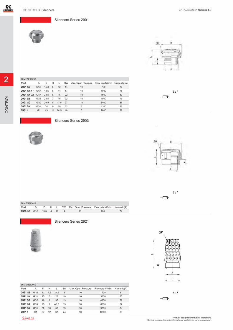
Products designed for industrial applications. General terms and conditions for sale are available on www.camozzi.com.
2
SilencersCONTROL > CATALOGUE > Release 8.7
/9.05.022
CO
NTR
OL
Silencers Series 2901
DIMENSIONSMod. A D H L SW Max. Oper. Pressure Flow rate Nl/min Noise db (A)2901 1/8 G1/8 15,3 5 12 14 10 700 762901 1/4-17 G1/4 18,5 6 14 17 10 1000 782901 1/4-22 G1/4 23,5 6 15 22 10 1600 802901 3/8 G3/8 23,5 7 16 22 10 1500 762901 1/2 G1/2 29,5 8 17,5 27 10 3400 862901 3/4 G3/4 34 9 20 32 6 4100 872901 1 G1 43 11 24,5 40 6 7600 88
Silencers Series 2903
DIMENSIONSMod. B D H L SW Max. Oper. Pressure Flow rate Nl/Min Noise db(A)2903 1/8 G1/8 15,3 4 11 14 10 700 74
Silencers Series 2921
DIMENSIONSMod. A D H L SW Max. Oper. Pressure Flow rate Nl/Min Noise db(A)2921 1/8 G1/8 12 4,5 21,5 8 10 1730 812921 1/4 G1/4 15 6 28 10 10 3300 852921 3/8 G3/8 19 8 37 13 10 4250 792921 1/2 G1/2 23 9 43,5 15 10 6800 872921 3/4 G3/4 30 10 56 19 10 9800 842921 1 G1 37 12 67 24 10 10900 86

Products designed for industrial applications. General terms and conditions for sale are available on www.camozzi.com.
SilencersCATALOGUE
2
/9.05.032
> Release 8.7 CONTROL >
CO
NTR
OL
Silencers Series 2931
DIMENSIONSMod. A D H I L SW Max. Oper. Pressure Flow rate Nl/Min Noise db (A)2931 M5 M5 7,7 4 8 16,5 7 10 450 692931 M7 M7 9 5 8,5 20 8 10 1130 762931 1/8 G1/8 13 4,5 13 21 12 10 1927 882931 1/4 G1/4 16,2 6 16,5 27 15 10 3200 862931 3/8 G3/8 20 7 23 35,5 19 10 4560 812931 1/2 G1/2 24,5 8 28 42 23 10 6800 872931 3/4 G3/4 32 9 37 54 30 10 9600 842931 1 G1 38,5 11 47 67 36 10 10800 86
Silencers Series 2938
DIMENSIONSMod. A D H L Max. Oper. Pressure Flow rate Nl/Min Noise db (A)2938 M5 M5 6,5 4,1 23 10 546 672938 1/8 G1/8 12,5 5,7 34 10 1441 752938 1/4 G1/4 15,5 7 42,5 10 2752 792938 3/8 G3/8 18,5 11,5 67,5 10 4735 732938 1/2 G1/2 23,5 11 77 10 8534 86
Operating temperature: - 40 / + 80 °C
Silencers Series 2939Operating temperature: - 40 / + 80 °C
DIMENSIONSMod. ØA D H L Max. Oper. Pressure Flow rate Nl/Min Noise db (A)2939 4 4 7 16 32 10 335 802939 6 6 12,5 20,5 45 10 632 79 *2939 8 8 13,5 21,5 43,5 10 1229 89 *2939 10 10 15,5 26,5 57,5 10 2650 87 *
* this code can be used on the Valve Island Series F (see the section 2/3.16).
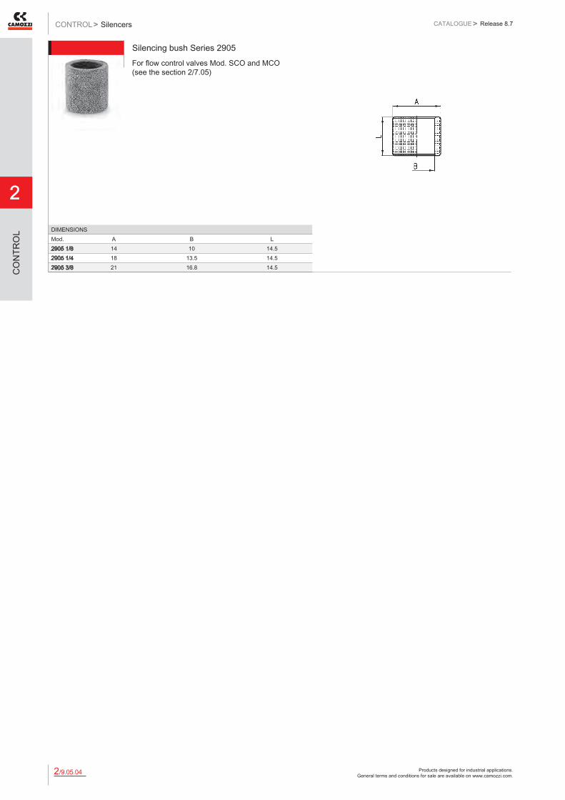
Products designed for industrial applications. General terms and conditions for sale are available on www.camozzi.com.
2
SilencersCONTROL > CATALOGUE > Release 8.7
/9.05.042
CO
NTR
OL
Silencing bush Series 2905For flow control valves Mod. SCO and MCO (see the section 2/7.05)
DIMENSIONSMod. A B L2905 1/8 14 10 14.52905 1/4 18 13.5 14.52905 3/8 21 16.8 14.5

Products designed for industrial applications. General terms and conditions for sale are available on www.camozzi.com.
Series AP proportional valvesCATALOGUE
2
/15.01.012
> Release 8.7 CONTROL >
CO
NTR
OL
Series AP directly operated proportional valves
2/2-way proportional valves, NC Sizes: 16 - 22 mm
Series AP directly operated 2/2-way proportional solenoid valves, NC, with nominal diameters range from 0.8 to 2.4 mm, can be used where an open loop flow control is required, with gas mixtures, to control free flows or blows, or emptying chambers using vacuum.
Series AP proportional valves have been manufactured to optimize and reduce friction and stick-slip effects. The output flow is proportional to the control signal. As they can work also in vacuum, a minimum working pressure is not required.
» Available in two sizes: 16 and 22 mm
» PWM or current operation
» Open loop flow control
» Also suitable for use with vacuum
» Size 16mm also available with body in PVDF
GENERAL DATAFunction Operation Ports Nominal diameter (ø) Nominal flow (Qn - Kv) Maximum operating pressure Hysteresis Repeatibility Operating temperature Medium Installation
2/2 NC proportional directly operated M5 - G1/8 see table see table see table 16 mm size < 7% 22 mm size < 5% 16 mm size < 5% 22 mm size < 3% 0 ÷ 60°C filtered compressed air, unlubricated, according to ISO 8573-1 class 3.4.3, inert gas in any position
Materials body = brass / PVDF (for size 16mm only) seals = NBR
Nominal resistance Rated current
GP7 GPH U711 U712 193 ohm 48 ohm 85 ohm 22 ohm 125 mA 250 mA 271 mA 0.542 mA
While choosing the valve characteristics and in order to reach the highest performances, it is important to know that there must be a pressure difference of 90% at least between the inlet and the outlet. For example: inlet P 10 bar - outlet P max 1 bar up to free flow.

Products designed for industrial applications. General terms and conditions for sale are available on www.camozzi.com.
2
Series AP proportional valvesCONTROL > CATALOGUE > Release 8.7
/15.01.022
CO
NTR
OL
CODING EXAMPLE
AP SERIES
7 BODY: 6 = Size 16 mm 7 = Size 22 mm
2 NUMBER OF WAYS: 2 = 2-way
1 VALVE FUNCTION: 1 = NC
1 PORTS: 0 = M5 (for size 16 mm only) 1 = G1/8 (for size 22 mm only) L = barbed fittings (for body in PVDF only)
L NOMINAL DIAMETER: D = ø 0.8 mm (for size 16 mm only) F = ø 1 mm H = ø 1.2 mm L = ø 1.6 mm N = ø 2 mm (for size 22 mm only) Q = ø 2.4 mm (for size 22 mm only)
R SEALS MATERIAL: R = NBR
2 BODY MATERIAL: 2 = brass 3 = PVDF (for size 16 mm only)
G ENCAPSULATING MATERIAL: G = PA (for size 16 mm only) U = PET (for size 22 mm only)
7 SOLENOID DIMENSIONS: P = 16x26 DIN EN 175301-803-C (for size 16 mm only) 7 = 22x22 DIN 43650 B (for size 22 mm only)
11 SOLENOID VOLTAGE: H = 12 V DC 3 W (for size 16 mm only) 7 = 24 V DC 3 W (for size 16 mm only) 11 = 24 V DC 6.5 W (for size 22 mm only) 12 = 12 V DC 6.5 W (for size 22 mm only)
AP - 7 2 1 1 - L R 2 - G 7 11
Series AP proportional valves - size 16mm
Mod. Port 1 Port 2 Function Orifice ø (mm) Kv (l/min) P Max (bar)AP-6210-DR2-GP* M5 M5 2/2 NC 0.8 0.4 10AP-6210-FR2-GP* M5 M5 2/2 NC 1 0.5 8AP-6210-HR2-GP* M5 M5 2/2 NC 1.2 0.65 6AP-6210-LR2-GP* M5 M5 2/2 NC 1.6 1.2 4
For the use with vacuum connect the line to connection 2.
* choose the desired voltage
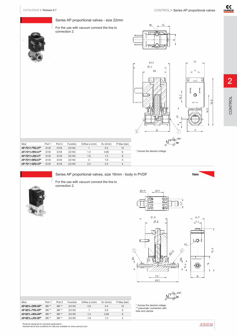
Products designed for industrial applications. General terms and conditions for sale are available on www.camozzi.com.
Series AP proportional valvesCATALOGUE
2
/15.01.032
> Release 8.7 CONTROL >
CO
NTR
OL
Series AP proportional valves - size 22mm
Mod. Port 1 Port 2 Function Orifice ø (mm) Kv (l/min) P Max (bar)AP-7211-FR2-U7* G1/8 G1/8 2/2 NC 1 0.5 10AP-7211-HR2-U7* G1/8 G1/8 2/2 NC 1.2 0.65 8AP-7211-LR2-U7* G1/8 G1/8 2/2 NC 1.6 1.0 6AP-7211-NR2-U7* G1/8 G1/8 2/2 NC 2 1.6 5AP-7211-QR2-U7* G1/8 G1/8 2/2 NC 2.4 2.0 4
For the use with vacuum connect the line to connection 2.
* choose the desired voltage
Series AP proportional valves, size 16mm - body in PVDF
Mod. Port 1 Port 2 Function Orifice ø (mm) Kv (l/min) P Max (bar)AP-621L-DR3-GP* Ø6 ** Ø6 ** 2/2 NC 0.8 0.4 10AP-621L-FR3-GP* Ø6 ** Ø6 ** 2/2 NC 1 0.5 8AP-621L-HR3-GP* Ø6 ** Ø6 ** 2/2 NC 1.2 0.65 6AP-621L-LR3-GP* Ø6 ** Ø6 ** 2/2 NC 1.6 1.2 4
For the use with vacuum connect the line to connection 2.
* choose the desired voltage ** pneumatic connection with tube and clamps
New

Products designed for industrial applications. General terms and conditions for sale are available on www.camozzi.com.
2
Series AP proportional valvesCONTROL > CATALOGUE > Release 8.7
/15.01.042
CO
NTR
OL
Connector Mod. 125-800 DIN 43650 pitch 9.4 mm
For size 16 mm only
Mod. description colour working voltage cable holding tightening torque125-800 connector, without electronics black - PG7 0.3 Nm
1 = 90° adjustable connector
Connector Mod. 125-550- DIN 43650 pitch 9.4 mm with cableFor size 16 mm only
Mod. description colour working voltage
cable length [ L ]
cable holding
tightening torque
125-550-1 moulded cable, without electronics
black - 1000 mm - 0.3 Nm
1 = 90° adjustable connector
In-line connectors with cable Mod. 125-553For size 16 mm only
Mod. description colour working voltage
cable length [ L ]
cable holding
tightening torque
125-553-2 in-line moulded cable, without electronics
black - 2000 mm - 0.3 Nm
125-553-5 in-line moulded cable, without electronics
black - 5000 mm - 0.3 Nm

Products designed for industrial applications. General terms and conditions for sale are available on www.camozzi.com.
Series AP proportional valvesCATALOGUE
2
/15.01.052
> Release 8.7 CONTROL >
CO
NTR
OL
Connectors Mod. 122-800 DIN 43650For size 22 mm only Mod. 122-800EX: for ATEX certified solenoids mod. U7*EX, with anti-screwing off screw mod. TORX.
Mod. description colour working voltage cable holding tightening torque122-800 connector, without electronics black - PG9 0.5 Nm122-800EX connector, without electronics black - PG9 0.5 Nm
Connectors Mod. 122-550 DIN 43650 with cableFor size 22 mm only
Mod. description colour working voltage
cable length [ L ]
cable holding
tightening torque
122-550-1 moulded cable, without electronics
black - 1000 mm - 0.5 Nm
122-550-5 moulded cable, without electronics
black - 5000 mm - 0.5 Nm

Products designed for industrial applications. General terms and conditions for sale are available on www.camozzi.com.
2
Series CP proportional solenoid valvesCONTROL > CATALOGUE > Release 8.7
/15.02.012
CO
NTR
OL
Series CP directly operated proportional solenoid valves
2/2-way NC Nominal diameters: 1mm - 1.5mm - 2mm
Series CP directly operated proportional solenoid valves can be used where an open loop flow control is required, with gas mixtures or to control flows.
Series CP valves have been designed to optimize dimensions and reduce friction and stick-slip effects. The output flow is proportional to the control signal. As they can work also in vacuum, a minimum working pressure is not required. Their cartridge design makes them particularly compact, thus they can be mounted directly near the workstation.
» High flow
» Great precision
» Low hysteresis
GENERAL DATA
TECHNICAL FEATURESFunction Operation Pneumatic connections Nominal diameters Free flow capacity Operating pressure Max overpressure Linearity Hysteresis Repeatibility Operating temperature Media Response time Installation
2/2 NC proportional directly operated cartridge 1 - 1.5 - 2 mm 70 - 80 - 90 l/min 8 – 5 – 3 bar 16 bar 3% FS 10% FS 5% FS +10°C / +50°C filtered compressed air, unlubricated, according to ISO 8573-1 class 3.4.3, inert gas see the following page in any position
MATERIALS IN CONTACT WITH THE MEDIUMBody Seals
brass, stainless steel, PPS FKM
ELECTRICAL FEATURESOperation Operation voltage Max power consumption Nominal resistance Rated current Duty cycle Electrical connection Protection class Average lifecycles
PWM > 1000 Hz or current control 6 - 11 - 24 V DC 3.2 W 11.8 - 37.6 - 184.7 Ohm 0.103 - 0.238 - 0.410 A 100% cable 300mm AWG24 IP00 / IP40 50000000
Versions available on demand - base with 1/8 - 1/4 ports - seals in EPDM (in progress)
New
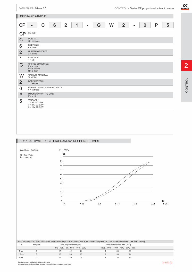
Products designed for industrial applications. General terms and conditions for sale are available on www.camozzi.com.
Series CP proportional solenoid valvesCATALOGUE
2
/15.02.022
> Release 8.7 CONTROL >
CO
NTR
OL
CODING EXAMPLE
CP SERIES
C PORTS: C = cartridge
6 BODY SIZE: 6 = 16mm
2 NUMBER OF PORTS: 2 = 2-way
1 FUNCTION: 1 = NC
G ORIFICE DIAMETRES: F = ø 1mm G = ø 1.5mm N = ø 2mm
W GASKETS MATERIAL: W = FKM
2 BODY MATERIAL: 2 = BRASS
0 OVERMOULDING MATERIAL OF COIL: 0 = cartridge
P DIMENSIONS OF THE COIL: P = ø 16
5 VOLTAGE: 1 = 6V DC 3.2W 3 = 24V DC 3.2W 5 = 11V DC 3.2W
CP - C 6 2 1 - G W 2 - 0 P 5
DIAGRAM LEGEND: Q = flow (l/min) I = current (A)
SIZE 16mm - RESPONSE TIMES calculated according to the maximum flow at each operating pressure. [ Electromechanical response time: 10 ms ]ø Pin [bar] Load response time [ms] Exhaust response time [ ms ]
0% - 10% 0% - 90% 10% - 90% 100% - 90% 100% - 10% 90% - 10%1mm 8 12 42 30 9 33 24
1.5mm 5 12 39 27 9 33 242mm 3 11 39 28 9 33 26
TYPICAL HYSTERESIS DIAGRAM and RESPONSE TIMES

Products designed for industrial applications. General terms and conditions for sale are available on www.camozzi.com.
2
Series CP proportional solenoid valvesCONTROL > CATALOGUE > Release 8.7
/15.02.032
CO
NTR
OL
Nominal diameter 1mm Q = flow (l/min) I = current (A) P1 = pressure in load (bar) P2 = 0 [ free flow pressure ] (bar)
Nominal diameter 1.5mm Q = flow (l/min) I = current (A) P1 = pressure in load (bar) P2 = 0 [ free flow pressure ] (bar)
FLOW DIAGRAMS
Nominal diameter 2mm Q = flow (l/min) I = current (A) P1 = pressure in load (bar) P2 = 0 [ free flow pressure ] (bar)
FLOW DIAGRAMS
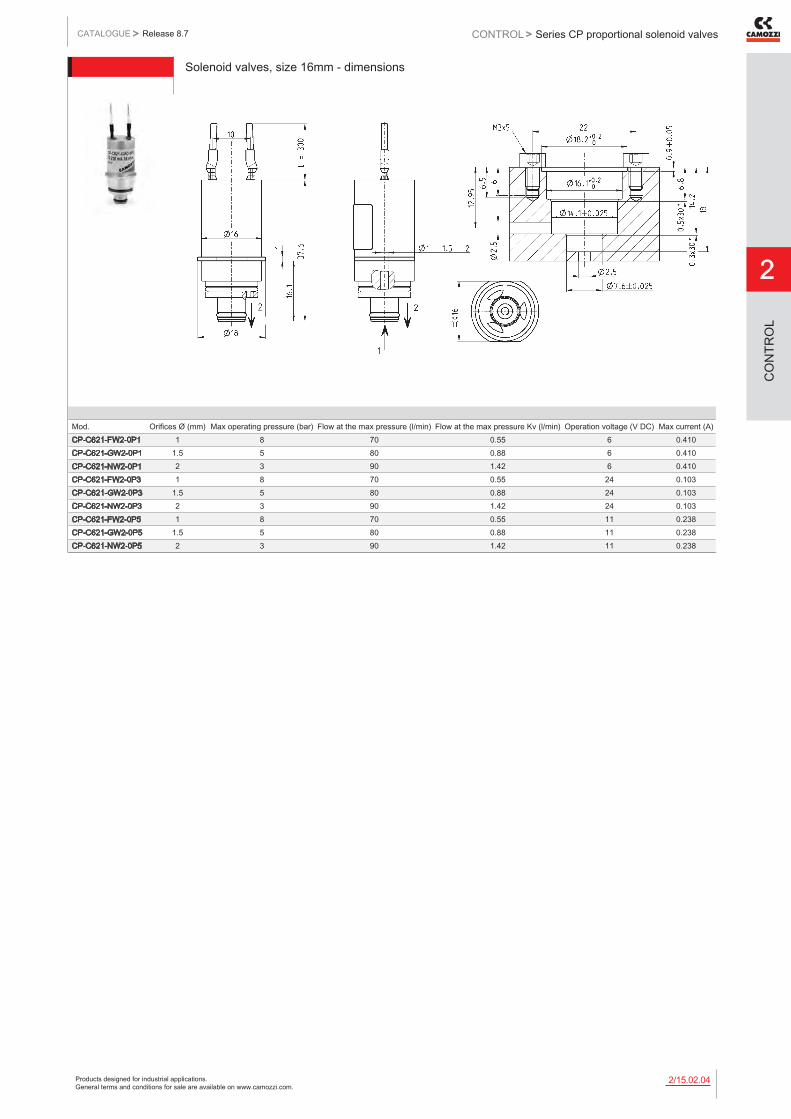
Products designed for industrial applications. General terms and conditions for sale are available on www.camozzi.com.
Series CP proportional solenoid valvesCATALOGUE
2
/15.02.042
> Release 8.7 CONTROL >
CO
NTR
OL
Solenoid valves, size 16mm - dimensions
Mod. Orifices Ø (mm) Max operating pressure (bar) Flow at the max pressure (l/min) Flow at the max pressure Kv (l/min) Operation voltage (V DC) Max current (A)CP-C621-FW2-0P1 1 8 70 0.55 6 0.410CP-C621-GW2-0P1 1.5 5 80 0.88 6 0.410CP-C621-NW2-0P1 2 3 90 1.42 6 0.410CP-C621-FW2-0P3 1 8 70 0.55 24 0.103CP-C621-GW2-0P3 1.5 5 80 0.88 24 0.103CP-C621-NW2-0P3 2 3 90 1.42 24 0.103CP-C621-FW2-0P5 1 8 70 0.55 11 0.238CP-C621-GW2-0P5 1.5 5 80 0.88 11 0.238CP-C621-NW2-0P5 2 3 90 1.42 11 0.238

Products designed for industrial applications. General terms and conditions for sale are available on www.camozzi.com.
2
Series 130 electronic control deviceCONTROL > CATALOGUE > Release 8.7
/15.03.012
CO
NTR
OL
Series 130 electronic control device for proportional valves
PWM control device, with current control system for directly operated proportional valves
Series 130 electronic control device allows to pilot any proportional valve with a maximun current of 1 A. It turns a standard inlet signal (0-10V or 4-20 mA) into a PWM signal to obtain at the solenoid outlet a current which is proportional to the inlet signal.
A control system of the provided current allows to compensate variations due to heating of the solenoid or to the variation of the supply voltage.It is possible to adjust the maximum current and the minimum current provided to the solenoid. The outlet signal can have a ramp progress that is adjustable between 0 and 5 s. The device has a firmware dedicated to the proportional valve to pilot in order to guarantee the best performance.
» Closed loop current control (max current that can be provided = 1A)
» Management of up and down ramp
» Command signal 0-10V and 4-20mA
» Regulation of min and max current (Span and Offset)
GENERAL DATA
Material of container PolycarbonateElectrical connections screwEnvironmental temperature 0 ÷ 50°CMounting in any positionPower supply 6 V ÷ 24 V DC (± 10%)Consumption 0.4 W (without valve)Analogical input 0 ÷ 10 V
4 ÷ 20 mAInput impedence >30 Kohm with inlet under voltage
<200 ohm with inlet under currentOutput PWM 120 Hz ÷ 11.7 KHz (fixed, according to the valve chosen)Maximum current (valve) 1 AProtection Polarity inversion, short circuit of the outletExternal diameter of cable jacket 5 ÷ 7.5 mm with seal only
4 ÷ 6 mm with reducer and sealConductor section 26 ÷ 16 AWG / 0,13 ÷ 1,5 mm2Maximum length supply/signal cable 10 mMaximum length valve cable 5 mIP protection class according to EN 60529 IP 54Ramp function Adjustable time from 0 to 5 sRegulation min. current (Offset) 0% ÷ 40% F.S.Regulation maximum current 50% ÷ 100% F.S.
New

Products designed for industrial applications. General terms and conditions for sale are available on www.camozzi.com.
Series 130 electronic control deviceCATALOGUE
2
/15.03.022
> Release 8.7 CONTROL >
CO
NTR
OL
CODING EXAMPLE
130 SERIES
2 VOLTAGE: 2 = 24 V DC (max power 24 W) 3 = 12 V DC (max power 12 W) 4 = 6 V DC (max power 6 W) 5 = 11 V DC (max power 11 W)
2 POWER: 1 = 3 W 2 = 6.5 W 3 = 3.2 W 4 = 4.3 W 5 = 10 W
2 PWM FREQUENCY: 2 = 500 Hz 3 = 1 KHz
NOTE: it is possible to realize configurations with voltage, power and PWM frequency values that are not yet foreseen in the coding example. For further information we suggest you to contact our technical department.
130 - 2 2 2
DRAWING LEGEND: 1 = 6 ÷ 24 V DC (supply) 2 = 0 V (Ground) common also for the reference signal 3 = analogical reference signal 0 ÷ 10V DC 4 = analogical reference signal 4 ÷ 20 mA A = regulation of min. current (OFFSET) B = regulation of max. current (SPAN) C = regulation of the PWM outlet up and down ramp D = red LED E = yellow LED Note 1: the GND of the reference signal and the GND of supply have to be linked together. Note 2: For the valve connection use a connector without protection - diodes, varistors, etc... - as these might alter the regulation of the device.
ELECTRICAL CONNECTIONS AND SETTINGS
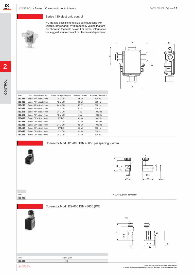
Products designed for industrial applications. General terms and conditions for sale are available on www.camozzi.com.
2
Series 130 electronic control deviceCONTROL > CATALOGUE > Release 8.7
/15.03.032
CO
NTR
OL
Series 130 electronic control
Mod. Matching valve family Valve voltage (Output) Adjusted power Adjusted frequency130-222 Series AP - size 22 mm 24 V DC 6.5 W 500 Hz130-322 Series AP - size 22 mm 12 V DC 6.5 W 500 Hz130-252 Series AP - size 22 mm 24 V DC 10 W 500 Hz130-352 Series AP - size 22 mm 12 V DC 10 W 500 Hz130-213 Series AP - size 16 mm 24 V DC 3 W 1000 Hz130-313 Series AP - size 16 mm 12 V DC 3 W 1000 Hz130-433 Series CP - size 16 mm 6 V DC 3.2 W 1000 Hz130-533 Series CP - size 16 mm 11 V DC 3.2 W 1000 Hz130-233 Series CP - size 16 mm 24 V DC 3.2 W 1000 Hz130-442 Series CP - size 20 mm 6 V DC 4.3 W 500 Hz130-342 Series CP - size 20 mm 12 V DC 4.3 W 500 Hz130-242 Series CP - size 20 mm 24 V DC 4.3 W 500 Hz
NOTE: it is possible to realize configurations with voltage, power and PWM frequency values that are not shown in the table below. For further information we suggest you to contact our technical department.
Connector Mod. 125-800 DIN 43650 pin spacing 9,4mm
Mod.125-800
1 = 90° adjustable connector
Connector Mod. 122-800 DIN 43650 (PG)
Mod. Torque (Nm)122-800 0.5

Products designed for industrial applications. General terms and conditions for sale are available on www.camozzi.com.
Series LRWA analogic proportional servo valvesCATALOGUE
2
/15.11.012
> Release 8.7 CONTROL >
CO
NTR
OL
Analogic proportional servo valves Flow control - Series LRWA
3/3-way directly operated servo valves for the flow control
Theser servo valves are equipped with a patented rotating spool system with closed loop control circuit. Their compact design makes them particularly suitable for several applications.
The LRWA0 cartridge has to be supplied with a controller that contains the electronic board and a connection cable. The valve controllers are adjusted to the corresponding cartridges. A correct function needs a cartridge and a controller with identical serial numbers. In the LRWA2 (cabinet mounting on DIN-rail) and LRWA4 (sub-base mounting, with G1/4 threaded ports) versions, the electronic board is integrated into the valve’s body ready to connect.
» Rotating spool with a metal to metal seal
» Compact design
» High flow rate
» Electronic control to ensure high precision in the flow control
» 3-way-function with 4 - 6 mm nominal diameters
» LRWA0 version: cartridge system, optimal mounting options for different applications
» LRWA2 version: for cabinet mounting on DIN-rail in any position
» LRWA4 version: realized on a proper sub-base with G1/4 threaded ports for mounting in any position
GENERAL DATAPower supply 24V DC +/- 10%, stabilized, max. 0,8 AControl signal +/- 10V 100 kohm; 0-10V 100 kohm; 0-20 mA 500 ohm; +/-5 V DC 100 ohm (LRWA4 only)Hysteresis 1% FSLinearity 1% FSSwitching time from 0 to 100%: approx. 5 ms; +/- 100%: approx. 7 msWorking temperature from 0 to 50°CRelative humidity of air max. 90%Weight of the cartridge 0.140 kg without cable; (LRWA0); 0.700 kg (LRWA2); 1 kg (LRWA4)Maximum flow rate at 6 bar ΔP 1 bar 350 Nl/min (LRWA4-34); 450 Nl/min (LRWA0-34, LRWA2-34); 550 Nl/min (LRWA4-36); 690 Nl/min (LRWA0-36,
LRWA2-36)Medium filtered compressed air, unlubricated, according to ISO 8573-1 class 3.4.3, inert gasSupply pressure -0,9 to 10 barLeakage < 1% of maximum flow rateElectrical connection SUB-D connector 25 poles with pre-wired cable of 0.5-1-2 m (LRWA0);
male connector M12 5 poles (LRWA2); male connector M16 7 poles (LRWA4)
Running out of stock
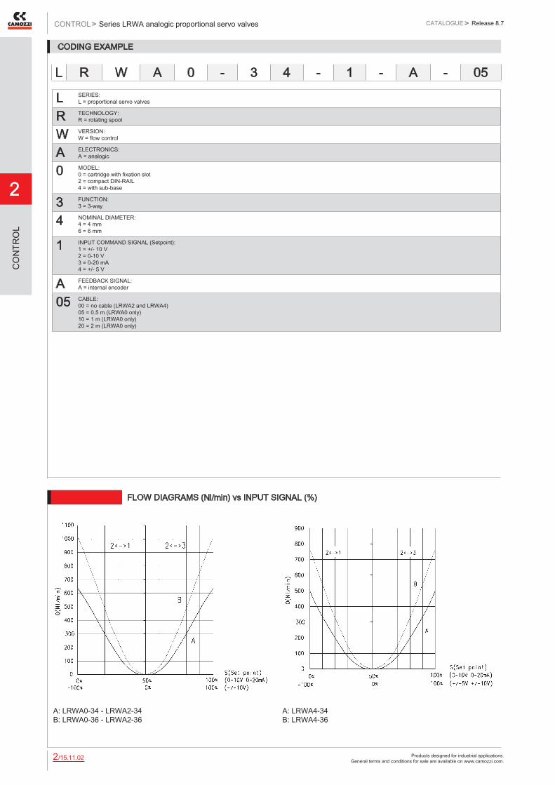
Products designed for industrial applications. General terms and conditions for sale are available on www.camozzi.com.
2
Series LRWA analogic proportional servo valvesCONTROL > CATALOGUE > Release 8.7
/15.11.022
CO
NTR
OL
CODING EXAMPLE
L SERIES: L = proportional servo valves
R TECHNOLOGY: R = rotating spool
W VERSION: W = flow control
A ELECTRONICS: A = analogic
0 MODEL: 0 = cartridge with fixation slot 2 = compact DIN-RAIL 4 = with sub-base
3 FUNCTION: 3 = 3-way
4 NOMINAL DIAMETER: 4 = 4 mm 6 = 6 mm
1 INPUT COMMAND SIGNAL (Setpoint): 1 = +/- 10 V 2 = 0-10 V 3 = 0-20 mA 4 = +/- 5 V
A FEEDBACK SIGNAL: A = internal encoder
05 CABLE: 00 = no cable (LRWA2 and LRWA4) 05 = 0.5 m (LRWA0 only) 10 = 1 m (LRWA0 only) 20 = 2 m (LRWA0 only)
L R W A 0 - 3 4 - 1 - A - 05
6512 FLOW DIAGRAMS (Nl/min) vs INPUT SIGNAL (%)
A: LRWA0-34 - LRWA2-34 B: LRWA0-36 - LRWA2-36
A: LRWA4-34 B: LRWA4-36

Products designed for industrial applications. General terms and conditions for sale are available on www.camozzi.com.
Series LRWA analogic proportional servo valvesCATALOGUE
2
/15.11.032
> Release 8.7 CONTROL >
CO
NTR
OL
LRWA0 SERVO VALVES - PNEUMATIC INSTALLATION
The servo valve works as follows: if the command signal or setpoint is lower than 50%, the valve establishes a link between connection 1 and connection 2; then the air passes between the inlet and the outlet. If the setpoint value is higher than 50%, the port 2 is connected with the exhaust 3. For a better understanding, please see the flow diagram on page 2.15.11.2. THE LENGTH OF THE LEADS SHOULD BE AS SHORT AS POSSIBLE, BETWEEN VALVE-OUTLET AND LOAD NORMALLY NOT MORE THAN 2 mts. Drawing legend: 1 = Supply 2 = Port 3 = Exhaust A = O-ring 17x1,5 B = fixation slot C = bending radius >50 D = bending radius >25 F = sub-d-25 pins (male) G = cartridge fitting block L = cable length
ELECTRICAL CONNECTIONSPIN FUNCTION NOTES7 power supply +24 VDC13 GND power supply14 GND Input command signal15 Input command signal6,8 Internal reference potential never connect to other GNDs!1 Testpoint motor voltage +/- 10 V vs. pin 624 Testpoint slide position +/- 1 V vs. pin 6
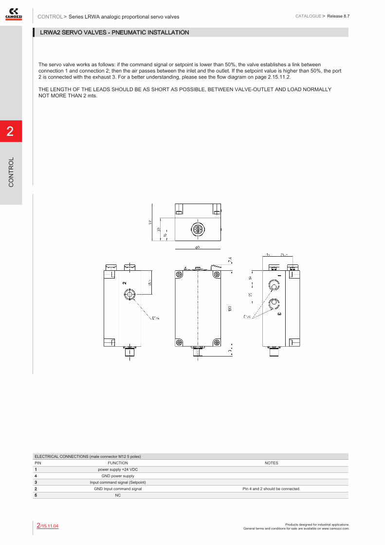
Products designed for industrial applications. General terms and conditions for sale are available on www.camozzi.com.
2
Series LRWA analogic proportional servo valvesCONTROL > CATALOGUE > Release 8.7
/15.11.042
CO
NTR
OL
LRWA2 SERVO VALVES - PNEUMATIC INSTALLATION
The servo valve works as follows: if the command signal or setpoint is lower than 50%, the valve establishes a link between connection 1 and connection 2; then the air passes between the inlet and the outlet. If the setpoint value is higher than 50%, the port 2 is connected with the exhaust 3. For a better understanding, please see the flow diagram on page 2.15.11.2. THE LENGTH OF THE LEADS SHOULD BE AS SHORT AS POSSIBLE, BETWEEN VALVE-OUTLET AND LOAD NORMALLY NOT MORE THAN 2 mts.
ELECTRICAL CONNECTIONS (male connector M12 5 poles)PIN FUNCTION NOTES1 power supply +24 VDC4 GND power supply3 Input command signal (Setpoint)2 GND Input command signal Pin 4 and 2 should be connected.5 NC

Products designed for industrial applications. General terms and conditions for sale are available on www.camozzi.com.
Series LRWA analogic proportional servo valvesCATALOGUE
2
/15.11.052
> Release 8.7 CONTROL >
CO
NTR
OL
LRWA4 SERVO VALVES - PNEUMATIC INSTALLATION
The servo valve works as follows: if the command signal or setpoint is lower than 50% the valve establishes a link between connection 1 and connection 2; then the air passes between the inlet and the outlet. If the setpoint value is higher than 50%, the port 2 is connected with the exhaust 3. For a better understanding, please see the flow diagram on page 2.15.11.2. THE LENGTH OF THE LEADS SHOULD BE AS SHORT AS POSSIBLE, BETWEEN VALVE-OUTLET AND LOAD NORMALLY NOT MORE THAN 2 mts.
ELECTRICAL CONNECTIONS (male connector M16 7 poles)PIN FUNCTION NOTES1 power supply +24 VDC2 GND power supply3 Input command signal (Setpoint)4 GND Input command signal Pin 4 and 2 should be connected.5 NC6 NC7 NC

Products designed for industrial applications. General terms and conditions for sale are available on www.camozzi.com.
2
Series LRWA analogic proportional servo valvesCONTROL > CATALOGUE > Release 8.7
/15.11.062
CO
NTR
OL
SERIES LRWA - TECHNICAL FEATURES
For the suitable accessories see the catalogue section 2/15.35
Mod. Model Nominal diameter Ø (mm) Command signal Cable length (m)LRWA0-34-1-A-05 cartridge with fixation slot 4 +/- 10 V 0.5LRWA0-34-1-A-10 cartridge with fixation slot 4 +/- 10 V 1LRWA0-34-1-A-20 cartridge with fixation slot 4 +/- 10 V 2LRWA0-34-2-A-05 cartridge with fixation slot 4 0-10 V 0.5LRWA0-34-2-A-10 cartridge with fixation slot 4 0-10 V 1LRWA0-34-2-A-20 cartridge with fixation slot 4 0-10 V 2LRWA0-34-3-A-05 cartridge with fixation slot 4 0-20 mA 0.5LRWA0-34-3-A-10 cartridge with fixation slot 4 0-20 mA 1LRWA0-34-3-A-20 cartridge with fixation slot 4 0-20 mA 2LRWA0-36-1-A-05 cartridge with fixation slot 6 +/- 10 V 0.5LRWA0-36-1-A-10 cartridge with fixation slot 6 +/- 10 V 1LRWA0-36-1-A-20 cartridge with fixation slot 6 +/- 10 V 2LRWA0-36-2-A-05 cartridge with fixation slot 6 0-10 V 0.5LRWA0-36-2-A-10 cartridge with fixation slot 6 0-10 V 1LRWA0-36-2-A-20 cartridge with fixation slot 6 0-10 V 2LRWA0-36-3-A-05 cartridge with fixation slot 6 0-20 mA 0.5LRWA0-36-3-A-10 cartridge with fixation slot 6 0-20 mA 1LRWA0-36-3-A-20 cartridge with fixation slot 6 0-20 mA 2LRWA2-34-1-A-00 compact DIN-RAIL 4 +/- 10 V no cableLRWA2-34-2-A-00 compact DIN-RAIL 4 0-10 V no cableLRWA2-34-3-A-00 compact DIN-RAIL 4 0-20 mA no cableLRWA2-36-1-A-00 compact DIN-RAIL 6 +/- 10 V no cableLRWA2-36-2-A-00 compact DIN-RAIL 6 0-10 V no cableLRWA2-36-3-A-00 compact DIN-RAIL 6 0-20 mA no cableLRWA4-34-1-A-00 with sub-base 4 +/- 10 V no cableLRWA4-34-2-A-00 with sub-base 4 0-10 V no cableLRWA4-34-3-A-00 with sub-base 4 0-20 mA no cableLRWA4-34-4-A-00 with sub-base 4 +/- 5 V no cableLRWA4-36-1-A-00 with sub-base 6 +/- 10 V no cableLRWA4-36-2-A-00 with sub-base 6 0-10 V no cableLRWA4-36-3-A-00 with sub-base 6 0-20 mA no cableLRWA4-36-4-A-00 with sub-base 6 +/- 5 V no cable
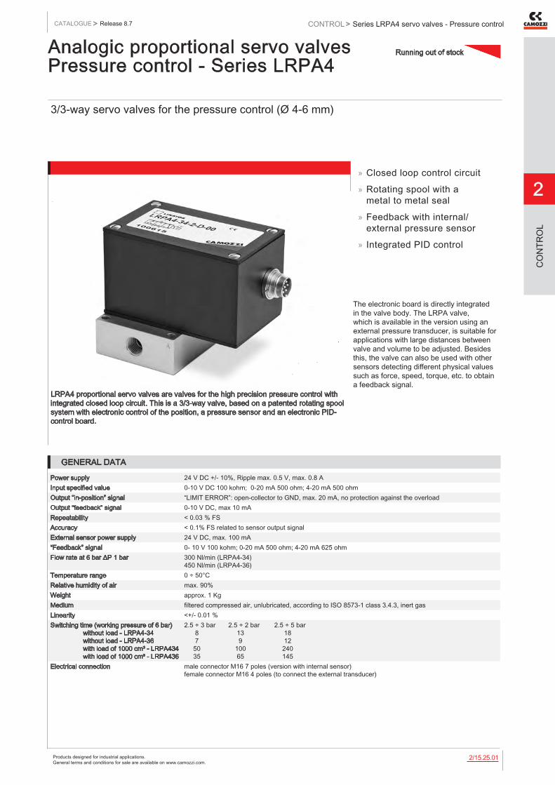
Products designed for industrial applications. General terms and conditions for sale are available on www.camozzi.com.
Series LRPA4 servo valves - Pressure controlCATALOGUE
2
/15.25.012
> Release 8.7 CONTROL >
CO
NTR
OL
Analogic proportional servo valves Pressure control - Series LRPA4
3/3-way servo valves for the pressure control (Ø 4-6 mm)
LRPA4 proportional servo valves are valves for the high precision pressure control with integrated closed loop circuit. This is a 3/3-way valve, based on a patented rotating spool system with electronic control of the position, a pressure sensor and an electronic PID-control board.
The electronic board is directly integrated in the valve body. The LRPA valve, which is available in the version using an external pressure transducer, is suitable for applications with large distances between valve and volume to be adjusted. Besides this, the valve can also be used with other sensors detecting different physical values such as force, speed, torque, etc. to obtain a feedback signal.
» Closed loop control circuit
» Rotating spool with a metal to metal seal
» Feedback with internal/external pressure sensor
» Integrated PID control
GENERAL DATA
Power supply 24 V DC +/- 10%, Ripple max. 0.5 V, max. 0.8 AInput specified value 0-10 V DC 100 kohm; 0-20 mA 500 ohm; 4-20 mA 500 ohmOutput “in-position” signal “LIMIT ERROR”: open-collector to GND, max. 20 mA, no protection against the overloadOutput “feedback” signal 0-10 V DC, max 10 mARepeatability < 0.03 % FSAccuracy < 0.1% FS related to sensor output signalExternal sensor power supply 24 V DC, max. 100 mA“Feedback” signal 0- 10 V 100 kohm; 0-20 mA 500 ohm; 4-20 mA 625 ohmFlow rate at 6 bar ΔP 1 bar 300 Nl/min (LRPA4-34)
450 Nl/min (LRPA4-36)Temperature range 0 ÷ 50°CRelative humidity of air max. 90%Weight approx. 1 KgMedium filtered compressed air, unlubricated, according to ISO 8573-1 class 3.4.3, inert gasLinearity <+/- 0.01 %Switching time (working pressure of 6 bar) without load - LRPA4-34 without load - LRPA4-36 with load of 1000 cm³ - LRPA434 with load of 1000 cm³ - LRPA436
2.5 ÷ 3 bar 2.5 ÷ 2 bar 2.5 ÷ 5 bar 8 13 18 7 9 12 50 100 240 35 65 145
Electrical connection male connector M16 7 poles (version with internal sensor) female connector M16 4 poles (to connect the external transducer)
Running out of stock
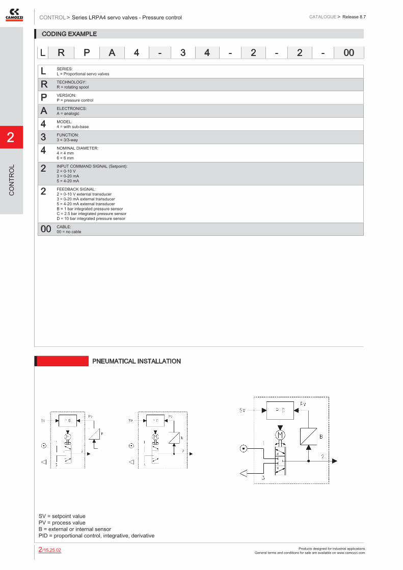
Products designed for industrial applications. General terms and conditions for sale are available on www.camozzi.com.
2
Series LRPA4 servo valves - Pressure controlCONTROL > CATALOGUE > Release 8.7
/15.25.022
CO
NTR
OL
CODING EXAMPLE
L SERIES: L = Proportional servo valves
R TECHNOLOGY: R = rotating spool
P VERSION: P = pressure control
A ELECTRONICS: A = analogic
4 MODEL: 4 = with sub-base
3 FUNCTION: 3 = 3/3-way
4 NOMINAL DIAMETER: 4 = 4 mm 6 = 6 mm
2 INPUT COMMAND SIGNAL (Setpoint): 2 = 0-10 V 3 = 0-20 mA 5 = 4-20 mA
2 FEEDBACK SIGNAL: 2 = 0-10 V external transducer 3 = 0-20 mA external transducer 5 = 4-20 mA external transducer B = 1 bar integrated pressure sensor C = 2.5 bar integrated pressure sensor D = 10 bar integrated pressure sensor
00 CABLE: 00 = no cable
L R P A 4 - 3 4 - 2 - 2 - 00
6512 PNEUMATICAL INSTALLATION
SV = setpoint value PV = process value B = external or internal sensor PID = proportional control, integrative, derivative

Products designed for industrial applications. General terms and conditions for sale are available on www.camozzi.com.
Series LRPA4 servo valves - Pressure controlCATALOGUE
2
/15.25.032
> Release 8.7 CONTROL >
CO
NTR
OL
Accessories are available in the section 2.15.35
B - Supply connector (7 poles male)PIN FUNCTION NOTES1 Power supply +24 VDC2 Power supply GND3 Input command signal
(Setpoint Value)0-10 VDC or 0-20 mA or 4-20mA. The output pressure always follows this signal that has to has to be as stable as possible. For example: if the
sensor has a range of 10 bar and the Setpoint has a Ripple error of 10 mV, this will generate a ripple of 10 mbar on the output.4 GND input command signal Pin 4 and 2 must be connected.5 Output “ERROR” see technical data6 Output “LIMIT” see technical data7 Output signal of the internal
sensor0-10 VDC. The accuracy-fault of that signal is 2% F.S. and there is an offset of approx. 150 mV.
B = male connector M16 7 poles for supply C = female connector M16 4 poles for external transducer
Female connector M16 4 poles for external transducerPIN FUNCTION NOTES1 Electrical supply to the external transducer 24 V DC2 GND Internal connection to GND power supply3 Input from the external transducer 0-10 V o 0-20 mA o 4-20 mA4 NC
LRPA4-xx-x-2/3/5-00 SERVO VALVES - PNEUMATICAL INSTALLATION
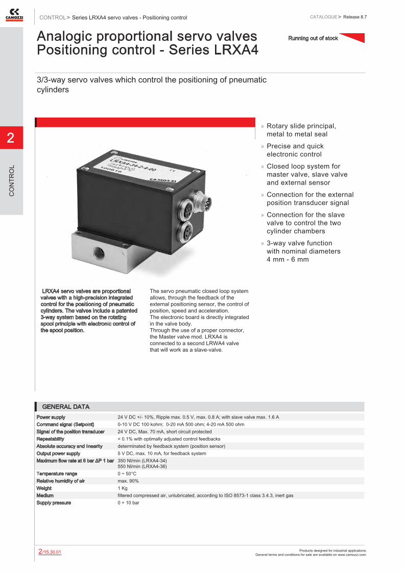
Products designed for industrial applications. General terms and conditions for sale are available on www.camozzi.com.
2
Series LRXA4 servo valves - Positioning controlCONTROL > CATALOGUE > Release 8.7
/15.30.012
CO
NTR
OL
Analogic proportional servo valves Positioning control - Series LRXA4
3/3-way servo valves which control the positioning of pneumatic cylinders
LRXA4 servo valves are proportional valves with a high-precision integrated control for the positioning of pneumatic cylinders. The valves include a patented 3-way system based on the rotating spool principle with electronic control of the spool position.
The servo pneumatic closed loop system allows, through the feedback of the external positioning sensor, the control of position, speed and acceleration. The electronic board is directly integrated in the valve body. Through the use of a proper connector, the Master valve mod. LRXA4 is connected to a second LRWA4 valve that will work as a slave-valve.
» Rotary slide principal, metal to metal seal
» Precise and quick electronic control
» Closed loop system for master valve, slave valve and external sensor
» Connection for the external position transducer signal
» Connection for the slave valve to control the two cylinder chambers
» 3-way valve function with nominal diameters 4 mm - 6 mm
GENERAL DATAPower supply 24 V DC +/- 10%, Ripple max. 0.5 V, max. 0.8 A; with slave valve max. 1.6 ACommand signal (Setpoint) 0-10 V DC 100 kohm; 0-20 mA 500 ohm; 4-20 mA 500 ohmSignal of the position transducer 24 V DC, Max. 70 mA, short circuit protectedRepeatability < 0.1% with optimally adjusted control feedbacksAbsolute accuracy and linearity determinated by feedback system (position sensor)Output power supply 5 V DC, max. 10 mA, for feedback systemMaximum flow rate at 6 bar ΔP 1 bar 350 Nl/min (LRXA4-34)
550 Nl/min (LRXA4-36)Temperature range 0 ÷ 50°CRelative humidity of air max. 90%Weight 1 KgMedium filtered compressed air, unlubricated, according to ISO 8573-1 class 3.4.3, inert gasSupply pressure 0 ÷ 10 bar
Running out of stock
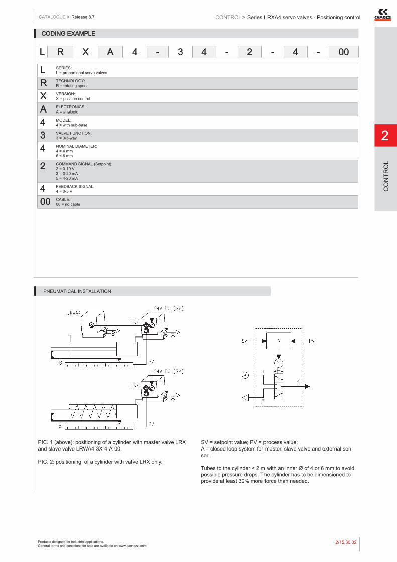
Products designed for industrial applications. General terms and conditions for sale are available on www.camozzi.com.
Series LRXA4 servo valves - Positioning controlCATALOGUE
2
/15.30.022
> Release 8.7 CONTROL >
CO
NTR
OL
CODING EXAMPLE
L SERIES: L = proportional servo valves
R TECHNOLOGY: R = rotating spool
X VERSION: X = position control
A ELECTRONICS: A = analogic
4 MODEL: 4 = with sub-base
3 VALVE FUNCTION: 3 = 3/3-way
4 NOMINAL DIAMETER: 4 = 4 mm 6 = 6 mm
2 COMMAND SIGNAL (Setpoint): 2 = 0-10 V 3 = 0-20 mA 5 = 4-20 mA
4 FEEDBACK SIGNAL: 4 = 0-5 V
00 CABLE: 00 = no cable
L R X A 4 - 3 4 - 2 - 4 - 00
PIC. 1 (above): positioning of a cylinder with master valve LRX and slave valve LRWA4-3X-4-A-00. PIC. 2: positioning of a cylinder with valve LRX only.
SV = setpoint value; PV = process value; A = closed loop system for master, slave valve and external sen-sor. Tubes to the cylinder < 2 m with an inner Ø of 4 or 6 mm to avoid possible pressure drops. The cylinder has to be dimensioned to provide at least 30% more force than needed.
PNEUMATICAL INSTALLATION
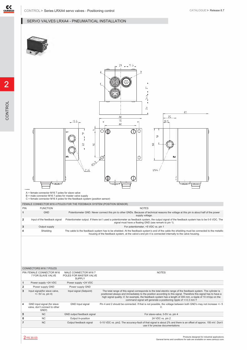
Products designed for industrial applications. General terms and conditions for sale are available on www.camozzi.com.
2
Series LRXA4 servo valves - Positioning controlCONTROL > CATALOGUE > Release 8.7
/15.30.032
CO
NTR
OL
CONNECTORS M16 7 POLESPIN FEMALE CONNECTOR M16
7 FOR SLAVE VALVEMALE CONNECTOR M16 7
POLES FOR MASTER VALVE SUPPLY
NOTES
1 Power supply +24 VDC Power supply +24 VDC2 Power supply GND Power supply GND3 Input signal(for slave valve,
+/- 5V vs. pin 4)Input signal (Setpoint) The total range of this signal corresponds to the total electric range of the feedback system. The cylinder is
positioned always and immediately to the position according to this signal. Therefore this signal has to have a high signal quality: if, for example, the feedback system has a length of 300 mm, a ripple of 10 mVpp on the
command signal will generate a positioning ripple of +/-0.3 mm !!4 GND input signal (for slave
valve, don’t connect to other GND!)
GND Input signal Pin 4 and 2 should be connected. If that is not possible, the voltage between both GND’s may not increase +/- 5 V.
5 NC GND output feedback signal For slave-valve, 0-5V vs. pin 46 NC Output In-position 24 VDC vs. pin 27 NC Output feedback signal 0-10 VDC vs. pin2. The accuracy-fault of that signal is about 2% and there is an offset of approx. 150 mV. Don’t
use it for precise documentations
A = female connector M16 7 poles for slave valve B = male connector M16 7 poles for master valve supply C = female connector M16 4 poles for the feedback system (position sensor)
FEMALE CONNECTOR M16 4 POLES FOR THE FEEDBACK SYSTEM (POSITION SENSOR)PIN FUNCTION NOTES1 GND Potentiometer GND. Never connect this pin to other GNDs. Because of technical reasons the voltage at this pin is about half of the power
supply voltage.2 Input of the feedback signal Potentiometer output. If there isn`t used a potentiometer as feedback system, the output signal of the feedback system has to be 0-5 VDC. The
signal must have a floating GND (see remark to pin 1).3 Output supply For potentiometer, +5 VDC vs. pin 14 Shielding The cable to the feedback system has to be shielded. At the feedback system’s end of the cable the shielding must be connected to the metallic
housing of the feedback system, at the valve’s end pin 4 is connected internally to the valve housing.
SERVO VALVES LRXA4 - PNEUMATICAL INSTALLATION

Products designed for industrial applications. General terms and conditions for sale are available on www.camozzi.com.
Series LR*D2 digital proportional servo valvesCATALOGUE
2
/15.32.012
> Release 8.7 CONTROL >
CO
NTR
OL
Digital proportional servo valves Flow control - Series LRWD2 Pressure control - Series LRPD23/3-way directly operated servo valves for the flow (LRWD2) and pressure control (LRPD2)
Series LRWD2 and LRPD2 digital proportional servo valves are direct driven 3/3-way valves with a patented rotating spool system with closed loop control circuit. The electronic board is integrated into the valve’s body ready to connect.
Series LR*D2 digital proportional servo valve has been designed to be as compact as possible in order to save space and to be mounted on a DIN-rail. Thanks to this new digital version, the valve can be configurated through a USB connection according to different requirements.
» Digital version which is completely configurable through USB
» Rotating spool system with a metal to metal seal
» Compact design
» High flow rate
» Electronic control to ensure high precision in the flow control
» 3-way-function with 4 - 6 mm nominal diameters
» Compact version for cabinet mounting on DIN-rail
GENERAL DATAPower supply 24 VDC +/- 10%, max absorption 1.5 ACommand signal +/- 10 V
0-10 V 0-20 mA
Hysteresis 1% FS LRWD2 - 0,2% FS LRPD2Linearity 1% FS LRWD2 - 0.3% FS LRPD2Switching time see the following pagesWorking temperature from 0 to 50° CRelative humidity of air max. 90%Direction of assembly anyMaximum flow rate at 6 bar ΔP 1 bar 450 Nl/min LRWD2 - 700 Nl/min LRPD2
690 Nl/min LRWD2 - 950 Nl/min LRPD2Medium filtered compressed air, unlubricated, according to ISO 8573-1 class 3.4.3, inert gasSupply pressure -0,9 to 10 barLeakage < 1% of maximum flow rateElectrical connection male connector M12 8 poles
New
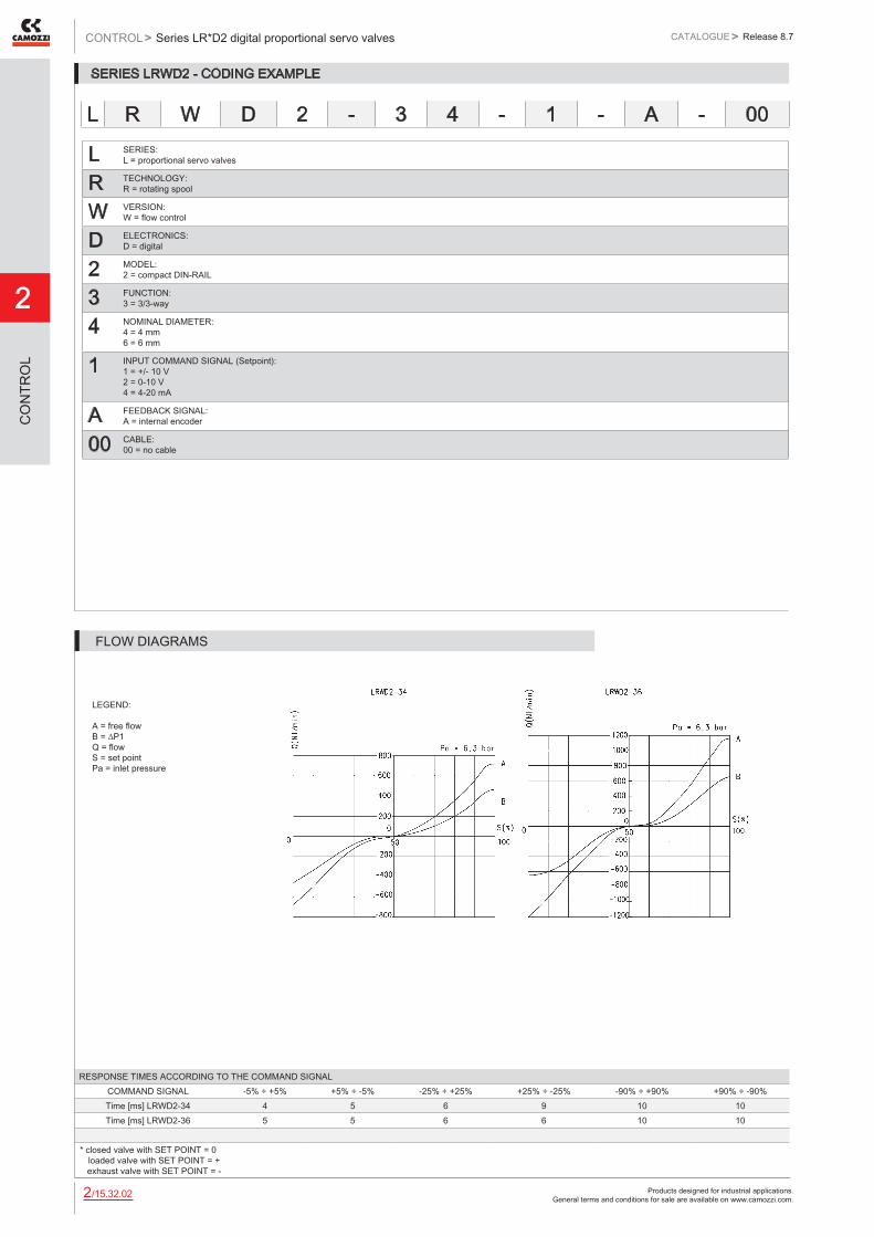
Products designed for industrial applications. General terms and conditions for sale are available on www.camozzi.com.
2
Series LR*D2 digital proportional servo valvesCONTROL > CATALOGUE > Release 8.7
/15.32.022
CO
NTR
OL
SERIES LRWD2 - CODING EXAMPLE
L SERIES: L = proportional servo valves
R TECHNOLOGY: R = rotating spool
W VERSION: W = flow control
D ELECTRONICS: D = digital
2 MODEL: 2 = compact DIN-RAIL
3 FUNCTION: 3 = 3/3-way
4 NOMINAL DIAMETER: 4 = 4 mm 6 = 6 mm
1 INPUT COMMAND SIGNAL (Setpoint): 1 = +/- 10 V 2 = 0-10 V 4 = 4-20 mA
A FEEDBACK SIGNAL: A = internal encoder
00 CABLE: 00 = no cable
L R W D 2 - 3 4 - 1 - A - 00
LEGEND: A = free flow B = ∆P1 Q = flow S = set point Pa = inlet pressure
RESPONSE TIMES ACCORDING TO THE COMMAND SIGNALCOMMAND SIGNAL -5% ÷ +5% +5% ÷ -5% -25% ÷ +25% +25% ÷ -25% -90% ÷ +90% +90% ÷ -90%Time [ms] LRWD2-34 4 5 6 9 10 10Time [ms] LRWD2-36 5 5 6 6 10 10
* closed valve with SET POINT = 0 loaded valve with SET POINT = + exhaust valve with SET POINT = -
FLOW DIAGRAMS

Products designed for industrial applications. General terms and conditions for sale are available on www.camozzi.com.
Series LR*D2 digital proportional servo valvesCATALOGUE
2
/15.32.032
> Release 8.7 CONTROL >
CO
NTR
OL
SERIES LRPD2 - CODING EXAMPLE
L SERIES: L = proportional servo valves
R TECHNOLOGY: R = rotating spool
P VERSION: P = pressure
D ELECTRONICS: D = digital
2 MODEL: 2 = compact DIN-RAIL
3 FUNCTION: 3 = 3/3-way
4 NOMINAL DIAMETER: 4 = 4 mm 6 = 6 mm
1 INPUT COMMAND SIGNAL (Setpoint): 1 = +/- 10 V 2 = 0-10 V 5 = 4-20 mA
D Sensor SIGNAL or External signal: 2 = 0..10 V 4 = 0 - 5 V 5 = 4..20 mA B = 1 bar INTERNAL D = 10 bar INTERNAL E = 250 mbar INTERNAL F = +1/-1 bar INTERNAL
00 CABLE: 00 = no cable
L R P D 2 - 3 4 - 2 - D - 00
SV = setpoint value PV = process value B = sensor PID = proportional control, integrative, derivative
SERIES LRPD2 - PNEUMATIC SCHEME FOR THE INSTALLATION

Products designed for industrial applications. General terms and conditions for sale are available on www.camozzi.com.
2
Series LR*D2 digital proportional servo valvesCONTROL > CATALOGUE > Release 8.7
/15.32.042
CO
NTR
OL
LEGEND: P = pressure F = flow Pa = inlet pressure
RESPONSE TIMES WITH COMMAND SIGNAL BETWEEN 0% AND 100%Without volume Volume 0,5 l Volume 2 l
Filling [ms] 24 313 1841Exhaust [ms] 35 663 3640
LRPD2-34 - STEP RESPONSE
LEGEND: P = pressure F = flow Pa = inlet pressure
RESPONSE TIMES WITH COMMAND SIGNAL BETWEEN 0% AND 100%Without volume Volume 0,5 l Volume 2 l
Filling [ms] 20 263 1560Exhaust [ms] 32 357 1905
LRPD2-36 - STEP RESPONSE

Products designed for industrial applications. General terms and conditions for sale are available on www.camozzi.com.
Series LR*D2 digital proportional servo valvesCATALOGUE
2
/15.32.052
> Release 8.7 CONTROL >
CO
NTR
OL
SERIES LRWD2 and LRPD2 - PNEUMATIC INSTALLATION
The servo valve works as follows: if the command signal or setpoint is lower than 50%, the valve establishes a link between connection 1 and connection 2; then the air passes between the inlet and the outlet. If the setpoint value is higher than 50%, the port 2 is connected with the exhaust 3. For a better understanding, please see the flow diagram on the previous page.
PIN SIGNAL DESCRIPTION1 +5V +5V power supply for external potentiometer transducer (ref. GND).
If used, is necessary to connect RIF- with GND.2 24 V DC 24V DC power supply (logic and motor): connect to the positive pole of the 24V DC power supply (ref. GND)3 RIF- GND reference or NEGATIVE pole of the command signal (0-10V / 4-20mA / ±10V)4 RIF+ POSITIVE reference of the command signal (0-10V / 4-20mA / ±10V)5 EXT Not used6 FBK Feedback signal 0-10V / 4-20mA (ref. GND)7 GND Common (reference pin 1 and 2): connect to the negative pole of the 24V DC power supply (compulsory)8 ERR Error signal (output) 0-24V (ref. GND)
THE LENGTH OF THE LEADS SHOULD BE AS SHORT AS POSSIBLE, BETWEEN VALVE-OUTLET AND LOAD NORMALLY NOT MORE THAN 2 mts.
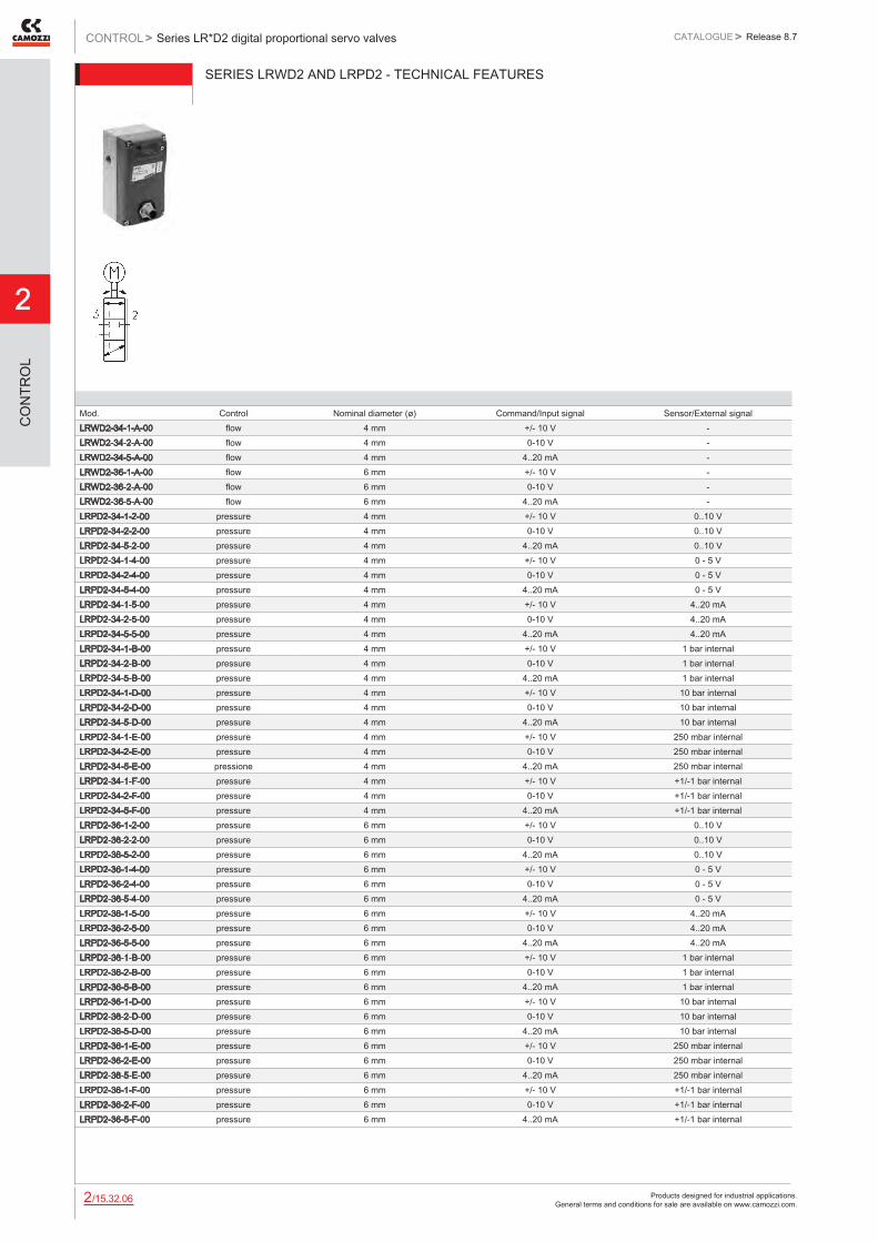
Products designed for industrial applications. General terms and conditions for sale are available on www.camozzi.com.
2
Series LR*D2 digital proportional servo valvesCONTROL > CATALOGUE > Release 8.7
/15.32.062
CO
NTR
OL
SERIES LRWD2 AND LRPD2 - TECHNICAL FEATURES
Mod. Control Nominal diameter (ø) Command/Input signal Sensor/External signalLRWD2-34-1-A-00 flow 4 mm +/- 10 V -LRWD2-34-2-A-00 flow 4 mm 0-10 V -LRWD2-34-5-A-00 flow 4 mm 4..20 mA -LRWD2-36-1-A-00 flow 6 mm +/- 10 V -LRWD2-36-2-A-00 flow 6 mm 0-10 V -LRWD2-36-5-A-00 flow 6 mm 4..20 mA -LRPD2-34-1-2-00 pressure 4 mm +/- 10 V 0..10 VLRPD2-34-2-2-00 pressure 4 mm 0-10 V 0..10 VLRPD2-34-5-2-00 pressure 4 mm 4..20 mA 0..10 VLRPD2-34-1-4-00 pressure 4 mm +/- 10 V 0 - 5 VLRPD2-34-2-4-00 pressure 4 mm 0-10 V 0 - 5 VLRPD2-34-5-4-00 pressure 4 mm 4..20 mA 0 - 5 VLRPD2-34-1-5-00 pressure 4 mm +/- 10 V 4..20 mALRPD2-34-2-5-00 pressure 4 mm 0-10 V 4..20 mALRPD2-34-5-5-00 pressure 4 mm 4..20 mA 4..20 mALRPD2-34-1-B-00 pressure 4 mm +/- 10 V 1 bar internalLRPD2-34-2-B-00 pressure 4 mm 0-10 V 1 bar internalLRPD2-34-5-B-00 pressure 4 mm 4..20 mA 1 bar internalLRPD2-34-1-D-00 pressure 4 mm +/- 10 V 10 bar internalLRPD2-34-2-D-00 pressure 4 mm 0-10 V 10 bar internalLRPD2-34-5-D-00 pressure 4 mm 4..20 mA 10 bar internalLRPD2-34-1-E-00 pressure 4 mm +/- 10 V 250 mbar internalLRPD2-34-2-E-00 pressure 4 mm 0-10 V 250 mbar internalLRPD2-34-5-E-00 pressione 4 mm 4..20 mA 250 mbar internalLRPD2-34-1-F-00 pressure 4 mm +/- 10 V +1/-1 bar internalLRPD2-34-2-F-00 pressure 4 mm 0-10 V +1/-1 bar internalLRPD2-34-5-F-00 pressure 4 mm 4..20 mA +1/-1 bar internalLRPD2-36-1-2-00 pressure 6 mm +/- 10 V 0..10 VLRPD2-36-2-2-00 pressure 6 mm 0-10 V 0..10 VLRPD2-36-5-2-00 pressure 6 mm 4..20 mA 0..10 VLRPD2-36-1-4-00 pressure 6 mm +/- 10 V 0 - 5 VLRPD2-36-2-4-00 pressure 6 mm 0-10 V 0 - 5 VLRPD2-36-5-4-00 pressure 6 mm 4..20 mA 0 - 5 VLRPD2-36-1-5-00 pressure 6 mm +/- 10 V 4..20 mALRPD2-36-2-5-00 pressure 6 mm 0-10 V 4..20 mALRPD2-36-5-5-00 pressure 6 mm 4..20 mA 4..20 mALRPD2-36-1-B-00 pressure 6 mm +/- 10 V 1 bar internalLRPD2-36-2-B-00 pressure 6 mm 0-10 V 1 bar internalLRPD2-36-5-B-00 pressure 6 mm 4..20 mA 1 bar internalLRPD2-36-1-D-00 pressure 6 mm +/- 10 V 10 bar internalLRPD2-36-2-D-00 pressure 6 mm 0-10 V 10 bar internalLRPD2-36-5-D-00 pressure 6 mm 4..20 mA 10 bar internalLRPD2-36-1-E-00 pressure 6 mm +/- 10 V 250 mbar internalLRPD2-36-2-E-00 pressure 6 mm 0-10 V 250 mbar internalLRPD2-36-5-E-00 pressure 6 mm 4..20 mA 250 mbar internalLRPD2-36-1-F-00 pressure 6 mm +/- 10 V +1/-1 bar internalLRPD2-36-2-F-00 pressure 6 mm 0-10 V +1/-1 bar internalLRPD2-36-5-F-00 pressure 6 mm 4..20 mA +1/-1 bar internal

Products designed for industrial applications. General terms and conditions for sale are available on www.camozzi.com.
Series LR*D2 digital proportional servo valvesCATALOGUE
2
/15.32.072
> Release 8.7 CONTROL >
CO
NTR
OL
Fixing footSupplied with: 2x feet 4x screws
Mod.LRADB
Mounting brackets for DIN-railDIN EN 50022 (7,5mm x 35mm - width 1) Supplied with: 2x mounting brackets 2x screws M4x6 UNI 5931 2x nuts
Mod.PCF-EN531
Electrical tee box Mod. CS-AA08EC
Connection valve-PLC-external transducer
CS-AA08EC

Products designed for industrial applications. General terms and conditions for sale are available on www.camozzi.com.
2
Series LR*D2 digital proportional servo valvesCONTROL > CATALOGUE > Release 8.7
/15.32.082
CO
NTR
OL
Straight female connector M12 8 poles
For electric supply and commands
CS-LF08HC
Cable with straight female connector M12 8 polesFor electrical supply and commands
Mod. Cable length (m)CS-LF08HB-C200 2CS-LF08HB-C500 5
Cable with angular (90°) female connector M12 8 polesFor electric supply and commands
Mod. Cable length (m)CS-LR08HB-C200 2CS-LR08HB-C500 5
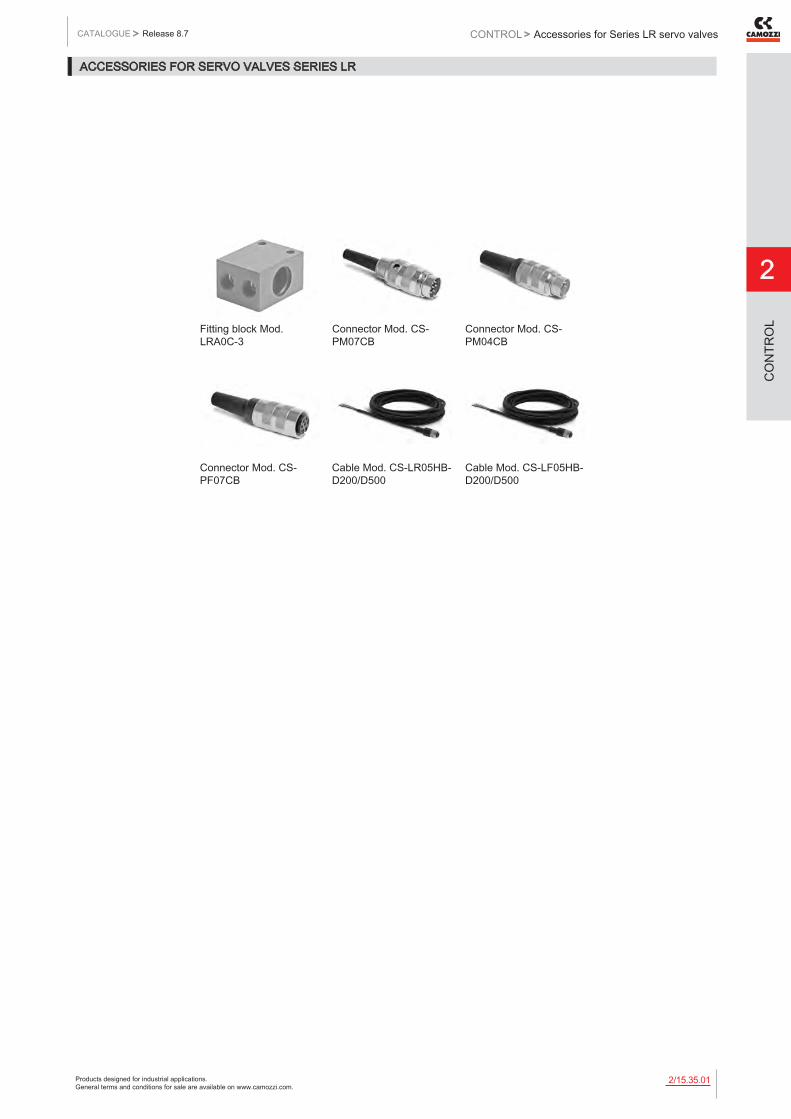
Products designed for industrial applications. General terms and conditions for sale are available on www.camozzi.com.
Accessories for Series LR servo valvesCATALOGUE
2
/15.35.012
> Release 8.7 CONTROL >
CO
NTR
OL
ACCESSORIES FOR SERVO VALVES SERIES LR
Fitting block Mod. LRA0C-3
Connector Mod. CS-PM07CB
Connector Mod. CS-PM04CB
Connector Mod. CS-PF07CB
Cable Mod. CS-LR05HB-D200/D500
Cable Mod. CS-LF05HB-D200/D500
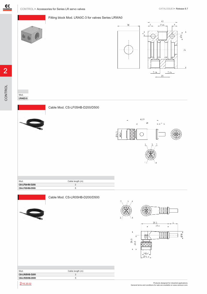
Products designed for industrial applications. General terms and conditions for sale are available on www.camozzi.com.
2
Accessories for Series LR servo valvesCONTROL > CATALOGUE > Release 8.7
/15.35.022
CO
NTR
OL
Fitting block Mod. LRA0C-3 for valves Series LRWA0
Mod.LRA0C-3
Cable Mod. CS-LF05HB-D200/D500
Mod. Cable length (m)CS-LF05HB-D200 2CS-LF05HB-D500 5
Cable Mod. CS-LR05HB-D200/D500
Mod. Cable length (m)CS-LR05HB-D200 2CS-LR05HB-D500 5

Products designed for industrial applications. General terms and conditions for sale are available on www.camozzi.com.
Accessories for Series LR servo valvesCATALOGUE
2
/15.35.032
> Release 8.7 CONTROL >
CO
NTR
OL
Male connector M16 4 pin Mod. CS-PM04CB
Mod.CS-PM04CB
Male connector M16 7 pin Mod. CS-PM07CB
Mod.CS-PM07CB
Female connector M16 7 pin Mod. CS-PF07CB
Mod.CS-PF07CB

Products designed for industrial applications. General terms and conditions for sale are available on www.camozzi.com.
2
Series K8P electronic proportional micro regulatorCONTROL > CATALOGUE > Release 8.7
/15.37.012
CO
NTR
OL
Series K8P electronic proportional micro regulator
Proportional regulator for the pressure control
Series K8P electronic proportional micro regulators have evolved from our Series K8 mini-solenoid valves. Series K8P regulators guarantee excellent pressure regulation, fast response times, self-regulation and low energy consumption. Series K8P is a high performance proportional pressure regulator which is suitable for use in all applications where high precision, quick response times and low consumption are required.
The K8P regulator adjusts the outlet pressure through the operation of two K8 monostable valves according to the inlet signal and to the retroactivity of the internal pressure sensor. A self-adjusting function has been integrated into the regulator control algorithm to guarantee the highest levels of performance apart from the volume connected.
» High precision
» Reduced response times
» Minimum consumption
» Self-regulation function
» Flexibility of use
» Compact design
GENERAL DATA
Fluids filtered compressed air, unlubricated, according to ISO 8573-1 class 3.4.3, inert gasRange of regulated pressure 0.5 ÷ 10 bar
0.15 ÷ 3 barMax inlet pressure 11 bar (0.5 ÷ 10 bar)
4 bar (0.15 ÷ 3 bar)Operating pressure 0 ÷ +50°CAnalogical input 0-10 V DC 4-20 mA Ripple ≤ 0,2%Analogical output 0.5 - 9.5 V [ Feedback ]Analog input impedance 20.000 Ω for versions 0-10 V
250 Ω for versions 4-20 mAMaximum flow Inlet P 10 bar - regulated P 6 bar 12 l/min
Inlet P 4 bar - regulated P 3 bar 6 l/minSupply / Use 24 V - ~1 WFunction 3/2 NCLinearity ≤ ± 1% FSHysteresis ±0,5% FSRepeatability ±0.5% FSMinimal set point change 50 mV => 50 mB ( 10 bar ) - 100mV => 30 mB ( 3 bar )Electrical connection M8 4 Pin ( Male )In compliance with the European Directive 2004/108/EC

Products designed for industrial applications. General terms and conditions for sale are available on www.camozzi.com.
Series K8P electronic proportional micro regulatorCATALOGUE
2
/15.37.022
> Release 8.7 CONTROL >
CO
NTR
OL
CODING EXAMPLE
K8P SERIES
0 BODY DESIGN: 0 = Stand alone S = Standard Sub-base L = Light Sub-base T = Light Sub-base for the pressure remote reading
D WORKING PRESSURE: D = 0 -10 bar E = 0 - 3 bar
5 VALVE FUNCTIONS: 5 = 2-way NC
2 COMMAND: 2 = 0-10 V DC 3 = 4-20 mA
2 OUTPUT SIGNAL: 2 = 0-10 V
0 CABLE LENGTH: 0 = without cable 2F = straight cable, 2 m 2R = right angle cable (90 degrees), 2 m 5F = straight cable, 5 m 5R = right angle cable (90 degrees), 5 m
APPLICATIONS The K8P proportional regulator can be used as a pilot valve to control the opening of high flow valves or to check the high flow pressure regulators proportionally (version with sub-base for the pressure remote reading). It enables proportional control of power in lifting systems and can be used with inert gas to maintain a constant pressure in pneumatic cylinders or expansion valve chambers. It has also been designed to maintain a constant pressure during the pulling power applied to the wires in winding machines, to modulate pressure during the smoothing process in woodworking machines or to adjust the opening of diaphragm valves.
K8P - 0 - D 5 2 2 - 0
DRAWING LEGENDNotes
1 = Supply Pneumatic connection2 = Outlet Pneumatic connection2* = area for possible positioning of outlet port 2 Do not exceed the indicated outline3 = Exhaust Pneumatic connection4 = OUTLET DIMENSION5 = VENT PORT FOR IP65 Optional when a OR seal is mounted
Interface for single use without sub-base

Products designed for industrial applications. General terms and conditions for sale are available on www.camozzi.com.
2
Series K8P electronic proportional micro regulatorCONTROL > CATALOGUE > Release 8.7
/15.37.032
CO
NTR
OL
Pr = Outlet pressure (bar)* Qn = Flow (Nl/min)* * = Inlet pressure 4 bar
Pr = Outlet pressure (bar)* Qn = Flow (Nl/min)* * = Inlet pressure 10 bar
FLOW DIAGRAMS
NOTE TO THE TABLE * according to the type of command desired, insert: 2 (0-10 V DC) or 3 (4-20 mA)
MALE CONNECTOR M8 4 POLES Pin 1: +24 V DC (Power supply) Pin 2: Command analogical signal 0-10 V DC or 4-20 mA Pin 3: 0 V (Ground) common also for the command signal Pin 4: Output analogical signal (according to the regulated pressure) 5 red LED 6 green LED
Series K8P electronic proportional micro regulator - dimensions
Mod.K8P-0-D5*2-0K8P-0-E5*2-0K8P-L-E5*2-0K8P-L-D5*2-0K8P-S-D5*2-0K8P-S-E5*2-0K8P-T-D5*2-0K8P-T-E5*2-0

Products designed for industrial applications. General terms and conditions for sale are available on www.camozzi.com.
Series K8P electronic proportional micro regulatorCATALOGUE
2
/15.37.042
> Release 8.7 CONTROL >
CO
NTR
OL
Standard Sub-baseNote: the use of a silencer on the exhaust is recommended. * * Mod. 2939 4
Mod.K8P-AS
1 = Power supply 2 = Outlet 3 = Exhaust
IP = IP65 connection
Light Sub-baseNote: the use of a silencer on the exhaust is recommended. * * Mod. 2931 M5, 2938 M5, 2901 M5
Mod.K8P-AL
1 = Power supply 2 = Outlet 3 = Exhaust
Light Sub-base for the pressure remote readingNote: the use of a silencer on the exhaust is recommended. * * Mod. 2931 M5, 2938 M5, 2901 M5 In the version Light sub-base for the pressure remote reading it is also possible to use the fixing bracket B2-E531 (see page 5/2.05.15).
Mod.K8P-AT
1 = Power supply 2 = Outlet 3 = Exhaust
S = remote-mounted sensor

Products designed for industrial applications. General terms and conditions for sale are available on www.camozzi.com.
2
Series K8P electronic proportional micro regulatorCONTROL > CATALOGUE > Release 8.7
/15.37.052
CO
NTR
OL
Mounting bracket for DIN railDIN EN 50022 (7,5mm x 35mm - width 1) Supplied with: 1x plate 1x screw M4x6 UNI 5931 Note: this accessory cannot be used with the Light sub-base version.
Mod.PCF-K8P
Bracket for horizontal mounting, for standard sub-baseSupplied with: 1x mounting bracket 2x screws M3x8 UNI 5931
Mod.K8P-B1
Circular M8 4-pole connectors, FemaleWith PU sheathing, non shielded cable. Protection class: IP65
Mod. Type of connector Cable length (m)CS-DF04EG-E200 straight 2CS-DF04EG-E500 straight 5CS-DR04EG-E200 right angle (90 degrees) 2CS-DR04EG-E500 right angle (90 degrees) 5

Products designed for industrial applications. General terms and conditions for sale are available on www.camozzi.com.
Series MX-PRO electronic proportional regulatorCATALOGUE
2
/15.45.012
> Release 8.7 CONTROL >
CO
NTR
OL
Series MX-PRO electronic proportional regulator
Ports: G1/2 Manifold ports: G1/2 Modular - Available with built-in pressure gauges or ports for gauges
Series MX-PRO electronic proportional pressure regulator is the result of combining advanced technology of Series K8P electronic proportional micro regulator, with reliability and high performance of Series MX2 modular regulators. This new regulator ensures high precision in pressure regulation, high flow rate and low consumption. Moreover, it can take the most of Series MX ease of assembly to provide particularly compact Manifolds.
» High precision
» Low electric consumption
» High exhaust flow
» Modular with Series MX2
» Available also in the MANIFOLD and external servo pilot supply versions
GENERAL DATA
Construction modular, compact, diaphragm typeMaterials see tables on the following pagesPorts G1/2Mounting vertical in-line,
wall-mounting (by means of clamps)Working temperature 0°C ÷ 50°CMax inlet pressure Regulated pressure
11 bar (10 bar), 4 bar (3 bar) 0.5 ÷ 10 bar, 0.15 ÷ 3 bar
Overpressure exhaust with relieving (standard) without relieving
Nominal flow see flow diagrams (following pages)Air specifications Filtered compressed air, non lubricated, class 3.4.3 according to ISO 8573.1 standard. If lubrication is necessary, please use only
oils with maximum viscosity of 32 Cst and the version with external servo-pilot supply. The servo-pilot supply air quality class must be 3.4.3 according to ISO 8573.1 standard.
Pressure gauge version with built-in pressure gauge (standard) version with G1/8 port
Analogical input 0-10 V DC Ripple ≤ 0.2% 4–20 mA
Analogical output 0.5-9.5 V DC [ Feedback ]Supply / Consumption 19-28 V DC - ~1 WLinearity ≤ ± 1% FSHysteresis ±0.5% FSRepeatability ±0.5% FSSensibility 0.3% FSProtection class IP51Electrical connection M8 4 Pin (Male)
New

Products designed for industrial applications. General terms and conditions for sale are available on www.camozzi.com.
2
Series MX-PRO electronic proportional regulatorCONTROL > CATALOGUE > Release 8.7
/15.45.022
CO
NTR
OL
CODING EXAMPLE
MX SERIES
2 SIZE: 2 = G1/2
1/2 PORTS: 1/2 = G1/2
R TYPE OF REGULATOR: R = pressure regulator M = Manifold pressure regulator (G1/2 only)
CV COMMAND: CV = electrical command 0-10 V DC CA = electrical command 4-20 mA EV = electrical command 0-10 V DC with external servo pilot supply EA = electrical command 4-20 mA with external servo pilot supply
2 OPERATING PRESSURE (1 bar = 14,5 psi): 1 = 0.15 ÷ 3 bar 2 = 0.5 ÷ 10 bar (standard)
0 DESIGN TYPE: 0 = relieving (standard) 1 = without relieving
4 PRESSURE GAUGE: 0 = without pressure gauge (with threaded port for gauges) 2 = with built-in pressure gauge 0-6 and working pressure 0.15 ÷ 3 bar 4 = with built-in pressure gauge 0-12 and working pressure 0.5 ÷ 10 bar (standard)
LH FLOW DIRECTION: = from left to right (standard) LH = from right to left
For the assembly of a single component with fixing flanges or wall-mounting, see the section “FRL Series MX Assembled” (pag. 3/1.50.01)
MX 2 - 1/2 - R CV 2 0 4 - LH
PARTS MATERIALS1 = Body Aluminium2 = Covering Polyacetal3 = Valve holder plug Polyacetal4 = Upper base Polyamide5 = Lower spring Zinc-plated steel6 = Diaphragm NBR Seals NBR
Series MX-PRO electronic proportional regulators - materialsR = pressure regulator M = Manifold pressure regulator

Products designed for industrial applications. General terms and conditions for sale are available on www.camozzi.com.
Series MX-PRO electronic proportional regulatorCATALOGUE
2
/15.45.032
> Release 8.7 CONTROL >
CO
NTR
OL
Series MX-PRO electronic proportional regulators
Male connector M8 4 poles Pin 1: +24 V DC (Power supply) Pin 2: Command analogical signal 0-10 V DC or 4-20 mA Pin 3: 0 V (Ground) common also for the command signal Pin 4: Output analogical signal (according to the regulated pressure) 5 red LED 6 green LED
Mod. Ports Electrical command Operating pressure (1 bar = 14,5 psi) Relieving Pressure gaugeMX2-1/2-RCV102 G1/2 0-10 V DC 0.15 ÷ 3 bar yes with built-in pressure gauge 0-6MX2-1/2-RCV112 G1/2 0-10 V DC 0.15 ÷ 3 bar no with built-in pressure gauge 0-6MX2-1/2-RCV204 G1/2 0-10 V DC 0.5 ÷ 10 bar yes with built-in pressure gauge 0-12MX2-1/2-RCV214 G1/2 0-10 V DC 0.5 ÷ 10 bar no with built-in pressure gauge 0-12MX2-1/2-RCA102 G1/2 4-20 mA 0.15 ÷ 3 bar yes with built-in pressure gauge 0-6MX2-1/2-RCA112 G1/2 4-20 mA 0.15 ÷ 3 bar no with built-in pressure gauge 0-6MX2-1/2-RCA204 G1/2 4-20 mA 0.5 ÷ 10 bar yes with built-in pressure gauge 0-12MX2-1/2-RCA214 G1/2 4-20 mA 0.5 ÷ 10 bar no with built-in pressure gauge 0-12MX2-1/2-RCV100 G1/2 0-10 V DC 0.15 ÷ 3 bar yes without pressure gaugeMX2-1/2-RCV110 G1/2 0-10 V DC 0.15 ÷ 3 bar no without pressure gaugeMX2-1/2-RCV200 G1/2 0-10 V DC 0.5 ÷ 10 bar yes without pressure gaugeMX2-1/2-RCV210 G1/2 0-10 V DC 0.5 ÷ 10 bar no without pressure gaugeMX2-1/2-RCA100 G1/2 4-20 mA 0.15 ÷ 3 bar yes without pressure gaugeMX2-1/2-RCA110 G1/2 4-20 mA 0.15 ÷ 3 bar no without pressure gaugeMX2-1/2-RCA200 G1/2 4-20 mA 0.5 ÷ 10 bar yes without pressure gaugeMX2-1/2-RCA210 G1/2 4-20 mA 0.5 ÷ 10 bar no without pressure gaugeMX2-1/2-REV100 G1/2 0-10 V DC 0.15 ÷ 3 bar yes without pressure gaugeMX2-1/2-REV102 G1/2 0-10 V DC 0.15 ÷ 3 bar yes with built-in pressure gauge 0-6MX2-1/2-REV110 G1/2 0-10 V DC 0.15 ÷ 3 bar no without pressure gaugeMX2-1/2-REV112 G1/2 0-10 V DC 0.15 ÷ 3 bar no with built-in pressure gauge 0-6MX2-1/2-REV200 G1/2 0-10 V DC 0.5 ÷ 10 bar yes without pressure gaugeMX2-1/2-REV204 G1/2 0-10 V DC 0.5 ÷ 10 bar yes with built-in pressure gauge 0-12MX2-1/2-REV210 G1/2 0-10 V DC 0.5 ÷ 10 bar no without pressure gaugeMX2-1/2-REV214 G1/2 0-10 V DC 0.5 ÷ 10 bar no with built-in pressure gauge 0-12MX2-1/2-REA100 G1/2 4-20 mA 0.15 ÷ 3 bar yes without pressure gaugeMX2-1/2-REA102 G1/2 4-20 mA 0.15 ÷ 3 bar yes with built-in pressure gauge 0-6MX2-1/2-REA110 G1/2 4-20 mA 0.15 ÷ 3 bar no without pressure gaugeMX2-1/2-REA112 G1/2 4-20 mA 0.15 ÷ 3 bar no with built-in pressure gauge 0-6MX2-1/2-REA200 G1/2 4-20 mA 0.5 ÷ 10 bar yes without pressure gaugeMX2-1/2-REA204 G1/2 4-20 mA 0.5 ÷ 10 bar yes with built-in pressure gauge 0-12MX2-1/2-REA210 G1/2 4-20 mA 0.5 ÷ 10 bar no without pressure gaugeMX2-1/2-REA214 G1/2 4-20 mA 0.5 ÷ 10 bar no with built-in pressure gauge 0-12
DRAWING NOTE ** = in the versions with external servo pilot supply only (MX2-1/2-REV... and MX2-1/2-REA...)
Accessories: see MX accessories (3/1.49) Assembled FRL: see Series MX (3/1.50) Connection cables: see Series K8P (2/15.37)

Products designed for industrial applications. General terms and conditions for sale are available on www.camozzi.com.
2
Series MX-PRO electronic proportional regulatorCONTROL > CATALOGUE > Release 8.7
/15.45.042
CO
NTR
OL
Pr = Regulated pressure Q = Flow Pa = Inlet pressure
Pr = Regulated pressure Q = Flow Pa = Inlet pressure
FLOW DIAGRAMS - STANDARD VERSION
Exhaust flow diagram Pr = Regulated pressure Q = Flow Pa = Inlet pressure
K801 = relieving, electrical command K802 = NO relieving, electrical command K803 = relieving, electrical command, built-in pressure gauge K804 = NO relieving, electrical command, built-in pressure gauge K809 = relieving, electrical command, ext. servo pilot supply K810 = NO reliev., electrical command, ext. servo pilot supply K811 = reliev., el. com., built-in pr. gauge, ext. servo pilot supply K812 = NO reliev., el. com., built-in pr. gauge, ext. servo pilot sup.
FLOW DIAGRAM AND PNEUMATIC SYMBOLS - STANDARD VERSION

Products designed for industrial applications. General terms and conditions for sale are available on www.camozzi.com.
Series MX-PRO electronic proportional regulatorCATALOGUE
2
/15.45.052
> Release 8.7 CONTROL >
CO
NTR
OL
Series MX-PRO Manifold regulators - dimensions
Male connector M8 4 poles Pin 1: +24 V DC (Power supply) Pin 2: Command analogical signal 0-10 V DC or 4-20 mA Pin 3: 0 V (Ground) common also for the command signal Pin 4: Output analogical signal (according to the regulated pressure) 5 red LED 6 green LED
Mod. Ports Electrical command Operating pressure (1 bar = 14,5 psi) Relieving Pressure gaugeMX2-1/2-MCV102 G1/2 0-10 V DC 0.15 ÷ 3 bar yes with built-in pressure gauge 0-6MX2-1/2-MCV112 G1/2 0-10 V DC 0.15 ÷ 3 bar no with built-in pressure gauge 0-6MX2-1/2-MCV204 G1/2 0-10 V DC 0.5 ÷ 10 bar yes with built-in pressure gauge 0-12MX2-1/2-MCV214 G1/2 0-10 V DC 0.5 ÷ 10 bar no with built-in pressure gauge 0-12MX2-1/2-MCA102 G1/2 4-20 mA 0.15 ÷ 3 bar yes with built-in pressure gauge 0-6MX2-1/2-MCA112 G1/2 4-20 mA 0.15 ÷ 3 bar no with built-in pressure gauge 0-6MX2-1/2-MCA204 G1/2 4-20 mA 0.5 ÷ 10 bar yes with built-in pressure gauge 0-12MX2-1/2-MCA214 G1/2 4-20 mA 0.5 ÷ 10 bar no with built-in pressure gauge 0-12MX2-1/2-MCV100 G1/2 0-10 V DC 0.15 ÷ 3 bar yes without pressure gaugeMX2-1/2-MCV110 G1/2 0-10 V DC 0.15 ÷ 3 bar no without pressure gaugeMX2-1/2-MCV200 G1/2 0-10 V DC 0.5 ÷ 10 bar yes without pressure gaugeMX2-1/2-MCV210 G1/2 0-10 V DC 0.5 ÷ 10 bar no without pressure gaugeMX2-1/2-MCA100 G1/2 4-20 mA 0.15 ÷ 3 bar yes without pressure gaugeMX2-1/2-MCA110 G1/2 4-20 mA 0.15 ÷ 3 bar no without pressure gaugeMX2-1/2-MCA200 G1/2 4-20 mA 0.5 ÷ 10 bar yes without pressure gaugeMX2-1/2-MCA210 G1/2 4-20 mA 0.5 ÷ 10 bar no without pressure gaugeMX2-1/2-MEV100 G1/2 0-10 V DC 0.15 ÷ 3 bar yes without pressure gaugeMX2-1/2-MEV102 G1/2 0-10 V DC 0.15 ÷ 3 bar yes with built-in pressure gauge 0-6MX2-1/2-MEV110 G1/2 0-10 V DC 0.15 ÷ 3 bar no without pressure gaugeMX2-1/2-MEV112 G1/2 0-10 V DC 0.15 ÷ 3 bar no with built-in pressure gauge 0-6MX2-1/2-MEV200 G1/2 0-10 V DC 0.5 ÷ 10 bar yes without pressure gaugeMX2-1/2-MEV204 G1/2 0-10 V DC 0.5 ÷ 10 bar yes with built-in pressure gauge 0-12MX2-1/2-MEV210 G1/2 0-10 V DC 0.5 ÷ 10 bar no without pressure gaugeMX2-1/2-MEV214 G1/2 0-10 V DC 0.5 ÷ 10 bar no with built-in pressure gauge 0-12MX2-1/2-MEA100 G1/2 4-20 mA 0.15 ÷ 3 bar yes without pressure gaugeMX2-1/2-MEA102 G1/2 4-20 mA 0.15 ÷ 3 bar yes with built-in pressure gauge 0-6MX2-1/2-MEA110 G1/2 4-20 mA 0.15 ÷ 3 bar no without pressure gaugeMX2-1/2-MEA112 G1/2 4-20 mA 0.15 ÷ 3 bar no with built-in pressure gauge 0-6MX2-1/2-MEA200 G1/2 4-20 mA 0.5 ÷ 10 bar yes without pressure gaugeMX2-1/2-MEA204 G1/2 4-20 mA 0.5 ÷ 10 bar yes with built-in pressure gauge 0-12MX2-1/2-MEA210 G1/2 4-20 mA 0.5 ÷ 10 bar no without pressure gaugeMX2-1/2-MEA214 G1/2 4-20 mA 0.5 ÷ 10 bar no with built-in pressure gauge 0-12
DRAWING NOTE ** = in the versions with external servo pilot supply only (MX2-1/2-REV... and MX2-1/2-REA...)
Accessories: see MX accessories (3/1.49) Assembled FRL: see Series MX (3/1.50) Connection cables: see Series K8P (2/15.37)

Products designed for industrial applications. General terms and conditions for sale are available on www.camozzi.com.
2
Series MX-PRO electronic proportional regulatorCONTROL > CATALOGUE > Release 8.7
/15.45.062
CO
NTR
OL
Pr = Regulated pressure Q = Flow Pa = Inlet pressure
FLOW DIAGRAMS - MANIFOLD VERSION
K805 = MANIFOLD reg., relieving, electrical command K806 = MANIFOLD reg., NO relieving, electrical command K807 = MANIFOLD reg., relieving, electrical command and built-in pressure gauge K808 = MANIFOLD reg., NO relieving, electrical command and built-in pressure gauge
K813 = MANIFOLD reg., relieving, electrical command, and external servo pilot supply K814 = MANIFOLD reg., NO relieving, electrical command, and external servo pilot supply K815 = MANIFOLD reg., relieving, electrical command, built-in pressure gauge and external servo pilot supply K816 = MANIFOLD reg., NO relieving, electrical command, built-in pressure gauge and external servo pilot supply
PNEUMATIC SYMBOLS - MANIFOLD VERSION

Products designed for industrial applications. General terms and conditions for sale are available on www.camozzi.com.
Series ER100 digital electro-pneumatic regulatorsCATALOGUE
2
/15.50.012
> Release 8.7 CONTROL >
CO
NTR
OL
Series ER100 digital electro-pneumatic regulators
Port G1/4
» Compact design
» Digital display
» Analog and digital input
» Programmable
» Zero/span adjustment function
» Error display function, pressure display
» Preset memory function 8-set points (3 bits).

Products designed for industrial applications. General terms and conditions for sale are available on www.camozzi.com.
2
Series ER100 digital electro-pneumatic regulatorsCONTROL > CATALOGUE > Release 8.7
/15.50.022
CO
NTR
OL
Model ER104-5 0/1/2 X Analog type
ER104-5 P X Parallel type
Fluid filtered compressed air, unlubricated, according to ISO 8573-1 class 3.4.3, inert gas
filtered compressed air, unlubricated, according to ISO 8573-1 class 3.4.3, inert gas
Max. working pressure 7 bar 7 barMin. working pressure Control pressure +
max. control pressure x 0,2Control pressure +
max. control pressure x 0,2Pressure control range 0,3 ÷ 5 bar 0,3 ÷ 5 barClass protection IP40 IP40Power supply voltage 24 V DC +/- 10%
(stabilized power supply with a ripple rate of 1% or less)
24 V DC +/- 10% (stabilized power supply
with a ripple rate of 1% or less)Consumption current 0.15 A
(or less rush current 0.6 A or less when power is turned on)
0.15 A (or less rush current 0.6 A
or less when power is turned on)Input signal (Input impendance)
0 ÷ 10 V DC (6,7 kΩ) 0 ÷ 5 V DC (10 kΩ)
4 ÷ 20 mA DC ( 250 Ω)
10 bit
Preset input 8 points N/AOutput signal Note 1
Analog output 1-5 VDC (load to be connected impedance 500 kW or more) Switch output NPN or PNP, open collector output,
30 V or less, 50 mA or less, voltage drop 2.4 or less, compatible for use with PLC or Relay
Analog output 1-5 VDC (load to be connected impedance 500 kW or more) Switch output NPN or PNP, open collector output,
30 V or less, 50 mA or less, voltage drop 2.4 or less, compatible for use for PLC or Relay
Error Output signal NPN or PNP open collector output, 30 V or less, 50 mA or less,
voltage drop 2,4 V or less, compatible for use with PLC or Relay
NPN or PNP open collector output, 30 V or less, 50 mA or less,
voltage drop 2,4 V or less, compatible for use with PLC or Relay
Direct memory setting 0,05 ÷ 5 bar minimum input width 0,01 bar
0,05 ÷ 5 bar minimum input width 0,01 bar
Hysteresis Note 2
0.5% F.S. or less 0.5% F.S. or less
Linearity Note 2
±0.3% F.S. or less ±0.3% F.S. or less
Resolution Note 2
0.2% F.S. or less 0.2% F.S. or less
Repeatability Note 2
0.3% F.S. or less 0.3% F.S. or less
Temperature characteristics: Zero point fluctation
0.15% F.S./°C or less 0.15% F.S./°C or less
Temperature characteristics: Span point fluctation
0.07% F.S./°C or less 0.07% F.S./°C or less
Max. flow rate (ANR ) Note 3
400 l/min (see diagram) 400 l/min (see diagram)
Step response time No load Note 4
0.2 sec. or less 0.2 sec. or less
Step response time 1000 cm³ load Note 4
0.8 sec. or less 0.8 sec. or less
Mechanical vibration proof 98 m/s² or less 98 m/s² or lessAmbient temperature 5°C ÷ 50 °C 5°C ÷ 50 °CFluid temperature 5°C ÷ 50 °C 5°C ÷ 50 °CConnection port size G1/4 G1/4Mounting direction Free FreeWeight 250g 250gNote 1: Select either analog or switch output.Note 2: This characteristic is guaranteed within a regulation range between 10 and 90% of the full
scale, with a power voltage of 24V±10%, a supply pressure of 1 bar higher compared with the set pressure (ex. regulation of 3 bar, supply pressure of 3+1 = 4 bar) and a volume
connected to the outlet without any loss. In applications with great air consumption, such as the blowing, the indicated tolerance may change.
Note 3: The above apply when working pressure and control pressure are maximum
Note 4: The above apply when working pressure is maximum and the step is as follows:
50% F.S. -> 100%F.S. 50% F.S. -> 60% F.S. 50% F.S. -> 40% F.S.
GENERAL DATA ER104-5xxx
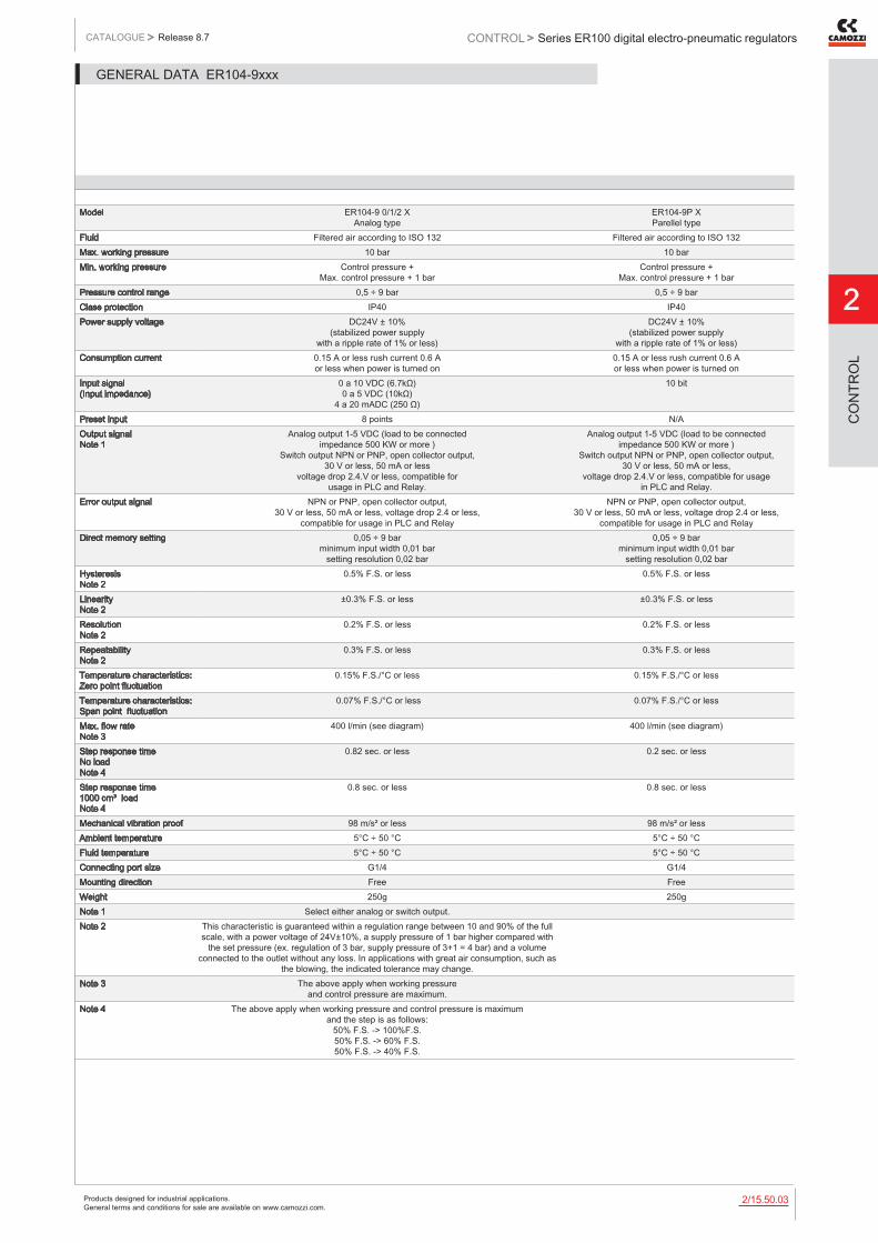
Products designed for industrial applications. General terms and conditions for sale are available on www.camozzi.com.
Series ER100 digital electro-pneumatic regulatorsCATALOGUE
2
/15.50.032
> Release 8.7 CONTROL >
CO
NTR
OL
Model ER104-9 0/1/2 X Analog type
ER104-9P X Parellel type
Fluid Filtered air according to ISO 132 Filtered air according to ISO 132Max. working pressure 10 bar 10 barMin. working pressure Control pressure +
Max. control pressure + 1 barControl pressure +
Max. control pressure + 1 barPressure control range 0,5 ÷ 9 bar 0,5 ÷ 9 barClass protection IP40 IP40Power supply voltage DC24V ± 10%
(stabilized power supply with a ripple rate of 1% or less)
DC24V ± 10% (stabilized power supply
with a ripple rate of 1% or less)Consumption current 0.15 A or less rush current 0.6 A
or less when power is turned on0.15 A or less rush current 0.6 A or less when power is turned on
Input signal (Input impedance)
0 a 10 VDC (6.7kΩ) 0 a 5 VDC (10kΩ)
4 a 20 mADC (250 Ω)
10 bit
Preset input 8 points N/AOutput signal Note 1
Analog output 1-5 VDC (load to be connected impedance 500 KW or more )
Switch output NPN or PNP, open collector output, 30 V or less, 50 mA or less
voltage drop 2.4.V or less, compatible for usage in PLC and Relay.
Analog output 1-5 VDC (load to be connected impedance 500 KW or more )
Switch output NPN or PNP, open collector output, 30 V or less, 50 mA or less,
voltage drop 2.4.V or less, compatible for usage in PLC and Relay.
Error output signal NPN or PNP, open collector output, 30 V or less, 50 mA or less, voltage drop 2.4 or less,
compatible for usage in PLC and Relay
NPN or PNP, open collector output, 30 V or less, 50 mA or less, voltage drop 2.4 or less,
compatible for usage in PLC and RelayDirect memory setting 0,05 ÷ 9 bar
minimum input width 0,01 bar setting resolution 0,02 bar
0,05 ÷ 9 bar minimum input width 0,01 bar
setting resolution 0,02 barHysteresis Note 2
0.5% F.S. or less 0.5% F.S. or less
Linearity Note 2
±0.3% F.S. or less ±0.3% F.S. or less
Resolution Note 2
0.2% F.S. or less 0.2% F.S. or less
Repeatability Note 2
0.3% F.S. or less 0.3% F.S. or less
Temperature characteristics: Zero point fluctuation
0.15% F.S./°C or less 0.15% F.S./°C or less
Temperature characteristics: Span point fluctuation
0.07% F.S./°C or less 0.07% F.S./°C or less
Max. flow rate Note 3
400 l/min (see diagram) 400 l/min (see diagram)
Step response time No load Note 4
0.82 sec. or less 0.2 sec. or less
Step response time 1000 cm³ load Note 4
0.8 sec. or less 0.8 sec. or less
Mechanical vibration proof 98 m/s² or less 98 m/s² or lessAmbient temperature 5°C ÷ 50 °C 5°C ÷ 50 °CFluid temperature 5°C ÷ 50 °C 5°C ÷ 50 °CConnecting port size G1/4 G1/4Mounting direction Free FreeWeight 250g 250gNote 1 Select either analog or switch output.Note 2 This characteristic is guaranteed within a regulation range between 10 and 90% of the full
scale, with a power voltage of 24V±10%, a supply pressure of 1 bar higher compared with the set pressure (ex. regulation of 3 bar, supply pressure of 3+1 = 4 bar) and a volume
connected to the outlet without any loss. In applications with great air consumption, such as the blowing, the indicated tolerance may change.
Note 3 The above apply when working pressure and control pressure are maximum.
Note 4 The above apply when working pressure and control pressure is maximum and the step is as follows:
50% F.S. -> 100%F.S. 50% F.S. -> 60% F.S. 50% F.S. -> 40% F.S.
GENERAL DATA ER104-9xxx

Products designed for industrial applications. General terms and conditions for sale are available on www.camozzi.com.
2
Series ER100 digital electro-pneumatic regulatorsCONTROL > CATALOGUE > Release 8.7
/15.50.042
CO
NTR
OL
STANDARD CODES
Models
ER104-50AP ER104-52AP ER104-5PSP ER104-90SP ER104-92SPER104-50SP ER104-52SP ER 104-90AP ER104-92AP ER104-9PSP
CODING EXAMPLE
ER 1 04 - 5 0 AN
ER SERIES
1 SIZE: 1 = size 1
04 PORT: 04 = G1/4
5 WORKING PRESSURE: 5 = 0 ÷ 5 bar 9 = 0.5 ÷ 9 bar
0 INPUT: 0 = 0 - 10 V DC 1 = 0 - 5 V DC 2 = 4 - 20 mA P = Parallel 10 bit
AN OUTPUT: AN = 1 - 5 V analog, error (NPN ) AP = 1 - 5 V analog, error (PNP ) SN = switch (NPN ), error (NPN ) SP = switch (PNP), error (PNP)
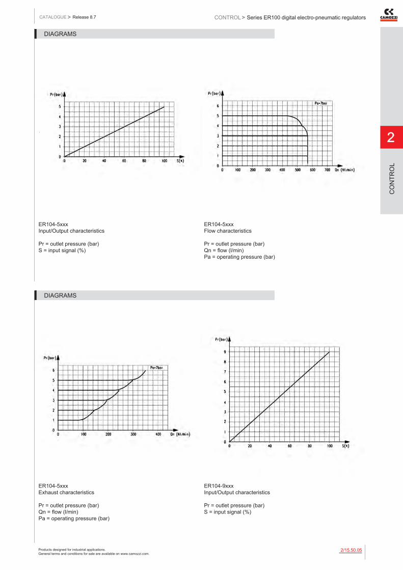
Products designed for industrial applications. General terms and conditions for sale are available on www.camozzi.com.
Series ER100 digital electro-pneumatic regulatorsCATALOGUE
2
/15.50.052
> Release 8.7 CONTROL >
CO
NTR
OL
ER104-5xxx Input/Output characteristics Pr = outlet pressure (bar) S = input signal (%)
ER104-5xxx Flow characteristics Pr = outlet pressure (bar) Qn = flow (l/min) Pa = operating pressure (bar)
DIAGRAMS
ER104-5xxx Exhaust characteristics Pr = outlet pressure (bar) Qn = flow (l/min) Pa = operating pressure (bar)
ER104-9xxx Input/Output characteristics Pr = outlet pressure (bar) S = input signal (%)
DIAGRAMS

Products designed for industrial applications. General terms and conditions for sale are available on www.camozzi.com.
2
Series ER100 digital electro-pneumatic regulatorsCONTROL > CATALOGUE > Release 8.7
/15.50.062
CO
NTR
OL
ER104-9xxx Flow characteristics Pr = outlet pressure (bar) Qn = flow (l/min) Pa = operating pressure (bar)
ER104-9xxx Exhaust characteristics Pr = outlet pressure (bar) Qn = flow (l/min) Pa = operating pressure (bar)
DIAGRAMS

Products designed for industrial applications. General terms and conditions for sale are available on www.camozzi.com.
Series ER100 digital electro-pneumatic regulatorsCATALOGUE
2
/15.50.072
> Release 8.7 CONTROL >
CO
NTR
OL
Proportional regulator Series ER100
See connectors on page 2/15.51.09
DIMENSIONSMod. A B C D E FER104 M3 depth 6 Ø5.3 EXH port D sub-connector 15 pins/plugs G1/4 4-40 UNC Ø4.2 Port R (pilot air exhaust port)

Products designed for industrial applications. General terms and conditions for sale are available on www.camozzi.com.
2
Series ER100 digital electro-pneumatic regulatorsCONTROL > CATALOGUE > Release 8.7
/15.50.082
CO
NTR
OL
Bracket ER1-B1
Floor installation type
DIMENSIONSMod.ER1-B1
Bracket ER1-B2
Wall installation type
DIMENSIONSMod.ER1-B2

Products designed for industrial applications. General terms and conditions for sale are available on www.camozzi.com.
Series ER200 digital electro-pneumatic regulatorsCATALOGUE
2
/15.51.012
> Release 8.7 CONTROL >
CO
NTR
OL
Series ER200 digital electro-pneumatic regulators
Ports G1/4 and G3/8
» Compact design
» Digital display
» Analog and digital input
» Programmable
» Zero/span adjustment function
» Error display function, pressure display
» Preset memory function 8-set points (3 bits).

Products designed for industrial applications. General terms and conditions for sale are available on www.camozzi.com.
2
Series ER200 digital electro-pneumatic regulatorsCONTROL > CATALOGUE > Release 8.7
/15.51.022
CO
NTR
OL
Model ER204-5 0/1/2 X ER238-5 0/1/2 X
Analog type
ER204-5P X ER238-5P X Parallel type
Fluid filtered compressed air, unlubricated, according to ISO 8573-1 class 3.4.3, inert gas
filtered compressed air, unlubricated, according to ISO 8573-1 class 3.4.3, inert gas
Max. working pressure 7 bar 7 barMin. working pressure Control pressure +
max. control pressure + 1 barControl pressure +
max. control pressure + 1 barPressure control range 0,3 ÷ 5 bar 0,3 ÷ 5 barClass protection IP40 IP40Power supply voltage DC24V ± 10%
(stabilized power supply with a ripple rate of 1% or less)
DC24V ± 10% (stabilized power supply
with a ripple rate of 1% or less)Consumption current 0.15 A
(rush current 0.6 A or less)0.15 A
(rush current 0.6 A or less)Input signal( Input Impedance ) 0 to 10 VDC (6.7k Ω)
0 to 5 VDC (10k Ω) 4 to 20 mADC (250 Ω)
10 bit
Preset input 8 points N/AOutput signal Note 1
Analog output 1-5 VDC ( load to be connected impedance 500 kΩ or more ) Switch output NPN or PNP, open collector output,
30 V, 50 mA, voltage drop 2.4 V, compatible for usage in PLC and Relay.
Analog output 1-5 VDC ( load to be connected impedance 500 kΩ or more ) Switch output NPN or PNP, open collector output,
30 V, 50 mA, voltage drop 2.4 V, compatible for usage in PLC and Relay.
Error output signal NPN or PNP, open collector, 30 V, 50 mA, voltage drop 2.4 V,
compatible for usage in PLC and Relay.
NPN or PNP, open collector, 30 V, 50 mA, voltage drop 2.4 V,
compatible for usage in PLC and Relay.Direct memory setting 0,05 ÷ 5 bar
minimum input width 0,01 bar0,05 ÷ 5 bar
minimum input width 0,01 barHysteresis Note 2
0.5% F.S. or less 0.5% F.S. or less
Linearity Note 2
±0.3% F.S. or less ±0.3% F.S. or less
Resolution Note 2
0.2% F.S. or less 0.2% F.S. or less
Repeatability Note 2
0.3% F.S. or less 0.3% F.S. or less
Temperature characteristics: zero point fluctuation
0.15% F.S./°C or less 0.15% F.S./°C or less
Temperature characteristics: span point fluctuation
0.07% F.S./°C or less 0.07% F.S./°C or less
Max. flow rate( ANR ) Note 3
1500 l/min 1500 l/min
Step response time: no load
0.2 sec. or less 0.2 sec. or less
Step response time: With load 1000 cm³
0.8 sec. or less 0.8 sec. or less
Mechanical vibration proof 98 m/s² or less 98 m/s² or lessAmbient temperature 5°C ÷ 50 °C 5°C ÷ 50 °CFluid temperature 5°C ÷ 50 °C 5°C ÷ 50 °CConnecting port size IN/OUT
G1/4 - G3/8 G1/4 - G3/8
Connecting port size EXHAUST
G3/8 G3/8
Mounting Free FreeWeight 450g 450gNote 1: Select either analog or switch output.Note 2: This characteristic is guaranteed within a regulation range between 10 and 90% of the full
scale, with a power voltage of 24V±10%, a supply pressure of 1 bar higher compared with the set pressure (ex. regulation of 3 bar, supply pressure of 3+1 = 4 bar) and a volume
connected to the outlet without any loss. In applications with great air consumption, such as the blowing, the indicated tolerance may change.
Note 3: The above apply when working pressure and control pressure are maximum.
Nota 4: The above apply when working pressure is maximum and the step is as follows:
50% F.S. -> 100% F.S. 50% F.S. -> 60% F.S. 50% F.S. -> 40% F.S.
GENERAL DATA ER2XX-5XXX

Products designed for industrial applications. General terms and conditions for sale are available on www.camozzi.com.
Series ER200 digital electro-pneumatic regulatorsCATALOGUE
2
/15.51.032
> Release 8.7 CONTROL >
CO
NTR
OL
Model ER204-9 0/1/2 X ER238-9 0/1/2 X
Analog type
ER238-9P X ER238-9P X Parallel type
Fluid Cleaned air Cleaned airMax. working pressure 10 bar 10 barMin. working pressure Control pressure +
max. control pressure + 1 barControl pressure +
max. control pressure + 1 barPressure control range 0,5 - 9 bar 0,5 - 9 barClass protection IP40 IP40Power supply voltage DC24V ± 10%
(stabilized power supply with a ripple rate of 1% or less)
DC24V ± 10% (stabilized power supply
with a ripple rate of 1% or less )Consumption current 0.15 A
(rush corrent 0.6 A or less)0.15 A
(rush corrent 0.6 A or less)Input signal ( Input impedance )
0 to 10 VDC (6.7kΩ) 0 to 5 VDC (10kΩ)
4 to 20 mADC (250Ω)
10 bit
Preset input 8 points N/AOutput signal Analog output 1-5 VDC
(load to be connected impedance 500 kΩ) Switch output NPN or PNP, open collector,
30 V, 50 mA, voltage drop 2.4 V, compatible for usage in PLC and Relay
Analog output 1-5 VDC (load to be connected impedance 500 kΩ) Switch output NPN or PNP, open collector,
30 V, 50 mA, voltage drop 2.4 V, compatible for usage in PLC and Relay
Error output signal NPN or PNP, open collector, 30 V, 50 mA, voltage drop 2.4 V,
compatible for usage in PLC and Relay
NPN or PNP, open collector, 30 V, 50 mA, voltage drop 2.4 V,
compatible for usage in PLC and RelayDirect memory setting 0,05 - 9 bar - min. input 0,01 bar
max. error 0,02 bar0,05 - 9 bar - min. input 0,01 bar
max. error 0,02 barHysteresis Note 2
0.5% F.S. or less 0.5% F.S. or less
Linearity Note 2
±0.3% F.S. or less ±0.3% F.S. or less
Resolution Note 2
0.2% F.S. or less 0.2% F.S. or less
Repeatability Note 2
0.3% F.S. or less 0.3% F.S. or less
Temperature characteristics: Zero point fluctuation
0.15% F.S./°C or less 0.15% F.S./°C or less
Temperature characteristics: Span point fluctuation
0.07% F.S./°C or less 0.07% F.S./°C or less
Max. flow rate(ANR) Note 3
1500 l/min 1500 l/min
Step response time No load
0.2 sec. or less 0.2 sec. or less
Step response time Load 1000 cm³
0.8 sec. or less 0.8 sec. or less
Mechanical vibration proof 98 m/s² 98 m/s²Ambient temperature 5 to 50 °C 5 to 50 °CFluid temperature 5 to 50 °C 5 to 50 °CConnecting port size IN/OUT
G1/4 - G3/8 G1/4 - G3/8
Connecting port size EXHAUST
G3/8 G3/8
Mounting Free FreeWeight 450g 450gNote 1: Select either analog or switch outputNote 2: This characteristic is guaranteed within a regulation range between 10 and 90% of the full scale, with
a power voltage of 24V±10%, a supply pressure of 1 bar higher compared with the set pressure (ex. regulation of 3 bar, supply pressure of 3+1 = 4 bar) and a volume connected to the outlet without any loss.
In applications with great air consumption, such as the blowing, the indicated tolerance may change.Note 3: The above apply when working pressure
and control pressure are maximum.Note 4: The above apply when working pressure is maximum
and the step is as follows: 50% F.S. -> 100% F.S. 50% F.S. -> 60% F.S. 50% F.S. -> 40% F.S.
GENERAL DATA ER2XX-9XXX

Products designed for industrial applications. General terms and conditions for sale are available on www.camozzi.com.
2
Series ER200 digital electro-pneumatic regulatorsCONTROL > CATALOGUE > Release 8.7
/15.51.042
CO
NTR
OL
STANDARD CODES
Models
ER238-50AP ER238-52AP ER238-5PSP ER238-90SP ER238-92SPER238-50SP ER238-52SP ER238-90AP ER238-92AP ER238-9PSP
CODING EXAMPLE
ER 2 04 - 5 0 AN
ER SERIES
2 SIZE: 2 = size 2
04 PORT: 04 = G1/4 38 = G3/8
5 WORKING PRESSURE: 5 = 0 ÷ 5 bar 9 = 0.5 ÷ 9 bar
0 INPUT: 0 = 0 - 10 V DC 1 = 0 - 5 V DC 2 = 4 - 20 mA P = Parallel 10 bit
AN OUTPUT: AN = 1 - 5 V analog error (NPN) AP = 1 - 5 V analog, error (PNP) SN = switch(NPN), error(NPN) SP = switch (PNP), error (PNP)

Products designed for industrial applications. General terms and conditions for sale are available on www.camozzi.com.
Series ER200 digital electro-pneumatic regulatorsCATALOGUE
2
/15.51.052
> Release 8.7 CONTROL >
CO
NTR
OL
ER2xx-5xxx Input/Output characteristics Pr = outlet pressure (bar) S = input signal (%)
ER204-5xxx Flow characteristics Pr = outlet pressure (bar) Qn = flow (l/min) Pa = working pressure (bar)
DIAGRAMS
ER238-5xxx Flow characteristics Pr = outlet pressure (bar) Qn = flow (l/min) Pa = working pressure (bar)
ER2xx-5xxx Exhaust characteristics Pr = outlet pressure (bar) Qn = flow (l/min) Pa = working pressure (bar)
DIAGRAMS
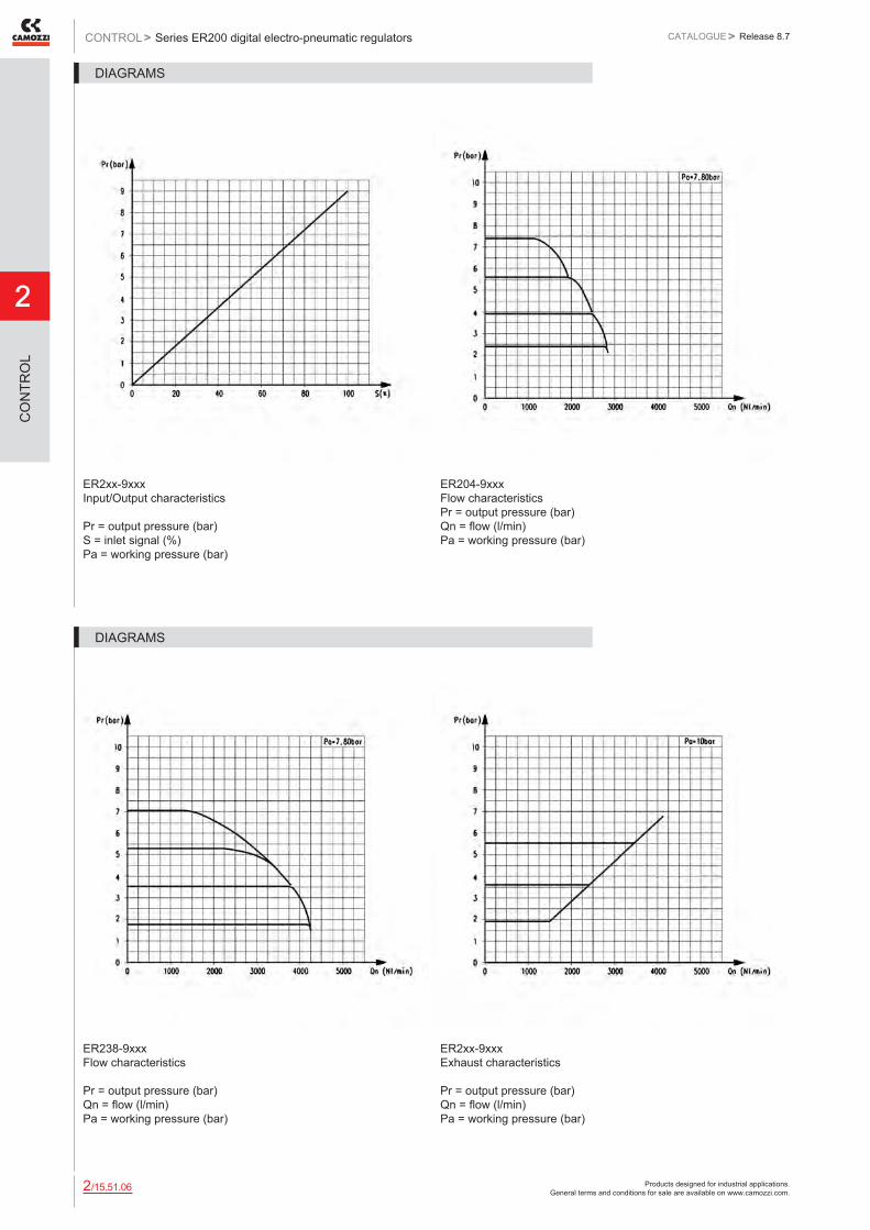
Products designed for industrial applications. General terms and conditions for sale are available on www.camozzi.com.
2
Series ER200 digital electro-pneumatic regulatorsCONTROL > CATALOGUE > Release 8.7
/15.51.062
CO
NTR
OL
ER2xx-9xxx Input/Output characteristics Pr = output pressure (bar) S = inlet signal (%) Pa = working pressure (bar)
ER204-9xxx Flow characteristics Pr = output pressure (bar) Qn = flow (l/min) Pa = working pressure (bar)
DIAGRAMS
ER238-9xxx Flow characteristics Pr = output pressure (bar) Qn = flow (l/min) Pa = working pressure (bar)
ER2xx-9xxx Exhaust characteristics Pr = output pressure (bar) Qn = flow (l/min) Pa = working pressure (bar)
DIAGRAMS

Products designed for industrial applications. General terms and conditions for sale are available on www.camozzi.com.
Series ER200 digital electro-pneumatic regulatorsCATALOGUE
2
/15.51.072
> Release 8.7 CONTROL >
CO
NTR
OL
Proportional regulators Series ER200
DIMENSIONSMod. A B C D E FER204 M4 depth 12 D sub-connector 15 pins/plugs G1/4 4-40 UNC Ø4.2 Port R (pilot air exhaust port) G3/8 EXH portER238 M4 depth 12 D sub-connector 15 pins/plugs G3/8 4-40 UNC Ø4.2 Port R (pilot air exhaust port) G3/8 EXH port

Products designed for industrial applications. General terms and conditions for sale are available on www.camozzi.com.
2
Series ER200 digital electro-pneumatic regulatorsCONTROL > CATALOGUE > Release 8.7
/15.51.082
CO
NTR
OL
Bracket ER2-B1
Floor installation type mounting
Mod.ER2-B1
Bracket ER2-B2
Wall installation type mounting
Mod.ER2-B2

Products designed for industrial applications. General terms and conditions for sale are available on www.camozzi.com.
Series ER200 digital electro-pneumatic regulatorsCATALOGUE
2
/15.51.092
> Release 8.7 CONTROL >
CO
NTR
OL
Cable and connector for regulator with analog Input
To check the correspondence between pin and cables’ colour, please refer to the instruction sheet included in the packaging or to the user manual.
Mod.G8X1-1G8X1-3
1 = shield wire* 2 = 9-AWG26 * Connect the shield wire to the power’s minus (0 V) side.
Cable and connector for regulator with parallel Input
To check the correspondence between pin and cables’ colour, please refer to the instruction sheet included in the packaging or to the user manual.
Mod.G8X2-1G8X2-3
1 = shield wire* 2 = 9-AWG26 * Connect the shield wire to the power’s minus (0 V) side.
Related Documents