TRANSPORTATION RES EARCH RECORD 1255 23 Control of Wheel Squeal Noise in Rail Transit Cars M. A. STAIANO AND G. SASTRY Because of community annoyance near a Washington, D.C., Metro rail transit car maintenance yard, a comprehensive noise measure- ment and analysis program was implemented for the Washington Metropolitan Area Transit Authority (WMAT A) to examine the wheel squeal generated as transit cars traveled around small- radius curves. Sound levels were measured near the track as well as at locations in the neighborhood near the subject maintenance yard. Comparative.measurements were also performed in tVl'.o other nearly identical yards. In the absence of wheel squeal, tram movements were almost undetectable outside the yard; hence, squeal elimination would satisfy community and all?w removal of an operations curfew. Water lubncat10n of the rails, found to be effective in eliminating squeal, was considered impractical for winter operations. Rail facing (a proprietary rail- head treatment) was selected by WMATA as an experimental squeal control. Testing of the rail facing within 1 week of instal- lation yielded a 23-dBA sound level reduction and the complete elimination of squeal. However, after about 3 months' service, a 14-dBA reduction with some squeal was observed; and after 6 months' service chronic squeal reappeared. This loss of effec- tiveness was ascribed to rapid contact point wear of the facing treatment. Wheel squeal is a tonal noise heard when railcars travel around curves of small radii. Washington Metro transit car move- ments in a maintenance yard produced wheel squeal and aroused complaints from neighbors. In response, the Washington Met- ropolitan Area Transit Authority (WMAT A) implemented a number of noise abatement measures, including the instal- lation of a prototype water rail lubrication system. Rail lubri- cation by water, although effective in eliminating squeal, pre- sented significant operational problems. The other actions reduced wheel squeal sound levels, but-because of its dis- tinctive character-squeal was still perceptible and ne ighbors remained dissatisfied. To ensure that no viable option was overlooked , a com- prehensive measurement and analysis program was developed and implemented . Sound levels were measured in the subject maintenance yard and in two nearly identical yards under controlled conditions at locations near the track. At the sub- ject yard , sound levels were also measured at locations in the community outsid e of the yard. Squeal at nighttime, with low ba ckground noise, was clearly audible. The squeal frequency spectra from the three maintenance yards appeared to exhibit characteristic differences. The overall A-weighted sound lev- els from the yards showed more variation than explainable by train speed and railcar/track geometry influences-· pos- sibly a result of restraining rail conditions. In the absence of M. A. Staiano, Staiano Engineering, Inc., 1 923 Stanley Ave., Rock- vill e, Md . 20851 -2225. G. Sas try, Deleuw , Cather & Ce ., 600 5th St., N. W., Washington, D .C. 20001. squeal, train movements were almost undetectable outside the yard. Thus, squeal elimination would probably provide community satisfaction and permit removal of an operations curfew. Therefore , noise controls that essentially eliminated squeal were sought. Rail facing, the application of a proprietary alloy filler to a specially ground groove in the rail head, was selected by WMATA for prototype testing. The prototype rail-facing treatment was completed in January 1989. Within a week of the installation, sound level measurements showed a 23-dBA sound level reduction and the complete elimination of squeal. However, measurements after about 3 months' service showed only a 14-dBA sound level reduction and occasional squeal, and after 6 months' service, chronic squeal had reappeared . SQUEAL GENERATION Railcars are supported on each end and guided through curves by a swiveling truck consisting of two pairs of wheels with parallel axle s. Because the axles are held rigidly by the truck frame , they cannot take up radial positions as the car traverses a curve. Consequently, the wheels must slide sideways across the rail top as well as roll along its length. The later al sliding of the wheel over the rail head creates rubbing forces on the wheel, which, if conditions are suitable, will cause its vibration to grow until a stable amplitude is reached (1). The wheel vibration is radiated as squeal noise characterized by one or more intense, high-pitched tones at the natural vibration fre- quencies of the wheel. The vibration excitatior; by the rail and the smmd radiation by the wheel is analogous to a bow exciting a violin string. The sliding of the wheel over the rail head is described by lateral creep, c = v/ V, where v is the lateral velocity of the wheel at the wheel-rail interface and Vis the rolling velocity of the wheel. Lateral creep is determined to the first order by the geometry of the truck and curve, as shown in Fig- ure 1. The average creep, c. , is proportional to WIR, where Wis the truck wheelbase and R is the curve radius. The intense squeal sound levels are an outgrowth of the high vibration levels induced by negative damping. The mag- nitude of the damping is proportional to the slope of the friction-creep curve shown in Figure 2. Th e slope of the fric- tion-creep curve (hence the negative damping) has three sig- nificant ranges of behavior: •No squeal-ca is less than c 0 (the lateral creep corre- sponding to μ. 0 , the maximum occurring coefficient of friction),

Welcome message from author
This document is posted to help you gain knowledge. Please leave a comment to let me know what you think about it! Share it to your friends and learn new things together.
Transcript
TRANSPORTATION RESEARCH RECORD 1255 23
Control of Wheel Squeal Noise in Rail Transit Cars
M. A. STAIANO AND G. SASTRY
Because of community annoyance near a Washington, D.C., Metro rail transit car maintenance yard, a comprehensive noise measurement and analysis program was implemented for the Washington Metropolitan Area Transit Authority (WMAT A) to examine the wheel squeal generated as transit cars traveled around smallradius curves. Sound levels were measured near the track as well as at locations in the neighborhood near the subject maintenance yard. Comparative.measurements were also performed in tVl'.o other nearly identical yards. In the absence of wheel squeal, tram movements were almost undetectable outside the yard; hence, squeal elimination would satisfy community c~mp~aints and all?w removal of an operations curfew. Water lubncat10n of the rails, found to be effective in eliminating squeal, was considered impractical for winter operations . Rail facing (a proprietary railhead treatment) was selected by WMATA as an experimental squeal control. Testing of the rail facing within 1 week of installation yielded a 23-dBA sound level reduction and the complete elimination of squeal. However, after about 3 months' service, a 14-dBA reduction with some squeal was observed ; and after 6 months' service chronic squeal reappeared . This loss of effectiveness was ascribed to rapid contact point wear of the facing treatment.
Wheel squeal is a tonal noise heard when railcars travel around curves of small radii. Washington Metro transit car movements in a maintenance yard produced wheel squeal and aroused complaints from neighbors. In response, the Washington Metropolitan Area Transit Authority (WMAT A) implemented a number of noise abatement measures, including the installation of a prototype water rail lubrication system. Rail lubrication by water, although effective in eliminating squeal , presented significant operational problems. The other actions reduced wheel squeal sound levels, but-because of its distinctive character-squeal was still perceptible and ~ome neighbors remained dissatisfied.
To ensure that no viable option was overlooked , a comprehensive measurement and analysis program was developed and implemented. Sound levels were measured in the subject maintenance yard and in two nearly identical yards under controlled conditions at locations near the track . At the subject yard , sound levels were also measured at locations in the community outside of the yard . Squeal at nighttime, with low background noise, was clearly audible. The squeal frequency spectra from the three maintenance yards appeared to exhibit characteristic differences . The overall A-weighted sound levels from the yards showed more variation than explainable by train speed and railcar/track geometry influences-· possibly a result of restraining rail conditions. In the absence of
M. A. Staiano, Staiano Engineering, Inc., 1923 Stanley Ave ., Rockville, Md. 20851-2225. G. Sastry , Deleuw , Cather & Ce., 600 5th St ., N. W., Washington, D .C. 20001.
squeal, train movements were almost undetectable outside the yard. Thus, squeal elimination would probably provide community satisfaction and permit removal of an operations curfew. Therefore , noise controls that essentially eliminated squeal were sought.
Rail facing, the application of a proprietary alloy filler to a specially ground groove in the rail head , was selected by WMATA for prototype testing. The prototype rail-facing treatment was completed in January 1989. Within a week of the installation, sound level measurements showed a 23-dBA sound level reduction and the complete elimination of squeal. However, measurements after about 3 months' service showed only a 14-dBA sound level reduction and occasional squeal, and after 6 months' service , chronic squeal had reappeared .
SQUEAL GENERATION
Railcars are supported on each end and guided through curves by a swiveling truck consisting of two pairs of wheels with parallel axles. Because the axles are held rigidly by the truck frame , they cannot take up radial positions as the car traverses a curve. Consequently, the wheels must slide sideways across the rail top as well as roll along its length. The lateral sliding of the wheel over the rail head creates rubbing forces on the wheel, which , if conditions are suitable , will cause its vibration to grow until a stable amplitude is reached (1). The wheel vibration is radiated as squeal noise characterized by one or more intense, high-pitched tones at the natural vibration frequencies of the wheel. The vibration excitatior; by the rail and the smmd radiation by the wheel is analogous to a bow exciting a violin string.
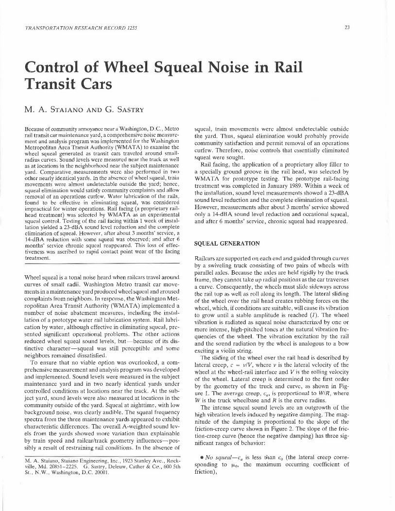
The sliding of the wheel over the rail head is described by lateral creep, c = v/V, where v is the lateral velocity of the wheel at the wheel-rail interface and Vis the rolling velocity of the wheel. Lateral creep is determined to the first order by the geometry of the truck and curve, as shown in Figure 1. The average creep, c. , is proportional to WIR, where Wis the truck wheelbase and R is the curve radius .
The intense squeal sound levels are an outgrowth of the high vibration levels induced by negative damping. The magnitude of the damping is proportional to the slope of the friction-creep curve shown in Figure 2. The slope of the friction-creep curve (hence the negative damping) has three significant ranges of behavior:
•No squeal-ca is less than c0 (the lateral creep corresponding to µ.0 , the maximum occurring coefficient of friction),
24 TRANSPORTATION RESEARCH RECORD 1255
ROLLING VELOCITY
-w
w 6-R R
FIGURE 1 Wheel squeal excitation geometry (2).
1.0
0 ~ ~
~ j::: S:? cc ~
~ 0.5 0 .... z ~ S:? ~ ~ w 8
0 ca co
FIGURE 2 Friction-creep curve (2).
• Intermediate squeal-c. is greater than c0 but Jess than 3c0 , and
• Severe squeal-c0 is greater than 3c0 •
For the intermediate squeal condition, the generated squeal sound power can be shown to be proportional to
u = V2 c~ {(8/3)[(c. - c0)/(3c0 - c.)]}
LATERAL CREEP, c
Thus, the squeal noise magnitude is a function of V, W, and R-because c. = WIR.
Approximate values for c. and c0 are (I, 2)
c. = 0.7WIR
Co= 0.007
Staiano and Sastry
Consequently, the boundaries for the squeal regimes are about WIR > 0.01 for intermediate squeal and WIR > 0.03 for severe squeal. For the geometries occurring in the WMAT A railcars and maintenance yards (0.02 < WIR < 0.03), the intermediate squeal condition is predicted .
These relationships suggest that severe squeal will occur with WMAT A railcars for curve radii less than 240 ft and that the minimum radius for no squeal will be greater than 755 ft. In actual practice, increasing curve radius initially causes a transition of squeal behavior from continuous to intermittent, with considerably larger radii necessary to ensure that even intermittent squeal will not occur (2). For WMATA railcars ,
Flange Contact
25
preventing intermittent squeal would require a curve radius of 1 mi or greater.
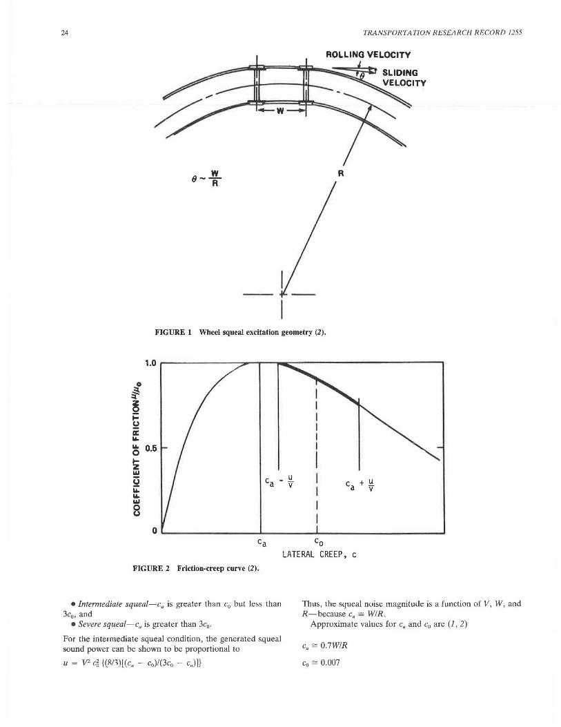
The preceding analy i i predicated on a wheel-rail sliding motion that con i ts of the wheel tread moving laterally aero s the rail head. Other rubbing mcchani m are possible: the wheel flange against the side of the running rail head, and for curves fitted with a restraining rail, the flange against the restraining rail-as shown in Figure 3 (J) . (A restraining rail is an auxiliary rail located adjacent to the inner rail. It relieves the leading outside wheel flange of lateral curving forces and transfers them to the back of the inner leading wheel flange, reducing wear and a tendency to derail.) The squeal contri-
Flange Contact
~on
LOW-SPEED FLANGE CONTACT--NO RESTRAINING RAIL
Wheel Flange -----_)
Flange Contact
Outer Running Rail
Restraining Rail
Inner Running Rail
Outer Running Rail
Restraining Rail
Inner -------- Running Rail
Section A-A (with wheels)
FLANGE CONTACT--WITH RESTRAINING RAIL FIGURE 3 Flange rubbing locations (3 J.
26
butions of the various rubbing surfaces have been determined in experiments involving lubrication of the surfaces to temporarily reduce the friction forces. These experiments have shown that flange rubbing alone is not a sufficient mechanism for squeal (1), and that "in all tests where lubrication occurred on the top of the rail, squeal was reduced or eliminated" (4). Although the restraining rail introduces an additional surface for flange contact, it does reduce some contact forces , and some data suggest that the restraining rail actually reduces wheel squeal (4) .
WMATA SQUEAL NOISE
Train operation sound levels were measured at locations around and inside the subject facility , the West Falls Church maintenance yard, and also at locations inside the two other similar yards, the Alexandria and Shady Grove maintenance yards. The purpose of these measurements was to define the community squeal exposure with controlled train operations and to compare squeal generation at West Falls Church with other similar facilities.
Community Noise Exposures
Two locations were selected as representative for the measurement of the squeal noise exposure in the community. Both locations were approximately 400 ft from the track-one each near the east and west loops of the yard . To avoid background noise interference (due to vehicles and insects), measurements were performed after midnight and after the onset of
-m "IJ .._,
0 z ~
50
40
30
TRANSPORTA TION RESEARCH RECORD 1255
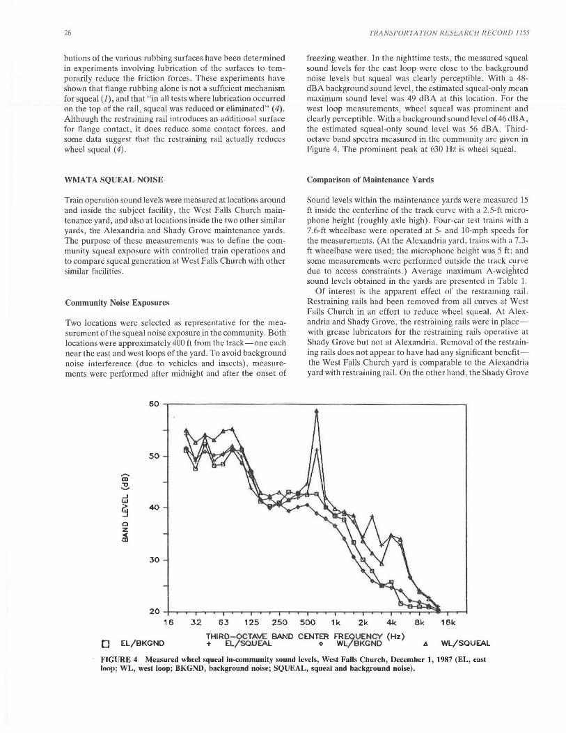
freezing weather. In the nighttime tests, the measured squeal sound levels for the east loop were close to the background noise levels but squeal was clearly perceptible. With a 48-dBA background sound level, the estimated squeal-only mean maximum sound level was 49 dBA at this location . For the west loop measurements, wheel squeal was prominent and clearly perceptible. With a background sound level of 46 dBA, the estimated squeal-only sound level was 56 dBA . Thirdoctave band spectra measured in the community are given in Figure 4. The prominent peak at 630 Hz is wheel squeal.
Comparison of Maintenance Yards
Sound levels within the maintenance yards were measured 15 ft inside the centerline of the track curve with a 2.5-ft microphone height (roughly axle high). Four-car test trains with a 7.6-ft wheelbase were operated at 5- and 10-mph speeds for the measurements. (At the Alexandria yard, trains with a 7.3-ft wheelbase were used; the microphone height was 5 ft; and some measurements were performed outside the track curve due to access constraints.) Average maximum A-weighted sound levels obtained in the yards are presented in Table 1.
Of interest is the apparent effect of the restraming rail. Restraining rails had been removed from all curves at West Falls Church in an effort to reduce wheel squeal. At Alexandria and Shady Grove, the restraining rails were in placewith grease lubricators for the restraining rails operative at Shady Grove but not at Alexandria . Removal of the restraining rails does not appear to have had any significant benefitthe West Falls Church yard is comparable to the Alexandria yard with restraining rail. On the other hand, the Shady Grove
20.i....,,.............-r--........,......,._,r---r--r--........... --r--r--r--.---r--r--.--,.......,..--.--,.......,..~~~~Lr--.--I 16 32 63 125 250 500 1k 2k Bk 16k
D EL/BKGNO THlRD- QCTAVE BAND CENTER FR EQUENCY (Hz) + EL/SOlJfAL o WL/BKGND t. WL/SOUfAL
FIGURE 4 Measured wheel squeal in-community sound levels, West Falls Church, December 1, 1987 (EL, east loop; WL, west loop; BKGND, background noise; SQUEAL, squeal and background noise).
S1aiano and Saslry
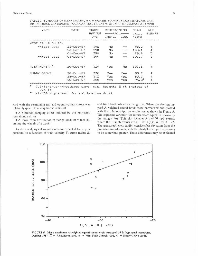
TABLE 1 SUMMARY OF MEAN MAXIMUM A-WEIGHTED SOUND LEVELS MEASURED 15 FT INSIDE TRACK CENTERLINE (FOUR-CAR TEST TRAINS WITH 7.6-FT WHEELBASE AT 5 MPH) :======~:=====~======~=====~==~======================~===========
YAFm DATE NUM. TRACK RADIUS
(ft)
F<ESTRA IN I NG ---·--RAIL---I NSTL. LUB.
MEAN LAma ~·: <dBA>
EVENTS
WEST FALLS CHURCH --East Loop 23·-0c t -··87 305 No 95.2 4
23-0ct-87 290 No 1 (1(1. 1 4 01-Dec-87 290 No 98.8 5
--West Loop 01-Dec-87 300 No 103.7 6
ALEXANDRIA * 20·-0ct-87 320 Yes No 101.6 4
SHADY GROVE 28-0ct-87 330 Yes Yes 85.9 4 28-Dct-87 315 Yes Yes 85.3 4 28-Dct-87 300 Yes Yes 95.0+ 4
=====-============================================================ * +
7.3-ft - truck-wheelbase cars; mic. height: 5 ft instead of 2.5 ft
+1-dBA adjustment for calibration drift
27
yard with the restraining rail and operative lubricators was relatively quiet. This may be the result of
• A vibration-damping effect induced by the lubricated restraining rail, or
• A more even distribution of flange loads or wheel slip among the wheels of a truck.
As discussed, squeal sound levels are expected to be proportional to a function of train velocity V, curve radius R,
and train truck wheelbase length W. When the daytime inyard A-weighted sound levels were normalized and plotted with this relationship, the results are as shown in Figure 5. The expected variation for intermediate squeal is shown by the straight line. This plot includes 5- and 10-mph events, where the 10-mph events are at - 26 < f(V, W, R) < - 22. The measured levels exhibit considerable deviation from the predicted sound levels, with the Shady Grove yard appearing to be somewhat quieter. These differences may be explained
,,-....
~ 100 "U ......, _J
~ ~ 0
90 z ::::> 0 (/)
:ii; ::::> ~
~ 80 ::i:
70 -+---,..-~~~~~----.-..----.-~....--....-....--....--..----...-....... --,.--....... __, ...... ...,....--1
-4-0 -30 -20
f [ V • W • R ] (dB)
FIGURE 5 Mean maximum A-weighted squeal sound levels measured 15 ft from track centerline, October 1987 (0 = Alexandria yard, + = West Falls Church yard, 0 = Shady Grove yard).
28
by the varying restraining rail conditions summarized in Table 1.
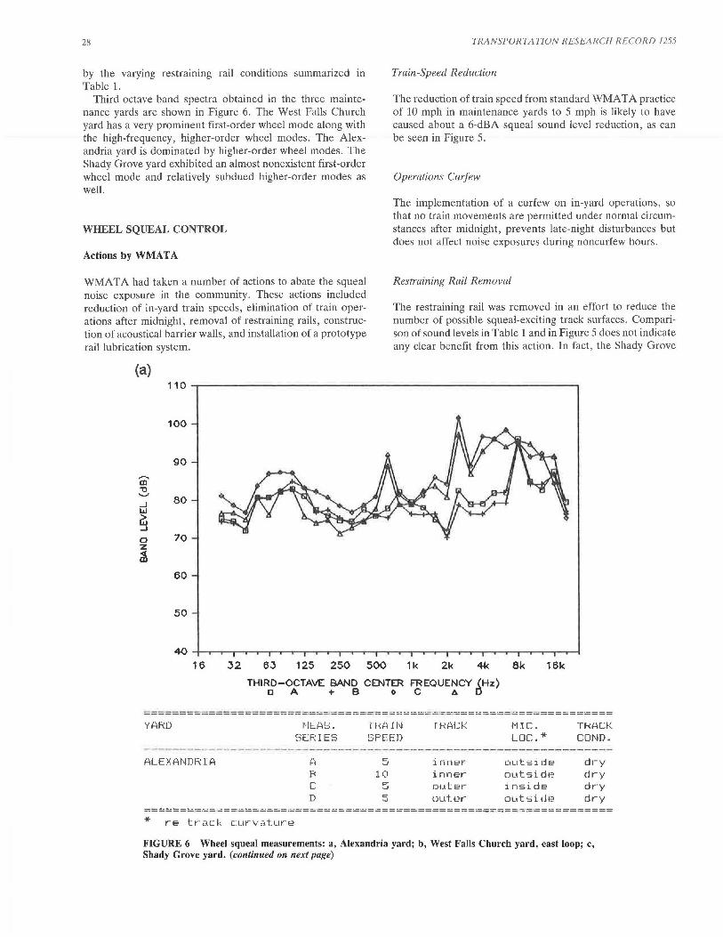
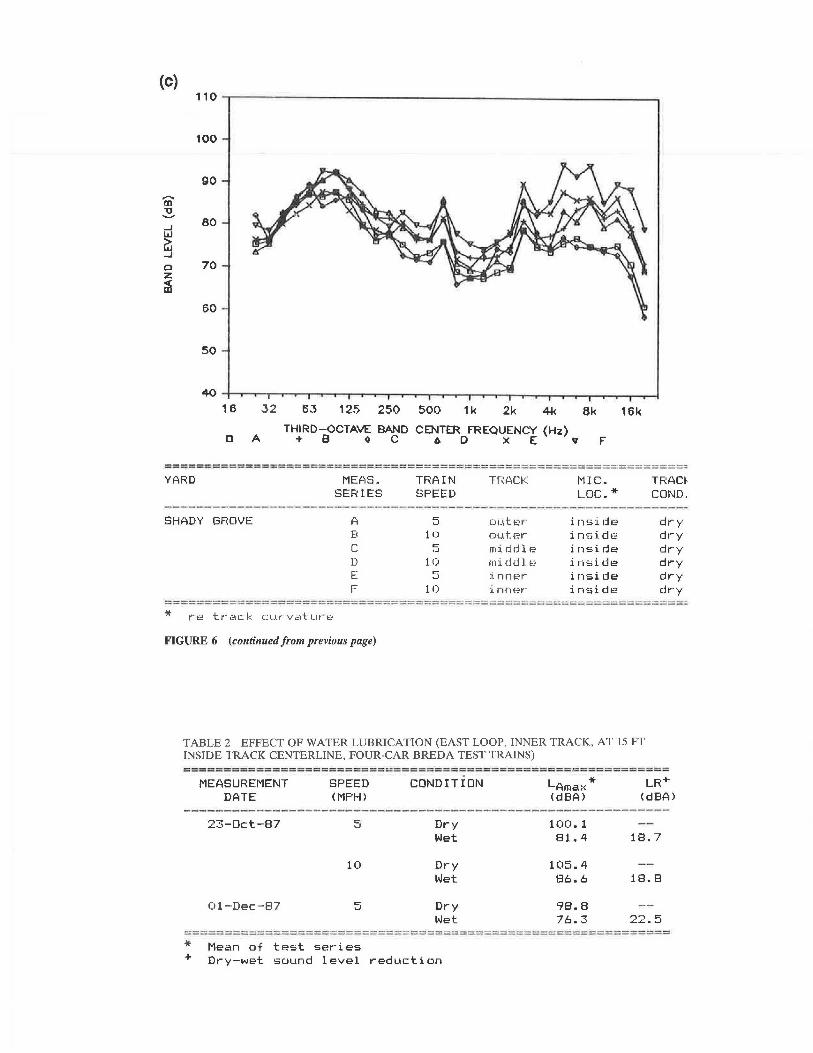
Third octave-band spectra obtained in the three maintenance yards are shown in Figure 6. The West Falls Church yard has a very prominent first-order wheel mode along with the high-frequency, higher-order wheel modes. The Alexandria yard is dominated by higher-order wheel modes. The Shady Grove yard exhibited an almost nonexistent first-order wheel mode and relatively subdued higher-order modes as well.
WHEEL SQUEAL CONTROL
Actions by WMAT A
WMAT A had taken a number of actions to abate the squeal noise exposure in the community. These actions included reduction of in-yard train speeds, elimination of train operations after midnight, removal of restraining rails, construction of acoustical barrier walls, and installation of a prototype rail lubrication system.
(a)
100
90
-m "U ........ _J 80 w
~ 0 70 z ~
60
50
TRANSPORTATION RESEARCH RECORD 1255
Train-Speed Reduction
The reduction of train speed from standard WMA TA practice of 10 mph in maintenance yards to 5 mph is likely to have caused about a 6-dBA squeal sound level reduction, as can be seen in Figure 5.
Operations Curfew
The implementation of a curfew on in-yard operations, so that no train movements are permitted under normal circumstances after midnight, prevents late-night disturbances but does not affect noise exposures during noncurfew hours.
Restraining Rail Removal
The restraining rail was removed in an effort to reduce the number of possible squeal-exciting track surfaces. Comparison of sound levels in Table 1 and in Figure 5 does not indicate any clear benefit from this action. In fact, the Shady Grove
40 -+-~~~~~~~~~~~~~~~~~~~~~~~~~~~~~~~~
16 32 63 125 250 500 1k 2k 8k 16k
THIRD-OCTAVE BAND CENTER FREQUENCY (Hz) DA+ Bo C 6 [}
========================~===========~===~=====~====~==~==========
YARD l"IE?lS. SERIES
ALEXANDRIA r. B c D
TJ:~AIN
SPEED
5 10
co .J
5
TRACf:::
inner· inner 01.1ter 0L1t:.er·
MIC. LDC.*
outside outside inside outside
TRACK COND.
dry dry dry dry
==========~=====~===~======~=~===================================
* re track curvature
FIGURE 6 Wheel squeal measurements: a, Alexandria yard; b, West Falls Church yard, east loop; c, Shady Grove yard. (continued on next page)
Staiano and Sastry
(b)
.....I I.LI
~ 0 z ~
29
100
90
80
70
60
50
16 32 63 125 250 500 1k 2k Bk 16k
a A THIRD-OCTAVE BAND CENTER FREQUENCY (Hz)
+ B ~CAD x Ev F
YARD MEAS. SERIES
WEST Ft'1LLS CHL.JF(CH A D c D [
F
TF~A IN SPEED
cc ·-'
1 (I 5
10 5
1 (I
1RACI<
c;uter--outer inner i r1nt:;;r-i nner :i nnt;?r-
MIC. LDC.*
inside inside inside inside inside inside
TRACI< CDND.
dry dry dry dry ~~•?t
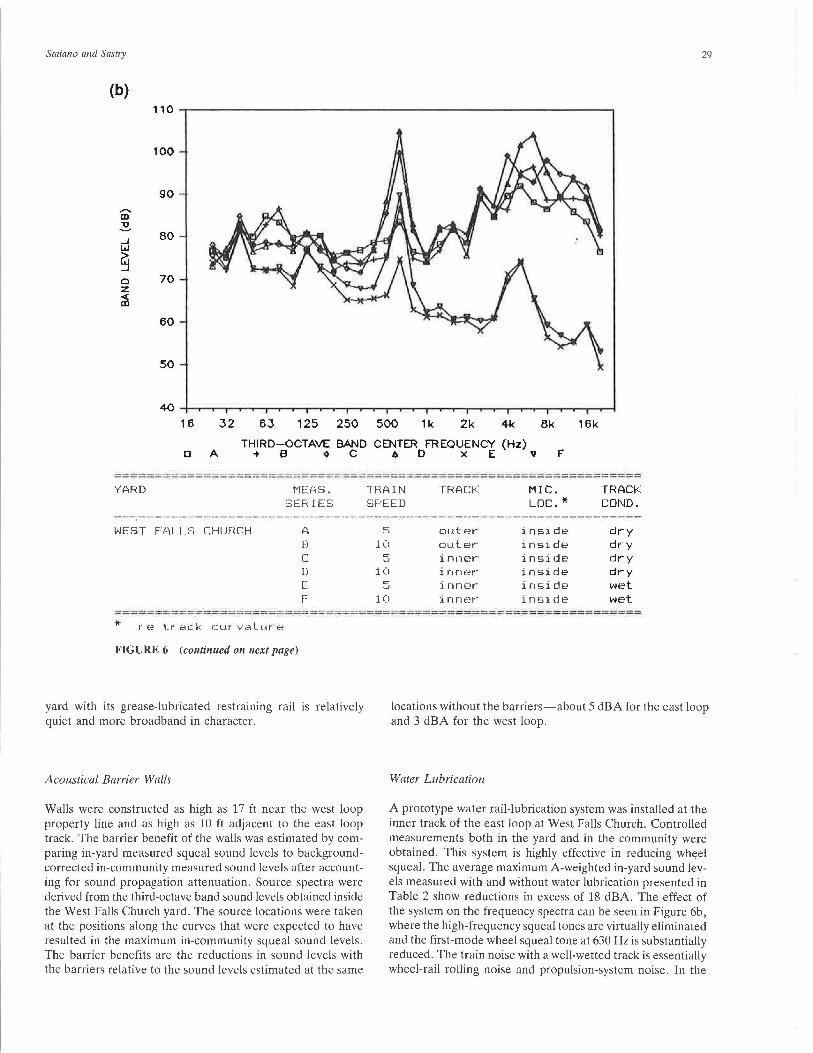
wet =====-=-====-===::::=-----=====-===== =-===============-=-==-==-==========-=·==== * FIGURE 6 (continued on next page)
yard with its grease-lubricated restrammg rail is relatively quiet and more broadband in character.
Acoustical Barrier Walls
Walls were constructed as high as 17 ft near the west loop property line and as high as 10 ft adjacent to the east loop track. The barrier benefit of the walls was estimated by comparing in-yard measured squeal sound levels to backgroundcorrected in-community measured sound levels after accounting for sound propagation attenuation. Source spectra were derived from the third-octave band sound levels obtained inside the West Falls Church yard. The source locations were taken at the positions along the curves that were expected to have resulted in the maximum in-community squeal sound levels. The barrier benefits are the reductions in sound levels with the barriers relative to the sound levels estimated at the same
locations without the barriers-about 5 dBA for the east loop and 3 dBA for the west loop.
Water Lubrication
A prototype water rail-lubrication system was installed at the inner track of the east loop at West Falls Church. Controlled measurements both in the yard and in the community were obtained. This system is highly effective in reducing wh~el squeal. The average maximum A-weighted in-yard sound levels measured with and without water lubrication presented in Table 2 show reductions in excess of 18 dBA. The effect of the system on the frequency spectra can be seen in Figure 6b, where the high-frequency squeal tones are virtually eliminated and the first-mode wheel squeal tone at 630 Hz is substantially reduced. The train noise with a well-wetted track is essentially wheel-rail rolling noise and propulsion-system noise. In the
(c)
-m "O -....;
..J w
~ 0 z ~
16 32
a A
63 125 250 500 1k 2k 4k 8k 16k
THIRD-OCTAVE BAND CENTER FREQUENCY {Hz) -t B ~ C 6. D x E v F
=========;:..:====~=======~====~============~================~======
YARD MEf.,S. TRAIN SPEED
TRACf< MIC. LDC.*
TRACf COND. SERIES
SHADY GFIOVE A 5 rn.1 ti;.;'r i nsi d1::; dry B 10 0L1t.er inside dry c <=" middle inside dr·y • .J
D 10 middl ~? inside dry E 5 inner· inside dry F 10 inner· inside cfr'y
====--"-=-==-=====-===-===-==-===-==============================·============ * r-[~ tr·ack cu1~vdt:.Llr " [·?
FIGURE 6 (continued from previous page)
TABLE 2 EFFECT OF WATER LUBRICATION (EAST LOOP, INNER TRACK, AT 15 FT INSIDE TRACK CENTERLINE, FOUR-CAR BREDA TEST TRAINS)
~=~===~==~====~=~========~=======~~==========~==~===========
MEASUREMENT DATE
23-0ct-87
01-Dec-87
SPEED (MPH>
5
10
5
CONDITION
Dry Wet
Dry Wet
Dry Wet
LAma:·: * !dBA>
100.1 Bl. 4
105.4 86.6
98.8 76.3
LR+ <dBA>
18.7
18.8
22.5 ========~===~===========~====~~======~======~=============~=
* + Mean of test series Dry-wet soL1nd level redL1ction
Staiano and Sastry
community, train operations with the track wet were virtually imperceptible.
Options for Effective Squeal Control
A number of the actions taken by WMATA achieved reductions in squeal sound levels. However, because of the distinctive character of the squeal signal, squeal is clearly perceptible in the community and quite pervasive during lowbackground-noise conditions. Even noticeable reductions of the squeal levels are unlikely to achieve community satisfaction if the squeal remains perceptible. Consequently, effective controls must essentially eliminate the generation of squeal. Water lubrication, as has already been demonstrated, is an example of such a control. Potentially effective squeal controls include rail lubrication, wheel or rail damping, rail facing, and track (tunnel) enclosures.
Wheel Damping
Wheel squeal increases in magnitude until the negative damping of the excitation is counterbalanced by the positive internal damping of the system. A number of approaches have been taken to increase wheel damping in practice. The simplest and most successful approach is the use of ring dampers. Ringdamped wheels have metal rings that are snapped into a semicylindrical groove cut into the inner diameter of the wheel rim. The rings are usually steel and are sprung into the groove such that the ring is free to vibrate ( 4). Damping is apparently provided by the frictional forces arising from the relative movement of the damping ring and the wheel. Ring dampers are used operationally by Chicago, Lindenwold (PATCO), New York City, and the Port Authority of New York and New Jersey (PATH) and are generally considered quite effective in reducing wheel squeal. Wayside sound level reductions due to ring dampers in curved track, reported by a number of different transit properties, have ranged up to 32 dBA (4).
Rail Damping
Another means for adding damping to the wheel-rail system is to increase the internal damping of the rail. However, the vibration magnitude of the rail is generally much less than that of the wheel. Thus, the effectiveness of rail damping is limited. Damping materials have been placed either on the bottom or sides of rails with "erratic and unpredictable" squeal reductions ( 4). Research indicates that damping of the rail is beneficial only if the rail vibration levels are sufficiently large, that is, greater than about 3 g (5).
Bolt-on tuned-damper assemblies can be secured to rails if diagnostic tests indicate high rail-vibration levels and if damper effectiveness is verified by prototype tests.
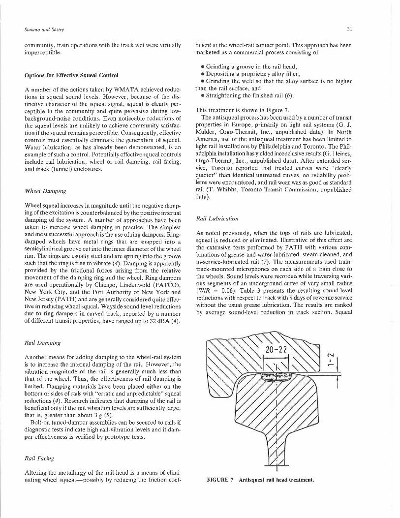
Rail Facing
Altering the metallurgy of the rail head is a means of eliminating wheel squeal-possibly by reducing the friction coef-
31
ficient at the wheel-rail contact point. This approach has been marketed as a commercial process consisting of
• Grinding a groove in the rail head, • Depositing a proprietary alloy filler, • Grinding the weld so that the alloy surface is no higher
than the rail surface, and • Straightening the finished rail ( 6).
This treatment is shown in Figure 7. The antisqueal process has been used by a number of transit
properties in Europe, primarily on light rail systems (G. J. Mulder, Orgo-Thermit, Inc., unpublished data). In North America, use of the antisqueal treatment has been limited to light rail installations by Philadelphia and Toronto. The Philadelphia installation has yielded inconclusive results ( G. Heines, Orgo-Thermit, Inc., unpublished data). After extended service, Toronto reported that treated curves were "clearly quieter" than identical untreated curves, no reliability problems were encountered, and rail wear was as good as standard rail (T. Whibbs, Toronto Transit Commission, unpublished data).
Rail Lubrication
As noted previously, when the tops of rails are lubricated, squeal is reduced or eliminated. Illustrative of this effect are the extensive tests performed by PATH with various combinations of grease-and-water-lubricated, steam-cleaned, and in-service-lubricated rail (7). The measurements used traintruck-mounted microphones on each side of a train close to the wheels. Sound levels were recorded while traversing various segments of an underground curve of very small radius (WIR = 0.06). Table 3 presents the resulting sound-level reductions with respect to track with 8 days of revenue service without the usual grease lubrication. The results are ranked by average sound-level reduction in track section. Squeal
N
FIGURE 7 Antisqueal rail head treatment.
32 TRANSPOR TATION RESEARCH RECORD 1255
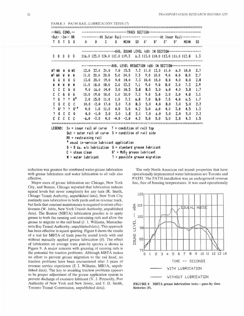
TABLE 3 PATH RAIL LUBRICATION TESTS (7) --------------------------------------------------------------------------------------____________________________ .. ________________________________________________________ _ --RAIL COND.-- ---------------------------TRACK SECTION--------------------------------Out- -In-- RR -----------At Outer Rail----------- -----------At Inner Rail-----------T S T S S A B C D "EAN SD A' B' C' D' "EAN SD
D D D D D --------------------AVB. SOUND LEVEL !dBi IN SECTION-------------------1 lb. O 125.0 124.0 112.0 119.3 b.3 113.0 114.0 113.0 111.0 112.B 1.3
--------------------------------------------------------------------- -----------------------------------AVB. LEVEL REDUCTION !dBl IN SECTION-----------------
W? W6 w W WG 12.0 22.0 21.0 7.0 15.5 7.2 11. 0 12.0 11. 0 b.O 10.0 2.7 W? WB w w w 11. 0 20.0 20.0 5.0 14.0 7.3 9.0 10.0 9.0 4.0 e.o 2.7 6 6 6 6 6 13.0 20.0 19.0 4.0 14.0 7.3 10.0 10.0 8.0 4.0 8.0 2.8 w w w II w 11. 0 rn .o 18.0 3.0 12.5 7. 1 9.0 9.0 e.o 3.0 7.3 2.9 c c c 6 6 9.0 lb.O 14.0 3.0 10.5 5.8 e.o 5.0 6.0 4.0 5.8 1. 7 c c 6 6 6 10.0 19.0 10.0 1.0 10.0 7.3 9.0 5.0 2.0 3.0 4.8 3.1 ? 6 ? ? s• 2.0 15.0 11.0 1.0 7.3 b.B 7.0 8.0 7.0 4.0 6.5 I. 7 c 6 c c c 10.0 -2.0 17.0 3.0 7.0 B.3 5.0 4.0 8.0 3.0 5.0 2.2 ? 6' ? ? s·• 4.0 1.0 11. 0 4.0 5.0 4.2 5.0 6.0 4.0 3.0 4.5 1.3 ? 6 c c 6 4.0 -1.0 2.0 2.0 I. 8 2.1 7.0 6.0 5.0 2.0 5.0 2.2 c c c c c -6.0 -2.0 4.0 -4.0 -2.0 4.3 5.0 5.0 5.0 2.0 4.3 1. 5 ===================================================~=~~===~===============================
LESE ND: In = inner rail of c:urve T = c:ondition of rail top Out = outer rail of curve S =condition of rail side RR = restraining rail t usual in-service lubricant application D = 8 da. w/o lubrication 6 = standard grease lubricant C = stean clean 6' = "0S2 grease lubricant N = 11•hr lubr icant ? = poss ible grease 1igration
reduction was greatest for combined water-grease lubrication with grease lubrication and water lubrication to all rails also effective.
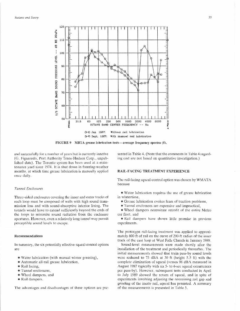
Major users of grease lubrication are Chicago , New York City, and Boston. Chicago reported that lubrication reduces squeal levels but never completely for any turn (R. Smith, Chicago Transit Authority, unpublished data). New York City routinely uses lubrication in both yards and on revenue track, but finds that constant maintenance is required to retain effectiveness (W. Jehle, New York Transit Authority, unpublished data). The Boston (MBTA) lubrication practice is to apply grease to both the running and restraining rails and allow the grease to migrate to the rail head (J . I. Williams, Massachusetts Bay Transit Authority, unpublished data). This approach has been effective in squeal quieting. Figure 8 shows the results of a test for MBTA of train pass-by sound levels with and without manually applied grease lubrication (8). The effect of lubrication on average train pass-by spectra is showu in Figure 9. A major concern with greasing of running rails is the potential for traction problems. Although MBTA makes no effort to prevent grease migration to the rail head , no traction problems have been encountered after 3 years of revenue service experience (J. I. Williams, MBTA, unpublished data). The key to avoiding traction problems appears to be proper adjustment of the grease application system to prevent discharge of excessive lubricant (V. J. Petrucelly, Port Authority of New York and New Jersey, and T. D . Smith, Toronto Transit Commission, unpublished data) .
The only North American rail transit properties that have operationally implemented water lubrication are Toronto and PATH. The PA TH installation was an underground revenue line, free of freezing temperatures . It was used operationally
_I w
120
100
~ 90 _I
p
s 80 0 (;?
70
I\. /s :JU! AL N[ ISi
/""'" _)
~ - \l / ~~ '--
I '-V "-..
~ \ I v ' ~
~\ 0 2 3 4 5 6 7 8 9 10 11 12 13 14
TIME SECONDS
\JITH LUBRICA TIDN
\JITHDUT LUBRICA TIDN
FIGURE 8 MBTA grease lubrication tests-pass-by time histories (8).
Staiano and Sastry 33
IZO
" "" " 0 N
:;! 110
ID .., 100
..J lol > ~ lol 90 Cl: :::> If)
~ Cl: D.
n 00 :z: ::::> 0 If)
c ~ ID
~ e 0 <')
~
31.5 63 125 250 500 1000 2000 1000 eooo ... "' OCTAVE BAND CENTER FREQUENCY -- Hz ~ I ..
G-£) Jan. 1987: Wilhoul r11ll lubricat:on
G-£1 Sepl. 1987: Wilh manual rail lubrication
FIGURE 9 MBTA grease lubrication tests-average frequency spectra (8).
and successfully for a number of years but is currently inactive (G. Figueredo, Port Authority Trans-Hudson Corp., unpublished data). The Toronto system has been used at a maintenance yard since 1974. It is shut down in freezing-weather months, at which time grease lubrication is manually applied once daily.
Tunnel Enclosures
Three-sided enclosures covering the inner and outer tracks of each loop must be composed of walls with high sound transmission loss and with sound-absorptive interior lining. The tunnels would have to extend sufficiently beyond the ends of the loops to minimize sound radiation from the enclosure apertures. However, even a relatively long tunnel may permit perceptible sound levels to escape.
Recommendations
In summary, the six potentially effective squeal-control options are
•Water lubrication (with manual winter greasing), • Automatic all-rail grease lubrication, •Rail facing, • Tunnel enclosures, • Wheel dampers, and •Rail dampers.
The advantages and disadvantages of these options are pre-
sented in Table 4. (Note that the comments in Table 4 regarding cost are not based on quantitative investigation.)
RAIL-FACING TREATMENT EXPERIENCE
The rail-facing squeal-control option was chosen by WMATA because
•Water lubrication requires the use of grease lubrication in wintertime,
• Grease lubrication evokes fears of traction problems, • Tunnel enclosures are expensive and impractical, • Wheel dampers necessitate retrofit of the entire Metro
car fleet, and • Rail dampers have shown little promise in previous
experiments.
The prototype rail-facing treatment was applied to approximately 800 ft of rail on the curve of 290-ft radius of the inner track of the east loop at West Falls Church in January 1989.
Sound-level measurements were made shortly after the installation of the treatment and periodically thereafter. The initial measurements showed that train pass-by sound !evils were reduced to 75 dBA at 30 ft (height 5.5 ft) with the complete elimination of squeal (versus 98 dBA measured in August 1987 typically with six 5- to 6-sec squeal occurrences per pass-by). However, subsequent tests conducted in April to July 1989 showed the return of squeal, and in spite of experiments involving adjusting the restraining rail gap and grinding of the inside rail, squeal has persisted. A summary of the measurements is presented in Table 5.
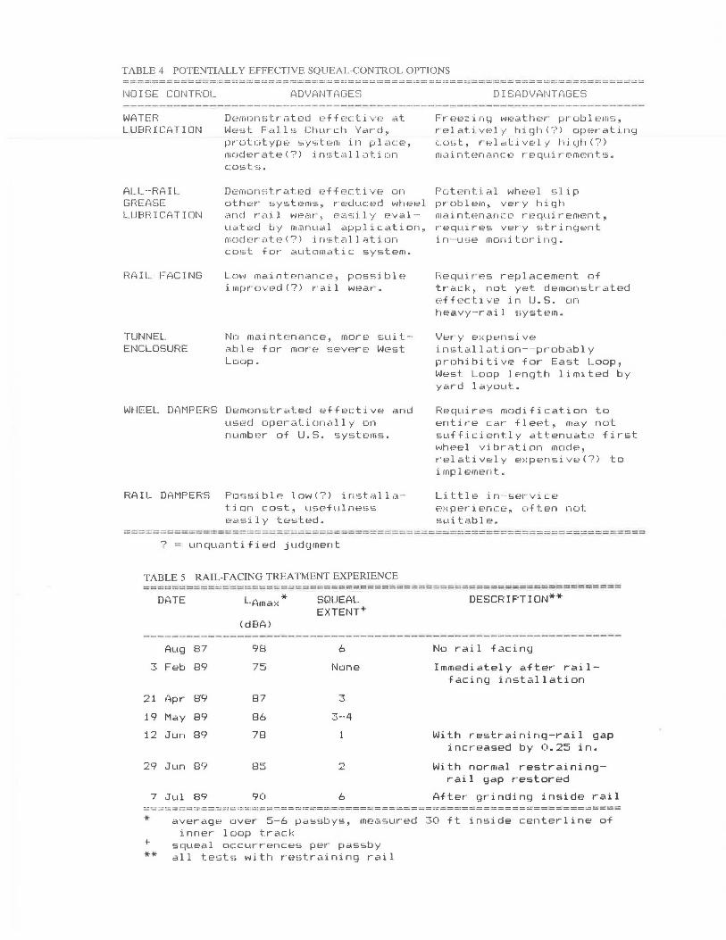
TABLE 4 POTENTIALLY EFFECTIVE SQUEAL-CONTROL OPTIONS ==~=======~==~=~~==~===========================··============:~~======~==
l'~O I SE CONTROL
WATER LUBRICATION
ALL--RAIL GFIEASE LUBr~: I C?l TI DN
RAIL. FACING
TUNNEL ENCLOSUFIE
Derncw1sl:r-ated pffc.,cl:i V f? at W0:st Fal 1 ~; Ctnir-ch Yc.<1·-cJ, pn::;totyJHo' sy~;tern in plac::E., moderate(?) installation c:osts.
Demo1 ·,,;; tr<.itf.?d e ·f f e c::t.i VE~ on othE;r· sy,;b?ms, r-- E·duc:F.:;d wheel <:ffH:1 rail wear, e<•<;;;i.ly f.?.val-u~1tt:; d by manual ;,:;1pplication, mode r ate(?) installation cost for automatic system.
Low maintenance, possible i mpr· clVc?d (?) r· a i l wear· .
Ne maintenance, more suit-· able for more severe West Loop.
WHEEL DAMPERS Demonstrated effective and used operationally on number of U.S. systems.
RAIL DAMPERS Possible low!?) installation cost, usefuln~=~•s
Pc>.sily tested.
? = unquantified judi;:1ment
TABLE 5 RAIL-FACING TREATMENT EXPERIENCE
DISADVANTAGES
Freezing weather problems, relat:. :ivE·ly hiqhC?> OfH=r-ati. ng co,;t, rE·l2..t.~ive.ly hi.qh(?) fiidi nten,-;,ncE• r· eql1i r· E·ment.s.
Potent i al wheel s lip problem, very high maintenance requirement, requires very strinqent i n ·- use moni tcw i 1-.<.~.
Requi r es replacement of track, not yet demonstrated effective in lJ.S. on heavy-rai 1 ~>ystem.
Ver-y e ;·:pE!nsive installation--probably prohibitive for East Loop, West Loop length limited by yard layout..
RE=quire!;:; modification t1::l entire car fleet, may not sufficiently attenuate first wheel vibration mode, relatively e x pensive(?) to implement.
Little in- service experience, often not 5Lli table.
==~=-==========:===========-===;;::=========-=-==-=-======-============---==-===
DATE
Aug 87 .,,. ·-· Feb 89
21 1'1pr- 8'9
19 May 89
12 Jun 89
29 Jun 89
7 Jul 89
(dBA>
98
75
87
86
78
85
90
SQUEAL EXTENT+
6
None
3
3--4
2
6
DESCRIPTION**
No rai 1 facing
Immediately after r-ail-facing installation
With r-estr-aining-r-ail gap incr-eased by 0.25 in.
With nor-mal r-estr-aining-r-ai 1 gap r-estor-ed
After- gr-inding inside rai 1 ::..: -:= =:::::;== ::: :.::: : ::== ;::' :..-: ::::.--:'.: . :: ~: .;.=.:...::i=·==:=!=-..:= ·:::.::=::.=::1 = !.7.:===== ::::. =.==----==-=~= =--=-=-==---= =====:::::::;====:..:.::::::==-======-==:::::
* +
**
average over 5-6 passbys, measured 30 ft inside centerline of inner- loop track
squeal o c curr-ences per- passby all tests with r·estraining rail
Staiano and Sastry
A preliminary evaluation suggests that, because the railfacing material is much softer than the adjacent rail head and has a tendency to adhere to the wheel tread, its initial effectiveness is lost due to rapid contact point wear caused by a peeling-off of the facing treatment.
REFERENCES
1. M. J. Rudd. Wheel/Rail Noise-Part II: Wheel Squeal. Journal of Sound and Vibration, Vol. 46, No. 3, Elsevier, Oxford, England, 1976, p. 381.
2. P. J. Remington et al. Control of Wheel/Rail Noise and Vibration, Report MA-06-0099-82-5, UMTA, U.S. Department of Transportation, Cambridge, Mass., Apr. 1983.
3. Reduction of Wheel Wear and Wheel Noise Study: Phase !Exploratory Research, Vol. 3: Wheel Squeal. Report A541, The Port Authority Trans-Hudson Corporation, Jersey City, N.J., Oct. 1978.
35
4. L. G. Kurzweil and L. E. Wittig. Wheel/Rail Noise Control-A Critical Evaluation. Report UMTA-MA-06-0099-81-1, UMTA, U.S. Department of Transportation, Cambridge, Mass., Jan. 1981.
5. Test to Reduce the Noise During Breaking and Running Around a Sharp Curve: Results of Tests and Conclusions. Report 7, Office of Research and Experiments of the International Union of Railways, ORE Question C137, Oct. 1977.
6. Technology News-Riflex Rail Comes to North America. Modern Railroads, July 1985.
7. A. R. Patel. Reduction of PATH Wheel Wear and Wheel Noise. Phase II-Analysis and Test, Task 3-Rail Lubrication Tests (Volumes I and 2). The Port Authority of New York and New Jersey, Reports 81-15 and 81-17, Jersey City, Oct. 1981.
8. C. E. Hanson. Red Line Lubricator Noise Tests. Report 260362-1, Harris, Miller, Miller, and Hanson Inc., Lexington, Mass., Oct. 1987.
Publication of this paper sponsored by Committee on TransportationRelated Noise and Vibration.
Related Documents