UNIVERSITI TEKNIKAL MALAYSIA MELAKA Control of Robotic Arm Using Visual Basic and PIC Microcontroller Thesis submitted in accordance with the requirements of the Universiti Teknikal Malaysia Melaka for the Degree of Bachelor of Engineering Manufacturing (Robotic and automation) Khairul Anuar bin Juhari Faculty of Manufacturing Engineering April 2007

Welcome message from author
This document is posted to help you gain knowledge. Please leave a comment to let me know what you think about it! Share it to your friends and learn new things together.
Transcript

UNIVERSITI TEKNIKAL MALAYSIA MELAKA
Control of Robotic Arm Using Visual Basic and
PIC Microcontroller
Thesis submitted in accordance with the requirements of the
Universiti Teknikal Malaysia Melaka for the Degree of
Bachelor of Engineering Manufacturing (Robotic and automation)
Khairul Anuar bin Juhari
Faculty of Manufacturing Engineering
April 2007

ABSTRAK
Projek Sarjana Muda ini adalah mengenai "Control of the robot arm using visual basic and PIC
microcontroller". Hasil kajian daripada orangsrang terdahulu mengenai lengan robot telah
dijadikan rujukan khususnya pada bahagian badan robot itu sendiri, sistem kawalannya dan
pemacu yang digunakan pada robot. Selain itu juga, projek ini mengetengahkan tentang cara
lengan robot dikawal melalui penggunaan perisian Visual Basic 6.0 dan implementasinya dengan
PIC micmntroller. Bagi melengkapkan bahagian kajian ilmiah bagi projek ini, perisian khas
seperti VModelo atau dengan narna "virtual reality modeling languagen telah digunakan. Ia
bertujuan untuk mendapatkan orientasi robot yang tepat berdasarlcan maklurnat asas yang telah
didapati dari DH m e t e r . Dalarn menjalankan projek ini, langkah kendalian projek telah
disusun mengikut aturan yang sistematik bennula daripada membuat kajian, rnembuat analisa
terhadap f i ng i robot, kajian terhadap sistem kawalan robot, rekabentuk litar elektronik dan
membuat ujkaji terhadap hasil kajian. Bagi pembangunan dan kerja-kerja lanjutan, beberapa
cadangan telah dibuat terutarnanya peningkatan penambahbaikan pada bahagian litar kawalan
motor dan juga sistem pacuan robot bagi memastikan objektif yang dilaksanakan untuk projek ini
tercapai.
ABSTRACT
This project is about "Control of the robot arm using visual basic and PIC microcontroller. Past
researchers have been implemented in this project especially the robot mechanism, the control
system of the robot and the actuator of the robot. Visual Basic 6.0 is the type of software that is
used in control the robot arm and was implemented with the Visual Basic so- as the control
system of the robot. To completed the literature review of this project, special software has been
use in adapted the robot orientation using VModelo or known as "virtual reality modeling
language". The purpose is to implement the DH algorithm in reason to get the right orientation of
the robot through virtual reality. To make sure that the objectives of this project achieved, a
systematic method have been applied in order to obtain the fUture development of the robot
especially for the robot motor control circuit and actuator mechanical system.

CHAPTER 1
INTRODUCTION
1.0 Project Ovemew
This project is about to design a robot arm manipulator and control system of the robotic
arm that using visual basic and microcontroller as the controller based system. The
project is focusing on designing a serial interface system that is use to control the serial
DC motor controller circuit board to run the robotic arm. The graphic user interface has
been design using the Microsoft Visual Basic 6.0. The ability to design the serial
interface application that runs on any personal computer (PC) has never been easier
using Visual Basic 6.0.Using a microcontroller in conjunction with a PC provides
enormous power and flexibility to any project. All of the concepts in this project can be
adapted and applied to any number of projects that require serial communications
software development.
The project will consists of three disciplines; programming, electrical and electronic
and fabricating. Additionally, experimental setup will be done in getting the best result
especially for the electronic parts. Research and journal study of robot system and
control helps most in adding ideas and to create the robotic arm control system. Perhaps,
the conclusion of the project report will briefly describe the whole of the project activity.

1.1 Problem Statement
The robots of the movies, such as C-3P0 and the Terminator are portrayed as
fantastic, intelligent, even dangerous forms of artificial life (Robot, 1999). However,
robots of today are not exactly the walking, talking intelligent machines of movies,
stories and our dreams. Today, we find most robots working for people in factories,
warehouses, and laboratories. In the future, robots may show up in other places: our
schools, our homes, even our bodies.
Robots have the potential to change our economy, our health, our standard of
living, our knowledge and the world in which we live. As the technology progresses, we
are finding new ways to use robots. Each new use brings new hope and possibilities, but
also potential dangers and risks (Robot, 1999).
Most robots are designed to be a helping hand. They help people with tasks that
would be difficult, unsafe, or boring for a real person to do alone. At its simplest, a robot
is machine that can be programmed to perform a variety of jobs, which usually involve
moving or handling objects. Robots can range from simple machines to highly complex,
computercontrolled devices. Many of today's robots are robotic arms. In this project,
the focus topic is on one very "flexible" kind of robot, which looks similar to a certain
part of human body. It is called a jointed-arm robot.
The problem statement that is discussed in this chapter consists of 4 part. of the
robot arm; controller, arm, actuator, end effector and sensor.
1.1.1 Controller
Every robot is connected to a computer, which keeps the pieces of the arm working
together. This computer is known as the controller. The controller functions as the
"brain" of the robot. The controller also allows the robot to be networked to other
systems, so that it may work together with other machines, processes, or robots. The
controller of the robot arm also can be in teaching pendent type where user operates the
robot arm manually according to the task.
Robots today have controllers that are run by programs - sets of instructions
written in code. Almost all robots of today are entirely pre-programmed by people; they
can do only what they are programmed to do at the time, and nothing else. In the future,
controllers with artificial intelligence, or A1 could allow robots to think on their own,
even program themselves. This could make robots more self-reliant and independent.
1.1.2 Arm
Robot anns come in all shapes and sizes. The arm is the part of the robot that positions
the endeffector and sensors to do their pre-programmed business. Many (but not all)
resemble human arms, and have shoulders, elbows, wrists, even fingers. This gives the
robot a lot of ways to position itself in its environment. Each joint is said to give the
robot 1 degree of freedom. So, a simple robot arm with 3 degrees of freedom could
move in 3 ways: up and down, left and right, forward and backward. Most working
robots today have 6 degrees of freedom.
1.13 Actuator
Actuator of the robot arm is the "engine" that drives the links (the sections between the
joints into their desired position. Without a drive, a robot would just sit there, which is

not often helphl. Most drives are powered by air, water pressure, or electricity. In this
project, the preferred actuator that is chose is electrical drive.
1.1.4 End - Effector
The endeffector is the "hand" connected to the robot's arm. It is often different
from a human hand and it could be a tool such as a gripper, a vacuum pump, tweezers,
scalpel, and blowtorch or just about anything that helps it do its job. Some robots can
change end-effectors, and be reprogrammed for a different set of tasks. If the robot has
more than one arm, there can be more than one endeffector on the same robot, each
suited for a specific task
1.1.5 Sensor
Most robots of today are nearly deaf and blind. Sensors can provide some limited
feedback to the robot so it can do its job. Compared to the senses and abilities of even
the simplest living things, robots have a very long way to go. The sensor sends
information, in the form of electronic signals back to the controller. It also gives the
robot controller information about its surroundings and lets it know the exact position of
the arm, or the state of the world around it. Sight, sound, touch, taste, and smell are the
kinds of information we get fiom our world. Robots can be designed and programmed to
get specific information that is beyond what our 5 senses can tell us. For instance, a
robot sensor might "see" in the dark, detect tiny amounts of invisible radiation or
measure movement that is too small or fast for the human eye to see. In the project of
control of robotic arm using visual basic and PIC microcontroller, sensor for the robot is
used such as the limit switch. This type of sensor famously used currently in robotic
system as the positioned limit of robot movement. To reduce the high costing on using
encoders, this type of sensor is the good solution for the robot positioning sensor.

1.2 Objectives
The objectives of this project are to:
Design and fabricate a robotic arm
Design the hardware and software of the robotic arm control system.
Encourage the application of the microcontroller and Visual Basic 6.0
Test the robot movement using programmable microcontroller PIC 16f877a
joystick and serial interface programming.
13 Scope of Project
Scope of the project will make sure that the objectives of the project
accomplished. This includes of hardware and software parts. These aspects will remain
the robotic arm control system which will be added as soon as the mechanical part of the
robot is build. The robot arm model will be simulating using the RModelo software to
get the trajectory model of the robot arm.
Another part in this project that has been establish is to design the control the DC
motor which have high current and high voltage using serial communication via PC.
Additional knowledge in PIC microcontroller has been very usefbl and as advantages to
taking fbrthers the project using both different programming.
Software for the robot arm will be build using the Visual Basic 6.0 where a
graphical user window interface will be design using this software. Typically, the
method for the arm robot control is in serial communications where the RS 232 PC port
will be use as the conjunction with the robot.
Experimental setup for the project consist of circuit analysis especially the DC
motor driver and the interface circuit. The results will then discuss and the best results
will be chosen. This will ensure that the control system of the robot will remain in stable
condition even it is not design by high technology precision machine. A special chart has
been built to make sure that the research and project activities are systematic (table. 1.0).

CHAPTER 2
LITERATURE REVIEW
2.0 lhbotics Overview
Robtics developed as an offspring of the industrial revoktttion and the more recent
information revolution. According to the Rachid Mansew, robots are machines
controlled by CO- (h4msew, 2006). Although the krms of mbot has come to
represent almost any machines, in this text, a robot is defined as a c o m p u t e r ~ l l e d
machine that can be programtned to accomplish difirent task autof~)mously. Robotics is
mk'isciplinary sciences that realize on contribution and advance in many areas of
science technology (Mansew, 2006). Figure 2.0 illustrates the multidisciplinary nature
oftobdics and shows some of contributing disciplines to robotics as well as a k w of its
filds of application. The freM of robotic will m n t r h t e dirsctly with multidiscipEmary
fieM such as mathematics, physics, electrical and computer engineering and engineering
f i . The application of robotic is widely spread out and as a result, robotics is a subject
of study and resea~~h in a wide variety of department within universities and scholarly
anters, usually at the graduate level.

2.1 Rabatic Arm
From previous study o f robdics, the main attraction that makes robot became
popular and usefirl is the bemftci84 to human espxk44y in help human to do job that
nxpks long concentration and precision. According to Rachid Manseur, what is means
by attraction of tobdics is the mechanical labor that similar to human arm. Labor is
exactly p e h e d by human arms powered by muscles and augmented by the use of
tools -(Manseur, 2006). Therefore, industrial robotics today's were Fobotics a ~ m which is
ca4l as manipulator.
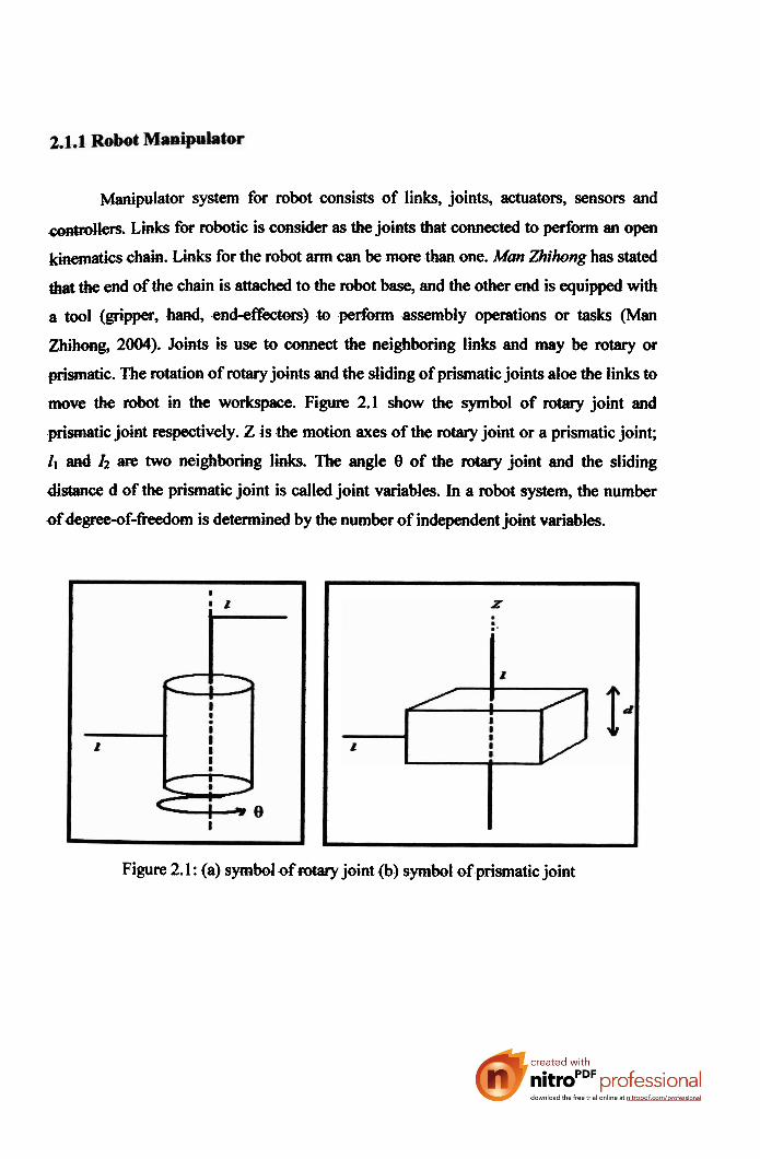
Manipulator system for robot consists of links, joints, actuators, sensors and
-lets. Links for robotic is consider as the joints that connected to perform an open
-tics chain. Links for the robot arm can be more than one. Man Zhihong has stated
the end of the chain is attached to the robot base, and the other end is equipped with
a tool (gripper, hand, end-efkctm) to perfbrm assembly operations or tasks (Man
Zhihong, 2004). Joints is use to connect the neighboring links and may be rotary ot
prismatic. The rotation of rotary joints and the sliding of prismatic joints aloe the links to
anow the robot in the workspace. Figure 2.1 show the symbol of rotary joint and
prismatic joint respectively. Z is the motion axes of the rotary joint or a prismatic joint;
1, a d I2 are two neighboring hks. The angle 0 of the rotary joint and the sliding
distance d of the prismatic joint is called joint variables. In a robot system, the number
ofdegme-of-Wom is determined by the number of independent joint variables.
Figure 2.1 : (a) symbol of rotary joint (b) symbol of prismatic joint

k w devices that cause Eotary joints to ro€&e about their motion axes. In
-1 an three types of actuating systans that has bear use in robotic systems;
h y w actuating systems, pneumatic actuating systems and electrical actuating
~~s(ems. Hydrsu4ic actuating systems provide mwe powerftll Forces and toque to handle
heavy W s compared to pneumatic actuating systems. The different between these two
of actuating systems is the types of h i d . Hydraulic use the oil as the fluid but
-tic use air compress to operate. The accuracy level of working condition for both
types of actuating also dillkrent. Pneumatic actuating system is less accuracy than
h y ~ because the elastically nature of the compress air, but pneumatic actuating
system is cheap, clean and reliable with high power compare to hydraulic (Man
ZhihoRg, 2004).
EkdrbI actuating systems also part of actuators and currently use for robotic
arm. W= motor, stepper motor and AC motor are commonly use as the electrical
actuating system for the robotic arm. The quick response from electric motor makes the
robd easily to conaOl by operators and automated. However, the electric motors are
aften heavy and gear system provides high &mpes and as a result, backlash problem
emmtered. Electric motor often heavy, but the precision and the degrees of movement
can be contPoZled easily without having trouble with nature responding (Man Zhihong,
2004).
Othet type of the tobd manipulator system is sensor. Sensor is the device that
cdleds Mormation from a system or objects that interacts by manipulator and their
en-ts. In human disp4ay design, a system gemrates information, some which
m s t be processed by the operator to perform task. Same to Mi arm, the task that
need to be done is interpreted by the sensor and information of the environment will then
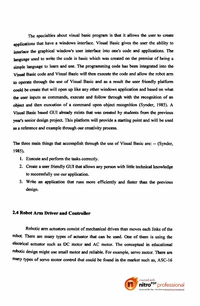
-date in the robot processor or computer (Man Zhihong, 2004). Figure 2.2 shows
hrtman interact with system and figure 2.3 shows the robot sensory interaction.
figwes describe the same idea ofthe ways of classifying displays. Human sensory
systems are not same as robot sensor because, b a n sensory principles senses the
display information that provided by the systems. Robot sensory systems have more that
one sensor to detect information and one of the examples is vision systems.
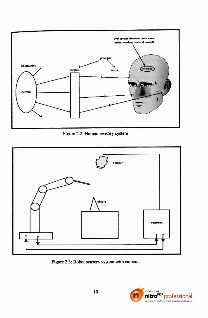
Figure 2.2: Human sensory system
Figure 2.3: Robot sensory system with camera.

~lthough vision sensory is an advanced technolugy in robotics, but whiskers sensors still
being use because it is cheap and simple to use.
Confxdlers are more important fot robot manipulator in robot system.
Controllers for robotic provides data processing and control the whole process of the
robot system circumstance all the joint, links, actuators as sensors. A robot control
system is actually the integration of electronic hardware and computer control software.
The Lynxmotion 5 Axis Robotic Arm Kit delivers fast, accurate and repeatable
movement. The robot features; base rotation, shoulder, elbow and wrist motion, with a
functional gripper to make five independent movements. No suldering is required for the
electronics. With the exception of some basic construction supplies, all of the
components are included 4~ assemble a functional robot. A host PC or microcontroller is
required to issue simple positioning commands for movement. The Lynxmotion 5 Axis
Robotic A m Kit is a very affwdaMe itl-wry system. Some ~f the uses include;
hobby robotics, tech school senior p*t, science fair project, light industrial proof of
cuncept, technical education, artificial intelligence programming and experimentation.
Figwe 2.4 show the 5 axis Lynxmotion robot arm. This robot is driven by 5 servos
inchding gripper and controlled by SSC (serial servo control) circuit (Lynxmotion,
1999).
Figure 2.4: 5-axis Lynxmotion robotic arm (Lynxmotion, 1999)
l I

Another type of mbotic arm €hat can be fad is designed by ROBIX. The company is
fiom United States of America. They have done inmy researches regarding to the
robotic and control system. ROBIX is a robotic kits that can be use for educational
purpose and stlitable for middle school student, high school student and colleges or
universities student and also for researchers ( R d R&D, 2006). The high motivated
with applicabi4it)l makes the robot easy to control and understand.
ROBIX is a robot arm that can be control using a computer. It uses programming
language to operate the robot. Figure 2.5 show the ROBIX ~obot kit. The control system
of this robot is base on programming where the preferred language pmgrmming is CU,
visual basic and input sensor as the additional part.
Figure 2.5: ROBIX robot for education (Rascal R&D, 2006)
Compare with Lynxmotion robotic arm, the programming style of the ROBIX
robot is less versatile because the programming language of the robot is limited. The
cuntdler of the robot is fixed and cannot be change by other microwntroller such as
PIC rnicmm&dIer or d h microcontroller. Same to Lynxrnotion robot, ROBIX robot
atso uses servo motor as the actuator because servo motor has internal encoder than
count on motor turns a d M b a c k system. Another capabilities that robotic arm should
have is pick and placing objects. RT-3200 Robot Arm is the good example in explaining
the basic capabilities tobd arm. Robots in the Seiko TR-Series are four axes, closed-

loop DC servo robots. Each of four axes provides a different motion in the robot's work
-%lope. The Alpha Axis or A axis provides rotation to the End-Effectors, the R axis
provides a horizontal stroke, the Theta Axis or T -Axis provides plane rotation and the z-
Axis provides vertical stroke. Each of the axes moves simultaneously as the robot
proceeds from point to point. This design feature allows for the high speeds movement
of the Seiko robots. Figure 2.6 show the RT-3200 robotic arm (Binh, 2000).
Figwe 2.6: RT-3200 Mi arm (Binh, 2000)
In RT-3200 robotic arm c o d system, the important thing that has to consider is the
rotrot calibration:
The robot arm calibration is a preset code that came with the robot arm to
calibrate the robot arm's coordinate system.
This process consists of the robot moving all 4 of its dc servo motors to make
swe they w r k and then moving the arm to a designated location.
Camera calibration: the camera has to calibrate and the calibmion result is saved
to calibration file. The program file must be load before run the robot. This
allows the robot to calibrate the programming file.

~aCjration fbr robot is not only for RT-3200 robotic arm, but all of robotic arm that
have links must do these steps in order to get the position data of each I-ink after the
a is programmed (Binh, 2000).
2.3 Robot Arm Software
There are various types of software w n t d or interface control software for robot
especially for robotic a m and there are di&rent to each other depends to manufacturer
ofthe software. The famous software that currently use for graphic interface software is
Visual Basic. Visual Basic (VB) is a Windows based d w a r e application that allows
users to create software applications for Windows (Synder, 1985). Figure 2.7 show the
sample of the graphic user interface serial motor cmtrdler that using visual basic.
2 3 .. ..- i . . . ." : . . _:_. .-
-5 ar ,.-.* :-*.*?A,-
i .,."*
-- &,* F..T-+. .."- '..:?I ....-, &< g-
PI. I.".,.. *-. ; -4-
1 ?-
.z . .* .r . ... > z , . i2 . - 131 141 .- 9' 16. 17! - . IS' . -.' i
1 - . . . _ . , 1
,- - . . . . . , . - . . , a r q 19' 20; 21 22 23: 24 '25' . . , . . . - - .-1, -- - .- ,. I " <
i ('1
0
-- . . . . . . ~ . .- - . . . . $ 4 1
Figure 2.7: The graphii user window interface serial DC motor controller using
Visual Basic 6.0.
m e specidties about visual basic ptogram is that it allows the user to create
qplidions that have a windows interface. Visual Basic gives the user the ability to
interlace the graphical window's user interface into one's code and applications. The
language used to write the code is basic which was created on the premise of being a
simple language to learn and use. The programming code has been integrated into the
v*l Basic oode and Visual Basic will then execute the code and allow the robot arm
v t e through the use d Visual Basic and as a =suit the user friendly platform
could be crate that will open up like any dher windows application and based on what
user inputs as commands, execute and follow through with the recognition of an
objed and then execution of a command upon object recognition (Synder, 1985). A
V i d Basic based GUI already exists that was created by students from the previous
year's senior design project. This platForm will provide a starting point and will be used
as a reference and example through our creativity process.
The three main things that accomplish through the use of Visual Basic are: - (Synder,
1985).
1. Execute and perform the tasks correctly.
2. create a user friendly GUI that allows any person with little technical knowledge
to successfbl-ly use our application.
3. Write an apprication that runs more efficiently and faster than the previous
design.
2.4 Robot Ann Driver and Controller
Robotic arm actuatm consist of mechanical driven than moves each links of the
robot. There are many types of actuator that can be used. One of them is using the
ckohical actuator such as DC motor and AC motor. The conceptual in educational
W i c design might use small motor and mliabk. For example, servo motor. There are
m y types of servo motor conttol that could be fbund in the market such as, ASC-16

serial sem controller, POLULU serial servo contrdler, SV203 RC Servo Motor
Controller and PARALLAX serial servo contrd. All of these types of conttol use serial
cmmmkations technology that let user to control the servo motor via serial
commtmications port of PC. ASC-16 is the one of the serial servo motor controller that
has been develop by Medonis Engineering. This contrdler can be use to control the
actuator of robot arm especially that using servo motor.
The new contrdler has a few more fancy features such as a move buffer,
position feedback and speed/ acceleration c o d in hardware. This will fi.ee up some
resources on the PC side of things because the software motion controller used with the
miniSSCs will no longer be needed. Also, the ASC-16 (fig. 2.8) ltas an onboard DC-DC
cofl- which means that the board only needs a single SVDC power supply
(pviously the miniSSC needed separate suppCies for the electronics and motors). The
test program can be written in VB6. The analogue I/0 will probably be used at a later
date for touch sensors on the hands (Medonis, 2000).
5V Digital/Analogue inputs
1
W Digital outputs -r
RS232 Serial mmms W 8 lADC 1-2 Sen teseet module ID Power ~ U P P ~ 2-3 Normal operation
Figwe 2.8: ASC-16 serial servo control (Medonis, 2000)

contpare with the POLOLU serial 8-servo controller (fig. 2.9), this serial controller
user to control up to eight RC servos with almost any robot controller or
e r . The interface to the servo controller is a standard RS-232 serial port or a
TTLlevel serial line, using any baud rate between 1200 and 38400 baud (POLULU,
2001-2006). Multiple 8-servo controllers can be connected to a single serial line to
control up to 128 servos independently. The servo controller is compatible various serial
motor controllers and servo controllers. The servo controller is also compatible with the
Scott Edwards MiniSSC I1 servo controller and any software written for it.
All of the ports are conveniently labeled on the back of the PCB. This servo
controller can be reset directly from a serial port using the DTR or RTS handshaking
lines. Other unique features include individual servo speed and range control.
Figure 2.9: POLULU serial &servo controller (POLULU, 2001-2006)
PIC based servo controller is a small project that has been designed to allow user
to control some robotics. The Servo Controller uses a PIC16F84 microcorrtroller h m
Microchip to drive servo motors and digital outputs. It receives commands from a host
computer via a standard RS232 serial interface. The PIC program can be download
which contains a HEX file which most PIC programmers can read; and a PIC Assembler
code (ASM) file (Ashley, 2000). The PIC assembler from Microchip can be
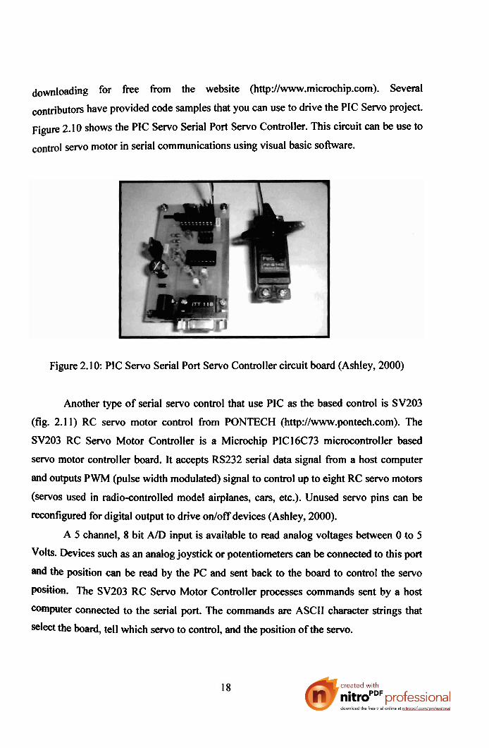
downloading for free from the website (http://www.microchip.com). Several
wntrib~tors have provided code samples that you can use to drive the PIC Servo project.
Figure 2.10 shows the PIC Servo Serial Port Servo Controller. This circuit can be use to
servo motor in serial communications using visual basic software.
Figure 2.10: PIC Servo Serial Port Servo Controller circuit board (Ashley, 2000)
Another type of serial servo control that use PIC as the based control is SV203
(fig. 2.1 1) RC servo motor control from PONTECH (http://www.pontech.com). The
SV203 RC Servo Motor Controller is a Microchip PIC16C73 microcontroller based
servo motor controller board. It accepts RS232 serial data signal h m a host computer
and outputs PWM (pulse width modulated) signal to control up to eight RC servo motors
(servos used in radio~ontrolled model airplanes, cars, etc.). Unused servo pins can be
reconfigured for digital output to drive onloff devices (Ashley, 2000).
A 5 channel, 8 bit AID input is available to read analog voltages between 0 to 5
Volts. Devices such as an analog joystick or potentiometers can be connected to this port
the position can be read by the PC and sent back to the board to control the servo
position. The SV203 RC Servo Motor Controller processes commands sent by a host
Wmputer connected to the serial port. The commands are ASCII character strings that
select the board, tell which servo to control, and the position of the servo.

Figure 2.1 1 : The SV203 RC servo motor controller (PONTECH, 2002)
SV203 serial servo motor controller is compatible with serial control where: - (PONTECH, 2002)
Controls 1 to 8 servos per board &bit resolution, value from 1 to 255,
under one degree of servo position precision resolution
Servo port can be reconfigured for digital output to drive onloff devices.
SourceISink 25 mA per pin
Interface to PC through RS232 Serial port (2400 to 19200 baud).
User definable board ID number (allowing multiple boards to share same serial
line).
5-Ch, 8-bit A/D input port for reading 0 - 5 Volts. (Control servo positions via
JoysticMPot)
Dimensions: 1.4 in X 1.7 in
Servo Connectors: 3 pin sip. Futaba J-type connectors.
Power supply: 7V (Up to 15V, but excessive voltage may damage servos)
Another thing that is highlight in this literature review is the driver of the electrical
actuators. Robot arm and controller cannot be separate with each other as they are

related to each other. Driver for electrical actuators of the robot arm is the basic part in
the robotic arm control system. There are many types of electrical actuator driver that is
to control the actuator. Examples below are the electrical actuators that require
driver to drive them: -- (Robot, 1999)
DC motor driver (direct current)
Stepper motor driver
Brushless DC motor driver
AC motor driver (analog current)
For DC motor driver, H-bridge motor control is the common thing to control the
direction of the DC motor.
Figure 2.12: L298 Compact Motor Driver Kit (Robot Objects, 2004-2005)
This L298 compact motor driver kit (fig. 2.12) comes with all of the components
needed to build a robust dual-motor driver with a small footprint. It is built around the
popular L298 IC chip and can handle up to 4 Amps total drive current (Robot Objects,
2004-2005). This driver uses the L298 dual f i l l bridge controller chip from
STMicroElectronics and is printed on circuit board (PCB). Another type of DC motor
driver is Bi-Directional DC Motor Driver (fig. 2.13) with PWM interface. This motor
driver is designed for simple motion control applications and ideal for driving DC
motors or to control the current in solenoids and proportional valves (MMS Electronics,
2005).

Figure 2.13: Bi-Directional DC Motor Driver (MMS Electronics, 2005)
The driver delivers 3 Amp continuously and accommodates peak output currents
up to 6 Amp. Readily interfaces with different PWM signals allowing easy interface to
PLC controllers or MMSe control boards. The internal circuit allows low loss sensing
of the output current with an adjustable current limit. Easy mounting and readily fitted
with aluminum heat sink (MMS Electronics, 2005).
The basic h-bridge is very simple. It only uses four transistors to operate and
changing the DC motor direction by digital signal applied (Motor Controller, 2006).
Figure 2.14 show the basic h-bridge theoretically that can be use to control the DC
motor direction.
Park 7 M 1 4 Xt 1K Resbta x4 F a K t # t C u r a t 2N2222Transistor xi 2 N 2 9 0 7 T r m s M u xi F a Low Curat: 2N3sxTmnslsta xl 2N39MTrsnsist# xi
Figure 2.14: Basic h-bridge transistor DC motor direction control
(Motor Controller, 2006)
According to figure 20, it shows that the DC motor can be driven into two directions:
Clockwise
Counter clockwise
he important things that the DC motor driver must be use is to avoid from the circuit
damaged because of the high pass current that produce by DC motor. Many types of DC
motor has big current operates values and robot controllers only use low current.
Compare with servo motor. It can be directly connected to the servo motor driver
because hobby servo only uses small current but provides applicable torque to operate
small robotic arm. Industrial and heavy robot arm require big motors. To avoid collision,
separation between the robot controller and the DC motor must be use and as a result the
DC motor drivers were invented.
From the current and past paper of robotic arm and control project study, several
hypothesis could be generate in order to get the best solutions for this paper objectives
which is about to design the control of robotic arm using visual basic and PIC
microcontroller. Serial communication has been embedded in controlling the robotic arm
as well as previous discussed project that requires serial port from PC as the
communications line. Recently, there are many types of robotic arm that use servo motor
such as Lynxmotion 5 Axis Robotic Arm Kit and ROBIX robot kit. These two kinds of
robot kit are small and applicable for research and study activity. Due to industrial
needs, these kits will no longer suitable especially to program a robotic arm to do a task
that requires high precision and cany a heavy load.
The requirements of the robot controller must have feedback system or closed
loop type where each turn of the motor could be count and positioned by the controller.
As a result, the robot a m position can be recorded and playback with various speed
according to the task given. Another thing that is highlighted in robot arm controller is
the motor driver which plays an important role in driving the actuator of the robot
according to the command of the robot controller. The use of H-bridge DC motor control
is familiar in robotic area because many types of DC motor actuators that requires
clockwise and counter clockwise must use DC motor driver as well as h-bridge.
Mechanical part for the robot kit is smaller compared to industrial robot and use
servo motor as the actuators but industrial robot use stepper motor, DC motor, AC motor
and brushless DC motor as the actuators and also heavy. Each links of the robot arm is
connected using chain link, belting or geared. Compare to robot arm kit that use hobby
servo motor, the actuator is attached directly to the link and without gear reduced or
chain mlueed. If the robot is big and use big motor, gear reducing, belting and chain link
the g d choice as the robot drive train especially using the electrical actuators.
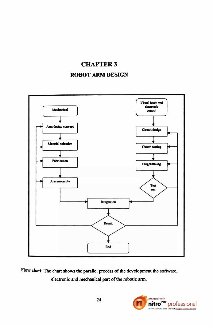
CHAPTER 3
ROBOT ARM DESIGN
Flow chart: The chart shows the parallel process of the development the sofhvare,
electronic and mechanical part of the robotic arm.
L
~Vispalbsoicaad \
Mccbaaical tlcumnic
ooatrol
1 \
circuit^ -+ b
Armdesigncooapt
1 M a t a i s l s e m 1
---b Circnittcstiag - 1
+ Fabrication 1 h_ B -
+ h a s s c m b l y
Related Documents