A. Galip Ulsoy Professor. Fellow ASME Y. Koren Professor. Fellow ASME Department of Mechanical Engineering and Applied Mechanics, University of Michigan, Ann Arbor, M148109-2125 Control of Machining Processes This paper reviews the important recent research contributions for control of ma- chining processes {e.g., turning, milling, drilling, and grinding). The major research accomplishments are reviewed from the perspective of a hierarchical control system structure which considers servo, process, and supervisory control levels. The use and benefits of advanced control methods (e.g., optimal control, adaptive control) are highlighted and illustrated with examples from research work conducted by the authors. Also included are observations on how significant the research to date has been in terms of industrial impact, and speculations on how this research area will develop in the coming decade. Introduction Motivation and Significance. Automation of manufactur- ing processes has continued to increase in importance over the last few decades due to increased global competition. It has been at, or near, the top of the lists of technologies identified as critical to national economic competitiveness and security in recent studies (Anon. 1980, 1990a, 1990b; Thurow, 1992). A strong manufacturing industry is clearly essential for con- tinued economic development; manufacturing accounts for approximately one third of the value of all goods and services produced in industrial nations. Its importance for national security is also clear; the conversion of the U.S. manufacturing enterprise to war-time production was essential to victory in World War II. Machining, or metal removal, processes are widely used in manufacturing and include operations such as turning, milling, drilling, and grinding. The push toward automation in ma- chining has been driven by the need to maintain high product quality while improving production rates. The potential eco- nomic benefits of automation in machining are schematically illustrated in Fig. 1. Consider, for purposes of illustration, an investment of $30,000 in a controller for a $300,000 machine tool that, typically, produces parts worth $30,000,000 during its lifetime. Assume that this 10 percent additional investment to increase the controller capability results in an effective in- crease of 10 percent in the productivity of the machining op- eration. This increase in productivity can be as a result of increased metal removal rates, reduced scrap or rework due to improved quality, reduced process down-time, or some com- bination of these effects. Since, during the lifetime of the machine, it produces products valued at $30,000,000, this 10 percent increase in effective productivity leads to an economic return of $3,000,000. A return on investment of 1000 times (i.e., =3,000,000/3,000) is achieved! It is this two-stage eco- nomic "amplification," as illustrated in Fig. 1, that makes the automation of machining processes so critical. Background. Machining operations date back to the 18th Value of Parts Produced During Machine Life Time Contributed by the Dynamic Systems and Control Division for publication in the JOURNAL OF DYNAMIC SYSTEMS, MEASUREMENT, AND CONTROL. Manuscript received by the Dynamic Systems and Control Division January 4, 1993. $30,000 $300,000 $30,000,000 Fig. 1 Economics of automation in machining. An investment of ten percent in the controller, leading to, say, a ten percent increase in ma- chine productivity, can produce a return on investment of 1,000 times the original investment. century, and represent a mature technology. However, there have been many improvements in machines, cutting tools, and materials that have led to significant benefits. One of the most important developments has been the introduction of auto- mation during the past three to four decades. In the 1950s •numerically controlled (NC) machine tools were developed under an Air Force contract to Parson's Machine Tool Com- pany (Traverse City, Michigan) by the Servomechanisms Lab- oratory at MIT. These reprogrammable but hard-wired digital devices represented the state-of-the-art into the 1960s. During the 1960s and 1970s, both computer technology and NC ma- chine tools continued to evolve. Computers became not only more powerful, but also less expensive and more reliable. The servo-control function (including interpolators for multiaxis coordination) became implemented using on-board computers Journal of Dynamic Systems, Measurement, and Control JUNE 1993, Vol. 115/301 Copyright © 1993 by ASME Downloaded 28 Jun 2010 to 141.213.232.87. Redistribution subject to ASME license or copyright; see http://www.asme.org/terms/Terms_Use.cfm

Welcome message from author
This document is posted to help you gain knowledge. Please leave a comment to let me know what you think about it! Share it to your friends and learn new things together.
Transcript
A. Galip Ulsoy Professor.
Fellow ASME
Y. Koren Professor.
Fellow ASME
Department of Mechanical Engineering and Applied Mechanics,
University of Michigan, Ann Arbor, M148109-2125
Control of Machining Processes This paper reviews the important recent research contributions for control of machining processes {e.g., turning, milling, drilling, and grinding). The major research accomplishments are reviewed from the perspective of a hierarchical control system structure which considers servo, process, and supervisory control levels. The use and benefits of advanced control methods (e.g., optimal control, adaptive control) are highlighted and illustrated with examples from research work conducted by the authors. Also included are observations on how significant the research to date has been in terms of industrial impact, and speculations on how this research area will develop in the coming decade.
Introduction
Motivation and Significance. Automation of manufacturing processes has continued to increase in importance over the last few decades due to increased global competition. It has been at, or near, the top of the lists of technologies identified as critical to national economic competitiveness and security in recent studies (Anon. 1980, 1990a, 1990b; Thurow, 1992). A strong manufacturing industry is clearly essential for continued economic development; manufacturing accounts for approximately one third of the value of all goods and services produced in industrial nations. Its importance for national security is also clear; the conversion of the U.S. manufacturing enterprise to war-time production was essential to victory in World War II.
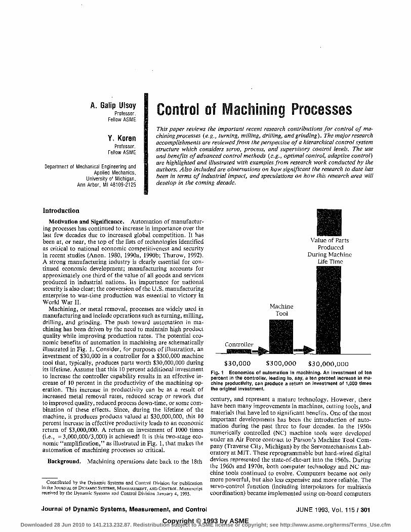
Machining, or metal removal, processes are widely used in manufacturing and include operations such as turning, milling, drilling, and grinding. The push toward automation in machining has been driven by the need to maintain high product quality while improving production rates. The potential economic benefits of automation in machining are schematically illustrated in Fig. 1. Consider, for purposes of illustration, an investment of $30,000 in a controller for a $300,000 machine tool that, typically, produces parts worth $30,000,000 during its lifetime. Assume that this 10 percent additional investment to increase the controller capability results in an effective increase of 10 percent in the productivity of the machining operation. This increase in productivity can be as a result of increased metal removal rates, reduced scrap or rework due to improved quality, reduced process down-time, or some combination of these effects. Since, during the lifetime of the machine, it produces products valued at $30,000,000, this 10 percent increase in effective productivity leads to an economic return of $3,000,000. A return on investment of 1000 times (i.e., =3,000,000/3,000) is achieved! It is this two-stage economic "amplification," as illustrated in Fig. 1, that makes the automation of machining processes so critical.
Background. Machining operations date back to the 18th
Value of Parts Produced
During Machine Life Time
Contributed by the Dynamic Systems and Control Division for publication in the JOURNAL OF DYNAMIC SYSTEMS, MEASUREMENT, AND CONTROL. Manuscript received by the Dynamic Systems and Control Division January 4, 1993.
$ 3 0 , 0 0 0 $ 3 0 0 , 0 0 0 $ 3 0 , 0 0 0 , 0 0 0
Fig. 1 Economics of automation in machining. An investment of ten percent in the controller, leading to, say, a ten percent increase in machine productivity, can produce a return on investment of 1,000 times the original investment.
century, and represent a mature technology. However, there have been many improvements in machines, cutting tools, and materials that have led to significant benefits. One of the most important developments has been the introduction of automation during the past three to four decades. In the 1950s •numerically controlled (NC) machine tools were developed under an Air Force contract to Parson's Machine Tool Company (Traverse City, Michigan) by the Servomechanisms Laboratory at MIT. These reprogrammable but hard-wired digital devices represented the state-of-the-art into the 1960s. During the 1960s and 1970s, both computer technology and NC machine tools continued to evolve. Computers became not only more powerful, but also less expensive and more reliable. The servo-control function (including interpolators for multiaxis coordination) became implemented using on-board computers
Journal of Dynamic Systems, Measurement, and Control JUNE 1993, Vol. 115/301
Copyright © 1993 by ASMEDownloaded 28 Jun 2010 to 141.213.232.87. Redistribution subject to ASME license or copyright; see http://www.asme.org/terms/Terms_Use.cfm

rather than hard-wired digital circuits. These computer numerically controlled (CNC) systems, because of their powerful computing capabilities, led to advances in the interpolators and in the servo control loops.
The additional on-board computing power of CNC machines also led to research interest in implementing a higher level process control aimed at improving production rates and product quality. These process control systems are commonly referred to as "adaptive control" (AC) systems in the manufacturing community, but may or may not include adaptation in the sense in which the term is used in the control literature (Stute, 1980; Ulsoy et al., 1983; Goodwin and Sin, 1984). The first of these process control systems, which was designed under an Air Force contract by Bendix, was an ambitious system which was only demonstrated in the laboratory (Centner, 1964; Huber and Centner, 1968). It included advanced control features such as on-line optimization and adaptive control, and was termed an adaptive control with optimization (ACO) system. However, a major drawback of this system was the need for an accurate on-line measurement or estimate of tool wear. Such measurement methods were not available in the 1960s, and even today a reliable tool wear measurement method that can operate in an industrial environment does not exist (Colwell et al., 1978; Tlusty and Andrews, 1983; Yen and Wright, 1983; Koren et al., 1991). Subsequent systems were often less ambitious than the original Bendix concept, and were designed to operate on the constraints of the permissible workspace (e.g., maximum cutting force). These systems are often classified as adaptive control with constraints (ACC) and geometric adaptive control (GAC) (Ulsoy et al., 1983; Koren and Ulsoy, 1989). Several commercial devices of the ACC type were also put on the market during the 1970s, but did not achieve widespread industrial acceptance (Ulsoy et al., 1983). Some of the problems, which led to the poor performance of these first generation ACC systems, are discussed in a subsequent section. The need for measurement of wear in the Bendix system also generated considerable research interest in on-line tool wear measurement and estimation (Ulsoy and Koren, 1989). For a more detailed discussion on the state-of-the-art in machine tool automation through the 1970s, the reader is referred to Pressman and Williams (1977), Stute (1980), Koren (1983), Ulsoy et al. (1983) and Ulsoy and Koren (1989).
Purpose and Scope. The purpose of this paper is to review the research on control of machining processes conducted during the 1980s, to assess the impact that this research has had on industrial practice, and to discuss the expected research directions for the next decade. In the next section of the paper, the recent research accomplishments at the servo, process, and supervisory control levels are presented and their economic impact discussed. These developments are illustrated with examples from our own research work. Subsequently, our views on future research directions in automation of machining processes are given. The final section includes a brief summary and conclusions.
Recent Research Accomplishments The 1980s saw increased research in the use of advanced
control methods for control of manufacturing processes (e.g., Masory, 1984; Kannatey-Asibu, 1987; Fussell and Srinivasan, 1991; Doumanidis and Hardt, 1991; and Suzuki et al., 1991). This can be related to several complementary factors: (f) the demand for better productivity, precision, and quality in manufacturing continued to increase; (if) the accomplishments of the 1970s had not solved the problems but clearly indicated the complexity of the machining system, including the nonlinear, nonstationary and multivariable nature of the processes to be controlled; (Hi) there were significant developments in
Supervisory contra
Servo Control
MACHINE
* position, velocity,..
PROCESS PRODUCT
" force, wear,.. v climensions, surface,..
Fig. 2 A controller for a manufacturing process, showing the servo, process, and supervisory control levels
computer technology, on the one hand, and in control and estimation theory, on the other (Wright and Bourne, 1988; Ulsoy and DeVries, 1989). Methods such as optimal control (Koren, 1989), adaptive control (Masory and Koren, 1983; Lauderbaugh and Ulsoy, 1989), preview control (Tomizuka et al., 1984), multivariable control (Kulkarni and Srinivasan, 1989), robust control (Masory and Koren, 1985), and state estimation (Takate et a l , 1985; Danai and Ulsoy, 1987b,c) have all been demonstrated on machining processes using the inexpensive and reliable microcomputer control technology of the 1980s. Many of these developments are applicable to all manufacturing processes; however, our focus here will be on machining processes such as turning, milling, drilling, and grinding.
Figure 2 schematically illustrates a convenient classification for the different levels of control that one might encounter in a controller for a machining process. The lowest level is servo control, where the motion of the cutting tool relative to the workpiece is controlled. Next is a process control level, where process variables such as cutting forces and tool wear are controlled to maintain high production rates and good part quality. Finally, the highest level is a supervisory one which directly measures product-related variables, such as part dimensions and surface roughness. The supervisory level also performs functions such as chatter detection, tool monitoring, machine monitoring, etc. The basic problems, approaches, and accomplishments at each of these control levels will be briefly described below.
Servo Control. The servo level controllers can be classified into two cases: (0 point-to-point (PTP), and (ii) contouring. In a PTP system, the controller moves the tool to a required position where the process operation is performed. The trajectory between the points is not controlled. Point-to-point control is required in applications like drilling and spot welding, and is the simpler of the two cases. It has much in common with PTP servo control problems in other application areas, such as robotics. However, the PTP control problem in manufacturing does have some special considerations which arise from the high accuracy requirements (e.g., 0.01 mm or better) and the interactions between the machine tool and the process, as shown in Fig. 2. For example, cutting forces and heat generated during the process must be considered to ensure accuracy in the PTP problem. The machine tool geometric errors affect PTP positioning accuracy, and are of several types: (i) volumetric errors due to slight irregularities in the components of the machine structure, (if) volumetric errors due to the machine thermal effects, and (iif) volumetric errors due to the effects of cutting forces. The first type can be compensated for, based upon off-line measurements (and modeling) of the machine geometric errors by technologies such as laser interferometry. However, the second and third type require on-line compensation, typically based upon temperature and/or force measurements and models relating these measured variables to geometric errors in each axis of the machine tool. Typically, minimum variance, forecasting, or predictive control approaches are used in these applications (Pandit and Wu, 1983;
302 /Vo l . 115, JUNE 1993 Transactions of the ASME
Downloaded 28 Jun 2010 to 141.213.232.87. Redistribution subject to ASME license or copyright; see http://www.asme.org/terms/Terms_Use.cfm
(a) Y-Axis
*
Desired / Contour /
Contour Error ^
' XfW / Tool
i i Actual ; Tool Path
Position Lag Error
Ex
"\ Reference Point
Ey
-> X-Axis
(b)
Fecdrate = 24 ipm
wi M I sol IDOI 1301 not isoi iwi
Simplei (Sampling Period • 10 msec)
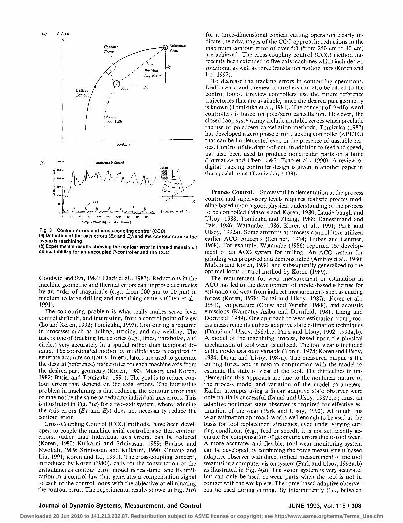
Fig. 3 Contour errors and cross-coupling control (CCC) (a) Definition of the axis errors (Ex and Ey) and the contour error in the two-axis machining (b) Experimental results showing the contour error in three-dimensional conical milling for an uncoupled P-controller and the CCC
Goodwin and Sin, 1984; Clark et al., 1987). Reductions in the machine geometric and thermal errors can improve accuracies by an order of magnitude (e.g., from 200 /zm to 20 jim) in medium to large drilling and machining centers (Chen et al., 1991).
The contouring problem is what really makes servo level control difficult, and interesting, from a control point of view (Lo and Koren, 1992; Tomizuka, 1993). Contouring is required in processes such as milling, turning, and arc welding. The task is one of tracking trajectories (e.g., lines, parabolas, and circles) very accurately in a spatial rather than temporal domain. The coordinated motion of multiple axes is required to generate accurate contours. Interpolators are used to generate the desired (reference) trajectories for each machine axis from the desired part geometry (Koren, 1983; Masory and Koren, 1982; Butler and Tomizuka, 1991). The goal is to reduce contour errors that depend on the axial errors. The interesting problem in machining is that reducing the contour error may or may not be the same as reducing individual axis errors. This is illustrated in Fig. 3(a) for a two-axis system, where reducing the axis errors (Ex and Ey) does not necessarily reduce the contour error.
Cross-Coupling Control (CCC) methods, have been developed to couple the machine axial controllers so that contour errors, rather than individual axis errors, can be reduced (Koren, 1980; Kulkarni and Srinivasan, 1989; Burhoe and Nwokah, 1989; Srinivasan and Kulkarni, 1990; Chuang and Liu, 1991; Koren and Lo, 1991). The cross-coupling concept, introduced by Koren (1980), calls for the construction of the instantaneous contour error model in real-time, and its utilization in a control law that generates a compensation signal to each of the control loops with the objective of eliminating the contour error. The experimental results shown in Fig. 3(b)
for a three-dimensional conical cutting operation clearly indicate the advantages of the CCC approach; reductions in the maximum contour error of over 5:1 (from 250 ^m to 40 /xm) are achieved. The cross-coupling control (CCC) method has recently been extended to five-axis machines which include two rotational as well as three translation motion axes (Koren and Lo, 1992).
To decrease the tracking errors in contouring operations, feedforward and preview controllers can also be added to the control loops. Preview controllers use the future reference trajectories that are available, since the desired part geometry is known (Tomizuka et al., 1984). The concept of feedforward controllers is based on pole/zero cancellation. However, the closed-loop system may include unstable zeroes which preclude the use of pole/zero cancellation methods. Tomizuka (1987) has developed a zero phase error tracking controller (ZPETC) that can be implemented even in the presence of unstable zeroes. Control of the depth-of-cut, in addition to feed and speed, has also been used to produce noncircular parts on a lathe (Tomizuka and Chen, 1987; Tsao et al., 1990). A review of digital tracking controller design is given in another paper in this special issue (Tomizuka, 1993).
Process Control. Successful implementation at the process control and supervisory levels requires realistic process modeling based upon a good physical understanding of the process to be controlled (Masory and Koren, 1980; Lauderbaugh and Ulsoy, 1988; Tomizuka and Zhang, 1988; Daneshmand and Pak, 1986; Watanabe, 1986; Koren et al., 1991; Park and Ulsoy, 1992a). Some attempts at process control have utilized earlier ACO concepts (Centner, 1964; Huber and Centner, 1968). For example, Watanabe (1986) reported the development of an ACO system for milling. An ACO system for grinding was proposed and demonstrated (Amitay et al., 1980; Malkin and Koren, 1984) and subsequently generalized to the optimal locus control method by Koren (1989).
The requirement for wear measurement or estimation in ACO has led to the development of model-based schemes for estimation of wear from indirect measurements such as cutting forces (Koren, 1978; Danai and Ulsoy, 1987a; Koren et al., 1991), temperature (Chow and Wright, 1988), and acoustic emissions (Kannatey-Asibu and Dornfeld, 1981; Liang and Dornfeld, 1989). One approach to wear estimation from process measurements utilizes adaptive state estimation techniques (Danai and Ulsoy, 1987b,c; Park and Ulsoy, 1992, 1993a,b). A model of the machining process, based upon the physical mechanisms of tool wear, is utilized. The tool wear is included in the model as a state variable (Koren, 1978; Koren and Ulsoy, 1984; Danai and Ulsoy, 1987a). The measured output is the cutting force, and is used in conjunction with the model to estimate the state of wear of the tool. The difficulties in implementing this approach are due to the nonlinear nature of the process model and variation of the model parameters. Earlier attempts using a linear adaptive state observer were only partially successful (Danai and Ulsoy, 1987b,c); thus, an adaptive nonlinear state observer is required for effective estimation of the wear (Park and Ulsoy, 1992). Although this wear estimation approach works well enough to be used as the basis for tool replacement strategies, even under varying cutting conditions (e.g., feed or speed), it is not sufficiently accurate for compensation of geometric errors due to tool wear. A more accurate, and flexible, tool wear monitoring system can be developed by combining the force measurement based adaptive observer with direct optical measurement of the tool wear using a computer vision system (Park and Ulsoy, 1993a,b) as illustrated in Fig. 4(a). The vision system is very accurate, but can only be used between parts when the tool is not in contact with the workpiece. The force-based adaptive observer can be used during cutting. By intermittently (i.e., between
Journal of Dynamic Systems, Measurement, and Control JUNE 1993, Vol. 115/303
Downloaded 28 Jun 2010 to 141.213.232.87. Redistribution subject to ASME license or copyright; see http://www.asme.org/terms/Terms_Use.cfm

T£ Cutting Process (a)
6 Adaptive Observer
Computer vision
Estimated State Estimated (Tool wear) Parameters
Estimates I Cutting . Force
orf-line Process between cuttlnt ooerations
w
0 100 200 300 -500 500 GOO 700 800
Cutting rme(5ec)
Fig. A Tool wear estimation using an adaptive observer (a) Schematic ol the adaptive observer integrated with computer vision (b) Estimated and measured flank wear in a turning experiment under varying cutting conditions (x microscope measurement, ® computer vision calibration of the observer, estimated flank wear from the adaptive observer)
parts) recalibrating the adaptive observer using the vision system, a very accurate estimate of tool wear can be obtained even under large variations in the cutting conditions. Experimental results, shown in Fig. 4(b), are from laboratory turning tests with large stepwise changes in the feedrate. The solid line is the tool wear estimate, the circles are the vision measurements used to recalibrate the observer, and the x's are the wear values measured using a tool maker's microscope. Errors in the flank wear estimate are less than 50 nm (2x 10"~3 in) over the entire cutting period, and improve as the cutting proceeds toward the end of the tool life.
Suboptimal process control systems were considered to be more practical than ACO systems, and systems of the ACC or GAC type were developed for various applications (Ulsoy et al., 1983; Masory and Koren, 1983; Watanabe and Iwai, 1983; Hahn, 1986; Wu et al., 1986). The emphasis has been on ACC systems, typically based upon force or torque measurements, rather than GAC systems, based upon product dimensions and surface finish. This is primarily a result of the availability of less expensive and more reliable sensors for force and torque measurement. However, with recent advances in optical sensing techniques for part dimensions and surface finish, this trend can be expected to change in the coming decade. Use of optical sensing in GAC systems has already been demonstrated in turning and milling applications (Wu et al., 1986; McCabe and Kirschbaum, 1989; McCabe et al., 1989).
Despite developments in ACC systems, machining processes were still found to be difficult to control due to process parameter variations which could lead to problems such as tool breakage or even instability. Consequently, adaptive control methods were widely investigated for a variety of machining processes (Ulsoy et al., 1983; Masory and Koren, 1983; Tom-izuka et al., 1983; Daneshmend and Pak, 1986; Tomizuka and
Controller
-H Estimator
j Digital Filter
Feedrate Override Circuit
Milling Process
Force Dyno.
TTT • * —
A
D
C
Analog
F i l te r F
H
Analog Signal
Processing
(b)
T A,
Time, T(seconds) Fig. 5 Model reference adaptive force control in milling (a) Schematic of the experimental system (b) Resultant versus time with MR AC in slot milling of a steel workpiece with step changes in depth-of-cut
Zhang, 1988; Lauderbaugh and Ulsoy, 1989). The basic problem arises from the fact that the effective process gains and time constants depend upon process variables such as feed, speed, and depth-of-cut. Furthermore, process related parameters such as tool geometry, work, and tool material properties are difficult to characterize and can have a significant effect on the process dynamics. This unpredictability of the process can lead to poor performance, tool breakage, or even instability when fixed gain process controllers are used (Masory and Koren, 1980, 1985). These problems, due to process model uncertainty, were a primary reason for the poor industrial acceptance of the first generation of AC systems for machining. To address this problem, adaptive control schemes, combining on-line parameter estimation and control, were developed and applied to machining processes. As an example of this class of controllers, a model reference adaptive force controller for a milling process is illustrated in Fig. 5(c) and described below.
A discrete-time model of a two-axis slot milling process can be written as (Lauderbaugh and Ulsoy, 1988),
F(z) boz+bi V(z) z2 + alz + a1
where V(k) is a voltage signal proportional to the machine feedrate, and F(k) is the measured resultant force. The parameters a,, a2, h, and 6, depend upon the spindle speed, feed, depth-of-cut, workpiece material properties, etc. Thus, they must be estimated on-line for effective control of the resultant force based upon manipulation of the feedrate (i.e., V(k)). The goal is to maintain the resultant force at the reference level, R(k), which is selected to maintain high metal removal rates without problems of tool breakage. The process zero at - (b\/ba), although the values of b0 and bt can vary, was found to be inside the unit circle for all cutting situations at the 50 ms sampling period that was used (Lauderbaugh and Ulsoy, 1988). Therefore, direct adaptive control methods can be employed. A model reference adaptive controller was designed and evaluated in laboratory tests for two different work-piece materials and for changing depths of cut (Lauderbaugh and Ulsoy, 1989). The controller design was straightforward,
304 /Vo l . 115, JUNE 1993 Transactions of the ASME
Downloaded 28 Jun 2010 to 141.213.232.87. Redistribution subject to ASME license or copyright; see http://www.asme.org/terms/Terms_Use.cfm

and gave satisfactory performance despite the process variations. The main difficulty is eliminating bias in the parameter estimates due to the "runout" noise in the force measurements (Turkay and Ulsoy, 1988). Experimental results are shown in Fig. 5(b) for machining of a 1020 CR steel workpiece with step changes in depth-of-cut from 2 to 3 to 4 mm. The desired value of R = 400 N is maintained despite these large changes in depth-of-cut at a spindle-speed of 550 rev/min. Note that initially the feedrate saturates, and the reference value of 400 N cannot be achieved at the 2 mm depth-of-cut. Also, initial transients occur due to the parameter adaptation. This controller also gave good results when used in machining other materials (e.g., aluminum) without any additional controller tuning (Lauderbaugh and Ulsoy, 1989).
Supervisory Control. The supervisory level is the area that has received the least research attention to date, and can be expected to be a major focus of future research. There are in fact many levels of control in a machining process control hierarchy, and what we have referred to here as supervisory control includes functions such as selection of control strategies (Furness, 1992), sensor fusion (Rangwala and Dornfeld, 1990), generation of reference commands for the process control level (Spence et al., 1990; Chryssolouris and Guillot, 1990), tool breakage monitoring (Lan and Dornfeld, 1984; Thangaraj and Wright, 1988), chatter detection (Hanna and Tobias, 1974; Tlusty et al., 1990), and machine monitoring (Isermann, 1984; Stein and Shin, 1986; Stein and Wang, 1990). Supervisory level strategies are aimed at compensating for factors not explicitly considered in the design of the servo and process level controllers. For example, knowledge of the part geometry as contained in the CAD system can be used to determine the reference values of process variables. Furthermore, the supervisory level can monitor for tool and/or machine failures or degradation. Process related phenomena, such as chatter and chip entanglement, can also be monitored. Information from various process related sensors can be integrated to improve the reliability and quality of sensor information. Finally, all of this information can be used to achieve on-line optimization of the machining process.
As an example of supervisory control in machining, consider a through-hole drilling operation. A successful control strategy must ensure good hole quality, prevent drill breakage, minimize burr formation at the exit, and also maintain high metal removal rates. A strategy which achieves these goals, based upon process optimization methods, is described in Furness (1992). The control system includes a servo control level where the spindle speed and the drill feedrate are accurately controlled. A process control level implements a torque controller to prevent drill breakage. The supervisory controller, based upon the drill position (depth-of-hole), selects an appropriate strategy for use at the process control level as well as the appropriate reference signals for that strategy. Specifically, the supervisory level selects a feed and speed control strategy at the entrance phase based upon hole quality (hole location error) considerations. The feed and speed references are selected based upon the required hole location error constraint. After the hole is initiated, the supervisory controller switches to a speed and torque control strategy with the reference values determined from tool breakage and tool wear considerations. Finally, as the operation nears drill breakthrough, the supervisory controller switches back to a feed and speed control strategy to minimize burr formation. Thus, the supervisory controller selects control strategies and their associated reference levels for optimization of the drilling process.
The results of using such a supervisory control strategy are illustrated in Table 1. This table compares experimental results obtained using four types of controllers: (1) no control (conventional approach where nominal feed and speed values are
Table 1 Comparison of control strategies in drilling (Furness, 1992)
No Feed/speed Torque/speed Supervisory controller controller controller controller
Machining Time iTH 11.28 9/79 11.71 (sec)
Burr Rating 2.93 2.94 2.26 1.58 Pooled Standard 4.43 4.53 6.28 4.25
Deviation (xl(T3in) '
% of Stoppage 25 15 0 0 Events
selected but not controlled during drilling), (2) feedback control of feed and speed, (3) feedback control of torque and speed, and (4) the supervisory controller (which combines (2) and (3) as described above). The comparison is made in terms of: (1) machining time for one hole, (2) burr rating, (3) hole location error (in terms of the pooled standard deviation of the hole location error), and (4) percentage of holes drilled with stoppage events. The machining time per hole is given in seconds, the burr rating ranges from l=very little burr formation to 5 = large burrs, and the hole quality is given in terms of the pooled standard deviation with smaller values indicating better hole location accuracy. The percentage of stoppage events is for holes for which the torque exceeded a maximum allowable value for drill breakage and the process was stopped. In this application, a hole location error pooled standard deviation of <4.5x 10"3 in, and a burr rating of < 1.75 are required. It is also desired that there be no stoppage events, and that the machining time be minimized subject to these hole quality, burr, and breakage constraints. The supervisory control strategy is the only one which meets the required hole quality and burr constraints, while eliminating stoppage events. It also yields a machining time very comparable to the uncontrolled or feed/speed control cases, and only slightly longer than the torque/speed controller. The results are average values based upon a statistical study involving the drilling of 20 holes with each strategy in a randomized order (Furness, 1992). These results clearly illustrate the potential advantages of a supervisory control strategy over each of the individual process control strategies (i.e., feed, speed, or torque control), and additional experimental results are presented in Furness (1992).
Impact on Industrial Practice. The research advances of the 1970s and 1980s have not had a serious impact to date on industrial practice, despite significant advances in research and numerous laboratory demonstrations. This is in part due to the unfavorable experience with the first generation of AC systems and their components introduced in the 1970s, and in part because these systems are still difficult to apply without considerable knowledge and experience on the part of the operator. One of the trends we can expect to see in the 1990s is the industrial application of many of the ideas demonstrated in laboratories in the 1970s and 1980s. The problems with process parameter variations have been addressed by the research of the 1980s, as described previously. The technology, however, is still difficult to apply, and this is still an area of on-going research (Ashley, 1990; NCMS, 1990). Global competition will force the machine tool industry, which in the U.S. took a serious economic downturn in the 1980s, to develop new state-of-the-art products. These new products will, in general, be machines whose accuracy and productivity is enhanced through the use of sensing and control technology. Thus, machine tool builders will need to upgrade the capabilities of their products by adding sensors, controls, and software.
A key impediment to the industrial use of research advances has been the problems associated with system integration, up-gradability of systems, and ease of use (e.g., complexity of
Journal of Dynamic Systems, Measurement, and Control JUNE 1993, Vol. 115/305
Downloaded 28 Jun 2010 to 141.213.232.87. Redistribution subject to ASME license or copyright; see http://www.asme.org/terms/Terms_Use.cfm
Market Need
DESIGN MACHINING INSPECTION
Quality Product
Taguchi Methods In-Process Quality Control
Statistical Process Control (SPC)
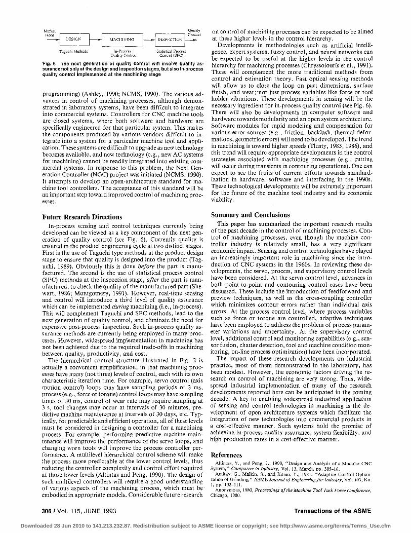
Fig. 6 The next generation of quality control will involve quality assurance not only at the design and inspection stages, but also in-process quality control implemented at the machining stage
programming) (Ashley, 1990; NCMS, 1990). The various advances in control of machining processes, although demonstrated in laboratory systems, have been difficult to integrate into commercial systems. Controllers for CNC machine tools are closed systems, where both software and hardware are specifically engineered for that particular system. This makes the components produced by various vendors difficult to integrate into a system for a particular machine tool and application. These systems are difficult to upgrade as new technology becomes available, and new technology (e.g., new AC systems for machining) cannot be readily integrated into existing commercial systems. In response to this problem, the Next Generation Controller (NGC) project was initiated (NCMS, 1990). It attempts to develop an open-architecture standard for machine tool controllers. The acceptance of this standard will be an important step toward improved control of machining processes.
on control of machining processes can be expected to be aimed at these higher levels in the control hierarchy.
Developments in methodologies such as artificial intelligence, expert systems, fuzzy control, and neural networks can be expected to be useful at the higher levels in the control hierarchy for machining processes (Chryssolouris et al., 1991). These will complement the more traditional methods from control and estimation theory. Fast optical sensing methods will allow us to close the loop on part dimensions, surface finish, and wear;'not just process variables like force or tool holder vibrations. These developments in sensing will be the necessary ingredient for in-process quality control (see Fig. 6). There will also be developments in computer software and hardware towards modularity and an open system architecture. Software modules for rapid modeling and compensation for various error sources (e.g., friction, backlash, thermal deformations, geometric errors) will need to be developed. The trend in machining is toward higher speeds (Tlusty, 1985, 1986), and this trend will require appropriate developments in the control strategies associated with machining processes (e.g., cutting will occur during transients in contouring operations). One can expect to see the fruits of current efforts towards standardization in hardware, software and interfacing in the 1990s. These technological developments will be extremely important for the future of the machine tool industry and its economic viability.
Future Research Directions In-process sensing and control techniques currently being
developed can be viewed as a key component of the next generation of quality control (see Fig. 6). Currently quality is ensured in the product engineering cycle at two distinct stages. First is the use of Taguchi type methods at the product design stage to ensure that quality is designed into the product (Taguchi, 1989). Obviously this is done before the part is manufactured. The second is the use of statistical process control (SPC) methods at the inspection stage, after the part is manufactured, to check the quality of the manufactured part (She-wart, 1986; Montgomery, 1991). However, real-time sensing and control will introduce a third level of quality assurance which can be implemented during machining (i.e., in-process). This will complement Taguchi and SPC methods, lead to the next generation of quality control, and eliminate the need for expensive post-process inspection. Such in-process quality assurance methods are currently being employed in many processes. However, widespread implementation in machining has not been achieved due to the required trade-offs in machining between quality, productivity, and cost.
The hierarchical control structure illustrated in Fig. 2 is actually a convenient simplification, in that machining processes have many (not three) levels of control, each with its own characteristic iteration time. For example, servo control (axis motion control) loops may have sampling periods of 3 ms, process (e.g., force or torque) control loops may have sampling times of 30 ms, control of wear rate may require sampling at 3 s, tool changes may occur at intervals of 30 minutes, predictive machine maintenance at intervals of 30 days, etc. Typically, for predictable and efficient operation, all of these levels must be considered in designing a controller for a machining process. For example, performing predictive machine maintenance will improve the performance of the servo loops, and changing worn tools will improve the process controller performance. A multilevel hierarchical control scheme will make the process more predictable at the lower control levels, thus reducing the controller complexity and control effort required at those lower levels (Altintas and Peng, 1990). The design of such multilevel controllers will require a good understanding of various aspects of the machining process, which must be embodied in appropriate models. Considerable future research
Summary and Conclusions This paper has summarized the important research results
of the past decade in the control of machining processes. Control of machining processes, even though the machine controller industry is relatively small, has a very significant economic impact. Sensing and control technologies have played an increasingly important role in machining since the introduction of CNC systems in the 1960s. In reviewing these developments, the servo, process, and supervisory control levels have been considered. At the servo control level, advances in both point-to-point and contouring control cases have been discussed. These include the introduction of feedforward and preview techniques, as well as the cross-coupling controller which minimizes contour errors rather than individual axis errors. At the process control level, where process variables such as force or torque are controlled, adaptive techniques have been employed to address the problem of process parameter variations and uncertainty. At the supervisory control level, additional control and monitoring capabilities (e.g., sensor fusion, chatter detection, tool and machine condition monitoring, on-line process optimization) have been incorporated.
The impact of these research developments on industrial practice, most of them demonstrated in the laboratory, has been modest. However, the economic factors driving the research on control of machining are very strong. Thus, widespread industrial implementation of many of the research developments reported here can be anticipated in the coming decade. A key to enabling widespread industrial application of sensing and control technologies in machining is the development of open architecture systems which facilitate the integration of new technologies into commercial products in a cost-effective manner. Such systems hold the promise of achieving in-process quality assurance, system flexibility, and high production rates in a cost-effective manner.
References Altintas, Y., and Peng, J., 1990, "Design and Analysis of a Modular CNC
System," Computers in Industry, Vol. 13, March, pp. 305-16. Amitay, G., Malkin, S., and Koren, Y., 1981, "Adaptive Control Optimi
zation of Grinding," ASME Journal of Engineering for Industry, Vol. 103, No. 1, pp. 102-111.
Anonymous, 1980, Proceedings of the Machine Tool Task Force Conference, Chicago, 1980.
306/Vol . 115, JUNE 1993 Transactions of the ASME
Downloaded 28 Jun 2010 to 141.213.232.87. Redistribution subject to ASME license or copyright; see http://www.asme.org/terms/Terms_Use.cfm

Anonymous, 1990a, Emerging Technologies: A Survey of Technical and Economic Opportunities, U.S. Department of Commerce, Spring.
Anonymous, 1990b, Critical Technologies Plan, U.S. Department of Defense, Mar. 15.
Ashley, S., 1990, "A Mosaic for Machine Tools," Mechanical Engineering, Sept., pp. 38-43.
Burhoe, J. C , and Nwokah, O. D., 1989, "Multivariable Control of a Biaxial Machine Tool," Proceedings of the Symposium on Dynamic Systems, Measurement, and Control, ASME Winter Annual Meeting, San Francisco, CA, Dec., pp. 1-6.
Butler, J., and Tomizuka, M., 1991, "Reference Input Generation for High Speed Coordinated Motion of a Two Axis System,'' ASME JOURNAL OF DYNAMIC SYSTEMS, MEASUREMENT, AND CONTROL, Vol. 113, March, pp. 67-74.
Centner, R., 1964, Final report on the development of an adaptive control technique for a numerically controlled milling machine, USAF Technical Documentary Report ML-TDR-64-279, August.
Chen, J. S., Yuan, J. X., Ni, J., and Wu, S. M., 1991, "Real-Time Compensation for Time-Variant Volumetric Error on a Machining Center," ASME Winter Annual Meeting, Atlanta, GA, Dec.
Chow, J. G., and Wright, P. K., 1988, "On-Line Estimation of Tool/Chip Interface Temperatures for a Turning Operation," ASME Journal of Engineering for Industry, Vol. 110, Feb., pp. 56-64.
Chryssolouris, G., and Guillot, M., 1990, "A Comparison of Statistical and AI Approaches to the Selection of Process Parameters in Intelligent Machining,'' ASME Journal of Engineering for Industry, Vol. 112, May, pp. 122-131.
Chryssolouris, G., Lee, M., and Domrese, M., 1991, "The Use of Neural Networks in Determining Operational Policies for Manufacturing Systems," Journal of Manufacturing Systems, Vol. 10, No. 2, pp. 166-175.
Chuang, H. Y., and Liu, C. H., 1991, "Cross-Coupled Adaptive Feedrate Control for Multiaxis Machine Tools," ASME JOURNAL OF DYNAMIC SYSTEMS, MEASUREMENT, AND CONTROL, Vol. 113, No. 3, Sept., pp. 451-457.
Clark, D. W., Mohtadi, C , and Tuffs, P. S., 1987, "Generalized Predictive Control—Part I; The Basic Algorithm, —Part II: Extensions and Interpretations," Automatica, Vol. 23, pp. 137-160.
Colwell, L. V., Mazur, J. C , and DeVries, W, R., 1978, "AnalyticalStrategies for Automatic Tracking of Tool Wear," Proceedings of the 6th North American Manufacturing Research Conference, pp. 274-282.
Danai, K., and Ulsoy, A. G., 1987a, "A Dynamic State Model for On-Line Tool Wear Estimation in Turning,'' ASME Journal of Engineering for Industry, Vol. 109, No. 4, Nov., pp. 396-399.
Danai, K., and Ulsoy, A. G., 1987b, "An Adaptive Observer for On-Line Tool Wear Estimation in Turning—Part I: Theory," Mechanical Systems and Signal Processing, Vol. 1, No. 2, Apr., pp. 211-225.
Danai, K., and Ulsoy, A. G., 1987c, "An Adaptive Observer for On-Line Tool Wear Estimation in Turning—Part II: Results," Mechanical Systems and Signal Processing, Vol. 1, No. 2, Apr., pp. 227-240.
Daneshmend, L. K., and Pak, H. A., 1986, "Model Reference Adaptive Control of Feed Force in Turning," ASME JOURNAL OF DYNAMIC SYSTEMS, MEASUREMENT, AND CONTROL, Vol. 108, Sept., pp. 215-222.
Doumanidis, C. C .andHard t , D. E., 1991, "Multivariable Adaptive Control of Thermal Properties During Welding,'' ASME JOURNAL OF DYNAMIC SYSTEMS, MEASUREMENT, AND CONTROL, Vol. 113, Mar., pp. 82-92.
Furness, R., 1992, Supervisory Control of the Drilling Process, Ph.D. dissertation, Department of Mechanical Engineering and Applied Mechanics, University of Michigan.
Fussell, B. K., and Srinivasan, K., 1991, "Adaptive Control of Force in End Milling Operations—An Evaluation of Available Algorithms," Journal of Manufacturing Systems, Vol. 10, No. 1, pp. 8-20.
Goodwin, G. C , and Sin, K., 1984, Adaptive Filtering, Prediction, and Control, Prentice-Hall.
Hahn, R. S., 1986, "Improving Performance with Force-Adaptive Grinding," Manufacturing Engineering, Vol. 97, Oct., pp. 73.
Hanna, N. H., and Tobias, S. A., 1974, "ATheoryofNonhnear Regenerative Chatter," ASME Journal of Engineering for Industry, pp. 247-254.
Huber, J., and Centner, R., 1968, "Test Results With an Adaptively Controlled Milling Machine," ASTME Paper No. MS68-638.
Isermann, R., 1984, "Process Fault Detection Based on Modeling and Estimation Methods—A Survey," Automatica, Vol. 20, No. 4, pp. 387-404.
Kannatey-Asibu, E., Jr., and Dornfeld, D. A., 1981, "Quantitative Relationships for Acoustic Emission From Orthogonal Metal Cutting," ASME Journal of Engineering for Industry, Vol. 103, No. 3, pp. 330-340.
Kannatey-Asibu, E., Jr., 1987, "Analysis of the GMAW Process for Microprocessor Control of Arc Length," ASME Journal of Engineering for Industry, Vol. 109, May, pp. 172-176.
Koren, Y., 1978, "Flank Wear Model of Cutting Tools Using Control Theory," ASME Journal of Engineering for Industry, Vol. 100, No. 1, Feb.
Koren, Y., 1980, "Cross-Coupled Computer Control for Manufacturing Systems," ASME JOURNAL OF DYNAMIC SYSTEMS, MEASUREMENT, AND CONTROL,
Vol. 102, No. 4, pp. 265-272. Koren, Y., 1983, Computer Control of Manufacturing Systems, McGraw-
Hill, New York, NY. Koren, Y., and Ulsoy, A. G., 1984, "State Model of Flank Wear in Metal
Cutting," Proceedings of the 12th NAMR Conference, Houghton, Michigan, May, pp. 100-105.
Koren, Y., 1989, "The Optimal Locus Approach with Machining Applications," ASME JOURNAL OF DYNAMIC SYSTEMS, MEASUREMENT, AND CONTROL,
Vol. I l l , pp. 260-267.
Koren, Y., and Ulsoy, A. G., 1989, "Adaptive Control in Machining," Metals Handbook: Machining, J. R. Davis (ed.), Vol. 16, 9th Ed., ASM International, Metals Park, OH, pp. 618-626.
Koren, Y., Ko, T. R., Ulsoy, A. G., and Danai,'K., 1991, "Flank Wear Estimation Under Varying Cutting Conditions," ASME JOURNAL OF DYNAMIC SYSTEMS, MEASUREMENT, AND CONTROL, Vol. 113, No. 2, June, pp. 300-307.
Koren, Y., and Lo, C. C , 1991, "Variable-Gain Cross-Coupling Controller for Contouring," CIRP Annals, Vol. 40, No. 1, pp. 371-374.
Koren, Y., and Lo, C. C , 1992, "Advanced Controllers for Feed Drives," CIRP Annals, Vol. 2, (a keynote paper presented at the CIRP Assembly).
Kulkarni, P. K., and Srinivasan, K., 1989, "Optimal Contouring Control of Multi-Axial Feed Drive Servomechanisms," ASME Journal of Engineering for Industry, Vol. I l l , May, pp. 140-148.
Lan, M.S. , and Dornfeld, D. A., 1984, "In-Process Tool Fracture Detection," ASME Journal of Engineering Materials and Technology, Vol. 106, Apr., pp. 111-118.
Lauderbaugh, L.K., and Ulsoy, A. G., 1988, "Dynamic Modeling for Control of the Milling Process," ASME Journal of Engineering for Industry, Vol. 110, No. 4, Nov., pp. 367-375.
Lauderbaugh, L. K., and Ulsoy, A. G., 1989, "Model Reference Adaptive Force Control in Milling," ASME Journal of Engineering for Industry, Vol. I l l , No. 1, Feb., pp. 13-21.
Liang, S. Y., and Dornfeld, D. A., 1989, "Tool Wear Detection Using Time Series Analysis of Acoustic Emission," ASME Journal of Engineering for Industry, Vol. I l l , Aug., pp. 199-205.
Lo,C. C , and Koren, Y., 1992, "Evaluation of Servo-Controllers for Machine Tools," Proceedings of the American Control Conference, Chicago, IL, June, pp. 370-374.
Malkin, S., and Koren, Y., 1984, "Optimal Infeed Control for Accelerated Spark-Out in Plunge Grinding," ASME Journal of Engineering for Industry, Vol. 106, Feb., pp. 70-74.
Masory, O., and Koren, Y., 1980, "Adaptive Control System for Turning," Annals of the CIRP, Vol. 1.
Masory, O., and Koren, Y., 1982, "Reference Word Circular Interpolators for CNC Systems," ASME Journal of Engineering for Industry, Vol. 104, No. 4, pp. 400-405.
Masory, O., and Koren, Y., 1983, "Variable-Gain Adaptive Control Systems for Machine Tools," Journal of Manufacturing Systems, Vol. 2, No. 2, pp. 165-174.
Masory, O., 1984, "Real-Time Estimation of Cutting Process Parameters in Turning," ASME Journal of Engineering for Industry, Vol. 106, Aug., pp. 218-221.
Masory, O., and Koren, Y., 1985, "Stability Analysis of a Constant Force AC System for Turning," ASME Journal of Engineering for Industry, Vol. 107, No. 4, pp. 295-300.
McCabe, J. T., and Kirschbaum, R. A., 1989, "In-Process Control of Milling," Rock Island Arsenal Report.
McCabe, J .T. , Locke, D., and Kirschbaum, R. A., 1989, "In-Process Control of Turning," Rock Island Arsenal Report.
Montgomery, D. C , 1991, Introduction to Statistical Quality Control, Wiley. National Center for Manufacturing Sciences (NCMS), 1990, Next Generation
Workstation/Machine Controller (NGC): Requirements Definition Document (RDD), Prepared for Air Force Systems Command, Aug.
Pandit, S. M., and Wu, S. M., Time Series and System Analysis With Applications, Wiley, New York, NY.
Park, J. J., and Ulsoy, A. G., 1992, "On-Line Tool Wear Estimation Using Force Measurement and a Nonlinear Observer," ASME JOURNAL OF DYNAMIC SYSTEMS, MEASUREMENT, AND CONTROL, Vol. 114, No. 4, Dec , pp. 666-692.
Park, J. J., and Ulsoy, A. G., 1993a, "On-Line Flank Wear Estimation Using an Adaptive Observer and Computer Vision, Part I: Theory," ASME Journal of Engineering for Industry, Vol. 115, No. 1, Feb., pp. 30-36.
Park, J. J., and Ulsoy, A. G., 1993b, "On-Line Flank Wear Estimation Using an Adaptive Observer and Computer Vision, Part II: Results," ASME Journal of Engineering for Industry, Vol. 115, No. 1, Feb., pp. 37-43.
Pressman, R. S., and Williams, J. E., 1977, NumericalControl and Computer-Aided Manufacturing, Wiley, New York, NY.
Rangwala, S., and Dornfeld, D. A., 1990, "Sensor Integration Using Neural Networks for Intelligent Tool Condition Monitoring," ASME Journal of Engineering for Industry, Vol. 112, Aug., pp. 219-228.
Shewhart, W. A., 1986, Statistical Method from the Viewpoint of Quality Control, Dover, New York, NY.
Spence, A. Altintas, Y., and Kirkpatrick, D., 1990, "Direct Calculation of Machining Parameters from a Solid Model," Computers in Industry, Vol. 14, July, pp. 271-280.
Srinivasan, K., and Kulkarni, P. K., 1990, "Cross-Coupled Control of Biaxial Feed Drive Servomechanisms," ASME JOURNAL OF DYNAMIC SYSTEMS, MEASUREMENT, AND CONTROL, Vol. 112, June, pp. 225-232.
Stein, J. L., and Wang, C-H., 1990, "Analysis of Power Monitoring on AC Induction Drive Systems," ASME JOURNAL OF DYNAMIC SYSTEMS, MEASUREMENT, AND CONTROL, Vol. 112, June, pp. 239-248.
Stein, J. L., and Shin, K. C , 1986, "Current Monitoring of Field Controlled DC Spindle Drives," ASME JOURNAL OF DYNAMIC SYSTEMS, MEASUREMENT,
AND CONTROL, Vol. 108, Dec., pp. 289-295. Stute, G., 1980, "Adaptive Control," Proceedings of the Machine Tool Task
Force Conference, Vol. 4, Sect. 7.14. Suzuki, A., Hardt, D. E., and Valavani, L., 1991, "Application of Adaptive
Control Theory to On-Line GTA Weld Geometry Regulation," ASME JOURNAL
Journal of Dynamic Systems, Measurement, and Control JUNE 1993, Vol. 115/307
Downloaded 28 Jun 2010 to 141.213.232.87. Redistribution subject to ASME license or copyright; see http://www.asme.org/terms/Terms_Use.cfm

OF DYNAMIC SYSTEMS, MEASUREMENT, AND CONTROL, Vol. 113, Mar., pp. 93-
KB. Taguchi, G., 1989, Quality Engineering in Production Systems, McGraw-Hill,
New York, NY. Takate, S., Ogawa, M., Bertok, P., Ootsuka, J., Matushima, K., and Sata,
T., 1985, "Real-Time Monitoring of Tool Breakage Using Kalman Filtering," Robotics and Computer Integrated Manufacturing, Vol. 2, No. 1, pp. 33-40.
Tarn, J. H., and Tomizuka, M., 1989, "On-Line Monitoring of Tool and Cutting Conditions in Milling," ASME Journal of Engineering for Industry, Vol. I l l , Aug., pp. 206-212.
Thangaraj, A., and Wright, P. K., 1988, "Computer-Assisted Prediction of Drill-Failure Using In-Process Measurements of Thrust Force," ASME Journal of Engineering for Industry, Vol. 110, May, pp. 192-200.
Thurow, L., 1992, Head-to-Head: The Coming Economic Battle Among Japan, Europe and America, Morrow, New York, NY.
Tlusty, J., 1985, "Machine Dynamics," Handbook of High-speed Machining Technology, R. I. King, ed., Chapman and Hall, New York, NY.
Tlusty, J., 1986, "Dynamics of High Speed Machining," ASME Journal of Engineering for Industry, Vol. 108, pp. 59-67.
Tlusty, J., and Andrews, G. C , 1983, "A Critical Review of Sensors for Unmanned Machining," Annals of the CIRP, Vol. 32, No. 2, pp. 563-572.
Tlusty, J., Smith, S., and Zamudio, C , 1990, "New NC Routines for Quality in Milling," CIRP Annals, Vol. 39, pp. 517-521.
Tomizuka, M„ Oh, J., and Dornfeld, D. A., 1983, "Model Reference Adaptive Control of the Milling Process," Control of Manufacturing Processes and Robotic Systems, ASME, Nov., New York, pp. 55-64.
Tomizuka, M., 1987, "Zero Phase Error Tracking Algorithm for Digital Control," ASME JOURNAL OF DYNAMIC SYSTEMS, MEASUREMENT, AND CONTROL,
Vol. 109, Mar., pp. 65-68. Tomizuka, M., 1993, "On the Design of Digital Tracking Controllers,'' ASME
JOURNAL OF DYNAMIC SYSTEMS, MEASUREMENT, AND CONTROL, Special 50th
Anniversary Issue, June. Tomizuka, M., and Chen, M. S., 1987, "Tool Positioning for Noncircular
Cutting With Lathe," ASME JOURNAL OF DYNAMIC SYSTEMS, MEASUREMENT, AND CONTROL, Vol. 109, June, pp. 176-179.
Tomizuka, M., Dornfeld, D. A., and Bian, X. Q., 1984, "Experimental Evaluation of the Preview Servo Scheme for a Two-Axis Positioning System," ASME JOURNAL OF DYNAMIC SYSTEMS, MEASUREMENT, AND CONTROL, Vol. 106,
Mar., pp. 1-5. Tomizuka, M., and Zhang, S., 1988, "Modeling and Conventional/Adaptive
PI Control of a Lathe Cutting Process," ASME JOURNAL OF DYNAMIC SYSTEMS, MEASUREMENT, AND CONTROL, Vol. 110, Dec , pp. 350-354.
Tsao, T. C , Chen, Y. Y., and Tomizuka, M., 1990, "Noncircular Turning of Workpieces With Sharp Corners," ASME Journal of Engineering for Industry, Vol. 112, May, pp. 181-183.
Turkay, O., and Ulsoy, A. G., 1988, "Frequency Versus Time Domain Parameter Estimation: Application to a Slot Milling Operation," Mechanical Systems and Signal Processing, Vol. 2, No. 3, pp. 265-277.
Ulsoy, A. G., and Koren, Y., 1989, "Applications of Adaptive Control to Machine Tool Process Control," IEEE Control Systems Magazine, Vol. 9, No. 4, pp. 33-37.
Ulsoy, A. G., and DeVries, W. R., 1989, Microcomputer Applications in Manufacturing, Wiley, New York, NY.
Ulsoy, A. G., Koren, Y., and Rasmussen, F., 1983, "Principal Developments in the Adaptive Control of Machine Tools," ASME JOURNAL OF DYNAMIC SYSTEMS, MEASUREMENT, AND CONTROL, Vol. 105, No. 2, pp. 107-112.
Watanabe, T., 1986, "A Model-Based Approach to Adaptive Control Optimization in Milling," ASME JOURNAL OF DYNAMIC SYSTEMS, MEASUREMENT,
AND CONTROL, Vol. 108, pp. 56-64. Watanabe, T., and Iwai, S., 1983, "A Control System to Improve the Accuracy
of Finished Surfaces in Milling," ASME JOURNAL OF DYNAMIC SYSTEMS, MEASUREMENT, AND CONTROL, Vol. 105, pp. 192-199.
Wright, P. K., and Bourne, D. A., 1988, Manufacturing Intelligence, Addison-Wesley, Reading, MA.
Wu, C L., Haboush, R. K., Lymburner, D. R., and Smith, G. H., 1986, "Closed-Loop Machining Control for Cylindrical Turning," Modeling, Sensing and Control of Manufacturing Systems, ASME, Nov., New York, pp. 189-204.
Yen, D. W., and Wright, P. K., 1983, "Adaptive Control in Machining—A New Approach Based on the Physical Constraints of Tool Wear Mechanisms," ASME Journal of Engineering for Industry, Vol. 105, Feb. pp. 31-38.
308/Vol . 115, JUNE 1993 Transactions of the ASME
Downloaded 28 Jun 2010 to 141.213.232.87. Redistribution subject to ASME license or copyright; see http://www.asme.org/terms/Terms_Use.cfm
Related Documents