PROJECT SPECIFICATIONS FOR ADDITION/ALTERATIONS TO AIRCRAFT CORROSION CONTROL FACILITY, BUILDING 180 PROJECT UHHZ 130401 ROBINS AIR FORCE BASE, GEORGIA 100% CORRECTED FINAL SUBMITTAL VOLUME 2 OF 2 DEPARTMENT OF THE AIR FORCE 78 CEG ROBINS AIR FORCE BASE, GEORGIA 100% Corrected Final Submittal Issued 10 FEBRUARY, 2016 (revised 28 March 2015) GCAG JOB NO: 15051 2/10/16

Welcome message from author
This document is posted to help you gain knowledge. Please leave a comment to let me know what you think about it! Share it to your friends and learn new things together.
Transcript

PROJECT SPECIFICATIONS
FOR
ADDITION/ALTERATIONS TO AIRCRAFT CORROSION
CONTROL FACILITY, BUILDING 180
PROJECT UHHZ 130401
ROBINS AIR FORCE BASE, GEORGIA
100% CORRECTED FINAL SUBMITTAL
VOLUME 2 OF 2
DEPARTMENT OF THE AIR FORCE
78 CEG
ROBINS AIR FORCE BASE, GEORGIA
100% Corrected Final Submittal Issued 10 FEBRUARY, 2016 (revised 28 March 2015) GCAG JOB NO: 15051
2/10/16

THIS PAGE INTENTIONALLY LEFT BLANK FOR DUPLEX PRINTING

UHHZ130401 INDEX OF SPECIFICATIONS
INDEX OF SPECIFICATIONS Page 1 of 5
DATE: Final Corrected Submittal Issued 10 February, 2016 (revised 28 March, 2016)
SPECIFICATIONS INDEX, UHHZ130401, ADDITION/ALTERATIONS TO AIRCRAFT CORROSION CONTROL FACILITY, BUILDING 180
NUMBER TITLE PAGES
VOLUME 2
Division 01 – ROBINS AFB – General Requirements
01005 01005-1 thru 01005-7 01040 01040-1 thru 01040-12 01300 01300-1 thru 01300-9
No. of pages = 2 01310 01310-1 thru 01310-5 01501 01501-1 thru 01501-3 01540 01540-1 thru 01540-12 01560 01560-1 thru 01560-24 01572 01572-1 thru 01572-6 01580 01580-1 thru 01580-6 01600 01600-1 thru 01600-3 01700 01700-1 thru 01700-6 01730
Statement of Work (revised 28 March, 2016)Site Requirements Submittals and Contractor-Furnished Items 01300 Appendix A Submittal Register CADD As-Built Drawings Temporary Services for Contractor Green Procurement Environmental Requirements Construction & Demolition Waste Management Safety Requirements Product Requirements Execution RequirementsOperations and Maintenance Data 01730-1 thru 01730-6
Division 02 – Existing Conditions
024100 Demolition and Deconstruction 024100-1 thru 024100-10 024251 Carpet Removal and Reclamation 024251-1 thru 0241251-4
Division 03 – Concrete
033000 Cast-In-Place Concrete 033000-1 thru 033000-37
Division 04 – Masonry
042000 Masonry 42000-1 thru 042000-25
Division 05 - Metals
053000 Steel Decks 053000-1 thru 053000-13 054001 Prefabricated Cold-formed Metal Trusses 054001-1 thru 054001-6 055013 Miscellaneous Metal Fabrications 055013-1 thru 055013-8 055200 Metal Railings 055200-1 thru 055200-4
Division 06 – Wood, Plastics and Composites
062000 Finish Carpentry 062000-1 thru 062000-6

UHHZ130401 INDEX OF SPECIFICATIONS
INDEX OF SPECIFICATIONS Page 2 of 5
064116.0010 Plastic-Laminate-Clad Architectural Casework 064116.0010-1 thru 064116.0010-9
066116 Solid Polymer (Solid Surfacing) Fabrications 066116-1 thru 066116-8
Division 07 - Thermal and Moisture Protection
071113 Bituminous Dampproofing 071113-1 thru 071113-3 071353 Elastomeric Sheet Waterproofing 071553-1 thru 071553-5 072113 Board Insulation 072113-1 thru 072113-6 072116 Mineral Fiber Blanket and Sound Attenuation Batt
Insulation 072116-1 thru 072116-5 072129 Sprayed Polyurethane Foam Insulation 072129-1 thru 072129-12 074113 Metal Roof Panels 074113-1 thru 074113-25 074213 Metal Wall and Soffit Panels 074213-1 thru 074213-18 075419 Polyvinyl-Chloride Roofing 075419-1 thru 075419-14 076000 Flashing, Sheet Metal, Parapet Wall Coping and Roof
Curbs 076000-1 thru 076000-7 078400 Firestopping 078400-1 thru 078400-5 079200 Joint Sealants 079200-1 thru 079200-6
Division 08 – Openings
081113 Steel Doors and Frames 081113-1 thru 081113-6 081116 Aluminum Doors and Frames 081116-1 thru 081116-7 081400 Wood Doors 081400-1 thru 081400-3 084113 Aluminum-Framed Storefronts 084113-1 thru 084113-11 087100 Door Hardware 087100-1 thru 087100-10 088100 Glazing 088100-1 thru 088100-7
Division 09 – Finishes
092200 Supports for Gypsum Board 092200-1 thru 092200-3 092900 Gypsum Board 092900-1 thru 092900-8 093013 Ceramic Tiling 093013-1 thru 093013-6 095100 Acoustical Ceiling 095100-1 thru 095100-7 096500 Resilient Flooring 096500-1 thru 096500-5 096723.13 Standard Resinous Flooring 096723.13-1 thru
096723.13-7 096800 Carpeting 096800-1 thru 096800-7 099000 Paints and Coatings 099000-1 thru 099000-22
Division 10 - Specialties
101100 Visual Display Units 101100-1 thru 101100-2 101400.10 Exterior Signage 101400.10-1 thru
101400.10-2

UHHZ130401 INDEX OF SPECIFICATIONS
INDEX OF SPECIFICATIONS Page 3 of 5
101400.20 Interior Signage 101400.20-1 thru 101400.20- 5
102113 Toilet Compartments 102113-1 thru 102113-7 102613 Corner Guards 102613-1 thru 102613-3 102813 Toilet, Locker Room, and Decontamination Room
Accessories 102813-1 thru 102813-4 104416 Fire Extinguishers 104416-1 thru 104416-3 107316 Pre-Engineered Aluminum Canopy Systems 107316-1 thru 107316-17
Division 11 - Equipment
Division 12 – Furnishings
122100 Window Blinds 122100-1 thru 122100-4 124813 Entrance Floor Mats and Frames 124813-1 thru 124813-3
Division 13 - Special Construction
Division 14 - Conveying Equipment
VOLUME 2
Division 21 – Fire Suppression
211313.0010 Wet Pipe Sprinkler System, Fire Protection 211313.0010-1 thru 211313.0010-13
Division 22 – Plumbing
220000 Plumbing, General Purpose 220000-1 thru 220000-35
Division 23 – Heating, Ventilation and Air Conditioning
230000 Air Supply, Distribution, Ventilation and Exhaust Systems 230000-1 thru 230000-23
230593 Testing, Adjusting, and Balancing for HVAC 230593-1 thru 230593-26 230700 Thermal Insulation for Mechanical Systems 230700-1 thru 230700-30 230800.0010 Commissioning of HVAC Systems 230800.0010-1 thru
230800.0010-29 230923.1320 BACnet Direct Digital Control Systems for HVAC 230923.1320-1 thru
230923.1320-43 236426 Chilled, Hot and Condenser Water Piping Systems 236426-1 thru 236426-22
Division 25 – Integrated Automation
Division 26 - Electrical
262000 Interior Distribution System 262000-1 thru 262000-28

UHHZ130401 INDEX OF SPECIFICATIONS
INDEX OF SPECIFICATIONS Page 4 of 5
264100 Lightning Protection System 264100-1 thru 264100-6 265100 Interior Lighting 265100-1 thru 265100-10 265600 Exterior Lighting 265600-1 thru 26500-10
Division 27 – Communications
271000 Building Telecommunications Cabling System 271000-1 thru 271000-16
Division 28 – Electronic Safety and Security
283176 Interior Fire Alarm and Mass Notification System 283176-1 thru 283176-38
Division 31 – Earthwork
310000 Earthwork 310000-1 thru 310000-15 311100 Clearing and Grubbing 311100-1 thru 311100-3 312300.0020 Excavation and Fill 312300.0020-1 thru
312300.0020-13 313116.13 Chemical Termite Control 313116.13-1 thru
3113116.13-7 312111 Soil Surface Erosion Control 312111-1 thru 312111-14
Division 32 – Exterior Improvements
321313.06 Portland Cement Concrete Pavement for Roads and Site 321313.06-1 thru Facilities 321313.06-20
321613 Concrete Sidewalks and Curbs and Gutters 321613-1 thru 321613-13 321723.0020 Pavement Markings 321723.0020-1 thru
321723.0020-15
Division 33 – Utilities
331100 Water Distribution 331100-1 thru 331100-9 333000 Sanitary Sewers 333000-1 thru 333000-8
Division 34 – Transportation
Division 35 – Water and Marine Construction
Division 40 – Process Integration
Division 41 – Material Processing and Handling Equipment
Division 42 – Process Heating, Cooling and Drying Equipment
Division 43 – Process Gas and Liquid Handling, Purification, and Storage Equipment
Division 44 – Pollution and Waste Control Equipment
UHHZ130401 INDEX OF SPECIFICATIONS
INDEX OF SPECIFICATIONS Page 5 of 5
Division 46 – Water and Wastewater Equipment
Division 48 – Electrical Power Generation
Appendix A – Geotechnical Report
Appendix B – Hazardous Materials Report
TOTAL NUMBER OF PAGES (Including Index) = 947
<<<<< END OF INDEX >>>>>

THIS PAGE INTENTIONALLY LEFT BLANK FOR DUPLEX PRINTING

Robins Air Force Base Building 180 UHHZ 130401 15051
SECTION 21 13 13.00 10
WET PIPE SPRINKLER SYSTEM, FIRE PROTECTION05/09
PART 1 GENERAL
1.1 REFERENCES
The publications listed below form a part of this specification to the extent referenced. The publications are referred to within the text by the basic designation only.
ASME INTERNATIONAL (ASME)
ASME B16.1 (2010) Gray Iron Pipe Flanges and Flanged Fittings Classes 25, 125, and 250
ASME B16.11 (2011) Forged Fittings, Socket-Welding and Threaded
ASME B16.21 (2011) Nonmetallic Flat Gaskets for Pipe Flanges
ASME B16.3 (2011) Malleable Iron Threaded Fittings, Classes 150 and 300
ASME B16.4 (2011) Standard for Gray Iron Threaded Fittings; Classes 125 and 250
ASME B16.9 (2012) Standard for Factory-Made Wrought Steel Buttwelding Fittings
ASME B18.2.2 (2010) Nuts for General Applications: Machine Screw Nuts, Hex, Square, Hex Flange, and Coupling Nuts (Inch Series)
ASTM INTERNATIONAL (ASTM)
ASTM A135/A135M (2009; R2014) Standard Specification for Electric-Resistance-Welded Steel Pipe
ASTM A183 (2014) Standard Specification for Carbon Steel Track Bolts and Nuts
ASTM A449 (2014) Standard Specification for Hex Cap Screws, Bolts, and Studs, Steel, Heat Treated, 120/105/90 ksi Minimum Tensile Strength, General Use
ASTM A47/A47M (1999; R 2014) Standard Specification for Ferritic Malleable Iron Castings
ASTM A53/A53M (2012) Standard Specification for Pipe, Steel, Black and Hot-Dipped, Zinc-Coated, Welded and Seamless
SECTION 21 13 13.00 10 Page 1

Robins Air Force Base Building 180 UHHZ 130401 15051
ASTM A536 (1984; R 2014) Standard Specification for Ductile Iron Castings
ASTM A795/A795M (2013) Standard Specification for Black and Hot-Dipped Zinc-Coated (Galvanized) Welded and Seamless Steel Pipe for Fire Protection Use
ASTM F436 (2011) Hardened Steel Washers
FM GLOBAL (FM)
FM APP GUIDE (updated on-line) Approval Guide http://www.approvalguide.com/
NATIONAL FIRE PROTECTION ASSOCIATION (NFPA)
NFPA 101 (2015; ERTA 2015) Life Safety Code
NFPA 13 (2013; TIA 10-1; TIA 11-2; ERTA 2014; TIA 14-3) Standard for the Installation of Sprinkler Systems
NFPA 13D (2013) Standard for the Installation of Sprinkler Systems in One- and Two-Family Dwellings and Manufactured Homes
NFPA 13R (2013) Standard for the Installation of Sprinkler Systems in Residential Occupancies Up to and Including Four Stories in Height
NFPA 24 (2013) Standard for the Installation of Private Fire Service Mains and Their Appurtenances
NATIONAL INSTITUTE FOR CERTIFICATION IN ENGINEERING TECHNOLOGIES (NICET)
NICET 1014-7 (2010) Program Detail Manual for Certification in the Field of Fire Protection Engineering Technology (Field Code 003) Subfield of Automatic Sprinkler System Layout
U.S. DEPARTMENT OF DEFENSE (DOD)
UFC 3-310-04 (2013) Seismic Design for Buildings
UNDERWRITERS LABORATORIES (UL)
UL Fire Prot Dir (2012) Fire Protection Equipment Directory
1.2 SYSTEM DESCRIPTION
Furnish piping offsets, fittings, and any other accessories as required to provide a complete installation and to eliminate interference with other construction. Install sprinkler system over and under ducts, piping and platforms when such equipment can negatively effect or disrupt the
SECTION 21 13 13.00 10 Page 2

Robins Air Force Base Building 180 UHHZ 130401 15051
sprinkler discharge pattern and coverage. Provide wet pipe sprinkler system in areas indicated on the drawings. Except as modified herein, the system shall be designed and installed in accordance with NFPA 13 . Rack sprinklers shall be in accordance with NFPA 13 . Pipe sizes which are not indicated on drawings shall be determined by hydraulic calculation. Design any portions of the sprinkler system that are not indicated on the drawings including locating sprinklers, piping and equipment, and size piping and equipment when this information is not indicated on the drawings or is not specified herein. The design of the sprinkler system shall be based on hydraulic calculations, and the other provisions specified herein.
1.2.1 Hydraulic Design
Hydraulically design the system to discharge a minimum density of 0.1 gpm/square foot over the hydraulically most demanding 1500 square feet of floor area. The minimum pipe size for branch lines in gridded systems shall be 1-1/4 inch. Hydraulic calculations shall be in accordance with the Area/Density Method of NFPA 13 . Water velocity in the piping shall not exceed 20 ft/s.
1.2.1.1 Hose Demand
Add an allowance for exterior hose streams of 250 gpm to the sprinkler system demand at the fire hydrant shown on the drawings closest to the point where the water service enters the building
1.2.1.2 Basis for Calculations
The design of the system shall be based upon a water supply with a static pressure of 67 psi, and a flow of 884 gpm at a residual pressure of 62 psi. Water supply shall be presumed available at the existing point of service shown on the plans. Hydraulic calculations shall be based upon the Hazen-Williams formula with a "C" value of 120 for steel piping, 150 for copper tubing, 140 for new cement-lined ductile-iron piping, and 100 for existing underground piping.
1.2.1.3 Hydraulic Calculations
Submit hydraulic calculations, including a drawing showing hydraulic reference points and pipe segments and as outlined in NFPA 13 , except that calculations shall be performed by computer using software intended specifically for fire protection system design using the design data shown on the drawings. Software that uses k-factors for typical branch lines is not acceptable. Calculations shall be based on the water supply data shown on the drawings to substantiate that the design area used in the calculations is the most demanding hydraulically. Water supply curves and system requirements shall be plotted on semi-logarithmic graph paper so as to present a summary of the complete hydraulic calculation. Provide a summary sheet listing sprinklers in the design area and their respective hydraulic reference points, elevations, actual discharge pressures and actual flows. Elevations of hydraulic reference points (nodes) shall be indicated. Documentation shall identify each pipe individually and the nodes connected thereto. Indicate the diameter, length, flow, velocity, friction loss, number and type fittings, total friction loss in the pipe, equivalent pipe length and Hazen-Williams coefficient for each pipe. For gridded systems, calculations shall show peaking of demand area friction loss to verify that the hydraulically most demanding area is being used. Also for gridded systems, a flow diagram indicating the quantity and
SECTION 21 13 13.00 10 Page 3

Robins Air Force Base Building 180 UHHZ 130401 15051
direction of flows shall be included. A drawing showing hydraulic reference points (nodes) and pipe designations used in the calculations shall be included and shall be independent of shop drawings.
1.2.2 Sprinkler Coverage
Sprinklers shall be uniformly spaced on branch lines. In buildings protected by automatic sprinklers, sprinklers shall provide coverage throughout 100 percent of the building. This includes, but is not limited to, telephone rooms, electrical equipment rooms, boiler rooms, switchgear rooms, transformer rooms, and other electrical and mechanical spaces. Coverage per sprinkler shall be in accordance with NFPA 13 , but shall not exceed 100 square feet for extra hazard occupancies, 130 square feet for ordinary hazard occupancies, and 225 square feet for light hazard occupancies. Exceptions are as follows:
a. Facilities that are designed in accordance with NFPA 13R and NFPA 13D.
b. Sprinklers may be omitted from small rooms which are exempted for specific occupancies in accordance with NFPA 101 .
1.3 SUBMITTALS
Government approval is required for submittals with a "G" designation; submittals not having a "G" designation are for Contractor Quality Control approval. Submit the following in accordance with Section 01300 SUBMITTAL PROCEDURES:
SD-02 Shop Drawings
Shop Drawings; GAs-Built Drawings
SD-03 Product Data
Fire Protection Related SubmittalsMaterials and Equipment; GSpare PartsPreliminary Tests; GFinal Acceptance Test; Onsite Training; GFire Protection Specialist; GSprinkler System Installer; G
SD-05 Design Data
Sway Bracing; Hydraulic Calculations; G
SD-06 Test Reports
Preliminary Test ReportFinal Acceptance Test Report
SD-07 Certificates
Inspection by Fire Protection Specialist
SD-10 Operation and Maintenance Data
SECTION 21 13 13.00 10 Page 4
Robins Air Force Base Building 180 UHHZ 130401 15051
Operating and Maintenance Manuals; G
1.4 QUALITY ASSURANCE
Compliance with referenced NFPA standards is mandatory. This includes advisory provisions listed in the appendices of such standards, as though the word "shall" had been substituted for the word "should" wherever it appears. In the event of a conflict between specific provisions of this specification and applicable NFPA standards, this specification shall govern. Reference to "authority having jurisdiction" shall be interpreted to mean the Contracting Officer.
1.4.1 Fire Protection Specialist
Perform work specified in this section under the supervision of and certified by the Fire Protection Specialist who is an individual registered professional engineer who has passed the fire protection engineering written examination administered by the National Council of Examiners for Engineering and Surveys (NCEES), in a related engineering discipline with a minimum of 5 years experience, dedicated to fire protection engineering that can be verified with documentation or who is certified as a Level III Technician by National Institute for Certification in Engineering Technologies (NICET) in the Automatic Sprinkler System Layout subfield of Fire Protection Engineering Technology in accordance with NICET 1014-7 . Submit the name and documentation of certification of the proposed Fire Protection Specialists, no later than 14 days after the Notice to Proceed and prior to the submittal of the sprinkler system drawings and hydraulic calculations. The Fire Protection Specialist shall prepare and submit a list of the fire protection related submittals, no later than 7 days after the approval of the Fire Protection Specialist, from the Contract Submittal Register that relate to the successful installation of the sprinkler systems(s). The submittals identified on this list shall be accompanied by a letter of approval signed and dated by the Fire Protection Specialist when submitted to the Government. The Fire Protection Specialist shall be regularly engaged in the design and installation of the type and complexity of system specified in the contract documents, and shall have served in a similar capacity for at least three systems that have performed in the manner intended for a period of not less than 6 months.
1.4.2 Sprinkler System Installer
Work specified in this section shall be performed by the Sprinkler System Installer who is regularly engaged in the installation of the type and complexity of system specified in the contract documents, and who has served in a similar capacity for at least three systems that have performed in the manner intended for a period of not less than 6 months. Submit the name and documentation of certification of the proposed Sprinkler System Installer, concurrent with submittal of the Fire Protection Specialist Qualifications.
1.4.3 Shop Drawings
Shop Drawings shall conform to the requirements established for working plans as prescribed in NFPA 13 . Submit 3 copies of the Sprinkler System shop drawings, no later than 21 days prior to the start of sprinkler system installation. Drawings shall include plan and elevation views demonstrating that the equipment will fit the allotted spaces with
SECTION 21 13 13.00 10 Page 5

Robins Air Force Base Building 180 UHHZ 130401 15051
clearance for installation and maintenance. Each set of drawings shall include the following:
a. Descriptive index of drawings in the submittal with drawings listed in sequence by drawing number. A legend identifying device symbols, nomenclature, and conventions used.
b. Floor plans drawn to a scale not less than 1/8" = 1'-0" which clearly show locations of sprinklers, risers, pipe hangers, seismic separation assemblies, sway bracing, inspector's test connections, drains, and other applicable details necessary to clearly describe the proposed arrangement. Each type of fitting used and the locations of bushings, reducing couplings, and welded joints shall be indicated.
c. Actual center-to-center dimensions between sprinklers on branch lines and between branch lines; from end sprinklers to adjacent walls; from walls to branch lines; from sprinkler feed mains, cross-mains and branch lines to finished floor and roof or ceiling. A detail shall show the dimension from the sprinkler and sprinkler deflector to the ceiling in finished areas.
d. Longitudinal and transverse building sections showing typical branch line and cross-main pipe routing as well as elevation of each typical sprinkler above finished floor.
e. Details of each type of riser assembly; pipe hanger; sway bracing for earthquake protection, and restraint of underground water main at point-of-entry into the building, and electrical devices and interconnecting wiring. Submit load calculations for sizing of sway bracing, for systems that are required to be protected against damage from earthquakes.
1.5 DELIVERY, STORAGE, AND HANDLING
All equipment delivered and placed in storage shall be housed in a manner to preclude any damage from the weather, humidity and temperature variations, dirt and dust, or other contaminants. Additionally, all pipes shall either be capped or plugged until installed.
1.6 EXTRA MATERIALS
Submit spare parts data for each different item of material and equipment specified. The data shall include a complete list of parts and supplies, with current unit prices and source of supply, and a list of parts recommended by the manufacturer to be replaced after 1 year and 3 years of service. Include a list of special tools and test equipment required for maintenance and testing of the products supplied.
PART 2 PRODUCTS
2.1 STANDARD PRODUCTS
Provide materials and equipment which are standard products of a manufacturer regularly engaged in the manufacture of such products and that essentially duplicate items that have been in satisfactory use for at least 2 years prior to bid opening.
SECTION 21 13 13.00 10 Page 6
Robins Air Force Base Building 180 UHHZ 130401 15051
2.2 NAMEPLATES
All equipment shall have a nameplate that identifies the manufacturer's name, address, type or style, model or serial number, and catalog number.
2.3 REQUIREMENTS FOR FIRE PROTECTION SERVICE
Provide Materials and Equipment that have been tested by Underwriters Laboratories, Inc. and are listed in UL Fire Prot Dir or approved by Factory Mutual and listed in FM APP GUIDE. Where the terms "listed" or "approved" appear in this specification, such shall mean listed in UL Fire Prot Dir or FM APP GUIDE. Submit manufacturer's catalog data included with the Sprinkler System Drawings for all items specified herein. The data shall be highlighted to show model, size, options, etc., that are intended for consideration. Data shall be adequate to demonstrate compliance with all contract requirements. In addition, provide a complete equipment list that includes equipment description, model number and quantity.
2.4 ABOVEGROUND PIPING COMPONENTS
Aboveground piping shall be steel.
2.4.1 Steel Piping Components
2.4.1.1 Steel Pipe
Except as modified herein, steel pipe shall be black as permitted by NFPA 13 and shall conform to applicable provisions of ASTM A795/A795M , ASTM A53/A53M, or ASTM A135/A135M . Pipe in which threads or grooves are cut or rolled formed shall be Schedule 40 or shall be listed by Underwriters' Laboratories to have a corrosion resistance ratio (CRR) of 1.0 or greater after threads or grooves are cut or rolled formed. Pipe shall be marked with the name of the manufacturer, kind of pipe, and ASTM designation.
2.4.1.2 Fittings for Non-Grooved Steel Pipe
Fittings shall be cast iron conforming to ASME B16.4 , steel conforming to ASME B16.9 or ASME B16.11 , or malleable iron conforming to ASME B16.3 . Fittings into which sprinklers, drop nipples or riser nipples (sprigs) are screwed shall be threaded type. Plain-end fittings with mechanical couplings, fittings that use steel gripping devices to bite into the pipe and segmented welded fittings shall not be used.
2.4.1.3 Grooved Mechanical Joints and Fittings
Joints and fittings shall be designed for not less than 175 psi service and shall be the product of the same manufacturer;segmented welded fittings shall not be used. Fitting and coupling houses shall be malleable iron conforming to ASTM A47/A47M, Grade 32510; ductile iron conforming to ASTM A536, Grade 65-45-12. Gasket shall be the flush type that fills the entire cavity between the fitting and the pipe. Nuts and bolts shall be heat-treated steel conforming to ASTM A183 and shall be cadmium plated or zinc electroplated.
2.4.1.4 Flanges
Flanges shall conform to NFPA 13 and ASME B16.1 . Gaskets shall be
SECTION 21 13 13.00 10 Page 7

Robins Air Force Base Building 180 UHHZ 130401 15051
non-asbestos compressed material in accordance with ASME B16.21 , 1/16 inch thick, and full face or self-centering flat ring type.
2.4.1.5 Bolts, Nut, and Washers
Bolts shall be conform to ASTM A449, Type 1 and shall extend no less than three full threads beyond the nut with bolts tightened to the required torque. Nuts shall be hexagon type conforming to ASME B18.2.2 . Washers shall meet the requirements of ASTM F436. Flat circular washers shall be provided under all bolt heads and nuts.
2.4.2 Pipe Hangers
Hangers shall be listed in UL Fire Prot Dir or FM APP GUIDE and of the type suitable for the application, construction, and pipe type and sized to be supported.
2.5 SPRINKLERS
Sprinklers with internal O-rings shall not be used. Sprinklers shall be used in accordance with their listed coverage limitations. Temperature classification shall be ordinary. Sprinklers in high heat areas including attic spaces or in close proximity to unit heaters shall have temperature classification in accordance with NFPA 13 . Extended coverage sprinklers shall not be used.
2.6 ACCESSORIES
2.6.1 Sprinkler Cabinet
Spare sprinklers shall be provided in accordance with NFPA 13 and shall be packed in a suitable metal or plastic cabinet. Spare sprinklers shall be representative of, and in proportion to, the number of each type and temperature rating of the sprinklers installed. At least one wrench of each type required shall be provided.
2.6.2 Pendent Sprinkler Escutcheon
Escutcheon shall be one-piece metallic type with a depth of less than 3/4 inch and suitable for installation on pendent sprinklers. The escutcheon shall have a factory finish that matches the pendent sprinkler heads.
2.6.3 Pipe Escutcheon
Escutcheon shall be polished chromium-plated zinc alloy, or polished chromium-plated copper alloy. Escutcheons shall be either one-piece or split-pattern, held in place by internal spring tension or set screw.
PART 3 EXECUTION
3.1 FIELD MEASUREMENTS
After becoming familiar with all details of the work, verify all dimensions in the field, and advise the Contracting Officer of any discrepancy before performing the work.
3.2 INSTALLATION REQUIREMENTS
The installation shall be in accordance with the applicable provisions of
SECTION 21 13 13.00 10 Page 8

Robins Air Force Base Building 180 UHHZ 130401 15051
NFPA 13 , NFPA 24 and publications referenced therein. Installation of in-rack sprinklers shall comply with applicable provisions of NFPA 13 .
3.3 INSPECTION BY FIRE PROTECTION SPECIALIST
Prior to ceiling installation and concurrent with the Final Acceptance Test Report, certification by the Fire Protection Specialist that the sprinkler system is installed in accordance with the contract requirements, including signed approval of the Preliminary and Final Acceptance Test Reports. The Fire Protection Specialist shall: 1) inspect the sprinkler system periodically during the installation to assure that the sprinkler system is being provided and installed in accordance with the contract requirements, 2) witness the preliminary and final tests, and sign the test results, 3) after completion of the system inspections and a successful final test, certify in writing that the system has been installed in accordance with the contract requirements. Any discrepancy shall be brought to the attention of the Contracting Officer in writing, no later than three working days after the discrepancy is discovered.
3.4 ABOVEGROUND PIPING INSTALLATION
3.4.1 Protection of Piping Against Earthquake Damage
Seismically protect the system piping against damage from earthquakes. This requirement is not subject to determination under NFPA 13 . Install the seismic protection of the system piping in accordance with UFC 3-310-04 , NFPA 13 and Annex A. Include the required features identified therein that are applicable to the specific piping system.
3.4.2 Piping in Exposed Areas
Install exposed piping without diminishing exit access widths, corridors or equipment access. Exposed horizontal piping, including drain piping, shall be installed to provide maximum headroom.
3.4.3 Piping in Finished Areas
In areas with suspended or dropped ceilings and in areas with concealed spaces above the ceiling, piping shall be concealed above ceilings. Piping shall be inspected, tested and approved before being concealed. Risers and similar vertical runs of piping in finished areas shall be concealed.
3.4.4 Pendent Sprinklers
Drop nipples to pendent sprinklers shall consist of minimum 1 inch pipe with a reducing coupling into which the sprinkler shall be threaded. Hangers shall be provided on arm-overs to drop nipples supplying pendent sprinklers when the arm-over exceeds 12 inches for steel pipe or 6 inches for copper tubing. Where sprinklers are installed below suspended or dropped ceilings, drop nipples shall be cut such that sprinkler ceiling plates or escutcheons are of a uniform depth throughout the finished space. The outlet of the reducing coupling shall not extend more than 1 inch below the underside of the ceiling. On pendent sprinklers installed below suspended or dropped ceilings, the distance from the sprinkler deflector to the underside of the ceiling shall not exceed 4 inches. Recessed pendent sprinklers shall be installed such that the distance from the sprinkler deflector to the underside of the ceiling shall not exceed the manufacturer's listed range and shall be of uniform depth throughout
SECTION 21 13 13.00 10 Page 9

Robins Air Force Base Building 180 UHHZ 130401 15051
the finished area. Pendent sprinklers in suspended ceilings shall be a minimum of 6 inches from ceiling grid.
3.4.5 Pipe Joints
Pipe joints shall conform to NFPA 13 , except as modified herein. Not more than four threads shall show after joint is made up. Welded joints will be permitted, only if welding operations are performed as required by NFPA 13 at the Contractor's fabrication shop, not at the project construction site. Flanged joints shall be provided where indicated or required by NFPA 13 . Grooved pipe and fittings shall be prepared in accordance with the manufacturer's latest published specification according to pipe material, wall thickness and size. Grooved couplings, fittings and grooving tools shall be products of the same manufacturer. For copper tubing, pipe and groove dimensions shall comply with the tolerances specified by the coupling manufacturer. The diameter of grooves made in the field shall be measured using a "go/no-go" gauge, vernier or dial caliper, narrow-land micrometer, or other method specifically approved by the coupling manufacturer for the intended application. Groove width and dimension of groove from end of pipe shall be measured and recorded for each change in grooving tool setup to verify compliance with coupling manufacturer's tolerances. Grooved joints shall not be used in concealed locations, such as behind solid walls or ceilings, unless an access panel is shown on the drawings for servicing or adjusting the joint.
3.4.6 Reducers
Reductions in pipe sizes shall be made with one-piece tapered reducing fittings. The use of grooved-end or rubber-gasketed reducing couplings will not be permitted. When standard fittings of the required size are not manufactured, single bushings of the face type will be permitted. Where used, face bushings shall be installed with the outer face flush with the face of the fitting opening being reduced. Bushings shall not be used in elbow fittings, in more than one outlet of a tee, in more than two outlets of a cross, or where the reduction in size is less than 1/2 inch.
3.4.7 Pipe Penetrations
Cutting structural members for passage of pipes or for pipe-hanger fastenings will not be permitted. Pipes that must penetrate concrete or masonry walls or concrete floors shall be core-drilled and provided with pipe sleeves. Each sleeve shall be Schedule 40 galvanized steel, ductile iron or cast iron pipe and shall extend through its respective wall or floor and be cut flush with each wall surface. Sleeves shall provide required clearance between the pipe and the sleeve per NFPA 13 . The space between the sleeve and the pipe shall be firmly packed with mineral wool insulation. Where pipes penetrate fire walls, fire partitions, or floors, pipes shall be fire stopped in accordance with Section 07 84 00 FIRESTOPPING. In penetrations that are not fire-rated or not a floor penetration, the space between the sleeve and the pipe shall be sealed at both ends with plastic waterproof cement that will dry to a firm but pliable mass or with a mechanically adjustable segmented elastomer seal.
3.4.8 Escutcheons
Escutcheons shall be provided for pipe penetration of ceilings and walls. Escutcheons shall be securely fastened to the pipe at surfaces through which piping passes.
SECTION 21 13 13.00 10 Page 10

Robins Air Force Base Building 180 UHHZ 130401 15051
3.4.9 Inspector's Test Connection
Unless otherwise indicated, test connection shall consist of 1 inch pipe connected to the remote branch line; a test valve located approximately 7 feet above the floor; a smooth bore brass outlet equivalent to the smallest orifice sprinkler used in the system; and a painted metal identification sign affixed to the valve with the words "Inspector's Test." The discharge orifice shall be located outside the building wall directed so as not to cause damage to adjacent construction or landscaping during full flow discharge.
3.4.10 Drains
Main drain piping shall be provided to discharge at a safe point outside the building. Auxiliary drains shall be provided as required by NFPA 13 .
3.4.11 Identification Signs
Signs shall be affixed to each control valve, inspector test valve, main drain, auxiliary drain, test valve, and similar valves as appropriate or as required by NFPA 13 . Hydraulic design data nameplates shall be permanently affixed to each sprinkler riser as specified in NFPA 13 .
3.5 PIPE COLOR CODE MARKING
Color code mark piping as specified in Section 09 90 00 PAINTS AND COATINGS.
3.6 PRELIMINARY TESTS
The system, including the aboveground piping and system components, shall be tested to assure that equipment and components function as intended. Submit proposed procedures for Preliminary Tests, no later than 14 days prior to the proposed start of the tests and proposed date and time to begin the preliminary tests. The aboveground interior piping systems and attached appurtenances subjected to system working pressure shall be tested in accordance with NFPA 13 and NFPA 24 . Upon completion of specified tests, submit 3 copies of the completed Preliminary Test Report, no later than 7 days after the completion of the Tests. The Report shall include both the Contractor's Material and Test Certificate for Underground Piping and the Contractor's Material and Test Certificate for Aboveground Piping. All items in the Preliminary Tests Report shall be signed by the Fire Protection Specialist.
3.6.1 Aboveground Piping
3.6.1.1 Hydrostatic Testing
Aboveground piping shall be hydrostatically tested in accordance with NFPA 13 at not less than 200 psi or 50 psi in excess of maximum system operating pressure and shall maintain that pressure without loss for 2 hours. There shall be no drop in gauge pressure or visible leakage when the system is subjected to the hydrostatic test. The test pressure shall be read from a gauge located at the low elevation point of the system or portion being tested.
SECTION 21 13 13.00 10 Page 11

Robins Air Force Base Building 180 UHHZ 130401 15051
3.6.2 Testing of Alarm Devices
Each alarm switch shall be tested by flowing water through the inspector's test connection. Each water-operated alarm devices shall be tested to verify proper operation.
3.6.3 Main Drain Flow Test
Following flushing of the underground piping, a main drain test shall be made to verify the adequacy of the water supply. Static and residual pressures shall be recorded on the certificate specified in paragraph SUBMITTALS. In addition, a main drain test shall be conducted each time after a main control valve is shut and opened.
3.7 FINAL ACCEPTANCE TEST
Begin the Final Acceptance Test only when the Preliminary Test Report has been approved. Submit proposed procedures for Final Acceptance Test, no later than 14 days prior to the proposed start of the tests, and proposed date and time to begin the Test, submitted with the procedures. Notification shall be provided at least 14 days prior to the proposed start of the test. Notification shall include a copy of the Contractor's Material & Test Certificates. The Fire Protection Specialist shall conduct the Final Acceptance Test and shall provide a complete demonstration of the operation of the system. This shall include operation of control valves and flowing of inspector's test connections to verify operation of associated waterflow alarm switches. After operation of control valves has been completed, the main drain test shall be repeated to assure that control valves are in the open position. Submit as-built shop drawings, at least 14 days after completion of the Final Tests, updated to reflect as-built conditions after all related work is completed. Drawings shall be on reproducible full-size mylar film. In addition, the representative shall have available copies of as-built drawings and certificates of tests previously conducted. The installation shall not be considered accepted until identified discrepancies have been corrected and test documentation is properly completed and received. Submit 3 copies of the completed Final Acceptance Test Report no later than 7 days after the completion of the Final Acceptance Tests. All items in the Final Acceptance Report shall be signed by the Fire Protection Specialist.as specified.
3.8 ONSITE TRAINING
The Fire Protection Specialist shall conduct a training course for operating and maintenance personnel as designated by the Contracting Officer. Submit proposed schedule, at least 14 days prior to the start of related training. Training shall be provided for a period of 1 hour of normal working time and shall start after the system is functionally complete and after the Final Acceptance Test. Submit 6 Operating and Maintenance Manuals listing step-by-step procedures required for system startup, operation, shutdown, and routine maintenance, at least 14 days prior to field training. The manuals shall include the manufacturer's name, model number, parts list, list of parts and tools that should be kept in stock by the owner for routine maintenance including the name of a local supplier, simplified wiring and controls diagrams, troubleshooting guide, and recommended service organization (including address and telephone number) for each item of equipment. Each service organization submitted shall be capable of providing 4 hour on-site response to a service call on an emergency basis. The Onsite Training shall cover all
SECTION 21 13 13.00 10 Page 12

Robins Air Force Base Building 180 UHHZ 130401 15051
of the items contained in the approved manuals.
-- End of Section --
SECTION 21 13 13.00 10 Page 13

THIS PAGE INTENTIONALLY LEFT BLANK FOR DUPLEX PRINTING

Robins Air Force Base Building 180 UHHZ 130401 15051
SECTION 22 00 00
PLUMBING, GENERAL PURPOSE11/11
PART 1 GENERAL
1.1 REFERENCES
The publications listed below form a part of this specification to the extent referenced. The publications are referred to within the text by the basic designation only.
AIR-CONDITIONING, HEATING AND REFRIGERATION INSTITUTE (AHRI)
AHRI 1010 (2002) Self-Contained, Mechanically Refrigerated Drinking-Water Coolers
AMERICAN NATIONAL STANDARDS INSTITUTE (ANSI)
ANSI Z21.22/CSA 4.4 (1999; Addenda A 2000, Addenda B 2001; R 2004) Relief Valves for Hot Water Supply Systems
AMERICAN SOCIETY OF HEATING, REFRIGERATING AND AIR-CONDITIONING ENGINEERS (ASHRAE)
ASHRAE 90.1 - IP (2013; INT 1 2013; Errata 1-3 2013; Errata 4-6 2014; Errata 7-8 2015; INT 2-3 2015) Energy Standard for Buildings Except Low-Rise Residential Buildings
AMERICAN SOCIETY OF SANITARY ENGINEERING (ASSE)
ASSE 1003 (2009) Performance Requirements for Water Pressure Reducing Valves for Domestic Water Distribution Systems - (ANSI approved 2010)
ASSE 1010 (2004) Performance Requirements for Water Hammer Arresters (ANSI approved 2004)
ASSE 1018 (2001) Performance Requirements for Trap Seal Primer Valves - Potable Water Supplied (ANSI Approved 2002
ASSE 1019 (2011) Performance Requirements for Vacuum Breaker Wall Hydrants, Freeze Resistant, Automatic Draining Type (ANSI Approved 2004)
AMERICAN WATER WORKS ASSOCIATION (AWWA)
AWWA 10084 (2005) Standard Methods for the Examination of Water and Wastewater
AWWA B300 (2010; Addenda 2011) Hypochlorites
SECTION 22 00 00 Page 1
Robins Air Force Base Building 180 UHHZ 130401 15051
AWWA B301 (2010) Liquid Chlorine
AWWA C203 (2008) Coal-Tar Protective Coatings and Linings for Steel Water Pipelines - Enamel and Tape - Hot-Applied
AWWA C606 (2011) Grooved and Shouldered Joints
AWWA C651 (2014) Standard for Disinfecting Water Mains
AWWA C652 (2011) Disinfection of Water-Storage Facilities
AWWA D100 (2011) Welded Steel Tanks for Water Storage
AMERICAN WELDING SOCIETY (AWS)
AWS A5.8/A5.8M (2011; Amendment 2012) Specification for Filler Metals for Brazing and Braze Welding
AWS B2.2/B2.2M (2010) Specification for Brazing Procedure and Performance Qualification
ASME INTERNATIONAL (ASME)
ASME A112.19.2/CSA B45.1 (2013) Standard for Vitreous China Plumbing Fixtures and Hydraulic Requirements for Water Closets and Urinals
ASME A112.19.3/CSA B45.4 (2008; R 2013) Stainless Steel Plumbing Fixtures
ASME A112.36.2M (1991; R 2012) Cleanouts
ASME A112.6.1M (1997; R 2012) Floor Affixed Supports for Off-the-Floor Plumbing Fixtures for Public Use
ASME A112.6.3 (2001; R 2007) Standard for Floor and Trench Drains
ASME B1.20.1 (2013) Pipe Threads, General Purpose (Inch)
ASME B16.15 (2013) Cast Copper Alloy Threaded Fittings Classes 125 and 250
ASME B16.18 (2012) Cast Copper Alloy Solder Joint Pressure Fittings
ASME B16.21 (2011) Nonmetallic Flat Gaskets for Pipe Flanges
ASME B16.22 (2013) Standard for Wrought Copper and Copper Alloy Solder Joint Pressure Fittings
ASME B16.24 (2011) Cast Copper Alloy Pipe Flanges and Flanged Fittings: Classes 150, 300, 600, 900, 1500, and 2500
SECTION 22 00 00 Page 2

Robins Air Force Base Building 180 UHHZ 130401 15051
ASME B16.34 (2013) Valves - Flanged, Threaded and Welding End
ASME B16.5 (2013) Pipe Flanges and Flanged Fittings: NPS 1/2 Through NPS 24 Metric/Inch Standard
ASME B16.50 (2013) Wrought Copper and Copper Alloy Braze-Joint Pressure Fittings
ASME B31.1 (2012; INT 2-6, 8-10, 13, 15, 17-25, 27-31 and 42-46) Power Piping
ASME B31.5 (2013) Refrigeration Piping and Heat Transfer Components
ASME B40.100 (2013) Pressure Gauges and Gauge Attachments
ASME BPVC SEC IV (2010) BPVC Section IV-Rules for Construction of Heating Boilers
ASME BPVC SEC IX (2010) BPVC Section IX-Welding and Brazing Qualifications
ASME CSD-1 (2012) Control and Safety Devices for Automatically Fired Boilers
ASTM INTERNATIONAL (ASTM)
ASTM A105/A105M (2013) Standard Specification for Carbon Steel Forgings for Piping Applications
ASTM A183 (2014) Standard Specification for Carbon Steel Track Bolts and Nuts
ASTM A193/A193M (2012a) Standard Specification for Alloy-Steel and Stainless Steel Bolting Materials for High-Temperature Service and Other Special Purpose Applications
ASTM A47/A47M (1999; R 2014) Standard Specification for Ferritic Malleable Iron Castings
ASTM A515/A515M (2010) Standard Specification for Pressure Vessel Plates, Carbon Steel, for Intermediate- and Higher-Temperature Service
ASTM A516/A516M (2010) Standard Specification for Pressure Vessel Plates, Carbon Steel, for Moderate- and Lower-Temperature Service
ASTM A536 (1984; R 2014) Standard Specification for Ductile Iron Castings
ASTM A74 (2013a) Standard Specification for Cast Iron Soil Pipe and Fittings
SECTION 22 00 00 Page 3

Robins Air Force Base Building 180 UHHZ 130401 15051
ASTM B117 (2011) Standard Practice for Operating Salt Spray (Fog) Apparatus
ASTM B32 (2008) Standard Specification for Solder Metal
ASTM B370 (2012) Standard Specification for Copper Sheet and Strip for Building Construction
ASTM B42 (2010) Standard Specification for Seamless Copper Pipe, Standard Sizes
ASTM B584 (2013) Standard Specification for Copper Alloy Sand Castings for General Applications
ASTM B813 (2010) Standard Specification for Liquid and Paste Fluxes for Soldering of Copper and Copper Alloy Tube
ASTM B828 (2002; R 2010) Standard Practice for Making Capillary Joints by Soldering of Copper and Copper Alloy Tube and Fittings
ASTM B88 (2014) Standard Specification for Seamless Copper Water Tube
ASTM C564 (2012) Standard Specification for Rubber Gaskets for Cast Iron Soil Pipe and Fittings
ASTM C920 (2014a) Standard Specification for Elastomeric Joint Sealants
ASTM D2000 (2012) Standard Classification System for Rubber Products in Automotive Applications
ASTM D2564 (2012) Standard Specification for Solvent Cements for Poly(Vinyl Chloride) (PVC) Plastic Piping Systems
ASTM D2665 (2012) Standard Specification for Poly(Vinyl Chloride) (PVC) Plastic Drain, Waste, and Vent Pipe and Fittings
ASTM D2822/D2822M (2005; E 2011; R 2011) Asphalt Roof Cement
ASTM D2855 (1996; R 2010) Standard Practice for Making Solvent-Cemented Joints with Poly(Vinyl Chloride) (PVC) Pipe and Fittings
ASTM D3139 (1998; R 2011) Joints for Plastic Pressure Pipes Using Flexible Elastomeric Seals
ASTM D3212 (2007; R 2013) Standard Specification for Joints for Drain and Sewer Plastic Pipes Using Flexible Elastomeric Seals
SECTION 22 00 00 Page 4

Robins Air Force Base Building 180 UHHZ 130401 15051
ASTM D3311 (2011) Drain, Waste, and Vent (DWV) Plastic Fittings Patterns
ASTM E1 (2013) Standard Specification for ASTM Liquid-in-Glass Thermometers
ASTM F1760 (2001; R 2011) Coextruded Poly(Vinyl Chloride) (PVC) Non-Pressure Plastic Pipe Having Reprocessed-Recycled Content
ASTM F477 (2014) Standard Specification for Elastomeric Seals (Gaskets) for Joining Plastic Pipe
ASTM F891 (2010) Coextruded Poly (Vinyl Chloride) (PVC) Plastic Pipe with a Cellular Core
CAST IRON SOIL PIPE INSTITUTE (CISPI)
CISPI 310 (2011) Coupling for Use in Connection with Hubless Cast Iron Soil Pipe and Fittings for Sanitary and Storm Drain, Waste, and Vent Piping Applications
COPPER DEVELOPMENT ASSOCIATION (CDA)
CDA A4015 (2010) Copper Tube Handbook
INTERNATIONAL CODE COUNCIL (ICC)
ICC A117.1 (2009) Accessible and Usable Buildings and Facilities
ICC IPC (2012) International Plumbing Code
MANUFACTURERS STANDARDIZATION SOCIETY OF THE VALVE AND FITTINGS INDUSTRY (MSS)
MSS SP-110 (2010) Ball Valves Threaded, Socket-Welding, Solder Joint, Grooved and Flared Ends
MSS SP-25 (2013) Standard Marking System for Valves, Fittings, Flanges and Unions
MSS SP-58 (1993; Reaffirmed 2010) Pipe Hangers and Supports - Materials, Design and Manufacture, Selection, Application, and Installation
MSS SP-69 (2003; Notice 2012) Pipe Hangers and Supports - Selection and Application (ANSI Approved American National Standard)
MSS SP-71 (2011; Errata 2013) Gray Iron Swing Check Valves, Flanged and Threaded Ends
MSS SP-72 (2010a) Ball Valves with Flanged or Butt-Welding Ends for General Service
SECTION 22 00 00 Page 5

Robins Air Force Base Building 180 UHHZ 130401 15051
MSS SP-78 (2011) Cast Iron Plug Valves, Flanged and Threaded Ends
MSS SP-80 (2013) Bronze Gate, Globe, Angle and Check Valves
NATIONAL ELECTRICAL MANUFACTURERS ASSOCIATION (NEMA)
NEMA 250 (2008) Enclosures for Electrical Equipment (1000 Volts Maximum)
NEMA MG 1 (2014) Motors and Generators
NEMA MG 11 (1977; R 2012) Energy Management Guide for Selection and Use of Single Phase Motors
NATIONAL FIRE PROTECTION ASSOCIATION (NFPA)
NFPA 90A (2015) Standard for the Installation of Air Conditioning and Ventilating Systems
NSF INTERNATIONAL (NSF)
NSF 372 (2011) Drinking Water System Components - Lead Content
NSF/ANSI 14 (2014) Plastics Piping System Components and Related Materials
NSF/ANSI 61 (2013) Drinking Water System Components - Health Effects
PLASTIC PIPE AND FITTINGS ASSOCIATION (PPFA)
PPFA Fire Man (2010) Firestopping: Plastic Pipe in Fire Resistive Construction
PLUMBING AND DRAINAGE INSTITUTE (PDI)
PDI WH 201 (2010) Water Hammer Arresters Standard
SOCIETY OF AUTOMOTIVE ENGINEERS INTERNATIONAL (SAE)
SAE J1508 (2009) Hose Clamp Specifications
U.S. ENVIRONMENTAL PROTECTION AGENCY (EPA)
EPA SM 9223 (2004) Enzyme Substrate Coliform Test
PL 93-523 (1974; A 1999) Safe Drinking Water Act
U.S. NATIONAL ARCHIVES AND RECORDS ADMINISTRATION (NARA)
10 CFR 430 Energy Conservation Program for Consumer Products
40 CFR 141.80 National Primary Drinking Water Regulations; Control of Lead and Copper;
SECTION 22 00 00 Page 6

Robins Air Force Base Building 180 UHHZ 130401 15051
General Requirements
PL 109-58 Energy Policy Act of 2005 (EPAct05)
UNDERWRITERS LABORATORIES (UL)
UL 174 (2004; Reprint Sep 2012) Household Electric Storage Tank Water Heaters
1.2 SUBMITTALS
Government approval is required for submittals with a "G" designation; submittals not having a "G" designation are for Contractor Quality Control approval.Submit the following in accordance with Section 01300 SUBMITTALS AND CONTRACTOR-FURNISHED ITEMS:
SD-02 Shop Drawings
Plumbing System; G,
Detail drawings consisting of schedules, performance charts, instructions, diagrams, and other information to illustrate the requirements and operations of systems that are not covered by the Plumbing Code. Detail drawings for the complete plumbing system including piping layouts and locations of connections ; dimensions for roughing-in, foundation, and support points; schematic diagrams and wiring diagrams or connection and interconnection diagrams. Detail drawings shall indicate clearances required for maintenance and operation. Where piping and equipment are to be supported other than as indicated, details shall include loadings and proposed support methods. Mechanical drawing plans, elevations, views, and details, shall be drawn to scale.
SD-03 Product Data
Fixtures; G
Fixtures with manufacturer, model, and flow rate.
Flush valve water closets; G
Flush valve urinals; G
Lavatory faucets; G
Kitchen sinks; G
Service sinks; G
Drinking-water coolers; G,
Water heaters; G,
Pumps; G,
Welding
SECTION 22 00 00 Page 7

Robins Air Force Base Building 180 UHHZ 130401 15051
A copy of qualified procedures and a list of names and identification symbols of qualified welders and welding operators.
Vibration-Absorbing Features
Details of vibration-absorbing features, including arrangement, foundation plan, dimensions and specifications.
Plumbing System
Diagrams, instructions, and other sheets proposed for posting. Manufacturer's recommendations for the installation of bell and spigot and hubless joints for cast iron soil pipe .
SD-06 Test Reports
Tests, Flushing and Disinfection
Test reports in booklet form showing all field tests performed to adjust each component and all field tests performed to prove compliance with the specified performance criteria, completion and testing of the installed system. Each test report shall indicate the final position of controls.
Test of Backflow Prevention Assemblies
Certification of proper operation shall be as accomplished in accordance with state regulations by an individual certified by the state to perform such tests. If no state requirement exists, the Contractor shall have the manufacturer's representative test the device, to ensure the unit is properly installed and performing as intended. The Contractor shall provide written documentation of the tests performed and signed by the individual performing the tests.
SD-07 Certificates
Materials and Equipment
Where equipment is specified to conform to requirements of the ASME Boiler and Pressure Vessel Code, the design, fabrication, and installation shall conform to the code.
Bolts
Written certification by the bolt manufacturer that the bolts furnished comply with the specified requirements.
SD-10 Operation and Maintenance Data
Plumbing System; G,
Submit in accordance with Section 01730 OPERATION AND MAINTENANCE DATA.
1.3 STANDARD PRODUCTS
Specified materials and equipment shall be standard products of a manufacturer regularly engaged in the manufacture of such products.
SECTION 22 00 00 Page 8

Robins Air Force Base Building 180 UHHZ 130401 15051
Specified equipment shall essentially duplicate equipment that has performed satisfactorily at least two years prior to bid opening. Standard products shall have been in satisfactory commercial or industrial use for 2 years prior to bid opening. The 2-year use shall include applications of equipment and materials under similar circumstances and of similar size. The product shall have been for sale on the commercial market through advertisements, manufacturers' catalogs, or brochures during the 2 year period.
1.3.1 Service Support
The equipment items shall be supported by service organizations. Submit a certified list of qualified permanent service organizations for support of the equipment which includes their addresses and qualifications. These service organizations shall be reasonably convenient to the equipment installation and able to render satisfactory service to the equipment on a regular and emergency basis during the warranty period of the contract.
1.3.2 Manufacturer's Nameplate
Each item of equipment shall have a nameplate bearing the manufacturer's name, address, model number, and serial number securely affixed in a conspicuous place; the nameplate of the distributing agent will not be acceptable.
1.3.3 Modification of References
In each of the publications referred to herein, consider the advisory provisions to be mandatory, as though the word, "shall" had been substituted for "should" wherever it appears. Interpret references in these publications to the "authority having jurisdiction", or words of similar meaning, to mean the Contracting Officer.
1.3.3.1 Definitions
For the International Code Council (ICC) Codes referenced in the contract documents, advisory provisions shall be considered mandatory, the word "should" shall be interpreted as "shall." Reference to the "code official" shall be interpreted to mean the "Contracting Officer." References to the "permit holder" shall be interpreted to mean the "Contractor."
1.3.3.2 Administrative Interpretations
For ICC Codes referenced in the contract documents, the provisions of Chapter 1, "Administrator," do not apply. These administrative requirements are covered by the applicable Federal Acquisition Regulations (FAR) included in this contract and by the authority granted to the Officer in Charge of Construction to administer the construction of this project. References in the ICC Codes to sections of Chapter 1, shall be applied appropriately by the Contracting Officer as authorized by his administrative cognizance and the FAR.
1.4 DELIVERY, STORAGE, AND HANDLING
Handle, store, and protect equipment and materials to prevent damage before and during installation in accordance with the manufacturer's recommendations, and as approved by the Contracting Officer. Replace damaged or defective items.
SECTION 22 00 00 Page 9

Robins Air Force Base Building 180 UHHZ 130401 15051
1.5 PERFORMANCE REQUIREMENTS
1.5.1 Welding
Piping shall be welded in accordance with qualified procedures using performance-qualified welders and welding operators . Procedures and welders shall be qualified in accordance with ASME BPVC SEC IX . Welding procedures qualified by others, and welders and welding operators qualified by another employer, may be accepted as permitted by ASME B31.1 . The Contracting Officer shall be notified 24 hours in advance of tests, and the tests shall be performed at the work site if practicable. Welders or welding operators shall apply their assigned symbols near each weld they make as a permanent record.
1.6 REGULATORY REQUIREMENTS
Unless otherwise required herein, plumbing work shall be in accordance with ICC IPC . Energy consuming products and systems shall be in accordance with PL 109-58 and ASHRAE 90.1 - IP
1.7 PROJECT/SITE CONDITIONS
The Contractor shall become familiar with details of the work, verify dimensions in the field, and advise the Contracting Officer of any discrepancy before performing any work.
1.8 INSTRUCTION TO GOVERNMENT PERSONNEL
When specified in other sections, furnish the services of competent instructors to give full instruction to the designated Government personnel in the adjustment, operation, and maintenance, including pertinent safety requirements, of the specified equipment or system. Instructors shall be thoroughly familiar with all parts of the installation and shall be trained in operating theory as well as practical operation and maintenance work.
Instruction shall be given during the first regular work week after the equipment or system has been accepted and turned over to the Government for regular operation.
When significant changes or modifications in the equipment or system are made under the terms of the contract, provide additional instruction to acquaint the operating personnel with the changes or modifications.
1.9 ACCESSIBILITY OF EQUIPMENT
Install all work so that parts requiring periodic inspection, operation, maintenance, and repair are readily accessible. Install concealed valves, expansion joints, controls, dampers, and equipment requiring access, in locations freely accessible through access doors.
PART 2 PRODUCTS
2.1 Materials
Materials for various services shall be in accordance with TABLES I and II. Pipe schedules shall be selected based on service requirements. Pipe fittings shall be compatible with the applicable pipe materials. Plastic
SECTION 22 00 00 Page 10

Robins Air Force Base Building 180 UHHZ 130401 15051
pipe, fittings, and solvent cement shall meet NSF/ANSI 14 and shall be NSF listed for the service intended. Pipe threads (except dry seal) shall conform to ASME B1.20.1 . Grooved pipe couplings and fittings shall be from the same manufacturer. Material or equipment containing a weighted average of greater than 0.25 percent lead shall not be used in any potable water system intended for human consumption, and shall be certified in accordance with NSF/ANSI 61 , Annex G or NSF 372 . In line devices such as water meters, building valves, check valves, meter stops, valves, fittings and back flow preventers shall comply with PL 93-523 and NSF/ANSI 61 , Section 8. End point devices such as drinking water fountains, lavatory faucets, kitchen and bar faucets, supply stops and end point control valves used to dispense water for drinking must meet the requirements of NSF/ANSI 61 , Section 9. Hubless cast-iron soil pipe shall not be installed underground or under concrete floor slabs. Plastic pipe shall not be installed in a pressure piping system.
2.1.1 Pipe Joint Materials
Grooved pipe and hubless cast-iron soil pipe shall not be used under ground. Solder containing lead shall not be used with copper pipe. Cast iron soil pipe and fittings shall be marked with the collective trademark of the Cast Iron Soil Institute. Joints and gasket materials shall conform to the following:
a. Coupling for Cast-Iron Pipe: for hub and spigot type ASTM A74, AWWA C606. For hubless type: CISPI 310
b. Coupling for Steel Pipe: AWWA C606.
c. Couplings for Grooved Pipe: Ductile Iron ASTM A536 (Grade 65-45-12), Malleable Iron ASTM A47/A47M (Grade 32510), or Copper ASTM A536.
d. Flange Gaskets: Gaskets shall be made of non-asbestos material in accordance with ASME B16.21 . Gaskets shall be flat, 1/16 inch thick, and contain Aramid fibers bonded with Styrene Butadiene Rubber (SBR) or Nitro Butadiene Rubber (NBR). Gaskets shall be the full face or self centering flat ring type. Gaskets used for hydrocarbon service shall be bonded with NBR.
e. Brazing Material: Brazing material shall conform to AWS A5.8/A5.8M , BCuP-5.
f. Brazing Flux: Flux shall be in paste or liquid form appropriate for use with brazing material. Flux shall be as follows: lead-free; have a 100 percent flushable residue; contain slightly acidic reagents; contain potassium borides; and contain fluorides.
g. Solder Material: Solder metal shall conform to ASTM B32.
h. Solder Flux: Flux shall be liquid form, non-corrosive, and conform to ASTM B813, Standard Test 1.
i. PTFE Tape: PTFE Tape, for use with Threaded Metal or Plastic Pipe.
j. Rubber Gaskets for Grooved Pipe: ASTM D2000, maximum temperature 230 degrees F.
k. Flexible Elastomeric Seals: ASTM D3139, ASTM D3212 or ASTM F477.
SECTION 22 00 00 Page 11

Robins Air Force Base Building 180 UHHZ 130401 15051
l. Bolts and Nuts for Grooved Pipe Couplings: Heat-treated carbon steel, ASTM A183.
m. Plastic Solvent Cement for PVC Plastic Pipe: ASTM D2564 and ASTM D2855.
n. Flanged fittings including flanges, bolts, nuts, bolt patterns, etc., shall be in accordance with ASME B16.5 class 150 and shall have the manufacturer's trademark affixed in accordance with MSS SP-25 . Flange material shall conform to ASTM A105/A105M . Blind flange material shall conform to ASTM A516/A516M cold service and ASTM A515/A515M for hot service. Bolts shall be high strength or intermediate strength with material conforming to ASTM A193/A193M .
o. Copper tubing shall conform to ASTM B88, Type K, L or M.
2.1.2 Miscellaneous Materials
Miscellaneous materials shall conform to the following:
a. Water Hammer Arrester: PDI WH 201 . Water hammer arrester shall be piston type.
b. Copper, Sheet and Strip for Building Construction: ASTM B370.
c. Asphalt Roof Cement: ASTM D2822/D2822M .
d. Hose Clamps: SAE J1508 .
e. Supports for Off-The-Floor Plumbing Fixtures: ASME A112.6.1M .
f. Metallic Cleanouts: ASME A112.36.2M .
g. Plumbing Fixture Setting Compound: A preformed flexible ring seal molded from hydrocarbon wax material. The seal material shall be nonvolatile nonasphaltic and contain germicide and provide watertight, gastight, odorproof and verminproof properties.
h. Coal-Tar Protective Coatings and Linings for Steel Water Pipelines: AWWA C203.
i. Hypochlorites: AWWA B300.
j. Liquid Chlorine: AWWA B301.
k. Gauges - Pressure and Vacuum Indicating Dial Type - Elastic Element: ASME B40.100 .
l. Thermometers: ASTM E1. Mercury shall not be used in thermometers.
2.1.3 Pipe Insulation Material
Insulation shall be as specified in Section 23 07 00 THERMAL INSULATION FOR MECHANICAL SYSTEMS.
2.2 PIPE HANGERS, INSERTS, AND SUPPORTS
Pipe hangers, inserts, and supports shall conform to MSS SP-58 and
SECTION 22 00 00 Page 12

Robins Air Force Base Building 180 UHHZ 130401 15051
MSS SP-69 .
2.3 VALVES
Valves shall be provided on supplies to equipment and fixtures. Valves 2-1/2 inches and smaller shall be bronze with threaded bodies for pipe and solder-type connections for tubing . Valves 3 inches and larger shall have flanged iron bodies and bronze trim. Pressure ratings shall be based upon the application. Grooved end valves may be provided if the manufacturer certifies that the valves meet the performance requirements of applicable MSS standard. Valves shall conform to the following standards:
Description Standard
Cast-Iron Swing Check Valves, Flanged and Threaded Ends
MSS SP-71
Ball Valves with Flanged Butt-Welding Ends for General Service
MSS SP-72
Ball Valves Threaded, Socket-Welding, Solder Joint, Grooved and Flared Ends
MSS SP-110
Cast-Iron Plug Valves, Flanged and Threaded Ends
MSS SP-78
Bronze Gate, Globe, Angle, and Check Valves MSS SP-80
Steel Valves, Socket Welding and Threaded Ends
ASME B16.34
Vacuum Relief Valves ANSI Z21.22/CSA 4.4
Water Pressure Reducing Valves ASSE 1003
Water Heater Drain Valves ASME BPVC SEC IV , Part HLW-810: Requirements for Potable-Water Heaters Bottom Drain Valve
Trap Seal Primer Valves ASSE 1018
Temperature and Pressure Relief Valves for Hot Water Supply Systems
ANSI Z21.22/CSA 4.4
SECTION 22 00 00 Page 13

Robins Air Force Base Building 180 UHHZ 130401 15051
Temperature and Pressure Relief Valves for Automatically Fired Hot Water Boilers
ASME CSD-1Safety Code No., Part CW, Article 5
2.3.1 Wall Faucets
Wall faucets with vacuum-breaker backflow preventer shall be brass with hexagon shoulder and 3/4 inch hose connection. Faucet handle shall be securely attached to stem.
2.3.2 Wall Hydrants (Frostproof)
ASSE 1019 with vacuum-breaker backflow preventer shall have a nickel-brass or nickel-bronze wall plate or flange with nozzle and detachable key handle. A brass or bronze operating rod shall be provided within a galvanized iron casing of sufficient length to extend through the wall so that the valve is inside the building, and the portion of the hydrant between the outlet and valve is self-draining. A brass or bronze valve with coupling and union elbow having metal-to-metal seat shall be provided. Valve rod and seat washer shall be removable through the face of the hydrant. The hydrant shall have 3/4 inch exposed hose thread on spout and male pipe thread on inlet.
2.3.3 Relief Valves
Water heaters and hot water storage tanks shall have a combination pressure and temperature (P&T) relief valve. The pressure relief element of a P&T relief valve shall have adequate capacity to prevent excessive pressure buildup in the system when the system is operating at the maximum rate of heat input. The temperature element of a P&T relief valve shall have a relieving capacity which is at least equal to the total input of the heaters when operating at their maximum capacity. Relief valves shall be rated according to ANSI Z21.22/CSA 4.4 . The discharge pipe from the relief valve shall be the size of the valve outlet.
2.3.4 Thermostatic Mixing Valves
Mixing valves, thermostatic type, pressure-balanced or combination thermostatic and pressure-balanced shall be constructed with rough or finish bodies either with or without plating. Each valve shall be constructed to control the mixing of hot and cold water and to deliver water at a desired temperature regardless of pressure or input temperature changes. The control element shall be of an approved type. The body shall be of heavy cast bronze, and interior parts shall be brass, bronze, corrosion-resisting steel or copper. The valve shall be equipped with necessary stops, check valves, unions, and sediment strainers on the inlets. Mixing valves shall maintain water temperature within 5 degrees F of any setting.
2.4 FIXTURES
Fixtures shall be water conservation type, in accordance with ICC IPC . Fixtures for use by the physically handicapped shall be in accordance with ICC A117.1 . ASME A112.19.3/CSA B45.4 302 stainless steel, Vitreous China, nonabsorbent, hard-burned, and vitrified throughout the body shall be provided. No fixture will be accepted that shows cracks, crazes, blisters, thin spots, or other flaws. Fixtures shall be equipped with
SECTION 22 00 00 Page 14
Robins Air Force Base Building 180 UHHZ 130401 15051
appurtenances such as traps, faucets, stop valves, and drain fittings. Each fixture and piece of equipment requiring connections to the drainage system shall be equipped with a trap. Brass expansion or toggle bolts capped with acorn nuts shall be provided for supports, and polished chromium-plated pipe, valves, and fittings shall be provided where exposed to view. Fixtures with the supply discharge below the rim shall be equipped with backflow preventers. Internal parts of flush and/or flushometer valves may contain acetal resin, fluorocarbon, nylon, acrylonitrile-butadiene-styrene (ABS) or other plastic material, if the material has provided satisfactory service under actual commercial or industrial operating conditions for not less than 2 years. Plastic in contact with hot water shall be suitable for 180 degrees F water temperature.
2.4.1 Automatic Controls
Flushing and faucet systems shall consist of solenoid-activated valves with light beam sensors. Flush valve for water closet shall include an override pushbutton. Flushing devices shall be provided as described in paragraph FIXTURES AND FIXTURE TRIMMINGS.
2.4.2 Flush Valve Water Closets
ASME A112.19.2/CSA B45.1 , white vitreous china, ASME A112.19.3/CSA B45.4 302, elongated bowl, floor-mounted, floor outlet. Top of toilet seat height above floor shall be 14 to 15 inches, except 17 to 19 inches for wheelchair water closets. Provide wax bowl ring including plastic sleeve. Provide white solid plastic elongated open-front seat.
Water flushing volume of the water closet and flush valve combination shall not exceed 1.28 gallons per flush.
Provide piston type flush valve including angle control-stop valve, vacuum breaker, tail pieces, slip nuts, and wall plates; exposed to view components shall be chromium-plated or polished stainless steel. Flush valves shall be nonhold-open type. Mount flush valves not less than 11 inches above the fixture. Mounted height of flush valve shall not interfere with the hand rail in ADA stalls. Provide hard wired solenoid-activated flush valves including electrical-operated light-beam-sensor and transformer to energize the solenoid.
2.4.3 Flush Valve Urinals
ASME A112.19.2/CSA B45.1 , white vitreous china, wall-mounted, wall outlet, integral trap, and extended side shields. Water flushing volume of the urinal and flush valve combination shall not exceed 0.125 gallons per flush. Provide ASME A112.6.1M concealed chair carriers with vertical steel pipe supports. Provide flush valve including angle control-stop valve, vacuum breaker, tail pieces, slip nuts, and wall plates; exposed to view components shall be chromium-plated or polished stainless steel. Flush valves shall be nonhold-open type. Mount flush valves not less than 11 inches above the fixture. Provide hard wired solenoid-activated flush valves including electrical-operated light-beam-sensor and transformer to energize the solenoid.
2.4.4 Lavatories
Lavatory shall be solid surface (refer to architectural) with supply openings for use with faucets. Provide aerator with faucet. Water flow
SECTION 22 00 00 Page 15

Robins Air Force Base Building 180 UHHZ 130401 15051
rate shall not exceed 0.35 gpm when measured at a flowing water pressure of 60 psi. Provide top mounted washerless centerset lavatory faucets as scheduled. Provide top-mounted hard wired solenoid-activated lavatory faucets including electrical-operated light-beam-sensor with transformer to energize the solenoid.
2.4.5 Kitchen Sinks
ASME A112.19.3/CSA B45.4 , stainless steel undermount single compartment sink, with undersides fully sound deadened, with supply openings for use with top mounted washerless sink faucets, and drain outlet. Provide aerator with faucet. Provide stainless steel drain outlets and stainless steel cup strainers. Provide separate P-trap and drain piping to vertical vent piping from each compartment. Provide top mounted washerless sink faucets.
2.4.6 Drinking-Water Coolers
AHRI 1010 with more than a single thickness of metal between the potable water and the refrigerant in the heat exchanger, wall-hung, bubbler style, air-cooled condensing unit, 4.75 gph minimum capacity, stainless steel splash receptor and basin, and stainless steel cabinet. Bubblers shall be controlled by push levers or push bars, front mounted or side mounted near the front edge of the cabinet. Spouts shall direct water flow at least 4 inches above unit basin and trajectory parallel or nearly parallel to the front of unit. Provide ASME A112.6.1M concealed steel pipe chair carriers.
2.4.7 Wheelchair Drinking Water cooler
AHRI 1010 , wall-mounted bubbler style with ASME A112.6.1M concealed chair carrier, air-cooled condensing unit, 4.75 gph minimum capacity, stainless steel splash receptor, and all stainless steel cabinet, with 27 inch minimum knee clearance from front bottom of unit to floor. Bubblers shall also be controlled by push levers, by push bars, or touch pads one on each side or one on front and both sides of the cabinet.
2.4.8 Precast Terrazzo Mop Sinks
Terrazzo shall be made of marble chips cast in white portland cement to produce 3000 psi minimum compressive strength 7 days after casting. Provide floor or wall outlet copper alloy body drain cast integral with terrazzo, with polished stainless steel strainers.
2.5 DRAINS
2.5.1 Floor Drains
Floor drains shall consist of a galvanized body, integral seepage pan, and adjustable perforated or slotted chromium-plated bronze, nickel-bronze, or nickel-brass strainer, consisting of grate and threaded collar. Floor drains shall be cast iron except where metallic waterproofing membrane is installed. Drains shall be of double drainage pattern for embedding in the floor construction. The seepage pan shall have weep holes or channels for drainage to the drainpipe. The strainer shall be adjustable to floor thickness. A clamping device for attaching flashing or waterproofing membrane to the seepage pan without damaging the flashing or waterproofing membrane shall be provided when required. Drains shall be provided with threaded connection. Between the drain outlet and waste pipe, a neoprene rubber gasket conforming to ASTM C564 may be installed, provided that the
SECTION 22 00 00 Page 16

Robins Air Force Base Building 180 UHHZ 130401 15051
drain is specifically designed for the rubber gasket compression type joint. Floor drains shall conform to ASME A112.6.3 .
2.5.2 Floor Sinks
Floor sinks shall be square. Floor sink shall have an acid-resistant interior finish with cast-iron body, aluminum sediment bucket, and perforated grate of cast iron in industrial areas and stainless steel in finished areas. The outlet pipe size shall be as indicated or of the same size as the connecting pipe.
2.6 TRAPS
Unless otherwise specified, traps shall be copper-alloy adjustable tube type with slip joint inlet and swivel Traps shall be without a cleanout. Tubes shall be copper alloy with walls not less than 0.032 inch thick within commercial tolerances, except on the outside of bends where the thickness may be reduced slightly in manufacture by usual commercial methods. Inlets shall have rubber washer and copper alloy nuts for slip joints above the discharge level. Swivel joints shall be below the discharge level and shall be of metal-to-metal or metal-to-plastic type as required for the application. Nuts shall have flats for wrench grip. Outlets shall have internal pipe thread, except that when required for the application, the outlets shall have sockets for solder-joint connections. The depth of the water seal shall be not less than 2 inches. The interior diameter shall be not more than 1/8 inch over or under the nominal size, and interior surfaces shall be reasonably smooth throughout. A copper alloy "P" trap assembly consisting of an adjustable "P" trap and threaded trap wall nipple with cast brass wall flange shall be provided for lavatories. The assembly shall be a standard manufactured unit and may have a rubber-gasketed swivel joint.
2.7 WATER HEATERS
Water heater types and capacities shall be as indicated. Each water heater shall have replaceable anodes. Each primary water heater shall have controls with an adjustable range that includes 90 to 160 degrees F. Hot water systems utilizing recirculation systems shall be tied into building off-hour controls. The thermal efficiencies and standby heat losses shall conform to TABLE III for each type of water heater specified. Plastic materials polyetherimide (PEI) and polyethersulfone (PES) are forbidden to be used for vent piping of combustion gases. A factory pre-charged expansion tank shall be installed on water heater. Expansion tanks shall be specifically designed for use on potable water systems and shall be rated for 200 degrees F water temperature and 150 psi working pressure.
2.7.1 Automatic Storage Type
Heaters shall be complete with control system, temperature gauge, and pressure gauge, and shall have ASME rated combination pressure and temperature relief valve.
2.7.1.1 Electric Type
Electric type water heaters shall conform to UL 174 with dual heating elements. The elements shall be wired so that only one element can operate at a time.
SECTION 22 00 00 Page 17

Robins Air Force Base Building 180 UHHZ 130401 15051
2.8 HOT-WATER STORAGE TANKS
Hot-water storage tanks shall be constructed by one manufacturer, ASME stamped for the working pressure, and shall have the National Board (ASME) registration. The tank shall be glass-lined steel type in accordance with AWWA D100. The heat loss shall conform to TABLE III as determined by the requirements of ASHRAE 90.1 - IP . Each tank shall be equipped with a thermometer, conforming to ASTM E1, Type I, Class 3, Range C, style and form as required for the installation, and with 7 inch scale. Thermometer shall have a separable socket suitable for a 3/4 inch tapped opening. Tanks shall be equipped with a pressure gauge 6 inch minimum diameter face. Insulation shall be as specified in Section 23 07 00 THERMAL INSULATION FOR MECHANICAL SYSTEMS. Storage tank capacity shall be as shown.
2.9 PUMPS
2.9.1 Circulating Pumps
Domestic hot water circulating pumps shall be electrically driven, single-stage, centrifugal, with mechanical seals, suitable for the intended service. Pump and motor shall be integrally mounted on a cast-iron or steel subbase, close-coupled with an overhung impeller, or supported by the piping on which it is installed. The shaft shall be one-piece, heat-treated, corrosion-resisting steel with impeller and smooth-surfaced housing of bronze.
Motor shall be totally enclosed, fan-cooled and shall have sufficient horsepower for the service required. Each pump motor shall be equipped with an across-the-line magnetic controller in a NEMA 250, Type 1 enclosure with "START-STOP" switch in cover.
2.10 ELECTRICAL WORK
Provide electrical motor driven equipment specified complete with motors, motor starters, and controls as specified herein and in Section 26 20 00 INTERIOR DISTRIBUTION SYSTEM. Provide internal wiring for components of packaged equipment as an integral part of the equipment. Provide high efficiency type, single-phase, fractional-horsepower alternating-current motors, including motors that are part of a system, corresponding to the applications in accordance with NEMA MG 11. Provide motors in accordance with NEMA MG 1 and of sufficient size to drive the load at the specified capacity without exceeding the nameplate rating of the motor.
Motors shall be rated for continuous duty with the enclosure specified. Motor duty requirements shall allow for maximum frequency start-stop operation and minimum encountered interval between start and stop. Motor torque shall be capable of accelerating the connected load within 20 seconds with 80 percent of the rated voltage maintained at motor terminals during one starting period. Motor bearings shall be fitted with grease supply fittings and grease relief to outside of the enclosure.
Controllers and contactors shall have auxiliary contacts for use with the controls provided. Manual or automatic control and protective or signal devices required for the operation specified and any control wiring required for controls and devices specified, but not shown, shall be provided. For packaged equipment, the manufacturer shall provide controllers, including the required monitors and timed restart.
SECTION 22 00 00 Page 18
Robins Air Force Base Building 180 UHHZ 130401 15051
Power wiring and conduit for field installed equipment shall be provided under and conform to the requirements of Section 26 20 00 INTERIOR DISTRIBUTION SYSTEM.
2.11 MISCELLANEOUS PIPING ITEMS
2.11.1 Escutcheon Plates
Provide one piece or split hinge metal plates for piping entering walls and ceilings in exposed spaces. Provide chromium-plated on copper alloy plates or polished stainless steel finish in finished spaces. Provide paint finish on plates in unfinished spaces.
2.11.2 Pipe Sleeves
Provide where piping passes entirely through walls, ceilings, roofs, and floors. Sleeves are not required where drain, waste, and vent (DWV) piping passes through concrete floor slabs located on grade, except where penetrating a membrane waterproof floor.
2.11.2.1 Sleeves in Masonry and Concrete
Provide steel pipe sleeves or schedule 40 PVC plastic pipe sleeves. Sleeves are not required where drain, waste, and vent (DWV) piping passes through concrete floor slabs located on grade. Core drilling of masonry and concrete may be provided in lieu of pipe sleeves when cavities in the core-drilled hole are completely grouted smooth.
2.11.2.2 Sleeves Not in Masonry and Concrete
Provide 26 gage galvanized steel sheet or PVC plastic pipe sleeves.
2.11.3 Pipe Hangers (Supports)
Provide MSS SP-58 and MSS SP-69 , Type 1 with adjustable type steel support rods, except as specified or indicated otherwise. Attach to steel joists with Type 19 or 23 clamps and retaining straps. Attach to Steel W or S beams with Type 21, 28, 29, or 30 clamps. Attach to steel angles and vertical web steel channels with Type 20 clamp with beam clamp channel adapter. Attach to horizontal web steel channel and wood with drilled hole on centerline and double nut and washer. Attach to concrete with Type 18 insert or drilled expansion anchor. Provide Type 40 insulation protection shield for insulated piping.
PART 3 EXECUTION
3.1 GENERAL INSTALLATION REQUIREMENTS
Piping located in air plenums shall conform to NFPA 90A requirements. Piping located in return air plenums, shafts that constitute air ducts or that enclose air ducts shall be noncombustible in accordance with NFPA 90A. Installation of plastic pipe where in compliance with NFPA may be installed in accordance with PPFA Fire Man . The plumbing system shall be installed complete with necessary fixtures, fittings, traps, valves, and accessories. Water and drainage piping shall be extended 5 feet outside the building, unless otherwise indicated. A full port valve and drain shall be installed on the water service line inside the building approximately 6 inches above the floor from point of entry. Piping shall be connected to the exterior service lines or capped or plugged if the
SECTION 22 00 00 Page 19

Robins Air Force Base Building 180 UHHZ 130401 15051
exterior service is not in place. Sewer and water pipes shall be laid in separate trenches, except when otherwise shown. Exterior underground utilities shall be at least 12 inches below the average local frost depth or as indicated on the drawings. If trenches are closed or the pipes are otherwise covered before being connected to the service lines, the location of the end of each plumbing utility shall be marked with a stake or other acceptable means. Valves shall be installed with control no lower than the valve body.
3.1.1 Water Pipe, Fittings, and Connections
3.1.1.1 Utilities
The piping shall be extended to fixtures, outlets, and equipment. The hot-water and cold-water piping system shall be arranged and installed to permit draining. The supply line to each item of equipment or fixture, except faucets, flush valves, or other control valves which are supplied with integral stops, shall be equipped with a shutoff valve to enable isolation of the item for repair and maintenance without interfering with operation of other equipment or fixtures. Supply piping to fixtures, faucets, hydrants, shower heads, and flushing devices shall be anchored to prevent movement.
3.1.1.2 Cutting and Repairing
The work shall be carefully laid out in advance, and unnecessary cutting of construction shall be avoided. Damage to building, piping, wiring, or equipment as a result of cutting shall be repaired by mechanics skilled in the trade involved.
3.1.1.3 Protection of Fixtures, Materials, and Equipment
Pipe openings shall be closed with caps or plugs during installation. Fixtures and equipment shall be tightly covered and protected against dirt, water, chemicals, and mechanical injury. Upon completion of the work, the fixtures, materials, and equipment shall be thoroughly cleaned, adjusted, and operated. Safety guards shall be provided for exposed rotating equipment.
3.1.1.4 Mains, Branches, and Runouts
Piping shall be installed as indicated. Pipe shall be accurately cut and worked into place without springing or forcing. Structural portions of the building shall not be weakened. Aboveground piping shall run parallel with the lines of the building, unless otherwise indicated. Branch pipes from service lines may be taken from top, bottom, or side of main, using crossover fittings required by structural or installation conditions. Supply pipes, valves, and fittings shall be kept a sufficient distance from other work and other services to permit not less than 1/2 inch between finished covering on the different services. Bare and insulated water lines shall not bear directly against building structural elements so as to transmit sound to the structure or to prevent flexible movement of the lines. Water pipe shall not be buried in or under floors unless specifically indicated or approved. Changes in pipe sizes shall be made with reducing fittings. Use of bushings will not be permitted except for use in situations in which standard factory fabricated components are furnished to accommodate specific accepted installation practice. Change in direction shall be made with fittings.
SECTION 22 00 00 Page 20
Robins Air Force Base Building 180 UHHZ 130401 15051
3.1.1.5 Expansion and Contraction of Piping
Allowance shall be made throughout for expansion and contraction of water pipe. Each hot-water and hot-water circulation riser shall have expansion loops or other provisions such as offsets, changes in direction, etc. Risers shall be securely anchored as required or where indicated to force expansion to loops. Branch connections from risers shall be made with ample swing or offset to avoid undue strain on fittings or short pipe lengths. Horizontal runs of pipe over 50 feet in length shall be anchored to the wall or the supporting construction about midway on the run to force expansion, evenly divided, toward the ends. Sufficient flexibility shall be provided on branch runouts from mains and risers to provide for expansion and contraction of piping. Flexibility shall be provided by installing one or more turns in the line so that piping will spring enough to allow for expansion without straining. If mechanical grooved pipe coupling systems are provided, the deviation from design requirements for expansion and contraction may be allowed pending approval of Contracting Officer.
3.1.1.6 Commercial-Type Water Hammer Arresters
Commercial-type water hammer arresters shall be provided on hot- and cold-water supplies and shall be located as generally indicated, with precise location and sizing to be in accordance with PDI WH 201 . Water hammer arresters, where concealed, shall be accessible by means of access doors or removable panels. Commercial-type water hammer arresters shall conform to ASSE 1010 . Vertical capped pipe columns will not be permitted.
3.1.2 Joints
Installation of pipe and fittings shall be made in accordance with the manufacturer's recommendations. Mitering of joints for elbows and notching of straight runs of pipe for tees will not be permitted. Joints shall be made up with fittings of compatible material and made for the specific purpose intended.
3.1.2.1 Threaded
Threaded joints shall have American Standard taper pipe threads conforming to ASME B1.20.1 . Only male pipe threads shall be coated with graphite or with an approved graphite compound, or with an inert filler and oil, or shall have a polytetrafluoroethylene tape applied.
3.1.2.2 Mechanical Couplings
Mechanical couplings may be used in conjunction with grooved pipe for aboveground, ferrous or non-ferrous, domestic hot and cold water systems, in lieu of unions, brazed, soldered, welded, flanged, or threaded joints.
Mechanical couplings are permitted in accessible locations including behind access plates. Flexible grooved joints will not be permitted, except as vibration isolators adjacent to mechanical equipment. Rigid grooved joints shall incorporate an angle bolt pad design which maintains metal-to-metal contact with equal amount of pad offset of housings upon installation to ensure positive rigid clamping of the pipe.
Designs which can only clamp on the bottom of the groove or which utilize gripping teeth or jaws, or which use misaligned housing bolt holes, or which require a torque wrench or torque specifications will not be
SECTION 22 00 00 Page 21

Robins Air Force Base Building 180 UHHZ 130401 15051
permitted.
Rigid grooved pipe couplings shall be for use with grooved end pipes, fittings, valves and strainers. Rigid couplings shall be designed for not less than 125 psi service and appropriate for static head plus the pumping head, and shall provide a watertight joint.
Grooved fittings and couplings, and grooving tools shall be provided from the same manufacturer. Segmentally welded elbows shall not be used. Grooves shall be prepared in accordance with the coupling manufacturer's latest published standards. Grooving shall be performed by qualified grooving operators having demonstrated proper grooving procedures in accordance with the tool manufacturer's recommendations.
The Contracting Officer shall be notified 24 hours in advance of test to demonstrate operator's capability, and the test shall be performed at the work site, if practical, or at a site agreed upon. The operator shall demonstrate the ability to properly adjust the grooving tool, groove the pipe, and to verify the groove dimensions in accordance with the coupling manufacturer's specifications.
3.1.2.3 Unions and Flanges
Unions, flanges and mechanical couplings shall not be concealed in walls, ceilings, or partitions. Unions shall be used on pipe sizes 2-1/2 inches and smaller; flanges shall be used on pipe sizes 3 inches and larger.
3.1.2.4 Copper Tube and Pipe
a. Brazed. Brazed joints shall be made in conformance with AWS B2.2/B2.2M , ASME B16.50 , and CDA A4015 with flux and are acceptable for all pipe sizes. Copper to copper joints shall include the use of copper-phosphorus or copper-phosphorus-silver brazing metal without flux. Brazing of dissimilar metals (copper to bronze or brass) shall include the use of flux with either a copper-phosphorus, copper-phosphorus-silver or a silver brazing filler metal.
b. Soldered. Soldered joints shall be made with flux and are only acceptable for piping 2 inches and smaller. Soldered joints shall conform to ASME B31.5 and CDA A4015.
3.1.2.5 Plastic Pipe
PVC pipe shall have joints made with solvent cement elastomeric, threading, (threading of Schedule 80 Pipe is allowed only where required for disconnection and inspection; threading of Schedule 40 Pipe is not allowed), or mated flanged.
3.1.3 Dissimilar Pipe Materials
Connections between ferrous and non-ferrous copper water pipe shall be made with dielectric unions or flange waterways. Dielectric waterways shall have temperature and pressure rating equal to or greater than that specified for the connecting piping. Waterways shall have metal connections on both ends suited to match connecting piping. Dielectric waterways shall be internally lined with an insulator specifically designed to prevent current flow between dissimilar metals. Dielectric flanges shall meet the performance requirements described herein for dielectric waterways. Connecting joints between plastic and metallic pipe
SECTION 22 00 00 Page 22

Robins Air Force Base Building 180 UHHZ 130401 15051
shall be made with transition fitting for the specific purpose.
3.1.4 Pipe Sleeves and Flashing
Pipe sleeves shall be furnished and set in their proper and permanent location.
3.1.4.1 Sleeve Requirements
Unless indicated otherwise, provide pipe sleeves meeting the following requirements:
Secure sleeves in position and location during construction. Provide sleeves of sufficient length to pass through entire thickness of walls, ceilings, roofs, and floors.
A modular mechanical type sealing assembly may be installed in lieu of a waterproofing clamping flange and caulking and sealing of annular space between pipe and sleeve. The seals shall consist of interlocking synthetic rubber links shaped to continuously fill the annular space between the pipe and sleeve using galvanized steel bolts, nuts, and pressure plates. The links shall be loosely assembled with bolts to form a continuous rubber belt around the pipe with a pressure plate under each bolt head and each nut. After the seal assembly is properly positioned in the sleeve, tightening of the bolt shall cause the rubber sealing elements to expand and provide a watertight seal between the pipe and the sleeve. Each seal assembly shall be sized as recommended by the manufacturer to fit the pipe and sleeve involved.
Sleeves shall not be installed in structural members, except where indicated or approved. Rectangular and square openings shall be as detailed. Each sleeve shall extend through its respective floor, or roof, and shall be cut flush with each surface, except for special circumstances. Pipe sleeves passing through floors in wet areas such as mechanical equipment rooms, lavatories, kitchens, and other plumbing fixture areas shall extend a minimum of 4 inches above the finished floor.
Unless otherwise indicated, sleeves shall be of a size to provide a minimum of one inch clearance between bare pipe or insulation and inside of sleeve or between insulation and inside of sleeve. Sleeves in bearing walls and concrete slab on grade floors shall be steel pipe or cast-iron pipe. Sleeves in nonbearing walls or ceilings may be steel pipe, cast-iron pipe, galvanized sheet metal with lock-type longitudinal seam, or plastic.
Except as otherwise specified, the annular space between pipe and sleeve, or between jacket over insulation and sleeve, shall be sealed as indicated with sealants conforming to ASTM C920 and with a primer, backstop material and surface preparation as specified in Section 07 92 00 JOINT SEALANTS. The annular space between pipe and sleeve, between bare insulation and sleeve or between jacket over insulation and sleeve shall not be sealed for interior walls which are not designated as fire rated.
3.1.4.2 Waterproofing
Waterproofing at floor-mounted water closets shall be accomplished by forming a flashing guard from soft-tempered sheet copper. The center of the sheet shall be perforated and turned down approximately 1-1/2 inches to fit between the outside diameter of the drainpipe and the inside
SECTION 22 00 00 Page 23

Robins Air Force Base Building 180 UHHZ 130401 15051
diameter of the cast-iron or steel pipe sleeve. The turned-down portion of the flashing guard shall be embedded in sealant to a depth of approximately 1-1/2 inches; then the sealant shall be finished off flush to floor level between the flashing guard and drainpipe. The flashing guard of sheet copper shall extend not less than 8 inches from the drainpipe and shall be lapped between the floor membrane in a solid coating of bituminous cement. If cast-iron water closet floor flanges are used, the space between the pipe sleeve and drainpipe shall be sealed with sealant and the flashing guard shall be upturned approximately 1-1/2 inches to fit the outside diameter of the drainpipe and the inside diameter of the water closet floor flange. The upturned portion of the sheet fitted into the floor flange shall be sealed.
3.1.4.3 Pipe Penetrations of Slab on Grade Floors
Where pipes, fixture drains, floor drains, cleanouts or similar items penetrate slab on grade floors, except at penetrations of floors with waterproofing membrane as specified in paragraphs Flashing Requirements and Waterproofing, a groove 1/4 to 1/2 inch wide by 1/4 to 3/8 inch deep shall be formed around the pipe, fitting or drain. The groove shall be filled with a sealant as specified in Section 07 92 00 JOINT SEALANTS.
3.1.4.4 Pipe Penetrations
Provide sealants for all pipe penetrations. All pipe penetrations shall be sealed to prevent infiltration of air, insects, and vermin.
3.1.5 Fire Seal
Where pipes pass through fire walls, fire-partitions, fire-rated pipe chase walls or floors above grade, a fire seal shall be provided as specified in Section 07 84 00 FIRESTOPPING.
3.1.6 Supports
3.1.6.1 General
Hangers used to support piping 2 inches and larger shall be fabricated to permit adequate adjustment after erection while still supporting the load. Pipe guides and anchors shall be installed to keep pipes in accurate alignment, to direct the expansion movement, and to prevent buckling, swaying, and undue strain. Piping subjected to vertical movement when operating temperatures exceed ambient temperatures shall be supported by variable spring hangers and supports or by constant support hangers. In the support of multiple pipe runs on a common base member, a clip or clamp shall be used where each pipe crosses the base support member. Spacing of the base support members shall not exceed the hanger and support spacing required for an individual pipe in the multiple pipe run. Threaded sections of rods shall not be formed or bent.
3.1.6.2 Pipe Hangers, Inserts, and Supports
Installation of pipe hangers, inserts and supports shall conform to MSS SP-58 and MSS SP-69 , except as modified herein.
a. Types 5, 12, and 26 shall not be used.
b. Type 3 shall not be used on insulated pipe.
SECTION 22 00 00 Page 24

Robins Air Force Base Building 180 UHHZ 130401 15051
c. Type 18 inserts shall be secured to concrete forms before concrete is placed. Continuous inserts which allow more adjustment may be used if they otherwise meet the requirements for type 18 inserts.
d. Type 19 and 23 C-clamps shall be torqued per MSS SP-69 and shall have both locknuts and retaining devices furnished by the manufacturer. Field-fabricated C-clamp bodies or retaining devices are not acceptable.
e. Type 20 attachments used on angles and channels shall be furnished with an added malleable-iron heel plate or adapter.
f. Type 24 may be used only on trapeze hanger systems or on fabricated frames.
g. Type 39 saddles shall be used on insulated pipe 4 inches and larger when the temperature of the medium is 60 degrees F or higher. Type 39 saddles shall be welded to the pipe.
h. Type 40 shields shall:
(1) Be used on insulated pipe less than 4 inches.
(2) Be used on insulated pipe 4 inches and larger when the temperature of the medium is 60 degrees F or less.
(3) Have a high density insert for all pipe sizes. High density inserts shall have a density of 8 pcf or greater.
i. Horizontal pipe supports shall be spaced as specified in MSS SP-69 and a support shall be installed not over 1 foot from the pipe fitting joint at each change in direction of the piping. Pipe supports shall be spaced not over 5 feet apart at valves. Operating temperatures in determining hanger spacing for PVC or CPVC pipe shall be 120 degrees F for PVC and 180 degrees F for CPVC. Horizontal pipe runs shall include allowances for expansion and contraction.
j. Vertical pipe shall be supported at each floor, except at slab-on-grade, at intervals of not more than 15 feet nor more than 8 feet from end of risers, and at vent terminations. Vertical pipe risers shall include allowances for expansion and contraction.
k. Type 35 guides using steel, reinforced polytetrafluoroethylene (PTFE) or graphite slides shall be provided to allow longitudinal pipe movement. Slide materials shall be suitable for the system operating temperatures, atmospheric conditions, and bearing loads encountered. Lateral restraints shall be provided as needed. Where steel slides do not require provisions for lateral restraint the following may be used:
(1) On pipe 4 inches and larger when the temperature of the medium is 60 degrees F or higher, a Type 39 saddle, welded to the pipe, may freely rest on a steel plate.
(2) On pipe less than 4 inches a Type 40 shield, attached to the pipe or insulation, may freely rest on a steel plate.
(3) On pipe 4 inches and larger carrying medium less that 60 degrees F a Type 40 shield, attached to the pipe or insulation, may freely rest on a steel plate.
SECTION 22 00 00 Page 25
Robins Air Force Base Building 180 UHHZ 130401 15051
l. Pipe hangers on horizontal insulated pipe shall be the size of the outside diameter of the insulation. The insulation shall be continuous through the hanger on all pipe sizes and applications.
m. Where there are high system temperatures and welding to piping is not desirable, the type 35 guide shall include a pipe cradle, welded to the guide structure and strapped securely to the pipe. The pipe shall be separated from the slide material by at least 4 inches or by an amount adequate for the insulation, whichever is greater.
n. Hangers and supports for plastic pipe shall not compress, distort, cut or abrade the piping, and shall allow free movement of pipe except where otherwise required in the control of expansion/contraction.
3.1.6.3 Structural Attachments
Attachment to building structure concrete and masonry shall be by cast-in concrete inserts, built-in anchors, or masonry anchor devices. Inserts and anchors shall be applied with a safety factor not less than 5. Supports shall not be attached to metal decking. Supports shall not be attached to the underside of concrete filled floor or concrete roof decks unless approved by the Contracting Officer. Masonry anchors for overhead applications shall be constructed of ferrous materials only.
3.1.7 Pipe Cleanouts
Pipe cleanouts shall be the same size as the pipe except that cleanout plugs larger than 4 inches will not be required. Cleanouts in connection with pipe, shall be T-pattern, 90-degree branch drainage fittings with cast-brass screw plugs, except plastic plugs shall be installed in plastic pipe. Plugs shall be the same size as the pipe up to and including 4 inches. Cleanout tee branches with screw plug shall be installed at the foot of soil and waste stacks. Cleanouts on pipe concealed in partitions shall be provided with chromium plated bronze, nickel bronze, nickel brass or stainless steel flush type access cover plates. Round access covers shall be provided and secured to plugs with securing screw. Square access covers may be provided with matching frames, anchoring lugs and cover screws. Cleanouts in finished walls shall have access covers and frames installed flush with the finished wall. Cleanouts installed in finished floors subject to foot traffic shall be provided with a chrome-plated cast brass, nickel brass, or nickel bronze cover secured to the plug or cover frame and set flush with the finished floor. Heads of fastening screws shall not project above the cover surface.
3.2 WATER HEATERS AND HOT WATER STORAGE TANKS
3.2.1 Relief Valves
No valves shall be installed between a relief valve and its water heater or storage tank. The P&T relief valve shall be installed where the valve actuator comes in contact with the hottest water in the heater. Whenever possible, the relief valve shall be installed directly in a tapping in the tank or heater; otherwise, the P&T valve shall be installed in the hot-water outlet piping. A vacuum relief valve shall be provided on the cold water supply line to the hot-water storage tank or water heater and mounted above and within 6 inches above the top of the tank or water heater.
SECTION 22 00 00 Page 26
Robins Air Force Base Building 180 UHHZ 130401 15051
3.2.2 Connections to Water Heaters
Connections of metallic pipe to water heaters shall be made with dielectric unions or flanges.
3.2.3 Expansion Tank
A pre-charged expansion tank shall be installed. The Contractor shall adjust the expansion tank air pressure, as recommended by the tank manufacturer, to match incoming water pressure.
3.3 FIXTURES AND FIXTURE TRIMMINGS
Polished chromium-plated pipe, valves, and fittings shall be provided where exposed to view. Angle stops, straight stops, stops integral with the faucets, or concealed type of lock-shield, and loose-key pattern stops for supplies with threaded, sweat or solvent weld inlets shall be furnished and installed with fixtures. Where connections between copper tubing and faucets are made by rubber compression fittings, a beading tool shall be used to mechanically deform the tubing above the compression fitting. Exposed traps and supply pipes for fixtures and equipment shall be connected to the rough piping systems at the wall, unless otherwise specified under the item. Floor and wall escutcheons shall be as specified. Drain lines and hot water lines of fixtures for handicapped personnel shall be insulated and do not require polished chrome finish. Plumbing fixtures and accessories shall be installed within the space shown.
3.3.1 Fixture Connections
Where space limitations prohibit standard fittings in conjunction with the cast-iron floor flange, special short-radius fittings shall be provided. Connections between earthenware fixtures and flanges on soil pipe shall be made gastight and watertight with a closet-setting compound or neoprene gasket and seal. Use of natural rubber gaskets or putty will not be permitted. Fixtures with outlet flanges shall be set the proper distance from floor or wall to make a first-class joint with the closet-setting compound or gasket and fixture used.
3.3.2 Flushometer Valves
Flushometer valves shall be secured to prevent movement by anchoring the long finished top spud connecting tube to wall adjacent to valve with approved metal bracket. In addition, for water closets intended for handicap use, the flush valve handle shall be installed on the wide side of the enclosure.
3.3.3 Shower Outfits
The area around the water supply piping to the mixing valves and behind the escutcheon plate shall be made watertight by caulking or gasketing.
3.3.4 Fixture Supports
Fixture supports for off-the-floor lavatories, urinals, and other fixtures of similar size, design, and use, shall be of the chair-carrier type. The carrier shall provide the necessary means of mounting the fixture, with a foot or feet to anchor the assembly to the floor slab. Adjustability shall be provided to locate the fixture at the desired height and in
SECTION 22 00 00 Page 27

Robins Air Force Base Building 180 UHHZ 130401 15051
proper relation to the wall. Support plates, in lieu of chair carrier, shall be fastened to the wall structure only where it is not possible to anchor a floor-mounted chair carrier to the floor slab.
3.3.4.1 Support for Solid Masonry Construction
Chair carrier shall be anchored to the floor slab. Where a floor-anchored chair carrier cannot be used, a suitable wall plate shall be imbedded in the masonry wall.
3.3.4.2 Support for Concrete-Masonry Wall Construction
Chair carrier shall be anchored to floor slab. Where a floor-anchored chair carrier cannot be used, a suitable wall plate shall be fastened to the concrete wall using through bolts and a back-up plate.
3.3.4.3 Support for Steel Stud Frame Partitions
Chair carrier shall be used. The anchor feet and tubular uprights shall be of the heavy duty design; and feet (bases) shall be steel and welded to a square or rectangular steel tube upright. Wall plates, in lieu of floor-anchored chair carriers, shall be used only if adjoining steel partition studs are suitably reinforced to support a wall plate bolted to these studs.
3.3.5 Access Panels
Access panels shall be provided for concealed valves and controls, or any item requiring inspection or maintenance. Access panels shall be of sufficient size and located so that the concealed items may be serviced, maintained, or replaced.
3.3.6 Traps
Each trap shall be placed as near the fixture as possible, and no fixture shall be double-trapped. Traps installed on cast-iron soil pipe shall be cast iron. Traps installed on steel pipe or copper tubing shall be recess-drainage pattern, or brass-tube type. Traps installed on plastic pipe may be plastic conforming to ASTM D3311. Traps for acid-resisting waste shall be of the same material as the pipe.
3.4 IDENTIFICATION SYSTEMS
3.4.1 Identification Tags
Identification tags made of brass, engraved laminated plastic, or engraved anodized aluminum, indicating service and valve number shall be installed on valves, except those valves installed on supplies at plumbing fixtures. Tags shall be 1-3/8 inch minimum diameter, and marking shall be stamped or engraved. Indentations shall be black, for reading clarity. Tags shall be attached to valves with No. 12 AWG, copper wire, chrome-plated beaded chain, or plastic straps designed for that purpose.
3.5 ESCUTCHEONS
Escutcheons shall be provided at finished surfaces where bare or insulated piping, exposed to view, passes through floors, walls, or ceilings, except in boiler, utility, or equipment rooms. Escutcheons shall be fastened securely to pipe or pipe covering and shall be satin-finish,
SECTION 22 00 00 Page 28

Robins Air Force Base Building 180 UHHZ 130401 15051
corrosion-resisting steel, polished chromium-plated zinc alloy, or polished chromium-plated copper alloy. Escutcheons shall be either one-piece or split-pattern, held in place by internal spring tension or setscrew.
3.6 PAINTING
Painting of pipes, hangers, supports, and other iron work, either in concealed spaces or exposed spaces, is specified in Section 09 90 00 PAINTS AND COATINGS.
3.6.1 Painting of New Equipment
New equipment painting shall be factory applied or shop applied, and shall be as specified herein, and provided under each individual section.
3.6.1.1 Factory Painting Systems
Manufacturer's standard factory painting systems may be provided subject to certification that the factory painting system applied will withstand 125 hours in a salt-spray fog test, except that equipment located outdoors shall withstand 500 hours in a salt-spray fog test. Salt-spray fog test shall be in accordance with ASTM B117, and for that test the acceptance criteria shall be as follows: immediately after completion of the test, the paint shall show no signs of blistering, wrinkling, or cracking, and no loss of adhesion; and the specimen shall show no signs of rust creepage beyond 0.125 inch on either side of the scratch mark.
The film thickness of the factory painting system applied on the equipment shall not be less than the film thickness used on the test specimen. If manufacturer's standard factory painting system is being proposed for use on surfaces subject to temperatures above 120 degrees F, the factory painting system shall be designed for the temperature service.
3.7 TESTS, FLUSHING AND DISINFECTION
3.7.1 Plumbing System
The following tests shall be performed on the plumbing system in accordance with , except that the drainage and vent system final test shall include the smoke test. The Contractor has the option to perform a peppermint test in lieu of the smoke test. If a peppermint test is chosen, the Contractor must submit a testing procedure to the Contracting Officer for approval.
a. Drainage and Vent Systems Test. The final test shall include a smoke test.
b. Building Sewers Tests.
c. Water Supply Systems Tests.
3.7.1.1 Test of Backflow Prevention Assemblies
Backflow prevention assembly shall be tested using gauges specifically designed for the testing of backflow prevention assemblies.
Backflow prevention assembly test gauges shall be tested annually for accuracy in accordance with the requirements of State or local regulatory
SECTION 22 00 00 Page 29

Robins Air Force Base Building 180 UHHZ 130401 15051
agencies. If there is no State or local regulatory agency requirements, gauges shall be tested annually for accuracy in accordance with the requirements of University of Southern California's Foundation of Cross Connection Control and Hydraulic Research or the American Water Works Association Manual of Cross Connection (Manual M-14), or any other approved testing laboratory having equivalent capabilities for both laboratory and field evaluation of backflow prevention assembly test gauges. Report form for each assembly shall include, as a minimum, the following:
Data on Device Data on Testing Firm
Type of Assembly Name
Manufacturer Address
Model Number Certified Tester
Serial Number Certified Tester No.
Size Date of Test
Location
Test Pressure Readings Serial Number and Test Data of Gauges
If the unit fails to meet specified requirements, the unit shall be repaired and retested.
3.7.2 Defective Work
If inspection or test shows defects, such defective work or material shall be replaced or repaired as necessary and inspection and tests shall be repeated. Repairs to piping shall be made with new materials. Caulking of screwed joints or holes will not be acceptable .
3.7.3 System Flushing
3.7.3.1 During Flushing
Before operational tests or disinfection, potable water piping system shall be flushed with hot potable water. Sufficient water shall be used to produce a water velocity that is capable of entraining and removing debris in all portions of the piping system. This requires simultaneous operation of all fixtures on a common branch or main in order to produce a flushing velocity of approximately 4 fps through all portions of the piping system. In the event that this is impossible due to size of system, the Contracting Officer (or the designated representative) shall specify the number of fixtures to be operated during flushing. Contractor shall provide adequate personnel to monitor the flushing operation and to ensure that drain lines are unobstructed in order to prevent flooding of the facility. Contractor shall be responsible for any flood damage resulting from flushing of the system. Flushing shall be continued until entrained dirt and other foreign materials have been removed and until discharge water shows no discoloration. All faucets and drinking water fountains, to include any device considered as an end point device by
SECTION 22 00 00 Page 30

Robins Air Force Base Building 180 UHHZ 130401 15051
NSF/ANSI 61 , Section 9, shall be flushed a minimum of 0.25 gallons per 24 hour period, ten times over a 14 day period.
3.7.3.2 After Flushing
System shall be drained at low points. Strainer screens shall be removed, cleaned, and replaced. After flushing and cleaning, systems shall be prepared for testing by immediately filling water piping with clean, fresh potable water. Any stoppage, discoloration, or other damage to the finish, furnishings, or parts of the building due to the Contractor's failure to properly clean the piping system shall be repaired by the Contractor. When the system flushing is complete, the hot-water system shall be adjusted for uniform circulation. Flushing devices and automatic control systems shall be adjusted for proper operation according to manufacturer's instructions. Comply with ASHRAE 90.1 - IP for minimum efficiency requirements. Unless more stringent local requirements exist, lead levels shall not exceed limits established by 40 CFR 141.80 (c)(1). The water supply to the building shall be tested separately to ensure that any lead contamination found during potable water system testing is due to work being performed inside the building.
3.7.4 Operational Test
Upon completion of flushing and prior to disinfection procedures, the Contractor shall subject the plumbing system to operating tests to demonstrate satisfactory installation, connections, adjustments, and functional and operational efficiency. Such operating tests shall cover a period of not less than 8 hours for each system and shall include the following information in a report with conclusion as to the adequacy of the system:
a. Time, date, and duration of test.
b. Water pressures at the most remote and the highest fixtures.
c. Operation of each fixture and fixture trim.
d. Operation of each valve, hydrant, and faucet.
e. Pump suction and discharge pressures.
f. Temperature of each domestic hot-water supply.
g. Operation of each floor and roof drain by flooding with water.
h. Operation of each vacuum breaker and backflow preventer.
i. Complete operation of each water pressure booster system, including pump start pressure and stop pressure.
3.7.5 Disinfection
After all system components are provided and operational tests are complete, the entire domestic hot- and cold-water distribution system shall be disinfected. Before introducing disinfecting chlorination material, entire system shall be flushed with potable water until any entrained dirt and other foreign materials have been removed.
Water chlorination procedure shall be in accordance with AWWA C651 and
SECTION 22 00 00 Page 31

Robins Air Force Base Building 180 UHHZ 130401 15051
AWWA C652 as modified and supplemented by this specification. The chlorinating material shall be hypochlorites or liquid chlorine. The chlorinating material shall be fed into the water piping system at a constant rate at a concentration of at least 50 parts per million (ppm) . Feed a properly adjusted hypochlorite solution injected into the system with a hypochlorinator, or inject liquid chlorine into the system through a solution-feed chlorinator and booster pump until the entire system is completely filled .
Test the chlorine residual level in the water at 6 hour intervals for a continuous period of 24 hours. If at the end of a 6 hour interval, the chlorine residual has dropped to less than 25 ppm, flush the piping including tanks with potable water, and repeat the above chlorination procedures. During the chlorination period, each valve and faucet shall be opened and closed several times.
After the second 24 hour period, verify that no less than 25 ppm chlorine residual remains in the treated system. The 24 hour chlorination procedure must be repeated until no less than 25 ppm chlorine residual remains in the treated system.
Upon the specified verification, the system including tanks shall then be flushed with potable water until the residual chlorine level is reduced to less than one part per million. During the flushing period, each valve and faucet shall be opened and closed several times.
Take addition samples of water in disinfected containers, for bacterial examination, at locations specified by the Contracting OfficerTest these samples for total coliform organisms (coliform bacteria, fecal coliform, streptococcal, and other bacteria) in accordance with EPA SM 9223 or AWWA 10084. The testing method used shall be EPA approved for drinking water systems and shall comply with applicable local and state requirements.
Disinfection shall be repeated until bacterial tests indicate the absence of coliform organisms (zero mean coliform density per 100 milliliters) in the samples for at least 2 full days. The system will not be accepted until satisfactory bacteriological results have been obtained.
3.8 POSTED INSTRUCTIONS
Framed instructions under glass or in laminated plastic, including wiring and control diagrams showing the complete layout of the entire system, shall be posted where directed. Condensed operating instructions explaining preventive maintenance procedures, methods of checking the system for normal safe operation, and procedures for safely starting and stopping the system shall be prepared in typed form, framed as specified above for the wiring and control diagrams and posted beside the diagrams. The framed instructions shall be posted before acceptance testing of the systems.
3.9 PERFORMANCE OF WATER HEATING EQUIPMENT
Standard rating condition terms are as follows:
EF = Energy factor, minimum overall efficiency.
ET = Minimum thermal efficiency with 70 degrees F delta T.
SECTION 22 00 00 Page 32

Robins Air Force Base Building 180 UHHZ 130401 15051
SL = Standby loss is maximum (Btu/h) based on a 70 degrees F temperature difference between stored water and ambient requirements.
V = Rated volume in gallons
Q = Nameplate input rate in kW (Btu/h)
3.9.1 Storage Water Heaters
3.9.1.1 Electric
a. Storage capacity of 60 gallons shall have a minimum energy factor (EF) of 0.93 or higher per FEMP requirements.
b. Storage capacity of 60 gallons or more shall have a minimum energy factor (EF) of 0.91 or higher per FEMP requirements.
3.10 TABLES
TABLE I
PIPE AND FITTING MATERIALS FOR DRAINAGE, WASTE, AND VENT PIPING SYSTEMS
Item #
Pipe and Fitting Materials SERVICE A
SERVICE B
SERVICE C
SERVICE D
SERVICE E
1 Polyvinyl Chloride plastic drain, waste and vent pipe and fittings, ASTM D2665, ASTM F891, (Sch 40) ASTM F1760
X X X X X
SERVICE: A - Underground Building Soil, Waste and Storm Drain B - Aboveground Soil, Waste, Drain In Buildings C - Underground Vent D - Aboveground Vent E - Interior Rainwater Conductors Aboveground - Piping located in return air plenums (ceiling cavities) shall be provided with plenum rated covering such as 3M Plenum Wrap or equivalent.
TABLE II
PIPE AND FITTING MATERIALS FOR PRESSURE PIPING SYSTEMS
Item # Pipe and Fitting Materials SERVICE A SERVICE B SERVICE C
1 Bronze flanged fittings, ASME B16.24 for use with Items 5 and 7
X X X
SECTION 22 00 00 Page 33
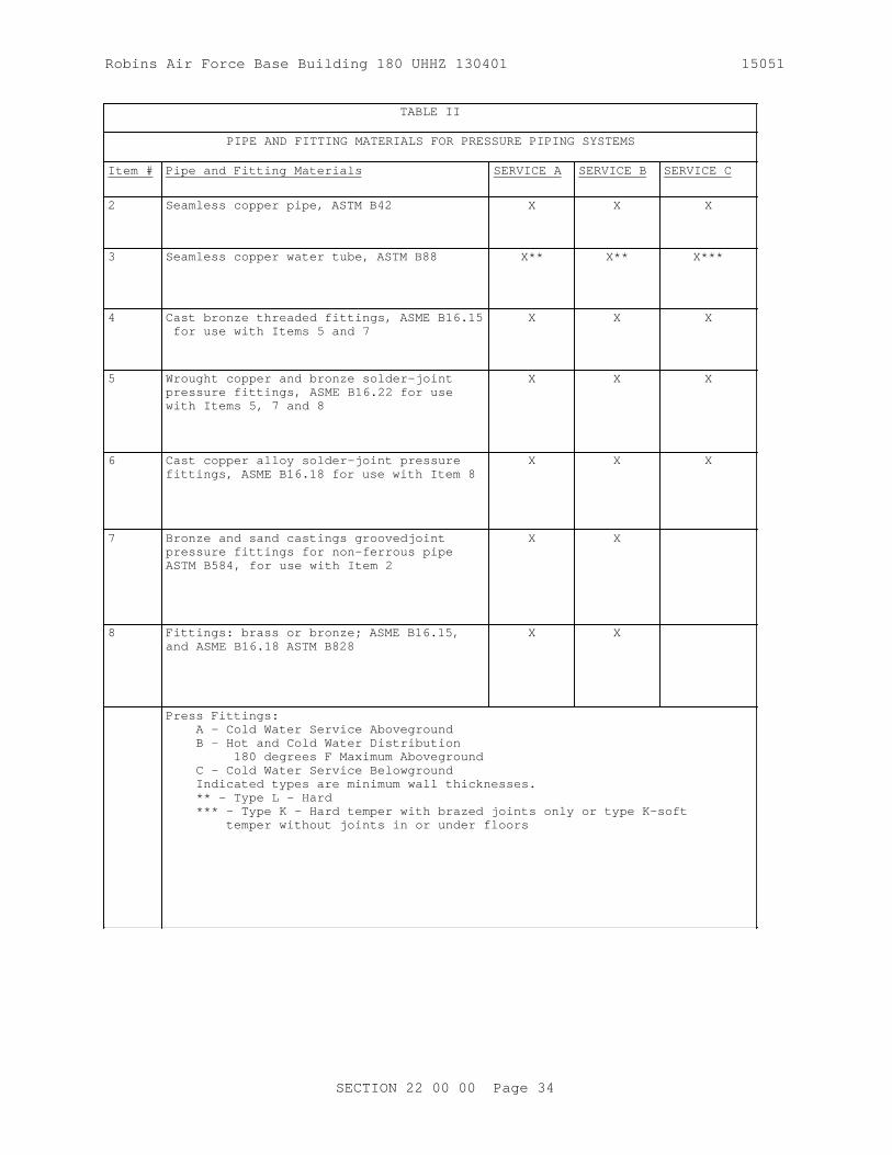
Robins Air Force Base Building 180 UHHZ 130401 15051
TABLE II
PIPE AND FITTING MATERIALS FOR PRESSURE PIPING SYSTEMS
Item # Pipe and Fitting Materials SERVICE A SERVICE B SERVICE C
2 Seamless copper pipe, ASTM B42 X X X
3 Seamless copper water tube, ASTM B88 X** X** X***
4 Cast bronze threaded fittings, ASME B16.15 for use with Items 5 and 7
X X X
5 Wrought copper and bronze solder-joint pressure fittings, ASME B16.22 for use with Items 5, 7 and 8
X X X
6 Cast copper alloy solder-joint pressure fittings, ASME B16.18 for use with Item 8
X X X
7 Bronze and sand castings groovedjoint pressure fittings for non-ferrous pipe ASTM B584, for use with Item 2
X X
8 Fittings: brass or bronze; ASME B16.15 , and ASME B16.18 ASTM B828
X X
Press Fittings: A - Cold Water Service Aboveground B - Hot and Cold Water Distribution 180 degrees F Maximum Aboveground C - Cold Water Service Belowground Indicated types are minimum wall thicknesses. ** - Type L - Hard *** - Type K - Hard temper with brazed joints only or type K-soft temper without joints in or under floors
SECTION 22 00 00 Page 34

Robins Air Force Base Building 180 UHHZ 130401 15051
TABLE III
STANDARD RATING CONDITIONS AND MINIMUM PERFORMANCE RATINGS FOR WATER HEATING EQUIPMENT
FUEL STORAGE CAPACITY GALLONS
INPUT RATING TEST PROCEDURE REQUIRED PERFORMANCE
A. STORAGE WATER HEATERS
Elect. 20 min. 12 kW max. 10 CFR 430 EF = 0.93-0.00132V minimum
TERMS:
EF = Energy factor, minimum overall efficiency.ET = Minimum thermal efficiency with 70 degrees F delta T.SL = Standby loss is maximum Btu/h based on a 70 degree F temperature difference between stored water and ambient requirements.V = Rated storage volume in gallonsQ = Nameplate input rate in Btu/h
-- End of Section --
SECTION 22 00 00 Page 35
THIS PAGE INTENTIONALLY LEFT BLANK FOR DUPLEX PRINTING

Robins Air Force Base Building 180 UHHZ 130401 15051
SECTION 23 00 00
AIR SUPPLY, DISTRIBUTION, VENTILATION, AND EXHAUST SYSTEMS08/10
PART 1 GENERAL
1.1 REFERENCES
The publications listed below form a part of this specification to the extent referenced. The publications are referred to within the text by the basic designation only.
AIR MOVEMENT AND CONTROL ASSOCIATION INTERNATIONAL (AMCA)
AMCA 201 (2002; R 2011) Fans and Systems
AMCA 210 (2007) Laboratory Methods of Testing Fans for Aerodynamic Performance Rating
AMCA 300 (2008) Reverberant Room Method for Sound Testing of Fans
AMCA 301 (2006; INT 2007) Methods for Calculating Fan Sound Ratings from Laboratory Test Data
AIR-CONDITIONING, HEATING AND REFRIGERATION INSTITUTE (AHRI)
AHRI 410 (2001; Addendum 1 2002; Addendum 2 2005; Addendum 3 2011) Forced-Circulation Air-Cooling and Air-Heating Coils
AHRI 430 (2009) Central-Station Air-Handling Units
AHRI 880 I-P (2011) Performance Rating of Air Terminals
AHRI 885 (2008; Addendum 2011) Procedure for Estimating Occupied Space Sound Levels in the Application of Air Terminals and Air Outlets
AMERICAN BEARING MANUFACTURERS ASSOCIATION (ABMA)
ABMA 11 (1990; R 2008) Load Ratings and Fatigue Life for Roller Bearings
ABMA 9 (1990; R 2008) Load Ratings and Fatigue Life for Ball Bearings
AMERICAN SOCIETY OF HEATING, REFRIGERATING AND AIR-CONDITIONING ENGINEERS (ASHRAE)
ASHRAE 62.1 (2010; Errata 2011; INT 3 2012; INT 4 2012; INT 5 2013) Ventilation for Acceptable Indoor Air Quality
ASHRAE 70 (2006; R 2011) Method of Testing for
SECTION 23 00 00 Page 1

Robins Air Force Base Building 180 UHHZ 130401 15051
Rating the Performance of Air Outlets and Inlets
ASHRAE 84 (2008) Method of Testing Air-to-Air Heat Exchangers
ASTM INTERNATIONAL (ASTM)
ASTM A123/A123M (2013) Standard Specification for Zinc (Hot-Dip Galvanized) Coatings on Iron and Steel Products
ASTM A167 (2011) Standard Specification for Stainless and Heat-Resisting Chromium-Nickel Steel Plate, Sheet, and Strip
ASTM A53/A53M (2012) Standard Specification for Pipe, Steel, Black and Hot-Dipped, Zinc-Coated, Welded and Seamless
ASTM A924/A924M (2014) Standard Specification for General Requirements for Steel Sheet, Metallic-Coated by the Hot-Dip Process
ASTM B117 (2011) Standard Practice for Operating Salt Spray (Fog) Apparatus
ASTM B152/B152M (2009) Standard Specification for Copper Sheet, Strip, Plate, and Rolled Bar
ASTM B766 (1986; R 2008) Standard Specification for Electrodeposited Coatings of Cadmium
ASTM C1071 (2012) Standard Specification for Fibrous Glass Duct Lining Insulation (Thermal and Sound Absorbing Material)
ASTM C553 (2013) Standard Specification for Mineral Fiber Blanket Thermal Insulation for Commercial and Industrial Applications
ASTM C916 (1985; R 2007) Standard Specification for Adhesives for Duct Thermal Insulation
ASTM D1654 (2008) Evaluation of Painted or Coated Specimens Subjected to Corrosive Environments
ASTM D3359 (2009; E 2010; R 2010) Measuring Adhesion by Tape Test
ASTM D520 (2000; R 2011) Zinc Dust Pigment
ASTM E2016 (2011) Standard Specification for Industrial Woven Wire Cloth
ASTM E84 (2015a) Standard Test Method for Surface Burning Characteristics of Building
SECTION 23 00 00 Page 2
Robins Air Force Base Building 180 UHHZ 130401 15051
Materials
NATIONAL ELECTRICAL MANUFACTURERS ASSOCIATION (NEMA)
NEMA MG 1 (2014) Motors and Generators
NEMA MG 10 (2013) Energy Management Guide for Selection and Use of Fixed Frequency Medium AC Squirrel-Cage Polyphase Induction Motors
NEMA MG 11 (1977; R 2012) Energy Management Guide for Selection and Use of Single Phase Motors
NATIONAL FIRE PROTECTION ASSOCIATION (NFPA)
NFPA 701 (2010) Standard Methods of Fire Tests for Flame Propagation of Textiles and Films
NFPA 90A (2015) Standard for the Installation of Air Conditioning and Ventilating Systems
SHEET METAL AND AIR CONDITIONING CONTRACTORS' NATIONAL ASSOCIATION (SMACNA)
SMACNA 1819 (2002) Fire, Smoke and Radiation Damper Installation Guide for HVAC Systems, 5th Edition
SMACNA 1966 (2005) HVAC Duct Construction Standards Metal and Flexible, 3rd Edition
U.S. NATIONAL ARCHIVES AND RECORDS ADMINISTRATION (NARA)
40 CFR 82 Protection of Stratospheric Ozone
UNDERWRITERS LABORATORIES (UL)
UL 181 (2005; Reprint Oct 2008) Factory-Made Air Ducts and Air Connectors
UL 555 (2006; Reprint May 2012) Standard for Fire Dampers
UL 6 (2007; reprint Nov 2010) Electrical Rigid Metal Conduit-Steel
UL 705 (2004; Reprint Mar 2012) Standard for Power Ventilators
UL 723 (2008; Reprint Aug 2013) Test for Surface Burning Characteristics of Building Materials
UL 900 (2004; Reprint Feb 2012) Standard for Air Filter Units
UL Bld Mat Dir (2012) Building Materials Directory
SECTION 23 00 00 Page 3

Robins Air Force Base Building 180 UHHZ 130401 15051
UL Fire Resistance (2014) Fire Resistance Directory
1.2 SYSTEM DESCRIPTION
Furnish ductwork, piping offsets, fittings, and accessories as required to provide a complete installation. Coordinate the work of the different trades to avoid interference between piping, equipment, structural, and electrical work. Provide complete, in place, all necessary offsets in piping and ductwork, and all fittings, and other components, required to install the work as indicated and specified.
1.2.1 Mechanical Equipment Identification
The number of charts and diagrams shall be equal to or greater than the number of mechanical equipment rooms. Where more than one chart or diagram per space is required, mount these in edge pivoted, swinging leaf, extruded aluminum frame holders which open to 170 degrees.
1.2.1.1 Charts
Provide chart listing of equipment by designation numbers and capacities such as flow rates, pressure and temperature differences, heating and cooling capacities, horsepower, pipe sizes, and voltage and current characteristics.
1.2.1.2 Diagrams
Submit proposed diagrams, at least 2 weeks prior to start of related testing. provide neat mechanical drawings provided with extruded aluminum frame under 1/8-inch glass or laminated plastic, system diagrams that show the layout of equipment, piping, and ductwork, and typed condensed operation manuals explaining preventative maintenance procedures, methods of checking the system for normal, safe operation, and procedures for safely starting and stopping the system. After approval, post these items where directed.
1.2.2 Service Labeling
Label equipment, including fans, air handlers, terminal units, etc. with labels made of self-sticking, plastic film designed for permanent installation. Labels shall be in accordance with drawings.
Identify similar services with different temperatures or pressures. Where pressures could exceed 125 pounds per square inch, gage, include the maximum system pressure in the label. Label and arrow piping in accordance with the following:
a. Each point of entry and exit of pipe passing through walls.
b. Each change in direction, i.e., elbows, tees.
c. In congested or hidden areas and at all access panels at each point required to clarify service or indicated hazard.
d. In long straight runs, locate labels at distances within eyesight of each other not to exceed 75 feet. All labels shall be visible and legible from the primary service and operating area.
SECTION 23 00 00 Page 4
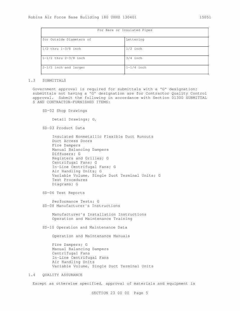
Robins Air Force Base Building 180 UHHZ 130401 15051
For Bare or Insulated Pipes
for Outside Diameters of Lettering
1/2 thru 1-3/8 inch 1/2 inch
1-1/2 thru 2-3/8 inch 3/4 inch
2-1/2 inch and larger 1-1/4 inch
1.3 SUBMITTALS
Government approval is required for submittals with a "G" designation; submittals not having a "G" designation are for Contractor Quality Control approval. Submit the following in accordance with Section 01300 SUBMITTALS AND CONTRACTOR-FURNISHED ITEMS:
SD-02 Shop Drawings
Detail Drawings; G,
SD-03 Product Data
Insulated Nonmetallic Flexible Duct RunoutsDuct Access DoorsFire DampersManual Balancing DampersDiffusers; GRegisters and Grilles; GCentrifugal Fans; GIn-Line Centrifugal Fans ; GAir Handling Units; GVariable Volume, Single Duct Terminal Units; GTest ProceduresDiagrams; G
SD-06 Test Reports
Performance Tests; GSD-08 Manufacturer's Instructions
Manufacturer's Installation InstructionsOperation and Maintenance Training
SD-10 Operation and Maintenance Data
Operation and Maintenance Manuals
Fire Dampers; GManual Balancing DampersCentrifugal FansIn-Line Centrifugal FansAir Handling UnitsVariable Volume, Single Duct Terminal Units
1.4 QUALITY ASSURANCE
Except as otherwise specified, approval of materials and equipment is
SECTION 23 00 00 Page 5

Robins Air Force Base Building 180 UHHZ 130401 15051
based on manufacturer's published data.
a. Where materials and equipment are specified to conform to the standards of the Underwriters Laboratories, the label of or listing with reexamination in UL Bld Mat Dir , and UL 6 is acceptable as sufficient evidence that the items conform to Underwriters Laboratories requirements. In lieu of such label or listing, submit a written certificate from any nationally recognized testing agency, adequately equipped and competent to perform such services, stating that the items have been tested and that the units conform to the specified requirements. Outline methods of testing used by the specified agencies.
b. Where materials or equipment are specified to be constructed or tested, or both, in accordance with the standards of the ASTM International (ASTM), the ASME International (ASME), or other standards, a manufacturer's certificate of compliance of each item is acceptable as proof of compliance.
c. Conformance to such agency requirements does not relieve the item from compliance with other requirements of these specifications.
1.4.1 Prevention of Corrosion
Protect metallic materials against corrosion. Manufacturer shall provide rust-inhibiting treatment and standard finish for the equipment enclosures. Do not use aluminum in contact with earth, and where connected to dissimilar metal. Protect aluminum by approved fittings, barrier material, or treatment. Ferrous parts such as anchors, bolts, braces, boxes, bodies, clamps, fittings, guards, nuts, pins, rods, shims, thimbles, washers, and miscellaneous parts not of corrosion-resistant steel or nonferrous materials shall be hot-dip galvanized in accordance with ASTM A123/A123M for exterior locations and cadmium-plated in conformance with ASTM B766 for interior locations.
1.4.2 Asbestos Prohibition
Do not use asbestos and asbestos-containing products.
1.4.3 Ozone Depleting Substances Used as Refrigerants
Minimize releases of Ozone Depleting Substances (ODS) during repair, maintenance, servicing or disposal of appliances containing ODS's by complying with all applicable sections of 40 CFR 82 Part 82 Subpart F. Any person conducting repair, maintenance, servicing or disposal of appliances owned by NASA shall comply with the following:
a. Do not knowingly vent or otherwise release into the environment, Class I or Class II substances used as a refrigerant.
b. Do not open appliances without meeting the requirements of 40 CFR 82 Part 82.156 Subpart F, regarding required practices for evacuation and collection of refrigerant, and 40 CFR 82 Part 82.158 Subpart F, regarding standards of recycling and recovery equipment.
c. Only persons who comply with 40 CFR 82 Part 82.161 Subpart F, regarding technician certification, can conduct work on appliances containing refrigerant.
SECTION 23 00 00 Page 6

Robins Air Force Base Building 180 UHHZ 130401 15051
In addition, provide copies of all applicable certifications to the Contracting Officer at least 14 calendar days prior to initiating maintenance, repair, servicing, dismantling or disposal of appliances, including:
a. Proof of Technician Certification
b. Proof of Equipment Certification for recovery or recycling equipment.
c. Proof of availability of certified recovery or recycling equipment.
1.4.4 Use of Ozone Depleting Substances, Other than Refrigerants
The use of Class I or Class II ODS's listed as nonessential in 40 CFR 82 Part 82.66 Subpart C is prohibited. These prohibited materials and uses include:
a. Any plastic party spray streamer or noise horn which is propelled by a chlorofluorocarbon
b. Any cleaning fluid for electronic and photographic equipment which contains a chlorofluorocarbon; including liquid packaging, solvent wipes, solvent sprays, and gas sprays.
c. Any plastic flexible or packaging foam product which is manufactured with or contains a chlorofluorocarbon, including, open cell foam, open cell rigid polyurethane poured foam, closed cell extruded polystyrene sheet foam, closed cell polyethylene foam and closed cell polypropylene foam except for flexible or packaging foam used in coaxial cabling.
d. Any aerosol product or other pressurized dispenser which contains a chlorofluorocarbon, except for those listed in 40 CFR 82 Part 82.66 Subpart C.
1.4.5 Detail Drawings
Submit detail drawings showing equipment layout, including assembly and installation details and electrical connection diagrams; ductwork layout showing the location of all supports and hangers, typical hanger details, gauge reinforcement, reinforcement spacing rigidity classification, and static pressure and seal classifications. Include any information required to demonstrate that the system has been coordinated and functions properly as a unit on the drawings and show equipment relationship to other parts of the work, including clearances required for operation and maintenance. Submit drawings showing bolt-setting information, and foundation bolts prior to concrete foundation construction for all equipment indicated or required to have concrete foundations. Submit function designation of the equipment and any other requirements specified throughout this Section with the shop drawings.
1.4.6 Test Procedures
Submit proposed test procedures and test schedules for the ductwork leak test, and performance tests of systems, at least 2 weeks prior to the start of related testing.
SECTION 23 00 00 Page 7

Robins Air Force Base Building 180 UHHZ 130401 15051
1.5 DELIVERY, STORAGE, AND HANDLING
Protect stored equipment at the jobsite from the weather, humidity and temperature variations, dirt and dust, or other contaminants. Additionally, cap or plug all pipes until installed.
PART 2 PRODUCTS
2.1 IDENTIFICATION PLATES
In addition to standard manufacturer's identification plates, provide engraved laminated phenolic identification plates for each piece of mechanical equipment. Identification plates are to designate the function of the equipment. Submit designation with the shop drawings. Identification plates shall be three layers, black-white-black, engraved to show white letters on black background. Letters shall be upper case. Identification plates 1-1/2-inches high and smaller shall be 1/16-inch thick, with engraved lettering 1/8-inch high; identification plates larger than 1-1/2-inches high shall be 1/8-inch thick, with engraved lettering of suitable height. Identification plates 1-1/2-inches high and larger shall have beveled edges. Install identification plates using a compatible adhesive.
2.2 EQUIPMENT GUARDS AND ACCESS
Fully enclose or guard belts, pulleys, chains, gears, couplings, projecting setscrews, keys, and other rotating parts exposed to personnel contact according to OSHA requirements. Properly guard or cover with insulation of a type specified, high temperature equipment and piping exposed to contact by personnel or where it creates a potential fire hazard.
2.3 ELECTRICAL WORK
a. Provide motors, controllers, integral disconnects, contactors, and controls with their respective pieces of equipment, except controllers indicated as part of motor control centers. Provide electrical equipment, including motors and wiring, as specified in Section 26 20 00INTERIOR DISTRIBUTION SYSTEM. Provide manual or automatic control and protective or signal devices required for the operation specified and control wiring required for controls and devices specified, but not shown. For packaged equipment, include manufacturer provided controllers with the required monitors and timed restart.
b. For single-phase motors, provide high-efficiency type, fractional-horsepower alternating-current motors, including motors that are part of a system, in accordance with NEMA MG 11. Integral size motors shall be the premium efficiency type in accordance with NEMA MG 1.
c. For polyphase motors, provide squirrel-cage medium induction motors, including motors that are part of a system , and that meet the efficiency ratings for premium efficiency motors in accordance with NEMA MG 1. Select premium efficiency polyphase motors in accordance with NEMA MG 10.
d. Provide motors in accordance with NEMA MG 1 and of sufficient size to drive the load at the specified capacity without exceeding the
SECTION 23 00 00 Page 8

Robins Air Force Base Building 180 UHHZ 130401 15051
nameplate rating of the motor. Provide motors rated for continuous duty with the enclosure specified. Provide motor duty that allows for maximum frequency start-stop operation and minimum encountered interval between start and stop. Provide motor torque capable of accelerating the connected load within 20 seconds with 80 percent of the rated voltage maintained at motor terminals during one starting period. Provide motor starters complete with thermal overload protection and other necessary appurtenances. Fit motor bearings with grease supply fittings and grease relief to outside of the enclosure.
2.4 ANCHOR BOLTS
Provide anchor bolts for equipment placed on concrete equipment pads or on concrete slabs. Bolts to be of the size and number recommended by the equipment manufacturer and located by means of suitable templates. Installation of anchor bolts shall not degrade the surrounding concrete.
2.5 PAINTING
Paint equipment units in accordance with approved equipment manufacturer's standards unless specified otherwise. Field retouch only if approved. Otherwise, return equipment to the factory for refinishing.
2.6 INDOOR AIR QUALITY
Provide equipment and components that comply with the requirements of ASHRAE 62.1 unless more stringent requirements are specified herein.
2.7 DUCT SYSTEMS
2.7.1 Metal Ductwork
Provide metal ductwork construction, including all fittings and components, that complies with SMACNA 1966, as supplemented and modified by this specification.
Provide radius type elbows with a centerline radius of 1.5 times the width or diameter of the duct where space permits. Otherwise, elbows having a minimum radius equal to the width or diameter of the duct or square elbows with factory fabricated turning vanes are allowed.
Provide sealants that conform to fire hazard classification specified in Section 23 07 00 THERMAL INSULATION FOR MECHANICAL SYSTEMS and are suitable for the range of air distribution and ambient temperatures to which it is exposed. Do not use pressure sensitive tape as a sealant.
Make spiral lock seam duct with duct sealant and lock with not less than 3 equally spaced drive screws or other approved methods indicated in SMACNA 1966. Apply the sealant to the exposed male part of the fitting collar so that the sealer is on the inside of the joint and fully protected by the metal of the duct fitting. Apply one brush coat of the sealant over the outside of the joint to at least 2 inch band width covering all screw heads and joint gap. Dents in the male portion of the slip fitting collar are not acceptable. Fabricate outdoor air intake ducts and plenums with watertight soldered or brazed joints and seams.
SECTION 23 00 00 Page 9

Robins Air Force Base Building 180 UHHZ 130401 15051
2.7.1.1 Insulated Nonmetallic Flexible Duct Runouts
Use flexible duct runouts only where indicated. Runout length is indicated on the drawings, and shall not exceed 5 feet. Provide runouts that are preinsulated, factory fabricated, and that comply with NFPA 90A and UL 181 . Provide either field or factory applied vapor barrier. Provide not less than 20 ounce glass fabric duct connectors coated on both sides with neoprene. Provide insulated material and vapor barrier that conform to the requirements of Section 23 07 00 THERMAL INSULATION FOR MECHANICAL SYSTEMS. Do not expose the insulation material surface to the air stream.
2.7.1.2 General Service Duct Connectors
Provide a flexible duct connector approximately 6 inches in width where sheet metal connections are made to fans or where ducts of dissimilar metals are connected. For round/oval ducts, secure the flexible material by stainless steel or zinc-coated, iron clinch-type draw bands. For rectangular ducts, install the flexible material locked to metal collars using normal duct construction methods. Provide a composite connector system that complies with NFPA 701 and is classified as "flame-retardent fabrics" in UL Bld Mat Dir .
2.7.1.3 Copper Sheets
ASTM B152/B152M , light cold rolled temper.
2.7.1.4 Corrosion Resisting (Stainless) Steel Sheets
ASTM A167
2.7.2 Duct Access Doors
Provide hinged access doors conforming to SMACNA 1966 in ductwork and plenums where indicated and at all air flow measuring stations, automatic dampers, dampers, coils, and other apparatus requiring service and inspection in the duct system. Provide access doors upstream and downstream of air flow measuring primaries and heating and cooling coils. Provide doors that are a minimum 15 by 18 inches, unless otherwise shown. Where duct size does not accommodate this size door, make the doors as large as practicable. Equip doors 24 by 24 inches or larger with fasteners operable from inside and outside the duct. Use insulated type doors in insulated ducts.
2.7.3 Fire Dampers
Use 3 hour rated fire dampers unless otherwise indicated. Provide fire dampers that conform to the requirements of NFPA 90A and UL 555 . Perform the fire damper test as outlined in NFPA 90A. Provide a pressure relief door upstream of the fire damper. If the ductwork connected to the fire damper is to be insulated then provide a factory installed pressure relief damper. Provide automatic operating fire dampers with a dynamic rating suitable for the maximum air velocity and pressure differential to which it is subjected. Provide fire dampers approved for the specific application, and install according to their listing. Equip fire dampers with a steel sleeve or adequately sized frame installed in such a manner that disruption of the attached ductwork, if any, does not impair the operation of the damper. Equip sleeves or frames with perimeter mounting angles attached on both sides of the wall or floor opening. Construct
SECTION 23 00 00 Page 10

Robins Air Force Base Building 180 UHHZ 130401 15051
ductwork in fire-rated floor-ceiling or roof-ceiling assembly systems with air ducts that pierce the ceiling of the assemblies in conformance with UL Fire Resistance . Provide curtain type with damper blades as detailed or multi-blade type fire dampers. Install dampers that do not reduce the duct or the air transfer opening cross-sectional area. Install dampers so that the centerline of the damper depth or thickness is located in the centerline of the wall, partition or floor slab depth or thickness. Unless otherwise indicated, comply with the installation details given in SMACNA 1819 and in manufacturer's instructions for fire dampers. Perform acceptance testing of fire dampers according to paragraph Fire Damper Acceptance Test and NFPA 90A.
2.7.4 Sound Attenuation Equipment
a. For acoustical duct liner: Use flexible elastomeric duct liner for lining ductwork and conforming to the requirements of ASTM C1071, Type I and II. Provide uniform density, graduated density, or dual density liner composition, as standard with the manufacturer. Provide not less than 0.5 inch thick lining. Where acoustical duct liner is used, provide the thermal equivalent of the insulation specified in Section 23 07 00 THERMAL INSULATION FOR MECHANICAL SYSTEMS for liner or combination of liner and insulation applied to the exterior of the ductwork.
2.7.5 Diffusers, Registers, and Grilles
Provide factory-fabricated units that distribute the specified quantity of air evenly over space intended without causing noticeable drafts, air movement faster than 50 fpm in occupied zone, or dead spots anywhere in the conditioned area. Provide outlets for diffusion, spread, throw, and noise level as required for specified performance. Certify performance according to ASHRAE 70. Provide sound rated and certified inlets and outlets according to ASHRAE 70. Provide sound power level as indicated. Provide diffusers and registers with volume damper with accessible operator, unless otherwise indicated. Provide opposed blade type volume dampers for diffusers and registers, where shown.
2.7.5.1 Diffusers
Provide diffuser types indicated. Furnish ceiling mounted units with anti-smudge devices, unless the diffuser unit minimizes ceiling smudging through design features. Provide diffusers with air deflectors of the type indicated. Install ceiling mounted units with rims tight against ceiling. Provide sponge rubber gaskets between ceiling and surface mounted diffusers for air leakage control. Provide suitable trim for flush mounted diffusers. For connecting the duct to diffuser, provide duct collar that is airtight and does not interfere with volume controller.
2.7.5.2 Registers and Grilles
Provide units that are four-way directional-control type. Furnish registers with sponge-rubber gasket between flanges and wall or ceiling. Install wall supply registers at least 6 inches below the ceiling unless otherwise indicated. Achieve four-way directional control by a grille face which can be rotated in 4 positions or by adjustment of horizontal and vertical vanes.
SECTION 23 00 00 Page 11

Robins Air Force Base Building 180 UHHZ 130401 15051
2.7.6 Air Vents, Penthouses, and Goosenecks
Fabricate air vents, penthouses, and goosenecks from galvanized steel or aluminum sheets with galvanized or aluminum structural shapes. Provide sheet metal thickness, reinforcement, and fabrication that conform to SMACNA 1966. Accurately fit and secure louver blades to frames. Fold or bead edges of louver blades for rigidity and baffle these edges to exclude driving rain. Provide air vents, penthouses, and goosenecks with bird screen.
2.7.7 Bird Screens and Frames
Provide bird screens that conform to ASTM E2016, No. 2 mesh, aluminum or stainless steel. Provide "medium-light" rated aluminum screens. Provide "light" rated stainless steel screens. Provide removable type frames fabricated from either stainless steel or extruded aluminum.
2.8 AIR SYSTEMS EQUIPMENT
2.8.1 Fans
Test and rate fans according to AMCA 210. Calculate system effect on air moving devices in accordance with AMCA 201 where installed ductwork differs from that indicated on drawings. Install air moving devices to minimize fan system effect. Where system effect is unavoidable, determine the most effective way to accommodate the inefficiencies caused by system effect on the installed air moving device. The sound power level of the fans shall not exceed 85 dBA when tested according to AMCA 300 and rated in accordance with AMCA 301. Provide all fans with an AMCA seal. Connect fans to the motors either directly or indirectly with V-belt drive. Use V-belt drives designed for not less than 120 percent of the connected driving capacity. Provide variable pitch motor sheaves. Select variable pitch sheaves to drive the fan at a speed which can produce the specified capacity when set at the approximate midpoint of the sheave adjustment. When fixed pitch sheaves are furnished, provide a replaceable sheave when needed to achieve system air balance. Provide motors for V-belt drives with adjustable rails or bases. Provide removable metal guards for all exposed V-belt drives, and provide speed-test openings at the center of all rotating shafts. Provide fans with personnel screens or guards on both suction and supply ends, except that the screens need not be provided, unless otherwise indicated, where ducts are connected to the fan. Provide fan and motor assemblies with vibration-isolation supports or mountings as indicated. Use vibration-isolation units that are standard products with published loading ratings. Select each fan to produce the capacity required at the fan static pressure indicated. Provide sound power level as indicated. Obtain the sound power level values according to AMCA 300. Provide standard AMCA arrangement, rotation, and discharge as indicated. Provide power ventilators that conform to UL 705 and have a UL label.
2.8.1.1 Centrifugal Fans
Provide centrifugal fans, with AMCA Pressure Class I, II, or III as required. Provide impeller wheels that are rigidly constructed and accurately balanced both statically and dynamically. Provide fan wheels that have one or more extra long bearings between the fan wheel and the drive. Provide sleeve type, self-aligning and self-oiling bearings with oil reservoirs, or precision self-aligning roller or ball-type with accessible grease fittings or permanently lubricated type. Connect grease
SECTION 23 00 00 Page 12

Robins Air Force Base Building 180 UHHZ 130401 15051
fittings to tubing for serviceability from a single accessible point. Provide L50 rated bearing life at not less than 200,000 hours as defined by ABMA 9 and ABMA 11. Provide steel, accurately finished fan shafts, with key seats and keys for impeller hubs and fan pulleys. Provide fan outlets of ample proportions, designed for the attachment of angles and bolts for attaching flexible connections. Unless otherwise indicated, provide motors that do not exceed 1800 rpm and have dripproof enclosures.
2.8.1.2 In-Line Centrifugal Fans
Provide in-line fans with centrifugal blades, stationary discharge conversion vanes. Provide a fan that axially flows the air in and out. Streamline inlets with conversion vanes to eliminate turbulence and provide smooth discharge air flow. Enclose and isolate fan bearings and drive shafts from the air stream. Provide precision, self aligning ball or roller type fan bearings that are sealed against dust and dirt and are permanently lubricated. Provide L50 rated bearing life at not less than 200,000 hours as defined by ABMA 9 and ABMA 11. Provide motors with dripproof enclosure. Provide magnetic motor starters across-the-line with general-purpose enclosures.
2.8.2 Coils
Provide fin-and-tube type coils constructed of seamless copper tubes and aluminum fins mechanically bonded or soldered to the tubes. Provide copper tube wall thickness that is a minimum of 0.016 inches. Provide casing and tube support sheets that are not lighter than 16 gauge galvanized steel, formed to provide structural strength. When required, provide multiple tube supports to prevent tube sag. Test each coil at the factory under water at not less than 400 psi air pressure and make suitable for 200 psi working pressure and 300 degrees F operating temperature unless otherwise stated. Mount coils for counterflow service. Rate and certify coils to meet the requirements of AHRI 410 .
2.8.2.1 Water Coils
Install water coils with a pitch of not less than 1/8 inch/foot of the tube length toward the drain end. Use headers constructed of cast iron, welded steel or copper. Furnish each coil with a plugged vent and drain connection extending through the unit casing. Provide removable water coils with drain pans.
2.8.3 Air Filters
List air filters according to requirements of UL 900 .
2.8.3.1 Extended Surface Pleated Panel Filters
Provide sectional, disposable type filters as scheduled. Provide UL Class 2 filters, and nonwoven cotton and synthetic fiber mat media. Attach a wire support grid bonded to the media to a moisture resistant fiberboard frame. Bond all four edges of the filter media to the inside of the frame to prevent air bypass and increase rigidity.
2.8.3.2 Holding Frames
Fabricate frames from not lighter than 16 gauge sheet steel with rust-inhibitor coating. Equip each holding frame with suitable filter holding devices. Provide gasketed holding frame seats. Make all joints
SECTION 23 00 00 Page 13

Robins Air Force Base Building 180 UHHZ 130401 15051
airtight.
2.9 AIR HANDLING UNITS
2.9.1 Factory-Fabricated Air Handling Units
Provide single-zone draw-through type units as indicated. Units shall include fans, coils, airtight insulated casing, filters, adjustable V-belt drives, belt guards for externally mounted motors, access sections where indicated, combination sectional filter-mixing box, vibration-isolators, and appurtenances required for specified operation. Provide vibration isolators as indicated. Physical dimensions of each air handling unit shall be suitable to fit space allotted to the unit with the capacity indicated. Provide air handling unit that is rated in accordance with AHRI 430 and AHRI certified for cooling.
2.9.1.1 Casings
Provide the following:
a. Casing sections 2 inch double wall type as indicated, constructed of a minimum 18 gauge galvanized steel. Inner casing of double-wall units that are a minimum 20 gauge solid galvanized steel. Design and construct casing with an integral insulated structural galvanized steel frame such that exterior panels are non-load bearing.
b. Individually removable exterior panels with standard tools. Removal shall not affect the structural integrity of the unit. Furnish casings with access sections, according to paragraph AIR HANDLING UNITS, inspection doors, and access doors, all capable of opening a minimum of 90 degrees, as indicated.
c. Insulated, fully gasketed, double-wall type inspection and access doors, of a minimum 18 gauge outer and 20 gauge inner panels made of either galvanized steel. Doors shall be rigid and provided with heavy duty hinges and latches. Inspection doors shall be a minimum 12 inches wide by 12 inches high. Access doors shall be a minimum 24 inches wide, the full height of the unit casing or a minimum of 6 foot, whichever is less.
d. Double-wall insulated type drain pan (thickness equal to exterior casing) constructed of 16 gauge corrosion resisting sheet stainless steel conforming to ASTM A167, Type 304, conforming to ASHRAE 62.1 . Construct drain pans water tight, treated to prevent corrosion, and designed for positive condensate drainage. When 2 or more cooling coils are used, with one stacked above the other, condensate from the upper coils shall not flow across the face of lower coils. Provide intermediate drain pans or condensate collection channels and downspouts, as required to carry condensate to the unit drain pan out of the air stream and without moisture carryover. Construct drain pan to allow for easy visual inspection, including underneath the coil without removal of the coil and to allow complete and easy physical cleaning of the pan underneath the coil without removal of the coil. Coils shall be individually removable from the casing.
e. Casing insulation that conforms to NFPA 90A. Double-wall casing sections handling conditioned air shall be insulated with not less than 2 inches of insulation. Foil-faced insulation is not an acceptable substitute for use with double wall casing. Double wall insulation
SECTION 23 00 00 Page 14

Robins Air Force Base Building 180 UHHZ 130401 15051
shall be completely sealed by inner and outer panels.
2.9.1.2 Heating and Cooling Coils
Provide coils as specified in paragraph AIR SYSTEMS EQUIPMENT.
2.9.1.3 Air Filters
Provide air filters as specified in paragraph AIR SYSTEMS EQUIPMENT for types and thickness indicated.
2.9.1.4 Fans
Provide the following:
a. Fans shall be double-inlet, scrolled centrifugal type. Dynamically balance fans and shafts prior to installation into air handling unit, then after it has been installed in the air handling unit, statically and dynamically balance the entire fan assembly. Mount fans on steel shafts, accurately ground and finished.
b. Fan bearings that are sealed against dust and dirt and are precision self-aligning ball or roller type, with L50 rated bearing life at not less than 200,000 hours as defined by ABMA 9 and ABMA 11. Bearings shall be permanently lubricated or lubricated type with lubrication fittings readily accessible at the drive side of the unit. Support bearings by structural shapes, or die formed sheet structural members, or support plates securely attached to the unit casing. Do not fasten bearings directly to the unit sheet metal casing. Furnish fans and scrolls with coating indicated.
2.9.1.5 Access Sections and Filter/Mixing Boxes
Provide access sections where indicated and furnish with access doors as shown. Construct access sections and filter/mixing boxes in a manner identical to the remainder of the unit casing and equip with access doors. Design mixing boxes to minimize air stratification and to promote thorough mixing of the air streams.
2.9.1.6 Ultraviolet Disinfection System
For central station air handling units provide an ultra violet band (UVC) disinfection system for mold, bacteria and odor control. Irradiation-emitters and fixtures are to be installed in sufficient quantity and in such an arrangement so as to provide an equal distribution of UVC energy on the coil and in the drain pan. To maintain energy efficiency, the UVC energy produced shall be of the lowest possible reflected and shadowed losses. Energy Efficiency - Power supplies shall be of the high efficiency electronic type and matched to the emitter. Intensity - The minimal UVC energy striking the leading edge (if installed upstream) or trailing edge (if installed downstream) of all the coil fins shall not be less than 820 AuW/cm2 at the closest point and through placement, not less than 60% of that value at the farthest point. Equal amounts are to strike the drain pan,either directly or indirectly through reflection. The foregoing sets the placement and minimum quantity of fixtures to be installed. Installation - emitters and fixtures shall be installed at right angles to the conforming lines of the coil fins, such that through incident angle reflection, UVC energy bathes all surfaces of the coil and drain pan as well as all of the available line of sight
SECTION 23 00 00 Page 15

Robins Air Force Base Building 180 UHHZ 130401 15051
airstream. One complete set of spare bulbs will be supplied. Provide door switch and inspection window.
2.10 TERMINAL UNITS
2.10.1 Variable Air Volume (VAV) Terminal Units
a. Provide VAV single duct terminal units that are the type, size, and capacity shown, mounted in the ceiling cavity, that are suitable for single duct system applications..
b. Provide unit enclosures that are constructed of galvanized steel not lighter than 22 gauge or aluminum sheet not lighter than 18 gauge. Units with flow limiters are not acceptable. Provide unit air volume that is factory preset and readily field adjustable without special tools. Provide reheat coils as indicated. Unit shall be single wall internally insulated with a minimum of one inch foil faced rigid insulation.
c. Attach a flow chart to each unit. Base acoustic performance of the terminal units upon units tested according to AHRI 880 I-P with the calculations prepared in accordance with AHRI 885 . Provide sound power level as indicated. Show discharge sound power for minimum and 1-1/2 inches water gauge inlet static pressure.
2.10.1.1 Variable Volume, Single Duct Terminal Units
Provide pressure independent variable volume, single duct, terminal units with a calibrated air volume sensing device, air valve or damper, actuator, and accessory relays. Provide units that control air volume to within plus or minus 5 percent of each air set point volume as determined by the thermostat with variations in inlet pressures from 3/4 to 6 inch water gauge. Provide units with an internal resistance not exceeding 0.6 inch water gauge at maximum flow range. Provide external differential pressure taps separate from the control pressure taps for air flow measurement with a 0 to 1 inch water gauge range.
2.10.1.2 Reheat Units
a. Hot Water Coils: Provide fin-and-tube type hot-water coils constructed of seamless copper tubes and copper or aluminum fins mechanically bonded or soldered to the tubes. Provide headers that are constructed of cast iron, welded steel or copper. Provide casing and tube support sheets that are 16 gauge, galvanized steel, formed to provide structural strength. Provide tubes that are correctly circuited for proper water velocity without excessive pressure drop and are drainable where required or indicated. At the factory, test each coil at not less than 250 psi air pressure and provide coils suitable for 200 psi working pressure. Install drainable coils in the air handling units with a pitch of not less than 1/8 inch per foot of tube length toward the drain end. Coils shall conform to the provisions of AHRI 410 .
2.11 ENERGY RECOVERY DEVICES
2.11.1 Rotary Wheel
Provide unit that is a factory fabricated and tested assembly for air-to-air energy recovery by transfer of sensible heat from exhaust air
SECTION 23 00 00 Page 16

Robins Air Force Base Building 180 UHHZ 130401 15051
to supply air stream, with device performance according to ASHRAE 84 and that delivers an energy transfer effectiveness of not less than 78 percent with cross-contamination not in excess of 0.04 percent of exhaust airflow rate at system design differential pressure, including purging sector if provided with wheel. Provide exchange media that is chemically inert, moisture-resistant, fire-retardant, laminated, nonmetallic material which complies with NFPA 90A. Isolate exhaust and supply streams by seals which are static, field adjustable, and replaceable. Equip chain drive mechanisms with ratcheting torque limiter or slip-clutch protective device. Fabricate enclosure from galvanized steel and include provisions for maintenance access. Provide recovery control and rotation failure provisions as indicated.
2.12 FACTORY PAINTING
Factory paint new equipment, which are not of galvanized construction. Paint with a corrosion resisting paint finish according to ASTM A123/A123M or ASTM A924/A924M . Clean, phosphatize and coat internal and external ferrous metal surfaces with a paint finish which has been tested according to ASTM B117, ASTM D1654, and ASTM D3359. Submit evidence of satisfactory paint performance for a minimum of 125 hours for units to be installed indoors and 500 hours for units to be installed outdoors. Provide rating of failure at the scribe mark that is not less than 6, average creepage not greater than 1/8 inch. Provide rating of the inscribed area that is not less than 10, no failure. On units constructed of galvanized steel that have been welded, provide a final shop docket of zinc-rich protective paint on exterior surfaces of welds or welds that have burned through from the interior according to ASTM D520 Type I.
Factory painting that has been damaged prior to acceptance by the Contracting Officer shall be field painted in compliance with the requirements of paragraph FIELD PAINTING OF MECHANICAL EQUIPMENT.
2.13 SUPPLEMENTAL COMPONENTS/SERVICES
2.13.1 Service Water Piping
The requirements for service water piping and accessories are specified in Section 23 64 26 CHILLED, HOT, AND CONDENSER WATER PIPING SYSTEMS
2.13.2 Condensate Drain Lines
Provide and install condensate drainage for each item of equipment that generates condensate in accordance with Section 22 00 00 PLUMBING, GENERAL PURPOSE.
2.13.3 Insulation
The requirements for shop and field applied insulation are specified in Section 23 07 00 THERMAL INSULATION FOR MECHANICAL SYSTEMS.
PART 3 EXECUTION
3.1 EXAMINATION
After becoming familiar with all details of the work, verify all dimensions in the field, and advise the Contracting Officer of any discrepancy before performing the work.
SECTION 23 00 00 Page 17

Robins Air Force Base Building 180 UHHZ 130401 15051
3.2 INSTALLATION
a. Install materials and equipment in accordance with the requirements of the contract drawings and approved manufacturer's installation instructions. Accomplish installation by workers skilled in this type of work. Perform installation so that there is no degradation of the designed fire ratings of walls, partitions, ceilings, and floors.
b. No installation is permitted to block or otherwise impede access to any existing machine or system. Install all hinged doors to swing open a minimum of 120 degrees. Provide an area in front of all access doors that clears a minimum of 3 feet. In front of all access doors to electrical circuits, clear the area the minimum distance to energized circuits as specified in OSHA Standards, part 1910.333 (Electrical-Safety Related work practices)and an additional 3 feet.
c. Except as otherwise indicated, install emergency switches and alarms in conspicuous locations. Mount all indicators, to include gauges, meters, and alarms in order to be easily visible by people in the area.
3.2.1 Condensate Drain Lines
Provide water seals in the condensate drain from all units. Provide a depth of each seal as detailed. Provide pipe cap or plug cleanouts where indicated. Connect drains indicated to connect to the sanitary waste system using an indirect waste fitting. Insulate air conditioner drain lines as specified in Section 23 07 00 THERMAL INSULATION FOR MECHANICAL SYSTEMS.
3.2.2 Equipment and Installation
Provide frames and supports for tanks, pumps, valves, air handling units, fans, coils, dampers, and other similar items requiring supports. Floor mount air handling units as indicated. Anchor and fasten as detailed. Set floor-mounted equipment on not less than 4 inch concrete pads or curbs doweled in place unless otherwise indicated. Make concrete foundations heavy enough to minimize the intensity of the vibrations transmitted to the piping, duct work and the surrounding structure, as recommended in writing by the equipment manufacturer. Provide the lines connected to the pump mounted on pedestal blocks with flexible connectors.
3.2.3 Access Panels
Install access panels for concealed valves, vents, controls, dampers, and items requiring inspection or maintenance of sufficient size, and locate them so that the concealed items are easily serviced and maintained or completely removed and replaced.
3.2.4 Flexible Duct
Install pre-insulated flexible duct in accordance with the latest printed instructions of the manufacturer to ensure a vapor tight joint. Provide hangers, when required to suspend the duct, of the type recommended by the duct manufacturer and set at the intervals recommended.
3.2.5 Metal Ductwork
Install according to SMACNA 1966 unless otherwise indicated. Install duct supports for sheet metal ductwork according to SMACNA 1966, unless
SECTION 23 00 00 Page 18

Robins Air Force Base Building 180 UHHZ 130401 15051
otherwise specified. Do not use friction beam clamps indicated in SMACNA 1966. Anchor risers on high velocity ducts in the center of the vertical run to allow ends of riser to move due to thermal expansion. Erect supports on the risers that allow free vertical movement of the duct. Attach supports only to structural framing members and concrete slabs. Do not anchor supports to metal decking unless a means is provided and approved for preventing the anchor from puncturing the metal decking. Where supports are required between structural framing members, provide suitable intermediate metal framing. Where C-clamps are used, provide retainer clips.
3.2.6 Acoustical Duct Lining
Apply lining in cut-to-size pieces attached to the interior of the duct with nonflammable fire resistant adhesive conforming to ASTM C916, Type I, NFPA 90A, UL 723 , and ASTM E84. Provide top and bottom pieces that lap the side pieces and are secured with welded pins, adhered clips of metal, nylon, or high impact plastic, and speed washers or welding cup-head pins installed according to SMACNA 1966. Provide welded pins, cup-head pins, or adhered clips that do not distort the duct, burn through, nor mar the finish or the surface of the duct. Make pins and washers flush with the surfaces of the duct liner and seal all breaks and punctures of the duct liner coating with the nonflammable, fire resistant adhesive. Coat exposed edges of the liner at the duct ends and at other joints where the lining is subject to erosion with a heavy brush coat of the nonflammable, fire resistant adhesive, to prevent delamination of glass fibers. Apply duct liner to flat sheet metal prior to forming duct through the sheet metal brake. Additionally secure lining at the top and bottom surfaces of the duct by welded pins or adhered clips as specified for cut-to-size pieces. Other methods indicated in SMACNA 1966 to obtain proper installation of duct liners in sheet metal ducts, including adhesives and fasteners, are acceptable.
3.2.7 Dust Control
To prevent the accumulation of dust, debris and foreign material during construction, perform temporary dust control protection. Protect the distribution system (supply and return) with temporary seal-offs at all inlets and outlets at the end of each day's work. Keep temporary protection in place until system is ready for startup.
3.2.8 Insulation
Provide thickness and application of insulation materials for ductwork, piping, and equipment according to Section 23 07 00 THERMAL INSULATION FOR MECHANICAL SYSTEMS. Externally insulate outdoor air intake ducts and plenums.
3.2.9 Duct Test Holes
Provide holes with closures or threaded holes with plugs in ducts and plenums as indicated or where necessary for the use of pitot tube in balancing the air system. Plug insulated duct at the duct surface, patched over with insulation and then marked to indicate location of test hole if needed for future use.
3.2.10 Power Roof Ventilator Mounting
Provide foamed 1/2 inch thick, closed-cell, flexible elastomer insulation
SECTION 23 00 00 Page 19

Robins Air Force Base Building 180 UHHZ 130401 15051
to cover width of roof curb mounting flange. Where wood nailers are used, predrill holes for fasteners.
3.3 EQUIPMENT PADS
Provide equipment pads to the dimensions shown or, if not shown, to conform to the shape of each piece of equipment served with a minimum 3-inch margin around the equipment and supports. Allow equipment bases and foundations, when constructed of concrete or grout, to cure a minimum of 14 calendar days before being loaded.
3.4 CUTTING AND PATCHING
Install work in such a manner and at such time that a minimum of cutting and patching of the building structure is required. Make holes in exposed locations, in or through existing floors, by drilling and smooth by sanding. Use of a jackhammer is permitted only where specifically approved. Make holes through masonry walls to accommodate sleeves with an iron pipe masonry core saw.
3.5 CLEANING
Thoroughly clean surfaces of piping and equipment that have become covered with dirt, plaster, or other material during handling and construction before such surfaces are prepared for final finish painting or are enclosed within the building structure. Before final acceptance, clean mechanical equipment, including piping, ducting, and fixtures, and free from dirt, grease, and finger marks.
3.6 PENETRATIONS
Provide sleeves and prepared openings for duct mains, branches, and other penetrating items, and install during the construction of the surface to be penetrated. Cut sleeves flush with each surface. Place sleeves for round duct 15 inches and smaller. Build framed, prepared openings for round duct larger than 15 inches and square, rectangular or oval ducts. Sleeves and framed openings are also required where grilles, registers, and diffusers are installed at the openings. Provide one inch clearance between penetrating and penetrated surfaces except at grilles, registers, and diffusers. Pack spaces between sleeve or opening and duct or duct insulation with mineral fiber conforming with ASTM C553, Type 1, Class B-2.
a. Sleeves: Fabricate sleeves, except as otherwise specified or indicated, from 20 gauge thick mill galvanized sheet metal. Where sleeves are installed in bearing walls or partitions, provide black steel pipe conforming with ASTM A53/A53M, Schedule 20.
b. Framed Prepared Openings: Fabricate framed prepared openings from 20 gauge galvanized steel, unless otherwise indicated.
c. Insulation: Provide duct insulation in accordance with Section 23 07 00 THERMAL INSULATION FOR MECHANICAL SYSTEMS continuous through sleeves and prepared openings except firewall penetrations. Terminate duct insulation at fire dampers and flexible connections. For duct handling air at or below 60 degrees F, provide insulation continuous over the damper collar and retaining angle of fire dampers, which are exposed to unconditioned air.
d. Closure Collars: Provide closure collars of a minimum 4 inches wide,
SECTION 23 00 00 Page 20

Robins Air Force Base Building 180 UHHZ 130401 15051
unless otherwise indicated, for exposed ducts and items on each side of penetrated surface, except where equipment is installed. Install collar tight against the surface and fit snugly around the duct or insulation. Grind sharp edges smooth to prevent damage to penetrating surface. Fabricate collars for round ducts 15 inches in diameter or less from 20 gauge galvanized steel. Fabricate collars for square and rectangular ducts, or round ducts with minimum dimension over 15 inches from 18 gauge galvanized steel. Fabricate collars for square and rectangular ducts with a maximum side of 15 inches or less from 20 gauge galvanized steel. Install collars with fasteners a maximum of 6 inches on center. Attach to collars a minimum of 4 fasteners where the opening is 12 inches in diameter or less, and a minimum of 8 fasteners where the opening is 20 inches in diameter or less.
e. Firestopping: Where ducts pass through fire-rated walls, fire partitions, and fire rated chase walls, seal the penetration with fire stopping materials as specified in Section 07 84 00 FIRESTOPPING.
3.7 FIELD PAINTING OF MECHANICAL EQUIPMENT
Clean, pretreat, prime and paint metal surfaces; except aluminum surfaces need not be painted. Apply coatings to clean dry surfaces. Clean the surfaces to remove dust, dirt, rust, oil and grease by wire brushing and solvent degreasing prior to application of paint, except clean to bare metal on metal surfaces subject to temperatures in excess of 120 degrees F. Where more than one coat of paint is specified, apply the second coat after the preceding coat is thoroughly dry. Lightly sand damaged painting and retouch before applying the succeeding coat. Provide aluminum or light gray finish coat.
a. Temperatures less than 120 degrees F: Immediately after cleaning, apply one coat of pretreatment primer applied to a minimum dry film thickness of 0.3 mil, one coat of primer applied to a minimum dry film thickness of one mil; and two coats of enamel applied to a minimum dry film thickness of one mil per coat to metal surfaces subject to temperatures less than 120 degrees F.
b. Temperatures between 120 and 400 degrees F: Apply two coats of 400 degrees F heat-resisting enamel applied to a total minimum thickness of two mils to metal surfaces subject to temperatures between 120 and 400 degrees F.
3.8 IDENTIFICATION SYSTEMS
Provide identification tags made of brass, engraved laminated plastic, or engraved anodized aluminum, indicating service and item number on all valves and dampers. Provide tags that are 1-3/8 inch minimum diameter with stamped or engraved markings. Make indentations black for reading clarity. Attach tags to valves with No. 12 AWG 0.0808-inch diameter corrosion-resistant steel wire, copper wire, chrome-plated beaded chain or plastic straps designed for that purpose.
3.9 DAMPER ACCEPTANCE TEST
Submit the proposed schedule, at least 2 weeks prior to the start of test. Operate all fire dampers and smoke dampers under normal operating conditions, prior to the occupancy of a building to determine that they function properly. Test each fire damper equipped with fusible link by having the fusible link cut in place. Test dynamic fire dampers with the
SECTION 23 00 00 Page 21

Robins Air Force Base Building 180 UHHZ 130401 15051
air handling and distribution system running. Reset all fire dampers with the fusible links replaced after acceptance testing. To ensure optimum operation and performance, install the damper so it is square and free from racking.
3.10 TESTING, ADJUSTING, AND BALANCING
The requirements for testing, adjusting, and balancing are specified in Section 23 05 93 TESTING, ADJUSTING AND BALANCING FOR HVAC. Begin testing, adjusting, and balancing only when the air supply and distribution, including controls, has been completed, with the exception of performance tests.
3.11 PERFORMANCE TESTS
After testing, adjusting, and balancing is complete as specified, test each system as a whole to see that all items perform as integral parts of the system and temperatures and conditions are evenly controlled throughout the building. Record the testing during the applicable season. Make corrections and adjustments as necessary to produce the conditions indicated or specified. Conduct capacity tests and general operating tests by an experienced engineer. Provide tests for each system and demonstrate that the entire system is functioning according to the specifications. Make coincidental chart recordings at points indicated on the drawings for the duration of the time period and record the temperature at space thermostats or space sensors, the humidity at space humidistats or space sensors and the ambient temperature and humidity in a shaded and weather protected area.
Submit test reports for the performance tests in booklet form, upon completion of testing. Document phases of tests performed including initial test summary, repairs/adjustments made, and final test results in the reports.
3.12 CLEANING AND ADJUSTING
Provide a temporary bypass for water coils to prevent flushing water from passing through coils. Inside of room fan-coil units, air terminal units, thoroughly clean ducts, plenums, and casing of debris and blow free of small particles of rubbish and dust and then vacuum clean before installing outlet faces. Wipe equipment clean, with no traces of oil, dust, dirt, or paint spots. Provide temporary filters prior to startup of all fans that are operated during construction, and install new filters after all construction dirt has been removed from the building, and the ducts, plenums, casings, and other items specified have been vacuum cleaned. Maintain system in this clean condition until final acceptance. Properly lubricate bearings with oil or grease as recommended by the manufacturer. Tighten belts to proper tension. Adjust control valves and other miscellaneous equipment requiring adjustment to setting indicated or directed. Adjust fans to the speed indicated by the manufacturer to meet specified conditions. Maintain all equipment installed under the contract until close out documentation is received, the project is completed and the building has been documented as beneficially occupied.
3.13 OPERATION AND MAINTENANCE
3.13.1 Operation and Maintenance Manuals
Submit six manuals at least 2 weeks prior to field training. Submit data
SECTION 23 00 00 Page 22

Robins Air Force Base Building 180 UHHZ 130401 15051
complying with the requirements specified in Section 01730 OPERATION AND MAINTENANCE DATA. Submit Data Package 3 for the items/units listed under SD-10 Operation and Maintenance Data
3.13.2 Operation And Maintenance Training
Conduct a training course for the members of the operating staff as designated by the Contracting Officer. Make the training period consist of a total of 4 hours of normal working time and start it after all work specified herein is functionally completed and the Performance Tests have been approved. Conduct field instruction that covers all of the items contained in the Operation and Maintenance Manuals as well as demonstrations of routine maintenance operations. Submit the proposed On-site Training schedule concurrently with the Operation and Maintenance Manuals and at least 14 days prior to conducting the training course.
-- End of Section --
SECTION 23 00 00 Page 23

THIS PAGE INTENTIONALLY LEFT BLANK FOR DUPLEX PRINTING

Robins Air Force Base Building 180 UHHZ 130401 15051
SECTION 23 05 93
TESTING, ADJUSTING, AND BALANCING FOR HVAC08/09
PART 1 GENERAL
1.1 REFERENCES
The publications listed below form a part of this specification to the extent referenced. The publications are referred to within the text by the basic designation only.
ACOUSTICAL SOCIETY OF AMERICA (ASA)
ASA S1.11 (2004; Errata 2005) Specification for Octave- Band and Fractional-Octave-Band Analog and Digital Filters (ASA 65)
ASA S1.4 (1983; Amendment 1985; R 2006) Specification for Sound Level Meters (ASA 47)
AIR MOVEMENT AND CONTROL ASSOCIATION INTERNATIONAL (AMCA)
AMCA 203 (1990) Field Performance Measurements of Fan Systems
AMERICAN SOCIETY OF HEATING, REFRIGERATING AND AIR-CONDITIONING ENGINEERS (ASHRAE)
ASHRAE 62.1 (2010; Errata 2011; INT 3 2012; INT 4 2012; INT 5 2013) Ventilation for Acceptable Indoor Air Quality
ASSOCIATED AIR BALANCE COUNCIL (AABC)
AABC MN-1 (2002) National Standards for Total System Balance
AABC MN-4 (1996) Test and Balance Procedures
NATIONAL ENVIRONMENTAL BALANCING BUREAU (NEBB)
NEBB MASV (2006) Procedural Standards for Measurements and Assessment of Sound and Vibration
NEBB PROCEDURAL STANDARDS (2005) Procedural Standards for TAB (Testing, Adjusting and Balancing) Environmental Systems
SHEET METAL AND AIR CONDITIONING CONTRACTORS' NATIONAL ASSOCIATION (SMACNA)
SMACNA 1143 (1985) HVAC Air Duct Leakage Test Manual
SMACNA 1780 (2002; 3rd Ed) HVAC Systems - Testing,
SECTION 23 05 93 Page 1

Robins Air Force Base Building 180 UHHZ 130401 15051
Adjusting and Balancing
SMACNA 1858 (2004) HVAC Sound And Vibration Manual - First Edition
1.2 DEFINITIONS
a. AABC: Associated Air Balance Council.
b. COTR: Contracting Officer's Technical Representative.
c. DALT: Duct air leakage test
d. DALT'd: Duct air leakage tested
e. HVAC: Heating, ventilating, and air conditioning; or heating, ventilating, and cooling.
f. NEBB: National Environmental Balancing Bureau
g. Out-of-tolerance data: Pertains only to field acceptance testing of Final DALT or TAB report. When applied to DALT work, this phase means "a leakage rate measured during DALT field acceptance testing which exceeds the leakage rate allowed by SMACNA Leak Test Manual for an indicated duct construction and sealant class." When applied to TAB work this phase means "a measurement taken during TAB field acceptance testing which does not fall within the range of plus 5 to minus 5 percent of the original measurement reported on the TAB Report for a specific parameter."
h. Season of maximum heating load: The time of year when the outdoor temperature at the project site remains within plus or minus 30 degrees Fahrenheit of the project site's winter outdoor design temperature, throughout the period of TAB data recording.
i. Season of maximum cooling load: The time of year when the outdoor temperature at the project site remains within plus or minus 5 degrees Fahrenheit of the project site's summer outdoor design temperature, throughout the period of TAB data recording.
j. Season 1, Season 2: Depending upon when the project HVAC is completed and ready for TAB, Season 1 is defined, thereby defining Season 2. Season 1 could be the season of maximum heating load, or the season of maximum cooling load.
k. Sound measurements terminology: Defined in AABC MN-1, NEBB MASV, or SMACNA 1858 (TABB).
l. TAB: Testing, adjusting, and balancing (of HVAC systems).
m. TAB'd: HVAC Testing/Adjusting/Balancing procedures performed.
n. TAB Agency: TAB Firm
o. TAB team field leader: TAB team field leader
p. TAB team supervisor: TAB team engineer.
q. TAB team technicians: TAB team assistants.
SECTION 23 05 93 Page 2

Robins Air Force Base Building 180 UHHZ 130401 15051
r. TABB: Testing Adjusting and Balancing Bureau.
1.2.1 Similar Terms
In some instances, terminology differs between the Contract and the TAB Standard primarily because the intent of this Section is to use the industry standards specified, along with additional requirements listed herein to produce optimal results.
The following table of similar terms is provided for clarification only. Contract requirements take precedent over the corresponding AABC, NEBB, or TABB requirements where differences exist.
SIMILAR TERMS
Contract Term AABC NEBB TABB Term Term Term
TAB Standard National Standards Procedural Standards International for for Standards for Testing and Balancing Testing, Adjusting Environmental Heating, Ventilating, and Balancing of Systems Balance and Air Conditioning Environmental Systems Systems
TAB Specialist TAB Engineer TAB Supervisor TAB Supervisor
Systems Construction Phase Field Readiness FieldReadiness Inspection Check & Preliminary ReadinessCheck Field Procedures. Check & Prelim. Field Procedures
1.3 WORK DESCRIPTION
The work includes duct air leakage testing (DALT) and testing, adjusting, and balancing (TAB) of new and existing heating, ventilating, and cooling (HVAC) air and water distribution systems including equipment and performance data, ducts, and piping which are located within, on, under, between, and adjacent to buildings , including records of existing conditions .
Perform TAB in accordance with the requirements of the TAB procedural standard recommended by the TAB trade association that approved the TAB Firm's qualifications. Comply with requirements of AABC MN-1, NEBB PROCEDURAL STANDARDS, or SMACNA 1780 (TABB) as supplemented and modified by this specification section. All recommendations and suggested practices contained in the TAB procedural standards are considered mandatory.
Conduct DALT and TAB of the indicated existing systems and equipment and submit the specified DALT and TAB reports for approval. Conduct DALT testing in compliance with the requirements specified in SMACNA 1143, except as supplemented and modified by this section. Conduct DALT and TAB work in accordance with the requirements of this section.
SECTION 23 05 93 Page 3

Robins Air Force Base Building 180 UHHZ 130401 15051
1.3.1 Air Distribution Systems
Test, adjust, and balance systems (TAB) in compliance with this section. Obtain Contracting Officer's written approval before applying insulation to exterior of air distribution systems as specified under Section 23 07 00 THERMAL INSULATION FOR MECHANICAL SYSTEMS.
1.3.2 Water Distribution Systems
TAB systems in compliance with this section. Obtain Contracting Officer's written approval before applying insulation to water distribution systems as specified under Section 23 07 00 THERMAL INSULATION FOR MECHANICAL SYSTEMS. At Contractor's option and with Contracting Officer's written approval, the piping systems may be insulated before systems are TAB'd.
Terminate piping insulation immediately adjacent to each flow control valve, automatic control valve, or device. Seal the ends of pipe insulation and the space between ends of pipe insulation and piping, with waterproof vapor barrier coating.
After completion of work under this section, insulate the flow control valves and devices as specified under Section 23 07 00 THERMAL INSULATION FOR MECHANICAL SYSTEMS.
1.3.3 TAB SCHEMATIC DRAWINGS
Show the following information on TAB Schematic Drawings:
1. A unique number or mark for each piece of equipment or terminal.
2. Air quantities at air terminals.
3. Air quantities and temperatures in air handling unit schedules.
4. Water quantities and temperatures in thermal energy transfer equipment schedules.
5. Water quantities and heads in pump schedules.
6. Water flow measurement fittings and balancing fittings.
7. Ductwork Construction and Leakage Testing Table that defines the DALT test requirements, including each applicable HVAC duct system ID or mark, duct pressure class, duct seal class, and duct leakage test pressure. This table is included in the file for Graphics for Unified Facilities Guide Specifications:http://www.wbdg.org/ccb/NAVGRAPH/graphtoc.pdf
The Testing, Adjusting, and Balancing (TAB) Specialist must review the Contract Plans and Specifications and advise the Contracting Officer of any deficiencies that would prevent the effective and accurate TAB of the system, including records of existing conditions, and systems readiness check. The TAB Specialist must provide a Design Review Report individually listing each deficiency and the corresponding proposed corrective action necessary for proper system operation.
Submit three copies of the TAB Schematic Drawings and Report Forms to the Contracting Officer, no later than 21 days prior to the start of TAB field
SECTION 23 05 93 Page 4
Robins Air Force Base Building 180 UHHZ 130401 15051
measurements.
1.3.4 Related Requirements
1.4 SUBMITTALS
Government approval is required for submittals with a "G" designation; submittals not having a "G" designation are for Contractor Quality Control approval. Submit the following in accordance with Section 01300 SUBMITTALS AND CONTRACTOR-FURNISHED ITEMS:
SD-01 Preconstruction Submittals
TAB Firm
Designation of TAB team assistants
Designation of TAB team engineeror TAB Specialist
Designation of TAB team field leader
SD-02 Shop Drawings
TAB Schematic Drawings and Report Forms
SD-03 Product Data
Equipment and Performance Data
TAB Related HVAC Submittals
A list of the TAB Related HVAC Submittals, no later than 7 days after the approval of the TAB team engineer and assistant.
TAB Procedures
Proposed procedures for TAB, submitted with the TAB Schematic Drawings and Report Forms.
Calibration
Systems Readiness Check
TAB Execution
TAB Verification
SD-06 Test Reports
DALT and TAB Work Execution Schedule
DALT and TAB Procedures Summary
Design review report
Pre-Final DALT report
Final DALT report
SECTION 23 05 93 Page 5

Robins Air Force Base Building 180 UHHZ 130401 15051
TAB report for Season 1
TAB report for Season 2
SD-07 Certificates
TAB Firm
Independent TAB Agency and Personnel Qualifications
DALT and TAB Submittal and Work Schedule
Design review report
Pre-field DALT preliminary notification
Pre-field TAB engineering report
Advanced notice for Season 1 TAB field work
Prerequisite HVAC Work Check Out List For Season 1
Advanced notice for Season 2 TAB field work
Prerequisite HVAC Work Check Out List For Season 2
1.5 QUALITY ASSURANCE
1.5.1 Independent Tab Agency and Personnel Qualifications
To secure approval for the proposed agency, submit information certifying that the TAB agency is a first tier subcontractor who is not affiliated with any other company participating in work on this contract, including design, furnishing equipment, or construction. Further, submit the following, for the agency, to Contracting Officer for approval:
a. Independent AABC or NEBB or TABB TAB agency:
TAB agency: AABC registration number and expiration date of current certification; or NEBB certification number and expiration date of current certification; or TABB certification number and expiration date of current certification.
TAB team supervisor: Name and copy of AABC or NEBB or TABB TAB supervisor certificate and expiration date of current certification.
TAB team field leader: Name and documented evidence that the team field leader has satisfactorily performed full-time supervision of TAB work in the field for not less than 3 years immediately preceding this contract's bid opening date.
TAB team field technicians: Names and documented evidence that each field technician has satisfactorily assisted a TAB team field leader in performance of TAB work in the field for not less than one year immediately preceding this contract's bid opening date.
Current certificates: Registrations and certifications are current,
SECTION 23 05 93 Page 6

Robins Air Force Base Building 180 UHHZ 130401 15051
and valid for the duration of this contract. Renew Certifications which expire prior to completion of the TAB work, in a timely manner so that there is no lapse in registration or certification. TAB agency or TAB team personnel without a current registration or current certification are not to perform TAB work on this contract.
b. TAB Team Members: TAB team approved to accomplish work on this contract are full-time employees of the TAB agency. No other personnel is allowed to do TAB work on this contract.
c. Replacement of TAB team members: Replacement of members may occur if each new member complies with the applicable personnel qualifications and each is approved by the Contracting Officer.
1.5.2 Tab Standard
Perform TAB in accordance with the requirements of the standard under which the TAB Firm's qualifications are approved, i.e., AABC MN-1, NEBB PROCEDURAL STANDARDS, or SMACNA 1780 unless otherwise specified herein. All recommendations and suggested practices contained in the TAB Standard are considered mandatory. Use the provisions of the TAB Standard, including checklists, report forms, etc., as nearly as practical, to satisfy the Contract requirements. Use the TAB Standard for all aspects of TAB, including qualifications for the TAB Firm and Specialist and calibration of TAB instruments. Where the instrument manufacturer calibration recommendations are more stringent than those listed in the TAB Standard, adhere to the manufacturer's recommendations.
All quality assurance provisions of the TAB Standard such as performance guarantees are part of this contract. For systems or system components not covered in the TAB Standard, TAB procedures must be developed by the TAB Specialist. Where new procedures, requirements, etc., applicable to the Contract requirements have been published or adopted by the body responsible for the TAB Standard used (AABC, NEBB, or TABB), the requirements and recommendations contained in these procedures and requirements are considered mandatory, including the latest requirements of ASHRAE 62.1 .
1.5.3 Qualifications
1.5.3.1 TAB Firm
The TAB Firm must be either a member of AABC or certified by the NEBB or the TABB and certified in all categories and functions where measurements or performance are specified on the plans and specifications, including TAB of environmental systems and building systems commissioning.
Certification must be maintained for the entire duration of duties specified herein. If, for any reason, the firm loses subject certification during this period, the Contractor must immediately notify the Contracting Officer and submit another TAB Firm for approval. Any firm that has been the subject of disciplinary action by either the AABC, the NEBB, or the TABB within the five years preceding Contract Award is not be eligible to perform any duties related to the HVAC systems, including TAB. All work specified in this Section and in other related Sections to be performed by the TAB Firm will be considered invalid if the TAB Firm loses its certification prior to Contract completion and must be performed by an approved successor.
SECTION 23 05 93 Page 7

Robins Air Force Base Building 180 UHHZ 130401 15051
These TAB services are to assist the prime Contractor in performing the quality oversight for which it is responsible. The TAB Firm must be a prime subcontractor of the Contractor and be financially and corporately independent of the mechanical subcontractor, reporting directly to and paid by the Contractor.
1.5.3.2 TAB Specialist
The TAB Specialist must be either a member of AABC,an experienced technician of the Firm certified by the NEBB, or a Supervisor certified by the TABB. The certification must be maintained for the entire duration of duties specified herein. If, for any reason, the Specialist loses subject certification during this period, immediately notify the Contracting Officer and submit another TAB Specialist for approval. Any individual that has been the subject of disciplinary action by either the AABC, the NEBB, or the TABB within the five years preceding Contract Award is not eligible to perform any duties related to the HVAC systems, including TAB. All work specified in this Section and in other related Sections performed by the TAB Specialist will be considered invalid if the TAB Specialist loses its certification prior to Contract completion and must be performed by the approved successor.
1.5.3.3 TAB Specialist Responsibilities
TAB Specialist responsibilities include all TAB work specified herein and in related sections under his direct guidance. The TAB specialist is required to be onsite on a daily basis to direct TAB efforts. The TAB Specialist must participate in the commissioning process specified in Section 23 08 00.00 10 COMMISSIONING OF HVAC SYSTEMS .
1.5.3.4 Tab Related HVAC Submittals
The TAB Specialist must prepare a list of the submittals from the Contract Submittal Register that relate to the successful accomplishment of all HVAC TAB. Accompany the submittals identified on this list with a letter of approval signed and dated by the TAB Specialist when submitted to the Government. Ensure that the location and details of ports, terminals, connections, etc., necessary to perform TAB are identified on the submittals.
1.5.4 Responsibilities
The Contractor is responsible for ensuring compliance with the requirements of this section. The following delineation of specific work responsibilities is specified to facilitate TAB execution of the various work efforts by personnel from separate organizations. This breakdown of specific duties is specified to facilitate adherence to the schedule listed in paragraph entitled "TAB Submittal and Work Schedule."
1.5.4.1 Contractor
a. TAB personnel: Ensure that the DALT work and the TAB work is accomplished by a group meeting the requirements specified in paragraph entitled "TAB Personnel Qualification Requirements."
b. Pre-DALT/TAB meeting: Attend the meeting with the TAB Supervisor, and ensure that a representative is present for the sheetmetal contractor, mechanical contractor, electrical contractor, and automatic
SECTION 23 05 93 Page 8

Robins Air Force Base Building 180 UHHZ 130401 15051
temperature controls contractor.
c. HVAC documentation: Furnish one complete set of the following HVAC-related documentation to the TAB agency:
(1) Contract drawings and specifications
(2) Approved submittal data for equipment
(3) Construction work schedule
(4) Up-to-date revisions and change orders for the previously listed items
d. Submittal and work schedules: Ensure that the schedule for submittals and work required by this section and specified in paragraph entitled "TAB Submittal and Work Schedule," is met.
e. Coordination of supporting personnel:
Provide the technical personnel, such as factory representatives or HVAC controls installer required by the TAB field team to support the DALT and the TAB field measurement work.
Provide equipment mechanics to operate HVAC equipment and ductwork mechanics to provide the field designated test ports to enable TAB field team to accomplish the DALT and the TAB field measurement work. Ensure these support personnel are present at the times required by the TAB team, and cause no delay in the DALT and the TAB field work.
Conversely, ensure that the HVAC controls installer has required support from the TAB team field leader to complete the controls check out.
f. Deficiencies: Ensure that the TAB Agency supervisor submits all Design/Construction deficiency notifications directly to the Contracting officer within 3 days after the deficiency is encountered. Further, ensure that all such notification submittals are complete with explanation, including documentation, detailing deficiencies.
g. Prerequisite HVAC work: Complete check out and debugging of HVAC equipment, ducts, and controls prior to the TAB engineer arriving at the project site to begin the TAB work. Debugging includes searching for and eliminating malfunctioning elements in the HVAC system installations, and verifying all adjustable devices are functioning as designed. Include as prerequisite work items, the deficiencies pointed out by the TAB team supervisor in the design review report.
h. Prior to the TAB field team's arrival, ensure completion of the applicable inspections and work items listed in the TAB team supervisor's pre-field engineering report. Do not allow the TAB team to commence TAB field work until all of the following are completed.
(1) HVAC system installations are fully complete.
(2) HVAC prerequisite checkout work lists specified in the paragraph "Pre-Field TAB Engineering Report" are completed, submitted, and approved. Ensure that the TAB Agency gets a copy of the approved
SECTION 23 05 93 Page 9

Robins Air Force Base Building 180 UHHZ 130401 15051
prerequisite HVAC work checklist.
(3) DALT field checks for all systems are completed.
(4) HVAC system filters are clean for both Season 1 and Season 2 TAB field work.
i. Advance notice: Furnish to the Contracting Officer with advance written notice for the commencement of the DALT field work and for the commencement of the TAB field work.
j. Insulation work: For required DALT work , ensure that insulation is not installed on ducts to be DALT'd until DALT work on the subject ducts is complete. Later, ensure that openings in duct and machinery insulation coverings for TAB test ports are marked, closed and sealed.
1.5.4.2 TAB Agency
Provide the services of a TAB team which complies with the requirements of paragraph entitled "Independent TAB Agency Personnel Qualifications". The work to be performed by the TAB agency is limited to testing, adjusting, and balancing of HVAC air and water systems to satisfy the requirements of this specification section.
1.5.4.3 TAB Team Supervisor
a. Overall management: Supervise and manage the overall TAB team work effort, including preliminary and technical DALT and TAB procedures and TAB team field work.
b. Pre-DALT/TAB meeting: Attend meeting with Contractor.
c. Design review report: Review project specifications and accompanying drawings to verify that the air systems and water systems are designed in such a way that the TAB engineer can accomplish the work in compliance with the requirements of this section. Verify the presence and location of permanently installed test ports and other devices needed, including gauge cocks, thermometer wells, flow control devices, circuit setters, balancing valves, and manual volume dampers.
d. Support required: Specify the technical support personnel required from the Contractor other than the TAB agency; such as factory representatives for temperature controls or for complex equipment. Inform the Contractor in writing of the support personnel needed and when they are needed. Furnish the notice as soon as the need is anticipated, either with the design review report, or the pre-field engineering report, the during the DALT or TAB field work.
e. Pre-field DALT preliminary notification: Monitor the completion of the duct installation of each system and provide the necessary written notification to the Contracting Officer.
f. Pre-field engineering report: Utilizing the following HVAC-related documentation; contract drawings and specifications, approved submittal data for equipment, up-to-date revisions and change orders; prepare this report.
g. Prerequisite HVAC work checklist: Ensure the Contractor gets a copy of this checklist at the same time as the pre-field engineering report
SECTION 23 05 93 Page 10

Robins Air Force Base Building 180 UHHZ 130401 15051
is submitted.
h. Technical assistance for DALT work.
(1) Technical assistance: Provide immediate technical assistance to TAB field team.
(2) DALT field visit: Near the end of the DALT field work effort, visit the contract site to inspect the HVAC installation and the progress of the DALT field work. Conduct a site visit to the extent necessary to verify correct procedures are being implemented and to confirm the accuracy of the Pre-final DALT Report data which has been reported. Also, perform sufficient evaluation to allow the TAB supervisor to issue certification of the final report. Conduct the site visit full-time for a minimum of one 8 hour workday duration.
i. Final DALT report: Certify the DALT report. This certification includes the following work:
(1) Review: Review the Pre-final DALT report data. From these field reports, prepare the Certified Final DALT report.
(2) TAB Verification: Verify adherence, by the TAB field team, to the procedures specified in this section.
j. Technical Assistance for TAB Work: Provide immediate technical assistance to the TAB field team for the TAB work.
(1) TAB field visit: At the midpoint of the Season 1 and Season 2 TAB field work effort, visit the contract site to inspect the HVAC installation and the progress of the TAB field work. Conduct site visit full-time for a minimum of one 8 hour workday duration.
(2) TAB field visit: Near the end of the TAB field work effort, visit the contract site to inspect the HVAC installation and the progress of the TAB field work. Conduct site visit full-time for a minimum of one 8 hour workday duration. Review the TAB final report data and certify the TAB final report.
(1) TAB field visit: Near the end of the TAB field work effort, visit the contract site to inspect the HVAC installation and the progress of the TAB field work. Conduct site visit full-time for a minimum of one 8 hour workday duration. Review the TAB final report data and certify the TAB final report.
k. Certified TAB report: Certify the TAB report. This certification includes the following work:
(1) Review: Review the TAB field data report. From this field report, prepare the certified TAB report.
(2) Verification: Verify adherence, by the TAB field team, to the TAB plan prescribed by the pre-field engineering report and verify adherence to the procedures specified in this section.
l. Design/Construction deficiencies: Within 3 working days after the TAB Agency has encountered any design or construction deficiencies, the TAB Supervisor must submit written notification directly to the
SECTION 23 05 93 Page 11

Robins Air Force Base Building 180 UHHZ 130401 15051
Contracting Officer, with a separate copy to the Contractor, of all such deficiencies. Provide in this submittal a complete explanation, including supporting documentation, detailing deficiencies. Where deficiencies are encountered that are believed to adversely impact successful completion of TAB, the TAB Agency must issue notice and request direction in the notification submittal.
m. TAB Field Check: The TAB team supervisor must attend and supervise Season 1 and Season 2 TAB field check.
1.5.4.4 TAB Team Field Leader
a. Field manager: Manage, in the field, the accomplishment of the work specified in Part 3, "Execution."
b. Full time: Be present at the contract site when DALT field work or TAB field work is being performed by the TAB team; ensure day-to-day TAB team work accomplishments are in compliance with this section.
c. Prerequisite HVAC work: Do not bring the TAB team to the contract site until a copy of the prerequisite HVAC Checklist, with all work items certified by the Contractor to be working as designed, reaches the office of the TAB Agency.
1.5.5 Test Reports
1.5.5.1 Data from DALT Field Work
Report the data for the Pre-final DALT Report and Certified Final DALT Report in compliance the following requirements:
a. Report format: Submit report data on Air Duct Leakage Test Summary Report Forms as shown on Page 6-2 of SMACNA 1143. In addition, submit in the report, a marked duct shop drawing which identifies each section of duct tested with assigned node numbers for each section. Include node numbers in the completed report forms to identify each duct section. The TAB supervisor must review and certify the report.
b. The TAB supervisor must include a copy of all calculations prepared in determining the duct surface area of each duct test section. In addition,provide the ductwork air leak testing (DALT) reports with a copy(s) of the calibration curve for each of the DALT test orifices used for testing.
c. Instruments: List the types of instruments actually used to measure the data. Include in the listing each instrument's unique identification number, calibration date, and calibration expiration date. Instruments must have been calibrated within one year of the date of use in the field. Instrument calibration must be traceable to the measuring standards of the National Institute of Standards and Technology.
d. Certification: Include the typed name of the TAB supervisor and the dated signature of the TAB supervisor.
1.5.5.2 Certified TAB Reports
Submit: TAB Report for Season 1 and TAB Report for Season 2 in the following manner:
SECTION 23 05 93 Page 12

Robins Air Force Base Building 180 UHHZ 130401 15051
a. Report format: Submit the completed pre-field data forms approved in the pre-field TAB Engineering Report completed by TAB field team, reviewed and certified by the TAB supervisor. Bind the report with a waterproof front and back cover. Include a table of contents identifying by page number the location of each report. Report forms and report data must be typewritten. Handwritten report forms or report data are not acceptable.
b. Temperatures: On each TAB report form reporting TAB work accomplished on HVAC thermal energy transfer equipment, include the indoor and outdoor dry bulb temperature range and indoor and outdoor wet bulb temperature range within which the TAB data was recorded. Include in the TAB report continuous time versus temperature recording data of wet and dry bulb temperatures for the rooms, or zones, as designated in the following list:
(1) . Measure and compile data on a continuous basis for the period in which TAB work affecting those rooms is being done.
(2) Measure and record data only after the HVAC systems installations are complete, the systems fully balanced and the HVAC systems controls operating in fully automatic mode.
(3) Data may be compiled using direct digital controls trend logging where available. Otherwise, temporarily install calibrated time versus temperature/humidity recorders for this purpose. The HVAC systems and controls must be fully operational a minimum of 24 hours in advance of commencing data compilation. Include the specified data in the Season I and Season 2 TAB Report.
c. System Diagrams: Provide updated diagrams with final installed locations of all terminals and devices, any numbering changes, and actual test locations. Use a key numbering system on the diagram which identifies each outlet contained in the outlet airflow report sheets.
d. Static Pressure Profiles: Report static pressure profiles for air duct systems including: . Report static pressure data for all supply, return, relief, exhaust and outside air ducts for the systems listed. Include the following in the static pressure report data, in addition to AABC/NEBB/TABB required data:
(1) Report supply fan, return fan, relief fan, and exhaust fan inlet and discharge static pressures.
(2) Report static pressure drop across chilled water coils, DX coils, hot water coils, steam coils, electric resistance heating coils and heat reclaim devices installed in unit cabinetry or the system ductwork.
(3) Report static pressure drop across outside air, return air, and supply air automatic control dampers, both proportional and two-position, installed in unit cabinetry.
(4) Report static pressure drop across air filters, acoustic silencers, moisture eliminators, air flow straighteners, air flow measuring stations or other pressure drop producing specialty items installed in unit cabinetry, or in the system ductwork.
SECTION 23 05 93 Page 13

Robins Air Force Base Building 180 UHHZ 130401 15051
Examples of these specialty items are smoke detectors, white sound generators, RF shielding, wave guides, security bars, blast valves, small pipes passing through ductwork, and duct mounted humidifiers.
Do not report static pressure drop across duct fittings provided for the sole purpose of conveying air, such as elbows, transitions, offsets, plenums, manual dampers, and branch takes-offs.
(5) Report static pressure drop across outside air and relief/exhaust air louvers.
(6) Report static pressure readings of supply air, return air, exhaust/relief air, and outside air in duct at the point where these ducts connect to each air moving unit.and also at the following locations:
Main Duct: Take readings at four locations along the full length of the main duct, 25 percent, 50 percent, 75 percent, and 100 percent of the total duct length.
Floor Branch Mains: Take readings at floor branch mains served by a main duct vertical riser.
Branch Main Ducts: Take readings at branch main ducts.
VAV Terminals: Take readings at inlet static pressure at VAV terminal box primary air branch ducts.
e. Duct Traverses: Report duct traverses for main and branch main supply, return, exhaust, relief and outside air ducts. This includes all ducts, including those which lack 7 1/2 duct diameters upstream and 2 1/2 duct diameters downstream of straight duct unobstructed by duct fittings/offsets/elbows. The TAB Agency must evaluate and report findings on the duct traverses taken. Evaluate the suitability of the duct traverse measurement based on satisfying the qualifications for a pilot traverse plane as defined by AMCA 203, "Field Measurements", Section 8, paragraph 8.3, "Location of Traverse Plane."
f. Instruments: List the types of instruments actually used to measure the tab data. Include in the listing each instrument's unique identification number, calibration date, and calibration expiration date.
Instrumentation, used for taking wet bulb temperature readings must provide accuracy of plus or minus 5 percent at the measured face velocities. Submit instrument manufacturer's literature to document instrument accuracy performance is in compliance with that specified.
g. Certification: Include the typed name of the TAB supervisor and the dated signature of the TAB supervisor.
h. Performance Curves: The TAB Supervisor must include, in the TAB Reports, factory pump curves and fan curves for pumps and fans TAB'd on the job.
i. Calibration Curves: The TAB Supervisor must include, in the TAB Reports, a factory calibration curve for installed flow control
SECTION 23 05 93 Page 14

Robins Air Force Base Building 180 UHHZ 130401 15051
balancing valves, flow venturi's and flow orifices TAB'd on the job.
1.6 PROJECT/SITE CONDITIONS
1.6.1 DALT and TAB Services to Obtain Existing Conditions
Conduct DALT and TAB of the indicated existing systems and equipment and submit the specified DALT and TAB reports for approval. Conduct this DALT and TAB work in accordance with the requirements of this section.
1.7 SEQUENCING AND SCHEDULING
1.7.1 DALT and TAB Submittal and Work Schedule
Submit this schedule,and TAB Schematic Drawings, adapted for this particular contract, to the Contracting Officer (CO) for review and approval. Include with the submittal the planned calendar dates for each submittal or work item. Resubmit an updated version for CO approval every 90 calendar days days. Compliance with the following schedule is the Contractor's responsibility.
Qualify TAB Personnel: Within 45 calendar days after date of contract award, submit TAB agency and personnel qualifications.
Pre-DALT/TAB Meeting: Within 30 calendar days after the date of approval of the TAB agency and personnel, meet with the COTR.
Design Review Report: Within 60 calendar days after the date of the TAB agency personnel qualifications approval, submit design review report.
Pre-Field DALT Preliminary Notification: On completion of the duct installation for each system, notify the Contracting Officer in writing within 5 days after completion.
Ductwork Selected for DALT: Within 7 calendar days of Pre-Field DALT Preliminary Notification, the COTR will select which of the project ductwork must be DALT'd.
DALT Field Work: Within 48 hours of COTR's selection, complete DALT field work on selected.
Submit Pre-final DALT Report: Within one working day after completion of DALT field work, submit Pre-final DALT Report. Separate Pre-final DALT reports may be submitted to allow phased testing from system to system.
DALT Work Field Check: Upon approval of the Pre-final DALT Report, schedule the COTR's DALT field check work with the Contracting Officer.
Submit Final DALT Report: Within 15 calendar days after completion of successful DALT Work Field Check, submit Season 1 TAB report.
Pre-Field TAB Engineering Report: Within the specified calendar days after approval of the TAB agency Personnel Qualifications,
SECTION 23 05 93 Page 15

Robins Air Force Base Building 180 UHHZ 130401 15051
submit the Pre-Field TAB Engineering Report.
Prerequisite HVAC Work Check Out List For Season 1 and Advanced Notice For Season 1 TAB Field Work: At a minimum of 115 calendar days prior to CCD, submit Season 1 prerequisite HVAC work check out list certified as complete, and submit advance notice of commencement of Season 1 TAB field work.
Season 1 TAB Field Work: At a minimum of 90 calendar days prior to CCD, and when the ambient temperature is within Season 1 limits, accomplish Season 1 TAB field work.
Submit Season 1 TAB Report: Within 15 calendar days after completion of Season 1 TAB field work, submit Season 1 TAB report.
Season 1 TAB Field Check: 30 calendar days after Season 1 TAB report is approved by the Contracting Officer, conduct Season 1 field check.
Complete Season 1 TAB Work: Prior to CCD, complete all TAB work except Season 2 TAB work.
Season 1 TAB Field Work: At a minimum of 90 calendar days prior to CCD, and when the ambient temperature is within Season 1 limits, accomplish Season 1 TAB field work; submit Season 1 TAB report; and conduct Season 1 field check.
Complete Season 1 TAB Work: Prior to CCD, complete all TAB work except Season 2 TAB work.
Prerequisite HVAC Work Check Out List For Season 2 and Advanced Notice For Season 2 TAB Field Work: Within 150 calendar days after date of the commencement of the Season 1 TAB field work, submit the Season 2 prerequisite HVAC work check out list certified as complete and submit advance notice of commencement of Season 2 TAB field work.
Season 2 TAB Field Work: Within 180 calendar days after date of commencement of the Season 1 TAB field work and when the ambient temperature is within Season 2 limits, accomplish Season 2 TAB field work.
Submit Season 2 TAB Report: Within 15 calendar days after completion of Season 2 TAB field work, submit Season 2 TAB report.
Season 2 TAB Field Check: 30 calendar days after the Season 2 TAB report is approved by the Contracting Officer, conduct Season 2 field check.
Complete Season 2 TAB Work: Within 15 calendar days after the completion of Season 2 TAB field data check, complete all TAB work.
Season 2 TAB Field Work: Within 180 calendar days after date of commencement of the Season 1 TAB field work and when the ambient temperature is within Season 2 limits, accomplish Season 2 TAB field work; submit Season 2 TAB report; and conduct Season 2 field check.
SECTION 23 05 93 Page 16

Robins Air Force Base Building 180 UHHZ 130401 15051
Complete Season 2 TAB Work: Within 15 calendar days after the completion of Season 2 field data check, complete TAB work.
1.7.1.1 Design Review Report
Submit typed report describing omissions and deficiencies in the HVAC system's design that would preclude the TAB team from accomplishing the duct leakage testing work and the TAB work requirements of this section. Provide a complete explanation including supporting documentation detailing the design deficiency. State that no deficiencies are evident if that is the case.
1.7.1.2 Pre-Field DALT Preliminary Notification
Notification: On completion of the installation of each duct system indicated to be DALT'd, notify the Contracting Officer in writing within 7 calendar days after completion.
1.7.1.3 Pre-Field TAB Engineering Report
Submit report containing the following information:
a. Step-by-step TAB procedure:
(1) Strategy: Describe the method of approach to the TAB field work from start to finish. Include in this description a complete methodology for accomplishing each seasonal TAB field work session.
(2) Air System Diagrams: Use the contract drawings and duct fabrication drawings if available to provide air system diagrams in the report showing the location of all terminal outlet supply, return, exhaust and transfer registers, grilles and diffusers. Use a key numbering system on the diagrams which identifies each outlet contained in the outlet airflow report sheets. Show intended locations of all traverses and static pressure readings.
(3) Procedural steps: Delineate fully the intended procedural steps to be taken by the TAB field team to accomplish the required TAB work of each air distribution system and each water distribution system. Include intended procedural steps for TAB work for subsystems and system components.
b. Pre-field data: Submit AABC or NEBB or SMACNA 1780 data report forms with the following pre-field information filled in:
(1) Design data obtained from system drawings, specifications, and approved submittals.
(2) Notations detailing additional data to be obtained from the contract site by the TAB field team.
(3) Designate the actual data to be measured in the TAB field work.
(4) Provide a list of the types of instruments, and the measuring range of each, which are anticipated to be used for measuring in the TAB field work. By means of a keying scheme, specify on each TAB data report form submitted, which instruments will be used for measuring each item of TAB data. If the selection of which instrument to use, is to be made in the field, specify from which
SECTION 23 05 93 Page 17

Robins Air Force Base Building 180 UHHZ 130401 15051
instruments the choice will be made. Place the instrument key number in the blank space where the measured data would be entered.
c. Prerequisite HVAC work checkout list: Provide a list of inspections and work items which are to be completed by the Contractor. This list must be acted upon and completed by the Contractor and then submitted and approved by the Contracting Officer prior to the TAB team coming to the contract site.
At a minimum, a list of the applicable inspections and work items listed in the NEBB PROCEDURAL STANDARDS, Section III, "Preliminary TAB Procedures" under paragraphs titled, "Air Distribution System Inspection" and "Hydronic Distribution System Inspection" must be provided for each separate system to be TAB'd.
1.8 WARRANTY
Furnish workmanship and performance warranty for the DALT and TAB system work performed for a period not less than 1, 2, 3, or 5 years from the date of Government acceptance of the work; issued directly to the Government. Include provisions that if within the warranty period the system shows evidence of major performance deterioration, or is significantly out of tolerance, resulting from defective TAB or DALT workmanship, the corrective repair or replacement of the defective materials and correction of the defective workmanship is the responsibility of the TAB firm. Perform corrective action that becomes necessary because of defective materials and workmanship while system TAB and DALT is under warranty 7 days after notification, unless additional time is approved by the Contracting Officer. Failure to perform repairs within the specified period of time constitutes grounds for having the corrective action and repairs performed by others and the cost billed to the TAB firm. The Contractor must also provide a 1, 2, 3, or 5 year contractor installation warranty.
PART 2 PRODUCTS
Not Used
PART 3 EXECUTION
3.1 WORK DESCRIPTIONS OF PARTICIPANTS
Comply with requirements of this section.
3.2 PRE-DALT/TAB MEETING
Meet with the Contracting Officer's technical representative (COTR)and the designing engineer of the HVAC systems to develop a mutual understanding relative to the details of the DALT work and TAB work requirements. Ensure that the TAB supervisor is present at this meeting. Requirements to be discussed include required submittals, work schedule, and field quality control.
3.3 DALT PROCEDURES
3.3.1 Instruments, Consumables and Personnel
Provide instruments, consumables and personnel required to accomplish the DALT field work. Follow the same basic procedure specified below for TAB
SECTION 23 05 93 Page 18

Robins Air Force Base Building 180 UHHZ 130401 15051
Field Work, including maintenance and calibration of instruments, accuracy of measurements, preliminary procedures, field work, workmanship and treatment of deficiencies. Calibrate and maintain instruments in accordance with manufacturer's written procedures.
3.3.2 Advance Notice of Pre-Final DALT Field Work
On completion of the installation of each duct system indicated to be DALT'd, notify the Contracting Officer in writing prior to the COTR's duct selection field visit.
3.3.3 Ductwork To Be DALT'd
From each duct system indicated as subject to DALT, the COTR will randomly select sections of each completed duct system for testing by the Contractor's TAB Firm. The sections selected will not exceed 20 percent of the total measured linear footage of duct systems indicated as subject to DALT. Sections of duct systems subject to DALT will include 20 percent of main ducts, branch main ducts, branch ducts and plenums for supply, return, exhaust, and plenum ductwork.
It is acceptable for an entire duct system to be DALT'd instead of disassembling that system in order to DALT only the 20 percent portion specified above.
3.3.4 DALT Testing
Perform DALT on the HVAC duct sections of each system as selected by the COTR. Use the duct class, seal class, leakage class and the leak test pressure data indicated on the drawings, to comply with the procedures specified in SMACNA 1143.
In spite of specifications of SMACNA 1143 to the contrary, DALT ductwork of construction class of 3-inch water gauge static pressure and below if indicated to be DALT'd. Complete DALT work on the COTR selected ductwork within 48 hours after the particular ductwork was selected for DALT. Separately conduct DALT work for large duct systems to enable the DALT work to be completed in 48 hours.
3.3.5 Pre-final DALT Report
After completion of the DALT work, prepare a Pre-final DALT Report using the reporting forms specified. TAB team to furnish data required by those data report forms . Prepare the report neatly and legibly; the Pre-final DALT report is the basis for the Final DALT Report. TAB supervisor must review and certify the Pre-final DALT Report and submit this report within one day of completion of DALT field work. Verbally notify the COTR that the field check of the Pre-final DALT Report data can commence.
3.3.6 Quality Assurance - COTR DALT Field Acceptance Testing
In the presence of the COTR and TAB team field leader, verify for accuracy Pre-final DALT Report data selected by the COTR. For each duct system, this acceptance testing shall be conducted on a maximum of 50 percent of the duct sections DALT'd.
Further, if any data on the Pre-final DALT report form for a given duct
SECTION 23 05 93 Page 19

Robins Air Force Base Building 180 UHHZ 130401 15051
section is out-of-tolerance, then field acceptance testing shall be conducted on data for one additional duct section, preferably in the same duct system, in the presence of the COTR.
3.3.7 Additional COTR Field Acceptance Testing
If any of the duct sections checked for a given system are determined to have a leakage rate measured that exceeds the leakage rate allowed by SMACNA Leak Test Manual for an indicated duct construction class and sealant class, terminate data checking for that section. The associated Pre-final DALT Report data for the given duct system will be disapproved. Make the necessary corrections and prepare a revised Pre-final DALT Report. Reschedule a field check of the revised report data with the COTR.
3.3.8 Certified Final DALT Report
On successful completion of all field checks of the Pre-final DALT Report data for all systems, the TAB Supervisor is to assemble, review, certify and submit the Final DALT Report to the Contracting Officer for approval.
3.3.9 Prerequisite for TAB Field Work
Do not commence TAB field work prior to the completion and approval, for all systems, of the Final DALT Report.
3.4 TAB PROCEDURES
3.4.1 TAB Field Work
Test, adjust, and balance the HVAC systems until measured flow rates (air and water flow) are within plus or minus 5 percent of the design flow rates as specified or indicated on the contract documents.
That is, comply with the the requirements of AABC MN-1 , or SMACNA 1780 (TABB) and SMACNA 1858 (TABB),except as supplemented and modified by this section.
Provide instruments and consumables required to accomplish the TAB work. Calibrate and maintain instruments in accordance with manufacturer's written procedures.
Test, adjust, and balance the HVAC systems until measured flow rates (air and water flow) are within plus or minus 5 percent of the design flow rates as specified or indicated on the contract documents. Conduct TAB work, including measurement accuracy, and sound measurement work in conformance with the AABC MN-1 and AABC MN-4, or NEBB TABES and NEBB MASV, or SMACNA 1780 (used by TABB) and SMACNA 1858 sound measurement procedures, except as supplemented and modified by this section. The only water flow and air flow reporting which can be deferred until the Season 2 is that data which would be affected in terms of accuracy due to outside ambient conditions.
3.4.2 Preliminary Procedures
Use the approved pre-field engineering report as instructions and procedures for accomplishing TAB field work. TAB engineer is to locate, in the field, test ports required for testing. It is the responsibility of the sheet metal contractor to provide and install test ports as
SECTION 23 05 93 Page 20

Robins Air Force Base Building 180 UHHZ 130401 15051
required by the TAB engineer.
3.4.3 TAB Air Distribution Systems
3.4.3.1 Units With Coils
Report heating and cooling performance capacity tests for hot water, chilled water coils for the purpose of verifying that the coils meet the indicated design capacity. Submit the following data and calculations with the coil test reports:
a. For air handlers with capacities greater than 7.5 tons (90,000 Btu) cooling, such as factory manufactured units, central built-up units and rooftop units, conduct capacity tests in accordance with AABC MN-4, procedure 3.5, "Coil Capacity Testing."
Do not determine entering and leaving wet and dry bulb temperatures by single point measurement, but by the average of multiple readings in compliance with paragraph 3.5-5, "Procedures", (in subparagraph d.) of AABC MN-4, Procedure 3.5, "Coil Capacity Testing."
Submit part-load coil performance data from the coil manufacturer converting test conditions to design conditions; use the data for the purpose of verifying that the coils meet the indicated design capacity in compliance with AABC MN-4, Procedure 3.5, "Coil Capacity Testing," paragraph 3.5.7, "Actual Capacity Vs. Design Capacity" (in subparagraph c.).
b. For units with capacities of 7.5 tons (90,000 Btu) or less, such as fan coil units, duct mounted reheat coils associated with VAV terminal units, and unitary units, such as through-the-wall heat pumps:
Determine the apparent coil capacity by calculations using single point measurement of entering and leaving wet and dry bulb temperatures; submit the calculations with the coil reports.
3.4.3.2 Air Handling Units
Air handling unit systems including fans (air handling unit fans, exhaust fans and winter ventilation fans), coils, ducts, plenums, mixing boxes, terminal units, variable air volume boxes, and air distribution devices for supply air, return air, outside air, mixed air relief air, and makeup air.
3.4.3.3 Fan Coils
Fan coil unit systems including fans, coils, ducts, plenums, and air distribution devices for supply air, return air, and outside air.
3.4.3.4 Exhaust Fans
Exhaust fan systems including fans, ducts, plenums, grilles, and hoods for exhaust air.
3.4.4 TAB Water Distribution Systems
3.4.4.1 Chilled Water
Chilled water systems including chillers, condensers, cooling towers,
SECTION 23 05 93 Page 21

Robins Air Force Base Building 180 UHHZ 130401 15051
pumps, coils, system balance valves and flow measuring devices.
For water chillers, report data as required by AABC, NEBB and TABB standard procedures, including refrigeration operational data.
3.4.4.2 Heating Hot Water
Heating hot water systems including boilers, hot water converters (e.g., heat exchangers), pumps, coils, system balancing valves and flow measuring devices.
3.4.5 Sound Measurement Work
3.4.5.1 Meters
Measure sound levels with a sound meter complying with ASA S1.4 , Type 1 or 2, and an octave band filter set complying with ASA S1.11 . Use measurement methods for overall sound levels and for octave band sound levels as prescribed by NEBB.
3.4.5.2 Calibration
Calibrate sound levels as prescribed by AABC or NEBB or TABB, except that calibrators emitting a sound pressure level tone of 94 dB at 1000 hertz (Hz) are also acceptable.
3.4.5.3 Background Noise Correction
Determine background noise component of room sound (noise) levels for each (of eight) octave bands as prescribed by AABC or NEBB or TABB.
3.4.6 TAB Work on Performance Tests Without Seasonal Limitations
3.4.6.1 Performance Tests
In addition to the TAB proportionate balancing work on the air distribution systems and the water distribution systems, accomplish TAB work on the HVAC systems which directly transfer thermal energy. TAB the operational performance of the heating systems and cooling systems.
3.4.6.2 Ambient Temperatures
On each tab report form used for recording data, record the outdoor and indoor ambient dry bulb temperature range and the outdoor and indoor ambient wet bulb temperature range within which the report form's data was recorded. Record these temperatures at beginning and at the end of data taking.
3.4.6.3 Water Chillers
For water chillers, report data as required by NEBB Form TAB 15-83, NEBB PROCEDURAL STANDARDS, including refrigeration operational data.
3.4.6.4 Refrigeration Units
For refrigeration compressors/condensers/condensing units, report data as required by NEBB Form TAB 15-83, NEBB PROCEDURAL STANDARDS, including refrigeration operational data.
SECTION 23 05 93 Page 22

Robins Air Force Base Building 180 UHHZ 130401 15051
3.4.6.5 Coils
Report heating and cooling performance capacity tests for , chilled water, for the purpose of verifying that the coils meet the indicated design capacity. Submit the following data and calculations with the coil test reports:
a. For Central station air handlers with capacities greater than 7.5 tons (90,000 Btu) cooling, such as factory manufactured units, central built-up units and rooftop units, conduct capacity tests in accordance with AABC MN-4, procedure 3.5, "Coil Capacity Testing".
Entering and leaving wet and dry bulb temperatures are not determined by single point measurement, but the average of multiple readings in compliance with paragraph 3.5-5, "Procedures", (in subparagraph d.) of AABC MN-4, Procedure 3.5, "Coil Capacity Testing."
Submit part-load coil performance data from the coil manufacturer converting test conditions to design conditions; use the data for the purpose of verifying that the coils meet the indicated design capacity in compliance with AABC MN-4, Procedure 3.5, "Coil Capacity Testing," paragraph 3.5.7, "Actual Capacity Vs. Design Capacity" (in subparagraph c.).
3.4.7 TAB Work on Performance Tests With Seasonal Limitations
3.4.7.1 Performance Tests
Accomplish proportionate balancing TAB work on the air distribution systems and water distribution systems, in other words, accomplish adjusting and balancing of the air flows and water flows, any time during the duration of this contract, subject to the limitations specified elsewhere in this section. However, accomplish, within the following seasonal limitations, TAB work on HVAC systems which directly transfer thermal energy.
3.4.7.2 Season Of Maximum Load
Visit the contract site for at least two TAB work sessions for TAB field measurements. Visit the contract site during the season of maximum heating load and visit the contract site during the season of maximum cooling load, the goal being to TAB the operational performance of the heating systems and cooling systems under their respective maximum outdoor environment-caused loading. During the seasonal limitations, TAB the operational performance of the heating systems and cooling systems.
3.4.7.3 Ambient Temperatures
On each tab report form used for recording data, record the outdoor and indoor ambient dry bulb temperature range and the outdoor and indoor ambient wet bulb temperature range within which the report form's data was recorded. Record these temperatures at beginning and at the end of data taking.
3.4.7.4 Water Chillers
Water chillers: For water chillers,report data as required by NEBB Form TAB 15-83, NEBB PROCEDURAL STANDARDS, including refrigeration operational data.
SECTION 23 05 93 Page 23

Robins Air Force Base Building 180 UHHZ 130401 15051
3.4.7.5 Refrigeration Units
For refrigeration compressors/condensers/condensing units,report data as required by NEBB Form TAB 15-83, NEBB PROCEDURAL STANDARDS, including refrigeration operational data.
3.4.7.6 Coils
Report heating and cooling performance capacity tests for , chilled water, for the purpose of verifying that the coils meet the indicated design capacity. Submit the following data and calculations with the coil test reports:
a. For Central station air handlers with capacities greater than 7.5 tons (90,000 Btu) cooling, such as factory manufactured units, central built-up units and rooftop units, conduct capacity tests in accordance with AABC MN-4, procedure 3.5, "Coil Capacity Testing."
Entering and leaving wet and dry bulb temperatures are not determined by single point measurement, but by the average of multiple readings in compliance with paragraph 3.5-5, "Procedures", (in subparagraph d.) of AABC MN-4, Procedure 3.5, "Coil Capacity Testing."
Submit part-load coil performance data from the coil manufacturer converting test conditions to design conditions; use the data for the purpose of verifying that the coils meet the indicated design capacity in compliance with AABC MN-4, Procedure 3.5, "Coil Capacity Testing," paragraph 3.5.7, "Actual Capacity Vs. Design Capacity" (in subparagraph c.).
b. For units with capacities of 7.5 tons (90,000 Btu) or less, such as fan coil units, duct mounted reheat coils associated with VAV terminal units, and unitary units, such as through-the-wall heat pumps:
Determine the apparent coil capacity by calculations using single point measurement of entering and leaving wet and dry bulb temperatures; submit the calculations with the coil reports.
3.4.8 Workmanship
Conduct TAB work on the HVAC systems until measured flow rates are within plus or minus 5 percent of the design flow rates as specified or indicated on the contract documents. This TAB work includes adjustment of balancing valves, balancing dampers, and sheaves. Further, this TAB work includes changing out fan sheaves and pump impellers if required to obtain air and water flow rates specified or indicated. If, with these adjustments and equipment changes, the specified or indicated design flow rates cannot be attained, contact the Contracting Officer for direction.
3.4.9 Deficiencies
Strive to meet the intent of this section to maximize the performance of the equipment as designed and installed. However, if deficiencies in equipment design or installation prevent TAB work from being accomplished within the range of design values specified in the paragraph entitled "Workmanship," provide written notice as soon as possible to the Contractor and the Contracting Officer describing the deficiency and recommended correction.
SECTION 23 05 93 Page 24

Robins Air Force Base Building 180 UHHZ 130401 15051
Responsibility for correction of installation deficiencies is the Contractor's. If a deficiency is in equipment design, call the TAB team supervisor for technical assistance. Responsibility for reporting design deficiencies to Contractor is the TAB team supervisor's.
3.4.10 TAB Reports
After completion of the TAB field work, prepare the TAB field data for TAB supervisor's review and certification, using the reporting forms approved in the pre-field engineering report. Data required by those approved data report forms is to be furnished by the TAB team. Except as approved otherwise in writing by the Contracting Officer, the TAB work and thereby the TAB report is considered incomplete until the TAB work is accomplished to within the accuracy range specified in the paragraph entitled "Workmanship."
After completion of the TAB work, prepare a pre-final TAB report using the reporting forms approved in the pre-field engineering report. Data required by those approved data report forms is to be furnished by the TAB team. Except as approved otherwise in writing by the Contracting Officer, the TAB work and the TAB report is considered incomplete until the TAB work is accomplished to within the accuracy range specified in the paragraph entitled "Workmanship" of this section.
Prepare the report neatly and legibly; the pre-final TAB report is the final TAB report minus the TAB supervisor's review and certification. Obtain, at the contract site, the TAB supervisor's review and certification of the TAB report.
Verbally notify the COTR that the field check of the TAB report data can commence; give this verbal notice 48 hours in advance of field check commencement. Do not schedule field check of the TAB report until the specified workmanship requirements have been met or written approval of the deviations from the requirements have been received from the Contracting Officer.
3.4.11 Quality Assurance - COTR TAB Field Acceptance Testing
3.4.11.1 TAB Field Acceptance Testing
During the field acceptance testing, verify, in the presence of the COTR, random selections of data (water, air quantities, air motion, sound level readings) recorded in the TAB Report. Points and areas for field acceptance testing are to be selected by the COTR. Measurement and test procedures are the same as approved for TAB work for the TAB Report.
Field acceptance testing includes verification of TAB Report data recorded for the following equipment groups:
Group 1: All chillers, boilers, return fans, computer room units, and air handling units (rooftop and central stations).
Group 2: 25 percent of the VAV terminal boxes and associated diffusers and registers.
Group 3: 25 percent of the supply diffusers, registers, grilles associated with constant volume air handling units.
SECTION 23 05 93 Page 25

Robins Air Force Base Building 180 UHHZ 130401 15051
Group 4: 25 percent of the return grilles, return registers, exhaust grilles and exhaust registers.
Group 5: 25 percent of the supply fans, exhaust fans, and pumps.
Further, if any data on the TAB Report for Groups 2 through 5 is found not to fall within the range of plus 5 to minus 5 percent of the TAB Report data, additional group data verification is required in the presence of the COTR. Verify TAB Report data for one additional piece of equipment in that group. Continue this additional group data verification until out-of-tolerance data ceases to be found.
3.4.11.2 Additional COTR TAB Field Acceptance Testing
If any of the acceptance testing measurements for a given equipment group is found not to fall within the range of plus 5 to minus 5 percent of the TAB Report data, terminate data verification for all affected data for that group. The affected data for the given group will be disapproved. Make the necessary corrections and prepare a revised TAB Report. Reschedule acceptance testing of the revised report data with the COTR.
Further, if any data on the TAB Report for a given field acceptance test group is out-of-tolerance, then field test data for one additional field test group as specified herein. Continue this increase field test work until out-of-tolerance data ceases to to be found. This additional field testing is up and above the original 25 percent of the of reported data entries to be field tested.
If there are no more similar field test groups from which to choose, additional field testing from another, but different, type of field testing group must be tested.
3.4.11.3 Prerequisite for Approval
Compliance with the field acceptance testing requirements of this section is a prerequisite for the final Contracting Officer approval of the TAB Report submitted.
3.5 MARKING OF SETTINGS
Upon the final TAB work approval, permanently mark the settings of HVAC adjustment devices including valves, gauges, splitters, and dampers so that adjustment can be restored if disturbed at any time. Provide permanent markings clearly indicating the settings on the adjustment devices which result in the data reported on the submitted TAB report.
3.6 MARKING OF TEST PORTS
The TAB team is to permanently and legibly mark and identify the location points of the duct test ports. If the ducts have exterior insulation, make these markings on the exterior side of the duct insulation. Show the location of test ports on the as-built mechanical drawings with dimensions given where the test port is covered by exterior insulation.
-- End of Section --
SECTION 23 05 93 Page 26

Robins Air Force Base Building 180 UHHZ 130401 15051
SECTION 23 07 00
THERMAL INSULATION FOR MECHANICAL SYSTEMS02/13
PART 1 GENERAL
1.1 REFERENCES
The publications listed below form a part of this specification to the extent referenced. The publications are referred to within the text by the basic designation only. At the discretion of the Government, the manufacturer of any material supplied will be required to furnish test reports pertaining to any of the tests necessary to assure compliance with the standard or standards referenced in this specification.
AMERICAN SOCIETY OF HEATING, REFRIGERATING AND AIR-CONDITIONING ENGINEERS (ASHRAE)
ASHRAE 90.1 - IP (2013; INT 1 2013; Errata 1-3 2013; Errata 4-6 2014; Errata 7-8 2015; INT 2-3 2015) Energy Standard for Buildings Except Low-Rise Residential Buildings
ASTM INTERNATIONAL (ASTM)
ASTM A167 (2011) Standard Specification for Stainless and Heat-Resisting Chromium-Nickel Steel Plate, Sheet, and Strip
ASTM A580/A580M (2015) Standard Specification for Stainless Steel Wire
ASTM B209 (2014) Standard Specification for Aluminum and Aluminum-Alloy Sheet and Plate
ASTM C1126 (2012a) Standard Specification for Faced or Unfaced Rigid Cellular Phenolic Thermal Insulation
ASTM C1136 (2012) Standard Specification for Flexible, Low Permeance Vapor Retarders for Thermal Insulation
ASTM C1290 (2011) Standard Specification for Flexible Fibrous Glass Blanket Insulation Used to Externally Insulate HVAC Ducts
ASTM C1710 (2011) Standard Guide for Installation of Flexible Closed Cell Preformed Insulation in Tube and Sheet Form
ASTM C195 (2007) Standard Specification for Mineral Fiber Thermal Insulating Cement
ASTM C450 (2008) Standard Practice for Fabrication
SECTION 23 07 00 Page 1
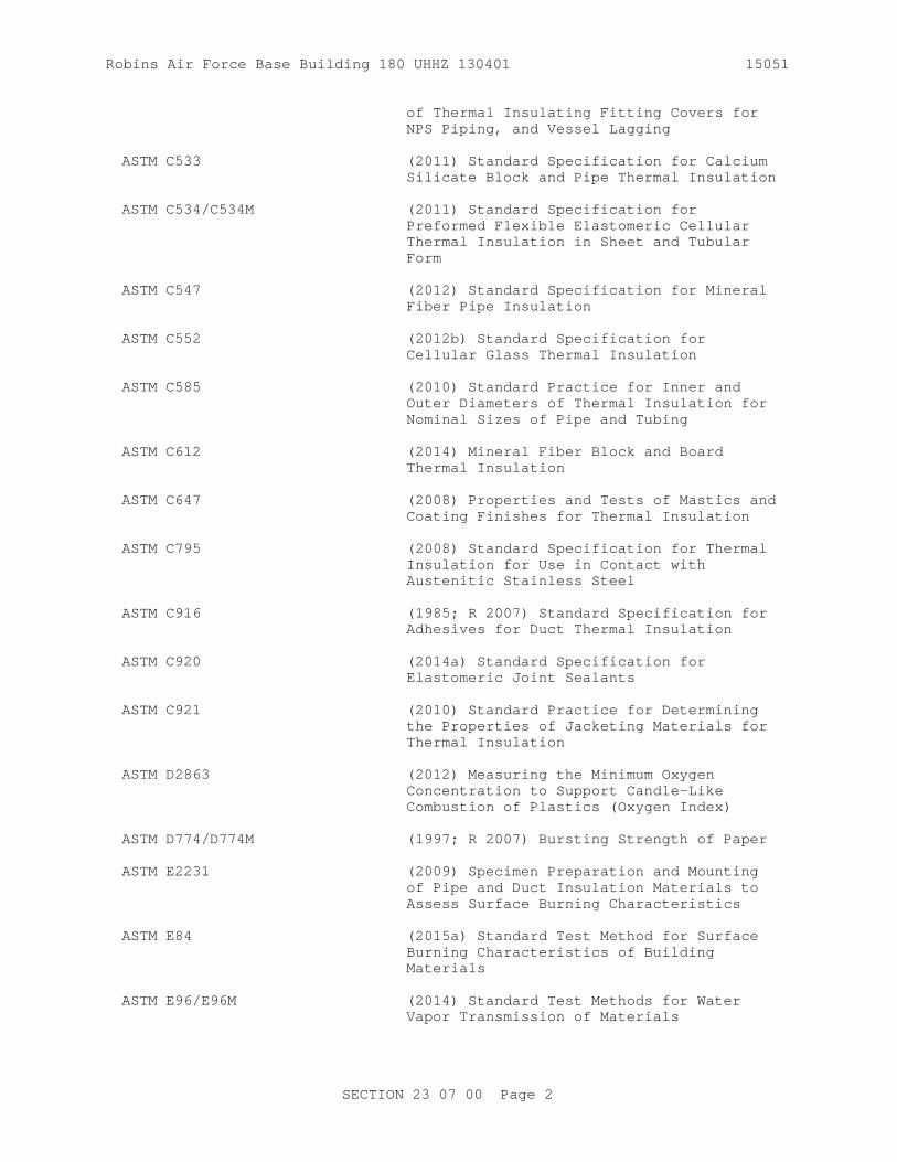
Robins Air Force Base Building 180 UHHZ 130401 15051
of Thermal Insulating Fitting Covers for NPS Piping, and Vessel Lagging
ASTM C533 (2011) Standard Specification for Calcium Silicate Block and Pipe Thermal Insulation
ASTM C534/C534M (2011) Standard Specification for Preformed Flexible Elastomeric Cellular Thermal Insulation in Sheet and Tubular Form
ASTM C547 (2012) Standard Specification for Mineral Fiber Pipe Insulation
ASTM C552 (2012b) Standard Specification for Cellular Glass Thermal Insulation
ASTM C585 (2010) Standard Practice for Inner and Outer Diameters of Thermal Insulation for Nominal Sizes of Pipe and Tubing
ASTM C612 (2014) Mineral Fiber Block and Board Thermal Insulation
ASTM C647 (2008) Properties and Tests of Mastics and Coating Finishes for Thermal Insulation
ASTM C795 (2008) Standard Specification for Thermal Insulation for Use in Contact with Austenitic Stainless Steel
ASTM C916 (1985; R 2007) Standard Specification for Adhesives for Duct Thermal Insulation
ASTM C920 (2014a) Standard Specification for Elastomeric Joint Sealants
ASTM C921 (2010) Standard Practice for Determining the Properties of Jacketing Materials for Thermal Insulation
ASTM D2863 (2012) Measuring the Minimum Oxygen Concentration to Support Candle-Like Combustion of Plastics (Oxygen Index)
ASTM D774/D774M (1997; R 2007) Bursting Strength of Paper
ASTM E2231 (2009) Specimen Preparation and Mounting of Pipe and Duct Insulation Materials to Assess Surface Burning Characteristics
ASTM E84 (2015a) Standard Test Method for Surface Burning Characteristics of Building Materials
ASTM E96/E96M (2014) Standard Test Methods for Water Vapor Transmission of Materials
SECTION 23 07 00 Page 2

Robins Air Force Base Building 180 UHHZ 130401 15051
FM GLOBAL (FM)
FM APP GUIDE (updated on-line) Approval Guide http://www.approvalguide.com/
MANUFACTURERS STANDARDIZATION SOCIETY OF THE VALVE AND FITTINGS INDUSTRY (MSS)
MSS SP-69 (2003; Notice 2012) Pipe Hangers and Supports - Selection and Application (ANSI Approved American National Standard)
MIDWEST INSULATION CONTRACTORS ASSOCIATION (MICA)
MICA Insulation Stds (1999) National Commercial & Industrial Insulation Standards
NATIONAL FIRE PROTECTION ASSOCIATION (NFPA)
NFPA 90A (2015) Standard for the Installation of Air Conditioning and Ventilating Systems
NFPA 90B (2012) Standard for the Installation of Warm Air Heating and Air Conditioning Systems
U.S. DEPARTMENT OF DEFENSE (DOD)
MIL-A-24179 (1969; Rev A; Am 2 1980; Notice 1 1987) Adhesive, Flexible Unicellular-Plastic Thermal Insulation
MIL-A-3316 (1987; Rev C; Am 2 1990) Adhesives, Fire-Resistant, Thermal Insulation
MIL-PRF-19565 (1988; Rev C) Coating Compounds, Thermal Insulation, Fire- and Water-Resistant, Vapor-Barrier
UNDERWRITERS LABORATORIES (UL)
UL 723 (2008; Reprint Sep 2010) Test for Surface Burning Characteristics of Building Materials
UL 94 (2013; Reprint Jul 2015) Standard for Tests for Flammability of Plastic Materials for Parts in Devices and Appliances
1.2 SYSTEM DESCRIPTION
1.2.1 General
Provide field-applied insulation and accessories on mechanical systems as specified herein; factory-applied insulation is specified under the piping, duct or equipment to be insulated.
SECTION 23 07 00 Page 3

Robins Air Force Base Building 180 UHHZ 130401 15051
1.3 SUBMITTALS
Government approval is required for submittals with a "G" designation; submittals not having a "G" designation are for information only. When used, an AE designation following the "G" designation identifies the office that will review the submittal for the Government. Submit the following in accordance with Section 01300 SUBMITTALS AND CONTRACTOR FURNISHED ITEMS:
Submit the three SD types, SD-02 Shop Drawings, SD-03 Product Data, and SD-08 Manufacturer's Instructions at the same time for each system.
SD-02 Shop Drawings
MICA Plates; G, AEPipe Insulation Systems and Associated AccessoriesDuct Insulation Systems and Associated AccessoriesEquipment Insulation Systems and Associated Accessories
SD-03 Product Data
Pipe Insulation Systems; G, AEDuct Insulation Systems; G, AEEquipment Insulation Systems; G, AE
SD-04 Samples
Thermal Insulation
SD-08 Manufacturer's Instructions
Pipe Insulation SystemsDuct Insulation SystemsEquipment Insulation Systems
1.4 QUALITY ASSURANCE
1.4.1 Installer Qualification
Qualified installers shall have successfully completed three or more similar type jobs within the last 5 years.
1.5 DELIVERY, STORAGE, AND HANDLING
Materials shall be delivered in the manufacturer's unopened containers. Materials delivered and placed in storage shall be provided with protection from weather, humidity, dirt, dust and other contaminants. The Contracting Officer may reject insulation material and supplies that become dirty, dusty, wet, or contaminated by some other means. Packages or standard containers of insulation, jacket material, cements, adhesives, and coatings delivered for use, and samples required for approval shall have manufacturer's stamp or label attached giving the name of the manufacturer and brand, and a description of the material, date codes, and approximate shelf life (if applicable). Insulation packages and containers shall be asbestos free.
SECTION 23 07 00 Page 4

Robins Air Force Base Building 180 UHHZ 130401 15051
PART 2 PRODUCTS
2.1 STANDARD PRODUCTS
Provide materials which are the standard products of manufacturers regularly engaged in the manufacture of such products and that essentially duplicate items that have been in satisfactory use for at least 2 years prior to bid opening. Submit a complete list of materials, including manufacturer's descriptive technical literature, performance data, catalog cuts, and installation instructions. The product number, k-value, thickness and furnished accessories including adhesives, sealants and jackets for each mechanical system requiring insulation shall be included. The product data must be copyrighted, have an identifying or publication number, and shall have been published prior to the issuance date of this solicitation. Materials furnished under this section shall be submitted together in a booklet.
2.1.1 Insulation System
Provide insulation systems in accordance with the approved MICA National Insulation Standards plates as supplemented by this specification. Provide field-applied insulation for heating, ventilating, and cooling (HVAC) air distribution systems and piping systems that are located within, on, under, and adjacent to buildings; and for plumbing systems. Insulation shall be CFC and HCFC free.
2.1.2 Surface Burning Characteristics
Unless otherwise specified, insulation shall have a maximum flame spreadindex of 25 and a maximum smoke developed index of 50 when tested inaccordance with ASTM E84. Flame spread, and smoke developed indexes,shall be determined by ASTM E84 or UL 723 . Insulation shall be tested inthe same density and installed thickness as the material to be used in theactual construction. Test specimens shall be prepared and mountedaccording to ASTM E2231.
2.2 MATERIALS
Provide insulation that meets or exceed the requirements of ASHRAE 90.1 - IP . Insulation exterior shall be cleanable, grease resistant, non-flaking and non-peeling. Materials shall be compatible and shall not contribute to corrosion, soften, or otherwise attack surfaces to which applied in either wet or dry state. Materials to be used on stainless steel surfaces shall meet ASTM C795 requirements. Calcium silicate shall not be used on chilled or cold water systems. Materials shall be asbestos free. Provide product recognized under UL 94 (if containing plastic) and listed in FM APP GUIDE.
2.2.1 Adhesives
2.2.1.1 Acoustical Lining Insulation Adhesive
Adhesive shall be a nonflammable, fire-resistant adhesive conforming to ASTM C916, Type I.
2.2.1.2 Mineral Fiber Insulation Cement
Cement shall be in accordance with ASTM C195.
SECTION 23 07 00 Page 5

Robins Air Force Base Building 180 UHHZ 130401 15051
2.2.1.3 Lagging Adhesive
Lagging is the material used for thermal insulation, especially around a cylindrical object. This may include the insulation as well as the cloth/material covering the insulation. Lagging adhesives shall be nonflammable and fire-resistant and shall have a maximum flame spread index of 25 and a maximum smoke developed index of 50 when tested in accordance with ASTM E84. Adhesive shall be MIL-A-3316 , Class 1, pigmented white and be suitable for bonding fibrous glass cloth to faced and unfaced fibrous glass insulation board; for bonding cotton brattice cloth to faced and unfaced fibrous glass insulation board; for sealing edges of and bonding glass tape to joints of fibrous glass board; for bonding lagging cloth to thermal insulation; or Class 2 for attaching fibrous glass insulation to metal surfaces. Lagging adhesives shall be applied in strict accordance with the manufacturer's recommendations for pipe and duct insulation.
2.2.1.4 Contact Adhesive
Adhesives may be any of, but not limited to, the neoprene based, rubber based, or elastomeric type that have a maximum flame spread index of 25 and a maximum smoke developed index of 50 when tested in accordance with ASTM E84. The adhesive shall not adversely affect, initially or in service, the insulation to which it is applied, nor shall it cause any corrosive effect on metal to which it is applied. Any solvent dispersing medium or volatile component of the adhesive shall have no objectionable odor and shall not contain any benzene or carbon tetrachloride. The dried adhesive shall not emit nauseous, irritating, or toxic volatile matters or aerosols when the adhesive is heated to any temperature up to 212 degrees F. The dried adhesive shall be nonflammable and fire resistant. Flexible Elastomeric Adhesive: Comply with MIL-A-24179 , Type II, Class I. Provide product listed in FM APP GUIDE.
2.2.2 Caulking
ASTM C920, Type S, Grade NS, Class 25, Use A.
2.2.3 Corner Angles
Nominal 0.016 inch aluminum 1 by 1 inch with factory applied kraft backing. Aluminum shall be ASTM B209, Alloy 3003, 3105, or 5005.
2.2.4 Fittings
Fabricated Fittings are the prefabricated fittings for flexible elastomeric pipe insulation systems in accordance with ASTM C1710. Together with the flexible elastomeric tubes, they provide complete system integrity for retarding heat gain and controlling condensation drip from chilled-water and refrigeration systems. Flexible elastomeric, fabricated fittings provide thermal protection (0.25 k) and condensation resistance (0.05 Water Vapor Transmission factor). For satisfactory performance, properly installed protective vapor retarder/barriers and vapor stops shall be used on high relative humidity and below ambient temperature applications to reduce movement of moisture through or around the insulation to the colder interior surface.
2.2.5 Finishing Cement
ASTM C450: Mineral fiber hydraulic-setting thermal insulating and
SECTION 23 07 00 Page 6

Robins Air Force Base Building 180 UHHZ 130401 15051
finishing cement. All cements that may come in contact with Austenitic stainless steel must comply with ASTM C795.
2.2.6 Fibrous Glass Cloth and Glass Tape
Fibrous glass cloth, with 20X20 maximum mesh size, and glass tape shall have maximum flame spread index of 25 and a maximum smoke developed index of 50 when tested in accordance with ASTM E84. Tape shall be 4 inch wide rolls. Class 3 tape shall be 4.5 ounces/square yard. Elastomeric Foam Tape: Black vapor-retarder foam tape with acrylic adhesive containing an anti-microbial additive.
2.2.7 Staples
Outward clinching type monel or ASTM A167, Type 304 or 316 stainless steel.
2.2.8 Jackets
2.2.8.1 Aluminum Jackets
Aluminum jackets shall be corrugated, embossed or smooth sheet, 0.016 inch nominal thickness; ASTM B209, Temper H14, Temper H16, Alloy 3003, 5005, or 3105. Corrugated aluminum jacket shall not be used outdoors. Aluminum jacket securing bands shall be Type 304 stainless steel, 0.015 inch thick, 1/2 inch wide for pipe under 12 inch diameter and 3/4 inch wide for pipe over 12 inch and larger diameter . Aluminum jacket circumferential seam bands shall be 2 by 0.016 inch aluminum matching jacket material. Bands for insulation below ground shall be 3/4 by 0.020 inch thick stainless steel, or fiberglass reinforced tape. The jacket may, at the option of the Contractor, be provided with a factory fabricated Pittsburgh or "Z" type longitudinal joint. When the "Z" joint is used, the bands at the circumferential joints shall be designed by the manufacturer to seal the joints and hold the jacket in place.
2.2.8.2 Polyvinyl Chloride (PVC) Jackets
Polyvinyl chloride (PVC) jacket and fitting covers shall have high impact strength, ultraviolet (UV) resistant rating or treatment and moderate chemical resistance with minimum thickness 0.030 inch.
2.2.8.3 Vapor Barrier/Weatherproofing Jacket
Vapor barrier/weatherproofing jacket shall be laminated self-adhesive, greater than 3 plies standard grade, silver, white, black and embossed or greater than 8 ply (minimum 2.9 mils adhesive); with 0.0000 permeability when tested in accordance with ASTM E96/E96M, using the water transmission rate test method; heavy duty, white or natural; and UV resistant. Flexible Elastomeric exterior foam with factory applied, UV Jacket made with a cold weather acrylic adhesive. Construction of laminate designed to provide UV resistance, high puncture, tear resistance and excellent Water Vapor Transmission (WVT) rate.
2.2.9 Vapor Retarder Required
ASTM C921, Type I, minimum puncture resistance 50 Beach units on all surfaces except concealed ductwork, where a minimum puncture resistance of 25 Beach units is acceptable. Minimum tensile strength, 35 pounds/inch width. ASTM C921, Type II, minimum puncture resistance 25 Beach units, tensile strength minimum 20 pounds/inch width. Jackets used on insulation
SECTION 23 07 00 Page 7

Robins Air Force Base Building 180 UHHZ 130401 15051
exposed in finished areas shall have white finish suitable for painting without sizing. Based on the application, insulation materials that require manufacturer or fabricator applied pipe insulation jackets are cellular glass, when all joints are sealed with a vapor barrier mastic, and mineral fiber. All non-metallic jackets shall have a maximum flame spread index of 25 and a maximum smoke developed index of 50 when tested in accordance with ASTM E84. Flexible elastomerics require (in addition to vapor barrier skin) vapor retarder jacketing for high relative humidity and below ambient temperature applications.
2.2.9.1 White Vapor Retarder All Service Jacket (ASJ)
ASJ is for use on hot/cold pipes, ducts, or equipment indoors or outdoors if covered by a suitable protective jacket. The product shall meet all physical property and performance requirements of ASTM C1136, Type I, except the burst strength shall be a minimum of 85 psi. ASTM D2863 Limited Oxygen Index (LOI) shall be a minimum of 31.
In addition, neither the outer exposed surface nor the inner-most surface contacting the insulation shall be paper or other moisture-sensitive material. The outer exposed surface shall be white and have an emittance of not less than 0.80. The outer exposed surface shall be paintable.
2.2.9.2 Vapor Retarder/Vapor Barrier Mastic Coatings
a. The vapor barrier shall be self adhesive (minimum 2 mils adhesive, 3 mils embossed) greater than 3 plies standard grade, silver, white, black and embossed white jacket for use on hot/cold pipes. Permeability shall be less than 0.02 when tested in accordance with ASTM E96/E96M. Products shall meet UL 723 or ASTM E84 flame and smoke requirements and shall be UV resistant.
b. The vapor retarder coating shall be fire and water resistant and appropriately selected for either outdoor or indoor service. Color shall be white. The water vapor permeance of the compound shall be 0.013 perms or less at 43 mils dry film thickness as determined according to procedure B of ASTM E96/E96M utilizing apparatus described in ASTM E96/E96M. The coating shall be nonflammable, fire resistant type. Coating shall meet MIL-PRF-19565 Type II (if selected for indoor service) and be Qualified Products Database listed. All other application and service properties shall be in accordance with ASTM C647.
2.2.9.3 Laminated Film Vapor Retarder
ASTM C1136, Type I, maximum moisture vapor transmission 0.02 perms, minimum puncture resistance 50 Beach units on all surfaces except concealed ductwork; where Type II, maximum moisture vapor transmission 0.02 perms, a minimum puncture resistance of 25 Beach units is acceptable. Vapor retarder shall have a maximum flame spread index of 25 and a maximum smoke developed index of 50 when tested in accordance with ASTM E84. Flexible Elastomeric exterior foam with factory applied UV Jacket. Construction of laminate designed to provide UV resistance, high puncture, tear resistance and an excellent WVT rate.
2.2.9.4 Vapor Barrier/Weather Barrier
The vapor barrier shall be greater than 3 ply self adhesive laminate -white vapor barrier jacket- superior performance (less than 0.0000
SECTION 23 07 00 Page 8

Robins Air Force Base Building 180 UHHZ 130401 15051
permeability when tested in accordance with ASTM E96/E96M). Vapor barrier shall meet UL 723 or ASTM E84 25 flame and 50 smoke requirements; and UV resistant. Minimum burst strength 185 psi in accordance with ASTM D774/D774M. Tensile strength 68 lb/inch width (PSTC-1000). Tape shall be as specified for laminated film vapor barrier above.
2.2.10 Vapor Retarder Not Required
ASTM C921, Type II, Class D, minimum puncture resistance 50 Beach units on all surfaces except ductwork, where Type IV, maximum moisture vapor transmission 0.10, a minimum puncture resistance of 25 Beach units is acceptable. Jacket shall have a maximum flame spread index of 25 and a maximum smoke developed index of 50 when tested in accordance with ASTM E84.
2.2.11 Wire
Soft annealed ASTM A580/A580M Type 302, 304 or 316 stainless steel, 16 or 18 gauge.
2.2.12 Insulation Bands
Insulation bands shall be 1/2 inch wide; 26 gauge stainless steel .
2.2.13 Sealants
Sealants shall be chosen from the butyl polymer type, the styrene-butadiene rubber type, or the butyl type of sealants. Sealants shall have a maximum permeance of 0.02 perms based on Procedure B for ASTM E96/E96M, and a maximum flame spread index of 25 and a maximum smoke developed index of 50 when tested in accordance with ASTM E84.
2.3 PIPE INSULATION SYSTEMS
Insulation materials shall conform to Table 1. Insulation thickness shall be as listed in Table 2 and meet or exceed the requirements of ASHRAE 90.1 - IP . Pipe insulation materials shall be limited to those listed herein and shall meet the following requirements:
2.3.1 Aboveground Cold Pipeline ( -30 to 60 deg. F)
Insulation for outdoor, indoor, exposed or concealed applications, shall be as follows:
a. Cellular Glass: ASTM C552, Type II, and Type III. Supply the insulation from the fabricator with (paragraph WHITE VAPOR RETARDER ALL SERVICE JACKET (ASJ)) ASJ vapor retarder and installed with all longitudinal overlaps sealed and all circumferential joints ASJ taped or supply the insulation unfaced from the fabricator and install with all longitudinal and circumferential joints sealed with vapor barrier mastic..
b. Flexible Elastomeric Cellular Insulation: Closed-cell, foam- or expanded-rubber materials containing anti-microbial additive, complying with ASTM C534/C534M, Grade 1, Type I or II. Type I, Grade 1 for tubular materials. Type II, Grade 1, for sheet materials. Type I and II shall have vapor retarder/vapor barrier skin on one or both sides of the insulation, and require an additional exterior vapor retarder covering for high relative humidity and below ambient temperature applications.
SECTION 23 07 00 Page 9

Robins Air Force Base Building 180 UHHZ 130401 15051
c. Phenolic Insulation: ASTM C1126 Type III to 250 degrees F service shall comply with ASTM C795. Supply the insulation with manufacturer's recommended factory-applied jacket/vapor barrier.
2.3.2 Aboveground Hot Pipeline (Above 60 deg. F)
Insulation for outdoor, indoor, exposed or concealed applications shall meet the following requirements. Supply the insulation with manufacturer's recommended factory-applied jacket/vapor barrier.
a. Mineral Fiber: ASTM C547, Types I, II or III, supply the insulation with manufacturer's recommended factory-applied jacket.
b. Calcium Silicate: ASTM C533, Type I indoor only, or outdoors above 250 degrees F pipe temperature. Supply insulation with the manufacturer's recommended factory-applied jacket/vapor barrier.
c. Flexible Elastomeric Cellular Insulation: Closed-cell, foam- or expanded-rubber materials containing anti-microbial additive, complying with ASTM C534/C534M, Grade 1, Type I or II to 220 degrees F service. Type I for tubular materials. Type II for sheet materials.
d. Phenolic Insulation: ASTM C1126 Type III to 250 degrees F service shall comply with ASTM C795. Supply the insulation with manufacturer's recommended factory-applied jacket/vapor barrier.
2.4 DUCT INSULATION SYSTEMS
2.4.1 Factory Applied Insulation
Provide factory-applied insulation according to manufacturer's recommendations for insulation with insulation manufacturer's standard reinforced fire-retardant vapor barrier, with identification of installed thermal resistance (R) value and out-of-package R value.
2.4.1.1 Rigid Insulation
Rigid mineral fiber in accordance with ASTM C612, Class 2 (maximum surface temperature 400 degrees F), 3 pcf average, 1-1/2 inch thick, Type IA, IB, II, III, and IV.
2.4.1.2 Blanket Insulation
Blanket flexible mineral fiber insulation conforming to ASTM C585, Type 1, Class B-3, 3/4 pcf nominal, 2.0 inches thick or Type II up to 250 degrees F. Also ASTM C1290 Type III may be used.
2.4.2 Duct Insulation Jackets
2.4.2.1 All-Purpose Jacket
Provide insulation with insulation manufacturer's standard reinforced fire-retardant jacket with or without integral vapor barrier as required by the service. In exposed locations, provide jacket with a white surface suitable for field painting.
SECTION 23 07 00 Page 10
Robins Air Force Base Building 180 UHHZ 130401 15051
2.4.2.2 Vapor Barrier/Weatherproofing Jacket
Vapor barrier/weatherproofing jacket shall be laminated self-adhesive (minimum 2 mils adhesive, 3 mils embossed) less than 0.0000 permeability, (greater than 3 ply, standard grade, silver, white, black and embossed or greater than 8 ply (minimum 2.9 mils adhesive), heavy duty white or natural).
2.5 EQUIPMENT INSULATION SYSTEMS
Insulate equipment and accessories as specified in Tables 5 and 6. In outside locations, provide insulation 1/2 inch thicker than specified. Increase the specified insulation thickness for equipment where necessary to equal the thickness of angles or other structural members to make a smooth, exterior surface. Submit a booklet containing manufacturer's published installation instructions for the insulation systems. The instructions must be copyrighted, have an identifying or publication number, and shall have been published prior to the issuance date of this solicitation. A booklet is also required by paragraphs titled: Pipe Insulation Systems and Duct Insulation Systems.
PART 3 EXECUTION
3.1 APPLICATION - GENERAL
Flexible elastomeric cellular insulation shall not be compressed at joists, studs, columns, ducts, hangers, etc. The insulation shall not pull apart after a one hour period; any insulation found to pull apart after one hour, shall be replaced.
3.1.1 Display Samples
Display, after approval of materials, actual sections of installed systems, properly insulated in accordance with the specification requirements. Such actual sections must remain accessible to inspection throughout the job and will be reviewed from time to time for controlling the quality of the work throughout the construction site. Each material used shall be identified, by indicating on an attached sheet the specification requirement for the material and the material by each manufacturer intended to meet the requirement. The Contracting Officer will inspect display sample sections at the jobsite. Approved display sample sections shall remain on display at the jobsite during the construction period. Upon completion of construction, the display sample sections will be closed and sealed.
3.1.1.1 Pipe Insulation Display Sections
Display sample sections shall include as a minimum an elbow or tee, a valve, dielectric waterways and flanges, a hanger with protection shield and insulation insert, or dowel as required, at support point, method of fastening and sealing insulation at longitudinal lap, circumferential lap, butt joints at fittings and on pipe runs, and terminating points for each type of pipe insulation used on the job, and for hot pipelines and cold pipelines, both interior and exterior, even when the same type of insulation is used for these services.
3.1.1.2 Duct Insulation Display Sections
Display sample sections for rigid and flexible duct insulation used on the
SECTION 23 07 00 Page 11

Robins Air Force Base Building 180 UHHZ 130401 15051
job. Use a temporary covering to enclose and protect display sections for duct insulation exposed to weather
3.1.2 Installation
Except as otherwise specified, material shall be installed in accordance with the manufacturer's written instructions. Insulation materials shall not be applied until tests specified in other sections of this specification are completed. Material such as rust, scale, dirt and moisture shall be removed from surfaces to receive insulation. Insulation shall be kept clean and dry. Insulation shall not be removed from its shipping containers until the day it is ready to use and shall be returned to like containers or equally protected from dirt and moisture at the end of each workday. Insulation that becomes dirty shall be thoroughly cleaned prior to use. If insulation becomes wet or if cleaning does not restore the surfaces to like new condition, the insulation will be rejected, and shall be immediately removed from the jobsite. Joints shall be staggered on multi layer insulation. Mineral fiber thermal insulating cement shall be mixed with demineralized water when used on stainless steel surfaces. Insulation, jacketing and accessories shall be installed in accordance with MICA Insulation Stds plates except where modified herein or on the drawings.
3.1.3 Firestopping
Where pipes and ducts pass through fire walls, fire partitions, above grade floors, and fire rated chase walls, the penetration shall be sealed with fire stopping materials as specified in Section 07 84 00 FIRESTOPPING. The protection of ducts at point of passage through firewalls must be in accordance with NFPA 90A and/or NFPA 90B. All other penetrations, such as piping, conduit, and wiring, through firewalls must be protected with a material or system of the same hourly rating that is listed by UL, FM, or a NRTL.
3.1.4 Painting and Finishing
Painting shall be as specified in Section 09 90 00 PAINTS AND COATINGS.
3.1.5 Installation of Flexible Elastomeric Cellular Insulation
Install flexible elastomeric cellular insulation with seams and joints sealed with rubberized contact adhesive. Flexible elastomeric cellular insulation shall not be used on surfaces greater than 220 degrees F. Stagger seams when applying multiple layers of insulation. Protect insulation exposed to weather and not shown to have vapor barrier weatherproof jacketing with two coats of UV resistant finish or PVC or metal jacketing as recommended by the manufacturer after the adhesive is dry and cured.
3.1.5.1 Adhesive Application
Apply a brush coating of adhesive to both butt ends to be joined and to both slit surfaces to be sealed. Allow the adhesive to set until dry to touch but tacky under slight pressure before joining the surfaces. Insulation seals at seams and joints shall not be capable of being pulled apart one hour after application. Insulation that can be pulled apart one hour after installation shall be replaced.
SECTION 23 07 00 Page 12

Robins Air Force Base Building 180 UHHZ 130401 15051
3.1.5.2 Adhesive Safety Precautions
Use natural cross-ventilation, local (mechanical) pickup, and/or general area (mechanical) ventilation to prevent an accumulation of solvent vapors, keeping in mind the ventilation pattern must remove any heavier-than-air solvent vapors from lower levels of the workspaces. Gloves and spectacle-type safety glasses are recommended in accordance with safe installation practices.
3.1.6 Welding
No welding shall be done on piping, duct or equipment without written approval of the Contracting Officer. The capacitor discharge welding process may be used for securing metal fasteners to duct .
3.1.7 Pipes/ Ducts/ Equipment That Require Insulation
Insulation is required on all pipes, ducts, or equipment, except for omitted items as specified.
3.2 PIPE INSULATION SYSTEMS INSTALLATION
3.2.1 Pipe Insulation
3.2.1.1 General
Pipe insulation shall be installed on aboveground hot and cold pipeline systems as specified below to form a continuous thermal retarder/barrier, including straight runs, fittings and appurtenances unless specified otherwise. Installation shall be with full length units of insulation and using a single cut piece to complete a run. Cut pieces or scraps abutting each other shall not be used. Pipe insulation shall be omitted on the following:
a. Pipe used solely for fire protection.
b. Chromium plated pipe to plumbing fixtures. However, fixtures for use by the physically handicapped shall have the hot water supply and drain, including the trap, insulated where exposed.
c. Sanitary drain lines not handling condensate.
d. Air chambers.
e. ASME stamps.
f. Access plates of fan housings.
g. Cleanouts or handholes.
3.2.1.2 Pipes Passing Through Walls, Roofs, and Floors
a. Pipe insulation shall be continuous through the sleeve.
b. An aluminum jacket or vapor barrier/weatherproofing - self adhesive jacket (minimum 2 mils adhesive, 3 mils embossed) less than 0.0000 permeability, greater than 3 ply standard grade, silver, white, black and embossed with factory applied moisture retarder shall be provided
SECTION 23 07 00 Page 13

Robins Air Force Base Building 180 UHHZ 130401 15051
over the insulation wherever penetrations require sealing.
c. Where pipes penetrate interior walls, the aluminum jacket or vapor barrier/weatherproofing - self adhesive jacket (minimum 2 mils adhesive, 3 mils embossed) less than 0.0000 permeability, greater than 3 plies standard grade, silver, white, black and embossed shall extend 2 inches beyond either side of the wall and shall be secured on each end with a band.
d. Where penetrating floors, the aluminum jacket shall extend from a point below the backup material to a point 10 inches above the floor with one band at the floor and one not more than 1 inch from the end of the aluminum jacket.
e. Where penetrating waterproofed floors, the aluminum jacket shall extend from below the backup material to a point 2 inches above the flashing with a band 1 inch from the end of the aluminum jacket.
f. Where penetrating exterior walls, the aluminum jacket required for pipe exposed to weather shall continue through the sleeve to a point 2 inches beyond the interior surface of the wall.
g. Where penetrating roofs, pipe shall be insulated as required for interior service to a point flush with the top of the flashing and sealed with flashing sealant. The insulation for exterior application shall butt tightly to the top of flashing and interior insulation. The exterior aluminum jacket shall extend 2 inches down beyond the end of the insulation to form a counter flashing. The flashing and counter flashing shall be sealed underneath with metal jacketing/flashing sealant.
h. For hot water pipes supplying lavatories or other similar heated service that requires insulation, the insulation shall be terminated on the backside of the finished wall. The insulation termination shall be protected with two coats of vapor barrier coating with a minimum total thickness of 1/16 inch applied with glass tape embedded between coats (if applicable). The coating shall extend out onto the insulation 2 inches and shall seal the end of the insulation. Glass tape seams shall overlap 1 inch. The annular space between the pipe and wall penetration shall be caulked with approved fire stop material. The pipe and wall penetration shall be covered with a properly sized (well fitting) escutcheon plate. The escutcheon plate shall overlap the wall penetration at least 3/8 inches.
i. For domestic cold water pipes supplying lavatories or other similar cooling service that requires insulation, the insulation shall be terminated on the finished side of the wall (i.e., insulation must cover the pipe throughout the wall penetration). The insulation shall be protected with two coats of weather barrier mastic (breather emulsion type weatherproof mastic impermeable to water and permeable to air) with a minimum total thickness of 1/16 inch. The mastic shall extend out onto the insulation 2 inches and shall seal the end of the insulation. The annular space between the outer surface of the pipe insulation and the wall penetration shall be caulked with an approved fire stop material having vapor retarder properties. The pipe and wall penetration shall be covered with a properly sized (well fitting) escutcheon plate. The escutcheon plate shall overlap the wall penetration by at least 3/8 inches.
SECTION 23 07 00 Page 14

Robins Air Force Base Building 180 UHHZ 130401 15051
3.2.1.3 Pipes Passing Through Hangers
a. Insulation, whether hot or cold application, shall be continuous through hangers. All horizontal pipes 2 inches and smaller shall be supported on hangers with the addition of a Type 40 protection shield to protect the insulation in accordance with MSS SP-69 . Whenever insulation shows signs of being compressed, or when the insulation or jacket shows visible signs of distortion at or near the support shield, insulation inserts as specified below for piping larger than 2 inches shall be installed, or factory insulated hangers (designed with a load bearing core) can be used.
b. Horizontal pipes larger than 2 inches at 60 degrees F and above shall be supported on hangers in accordance with MSS SP-69 , and Section 22 00 00 PLUMBING, GENERAL PURPOSE.
c. Horizontal pipes larger than 2 inches and below 60 degrees F shall be supported on hangers with the addition of a Type 40 protection shield in accordance with MSS SP-69 . An insulation insert of cellular glass or prefabricated insulation pipe hangers above 80 degrees F shall be installed above each shield. The insert shall cover not less than the bottom 180-degree arc of the pipe. Inserts shall be the same thickness as the insulation, and shall extend 2 inches on each end beyond the protection shield. When insulation inserts are required in accordance with the above, and the insulation thickness is less than 1 inch, wooden or cork dowels or blocks may be installed between the pipe and the shield to prevent the weight of the pipe from crushing the insulation, as an option to installing insulation inserts. The insulation jacket shall be continuous over the wooden dowel, wooden block, or insulation insert.
d. Vertical pipes shall be supported with either Type 8 or Type 42 riser clamps with the addition of two Type 40 protection shields in accordance with MSS SP-69 covering the 360-degree arc of the insulation. An insulation insert of cellular glass or calcium silicate shall be installed between each shield and the pipe. The insert shall cover the 360-degree arc of the pipe. Inserts shall be the same thickness as the insulation, and shall extend 2 inches on each end beyond the protection shield. When insulation inserts are required in accordance with the above, and the insulation thickness is less than 1 inch, wooden or cork dowels or blocks may be installed between the pipe and the shield to prevent the hanger from crushing the insulation, as an option instead of installing insulation inserts. The insulation jacket shall be continuous over the wooden dowel, wooden block, or insulation insert. The vertical weight of the pipe shall be supported with hangers located in a horizontal section of the pipe. When the pipe riser is longer than 30 feet, the weight of the pipe shall be additionally supported with hangers in the vertical run of the pipe that are directly clamped to the pipe, penetrating the pipe insulation. These hangers shall be insulated and the insulation jacket sealed as indicated herein for anchors in a similar service.
e. Inserts shall be covered with a jacket material of the same appearance and quality as the adjoining pipe insulation jacket, shall overlap the adjoining pipe jacket 1-1/2 inches, and shall be sealed as required for the pipe jacket. The jacket material used to cover inserts in flexible elastomeric cellular insulation shall conform to ASTM C1136, Type 1, and is allowed to be of a different material than the
SECTION 23 07 00 Page 15

Robins Air Force Base Building 180 UHHZ 130401 15051
adjoining insulation material.
3.2.1.4 Flexible Elastomeric Cellular Pipe Insulation
Flexible elastomeric cellular pipe insulation shall be tubular form for pipe sizes 6 inches and less. Grade 1, Type II sheet insulation used on pipes larger than 6 inches shall not be stretched around the pipe. On pipes larger than 12 inches, the insulation shall be adhered directly to the pipe on the lower 1/3 of the pipe. Seams shall be staggered when applying multiple layers of insulation. Sweat fittings shall be insulated with miter-cut pieces the same size as on adjacent piping. Screwed fittings shall be insulated with sleeved fitting covers fabricated from miter-cut pieces and shall be overlapped and sealed to the adjacent pipe insulation. Type II requires an additional exterior vapor retarder/barrier covering for high relative humidity and below ambient temperature applications.
SECTION 23 07 00 Page 16

Robins Air Force Base Building 180 UHHZ 130401 15051
3.2.1.5 Pipe Insulation Material and Thickness
TABLE 1
Insulation Material for Piping
Service
Material Specification Type Class VR/VB Req'd
Chilled Water (Supply & Return, Dual Temperature Piping, 40 F nominal)
Cellular Glass ASTM C552 II 2 Yes
Faced Phenol Foam ASTM C1126 III Yes
Heating Hot Water Supply & Return (Max 250 F)
Mineral Fiber ASTM C547 I 1 No
Calcium Silicate ASTM C533 I No
Flexible Elastomeric Cellular
ASTM C534/C534M I 2 No
Cold Domestic Water Piping, Makeup Water Piping
Flexible Elastomeric Cellular
ASTM C534/C534M I No
Hot Domestic Water Supply & Recirculating Piping (Max 200 F)
Mineral Fiber ASTM C547 I 1 No
Flexible Elastomeric Cellular
ASTM C534/C534M I No
Refrigerant Suction Piping (35 degrees F nominal)
Flexible Elastomeric Cellular
ASTM C534/C534M I No
Exposed Lavatory Drains, Exposed Domestic Water Piping & Drains to Areas for Handicapped Personnel
Flexible Elastomeric Cellular
ASTM C534/C534M I No
Condensate Drain Located Inside Building
Flexible Elastomeric Cellular
ASTM C534/C534M I No
Note: VR/VB = Vapor Retarder/Vapor Barrier
SECTION 23 07 00 Page 17

Robins Air Force Base Building 180 UHHZ 130401 15051
TABLE 2
Piping Insulation Thickness (inch) Do not use integral wicking material in Chilled water applications exposed to
outdoor ambient conditions in climatic zones 1 through 4.
Service
Material Tube And Pipe Size (inch)
<1 1-<1.5 1.5-<4 4-<8
Chilled Water (Supply & Return Piping, 40 Degrees F nominal)
Cellular Glass 1.5 2 2 2.5
Faced Phenol Foam 1 1 1 1.5
Heating Hot Water Supply & Return (Max 250 F)
Mineral Fiber 1.5 1.5 2 2
Calcium Silicate 2.5 2.5 3 3
Cold Domestic Water Piping, Makeup Water Piping
Mineral Fiber 0.5 0.5 0.5 N/A
Hot Domestic Water Supply & Recirculating Piping (Max 200 F)
Mineral Fiber 1.5 1.5 1.5 1.5
Refrigerant Suction Piping (35 degrees F nominal)
Flexible Elastomeric Cellular 1 1 1 N/A
Exposed Lavatory Drains, Exposed Domestic Water Piping & Drains to Areas for Handicapped Personnel
Flexible Elastomeric Cellular 0.5 0.5 0.5 0.5
Condensate Drain Located Inside Building
Flexible Elastomeric Cellular 1 1 1 N/A
3.2.2 Aboveground Cold Pipelines
The following cold pipelines for minus 30 to plus 60 degrees F, shall be insulated in accordance with Table 2 except those piping listed in subparagraph Pipe Insulation in PART 3 as to be omitted. This includes but is not limited to the following:
SECTION 23 07 00 Page 18

Robins Air Force Base Building 180 UHHZ 130401 15051
a. Domestic cold water
b. Make-up water.
c. Refrigerant suction lines.
d. Chilled water.
e. Air conditioner condensate drains.
f. Exposed lavatory drains and domestic water lines serving plumbing fixtures for handicap persons.
3.2.2.1 Insulation Material and Thickness
Insulation thickness for cold pipelines shall be determined using Table 2.
3.2.2.2 Factory or Field applied Jacket
Insulation shall be covered with a factory applied vapor retarder jacket/vapor barrier or field applied seal welded PVC jacket or greater than 3 ply laminated self-adhesive (minimum 2 mils adhesive, 3 mils embossed) vapor barrier/weatherproofing jacket - less than 0.0000 permeability, standard grade, sliver, white, black and embossed for use with Mineral Fiber, Cellular Glass, and Phenolic Foam Insulated Pipe. Insulation inside the building, to be protected with an aluminum jacket or greater than 3ply vapor barrier/weatherproofing self-adhesive (minimum 2 mils adhesive, 3 mils embossed) product, less than 0.0000 permeability, standard grade, Embossed Silver, White & Black, shall have the insulation and vapor retarder jacket installed as specified herein. The aluminum jacket or greater than 3ply vapor barrier/weatherproofing self-adhesive (minimum 2 mils adhesive, 3 mils embossed) product, less than 0.0000 permeability, standard grade, embossed silver, White & Black, shall be installed as specified for piping exposed to weather, except sealing of the laps of the aluminum jacket is not required.
3.2.2.3 Installing Insulation for Straight Runs Hot and Cold Pipe
a. Insulation shall be applied to the pipe with joints tightly butted. All butted joints and ends shall be sealed with joint sealant and sealed with a vapor retarder coating, greater than 3 ply laminate jacket - less than 0.0000 perm adhesive tape or PVDC adhesive tape.
b. Longitudinal laps of the jacket material shall overlap not less than 1-1/2 inches. Butt strips 3 inches wide shall be provided for circumferential joints.
c. Laps and butt strips shall be secured with adhesive and stapled on 4 inch centers if not factory self-sealing. If staples are used, they shall be sealed in accordance with item "e." below. Note that staples are not required with cellular glass systems.
d. Factory self-sealing lap systems may be used when the ambient temperature is between 40 and 120 degrees F during installation. The lap system shall be installed in accordance with manufacturer's recommendations. Stapler shall be used only if specifically recommended by the manufacturer. Where gaps occur, the section shall be replaced or the gap repaired by applying adhesive under the lap and then stapling.
SECTION 23 07 00 Page 19

Robins Air Force Base Building 180 UHHZ 130401 15051
e. All Staples, including those used to repair factory self-seal lap systems, shall be coated with a vapor retarder coating or PVDC adhesive tape or greater than 3 ply laminate jacket - less than 0.0000 perm adhesive tape. All seams, except those on factory self-seal systems shall be coated with vapor retarder coating or PVDC adhesive tape or greater than 3 ply laminate jacket - less than 0.0000 perm adhesive tape.
f. Breaks and punctures in the jacket material shall be patched by wrapping a strip of jacket material around the pipe and securing it with adhesive, stapling, and coating with vapor retarder coating or PVDC adhesive tape or greater than 3 ply laminate jacket - less than 0.0000 perm adhesive tape. The patch shall extend not less than 1-1/2 inches past the break.
g. At penetrations such as thermometers, the voids in the insulation shall be filled and sealed with vapor retarder coating or PVDC adhesive tape or greater than 3 ply laminate jacket - less than 0.0000 perm adhesive tape or greater than 3 ply laminate jacket - less than 0.0000 perm adhesive tape.
h. Installation of flexible elastomeric cellular pipe insulation shall be by slitting the tubular sections and applying them onto the piping or tubing. Alternately, whenever possible slide un-slit sections over the open ends of piping or tubing. All seams and butt joints shall be secured and sealed with adhesive. When using self seal products only the butt joints shall be secured with adhesive. Insulation shall be pushed on the pipe, never pulled. Stretching of insulation may result in open seams and joints. All edges shall be clean cut. Rough or jagged edges of the insulation shall not be permitted. Proper tools such as sharp knives shall be used. Grade 1, Type II sheet insulation when used on pipe larger than 6 inches shall not be stretched around the pipe. On pipes larger than 12 inches, adhere sheet insulation directly to the pipe on the lower 1/3 of the pipe.
3.2.2.4 Insulation for Fittings and Accessories
a. Pipe insulation shall be tightly butted to the insulation of the fittings and accessories. The butted joints and ends shall be sealed with joint sealant and sealed with a vapor retarder coating or PVDC adhesive tape or greater than 3 ply laminate jacket - less than 0.0000 perm adhesive tape.
b. Precut or preformed insulation shall be placed around all fittings and accessories and shall conform to MICA plates except as modified herein: 5 for anchors; 10, 11, and 13 for fittings; 14 for valves; and 17 for flanges and unions. Insulation shall be the same insulation as the pipe insulation, including same density, thickness, and thermal conductivity. Where precut/preformed is unavailable, rigid preformed pipe insulation sections may be segmented into the shape required. Insulation of the same thickness and conductivity as the adjoining pipe insulation shall be used. If nesting size insulation is used, the insulation shall be overlapped 2 inches or one pipe diameter. Elbows insulated using segments shall conform to MICA Tables 12.20 "Mitered Insulation Elbow'. Submit a booklet containing completed MICA Insulation Stds plates detailing each insulating system for each pipe, duct, or equipment insulating system, after approval of materials and prior to applying insulation.
SECTION 23 07 00 Page 20

Robins Air Force Base Building 180 UHHZ 130401 15051
(1) The MICA plates shall detail the materials to be installed and the specific insulation application. Submit all MICA plates required showing the entire insulating system, including plates required to show insulation penetrations, vessel bottom and top heads, legs, and skirt insulation as applicable. The MICA plates shall present all variations of insulation systems including locations, materials, vaporproofing, jackets and insulation accessories.
(2) If the Contractor elects to submit detailed drawings instead of edited MICA Plates, the detail drawings shall be technically equivalent to the edited MICA Plate submittal.
c. Upon completion of insulation installation on flanges, unions, valves, anchors, fittings and accessories, terminations, seams, joints and insulation not protected by factory vapor retarder jackets or PVC fitting covers shall be protected with PVDC or greater than 3 ply laminate jacket - less than 0.0000 perm adhesive tape or two coats of vapor retarder coating with a minimum total thickness of 1/16 inch, applied with glass tape embedded between coats. Tape seams shall overlap 1 inch. The coating shall extend out onto the adjoining pipe insulation 2 inches. Fabricated insulation with a factory vapor retarder jacket shall be protected with either greater than 3 ply laminate jacket - less than 0.0000 perm adhesive tape, standard grade, silver, white, black and embossed or PVDC adhesive tape or two coats of vapor retarder coating with a minimum thickness of 1/16 inch and with a 2 inch wide glass tape embedded between coats. Where fitting insulation butts to pipe insulation, the joints shall be sealed with a vapor retarder coating and a 4 inch wide ASJ tape which matches the jacket of the pipe insulation.
d. Anchors attached directly to the pipe shall be insulated for a sufficient distance to prevent condensation but not less than 6 inches from the insulation surface.
e. Insulation shall be marked showing the location of unions, strainers, and check valves.
3.2.2.5 Optional PVC Fitting Covers
At the option of the Contractor, premolded, one or two piece PVC fitting covers may be used in lieu of the vapor retarder and embedded glass tape. Factory precut or premolded insulation segments shall be used under the fitting covers for elbows. Insulation segments shall be the same insulation as the pipe insulation including same density, thickness, and thermal conductivity. The covers shall be secured by PVC vapor retarder tape, adhesive, seal welding or with tacks made for securing PVC covers. Seams in the cover, and tacks and laps to adjoining pipe insulation jacket, shall be sealed with vapor retarder tape to ensure that the assembly has a continuous vapor seal.
3.2.3 Aboveground Hot Pipelines
3.2.3.1 General Requirements
All hot pipe lines above 60 degrees F, except those piping listed in subparagraph Pipe Insulation in PART 3 as to be omitted, shall be insulated in accordance with Table 2. This includes but is not limited to
SECTION 23 07 00 Page 21

Robins Air Force Base Building 180 UHHZ 130401 15051
the following:
a. Domestic hot water supply & re-circulating system.
b. Hot water heating.
Insulation shall be covered, in accordance with manufacturer's recommendations, with a factory applied Type I jacket or field applied aluminum where required or seal welded PVC.
3.2.3.2 Insulation for Fittings and Accessories
a. General. Pipe insulation shall be tightly butted to the insulation of the fittings and accessories. The butted joints and ends shall be sealed with joint sealant. Insulation shall be marked showing the location of unions, strainers, check valves and other components that would otherwise be hidden from view by the insulation.
b. Precut or Preformed. Precut or preformed insulation shall be placed around all fittings and accessories. Insulation shall be the same insulation as the pipe insulation, including same density, thickness, and thermal conductivity.
c. Rigid Preformed. Where precut/preformed is unavailable, rigid preformed pipe insulation sections may be segmented into the shape required. Insulation of the same thickness and conductivity as the adjoining pipe insulation shall be used. If nesting size insulation is used, the insulation shall be overlapped 2 inches or one pipe diameter. Elbows insulated using segments shall conform to MICA Tables 12.20 "Mitered Insulation Elbow".
3.2.4 Piping Exposed to Weather
Piping exposed to weather shall be insulated and jacketed as specified for the applicable service inside the building. After this procedure, a laminated self-adhesive (minimum 2 mils adhesive, 3 mils embossed) vapor barrier/weatherproofing jacket - less than 0.0000 permeability (greater than 3 ply, standard grade, silver, white, black and embossed aluminum jacket or PVC jacket shall be applied. PVC jacketing requires no factory-applied jacket beneath it, however an all service jacket shall be applied if factory applied jacketing is not furnished. Flexible elastomeric cellular insulation exposed to weather shall be treated in accordance with paragraph INSTALLATION OF FLEXIBLE ELASTOMERIC CELLULAR INSULATION in PART 3.
3.2.4.1 Aluminum Jacket
The jacket shall overlap not less than 2 inches at longitudinal and circumferential joints and shall be secured with bands at not more than 12 inch centers. Longitudinal joints shall be overlapped down to shed water and located at 4 or 8 o'clock positions. Joints on piping 60 degrees F and below shall be sealed with metal jacketing/flashing sealant while overlapping to prevent moisture penetration. Where jacketing on piping 60 degrees F and below abuts an un-insulated surface, joints shall be caulked to prevent moisture penetration. Joints on piping above 60 degrees F shall be sealed with a moisture retarder.
SECTION 23 07 00 Page 22
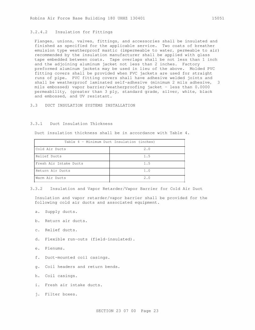
Robins Air Force Base Building 180 UHHZ 130401 15051
3.2.4.2 Insulation for Fittings
Flanges, unions, valves, fittings, and accessories shall be insulated and finished as specified for the applicable service. Two coats of breather emulsion type weatherproof mastic (impermeable to water, permeable to air) recommended by the insulation manufacturer shall be applied with glass tape embedded between coats. Tape overlaps shall be not less than 1 inch and the adjoining aluminum jacket not less than 2 inches. Factory preformed aluminum jackets may be used in lieu of the above. Molded PVC fitting covers shall be provided when PVC jackets are used for straight runs of pipe. PVC fitting covers shall have adhesive welded joints and shall be weatherproof laminated self-adhesive (minimum 2 mils adhesive, 3 mils embossed) vapor barrier/weatherproofing jacket - less than 0.0000 permeability, (greater than 3 ply, standard grade, silver, white, black and embossed, and UV resistant.
3.3 DUCT INSULATION SYSTEMS INSTALLATION
3.3.1 Duct Insulation Thickness
Duct insulation thickness shall be in accordance with Table 4.
Table 4 - Minimum Duct Insulation (inches)
Cold Air Ducts 2.0
Relief Ducts 1.5
Fresh Air Intake Ducts 1.5
Return Air Ducts 1.0
Warm Air Ducts 2.0
3.3.2 Insulation and Vapor Retarder/Vapor Barrier for Cold Air Duct
Insulation and vapor retarder/vapor barrier shall be provided for the following cold air ducts and associated equipment.
a. Supply ducts.
b. Return air ducts.
c. Relief ducts.
d. Flexible run-outs (field-insulated).
e. Plenums.
f. Duct-mounted coil casings.
g. Coil headers and return bends.
h. Coil casings.
i. Fresh air intake ducts.
j. Filter boxes.
SECTION 23 07 00 Page 23

Robins Air Force Base Building 180 UHHZ 130401 15051
k. Mixing boxes (field-insulated).
Insulation for rectangular ducts shall be flexible type where concealed, minimum density 3/4 pcf, and rigid type where exposed, minimum density 3 pcf. Insulation for both concealed or exposed round/oval ducts shall be flexible type, minimum density 3/4 pcf or a semi rigid board, minimum density 3 pcf, formed or fabricated to a tight fit, edges beveled and joints tightly butted and staggered. Insulation for all exposed ducts shall be provided with either a white, paint-able, factory-applied Type I jacket or a field applied vapor retarder/vapor barrier jacket coating finish as specified, the total field applied dry film thickness shall be approximately 1/16 inch. Insulation on all concealed duct shall be provided with a factory-applied Type I or II vapor retarder/vapor barrier jacket. Duct insulation shall be continuous through sleeves and prepared openings except firewall penetrations. Duct insulation terminating at fire dampers, shall be continuous over the damper collar and retaining angle of fire dampers, which are exposed to unconditioned air and which may be prone to condensate formation. Duct insulation and vapor retarder/vapor barrier shall cover the collar, neck, and any un-insulated surfaces of diffusers, registers and grills. Vapor retarder/vapor barrier materials shall be applied to form a complete unbroken vapor seal over the insulation. Sheet Metal Duct shall be sealed in accordance with Section 23 00 00 AIR SUPPLY, DISTRIBUTION, VENTILATION, AND EXHAUST SYSTEM.
3.3.2.1 Installation on Concealed Duct
a. For rectangular, oval or round ducts, flexible insulation shall be attached by applying adhesive around the entire perimeter of the duct in 6 inch wide strips on 12 inch centers.
b. For rectangular and oval ducts, 24 inches and larger insulation shall be additionally secured to bottom of ducts by the use of mechanical fasteners. Fasteners shall be spaced on 16 inch centers and not more than 16 inches from duct corners.
c. For rectangular, oval and round ducts, mechanical fasteners shall be provided on sides of duct risers for all duct sizes. Fasteners shall be spaced on 16 inch centers and not more than 16 inches from duct corners.
d. Insulation shall be impaled on the mechanical fasteners (self stick pins) where used and shall be pressed thoroughly into the adhesive. Care shall be taken to ensure vapor retarder/vapor barrier jacket joints overlap 2 inches. The insulation shall not be compressed to a thickness less than that specified. Insulation shall be carried over standing seams and trapeze-type duct hangers.
e. Where mechanical fasteners are used, self-locking washers shall be installed and the pin trimmed and bent over.
f. Jacket overlaps shall be secured with staples and tape as necessary to ensure a secure seal. Staples, tape and seams shall be coated with a brush coat of vapor retarder coating or PVDC adhesive tape or greater than 3 ply laminate (minimum 2 mils adhesive, 3 mils embossed) - less than 0.0000 perm adhesive tape.
g. Breaks in the jacket material shall be covered with patches of the same material as the vapor retarder jacket. The patches shall extend not less than 2 inches beyond the break or penetration in all
SECTION 23 07 00 Page 24

Robins Air Force Base Building 180 UHHZ 130401 15051
directions and shall be secured with tape and staples. Staples and tape joints shall be sealed with a brush coat of vapor retarder coating or PVDC adhesive tape or greater than 3 ply laminate (minimum 2 mils adhesive, 3 mils embossed) - less than 0.0000 perm adhesive tape.
h. At jacket penetrations such as hangers, thermometers, and damper operating rods, voids in the insulation shall be filled and the penetration sealed with a brush coat of vapor retarder coating or PVDC adhesive tape greater than 3 ply laminate (minimum 2 mils adhesive, 3 mils embossed) - less than 0.0000 perm adhesive tape.
i. Insulation terminations and pin punctures shall be sealed and flashed with a reinforced vapor retarder coating finish or tape with a brush coat of vapor retarder coating.. The coating shall overlap the adjoining insulation and un-insulated surface 2 inches. Pin puncture coatings shall extend 2 inches from the puncture in all directions.
j. Where insulation standoff brackets occur, insulation shall be extended under the bracket and the jacket terminated at the bracket.
3.3.2.2 Installation on Exposed Duct Work
a. For rectangular ducts, insulation shall be secured to the duct by mechanical fasteners on all four sides of the duct, spaced not more than 12 inches apart and not more than 3 inches from the edges of the insulation joints. A minimum of two rows of fasteners shall be provided for each side of duct 12 inches and larger. One row shall be provided for each side of duct less than 12 inches. Mechanical fasteners shall be as corrosion resistant as G60 coated galvanized steel, and shall indefinitely sustain a 50 lb tensile dead load test perpendicular to the duct wall.
b. Form duct insulation with minimum jacket seams. Fasten each piece of rigid insulation to the duct using mechanical fasteners. When the height of projections is less than the insulation thickness, insulation shall be brought up to standing seams, reinforcing, and other vertical projections and shall not be carried over. Vapor retarder/barrier jacket shall be continuous across seams, reinforcing, and projections. When height of projections is greater than the insulation thickness, insulation and jacket shall be carried over. Apply insulation with joints tightly butted. Neatly bevel insulation around name plates and access plates and doors.
c. Impale insulation on the fasteners; self-locking washers shall be installed and the pin trimmed and bent over.
d. Seal joints in the insulation jacket with a 4 inch wide strip of tape. Seal taped seams with a brush coat of vapor retarder coating.
e. Breaks and ribs or standing seam penetrations in the jacket material shall be covered with a patch of the same material as the jacket. Patches shall extend not less than 2 inches beyond the break or penetration and shall be secured with tape and stapled. Staples and joints shall be sealed with a brush coat of vapor retarder coating.
f. At jacket penetrations such as hangers, thermometers, and damper operating rods, the voids in the insulation shall be filled and the penetrations sealed with a flashing sealant.
SECTION 23 07 00 Page 25

Robins Air Force Base Building 180 UHHZ 130401 15051
g. Insulation terminations and pin punctures shall be sealed and flashed with a reinforced vapor retarder coating finish. The coating shall overlap the adjoining insulation and un-insulated surface 2 inches. Pin puncture coatings shall extend 2 inches from the puncture in all directions.
h. Oval and round ducts, flexible type, shall be insulated with factory Type I jacket insulation with minimum density of 3/4 pcf, attached as in accordance with MICA standards.
3.3.3 Duct Test Holes
After duct systems have been tested, adjusted, and balanced, breaks in the insulation and jacket shall be repaired in accordance with the applicable section of this specification for the type of duct insulation to be repaired.
3.4 EQUIPMENT INSULATION SYSTEMS INSTALLATION
3.4.1 General
Removable insulation sections shall be provided to cover parts of equipment that must be opened periodically for maintenance including vessel covers, fasteners, flanges and accessories. Equipment insulation shall be omitted on the following:
a. Hand-holes.
b. Boiler manholes.
c. Cleanouts.
d. ASME stamps.
e. Manufacturer's nameplates.
f. Duct Test/Balance Test Holes.
3.4.2 Insulation for Cold Equipment
Cold equipment below 60 degrees F: Insulation shall be furnished on equipment handling media below 60 degrees F including the following:
a. Pumps.
b. Refrigeration equipment parts that are not factory insulated.
c. Drip pans under chilled equipment.
d. Duct mounted coils.
e. Chilled water pumps.
f. Air handling equipment parts that are not factory insulated.
g. Expansion and air separation tanks.
SECTION 23 07 00 Page 26

Robins Air Force Base Building 180 UHHZ 130401 15051
3.4.2.1 Insulation Type
Insulation shall be suitable for the temperature encountered. Material and thicknesses shall be as shown in Table 5:
TABLE 5
Insulation Thickness for Cold Equipment (inches)
Equipment handling media at indicated temperature
Material Thickness (inches)
35 to 60 degrees F
Cellular Glass 1.5
Phenolic Foam 1.5
Flexible Elastomeric Cellular 1
1 to 34 degrees F
Cellular Glass 3
Flexible Elastomeric Cellular 1.5
Phenolic Foam 1.5
Minus 30 to 0 degrees F
Cellular Glass 3.5
Flexible Elastomeric Cellular 1.75
Phenolic Foam 1.5
3.4.2.2 Pump Insulation
a. Insulate pumps by forming a box around the pump housing. The box shall be constructed by forming the bottom and sides using joints that do not leave raw ends of insulation exposed. Joints between sides and between sides and bottom shall be joined by adhesive with lap strips for rigid mineral fiber and contact adhesive for flexible elastomeric cellular insulation. The box shall conform to the requirements of MICA Insulation Stds plate No. 49 when using flexible elastomeric cellular insulation. Joints between top cover and sides shall fit tightly forming a female shiplap joint on the side pieces and a male joint on the top cover, thus making the top cover removable.
b. Exposed insulation corners shall be protected with corner angles.
c. Upon completion of installation of the insulation, including removable sections, two coats of vapor retarder coating shall be applied with a layer of glass cloth embedded between the coats. The total dry thickness of the finish shall be 1/16 inch. A parting line shall be provided between the box and the removable sections allowing the
SECTION 23 07 00 Page 27

Robins Air Force Base Building 180 UHHZ 130401 15051
removable sections to be removed without disturbing the insulation coating. Flashing sealant shall be applied to parting line, between equipment and removable section insulation, and at all penetrations.
3.4.2.3 Other Equipment
a. Insulation shall be formed or fabricated to fit the equipment. To ensure a tight fit on round equipment, edges shall be beveled and joints shall be tightly butted and staggered.
b. Insulation shall be secured in place with bands or wires at intervals as recommended by the manufacturer but not more than 12 inch centers except flexible elastomeric cellular which shall be adhered with contact adhesive. Insulation corners shall be protected under wires and bands with suitable corner angles.
c. Cellular glass shall be installed in accordance with manufacturer's instructions. Joints and ends shall be sealed with joint sealant, and sealed with a vapor retarder coating.
d. Insulation on heads of heat exchangers shall be removable. Removable section joints shall be fabricated using a male-female shiplap type joint. The entire surface of the removable section shall be finished by applying two coats of vapor retarder coating with a layer of glass cloth embedded between the coats. The total dry thickness of the finish shall be 1/16 inch.
e. Exposed insulation corners shall be protected with corner angles.
f. Insulation on equipment with ribs shall be applied over 6 by 6 inches by 12 gauge welded wire fabric which has been cinched in place, or if approved by the Contracting Officer, spot welded to the equipment over the ribs. Insulation shall be secured to the fabric with J-hooks and 2 by 2 inches washers or shall be securely banded or wired in place on 12 inch centers.
3.4.2.4 Vapor Retarder/Vapor Barrier
Upon completion of installation of insulation, penetrations shall be caulked. Two coats of vapor retarder coating or vapor barrier jacket shall be applied over insulation, including removable sections, with a layer of open mesh synthetic fabric embedded between the coats. The total dry thickness of the finish shall be 1/16 inch. Flashing sealant or vapor barrier tape shall be applied to parting line between equipment and removable section insulation.
3.4.3 Insulation for Hot Equipment
Insulation shall be furnished on equipment handling media above 60 degrees F including the following:
a. Water heaters.
b. Pumps handling media above 130 degrees F.
c. Hot water storage tanks.
d. Air separation tanks.
SECTION 23 07 00 Page 28

Robins Air Force Base Building 180 UHHZ 130401 15051
3.4.3.1 Insulation
Insulation shall be suitable for the temperature encountered. Shell and tube-type heat exchangers shall be insulated for the temperature of the shell medium.
Insulation thickness for hot equipment shall be determined using Table 6:
TABLE 6
Insulation Thickness for Hot Equipment (inches)
Equipment handling media to indicated temperature limit
Material Thickness (inches)
250 degrees F
Rigid Mineral Fiber 3
Flexible Mineral Fiber 3
Calcium Silicate 4
Cellular Glass 3
Faced Phenolic Foam 1.5
400 degrees F
Rigid Mineral Fiber 3
Flexible Mineral Fiber 3
Calcium Silicate 4
Cellular Glass 4
600 degrees F
Rigid Mineral Fiber 5
Flexible Mineral Fiber 6
Calcium Silicate 6
Cellular Glass 6
600 degrees F: Thickness necessary to limit the external temperature of the insulation to 120 F. Heat transfer calculations shall be submitted to substantiate insulation and thickness selection.
3.4.3.2 Insulation of Pumps
Insulate pumps by forming a box around the pump housing. The box shall be constructed by forming the bottom and sides using joints that do not leave raw ends of insulation exposed. Bottom and sides shall be banded to form
SECTION 23 07 00 Page 29

Robins Air Force Base Building 180 UHHZ 130401 15051
a rigid housing that does not rest on the pump. Joints between top cover and sides shall fit tightly. The top cover shall have a joint forming a female shiplap joint on the side pieces and a male joint on the top cover, making the top cover removable. Two coats of Class I adhesive shall be applied over insulation, including removable sections, with a layer of glass cloth embedded between the coats. A parting line shall be provided between the box and the removable sections allowing the removable sections to be removed without disturbing the insulation coating. The total dry thickness of the finish shall be 1/16 inch. Caulking shall be applied to parting line of the removable sections and penetrations.
3.4.3.3 Other Equipment
a. Insulation shall be formed or fabricated to fit the equipment. To ensure a tight fit on round equipment, edges shall be beveled and joints shall be tightly butted and staggered.
b. Insulation shall be secured in place with bands or wires at intervals as recommended by the manufacturer but not greater than 12 inch centers except flexible elastomeric cellular which shall be adhered. Insulation corners shall be protected under wires and bands with suitable corner angles.
c. On high vibration equipment, cellular glass insulation shall be set in a coating of bedding compound as recommended by the manufacturer, and joints shall be sealed with bedding compound. Mineral fiber joints shall be filled with finishing cement.
d. Insulation on heads of heat exchangers shall be removable. The removable section joint shall be fabricated using a male-female shiplap type joint. Entire surface of the removable section shall be finished as specified.
e. Exposed insulation corners shall be protected with corner angles.
f. On equipment with ribs, such as boiler flue gas connection, draft fans, and fly ash or soot collectors, insulation shall be applied over 6 by 6 inch by 12 gauge welded wire fabric which has been cinched in place, or if approved by the Contracting Officer, spot welded to the equipment over the ribs. Insulation shall be secured to the fabric with J-hooks and 2 by 2 inch washers or shall be securely banded or wired in place on 12 inch (maximum) centers.
g. On equipment handling media above 600 degrees F, insulation shall be applied in two or more layers with joints staggered.
h. Upon completion of installation of insulation, penetrations shall be caulked. Two coats of adhesive shall be applied over insulation, including removable sections, with a layer of glass cloth embedded between the coats. The total dry thickness of the finish shall be 1/16 inch. Caulking shall be applied to parting line between equipment and removable section insulation.
-- End of Section --
SECTION 23 07 00 Page 30

Robins Air Force Base Building 180 UHHZ 130401 15051
SECTION 23 08 00.00 10
COMMISSIONING OF HVAC SYSTEMS01/08
PART 1 GENERAL
1.1 REFERENCES
The publications listed below form a part of this specification to the extent referenced. The publications are referred to within the text by the basic designation only.
ASSOCIATED AIR BALANCE COUNCIL (AABC)
ACG Commissioning Guideline (2005) Commissioning Guideline
NATIONAL ENVIRONMENTAL BALANCING BUREAU (NEBB)
NEBB Commissioning Standard (1999) Procedural Standards for Building Systems Commissioning
SHEET METAL AND AIR CONDITIONING CONTRACTORS' NATIONAL ASSOCIATION (SMACNA)
SMACNA 1429 (1994, 1st Ed) HVAC Systems Commissioning Manual
1.2 DEFINITIONS
In some instances, terminology differs between the Contract and the Commissioning Standard primarily because the intent of this Section is to use the industry standards specified, along with additional requirements listed herein to produce optimal results. The following table of similar terms is provided for clarification only. Contract requirements take precedent over the corresponding ACG, NEBB, or TABB requirements where differences exist.
SIMILAR TERMS
Contract Term ACG NEBB TABB
Commissioning ACG Procedural SMACNA HVAC Standard Commissioning Standards for Commissioning Guideline Building Systems Guideline Commissioning
Commissioning ACG Certified NEBB Qualified TABB Certified Specialist Commissioning Commissioning Commissioning Agent Administrator Supervisor
1.3 SYSTEM DESCRIPTION
1.3.1 General
Perform Commissioning in accordance with the requirements of the standard under which the Commissioning Firm's qualifications are approved, i.e.,
SECTION 23 08 00.00 10 Page 1

Robins Air Force Base Building 180 UHHZ 130401 15051
ACG Commissioning Guideline , NEBB Commissioning Standard , or SMACNA 1429 unless otherwise stated herein. Consider mandatory all recommendations and suggested practices contained in the Commissioning Standard. Use the Commissioning Standard for all aspects of Commissioning, including calibration of Commissioning instruments. Where the instrument manufacturer calibration recommendations are more stringent than those listed in the Commissioning Standard, the manufacturer's recommendations shall be adhered to. All quality assurance provisions of the Commissioning Standard such as performance guarantees shall be part of this contract. For systems or system components not covered in the Commissioning Standard, Commissioning procedures shall be developed by the Commissioning Specialist. Where new procedures, requirements, etc., applicable to the Contract requirements have been published or adopted by the body responsible for the Commissioning Standard used (ACG, NEBB, or TABB), the requirements and recommendations contained in these procedures and requirements shall be considered mandatory.
1.4 SUBMITTALS
Government approval is required for submittals with a "G" designation; submittals not having a "G" designation are for Contractor Quality Control approval. Submit the following in accordance with Section 01300 SUBMITTALS AND CONTRACTOR-FURNISHED ITEMS:
SD-02 Shop Drawings
Commissioning Plan; G
Commissioning Plan prepared in accordance with Commissioning Standard, no later than 28 days after the approval of the Commissioning Specialist.
SD-03 Product Data
Pre-Functional Performance Test Checklists; G
At least 28 days prior to the start of Pre-Functional Performance Test Checks. Submit the schedule for the test checks at least 14 days prior to the start of Pre-Functional Performance Test Checks.
Functional Performance Tests; G
Test procedures at least 28 days prior to the start of Functional Performance Tests. The schedule for the tests at least 14 days prior to the start of Functional Performance Tests.
SD-06 Test Reports
Commissioning Report; G
No later than 14 days after completion of Functional Performance Tests.
SD-07 Certificates
Commissioning Firm; G
Certification of the proposed Commissioning Firm's
SECTION 23 08 00.00 10 Page 2

Robins Air Force Base Building 180 UHHZ 130401 15051
qualifications by one of the following ACG, NEBB, or TABB to perform the duties specified herein and in other related Sections, no later than 21 days after the Notice to Proceed. Include in the documentation the date that the Certification was initially granted and the date when the current Certification expires. Any lapses in Certification of the proposed Commissioning Firm or disciplinary action taken by ACG, NEBB, or TABB against the proposed Commissioning Firm shall be described in detail.
Commissioning Specialist; G
Certification of the proposed Commissioning Specialist's qualifications by one of the following ACG, NEBB, or TABB to perform the duties specified herein and in other related Sections, no later than 21 days after the Notice to Proceed. The documentation shall include the date that the Certification was initially granted and the date when the current Certification expires. Any lapses in Certification of the proposed Commissioning Specialist or disciplinary action taken by ACG, NEBB, or TABB against the proposed Commissioning Specialist shall be described in detail.
1.5 QUALITY ASSURANCE
1.5.1 Commissioning Firm
Contractor shall provide a Commissioning Firm that is either a member of ACG or certified by the NEBB or the TABB and certified in all categories and functions where measurements or performance are specified on the plans and specifications. The certification shall be maintained for the entire duration of duties specified herein. If, for any reason, the firm loses subject certification during this period, immediately notify the Contracting Officer and submit another Commissioning Firm for approval. Any firm that has been the subject of disciplinary action by the ACG, the NEBB, or the TABB within the five years preceding Contract Award is not eligible to perform any duties related to the HVAC systems, including Commissioning. All work specified in this Section and in other related Sections to be performed by the Commissioning Firm shall be considered invalid if the Commissioning Firm loses its certification prior to Contract completion and must be performed by an approved successor. These Commissioning services are to assist the prime Contractor in performing the quality oversight for which it is responsible. The Commissioning Firm shall be a subcontractor of the prime Contractor and shall be financially and corporately independent of all other subContractors. The Commissioning Firm shall report to and be paid by the prime Contractor.
1.5.2 Commissioning Specialist
1.5.2.1 General
The Commissioning Specialist shall be an ACG Certified Commissioning Agent, a NEBB Qualified Commissioning Administrator, or a TABB Certified Commissioning Supervisor and shall be an employee of the approved Commissioning Firm. The certification shall be maintained for the entire duration of duties specified herein. If, for any reason, the Commissioning Specialist loses subject certification during this period, immediately notify the Contracting Officer and submit another Commissioning Specialist for approval. Any individual that has been the subject of disciplinary action by the ACG, the NEBB, or the TABB within
SECTION 23 08 00.00 10 Page 3

Robins Air Force Base Building 180 UHHZ 130401 15051
the five years preceding Contract Award is not eligible to perform any duties related to the HVAC systems, including Commissioning. All work specified in this Section and in other related Sections performed by the Commissioning Specialist shall be considered invalid if the Commissioning Specialist loses his certification prior to Contract completion and must be performed by the approved successor.
1.5.2.2 Responsibilities
Perform all Commissioning work specified herein and in related sections under the direct guidance of the Commissioning Specialist. The Commissioning Specialist shall prepare the Commissioning Plan, which will be a comprehensive schedule and will include all submittal requirements for procedures, notifications, reports and the Commissioning Report. After approval of the Commissioning Plan, revise the Contract NAS schedule to reflect the schedule requirements in the Commissioning Plan.
1.6 SEQUENCING AND SCHEDULING
Begin the work described in this Section only after all work required in related Sections has been successfully completed, and all test and inspection reports and operation and maintenance manuals required in these Sections have been submitted and approved. Pre-Functional Performance Test Checklists shall be performed at appropriate times during the construction phase of the Contract.
PART 2 PRODUCTS (Not Applicable)
PART 3 EXECUTION
3.1 COMMISSIONING TEAM AND TEST FORMS AND CHECKLISTS
Designate Contractor team members to participate in the Pre- Functional Performance Test Checklists and the Functional Performance Tests specified herein. In addition, the Government team members will include a representative of the Contracting Officer and the Using Agency's Representative. The team members shall be as follows:
Designation Function
A Contractor's Commissioning SpecialistM Contractor's Mechanical RepresentativeE Contractor's Electrical RepresentativeT Contractor's Testing, Adjusting, and Balancing (TAB) SpecialistC Contractor's Controls RepresentativeO Contracting Officer's Representative
Appendices A and B shall be completed by the commissioning team. Acceptance by each commissioning team member of each Pre- Functional Performance Test Checklist item shall be indicated by initials and date unless an "X" is shown indicating that participation by that individual is not required. Acceptance by each commissioning team member of each functional performance test item shall be indicated by signature and date.
3.2 TESTS
Perform the pre-functional performance test checklists and functional performance tests in a manner that essentially duplicates the checking,
SECTION 23 08 00.00 10 Page 4

Robins Air Force Base Building 180 UHHZ 130401 15051
testing, and inspection methods established in the related Sections. Where checking, testing, and inspection methods are not specified in other Sections, establish methods which will provide the information required. Testing and verification required by this section shall be performed during the Commissioning phase. Requirements in related Sections are independent from the requirements of this Section and shall not be used to satisfy any of the requirements specified in this Section. Provide all materials, services, and labor required to perform the pre- functional performance tests checks and functional performance tests. A functional performance test shall be aborted if any system deficiency prevents the successful completion of the test or if any participating non-Government commissioning team member of which participation is specified is not present for the test.
3.2.1 Pre-Functional Performance Test Checklists
Perform Pre-Functional Performance Test Checklists for the items indicated in Appendix A. Correct and re-inspect deficiencies discovered during these checks in accordance with the applicable contract requirements.
3.2.2 Functional Performance Tests
Perform Functional Performance Tests for the items indicated in Appendix B. Begin Functional Performance Tests only after all Pre-Functional Performance Test Checklists have been successfully completed. Tests shall prove all modes of the sequences of operation, and shall verify all other relevant contract requirements. Begin Tests with equipment or components and progress through subsystems to complete systems. Upon failure of any Functional Performance Test item, correct all deficiencies in accordance with the applicable contract requirements. The item shall then be retested until it has been completed with no errors.
3.3 COMMISSIONING REPORT
The Commissioning Report shall consist of completed Pre- Functional Performance Test Checklists and completed Functional Performance Tests organized by system and by subsystem and submitted as one package. The Commissioning Report shall also include all HVAC systems test reports, inspection reports (Preparatory, Initial and Follow-up inspections), start-up reports, TAB report, TAB verification report, Controls start-up test reports and Controls Performance Verification Test (PVT) report required by USGBC for the credits persued. The results of failed tests shall be included along with a description of the corrective action taken.
SECTION 23 08 00.00 10 Page 5

Robins Air Force Base Building 180 UHHZ 130401 15051
APPENDIX A
PRE-FUNCTIONAL PERFORMANCE TEST CHECKLISTS
Pre-Functional Performance Test Checklist - Variable Volume Air Handling Unit
For Air Handling Unit: _____
Checklist Item A M E T C O
Installation
a. Inspection and access doors are operable and sealed. ___ ___ X ___ X ___
b. Condensate drainage is unobstructed. (Visually verify drainage by pouring a cup of water into drain pan.) ___ ___ X X X ___
c. Fan belt (VFD) adjusted. ___ ___ X ___ X ___
Electrical A M E T C O
a. Power available to unit disconnect. ___ X ___ X X ___
b. Power available to unit control panel. ___ X ___ X X ___
c. Proper motor rotation verified. ___ X ___ ___ X ___
d. Verify that power disconnect is located within sight of the unit it controls. ___ X ___ X X ___
Coils A M E T C O
a. Chilled water piping properly connected. ___ ___ X X X ___
b. Hot water piping properly connected. ___ ___ X X X ___
SECTION 23 08 00.00 10 Page 6

Robins Air Force Base Building 180 UHHZ 130401 15051
Pre-Functional Performance Test Checklist - Variable Volume Air Handling Unit
Controls A M E T C O
a. Control valves/actuators properly installed. ___ X X X ___ ___
b. Control valves/actuators operable. ___ X X X ___ ___
c. Dampers/actuators properly installed. ___ X X X ___ ___
d. Dampers/actuators operable. ___ X X X ___ ___
e. Verify proper location, installation and calibration of duct static pressure sensor. ___ X X X ___ ___
f. Fan air volume controller operable. ___ X X X ___ ___
g. Air handler controls system operational. ___ X X X ___ ___
Testing, Adjusting, and Balancing (TAB) A M E T C O
a. Construction filters removed and replaced. ___ ___ X ___ ___ ___ b. TAB report approved. ___ X X ___ X ___
SECTION 23 08 00.00 10 Page 7

Robins Air Force Base Building 180 UHHZ 130401 15051
Pre-Functional Performance Test Checklist - VAV Terminal
For VAV Terminal: _____
Checklist Item A M E T C O Installation
a. Reheat coil connected to hot water pipe. ___ ___ X ___ X ___
Controls A M E T C O
a. Cooling only VAV terminal controls set. ___ X X X ___ ___
b. Cooling only VAV controls verified. ___ X X X ___ ___
c. Reheat VAV terminal controls set. ___ X X X ___ ___
d. Reheat terminal/coil controls verified. ___ X X X ___ ___
Testing, Adjusting, and Balancing (TAB) A M E T C O
a. TAB report approved. ___ ___ X ___ X ___
SECTION 23 08 00.00 10 Page 8

Robins Air Force Base Building 180 UHHZ 130401 15051
Pre-Functional Performance Test Checklist - DX Air Cooled Condensing Unit
For Condensing Unit: _____
Checklist Item A M E T C O
Installation
a. Check condenser fans for proper rotation. ___ ___ X ___ X ___
Electrical A M E T C O
a. Power available to unit disconnect. ___ X ___ X X ___
b. Power available to unit control panel. ___ X ___ X ___ ___
c. Verify that power disconnect is located within sight of the unit it controls ___ X ___ X ___ ___
Controls A M E T C O
a. Unit safety/protection devices tested. ___ ___ X X ___ ___
b. Control system and interlocks installed. ___ ___ X X ___ ___
c. Control system and interlocks operational. ___ ___ X X ___ ___
SECTION 23 08 00.00 10 Page 9

Robins Air Force Base Building 180 UHHZ 130401 15051
Pre-Functional Performance Test Checklist - Pumps
For Pump: _____
Checklist Item A M E T C O
Installation
a. Piping system installed. ___ ___ X X X ___
Electrical A M E T C O
a. Power available to pump disconnect. ___ X ___ X X ___
b. Pump rotation verified. ___ X ___ X X ___
c. Control system interlocks functional. ___ X ___ X ___ ___
Testing, Adjusting, and Balancing (TAB) A M E T C O
a. Pressure/temperature gauges installed. ___ ___ X ___ X ___
b. TAB Report approved. ___ ___ X ___ X ___
Pre-Functional Performance Test Checklist - Fan Coil Unit
For Fan Coil Unit: _____
Checklist Item
Installation A M E T C O
a. Access doors/removable panels are operable and sealed. ___ ___ X ___ X ___
b. Condensate drainage is unobstructed. ___ ___ X X X ___
Electrical A M E T C O
a. Power available to unit disconnect. ___ ___ ___ X ___ ___
b. Power available to unit control panel. ___ ___ ___ X ___ ___
c. Proper motor rotation verified. ___ ___ ___ ___ X ___
d. Verify that power disconnect is located within sight of the unit it controls. ___ ___ ___ X ___ ___
e. Power available to electric heating coil. ___ ___ ___ X X ___
Coils A M E T C O
SECTION 23 08 00.00 10 Page 10
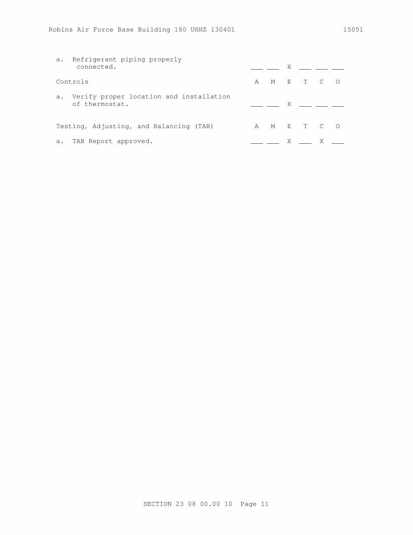
Robins Air Force Base Building 180 UHHZ 130401 15051
a. Refrigerant piping properly connected. ___ ___ X ___ ___ ___
Controls A M E T C O
a. Verify proper location and installation of thermostat. ___ ___ X ___ ___ ___
Testing, Adjusting, and Balancing (TAB) A M E T C O
a. TAB Report approved. ___ ___ X ___ X ___
SECTION 23 08 00.00 10 Page 11

Robins Air Force Base Building 180 UHHZ 130401 15051
Pre-Functional Performance Test Checklist - Exhaust Fan
For Exhaust Fan: _____
Checklist Item
Installation A M E T C O
a. Fan belt or speed control adjusted. ___ ___ X ___ X ___
Electrical A M E T C O
a. Power available to fan disconnect. ___ ___ ___ X ___ ___
b. Proper motor rotation verified. ___ ___ ___ ___ X ___
c. Verify that power disconnect is located within sight of the unit it controls. ___ ___ ___ X ___ ___
Controls A M E T C O
a. Control interlocks properly installed. ___ ___ ___ X ___ ___
b. Control interlocks operable. ___ ___ ___ X ___ ___
c. Dampers/actuators properly installed. ___ ___ X ___ ___ ___
d. Dampers/actuators operable. ___ ___ X ___ ___ ___
e. Verify proper location and installation of controls. ___ ___ X ___ ___ ___
Testing, Adjusting, and Balancing (TAB) A M E T C O
a. TAB Report approved. ___ ___ X ___ X ___
SECTION 23 08 00.00 10 Page 12

Robins Air Force Base Building 180 UHHZ 130401 15051
Pre-Functional Performance Test Checklist - HVAC System Controls
For HVAC System: _____
Checklist Item
Installation A M E T C O
a. Layout of control panel matches drawings. ___ ___ X X ___ ___
b. Framed instructions mounted in or near control panel. ___ ___ X X ___ ___
c. Components properly labeled (on inside and outside of panel). ___ ___ X X ___ ___
d. Control components piped and/or wired to each labeled terminal strip. ___ ___ X X ___ ___
e. EMCS connection made to each labeled terminal strip as shown. ___ ___ X X ___ ___
f. Control wiring and tubing labeled at all terminations, splices, and junctions. ___ ___ X X ___ ___
Main Power
a. 120 volt AC power available to panel. ___ ___ ___ X ___ ___
Testing, Adjusting, and Balancing (TAB) A M E T C O
a. TAB Report submitted. ___ ___ X ___ X ___
SECTION 23 08 00.00 10 Page 13
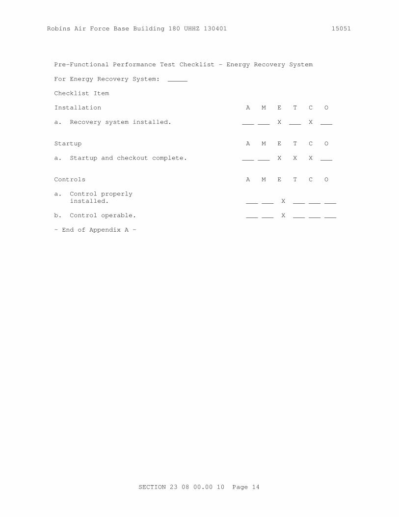
Robins Air Force Base Building 180 UHHZ 130401 15051
Pre-Functional Performance Test Checklist - Energy Recovery System
For Energy Recovery System: _____
Checklist Item
Installation A M E T C O
a. Recovery system installed. ___ ___ X ___ X ___
Startup A M E T C O
a. Startup and checkout complete. ___ ___ X X X ___
Controls A M E T C O
a. Control properly installed. ___ ___ X ___ ___ ___
b. Control operable. ___ ___ X ___ ___ ___
- End of Appendix A -
SECTION 23 08 00.00 10 Page 14

Robins Air Force Base Building 180 UHHZ 130401 15051
APPENDIX B
FUNCTIONAL PERFORMANCE TESTS CHECKLISTS
SECTION 23 08 00.00 10 Page 15

Robins Air Force Base Building 180 UHHZ 130401 15051
Functional Performance Test - Pump _____
NOTE: Prior to performing this test, for closed loop systems ensure that the system is pressurized and the make-up water system is operational, or for open loop systems ensure that the sumps are filled to the proper level.
1. Activate pump start using control system commands.
a. Verify correct operation in:
HAND__________ OFF__________ AUTO__________
b. Verify pressure drop across strainer:
Strainer inlet pressure __________ psig
Strainer outlet pressure _________ psig
c. Verify pump inlet/outlet pressure reading, compare to Testing, Adjusting, and Balancing (TAB) Report and pump design conditions.
DESIGN TAB ACTUAL
Pump inlet pressure psig _________ __________ __________
Pump outlet pressure psig _________ __________ __________
d. Operate pump at shutoff and at 100 percent of designed flow when all components are in full flow. Plot test readings on pump curve and compare results against readings taken from flow measuring devices.
SHUTOFF 100 percent
Pump inlet pressure psig __________ __________
Pump outlet pressure psig __________ __________
Pump flow rate gpm __________ __________
SETPOINTDifferential Pressure Transmitter ________
SECTION 23 08 00.00 10 Page 16
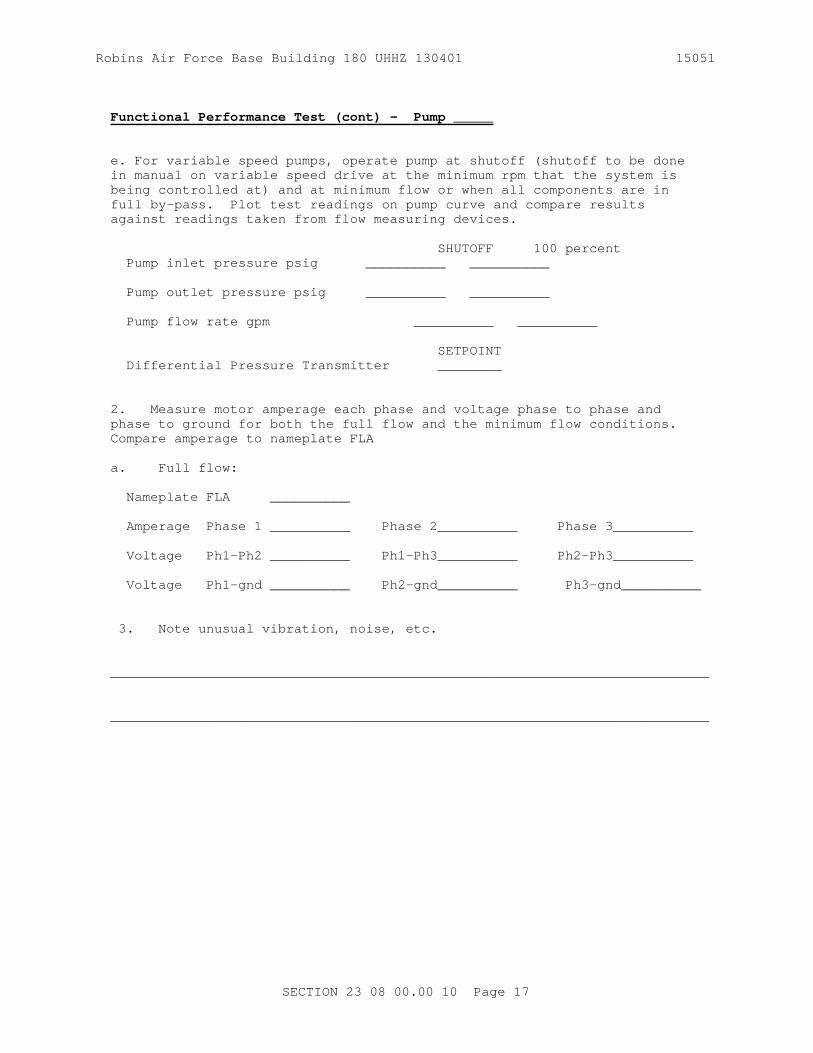
Robins Air Force Base Building 180 UHHZ 130401 15051
Functional Performance Test (cont) - Pump _____
e. For variable speed pumps, operate pump at shutoff (shutoff to be done in manual on variable speed drive at the minimum rpm that the system is being controlled at) and at minimum flow or when all components are in full by-pass. Plot test readings on pump curve and compare results against readings taken from flow measuring devices.
SHUTOFF 100 percent Pump inlet pressure psig __________ __________
Pump outlet pressure psig __________ __________
Pump flow rate gpm __________ __________
SETPOINT Differential Pressure Transmitter ________
2. Measure motor amperage each phase and voltage phase to phase and phase to ground for both the full flow and the minimum flow conditions. Compare amperage to nameplate FLA
a. Full flow:
Nameplate FLA __________
Amperage Phase 1 __________ Phase 2__________ Phase 3__________
Voltage Ph1-Ph2 __________ Ph1-Ph3__________ Ph2-Ph3__________ Voltage Ph1-gnd __________ Ph2-gnd__________ Ph3-gnd__________
3. Note unusual vibration, noise, etc.
___________________________________________________________________________
___________________________________________________________________________
SECTION 23 08 00.00 10 Page 17

Robins Air Force Base Building 180 UHHZ 130401 15051
Functional Performance Test (cont) - Pump _____
4. Certification: We the undersigned have witnessed the above functional performance tests and certify that the item tested has met the performance requirements in this section of the specifications.
Signature and Date
Contractor's Commissioning Specialist _____________________________
Contractor's Mechanical Representative _____________________________
Contractor's Electrical Representative _____________________________
Contractor's TAB Representative _____________________________
Contractor's Controls Representative _____________________________
Contracting Officer's Representative _____________________________
Using Agency's Representative _____________________________
SECTION 23 08 00.00 10 Page 18

Robins Air Force Base Building 180 UHHZ 130401 15051
Functional Performance Test Checklist - VAV Terminals
The Contracting officer will select VAV terminals to be spot-checked during the functional performance test. The number of terminals selected shall not exceed 10 percent.
1. Functional Performance Test: Contractor shall demonstrate operation of selected VAV boxes in accordance with specifications including the following:
a. Cooling only VAV boxes:
(1) Verify VAV box response to room temperature set point adjustment. Turn thermostat to 5 degrees F below ambient and measure maximum airflow. Turn thermostat to 5 degrees F above ambient and measure minimum airflow. Setting Measured Design Maximum flow ______ _____ _____ cfm Minimum flow ______ _____ _____ cfm
b. Cooling with reheat VAV boxes:
(1) Verify VAV box response to room temperature set point adjustment. Turn thermostat to 5 degrees F above ambient and measure maximum airflow. Turn thermostat to 5 degrees F below ambient and measure minimum airflow.
Setting Measured Design Maximum flow ______ _____ _____ cfm Minimum flow ______ _____ _____ cfm
(2) Verify reheat coil operation range (full closed to full open) by turning room thermostat 5 degrees F above ambient _______.
With heating water system and boiler in operation providing design supply hot water temperature record the following:
Design HW supply temperature______ deg F Actual HW supply temperature______ deg F AHU supply air temperature______ deg F VAV supply air temperature______ deg F Calculate coil capacity and compare to design: Design ______ BTU/hr Actual _____BTU/hr
SECTION 23 08 00.00 10 Page 19

Robins Air Force Base Building 180 UHHZ 130401 15051
Functional Performance Test Checklist (cont)- VAV Terminals
(4) Verify that minimal primary air is discharging into the plenum space when in full cooling mode.
(5) Verify that no plenum air is being induced from the plenum space into the supply air during full cooling by measuring supply air temperature and comparing to primary air temperature
Primary air temp _____ deg F Supply air temp _____ deg F
2. Certification: We the undersigned have witnessed the above functional performance tests and certify that the item tested has met the performance requirements in this section of the specifications.
Signature and Date Contractor's Commissioning Specialist ___________________________ Contractor's Mechanical Representative _____________________________
Contractor's Electrical Representative _____________________________
Contractor's TAB Representative _____________________________ Contractor's Controls Representative _____________________________
Contracting Officer's Representative _____________________________
Using Agency's Representative _____________________________
SECTION 23 08 00.00 10 Page 20

Robins Air Force Base Building 180 UHHZ 130401 15051
Functional Performance Test Checklist - Variable Volume Air Handling Unit
For Air Handling Unit: _____
1. Functional Performance Test: Contractor shall verify operation of air handling unit in accordance with specification including the following:
a. Ensure that a slight negative pressure exists on inboard side of the outside air dampers throughout the operation of the dampers. Modulate OA, RA, and EA dampers from fully open to fully closed positions__________.
b. The following shall be verified supply fan operating mode is initiated:
(1) All dampers in normal position prior to fan start___________.
(2) All valves in normal position prior to fan start____________.
(3) System safeties allow start if safety conditions are met.____
(4) VAV fan controller shall "soft-start" fan. __________________
(5) Modulate all VAV boxes to minimum air flow and verify that the static pressure does not exceed the high static pressure shutdown setpoint_____________.
(6) Return all VAV boxes to auto _______________.
c. Occupied mode of operation - economizer de-energized.
(1) Outside air damper at minimum position. _____________________
(2) Return air damper open. _____________________________________
(3) Chilled water control valve modulating to maintain leaving air temperature set point. Setpoint _______deg F Actual _____deg F
(4) Fan VAV controller receiving signal from duct static pressure sensor and modulating fan to maintain supply duct static pressure set point. Setpoint _______inches-wg Actual _____inches-wg
d. Occupied mode of operation - economizer energized.
(1) Outside air damper modulated to maintain mixed air temperature set point. Setpoint _______deg F, Actual _____deg F, Outside air damper position ________%.
(2) Relief air damper modulates with outside air damper according to sequence of operation. Relief air damper position_____________%.
(3) Chilled water control valve modulating to maintain leaving air temperature set point. Setpoint _______deg F Actual _____deg F
SECTION 23 08 00.00 10 Page 21

Robins Air Force Base Building 180 UHHZ 130401 15051
Functional Performance Test Checklist (cont) - Variable Volume Air Handling Unit
(5) Fan VAV controller receives signal from duct static pressure sensor and modulates fan to maintain supply duct static pressure set point. Setpoint inches-wg________________ Actual inches-wg___________
e. Unoccupied mode of operation
(1) Observe fan starts when space temperature calls for heating and/or cooling. _________ Note: This does not apply to series boxes. (2) All dampers in normal position. _____________________________(3) Verify space temperature is maintained as specified in sequence of operation. _______________
f. The following shall be verified when the supply fan off mode is initiated:
(1) All dampers in normal position. _____________________________
(2) All valves in normal position. ______________________________
(3) Fan de-energizes. ___________________________________________
g. Verify the chilled water coil control valve operation by setting all VAV's to maximum and minimum cooling.
Max Cooling Supply air temp. _____ deg F Verify cooling valve operation_______.
Min cooling
Supply air temp. _____ deg F Verify cooling valve operation_______.
h. Verify safety shut down initiated by low temperature protection thermostat. _________
i. Verify occupancy schedule is programmed into time clock/UMCS________.
2. Certification: We the undersigned have witnessed the above functional performance tests and certify that the item tested has met the performance requirements in this section of the specifications. Signature and Date
Contractor's Commissioning Specialist _____________________________
Contractor's Mechanical Representative _____________________________
Contractor's Electrical Representative _____________________________
Contractor's TAB Representative _____________________________
Contractor's Controls Representative _____________________________
Contracting Officer's Representative _____________________________
SECTION 23 08 00.00 10 Page 22

Robins Air Force Base Building 180 UHHZ 130401 15051
Using Agency's Representative _____________________________
SECTION 23 08 00.00 10 Page 23

Robins Air Force Base Building 180 UHHZ 130401 15051
Functional Performance Test Checklist - Heat Recovery Chiller
For Chiller: _____
1. Functional Performance Test: Contractor shall demonstrate operation of chilled water system in accordance with specifications including the following: Start building air handler to provide load for chiller. Activate controls system chiller start sequence as follows.
a. Start chilled water pump and establish chilled water flow. Verify chiller-chilled water proof-of-flow switch operation. ____________
b. Verify control system energizes chiller start sequence. ________
c. Verify chiller senses chilled water temperature above set point and control system activates chiller start. Setpoint_____deg F Actual_____ deg F
d. Verify functioning of "soft start" sequence. ___________________ e. Verify and record chiller data in accordance with 2, 3 and 4 below on fully loaded chiller.
f. Shut off air handling equipment to remove load on chilled water system. Verify chiller shutdown sequence is initiated and accomplished after load is removed. ___________________________________________
g. Restart air handling equipment one minute after chiller shut down. Verify chiller restart sequence. ________________________________
2. Verify chiller inlet/outlet pressure reading, compare to Testing, Adjusting, and Balancing (TAB) Report, chiller design conditions, and chiller manufacturer's performance data.
DESIGN TAB TEST ACTUAL
Chiller inlet pressure (psig) __________ __________ __________
Chiller outlet pressure (psig) __________ __________ __________
Chiller flow GPM __________ __________ __________
3. Verify chiller amperage each phase and voltage phase-to-phase and phase-to-ground. Motor F/L AMPS Amperage Phase 1 __________ Phase 2__________ Phase 3_______ _____
Voltage Ph1-Ph2 __________ Ph1-Ph3__________ Ph2-Ph3_______ Voltage Ph1-gnd __________ Ph2-gnd__________ Ph3-gnd_______
SECTION 23 08 00.00 10 Page 24

Robins Air Force Base Building 180 UHHZ 130401 15051
Functional Performance Test Checklist - Air Cooled Condensing Unit
For Condensing Unit: _____
1. Functional Performance Test: Contractor shall demonstrate operation of refrigeration system in accordance with specifications including the following: Start building air handler to provide load for condensing unit. Activate controls system start sequence as follows.
a. Start air handling unit. Verify control system energizes condensing unit start sequence. __________________________________________
b. Verify and record data in 2 and 3 below. c. Shut off air handling equipment to verify condensing unit de-energizes. ___________________________________________________________
d. Restart air handling equipment one minute after condensing unit shut down. Verify condensing unit restart sequence. _____________________
2. Verify condensing unit amperage each phase and voltage phase to phase and phase to ground. Motor Full-Load Amps __________ Amperage Phase 1 __________ Phase 2__________ Phase 3_______
Voltage Ph1-Ph2 __________ Ph1-Ph3__________ Ph2-Ph3_______ Voltage Ph1-gnd __________ Ph2-gnd__________ Ph3-gnd_______
3. Record the following information: Ambient dry bulb temperature __________ degrees F Suction pressure __________ psig Discharge pressure __________ psig 4. Unusual vibration, noise, etc. ___________________________________________________________________________
___________________________________________________________________________
5. Certification: We the undersigned have witnessed the above functional performance tests and certify that the item tested has met the performance requirements in this section of the specifications. Signature and DateContractor's Commissioning Specialist _____________________________
Contractor's Mechanical Representative _____________________________
Contractor's Electrical Representative _____________________________
Contractor's TAB Representative _____________________________
Contractor's Controls Representative _____________________________
Contracting Officer's Representative _____________________________
Using Agency's Representative _____________________________
SECTION 23 08 00.00 10 Page 25

Robins Air Force Base Building 180 UHHZ 130401 15051
SECTION 23 08 00.00 10 Page 26

Robins Air Force Base Building 180 UHHZ 130401 15051
Functional Performance Test Checklist - HVAC Controls
For HVAC System: _____
The Contracting Officer will select HVAC control systems to undergo functional performance testing. The number of systems shall not exceed 10 percent. Perform this test simultaneously with FPT for AHU or other controlled equipment.
1. Functional Performance Test: Contractor shall verify operation of HVAC controls by performing the Performance Verification Test {PVT} test for that system. Contractor to provide blank PVT test procedures previously done by the controls Contractor.
2. Verify interlock with UMCS system______.
3. Verify all required I/O points function from the UMCS system_____.
4. Certification: We the undersigned have witnessed the Performance Verification Test and certify that the item tested has met the performance requirements in this section of the specifications.
Signature and Date
Contractor's Commissioning Specialist _________________________
Contractor's Mechanical Representative ___________________________
Contractor's Electrical Representative ___________________________
Contractor's TAB Representative ___________________________ Contractor's Controls Representative ___________________________
Contractor's Officer's Representative ___________________________ Using Agency's Representative ___________________________
Functional Performance Test Checklist - Energy Recovery System
For Energy Recovery System: _____
1. Functional Performance Test: Contractor shall demonstrate operation of energy recovery system in accordance with specifications including the following: Start equipment to provide energy source for recovery system.
a. Verify energy source is providing recoverable energy.____________
b. Verify recovery system senses available energy and activates.____
2. Verify recovery system inlet/outlet readings, compare to design conditions and manufacturer's performance data.
Design Actual Primary loop inlet temp (degrees F) __________ __________
SECTION 23 08 00.00 10 Page 27

Robins Air Force Base Building 180 UHHZ 130401 15051
Primary loop outlet temp (degrees F) __________ __________ Primary loop flow rate cfm __________ __________ Secondary loop inlet temp (degrees F) __________ __________ Secondary loop outlet temp (degrees F) __________ __________ Secondary loop flow rate cfm __________ __________ Primary loop energy BTU/hr __________ __________ Secondary loop energy BTU/hr __________ __________
3. Verify that recovery system deactivates when recoverable energy is no longer available. __________________________________________________
4. Check and report unusual vibration, noise, etc. ___________________________________________________________________________
___________________________________________________________________________
5. Certification: We the undersigned have witnessed the above functional performance tests and certify that the item tested has met the performance requirements in this section of the specifications.
Signature and Date
Contractor's Commissioning Specialist __________________________
Contractor's Mechanical Representative ___________________________
Contractor's Electrical Representative ___________________________
Contractor's TAB Representative ___________________________
Contractor's Controls Representative ___________________________
Contractor's Officer's Representative ___________________________
Using Agency's Representative ___________________________
SECTION 23 08 00.00 10 Page 28

Robins Air Force Base Building 180 UHHZ 130401 15051
- End of Appendix B -
- End of document -- End of Section --
SECTION 23 08 00.00 10 Page 29

THIS PAGE INTENTIONALLY LEFT BLANK FOR DUPLEX PRINTING

Robins Air Force Base Building 180 UHHZ 130401 15051
SECTION 23 09 23.13 20
BACnet DIRECT DIGITAL CONTROL SYSTEMS FOR HVAC08/09
PART 1 GENERAL
1.1 REFERENCES
The publications listed below form a part of this specification to the extent referenced. The publications are referred to in the text by the basic designation only.
AIR MOVEMENT AND CONTROL ASSOCIATION INTERNATIONAL (AMCA)
AMCA 500-D (2012) Laboratory Methods of Testing Dampers for Rating
AMERICAN SOCIETY OF HEATING, REFRIGERATING AND AIR-CONDITIONING ENGINEERS (ASHRAE)
ASHRAE 135 (2012; Errata 2013) BACnet—A Data Communication Protocol for Building Automation and Control Networks
ARCNET TRADE ASSOCIATION (ATA)
ATA 878.1 (1999) Local Area Network: Token Bus
ASME INTERNATIONAL (ASME)
ASME B16.5 (2013) Pipe Flanges and Flanged Fittings: NPS 1/2 Through NPS 24 Metric/Inch Standard
ASME B31.1 (2012; INT 2-6, 8-10, 13, 15, 17-25, 27-31 and 42-46) Power Piping
ASME B40.100 (2013) Pressure Gauges and Gauge Attachments
ASTM INTERNATIONAL (ASTM)
ASTM A126 (2004; R 2009) Standard Specification for Gray Iron Castings for Valves, Flanges, and Pipe Fittings
ASTM B117 (2011) Standard Practice for Operating Salt Spray (Fog) Apparatus
CONSUMER ELECTRONICS ASSOCIATION (CEA)
CEA-709.1-C (2010) Control Network Protocol Specification
INSTITUTE OF ELECTRICAL AND ELECTRONICS ENGINEERS (IEEE)
IEEE C62.41.1 (2002; R 2008) Guide on the Surges
SECTION 23 09 23.13 20 Page 1

Robins Air Force Base Building 180 UHHZ 130401 15051
Environment in Low-Voltage (1000 V and Less) AC Power Circuits
IEEE C62.41.2 (2002) Recommended Practice on Characterization of Surges in Low-Voltage (1000 V and Less) AC Power Circuits
IEEE C62.45 (2002; R 2008) Recommended Practice on Surge Testing for Equipment Connected to Low-Voltage (1000v and less)AC Power Circuits
INTERNATIONAL ORGANIZATION FOR STANDARDIZATION (ISO)
ISO 8802-3 (2000) Information Technology - Telecommunications and Information Exchange Between Systems - Local and Metropolitan Area Networks - Specific Requirements - Part 3: Carrier Sense Multiple Access with Collision Detection (CSMA/CD)Access Method and Physical Layer Specifications
NATIONAL FIRE PROTECTION ASSOCIATION (NFPA)
NFPA 70 (2014; AMD 1 2013; Errata 1 2013; AMD 2 2013; Errata 2 2013; AMD 3 2014; Errata 3-4 2014; AMD 4-6 2014) National Electrical Code
NFPA 72 (2013) National Fire Alarm and Signaling Code
NFPA 90A (2015) Standard for the Installation of Air Conditioning and Ventilating Systems
SHEET METAL AND AIR CONDITIONING CONTRACTORS' NATIONAL ASSOCIATION (SMACNA)
SMACNA 1966 (2005) HVAC Duct Construction Standards Metal and Flexible, 3rd Edition
UNDERWRITERS LABORATORIES (UL)
UL 1449 (2006; Reprint Jul 2012) Surge Protective Devices
UL 506 (2008; Reprint Oct 2013) Specialty Transformers
UL 508A (2001; Reprint Feb 2010) Industrial Control Panels
UL 916 (2007; Reprint Jul 2013) Standard for Energy Management Equipment
SECTION 23 09 23.13 20 Page 2

Robins Air Force Base Building 180 UHHZ 130401 15051
1.2 DEFINITIONS
1.2.1 ANSI/ASHRAE Standard 135
ANSI/ASHRAE Standard 135: BACnet - A Data Communication Protocol for Building Automation and Control Networks, referred to as "BACnet". ASHRAE developed BACnet to provide a method for diverse building automation devices to communicate and share data over a network.
1.2.2 ARCNET
ATA 878.1 - Attached Resource Computer Network. ARCNET is a deterministic LAN technology; meaning it's possible to determine the maximum delay before a device is able to transmit a message.
1.2.3 BACnet
Building Automation and Control Network; the common name for the communication standard ASHRAE 135. The standard defines methods and protocol for cooperating building automation devices to communicate over a variety of LAN technologies.
1.2.4 BACnet/IP
An extension of BACnet, Annex J, defines this mechanism using a reserved UDP socket to transmit BACnet messages over IP networks. A BACnet/IP network is a collection of one or more IP subnetworks that share the same BACnet network number. See also "BACnet Broadcast Management Device".
1.2.5 BACnet Internetwork
Two or more BACnet networks, possibly using different LAN technologies, connected with routers. In a BACnet internetwork, there exists only one message path between devices.
1.2.6 BACnet Network
One or more BACnet segments that have the same network address and are interconnected by bridges at the physical and data link layers.
1.2.7 BACnet Segment
One or more physical segments of BACnet devices on a BACnet network, connected at the physical layer by repeaters.
1.2.8 BBMD
BACnet Broadcast Management Device (BBMD). A communications device, typically combined with a BACnet router. A BBMD forwards BACnet broadcast messages to BACnet/IP devices and other BBMDs connected to the same BACnet/IP network. Every IP subnetwork that is part of a BACnet/IP network must have only one BBMD. See also "BACnet/IP".
1.2.9 BAS
Building Automation Systems, including DDC (Direct Digital Controls) used for facility automation and energy management.
SECTION 23 09 23.13 20 Page 3

Robins Air Force Base Building 180 UHHZ 130401 15051
1.2.10 BAS Owner
The regional or local user responsible for managing all aspects of the BAS operation, including: network connections, workstation management, submittal review, technical support, control parameters, and daily operation.
1.2.11 BIBBs
BACnet Interoperability Building Blocks. A collection of BACnet services used to describe supported tasks. BIBBs are often described in terms of "A" (client) and "B" (server) devices. The “A” device uses data provided by the "B" device, or requests an action from the “B” device.
1.2.12 BI
BACnet International, formerly two organizations: the BACnet Manufacturers Association (BMA) and the BACnet Interest Group - North America (BIG-NA).
1.2.13 BI/BTL
BACnet International/BACnet Testing Laboratories (Formerly BMA/BTL). The organization responsible for testing products for compliance with the BACnet standard, operated under the direction of BACnet International.
1.2.14 Bridge
Network hardware that connects two or more network (or BACnet internetwork) segments at the physical and data link layers. A bridge may also filter messages.
1.2.15 Broadcast
A message sent to all devices on a network segment.
1.2.16 Device
Any control system component, usually a digital controller, that contains a BACnet Device Object and uses BACnet to communicate with other devices. See also "Digital Controller".
1.2.17 Device Object
Every BACnet device requires one Device Object, whose properties represent the network visible properties of that device. Every Device Object requires a unique Object Identifier number on the BACnet internetwork. This number is often referred to as the device instance.
1.2.18 Device Profile
A collection of BIBBs determining minimum BACnet capabilities of a device, defined in ASHRAE Standard 135-2004, Annex L. Standard device profiles include BACnet Operator Workstations (B-OWS), BACnet Building Controllers (B-BC), BACnet Advanced Application Controllers (B-AAC), BACnet Application Specific Controllers (B-ASC), BACnet Smart Actuator (B-SA), andBACnet Smart Sensor (B-SS). Each device used in new construction is required to have a PICS statement listing BIBBs supported.
SECTION 23 09 23.13 20 Page 4

Robins Air Force Base Building 180 UHHZ 130401 15051
1.2.19 Digital Controller
An electronic controller, usually with internal programming logic and digital and analog input/output capability, which performs control functions. In most cases, synonymous with a BACnet device described in this specification. See also "Device".
1.2.20 Direct Digital Control (DDC)
Digital controllers performing control logic. Usually the controller directly senses physical values, makes control decisions with internal programs, and outputs control signals to directly operate switches, valves, dampers, and motor controllers.
1.2.21 DDC System
A network of digital controllers, communication architecture, and user interfaces. A DDC system may include programming, sensors, actuators, switches, relays, factory controls, operator workstations, and various other devices, components, and attributes.
1.2.22 Ethernet
A family of local-area-network technologies providing high-speed networking features over various media.
1.2.23 Firmware
Software programmed into read only memory (ROM), flash memory, electrically erasable programmable read only memory (EEPROM), or erasable programmable read only memory (EPROM) chips.
1.2.24 Gateway
Communication hardware connecting two or more different protocols, similar to human language translators. The Gateway translates one protocol into equivalent concepts for the other protocol. In BACnet applications, a gateway has BACnet on one side and non-BACnet (usually proprietary) protocols on the other side.
1.2.25 Half Router
A device that participates as one partner in a BACnet point-to-point (PTP) connection. Two half-routers in an active PTP connection combine to form a single router.
1.2.26 Hub
A common connection point for devices on a network.
1.2.27 Internet Protocol (IP, TCP/IP, UDP/IP)
A communication method, the most common use is the World Wide Web. At the lowest level, it is based on Internet Protocol (IP), a method for conveying and routing packets of information over various LAN media. Two common protocols using IP are User Datagram Protocol (UDP) and Transmission Control Protocol (TCP). UDP conveys information to well-known "sockets" without confirmation of receipt. TCP establishes "sessions", which have end-to-end confirmation and guaranteed sequence of
SECTION 23 09 23.13 20 Page 5

Robins Air Force Base Building 180 UHHZ 130401 15051
delivery.
1.2.28 Input/Output (I/O)
Physical inputs and outputs to and from a device, although the term sometimes describes software, or "virtual" I/O. See also "Points".
1.2.29 I/O Expansion Unit
An I/O expansion unit provides additional point capacity to a digital controller.
1.2.30 IP subnet
Internet protocol (IP) identifies individual devices with a 32-bit number divided into four groups from 0 to 255. Devices are often grouped and share some portion of this number. For example, one device has IP address 209.185.47.68 and another device has IP address 209.185.47.82. These two devices share Class C subnet 209.185.47.00
1.2.31 Local-Area Network (LAN)
A communication network that spans a limited geographic area and uses the same basic communication technology throughout.
1.2.32 LonTalk
CEA-709.1-C . A communication protocol developed by Echelon Corp. LonTalk is an optional physical and data link layer for BACnet.
1.2.33 MAC Address
Media Access Control address. The physical node address that identifies a device on a Local Area Network.
1.2.34 Master-Slave/Token-Passing (MS/TP)
ISO 8802-3 . One of the LAN options for BACnet. MSTP uses twisted-pair wiring for relatively low speed and low cost communication (up to 4,000 ft at 76.8K bps).
1.2.35 Native BACnet Device
A device that uses BACnet as its primary, if not only, method of communication with other BACnet devices without intermediary gateways. A system that uses native BACnet devices at all levels is a native BACnet system.
1.2.36 Network
Communication technology for data communications. BACnet approved network types are BACnet over Internet Protocol (IP), Point to Point (PTP) Ethernet, ARCNET, MS/TP, and LonTalk®.
1.2.37 Network Number
A site-specific number assigned to each network segment to identify for routing. This network number must be unique throughout the BACnet internetwork.
SECTION 23 09 23.13 20 Page 6

Robins Air Force Base Building 180 UHHZ 130401 15051
1.2.38 Object
The concept of organizing BACnet information into standard components with various associated properties. Examples include analog input objects and binary output objects.
1.2.39 Object Identifier
An object property used to identify the object, including object type and instance. Object Identifiers must be unique within a device.
1.2.40 Object Properties
Attributes of an object. Examples include present value and high limit properties of an analog input object. Properties are defined in ASHRAE 135; some are optional and some are required. Objects are controlled by reading from and writing to object properties.
1.2.41 Peer-to-Peer
Peer-to-peer refers to devices where any device can initiate and respond to communication with other devices.
1.2.42 Performance Verification Test (PVT)
The procedure for determining if the installed BAS meets design criteria prior to final acceptance. The PVT is performed after installation, testing, and balancing of mechanical systems. Typically the PVT is performed by the Contractor in the presence of the Government.
1.2.43 PID
Proportional, integral, and derivative control; three parameters used to control modulating equipment to maintain a setpoint. Derivative control is often not required for HVAC systems (leaving "PI" control).
1.2.44 PICS
Protocol Implementation Conformance Statement (PICS), describing the BACnet capabilities of a device. See BACnet, Annex A for the standard format and content of a PICS statement.
1.2.45 Points
Physical and virtual inputs and outputs. See also "Input/Output".
1.2.46 PTP
Point-to-Point protocol connects individual BACnet devices or networks using serial connections like modem-to-modem links.
1.2.47 Repeater
A network component that connects two or more physical segments at the physical layer.
SECTION 23 09 23.13 20 Page 7

Robins Air Force Base Building 180 UHHZ 130401 15051
1.2.48 Router
A BACnet router is a component that joins together two or more networks using different LAN technologies. Examples include joining a BACnet Ethernet LAN to a BACnet MS/TP LAN.
1.2.49 Stand-Alone Control
Refers to devices performing equipment-specific and small system control without communication to other devices or computers for physical I/O, excluding outside air and other common shared conditions. Devices are located near controlled equipment, with physical input and output points limited to 64 or less per device, except for complex individual equipment or systems. Failure of any single device will not cause other network devices to fail. BACnet "Smart" actuators (B-SA profile) and sensors (B-SS profile) communicating on a network with a parent device are exempt from stand-alone requirements.
1.3 BACnet DIRECT DIGITAL CONTROL SYSTEMS FOR HVAC DESCRIPTION
a. Remove existing and provide new BACnet DDC controls for the systems shown including associated equipment and accessories. All new devices are accessible using a Web browser interface and communicate using ASHRAE 135 BACnet communications without the use of gateways, unless gateways are shown on the design drawings and specifically requested by the Government. Where gateways are allowed, they must support ASHRAE 135, including all object properties and read-write services shown on Government approved interoperability schedules. Manufacturer's products, including design, materials, fabrication, assembly, inspection, and testing shall be in accordance with ASHRAE 135, ASME B31.1 , and NFPA 70 , except where indicated otherwise.
1.3.1 Design Requirements
1.3.1.1 Control System Drawings Title Sheet
Provide a title sheet for the control system drawing set. Include the project title, project location, contract number, the controls contractor preparing the drawings, an index of the control drawings in the set, and a legend of the symbols and abbreviations used throughout the control system drawings.
1.3.1.2 List of I/O Points
Also known as a Point Schedule, provide for each input and output point physically connected to a digital controller: point name, point description, point type (Analog Output (AO), Analog Input (AI), Binary Output (BO), Binary Input (BI)), point sensor range, point actuator range, point address, BACnet object, associated BIBBS (where applicable), and point connection terminal number. Typical schedules for multiple identical equipment are allowed unless otherwise requested in design or contract criteria.
1.3.1.3 Control System Components List
Provide a complete list of control system components installed on this project. Include for each controller and device: control system schematic name, control system schematic designation, device description, manufacturer, and manufacturer part number. For sensors, include point
SECTION 23 09 23.13 20 Page 8

Robins Air Force Base Building 180 UHHZ 130401 15051
name, sensor range, and operating limits. For valves, include body style, Cv, design flow rate, pressure drop, valve characteristic (linear or equal percentage), and pipe connection size. For actuators, include point name, spring or non-spring return, modulating or two-position action, normal (power fail) position, nominal control signal operating range (0-10 volts DC or 4-20 milliamps), and operating limits.
1.3.1.4 Control System Schematics
Provide control system schematics. Typical schematics for multiple identical equipment are allowed unless otherwise requested in design or contract criteria. Include the following:
a. Location of each input and output device
b. Flow diagram for each piece of HVAC equipment
c. Name or symbol for each control system component, such as V-1 for a valve
d. Setpoints, with differential or proportional band values
e. Written sequence of operation for the HVAC equipment
f. Valve and Damper Schedules, with normal (power fail) position
1.3.1.5 HVAC Equipment Electrical Ladder Diagrams
Provide HVAC equipment electrical ladder diagrams. Indicate required electrical interlocks.
1.3.1.6 Component Wiring Diagrams
Provide a wiring diagram for each type of input device and output device. Indicate how each device is wired and powered; showing typical connections at the digital controller and power supply. Show for all field connected devices such as control relays, motor starters, actuators, sensors, and transmitters.
1.3.1.7 Terminal Strip Diagrams
Provide a diagram of each terminal strip. Indicate the terminal strip location, termination numbers, and associated point names.
1.3.1.8 BACnet Communication Architecture Schematic
Provide a schematic showing the project's entire BACnet communication network, including addressing used for LANs, LAN devices including routers and bridges, gateways, controllers, workstations, and field interface devices. If applicable, show connection to existing networks.
1.4 SUBMITTALS
Submit detailed and annotated manufacturer's data, drawings, and specification sheets for each item listed, that clearly show compliance with the project specifications.
SECTION 23 09 23.13 20 Page 9

Robins Air Force Base Building 180 UHHZ 130401 15051
Government approval is required for submittals with a "G" designation; submittals not having a "G" designation are for Contractor Quality Control approval. Submit the following according to 01300 SUBMITTALS AND CONTRACTOR-FURNISHED ITEMS:
SD-02 Shop Drawings
Include the following in the project's control system drawing set :
Control system drawings title sheet; G
List of I/O Points; G
Control System Components List; G
Control system schematics; G
HVAC Equipment Electrical Ladder diagrams; G
Component wiring diagrams; G
Terminal strip diagrams; G
BACnet communication architecture schematic; G
SD-03 Product Data
Direct Digital Controllers; G
Include BACnet PICS for each controller/device type, including smart sensors (B-SS) and smart actuators (B-SA).
BACnet Gateways
BACnet Protocol Analyzer
Include capability to store and report data traffic on BACnet networks, measure bandwidth usage, filter information, and identify BACnet devices.
DDC Software; G
Sensors and Input Hardware; G
Output Hardware; G
Surge and transient protection; G
Indicators; G
Variable frequency (motor) drives; G
SD-05 Design Data
Performance Verification Testing Plan; G
Pre-Performance Verification Testing Checklist; G
SD-06 Test Reports
SECTION 23 09 23.13 20 Page 10

Robins Air Force Base Building 180 UHHZ 130401 15051
Performance Verification Testing Report
SD-07 Certificates
Contractor's Qualifications
SD-09 Manufacturer's Field Reports
Pre-PVT Checklist; G
SD-10 Operation and Maintenance Data
Comply with requirements for data packages in Section 01730OPERATION AND MAINTENANCE DATA, except as supplemented and modified in this specification.
BACnet Direct Digital Control Systems, Data Package
Controls System Operators Manuals, Data Package
VFD Service Manuals, Data Package
SD-11 Closeout Submittals
Training documentation
1.5 QUALITY ASSURANCE
1.5.1 Standard Products
Provide material and equipment that are standard manufacturer's products currently in production and supported by a local service organization.
1.5.2 Delivery, Storage, and Handling
Handle, store, and protect equipment and materials to prevent damage before and during installation according to manufacturer's recommendations, and as approved by the Contracting Officer. Replace damaged or defective items.
1.5.3 Operating Environment
Protect components from humidity and temperature variation, dust, and contaminants. If components are stored before installation, keep them within the manufacturer's limits.
1.5.4 Finish of New Equipment
New equipment finishing shall be factory provided. Manufacturer's standard factory finishing shall be proven to withstand 125 hours in a salt-spray fog test. Equipment located outdoors shall be proven to withstand 500 hours in a salt-spray fog test.
Salt-spray fog test shall be according to ASTM B117, with acceptance criteria as follows: immediately after completion of the test, the finish shall show no signs of degradation or loss of adhesion beyond 0.125 inch on either side of the scratch mark.
SECTION 23 09 23.13 20 Page 11

Robins Air Force Base Building 180 UHHZ 130401 15051
1.5.5 Verification of Dimensions
The contractor shall verify all dimensions in the field, and advise the Contracting Officer of any discrepancy before performing work.
1.5.6 Contractor's Qualifications
Submit documentation certifying the controls Contractor performing the work has completed at least three DDC systems installations of a similar design to this project, and programmed similar sequences of operation for at least two years.
1.5.7 Modification of References
The advisory provisions in ASME B31.1 and NFPA 70 are mandatory. Substitute "shall" for "should" wherever it appears and interpret all references to the "authority having jurisdiction" and "owner" to mean the Contracting Officer.
1.5.8 Project Sequence
The control system work for this project shall proceed in the following order:
a. Submit and receive approval on the Shop Drawings, Product Data, and Certificates specified under the paragraph entitled "SUBMITTALS."
b. Perform the control system installation work, including all field check-outs and tuning.
c. Provide support to TAB personnel as specified under the paragraph "TEST AND BALANCE SUPPORT."
d. Submit and receive approval of the Controls System Operators Manual specified under the paragraph "CONTROLS SYSTEM OPERATORS MANUALS."
e. Submit and receive approval of the Performance Verification Testing Plan and the Pre-PVT Checklist specified under the paragraph "PERFORMANCE VERIFICATION TESTING."
f. Perform the Performance Verification Testing.
g. Submit and receive approval on the PVT Report.
h. Submit and receive approval on the Training Documentation specified under the paragraph "INSTRUCTION TO GOVERNMENT PERSONNEL". Submit at least 30 days before training.
i. Deliver the final Controls System Operators Manuals.
j. Conduct the Phase I Training.
k. Conduct the Phase II Training.
l. Submit and receive approval of Closeout Submittals.
SECTION 23 09 23.13 20 Page 12

Robins Air Force Base Building 180 UHHZ 130401 15051
PART 2 PRODUCTS
2.1 DDC SYSTEM
a. Provide a networked DDC system for stand-alone control in compliance with the latest revision of the ASHRAE 135 BACnet standard fully compatible with the existing Johnson Controls DDC system. Include all programming, objects, and services required to meet the sequence of control. Provide BACnet communications between the DDC system and native BACnet devices furnished with HVAC equipment and plant equipment including chillers and variable frequency drives. Devices provided shall be certified in the BACnet Testing Laboratories (BTL) Product Listing.
b. Interface the new DDC system with the site's existing server and operator workstation and software including graphic creation, scheduling, alarming, and trending.
2.1.1 Direct Digital Controllers
Direct digital controllers shall be UL 916 rated.
2.1.1.1 I/O Point Limitation
The total number of I/O hardware points used by a single stand-alone digital controller, including I/O expansion units, shall not exceed 64, except for complex individual equipment or systems. Place I/O expansion units in the same cabinet as the digital controller.
2.1.1.2 Environmental Limits
Controllers shall be suitable for, or placed in protective enclosures suitable for the environment (temperature, humidity, dust, and vibration) where they are located.
2.1.1.3 Stand-Alone Control
Provide stand-alone digital controllers.
2.1.1.4 Internal Clock
Provide internal clocks for all BACnet Building Controllers (B-BC) and BACnet Advanced Application Controllers (B-AAC) using BACnet time synchronization services. Automatically synchronize system clocks daily from an operator-designated controller. The system shall automatically adjust for daylight saving time.
2.1.1.5 Memory
Provide sufficient memory for each controller to support the required control, communication, trends, alarms, and messages. Protect programs residing in memory with EEPROM, flash memory, or by an uninterruptible power source (battery or uninterruptible power supply). The backup power source shall have capacity to maintain the memory during a 72-hour continuous power outage. Rechargeable power sources shall be constantly charged while the controller is operating under normal line power. Batteries shall be replaceable without soldering. Trend and alarm history collected during normal operation shall not be lost during power outages
SECTION 23 09 23.13 20 Page 13

Robins Air Force Base Building 180 UHHZ 130401 15051
less than 72 hours long.
2.1.1.6 Immunity to Power Fluctuations
Controllers shall operate at 90 percent to 110 percent nominal voltage rating.
2.1.1.7 Transformer
The controller power supply shall be fused or current limiting and rated at 125 percent power consumption.
2.1.1.8 Wiring Terminations
Use screw terminal wiring terminations for all field-installed controllers. Provide field-removable modular terminal strip or a termination card connected by a ribbon cable for all controllers other than terminal units.
2.1.1.9 Input and Output Interface
Provide hard-wired input and output interface for all controllers as follows:
a. Protection: Shorting an input or output point to itself, to another point, or to ground shall cause no controller damage. Input or output point contact with sources up to 24 volts AC or DC for any duration shall cause no controller damage.
b. Binary Inputs: Binary inputs shall have a toggle switch and monitor on and off contacts from a "dry" remote device without external power, and external 5-24 VDC voltage inputs.
c. Pulse Accumulation Inputs: Pulse accumulation inputs shall conform to binary input requirements and accumulate pulses at a resolution suitable to the application.
d. Analog Inputs: Analog inputs shall monitor low-voltage (0-10 VDC), current (4-20 mA), or resistance (thermistor or RTD) signals.
e. Binary Outputs: Binary outputs shall have a toggle switch and send a pulsed 24 VDC low-voltage signal for modulation control, or provide a maintained open-closed position for on-off control. For HVAC equipment and plant controllers, provide for manual overrides, either with three-position (on-off-auto) override switches and status lights, or with an adjacent operator display and interface. Where appropriate, provide a method to select normally open or normally closed operation.
f. Analog Outputs: Analog outputs shall send modulating 0-10 VDC or 4-20 mA signals to control output devices.
g. Tri-State Outputs: Tri-State outputs shall provide three-point floating control of terminal unit electronic actuators.
SECTION 23 09 23.13 20 Page 14

Robins Air Force Base Building 180 UHHZ 130401 15051
2.1.1.10 Digital Controller BACnet Internetwork
Provide a BACnet internetwork with control products, communication media, connectors, repeaters, hubs, and routers. Provide intermediate gateways, only when requested by the Government and shown on the contract drawings, to connect existing non-BACnet devices to the BACnet internetwork. Controller and operator interface communication shall conform to ASHRAE 135, BACnet. If a controller becomes non-responsive, the remaining controllers shall continue operating and not be affected by the failed controller.
2.1.1.11 Communications Ports
a. Direct-Connect Interface Ports: Provide at least one extra communication port at each local BACnet network for direct connecting a notebook computer or BACnet hand-held terminal so all network BACnet objects and properties may be viewed and edited by the operator.
b. Telecommunications Interface Port: Provide one telecommunication port per building, permitting remote communication via point-to-point (PTP) protocol over telephone lines.
2.1.1.12 Modems
Provide modems where required for communication between the BACnet Operator Workstation (B-OWS) and the DDC system.
2.1.1.13 BACnet Gateways
Provide BACnet communication ports, whenever available as a plant equipment OEM standard option, for DDC integration via a single communication cable. Typical BACnet controlled plant equipment includes, but is not limited to, boilers, chillers, and variable frequency motor drives.
Provide gateways to connect BACnet to legacy systems, only when specifically requested and approved by the Government, and shown on the Government approved BACnet Communication Architecture Schematic. Provide with each gateway an interoperability schedule, showing each point or event on the legacy side that the BACnet "client" will read, and each parameter that the BACnet network will write to. Describe this interoperability in terms of BACnet services, or Interoperability Building Blocks (BIBBS), defined in ASHRAE 135 Annex K. Provide two-year minimum warranty for each gateway, including parts and labor.
The following minimum capabilities are required:
a. Gateways shall be able to read and view all readable object properties listed in the interoperability schedule on the non-BACnet network to the BACnet network and vice versa where applicable.
b. Gateways shall be able to write to all writeable object properties listed in the interoperability schedule on the non-BACnet network from the BACnet network and vice versa where applicable.
c. Gateways shall provide single-pass (only one protocol to BACnet without intermediary protocols) translation from the non-BACnet protocol to BACnet and vice versa.
SECTION 23 09 23.13 20 Page 15

Robins Air Force Base Building 180 UHHZ 130401 15051
d. Gateways shall meet the requirements of Data Sharing Read Property (DS-RP-B), Data Sharing Write Property (DS-WP-B), Device Management Dynamic Device Binding-B (DM-DDB-B), and Device Management Communication Control (DM-DCC-B) BIBBs, in accordance with ASHRAE 135.
e. Gateways shall include all hardware, software, software licenses, and configuration tools for operator-to-gateway communications. Provide backup programming and parameters on CD media and the ability to modify, download, backup, and restore gateway configuration.
2.1.1.14 Digital Controller Cabinet
Provide each digital controller in a factory fabricated cabinet enclosure. Cabinets located indoors shall protect against dust and have a minimum NEMA 1 rating. Cabinets located outdoors or in damp environments shall protect against all outdoor conditions and have a minimum NEMA 4 rating. Outdoor control panels and controllers must be able to withstand extreme ambient conditions, without malfunction or failure, whether or not the controlled equipment is running. If necessary, provide a thermostatically controlled panel heater in freezing locations, and an internal ventilating fan in locations exposed to direct sunlight. Cabinets shall have a hinged lockable door and an offset removable metal back plate, except controllers integral with terminal units, like those mounted on VAV boxes. Provide like-keyed locks for all hinged panels provided and a set of two keys at each panel, with one key inserted in the lock.
2.1.1.15 Main Power Switch and Receptacle
Provide each control cabinet with a main external power on/off switch located inside the cabinet. Also provide each cabinet with a separate 120 VAC duplex receptacle.
2.1.2 DDC Software
2.1.2.1 ProgrammingProvide programming to execute the sequence of operation shown on drawings. Provide all programming and tools to configure and program all controllers. Provide programming routines in simple, easy-to-follow logic with detailed text comments describing what the logic does and how it corresponds to the project's written sequence of operation.
a. Graphic-based programming shall use a library of function blocks made from pre-programmed code designed for BAS control. Function blocks shall be assembled with interconnecting lines, depicting the control sequence in a flowchart. If providing a computer with device programming tools as part of the project, graphic programs shall be viewable in real time showing present values and logical results from each function block.
b. Menu-based programming shall be done by entering parameters, definitions, conditions, requirements, and constraints.
c. For line-by-line and text-based programming, declare variable types (local, global, real, integer, etc.) at the beginning of the program. Use descriptive comments frequently to describe the programming.
SECTION 23 09 23.13 20 Page 16

Robins Air Force Base Building 180 UHHZ 130401 15051
2.1.2.2 Parameter Modification
All writeable object properties, and all other programming parameters needed to comply with the project specification shall be adjustable for devices at any network level, including those accessible with web-browser communication, and regardless of programming methods used to create the applications.
2.1.2.3 Short Cycling Prevention
Provide setpoint differentials and minimum on/off times to prevent equipment short cycling.
2.1.2.4 Equipment Status Delay
Provide an adjustable delay from when equipment is commanded on or off and when the control program looks to the status input for confirmation.
2.1.2.5 Run Time Accumulation
Use the Elapsed Time Property to provide re-settable run time accumulation for each Binary Output Object connected to mechanical loads greater than 1 HP, electrical loads greater than 10 KW, or wherever else specified.
2.1.2.6 Timed Local Override
Provide an adjustable override time for each push of a timed local override button.
2.1.2.7 Time Synchronization
Provide time synchronization, including adjustments for leap years, daylight saving time, and operator time adjustments.
2.1.2.8 Scheduling
Provide operating schedules as indicated, with equipment assigned to groups. Changing the schedule of a group shall change the operating schedule of all equipment in the group. Groups shall be capable of operator creation, modification, and deletion. Provide capability to view and modify schedules in a seven-day week format. Provide capability to enter holiday and override schedules one full year at a time.
2.1.2.9 Object Property Override
Allow writeable object property values to accept overrides to any valid value. Where specified or required for the sequence of control, the Out-Of-Service property of Objects shall be modifiable using BACnet's write property service. When documented, exceptions to these requirement are allowed for life, machine, and process safeties.
2.1.2.10 Alarms and Events
Alarms and events shall be capable of having programmed time delays and high-low limits. When a computer workstation or web server is connected to the BACnet internetwork, alarms/events shall report to the computer, printer, as defined by an authorized operator. Otherwise alarms/events shall be stored within a device on the BACnet network until connected to a user interface device and retrieved. Provide alarms/events in agreement
SECTION 23 09 23.13 20 Page 17

Robins Air Force Base Building 180 UHHZ 130401 15051
with the point schedule, sequence of operation, and the BAS Owner. At a minimum, provide programming to initiate alarms/events any time a piece of equipment fails to operate, a control point is outside normal range or condition shown on schedules, communication to a device is lost, a device has failed, or a controller has lost its memory.
2.1.2.11 Trending
Provide BACnet trend services capable of trending all object present values set points, and other parameters indicated for trending on project schedules. Trends may be associated into groups, and a trend report may be set up for each group. Trends are stored within a device on the BACnet network, with operator selectable trend intervals from 10 seconds up to 60 minutes. The minimum number of consecutive trend values stored at one time shall be 100 per variable. When trend memory is full, the most recent data shall overwrite the oldest data.
The operator workstation shall upload trends automatically upon reaching 3/4 of the device buffer limit (via Notification_Threshold property), by operator request, or by time schedule for archiving. Archived and real-time trend data shall be available for viewing numerically and graphically for at the workstation and connected notebook computers.
2.1.2.12 Device Diagnostics
Each controller shall have diagnostic LEDs for power, communication, and device fault condition. The DDC system shall recognize and report a non-responsive controller.
2.1.2.13 Power Loss
Upon restoration of power, the DDC system shall perform an orderly restart and restoration of control.
2.2 SENSORS AND INPUT HARDWARE
Coordinate sensor types with the BAS Owner to keep them consistent with existing installations.
2.2.1 Field-Installed Temperature Sensors
Where feasible, provide the same sensor type throughout the project. Avoid using transmitters unless absolutely necessary.
2.2.1.1 Thermistors
Precision thermistors may be used in applications below 200 degrees F. Sensor accuracy over the application range shall be 0.36 degree F or less between 32 to 150 degrees F. Stability error of the thermistor over five years shall not exceed 0.25 degrees F cumulative. A/D conversion resolution error shall be kept to 0.1 degrees F. Total error for a thermistor circuit shall not exceed 0.5 degrees F.
2.2.1.2 Resistance Temperature Detectors (RTDs)
Provide RTD sensors with platinum elements compatible with the digital controllers. Encapsulate sensors in epoxy, series 300 stainless steel, anodized aluminum, or copper. Temperature sensor accuracy shall be 0.1 percent (1 ohm) of expected ohms (1000 ohms) at 32 degrees F. Temperature
SECTION 23 09 23.13 20 Page 18

Robins Air Force Base Building 180 UHHZ 130401 15051
sensor stability error over five years shall not exceed 0.25 degrees F cumulative. Direct connection of RTDs to digital controllers without transmitters is preferred. When RTDs are connected directly, lead resistance error shall be less than 0.25 degrees F. The total error for a RTD circuit shall not exceed 0.5 degrees F.
2.2.1.3 Temperature Sensor Details
a. Room Type: Provide the sensing element components within a decorative protective cover suitable for surrounding decor. Provide room temperature sensors with timed override button, setpoint adjustment lever, digital temperature display. Provide a communication port or 802.11x wireless support for a portable operator interface like a notebook computer or PDA.
b. Duct Probe Type: Ensure the probe is long enough to properly sense the air stream temperature.
c. Duct Averaging Type: Continuous averaging sensors shall be one foot in length for each 4 square feet of duct cross-sectional area, and a minimum length of 6 feet.
d. Pipe Immersion Type: Provide minimum three-inch immersion. Provide each sensor with a corresponding pipe-mounted sensor well, unless indicated otherwise. Sensor wells shall be stainless steel when used in steel piping, and brass when used in copper piping. Provide the sensor well with a heat-sensitive transfer agent between the sensor and the well interior.
e. Outside Air Type: Provide the sensing element on the building's north side with a protective weather shade that positions the sensor approximately 3 inches off the wall surface, does not inhibit free air flow across the sensing element, and protects the sensor from snow, ice, and rain.
2.2.2 Transmitters
Provide transmitters with 4 to 20 mA or 0 to 10 VDC linear output scaled to the sensed input. Transmitters shall be matched to the respective sensor, factory calibrated, and sealed. Size transmitters for an output near 50 percent of its full-scale range at normal operating conditions. The total transmitter error shall not exceed 0.1 percent at any point across the measured span. Supply voltage shall be 12 to 24 volts AC or DC. Transmitters shall have non-interactive offset and span adjustments. For temperature sensing, transmitter drift shall not exceed 0.03 degrees F a year.
2.2.2.1 Relative Humidity Transmitters
Provide transmitters with an accuracy equal to plus or minus 5 percent from 0 to 90 percent scale, and less than one percent drift per year. Sensing elements shall be the polymer type.
2.2.2.2 Pressure Transmitters
Provide transmitters integral with the pressure transducer.
SECTION 23 09 23.13 20 Page 19

Robins Air Force Base Building 180 UHHZ 130401 15051
2.2.3 Current Transducers
Provide current transducers to monitor motor amperage, unless current switches are shown on design drawings or point tables.
2.2.4 Air Quality Sensors
Provide power supply for each sensor.
2.2.4.1 CO2 Sensors
Provide photo-acoustic type CO2 sensors with integral transducers and linear output. The devices shall read CO2 concentrations between 0 and 2000 ppm with full scale accuracy of at least plus or minus 100 ppm.
2.2.5 Input Switches
2.2.5.1 Timed Local Overrides
Provide buttons or switches to override the DDC occupancy schedule programming for each major building zone during unoccupied periods, and to return HVAC equipment to the occupied mode.
2.2.6 Freeze Protection Thermostats
Provide special purpose thermostats with flexible capillary elements 20 feet minimum length for coil face areas up to 40 square feet. Provide longer elements for larger coils at 1-foot of element for every 4 square feet of coil face area, or provide additional thermostats. Provide switch contacts rated for the respective motor starter's control circuit voltage. Include auxiliary contacts for the switch's status condition. A freezing condition at any 18-inch increment along the sensing element's length shall activate the switch. The thermostat shall be equipped with a manual push-button reset switch so that when tripped, the thermostat requires manual resetting before the HVAC equipment can restart.
2.2.7 Air Flow Measurement Stations
Air flow measurement stations shall have an array of velocity sensing elements and straightening vanes if required) inside a flanged sheet metal casing. The velocity sensing elements shall be the RTD or thermistor type, traversing the ducted air in at least two directions. The air flow pressure drop across the station shall not exceed 0.08 inch water gage at a velocity of 2,000 fpm. The station shall be suitable for air flows up to 5,000 fpm, and a temperature range of 40 to 120 degrees F. The station's measurement accuracy over the range of 125 to 2,500 fpm shall be plus or minus 3 percent of the measured velocity. Station transmitters shall provide a linear, temperature-compensated 4 to 20 mA or 0 to 10 VDC output. The output shall be capable of being accurately converted to a corresponding air flow rate in cubic feet per minute. Transmitters shall be a 2-wire, loop powered device. The output error of the transmitter shall not exceed 0.5 percent of the measurement.
2.3 OUTPUT HARDWARE
2.3.1 Control Dampers
Provide factory manufactured galvanized steel dampers where
SECTION 23 09 23.13 20 Page 20

Robins Air Force Base Building 180 UHHZ 130401 15051
indicated. Control dampers shall comply with SMACNA 1966 except as modified or supplemented by this specification. Published damper leakage rates and respective pressure drops shall have been verified by tests in compliance with AMCA 500-D requirements.
Provide damper assembly frames constructed of 0.064 inch minimumthickness galvanized steel channels with mitered and welded corners. Damper axles shall be 0.5 inches minimum diameter plated steel rods supported in the damper frame by stainless steel or bronze bearings. Blades mounted vertically shall be supported by thrust bearings.
Dampers shall be rated for not less than 2000 fpm air velocity. The pressure drop through each damper when full-open shall not exceed 0.04 inches water gage at 1000 fpm face velocity. Damper assemblies in ductwork subject to above 3-inch water gauge static air pressure shall be constructed to meet SMACNA Seal Class "A" construction requirements.
Provide the damper operating linkages outside of the air stream, including crank arms, connecting rods, and other hardware that transmits motion from the damper actuators to the dampers, shall be adjustable. Additionally, operating linkages shall be designed and constructed to have a 2 to 1 safety factor when loaded with the maximum required damper operating force. Linkages shall be brass, bronze, galvanized steel, or stainless steel.
Provide access doors or panels in hard ceilings and walls for access to all concealed damper operators and damper locking setscrews.
For field-installed control dampers, a single damper section shall have blades no longer than 48 inches and no higher than 72 inches. The maximum damper blade width shall be 12 inches. Larger sized dampers shall be built using a combination of sections.
Frames shall be at least 2 inches wide. Flat blades shall have edges folded for rigidity. Blades shall be provided with compressible gasket seals along the full length of the blades to prevent air leakage when closed.
The damper frames shall be provided with jamb seals to minimize air leakage. Seals shall be suitable for an operating temperature range of minus 40 degrees F to 200 degrees F.
The leakage rate of each damper when full-closed shall be no morethan 3 cfm per sq. foot of damper face area at 1.0 inches water gage static pressure.
2.3.2 Control Valves
2.3.2.1 Valve Assembly
Valve bodies shall be designed for 125 psig minimum working pressure or 150 percent of the operating pressure, whichever is greater. Valve stems shall be Type 316 stainless steel. Valve leakage ratings shall be 0.01 percent of rated Cv value. Class 125 copper alloy valve bodies and Class 150 steel or stainless steel valves shall meet the requirements of ASME B16.5 . Cast iron valve components shall meet the requirements of ASTM A126 Class B or C. Control valves shall be pressure independent.
SECTION 23 09 23.13 20 Page 21

Robins Air Force Base Building 180 UHHZ 130401 15051
2.3.2.2 Butterfly Valves
Butterfly valves shall be the threaded lug type suitable for dead-end service and for modulation to the fully-closed position, with stainless steel shafts supported by bearings, non-corrosive discs geometrically interlocked with or bolted to the shaft (no pins), and EPDM seats suitable for temperatures from minus 20 degrees F to plus 250 degrees F. Valves shall have a means of manual operation independent of the actuator.
2.3.2.3 Two-Way Valves
Two-way modulating valves shall have an equal percentage characteristic.
2.3.2.4 Valves for Chilled Water Service
a. Bodies for valves 1-1/2 inches and smaller shall be brass or bronze, with threaded or union ends. Bodies for valves from 2 inches to 3 inches inclusive shall be of brass, bronze, or iron. Bodies for 2 inch valves shall have threaded connections. Bodies for valves from 2-1/2 to 3 inches shall have flanged connections.
b. Internal valve trim shall be brass or bronze, except that valve stems shall be stainless steel.
c. Unless indicated otherwise, provide modulating valves sized for 2 psi minimum and 4 psi maximum differential across the valve at the design flow rate.
d. Valves 4 inches and larger shall be butterfly valves, unless indicated otherwise.
2.3.2.5 Valves for Hot Water Service
Valves for hot water service below 250 Degrees F:
a. Bodies for valves 1-1/2 inches and smaller shall be brass or bronze, with threaded or union ends. Bodies for valves from 2 inches to 3 inches inclusive shall be of brass, bronze, or iron. Bodies for 2 inch valves shall have threaded connections. Bodies for valves from 2-1/2 to 3 inches shall have flanged connections.
b. Internal trim (including seats, seat rings, modulation plugs, valve stems, and springs) of valves controlling water above 210 degrees F shall be Type 316 stainless steel.
c. Internal trim for valves controlling water 210 degrees F or less shall be brass or bronze. Valve stems shall be Type 316 stainless steel.
d. Non-metallic parts of hot water control valves shall be suitable for a minimum continuous operating temperature of 250 degrees F or 50 degrees F above the system design temperature, whichever is higher.
e. Unless indicated otherwise, provide modulating valves sized for 2 psi minimum and 4 psi maximum differential across the valve at the design flow rate.
f. Valves 4 inches and larger shall be butterfly valves, unless indicated otherwise.
SECTION 23 09 23.13 20 Page 22

Robins Air Force Base Building 180 UHHZ 130401 15051
2.3.3 Actuators
Provide direct-drive electric actuators for all control applications, except where indicated otherwise.
2.3.3.1 Electric Actuators
Each actuator shall deliver the torque required for continuous uniform motion and shall have internal end switches to limit the travel, or be capable of withstanding continuous stalling without damage. Actuators shall function properly within 85 to 110 percent of rated line voltage. Provide actuators with hardened steel running shafts and gears of steel or copper alloy. Fiber or reinforced nylon gears may be used for torques less than 16 inch-pounds. Provide two-position actuators of single direction, spring return, or reversing type. Provide modulating actuators capable of stopping at any point in the cycle, and starting in either direction from any point. Actuators shall be equipped with a switch for reversing direction, and a button to disengage the clutch to allow manual adjustments. Provide the actuator with a hand crank for manual adjustments, as applicable. Spring return actuators shall be provided on all control dampers and all control valves unless indicated otherwise. Each actuator shall have distinct markings indicating the full-open and full-closed position, and the points in-between.
2.3.4 Output Switches
2.3.4.1 Control Relays
Field installed and DDC panel relays shall be double pole, double throw, UL listed, with contacts rated for the intended application, indicator light, and dust proof enclosure. The indicator light shall be lit when the coil is energized and off when coil is not energized. Relays shall be the socket type, plug into a fixed base, and replaceable without tools or removing wiring. Encapsulated "PAM" type relays may be used for terminal control applications.
2.4 ELECTRICAL POWER AND DISTRIBUTION
2.4.1 Transformers
Transformers shall conform to UL 506 . For control power other than terminal level equipment, provide a fuse or circuit breaker on the secondary side of each transformer.
2.4.2 Surge and Transient Protection
Provide each digital controller with surge and transient power protection. Surge and transient protection shall consist of the following devices, installed externally to the controllers.
2.4.2.1 Power Line Surge Protection
Provide surge suppressors on the incoming power at each controller or grouped terminal controllers. Surge suppressors shall be rated in accordance with UL 1449 , have a fault indicating light, and conform to the following:
a. The device shall be a transient voltage surge suppressor, hard-wire
SECTION 23 09 23.13 20 Page 23

Robins Air Force Base Building 180 UHHZ 130401 15051
type individual equipment protector for 120 VAC/1 phase/2 wire plus ground.
b. The device shall react within 5 nanoseconds and automatically reset.
c. The voltage protection threshold, line to neutral, shall be no more than 211 volts.
d. The device shall have an independent secondary stage equal to or greater than the primary stage joule rating.
e. The primary suppression system components shall be pure silicon avalanche diodes.
f. The secondary suppression system components shall be silicon avalanche diodes or metal oxide varistors.
g. The device shall have an indication light to indicate the protection components are functioning.
h. All system functions of the transient suppression system shall be individually fused and not short circuit the AC power line at any time.
i. The device shall have an EMI/RFI noise filter with a minimum attenuation of 13 dB at 10 kHz to 300 MHz.
j. The device shall comply with IEEE C62.41.1 and IEEE C62.41.2 , Class "B" requirements and be tested according to IEEE C62.45 .
k. The device shall be capable of operating between minus 20 degrees F and plus 122 degrees F.
2.4.2.2 Telephone and Communication Line Surge Protection
Provide surge and transient protection for DDC controllers and DDC network related devices connected to phone and network communication lines, in accordance with the following:
a. The device shall provide continuous, non-interrupting protection, and shall automatically reset after safely eliminating transient surges.
b. The protection shall react within 5 nanoseconds using only solid-state silicon avalanche technology.
c. The device shall be installed at the distance recommended by its manufacturer.
2.4.2.3 Controller Input/Output Protection
Provide controller inputs and outputs with surge protection via optical isolation, metal oxide varistors (MOV), or silicon avalanche devices. Fuses are not permitted for surge protection.
SECTION 23 09 23.13 20 Page 24

Robins Air Force Base Building 180 UHHZ 130401 15051
2.4.3 Wiring
Provide complete electrical wiring for the DDC System, including wiring to transformer primaries. Unless indicated otherwise, provide all normally visible or otherwise exposed wiring in conduit. Where conduit is required, control circuit wiring shall not run in the same conduit as power wiring over 100 volts. Circuits operating at more than 100 volts shall be in accordance with Section 26 20 00, INTERIOR DISTRIBUTION SYSTEM. Run all circuits over 100 volts in conduit, metallic tubing, covered metal raceways, or armored cable. Use plenum-rated cable for circuits under 100 volts in enclosed spaces. Examples of these spaces include HVAC plenums, within walls, above suspended ceilings, in attics, and within ductwork.
2.4.3.1 Power Wiring
The following requirements are for field-installed wiring:
a. Wiring for 24 V circuits shall be insulated copper 18 AWG minimum and rated for 300 VAC service.
b. Wiring for 120 V circuits shall be insulated copper 14 AWG minimum and rated for 600 VAC service.
2.4.3.2 Analog Signal Wiring
Field-installed analog signal wiring shall be 18 AWG single or multiple twisted pair. Each cable shall be 100 percent shielded and have a 20 AWG drain wire. Each wire shall have insulation rated for 300 VAC service. Cables shall have an overall aluminum-polyester or tinned-copper cable-shield tape.
2.5 FIRE PROTECTION DEVICES
2.5.1 Duct Smoke Detectors
Provide duct smoke detectors in HVAC ducts in accordance with NFPA 72 and NFPA 90A, except as indicated otherwise. Provide UL listed or FM approved detectors, designed specifically for duct installation.
2.6 INDICATORS
2.6.1 Thermometers
Provide bi-metal type thermometers at locations shown. Thermometers shall have either 9 inch long scales or 3.5 inch diameter dials, with insertion, immersion, or averaging elements. Provide matching thermowells for pipe-mounted installations. Select scale ranges suitable for the intended service, with the normal operating temperature near the scale's midpoint. The thermometer's accuracy shall be plus or minus 2 percent of the scale range.
2.6.2 Pressure Gauges for Piping Systems
Provide pipe-mounted pressure gauges at the locations shown. Gauges shall conform to ASME B40.100 and have a 4-inch diameter dial and shutoff cock. Select scale ranges suitable for the intended service, with the normal operating pressure near the scale's midpoint. The gauge's accuracy shall be plus or minus 2 percent of the scale range.
SECTION 23 09 23.13 20 Page 25

Robins Air Force Base Building 180 UHHZ 130401 15051
2.7 VARIABLE FREQUENCY (MOTOR) DRIVES
Provide variable frequency drives (VFDs) as indicated. VFDs shall convert 240 or 460 volt (plus or minus 10 percent), three phase, 60 hertz (plus or minus 2Hz), utility grade power to adjustable voltage/frequency, three phase, AC power for stepless motor control from 5 percent to 105 percent of base speed. VFDs shall be UL listed as delivered to the end user. The VFD shall meet the requirements specified in the most current National Electrical Code. Each VFD shall also meet the following:
a. The VFD shall use sine coded Pulse Width Modulation (PWM) technology. PWM calculations shall be performed by the VFD microprocessor.
b. The VFD shall be capable of automatic control by a remote 4-20 mA or 0 to 10 VDC signal, by network command, or manually by the VFD control panel.
2.7.1 VFD Quality Assurance
VFDs shall be the manufacturer's current standard production unit with at least 10 identical units successfully operating in the field.
2.7.2 VFD Service Support
a. Warranty: Provide the VFDs with a minimum 24-month full parts and labor warranty. The warranty shall start when the contract's HVAC system is accepted by the Government. Include warranty documentation, dates, and contact information with the VFD on-site service manuals.
b. VFD Service Manuals: Provide the VFDs with all necessary installation, operation, maintenance, troubleshooting, service, and repair manuals in English including related factory technical bulletins. Provide the documents factory bound, in sturdy 3-ring binders, or hard bound covers. Provide a title sheet on the outside of each binder indicating the project title, project location, installing contractor, contract number, and the VFD manufacturer, address, and telephone number. Each binder shall include a table of contents and tabbed dividers, with all material neatly organized. The documentation provided shall be specifically applicable to this project, shall be annotated to reflect the actual project conditions, and shall provide a complete and concise depiction of the installed work.
c. Technical Support: Provide the VFDs with manufacturer's technical telephone support in English, readily available during normal working hours, and free of charge for the life of the equipment.
d. Initial Start-Up: Provide the VFDs with factory-trained personnel for the on-site start-up of the HVAC equipment and associated VFD. The personnel shall be competent in the complete start-up, operation, and repair of the particular model VFD installed. The factory start-up representative shall perform the factory's complete recommended start-up procedures and check-out tests on the VFD. Include a copy of the start-up test documentation with the VFD on-site service manuals.
e. Provide the VFDs with on-site/hands-on training for the user and maintenance personnel. Provide a capable and qualified instructor with minimum two years field experience with the operation and
SECTION 23 09 23.13 20 Page 26

Robins Air Force Base Building 180 UHHZ 130401 15051
maintenance of similar VFDs. The training shall occur during normal working hours and last not less than 2 hours. Coordinate the training time with the Contracting Officer and the end user. The VFD service manuals shall be used during the training. The contractor shall ensure the manuals are on-site before the start of training. The training shall cover all operational aspects of the VFD.
2.7.3 VFD Features
VFDs shall have the following features:
a. A local operator control keypad capable of:
(1) Remote/Local operator selection with password access.
(2) Run/Stop and manual speed commands.
(3) All programming functions.
(4) Scrolling through all display functions.
b. Digital display capable of indicating:
(1) VFD status.
(2) Frequency.
(3) Motor RPM.
(4) Phase current.
(5) Fault diagnostics in descriptive text.
(6) All programmed parameters.
c. Standard PI loop controller with input terminal for controlled variable and parameter settings.
d. User interface terminals for remote control of VFD speed, speed feedback, and an isolated form C SPDT relay, which energizes on a drive fault condition.
e. An isolated form C SPDT auxiliary relay which energizes on a run command.
f. A metal NEMA 1 enclosure for indoors, NEMA 4 with heater for outdoors.
g. An adjustable carrier frequency with 16 KHz minimum upper limit.
h. A built in or external line reactor with 3 percent minimum impedance to protect the VFDs DC buss capacitors and rectifier section diodes.
2.7.4 Programmable Parameters
VFDs shall include the following operator programmable parameters:
a. Upper and lower limit frequency.
b. Acceleration and Deceleration rate.
SECTION 23 09 23.13 20 Page 27

Robins Air Force Base Building 180 UHHZ 130401 15051
c. Variable torque volts per Hertz curve .
d. Starting voltage level.
e. Starting frequency level.
f. Display speed scaling.
g. Enable/disable auto-restart feature.
h. Enable/disable soft stall feature.
i. Motor overload level.
j. Motor stall level.
k. Jump frequency and hysteresis band.
l. PWM carrier frequency.
2.7.5 Protective Features
VFDs shall have the following protective features:
a. An electronic adjustable inverse time current limit with consideration for additional heating of the motor at frequencies below 45Hz, for the protection of the motor.
b. An electronic adjustable soft stall feature, allowing the VFD to lower the frequency to a point where the motor will not exceed the full-load amperage when an overload condition exists at the requested frequency. The VFD will automatically return to the requested frequency when load conditions permit.
c. A separate electronic stall at 110 percent VFD rated current, and a separate hardware trip at 190 percent current.
d. Ground fault protection that protects the output cables and motor from grounds during both starting and continuous running conditions.
e. The ability to restart after the following faults:
(1) Overcurrent (drive or motor).
(2) Power outage.
(3) Phase loss.
(4) Over voltage/Under voltage.
f. The ability shut down if inadvertently started into a rotating load without damaging the VFD or the motor.
g. The ability to keep a log of a minimum of four previous fault conditions, indicating the fault type and time of occurrence in descriptive text.
h. The ability to sustain 110 percent rated current for 60 seconds
SECTION 23 09 23.13 20 Page 28

Robins Air Force Base Building 180 UHHZ 130401 15051
i. The ability to shutdown safely or protect against and record the following fault conditions:
(1) Over current (and an indication if the over current was during acceleration, deceleration, or running).
(2) Over current internal to the drive.
(3) Motor overload at start-up.
(4) Over voltage from utility power.
(5) Motor running overload.
(6) Over voltage during deceleration.
(7) VFD over heat.
(8) Load end ground fault.
(9) Abnormal parameters or data in VFD EEPROM.
2.7.6 Minimum Operating Conditions
VFDs shall be designed and constructed to operate within the following service conditions:
a. Ambient Temperature Range, 0 to 120 degrees F.
b. Non-condensing relative humidity to 90 percent.
2.7.7 Additional Features
Provide VFDs with the following additional features:
a. BACnet communication interface port
b. RFI/EMI filters
c. Manual bypass circuit and switch integral to the drive to allow drive bypass and operation at 100 percent speed. Motor overload and short circuit protective features shall remain in use during the bypass mode.
PART 3 EXECUTION
3.1 INSTALLATION
Perform the installation under the supervision of competent technicians regularly employed in the installation of DDC systems.
3.1.1 BACnet Naming and Addressing
Coordinate with the BAS Owner and provide unique naming and addressing for BACnet networks and devices.
a. MAC Address
Every BACnet device shall have an assigned and documented MAC Address
SECTION 23 09 23.13 20 Page 29

Robins Air Force Base Building 180 UHHZ 130401 15051
unique to its network. For Ethernet networks, document the MAC Address assigned at its creation. For ARCNET or MS/TP, assign from 00 to 64.
b. Network Numbering
Assign unique numbers to each new network installed on the BACnet internetwork. Provide ability for changing the network number; either by device switches, network computer, or field operator interface. The BACnet internetwork (all possible connected networks) can contain up to 65,534 possible unique networks.
c. Device Object Identifier Property Number
Assign unique Device "Object_Identifier" property numbers or device instances for each device on the BACnet internetwork. Provide for future modification of the device instance number; either by device switches, network computer, or field interface. BACnet allows up to 4,194,302 possible unique devices per internetwork.
d. Device Object Name Property Text
The Device Object Name property field shall support 32 minimum printable characters. Assign unique Device "Object_Name" property names with plain-English descriptive names for each deviceFor example, the Device Object Name that for the device controlling the chiller plant at Building 3408 would be:
Device Object_Name = CW System B3408
A Device Object Name for a VAV box controller might be:
Device Object_Name = VAV BOX25
e. Object Name Property Text (Other than Device Objects)
The Object Name property field shall support 32 minimum printable characters. Assign Object Name properties with plain-English names descriptive of the application. Examples include "Zone 1 Temperature" and "Fan Start/Stop".
f. Object Identifier Property Number (Other than Device Objects)
Assign Object Identifier property numbers according to design drawings or tables if provided. If not provided, Object Identifier property numbers may be assigned at the Contractor's discretion but must be approved by the Government. In this case they must be documented and unique for like object types within the device.
3.1.2 Minimum BACnet Object Requirements
a. Use of Standard BACnet Objects
For the following points and parameters, use standard BACnet objects, where all relevant object properties can be read using BACnet's Read Property Service, and all relevant object properties can be modified using BACnet's Write Property Service:all device physical inputs and outputs, all set points, all PID tuning parameters, all calculated pressures, flow rates, and consumption
SECTION 23 09 23.13 20 Page 30

Robins Air Force Base Building 180 UHHZ 130401 15051
values, all alarms, all trends, all schedules, and all equipment and lighting circuit operating status.
b. BACnet Object Description Property
The Object Description property shall support 32 minimum printable characters. For each object, complete the description property field using a brief, narrative, plain English description specific to the object and project application. For example: "HW Pump 1 Proof." Document compliance, length restrictions, and whether the description is writeable in the device PICS.
c. Analog Input, Output, and Value Objects
Support and provide Description and/or Device_Type text strings matching signal type and engineering units shown on the points list.
d. Binary Input, Output, and Value Objects
Support and provide Inactive_Text and Active_Text property descriptions matching conditions shown on the points list.
e. Calendar Object
For devices with scheduling capability, provide at least one Calendar Object with ten-entry capacity. All operators may view Calendar Objects; authorized operators may make modifications from a workstation. Enable the writeable Date List property and support all calendar entry data types.
f. Schedule Object
Use Schedule Objects for all building system scheduling. All operators may view schedule entries; authorized operators may modify schedules from a workstation.
g. Loop Object or Equal
Use Loop Objects or equivalent BACnet objects in each applicable field device for PID control. Regardless of program method or object used, allow authorized operators to adjust the Update Interval, Setpoint, Proportional Constant, Integral Constant, and Derivative Constant using BACnet read/write services.
3.1.3 Minimum BACnet Service Requirements
a. Command Priorities
Use commandable BACnet objects to control machinery and systems, providing the priority levels listed below. If the sequence of operation requires a different priority, obtain approval from the Contracting Officer.
SECTION 23 09 23.13 20 Page 31

Robins Air Force Base Building 180 UHHZ 130401 15051
Priority Level Application
1 Manual-Life Safety
2 Automatic-Life Safety
3 (User Defined)
4 (User Defined)
5 Critical Equipment Control
6 Minimum On/Off
7 (User Defined)
8 Manual Operator
9 (User Defined)
10 (User Defined)
11 Load Shedding
12 (User Defined)
13 (User Defined)
14 (User Defined)
15 (User Defined)
16 (User Defined)
b. Alarming
(1) Alarm Priorities - Coordinate alarm and event notification with the BAS Owner.
(2) Notification Class - Enable writeable Priority, Ack Required, and Recipient List properties of Notification Class objects.
(3) Event Notification Message Texts - Use condition specific narrative text and numerical references for alarm and event notification.
c. Updating Displayed Property Values
Allow workstations to display property values at discrete polled intervals, or based on receipt of confirmed and unconfirmed Change of Value notifications. The COV increment shall be adjustable by an operator using BACnet services, and polled intervals shall be adjustable at the operator workstation.
SECTION 23 09 23.13 20 Page 32

Robins Air Force Base Building 180 UHHZ 130401 15051
3.1.4 Local Area Networks
Obtain Government approval before connecting new networks with existing networks. Network numbers and device instance numbers shall remain unique when joining networks. Do not change existing network addressing without Government approval. See also "BACnet Naming and Addressing".
3.1.5 BACnet Routers, Bridges, and Switches
Provide the quantity of BACnet routers, bridges, and switches necessary for communications shown on the BACnet Communication Architecture schematic. Provide BACnet routers with BACnet Broadcast Message Device (BBMD) capability on each BACnet internetwork communicating across an IP network. Configure each BACnet device and bridge, router, or switch to communicate on its network segment.
3.1.6 Wiring Criteria
a. Run circuits operating at more than 100 volts in rigid or flexible conduit, metallic tubing, covered metal raceways, or armored cable.
b. Do not run binary control circuit wiring in the same conduit as power wiring over 100 volts. Where analog signal wiring requires conduit, do not run in the same conduit with AC power circuits or control circuits operating at more than 100 volts.
c. Provide circuit and wiring protection required by NFPA 70 .
d. Run all wiring located inside mechanical rooms in conduit.
e. Do not bury aluminum-sheathed cable or aluminum conduit in concrete.
f. Input/output identification: Permanently label each field-installed wire, cable, and pneumatic tube at each end with descriptive text using a commercial wire marking system that fully encircles the wire, cable, or tube. Locate the markers within 2 inches of each termination. Match the names and I/O number to the project's point list. Similarly label all power wiring serving control devices, including the word "power" in the label. Number each pneumatic tube every six feet. Label all terminal blocks with alpha/numeric labels. All wiring and the wiring methods shall be in accordance with UL 508A .
g. For controller power, provide new 120 VAC circuits, with ground. Provide each circuit with a dedicated breaker, and run wiring in its own conduit, separate from any control wiring. Connect the controller's ground wire to the electrical panel ground; conduit grounds are not acceptable.
h. Surge Protection: Install surge protection according to manufacturer's instructions. Multiple controllers fed from a common power supply may be protected by a common surge protector, properly sized for the total connected devices.
i. Grounding: Ground controllers and cabinets to a good earth ground as specified in Section 26 20 00 INTERIOR DISTRIBUTION SYSTEM. Conduit grounding is not acceptable; all grounding shall have a direct path to the building earth ground. Ground sensor drain wire shields at the controller end.
SECTION 23 09 23.13 20 Page 33

Robins Air Force Base Building 180 UHHZ 130401 15051
j. The Contractor shall be responsible for correcting all associated ground loop problems.
k. Run wiring in panel enclosures in covered wire track.
3.1.7 Accessibility
Install all equipment so that parts requiring periodic inspection, operation, maintenance, and repair are readily accessible. Install digital controllers, data ports, and concealed actuators, valves, dampers, and like equipment in locations freely accessible through access doors.
3.1.8 Digital Controllers
a. Install as stand alone control devices (see definitions).
b. Locate control cabinets at the locations shown on the drawings. If not shown on the drawings, install in the most accessible space, close to the controlled equipment.
3.1.9 Hand-Off-Auto Switches
Wire safety controls such as smoke detectors and freeze protection thermostats to protect the equipment during both hand and auto operation.
3.1.10 Temperature Sensors
Install temperature sensors in locations that are accessible and provide a good representation of sensed media. Installations in dead spaces are not acceptable. Calibrate sensors according to manufacturer's instructions. Do not use sensors designed for one application in a different application.
3.1.10.1 Room Temperature Sensors
Mount the sensors on interior walls to sense the average room temperature at the locations indicated. Avoid locations near heat sources such as copy machines or locations by supply air outlet drafts. Mount the center of the sensor 54 inches above the floor to meet ADA requirements.
3.1.10.2 Duct Temperature Sensors
a. Probe Type: Provide a gasket between the sensor housing and the duct wall. Seal the duct penetration air tight. Seal the duct insulation penetration vapor tight.
b. Averaging Type (and coil freeze protection thermostats): Weave the capillary tube sensing element in a serpentine fashion perpendicular to the flow, across the duct or air handler cross-section, using durable non-metal supports. Prevent contact between the capillary and the duct or air handler internals. Provide a duct access door at the sensor location. The access door shall be hinged on the side, factory insulated, have cam type locks, and be as large as the duct will permit, maximum 18 by 18 inches. For sensors inside air handlers, the sensors shall be fully accessible through the air handler's access doors without removing any of the air handler's internals.
3.1.10.3 Immersion Temperature Sensors
Provide thermowells for sensors measuring piping, tank, or pressure vessel
SECTION 23 09 23.13 20 Page 34

Robins Air Force Base Building 180 UHHZ 130401 15051
temperatures. Locate wells to sense continuous flow conditions. Do not install wells using extension couplings. Where piping diameters are smaller than the length of the wells, provide wells in piping at elbows to sense flow across entire area of well. Wells shall not restrict flow area to less than 70 percent of pipe area. Increase piping size as required to avoid restriction. Provide thermal conductivity material within the well to fully coat the inserted sensor.
3.1.10.4 Outside Air Temperature Sensors
Provide outside air temperature sensors in weatherproof enclosures on the north side of the building, away from exhaust hoods and other areas that may affect the reading. Provide a shield to shade the sensor from direct sunlight.
3.1.11 Damper Actuators
Where possible, mount actuators outside the air stream in accessible areas.
3.1.12 Thermometers and Gages
Mount devices to allow reading while standing on the floor or ground, as applicable.
3.1.13 Pressure Sensors
Locate pressure sensors as indicated.
3.1.14 Component Identification Labeling
Using an electronic hand-held label maker with white tape and bold black block lettering, provide an identification label on the exterior of each new control panel, control device, actuator, and sensor. Also provide labels on the exterior of each new control actuator indicating the (full) open and (full) closed positions. For labels located outdoors, use exterior grade label tape, and provide labels on both the inside and outside of the panel door or device cover. Acceptable alternatives are white plastic labels with engraved bold black block lettering permanently attached to the control panel, control device, actuator, and sensor. Have the labels and wording approved by the BAS Owner prior to installation.
3.1.15 Network and Telephone Communication Lines
When telephone lines or network connections by the Government are required, provide the Contracting Officer at least 60 days advance notice of need.
3.2 TEST AND BALANCE SUPPORT
The controls contractor shall coordinate with and provide on-site support to the test and balance (TAB) personnel specified under Section 23 05 93 TESTING, ADJUSTING AND BALANCING. This support shall include:
a. On-site operation and manipulation of control systems during the testing and balancing.
b. Control setpoint adjustments for balancing all relevant mechanical systems, including VAV boxes.
SECTION 23 09 23.13 20 Page 35

Robins Air Force Base Building 180 UHHZ 130401 15051
c. Tuning control loops with setpoints and adjustments determined by TAB personnel.
3.3 CONTROLS SYSTEM OPERATORS MANUALS
Provide electronic and printed copies of a Controls System Operators Manual. The manual shall be specific to the project, written to actual project conditions, and provide a complete and concise depiction of the installed work. Provide information in detail to clearly explain all operation requirements for the control system.
Provide with each manual: CDs of the project's control system drawings, control programs, data bases, graphics, and all items listed below. Include gateway back-up data and configuration tools where applicable. Provide CDs in jewel case with printed and dated project-specific labels on both the CD and the case. For text and drawings, use Adobe Acrobat or MS Office file types. When approved by the Government, AutoCAD and Visio files are allowed. Give files descriptive English names and organize in folders.
Provide printed manuals in sturdy 3-ring binders with a title sheet on the outside of each binder indicating the project title, project location, contract number, and the controls contractor name, address, and telephone number. Each binder shall include a table of contents and tabbed dividers, with all material neatly organized. Manuals shall include the following:
a. A copy of the as-built control system (shop) drawings set, with all items specified under the paragraph "Submittals." Indicate all field changes and modifications.
b. A copy of the project's mechanical design drawings, including any official modifications and revisions.
c. A copy of the project's approved Product Data submittals provided under the paragraph "Submittals."
d. A copy of the project's approved Performance Verification Testing Plan and Report.
e. A copy of the project's approved final TAB Report.
f. Printouts of all control system programs, including controller setup pages if used. Include plain-English narratives of application programs, flowcharts, and source code.
g. Printouts of all physical input and output object properties, including tuning values, alarm limits, calibration factors, and set points.
h. A table entitled "AC Power Table" listing the electrical power source for each controller. Include the building electrical panel number, panel location, and circuit breaker number.
i. The DDC manufacturer's hardware and software manuals in both print and CD format with printed project-specific labels. Include installation and technical manuals for all controller hardware, operator manuals for all controllers, programming manuals for all controllers, operator manuals for all workstation software, installation and technical
SECTION 23 09 23.13 20 Page 36
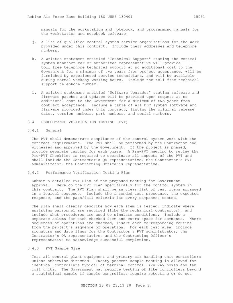
Robins Air Force Base Building 180 UHHZ 130401 15051
manuals for the workstation and notebook, and programming manuals for the workstation and notebook software.
j. A list of qualified control system service organizations for the work provided under this contract. Include their addresses and telephone numbers.
k. A written statement entitled "Technical Support" stating the control system manufacturer or authorized representative will provide toll-free telephone technical support at no additional cost to the Government for a minimum of two years from project acceptance, will be furnished by experienced service technicians, and will be available during normal weekday working hours. Include the toll-free technical support telephone number.
l. A written statement entitled "Software Upgrades" stating software and firmware patches and updates will be provided upon request at no additional cost to the Government for a minimum of two years from contract acceptance. Include a table of all DDC system software and firmware provided under this contract, listing the original release dates, version numbers, part numbers, and serial numbers.
3.4 PERFORMANCE VERIFICATION TESTING (PVT)
3.4.1 General
The PVT shall demonstrate compliance of the control system work with the contract requirements. The PVT shall be performed by the Contractor and witnessed and approved by the Government. If the project is phased, provide separate testing for each phase. A Pre-PVT meeting to review the Pre-PVT Checklist is required to coordinate all aspects of the PVT and shall include the Contractor's QA representative, the Contractor's PVT administrator, the Contracting Officer's representative.
3.4.2 Performance Verification Testing Plan
Submit a detailed PVT Plan of the proposed testing for Government approval. Develop the PVT Plan specifically for the control system in this contract. The PVT Plan shall be an clear list of test items arranged in a logical sequence. Include the intended test procedure, the expected response, and the pass/fail criteria for every component tested.
The plan shall clearly describe how each item is tested, indicate where assisting personnel are required (like the mechanical contractor), and include what procedures are used to simulate conditions. Include a separate column for each checked item and extra space for comments. Where sequences of operations are checked, insert each corresponding routine from the project’s sequence of operation. For each test area, include signature and date lines for the Contractor's PVT administrator, the Contractor's QA representative, and the Contracting Officer's representative to acknowledge successful completion.
3.4.3 PVT Sample Size
Test all central plant equipment and primary air handling unit controllers unless otherwise directed. Twenty percent sample testing is allowed for identical controllers typical of terminal control like VAV boxes and fan coil units. The Government may require testing of like controllers beyond a statistical sample if sample controllers require retesting or do not
SECTION 23 09 23.13 20 Page 37

Robins Air Force Base Building 180 UHHZ 130401 15051
have consistent results.
The Government may witness all testing, or random samples of PVT items. When only random samples are witnessed, the Government may choose which ones.
3.4.4 Pre-Performance Verification Testing Checklist
Submit the following as a list with items checked off once verified. Provide a detailed explanation for any items that are not completed or verified.
a. Verify all required mechanical installation work is successfully completed, and all HVAC equipment is working correctly (or will be by the time the PVT is conducted).
b. Verify HVAC motors operate below full-load amperage ratings.
c. Verify all required control system components, wiring, and accessories are installed.
d. Verify the installed control system architecture matches approved drawings.
e. Verify all control circuits operate at the proper voltage and are free from grounds or faults.
f. Verify all required surge protection is installed.
g. Verify the A/C Power Table specified in "CONTROLS SYSTEM OPERATORS MANUALS" is accurate.
h. Verify all DDC network communications function properly, including uploading and downloading programming changes.
i. Using the BACnet protocol analyzer (if provided or required in this specification), verify communications are error free.
j. Verify each digital controller’s programming is backed up.
k. Verify all wiring, components, and panels are properly labeled.
l. Verify all required points are programmed into devices.
m. Verify all TAB work affecting controls is complete.
n. Verify all valve and actuator zero and span adjustments are set properly.
o. Verify all sensor readings are accurate and calibrated.
p. Verify each control valve and actuator goes to normal position upon loss of power.
q. Verify all control loops are tuned for smooth and stable operation. View trend data where applicable.
r. Verify each controller works properly in stand-alone mode.
SECTION 23 09 23.13 20 Page 38

Robins Air Force Base Building 180 UHHZ 130401 15051
s. Verify all safety controls and devices function properly, including freeze protection and interfaces with building fire alarm systems.
t. Verify all electrical interlocks work properly.
u. Verify all workstations, notebooks and maintenance personnel interface tools are delivered, all system and database software is installed, and graphic pages are created for each workstation and notebook.
v. Verify the as-built (shop) control drawings are completed.
3.4.5 Conducting Performance Verification Testing
a. Conduct Government-witnessed PVT after approval of the PVT Plan and the completed Pre-PVT Checklist. Notify the Contracting Officer of the planned PVT at least 15 days prior to testing. Provide an estimated time table required to perform the testing. Furnish personnel, equipment, instrumentation, and supplies necessary to perform all aspects of the PVT. Ensure that testing personnel are regularly employed in the testing and calibration of DDC systems. Using the project's as-built control system (shop) drawings, the project's mechanical design drawings, the approved Pre-PVT Checklist, and the approved PVT Plan, conduct the PVT.
b. During testing, identify any items that do not meet the contract requirements and if time permits, conduct immediate repairs and re-test. Otherwise, deficiencies shall be investigated, corrected, and re-tested later. Document each deficiency and corrective action taken.
c. If re-testing is required, follow the procedures for the initial PVT. The Government may require re-testing of any control system components affected by the original failed test.
3.4.6 Controller Capability and Labeling
Test the following for each controller:
a. Memory: Demonstrate that programmed data, parameters, and trend/ alarm history collected during normal operation is not lost during power failure.
b. Direct Connect Interface: Demonstrate the ability to connect directly to each type of digital controller with a portable electronic device like a notebook computer or PDA. Show that maintenance personnel interface tools perform as specified in the manufacturer's technical literature.
c. Stand Alone Ability: Demonstrate controllers provide stable and reliable stand-alone operation using default values or other method for values normally read over the network.
d. Wiring and AC Power: Demonstrate the ability to disconnect any controller safely from its power source using the AC Power Table. Demonstrate the ability to match wiring labels easily with the control drawings. Demonstrate the ability to locate a controller's location using the BACnet Communication Architecture Schematic and floor plans.
e. Nameplates and Tags: Show the nameplates and tags are accurate and
SECTION 23 09 23.13 20 Page 39
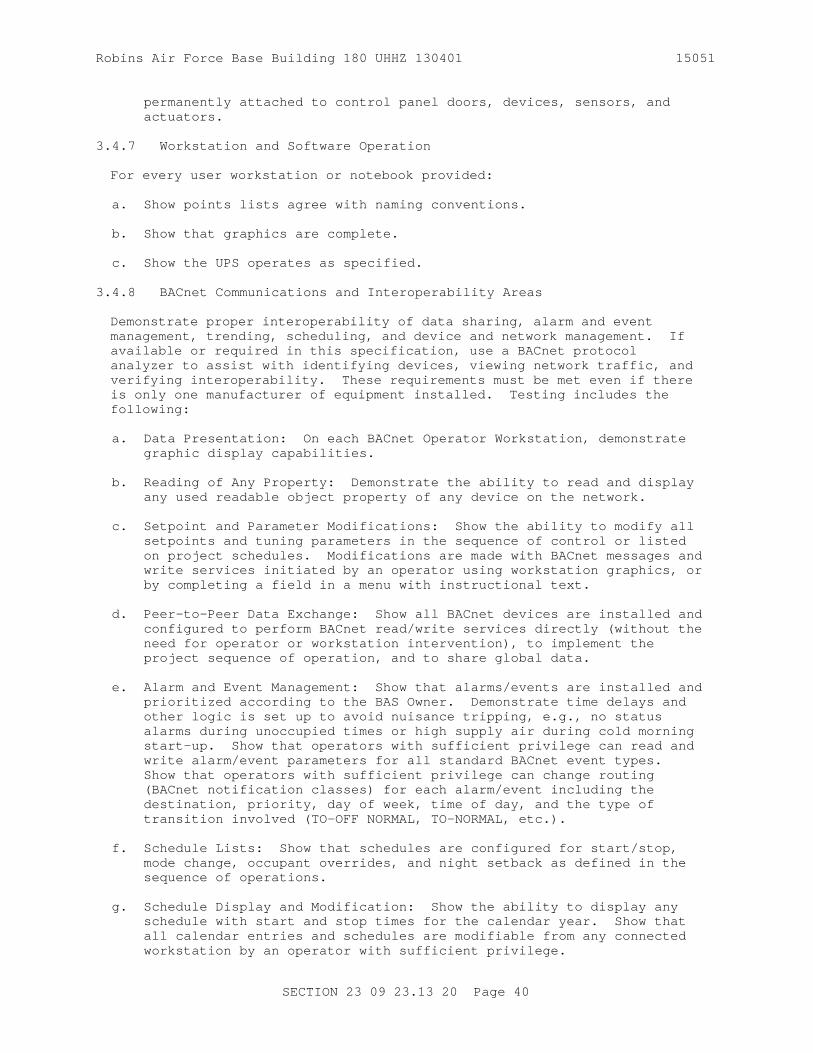
Robins Air Force Base Building 180 UHHZ 130401 15051
permanently attached to control panel doors, devices, sensors, and actuators.
3.4.7 Workstation and Software Operation
For every user workstation or notebook provided:
a. Show points lists agree with naming conventions.
b. Show that graphics are complete.
c. Show the UPS operates as specified.
3.4.8 BACnet Communications and Interoperability Areas
Demonstrate proper interoperability of data sharing, alarm and event management, trending, scheduling, and device and network management. If available or required in this specification, use a BACnet protocol analyzer to assist with identifying devices, viewing network traffic, and verifying interoperability. These requirements must be met even if there is only one manufacturer of equipment installed. Testing includes the following:
a. Data Presentation: On each BACnet Operator Workstation, demonstrate graphic display capabilities.
b. Reading of Any Property: Demonstrate the ability to read and display any used readable object property of any device on the network.
c. Setpoint and Parameter Modifications: Show the ability to modify all setpoints and tuning parameters in the sequence of control or listed on project schedules. Modifications are made with BACnet messages and write services initiated by an operator using workstation graphics, or by completing a field in a menu with instructional text.
d. Peer-to-Peer Data Exchange: Show all BACnet devices are installed and configured to perform BACnet read/write services directly (without the need for operator or workstation intervention), to implement the project sequence of operation, and to share global data.
e. Alarm and Event Management: Show that alarms/events are installed and prioritized according to the BAS Owner. Demonstrate time delays and other logic is set up to avoid nuisance tripping, e.g., no status alarms during unoccupied times or high supply air during cold morning start-up. Show that operators with sufficient privilege can read and write alarm/event parameters for all standard BACnet event types. Show that operators with sufficient privilege can change routing (BACnet notification classes) for each alarm/event including the destination, priority, day of week, time of day, and the type of transition involved (TO-OFF NORMAL, TO-NORMAL, etc.).
f. Schedule Lists: Show that schedules are configured for start/stop, mode change, occupant overrides, and night setback as defined in the sequence of operations.
g. Schedule Display and Modification: Show the ability to display any schedule with start and stop times for the calendar year. Show that all calendar entries and schedules are modifiable from any connected workstation by an operator with sufficient privilege.
SECTION 23 09 23.13 20 Page 40

Robins Air Force Base Building 180 UHHZ 130401 15051
h. Archival Storage of Data: Show that data archiving is handled by the operator workstation/server, and local trend archiving and display is accomplished with BACnet Trend Log objects.
i. Modification of Trend Log Object Parameters: Show that an operator with sufficient privilege can change the logged data points, sampling rate, and trend duration.
j. Device and Network Management: Show the following capabilities:
(1) Display of Device Status Information
(2) Display of BACnet Object Information
(3) Silencing Devices that are Transmitting Erroneous Data
(4) Time Synchronization
(5) Remote Device Reinitialization
(6) Backup and Restore Device Programming and Master Database(s)
(7) Configuration Management of Half-Routers, Routers and BBMDs
3.4.9 Execution of Sequence of Operation
Demonstrate that the HVAC system operates properly through the complete sequence of operation. Use read/write property services to globally read and modify parameters over the internetwork.
3.4.10 Control Loop Stability and Accuracy
For all control loops tested, give the Government trend graphs of the control variable over time, demonstrating that the control loop responds to a 20 percent sudden change of the control variable set point without excessive overshoot and undershoot. If the process does not allow a 20 percent set point change, use the largest change possible. Show that once the new set point is reached, it is stable and maintained. Control loop trend data shall be in real-time with the time between data points 30 seconds or less.
3.4.11 Performance Verification Testing Report
Upon successful completion of the PVT, submit a PVT Report to the Government and prior to the Government taking use and possession of the facility. Do not submit the report until all problems are corrected and successfully re-tested. The report shall include the annotated PVT Plan used during the PVT. Where problems were identified, explain each problem and the corrective action taken. Include a written certification that the installation and testing of the control system is complete and meets all of the contract's requirements.
3.5 TRAINING REQUIREMENTS
Provide a qualified instructor with two years minimum field experience with the installation and programming of similar BACnet DDC systems. Orient training to the specific systems installed. Coordinate training times with the Contracting Officer and BAS Owner after receiving approval
SECTION 23 09 23.13 20 Page 41

Robins Air Force Base Building 180 UHHZ 130401 15051
of the training course documentation. Training shall take place at the job site and/or a nearby Government-furnished location. A training day shall occur during normal working hours, last no longer than 8 hours and include a one-hour break for lunch and two additional 15-minute breaks. The project's approved Controls System Operators Manual shall be used as the training text. The Contractor shall ensure the manuals are submitted, approved, and available to hand out to the trainees before the start of training.
3.5.1 Training Documentation
Submit training documentation for review 30 days minimum before training. Documentation shall include an agenda for each training day, objectives, a synopses of each lesson, and the instructor's background and qualifications. The training documentation can be submitted at the same time as the project's Controls System Operators Manual.
3.5.2 Phase I Training - Fundamentals
The Phase I training session shall last one day and be conducted in a classroom environment with complete audio-visual aids provided by the contractor. Provide each trainee a printed 8.5 by 11 inch hard-copy of all visual aids used. Upon completion of the Phase I Training, each trainee should fully understand the project's DDC system fundamentals. The training session shall include the following:
a. BACnet fundamentals (objects, services, addressing) and how/where they are used on this project
b. This project's list of control system components
c. This project's list of points and objects
d. This project's device and network communication architecture
e. This project's sequences of control, and:
f. Alarm capabilities
g. Trending capabilities
h. Troubleshooting communication errors
i. Troubleshooting hardware errors
3.5.3 Phase II Training - Operation
Provide Phase II Training shortly after completing Phase I Training. The Phase II training session shall last one day and be conducted at the DDC system workstation, at a notebook computer connected to the DDC system in the field, and at other site locations as necessary. Upon completion of the Phase II Training, each trainee should fully understand the project's DDC system operation. The training session shall include the following:
a. A walk-through tour of the mechanical system and the installed DDC components (controllers, valves, dampers, surge protection, switches, thermostats, sensors, etc.)
b. A discussion of the components and functions at each DDC panel
SECTION 23 09 23.13 20 Page 42

Robins Air Force Base Building 180 UHHZ 130401 15051
c. Logging-in and navigating at each operator interface type
d. Using each operator interface to find, read, and write to specific controllers and objects
e. Modifying and downloading control program changes
f. Modifying setpoints
g. Creating, editing, and viewing trends
h. Creating, editing, and viewing alarms
i. Creating, editing, and viewing operating schedules and schedule objects
j. Backing-up and restoring programming and data bases
k. Modifying graphic text, backgrounds, dynamic data displays, and links to other graphics
l. Creating new graphics and adding new dynamic data displays and links
m. Alarm and Event management
n. Adding and removing network devices
-- End of Section --
SECTION 23 09 23.13 20 Page 43

THIS PAGE INTENTIONALLY LEFT BLANK FOR DUPLEX PRINTING
Robins Air Force Base Building 180 UHHZ 130401 15051
SECTION 23 64 26
CHILLED, HOT, AND CONDENSER WATER PIPING SYSTEMS08/09
PART 1 GENERAL
1.1 REFERENCES
The publications listed below form a part of this specification to the extent referenced. The publications are referred to within the text by the basic designation only.
AMERICAN WELDING SOCIETY (AWS)
AWS A5.8/A5.8M (2011; Amendment 2012) Specification for Filler Metals for Brazing and Braze Welding
AWS BRH (2007) Brazing Handbook
AWS D1.1/D1.1M (2015) Structural Welding Code - Steel
AWS Z49.1 (2005) Safety in Welding, Cutting and Allied Processes
ASME INTERNATIONAL (ASME)
ASME B1.20.1 (2013) Pipe Threads, General Purpose (Inch)
ASME B16.1 (2010) Gray Iron Pipe Flanges and Flanged Fittings Classes 25, 125, and 250
ASME B16.11 (2011) Forged Fittings, Socket-Welding and Threaded
ASME B16.18 (2012) Cast Copper Alloy Solder Joint Pressure Fittings
ASME B16.21 (2011) Nonmetallic Flat Gaskets for Pipe Flanges
ASME B16.22 (2013) Standard for Wrought Copper and Copper Alloy Solder Joint Pressure Fittings
ASME B16.26 (2013) Standard for Cast Copper Alloy Fittings for Flared Copper Tubes
ASME B16.3 (2011) Malleable Iron Threaded Fittings, Classes 150 and 300
ASME B16.39 (2009) Standard for Malleable Iron Threaded Pipe Unions; Classes 150, 250, and 300
ASME B16.9 (2012) Standard for Factory-Made Wrought Steel Buttwelding Fittings
SECTION 23 64 26 Page 1

Robins Air Force Base Building 180 UHHZ 130401 15051
ASME B31.9 (2011) Building Services Piping
ASME B40.100 (2013) Pressure Gauges and Gauge Attachments
ASTM INTERNATIONAL (ASTM)
ASTM A 733 (2003) Standard Specification for Welded and Seamless Carbon Steel and Austenitic Stainless Steel Pipe Nipples
ASTM A53/A53M (2012) Standard Specification for Pipe, Steel, Black and Hot-Dipped, Zinc-Coated, Welded and Seamless
ASTM A653/A653M (2015) Standard Specification for Steel Sheet, Zinc-Coated (Galvanized) or Zinc-Iron Alloy-Coated (Galvannealed) by the Hot-Dip Process
ASTM B 117 (2009) Standing Practice for Operating Salt Spray (Fog) Apparatus
ASTM B 32 (2008) Standard Specification for Solder Metal
ASTM B 42 (2002e1) Standard Specification for Seamless Copper Pipe, Standard Sizes
ASTM B 62 (2009) Standard Specification for Composition Bronze or Ounce Metal Castings
ASTM B 813 (2000; R 2009) Standard Specification for Liquid and Paste Fluxes for Soldering of Copper and Copper Alloy Tube
ASTM B75/B75M (2011) Standard Specification for Seamless Copper Tube
ASTM B88 (2014) Standard Specification for Seamless Copper Water Tube
ASTM D 3308 (2006) PTFE Resin Skived Tape
ASTM D 520 (2000; R 2005) Zinc Dust Pigment
ASTM E 84 (2010) Standard Test Method for Surface Burning Characteristics of Building Materials
ASTM F 1199 (1988; R 2004) Cast (All Temperatures and Pressures) and Welded Pipe Line Strainers (150 psig and 150 degrees F Maximum)
HYDRAULIC INSTITUTE (HI)
HI 1.1-1.2 (2000) Centrifugal Pump Nomenclature
SECTION 23 64 26 Page 2

Robins Air Force Base Building 180 UHHZ 130401 15051
MANUFACTURERS STANDARDIZATION SOCIETY OF THE VALVE AND FITTINGS INDUSTRY (MSS)
MSS SP-110 (2010) Ball Valves Threaded, Socket-Welding, Solder Joint, Grooved and Flared Ends
MSS SP-25 (2013) Standard Marking System for Valves, Fittings, Flanges and Unions
MSS SP-58 (1993; Reaffirmed 2010) Pipe Hangers and Supports - Materials, Design and Manufacture, Selection, Application, and Installation
MSS SP-67 (2002a; R 2004) Standard for Butterfly Valves
MSS SP-69 (2003; Notice 2012) Pipe Hangers and Supports - Selection and Application (ANSI Approved American National Standard)
MSS SP-70 (2006) Standard for Cast Iron Gate Valves, Flanged and Threaded Ends
MSS SP-71 (2011; Errata 2013) Gray Iron Swing Check Valves, Flanged and Threaded Ends
MSS SP-72 (2010a) Ball Valves with Flanged or Butt-Welding Ends for General Service
MSS SP-78 (2011) Cast Iron Plug Valves, Flanged and Threaded Ends
MSS SP-80 (2013) Bronze Gate, Globe, Angle and Check Valves
MSS SP-85 (2002) Standard for Cast Iron Globe & Angle Valves, Flanged and Threaded Ends
NATIONAL ELECTRICAL MANUFACTURERS ASSOCIATION (NEMA)
NEMA 250 (2008) Enclosures for Electrical Equipment (1000 Volts Maximum)
NEMA MG 1 (2014) Motors and Generators
NEMA MG 11 (1977; R 2012) Energy Management Guide for Selection and Use of Single Phase Motors
NATIONAL FIRE PROTECTION ASSOCIATION (NFPA)
NFPA 90A (2015) Standard for the Installation of Air Conditioning and Ventilating Systems
1.2 SYSTEM DESCRIPTION
Provide the water systems having the minimum service (design) temperature-pressure rating indicated. Provision of the piping systems,
SECTION 23 64 26 Page 3

Robins Air Force Base Building 180 UHHZ 130401 15051
including materials, installation, workmanship, fabrication, assembly, erection, examination, inspection, and testing shall be in accordance with the required and advisory provisions of ASME B31.9 except as modified or supplemented by this specification section or design drawings.
1.3 SUBMITTALS
Government approval is required for submittals with a "G" designation; submittals not having a "G" designation are for Contractor Quality Control approval. Submit the following submitted in accordance with Section 01300 SUBMITTALS AND CONTRACTOR-FURNISHED ITEMS:
SD-03 Product Data
Calibrated Balancing Valves; G
Pumps; G
Strainers; G
SD-06 Test Reports
Piping welds report
Pressure tests reports; G
Report shall be provided in bound 8-1/2 by 11 inch booklets. In the reports, document all phases of the tests performed. Include initial test summaries, all repairs/adjustments made, and the final test results.
SD-07 Certificates
Employer's Record Documents (For Welding)
Welding Procedures and Qualifications
SD-08 Manufacturer's Instructions
Lesson plan for the Instruction Course
SD-10 Operation and Maintenance Data
Requirements for data packages are specified ,except as supplemented and modified by this specification section.
Submit spare parts data for each different item of equipment specified, with operation and maintenance data packages. Include a complete list of parts and supplies, with current unit prices and source of supply, a recommended spare parts list for 1 year of operation, and a list of the parts recommended by the manufacturer to be replaced on a routine basis.
Submit a list of qualified permanent service organizations with operation and maintenance data packages. Include service organization addresses and service area or expertise. The service organizations shall be reasonably convenient to the equipment installation and be able to render satisfactory service to the equipment on a regular and emergency basis during the warranty
SECTION 23 64 26 Page 4

Robins Air Force Base Building 180 UHHZ 130401 15051
period of the contract.
A maintenancy manual in bound 8-1/2 by 11 inch booklets listing routine maintenance procedures, possible breakdowns and repairs, and a trouble shooting guide.
SD-11 Closeout Submittals
Field Training Lesson Plan
1.4 MODIFICATIONS TO REFERENCES
In each of the publications referred to herein, consider the advisory provisions to be mandatory, as though the word, "shall" had been substituted for "should" wherever it appears. Interpret references in these publications to the "authority having jurisdiction", or words of similar meaning, to mean the Contracting Officer.
1.4.1 Definitions
For the International Code Council (ICC) Codes referenced in the contract documents, advisory provisions shall be considered mandatory, the word "should" shall be interpreted as "shall." Reference to the "code official" shall be interpreted to mean the "Contracting Officer." For Navy owned property, references to the "owner" shall be interpreted to mean the "Contracting Officer." For leased facilities, references to the "owner" shall be interpreted to mean the "lessor." References to the "permit holder" shall be interpreted to mean the "Contractor."
1.4.2 Administrative Interpretations
For ICC Codes referenced in the contract documents, the provisions of Chapter 1, "Administrator," do not apply. These administrative requirements are covered by the applicable Federal Acquisition Regulations (FAR) included in this contract and by the authority granted to the Officer in Charge of Construction to administer the construction of this project. References in the ICC Codes to sections of Chapter 1, shall be applied appropriately by the Contracting Officer as authorized by his administrative cognizance and the FAR.
1.5 SAFETY REQUIREMENTS
Exposed moving parts, parts that produce high operating temperature, parts which may be electrically energized, and parts that may be a hazard to operating personnel shall be insulated, fully enclosed, guarded, or fitted with other types of safety devices. Safety devices shall be installed so that proper operation of equipment is not impaired.
1.6 DELIVERY, STORAGE, AND HANDLING
Protect stored items from the weather, humidity and temperature variations, dirt and dust, or other contaminants. Proper protection and care of all material both before and during installation shall be the Contractor's responsibility. Any materials found to be damaged shall be replaced at the Contractor's expense. During installation, cap piping and similar openings to keep out dirt and other foreign matter. Any porous materials found to be contaminated with mold or mildew will be replaced at the Contractor's expense. Non-porous materials found to be contaminated with mold or mildew will be disinfected and cleaned prior to installation.
SECTION 23 64 26 Page 5
Robins Air Force Base Building 180 UHHZ 130401 15051
1.7 PROJECT/SITE CONDITIONS
1.7.1 Verification of Dimensions
The Contractor shall become familiar with all details of the work, verify all dimensions in the field, and advise the Contracting Officer of any discrepancy before performing any work.
1.7.2 Drawings
Because of the small scale of the drawings, it is not possible to indicate all offsets, fittings, and accessories that may be required. The Contractor shall carefully investigate the plumbing, fire protection, electrical, structural and finish conditions that would affect the work to be performed and shall arrange such work accordingly, furnishing required offsets, fittings, and accessories to meet such conditions.
1.7.3 Accessibility
Install all work so that parts requiring periodic inspection, operation, maintenance, and repair are readily accessible. Install concealed valves, expansion joints, controls, dampers, and equipment requiring access, in locations freely accessible through access doors.
PART 2 PRODUCTS
2.1 STANDARD COMMERCIAL PRODUCTS
Materials and equipment shall be standard products of a manufacturer regularly engaged in the manufacturing of such products, which are of a similar material, design and workmanship. The standard products shall have been in satisfactory commercial or industrial use for 2 years prior to bid opening.
The two year use shall include applications of equipment and materials under similar circumstances and of similar size. The 2 years experience shall be satisfactorily completed by a product which has been sold or is offered for sale on the commercial market through advertisements, manufacturer's catalogs, or brochures.
The equipment items shall be supported by service organizations. These service organizations shall be reasonably convenient to the equipment installation and able to render satisfactory service to the equipment on a regular and emergency basis during the warranty period of the contract.
2.2 STEEL PIPING
Water piping shall be steel pipe or copper tubing. Provide steel piping with a ANSI/ASME Class 125 service rating, which for 150 degrees F, the pressure rating is 175 psig.
2.2.1 Pipe
Steel pipe, conform to ASTM A53/A53M, Schedule 40, Type E or S, Grades A or B. Do not use Type F pipe.
SECTION 23 64 26 Page 6

Robins Air Force Base Building 180 UHHZ 130401 15051
2.2.2 Fittings and End Connections (Joints)
Piping and fittings 1 inch and smaller shall have threaded connections. Piping and fittings larger than 1 inch and smaller than 3 inches shall have either threaded, grooved, or welded connections. Piping and fittings 3 inches and larger shall have grooved, welded, or flanged connections. The manufacturer of each fitting shall be permanently identified on the body of the fitting in accordance with MSS SP-25 .
2.2.2.1 Threaded Connections
Use threaded valves and pipe connections conforming to ASME B1.20.1 . Used threaded fitting conforming to ASME B16.3 . Use threaded unions conforming to ASME B16.39 . Use threaded pipe nipples conforming to ASTM A 733 .
2.2.2.2 Flanged Connections
Flanges shall conform to ASME B16.1 , Class 150. Gaskets shall be nonasbestos compressed material in accordance with ASME B16.21 , 1/16 inch thickness, full face or self-centering flat ring type. These gaskets shall contain aramid fibers bonded with styrene butadeine rubber (SBR) or nitrile butadeine rubber (NBR). Bolts, nuts, and bolt patterns shall conform to ASME B16.1 .
2.2.2.3 Welded Connections
Welded valves and pipe connections (both butt-welds and socket-welds types) shall conform to ASME B31.9 . Butt-welded fittings shall conform to ASME B16.9 . Socket-welded fittings shall conform to ASME B16.11 . Welded fittings shall be identified with the appropriate grade and marking symbol.
2.2.2.4 Dielectric Waterways and Flanges
Provide dielectric waterways with a water impervious insulation barrier capable of limiting galvanic current to 1 percent of short circuit current in a corresponding bimetallic joint. When dry, insulation barrier shall be able to withstand a 600-volt breakdown test. Provide dielectric waterways constructed of galvanized steel and have threaded end connections to match connecting piping. Dielectric waterways shall be suitable for the required operating pressures and temperatures. Provide dielectric flanges with the same pressure ratings as standard flanges and provide complete electrical isolation between connecting pipe and/or equipment as described herein for dielectric waterways.
2.3 COPPER TUBING
Provide copper tubing and fittings with a ANSI/ASME Class 125 service rating, which for 150 degrees F., the pressure rating is 175 psig.
2.3.1 Tube
Use copper tube conforming to ASTM B88, Type L or M for aboveground tubing, and Type K for buried tubing.
2.3.2 Fittings and End Connections (Solder and Flared Joints)
Wrought copper and bronze solder joint pressure fittings, including unions ands flanges, shall conform to ASME B16.22 and ASTM B75/B75M. Provide
SECTION 23 64 26 Page 7
Robins Air Force Base Building 180 UHHZ 130401 15051
adapters as required. Cast copper alloy solder-joint pressure fittings , including unions and flanges, shall conform to ASME B16.18 . Cast copper alloy fittings for flared copper tube shall conform to ASME B16.26 and ASTM B 62 . ASTM B 42 copper pipe nipples with threaded end connections shall conform to ASTM B 42 .
Copper tubing of sizes larger than 4 inches shall have brazed joints.Brass or bronze adapters for brazed tubing may be used for connecting tubing to flanges and to threaded ends of valves and equipment.
Extracted brazed tee joints may be used if produced with an acceptable tool and installed in accordance with tool manufacturer's written procedures.
2.3.3 Solder
Provide solder in conformance with ASTM B 32 , grade Sb5, tin-antimony alloy. Solder flux shall be liquid or paste form, non-corrosive and conform to ASTM B 813 .
2.3.4 Brazing Filler Metal
Filler metal shall conform to AWS A5.8/A5.8M , Type BAg-5 with AWS Type 3 flux, except Type BCuP-5 or BCuP-6 may be used for brazing copper-to-copper joints.
2.4 VALVES
Provide valves with a ANSI/ASME Class 125 service rating, which for 150 degrees F, the pressure rating is 175 psig.
Valves in sizes larger than 1 inch and used on steel pipe systems, may be provided with rigid grooved mechanical joint ends. Such grooved end valves shall be subject to the same requirements as rigid grooved mechanical joints and fittings and, shall be furnished by the same manufacturer as the grooved pipe joint and fitting system.
2.4.1 Gate Valve
Gate valves 2-1/2 inches and smaller shall conform to MSS SP-80 Class 125 and shall be bronze with wedge disc, rising stem and threaded, soldered, or flanged ends. Gate valves 3 inches and larger shall conform to MSS SP-70 , Class 125, cast iron with bronze trim, outside screw and yoke, and flanged or threaded ends.
2.4.2 Globe and Angle Valve
Globe and angle valves 2-1/2 inches and smaller shall conform to MSS SP-80 , Class 125. Globe and angle valves 3 inches and larger shall conform to MSS SP-85 , Class 125.
2.4.3 Check Valve
Check valves 2-1/2 inches and smaller shall conform to MSS SP-80 . Check valves 3 inches and larger shall conform to MSS SP-71 , Class 125.
2.4.4 Butterfly Valve
Butterfly valves shall conform to MSS SP-67 , Type 1 and shall be either
SECTION 23 64 26 Page 8

Robins Air Force Base Building 180 UHHZ 130401 15051
the wafer or lug type. Valves smaller than 8 inches shall have throttling handles with a minimum of seven locking positions. Valves 8 inches and larger shall have totally enclosed manual gear operators with adjustable balance return stops and position indicators.
2.4.5 Plug Valve
Plug valves 2 inches and larger shall conform to MSS SP-78 , have flanged or threaded ends, and have cast iron bodies with bronze trim. Valves 2 inches and smaller shall be bronze with NPT connections for black steel pipe and brazed connections for copper tubing. Valve shall be lubricated, non-lubricated, or tetrafluoroethylene resin-coated type. Valve shall be resilient, double seated, trunnion mounted with tapered lift plug capable of 2-way shutoff. Valve shall operate from fully open to fully closed by rotation of the handwheel to lift and turn the plug. Valves 8 inches or larger shall be provided with manual gear operators with position indicators.
2.4.6 Ball Valve
Full port design. Ball valves 1/2 inch and larger shall conform to MSS SP-72 or MSS SP-110 and shall be cast iron or bronze with threaded, soldered, or flanged ends. Valves 8 inches or larger shall be provided with manual gear operators with position indicators. Ball valves may be provided in lieu of gate valves.
2.4.7 Square Head Cocks
Provide copper alloy or cast-iron body with copper alloy plugs, suitable for 125 psig water working pressure.
2.4.8 Calibrated Balancing Valves
Copper alloy or cast iron body, copper alloy or stainless internal working parts. Provide valve calibrated so that flow can be determined when the temperature and pressure differential across valve is known. Valve shall have an integral pointer which registers the degree of valve opening. Valve shall function as a service valve when in fully closed position. Valve shall be constructed with internal seals to prevent leakage and shall be supplied with preformed insulation.
Provide valve bodies with tapped openings and pipe extensions with positive shutoff valves outside of pipe insulation. The pipe extensions shall be provided with quick connecting hose fittings for a portable differential pressure meter connections to verify the pressure differential. Provide metal tag on each valve showing the gallons per minute flow for each differential pressure reading.
2.4.9 Air Venting Valves
Manually-operated general service type air venting valves, brass or bronze valves that are furnished with threaded plugs or caps. Automatic type air venting shall be the ball-float type with brass/bronze or brass bodies, 300 series corrosion-resistant steel float, linkage and removable seat. Air venting valves on water coils shall have not less than 1/8 inch threaded end connections. Air venting valves on water mains shall have not less than 3/4 inch threaded end connections. Air venting valves on all other applications shall have not less than 1/2 inch threaded end connections.
SECTION 23 64 26 Page 9

Robins Air Force Base Building 180 UHHZ 130401 15051
2.5 PIPING ACCESSORIES
2.5.1 Strainer
Strainer, ASTM F 1199 , except as modified and supplemented in this specification. Strainer shall be the cleanable, basket or "Y" type, the same size as the pipeline. Strainer bodies shall be fabricated of cast iron with bottoms drilled, and tapped. Provide blowoff outlet with pipe nipple, gate valve, and discharge pipe nipple. The bodies shall have arrows clearly cast on the sides indicating the direction of flow.
Provide strainer with removable cover and sediment screen. The screen shall be made of minimum 22 gauge corrosion-resistant steel, with small perforations numbering not less than 400 per square inch to provide a net free area through the basket of at least 3.30 times that of the entering pipe. The flow shall be into the screen and out through the perforations.
2.5.2 Flexible Pipe Connectors
Provide flexible bronze or stainless steel piping connectors with single braid. Equip flanged assemblies with limit bolts to restrict maximum travel to the manufacturer's standard limits. Unless otherwise indicated, the length of the flexible connectors shall be as recommended by the manufacturer for the service intended. Internal sleeves or liners, compatible with circulating medium, shall be provided when recommended by the manufacturer. Provide covers to protect the bellows where indicated.
2.5.3 Pressure and Vacuum Gauges
Gauges, ASME B40.100 with throttling type needle valve or a pulsation dampener and shut-off valve. Provide gauges with 4.5 inch dial, brass or aluminum case, bronze tube, and siphon. Gauge shall have a minimum of with a range from 0 psig to approximately 1.5 times the maximum system working pressure. Each gauge range shall be selected so that at normal operating pressure, the needle is within the middle-third of the range.
2.5.4 Temperature Gauges
Temperature gauges, shall be the industrial duty type and be provided for the required temperature range. Provide gauges with fixed thread connection, dial face gasketed within the case; and an accuracy within 2 percent of scale range. Gauges shall have Fahrenheit scale in 2 degree graduations scale (black numbers) on a white face. The pointer shall be adjustable. Rigid stem type temperature gauges shall be provided in thermal wells located within 5 feet of the finished floor. Universal adjustable angle type or remote element type temperature gauges shall be provided in thermal wells located 5 to 7 feet above the finished floor or in locations indicated. Remote element type temperature gauges shall be provided in thermal wells located 7 feet above the finished floor or in locations indicated.
2.5.4.1 Stem Cased-Glass
Stem cased-glass case shall be polished stainless steel or cast aluminum, 9 inches long, with clear acrylic lens, and non-mercury filled glass tube with indicating-fluid column.
SECTION 23 64 26 Page 10

Robins Air Force Base Building 180 UHHZ 130401 15051
2.5.4.2 Bimetallic Dial
Bimetallic dial type case shall be not less than 3-1/2 inches, stainless steel, and shall be hermetically sealed with clear acrylic lens. Bimetallic element shall be silicone dampened and unit fitted with external calibrator adjustment.
2.5.4.3 Liquid-, Solid-, and Vapor-Filled Dial
Liquid-, solid-, and vapor-filled dial type cases shall be not less than 3-1/2 inches, stainless steel or cast aluminum with clear acrylic lens. Fill shall be nonmercury, suitable for encountered cross-ambients, and connecting capillary tubing shall be double-braided bronze.
2.5.4.4 Thermal Well
Thermal well shall be identical size, 1/2 or 3/4 inch NPT connection, brass or stainless steel. Where test wells are indicated, provide captive plug-fitted type 1/2 inch NPT connection suitable for use with either engraved stem or standard separable socket thermometer or thermostat. Mercury shall not be used in thermometers. Extended neck thermal wells shall be of sufficient length to clear insulation thickness by 1 inch.
2.5.5 Pipe Hangers, Inserts, and Supports
Pipe hangers, inserts, guides, and supports: to MSS SP-58 and MSS SP-69 .
2.5.6 Escutcheons
Provide one piece or split hinge metal plates for piping entering floors, walls, and ceilings in exposed spaces. Secure plates in place by internal spring tension or set screws. Provide polished stainless steel plates or chromium-plated finish on copper alloy plates in finished spaces. Provide paint finish on metal plates in unfinished spaces.
2.6 PUMPS
Pumps shall be the electrically driven, non-overloading, centrifugal type which conform to HI 1.1-1.2 . Pumps shall be selected at or within 5 percent of peak efficiency. Pump curve shall rise continuously from maximum capacity to shutoff. Pump motor shall conform to PREMIUM EFFICIENCYNEMA MG 1 minimum Class F insulation, be open, and have sufficient horsepower for the service required. Pump motor shall have the required capacity to prevent overloading with pump operating at any point on its characteristic curve. Pump speed shall not exceed 1,750 rpm. Pump motor shall be equipped with an across-the-line magnetic controller in a NEMA 250, Type 1 enclosure with "START-STOP" switch in the cover or a variable frequency drive as shown on drawings.
2.6.1 Construction
Each pump casing shall be designed to withstand the discharge head specified plus the static head on system plus 50 percent of the total, but not less than 125 psig. Pump casing and bearing housing shall be close grained cast iron. High points in the casing shall be provided with manual air vents; low points shall be provided with drain plugs. Provide threaded suction and discharge pressure gage tapping with square-head plugs.
SECTION 23 64 26 Page 11

Robins Air Force Base Building 180 UHHZ 130401 15051
Impeller shall be statically and dynamically balanced. Impeller, impeller wearing rings, glands, casing wear rings, and shaft sleeve shall be bronze. Shaft shall be carbon or alloy steel, turned and ground. Bearings shall be ball-bearings, roller-bearings, or oil-lubricated bronze-sleeve type bearings, and be efficiently sealed or isolated to prevent loss of oil or entrance of dirt or water.
Close-coupled pump shall be provided with integrally cast or fabricated steel feet with bolt holes for securing feet to supporting surface. Close- coupled pumps shall be provided with drip pockets and tapped openings. Pump shall be accessible for servicing without disturbing piping connections. Shaft seals shall be mechanical-seals or stuffing-box type.
2.6.2 Mechanical Shaft Seals
Where required, seals shall be single, inside mounted, end-face-elastomer bellows type with stainless steel spring, brass or stainless steel seal head, carbon rotating face, and tungsten carbide or ceramic sealing face. Glands shall be bronze and of the water-flush design to provide lubrication flush across the face of the seal.
2.7 ELECTRICAL WORK
Provide motors, controllers, integral disconnects, contactors, and controls with their respective pieces of equipment, except controllers indicated as part of motor control centers. Provide electrical equipment, including motors and wiring, as specified in Section 26 20 00 INTERIOR DISTRIBUTION SYSTEM. Manual or automatic control and protective or signal devices required for the operation specified and control wiring required for controls and devices specified, but not shown, shall be provided. For packaged equipment, the manufacturer shall provide controllers including the required monitors and timed restart.
Provide high efficiency type, single-phase, fractional-horsepower alternating-current motors, including motors that are part of a system, in accordance with NEMA MG 11.
Provide polyphase, squirrel-cage medium induction motors, including motors that are part of a system, that meet the efficiency ratings for premium efficiency motors in accordance with NEMA MG 1 minimum Class F insulation. Provide motors in accordance with NEMA MG 1 and of sufficient size to drive the load at the specified capacity without exceeding the nameplate rating of the motor.
Motors shall be rated for continuous duty with the enclosure specified. Motor duty requirements shall allow for maximum frequency start-stop operation and minimum encountered interval between start and stop. Motor torque shall be capable of accelerating the connected load within 20 seconds with 80 percent of the rated voltage maintained at motor terminals during one starting period. Provide motor starters complete with thermal overload protection and other necessary appurtenances. Motor bearings shall be fitted with grease supply fittings and grease relief to outside of the enclosure.
2.8 PAINTING OF NEW EQUIPMENT
New equipment painting shall be factory applied or shop applied, and shall be as specified herein, and provided under each individual section.
SECTION 23 64 26 Page 12
Robins Air Force Base Building 180 UHHZ 130401 15051
2.8.1 Factory Painting Systems
Manufacturer's standard factory painting systems may be provided. The factory painting system applied will withstand 125 hours in a salt-spray fog test, except that equipment located outdoors shall withstand 500 hours in a salt-spray fog test.
Salt-spray fog test shall be in accordance with ASTM B 117 , and for that test, the acceptance criteria shall be as follows: immediately after completion of the test, the paint shall show no signs of blistering, wrinkling, or cracking, and no loss of 0.125 inch on either side of the scratch mark. The film thickness of the factory painting system applied on the equipment shall not be less than the film thickness used on the test specimen.
If manufacturer's standard factory painting system is being proposed for use on surfaces subject to temperatures above 120 degrees F, the factory painting system shall be designed for the temperature service.
2.8.2 Shop Painting Systems for Metal Surfaces
Clean, retreat, prime and paint metal surfaces; except aluminum surfaces need not be painted. Apply coatings to clean dry surfaces. Clean the surfaces to remove dust, dirt, rust, oil and grease by wire brushing and solvent degreasing prior to application of paint, except metal surfaces subject to temperatures in excess of 120 degrees F shall be cleaned to bare metal.
Where hot-dip galvanized steel has been cut, resulting surfaces with no galvanizing shall be coated with a zinc-rich coating conforming to ASTM D 520 , Type I.
Where more than one coat of paint is specified, apply the second coat after the preceding coat is thoroughly dry. Lightly sand damaged painting and retouch before applying the succeeding coat. Color of finish coat shall be aluminum or light gray.
a. Temperatures Less Than 120 Degrees F: Immediately after cleaning, the metal surfaces subject to temperatures less than 120 degrees F shall receive one coat of pretreatment primer applied to a minimum dry film thickness of 0.3 mil, one coat of primer applied to a minimum dry film thickness of one mil; and two coats of enamel applied to a minimum dry film thickness of one mil per coat.
b. Temperatures Between 120 and 400 degrees F: Metal surfaces subject to temperatures between 120 and 400 degrees F shall receive two coats of 400 degrees F heat-resisting enamel applied to a total minimum thickness of 2 mils.
c. Temperatures Greater Than 400 degrees F: Metal surfaces subject to temperatures greater than 400 degrees F shall receive two coats of 600 degrees F heat-resisting paint applied to a total minimum dry film thickness of 2 mils.
2.9 FACTORY APPLIED INSULATION
Factory insulated items installed outdoors are not required to be fire-rated. As a minimum, factory insulated items installed indoors shall have a flame spread index no higher than 75 and a smoke developed index no
SECTION 23 64 26 Page 13
Robins Air Force Base Building 180 UHHZ 130401 15051
higher than 150. Factory insulated items (no jacket) installed indoors and which are located in air plenums, in ceiling spaces, and in attic spaces shall have a flame spread index no higher than 25 and a smoke developed index no higher than 50. Flame spread and smoke developed indexes shall be determined by ASTM E 84 .
Insulation shall be tested in the same density and installed thickness as the material to be used in the actual construction. Material supplied by a manufacturer with a jacket shall be tested as a composite material. Jackets, facings, and adhesives shall have a flame spread index no higher than 25 and a smoke developed index no higher than 50 when tested in accordance with ASTM E 84 .
2.10 NAMEPLATES
Major equipment including pumps, pump motors, expansion tanks, and air separator tanks shall have the manufacturer's name, type or style, model or serial number on a plate secured to the item of equipment. The nameplate of the distributing agent will not be acceptable. Plates shall be durable and legible throughout equipment life and made of anodized aluminum. Plates shall be fixed in prominent locations with nonferrous screws or bolts.
2.11 RELATED COMPONENTS/SERVICES
2.11.1 Field Applied Insulation
Requirements for field applied insulation is specified in Section 23 07 00 THERMAL INSULATION FOR MECHANICAL SYSTEMS.
2.11.2 Field Painting
Requirements for painting of surfaces not otherwise specified, and finish painting of items only primed at the factory, are specified in Section 099000PAINTS AND COATINGS.
PART 3 EXECUTION
3.1 INSTALLATION
Cut pipe accurately to measurements established at the jobsite, and work into place without springing or forcing, completely clearing all windows, doors, and other openings. Cutting or other weakening of the building structure to facilitate piping installation is not permitted without written approval. Cut pipe or tubing square, remove burrs by reaming, and fashion to permit free expansion and contraction without causing damage to the building structure, pipe, joints, or hangers.
Notify the Contracting Officer in writing at least 15 calendar days prior to the date the connections are required. Obtain approval before interrupting service. Furnish materials required to make connections into existing systems and perform excavating, backfilling, compacting, and other incidental labor as required. Furnish labor and tools for making actual connections to existing systems.
3.1.1 Welding
Provide welding work specified this section for piping systems in conformance with ASME B31.9 , as modified and supplemented by this
SECTION 23 64 26 Page 14

Robins Air Force Base Building 180 UHHZ 130401 15051
specification section and the accompanying drawings. The welding work includes: qualification of welding procedures, welders, welding operators, brazers, brazing operators, and nondestructive examination personnel; maintenance of welding records, and examination methods for welds.
3.1.1.1 Employer's Record Documents (For Welding)
Submit for review and approval the following documentation. This documentation and the subject qualifications shall be in compliance with ASME B31.9 .
a. List of qualified welding procedures that is proposed to be used to provide the work specified in this specification section.
b. List of qualified welders, brazers, welding operators, and brazing operators that are proposed to be used to provide the work specified in this specification section.
c. List of qualified weld examination personnel that are proposed to be used to provide the work specified in this specification section.
3.1.1.2 Welding Procedures and Qualifications
a. Specifications and Test Results: Submit copies of the welding procedures specifications and procedure qualification test results for each type of welding required. Approval of any procedure does not relieve the Contractor of the responsibility for producing acceptable welds. Submit this information on the forms printed in ASME BPVC SEC IX or their equivalent.
b. Certification: Before assigning welders or welding operators to the work, submit a list of qualified welders, together with data and certification that each individual is performance qualified as specified. Do not start welding work prior to submitting welder, and welding operator qualifications. The certification shall state the type of welding and positions for which each is qualified, the code and procedure under which each is qualified, date qualified, and the firm and individual certifying the qualification tests.
3.1.1.3 Examination of Piping Welds
Conduct non-destructive examinations (NDE) on piping welds and brazing and verify the work meets the acceptance criteria specified in ASME B31.9. NDE on piping welds covered by ASME B31.9 is visual inspection only. Submit a piping welds NDE report meeting the requirements specified in ASME B31.9.
3.1.1.4 Welding Safety
Welding and cutting safety requirements shall be in accordance with AWS Z49.1 .
3.1.2 Directional Changes
Make changes in direction with fittings, except that bending of pipe 4 inches and smaller is permitted, provided a pipe bender is used and wide weep bends are formed. Mitering or notching pipe or other similar construction to form elbows or tees is not permitted. The centerline radius of bends shall not be less than 6 diameters of the pipe. Bent pipe
SECTION 23 64 26 Page 15
Robins Air Force Base Building 180 UHHZ 130401 15051
showing kinks, wrinkles, flattening, or other malformations is not acceptable.
3.1.3 Functional Requirements
Pitch horizontal supply mains down in the direction of flow as indicated. The grade shall not be less than 1 inch in 40 feet. Reducing fittings shall be used for changes in pipe sizes. Cap or plug open ends of pipelines and equipment during installation to keep dirt or other foreign materials out of the system.
Pipe not otherwise specified shall be uncoated. Connections to appliances shall be made with malleable iron unions for steel pipe 2-1/2 inches or less in diameter, and with flanges for pipe 3 inches and above in diameter. Connections between ferrous and copper piping shall be electrically isolated from each other with dielectric waterways or flanges.
Piping located in air plenums shall conform to NFPA 90A requirements. Pipe and fittings installed in inaccessible conduits or trenches under concrete floor slabs shall be welded. Equipment and piping arrangements shall fit into space allotted and allow adequate acceptable clearances for installation, replacement, entry, servicing, and maintenance. Electric isolation fittings shall be provided between dissimilar metals.
3.1.4 Fittings and End Connections
3.1.4.1 Threaded Connections
Threaded connections shall be made with tapered threads and made tight with PTFE tape complying with ASTM D 3308 or equivalent thread-joint compound applied to the male threads only. Not more than three threads shall show after the joint is made.
3.1.4.2 Brazed Connections
Brazing, AWS BRH, except as modified herein. During brazing, the pipe and fittings shall be filled with a pressure regulated inert gas, such as nitrogen, to prevent the formation of scale. Before brazing copper joints, both the outside of the tube and the inside of the fitting shall be cleaned with a wire fitting brush until the entire joint surface is bright and clean. Do not use brazing flux. Surplus brazing material shall be removed at all joints. Steel tubing joints shall be made in accordance with the manufacturer's recommendations. Piping shall be supported prior to brazing and not be sprung or forced.
3.1.4.3 Welded Connections
Branch connections shall be made with welding tees or forged welding branch outlets. Pipe shall be thoroughly cleaned of all scale and foreign matter before the piping is assembled. During welding, the pipe and fittings shall be filled with an inert gas, such as nitrogen, to prevent the formation of scale. Beveling, alignment, heat treatment, and inspection of weld shall conform to ASME B31.9 . Weld defects shall be removed and rewelded at no additional cost to the Government. Electrodes shall be stored and dried in accordance with AWS D1.1/D1.1M or as recommended by the manufacturer. Electrodes that have been wetted or that have lost any of their coating shall not be used.
SECTION 23 64 26 Page 16

Robins Air Force Base Building 180 UHHZ 130401 15051
3.1.4.4 Flared Connections
When flared connections are used, a suitable lubricant shall be used between the back of the flare and the nut in order to avoid tearing the flare while tightening the nut.
3.1.4.5 Flanges and Unions
Except where copper tubing is used, union or flanged joints shall be provided in each line immediately preceding the connection to each piece of equipment or material requiring maintenance such as coils, pumps, control valves, and other similar items. Flanged joints shall be assembled square end tight with matched flanges, gaskets, and bolts. Gaskets shall be suitable for the intended application.
3.1.5 Valves
Isolation gate or ball valves shall be installed on each side of each piece of equipment, at the midpoint of all looped mains, and at any other points indicated or required for draining, isolating, or sectionalizing purpose. Isolation valves may be omitted where balancing cocks are installed to provide both balancing and isolation functions. Each valve except check valves shall be identified. Valves in horizontal lines shall be installed with stems horizontal or above.
3.1.6 Air Vents
Air vents shall be provided at all high points, on all water coils, and where indicated to ensure adequate venting of the piping system.
3.1.7 Drains
Drains shall be provided at all low points and where indicated to ensure complete drainage of the piping. Drains shall be accessible, and shall consist of nipples and caps or plugged tees unless otherwise indicated.
3.1.8 Flexible Pipe Connectors
Connectors shall be attached to components in strict accordance with the latest printed instructions of the manufacturer to ensure a vapor tight joint. Hangers, when required to suspend the connectors, shall be of the type recommended by the flexible pipe connector manufacturer and shall be provided at the intervals recommended.
3.1.9 Temperature Gauges
Temperature gauges shall be located on coolant supply and return piping at each heat exchanger, on condenser water piping entering and leaving a condenser, at each automatic temperature control device without an integral thermometer, and where indicated or required for proper operation of equipment. Thermal wells for insertion thermometers and thermostats shall extend beyond thermal insulation surface not less than 1 inch.
3.1.10 Pipe Hangers, Inserts, and Supports
Pipe hangers, inserts, and supports shall conform to MSS SP-58 and MSS SP-69 , except as supplemented and modified in this specification section. Pipe hanger types 5, 12, and 26 shall not be used. Hangers used to support piping 2 inches and larger shall be fabricated to permit
SECTION 23 64 26 Page 17
Robins Air Force Base Building 180 UHHZ 130401 15051
adequate adjustment after erection while still supporting the load. Piping subjected to vertical movement, when operating temperatures exceed ambient temperatures, shall be supported by variable spring hangers and supports or by constant support hangers.
3.1.10.1 Hangers
Type 3 shall not be used on insulated piping. Type 24 may be used only on trapeze hanger systems or on fabricated frames.
3.1.10.2 Inserts
Type 18 inserts shall be secured to concrete forms before concrete is placed. Continuous inserts which allow more adjustments may be used if they otherwise meet the requirements for Type 18 inserts.
3.1.10.3 C-Clamps
Type 19 and 23 C-clamps shall be torqued per MSS SP-69 and have both locknuts and retaining devices, furnished by the manufacturer. Field-fabricated C-clamp bodies or retaining devices are not acceptable.
3.1.10.4 Angle Attachments
Type 20 attachments used on angles and channels shall be furnished with an added malleable-iron heel plate or adapter.
3.1.10.5 Saddles and Shields
Where Type 39 saddle or Type 40 shield are permitted for a particular pipe attachment application, the Type 39 saddle, connected to the pipe, shall be used on all pipe 4 inches and larger when the temperature of the medium is 60 degrees F or higher. Type 40 shields shall be used on all piping less than 4 inches and all piping 4 inches and larger carrying medium less than 60 degrees F. A high density insulation insert of cellular glass shall be used under the Type 40 shield for piping 2 inches and larger.
3.1.10.6 Horizontal Pipe Supports
Horizontal pipe supports shall be spaced as specified in MSS SP-69 and a support shall be installed not over 1 foot from the pipe fitting joint at each change in direction of the piping. Pipe supports shall be spaced not over 5 feet apart at valves. Pipe hanger loads suspended from steel joist with hanger loads between panel points in excess of 50 pounds shall have the excess hanger loads suspended from panel points.
3.1.10.7 Vertical Pipe Supports
Vertical pipe shall be supported at each floor, except at slab-on-grade, and at intervals of not more than 15 feet, not more than 8 feet from end of risers, and at vent terminations.
3.1.10.8 Pipe Guides
Type 35 guides using, steel, reinforced polytetrafluoroethylene (PTFE) or graphite slides shall be provided where required to allow longitudinal pipe movement. Lateral restraints shall be provided as required. Slide materials shall be suitable for the system operating temperatures, atmospheric conditions, and bearing loads encountered.
SECTION 23 64 26 Page 18

Robins Air Force Base Building 180 UHHZ 130401 15051
3.1.10.9 Steel Slides
Where steel slides do not require provisions for restraint of lateral movement, an alternate guide method may be used. On piping 4 inches and larger, a Type 39 saddle shall be used. On piping under 4 inches, a Type 40 protection shield may be attached to the pipe or insulation and freely rest on a steel slide plate.
3.1.10.10 Multiple Pipe Runs
In the support of multiple pipe runs on a common base member, a clip or clamp shall be used where each pipe crosses the base support member. Spacing of the base support members shall not exceed the hanger and support spacing required for an individual pipe in the multiple pipe run.
3.1.10.11 Structural Attachments
Attachment to building structure concrete and masonry shall be by cast-in concrete inserts, built-in anchors, or masonry anchor devices. Inserts and anchors shall be applied with a safety factor not less than 5. Supports shall not be attached to metal decking. Supports shall not be attached to the underside of concrete filled floors or concrete roof decks unless approved by the Contracting Officer. Masonry anchors for overhead applications shall be constructed of ferrous materials only. Structural steel brackets required to support piping, headers, and equipment, but not shown, shall be provided under this section.
3.1.11 Pipe Alignment Guides
Pipe alignment guides shall be provided where indicated for expansion loops, offsets, and bends and as recommended by the manufacturer for expansion joints, not to exceed 5 feet on each side of each expansion joint, and in lines 4 inches or smaller not more than 2 feet on each side of the joint.
3.1.12 Pipe Anchors
Anchors shall be provided where indicated. Unless indicated otherwise, anchors shall comply with the requirements specified.Anchors shall consist of heavy steel collars with lugs and bolts for clamping and attaching anchor braces, unless otherwise indicated. Anchor braces shall be installed in the most effective manner to secure the desired results using turnbuckles where required.
Supports, anchors, or stays shall not be attached where they will injure the structure or adjacent construction during installation or by the weight of expansion of the pipeline. Where pipe and conduit penetrations of vapor barrier sealed surfaces occur, these items shall be anchored immediately adjacent to each penetrated surface, to provide essentially zero movement within penetration seal.
3.1.13 Building Surface Penetrations
Sleeves shall not be installed in structural members except where indicated or approved. Except as indicated otherwise piping sleeves shall comply with requirements specified. Sleeves in nonload bearing surfaces shall be galvanized sheet metal, conforming to ASTM A653/A653M , Coating Class G-90, 20 gauge. Sleeves in load bearing surfaces shall be uncoated
SECTION 23 64 26 Page 19

Robins Air Force Base Building 180 UHHZ 130401 15051
carbon steel pipe, conforming to ASTM A53/A53M, Schedule 30, Schedule 20, or Standard weight. Sealants shall be applied to moisture and oil-free surfaces and elastomers to not less than 1/2 inch depth. Sleeves shall not be installed in structural members.
3.1.13.1 General Service Areas
Each sleeve shall extend through its respective wall, floor, or roof, and shall be cut flush with each surface. Pipes passing through concrete or masonry wall or concrete floors or roofs shall be provided with pipe sleeves fitted into place at the time of construction. Sleeves shall be of such size as to provide a minimum of 1/4 inch all-around clearance between bare pipe and sleeves or between jacketed-insulation and sleeves. Except in pipe chases or interior walls, the annular space between pipe and sleeve or between jacket over-insulation and sleeve shall be sealed in accordance with Section 07 92 00 JOINT SEALANTS.
3.1.13.2 Escutcheons
Finished surfaces where exposed piping, bare or insulated, pass through floors, walls, or ceilings, except in boiler, utility, or equipment rooms, shall be provided with escutcheons. Where sleeves project slightly from floors, special deep-type escutcheons shall be used. Escutcheon shall be secured to pipe or pipe covering.
3.2 ELECTRICAL INSTALLATION
Install electrical equipment in accordance with NFPA 70 and manufacturers instructions.
3.3 CLEANING AND ADJUSTING
Pipes shall be cleaned free of scale and thoroughly flushed of all foreign matter. A temporary bypass shall be provided for all water coils to prevent flushing water from passing through coils. Strainers and valves shall be thoroughly cleaned. Prior to testing and balancing, air shall be removed from all water systems by operating the air vents. Temporary measures, such as piping the overflow from vents to a collecting vessel shall be taken to avoid water damage during the venting process. Air vents shall be plugged or capped after the system has been vented. Control valves and other miscellaneous equipment requiring adjustment shall be adjusted to setting indicated or directed.
3.4 FIELD TESTS
Field tests shall be conducted in the presence of the QC Manager or his designated representative to verify systems compliance with specifications. Any material, equipment, instruments, and personnel required for the test shall be provided by the Contractor.
3.4.1 Equipment and Component Isolation
Prior to testing, equipment and components that cannot withstand the tests shall be properly isolated.
3.4.2 Pressure Tests
Each piping system shall be hydrostatically tested at a pressure not less than 188 psig for period of time sufficient to inspect every joint in the
SECTION 23 64 26 Page 20

Robins Air Force Base Building 180 UHHZ 130401 15051
system and in no case less than 2 hours. Test pressure shall be monitored by a currently calibrated test pressure gauge. Leaks shall be repaired and piping retested until test requirements are met. No leakage or reduction in gage pressure shall be allowed.
Leaks shall be repaired by rewelding or replacing pipe or fittings. Caulking of joints will not be permitted. Concealed and insulated piping shall be tested in place before concealing.
Submit for approval pressure tests reports covering the above specified piping pressure tests; describe the systems tested, test results, defects found and repaired, and signature of the pressure tests' director. Obtain approval from the QC Manager before concealing piping or applying insulation to tested and accepted piping.
3.4.3 Related Field Inspections and Testing
3.4.3.1 Piping Welds
Examination of Piping Welds is specified in the paragraph above entitled "Examination of Piping Welds".
3.4.3.2 HVAC TAB
Requirements for testing, adjusting, and balancing (TAB) of HVAC water piping, and associated equipment is specified in Section 23 05 93 TESTING,ADJUSTING, AND BALANCING FOR HVAC. Coordinate with the TAB team, and provide support personnel and equipment as specified in Section 23 05 93 TESTING, ADJUSTING AND BALANCING FOR HVAC to assist TAB team to meet the TAB work requirements.
3.5 INSTRUCTION TO GOVERNMENT PERSONNEL
Furnish the services of competent instructors to give full instruction to the designated Government personnel in the adjustment, operation, and maintenance, including pertinent safety requirements, of the chilled water, . Instructors shall be thoroughly familiar with all parts of the installation and shall be instructed in operating theory as well as practical operation and maintenance work. Submit a lesson plan for the instruction course for approval. The lesson plan and instruction course shall be based on the approved operation and maintenance data and maintenance manuals.
Conduct a training course for the operating staff for each particular system. The course shall take place in a classroom setting and shall be conducted during normal working hours after building systems are functionally complete. The Contractor shall develop and submit a Field Training Lesson Plan for review and approval 90 days before contract completion, before training is to occur. Include a detailed outline of course content, the proposed course location and date. Course content shall include review of field instructions for all relevant items identified in related submitted Equipment Operating, Maintenance and Repair Manual data. Once the submitted Plan has been approved, the Contractor shall provide written notice to all attendees (7) working days in advance of the scheduled course date. Record training on DVD and furnish the completed DVD to the Government within (10) days following training. Document all training and furnish a list of all attendees.
When significant changes or modifications in the equipment or system are
SECTION 23 64 26 Page 21

Robins Air Force Base Building 180 UHHZ 130401 15051
made under the terms of the contract, provide additional instruction to acquaint the operating personnel with the changes or modifications.
-- End of Section --
SECTION 23 64 26 Page 22

Robins Air Force Base Building 180 UHHZ 130401 15051
SECTION 26 20 00
INTERIOR DISTRIBUTION SYSTEM02/14
PART 1 GENERAL
1.1 REFERENCES
The publications listed below form a part of this specification to the extent referenced. The publications are referred to in the text by the basic designation only.
ASTM INTERNATIONAL (ASTM)
ASTM B1 (2013) Standard Specification for Hard-Drawn Copper Wire
ASTM B8 (2011) Standard Specification for Concentric-Lay-Stranded Copper Conductors, Hard, Medium-Hard, or Soft
ASTM D709 (2013) Laminated Thermosetting Materials
INSTITUTE OF ELECTRICAL AND ELECTRONICS ENGINEERS (IEEE)
IEEE 100 (2000; Archived) The Authoritative Dictionary of IEEE Standards Terms
IEEE 81 (2012) Guide for Measuring Earth Resistivity, Ground Impedance, and Earth Surface Potentials of a Ground System
IEEE C2 (2012; Errata 2012; INT 1-4 2012; INT 5-7 2013; INT 8-10 2014; INT 11 2015) National Electrical Safety Code
NATIONAL ELECTRICAL MANUFACTURERS ASSOCIATION (NEMA)
ANSI C80.1 (2005) American National Standard for Electrical Rigid Steel Conduit (ERSC)
ANSI C80.3 (2005) American National Standard for Electrical Metallic Tubing (EMT)
ANSI C80.5 (2005) American National Standard for Electrical Rigid Aluminum Conduit
NEMA 250 (2008) Enclosures for Electrical Equipment (1000 Volts Maximum)
NEMA ICS 1 (2000; R 2008; E 2010) Standard for Industrial Control and Systems: General Requirements
NEMA ICS 2 (2000; R 2005; Errata 2008) Standard for Controllers, Contactors, and Overload Relays Rated 600 V
SECTION 26 20 00 Page 1

Robins Air Force Base Building 180 UHHZ 130401 15051
NEMA ICS 4 (2010) Terminal Blocks
NEMA ICS 6 (1993; R 2011) Enclosures
NEMA KS 1 (2013) Enclosed and Miscellaneous Distribution Equipment Switches (600 V Maximum)
NEMA MG 1 (2014) Motors and Generators
NEMA MG 10 (2013) Energy Management Guide for Selection and Use of Fixed Frequency Medium AC Squirrel-Cage Polyphase Induction Motors
NEMA MG 11 (1977; R 2012) Energy Management Guide for Selection and Use of Single Phase Motors
NEMA RN 1 (2005; R 2013) Polyvinyl-Chloride (PVC) Externally Coated Galvanized Rigid Steel Conduit and Intermediate Metal Conduit
NEMA TC 2 (2013) Standard for Electrical Polyvinyl Chloride (PVC) Conduit
NEMA TC 3 (2013) Standard for Polyvinyl Chloride (PVC) Fittings for Use With Rigid PVC Conduit and Tubing
NEMA WD 1 (1999; R 2005; R 2010) Standard for General Color Requirements for Wiring Devices
NEMA WD 6 (2012) Wiring Devices Dimensions Specifications
NEMA Z535.4 (2011) American National Standard for Product Safety Signs and Labels
NATIONAL FIRE PROTECTION ASSOCIATION (NFPA)
NFPA 70 (2014; AMD 1 2013; Errata 1 2013; AMD 2 2013; Errata 2 2013; AMD 3 2014; Errata 3-4 2014; AMD 4-6 2014) National Electrical Code
NFPA 70E (2012; Errata 2012) Standard for Electrical Safety in the Workplace
NFPA 780 (2014) Standard for the Installation of Lightning Protection Systems
TELECOMMUNICATIONS INDUSTRY ASSOCIATION (TIA)
TIA-568-C.1 (2009; Add 2 2011; Add 1 2012) Commercial Building Telecommunications Cabling Standard
SECTION 26 20 00 Page 2

Robins Air Force Base Building 180 UHHZ 130401 15051
TIA-569 (2015d) Commercial Building Standard for Telecommunications Pathways and Spaces
TIA-607 (2011b) Generic Telecommunications Bonding and Grounding (Earthing) for Customer Premises
U.S. NATIONAL ARCHIVES AND RECORDS ADMINISTRATION (NARA)
29 CFR 1910.147 Control of Hazardous Energy (Lock Out/Tag Out)
UNDERWRITERS LABORATORIES (UL)
UL 1 (2005; Reprint Jul 2012) Standard for Flexible Metal Conduit
UL 1063 (2006; Reprint Jul 2012) Machine-Tool Wires and Cables
UL 1203 (2013) UL Standard for Safety Explosion-Proof and Dust-Ignition-Proof Electrical Equipment for Use in Hazardous (Classified) Locations
UL 1242 (2006; Reprint Mar 2014) Standard for Electrical Intermediate Metal Conduit -- Steel
UL 1660 (2014) Liquid-Tight Flexible Nonmetallic Conduit
UL 20 (2010; Reprint Feb 2012) General-Use Snap Switches
UL 360 (2013; Reprint Aug 2014) Liquid-Tight Flexible Steel Conduit
UL 44 (2014; Reprint Jun 2014) Thermoset-Insulated Wires and Cables
UL 467 (2007) Grounding and Bonding Equipment
UL 486A-486B (2013; Reprint Feb 2014) Wire Connectors
UL 486C (2013; Reprint Feb 2014) Splicing Wire Connectors
UL 489 (2013; Reprint Mar 2014) Molded-Case Circuit Breakers, Molded-Case Switches, and Circuit-Breaker Enclosures
UL 498 (2012; Reprint Feb 2014) Attachment Plugs and Receptacles
UL 50 (2007; Reprint Apr 2012) Enclosures for Electrical Equipment, Non-environmental Considerations
SECTION 26 20 00 Page 3

Robins Air Force Base Building 180 UHHZ 130401 15051
UL 506 (2008; Reprint Oct 2013) Specialty Transformers
UL 508 (1999; Reprint Oct 2013) Industrial Control Equipment
UL 510 (2005; Reprint Jul 2013) Polyvinyl Chloride, Polyethylene and Rubber Insulating Tape
UL 514A (2013) Metallic Outlet Boxes
UL 514B (2012; Reprint Jun 2014) Conduit, Tubing and Cable Fittings
UL 514C (2014; Reprint Dec 2014) Nonmetallic Outlet Boxes, Flush-Device Boxes, and Covers
UL 6 (2007; reprint Nov 2010) Electrical Rigid Metal Conduit-Steel
UL 651 (2011; Reprint May 2014) Standard for Schedule 40 and 80 Rigid PVC Conduit and Fittings
UL 67 (2009; Reprint Jan 2013) Standard for Panelboards
UL 674 (2011; Reprint Jul 2013) Electric Motors and Generators for Use in Division 1 Hazardous (Classified) Locations
UL 6A (2008; Reprint May 2013) Electrical Rigid Metal Conduit - Aluminum, Red Brass, and Stainless Steel
UL 797 (2007; Reprint Dec 2012) Electrical Metallic Tubing -- Steel
UL 83 (2014) Thermoplastic-Insulated Wires and Cables
UL 869A (2006) Reference Standard for Service Equipment
UL 943 (2006; Reprint Jun 2012) Ground-Fault Circuit-Interrupters
UL 984 (1996; Reprint Sep 2005) Hermetic Refrigerant Motor-Compressors
1.2 DEFINITIONS
Unless otherwise specified or indicated, electrical and electronics terms used in these specifications, and on the drawings, are as defined in IEEE 100 .
SECTION 26 20 00 Page 4

Robins Air Force Base Building 180 UHHZ 130401 15051
1.3 SUBMITTALS
Government approval is required for submittals with a "G" designation; submittals not having a "G" designation are for Contractor Quality Control approval. Submit the following in accordance with Section 01300 SUBMITTALS AND CONTRACTOR-FURNISHED ITEMS.
SD-02 Shop Drawings
Panelboards; G
Marking strips drawings; G
SD-03 Product Data
Receptacles; G
Circuit breakers; G
Switches; G
Motor controllers; G
Telecommunications Grounding Busbar; G
Include performance and characteristic curves.
SD-06 Test Reports
600-volt wiring test; G
Grounding system test; G
Ground-fault receptacle test; G
SD-10 Operation and Maintenance Data
Electrical Systems, Data Package 5; G
Submit operation and maintenance data in accordance with Section 01730, OPERATION AND MAINTENANCE DATA and as specified herein.
1.4 QUALITY ASSURANCE
1.4.1 Regulatory Requirements
In each of the publications referred to herein, consider the advisory provisions to be mandatory, as though the word, "shall" or "must" had been substituted for "should" wherever it appears. Interpret references in these publications to the "authority having jurisdiction," or words of similar meaning, to mean the Contracting Officer. Provide equipment, materials, installation, and workmanship in accordance with the mandatory and advisory provisions of NFPA 70 unless more stringent requirements are specified or indicated.
SECTION 26 20 00 Page 5

Robins Air Force Base Building 180 UHHZ 130401 15051
1.4.2 Standard Products
Provide materials and equipment that are products of manufacturers regularly engaged in the production of such products which are of equal material, design and workmanship and:
a. Have been in satisfactory commercial or industrial use for 2 years prior to bid opening including applications of equipment and materials under similar circumstances and of similar size.
b. Have been on sale on the commercial market through advertisements, manufacturers' catalogs, or brochures during the 2-year period.
c. Where two or more items of the same class of equipment are required, provide products of a single manufacturer; however, the component parts of the item need not be the products of the same manufacturer unless stated in this section.
1.4.2.1 Alternative Qualifications
Products having less than a 2-year field service record will be acceptable if a certified record of satisfactory field operation for not less than 6000 hours, exclusive of the manufacturers' factory or laboratory tests, is furnished.
1.4.2.2 Material and Equipment Manufacturing Date
Products manufactured more than 3 years prior to date of delivery to site are not acceptable.
1.5 MAINTENANCE
1.5.1 Electrical Systems
Submit operation and maintenance manuals for electrical systems that provide basic data relating to the design, operation, and maintenance of the electrical distribution system for the building. Include the following:
a. Single line diagram of the "as-built" building electrical system.
b. Schematic diagram of electrical control system (other than HVAC, covered elsewhere).
c. Manufacturers' operating and maintenance manuals on active electrical equipment.
1.6 WARRANTY
Provide equipment items supported by service organizations that are reasonably convenient to the equipment installation in order to render satisfactory service to the equipment on a regular and emergency basis during the warranty period of the contract.
PART 2 PRODUCTS
2.1 MATERIALS AND EQUIPMENT
As a minimum, meet requirements of UL, where UL standards are established
SECTION 26 20 00 Page 6

Robins Air Force Base Building 180 UHHZ 130401 15051
for those items, and requirements of NFPA 70 for all materials, equipment, and devices.
2.2 CONDUIT AND FITTINGS
Conform to the following:
2.2.1 Rigid Metallic Conduit
2.2.1.1 Rigid, Threaded Zinc-Coated Steel Conduit
ANSI C80.1 , UL 6 .
2.2.1.2 Rigid Aluminum Conduit
ANSI C80.5 , UL 6A .
2.2.2 Rigid Nonmetallic Conduit
PVC Type EPC-40 in accordance with NEMA TC 2, UL 651 .
2.2.3 Intermediate Metal Conduit (IMC)
UL 1242 , zinc-coated steel only.
2.2.4 Electrical, Zinc-Coated Steel Metallic Tubing (EMT)
UL 797 , ANSI C80.3 .
2.2.5 Plastic-Coated Rigid Steel and IMC Conduit
NEMA RN 1, Type 40( 40 mils thick).
2.2.6 Flexible Metal Conduit
UL 1 .
2.2.6.1 Liquid-Tight Flexible Metal Conduit, Steel
UL 360 .
2.2.7 Fittings for Metal Conduit, EMT, and Flexible Metal Conduit
UL 514B . Ferrous fittings: cadmium- or zinc-coated in accordance with UL 514B .
2.2.7.1 Fittings for Rigid Metal Conduit and IMC
Threaded-type. Split couplings unacceptable.
2.2.7.2 Fittings for EMT
Steelcompression type.
2.2.8 Fittings for Rigid Nonmetallic Conduit
NEMA TC 3 for PVC, and UL 514B .
SECTION 26 20 00 Page 7
Robins Air Force Base Building 180 UHHZ 130401 15051
2.2.9 Liquid-Tight Flexible Nonmetallic Conduit
UL 1660 .
2.3 OUTLET BOXES AND COVERS
UL 514A , cadmium- or zinc-coated, if ferrous metal. UL 514C , if nonmetallic.
2.3.1 Outlet Boxes for Telecommunications System
Provide the following:
a. Standard type 4 inches square by 2 1/8 inches deep.
b. Outlet boxes for wall-mounted telecommunications outlets: 4 by 2 1/8 by 2 1/8 inches deep.
c. Depth of boxes: large enough to allow manufacturers' recommended conductor bend radii.
2.4 CABINETS, JUNCTION BOXES, AND PULL BOXES
Volume greater than 100 cubic inches, UL 50 , hot-dip, zinc-coated, if sheet steel.
2.5 WIRES AND CABLES
Provide wires and cables in accordance applicable requirements of NFPA 70 and UL for type of insulation, jacket, and conductor specified or indicated. Do not use wires and cables manufactured more than 12 months prior to date of delivery to site.
2.5.1 Conductors
Provide the following:
a. Conductor sizes and capacities shown are based on copper, unless indicated otherwise.
b. Conductors No. 8 AWG and larger diameter: stranded.
c. Conductors No. 10 AWG and smaller diameter: solid.
d. Conductors for remote control, alarm, and signal circuits, classes 1, 2, and 3: stranded unless specifically indicated otherwise.
e. All conductors: copper. 2.5.1.1 Minimum Conductor Sizes
Provide minimum conductor size in accordance with the following:
a. Branch circuits: No. 12 AWG.
b. Class 1 remote-control and signal circuits: No. 14 AWG.
c. Class 2 low-energy, remote-control and signal circuits: No. 16 AWG.
d. Class 3 low-energy, remote-control, alarm and signal circuits: No. 22 AWG.
SECTION 26 20 00 Page 8

Robins Air Force Base Building 180 UHHZ 130401 15051
2.5.2 Color Coding
Provide color coding for service, feeder, branch, control, and signaling circuit conductors.
2.5.2.1 Ground and Neutral Conductors
Provide color coding of ground and neutral conductors as follows:
a. Grounding conductors: Green.
b. Neutral conductors: White.
c. Exception, where neutrals of more than one system are installed in same raceway or box, other neutrals color coding: white with a different colored (not green) stripe for each.
2.5.2.2 Ungrounded Conductors
Provide color coding of ungrounded conductors in different voltage systems as follows:
a. 208/120 volt, three-phase
(1) Phase A - black
(2) Phase B - red
(3) Phase C - blue
b. 480/277 volt, three-phase
(1) Phase A - brown
(2) Phase B - orange
(3) Phase C - yellow
2.5.3 Insulation
Unless specified or indicated otherwise or required by NFPA 70 , provide power and lighting wires rated for 600-volts, Type THWN/THHN conforming to UL 83 conforming to UL 44 , except that grounding wire may be type TW conforming to UL 83 ; remote-control and signal circuits: Type TW or TF, conforming to UL 83 . Where lighting fixtures require 90-degree Centigrade (C) conductors, provide only conductors with 90-degree C insulation or better.
2.5.4 Bonding Conductors
ASTM B1, solid bare copper wire for sizes No. 8 AWG and smaller diameter; ASTM B8, Class B, stranded bare copper wire for sizes No. 6 AWG and larger diameter.
2.5.4.1 Telecommunications Bonding Backbone (TBB)
Provide a copper conductor TBB in accordance with TIA-607 with No. 6 AWG minimum size, and sized at 2 kcmil per linear foot of conductor length up
SECTION 26 20 00 Page 9

Robins Air Force Base Building 180 UHHZ 130401 15051
to a maximum size of 3/0 AWG.
2.5.4.2 Bonding Conductor for Telecommunications
Provide a copper conductor Bonding Conductor for Telecommunications between the telecommunications main grounding busbar (TMGB) and the electrical service ground in accordance with TIA-607 . Size the bonding conductor for telecommunications the same as the TBB.
2.6 SPLICES AND TERMINATION COMPONENTS
UL 486A-486B for wire connectors and UL 510 for insulating tapes. Connectors for No. 10 AWG and smaller diameter wires: insulated, pressure-type in accordance with UL 486A-486B or UL 486C (twist-on splicing connector). Provide solderless terminal lugs on stranded conductors.
2.7 DEVICE PLATES
Provide the following:
a. UL listed, one-piece device plates for outlets to suit the devices installed.
b. For metal outlet boxes, plates on unfinished walls: zinc-coated sheet steel or cast metal having round or beveled edges.
c. For nonmetallic boxes and fittings, other suitable plates may be provided.
e. Plates on finished walls: satin finish stainless steel or brushed-finish aluminum, minimum 0.03 inch thick.
f. Screws: machine-type with countersunk heads in color to match finish of plate.
g. Sectional type device plates are not be permitted.
h. Plates installed in wet locations: gasketed and UL listed for "wet locations."
2.8 SWITCHES
2.8.1 Toggle Switches
NEMA WD 1, UL 20 , single pole, three-way, and four-way, totally enclosed with bodies of thermoplastic or thermoset plastic and mounting strap with grounding screw. Include the following:
a. Handles: ivory thermoplastic.
b. Wiring terminals: screw-type, side-wired.
c. Contacts: silver-cadmium and contact arm - one-piece copper alloy.
d. Switches: rated quiet-type ac only, 120/277 volts, with current rating and number of poles indicated.
SECTION 26 20 00 Page 10

Robins Air Force Base Building 180 UHHZ 130401 15051
2.8.2 Disconnect Switches
NEMA KS 1. Provide heavy duty-type switches where indicated, where switches are rated higher than 240 volts, and for double-throw switches. Utilize Class R fuseholders and fuses for fused switches, unless indicated otherwise. Provide horsepower rated for switches serving as the motor-disconnect means. Provide switches in NEMA 3R, enclosure as indicated per NEMA ICS 6 .
2.9 RECEPTACLES
Provide the following:
a. UL 498 , hard use (also designated heavy-duty), grounding-type.
b. Ratings and configurations: as indicated.
c. Bodies: ivory as per NEMA WD 1.
d. Face and body: thermoplastic supported on a metal mounting strap.
e. Dimensional requirements: per NEMA WD 6.
f. Screw-type, side-wired wiring terminals or of the solderless pressure type having suitable conductor-release arrangement.
g. Grounding pole connected to mounting strap.
h. The receptacle: containing triple-wipe power contacts and double or triple-wipe ground contacts.
2.9.1 Weatherproof Receptacles
Provide receptacles, UL listed for use in "wet locations". Include cast metal box with gasketed, hinged, lockable and weatherproof while-in-use, die-cast metal/aluminum cover plate.
2.9.2 Ground-Fault Circuit Interrupter Receptacles
UL 943 , duplex type for mounting in standard outlet box. Provide device capable of detecting current leak of 6 milliamperes or greater and tripping per requirements of UL 943 for Class A ground-fault circuit interrupter devices. Provide screw-type, side-wired wiring terminals or pre-wired (pigtail) leads.
2.10 PANELBOARDS
Provide panelboards in accordance with the following:
a. UL 67 and UL 50 having a short-circuit current rating as indicated.
b. Panelboards for use as service disconnecting means: additionally conform to UL 869A .
c. Panelboards: circuit breaker-equipped.
d. Designed such that individual breakers can be removed without disturbing adjacent units or without loosening or removing supplemental insulation supplied as means of obtaining clearances as
SECTION 26 20 00 Page 11

Robins Air Force Base Building 180 UHHZ 130401 15051
required by UL.
e. "Specific breaker placement" is required in panelboards to match the breaker placement indicated in the panelboard schedule on the drawings.
f. Use of "Subfeed Breakers" is not acceptable unless specifically indicated otherwise.
g. Main breaker: "separately" mounted "above" or "below" branch breakers.
h. Where "space only" is indicated, make provisions for future installation of breakers.
i. Directories: indicate load served by each circuit in panelboard.
j. Directories: indicate source of service to panelboard (e.g., Panel PA served from Panel MDP).
k. Provide new directories for existing panels modified by this project as indicated.
l. Type directories and mount in holder behind transparent protective covering.
m. Panelboards: listed and labeled for their intended use.
n. Panelboard nameplates: provided in accordance with paragraph FIELD FABRICATED NAMEPLATES.
2.10.1 Enclosure
Provide panelboard enclosure in accordance with the following:
a. UL 50 .
b. Cabinets mounted outdoors or flush-mounted: hot-dipped galvanized after fabrication.
c. Cabinets: painted in accordance with paragraph PAINTING.
d. Outdoor cabinets: NEMA 3R raintight with a removable steel plate 1/4 inch thick in the bottom for field drilling for conduit connections.
e. Front edges of cabinets: form-flanged or fitted with structural shapes welded or riveted to the sheet steel, for supporting the panelboard front.
f. All cabinets: fabricated such that no part of any surface on the finished cabinet deviates from a true plane by more than 1/8 inch.
g. Holes: provided in the back of indoor surface-mounted cabinets, with outside spacers and inside stiffeners, for mounting the cabinets with a 1/2 inch clear space between the back of the cabinet and the wall surface.
h. Flush doors: mounted on hinges that expose only the hinge roll to view when the door is closed.
SECTION 26 20 00 Page 12
Robins Air Force Base Building 180 UHHZ 130401 15051
i. Each door: fitted with a combined catch and lock, except that doors over 24 inches long provided with a three-point latch having a knob with a T-handle, and a cylinder lock.
j. Keys: two provided with each lock, with all locks keyed alike.
k. Finished-head cap screws: provided for mounting the panelboard fronts on the cabinets.
2.10.2 Panelboard Buses
Support bus bars on bases independent of circuit breakers. Design main buses and back pans so that breakers may be changed without machining, drilling, or tapping. Provide isolated neutral bus in each panel for connection of circuit neutral conductors. Provide separate ground bus identified as equipment grounding bus per UL 67 for connecting grounding conductors; bond to steel cabinet.
2.10.3 Circuit Breakers
UL 489 , thermal magnetic-type having a minimum short-circuit current rating equal to the short-circuit current rating of the panelboard in which the circuit breaker will be mounted. Breaker terminals: UL listed as suitable for type of conductor provided. Series rated circuit breakers and plug-in circuit breakers are unacceptable.
2.10.3.1 Multipole Breakers
Provide common trip-type with single operating handle. Design breaker such that overload in one pole automatically causes all poles to open. Maintain phase sequence throughout each panel so that any three adjacent breaker poles are connected to Phases A, B, and C, respectively.
2.10.3.2 Circuit Breaker With Ground-Fault Circuit Interrupter
UL 943 and NFPA 70 . Provide with "push-to-test" button, visible indication of tripped condition, and ability to detect and trip on current imbalance of 6 milliamperes or greater per requirements of UL 943 for Class A ground-fault circuit interrupter.
2.10.3.3 Circuit Breakers for HVAC Equipment
Provide circuit breakers for HVAC equipment having motors (group or individual) marked for use with HACR type and UL listed as HACR type.
2.11 MOTORS
Provide motors in accordance with the following:
a. NEMA MG 1.
b. Hermetic-type sealed motor compressors: Also comply with UL 984 .
c. Provide the size in terms of HP, or kVA, or full-load current, or a combination of these characteristics, and other characteristics, of each motor as indicated or specified.
d. Determine specific motor characteristics to ensure provision of correctly sized starters and overload heaters.
SECTION 26 20 00 Page 13

Robins Air Force Base Building 180 UHHZ 130401 15051
e. Rate motors for operation on 208-volt, 3-phase circuits with a terminal voltage rating of 200 volts, and those for operation on 480-volt, 3-phase circuits with a terminal voltage rating of 460 volts.
f. Use motors designed to operate at full capacity with voltage variation of plus or minus 10 percent of motor voltage rating.
g. Unless otherwise indicated, use continuous duty type motors if rated 1 HP and above.
h. Where fuse protection is specifically recommended by the equipment manufacturer, provide fused switches in lieu of non-fused switches indicated.
2.11.1 High Efficiency Single-Phase Motors
Single-phase fractional-horsepower alternating-current motors: high efficiency types corresponding to the applications listed in NEMA MG 11. In exception, for motor-driven equipment with a minimum seasonal or overall efficiency rating, such as a SEER rating, provide equipment with motor to meet the overall system rating indicated.
2.11.2 Premium Efficiency Polyphase Motors
Select polyphase motors based on high efficiency characteristics relative to typical characteristics and applications as listed in NEMA MG 10. In addition, continuous rated, polyphase squirrel-cage medium induction motors must meet the requirements for premium efficiency electric motors in accordance with NEMA MG 1, including the NEMA full load efficiency ratings. In exception, for motor-driven equipment with a minimum seasonal or overall efficiency rating, such as a SEER rating, provide equipment with motor to meet the overall system rating indicated.
2.11.3 Motor Sizes
Provide size for duty to be performed, not exceeding the full-load nameplate current rating when driven equipment is operated at specified capacity under most severe conditions likely to be encountered. When motor size provided differs from size indicated or specified, make adjustments to wiring, disconnect devices, and branch circuit protection to accommodate equipment actually provided. Provide controllers for motors rated 1-hp and above with electronic phase-voltage monitors designed to protect motors from phase-loss, undervoltage, and overvoltage. Provide protection for motors from immediate restart by a time adjustable restart relay.
2.11.4 Wiring and Conduit
Provide internal wiring for components of packaged equipment as an integral part of the equipment. Provide power wiring and conduit for field-installed equipment as specified herein. Power wiring and conduit: conform to the requirements specified herein. Control wiring: provided under, and conform to, the requirements of the section specifying the associated equipment.
SECTION 26 20 00 Page 14

Robins Air Force Base Building 180 UHHZ 130401 15051
2.12 MOTOR CONTROLLERS
Provide motor controllers in accordance with the following:
a. UL 508 , NEMA ICS 1 , and NEMA ICS 2 ,.
b. Provide controllers with thermal overload protection in each phase, and one spare normally open auxiliary contact, and one spare normally closed auxiliary contact.
c. Provide controllers for motors rated 1-hp and above with electronic phase-voltage monitors designed to protect motors from phase-loss, undervoltage, and overvoltage.
d. Provide protection for motors from immediate restart by a time adjustable restart relay.
e. When used with pressure, float, or similar automatic-type or maintained-contact switch, provide a hand/off/automatic selector switch with the controller.
f. Connections to selector switch: wired such that only normal automatic regulatory control devices are bypassed when switch is in "hand" position.
g. Safety control devices, such as low and high pressure cutouts, high temperature cutouts, and motor overload protective devices: connected in motor control circuit in "hand" and "automatic" positions.
h. Control circuit connections to hand/off/automatic selector switch or to more than one automatic regulatory control device: made in accordance with indicated or manufacturer's approved wiring diagram.
j. Provide a disconnecting means, capable of being locked in the open position, for the motor that is located in sight from the motor location and the driven machinery location. As an alternative, provide a motor controller disconnect, capable of being locked in the open position, to serve as the disconnecting means for the motor if it is in sight from the motor location and the driven machinery location.
l. Overload protective devices: provide adequate protection to motor windings; be thermal inverse-time-limit type; and include manual reset-type pushbutton on outside of motor controller case.
m. Cover of combination motor controller and manual switch or circuit breaker: interlocked with operating handle of switch or circuit breaker so that cover cannot be opened unless handle of switch or circuit breaker is in "off" position.
2.12.1 Control Wiring
Provide control wiring in accordance with the following:
a. All control wire: stranded tinned copper switchboard wire with 600-volt flame-retardant insulation Type SIS meeting UL 44 , or Type MTW meeting UL 1063 , and passing the VW-1 flame tests included in those standards.
b. Hinge wire: Class K stranding.
SECTION 26 20 00 Page 15

Robins Air Force Base Building 180 UHHZ 130401 15051
c. Current transformer secondary leads: not smaller than No. 10 AWG.
d. Control wire minimum size: No. 14 AWG.
e. Power wiring for 480-volt circuits and below: the same type as control wiring with No. 12 AWG minimum size.
f. Provide wiring and terminal arrangement on the terminal blocks to permit the individual conductors of each external cable to be terminated on adjacent terminal points.
2.12.2 Control Circuit Terminal Blocks
Provide control circuit terminal blocks in accordance with the following:
a. NEMA ICS 4 .
b. Control circuit terminal blocks for control wiring: molded or fabricated type with barriers, rated not less than 600 volts.
c. Provide terminals with removable binding, fillister or washer head screw type, or of the stud type with contact and locking nuts.
d. Terminals: not less than No. 10 in size with sufficient length and space for connecting at least two indented terminals for 10 AWG conductors to each terminal.
e. Terminal arrangement: subject to the approval of the Contracting Officer with not less than four (4) spare terminals or 10 percent, whichever is greater, provided on each block or group of blocks.
f. Modular, pull apart, terminal blocks are acceptable provided they are of the channel or rail-mounted type.
g. Submit data showing that any proposed alternate will accommodate the specified number of wires, are of adequate current-carrying capacity, and are constructed to assure positive contact between current-carrying parts.
2.12.2.1 Types of Terminal Blocks
a. Short-Circuiting Type: Short-circuiting type terminal blocks: furnished for all current transformer secondary leads with provision for shorting together all leads from each current transformer without first opening any circuit. Terminal blocks: comply with the requirements of paragraph CONTROL CIRCUIT TERMINAL BLOCKS above.
b. Load Type: Load terminal blocks rated not less than 600 volts and of adequate capacity: provided for the conductors for NEMA Size 3 and smaller motor controllers and for other power circuits, except those for feeder tap units. Provide terminals of either the stud type with contact nuts and locking nuts or of the removable screw type, having length and space for at least two indented terminals of the size required on the conductors to be terminated. For conductors rated more than 50 amperes, provide screws with hexagonal heads. Conducting parts between connected terminals must have adequate contact surface and cross-section to operate without overheating. Provide eEach connected terminal with the circuit designation or wire number placed
SECTION 26 20 00 Page 16

Robins Air Force Base Building 180 UHHZ 130401 15051
on or near the terminal in permanent contrasting color.
2.12.3 Control Circuits
Control circuits: maximum voltage of 120 volts derived from control transformer in same enclosure. Transformers: conform to UL 506 , as applicable. Transformers, other than transformers in bridge circuits: provide primaries wound for voltage available and secondaries wound for correct control circuit voltage. Size transformers so that 80 percent of rated capacity equals connected load. Provide disconnect switch on primary side. Provide one fused secondary lead with the other lead grounded.. Provide for automatic switchover and alarm upon failure of primary control circuit.
2.12.4 Enclosures for Motor Controllers
NEMA ICS 6 .
2.12.5 Multiple-Speed Motor Controllers and Reversible Motor Controllers
Across-the-line-type, electrically and mechanically interlocked. Multiple-speed controllers: include compelling relays and multiple-button, station-type with pilot lights for each speed.
2.12.6 Pushbutton Stations
Provide with "start/stop" momentary contacts having one normally open and one normally closed set of contacts, and red lights to indicate when motor is running. Stations: heavy duty, oil-tight design.
2.13 LOCKOUT REQUIREMENTS
Provide disconnecting means capable of being locked out for machines and other equipment to prevent unexpected startup or release of stored energy in accordance with 29 CFR 1910.147 . Comply with requirements of Division 23, "Mechanical" for mechanical isolation of machines and other equipment.
2.14 TELECOMMUNICATIONS SYSTEM
Provide system of telecommunications wire-supporting structures (pathway), including: outlet boxes, conduits with pull wires wireways, cable trays, and other accessories for telecommunications outlets and pathway in accordance with TIA-569 and as specified herein. Provide void-free, fire rated interior grade plywood, 3/4 inch thick, as indicated.
2.15 GROUNDING AND BONDING EQUIPMENT
2.15.1 Ground Rods
UL 467 . Ground rods: copper-clad steel, with minimum diameter of 3/4 inch and minimum length 10 feet. Sectional ground rods are permitted.
2.15.2 Telecommunications Grounding Busbar
Provide corrosion-resistant grounding busbar suitable for indoor installation in accordance with TIA-607 . Busbars: plated for reduced contact resistance. If not plated, clean the busbar prior to fastening the conductors to the busbar and apply an anti-oxidant to the contact area to control corrosion and reduce contact resistance. Provide a
SECTION 26 20 00 Page 17

Robins Air Force Base Building 180 UHHZ 130401 15051
telecommunications main grounding busbar (TMGB) in the telecommunications entrance facility. The telecommunications main grounding busbar (TMGB): sized in accordance with the immediate application requirements and with consideration of future growth. Provide telecommunications grounding busbars with the following:
a. Predrilled copper busbar provided with holes for use with standard sized lugs,
b. Minimum dimensions of 0.25 in thick by 4 in wide for the TMGB with length as indicated;
c. Listed by a nationally recognized testing laboratory.
2.16 HAZARDOUS LOCATIONS
Electrical materials, equipment, and devices for installation in hazardous locations, as defined by NFPA 70 : specifically approved by Underwriters' Laboratories, Inc., or Factory Mutual for particular "Class," "Division," and "Group" of hazardous locations involved. Boundaries and classifications of hazardous locations: as indicated. Equipment in hazardous locations: comply with UL 1203 for electrical equipment and industrial controls and UL 674 for motors.
2.17 MANUFACTURER'S NAMEPLATE
Provide on each item of equipment a nameplate bearing the manufacturer's name, address, model number, and serial number securely affixed in a conspicuous place; the nameplate of the distributing agent will not be acceptable.
2.18 FIELD FABRICATED NAMEPLATES
Provide field fabricated nameplates in accordance with the following:
a. ASTM D709.
b. Provide laminated plastic nameplates for each equipment enclosure, relay, switch, and device; as specified or as indicated on the drawings.
c. Each nameplate inscription: identify the function and, when applicable, the position.
d. Nameplates: melamine plastic, 0.125 inch thick, white with black center core.
f. Surface: matte finish. Corners: square. Accurately align lettering and engrave into the core.
g. Minimum size of nameplates: one by 2.5 inches.
h. Lettering size and style: a minimum of 0.25 inch high normal block style.
2.19 WARNING SIGNS
Provide warning signs for flash protection in accordance with NFPA 70E and NEMA Z535.4 for switchboards, panelboards, industrial control panels, and
SECTION 26 20 00 Page 18

Robins Air Force Base Building 180 UHHZ 130401 15051
motor control centers that are in other than dwelling occupancies and are likely to require examination, adjustment, servicing, or maintenance while energized. Provide field installed signs to warn qualified persons of potential electric arc flash hazards when warning signs are not provided by the manufacturer. Provide marking that is clearly visible to qualified persons before examination, adjustment, servicing, or maintenance of the equipment.
2.20 FIRESTOPPING MATERIALS
Provide firestopping around electrical penetrations in accordance with Section 07 84 00, FIRESTOPPING .
2.21 FACTORY APPLIED FINISH
Provide factory-applied finish on electrical equipment in accordance with the following:
a. NEMA 250 corrosion-resistance test and the additional requirements as specified herein.
b. Interior and exterior steel surfaces of equipment enclosures: thoroughly cleaned followed by a rust-inhibitive phosphatizing or equivalent treatment prior to painting.
c. Exterior surfaces: free from holes, seams, dents, weld marks, loose scale or other imperfections.
d. Interior surfaces: receive not less than one coat of corrosion-resisting paint in accordance with the manufacturer's standard practice.
e. Exterior surfaces: primed, filled where necessary, and given not less than two coats baked enamel with semigloss finish.
f. Equipment located indoors: ANSI Light Gray, and equipment located outdoors: ANSI Light Gray.
g. Provide manufacturer's coatings for touch-up work and as specified in paragraph FIELD APPLIED PAINTING.
PART 3 EXECUTION
3.1 INSTALLATION
Electrical installations, including weatherproof and hazardous locations and ducts, plenums and other air-handling spaces: conform to requirements of NFPA 70 and IEEE C2 and to requirements specified herein.
3.1.1 Underground Service
Underground service conductors and associated conduit: continuous from service entrance equipment to outdoor power system connection.
3.1.2 Hazardous Locations
Perform work in hazardous locations, as defined by NFPA 70 , in strict accordance with NFPA 70 for particular "Class," "Division," and "Group" of hazardous locations involved. Provide conduit and cable seals where
SECTION 26 20 00 Page 19
Robins Air Force Base Building 180 UHHZ 130401 15051
required by NFPA 70 . Provide conduit with tapered threads.
3.1.3 Wiring Methods
Provide insulated conductors installed in rigid steel conduit, IMC, rigid nonmetallic conduit, or EMT, except where specifically indicated or specified otherwise or required by NFPA 70 to be installed otherwise. Grounding conductor: separate from electrical system neutral conductor. Provide insulated green equipment grounding conductor for circuit(s) installed in conduit and raceways. Shared neutral, or multi-wire branch circuits, are not permitted with arc-fault circuit interrupters. Minimum conduit size: 1/2 inch in diameter for low voltage lighting and power circuits. Vertical distribution in multiple story buildings: made with metal conduit in fire-rated shafts, with metal conduit extending through shafts for minimum distance of 6 inches. Firestop conduit which penetrates fire-rated walls, fire-rated partitions, or fire-rated floors in accordance with Section 07 84 00, FIRESTOPPING.
3.1.3.1 Pull Wire
Install pull wires in empty conduits. Pull wire: plastic having minimum 200-pound force tensile strength. Leave minimum 36 inches of slack at each end of pull wire.
3.1.4 Conduit Installation
Unless indicated otherwise, conceal conduit under floor slabs and within finished walls, ceilings, and floors. Keep conduit minimum 6 inches away from parallel runs of flues and steam or hot water pipes. Install conduit parallel with or at right angles to ceilings, walls, and structural members where located above accessible ceilings and where conduit will be visible after completion of project.
3.1.4.1 Restrictions Applicable to EMT
a. Do not install underground.
b. Do not encase in concrete, mortar, grout, or other cementitious materials.
c. Do not use in areas subject to severe physical damage including but not limited to equipment rooms where moving or replacing equipment could physically damage the EMT.
d. Do not use in hazardous areas.
e. Do not use outdoors.
f. Do not use in fire pump rooms.
g. Do not use when the enclosed conductors must be shielded from the effects of High-altitude Electromagnetic Pulse (HEMP).
3.1.4.2 Restrictions Applicable to Nonmetallic Conduit
a. PVC Schedule 40 and PVC Schedule 80
(1) Do not use in areas where subject to severe physical damage, including but not limited to, mechanical equipment rooms,
SECTION 26 20 00 Page 20

Robins Air Force Base Building 180 UHHZ 130401 15051
electrical equipment rooms, hospitals, power plants, missile magazines, and other such areas.
(2) Do not use in hazardous (classified) areas.
(3) Do not use in fire pump rooms.
(4) Do not use in penetrating fire-rated walls or partitions, or fire-rated floors.
(5) Do not use above grade, except where allowed in this section for rising through floor slab or indicated otherwise.
(6) Do not use when the enclosed conductors must be shielded from the effects of High-altitude Electromagnetic Pulse (HEMP).
3.1.4.3 Restrictions Applicable to Flexible Conduit
Use only as specified in paragraph FLEXIBLE CONNECTIONS. Do not use when the enclosed conductors must be shielded from the effects of High-altitude Electromagnetic Pulse (HEMP).
3.1.4.4 Underground Conduit
PVC, Type EPC-40. Plastic coating: extend minimum 6 inches above floor.
3.1.4.5 Conduit Installed Under Floor Slabs
Conduit run under floor slab: located a minimum of 12 inches below the vapor barrier. Seal around conduits at penetrations thru vapor barrier.
3.1.4.6 Conduit Through Floor Slabs
Where conduits rise through floor slabs, do not allow curved portion of bends to be visible above finished slab.
3.1.4.7 Stub-Ups
Provide conduits stubbed up through concrete floor for connection to free-standing equipment with adjustable top or coupling threaded inside for plugs, set flush with finished floor. Extend conductors to equipment in rigid steel conduit, except that flexible metal conduit may be used 6 inches above floor. Where no equipment connections are made, install screwdriver-operated threaded flush plugs in conduit end.
3.1.4.8 Conduit Support
Support conduit by pipe straps, wall brackets, threaded rod conduit hangers, or ceiling trapeze. Fasten by wood screws to wood; by toggle bolts on hollow masonry units; by concrete inserts or expansion bolts on concrete or brick; and by machine screws, welded threaded studs, or spring-tension clamps on steel work. Threaded C-clamps may be used on rigid steel conduit only. Do not weld conduits or pipe straps to steel structures. Do not exceed one-fourth proof test load for load applied to fasteners. Provide vibration resistant and shock-resistant fasteners attached to concrete ceiling. Do not cut main reinforcing bars for any holes cut to depth of more than 1 1/2 inches in reinforced concrete beams or to depth of more than 3/4 inch in concrete joints. Fill unused holes.
SECTION 26 20 00 Page 21

Robins Air Force Base Building 180 UHHZ 130401 15051
In partitions of light steel construction, use sheet metal screws. In suspended-ceiling construction, run conduit above ceiling. Do not support conduit by ceiling support system. Conduit and box systems: supported independently of both (a) tie wires supporting ceiling grid system, and (b) ceiling grid system into which ceiling panels are placed. Do not share supporting means between electrical raceways and mechanical piping or ducts. Coordinate installationwith above-ceiling mechanical systems to assure maximum accessibility to all systems. Spring-steel fasteners may be used for lighting branch circuit conduit supports in suspended ceilings in dry locations. Where conduit crosses building expansion joints, provide suitable expansion fitting that maintains conduit electrical continuity by bonding jumpers or other means. For conduits greater than 2 1/2 inches inside diameter, provide supports to resist forces of 0.5 times the equipment weight in any direction and 1.5 times the equipment weight in the downward direction.
3.1.4.9 Directional Changes in Conduit Runs
Make changes in direction of runs with symmetrical bends or cast-metal fittings. Make field-made bends and offsets with hickey or conduit-bending machine. Do not install crushed or deformed conduits. Avoid trapped conduits. Prevent plaster, dirt, or trash from lodging in conduits, boxes, fittings, and equipment during construction. Free clogged conduits of obstructions.
3.1.4.10 Locknuts and Bushings
Fasten conduits to sheet metal boxes and cabinets with two locknuts where required by NFPA 70 , where insulated bushings are used, and where bushings cannot be brought into firm contact with the box; otherwise, use at least minimum single locknut and bushing. Provide locknuts with sharp edges for digging into wall of metal enclosures. Install bushings on ends of conduits, and provide insulating type where required by NFPA 70 .
3.1.4.11 Flexible Connections
Provide flexible steel conduit between 3 and 6 feet in length for recessed and semirecessed lighting fixtures; for equipment subject to vibration, noise transmission, or movement; and for motors. Install flexible conduit to allow 20 percent slack. Minimum flexible steel conduit size: 1/2 inch diameter. Provide liquidtight flexible conduit in wet and damp locations and in fire pump rooms for equipment subject to vibration, noise transmission, movement or motors. Provide separate ground conductor across flexible connections.
3.1.4.12 Telecommunications and Signal System Pathway
Install telecommunications pathway in accordance with TIA-569 .
a. Horizontal Pathway: Telecommunications pathways from the work area to the telecommunications room: installed and cabling length requirements in accordance with TIA-568-C.1 . Size conduits, wireways, and cable trays in accordance with TIA-569 and as indicated.
b. Backbone Pathway: Telecommunication pathways from the telecommunications entrance facility to telecommunications rooms, and, telecommunications equipment rooms (backbone cabling): installed in accordance with TIA-569 . Size conduits, wireways, and cable trays for telecommunications risers in accordance with TIA-569 and as indicated.
SECTION 26 20 00 Page 22
Robins Air Force Base Building 180 UHHZ 130401 15051
3.1.5 Boxes, Outlets, and Supports
Provide boxes in wiring and raceway systems wherever required for pulling of wires, making connections, and mounting of devices or fixtures. Boxes for metallic raceways: cast-metal, hub-type when located in wet locations, when surface mounted on outside of exterior surfaces, when surface mounted on interior walls exposed up to 7 feet above floors and walkways, and when specifically indicated. Boxes in other locations: sheet steel. Provide each box with volume required by NFPA 70 for number of conductors enclosed in box. Boxes for mounting lighting fixtures: minimum 4 inches square, or octagonal, except that smaller boxes may be installed as required by fixture configurations, as approved. Boxes for use in masonry-block or tile walls: square-cornered, tile-type, or standard boxes having square-cornered, tile-type covers. Provide gaskets for cast-metal boxes installed in wet locations and boxes installed flush with outside of exterior surfaces. Provide separate boxes for flush or recessed fixtures when required by fixture terminal operating temperature; provide readily removable fixturesfor access to boxes unless ceiling access panels are provided. Support boxes and pendants for surface-mounted fixtures on suspended ceilings independently of ceiling supports. Fasten boxes and supports with wood screws on wood, with bolts and expansion shields on concrete or brick, with toggle bolts on hollow masonry units, and with machine screws or welded studs on steel. Threaded studs driven in by powder charge and provided with lockwashers and nuts or nail-type nylon anchors may be used in lieu of wood screws, expansion shields, or machine screws. In open overhead spaces, cast boxes threaded to raceways need not be separately supported except where used for fixture support; support sheet metal boxes directly from building structure or by bar hangers. Where bar hangers are used, attach bar to raceways on opposite sides of box, and support raceway with approved-type fastener maximum 24 inches from box. When penetrating reinforced concrete members, avoid cutting reinforcing steel.
3.1.5.1 Boxes
Boxes for use with raceway systems: minimum 1 1/2 inches deep, except where shallower boxes required by structural conditions are approved. Boxes for other than lighting fixture outlets: minimum 4 inches square, except that 4 by 2 inch boxes may be used where only one raceway enters outlet. Telecommunications outlets: a minimum of 4 11/16 inches square by 2 1/8 inches deep, except for wall mounted telephones. Mount outlet boxes flush in finished walls.
3.1.5.2 Pull Boxes
Construct of at least minimum size required by NFPA 70 of code-gauge aluminum or galvanized sheet steel, except where cast-metal boxes are required in locations specified herein. Provide boxes with screw-fastened covers. Where several feeders pass through common pull box, tag feeders to indicate clearly electrical characteristics, circuit number, and panel designation.
3.1.5.3 Extension Rings
Extension rings are not permitted for new construction. Use only on existing boxes in concealed conduit systems where wall is furred out for new finish.
SECTION 26 20 00 Page 23

Robins Air Force Base Building 180 UHHZ 130401 15051
3.1.6 Mounting Heights
Mount panelboards, enclosed circuit breakers, motor controller and disconnecting switches so height of operating handle at its highest position is maximum 78 inches above floor. Mount lighting switches 48 inches above finished floor. Mount receptacles and telecommunications outlets 18 inches above finished floor, unless otherwise indicated. Wall-mounted telecommunications outlets: mounted at height indicated. Mount other devices as indicated. Measure mounting heights of wiring devices and outlets in non-hazardous areas to center of device or outlet. Measure mounting heights of receptacle outlet boxes in the hazardous area to the bottom of the outlet box.
3.1.7 Conductor Identification
Provide conductor identification within each enclosure where tap, splice, or termination is made. For conductors No. 6 AWG and smaller diameter, provide color coding by factory-applied, color-impregnated insulation. For conductors No. 4 AWG and larger diameter, provide color coding by plastic-coated, self-sticking markers; colored nylon cable ties and plates; or heat shrink-type sleeves. Identify control circuit terminations in accordance with manufacturer's recommendations.
3.1.7.1 Marking Strips
Provide marking strips in accordance with the following:
a. Provide white or other light-colored plastic marking strips, fastened by screws to each terminal block, for wire designations.
b. Use permanent ink for the wire numbers
c. Provide reversible marking strips to permit marking both sides, or provide two marking strips with each block.
d. Size marking strips to accommodate the two sets of wire numbers.
e. Assign a device designation in accordance with NEMA ICS 1 to each device to which a connection is made. Mark each device terminal to which a connection is made with a distinct terminal marking corresponding to the wire designation used on the Contractor's schematic and connection diagrams.
f. The wire (terminal point) designations used on the Contractor's wiring diagrams and printed on terminal block marking strips may be according to the Contractor's standard practice; however, provide additional wire and cable designations for identification of remote (external) circuits for the Government's wire designations.
g. Prints of the marking strips drawings submitted for approval will be so marked and returned to the Contractor for addition of the designations to the terminal strips and tracings, along with any rearrangement of points required.
3.1.8 Splices
Make splices in accessible locations. Make splices in conductors No. 10 AWG and smaller diameter with insulated, pressure-type connector. Make splices in conductors No. 8 AWG and larger diameter with solderless
SECTION 26 20 00 Page 24

Robins Air Force Base Building 180 UHHZ 130401 15051
connector, and cover with insulation material equivalent to conductor insulation.
3.1.9 Covers and Device Plates
Install with edges in continuous contact with finished wall surfaces without use of mats or similar devices. Plaster fillings are not permitted. Install plates with alignment tolerance of 1/16 inch. Use of sectional-type device plates are not permitted. Provide gasket for plates installed in wet locations.
3.1.10 Electrical Penetrations
Seal openings around electrical penetrations through fire resistance-rated walls, partitions, floors, or ceilings.
3.1.11 Grounding and Bonding
Provide in accordance with NFPA 70 and NFPA 780 . Ground exposed, non-current-carrying metallic parts of electrical equipment, metallic raceway systems, grounding conductor in metallic and nonmetallic raceways, telecommunications system grounds, and neutral conductor of wiring systems. Make ground connection at main service equipment, and extend grounding conductor to point of entrance of metallic water service. Make connection to water pipe by suitable ground clamp or lug connection to plugged tee. If flanged pipes are encountered, make connection with lug bolted to street side of flanged connection. Supplement metallic water service grounding system with additional made electrode in compliance with NFPA 70 . Make ground connection to driven ground rods on exterior of building. Interconnect all grounding media in or on the structure to provide a common ground potential. This includes lightning protection, electrical service, telecommunications system grounds, as well as underground metallic piping systems. Make interconnection to the gas line on the customer's side of the meter. Use main size lightning conductors for interconnecting these grounding systems to the lightning protection system. In addition to the requirements specified herein, provide telecommunications grounding in accordance with TIA-607 . Where ground fault protection is employed, ensure that connection of ground and neutral does not interfere with correct operation of fault protection.
3.1.11.1 Ground Rods
Provide cone pointed ground rods. Measure the resistance to ground using the fall-of-potential method described in IEEE 81 . Do not exceed 25 ohms under normally dry conditions for the maximum resistance of a driven ground. If this resistance cannot be obtained with a single rod, additional rods, spaced on center, not less than twice the distance of the length of the rod, or if sectional type rods are used,2 additional sections may be coupled and driven with the first rod. If the resultant resistance exceeds 25 ohms measured not less than 48 hours after rainfall, notify the Contracting Officer who will decide on the number of ground rods to add.
3.1.11.2 Grounding Connections
Make grounding connections which are buried or otherwise normally inaccessible, excepting specifically those connections for which access for periodic testing is required, by exothermic weld or compression connector.
SECTION 26 20 00 Page 25

Robins Air Force Base Building 180 UHHZ 130401 15051
a. Make exothermic welds strictly in accordance with the weld manufacturer's written recommendations. Welds which are "puffed up" or which show convex surfaces indicating improper cleaning are not acceptable. Mechanical connectors are not required at exothermic welds.
b. Make compression connections using a hydraulic compression tool to provide the correct circumferential pressure. Provide tools and dies as recommended by the manufacturer. Use an embossing die code or other standard method to provide visible indication that a connector has been adequately compressed on the ground wire.
3.1.11.3 Telecommunications System
Provide telecommunications grounding in accordance with the following:
a. Telecommunications Grounding Busbars: Provide a telecommunications main grounding busbar (TMGB) in the telecommunications entrance facility. Install the TMGB as close to the electrical service entrance grounding connection as practicable. Install telecommunications grounding busbars to maintain clearances as required by NFPA 70 and insulated from its support. A minimum of 2 inches separation from the wall is recommended to allow access to the rear of the busbar and adjust the mounting height to accommodate overhead or underfloor cable routing.
b. Telecommunications Bonding Conductors: Provide main telecommunications service equipment ground consisting of separate bonding conductor for telecommunications, between the TMGB and readily accessible grounding connection of the electrical service. Grounding and bonding conductors should not be placed in ferrous metallic conduit. If it is necessary to place grounding and bonding conductors in ferrous metallic conduit that exceeds3 feet in length, bond the conductors to each end of the conduit using a grounding bushing or a No. 6 AWG conductor, minimum.
c. Telecommunications Grounding Connections: Telecommunications grounding connections to the TMGB: utilize listed compression two-hole lugs, exothermic welding, suitable and equivalent one hole non-twisting lugs, or other irreversible compression type connections. Bond all metallic pathways, cabinets, and racks for telecommunications cabling and interconnecting hardware located within the same room or space as the TMGB to the TMGB. In a metal frame (structural steel) building, where the steel framework is readily accessible within the room; bond each TMGB to the vertical steel metal frame using a minimum No. 6 AWG conductor. Where the metal frame is external to the room and readily accessible, bond the metal frame to the TGB or TMGB with a minimum No. 6 AWG conductor. When practicable because of shorter distances and, where horizontal steel members are permanently electrically bonded to vertical column members, the TGB may be bonded to these horizontal members in lieu of the vertical column members. All connectors used for bonding to the metal frame of a building must be listed for the intended purpose.
3.1.12 Equipment Connections
Provide power wiring for the connection of motors and control equipment under this section of the specification. Except as otherwise specifically
SECTION 26 20 00 Page 26

Robins Air Force Base Building 180 UHHZ 130401 15051
noted or specified, automatic control wiring, control devices, and protective devices within the control circuitry are not included in this section of the specifications and are provided under the section specifying the associated equipment.
3.1.13 Repair of Existing Work
Perform repair of existing work, demolition, and modification of existing electrical distribution systems as follows:
3.1.13.1 Workmanship
Lay out work in advance. Exercise care where cutting, channeling, chasing, or drilling of floors, walls, partitions, ceilings, or other surfaces is necessary for proper installation, support, or anchorage of conduit, raceways, or other electrical work. Repair damage to buildings, piping, and equipment using skilled craftsmen of trades involved.
3.1.13.2 Existing Concealed Wiring to be Removed
Disconnect existing concealed wiring to be removed from its source. Remove conductors; cut conduit flush with floor, underside of floor, and through walls; and seal openings.
3.1.13.3 Removal of Existing Electrical Distribution System
Removal of existing electrical distribution system equipment includes equipment's associated wiring, including conductors, cables, exposed conduit, surface metal raceways, boxes, and fittings, back to equipment's power source as indicated.
3.1.13.4 Continuation of Service
Maintain continuity of existing circuits of equipment to remain. Maintain existing circuits of equipment energized. Restore circuits wiring and power which are to remain but were disturbed during demolition back to original condition.
3.2 FIELD FABRICATED NAMEPLATE MOUNTING
Provide number, location, and letter designation of nameplates as indicated. Fasten nameplates to the device with a minimum of two sheet-metal screws or two rivets.
3.3 WARNING SIGN MOUNTING
Provide the number of signs required to be readable from each accessible side. Space the signs in accordance with NFPA 70E.
3.4 FIELD APPLIED PAINTING
Paint electrical equipment as required to match finish of adjacent surfaces or to meet the indicated or specified safety criteria. Painting: as specified in Section 09 90 00 PAINTS AND COATINGS.Where field painting of enclosures for panelboards, load centers or the like is specified to match adjacent surfaces, to correct damage to the manufacturer's factory applied coatings, or to meet the indicated or specified safety criteria, provide manufacturer's recommended coatings and apply in accordance to manufacturer's instructions.
SECTION 26 20 00 Page 27

Robins Air Force Base Building 180 UHHZ 130401 15051
3.5 FIELD QUALITY CONTROL
Furnish test equipment and personnel and submit written copies of test results. Give Contracting Officer 5 working days notice prior to each test.
3.5.1 Devices Subject to Manual Operation
Operate each device subject to manual operation at least five times, demonstrating satisfactory operation each time.
3.5.2 600-Volt Wiring Test
Test wiring rated 600 volt and less to verify that no short circuits or accidental grounds exist. Perform insulation resistance tests on wiring No. 6 AWG and larger diameter using instrument which applies voltage of approximately 500 volts to provide direct reading of resistance. Minimum resistance: 250,000 ohms.
3.5.3 Ground-Fault Receptacle Test
Test ground-fault receptacles with a "load" (such as a plug in light) to verify that the "line" and "load" leads are not reversed.
3.5.4 Grounding System Test
Test grounding system to ensure continuity, and that resistance to ground is not excessive. Test each ground rod for resistance to ground before making connections to rod; tie grounding system together and test for resistance to ground. Make resistance measurements in dry weather, not earlier than 48 hours after rainfall. Submit written results of each test to Contracting Officer, and indicate location of rods as well as resistance and soil conditions at time measurements were made.
-- End of Section --
SECTION 26 20 00 Page 28

Robins Air Force Base Building 180 UHHZ 130401 15051
SECTION 26 41 00
LIGHTNING PROTECTION SYSTEM11/13
PART 1 GENERAL
1.1 REFERENCES
The publications listed below form a part of this specification to the extent referenced. The publications are referred to within the text by the basic designation only.
INSTITUTE OF ELECTRICAL AND ELECTRONICS ENGINEERS (IEEE)
IEEE 81 (2012) Guide for Measuring Earth Resistivity, Ground Impedance, and Earth Surface Potentials of a Ground System
NATIONAL FIRE PROTECTION ASSOCIATION (NFPA)
NFPA 70 (2014; AMD 1 2013; Errata 1 2013; AMD 2 2013; Errata 2 2013; AMD 3 2014; Errata 3-4 2014; AMD 4-6 2014) National Electrical Code
NFPA 780 (2014) Standard for the Installation of Lightning Protection Systems
UNDERWRITERS LABORATORIES (UL)
UL 467 (2007) Grounding and Bonding Equipment
UL 96 (2005; Reprint Sep 2013) Standard for Lightning Protection Components
UL Electrical Constructn (2012) Electrical Construction Equipment Directory
1.2 RELATED REQUIREMENTS
1.2.1 Verification of Dimensions
Confirm all details of work, verify all dimensions in field, and advise Contracting Officer of any discrepancy before performing work. Obtain prior approval of Contracting Officer before making any departures from the design.
1.2.2 System Requirements
Provide a system furnished under this specification consisting of the latest UL Listed products of a manufacturer regularly engaged in production of lightning protection system components. Comply with NFPA 70 , NFPA 780 , and UL 96 .
1.2.3 Lightning Protection System Installers Documentation
Provide documentation showing that the installer is certified with a
SECTION 26 41 00 Page 1

Robins Air Force Base Building 180 UHHZ 130401 15051
commercial third-party inspection company whose sole work is lightning protection, or is a UL Listed Lightning Protection Installer. In either case, the documentation must show that they have completed and passed the requirements for certification or listing, and have a minimum of 2 years documented experience installing lightning protection systems for DoD projects of similar scope and complexity.
1.3 SUBMITTALS
Government approval is required for submittals with a "G" designation; submittals not having a "G" designation are for Contractor Quality Control approvalSubmit the following in accordance with Section 01300 SUBMITTALS AND CONTRACTOR-FURNISHED ITEMS:
SD-02 Shop Drawings
Overall lightning protection system; G,
Each major component; G,
SD-06 Test Reports
Lightning Protection and Grounding System Test Plan; G
Lightning Protection and Grounding System Test; G
SD-07 Certificates
Lightning Protection System Installers Documentation; G
Component UL Listed and Labeled; G
Lightning protection system inspection certificate; G
Roof manufacturer's warranty; G
1.4 QUALITY ASSURANCE
In each standard referred to herein, consider the advisory provisions to be mandatory, as though the word "shall" or "must" has been substituted for "should" wherever it appears. Interpret references in these standards to "authority having jurisdiction," or words of similar meaning, to mean Contracting Officer.
1.4.1 Installation Drawings
1.4.1.1 Overall System Drawing
Submit installation shop drawing for the overall lightning protection system. Include on the drawings the physical layout of the equipment (plan view and elevations), mounting details, relationship to other parts of the work, and wiring diagrams.
1.4.1.2 Major Components
Submit detail drawings for each major component including manufacturer's descriptive and technical literature, catalog cuts, and installation instructions.
SECTION 26 41 00 Page 2

Robins Air Force Base Building 180 UHHZ 130401 15051
1.4.2 Component UL Listed and Labeled
Submit proof of compliance that components are UL Listed and Labeled. Listing alone in UL Electrical Constructn , which is the UL Electrical Construction Directory, is not acceptable evidence. In lieu of Listed and Labeled, submit written certificate from an approved, nationally recognized testing organization equipped to perform such services, stating that items have been tested and conform to requirements and testing methods of Underwriters Laboratories.
1.4.3 Lightning Protection and Grounding System Test Plan
Provide a lightning protection and grounding system test plan. Detail both the visual inspection and electrical testing of the system and components in the test plan. Identify (number) the system test points/locations along with a listing or description of the item to be tested and the type of test to be conducted. As a minimum, include a sketch of the facility and surrounding lightning protection system as part of the specific test plan for each structure. Include the requirements specified in paragraph, "Testing of Integral Lightning Protection System" in the test plan.
1.4.4 Lightning Protection System Inspection Certificate
Provide certification from a commercial third-party inspection company whose sole work is lightning protection, stating that the lightning protection system complies with NFPA 780 . Third party inspection company cannot be the system installer or the system designer. Alternatively, provide a UL Lightning Protection Inspection Master Label Certificate for each facility indicating compliance to NFPA 780 .
Inspection must cover every connection, air terminal, conductor, fastener, accessible grounding point and other components of the lightning protection system to ensure 100% system compliance. This includes witnessing the tests for the resistance measurements for ground rods with test wells, and for continuity measurements for bonds. It also includes verification of proper surge protective devices for power, data and telecommunication systems. Random sampling or partial inspection of a facility is not acceptable.
1.5 SITE CONDITIONS
Confirm all details of work, verify all dimensions in field, and advise Contracting Officer of any discrepancy before performing work. Obtain prior approval of Contracting Officer before changing the design.
PART 2 PRODUCTS
2.1 MATERIALS
Do not use a combination of materials that forms an electrolytic couple of such nature that corrosion is accelerated in the presence of moisture unless moisture is permanently excluded from the junction of such metals. Where unusual conditions exist which would cause corrosion of conductors, provide conductors with protective coatings, such as tin or lead, or oversize conductors. Where a mechanical hazard is involved, increase conductor size to compensate for the hazard or protect conductors. When metallic conduit or tubing is provided, electrically bond conductor to conduit or tubing at the upper and lower ends by clamp type connectors or
SECTION 26 41 00 Page 3

Robins Air Force Base Building 180 UHHZ 130401 15051
welds (including exothermic). All lightning protection components, such as bonding plates, air terminals, air terminal supports and braces, chimney bands, clips, connector fittings, and fasteners are to comply with the requirements of UL 96 classes as applicable.
2.1.1 Main and Bonding Conductors
NFPA 780 and UL 96 Class I, Class II, or Class II modified materials as applicable.
2.2 COMPONENTS
2.2.1 Air Terminals
Provide solid air terminals with a blunt tip. Tubular air terminals are not permitted. Support air terminals more than 24 inches in length by suitable brace, supported at not less than one-half the height of the terminal.
2.2.2 Ground Rods
Provide ground rods made of copper-clad steel conforming to conform to UL 467 . Provide ground rods that are not less than 3/4 inch in diameter and 10 feet in length. Do not mix ground rods of copper-clad steel or solid copper on the job.
2.2.3 Connections and Terminations
Provide connectors for splicing conductors that conform to UL 96 , class as applicable. Conductor connections can be made by clamps or welds (including exothermic). Provide style and size connectors required for the installation.
2.2.4 Connector Fittings
Provide connector fittings for "end-to-end", "Tee", or "Y" splices that conform to NFPA 780 and UL 96 .
PART 3 EXECUTION
3.1 INTEGRAL SYSTEM
Provide a lightning protection system that meets the requirements of NFPA 780 . Lightning protection system consists of air terminals, roof conductors, down conductors, ground connections, grounding electrodes and ground ring electrode conductor. Expose conductors on the structures except where conductors are required to be in protective sleeves. Bond secondary conductors with grounded metallic parts within the building. Make interconnections within side-flash distances at or below the level of the grounded metallic parts.
3.1.1 Roof-Mounted Components
Coordinate with the roofing manufacturer and provide certification that the roof manufacturer's warranty is not violated by the installation methods for air terminals and roof conductors.
SECTION 26 41 00 Page 4
Robins Air Force Base Building 180 UHHZ 130401 15051
3.1.1.1 Air Terminals
Use a standing seam base for installation of air terminals on a standing seam metal roof that does not produce any roof penetrations.
3.1.1.2 Roof Conductors
Use a standing seam base for installation of roof conductors on a standing seam metal roof that does not produce any roof penetrations.
3.1.2 Down Conductors
Protect exposed down conductors from physical damage as required by NFPA 780 . Use Schedule 80 PVC to protect down conductors. Paint the Schedule 80 PVC to match the surrounding surface with paint that is approved for use on PVC.
3.1.3 Ground Connections
Attach each down conductor and ground ring electrode to ground rods by welding (including exothermic), brazing, or compression. All connections to ground rods below ground level must be by exothermic weld connection or with a high compression connection using a hydraulic or electric compression tool to provide the correct circumferential pressure. Accessible connections above ground level and in test wells can be accomplished by mechanical clamping.
3.1.4 Grounding Electrodes
Extend driven ground rods vertically into the existing undisturbed earth for a distance of not less 10 feet. Set ground rods not less than 3 feet nor more than 8 feet, from the structure foundation, and at least beyond the drip line for the facility. After the completed installation, measure the total resistance to ground using the fall-of-potential method described in IEEE 81 . Maximum allowed resistance of a driven ground rod is 25 ohms, under normally dry conditions . Contact the Contracting Officer for direction on how to proceed when two of any three ground rods, driven not less than 10 feet into the ground, a minimum of 10 feet apart, and equally spaced around the perimeter, give a combined value exceeding 50 ohms immediately after having driven. For ground ring electrode, provide continuous No. 1/0 bare stranded copper cable. Lay ground ring electrode around the perimeter of the structure in a trench not less than 3 feet nor more than 8 feet from the nearest point of the structure foundation, and at least beyond the drip line for the facility. Install ground ring electrode to a minimum depth of 30 inches. Install a ground ring electrode in earth undisturbed by excavation, not earth fill, and do not locate beneath roof overhang, or wholly under paved areas or roadways where rainfall cannot penetrate to keep soil moist in the vicinity of the cable.
3.2 APPLICATIONS
3.2.1 Nonmetallic Exterior Walls with Metallic Roof
Bond metal roof sections together which are insulated from each other so that they are electrically continuous, having a surface contact of at least 3 square inches.
SECTION 26 41 00 Page 5

Robins Air Force Base Building 180 UHHZ 130401 15051
3.3 RESTORATION
Where sod has been removed, place sod as soon as possible after completing the backfilling. Restore, to original condition, the areas disturbed by trenching, storing of dirt, cable laying, and other work. Overfill to accommodate for settling. Include necessary topsoil, fertilizing, liming, seeding, sodding, sprigging or mulching in any restoration. Maintain disturbed surfaces and replacements until final acceptance.
3.4 FIELD QUALITY CONTROL
3.4.1 Lightning Protection and Grounding System Test
Test the lightning protection and grounding system to ensure continuity is not in excess of 1 ohm and that resistance to ground is not in excess of 25 ohms. Provide documentation for the measured values at each test point. Test the ground rod for resistance to ground before making connections to the rod. Tie the grounding system together and test for resistance to ground. Make resistance measurements in dry weather, not earlier than 48 hours after rainfall. Include in the written report: locations of test points, measured values for continuity and ground resistances, and soil conditions at the time that measurements were made. Submit results of each test to the Contracting Officer.
-- End of Section --
SECTION 26 41 00 Page 6

Robins Air Force Base Building 180 UHHZ 130401 15051
SECTION 26 51 00
INTERIOR LIGHTING07/07
PART 1 GENERAL
1.1 REFERENCES
The publications listed below form a part of this specification to the extent referenced. The publications are referred to in the text by the basic designation only.
ASTM INTERNATIONAL (ASTM)
ASTM A580/A580M (2015) Standard Specification for Stainless Steel Wire
ASTM A641/A641M (2009a; R 2014) Standard Specification for Zinc-Coated (Galvanized) Carbon Steel Wire
GREEN SEAL (GS)
GS-12 (1997) Occupancy Sensors
ILLUMINATING ENGINEERING SOCIETY OF NORTH AMERICA (IES)
IES HB-10 (2011) IES Lighting Handbook
IES LM-79 (2008) Electrical and Photometric Measurements of Solid-State Lighting Products
IES LM-80 (2008) Measuring Lumen Maintenance of LED Light Sources
IES TM-21 (2011) Projecting Long Term Lumen Maintenance of LED Light Sources
INSTITUTE OF ELECTRICAL AND ELECTRONICS ENGINEERS (IEEE)
IEEE 100 (2000; Archived) The Authoritative Dictionary of IEEE Standards Terms
IEEE C2 (2012; Errata 2012; INT 1-4 2012; INT 5-7 2013; INT 8-10 2014; INT 11 2015) National Electrical Safety Code
NATIONAL ELECTRICAL MANUFACTURERS ASSOCIATION (NEMA)
NEMA 250 (2008) Enclosures for Electrical Equipment (1000 Volts Maximum)
NATIONAL FIRE PROTECTION ASSOCIATION (NFPA)
NFPA 101 (2015; ERTA 2015) Life Safety Code
NFPA 70 (2014; AMD 1 2013; Errata 1 2013; AMD 2
SECTION 26 51 00 Page 1

Robins Air Force Base Building 180 UHHZ 130401 15051
2013; Errata 2 2013; AMD 3 2014; Errata 3-4 2014; AMD 4-6 2014) National Electrical Code
U.S. NATIONAL ARCHIVES AND RECORDS ADMINISTRATION (NARA)
47 CFR 15 Radio Frequency Devices
U.S. ENVIRONMENTAL PROTECTION AGENCY (EPA)
Energy Star (1992; R 2006) Energy Star Energy Efficiency Labeling System
UNDERWRITERS LABORATORIES (UL)
UL 1310 (2011; Reprint Oct 2013) UL Standard for Safety Class 2 Power Units
UL 1598 (2008; Reprint Oct 2012) Luminaires
UL 924 (2006; Reprint Feb 2011) Standard for Emergency Lighting and Power Equipment
1.2 RELATED REQUIREMENTS
Materials not considered to be lighting equipment or lighting fixture accessories are specified in Section 26 20 00 INTERIOR DISTRIBUTION SYSTEM. Lighting fixtures and accessories mounted on exterior surfaces of buildings are specified in this section.
1.3 DEFINITIONS
a. Unless otherwise specified or indicated, electrical and electronics terms used in these specifications, and on the drawings, shall be as defined in IEEE 100 .
b. Average life is the time after which 50 percent will have failed and 50 percent will have survived under normal conditions.
c. Total harmonic distortion (THD) is the root mean square (RMS) of all the harmonic components divided by the total fundamental current.
d. For LED luminaire light sources, "Useful Life" is the operating hours before reaching 70 percent of the initial rated lumen output (L70) with no catastrophic failures under normal operating conditions. This is also known as 70 percent "Rated Lumen Maintenance Life" as defined in IES LM-80 .
1.4 SUBMITTALS
Government approval is required for submittals with a "G" designation; submittals not having a "G" designation are for Contractor Quality Control appoval. The following shall be submitted in accordance with Section 01300 SUBMITTALS AND CONTRACTOR-FURNISHED ITEMS:
Data, drawings, and reports shall employ the terminology, classifications, and methods prescribed by the IES HB-10 , as applicable, for the lighting system specified.
SECTION 26 51 00 Page 2

Robins Air Force Base Building 180 UHHZ 130401 15051
SD-03 Product Data
LED Luminaires; G
Luminaire Light Sources; G
Luminaire Power Supply Units (Drivers); G
Exit signs; G
Emergency lighting equipment; G
Occupancy sensors; G
Energy Efficiency
SD-05 Design Data
Design Data for luminaires; G
SD-06 Test Reports
LED Luminaire - IES LM-79 Test Report; G
LED Light Source - IES LM-80 Test Report; G
Operating test
Submit test results as stated in paragraph entitled "Field Quality Control."
SD-07 Certificates
Luminaire Useful Life Certificate; G
Submit certification from the manufacturer indicating the expected useful life of the luminaires provided. The useful life shall be directly correlated from the IES LM-80 test data using procedures outlined in IES TM-21 . Thermal properties of the specific luminaire and local ambient operating temperature and conditions shall be taken into consideration.
1.5 QUALITY ASSURANCE
1.5.1 LED Luminaire - IES LM-79 Test Report
Submit test report on manufacturer's standard production model luminaire. Submittal shall include all photometric and electrical measurements, as well as all other pertinent data outlined under "14.0 Test Report" in IES LM-79 .
1.5.2 LED Light Source - IES LM-80 Test Report
Submit report on manufacturer's standard production LED package, array, or module. Submittal shall include:
a. Testing agency, report number, date, type of equipment, and LED light source being tested.
SECTION 26 51 00 Page 3
Robins Air Force Base Building 180 UHHZ 130401 15051
b. All data required by IES LM-80 .
1.5.2.1 Test Laboratories
Test laboratories for the IES LM-79 and IES LM-80 test reports shall be one of the following:
a. National Voluntary Laboratory Accreditation Program (NVLAP) accredited for solid-state lighting testing as part of the Energy-Efficient Lighting Products laboratory accreditation program.
b. One of the qualified labs listed on the Department of Energy - Energy Efficiency & Renewable Energy, Solid-State Lighting web site.
c. A manufacturer's in-house lab that meets the following criteria:
1. Manufacturer has been regularly engaged in the design and production of high intensity discharge roadway and area luminaires and the manufacturer's lab has been successfully certifying these fixtures for a minimum of 15 years.
2. Annual equipment calibration including photometer calibration in accordance with National Institute of Standards and Technology.
1.5.3 Regulatory Requirements
In each of the publications referred to herein, consider the advisory provisions to be mandatory, as though the word, "shall" had been substituted for "should" wherever it appears. Interpret references in these publications to the "authority having jurisdiction," or words of similar meaning, to mean the Contracting Officer. Equipment, materials, installation, and workmanship shall be in accordance with the mandatory and advisory provisions of NFPA 70 unless more stringent requirements are specified or indicated.
1.5.4 Standard Products
Provide materials and equipment that are products of manufacturers regularly engaged in the production of such products which are of equal material, design and workmanship. Products shall have been in satisfactory commercial or industrial use for 2 years prior to bid opening. The 2-year period shall include applications of equipment and materials under similar circumstances and of similar size. The product shall have been on sale on the commercial market through advertisements, manufacturers' catalogs, or brochures during the 2-year period. Where two or more items of the same class of equipment are required, these items shall be products of a single manufacturer; however, the component parts of the item need not be the products of the same manufacturer unless stated in this section.
1.5.4.1 Alternative Qualifications
Products having less than a 2-year field service record will be acceptable if a certified record of satisfactory field operation for not less than 6000 hours, exclusive of the manufacturers' factory or laboratory tests, is furnished.
SECTION 26 51 00 Page 4

Robins Air Force Base Building 180 UHHZ 130401 15051
1.5.4.2 Material and Equipment Manufacturing Date
Products manufactured more than 3 years prior to date of delivery to site shall not be used, unless specified otherwise.
1.5.4.3 Energy Efficiency
Comply with National Energy Policy Act and Energy Star requirements for lighting products. Submit data indicating lumens per watt efficiency and color rendition index of light source.
1.6 WARRANTY
The equipment items shall be supported by service organizations which are reasonably convenient to the equipment installation in order to render satisfactory service to the equipment on a regular and emergency basis during the warranty period of the contract.
1.6.1 LED Luminaire Warranty
Provide Luminaire Useful Life Certificate.
The equipment items shall be supported by service organizations which are reasonably convenient to the equipment installation in order to render satisfactory service to the equipment on a regular and emergency basis during the warranty period of the contract.
a. Provide a written five year on-site replacement warranty for material, fixture finish, and workmanship. On-site replacement includes transportation, removal, and installation of new products.
1. Finish warranty shall include warranty against failure and against substantial deterioration such as blistering, cracking, peeling, chalking, or fading.
2. Material warranty shall include:
(a) All power supply units (drivers).
(b) Replacement when more than 10 percent of LED sources in any lightbar or subassembly(s) are defective or non-starting.
b. Warranty period must begin on date of beneficial occupancy. Contractor shall provide the Contracting Officer signed warranty certificates prior to final payment.
PART 2 PRODUCTS
2.1 Luminaire and Power Supply Units (Drivers)
2.1.1 LED Power Supply Units (Drivers)
UL 1310 . LED Power Supply Units (Drivers) shall meet the following requirements:
a. Minimum efficiency shall be 85 percent.
b. Drive current to each individual LED shall not exceed 600 mA, plus or
SECTION 26 51 00 Page 5

Robins Air Force Base Building 180 UHHZ 130401 15051
minus 10 percent.
c. Shall be rated to operate between ambient temperatures of minus 22 degrees F and 104 degrees F.
d. Shall be designed to operate on the voltage system to which they are connected, typically ranging from 120 V to 480 V nominal.
e. Operating frequency shall be: 50 or 60 Hz.
f. Power Factor (PF) shall be greater than or equal to 0.90.
g. Total Harmonic Distortion (THD) current shall be less than or equal to 20 percent.
h. Shall meet requirements of 47 CFR 15 , Class B.
i. Shall be RoHS-compliant.
j. Shall be mounted integral to luminaire. Remote mounting of power supply is not allowed.
k. Power supplies in luminaires mounted under a covered structure, such as a canopy, or where otherwise appropriate shall be UL listed with a sound rating of A.
l. Shall be dimmable, and compatible with a standard dimming control circuit of 0 - 10V or other approved dimming system.
m. Shall be equipped with over-temperature protection circuit that turns light source off until normal operating temperature is achieved.
2.2 RECESS- AND FLUSH-MOUNTED FIXTURES
Provide type that can be relamped from the bottom. Access to ballast shall be from the bottom. Trim for the exposed surface of flush-mounted fixtures shall be as indicated.
2.3 SUSPENDED FIXTURES
Provide hangers capable of supporting twice the combined weight of fixtures supported by hangers. Provide with swivel hangers to ensure a plumb installation. Hangers shall be cadmium-plated steel with a swivel-ball tapped for the conduit size indicated. Hangers shall allow fixtures to swing within an angle of 45 degrees. Brace pendants 4 feet or longer to limit swinging. Single-unit suspended fluorescent fixtures shall have twin-stem hangers. Multiple-unit or continuous row fluorescent fixtures shall have a tubing or stem for wiring at one point and a tubing or rod suspension provided for each unit length of chassis, including one at each end. Rods shall be a minimum 0.18 inch diameter.
2.4 SWITCHES
2.4.1 Toggle Switches
Provide toggle switches as specified in Section 26 20 00 INTERIOR DISTRIBUTION SYSTEM.
SECTION 26 51 00 Page 6
Robins Air Force Base Building 180 UHHZ 130401 15051
2.5 EXIT SIGNS
UL 924 , NFPA 70 , and NFPA 101 . Exit signs shall be self-powered type. Exit signs shall use no more than 5 watts.
2.5.1 Self-Powered LED Type Exit Signs (Battery Backup)
Provide with automatic power failure device, test switch, pilot light, and fully automatic high/low trickle charger in a self-contained power pack. Battery shall be sealed electrolyte type, shall operate unattended, and require no maintenance, including no additional water, for a period of not less than 5 years. LED exit sign shall have emergency run time of 1 1/2 hours (minimum). The light emitting diodes shall have rated lamp life of 70,000 hours (minimum).
2.6 EMERGENCY LIGHTING EQUIPMENT
UL 924 , NFPA 70 , and NFPA 101 . Provide emergency lumen output as indicated.
2.6.1 Emergency System
Each system shall consist of an automatic power failure device, test switch operable from outside of the fixture, pilot light visible from outside the fixture, and fully automatic solid-state charger in a self-contained power pack. Charger shall be either trickle, float, constant current or constant potential type, or a combination of these. Battery shall be sealed electrolyte type with capacity as required to supply power to provide the number of lumens shown for each system for 90 minutes at a minimum of 1100 lumens per lamp output. Battery shall operate unattended and require no maintenance, including no additional water, for a period of not less than 5 years.
2.7 OCCUPANCY SENSORS
UL listed. Comply with GS-12. Occupancy sensors and power packs shall be designed to operate on the voltage indicated. Sensors and power packs shall have circuitry that only allows load switching at or near zero current crossing of supply voltage. Occupancy sensor mounting as indicated. Sensor shall have an LED occupant detection indicator. Sensor shall have adjustable sensitivity and adjustable delayed-off time range of 5 minutes to 15 minutes. Wall mounted sensors shall match the color of adjacent wall plates as specified in Section 26 20 00 INTERIOR DISTRIBUTION SYSTEM, ceiling mounted sensors shall be white. Ceiling mounted sensors shall have 360 degree coverage unless otherwise indicated.
a. Ultrasonic sensor shall be crystal controlled and shall not cause detection interference between adjacent sensors.
b. Infrared sensors shall have a daylight filter. Sensor shall have a fresnel lens that is applicable to space to be controlled.
c. Ultrasonic/Infrared Combination Sensor
d. Microwave and audiophonic sensors.
Occupancy detection to turn lights on requires both ultrasonic and infrared sensor detection. Lights shall remain on if either the ultrasonic or infrared sensor detects movement. Infrared sensor shall
SECTION 26 51 00 Page 7

Robins Air Force Base Building 180 UHHZ 130401 15051
have lens selected for indicated usage and daylight filter to prevent short wavelength infrared interference. Ultrasonic sensor frequency shall be crystal controlled.
2.8 SUPPORT HANGERS FOR LIGHTING FIXTURES IN SUSPENDED CEILINGS
2.8.1 Wires
ASTM A641/A641M , galvanized regular coating, soft temper, 0.1055 inches in diameter (12 gage).
2.8.2 Wires, for Humid Spaces
ASTM A580/A580M , composition 302 or 304, annealed stainless steel 0.1055 inches in diameter (12 gage).
2.8.3 Rods
Threaded steel rods, 3/16 inch diameter, zinc or cadmium coated.
2.9 EQUIPMENT IDENTIFICATION
2.9.1 Manufacturer's Nameplate
Each item of equipment shall have a nameplate bearing the manufacturer's name, address, model number, and serial number securely affixed in a conspicuous place; the nameplate of the distributing agent will not be acceptable.
2.9.2 Labels
Provide labeled luminaires in accordance with UL 1598 requirements. All luminaires shall be clearly marked for operation of specific lamps and ballasts according to proper lamp type. The following lamp characteristics shall be noted in the format "Use Only _____":
All markings related to lamp type shall be clear and located to be readily visible to service personnel, but unseen from normal viewing angles when lamps are in place.
2.10 FACTORY APPLIED FINISH
Electrical equipment shall have factory-applied painting systems which shall, as a minimum, meet the requirements of NEMA 250 corrosion-resistance test.
PART 3 EXECUTION
3.1 INSTALLATION
Electrical installations shall conform to IEEE C2 , NFPA 70 , and to the requirements specified herein.
3.1.1 Lighting Fixtures
Set lighting fixtures plumb, square, and level with ceiling and walls, in alignment with adjacent lighting fixtures, and secure in accordance with manufacturers' directions and approved drawings. Installation shall meet requirements of NFPA 70 . Mounting heights specified or indicated shall be
SECTION 26 51 00 Page 8

Robins Air Force Base Building 180 UHHZ 130401 15051
to the bottom of fixture for ceiling-mounted fixtures and to center of fixture for wall-mounted fixtures. Obtain approval of the exact mounting for lighting fixtures on the job before commencing installation and, where applicable, after coordinating with the type, style, and pattern of the ceiling being installed. Recessed and semi-recessed fixtures shall be independently supported from the building structure by a minimum of four wires or rods per fixture and located near each corner of each fixture. Ceiling grid clips are not allowed as an alternative to independently supported light fixtures. Round fixtures or fixtures smaller in size than the ceiling grid shall be independently supported from the building structure by a minimum of four wires or rods per fixture spaced approximately equidistant around the fixture. Do not support fixtures by ceiling acoustical panels. Where fixtures of sizes less than the ceiling grid are indicated to be centered in the acoustical panel, support such fixtures independently and provide at least two 3/4 inch metal channels spanning, and secured to, the ceiling tees for centering and aligning the fixture. Provide wires or rods for lighting fixture support in this section. Lighting fixtures installed in suspended ceilings shall also comply with the requirements of Section 09 51 00 ACOUSTICAL CEILINGS.
3.1.2 Suspended Fixtures
Suspended fixtures shall be provided with 45 degree swivel hangers so that they hang plumb and shall be located with no obstructions within the 45 degree range in all directions. The stem, canopy and fixture shall be capable of 45 degree swing. Pendants, rods, or chains 4 feet or longer excluding fixture shall be braced to prevent swaying using three cables at 120 degree separation. Suspended fixtures in continuous rows shall have internal wireway systems for end to end wiring and shall be properly aligned to provide a straight and continuous row without bends, gaps, light leaks or filler pieces. Aligning splines shall be used on extruded aluminum fixtures to assure hairline joints. Steel fixtures shall be supported to prevent "oil-canning" effects. Fixture finishes shall be free of scratches, nicks, dents, and warps, and shall match the color and gloss specified. Pendants shall be finished to match fixtures. Aircraft cable shall be stainless steel. Canopies shall be finished to match the ceiling and shall be low profile unless otherwise shown. Maximum distance between suspension points shall be 10 feet or as recommended by the manufacturer, whichever is less.
3.1.3 Exit Signs and Emergency Lighting Units
Wire exit signs and emergency lighting units ahead of the switch to the normal lighting circuit located in the same room or area.
3.1.4 Occupancy Sensor
Provide quantity of sensor units indicated as a minimum. Provide additional units to give full coverage over controlled area. Full coverage shall provide hand and arm motion detection for office and administration type areas and walking motion for industrial areas, warehouses, storage rooms and hallways. Locate the sensor(s) as indicated and in accordance with the manufacturer's recommendations to maximize energy savings and to avoid nuisance activation and deactivation due to sudden temperature or airflow changes and usage. Set sensor "on" duration to 15 minutes.
SECTION 26 51 00 Page 9

Robins Air Force Base Building 180 UHHZ 130401 15051
3.2 FIELD APPLIED PAINTING
Paint electrical equipment as required to match finish of adjacent surfaces or to meet the indicated or specified safety criteria. Painting shall be as specified in Section 09 90 00 PAINTS AND COATINGS.
3.3 FIELD QUALITY CONTROL
Upon completion of installation, verify that equipment is properly installed, connected, and adjusted. Conduct an operating test to show that equipment operates in accordance with requirements of this section.
3.3.1 Occupancy Sensor
Test sensors for proper operation. Observe for light control over entire area being covered.
-- End of Section --
SECTION 26 51 00 Page 10

Robins Air Force Base Building 180 UHHZ 130401 15051
SECTION 26 56 00
EXTERIOR LIGHTING05/13
PART 1 GENERAL
1.1 REFERENCES
The publications listed below form a part of this specification to the extent referenced. The publications are referred to in the text by the basic designation only.
AMERICAN SOCIETY OF HEATING, REFRIGERATING AND AIR-CONDITIONING ENGINEERS (ASHRAE)
ASHRAE 90.1 - IP (2013; INT 1 2013; Errata 1-3 2013; Errata 4-6 2014; Errata 7-8 2015; INT 2-3 2015) Energy Standard for Buildings Except Low-Rise Residential Buildings
ASTM INTERNATIONAL (ASTM)
ASTM B117 (2011) Standard Practice for Operating Salt Spray (Fog) Apparatus
ILLUMINATING ENGINEERING SOCIETY OF NORTH AMERICA (IES)
IES HB-10 (2011) IES Lighting Handbook
IES LM-79 (2008) Electrical and Photometric Measurements of Solid-State Lighting Products
IES LM-80 (2008) Measuring Lumen Maintenance of LED Light Sources
IES RP-16 (2010; Addendum A 2008; Addenda B & C 2009) Nomenclature and Definitions for Illuminating Engineering
IES RP-8 (2000; Errata 2004; R 2005; Errata 2007) Roadway Lighting
IES TM-15 (2011) Luminaire Classification System for Outdoor Luminaires
IES TM-21 (2011) Projecting Long Term Lumen Maintenance of LED Light Sources
INSTITUTE OF ELECTRICAL AND ELECTRONICS ENGINEERS (IEEE)
IEEE 100 (2000; Archived) The Authoritative Dictionary of IEEE Standards Terms
IEEE C2 (2012; Errata 2012; INT 1-4 2012; INT 5-7 2013; INT 8-10 2014; INT 11 2015) National Electrical Safety Code
SECTION 26 56 00 Page 1

Robins Air Force Base Building 180 UHHZ 130401 15051
IEEE C62.41.2 (2002) Recommended Practice on Characterization of Surges in Low-Voltage (1000 V and Less) AC Power Circuits
NATIONAL ELECTRICAL MANUFACTURERS ASSOCIATION (NEMA)
NEMA 250 (2008) Enclosures for Electrical Equipment (1000 Volts Maximum)
NEMA ANSLG C78.377 (2011) American National Standard for Electric Lamps— Specifications for the Chromaticity of Solid State Lighting Products
NEMA C136.31 (2010) American National for Roadway and Area Lighting Equipment - Luminaire Vibration
NEMA C82.77 (2002) Harmonic Emission Limits - Related Power Quality Requirements for Lighting Equipment
NEMA IEC 60529 (2004) Degrees of Protection Provided by Enclosures (IP Code)
NATIONAL FIRE PROTECTION ASSOCIATION (NFPA)
NFPA 70 (2014; AMD 1 2013; Errata 1 2013; AMD 2 2013; Errata 2 2013; AMD 3 2014; Errata 3-4 2014; AMD 4-6 2014) National Electrical Code
U.S. NATIONAL ARCHIVES AND RECORDS ADMINISTRATION (NARA)
47 CFR 15 Radio Frequency Devices
UNDERWRITERS LABORATORIES (UL)
UL 1310 (2011; Reprint Oct 2013) UL Standard for Safety Class 2 Power Units
UL 1598 (2008; Reprint Oct 2012) Luminaires
UL 8750 (2009; Reprint Sep 2013) UL Standard for Safety Light Emitting Diode (LED) Equipment for Use in Lighting Products
1.2 RELATED REQUIREMENTS
Materials not considered to be luminaires or lighting equipment are specified in Section(s) 26 20 00 INTERIOR DISTRIBUTION SYSTEM. Luminaires and accessories installed in interior of buildings are specified in Section 26 51 00 INTERIOR LIGHTING.
1.3 DEFINITIONS
a. Unless otherwise specified or indicated, electrical and electronics terms used in these specifications, and on the drawings shall be as
SECTION 26 56 00 Page 2

Robins Air Force Base Building 180 UHHZ 130401 15051
defined in IEEE 100 and IES RP-16 .
c. For LED luminaire light sources, "Useful Life" is the operating hours before reaching 70 percent of the initial rated lumen output (L70) with no catastrophic failures under normal operating conditions. This is also known as 70 percent "Rated Lumen Maintenance Life" as defined in IES LM-80 .
1.4 SUBMITTALS
Government approval is required for submittals with a "G" designation; submittals not having a "G" designation are for Contractor Quality Control approval. The following shall be submitted in accordance with Section 01300 SUBMITTALS AND CONTRACTOR-FURNISHED ITEMS:
SD-01 Preconstruction Submittals
LED Luminaire Warranty; G,
SD-02 Shop Drawings
Luminaire drawings; G,
SD-03 Product Data
LED Luminaires; G,
Luminaire Light Sources; G,
Luminaire Power Supply Units (Drivers); G,
SD-05 Design Data
Design Data for luminaires; G,
SD-06 Test Reports
LED Luminaire - IES LM-79 Test Report; G
LED Light Source - IES LM-80 Test Report; G
Operating test
Submit operating test results as stated in paragraph entitled "Field Quality Control."
SD-07 Certificates
Luminaire Useful Life Certificate; G
Submit certification from the manufacturer indicating the expected useful life of the luminaires provided. The useful life shall be directly correlated from the IES LM-80 test data using procedures outlined in IES TM-21 . Thermal properties of the specific luminaire and local ambient operating temperature and conditions
SECTION 26 56 00 Page 3

Robins Air Force Base Building 180 UHHZ 130401 15051
shall be taken into consideration.
SD-10 Operation and Maintenance Data
1.5 QUALITY ASSURANCE
1.5.1 Drawing Requirements
1.5.1.1 Luminaire Drawings
Include dimensions, effective projected area (EPA), accessories, and installation and construction details. Photometric data, including zonal lumen data, average and minimum ratio, aiming diagram, and computerized candlepower distribution data shall accompany shop drawings.
1.5.2 Design Data for Luminaires
a. Provide distribution data according to IES classification type as defined in IES HB-10 .
b. Shielding as defined by IES RP-8 or B.U.G. rating for the installed position as defined by IES TM-15 .
c. Provide safety certification and file number for the luminaire family. Include listing, labeling and identification per NFPA 70 (NEC). Applicable testing bodies are determined by the US Occupational Safety Health Administration (OSHA) as Nationally Recognized Testing Laboratories (NRTL) and include: CSA (Canadian Standards Association), ETL (Edison Testing Laboratory), and UL (Underwriters Laboratories).
d. Provide long term lumen maintenance projections for each LED luminaire in accordance with IES TM-21 . Data used for projections shall be obtained from testing in accordance with IES LM-80 .
e. Provide wind loading calculations for luminaires mounted on poles. Weight and effective projected area (EPA) of luminaires and mounting brackets shall not exceed maximum rating of pole as installed in particular wind zone area.
1.5.3 LED Luminaire - IES LM-79 Test Report
Submit test report on manufacturer's standard production model luminaire. Submittal shall include all photometric and electrical measurements, as well as all other pertinent data outlined under "14.0 Test Report" in IES LM-79 .
1.5.4 LED Light Source - IES LM-80 Test Report
Submit report on manufacturer's standard production LED package, array, or module. Submittal shall include:
a. Testing agency, report number, date, type of equipment, and LED light source being tested.
b. All data required by IES LM-80 .
SECTION 26 56 00 Page 4

Robins Air Force Base Building 180 UHHZ 130401 15051
1.5.4.1 Test Laboratories
Test laboratories for the IES LM-79 and IES LM-80 test reports shall be one of the following:
a. National Voluntary Laboratory Accreditation Program (NVLAP) accredited for solid-state lighting testing as part of the Energy-Efficient Lighting Products laboratory accreditation program.
b. One of the qualified labs listed on the Department of Energy - Energy Efficiency & Renewable Energy, Solid-State Lighting web site.
c. A manufacturer's in-house lab that meets the following criteria:
1. Manufacturer has been regularly engaged in the design and production of high intensity discharge roadway and area luminaires and the manufacturer's lab has been successfully certifying these fixtures for a minimum of 15 years.
2. Annual equipment calibration including photometer calibration in accordance with National Institute of Standards and Technology.
1.5.5 Regulatory Requirements
In each of the publications referred to herein, consider the advisory provisions to be mandatory, as though the word, "shall" had been substituted for "should" wherever it appears. Interpret references in these publications to the "authority having jurisdiction," or words of similar meaning, to mean the Contracting Officer. Equipment, materials, installation, and workmanship shall be in accordance with the mandatory and advisory provisions of NFPA 70 unless more stringent requirements are specified or indicated.
1.5.6 Standard Products
Provide materials and equipment that are products of manufacturers regularly engaged in the production of such products which are of equal material, design and workmanship. Products shall have been in satisfactory commercial or industrial use for 2 years prior to bid opening. The 2-year period shall include applications of equipment and materials under similar circumstances and of similar size. The product shall have been on sale on the commercial market through advertisements, manufacturers' catalogs, or brochures during the 2-year period. Where two or more items of the same class of equipment are required, these items shall be products of a single manufacturer; however, the component parts of the item need not be the products of the same manufacturer unless stated in this section.
1.5.6.1 Alternative Qualifications
Products having less than a 2-year field service record will be acceptable if the manufacturer has been regularly engaged in the design and production of high intensity discharge roadway and area luminaires for a minimum of 15 years. Products shall have been in satisfactory commercial or industrial use for 15 years prior to bid opening. The product shall have been on sale on the commercial market through advertisements, manufacturers' catalogs, or brochures during the 15-year period.
SECTION 26 56 00 Page 5

Robins Air Force Base Building 180 UHHZ 130401 15051
1.5.6.2 Material and Equipment Manufacturing Date
Products manufactured more than 1 year prior to date of delivery to site shall not be used, unless specified otherwise.
1.6 DELIVERY, STORAGE, AND HANDLING OF POLES
1.6.1 Concrete Poles
Do not store poles on ground. Support poles so they are at least one foot above ground level and growing vegetation.
1.7 WARRANTY
The equipment items shall be supported by service organizations which are reasonably convenient to the equipment installation in order to render satisfactory service to the equipment on a regular and emergency basis during the warranty period of the contract.
1.7.1 LED Luminaire Warranty
Provide Luminaire Useful Life Certificate.
The equipment items shall be supported by service organizations which are reasonably convenient to the equipment installation in order to render satisfactory service to the equipment on a regular and emergency basis during the warranty period of the contract.
a. Provide a written five year on-site replacement warranty for material, fixture finish, and workmanship. On-site replacement includes transportation, removal, and installation of new products.
1. Finish warranty shall include warranty against failure and against substantial deterioration such as blistering, cracking, peeling, chalking, or fading.
2. Material warranty shall include:
(a) All power supply units (drivers).
(b) Replacement when more than 10 percent of LED sources in any lightbar or subassembly(s) are defective or non-starting.
b. Warranty period must begin on date of beneficial occupancy. Contractor shall provide the Contracting Officer signed warranty certificates prior to final payment.
PART 2 PRODUCTS
2.1 PRODUCT COORDINATION
Products and materials not considered to be luminaires, equipment or accessories are specified inSection 26 20 00 INTERIOR DISTRIBUTION SYSTEM. Luminaires and associated equipment and accessories for interior applications are specified in Section 26 51 00 INTERIOR LIGHTING.
SECTION 26 56 00 Page 6

Robins Air Force Base Building 180 UHHZ 130401 15051
2.2 LED LUMINAIRES
UL 1598 , NEMA C82.77 and UL 8750 . Provide luminaires as indicated in luminaire schedule and XL plates or details on project plans. Provide luminaires complete with light sources of quantity, type, and wattage indicated. All luminaires of the same type shall be provided by the same manufacturer.
2.2.1 General Requirements
a. LED luminaire housings shall be die cast or extruded aluminum.
b. LED luminaires shall be rated for operation within an ambient temperature range of minus 22 degrees F to 104 degrees F.
c. Luminaires shall be UL listed for wet locations per UL 1598 . Optical compartment for LED luminaires shall be sealed and rated a minimum of IP65 per NEMA IEC 60529 .
d. LED luminaires shall produce a minimum efficacy as shown in the following table, tested per IES LM-79 . Theoretical models of initial raw LED lumens per watt are not acceptable.
Application Luminaire Efficacy in Lumens per Watt
Exterior Pole/Arm-Mounted Area and Roadway Luminaires
65
Exterior Pole/Arm-Mounted Decorative Luminaires
65
Exterior Wall-Mounted Area Luminaires 60
Bollards 35
Parking Garage Luminaires 70
e. Luminaires shall have IES distribution and NEMA field angle classifications as indicated in luminaire schedule on project plans per IES HB-10 .
f. Housing finish shall be baked-on enamel, anodized, or baked-on powder coat paint. Finish shall be capable of surviving ASTM B117 salt fog environment testing for 2500 hours minimum without blistering or peeling.
g. Luminaires shall not exceed the following IES TM-15 Backlight, Uplight and Glare (B.U.G.) ratings:
1. Maximum Backlight (B) rating shall be determined by lighting zone in which luminaire is placed.
2. Maximum Uplight (U) rating shall be U0.
3. Maximum Glare (G) rating shall be determined by lighting zone in
SECTION 26 56 00 Page 7

Robins Air Force Base Building 180 UHHZ 130401 15051
which luminaire is placed.
h. Luminaires shall be fully assembled and electrically tested prior to shipment from factory.
i. The finish color shall be as indicated in the luminaire schedule or detail on the project plans.
m. Incorporate modular electrical connections, and construct luminaires to allow replacement of all or any part of the optics, heat sinks, power supply units, ballasts, surge suppressors and other electrical components using only a simple tool, such as a manual or cordless electric screwdriver.
n. Luminaires shall have a nameplate bearing the manufacturer's name, address, model number, date of manufacture, and serial number securely affixed in a conspicuous place. The nameplate of the distributing agent will not be acceptable.
p. Luminaire must pass 3G vibration testing in accordance with NEMA C136.31 .
q. All factory electrical connections shall be made using crimp, locking, or latching style connectors. Twist-style wire nuts are not acceptable.
2.2.2 Luminaire Light Sources
2.2.2.1 LED Light Sources
a. Correlated Color Temperature (CCT) shall be in accordance with NEMA ANSLG C78.377 :
b. Color Rendering Index (CRI) shall be:
Greater than or equal to 70 for 4000 degrees K light sources.
c. Color Consistency:
Manufacturer shall utilize a maximum 4-step MacAdam ellipse binning tolerance for color consistency of LEDs used in luminaires.
2.2.3 Luminaire Power Supply Units (Drivers)
2.2.3.1 LED Power Supply Units (Drivers)
UL 1310 . LED Power Supply Units (Drivers) shall meet the following requirements:
a. Minimum efficiency shall be 85 percent.
b. Drive current to each individual LED shall not exceed 600 mA, plus or minus 10 percent.
c. Shall be rated to operate between ambient temperatures of minus 22 degrees F and 104 degrees F.
SECTION 26 56 00 Page 8

Robins Air Force Base Building 180 UHHZ 130401 15051
d. Shall be designed to operate on the voltage system to which they are connected, typically ranging from 120 V to 480 V nominal.
e. Operating frequency shall be: 50 or 60 Hz.
f. Power Factor (PF) shall be greater than or equal to 0.90.
g. Total Harmonic Distortion (THD) current shall be less than or equal to 20 percent.
h. Shall meet requirements of 47 CFR 15 , Class B.
i. Shall be RoHS-compliant.
j. Shall be mounted integral to luminaire. Remote mounting of power supply is not allowed.
k. Power supplies in luminaires mounted under a covered structure, such as a canopy, or where otherwise appropriate shall be UL listed with a sound rating of A.
m. Shall be equipped with over-temperature protection circuit that turns light source off until normal operating temperature is achieved.
2.2.4 LED Luminaire Surge Protection
Provide surge protection integral to luminaire to meet C Low waveforms as defined by IEEE C62.41.2 , Scenario 1, Location Category C.
2.3 EXTERIOR LUMINAIRE CONTROLS
Controls shall comply with Section 9 of ASHRAE 90.1 - IP .
2.4 EQUIPMENT IDENTIFICATION
2.4.1 Manufacturer's Nameplate
Each item of equipment shall have a nameplate bearing the manufacturer's name, address, model number, and serial number securely affixed in a conspicuous place; the nameplate of the distributing agent will not be acceptable.
2.4.2 Labels
Provide labeled luminaires in accordance with UL 1598 requirements. Luminaires shall be clearly marked for operation of specific light sources and ballasts according to proper light source type. The following light source characteristics shall be noted in the format "Use Only _____":
e. Correlated color temperature (CCT) and color rendering index (CRI) for all luminaires.
Markings related to lamp type shall be clear and located to be readily visible to service personnel, but unseen from normal viewing angles when lamps are in place.
SECTION 26 56 00 Page 9

Robins Air Force Base Building 180 UHHZ 130401 15051
2.5 FACTORY APPLIED FINISH
Electrical equipment shall have factory-applied painting systems which shall, as a minimum, meet the requirements of NEMA 250 corrosion-resistance test.
PART 3 EXECUTION
3.1 INSTALLATION
Electrical installations shall conform to IEEE C2 , NFPA 70 , and to the requirements specified herein.
3.1.1 GROUNDING
Ground noncurrent-carrying parts of equipment including luminaires, mounting arms, brackets, and metallic enclosures as specified in Section 26 20 OO INTERIOR DISTRIBUTION SYSTEM. Where copper grounding conductor is connected to a metal other than copper, provide specially treated or lined connectors suitable for this purpose.
3.1.2 FIELD APPLIED PAINTING
Paint electrical equipment as required to match finish of adjacent surfaces or to meet the indicated or specified safety criteria. Painting shall be as specified in Section 09 90 00 PAINTS AND COATINGS.
3.2 FIELD QUALITY CONTROL
Upon completion of installation, verify that equipment is properly installed, connected, and adjusted. Conduct an operating test after 100 hours of burn-in time to show that the equipment operates in accordance with the requirements of this section.
-- End of Section --
SECTION 26 56 00 Page 10

Robins Air Force Base Building 180 UHHZ 130401 15051
SECTION 27 10 00
BUILDING TELECOMMUNICATIONS CABLING SYSTEM08/11
PART 1 GENERAL
1.1 REFERENCES
The publications listed below form a part of this specification to the extent referenced. The publications are referred to within the text by the basic designation only.
ASTM INTERNATIONAL (ASTM)
ASTM D709 (2013) Laminated Thermosetting Materials
ELECTRONIC COMPONENTS INDUSTRY ASSOCIATION (ECIA)
ECIA EIA/ECA 310-E (2005) Cabinets, Racks, Panels, and Associated Equipment
INSTITUTE OF ELECTRICAL AND ELECTRONICS ENGINEERS (IEEE)
IEEE 100 (2000; Archived) The Authoritative Dictionary of IEEE Standards Terms
INSULATED CABLE ENGINEERS ASSOCIATION (ICEA)
ICEA S-90-661 (2012) Category 3, 5, & 5e Individually Unshielded Twisted Pair Indoor Cables for Use in General Purpose and LAN Communications Wiring Systems Technical Requirements
NATIONAL ELECTRICAL CONTRACTORS ASSOCIATION (NECA)
NECA/BICSI 568 (2006) Standard for Installing Building Telecommunications Cabling
NATIONAL ELECTRICAL MANUFACTURERS ASSOCIATION (NEMA)
ANSI/NEMA WC 66 (2013) Performance Standard for Category 6 and Category 7 100 Ohm Shielded and Unshielded Twisted Pairs
NATIONAL FIRE PROTECTION ASSOCIATION (NFPA)
NFPA 70 (2014; AMD 1 2013; Errata 1 2013; AMD 2 2013; Errata 2 2013; AMD 3 2014; Errata 3-4 2014; AMD 4-6 2014) National Electrical Code
TELECOMMUNICATIONS INDUSTRY ASSOCIATION (TIA)
TIA-1152 (2009) Requirements for Field Test Instruments and Measurements for Balanced Twisted-Pair Cabling
SECTION 27 10 00 Page 1
Robins Air Force Base Building 180 UHHZ 130401 15051
TIA-568-C.0 (2009; Add 1 2010; Add 2 2012) Generic Telecommunications Cabling for Customer Premises
TIA-568-C.1 (2009; Add 2 2011; Add 1 2012) Commercial Building Telecommunications Cabling Standard
TIA-568-C.2 (2009; Errata 2010) Balanced Twisted-Pair Telecommunications Cabling and Components Standards
TIA-568-C.3 (2008; Add 1 2011) Optical Fiber Cabling Components Standard
TIA-569 (2015d) Commercial Building Standard for Telecommunications Pathways and Spaces
TIA-606 (2012b) Administration Standard for the Telecommunications Infrastructure
TIA-607 (2011b) Generic Telecommunications Bonding and Grounding (Earthing) for Customer Premises
U.S. FEDERAL COMMUNICATIONS COMMISSION (FCC)
FCC Part 68 Connection of Terminal Equipment to the Telephone Network (47 CFR 68)
UNDERWRITERS LABORATORIES (UL)
UL 1286 (2008; Reprint Feb 2015) Office Furnishings
UL 1863 (2004; Reprint Nov 2012) Communication Circuit Accessories
UL 444 (2008; Reprint Apr 2015) Communications Cables
UL 467 (2007) Grounding and Bonding Equipment
UL 50 (2007; Reprint Apr 2012) Enclosures for Electrical Equipment, Non-environmental Considerations
UL 514C (2014; Reprint Dec 2014) Nonmetallic Outlet Boxes, Flush-Device Boxes, and Covers
UL 723 (2008; Reprint Aug 2013) Test for Surface Burning Characteristics of Building Materials
UL 969 (1995; Reprint Sep 2014) Standard for Marking and Labeling Systems
SECTION 27 10 00 Page 2

Robins Air Force Base Building 180 UHHZ 130401 15051
1.2 RELATED REQUIREMENTS
Section 26 20 00 INTERIOR DISTRIBUTION SYSTEM, apply to this section with additions and modifications specified herein.
1.3 DEFINITIONS
Unless otherwise specified or indicated, electrical and electronics terms used in this specification shall be as defined in TIA-568-C.1 , TIA-568-C.2 , TIA-568-C.3 , TIA-569 , TIA-606 and IEEE 100 and herein.
1.3.1 Campus Distributor (CD)
A distributor from which the campus backbone cabling emanates. (International expression for main cross-connect (MC).)
1.3.2 Building Distributor (BD)
A distributor in which the building backbone cables terminate and at which connections to the campus backbone cables may be made. (International expression for intermediate cross-connect (IC).)
1.3.3 Floor Distributor (FD)
A distributor used to connect horizontal cable and cabling subsystems or equipment. (International expression for horizontal cross-connect (HC).)
1.3.4 Telecommunications Room (TR)
An enclosed space for housing telecommunications equipment, cable, terminations, and cross-connects. The room is the recognized cross-connect between the backbone cable and the horizontal cabling.
1.3.5 Entrance Facility (EF) (Telecommunications)
An entrance to the building for both private and public network service cables (including wireless) including the entrance point at the building wall and continuing to the equipment room.
1.3.6 Equipment Room (ER) (Telecommunications)
An environmentally controlled centralized space for telecommunications equipment that serves the occupants of a building. Equipment housed therein is considered distinct from a telecommunications room because of the nature of its complexity.
1.3.7 Open Cable
Cabling that is not run in a raceway as defined by NFPA 70 . This refers to cabling that is "open" to the space in which the cable has been installed and is therefore exposed to the environmental conditions associated with that space.
1.3.8 Open Office
A floor space division provided by furniture, moveable partitions, or other means instead of by building walls.
SECTION 27 10 00 Page 3

Robins Air Force Base Building 180 UHHZ 130401 15051
1.3.9 Pathway
A physical infrastructure utilized for the placement and routing of telecommunications cable.
1.4 SYSTEM DESCRIPTION
The building telecommunications cabling and pathway system shall include permanently installed backbone and horizontal cabling, horizontal and backbone pathways, service entrance facilities, work area pathways, telecommunications outlet assemblies, conduit, raceway, and hardware for splicing, terminating, and interconnecting cabling necessary to transport telephone and data (including LAN) between equipment items in a building. The horizontal system shall be wired in a star topology from the telecommunications work area to the floor distributor or campus distributor at the center or hub of the star. The backbone cabling and pathway system includes intrabuilding and interbuilding interconnecting cabling, pathway, and terminal hardware. The intrabuilding backbone provides connectivity from the floor distributors to the building distributors or to the campus distributor and from the building distributors to the campus distributor as required. The backbone system shall be wired in a star topology with the campus distributor at the center or hub of the star. Provide telecommunications pathway systems referenced herein as specified in Section 26 20 00 INTERIOR DISTRIBUTION SYSTEM. The telecommunications contractor must coordinate with the NMCI/COSC/NGEN contractor concerning access to and configuration of telecommunications spaces. The telecommunications contractor may be required to coordinate work effort within the telecommunications spaces with the NMCI/COSC/NGEN contractor.
1.5 SUBMITTALS
Government approval is required for submittals with a "G" designation; submittals not having a "G" designation are for Contractor Quality Control approval. Submit the following in accordance with Section 01300 SUBMITTALS AND CONTRACTOR-FURNISHED ITEMS:
SD-02 Shop Drawings
Telecommunications drawings; G
Telecommunications Space Drawings; G
In addition to Section 01300 SUBMITTALS AND CONTRACTOR-FURNISHED ITEMS, provide shop drawings in accordance with paragraph SHOP DRAWINGS.
SD-03 Product Data
Telecommunications cabling (backbone and horizontal); G
Patch panels; G
Telecommunications outlet/connector assemblies; G
Equipment support frame; G
SECTION 27 10 00 Page 4

Robins Air Force Base Building 180 UHHZ 130401 15051
Submittals shall include the manufacturer's name, trade name, place of manufacture, and catalog model or number. Include performance and characteristic curves. Submittals shall also include applicable federal, military, industry, and technical society publication references. Should manufacturer's data require supplemental information for clarification, the supplemental information shall be submitted as specified in paragraph REGULATORY REQUIREMENTS and as required in Section 01300 SUBMITTALS AND CONTRACTOR-FURNISHED ITEMS.
SD-06 Test Reports
Telecommunications cabling testing; G
SD-07 Certificates
Telecommunications Contractor Qualifications; G
Key Personnel Qualifications; G
Manufacturer Qualifications; G
Test plan; G
SD-09 Manufacturer's Field Reports
Factory reel tests; G
SD-10 Operation and Maintenance Data
Telecommunications cabling and pathway system Data Package 5; G
SD-11 Closeout Submittals
Record Documentation; G
1.6 QUALITY ASSURANCE
1.6.1 Shop Drawings
In exception to Section 01300 SUBMITTALS AND CONTRACTOR-FURNISHED ITEMS, submitted plan drawings shall be a minimum of 11 by 17 inches in size using a minimum scale of 1/8 inch per foot, except as specified otherwise. Include wiring diagrams and installation details of equipment indicating proposed location, layout and arrangement, control panels, accessories, piping, ductwork, and other items that must be shown to ensure a coordinated installation. Wiring diagrams shall identify circuit terminals and indicate the internal wiring for each item of equipment and the interconnection between each item of equipment. Drawings shall indicate adequate clearance for operation, maintenance, and replacement of operating equipment devices. Submittals shall include the nameplate data, size, and capacity. Submittals shall also include applicable federal, military, industry, and technical society publication references.
1.6.1.1 Telecommunications Drawings
Provide registered communications distribution designer (RCDD) approved, drawings in accordance with TIA-606 . The identifier for each termination and cable shall appear on the drawings. Drawings shall depict final
SECTION 27 10 00 Page 5

Robins Air Force Base Building 180 UHHZ 130401 15051
telecommunications installed wiring system infrastructure in accordance with TIA-606 . The drawings should provide details required to prove that the distribution system shall properly support connectivity from the EF telecommunications and ER telecommunications, CD's, BD's, and FD's to the telecommunications work area outlets. Provide a plastic laminated schematic of the as-installed telecommunications cable system showing cabling, CD's, BD's, FD's, and the EF and ER for telecommunications keyed to floor plans by room number. Mount the laminated schematic in the EF telecommunications space as directed by the Contracting Officer. The following drawings shall be provided as a minimum:
a. T1 - Layout of complete building per floor - Building Area/Serving Zone Boundaries, Backbone Systems, and Horizontal Pathways. Layout of complete building per floor. The drawing indicates location of building areas, serving zones, vertical backbone diagrams, telecommunications rooms, access points, pathways, grounding system, and other systems that need to be viewed from the complete building perspective.
b. T2 - Serving Zones/Building Area Drawings - Drop Locations and Cable Identification (ID’S). Shows a building area or serving zone. These drawings show drop locations, telecommunications rooms, access points and detail call outs for common equipment rooms and other congested areas.
c. T4 - Typical Detail Drawings - Faceplate Labeling, Firestopping, Americans with Disabilities Act (ADA), Safety, Department of Transportation (DOT). Detailed drawings of symbols and typicals such as faceplate labeling, faceplate types, faceplate population installation procedures, detail racking, and raceways.
1.6.1.2 Telecommunications Space Drawings
Provide T3 drawings in accordance with TIA-606 that include telecommunications rooms plan views, pathway layout (cable tray, racks, ladder-racks, etc.), mechanical/electrical layout, and , rack, backboard and wall elevations. Drawings shall show layout of applicable equipment including incoming cable stub or connector blocks, building protector assembly, outgoing cable connector blocks, patch panels and equipment spaces and cabinet/racks. Drawings shall include a complete list of equipment and material, equipment rack details, proposed layout and anchorage of equipment and appurtenances, and equipment relationship to other parts of the work including clearance for maintenance and operation. Drawings may also be an enlargement of a congested area of T1 or T2 drawings.
1.6.2 Telecommunications Qualifications
Work under this section shall be performed by and the equipment shall be provided by the approved telecommunications contractor and key personnel. Qualifications shall be provided for: the telecommunications system contractor, the telecommunications system installer, and the supervisor (if different from the installer). A minimum of 30 days prior to installation, submit documentation of the experience of the telecommunications contractor and of the key personnel.
1.6.2.1 Telecommunications Contractor
The telecommunications contractor shall be a firm which is regularly and
SECTION 27 10 00 Page 6

Robins Air Force Base Building 180 UHHZ 130401 15051
professionally engaged in the business of the applications, installation, and testing of the specified telecommunications systems and equipment. The telecommunications contractor shall demonstrate experience in providing successful telecommunications systems within the past 3 years of similar scope and size. Submit documentation for a minimum of three and a maximum of five successful telecommunication system installations for the telecommunications contractor.
1.6.2.2 Key Personnel
Provide key personnel who are regularly and professionally engaged in the business of the application, installation and testing of the specified telecommunications systems and equipment. There may be one key person or more key persons proposed for this solicitation depending upon how many of the key roles each has successfully provided. Each of the key personnel shall demonstrate experience in providing successful telecommunications systems within the past 3 years.
Supervisors and installers assigned to the installation of this system or any of its components shall be Building Industry Consulting Services International (BICSI) Registered Cabling Installers, Technician Level. Submit documentation of current BICSI certification for each of the key personnel.
In lieu of BICSI certification, supervisors and installers assigned to the installation of this system or any of its components shall have a minimum of 3 years experience in the installation of the specified copper and fiber optic cable and components. They shall have factory or factory approved certification from each equipment manufacturer indicating that they are qualified to install and test the provided products. Submit documentation for a minimum of three and a maximum of five successful telecommunication system installations for each of the key personnel. Documentation for each key person shall include at least two successful system installations provided that are equivalent in system size and in construction complexity to the telecommunications system proposed for this solicitation. Include specific experience in installing and testing telecommunications systems and provide the names and locations of at least two project installations successfully completed using copper telecommunications cabling systems. All of the existing telecommunications system installations offered by the key persons as successful experience shall have been in successful full-time service for at least 18 months prior to the issuance date for this solicitation. Provide the name and role of the key person, the title, location, and completed installation date of the referenced project, the referenced project owner point of contact information including name, organization, title, and telephone number, and generally, the referenced project description including system size and construction complexity.
Indicate that all key persons are currently employed by the telecommunications contractor, or have a commitment to the telecommunications contractor to work on this project. All key persons shall be employed by the telecommunications contractor at the date of issuance of this solicitation, or if not, have a commitment to the telecommunications contractor to work on this project by the date that the bid was due to the Contracting Officer.
Note that only the key personnel approved by the Contracting Officer in the successful proposal shall do work on this solicitation's telecommunications system. Key personnel shall function in the same roles
SECTION 27 10 00 Page 7

Robins Air Force Base Building 180 UHHZ 130401 15051
in this contract, as they functioned in the offered successful experience. Any substitutions for the telecommunications contractor's key personnel requires approval from The Contracting Officer.
1.6.2.3 Minimum Manufacturer Qualifications
Cabling, equipment and hardware manufacturers shall have a minimum of 3 years experience in the manufacturing, assembly, and factory testing of components which comply with TIA-568-C.1 , TIA-568-C.2 and TIA-568-C.3 .
1.6.3 Test Plan
Provide a complete and detailed test plan for the telecommunications cabling system including a complete list of test equipment for the components and accessories for each cable type specified, 60 days prior to the proposed test date. Include procedures for certification, validation, and testing.
1.6.4 Regulatory Requirements
In each of the publications referred to herein, consider the advisory provisions to be mandatory, as though the word, "shall" had been substituted for "should" wherever it appears. Interpret references in these publications to the "authority having jurisdiction," or words of similar meaning, to mean the Contracting Officer. Equipment, materials, installation, and workmanship shall be in accordance with the mandatory and advisory provisions of NFPA 70 unless more stringent requirements are specified or indicated.
1.6.5 Standard Products
Provide materials and equipment that are products of manufacturers regularly engaged in the production of such products which are of equal material, design and workmanship. Products shall have been in satisfactory commercial or industrial use for 2 years prior to bid opening. The 2-year period shall include applications of equipment and materials under similar circumstances and of similar size. The product shall have been on sale on the commercial market through advertisements, manufacturers' catalogs, or brochures during the 2-year period. Where two or more items of the same class of equipment are required, these items shall be products of a single manufacturer; however, the component parts of the item need not be the products of the same manufacturer unless stated in this section.
1.6.5.1 Alternative Qualifications
Products having less than a 2-year field service record will be acceptable if a certified record of satisfactory field operation for not less than 6000 hours, exclusive of the manufacturers' factory or laboratory tests, is furnished.
1.6.5.2 Material and Equipment Manufacturing Date
Products manufactured more than 1 year prior to date of delivery to site shall not be used, unless specified otherwise.
1.7 DELIVERY AND STORAGE
Provide protection from weather, moisture, extreme heat and cold, dirt,
SECTION 27 10 00 Page 8

Robins Air Force Base Building 180 UHHZ 130401 15051
dust, and other contaminants for telecommunications cabling and equipment placed in storage.
1.8 ENVIRONMENTAL REQUIREMENTS
Connecting hardware shall be rated for operation under ambient conditions of 32 to 140 degrees F and in the range of 0 to 95 percent relative humidity, noncondensing.
1.9 WARRANTY
The equipment items shall be supported by service organizations which are reasonably convenient to the equipment installation in order to render satisfactory service to the equipment on a regular and emergency basis during the warranty period of the contract.
1.10 MAINTENANCE
1.10.1 Operation and Maintenance Manuals
Commercial off the shelf manuals shall be furnished for operation, installation, configuration, and maintenance of products provided as a part of the telecommunications cabling and pathway system, Data Package 5. Submit operations and maintenance data in accordance with Section 01730 OPERATION AND MAINTENANCE DATA and as specified herein not later than 2 months prior to the date of beneficial occupancy. In addition to requirements of Data Package 5, include the requirements of paragraphs TELECOMMUNICATIONS DRAWINGS, TELECOMMUNICATIONS SPACE DRAWINGS, and RECORD DOCUMENTATION. Ensure that these drawings and documents depict the as-built configuration.
1.10.2 Record Documentation
Provide T5 drawings including documentation on cables and termination hardware in accordance with TIA-606 . T5 drawings shall include schedules to show information for cut-overs and cable plant management, patch panel layouts and cover plate assignments, cross-connect information and connecting terminal layout as a minimum. T5 drawings shall be provided on electronic media using Windows based computer cable management software. Provide the following T5 drawing documentation as a minimum:
a. Cables - A record of installed cable shall be provided in accordance with TIA-606 . The cable records shall include the required data fields for each cable and complete end-to-end circuit report for each complete circuit from the assigned outlet to the entry facility in accordance with TIA-606 . Include manufacture date of cable with submittal.
b. Termination Hardware - A record of installed patch panels, cross-connect points, distribution frames, terminating block arrangements and type, and outlets shall be provided in accordance with TIA-606 . Documentation shall include the required data fields as a minimum in accordance with TIA-606 .
PART 2 PRODUCTS
2.1 COMPONENTS
Components shall be UL or third party certified. Where equipment or
SECTION 27 10 00 Page 9

Robins Air Force Base Building 180 UHHZ 130401 15051
materials are specified to conform to industry and technical society reference standards of the organizations, submit proof of such compliance. The label or listing by the specified organization will be acceptable evidence of compliance. In lieu of the label or listing, submit a certificate from an independent testing organization, competent to perform testing, and approved by the Contracting Officer. The certificate shall state that the item has been tested in accordance with the specified organization's test methods and that the item complies with the specified organization's reference standard. Provide a complete system of telecommunications cabling and pathway components using star topology. Provide support structures and pathways, complete with outlets, cables, connecting hardware and telecommunications cabinets/racks. Cabling and interconnecting hardware and components for telecommunications systems shall be UL listed or third party independent testing laboratory certified, and shall comply with NFPA 70 and conform to the requirements specified herein.
2.2 TELECOMMUNICATIONS PATHWAY
Provide telecommunications pathways in accordance with TIA-569 and as specified in Section 26 20 00 INTERIOR DISTRIBUTION SYSTEM. Provide system furniture pathways in accordance with UL 1286 .
2.3 TELECOMMUNICATIONS CABLING
Cabling shall be UL listed for the application and shall comply with TIA-568-C.0 , TIA-568-C.1 , TIA-568-C.2 , TIA-568-C.3 and NFPA 70 . Provide a labeling system for cabling as required by TIA-606 and UL 969 . Ship cable on reels or in boxes bearing manufacture date for for unshielded twisted pair (UTP) in accordance with ICEA S-90-661 for all cable used on this project. Cabling manufactured more than 12 months prior to date of installation shall not be used.
2.3.1 Horizontal Cabling
Provide horizontal cable in compliance with NFPA 70 and performance characteristics in accordance with TIA-568-C.1 .
2.3.1.1 Horizontal Copper
Provide horizontal copper cable, UTP, 100 ohm in accordance with TIA-568-C.2 , UL 444 , ANSI/NEMA WC 66 , ICEA S-90-661 . Provide four each individually twisted pair, minimum size 24 AWG conductors, Category 6, with a blue thermoplastic jacket. Cable shall be imprinted with manufacturers name or identifier, flammability rating, gauge of conductor, transmission performance rating (category designation) and length marking at regular intervals in accordance with ICEA S-90-661 . Provide plenum (CMP), riser (CMR), or general purpose (CM or CMG) communications rated cabling in accordance with NFPA 70 . Substitution of a higher rated cable shall be permitted in accordance with NFPA 70 . Cables installed in conduit within and under slabs shall be UL listed and labeled for wet locations in accordance with NFPA 70 .
2.4 TELECOMMUNICATIONS SPACES
Provide connecting hardware and termination equipment in the telecommunications entrance facility and telecommunication equipment room to facilitate installation as shown on design drawings for terminating and
SECTION 27 10 00 Page 10

Robins Air Force Base Building 180 UHHZ 130401 15051
cross-connecting permanent cabling. Provide telecommunications interconnecting hardware color coding in accordance with TIA-606 .
2.4.1 Backboards
Provide void-free, interior gradeA-C plywood 3/4 inch thick 4 by 8 feet. Backboards shall be fire rated by manufacturing process. Fire stamp shall be clearly visible. Paint applied over fire retardant backboard shall be UL 723 fire retardant paint. Provide label including paint manufacturer, date painted, UL listing and name of Installer. When painted, paint label and fire stamp shall be clearly visible. . Backboards shall be provided on a minimum of two adjacentwalls in the telecommunication spaces.
2.4.2 Equipment Support Frame
Provide in accordance with ECIA EIA/ECA 310-E and UL 50 .
b. Racks, floor mounted modular type, 16 gauge steel construction, minimum, treated to resist corrosion. Provide rack with vertical and horizontal cable management channels, top and bottom cable troughs, grounding lug. Rack shall be compatible with 19 inches panel mounting.
2.4.3 Patch Panels
Provide ports for the number of horizontal and backbone cables terminated on the panel plus 25 percent spare. Provide pre-connectorized copper patch cords for patch panels. Provide patch cords, as complete assemblies, with matching connectors as specified.. Patch cords shall meet minimum performance requirements specified in TIA-568-C.1 , TIA-568-C.2 for cables, cable length and hardware specified.
2.4.3.1 Modular to 110 Block Patch Panel
Provide in accordance with TIA-568-C.1 and TIA-568-C.2 . Panels shall be third party verified and shall comply with EIA/TIACategory 6 requirements. Panel shall be constructed of 0.09 inches minimum aluminum and shall be rack mounted and compatible with an ECIA EIA/ECA 310-E 19 inches equipment rack. Panel shall provide 48 non-keyed, 8-pin modular ports, wired to T568A. Patch panels shall terminate the building cabling on Type 110 IDCs and shall utilize a printed circuit board interface. The rear of each panel shall have incoming cable strain-relief and routing guides. Panels shall have each port factory numbered and be equipped with laminated plastic nameplates above each port.
2.5 TELECOMMUNICATIONS OUTLET/CONNECTOR ASSEMBLIES
2.5.1 Outlet/Connector Copper
Outlet/connectors shall comply with FCC Part 68 , TIA-568-C.1 , and TIA-568-C.2 . UTP outlet/connectors shall be UL 1863 listed, non-keyed, 8-pin modular, constructed of high impact rated thermoplastic housing and shall be third party verified and shall comply with TIA-568-C.2 Category 6 requirements. Outlet/connectors provided for UTP cabling shall meet or exceed the requirements for the cable provided. Outlet/connectors shall be terminated using a Type 110 IDC PC board connector, color-coded for both T568A and T568B wiring. Each outlet/connector shall be wired T568A. UTP outlet/connectors shall comply with TIA-568-C.2 for 200 mating cycles.
SECTION 27 10 00 Page 11

Robins Air Force Base Building 180 UHHZ 130401 15051
2.5.2 Cover Plates
Telecommunications cover plates shall comply with UL 514C , and TIA-568-C.1 , TIA-568-C.2 , ; flush design constructed of high impact thermoplastic material white in color. Provide labeling in accordance with the paragraph LABELING in this section.
2.6 GROUNDING AND BONDING PRODUCTS
Provide in accordance with UL 467 , TIA-607 , and NFPA 70 . Components shall be identified as required by TIA-606 . Provide ground rods, bonding conductors, and grounding busbars as specified in Section 26 20 00 INTERIOR DISTRIBUTION SYSTEM.
2.7 FIRESTOPPING MATERIAL
Provide as specified in Section 07 84 00 FIRESTOPPING.
2.8 MANUFACTURER'S NAMEPLATE
Each item of equipment shall have a nameplate bearing the manufacturer's name, address, model number, and serial number securely affixed in a conspicuous place; the nameplate of the distributing agent will not be acceptable.
2.9 FIELD FABRICATED NAMEPLATES
ASTM D709. Provide laminated plastic nameplates for each equipment enclosure, relay, switch, and device; as specified or as indicated on the drawings. Each nameplate inscription shall identify the function and, when applicable, the position. Nameplates shall be melamine plastic, 0.125 inches thick, white with black center core. Surface shall be matte finish. Corners shall be square. Accurately align lettering and engrave into the core. Minimum size of nameplates shall be one by 2.5 inches. Lettering shall be a minimum of 0.25 inches high normal block style.
2.10 TESTS, INSPECTIONS, AND VERIFICATIONS
2.10.1 Factory Reel Tests
Provide documentation of the testing and verification actions taken by manufacturer to confirm compliance with TIA-568-C.1 , TIA-568-C.2 , TIA-568-C.3 cables.
PART 3 EXECUTION
3.1 INSTALLATION
Install telecommunications cabling and pathway systems, including the horizontal and backbone cable, pathway systems, telecommunications outlet/connector assemblies, and associated hardware in accordance with NECA/BICSI 568 , TIA-568-C.1 , TIA-568-C.2 , TIA-569 , NFPA 70 , and UL standards as applicable. Provide cabling in a star topology network. Pathways and outlet boxes shall be installed as specified in Section 26 20 00 INTERIOR DISTRIBUTION SYSTEM. Install telecommunications cabling with copper media in accordance with the following criteria to avoid potential electromagnetic interference between power and telecommunications equipment. The interference ceiling shall not exceed 3.0 volts per meter measured over the usable bandwidth of the
SECTION 27 10 00 Page 12

Robins Air Force Base Building 180 UHHZ 130401 15051
telecommunications cabling. Cabling shall be run with horizontal and vertical cable guides in telecommunications spaces with terminating hardware and interconnection equipment.
3.1.1 Cabling
Install UTP, telecommunications cabling system as detailed in TIA-568-C.1 , TIA-568-C.2 , . Screw terminals shall not be used except where specifically indicated on plans. Use an approved insulation displacement connection (IDC) tool kit for copper cable terminations. Do not exceed manufacturers' cable pull tensions for copper and optical fiber cables. Provide a device to monitor cable pull tensions. Do not exceed 25 pounds pull tension for four pair copper cables. Do not chafe or damage outer jacket materials. Use only lubricants approved by cable manufacturer. Do not over cinch cables, or crush cables with staples. For UTP cable, bend radii shall not be less than four times the cable diameter. Cables shall be terminated; no cable shall contain unterminated elements. Cables shall not be spliced. Label cabling in accordance with paragraph LABELING in this section.
3.1.1.1 Horizontal Cabling
Install horizontal cabling as indicated on drawings Do not untwist Category 6 UTP cables more than one half inch from the point of termination to maintain cable geometry. Provide slack cable in the form of a figure eight (not a service loop) on each end of the cable, 10 feet in the telecommunications room, and 12 inches in the work area outlet..
3.1.2 Pathway Installations
Provide in accordance with TIA-569 and NFPA 70 . Provide building pathway as specified in Section 26 20 00 INTERIOR DISTRIBUTION SYSTEM.
3.1.3 Cable Tray Installation
Install cable tray as specified in Section 26 20 00 INTERIOR DISTRIBUTION SYSTEM. Only CMP type cable shall be installed in a plenum.
3.1.4 Work Area Outlets
3.1.4.1 Terminations
Terminate UTP cable in accordance with TIA-568-C.1 , TIA-568-C.2 and wiring configuration as specified.
3.1.4.2 Cover Plates
As a minimum, each outlet/connector shall be labeled as to its function and a unique number to identify cable link in accordance with the paragraph LABELING in this section.
3.1.4.3 Cables
Unshielded twisted pair and fiber optic cables shall have a minimum of 12 inches of slack cable loosely coiled into the telecommunications outlet boxes. Minimum manufacturer's bend radius for each type of cable shall not be exceeded.
SECTION 27 10 00 Page 13

Robins Air Force Base Building 180 UHHZ 130401 15051
3.1.4.4 Pull Cords
Pull cords shall be installed in conduit serving telecommunications outlets that do not have cable installed.
3.1.5 Telecommunications Space Termination
Install termination hardware required for Category 6 system. An insulation displacement tool shall be used for terminating copper cable to insulation displacement connectors.
3.1.5.1 Patch Panels
Patch panels shall be mounted racks with sufficient ports to accommodate the installed cable plant plus 25 percent spares.
a. Copper Patch Panel. Copper cable entering a patch panel shall be secured to the panel with velcro cable ties to prevent movement of the cable.
3.1.5.2 Equipment Support Frames
Install in accordance with TIA-569 :
b. Racks, floor mounted modular type. Permanently anchor rack to the floor in accordance with manufacturer's recommendations.
3.1.6 Electrical Penetrations
Seal openings around electrical penetrations through fire resistance-rated wall, partitions, floors, or ceilings as specified in Section 07 84 00 FIRESTOPPING.
3.1.7 Grounding and Bonding
Provide in accordance with TIA-607 , NFPA 70 and as specified in Section 26 20 00 INTERIOR DISTRIBUTION SYSTEM.
3.2 LABELING
3.2.1 Labels
Provide labeling in accordance with TIA-606 . Handwritten labeling is unacceptable. Stenciled lettering for voice and data circuits shall be provided using laser printer .
3.2.2 Cable
Cables shall be labeled using color labels on both ends with identifiers in accordance with TIA-606 .
3.2.3 Termination Hardware
Workstation outlets and patch panel connections shall be labeled using color coded labels with identifiers in accordance with TIA-606 .
SECTION 27 10 00 Page 14

Robins Air Force Base Building 180 UHHZ 130401 15051
3.3 FIELD APPLIED PAINTING
Paint electrical equipment as required to match finish of adjacent surfaces or to meet the indicated or specified safety criteria. Painting shall be as specified in Section 09 90 00 PAINTS AND COATINGS.
3.3.1 Painting Backboards
If backboards are required to be painted, then the manufactured fire retardant backboard must be painted with fire retardant paint, so as not to increase flame spread and smoke density and must be appropriately labeled. Label and fire rating stamp must be unpainted.
3.4 FIELD FABRICATED NAMEPLATE MOUNTING
Provide number, location, and letter designation of nameplates as indicated. Fasten nameplates to the device with a minimum of two sheet-metal screws or two rivets.
3.5 TESTING
3.5.1 Telecommunications Cabling Testing
Perform telecommunications cabling inspection, verification, and performance tests in accordance with TIA-568-C.1 , TIA-568-C.2 , . Test equipment shall conform to TIA-1152 . Perform optical fiber field inspection tests via attenuation measurements on factory reels and provide results along with manufacturer certification for factory reel tests. Remove failed cable reels from project site upon attenuation test failure.
3.5.1.1 Inspection
Visually inspect UTP and optical fiber jacket materials for UL or third party certification markings. Inspect cabling terminations in telecommunications rooms and at workstations to confirm color code for T568A or T568B pin assignments, and inspect cabling connections to confirm compliance with TIA-568-C.1 , TIA-568-C.2 , , . Visually confirm Category 6, marking of outlets, cover plates, outlet/connectors, and patch panels.
3.5.1.2 Verification Tests
UTP backbone copper cabling shall be tested for DC loop resistance, shorts, opens, intermittent faults, and polarity between conductors, and between conductors and shield, if cable has overall shield. Test operation of shorting bars in connection blocks. Test cables after termination but prior to being cross-connected.
3.5.1.3 Performance Tests
Perform testing for each outlet and MUTOA as follows:
a. Perform Category 6 link tests in accordance with TIA-568-C.1 and TIA-568-C.2 . Tests shall include wire map, length, insertion loss, NEXT, PSNEXT, ELFEXT, PSELFEXT, return loss, propagation delay, and delay skew.
SECTION 27 10 00 Page 15

Robins Air Force Base Building 180 UHHZ 130401 15051
3.5.1.4 Final Verification Tests
Perform verification tests for UTP systems after the complete telecommunications cabling and workstation outlet/connectors are installed.
a. Voice Tests. These tests assume that dial tone service has been installed. Connect to the network interface device at the demarcation point. Go off-hook and listen and receive a dial tone. If a test number is available, make and receive a local, long distance, and DSN telephone call.
b. Data Tests. These tests assume the Information Technology Staff has a network installed and are available to assist with testing. Connect to the network interface device at the demarcation point. Log onto the network to ensure proper connection to the network.
-- End of Section --
SECTION 27 10 00 Page 16

Robins Air Force Base Building 180 UHHZ 130401 15051
SECTION 28 31 76
INTERIOR FIRE ALARM AND MASS NOTIFICATION SYSTEM08/11
PART 1 GENERAL
1.1 RELATED SECTIONS
Section 26 20 00 BASIC ELECTRICAL MATERIALS AND METHODS, applies to this section, with the additions and modifications specified herein. In addition, refer to the following sections for related work and coordination:
Section 23 00 00 AIR SUPPLY, DISTRIBUTION, VENTILATION, AND EXHAUST SYSTEMS
Section 07 84 00 FIRESTOPPING for additional work related to firestopping.
1.2 REFERENCES
The publications listed below form a part of this specification to the extent referenced. The publications are referred to within the text by the basic designation only.
ACOUSTICAL SOCIETY OF AMERICA (ASA)
ASA S3.2 (2009) Method for Measuring the Intelligibility of Speech Over Communication Systems (ASA 85)
FM GLOBAL (FM)
FM APP GUIDE (updated on-line) Approval Guide http://www.approvalguide.com/
INSTITUTE OF ELECTRICAL AND ELECTRONICS ENGINEERS (IEEE)
IEEE C62.41.1 (2002; R 2008) Guide on the Surges Environment in Low-Voltage (1000 V and Less) AC Power Circuits
IEEE C62.41.2 (2002) Recommended Practice on Characterization of Surges in Low-Voltage (1000 V and Less) AC Power Circuits
INTERNATIONAL ELECTROTECHNICAL COMMISSION (IEC)
IEC 60268-16 (2003) Sound System Equipment - Part 16: Objective Rating Of Speech Intelligibility By Speech Transmission Index; Ed 3.0
INTERNATIONAL ORGANIZATION FOR STANDARDIZATION (ISO)
ISO 7240-16 (2007) Fire Detection And Alarm Systems — Part 16: Sound System Control And
SECTION 28 31 76 Page 1
Robins Air Force Base Building 180 UHHZ 130401 15051
Indicating Equipment
ISO 7240-19 (2007) Fire Detection and Alarm Systems — Part 19: Design, Installation, Commissioning and Service of Sound Systems for Emergency Purposes
NATIONAL FIRE PROTECTION ASSOCIATION (NFPA)
NFPA 70 (2014; AMD 1 2013; Errata 1 2013; AMD 2 2013; Errata 2 2013; AMD 3 2014; Errata 3-4 2014; AMD 4-6 2014) National Electrical Code
NFPA 72 (2013) National Fire Alarm and Signaling Code
NFPA 90A (2015) Standard for the Installation of Air Conditioning and Ventilating Systems
U.S. DEPARTMENT OF DEFENSE (DOD)
UFC 3-601-02 (2010) Operations and Maintenance: Inspection, Testing, and Maintenance of Fire Protection Systems
UFC 4-021-01 (2008; Change 1 2010) Design and O&M: Mass Notification Systems
U.S. NATIONAL ARCHIVES AND RECORDS ADMINISTRATION (NARA)
47 CFR 15 Radio Frequency Devices
47 CFR 90 Private Land Mobile Radio Services
UNDERWRITERS LABORATORIES (UL)
UL 1480 (2003; Reprint Jun 2010) Standard for Speakers for Fire Alarm, Emergency, and Commercial and Professional Use
UL 1638 (2001; Reprint Oct 2008) Visual Signaling Appliances - Private Mode Emergency and General Utility Signaling
UL 1971 (2002; Reprint Oct 2008) Signaling Devices for the Hearing Impaired
UL 2017 (2008; Reprint May 2011) General-Purpose Signaling Devices and Systems
UL 268 (2009) Smoke Detectors for Fire Alarm Systems
UL 464 (2009; Reprint Jan 2011) Standard for Audible Signal Appliances
UL 521 (1999; Reprint May 2010) Heat Detectors for Fire Protective Signaling Systems
SECTION 28 31 76 Page 2

Robins Air Force Base Building 180 UHHZ 130401 15051
UL 864 (2003; Reprint Jan 20110) Standard for Control Units and Accessories for Fire Alarm Systems
UL Electrical Constructn (2012) Electrical Construction Equipment Directory
UL Fire Prot Dir (2012) Fire Protection Equipment Directory
1.3 DEFINITIONS
Wherever mentioned in this specification or on the drawings, the equipment, devices, and functions shall be defined as follows:
a. Interface Device: An addressable device that interconnects hard wired systems or devices to an analog/addressable system.
b. Remote Fire Alarm and Mass Notification Control Unit: A control panel, electronically remote from the fire alarm and mass notification control panel, that receives inputs from automatic and manual fire alarm devices; may supply power to detection devices and interface devices; may provide transfer of power to the notification appliances; may provide transfer of condition to relays or devices connected to the control unit; and reports to and receives signals from the fire alarm control panel.
c. Fire Alarm Control Unit and Mass Notification Autonomous Control Unit (FMCP): A master control panel having the features of a fire alarm and mass notification control unit and fire alarm and mass notification control units are interconnected. The panel has central processing, memory, input and output terminals, and LCD, LED Display units
d. Local Operating Console (LOC): A unit designed to allow emergency responders and/or building occupants to operate the MNS including delivery or recorded and/or live messages, initiate strobe and textural visible appliance operation and other relayed functions.
e. Terminal Cabinet: A steel cabinet with locking, hinge-mounted door that terminal strips are securely mounted.
1.4 SYSTEM DESCRIPTION
1.4.1 Scope
a. This work includes completion of design and providing a new, complete, fire alarm and mass notification system as described herein and on the contract drawings for the building. Include in the system wiring, raceways, pull boxes, terminal cabinets, outlet and mounting boxes, control equipment, alarm, and supervisory signal initiating devices, alarm notification appliances, supervising station fire alarm system transmitter, and other accessories and miscellaneous items required for a complete operating system even though each item is not specifically mentioned or described. Provide system complete and ready for operation.
b. Provide equipment, materials, installation, workmanship, inspection, and testing in strict accordance with the required and advisory
SECTION 28 31 76 Page 3
Robins Air Force Base Building 180 UHHZ 130401 15051
provisions of NFPA 72 , ISO 7240-16 , IEC 60268-16 , except as modified herein.
1.4.2 Technical Data and Computer Software
Technical data and computer software (meaning technical data that relates to computer software) that are specifically identified in this project, and may be defined/required in other specifications, shall be delivered, strictly in accordance with the CONTRACT CLAUSES. Identify data delivered by reference to the particular specification paragraph against which it is furnished. Data to be submitted shall include complete system, equipment, and software descriptions. Descriptions shall show how the equipment will operate as a system to meet the performance requirements of this contract. The data package shall also include the following:
a. Identification of programmable portions of system equipment and capabilities.
b. Description of system revision and expansion capabilities and methods of implementation detailing both equipment and software requirements.
c. Provision of operational software data on all modes of programmable portions of the fire alarm and detection system.
d. Description of Fire Alarm and Mass Notification Control Panel equipment operation.
e. Description of auxiliary and remote equipment operations.
f. Library of application software.
g. Operation and maintenance manuals.
1.4.3 Keys
Keys and locks for equipment shall be identical. Provide not less than six keys of each type required. Master all keys and locks to a single key as required by the Installation Fire Department.
LOC is not permitted to be locked or lockable.
1.5 SUBMITTALS
Government approval is required for submittals with a "G" designation; submittals not having a "G" designation are for Contractor Quality Control approvalinformation only. When used, a designation following the "G" designation identifies the office that will review the submittal for the Government. Submit the following in accordance with Section 01300 SUBMITTALS AND CONTRACTOR-FURNISHED ITEMS:
SD-02 Shop Drawings
Wiring Diagrams; G,
System Operation; G, Notification Appliances; G, Amplifiers; G,
SD-03 Product Data
SECTION 28 31 76 Page 4

Robins Air Force Base Building 180 UHHZ 130401 15051
Technical Data And Computer Software; G, Fire Alarm Control Unit and Mass Notification Control Unit (FMCP); GManual stations; G, Transmitters (including housing); G, Batteries; G, Smoke sensors; G, Heat detectors; G, Notification appliances; G, Addressable interface devices; G, Amplifiers; G, Tone generators; G, Digitalized voice generators; G, Remote Fire Alarm/Mass Notification Control Units; G, Radio transmitter and interface panels; G, Digital alarm communicator transmitter (DACT); G, Local Operating Console (LOC); G,
SD-05 Design Data
Battery power; G,
SD-06 Test Reports
Field Quality ControlTesting Procedures; G, procedures; G,
SD-07 Certificates
InstallerFormal Inspection and TestsFinal Testing
SD-09 Manufacturer's Field Reports
System Operation; G, Fire Alarm/Mass Notification System
SD-10 Operation and Maintenance Data
Operation and Maintenance (O&M) Instructions; G, Instruction of Government Employees
SD-11 Closeout Submittals
As-Built Drawings
1.6 QUALITY ASSURANCE
Equipment and devices shall be compatible and operable with existing station fire alarm system and shall not impair reliability or operational functions of existing supervising station fire alarm system. The supervising equipment is existing and consists of the following brands and models: supervising station control panel AES.
a. In NFPA publications referred to herein, consider advisory provisions to be mandatory, as though the word "shall" had been substituted for
SECTION 28 31 76 Page 5

Robins Air Force Base Building 180 UHHZ 130401 15051
"should" wherever it appears; interpret reference to "authority having jurisdiction" to mean the Contracting Offices Designated Representative (COR).
b. The recommended practices stated in the manufacturer's literature or documentation shall be considered as mandatory requirements.
c. Devices and equipment for fire alarm service shall be listed by UL Fire Prot Dir or approved by FM APP GUIDE.
1.6.1 Qualifications
1.6.1.1 Design Services
Installations requiring completion of installation drawings and specification or modifications of fire detection, fire alarm, mass notification system, fire suppression systems or mass notification systems shall require the services and review of a qualified engineer. For the purposes of meeting this requirement, a qualified engineer is defined as an individual meeting one of the following conditions:
a. A registered professional engineer having a Bachelor of Science or Masters of Science Degree in Fire Protection Engineering from an accredited university engineering program, plus a minimum of four years work experience in fire protection engineering.
b. A registered professional engineer (P.E.) in fire protection engineering.
c. Registered Professional Engineer with verification of experience and at least five years of current experience in the design of the fire protection and detection systems.
1.6.1.2 Supervisor
NICET Fire Alarm Technicians to perform the installation of the system. A NICET Level 3 Fire Alarm Technician shall supervise the installation of the fire alarm system/mass notification system. The Fire Alarm technicians supervising the installation of equipment shall be factory trained in the installation, adjustment, testing, and operation of the equipment specified herein and on the drawings.
1.6.1.3 Technician
Fire Alarm Technicians with a minimum of four years of experience utilized to install and terminate fire alarm/mass notification devices, cabinets and panels. The Fire Alarm technicians installing the equipment shall be factory trained in the installation, adjustment, testing, and operation of the equipment specified herein and on the drawings.
1.6.1.4 Installer
NICET Level II technician to assist in the installation of fire alarm/mass notification devices, cabinets and panels. An electrician shall be allowed to install wire, cable, conduit and backboxes for the fire alarm system/mass notification system. The Fire Alarm installer shall be factory trained in the installation, adjustment, testing, and operation of the equipment specified herein and on the drawings.
SECTION 28 31 76 Page 6

Robins Air Force Base Building 180 UHHZ 130401 15051
1.6.1.5 Test Personnel
Fire Alarm Technicians with a minimum of eight years of experience (NICET Level III)utilized to test and certify the installation of the fire alarm/mass notification devices, cabinets and panels. The Fire Alarm technicians testing the equipment shall be factory trained in the installation, adjustment, testing, and operation of the equipment specified herein and on the drawings.
1.6.1.6 Manufacturer's Representative
The fire alarm and mass notification equipment manufacturer's representative shall be present for the connection of wiring to the control panel. The Manufacturer's Representative shall be an employee of the manufacturer with necessary technical training (NICET Level III)on the system being installed.
1.6.1.7 Manufacturer
Components shall be of current design and shall be in regular and recurrent production at the time of installation. Provide design, materials, and devices for a protected premises fire alarm system, complete, conforming to NFPA 72 , except as otherwise or additionally specified herein.
1.6.2 Regulatory Requirements
1.6.2.1 Requirements for Fire Protection Service
Equipment and material shall have been tested by UL and listed in UL Fire Prot Dir or approved by FM and listed in FM APP GUIDE. Where the terms "listed" or "approved" appear in this specification, they shall mean listed in UL Fire Prot Dir or FM APP GUIDE. The omission of these terms under the description of any item of equipment described shall not be construed as waiving this requirement. All listings or approval by testing laboratories shall be from an existing ANSI or UL published standard.
1.6.2.2 Fire Alarm/Mass Notification System
Furnish equipment that is compatible and is UL listed, FM approved, or listed by a nationally recognized testing laboratory for the intended use. All listings by testing laboratories shall be from an existing ANSI or UL published standard. Submit a unique identifier for each device, including the control panel and initiating and indicating devices, with an indication of test results, and signature of the factory-trained technician of the control panel manufacturer and equipment installer. With reports on preliminary tests, include printer information. Include the NFPA 72 Record of Completion and NFPA 72 Inspection and Testing Form, with the appropriate test reports.
1.6.2.3 Fire alarm Testing Services or Laboratories
construct fire alarm and fire detection equipment in accordance with UL Fire Prot Dir , UL Electrical Constructn , or FM APP GUIDE.
1.7 DELIVERY, STORAGE, AND HANDLING
Protect equipment delivered and placed in storage from the weather,
SECTION 28 31 76 Page 7

Robins Air Force Base Building 180 UHHZ 130401 15051
humidity, and temperature variation, dirt and dust, and other contaminants.
1.8 OPERATION AND MAINTENANCE (O&M) INSTRUCTIONS
Submit 6 copies of the Operation and Maintenance Instructions, indexed and in booklet form. The Operation and Maintenance Instructions shall be a single volume or in separate volumes, and may be submitted as a Technical Data Package. Manuals shall be approved prior to training. The Interior Fire Alarm And Mass Notification System Operation and Maintenance Instructions shall include:
a. "Manufacturer Data Package 5" as specified in Section 01730 OPERATION AND MAINTENANCE DATA.
b. Operating manual outlining step-by-step procedures required for system startup, operation, and shutdown. The manual shall include the manufacturer's name, model number, service manual, parts list, and complete description of equipment and their basic operating features.
c. Maintenance manual listing routine maintenance procedures, possible breakdowns and repairs, and troubleshooting guide. The manuals shall include conduit layout, equipment layout and simplified wiring, and control diagrams of the system as installed.
d. The manuals shall include complete procedures for system revision and expansion, detailing both equipment and software requirements.
e. Software delivered for this project shall be provided, on each type of CD/DVD media utilized.
f. Printouts of configuration settings for all devices.
g. Routine maintenance checklist. The routine maintenance checklist shall be arranged in a columnar format. The first column shall list all installed devices, the second column shall state the maintenance activity or state no maintenance required, the third column shall state the frequency of the maintenance activity, and the fourth column for additional comments or reference. All data (devices, testing frequencies, etc.) shall comply with UFC 3-601-02 .
1.9 EXTRA MATERIALS
1.9.1 Repair Service/Replacement Parts
Repair services and replacement parts for the system shall be available for a period of 10 years after the date of final acceptance of this work by the Contracting Officer. During guarantee period, the service technician shall be on-site within 24 hours after notification. All repairs shall be completed within 24 hours of arrival on-site.
1.9.2 Interchangeable Parts
Spare parts furnished shall be directly interchangeable with the corresponding components of the installed system. Spare parts shall be suitably packaged and identified by nameplate, tagging, or stamping. Spare parts shall be delivered to the Contracting Officer at the time of the final acceptance testing.
SECTION 28 31 76 Page 8

Robins Air Force Base Building 180 UHHZ 130401 15051
1.9.3 Spare Parts
Furnish the following spare parts and accessories:
a. Four fuses for each fused circuit
b. Two of each type of notification appliance in the system (e.g. speaker, FA strobe, MNS strobe, etc.)
c. Two of each type of initiating device included in the system (e.g. smoke detector, thermal detector, manual station, etc.)
1.9.4 Special Tools
Software, connecting cables and proprietary equipment, necessary for the maintenance, testing, and reprogramming of the equipment shall be furnished to the Contracting Officer.
PART 2 PRODUCTS
2.1 MATERIALS AND EQUIPMENT
Submit annotated catalog data as required in the paragraph SUBMITTAL, in table format on the drawings, showing manufacturer's name, model, voltage, and catalog numbers for equipment and components. Submitted shop drawings shall not be smaller than ISO A1. Also provide UL or FM listing cards for equipment provided.
2.1.1 Standard Products
Provide materials, equipment, and devices that have been tested by a nationally recognized testing laboratory, such as UL or FM Approvals, LLC (FM), and listed or approved for fire protection service when so required by NFPA 72 or this specification. Select material from one manufacturer, where possible, and not a combination of manufacturers, for any particular classification of materials. Material and equipment shall be the standard products of a manufacturer regularly engaged in the manufacture of the products for at least twoyears prior to bid opening.
2.1.2 Nameplates
Major components of equipment shall have the manufacturer's name, address, type or style, model or serial number, catalog number, date of installation, installing Contractor's name and address, and the contract number provided on a new plate permanently affixed to the item or equipment. Major components include, but are not limited to, the following:
a. FMCPs
b. Automatic transmitter/transceiver
c. Terminal Cabinet
Furnish nameplate illustrations and data to obtain approval by the Contracting Officer before installation. Obtain approval by the Contracting Officer for installation locations. Nameplates shall be etched metal or plastic, permanently attached by screws to panels or adjacent walls.
SECTION 28 31 76 Page 9

Robins Air Force Base Building 180 UHHZ 130401 15051
2.2 GENERAL PRODUCT REQUIREMENT
All fire alarm and mass notification equipment shall be listed for use under the applicable reference standards. Interfacing of Listed UL 864 or similar approved industry listing with Mass Notification Panels listed to UL 2017 shall be done in a laboratory listed configuration, if the software programming features cannot provide a listed interface control. If a field modification is needed, such as adding equipment like relays, the manufacturer of the panels being same or different brand from manufacturer shall provide the installing contractor for review and confirmation by the installing contractor. As part of the submittal documents, provide this information.
2.3 SYSTEM OPERATION
The Addressable Interior Fire Alarm and Mass Notification System shall be a complete, supervised, noncoded, analog/addressable fire alarm and mass notification system conforming to NFPA 72 , UL 864 , and UL 2017 . The system shall be activated into the alarm mode by actuation of any alarm initiating device. The system shall remain in the alarm mode until the initiating device is reset and the control panel is reset and restored to normal. The system may be placed in the alarm mode by local microphones, LOC, or remotely from authorized locations/users.
Submit data on each circuit to indicate that there is at least 2550 percent spare capacity for notification appliances, 2550 percent spare capacity for initiating devices. Annotate data for each circuit on the drawings. Submit a complete description of the system operation in matrix format on the drawings. Submit a complete list of device addresses and corresponding messages.
2.3.1 Alarm Initiating Devices and Notification Appliances (Visual, Voice, Textural)
a. Connect alarm initiating devices to initiating device circuits (IDC) Class "A" , or to signal line circuits (SLC) Class "A" and installed in accordance with NFPA 72 .
b. Connect alarm notification appliances and speakers to notification appliance circuits (NAC) Class "A.
c. The system shall operate in the alarm mode upon actuation of any alarm initiating device or a mass notification signal. The system shall remain in the alarm mode until initiating device(s) or mass notification signal is/are reset and the control panel is manually reset and restored to normal. Audible, and visual appliances and systems shall comply with NFPA 72 and as specified herein. Fire alarm system/mass notification system components requiring power, except for the control panel power supply, shall operate on 24 Volts dc.
2.3.2 Functions and Operating Features
The system shall provide the following functions and operating features:
a. The FMCP shall provide power, annunciation, supervision, and control for the system. Addressable systems shall be microcomputer (microprocessor or microcontroller) based with a minimum word size of eight bits with sufficient memory to perform as specified.
SECTION 28 31 76 Page 10

Robins Air Force Base Building 180 UHHZ 130401 15051
b. For Class "A" or "X" circuits with conductor lengths of 3m (10 feet) or less, the conductors shall be permitted to be installed in the same raceway in accordance with NFPA 72 .
c. Provide signaling line circuits for each floor.
d. Provide signaling line circuits for the network.
e. Provide notification appliance circuits. The visual alarm notification appliances shall have the flash rates synchronized as required by NFPA 72 .
f. Provide electrical supervision of the primary power (AC) supply, presence of the battery, battery voltage, and placement of system modules within the control panel.
g. Provide an audible and visual trouble signal to activate upon a single break or open condition, or ground fault (or short circuit for Class "X"). The trouble signal shall also operate upon loss of primary power (AC) supply, absence of a battery supply, low battery voltage, or removal of alarm or supervisory panel modules. Provide a trouble alarm silence feature that shall silence the audible trouble signal, without affecting the visual indicator. After the system returns to normal operating conditions, the trouble signal shall again sound until the trouble is acknowledged. A smoke sensor in the process of being verified for the actual presence of smoke shall not initiate a trouble condition.
h. Provide program capability via switches in a locked portion of the FACP to bypass the automatic notification appliance circuits, fire reporting systemair handler shutdown features. Operation of this programming shall indicate this action on the FACP display and printer output.
i. Alarm, supervisory, and/or trouble signals shall be automatically transmitted to the fire department. .
j. Alarm functions shall override trouble or supervisory functions. Supervisory functions shall override trouble functions.
k. The system shall be capable of being programmed from the panels keyboard. Programmed information shall be stored in non-volatile memory.
l. The system shall be capable of operating, supervising, and/or monitoring both addressable and non-addressable alarm and supervisory devices.
m. There shall be no limit, other than maximum system capacity, as to the number of addressable devices, that may be in alarm simultaneously.
n. Where the fire alarm/mass notification system is responsible for initiating an action in another emergency control device or system, such as an HVAC system, the addressable fire alarm relay shall be in the vicinity of the emergency control device.
o. An alarm signal shall automatically initiate the following functions:
SECTION 28 31 76 Page 11

Robins Air Force Base Building 180 UHHZ 130401 15051
(1) Transmission of an alarm signal to the fire department.
(2) Visual indication of the device operated on the control panel (FACP/MNCP), LCD, LED Display unit (VDU). Indication on the graphic annunciator shall be by floor, zone or circuit, and type of device.
(3) Continuous actuation of all alarm notification appliances.
(4) Recording of the event via electronically in the history log of the fire control system unit.
(5) Release of doors held open by electromagnetic devices.
(7) Release of power to electric locks (delayed egress locks) on doors that are part of the means of egress.
(9) Operation of a duct smoke sensor shall shut down the appropriate air handler in accordance with NFPA 90A in addition to other requirements of this paragraph and as allowed by NFPA 72 .
p. A supervisory signal shall automatically initiate the following functions:
(1) Visual indication of the device operated on the FACP, VDU, and on the graphic annunciator, and sound the audible alarm at the respective panel.
(2) Transmission of a supervisory signal to the fire department.
(3) Recording of the event electronically in the history log of the control unit.
q. A trouble condition shall automatically initiate the following functions:
(1) Visual indication of the system trouble on the FACP, and on the graphic annunciator, and sound the audible alarm at the respective panel.
(2) Transmission of a trouble signal to the fire department.
(3) Recording of the event in the history log of the control unit.
r. The maximum permissible elapsed time between the actuation of an initiating device and its indication at the FACP is 10 seconds.
s. The maximum elapsed time between the occurrence of the trouble condition and its indication at the FACP is 200 seconds.
t. Activation of a LOC pushbutton shall activate the audible and visual alarms in the facility. The audible message shall be the one associated with the pushbutton activated.
SECTION 28 31 76 Page 12

Robins Air Force Base Building 180 UHHZ 130401 15051
2.4 SYSTEM MONITORING
2.4.1 Valves
Each valve affecting the proper operation of a fire protection system, including automatic sprinkler control valves, standpipe control valves, sprinkler service entrance valve, valves at fire pumps, isolating valves for pressure type waterflow or supervision switches, and valves at backflow preventers, whether supplied under this contract or existing, shall be electrically monitored to ensure its proper position. Provide each tamper switch with a separate address.
2.4.2 Independent Fire Detection System
Each existing independent smoke detection subsystem, kitchen fire extinguishing system, and releasing system (e.g. AFFF) shall be monitored both for the presence of an alarm condition and for a trouble condition. Provide each monitored condition with a separate address.
2.5 MASS NOTIFICATION SYSTEM FUNCTIONS
2.5.1 Notification Appliance Network
The audible notification appliance network consists of speakers located to provide intelligible instructions at all locations in the building. The Mass Notification System announcements shall take priority over all other audible announcements of the system including the output of the fire alarm system in a normal or alarm state. When a mass notification announcement is activated during a fire alarm, all fire alarm system functions shall continue in an alarm state except for the output signals of the fire alarm audible and visual notification appliances.
2.5.2 Strobes
Provide strobes to alert hearing-impaired occupants.
2.5.3 Text Displays
LED text displays (textural visible appliances) for hearing impaired occupants. The textual displays shall be programmable and shall display the same content of the voice message being played. The signs shall be able to provide a minimum of100 mm 4 inch high letters and be located in high traffic areas easily seen by building occupants. The system shall interface with the Programmable sign controller to activate the proper message.
2.5.4 Wide Area MNS
The Wide Area MNS system (if available) in the area of the building shall not be activated by the in-building MNS.
2.5.5 Voice Notification
An autonomous voice notification control unit is used to monitor and control the notification appliance network and provide consoles for local operation. Using a console, personnel in the building can initiate delivery of pre-recorded voice messages, provide live voice messages and instructions, and initiate visual strobe and optional textual message notification appliances. The autonomous voice notification control unit
SECTION 28 31 76 Page 13

Robins Air Force Base Building 180 UHHZ 130401 15051
will temporarily override audible fire alarm notification while delivering Mass Notification messages to ensure they are intelligible.
2.5.6 Installation-Wide Control
If an installation-wide control system for mass notification exists on the base, the autonomous control unit shall communicate with the central control unit of the installation-wide system. The autonomous control unit shall receive commands/messages from the central control unit and provide status information.
2.6 OVERVOLTAGE AND SURGE PROTECTION
2.6.1 Signaling Line Circuit Surge Protection
For systems having circuits located outdoors, communications equipment shall be protected against surges induced on any signaling line circuit and shall comply with the applicable requirements of IEEE C62.41.1 and IEEE C62.41.2 . Cables and conductors, that serve as communications links, shall have surge protection circuits installed at each end that meet the following waveform(s):
a. A 10 microsecond by 1000 microsecond waveform with a peak voltage of 1500 volts and a peak current of 60 amperes.
b. An 8 microsecond by 20 microsecond waveform with a peak voltage of 1000 volts and a peak current of 500 amperes. Protection shall be provided at the equipment. Additional triple electrode gas surge protectors, rated for the application, shall be installed on each wireline circuit within 3 feet of the building cable entrance. Fuses shall not be used for surge protection.
2.6.2 Sensor Wiring Surge Protection
Digital and analog inputs and outputs shall be protected against surges induced by sensor wiring installed outdoors and as shown. The inputs and outputs shall be tested with the following waveforms:
a. A 10 by 1000 microsecond waveform with a peak voltage of 1500 volts and a peak current of 60 amperes.
b. An 8 by 20 microsecond waveform with a peak voltage of 1000 volts and a peak current of 500 amperes. Fuses shall not be used for surge protection.
2.7 ADDRESSABLE INTERFACE DEVICES
The initiating device being monitored shall be configured as a Class "A" initiating device circuits. The system shall be capable of defining any module as an alarm module and report alarm trouble, loss of polling, or as a supervisory module, and reporting supervisory short, supervisory open or loss of polling such as waterflow switches, valve supervisory switches, fire pump monitoring, independent smoke detection systems, relays for output function actuation, etc. The module shall be UL or FM listed as compatible with the control panel. The monitor module shall provide address setting means compatible with the control panel's SLC supervision and store an internal identifying code. Monitor module shall contain an integral LED that flashes each time the monitor module is polled and is visible through the device cover plate. Pull stations with a monitor
SECTION 28 31 76 Page 14

Robins Air Force Base Building 180 UHHZ 130401 15051
module in a common backbox are not required to have an LED.
2.8 ADDRESSABLE CONTROL MODULE
The control module shall be capable of operating as a relay (dry contact form C) for interfacing the control panel with other systems, and to control door holders or initiate elevator fire service. The module shall be UL or FM listed as compatible with the control panel. The indicating device or the external load being controlled shall be configured as a Class "B" notification appliance circuits. The system shall be capable of supervising, audible, visual and dry contact circuits. The control module shall have both an input and output address. The supervision shall detect a short on the supervised circuit and shall prevent power from being applied to the circuit. The control model shall provide address setting means compatible with the control panel's SLC supervision and store an internal identifying code. The control module shall contain an integral LED that flashes each time the control module is polled and is visible through the device cover plate. Control Modules shall be located in environmental areas that reflect the conditions to which they were listed.
2.9 ISOLATION MODULES
Provide isolation modules to subdivide each signaling line circuit into groups of not more than 20 addressable devices between adjacent isolation modules.
2.10 SMOKE SENSORS
2.10.1 Photoelectric Smoke Sensors
Provide addressable photoelectric smoke sensors as follows:
a. Provide analog/addressable photoelectric smoke sensors utilizing the photoelectric light scattering principle for operation in accordance with UL 268 . Smoke sensors shall be listed for use with the fire alarm control panel.
b. Provide self-restoring type sensors that do not require any readjustment after actuation at the FACP to restore them to normal operation. Sensors shall be UL listed as smoke-automatic fire sensors.
c. Components shall be rust and corrosion resistant. Vibration shall have no effect on the sensor's operation. Protect the detection chamber with a fine mesh metallic screen that prevents the entrance of insects or airborne materials. The screen shall not inhibit the movement of smoke particles into the chamber.
d. Provide twist lock bases for the sensors. The sensors shall maintain contact with their bases without the use of springs. Provide companion mounting base with screw terminals for each conductor. Terminate field wiring on the screw terminals. The sensor shall have a visual indicator to show actuation.
e. The sensor address shall identify the particular unit, its location within the system, and its sensitivity setting. Sensors shall be of the low voltage type rated for use on a 24 VDC system.
f. An operator at the control panel, having a proper access level, shall have the capability to manually access the following information for
SECTION 28 31 76 Page 15

Robins Air Force Base Building 180 UHHZ 130401 15051
each initiating device.
(1) Primary status
(2) Device type
(3) Present average value
(4) Present sensitivity selected
(5) Sensor range (normal, dirty, etc.)
2.10.2 Duct Smoke Sensors
Duct-mounted photoelectric smoke detectors shall be furnished and installed where indicated and in accordance with NFPA 90A. Units shall consist of a smoke detector as specified in paragraph Photoelectric Detectors, mounted in a special housing fitted with duct sampling tubes. Detector circuitry shall be mounted in a metallic enclosure exterior to the duct. (It is not permitted to cut the duct insulation to install the duct detector directly on the duct). Detectors shall have a manual reset. Detectors shall be rated for air velocities that include air flows between 500 and 4000 fpm. Detectors shall be powered from the fire alarm panel.
a. Sampling tubes shall run the full width of the duct. The duct detector package shall conform to the requirements of NFPA 90A, UL 268A, and shall be UL listed for use in air-handling systems. The control functions, operation, reset, and bypass shall be controlled from the fire alarm control panel.
b. Lights to indicate the operation and alarm condition; and the test and reset buttons shall be visible and accessible with the unit installed and the cover in place. Remote indicators shall be provided where required by NFPA 72 and these shall be provided with test and reset switches.
c. Remote lamps and switches as well as the affected fan units shall be properly identified in etched plastic placards. Detectors shall provide for control of auxiliary contacts that provide control, interlock, and shutdown functions. Auxiliary contacts provide for this function shall be located within 3 feet of the controlled circuit or appliance. The detectors shall be supplied by the fire alarm system manufacturer to ensure complete system compatibility.
2.11 HEAT DETECTORS
2.11.1 Heat Detectors
Heat detectors shall be designed for detection of fire by combination fixed temperature and rate-of-rise principle . The alarm condition shall be determined by comparing sensor valve with the stored values. Heat detector spacing shall be rated in accordance with UL 521 . Detectors located in areas subject to moisture, exterior atmospheric conditions, or hazardous locations as defined by NFPA 70 , shall be types approved for such locations.
2.11.1.1 Combination Fixed-Temperature and Rate-of-Rise Detectors
Detectors shall be designed for semi-flush outlet box mounting and
SECTION 28 31 76 Page 16
Robins Air Force Base Building 180 UHHZ 130401 15051
supported independently of wiring connections. Contacts shall be self-resetting after response to rate-of-rise principle. Under fixed temperature actuation, the detector shall have a permanent external indication that is readily visible. Detector units located in boiler rooms, showers, or other areas subject to abnormal temperature changes shall operate on fixed temperature principle only. The UL 521 test rating for the fixed temperature portion shall be 135 degrees F. The UL 521 test rating for the Rate-of-Rise detectors shall be rated for 50 by 50 feet.
2.11.2 Self-Test Routines
Automatic self-test routines shall be performed on each sensor that will functionally check sensor sensitivity electronics and ensure the accuracy of the value being transmitted. Any sensor that fails this test shall indicate a trouble condition with the sensor location at the control panel.
2.11.3 Operator Access
An operator at the control panel, having the proper access level, shall have the capability to manually access the following information for each heat sensor:
a. Primary status
b. Device type
c. Present average value
d. Sensor range
2.11.4 Operator Control
An operator at the control panel, having the proper access level, shall have the capability to manually control the following information for each heat sensor:
a. Alarm detection sensitivity values
b. Enable or disable the point/device
c. Control sensors relay driver output
2.12 ELECTRIC POWER
2.12.1 Primary Power
Power shall be 120 VAC service for the FMCP from the AC service to the building in accordance with NFPA 72 .
2.13 SECONDARY POWER SUPPLY
Provide for system operation in the event of primary power source failure. Transfer from normal to auxiliary (secondary) power or restoration from auxiliary to normal power shall be automatic and shall not cause transmission of a false alarm.
2.13.1 Batteries
Provide sealed, maintenance-free, sealed lead acid batteries as the
SECTION 28 31 76 Page 17

Robins Air Force Base Building 180 UHHZ 130401 15051
source for emergency power to the FMCP. Batteries shall contain suspended electrolyte. The battery system shall be maintained in a fully charged condition by means of a solid state battery charger. Provide an automatic transfer switch to transfer the load to the batteries in the event of the failure of primary power.
2.13.1.1 Capacity
Battery size shall be the greater of the following two capacities.
a. Sufficient capacity to operate the fire alarm system under supervisory and trouble conditions, including audible trouble signal devices for 24 hours and audible and visual signal devices under alarm conditions for an additional 15 minutes.
b. Sufficient capacity to operate the mass notification for 60 minutes after loss of AC power.
2.13.1.2 Battery Power Calculations
a. Verify that battery capacity exceeds supervisory and alarm power requirements.
(1) Substantiate the battery calculations for alarm, alert, and supervisory power requirements. Include ampere-hour requirements for each system component and each panel component, and compliance with UL 864 .
(2) Provide complete battery calculations for both the alarm, alert, and supervisory power requirements. Submit ampere-hour requirements for each system component with the calculations.
(3) A voltage drop calculation to indicate that sufficient voltage is available for proper operation of the system and all components, at the minimum rated voltage of the system operating on batteries.
b. For battery calculations use the following assumptions: Assume a starting voltage of 24 VDC for starting the calculations to size the batteries. Calculate the required Amp-Hours for the specified standby time, and then calculate the required Amp-Hours for the specified alarm time. Calculate the nominal battery voltage after operation on batteries for the specified time period. Using this voltage perform a voltage drop calculation for circuit containing device and/or appliances remote from the power sources.
2.13.2 Battery Chargers
Provide a solid state, fully automatic, variable charging rate battery charger. The charger shall be capable of providing 120 percent of the connected system load and shall maintain the batteries at full charge. In the event the batteries are fully discharged (20.4 Volts dc), the charger shall recharge the batteries back to 95 percent of full charge within 48 hours after a single discharge cycle as described in paragraph CAPACITY above. Provide pilot light to indicate when batteries are manually placed on a high rate of charge as part of the unit assembly if a high rate switch is provided.
SECTION 28 31 76 Page 18

Robins Air Force Base Building 180 UHHZ 130401 15051
2.14 FIRE ALARM CONTROL UNIT AND MASS NOTIFICATION CONTROL UNIT (FMCP)
Provide a complete control panel fully enclosed in a lockable steel cabinet as specified herein. Operations required for testing or for normal care and maintenance of the systems shall be performed from the front of the enclosure. If more than a single unit is required at a location to form a complete control panel, the unit cabinets shall match exactly.
a. Each control unit shall provide power, supervision, control, and logic for the entire system, utilizing solid state, modular components, internally mounted and arranged for easy access. Each control unit shall be suitable for operation on a 120 volt, 60 hertz, normal building power supply. Provide each panel with supervisory functions for power failure, internal component placement, and operation.
b. Visual indication of alarm, supervisory, or trouble initiation on the fire alarm control panel shall be by liquid crystal display or similar means with a minimum of 80 characters. The mass notification control unit shall have the capability of temporarily deactivate the fire alarm audible notification appliances while delivering voice messages.
c. Provide secure operator console for initiating recorded messages, strobes and displays; and for delivering live voice messages. Provide capacity for at least eight pre-recorded messages. Provide the ability to automatically repeat pre-recorded messages. Provide a secure microphone for delivering live messages. Provide adequate discrete outputs to temporarily deactivate fire alarm audible notification, and initiate/synchronize strobes. Provide a complete set of self-diagnostics for controller and appliance network. Provide local diagnostic information display and local diagnostic information and system event log file.
2.14.1 Cabinet
Install control panel components in cabinets large enough to accommodate all components and also to allow ample gutter space for interconnection of panels as well as field wiring. The enclosure shall be identified by an engraved laminated phenolic resin nameplate. Lettering on the nameplate shall say "Fire Alarm and Mass Notification Control Panel" and shall not be less than 1 inch high. Provide prominent rigid plastic or metal identification plates for lamps, circuits, meters, fuses, and switches. The cabinet shall be provided in a sturdy steel housing, complete with back box, hinged steel door with cylinder lock, and surface mounting provisions.
2.14.2 Control Modules
Provide power and control modules to perform all functions of the FACP. Provide audible signals to indicate any alarm, supervisory, or trouble condition. The alarm signals shall be different from the trouble signal. Connect circuit conductors entering or leaving the panel to screw-type terminals with each terminal marked for identification. Locate diodes and resistors, if any, on screw terminals in the FACP. Circuits operating at 24 VDC shall not operate at less than the UL listed voltage at the sensor or appliance connected. Circuits operating at any other voltage shall not have a voltage drop exceeding 10 percent of nominal voltage
SECTION 28 31 76 Page 19

Robins Air Force Base Building 180 UHHZ 130401 15051
2.14.3 Silencing Switches
2.14.3.1 Alarm Silencing Switch
Provide an alarm silencing switch at the FMCP that shall silence the audible and visual. This switch shall be overridden upon activation of a subsequent alarm.
2.14.3.2 Supervisory/Trouble Silencing Switch
Provide supervisory and trouble silencing switch that shall silence the audible trouble and supervisory signal, but not extinguish the visual indicator. This switch shall be overridden upon activation of a subsequent alarm, supervision, or trouble condition. Audible trouble indication must resound automatically every 24 hours after the silencing feature has been operated.
2.14.4 Non-Interfering
Power and supervise each circuit such that a signal from one device does not prevent the receipt of signals from any other device. Circuits shall be manually reset by switch from the FACP after the initiating device or devices have been restored to normal.
2.14.5 Audible Notification System
The Audible Notification System shall comply with the requirements of NFPA 72 for Emergency Voice/Alarm Communications System requirements ISO 7240-16 , IEC 60268-16 , except as specified herein. The system shall be a one-waytwo-way multi-channel voice notification system incorporating user selectability of a minimum eight distinct sounds for tone signaling, and the incorporation of a voice module for delivery of prerecorded messages. Audible appliances shall produce a temporal code 3 tone for three cycles followed by a voice message that is repeated until the control panel is reset or silenced. Automatic messages shall be broadcast through speakers throughout the building/facility but not in stairs or elevator cabs. A live voice message shall override the automatic audible output through use of a microphone input at the control panel or the LOC.
a. When using the microphone, live messages shall be broadcast throughout a selected floor or floors or all call The system shall be capable of operating all speakers at the same time. The microprocessor shall actively interrogate circuitry, field wiring, and digital coding necessary for the immediate and accurate rebroadcasting of the stored voice data into the appropriate amplifier input. Loss of operating power, supervisory power, or any other malfunction that could render the digitalized voice module inoperative shall automatically cause the code 3 temporal tone to take over all functions assigned to the failed unit in the event an alarm is activated.
b. The Mass Notification functions shall override the manual or automatic fire alarm notification or Public Address (PA) functions. Other fire alarm functions including transmission of a signal(s) to the fire department shall remain operational. The system shall have the capability of utilizing LOC with redundant controls of the notification system control panel. Notification Appliance Circuits (NAC) shall be provided for the activation of strobe appliances. The activation of the NAC Circuits shall follow the operation of the
SECTION 28 31 76 Page 20
Robins Air Force Base Building 180 UHHZ 130401 15051
speaker NAC circuits. Audio output shall be selectable for line level. Amplifier outputs shall be not greater than 100 watts RMS output. The strobe NAC Circuits shall provide at least 2 amps of 24 VDC power to operate strobes and have the ability to synchronize all strobes. A hand held microphone shall be provided and, upon activation, shall take priority over any tone signal, recorded message or PA microphone operation in progress, while maintaining the strobe NAC Circuits activation.
2.14.5.1 Outputs and Operational Modules
All outputs and operational modules shall be fully supervised with on-board diagnostics and trouble reporting circuits. Provide form "C" contacts for system alarm and trouble conditions. Provide circuits for operation of auxiliary appliance during trouble conditions. During a Mass Notification event the panel shall not generate nor cause any trouble alarms to be generated with the Fire Alarm system.
2.14.5.2 Mass Notification
a. Mass Notification functions shall take precedence over all other function performed by the Audible Notification System. Messages shall utilize a female voice and shall be similar to the following:
(1) 1000 Hz tones (as required in 18.4.2.1 of NFPA 72 )
(2) "May I have your attention please. May I have your attention please. An fire emergency has been reported in the building. Please leave the building by the nearest exit or exit stairway. Do not use the elevators." (Provide a 2 second pause.) "May I have your attention please, (repeat the message)."
(3) "May I have your attention please. May I have your attention please. (insert installation specific message here)" (Provide a 2 second pause.) (repeat the message)
(4) "May I have your attention please. May I have your attention please. (insert installation specific message here)" (Provide a 2 second pause.) (repeat the message)
(5) "May I have your attention please. May I have your attention please. (insert installation specific message here)" (Provide a 2 second pause.) (repeat the message)
(6) "May I have your attention please. May I have your attention please. (insert installation specific message here)" (Provide a 2 second pause.) (repeat the message)
b. Include ALL installation specific message in this section.
c. The LOC shall incorporate a Push-To-Talk (PTT) microphone, redundant controls and system status indicators of/for the system. The unit shall incorporate microphone override of any tone generation or prerecorded messages. The unit shall be fully supervised from the control panel. The housing shall contain a latch (not lock).
d. Auxiliary Input Module shall be designed to be an outboard expansion module to either expand the number of optional LOC's, or allow a telephone interface.
SECTION 28 31 76 Page 21

Robins Air Force Base Building 180 UHHZ 130401 15051
e. LOC shall incorporate a Push-To-Talk (PTT) microphone, and controls to allow Public Address paging in the facility. The Public Address paging function shall not override any alarm or notification functions and shall be disabled by such signals. The microphone shall be handheld style. All wiring to the LOC shall be supervised in accordance with UFC 4-021-01 . Systems that require field modification or are not supervised for multiple LOC's shall not be approved.
f. When an installation has more than one LOC, the LOC's shall be programmed to allow only one LOC to be available for page or messaging at a time. Once one LOC becomes active, all other LOC's will have an indication that the system is busy (Amber Busy Light)and cannot be used at that time. This is to avoid two messages being given at the same time. Also, it must be possible to override or lockout the LOC's from the Master Command Panel (in accordance with NFPA 72 .)
2.14.6 Memory
Provide each control unit with non-volatile memory and logic for all functions. The use of long life batteries, capacitors, or other age-dependent devices shall not be considered as equal to non-volatile processors, PROMS, or EPROMS.
2.14.7 Field Programmability
Provide control units and control panels that are fully field programmable for control, initiation, notification, supervisory, and trouble functions of both input and output. The system program configuration shall be menu driven. System changes shall be password protected and shall be accomplished using personal computer based equipment. Any proprietary equipment and proprietary software needed by qualified technicians to implement future changes to the fire alarm system shall be provided as part of this contract.
2.14.8 Input/Output Modifications
The FMCP shall contain features that allow the bypassing of input devices from the system or the modification of system outputs. These control features shall consist of a panel mounted keypad and a keyboard. Any bypass or modification to the system shall indicate a trouble condition on the FMCP.
2.14.9 Resetting
Provide the necessary controls to prevent the resetting of any alarm, supervisory, or trouble signal while the alarm, supervisory or trouble condition on the system still exists.
2.14.10 Instructions
Provide a typeset printed or typewritten instruction card mounted behind a Lexan plastic or glass cover in a stainless steel or aluminum frame. Install the instructions on the interior of the FACP. The card shall show those steps to be taken by an operator when a signal is received as well as the functional operation of the system under all conditions, normal, alarm, supervisory, and trouble. The instructions shall be approved by the Contracting Officer before being posted.
SECTION 28 31 76 Page 22

Robins Air Force Base Building 180 UHHZ 130401 15051
2.14.11 Walk Test
The FACP shall have a walk test feature. When using this feature, operation of initiating devices shall result in limited system outputs, so that the notification appliances operate for only a few seconds and the event is indicated on the system printer, but no other outputs occur.
2.14.12 History Logging
In addition to the required printer output, the control panel shall have the ability to store a minimum of 400 events in a log. These events shall be stored in a battery-protected memory and shall remain in the memory until the memory is downloaded or cleared manually. Resetting of the control panel shall not clear the memory.
2.14.13 Remote LCD Text Display
An LCD text display shall be provided at locations as shown on the drawings. The size shall not exceed 16 inches length by 3 inches deep with a height necessary to meet the requirements of Chapter 24 of NFPA 72). The text display shall as a minimum meet the following requirements:
a. Two lines of information for high priority messaging.
b. Minimum of 20 characters per line (40 total) displayed.
c. Text shall be no less than height requirements in Table 24.4.2.20.14.5 of NFPA 72 and color/contrast requirements of 24.4.2.20 of NFPA 72 .
d. 32K character memory.
e. Display shall be wall or ceiling mounted.
f. Mounting brackets for a convenient wall/cubicle mount.
g. During non-emergency periods, display date and time.
h. All programming shall be accomplished from the Mass Notification network. No user programming shall be required.
An LCD text display shall be provided at locations as shown on the drawings. The LCD text display shall spell out the words "EVACUATE" and "ANNOUNCEMENT" and the remainder of the emergency instructions. The design of LCD text display shall be such that it cannot be read when not illuminated.
2.15 REMOTE FIRE ALARM/MASS NOTIFICATION CONTROL UNITS
Provide complete remote control units fully enclosed in a lockable steel enclosure as specified herein. Operations required for testing or for normal care and maintenance of the control units shall be performed from the front of the enclosure. If more than a single unit is required at a location to form a complete control panel, the unit enclosures shall match exactly. Each control unit shall provide power, supervision, control, and logic for its portion of the entire system, utilizing solid state, modular components, internally mounted and arranged for easy access. Each control unit shall be suitable for operation on a 120 volt, 60 hertz, normal building power supply. Provide each unit with supervisory functions for power failure, internal component placement, and operation.
SECTION 28 31 76 Page 23

Robins Air Force Base Building 180 UHHZ 130401 15051
2.15.1 Cabinet
Install remote control unit components in cabinets large enough to accommodate components and also to allow ample gutter space for interconnection of units as well as field wiring. The enclosure shall be identified by an engraved laminated phenolic resin nameplate. Lettering on the nameplate shall be labeled "Remote Fire Alarm/Mass Notification Control Unit" and shall not be less than one inch high. Provide prominent rigid plastic or metal identification plates for lamps, circuits, meters, fuses, and switches. The cabinet shall be provided in a sturdy steel housing, complete with back box, hinged steel door with cylinder lock (keyed the same as the FMCP), and surface mounting provisions.
2.15.2 Control Modules
Provide power and control modules to perform all functions of the remote control unit. Provide audible signals to indicate any alarm or trouble condition. The alarm signals shall be different from the trouble signal. Connect circuit conductors entering or leaving the panel to screw-type terminals with each terminal marked for identification. Locate diodes and relays, if any, on screw terminals in the remote control unit. Circuits shall not have a voltage drop exceeding 10 percent of nominal voltage. Circuits shall be arranged so that there is 25 percent spare capacity for any circuit.
2.15.3 Silencing Switches
Provide an alarm silencing switch at the remote control unit that shall silence the audible signal and extinguish the visual alarms. This switch shall be overridden upon activation of a subsequent alarm. Provide trouble and supervisory silencing switch that shall silence the audible trouble and supervisory signal, but not extinguish the visual indicator. This switch shall be overridden upon activation of a subsequent trouble or supervisory signal. Audible trouble indication must resound automatically every 24 hours after the silencing feature has been operated.
2.15.4 Non-Interfering
Power and supervise each circuit such that a signal from one device does not prevent the receipt of signals from any other device. Circuits shall be manually resettable by switch from the remote control unit after the initiating device or devices have been restored to normal.
2.15.5 Memory
Provide each control unit with non-volatile memory and logic for all functions. The use of long life batteries, capacitors, or other age-dependent devices shall not be considered as equal to non-volatile processors, PROMS, or EPROMS.
2.15.6 Field Programmability
Provide control units that are fully field programmable for control, initiating, supervisory, and trouble functions of both input and output. The system program configuration shall be menu driven. System changes shall be password protected and shall be accomplished using personal computer based equipment. Any proprietary equipment and proprietary software needed by qualified technicians to implement future changes to
SECTION 28 31 76 Page 24
Robins Air Force Base Building 180 UHHZ 130401 15051
the fire alarm system shall be provided as part of this contract.
2.15.7 Input/Output Modifications
Each remote control unit shall contain features that allow the elimination of input devices from the system or the modification of system outputs. Any such modifications shall indicate a trouble condition on the remote control unit, the FACP, and a printed output of the trouble condition.
2.15.8 Resetting
Provide the necessary controls to prevent the resetting of any alarm, supervisory, or trouble signal while the alarm, supervisory, or trouble condition on the system still exists.
2.15.9 Instructions
Provide a typeset printed or typewritten instruction card mounted behind a Lexan plastic or glass cover in a stainless steel or aluminum frame. Install the frame in a conspicuous location observable from the remote fire alarm control unit. The card shall show those steps to be taken by an operator when a signal is received as well as the functional operation of the system under all conditions, normal, alarm, supervisory, and trouble. The instructions shall be approved by the Contracting Officer before being posted.
2.15.10 Walk Test
Each remote control unit shall have a walk test feature. When using this feature, operation of initiating devices shall result in limited system outputs, so that the notification appliances operate for only a few seconds and the event is indicated on the system printer, but no other outputs occur.
2.15.11 History Logging
In addition to the required printer output, the control panel shall have the ability to store a minimum of 1000 events in a log. These events shall be stored in a battery-protected memory and shall remain in the memory until the memory is downloaded or cleared manually.
2.16 AMPLIFIERS, PREAMPLIFIERS, TONE GENERATORS
Any amplifiers, preamplifiers, tone generators, digitalized voice generators, and other hardware necessary for a complete, operational, textual audible circuit conforming to NFPA 72 shall be housed in a remote FMCP, terminal cabinet, or in the FMCP. Submit data to indicate that the amplifiers have sufficient capacity to simultaneously drive all notification speakers at the maximum rating plus 50 percent spare capacity. Annotate data for each circuit on the drawings.
2.16.1 Operation
The system shall automatically operate and control all building speakers except those installed in the stairs and within elevator cabs. The speakers in the stairs and elevator cabs shall operate only when the microphone is used to deliver live messages.
SECTION 28 31 76 Page 25

Robins Air Force Base Building 180 UHHZ 130401 15051
2.16.2 Construction
Amplifiers shall utilize computer grade solid state components and shall be provided with output protection devices sufficient to protect the amplifier against any transient up to 10 times the highest rated voltage in the system.
2.16.3 Inputs
Equip each system with separate inputs for the tone generator, digitalized voice driver and panel mounted microphone . Microphone inputs shall be of the low impedance, balanced line type. Both microphone and tone generator input shall be operational on any amplifier.
2.16.4 Tone Generator
The tone generator shall be of the modular, plug-in type with securely attached labels to identify the component as a tone generator and to identify the specific tone it produces. The tone generator shall produce a code 3 temporal tone and shall be constantly repeated until interrupted by either the digitalized voice message, the microphone input, or the alarm silence mode as specified. The tone generator shall be single channel with an automatic backup generator per channel such that failure of the primary tone generator causes the backup generator to automatically take over the functions of the failed unit and also causes transfer of the common trouble relay.
2.16.5 Protection Circuits
Each amplifier shall be constantly supervised for any condition that could render the amplifier inoperable at its maximum output. Failure of any component shall cause automatic transfer to a designated backup amplifier, illumination of a visual "amplifier trouble" indicator on the control panel, appropriate logging of the condition on the system printer, and other actions for trouble conditions as specified.
2.17 ANNUNCIATOR
2.17.1 Annunciator Panel
Provide an annunciator that includes an LCD display. The display shall indicate the device in trouble/alarm or any supervisory device. Display the device name, address, and actual building location.
A building floor plan shall be provided mounted (behind plexiglass or similar protective material) at the annunciator location. The floor plan shall indicate all rooms by name and number including the locations of stairs and elevators. The floor plan shall show all devices and their programmed address to facilitate their physical location from the LCD display information.
2.17.2 Programming
Where programming for the operation of the annunciator is accomplished by a separate software program than the software for the FMCP, the software program shall not require reprogramming after loss of power. The software shall be reprogrammable in the field.
SECTION 28 31 76 Page 26

Robins Air Force Base Building 180 UHHZ 130401 15051
2.18 MANUAL STATIONS
Provide metal or plastic, semi-flush mounted, double action, addressable manual stations, that are not subject to operation by jarring or vibration. Stations shall be equipped with screw terminals for each conductor. Stations that require the replacement of any portion of the device after activation are not permitted. Stations shall be finished in fire-engine red with molded raised lettering operating instructions of contrasting color. The use of a key or wrench shall be required to reset the station. Manual stations shall be mounted at 44inches. Stations shall have a separate screw terminal for each conductor.
2.19 NOTIFICATION APPLIANCES
2.19.1 Fire Alarm/Mass Notification Speakers
Audible appliances shall conform to the applicable requirements of UL 464 . Appliances shall be connected into notification appliance circuits. Surface mounted audible appliances shall be painted red. Recessed audible appliances shall be installed with a grill that is painted red.
a. Speakers shall conform to the applicable requirements of UL 1480 . Speakers shall have six different sound output levels and operate with audio line input levels of 70.7 VRMs and 25 VRMs, by means of selectable tap settings. Tap settings shall include taps of 1/8, 1/4, 1/2, 1, and 2 watt. Speakers shall incorporate a high efficiency speaker for maximum output at minimum power across a frequency range of 150 Hz to 10,000 Hz, and shall have a sealed back construction. Speakers shall be capable of installation on standard 4 inch square electrical boxes. Where speakers and strobes are provided in the same location, they may be combined into a single wall mounted unit. All inputs shall be polarized for compatibility with standard reverse polarity supervision of circuit wiring via the FMCP.
b. Provide speaker mounting plates constructed of cold rolled steel having a minimum thickness of 16 gauge or molded high impact plastic and equipped with mounting holes and other openings as needed for a complete installation. Fabrication marks and holes shall be ground and finished to provide a smooth and neat appearance for each plate. Each plate shall be primed and painted.
c. Speakers shall utilize screw terminals for termination of all field wiring.
2.19.2 Visual Notification Appliances
Visual notification appliances shall conform to the applicable requirements of UL 1971 and conform to the Architectural Barriers Act (ABA). Colored lens, such as amber, shall comply with UL 1638 . The manufacturer shall have the color lens tested to the full UL 1971 polar plotting criteria, voltage drop, and temperature rise as stated in 1971. Fire Alarm Notification Appliances shall have clear high intensity optic lens, xenon flash tubes, and be marked "Fire" in red letters.Fire Alarm/Mass Notification Appliances shall have amber high intensity optic lens, xenon flash tubes, and output white light and be marked "ALERT" in red letters. The light pattern shall be disbursed so that it is visible above and below the strobe and from a 90 degree angle on both sides of the strobe. Strobe flash rate shall be 1 flash per second and a minimum of 30 candela (actual output after derating for tinted lens) based on the UL 1971
SECTION 28 31 76 Page 27

Robins Air Force Base Building 180 UHHZ 130401 15051
test. Strobe shall be semi-flush mounted. Where more than two appliances are located in the same room or corridor or field of view, provide synchronized operation. Devices shall use screw terminals for all field wiring.
2.20 ENVIRONMENTAL ENCLOSURES OR GUARDS
Environmental enclosures shall be provided to permit Fire Alarm or Mass Notification components to be used in areas that exceed the environmental limits of the listing. The enclosure shall be listed for the device or appliance as either a manufactured part number or as a listed compatible accessory for the UL category that the component is currently listed. Guards required to deter mechanical damage shall be either a listed manufactured part or a listed accessory for the category of the initiating device or notification appliance.
2.21 INTERFACE TO THE BASE WIDE MASS NOTIFICATION NETWORK
2.21.1 Radio
The radio transceiver shall be bi-direction and meet all the requirements of paragraph, RADIO TRANSMITTER AND INTERFACE PANELS as specified in this Specification Section. The transceiver utilized in the Mass Notification System shall be capable of the following:
a. Communication with the Central Control/Monitoring System to provide supervision of communication link and status changes are reported by automatic and manual poll/reply/acknowledge routines.
b. All monitored points/status changes are transmitted immediately and at programmed intervals until acknowledged by the Central Control/Monitoring System.
c. Each transceiver shall transmits a unique identity code as part of all messages; the code is set by the user at the transceiver.
2.21.1.1 Radio Frequency Communications
Use of radio frequency-type communications systems shall comply with National Telecommunications and Information Administration (NTIA) requirements.
2.21.1.2 Licensed Radio Frequency Systems
An approved DD Form 1494 for the system is required prior to operation.
2.21.2 Secure Radio System
2.21.2.1 Communications Network
The communications network provides two-way signals between central control units and autonomous control units (in individual building systems), and should include redundant (primary and backup) communication links. The system shall incorporate technology to prevent easy interruption of the radio traffic for MNS Alerting.
2.21.2.2 Radio Frequency Communications
Use of radio frequency-type communications systems shall comply with
SECTION 28 31 76 Page 28

Robins Air Force Base Building 180 UHHZ 130401 15051
National Telecommunications and Information Administration (NTIA) requirements. The systems shall be designed to minimize the potential for interference, jamming, eavesdropping, and spoofing.
2.21.2.3 Licensed Radio Frequency Systems
An approved DD Form 1494 for the system is required prior to operation.
2.22 AUTOMATIC FIRE TRANSMITTERS
2.22.1 Radio Transmitter and Interface Panels
Transmitters shall be compatible with proprietary supervising station receiving equipment. Each radio alarm transmitter shall be the manufacturer's recognized commercial product, completely assembled, wired, factory tested, and delivered ready for installation and operation. Transmitters shall be provided in accordance with applicable portions of NFPA 72 , Federal Communications Commission (FCC) 47 CFR 90 and Federal Communications Commission (FCC) 47 CFR 15 . Transmitter electronics module shall be contained within the physical housing as an integral, removable assembly. The proprietary supervising station receiving equipment is AES and the transceiver shall be fully compatible with this equipment. At the contractors option, and if UL or FM listed, the transmitter may be housed in the same panel as the fire alarm control panel. The transmitter shall be Narrowband radio, with FCC certification for narrowband operation and meets the requirements of the NTIA (National Telecommunications and Information Administration) Manual of Regulations and Procedures for Federal Frequency Management.
a. Operation: Each transmitter shall operate from 120-volt ac power. In the event of 120-volt ac power loss, the transmitter shall automatically switch to battery operation. Switchover shall be accomplished with no interruption of protective service, and shall automatically transmit a trouble message. Upon restoration of ac power, transfer back to normal ac power supply shall also be automatic.
b. Battery Power: Transmitter standby battery capacity shall provide sufficient power to operate the transmitter in a normal standby status for a minimum of 72 hours and be capable of transmitting alarms during that period.
c. Transmitter housing shall be NEMA Type 1. The housing shall contain a lock that is keyed identical to radio alarm transmitter housings on the base. Radio alarm transmitter housing shall be factory painted with a suitable priming coat and not less than two coats of a hard, durable weatherproof enamel.
d. Antenna shall be omnidirectional, coaxial, halfwave dipole antennas for radio alarm transmitters with a driving point impedance to match transmitter output. The antenna and antenna mounts shall be corrosion resistant and designed to withstand wind velocities of 100 mph. Do not mount antennas to any portion of the building roofing system. Protect the antenna from physical damage.
2.22.2 Digital Alarm Communicator Transmitter (DACT)
Provide DACT that is compatible with the existing supervising station fire alarm system. Transmitter shall have a means to transmit alarm, supervisory, and trouble conditions via a single transmitter. Transmitter
SECTION 28 31 76 Page 29
Robins Air Force Base Building 180 UHHZ 130401 15051
shall have a source of power for operation that conforms to NFPA 72 . Transmitter shall be capable of initiating a test signal daily at any selected time. Transmitter shall be arranged to seize telephone circuits in accordance with NFPA 72 .
2.22.3 Signals to Be Transmitted to the Base Receiving Station
The following signals shall be sent to the base receiving station:
a. Sprinkler water flow
b. Manual pull stations
c. Smoke detectors
d. Duct smoke detectors
e. Heat detectors
f. Sprinkler valve supervision
2.23 WIRING
Provide wiring materials under this section as specified in Section 26 20 00 INTERIOR DISTRIBUTION SYSTEM with the additions and modifications specified herein. NFPA 70 accepted fire alarm cables that do not require the use of raceways except as modified herein are permitted.
2.23.1 Alarm Wiring
The SLC wiring shall be solid copper cable in accordance with the manufacturers requirements. Copper signaling line circuits and initiating device circuit field wiring shall be No. 16 AWG size twisted and shielded solid conductors at a minimum. Visual notification appliance circuit conductors, that contain audible alarm appliances, shall be solid copper No. 14 AWG size conductors at a minimum. Speaker circuits shall be copper No. 16AWG size twisted and shielded conductors at a minimum. Wire size shall be sufficient to prevent voltage drop problems. Circuits operating at 24 VDC shall not operate at less than the UL listed voltages for the sensors and/or appliances. Power wiring, operating at 120 VAC minimum, shall be a minimum No. 12 AWG solid copper having similar insulation. Acceptable power-limited cables are FPL, FPLR or FPLP as appropriate with red colored covering. Nonpower-limited cables shall comply with NFPA 70 .
PART 3 EXECUTION
3.1 INSTALLATION OF FIRE ALARM INITIATING DEVICES AND NOTIFICATION APPLIANCES
3.1.1 FMCP
Locate the FMCP where indicated on the drawings. Surface mount the enclosure with the top of the cabinet 6 feet above the finished floor or center the cabinet at 5feet, whichever is lower. Conductor terminations shall be labeled and a drawing containing conductors, their labels, their circuits, and their interconnection shall be permanently mounted in the FMCP.
SECTION 28 31 76 Page 30

Robins Air Force Base Building 180 UHHZ 130401 15051
3.1.2 Manual Stations:
Locate manual stations as required by NFPA 72 and as shown on the drawings. Mount stations so that their operating handles are 4 feet above the finished floor. Mount stations so they are located no farther than 5feet from the exit door they serve, measured horizontally.
3.1.3 Notification Appliance Devices
Locate notification appliance devices where indicated. Mount assemblies on walls as required by NFPA 72 and to meet the intelligibility requirements. Ceiling mounted speakers shall conform to NFPA 72 .
3.1.4 Smoke and Heat Sensors
Locate sensors as indicated on a 4 inch mounting box. Locate smoke and heat sensors on the ceiling. Install heat sensors not less than 4 inches from a side wall to the near edge. Heat sensors located on the wall shall have the top of the sensor at least 4 inches below the ceiling, but not more than 12 inches below the ceiling. Smoke sensors are permitted to be on the wall no lower than 12 inches from the ceiling with no minimum distance from the ceiling. In raised floor spaces, install the smoke sensors to protect 225 square feet per sensor. Install smoke sensors no closer than 5 feet from air handling supply outlets.
3.1.5 Annunciator
Locate the annunciator as shown on the drawings. Surface mount the panel, with the top of the panel 6 feet above the finished floor or center the panel at 5 feet, whichever is lower.
3.1.6 Water Flow Detectors and Tamper Switches
Connect to water flow detectors and tamper switches.
3.1.7 Local Operating Console (LOC)
Locate the LOC as required by NFPA 72 and as indicated. Mount the console so that the top message button is no higher than 44 inches above the floor.
3.2 SYSTEM FIELD WIRING
3.2.1 Wiring within Cabinets, Enclosures, and Boxes
Provide wiring installed in a neat and workmanlike manner and installed parallel with or at right angles to the sides and back of any box, enclosure, or cabinet. Conductors that are terminated, spliced, or otherwise interrupted in any enclosure, cabinet, mounting, or junction box shall be connected to screw-type terminal blocks. Mark each terminal in accordance with the wiring diagrams of the system. The use of wire nuts or similar devices is prohibited. Conform wiring to NFPA 70 .
Indicate the following in the wiring diagrams.
a. Point-to-point wiring diagrams showing the points of connection and terminals used for electrical field connections in the system, including interconnections between the equipment or systems that are supervised or controlled by the system. Diagrams shall show connections from field devices to the FACP and remote fire alarm
SECTION 28 31 76 Page 31

Robins Air Force Base Building 180 UHHZ 130401 15051
control units, initiating circuits, switches, relays and terminals.
b. Complete riser diagrams indicating the wiring sequence of devices and their connections to the control equipment. Include a color code schedule for the wiring. Include floor plans showing the locations of devices and equipment.
3.2.2 Terminal Cabinets
Provide a terminal cabinet at the base of any circuit riser, on each floor at each riser, and where indicated on the drawings. Terminal size shall be appropriate for the size of the wiring to be connected. Conductor terminations shall be labeled and a drawing containing conductors, their labels, their circuits, and their interconnection shall be permanently mounted in the terminal cabinet. Minimum size is 8 inches by 8 inches. Only screw-type terminals are permitted.
3.2.3 Alarm Wiring
Voltages shall not be mixed in any junction box, housing, or device, except those containing power supplies and control relays. Provide all wiring in electrical metallic. Conceal conduit in finished areas of new construction and wherever practicable in existing construction. The use of flexible conduit not exceeding a 6 foot length shall be permitted in initiating device or notification appliance circuits. Run conduit or tubing (rigid, IMC, EMT, FMC, etc. as permitted by NFPA 72 and NFPA 70 ) concealed unless specifically indicated otherwise.
3.2.4 Conductor Terminations
Labeling of conductors at terminal blocks in terminal cabinets, FMCP, and remote FMCP and the LOC shall be provided at each conductor connection. Each conductor or cable shall have a shrink-wrap label to provide a unique and specific designation. Each terminal cabinet, FMCP, and remote FMCP shall contain a laminated drawing that indicates each conductor, its label, circuit, and terminal. The laminated drawing shall be neat, using 12 point lettering minimum size, and mounted within each cabinet, panel, or unit so that it does not interfere with the wiring or terminals. Maintain existing color code scheme where connecting to existing equipment.
3.3 DISCONNECTION AND REMOVAL OF EXISTING SYSTEM
Maintain existing fire alarm equipment fully operational until the new equipment has been tested and accepted by the Contracting Officer. As new equipment is installed, label it "NOT IN SERVICE" until the new equipment is accepted. Once the new system is completed, tested, and accepted by the Government, it shall be placed in service and connected to the station fire alarm system. Remove tags from new equipment and tag the existing equipment "NOT IN SERVICE" until removed from the building.
a. After acceptance of the new system by the Contracting Officer, remove existing equipment not connected to the new system, remove unused exposed conduit, and restore damaged surfaces. Remove the material from the site and dispose.
b. Disconnect and remove the existing fire alarm and smoke detection systems where indicated and elsewhere in the specification.
c. Control panels and fire alarm devices and appliances disconnected and
SECTION 28 31 76 Page 32

Robins Air Force Base Building 180 UHHZ 130401 15051
removed shall be turned over to the Contracting Officer.
d. Properly dispose of fire alarm outlet and junction boxes, wiring, conduit, supports, and other such items.
3.4 CONNECTION OF NEW SYSTEM
The following new system connections shall be made during the last phase of construction, at the beginning of the preliminary tests. New system connections shall include:
a. Connection of new control modules to existing magnetically held smoke door (hold-open) devices.
b. Connection of new elevator recall smoke sensors to existing wiring and conduit.
c. Connection of new system transmitter to existing base fire reporting system.
Once these connections are made, system shall be left energized and new audio/visual devices deactivated. Report immediately to the Contracting Officer, coordination and field problems resulting from the connection of the above components.
3.5 FIRESTOPPING
Provide firestopping for holes at conduit penetrations through floor slabs, fire rated walls, partitions with fire rated doors, corridor walls, and vertical service shafts in accordance with Section 07 84 00 FIRESTOPPING.
3.6 PAINTING
Paint exposed electrical, fire alarm conduit, and surface metal raceway to match adjacent finishes in exposed areas. Paint junction boxes red in unfinished areas and conduits and surface metal raceways shall be painted with a 1-inch wide red band every 10 feet in unfinished areas.. Painting shall comply with Section 09 90 00 PAINTS AND COATINGS.
3.7 FIELD QUALITY CONTROL
3.7.1 Testing Procedures
Submit detailed test procedures, prepared and signed by a Registered Professional Engineer or a NICET Level 3 Fire Alarm Technician, and signed by representative of the installing company, for the fire detection and alarm system 60 days prior to performing system tests. Detailed test procedures shall list all components of the installed system such as initiating devices and circuits, notification appliances and circuits, signaling line devices and circuits, control devices/equipment, batteries, transmitting and receiving equipment, power sources/supply, annunciators, special hazard equipment, emergency communication equipment, interface equipment, Guard's Tour equipment, and transient (surge) suppressors. Test procedures shall include sequence of testing, time estimate for each test, and sample test data forms. The test data forms shall be in a check-off format (pass/fail with space to add applicable test data; similar to the forma in NFPA 72 ) and shall be used for the preliminary testing and the acceptance testing. The test data forms shall record the
SECTION 28 31 76 Page 33

Robins Air Force Base Building 180 UHHZ 130401 15051
test results and shall:
a. Identify the NFPA Class of all Initiating Device Circuits (IDC), Notification Appliance Circuits (NAC), Voice Notification System Circuits (NAC Audio), and Signaling Line Circuits (SLC).
b. Identify each test required by NFPA 72 Test Methods and required test herein to be performed on each component, and describe how this test shall be performed.
c. Identify each component and circuit as to type, location within the facility, and unique identity within the installed system. Provide necessary floor plan sheets showing each component location, test location, and alphanumeric identity.
d. Identify all test equipment and personnel required to perform each test (including equipment necessary for testing smoke detectors using real smoke).
e. Provide space to identify the date and time of each test. Provide space to identify the names and signatures of the individuals conducting and witnessing each test.
3.7.2 Tests Stages
3.7.2.1 Preliminary Testing
Conduct preliminary tests to ensure that devices and circuits are functioning properly. Tests shall meet the requirements of paragraph entitled "Minimum System Tests." After preliminary testing is complete, provide a letter certifying that the installation is complete and fully operable. The letter shall state that each initiating and indicating device was tested in place and functioned properly. The letter shall also state that panel functions were tested and operated properly. The letter shall include the names and titles of the witnesses to the preliminary tests. The Contractor and an authorized representative from each supplier of equipment shall be in attendance at the preliminary testing to make necessary adjustments.
3.7.2.2 Request for Formal Inspection and Tests
When tests have been completed and corrections made, submit a signed, dated certificate with a request for formal inspection and tests to the Naval Facilities Engineering Command, Contracting Offices Designated Representative (COR).
3.7.2.3 Final Testing
Notify the Contracting Officer in writing when the system is ready for final acceptance testing. Submit request for test at least 15 calendar days prior to the test date. The tests shall be performed in accordance with the approved test procedures in the presence of the Contracting Officer. Furnish instruments and personnel required for the tests. A final acceptance test will not be scheduled until the following are provided at the job site:
a. The systems manufacturer's technical representative
b. Marked-up red line drawings of the system as actually installed
SECTION 28 31 76 Page 34

Robins Air Force Base Building 180 UHHZ 130401 15051
c. Megger test results
d. Loop resistance test results
e. Complete program printout including input/output addresses
The final tests will be witnessed by the Contracting Offices Designated Representative (COR). At this time, any and all required tests shall be repeated at their discretion.
3.7.2.4 System Acceptance
Following acceptance of the system, as-built drawings and O&M manuals shall be delivered to the Contracting Officer for review and acceptance. Submit six sets of detailed as-built drawings. The drawings shall show the system as installed, including deviations from both the project drawings and the approved shop drawings. These drawings shall be submitted within two weeks after the final acceptance test of the system. At least one set of as-built (marked-up) drawings shall be provided at the time of, or prior to the final acceptance test.
a. Furnish one set of full size paper as-built drawings and schematics. The drawings shall be prepared on uniform sized mylar sheets not less than 30 by 42 inches with 8 by 4 inch title block similar to contract drawings. Furnish one set of CD or DVD discs containing software back-up and CAD based drawings in latest version of AutoCAD and DXF format of as-built drawings and schematics.
b. Include complete wiring diagrams showing connections between devices and equipment, both factory and field wired.
c. Include a riser diagram and drawings showing the as-built location of devices and equipment.
3.7.3 Minimum System Tests
Test the system in accordance with the procedures outlined in NFPA 72 , ISO 7240-16 , IEC 60268-16 . The required tests are as follows:
a. Megger Tests: After wiring has been installed, and prior to making any connections to panels or devices, wiring shall be megger tested for insulation resistance, grounds, and/or shorts. Conductors with 300 volt rated insulation shall be tested at a minimum of 250 VDC. Conductors with 600 volt rated insulation shall be tested at a minimum of 500 VDC. The tests shall be witnessed by the Contracting Officer and test results recorded for use at the final acceptance test.
b. Loop Resistance Tests: Measure and record the resistance of each circuit with each pair of conductors in the circuit short-circuited at the farthest point from the circuit origin. The tests shall be witnessed by the Contracting Officer and test results recorded for use at the final acceptance test.
c. Verify the absence of unwanted voltages between circuit conductors and ground. The tests shall be accomplished at the preliminary test with results available at the final system test.
SECTION 28 31 76 Page 35

Robins Air Force Base Building 180 UHHZ 130401 15051
d. Verify that the control unit is in the normal condition as detailed in the manufacturer's O&M manual.
e. Test each initiating device and notification appliance and circuit for proper operation and response at the control unit. Smoke sensors shall be tested in accordance with manufacturer's recommended calibrated test method. Use of magnets is prohibited. Testing of duct smoke detectors shall comply with the requirements of NFPA 72 except that, for item 12(e) (Supervision) in Table 14.4.2.2, disconnect at least 20 percent of devices. If there is a failure at these devices, then supervision shall be tested at each device.
f. Test the system for specified functions in accordance with the contract drawings and specifications and the manufacturer's O&M manual.
g. Test both primary power and secondary power. Verify, by test, the secondary power system is capable of operating the system for the time period and in the manner specified.
h. Determine that the system is operable under trouble conditions as specified.
i. Visually inspect wiring.
j. Test the battery charger and batteries.
k. Verify that software control and data files have been entered or programmed into the FACP. Hard copy records of the software shall be provided to the Contracting Officer.
l. Verify that red-line drawings are accurate.
m. Measure the current in circuits to ensure there is the calculated spare capacity for the circuits.
n. Measure voltage readings for circuits to ensure that voltage drop is not excessive.
o. Disconnect the verification feature for smoke sensors during tests to minimize the amount of smoke needed to activate the sensor. Testing of smoke sensors shall be conducted using real smoke or the use of canned smoke which is permitted.
p. Measure the voltage drop at the most remote appliance (based on wire length) on each notification appliance circuit.
3.7.3.1 Intelligibility Tests
Intelligibility testing of the System shall be accomplished in accordance with NFPA 72 for Voice Evacuation Systems, IEC 60268-16 , and ASA S3.2 . Following are the specific requirements for intelligibility tests:
a. Intelligibility Requirements: Verify intelligibility by measurement after installation.
b. Ensure that a CIS value greater than the required minimum value is provided in each area where building occupants typically could be found. The minimum required value for CIS is .7.
SECTION 28 31 76 Page 36

Robins Air Force Base Building 180 UHHZ 130401 15051
c. Areas of the building provided with hard wall and ceiling surfaces (such as metal or concrete) that are found to cause excessive sound reflections may be permitted to have a CIS score less than the minimum required value if approved by the DOD installation, and if building occupants in these areas can determine that a voice signal is being broadcast and they must walk no more than 33 feet to find a location with at least the minimum required CIS value within the same area.
d. Areas of the building where occupants are not expected to be normally present are permitted to have a CIS score less than the minimum required value if personnel can determine that a voice signal is being broadcast and they must walk no more than 50 feet to a location with at least the minimum required CIS value within the same area.
e. Take measurements near the head level applicable for most personnel in the space under normal conditions (e.g., standing, sitting, sleeping, as appropriate).
f. The distance the occupant must walk to the location meeting the minimum required CIS value shall be measured on the floor or other walking surface as follows:
(1) Along the centerline of the natural path of travel, starting from any point subject to occupancy with less than the minimum required CIS value.
(2) Curving around any corners or obstructions, with a 12 inches clearance there from.
(3) Terminating directly below the location where the minimum required CIS value has been obtained.
Use commercially available test instrumentation to measure intelligibility as specified by ISO 7240-19 and ISO 7240-16 as applicable. Use the mean value of at least three readings to compute the intelligibility score at each test location.
3.8 INSTRUCTION OF GOVERNMENT EMPLOYEES
3.8.1 Instructor
Include in the project the services of an instructor, who has received specific training from the manufacturer for the training of other persons regarding the inspection, testing, and maintenance of the system provided. The instructor shall train the Government employees designated by the Contracting Officer, in the care, adjustment, maintenance, and operation of the fire alarm and fire detection system. Each instructor shall be thoroughly familiar with all parts of this installation. The instructor shall be trained in operating theory as well as in practical O&M work. Submit the instructors information and qualifications including the training history.
3.8.2 Required Instruction Time
Provide 8 hours of instruction after final acceptance of the system. The instruction shall be given during regular working hours on such dates and times as are selected by the Contracting Officer. The instruction may be divided into two or more periods at the discretion of the Contracting Officer. The training shall allow for rescheduling for unforeseen
SECTION 28 31 76 Page 37

Robins Air Force Base Building 180 UHHZ 130401 15051
maintenance and/or fire department responses.
3.8.2.1 Technical Training
Equipment manufacturer or a factory representative shall provide 1 day of on site Training shall allow for classroom instruction as well as individual hands on programming, troubleshooting and diagnostics exercises. Training shall occur within 6months of system acceptance.
3.9 Technical Data and Computer Software
Provide, in manual format, lesson plans, operating instructions, maintenance procedures, and training data for the training courses. The operations training shall familiarize designated government personnel with proper operation of the installed system. The maintenance training course shall provide the designated government personnel adequate knowledge required to diagnose, repair, maintain, and expand functions inherent to the system.
-- End of Section --
SECTION 28 31 76 Page 38
Robins Air Force Base Building 180 UHHZ 130401 15051
Robins Air Force Base Building 180 UHHZ 130401SECTION 31 00 00
EARTHWORK08/08
PART 1 GENERAL
1.1 CRITERIA FOR BIDDING
Base bids on the following criteria:
a. Surface elevations are as indicated.
b. Pipes or other artificial obstructions, except those indicated, will not be encountered.
c. Ground water elevations indicated by the boring log were those existing at the time subsurface investigations were made and do not necessarily represent ground water elevation at the time of construction.Ground water elevation is 6 feet below existing surface elevation.
e. Material character is indicated by the boring logs.
f. Hard materials and rockwill not be encountered down to 20 feet below existing surface elevations.
1.2 REFERENCES
The publications listed below form a part of this specification to the extent referenced. The publications are referred to within the text by the basic designation only.
AMERICAN ASSOCIATION OF STATE HIGHWAY AND TRANSPORTATION OFFICIALS (AASHTO)
AASHTO T 180 (2015) Standard Method of Test for Moisture-Density Relations of Soils Using a 4.54-kg (10-lb) Rammer and a 457-mm (18-in.) Drop
AASHTO T 224 (2010) Standard Method of Test for Correction for Coarse Particles in the Soil Compaction Test
AMERICAN WATER WORKS ASSOCIATION (AWWA)
AWWA C600 (2010) Installation of Ductile-Iron Water Mains and Their Appurtenances
ASTM INTERNATIONAL (ASTM)
ASTM C136/C136M (2014) Standard Test Method for Sieve Analysis of Fine and Coarse Aggregates
SECTION 31 00 00 Page 1

Robins Air Force Base Building 180 UHHZ 130401 15051
ASTM C33/C33M (2013) Standard Specification for Concrete Aggregates
ASTM D1140 (2014) Amount of Material in Soils Finer than the No. 200 (75-micrometer) Sieve
ASTM D1556/D1556M (2015) Standard Test Method for Density and Unit Weight of Soil in Place by Sand-Cone Method
ASTM D1557 (2012; E 2015) Standard Test Methods for Laboratory Compaction Characteristics of Soil Using Modified Effort (56,000 ft-lbf/ft3) (2700 kN-m/m3)
ASTM D2487 (2011) Soils for Engineering Purposes (Unified Soil Classification System)
ASTM D2937 (2010) Density of Soil in Place by the Drive-Cylinder Method
ASTM D422 (1963; R 2007; E 2014; E 2014) Particle-Size Analysis of Soils
ASTM D4318 (2010; E 2014) Liquid Limit, Plastic Limit, and Plasticity Index of Soils
ASTM D6938 (2015) Standard Test Method for In-Place Density and Water Content of Soil and Soil-Aggregate by Nuclear Methods (Shallow Depth)
ASTM D698 (2012; E 2014; E 2015) Laboratory Compaction Characteristics of Soil Using Standard Effort (12,400 ft-lbf/cu. ft. (600 kN-m/cu. m.))
U.S. ENVIRONMENTAL PROTECTION AGENCY (EPA)
EPA 600/4-79/020 (1983) Methods for Chemical Analysis of Water and Wastes
EPA SW-846.3-3 (1999, Third Edition, Update III-A) Test Methods for Evaluating Solid Waste: Physical/Chemical Methods
1.3 DEFINITIONS
1.3.1 Satisfactory Materials
Satisfactory materials comprise any materials classified by ASTM D2487 as GW, GP, GM, GP-GM, GW-GM, GC, GP-GC, GM-GC, SW, SP,. Satisfactory materials for grading comprise stones less than 8 inches, except for fill material for pavements and railroads which comprise stones less than 3 inches in any dimension.
1.3.2 Unsatisfactory Materials
Materials which do not comply with the requirements for satisfactory
SECTION 31 00 00 Page 2

Robins Air Force Base Building 180 UHHZ 130401 15051
materials are unsatisfactory. Unsatisfactory materials also include man-made fills; trash; refuse; backfills from previous construction; and material classified as satisfactory which contains root and other organic matter or frozen material. Notify the Contracting Officer when encountering any contaminated materials.
1.3.3 Cohesionless and Cohesive Materials
Cohesionless materials include materials classified in ASTM D2487 as GW, GP, SW, and SP. Cohesive materials include materials classified as GC, SC, ML, CL, MH, and CH. Materials classified as GM and SM will be identified as cohesionless only when the fines are nonplastic. Perform testing, required for classifying materials, in accordance with ASTM D4318, ASTM C136/C136M, ASTM D422, and ASTM D1140.
1.3.4 Degree of Compaction
Degree of compaction required, except as noted in the second sentence, is expressed as a percentage of the maximum density obtained by the test procedure presented in ASTM D1557 abbreviated as a percent of laboratory maximum density. Since ASTM D1557 applies only to soils that have 30 percent or less by weight of their particles retained on the 3/4 inch sieve, express the degree of compaction for material having more than 30 percent by weight of their particles retained on the 3/4 inch sieve as a percentage of the maximum density in accordance with AASHTO T 180 and corrected with AASHTO T 224 . To maintain the same percentage of coarse material, use the "remove and replace" procedure as described in NOTE 8 of Paragraph 7.2 in AASHTO T 180 .
1.3.5 Unstable Material
Unstable materials are too wet to properly support the utility pipe, conduit, or appurtenant structure.
1.3.6 Select Granular Material
1.3.6.1 General Requirements
Select granular material consist of materials classified as GW,GP,SW,SP, or by ASTM D2487 where indicated. The liquid limit of such material must not exceed 35percent when tested in accordance with ASTM D4318. The plasticity index must not be greater than 12percent when tested in accordance with ASTM D4318, and not more than 35percent by weight may be finer than No. 200 sieve when tested in accordance with ASTM D1140.
1.3.6.2 California Bearing Ratio Values
Conform the combined material to the following sieve analysis:
Sieve Size Percent Passing by Weight
2-1/2 inches 100
No. 4 40 - 85
No. 10 20 - 80
SECTION 31 00 00 Page 3

Robins Air Force Base Building 180 UHHZ 130401 15051
Sieve Size Percent Passing by Weight
No. 40 10 - 60
No. 200 5 - 25
1.3.7 Initial Backfill Material
Initial backfill consists of select granular material or satisfactory materials free from rocks 3 inches or larger in any dimension or free from rocks of such size as recommended by the pipe manufacturer, whichever is smaller.
1.3.8 Nonfrost Susceptible (NFS) Material
Nonfrost susceptible material are a uniformly graded washed sand with a maximum particle size of 3 inch and less than 5 percent passing the No. 200 size sieve, and with not more than 3 percent by weight finer than 0.02 mm grain size.
1.4 SYSTEM DESCRIPTION
Subsurface soil boring logs are appended to the SPECIAL CONTRACT REQUIREMENTS. The subsoil investigation report may be examined at government offices. These data represent the best subsurface information available; however, variations may exist in the subsurface between boring locations.
1.4.1 Classification of Excavation
No consideration will be given to the nature of the materials, and all excavation will be designated as unclassified excavation.
1.4.1.1 Common Excavation
Include common excavation with the satisfactory removal and disposal of all materials not classified as rock excavation.
1.4.2 Dewatering Work Plan
Submit procedures for accomplishing dewatering work.
1.5 SUBMITTALS
Government approval is required for submittals with a "G" designation; submittals not having a "G" designation are for Contractor Quality Control approval. Submit the following in accordance with Section 01300 SUBMITTALS AND CONTRACTOR-FURNISHED ITEMS:
SD-01 Preconstruction Submittals
Dewatering Work Plan; G
SD-03 Product Data
Utilization of Excavated Materials;
SECTION 31 00 00 Page 4
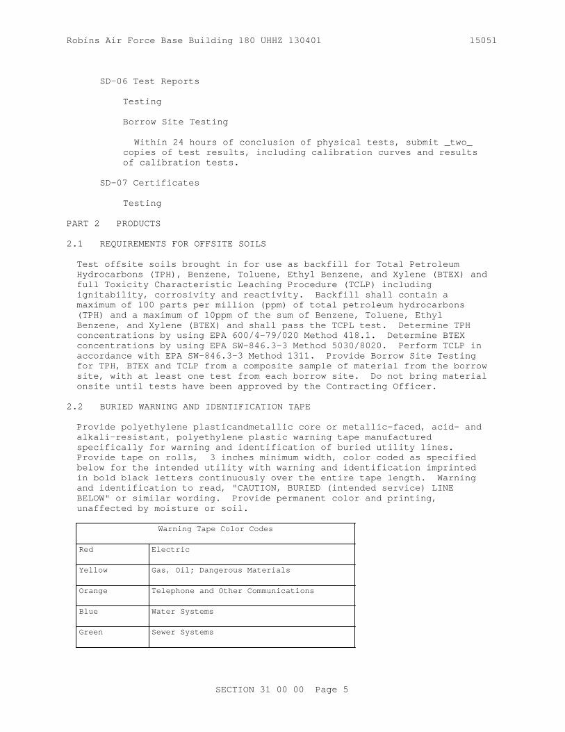
Robins Air Force Base Building 180 UHHZ 130401 15051
SD-06 Test Reports
Testing
Borrow Site Testing
Within 24 hours of conclusion of physical tests, submit _two_ copies of test results, including calibration curves and results of calibration tests.
SD-07 Certificates
Testing
PART 2 PRODUCTS
2.1 REQUIREMENTS FOR OFFSITE SOILS
Test offsite soils brought in for use as backfill for Total Petroleum Hydrocarbons (TPH), Benzene, Toluene, Ethyl Benzene, and Xylene (BTEX) and full Toxicity Characteristic Leaching Procedure (TCLP) including ignitability, corrosivity and reactivity. Backfill shall contain a maximum of 100 parts per million (ppm) of total petroleum hydrocarbons (TPH) and a maximum of 10ppm of the sum of Benzene, Toluene, Ethyl Benzene, and Xylene (BTEX) and shall pass the TCPL test. Determine TPH concentrations by using EPA 600/4-79/020 Method 418.1. Determine BTEX concentrations by using EPA SW-846.3-3 Method 5030/8020. Perform TCLP in accordance with EPA SW-846.3-3 Method 1311. Provide Borrow Site Testing for TPH, BTEX and TCLP from a composite sample of material from the borrow site, with at least one test from each borrow site. Do not bring material onsite until tests have been approved by the Contracting Officer.
2.2 BURIED WARNING AND IDENTIFICATION TAPE
Provide polyethylene plasticandmetallic core or metallic-faced, acid- and alkali-resistant, polyethylene plastic warning tape manufactured specifically for warning and identification of buried utility lines. Provide tape on rolls, 3 inches minimum width, color coded as specified below for the intended utility with warning and identification imprinted in bold black letters continuously over the entire tape length. Warning and identification to read, "CAUTION, BURIED (intended service) LINE BELOW" or similar wording. Provide permanent color and printing, unaffected by moisture or soil.
Warning Tape Color Codes
Red Electric
Yellow Gas, Oil; Dangerous Materials
Orange Telephone and Other Communications
Blue Water Systems
Green Sewer Systems
SECTION 31 00 00 Page 5

Robins Air Force Base Building 180 UHHZ 130401 15051
Warning Tape Color Codes
White Steam Systems
Gray Compressed Air
2.2.1 Warning Tape for Metallic Piping
Provide acid and alkali-resistant polyethylene plastic tape conforming to the width, color, and printing requirements specified above, with a minimum thickness of 0.003 inch and a minimum strength of 1500 psi lengthwise, and 1250 psi crosswise, with a maximum 350 percent elongation.
2.2.2 Detectable Warning Tape for Non-Metallic Piping
Provide polyethylene plastic tape conforming to the width, color, and printing requirements specified above, with a minimum thickness of 0.004 inch, and a minimum strength of 1500 psi lengthwise and 1250 psi crosswise. Manufacture tape with integral wires, foil backing, or other means of enabling detection by a metal detector when tape is buried up to 3 feet deep. Encase metallic element of the tape in a protective jacket or provide with other means of corrosion protection.
2.3 DETECTION WIRE FOR NON-METALLIC PIPING
Insulate a single strand, solid copper detection wire with a minimum of 12 AWG.
2.4 CAPILLARY WATER BARRIER
Provide capillary water barrier of clean, poorly graded crushed rock, crushed gravel, or uncrushed gravel placed beneath a building slab with or without a vapor barrier to cut off the capillary flow of pore water to the area immediately below. Conform to ASTM C33/C33M for fine aggregate grading with a maximum of 3 percent by weight passing ASTM D1140, No. 200 sieve, or 1-1/2 inch and no more than 2 percent by weight passing the No. 4 size sieve or coarse aggregate Size 57, 67, or 77.
PART 3 EXECUTION
3.1 STRIPPING OF TOPSOIL
Where indicated or directed, strip topsoil to a depth of4inches. Spread topsoil on areas already graded and prepared for topsoil, or transported and deposited in stockpiles convenient to areas that are to receive application of the topsoil later, or at locations indicated or specified. Keep topsoil separate from other excavated materials, brush, litter, objectionable weeds, roots, stones larger than 2 inches in diameter, and other materials that would interfere with planting and maintenance operations.Remove from the site any surplus of topsoil from excavations and gradings.
3.2 GENERAL EXCAVATION
Perform excavation of every type of material encountered within the limits of the project to the lines, grades, and elevations indicated and as
SECTION 31 00 00 Page 6

Robins Air Force Base Building 180 UHHZ 130401 15051
specified. Perform the grading in accordance with the typical sections shown and the tolerances specified in paragraph FINISHING. Transport satisfactory excavated materials and place in fill or embankment within the limits of the work. Excavate unsatisfactory materials encountered within the limits of the work below grade and replace with satisfactory materials as directed. Include such excavated material and the satisfactory material ordered as replacement in excavation. Dispose surplus satisfactory excavated material not required for fill or embankment in areas approved for surplus material storage or designated waste areas. Dispose unsatisfactory excavated material in designated waste or spoil areas. During construction, perform excavation and fill in a manner and sequence that will provide proper drainage at all times. Excavate material required for fill or embankment in excess of that produced by excavation within the grading limits from the borrow areas indicated or from other approved areas selected by the Contractor as specified.
3.2.1 Ditches, Gutters, and Channel Changes
Finish excavation of ditches, gutters, and channel changes by cutting accurately to the cross sections, grades, and elevations shown on Drawing Sheet No. C300. Do not excavate ditches and gutters below grades shown. Backfill the excessive open ditch or gutter excavation with satisfactory, thoroughly compacted, material or with suitable stone or cobble to grades shown. Dispose excavated material as shown or as directed, except in no case allow material be deposited a maximum 4 feet from edge of a ditch. Maintain excavations free from detrimental quantities of leaves, brush, sticks, trash, and other debris until final acceptance of the work.
3.2.2 Drainage Structures
Make excavations to the lines, grades, and elevations shown, or as directed. Provide trenches and foundation pits of sufficient size to permit the placement and removal of forms for the full length and width of structure footings and foundations as shown. Clean rock or other hard foundation material of loose debris and cut to a firm, level, stepped, or serrated surface. Remove loose disintegrated rock and thin strata. Do not disturb the bottom of the excavation when concrete or masonry is to be placed in an excavated area. Do not excavate to the final grade level until just before the concrete or masonry is to be placed.
3.2.3 Drainage
Provide for the collection and disposal of surface and subsurface water encountered during construction. Completely drain construction site during periods of construction to keep soil materials sufficiently dry. Construct storm drainage features at the earliest stages of site development, and throughout construction grade the construction area to provide positive surface water runoff away from the construction activity andprovide temporary ditches, swales, and other drainage features and equipment as required to maintain dry soils. When unsuitable working platforms for equipment operation and unsuitable soil support for subsequent construction features develop, remove unsuitable material and provide new soil material as specified herein. It is the responsibility of the Contractor to assess the soil and ground water conditions presented by the plans and specifications and to employ necessary measures to permit construction to proceed.
SECTION 31 00 00 Page 7

Robins Air Force Base Building 180 UHHZ 130401 15051
3.2.4 Dewatering
Control groundwater flowing toward or into excavations to prevent sloughing of excavation slopes and walls, boils, uplift and heave in the excavation and to eliminate interference with orderly progress of construction. Do not permit French drains, sumps, ditches or trenches within 3 feet of the foundation of any structure, except with specific written approval, and after specific contractual provisions for restoration of the foundation area have been made. Take control measures by the time the excavation reaches the water level in order to maintain the integrity of the in situ material. While the excavation is open, maintain the water level continuously, at least two feet below the working level. Operate dewatering system continuously until construction work below existing water levels is complete.
3.2.5 Trench Excavation Requirements
Excavate the trench as recommended by the manufacturer of the pipe to be installed. Slope trench walls below the top of the pipe, or make vertical, and of such width as recommended in the manufacturer's printed installation manual. Provide vertical trench walls where no manufacturer's printed installation manual is available. Shore trench walls more than five feet high, cut back to a stable slope, or provide with equivalent means of protection for employees who may be exposed to moving ground or cave in. Shore vertical trench walls more than four feet high. Excavate trench walls which are cut back to at least the angle of repose of the soil. Give special attention to slopes which may be adversely affected by weather or moisture content. Do not exceed the trench width below the pipe top of 24 inches plus pipe outside diameter (O.D.) for pipes of less than 24 inches inside diameter, and do not exceed 36 inches plus pipe outside diameter for sizes larger than 24 inches inside diameter. Where recommended trench widths are exceeded, provide redesign, stronger pipe, or special installation procedures by the Contractor. The Contractor is responsible for the cost of redesign, stronger pipe, or special installation procedures without any additional cost to the Government.
3.2.5.1 Bottom Preparation
Grade the bottoms of trenches accurately to provide uniform bearing and support for the bottom quadrant of each section of the pipe. Excavate bell holes to the necessary size at each joint or coupling to eliminate point bearing. Remove stones of 3 inch or greater in any dimension, or as recommended by the pipe manufacturer, whichever is smaller, to avoid point bearing.
3.2.5.2 Removal of Unyielding Material
Where overdepth is not indicated and unyielding material is encountered in the bottom of the trench, remove such material 4 inch below the required grade and replaced with suitable materials as provided in paragraph BACKFILLING AND COMPACTION.
3.2.5.3 Removal of Unstable Material
Where unstable material is encountered in the bottom of the trench, remove such material to the depth directed and replace it to the proper grade with select granular material as provided in paragraph BACKFILLING AND COMPACTION. When removal of unstable material is required due to the
SECTION 31 00 00 Page 8

Robins Air Force Base Building 180 UHHZ 130401 15051
Contractor's fault or neglect in performing the work, the Contractor is responsible for excavating the resulting material and replacing it without additional cost to the Government.
3.2.5.4 Excavation for Appurtenances
Provide excavation for manholes, catch-basins, inlets, or similar structures sufficient to leave at least 12 inches clear between the outer structure surfaces and the face of the excavation or support members. Clean rock or loose debris and cut to a firm surface either level, stepped, or serrated, as shown or as directed. Remove loose disintegrated rock and thin strata. Specify removal of unstable material. When concrete or masonry is to be placed in an excavated area, take special care not to disturb the bottom of the excavation. Do not excavate to the final grade level until just before the concrete or masonry is to be placed.
3.2.6 Underground Utilities
The Contractor is responsible for movement of construction machinery and equipment over pipes and utilities during construction. Excavation made with power-driven equipment is not permitted within2feet of known Government-owned utility or subsurface construction. For work immediately adjacent to or for excavations exposing a utility or other buried obstruction, excavate by hand. Start hand excavation on each side of the indicated obstruction and continue until the obstruction is uncovered or until clearance for the new grade is assured. Support uncovered lines or other existing work affected by the contract excavation until approval for backfill is granted by the Contracting Officer. Report damage to utility lines or subsurface construction immediately to the Contracting Officer.
3.2.7 Structural Excavation
Ensure that footing subgrades have been inspected and approved by the Contracting Officer prior to concrete placement.
3.3 SHORING
3.3.1 Geotechnical Engineer
Hire a Professional Geotechnical Engineer to provide inspection of excavations and soil/groundwater conditions throughout construction. The Geotechnical Engineer is responsible for performing pre-construction and periodic site visits throughout construction to assess site conditions. The Geotechnical Engineer is responsible for updating the excavation, sheeting and dewatering plans as construction progresses to reflect changing conditions and submit an updated plan if necessary. Submit a monthly written report, informing the Contractor and Contracting Officer of the status of the plan and an accounting of the Contractor's adherence to the plan addressing any present or potential problems. The Contracting Officer is responsible for arranging meetings with the Geotechnical Engineer at any time throughout the contract duration.
3.4 FINAL GRADE OF SURFACES TO SUPPORT CONCRETE
Do not excavate to final grade until just before concrete is to be placed. Only use excavation methods that will leave the foundation rock in a solid and unshattered condition. Roughen the level surfaces, and cut the sloped surfaces, as indicated, into rough steps or benches to provide
SECTION 31 00 00 Page 9

Robins Air Force Base Building 180 UHHZ 130401 15051
a satisfactory bond. Protect shales from slaking and all surfaces from erosion resulting from ponding or water flow.
3.5 GROUND SURFACE PREPARATION
3.5.1 General Requirements
Remove and replace unsatisfactory material with satisfactory materials, as directed by the Contracting Officer, in surfaces to receive fill or in excavated areas. Scarify the surface to a depth of 6 inches before the fill is started. Plow, step, bench, or break up sloped surfaces steeper than 1 vertical to 4 horizontal so that the fill material will bond with the existing material. When subgrades are less than the specified density, break up the ground surface to a minimum depth of 6 inches, pulverizing, and compacting to the specified density. When the subgrade is part fill and part excavation or natural ground, scarify the excavated or natural ground portion to a depth of 12 inches and compact it as specified for the adjacent fill.
3.5.2 Frozen Material
Do not place material on surfaces that are muddy, frozen, or contain frost. Finish compaction by sheepsfoot rollers, pneumatic-tired rollers, steel-wheeled rollers, or other approved equipment well suited to the soil being compacted. Moisten material as necessary to provide the moisture content that will readily facilitate obtaining the specified compaction with the equipment used.
3.6 UTILIZATION OF EXCAVATED MATERIALS
Dispose unsatisfactory materials removing from excavations into designated waste disposal or spoil areas. Use satisfactory material removed from excavations, insofar as practicable, in the construction of fills, embankments, subgrades, shoulders, bedding (as backfill), and for similar purposes. Submit procedure and location for disposal of unused satisfactory material. Submit proposed source of borrow material . Do not waste any satisfactory excavated material without specific written authorization. Dispose of satisfactory material, authorized to be wasted, in designated areas approved for surplus material storage or designated waste areas as directed. Clear and grub newly designated waste areas on Government-controlled land before disposal of waste material thereon. Stockpile and use coarse rock from excavations for constructing slopes or embankments adjacent to streams, or sides and bottoms of channels and for protecting against erosion. Do not dispose excavated material to obstruct the flow of any stream, endanger a partly finished structure, impair the efficiency or appearance of any structure, or be detrimental to the completed work in any way.
3.7 BURIED TAPE AND DETECTION WIRE
3.7.1 Buried Warning and Identification Tape
Provide buried utility lines with utility identification tape. Bury tape 12 inches below finished grade; under pavements and slabs, bury tape 6 inches below top of subgrade.
3.7.2 Buried Detection Wire
Bury detection wire directly above non-metallic piping at a distance not
SECTION 31 00 00 Page 10

Robins Air Force Base Building 180 UHHZ 130401 15051
to exceed 12 inches above the top of pipe. Extend the wire continuously and unbroken, from manhole to manhole. Terminate the ends of the wire inside the manholes at each end of the pipe, with a minimum of 3 feet of wire, coiled, remaining accessible in each manhole. Furnish insulated wire over it's entire length. Install wires at manholes between the top of the corbel and the frame, and extend up through the chimney seal between the frame and the chimney seal. For force mains, terminate the wire in the valve pit at the pump station end of the pipe.
3.8 BACKFILLING AND COMPACTION
Place backfill adjacent to any and all types of structures, in successive horizontal layers of loose materia not more than 8 inches in depth. Compact to at least 90 percent laboratory maximum density for cohesive materials or 95 percent laboratory maximum density for cohesionless materials, to prevent wedging action or eccentric loading upon or against the structure. Backfill material must be within the range of -2 to +2 percent of optimum moisture content at the time of compaction.
Prepare ground surface on which backfill is to be placed and provide compaction requirements for backfill materials in conformance with the applicable portions of paragraphs GROUND SURFACE PREPARATION. Finish compaction by sheepsfoot rollers, pneumatic-tired rollers, steel-wheeled rollers, vibratory compactors, or other approved equipment.
3.8.1 Trench Backfill
Backfill trenches to the grade shown. Backfill the trench to 2 feet above the top of pipe prior to performing the required pressure tests. Leave the joints and couplings uncovered during the pressure test.Do not backfill the trench until all specified tests are performed.
3.8.1.1 Replacement of Unyielding Material
Replace unyielding material removed from the bottom of the trench with select granular material or initial backfill material.
3.8.1.2 Replacement of Unstable Material
Replace unstable material removed from the bottom of the trench or excavation with select granular material placed in layers not exceeding 6 inches loose thickness.
3.8.1.3 Bedding and Initial Backfill
Provide bedding of the type and thickness shown. Place initial backfill material and compact it with approved tampers to a height of at least one foot above the utility pipe or conduit. Bring up the backfill evenly on both sides of the pipe for the full length of the pipe. Take care to ensure thorough compaction of the fill under the haunches of the pipe. Except as specified otherwise in the individual piping section, provide bedding for buried piping in accordance with AWWA C600, Type 4, except as specified herein. Compact backfill to top of pipe to 95 percent of ASTM D698 maximum density. Provide plastic piping with bedding to spring line of pipe. Provide materials as follows:
3.8.1.3.1 Class I
Angular, 0.25 to 1.5 inch, graded stone, including a number of fill
SECTION 31 00 00 Page 11

Robins Air Force Base Building 180 UHHZ 130401 15051
materials that have regional significance such as coral, slag, cinders, crushed stone, and crushed shells.
3.8.1.3.2 Class II
Coarse sands and gravels with maximum particle size of 1.5 inch, including various graded sands and gravels containing small percentages of fines, generally granular and noncohesive, either wet or dry. Soil Types GW, GP, SW, and SP are included in this class as specified in ASTM D2487.
3.8.1.3.3 Sand
Clean, coarse-grained sand classified in accordance with Section 31 23 00.00 20 EXCAVATION AND FILL, of the GA DOT State Standard or SW orSP by ASTM D2487 for beddingand backfill.
3.8.1.3.4 Gravel and Crushed Stone
Clean, coarsely graded natural gravel, crushed stone or a combination thereof identified in accordance with Section 31 23 00.00 20 EXCAVATION AND FILL, gradation of the GA DOT State Standard or having a classification of GW in accordance with ASTM D2487 for bedding and backfill as indicated. Do not exceed maximum particle size of 3 inches.
3.8.1.4 Final Backfill
Fill the remainder of the trench, except for special materials for roadways, railroads and airfields, with satisfactory material. Place backfill material and compact as follows:
3.8.1.4.1 Roadways, Railroads, and Airfields
Place backfill up to the required elevation as specified. Do not permit water flooding or jetting methods of compaction.
3.8.1.4.2 Sidewalks, Turfed or Seeded Areas and Miscellaneous Areas
Deposit backfill in layers of a maximum of 12 inches loose thickness, and compact it to 85 percent maximum density for cohesive soils and 90 percent maximum density for cohesionless soils. Allow water flooding or jetting methods of compaction for granular noncohesive backfill material. Do not allow water jetting to penetrate the initial backfill.Do not permit compaction by water flooding or jetting. Apply this requirement to all other areas not specifically designated above.
3.8.2 Backfill for Appurtenances
After the manhole, catchbasin, inlet, or similar structure has been constructed and the concrete has been allowed to cure for 3 days, place backfill in such a manner that the structure is not be damaged by the shock of falling earth. Deposit the backfill material, compact it as specified for final backfill, and bring up the backfill evenly on all sides of the structure to prevent eccentric loading and excessive stress.
3.9 SPECIAL REQUIREMENTS
Special requirements for both excavation and backfill relating to the specific utilities are as follows:
SECTION 31 00 00 Page 12

Robins Air Force Base Building 180 UHHZ 130401 15051
3.9.1 Water Lines
Excavate trenches to a depth that provides a minimum cover of 3 feet from the existing ground surface, or from the indicated finished grade, whichever is lower, to the top of the pipe.
3.10 SUBGRADE PREPARATION
3.10.1 Construction
Shape subgrade to line, grade, and cross section, and compact as specified. Include plowing, disking, and any moistening or aerating required to obtain specified compaction for this operation. Remove soft or otherwise unsatisfactory material and replace with satisfactory excavated material or other approved material as directed. Excavate rock encountered in the cut section to a depth of 6 inches below finished grade for the subgrade. Bring up low areas resulting from removal of unsatisfactory material or excavation of rock to required grade with satisfactory materials, and shape the entire subgrade to line, grade, and cross section and compact as specified. Do not vary the elevation of the finish subgrade more than 0.05 foot from the established grade and cross section.
3.10.2 Compaction
Finish compaction by sheepsfoot rollers, pneumatic-tired rollers, steel-wheeled rollers, vibratory compactors, or other approved equipment. Except for paved areas and railroads, compact each layer of the embankment to at least 95 percent of laboratory maximum density.
3.10.2.1 Subgrade for Pavements
Compact subgrade for pavements to at least 95 percentage laboratory maximum density for the depth below the surface of the pavement shown.
3.11 FINISHING
Finish the surface of excavations, embankments, and subgrades to a smooth and compact surface in accordance with the lines, grades, and cross sections or elevations shown. Provide the degree of finish for graded areas within 0.1 foot of the grades and elevations indicated except that the degree of finish for subgrades specified in paragraph SUBGRADE PREPARATION. Finish gutters and ditches in a manner that will result in effective drainage. Finish the surface of areas to be turfed from settlement or washing to a smoothness suitable for the application of turfing materials. Repair graded, topsoiled, or backfilled areas prior to acceptance of the work, and re-established grades to the required elevations and slopes.
3.11.1 Capillary Water Barrier
Place a capillary water barrier under concrete floor and area-way slabs grade directly on the subgrade and compact with a minimum of two passes of a hand-operated plate-type vibratory compactor.
3.11.2 Grading Around Structures
Construct areas within 5 feet outside of each building and structure line true-to-grade, shape to drain, and maintain free of trash and debris until
SECTION 31 00 00 Page 13
Robins Air Force Base Building 180 UHHZ 130401 15051
final inspection has been completed and the work has been accepted.
3.12 PLACING TOPSOIL
On areas to receive topsoil, prepare the compacted subgrade soil to a 2 inches depth for bonding of topsoil with subsoil. Spread topsoil evenly to a thickness of 4 inches and grade to the elevations and slopes shown. Do not spread topsoil when frozen or excessively wet or dry. Obtain material required for topsoil in excess of that produced by excavation within the grading limits from offsite areas.
3.13 TESTING
Perform testing by a Corps validated commercial testing laboratory or the Contractor's validated testing facility. Submit qualifications of the Corps validated commercial testing laboratory or the Contractor's validated testing facilities. If the Contractor elects to establish testing facilities, do not permit work requiring testing until the Contractor's facilities have been inspected, Corps validated and approved by the Contracting Officer.
a. Determine field in-place density in accordance with ASTM D1556/D1556M
b. Check the calibration curves furnished with the moisture gauges along with density calibration checks as described in ASTM D6938; check the calibration of both the density and moisture gauges at the beginning of a job on each different type of material encountered and at intervals as directed by the Contracting Officer. ASTM D2937, use the Drive Cylinder Method only for soft, fine-grained, cohesive soils. When test results indicate, as determined by the Contracting Officer, that compaction is not as specified, remove the material, replace and recompact to meet specification requirements.
c. Perform tests on recompacted areas to determine conformance with specification requirements. Appoint a registered professional civil engineer to certify inspections and test results. These certifications shall state that the tests and observations were performed by or under the direct supervision of the engineer and that the results are representative of the materials or conditions being certified by the tests. The following number of tests, if performed at the appropriate time, will be the minimum acceptable for each type operation.
3.13.1 Fill and Backfill Material Gradation
One test per 20 cubic yards stockpiled or in-place source material. Determine gradation of fill and backfill material in accordance with ASTM C136/C136M.
3.13.2 In-Place Densities
a. One test per 2000 square feet, or fraction thereof, of each lift of fill or backfill areas compacted by other than hand-operated machines.
b. One test per 2000 square feet, or fraction thereof, of each lift of fill or backfill areas compacted by hand-operated machines.
SECTION 31 00 00 Page 14
Robins Air Force Base Building 180 UHHZ 130401 15051
3.13.3 Check Tests on In-Place Densities
If ASTM D6938 is used, check in-place densities by ASTM D1556/D1556M as follows:
a. One check test per lift for each 2000 square feet, or fraction thereof, of each lift of fill or backfill compacted by other than hand-operated machines.
b. One check test per lift for each 2000 square feet, of fill or backfill areas compacted by hand-operated machines.
3.13.4 Moisture Contents
In the stockpile, excavation, or borrow areas, perform a minimum of two tests per day per type of material or source of material being placed during stable weather conditions. During unstable weather, perform tests as dictated by local conditions and approved by the Contracting Officer.
3.13.5 Optimum Moisture and Laboratory Maximum Density
Perform tests for each type material or source of material including borrow material to determine the optimum moisture and laboratory maximum density values. One representative test per 100 cubic yards of fill and backfill, or when any change in material occurs which may affect the optimum moisture content or laboratory maximum density.
3.13.6 Tolerance Tests for Subgrades
Perform continuous checks on the degree of finish specified in paragraph SUBGRADE PREPARATION during construction of the subgrades.
3.13.7 Displacement of Sewers
After other required tests have been performed and the trench backfill compacted to 2 feet above the top of the pipe, inspect the pipe to determine whether significant displacement has occurred. Conduct this inspection in the presence of the Contracting Officer. If, in the judgment of the Contracting Officer, the interior of the pipe shows poor alignment or any other defects that would cause improper functioning of the system, replace or repair the defects as directed at no additional cost to the Government.
3.14 DISPOSITION OF SURPLUS MATERIAL
Remove surplus material or other soil material not required or suitable for filling or backfilling, and brush, refuse, stumps, roots, and timber from Government property to an approved location .
-- End of Section --
SECTION 31 00 00 Page 15

Robins Air Force Base Building 180 UHHZ 130401 15051
Robins Air Force Base Building 180 UHHZ 130401
SECTION 31 11 00
CLEARING AND GRUBBING08/08
PART 1 GENERAL
1.1 SUBMITTALS
Government approval is required for submittals with a "G" designation; submittals not having a "G" designation are for Contractor Quality Control approval. Submit the following in accordance with Section 01300 SUBMITTALS AND CONTRACTOR-FURNISHED ITEMS:
SD-03 Product Data
Nonsaleable Materials; G
SD-04 Samples
Tree Wound PaintHerbicide
1.2 DELIVERY, STORAGE, AND HANDLING
Deliver materials to store at the site, and handle in a manner which will maintain the materials in their original manufactured or fabricated condition until ready for use.
PART 2 PRODUCTS
2.1 TREE WOUND PAINT
Submit samples in cans with manufacturer's label of bituminous based paint of standard manufacture specially formulated for tree wounds.
PART 3 EXECUTION
3.1 PROTECTION
3.1.1 Roads and Walks
Keep roads and walks free of dirt and debris at all times.
3.1.2 Trees, Shrubs, and Existing Facilities
Protect trees and vegetation to be left standing from damage incident to clearing, grubbing, and construction operations by the erection of barriers or by such other means as the circumstances require.
3.1.3 Utility Lines
Protect existing utility lines that are indicated to remain from damage. Notify the Contracting Officer immediately of damage to or an encounter with an unknown existing utility line. The Contractor is responsible for the repairs of damage to existing utility lines that are indicated or made known to the Contractor prior to start of clearing and grubbing
SECTION 31 11 00 Page 1

Robins Air Force Base Building 180 UHHZ 130401 15051
operations. When utility lines which are to be removed are encountered within the area of operations, notify the Contracting Officer in ample time to minimize interruption of the service. Refer to Section 01300 ADMINISTRATIVE REQUIREMENTS.
3.2 CLEARING
Clearing shall consist of the felling, trimming, and cutting of trees into sections and the satisfactory disposal of the trees and other vegetation designated for removal, including downed timber, snags, brush, and rubbish occurring within the areas to be cleared. Clearing shall also include the removal and disposal of structures that obtrude, encroach upon, or otherwise obstruct the work. Trees, stumps, roots, brush, and other vegetation in areas to be cleared shall be cut off flush with or below the original ground surface, except such trees and vegetation as may be indicated or directed to be left standing. Trees designated to be left standing within the cleared areas shall be trimmed of dead branches 1-1/2 inches or more in diameter and shall be trimmed of all branches the heights indicated or directed. Limbs and branches to be trimmed shall be neatly cut close to the bole of the tree or main branches. Cuts more than 1-1/2 inches in diameter shall be painted with an approved tree-wound paint.
3.3 TREE REMOVAL
Where indicated or directed, trees and stumps that are designated as trees shall be removed from areas outside those areas designated for clearing and grubbing. This work shall include the felling of such trees and the removal of their stumps and roots as specified in paragraph GRUBBING. Trees shall be disposed of as specified in paragraph DISPOSAL OF MATERIALS.
3.4 PRUNING
Trim trees designated to be left standing within the cleared areas of dead branches 1-1/2 inches or more in diameter; and trim branches to heights and in a manner as indicated. Neatly cut limbs and branches to be trimmed close to the bole of the tree or main branches. Paint cuts more than 1-1/4 inches in diameter with an approved tree wound paint.
3.5 GRUBBING
Grubbing consists of the removal and disposal of stumps, roots larger than 3 inches in diameter, and matted roots from the designated grubbing areas. Remove material to be grubbed, together with logs and other organic or metallic debris not suitable for foundation purposes, to a depth of not less than 18 inches below the original surface level of the ground in areas indicated to be grubbed and in areas indicated as construction areas under this contract, such as areas for buildings, and areas to be paved. Fill depressions made by grubbing with suitable material and compact to make the surface conform with the original adjacent surface of the ground.
3.6 DISPOSAL OF MATERIALS
3.6.1 Nonsaleable Materials
Logs, stumps, roots, brush, rotten wood, and other refuse from the clearing and grubbing operations shall be disposed of in the designated waste disposal areaoutside the limits of Government-controlled land at the
SECTION 31 11 00 Page 2

Robins Air Force Base Building 180 UHHZ 130401 15051
Contractor's responsibilityNo Burning is allowed on the project site.
-- End of Section --
SECTION 31 11 00 Page 3

Robins Air Force Base Building 180 UHHZ 130401 15051
Robins Air Force Base Building 180 UHHZ 130401
SECTION 31 23 00.00 20
EXCAVATION AND FILL02/11
PART 1 GENERAL
1.1 REFERENCES
The publications listed below form a part of this specification to the extent referenced. The publications are referred to in the text by the basic designation only.
AMERICAN WATER WORKS ASSOCIATION (AWWA)
AWWA C600 (2010) Installation of Ductile-Iron Water Mains and Their Appurtenances
ASTM INTERNATIONAL (ASTM)
ASTM C136/C136M (2014) Standard Test Method for Sieve Analysis of Fine and Coarse Aggregates
ASTM C33/C33M (2013) Standard Specification for Concrete Aggregates
ASTM D1140 (2014) Amount of Material in Soils Finer than the No. 200 (75-micrometer) Sieve
ASTM D1556/D1556M (2015) Standard Test Method for Density and Unit Weight of Soil in Place by Sand-Cone Method
ASTM D1557 (2012; E 2015) Standard Test Methods for Laboratory Compaction Characteristics of Soil Using Modified Effort (56,000 ft-lbf/ft3) (2700 kN-m/m3)
ASTM D2216 (2010) Laboratory Determination of Water (Moisture) Content of Soil and Rock by Mass
ASTM D2321 (2014; E 2014) Standard Practice for Underground Installation of Thermoplastic Pipe for Sewers and Other Gravity-Flow Applications
ASTM D2487 (2011) Soils for Engineering Purposes (Unified Soil Classification System)
ASTM D4318 (2010; E 2014) Liquid Limit, Plastic Limit, and Plasticity Index of Soils
ASTM D5084 (2010) Measurement of Hydraulic Conductivity of Saturated Porous Materials Using a Flexible Wall Permeameter
SECTION 31 23 00.00 20 Page 1

Robins Air Force Base Building 180 UHHZ 130401 15051
ASTM D6938 (2015) Standard Test Method for In-Place Density and Water Content of Soil and Soil-Aggregate by Nuclear Methods (Shallow Depth)
ASTM D698 (2012; E 2014; E 2015) Laboratory Compaction Characteristics of Soil Using Standard Effort (12,400 ft-lbf/cu. ft. (600 kN-m/cu. m.))
U.S. ENVIRONMENTAL PROTECTION AGENCY (EPA)
EPA SW-846.3-3 (1999, Third Edition, Update III-A) Test Methods for Evaluating Solid Waste: Physical/Chemical Methods
1.2 DEFINITIONS
1.2.1 Capillary Water Barrier
A layer of clean, poorly graded crushed rock, stone, or natural sand or gravel having a high porosity which is placed beneath a building slab with or without a vapor barrier to cut off the capillary flow of pore water to the area immediately below a slab.
1.2.2 Degree of Compaction
Degree of compaction is expressed as a percentage of the maximum density obtained by the test procedure presented in ASTM D1557, for general soil types, abbreviated as percent laboratory maximum density.
1.2.3 Hard Materials
Weathered rock, dense consolidated deposits, or conglomerate materials which are not included in the definition of "rock" but which usually require the use of heavy excavation equipment, ripper teeth, or jack hammers for removal.
1.3 SUBMITTALS
Government approval is required for submittals with a "G" designation; submittals not having a "G" designation are for Contractor Quality Control approval. Submit the following in accordance with Section 01300 SUBMITTALS AND CONTRACTOR-FURNISHED ITEMS:
SD-01 Preconstruction Submittals
Shoring and Sheeting Plan
Dewatering work plan
Submit 15 days prior to starting work.
SD-06 Test Reports
Borrow Site Testing; G
Fill and backfill test
SECTION 31 23 00.00 20 Page 2

Robins Air Force Base Building 180 UHHZ 130401 15051
Select material test
Porous fill test for capillary water barrier
Density tests
Moisture Content Tests
Copies of all laboratory and field test reports within 24 hours of the completion of the test.
1.4 DELIVERY, STORAGE, AND HANDLING
Perform in a manner to prevent contamination or segregation of materials.
1.5 CRITERIA FOR BIDDING
Base bids on the following criteria:
a. Surface elevations are as indicated.
b. Pipes or other artificial obstructions, except those indicated, will not be encountered.
c. Ground water elevations indicated by the boring log were those existing at the time subsurface investigations were made and do not necessarily represent ground water elevation at the time of construction.
d. Ground water elevation is 6 feet below existing surface elevation.
e. Material character is indicated by the boring logs.
f. Hard materials and rock will not be encountered at 20 feet below existing surface elevations.
g. Suitable backfill and bedding material in the quantities required is not available at the project site.
h. Blasting will not be permitted. Remove material in an approved manner.
1.6 REQUIREMENTS FOR OFF SITE SOIL
Soils brought in from off site for use as backfill shall be tested for petroleum hydrocarbons, BTEX, PCBs and HW characteristics (including toxicity, ignitability, corrosivity, and reactivity). Backfill shall not contain concentrations of these analytes above the appropriate State and/or EPA criteria, and shall pass the tests for HW characteristics. Determine petroleum hydrocarbon concentrations by using appropriate State protocols. Determine BTEX concentrations by using EPA SW-846.3-3 Method 5035/8260B. Perform complete TCLP in accordance with EPA SW-846.3-3 Method 1311. Perform HW characteristic tests for ignitability, corrosivity, and reactivity in accordance with accepted standard methods. Perform PCB testing in accordance with accepted standard methods for sampling and analysis of bulk solid samples. Provide borrow site testing for petroleum hydrocarbons and BTEX from a grab sample of material from the area most likely to be contaminated at the borrow site (as indicated by visual or olfactory evidence), with at least one test from each borrow
SECTION 31 23 00.00 20 Page 3

Robins Air Force Base Building 180 UHHZ 130401 15051
site. For each borrow site, provide borrow site testing for HW characteristics from a composite sample of material, collected in accordance with standard soil sampling techniques. Do not bring material onsite until tests results have been received and approved by the Contracting Officer.
1.7 QUALITY ASSURANCE
1.7.1 Shoring and Sheeting Plan
Submit drawings and calculations, certified by a registered professional engineer, describing the methods for shoring and sheeting of excavations. Drawings shall include material sizes and types, arrangement of members, and the sequence and method of installation and removal. Calculations shall include data and references used.
1.7.2 Dewatering Work Plan
Submit procedures for accomplishing dewatering work.
1.7.3 Utilities
Movement of construction machinery and equipment over pipes and utilities during construction shall be at the Contractor's risk. Excavation made with power-driven equipment is not permitted withintwo feet of known Government-owned utility or subsurface construction. For work immediately adjacent to or for excavations exposing a utility or other buried obstruction, excavate by hand. Start hand excavation on each side of the indicated obstruction and continue until the obstruction is uncovered or until clearance for the new grade is assured. Support uncovered lines or other existing work affected by the contract excavation until approval for backfill is granted by the Contracting Officer. Report damage to utility lines or subsurface construction immediately to the Contracting Officer.
PART 2 PRODUCTS
2.1 SOIL MATERIALS
2.1.1 Satisfactory Materials
Any materials classified by ASTM D2487 as GW, GP, GM, GP-GM, GW-GM, GC, GP-GC, GM-GC, SW, SP free of debris, roots, wood, scrap material, vegetation, refuse, soft unsound particles, and frozen, deleterious, or objectionable materials. Unless specified otherwise, the maximum particle diameter shall be one-half the lift thickness at the intended location.
2.1.2 Unsatisfactory Materials
Materials which do not comply with the requirements for satisfactory materials. Unsatisfactory materials also include man-made fills, trash, refuse, or backfills from previous construction. Unsatisfactory material also includes material classified as satisfactory which contains root and other organic matter, frozen material, and stones larger than 3 inches. The Contracting Officer shall be notified of any contaminated materials.
2.1.3 Cohesionless and Cohesive Materials
Cohesionless materials include materials classified in ASTM D2487 as GW, GP, SW, and SP. Cohesive materials include materials classified as GC,
SECTION 31 23 00.00 20 Page 4

Robins Air Force Base Building 180 UHHZ 130401 15051
SC, ML, CL, MH, and CH. Materials classified as GM, GP-GM, GW-GM, SW-SM, SP-SM, and SM shall be identified as cohesionless only when the fines are nonplastic (plasticity index equals zero). Materials classified as GM and SM will be identified as cohesive only when the fines have a plasticity index greater than zero.
2.1.4 Nonfrost Susceptible (NFS) Material
A uniformly graded washed sand with a maximum particle size of 0.02 inch and less than 5 percent passing the No. 200 size sieve, and with not more than 3 percent by weight finer than 0.02 mm grain size.
2.1.5 Common Fill
Approved, unclassified soil material with the characteristics required to compact to the soil density specified for the intended location.
2.1.6 Backfill and Fill Material
ASTM D2487, classification GW, GP, GM, GC, SW, SP, SM with a maximum ASTM D4318 liquid limit of 35, maximum ASTM D4318 plasticity index of 12, and a maximum of 25 percent by weight passing ASTM D1140, No. 200 sieve.
2.1.7 Select Material
Provide materials classified as GW, GP, SW, SP by ASTM D2487 where indicated. The liquid limit of such material shall not exceed 35 percent when tested in accordance with ASTM D4318. The plasticity index shall not be greater than 12 percent when tested in accordance with ASTM D4318, and not more than 35 percent by weight shall be finer than No. 200 sieve when tested in accordance with ASTM D1140. Coefficient of permeability shall be a minimum of0.002 feet per minute when tested in accordance with ASTM D5084.
2.1.8 Topsoil
Natural, friable soil representative of productive, well-drained soils in the area, free of subsoil, stumps, rocks larger than one inch diameter, brush, weeds, toxic substances, and other material detrimental to plant growth. Amend topsoil pH range to obtain a pH of 5.5 to 7.
2.2 POROUS FILL FOR CAPILLARY WATER BARRIER
ASTM C33/C33M fine aggregate grading with a maximum of 3 percent by weight passing ASTM D1140, No. 200 sieve, or 1-1/2 inches and no more than 2 percent by weight passing the No. 4 size sieve or coarse aggregate Size 57, 67, or 77 and conforming to the general soil material requirements specified in paragraph entitled "Satisfactory Materials."
2.3 UTILITY BEDDING MATERIAL
Except as specified otherwise in the individual piping section, provide bedding for buried piping in accordance with AWWA C600, Type 4, except as specified herein. Backfill to top of pipe shall be compacted to 95 percent of ASTM D698 maximum density. Plastic piping shall have bedding to spring line of pipe. Provide ASTM D2321 materials as follows:
a. Class I: Angular, 0.25 to 1.5 inches, graded stone, including a number of fill materials that have regional significance such as coral, slag, cinders, crushed stone, and crushed shells.
SECTION 31 23 00.00 20 Page 5
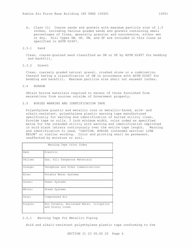
Robins Air Force Base Building 180 UHHZ 130401 15051
b. Class II: Coarse sands and gravels with maximum particle size of 1.5 inches, including various graded sands and gravels containing small percentages of fines, generally granular and noncohesive, either wet or dry. Soil Types GW, GP, SW, and SP are included in this class as specified in ASTM D2487.
2.3.1 Sand
Clean, coarse-grained sand classified as SW or SP by ASTM D2487 for bedding and backfill.
2.3.2 Gravel
Clean, coarsely graded natural gravel, crushed stone or a combination thereof having a classification of GW in accordance with ASTM D2487 for bedding and backfill. Maximum particle size shall not exceed3 inches.
2.4 BORROW
Obtain borrow materials required in excess of those furnished from excavations from sources outside of Government property.
2.5 BURIED WARNING AND IDENTIFICATION TAPE
Polyethylene plastic and metallic core or metallic-faced, acid- and alkali-resistant, polyethylene plastic warning tape manufactured specifically for warning and identification of buried utility lines. Provide tape on rolls, 3 inch minimum width, color coded as specified below for the intended utility with warning and identification imprinted in bold black letters continuously over the entire tape length. Warning and identification to read, "CAUTION, BURIED (intended service) LINE BELOW" or similar wording. Color and printing shall be permanent, unaffected by moisture or soil.
Warning Tape Color Codes
Red: Electric
Yellow: Gas, Oil; Dangerous Materials
Orange: Telephone and Other Communications
Blue: Potable Water Systems
Green: Sewer Systems
White: Steam Systems
Gray: Compressed Air
Purple: Non Potable, Reclaimed Water, Irrigation and Slurry lines
2.5.1 Warning Tape for Metallic Piping
Acid and alkali-resistant polyethylene plastic tape conforming to the
SECTION 31 23 00.00 20 Page 6

Robins Air Force Base Building 180 UHHZ 130401 15051
width, color, and printing requirements specified above. Minimum thickness of tape shall be 0.003 inch. Tape shall have a minimum strength of 1500 psi lengthwise, and 1250 psi crosswise, with a maximum 350 percent elongation.
2.5.2 Detectable Warning Tape for Non-Metallic Piping
Polyethylene plastic tape conforming to the width, color, and printing requirements specified above. Minimum thickness of the tape shall be 0.004 inch. Tape shall have a minimum strength of 1500 psi lengthwise and 1250 psi crosswise. Tape shall be manufactured with integral wires, foil backing, or other means of enabling detection by a metal detector when tape is buried up to 3 feet deep. Encase metallic element of the tape in a protective jacket or provide with other means of corrosion protection.
2.6 DETECTION WIRE FOR NON-METALLIC PIPING
Detection wire shall be insulated single strand, solid copper with a minimum of 12 AWG.
PART 3 EXECUTION
3.1 PROTECTION
3.1.1 Drainage and Dewatering
Provide for the collection and disposal of surface and subsurface water encountered during construction.
3.1.1.1 Drainage
So that construction operations progress successfully, completely drain construction site during periods of construction to keep soil materials sufficiently dry. The Contractor shall establish/construct storm drainage features at the earliest stages of site development, and throughout construction grade the construction area to provide positive surface water runoff away from the construction activity and/or provide temporary ditches, swales, and other drainage features and equipment as required to maintain dry soils, prevent erosion and undermining of foundations. When unsuitable working platforms for equipment operation and unsuitable soil support for subsequent construction features develop, remove unsuitable material and provide new soil material as specified herein. It is the responsibility of the Contractor to assess the soil and ground water conditions presented by the plans and specifications and to employ necessary measures to permit construction to proceed. Excavated slopes and backfill surfaces shall be protected to prevent erosion and sloughing. Excavation shall be performed so that the site, the area immediately surrounding the site, and the area affecting operations at the site shall be continually and effectively drained.
3.1.1.2 Dewatering
Groundwater flowing toward or into excavations shall be controlled to prevent sloughing of excavation slopes and walls, boils, uplift and heave in the excavation and to eliminate interference with orderly progress of construction. French drains, sumps, ditches or trenches will not be permitted within 3 feet of the foundation of any structure, except with specific written approval, and after specific contractual provisions for restoration of the foundation area have been made. Control measures shall
SECTION 31 23 00.00 20 Page 7

Robins Air Force Base Building 180 UHHZ 130401 15051
be taken by the time the excavation reaches the water level in order to maintain the integrity of the in situ material. While the excavation is open, the water level shall be maintained continuously, at least 2 feet below the working level.
Operate dewatering system continuously until construction work below existing water levels is complete.
3.1.2 Underground Utilities
Location of the existing utilities indicated is approximate. The Contractor shall physically verify the location and elevation of the existing utilities indicated prior to starting construction. The Contractor shall contact the Public Works Departmentfor assistance in locating existing utilities. The Contractor shall scan the construction site with electromagnetic and sonic equipment and mark the surface of the ground where existing underground utilities are discovered.
3.1.3 Machinery and Equipment
Movement of construction machinery and equipment over pipes during construction shall be at the Contractor's risk. Repair, or remove and provide new pipe for existing or newly installed pipe that has been displaced or damaged.
3.2 SURFACE PREPARATION
3.2.1 Clearing and Grubbing
Unless indicated otherwise, remove trees, stumps, logs, shrubs, brush and vegetation and other items that would interfere with construction operations within the clearing limits. Remove stumps entirely. Grub out matted roots and roots over 2 inches in diameter to at least 18 inches below existing surface.
3.2.2 Stripping
Strip suitable soil from the site where excavation or grading is indicated and stockpile separately from other excavated material. Material unsuitable for use as topsoil shall be stockpiled and used for backfilling. Locate topsoil so that the material can be used readily for the finished grading. Where sufficient existing topsoil conforming to the material requirements is not available on site, provide borrow materials suitable for use as topsoil. Protect topsoil and keep in segregated piles until needed.
3.2.3 Unsuitable Material
Remove vegetation, debris, decayed vegetable matter, sod, mulch, and rubbish underneath paved areas or concrete slabs.
3.3 EXCAVATION
Excavate to contours, elevation, and dimensions indicated. Reuse excavated materials that meet the specified requirements for the material type required at the intended location. Keep excavations free from water. Excavate soil disturbed or weakened by Contractor's operations, soils softened or made unsuitable for subsequent construction due to exposure to weather. Excavations below indicated depths will not be permitted except
SECTION 31 23 00.00 20 Page 8

Robins Air Force Base Building 180 UHHZ 130401 15051
to remove unsatisfactory material. Unsatisfactory material encountered below the grades shown shall be removed as directed. Refill with satisfactory material and compact to 95 percent of ASTM D1557 maximum density. Unless specified otherwise, refill excavations cut below indicated depth with satisfactory material and compact to 95 percent of ASTM D1557 maximum density. Satisfactory material removed below the depths indicated, without specific direction of the Contracting Officer, shall be replaced with satisfactory materials to the indicated excavation grade; except as specified for spread footings. Determination of elevations and measurements of approved overdepth excavation of unsatisfactory material below grades indicated shall be done under the direction of the Contracting Officer.
3.3.1 Structures With Spread Footings
Ensure that footing subgrades have been inspected and approved by the Contracting Officer prior to concrete placement. Fill over excavations with concrete during foundation placement.
3.3.2 Pipe Trenches
Excavate to the dimension indicated. Grade bottom of trenches to provide uniform support for each section of pipe after pipe bedding placement. Tamp if necessary to provide a firm pipe bed. Recesses shall be excavated to accommodate bells and joints so that pipe will be uniformly supported for the entire length. Rock, where encountered, shall be excavated to a depth of at least 6 inches below the bottom of the pipe.
3.3.3 Excavated Materials
Satisfactory excavated material required for fill or backfill shall be placed in the proper section of the permanent work required or shall be separately stockpiled if it cannot be readily placed. Satisfactory material in excess of that required for the permanent work and all unsatisfactory material shall be disposed of as specified in Paragraph "DISPOSITION OF SURPLUS MATERIAL."
3.3.4 Final Grade of Surfaces to Support Concrete
Excavation to final grade shall not be made until just before concrete is to be placed. For pile foundations, the excavation shall be stopped at an elevation 6 to 12 inches above the bottom of the footing before driving piles. After pile driving has been completed, the remainder of the excavation shall be completed to the elevations shown. Only excavation methods that will leave the foundation rock in a solid and unshattered condition shall be used. Approximately level surfaces shall be roughened, and sloped surfaces shall be cut as indicated into rough steps or benches to provide a satisfactory bond. Shales shall be protected from slaking and all surfaces shall be protected from erosion resulting from ponding or flow of water.
3.4 SUBGRADE PREPARATION
Unsatisfactory material in surfaces to receive fill or in excavated areas shall be removed and replaced with satisfactory materials as directed by the Contracting Officer. The surface shall be scarified to a depth of 6 inches before the fill is started. Sloped surfaces steeper than 1 vertical to 4 horizontal shall be plowed, stepped, benched, or broken up so that the fill material will bond with the existing material. When
SECTION 31 23 00.00 20 Page 9

Robins Air Force Base Building 180 UHHZ 130401 15051
subgrades are less than the specified density, the ground surface shall be broken up to a minimum depth of 6 inches, pulverized, and compacted to the specified density. When the subgrade is part fill and part excavation or natural ground, the excavated or natural ground portion shall be scarified to a depth of12 inches and compacted as specified for the adjacent fill. Material shall not be placed on surfaces that are muddy, frozen, or contain frost. Compaction shall be accomplished by sheepsfoot rollers, pneumatic-tired rollers, steel-wheeled rollers, or other approved equipment well suited to the soil being compacted. Material shall be moistened or aerated as necessary to plus or minus 2 percent of optimum moisture. Minimum subgrade density shall be as specified herein.
3.5 FILLING AND BACKFILLING
Fill and backfill to contours, elevations, and dimensions indicated. Compact each lift before placing overlaying lift.
3.5.1 Common Fill Placement
Provide for general site and under porous fill. Place in 6 inch lifts. Compact areas not accessible to rollers or compactors with mechanical hand tampers. Aerate material excessively moistened by rain to a satisfactory moisture content. Finish to a smooth surface by blading, rolling with a smooth roller, or both.
3.5.2 Backfill and Fill Material Placement
Provide for paved areas and under concrete slabs, except where select material is provided. Place in6 inch lifts. Do not place over wet or frozen areas. Place backfill material adjacent to structures as the structural elements are completed and accepted. Backfill against concrete only when approved. Place and compact material to avoid loading upon or against the structure.
3.5.3 Select Material Placement
Place in 6 inch lifts. Do not place over wet or frozen areas. Backfill adjacent to structures shall be placed as structural elements are completed and accepted. Backfill against concrete only when approved. Place and compact material to avoid loading upon or against structure.
3.5.4 Backfill and Fill Material Placement Over Pipes and at Walls
Backfilling shall not begin until construction below finish grade has been approved, underground utilities systems have been inspected, tested and approved, forms removed, and the excavation cleaned of trash and debris. Backfill shall be brought to indicated finish grade. Where pipe is coated or wrapped for protection against corrosion, the backfill material up to an elevation 2 feet above sewer lines and 1 foot above other utility lines shall be free from stones larger than 1 inch in any dimension. Heavy equipment for spreading and compacting backfill shall not be operated closer to foundation or retaining walls than a distance equal to the height of backfill above the top of footing; the area remaining shall be compacted in layers not more than 4 inches in compacted thickness with power-driven hand tampers suitable for the material being compacted. Backfill shall be placed carefully around pipes or tanks to avoid damage to coatings, wrappings, or tanks. Backfill shall not be placed against foundation walls prior to 7 days after completion of the walls. As far as practicable, backfill shall be brought up evenly on each side of the wall
SECTION 31 23 00.00 20 Page 10
Robins Air Force Base Building 180 UHHZ 130401 15051
and sloped to drain away from the wall.
3.5.5 Porous Fill Placement
Provide under floor and area-way slabs on a compacted subgrade. Place in4 inch lifts with a minimum of two passes of a hand-operated plate-type vibratory compactor.
3.5.6 Trench Backfilling
Backfill as rapidly as construction, testing, and acceptance of work permits. Place and compact backfill under structures and paved areas in6 inch lifts to top of trench and in6 inch lifts to one foot over pipe outside structures and paved areas.
3.6 BORROW
Where satisfactory materials are not available in sufficient quantity from required excavations, approved borrow materials shall be obtained as specified herein.
3.7 BURIED WARNING AND IDENTIFICATION TAPE
Provide buried utility lines with utility identification tape. Bury tape 12 inches below finished grade; under pavements and slabs, bury tape 6 inches below top of subgrade.
3.8 BURIED DETECTION WIRE
Bury detection wire directly above non-metallic piping at a distance not to exceed 12 inches above the top of pipe. The wire shall extend continuously and unbroken, from manhole to manhole. The ends of the wire shall terminate inside the manholes at each end of the pipe, with a minimum of 3 feet of wire, coiled, remaining accessible in each manhole. The wire shall remain insulated over it's entire length. The wire shall enter manholes between the top of the corbel and the frame, and extend up through the chimney seal between the frame and the chimney seal. For force mains, the wire shall terminate in the valve pit at the pump station end of the pipe.
3.9 COMPACTION
Determine in-place density of existing subgrade; if required density exists, no compaction of existing subgrade will be required. Density requirements specified herein are for cohesionless materials. When cohesive materials are encountered or used, density requirements may be reduced by 5 percent.
3.9.1 General Site
Compact underneath areas designated for vegetation and areas outside the 5 foot line of the paved area or structure to 90 percent of ASTM D1557.
3.9.2 Structures, Spread Footings, and Concrete Slabs
Compact top 12 inches of subgrades to 95 percent of ASTM D1557. Compact fill and backfill material to 95 percent of ASTM D1557.
SECTION 31 23 00.00 20 Page 11

Robins Air Force Base Building 180 UHHZ 130401 15051
3.9.3 Adjacent Area
Compact areas within 5 feet of structures to 90 percent of ASTM D1557.
3.9.4 Paved Areas
Compact top 12 inches of subgrades to 95 percent of ASTM D1557. Compact fill and backfill materials to 95 percent of ASTM D1557.
3.10 FINISH OPERATIONS
3.10.1 Grading
Finish grades as indicated within one-tenth of one foot. Grade areas to drain water away from structures. Maintain areas free of trash and debris. For existing grades that will remain but which were disturbed by Contractor's operations, grade as directed.
3.10.2 Topsoil and Seed
Scarify existing subgrade. Provide 4 inches of topsoil for newly graded finish earth surfaces and areas disturbed by the Contractor. Topsoil shall not be placed when the subgrade is frozen, excessively wet, extremely dry, or in a condition otherwise detrimental to seeding, planting, or proper grading. Additional topsoil will not be required if work is performed in compliance with stripping and stockpiling requirements. If there is insufficient on-site topsoil meeting specified requirements for topsoil, provide topsoil required in excess of that available. Seed shall match existing vegetation. Provide seed at 5 pounds per 1000 square feet. Provide granular controlled release fertilizer containing nitrogen, phosphorus, potassium, sulfur, and iron.:
Provide mulch and water to establish an acceptable stand of grass.
3.10.3 Protection of Surfaces
Protect newly backfilled, graded, and topsoiled areas from traffic, erosion, and settlements that may occur. Repair or reestablish damaged grades, elevations, or slopes.
3.11 DISPOSITION OF SURPLUS MATERIAL
Remove from Government property surplus or other soil material not required or suitable for filling or backfilling, and brush, refuse, stumps, roots, and timber.
3.12 FIELD QUALITY CONTROL
3.12.1 Sampling
Take the number and size of samples required to perform the following tests.
3.12.2 Testing
Perform one of each of the following tests for each material used. Provide additional tests for each source change.
SECTION 31 23 00.00 20 Page 12

Robins Air Force Base Building 180 UHHZ 130401 15051
3.12.2.1 Fill and Backfill Material Testing
Test fill and backfill material in accordance with ASTM C136/C136M for conformance to ASTM D2487 gradation limits; ASTM D1140 for material finer than the No. 200 sieve; ASTM D4318 for liquid limit and for plastic limit; ASTM D698 or ASTM D1557 for moisture density relations, as applicable.
3.12.2.2 Select Material Testing
Test select material in accordance with ASTM C136/C136M for conformance to ASTM D2487 gradation limits; ASTM D1140 for material finer than the No. 200 sieve; ASTM D698 or ASTM D1557 for moisture density relations, as applicable.
3.12.2.3 Porous Fill Testing
Test porous fill in accordance with ASTM C136/C136M for conformance to gradation specified in ASTM C33/C33M.
3.12.2.4 Density Tests
Test density in accordance with ASTM D1556/D1556M , or ASTM D6938. When ASTM D6938 density tests are used, verify density test results by performing an ASTM D1556/D1556M density test at a location already ASTM D6938 tested as specified herein. Perform an ASTM D1556/D1556M density test at the start of the job, and for every 10 ASTM D6938 density tests thereafter. Test each lift at randomly selected locations every2000 square feet of existing grade in fills for structures and concrete slabs, and every2500 square feet for other fill areas and every2000 square feet of subgrade in cut. Include density test results in daily report.
Bedding and backfill in trenches: One test per50 linear feet in each lift.
3.12.2.5 Moisture Content Tests
In the stockpile, excavation or borrow areas, a minimum of two tests per day per type of material or source of materials being placed is required during stable weather conditions. During unstable weather, tests shall be made as dictated by local conditions and approved moisture content shall be tested in accordance with ASTM D2216. Include moisture content test results in daily report.
-- End of Section --
SECTION 31 23 00.00 20 Page 13

THIS PAGE INTENTIONALLY LEFT BLANK FOR DUPLEX PRINTING
Robins Air Force Base Building 180 UHHZ 130401 15051
Robins Air Force Base Building 180 UHHZ 130401
SECTION 31 31 16.13
CHEMICAL TERMITE CONTROL11/14
PART 1 GENERAL
1.1 REFERENCES
The publications listed below form a part of this specification to the extent referenced. The publications are referred to within the text by the basic designation only.
U.S. DEPARTMENT OF DEFENSE (DOD)
DODI 4150.07 DOD Pest Management Program
1.2 SUBMITTALS
Government approval is required for submittals with a "G" designation; submittals not having a "G" designation are for Contractor Quality Control approval. Submit the following in accordance with Section 01300 SUBMITTALS AND CONTRACTOR-FURNISHED ITEMS:
SD-03 Product Data
Termiticide Application Plan;TermiticidesFoundation ExteriorUtilities and Vents
Verification of MeasurementApplication EquipmentWarranty
SD-04 Samples
Termiticides
SD-06 Test Reports
Equipment Calibration and Tank MeasurementSoil MoistureQuality Assurance
SD-07 Certificates
Qualifications
1.3 QUALITY ASSURANCE
Comply with DODI 4150.07 for requirements on Contractor's licensing, certification, and record keeping. Maintain daily records using the Pest Management Maintenance Record, DD Form 1532-1, or a computer generated equivalent, and submit copies of records when requested by the Contracting Officer. These forms may be obtained from the main web site:
SECTION 31 31 16.13 Page 1
Robins Air Force Base Building 180 UHHZ 130401 15051
Upon completion of this work, submit the Pest Management Report DD Form 1532, or an equivalent computer product, to the Integrated Pest Management Coordinator. This form identifies the target pest, type of operation, brand name and manufacturer of pesticide, formulation, concentration or rate of application used.
1.3.1 Qualifications
For the application of pesticides, use the services of a applicator whose principal business is pest control. The applicator shall be licensed and certified in the state where the work is to be performed. Termiticide applicators shall also be certified in the U.S. Environmental Protection Agency (EPA) pesticide applicator category which includes structural pest control. Submit a copy of the pest control business license and pesticide applicator certificate(s).
The contractor shall:
a. Have personnel with a commercial state of North Carolina certification as required by DODI 4150.07 .
b. Provide a submittal with the following information to the Contracting Officer and installation Integrated Pest Management Coordinator:
(1) Quantity of pesticide used.(2) Rate of dispersion.(3) Percent of use.(4) Total amount used.
1.3.2 Safety Requirements
Formulate, treat, and dispose of termiticides and their containers in accordance with label directions. Draw water for formulating only from sites designated by the Contracting Officer, and fit the filling hose with a backflow preventer meeting local plumbing codes or standards. The filling operation shall be under the direct and continuous observation of a contractor's representative to prevent overflow. Secure pesticides and related materials under lock and key when unattended. Ensure that proper protective clothing and equipment are worn and used during all phases of termiticide application. Dispose of used pesticide containers off Government property.
1.4 DELIVERY, STORAGE, AND HANDLING
1.4.1 Delivery
Deliver termiticide material to the site in the original unopened containers bearing legible labels indicating the EPA registration number and manufacturer's registered uses. All other materials, to be used on site for the purpose of termite control, shall be delivered in new or otherwise good condition as supplied by the manufacturer or formulator.
1.4.2 Inspection
Inspect termiticides upon arrival at the job site for conformity to type and quality in accordance with paragraph TERMITICIDES. Each label shall bear evidence of registration under the Federal Insecticide, Fungicide, and Rodenticide Act (FIFRA), as amended or under appropriate regulations of the host county. Other materials shall be inspected for conformance
SECTION 31 31 16.13 Page 2

Robins Air Force Base Building 180 UHHZ 130401 15051
with specified requirements. Remove unacceptable materials from the job site.
1.4.3 Storage
Contractors shall not store pesticides on the installation unless it is written into the contract.
1.4.4 Handling
Termiticides shall be handled and mixed in accordance with the manufacturer's label and SDS, preventing contamination by dirt, water, and organic material. Protect termiticides from weather elements as recommended by the manufacturer's label and SDS. Spill kits must be maintained on pest control vehicles and must be available at the mixing site. Termiticide mixing must be conducted in an area with adequate spill containment..
1.5 SITE CONDITIONS
The following conditions will determine the time of application.
1.5.1 Soil Moisture
Soils to be treated shall be tested immediately before application. Test soil moisture content to a minimum depth of 3 inches. The soil moisture shall be as recommended by the termiticide manufacturer. The termiticide will not be applied when soil moisture exceeds manufacturer's recommendations because termiticides do not adhere to the soil particles in saturated soils.
1.5.2 Runoff and Wind Drift
Do not apply termiticide during or immediately following heavy rains. Applications shall not be performed when conditions may cause runoff or create an environmental hazard. Applications shall not be performed when average wind speed exceeds 10 miles per hour. The termiticide shall not be allowed to enter water systems, aquifers, or endanger humans or animals.
1.5.2.1 Vapor Barriers and Waterproof Membranes
Termiticide shall be applied prior to placement of a vapor barrier or waterproof membrane.
1.5.2.2 Utilities and Vents
Prior to application, HVAC ducts and vents located in treatment area shall be turned off and blocked to protect people and animals from termiticide. Submit written verification that utilities and vents have been located and treated as specified.
1.5.3 Placement of Concrete
Place concrete covering treated soils as soon as the termiticide has reached maximum penetration into the soil. Time for maximum penetration shall be as recommended by the manufacturer.
SECTION 31 31 16.13 Page 3

Robins Air Force Base Building 180 UHHZ 130401 15051
1.6 WARRANTY
The Contractor shall provide a 5 -year written warranty against infestations or reinfestations by subterranean termites of the buildings or building additions constructed under this contract. Warranty shall include annual inspections of the building addition. If live subterranean termite infestation or subterranean termite damage is discovered during the warranty period, and the soil and building conditions have not been altered in the interim:
a. Retreat the soil and perform other treatment as may be necessary for elimination of subterranean termite infestation;
b. Repair damage caused by termite infestation; and
c. Reinspect the building approximately 180 days after the retreatment.
PART 2 PRODUCTS
2.1 TERMITICIDES
Submit manufacturer's label and Material Safety Data Sheet (MSDS) for termiticides proposed for use. Provide termiticides currently registered by the EPA or approved for such use by the appropriate agency of the host county. Non-repellant termiticides shall be selected for maximum effectiveness and duration after application. The selected termiticide shall be suitable for the soil and climatic conditions at the project site and applied at the highest labeled rate. Submit samples of the pesticides used in this work. The Contracting Officer may draw, at any time and without prior notice, from stocks at the job site; should analysis, performed by the Government, indicate such samples to contain less than the amount of active ingredient specified on the label, work performed with such products shall be repeated, with pesticides conforming to this specification, at no additional cost to the Government.
PART 3 EXECUTION
3.1 VERIFICATION OF MEASUREMENT
Once termiticide application has been completed, measure tank contents to determine the remaining volume. The total volume measurement of used contents for the application shall equal the established application rate for the project site conditions. Provide written verification that the volume of termiticide used meets the application rate.
3.2 TECHNICAL REPRESENTATIVE
A DOD certified pesticide applicator or Pest Management Quality Assurance Evaluator (QAE)/Performance Assessment Representative (PAR) shall be the technical representative, shall be present at all meetings concerning treatment measures for subterranean termites, and shall be present during treatment application. The command Integrated Pest Management Coordinator shall be contacted prior to starting work.
3.3 SITE PREPARATION
Work related to final grades, landscape plantings, foundations, or any other alterations to finished construction which might alter the condition of treated soils, must be coordinated with this specification.
SECTION 31 31 16.13 Page 4
Robins Air Force Base Building 180 UHHZ 130401 15051
3.3.1 Ground Preparation
Eliminate food sources by removing debris from clearing and grubbing and post construction wood scraps such as ground stakes, form boards, and scrap lumber from the site, before termiticide application begins.
3.3.2 Verification
Before work starts, verify that final grades are as indicated and smooth grading has been completed in accordance with Section 31 00 00 EARTHWORK. Soil particles shall be finely graded with particles no larger than 1 inch and compacted to eliminate soil movement to the greatest degree.
3.3.3 Foundation Exterior
Provide written verification that final grading and landscape planting operations will not disturb treatment of the soil on the exterior sides of foundation walls, grade beams, and similar structures.
3.3.4 Utilities and Vents
Provide written verification that the location and identity of HVAC ducts and vents, water and sewer lines, and plumbing have been accomplished prior to the termiticide application.
3.3.5 Crawl and Plenum Air Spaces
Provide written verification that the location and identity of crawl and plenum air spaces have been accomplished prior to the termiticide application.
3.3.6 Application Plan
Submit a Termiticide Application Plan with proposed sequence of treatment work with dates and times for approval before starting the specified treatment. Include the termiticide trade name, EPA registration number, chemical composition, formulation, concentration of original and diluted material, application rate of active ingredients, method of application, area/volume treated, and amount applied. Also include a copy of the pest control business license and pesticide applicator certificate(s).
3.4 TERMITICIDE TREATMENT
3.4.1 Equipment Calibration and Tank Measurement
Submit a listing of equipment to be used. Immediately prior to commencement of termiticide application, calibration tests shall be conducted on the application equipment to be used and the application tank shall be measured to determine the volume and contents. These tests shall confirm that the application equipment is operating within the manufacturer's specifications and will meet the specified requirements. Submit written certification of the equipment calibration test results within 1 week of testing.
3.4.2 Mixing and Application
Formulating, mixing, and application shall be performed in the presence of a DOD certified pesticide applicator, Pest Management QAE/PAR, or
SECTION 31 31 16.13 Page 5

Robins Air Force Base Building 180 UHHZ 130401 15051
Integrated Pest Management Coordinator. A closed system is recommended as it prevents the termiticide from coming into contact with the applicator or other persons. Water for formulating shall only come from designated locations. Filling hoses shall be fitted with a backflow preventer meeting local plumbing codes or standards. Overflow shall be prevented during the filling operation. Spill kits must be maintained on pest control vehicles and must be available at the mixing site. Termiticide mixing must be conducted in an area that has been designated by the government representative and that has adequate spill containment. Prior to each day of use, the equipment used for applying termiticides shall be inspected for leaks, clogging, wear, or damage. Any repairs are to be performed immediately.
3.4.3 Treatment Method
For areas to be treated, establish complete and unbroken vertical and/or horizontal soil poison barriers between the soil and all portions of the intended structure which may allow termite access to wood and wood related products. Applications to crawl spaces shall be made in accordance with (IAW) label directions. Applications shall not be made to crawl space areas that are used as plenum air spaces.
3.4.3.1 Surface Application
Use surface application for establishing horizontal barriers. Surface applicants shall be applied as a coarse spray and provide uniform distribution over the soil surface. Termiticide shall penetrate a minimum of 1 inch into the soil, or as recommended by the manufacturer.
3.4.3.2 Rodding and Trenching
Use rodding and trenching for establishing vertical soil barriers. Trenching shall be to the depth of the foundation footing. Width of trench shall be as recommended by the manufacturer, or as indicated. Rodding or other approved method may be implemented for saturating the base of the trench with termiticide. Immediately after termiticide has reached maximum penetration as recommended by the manufacturer, backfilling of the trench shall commence. Backfilling shall be in 6 inch rises or layers. Each rise shall be treated with termiticide.
3.4.4 Sampling
The Contracting Officer may draw from stocks at the job site, at any time and without prior notice, take samples of the termiticides used to determine if the amount of active ingredient specified on the label is being applied.
3.5 CLEAN UP, DISPOSAL, AND PROTECTION
Once application has been completed, proceed with clean up and protection of the site without delay.
3.5.1 Clean Up
The site shall be cleaned of all material associated with the treatment measures, according to label instructions, and as indicated. Excess and waste material shall be removed and disposed off site.
SECTION 31 31 16.13 Page 6

Robins Air Force Base Building 180 UHHZ 130401 15051
3.5.2 Disposal of Termiticide
Dispose of residual termiticides and containers off Government property, and in accordance with label instructions and EPA criteria.
3.5.3 Protection of Treated Area
Immediately after the application, the area shall be protected from other use by erecting barricades and providing signage as required or directed. Signage shall be in accordance with Section 10 14 00.10 EXTERIOR SIGNAGE. Signage shall be placed inside the entrances to crawl spaces and shall identify the space as treated with termiticide and not safe for children and animals. Treated areas should be covered with plastic if slab is not to be poured immediately following termiticide application.
3.6 CONDITIONS FOR SATISFACTORY TREATMENT
3.6.1 Equipment Calibrations and Measurements
Where results from the equipment calibration and tank measurements tests are unsatisfactory, re-treatment will be required.
3.6.2 Testing
Should an analysis, performed by a third party, indicate that the samples of the applied termiticide contain less than the amount of active ingredient specified on the label, and/or if soils are treated to a depth less than specified or approved, re-treatment will be required.
3.6.3 Disturbance of Treated Soils
Soil and fill material disturbed after treatment shall be re-treated before placement of slabs or other covering structures.
3.6.4 Termites Found Within the Warranty Period
If live subterranean termite infestation or termite damage is discovered during the warranty period, re-treat the site.
3.7 RE-TREATMENT
Where re-treatment is required, comply with the requirements specified in paragraph WARRANTY.
-- End of Section --
SECTION 31 31 16.13 Page 7

THIS PAGE INTENTIONALLY LEFT BLANK FOR DUPLEX PRINTING

Robins Air Force Base Building 180 UHHZ 130401 15051
Robins Air Force Base Building 180 UHHZ 130401
SECTION 31 32 11
SOIL SURFACE EROSION CONTROL
08/08
PART 1 GENERAL
1.1 SUMMARY
The work consists of furnishing and installing temporary and permanent soil surface erosion control materials to prevent the pollution of air, water, and land , including fine grading, blanketing, stapling, mulching , vegetative measures, structural measures, and miscellaneous related work, within project limits and in areas outside the project limits where the soil surface is disturbed from work under this contract at the designated locations. This work includes all necessary materials, labor, supervision and equipment for installation of a complete system. Submit a listing of equipment to be used for the application of erosion control materials. Coordinate this section with the requirements of Section 31 00 00 EARTHWORK. Complete backfilling the openings in synthetic grid systems and articulating cellular concrete block systems a maximum 7 days after placement to protect the material from ultraviolet radiation.
1.2 REFERENCES
The publications listed below form a part of this specification to the extent referenced. The publications are referred to within the text by the basic designation only.
ASTM INTERNATIONAL (ASTM)
ASTM D1248 (2012) Standard Specification for Polyethylene Plastics Extrusion Materials for Wire and Cable
ASTM D1560 (2015) Resistance to Deformation and Cohesion of Bituminous Mixtures by Means of Hveem Apparatus
ASTM D1777 (1996; E 2011; R 2011) Thickness of Textile Materials
ASTM D2028/D2028M (2015) Cutback Asphalt (Rapid-Curing Type)
ASTM D2844/D2844M (2013) Resistance R-Value and Expansion Pressure of Compacted Soils
ASTM D3776/D3776M (2009a; R 2013) Standard Test Method for Mass Per Unit Area (Weight) of Fabric
ASTM D3787 (2007; R 2011) Bursting Strength of Textiles - Constant-Rate-of-Traverse (CRT), Ball Burst Test
ASTM D3884 (2009; R 2013; E 2014) Abrasion Resistance of Textile Fabrics (Rotary Platform,
SECTION 31 32 11 Page 1

Robins Air Force Base Building 180 UHHZ 130401 15051
Double-Head Method)
ASTM D4355/D4355M (2014) Deterioration of Geotextiles from Exposure to Light, Moisture and Heat in a Xenon-Arc Type Apparatus
ASTM D4491/D4491M (2015) Standard Test Methods for Water Permeability of Geotextiles by Permittivity
ASTM D4533/D4533M (2015) Standard Test Method for Trapezoid Tearing Strength of Geotextiles
ASTM D4632/D4632M (2015a) Grab Breaking Load and Elongation of Geotextiles
ASTM D4751 (2012) Determining Apparent Opening Size of a Geotextile
ASTM D4833/D4833M (2007; E 2013; R 2013) Index Puncture Resistance of Geotextiles, Geomembranes, and Related Products
ASTM D4972 (2013) pH of Soils
ASTM D5268 (2013) Topsoil Used for Landscaping Purposes
ASTM D5852 (2000; R 2007; E 2014) Standard Test Method for Erodibility Determination of Soil in the Field or in the Laboratory by the Jet Index Method
ASTM D648 (2007) Deflection Temperature of Plastics Under Flexural Load in the Edgewise Position
ASTM D6629 (2001; E 2012; R 2012) Selection of Methods for Estimating Soil Loss by Erosion
ASTM D977 (2013; E 2014) Emulsified Asphalt
U.S. GREEN BUILDING COUNCIL (USGBC)
LEED BD+C (2009; R 2010) Leadership in Energy and Environmental Design(tm) Building Design and Construction (LEED-NC)
LEED GBDC Ref Guide (2009; R 2010) LEED Reference Guide for Green Building Design, Construction and Major Renovations of Commercial and Institutional Buildings including Core & Shell and K-12 Projects
1.3 SUBMITTALS
Government approval is required for submittals with a "G" designation; submittals not having a "G" designation are for Contractor Quality Control approval. Submit the following in accordance with Section 01300 SUBMITTALS AND CONTRACTOR-FURNISHED ITEMS :
SECTION 31 32 11 Page 2

Robins Air Force Base Building 180 UHHZ 130401 15051
SD-01 Preconstruction Submittals
Work Sequence Schedule; G
SD-02 Shop Drawings
Seed Establishment PeriodMaintenance Record
SD-03 Product Data
Local/Regional Materials; ( LEED BD+C)Biobased Materials
Geosynthetic Binders; GRecycled Plastic ; GWood Cellulose Fiber ; Paper Fiber ; Mulch Control Netting and Filter Fabric ; Hydraulic Mulch; GGeotextile Fabrics; GAggregate ; ( LEED BD+C)EquipmentFinished GradeErosion Control Blankets
Submit manufacturer's literature including physical characteristics, application and installation instructions. Documentation indicating percentage of post-industrial and post-consumer recycled content per unit of product. Indicate relative dollar value of recycled content products to total dollar value of products included in project.
SD-04 Samples
In addition to the samples, submit certification of recycled content or Statement of recycled content. Also submit certification of origin including the name, address and telephone number of manufacturer.
Geosynthetic Binders
1 quart
Mulch
2 pounds
Hydraulic Mulch
2 pounds
Geotextile Fabrics
6 inch square
SD-06 Test Reports
SECTION 31 32 11 Page 3

Robins Air Force Base Building 180 UHHZ 130401 15051
Geosynthetic BindersHydraulic MulchGeotextile Fabrics
Compressive Strength TestingSandGravel
SD-07 Certificates
Fill MaterialMulchHydraulic MulchGeotextile FabricsGeosynthetic BindersSynthetic Soil BindersInstaller's QualificationRecycled PlasticSeedAsphalt AdhesiveTackifierWood By-ProductsWood Cellulose Fiber
SD-10 Operation and Maintenance Data
Maintenance Instructions;
SD-11 Closeout Submittals
Local/Regional Materials;Recycled Plastic;Wood Cellulose Fiber;Paper Fiber; SMulch Control Netting and Filter Fabric;Hydraulic Mulch;
Geotextile Fabrics;Aggregate;
1.4 QUALITY ASSURANCE
1.4.1 Installer's Qualification
The installer shall be certified by the manufacturer for training and experience installing the material. Submit the installer's company name and address, and/or certification.
1.4.2 Erosion Potential
Assess potential effects of soil management practices on soil loss in accordance with ASTM D6629. Assess erodibility of soil with dominant soil structure less than 2.8 to 3.1 inches in accordance with ASTM D5852.
1.4.3 Substitutions
Substitutions will not be allowed without written request and approval from the Contracting Officer.
SECTION 31 32 11 Page 4

Robins Air Force Base Building 180 UHHZ 130401 15051
1.4.4 SUSTAINABLE DESIGN REQUIREMENTS
1.4.4.1 Local/Regional Materials
Use materials or products extracted, harvested, or recovered, as well as manufactured, within a500mile radius from the project site, if available from a minimum of three sources. Submit LEED documentation relative to local/regional materials credit in accordance with LEED GBDC Ref Guide . Submit documentation indicating distance between manufacturing facility and the project site. Indicate distance of raw material origin from the project site. Indicate relative dollar value of local/regional materials to total dollar value of products included in project.
1.4.4.2 Biobased Materials
Use biobased materials when feasible and as specified. Submit documentation indicating type of biobased material in product and biobased content.
1.5 DELIVERY, STORAGE, AND HANDLING
Prior to delivery of materials, submit certificates of compliance attesting that materials meet the specified requirements. Store materials in designated areas and as recommended by the manufacturer protected from the elements, direct exposure, and damage. Do not drop containers from trucks. Material shall be free of defects that would void required performance or warranty. Deliver geosynthetic binders and synthetic soil binders in the manufacturer's original sealed containers and stored in a secure area.
a. Furnish erosion control blankets and geotextile fabric in rolls with suitable wrapping to protect against moisture and extended ultraviolet exposure prior to placement. Label erosion control blanket and geotextile fabric rolls to provide identification sufficient for inventory and quality control purposes.
b. All synthetic grids, synthetic sheets, and articulating cellular concrete block grids shall be sound and free of defects that would interfere with the proper placing of the block or impair the strength or permanence of the construction. Minor cracks in synthetic grids and concrete cellular block, incidental to the usual methods of manufacture, or resulting from standard methods of handling in shipment and delivery, will not be deemed grounds for rejection.
c. Inspect seed upon arrival at the jobsite for conformity to species and quality. Seed that is wet, moldy, or bears a test date five months or older, shall be rejected.
1.6 SCHEDULING
Submit a construction work sequence schedule, with the approved erosion control plan a minimum of 30 days prior to start of construction. The work schedule shall coordinate the timing of land disturbing activities with the provision of erosion control measures to reduce on-site erosion and off-site sedimentation. Coordinate installation of temporary erosion control features with the construction of permanent erosion control features to assure effective and continuous control of erosion, pollution, and sediment deposition. Include a vegetative plan with planting and
SECTION 31 32 11 Page 5

Robins Air Force Base Building 180 UHHZ 130401 15051
seeding dates and fertilizer, lime, and mulching rates. Distribute copies of the work schedule and erosion control plan to site subcontractors. Address the following in the erosion control plan:
a. Statement of erosion control and stormwater control objectives.
b. Description of temporary and permanent erosion control, stormwater control, and air pollution control measures to be implemented on site.
c. Description of the type and frequency of maintenance activities required for the chosen erosion control methods.
d. Comparison of proposed post-development stormwater runoff conditions with predevelopment conditions.
1.7 WARRANTY
Erosion control material shall have a warranty for use and durable condition for project specific installations. Temporary erosion control materials shall carry a minimum eighteen month warranty. Permanent erosion control materials shall carry a minimum three year warranty.
PART 2 PRODUCTS
2.1 RECYCLED PLASTIC
Submit individual component and assembled unit structural integrity test results; creep tolerance; deflection tolerance; and vertical load test results and Life-cycle durability. Recycled plastic shall contain a minimum 85 percent of recycled post-consumer product. Recycled material shall be constructed or manufactured with a maximum 1/4 inch deflection or creep in any member, according to ASTM D648 and ASTM D1248. The components shall be molded of ultraviolet (UV) and color stabilized polyethylene. The material shall consist of a minimum 75 percent plastic profile of high-density polyethylene, low-density polyethylene, and polypropylene raw material. The material shall be non-toxic and have no discernible contaminates such as paper, foil, or wood. The material shall contain a maximum 3 percent air voids and shall be free of splinters, chips, peels, buckling, and cracks. Material shall be resistant to deformation from solar heat gain.
2.2 BINDERS
2.2.1 Synthetic Soil Binders
Calcium chloride, or other standard manufacturer's spray on adhesives designed for dust suppression. Submit certification for binders showing EPA registered uses, toxicity levels, and application hazards.
2.2.2 Geosynthetic Binders
Geosynthetic binders shall be manufactured in accordance with ASTM D1560, ASTM D2844/D2844M ; and shall be referred to as products manufactured for use as modified emulsions for the purpose of erosion control and soil stabilization. Emulsions shall be manufactured from all natural materials and provide a hard durable finish.
SECTION 31 32 11 Page 6

Robins Air Force Base Building 180 UHHZ 130401 15051
2.3 MULCH
Mulch shall be free from weeds, mold, and other deleterious materials. Mulch materials shall be native to the region.
2.3.1 Straw
Straw shall be stalks from oats, wheat, rye, barley, or rice, furnished in air-dry condition and with a consistency for placing with commercial mulch-blowing equipment.
2.3.2 Hay
Hay shall be native hay, sudan-grass hay, broomsedge hay, or other herbaceous mowings, furnished in an air-dry condition suitable for placing with commercial mulch-blowing equipment.
2.3.3 Wood Cellulose Fiber
Submit certification stating that wood components were obtained from managed forests. Wood cellulose fiber shall be 100 percent recycled material and shall not contain any growth or germination-inhibiting factors and shall be dyed with non-toxic, biodegradable dye an appropriate color to facilitate placement during application. Composition on air-dry weight basis: a minimum 9 to a maximum 15 percent moisture, and between a minimum 4.5 to a maximum 6.0 pH. Wood cellulose fiber shall not contain environmentally hazardous levels of heavy metals. Materials may be bulk tested or tested by toxicity characteristic leaching procedure (TCLP).
2.3.4 Paper Fiber
Paper fiber mulch shall be 100 percent post-consumer recycled news print that is shredded for the purpose of mulching seed.
2.3.5 Shredded Bark
Locally shredded material shall be treated to retard the growth of mold and fungi.
2.3.6 Wood By-Products
Submit composition, source, and particle size. Products shall be free from toxic chemicals or hazardous material. Wood locally chipped or ground bark shall be treated to retard the growth of mold and fungi. Gradation: A maximum 2 inch wide by 4 inch long.
2.3.7 Coir
Coir shall be manufactured from 100 percent coconut fiber cured in fresh water for a minimum of 6 months.
2.3.8 Asphalt Adhesive
Asphalt adhesive shall conform to the following: Emulsified asphalt, conforming to ASTM D977, Grade SS-1; and cutback asphalt, conforming to ASTM D2028/D2028M , Designation RC-70.
SECTION 31 32 11 Page 7

Robins Air Force Base Building 180 UHHZ 130401 15051
2.3.9 Mulch Control Netting and Filter Fabric
Mulch control netting and filter fabric may be constructed of lightweight recycled plastic, cotton, or paper or organic fiber. The recycled plastic shall be a woven or nonwoven polypropylene, nylon, or polyester containing stabilizers and/or inhibitors to make the fabric resistant to deterioration from UV, and with the following properties:
Minimum grab tensile strength (TF 25 #1/ASTM D4632/D4632M)
180 pounds
Minimum Puncture (TF 25 #4/ ASTM D3787) 75 psi in the weakest direction
Apparent opening sieve size minimum 40 and maximum 80 (U.S. Sieve Size)
Minimum Trapezoidal tear strength (TF 25 #2/ ASTM D4533/D4533M)
50 pounds
2.3.10 Hydraulic Mulch
Hydraulic mulch shall be made of 100 percent recycled material. Wood shall be naturally air-dried to a moisture content of 10.0 percent, plus or minus 3.0 percent. A minimum of 50 percent of the fibers shall be equal to or greater than 0.15 inch in length and a minimum of 75 percent of the fibers shall be retained on a 28 mesh screen. Hydraulic mulch shall have the following mixture characteristics:
CHARACTERISTIC (typical) VALUE
pH 5.4 + 0.1
Organic Matter (oven dried basis) percent 99.3 within + 0.2
Inorganic Ash (oven dried basis) percent 0.7 within + 0.2
Water Holding Capacity percent 1,401
2.3.11 Tackifier
Tackifier shall be a blended polyacrylimide material with non-ionic galactomannan of Gramineae endosperm in powder and crystalline form with molecular weights over 250,000. Tackifier shall be pre-packaged in the hydraulic mulch at the rate of 3% of wood fiber.
2.3.12 Dye
Dye shall be a water-activated, green color. Pre-package dye in water dissolvable packets in the hydraulic mulch.
2.4 GEOTEXTILE FABRICS
Geotextile fabrics shall be woven of polypropylene filaments formed into a stable network so that the filaments retain their relative position to each other. Geotextile fabric may contain post-consumer or post-industrial recycled content. Sewn seams shall have strength equal to or greater than the geotextile itself. Install fabric to withstand maximum velocity flows as recommended by the manufacturer. The geotextile
SECTION 31 32 11 Page 8

Robins Air Force Base Building 180 UHHZ 130401 15051
shall conform to the following minimum average roll values:
Property Performance Test Method
Weight 264 g/m 2 ASTM D3776/D3776M
Thickness 0.635 mm ASTM D1777
Permeability 0.12 cm/sec ASTM D4491/D4491M
Abrasion Resistance, Type (percent strength retained)
58 percent X 81 percent ASTM D3884
Tensile Grab Strength 1467 N X 1933 N ASTM D4632/D4632M
Grab Elongation 15 percent X 20 percent ASTM D4632/D4632M
Burst Strength 5510 kN/m 2 ASTM D3787
Puncture Strength 733 N ASTM D4833/D4833M
Trapezoid Tear 533 N X 533 N ASTM D4533/D4533M
Apparent Opening Size 40 US Std Sieve ASTM D4751
UV Resistance @ 500 hours 90 percent ASTM D4355/D4355M
2.5 SEDIMENT FENCING
Wood or burlap.
2.6 COMPOST FILTER BERMS
Compost berms shall consist of 100 percent biobased windrow-shaped compost piles arranged across slopes. Berms shall have the following properties:
Parameter Range
Particle size 3/8-1/2 inch sieve and 2-3 inch sieve (ratio = 1:1)
Moisture content 20 - 50 percent
Soluble salt 4.0 - 6.0 mmhos/cm
Organic matter 40 - 70 percent
pH 6.0 - 8.0
Nitrogen content 0.5 - 2.0 percent
Human made inerts 0.0 - 1.0 percent
SECTION 31 32 11 Page 9

Robins Air Force Base Building 180 UHHZ 130401 15051
Parameter Range
Size 1 - 2 feet H x 2.5 - 4 feet W
2.7 AGGREGATE
Submit LEED documentation relative to recycled content credit in accordance with LEED GBDC Ref Guide . Include in LEED Documentation Notebook. Aggregate shall be offsite material generated from grading and demolition operations, as available. Recycled crushed concrete shall be free of steel, free-draining and graded between a minimum 3/4 inch and a maximum 1.5 inches. Submit sieve test results for both gravel and sand. Sand shall be uniformly graded.
2.8 WATER
Unless otherwise directed, water is the responsibility of the Contractor. Water shall be potable or supplied by an existing irrigation system.
PART 3 EXECUTION
3.1 WEATHER CONDITIONS
Perform erosion control operations under favorable weather conditions; when excessive moisture, frozen ground or other unsatisfactory conditions prevail, the work shall be stopped as directed. When special conditions warrant a variance to earthwork operations, submit a revised construction schedule for approval. Do not apply erosion control materials in adverse weather conditions which could affect their performance.
3.1.1 Finished Grade
Provide condition of finish grade status prior to installation, location of underground utilities and facilities. Verify that finished grades are as indicated on the drawings; complete finish grading and compaction in accordance with Section 31 00 00 EARTHWORK, prior to the commencement of the work. Verify and mark the location of underground utilities and facilities in the area of the work. Repair damage to underground utilities and facilities at the Contractor's expense.
3.2 SITE PREPARATION
3.2.1 Soil Test
Test soil in accordance with ASTM D5268 and ASTM D4972 for determining the particle size and mechanical analysis. Sample collection onsite shall be random over the entire site. The test shall determine the soil particle size as compatible for the specified material.
3.2.2 Layout
Submit scale drawings defining areas to receive recommended materials as required by federal, state or local regulations. Erosion control material locations may be adjusted to meet field conditions. When soil tests
SECTION 31 32 11 Page 10

Robins Air Force Base Building 180 UHHZ 130401 15051
result in unacceptable particle sizes, submit a shop drawing indicating the corrective measures.
3.2.3 Protecting Existing Vegetation
When there are established lawns in the work area, the turf shall be covered and/or protected or replaced after construction operations. Identify existing trees, shrubs, plant beds, and landscape features that are to be preserved on site by appropriate tags and barricade with reusable, high-visibility fencing along the dripline. Mitigate damage to existing trees at no additional cost to the Government. Damage shall be assessed by a state certified arborist or other approved professional using the National Arborist Association's tree valuation guideline.
3.2.4 Obstructions Below Ground
When obstructions below ground affect the work, submit shop drawings showing proposed adjustments to placement of erosion control material for approval.
3.3 INSTALLATION
Immediately stabilize exposed soil using fabric, mulch, compost, and seed. Stabilize areas for construction access immediately as specified in the paragraph Construction Entrance. Install principal sediment basins and traps before any major site grading takes place. Provide additional sediment traps and sediment fences as grading progresses. Provide inlet and outlet protection at the ends of new drainage systems. Remove temporary erosion control measures at the end of construction and provide permanent seeding.
3.3.1 Construction Entrance
Provide as indicated on drawings, a minimum of 6 inches thick, at points of vehicular ingress and egress on the construction site. Construction entrances shall be cleared and grubbed, and then excavated a minimum of 3 inches prior to placement of the filter fabric and aggregate. The aggregate shall be placed in a manner that will prevent damage and movement of the fabric. Place fabric in one piece, where possible. Overlap fabric joints a minimum of 12 inches.
3.3.2 Compost Filter Berms
Place compost filter berm uncompacted on bare soil as indicated on drawings, parallel to base of slope, and according to manufacturer recommendations. When no longer required, berm material may be left to decompose naturally, or distributed over area for use as a soil amendment or ground cover.
3.3.3 Synthetic Binders
Apply synthetic binders heaviest at edges of areas and at crests of ridges and banks to prevent displacement. Apply binders to the remainder of the area evenly as recommended by the manufacturer.
3.3.4 Seeding
When seeding is required prior to installing mulch on synthetic grid systems verify that seeding will be completed in accordance with Sections
SECTION 31 32 11 Page 11

Robins Air Force Base Building 180 UHHZ 130401 15051
31 00 00 EARTHWORK.
3.3.5 Mulch Installation
Install mulch in the areas indicated.
3.3.6 Mulch Control Netting
Netting may be stapled over mulch according to manufacturer's recommendations.
3.3.7 Mechanical Anchor
Mechanical anchor shall be a V-type-wheel land packer; a scalloped-disk land packer designed to force mulch into the soil surface; or other suitable equipment.
3.3.8 Asphalt Adhesive Tackifier
Asphalt adhesive tackifier shall be sprayed at a rate between 10 to 13 gallons/1000 square feet. Do no completely exclude sunlight from penetrating to the ground surface.
3.3.9 Non-Asphaltic Tackifier
Apply hydrophilic colloid at the rate recommended by the manufacturer, using hydraulic equipment suitable for thoroughly mixing with water. Apply a uniform mixture over the area.
3.3.10 Asphalt Adhesive Coated Mulch
Hay or straw mulch may be spread simultaneously with asphalt adhesive applied at a rate between 10 to 13 gallons/1000 square feet, using power mulch equipment equipped with suitable asphalt pump and nozzle. Apply the adhesive-coated mulch evenly over the surface. Do not completely exclude sunlight from penetrating to the ground surface.
3.3.11 Wood Cellulose Fiber, Paper Fiber, and Recycled Paper
Apply wood cellulose fiber, paper fiber, or recycled paper as part of the hydraulic mulch operation.
3.3.12 Hydraulic Mulch Application
3.3.12.1 Unseeded Area
Install hydraulic mulch as indicated and in accordance with manufacturer's recommendations. Mix hydraulic mulch with water at the rate recommended by the manufacturer for the area to be covered. Mixing shall be done in equipment manufactured specifically for hydraulic mulching work, including an agitator in the mixing tank to keep the mulch evenly disbursed.
3.3.12.2 Seeded Area
For drill or broadcast seeded areas, apply hydraulic mulch evenly at the rate of 2,000 pounds per acre.
SECTION 31 32 11 Page 12

Robins Air Force Base Building 180 UHHZ 130401 15051
3.3.13 Sediment Fencing
Install posts at the spacing indicated on drawings and at an angle between 2 degrees and 20 degrees towards the potential silt load area. Sediment fence height shall be approximately 16 inches. Do not attach filter fabric to existing trees. Secure filter fabric to the post and wire fabric using staples, tie wire, or hog rings. Imbed the filter fabric into the ground as indicated on drawings. Splice filter fabric at support pole using a 6 inches overlap and securely seal.
3.4 CLEAN-UP
Dispose of excess material, debris, and waste materials offsite at an approved landfill or recycling center. Clear adjacent paved areas. Immediately upon completion of the installation in an area, protect the area against traffic or other use by erecting barricades and providing signage as required, or as directed. Signage shall be in accordance with Section 10 14 00.10 EXTERIOR SIGNAGE.
3.5 WATERING SEED
Apply water to supplement rainfall at a sufficient rate to ensure moist soil conditions to a minimum 1 inch depth. Prevent run-off and puddling. Do no drive watering trucks over turf areas, unless otherwise directed. Prevent watering of other adjacent areas or plant material.
3.6 MAINTENANCE RECORD
Furnish a record describing the maintenance work performed, record of measurements and findings for product failure, recommendations for repair, and products replaced.
3.6.1 Maintenance
Maintenance shall include eradicating weeds; protecting embankments and ditches from surface erosion; maintaining the performance of the erosion control materials and mulch; protecting installed areas from traffic.
3.6.2 Maintenance Instructions
Furnish written instructions containing drawings and other necessary information, describing the care of the installed material; including, when and where maintenance should occur, and the procedures for material replacement. Submit instruction for year-round care of installed material. Include manufacturer supplied spare parts.
3.6.3 Patching and Replacement
Unless otherwise directed, material shall be placed, seamed or patched as recommended by the manufacturer. Remove material not meeting the required performance as a result of placement, seaming or patching from the site. Replace the unacceptable material at no additional cost to the Government.
3.7 SATISFACTORY STAND OF GRASS PLANTS
When erosion control blanket type XI (revegetation mat) is installed, evaluate the grass plants for species and health when the grass plants are a minimum 1 inch high. A satisfactory stand of grass plants from the revegetation mat area shall be a minimum 10 grass plants per square foot.
SECTION 31 32 11 Page 13

Robins Air Force Base Building 180 UHHZ 130401 15051
The total bare spots shall not exceed 2 percent of the total revegetation mat area.
-- End of Section --
SECTION 31 32 11 Page 14

Robins Air Force Base Building 180 UHHZ 130401 15051
Robins Air Force Base Building UHHZ 13040 1
SECTION 32 13 13.06
PORTLAND CEMENT CONCRETE PAVEMENT FOR ROADS AND SITE FACILITIES11/11
PART 1 GENERAL
1.1 REFERENCES
The publications listed below form a part of this specification to the extent referenced. The publications are referred to within the text by the basic designation only.
AMERICAN CONCRETE INSTITUTE INTERNATIONAL (ACI)
ACI 211.1 (1991; R 2009) Standard Practice for Selecting Proportions for Normal, Heavyweight and Mass Concrete
ACI 301 (2010; ERTA 2015) Specifications for Structural Concrete
ACI 305.1 (2014) Specification for Hot Weather Concreting
ACI 306.1 (1990; R 2002) Standard Specification for Cold Weather Concreting
ACI 325.12R (2002; R 2013) Guide for Design of Jointed Concrete Pavements for Streets and Local Roads
ACI 330R (2008) Guide for the Design and Construction of Concrete Parking Lots
AMERICAN WATER WORKS ASSOCIATION (AWWA)
AWWA C215 (2010) Extruded Polyolefin Coatings for the Exterior of Steel Water Pipelines
ASTM INTERNATIONAL (ASTM)
ASTM A184/A184M (2006; E2011) Standard Specification for Fabricated Deformed Steel Bar Mats for Concrete Reinforcement
ASTM A615/A615M (2015a) Standard Specification for Deformed and Plain Carbon-Steel Bars for Concrete Reinforcement
ASTM A966/A966M (2015) Standard Test Method for Magnetic Particle Examination of Steel Forgings Using Alternating Current
ASTM C1077 (2015) Standard Practice for Laboratories
SECTION 32 13 13.06 Page 1
Robins Air Force Base Building 180 UHHZ 130401 15051
Testing Concrete and Concrete Aggregates for Use in Construction and Criteria for Laboratory Evaluation
ASTM C1157/C1157M (2011) Standard Specification for Hydraulic Cement
ASTM C1260 (2014) Standard Test Method for Potential Alkali Reactivity of Aggregates (Mortar-Bar Method)
ASTM C143/C143M (2012) Standard Test Method for Slump of Hydraulic-Cement Concrete
ASTM C150/C150M (2015) Standard Specification for Portland Cement
ASTM C1549 (2009; R 2014) Standard Test Method for Determination of Solar Reflectance Near Ambient Temperature Using a Portable Solar Reflectometer
ASTM C1567 (2013) Standard Test Method for Potential Alkali-Silica Reactivity of Combinations of Cementitious Materials and Aggregate (Accelerated Mortar-Bar Method)
ASTM C1602/C1602M (2012) Standard Specification for Mixing Water Used in Production of Hydraulic Cement Concrete
ASTM C171 (2007) Standard Specification for Sheet Materials for Curing Concrete
ASTM C172/C172M (2014a) Standard Practice for Sampling Freshly Mixed Concrete
ASTM C231/C231M (2014) Standard Test Method for Air Content of Freshly Mixed Concrete by the Pressure Method
ASTM C260/C260M (2010a) Standard Specification for Air-Entraining Admixtures for Concrete
ASTM C309 (2011) Standard Specification for Liquid Membrane-Forming Compounds for Curing Concrete
ASTM C31/C31M (2012) Standard Practice for Making and Curing Concrete Test Specimens in the Field
ASTM C33/C33M (2013) Standard Specification for Concrete Aggregates
ASTM C494/C494M (2013) Standard Specification for Chemical Admixtures for Concrete
ASTM C595/C595M (2015; E 2015) Standard Specification for Blended Hydraulic Cements
SECTION 32 13 13.06 Page 2

Robins Air Force Base Building 180 UHHZ 130401 15051
ASTM C618 (2012a) Standard Specification for Coal Fly Ash and Raw or Calcined Natural Pozzolan for Use in Concrete
ASTM C78/C78M (2015a) Standard Test Method for Flexural Strength of Concrete (Using Simple Beam with Third-Point Loading)
ASTM C94/C94M (2015) Standard Specification for Ready-Mixed Concrete
ASTM C989/C989M (2014) Standard Specification for Slag Cement for Use in Concrete and Mortars
U.S. DEPARTMENT OF DEFENSE (DOD)
UFC 3-250-01FA (2004) Pavement Design for Roads, Streets, Walks, and Open Storage Areas
1.2 DESIGN
This materials and construction specification is intended to be used on projects where the design was completed using UFC 3-250-01FA Pavement Design for Roads, Streets, Walks, and Open Storage Areas, ACI 330R , Guide for the Design and Construction of Concrete Parking Lots or ACI 325.12R , Guide for Design of Jointed Concrete Pavements for Streets and Local Roads, or equivalent.
1.3 RELATED SECTIONS
Portland cement concrete pavement shall use Section 32 16 13 CONCRETE SIDEWALKS AND CURBS AND GUTTERS in addition to this section.
1.4 SUBMITTALS
Government approval is required for submittals with a "G" designation; submittals not having a "G" designation are for Contractor Quality Control approval.Submit the following in accordance with Section 01300 SUBMITTALS AND CONTRACTOR-FURNISHED ITEMS:
SD-03 Product Data
Curing Materials; G
Admixtures; G
Dowel; G
Reinforcement; G
Submit a complete list of materials including type, brand and applicable reference specifications.
Cementitious Materials; G
Aggregate; G
Submit documentation indicating percentage of post-industrial
SECTION 32 13 13.06 Page 3

Robins Air Force Base Building 180 UHHZ 130401 15051
and post-consumer recycled content per unit of product. Indicate relative dollar value of recycled content products to total dollar value of products included in project.
Local/Regional Materials; G
Submit documentation indicating distance between manufacturing facility and the project site. Indicate distance of raw material origin from the project site. Indicate relative dollar value of local/regional materials to total dollar value of products included in project.
Albedo; (LEED)
SD-04 Samples
SD-05 Design Data
Concrete Mix Design; G
Thirty days minimum prior to concrete placement, submit a mix design, with applicable tests, for each strength and type of concrete for approval. Submit a complete list of materials including type; brand; source and amount of cement, fly ash, slag, and admixtures; and applicable reference specifications. Provide mix proportion data using at least three different water-cement ratios for each type of mixture, which will produce a range of strength encompassing those required for each class and type of concrete required. Submittal shall clearly indicate where each mix design will be used when more than one mix design is submitted. Obtain acknowledgement of approvals prior to concrete placement. Submit a new mix design for each material source change.
SD-06 Test Reports
Aggregate Tests; G
Concrete Slump Tests; G
Air Content Tests; G
Flexural Strength Tests; G
Cementitious Materials; G
SD-07 Certificates
Ready-mixed Concrete Plant; G
Batch Tickets; G
Cementitious Materials; G
SD-11 Closeout Submittals
Local/Regional Materials; G
LEED documentation relative to local/regional materials credit
SECTION 32 13 13.06 Page 4

Robins Air Force Base Building 180 UHHZ 130401 15051
in accordance with LEED Reference Guide. Include in LEED Documentation Notebook.
Cementitious Materials; G
Albedo; G
LEED documentation relative to heat island effect - non-roof credit in accordance with LEED Reference Guide. Include in LEED Documentation Notebook.
1.5 DELIVERY, STORAGE, AND HANDLING
ASTM C94/C94M.
1.6 QUALITY ASSURANCE
1.6.1 Ready-mixed Concrete Plant Certification
Unless otherwise approved by the Contracting Officer, ready mixed concrete shall be produced and provided by a National Ready-Mix Concrete Association (NRMCA) certified plant. If a volumetric mobile mixer is used to produce the concrete, rather than ready-mixed concrete, the mixer(s) must conform to the standards of the Volumetric Mixer Manufacturers Bureau (VMMB). Verification shall be made by a current VMMB conformance plate affixed to the volumetric mixer equipment.
1.6.2 Contractor Qualifications
Unless waived by the Contracting Officer, the Contractor shall meet one of the following criteria:
a. Contractor shall have at least one National Ready Mixed Concrete Association (NMRCA) certified concrete craftsman and at least one American Concrete Institute (ACI) Flatwork Finisher Certified craftsman on site, overseeing each placement crew during all concrete placement.
b. Contractor shall have no less than three NRMCA certified concrete
installersand at least two American Concrete Institute (ACI) Flatwork Finisher Certified installers, who shall be on site working as members of each placement crew during all concrete placement.
1.6.3 Required Information
Submit copies of laboratory test reports showing that the mix has been successfully tested to produce concrete with the properties specified and that mix will be suitable for the job conditions. The laboratory test reports shall include mill test and all other test for cementitious materials, aggregates, and admixtures. Provide maximum nominal aggregate size, combined aggregate gradation analysis, percentage retained and passing sieve, and a graph of percentage retained verses sieve size. Test reports shall be submitted along with the concrete mix design. Sampling and testing of materials, concrete mix design, sampling and testing in the field shall be performed by a commercial testing laboratory which conforms to ASTM C1077. The laboratory shall be approved in writing by the Government.
SECTION 32 13 13.06 Page 5

Robins Air Force Base Building 180 UHHZ 130401 15051
1.6.4 Batch Tickets
ASTM C94/C94M. Submit mandatory batch ticket information for each load of ready-mixed concrete.
1.6.5 Field-Constructed Mockup
Install a minimum 400 square feet to demonstrate typical joints, surface finish, texture, color, thickness, and standard of workmanship. Test panels shall be placed using the mixture proportions, materials, and equipment as proposed for the project. Test mock up panels in accordance with requirements in FIELD QUALITY CONTROL.
When a test panel is does not meet one or more of the requirements, the test panel shall be rejected, removed, and replaced at the Contractor's expense. If the test panels are acceptable, they may be incorporated into the project with the approval of the Contracting Officer.
1.7 SUSTAINABLE DESIGN REQUIREMENTS
1.7.1 Local/Regional Materials
Use materials or products extracted, harvested, or recovered, as well as manufactured, within a 500 mile radius from the project site, if available from a minimum of three sources. Pavement materials may be locally available.
PART 2 PRODUCTS
2.1 MATERIALS
2.1.1 Cementitious Materials
Cementitious materials in concrete mix shall be 20 to 50 percent non-portland cement pozzolanic materials or slag by weight. Provide test data demonstrating compatibility and performance of concrete satisfactory to Contracting Officer.
2.1.1.1 Cement
ASTM C150/C150M, Type I or II or Vlow alkalior ASTM C595/C595M, Type IS, IP, or P MS MH mortar expansion or ASTM C1157/C1157M MS.
2.1.1.2 Fly Ash and Pozzolan
ASTM C618, Type F, or N. Fly ash certificates shall include test results in accordance with ASTM C618.
2.1.1.3 Ultra Fine Fly Ash and Ultra Fine Pozzolan
Ultra Fine Fly Ash (UFFA) and Ultra Fine Pozzolan (UFP) shall conform to ASTM C618, Class F or N, and the following additional requirements:
a. The strength activity index at 28 days of age shall be at least 95 percent of the control specimens.
b. The average particle size shall not exceed 6 microns.
SECTION 32 13 13.06 Page 6

Robins Air Force Base Building 180 UHHZ 130401 15051
2.1.1.4 Slag
ASTM C989/C989M, Slag Cement (formerly Ground Granulated Blast Furnace Slag) Grade 100 or 120. Certificates shall include test results in accordance with ASTM C989/C989M.
2.1.1.5 Supplementary Cementitious Materials (SCM) Content
The concrete mix shall always contain one of the SCMs listed in Table 1 within the range specified therein, whether or not the aggregates are found to be reactive in accordance with the paragraph entitled, "Alkali Silica Reactivity".
TABLE 1SUPPLEMENTARY CEMENTITIOUS MATERIALS CONTENT
Supplementary Cementitious Material Minimum Content(percent)
Maximum Content(percent)
Class N Pozzolan and Class F Fly Ash
SiO2 + Al2O3 + Fe2O3 > 70 percent 25 35
SiO2 + A12O3 + Fe2O3 > 80 percent 20 35
SiO2 + A12O3 + Fe2O3 > 90 percent 15 35
UFFA and UFP 7 16
GGBF Slag 40 50
2.1.2 Water
Water shall conform to ASTM C1602/C1602M . Hot water shall not be used unless approved by the Contracting Officer.
2.1.3 Aggregate
Coarse aggregate shall consist of crushed or uncrushed gravel, crushed stone, or a combination thereof. Aggregates, as delivered to the mixers, shall consist of clean, hard, uncoated particles. Coarse aggregate shall be washed. Washing shall be sufficient to remove dust and other coatings. Fine aggregate shall consist of natural sand, manufactured sand, or a combination of the two, and shall be composed of clean, hard, durable particles. Both coarse and fine aggregates shall meet the requirements of ASTM C33/C33M.
2.1.3.1 Alkali Reactivity Test
Aggregates to be used in all concrete in projects over 50,000 SF in size shall be evaluated and tested by the Contractor for alkali-aggregate reactivity in accordance with ASTM C1260. The types of aggregates shall be evaluated in a combination which matches the contractors' proposed mix design (including Class F fly ash or GGBF slag), utilizing ASTM C1567. Test results of the combination shall have a measured expansion of less than 0.08 percent at 28 days. Should the test data indicate an expansion of greater than 0.08%, the aggregate(s) shall be rejected and the
SECTION 32 13 13.06 Page 7

Robins Air Force Base Building 180 UHHZ 130401 15051
contractor shall submit new aggregate sources for retesting or may submit additional test results incorporating Lithium Nitrate for consideration.
ASTM C1567 shall be performed as follows to include one of the following options:
a. Utilize the contractor's proposed low alkali Portland cement and Class F fly ash in combination for the test proportioning. The laboratory shall use the contractor's proposed percentage of cement and fly ash.
b. Utilize the contractor's proposed low alkali Portland cement and ground granulated blast furnace (GGBF) slag in combination for the test proportioning. The laboratory shall use the contractor's proposed percentage of cement and GGBF.
c. Utilize the contractor's proposed low alkali Portland cement and Class F fly ash and ground granulated blast furnace (GGBF) slag in combination for the test proportioning. The laboratory shall use the contractor's proposed percentage of cement, fly ash and GGBF.
2.1.3.2 Fine Aggregates
ASTM C33/C33M.
2.1.3.3 Coarse Aggregates
ASTM C33/C33M.
2.1.4 Admixtures
ASTM C494/C494M: Type A, water reducing; Type B, retarding; Type C, accelerating; Type D, water-reducing and retarding; and Type E, water-reducing and accelerating admixture. Do not use calcium chloride admixtures. Where not shown or specified, the use of admixtures is subject to written approval of the Contracting Officer.
ASTM C260/C260M: Air-entraining.
2.1.5 Reinforcement
2.1.5.1 Dowel Bars
Bars shall conform to ASTM A615/A615M ,Grade 60 for plain billet-steel bars of the size and length indicated. Remove all burrs and projections from the bars.
2.1.5.2 Coated Dowel Bars
Bars shall conform to ASTM A615/A615M , Grade 60 for plain billet-steel bars of the size and length indicated. Remove all burrs or projections from the dowel bars. Coating system shall conform to AWWA C215, Type 2. Coat the bars with a double coat system or an epoxy coating system for resistance to penetration of oil and salt solutions. The systems shall be in accordance with manufacturer's recommendation for coatings which are not bondable to concrete. Bond the coating to the dowel bar to resist laps or folds during movement of the joint. Coating thickness shall be 7 mils minimum and 20 mils maximum.
SECTION 32 13 13.06 Page 8

Robins Air Force Base Building 180 UHHZ 130401 15051
2.1.5.3 Tie Bars
Bars shall be billet or axle steel deformed bars and conform to ASTM A615/A615M or ASTM A966/A966M Grade 60.
2.1.5.4 Reinforcement
Deformed steel bar mats shall conform to ASTM A184/A184M . Bar reinforcement shall conform to ASTM A615/A615M Grade 60.
2.1.6 Curing Materials
2.1.6.1 White-Burlap-Polyethylene Sheet
ASTM C171, 0.004 inch thick white opaque polyethylene bonded to 10 oz/linear yard (40 inch) wide burlap.
2.1.6.2 Liquid Membrane-Forming Compound
ASTM C309, white pigmented, Type 2, Class B, free of paraffin or petroleum.
2.1.6.3 Liquid Chemical Sealer-Hardener Compound
Compound shall be magnesium fluosilicate which when mixed with water seals and hardens the surface of the concrete. Do not use on exterior slabs exposed to freezing conditions. Compound shall not reduce the adhesion of resilient flooring, tile, paint, roofing, waterproofing, or other material applied to concrete.
2.1.7 Joint Fillers and Sealants
Provide FIELD MOLDED SEALANTS FOR SEALING JOINTS IN RIGID PAVEMENTS. New joints shall match existing alignment.
2.2 CONCRETE PAVEMENT
2.2.1 Joint Layout Drawings
If jointing requirements on the project drawings are not compatible with the contractor's placement sequence, the contractor shall submit a joint layout plan shop drawing to the Contracting Officer for approval. No work shall be allowed to start until the joint layout plan is approved. The joint layout plan shall indicate and describe in the detail the proposed jointing plan for contraction joints, expansion joints, and construction joints, in accordance with the following:
a. Indicate locations of contraction joints, construction joints, and expansion joints. Spacing between contraction joints shall not exceed 15 feet unless noted otherwise or approved by the Contracting Officer.
b. The larger dimension of a panel shall not be greater than 125% of the smaller dimension.
c. The minimum angle between two intersecting joints shall be 80 degrees, unless noted otherwise or approved by the Contracting Officer.
d. Joints shall intersect pavement-free edges at a 90 degree angle the pavement edge and shall extend straight for a minimum of 1.5 feet from the pavement edge, where possible .
SECTION 32 13 13.06 Page 9

Robins Air Force Base Building 180 UHHZ 130401 15051
e. Align joints of adjacent panels.
f. Align joints in attached curbs with joints in pavement when possible.
g. Ensure joint depth, widths, and dimensions are specified.
h. Minimum contraction joint depth shall be 1/4 of the pavement thickness. The minimum joint width shall be 1/8 inch.
i. Use expansion joints only where pavement abuts buildings, foundations, manholes, and other fixed objects.
2.2.2 Albedo
Installed system shall have a minimum solar reflectance of 0.3. per ASTM C1549. Installed system must meet the requirements of LEED heat island effect non-roof credit.
2.3 CONTRACTOR-FURNISHED MIX DESIGN
Contractor-furnished mix design concrete shall be designed in accordance with ACI 211.1 except as modified herein, and the mix design shall be as specified herein under paragraph entitled "Submittals." The concrete shall have a minimum flexural strength of 650pounds per square inch at 28 days. The concrete may be air entrained. If air entrainment is used the air content shall be 6.0. Maximum size aggregate for slip forming shall be 1.5 inches. The slump shall be 1 to 3 inches (or less when slip form is used). For slipformed pavement, at the start of the project, select a maximum allowable slump which will produce in-place pavement meeting the specified tolerances for control of edge slump. The selected slump shall be applicable to both pilot and fill-in lanes.
If the cementitious material is not sufficient to produce concrete of the flexural strength required it shall be increased as necessary, without additional compensation under the contract. The cementitious factor shall be calculated using cement, Class F fly ash, and or GGBF slag. The mix shall use a SCM material by weightper Table 1 in "Supplementary Cementitious Materials (SCM) Content"
PART 3 EXECUTION
3.1 FORMS
3.1.1 Construction
Construct forms to be removable without damaging the concrete.
3.1.2 Coating
Before placing the concrete, coat the contact surfaces of forms except existing pavement sections where bonding is required, with a non-staining mineral oil, non-staining form coating compound, or two coats of nitro-cellulose lacquer. When using existing pavement as a form, clean existing concrete and then coat with asphalt emulsion bondbreaker before concrete is placed.
SECTION 32 13 13.06 Page 10

Robins Air Force Base Building 180 UHHZ 130401 15051
3.1.3 Grade and Alignment
Check and correct grade elevations and alignment of the forms immediately before placing the concrete.
3.2 REINFORCEMENT
3.2.1 Dowel Bars
Install bars accurately aligned, vertically and horizontally, at indicated locations and to the dimensions and tolerances indicated. Before installation thoroughly grease the sliding portion of each dowel. Dowels must remain in position during concrete placement and curing.
3.2.2 Coated Dowel Bars
Install bars, accurately aligned vertically and horizontally, at indicated locations and to the dimensions and tolerances indicated. Reject coatings which are perforated, cracked or otherwise damaged. While handling avoid scuffing or gouging of the coatings.
3.2.3 Tie Bars
Install bars, accurately aligned horizontally and vertically, at indicated locations. For slipform construction, insert bent tie bars by hand or other approved means.
3.2.4 Setting Slab Reinforcement
Reinforcement shall be positioned on suitable chairs prior to concrete placement. At expansion, contraction and construction joints, place the reinforcement as indicated. Reinforcement, when placed in concrete, shall be free of mud, oil, scale or other foreign materials. Place reinforcement accurately and wire securely. The laps at splices shall be 12 inches minimum and the distances from ends and sides of slabs and joints shall be as indicated.
3.3 MEASURING, MIXING, CONVEYING, AND PLACING CONCRETE
3.3.1 Measuring
ASTM C94/C94M.
3.3.2 Mixing
ASTM C94/C94M, except as modified herein. Begin mixing within 30 minutes after cement has been added to aggregates. When the air temperature is greater than 85 degrees F, place concrete within 60 minutes. With the approval of the Contracting Officer, a hydration stabilizer admixture meeting the requirements of ASTM C494/C494M Type D, may be used to extend the placement time to 90 minutes. Additional water may be added to bring slump within required limits as specified in Section 11.7 of ASTM C94/C94M, provided that the specified water-cement ratio is not exceeded.
3.3.3 Conveying
ASTM C94/C94M.
SECTION 32 13 13.06 Page 11

Robins Air Force Base Building 180 UHHZ 130401 15051
3.3.4 Placing
Follow guidance of ACI 301 , except as modified herein. Do not exceed a free vertical drop of 5 feet from the point of discharge. Deposit concrete either directly from the transporting equipment or by conveyor on to the pre-wetted subgrade or subbase, unless otherwise specified. Do not place concrete on frozen subgrade or subbase. Deposit the concrete between the forms to an approximately uniform height. Place concrete continuously at a uniform rate, with minimum amount of segregation, without damage to the grade and without unscheduled stops except for equipment failure or other emergencies. If this occurs within 10 feet of a previously placed expansion joint, remove concrete back to joint, repair any damage to grade, install a construction joint and continue placing concrete only after cause of the stop has been corrected.
3.3.5 Vibration
Immediately after spreading concrete, consolidate concrete with internal type vibrating equipment along the boundaries of all slabs regardless of slab thickness, and interior of all concrete slabs 6 inches or more in thickness. Limit duration of vibration to that necessary to produce consolidation of concrete. Excessive vibration will not be permitted. Vibrators shall not be operated in concrete at one location for more than 15 seconds. At the option of the Contractor, vibrating equipment of a type approved by the Contracting Officer may be used to consolidate concrete in unreinforced pavement slabs less than 6 inches thick.
3.3.5.1 Vibrating Equipment
Operate equipment, except hand-manipulated equipment, ahead of the finishing machine. Select the number of vibrating units and power of each unit to properly consolidate the concrete. Mount units on a frame that is capable of vertical movement and, when necessary, radial movement, so vibrators may be operated at any desired depth within the slab or be completely withdrawn from the concrete. Clear distance between frame-mounted vibrating units that have spuds that extend into the slab at intervals across the paving lane shall not exceed 30 inches. Distance between end of vibrating tube and side form shall not exceed 2 inches. For pavements less than 10 inches thick, operate vibrators at mid-depth parallel with or at a slight angle to the subbase. For thicker pavements, angle vibrators toward the vertical, with vibrator tip preferably about 2 inches from subbase, and top of vibrator a few inches below pavement surface. Vibrators may be pneumatic, gas driven, or electric, and shall be operated at frequencies within the concrete of not less than 8,000 vibrations per minute. Amplitude of vibration shall be such that noticeable vibrations occur at 1.5 foot radius when the vibrator is inserted in the concrete to the depth specified.
3.3.6 Cold Weather
Except with authorization, do not place concrete when ambient temperature is below 40 degrees F or when concrete is likely to be subjected to freezing temperatures within 24 hours. When authorized, when concrete is likely to be subjected to freezing within 24 hours after placing, heat concrete materials so that temperature of concrete when deposited is between 65 and 80 degrees F. Methods of heating materials are subject to approval of the Contracting Officer. Do not heat mixing water above 165 degrees F. Remove lumps of frozen material and ice from aggregates before placing aggregates in mixer. Follow practices found in ACI 306.1 .
SECTION 32 13 13.06 Page 12
Robins Air Force Base Building 180 UHHZ 130401 15051
3.3.7 Hot Weather
Maintain required concrete temperature in accordance with Figure NRMCA NOMOGRAPH FOR ESTIMATING EVAPORATION RATE ON THE BASIS OF MENZEL FORMULA in ACI 305.1 to prevent evaporation rate from exceeding 0.2 pound of water per square foot of exposed concrete per hour. Cool ingredients before mixing or use other suitable means to control concrete temperature and prevent rapid drying of newly placed concrete. After placement, use fog spray, apply monomolecular film, or use other suitable means to reduce the evaporation rate. Start curing when surface of fresh concrete is sufficiently hard to permit curing without damage. Cool underlying material by sprinkling lightly with water before placing concrete. Follow practices found in ACI 305.1 .
3.4 PAVING
Pavement shall be constructed with paving and finishing equipment utilizing fixed forms.
3.4.1 Consolidation
The paver vibrators shall be inserted into the concrete not closer to the underlying material than 2 inches. The vibrators or any tamping units in front of the paver shall be automatically controlled so that they shall be stopped immediately as forward motion ceases. Excessive vibration shall not be permitted. Concrete in small, odd-shaped slabs or in locations inaccessible to the paver mounted vibration equipment shall be vibrated with a hand-operated immersion vibrator. Vibrators shall not be used to transport or spread the concrete.
3.4.2 Operation
When the paver is operated between or adjacent to previously constructed pavement (fill-in lanes), provisions shall be made to prevent damage to the previously constructed pavement, including keeping the existing pavement surface free of any debris, and placing rubber mats beneath the paver tracks. Transversely oscillating screeds and extrusion plates shall overlap the existing pavement the minimum possible, but in no case more than 8 inches.
3.4.3 Required Results
The paver-finisher shall be operated to produce a thoroughly consolidated slab throughout, true to line and grade within specified tolerances. The paver-finishing operation shall produce a surface finish free of irregularities, tears, voids of any kind, and any other discontinuities. It shall produce only a very minimum of paste at the surface. Multiple passes of the paver-finisher shall not be permitted. The equipment and its operation shall produce a finished surface requiring no hand finishing, other than the use of cutting straightedges, except in very infrequent instances. No water, other than true fog sprays (mist), shall be applied to the concrete surface during paving and finishing.
3.4.4 Fixed Form Paving
Forms shall be steel, except that wood forms may be used for curves having a radius of 150 feet or less, and for fillets. Forms may be built up with metal or wood, added only to the base, to provide an increase in depth of
SECTION 32 13 13.06 Page 13

Robins Air Force Base Building 180 UHHZ 130401 15051
not more than 25 percent. The base width of the form shall be not less than eight-tenths of the vertical height of the form, except that forms 8 inches or less in vertical height shall have a base width not less than the vertical height of the form. Wood forms for curves and fillets shall be adequate in strength and rigidly braced. Forms shall be set on firm material cut true to grade so that each form section when placed will be firmly in contact with the underlying layer for its entire base. Forms shall not be set on blocks or on built-up spots of underlying material. Forms for overlay pavements and for other locations where forms must be set on existing pavements shall be held securely in place with stakes or by other approved methods. Holes in existing pavements for form stakes shall be carefully drilled without cracking or spalling the existing pavement. Prior to setting forms for paving operations, the Contractor shall demonstrate the proposed form setting procedures at an approved location and shall not proceed further until the proposed method is approved. Forms shall remain in place at least 12 hours after the concrete has been placed. Forms shall be removed without injuring the concrete.
3.4.5 Slipform Paving
The slipform paver shall shape the concrete to the specified and indicated cross section in one pass, and shall finish the surface and edges so that only a very minimum amount of hand finishing is required. Dowels shall not be installed by dowel inserters attached to the paver or by any other means of inserting the dowels into the plastic concrete. If a keyway is required, a 26 gauge thick metal keyway liner shall be installed as the keyway is extruded. The keyway liner shall be protected and shall remain in place and become part of the joint.
3.4.6 Placing Reinforcing Steel
Reinforcement shall be positioned on suitable chairs securely fastened to the subgrade prior to concrete placement.
3.4.7 Placing Dowels and Tie Bars
Dowels shall be installed with alignment not greater than 1/8 inch per ft. Except as otherwise specified below, location of dowels shall be within a horizontal tolerance of plus or minus 5/8 inch and a vertical tolerance of plus or minus 3/16 inch. The portion of each dowel intended to move within the concrete or expansion cap shall be painted with one coat of rust inhibiting primer paint, and then oiled just prior to placement. Dowelsand tie bars in joints shall be omitted when the center of the doweltie bar is located within a horizontal distance from an intersecting joint equal to or less than one-fourth of the slab thickness.
3.4.7.1 Contraction Joints
Dowelsandtie bars in longitudinal and transverse contraction joints within the paving lane shall be held securely in place by means of rigid metal basket assemblies. The dowels and tie bars shall be welded to the assembly or held firmly by mechanical locking arrangements that will prevent them from becoming distorted during paving operations. The basket assemblies shall be held securely in the proper location by means of suitable anchors.
SECTION 32 13 13.06 Page 14

Robins Air Force Base Building 180 UHHZ 130401 15051
3.4.7.2 Construction Joints-Fixed Form Paving
Installation of dowels and tie bars shall be by the bonded-in-place method, supported by means of devices fastened to the forms. Installation by removing and replacing in preformed holes will not be permitted.
3.4.7.3 Dowels Installed in Hardened Concrete
Installation shall be by bonding the dowels into holes drilled into the hardened concrete. Holes approximately 1/8 inch greater in diameter than the dowels shall be drilled into the hardened concrete. Dowels shall be bonded in the drilled holes using epoxy resin injected at the back of the hole before installing the dowel and extruded to the collar during insertion of the dowel so as to completely fill the void around the dowel. Application by buttering the dowel shall not be permitted. The dowels shall be held in alignment at the collar of the hole, after insertion and before the grout hardens, by means of a suitable metal or plastic collar fitted around the dowel. The vertical alignment of the dowels shall be checked by placing the straightedge on the surface of the pavement over the top of the dowel and measuring the vertical distance between the straightedge and the beginning and ending point of the exposed part of the dowel. Where tie bars are required in longitudinal construction joints of slipform pavement, bent tie bars shall be installed at the paver, in front of the transverse screed or extrusion plate. If tie bars are required, a standard keyway shall be constructed, and the bent tie bars shall be inserted into the plastic concrete through a 26 gauge thick metal keyway liner. Tie bars shall not be installed in preformed holes. The keyway liner shall be protected and shall remain in place and become part of the joint. Before placement of the adjoining paving lane, the tie bars shall be straightened, without spalling the concrete around the bar.
3.4.7.4 Expansion Joints
Dowels in expansion joints shall be installed by the bonded-in-place method or by bonding into holes drilled in hardened concrete, using procedures specified above.
3.5 FINISHING CONCRETE
Start finishing operations immediately after placement of concrete. Use finishing machine, except hand finishing may be used in emergencies and for concrete slabs in inaccessible locations or of such shapes or sizes that machine finishing is impracticable. Finish pavement surface on both sides of a joint to the same grade. Finish formed joints from a securely supported transverse bridge. Provide hand finishing equipment for use at all times. Transverse and longitudinal surface tolerances shall be 1/4 inch in 10 feet.
3.5.1 Side Form Finishing
Strike off and screed concrete to the required slope and cross-section by a power-driven transverse finishing machine. Transverse rotating tube or pipe shall not be permitted unless approved by the Contracting Officer. Elevation of concrete shall be such that, when consolidated and finished, pavement surface will be adequately consolidated and at the required grade. Equip finishing machine with two screeds which are readily and accurately adjustable for changes in pavement slope and compensation for wear and other causes. Make as many passes over each area of pavement and
SECTION 32 13 13.06 Page 15

Robins Air Force Base Building 180 UHHZ 130401 15051
at such intervals as necessary to give proper compaction, retention of coarse aggregate near the finished surface, and a surface of uniform texture, true to grade and slope. Do not permit excessive operation over an area, which will result in an excess of mortar and water being brought to the surface.
3.5.1.1 Equipment Operation
Maintain the travel of machine on the forms without lifting, wobbling, or other variation of the machine which tend to affect the precision of concrete finish. Keep the tops of the forms clean by a device attached to the machine. During the first pass of the finishing machine, maintain a uniform ridge of concrete ahead of the front screed for its entire length.
3.5.1.2 Joint Finish
Before concrete is hardened, correct edge slump of pavement, exclusive of edge rounding, in excess of 0.02 foot. Finish concrete surface on each side of construction joints to the same plane, and correct deviations before newly placed concrete has hardened.
3.5.1.3 Hand Finishing
Strike-off and screed surface of concrete to elevations slightly above finish grade so that when concrete is consolidated and finished pavement surface is at the indicated elevation. Vibrate entire surface until required compaction and reduction of surface voids is secured with a strike-off template.
3.5.1.4 Longitudinal Floating
After initial finishing, further smooth and consolidate concrete by means of hand-operated longitudinal floats. Use floats that are not less than 12 feet long and 6 inches wide and stiffened to prevent flexing and warping.
3.5.2 Texturing
Before the surface sheen has disappeared and before the concrete hardens, the surface of the pavement shall be given a texture as described herein. Following initial texturing on the first day of placement, the Placing Foreman, Contracting Officer representative, and a representative of the Using Agency shall inspect the texturing for compliance with design requirements. After curing is complete, all textured surfaces shall be thoroughly power broomed to remove all debris. Any type of transverse texturing shall produce grooves in straight lines across each lane within a tolerance of plus or minus 1/2 inch of a true line. The concrete in areas of recesses for tie-down anchors, lighting fixtures, and other outlets in the pavement shall be finished to provide a surface of the same texture as the surrounding area.
3.5.2.1 Brooming
Finish the surface of the slab by brooming the surface with a new wire broom at least 18 inches wide. Gently pull the broom over the surface of the pavement from edge to edge just before the concrete becomes non-plastic. Slightly overlap adjacent strokes of the broom. Broom perpendicular to centerline of pavement so that corrugations produced will be uniform in character and width, and not more than 1/16 inch in depth.
SECTION 32 13 13.06 Page 16
Robins Air Force Base Building 180 UHHZ 130401 15051
Broomed surface shall be free from porous spots, irregularities, depressions, and small pockets or rough spots such as may be caused by accidentally disturbing particles of coarse aggregate embedded near the surface.
3.5.2.2 Wire-Comb Texturing
Surface texture transverse to the pavement center line shall be applied using a mechanical wire comb drag. The comb shall be capable of traversing the full width of the pavement in a single pass at a uniform speed and with a uniform pressure. Successive passes of the comb shall be overlapped the minimum necessary to obtain a continuous and uniformly textured surface. The scores shall be 1/16 to 3/16 inch deep, 1/16 to 1/8 inch wide, and spaced 3/8 inch apart.
3.5.2.3 Surface Grooving
The areas indicated on the drawings shall be grooved with a spring tine drag producing individual grooves 1/4 inch deep and 1/4 inch wide at a spacing between groove centerlines of 2 inches. These grooves shall be cut perpendicular to the centerline. Before grooving begins, the concrete shall be allowed to stiffen sufficiently to prevent dislodging of aggregate. Grooves shall not be cut within 6 inches of a transverse joint or crack.
3.5.3 Edging
At the time the concrete has attained a degree of hardness suitable for edging, carefully finish slab edges, including edges at formed joints, with an edge having a maximum radius of one-eighth inch. When brooming is specified for the final surface finish, edge transverse joints before starting brooming, then operate broom to obliterate as much as possible the mark left by the edging tool without disturbing the rounded corner left by the edger. Clean by removing loose fragments and soupy mortar from corners or edges of slabs which have crumbled and areas which lack sufficient mortar for proper finishing. Refill voids solidly with a mixture of suitable proportions and consistency and refinish. Remove unnecessary tool marks and edges. Remaining edges shall be smooth and true to line.
3.5.4 Repair of Surface Defects
Follow guidance of ACI 301 .
3.6 CURING AND PROTECTION
Protect concrete adequately from injurious action by sun, rain, flowing water, frost, mechanical injury, tire marks and oil stains, and do not allow it to dry out from the time it is placed until the expiration of the minimum curing periods specified herein. Use White-Burlap-Polyethylene Sheet or liquid membrane-forming compound, except as specified otherwise herein. Do not use membrane-forming compound on surfaces where its appearance would be objectionable, on surfaces to be painted, where coverings are to be bonded to concrete, or on concrete to which other concrete is to be bonded. Maintain temperature of air next to concrete above 40 degrees F for the full curing periods.
SECTION 32 13 13.06 Page 17

Robins Air Force Base Building 180 UHHZ 130401 15051
3.6.1 White-Burlap-Polyethylene Sheet
Wet entire exposed surface thoroughly with a fine spray of water, saturate burlap but do not have excessive water dripping off the burlap and then cover concrete with White-Burlap-Polyethylene Sheet, burlap side down. Lay sheets directly on concrete surface and overlap 12 inches. Make sheeting not less than 18 inches wider than concrete surface to be cured, and weight down on the edges and over the transverse laps to form closed joints. Repair or replace sheets when damaged during curing. Check daily to assure burlap has not lost all moisture. If moisture evaporates, resaturate burlap and re-place on pavement (re-saturation and re-placing shall take no longer than 10 minutes per sheet). Leave sheeting on concrete surface to be cured for at least 7 days.
3.6.2 Liquid Membrane-Forming Compound Curing
Apply compound immediately after surface loses its water sheen and has a dull appearance and before joints are sawed. Agitate curing compound thoroughly by mechanical means during use and apply uniformly in a two-coat continuous operation by suitable power-spraying equipment. Total coverage for the two coats shall be at least one gallon of undiluted compound per 200 square feet. Compound shall form a uniform, continuous, coherent film that will not check, crack, or peel and shall be free from pinholes or other imperfections. Apply an additional coat of compound immediately to areas where film is defective. Respray concrete surfaces that are subject to heavy rainfall within 3 hours after curing compound has been applied in the same manner.
3.6.2.1 Protection of Treated Surfaces
Keep concrete surfaces to which liquid membrane-forming compounds have been applied free from vehicular traffic and other sources of abrasion for not less than 72 hours. Foot traffic is allowed after 24 hours for inspection purposes. Maintain continuity of coating for entire curing period and repair damage to coating immediately.
3.6.3 Liquid Chemical Sealer-Hardener
Apply sealer-hardener to interior floors not receiving floor covering and floors located under access flooring. Apply the sealer-hardener in accordance with manufacturer's recommendations. Seal or cover joints and openings in which joint sealant is to be applied as required by the joint sealant manufacturer. The sealer-hardener shall not be applied until the concrete has been moist cured and has aged for a minimum of 30 days. Apply a minimum of two coats of sealer-hardener.
3.7 FIELD QUALITY CONTROL
3.7.1 Sampling
The Contractor's approved laboratory shall collect samples of fresh concrete in accordance with ASTM C172/C172M during each working day as required to perform tests specified herein. Make test specimens in accordance with ASTM C31/C31M.
3.7.2 Consistency Tests
The Contractor's approved laboratory shall perform concrete slump tests in accordance with ASTM C143/C143M. Take samples for slump determination
SECTION 32 13 13.06 Page 18

Robins Air Force Base Building 180 UHHZ 130401 15051
from concrete during placement. Perform tests at the beginning of a concrete placement operation and and for each batch (minimum) or every 20 cubic yards (maximum) of concrete to ensure that specification requirements are met. In addition, perform tests each time test beams and cylinders are made.
3.7.3 Flexural Strength Tests
The Contractor's approved laboratory shall test for flexural strength in accordance with ASTM C78/C78M. Make four test specimens for each set of tests. Test two specimens at 7 days, and the other two at 28 days. Concrete strength will be considered satisfactory when the minimum of the 28-day test results equals or exceeds the specified 28-day flexural strength, and no individual strength test is less than 550pounds per square inch. If the ratio of the 7-day strength test to the specified 28-day strength is less than 65 percent, make necessary adjustments for conformance. Frequency of flexural tests on concrete beams shall be not less than four test beams for each 50 cubic yards of concrete, or fraction thereof, placed. Concrete which is determined to be defective, based on the strength acceptance criteria therein, shall be removed and replaced with acceptable concrete.
3.7.4 Air Content Tests
Test air-entrained concrete for air content at the same frequency as specified for slump tests. Determine percentage of air in accordance with ASTM C231/C231M on samples taken during placement of concrete in forms.
3.7.5 Surface Testing
Surface testing for surface smoothness, edge slump and plan grade shall be performed as indicated below by the Testing Laboratory. The measurements shall be properly referenced in accordance with paving lane identification and stationing, and a report given to the Government within 24 hours after measurement is made. A final report of surface testing, signed by a Registered Engineer, containing all surface measurements and a description of all actions taken to correct deficiencies, shall be provided to the Government upon conclusion of surface testing.
3.7.5.1 Surface Smoothness Requirements
Surface smoothness shall be measured every 500 square feet. The finished surfaces of the pavements shall have no abrupt change of 1/8 inch or more, and all pavements shall be within the tolerances specified when checked with a 12 foot straightedge: 1/5 inch longitudinal and 1/4 inch transverse directions for roads and streets and 1/4 inch for both directions for other concrete surfaces, such as parking areas.
3.7.5.2 Surface Smoothness Testing Method
The surface of the pavement shall be tested with the straightedge to identify all surface irregularities exceeding the tolerances specified above. The straightedge shall be 12 feet and be constructedof aluminum or other lightweight metal and shall have blades of box or box-girder cross section with flat bottom reinforced to ensure rigidity and accuracy. Straightedges shall have handles to facilitate movement on pavement. The entire area of the pavement shall be tested in both a longitudinal and a transverse direction on parallel lines approximately 15 feet apart. The straightedge shall be held in contact with the surface
SECTION 32 13 13.06 Page 19

Robins Air Force Base Building 180 UHHZ 130401 15051
and moved ahead one-half the length of the straightedge for each successive measurement. The amount of surface irregularity shall be determined by placing the straightedge on the pavement surface and allowing it to rest upon the two highest spots covered by its length and measuring the maximum gap between the straightedge and the pavement surface, in the area between these two high points.
3.7.6 Plan Grade Testing and Conformance
The surfaces shall vary not more than 0.06 foot above or below the plan grade line or elevation indicated. Each pavement category shall be checked by the Contractor for conformance with plan grade requirements by running lines of levels at intervals to determine the elevation at each joint intersection.
3.7.7 Test for Pavement Thickness
Full depth cores of 4 inch diameter shall be taken of concrete pavement every 500 square feet to measure thickness.
3.7.8 Reinforcement
Inspect reinforcement prior to installation to assure it is free of loose flaky rust, loose scale, oil, mud, or other objectionable material.
3.7.9 Dowels
Inspect dowel placement prior to placing concrete to assure that dowels are of the size indicated, and are spaced, aligned and painted and oiled as specified. Dowels shall not deviate from vertical or horizontal alignment after concrete has been placed by more than 1/8 inch per foot.
3.8 WASTE MANAGEMENT
In accordance with the Waste Management Plan. Protect excess material from contamination and return to manufacturer, or reuse on-site for walkways, patching, ditch beds, speed bumps, or curbs.
-- End of Section --
SECTION 32 13 13.06 Page 20

Robins Air Force Base Building 180 UHHZ 130401 15051
Robins Air Force Base Building 180 UHHZ 130401
SECTION 32 16 13
CONCRETE SIDEWALKS AND CURBS AND GUTTERS04/08
PART 1 GENERAL
1.1 REFERENCES
The publications listed below form a part of this specification to the extent referenced. The publications are referred to within the text by the basic designation only.
AMERICAN ASSOCIATION OF STATE HIGHWAY AND TRANSPORTATION OFFICIALS (AASHTO)
AASHTO M 182 (2005; R 2012) Standard Specification for Burlap Cloth Made from Jute or Kenaf and Cotton Mats
ASTM INTERNATIONAL (ASTM)
ASTM A1064/A1064M (2015) Standard Specification for Carbon-Steel Wire and Welded Wire Reinforcement, Plain and Deformed, for Concrete
ASTM A615/A615M (2015a) Standard Specification for Deformed and Plain Carbon-Steel Bars for Concrete Reinforcement
ASTM C143/C143M (2012) Standard Test Method for Slump of Hydraulic-Cement Concrete
ASTM C171 (2007) Standard Specification for Sheet Materials for Curing Concrete
ASTM C172/C172M (2014a) Standard Practice for Sampling Freshly Mixed Concrete
ASTM C173/C173M (2014) Standard Test Method for Air Content of Freshly Mixed Concrete by the Volumetric Method
ASTM C231/C231M (2014) Standard Test Method for Air Content of Freshly Mixed Concrete by the Pressure Method
ASTM C309 (2011) Standard Specification for Liquid Membrane-Forming Compounds for Curing Concrete
ASTM C31/C31M (2012) Standard Practice for Making and Curing Concrete Test Specimens in the Field
ASTM C920 (2014a) Standard Specification for Elastomeric Joint Sealants
SECTION 32 16 13 Page 1
Robins Air Force Base Building 180 UHHZ 130401 15051
ASTM D1751 (2004; E 2013; R 2013) Standard Specification for Preformed Expansion Joint Filler for Concrete Paving and Structural Construction (Nonextruding and Resilient Bituminous Types)
ASTM D1752 (2004a; R 2013) Standard Specification for Preformed Sponge Rubber Cork and Recycled PVC Expansion
ASTM D5893/D5893M (2010) Cold Applied, Single Component, Chemically Curing Silicone Joint Sealant for Portland Cement Concrete Pavements
INTERNATIONAL CODE COUNCIL (ICC)
ICC A117.1 (2009) Accessible and Usable Buildings and Facilities
1.2 SYSTEM DESCRIPTION
1.2.1 General Requirements
Provide plant, equipment, machines, and tools used in the work subject to approval and maintained in a satisfactory working condition at all times. The equipment shall have the capability of producing the required product, meeting grade controls, thickness control and smoothness requirements as specified. Use of the equipment shall be discontinued if it produces unsatisfactory results. The Contracting Officer shall have access at all times to the plant and equipment to ensure proper operation and compliance with specifications.
1.2.2 Slip Form Equipment
Slip form paver or curb forming machine, will be approved based on trial use on the job and shall be self-propelled, automatically controlled, crawler mounted, and capable of spreading, consolidating, and shaping the plastic concrete to the desired cross section in 1 pass.
1.3 SUBMITTALS
Government approval is required for submittals with a "G" designation; submittals not having a "G" designation are for Contractor Quality Control approval.Submit the following in accordance with Section 01300 SUBMITTALS AND CONTRACTOR-FURNISHED ITEMS:
SD-03 Product Data
Concrete
SD-06 Test Reports
Field Quality Control
SECTION 32 16 13 Page 2

Robins Air Force Base Building 180 UHHZ 130401 15051
1.4 ENVIRONMENTAL REQUIREMENTS
1.4.1 Placing During Cold Weather
Do not place concrete when the air temperature reaches 40 degrees F and is falling, or is already below that point. Placement may begin when the air temperature reaches 35 degrees F and is rising, or is already above 40 degrees F. Make provisions to protect the concrete from freezing during the specified curing period. If necessary to place concrete when the temperature of the air, aggregates, or water is below 35 degrees F, placement and protection shall be approved in writing. Approval will be contingent upon full conformance with the following provisions. The underlying material shall be prepared and protected so that it is entirely free of frost when the concrete is deposited. Mixing water and aggregates shall be heated as necessary to result in the temperature of the in-place concrete being between 50 and 85 degrees F. Methods and equipment for heating shall be approved. The aggregates shall be free of ice, snow, and frozen lumps before entering the mixer. Covering and other means shall be provided for maintaining the concrete at a temperature of at least 50 degrees F for not less than 72 hours after placing, and at a temperature above freezing for the remainder of the curing period.
1.4.2 Placing During Warm Weather
The temperature of the concrete as placed shall not exceed85 degrees F except where an approved retarder is used. The mixing water and/or aggregates shall be cooled, if necessary, to maintain a satisfactory placing temperature. The placing temperature shall not exceed95 degrees F at any time.
PART 2 PRODUCTS
2.1 CONCRETE
Provide concrete conforming to the applicable requirements of Section 03 30 00 CAST-IN-PLACE CONCRETE except as otherwise specified. Concrete shall have a minimum compressive strength of 3500 psi at 28 days. Maximum size of aggregate shall be 1-1/2 inches. Submit copies of certified delivery tickets for all concrete used in the construction.
2.1.1 Air Content
Mixtures shall have air content by volume of concrete of 5 to 7 percent, based on measurements made immediately after discharge from the mixer.
2.1.2 Slump
The concrete slump shall be 2 inches plus or minus 1 inch where determined in accordance with ASTM C143/C143M.
2.1.3 Reinforcement Steel
Reinforcement bars shall conform to ASTM A615/A615M . Wire mesh reinforcement shall conform to ASTM A1064/A1064M .
SECTION 32 16 13 Page 3

Robins Air Force Base Building 180 UHHZ 130401 15051
2.2 CONCRETE CURING MATERIALS
2.2.1 Impervious Sheet Materials
Impervious sheet materials shall conform to ASTM C171, type optional, except that polyethylene film, if used, shall be white opaque.
2.2.2 Burlap
Burlap shall conform to AASHTO M 182.
2.2.3 White Pigmented Membrane-Forming Curing Compound
White pigmented membrane-forming curing compound shall conform to ASTM C309, Type 2.
2.3 CONCRETE PROTECTION MATERIALS
Concrete protection materials shall be a linseed oil mixture of equal parts, by volume, of linseed oil and either mineral spirits, naphtha, or turpentine. At the option of the Contractor, commercially prepared linseed oil mixtures, formulated specifically for application to concrete to provide protection against the action of deicing chemicals may be used, except that emulsified mixtures are not acceptable.
2.4 JOINT FILLER STRIPS
2.4.1 Contraction Joint Filler for Curb and Gutter
Contraction joint filler for curb and gutter shall consist of hard-pressed fiberboard.
2.4.2 Expansion Joint Filler, Premolded
Expansion joint filler, premolded, shall conform to ASTM D1751 or ASTM D1752, 1/2 inch thick, unless otherwise indicated.
2.5 JOINT SEALANTS
Joint sealant, cold-applied shall conform to ASTM C920 or ASTM D5893/D5893M .
2.6 FORM WORK
Design and construct form work to ensure that the finished concrete will conform accurately to the indicated dimensions, lines, and elevations, and within the tolerances specified. Forms shall be of wood or steel, straight, of sufficient strength to resist springing during depositing and consolidating concrete. Wood forms shall be surfaced plank, 2 inches nominal thickness, straight and free from warp, twist, loose knots, splits or other defects. Wood forms shall have a nominal length of 10 feet. Radius bends may be formed with 3/4 inch boards, laminated to the required thickness. Steel forms shall be channel-formed sections with a flat top surface and with welded braces at each end and at not less than two intermediate points. Ends of steel forms shall be interlocking and self-aligning. Steel forms shall include flexible forms for radius forming, corner forms, form spreaders, and fillers. Steel forms shall have a nominal length of 10 feet with a minimum of 3 welded stake pockets per form. Stake pins shall be solid steel rods with chamfered heads and pointed tips designed for use with steel forms.
SECTION 32 16 13 Page 4

Robins Air Force Base Building 180 UHHZ 130401 15051
2.6.1 Sidewalk Forms
Sidewalk forms shall be of a height equal to the full depth of the finished sidewalk.
2.6.2 Curb and Gutter Forms
Curb and gutter outside forms shall have a height equal to the full depth of the curb or gutter. The inside form of curb shall have batter as indicated and shall be securely fastened to and supported by the outside form. Rigid forms shall be provided for curb returns, except that benders or thin plank forms may be used for curb or curb returns with a radius of 10 feet or more, where grade changes occur in the return, or where the central angle is such that a rigid form with a central angle of 90 degrees cannot be used. Back forms for curb returns may be made of 1-1/2 inch benders, for the full height of the curb, cleated together. In lieu of inside forms for curbs, a curb "mule" may be used for forming and finishing this surface, provided the results are approved.
2.7 Detectable Warning System
Detectable Warning Systems shown on the contract plans are to meet requirements of ICC A117.1 - Section 705.
PART 3 EXECUTION
3.1 SUBGRADE PREPARATION
The subgrade shall be constructed to the specified grade and cross section prior to concrete placement. Subgrade shall be placed and compacted as directed.
3.1.1 Sidewalk Subgrade
The subgrade shall be tested for grade and cross section with a template extending the full width of the sidewalk and supported between side forms.
3.1.2 Curb and Gutter Subgrade
The subgrade shall be tested for grade and cross section by means of a template extending the full width of the curb and gutter. The subgrade shall be of materials equal in bearing quality to the subgrade under the adjacent pavement.
3.1.3 Maintenance of Subgrade
The subgrade shall be maintained in a smooth, compacted condition in conformity with the required section and established grade until the concrete is placed. The subgrade shall be in a moist condition when concrete is placed. The subgrade shall be prepared and protected to produce a subgrade free from frost when the concrete is deposited.
3.2 FORM SETTING
Set forms to the indicated alignment, grade and dimensions. Hold forms rigidly in place by a minimum of 3 stakes per form placed at intervals not to exceed 4 feet. Corners, deep sections, and radius bends shall have additional stakes and braces, as required. Clamps, spreaders, and braces
SECTION 32 16 13 Page 5
Robins Air Force Base Building 180 UHHZ 130401 15051
shall be used where required to ensure rigidity in the forms. Forms shall be removed without injuring the concrete. Bars or heavy tools shall not be used against the concrete in removing the forms. Any concrete found defective after form removal shall be promptly and satisfactorily repaired. Forms shall be cleaned and coated with form oil each time before concrete is placed. Wood forms may, instead, be thoroughly wetted with water before concrete is placed, except that with probable freezing temperatures, oiling is mandatory.
3.2.1 Sidewalks
Set forms for sidewalks with the upper edge true to line and grade with an allowable tolerance of 1/8 inch in any 10 foot long section. After forms are set, grade and alignment shall be checked with a 10 foot straightedge. Forms shall have a transverse slopeof 1/4 inch per foot with the low side adjacent to the roadway. Side forms shall not be removed for 12 hours after finishing has been completed.
3.2.2 Curbs and Gutters
The forms of the front of the curb shall be removed not less than 2 hours nor more than 6 hours after the concrete has been placed. Forms back of curb shall remain in place until the face and top of the curb have been finished, as specified for concrete finishing. Gutter forms shall not be removed while the concrete is sufficiently plastic to slump in any direction.
3.3 SIDEWALK CONCRETE PLACEMENT AND FINISHING
3.3.1 Formed Sidewalks
Place concrete in the forms in one layer. When consolidated and finished, the sidewalks shall be of the thickness indicated. After concrete has been placed in the forms, a strike-off guided by side forms shall be used to bring the surface to proper section to be compacted. The concrete shall be consolidated by tamping and spading or with an approved vibrator, and the surface shall be finished to grade with a strike off.
3.3.2 Concrete Finishing
After straightedging, when most of the water sheen has disappeared, and just before the concrete hardens, finish the surface with a wood or magnesium float or darby to a smooth and uniformly fine granular or sandy texture free of waves, irregularities, or tool marks. A scored surface shall be produced by brooming with a fiber-bristle brush in a direction transverse to that of the traffic, followed by edging.
3.3.3 Edge and Joint Finishing
All slab edges, including those at formed joints, shall be finished with an edger having a radius of 1/8 inch. Transverse joint shall be edged before brooming, and the brooming shall eliminate the flat surface left by the surface face of the edger. Corners and edges which have crumbled and areas which lack sufficient mortar for proper finishing shall be cleaned and filled solidly with a properly proportioned mortar mixture and then finished.
SECTION 32 16 13 Page 6
Robins Air Force Base Building 180 UHHZ 130401 15051
3.3.4 Surface and Thickness Tolerances
Finished surfaces shall not vary more than 5/16 inch from the testing edge of a 10-foot straightedge. Permissible deficiency in section thickness will be up to 1/4 inch.
3.4 CURB AND GUTTER CONCRETE PLACEMENT AND FINISHING
3.4.1 Formed Curb and Gutter
Concrete shall be placed to the section required in a single lift. Consolidation shall be achieved by using approved mechanical vibrators. Curve shaped gutters shall be finished with a standard curb "mule".
3.4.2 Curb and Gutter Finishing
Approved slipformed curb and gutter machines may be used in lieu of hand placement.
3.4.3 Concrete Finishing
Exposed surfaces shall be floated and finished with a smooth wood float until true to grade and section and uniform in texture. Floated surfaces shall then be brushed with a fine-hair brush with longitudinal strokes. The edges of the gutter and top of the curb shall be rounded with an edging tool to a radius of 1/2 inch. Immediately after removing the front curb form, the face of the curb shall be rubbed with a wood or concrete rubbing block and water until blemishes, form marks, and tool marks have been removed. The front curb surface, while still wet, shall be brushed in the same manner as the gutter and curb top. The top surface of gutter and entrance shall be finished to grade with a wood float.
3.4.4 Joint Finishing
Curb edges at formed joints shall be finished as indicated.
3.4.5 Surface and Thickness Tolerances
Finished surfaces shall not vary more than 1/4 inch from the testing edge of a 10-foot straightedge. Permissible deficiency in section thickness will be up to 1/4 inch.
3.5 SIDEWALK JOINTS
Sidewalk joints shall be constructed to divide the surface into rectangular areas. Transverse contraction joints shall be spaced at a distance equal to the sidewalk width or 5 feet on centers, whichever is less, and shall be continuous across the slab. Longitudinal contraction joints shall be constructed along the centerline of all sidewalks 10 feet or more in width. Transverse expansion joints shall be installed at sidewalk returns and opposite expansion joints in adjoining curbs. Where the sidewalk is not in contact with the curb, transverse expansion joints shall be installed as indicated. Expansion joints shall be formed about structures and features which project through or into the sidewalk pavement, using joint filler of the type, thickness, and width indicated. Expansion joints are not required between sidewalks and curb that abut the sidewalk longitudinally.
SECTION 32 16 13 Page 7

Robins Air Force Base Building 180 UHHZ 130401 15051
3.5.1 Sidewalk Contraction Joints
The contraction joints shall be formed in the fresh concrete by cutting a groove in the top portion of the slab to a depth of at least one-fourth of the sidewalk slab thickness, using a jointer to cut the groove, or by sawing a groove in the hardened concrete with a power-driven saw, unless otherwise approved. Sawed joints shall be constructed by sawing a groove in the concrete with a 1/8 inch blade to the depth indicated. An ample supply of saw blades shall be available on the job before concrete placement is started, and at least one standby sawing unit in good working order shall be available at the jobsite at all times during the sawing operations.
3.5.2 Sidewalk Expansion Joints
Expansion joints shall be formed with 1/2 inch joint filler strips. Joint filler in expansion joints surrounding structures and features within the sidewalk may consist of preformed filler material conforming to ASTM D1752 or building paper. Joint filler shall be held in place with steel pins or other devices to prevent warping of the filler during floating and finishing. Immediately after finishing operations are completed, joint edges shall be rounded with an edging tool having a radius of 1/8 inch, and concrete over the joint filler shall be removed. At the end of the curing period, expansion joints shall be cleaned and filled with cold-applied joint sealant. Joint sealant shall be gray or stone in color. The joint opening shall be thoroughly cleaned before the sealing material is placed. Sealing material shall not be spilled on exposed surfaces of the concrete. Concrete at the joint shall be surface dry and atmospheric and concrete temperatures shall be above 50 degrees F at the time of application of joint sealing material. Excess material on exposed surfaces of the concrete shall be removed immediately and concrete surfaces cleaned.
3.5.3 Reinforcement Steel Placement
Reinforcement steel shall be accurately and securely fastened in place with suitable supports and ties before the concrete is placed.
3.6 CURB AND GUTTER JOINTS
Curb and gutter joints shall be constructed at right angles to the line of curb and gutter.
3.6.1 Contraction Joints
Contraction joints shall be constructed directly opposite contraction joints in abutting portland cement concrete pavements and spaced so that monolithic sections between curb returns will not be less than 5 feet nor greater than 15 feet in length.
a. Contraction joints (except for slip forming) shall be constructed by means of 1/8 inch thick separators and of a section conforming to the cross section of the curb and gutter. Separators shall be removed as soon as practicable after concrete has set sufficiently to preserve the width and shape of the joint and prior to finishing.
b. When slip forming is used, the contraction joints shall be cut in the top portion of the gutter/curb hardened concrete in a continuous cut across the curb and gutter, using a power-driven saw. The depth of
SECTION 32 16 13 Page 8

Robins Air Force Base Building 180 UHHZ 130401 15051
cut shall be at least one-fourth of the gutter/curb depth and 1/8 inch in width.
3.6.2 Expansion Joints
Expansion joints shall be formed by means of preformed expansion joint filler material cut and shaped to the cross section of curb and gutter. Expansion joints shall be provided in curb and gutter directly opposite expansion joints of abutting portland cement concrete pavement, and shall be of the same type and thickness as joints in the pavement. Where curb and gutter do not abut portland cement concrete pavement, expansion joints at least 1/2 inch in width shall be provided at intervals not less than 30 feet nor greater than 120 feet. Expansion joints shall be provided in nonreinforced concrete gutter at locations indicated. Expansion joints shall be sealed immediately following curing of the concrete or as soon thereafter as weather conditions permit. Expansion joints and the top 1 inch depth of curb and gutter contraction-joints shall be sealed with joint sealant. The joint opening shall be thoroughly cleaned before the sealing material is placed. Sealing material shall not be spilled on exposed surfaces of the concrete. Concrete at the joint shall be surface dry and atmospheric and concrete temperatures shall be above 50 degrees F at the time of application of joint sealing material. Excess material on exposed surfaces of the concrete shall be removed immediately and concrete surfaces cleaned.
3.7 CURING AND PROTECTION
3.7.1 General Requirements
Protect concrete against loss of moisture and rapid temperature changes for at least 7 days from the beginning of the curing operation. Protect unhardened concrete from rain and flowing water. All equipment needed for adequate curing and protection of the concrete shall be on hand and ready for use before actual concrete placement begins. Protection shall be provided as necessary to prevent cracking of the pavement due to temperature changes during the curing period.
3.7.1.1 Mat Method
The entire exposed surface shall be covered with 2 or more layers of burlap. Mats shall overlap each other at least 6 inches. The mat shall be thoroughly wetted with water prior to placing on concrete surface and shall be kept continuously in a saturated condition and in intimate contact with concrete for not less than 7 days.
3.7.1.2 Impervious Sheeting Method
The entire exposed surface shall be wetted with a fine spray of water and then covered with impervious sheeting material. Sheets shall be laid directly on the concrete surface with the light-colored side up and overlapped 12 inches when a continuous sheet is not used. The curing medium shall not be less than 18-inches wider than the concrete surface to be cured, and shall be securely weighted down by heavy wood planks, or a bank of moist earth placed along edges and laps in the sheets. Sheets shall be satisfactorily repaired or replaced if torn or otherwise damaged during curing. The curing medium shall remain on the concrete surface to be cured for not less than 7 days.
SECTION 32 16 13 Page 9

Robins Air Force Base Building 180 UHHZ 130401 15051
3.7.1.3 Membrane Curing Method
A uniform coating of white-pigmented membrane-curing compound shall be applied to the entire exposed surface of the concrete as soon after finishing as the free water has disappeared from the finished surface. Formed surfaces shall be coated immediately after the forms are removed and in no case longer than 1 hour after the removal of forms. Concrete shall not be allowed to dry before the application of the membrane. If any drying has occurred, the surface of the concrete shall be moistened with a fine spray of water and the curing compound applied as soon as the free water disappears. Curing compound shall be applied in two coats by hand-operated pressure sprayers at a coverage of approximately 200 square feet/gallon for the total of both coats. The second coat shall be applied in a direction approximately at right angles to the direction of application of the first coat. The compound shall form a uniform, continuous, coherent film that will not check, crack, or peel and shall be free from pinholes or other imperfections. If pinholes, abrasion, or other discontinuities exist, an additional coat shall be applied to the affected areas within 30 minutes. Concrete surfaces that are subjected to heavy rainfall within 3 hours after the curing compound has been applied shall be resprayed by the method and at the coverage specified above. Areas where the curing compound is damaged by subsequent construction operations within the curing period shall be resprayed. Necessary precautions shall be taken to insure that the concrete is properly cured at sawed joints, and that no curing compound enters the joints. The top of the joint opening and the joint groove at exposed edges shall be tightly sealed before the concrete in the region of the joint is resprayed with curing compound. The method used for sealing the joint groove shall prevent loss of moisture from the joint during the entire specified curing period. Approved standby facilities for curing concrete pavement shall be provided at a location accessible to the jobsite for use in the event of mechanical failure of the spraying equipment or other conditions that might prevent correct application of the membrane-curing compound at the proper time. Concrete surfaces to which membrane-curing compounds have been applied shall be adequately protected during the entire curing period from pedestrian and vehicular traffic, except as required for joint-sawing operations and surface tests, and from any other possible damage to the continuity of the membrane.
3.7.2 Backfilling
After curing, debris shall be removed and the area adjoining the concrete shall be backfilled, graded, and compacted to conform to the surrounding area in accordance with lines and grades indicated.
3.7.3 Protection
Completed concrete shall be protected from damage until accepted. Repair damaged concrete and clean concrete discolored during construction. Concrete that is damaged shall be removed and reconstructed for the entire length between regularly scheduled joints. Refinishing the damaged portion will not be acceptable. Removed damaged portions shall be disposed of as directed.
3.7.4 Protective Coating
Protective coating, of linseed oil mixture, shall be applied to the exposed-to-view concrete surface after the curing period, if concrete will be exposed to de-icing chemicals within 6 weeks after placement. Concrete
SECTION 32 16 13 Page 10
Robins Air Force Base Building 180 UHHZ 130401 15051
to receive a protective coating shall be moist cured.
3.7.4.1 Application
Curing and backfilling operation shall be completed prior to applying two coats of protective coating. Concrete shall be surface dry and clean before each application. Coverage shall be by spray application at not more than 50 square yards/gallon for first application and not more than 70 square yards/gallon for second application, except that the number of applications and coverage for each application for commercially prepared mixture shall be in accordance with the manufacturer's instructions. Coated surfaces shall be protected from vehicular and pedestrian traffic until dry.
3.7.4.2 Precautions
Protective coating shall not be heated by direct application of flame or electrical heaters and shall be protected from exposure to open flame, sparks, and fire adjacent to open containers or applicators. Material shall not be applied at ambient or material temperatures lower than 50 degrees F.
3.8 FIELD QUALITY CONTROL
Submit copies of all test reports within 24 hours of completion of the test.
3.8.1 General Requirements
Perform the inspection and tests described and meet the specified requirements for inspection details and frequency of testing. Based upon the results of these inspections and tests, take the action and submit reports as required below, and any additional tests to insure that the requirements of these specifications are met.
3.8.2 Concrete Testing
3.8.2.1 Strength Testing
Provide molded concrete specimens for strength tests. Samples of concrete placed each day shall be taken not less than once a day nor less than once for every 250 cubic yards of concrete. The samples for strength tests shall be taken in accordance with ASTM C172/C172M. Cylinders for acceptance shall be molded in conformance with ASTM C31/C31M by an approved testing laboratory. Each strength test result shall be the average of 2 test cylinders from the same concrete sample tested at 28 days, unless otherwise specified or approved. Concrete specified on the basis of compressive strength will be considered satisfactory if the averages of all sets of three consecutive strength test results equal or exceed the specified strength, and no individual strength test result falls below the specified strength by more than 500 psi.
3.8.2.2 Air Content
Determine air content in accordance with ASTM C173/C173M or ASTM C231/C231M. ASTM C231/C231M shall be used with concretes and mortars made with relatively dense natural aggregates. Two tests for air content shall be made on randomly selected batches of each class of concrete placed during each shift. Additional tests shall be made when excessive variation in
SECTION 32 16 13 Page 11

Robins Air Force Base Building 180 UHHZ 130401 15051
concrete workability is reported by the placing foreman or the Government inspector. If results are out of tolerance, the placing foreman shall be notified and he shall take appropriate action to have the air content corrected at the plant. Additional tests for air content will be performed on each truckload of material until such time as the air content is within the tolerance specified.
3.8.2.3 Slump Test
Two slump tests shall be made on randomly selected batches of each class of concrete for every 250 cubic yards, or fraction thereof, of concrete placed during each shift. Additional tests shall be performed when excessive variation in the workability of the concrete is noted or when excessive crumbling or slumping is noted along the edges of slip-formed concrete.
3.8.3 Thickness Evaluation
The anticipated thickness of the concrete shall be determined prior to placement by passing a template through the formed section or by measuring the depth of opening of the extrusion template of the curb forming machine. If a slip form paver is used for sidewalk placement, the subgrade shall be true to grade prior to concrete placement and the thickness will be determined by measuring each edge of the completed slab.
3.8.4 Surface Evaluation
The finished surface of each category of the completed work shall be uniform in color and free of blemishes and form or tool marks.
3.9 SURFACE DEFICIENCIES AND CORRECTIONS
3.9.1 Thickness Deficiency
When measurements indicate that the completed concrete section is deficient in thickness by more than 1/4 inch the deficient section will be removed, between regularly scheduled joints, and replaced.
3.9.2 High Areas
In areas not meeting surface smoothness and plan grade requirements, high areas shall be reduced either by rubbing the freshly finished concrete with carborundum brick and water when the concrete is less than 36 hours old or by grinding the hardened concrete with an approved surface grinding machine after the concrete is 36 hours old or more. The area corrected by grinding the surface of the hardened concrete shall not exceed 5 percent of the area of any integral slab, and the depth of grinding shall not exceed 1/4 inch. Pavement areas requiring grade or surface smoothness corrections in excess of the limits specified above shall be removed and replaced.
3.9.3 Appearance
Exposed surfaces of the finished work will be inspected by the Government and any deficiencies in appearance will be identified. Areas which exhibit excessive cracking, discoloration, form marks, or tool marks or which are otherwise inconsistent with the overall appearances of the work shall be removed and replaced.
SECTION 32 16 13 Page 12

Robins Air Force Base Building 180 UHHZ 130401 15051
3.10 Detectable Warning System
Install Detectable Warning Systems required by contract plans per ICC A117.1 , Section 705, and by manufacturers' installation instructions.
-- End of Section --
SECTION 32 16 13 Page 13

THIS PAGE INTENTIONALLY LEFT BLANK FOR DUPLEX PRINTING

Robins Air Force Base Building 180 UHHZ 130401 15051
Robins Air Force Base Building 180 UHHZ 130401
SECTION 32 17 23.00 20
PAVEMENT MARKINGS04/06
PART 1 GENERAL
1.1 REFERENCES
The publications listed below form a part of this specification to the extent referenced. The publications are referred to in the text by the basic designation only.
ASTM INTERNATIONAL (ASTM)
ASTM D2240 (2005; R 2010) Standard Test Method for Rubber Property - Durometer Hardness
ASTM D2621 (1987; R 2011) Infrared Identification of Vehicle Solids from Solvent-Reducible Paints
ASTM D2697 (2003; R 2014) Volume Nonvolatile Matter in Clear or Pigmented Coatings
ASTM D3335 (1985a; R 2014) Low Concentrations of Lead, Cadmium, and Cobalt in Paint by Atomic Absorption Spectroscopy
ASTM D3718 (1985a; R 2015) Low Concentrations of Chromium in Paint by Atomic Absorption Spectroscopy
ASTM D3924 (1980; R 2011) Standard Environment for Conditioning and Testing Paint, Varnish, Lacquer, and Related Materials
ASTM D3960 (2005; R 2013) Determining Volatile Organic Compound (VOC) Content of Paints and Related Coatings
ASTM D4505 (2012) Preformed Retroflective Pavement Marking Tape for Extended Service Life
ASTM D4541 (2009; E 2010) Pull-Off Strength of Coatings Using Portable Adhesion Testers
ASTM D471 (2012a) Standard Test Method for Rubber Property - Effect of Liquids
ASTM D522/D522M (2014) Mandrel Bend Test of Attached Organic Coatings
ASTM D711 (2010; R 2015) No-Pick-Up Time of Traffic Paint
ASTM D792 (2013) Density and Specific Gravity
SECTION 32 17 23.00 20 Page 1

Robins Air Force Base Building 180 UHHZ 130401 15051
(Relative Density) of Plastics by Displacement
ASTM D823 (1995; E 2012; R 2012) Producing Films of Uniform Thickness of Paint, Varnish, and Related Products on Test Panels.
ASTM E28 (2014) Softening Point of Resins Derived from Naval Stores by Ring and Ball Apparatus
ASTM G154 (2012a) Standard Practice for Operating Fluorescent Light Apparatus for UV Exposure of Nonmetallic Materials
INTERNATIONAL CONCRETE REPAIR INSTITUTE (ICRI)
ICRI 03732 (1997) Selecting and Specifying Concrete Surface Preparation for Sealers, Coatings, and Polymer Overlays
MASTER PAINTERS INSTITUTE (MPI)
MPI 32 (2005) Standard for Alkyd Traffic Marking Paint
U.S. GENERAL SERVICES ADMINISTRATION (GSA)
FED-STD-595 (Rev C; Notice 1) Colors Used in Government Procurement
FS TT-B-1325 (Rev D; Notice 1) Beads (Glass Spheres) Retro-Reflective (Metric)
1.2 SUBMITTALS
Government approval is required for submittals with a "G" designation; submittals not having a "G" designation are for information only or as otherwise designated. When used, a designation following the "G" designation identifies the office that will review the submittal for the Government. Submit the following in accordance with Section 01300 SUBMITTALS AND CONTRACTOR-FURNISHED ITEMS:
SD-03 Product Data
Reflective media for roads and streets
Paints for roads and streets
Thermoplastic compound
Equipment; G
Lists of proposed equipment, including descriptive data, and notifications of proposed Contractor actions as specified in this section. List of removal equipment shall include descriptive data indicating area of coverage per pass, pressure adjustment range, tank and flow capacities, and safety precautions required for the equipment operation.
SECTION 32 17 23.00 20 Page 2

Robins Air Force Base Building 180 UHHZ 130401 15051
SD-06 Test Reports
Reflective media for roads and streets
Paints for roads and streets
Thermoplastic compound
Certified reports from sampling and testing made in accordance with paragraph entitled "Sampling and Testing" prior to the use of the materials at the jobsite. Testing shall be performed in an approved independent laboratory.
SD-07 Certificates
Qualifications
Reflective media for roads and streets
Paints for roads and streets
Volatile Organic Compound, (VOC)
Certificate stating that the proposed pavement marking paint meets the VOC regulations of the local Air Pollution Control District having jurisdiction over the geographical area in which the project is located.
Thermoplastic compound
Construction equipment list
SD-08 Manufacturer's Instructions
Paints for roads and streets
Thermoplastic compound
Submit manufacturer's Material Safety Data Sheets.
1.3 DELIVERY AND STORAGE
Deliver paints, paint materials and thermoplastic compound materials in original sealed containers that plainly show the designated name, specification number, batch number, color, date of manufacture, manufacturer's directions, and name of manufacturer. Provide storage facilities at the job site, only in areas approved by the Contracting Officer or authorized representative, for maintaining materials at temperatures recommended by the manufacturer. Make available paint stored at the project site or segregated at the source for sampling not less than 30 days prior to date of required approval for use to allow sufficient time for testing. Notify the Contracting Officer when paint is available for sampling.
1.4 WEATHER LIMITATIONS
Apply paint to clean, dry surfaces, and unless otherwise approved, only when the air and pavement surface temperature is at least 5 degrees above
SECTION 32 17 23.00 20 Page 3

Robins Air Force Base Building 180 UHHZ 130401 15051
the dew point and the air and pavement temperatures are above 40 degrees F and less than 95 degrees F for oil-based materials; above 50 degrees F and less than 110 degrees F for water-based materials. Maintain paint temperature within these same limits.
1.5 EQUIPMENT
Machines, tools, and equipment used in the performance of the work shall be approved by the Contracting Officer and maintained in satisfactory operating condition. Submit construction equipment list for approval by the Contracting Officer.
1.5.1 Mobile and Maneuverable
Application equipment shall be mobile and maneuverable to the extent that straight lines can be followed and normal curves can be made in a true arc.
1.5.2 Paint Application Equipment
1.5.2.1 Hand-Operated, Push-Type Machines
Provide hand-operated push-type applicator machine of a type commonly used for application of paint to pavement surfaces. Paint applicator machine shall be acceptable for marking small street and parking areas. Applicator machine shall be equipped with the necessary paint tanks and spraying nozzles, and shall be capable of applying paint uniformly at coverage specified. Applicator for water-based markings shall be equipped with non-stick coated hoses; metal parts in contact with the paint material shall be constructed of grade 302, 304, 316, or equal stainless steel.
1.5.3 Thermoplastic Application Equipment
1.5.3.1 Thermoplastic Material
Thermoplastic material shall be applied to the primed pavement surface by spray techniques or by the extrusion method, wherein one side of the shaping die is the pavement and the other three sides are contained by, or are part of, suitable equipment for heating and controlling the flow of material. By either method, the markings shall be applied with equipment that is capable of providing continuous uniformity in the dimensions of the stripe.
1.5.3.2 Application Equipment
a. Application equipment shall provide continuous mixing and agitation of the material. Conveying parts of the equipment between the main material reservoir and the extrusion shoe or spray gun shall prevent accumulation and clogging. All parts of the equipment which come into contact with the material shall be easily accessible and exposable for cleaning and maintenance. All mixing and conveying parts up to and including the extrusion shoes and spray guns shall maintain the material at the required temperature with heat-transfer oil or electrical-element-controlled heat.
b. The application equipment shall be constructed to ensure continuous uniformity in the dimensions of the stripe. The applicator shall provide a means for cleanly cutting off stripe ends squarely and shall
SECTION 32 17 23.00 20 Page 4

Robins Air Force Base Building 180 UHHZ 130401 15051
provide a method of applying "skiplines". The equipment shall be capable of applying varying widths of traffic markings.
c. The applicator shall be equipped with a drop-on type bead dispenser capable of uniformly dispensing reflective glass spheres at controlled rates of flow. The bead dispenser shall be automatically operated and shall begin flow prior to the flow of composition to assure that the strip is fully reflectorized.
1.5.3.3 Portable Application Equipment
The portable applicator shall be defined as hand-operated equipment, specifically designed for placing special markings such as crosswalks, stopbars, legends, arrows, and short lengths of lane, edge and centerlines. The portable applicator shall be capable of applying thermoplastic pavement markings by the extrusion method. The portable applicator shall be loaded with hot thermoplastic composition from the melting kettles on the mobile applicator. The portable applicator shall be equipped with all the necessary components, including a materials storage reservoir, bead dispenser, extrusion shoe, and heating accessories, so as to be capable of holding the molten thermoplastic at a temperature of 375 to 425 degrees F, of extruding a line of 3 to 12 inches in width, and in thickness of not less than 0.120 inch nor more than 0.190 inch and of generally uniform cross section.
1.5.4 Reflective Media Dispenser
The dispenser for applying the reflective media shall be attached to the paint dispenser and shall operate automatically and simultaneously with the applicator through the same control mechanism. The dispenser shall be capable of adjustment and designed to provide uniform flow of reflective media over the full length and width of the stripe at the rate of coverage specified in paragraph APPLICATION, at all operating speeds of the applicator to which it is attached.
1.5.5 Preformed Tape Application Equipment
Mechanical application equipment shall be used for the placement of preformed marking tape. Mechanical application equipment shall be defined as a mobile pavement marking machine specifically designed for use in applying precoated, pressure-sensitive pavement marking tape of varying widths, up to 12 inches. The applicator shall be equipped with rollers, or other suitable compactive device, to provide initial adhesion of the preformed, pressure-sensitive marking tape with the pavement surface. Additional hand-operated rollers shall be used as required to properly seat the thermoplastic tape.
1.5.6 Surface Preparation Equipment
1.5.6.1 Sandblasting Equipment
Sandblasting equipment shall include an air compressor, hoses, and nozzles of proper size and capacity as required for cleaning surfaces to be painted. The compressor shall be capable of furnishing not less than 150 cfm of air at a pressure of not less than 90 psi at each nozzle used, and shall be equipped with traps that will maintain the compressed air free of oil and water.
SECTION 32 17 23.00 20 Page 5

Robins Air Force Base Building 180 UHHZ 130401 15051
1.5.6.2 Waterblast Equipment
The water pressure shall be specified at 2600 psi at 140 degrees F in order to adequately clean the surfaces to be marked. Water will be furnished at no cost to the Contractor from a fire hydrant designated by the Contracting Officer or authorized representative and located within a reasonable proximity to the work area. The Contractor shall install a gate valve and a back-flow prevention device on the fire hydrant tap. The Contractor shall furnish all equipment, material, and labor required to obtain and deliver water from the designated fire hydrant to the work area(s).
1.5.7 Marking Removal Equipment
Equipment shall be mounted on rubber tires and shall be capable of removing markings from the pavement without damaging the pavement surface or joint sealant. Waterblasting equipment shall be capable of producing an adjustable, pressurized stream of water. Sandblasting equipment shall include an air compressor, hoses, and nozzles. The compressor shall be equipped with traps to maintain the air free of oil and water.
1.5.7.1 Shotblasting Equipment
Shotblasting equipment shall be capable of producing an adjustable depth of removal of marking and pavement. Each unit shall be self-cleaning and self-contained, shall be able to confine dust and debris from the operation, and shall be capable of recycling the abrasive for reuse.
1.5.7.2 Chemical Equipment
Chemical equipment shall be capable of application and removal of chemicals from the pavement surface, and shall leave only non-toxic biodegradable residue.
1.5.8 Traffic Controls
Suitable warning signs shall be placed near the beginning of the worksite and well ahead of the worksite for alerting approaching traffic from both directions. Small markers shall be placed along newly painted lines or freshly placed raised markers to control traffic and prevent damage to newly painted surfaces or displacement of raised pavement markers. Painting equipment shall be marked with large warning signs indicating slow-moving painting equipment in operation.
1.6 MAINTENANCE OF TRAFFIC
1.6.1 Lighting
When night operations are necessary, all necessary lighting and equipment shall be provided. Lighting shall be directed or shaded to prevent interference with aircraft, the air traffic control tower, and other base operations. All lighting and related equipment shall be capable of being removed from the runway within 15 minutes of notification of an emergency. Night work must be coordinated with the Airfield Manager and approved in advance by the Contracting Officer or authorized representative. The Government reserves the right to accept or reject night work on the day following night activities by the Contractor.
SECTION 32 17 23.00 20 Page 6

Robins Air Force Base Building 180 UHHZ 130401 15051
1.6.2 Roads, Streets, and Parking Areas
When traffic must be rerouted or controlled to accomplish the work, the necessary warning signs, flagpersons, and related equipment for the safe passage of vehicles shall be provided.
1.7 WEATHER LIMITATIONS FOR REMOVAL
Pavement surface shall be free of snow, ice, or slush. Surface temperature shall be at least 40 degrees F and rising at the beginning of operations, except those involving shot or sand blasting. Operation shall cease during thunderstorms. Operation shall cease during rainfall, except for waterblasting and removal of previously applied chemicals. Waterblasting shall cease where surface water accumulation alters the effectiveness of material removal.
PART 2 PRODUCTS
2.1 MATERIALS
Provide materials conforming to the requirements specified herein.
2.1.1 Paints for Roads and Streets
MPI 32 , color as indicated.
2.1.2 Reflective Media for Airfields
FS TT-B-1325 , Type I, Gradation A.
2.1.3 Reflective Media for Roads and Streets
FS TT-B-1325 , Type I, Gradation A.
2.1.4 Thermoplastic Compound
The thermoplastic reflectorized pavement marking compound shall be extruded or sprayed in a molten state onto a primed pavement surface. Following a surface application of glass beads and upon cooling to normal pavement temperatures, the marking shall be an adherent reflectorized strip of the specified thickness and width that is capable of resisting deformation by traffic.
2.1.4.1 Composition Requirements
The binder component shall be formulated as a hydrocarbon resin. The pigment, beads and filler shall be uniformly dispersed in the binder resin. The thermoplastic composition shall be free from all skins, dirt, and foreign objects and shall comply with the following requirements:
Component Percent by Weight
White Yellow
Binder 17 min 17 min
Titanium dioxide 10 min -
Glass beads 20 min 20 min
SECTION 32 17 23.00 20 Page 7

Robins Air Force Base Building 180 UHHZ 130401 15051
Component Percent by Weight
White Yellow
Calcium carbonate and inert fillers
49 min *
Yellow pigments - *
*Amount and type of yellow pigment, calcium carbonate and inert fillers shall be at the option of the manufacturer, providing the other composition requirements of this specification are met.
2.1.4.2 Physical Properties
a. Drying time: When installed at 70 degrees F and in thicknesses between 0.120 and 0.190 inch, the composition shall be completely solid and shall show no damaging effect from traffic after curing 15 minutes.
b. Softening point: The composition shall have a softening point of not less than 194 degrees F when tested in accordance with ASTM E28.
c. Specific gravity: The specific gravity of the composition shall be between 1.9 and 2.2 as determined in accordance with ASTM D792.
2.1.4.3 Primer
a. Asphalt concrete primer: The primer for asphalt concrete pavements shall be a thermosetting adhesive with a solids content of pigment reinforced synthetic rubber and synthetic plastic resin dissolved or dispersed in a volatile organic solvent. The solids content shall not be less than 10 percent by weight at 70 degrees F and 60 percent relative humidity. A wet film thickness of 0.005 inch, plus or minus 0.001 inch, shall dry to a tack-free condition in less than 5 minutes.
b. Portland cement concrete primer: The primer for portland cement concrete pavements shall be an epoxy resin primer. The primer shall be of the type recommended by the manufacturer of the thermoplastic composition.
2.1.5 PREFORMED TAPE
The preformed tape shall be an adherent reflectorized strip in accordance with ASTM D4505 Type I or IV, Class optional.
PART 3 EXECUTION
3.1 SURFACE PREPARATION
Allow new pavement surfaces to cure for a period of not less than 30 days before application of marking materials. Thoroughly clean surfaces to be marked before application of the paint. Remove dust, dirt, and other granular surface deposits by sweeping, blowing with compressed air, rinsing with water, or a combination of these methods as required. Remove rubber deposits,existing paint markings,residual curing compounds, and other coatings adhering to the pavement by water blasting. For Portland Cement Concrete pavement, grinding, light shot blasting, and light scarification, to a resulting profile equal to ICRI 03732 CSP 2, CSP 3, and CSP 4, respectively, can be used in addition to water blasting, to either remove existing coatings or for surface preparation on most pavements: shot blasting shall not be used on airfield pavements due to
SECTION 32 17 23.00 20 Page 8

Robins Air Force Base Building 180 UHHZ 130401 15051
the potential of Foreign Object Damage (FOD) to aircraft. Scrub affected areas, where oil or grease is present on old pavements to be marked, with several applications of trisodium phosphate solution or other approved detergent or degreaser and rinse thoroughly after each application. After cleaning oil-soaked areas, seal with shellac or primer recommended by the manufacturer to prevent bleeding through the new paint. Do not commence painting in any area until pavement surfaces are dry and clean.
3.1.1 Early Painting of Rigid Pavements
Pretreat rigid pavements that require early painting with an aqueous solution containing 3 percent phosphoric acid and 2 percent zinc chloride. Apply the solution to the areas to be marked.
3.1.2 Early Painting of Asphalt Pavements
For asphalt pavement systems requiring painting application at less than 30 days, apply the paint and beads at half the normal application rate, followed by a second application at the normal rate after 30 days.
3.2 APPLICATION
3.2.1 Testing for Moisture
Apply pavement markings to dry pavement only. The Contractor shall test the pavement surface for moisture before beginning work after each period of rainfall, fog, high humidity, or cleaning, or when the ambient temperature has fallen below the dew point. Do not commence marking until the pavement is sufficiently dry and the pavement condition has been approved by the CO or authorized representative. Employ the "plastic wrap method" to test the pavement for moisture as follows: Cover the pavement with a 12 inch by 12 inch section of clear plastic wrap and seal the edges with tape. After 15 minutes, examine the plastic wrap for any visible moisture accumulation inside the plastic. Do not begin marking operations until the test can be performed with no visible moisture accumulation inside the plastic wrap.
3.2.2 Rate of Application
3.2.2.1 Reflective Markings
Apply paint evenly to the pavement area to be coated at a rate of 105 plus or minus 5 square feet per gallon. Collect and record readings for white and yellow retroreflective markings at the rate of one reading per 1000 linear feet. The minimum acceptable average for white markings is 200 millicandelas per square meter per lux (mcd/m2/lx) (measured with Mirolux 12 Retroreflectometer or similar instrument as agreed). The minimum acceptable average for yellow markings is 175 millicandelas per square meter per lux (mcd/m2/lx). Readings shall be computed by averaging a minimum of 10 readings taken within the area at random locations. Areas not meeting the retroreflective requirements stated above shall be re-marked.
3.2.2.2 Nonreflective Markings
Apply paint evenly to the pavement surface to be coated at a rate of 105 plus or minus 5 square feet per gallon.
SECTION 32 17 23.00 20 Page 9

Robins Air Force Base Building 180 UHHZ 130401 15051
3.2.2.3 Thermoplastic Compound
After surface preparation has been completed, prime the asphalt or concrete pavement surface with spray equipment. Allow primer materials to "set-up" prior to applying the thermoplastic composition. Allow the Portland Cement concrete primer to dry in accordance with the thermoplastic manufacturer recommendations. To shorten the curing time of the epoxy resins, an infrared heating device may be used on the concrete primer. Apply portland cement concrete primer to all concrete pavements (including concrete bridge decks) at a wet film thickness of between 0.04 to 0.05 inch 320 to 400 square feet per gallon. After the primer has "set-up", apply the thermoplastic at temperatures no lower than 375 degrees F nor higher than 425 degrees F at the point of deposition. Immediately after installation of the marking, apply drop-on reflective glass spheres mechanically at the rate of one pound per 20 square feet such that the spheres are held by and imbedded in the surface of the molten material. Apply all extruded thermoplastic markings at the specified width and at a thickness of not less than 0.125 inch nor more than 0.190 inch. Apply all sprayed thermoplastic markings at the specified width and the thickness designated in the contract plans. If the plans do not specify a thickness, apply centerline markings at a wet thickness of 0.090 inch, plus or minus 0.005 inch, and edgeline markings at a wet thickness of 0.060 inch, plus or minus 0.005 inch.
3.2.3 Painting
Apply paint pneumatically with approved equipment at rate of coverage specified herein. Provide guidelines and templates as necessary to control paint application. Take special precautions in marking numbers, letters, and symbols. Manually paint numbers, letters, and symbols. Sharply outline all edges of markings. The maximum drying time requirements of the paint specifications will be strictly enforced, to prevent undue softening of bitumen, and pickup, displacement, or discoloration by tires of traffic. Discontinue painting operations if there is a deficiency in drying of the markings until cause of the slow drying is determined and corrected.
3.2.4 Reflective Media
Application of reflective media shall immediately follow the application of paint. Accomplish drop-on application of the glass spheres to ensure even distribution at the specified rate of coverage. Should there be malfunction of either paint applicator or reflective media dispenser, discontinue operations until deficiency is corrected.
3.2.5 Thermoplastic Compound
Place thermoplastic pavement markings upon dry pavement. At the time of installation the pavement surface temperature shall be a minimum of 40 degrees F and rising. Thermoplastics, as placed, shall be free from dirt or tint. Apply all centerline, skipline, edgeline, and other longitudinal type markings with a mobile applicator. Place all special markings, crosswalks, stop bars, legends, arrows, and similar patterns with a portable applicator, using the extrusion method.
SECTION 32 17 23.00 20 Page 10

Robins Air Force Base Building 180 UHHZ 130401 15051
3.3 FIELD TESTING, INSPECTION, AND DEMONSTRATIONS
3.3.1 Sampling and Testing
As soon as the paint and reflective and thermoplastic materials are available for sampling, obtain by random selection from the sealed containers, two quart samples of each batch in the presence of the Contracting Officer. Accomplish adequate mixing prior to sampling to ensure a uniform, representative sample. A batch is defined as that quantity of material processed by the manufacturer at one time and identified by number on the label. Clearly identify samples by designated name, specification number, batch number, project contract number, intended use, and quantity involved. Test samples by an approved laboratory. If a sample fails to meet specification, replace the material in the area represented by the samples and retest the replacement material as specified above. Submit copy of the test results to the Contracting Officer. Include in the report of test results a listing of any specification requirements not verified by the test laboratory. At the discretion of the Contracting Officer, samples provided may be tested by the Government for verification.
3.3.2 Inspection
Examine material at the job site to determine that it is the material referenced in the report of test results or certificate of compliance. A certificate of compliance shall be accompanied by test results substantiating conformance to the specified requirements.
3.3.3 Surface Preparations and Application Procedures
Surface preparations and application procedures will be examined by the Contracting Officer to determine conformance with the requirements specified. Approve each separate operation prior to initiation of subsequent operations.
3.3.3.1 Surface Preparation Demonstration
Prior to surface preparation, demonstrate surface preparation using the proposed materials, methods and equipment according to the procedures outlined in industry standards. Prepare areas large enough to determine cleanliness, adhesion of remaining coating and rate of cleaning.
3.3.3.2 Test Stripe Demonstration
Prior to paint application, demonstrate test stripe application within the work area using the proposed materials and equipment. Apply separate test stripes in each of the line widths and configurations required herein using the proposed equipment. The test stripes shall be long enough to determine the proper speed and operating pressures for the vehicle(s) and machinery, but not less than 50 feet long.
3.3.3.3 Application Rate Demonstration
During the Test Stripe Demonstration, demonstrate compliance with the application rates specified herein. Document the equipment speed and operating pressures required to meet the specified rates in each configuration of the equipment and provide a copy of the documentation to the Contracting Officer or authorized representative 7 days prior to proceeding with the work.
SECTION 32 17 23.00 20 Page 11

Robins Air Force Base Building 180 UHHZ 130401 15051
3.3.3.4 Retroreflective Value Demonstration
After the test stripes have cured to a "no-track" condition, demonstrate compliance with the average retroreflective values specified herein. Take a minimum of ten readings on each test stripe with a Mirolux 12 Retroreflectometer, or similar instrument with the same measuring geometry and direct readout in millicandelas per square meter per lux (mcd/m2/lx).
3.3.3.5 Level of Performance Demonstration
The Contracting Officer or authorized representative will be present the application demonstrations to observe the results obtained and to validate the operating parameters of the vehicle(s) and equipment. If accepted by the Contracting Officer or authorized representative, the test stripe shall be the measure of performance required for this project. Work shall not proceed until the demonstration results are satisfactory to the Contracting Officer or authorized representative.
3.4 TRAFFIC CONTROL AND PROTECTION
Place warning signs near the beginning of the work site and well ahead of the work site for alerting approaching traffic from both directions. Place small markers along newly painted lines to control traffic and prevent damage to newly painted surfaces. Mark painting equipment with large warning signs indicating slow-moving painting equipment in operation. Do not use foil-backed material for temporary pavement marking because of its potential to conduct electricity during accidents involving downed power lines.
3.5 QUALITY ASSURANCE
Demonstrate success of bond of reflective media, new paint marking and the pavement surface, vacuum cured surface of new marking after a seven (7) day dry time. Inspect newly applied markings for signs of bond failure based on visual inspection and comparison to results from Test Stripe Demonstration paragraph.
3.5.1 Reflective Media and Coating Bond Verification
Within seven (7) days after pavement marking application, use industrial vacuum to sweep new markings. Visually inspect the pavement markings and the material captured by the vacuum. Verify that no significant loss of reflective media has occurred to the pavement marking due to the vacuum cleaning.
3.5.2 Reflective Media and Coating Application Verification
Use a wet film thickness gauge to measure the application of wet paint.
Use a microscope or magnifying glass to evaluate the embedment of glass beads in the paint. Verify the glass bead embedment with approximately 50 percent of the beads embedded and 50 percent of the beads exposed.
SECTION 32 17 23.00 20 Page 12
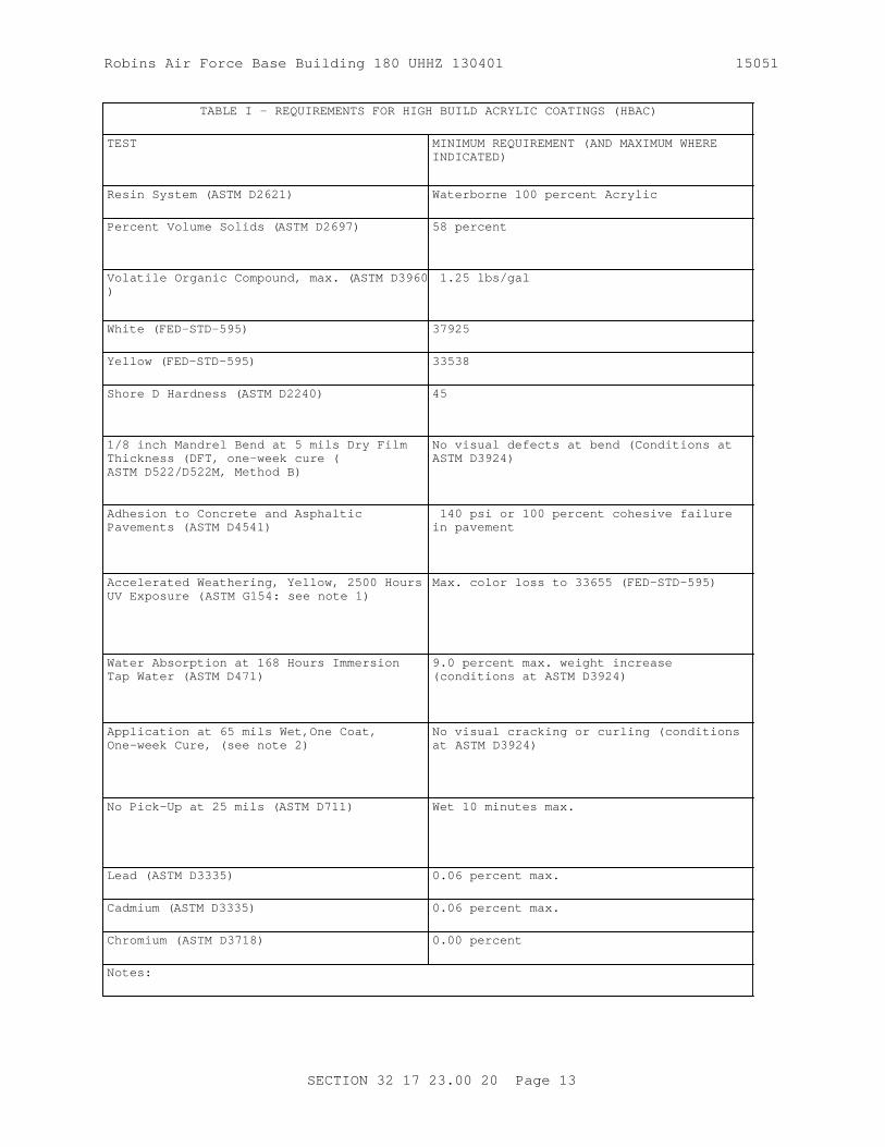
Robins Air Force Base Building 180 UHHZ 130401 15051
TABLE I - REQUIREMENTS FOR HIGH BUILD ACRYLIC COATINGS (HBAC)
TEST MINIMUM REQUIREMENT (AND MAXIMUM WHERE INDICATED)
Resin System ( ASTM D2621) Waterborne 100 percent Acrylic
Percent Volume Solids ( ASTM D2697) 58 percent
Volatile Organic Compound, max. ( ASTM D3960)
1.25 lbs/gal
White ( FED-STD-595 ) 37925
Yellow ( FED-STD-595 ) 33538
Shore D Hardness ( ASTM D2240) 45
1/8 inch Mandrel Bend at 5 mils Dry Film Thickness (DFT, one-week cure (ASTM D522/D522M, Method B)
No visual defects at bend (Conditions at ASTM D3924)
Adhesion to Concrete and Asphaltic Pavements ( ASTM D4541)
140 psi or 100 percent cohesive failure in pavement
Accelerated Weathering, Yellow, 2500 Hours UV Exposure ( ASTM G154: see note 1)
Max. color loss to 33655 ( FED-STD-595 )
Water Absorption at 168 Hours Immersion Tap Water ( ASTM D471)
9.0 percent max. weight increase (conditions at ASTM D3924)
Application at 65 mils Wet,One Coat, One-week Cure, (see note 2)
No visual cracking or curling (conditions at ASTM D3924)
No Pick-Up at 25 mils ( ASTM D711) Wet 10 minutes max.
Lead ( ASTM D3335) 0.06 percent max.
Cadmium ( ASTM D3335) 0.06 percent max.
Chromium ( ASTM D3718) 0.00 percent
Notes:
SECTION 32 17 23.00 20 Page 13

Robins Air Force Base Building 180 UHHZ 130401 15051
TABLE I - REQUIREMENTS FOR HIGH BUILD ACRYLIC COATINGS (HBAC)
TEST MINIMUM REQUIREMENT (AND MAXIMUM WHERE INDICATED)
(1) Properly mix and apply yellow paint at 10 mils plus or minus 2 mils DFT over a suitably sized, clean aluminum substrate ( ASTM D823), and cure for a minimum of 48 hours: four individual yellow samples shall be prepared. Expose three samples to continuous Ultraviolet (UV) light for 2500 hours, without cycles condensation, in accordance to ASTM G154: UVA-340 lamps shall be used in the testing apparatus. Following exposure, compare the three exposed samples to the "one" non-exposed sample using FED-STD-595 colors 33538 and 33655 as visual references: evaluate exposed samples for degree of visual color loss. Yellow paint shall receive a passing rating if each exposed sample appears equivalent to the non-exposed sample, and in addition, displays color loss no greater than FED-STD-595 color 33655.
(2) Using double-stick, foam mounting tape (or equal) with a nominal thickness of 65 mils, apply a rectangular mold with inner dimensions of 3 in by 10 in to a clean aluminum sample approximately sized at 6 in by 12 in by 1/8 in. Do not remove the tape's plastic backing. Mix and apply excess paint into mold. Remove excess paint, by squeegee or other appropriate draw down technique, to a uniform thickness equal to the tape's height. Paint application and draw down shall be performed within a period of no more than 60 seconds. Approximately one to two minutes following the draw down, remove tape from sample and allow coating to cure for a minimum period of one week ASTM D3924. Using a micrometer or other appropriate device, measure cured coating thickness (less sample thickness) to confirm resulting coating application was at or above 38 mils DFT. Inspect coating for visual signs of cracking and curling. Following a one week cure, coating shall receive a passing rating if applied greater than 38 mils DFT and visually free of both cracking and curling.
SECTION 32 17 23.00 20 Page 14

Robins Air Force Base Building 180 UHHZ 130401 15051
TABLE II - PREAPPROVED HBACs
MANUFACTURER PRODUCTS
TMT-Pathway1021 North Mission RoadLos Angeles, CA 90033(800) 338-7680
Legend Build, #2712A9, White
Legend Build, #2713A9, Yellow
Pervo Paints6624 Stanford AvenueLos Angeles, CA 90001(323) 758-1147
Pervo 6050, White
Pervo 6053, Yellow
Vogel Traffic Services1920 Albany Place SouthPO Box 140Orange City, IA 51041(712) 737-4016
UC-1516, White
UC-3588, Yellow
-- End of Section --
SECTION 32 17 23.00 20 Page 15

THIS PAGE INTENTIONALLY LEFT BLANK FOR DUPLEX PRINTING

Robins Air Force Base Building 180 UHHZ 130401 15051
Robins Air Force Base Building 180 UHHZ 130401
SECTION 33 11 00
WATER DISTRIBUTION02/11
PART 1 GENERAL
1.1 REFERENCES
The publications listed below form a part of this specification to the extent referenced. The publications are referred to within the text by the basic designation only.
AMERICAN ASSOCIATION OF STATE HIGHWAY AND TRANSPORTATION OFFICIALS (AASHTO)
AASHTO HB-17 (2002; Errata 2003; Errata 2005, 17th Edition) Standard Specifications for Highway Bridges
AMERICAN WATER WORKS ASSOCIATION (AWWA)
AWWA B300 (2010; Addenda 2011) Hypochlorites
AWWA B301 (2010) Liquid Chlorine
AWWA C600 (2010) Installation of Ductile-Iron Water Mains and Their Appurtenances
AWWA C651 (2014) Standard for Disinfecting Water Mains
AWWA C800 (2014) Underground Service Line Valves and Fittings
AWWA M11 (2004; 4th Ed; Errata 2013) Manual: Steel Water Pipe: A Guide for Design and Installation
AWWA M23 (2002; 2nd Ed) Manual: PVC Pipe - Design and Installation
AWWA M9 (2008; Errata 2013) Manual: Concrete Pressure Pipe
ASME INTERNATIONAL (ASME)
ASME B16.26 (2013) Standard for Cast Copper Alloy Fittings for Flared Copper Tubes
ASTM INTERNATIONAL (ASTM)
ASTM B61 (2015) Standard Specification for Steam or Valve Bronze Castings
ASTM B62 (2015) Standard Specification for Composition Bronze or Ounce Metal Castings
SECTION 33 11 00 Page 1

Robins Air Force Base Building 180 UHHZ 130401 15051
ASTM D1785 (2012) Standard Specification for Poly(Vinyl Chloride) (PVC), Plastic Pipe, Schedules 40, 80, and 120
ASTM D2241 (2015) Standard Specification for Poly(Vinyl Chloride) (PVC) Pressure-Rated Pipe (SDR Series)
ASTM D2774 (2012) Underground Installation of Thermoplastic Pressure Piping
ASTM D2855 (1996; R 2010) Standard Practice for Making Solvent-Cemented Joints with Poly(Vinyl Chloride) (PVC) Pipe and Fittings
ASTM F402 (2005; R 2012) Safe Handling of Solvent Cements, Primers, and Cleaners Used for Joining Thermoplastic Pipe and Fittings
MANUFACTURERS STANDARDIZATION SOCIETY OF THE VALVE AND FITTINGS INDUSTRY (MSS)
MSS SP-80 (2013) Bronze Gate, Globe, Angle and Check Valves
NATIONAL FIRE PROTECTION ASSOCIATION (NFPA)
NFPA 704 (2012) Standard System for the Identification of the Hazards of Materials for Emergency Response
UNI-BELL PVC PIPE ASSOCIATION (UBPPA)
UBPPA UNI-PUB-08 (2010) Tapping Guide for PVC Pressure Pipe)
1.2 DESIGN REQUIREMENTS
1.2.1 Water Service Lines
Provide water service line indicated as 2 inch line from water distribution main to temporary trailers at a point approximately 5 feet from building . Water service lines shall be polyvinyl chloride (PVC) plastic pipe. Ppolyvinyl chloride (PVC) plastic pipe appurtenances, and valves as specified for water mains may also be used for service lines. Provide water service line appurtenances as specified and where indicated.
1.3 SUBMITTALS
Government approval is required for submittals with a "G" designation; submittals not having a "G" designation are for Contractor Quality Control approval. Submit the following in accordance with Section 01300 SUBMITTALS AND CONTRACTOR-FURNISHED ITEMS:
SD-03 Product Data
SECTION 33 11 00 Page 2

Robins Air Force Base Building 180 UHHZ 130401 15051
Piping Materials
Water service line piping, fittings, joints, valves, and coupling
Corporation stops
Valve boxes
Submit manufacturer's standard drawings or catalog cuts. Include information concerning gaskets with submittal for joints and couplings.
SD-06 Test Reports
Bacteriological Disinfection; G.
Test results from commercial laboratory verifying disinfection
SD-07 Certificates
Water service line piping, fittings, joints, valves, and coupling
Certificates shall attest that tests set forth in each applicable referenced publication have been performed, whether specified in that publication to be mandatory or otherwise and that production control tests have been performed at the intervals or frequency specified in the publication. Other tests shall have been performed within 3 years of the date of submittal of certificates on the same type, class, grade, and size of material as is being provided for the project.
SD-08 Manufacturer's Instructions
Delivery, storage, and handling
Installation procedures for water piping
1.4 DELIVERY, STORAGE, AND HANDLING
1.4.1 Delivery and Storage
Inspect materials delivered to site for damage. Unload and store with minimum handling. Store materials on site in enclosures or under protective covering. Store plastic piping, jointing materials and rubber gaskets under cover out of direct sunlight. Do not store materials directly on the ground. Keep inside of pipes, fittings and valves free of dirt and debris.
1.4.2 Handling
Handle pipe, fittings, valves, and other accessories in a manner to ensure delivery to the trench in sound undamaged condition. Take special care to avoid injury to coatings and linings on pipe and fittings; make repairs if coatings or linings are damaged. Do not place any other material or pipe inside a pipe or fitting after the coating has been applied. Carry, do not drag pipe to the trench. Use of pinch bars and tongs for aligning or turning pipe will be permitted only on the bare ends of the pipe. The interior of pipe and accessories shall be thoroughly cleaned of foreign matter before being lowered into the trench and shall be kept clean during
SECTION 33 11 00 Page 3

Robins Air Force Base Building 180 UHHZ 130401 15051
laying operations by plugging or other approved method. Before installation, the pipe shall be inspected for defects. Material found to be defective before or after laying shall be replaced with sound material without additional expense to the Government. Store rubber gaskets that are not to be installed immediately, under cover out of direct sunlight.
1.4.2.1 Miscellaneous Plastic Pipe and Fittings
Handle Polyvinyl Chloride (PVC) pipe and fittings in accordance with the manufacturer's recommendations. Store plastic piping and jointing materials that are not to be installed immediately under cover out of direct sunlight.
Storage facilities shall be classified and marked in accordance with NFPA 704 .
PART 2 PRODUCTS
2.1 WATER DISTRIBUTION MAIN MATERIALS
2.1.1 Valves, Hydrants, and Other Water Main Accessories
2.1.1.1 Tracer Wire for Nonmetallic Piping
Provide bare copper or aluminum wire not less than 0.10 inch in diameter in sufficient length to be continuous over each separate run of nonmetallic pipe.
2.2 WATER SERVICE LINE MATERIALS
2.2.1 Piping Materials
2.2.1.1 Plastic Piping
Plastic pipe and fittings shall bear the seal of the National Sanitation Foundation (NSF) for potable water service. Plastic pipe and fittings shall be supplied from the same manufacturer.
b. Polyvinyl Chloride (PVC) Plastic Piping with Elastomeric-Gasket Joints:
Pipe shall conform to dimensional requirements of ASTM D1785 Schedule 40, with joints meeting the requirements of 150 psi working pressure, 200 psi hydrostatic test pressure, unless otherwise shown or specified.
c. Polyvinyl Chloride (PVC) Plastic Piping with Solvent Cement Joints:
Pipe shall conform to dimensional requirements of ASTM D1785 or ASTM D2241 with joints meeting the requirements of 150 psi working pressure and 200 psi hydrostatic test pressure.
2.2.2 Water Service Line Appurtenances
2.2.2.1 Corporation Stops
Ground key type; bronze, ASTM B61 or ASTM B62; and suitable for the working pressure of the system. Ends shall be suitable for solder-joint, or flared tube compression type joint. Threaded ends for inlet and outlet of corporation stops, AWWA C800; coupling nut for connection to flared copper tubing, ASME B16.26 .
SECTION 33 11 00 Page 4

Robins Air Force Base Building 180 UHHZ 130401 15051
2.2.2.2 Curb or Service Stops
Ground key, round way, inverted key type; made of bronze, ASTM B61 or ASTM B62; and suitable for the working pressure of the system. Ends shall be as appropriate for connection to the service piping. Arrow shall be cast into body of the curb or service stop indicating direction of flow.
2.2.2.3 Service Clamps
Service clamps used for repairing damaged cast-iron, steel, PVC or asbestos-cement pipe shall have a pressure rating not less than that of the pipe to be connected and shall be either the single or double flattened strap type. Clamps shall have a galvanized malleable-iron body with cadmium plated straps and nuts. Clamps shall have a rubber gasket cemented to the body.
2.2.2.4 Check Valves
Check valves shall be designed for a minimum working pressure of 150 psi or as indicated. Valves shall have a clear waterway equal to the full nominal diameter of the valve. Valves shall open to permit flow when inlet pressure is greater than the discharge pressure, and shall close tightly to prevent return flow when discharge pressure exceeds inlet pressure. The size of the valve, working pressure, manufacturer's name, initials, or trademark shall be cast on the body of each valve. Valves 2 inches and larger shall be outside lever and springtype.
Valves 2 inches and smaller shall be all bronze designed for screwed fittings, and shall conform to MSS SP-80 , Class 150, Types 3 and 4 as suitable for the application.
2.2.2.5 Gate Valves Smaller than 3 Inch in Size on Buried Piping
Gate valves smaller than 3 inch size on Buried Piping MSS SP-80 , Class 150, solid wedge, nonrising stem. Valves shall have flanged or threaded end connections, with a union on one side of the valve. Provide handwheel operators.
2.2.2.6 Curb Boxes
Provide a curb box for each curb or service stop. Curb boxes shall be of cast iron of a size suitable for the stop on which it is to be used. Provide a round head. Cast the word "WATER" on the lid. Each box shall have a heavy coat of bituminous paint.
2.2.2.7 Valve Boxes
Provide a valve box for each gate valve on buried piping. Valve boxes shall be of cast iron or precast concrete as indicated of a size suitable for the valve on which it is to be used and shall be adjustable. Precast concrete boxes installed in locations subjected to vehicular traffic shall be designed to withstand the following HS-20 AASHTO load designation as outline in AASHTO HB-17. Precast concrete boxes shall be manufactured in accordance with industry standards. Provide a round head. Cast the word "WATER" on the lid. The least diameter of the shaft of the box shall be 5 1/4 inches as indicated. Cast-iron box shall have a heavy coat of bituminous paint.
SECTION 33 11 00 Page 5

Robins Air Force Base Building 180 UHHZ 130401 15051
2.2.2.8 Disinfection
Chlorinating materials shall conform to the following:
Chlorine, Liquid: AWWA B301.
Hypochlorite, Calcium and Sodium: AWWA B300.
PART 3 EXECUTION
3.1 INSTALLATION OF PIPELINES
3.1.1 General Requirements for Installation of Pipelines
These requirements shall apply to all pipeline installation except where specific exception is made in the "Special Requirements..." paragraphs.
3.1.1.1 Location of Water Lines
Terminate the work covered by this section at a point approximately 5 feet from the trailers unless otherwise indicated. Where the location of the water line is not clearly defined by dimensions on the drawings, do not lay water line closer horizontally than 10 feet from any sewer line. Where water lines cross under gravity sewer lines, encase sewer line fully in concrete for a distance of at least 10 feet on each side of the crossing, unless sewer line is made of pressure pipe with rubber-gasketed joints and no joint is located within 3 feet horizontally of the crossing. Do not lay water lines in the same trench withelectric wiring.
Where water piping is required to be installed within 3 feet of existing structures, the water pipe shall be sleeved. Provide ductile-iron or Schedule 40 steel sleeves. Annular space between pipe and sleeves shall be filled with mastic. The Contractor shall install the water pipe and sleeve ensuring that there will be no damage to the structures and no settlement or movement of foundations or footings.
Terminate the work covered by this section at a point approximately 5 feet from the trailers unless otherwise indicated. Do not lay water lines in the same trench withelectric wiring.
a. Water Piping Installation Parallel With Sewer Piping
Normal Conditions: Lay water piping at least 10 feet horizontally from a sewer or sewer manhole whenever possible. Measure the distance edge-to-edge.
(1) The bottom (invert) of the water piping shall be at least 18 inches above the top (crown) of the sewer piping.
(2) Where this vertical separation cannot be obtained, the sewer piping shall be constructed of AWWA-approved water pipe and pressure tested in place without leakage prior to backfilling. Approved waste water disposal method shall be utilized.
(3) The sewer manhole shall be of watertight construction and tested in place.
b. Installation of Water Piping Crossing Sewer Piping
SECTION 33 11 00 Page 6

Robins Air Force Base Building 180 UHHZ 130401 15051
(1) Normal Conditions: Water piping crossing above sewer piping shall be laid to provide a separation of at least 18 inches between the bottom of the water piping and the top of the sewer piping.
(2) Unusual Conditions: When local conditions prevent a vertical separation described above, use the following construction:
(a) Sewer piping passing over or under water piping shall be constructed of AWWA-approved ductile iron water piping, pressure tested in place without leakage prior to backfilling.
(b) Water piping passing under sewer piping shall, in addition, be protected by providing a vertical separation of at least 18 inches between the bottom of the sewer piping and the top of the water piping; adequate structural support for the sewer piping to prevent excessive deflection of the joints and the settling on and breaking of the water piping; and that the length, minimum 20 feet, of the water piping be centered at the point of the crossing so that joints shall be equidistant and as far as possible from the sewer piping.
c. Sewer Piping or Sewer Manholes: No water piping shall pass through or come in contact with any part of a sewer manhole.
3.1.1.2 Earthwork
Perform earthwork operations in accordance with Section 31 00 00.
3.1.1.3 Pipe Laying and Jointing
Remove fins and burrs from pipe and fittings. Before placing in position, clean pipe, fittings, valves, and accessories, and maintain in a clean condition. Provide proper facilities for lowering sections of pipe into trenches. Do not under any circumstances drop or dump pipe, fittings, valves, or any other water line material into trenches. Cut pipe in a neat workmanlike manner accurately to length established at the site and work into place without springing or forcing. Replace by one of the proper length any pipe or fitting that does not allow sufficient space for proper installation of jointing material. Blocking or wedging between bells and spigots will not be permitted. Lay bell-and-spigot pipe with the bell end pointing in the direction of laying. Grade the pipeline in straight lines; avoid the formation of dips and low points. Support pipe at proper elevation and grade. Secure firm, uniform support. Wood support blocking will not be permitted. Lay pipe so that the full length of each section of pipe and each fitting will rest solidly on the pipe bedding; excavate recesses to accommodate bells, joints, and couplings. Provide anchors and supports where necessary for fastening work into place. Make proper provision for expansion and contraction of pipelines. Keep trenches free of water until joints have been properly made. At the end of each work day, close open ends of pipe temporarily with wood blocks or bulkheads. Do not lay pipe when conditions of trench or weather prevent installation. Depth of cover over top of pipe shall not be less than 2 1/2 feet.
3.1.1.4 Installation of Tracer Wire
Install a continuous length of tracer wire for the full length of each run
SECTION 33 11 00 Page 7

Robins Air Force Base Building 180 UHHZ 130401 15051
of nonmetallic pipe. Attach wire to top of pipe in such manner that it will not be displaced during construction operations.
3.1.1.5 Connections to Existing Water Lines
Make connections to existing water lines after approval is obtained and with a minimum interruption of service on the existing line. Make connections to existing lines under pressure in accordance with the recommended procedures of the manufacturer of the pipe being tapped.
3.1.2 Installation of Water Service Piping
3.1.2.1 Location
Connect water service piping to the building service where the building service has been installed. Where building service has not been installed, terminate water service lines approximately 5 feet from the building line at a point directed by the Contracting Officer; such water service lines shall be closed with plugs or caps.
3.1.2.2 Service Line Connections to Water Mains
Connect service lines 2 inch size to the main with a rigid connection or a corporation stop and gooseneck and install a gate valve on service line below the frostline. Connect service lines to ductile-iron water mains in accordance with AWWA C600 for service taps.Connect service lines to PVC plastic water mains in accordance with UBPPA UNI-PUB-08 and the recommendations of AWWA M23, Chapter 9, "Service Connections."Connect service lines to concrete water mains in accordance with the recommendations of AWWA M9, Chapter 12, "Tapping Concrete Pressure Pipe."Connect service lines to steel water mains in accordance with the recommendations of the steel water main pipe manufacturer and with the recommendations for special and valve connections and other appurtenances in AWWA M11, Chapter 13, "Supplementary Design Data and Details."
3.1.3 Special Requirements for Installation of Water Service Piping
3.1.3.1 Installation of Plastic Piping
Install pipe and fittings in accordance with paragraph entitled "General Requirements for Installation of Pipelines" and with the applicable requirements of ASTM D2774 and ASTM D2855, unless otherwise specified. Handle solvent cements used to join plastic piping in accordance with ASTM F402.
a. Jointing: Make solvent-cemented joints for PVC plastic piping using the solvent cement previously specified for this material; assemble joints in accordance with ASTM D2855. Make plastic pipe joints to other pipe materials in accordance with the recommendations of the plastic pipe manufacturer.
b. Plastic Pipe Connections to Appurtenances: Connect plastic pipe service lines to corporation stops and gate valves in accordance with the recommendations of the plastic pipe manufacturer.
3.1.4 Disinfection
Prior to disinfection, obtain Contracting Officer approval of the proposed method for disposal of waste water from disinfection procedures.
SECTION 33 11 00 Page 8

Robins Air Force Base Building 180 UHHZ 130401 15051
Disinfect new water piping and existing water piping affected by Contractor's operations in accordance with AWWA C651. Fill piping systems with solution containing minimum of 50 parts per million of available chlorine and allow solution to stand for minimum of 24 hours. Flush solution from the systems with domestic water until maximum residual chlorine content is within the range of 0.2 and 0.5 parts per million, or the residual chlorine content of domestic water supply. Obtain at least two consecutive satisfactory bacteriological samples from new water piping, analyze by a certified laboratory, and submit the results prior to the new water piping being placed into service. Disinfection of systems supplying nonpotable water is not required.
3.2 FIELD QUALITY CONTROL
3.2.1 Field Tests and Inspections
Prior to hydrostatic testing, obtain Contracting Officer approval of the proposed method for disposal of waste water from hydrostatic testing. The Contracting Officer will conduct field inspections and witness field tests specified in this section. The Contractor shall perform field tests, and provide labor, equipment, and incidentals required for testing . The Contractor shall produce evidence, when required, that any item of work has been constructed in accordance with the drawings and specifications.
3.2.2 Testing Procedure
3.2.2.1 Hydrostatic Testing
Test water mains and water service lines in accordance with the applicable specified standard.
3.2.2.2 Leakage Testing
For leakage test, use a hydrostatic pressure not less than the maximum working pressure of the system. Leakage test may be performed at the same time and at the same test pressure as the pressure test.
3.3 CLEANUP
Upon completion of the installation of water lines, and appurtenances, all debris and surplus materials resulting from the work shall be removed.
-- End of Section --
SECTION 33 11 00 Page 9

THIS PAGE INTENTIONALLY LEFT BLANK FOR DUPLEX PRINTING

Robins Air Force Base Building 180 UHHZ 130401 15051
Robins Air Force Base Building 180 UHHZ 130401
SECTION 33 30 00
SANITARY SEWERS04/08
PART 1 GENERAL
1.1 SUMMARY
1.1.1 Sanitary Sewer Gravity Pipeline
Provide laterals and building connections 4 inch lines of polyvinyl chloride (PVC) plastic pipe. Provide new and modify existing exterior sanitary gravity sewer piping and appurtenances. Provide each system complete and ready for operation. The exterior sanitary gravity sewer system includes equipment, materials, installation, and workmanship as specified herein more than 5 feet outside of building walls.
1.1.2 USAF Project
The construction required herein shall include appurtenant structures and building sewers to points of connection with the building drains 5 feet outside the building to which the sewer system is to be connected. Replace damaged material and redo unacceptable work at no additional cost to the Government. Backfilling shall be accomplished after inspection by the Contracting Officer. Before, during, and after installation, plastic pipe and fittings shall be protected from any environment that would result in damage or deterioration to the material. Keep a copy of the manufacturer's instructions available at the construction site at all times and shall follow these instructions unless directed otherwise by the Contracting Officer. Solvents, solvent compounds, lubricants, elastomeric gaskets, and any similar materials required to install the plastic pipe shall be stored in accordance with the manufacturer's recommendation and shall be discarded if the storage period exceeds the recommended shelf life. Solvents in use shall be discarded when the recommended pot life is exceeded.
1.2 REFERENCES
The publications listed below form a part of this specification to the extent referenced. The publications are referred to within the text by the basic designation only.
AMERICAN WATER WORKS ASSOCIATION (AWWA)
AWWA C104/A21.4 (2013) Cement-Mortar Lining for Ductile-Iron Pipe and Fittings for Water
AWWA C110/A21.10 (2012) Ductile-Iron and Gray-Iron Fittings for Water
AWWA C111/A21.11 (2012) Rubber-Gasket Joints for Ductile-Iron Pressure Pipe and Fittings
AWWA C153/A21.53 (2011) Ductile-Iron Compact Fittings for Water Service
SECTION 33 30 00 Page 1

Robins Air Force Base Building 180 UHHZ 130401 15051
AWWA C600 (2010) Installation of Ductile-Iron Water Mains and Their Appurtenances
ASTM INTERNATIONAL (ASTM)
ASTM A746 (2009; R 2014) Standard Specification for Ductile Iron Gravity Sewer Pipe
ASTM C924 (2002; R 2009) Testing Concrete Pipe Sewer Lines by Low-Pressure Air Test Method
ASTM C969 (2002; R 2009) Standard Practice for Infiltration and Exfiltration Acceptance Testing of Installed Precast Concrete Pipe Sewer Lines
ASTM D2321 (2014; E 2014) Standard Practice for Underground Installation of Thermoplastic Pipe for Sewers and Other Gravity-Flow Applications
ASTM D2680 (2001; R 2014) Standard Specification for Acrylonitrile-Butadiene-Styrene (ABS) and Poly(Vinyl Chloride) (PVC) Composite Sewer Piping
ASTM D2751 (2005) Standard Specification for Acrylonitrile-Butadiene-Styrene (ABS) Sewer Pipe and Fittings
ASTM D3034 (2014a) Standard Specification for Type PSM Poly(Vinyl Chloride) (PVC) Sewer Pipe and Fittings
ASTM D3212 (2007; R 2013) Standard Specification for Joints for Drain and Sewer Plastic Pipes Using Flexible Elastomeric Seals
ASTM F477 (2014) Standard Specification for Elastomeric Seals (Gaskets) for Joining Plastic Pipe
ASTM F949 (2015) Poly(Vinyl Chloride) (PVC) Corrugated Sewer Pipe with a Smooth Interior and Fittings
UNI-BELL PVC PIPE ASSOCIATION (UBPPA)
UBPPA UNI-B-6 (1998) Recommended Practice for Low-Pressure Air Testing of Installed Sewer Pipe
1.3 SUBMITTALS
Government approval is required for submittals with a "G" designation; submittals not having a "G" designation are for Contractor Quality Control approval. Submit the following in accordance with Section 01300 SUBMITTALS AND CONTRACTOR-FURNISHED ITEMS:
SECTION 33 30 00 Page 2

Robins Air Force Base Building 180 UHHZ 130401 15051
SD-01 Preconstruction Submittals
Existing Conditions
SD-03 Product Data
Pipeline materials; G
SD-07 Certificates
Portland Cement; GGaskets; G
1.4 QUALITY ASSURANCE
1.4.1 Installer Qualifications
Install specified materials by a licensed underground utility Contractor licensed for such work in the state where the work is to be performed. Installing Contractor's License shall be current and be state certified or state registered.
1.4.2 Drawings
a. Submit Installation Drawings showing complete detail, both plan and side view details with proper layout and elevations.
b. Submit As-Built Drawings for the complete sanitary sewer system showing complete detail with all dimensions, both above and below grade, including invert elevation.
1.5 DELIVERY, STORAGE, AND HANDLING
1.5.1 Delivery and Storage
1.5.1.1 Piping
Inspect materials delivered to site for damage; store with minimum of handling. Store materials on site in enclosures or under protective coverings. Store plastic piping and jointing materials and rubber gaskets under cover out of direct sunlight. Do not store materials directly on the ground. Keep inside of pipes and fittings free of dirt and debris.
1.5.1.2 Metal Items
Check upon arrival; identify and segregate as to types, functions, and sizes. Store off the ground in a manner affording easy accessibility and not causing excessive rusting or coating with grease or other objectionable materials.
1.5.1.3 Cement, Aggregate, and Reinforcement
As specified in CAST-IN-PLACE CONCRETE section.
1.5.2 Handling
Handle pipe, fittings, and other accessories in such manner as to ensure delivery to the trench in sound undamaged condition.Carry, do not drag,
SECTION 33 30 00 Page 3

Robins Air Force Base Building 180 UHHZ 130401 15051
pipe to trench.
1.6 PROJECT/SITE CONDITIONS
Submit drawings of existing conditions, after a thorough inspection of the area in the presence of the Contracting Officer. Details shall include the environmental conditions of the site and adjacent areas. Submit copies of the records for verification before starting work.
PART 2 PRODUCTS
2.1 PIPELINE MATERIALS
Pipe shall conform to the respective specifications and other requirements specified below. Submit manufacturer's standard drawings or catalog cuts.
2.1.1 Ductile Iron Gravity Sewer Pipe and Associated Fittings
2.1.1.1 Ductile Iron Gravity Pipe and Fittings
Ductile iron pipe shall conform to ASTM A746, Thickness Class 51. Fittings shall conform to AWWA C110/A21.10 or AWWA C153/A21.53 . Fittings with push-on joint ends shall conform to the same requirements as fittings with mechanical-joint ends, . Fittings shall have strength at least equivalent to that of the pipe. Ends of pipe and fittings shall be suitable for the joints specified hereinafter. Pipe and fittings shall have cement-mortar lining conforming to AWWA C104/A21.4 , standard thickness.
2.1.1.2 Ductile Iron Gravity Joints and Jointing Materials
Pipe and fittings shall have push-on joints, except as otherwise specified in this paragraph. Push-on joint pipe ends and fitting ends, gaskets, and lubricant for joint assembly shall conform to AWWA C111/A21.11 .
2.1.2 PVC Plastic Gravity Sewer Piping
2.1.2.1 PVC Plastic Gravity Pipe and Fittings
ASTM D3034, SDR 35, or ASTM F949 with ends suitable for elastomeric gasket joints.
2.1.2.2 PVC Plastic Gravity Joints and Jointing Material
Joints shall conform to ASTM D3212. Gaskets shall conform to ASTM F477.
2.2 REPORTS
Compaction and density test shall be in accordance with Section 31 00 00 EARTHWORK. Submit Test Reports. Submit Inspection Reports for daily activities during the installation of the sanitary system. Information in the report shall be detailed enough to describe location of work and amount of pipe laid in place, measured in linear feet.
SECTION 33 30 00 Page 4

Robins Air Force Base Building 180 UHHZ 130401 15051
PART 3 EXECUTION
3.1 INSTALLATION OF PIPELINES AND APPURTENANT CONSTRUCTION
3.1.1 General Requirements for Installation of Pipelines
These general requirements apply except where specific exception is made in the following paragraphs entitled "Special Requirements."
3.1.1.1 Location
The work covered by this section shall terminate at a point approximately 5 feet from the building . Where the location of the sewer is not clearly defined by dimensions on the drawings, do not lay sewer line closer horizontally than 10 feet to a water main or service line.
3.1.1.1.1 Sanitary Piping Installation Parallel with Water Line
3.1.1.1.1.1 Normal Conditions
Sanitary piping or manholes shall be laid at least 10 feet horizontally from a water line whenever possible. The distance shall be measured edge-to-edge.
3.1.1.1.1.2 Unusual Conditions
When local conditions prevent a horizontal separation of 10 feet, the sanitary piping or manhole may be laid closer to a water line provided that:
a. The top (crown) of the sanitary piping shall be at least 18 inches below the bottom (invert) of the water main.
b. Where this vertical separation cannot be obtained, the sanitary piping shall be constructed of AWWA-approved ductile iron water pipe pressure tested in place without leakage prior to backfilling.
c. The sewer manhole shall be of watertight construction and tested in place.
3.1.1.1.2 Installation of sanitary Piping Crossing a Water Line
3.1.1.1.2.1 Normal Conditions
Lay sanitary sewer piping by crossing under water lines to provide a separation of at least 18 inches between the top of the sanitary piping and the bottom of the water line whenever possible.
3.1.1.1.2.2 Unusual Conditions
When local conditions prevent a vertical separation described above, use the following construction:
a. Sanitary piping passing over or under water lines shall be constructed of AWWA-approved ductile iron water pipe, pressure tested in place without leakage prior to backfilling.
b. Sanitary piping passing over water lines shall, in addition, be protected by providing:
SECTION 33 30 00 Page 5

Robins Air Force Base Building 180 UHHZ 130401 15051
(1) A vertical separation of at least 18 inches between the bottom of the sanitary piping and the top of the water line.
(2) Adequate structural support for the sanitary piping to prevent excessive deflection of the joints and the settling on and breaking of the water line.
(3) That the length, minimum 20 feet, of the sanitary piping be centered at the point of the crossing so that joints shall be equidistant and as far as possible from the water line.
3.1.1.2 Earthwork
Perform earthwork operations in accordance with Section 31 00 00 EARTHWORK.
3.1.1.3 Pipe Laying and Jointing
Inspect each pipe and fitting before and after installation; replace those found defective and remove from site. Provide proper facilities for lowering sections of pipe into trenches. Lay nonpressure pipe with the bell or groove ends in the upgrade direction. Adjust spigots in bells and tongues in grooves to give a uniform space all around. Blocking or wedging between bells and spigots or tongues and grooves will not be permitted. Replace by one of the proper dimensions, pipe or fittings that do not allow sufficient space for installation of joint material. At the end of each work day, close open ends of pipe temporarily with wood blocks or bulkheads. Provide batterboards not more than 25 feet apart in trenches for checking and ensuring that pipe invert elevations are as indicated. Laser beam method may be used in lieu of batterboards for the same purpose. Branch connections shall be made by use of regular fittings or solvent cemented saddles as approved. Saddles for ABS and PVC composite pipe shall conform to Figure 2 of ASTM D2680; saddles for ABS pipe shall comply with Table 3 of ASTM D2751; and saddles for PVC pipe shall conform to Table 4 of ASTM D3034.
3.1.1.4 Connections to Existing Lines
Obtain approval from the Contracting Officer before making connection to existing line. Conduct work so that there is minimum interruption of service on existing line.
3.1.2 Special Requirements
3.1.2.1 Installation of Ductile Iron Gravity Sewer Pipe
Unless otherwise specified, install pipe and associated fittings in accordance with paragraph entitled "General Requirements for Installation of Pipelines" of this section and with the requirements of AWWA C600 for pipe installation and joint assembly.
a. Make push-on joints with the gaskets and lubricant specified for this type joint and assemble in accordance with the applicable requirements of AWWA C600 for joint assembly.
3.1.2.2 Installation of PVC Plastic Piping
Install pipe and fittings in accordance with paragraph entitled "General Requirements for Installation of Pipelines" of this section and with the
SECTION 33 30 00 Page 6

Robins Air Force Base Building 180 UHHZ 130401 15051
requirements of ASTM D2321 for laying and joining pipe and fittings. Make joints with the gaskets specified for joints with this piping and assemble in accordance with the requirements of ASTM D2321 for assembly of joints. Make joints to other pipe materials in accordance with the recommendations of the plastic pipe manufacturer.
3.1.3 Miscellaneous Construction and Installation
3.1.3.1 Connecting to Existing Manholes
Pipe connections to existing manholes shall be made so that finish work will conform as nearly as practicable to the applicable requirements specified for new manholes, including all necessary concrete work, cutting, and shaping. The connection shall be centered on the manhole. Holes for the new pipe shall be of sufficient diameter to allow packing cement mortar around the entire periphery of the pipe but no larger than 1.5 times the diameter of the pipe. Cutting the manhole shall be done in a manner that will cause the least damage to the walls.
3.1.4 Installations of Wye Branches
Cutting into piping for connections shall not be done except in special approved cases. When the connecting pipe cannot be adequately supported on undisturbed earth or tamped backfill, the pipe shall be encased in concrete backfill or supported on a concrete cradle as directed. Concrete required because of conditions resulting from faulty construction methods or negligence shall be installed at no additional cost to the Government. The installation of wye branches in an existing sewer shall be made by a method which does not damage the integrity of the existing sewer. One acceptable method consists of removing one pipe section, breaking off the upper half of the bell of the next lower section and half of the running bell of wye section. After placing the new section, it shall be rotated so that the broken half of the bell will be at the bottom. The two joints shall then be made with joint packing and cement mortar.
3.2 FIELD QUALITY CONTROL
3.2.1 Field Tests and Inspections
The Contracting Officer will conduct field inspections and witness field tests specified in this section. Perform field tests and provide labor, equipment, and incidentals required for testing. Be able to produce evidence, when required, that each item of work has been constructed in accordance with the drawings and specifications.
3.2.2 Tests for Nonpressure Lines
Check each straight run of pipeline for gross deficiencies by holding a light in a manhole; it shall show a practically full circle of light through the pipeline when viewed from the adjoining end of line. When pressure piping is used in a nonpressure line for nonpressure use, test this piping as specified for nonpressure pipe.
3.2.2.1 Leakage Tests
Test lines for leakage by either infiltration tests or exfiltration tests, or by low-pressure air tests. Prior to testing for leakage, backfill trench up to at least lower half of pipe. When necessary to prevent pipeline movement during testing, place additional backfill around pipe
SECTION 33 30 00 Page 7

Robins Air Force Base Building 180 UHHZ 130401 15051
sufficient to prevent movement, but leaving joints uncovered to permit inspection. When leakage or pressure drop exceeds the allowable amount specified, make satisfactory correction and retest pipeline section in the same manner. Correct visible leaks regardless of leakage test results.
3.2.2.1.1 Infiltration Tests and Exfiltration Tests
Perform these tests for sewer lines made of the specified materials, not only concrete, in accordance with ASTM C969. Make calculations in accordance with the Appendix to ASTM C969.
3.2.2.1.2 Low-Pressure Air Tests
Perform tests as follows: 3.2.2.1.2.1 Ductile-Iron Pipelines
Test in accordance with the applicable requirements of ASTM C924. Allowable pressure drop shall be as given in ASTM C924. Make calculations in accordance with the Appendix to ASTM C924.
3.2.2.1.2.2 PVC Plastic Pipelines
Test in accordance with UBPPA UNI-B-6 . Allowable pressure drop shall be as given in UBPPA UNI-B-6 . Make calculations in accordance with the Appendix to UBPPA UNI-B-6 .
3.2.3 Field Tests for Concrete
Field testing requirements are covered in CAST-IN-PLACE CONCRETE section.
-- End of Section --
SECTION 33 30 00 Page 8

APPENDIX AGeotechnical Report

THIS PAGE INTENTIONALLY LEFT BLANK FOR DUPLEX PRINTING

GEOTECHNICAL EXPLORATION PROGRAM ADDITION/ALTERATIONS TO AIRCRAFT
CORROSION CONTROL FACILITY, BUILDING 180
PROJECT UHHZ130401 ROBINS AIR FORCE BASE
WARNER ROBINS, HOUSTON COUNTY, GEORGIA
UES PROJECT NO. 1730.1500098.0000 UES DOCS REPORT NO. 1266503
September 21, 2015
Prepared For:
Mr. Amir S. Fallahi, P.E. CFM AECOM
1000 Abernathy Road Northeast, Suite 600 Atlanta, Georgia 30328
Prepared By:
UNIVERSAL ENGINEERING SCIENCES 1203 North Central Avenue, Suite 3
Tifton, Georgia 31794 (229) 834-5330
Consultants In: Geotechnical Engineering • Environmental Sciences • Geophysical Services • Construction Materials Testing • Threshold Inspection • Building Inspection • Private Provider Inspection • Building Code Administration
UNIVERSAL ENGINEERING SCIENCES

i
September 21, 2015 Mr. Amir S. Fallahi, P.E. CFM AECOM 1000 Abernathy Road Northeast Suite 900 Atlanta, Georgia 30328 Reference: Geotechnical Exploration Report Building 180 Addition
Robins Air Force Base Warner Robins, Houston County, Georgia UES Project No. 1730.1500098.0000 UES Docs Report No. 1266503
Dear Mr. Fallahi: Universal Engineering Sciences, Inc. (UES) has completed a geotechnical exploration at the above referenced site at Robins Air Force Base in Warner Robins, Houston County, Georgia. These services were provided in general accordance with our Proposal No. 1256167 dated August 11, 2015. The following report presents the results of our field exploration with a geotechnical engineering interpretation of those results with respect to the project characteristics as provided to us. We have included our estimates of the seasonal high groundwater level at our boring location and geotechnical recommendations for foundation design, and site preparation. We appreciate the opportunity to have worked with you on this project and look forward to a continued association. Please contact the undersigned if you have any questions, or if we may further assist you as your plans proceed. Respectfully submitted, UNIVERSAL ENGINEERING SCIENCES, INC.
Michael D. Reed, P.E. Jeffrey Pruett, P.E. Geotechnical Services Manager - Tifton Regional Manager – Tifton Georgia P.E. No. 38588 Georgia P.E. No. 23644 Distribution: Client (2) and .Pdf via e-mail
1203 North Central Avenue, Suite 3 • Tifton, Georgia 31794 • (229) 834-5330 • Fax (850) 944-5885
OFFICES IN • Daytona Beach, FL • Fort Myers, FL • Gainesville, FL • Jacksonville, FL • Norcross, GA • Ocala, FL • Orlando, FL • Miami, FL • Palm Coast, FL • Panama City, FL • Pensacola, FL • Rockledge, FL • Sarasota, FL • St. Augustine, FL • Tampa, FL • Tifton, GA • West Palm Beach, FL

ii
TABLE OF CONTENTS
1.0 INTRODUCTION ................................................................................................... 1 1.1 GENERAL ................................................................................................................. 1
2.0 SCOPE OF SERVICE ........................................................................................... 1 2.1 PROJECT DESCRIPTION ....................................................................................... 1 2.2 PURPOSE ................................................................................................................ 1 2.3 GEOTECHNICAL EXPLORATION ........................................................................... 2 2.4 LABORATORY TESTING PROGRAM ..................................................................... 2
2.4.1 Visual Classification ........................................................................................... 2 2.4.2 Laboratory Index Testing ................................................................................... 3
3.0 FINDINGS ............................................................................................................. 3 3.1 USDA NRCS SOIL SURVEY .................................................................................... 3 3.2 SURFACE CONDITIONS ......................................................................................... 4 3.3 SUBSURFACE CONDITIONS .................................................................................. 4
4.0 RECOMMENDATIONS ......................................................................................... 4 4.1 GEOTECHNICAL ASSESSMENT ............................................................................ 4 4.2 GROUNDWATER CONSIDERATIONS ................................................................... 5
4.2.1 Temporary Groundwater Control ....................................................................... 6 4.3 BUILDING FOUNDATION RECOMMENDATIONS ................................................. 6
4.3.1 General .............................................................................................................. 6 4.3.2 Bearing Pressure ............................................................................................... 6 4.3.3 Foundation Size ................................................................................................. 7 4.3.4 Bearing Depth .................................................................................................... 7 4.3.5 Bearing Material ................................................................................................. 7 4.3.6 Settlement Estimates ......................................................................................... 8 4.3.7 Floor Slab ........................................................................................................... 8
4.4 SITE PREPARATION ............................................................................................... 9 4.5 CONSTRUCTION RELATED SERVICES .............................................................. 11
4.5.1 Excavation and Safety ..................................................................................... 11
5.0 LIMITATIONS ..................................................................................................... 12

iii
LIST OF TABLES TABLE 1: SUMMARY OF SOIL SURVEY INFORMATION .......................................................... 3 TABLE 2: GENERAL SOIL PROFILE ........................................................................................... 4
LIST OF APPENDICES
SITE VICINITY MAP ..................................................................................................................... A USDA NRCS SOIL SURVEY MAP ............................................................................................... A BORING LOCATION PLAN .......................................................................................................... B BORING LOG ............................................................................................................................... B KEY TO BORING LOG ................................................................................................................. B FIELD PROCEDURES ................................................................................................................. B LABORATORY TESTING PROCEDURES ................................................................................. C ASFE DOCUMENT, CONSTRAINTS AND RESTRICTIONS ...................................................... D

Reference: Geotechnical Exploration Report Addition/Alterations to Aircraft Corrosion Control Facility, Building 180 Project UHHZ130401 Robins AFB, Houston County, Georgia UES Project No. 1730.1500098.0000 UES Docs Report No. 1266503
1
1.0 INTRODUCTION 1.1 GENERAL In this report, we present the results of the subsurface exploration of the site for the proposed addition to building 180 at the Robins Air Force Base. We have divided this report into the following sections:
SCOPE OF SERVICES - Defines what we did FINDINGS - Describes what we encountered RECOMMENDATIONS - Describes what we encourage you to do LIMITATIONS - Describes the restrictions inherent in this report APPENDICES - Presents support materials referenced in this report.
2.0 SCOPE OF SERVICE
2.1 PROJECT DESCRIPTION Project information was provided to us by the client via email. The subject parcel is located at the northwest corner of building 180, near the intersection of First Street and Milledgeville Street at Robins Air Force Base in Warner Robins, Houston County, Georgia. We understand that the proposed development will consist of constructing a single story addition to the existing building. Preliminary structural loading information was not provided by the client at the time of this report. We have assumed the structure will have column loads on the order of 50 kips or less with wall loads on the order of 3 kips/ft. We anticipate that minimal (i.e. less than 3 feet of) structural fill will be necessary to achieve finished grades in the proposed building area. Our recommendations are based upon the above supplied or assumed information. If any of this information is incorrect, or changes, please inform Universal Engineering Sciences so that we may review our recommendations. Without such a review, the recommendations herein may not be valid. No other site or project facilities should be designed using the soil information contained herein. As such, UES will not be responsible for the performance of any other site improvement designed using the data in this report. 2.2 PURPOSE The purposes of this exploration program were:

Reference: Geotechnical Exploration Report Addition/Alterations to Aircraft Corrosion Control Facility, Building 180 Project UHHZ130401 Robins AFB, Houston County, Georgia UES Project No. 1730.1500098.0000 UES Docs Report No. 1266503
2
To explore the general subsurface conditions in the building addition area;
To interpret and review the subsurface conditions with respect to the proposed construction;
To perform a series of laboratory tests on selected soil samples to assist with engineering soil classifications and to establish relevant soil engineering characteristics; and,
To provide geotechnical engineering recommendations for groundwater control, foundation design, and site preparation.
This report presents an evaluation of site conditions on the basis of traditional geotechnical procedures for site characterization. The recovered samples were not examined, either visually or analytically, for chemical composition or environmental hazards. Universal Engineering Sciences would be pleased to perform these services, if you desire. Our exploration was confined to the zone of soil likely to be stressed by the proposed construction. Our work did not address the potential for surface expression of deep geological conditions. This evaluation requires a more extensive range of field services than performed in this study. We will be pleased to provide a proposal for an exploration to evaluate the probable effect of the regional geology upon the proposed construction, if you desire. 2.3 GEOTECHNICAL EXPLORATION To explore the subsurface conditions present on the proposed site, we located and drilled one (1), 20-feet deep Standard Penetration Test (SPT) boring within the area of the proposed building footprint. The SPT boring was performed in general accordance with the methodology outlined in ASTM D 1586. A summary of this field procedure has been included in Appendix B. Split-spoon soil samples recovered during performance of the boring were visually classified in the field and representative portions of the samples were transported to our laboratory for further evaluation. 2.4 LABORATORY TESTING PROGRAM 2.4.1 Visual Classification Upon completion of the field tests and sampling, recovered representative samples of the soils were placed in labeled plastic containers, sealed, and transported to our laboratory for further visual examination and classification. Samples of the soils found will be held in our laboratory for your inspection for 90 days and then discarded unless we are notified otherwise. The soil samples collected on site were visually classified in

Reference: Geotechnical Exploration Report Addition/Alterations to Aircraft Corrosion Control Facility, Building 180 Project UHHZ130401 Robins AFB, Houston County, Georgia UES Project No. 1730.1500098.0000 UES Docs Report No. 1266503
3
general accordance with the USCS Soil Classification System (ASTM D1587). A summary of the resulting soil descriptions are shown on the Boring Log presented in Appendix B. 2.4.2 Laboratory Index Testing Laboratory soil tests were performed on selected soil samples obtained from the test boring to aid in the classification of the soils and to help in the evaluation of pertinent engineering characteristics of the soils. The classifications and laboratory testing completed for this project consisted of performing the following procedures/tests in general accordance with the methods listed and at the quantities specified.
Soil Classification per the Unified Soil Classification System – ASTM D 1587 Two (2), Natural Moisture Content Tests – ASTM D 2216 Two (2), Percent - 200 Soil Fines Content Tests – ASTM D 1140 Two (2), Atterberg Limits – Standard Test Method for Liquid Limits, Plastic
Limits, and Plasticity Index of Soils – ASTM D 4318 Detailed explanations of these procedures/tests are attached in Appendix C. The results of the tests are summarized on the boring logs presented in the Appendix B.
3.0 FINDINGS 3.1 USDA NRCS SOIL SURVEY Based on the Web Soil Survey for Houston County, Georgia, as prepared by the USDA NRCS, the predominant, pre-development soil type at the site is identified as LcB – Lucy Sand, 0 to 5 percent slopes. A summary of the characteristics of these soil series were obtained from the USDA SCS Soil Survey of Houston County, Georgia, and is included in Table 1. Please note the soils presented in the table below are the pre-development soils and may have been altered during the past development of the site.
Table 1 – Summary of Soil Survey Information
Soil Type Constituents Internal Drainage
Soil Permeability Corrosion Potential Seasonal
High Water Table (ft) Depth (in) Perm
(in/hr) Steel Concrete
LcB – Lucy Sand, 0 to 5
percent slopes
SM, SP-SM, SC-SM, SC Well Drained
0 - 24 24 – 35 35 – 70
6.0 - 20 2.0 – 6.0 0.6 – 2.0
Moderate Moderate Greater than 6.5

Reference: Geotechnical Exploration Report Addition/Alterations to Aircraft Corrosion Control Facility, Building 180 Project UHHZ130401 Robins AFB, Houston County, Georgia UES Project No. 1730.1500098.0000 UES Docs Report No. 1266503
4
3.2 SURFACE CONDITIONS UES personnel visited the project site during the performance of the field portion of this geotechnical study. At the time of UES’ field exploration program, the subject site consisted of an open, previously developed area with existing asphalt paving and sidewalks. 3.3 SUBSURFACE CONDITIONS The general subsurface conditions encountered during the subsurface exploration are described in Table 2. For more detailed soil descriptions and stratifications at the boring location, the Boring Log presented in the Appendix should be reviewed. Also, see Appendix B: Soils Classification Chart, for further explanation of the symbols and placement of data on the Boring Log. The Boring Log represents our interpretation of the subsurface conditions based on a review of the field log, an engineering examination of the samples, and a limited number of laboratory tests. The horizontal stratification lines designating the interface between various strata represent approximate boundaries. Transition between different strata in the field may be gradual in both the horizontal and vertical directions. Groundwater encountered in the boring and noted on the “Boring Log” represents conditions only at the time of the exploration. Table 2: General Soil Profile, summarizes the soil conditions found.
Table 2 – General Soil Profile
Stratum No.
Typical depth (ft) Soil Descriptions Range of SPT “N”
Blow Counts From To
1 0 0.17 Asphalt N/A
2 0.17 0.67 Compacted base material N/A
3 0.67 20 Loose to medium dense silty, clayey and poorly graded SAND [SM, SC & SP] 5 to 15
[ ] Brackets indicate Unified Soil Classification System (ASTM D 2487)
Two inches of asphalt underlain by 6 inches of compacted base material was encountered in the boring. At the time of our field exploration, the groundwater table was encountered at a depth of approximately 6.5 feet.
4.0 RECOMMENDATIONS 4.1 GEOTECHNICAL ASSESSMENT In this section of the report, we present recommendations for foundation and pavement design, site preparation, and construction related services. The following geotechnical

Reference: Geotechnical Exploration Report Addition/Alterations to Aircraft Corrosion Control Facility, Building 180 Project UHHZ130401 Robins AFB, Houston County, Georgia UES Project No. 1730.1500098.0000 UES Docs Report No. 1266503
5
design recommendations have been developed on the basis of the previously described project characteristics and subsurface conditions encountered. If there are any changes in these project criteria, including the building addition location on the site, a review should be made by UES to determine if modifications to the recommendations are warranted. Once final design plans and specifications are available, a general review by UES is recommended as a means to check that the evaluations made in preparation of this report are correct and that earthwork and foundation recommendations are properly interpreted and implemented. Based on the results of the fieldwork, laboratory evaluation and engineering analyses, we have identified the following potential constraints to the development of this site including the presence of loose surficial moisture-sensitive soils and the potential for a shallow (i.e. perched) groundwater table. The following sections discuss our findings and professional opinions for remediation of the subject site for the proposed construction. We believe with proper planning and execution, the site can be adapted for the proposed structures and associated improvements. 4.2 GROUNDWATER CONSIDERATIONS The groundwater table will fluctuate seasonally depending upon local rainfall. The typical wet season groundwater table is defined as the highest groundwater level sustained for a period of 2 to 4 weeks during the "wet" season of the year, for existing site conditions, in a year with average normal rainfall amounts. Groundwater was encountered at a depth of 6.5 feet below existing grade in the boring at the time of our field work. Based upon our review of U.S.G.S. data, Houston County Soils Survey, and regional hydrogeology, we estimate that the normal seasonal high groundwater table (SHWT) may be encountered at a depth of approximately 6.5 to 7 feet below the existing surface. There is the potential for a perched groundwater table directly above the silty (SM) layer if construction is attempted during the wet season or soon after a higher than normal amount of rainfall. The normal seasonal high water table is affected by a number of factors. The drainage characteristic of the soils, the land surface elevation, relief points such as lakes, rivers, swamp areas, etc., and distance to relief points are some of the more important factors influencing the normal seasonal high water table elevation. We recommend positive surface gradients be established and maintained away from the foundation areas. Sidewalks and planter areas that trap water against the foundations should be avoided. We further recommend permanent drainage measures, such as installation of downspouts discharging onto pavements with positive drainage away from foundations and into the stormwater system. We recommend the grading, drainage and foundation designs account for the potential perched water conditions.

Reference: Geotechnical Exploration Report Addition/Alterations to Aircraft Corrosion Control Facility, Building 180 Project UHHZ130401 Robins AFB, Houston County, Georgia UES Project No. 1730.1500098.0000 UES Docs Report No. 1266503
6
It should be understood that the estimated SHWT is independent of the actual location of the groundwater level and does not provide any assurance that groundwater levels will not exceed this level in the future. Should impediments to surface water drainage exist on the site, or should rainfall intensity and duration exceed the normally anticipated amounts, groundwater levels may exceed our seasonal high estimate. 4.2.1 Temporary Groundwater Control If encountered during construction, we recommend that the groundwater table be lowered and maintained at a depth of at least 2 feet below bearing levels and excavation bottoms. Dewatering may consist of ditching, well points, or other means. However, groundwater control means and methods are the sole responsibility of the contractor. Furthermore, we recommend that the contractor determine the actual groundwater levels at the time of construction to determine the groundwater impact on the construction procedures. If groundwater is encountered during trenching or foundation installation, Universal Engineering should be notified so that we can determine whether there is a need for underslab drainage, perimeter drains, or other recommendations for dewatering. 4.3 BUILDING FOUNDATION RECOMMENDATIONS 4.3.1 General Our foundation recommendations presented below are contingent upon the successful implementation and completion of the building pad preparation outlined herein. Furthermore, our evaluation and recommendations are based on the project information outlined previously, the field exploration, and the laboratory test results. If the structural loading, geometry, alignment, or grading (cut and/or fill) of the building pad differ from those outlined herein, or if conditions are encountered during construction differ from those encountered at the widely spaced test boring locations, UES requests the opportunity to review the recommendations presented herein based on the new information and make revisions or modifications, if needed. 4.3.2 Bearing Pressure The maximum allowable net soil bearing pressure for use in the shallow foundation design should not exceed 2,500 pounds per square foot for code dead and live loads plus any short duration loadings. This bearing pressure assumes the surficial soils to a depth of 2 feet beneath foundations are densified to at least 95 percent of the Modified Proctor maximum dry density (ASTM D 1557) prior to foundation construction.

Reference: Geotechnical Exploration Report Addition/Alterations to Aircraft Corrosion Control Facility, Building 180 Project UHHZ130401 Robins AFB, Houston County, Georgia UES Project No. 1730.1500098.0000 UES Docs Report No. 1266503
7
Net bearing pressure is defined as the soil bearing pressure at the base of the foundation in excess of the natural overburden pressure. The foundations should be designed based upon the maximum load that could be imposed by all loading conditions. 4.3.3 Foundation Size The minimum widths recommended for any isolated column footings and continuous wall footings are 24 inches and 18 inches, respectively. Even though the maximum allowable net soil bearing pressure may not be achieved, these width recommendations should control the minimum size of the foundations. Where cut operations must extend below the exiting buildings’ foundation bearing elevations, and extend laterally within five feet of the same existing foundations, the stability of the existing foundations should be addressed by the Structural Engineer. If excavation extends below an imaginary plane projecting downward at 1:1 (horizontal to vertical) from existing foundations, the existing foundations should either be underpinned or shoring should be designed to keep settlements of the foundations within acceptable limits. The design and installation of all necessary underpinning and shoring would be the responsibility of the contractor. 4.3.4 Bearing Depth The exterior foundations should bear at a depth of at least 18 inches below the finished exterior grades and the interior foundations should bear at a depth of at least 12 inches below the finish floor elevation to provide confinement to the bearing level soils. Stormwater should be diverted away from the building exteriors to reduce the possibility of erosion beneath the exterior footings. The foundations in areas adjacent to the existing structure may need special consideration. It is recommended that the addition be structurally independent of the existing building, since the additional loads of the new structure on existing footings may cause detrimental settlement and unsightly cracking. For the same reason, new footings should be located in such a way that the stresses under new footings will not overstress the soil under existing footings. This problem applies to new footings in the critical zone which extends about 5 feet laterally from the existing footings. 4.3.5 Bearing Material The foundation may bear in either compacted native clayey sand soils or compacted structural fill, depending on the desired finished floor elevation for the proposed structure. Bearing level fill soils should be compacted to at least 95 percent of the modified Proctor maximum dry density (ASTM D 1557) to a depth of at least two feet below the foundation bearing level.

Reference: Geotechnical Exploration Report Addition/Alterations to Aircraft Corrosion Control Facility, Building 180 Project UHHZ130401 Robins AFB, Houston County, Georgia UES Project No. 1730.1500098.0000 UES Docs Report No. 1266503
8
We recommend that hand auger borings be performed in the footing excavations in conjunction with probing with a dynamic cone penetrometer to a depth of at least 3 feet below the excavations to help determine the suitability of the subgrade soils. Any loose or marginal soils encountered should be undercut and replaced with suitable structural fill material as define in the Site Preparation section of this report. 4.3.6 Settlement Estimates Post-construction settlement of the addition will be influenced by several interrelated factors, such as (1) subsurface stratification and strength/compressibility characteristics; (2) footing sizes, bearing level, applied loads, and resulting bearing pressures beneath the foundation; and (3) site preparation and earthwork construction techniques used by the contractor. Our settlement estimates for the structure are based on the provided or assumed structural loading information and the site preparation/earthwork recommendations in Section 4.4 of this report. Any deviation from these recommendations could result in an increase in the estimated post-construction settlement of the structure. Using the recommended maximum bearing pressure along with successful implementation of the subgrade remediation, the assumed maximum structural loads and the field data which we have correlated to geotechnical strength and compressibility characteristics of the subsurface soils, we estimate that total settlement of the structure could be on the order of about 1-inch or less. Differential settlements result from differences in applied bearing pressures and variations in the compressibility characteristics of the subsurface soils. We anticipate that differential settlement of the structure should be within tolerable magnitudes on the order of about ½-inch or less. The estimated differential settlements are considered structurally tolerable; however, aesthetic cracking in masonry and brick walls may occur. If such cracking is not desirable, the structural engineer should design the wall/foundation system with sufficient stiffness to minimize such cracking. 4.3.7 Floor Slab The floor slab can be constructed as a slab-on-grade member provided the subgrade materials are compacted as outlined in Section 4.4 of this report. It is recommended the floor slab bearing soils be covered with an impervious membrane to reduce moisture entry and floor dampness. A minimum 10-mil thick plastic membrane is commonly used for this purpose. Care should be exercised not to tear the membrane during placement of reinforcing steel and concrete.

Reference: Geotechnical Exploration Report Addition/Alterations to Aircraft Corrosion Control Facility, Building 180 Project UHHZ130401 Robins AFB, Houston County, Georgia UES Project No. 1730.1500098.0000 UES Docs Report No. 1266503
9
4.4 SITE PREPARATION We recommend only normal, good practice site preparation procedures. These procedures include: stripping the site of vegetation, proof-rolling and proof-compacting the subgrade, and filling to grade with engineered fill. A more detailed synopsis of this work is as follows:
1. Prior to construction, the location of any existing underground structures and utility lines within the proposed construction areas should be established. Provisions should then be made to relocate or abandon as appropriate interfering utilities to appropriate locations. It should be noted that if underground structures and pipes are not properly removed or plugged, they may serve as conduits for subsurface erosion which may subsequently lead to excessive settlement of overlying structure(s).
2. Strip the proposed construction limits of all deleterious materials including demolition and removal of any existing underground utilities, trees, underbrush and topsoil present within and 5 feet beyond the perimeter of the proposed building footprint and 2 feet beyond the perimeter of all proposed pavement areas. Expect typical stripping at this site to a depth of about 6 to 12 inches. Deeper stripping may be required where large trees are removed.
3. A perched groundwater table was not encountered at the time of our field exploration, however; the potential for perched groundwater is present. The groundwater level should be maintained at least 2 feet below the surface of any vibratory compaction procedures. The groundwater table was encountered at a depth of 6.5 feet below existing grades at the site during our exploration. If required, temporary groundwater control can probably be achieved by pumping from sumps located in perimeter ditches. Each sump should be located outside the bearing area to avoid loosening of the bearing soils. Control of surface waters is important on this site as the native clayey and silty soils will become unstable when wet. Provision of positive surface gradients on all working soil surfaces is recommended. Maintenance of surface and perched subsurface water is the sole responsibility of the contractor.
4. Proof-roll the subgrade using a heavily loaded, rubber-tired vehicle (i.e. fully loaded dump truck) making a minimum of 8 passes in each of two perpendicular directions under the observation of a Universal Engineering Sciences geotechnical engineer or his representative. Proof-rolling will help locate any isolated zones of especially loose or soft soils. Areas that wave, rut, or deflect significantly and continue to do so after several passes of the proof-roller should be undercut to firmer soils as directed by a qualified UES representative. Undercut areas should be backfilled in thin lifts with approved,

Reference: Geotechnical Exploration Report Addition/Alterations to Aircraft Corrosion Control Facility, Building 180 Project UHHZ130401 Robins AFB, Houston County, Georgia UES Project No. 1730.1500098.0000 UES Docs Report No. 1266503
10
compacted fill materials. Proof-roll operations should be monitored carefully by a qualified UES representative.
5. Compact the subgrade in undercut areas and within non-undercut building
areas from the surface until you obtain a minimum density of at least 95 percent of the Modified Proctor maximum dry density (ASTM D-1557), to a depth of 2 feet below the compacted surface. A minimum of eight (8) complete coverages (in perpendicular directions) should be made in the building construction area with the compaction equipment to improve the uniformity and increase the density of the underlying silty and clayey sand soils. Should the bearing level soils experience pumping and soil strength loss during the compaction operations, compaction work should be immediately terminated and (1) the disturbed soils removed and backfilled with dry structural fill soils which are then compacted, or (2) the excess pore pressures within the disturbed soils allowed to dissipate before re-compacting. Care should be exercised to avoid damaging any nearby structures while the compaction operation is underway. Prior to commencing compaction, occupants of adjacent structures should be notified and the existing conditions of the structures be documented with photographs and survey (if deemed necessary). Compaction should cease if deemed detrimental to adjacent structures. Universal Engineering Sciences can provide vibration monitoring services to help document and evaluate the effects of the surface compaction operation on existing structures. In the absence of vibration monitoring it is recommended the vibratory roller remain a minimum of 50 feet from existing structures. Within this zone, use of a bulldozer or a vibratory roller operating in the static mode is recommended.
6. Test the subgrade for compaction at a frequency of not less than one test per 2,500 square feet in the building area, or a minimum of three test locations, whichever is greater. Additionally, test the subgrade for compaction at a frequency of not less than one test per 10,000 square feet in the pavement areas, or a minimum of three test locations, whichever is greater.
7. Place fill material, as required. The fill should consist of fine sand with less than 25 percent soil fines and a plasticity index of 20 or less. Existing on-site soils with fines contents of 35 percent or less and a plasticity index of 25 or less will also be acceptable. However, strict moisture control should be maintained within ± 2% of the optimum moisture content, as these soils may become difficult to work during wet conditions. Place fill in uniform 8 to 12-inch loose lifts and compact each lift to a minimum density of 95 percent of the Modified Proctor maximum dry density.

Reference: Geotechnical Exploration Report Addition/Alterations to Aircraft Corrosion Control Facility, Building 180 Project UHHZ130401 Robins AFB, Houston County, Georgia UES Project No. 1730.1500098.0000 UES Docs Report No. 1266503
11
8. Perform compliance tests within the fill/backfill at a frequency of not less than
one test per 2,500 square feet per lift in the building areas, or at a minimum of two tests per building, whichever is greater. In paved areas, perform compliance tests at a frequency of not less than one test per 10,000 square feet per lift, or at a minimum of two test locations, whichever is greater.
9. Test all footing cuts for compaction to a depth of 3 feet. Undercut and backfill
existing loose/soft areas within this zone. We recommend you conduct density testing or DCP testing in every column footing, and every 100 lineal feet in wall footings. Re-compaction of the foundation excavation bearing level soils, if loosened by the excavation process, can probably be achieved by making several coverages with a light weight walk-behind vibratory sled or roller.
4.5 CONSTRUCTION RELATED SERVICES We recommend the owner retain Universal Engineering Sciences to perform construction materials tests and observations on this project. Field tests and observations include verification of embankment, stabilized subgrade, and base courses in the proposed pavement areas by performing quality assurance tests on the placement of compacted structural fill courses. We can also provide proof-rolling monitoring, asphalt placement monitoring and testing, and general construction observation services. The geotechnical engineering design does not end with the advertisement of the construction documents. The design is an on-going process throughout construction. Because of our familiarity with the site conditions and the intent of the engineering design, we are most qualified to address problems that might arise during construction in a timely and cost-effective manner. 4.5.1 Excavation and Safety In Federal Register, Volume 54, No. 209 (October 1989), the United States Department of Labor, Occupational Safety and Health Administration (OSHA) amended its “Construction Standards for Excavations, 29 CFR, Part 1926, Subpart P”. This document was issued to better allow for the safety of workers entering trenches or excavations. It is mandated by this federal regulation that excavations, whether they be utility trenches, basement excavations or footing excavations, be constructed in accordance with the new OSHA guidelines. It is our understanding that these regulations are being strictly enforced and if they are not closely followed, the owner and the Contractor could be liable for substantial penalties.

Reference: Geotechnical Exploration Report Addition/Alterations to Aircraft Corrosion Control Facility, Building 180 Project UHHZ130401 Robins AFB, Houston County, Georgia UES Project No. 1730.1500098.0000 UES Docs Report No. 1266503
12
The Contractor is solely responsible for designing and constructing stable, temporary excavations and should shore, slope, or bench the sides of the excavations as required to maintain stability of both the excavation sides and bottom. The Contractor's “responsible person”, as defined in 29 CFR Part 1926, should evaluate the soil exposed in the excavations as part of the Contractor’s safety procedures. In no case should slope height, slope inclination, or excavation depth, including utility trench excavation depth, exceed those specified in all local, state, and federal safety regulations. We are providing this information solely as a service to our client. Universal Engineering Sciences does not assume responsibility for construction site safety or the Contractor’s or other parties' compliance with local, state, and federal safety or other regulations.
5.0 LIMITATIONS This report has been prepared for the exclusive use of AECOM and other members of the design/construction team associated with the proposed construction for the specific project discussed in this report. No other site or project facilities should be designed using the soil information contained in this report. As such, UES will not be responsible for the performance of any other site improvement designed using the data in this report. We note that since the applicability of geotechnical recommendations is very dependent upon project characteristics, most specifically: improvement locations, grade alterations, and actual structural loads applied, UES must review the preliminary and final site and grading plans to validate all recommendations rendered herein. Without such review our recommendations should not be relied upon for final design or construction of any site improvements. Our field exploration did not find unsuitable or unexpected materials at the time of occurrence. It should be noted, however, that borings for a typical geotechnical report are widely spaced and generally not sufficient for reliably detecting the presence of isolated, anomalous surface or subsurface conditions, or reliably estimating unsuitable or suitable material quantities. Accordingly, UES does not recommend relying on our boring information to negate the presence of anomalous materials or for estimation of material quantities unless our contracted services specifically include sufficient exploration for such purpose(s) and within the report we so state that the level of exploration provided should be sufficient to detect such anomalous conditions or estimate such quantities. Therefore, UES will not be responsible for any extrapolation or use of our data by others beyond the purpose(s) for which it is applicable or intended. This report has been prepared in accordance with generally accepted local geotechnical engineering practices; no other warranty is expressed or implied. If any changes in the design or location of the proposed site improvements as outlined in this report are planned, the conclusions and recommendations contained in this report shall not be considered valid unless the changes are reviewed and the conclusions modified or approved, in writing by UES.

Reference: Geotechnical Exploration Report Addition/Alterations to Aircraft Corrosion Control Facility, Building 180 Project UHHZ130401 Robins AFB, Houston County, Georgia UES Project No. 1730.1500098.0000 UES Docs Report No. 1266503
13
During the early stages of most construction projects, geotechnical issues not addressed in this report may arise. Because of the natural limitations inherent in working with the subsurface, it is not possible for a geotechnical engineer to predict and address all possible problems. An ASFE publication, "Important Information About Your Geotechnical Engineering Report" appears in the Appendix, and will help explain the nature of geotechnical issues. Further, we present documents in the Appendix “Constraints and Restrictions”, to bring to your attention the potential concerns and the basic limitations of a typical geotechnical report.
**********


55
36
2" Asphalt6" BaseLoose red, orange clayey SAND [SC]
Loose white silty SAND [SM]Loose orange, red clayey SAND [SC]
Loose to medium dense white clayey SAND [SC]
Medium dense orangish-white SAND [SP]
Boring Terminated at 20'
22
7
1-2-3
3-3-3
2-4-5
3-6-7
3-6-9
4-6-7
5
6
9
13
15
13
12
19
36
28
9/11/15DATE STARTED:
DATE FINISHED:
DRILLED BY:
TYPE OF SAMPLING:
9/11/15
TR/MS
ASTM D-1586
LOCATION:REMARKS:
AECOMCLIENT:SEE BORING LOCATION PLAN
9/11/15
6.5
GS ELEVATION(ft):
WATER TABLE (ft):
DATE OF READING:
EST. WSWT (ft):
ORG.ATTERBERGBLOWS
(%)
REPORT NO.:
PAGE: B-2
PER 6"
PROJECT NO.:
W.T. LIMITS CONT.
SAMPLE
SYMBOL
-200 MC
ROBINS AFB
(%)LL
UNIVERSAL ENGINEERING SCIENCES
PI
1 of 1
BORING LOG1266503
1730.1500098.0000
(%)DESCRIPTION
PROJECT:
WARNER ROBINS, GEORGIA
INCREMENT
ROBINS AFB-BUILDING 180 ADDITION SHEET:
TOWNSHIP: RANGE:SECTION:
VALUE
BORING NO: B-1
0
1
2
3
4
5
6
7
8
9
10
11
12
13
14
15
16
17
18
19
20
DEPTH(FT.) (FT./
DAY)
N K

ENGINEERING SCIENCES
UNIVERSAL KEY TO BORING LOGS
UNIFIED SOIL CLASSIFICATION SYSTEM
MAJOR DIVISIONS GROUP SYMBOLS TYPICAL NAMES
GW Well-graded gravels and gravel-sand mixtures, little or no fines CLEAN
GRAVELS GP
Poorly graded gravels and gravel-sand mixtures, little or no
fines
GM Silty gravels and gravel-sand-silt mixtures
GRAVELS50% or more of coarse fraction
retained on No. 4 sieve
GRAVELS WITH FINES
GC Clayey gravels and gravel-sand-clay mixtures
SW** Well-graded sands and gravelly sands, little or no fines
CLEAN SANDS
5% or less passing No. 200 sieve SP** Poorly graded sands and
gravelly sands, little or no fines
SM** Silty sands, sand-silt mixtures
CO
AR
SE
GR
AIN
ED
SO
ILS
M
ore
than
50%
reta
ined
on
the
No.
200
sie
ve*
SANDS More than
50% of coarse fraction
passes No. 4 sieve
SANDS with 12% or more passing No. 200 sieve SC** Clayey sands, sand-clay
mixtures
ML Inorganic silts, very fine sands,
rock flour, silty or clayey fine sands
CL Inorganic clays of low to
medium plasticity, gravelly clays, sandy clays, lean clays
SILTS AND CLAYS Liquid limit 50% or less
OL Organic silts and organic silty clays of low plasticity
MH Inorganic silts, micaceous or diamicaceous fine sands or
silts, elastic silts
CH Inorganic clays or clays of high plasticity, fat clays
OH Organic clays of medium to high plasticity
FIN
E-G
RA
INE
D S
IOLS
50
% o
r mor
e pa
sses
the
No.
200
sie
ve*
SILTS AND CLAYS Liquid limit
greater than 50%
PT Peat, muck and other highly organic soils
*Based on the material passing the 3-inch (75 mm) sieve ** Use dual symbol (such as SP-SM and SP-SC) for soils with more than 5% but less than 12% passing the No. 200 sieve
RELATIVE DENSITY (Sands and Gravels)
Very loose – Less than 4 Blow/Foot Loose – 4 to 10 Blows/Foot
Medium Dense – 11 to 30 Blows/Foot Dense – 31 to 50 Blows/Foot
Very Dense – More than 50 Blows/Foot
CONSISTENCY (Silts and Clays)
Very Soft – Less than 2 Blows/Foot Soft – 2 to 4 Blows/Foot Firm – 5 to 8 Blows/Foot Stiff – 9 to 15 Blows/Foot
Very Stiff – 16 to 30 Blows/Foot Hard – More than 30 Blows/Foot
RELATIVE HARDNESS
(Limestone) Soft – 100 Blows for more than 2 Inches Hard – 100 Blows for less than 2 Inches
MODIFIERS
These modifiers Provide Our Estimate of the Amount of Minor Constituents (Silt or Clay Size Particles) in the Soil Sample
Trace – 5% or less With Silt or With Clay – 6% to 11%
Silty or Clayey – 12% to 30% Very Silty or Very Clayey – 31% to 50%
These Modifiers Provide Our Estimate of the Amount of Organic
Components in the Soil Sample Trace – Less than 3%
Few – 3% to 4% Some – 5% to 8%
Many – Greater than 8%
These Modifiers Provide Our Estimate of the Amount of Other Components (Shell, Gravel, Etc.) in the Soil Sample
Trace – 5% or less Few – 6% to 12%
Some – 13% to 30% Many – 31% to 50%
SYMBOLS AND ABBREVIATIONS SYMBOL DESCRIPTION
N-Value No. of Blows of a 140-lb. Weight Falling 30 Inches Required to Drive a Standard Spoon 1 Foot
WOR Weight of Drill Rods
WOH Weight of Drill Rods and Hammer
Sample from Auger Cuttings
Standard Penetration Test Sample
Thin-wall Shelby Tube Sample (Undisturbed Sampler Used)
RQD Rock Quality Designation
Stabilized Groundwater Level
Seasonal High Groundwater Level (also referred to as the W.S.W.T.)
NE Not Encountered
GNE Groundwater Not Encountered
BT Boring Terminated
-200 (%) Fines Content or % Passing No. 200 Sieve
MC (%) Moisture Content
LL Liquid Limit (Atterberg Limits Test)
PI Plasticity Index (Atterberg Limits Test)
NP Non-Plastic (Atterberg Limits Test)
K Coefficient of Permeability
Org. Cont. Organic Content
G.S. Elevation Ground Surface Elevation

UNIVERSAL ENGINEERING SCIENCES
FIELD PROCEDURES
Auger Borings (Flight and Hand-Held Bucket) To aid in evaluating the subsurface conditions present on the site, we located and drilled flight and hand-held bucket type auger borings to the depths indicated on the attached Boring Logs. In the flight-auger procedure, the boring was advanced using a drilling-rig to rotate a spiral type auger slowly until the auger blades were filled with representative samples of the soils. Once the blades were filled, the auger assembly was retrieved from the borehole and the sample was removed from the blades, placed in a labeled plastic container, and sealed. In the hand-held bucket auger procedure, the boring was advanced by rotating a hand-held bucket type auger until the receiving end of the auger filled with soil. Once the bucket was filled, the auger assembly was removed from the borehole and the sample was retrieved from the bucket, placed in a labeled plastic container, and sealed. After completing the auger borings, the samples obtained were transported to our laboratory where they were examined by a member of our geotechnical staff. This procedure was performed in general accordance with the latest revision of ASTM D 1452, Standard Practice for Soil Investigation and Sampling by Auger Borings. Auger Borings (Flight) To aid in evaluating the subsurface conditions present on the site, we located and drilled one or more flight auger borings to the depths indicated on the attached Boring Logs. In the flight-auger procedure, the boring was advanced using a drilling-rig to rotate a spiral type auger slowly until the auger blades were filled with representative samples of the soils. Once the blades were filled, the auger assembly was retrieved from the borehole and the sample was removed from the blades, placed in a labeled plastic container, and sealed. After completing the flight auger boring(s), the samples obtained were transported to our laboratory where they were examined by a member of our geotechnical staff. This procedure was performed in general accordance with the latest revision of ASTM D 1452, Standard Practice for Soil Investigation and Sampling by Auger Borings. Auger Borings (Hand-Held Bucket) To aid in evaluating the subsurface conditions present on the site, we located and drilled one or more hand-held bucket type auger borings to the depths indicated on the attached Boring Logs. In the hand-held bucket auger procedure, the boring was advanced by rotating a hand-held bucket type auger until the receiving end of the auger filled with soil. Once the bucket was filled, the auger assembly was removed from the borehole and the sample was retrieved from the bucket, placed in a labeled plastic container, and sealed. After completing the auger boring(s), the samples obtained were transported to our laboratory where they were examined by a member of our geotechnical staff. This procedure was performed in general accordance with the latest revision of ASTM D 1452, Standard Practice for Soil Investigation and Sampling by Auger Borings. Standard Penetration Test Borings (Flight Auger Advanced) To aid in evaluating the subsurface conditions present on the site, we located and drilled one or more Standard Penetration Test (SPT) borings to the depths indicated on the attached Boring Logs.
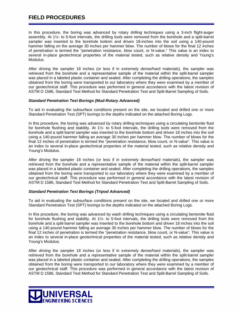
UNIVERSAL ENGINEERING SCIENCES
FIELD PROCEDURES
In this procedure, the boring was advanced by rotary drilling techniques using a 3-inch flight-auger assembly. At 1½- to 5-foot intervals, the drilling tools were removed from the borehole and a split-barrel sampler was inserted to the borehole bottom and driven 18-inches into the soil using a 140-pound hammer falling on the average 30 inches per hammer blow. The number of blows for the final 12 inches of penetration is termed the “penetration resistance, blow count, or N-value.” This value is an index to several in-place geotechnical properties of the material tested, such as relative density and Young’s Modulus. After driving the sampler 18 inches (or less if in extremely dense/hard materials), the sampler was retrieved from the borehole and a representative sample of the material within the split-barrel sampler was placed in a labeled plastic container and sealed. After completing the drilling operations, the samples obtained from the boring were transported to our laboratory where they were examined by a member of our geotechnical staff. This procedure was performed in general accordance with the latest revision of ASTM D 1586, Standard Test Method for Standard Penetration Test and Split-Barrel Sampling of Soils. Standard Penetration Test Borings (Mud-Rotary Advanced) To aid in evaluating the subsurface conditions present on the site, we located and drilled one or more Standard Penetration Test (SPT) borings to the depths indicated on the attached Boring Logs. In this procedure, the boring was advanced by rotary drilling techniques using a circulating bentonite fluid for borehole flushing and stability. At 1½- to 5-foot intervals, the drilling tools were removed from the borehole and a split-barrel sampler was inserted to the borehole bottom and driven 18 inches into the soil using a 140-pound hammer falling an average 30 inches per hammer blow. The number of blows for the final 12 inches of penetration is termed the “penetration resistance, blow count, or N-value”. This value is an index to several in-place geotechnical properties of the material tested, such as relative density and Young’s Modulus. After driving the sampler 18 inches (or less if in extremely dense/hard materials), the sampler was retrieved from the borehole and a representative sample of the material within the split-barrel sampler was placed in a labeled plastic container and sealed. After completing the drilling operations, the samples obtained from the boring were transported to our laboratory where they were examined by a member of our geotechnical staff. This procedure was performed in general accordance with the latest revision of ASTM D 1586, Standard Test Method for Standard Penetration Test and Split-Barrel Sampling of Soils. Standard Penetration Test Borings (Tripod Advanced) To aid in evaluating the subsurface conditions present on the site, we located and drilled one or more Standard Penetration Test (SPT) borings to the depths indicated on the attached Boring Logs. In this procedure, the boring was advanced by wash drilling techniques using a circulating bentonite fluid for borehole flushing and stability. At 1½- to 5-foot intervals, the drilling tools were removed from the borehole and a split-barrel sampler was inserted to the borehole bottom and driven 18 inches into the soil using a 140-pound hammer falling an average 30 inches per hammer blow. The number of blows for the final 12 inches of penetration is termed the “penetration resistance, blow count, or N-value”. This value is an index to several in-place geotechnical properties of the material tested, such as relative density and Young’s Modulus. After driving the sampler 18 inches (or less if in extremely dense/hard materials), the sampler was retrieved from the borehole and a representative sample of the material within the split-barrel sampler was placed in a labeled plastic container and sealed. After completing the drilling operations, the samples obtained from the boring were transported to our laboratory where they were examined by a member of our geotechnical staff. This procedure was performed in general accordance with the latest revision of ASTM D 1586, Standard Test Method for Standard Penetration Test and Split-Barrel Sampling of Soils.

UNIVERSAL ENGINEERING SCIENCES
FIELD PROCEDURES
Double Ring Infiltrometer (DRI) Test Double Ring Infiltrometer (DRI) testing was conducted in the field in the proposed stormwater management system area of the site. The depth and location of each DRI test was determined from the results of the test borings performed in the proposed stormwater management system area. In this test, the test area is excavated with a flat blade shovel to the indicated test depth (typically 1 to 3 feet below existing grades). The test area was widened and smoothed such that the 24-inch outer ring could be easily placed in the excavated area and tamped 6 inches into the subsurface from a relatively level plane. Once the outer ring was in place and tamped into the subsurface, the inner ring was placed in the approximate center of the outer ring and driven 4 inches into the underlying soils. Once the inner and outer rings were in place, presaturation of the subsurface soils was initiated. Tap water (in prefilled barrels) was placed in the inner and outer rings to 6 inches above the excavated surface in each ring. The water was placed such that “tunneling” of the soils between the inner and outer rings did not occur (this will cause stabilization of the water levels in the inner and outer rings, making the test useless). The water levels in the rings were kept at a constant 6-inch level by adding water as needed for a period of thirty minutes to an hour. Note that saturation times become longer in low permeability soils. The DRI test was initiated once the saturation period was complete. The water levels in both rings were kept at the 6-inch level and time readings were started. The appropriate schedule of readings may be determined only through experience. Time reading intervals typically range from 2 to 60 minutes in sandy materials, while for low-permeability materials, the reading interval may be up to 24 hours, or more. During the designated time period, the water was kept at a constant 6-inch level in both rings. The volume of water (in mL) added to the inner ring during this procedure was recorded adjacent to the time period the reading was taken. This process was continued until the volume readings in the inner ring became stabilized. Once the test stabilized and the results were recorded, the DRI equipment was removed from the excavation area and the test area was backfilled with soil cuttings. The DRI testing was performed in general accordance with ASTM D 3385, Standard Test Method for Infiltration Rate of Soils in Field Using Double Ring Infiltrometer. Soil Electrical Resistivity Test To aid in evaluating the subsurface conditions present on the site, soil electrical resistivity testing was performed for this project. The soil resistivity test was performed using the Wenner method (a.k.a., the four-point method) utilizing a Nilsson Soil Resistivity Meter Model 400. The Wenner method involves placing four, equally spaced probes in the test area, perpendicular of any underground utilities. The resistivity was measured at probe spacing’s of 5, 10, 15, 20, and 30 linear feet by adjusting the coarse and fine adjustment knobs on the meter until the null indicator on the meter was balanced. The resistivity at the above probe spacing’s roughly corresponds to resistivity measurements at depths of 5, 10, 15, 20, and 30 feet below existing grade. This test was performed in general accordance with the methodology outlined in ASTM G 57, Standard Test Method for Field Measurement of Soil Resistivity Using the Wenner Four-Electrode Method. Muck Probing To aid in evaluating the subsurface conditions present on the site, we located and performed muck probing on select areas of the site. The muck probes were completed by manually advancing a probe-rod into the loose surficial and organic laden soils (muck) present on the site until firm resistance was encountered. The results of the muck probes were recorded in the field and were reported to the geotechnical engineer for analysis. No specific method applies to this procedure.

UNIVERSAL ENGINEERING SCIENCES
FIELD PROCEDURES
Limerock Bearing Ratio (LBR) Test Sample Collection One or more samples of the shallow, near-surface, subgrade soils were collected for LBR testing. To collect the sample, the topsoil and the upper few inches of the in-situ soils were scraped away with a shovel as to expose the soil chosen for testing. Once the refuse soils were removed, two five-gallon buckets of the soils were collected and returned to our laboratory for LBR testing. The sample was combined and spread out to air dry prior to running the LBR test. No specific test method applies to this procedure. Dynamic Cone Penetrometer Testing In order to evaluate the relative density of the in situ soils, we performed the Dynamic Cone Penetrometer at shallow depths in the auger borings. The Dynamic Cone Penetrometer test was performed at one foot intervals in depth. The DCP test was performed according to the procedures developed by Professor G. F. Sowers and Charles S. Hedges (ASCE, 1966) and outlined in ASTM STP 399. The test procedure involves first seating the conical point of the penetrometer two inches into the bearing materials. The conical point is then driven two additional 1¾-inch increments using a 15-pound weight falling 20 inches. The penetrometer reading is the average number of blows required to drive the conical point two 1¾-inch increments. Correlations have been developed using the penetrometer results to evaluate the level of compaction of soils and to estimate the allowable net soil bearing capacity. Asphalt Coring To aid in determining the general condition of the asphalt section present on the site, we located and drilled on or more asphalt cores to collect samples of the asphaltic concrete for thickness measurement and/or to provide access to the underlying base and subgrade soils. The asphalt coring was performed by the use of an electric coring machine. A four-inch, water cooled, coring drill bit is placed on the pavement and rotated while simultaneously being pushed slowly into the asphalt and base soil/rock materials (note that a six-inch coring bit is used for FDOT projects). The coring is terminated when the asphalt has been bypassed and the core bit has been inserted in to the underlying base soils. Note that for hard or cemented base materials such as crushed limerock or soil cement; the core bit is used to bypass and collect those materials as well. The asphalt and base soil/rock cores were then transported to our laboratory for further analysis. No specific test method applies to this procedure.


UNIVERSAL ENGINEERING SCIENCES
LABORATORY PROCEDURES
Natural Moisture Content Test One or more samples of the soils found during our subsurface exploration were chosen for natural moisture content testing. In this test, the soil sample is placed into a metal pan of known weight, weighed, dried for a minimum of 12 hours in a 110 ± 5°C oven, and then weighed again to record the weight of water released during drying. The natural moisture content of the soil is termed the ratio of “pore” or “free” water in a given mass of material to the mass of solid material particles. This test was conducted in general accordance with ASTM D 2216, Standard Test Method for Laboratory Determination of Water (Moisture) Content of Soil and Rock by Mass. Percent -200 Soil Fines Content Test One or more samples of the soils found during our subsurface exploration were chosen to determine the percentage of silt and clay fines present in the individual samples. In this test, the Natural Moisture Content test (ASTM D 2216) was performed and the sample was then washed over a No. 200 mesh sieve. The materials present in the sample that did not pass through the No. 200 sieve was then placed back in its original pan and dried until the water retained from the wet-sieve process was totally evaporated. Once dried, the sample was weighed again to determine the weight of fines removed during the wet-sieve process. The percent of soil by weight passing the No. 200 sieve is termed the percentage of fines or portion of the sample in the silt and clay size range. This test was conducted in general accordance with ASTM D 1140, Standard Test Methods for Amount of Material in Soils Finer Than the No. 200 (75-μm) Sieve. Organic Content Test One or more samples of the soils found during our subsurface exploration were chosen to determine the organic contents of the individual samples. The organic content test involves performing the Natural Moisture Content test (ASTM D 2216) and then placing 10 to 40 grams of the mixed and dried soil sample into a porcelain crucible of known weight. The crucible (with sample) was then placed into a Barnstead|Thermolyne Model 1400 Muffle Furnace and ignited at a temperature of 455 ± 10°C for 6 hours. After six hours, the crucible was then allowed to cool in a desiccator to prevent moisture entry from the lab’s atmosphere. Once cool to the touch, the crucible was removed from the desiccator and then weighed to determine the mass of organic materials disintegrated during the ignition process. The organic content of the soil is defined as the percentage of combustible organic materials present in a given amounts of the dried soil sample. This test was conducted in general accordance with AASHTO T 267, Standard Method of Test for Determination of Organic Content in Soils by Loss on Ignition. Constant-Head Permeability Test One or more samples of the soils found during our subsurface exploration were chosen to determine the permeability rates (a.k.a., hydraulic conductivity values) of the soils. In this test, the remolded sampled material was compacted in two or three lifts in a 1.5-in diameter, 2.5 inch long permeameter of known weight and volume. Once the material was compacted into the mold, the mold and material were then weighed. In addition to weighing the mold and soil, the Natural Moisture Content test (ASTM D 2216) was performed on the trimmings left over from the sample compaction. The Dry Density of the material was then calculated using the volume, weight, and moisture content of the compacted sample. Once the density procedure was performed, the permeability mold with the compacted material was then covered with a porous stone. A constant-head water source was then connected to the permeameter and the sample was allowed to saturate. After equilibrium flow was established through the sample, a minimum of three time measurements were taken for a specified volume of water flowing out through the sample. This was accomplished using a graduated cylinder and a stop watch. The recorded times were averaged and used in calculation for the determination of the permeability rate.

UNIVERSAL ENGINEERING SCIENCES
LABORATORY PROCEDURES
Falling-Head Permeability Test One or more samples of the soils found during our subsurface exploration were chosen to determine the permeability rates (a.k.a., hydraulic conductivity values) of the soils. In this test, the sampled material was compacted in two or three lifts in a 4-in permeability mold of known weight and volume. Once the material was compacted into the mold, the mold and material were then weighed. In addition to weighing the mold and soil, the Natural Moisture Content test (ASTM D 2216) was performed on the trimmings left over from the sample compaction. The Dry Density of the material was then calculated using the volume, weight, and moisture content of the compacted sample. Once the density procedure was performed, the permeability mold with the compacted material was then covered with a porous stone and spring system to control loosening of the materials during the permeability test. A support collar and top plate was then placed atop the permeability mold (the top plate is equipped with a vent port to allow air to escape the mold/sample as well as an influent port to allow water to saturate the compacted sample). Once the apparatus was assembled and properly tightened, a one-half inch diameter vertical tube, marked with one-foot increments, is attached to the influent port. The tubing was then filled with water and permitted to drain into the influent port, thru the sample, and out of the effluent tube at the bottom of the apparatus. Once the sample was saturated and nearly devoid of air, the tubing was filled with water to seven feet above the apparatus and allowed to drain thru the sample while the time (in seconds) it took for the water to drop each one foot increment was recorded. The hydraulic conductivity of the sample was then calculated using data obtained from the procedure. This test was conducted in general accordance with ASTM D 5084, Standard Test Method for Measurement of Hydraulic Conductivity of Saturated Porous Material Using a Flexible-Wall Permeameter. Atterberg Limits Test One or more samples of the soils found during our subsurface exploration were selected to determine their liquid limits, plastic limits, and plasticity indices (a.k.a., the Atterberg Limits). The liquid limit (LL) of the sample tested was determined using the multi-point method. In this method, the soil sample was dried per ASTM D 2216 (Natural Moisture Content) and then sieved through a No. 40 (425-μm) sieve until approximately 200 grams of sieved material was obtained. Once 200 grams of the sieved material was obtained, distilled water was added until a specific material consistency was reached (as determined only by experience). The wet material was then spread into a brass cup utilizing a spatula, divided into two parts using a grooving tool, and then allowed to flow together using the shocks made by dropping the brass cup onto a standard mechanical device. Once this has been performed several times (typically three times), the moisture content of the sample and the number of blows required to make the material flow together after grooving was plotted to derive the liquid limit of the sample. The plastic limit (PL) of the sample was determined by rolling a small portion of the sieved, wet sample, into a 0.5-in (3.2-mm) thread until the moisture content of the sample was reduced such that the thread crumbled and the soil could no longer be pressed together and re-rolled. The moisture content of the sample at that point is its plastic limit. The plasticity index (PI) is reported as the difference between the liquid limit and plastic limit of the samples (LL minus PL). This test was conducted in general accordance with ASTM D 4318, Standard Test Methods for Liquid Limit, Plastic Limit, and Plasticity Index of Soils. Limerock Bearing Ratio (LBR) Test One or more samples of the predominant, near surface, soils found during our subsurface exploration were collected and returned to our laboratory for LBR testing. In this test, a minimum of four, preferably five, samples of the material are compacted at varying moisture contents to establish a moisture-density relationship for the material. The samples were then soaked for a period of 48 hours under a surcharge mass of at least 2.5 lb (1.13 kg). A penetration test was then performed on each sample by causing a 1.95-in (49.5-mm) diameter piston to penetrate the soil at a constant rate to a depth of 0.5 in (12.7 mm). A

UNIVERSAL ENGINEERING SCIENCES
LABORATORY PROCEDURES
load-penetration curve was then plotted for each sample and the LBR corresponding to 0.1 in (2.5 mm) penetration was calculated. The maximum LBR for a material is determined from a plot of the LBR versus moisture content. This test was performed in general accordance with FM 5-515, Florida Method of Test for Limerock Bearing Ratio. California Bearing Ratio (CBR) Test One or more samples of the predominant, near surface, soils found during our subsurface exploration were collected and returned to our laboratory for CBR testing. In this test, a minimum of four, preferably five, samples of the material are compacted at varying moisture contents to establish a moisture-density relationship for the material. The samples were then soaked for a period of 96 hours under a surcharge mass of at least 2.5 lb (1.13 kg). A penetration test was then performed on each sample by causing a 1.95-in (49.5-mm) diameter piston to penetrate the soil at a constant rate to a depth of 0.5 in (12.7 mm). A load-penetration curve was then plotted for each sample and the CBR corresponding to 0.1 in (2.5 mm) penetration was calculated. The maximum CBR for a material is determined from a plot of the CBR versus moisture content. This test was performed in general accordance with ASTM D1883, Standard Test Method for CBR (California Bearing Ratio) of Laboratory Compacted Soils. Asphalt Core Measurement One or more samples of the asphalt (asphalt cores) collected during our field exploration were returned to our laboratory for thickness measurements. In this procedure, the asphalt core is stripped of all base/subgrade materials which have cemented to the bottom of the core. Once clean, the core is measured by taking a minimum of four measurements using a caliper along the edges of the core. The four measurements are then averaged to obtain the average thickness of the asphalt core. No specific test method applies to this procedure. Grainsize Distribution Test One or more samples of the soils found during our subsurface exploration were selected for grainsize distribution testing. In this test, the Natural Moisture Content (ASTM D 2216) and the Percent -200 Soil Fines Content Test (ASTM D 1140) was performed on the sample. The materials which did not pass through the No. 200 sieve were then dried and weighed and then placed into a stack of mesh sieves (sieve sizes typically range from the 2-in sieve to the No. 200 sieve) and were then shaken for approximately 540 seconds (9 minutes) in a mechanical shaker. Once the sample was agitated, the amount of sample retained on each of the stacked sieves was measured and plotted. The grainsize distribution of the sample tested is defined as the percentage of material retained on a specific set of sieves when compared to the weight of the original washed and dried sample. This test was performed in general accordance with ASTM C 136, Standard Test Method for Sieve Analysis of Fine and Coarse Aggregates. pH Level Test One or more samples of the soils found during our subsurface exploration were selected to evaluate the pH (potential of Hydrogen) levels of the soils. For this test, approximately 100 ml of soil was added to a like amount of distilled water in a 250-ml glass beaker. The soil and water mixture was then mixed thoroughly in ten minute intervals for thirty minutes, ensuring that any clumps of soil were no longer intact. The pH of the soil was then tested using a Hanna Model LA 3410 pH probe. Solutions with a pH of less than 7.0 are considered acidic, while solutions with a pH greater than 7.0 are considered basic (alkaline). This test was conducted in general accordance with FM 5-550, Florida Method of Test for Determining pH of Soil and Water.

UNIVERSAL ENGINEERING SCIENCES
LABORATORY PROCEDURES
Chloride Content Test One or more samples of the soils found during our subsurface exploration were selected to evaluate the chloride levels present in the soils. For this test, approximately 400 grams of soil was air dried to a constant weight and then sieved through a No. 10 sieve (please note that for muck or clay soils, the sample is pulverized with a mallet after drying). Approximately 100 grams of the dried soil was then placed in a 500-ml Erlenmeyer flask. Approximately 300 ml of distilled water was then added to the soil, the flask was capped with a stopper, and the soil/water mixture was shaken vigorously for 20 seconds; the mixture was allowed to stand for 1 hour, was shaken again, and then allowed to stand for 12 hours. The water used in the above procedure was then filtered through a No. 4 filter paper until the water stopped dripping from the filter paper. A 10-ml measuring tube was then over-filled with the filtered water and then the filtered water was transferred to a mixing bottle. The contents of one potassium dichromate indicator pillow was completely dissolved in the sample and then a silver nitrate catalyst was added (with a dropper, swirling after each drop) until the solution became orange in color. The number of drops used to obtain the orange color was then multiplied by 20 to obtain the concentration of chloride present in the samples (in ppm). This test was conducted in general accordance with FM 5-552, Florida Method of Test for Chloride in Soil and Water. Sulfate Content Test One or more samples of the soils found during our subsurface exploration were selected to evaluate the sulfate levels present in the soils. For this test, approximately 400 grams of soil was air dried to a constant weight and then sieved through a No. 10 sieve (note that for muck or clay soils, the sample is pulverized with a mallet after drying). Approximately 100 grams of the dried soil was then placed in a 500-ml Erlenmeyer flask. Approximately 300 ml of distilled water was then added to the soil, the flask was capped with a stopper, and the soil/water mixture was shaken vigorously for 20 seconds; the mixture was allowed to stand for one hour, was shaken again, and then allowed to stand for 12 hours. The water used in the above procedure was then filtered through a No. 4 filter paper until the water stopped dripping from the filter paper. A 10-ml measuring tube was then over-filled with the filtered water and then the filtered water was transferred to a mixing bottle. Note that if the filtered water was still cloudy after filtering, three to five drops of hydrochloric acid was added to half of the filtered water to clear up the solution. Once the filtered water sample was prepared, 10 ml of the sample water was pipetted into a 10-ml sample vial. The contents of one Barium chloride pillow were added to the sample and the sample was inverted several times until the contents of the Barium chloride pillow were dissolved. The solution was allowed to react for at least 5 minutes (but no more than 10 minutes) before measurement. A small portion of the unreacted sample (sample without Barium chloride) was then placed into sample cell and then into a prewarmed and zeroed HACH DR/2400 Spectrophotometer set to 100% transmittance. The spectrophotometer was then adjusted to read zero concentration. The sample cell was then emptied and filled with sample water reacted with Barium chloride and the spectrophotometer procedure above was then repeated. The percent transmittance (%T) of the reacted sample was then obtained from the spectrophotometer. Once the %T was obtained from the spectrophotometer, the sulfate content was determined utilizing the %T versus Concentration (ppm) adjustments for the spectrophotometer unit. This test was conducted in general accordance with FM 5-553, Florida Method of Test for Sulfate in Soil and Water. Soil Electrical Resistivity Test One or more of the soil samples found during our subsurface exploration were selected for electrical resistivity testing. This test was performed with a Nilsson Soil Resistivity Meter Model 400 and soil box. For this test, approximately 1000 grams of the thoroughly mixed soil was placed into the soil box at its natural moisture content. The resistivity was obtained by adjusting the fine and coarse ohm adjustments on the meter. The soil was placed back into a mixing pan and then 50 to 100 ml of deionized water was thoroughly mixed into the material. The resistivity was obtained again by adjusting the fine and coarse ohm adjustments on the meter. This procedure was repeated until the resistivity stopped dropping or began to rise. The result of the resistivity test is the lowest reading obtained during the procedure. This test was conducted in general accordance with the concepts outlined in FM 5-551, Florida Method of Test
UNIVERSAL ENGINEERING SCIENCES
LABORATORY PROCEDURES
for Resistivity of Soil and Water. Note that while the equipment used to perform the procedure is the same, this procedure provides data different than that of the electrical resistivity test performed in the field. Corrosive Series Test One or more samples of the soil samples found were selected for corrosive series testing. The corrosive series test involves several tests including: pH level, chloride content, sulfate content, and resistivity. The individual testing methods are outlined below.


Geotechnical-Engineering Report
Geotechnical Services Are Performed for Specific Purposes, Persons, and ProjectsGeotechnical engineers structure their services to meet the specific needs of their clients. A geotechnical-engineering study conducted for a civil engineer may not fulfill the needs of a constructor — a construction contractor — or even another civil engineer. Because each geotechnical- engineering study is unique, each geotechnical-engineering report is unique, prepared solely for the client. No one except you should rely on this geotechnical-engineering report without first conferring with the geotechnical engineer who prepared it. And no one — not even you — should apply this report for any purpose or project except the one originally contemplated.
Read the Full ReportSerious problems have occurred because those relying on a geotechnical-engineering report did not read it all. Do not rely on an executive summary. Do not read selected elements only.
Geotechnical Engineers Base Each Report on a Unique Set of Project-Specific FactorsGeotechnical engineers consider many unique, project-specific factors when establishing the scope of a study. Typical factors include: the client’s goals, objectives, and risk-management preferences; the general nature of the structure involved, its size, and configuration; the location of the structure on the site; and other planned or existing site improvements, such as access roads, parking lots, and underground utilities. Unless the geotechnical engineer who conducted the study specifically indicates otherwise, do not rely on a geotechnical-engineering report that was:• not prepared for you;• not prepared for your project;• not prepared for the specific site explored; or• completed before important project changes were made.
Typical changes that can erode the reliability of an existing geotechnical-engineering report include those that affect: • the function of the proposed structure, as when it’s changed
from a parking garage to an office building, or from a light-industrial plant to a refrigerated warehouse;
• the elevation, configuration, location, orientation, or weight of the proposed structure;
• the composition of the design team; or• project ownership.
As a general rule, always inform your geotechnical engineer of project changes—even minor ones—and request an
assessment of their impact. Geotechnical engineers cannot accept responsibility or liability for problems that occur because their reports do not consider developments of which they were not informed.
Subsurface Conditions Can ChangeA geotechnical-engineering report is based on conditions that existed at the time the geotechnical engineer performed the study. Do not rely on a geotechnical-engineering report whose adequacy may have been affected by: the passage of time; man-made events, such as construction on or adjacent to the site; or natural events, such as floods, droughts, earthquakes, or groundwater fluctuations. Contact the geotechnical engineer before applying this report to determine if it is still reliable. A minor amount of additional testing or analysis could prevent major problems.
Most Geotechnical Findings Are Professional OpinionsSite exploration identifies subsurface conditions only at those points where subsurface tests are conducted or samples are taken. Geotechnical engineers review field and laboratory data and then apply their professional judgment to render an opinion about subsurface conditions throughout the site. Actual subsurface conditions may differ — sometimes significantly — from those indicated in your report. Retaining the geotechnical engineer who developed your report to provide geotechnical-construction observation is the most effective method of managing the risks associated with unanticipated conditions.
A Report’s Recommendations Are Not FinalDo not overrely on the confirmation-dependent recommendations included in your report. Confirmation-dependent recommendations are not final, because geotechnical engineers develop them principally from judgment and opinion. Geotechnical engineers can finalize their recommendations only by observing actual subsurface conditions revealed during construction. The geotechnical engineer who developed your report cannot assume responsibility or liability for the report’s confirmation-dependent recommendations if that engineer does not perform the geotechnical-construction observation required to confirm the recommendations’ applicability.
A Geotechnical-Engineering Report Is Subject to MisinterpretationOther design-team members’ misinterpretation of geotechnical-engineering reports has resulted in costly
Important Information about This
Subsurface problems are a principal cause of construction delays, cost overruns, claims, and disputes.
While you cannot eliminate all such risks, you can manage them. The following information is provided to help.

problems. Confront that risk by having your geo technical engineer confer with appropriate members of the design team after submitting the report. Also retain your geotechnical engineer to review pertinent elements of the design team’s plans and specifications. Constructors can also misinterpret a geotechnical-engineering report. Confront that risk by having your geotechnical engineer participate in prebid and preconstruction conferences, and by providing geotechnical construction observation.
Do Not Redraw the Engineer’s LogsGeotechnical engineers prepare final boring and testing logs based upon their interpretation of field logs and laboratory data. To prevent errors or omissions, the logs included in a geotechnical-engineering report should never be redrawn for inclusion in architectural or other design drawings. Only photographic or electronic reproduction is acceptable, but recognize that separating logs from the report can elevate risk.
Give Constructors a Complete Report and GuidanceSome owners and design professionals mistakenly believe they can make constructors liable for unanticipated subsurface conditions by limiting what they provide for bid preparation. To help prevent costly problems, give constructors the complete geotechnical-engineering report, but preface it with a clearly written letter of transmittal. In that letter, advise constructors that the report was not prepared for purposes of bid development and that the report’s accuracy is limited; encourage them to confer with the geotechnical engineer who prepared the report (a modest fee may be required) and/or to conduct additional study to obtain the specific types of information they need or prefer. A prebid conference can also be valuable. Be sure constructors have sufficient time to perform additional study. Only then might you be in a position to give constructors the best information available to you, while requiring them to at least share some of the financial responsibilities stemming from unanticipated conditions.
Read Responsibility Provisions CloselySome clients, design professionals, and constructors fail to recognize that geotechnical engineering is far less exact than other engineering disciplines. This lack of understanding has created unrealistic expectations that have led to disappointments, claims, and disputes. To help reduce the risk of such outcomes, geotechnical engineers commonly include a variety of explanatory provisions in their reports. Sometimes labeled “limitations,” many of these provisions indicate where geotechnical engineers’ responsibilities begin and end, to help
others recognize their own responsibilities and risks. Read these provisions closely. Ask questions. Your geotechnical engineer should respond fully and frankly.
Environmental Concerns Are Not Covered The equipment, techniques, and personnel used to perform an environmental study differ significantly from those used to perform a geotechnical study. For that reason, a geotechnical-engineering report does not usually relate any environmental findings, conclusions, or recommendations; e.g., about the likelihood of encountering underground storage tanks or regulated contaminants. Unanticipated environmental problems have led to numerous project failures. If you have not yet obtained your own environmental information, ask your geotechnical consultant for risk-management guidance. Do not rely on an environmental report prepared for someone else.
Obtain Professional Assistance To Deal with MoldDiverse strategies can be applied during building design, construction, operation, and maintenance to prevent significant amounts of mold from growing on indoor surfaces. To be effective, all such strategies should be devised for the express purpose of mold prevention, integrated into a comprehensive plan, and executed with diligent oversight by a professional mold-prevention consultant. Because just a small amount of water or moisture can lead to the development of severe mold infestations, many mold- prevention strategies focus on keeping building surfaces dry. While groundwater, water infiltration, and similar issues may have been addressed as part of the geotechnical- engineering study whose findings are conveyed in this report, the geotechnical engineer in charge of this project is not a mold prevention consultant; none of the services performed in connection with the geotechnical engineer’s study were designed or conducted for the purpose of mold prevention. Proper implementation of the recommendations conveyed in this report will not of itself be sufficient to prevent mold from growing in or on the structure involved.
Rely, on Your GBC-Member Geotechnical Engineer for Additional AssistanceMembership in the Geotechnical Business Council of the Geoprofessional Business Association exposes geotechnical engineers to a wide array of risk-confrontation techniques that can be of genuine benefit for everyone involved with a construction project. Confer with you GBC-Member geotechnical engineer for more information.
8811 Colesville Road/Suite G106, Silver Spring, MD 20910Telephone: 301/565-2733 Facsimile: 301/589-2017
e-mail: [email protected] www.geoprofessional.org
Copyright 2015 by Geoprofessional Business Association (GBA). Duplication, reproduction, or copying of this document, or its contents, in whole or in part, by any means whatsoever, is strictly prohibited, except with GBA’s specific written permission. Excerpting, quoting, or otherwise extracting wording from this document
is permitted only with the express written permission of GBA, and only for purposes of scholarly research or book review. Only members of GBA may use this document as a complement to or as an element of a geotechnical-engineering report. Any other firm, individual, or other entity that so uses this document without
being a GBA member could be commiting negligent or intentional (fraudulent) misrepresentation.

WARRANTY Universal Engineering Sciences has prepared this report for our client for his exclusive use, in accordance with generally accepted soil and foundation engineering practices, and makes no other warranty either expressed or implied as to the professional advice provided in the report. UNANTICIPATED SOIL CONDITIONS The analysis and recommendations submitted in this report are based upon the data obtained from soil borings performed at the locations indicated on the Boring Location Plan. This report does not reflect any variations which may occur between these borings. The nature and extent of variations between borings may not become known until excavation begins. If variations appear, we may have to re-evaluate our recommendations after performing on-site observations and noting the characteristics of any variations. CHANGED CONDITIONS We recommend that the specifications for the project require that the contractor immediately notify Universal Engineering Sciences, as well as the owner, when subsurface conditions are encountered that are different from those present in this report. No claim by the contractor for any conditions differing from those anticipated in the plans, specifications, and those found in this report, should be allowed unless the contractor notifies the owner and Universal Engineering Sciences of such changed conditions. Further, we recommend that all foundation work and site improvements be observed by a representative of Universal Engineering Sciences to monitor field conditions and changes, to verify design assumptions and to evaluate and recommend any appropriate modifications to this report. MISINTERPRETATION OF SOIL ENGINEERING REPORT Universal Engineering Sciences is responsible for the conclusions and opinions contained within this report based upon the data relating only to the specific project and location discussed herein. If the conclusions or recommendations based upon the data presented are made by others, those conclusions or recommendations are not the responsibility of Universal Engineering Sciences. CHANGED STRUCTURE OR LOCATION This report was prepared in order to aid in the evaluation of this project and to assist the architect or engineer in the design of this project. If any changes in the design or location of the structure as outlined in this report are planned, or if any structures are included or added that are not discussed in the report, the conclusions and recommendations contained in this report shall not be considered valid unless the changes are reviewed and the conclusions modified or approved by Universal Engineering Sciences. USE OF REPORT BY BIDDERS Bidders who are examining the report prior to submission of a bid are cautioned that this report was prepared as an aid to the designers of the project and it may affect actual construction operations.
Bidders are urged to make their own soil borings, test pits, test caissons or other investigations to determine those conditions that may affect construction operations. Universal Engineering Sciences cannot be responsible for any interpretations made from this report or the attached boring logs with regard to their adequacy in reflecting subsurface conditions which will affect construction operations. STRATA CHANGES Strata changes are indicated by a definite line on the boring logs which accompany this report. However, the actual change in the ground may be more gradual. Where changes occur between soil samples, the location of the change must necessarily be estimated using all available information and may not be shown at the exact depth. OBSERVATIONS DURING DRILLING Attempts are made to detect and/or identify occurrences during drilling and sampling, such as: water level, boulders, zones of lost circulation, relative ease or resistance to drilling progress, unusual sample recovery, variation of driving resistance, obstructions, etc.; however, lack of mention does not preclude their presence. WATER LEVELS Water level readings have been made in the drill holes during drilling and they indicate normally occurring conditions. Water levels may not have been stabilized at the last reading. This data has been reviewed and interpretations made in this report. However, it must be noted that fluctuations in the level of the groundwater may occur due to variations in rainfall, temperature, tides, and other factors not evident at the time measurements were made and reported. Since the probability of such variations is anticipated, design drawings and specifications should accommodate such possibilities and construction planning should be based upon such assumptions of variations. LOCATION OF BURIED OBJECTS All users of this report are cautioned that there was no requirement for Universal Engineering Sciences to attempt to locate any man-made buried objects during the course of this exploration and that no attempt was made by Universal Engineering Sciences to locate any such buried objects. Universal Engineering Sciences cannot be responsible for any buried man-made objects which are subsequently encountered during construction that are not discussed within the text of this report. TIME This report reflects the soil conditions at the time of exploration. If the report is not used in a reasonable amount of time, significant changes to the site may occur and additional reviews may be required.
CONSTRAINTS & RESTRICTIONS The intent of this document is to bring to your attention the potential concerns and the basic limitations of a typical geotechnical report.
Universal Engineering Sciences, Inc. GENERAL CONDITIONS
SECTION 1: RESPONSIBILITIES 1.1 Universal Engineering Sciences, Inc., (“UES”), has the responsibility for providing the services described under the Scope of Services section. The
work is to be performed according to accepted standards of care and is to be completed in a timely manner. The term "UES" as used herein includes all of Universal Engineering Sciences, Inc's agents, employees, professional staff, and subcontractors.
1.2 The Client or a duly authorized representative is responsible for providing UES with a clear understanding of the project nature and scope. The Client shall supply UES with sufficient and adequate information, including, but not limited to, maps, site plans, reports, surveys and designs, to allow UES to properly complete the specified services. The Client shall also communicate changes in the nature and scope of the project as soon as possible during performance of the work so that the changes can be incorporated into the work product.
1.3 The Client acknowledges that UES’s responsibilities in providing the services described under the Scope of Services section is limited to those services described therein, and the Client hereby assumes any collateral or affiliated duties necessitated by or for those services. Such duties may include, but are not limited to, reporting requirements imposed by any third party such as federal, state, or local entities, the provision of any required notices to any third party, or the securing of necessary permits or permissions from any third parties required for UES’s provision of the services so described, unless otherwise agreed upon by both parties.
1.4 PURSUANT TO FLORIDA STATUTES §558.0035, ANY INDIVIDUAL EMPLOYEE OR AGENT OF UES MAY NOT BE HELD INDIVIDUALLY LIABLE FOR NEGLIGENCE.
SECTION 2: STANDARD OF CARE 2.1 Services performed by UES under this Agreement will be conducted in a manner consistent with the level of care and skill ordinarily exercised by
members of UES's profession practicing contemporaneously under similar conditions in the locality of the project. No other warranty, express or implied, is made.
2.2 The Client recognizes that subsurface conditions may vary from those observed at locations where borings, surveys, or other explorations are made, and that site conditions may change with time. Data, interpretations, and recommendations by UES will be based solely on information available to UES at the time of service. UES is responsible for those data, interpretations, and recommendations, but will not be responsible for other parties’ interpretations or use of the information developed.
2.3 Execution of this document by UES is not a representation that UES has visited the site, become generally familiar with local conditions under which the services are to be performed, or correlated personal observations with the requirements of the Scope of Services. It is the Client’s responsibility to provide UES with all information necessary for UES to provide the services described under the Scope of Services, and the Client assumes all liability for information not provided to UES that may affect the quality or sufficiency of the services so described. 2.4 Should UES be retained to provide threshold inspection services under Florida Statutes §553.79, Client acknowledges that UES’s services
thereunder do not constitute a guarantee that the construction in question has been properly designed or constructed, and UES’s services do not replace any of the obligations or liabilities associated with any architect, contractor, or structural engineer. Therefore it is explicitly agreed that the Client will not hold UES responsible for the proper performance of service by any architect, contractor, structural engineer or any other entity associated with the project.
SECTION 3: SITE ACCESS AND SITE CONDITIONS 3.1 Client will grant or obtain free access to the site for all equipment and personnel necessary for UES to perform the work set forth in this Agreement.
The Client will notify any and all possessors of the project site that Client has granted UES free access to the site. UES will take reasonable precautions to minimize damage to the site, but it is understood by Client that, in the normal course of work, some damage may occur, and the correction of such damage is not part of this Agreement unless so specified in the Proposal.
3.2 The Client is responsible for the accuracy of locations for all subterranean structures and utilities. UES will take reasonable precautions to avoid known subterranean structures, and the Client waives any claim against UES, and agrees to defend, indemnify, and hold UES harmless from any claim or liability for injury or loss, including costs of defense, arising from damage done to subterranean structures and utilities not identified or accurately located. In addition, Client agrees to compensate UES for any time spent or expenses incurred by UES in defense of any such claim with compensation to be based upon UES's prevailing fee schedule and expense reimbursement policy.
SECTION 4: SAMPLE OWNERSHIP AND DISPOSAL 4.1 Soil or water samples obtained from the project during performance of the work shall remain the property of the Client. 4.2 UES will dispose of or return to Client all remaining soils and rock samples 60 days after submission of report covering those samples. Further
storage or transfer of samples can be made at Client's expense upon Client's prior written request. 4.3 Samples which are contaminated by petroleum products or other chemical waste will be returned to Client for treatment or disposal, consistent with
all appropriate federal, state, or local regulations. SECTION 5: BILLING AND PAYMENT 5.1 UES will submit invoices to Client monthly or upon completion of services. Invoices will show charges for different personnel and expense
classifications. 5.2 Payment is due 30 days after presentation of invoice and is past due 31 days from invoice date. Client agrees to pay a finance charge of one and
one-half percent (1 ½ %) per month, or the maximum rate allowed by law, on past due accounts. 5.3 If UES incurs any expenses to collect overdue billings on invoices, the sums paid by UES for reasonable attorneys' fees, court costs, UES's time,
UES's expenses, and interest will be due and owing by the Client. SECTION 6: OWNERSHIP AND USE OF DOCUMENTS 6.1 All reports, boring logs, field data, field notes, laboratory test data, calculations, estimates, and other documents prepared by UES, as instruments
of service, shall remain the property of UES. 6.2 Client agrees that all reports and other work furnished to the Client or his agents, which are not paid for, will be returned upon demand and will not
be used by the Client for any purpose. 6.3 UES will retain all pertinent records relating to the services performed for a period of five years following submission of the report, during which
period the records will be made available to the Client at all reasonable times. 6.4 All reports, boring logs, field data, field notes, laboratory test data, calculations, estimates, and other documents prepared by UES, are prepared
for the sole and exclusive use of Client, and may not be given to any other party or used or relied upon by any such party without the express written consent of UES.

SECTION 7: DISCOVERY OF UNANTICIPATED HAZARDOUS MATERIALS 7.1 Client warrants that a reasonable effort has been made to inform UES of known or suspected hazardous materials on or near the project site. 7.2 Under this agreement, the term hazardous materials include hazardous materials (40 CFR 172.01), hazardous wastes (40 CFR 261.2), hazardous
substances (40 CFR 300.6), petroleum products, polychlorinated biphenyls, and asbestos. 7.3 Hazardous materials may exist at a site where there is no reason to believe they could or should be present. UES and Client agree that the
discovery of unanticipated hazardous materials constitutes a changed condition mandating a renegotiation of the scope of work. UES and Client also agree that the discovery of unanticipated hazardous materials may make it necessary for UES to take immediate measures to protect health and safety. Client agrees to compensate UES for any equipment decontamination or other costs incident to the discovery of unanticipated hazardous waste.
7.4 UES agrees to notify Client when unanticipated hazardous materials or suspected hazardous materials are encountered. Client agrees to make any disclosures required by law to the appropriate governing agencies. Client also agrees to hold UES harmless for any and all consequences of disclosures made by UES which are required by governing law. In the event the project site is not owned by Client, Client recognizes that it is the Client's responsibility to inform the property owner of the discovery of unanticipated hazardous materials or suspected hazardous materials.
7.5 Notwithstanding any other provision of the Agreement, Client waives any claim against UES, and to the maximum extent permitted by law, agrees to defend, indemnify, and save UES harmless from any claim, liability, and/or defense costs for injury or loss arising from UES's discovery of unanticipated hazardous materials or suspected hazardous materials including any costs created by delay of the project and any cost associated with possible reduction of the property's value. Client will be responsible for ultimate disposal of any samples secured by UES which are found to be contaminated.
SECTION 8: RISK ALLOCATION 8.1 Client agrees that UES's liability for any damage on account of any breach of contract, error, omission or other professional negligence will be
limited to a sum not to exceed $50,000 or UES’s fee, whichever is greater. If Client prefers to have higher limits on contractual or professional liability, UES agrees to increase the limits up to a maximum of $1,000,000.00 upon Client’s written request at the time of accepting our proposal provided that Client agrees to pay an additional consideration of four percent of the total fee, or $400.00, whichever is greater. The additional charge for the higher liability limits is because of the greater risk assumed and is not strictly a charge for additional professional liability insurance.
SECTION 9: INSURANCE 9.1 UES represents and warrants that it and its agents, staff and consultants employed by it, is and are protected by worker's compensation insurance
and that UES has such coverage under public liability and property damage insurance policies which UES deems to be adequate. Certificates for all such policies of insurance shall be provided to Client upon request in writing. Within the limits and conditions of such insurance, UES agrees to indemnify and save Client harmless from and against loss, damage, or liability arising from negligent acts by UES, its agents, staff, and consultants employed by it. UES shall not be responsible for any loss, damage or liability beyond the amounts, limits, and conditions of such insurance or the limits described in Section 8, whichever is less. The Client agrees to defend, indemnify and save UES harmless for loss, damage or liability arising from acts by Client, Client's agent, staff, and other UESs employed by Client.
SECTION 10: DISPUTE RESOLUTION 10.1 All claims, disputes, and other matters in controversy between UES and Client arising out of or in any way related to this Agreement will be
submitted to alternative dispute resolution (ADR) such as mediation or arbitration, before and as a condition precedent to other remedies provided by law, including the commencement of litigation.
10.2 If a dispute arises related to the services provided under this Agreement and that dispute requires litigation instead of ADR as provided above, then: (a) the claim will be brought and tried in judicial jurisdiction of the court of the county where UES's principal place of business is located and
Client waives the right to remove the action to any other county or judicial jurisdiction, and (b) The prevailing party will be entitled to recovery of all reasonable costs incurred, including staff time, court costs, attorneys’ fees, and
other claim related expenses. SECTION 11: TERMINATION 11.1 This agreement may be terminated by either party upon seven (7) days written notice in the event of substantial failure by the other party to
perform in accordance with the terms hereof. Such termination shall not be effective if that substantial failure has been remedied before expiration of the period specified in the written notice. In the event of termination, UES shall be paid for services performed to the termination notice date plus reasonable termination expenses.
11.2 In the event of termination, or suspension for more than three (3) months, prior to completion of all reports contemplated by the Agreement, UES may complete such analyses and records as are necessary to complete its files and may also complete a report on the services performed to the date of notice of termination or suspension. The expense of termination or suspension shall include all direct costs of UES in completing such analyses, records and reports.
SECTION 12: ASSIGNS 12.1 Neither the Client nor UES may delegate, assign, sublet or transfer their duties or interest in this Agreement without the written consent of the other
party. SECTION 13. GOVERNING LAW AND SURVIVAL 13.1 The laws of the State of Florida will govern the validity of these Terms, their interpretation and performance. 13.2 If any of the provisions contained in this Agreement are held illegal, invalid, or unenforceable, the enforceability of the remaining provisions will not
be impaired. Limitations of liability and indemnities will survive termination of this Agreement for any cause.
SECTION 14. INTEGRATION CLAUSE 14.1 This Agreement represents and contains the entire and only agreement and understanding among the parties with respect to the subject matter of this Agreement, and supersedes any and all prior and contemporaneous oral and written agreements, understandings, representations, inducements, promises, warranties, and conditions among the parties. No agreement, understanding, representation, inducement, promise, warranty, or condition of any kind with respect to the subject matter of this Agreement shall be relied upon by the parties unless expressly incorporated herein. 14.2 This Agreement may not be amended or modified except by an agreement in writing signed by the party against whom the enforcement of any
modification or amendment is sought.
Rev. 07/11/13
APPENDIX BHazardous Materials Report

THIS PAGE INTENTIONALLY LEFT BLANK FOR DUPLEX PRINTING

Prepared for: Prepared by: Robins Air Force Base AECOM Warner Robins, Georgia 400 Northpark Town Center 1000 Abernathy Road, Ste. 900 Atlanta, Georgia 30328 Phone: (678) 808-8800 Project No. 60438264
Environment
Pre-Demolition Asbestos and Lead-Based Paint Survey Robins Air Force Base Building #180 Warner Robins, Georgia
September 16, 2015

Pre-Demolition Survey Report Robins AFB – Building 180
September, 2015
PRE-DEMOLITION EXECUTIVE SUMMARY ......................................................................... i ASBESTOS ............................................................................................................................. i LEAD BASED PAINT ............................................................................................................. ii 1.0 OVERVIEW ................................................................................................................. 1
1.1 INTRODUCTION ......................................................................................................... 1
1.2 SITE DESCRIPTION ................................................................................................... 1
1.3 PURPOSE AND SCOPE OF WORK .......................................................................... 1
1.4 OBJECTIVE, SCOPE, AND LIMITATIONS OF THIS DOCUMENT ........................... 1 1.4.1 Objective ....................................................................................................... 1 1.4.2 Scope ........................................................................................................... 1 1.4.3 Limitations .................................................................................................... 2
2.0 ASBESTOS SURVEY ................................................................................................. 3 2.1 METHODOLOGY ........................................................................................................ 3 2.2 INFORMATION REVIEW AND INITIAL WALK-THROUGH INSPECTION ................. 3 2.3 GROUPING OF SUSPECT ACBM .............................................................................. 3 2.4 RISK ASSESSMENT METHODOLOGY ..................................................................... 4 2.5 BULK SAMPLE COLLECTION ................................................................................... 5 2.6 FRIABLE MATERIALS ................................................................................................ 7 2.7 NON-FRIABLE MATERIALS ....................................................................................... 7 3.0 LEAD BASED PAINT (LBP) SURVEY ....................................................................... 8 3.1 METHODOLOGY ........................................................................................................ 8 3.2 INFORMATION REVIEW AND INITIAL WALK-THROUGH INSPECTION ................. 8 3.3 GROUPING OF SUSPECT LBP ................................................................................. 8 3.4 PAINT CHIP SAMPLE COLLECTION ......................................................................... 8 3.5 LBP MATERIALS ........................................................................................................ 9 3.6 LBP RISK ASSESSMENT METHODOLOGY ............................................................. 9
4.0 CONCLUSIONS AND RECCOMMENDATIONS ...................................................... 11 4.1 ASBESTOS-CONTAINING MATERIALS .................................................................. 11 4.2 LEAD BASED PAINT SURFACES ............................................................................ 11
LIST OF TABLES TABLE 1 Asbestos Survey TABLE 2 Lead Based Paint Survey LIST OF APPENDICES APPENDIX A Inspector Certification APPENDIX B ACM Laboratory Data Sheets APPENDIX C LBP Laboratory Data Sheets

Pre-Demolition Survey Report Robins AFB – Building 180
September, 2015 i
PRE-DEMOLITION EXECUTIVE SUMMARY
AECOM has completed a Pre-Demolition Asbestos and Lead Based Paint Survey of the proposed demolition/renovation and new construction areas of Building #180 at the Robins Air Force Base (AFB), located in Warner Robins, Georgia. The building areas are to be demolished/renovated as part of the planned additions/alterations to the Aircraft Corrosion Control Facility, Building #180. The findings, conclusions, and recommendations of this Pre-Demolition Survey Report will be incorporated, as warranted, into the final design, drawings, and project specifications. Building #180 is an Aircraft Corrosion Control Facility, located at Robins Air Force Base in Warner Robins GA. The building was constructed circa 1982 and is approximately 43,150 square feet in size. The building is constructed as a steel frame and metal panel clad structure. The primary function of this facility is the stripping, preparing and repainting of protective coatings for aircraft components. Specifically, AECOM conducted the pre-demolition survey of existing space on the northern side of the building.
The objective of the pre-demolition survey was to provide information required to plan for the proposed Building #180 renovation and reconfiguration of the Administrative/Support areas, and construction a new building addition on the northwestern side of the building at Robins Air Force Base.
The proposed scope of work consisted of the following tasks:
(1) An assessment of the planned demolition/renovation and new construction areas by a state-certified Asbestos Inspector in accordance with State of Georgia regulations; and,
(2) An assessment of the planned demolition/renovation and new construction areas in accordance with State of Georgia regulations.
ASBESTOS
Demolition, according to the National Emissions Standard for Hazardous Air Pollutants (NESHAP), is any disturbance of a structural member of the building and represents a specific type of renovation. The asbestos survey was performed by Mr. Nathan Bruce, a state-certified Asbestos Inspector through the Environmental Protection Agency (EPA), Asbestos Hazard Emergency Response Act (AHERA), and the Asbestos School Hazard Abatement Reauthorization Act (ASHARA). All areas of the facility building were accessible to the asbestos inspector, with the exception of the existing mechanical room. However, it is AECOM’s understanding that this area will not be part of the planned renovation/demolition and construction area. In addition, some limited areas above the facility ceilings, behind walls, within HVAC equipment, and within electrical boxes and associated equipment were inaccessible. These areas are believed to be similar in construction to accessible areas that were inspected during the course of the survey. However, should additional suspect materials in these inaccessible area be

Pre-Demolition Survey Report Robins AFB – Building 180
September, 2015 ii
identified, it is recommended that these materials be sampled to confirm the asbestos content, or that these materials be assumed to be asbestos containing. Based on information provided, and AECOM’s understanding of the areas of demolition/renovation and new construction, friable and non-friable thermal systems insulation (TSI), surfacing, miscellaneous, and/or assumed materials that contain asbestos were not identified at this facility. Based on the results of the pre-demolition asbestos survey, the following conclusions and recommendations are presented:
Asbestos-containing building materials (ACBMs) were not identified at the facility, within the renovation/demolition and new construction area, that require abatement, disposal, and/or special handling.
LEAD BASED PAINT
AECOM assessed the degree (presence and location), type, and condition of total lead hazard in the planned demolition/renovation and new construction areas. AECOM conducted a walk-through of the building to assess the location of suspected lead based paint (LBP). The results of the laboratory analysis indicated that one (1) homogeneous area had reportable levels of lead. These lead based painted materials were observed to be in generally intact at the time of the survey.
Sample Location Sample Description
Sample ID Percent Lead
Comments
Mezzanine Handrail Brown 180-LBP-10 0.0986 Intact, good condition.
Based on the results of the pre-demolition lead based paint survey, the following conclusions and recommendations are presented:
Positive readings for lead based paint were identified in the mezzanine metal handrails (brown) of the building. The demolition/renovation contractor must be notified as to the presence and location of the lead painted materials.
Additional sampling of the painted surfaces needs to be conducted to evaluate the
disposal requirements for painted surfaces as general construction debris or hazardous materials. Samples will need to be submitted for total characteristic leachate procedure (TCLP) lead analysis.

Pre-Demolition Survey Report Robins AFB – Building 180
1 of 11 September, 2015
1.0 OVERVIEW
1.1 INTRODUCTION AECOM has completed a Pre-Demolition Asbestos and Lead Based Paint Survey of the proposed demolition/renovation and new construction areas of Building #180 at the Robins Air Force Base, located in Warner Robins, Georgia. The building areas are to be demolished/renovated as part of the planned additions/alterations to the Aircraft Corrosion Control Facility, Building #180. This Pre-Demolition Asbestos and Lead Based Paint report summarizes the methodology used for the survey, presents the findings and recommendations, and includes supporting documentation.
1.2 SITE DESCRIPTION Building #180 is an Aircraft Corrosion Control Facility, located at Robins Air Force Base in Warner Robins GA. The building was constructed circa 1982 and is approximately 43,150 square feet in size. The building is constructed as a steel frame and metal panel clad structure. The primary function of this facility is the stripping, preparing and repainting of protective coatings for aircraft components.
1.3 PURPOSE AND SCOPE OF WORK In order to provide a safe and healthy work environment, Federal, State, and local regulations require that asbestos-containing building materials (ACBM) be identified prior to the demolition or renovation activities and that certain wastes and materials be handled and disposed in an acceptable manner. The main purpose of the survey and associated report was to establish the location and extent of ACBM throughout the planned area of demolition/renovation and construction and establish the location and extent of lead based painted surfaces (northern side of building).
1.4 OBJECTIVE, SCOPE, AND LIMITATIONS OF THIS DOCUMENT
1.4.1 Objective
The objective of this document is to illustrate the recommended concepts for the proposed Building #180 renovation and reconfiguration of the Administrative/Support areas and construction of a new building addition on the northwestern side of the building at Robins Air Force Base.
1.4.2 Scope
The Pre-Demolition Survey Report document is part of the Design Analysis submittal for the additions/alterations to Aircraft Corrosion Control Facility, Building #180. These proposed additional/alterations include: (1) the renovation of approximately 4,970 SF of existing space on the north side of the Building #180 that will include a conference/training room, break room, men’s personal protection equipment (PPE) locker room, men’s personal locker room, men’s shower room, men’s decontamination room, communications room, and janitor closet; and (2) the construction of a new building addition (area to be determined), on the northwest side of the building. The addition will include an office, entry/lobby area, women’s restrooms,

Pre-Demolition Survey Report Robins AFB – Building 180
2 of 11 September, 2015
janitor closet, women’s PPE locker room, women’s personal locker room, women’s shower room, and women’s decontamination room. 1.4.3 Limitations
All areas of the facility building were accessible to the asbestos inspector, with the exception of the existing mechanical room. However, it is AECOM’s understanding that this area will not be part of the planned renovation/demolition and construction area, In addition, some limited areas above the facility ceilings, behind walls, within HVAC equipment, and within electrical boxes and associated equipment were inaccessible. These areas are believed to be similar in construction to accessible areas that were inspected during the course of the survey. However, should additional suspect materials in these inaccessible area be identified, it is recommended that these materials be sampled to confirm the asbestos content, or that these materials be assumed to be asbestos containing.

Pre-Demolition Survey Report Robins AFB – Building 180
3 of 11 September, 2015
2.0 ASBESTOS SURVEY
2.1 METHODOLOGY
The following section presents the methodology for assessing the materials as a part of the Pre-Demolition Asbestos Survey, and identifying materials to be sampled, if warranted. The asbestos survey of this facility was performed by Mr. Nathan Bruce, a certified Asbestos Inspector through the Environmental Protection Agency (EPA), Asbestos Hazard Emergency Response Act (AHERA), and the Asbestos School Hazard Abatement Reauthorization Act (ASHARA). A copy of the inspector certification is included in Appendix A of this report.
2.2 INFORMATION REVIEW AND INITIAL WALK-THROUGH INSPECTION
Mr. Nathan Bruce conducted an initial walk-through inspection of the demolition/renovation and asbestos pre-demolition survey on September 2, 2015. Accessible areas of the planned area of demolition/renovation were observed. All areas of the planned area of demolition/renovation and construction were accessible to the asbestos inspector, with the exception of the mechanical room in the northernmost area of the building, some limited areas above the facility ceilings, behind walls, within HVAC equipment, and within electrical boxes and associated equipment. These areas are believed to be similar in construction to accessible areas that were inspected during the course of the survey. However, should additional suspect materials in these inaccessible areas be identified, it is recommended that these materials be sampled to confirm the asbestos content, or that these materials be assumed to be asbestos containing.
2.3 GROUPING OF SUSPECT ACBM
During the initial walk-through inspection, the known and suspect ACBM were grouped according to the type of material. These materials were then grouped by homogenous area. At the conclusion of the walk through, a general sampling plan was devised for the collection of bulk material samples, if warranted. This sampling plan was based in general accordance with the AHERA regulations and the scope of work. The term ACBM is used to describe thermal systems insulation, surfacing materials and other miscellaneous building components that have been historically identified to contain 1 percent (1%) or more asbestos. Any suspect ACBM present at a facility falls into one of the following material categories:
Thermal Systems Insulation (TSI): Includes insulating materials applied to boilers, tanks, vessels, piping, and ducts to help control temperature and/or condensation. Typically, the thermal systems insulation is held in place with a metal wire mesh, metal, paper, or cloth jacket, cementitious covering, and/or a paint coating. In general, thermal systems insulation materials are friable or have the potential to become friable when contacted. TSI materials are typically evident to the building inspector, although it is common for building TSI to be contained within cinder-block walls, above ceilings, pipe chases, pipe enclosures, or other areas not easily accessible to the inspector.

Pre-Demolition Survey Report Robins AFB – Building 180
4 of 11 September, 2015
Surfacing Materials: Includes materials applied to or contained within walls, ceilings, beams, ducts, and other surfaces. These materials were typically added to structural components for fireproofing, thermal insulation, acoustical insulation, or decorative purposes. In general, surfacing materials are friable or have the potential to become friable when contacted. Surfacing materials are typically evident to the building inspector, although areas above drop ceilings must be investigated for the presence of surfacing materials.
Miscellaneous Materials: Includes materials that do not fall within the above two categories. The materials include: patching compounds, caulks, mastics, tiles, floor coverings, cementitious boards, panels, roofing materials, and sheeting. Typically, miscellaneous materials are non-friable, but have the potential to become friable when damaged/disturbed. Materials in this category are typically evident to the building inspector, although patching compounds used on a limited basis in a facility and concealed with paint coatings can be difficult to locate without extensive invasive sampling techniques.
2.4 RISK ASSESSMENT METHODOLOGY
During the survey, the building inspector performed a visual and tactile assessment of the suspect ACBM. This assessment of the ACBM included a variety of factors including: the location and amount of material, the condition of the material, the accessibility of the material, potential for disturbance, and known or suspected causes of damage. The following parameters were evaluated by the inspector.
Friability
Friable – Material that, when dry, can be crumbled, pulverized, or reduced to powder by hand pressure, and includes previously non-friable materials that become damaged to the extent that when dry it can be crumbled, pulverized, or reduced to powder by hand pressure.
Non-friable – Material that does not meet the above definition.
Condition
Good – Material with no visible damage or deterioration, or showing only very limited damage or deterioration.
Fair – Material is crumbling, blistered, water-stained, gouged, marred, or otherwise abraded over less than one tenth of the surface, if the damage is evenly distributed (or less than one quarter if the damage is localized).
Poor – Material exhibits crumbling or blistering over at least one tenth of the surface if the damage is evenly distributed (or at least one quarter if the damage is localized); large areas of material hanging from the surface, delaminated, or showing adhesive failure; water stains, gouges, marred areas over at least one tenth of the surface if the damage is evenly distributed (or at least one quarter if the damage is localized).
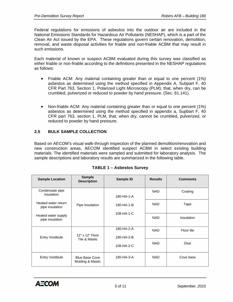
Pre-Demolition Survey Report Robins AFB – Building 180
5 of 11 September, 2015
Federal regulations for emissions of asbestos into the outdoor air are included in the National Emissions Standards for Hazardous Air Pollutants (NESHAP), which is a part of the Clean Air Act issued by the EPA. These regulations govern certain renovation, demolition, removal, and waste disposal activities for friable and non-friable ACBM that may result in such emissions. Each material of known or suspect ACBM evaluated during this survey was classified as either friable or non-friable according to the definitions presented in the NESHAP regulations as follows:
Friable ACM: Any material containing greater than or equal to one percent (1%) asbestos as determined using the method specified in Appendix A, Subpart F, 40 CFR Part 763, Section 1, Polarized Light Microscopy (PLM), that, when dry, can be crumbled, pulverized or reduced to powder by hand pressure. (Sec. 61.141).
Non-friable ACM: Any material containing greater than or equal to one percent (1%) asbestos as determined using the method specified in appendix a, Supbart F, 40 CFR part 763, section 1, PLM, that, when dry, cannot be crumbled, pulverized, or reduced to powder by hand pressure.
2.5 BULK SAMPLE COLLECTION
Based on AECOM’s visual walk-through inspection of the planned demolition/renovation and new construction areas, AECOM identified suspect ACBM in select existing building materials. The identified materials were sampled and submitted for laboratory analysis. The sample descriptions and laboratory results are summarized in the following table.
TABLE 1 – Asbestos Survey
Sample Location Sample Description Sample ID Results Comments
Condensate pipe insulation
Heated water return pipe insulation
Heated water supply pipe insulation
Pipe Insulation
180-HA-1-A
180-HA-1-B
108-HA-1-C
NAD Coating
NAD Tape
NAD Insulation
Entry Vestibule 12” x 12” Floor Tile & Mastic
180-HA-2-A
180-HA-2-B
108-HA-2-C
NAD Floor tile
NAD Glue
Entry Vestibule Blue Base Cove Molding & Mastic
180-HA-3-A NAD Cove base

Pre-Demolition Survey Report Robins AFB – Building 180
6 of 11 September, 2015
Sample Location Sample Description Sample ID Results Comments
180-HA-3-B
108-HA-3-C NAD Glue
Entry Vestibule Drywall and Vinyl Wall Covering
180-HA-4-A
180-HA-4-B
108-HA-4-C
NAD Wall covering
NAD Drywall tape
NAD Wallboard
Entry Vestibule Acoustic Ceiling Tile
180-HA-5-A
180-HA-5-B
108-HA-5-C
NAD Ceiling tile, paint included as binder
Main Hallway Gray Base Cove Molding & Mastic
180-HA-6-A
180-HA-6-B
108-HA-6-C
NAD Cove base
NAD Glue
Interior Hall Acoustic Ceiling Tile
180-HA-7-A
180-HA-7-B
108-HA-7-C
NAD Ceiling tile, paint included as binder
Men’s & Women’s Restroom Caulking
180-HA-8-A
180-HA-8-B
108-HA-8-C
NAD Caulk
Windows Exterior Window Gasket
180-HA-9-A
180-HA-9-B
108-HA-9-C
NAD Caulk
Windows Exterior Window Sealant/Caulk
180-HA-10-A
180-HA-10-B
108-HA-10-C
NAD Caulk

Pre-Demolition Survey Report Robins AFB – Building 180
7 of 11 September, 2015
Sample Location Sample Description Sample ID Results Comments
Administrative Office Area
Office Tile & Mastic (below
carpet)
180-HA-11-A
180-HA-11-B
108-HA-11-C
NAD Black mastic
NAD Floor tile
NAD Glue
NAD Leveling compound
Administrative Office Breakroom
White Speckled Floor Tile & Mastic
180-HA-11-A
180-HA-11-B
108-HA-11-C
NAD Floor tile
NAD Leveling compound with glue
A copy of the ACM laboratory data results is included in Appendix B of this report.
2.6 FRIABLE MATERIALS
Based on information provided, and AECOM’s understanding of the areas of demolition/renovation and new construction friable TSI, surfacing, miscellaneous, and/or assumed materials that contain asbestos were not identified at this facility.
2.7 NON-FRIABLE MATERIALS
Based on information provided, and AECOM’s understanding of the areas of demolition/renovation and new construction non-friable miscellaneous materials that contain asbestos were not identified at this facility. No other non-Friable thermal systems insulation, surfacing, and miscellaneous materials that contain asbestos were identified at this facility.

Pre-Demolition Survey Report Robins AFB – Building 180
8 of 11 September, 2015
3.0 LEAD BASED PAINT (LBP) SURVEY
3.1 METHODOLOGY
The following section presents the methodology for assessing the materials sampled as a part of the Pre-Demolition Lead Based Paint (LBP) Survey and identifying materials to be sampled, if warranted. The LBP survey of this facility was performed by Mr. Nathan Bruce, of AECOM.
3.2 INFORMATION REVIEW AND INITIAL WALK-THROUGH INSPECTION
AECOM conducted an initial walk-through inspection and pre-demolition LBP survey of the planned demolition/renovation and new construction areas on September 2, 2015. Accessible areas of the planned demolition/renovation and new construction areas were observed and the locations of suspect LBP were noted within the planned demolition/renovation and new construction areas. All areas of the facility building were accessible to the inspector, except for the mechanical room in the northernmost section of the building.
3.3 GROUPING OF SUSPECT LBP
During the initial walk-through inspection of the planned demolition/renovation and new construction areas, the location of suspected lead based paint surfaces were grouped according to the type of material then grouped by homogenous area and assessed for degree (presence and location), type, and condition of total lead hazard. At the conclusion of the walk through, a general sampling plan was devised for the collection of paint chip samples, if warranted.
3.4 PAINT CHIP SAMPLE COLLECTION
Based on AECOM’s visual walk-through inspection of the planned demolition/renovation and new construction areas, AECOM identified suspect LBP in select existing building areas. The identified materials were sampled and submitted for laboratory analysis. The sample descriptions and laboratory results are summarized in the following table.
TABLE 2 – Lead Based Paint Survey
Sample Location Sample Description
Sample ID Percent Lead
Comments
Exterior Siding Yellow Beige 180-LBP-1 BRL Intact, good condition.
Exterior Siding Rose Beige 180-LBP-2 BRL Intact, good condition.
Exterior Siding Orange Beige 180-LBP-3 BRL Intact, good condition.
Entry Vestibule Yellow (gray undercoat) 180-LBP-4 BRL Intact, good condition.

Pre-Demolition Survey Report Robins AFB – Building 180
9 of 11 September, 2015
Sample Location Sample Description
Sample ID Percent Lead
Comments
Main Hallway White (yellow gray undercoat) 180-LBP-5 BRL Intact, good condition.
Interior Metal Door Frame Gray 180-LBP-6 BRL Intact, good condition.
Interior Metal Door Gray 180-LBP-7 BRL Intact, good condition.
Restroom Mottled Pink Beige 180-LBP-8 BRL Intact, good condition.
Warehouse Wall Light Gray 180-LBP-9 BRL Intact, good condition.
Mezzanine Handrail Brown 180-LBP-10 0.0986 Intact, good condition.
Mezzanine Ductwork and Steel Framing Yellow 180-LBP-11 BRL Intact, good condition.
Mezzanine Steel Framing Yellow/Red Base Coat 180-LBP-12 BRL Intact, good condition.
Interior Metal Door Frame Red 180-LBP-13 BRL Intact, good condition.
Maintenance Closet Wall & Door Frame Gray 180-LBP-14 BRL Intact, good condition.
BLR = results below laboratory reporting limits
A copy of the LBP laboratory data sheets are included in Appendix C of this report.
3.5 LBP MATERIALS
Based on the results of the pre-demolition lead based paint survey, positive readings for lead based paint were identified in the mezzanine metal handrails (brown) of the building.
3.6 LBP RISK ASSESSMENT METHODOLOGY
Paint with greater than 0.06% lead is required to be identified as a potential worker exposure under the Lead-Based Paint Poisoning Prevention Act of 1971. Currently, there are no federal or state regulations that require removal of LBP prior to building demolition or renovation. Under U.S. Occupational Safety and Health Administration (OSHA) regulations 29 CFR 1926.62, which are designed to protect workers who are potentially exposed to elevated airborne levels of lead from LBP, you are required to disclose to contractors or workers connected with the building demolition or renovation the presence of LBP with any lead content. These OSHA regulations require specific health and safety measures to be taken by the contractor(s) if demolition of surfaces containing LBP is performed. Although federal and state regulations do not require pre-demolition/renovations of LBP, federal regulations do require laboratory analysis of demolition or renovation wastes prior to disposal at a landfill. This testing involves determining the leachability characteristics of the

Pre-Demolition Survey Report Robins AFB – Building 180
10 of 11 September, 2015
lead in the LBP-containing building components. This test is known as Toxicity Characteristic Leaching Procedure (TCLP). The TCLP regulatory limit for LBP materials which have to be disposed of as hazardous waste is 5.0 milligrams per liter (mg/L) or parts per million (ppm). TCLP sampling may be performed prior to demolition or at the time the building is demolished. If results of TCLP testing find leachable lead in excess of 5.0 mg/L, disposal of demolition debris coated with LBP as a hazardous waste and special handling and disposal requirements will be necessary.

Pre-Demolition Survey Report Robins AFB – Building 180
11 of 11 September, 2015
4.0 CONCLUSIONS AND RECOMMENDATIONS
4.1 ASBESTOS-CONTAINING MATERIALS
Based on the results of the pre-demolition asbestos survey the following conclusions and recommendations are presented:
Asbestos-containing building materials (ACBMs) were not identified at the facility, within the renovation/demolition and new construction area, that require abatement, disposal, and/or special handling.
4.2 LEAD BASED PAINT SURFACES
Based on the results of the pre-demolition lead based paint survey, the following conclusions and recommendations are presented:
Positive readings for lead based paint were identified in the mezzanine metal handrails (brown) of the building. The demolition/renovation contractor must be notified as to the presence and location of the lead painted materials.
Additional sampling of the painted surfaces needs to be conducted to evaluate the
disposal requirements for painted surfaces as general construction debris or hazardous materials. Samples will need to be submitted for total characteristic leachate procedure (TCLP) lead analysis.

Pre-Demolition Survey Report Robins AFB – Building 180
September, 2015
APPENDIX A ASBESTOS SAMPLE LABORATORY RESULTS
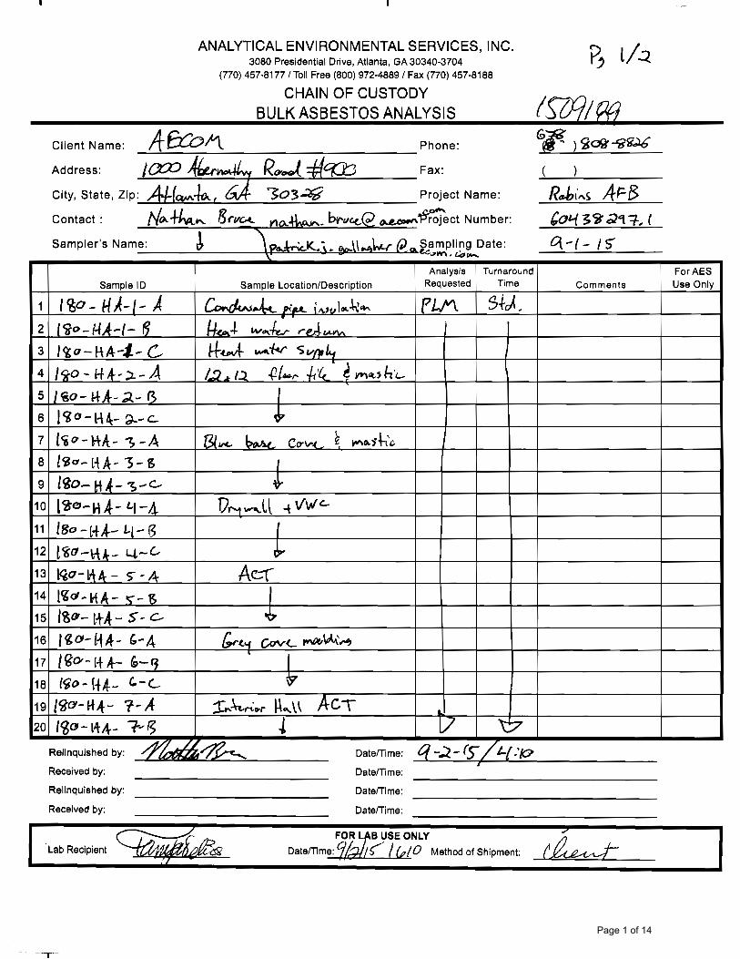
Page 1 of 14

Page 2 of 14

ANALYTICAL ENVIRONMENTAL SERVICES, INC.
10-Sep-15
Bulk Sample Summary ReportLab Code 102082-0
AES Job Number:
Project Number:Project Name:
Client Name:
LocationClient ID AES ID Asbestos Mineral Percentage Comments
1509189
Robins AFB 60438297.1
URS
AMCH CR AN TR AC
1
CoatingNDNDNDNDNDNDCondensate Pipe Insulation1509189-
001A180-HA-1-A
Layer:
2
TapeNDNDNDNDNDNDCondensate Pipe Insulation1509189-
001A180-HA-1-A
Layer:
3
InsulationNDNDNDNDNDNDCondensate Pipe Insulation1509189-
001A180-HA-1-A
Layer:
1
TapeNDNDNDNDNDNDHeat Water Return1509189-
002A180-HA-1-B
Layer:
2
InsulationNDNDNDNDNDNDHeat Water Return1509189-
002A180-HA-1-B
Layer:
1
TapeNDNDNDNDNDNDHeat Water Supply1509189-
003A180-HA-1-C
Layer:
Note: CH=chrysotile, AM=amosite, CR=crocidolite, AC=actinolite, TR=tremolite, AN=anthophylite
ND = None Detected
For comments on the samples, see the individual analysis sheets.
AES,Inc. is accredited by NIST’s National Voluntary Laboratory Accreditation Program (NVLAP) for Polarized Light Microscopy (PLM) analysis, Lab
Code 102082-0. All analyses performed in accordance with EPA “Interim Method for the Determination of Asbestos in Bulk Insulation Samples” (EPA
600/M4-82-020), 1982 as found in 40 CFR, Part 763, Appendix E to Subpart E and “Method for the Determination of Asbestos in Bulk Building
Materials” (EPA/600/R-93/116), 1993.
These test results apply only to those samples actually tested, as submitted by the client. All percentages are reported by visually estimated volume.
PLM is not consistently reliable in detecting small concentrations of asbestos in floor tiles and similar nonfriable materials, quantitative TEM is currently
the only method that can be used to determine conclusive asbestos content.
This report must not be reproduced except in full without written approval of Analytical Environmental Services, Inc .
Microanalyst: QC Analyst:
Yelena KhaninaSvetlana Arkhipov
Page 3 of 14

ANALYTICAL ENVIRONMENTAL SERVICES, INC.
10-Sep-15
Bulk Sample Summary ReportLab Code 102082-0
AES Job Number:
Project Number:Project Name:
Client Name:
LocationClient ID AES ID Asbestos Mineral Percentage Comments
1509189
Robins AFB 60438297.1
URS
AMCH CR AN TR AC
2
InsulationNDNDNDNDNDNDHeat Water Supply1509189-
003A180-HA-1-C
Layer:
1
Floor tileNDNDNDNDNDND12x12 Floor Tile & Mastic1509189-
004A180-HA-2-A
Layer:
2
GlueNDNDNDNDNDND12x12 Floor Tile & Mastic1509189-
004A180-HA-2-A
Layer:
1
Floor tileNDNDNDNDNDND12x12 Floor Tile & Mastic1509189-
005A180-HA-2-B
Layer:
2
GlueNDNDNDNDNDND12x12 Floor Tile & Mastic1509189-
005A180-HA-2-B
Layer:
1
Floor tileNDNDNDNDNDND12x12 Floor Tile & Mastic1509189-
006A180-HA-2-C
Layer:
Note: CH=chrysotile, AM=amosite, CR=crocidolite, AC=actinolite, TR=tremolite, AN=anthophylite
ND = None Detected
For comments on the samples, see the individual analysis sheets.
AES,Inc. is accredited by NIST’s National Voluntary Laboratory Accreditation Program (NVLAP) for Polarized Light Microscopy (PLM) analysis, Lab
Code 102082-0. All analyses performed in accordance with EPA “Interim Method for the Determination of Asbestos in Bulk Insulation Samples” (EPA
600/M4-82-020), 1982 as found in 40 CFR, Part 763, Appendix E to Subpart E and “Method for the Determination of Asbestos in Bulk Building
Materials” (EPA/600/R-93/116), 1993.
These test results apply only to those samples actually tested, as submitted by the client. All percentages are reported by visually estimated volume.
PLM is not consistently reliable in detecting small concentrations of asbestos in floor tiles and similar nonfriable materials, quantitative TEM is currently
the only method that can be used to determine conclusive asbestos content.
This report must not be reproduced except in full without written approval of Analytical Environmental Services, Inc .
Microanalyst: QC Analyst:
Yelena KhaninaSvetlana Arkhipov
Page 4 of 14

ANALYTICAL ENVIRONMENTAL SERVICES, INC.
10-Sep-15
Bulk Sample Summary ReportLab Code 102082-0
AES Job Number:
Project Number:Project Name:
Client Name:
LocationClient ID AES ID Asbestos Mineral Percentage Comments
1509189
Robins AFB 60438297.1
URS
AMCH CR AN TR AC
2
GlueNDNDNDNDNDND12x12 Floor Tile & Mastic1509189-
006A180-HA-2-C
Layer:
1
Cove baseNDNDNDNDNDNDBlue Base Cove & Mastic1509189-
007A180-HA-3-A
Layer:
2
GlueNDNDNDNDNDNDBlue Base Cove & Mastic1509189-
007A180-HA-3-A
Layer:
1
Cove baseNDNDNDNDNDNDBlue Base Cove & Mastic1509189-
008A180-HA-3-B
Layer:
2
GlueNDNDNDNDNDNDBlue Base Cove & Mastic1509189-
008A180-HA-3-B
Layer:
1
Cove baseNDNDNDNDNDNDBlue Base Cove & Mastic1509189-
009A180-HA-3-C
Layer:
Note: CH=chrysotile, AM=amosite, CR=crocidolite, AC=actinolite, TR=tremolite, AN=anthophylite
ND = None Detected
For comments on the samples, see the individual analysis sheets.
AES,Inc. is accredited by NIST’s National Voluntary Laboratory Accreditation Program (NVLAP) for Polarized Light Microscopy (PLM) analysis, Lab
Code 102082-0. All analyses performed in accordance with EPA “Interim Method for the Determination of Asbestos in Bulk Insulation Samples” (EPA
600/M4-82-020), 1982 as found in 40 CFR, Part 763, Appendix E to Subpart E and “Method for the Determination of Asbestos in Bulk Building
Materials” (EPA/600/R-93/116), 1993.
These test results apply only to those samples actually tested, as submitted by the client. All percentages are reported by visually estimated volume.
PLM is not consistently reliable in detecting small concentrations of asbestos in floor tiles and similar nonfriable materials, quantitative TEM is currently
the only method that can be used to determine conclusive asbestos content.
This report must not be reproduced except in full without written approval of Analytical Environmental Services, Inc .
Microanalyst: QC Analyst:
Yelena KhaninaSvetlana Arkhipov
Page 5 of 14
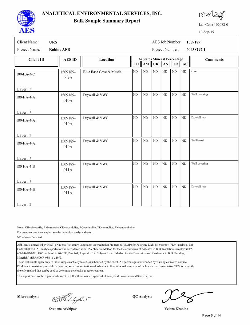
ANALYTICAL ENVIRONMENTAL SERVICES, INC.
10-Sep-15
Bulk Sample Summary ReportLab Code 102082-0
AES Job Number:
Project Number:Project Name:
Client Name:
LocationClient ID AES ID Asbestos Mineral Percentage Comments
1509189
Robins AFB 60438297.1
URS
AMCH CR AN TR AC
2
GlueNDNDNDNDNDNDBlue Base Cove & Mastic1509189-
009A180-HA-3-C
Layer:
1
Wall coveringNDNDNDNDNDNDDrywall & VWC1509189-
010A180-HA-4-A
Layer:
2
Drywall tapeNDNDNDNDNDNDDrywall & VWC1509189-
010A180-HA-4-A
Layer:
3
WallboardNDNDNDNDNDNDDrywall & VWC1509189-
010A180-HA-4-A
Layer:
1
Wall coveringNDNDNDNDNDNDDrywall & VWC1509189-
011A180-HA-4-B
Layer:
2
Drywall tapeNDNDNDNDNDNDDrywall & VWC1509189-
011A180-HA-4-B
Layer:
Note: CH=chrysotile, AM=amosite, CR=crocidolite, AC=actinolite, TR=tremolite, AN=anthophylite
ND = None Detected
For comments on the samples, see the individual analysis sheets.
AES,Inc. is accredited by NIST’s National Voluntary Laboratory Accreditation Program (NVLAP) for Polarized Light Microscopy (PLM) analysis, Lab
Code 102082-0. All analyses performed in accordance with EPA “Interim Method for the Determination of Asbestos in Bulk Insulation Samples” (EPA
600/M4-82-020), 1982 as found in 40 CFR, Part 763, Appendix E to Subpart E and “Method for the Determination of Asbestos in Bulk Building
Materials” (EPA/600/R-93/116), 1993.
These test results apply only to those samples actually tested, as submitted by the client. All percentages are reported by visually estimated volume.
PLM is not consistently reliable in detecting small concentrations of asbestos in floor tiles and similar nonfriable materials, quantitative TEM is currently
the only method that can be used to determine conclusive asbestos content.
This report must not be reproduced except in full without written approval of Analytical Environmental Services, Inc .
Microanalyst: QC Analyst:
Yelena KhaninaSvetlana Arkhipov
Page 6 of 14

ANALYTICAL ENVIRONMENTAL SERVICES, INC.
10-Sep-15
Bulk Sample Summary ReportLab Code 102082-0
AES Job Number:
Project Number:Project Name:
Client Name:
LocationClient ID AES ID Asbestos Mineral Percentage Comments
1509189
Robins AFB 60438297.1
URS
AMCH CR AN TR AC
3
WallboardNDNDNDNDNDNDDrywall & VWC1509189-
011A180-HA-4-B
Layer:
1
Wall coveringNDNDNDNDNDNDDrywall & VWC1509189-
012A180-HA-4-C
Layer:
2
Drywall tapeNDNDNDNDNDNDDrywall & VWC1509189-
012A180-HA-4-C
Layer:
3
WallboardNDNDNDNDNDNDDrywall & VWC1509189-
012A180-HA-4-C
Layer:
1
Ceiling tile. Paint included as
binder
NDNDNDNDNDNDACT1509189-
013A180-HA-5-A
Layer:
1
Ceiling tile. Paint included as
binder
NDNDNDNDNDNDACT1509189-
014A180-HA-5-B
Layer:
Note: CH=chrysotile, AM=amosite, CR=crocidolite, AC=actinolite, TR=tremolite, AN=anthophylite
ND = None Detected
For comments on the samples, see the individual analysis sheets.
AES,Inc. is accredited by NIST’s National Voluntary Laboratory Accreditation Program (NVLAP) for Polarized Light Microscopy (PLM) analysis, Lab
Code 102082-0. All analyses performed in accordance with EPA “Interim Method for the Determination of Asbestos in Bulk Insulation Samples” (EPA
600/M4-82-020), 1982 as found in 40 CFR, Part 763, Appendix E to Subpart E and “Method for the Determination of Asbestos in Bulk Building
Materials” (EPA/600/R-93/116), 1993.
These test results apply only to those samples actually tested, as submitted by the client. All percentages are reported by visually estimated volume.
PLM is not consistently reliable in detecting small concentrations of asbestos in floor tiles and similar nonfriable materials, quantitative TEM is currently
the only method that can be used to determine conclusive asbestos content.
This report must not be reproduced except in full without written approval of Analytical Environmental Services, Inc .
Microanalyst: QC Analyst:
Yelena KhaninaSvetlana Arkhipov
Page 7 of 14

ANALYTICAL ENVIRONMENTAL SERVICES, INC.
10-Sep-15
Bulk Sample Summary ReportLab Code 102082-0
AES Job Number:
Project Number:Project Name:
Client Name:
LocationClient ID AES ID Asbestos Mineral Percentage Comments
1509189
Robins AFB 60438297.1
URS
AMCH CR AN TR AC
1
Ceiling tile. Paint included as
binder
NDNDNDNDNDNDACT1509189-
015A180-HA-5-C
Layer:
1
Cove baseNDNDNDNDNDNDGray Cove Molding1509189-
016A180-HA-6-A
Layer:
2
GlueNDNDNDNDNDNDGray Cove Molding1509189-
016A180-HA-6-A
Layer:
1
Cove baseNDNDNDNDNDNDGray Cove Molding1509189-
017A180-HA-6-B
Layer:
2
GlueNDNDNDNDNDNDGray Cove Molding1509189-
017A180-HA-6-B
Layer:
1
Cove baseNDNDNDNDNDNDGray Cove Molding1509189-
018A180-HA-6-C
Layer:
Note: CH=chrysotile, AM=amosite, CR=crocidolite, AC=actinolite, TR=tremolite, AN=anthophylite
ND = None Detected
For comments on the samples, see the individual analysis sheets.
AES,Inc. is accredited by NIST’s National Voluntary Laboratory Accreditation Program (NVLAP) for Polarized Light Microscopy (PLM) analysis, Lab
Code 102082-0. All analyses performed in accordance with EPA “Interim Method for the Determination of Asbestos in Bulk Insulation Samples” (EPA
600/M4-82-020), 1982 as found in 40 CFR, Part 763, Appendix E to Subpart E and “Method for the Determination of Asbestos in Bulk Building
Materials” (EPA/600/R-93/116), 1993.
These test results apply only to those samples actually tested, as submitted by the client. All percentages are reported by visually estimated volume.
PLM is not consistently reliable in detecting small concentrations of asbestos in floor tiles and similar nonfriable materials, quantitative TEM is currently
the only method that can be used to determine conclusive asbestos content.
This report must not be reproduced except in full without written approval of Analytical Environmental Services, Inc .
Microanalyst: QC Analyst:
Yelena KhaninaSvetlana Arkhipov
Page 8 of 14

ANALYTICAL ENVIRONMENTAL SERVICES, INC.
10-Sep-15
Bulk Sample Summary ReportLab Code 102082-0
AES Job Number:
Project Number:Project Name:
Client Name:
LocationClient ID AES ID Asbestos Mineral Percentage Comments
1509189
Robins AFB 60438297.1
URS
AMCH CR AN TR AC
2
GlueNDNDNDNDNDNDGray Cove Molding1509189-
018A180-HA-6-C
Layer:
1
Paint included as binderNDNDNDNDNDNDInterior Hall ACT1509189-
019A180-HA-7-A
Layer:
1
Paint included as binderNDNDNDNDNDNDInterior Hall ACT1509189-
020A180-HA-7-B
Layer:
1
Paint included as binderNDNDNDNDNDNDInterior Hall ACT1509189-
021A180-HA-7-C
Layer:
1
CaulkNDNDNDNDNDNDRestroom Caulking1509189-
022A180-HA-8-A
Layer:
1
CaulkNDNDNDNDNDNDRestroom Caulking1509189-
023A180-HA-8-B
Layer:
Note: CH=chrysotile, AM=amosite, CR=crocidolite, AC=actinolite, TR=tremolite, AN=anthophylite
ND = None Detected
For comments on the samples, see the individual analysis sheets.
AES,Inc. is accredited by NIST’s National Voluntary Laboratory Accreditation Program (NVLAP) for Polarized Light Microscopy (PLM) analysis, Lab
Code 102082-0. All analyses performed in accordance with EPA “Interim Method for the Determination of Asbestos in Bulk Insulation Samples” (EPA
600/M4-82-020), 1982 as found in 40 CFR, Part 763, Appendix E to Subpart E and “Method for the Determination of Asbestos in Bulk Building
Materials” (EPA/600/R-93/116), 1993.
These test results apply only to those samples actually tested, as submitted by the client. All percentages are reported by visually estimated volume.
PLM is not consistently reliable in detecting small concentrations of asbestos in floor tiles and similar nonfriable materials, quantitative TEM is currently
the only method that can be used to determine conclusive asbestos content.
This report must not be reproduced except in full without written approval of Analytical Environmental Services, Inc .
Microanalyst: QC Analyst:
Yelena KhaninaSvetlana Arkhipov
Page 9 of 14

ANALYTICAL ENVIRONMENTAL SERVICES, INC.
10-Sep-15
Bulk Sample Summary ReportLab Code 102082-0
AES Job Number:
Project Number:Project Name:
Client Name:
LocationClient ID AES ID Asbestos Mineral Percentage Comments
1509189
Robins AFB 60438297.1
URS
AMCH CR AN TR AC
1
CaulkNDNDNDNDNDNDRestroom Caulking1509189-
024A180-HA-8-C
Layer:
1
CaulkNDNDNDNDNDNDExterior Window Gasket1509189-
025A180-HA-9-A
Layer:
1
CaulkNDNDNDNDNDNDExterior Window Gasket1509189-
026A180-HA-9-B
Layer:
1
CaulkNDNDNDNDNDNDExterior Window Gasket1509189-
027A180-HA-9-C
Layer:
1
CaulkNDNDNDNDNDNDExt. Window Sealant / Caulk1509189-
028A180-HA-10-A
Layer:
1
CaulkNDNDNDNDNDNDExt. Window Sealant / Caulk1509189-
029A180-HA-10-B
Layer:
Note: CH=chrysotile, AM=amosite, CR=crocidolite, AC=actinolite, TR=tremolite, AN=anthophylite
ND = None Detected
For comments on the samples, see the individual analysis sheets.
AES,Inc. is accredited by NIST’s National Voluntary Laboratory Accreditation Program (NVLAP) for Polarized Light Microscopy (PLM) analysis, Lab
Code 102082-0. All analyses performed in accordance with EPA “Interim Method for the Determination of Asbestos in Bulk Insulation Samples” (EPA
600/M4-82-020), 1982 as found in 40 CFR, Part 763, Appendix E to Subpart E and “Method for the Determination of Asbestos in Bulk Building
Materials” (EPA/600/R-93/116), 1993.
These test results apply only to those samples actually tested, as submitted by the client. All percentages are reported by visually estimated volume.
PLM is not consistently reliable in detecting small concentrations of asbestos in floor tiles and similar nonfriable materials, quantitative TEM is currently
the only method that can be used to determine conclusive asbestos content.
This report must not be reproduced except in full without written approval of Analytical Environmental Services, Inc .
Microanalyst: QC Analyst:
Yelena KhaninaSvetlana Arkhipov
Page 10 of 14

ANALYTICAL ENVIRONMENTAL SERVICES, INC.
10-Sep-15
Bulk Sample Summary ReportLab Code 102082-0
AES Job Number:
Project Number:Project Name:
Client Name:
LocationClient ID AES ID Asbestos Mineral Percentage Comments
1509189
Robins AFB 60438297.1
URS
AMCH CR AN TR AC
1
CaulkNDNDNDNDNDNDExt. Window Sealant / Caulk1509189-
030A180-HA-10-C
Layer:
1
Black MasticNDNDNDNDNDNDOffice Tile & Mastic (Below
Carpet)
1509189-
031A180-HA-11-A
Layer:
2
Floor tileNDNDNDNDNDNDOffice Tile & Mastic (Below
Carpet)
1509189-
031A180-HA-11-A
Layer:
3
GlueNDNDNDNDNDNDOffice Tile & Mastic (Below
Carpet)
1509189-
031A180-HA-11-A
Layer:
4
Leveling compoundNDNDNDNDNDNDOffice Tile & Mastic (Below
Carpet)
1509189-
031A180-HA-11-A
Layer:
1
Black MasticNDNDNDNDNDNDOffice Tile & Mastic (Below
Carpet)
1509189-
032A180-HA-11-B
Layer:
Note: CH=chrysotile, AM=amosite, CR=crocidolite, AC=actinolite, TR=tremolite, AN=anthophylite
ND = None Detected
For comments on the samples, see the individual analysis sheets.
AES,Inc. is accredited by NIST’s National Voluntary Laboratory Accreditation Program (NVLAP) for Polarized Light Microscopy (PLM) analysis, Lab
Code 102082-0. All analyses performed in accordance with EPA “Interim Method for the Determination of Asbestos in Bulk Insulation Samples” (EPA
600/M4-82-020), 1982 as found in 40 CFR, Part 763, Appendix E to Subpart E and “Method for the Determination of Asbestos in Bulk Building
Materials” (EPA/600/R-93/116), 1993.
These test results apply only to those samples actually tested, as submitted by the client. All percentages are reported by visually estimated volume.
PLM is not consistently reliable in detecting small concentrations of asbestos in floor tiles and similar nonfriable materials, quantitative TEM is currently
the only method that can be used to determine conclusive asbestos content.
This report must not be reproduced except in full without written approval of Analytical Environmental Services, Inc .
Microanalyst: QC Analyst:
Yelena KhaninaSvetlana Arkhipov
Page 11 of 14

ANALYTICAL ENVIRONMENTAL SERVICES, INC.
10-Sep-15
Bulk Sample Summary ReportLab Code 102082-0
AES Job Number:
Project Number:Project Name:
Client Name:
LocationClient ID AES ID Asbestos Mineral Percentage Comments
1509189
Robins AFB 60438297.1
URS
AMCH CR AN TR AC
2
Floor tileNDNDNDNDNDNDOffice Tile & Mastic (Below
Carpet)
1509189-
032A180-HA-11-B
Layer:
3
GlueNDNDNDNDNDNDOffice Tile & Mastic (Below
Carpet)
1509189-
032A180-HA-11-B
Layer:
4
Leveling compoundNDNDNDNDNDNDOffice Tile & Mastic (Below
Carpet)
1509189-
032A180-HA-11-B
Layer:
1
Black MasticNDNDNDNDNDNDOffice Tile & Mastic (Below
Carpet)
1509189-
033A180-HA-11-C
Layer:
2
Floor tileNDNDNDNDNDNDOffice Tile & Mastic (Below
Carpet)
1509189-
033A180-HA-11-C
Layer:
3
GlueNDNDNDNDNDNDOffice Tile & Mastic (Below
Carpet)
1509189-
033A180-HA-11-C
Layer:
Note: CH=chrysotile, AM=amosite, CR=crocidolite, AC=actinolite, TR=tremolite, AN=anthophylite
ND = None Detected
For comments on the samples, see the individual analysis sheets.
AES,Inc. is accredited by NIST’s National Voluntary Laboratory Accreditation Program (NVLAP) for Polarized Light Microscopy (PLM) analysis, Lab
Code 102082-0. All analyses performed in accordance with EPA “Interim Method for the Determination of Asbestos in Bulk Insulation Samples” (EPA
600/M4-82-020), 1982 as found in 40 CFR, Part 763, Appendix E to Subpart E and “Method for the Determination of Asbestos in Bulk Building
Materials” (EPA/600/R-93/116), 1993.
These test results apply only to those samples actually tested, as submitted by the client. All percentages are reported by visually estimated volume.
PLM is not consistently reliable in detecting small concentrations of asbestos in floor tiles and similar nonfriable materials, quantitative TEM is currently
the only method that can be used to determine conclusive asbestos content.
This report must not be reproduced except in full without written approval of Analytical Environmental Services, Inc .
Microanalyst: QC Analyst:
Yelena KhaninaSvetlana Arkhipov
Page 12 of 14

ANALYTICAL ENVIRONMENTAL SERVICES, INC.
10-Sep-15
Bulk Sample Summary ReportLab Code 102082-0
AES Job Number:
Project Number:Project Name:
Client Name:
LocationClient ID AES ID Asbestos Mineral Percentage Comments
1509189
Robins AFB 60438297.1
URS
AMCH CR AN TR AC
4
Leveling compoundNDNDNDNDNDNDOffice Tile & Mastic (Below
Carpet)
1509189-
033A180-HA-11-C
Layer:
1
Floor tileNDNDNDNDNDNDWhite Speckled Floor Tile &
Mastic
1509189-
034A180-HA-12-A
Layer:
2
Leveling compound with glueNDNDNDNDNDNDWhite Speckled Floor Tile &
Mastic
1509189-
034A180-HA-12-A
Layer:
1
Floor tileNDNDNDNDNDNDWhite Speckled Floor Tile &
Mastic
1509189-
035A180-HA-12-B
Layer:
2
Leveling compound with glueNDNDNDNDNDNDWhite Speckled Floor Tile &
Mastic
1509189-
035A180-HA-12-B
Layer:
1
Floor tileNDNDNDNDNDNDWhite Speckled Floor Tile &
Mastic
1509189-
036A180-HA-12-C
Layer:
Note: CH=chrysotile, AM=amosite, CR=crocidolite, AC=actinolite, TR=tremolite, AN=anthophylite
ND = None Detected
For comments on the samples, see the individual analysis sheets.
AES,Inc. is accredited by NIST’s National Voluntary Laboratory Accreditation Program (NVLAP) for Polarized Light Microscopy (PLM) analysis, Lab
Code 102082-0. All analyses performed in accordance with EPA “Interim Method for the Determination of Asbestos in Bulk Insulation Samples” (EPA
600/M4-82-020), 1982 as found in 40 CFR, Part 763, Appendix E to Subpart E and “Method for the Determination of Asbestos in Bulk Building
Materials” (EPA/600/R-93/116), 1993.
These test results apply only to those samples actually tested, as submitted by the client. All percentages are reported by visually estimated volume.
PLM is not consistently reliable in detecting small concentrations of asbestos in floor tiles and similar nonfriable materials, quantitative TEM is currently
the only method that can be used to determine conclusive asbestos content.
This report must not be reproduced except in full without written approval of Analytical Environmental Services, Inc .
Microanalyst: QC Analyst:
Yelena KhaninaSvetlana Arkhipov
Page 13 of 14

ANALYTICAL ENVIRONMENTAL SERVICES, INC.
10-Sep-15
Bulk Sample Summary ReportLab Code 102082-0
AES Job Number:
Project Number:Project Name:
Client Name:
LocationClient ID AES ID Asbestos Mineral Percentage Comments
1509189
Robins AFB 60438297.1
URS
AMCH CR AN TR AC
2
Leveling compound with glueNDNDNDNDNDNDWhite Speckled Floor Tile &
Mastic
1509189-
036A180-HA-12-C
Layer:
Note: CH=chrysotile, AM=amosite, CR=crocidolite, AC=actinolite, TR=tremolite, AN=anthophylite
ND = None Detected
For comments on the samples, see the individual analysis sheets.
AES,Inc. is accredited by NIST’s National Voluntary Laboratory Accreditation Program (NVLAP) for Polarized Light Microscopy (PLM) analysis, Lab
Code 102082-0. All analyses performed in accordance with EPA “Interim Method for the Determination of Asbestos in Bulk Insulation Samples” (EPA
600/M4-82-020), 1982 as found in 40 CFR, Part 763, Appendix E to Subpart E and “Method for the Determination of Asbestos in Bulk Building
Materials” (EPA/600/R-93/116), 1993.
These test results apply only to those samples actually tested, as submitted by the client. All percentages are reported by visually estimated volume.
PLM is not consistently reliable in detecting small concentrations of asbestos in floor tiles and similar nonfriable materials, quantitative TEM is currently
the only method that can be used to determine conclusive asbestos content.
This report must not be reproduced except in full without written approval of Analytical Environmental Services, Inc .
Microanalyst: QC Analyst:
Yelena KhaninaSvetlana Arkhipov
Page 14 of 14

Pre-Demolition Survey Report Robins AFB – Building 180
September, 2015
APPENDIX B INSPECTOR CERTIFICATION

Pre-Demolition Survey Report Robins AFB – Building 180
September, 2015
APPENDIX C LEAD BASED PAINT LABORATORY RESULTS

September 11, 2015
Dear Order No:
RE:
Analytical Environmental Services, Inc. received samples on for the analyses presented in following report.
FAX:TEL:
14
No problems were encountered during the analyses. Additionally, all results for the associated
Quality Control samples were within EPA and/or AES established limits. Any discrepancies
associated with the analyses contained herein will be noted and submitted in the form of a
project Case Narrative.
AES’ certifications are as follows:
-NELAC/Florida Certification number E87582 for analysis of Environmental Water,
soil/hazardous waste, and Drinking Water Microbiology, effective 07/01/15-06/30/16.
-AIHA-LAP, LLC Laboratory ID: 100671 for Industrial Hygiene samples (Organics,
Inorganics), Environmental Lead (Paint, Soil, Dust Wipes, Air), and Environmental
Microbiology (Fungal) Direct Examination, effective until 09/01/17.
These results relate only to the items tested. This report may only be reproduced in full.
If you have any questions regarding these test results, please feel free to call.
(678) 808-8800(678) 808-8400
Project Manager
1509202
Nathan BruceURS400 Northpark Town CenterAtlanta GA 30328
Robins AFB
Ioana Pacurar
9/2/2015 4:00:00 PM
Nathan Bruce:
Page 1 of 6

Page 2 of 6

11-Sep-15Date:Analytical Environmental Services, Inc
Client:
Case NarrativeRobins AFB
URS
Lab ID:
Project:
1509202
Lead in Paint Analysis by Method N7082:
For all samples submitted with less than 0.100g of material for analysis, values are reported with elevated reporting limits.
Page 3 of 6

Analytical Environmental Services, Inc Date: 11-Sep-15
TOTAL LEAD IN PAINT (N7082)
Matrix:
Lab Order: 1509202
Solid
Date Received:
Project: Robins AFB
9/2/2015 4:00:00 PM
Client: URS
PAINT
AnalystUnitsResultClient Sample IDLaboratory IDDate
Analyzed
Date
CollectedDF
Reporting
LimitQual
1509202-001A 180-LBP-1 BRL wt% 0.0498 1 09/01/2015 09/09/2015 CC
1509202-002A 180-LBP-2 BRL wt% 0.00974 1 09/01/2015 09/09/2015 CC
1509202-003A 180-LBP-3 BRL wt% 0.0193 1 09/01/2015 09/09/2015 CC
1509202-004A 180-LBP-4 BRL wt% 0.0158 1 09/01/2015 09/09/2015 CC
1509202-005A 180-LBP-5 BRL wt% 0.00917 1 09/01/2015 09/09/2015 CC
1509202-006A 180-LBP-6 BRL wt% 0.00976 1 09/01/2015 09/09/2015 CC
1509202-007A 180-LBP-7 BRL wt% 0.00919 1 09/01/2015 09/09/2015 CC
1509202-008A 180-LBP-8 BRL wt% 0.00972 1 09/01/2015 09/09/2015 CC
1509202-009A 180-LBP-9 BRL wt% 0.00954 1 09/01/2015 09/09/2015 CC
1509202-010A 180-LBP-10 0.0986 wt% 0.00964 1 09/01/2015 09/09/2015 CC
1509202-011A 180-LBP-11 BRL wt% 0.00935 1 09/01/2015 09/09/2015 CC
1509202-012A 180-LBP-12 BRL wt% 0.0112 1 09/01/2015 09/09/2015 CC
1509202-013A 180-LBP-13 BRL wt% 0.00978 1 09/01/2015 09/09/2015 CC
1509202-014A 180-LBP-14 BRL wt% 0.00983 1 09/01/2015 09/09/2015 CC
Qualifiers: BRL - Not Detected at the Reporting Limit DF - Dilution Factor
Results are blank corrected where applicable
B - Analyte detected in the associated Method Blank Page 4 of 6

Analytical Environmental Services, Inc.
Sample/Cooler Receipt Checklist
Client __ ---'---'---~"-'--'''__''__'-- _
Checklist completed by _---'~"---""=-'--"'--'---_~"_~--'---~' ___=_L_____'______'____'>.L _Signature
Carrier name: FedEx UPS Courier
Shipping container/cooler in good condition? Yes
Custody seals intact on shipping container/cooler? Yes
Custody seals intact on sample bottles? Yes
Container/Temp Blank temperature in compliance? (O°:'S6°C)*Yes / No
Cooler #1 v.Mb Cooler #2 _ Cooler #3 _ Cooler #4 _
Chain of custody present? Yes -.LYes -iYes IYesd
Chain of custody signed when relinquished and received?
Chain of custody agrees with sample labels?
Samples in proper container/bottle?
Sample containers intact? Yes -.LYes -J!Yes JYes J
Sufficient sample volume for indicated test?
All samples received within holding time?
Was TAT marked on the COC?
Proceed with Standard TAT as per project history? Yes
Water - VOA vials have zero headspace? No VOA vials submitted JWater - pH acceptable upon receipt? Yes
Work Order Number _---I---Y-=----=--_----""--- _
Other _
No
No
No
No
No
No
No
No
No
No
No
No
Yes
No
Not Present ~
Not Present /
Not Present ./
Cooler#5 _ Cooler #6 _
Not Applicable-'/
No
Not Applicable ./
Adjusted? Checked by _
Sample Condition: Good ~ Other(Explain) -------------------r----
(For diffusive samples or AIHA lead) Is a known blank included?
See Case Narrative for resolution of the Non-Conformance.
* Samples do not have to comply with the given range for certain parameters.
\\Aes _server\I\Sample Receipt\My Documents\COCs and pH Adjustment Sheet\Sample _Cooler _Recipt_ Checklist_ Revl.rtf
Yes No /'
Page 5 of 6

11-Sep-15Date:Analytical Environmental Services, Inc
Client:
BatchID:Workorder:
Project Name:ANALYTICAL QC SUMMARY REPORT
Robins AFB
1509202
URS
212466
RPT Limit QualAnalyte Result SPK value SPK Ref Val %REC Low Limit High Limit RPD Ref Val %RPD RPD Limit
SampleType: BatchID: Analysis Date: Seq No:TestCode: 212466MBLK 09/09/2015TOTAL LEAD IN PAINT (N7082)
Units: Prep Date:Sample ID: Client ID: Run No:wt% 09/09/2015 299601MB-212466
6398697
Lead 0.0100BRL
RPT Limit QualAnalyte Result SPK value SPK Ref Val %REC Low Limit High Limit RPD Ref Val %RPD RPD Limit
SampleType: BatchID: Analysis Date: Seq No:TestCode: 212466LCS 09/09/2015TOTAL LEAD IN PAINT (N7082)
Units: Prep Date:Sample ID: Client ID: Run No:wt% 09/09/2015 299601LCS-212466
6398698
Lead 0.07360.8487 0.7296 116 80 120
RPT Limit QualAnalyte Result SPK value SPK Ref Val %REC Low Limit High Limit RPD Ref Val %RPD RPD Limit
SampleType: BatchID: Analysis Date: Seq No:TestCode: 212466MS 09/09/2015TOTAL LEAD IN PAINT (N7082)
180-LBP-11 Units: Prep Date:Sample ID: Client ID: Run No:wt% 09/09/2015 2996011509202-011AMS
6398700
Lead 0.009320.4308 0.4660 0.008084 90.7 75 125
RPT Limit QualAnalyte Result SPK value SPK Ref Val %REC Low Limit High Limit RPD Ref Val %RPD RPD Limit
SampleType: BatchID: Analysis Date: Seq No:TestCode: 212466MSD 09/09/2015TOTAL LEAD IN PAINT (N7082)
180-LBP-11 Units: Prep Date:Sample ID: Client ID: Run No:wt% 09/09/2015 2996011509202-011AMSD
6398701
Lead 0.009300.4283 250.4651 0.008084 90.4 75 125 0.4308 0.563
Qualifiers:
J Estimated value detected below Reporting Limit
BRL Below reporting limit H Holding times for preparation or analysis exceeded
N Analyte not NELAC certified
B Analyte detected in the associated method blank
E Estimated (value above quantitation range)
S Spike Recovery outside limits due to matrix
< Less than Result value> Greater than Result value
R RPD outside limits due to matrix
Rpt Lim Reporting LimitPage 6 of 6
Related Documents