B3/1 Switch- disconnectors Switch-disconnectors TeSys Vario Door mounting isolation switch - mini Vario - Vario Type of product Range Pages Switch disconnectors mini-Vario Up to 12 or 20 A B3/2 Switch disconnectors, high performance applications Vario From 12 to 175 A B3/6 Accessories mini-Vario and Vario B3/8 TeSys Control and Protection Components Chapter B3 Technical Data for Designers B3/17

Welcome message from author
This document is posted to help you gain knowledge. Please leave a comment to let me know what you think about it! Share it to your friends and learn new things together.
Transcript

B3/1
Switch-
disconnectors
Switch-disconnectorsTeSys Vario
Door mounting isolation switch - mini Vario - Vario
Type of product Range Pages
Switch disconnectors
mini-VarioUp to 12 or 20 A B3/2
Switch disconnectors,
high performance applications
Vario
From 12 to 175 A B3/6
Accessories
mini-Vario and VarioB3/8
TeSys Control and
Protection Components
Chapter
B3
Technical Data for Designers B3/17
B3/2
TeSys protection components Mini-VARIO switch-disconnectors
for standard applicationsComplete units
b 3-pole rotary switch-disconnectors, 12 to 20 A
b Marking on operator .
b Padlockable operating handle (padlocks not supplied).
b Degree of protection IP 65.
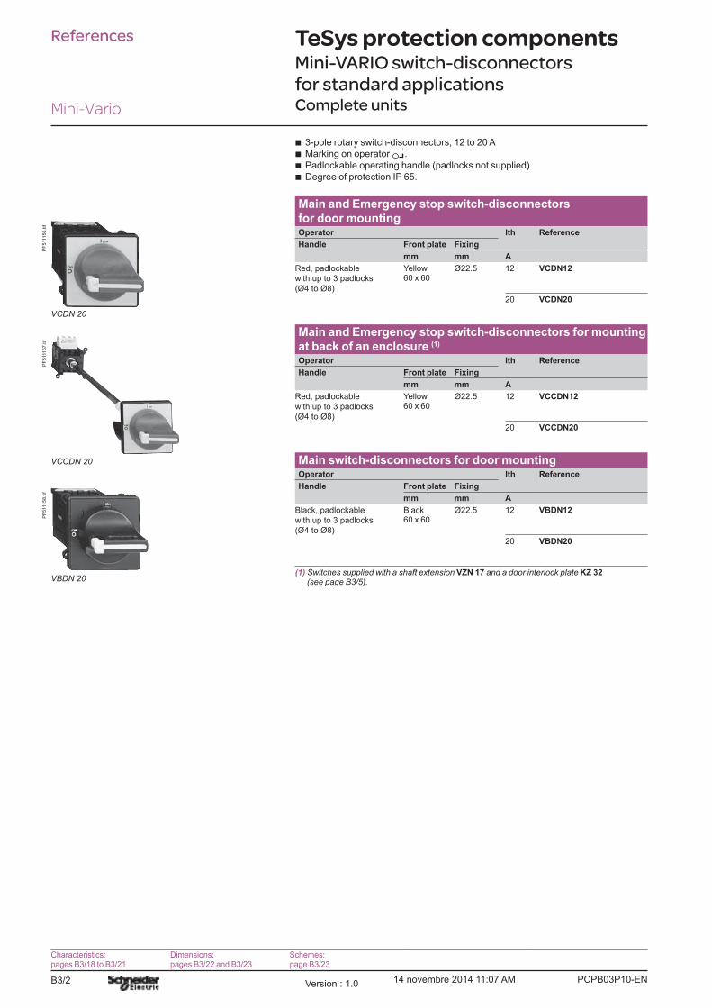
Main and Emergency stop switch-disconnectors for door mountingOperator lth Reference
Handle Front plate Fixing
mm mm A
Red, padlockable
with up to 3 padlocks
(Ø4 to Ø8)
Yellow60 x 60
Ø22.5
12 VCDN12
20 VCDN20
Main and Emergency stop switch-disconnectors for mounting
at back of an enclosure (1)
Operator lth Reference
Handle Front plate Fixing
mm mm A
Red, padlockable
with up to 3 padlocks
(Ø4 to Ø8)
Yellow60 x 60
Ø22.5
12 VCCDN12
20 VCCDN20
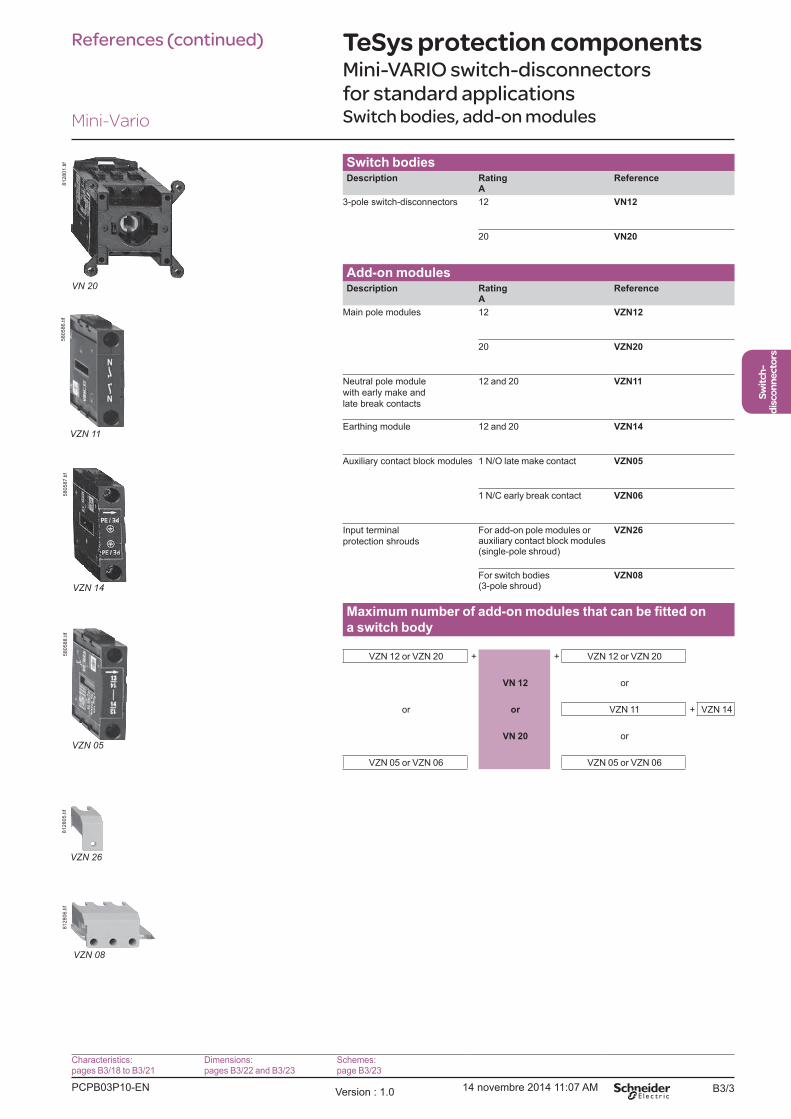
Main switch-disconnectors for door mountingOperator lth Reference
Handle Front plate Fixing
mm mm A
Black, padlockable
with up to 3 padlocks
(Ø4 to Ø8)
Black60 x 60
Ø22.5
12 VBDN12
20 VBDN20
(1) Switches supplied with a shaft extension VZN 17 and a door interlock plate KZ 32 (see page B3/5).
References
VCDN 20
PF
511156.tif
VCCDN 20
PF
511157.tif
VBDN 20
PF
511158.tif
Characteristics:pages B3/18 to B3/21
Dimensions:pages B3/22 and B3/23
Schemes:page B3/23
Mini-Vario
PCPB03P10-ENVersion : 1.0 14 novembre 2014 11:07 AM
B3/3
Switch-
disconnectors
Switch bodiesDescription Rating
AReference
3-pole switch-disconnectors 12 VN12
20 VN20
Add-on modulesDescription Rating
AReference
Main pole modules 12 VZN12
20 VZN20
Neutral pole module
with early make and
late break contacts
12 and 20 VZN11
Earthing module 12 and 20 VZN14
Auxiliary contact block modules 1 N/O late make contact VZN05
1 N/C early break contact VZN06
Input terminal
protection shrouds
For add-on pole modules or auxiliary contact block modules (single-pole shroud)
VZN26
For switch bodies (3-pole shroud)
VZN08
a switch body
VZN 12 or VZN 20 + + VZN 12 or VZN 20
VN 12 or
or or VZN 11 + VZN 14
VN 20 or
VZN 05 or VZN 06 VZN 05 or VZN 06
TeSys protection components Mini-VARIO switch-disconnectors
for standard applicationsSwitch bodies, add-on modules
References (continued)
VN 20
812801.tif
VZN 11
580586.tif
VZN 14
580587.tif
VZN 05
580588.tif
VZN 26
812805.tif
VZN 08
812806.tif
Characteristics:pages B3/18 to B3/21
Dimensions:pages B3/22 and B3/23
Schemes:page B3/23
Mini-Vario
PCPB03P10-EN Version : 1.0 14 novembre 2014 11:07 AM
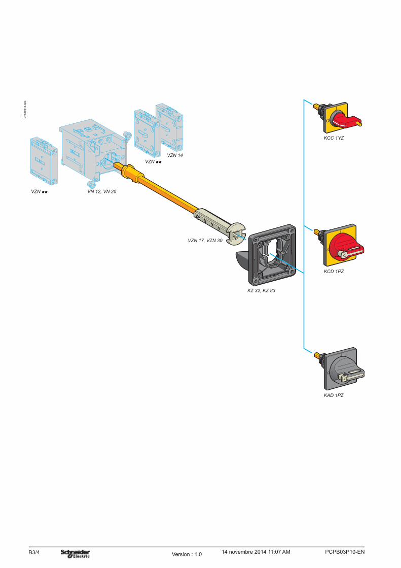
B3/4
DF
580544.e
ps
VZN pp VN 12, VN 20
VZN pp
VZN 14
VZN 17, VZN 30
KZ 32, KZ 83
KCD 1PZ
KCC 1YZ
KAD 1PZ
PCPB03P10-ENVersion : 1.0 14 novembre 2014 11:07 AM
B3/5
Switch-
disconnectors
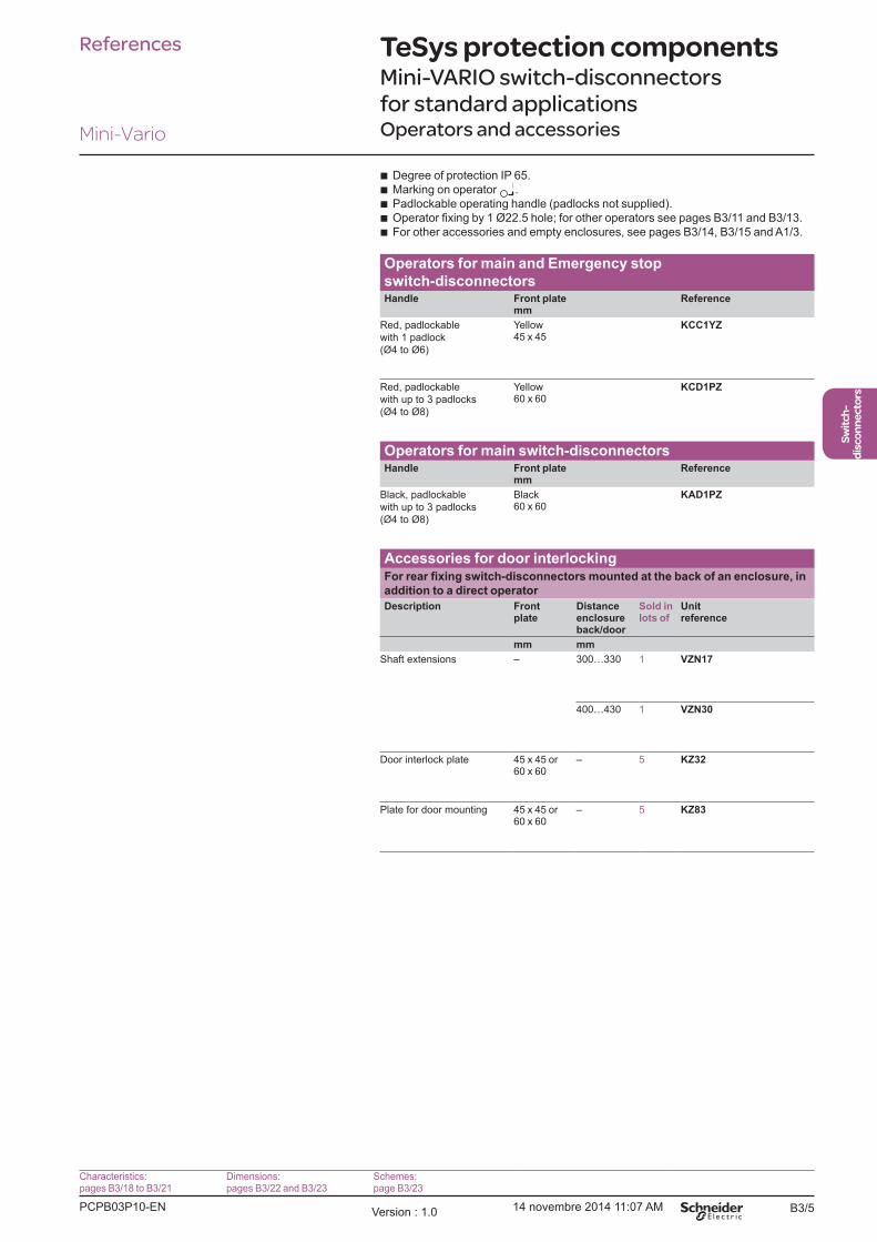
TeSys protection componentsMini-VARIO switch-disconnectors
for standard applicationsOperators and accessories
b Degree of protection IP 65.
b Marking on operator .
b Padlockable operating handle (padlocks not supplied).
b b For other accessories and empty enclosures, see pages B3/14, B3/15 and A1/3.
Operators for main and Emergency stop
switch-disconnectorsHandle Front plate
mmReference
Red, padlockable
with 1 padlock
(Ø4 to Ø6)
Yellow45 x 45
KCC1YZ
Red, padlockable
with up to 3 padlocks
(Ø4 to Ø8)
Yellow60 x 60
KCD1PZ
Operators for main switch-disconnectorsHandle Front plate
mmReference
Black, padlockable
with up to 3 padlocks
(Ø4 to Ø8)
Black60 x 60
KAD1PZ
Accessories for door interlocking
addition to a direct operator
Description Front plate
Distance enclosure back/door
Sold in lots of
Unit reference
mm mm
Shaft extensions � 300�330 1 VZN17
400�430 1 VZN30
Door interlock plate 45 x 45 or 60 x 60
� 5 KZ32
Plate for door mounting 45 x 45 or 60 x 60
� 5 KZ83
References
Characteristics:pages B3/18 to B3/21
Dimensions:pages B3/22 and B3/23
Schemes:page B3/23
Mini-Vario
PCPB03P10-EN Version : 1.0 14 novembre 2014 11:07 AM

B3/6
TeSys protection componentsVARIO switch-disconnectors
for high performance applicationsComplete units
b 3-pole rotary switch-disconnectors, 12 to 175 A
b Marking on operator .
b Padlockable operating handle (padlocks not supplied).
b Degree of protection IP 65.
Main and Emergency stop switch-disconnectors for door mountingHandle Front plate
mmFixing Rating
AReference Weight
kg
Red,
padlockable
with up to
3 padlocks
(Ø4 to Ø8)
Yellow60 x 60
Ø22.5 12 VCD02 0.215
20 VCD01 0.215
25 VCD0 0.215
32 VCD1 0.215
40 VCD2 0.215
4 screws 12 VCF02 0.250
20 VCF01 0.250
25 VCF0 0.250
32 VCF1 0.250
40 VCF2 0.250
63 VCF3 0.560
80 VCF4 0.560
Red, long,
padlockable
with up to
3 padlocks
(Ø4 to Ø8)
Yellow90 x 90
4 screws 125 VCF5 1.200
175 VCF6 1.200
Main and Emergency stop switch-disconnectors for mounting at back of an enclosure (1)
Handle Front platemm
Fixing RatingA
Reference Weight kg
Red,
padlockable
with up to
3 padlocks
(Ø4 to Ø8)
Yellow60 x 60
Ø22.5 12 VCCD02 0.392
20 VCCD01 0.392
25 VCCD0 0.392
32 VCCD1 0.392
40 VCCD2 0.392
4 screws 12 VCCF02 0.527
20 VCCF01 0.527
25 VCCF0 0.527
32 VCCF1 0.527
40 VCCF2 0.527
63 VCCF3 0.440
80 VCCF4 0.680
Red, long,
padlockable
with up to
3 padlocks
(Ø4 to Ø8)
Yellow90 x 90
4 screws 125 VCCF5 1.320
175 VCCF6 1.320
(1) Unit supplied with a shaft extension VZN 17 and a door interlock plate KZ 32 or KZ 74 (see page B3/14).
References
VCF 0
PF
511159.tif
VCF 5
PF
511160.tif
VCCF 0
PF
511161.tif
Characteristics:pages B3/18to B3/21
Dimensions:pages B3/24 and B3/25
Schemes:page B3/25
Vario
PCPB03P10-ENVersion : 1.0 14 novembre 2014 11:07 AM

B3/7
Switch-
disconnectors
TeSys protection componentsVARIO switch-disconnectors
for high performance applicationsComplete units
b 3-pole rotary switch-disconnectors, 12 to 175 A
b Marking on operator .
b Padlockable operating handle (padlocks not supplied).
b Degree of protection IP 65.
Main switch-disconnectors for door mountingHandle Front plate
mmFixing Rating
AReference Weight
kg
Black,
padlockable
with up to
3 padlocks
(Ø4 to Ø8)
Black60 x 60
Ø22.5 12 VBD02 0.215
20 VBD01 0.215
25 VBD0 0.215
32 VBD1 0.215
40 VBD2 0.215
4 screws 12 VBF02 0.250
20 VBF01 0.250
25 VBF0 0.250
32 VBF1 0.250
40 VBF2 0.250
63 VBF3 0.560
80 VBF4 0.560
Red, long,
padlockable
with up to
3 padlocks
(Ø4 to Ø8)
Black90 x 90
4 screws 125 VBF5 1.200
175 VBF6 1.200
Main and Emergency stop switch-disconnectorsFor mounting in an enclosure or for modular distribution boards
Handle Front platemm
RatingA
Reference Weight kg
Red,
padlockable
with 1 padlock
(Ø4 to Ø6)
Yellow45 x 45
25 VVE0 0.250
32 VVE1 0.250
40 VVE2 0.250
63 VVE3 0.530
80 VVE4 0.530
Main switch-disconnectorsFor mounting in an enclosure or for modular distribution boards
Handle Front platemm
RatingA
Reference Weight kg
Black, not
padlockable
Black45 x 45
25 VVD0 0.250
32 VVD1 0.250
40 VVD2 0.250
63 VVD3 0.560
80 VVD4 0.560
ReferencesP
F5
11
16
2.t
if
VBD 0
VBF 4
PF
511163.tif
VVE 1
580534.tif
Characteristics:pages B3/18to B3/21
Dimensions:pages B3/24 and B3/25
Schemes:page B3/25
Vario
PCPB03P10-EN Version : 1.0 14 novembre 2014 11:07 AM

B3/8
TeSys protection componentsVARIO switch-disconnectors for high performance applicationsSwitch bodies, add-on modules, auxiliary contacts (for customer assembly)
Switch bodiesDescription Rating
AReference
3-pole switch-disconnectors (1) 12 V02
20 V01
25 V0
32 V1
40 V2
63 V3
80 V4
125 V5
175 V6
Add-on modulesDescription Rating
AReference
Main pole modules 12 VZ02
20 VZ01
25 VZ0
32 VZ1
40 VZ2
63 VZ3
80 VZ4
Neutral pole modules with early
make and late break contacts (1)
12 to 40 VZ11
63 to 80 VZ12
125 and 175 VZ13
Earthing modules 12 to 40 VZ14
63 and 80 VZ15
125 and 175 VZ16
Auxiliary contact block modulesDescription Type Reference
Auxiliary contact block modules with 2 auxiliary contacts
N/O + N/C (2) VZ7
N/O + N/O VZ20
(1) Protection shrouds are available if required: see page B3/14.(2) Late make N/O, early break N/C contacts
References
V5
580536.tif
VZ 0
580537.tif
VZ 11
580538.tif
VZ 15
580539.tif
VZ 20
580540.tif
Characteristics:pages B3/18to B3/21
Dimensions:pages B3/24 and B3/25
Schemes:page B3/25
Vario
PCPB03P10-ENVersion : 1.0 14 novembre 2014 11:07 AM
B3/9
Switch-
disconnectors
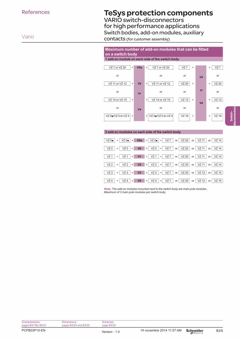
TeSys protection componentsVARIO switch-disconnectors for high performance applicationsSwitch bodies, add-on modules, auxiliary contacts (for customer assembly)
on a switch body1 add-on module on each side of the switch body
VZ 7 or VZ 20 + V0p
V0
to
V4
+ VZ 7 or VZ 20 VZ 7 +
V5
or
V6
+ VZ 7
or or or or
VZ 11 or VZ 12 + + VZ 11 or VZ 12 VZ 20 + + VZ 20
or or or or
VZ 14 or VZ 15 + + VZ 14 or VZ 15 VZ 13 + + VZ 13
or or or or
VZ 0p/VZ 0 to VZ 4 + + VZ 0p/VZ 0 to VZ 4 VZ 16 + + VZ 16
2 add-on modules on each side of the switch body
VZ 0p + VZ 0p + V0p + VZ 0p + VZ 7 or VZ 20 or VZ 11 or VZ 14
VZ 0 + VZ 0 + V0 + VZ 0 + VZ 7 or VZ 20 or VZ 11 or VZ 14
VZ 1 + VZ 1 + V1 + VZ 1 + VZ 7 or VZ 20 or VZ 11 or VZ 14
VZ 2 + VZ 2 + V2 + VZ 2 + VZ 7 or VZ 20 or VZ 11 or VZ 14
VZ 3 + VZ 3 + V3 + VZ 3 + VZ 7 or VZ 20 or VZ 12 or VZ 15
VZ 4 + VZ 4 + V4 + VZ 4 + VZ 7 or VZ 20 or VZ 12 or VZ 15
Note: The add-on modules mounted next to the switch body are main pole modules. Maximum of 3 main pole modules per switch body.
References
Characteristics:pages B3/18to B3/21
Dimensions:pages B3/24 and B3/25
Schemes:page B3/25
Vario
PCPB03P10-EN Version : 1.0 14 novembre 2014 11:07 AM

B3/10
DF
503798.e
ps
VN 12, VN 20 V02�V2
VZN 17, VZN 30
V3, V4
KZ 32, KZ 83
KCp 1YZ
KCp 1LZ
KAp 1BZ
KCp 1PZ
KAp 1PZ
KDp 1PZ
KBp 1PZ
VZ 18, VZ 31
V5, V6
KZ 81
VZ 18, VZ 31
KCF 2PZ
KAF 2PZ
KDF 2PZ
KBF 2PZ
KCF 3PZ
KAF 3PZ
KDF 3PZ
KBF 3PZ
KZ 74
PCPB03P10-ENVersion : 1.0 14 novembre 2014 11:07 AM
B3/11
Switch-
disconnectors
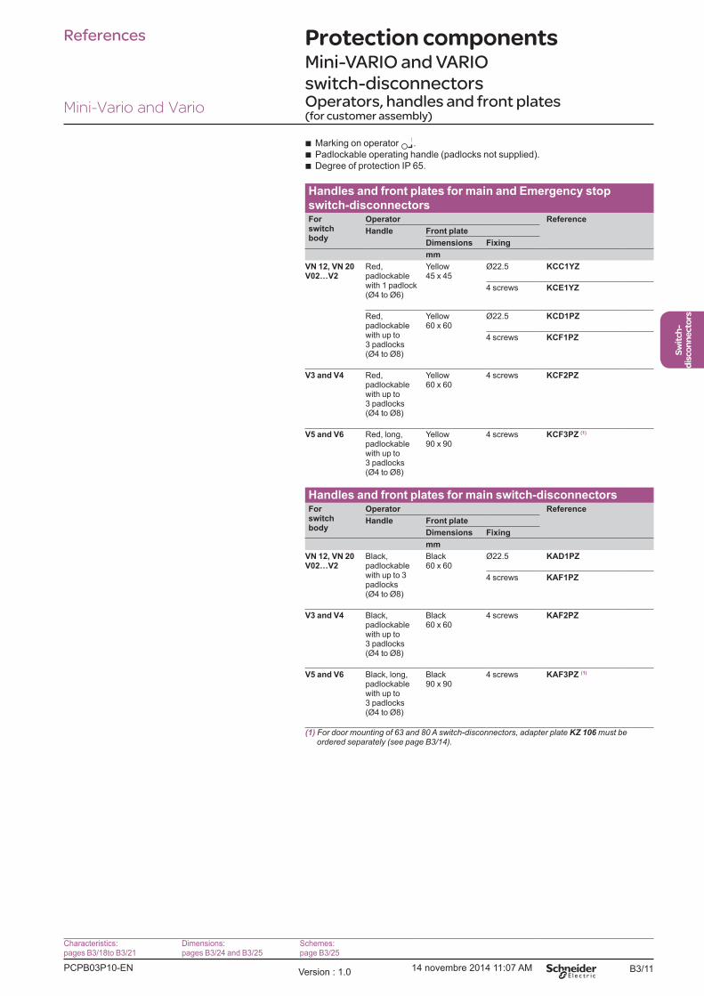
Protection componentsMini-VARIO and VARIO switch-disconnectorsOperators, handles and front plates (for customer assembly)
b Marking on operator .
b Padlockable operating handle (padlocks not supplied).
b Degree of protection IP 65.
Handles and front plates for main and Emergency stop
switch-disconnectorsFor switch body
Operator Reference
Handle Front plate
Dimensions Fixing
mm
V02�V2Red, padlockable with 1 padlock (Ø4 to Ø6)
Yellow45 x 45
Ø22.5 KCC1YZ
4 screws KCE1YZ
Red, padlockable with up to 3 padlocks (Ø4 to Ø8)
Yellow60 x 60
Ø22.5 KCD1PZ
4 screws KCF1PZ
V3 and V4 Red, padlockable with up to 3 padlocks (Ø4 to Ø8)
Yellow60 x 60
4 screws KCF2PZ
V5 and V6 Red, long, padlockable with up to 3 padlocks (Ø4 to Ø8)
Yellow90 x 90
4 screws KCF3PZ (1)
Handles and front plates for main switch-disconnectorsFor switch body
Operator Reference
Handle Front plate
Dimensions Fixing
mm
V02�V2Black, padlockable with up to 3 padlocks (Ø4 to Ø8)
Black60 x 60
Ø22.5 KAD1PZ
4 screws KAF1PZ
V3 and V4 Black, padlockable with up to 3 padlocks (Ø4 to Ø8)
Black60 x 60
4 screws KAF2PZ
V5 and V6 Black, long, padlockable with up to 3 padlocks (Ø4 to Ø8)
Black90 x 90
4 screws KAF3PZ (1)
(1) For door mounting of 63 and 80 A switch-disconnectors, adapter plate KZ 106 must be ordered separately (see page B3/14).
References
Characteristics:pages B3/18to B3/21
Dimensions:pages B3/24 and B3/25
Schemes:page B3/25
Mini-Vario and Vario
PCPB03P10-EN Version : 1.0 14 novembre 2014 11:07 AM

B3/12
DF
503799.e
ps
VN 12, VN 20 V02�V2
VZN 17, VZN 30
V3, V4
KZ 32, KZ 83
KCp 1YZ
KCp 1LZ
KAp 1BZ
KCp 1PZ
KAp 1PZ
KDp 1PZ
KBp 1PZ
VZ 18, VZ 31
V5, V6
KZ 81
VZ 18, VZ 31
KCF 2PZ
KAF 2PZ
KDF 2PZ
KBF 2PZ
KCF 3PZ
KAF 3PZ
KDF 3PZ
KBF 3PZ
KZ 74
PCPB03P10-ENVersion : 1.0 14 novembre 2014 11:07 AM

B3/13
Switch-
disconnectors
Protection componentsMini-VARIO and VARIO switch-disconnectorsOperators, handles and front plates (for customer assembly)
b Marking on operator .
b Degree of protection IP 65.
Handles and front plates for Emergency stop switch-disconnectorsFor switch body
Operator Reference
Handle Front plate
Dimensions Fixing
mm
V02�V2Red, not padlockable
Yellow45 x 45
Ø22.5 KCC1LZ
4 screws KCE1LZ
Yellow60 x 60
Ø22.5 KDD1PZ
4 screws KDF1PZ
V3 and V4 Red, long, not padlockable
Yellow60 x 60
4 screws KDF2PZ
V5 and V6 Red, long, not padlockable
Yellow90 x 90
4 screws KDF3PZ (1)
Handles and front plates for switch-disconnectorsFor switch body
Operator Reference
Handle Front plate
Dimensions Fixing
mm
V02�V2Black, not padlockable
Black45 x 45
Ø22.5 KAC1BZ
4 screws KAE1BZ
Black60 x 60
Ø22.5 KBD1PZ
4 screws KBF1PZ
V3 and V4 Black, not padlockable
Black60 x 60
4 screws KBF2PZ
V5 and V6 Black, not padlockable
Black90 x 90
4 screws KBF3PZ (1)
(1) For door mounting of 63 and 80 A switch-disconnectors, adapter plate KZ 106 must be ordered separately (see next page).
References
Characteristics:pages B3/18to B3/21
Dimensions:pages B3/24 and B3/25
Schemes:page B3/25
Mini-Vario and Vario
PCPB03P10-EN Version : 1.0 14 novembre 2014 11:07 AM

B3/14
Protection componentsMini-VARIO and VARIO switch-disconnectorsAccessories
Input terminal protection shroudsDescription For
use onReference
For switch bodies
(3-pole shroud)
V02�V2 VZ8
V3 and V4 VZ9
V5 and V6 VZ10
For add-on pole modules
(single-pole shroud)
VZ 02�VZ 2, VZ 11, VZ 14 VZ26
VZ 3, VZ 4, VZ 12, VZ 15 VZ27
VZ 13, VZ 16 VZ28
For contact blocks
with 2 auxiliary contacts
� VZ29
Components for door interlocking
in addition to a direct operator
Description For use on
Distance enc.back/door
Sold in lots of
Unit reference
mm
Shaft
extensions
VN 12, VN 20 V02�V2
300�330 1 VZN17 (1)
400�430 1 VZN30 (1)
V02�V2 300�330 1 VZ17
400�430 1 VZ30
V3 and V4 300�320 1 VZ18
400�420 1 VZ31
V5 and V6 330�350 1 VZ18
430�450 1 VZ31
Door
interlock plates
VN 12, VN 20 V02�V2
� 5 KZ32
V3�V6 � 5 KZ74
Description For use on
Front plate dimensions
Sold in lots of
Unit reference
mm
Plates for
door mounting
of handles with
VN 12, VN 20 V02�V2
45 x 45 or 60 x 60
5 KZ83
V3�V6 60 x 60 or 90 x 90
5 KZ81
Adapter plate
for switch-
disconnectors
V3 and V4 90 x 90 5 KZ106
(1) Can be used with V02 to V2 switches.
References
Characteristics:pages B3/18to B3/21
Dimensions:pages B3/24 and B3/25
Schemes:page B3/25
Mini-Vario and Vario
VZ 8
580583.tif
580584.tif
VZ 18
580526.tif
KZ 32
580585.tif
KZ 81
580527.tif
VZ 26
PCPB03P10-ENVersion : 1.0 14 novembre 2014 11:07 AM
B3/15
Switch-
disconnectors
Protection componentsMini-VARIO and VARIO switch-disconnectorsAccessories
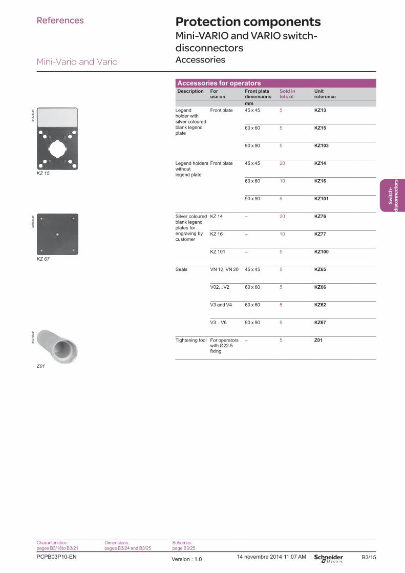
Accessories for operatorsDescription For
use onFront plate dimensions
Sold in lots of
Unit reference
mm
Legend
holder with
silver coloured
blank legend
plate
Front plate 45 x 45 5 KZ13
60 x 60 5 KZ15
90 x 90 5 KZ103
Legend holders
without
legend plate
Front plate 45 x 45 20 KZ14
60 x 60 10 KZ16
90 x 90 5 KZ101
Silver coloured
blank legend
plates for
engraving by
customer
KZ 14 � 20 KZ76
KZ 16 � 10 KZ77
KZ 101 � 5 KZ100
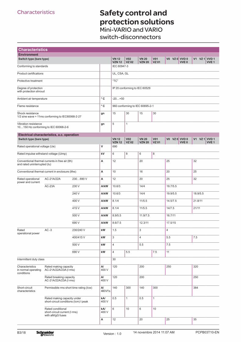
Seals VN 12, VN 20 45 x 45 5 KZ65
V02�V2 60 x 60 5 KZ66
V3 and V4 60 x 60 5 KZ62
V3�V6 90 x 90 5 KZ67
Tightening tool For operators with Ø22.5
� 5 Z01
References
Characteristics:pages B3/18to B3/21
Dimensions:pages B3/24 and B3/25
Schemes:page B3/25
Mini-Vario and Vario
KZ 15
812783.tif
KZ 67
580528.tif
Z01
812785.tif
PCPB03P10-EN Version : 1.0 14 novembre 2014 11:07 AM

B3/16 PCPB03P10-ENVersion : 1.0 14 novembre 2014 11:07 AM
B3/17
Switch-
disconnectors
Technical Data for DesignersV
ario
Contents
Characteristics ......................................................B3/18 to B3/21
Mini Vario:
> Dimensions ............................................B3/22 to B3/23
> Schemes .......................................................................B3/23
Vario:
> Dimensions ............................................B3/24 to B3/25
> Schemes .......................................................................B3/25
PCPB03T10-ENVersion : 1.0 14 novembre 2014 11:07 AMB3/18
Safety control and protection solutionsMini-VARIO and VARIO switch-disconnectors
CharacteristicsEnvironment
Switch type (bare type) VN 12 VZN 12
V02 VZ 02
VN 20 VZN 20
V01 VZ 01
V0 VZ 0 VVD 0 VVE 0
V1 VZ 1 VVD 1 VVE 1
Conforming to standards IEC 60947-3
UL, CSA, GL
Protective treatment �TC�
Degree of protection with protection shroud
IP 20 conforming to IEC 60529
Ambient air temperature ° C -20�+50
Flame resistance ° C 960 conforming to IEC 60695-2-1
Shock resistance 1/2 sine wave = 11ms conforming to IEC60068-2-27
gn
15 30 15 30
Vibration resistance 10�150 Hz conforming to IEC 60068-2-6
gn
5 1
Switch type (bare type) VN 12 VZN 12
V02 VZ 02
VN 20 VZN 20
V01 VZ 01
V0 VZ 0 VVD 0 VVE 0
V1 VZ 1 VVD 1 VVE 1
Rated operational voltage (Ue) V 690
Rated impulse withstand voltage (Uimp) kV 6 8 6 8
Conventional thermal currents in free air (lth) and rated uninterrupted (lu)
A
12 20 25 32
Conventional thermal current in enclosure (lthe) A 10 16 20 25
Rated operational power and current
AC-21A/22A 230�690 V A 12 20 25 32
AC-23A 230 V A/kW 10.6/3 14/4 19.7/5.5
240 V A/kW 10.6/3 14/4 19.9/5.5 18.9/5.5
400 V A/kW 8.1/4 11/5.5 14.5/7.5 21.8/11
415 V A/kW 8.1/4 11/5.5 14/7.5 21/11
500 V A/kW 8.9/5.5 11.9/7.5 16.7/11
690 V A/kW 8.6/7.5 12.3/11 17.5/15
Rated operational power
AC -3 230/240 V kW 1.5 3 4
400/415 V kW 3 4 5.5 7.5
500 V kW 4 5.5 7.5
690 V kW 4 5.5 7.5 11
Intermittent duty class 30
Characteristics in normal operating conditions
Rated making capacity AC-21A/22A/23A (I rms)
A/ 400 V
120 200 250 320
Rated breaking capacity AC-21A/22A/23A (I rms)
A/ 400 V
120 200 250
Short-circuit characteristics
Permissible rms short time rating (Icw) A/ 400 V/1 s
140 300 140 300 384
Rated making capacity under short-circuit conditions (Icm) I peak
kA/ 400 V
0.5 1 0.5 1
Rated conditional short-circuit current (I rms) with aM/gG fuses
kA/ 400 V
6 10 6 10
A 12 20 25 35
Characteristics

PCPB03T10-EN Version : 1.0 14 novembre 2014 11:07 AM B3/19
Switch-
disconnectors
B3/19
V2 VZ 2
VVD 2 VVE 2
V3 VZ 3
VVD 3 VVE 3
V4 VZ 4
VVD 4 VVE 4
V5 V6 VZ7 VZ2 0
VZN 05 VZN 06
IEC 60947-3 IEC 60947-5
UL, CSA, GL
�TC�
IP 20 conforming to IEC 60529
-20�+50
960 conforming to IEC 60695-2-1
30 �
1 �
V2 VZ 2
VVD 2 VVE 2
V3 VZ 3
VVD 3 VVE 3
V4 VZ 4
VVD 4 VVE 4
V5 V6 VZ7 VZ2 0
VZN 05 VZN 06
690
8 6
40 63 80 125 175 12 6
32 50 63 100 140 10 4
40 63 80 125 160 le/AC-15
25.8/7.5 50.3/15 61.2/18.5 71.9/22 96.6/30 6 A
24.8/7.5 48.2/15 58.5/18.5 68/22 92.7/30 6 A
29/15 41.5/22 57/30 68.5/37 83/45 4 A
28/15 40/22 55/30 66/37 80/45 4 A
28.5/18.5 44/30 54/37 64.5/45 79/55 2 A
17.5/15 25/22 33/30 42/37 49/45 1 A
5.5 11 15 22 30 �
11 18.5 22 30 37 �
15 22 30 37 45 �
11 18.5 30 37 �
30 �
400 630 800 1250 1750 �
320 500 640 1000 1400 �
480 756 960 1500 2100 �
1 2.1 2.8 �
10 1
50 63 80 125 200 16 1.6

PCPB03T10-ENVersion : 1.0 14 novembre 2014 11:07 AMB3/20
Safety control and protection solutions Mini-VARIO and VARIO switch-disconnectors
Characteristics
Switch type (bare type) VN 12 VZN 12
V02 VZ 02
VN 20 VZN 20
V01 VZ 01
V0 VZ 0 VVD 0 VVE 0
V1 VZ 1 VVD 1 VVE 1
Rated operational currentDC-1 (L/R = 1ms)
812834.e
ps
812835.e
ps
812836.e
ps
24 V 1 contact A 12 20 25 32
2 contacts A 12 20 25 32
3 contacts A 12 20 25 32
48 V 1 contact A 12 20 25 32
2 contacts A 12 20 25 32
3 contacts A 12 20 25 32
60 V 1 contact A 12 20 25 32
2 contacts A 12 20 25 32
3 contacts A 12 20 25 32
110 V 1 contact A 1.5 2 9 10
2 contacts A 8 10 12 16
3 contacts A 12 20 25 32
220 V 1 contact A 1.5 2 2.5 3
2 contacts A 7 8 10 12
3 contacts A 10 14 16 20
250 V 1 contact A 0.6 0.7 0.8 1
2 contacts A 3 4 6 8
3 contacts A 8 10 12 16
Rated operational current DC-2 to DC-5 (L/R = 1ms)
24 V 1 contact A 12 20 25 32
2 contacts A 12 20 25 32
3 contacts A 12 20 25 32
48 V 1 contact A 12 20 25 32
2 contacts A 12 20 25 32
3 contacts A 12 20 25 32
60 V 1 contact A 10 14 16 20
2 contacts A 12 20 25 32
3 contacts A 12 20 25 32
110 V 1 contact A 1.5 2 2.5 3
2 contacts A 3 4 5 6
3 contacts A 12 20 25 32
220 V 1 contact A 0.4 0.5 0.5 0.8
2 contacts A 1.4 1.5 1.5 2
3 contacts A 1 2 3 4
250 V 1 contact A 0.3 0.4 0.5 0.8
2 contacts A 0.4 0.6 0.8 1
3 contacts A 1.2 2.4 1.6 2
Other characteristics
Switch type (bare type) VN 12 VZN 12
V02 VZ 02
VN 20 VZN 20
V01 VZ 01
V0 VZ 0 VVD 0 VVE 0
V1 VZ 1 VVD 1 VVE 1
Mechanical durability (millions of operating cycles)
0.05 0.1 0.05 0.1
Electrical durability in cat. AC-21 (millions of operating cycles)
0.05 0.1 0.05 0.1
Electrical durability in cat. DC-1 to 5 (operating cycles)
30000
Suitable for isolation Yes
Cabling Flexible cable + cable end mm2 4 6 4 6
Solid cable mm2 4 10 4 10
Tightening torque N.m 0.7 2.1 0.7 2.1
Characteristics

PCPB03T10-EN Version : 1.0 14 novembre 2014 11:07 AM B3/21
Switch-
disconnectors
B3/21
V2 VZ 2
VVD 2 VVE 2
V3 VZ 3
VVD 3 VVE 3
V4 VZ 4
VVD 4 VVE 4
V5 V6 VZ7 VZ2 0
VZN 05 VZN 06
40 63 80 125 175 8 (le/DC-11)
40 63 80 125 175 �
40 63 80 125 175 �
40 63 80 125 175 8 (le/DC-11)
40 63 80 125 175 �
40 63 80 125 175 �
35 40 50 60 70 4 (le/DC-11)
40 63 80 125 175 �
40 63 80 125 175 �
12 20 25 30 12 2 (le/DC-11)
20 63 80 125 175 �
40 63 80 125 175 �
4 6 8 12 15 1 (le/DC-11)
14 25 30 40 50 �
25 30 40 80 100 �
2 4 5 3 10 0.8 (le/DC-11)
12 20 25 30 40 �
20 30 40 50 61 �
40 63 80 125 175 �
40 63 80 125 175 �
40 63 80 125 175 �
40 63 80 125 175 �
40 63 80 125 175 �
40 63 80 125 175 �
25 40 50 60 70 �
40 63 80 125 175 �
40 63 80 125 175 �
5 6 8 10 12 �
8 10 20 22 24 �
40 50 63 70 80 �
1 1.5 2 2.2 2.4 �
3 4 6 7 8 �
7 10 15 16 13 �
1 1.2 1.5 1.6 1.8 �
2 3 6 7 8 �
6 8 10 12 14 �
V2 VZ 2
VVD 2 VVE 2
V3 VZ 3
VVD 3 VVE 3
V4 VZ 4
VVD 4 VVE 4
V5 V6 VZ7 VZ2 0
VZN 05 VZN 06
0.1 0.03 0.1 0.05
0.1 0.03 0.1 (AC-15) 0.05
30000 30000 (DC-11)
Yes �
6 16 70 2 x 0.75�1.5
10 25 95 2 x 1�2.5
2.1 4 22.6 0.7
PCPB03T10-ENVersion : 1.0 14 novembre 2014 11:07 AMB3/22
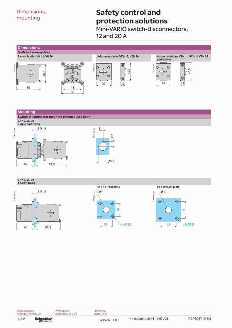
Safety control and protection solutionsMini-VARIO switch-disconnectors, 12 and 20 A
DimensionsSwitch-disconnectors
and VZN 06
62
46
,5
48
56
812765.e
ps
39 12
45,5812766.e
ps
39 12
45,5
812767.e
ps
MountingSwitch-disconnector mounted on enclosure door
1,5...5
74,544
DD
401033.e
ps 3
12,7
22,5
DF
510390.e
ps
45 x 45 front plate 60 x 60 front plate
1,5...5
62,544
DD
401034.e
ps
Ø13
36
36
DF
580524.e
ps
48
48
DF
580525.e
ps
Dimensions,
mounting
Characteristics:pages B3/18 to B3/21
References:pages B3/2 to B3/5
Schemes:page B3/23

PCPB03T10-EN Version : 1.0 14 novembre 2014 11:07 AM B3/23
Switch-
disconnectors
B3/23
Safety control and protection solutionsMini-VARIO switch-disconnectors, 12 and 20 A
Mounting (continued)
Switch-disconnector mounted at back of enclosure with shaft extension VZN 17 or VZN 30 (clip-on mounting on 6 rail)
1,5...5
e
DD
401035.e
ps 1,5...5
e
DD
401036.e
ps
Shaft extension Distance (e) enclosure back/door
mm
VZN 17 300�330
VZN 30 400�430
SchemesSwitch body Main pole module Neutral pole module
VZN 11Auxiliary contact blocks
VZN 05 VZN 06
1/L
12
/T1
3/L
24
/T2
5/L
36
/T3
812769.e
ps
812770.e
ps
812771.e
ps
13
148
12774.e
ps
22
21
812775.e
ps
Mounting (continued),
schemes 4
Characteristics:pages B3/18 to B3/21
References:pages B3/2 to B3/5

PCPB03T10-ENVersion : 1.0 14 novembre 2014 11:07 AMB3/24
Safety control and protection solutionsVARIO switch-disconnectors,
12 to 175 A
DimensionsSwitch-disconnectors
Switch bodies V0p Switch bodies V3 to V6
60
DF
580508.e
ps
74
55
DF
580509.e
ps
cD
F510472.e
ps
G
a
H b
==
DF
510473.e
ps
a b c G H Ø
60 83 65 48 48 5.5
90 125 90 68 68 5.5
Add-on modules VZ 02 to VZ 4 and VZ 11 to VZ 16
c
DF
580510.e
ps
b
a
DF
580511.e
ps 48,5
DF
580512.e
ps
65
20
DF
580513.e
ps
a b c
16 74 35
20 83 46
30 125 63
MountingSwitch-disconnector mounted on enclosure door
V0p
V0p
45 x 45 front plate V0p
60 x 60 front plate V0p
1,5...5
7244
DB
401026.e
ps
3
12,7
22,5
DF
580505.e
ps
1,5...5
c44
DB
401027.e
ps 1,5...5
c37
DB
401028.e
ps
36
36
DF
523860.e
ps
48
48
DF
523861.e
ps
c
V0p 60
65
90 x 90 front plate
1,5...5
9065
94
DB
401029.e
ps
68
68
DF
510471.e
ps
Dimensions,
mounting
Characteristics:pages B3/18 to B3/21
References:pages B3/6 to B3/9
Schemes:pageB3/25

PCPB03T10-EN Version : 1.0 14 novembre 2014 11:07 AM B3/25
Switch-
disconnectors
B3/25
Safety control and protection solutions VARIO switch-disconnectors,
12 to 175 A
Mounting (continued)
Switch-disconnector mounted at back of enclosure
V0pextension VZ 17 or VZ 30 (clip-on mounting on 6 rail possible for V0p to V2)
V3 to V4 with shaft extension VZ 18 or VZ 31
V5 and V6 with shaft extension VZ 18 or VZ 31
1,5...5
e
DB
401030.e
ps 1,5...5
e
DB
401031.e
ps
60
G
DF
510476.e
ps
100
30
DF
580522.e
ps1,5...5
e
94
DB
401032.e
ps
Shaft extension Distance (e) enc.back/door
Ø G Shaft extension
Distance (e) enc.back/door
mm mm
V02 and V01 V0 to V2
VZ 17 300�330 2 x 4.2 15 V5 and V6 VZ 18 300�350
VZ 30 400�430 2 x 4.2 15 VZ 31 430�450
V3 and V4 VZ 18 300�320 2 x 5 20
VZ 31 400�420 2 x 5 20
Switch-disconnectors for modular distribution boards
VVp 0 to VVp 2 VVp 3 to VVp 4
45
74
5,5
68
106
45812762.e
ps
60
83
5,5
72
110
458
12761.e
ps
SchemesSwitch body Main pole module Neutral pole module Auxiliary contact blocks
V02 and V01 V0 to V6
VZ 02 and VZ 01 VZ 0 to VZ 4
VZ 11 to VZ 13 VZ 7 VZ 20
1/L
12
/T1
3/L
24
/T2
5/L
36
/T3
812754.e
ps
812755.e
ps
812756.e
ps
22
21
13
148
12757.e
ps
13
14
24
23
812758.e
ps
Mounting,
schemes
Characteristics:pages B3/18 to B3/21
References:pages B3/6 to B3/9

PCPB03T10-ENVersion : 1.0 14 novembre 2014 11:07 AMB3/26

B4/1
Fuse
carriers
Fuse carriersTeSys DF, LS, GK
Fuse carriers - TeSys DF, LS, GK
Type of product Range Pages
For protection of control circuits
or transformer
TeSys DF and accessoriesUp to 25, 32, 50 or 125 A B4/2
For protection of control circuits
or transformer
TeSys DF – For North Amercan market
Up to 30 A B4/4
For protection of motors
or transformers
TeSys LS, GK and accessoriesUp to 25, 32, 50 or 125 A B4/5
TeSys Control and
Protection Components
Chapter
B4
Technical Data for Designers B4/9
PCPB04S10-EN Version : 1.0 14 novembre 2014 9:58 AM

B4/2
TeSys DF
Fuse carriers (1)
Conventional thermal current (Ith)
Size of cartridge fuse or link
Composition Sold in lots of
Unit reference
A mm
25 8.5 x 31.5 1 P 12 DF81
N 12 DF10N
1 P + N (2) 6 DF81N
2 P 6 DF82
3 P 4 DF83
3 P + N (2) 3 DF83N
32 10 x 38 1 P 12 DF101
N 12 DF10N
1 P + N (2) 6 DF101N
2 P 6 DF102
3 P 4 DF103
3 P + N (2) 3 DF103N
50 14 x 51 1 P 6 DF141
N 6 DF14N
1 P + N (2) 3 DF141N
2 P 3 DF142
3 P 2 DF143C (3)
3 P + N (2) 1 DF143NC (3)
125 22 x 58 1 P 6 DF221
N 6 DF22N
1 P + N (2) 3 DF221N
2 P 3 DF222
3 P 2 DF223C (3)
3 P + N (2) 1 DF223NC (3)
Fuse carriers with �blown fuse� indicators (neon) (1) (4)
Conventional thermal current (Ith)
Size of cartridge fuse or link
Composition Sold in lots of
Unit reference
A mm
25 8.5 x 31.5 1 P 12 DF81V
1 P + N (2) 6 DF81NV
2 P 6 DF82V
3 P 4 DF83V
3 P + N (2) 3 DF83NV
32 10 x 38 1 P 12 DF101V
1 P + N (2) 6 DF101NV
2 P 6 DF102V
3 P 4 DF103V
3 P + N (2) 3 DF103NV
50 14 x 51 1 P 6 DF141V
1 P + N (2) 3 DF141NV
2 P 3 DF142V
3 P 2 DF143VC (3)
3 P + N (2) 1 DF143NVC (3)
125 22 x 58 1 P 6 DF221V
1 P + N (2) 3 DF221NV
2 P 3 DF222V
3 P 2 DF223VC (3)
3 P + N (2) 1 DF223NVC (3)
(1) Each pole can be marked. A clip-in marker holder is provided for this purpose. Clip-in markers type AB1 Rp or AB1 Gp can also be used.
(2)(3)
(4)
References Fuse carriersFor protection of control circuits or
transformers
PF
526267-9
-M.tif
PF
526268-2
0-M
.tif
PF
526269-2
0-M
.tif
DF14 1
PF
526270-2
7-M
.tif
PF
526271-1
1-M
.tif
DF22 1
PF
526272-2
9-M
.tif
PF
526274-1
6-M
.tif
PF
526273-1
3-M
.tif
PF
526275-1
7-M
.tif
PF
526276-2
1-M
.tif
PF
526277-1
7-M
.tif
PF
526278-2
3-M
.tif
Characteristics:page B4/10
Substitution:page B4/3
Dimensions:page B4/11
Schemes:page B4/11
PCPB04P10-ENVersion : 1.0 14 novembre 2014 9:58 AM
B4/3
Fuse
carriers
TeSys DF
References,
substitutionFuse carriersFor protection of control circuits or
transformers
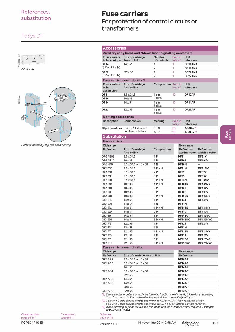
AccessoriesAuxiliary early break and �blown fuse� signalling contacts (1)
Fuse carriers to be equipped
Size of cartridge fuse or link
Number of contacts
Sold in lots of
Unit reference
DF14(3 P or 3 P + N)
14 x 51 1 1 DF14AM1
2 1 DF14AM2
DF22(3 P or 3 P + N)
22 X 58 1 1 DF22AM1
2 1 DF22AM2
Fuse carrier assembly kits (2)
Fuse carriers to be assembled
Size of cartridge fuse or link
Composition Sold in lots of
Unit reference
DF8 8.5 x 31.5 1 pin, 2 clips
12 DF10AP
DF10 10 x 38
DF14 14 x 51 1 pin, 3 clips
10 DF14AP
DF22 22 x 58 1 pin, 3 clips
10 DF22AP
Marking accessories
Description Composition Marking Sold in lots of
Unit reference
Clip-in markers Strip of 10 identical numbers or letters
0�9 25 AB1Rp (3)
A�Z 25 AB1Gp (3)
SubstitutionFuse carriers
Old range New range
Reference Size of cartridge fuse or link
Composition Reference w/o indicator
Reference with indicator
DF6 AB08 8.5 x 31.5 1 P DF81 DF81V
DF6 AB10 10 x 38 1 P DF101 DF101V
DF6 N10 8.5 x 31.5 or 10 x 38 1 N DF10N �
GK1 CC 8.5 x 31.5 1 P + N DF81N DF81NV
GK1 CD 8.5 x 31.5 2 P DF82 DF82V
GK1 CF 8.5 x 31.5 3 P DF83 DF83V
GK1 CH 8.5 x 31.5 3 P + N DF83N DF83NV
GK1 DC 10 x 38 1 P + N DF101N DF101NV
GK1 DD 10 x 38 2 P DF102 DF102V
GK1 DF 10 x 38 3 P DF103 DF103V
GK1 DH 10 x 38 3 P + N DF103N DF103NV
GK1 EB 14 x 51 1 P DF141 DF141V
GK1 EN 14 x 51 1 N DF14N �
GK1 EC 14 x 51 1 P + N DF141N DF141NV
GK1 ED 14 x 51 2 P DF142 DF142V
GK1 EF 14 x 51 3 P DF143C DF143VC
GK1 EH 14 x 51 3 P + N DF143NC DF143NVC
GK1 FB 22 x 58 1 P DF221 DF221V
GK1 FN 22 x 58 1 N DF22N �
GK1 FC 22 x 58 1 P + N DF221N DF221NV
GK1 FD 22 x 58 2 P DF222 DF222V
GK1 FF 22 x 58 3 P DF223C DF223VC
GK1 FH 22 x 58 3 P + N DF223NC DF223NVC
Fuse carrier assembly kits
Old range New range
Reference Size of cartridge fuse or link Reference
GK1 AP2 8.5 x 31.5 or 10 x 38 DF10AP
GK1 AP3 8.5 x 31.5 or 10 x 38 DF10AP
14 x 51 DF14AP
GK1 AP4 8.5 x 31.5 or 10 x 38 DF10AP
22 x 58 DF22AP
GK1 AP5 14 x 51 DF14AP
GK1 AP6 14 x 51 DF14AP
22 x 58 DF22AP
GK1 AP9 22 x 58 DF22AP
(1)
(2)
(3) pAB1-R1 or AB1-GA.
524196.e
ps
PF
106836-2
1-M
.tif
DF14 AMp
Characteristics:page B4/10
Dimensions:page B4/11
Schemes:page B4/11
PCPB04P10-EN Version : 1.0 14 novembre 2014 9:58 AM
B4/4
References Fuse carriers for the North
American marketFor protection of control circuits or
transformers
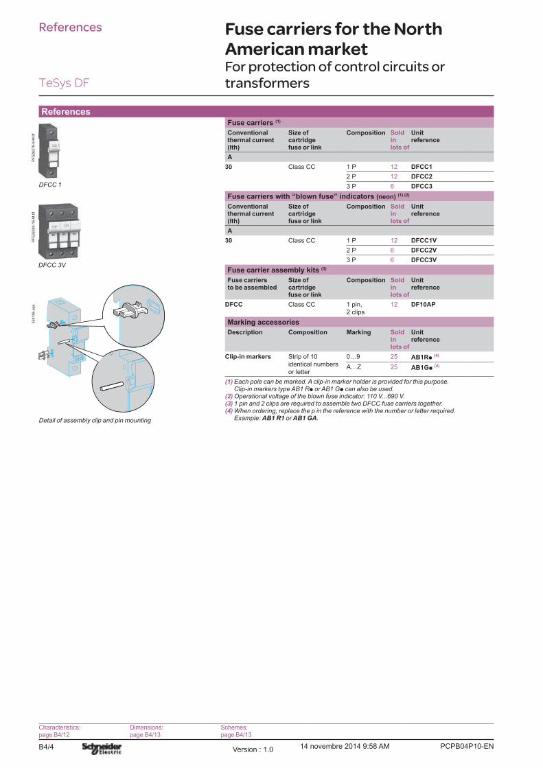
ReferencesFuse carriers (1)
Conventional thermal current (Ith)
Size of cartridge fuse or link
Composition Sold in lots of
Unit reference
A
30 Class CC 1 P 12 DFCC1
2 P 12 DFCC2
3 P 6 DFCC3
Fuse carriers with �blown fuse� indicators (neon) (1) (2)
Conventional thermal current (Ith)
Size of cartridge fuse or link
Composition Sold in lots of
Unit reference
A
30 Class CC 1 P 12 DFCC1V
2 P 6 DFCC2V
3 P 6 DFCC3V
Fuse carrier assembly kits (3)
Fuse carriers to be assembled
Size of cartridge fuse or link
Composition Sold in lots of
Unit reference
DFCC Class CC 1 pin,
2 clips
12 DF10AP
Marking accessories
Description Composition Marking Sold in lots of
Unit reference
Clip-in markers Strip of 10
identical numbers
or letter
0�9 25 AB1Rp (4)
A�Z 25 AB1Gp (4)
(1) Each pole can be marked. A clip-in marker holder is provided for this purpose. Clip-in markers type AB1 Rp or AB1 Gp can also be used.
(2)(3)(4)
AB1 R1 or AB1 GA.
DFCC 1
PF
526279-9
-M.tif
PF
526280-1
6-M
.tif
524196.e
ps
TeSys DF
Characteristics:page B4/12
Dimensions:page B4/13
Schemes:page B4/13
PCPB04P10-ENVersion : 1.0 14 novembre 2014 9:58 AM
B4/5
Fuse
carriers
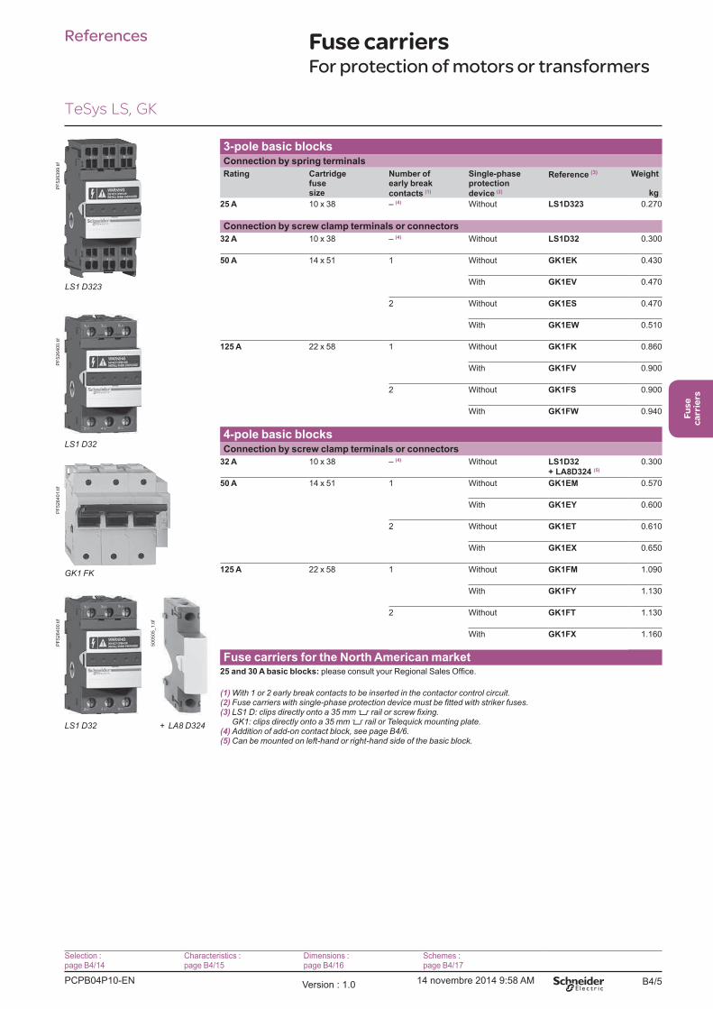
References Fuse carriersFor protection of motors or transformers
3-pole basic blocksConnection by spring terminals
Rating Cartridge fuse size
Number of early break
contacts (1)
Single-phase protection
device (2)
Reference (3) Weight
kg
25 A 10 x 38 � (4) Without LS1D323 0.270
Connection by screw clamp terminals or connectors
32 A 10 x 38 � (4) Without LS1D32 0.300
50 A 14 x 51 1 Without GK1EK 0.430
With GK1EV 0.470
2 Without GK1ES 0.470
With GK1EW 0.510
125 A 22 x 58 1 Without GK1FK 0.860
With GK1FV 0.900
2 Without GK1FS 0.900
With GK1FW 0.940
4-pole basic blocksConnection by screw clamp terminals or connectors
32 A 10 x 38 � (4) Without LS1D32
+ LA8D324 (5)
0.300
50 A 14 x 51 1 Without GK1EM 0.570
With GK1EY 0.600
2 Without GK1ET 0.610
With GK1EX 0.650
125 A 22 x 58 1 Without GK1FM 1.090
With GK1FY 1.130
2 Without GK1FT 1.130
With GK1FX 1.160
Fuse carriers for the North American market25 and 30 A basic blocks:
(1) With 1 or 2 early break contacts to be inserted in the contactor control circuit.(2)(3) 5
5(4)(5)
PF
526399.tif
PF
526400.tif
PF
526401.tif
GK1 FK
PF
526400.tif
500505_
1.tif
Selection :page B4/14
Characteristics :page B4/15
Dimensions :page B4/16
Schemes :page B4/17
TeSys LS, GK
PCPB04P10-EN Version : 1.0 14 novembre 2014 9:58 AM
B4/6
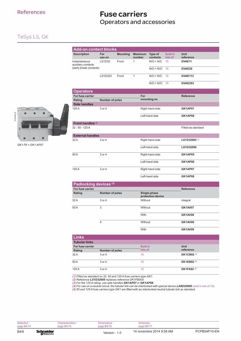
References Fuse carriersOperators and accessories
PF
526402.tif
Selection :page B4/14
Characteristics :page B4/15
Dimensions :page B4/16
Schemes :page B4/17
Add-on contact blocksDescription For
use onMounting Maximum
numberType of contacts
Sold in lots of
Unit reference
Instantaneous auxiliary contacts (early break contacts)
LS1D32 Front 1 N/O + N/C 10 GVAE11
N/O + N/O 10 GVAE20
LS1D323 Front 1 N/O + N/C 10 GVAE113
N/O + N/O 10 GVAE203
OperatorsFor fuse carrier For
mounting onReference
Rating Number of poles
Side handles
125 A 3 or 4 Right-hand side GK1AP07
Left-hand side GK1AP08
Front handles (1)
32 - 50 - 125 A Fitted as standard
External handles
32 A 3 or 4 Right-hand side LS1D32005 (2)
Left-hand side LS1D32006
50 A 3 or 4 Right-hand side GK1AP05
Left-hand side GK1AP06
125 A 3 or 4 Right-hand side GK1AP07
Left-hand side GK1AP08
Padlocking devices (3)
For fuse carrier Reference
Rating Number of poles Single-phase protection device
32 A 3 or 4 Without integral
50 A 3 Without GK1AV07
With GK1AV08
4 Without GK1AV08
With GK1AV09
LinksTubular links
For fuse carrier Sold in lots of
Unit referenceRating Number of poles
32 A 3 or 4 10 DK1CB92 (4)
50 A 3 or 4 10 DK1EB92 (5)
125 A 3 or 4 10 DK1FA92 (5)
(1)(2) Reference LS1D32005(3) GK1AP07 or GK1AP08.(4) LA8D25906 .(5)
TeSys LS, GK
PCPB04P10-ENVersion : 1.0 14 novembre 2014 9:58 AM
B4/7
Fuse
carriers
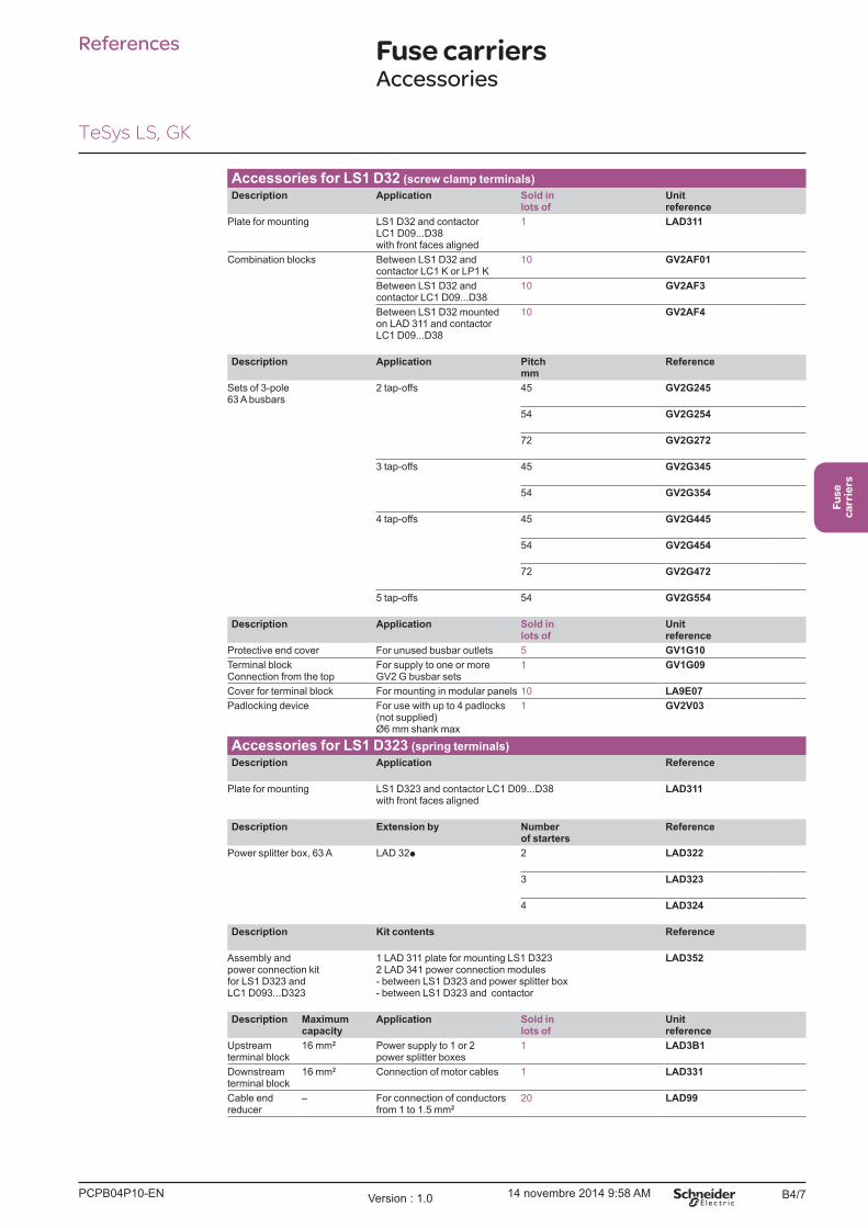
Accessories for LS1 D32 (screw clamp terminals)
Description Application Sold in lots of
Unit reference
Plate for mounting LS1 D32 and contactor LC1 D09...D38 with front faces aligned
1 LAD311
Combination blocks Between LS1 D32 and contactor LC1 K or LP1 K
10 GV2AF01
Between LS1 D32 and contactor LC1 D09...D38
10 GV2AF3
Between LS1 D32 mounted on LAD 311 and contactor LC1 D09...D38
10 GV2AF4
Description Application Pitch mm
Reference
Sets of 3-pole 63 A busbars
2 tap-offs 45 GV2G245
54 GV2G254
72 GV2G272
3 tap-offs 45 GV2G345
54 GV2G354
4 tap-offs 45 GV2G445
54 GV2G454
72 GV2G472
5 tap-offs 54 GV2G554
Description Application Sold in lots of
Unit reference
Protective end cover For unused busbar outlets 5 GV1G10
Terminal block Connection from the top
For supply to one or more GV2 G busbar sets
1 GV1G09
Cover for terminal block For mounting in modular panels 10 LA9E07
Padlocking device For use with up to 4 padlocks (not supplied) Ø6 mm shank max
1 GV2V03
Accessories for LS1 D323 (spring terminals)
Description Application Reference
Plate for mounting LS1 D323 and contactor LC1 D09...D38 with front faces aligned
LAD311
Description Extension by Number of starters
Reference
Power splitter box, 63 A LAD 32p 2 LAD322
3 LAD323
4 LAD324
Description Kit contents Reference
Assembly andpower connection kitfor LS1 D323 andLC1 D093...D323
1 LAD 311 plate for mounting LS1 D3232 LAD 341 power connection modules- between LS1 D323 and power splitter box- between LS1 D323 and contactor
LAD352
Description Maximum capacity
Application Sold in lots of
Unit reference
Upstream terminal block
16 mm2 Power supply to 1 or 2 power splitter boxes
1 LAD3B1
Downstream terminal block
16 mm2 Connection of motor cables 1 LAD331
Cable end reducer
� For connection of conductors from 1 to 1.5 mm2
20 LAD99
References Fuse carriersAccessories
TeSys LS, GK
PCPB04P10-EN Version : 1.0 14 novembre 2014 9:58 AM

B4/8 PCPB04P10-ENVersion : 1.0 14 novembre 2014 9:58 AM
B4/9
Fuse
carriers
Technical Data for Designers
TeSys DF, LS, GK
Contents
TeSys DF:
> Characteristics ........................................................B4/10
> Dimensions and schemes ................................B4/11
TeSys DF for the North American market:
> Characteristics ........................................................B4/12
> Dimensions and schemes ................................B4/13
TeSys LS and GK:
> Selection ....................................................................B4/14
> Characteristics ........................................................B4/15
> Dimensions ...............................................................B4/16
> Schemes ....................................................................B4/17

PCPB04T10-ENVersion : 1.0 14 novembre 2014 9:57 AMB4/10
Fuse carriers
Environment characteristics
Fuse carrier type DF8 DF10 DF14 DF22
Conforming to standards IEC 60947-3, UL 512, CSA 22-2 n° 39
Protective treatment �TH�
Degree of protection Conforming to IEC 60529 IP 20
Ambient air temperature Storage °C -40�+80
For operation, with derating (1) °C -20�+60
Operating positions Without derating ± 23° in relation to normal mounting plane
Flame resistance Conforming to IEC 60695-2-1 °C 960
Pole characteristicsFuse size mm 8.5 x 31.5 10 x 38 14 x 51 22 x 58
Rated insulation voltage (Ui) with tubular links, a.c. or D.C. supply
V 500 690 690 690
Rated impulse withstand voltage (Uimp) kV 6 6 8 8
Conventional thermal current (Ith) for ambient air temperature y 40 °C (1)
With tubular links A 25 32 50 125
With aM cartridge fuses A 25 32 50 125
With gG cartridge fuses A 25 32 50 100
Rated conditional short-circuit currentConforming to IEC 60947-3
400 V kA 20 120 120 120
500 V kA � 120 120 120
690 V kA � � 80 80
Peak withstand current (dynamic stress)Conforming to IEC 60269-1
With tubular links kA 11 15 15 19
Cabling (number of conductors x c.s.a.) Min. Max. Min. Max. Min. Max. Min. Max.
Solid cable mm2 1 x 1.5 1 x 162 x 6
1 x 1.5 1 x 162 x 6
1 x 2.5 1 x 252 x 10
1 x 2.5 1 x 352 x 25
Flexible cable without cable end mm2 1 x 1.5 1 x 102 x 6
1 x 1.5 1 x 102 x 6
1 x 2.5 1 x 252 x 10
1 x 2.5 1 x 352 x 16
Flexible cable with cable end mm2 1 x 1.5 1 x 102 x 6
1 x 1.5 1 x 102 x 6
1 x 2.5 1 x 252 x 10
1 x 2.5 1 x 352 x 16
Tightening torque Nm 2.2 3.5 4
Characteristics of early break and signalling contacts DF14 AM and DF22 AMRated insulation voltage (Ui) a.c. supply
V 250
Conventional thermal current (Ith) for ambient air temperature y 40 °C (1)
A 5
Rated operational current 24 V 48 V 127 V 240 V
Category AC-15 A 4 4 3 2.5
Category DC-13 A 3 1 0.2 0.1
rated characteristics
Conforming to IEC 60947-5-1 B300
Low load operating characteristics
Minimum voltage V 10
Minimum current mA 30
Cabling Faston connectors
(1)
Maximum temperature 20 °C 30 °C 40 °C 50 °C 60 °C
Max. relative humidity 95 % 90 % 80 % 50 % 50 %
Current derating 1 0.95 0.9 0.8 0.7
Characteristics
References:pages B4/2 and B4/3
Substitution:page B4/3
Dimensions:page B4/11
Schemes:page B4/11
TeSys DF

PCPB04T10-EN Version : 1.0 14 novembre 2014 9:57 AM B4/11
Fuse
carriers
B4/11
Fuse carriers
DimensionsModular fuse carriers 25 A and 32 A
Mounting on 35 mm 5 rail
DF8 1 and DF8 1VDF10 1 and DF10 1VDF10 N
DF8 1N and DF8 1NV DF8 2 and DF8 2VDF10 1N and DF10 1NV DF10 2 and DF10 2V
DF8 3 and DF8 3VDF10 3 and DF10 3V
DF8 3N and DF8 3NVDF10 3N and DF10 3NV
47
58
64
83
5,5
17,5 4x17,53x17,52x17,5
45 4
0,5
DF
537034.e
ps
Modular fuse carriers 50 A
Mounting on 35 mm 5 rail
DF14 1 and DF14 1V DF14 N
DF14 1N and DF14 1NVDF14 2 and DF14 2V
DF14 3C and DF14 3VC DF14 3NC and DF14 3NVC
107 45
3,8
76,5
1,5x17,550,5 3x17,5 4,5x17,5 6x17,5
48,5
70
DF
537033.e
ps
Modular fuse carriers 125 A
Mounting on 35 mm 5 rail
DF22 1 and DF22 1V DF22 N
DF22 1N and DF22 1NVDF22 2 and DF22 2V
DF22 3C and DF22 3VC DF22 3NC and DF22 3NVC
12
6,5
50,5
76,5
51
45
1
2x17,5 4x17,5
70
6x17,5 8x17,5
DF
537032.e
ps
SchemesModular fuse carriers
DFp 1P DFp N DFp 1P + N DFp 2P
812916.e
ps
812917.e
ps 1
2
N
812920.e
ps 3
4
12
812918.e
ps
DFp 3P DFp 3P + N
56
34
12
812919.e
ps 5
6
34
12
N
812921.e
ps
Dimensions,
schemes
References:pages B4/2 and B4/3
Substitution:page B4/3
Characteristics:page B4/10
TeSys DF

PCPB04T10-ENVersion : 1.0 14 novembre 2014 9:57 AMB4/12
Characteristics Fuse carriers for
the North American market
Environment characteristicsFuse carrier type DFCC
Conforming to standards IEC 60947-3, UL 512, CSA 22-2 n° 39
Protective treatment �TH�
Degree of protection Conforming to IEC 60529 IP 20
Ambient air temperature Storage °C -40�+80
For operation, with derating (1) °C -20�+60
Operating positions Without derating ±23° in relation to normal vertical mounting plane
Flame resistance Conforming to IEC 60695-2-1 °C 960
Pole characteristicsFuse carrier type DFCC
Fuse size Class CC
Rated insulation voltage (Ui) with tubular links, a.c. supply
V 600
Rated impulse withstand voltage (Uimp) kV 6
Conventional thermal current (Ith) for ambient air temperature y 40 °C (1)
With tubular links A 30
With aM cartridge fuses A 30
With gG cartridge fuses A 30
Short-circuit current withstandWith UL 248-4 Class CC fuses
Conforming to UL 512 at 600 V kA 200
Cabling (number of conductors x c.s.a.) Min. Max.
Solid cable mm2 1 x 1.5 1 x 16
2 x 6
Flexible cable without cable end mm2 1 x 1.5 1 x 10
2 x 6
Flexible cable with cable end mm2 1 x 1.5 1 x 10
2 x 6
Tightening torque Nm 2.2
(1)
Maximum temperature 20 °C 30 °C 40 °C 50 °C 60 °C
Max. relative humidity 95 % 90 % 80 % 50 % 50 %
1 0.95 0.9 0.8 0.7
References:page B4/4
Dimensions:page B4/13
Schemes:page B4/13
TeSys DF
PCPB04T10-EN Version : 1.0 14 novembre 2014 9:57 AM B4/13
Fuse
carriers
B4/13
References,
dimensions,
schemes
Fuse carriers for
the North American market
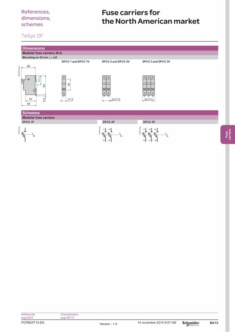
DimensionsModular fuse carriers 30 A
Mounting on 35 mm 5 rail
DFCC 1 and DFCC 1V DFCC 2 and DFCC 2V DFCC 3 and DFCC 3V
47
58
64
83
5,5
17,5 3x17,52x17,5
45 4
0,5
DF
537818.e
ps
SchemesModular fuse carriers
DFCC 1P DFCC 2P DFCC 3P
812916.e
ps
34
12
812918.e
ps
56
34
12
812919.e
ps
References:page B4/4
Characteristics: page B4/12
TeSys DF
PCPB04T10-ENVersion : 1.0 14 novembre 2014 9:57 AMB4/14
Fuse carriers
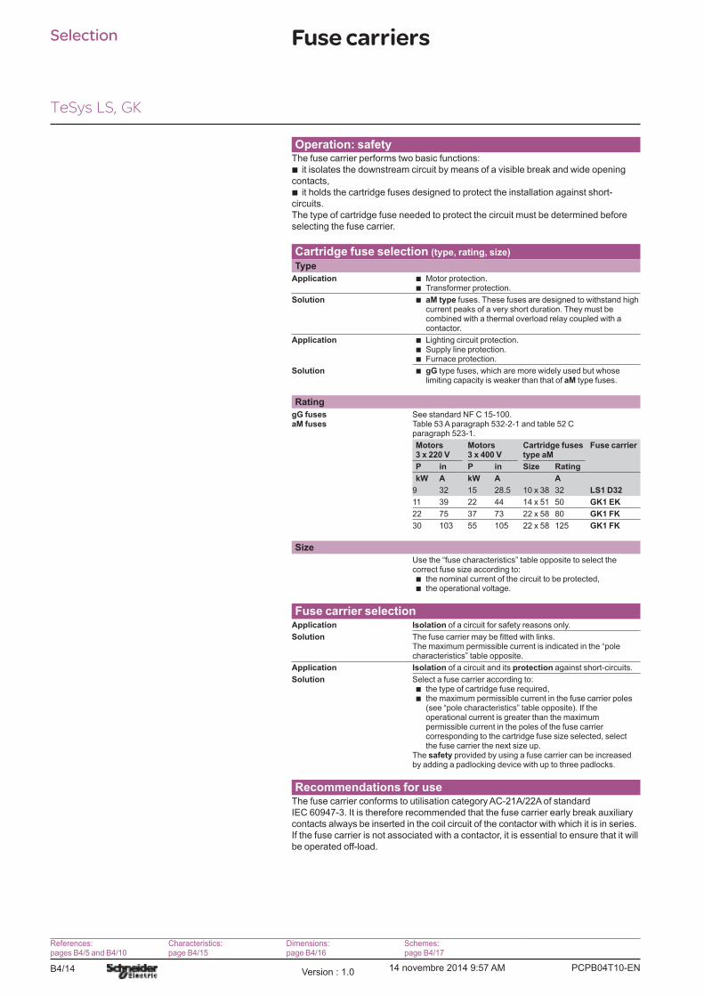
Operation: safetyThe fuse carrier performs two basic functions:
b it isolates the downstream circuit by means of a visible break and wide opening
contacts,
b it holds the cartridge fuses designed to protect the installation against short-
circuits.
The type of cartridge fuse needed to protect the circuit must be determined before
selecting the fuse carrier.
Cartridge fuse selection (type, rating, size)
Type
Application b Motor protection.b Transformer protection.
Solution b aM type fuses. These fuses are designed to withstand high current peaks of a very short duration. They must be combined with a thermal overload relay coupled with a contactor.
Application b Lighting circuit protection.b Supply line protection.b Furnace protection.
Solution b gG type fuses, which are more widely used but whose limiting capacity is weaker than that of aM type fuses.
Rating
gG fusesaM fuses
See standard NF C 15-100.Table 53 A paragraph 532-2-1 and table 52 C paragraph 523-1.
Motors3 x 220 V
Motors3 x 400 V
Cartridge fusestype aM
Fuse carrier
P in P in Size Rating
kW A kW A A
9 32 15 28.5 10 x 38 32 LS1 D32
11 39 22 44 14 x 51 50 GK1 EK
22 75 37 73 22 x 58 80 GK1 FK
30 103 55 105 22 x 58 125 GK1 FK
Size
Use the �fuse characteristics� table opposite to select the correct fuse size according to:b the nominal current of the circuit to be protected,b the operational voltage.
Fuse carrier selectionApplication Isolation of a circuit for safety reasons only.
SolutionThe maximum permissible current is indicated in the �pole characteristics� table opposite.
Application Isolation of a circuit and its protection against short-circuits.
Solution Select a fuse carrier according to:b the type of cartridge fuse required,b the maximum permissible current in the fuse carrier poles
(see �pole characteristics� table opposite). If the operational current is greater than the maximum permissible current in the poles of the fuse carrier corresponding to the cartridge fuse size selected, select the fuse carrier the next size up.
The safety provided by using a fuse carrier can be increased by adding a padlocking device with up to three padlocks.
Recommendations for useThe fuse carrier conforms to utilisation category AC-21A/22A of standard
IEC 60947-3. It is therefore recommended that the fuse carrier early break auxiliary
contacts always be inserted in the coil circuit of the contactor with which it is in series.
If the fuse carrier is not associated with a contactor, it is essential to ensure that it will
be operated off-load.
Selection
References:pages B4/5 and B4/10
Characteristics:page B4/15
Dimensions:page B4/16
Schemes:page B4/17
TeSys LS, GK
PCPB04T10-EN Version : 1.0 14 novembre 2014 9:57 AM B4/15
Fuse
carriers
B4/15
Fuse carriers
Environment
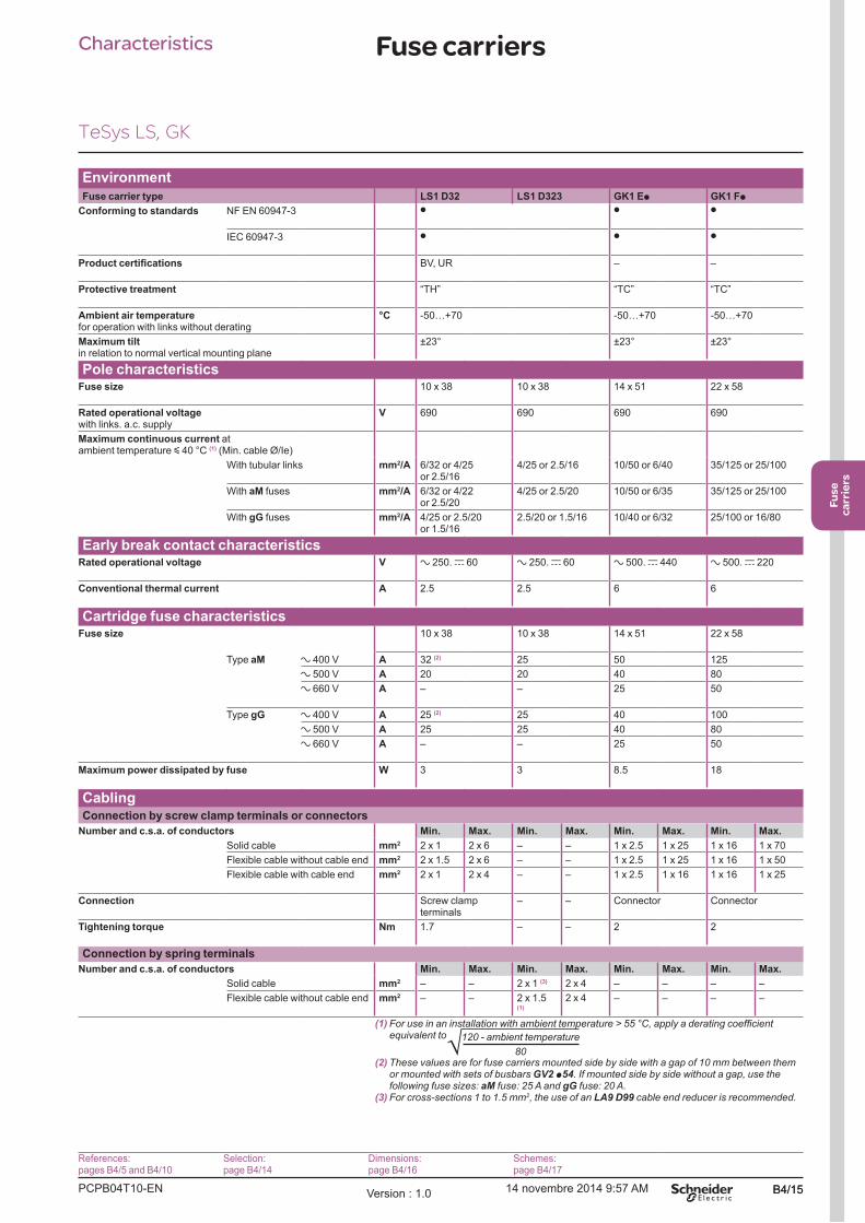
Fuse carrier type LS1 D32 LS1 D323 GK1 Ep GK1 Fp
Conforming to standards NF EN 60947-3 p p p
IEC 60947-3 p p p
BV, UR � �
Protective treatment �TH� �TC� �TC�
Ambient air temperature for operation with links without derating
°C -50�+70 -50�+70 -50�+70
Maximum tiltin relation to normal vertical mounting plane
±23° ±23° ±23°
Pole characteristicsFuse size 10 x 38 10 x 38 14 x 51 22 x 58
Rated operational voltage with links. a.c. supply
V 690 690 690 690
Maximum continuous current atambient temperature y 40 °C (1) (Min. cable Ø/Ie)
With tubular links mm2/A 6/32 or 4/25 or 2.5/16
4/25 or 2.5/16 10/50 or 6/40 35/125 or 25/100
With aM fuses mm2/A 6/32 or 4/22 or 2.5/20
4/25 or 2.5/20 10/50 or 6/35 35/125 or 25/100
With gG fuses mm2/A 4/25 or 2.5/20or 1.5/16
2.5/20 or 1.5/16 10/40 or 6/32 25/100 or 16/80
Early break contact characteristicsRated operational voltage V a 250. c 60 a 250. c 60 a 500. c 440 a 500. c 220
Conventional thermal current A 2.5 2.5 6 6
Cartridge fuse characteristicsFuse size 10 x 38 10 x 38 14 x 51 22 x 58
Type aM a 400 V A 32 (2) 25 50 125
a 500 V A 20 20 40 80
a 660 V A � � 25 50
Type gG a 400 V A 25 (2) 25 40 100
a 500 V A 25 25 40 80
a 660 V A � � 25 50
Maximum power dissipated by fuse W 3 3 8.5 18
CablingConnection by screw clamp terminals or connectors
Number and c.s.a. of conductors Min. Max. Min. Max. Min. Max. Min. Max.
Solid cable mm2 2 x 1 2 x 6 � � 1 x 2.5 1 x 25 1 x 16 1 x 70
Flexible cable without cable end mm2 2 x 1.5 2 x 6 � � 1 x 2.5 1 x 25 1 x 16 1 x 50
Flexible cable with cable end mm2 2 x 1 2 x 4 � � 1 x 2.5 1 x 16 1 x 16 1 x 25
Connection Screw clamp terminals
� � Connector Connector
Tightening torque Nm 1.7 � � 2 2
Connection by spring terminals
Number and c.s.a. of conductors Min. Max. Min. Max. Min. Max. Min. Max.
Solid cable mm2 � � 2 x 1 (3) 2 x 4 � � � �
Flexible cable without cable end mm2 � � 2 x 1.5 (1)
2 x 4 � � � �
(1)equivalent to
(2)GV2 p54
aM gG(3) 2, the use of an LA9 D99 cable end reducer is recommended.
Characteristics4
References:pages B4/5 and B4/10
Selection:page B4/14
Dimensions:page B4/16
Schemes:page B4/17
TeSys LS, GK

PCPB04T10-ENVersion : 1.0 14 novembre 2014 9:57 AMB4/16
Fuse carriers
LS1 D32 LS1 D32 + LA8 D324
Mounting on rail AM1 DP200 Panel mounting
Mounting on rail AM1 DP200
Mounting of 4th pole
14,2
51,5
68,338,5
22,5
89
45
DF
533526.e
ps
DF
533527.e
ps
22,5
2xØ5
84
40
57
DF
533528.e
ps On left-hand side
89
4517,5
87
DF
533529.e
ps
On right-hand side
17,5
87
45
DF
533530.e
ps
GK1 EK, EM, ES, ET, EV, EW, EX, EY GK1 E + GK1 AV (padlocking device)
Mounting on rail AM1 DP200 Mounting on pre-slotted plate AM 1P
29
,5
20
,5
45
2
40
,58
95
82
45
7,57,5 7,5a
a1
82
45
DF
533531.e
ps
98
4553 4,54,5
DF
533532.e
ps
External operator GK1 AP05 right-hand, GK1 AP06 left-hand
Panel cut-out
70
15
15
70
110f
3013
5
8
DF
533533.e
ps
GK1 a a1
3 P 4 P 3 P 4 P
EK � � 88 �
EM � � � 114
ES � � 97 �
ET � � � 123
EV 106 � � �
EW 115 � � � External operator, RH or LH side f
EX � 141 � � GK1 EK, EM, ES, ET 29�114
EY � 132 � � GK1 EV, EW, EX, EY 29�114
GK1 Fp + GK1 AP07 (internal right-hand control)
Mounting on rail AM1 DE or ED Mounting on pre-slotted plate AM1PA
82 15 a
a1 55 35
(1)
44
120
47
4
4 6
7,5
DF
533534.e
ps
a1
a
100/1
10
a AF1 EA4
82
44
DF
533535.e
ps
GK1 a a1
3 P 4 P 3 P 4 P
Fp 70 105 96 131
(1)
Internal or external control GK1 AP07 RH, AP08LH
Panel cut-out (for external control)
55
=
=
12
,5
55
110 f
3025
5
8
8,5
====
DF
533536.e
ps
GK1 a a1
3 P 4 P 3 P 4 P
FK � � 121 �
FM � � � 156
FS � � 136 �
FT � � � 171
FV 136 � � �
FW 151 � � � External operator, RH or LH side f
FX � 186 � � GK1 FK, FM, FS, FT 35�114
FY � 171 � � GK1 FV, FW, FX, FY 35�114
Dimensions,
mounting
References:pages B4/5 and B4/10
Selection:page B4/14
Characteristics:page B4/15
Schemes:page B4/17
TeSys LS, GK
PC
PB
04T
10-E
NV
ers
ion : 1
.014 n
ovem
bre
2014 9
:57 A
MB
4/1
7
Fuse
carriers
B4/1
7
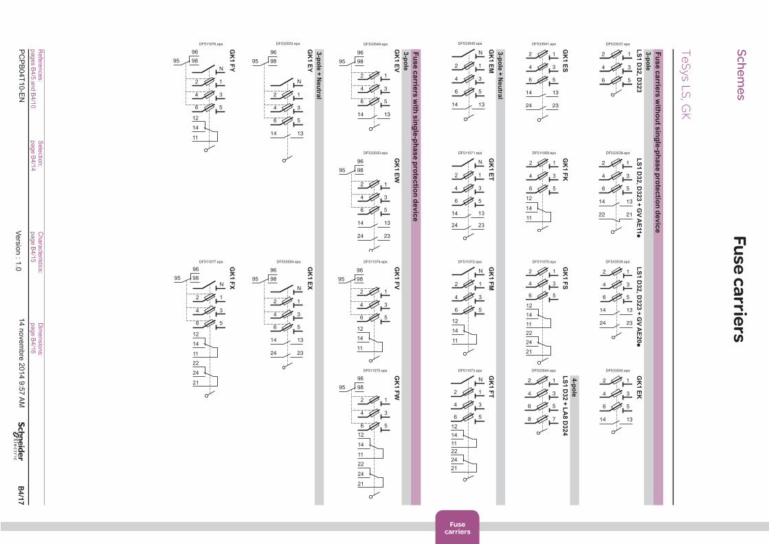
Fuse carriers
Fu
se c
arrie
rs w
itho
ut s
ing
le-p
hase
pro
tectio
n d
evic
e
3-p
ole
LS
1 D
32
, D3
23
LS
1 D
32
, D3
23
+ G
V A
E11p
LS
1 D
32
, D3
23
+ G
V A
E2
0p
GK
1 E
K
56
34
12
DF533537.eps
56
34
12
2122
1314
DF533538.eps
56
34
12
2324
1314
DF533539.eps
56
34
12
1314
DF533540.eps
4-p
ole
GK
1 E
SG
K1 F
KG
K1
FS
LS
1 D
32
+ L
A8
D3
24
56
34
12
2324
1314
DF533541.eps
56
34
12
14
11
12
DF511069.eps
14
11
12
56
34
12
24
21
22
DF511070.eps
56
78
34
12
DF533544.eps
3-p
ole
+ N
eu
tral
GK
1 E
MG
K1
ET
GK
1 F
MG
K1
FT
56
34
12
1314
N
DF533545.eps
56
34
12
2324
1314
N
DF511071.eps
56
34
12
N
14
11
12
DF511072.eps
14
11
12
56
34
12
N
24
21
22
DF511073.eps
Fu
se c
arrie
rs w
ith s
ing
le-p
hase
pro
tectio
n d
evic
e
3-p
ole
GK
1 E
VG
K1
EW
GK
1 F
VG
K1
FW
56
34
12
1314
9895
96
DF533549.eps
56
34
12
1314
9895
96
2324
DF533550.eps
56
34
12
9895
96
14
11
12
DF511074.eps
14
11
12
56
34
12
9895
96
24
21
22
DF511075.eps
3-p
ole
+ N
eu
tral
GK
1 E
YG
K1
EX
56
34
12
1314
9895
96
N
DF533553.eps
56
34
12
1314
9895
96
N
2324
DF533554.eps
GK
1 F
YG
K1
FX
56
34
12
9895
96
N
14
12
11
DF511076.eps
56
34
12
9895
96
N
14
11
12
24
21
22
DF511077.eps
Schemes
Refe
rences:
pages B
4/5
and B
4/1
0S
ele
ctio
n:
page B
4/1
4C
hara
cte
ristic
s:
page
B4/1
5D
imensio
ns:
page B
4/1
6
TeSys L
S, G
K

PCPB04T10-ENVersion : 1.0 14 novembre 2014 9:57 AMB4/18
B5/1
Switch-
disconnectors
fuses
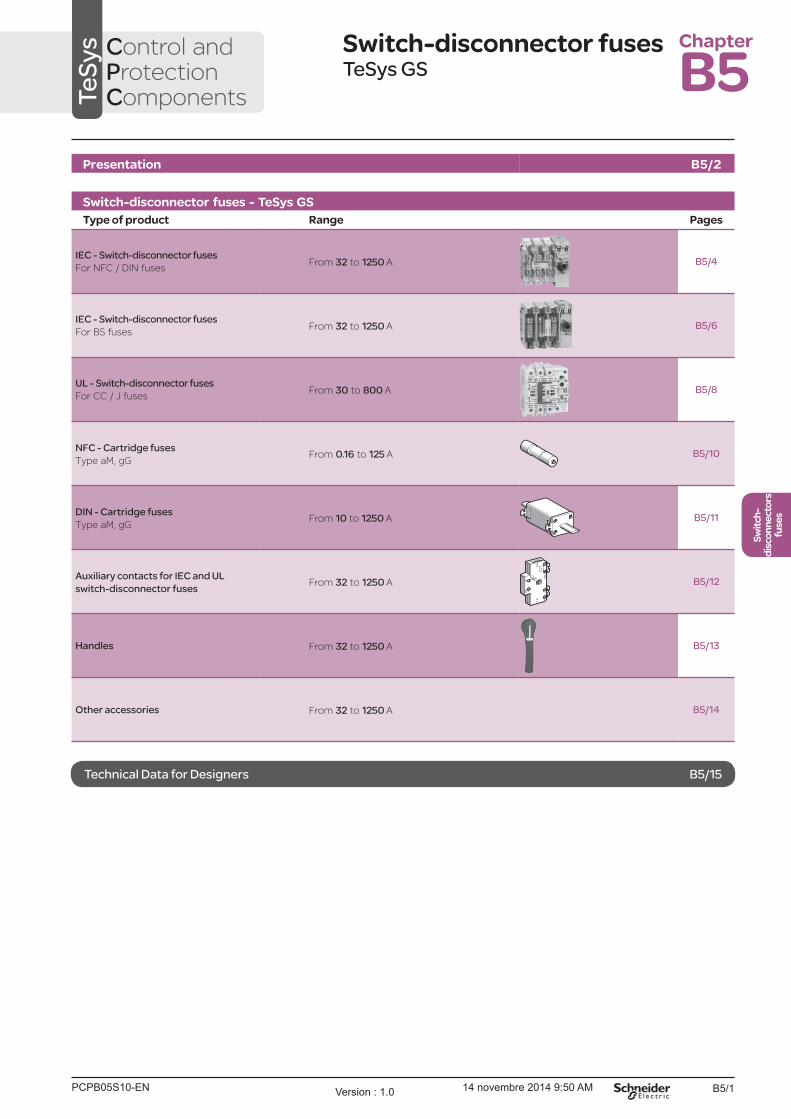
Switch-disconnector fusesTeSys GS
Presentation B5/2
Switch-disconnector fuses - TeSys GS
Type of product Range Pages
IEC - Switch-disconnector fuses
For NFC / DIN fusesFrom 32 to 1250 A B5/4
IEC - Switch-disconnector fuses
For BS fusesFrom 32 to 1250 A B5/6
UL - Switch-disconnector fuses
For CC / J fusesFrom 30 to 800 A B5/8
NFC - Cartridge fuses
Type aM, gGFrom 0.16 to 125 A B5/10
DIN - Cartridge fuses
Type aM, gGFrom 10 to 1250 A B5/11
Auxiliary contacts for IEC and UL
switch-disconnector fusesFrom 32 to 1250 A B5/12
Handles From 32 to 1250 A B5/13
Other accessories From 32 to 1250 A B5/14
TeSys Control and
Protection Components
Chapter
B5
Technical Data for Designers B5/15
PCPB05S10-EN Version : 1.0 14 novembre 2014 9:50 AM

B5/2
Presentation Switch-disconnector fuses and
accessoriesDiscover the components
1Switch-disconnector fuse
b NFC/DIN or BS fuse compatible
b Enhanced isolation between poles
b On-load making/breaking with double break
isolation of the power circuit
2Operating mechanism
b For one front or side external handle, right or
left side
b Cavity for early-break contacts
3Terminal shrouds
b For use when the switch-disconnector fuse
is installed outside an enclosure or when the
operating voltage is over 500 V AC
4Operating handle
b Padlockable in open position
5GS1ANpp Position signalling contacts
b Synchronized with the poles operation
6GS1AMppp Early-break signalling contacts
b Activated before the poles are opened
7GS1AFpp Blown fuse signalling contacts
b A missing fuse is also indicated
Customizable
GS2 APp
GS2 APp
GS2 AH260
GS2 AF6p, AF7p
GS1 AF
GS1 AMp
GS2 AE5p
GS2 AE5p
GS1 AN11
GS2 AH550
GS2 AH570
GS1 AN22
DB
416394.e
ps
Blown fuse signaling
contacts and their
control shaft
7
I,O position signalling
contacts
6
Early break, I, O
position signalling
contact
5
External handle and
shaft
4
Terminal shroud3
Terminal shroud3
Switch-disconnector
fuse
1
Operating
mechanism,
control by front or
by side external
handle
2
A customizable functional block
an automatic control before full opening, enhanced protection of terminals...
GS2 630 A switch-disconnector fuse
TeSys GS
PCPB05P10-ENVersion : 1.0 14 novembre 2014 9:50 AM

B5/3
Switch-
disconnectors
fuses
Presentation Switch-disconnector fuses and accessoriesDiscover the operating by direct and remote external handles
Position of the handle, a free choice
GS1JD3 - 100 A switch-disconnector fuseDirect lateral operating
GS1 AH01
GS1 AH02
DB
416395.e
ps
GS1 AH103
DB
416396.e
ps
GS2DB3 - 32 A switch-disconnector fuseDirect front operating
The handles are available
in different lengths. They
are chosen according
the operating effort which
depends on the rating of
the switch-disconnector
fuse.
The drive shaft can be cut
to the ideal length.
The choice of a red and
yellow handle (CNOMO
standard) will identify an
"Emergency Stop handle"
among others handles,
generally black and gray.
GS2 AH260
GS2 AE5p
GS2 AH550
GS2 AH570
GS2 AE5p
DB
416397.e
ps
GS2SB3 - 630 A switch-disconnector fuseRemote front and lateral (right only) operating
Simplicity of the direct operatingThe mounting of an operating handle directly on the side of the switch-disconnector fuse is a simple operation.
This handle will be for use by qualified personnel only.
As the mechanical design is simplified, the manoeuvre will be immediately understood by the operator.
Each handle can be padlocked in open position. Locking device for 3 padlocks.
Performance remote operatingLocated on the front or side panel of an enclosure, the operating handle provide complementary features:
b simple (IP55) or reinforced (IP65) protection against dust
b intermediate "Test" position
b door interlock when the handle is in "Close" position, opening by mean of a special tool is needed for
opening.
b optional key-operated handle lock
TeSys GS
PCPB05P10-EN Version : 1.0 14 novembre 2014 9:50 AM
B5/4
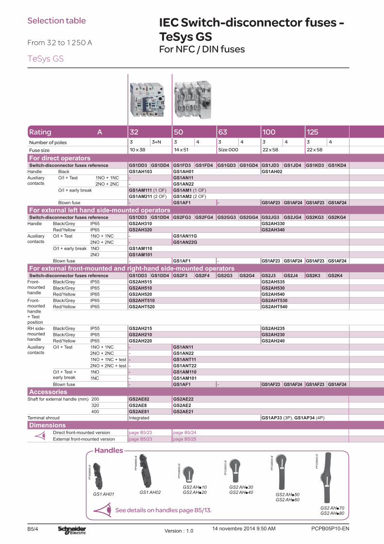
IEC Switch-disconnector fuses - TeSys GSFor NFC / DIN fuses
GS1 AH01
PF
568668.tif
GS1 AH02
PF
568669.tif
GS2 AHp10GS2 AHp20
PF
538656.tif
GS2 AHp30GS2 AHp40
PF
538655.tif
GS2 AHp50GS2 AHp60
PF
538654.tif
GS2 AHp70GS2 AHp80
PF
538653.tif
Handles
See details on handles page B5/13.
Rating A 32 50 63 100 125
Number of poles 3 3+N 3 4 3 4 3 4 3 4
Fuse size 10 x 38 14 x 51 Size 000 22 x 58 22 x 58
For direct operatorsSwitch-disconnector fuses reference GS1DD3 GS1DD4 GS1FD3 GS1FD4 GS1GD3 GS1GD4 GS1JD3 GS1JD4 GS1KD3 GS1KD4
Handle Black GS1AH103 GS1AH01 GS1AH02
Auxiliary
contacts
O/I + Test 1NO + 1NC - GS1AN11
2NO + 2NC - GS1AN22
O/I + early break GS1AM111 (1 OF) GS1AM1 (1 OF)
GS1AM211 (2 OF) GS1AM2 (2 OF)
Blown fuse - GS1AF1 - GS1AF23 GS1AF24 GS1AF23 GS1AF24
For external left hand side-mounted operatorsSwitch-disconnector fuses reference GS1DD3 GS1DD4 GS2FG3 GS2FG4 GS2GG3 GS2GG4 GS2JG3 GS2JG4 GS2KG3 GS2KG4
Handle Black/Grey IP65 GS2AH310 GS2AH330
Red/Yellow IP65 GS2AH320 GS2AH340
Auxiliary
contacts
O/I + Test 1NO + 1NC - GS1AN11G
2NO + 2NC - GS1AN22G
O/I + early break 1NO GS1AM110
2NO GS1AM101
Blown fuse - GS1AF1 - GS1AF23 GS1AF24 GS1AF23 GS1AF24
For external front-mounted and right-hand side-mounted operatorsSwitch-disconnector fuses reference GS1DD3 GS1DD4 GS2F3 GS2F4 GS2G3 GS2G4 GS2J3 GS2J4 GS2K3 GS2K4
Front-
mounted
handle
Black/Grey IP55 GS2AH515 GS2AH535
Black/Grey IP65 GS2AH510 GS2AH530
Red/Yellow IP65 GS2AH520 GS2AH540
Front-
mounted
handle
+ Test
position
Black/Grey IP65 GS2AHT510 GS2AHT530
Red/Yellow IP65 GS2AHT520 GS2AHT540
RH side-
mounted
handle
Black/Grey IP55 GS2AH215 GS2AH235
Black/Grey IP65 GS2AH210 GS2AH230
Red/Yellow IP65 GS2AH220 GS2AH240
Auxiliary
contacts
O/I + Test 1NO + 1NC - GS1AN11
2NO + 2NC - GS1AN22
1NO + 1NC + test - GS1ANT11
2NO + 2NC + test - GS1ANT22
O/I + Test +
early break
1NO - GS1AM110
1NC - GS1AM101
Blown fuse - GS1AF1 - GS1AF23 GS1AF24 GS1AF23 GS1AF24
AccessoriesShaft for external handle (mm) 200 GS2AE82 GS2AE22
320 GS2AE8 GS2AE2
400 GS2AE81 GS2AE21
Terminal shroud Integrated GS1AP33 (3P), GS1AP34 (4P)
DimensionsDirect front-mounted version page B5/23 page B5/24
External front-mounted version page B5/23 page B5/25
From 32 to 1250 A
Selection table
TeSys GS
PCPB05P10-ENVersion : 1.0 14 novembre 2014 9:50 AM

B5/5
Switch-
disconnectors
fuses
125 160 250 400 630 1250
3 4 3 4 3 4 3 4 3 4 3 4 3 4
Size 00 Size 00 Size 0 Size 1 Size 2 Size 3 Size 4
GS1KKD3 GS1KKD4 GS1LLD3 GS1LLD4 GS1LD3 GS1LD4 GS1ND3 GS1ND4 GS1QQD3 GS1QQD4 GS2S3 GS2S4 GS2V3 GS2V4
GS1AH02 GS2AH104 GS2AH105
GS1AN11
GS1AN22
GS1AM1 (1 OF) GS1AM110 (1 NO)
GS1AM2 (2 OF) GS1AM101 (1 NC)
- GS1AF33 GS1AF34 GS1AF43 GS1AF44 GS1AF43 GS1AF44 GS2AF63 GS2AF64 GS2AF73 GS2AF74
GS2KKG3 GS2KKG4 GS2LLG3 GS2LLG4 GS2LG3 GS2LG4 GS2NG3 GS2NG4 GS2QQG3 GS2QQG4 GS2SG3 GS2SG4 GS2VG3 GS2VG4
GS2AH330 GS2AH350
GS2AH340 GS2AH360
GS1AN11G
GS1AN22G
GS1AM110
GS1AM101
- GS1AF33 GS1AF34 GS1AF43 GS1AF44 GS1AF43 GS1AF44 GS2AF63 GS2AF64 GS2AF73 GS2AF74
GS2KK3 GS2KK4 GS2LL3 GS2LL4 GS2L3 GS2L4 GS2N3 GS2N4 GS2QQ3 GS2QQ4 GS2S3 GS2S4 GS2V3 GS2V4
GS2AH535 -
GS2AH530 GS2AH550 GS2AH570
GS2AH540 GS2AH560 GS2AH580
GS2AHT530 -
GS2AHT540 -
GS2AH235 -
GS2AH230 GS2AH250
GS2AH240 GS2AH260
GS1AN11
GS1AN22
GS1ANT11 -
GS1ANT22 -
GS1AM110 -
GS1AM101 -
- GS1AF33 GS1AF34 GS1AF43 GS1AF44 GS1AF43 GS1AF44 GS2AF63 GS2AF64 GS2AF73 GS2AF74
GS2AE22 GS2AE52
GS2AE2 GS2AE5
GS2AE21 GS2AE51
GS1AP33 (3P), GS1AP34 (4P) GS1AP43 (3P), GS1AP44 (4P) GS2AP73 GS2AP64 GS2AP83 GS2AP84
page B5/24 page B5/26
page B5/25 page B5/27
Auxiliary contacts
DF
568473.e
ps
GS1 AM1pp GS1 ANppp
DF
568476.e
ps
GS1 AMp11
DF
568474.e
ps
GS1 AMp
DF
568475.e
ps Maximal number of auxiliary contacts
Switch rating (A)
Standard With additional
bracket
Reference of additional
bracket
32 4 4 GS1AD10
50...400 4 4 GS2AD20
200...400 8 8 GS2AD20
630...1250 8 - -
See details on auxiliary contacts, page B5/12.
TeSys GS
PCPB05P10-EN Version : 1.0 14 novembre 2014 9:50 AM

B5/6
From 32 to 1250 A
Rating 32 Compact 32 63 100 160
Number of poles 3 3+N 3 4 3 4 3 4 3 4 3 4
Fuse size A1 A1 A2-A3 A4 A4 B1-B2
For direct operatorsSwitch-disconnector fuses
reference
GS1DDB3 GS1DDB4 -
Handle Black GS1AH103 -
Auxiliary
contacts
O/I + Test 1NO + 1NC - -
2NO + 2NC - -
O/I + early break GS1AM111 (1 OF) -
GS1AM211 (2 OF) -
For external front-mounted and right-hand side-mounted operatorsSwitch-disconnector fuses reference
GS1DDB3 GS1DDB4 GS2DB3 GS2DB4 GS2GB3 GS2GB4 GS2JB3 GS2JB4 GS2LLB3 GS2LLB4 GS2LB3 GS2LB4
Front-
mounted
handle
Black/Grey IP55 GS2AH515 GS2AH535
Black/Grey IP65 GS2AH510 GS2AH530
Red/Yellow IP65 GS2AH520 GS2AH540
Front-
mounted
handle
+ Test
position
Black/Grey IP65 GS2AHT510 GS2AHT530
Red/Yellow IP65 GS2AHT520 GS2AHT540
RH side-
mounted
handle
Black/Grey IP55 GS2AH215 GS2AH235
Black/Grey IP65 GS2AH210 GS2AH230
Red/Yellow IP65 GS2AH220 GS2AH240
Auxiliary
contacts
O/I + Test 1NO + 1NC - GS1AN11
2NO + 2NC - GS1AN22
1NO + 1NC
+ test
- GS1ANT11
2NO + 2NC
+ test
- GS1ANT22
O/I + Test +
early break
1NO GS1AM110 - max 4 contacts
1NC GS1AM101 - max 4 contacts
AccessoriesShaft for external handle
(mm)
200 GS2AE82 GS2AE22
320 GS2AE8 GS2AE2
400 GS2AE81 GS2AE21
Terminal shroud Integrated GS1AP33 (3P), GS1AP34 (4P)
DimensionsDirect front-mounted
versionpage B5/23 page B5/24
External front-mounted
versionpage B5/23 page B5/25
Selection table IEC Switch-disconnector fuses - TeSys GSFor BS fuses
TeSys GS
PCPB05P10-ENVersion : 1.0 14 novembre 2014 9:50 AM
B5/7
Switch-
disconnectors
fuses
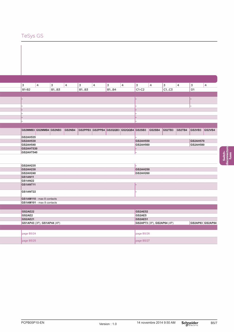
200 250 315 400 630 800 1250
3 4 3 4 3 4 3 4 3 4 3 4 3 4
B1-B2 B1...B3 B1...B3 B1...B4 C1-C2 C1...C3 D1
- - -
- - -
- -
- -
- -
- -
GS2MMB3 GS2MMB4 GS2NB3 GS2NB4 GS2PPB3 GS2PPB4 GS2QQB3 GS2QQB4 GS2SB3 GS2SB4 GS2TB3 GS2TB4 GS2VB3 GS2VB4
GS2AH535 -
GS2AH530 GS2AH550 GS2AH570
GS2AH540 GS2AH560 GS2AH580
GS2AHT530 -
GS2AHT540 -
GS2AH235 -
GS2AH230 GS2AH250
GS2AH240 GS2AH260
GS1AN11
GS1AN22
GS1ANT11 -
GS1ANT22 -
GS1AM110 - max 8 contacts
GS1AM101 - max 8 contacts
GS2AE22 GS2AE52
GS2AE2 GS2AE5
GS2AE21 GS2AE51
GS1AP43 (3P), GS1AP44 (4P) GS2AP73 (3P), GS2AP64 (4P) GS2AP83 GS2AP84
page B5/24 page B5/26
page B5/25 page B5/27
TeSys GS
PCPB05P10-EN Version : 1.0 14 novembre 2014 9:50 AM

B5/8
From 32 to 1250 A
PB
112395_
NB
.eps
PB
112396_
NB
.eps
Rating 30 Compact 30 60 100
Number of poles 3 3 3 3
Fuse size CC J CC J J J
For direct operatorsSwitch-disconnector fuses reference
GS1DDU3 GS1DU3 -
Handle Black GS1AH106 -
Auxiliary
contacts
O/I + Test 1NO + 1NC -
2NO + 2NC -
O/I + early
break
1NO GS1AM110 + GS1AD10 -
1NC GS1AM101 + GS1AD10 -
For external front-mounted operatorsSwitch-disconnector fuses reference
GS1DDU3 GS1DU3 GS2EEU3 GS2EU3N GS2GU3N GS2JU3N
Front-
mounted
handle
Black/Grey 1,3R, 12 GS2AH110 GS2AH130
4, 4X GS2AH410 GS2AH430
Red/Yellow 1,3R, 12 GS2AH120 GS2AH140
4, 4X GS2AH420 GS2AH440
Front-
mounted
handle
+ Test
position
Black/Grey 1,3R, 12 GS2AHT110 GS2AHT130
4, 4X GS2AHT410 GS2AHT430
Red/Yellow 1,3R, 12 GS2AHT120 GS2AHT140
4, 4X GS2AHT420 GS2AHT440
Auxiliary
contacts
O/I + Test 1NO + 1NC - GS1AN11
2NO + 2NC - GS1AN22
1NO + 1NC
+ test
- GS1ANT11
2NO + 2NC
+ test
- GS1ANT22
O/I + Test +
early break
1NO GS1AM110 - max 4 contacts (1) GS1AM110 - max 4 contacts (1)
1NC GS1AM101 - max 4 contacts (1) GS1AM101 - max 4 contacts (1)
AccessoriesShaft for external handle
(mm)
320 GS2AE8 GS2AE2
400 GS2AE81 GS2AE21
Terminal shroud Integrated
DimensionsDirect front-mounted
versionpage B5/23 page B5/24
External front-mounted
versionpage B5/23 page B5/25
(1) 4 more contacts allowed with GS1AD10 additional bracket.
Selection table UL Switch-disconnector fuses - TeSys GSFor CC and J fuses
TeSys GS
PCPB05P10-ENVersion : 1.0 14 novembre 2014 9:50 AM
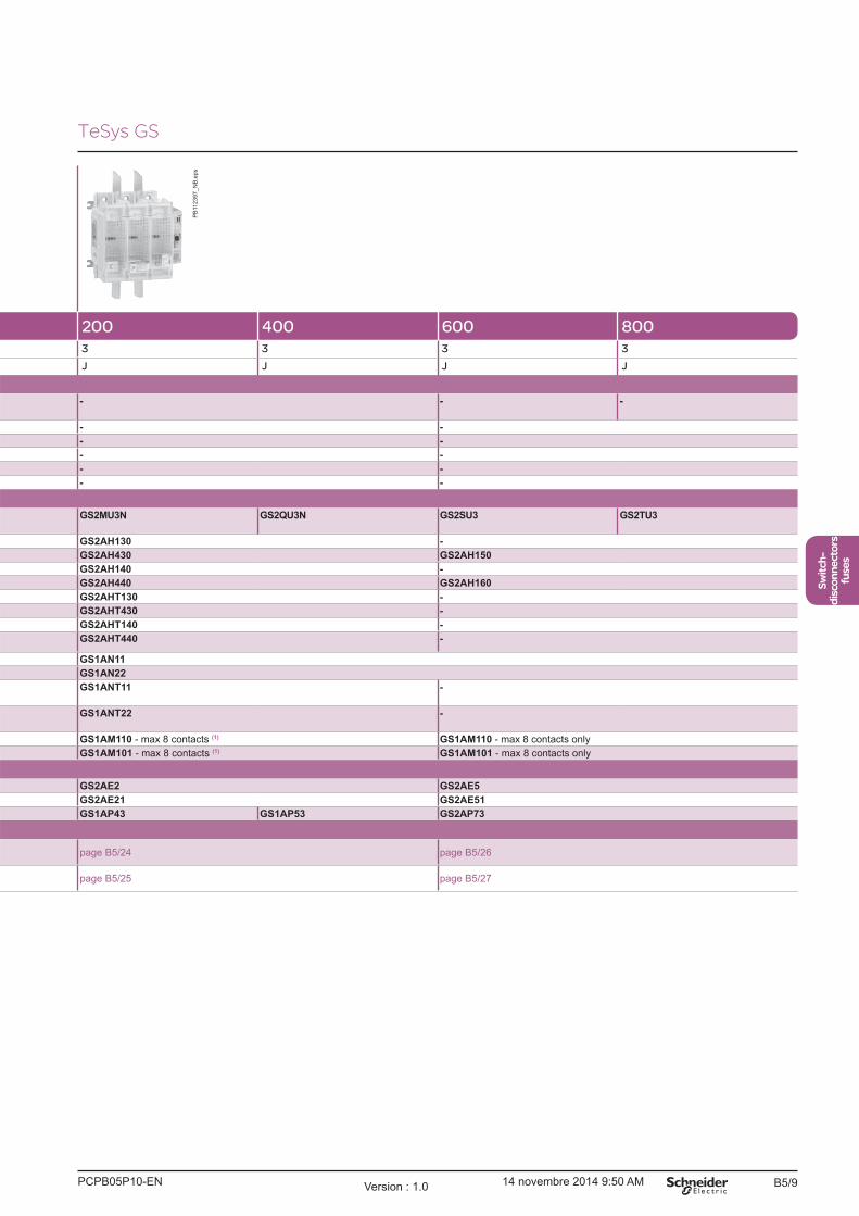
B5/9
Switch-
disconnectors
fuses
PB
112397_
NB
.eps
200 400 600 800
3 3 3 3
J J J J
- - -
- -
- -
- -
- -
- -
GS2MU3N GS2QU3N GS2SU3 GS2TU3
GS2AH130 -
GS2AH430 GS2AH150
GS2AH140 -
GS2AH440 GS2AH160
GS2AHT130 -
GS2AHT430 -
GS2AHT140 -
GS2AHT440 -
GS1AN11
GS1AN22
GS1ANT11 -
GS1ANT22 -
GS1AM110 - max 8 contacts (1) GS1AM110 - max 8 contacts only
GS1AM101 - max 8 contacts (1) GS1AM101 - max 8 contacts only
GS2AE2 GS2AE5
GS2AE21 GS2AE51
GS1AP43 GS1AP53 GS2AP73
page B5/24 page B5/26
page B5/25 page B5/27
TeSys GS
PCPB05P10-EN Version : 1.0 14 novembre 2014 9:50 AM
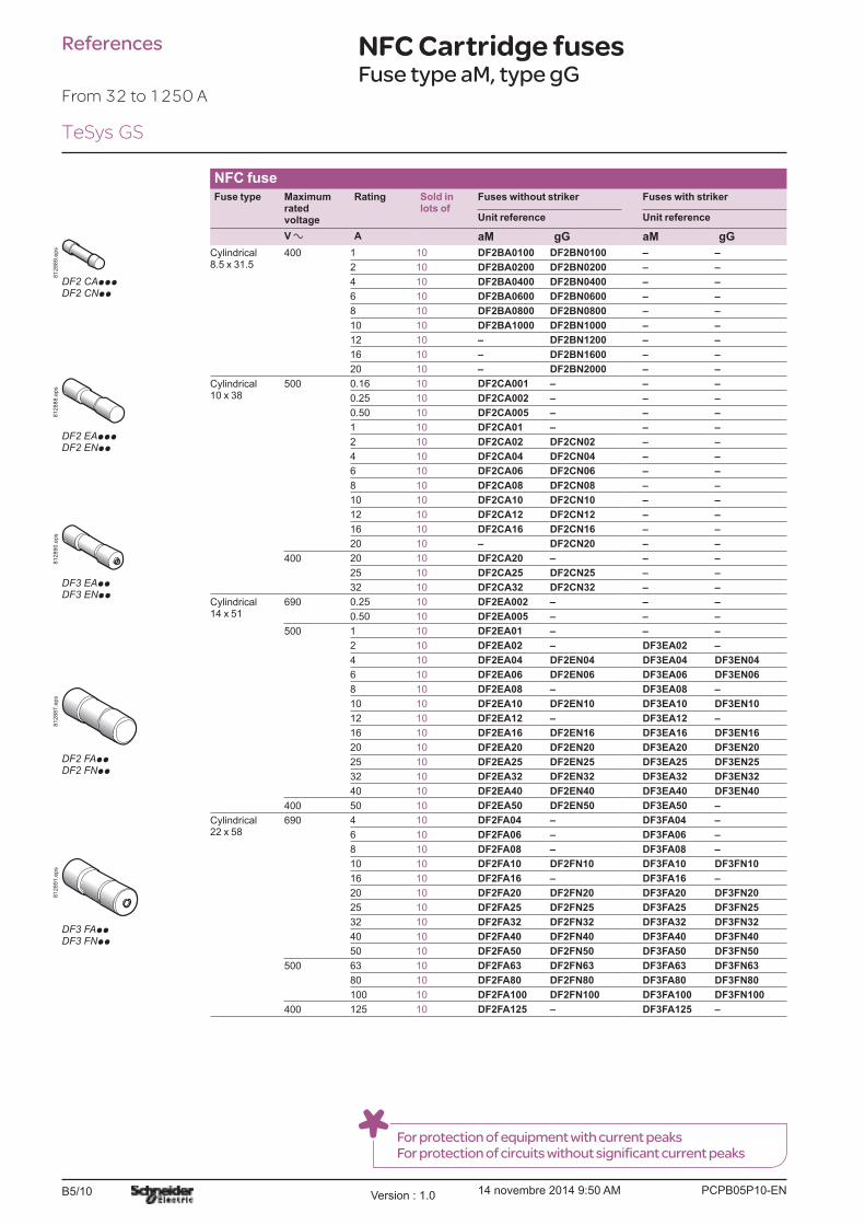
B5/10
References NFC Cartridge fusesFuse type aM, type gG
NFC fuseFuse type Maximum
rated voltage
Rating Sold in lots of
Fuses without striker Fuses with striker
Unit reference Unit reference
V a A aM gG aM gG
Cylindrical8.5 x 31.5
400 1 10 DF2BA0100 DF2BN0100 � �
2 10 DF2BA0200 DF2BN0200 � �
4 10 DF2BA0400 DF2BN0400 � �
6 10 DF2BA0600 DF2BN0600 � �
8 10 DF2BA0800 DF2BN0800 � �
10 10 DF2BA1000 DF2BN1000 � �
12 10 � DF2BN1200 � �
16 10 � DF2BN1600 � �
20 10 � DF2BN2000 � �
Cylindrical10 x 38
500 0.16 10 DF2CA001 � � �
0.25 10 DF2CA002 � � �
0.50 10 DF2CA005 � � �
1 10 DF2CA01 � � �
2 10 DF2CA02 DF2CN02 � �
4 10 DF2CA04 DF2CN04 � �
6 10 DF2CA06 DF2CN06 � �
8 10 DF2CA08 DF2CN08 � �
10 10 DF2CA10 DF2CN10 � �
12 10 DF2CA12 DF2CN12 � �
16 10 DF2CA16 DF2CN16 � �
20 10 � DF2CN20 � �
400 20 10 DF2CA20 � � �
25 10 DF2CA25 DF2CN25 � �
32 10 DF2CA32 DF2CN32 � �
Cylindrical 14 x 51
690 0.25 10 DF2EA002 � � �
0.50 10 DF2EA005 � � �
500 1 10 DF2EA01 � � �
2 10 DF2EA02 � DF3EA02 �
4 10 DF2EA04 DF2EN04 DF3EA04 DF3EN04
6 10 DF2EA06 DF2EN06 DF3EA06 DF3EN06
8 10 DF2EA08 � DF3EA08 �
10 10 DF2EA10 DF2EN10 DF3EA10 DF3EN10
12 10 DF2EA12 � DF3EA12 �
16 10 DF2EA16 DF2EN16 DF3EA16 DF3EN16
20 10 DF2EA20 DF2EN20 DF3EA20 DF3EN20
25 10 DF2EA25 DF2EN25 DF3EA25 DF3EN25
32 10 DF2EA32 DF2EN32 DF3EA32 DF3EN32
40 10 DF2EA40 DF2EN40 DF3EA40 DF3EN40
400 50 10 DF2EA50 DF2EN50 DF3EA50 �
Cylindrical 22 x 58
690 4 10 DF2FA04 � DF3FA04 �
6 10 DF2FA06 � DF3FA06 �
8 10 DF2FA08 � DF3FA08 �
10 10 DF2FA10 DF2FN10 DF3FA10 DF3FN10
16 10 DF2FA16 � DF3FA16 �
20 10 DF2FA20 DF2FN20 DF3FA20 DF3FN20
25 10 DF2FA25 DF2FN25 DF3FA25 DF3FN25
32 10 DF2FA32 DF2FN32 DF3FA32 DF3FN32
40 10 DF2FA40 DF2FN40 DF3FA40 DF3FN40
50 10 DF2FA50 DF2FN50 DF3FA50 DF3FN50
500 63 10 DF2FA63 DF2FN63 DF3FA63 DF3FN63
80 10 DF2FA80 DF2FN80 DF3FA80 DF3FN80
100 10 DF2FA100 DF2FN100 DF3FA100 DF3FN100
400 125 10 DF2FA125 � DF3FA125 �
812889.e
ps
DF2 CApppDF2 CNpp
812888.e
ps
DF2 EApppDF2 ENpp
812890.e
ps
DF3 EAppDF3 ENpp
812887.e
ps
DF2 FAppDF2 FNpp
812891.e
ps
DF3 FAppDF3 FNpp
For protection of equipment with current peaksFor protection of circuits without significant current peaks
From 32 to 1250 A
TeSys GS
PCPB05P10-ENVersion : 1.0 14 novembre 2014 9:50 AM

B5/11
Switch-
disconnectors
fuses
DIN fuseFuse type Maximum
rated voltage
Rating Sold in lots of
Fuses without striker Fuses with striker
Unit reference Unit reference
V a A aM gG aM gG aM gG
Blade size 000
690 10 - 10 � DF2FGN10 � �
16 3 10 DF2FGA16 DF2FGN16 � �
20 3 10 DF2FGA20 DF2FGN20 � �
25 3 10 DF2FGA25 DF2FGN25 � �
32 3 10 DF2FGA32 DF2FGN32 � �
40 3 10 DF2FGA40 DF2FGN40 � �
50 3 10 DF2FGA50 DF2FGN50 � �
63 3 10 DF2FGA63 DF2FGN63 � �
80 - 10 � DF2FGN80 � �
Blade size 00
690 80 3 - DF2FGA80 � � �
100 3 10 DF2FGA100 DF2FGN100 � �
125 3 10 DF2FGA125 DF2FGN125 � �
500 160 - 10 � DF2FGN160 � �
Blade size 0
690 50 3 3 DF2GA1051 DF2GN1051 � �
63 3 3 DF2GA1061 DF2GN1061 � �
80 3 3 DF2GA1081 DF2GN1081 � �
100 3 3 DF2GA1101 DF2GN1101 � �
125 3 3 DF2GA1121 DF2GN1121 DF4GA1121 �
160 3 3 DF2GA1161 DF2GN1161 DF4GA1161 �
500 125 - 3 � � � DF4GN1121
160 - 3 � � � DF4GN1161
200 3 - DF2GA1201 � DF4GA1201 �
Blade size 1
690 160 3 3 DF2HA1161 DF2HN1161 � �
200 3 3 DF2HA1201 DF2HN1201 DF4HA1201 DF4HN1201
250 3 - DF2HA1251 � DF4HA1251 �
500 250 - 3 � DF2HN1251 � DF4HN1251
315 3 - DF2HA1311 � DF4HA1311 �
Blade size 2
690 250 3 3 DF2JA1251 DF2JN1251 � �
315 3 3 DF2JA1311 DF2JN1311 DF4JA1311 DF4JN1311
400 3 - DF2JA1401 � DF4JA1401 �
500 400 - 3 � DF2JN1401 � DF4JN1401
500 3 - DF2JA1501 � DF4JA1501 �
Blade size 3
690 400 3 - DF2KA1401 � � �
500 3 3 DF2KA1501 � DF4KA1501 DF4KN1501
500 500 - 3 � DF2KN1501 � �
630 3 3 DF2KA1631 DF2KN1631 DF4KA1631 DF4KN1631
Blade size 4
690 800 1 3 DF2LA1801 � DF4LA1801 DF4LN1801
1000 1 - DF2LA1101 � DF4LA1101 �
500 800 - 1 � DF2LN1801 � �
1000 - 1 � DF2LN1101 � DF4LN1101
1250 1 1 DF2LA1251 DF2LN1251 DF4LA1251 DF4LN1251
DF
533330.e
ps
DF2 GAppppDF2 GNpppp
DF
533331.e
ps
DF4 GAppppDF4 GNpppp
DF
533332.e
ps
DF2 JAppppDF2 JNpppp
For protection of equipment with current peaksFor protection of circuits without significant current peaks
DIN Cartridge fusesFuse type aM, type gG
References
From 32 to 1250 A
TeSys GS
PCPB05P10-EN Version : 1.0 14 novembre 2014 9:50 AM
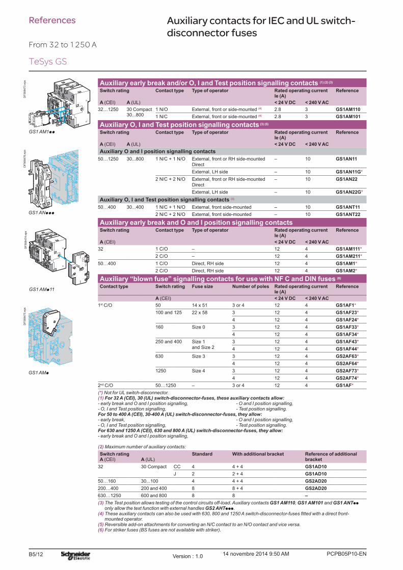
B5/12
Auxiliary early break and/or O, I and Test position signalling contacts (1) (2) (3) Switch rating Contact type Type of operator Rated operating current
Ie (A)Reference
A (CEI) A (UL) < 24 V DC < 240 V AC
32�1250 30 Compact 30...800
1 N/O External, front or side-mounted (4) 2.8 3 GS1AM110
1 N/C External, front or side-mounted (4) 2.8 3 GS1AM101
Auxiliary O, I and Test position signalling contacts (3) (5)
Switch rating Contact type Type of operator Rated operating current Ie (A)
Reference
A (CEI) A (UL) < 24 V DC < 240 V AC
Auxiliary O and I position signalling contacts
50�1250 30...800 1 N/C + 1 N/O External, front or RH side-mounted
Direct
� 10 GS1AN11
External, LH side � 10 GS1AN11G*
2 N/C + 2 N/O External, front or RH side-mounted
Direct
� 10 GS1AN22
External, LH side � 10 GS1AN22G*
Auxiliary O, I and Test position signalling contacts (3)
50�400 30...400 1 N/C + 1 N/O External, front side-mounted � 10 GS1ANT11
2 N/C + 2 N/O External, front side-mounted � 10 GS1ANT22
Auxiliary early break and O and I position signalling contacts Switch rating Contact type Type of operator Rated operating current
Ie (A)Reference
A (CEI) < 24 V DC < 240 V AC
32 1 C/O � 12 4 GS1AM111*
2 C/O � 12 4 GS1AM211*
50�400 1 C/O Direct, RH side 12 4 GS1AM1*
2 C/O Direct, RH side 12 4 GS1AM2*
Auxiliary �blown fuse� signalling contacts for use with NF C and DIN fuses (6)
Contact type Switch rating Fuse size Number of poles Rated operating current Ie (A)
Reference
A (CEI) < 24 V DC < 240 V AC
1st C/O 50 14 x 51 3 or 4 12 4 GS1AF1*
100 and 125 22 x 58 3 12 4 GS1AF23*
4 12 4 GS1AF24*
160 Size 0 3 12 4 GS1AF33*
4 12 4 GS1AF34*
250 and 400 Size 1
and Size 2
3 12 4 GS1AF43*
4 12 4 GS1AF44*
630 Size 3 3 12 4 GS2AF63*
4 12 4 GS2AF64*
1250 Size 4 3 12 4 GS2AF73*
4 12 4 GS2AF74*
2nd C/O 50�1250 � 3 or 4 12 4 GS1AF*
(*) Not for UL switch-disconnector.(1) For 32 A (CEI), 30 (UL) switch-disconnector-fuses, these auxiliary contacts allow:- early break and O and I position signalling, - O and I position signalling,- O, I and Test position signalling, - Test position signalling.For 50 to 400 A (CEI), 30-400 A (UL) switch-disconnector-fuses, they allow:- early break, - O and I position signalling,- O, I and Test position signalling, - Test position signalling.For 630 and 1250 A (CEI), 630 and 800 A (UL) switch-disconnector-fuses, they allow:- early break and O and I position signalling,
(2) Maximum number of auxiliary contacts:
Switch rating A (CEI) A (UL)
Standard With additional bracket Reference of additional bracket
32 30 Compact CC 4 4 + 4 GS1AD10
J 2 2 + 4 GS1AD10
50�160 30...100 4 4 + 4 GS2AD20
200�400 200 and 400 8 8 + 4 GS2AD20
630�1250 600 and 800 8 8 �
(3) The Test position allows testing of the control circuits off-load. Auxiliary contacts GS1 AM110, GS1 AM101 and GS1 ANTpp only allow the text function with external handles GS2 AHTppp.
(4)mounted operator.
(5) Reversible add-on attachments for converting an N/C contact to an N/O contact and vice versa.(6) For striker fuses (BS fuses are not available with striker).
References Auxiliary contacts for IEC and UL switch-disconnector fuses
DF
568473.e
ps
GS1 AM1pp
GS1 ANppp
DF
568476.e
ps
GS1 AMp11
DF
568474.e
ps
GS1 AMp
DF
568475.e
ps
From 32 to 1250 A
TeSys GS
PCPB05P10-ENVersion : 1.0 14 novembre 2014 9:50 AM
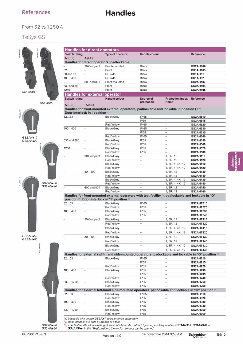
B5/13
Switch-
disconnectors
fuses
Handles
Handles for direct operators Switch rating Type of operator Handle colour Reference
A (CEI) A (UL)
Handles for direct operators, padlockable
- 30 Compact Front-mounted Black GS2AH106
32 - Front Black GS1AH103
50 and 63 - RH side Black GS1AH01
100�400 - RH side Black GS1AH02
- 600 and 800 Front-mounted Black GS2AH107
630 and 800 - Front Black GS2AH104
1250 - Front Black GS2AH105
Handles for external operator Switch rating Handle colour Degree of
protectionProtection indexNema
Reference
A (CEI) A (UL)
Handles for front-mounted external operators, padlockable and lockable in position O (1)
Door interlock in I position (2)
32�63 - Black/Grey IP 65 � GS2AH510
IP55 � GS2AH515
Red/Yellow IP 65 � GS2AH520
100�400 - Black/Grey IP 65 � GS2AH530
IP55 � GS2AH535
Red/Yellow IP 65 � GS2AH540
630 and 800 - Black/Grey IP65 � GS2AH550
Red/Yellow IP65 � GS2AH560
1250 - Black/Grey IP65 � GS2AH570
Red/Yellow IP65 � GS2AH580
- 30 Compact Black/Grey � 1, 3R, 12 GS2AH110
Red/Yellow � 1, 3R, 12 GS2AH120
Black/Grey � 1, 3R, 4, 4X, 12 GS2AH410
Red/Yellow � 1, 3R, 4, 4X, 12 GS2AH420
- 30�400 Black/Grey � 1, 3R, 12 GS2AH130
Red/Yellow � 1, 3R, 12 GS2AH140
Black/Grey � 1, 3R, 4, 4X, 12 GS2AH430
Red/Yellow � 1, 3R, 4, 4X, 12 GS2AH440
- 600 and 800 Black/Grey � 1, 3R, 12 GS2AH150
Red/Yellow � 1, 3R, 12 GS2AH160
Handles for front-mounted external operators with test facility (3), padlockable and lockable in "O" position (1). Door interlock in �I� position (2)
32�63 - Black/Grey IP 65 � GS2AHT510
Red/Yellow IP65 � GS2AHT520
100�400 - Black/Grey IP65 � GS2AHT530
Red/Yellow IP65 � GS2AHT540
- 30 Compact Black/Grey � 1, 3R, 12 GS2AHT110
Red/Yellow � 1, 3R, 12 GS2AHT120
Black/Grey � 1, 3R, 4, 4X, 12 GS2AHT410
Red/Yellow � 1, 3R, 4, 4X, 12 GS2AHT420
- 30�400 Black/Grey � 1, 3R, 12 GS2AHT130
Red/Yellow � 1, 3R, 12 GS2AHT140
Black/Grey � 1, 3R, 4, 4X, 12 GS2AHT430
Red/Yellow � 1, 3R, 4, 4X, 12 GS2AHT440
Handles for external right-hand side-mounted operators, padockable and lockable in "O" position (1)
32�63 - Black/Grey IP 65 � GS2AH210
IP55 � GS2AH215
Red/Yellow IP65 � GS2AH220
100�400 - Black/Grey IP65 � GS2AH230
IP55 � GS2AH235
Red/Yellow IP65 � GS2AH240
630�1250 - Black/Grey IP65 � GS2AH250
Red/Yellow IP65 � GS2AH260
Handles for external left-hand side-mounted operators, padockable and lockable in "O" position (1)
32�63 - Black/Grey IP 65 � GS2AH310
Red/Yellow IP65 � GS2AH320
100�400 - Black/Grey IP65 � GS2AH330
Red/Yellow IP65 � GS2AH340
630�1250 - Black/Grey IP65 � GS2AH350
Red/Yellow IP65 � GS2AH360
(1) Lockable with device GS2AX1, to be ordered separately.(2) Door interlock override by means of a tool.(3) The Test facility allows testing of the control circuits off-load, by using auxiliary contacts GS1AM110, GS1AM101 or
GS1ANTpp. In the �Test� position, the enclosure door can be opened.
GS1 AH01
PF
568668.tif
GS1 AH02
PF
568669.tif
GS2 AHp10GS2 AHp20
PF
538656.tif
GS2 AHp30GS2 AHp40
PF
538655.tif
GS2 AHp50GS2 AHp60
PF
538654.tif
GS2 AHp70GS2 AHp80
PF
538653.tif
From 32 to 1250 A
References
TeSys GS
PCPB05P10-EN Version : 1.0 14 novembre 2014 9:50 AM

B5/14
References Accessories
Shafts for external operatorsSwitch rating Shaft length Shaft cross section Reference
A (CEI) A (UL) mm mm
32 30 Compact 200 5 x 5 GS2AE82
320 5 x 5 GS2AE8
400 5 x 5 GS2AE81
50�400 30...400 200 10 x 10 GS2AE22
320 10 x 10 GS2AE2
400 10 x 10 GS2AE21
630�1250 600 and 800 200 12 x 12 GS2AE52
320 12 x 12 GS2AE5
40 12 x 12 GS2AE51
Terminal protection shrouds for upstream or downstream connector platesSwitch rating Number of poles Reference
A (CEI) A (UL)
50 and 63 30 Compact, 30...60 (3P) 3 or 4 (1)
100�160 100 3 GS1AP33
� 4 GS1AP34
200�400 200 3 GS1AP43
� 4 GS1AP44
� 400 3 GS1APU53
630�800 600 and 800 3 GS2AP73
� 4 GS2AP64
1250 � 3 GS2AP83
4 GS2AP84
Devices for locking fuse covers in "I" position (2)
Switch rating Fuse size Number of poles Reference
A
50 14 x 51 3 or 4 (3)
63 Size 00C 3 or 4 GS1AV1
100�160 22 x 58, Size 00 3 or 4 GS1AV2
160 Size 0 3 GS1AV33
4 GS1AV34
250 Size 1 3 GS1AV53
4 GS1AV54
400 Size 2 3 GS1AV73
4 GS1AV74
Cage terminals for connection of bare cables (without lug)Switch rating Number of poles Reference
A
50 and 63 3 or 4 (4)
100�160 3 GS1AW33
4 GS1AW34
200�250 3 GS1AW43
4 GS1AW44
External handle locking deviceSwitch rating Description Reference
A
32�1250 Device for RONIS EL11AP keylock
(lock to be ordered separately).GS2AX1
Height compensation plate for external handlesSwitch ratingA (CEI) A (UL)
Description Degree of protection
Reference
32�1250 30 Compact, 30...400 Allows a new GS2pp handle IP 65 GS2AH001
Flat mounting kitSwitch rating Description Reference
A
50�400 The kit, for use with a front-mounted external handle, includes:
b a 200 mm shaft, cross section 10 x 10 mm,
b an adapter plate
GS2ADL2
(1)(2)(3)(4)
GS2 AE5
GS
2AE
5_A
E6.
psd
GS2 AE2 - GS2 AE21
GS
2A
E2.p
sd
GS2 AE8 - GS2 AE81
GS2A
E8_
AE81
.psd
From 32 to 1250 A
TeSys GS
PCPB05P10-ENVersion : 1.0 14 novembre 2014 9:50 AM
B5/15
Switch-
disconnectors
fuses
Technical Data for DesignersT
eSys GS
Contents
Characteristics:
> switch-disconnector fuses ........B5/16 to B5/21
> auxiliary contacts ..................................................B5/22
Dimensions .............................................................B5/23 to B5/31
Schemes .........................................................................................B5/31
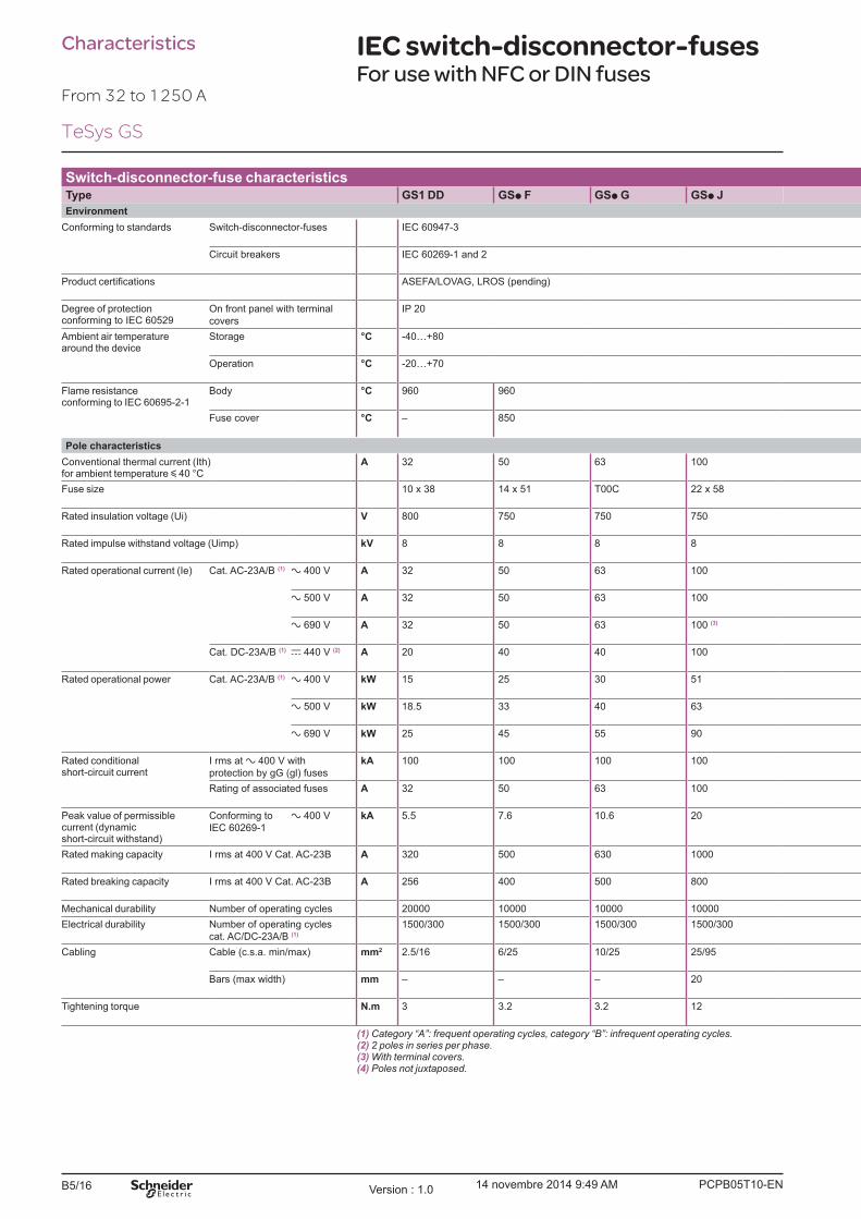
PCPB05T10-ENVersion : 1.0 14 novembre 2014 9:49 AMB5/16
Switch-disconnector-fuse characteristicsType GS1 DD GSp F GSp G GSp J
Environment
Conforming to standards Switch-disconnector-fuses IEC 60947-3
Circuit breakers IEC 60269-1 and 2
ASEFA/LOVAG, LROS (pending)
Degree of protectionconforming to IEC 60529
On front panel with terminal
covers
IP 20
Ambient air temperature around the device
Storage °C -40�+80
Operation °C -20�+70
Flame resistance conforming to IEC 60695-2-1
Body °C 960 960
Fuse cover °C � 850
Pole characteristics
Conventional thermal current (Ith) for ambient temperature y 40 °C
A 32 50 63 100
Fuse size 10 x 38 14 x 51 T00C 22 x 58
Rated insulation voltage (Ui) V 800 750 750 750
Rated impulse withstand voltage (Uimp) kV 8 8 8 8
Rated operational current (Ie) Cat. AC-23A/B (1) a 400 V A 32 50 63 100
a 500 V A 32 50 63 100
a 690 V A 32 50 63 100 (3)
Cat. DC-23A/B (1) c 440 V (2) A 20 40 40 100
Rated operational power Cat. AC-23A/B (1) a 400 V kW 15 25 30 51
a 500 V kW 18.5 33 40 63
a 690 V kW 25 45 55 90
Rated conditional short-circuit current
I rms at a 400 V with
protection by gG (gl) fuses
kA 100 100 100 100
Rating of associated fuses A 32 50 63 100
Peak value of permissible current (dynamic short-circuit withstand)
Conforming to
IEC 60269-1
a 400 V kA 5.5 7.6 10.6 20
Rated making capacity I rms at 400 V Cat. AC-23B A 320 500 630 1000
Rated breaking capacity I rms at 400 V Cat. AC-23B A 256 400 500 800
Mechanical durability Number of operating cycles 20000 10000 10000 10000
Electrical durability Number of operating cycles
cat. AC/DC-23A/B (1)
1500/300 1500/300 1500/300 1500/300
Cabling Cable (c.s.a. min/max) mm2 2.5/16 6/25 10/25 25/95
Bars (max width) mm � � � 20
Tightening torque N.m 3 3.2 3.2 12
(1) Category �A�: frequent operating cycles, category �B�: infrequent operating cycles.(2) 2 poles in series per phase.(3) With terminal covers.(4) Poles not juxtaposed.
Characteristics IEC switch-disconnector-fuses For use with NFC or DIN fuses
From 32 to 1250 A
TeSys GS

PCPB05T10-EN Version : 1.0 14 novembre 2014 9:49 AM B5/17
Switch-
disconnectors
fuses
B5/17
Switch-
disconnectors
fuses
GSp K GSp KK GSp LL GSp L GSp N GSp QQ GS2 S GS2 V
IEC 60947-3
IEC 60269-1 and 2
ASEFA/LOVAG, LROS (pending)
IP 20
-40�+80
-20�+70
960
850
125 125 160 160 250 400 630 1250
22 x 58 T00 T00 T0 T1 T2 T3 T4
750 750 750 750 750 800 1000 1000
8 8 8 8 8 8 12 12
125 125 160 160 250 400 630 1000
125 125 160 160 250 315 500 800
100 (3) 100 (3) 125 (3) 125 (3) 250 (3) 250/315 315/400 630
100 100 125 125 200 200/315 (4) 400/630 (4) 1000
63 63 80 80 132 220 355 560
90 90 110 110 160 220 355 560
80 80 110 110 220 220/295 295/400 400/475
100 100 100 (50) 100 100 50 100 100
125 125 125 (160) 160 250 400 630 1250
20 20 22.7 20 32.5 40 70 90
1250 1250 1600 1600 2500 4000 6300 10 000
1000 1000 1280 1280 2000 3200 5040 8000
10000 10000 10000 10000 10000 10000 8000 5000
1000/200 1000/200 1000/200 1000/200 1000/200 1000/200 1000/200 500/100
35/95 35/95 50/95 50/95 95/240 185/240 2 x 150 / 2 x 300 - / 4 x 185
20 20 20 20 32 45 63 80
12 12 12 12 25 25 44 44
TeSys GS

PCPB05T10-ENVersion : 1.0 14 novembre 2014 9:49 AMB5/18
Switch-disconnector-fuse characteristicsType GS1 DDB GS2 DB GS2 GB GS2 JB
Environment
Conforming to standards Switch-disconnector-fuses IEC 60947-3
Circuit breakers IEC 60269-1 and 2
ASEFA/LOVAG, LROS (pending)
Degree of protectionconforming to IEC 60529
On Front panel, with terminal
covers
IP 20
Ambient air temperature around the device
Storage °C -40�+80
Operation °C -20�+70
Flame resistance conforming to IEC 60695-2-1
Body °C 960
Fuse cover °C � 850
Pole characteristics
Conventional thermal current (Ith) for ambient temperature y 40 °C
A 32 32 63 100
Fuse size A1 A1 A2-A3 A4 Ø y 31 mm
Rated insulation voltage (Ui) V 800 750 750 750
Rated impulse withstand voltage (Uimp) kV 8 8 8 8
Rated operational current (Ie) Cat. AC-23A/B (1) a 400 V A 32 32 63 100
a 500 V A 32 32 63 100
a 690 V A 32 32 63 100 (4)
Cat. DC-23A/B (1) c 440 V (2) A 20 20 40 100
Rated operational power Cat. AC-23A/B (1) a 400 V kW 15 15 30 51
a 500 V kW 18.5 18.5 40 63
a 690 V kW 25 25 55 90
Rated conditional short-circuit current
I rms at a 400 V with
protection by gG (gl) fuses
kA 80 80 80 80
Rating of associated fuses A 32 32 63 100
Peak value of permissible current (dynamic short-circuit withstand)
Conforming to
IEC 60269-1
a 400 V kA 5.5 9 10.6 20
Rated making capacity I rms at 400 V Cat. AC-23B A 320 320 630 1000
Rated breaking capacity I rms at 400 V Cat. AC-23B A 256 256 500 800
Mechanical durability Number of operating cycles 20000 10000 10000 10000
Electrical durability Number of operating cycles
cat. AC/DC-23A/B (1)
1500/300 1500/300 1500/300 1500/300
Cabling Cable (c.s.a. min/max) mm2 2.5/16 6/25 10/25 25/95
Bars (max width) mm � � � 20
Tightening torque N.m 3 3.2 3.2 12
(1) Category �A�: frequent operating cycles, category �B�: infrequent operating cycles.(2) 2 poles in series per phase.(3) Fit switch-disconnector-fuses GS2 LB with B1 or B2 fuses and GS2 LLB with A4 fuses.(4) With terminal covers.(5) Poles not juxtaposed.
Characteristics IEC switch-disconnector-fuses For use with BS fuses
From 32 to 1250 A
TeSys GS
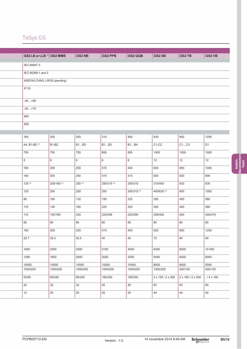
PCPB05T10-EN Version : 1.0 14 novembre 2014 9:49 AM B5/19
Switch-
disconnectors
fuses
B5/19
Switch-
disconnectors
fuses
GS2 LB or LLB (3) GS2 MMB GS2 NB GS2 PPB GS2 QQB GS2 SB GS2 TB GS2 VB
IEC 60947-3
IEC 60269-1 and 2
ASEFA/LOVAG, LROS (pending)
IP 20
-40�+80
-20�+70
960
850
160 200 250 315 400 630 800 1250
A4. B1-B2 (3) B1-B2 B1�B3 B1�B3 B1�B4 C1-C2 C1�C3 D1
750 750 750 800 800 1000 1000 1000
8 8 8 8 8 12 12 12
160 200 250 315 400 630 800 1000
160 200 250 315 315 500 630 800
125 (4) 200/160 (4) 250 (4) 250/315 (4) 250/315 315/400 630 630
125 200 200 200 200/315 (5) 400/630 (5) 800 1000
80 100 132 150 220 355 450 560
110 140 160 220 220 355 450 560
110 150/185 220 220/295 220/295 295/400 400 400/475
80 80 80 80 80 80 80 80
160 200 250 315 400 630 800 1250
22.7 32.5 32.5 40 40 70 80 90
1600 2000 2500 3150 4000 6300 8000 10 000
1280 1600 2000 2520 3200 5040 6400 8000
10000 10000 10000 10000 10000 8000 8000 5000
1000/200 1000/200 1000/200 1000/200 1000/200 1000/200 500/100 500/100
50/95 95/240 95/240 185/240 185/240 2 x 150 / 2 x 300 2 x 185 / 2 x 300 - / 4 x 185
20 32 32 45 45 63 63 80
12 25 25 25 25 44 44 44
TeSys GS
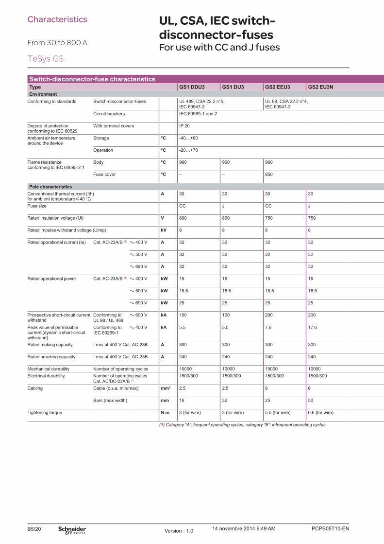
PCPB05T10-ENVersion : 1.0 14 novembre 2014 9:49 AMB5/20
Characteristics UL, CSA, IEC switch-
disconnector-fusesFor use with CC and J fuses
From 30 to 800 A
Switch-disconnector-fuse characteristicsType GS1 DDU3 GS1 DU3 GS2 EEU3 GS2 EU3N
Environment
Conforming to standards Switch-disconnector-fuses UL 489, CSA 22.2 n°5,
IEC 60947-3
UL 98, CSA 22.2 n°4,
IEC 60947-3
Circuit breakers IEC 60969-1 and 2
Degree of protectionconforming to IEC 60529
With terminal covers IP 20
Ambient air temperaturearound the device
Storage °C -40�+80
Operation °C -20�+70
Flame resistanceconforming to IEC 60695-2-1
Body °C 960 960 960
Fuse cover °C � � 850
Pole characteristics
Conventional thermal current (Ith)for ambient temperature y 40 °C
A 30 30 30 30
Fuse size CC J CC J
Rated insulation voltage (Ui) V 800 800 750 750
Rated impulse withstand voltage (Uimp) kV 8 8 8 8
Rated operational current (Ie) Cat. AC-23A/B (1) a 400 V A 32 32 32 32
a 500 V A 32 32 32 32
a 690 V A 32 32 32 32
Rated operational power Cat. AC-23A/B (1) a 400 V kW 15 15 15 15
a 500 V kW 18.5 18.5 18.5 18.5
a 690 V kW 25 25 25 25
Prospective short-circuit current withstand
Conforming to
UL 98 / UL 489
a 600 V kA 100 100 200 200
Peak value of permissible current (dynamic short-circuit withstand)
Conforming to
IEC 60269-1
a 400 V kA 5.5 5.5 7.6 17.6
Rated making capacity I rms at 400 V Cat. AC-23B A 300 300 300 300
Rated breaking capacity I rms at 400 V Cat. AC-23B A 240 240 240 240
Mechanical durability Number of operating cycles 10000 10000 10000 10000
Electrical durability Number of operating cycles
Cat. AC/DC-23A/B (1)
1500/300 1500/300 1500/300 1500/300
Cabling Cable (c.s.a. min/max) mm2 2.5 2.5 6 6
Bars (max width) mm 16 32 25 50
Tightening torque N.m 3 (for wire) 3 (for wire) 5.5 (for wire) 6.6 (for wire)
(1) Category �A�: frequent operating cycles, category �B�: infrequent operating cycles.
TeSys GS
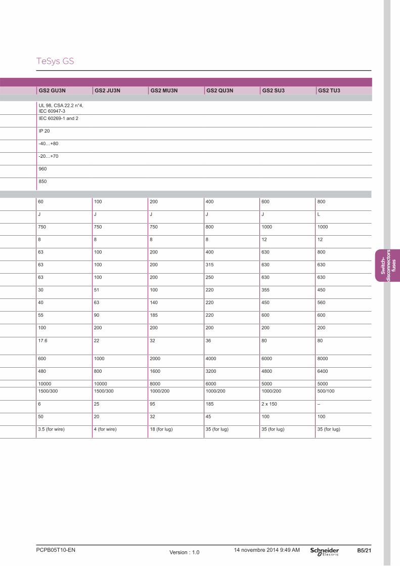
PCPB05T10-EN Version : 1.0 14 novembre 2014 9:49 AM B5/21
Switch-
disconnectors
fuses
B5/21
Switch-
disconnectors
fuses
GS2 GU3N GS2 JU3N GS2 MU3N GS2 QU3N GS2 SU3 GS2 TU3
UL 98, CSA 22.2 n°4,
IEC 60947-3
IEC 60269-1 and 2
IP 20
-40�+80
-20�+70
960
850
60 100 200 400 600 800
J J J J J L
750 750 750 800 1000 1000
8 8 8 8 12 12
63 100 200 400 630 800
63 100 200 315 630 630
63 100 200 250 630 630
30 51 100 220 355 450
40 63 140 220 450 560
55 90 185 220 600 600
100 200 200 200 200 200
17.6 22 32 36 80 80
600 1000 2000 4000 6000 8000
480 800 1600 3200 4800 6400
10000 10000 8000 6000 5000 5000
1500/300 1500/300 1000/200 1000/200 1000/200 500/100
6 25 95 185 2 x 150 �
50 20 32 45 100 100
3.5 (for wire) 4 (for wire) 18 (for lug) 35 (for lug) 35 (for lug) 35 (for lug)
TeSys GS

PCPB05T10-ENVersion : 1.0 14 novembre 2014 9:49 AMB5/22
Characteristics Auxiliary contacts
GS1 AMp11, GS1 AM1 and GS1 AM2 early break and signalling contact characteristicsConventional thermal current (Ith) for ambient temperature y 40 °C
A 16
Rated operational current (Ie) Cat. AC-15 A 127 V: 5 - 230 V: 4 - 400 /415 V: 3 - 440 V: 2
Cat. DC-13 A 24 V: 12 - 48 V: 2 - 110 V: 0.6 - 220 V: 0.4
Durability Number of operating cycles Mechanical: 1000000
Electrical: cat. AC-15: 30000
Fuse protection gG A 6 max
Cabling mm Faston connectors: 1 x 6.35 or 2 x 2.8
GS1 AN and GS1 ANT signalling contact characteristicsConventional thermal current (Ith) for ambient temperature y 40 °C
A 20
Rated operational current (Ie) Cat. AC-15 A 127 V: 12 - 230 V: 10 - 400/415 V: 8 - 440 V: 6
Cat. DC-13 A 48 V: 4 - 110 V: 1.2 - 220 V: 1
Durability Number of operating cycles Mechanical: 30000
Electrical: cat. AC-15: 30000
Fuse protection gG A 16 max
Cabling Cable (c.s.a. min/max) mm2 Min: 1.5 - max: 10
GS1 AM110 and GS1 AM101 early break and signalling contact characteristicsConventional thermal current (Ith) for ambient temperature y 40 °C
A 10
Rated operational current (Ie) Cat. AC-15 A 120 V: 6 - 240 V: 3 - 400 V: 1.8 - 480 V: 1.5
Cat. DC-13 A 24 V: 2.8 - 48 V: 1.4 - 125 V: 0.55 - 250 V: 0.27 - 400 V: 0.15
Durability Number of operating cycles Mechanical: 5000000
Electrical: cat. AC-15: 1000000
Cabling Cable (c.s.a. min/max) mm2 Min: 1 x 0.22 - max: 2 x 2.5
GSp AF "blown fuse" signalling contact characteristicsConventional thermal current (Ith) for ambient temperature y 40 °C
A 16
Rated operational current (Ie) Cat. AC-15 A 230 V: 4 - 400 V: 3
Cat. DC-13 A 24 V: 12 - 48 V: 2 - 110 V: 0.6 - 220 V: 0.4
Durability Number of operating cycles Mechanical: 30000
Electrical: cat. AC-15: 30000
Cabling mm Faston connectors: 1 x 6.35
From 32 to 1250 A
TeSys GS
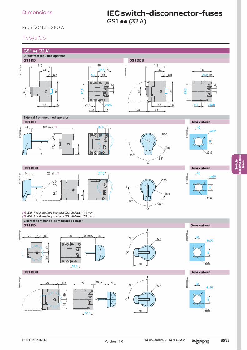
PCPB05T10-EN Version : 1.0 14 novembre 2014 9:49 AM B5/23
Switch-
disconnectors
fuses
B5/23
Switch-
disconnectors
fuses
GS1 pp (32 A)Direct front-mounted operator
GS1 DD GS1 DDB
45
65 8,5
14
96
37,5
35
15
21,5 17
21,5
5,2
112
44
19 6,5
79,5
98
2xØ5
DF
568730.e
ps
98
45
65 8,5
14
96
37,5 15
5,2
112
44
19 6,5
79,5
8398
2xØ5
DF
568731.e
ps
External front-mounted operator
GS1 DD Door cut-out
1537,5
14
44
70
90° 65°
I
Test
O
35
49
Ø78
102 min. (1)
DF
568732.e
ps
4xØ7
28
40
Ø37
DF
568735.e
ps
GS1 DDB Door cut-out
14
35
90° 65°
I
Test
O
Ø78
44
70
37,5 15
49
102 min. (1)
DF
568734.e
ps
(1) With 1 or 2 auxiliary contacts GS1 AM1pp: 130 mm.
(2) With 3 or 4 auxiliary contacts GS1 AM1pp: 155 mm.
4xØ7
28
40
Ø37
DF
568739.e
ps
External right-hand side-mounted operator
GS1 DD Door cut-out
49
49
441970 6,5 96
52,5
I
70
90°
O
Ø7836 min.
DF
568736.e
ps
40
4xØ7
28
Ø37
DF
568733.e
ps
GS1 DDB Door cut-out
4496
52,5
49
49
I
70
90°
O
Ø781970 6,5 36 min.
DF
568738.e
ps
40
4xØ7
28
Ø37
DF
568733.e
ps
Dimensions IEC switch-disconnector-fusesGS1 pp (32 A)
From 32 to 1250 A
TeSys GS
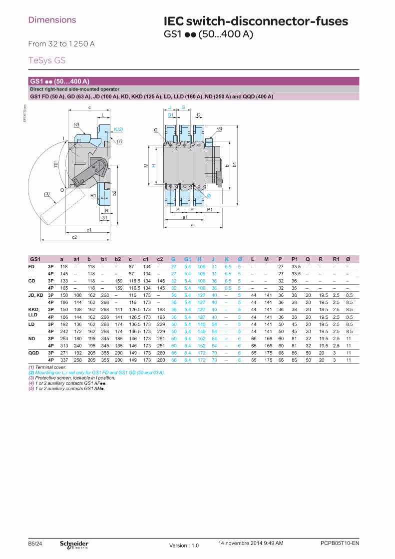
PCPB05T10-ENVersion : 1.0 14 novembre 2014 9:49 AMB5/24
GS1 pp (50�400 A)Direct right-hand side-mounted operator
GS1 FD (50 A), GD (63 A), JD (100 A), KD, KKD (125 A), LD, LLD (160 A), ND (250 A) and QQD (400 A)
R
G1
Ø
M70°
P P P1
b
b2
b1
a1
a
K(2)
J G
R1
31
c
L
c1
c2
(1)
(4) (5)
Q
H
(3)
I
O
DF
538732.e
ps
GS1 a a1 b b1 b2 c c1 c2 G G1 H J K Ø L M P P1 Q R R1 Ø
FD 3P 118 � 118 � � 87 134 � 27 5.4 106 31 6.5 5 � � 27 33.5 � � � �
4P 145 � 118 � � 87 134 � 27 5.4 106 31 6.5 5 � � 27 33.5 � � � �
GD 3P 133 � 118 � 159 116.5 134 145 32 5.4 106 36 6.5 5 � � 32 36 � � � �
4P 165 � 118 � 159 116.5 134 145 32 5.4 106 36 6.5 5 � � 32 36 � � � �
JD, KD 3P 150 108 162 268 � 116 173 � 36 5.4 127 40 � 5 44 141 36 38 20 19.5 2.5 8.5
4P 186 144 162 268 � 116 173 � 36 5.4 127 40 � 5 44 141 36 38 20 19.5 2.5 8.5
KKD, LLD
3P 150 108 162 268 141 126.5 173 193 36 5.4 127 40 � 5 44 141 36 38 20 19.5 2.5 8.5
4P 186 144 162 268 141 126.5 173 193 36 5.4 127 40 � 5 44 141 36 38 20 19.5 2.5 8.5
LD 3P 192 136 162 268 174 136.5 173 229 50 5.4 140 54 � 5 44 141 50 45 20 19.5 2.5 8.5
4P 242 172 162 268 174 136.5 173 229 50 5.4 140 54 � 5 44 141 50 45 20 19.5 2.5 8.5
ND 3P 253 180 195 345 185 146 173 251 60 6.4 162 64 � 6 65 166 60 81 32 19.5 2.5 11
4P 313 240 195 345 185 146 173 251 60 6.4 162 64 � 6 65 166 60 81 32 19.5 2.5 11
QQD 3P 271 192 205 355 200 149 173 260 66 6.4 172 70 � 6 65 175 66 86 50 20 3 11
4P 337 258 205 355 200 149 173 260 66 6.4 172 70 � 6 65 175 66 86 50 20 3 11
(1) Terminal cover.(2) Mounting on 5 rail only for GS1 FD and GS1 GD (50 and 63 A).(3) Protective screen, lockable in I position.(4) 1 or 2 auxiliary contacts GS1 AFpp.(5) 1 or 2 auxiliary contacts GS1 AMp.
Dimensions IEC switch-disconnector-fusesGS1 pp (50...400 A)
From 32 to 1250 A
TeSys GS
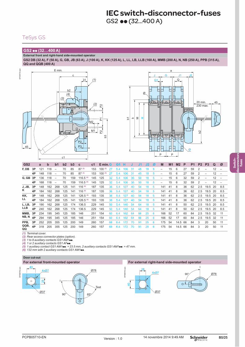
PCPB05T10-EN Version : 1.0 14 novembre 2014 9:49 AM B5/25
Switch-
disconnectors
fuses
B5/25
Switch-
disconnectors
fuses
GS2 pp (32�400 A)External front and right-hand side-mounted operator
GS2 DB (32 A), F (50 A), G, GB, JB (63 A), J (100 A), K, KK (125 A), L, LL, LB, LLB (160 A), MMB (200 A), N, NB (250 A), PPB (315 A),
QQ and QQB (400 A)
P
P2
P3
c1
M1
M2
P
J
G1
G J1 J2
45
Ø
45
(1)
(2)
(3)
(4)
a
31
c
b2
H
b2
Mb
b3
b1
P2
P1
P2
Q
Ø
E min.
20 min.
230 max.
DF
538733.e
ps
GS2 a b b1 b2 b3 c c1 E min.G G1 H J J1 J2 Ø M M1 M2 P P1 P2 P3 Q Ø
F, DB 3P 121 118 � 70 85 87 (5) 153 100 (5) 27 5.4 106 31 45 18 5 � 15 6 27 59 2 � 12 �
4P 148 118 � 70 85 87 (5) 153 100 (5) 27 5.4 106 31 45 18 5 � 15 6 27 59 2 � 12 �
G, GB 3P 136 118 � 70 159 116.5 (6) 145 125 32 5.4 106 36 50 18 5 � 15 6 32 59 2 � 12 �
4P 168 118 � 70 159 116.5 (6) 145 125 32 5.4 106 36 50 18 5 � 15 6 32 59 2 � 12 �
J, JB, K
3P 148 162 268 125 141 116 (6) 187 135 36 5.4 127 40 54 18 5 141 41 8 36 62 2.5 19.5 20 8.5
4P 184 162 268 125 141 116 (6) 187 135 36 5.4 127 40 54 18 5 141 41 8 36 62 2.5 19.5 20 8.5
KK, LL
3P 148 162 268 125 141 126.5 (6) 193 135 36 5.4 127 40 54 18 5 141 41 8 36 62 2.5 19.5 20 8.5
4P 184 162 268 125 141 126.5 (6) 193 135 36 5.4 127 40 54 18 5 141 41 8 36 62 2.5 19.5 20 8.5
L, LB, LLB
3P 190 162 268 125 174 136.5 229 145 50 5.4 140 54 64 18 5 141 41 8 50 62 2.5 19.5 20 8.5
4P 240 162 268 125 174 136.5 229 145 50 5.4 140 54 64 18 5 141 41 8 50 62 2.5 19.5 20 8.5
MMB, NB, N
3P 234 195 345 125 185 146 251 154 60 6.4 162 64 86 25 6 166 52 17 60 84 2.5 19.5 32 11
4P 294 195 345 125 185 146 251 154 60 6.4 162 64 86 25 6 166 52 17 60 84 2.5 19.5 32 11
PPB, QQB, QQ
3P 252 205 355 125 200 149 260 157 66 6.4 172 70 91 25 6 175 54 14.5 66 84 3 20 50 11
4P 318 205 355 125 200 149 260 157 66 6.4 172 70 91 25 6 175 54 14.5 66 84 3 20 50 11
(1) Terminal cover.(2) Rear access connector plates (option).(3) 1 to 8 auxiliary contacts GS1 AM1pp.(4) 1 or 2 auxiliary contacts GS1 AFpp.(5) 1 auxiliary contact GS1 AM1pp: + 23.5 mm, 2 auxiliary contacts GS1 AM1pp: + 47 mm.(6) 132 mm with 2 auxiliary contacts GS1 AM1pp.
Door cut-out
For external front-mounted operator For external right-hand side-mounted operator
90° 65°
I
Test
O
4xØ7
28
40
Ø37
Ø78
DF
568742.e
ps I
O
90°
40
4xØ7
28
Ø37
Ø78
DF
568743.e
ps
IEC switch-disconnector-fusesGS2 pp (32...400 A)
TeSys GS

PCPB05T10-ENVersion : 1.0 14 novembre 2014 9:49 AMB5/26
Dimensions
GS2 pp (630�1250 A)Direct front-mounted operator
GS2 S, SB (630 A), TB (800 A), V and VB (1250 A)
(2)
(1)
250
b22
G
11
34
260
90
235,5
471
P P
9
c1
155 Q R
59
7
(3)
c
79,5
85,5
a
235,51
88
77
300
Ø13
E min.
DF
568745.e
ps
GS2 a b c c1 E min. G P Q R
S, SB, TB 3P 364 300 250 380 265 284 94 51 65
4P 458 300 250 380 265 378 94 51 65
V, VB 3P 442 355 289 295 304 362 120 77 88
4P 562 355 289 295 304 482 120 77 88
(1) Handle GS2 AH104 for GS2S, GS2 SB and GS2 TB.(2) Terminal cover. (3) Rear access connector plates (GS2 V and GS2 VB).
Handle GS2 AH105 for GS2 V and GS2 VB
(direct front-mounted operator)
Connector plates for GS2 V and GS2 VB
103 28
165
165
330
DF
568746.e
ps 40
25
20
Ø13 77
DF
568747.e
ps
From 32 to 1250 A
IEC switch-disconnector-fusesGS2 pp (630...1250 A)
TeSys GS
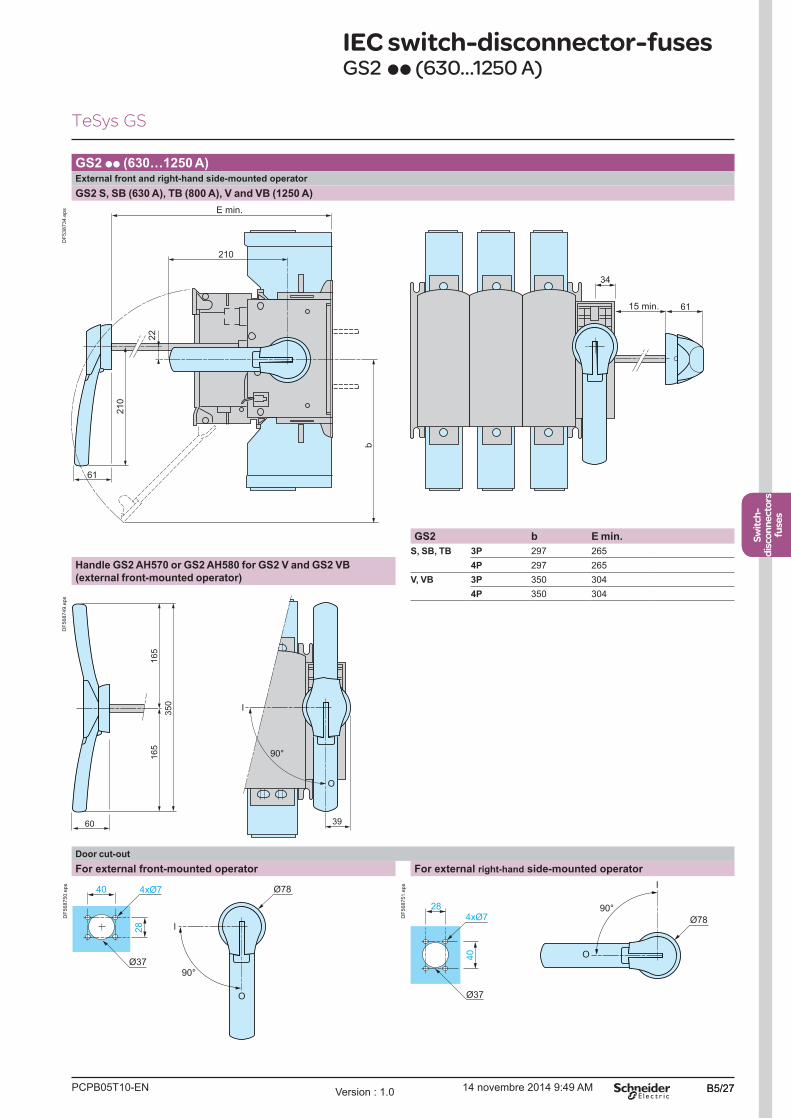
PCPB05T10-EN Version : 1.0 14 novembre 2014 9:49 AM B5/27
Switch-
disconnectors
fuses
B5/27
Switch-
disconnectors
fuses
GS2 pp (630�1250 A) External front and right-hand side-mounted operator
GS2 S, SB (630 A), TB (800 A), V and VB (1250 A)
61
34
61
210
b
210
22
E min.
15 min.
DF
538734.e
ps
GS2 b E min.
S, SB, TB 3P 297 265
4P 297 265
V, VB 3P 350 304
4P 350 304
Handle GS2 AH570 or GS2 AH580 for GS2 V and GS2 VB
(external front-mounted operator)
165
165
350
60 39
90°
I
O
DF
568749.e
ps
Door cut-out
For external front-mounted operator For external right-hand side-mounted operator
90°
I
O
4xØ7
28
40
Ø37
Ø78
DF
568750.e
ps I
O
90°
40
4xØ7
28
Ø37
Ø78
DF
568751.e
ps
TeSys GS
IEC switch-disconnector-fusesGS2 pp (630...1250 A)
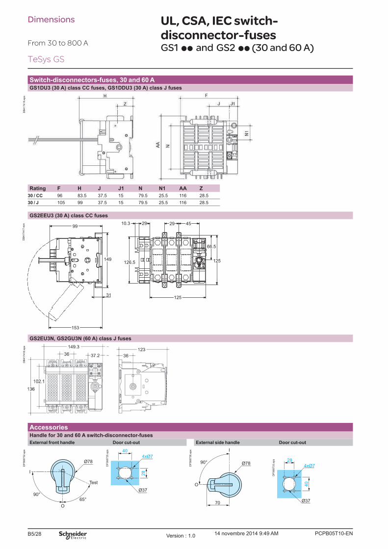
PCPB05T10-ENVersion : 1.0 14 novembre 2014 9:49 AMB5/28
Dimensions
From 30 to 800 A
UL, CSA, IEC switch-
disconnector-fusesGS1 pp and GS2 pp (30 and 60 A)
Switch-disconnectors-fuses, 30 and 60 AGS1DU3 (30 A) class CC fuses, GS1DDU3 (30 A) class J fuses
DB
417416.e
ps
Rating F H J J1 N N1 AA Z
30 / CC 96 83.5 37.5 15 79.5 25.5 116 28.5
30 / J 105 99 37.5 15 79.5 25.5 116 28.5
GS2EEU3 (30 A) class CC fuses
153
31
149
99
125
125
66.5
45292910.3
126.5
DB
417417.e
ps
GS2EU3N, GS2GU3N (60 A) class J fuses
DB
417418.e
ps
AccessoriesHandle for 30 and 60 A switch-disconnector-fuses
External front handle Door cut-out External side handle Door cut-out
90° 65°
I
Test
O
Ø78
DF
568732.e
ps
4xØ7
28
40
Ø37
DF
568735.e
ps I
70
90°
O
Ø78
DF
568736.e
ps
40
4xØ7
28
Ø37
DF
568733.e
ps
TeSys GS
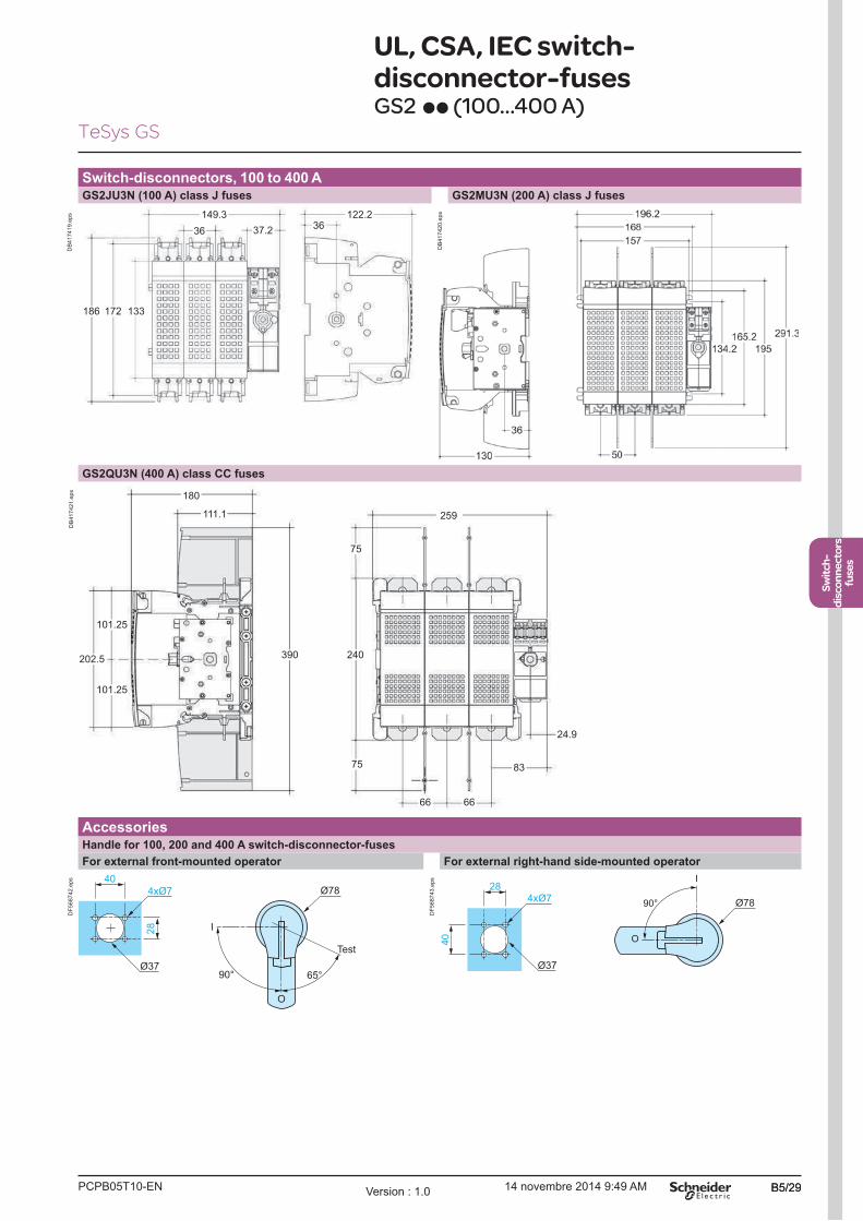
PCPB05T10-EN Version : 1.0 14 novembre 2014 9:49 AM B5/29
Switch-
disconnectors
fuses
B5/29
Switch-
disconnectors
fuses
UL, CSA, IEC switch-
disconnector-fusesGS2 pp (100...400 A)
Switch-disconnectors, 100 to 400 AGS2JU3N (100 A) class J fuses GS2MU3N (200 A) class J fuses
149.3 122.2
186 172 133
3636
37.2
DB
417419.e
ps
DB
417420.e
ps
GS2QU3N (400 A) class CC fuses
180
111.1
390202.5
101.25
101.25
259
75
75
240
66 66
83
24.9
DB
417421.e
ps
AccessoriesHandle for 100, 200 and 400 A switch-disconnector-fuses
For external front-mounted operator For external right-hand side-mounted operator
90° 65°
I
Test
O
4xØ7
28
40
Ø37
Ø78
DF
568742.e
ps I
O
90°
40
4xØ7
28
Ø37
Ø78
DF
568743.e
ps
TeSys GS

PCPB05T10-ENVersion : 1.0 14 novembre 2014 9:49 AMB5/30
Dimensions
From 30 to 800 A
UL, CSA, IEC switch-
disconnector-fusesGS2 pp (600 and 800 A)
Switch-disconnectors, 600 and 800 AGS2SU3 (600 A), GS2TU3 (800 A) class J fuses
min 265
250
155
79.5
90
7
7
300
380
59
7
300 471
85.5
85.5
Ø13
260 250 126.5
284
65 34
9
9494
51
364
11
DB
417422.e
ps
AccessoriesHandle for 600 and 800 A switch-disconnector-fuses
For external front-mounted operator For external right-hand side-mounted operator
90°
I
O
4xØ7
28
40
Ø37
Ø78
DF
568750.e
ps I
O
90°
40
4xØ7
28
Ø37
Ø78
DF
568751.e
ps
TeSys GS

PCPB05T10-EN Version : 1.0 14 novembre 2014 9:49 AM B5/31
Switch-
disconnectors
fuses
B5/31
Switch-
disconnectors
fuses
Auxiliary contacts
GS1 AM111, GS1 AM211 GS1 AM110, GS1 AM101
18
98
DF
538730.e
ps
24 24 65
DF
538731.e
ps
Schemes
3-pole GS 4-pole GS
32 to 1250 A 32 A 50 to 1250 A
1/L
1
3/L
2
5/L
3
2/T
1
4/T
2
6/T
3
DF
568508.e
ps
1/L
1
3/L
2
5/L
3
2/T
1
4/T
2
6/T
3
7/L
38/T
3
DF
568510.e
ps
1/L
1
3/L
2
5/L
3
2/T
1
4/T
2
6/T
3
7/L
38/T
3
DF
510769.e
ps
Auxiliary contacts
GS1 AM110 GS1 AM101 GS1 AM111 and GS1 AM1 GS1 AM211 and GS1 AM2
1 N/O 1 N/C 1 C/O 2 C/O
p3
p4
DF
568512.e
ps
p2
p1
DF
568513.e
ps
11
14
12
DF
568514.e
ps
11
14
12
21
24
22
DF
568515.e
ps
GS1 ANpp GS1 AFp
1 N/C + 1 N/O 2 N/C + 2 N/O 1 C/O 2 C/O
13
14
22
21
DF
568517.e
ps
13
14
22
21
33
34
42
41
DF
510768.e
ps
142
DF
568516.e
ps
11
14
12
21
24
22
DF
568515.e
ps
Dimensions, schemes Auxiliary contacts
From 32 to 1250 A
TeSys GS

PCPB05T10-ENVersion : 1.0 14 novembre 2014 9:49 AMB5/32
Related Documents