Airway Obstruction and the Unilateral Cleft Lip and Palate Deformity Contributions by the Bony Septum Michael T. Friel, MD,* John M. Starbuck, PhD,Þ Ahmed M. Ghoneima, DDS, PhD,Þ Kariuki Murage, MD,þ Katherine S. Kula, DMD, MS,Þ Sunil Tholpady, MD, PhD,* Robert J. Havlik, MD,§ and Roberto L. Flores, MD* Background: Patients with unilateral cleft lip and palate (CLP) deformities commonly develop nasal airway obstruction, necessitating septoplasty at the time of definitive rhinoplasty. We assessed the contribution of the bony sep- tum to airway obstruction using computed tomography (CT) and cone beam CT (CBCT). Methods: A 2-year retrospective review of all subjects with unilateral CLP who underwent CBCT imaging (n = 22) and age-matched controls (n = 9) who underwent CT imaging was conducted. Control CT scans were used to de- termine the segment of nasal septum comprised almost entirely of bone. The CBCT of the nasal airway was assessed using Dolphin software to determine the contribution of the bony septum to septal deviation and airway obstruction. Results: The nasal septum posterior to the midpoint between anterior and posterior nasal spine is comprised of 96% bone. The nasal airway associated with this posterior bony segment was 43.1% (P G 0.001) larger by volume on the nonYcleft side in patients with unilateral CLP. The average septal deviation within the posterior bony segment was 5.4 mm, accounting for 74.4% of the maximal deviation within the nasal airway. The average airway stenosis within the posterior bony nasal airway was 0.45 mm (0Y2.2 mm). Conclusions: In patients with unilateral CLP, the bony nasal septum can demonstrate significant deviation and airway stenosis. Surgeons should con- sider a bony septoplasty in their treatment algorithm in unilateral CLP patients who have reached skeletal maturity. Key Words: cleft nasal deformity, cone beam CT, septoplasty, septal deviation, airway stenosis, cleft lip and palate (Ann Plast Surg 2015;75: 37Y43) T he management of the nasal deformity in patients with unilateral cleft lip and palate (CLP) has traditionally focused on the ap- pearance of the nasal tip and achieving nasal symmetry. Although there have been continuous modifications of the cleft rhinoplasty techniques, 1Y5 limited attention has focused on the anatomic defor- mities leading to airway obstruction and the proper interventions re- quired to restore normal airflow. The etiology of the nasal deformity in CLP patients is thought to be caused by an embryologic failure of the nasal and maxillary facial prominences to fuse correctly during the fifth week of gesta- tion. 6 The structural abnormalities are numerous and multifaceted. 7 Classically, there is deviation of the anterior caudal septum to the nonYcleft nostril. Additionally, the columella is shortened on the cleft side, the lower lateral cartilage is inferiorly rotated, the alar base is laterally displaced, and the alar rim and the bony platform of the nose are distorted. These findings are attributed to an imbalance of the muscular forces upon the alar base and anterior caudal septum 8 as well as displacement of the greater and lesser segments of the alve- olus. These anatomical changes negatively impact the function of the nasal airway, resulting in increased susceptibility to upper respiratory infections and reliance on mouth breathing. 9Y11 Although some an- atomic and functional changes in cleft nasal pathology are docu- mented, few recommendations have been made regarding the proper techniques of septoplasty in published approaches to cleft nasal reconstruction. 12Y19 Our experience during definitive cleft rhinoplasty is that the bony septum is severely deviated and contributes to nasal airway obstruction even after removal of the cartilaginous septum. There are few quantitative data to support our belief that bony septoplasty should be considered when addressing cleft rhinoplasty. The pur- poses of this study are to (1) assess nasal airway volumes of the cleft and nonYcleft sides in patients with unilateral CLP deformity, (2) anatomically define the posterior segment of the nasal septum that is comprised almost entirely of bone, (3) determine the degree of de- viation in the posterior segment of the nasal septum, and (4) measure the degree of airway stenosis caused by septal deviation within the posterior segment of the nasal airway. We performed our analysis using cone beam computed tomography (CBCT), traditional com- puted tomography (CT), and 3-dimensional mathematical modeling. METHODS Institutional review board approval (#1208009367) was obtained before the start of this study. We performed a 2-year retro- spective review of all unilateral CLP patients who have previously undergone CBCT imaging as part of their orthodontic treatment plan. Inclusion criteria were nonsyndromic patients diagnosed with Veau Class III unilateral clefts, with dental and craniofacial treatment records. Coded CBCT images were analyzed using 3-dimensional Dolphin Imaging software (v11.5; Chatsworth, CA) by the same in- dividual (J.M.S.). Orientation was 3-dimensionally standardized using an orientation module in Dolphin Imaging software that ori- ented CBCT images in lateral view by passing a reference line through orbitale and porion, and in frontal view by passing a line through nasion and pogonion. The CT scan images (Phillips 64-slice CT scan) of aged-matched controls were obtained through the trauma database and oriented in a similar manner. Anatomic and constructed landmarks were identified on CBCT and CT images and used to collect the nasal measurements, as HEAD AND NECK SURGERY Annals of Plastic Surgery & Volume 75, Number 1, July 2015 www.annalsplasticsurgery.com 37 Received May 19, 2013, and accepted for publication, after revision, September 24, 2013. From the *Division of Plastic Surgery, Department of Surgery, Indiana University; †Department of Orthodontics and Orofacial Genetics, Indiana University School of Dentistry; ‡Department of Surgery, Indiana University, Indianapolis, IN; and §Department of Plastic Surgery, Medical College of Wisconsin, Milwaukee, WI. Presented at the 12th International Congress on Cleft Lip/Palate and Related Cra- niofacial Anomalies Meeting, May 8, 2013, Orlando, FL, and at the 56th An- nual Meeting of the Ohio Valley Society of Plastic Surgeons, Sheraton Indianapolis City Centre, May 17, 2013, Indianapolis, IN. Conflicts of interest and sources of funding: none declared. Reprints: Roberto L. Flores, MD, Division of Plastic Surgery, Department of Surgery, Indiana University, 705 Riley Hospital Dr, RI 2513, Indianapolis, IN 46202. E-mail: [email protected]. Copyright * 2013 Wolters Kluwer Health, Inc. All rights reserved. ISSN: 0148-7043/15/7501-0037 DOI: 10.1097/SAP.0000000000000027 Copyright © 2015 Wolters Kluwer Health, Inc. All rights reserved.

Welcome message from author
This document is posted to help you gain knowledge. Please leave a comment to let me know what you think about it! Share it to your friends and learn new things together.
Transcript

Airway Obstruction and the UnilateralCleft Lip and Palate DeformityContributions by the Bony Septum
Michael T. Friel, MD,* John M. Starbuck, PhD,Þ Ahmed M. Ghoneima, DDS, PhD,ÞKariuki Murage, MD,þ Katherine S. Kula, DMD, MS,Þ Sunil Tholpady, MD, PhD,*
Robert J. Havlik, MD,§ and Roberto L. Flores, MD*
Background: Patients with unilateral cleft lip and palate (CLP) deformitiescommonly develop nasal airway obstruction, necessitating septoplasty at thetime of definitive rhinoplasty. We assessed the contribution of the bony sep-tum to airway obstruction using computed tomography (CT) and cone beamCT (CBCT).Methods: A 2-year retrospective review of all subjects with unilateral CLPwho underwent CBCT imaging (n = 22) and age-matched controls (n = 9) whounderwent CT imaging was conducted. Control CT scans were used to de-termine the segment of nasal septum comprised almost entirely of bone. TheCBCT of the nasal airway was assessed using Dolphin software to determinethe contribution of the bony septum to septal deviation and airway obstruction.Results: The nasal septum posterior to the midpoint between anterior andposterior nasal spine is comprised of 96% bone. The nasal airway associatedwith this posterior bony segment was 43.1% (P G 0.001) larger by volume onthe nonYcleft side in patients with unilateral CLP. The average septal deviationwithin the posterior bony segment was 5.4 mm, accounting for 74.4% of themaximal deviation within the nasal airway. The average airway stenosis withinthe posterior bony nasal airway was 0.45 mm (0Y2.2 mm).Conclusions: In patients with unilateral CLP, the bony nasal septum candemonstrate significant deviation and airway stenosis. Surgeons should con-sider a bony septoplasty in their treatment algorithm in unilateral CLP patientswho have reached skeletal maturity.
Key Words: cleft nasal deformity, cone beam CT, septoplasty, septaldeviation, airway stenosis, cleft lip and palate
(Ann Plast Surg 2015;75: 37Y43)
T he management of the nasal deformity in patients with unilateralcleft lip and palate (CLP) has traditionally focused on the ap-
pearance of the nasal tip and achieving nasal symmetry. Althoughthere have been continuous modifications of the cleft rhinoplastytechniques,1Y5 limited attention has focused on the anatomic defor-mities leading to airway obstruction and the proper interventions re-quired to restore normal airf low.
The etiology of the nasal deformity in CLP patients is thoughtto be caused by an embryologic failure of the nasal and maxillaryfacial prominences to fuse correctly during the fifth week of gesta-tion.6 The structural abnormalities are numerous and multifaceted.7
Classically, there is deviation of the anterior caudal septum to thenonYcleft nostril. Additionally, the columella is shortened on the cleftside, the lower lateral cartilage is inferiorly rotated, the alar base islaterally displaced, and the alar rim and the bony platform of the noseare distorted. These findings are attributed to an imbalance of themuscular forces upon the alar base and anterior caudal septum8 aswell as displacement of the greater and lesser segments of the alve-olus. These anatomical changes negatively impact the function of thenasal airway, resulting in increased susceptibility to upper respiratoryinfections and reliance on mouth breathing.9Y11 Although some an-atomic and functional changes in cleft nasal pathology are docu-mented, few recommendations have been made regarding the propertechniques of septoplasty in published approaches to cleft nasalreconstruction.12Y19
Our experience during definitive cleft rhinoplasty is that thebony septum is severely deviated and contributes to nasal airwayobstruction even after removal of the cartilaginous septum. There arefew quantitative data to support our belief that bony septoplastyshould be considered when addressing cleft rhinoplasty. The pur-poses of this study are to (1) assess nasal airway volumes of the cleftand nonYcleft sides in patients with unilateral CLP deformity, (2)anatomically define the posterior segment of the nasal septum that iscomprised almost entirely of bone, (3) determine the degree of de-viation in the posterior segment of the nasal septum, and (4) measurethe degree of airway stenosis caused by septal deviation within theposterior segment of the nasal airway. We performed our analysisusing cone beam computed tomography (CBCT), traditional com-puted tomography (CT), and 3-dimensional mathematical modeling.
METHODSInstitutional review board approval (#1208009367) was
obtained before the start of this study. We performed a 2-year retro-spective review of all unilateral CLP patients who have previouslyundergone CBCT imaging as part of their orthodontic treatment plan.Inclusion criteria were nonsyndromic patients diagnosed with VeauClass III unilateral clefts, with dental and craniofacial treatment records.
Coded CBCT images were analyzed using 3-dimensionalDolphin Imaging software (v11.5; Chatsworth, CA) by the same in-dividual (J.M.S.). Orientation was 3-dimensionally standardizedusing an orientation module in Dolphin Imaging software that ori-ented CBCT images in lateral view by passing a reference linethrough orbitale and porion, and in frontal view by passing a linethrough nasion and pogonion. The CT scan images (Phillips 64-sliceCT scan) of aged-matched controls were obtained through the traumadatabase and oriented in a similar manner.
Anatomic and constructed landmarks were identified onCBCT and CT images and used to collect the nasal measurements, as
HEAD AND NECK SURGERY
Annals of Plastic Surgery & Volume 75, Number 1, July 2015 www.annalsplasticsurgery.com 37
Received May 19, 2013, and accepted for publication, after revision, September 24,2013.
From the *Division of Plastic Surgery, Department of Surgery, Indiana University;†Department of Orthodontics and Orofacial Genetics, Indiana UniversitySchool of Dentistry; ‡Department of Surgery, Indiana University, Indianapolis,IN; and §Department of Plastic Surgery, Medical College of Wisconsin,Milwaukee, WI.
Presented at the 12th International Congress on Cleft Lip/Palate and Related Cra-niofacial Anomalies Meeting, May 8, 2013, Orlando, FL, and at the 56th An-nual Meeting of the Ohio Valley Society of Plastic Surgeons, SheratonIndianapolis City Centre, May 17, 2013, Indianapolis, IN.
Conflicts of interest and sources of funding: none declared.Reprints: Roberto L. Flores, MD, Division of Plastic Surgery, Department of
Surgery, Indiana University, 705 Riley Hospital Dr, RI 2513, Indianapolis,IN 46202. E-mail: [email protected].
Copyright * 2013 Wolters Kluwer Health, Inc. All rights reserved.ISSN: 0148-7043/15/7501-0037DOI: 10.1097/SAP.0000000000000027
Copyright © 2015 Wolters Kluwer Health, Inc. All rights reserved.

listed in Table 1 and depicted in Figure 1. First, the contribution ofbone to the anterior, middle, and posterior segments of the nasalseptum was determined using CT scans of the 9 aged-matched con-trols (mean, 10.8 years; range, 6Y15 years). The controls were iden-tified through an independently maintained pediatric traumadatabase. All controls had calvarial fractures without bony trauma tothe nose, midface, or anterior cranial vault, and no craniofacial con-genital anomaly. Landmarks and linear distances were used to dividethe nasal septum into 3 areas, to best attain approximation of theanterior cartilaginous septum (Fig. 1, area A), the middle aspect of thecartilaginous septum consisting of cartilage and bone (Fig. 1, area B),and the posterior bony septum (Fig. 1, area C). In brief, area Awas de-fined as the nasal septum anterior to the anterior nasal spine (ANS), areaB was defined as the nasal septum between ANS and the midpoint
between ANS and posterior nasal spine (PNS), and area Cwas defined asthe nasal septum between the ANS-PNS midpoint and PNS.
Using the established boundaries, the 9 control subjects wereanalyzed in Synapse CT Imaging Software and verified in DolphinSoftware for the presence of bone in segments A, B, and C. First,the area calculations of segments A, B, and C were performed withimaging software. The areas of the nasal septum with Hounsfieldunits greater than 240 were noted as bone (Fig. 2) and areas withHounsfield units less than 240 were noted as cartilage/air. The areacalculations of bone were then subtracted from the overall area ineach of the segments A, B, and C to develop a ratio of percentagebone in each of the 3 segments, A, B, and C.
In the CLP group, nasal volume measurements were collectedof each nasal airway of each individual CBCT image using an inte-grated volumetric measurement tool in Dolphin. The nasal airwaywas divided into 3 airspaces, based on the 3 described areas of nasalseptum. The anterior airway is associated with area A and includesthe septum anterior to a line drawn between the rhinon and the ANS.The middle airway is associated with area B and is defined in ananterior to posterior dimension along the palatal plane from the ANSto the midpoint of the distance between ANS and PNS. The verticaldimension of this volume spans from nasal f loor to a constructedplane from the sella to rhinon. The posterior airway is associated witharea C and is defined in the A-P dimension by the midpoint of theANS-PNS to the PNS. Vertical height of this area was marked fromthe palatal plane to a constructed plane from the sella to rhinon.
Landmarks were chosen from the nostril opening to the start ofthe pharyngeal airway at the level of the PNS. The midline was de-fined at crista galli. The width of this volume was calculated from theseptum to the lateral nasal wall (Fig. 3). Left- and right-side bound-aries were defined in the axial view using the nasal septum and thelateral margins of the nasal airway cavity. For the anterior nasal air-way volume measurement, additional points were used to outline thesoft tissue morphology of the nose including the pronasale. Afterboundaries were adequately outlined, the airways were seeded usingDolphin software (sensitivity, 60), and the volume of the defined
TABLE 1. Traditional CT and CBCT Landmark Definitions
Landmark Definitions
1. Rhinion (rh)Vmost inferior and anterior point between nasal bones.
2. Soft tissue pronasale (prn)Vthe most protruded point of the apex nasi.
3. ANSVthe anterior most pointed projection of the intermaxillary suture.
4. Midpoint nasal spine (mns)Vmidpoint of straight line whose end points areANS and PNS.
5. Intersection of rh-s and perpendicular line through msnVthis landmark lieson a line drawn through rhinion and sella and is found by drawing a linethrough mns that is at a right angle to the line formed by ANS-PNS.
6. PNSVthe sharp posterior extremity of the nasal crest.
7. Intersection of rh-s and perpendicular line through PNSVthis landmark lieson a line drawn through rhinion and sella and is found by drawing a linethrough PNS that is at a right angle to the line formed by ANS-PNS.
8. Sella turcica (s)Vmidpoint of the depression atop the sphenoid where thepituitary gland is situated, posterior and inferior to the optic canals.
FIGURE 1. Sagittal view of the nasal airway showing 3 areas ofvolumetric analysis. Numbered points are defined in Table 1.Area A is the anterior nasal airway. Area B is the middle nasalairway and area C is the posterior airway. 1, Rhinon (rh); 2, softtissue pronasale (prn); 3, ANS; 4, midpoint between the ANSand PNS (msn); 5, is a constructed landmark denoting theintersection of a perpendicular line from msn and line drawnthrough rh and sella turcica; 6, PNS; 7, intersection of rh-sellaturcica and perpendicular line through PNS; 8, sella turcica (s).
FIGURE 2. Depiction of bone in the nasal septum within the3 segments of the nasal airway. Note the posterior airway(area C) consists almost entirely of bone.
Friel et al Annals of Plastic Surgery & Volume 75, Number 1, July 2015
38 www.annalsplasticsurgery.com * 2013 Wolters Kluwer Health, Inc. All rights reserved.
Copyright © 2015 Wolters Kluwer Health, Inc. All rights reserved.

airway space was automatically calculated, allowing only the actualairway to be included in volumetric measurements. Volumetricmeasurements of the anterior, middle, and posterior nasal airwaywere determined for the cleft and nonYcleft airspace using this
method. The definitions of the linear measurements and volumes aresummarized in Table 2.
Septal deviation was measured from the midline in the coronalplane. The midline was defined as a perpendicular line from cristagalli to the palatal plane. The point of maximum deviation was notedby measuring the longest distance drawn perpendicular from midlineto the deviated segment of the septum. Measurements for septal de-viation were recorded at 3 additional locations: the ANS, the mid-point of the hard palate, and the PNS (Fig. 4BYD). The measurementof stenosis at the area of maximal septal deviation in posterior seg-ment was calculated as depicted in Figure 4E, and was calculated bymeasuring the distance between the point of maximal deviation andthe lateral nasal wall or turbinate, whichever distance was shortest.
StatisticsPaired t testing was used to compare cleft versus nonYcleft
nasal airway volumes. A value of P G 0.05 was used to determinestatistical significance. Measurement error was assessed for allmeasurements (volume and linear distances) by recording measure-ments from 10 random individuals from the overall sample on 3separate occasions with at least 72 hours between each round ofmeasurements. The relative variability of linear and volumetricmeasurements between trials was assessed by calculating the coeffi-cient of variance (CoV = standard deviation (R)/mean (H)) for eachlinear and volumetric measurement. The CoV was used to assessvalidity of linear measurements of septal deviation and of volumetricdata of the cleft and nonYcleft nostrils. The CoV shows the extentof variability in relation to the mean of the sample. To assess thereproducibility of the quantitative measurements, the intraclasscorrelation coefficient of the resulting values was calculated (0.996)in SPSS (v 20) using a 2-way random analysis of variance with
FIGURE 3. Surface area wasmeasured in coronal view by placinga point at crista galli and following the anatomy of the nasalairway on the left (green) and right (yellow) side. Figure 3 can beviewed online in color at www.annalsplasticsurgery.com.
TABLE 2. Description of Measurements and Volumes
Measurements Measurement Definitions
Volumes
Anterior nasal airway (L and R) The sagittal boundary was placed as seen in Figure 1 using landmarks 1, 2, and 3 (area A). The coronalview was placed by placing a point at crista galli and following the anatomical boundaries of the nasalseptum and nasal borders. After boundaries were defined, Dolphin software was used to automaticallycalculate volume.
Middle nasal airway (L and R) The sagittal boundary was placed as seen in Figure 1 using landmarks 1, 3, 4, and 5 (area B). The coronalview was placed by placing a point at crista galli and following the anatomical boundaries of the nasalseptum and nasal borders. After boundaries were defined, Dolphin software was used to automaticallycalculate volume.
Posterior nasal airway (L and R) The sagittal boundary was placed as seen in Figure 1 using landmarks 4, 5, 6, and 7 (area C). The coronalview was placed by placing a point at crista galli and following the anatomical boundaries of the nasalseptum and nasal borders. After boundaries were defined, Dolphin software was used to automaticallycalculate volume.
Linear distances
Maximal septal deviation from midline(L or R)
Maximum septal deviation from the midline was measured in the coronal view as the longest horizontaldistance from midline to nasal septum shown in Figure 4A. The midline was defined when imageorientation was standardized using nasion and menton.
Diameter of maximal stenosis of theposterior nasal airway
Maximal stenosis of the posterior nasal airway was measured as the shortest linear distance from thepoint of maximum septal deviation in the posterior nasal airway to the lateral nasal wall or turbinateas depicted in Figure 4E.
Septal deviation at ANS (L or R) The coronal plane was set in sagittal view to go through the ANS. Maximum septal deviation from themidline was measured as the longest horizontal distance from midline to nasal septum shown inFigure 4B. The midline was defined when image orientation was standardized using nasion and menton.
Septal deviation at midpoint of anteriorand PNS (L or R)
The coronal plane was set in sagittal view to go through the midpoint of the anterior and PNSs(landmark 4). Maximum septal deviation from the midline was measured as the longest horizontaldistance from midline to nasal septum shown in Figure 4C. The midline was defined when imageorientation was standardized using nasion and menton.
Septal deviation at PNS (L or R) The coronal plane was set in sagittal view to go through the PNS. Maximum septal deviation from themidline was measured as the longest horizontal distance from midline to nasal septum shown inFigure 4D. The midline was defined when image orientation was standardized using nasion and menton.
Annals of Plastic Surgery & Volume 75, Number 1, July 2015 Cleft Lip and Palate Bony Septum
* 2013 Wolters Kluwer Health, Inc. All rights reserved. www.annalsplasticsurgery.com 39
Copyright © 2015 Wolters Kluwer Health, Inc. All rights reserved.

excellent agreement, indicating that the linear and volumetric mea-surements used in this study are highly repeatable.
RESULTSTwenty-two subjects with a unilateral CLP (Veau III) were
identified for the study. Demographics of the patients included in thestudy are presented in Table 3. CT analysis of age-matched controlswithout cleft palate demonstrated the following composition of thenasal septum: the anterior segment of the nasal septum (Fig. 2,area A) contained no bone; the middle segment (Fig. 2, area B)contained 23.9% bone (range, 12.5%Y41.9%); and the posterior seg-ment (Fig. 2, area C) contained 96.1% bone (range, 90.9%Y99.2%).
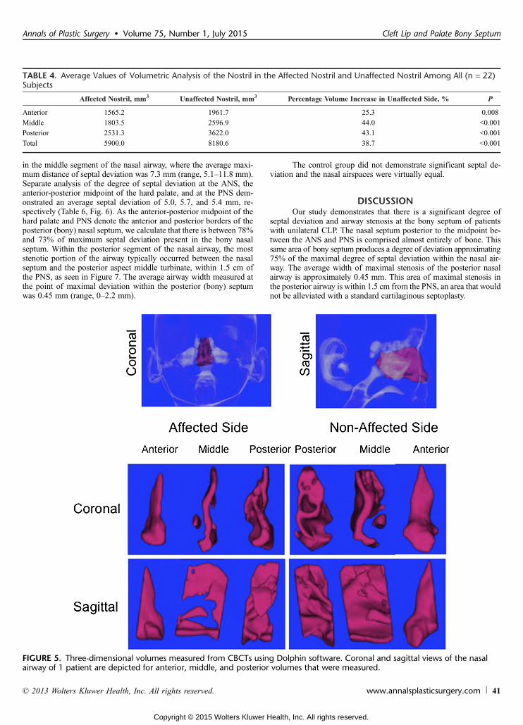
Volumetric analysis of the anterior, middle, and posteriorsegments of those patients with CLP by CBCT and Dolphin softwaredemonstrated significantly greater volumes on the nonYcleft side by25.3%, 44.0%, and 43.1%, respectively (Table 4), as compared withthe cleft side. The average total volume difference between the
cleft and nonYcleft side was 38.7% (P G 0.001), as depicted visuallyin Figure 5. The CoV values for each set of measurements weresmall, indicating that variability from measuring tissue depths acrossdifferent subjects was minimal (Table 5).
The extent of septal deviation from midline is demonstratedin Table 6. The area of maximum septal deviation in the CLP groupwas located in the posterior aspect of the cartilaginous septum, found
FIGURE 4. Linear distance measurements collected. A, Maximum septal deviation (green line) was measured from the midline(red line). B, Septal deviation (green line) from the midline (red line) was measured after setting the sagittal plane through theANS in sagittal view. C, Septal deviation (green line) from themidline (red line) wasmeasured after setting the sagittal plane throughthe midpoint between anterior and PNS in sagittal view. D, Septal deviation (green line) from the midline (red line) was measuredafter setting the sagittal plane through the PNS in sagittal view. E, Maximal stenosis of the posterior nasal airway wasmeasured at the point of maximum septal deviation in the posterior nasal airway (pink line). Figure 4 can be viewed online in color atwww.annalsplasticsurgery.com.
TABLE 3. Demographics of Unilateral CLP Subjects
No. subjects 22
Mean age at CBCT, y 10.8 (6.8Y17.9)
Mean age at lip repair, mo 4 (2.1Y6.2)
Mean age at palate repair, mo 15.8 (11Y24.6)
Right unilateral clefts no. 7
Left unilateral clefts no. 15
Friel et al Annals of Plastic Surgery & Volume 75, Number 1, July 2015
40 www.annalsplasticsurgery.com * 2013 Wolters Kluwer Health, Inc. All rights reserved.
Copyright © 2015 Wolters Kluwer Health, Inc. All rights reserved.
in the middle segment of the nasal airway, where the average maxi-mum distance of septal deviation was 7.3 mm (range, 5.1Y11.8 mm).Separate analysis of the degree of septal deviation at the ANS, theanterior-posterior midpoint of the hard palate, and at the PNS dem-onstrated an average septal deviation of 5.0, 5.7, and 5.4 mm, re-spectively (Table 6, Fig. 6). As the anterior-posterior midpoint of thehard palate and PNS denote the anterior and posterior borders of theposterior (bony) nasal septum, we calculate that there is between 78%and 73% of maximum septal deviation present in the bony nasalseptum. Within the posterior segment of the nasal airway, the moststenotic portion of the airway typically occurred between the nasalseptum and the posterior aspect middle turbinate, within 1.5 cm ofthe PNS, as seen in Figure 7. The average airway width measured atthe point of maximal deviation within the posterior (bony) septumwas 0.45 mm (range, 0Y2.2 mm).
The control group did not demonstrate significant septal de-viation and the nasal airspaces were virtually equal.
DISCUSSIONOur study demonstrates that there is a significant degree of
septal deviation and airway stenosis at the bony septum of patientswith unilateral CLP. The nasal septum posterior to the midpoint be-tween the ANS and PNS is comprised almost entirely of bone. Thissame area of bony septum produces a degree of deviation approximating75% of the maximal degree of septal deviation within the nasal air-way. The average width of maximal stenosis of the posterior nasalairway is approximately 0.45 mm. This area of maximal stenosis inthe posterior airway is within 1.5 cm from the PNS, an area that wouldnot be alleviated with a standard cartilaginous septoplasty.
TABLE 4. Average Values of Volumetric Analysis of the Nostril in the Affected Nostril and Unaffected Nostril Among All (n = 22)Subjects
Affected Nostril, mm3 Unaffected Nostril, mm3 Percentage Volume Increase in Unaffected Side, % P
Anterior 1565.2 1961.7 25.3 0.008
Middle 1803.5 2596.9 44.0 G0.001
Posterior 2531.3 3622.0 43.1 G0.001
Total 5900.0 8180.6 38.7 G0.001
FIGURE 5. Three-dimensional volumes measured from CBCTs using Dolphin software. Coronal and sagittal views of the nasalairway of 1 patient are depicted for anterior, middle, and posterior volumes that were measured.
Annals of Plastic Surgery & Volume 75, Number 1, July 2015 Cleft Lip and Palate Bony Septum
* 2013 Wolters Kluwer Health, Inc. All rights reserved. www.annalsplasticsurgery.com 41
Copyright © 2015 Wolters Kluwer Health, Inc. All rights reserved.

A septoplasty can involve the treatment of both cartilage andbone20; however, cartilaginous septoplasty is the more commonseptoplasty performed for cosmetic and reconstructive purposes.Bony septoplasty is more technically challenging as it is associatedwith increased morbidity, a likely reason for its limited use. Whenaddressing the bony components of the septum, the same subperi-chondrial plane used to expose the cartilaginous septum is extendedover the vomer and perpendicular plate of the ethmoid. As the
cartilaginous septum is frequently dislocated from the vomer, therisks to mucosal tears are significant. After submucous resection ofthe cartilaginous septum, the nasal speculum can be used to inspectthe bony septum under direct vision. Frequently, a significantly de-viated bony septum can be seen obstructing the cleft-sided nasalairway despite thorough resection of the cartilaginous septum. Inthese cases, a 4-mm straight osteotome is used to fracture the vomerand inferior aspect of the perpendicular plate. ATakahashi forceps isused to remove the fractured vomer and to manually remove thedeviated perpendicular plate of the ethmoid as far posterior as thesphenoid. Care is taken to proceed with the dissection directly pos-teriorly as superiorly directed dissection may risk damage to thecribriform plate, creating a cerebrospinal f luid leak. After the re-section, the mucosa is approximated with quilting sutures and nasalstents applied as needed. Due to the increased complexity associatedwith bony septoplasty, patients should be counseled on the increasedrisk of hematoma and possible damage to olfactory nerves. Otherreported complications associated with bony septoplasty include ce-rebrospinal f luid leak from damage to the cribriform plate, septalabscess, cavernous sinus thrombosis, meningitis, pneumocephalus,and rhinorrhea,21,22 underscoring the importance of understandingthe deep nasal anatomy before performing this procedure.
This report is an anatomic study, not a functional study. Wedid not study the functional aspects of airf low in this work, butthis would be a topic for further investigation. By performing abony septoplasty and relieving obstruction to the posterior nasalairway, we would surmise that nasal airf low is more laminar andless restrictive in this area. We feel strongly that the bony septumshould be inspected at the time of cartilaginous septoplasty andaddressed as needed depending on the degree of airway obstructionremaining. In addition, we cannot quantify the added morbiditythat may ensue with a bony septoplasty. Cone beam CT analysiswas performed before the time of full facial maturity. This studydid not analyze the effects of facial growth on nasal volumes andthis certainly speaks to future investigation as well. Animal modelshave suggested that bony septal resection before skeletal maturitysignificantly decreases facial growth.23 However, Ortiz-Monasterioand Olmedo24 demonstrated no detrimental effects in their long-term follow-up. Our current treatment plan for cartilaginous andbony septoplasty is to defer intervention until the time of fullfacial maturity. Although each patient’s situation is unique withrespect to treatment decisions, our data support the considerationof a bony septoplasty in the treatment of patients with CLP. Wewould also note that all patients in our study had a cleft palate.Prior studies suggest that cleft lip patients without cleft palatehave more mild degrees of nasal asymmetry.25
Anatomical studies of the nasal airway in cleft patients can behelpful for surgical planning.14,26 We know from previous reports
TABLE 5. Average Coefficient of Variability Values for Homologous Measurements
MaximumDeviation From
Midline toAffected Side
Deviation FromMidline at
Halfway BetweenANS to PNS
DeviationFrom
Midline atPNS
UnaffectedAnteriorNasalVolume
UnaffectedMiddleNasalVolume
UnaffectedPosteriorNasalVolume
AffectedAnteriorNasalVolume
AffectedMiddleNasalVolume
AffectedPosteriorNasalVolume
CoV 0.032 0.044 0.036 0.056 0.061 0.062 0.050 0.048 0.045
TABLE 6. Average Measurements of Septal Deviation Among the 22 Study Subjects
Maximal SeptalDeviation to the
Affected Side, mm
MaximumDeviation atANS, mm
% ofMaximumDeviation
Maximum Deviationto the Affected Sideat Midpoint of theHard Palate, mm
% ofMaximalDeviation
Maximum Deviationto the Affected Side
at PNS, mm
% ofMaximalDeviation
Average 7.27 4.99 70.69% 5.71 80.73% 5.37 74.37
FIGURE 6. Graphical representation of septal deviation frommidline at the ANS, midpoint of the ANS and PNS, and thePNS. The area denoted in red would not be addressed bytraditional septoplasty. Figure 6 can be viewed online in colorat www.annalsplasticsurgery.com.
Friel et al Annals of Plastic Surgery & Volume 75, Number 1, July 2015
42 www.annalsplasticsurgery.com * 2013 Wolters Kluwer Health, Inc. All rights reserved.
Copyright © 2015 Wolters Kluwer Health, Inc. All rights reserved.

that the bony septum typically deviates to the cleft side in CLP pa-tients.27,28 Our findings support these data, however, prior reports havenot quantified the severity of bony septal deviation or the extent of as-sociated airway stenosis as we have in this work. Functional studiesassessing patients with a cleft demonstrate stenosis in the cleft nostril.27
Cohen and colleagues29 found rhinometry useful in the evaluation of leftand right nasal patency, providing a functional analysis before surgery,but did not comment on the specific affected areas of the nasal airway.
A natural concern about CBCT in children is related to radi-ation exposure. Cone beam CT scanning is a useful adjunct in thecare for complex craniofacial conditions and dental relationships.30
Studies show that the advantages of CBCT are seen in radiation dosereduction, reduced image artifact, improved image accuracy, and x-ray beam limitation when compared to conventional imaging.31
Bite-wing dental radiographs, panoramic radiographs, CBCT, and64-slice CT scans have an effective dose (in microsieverts) of 0.004,86, 131.1, and 860, respectively.32Y34 Our analysis included only pa-tients who underwent CBCT for orthodontic planning, and no CBCTswere performed solely for the purpose of studying nasal airway.
CONCLUSIONSThe nasal septum posterior to themidpoint between anterior and
PNS is comprised almost entirely of bone. This area of bony septumproduces a significant amount of septal deviation and airway stenosisin patients with unilateral CLP deformity. This patient populationshould be considered for bony septoplasty, at the time of skeletal ma-turity, if septal surgery is indicated as part of a definitive rhinoplasty.
REFERENCES1. McComb H. Treatment of the unilateral cleft lip nose. Plast Reconstr Surg.
1975;55:596Y601.
2. Morselli PG, Pinto V, Negosanti L, et al. Early correction of septum JJdeformity in unilateral cleft lip-cleft palate. Plast Reconstr Surg. 2012;130:434eY441e.
3. Millard DR Jr. The unilateral cleft lip nose. Plast Reconstr Surg. 1964;34:169Y175.
4. Salyer KE. Primary correction of the unilateral cleft lip nose: a 15-year ex-perience. Plast Reconstr Surg. 1986;77:558Y568.
5. McComb HK, Coghlan BA. Primary repair of the unilateral cleft lip nose:completion of a longitudinal study. Cleft Palate Craniofac J. 1996;33:23Y30;discussion 30-21.
6. Eppley BL, van Aalst JA, Robey A, et al. The spectrum of orofacial clefting.Plast Reconstr Surg. 2005;115:101eY114e.
7. Guyuron B. MOC-PS(SM) CME article: late cleft lip nasal deformity. PlastReconstr Surg. 2008;121(suppl 4):1Y11.
8. Byrd HS, El-Musa KA, Yazdani A. Definitive repair of the unilateral cleft lipnasal deformity. Plast Reconstr Surg. 2007;120:1348Y1356.
9. Nagasao T, Miyamoto J, Yasuda S, et al. An anatomical study of the three-dimensional structure of the nasal septum in patients with alveolar clefts andalveolar-palatal clefts. Plast Reconstr Surg. 2008;121:2074Y2083.
10. Wetmore RF. Importance of maintaining normal nasal function in the cleftpalate patient. Cleft Palate Craniofac J. 1992;29:498Y506.
11. Warren DW, Hairfield WM, Seaton D, et al. The relationship between nasalairway size and nasal-oral breathing. Am J Orthod Dentofacial Orthop. 1988;93:289Y293.
12. Black PW, Hartrampf CR Jr, Beegle P. Cleft lip type nasal deformity: definitiverepair. Ann Plast Surg. 1984;12:128Y138.
13. Burstein FD. Surgical treatment of the nasal-maxillary complex in adolescentswith cleft lip and palate. J Craniofac Surg. 2007;18:748Y755.
14. Stenstrom SJ, Oberg TR. The nasal deformity in unilateral cleft lip. Some noteson its anatomic bases and secondary operative treatment. Plast Reconstr Surg.1961;28:295Y305.
15. Stal S, Hollier L. Correction of secondary deformities of the cleft lip nose.Plast Reconstr Surg. 2002;109:1386Y1392; quiz 1393.
16. Van Beek AL, Hatfield AS, Schnepf E. Cleft rhinoplastyVCME. PlastReconstr Surg. 2004;114:57eY69e.
17. Haddock NT, McRae MH, Cutting CB. Long-term effect of primary cleftrhinoplasty on secondary cleft rhinoplasty in patients with unilateral cleft lip-cleft palate. Plast Reconstr Surg. 2012;129:740Y748.
18. Salyer KE, Genecov ER, Genecov DG. Unilateral cleft lip-nose repair: a33-year experience. J Craniofac Surg. 2003;14:549Y558.
19. Salyer KE, Xu H, Genecov ER. Unilateral cleft lip and nose repair; closedapproach Dallas protocol completed patients. J Craniofac Surg. 2009;20(suppl 2):1939Y1955.
20. Golde AR. Rhinoplastic techniques for the nasal valve for the patient withsleep apnea. Oper Tech Otolaryngol. 2006;17:242Y251.
21. Thakar A, Lal P, Verma R. Delayed cerebrospinal fluid leak followingseptoplasty. Ann Otol Rhinol Laryng. 2009;118:636Y638.
22. Haddad F, Hubballa J, Zaytoun G, et al. Intracranial complications ofsubmucous resection of the nasal septum. Am J Otolaryngol. 1985;6:443Y447.
23. Wong KK, Filatov S, Kibblewhite DJ. Septoplasty retards midfacial growth in arabbit model. Laryngoscope. 2010;120:450Y453.
24. Ortiz-Monasterio F, Olmedo A. Corrective rhinoplasty before puberty: a long-term follow-up. Plast Reconstr Surg. 1981;68:381Y391.
25. Smahel Z, Brejcha M. Differences in craniofacial morphology between com-plete and incomplete unilateral cleft lip and palate in adults. Cleft PalateCraniofac J. 1983;20:113Y127.
26. Sundine MJ, Phillips JH. Treatment of the unilateral cleft lip nasal deformity.J Craniofac Surg. 2004;15:69Y76; discussion 76-67.
27. Sandham A, Murray JA. Nasal septal deformity in unilateral cleft lip andpalate. Cleft Palate Craniofac J. 1993;30:222Y226.
28. Mani M, Moren S, Thorvardsson O, et al. EDITOR’S CHOICE: objectiveassessment of the nasal airway in unilateral cleft lip and palateVa long-termstudy. Cleft Palate Craniofac J. 2010;47:217Y224.
29. Cohen M, Smith BE, Daw JL. Secondary unilateral cleft lip nasal deformity:functional and esthetic reconstruction. J Craniofac Surg. 2003;14:584Y593.
30. Wortche R, Hassfeld S, Lux CJ, et al. Clinical application of cone beam digitalvolume tomography in children with cleft lip and palate. DentomaxillofacRadiol. 2006;35:88Y94.
31. Scarfe WC, Farman AG, Sukovic P. Clinical applications of cone-beam com-puted tomography in dental practice. J Can Dent Assoc. 2006;72:75Y80.
32. Ludlow JB, Ivanovic M. Comparative dosimetry of dental CBCT devices and64-slice CT for oral and maxillofacial radiology. Oral Surg Oral Med OralPathol Oral Radiol Endod. 2008;106:106Y114.
33. Grunheid T, Kolbeck Schieck JR, Pliska BT, et al. Dosimetry of a cone-beamcomputed tomography machine compared with a digital x-ray machine inorthodontic imaging. Am J Orthod Dentofacial Orthop. 2012;141:436Y443.
34. Roberts JA, Drage NA, Davies J, et al. Effective dose from cone beam CTexaminations in dentistry. Br J Rradiol. 2009;82:35Y40.
FIGURE 7. Area of maximal stenosis in the posterior nasalairway is depicted in the shaded region.
Annals of Plastic Surgery & Volume 75, Number 1, July 2015 Cleft Lip and Palate Bony Septum
* 2013 Wolters Kluwer Health, Inc. All rights reserved. www.annalsplasticsurgery.com 43
Copyright © 2015 Wolters Kluwer Health, Inc. All rights reserved.
Related Documents