www.technology.matthey.com https://doi.org/10.1595/205651319X15535963555844 Johnson Matthey Technol. Rev., 2019, 63, (3), 191–204 191 © 2019 Johnson Matthey Sonia García*, Stephen Poulston, Deena Modeshia Johnson Matthey, Blounts Court, Sonning Common, Reading, RG4 9HN, UK Petr Stavarek, Massimo Ujcic, Farzad Lali Institute of Chemical Process Fundamentals of the CAS, v. v. i., Rozvojova 2/135, CZ-165 02 Prague 6 - Suchdol, Czech Republic Manuel A. Alves, José D. Araújo The Faculty of Engineering of the University of Porto, Department of Chemical Engineering, Rua Dr Roberto Frias, 4200-465, Porto, Portugal Michael Krusche, Frank Ullrich, Diana Maier Advanced Machinery & Technology Chemnitz GmbH (AMTECH), Annaberger Strasse 240, 09125 Chemnitz, Germany *E-mail: [email protected] Squalene (SQE) was fully converted into squalane (SQA) in a continuous reactor. The design of a three-dimensional (3D) printed support allowed selectivity to be tuned towards squalane. The advantages of being able to design the geometry of the catalytic support using 3D printing technology are presented in this paper. Introduction SQA is a colourless, odourless and tasteless hydrocarbon oil notably resistant to oxidation. It is known to act as an immune system stimulant as well as antioxidant agent. These properties are contributing to it increasingly being used in the pharmaceutical industry. For instance, emulsions of SQA with surfactants are added to vaccines to enhance the immune response (1). A number of studies have proved the properties of SQE and SQA as an antioxidant, drug carrier and emollient (2). The pharmaceutical industry uses SQA in vaccines and in anticancer treatment. SQA and SQE have been proven to have very little toxicity and improve the antibody responses to antigens in a number of primates (3). Due to its capability to penetrate the human skin, SQA is best known for its applications in the cosmetic industry. The main interest is to transport and increase absorption of other active components (4). The main uses of SQA are shown in Figure 1. The use of SQA is preferred for all of these uses to SQE as this molecule is stable and not susceptible to oxidation (5). SQA is produced from hydrogenation of SQE, which is a non-saponifiable component of natural lipids. The reaction is shown in Scheme I. SQE used to be obtained from shark liver oil, although this practice is generally not accepted by cosmetic manufacturers. Today most of the SQE is derived from vegetable sources, such as olive Continuous Production of Squalane Using 3D Printed Catalytic Supports Additive manufacturing confers advantages for catalyst support design Squalene Squalane + 6H 2 Scheme I

Welcome message from author
This document is posted to help you gain knowledge. Please leave a comment to let me know what you think about it! Share it to your friends and learn new things together.
Transcript

www.technology.matthey.com
https://doi.org/10.1595/205651319X15535963555844 Johnson Matthey Technol. Rev., 2019, 63, (3), 191–204
191 © 2019 Johnson Matthey
Sonia García*, Stephen Poulston, Deena Modeshia Johnson Matthey, Blounts Court, Sonning Common, Reading, RG4 9HN, UK
Petr Stavarek, Massimo Ujcic, Farzad LaliInstitute of Chemical Process Fundamentals of the CAS, v. v. i., Rozvojova 2/135, CZ-165 02 Prague 6 - Suchdol, Czech Republic
Manuel A. Alves, José D. Araújo The Faculty of Engineering of the University of Porto, Department of Chemical Engineering, Rua Dr Roberto Frias, 4200-465, Porto, Portugal
Michael Krusche, Frank Ullrich, Diana MaierAdvanced Machinery & Technology Chemnitz GmbH (AMTECH), Annaberger Strasse 240, 09125 Chemnitz, Germany
*E-mail: [email protected]
Squalene (SQE) was fully converted into squalane (SQA) in a continuous reactor. The design of a three-dimensional (3D) printed support allowed selectivity to be tuned towards squalane. The advantages of being able to design the geometry of the catalytic support using 3D printing technology are presented in this paper.
Introduction
SQA is a colourless, odourless and tasteless hydrocarbon oil notably resistant to oxidation. It is known to act as an immune system stimulant as well as antioxidant agent. These properties are contributing to it increasingly being used in the pharmaceutical industry. For instance, emulsions of SQA with surfactants are added to vaccines to enhance the immune response (1). A number of studies have proved the properties of SQE and SQA as an antioxidant, drug carrier and emollient (2). The pharmaceutical industry uses SQA in vaccines and in anticancer treatment. SQA and SQE have been proven to have very little toxicity and improve the antibody responses to antigens in a number of primates (3).Due to its capability to penetrate the human
skin, SQA is best known for its applications in the cosmetic industry. The main interest is to transport and increase absorption of other active components (4). The main uses of SQA are shown in Figure 1.The use of SQA is preferred for all of these uses to
SQE as this molecule is stable and not susceptible to oxidation (5).SQA is produced from hydrogenation of SQE,
which is a non-saponifiable component of natural lipids. The reaction is shown in Scheme I.SQE used to be obtained from shark liver oil,
although this practice is generally not accepted by cosmetic manufacturers. Today most of the SQE is derived from vegetable sources, such as olive
Continuous Production of Squalane Using 3D Printed Catalytic SupportsAdditive manufacturing confers advantages for catalyst support design
Squalene Squalane+ 6H2
Scheme I

192 © 2019 Johnson Matthey
https://doi.org/10.1595/205651319X15535963555844 Johnson Matthey Technol. Rev., 2019, 63, (3)
oil and sugarcane. The cost of SQE as well as the impurities present in the reactant depend on the source, as shown in Table I.The purity of SQE will affect the selectivity towards
SQA. For instance, a range of different purities of SQE were studied by Pandarus et al. (4). Results showed that under the same reaction conditions, high purity SQE (98 wt%) achieved 99% selectivity towards SQA, whilst in a lower purity sample (82 wt%) the selectivity was 39%.This hydrogenation is traditionally carried out in a
batch reactor with the use of a nickel based catalyst (6) or more recently palladium catalysts (7). The disadvantages of the traditional process are the fast and irreversible Ni catalyst deactivation and Ni leaching that requires product purification. The cost of the hydrogenation of SQE comprises ca. 40% of the total price of the entire process (8). Therefore, a new catalyst that would overcome disadvantages of the traditional process might bring considerable cost savings. Nevertheless, the other challenge of this reaction is its extreme exothermicity (ΔHr = –604.26 kJ mol–1). It is therefore important to consider that the intensified catalytic system will generate more reaction heat, which needs to be removed from the process.This paper presents results on hydrogenation
of SQE in a continuous reactor with use of newly
developed catalyst on a ceramic 3D printed support to improve the process from the points of view of both catalyst activity and heat transfer.The intensification of a catalytic reactor is mainly
dependent on the operational limitations of the system and requirements related to the specific chemical reactions. For that purpose, working on the geometry of the catalytic support is one way to reach the desired improvements, which implies the definition of an adequate approach to design such 3D structures.In a continuous flow reactor, the catalyst needs
to be shaped in a form that suits both the process and chemical reaction itself. The shape must consider factors such as mass transfer limitations and reduction of selectivity due to side reactions (9). Packed beds of shaped supports tend to be used in continuous reactors. However, a common problem due to the nature of the shape packing is their associated pressure drop (10) as well as possible flow maldistribution. The latter can result in reactants not accessing the surface of the catalyst uniformly decreasing the overall performance of the process, for instance, by causing wide distribution in residence time that lowers selectivity (9).Digital methods allow objects to be designed
and produced for specific applications. Optimised structures offer the possibility of efficiently controlling the fluid dynamics and temperature uniformity (9). The work presented in this paper uses modelling of the flow phenomena involved in the hydrogenation of SQE to produce a 3D structure that optimises the process.
Catalysts Used in this Study
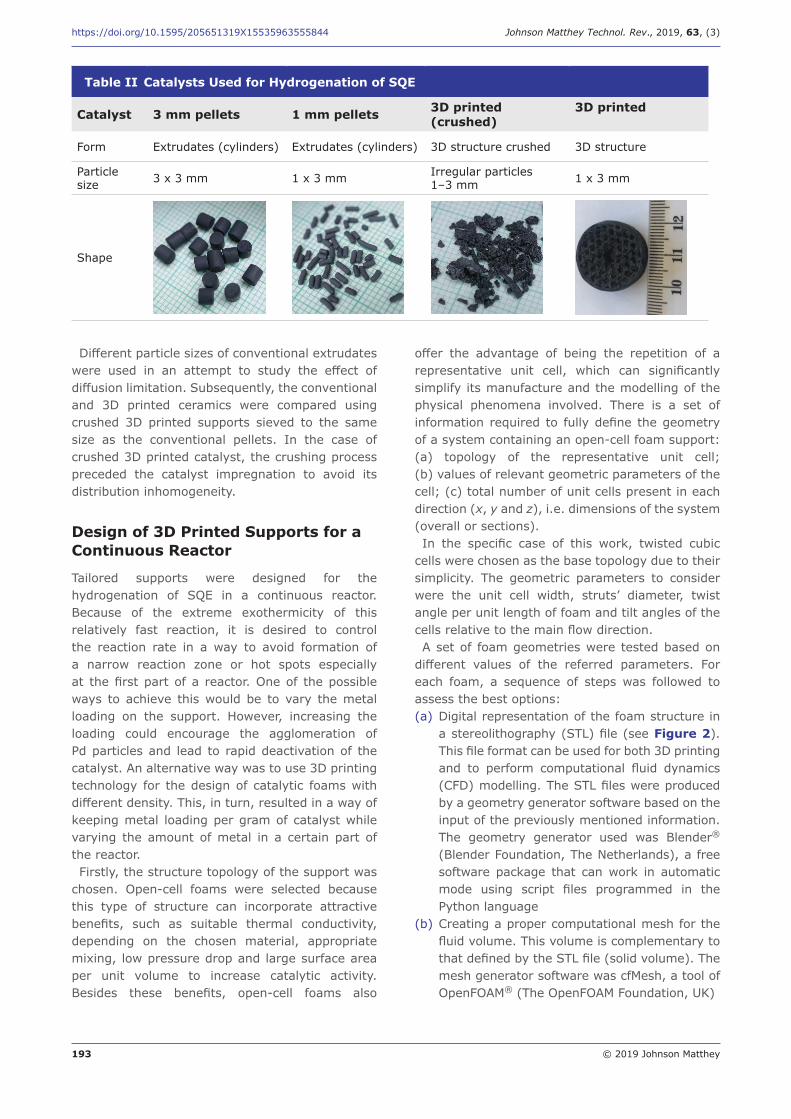
The catalyst support was based on a ceramic precursor that is commercially available in the form of cylindrical pellets and served as a benchmarking material for the developed 3D printed catalysts. The catalysts were prepared by 3D printing to provide a precursor that was consequently thermally converted to the ceramic of a desired structure. The structure was then impregnated with Pd. A novel preparation method was developed in Johnson Matthey, UK, to ensure high dispersion and high stability for Pd on ceramic. A summary of the physical characteristics of the samples is shown in Table II.All the catalysts were supplied by Johnson Matthey
and consisted of 2 wt% Pd developmental samples. The testing was carried out using 3.5 mmolPd per 100 g of SQE.
Cosmetics 69%
Food supplements
23%
Pharmaceutical industry
8%
Fig. 1. Uses of SQA in 2014
Table I SQE Purity and Cost Depending on Source
SQE source
Content, %
Cost, € kg–1
Impurities after hydrogenation
Shark liver oil 98–99 17–19 Not significant
Olive oil 5–17 21–24 Sterol estersParafins
Sugar cane 92–93 22–27 Isosqualane
Monocyclosqualane
193 © 2019 Johnson Matthey
https://doi.org/10.1595/205651319X15535963555844 Johnson Matthey Technol. Rev., 2019, 63, (3)
Different particle sizes of conventional extrudates were used in an attempt to study the effect of diffusion limitation. Subsequently, the conventional and 3D printed ceramics were compared using crushed 3D printed supports sieved to the same size as the conventional pellets. In the case of crushed 3D printed catalyst, the crushing process preceded the catalyst impregnation to avoid its distribution inhomogeneity.
Design of 3D Printed Supports for a Continuous Reactor
Tailored supports were designed for the hydrogenation of SQE in a continuous reactor. Because of the extreme exothermicity of this relatively fast reaction, it is desired to control the reaction rate in a way to avoid formation of a narrow reaction zone or hot spots especially at the first part of a reactor. One of the possible ways to achieve this would be to vary the metal loading on the support. However, increasing the loading could encourage the agglomeration of Pd particles and lead to rapid deactivation of the catalyst. An alternative way was to use 3D printing technology for the design of catalytic foams with different density. This, in turn, resulted in a way of keeping metal loading per gram of catalyst while varying the amount of metal in a certain part of the reactor.Firstly, the structure topology of the support was
chosen. Open-cell foams were selected because this type of structure can incorporate attractive benefits, such as suitable thermal conductivity, depending on the chosen material, appropriate mixing, low pressure drop and large surface area per unit volume to increase catalytic activity. Besides these benefits, open-cell foams also
offer the advantage of being the repetition of a representative unit cell, which can significantly simplify its manufacture and the modelling of the physical phenomena involved. There is a set of information required to fully define the geometry of a system containing an open-cell foam support: (a) topology of the representative unit cell; (b) values of relevant geometric parameters of the cell; (c) total number of unit cells present in each direction (x, y and z), i.e. dimensions of the system (overall or sections).In the specific case of this work, twisted cubic
cells were chosen as the base topology due to their simplicity. The geometric parameters to consider were the unit cell width, struts’ diameter, twist angle per unit length of foam and tilt angles of the cells relative to the main flow direction.A set of foam geometries were tested based on
different values of the referred parameters. For each foam, a sequence of steps was followed to assess the best options:(a) Digital representation of the foam structure in
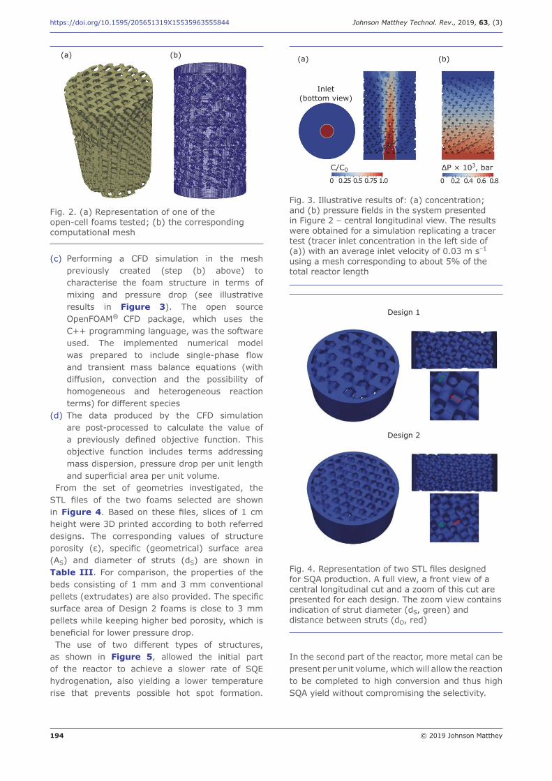
a stereolithography (STL) file (see Figure 2). This file format can be used for both 3D printing and to perform computational fluid dynamics (CFD) modelling. The STL files were produced by a geometry generator software based on the input of the previously mentioned information. The geometry generator used was Blender® (Blender Foundation, The Netherlands), a free software package that can work in automatic mode using script files programmed in the Python language
(b) Creating a proper computational mesh for the fluid volume. This volume is complementary to that defined by the STL file (solid volume). The mesh generator software was cfMesh, a tool of OpenFOAM® (The OpenFOAM Foundation, UK)
Table II Catalysts Used for Hydrogenation of SQE
Catalyst 3 mm pellets 1 mm pellets 3D printed(crushed)
3D printed
Form Extrudates (cylinders) Extrudates (cylinders) 3D structure crushed 3D structure
Particle size 3 x 3 mm 1 x 3 mm Irregular particles
1–3 mm 1 x 3 mm
Shape
194 © 2019 Johnson Matthey
https://doi.org/10.1595/205651319X15535963555844 Johnson Matthey Technol. Rev., 2019, 63, (3)
(c) Performing a CFD simulation in the mesh previously created (step (b) above) to characterise the foam structure in terms of mixing and pressure drop (see illustrative results in Figure 3). The open source OpenFOAM® CFD package, which uses the C++ programming language, was the software used. The implemented numerical model was prepared to include single-phase flow and transient mass balance equations (with diffusion, convection and the possibility of homogeneous and heterogeneous reaction terms) for different species
(d) The data produced by the CFD simulation are post-processed to calculate the value of a previously defined objective function. This objective function includes terms addressing mass dispersion, pressure drop per unit length and superficial area per unit volume.
From the set of geometries investigated, the STL files of the two foams selected are shown in Figure 4. Based on these files, slices of 1 cm height were 3D printed according to both referred designs. The corresponding values of structure porosity (ε), specific (geometrical) surface area (AS) and diameter of struts (dS) are shown in Table III. For comparison, the properties of the beds consisting of 1 mm and 3 mm conventional pellets (extrudates) are also provided. The specific surface area of Design 2 foams is close to 3 mm pellets while keeping higher bed porosity, which is beneficial for lower pressure drop.The use of two different types of structures,
as shown in Figure 5, allowed the initial part of the reactor to achieve a slower rate of SQE hydrogenation, also yielding a lower temperature rise that prevents possible hot spot formation.
Fig. 2. (a) Representation of one of the open-cell foams tested; (b) the corresponding computational mesh
(a) (b) (a) (b)
Inlet (bottom view)
0 0.25 0.5 0.75 1.0 0 0.2 0.4 0.6 0.8
Fig. 3. Illustrative results of: (a) concentration; and (b) pressure fields in the system presented in Figure 2 – central longitudinal view. The results were obtained for a simulation replicating a tracer test (tracer inlet concentration in the left side of (a)) with an average inlet velocity of 0.03 m s–1 using a mesh corresponding to about 5% of the total reactor length
ΔP × 103, barC/C0
Design 1
Design 2
Fig. 4. Representation of two STL files designed for SQA production. A full view, a front view of a central longitudinal cut and a zoom of this cut are presented for each design. The zoom view contains indication of strut diameter (dS, green) and distance between struts (dO, red)
In the second part of the reactor, more metal can be present per unit volume, which will allow the reaction to be completed to high conversion and thus high SQA yield without compromising the selectivity.

195 © 2019 Johnson Matthey
https://doi.org/10.1595/205651319X15535963555844 Johnson Matthey Technol. Rev., 2019, 63, (3)
Catalyst Preparation and CharacterisationThe catalyst was prepared by impregnation of a Pd precursor, aiming at 2 wt% Pd, on the different ceramic supports and subsequent reduction. The particle size of the Pd was derived from carbon monoxide (CO) metal area measurements. The sample was reduced under H2/N2 at 80°C for 10 min. The catalyst was then cooled under N2 to 35°C. Subsequently, pulses of CO were introduced. A Pd:CO stoichiometry of 1:1 was assumed and the Pd atomic area was assumed to be 0.0800 nm2. The Pd particle size calculated from the CO adsorption measurements was 3–8 nm (11).
The samples were examined in a JEM-2800 Transmission Electron Microscope (JEOL, Japan) using the following instrumental conditions: Voltage 200 kV; C2 aperture 70 µm (Z-contrast) imaging in scanning mode using an off-axis annular detector. The secondary electron (SE) signal was acquired simultaneously with the other scanning transmission electron microscopy (STEM) images providing topological information about the sample.The STEM images showed the distribution of
the metal in the support. Similar distribution was observed for different samples. Figure 6 shows the images corresponding to 1 mm pellets, representative of the catalysts used in the study. The bright areas indicate the location of Pd on the surface of the ceramic material. These images (Figure 6) illustrate a good dispersion and metal distribution of the metallic particles. The particle size was determined to be between 2 nm and 6 nm, similar to those observed via CO metal area.The metal loading for the 3D printed catalysts
was kept constant at 2 wt% Pd. The same Johnson Matthey developmental synthetic method was followed for the samples using the 3D printed support.The metal concentration on the 3D printed foam
was investigated via electron probe microanalysis (EPMA) and results for the areas illustrated in Figure 7 are presented in Figure 8. Although the centre of the foams presented lower Pd density, EPMA analysis showed metal present in the inner areas of the support, showing a gradient of concentration.
Results and Discussion
Batch Reactor Testing
Traditionally, hydrogenation of SQE is carried out in a batch reactor using Ni catalyst with reaction
Table III Parameter Values for the Selected Open-Cell Foam Designs and Pellets
ε AS, m–1 dS, mm
Design 1 0.44 (0.52a) 1080a 1.64
Design 2 0.51 (0.61a) 1420a 1.0
1 mm pellets 0.38 2894 1.0
3 mm pellets 0.40 1266 3.0a Internal structure porosity without accounting for the outer
shell
Reactor inlet
3D printed catalyst
3D printed catalyst
Design 1
Design 2
Reactor outlet
Fig. 5. Schematic of the reactor filled with the two different types of structures, ratio of design 1 and design 2 is 1:3
Fig. 6. Dark-field STEM (DF-STEM) images of Pd/ceramic catalyst
20 nm 20 nm

196 © 2019 Johnson Matthey
https://doi.org/10.1595/205651319X15535963555844 Johnson Matthey Technol. Rev., 2019, 63, (3)
Original catalyst Areas investigated
A
C
D
B
Fig. 7. Areas studied by EPMA for catalytic foams for hydrogenation of SQE
(a) (b)
(c) (d)
–92
–92.5
–93
–93.5
–Y (
–1 m
m)
[1.7
94 m
m]
–74 –73.5 –73 –72.5
–X (–1 mm) [1.794 mm]
4.84.64.44.243.83.63.43.232.82.62.42.221.81.61.41.210.80.60.40.20
4.84.64.44.243.83.63.43.232.82.62.42.221.81.61.41.210.80.60.40.20
Pd wt%
–89
–89.5
–90
–90.5
–Y (
–1 m
m)
[1.7
94 m
m]
Pd wt%
–66.5 –66 –65.5–X (–1 mm) [1.794 mm]
4.84.64.44.243.83.63.43.232.82.62.42.221.81.61.41.210.80.60.40.20
Pd wt%
4.84.64.44.243.83.63.43.232.82.62.42.221.81.61.41.210.80.60.40.20
Pd wt%
–81.5
–82
–82.5
–83
–Y (
–1 m
m)
[1.7
94 m
m]
–73 –72.5 –72–X (–1 mm) [1.794 mm]
–81
–81.5
–82
–Y (
–1 m
m)
[1.7
94 m
m]
–79.5 –79 –78.5–X (–1 mm) [1.794 mm]
Fig. 8. Metal distribution for Pd/3D ceramic printed foams: (a) A; (b) B; (c) C; (d) D (see Figure 7)
conditions changing in a series of steps. High temperatures during the first steps are typically avoided since the reaction tends to yield undesired products such as cyclosqualanes. Therefore, to obtain high SQA yields usually the temperature
and hydrogen pressure are gradually increased to compensate for catalyst deactivation.From the mechanistic point of view, hydrogenation
of SQE to SQA proceeds through formation of numerous amounts of partially hydrogenated

197 © 2019 Johnson Matthey
https://doi.org/10.1595/205651319X15535963555844 Johnson Matthey Technol. Rev., 2019, 63, (3)
intermediates and their isomers. Using gas chromatography-mass spectrometry (GC-MS), more than 60 individual peaks of partially hydrogenated intermediates and isomers have been identified, which were divided into six groups based on their molecular weight (MW). Besides the SQE (MW 410) and SQA (MW 422) there were six groups of partially hydrogenated intermediates differentiated by one double bond (H2) giving molecular masses MW 410, MW 412, MW 414, MW 416, MW 418 and MW 420. Among the undesired intermediates, cyclosqualane (MW 420) can be found. This presented a more significant peak in the GC-MS spectrum. Catalytic performance of different catalyst shapes as well as effect of operating conditions on the hydrogenation process
were investigated. For this series of experiments, 99% SQE (marine source) was used to rule out the effect of vegetable SQE impurities.Comparison of different catalysts, using high
purity SQE (99%, Aldrich) showed that the best performance was obtained with 1 × 3 mm pellets followed by 3 × 3 mm pellets and 3D printed crushed catalyst that had slightly lower performance, see Figure 9. This result indicates that most probably internal diffusion limitations take place and the effect is less important for 1 × 3 mm pellets.The impact of different operating conditions is
discussed below. Figure 10 shows the temperature effect on relative SQE concentration and SQA yield profiles versus time. After about 3 h of reaction, all SQE was practically converted at all reaction
Time, hh:mm00:00 01:00 02:00 03:00 04:00 05:00 06:00
Yiel
d SQ
A,
%1009080706050403020100
3 × 3 mm pellets1 × 3 mm pellets3D printed
Fig. 9. SQE hydrogenation: comparison of different catalysts, 2% Pd/ceramic, 180°C, 20 bar, 10% SQE (marine) in an organic solvent
00:00 01:00 02:00 03:00 04:00 05:00Time, hh:mm
200 ºC180 ºC160 ºC
100
80
60
40
20
0
CSQ
E/C
0 SQ
E, y
ield
SQ
A,
%
Fig. 10. SQE hydrogenation: temperature effect, 2% Pd/ceramic, 3 × 3 mm pellets, 20 bar, 10% SQE (marine) in an organic solvent
100
90
80
70
60
50
40
30
20
10
0
Yiel
d SQ
A,
%
15 bar30 bar
00:00 01:00 02:00 03:00 04:00 05:00 06:00Time, hh:mm
100
90
80
70
60
50
40
30
20
10
0
Yiel
d IT
M,
%
00:00 01:00 02:00 03:00 04:00 05:00 06:00Time, hh:mm
15 bar30 bar
Fig. 11. SQE hydrogenation: (a) pressure effect on SQA yield; (b) intermediates (ITM) yield. 2% Pd/ceramic 3 × 3 mm pellets, 180°C, 10% SQE (marine) in an organic solvent
(a) (b)

198 © 2019 Johnson Matthey
https://doi.org/10.1595/205651319X15535963555844 Johnson Matthey Technol. Rev., 2019, 63, (3)
temperatures, while the SQA yield reached only 54.5% at 160°C or 70% at 180°C respectively. This observation most probably indicates that the apparent activation energy of the subsequent hydrogenation steps of individual C=C double bonds increases with the degree of saturation. Note that undesired side products of reaction such as cyclosqualanes were not observed under these conditions.The effect of pressure is presented in Figure 11,
demonstrating that the formation of partially saturated intermediates was favoured against SQE at hydrogen pressure about 15 bar. Besides, high pressure was necessary to reach high SQE yields. The parametric study in a batch reactor provided the necessary input about the optimal operating conditions to conduct the SQE hydrogenation in a continuous reactor.
Catalyst Deactivation in Batch Reactor
In a batch reactor, a powder version of the catalysts prepared was tested for stability. For this series of experiments, vegetable SQE was used, with a purity of 82% as it is expected that this would be more representative of the behaviour of the catalyst in the pilot plant. The reaction was carried out for 4 h at 200°C and 20 bar of hydrogen.The experimental results are shown in Figure 12.
The partially hydrogenated SQE intermediates are presented as groups according to their GC-MS MW starting from SQE and its isomers with MW 410
to SQA (MW 422). L1 represents the analyses of the reaction products using a fresh catalyst. Subsequently, L2 to L4 represent runs 2 to 4 using the same catalyst and conditions with a fresh feed. L4a, however, corresponds to the product of the reaction after thoroughly washing the catalyst with xylene. Both activity and selectivity decreased after each cycle. A significant regeneration of both SQE conversion and selectivity towards production of SQA was observed in L4a.This experiment followed a thorough washing of
the catalyst attempting its regeneration. A likely explanation for recovering the activity and selectivity is that the washing had removed intermediates of the reaction deposited on the surface of the catalyst. Some waxes were observed in the final product, which tended to dissolve in the feed when hot.Thermogravimetric experiments showed the
presence of a product in the used catalyst after one use that decomposed at ca. 250°C, as shown in Figure 13.In a continuous reactor, the temperature should
be kept above 85°C to avoid solidification of the waxes that occur on the surface of the catalyst.In conventional methods for production of SQE
using Ni as the reducing agent, the metal tends to leach onto the final product. In order to avoid toxic metal in the SQA, a costly cleaning step is required after reduction. Although the process presented in this paper is Ni free, it was necessary to determine whether Pd leaches into the final product. Various Pd compounds have been proven to induce sensitisation in several animal species (11). It was thus necessary to test the levels of Pd present in the final SQA. The Pd content for L1 and L4a were analysed by inductively coupled plasma
SQE left 410 412 414 416 418 420 SQAMixture component
SQ
E le
ft y
ield
s, %
40
35
30
25
20
15
10
5
0
L1-fresh cat L2-used 1x L3-used 2x L4-used 3x L4a-used 4x
Fig. 12. Product composition after repeated use of the catalyst, reaction time 4 h at 200°C and 20 bar, Pd/ceramic
100
98
96
94
92
Wei
ght,
%
Y-1
0 200 400 600 800Temperature, ºC
0.8
0.6
0.4
0.2
0.0
–0.2
Temperature difference, ºC m
g–1
Y-2
600
400
200Tem
pera
ture
, ºC
Y-3250.02 ºC 93.93% 0.6366 ºC mg–1
183.01 ºC 98.31% 0.03057 ºC mg–1
303.97 ºC 93.10% –0.004993 ºC mg–1
92.28%
Fig. 13. Thermogravimetric study of Pd/ceramic catalyst after one use

199 © 2019 Johnson Matthey
https://doi.org/10.1595/205651319X15535963555844 Johnson Matthey Technol. Rev., 2019, 63, (3)
mass spectrometry (ICP-MS) to show levels of the metal below 5 ppb. This proved the safety of using this Pd catalyst for a cosmetic application. Both the absence of Pd in the final product and the possibility of regenerating the catalyst, suggested that the catalyst was stable under the reaction conditions.
Continuous Hydrogenation of Squalene in a Trickle-Bed Milli-Reactor and a Pilot-PlantA feasibility study was carried out to determine whether it would be possible to perform the hydrogenation of SQE in a continuous reactor. A trickle-bed milli-reactor of a bed volume about 10 ml was employed to perform hydrogenation tests with catalyst of conventional shape. The unit was operated for several days while each experiment at constant operating conditions took at least 6 h. At 180°C and 25 bar a stable SQE conversion 99.5% with SQE yield 69.8% was obtained (see Table IV).
Catalyst deactivation was not observed in the trickle-bed milli-reactor. However, the transmission electron microscopy (TEM) images of the spent catalyst showed a slight aggregation of Pd particles after ca. 40 h of reaction, as illustrated in Figures 14 and 15. Once the hydrogenation process in continuous mode was proven to be feasible in the trickle-bed milli-reactor, experiments in a pilot-plant of volume 324 ml were approached under the same operating conditions.
Continuous Pilot-Plant Squalene Hydrogenation
The pilot-plant for continuous hydrogenation of SQE is an automated, computer-controlled system (which was developed and built by Advanced Machinery & Technology Chemnitz GmbH within the project PRINTCR3DIT).
Table IV Comparison of SQE Hydrogenation Performed in Continuous Reactors of Different Scales
Unit Trickle-bed milli-reactor
Pilot-plant reactor
Pilot-plant reactor
Catalyst – Conventional Conventional 3D printed
Reactor volume ml 10 324 324
Reactor diameter mm 8.5 22 22
Catalyst size mm Pellets 1 × 3 mm Pellets 3 × 3 mm 3D printed
SQE flowrate(20% in solvent) g h–1 5.5 185 185
Temperature °C 180 180 180
Pressure bar 25 25 25
Space velocity mmolPd h g–1SQE 20 20 20
SQE conversion % 99.5 100 100
SQA selectivity % 69.8 89 95.7
30
25
20
15
10
5
0
Part
icle
cou
nt
1.60 2.40 3.20 4.00 4.80 5.60 moreParticle size, nm
20 nm
Fig. 14. (a) TEM image for fresh catalyst; (b) particle size analysis for fresh catalyst
(a) (b)

200 © 2019 Johnson Matthey
https://doi.org/10.1595/205651319X15535963555844 Johnson Matthey Technol. Rev., 2019, 63, (3)
With the aim of transferring the SQE hydrogenation from conventional batch to a continuous method a tubular reactor was the most suitable choice. It can be run as a trickle-bed reactor. The reactor itself is made of stainless steel. Solid catalyst can be loaded from the top of the reactor. Figure 16 represents a schematic of the pilot plant, with the reactor highlighted by the red line.
State-of-the-art Catalyst
For the purpose of a benchmark, a state-of-the-art catalyst supported on conventional 3 mm pellets form (see Table II) was loaded into the reactor. The catalyst was obtained following a proprietary synthetic method from Johnson Matthey. This was compared with a catalyst prepared using a 3D printed ceramic support. No significant pressure
drop was observed between the top and the bottom of the reactor.This conventional catalyst allowed an excellent
conversion of SQE into SQA at temperatures from 180°C to 240°C with a pressure of 25–30 bar. However, adjusting the temperature to 240°C and the pressure to 30 bar resulted in high conversion with an acceptable level of isomerisation.
3D Printed Catalyst
The 3D printed catalyst as a foam (see Table II) was loaded into the reactor. The total weight of the sample was 200 g, forming a catalyst bed of 75 cm high. As for the conventional catalyst, no significant pressure drop was observed during this trial between the top and the bottom of the bed.Conversion and selectivity were high at low
temperatures with the 3D printed catalyst, which differed from the low selectivity observed when using conventional supports. The novel 3D printed catalyst showed high selectivity towards SQA at a temperature of 180°C and a pressure of 25 bar (see Table IV). A possible explanation for this improvement could be the fact that the geometry of the foam enhanced the diffusion of SQE and hydrogen on the surface of the metal.The effect of temperature on the selectivity to
SQA was also investigated, as shown in Figure 17. Operation at temperatures below 180°C allowed good conversion of SQE. However, the selectivity towards SQA becomes insufficient. Nevertheless, at 240°C excellent conversion and selectivity were obtained even for the 100 wt% vegetable SQE feed.The single load of 3D printed catalyst has produced
more than 15 kg of good quality SQA up to the time of writing this article with no signs of deactivation.
Fig. 15. (a) TEM image for catalyst after ca. 40 h in trickle-bed milli-reactor; (b) particle size analysis for catalyst after ca. 40 h in trickle-bed milli-reactor
20 nm
60
50
40
30
20
10
0
Part
icle
cou
nt
less 3.00 6.00 9.00 12.00 15.00 moreParticle size, nm
(a) (b)
Fig. 16. Schematic of the continuous pilot-plant for SQE hydrogenation

201 © 2019 Johnson Matthey
https://doi.org/10.1595/205651319X15535963555844 Johnson Matthey Technol. Rev., 2019, 63, (3)
This suggests that the catalytically active phase does not change during the process and the metal does not significantly leach into the product. The use of 3D printed technology allowed optimisation of the reaction conditions and production of large amounts of SQA using a more compact reactor than current technologies.
Conclusions
In principle, it would be possible to carry out the hydrogenation of SQE in a batch reactor with the novel catalyst developed by Johnson Matthey. However, it would require catalyst reactivation between cycles. The use of a continuous reactor presents the advantages of reusability of the catalyst with no significant losses of activity or selectivity. On the other hand, for a typical SQA production plant, a batch reactor of ca. 1.5 m3 would be required, while a continuous system could carry on the process with a volume of about 0.05 m3, 30 times smaller. Being able to control the reaction rate along the reactor bed and preventing formation of undesired isomers is a potential advantage of the use of 3D printing technology. The use of CFD modelling for the efficient design of the support proved crucial in the success of the experiments. Being able to directly print the final catalytic support offered the advantage of an alternative way to change the process, which in turn, would allow higher levels of flexibility. In addition, because of the use of a Pd catalyst, the final product was Ni free, which removed the cleaning step that would normally occur in the manufacturing of SQA for the pharmaceutical and cosmetic industries.
Acknowledgements
The authors acknowledge the financial support given to the PRINTCR3DIT project by the European Union’s Horizon 2020 research and innovation programme under grant agreement No 680414. The project belongs to the Sustainable Process Industry through Resource and Energy Efficiency (SPIRE) programme and information can be found online. The authors would also like to thank Daniel G. Direito for preparing the STL files in Blender® and Martha Briceno de Gutiérrez and Trung Tran for the STEM images. Thanks to Gareth Hatton for the EMPA study. Finally, the author would like to acknowledge Paul Fisher and Raquel García for their study on Pd leaching.This contribution has been prepared using results
achieved within the open access infrastructure belonging to the project Efficient Use of Energy Resources Using Catalytic Processes (project code LM2015039) which was financially supported by the Ministry of Education, Youth and Sports of the Czech Republic within the targeted support of large infrastructures. The project has been integrated into the National Sustainability Programme I of the Ministry of Education, Youth and Sports of the Czech Republic through the project Development of the UniCRE Centre, project code LO1606.
References
1. World Health Organization, Weekly Epidemiological Record, 2006, 81, (28), 273
2. S.-K. Kim and F. Karadeniz, ‘Biological Importance and Applications of Squalene and Squalane’, in “Advances in Food and Nutrition Research: Marine
1009080706050403020100
%
140 160 180 200 220 240Temperature, ºC
SQA, %Conversion SQE, %
Fig. 17. Conversion of SQE and selectivity towards SQA at different temperatures, at liquid feed rate 250 g h–1, 75 wt% SQE in organic solvent, 25 bar, 3D printed catalyst

202 © 2019 Johnson Matthey
https://doi.org/10.1595/205651319X15535963555844 Johnson Matthey Technol. Rev., 2019, 63, (3)
Medicinal Foods – Implications and Applications – Animals and Microbes”, ed. S.-K. Kim, Vol. 65, Ch. 14, Elsevier Inc., Waltham, USA, 2012, pp. 223–233
3. A. C. Allison, Methods, 1999, 19, (1), 87
4. V. Pandarus, R. Ciriminna, F. Béland, M. Pagliaro and S. Kaliaguine, ACS Omega, 2017, 2, (7), 3989
5. W.-L. Chen, S.-J. Liu, C.-H. Leng, H.-W. Chen, P. Chong and M.-H. Huang, Biomater., 2014, 35, (5), 1686
6. J. Dale and T. Årtun, Acta Chem. Scand., 1956, 10, (3), 439
7. R. Ciriminna, V. Pandarus, F. Béland and M. Pagliaro, Org. Process Res. Dev., 2014, 18, (9), 1110
8. M. Z. Tsimidou, ‘Squalene and Tocopherols in Olive Oil: Importance and Methods of Analysis’, in “Olives and Olive Oil in Health and Disease Prevention”, eds. V. R. Preedy and R. R. Watson, Ch. 61, Elsevier Inc., New York, USA, 2010, pp. 561–567
9. C. Parra-Cabrera, C. Achille, S. Kuhn and R. Ameloot, Chem. Soc. Rev., 2018, 47, (1), 209
10. “Handbook of Heterogeneous Catalysis”, 2nd Edn., eds. G. Ertl, H. Knözinger, F. Schüth and J. Weitkamp, Wiley-VCH Verlag GmbH & Co KGaA, Weinheim, Germany, 2008
11. ‘Toxicity Profile for Palladium and its Compounds’, Bibra toxicology advice and consulting, Wallington, UK, 2007, 28 pp
The Authors
Sonia Garcia obtained a BSc in Chemistry from the University of La Rioja, Spain. She joined Johnson Matthey in 2001 where she worked on a Marie Curie funded PhD in Chemistry from the University of Reading, UK, on nanocatalysts for fuel cell applications. Currently she is working in the New Applications Group in Johnson Matthey on a variety of projects.
Stephen Poulston has a PhD in chemistry from the University of Cambridge, UK, and is a research scientist at Johnson Matthey, Sonning Common, UK where he has worked since 1998. Stephen has experience of a wide range of heterogeneous catalyst systems including hydrogenation and platinum group metal catalysis.
Deena Modeshia obtained a MChem in 2006, followed by a PhD on hydrothermal synthesis of mixed metal oxides, from the University of Warwick, UK, in 2010. She joined Johnson Matthey in 2012 and has worked on several gas purification projects and currently works on catalysts for improving the process of converting waste into useful products or hydrogen.
Petr Stavarek graduated in Chemical Engineering at VŠB - Technical University of Ostrava, Czech Republic and pursued his PhD studies at the Institute of Chemical Technology, Prague, Czech Republic. As a member of the Department of Multiphase Reactors at the Institute of Chemical Process Fundamentals of the CAS, Prague, Czech Republic, he is leader of a laboratory of microreactors. His main research interests are in microreaction technology, microreactor design and process intensification for multiphase and catalytic reactions.
203 © 2019 Johnson Matthey
https://doi.org/10.1595/205651319X15535963555844 Johnson Matthey Technol. Rev., 2019, 63, (3)
Massimo Ujčić graduated in Chemical Engineering at the Faculty of Chemical Engineering and Technology, University of Zagreb, Croatia. In 2016 he joined the Department of Multiphase Reactors at the Institute of Chemical Process Fundamentals of the CAS, Prague, Czech Republic where he pursues PhD study. His research interests are in microreactor design, 3D printing and process intensification for multiphase and catalytic reactions.
Farzad Lali graduated in 2008 in Chemical Engineering from RWTH Aachen University, Aachen, Germany and obtained his PhD degree in 2015 from Dresden University of Technology, Germany. His research interests are multiphase reactions, structured catalysts and modelling and simulation. He was a postdoctoral fellow at the Department of Multiphase Reactors of the Institute of Chemical Process Fundamentals of the CAS, Prague, Czech Republic. He is currently working as a research associate at the Institute of Chemical Engineering of the University of Ulm, Germany.
Manuel A. Alves graduated in 1995 in Chemical Engineering from the Faculty of Engineering of the University of Porto (FEUP) and obtained a PhD degree in 2004 at the same institution. He is an Associate Professor at FEUP and his main research interests are in complex fluids, microfluidics and computational rheology.
José Daniel Araújo graduated in Chemical Engineering from the FEUP and obtained his PhD degree at the same institution. The PhD work involved the design, operation and modelling of a pilot scale setup based on a continuous structured packing bubble column reactor for vanillin production from lignin oxidation. He joined the Transport Phenomena Research Center (CEFT) at FEUP in 2008 and worked in several projects involving modelling and CFD applied to multiphase flow, transport phenomena and process intensification.
Michael Krusche obtained his degree in physics from the Dresden University of Technology, Germany, in 1980. He is Managing Director of Advanced Machinery & Technology Chemnitz GmbH (AMTECH), Chemnitz, Germany, which he founded in 2010 emerging from his former company AMTEC GmbH, Germany. The core competence of AMTECH is the development and production of highly automated reactor systems, with applications especially in the field of catalysis.
Frank Ullrich graduated in Chemistry at the Freiberg University of Mining and Technology, Germany, in 2003 and obtained his PhD from the same university in 2008. At the same time, he was a staff member of AMTEC GmbH. Currently, he is chief technology officer of the company and primarily responsible for the development of AMTECH systems.

204 © 2019 Johnson Matthey
https://doi.org/10.1595/205651319X15535963555844 Johnson Matthey Technol. Rev., 2019, 63, (3)
Diana Maier graduated in Chemical Engineering at the Dresden University of Applied Sciences, Germany, in 2006. She joined the Leibniz Institute for Solid State and Materials Research (IFW) Dresden, Germany, where she conducted her PhD, followed by a PhD degree from the Dresden University of Technology in 2011. Since 2012 she has been a staff member of AMTECH.
Related Documents