FINAL PROJECT REPORT WTFRC Project Number: TR-10-104 Project Title: Digital traps for automated monitoring of insect populations PI: Johnny Park Co-PI (2): Vincent Jones Organization: Spensa Technologies, Inc Organization: WSU-TFREC Telephone: 765-714-2379 Telephone: 509-663-8181 x273 Email: [email protected] Email: [email protected] Address: 1281 Win Hentschel Blvd Address: 1100 N Western Ave City: West Lafayette City: Wenatchee State/Zip: IN 47906 State/Zip: WA 98801 Co-PI(3): Larry Hull Organization: Penn State University Telephone: 717-677-6116 x6 Email: [email protected] Address: 290 University Drive City: Biglerville State/Zip: PA 17307-0330 Cooperators: None Total Project Request: Year 1: $64,950 Other funding Sources: None WTFRC Collaborative expenses: None Budget 1 Organization Name: Spensa Technologies, Inc Contract Administrator: Johnny Park Telephone: 765-714-2379 Email address: [email protected] Item Year 1 Salaries 34,000 Benefits 13,600 Wages Benefits Equipment Supplies 1,600 Travel 800 Miscellaneous Total 50,000

Welcome message from author
This document is posted to help you gain knowledge. Please leave a comment to let me know what you think about it! Share it to your friends and learn new things together.
Transcript

FINAL PROJECT REPORT WTFRC Project Number: TR-10-104 Project Title: Digital traps for automated monitoring of insect populations PI: Johnny Park Co-PI (2): Vincent Jones Organization: Spensa Technologies, Inc Organization: WSU-TFREC Telephone: 765-714-2379 Telephone: 509-663-8181 x273 Email: [email protected] Email: [email protected] Address: 1281 Win Hentschel Blvd Address: 1100 N Western Ave City: West Lafayette City: Wenatchee State/Zip: IN 47906 State/Zip: WA 98801 Co-PI(3): Larry Hull Organization: Penn State University Telephone: 717-677-6116 x6 Email: [email protected] Address: 290 University Drive City: Biglerville State/Zip: PA 17307-0330 Cooperators: None Total Project Request: Year 1: $64,950
Other funding Sources: None
WTFRC Collaborative expenses: None Budget 1 Organization Name: Spensa Technologies, Inc Contract Administrator: Johnny Park Telephone: 765-714-2379 Email address: [email protected] Item Year 1
Salaries 34,000 Benefits 13,600 Wages Benefits Equipment Supplies 1,600 Travel 800 Miscellaneous Total 50,000
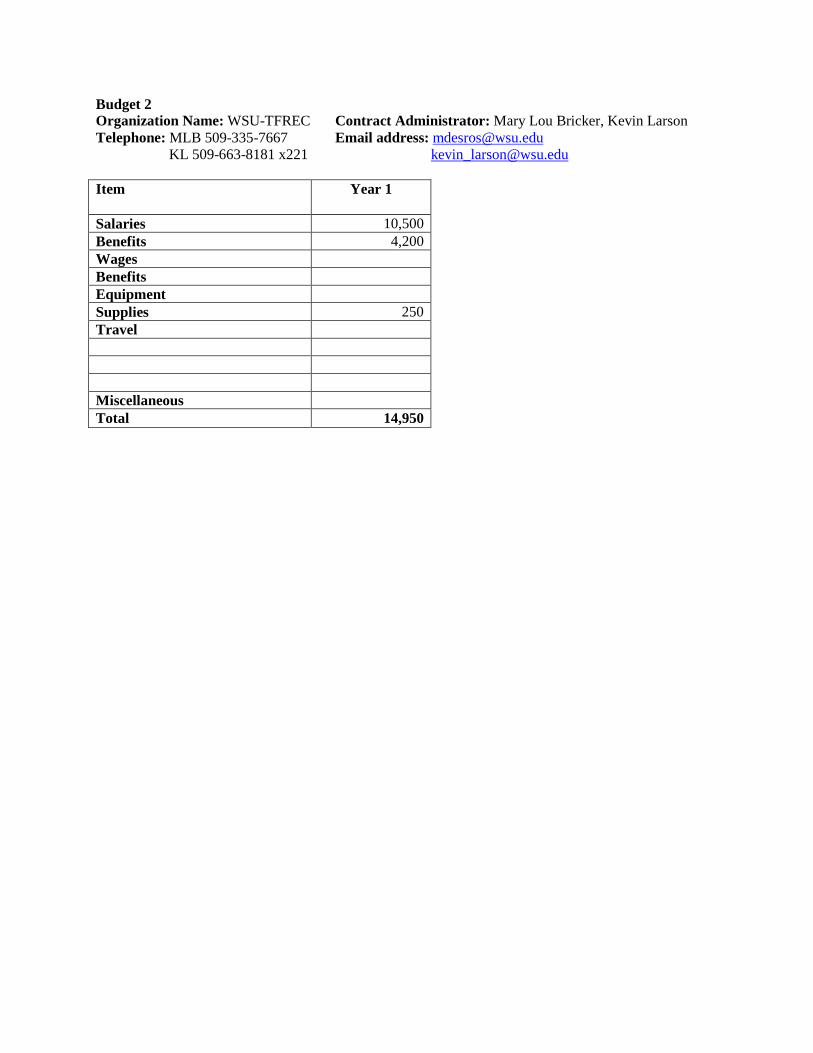
Budget 2 Organization Name: WSU-TFREC Contract Administrator: Mary Lou Bricker, Kevin Larson Telephone: MLB 509-335-7667 Email address: [email protected] KL 509-663-8181 x221 [email protected] Item Year 1
Salaries 10,500 Benefits 4,200 Wages Benefits Equipment Supplies 250 Travel Miscellaneous Total 14,950

Objective 1. Devise an electrical discharge system for killing target insects entering the trap: (i) Determine optimal voltage and current levels for killing codling moths and other major pests; (ii) Investigate various features that can be extracted during electrical discharge for possible identification of insect species.
We have devised an electrical discharge grid (or “zapper”) that consists of a pair of metallic wires rolled around a cylindrical plastic grid spaced 1/5” apart from each other. Figure 1 (left) shows a picture of the first version of grid. Ten prototypes of the grid were constructed for use in our experiments. Although the initial electrical discharge grid design performed satisfactorily under most conditions, during the experimental evaluation we learned that in the presence of water or certain chemicals (such as the stannic oxychloride used to visualize air flow in the wind tunnel), the plastic frame that was used to support the wires that form the electric discharge coils would become conductive and short circuit the two terminals of the device, impairing its functionality. Additional laboratory experiments revealed that several chemicals commonly used in agriculture had a similar effect and some of these chemicals were very hard to remove from the plastic frame (Table 1). In addition, the plastic frame was sometimes used as a landing surface by the target insects, which would not get electrocuted because they would not touch the wires. For these reasons, we devised a new electric discharge grid that consists exclusively of two conductive coils without a plastic frame, as illustrated in Figure 1 (right). The new design successfully solved both problems.
Table 1: Results of laboratory experiments about the effects of chemicals on the zapper grid with plastic frame.
Chemical Amount needed to short-circuit the grid
Difficulty to remove
Surround Small Medium Damoil Small Hard
Lime Sulfur Small Easy Micro Sulf Small Hard Cuprofix Small Medium Captan Large Easy
Calcium Chloride Large Easy Penncozeb Small Easy
Stannic Oxychloride Small Very Hard Water Medium Easy
Figure 1: Initial electrical discharge grid with plastic support frame (left). New electrical discharge grid without
plastic support frame (right).
We also designed and implemented a high-voltage electronic circuit that allows a digital microcontroller to adjust the voltage applied to the grid. The circuit allows the voltage applied to the zapper to be varied by small increments up to several hundred volts. Several units of this circuit were
constructed, and were used to evaluate the electric characteristics of the signal required to effectively electrocute and count the adults of codling moth (CM), oriental fruit moth (OFM), and obliquebanded leafroller (OBLR).
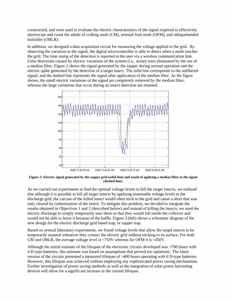
In addition, we designed a data acquisition circuit for measuring the voltage applied to the grid. By observing the variation in the signal, the digital microcontroller is able to detect when a moth touches the grid. The time stamp of the detection is reported to the user via a wireless communication link. False detections caused by electric variations of the system (i.e., noise) were eliminated by the use of a median filter. Figure 2 shows the signal generated by the zapper during normal operation and the electric spike generated by the detection of a target insect. The solid line corresponds to the unfiltered signal, and the dashed line represents the signal after application of the median filter. As the figure shows, the small electric variations of the signal are completely removed by the median filter, whereas the large variations that occur during an insect detection are retained.
Figure 2: Electric signal generated by the zapper grid (solid line) and result of applying a median filter to the signal
(dashed line).
As we carried out experiments to find the optimal voltage levels to kill the target insects, we realized that although it is possible to kill all target insects by applying reasonable voltage levels to the discharge grid, the carcass of the killed insect would often stick to the grid and cause a short that was only cleared by carbonization of the insect. To mitigate this problem, we decided to integrate the results obtained in Objectives 1 and 2 (described below) and instead of killing the insects, we used the electric discharge to simply temporarily stun them so that they would fall inside the collector and would not be able to leave it because of the baffle. Figure 3 (left) shows a schematic diagram of the new design for the electric discharge grid based trap, or zapper trap.
Based on several laboratory experiments, we found voltage levels that allow the target insects to be temporarily stunned whenever they contact the electric grid without sticking to its surface. For both CM and OBLR, the average voltage level is ≈750V whereas for OFM it is ≈450V.
Although the initial estimate of the lifespan of the electronic circuits developed was ≈700 hours with 4 D-type batteries, this estimate was based on assumptions that proved too optimistic. The latest version of the circuits presented a measured lifespan of ≈400 hours operating with 6 D-type batteries. However, this lifespan was achieved without employing any sophisticated power saving mechanisms. Further investigation of power saving methods as well as the integration of solar power harvesting devices will allow for a significant increase in the current lifespan.
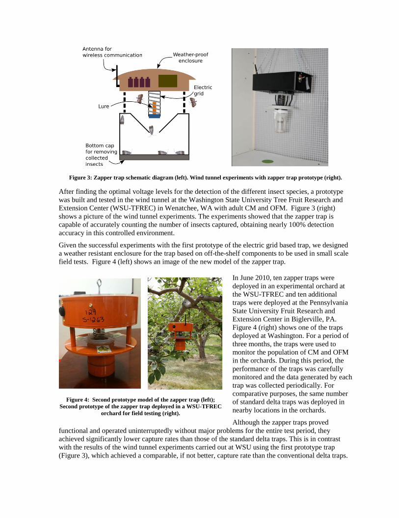
Figure 3: Zapper trap schematic diagram (left). Wind tunnel experiments with zapper trap prototype (right).
After finding the optimal voltage levels for the detection of the different insect species, a prototype was built and tested in the wind tunnel at the Washington State University Tree Fruit Research and Extension Center (WSU-TFREC) in Wenatchee, WA with adult CM and OFM. Figure 3 (right) shows a picture of the wind tunnel experiments. The experiments showed that the zapper trap is capable of accurately counting the number of insects captured, obtaining nearly 100% detection accuracy in this controlled environment.
Given the successful experiments with the first prototype of the electric grid based trap, we designed a weather resistant enclosure for the trap based on off-the-shelf components to be used in small scale field tests. Figure 4 (left) shows an image of the new model of the zapper trap.
In June 2010, ten zapper traps were deployed in an experimental orchard at the WSU-TFREC and ten additional traps were deployed at the Pennsylvania State University Fruit Research and Extension Center in Biglerville, PA. Figure 4 (right) shows one of the traps deployed at Washington. For a period of three months, the traps were used to monitor the population of CM and OFM in the orchards. During this period, the performance of the traps was carefully monitored and the data generated by each trap was collected periodically. For comparative purposes, the same number of standard delta traps was deployed in nearby locations in the orchards.
Although the zapper traps proved functional and operated uninterruptedly without major problems for the entire test period, they achieved significantly lower capture rates than those of the standard delta traps. This is in contrast with the results of the wind tunnel experiments carried out at WSU using the first prototype trap (Figure 3), which achieved a comparable, if not better, capture rate than the conventional delta traps.
Figure 4: Second prototype model of the zapper trap (left); Second prototype of the zapper trap deployed in a WSU-TFREC
orchard for field testing (right).
We believe that the exterior shape of the current trap is somehow disrupting the dispersion of the pheromone plume.
We evaluated the initial trap design in the wind tunnel and in the field. In the field, during the month of July, the original trap design caught between 8 and 11% of the moth catch of standard delta traps. In the wind tunnel, we used smoke (i.e., stannic oxychloride) to evaluate the pheromone plume emitted from the trap. We found that the shape of the trap caused a vacuum downwind from the large top, which caused the pheromone to curl back to the top, so that moths spent more time around the top of the trap and did not approach the zapper coil. The lower part of the trap was also problematic, because moths that went below the bottom part of the trap also lost the pheromone signal and were unable to locate the plume again, which resulted in the moths staying below the lower disk.
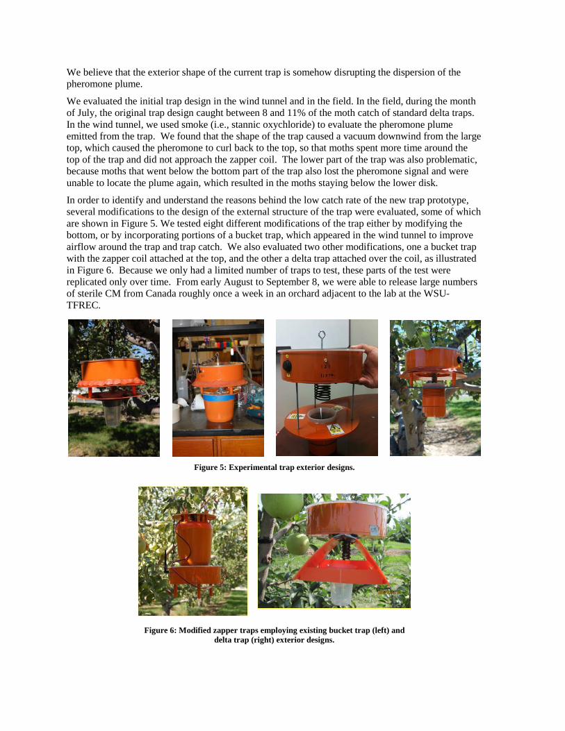
In order to identify and understand the reasons behind the low catch rate of the new trap prototype, several modifications to the design of the external structure of the trap were evaluated, some of which are shown in Figure 5. We tested eight different modifications of the trap either by modifying the bottom, or by incorporating portions of a bucket trap, which appeared in the wind tunnel to improve airflow around the trap and trap catch. We also evaluated two other modifications, one a bucket trap with the zapper coil attached at the top, and the other a delta trap attached over the coil, as illustrated in Figure 6. Because we only had a limited number of traps to test, these parts of the test were replicated only over time. From early August to September 8, we were able to release large numbers of sterile CM from Canada roughly once a week in an orchard adjacent to the lab at the WSU-TFREC.
Figure 5: Experimental trap exterior designs.
Figure 6: Modified zapper traps employing existing bucket trap (left) and delta trap (right) exterior designs.
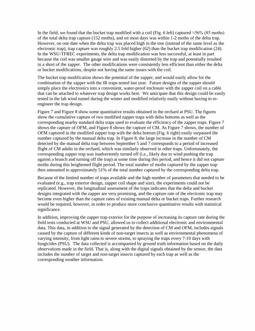
In the field, we found that the bucket trap modified with a coil (Fig. 6 left) captured ≈56% (85 moths) of the total delta trap capture (152 moths), and on most days was within 1-2 moths of the delta trap. However, on one date when the delta trap was placed high in the tree (instead of the same level as the electronic trap), trap capture was roughly 2.5 fold higher (62) than the bucket trap modification (24). In the WSU-TFREC experiments, the delta trap modification was less successful, at least in part because the coil was smaller gauge wire and was easily distorted by the trap and potentially resulted in a short of the zapper. The other modifications were consistently less efficient than either the delta or bucket modifications, despite not having the same issues with the coil.
The bucket trap modification shows the potential of the zapper, and would easily allow for the combination of the zapper with the IR traps tested last year. Future designs of the zapper should simply place the electronics into a convenient, water-proof enclosure with the zapper coil on a cable that can be attached to whatever trap design works best. We anticipate that this design could be easily tested in the lab wind tunnel during the winter and modified relatively easily without having to re-engineer the trap design.
Figure 7 and Figure 8 show some quantitative results obtained in the orchard at PSU. The figures show the cumulative capture of two modified zapper traps with delta bottoms as well as the corresponding nearby standard delta traps used to evaluate the efficiency of the zapper traps. Figure 7 shows the capture of OFM, and Figure 8 shows the capture of CM. As Figure 7 shows, the number of OFM captured in the modified zapper trap with the delta bottom (Fig. 6 right) easily surpassed the number captured by the manual delta trap. In Figure 8, the large increase in the number of CM detected by the manual delta trap between September 5 and 7 corresponds to a period of increased flight of CM adults in the orchard, which was similarly observed in other traps. Unfortunately, the corresponding zapper trap was inadvertently turned off (i.e., likely due to wind pushing the trap against a branch and turning off the trap) at some time during this period, and hence it did not capture moths during this heightened flight period. The total number of moths captured by the zapper trap then amounted to approximately 51% of the total number captured by the corresponding delta trap.
Because of the limited number of traps available and the high number of parameters that needed to be evaluated (e.g., trap exterior design, zapper coil shape and size), the experiments could not be replicated. However, the longitudinal assessment of the traps indicates that the delta and bucket designs integrated with the zapper are very promising, and the capture rate of the electronic trap may become even higher than the capture rates of existing manual delta or bucket traps. Further research would be required, however, in order to produce more conclusive quantitative results with statistical significance.
In addition, improving the zapper trap exterior for the purpose of increasing its capture rate during the field tests conducted at WSU and PSU, allowed us to collect additional electronic and environmental data. This data, in addition to the signal generated by the detection of CM and OFM, includes signals caused by the capture of different kinds of non-target insects as well as environmental phenomena of varying intensity, from light rains to severe storms, to spraying the traps every 7-10 days with fungicides (PSU). The data collected is accompanied by ground truth information based on the daily observations made in the field. That is, along with the digital signals obtained by the sensor, the data includes the number of target and non-target insects captured by each trap as well as the corresponding weather information.
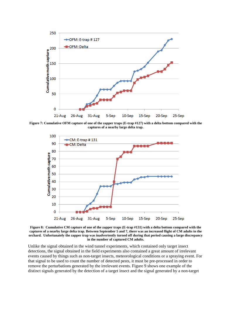
Figure 7: Cumulative OFM capture of one of the zapper traps (E-trap #127) with a delta bottom compared with the
captures of a nearby large delta trap.
Figure 8: Cumulative CM capture of one of the zapper traps (E-trap #131) with a delta bottom compared with the captures of a nearby large delta trap. Between September 5 and 7, there was an increased flight of CM adults in the orchard. Unfortunately the zapper trap was inadvertently turned off during that period causing a large discrepancy
in the number of captured CM adults. Unlike the signal obtained in the wind tunnel experiments, which contained only target insect detections, the signal obtained in the field experiments also contained a great amount of irrelevant events caused by things such as non-target insects, meteorological conditions or a spraying event. For that signal to be used to count the number of detected pests, it must be pre-processed in order to remove the perturbations generated by the irrelevant events. Figure 9 shows one example of the distinct signals generated by the detection of a target insect and the signal generated by a non-target
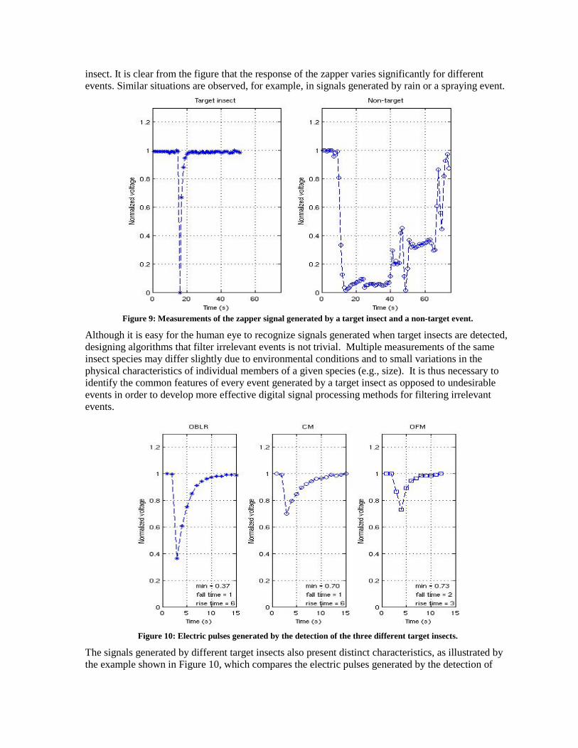
insect. It is clear from the figure that the response of the zapper varies significantly for different events. Similar situations are observed, for example, in signals generated by rain or a spraying event.
Figure 9: Measurements of the zapper signal generated by a target insect and a non-target event.
Although it is easy for the human eye to recognize signals generated when target insects are detected, designing algorithms that filter irrelevant events is not trivial. Multiple measurements of the same insect species may differ slightly due to environmental conditions and to small variations in the physical characteristics of individual members of a given species (e.g., size). It is thus necessary to identify the common features of every event generated by a target insect as opposed to undesirable events in order to develop more effective digital signal processing methods for filtering irrelevant events.
Figure 10: Electric pulses generated by the detection of the three different target insects.
The signals generated by different target insects also present distinct characteristics, as illustrated by the example shown in Figure 10, which compares the electric pulses generated by the detection of
OBLR, CM, and OFM. Although these examples are encouraging, they should be no means be considered as general representatives of the corresponding insect species. In order to extend these results and design effective detection algorithms based on them, a more rigorous evaluation of the variability of the detection signal within each insect species is required.
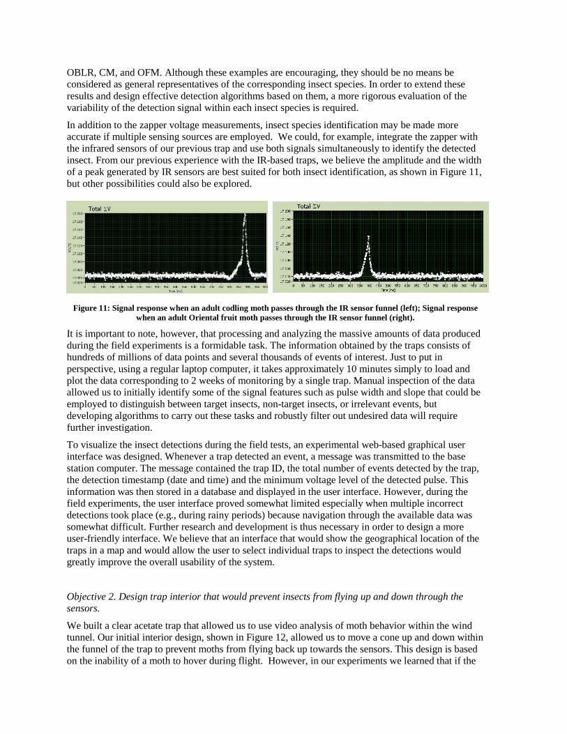
In addition to the zapper voltage measurements, insect species identification may be made more accurate if multiple sensing sources are employed. We could, for example, integrate the zapper with the infrared sensors of our previous trap and use both signals simultaneously to identify the detected insect. From our previous experience with the IR-based traps, we believe the amplitude and the width of a peak generated by IR sensors are best suited for both insect identification, as shown in Figure 11, but other possibilities could also be explored.
Figure 11: Signal response when an adult codling moth passes through the IR sensor funnel (left); Signal response when an adult Oriental fruit moth passes through the IR sensor funnel (right).
It is important to note, however, that processing and analyzing the massive amounts of data produced during the field experiments is a formidable task. The information obtained by the traps consists of hundreds of millions of data points and several thousands of events of interest. Just to put in perspective, using a regular laptop computer, it takes approximately 10 minutes simply to load and plot the data corresponding to 2 weeks of monitoring by a single trap. Manual inspection of the data allowed us to initially identify some of the signal features such as pulse width and slope that could be employed to distinguish between target insects, non-target insects, or irrelevant events, but developing algorithms to carry out these tasks and robustly filter out undesired data will require further investigation.
To visualize the insect detections during the field tests, an experimental web-based graphical user interface was designed. Whenever a trap detected an event, a message was transmitted to the base station computer. The message contained the trap ID, the total number of events detected by the trap, the detection timestamp (date and time) and the minimum voltage level of the detected pulse. This information was then stored in a database and displayed in the user interface. However, during the field experiments, the user interface proved somewhat limited especially when multiple incorrect detections took place (e.g., during rainy periods) because navigation through the available data was somewhat difficult. Further research and development is thus necessary in order to design a more user-friendly interface. We believe that an interface that would show the geographical location of the traps in a map and would allow the user to select individual traps to inspect the detections would greatly improve the overall usability of the system.
Objective 2. Design trap interior that would prevent insects from flying up and down through the sensors.
We built a clear acetate trap that allowed us to use video analysis of moth behavior within the wind tunnel. Our initial interior design, shown in Figure 12, allowed us to move a cone up and down within the funnel of the trap to prevent moths from flying back up towards the sensors. This design is based on the inability of a moth to hover during flight. However, in our experiments we learned that if the

cone of the funnel was a reasonable size, this modification was not required. It was required on the IR traps used last year, because the funnel was shortened, which made the opening larger to insert the electronics in the trap. In our traps this year, in both the lab and the field, we found that the normal size funnel is all that was required.
Figure 12: Trap interior design for preventing moths from flying up and down through the sensors
A preliminary laboratory study was conducted at PSU to understand if the size of the funnel opening at its base is important in preventing CM and OFM moths from escaping from the zapper traps since the moths are only temporarily stunned when touching the coil. When the funnel opening inner diameter was 27 mm (i.e., the size of opening included in the initial prototype design), significantly more OFM moths (38.3% escape rate) were able to escape upward through the funnel opening than CM moths (13.3%) over a 24 hr period. When we reduced the funnel opening to 13 mm (ID) on all modified zapper traps at PSU, we still observed some OFM adults escaping upward from the collector. More studies are needed to select the correct inner diameter opening of the funnel to minimize moth escape in the orchard.
Objective 3. Investigate the effects of electronic components towards the behavior of moths, e.g., size of area affected, frequency sensitivity, etc.
All tests performed this year with the IR traps showed no effect of the electronics on the moths in the wind tunnel. In our trials, we placed a piece of hardware cloth on top of the trap opening and coated the hardware cloth with sticky material. We then used a low load CM lure placed on the hardware cloth. In 13 trials in December through February, we released moths in the wind tunnel with the traps present. Video analysis and catch on the hardware cloth did not reveal any observable difference when the electronics were on or off. We also have video that showed high activity around the lure when the trap was on – this strongly suggests that the effect in the field was not auditory, as the lure was directly over the cone shape collection funnel where presumably the effect would be quite strong.
Initially, we thought that the methods that we were using to turn on different parts of the electronic circuit during the on/off studies were defective, however, the trap was shipped back to the Spensa group, which checked them and installed LEDs so that we could be sure which parts of the trap were turned off. Further video analysis did not show any noticeable effects of the electronics. We are still unsure why the IR traps did not catch any CM in WA or PA last year. Possibly, it could have been from the moths exiting the traps, because of the different shape of the funnel necessary for the installation of the electronics (see Objective 2 for more details on findings about funnel size) or it could have been due to the inclusion of the Vapona® strip (i.e., killing agent to knock down moths within the funnel). It is very clear, however, that the electronic circuits did not have any noticeable effect on the behavior of either moth species.
Executive Summary
The project described in this report represents significant progress toward the goal of automating the monitoring of pest insect populations in apple orchards. It consisted of three main objectives, each of which assessed the viability of a different component required by an electronic system to automatically detect target insects. The technologies developed in this project were designed for three main target insects: codling moth (CM), oriental fruit moth (OFM), and obliquebanded leafroller (OBLR).
In the first objective, an electric discharge grid (or “zapper”) was developed for the purpose of stunning the target insects and simultaneously detecting the electric discharge to count the number of insects captured. During this project, in addition to developing the discharge grid itself, we also designed the electronic circuits necessary to generate the electric charge and to measure the discharge. In addition, we designed a digital circuit that automatically transmits the detections to a computer via wireless communication. A trap prototype using the designed circuits was constructed and evaluated in the wind tunnel with outstanding results (practically 100% detection rate). Different models of the electronic trap were constructed and tested in the field. In addition to several variations of the exterior model designed specifically for the zapper trap, we also experimented with delta traps and bucket traps retrofitted to include the zapper and the electronic circuits. We learned that the trap exterior design had a great impact on its insect capture rate. Of all the trap models evaluated, the standard delta traps and bucket traps modified to include the zapper grid and corresponding electronic circuits obtained the best capture rate. The traps were evaluated in orchards in WA and PA from early August to late September. All of the data generated by the traps in the field were collected and analyzed. As expected, we observed that in the field, unlike in the wind tunnel experiments, the data presented several undesired events caused by different factors such as rain, fungicide spraying, and the capture of non-target insects. Based on the information collected, the signal characteristics were analyzed and simple algorithms were developed to distinguish the events caused by the detection of target insects from irrelevant events. However, this task requires much more careful evaluation and identification of common signal features from the tens of millions of data points collected in the field. Although preliminary qualitative results were obtained, further research is required to create robust algorithms that can count target insects with acceptable accuracy in the field. For the next generation of automated traps, we will consider the possibility of including optical measurements (e.g., IR) as a second source of target insect detection. In the second project objective, we designed and evaluated insect collectors that can be used in the proposed automated traps. The main goal was to design collectors that would allow temporarily stunned insects to enter easily but that would not permit the insects to exit. Our experiments showed that a simple funnel placed below the stunning element (the zapper in this case) and above the collector entrance is generally enough to prevent insects from escaping the collector, as long as the funnel opening dimension is appropriately chosen. We were able to obtain negligible escape rates for CM. Although we also made significant progress in reducing the escape rate of OFM, we believe further research is necessary to identify the optimal opening size. As OBLR is larger than CM, if CM cannot escape, it is unlikely that OBLR could.
Finally, in our third objective, we evaluated the effects of electronic circuits on the behavior of adult codling moth and oriental fruit moth. We assessed the response of the different insect species to the auditory, visual and electromagnetic effects of the electronic circuits. Our experiments showed no noticeable effect of the electronics on moth behavior. Further studies would be required to precisely identify the reason for the absence of captures in the experiments with the IR traps from the previous year, but we believe it may be related to the size of the funnels used in the trap collectors or a possible repellent effect of the Vapona® strips used to kill the collected moths.
Related Documents