Master Thesis Contiki applications for Z1 motes for 6LowPAN Student: Jose Ignacio Mimbrero Catalán Studies: Telecommunication Engineering Director: Anna Calveras Auge Year: 2016

Welcome message from author
This document is posted to help you gain knowledge. Please leave a comment to let me know what you think about it! Share it to your friends and learn new things together.
Transcript
Master Thesis
Contiki applications for Z1 motes for6LowPAN
Student: Jose Ignacio Mimbrero Catalán
Studies: Telecommunication Engineering
Director: Anna Calveras Auge
Year: 2016
Table of Contents
1 INTRODUCTION.....................................................................................................81.1 MOTIVATION AND PROBLEM STATEMENT...................................................................................81.2 THESIS OBJECTIVES..............................................................................................................81.3 THESIS STRUCTURE...............................................................................................................8
2 WIRELESS SENSORS NETWORKS..................................................................102.1 COMPOSITION.....................................................................................................................10
3 TECHNOLOGY STANDARDS.............................................................................123.1 PHYSICAL AND MAC LAYER (IEEE 802.15.4)....................................................................12
3.1.1 Physical Layer.......................................................................................................133.1.2 Definitions.............................................................................................................133.1.3 Topologies.............................................................................................................14
3.2 RIME...............................................................................................................................153.3 6LOWPAN.......................................................................................................................17
3.3.1 Characteristics......................................................................................................173.3.2 Encapsulation Header format...............................................................................173.3.3 Fragment Header..................................................................................................183.3.4 Mesh addressing header........................................................................................183.3.5 Header compression (RFC4944)...........................................................................193.3.6 Header compression Improved (draft-hui-6lowpan-hc-01)...................................21
3.4 RPL..................................................................................................................................233.5 COAP (CONSTRAINED APPLICATION PROTOCOL)....................................................................26
3.5.1 Overview...............................................................................................................263.5.2 Coap Methods.......................................................................................................263.5.3 Coap Transactions.................................................................................................273.5.4 Coap Messages......................................................................................................27
4 CONTIKI OS...........................................................................................................294.1 MAIN ASPECTS...................................................................................................................294.2 CONTIKI SIZE.....................................................................................................................294.3 CONTIKI DIRECTORIES..........................................................................................................304.4 CONTIKI HARDWARE...........................................................................................................304.5 KERNEL STRUCTURE............................................................................................................31
4.5.1 Event Kernel..........................................................................................................314.5.2 Multi-threading Kernel..........................................................................................324.5.3 Contiki Kernel (Protothreads)...............................................................................33
4.6 CONTIKI CODE STRUCTURE....................................................................................................354.7 TIMERS.............................................................................................................................36
4.7.1 Clock Module........................................................................................................364.7.2 Timer Library........................................................................................................374.7.3 Stimer Library.......................................................................................................384.7.4 Etimer Library.......................................................................................................384.7.5 Ctimer Library.......................................................................................................394.7.6 Rtimer Library.......................................................................................................40
4.8 RIME................................................................................................................................414.8.1 Rime buffer management.......................................................................................414.8.2 Rime addresses......................................................................................................42
2
4.8.3 Single-hop Unicast................................................................................................424.8.4 Best-effort local area broadcast............................................................................444.8.5 Mesh routing..........................................................................................................45
4.9 CONTIKI UIP STACK...........................................................................................................464.9.1 TCP.......................................................................................................................48
4.9.1.1 Raw API.......................................................................................................................................484.9.1.2 Protosocket API...........................................................................................................................48
4.9.2 UDP.......................................................................................................................514.9.2.1 Raw UDP API..............................................................................................................................514.9.2.2 Simple-UDP API..........................................................................................................................52
4.10 CONTIKI COAP 13 (ERBIUM)...........................................................................................524.10.1 CoAP Resources..................................................................................................58
4.10.1.1 Resource....................................................................................................................................584.10.1.2 Sub-resource..............................................................................................................................594.10.1.3 Event resource...........................................................................................................................594.10.1.4 Periodic resource........................................................................................................................60
5 ZOLERTIA Z1 MOTES.........................................................................................625.1 PERIPHERALS PORTS............................................................................................................62
5.1.1 North Port.............................................................................................................625.1.2 East Port................................................................................................................625.1.3 South Port..............................................................................................................635.1.4 West Port...............................................................................................................64
6 Z1 SENSORS...........................................................................................................656.1 INTERNAL SENSORS.............................................................................................................65
6.1.1 Temperature Sensor...............................................................................................656.1.2 Accelerometer........................................................................................................66
6.2 EXTERNAL SENSORS............................................................................................................686.2.1 Analog sensors......................................................................................................68
6.2.1.1 Precision Light Sensor.................................................................................................................686.2.1.2 Force Sensor................................................................................................................................70
6.3 RELAY ACTUATOR...............................................................................................................716.3.1 Distance sensor.....................................................................................................73
7 SENTILO.................................................................................................................757.1 DEFINITIONS......................................................................................................................757.2 SENTILO ARCHITECTURE......................................................................................................75
7.2.1 PubSub Server.......................................................................................................777.2.2 Web Catalog Application.......................................................................................797.2.3 Extensions (Agents)...............................................................................................79
7.3 SENTILO STRUCTURE............................................................................................................807.4 SENTILO API....................................................................................................................81
8 EXPERIMENTAL ENVIRONMENT...................................................................828.1 SENSOR NETWORK..............................................................................................................82
8.1.1 Border Router........................................................................................................828.1.2 Nodes.....................................................................................................................83
8.2 NETWORK CONNECTOR.........................................................................................................848.2.1 Application workflow.............................................................................................848.2.2 Sensor registration................................................................................................868.2.3 Sensor data publish...............................................................................................87
9 FUTURE LINES OF WORK.................................................................................89
3

10 CONCLUSION......................................................................................................90
11 APPENDIX I: CONTIKI OS 2.7 WORKSPACE IN UBUNTU 14.04..............9111.1 DOWNLOAD CONTIKI OS 2.7.............................................................................................9111.2 INSTALLING THE TOOLS.......................................................................................................9111.3 INSTALL MSP430-GCC 4.7..................................................................................................9111.4 INSTALL 64 BITS LIBRARIES (ONLY FOR X64 SYSTEMS)............................................................92
12 APPENDIX II: INSTALLATION OF SENTILO IN UBUNTU 14.04..............9312.1 INSTALL DEPENDENCIES......................................................................................................9312.2 DOWNLOAD AND BUILD CODE..............................................................................................9312.3 CONFIGURE REDIS............................................................................................................9312.4 CONFIGURE MONGODB....................................................................................................9412.5 CONFIGURE MYSQL SERVER.............................................................................................9412.6 CONFIGURE TOMCAT7.......................................................................................................9512.7 START SERVICES................................................................................................................95
13 BIBLIOGRAPHY.................................................................................................97
4
List of FiguresFig. 1: WSN composition.............................................................................................12Fig. 2: Standard Technology Map 2015.......................................................................13Fig. 3: Standard Technology Options...........................................................................13Fig. 4: Operating Frequency Bands..............................................................................14Fig. 5: Star Topology....................................................................................................15Fig. 6: Peer to peer topologies......................................................................................15Fig. 7: Clustered Star....................................................................................................16Fig. 8: RIME Stack.......................................................................................................17Fig. 9: Typical 6LoWPAN Header Stacks....................................................................18Fig. 10: 6LoWPAN Fragment Header..........................................................................19Fig. 11: 6LoWPAN Mesh Addressing Header..............................................................19Fig. 12: 6LoWPAN RFC 4944 IPv6 Header Compression..........................................20Fig. 13: 6LoWPAN RFC 4944 UDP Header Compression Encoding.........................21Fig. 14: 6LoWPAN RFC4944 Header Compression Examples...................................21Fig. 15: 6LoWPAN Improved IPv6 Header Compression...........................................22Fig. 16: 6LoWPAN Improved Header Compression Examples...................................24Fig. 17: RPL Instance...................................................................................................24Fig. 18: RPL Node Rank..............................................................................................26Fig. 19: Message Format..............................................................................................28Fig. 20: Option Format.................................................................................................29Fig. 21: Possible options (Coap 13).............................................................................29Fig. 22: Event Driven Kernel.......................................................................................33Fig. 23: Event Handler Example..................................................................................33Fig. 24: Stacks in multi-threading................................................................................34Fig. 25: Protothread code structure..............................................................................34Fig. 26: Protothreads implementation..........................................................................35Fig. 27: Protothreads failing example..........................................................................35Fig. 28: Protothreads example output...........................................................................35Fig. 29: Contiki Makefile structure..............................................................................36Fig. 30: Contiki program structure...............................................................................36Fig. 31: Timer diagram example..................................................................................38Fig. 32: Etimer example...............................................................................................40Fig. 33: Ctimer example...............................................................................................41Fig. 34: unicast example...............................................................................................44Fig. 35: broadcast example...........................................................................................45Fig. 36: mesh example..................................................................................................46Fig. 37: TCP protosocket example...............................................................................51Fig. 38: TCP protosocket example main loop..............................................................52Fig. 39: CoAP 13 resource definition example............................................................59Fig. 40: CoAP 13 resource example main process.......................................................59Fig. 41: CoAP 13 sub-resource definition example.....................................................60Fig. 42: CoAP 13 sub-resource example main process................................................60Fig. 43: CoAP 13 event resource definition example...................................................61Fig. 44: CoAP 13 event resource example main process.............................................61Fig. 45: CoAP 13 periodic resource definition example..............................................62Fig. 46: CoAP 13 periodic resource example main process.........................................62Fig. 47: Z1 Motes Ports................................................................................................63Fig. 48: JP1A Pinout description..................................................................................63
5
Fig. 49: JP1B Pinout description..................................................................................64Fig. 50: JP1B Pinout.....................................................................................................64Fig. 51: JP1C Pinout description..................................................................................64Fig. 52: JP1C Pinout.....................................................................................................64Fig. 53: West Port.........................................................................................................65Fig. 54: Temperature sensor example...........................................................................67Fig. 55: Temperature sensor example output................................................................67Fig. 56: Accelerometer example...................................................................................68Fig. 57: Accelerometer example output........................................................................68Fig. 58: Precision light sensor......................................................................................69Fig. 59: Precision light sensor with Z1.........................................................................70Fig. 60: Light sensor example code..............................................................................70Fig. 61: Light sensor example output...........................................................................71Fig. 62: Force sensor....................................................................................................71Fig. 63: Force sensor with Z1.......................................................................................71Fig. 64: Force sensor example code.............................................................................72Fig. 65: Force sensor example output..........................................................................72Fig. 66: Relay actuator.................................................................................................72Fig. 67: Z1 with relay and a led....................................................................................73Fig. 68: Relay toggle example......................................................................................74Fig. 69: SEN-12784......................................................................................................74Fig. 70: Z1 with distance sensor...................................................................................74Fig. 71: VL6180 getDistance function.........................................................................75Fig. 72: VL6180 example output..................................................................................75Fig. 73: VL6180 set register function...........................................................................75Fig. 74: VL6180 get register function..........................................................................76Fig. 75: Sentilo Arquitecture........................................................................................78Fig. 76: Sentilo Transport Layer...................................................................................79Fig. 77: Sentilo Service Layer......................................................................................80Fig. 78: Experimental Environment.............................................................................83Fig. 79: CoAP resources example................................................................................84Fig. 80: GET sensor/force............................................................................................84Fig. 81: OBSERVE sensor/force..................................................................................85Fig. 82: Sentilo provider...............................................................................................85Fig. 83: Mote search.....................................................................................................86Fig. 84: Border router response....................................................................................86Fig. 85: Resource discover...........................................................................................86Fig. 86: Resource information retrieval........................................................................87Fig. 87: Sensor Register...............................................................................................87Fig. 88: Sensor data registration...................................................................................87Fig. 89: Registration JSON Example...........................................................................88Fig. 90: Publication JSON Example.............................................................................89Fig. 91: sudoers file......................................................................................................93Fig. 92: redis.conf.........................................................................................................95Fig. 93: mongodb.conf.................................................................................................95Fig. 94: sentilo-start......................................................................................................96
6
List of Tables Tab. 1: Technologies Comparison...............................................................................14 Tab. 2: CoAP Protocol Stack.......................................................................................27 Tab. 3: CoAP Methods................................................................................................27 Tab. 4: CoAP Transactions..........................................................................................28 Tab. 5: Contiki compiled code size (bytes).................................................................30 Tab. 6: Contiki directories...........................................................................................31 Tab. 7: Contiki OS supported hardware......................................................................32 Tab. 8: Process API......................................................................................................36 Tab. 9: Clock Module API...........................................................................................37 Tab. 10: Timer library API...........................................................................................38 Tab. 11: Stimer library API..........................................................................................39 Tab. 12: Etimer library API.........................................................................................39 Tab. 13: Ctimer library API.........................................................................................40 Tab. 14: Rtimer library API.........................................................................................41 Tab. 15: Rime packetbuf API......................................................................................42 Tab. 16: Rime packetbuf macros.................................................................................43 Tab. 17: Rime addresses API.......................................................................................43 Tab. 18: Rime addresses variables...............................................................................43 Tab. 19: Rime unicast struct........................................................................................44 Tab. 20: Rime unicast API...........................................................................................44 Tab. 21: Rime broadcast struct....................................................................................45 Tab. 22: Rime broadcast API.......................................................................................46 Tab. 23: Rime mesh struct...........................................................................................47 Tab. 24: Rime mesh API..............................................................................................47 Tab. 25: uIP struct........................................................................................................48 Tab. 26: uIP macros.....................................................................................................48 Tab. 27: uIP functions..................................................................................................49 Tab. 28: TCP raw API..................................................................................................49 Tab. 29: Protosocket API.............................................................................................50 Tab. 30: raw UDP API.................................................................................................53 Tab. 31: Simple-UDP API...........................................................................................53 Tab. 32: CoAP 13 raw API..........................................................................................55 Tab. 33: CoAP 13 resource definition API..................................................................55 Tab. 34: CoAP 13 resource methods...........................................................................56 Tab. 35: CoAP 13 resource activation functions.........................................................56 Tab. 36: CoAP 13 handler function definition.............................................................56 Tab. 37: CoAP 13 constants.........................................................................................56 Tab. 38: REST struc functions.....................................................................................57 Tab. 39: REST content-type constants.........................................................................58 Tab. 40: REST status codes constants.........................................................................59 Tab. 41: Contiki tmp102.h functions...........................................................................66 Tab. 42: Contiki Phidgets library functions.................................................................69 Tab. 43: Contiki Phidgets port mapping......................................................................69 Tab. 44: Precision light measurement range................................................................70 Tab. 45: Force sensor measurement range...................................................................71 Tab. 46: Contiki Z1 relay API.....................................................................................73 Tab. 47: CoAP resource information...........................................................................88 Tab. 48: HTTP request to register a sensor..................................................................88
7

Tab. 49: JSON request parameters to register a sensor...............................................88 Tab. 50: HTTP request to register data from a sensor.................................................88 Tab. 51: JSON request parameters to register data from a sensor...............................89
8
1 Introduction
From the start of the computer networks, to the mobile applications nowadays, the
amount of information shared has been constantly increasing. We have all kind of
devices, from the big servers in datacenters, the TVs at home, mobile phones, car
sensors, ...
The Internet Of Things (IOT) refers to the idea of connecting all the “things”to the
Internet. By “things”, it refers to any ordinary object that can be useful getting
information.
These “things” should be connected by an embedded device, capable to connect to
the Internet in one side, and get information from the “thing” on the other.
1.1 Motivation and Problem Statement
There has been an increased research and development for the Smart Cities. The smart
cities objective is to gather information from the city, to enhance quality and
performance of urban services, to reduce costs and resource consumption, and to
engage more effectively and actively with its citizens.
This project is intended to approach two goals, to be used as a starting point for
anyone who wants to use the Contiki OS with the Z1 motes, and to build a simple
application for the Smart Cities, to collect data from sensors, and sending it to an
information center.
1.2 Thesis Objectives
The first objective of this thesis is to document the capabilities of the Z1 motes and
the Contiki OS for the IOT, by building applications to gather data from sensors and
the network capabilities both from the motes and the OS.
Secondly, to build an application using the Z1 motes, and the Contiki OS, using
COAP(Constrained Application Protocol) and 6LoWPan(IPv6 over Low power
Wireless Personal Area Networks) to retrieve information from the motes, and connect
them to Sentilo, an open source sensor and actuator platform.
1.3 Thesis Structure
This document is divided in two parts.
9

First, the description of the main tools used to create the experimental
environments. A description of the Contiki OS, the Z1 motes, and the protocols used
to communicate, IEEE 802.14.5, 6LowPAN and CoAP. The a brief description of the
sensor data collector Sentilo
Secondly, a description of the environment setup, and an explanation of how it
works.
Finally, conclusions and future work is presented.
10
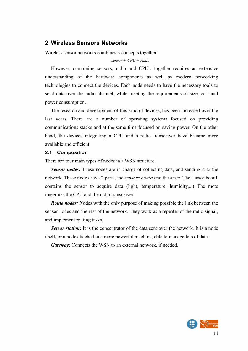
2 Wireless Sensors Networks
Wireless sensor networks combines 3 concepts together:
sensor + CPU + radio.
However, combining sensors, radio and CPU's together requires an extensive
understanding of the hardware components as well as modern networking
technologies to connect the devices. Each node needs to have the necessary tools to
send data over the radio channel, while meeting the requirements of size, cost and
power consumption.
The research and development of this kind of devices, has been increased over the
last years. There are a number of operating systems focused on providing
communications stacks and at the same time focused on saving power. On the other
hand, the devices integrating a CPU and a radio transceiver have become more
available and efficient.
2.1 Composition
There are four main types of nodes in a WSN structure.
Sensor nodes: These nodes are in charge of collecting data, and sending it to the
network. These nodes have 2 parts, the sensors board and the mote. The sensor board,
contains the sensor to acquire data (light, temperature, humidity,...) The mote
integrates the CPU and the radio transceiver.
Route nodes: Nodes with the only purpose of making possible the link between the
sensor nodes and the rest of the network. They work as a repeater of the radio signal,
and implement routing tasks.
Server station: It is the concentrator of the data sent over the network. It is a node
itself, or a node attached to a more powerful machine, able to manage lots of data.
Gateway: Connects the WSN to an external network, if needed.
11
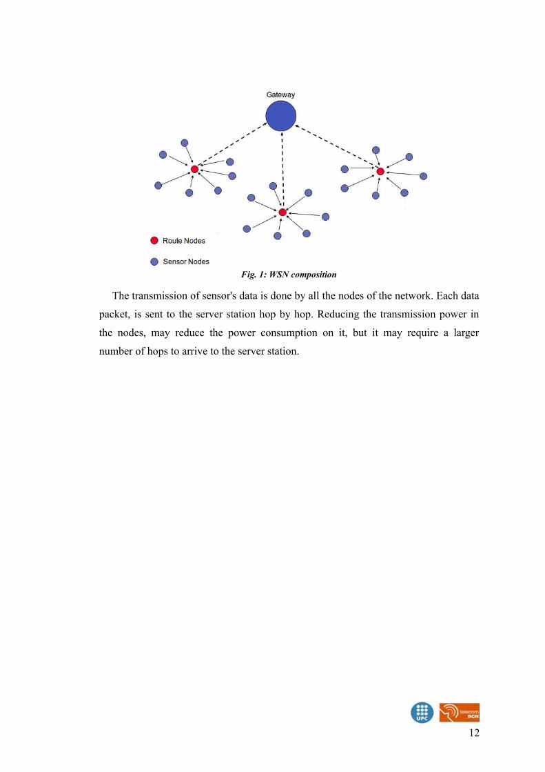
The transmission of sensor's data is done by all the nodes of the network. Each data
packet, is sent to the server station hop by hop. Reducing the transmission power in
the nodes, may reduce the power consumption on it, but it may require a larger
number of hops to arrive to the server station.
12
Fig. 1: WSN composition
3 Technology Standards
3.1 Physical and MAC Layer (IEEE 802.15.4)
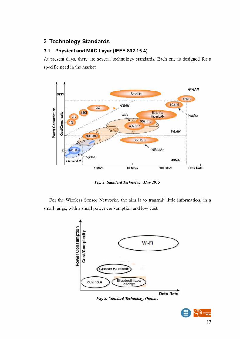
At present days, there are several technology standards. Each one is designed for a
specific need in the market.
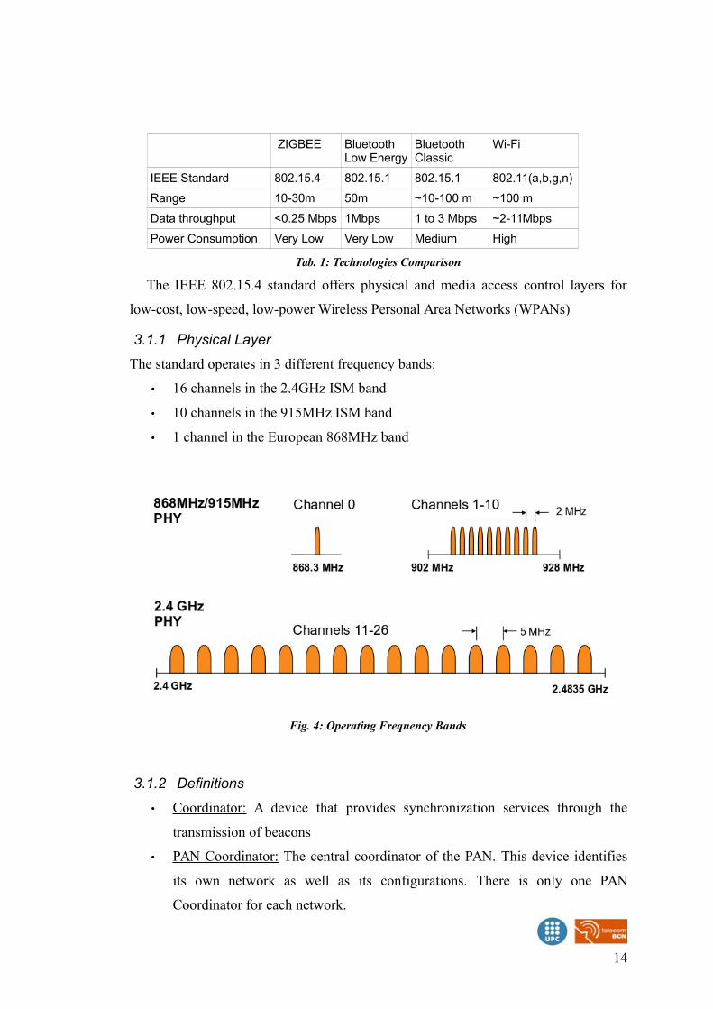
For the Wireless Sensor Networks, the aim is to transmit little information, in a
small range, with a small power consumption and low cost.
13
Fig. 3: Standard Technology Options
Fig. 2: Standard Technology Map 2015
ZIGBEE Bluetooth Low Energy
Bluetooth Classic
Wi-Fi
IEEE Standard 802.15.4 802.15.1 802.15.1 802.11(a,b,g,n)
Range 10-30m 50m ~10-100 m ~100 m
Data throughput <0.25 Mbps 1Mbps 1 to 3 Mbps ~2-11Mbps
Power Consumption Very Low Very Low Medium High
Tab. 1: Technologies Comparison
The IEEE 802.15.4 standard offers physical and media access control layers for
low-cost, low-speed, low-power Wireless Personal Area Networks (WPANs)
3.1.1 Physical Layer
The standard operates in 3 different frequency bands:
• 16 channels in the 2.4GHz ISM band
• 10 channels in the 915MHz ISM band
• 1 channel in the European 868MHz band
3.1.2 Definitions
• Coordinator: A device that provides synchronization services through the
transmission of beacons
• PAN Coordinator: The central coordinator of the PAN. This device identifies
its own network as well as its configurations. There is only one PAN
Coordinator for each network.
14
Fig. 4: Operating Frequency Bands
• Full Function Device (FFD): A device that implements the complete protocol
set, PAN coordinator capable , talks to any other device. This type of device is
suitable for any topology.
• Reduced Function Device (RFD): A device with a reduced implementation of
the protocol, cannot become a PAN Coordinator. This device is limited to leafs
in some topologies.
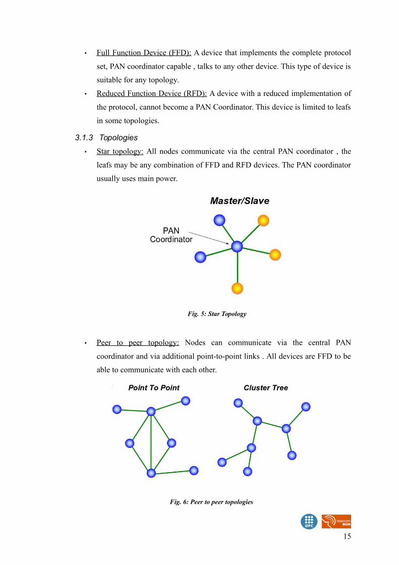
3.1.3 Topologies
• Star topology: All nodes communicate via the central PAN coordinator , the
leafs may be any combination of FFD and RFD devices. The PAN coordinator
usually uses main power.
• Peer to peer topology: Nodes can communicate via the central PAN
coordinator and via additional point-to-point links . All devices are FFD to be
able to communicate with each other.
15
Fig. 5: Star Topology
Fig. 6: Peer to peer topologies
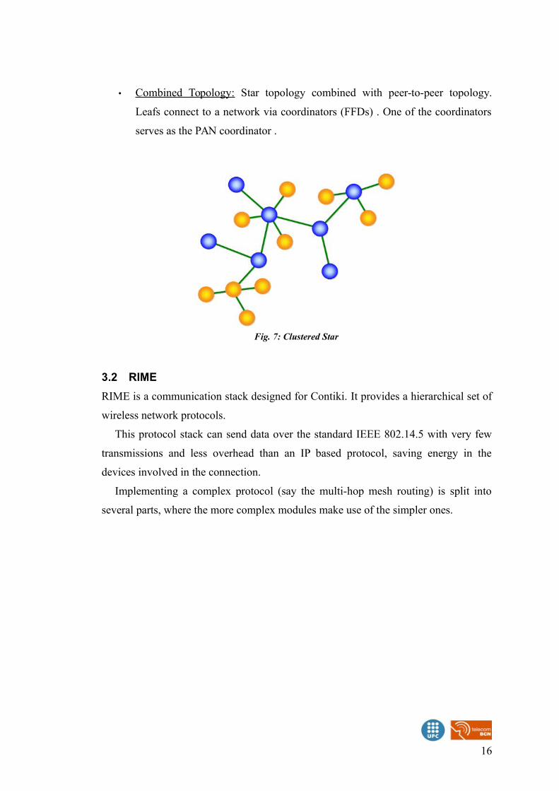
• Combined Topology: Star topology combined with peer-to-peer topology.
Leafs connect to a network via coordinators (FFDs) . One of the coordinators
serves as the PAN coordinator .
3.2 RIME
RIME is a communication stack designed for Contiki. It provides a hierarchical set of
wireless network protocols.
This protocol stack can send data over the standard IEEE 802.14.5 with very few
transmissions and less overhead than an IP based protocol, saving energy in the
devices involved in the connection.
Implementing a complex protocol (say the multi-hop mesh routing) is split into
several parts, where the more complex modules make use of the simpler ones.
16
Fig. 7: Clustered Star
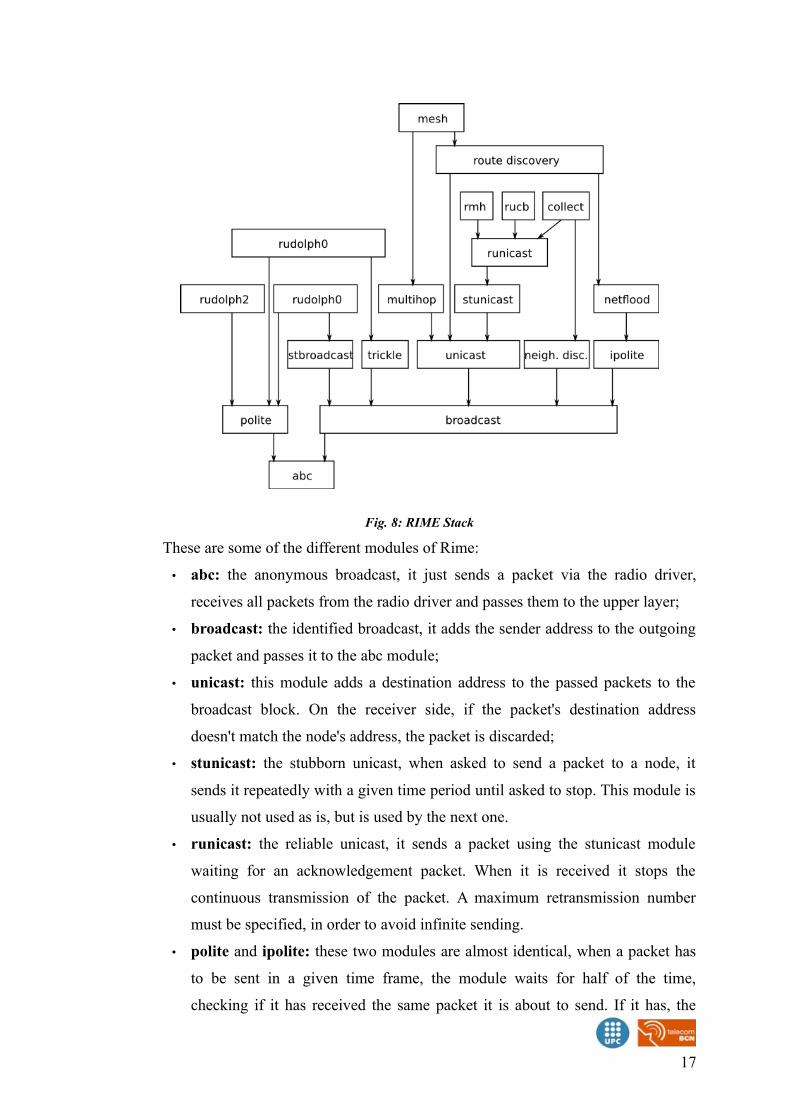
These are some of the different modules of Rime:
• abc: the anonymous broadcast, it just sends a packet via the radio driver,
receives all packets from the radio driver and passes them to the upper layer;
• broadcast: the identified broadcast, it adds the sender address to the outgoing
packet and passes it to the abc module;
• unicast: this module adds a destination address to the passed packets to the
broadcast block. On the receiver side, if the packet's destination address
doesn't match the node's address, the packet is discarded;
• stunicast: the stubborn unicast, when asked to send a packet to a node, it
sends it repeatedly with a given time period until asked to stop. This module is
usually not used as is, but is used by the next one.
• runicast: the reliable unicast, it sends a packet using the stunicast module
waiting for an acknowledgement packet. When it is received it stops the
continuous transmission of the packet. A maximum retransmission number
must be specified, in order to avoid infinite sending.
• polite and ipolite: these two modules are almost identical, when a packet has
to be sent in a given time frame, the module waits for half of the time,
checking if it has received the same packet it is about to send. If it has, the
17
Fig. 8: RIME Stack
packet is not sent, otherwise it sends the packet. This is useful for flooding
techniques to avoid unnecessary retransmissions.
• multihop: this module requires a route table function, and when it is about to
send a packet it asks the route table for the next hop and sends the packet to it
using unicast. When it receives a packet, if the node is the destination then the
packet is passed to the upper layer, otherwise it asks again the route table for
the next hop and relays the packet to it.
3.3 6LowPAN
6LoWPAN is a networking technology or adaptation layer that allows IPv6 packets to
be carried efficiently within a small link layer frame, over IEEE 802.15.4 based
networks.
As the full name implies, “IPv6 over Low-Power Wireless Personal Area
Networks”, it is a protocol for connecting wireless low power networks using IPv6.
3.3.1 Characteristics
• Compression of IPv6 and UDP/ICMP headers
• Fragmentation / reassembly of IPv6 packets
• Mesh addressing
• Stateless auto configuration
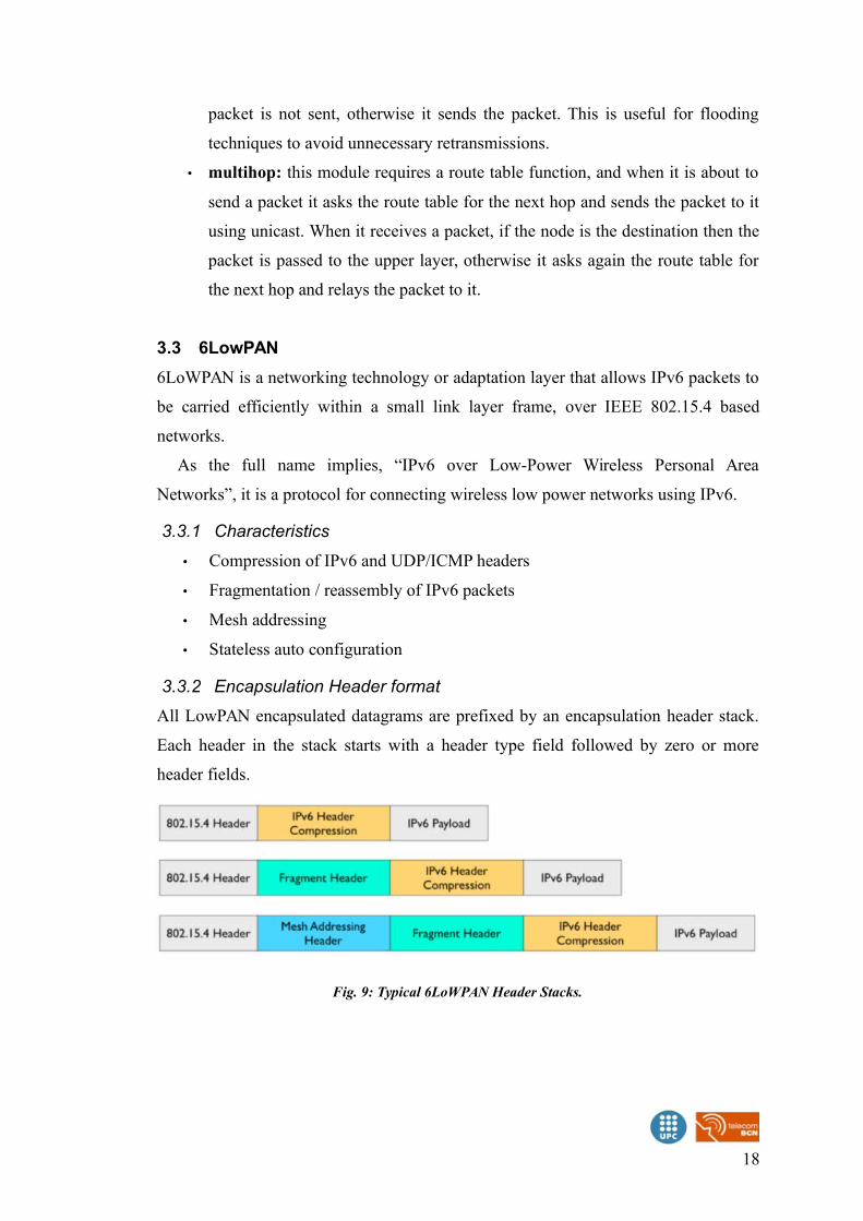
3.3.2 Encapsulation Header format
All LowPAN encapsulated datagrams are prefixed by an encapsulation header stack.
Each header in the stack starts with a header type field followed by zero or more
header fields.
18
Fig. 9: Typical 6LoWPAN Header Stacks.
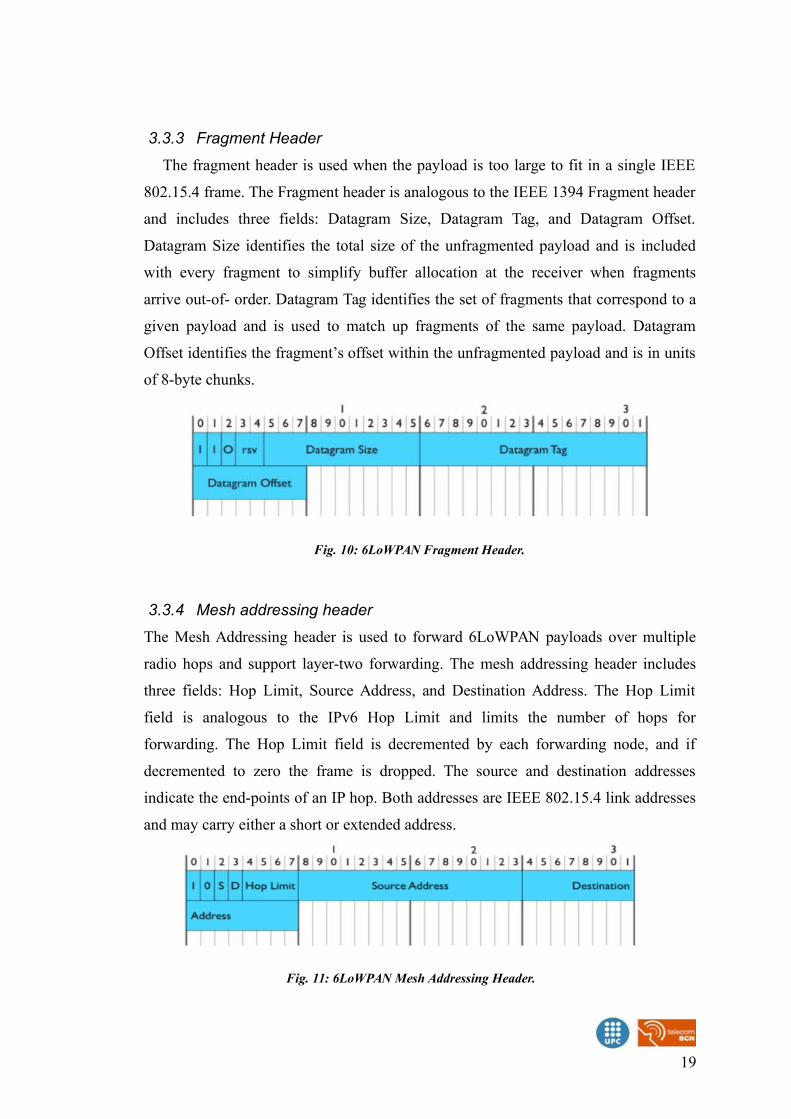
3.3.3 Fragment Header
The fragment header is used when the payload is too large to fit in a single IEEE
802.15.4 frame. The Fragment header is analogous to the IEEE 1394 Fragment header
and includes three fields: Datagram Size, Datagram Tag, and Datagram Offset.
Datagram Size identifies the total size of the unfragmented payload and is included
with every fragment to simplify buffer allocation at the receiver when fragments
arrive out-of- order. Datagram Tag identifies the set of fragments that correspond to a
given payload and is used to match up fragments of the same payload. Datagram
Offset identifies the fragment’s offset within the unfragmented payload and is in units
of 8-byte chunks.
3.3.4 Mesh addressing header
The Mesh Addressing header is used to forward 6LoWPAN payloads over multiple
radio hops and support layer-two forwarding. The mesh addressing header includes
three fields: Hop Limit, Source Address, and Destination Address. The Hop Limit
field is analogous to the IPv6 Hop Limit and limits the number of hops for
forwarding. The Hop Limit field is decremented by each forwarding node, and if
decremented to zero the frame is dropped. The source and destination addresses
indicate the end-points of an IP hop. Both addresses are IEEE 802.15.4 link addresses
and may carry either a short or extended address.
19
Fig. 10: 6LoWPAN Fragment Header.
Fig. 11: 6LoWPAN Mesh Addressing Header.
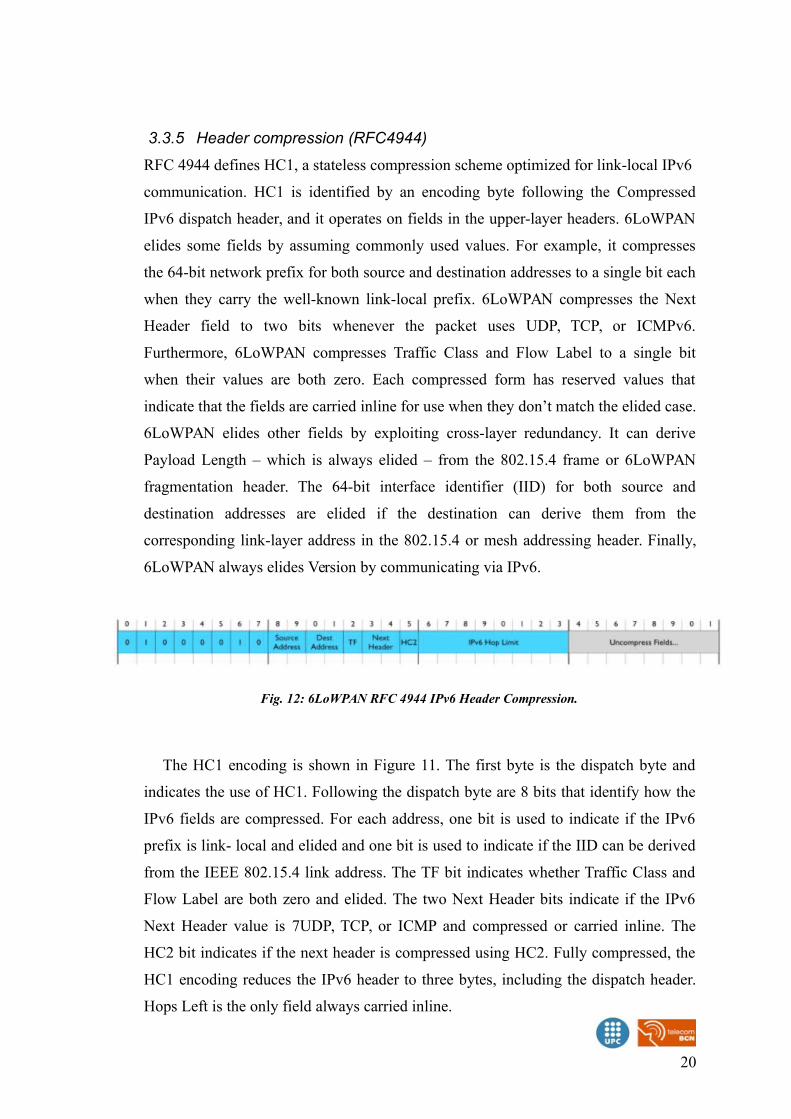
3.3.5 Header compression (RFC4944)
RFC 4944 defines HC1, a stateless compression scheme optimized for link-local IPv6
communication. HC1 is identified by an encoding byte following the Compressed
IPv6 dispatch header, and it operates on fields in the upper-layer headers. 6LoWPAN
elides some fields by assuming commonly used values. For example, it compresses
the 64-bit network prefix for both source and destination addresses to a single bit each
when they carry the well-known link-local prefix. 6LoWPAN compresses the Next
Header field to two bits whenever the packet uses UDP, TCP, or ICMPv6.
Furthermore, 6LoWPAN compresses Traffic Class and Flow Label to a single bit
when their values are both zero. Each compressed form has reserved values that
indicate that the fields are carried inline for use when they don’t match the elided case.
6LoWPAN elides other fields by exploiting cross-layer redundancy. It can derive
Payload Length – which is always elided – from the 802.15.4 frame or 6LoWPAN
fragmentation header. The 64-bit interface identifier (IID) for both source and
destination addresses are elided if the destination can derive them from the
corresponding link-layer address in the 802.15.4 or mesh addressing header. Finally,
6LoWPAN always elides Version by communicating via IPv6.
The HC1 encoding is shown in Figure 11. The first byte is the dispatch byte and
indicates the use of HC1. Following the dispatch byte are 8 bits that identify how the
IPv6 fields are compressed. For each address, one bit is used to indicate if the IPv6
prefix is link- local and elided and one bit is used to indicate if the IID can be derived
from the IEEE 802.15.4 link address. The TF bit indicates whether Traffic Class and
Flow Label are both zero and elided. The two Next Header bits indicate if the IPv6
Next Header value is 7UDP, TCP, or ICMP and compressed or carried inline. The
HC2 bit indicates if the next header is compressed using HC2. Fully compressed, the
HC1 encoding reduces the IPv6 header to three bytes, including the dispatch header.
Hops Left is the only field always carried inline.
20
Fig. 12: 6LoWPAN RFC 4944 IPv6 Header Compression.
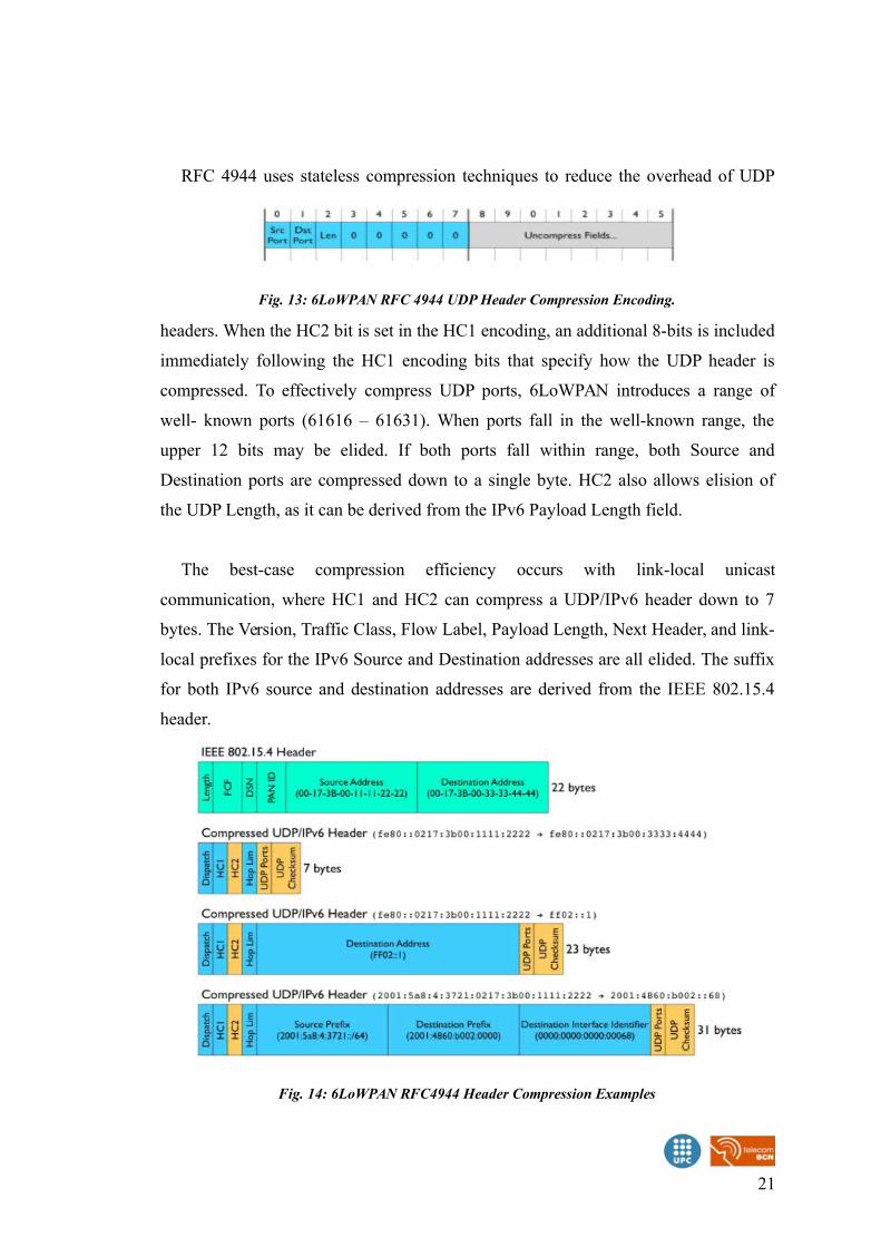
RFC 4944 uses stateless compression techniques to reduce the overhead of UDP
headers. When the HC2 bit is set in the HC1 encoding, an additional 8-bits is included
immediately following the HC1 encoding bits that specify how the UDP header is
compressed. To effectively compress UDP ports, 6LoWPAN introduces a range of
well- known ports (61616 – 61631). When ports fall in the well-known range, the
upper 12 bits may be elided. If both ports fall within range, both Source and
Destination ports are compressed down to a single byte. HC2 also allows elision of
the UDP Length, as it can be derived from the IPv6 Payload Length field.
The best-case compression efficiency occurs with link-local unicast
communication, where HC1 and HC2 can compress a UDP/IPv6 header down to 7
bytes. The Version, Traffic Class, Flow Label, Payload Length, Next Header, and link-
local prefixes for the IPv6 Source and Destination addresses are all elided. The suffix
for both IPv6 source and destination addresses are derived from the IEEE 802.15.4
header.
21
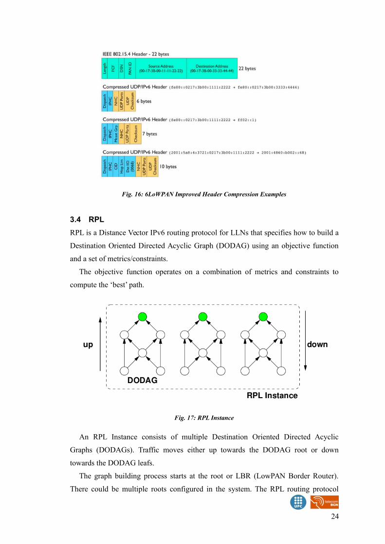
Fig. 14: 6LoWPAN RFC4944 Header Compression Examples
Fig. 13: 6LoWPAN RFC 4944 UDP Header Compression Encoding.
However, RFC 4944 does not efficiently compress headers when communicating
outside of link-local scope or when using multicast. Any prefix other than the link-
local prefix must be carried inline. Any suffix must be at least 64 bits when carried
inline even if derived from a short 802.15.4 address. As shown in Figure 8, HC1/HC2
can compress a link-local multicast UDP/IPv6 header down to 23 bytes in the best
case. When communicating with nodes outside the LoWPAN, the IPv6 Source
Address prefix and full IPv6 Destination Address must be carried inline.
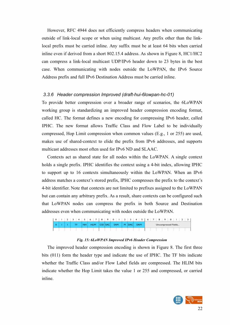
3.3.6 Header compression Improved (draft-hui-6lowpan-hc-01)
To provide better compression over a broader range of scenarios, the 6LoWPAN
working group is standardizing an improved header compression encoding format,
called HC. The format defines a new encoding for compressing IPv6 header, called
IPHC. The new format allows Traffic Class and Flow Label to be individually
compressed, Hop Limit compression when common values (E.g., 1 or 255) are used,
makes use of shared-context to elide the prefix from IPv6 addresses, and supports
multicast addresses most often used for IPv6 ND and SLAAC.
Contexts act as shared state for all nodes within the LoWPAN. A single context
holds a single prefix. IPHC identifies the context using a 4-bit index, allowing IPHC
to support up to 16 contexts simultaneously within the LoWPAN. When an IPv6
address matches a context’s stored prefix, IPHC compresses the prefix to the context’s
4-bit identifier. Note that contexts are not limited to prefixes assigned to the LoWPAN
but can contain any arbitrary prefix. As a result, share contexts can be configured such
that LoWPAN nodes can compress the prefix in both Source and Destination
addresses even when communicating with nodes outside the LoWPAN.
The improved header compression encoding is shown in Figure 8. The first three
bits (011) form the header type and indicate the use of IPHC. The TF bits indicate
whether the Traffic Class and/or Flow Label fields are compressed. The HLIM bits
indicate whether the Hop Limit takes the value 1 or 255 and compressed, or carried
inline.
22
Fig. 15: 6LoWPAN Improved IPv6 Header Compression
Bits 8-15 of the IPHC encoding indicate the compression methods used for the
IPv6 Source and Destination Addresses. When the Context Identifier (CID) bit is zero,
the default context may be used to compress Source and/or Destination Addresses.
This mode is typically when both Source and Destination Addresses are assigned to
nodes in the same LoWPAN. When the CID bit is one, two additional 4-bit fields
follow the IPHC encoding to indicate which one of 16 contexts is in use for the source
and destination addresses.
The Source Address Compression (SAC) indicates whether stateless compression
is used (typically for link-local communication) or stateful context-based compression
is used (typically for global communication). The Source Address Mode (SAM)
indicates whether the full Source Address is carried inline, upper 16 or 64-bits are
elided, or the full Source Address is elided. When SAC is set and the Source
Addresses’ prefix is elided, the identified context is used to restore those bits.
The Multicast (M) field indicates whether the Destination Address is a unicast or
multicast address. When the Destination Address is a unicast address, the DAC and
DAM bits are analogous to the SAC and SAM bits. When the Destination Address is a
multicast address, the DAM bits indicate different forms of multicast compression.
HC also defines a new framework for compressing arbitrary next headers, called
NHC. HC2 in RFC 4944 is only capable of compressing UDP, TCP, and ICMPv6
headers, the latter two are not yet defined. Instead, the NHC header defines a new
variable length Next Header identifier, allowing for future definition of arbitrary next
header compression encodings.
HC initially defines a compression encoding for UDP headers, similar to that
defined in RFC 4944. Like RFC 4944, HC utilizes the same well-known port range
(61616-61631) to effectively compress UDP ports down to 4-bits each in the best
case. However, HC no longer provides an option to carry the Payload Length in line,
as it can always be derived from the IPv6 header. Finally, HC allows elision of the
UDP Checksum whenever an 10upper layer message integrity check covers the same
information and has at least the same strength. Such a scenario is typical when
transport- or application-layer security is used. As a result, the UDP header can be
compressed down to two bytes in the best case.
23
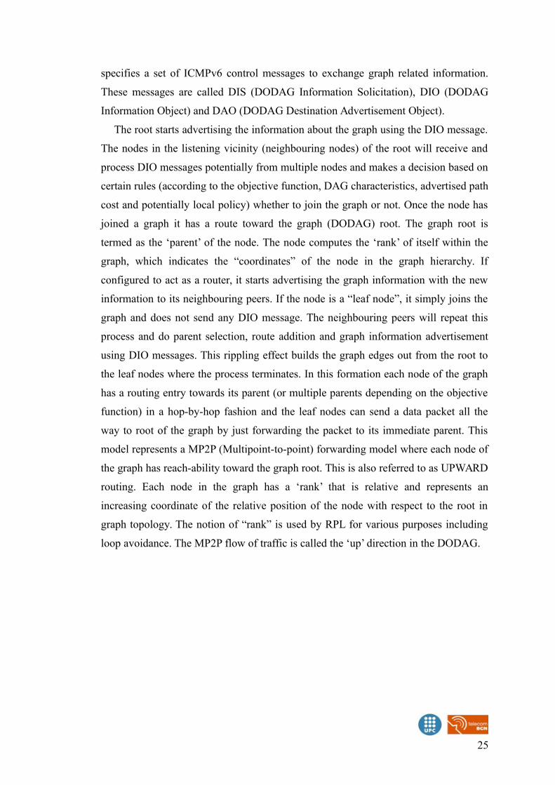
3.4 RPL
RPL is a Distance Vector IPv6 routing protocol for LLNs that specifies how to build a
Destination Oriented Directed Acyclic Graph (DODAG) using an objective function
and a set of metrics/constraints.
The objective function operates on a combination of metrics and constraints to
compute the ‘best’ path.
An RPL Instance consists of multiple Destination Oriented Directed Acyclic
Graphs (DODAGs). Traffic moves either up towards the DODAG root or down
towards the DODAG leafs.
The graph building process starts at the root or LBR (LowPAN Border Router).
There could be multiple roots configured in the system. The RPL routing protocol
24
Fig. 17: RPL Instance
Fig. 16: 6LoWPAN Improved Header Compression Examples
specifies a set of ICMPv6 control messages to exchange graph related information.
These messages are called DIS (DODAG Information Solicitation), DIO (DODAG
Information Object) and DAO (DODAG Destination Advertisement Object).
The root starts advertising the information about the graph using the DIO message.
The nodes in the listening vicinity (neighbouring nodes) of the root will receive and
process DIO messages potentially from multiple nodes and makes a decision based on
certain rules (according to the objective function, DAG characteristics, advertised path
cost and potentially local policy) whether to join the graph or not. Once the node has
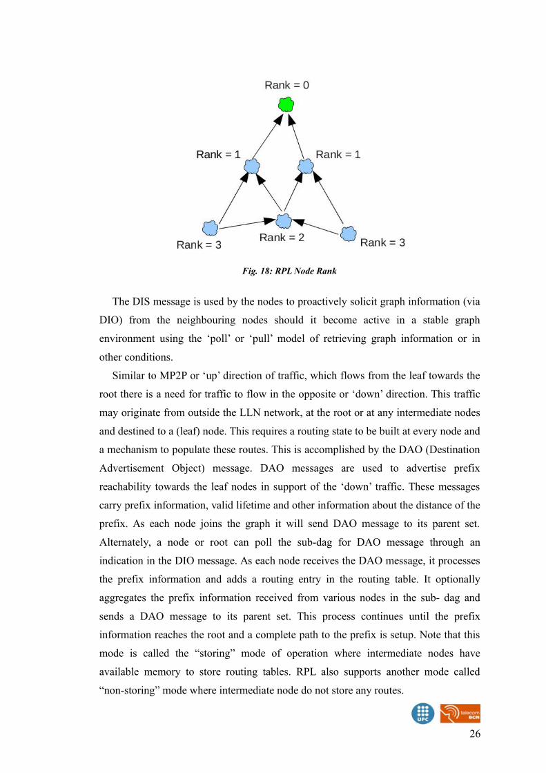
joined a graph it has a route toward the graph (DODAG) root. The graph root is
termed as the ‘parent’ of the node. The node computes the ‘rank’ of itself within the
graph, which indicates the “coordinates” of the node in the graph hierarchy. If
configured to act as a router, it starts advertising the graph information with the new
information to its neighbouring peers. If the node is a “leaf node”, it simply joins the
graph and does not send any DIO message. The neighbouring peers will repeat this
process and do parent selection, route addition and graph information advertisement
using DIO messages. This rippling effect builds the graph edges out from the root to
the leaf nodes where the process terminates. In this formation each node of the graph
has a routing entry towards its parent (or multiple parents depending on the objective
function) in a hop-by-hop fashion and the leaf nodes can send a data packet all the
way to root of the graph by just forwarding the packet to its immediate parent. This
model represents a MP2P (Multipoint-to-point) forwarding model where each node of
the graph has reach-ability toward the graph root. This is also referred to as UPWARD
routing. Each node in the graph has a ‘rank’ that is relative and represents an
increasing coordinate of the relative position of the node with respect to the root in
graph topology. The notion of “rank” is used by RPL for various purposes including
loop avoidance. The MP2P flow of traffic is called the ‘up’ direction in the DODAG.
25
The DIS message is used by the nodes to proactively solicit graph information (via
DIO) from the neighbouring nodes should it become active in a stable graph
environment using the ‘poll’ or ‘pull’ model of retrieving graph information or in
other conditions.
Similar to MP2P or ‘up’ direction of traffic, which flows from the leaf towards the
root there is a need for traffic to flow in the opposite or ‘down’ direction. This traffic
may originate from outside the LLN network, at the root or at any intermediate nodes
and destined to a (leaf) node. This requires a routing state to be built at every node and
a mechanism to populate these routes. This is accomplished by the DAO (Destination
Advertisement Object) message. DAO messages are used to advertise prefix
reachability towards the leaf nodes in support of the ‘down’ traffic. These messages
carry prefix information, valid lifetime and other information about the distance of the
prefix. As each node joins the graph it will send DAO message to its parent set.
Alternately, a node or root can poll the sub-dag for DAO message through an
indication in the DIO message. As each node receives the DAO message, it processes
the prefix information and adds a routing entry in the routing table. It optionally
aggregates the prefix information received from various nodes in the sub- dag and
sends a DAO message to its parent set. This process continues until the prefix
information reaches the root and a complete path to the prefix is setup. Note that this
mode is called the “storing” mode of operation where intermediate nodes have
available memory to store routing tables. RPL also supports another mode called
“non-storing” mode where intermediate node do not store any routes.
26
Fig. 18: RPL Node Rank
3.5 COAP (COnstrained Application Protocol)
The Constrained Application Protocol (CoAP) is a specialized web transfer protocol
for use with constrained nodes and constrained networks in the Internet of Things.
More detailed information about the protocol is given in the Contiki OS CoAP
section.
3.5.1 Overview
Like HTTP, CoAP is a document transfer protocol. Unlike HTTP, CoAP is designed
for the needs of constrained devices.
The packets are much smaller than HTTP TCP flows. Packets are simple to
generate and can be parsed in place without consuming extra RAM in constrained
devices.
CoAP runs over UDP, not TCP. Clients and servers communicate through
connectionless datagrams. Retries and reordering are implemented in the application
stack.
It follows a client/server model. Clients make requests to servers, servers send back
responses. Clients may GET, PUT, POST and DELETE resources.
CoAP implements the REST model from HTTP, with the primitives GET, POST,
PUT and DELETE.
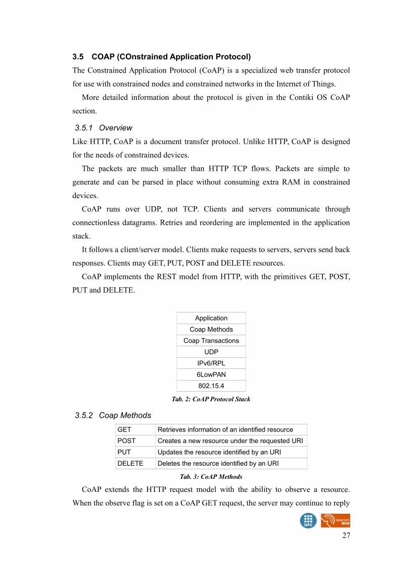
Application
Coap Methods
Coap Transactions
UDP
IPv6/RPL
6LowPAN
802.15.4
Tab. 2: CoAP Protocol Stack
3.5.2 Coap Methods
GET Retrieves information of an identified resource
POST Creates a new resource under the requested URI
PUT Updates the resource identified by an URI
DELETE Deletes the resource identified by an URI
Tab. 3: CoAP Methods
CoAP extends the HTTP request model with the ability to observe a resource.
When the observe flag is set on a CoAP GET request, the server may continue to reply
27
after the initial document has been transferred. This allows servers to stream state
changes to clients as they occur. Either end may cancel the observation.
CoAP defines a standard mechanism for resource discovery. Servers provide a list
of their resources (along with metadata about them) at /.well-known/core. These links
are in the application/link-format media type and allow a client to discover what
resources are provided and what media types they are.
3.5.3 Coap Transactions
CON Confirmable requests. The receiving peer must send an acknowledgement or a reset after receiving a request.
NON Non-confirmable messages do not request any message being sent by the receiving peer
ACK Acknowledges that a CON has been received,may carry payload
RST Indicates that a CON has been received but some context is missing to process it
Tab. 4: CoAP Transactions
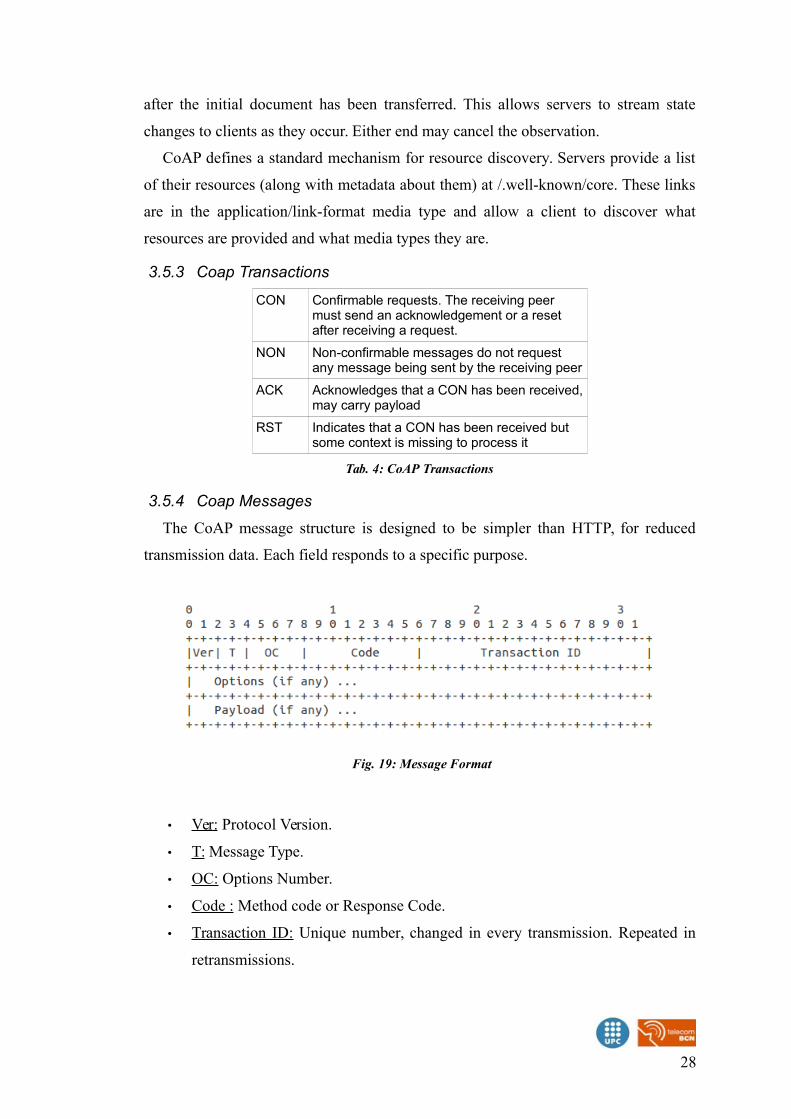
3.5.4 Coap Messages
The CoAP message structure is designed to be simpler than HTTP, for reduced
transmission data. Each field responds to a specific purpose.
• Ver: Protocol Version.
• T: Message Type.
• OC: Options Number.
• Code : Method code or Response Code.
• Transaction ID: Unique number, changed in every transmission. Repeated in
retransmissions.
28
Fig. 19: Message Format
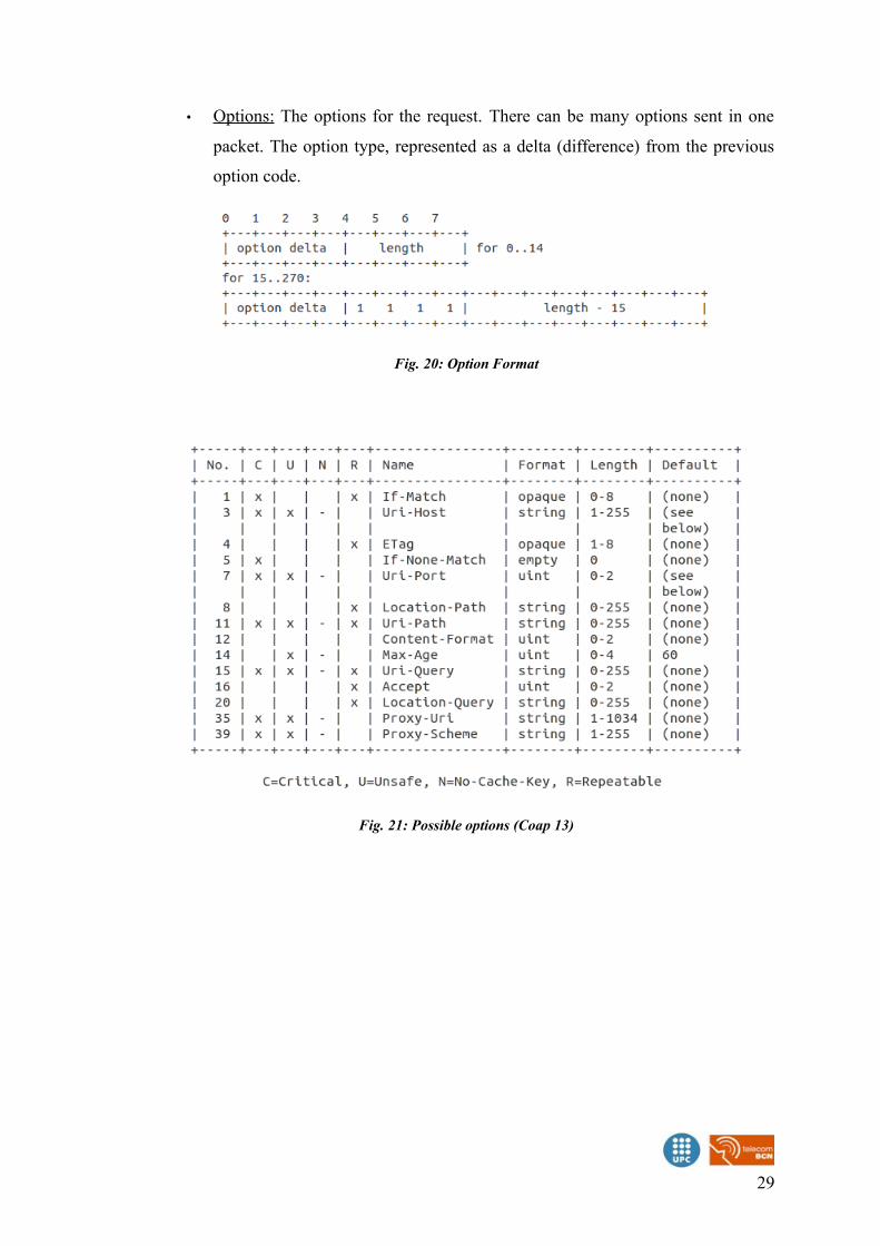
• Options: The options for the request. There can be many options sent in one
packet. The option type, represented as a delta (difference) from the previous
option code.
29
Fig. 20: Option Format
Fig. 21: Possible options (Coap 13)
4 Contiki OS
Contiki is an open source operating system for the Internet of Things. Contiki
connects tiny low-cost, low-power micro-controllers to the Internet.
4.1 Main aspects
• A lightweight OS written in C for networked devices
• 2k RAM, 60k ROM; 10k RAM, 48K ROM
• Portable to tiny low-power micro-controllers
• I386 based, ARM, AVR, MSP430, …
• Implements uIP stack
• IPv6 protocol for Wireless Sensor Networks (WSN)
• Uses the protothreads abstraction to run multiple process in an event based
kernel.
• “Emulates” concurrency
• Contiki has an event based kernel (1 stack)
• Calls a process when an event happens
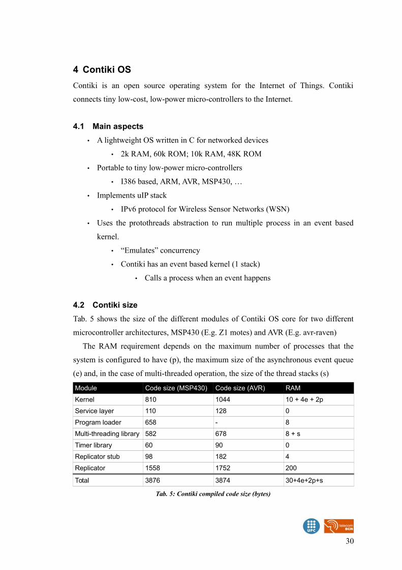
4.2 Contiki size
Tab. 5 shows the size of the different modules of Contiki OS core for two different
microcontroller architectures, MSP430 (E.g. Z1 motes) and AVR (E.g. avr-raven)
The RAM requirement depends on the maximum number of processes that the
system is configured to have (p), the maximum size of the asynchronous event queue
(e) and, in the case of multi-threaded operation, the size of the thread stacks (s)
Module Code size (MSP430) Code size (AVR) RAM
Kernel 810 1044 10 + 4e + 2p
Service layer 110 128 0
Program loader 658 - 8
Multi-threading library 582 678 8 + s
Timer library 60 90 0
Replicator stub 98 182 4
Replicator 1558 1752 200
Total 3876 3874 30+4e+2p+s
Tab. 5: Contiki compiled code size (bytes)
30
One of the main aspect of the system, is the modularity of the code. Besides the
system core, each program builds only the necessary modules to be able to run, not
the entire system image. This way, the memory used from the system, can be reduced
to the strictly necessary. This methodology makes more practical any change in any
module, if it is needed.
The code size of Contiki is larger than that of TinyOS, but smaller than that of the
Mantis system. Contiki's event kernel is significantly larger than that of TinyOS
because of the different services provided. While the TinyOS event kernel only
provides a FIFO event queue scheduler , the Contiki kernel supports both FIFO events
and poll handlers with priorities. Furthermore, the flexibility in Contiki requires more
run-time code than for a system like TinyOS, where compile time optimization can be
done to a larger extent.
4.3 Contiki directories
apps/ Several applications that can be included in our platform
core/ The Contiki kernel sources
cpu/The different low-layer source files related to each CPU architecture
The Z1 platform uses cpu/msp430/
platform/
All the platforms supported from Contiki, and its configurations
The source files include the main() program call, which initiates all the system
Z1 platform source files are included in the platform/z1/ directory
tools/Different tools for debugging and program the nodes. It includes the simulator Cooja and MSPSim
examples/ Several application examples for different protocols and nodes
doc/ Documentation about examples and functionalities
Tab. 6: Contiki directories
The documentation in the doc folder can be compiled, in order to get the html wiki
of all the code. It needs doxygen installed, and to run the command “make html”.
This will create a new folder, “doc/hmtl”, and in the index.html file, the wiki can
be opened.
4.4 Contiki Hardware
Contiki can be run in a number of platforms, each one with a different CPU.
Tab.7 shows the hardware platforms currently defined in the Contiki code tree. All
these platforms are in the “platform” folder of the code.
31
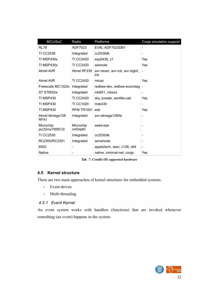
MCU/SoC Radio Platforms Cooja simulation support
RL78 ADF7023 EVAL-ADF7023DB1 -
TI CC2538 Integrated cc2538dk -
TI MSP430x TI CC2420 exp5438, z1 Yes
TI MSP430x TI CC2420 wismote Yes
Atmel AVR Atmel RF230 avr-raven, avr-rcb, avr-zigbit, iris
-
Atmel AVR TI CC2420 micaz Yes
Freescale MC1322x Integrated redbee-dev, redbee-econotag -
ST STM32w Integrated mb851, mbxxx -
TI MSP430 TI CC2420 sky, jcreate, sentilla-usb Yes
TI MSP430 TI CC1020 msb430 -
TI MSP430 RFM TR1001 esb Yes
Atmel Atmega128 RFA1
Integrated avr-atmega128rfa -
Microchip pic32mx795f512l
Microchip mrf24j40
seed-eye -
TI CC2530 Integrated cc2530dk -
RC2300/RC2301 Integrated sensinode -
6502 - apple2enh, atari, c128, c64 -
Native - native, minimal-net, cooja Yes
Tab. 7: Contiki OS supported hardware
4.5 Kernel structure
There are two main approaches of kernel structures for embedded systems.
• Event-driven
• Multi-threading
4.5.1 Event Kernel
An event system works with handlers (functions) that are invoked whenever
something (an event) happens in the system.
32
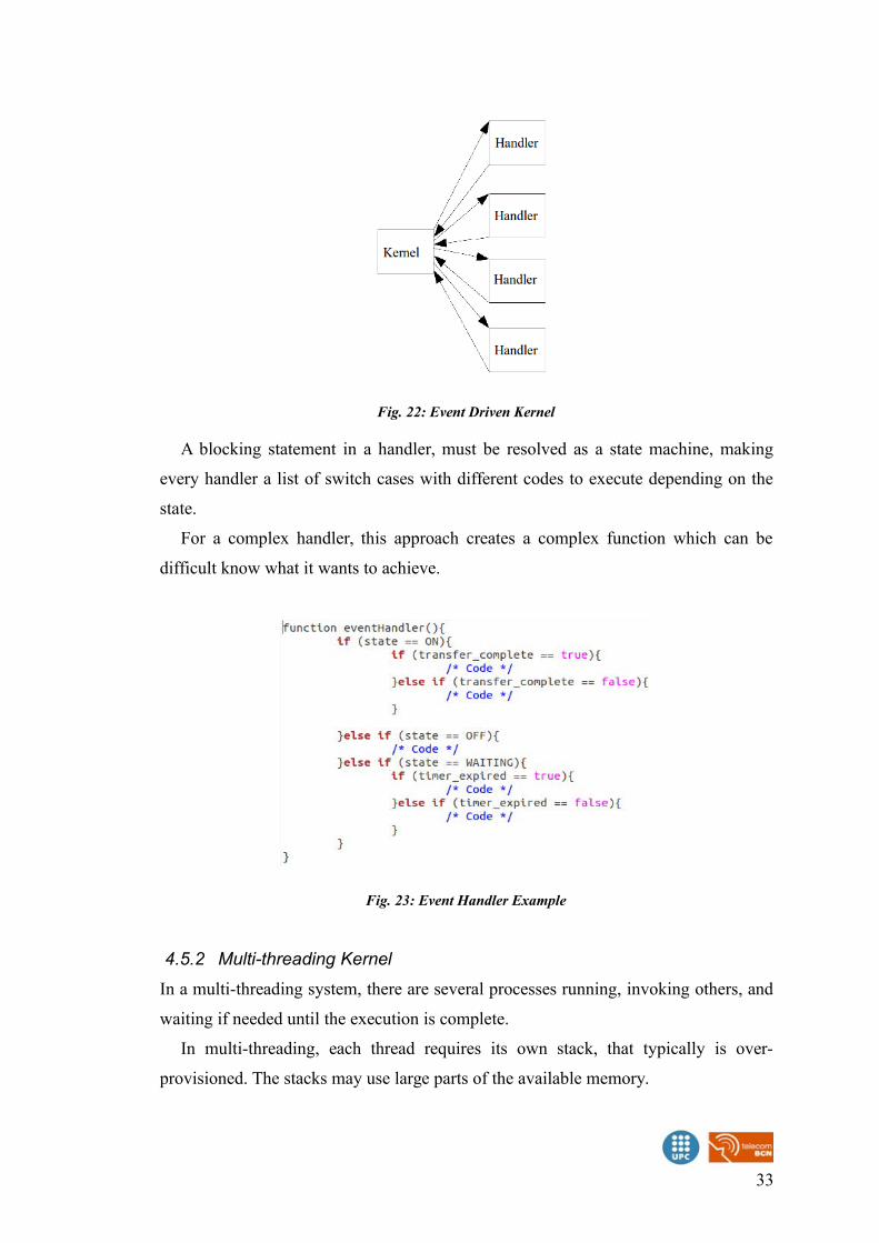
A blocking statement in a handler, must be resolved as a state machine, making
every handler a list of switch cases with different codes to execute depending on the
state.
For a complex handler, this approach creates a complex function which can be
difficult know what it wants to achieve.
4.5.2 Multi-threading Kernel
In a multi-threading system, there are several processes running, invoking others, and
waiting if needed until the execution is complete.
In multi-threading, each thread requires its own stack, that typically is over-
provisioned. The stacks may use large parts of the available memory.
33
Fig. 22: Event Driven Kernel
Fig. 23: Event Handler Example
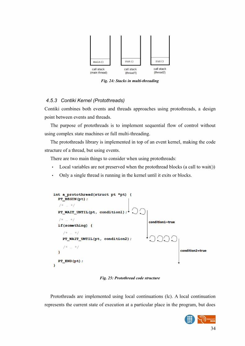
4.5.3 Contiki Kernel (Protothreads)
Contiki combines both events and threads approaches using protothreads, a design
point between events and threads.
The purpose of protothreads is to implement sequential flow of control without
using complex state machines or full multi-threading.
The protothreads library is implemented in top of an event kernel, making the code
structure of a thread, but using events.
There are two main things to consider when using protothreads:
• Local variables are not preserved when the protothread blocks (a call to wait())
• Only a single thread is running in the kernel until it exits or blocks.
Protothreads are implemented using local continuations (lc). A local continuation
represents the current state of execution at a particular place in the program, but does
34
Fig. 25: Protothread code structure
Fig. 24: Stacks in multi-threading
not provide any call history or local variables. It is used to capture the state of the
function. When a protothread is started, his local continuation is set to 0. When a wait
statement is invoked, the local continuation stores the line the wait was set, and exits
the protothreat. The protothread is called periodically, and jumps directly into the
local continuation line and resumes the execution.
In Fig.27 example, the expected result of the program is to print the variable “i”,
increase the value, then print the value increased, and so on.
Due to the nature of the protothreads, the result of the code will not be the expected
one.
As mentioned before, the local variables are not saved between wait statements.
35
Fig. 26: Protothreads implementation
Fig. 27: Protothreads failing example
Fig. 28: Protothreads example output
To solve this issue, the variables that need to be saved between statements, need to
be global or static. This two kind of variables will be saved between function calls.
A global variable can be used by any function on the code, on the other hand, a
static one will be used only in the function it has been declared.
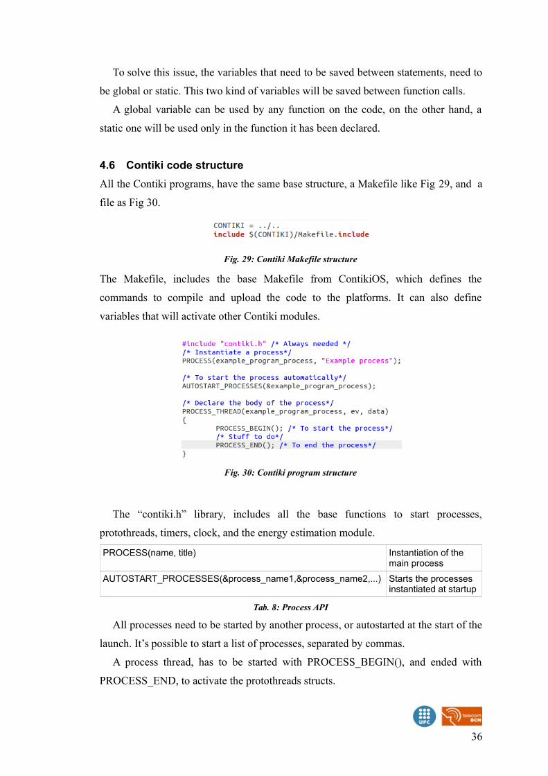
4.6 Contiki code structure
All the Contiki programs, have the same base structure, a Makefile like Fig 29, and a
file as Fig 30.
The Makefile, includes the base Makefile from ContikiOS, which defines the
commands to compile and upload the code to the platforms. It can also define
variables that will activate other Contiki modules.
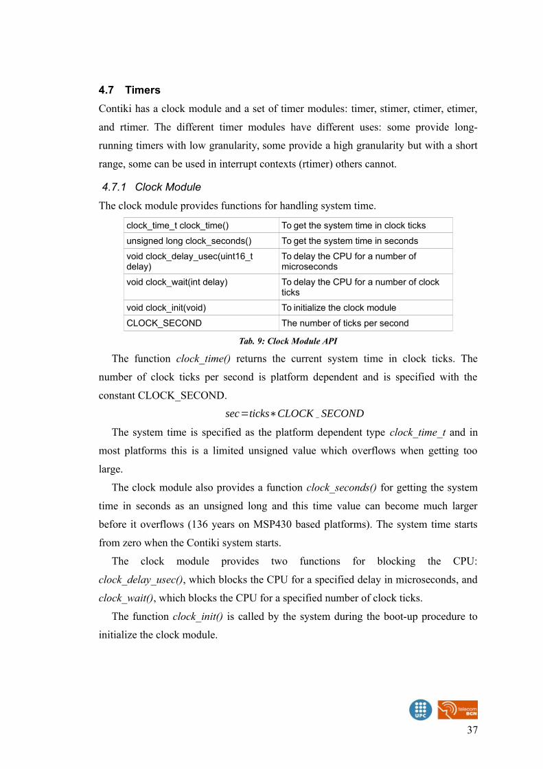
The “contiki.h” library, includes all the base functions to start processes,
protothreads, timers, clock, and the energy estimation module.
PROCESS(name, title) Instantiation of the main process
AUTOSTART_PROCESSES(&process_name1,&process_name2,...) Starts the processes instantiated at startup
Tab. 8: Process API
All processes need to be started by another process, or autostarted at the start of the
launch. It’s possible to start a list of processes, separated by commas.
A process thread, has to be started with PROCESS_BEGIN(), and ended with
PROCESS_END, to activate the protothreads structs.
36
Fig. 29: Contiki Makefile structure
Fig. 30: Contiki program structure
4.7 Timers
Contiki has a clock module and a set of timer modules: timer, stimer, ctimer, etimer,
and rtimer. The different timer modules have different uses: some provide long-
running timers with low granularity, some provide a high granularity but with a short
range, some can be used in interrupt contexts (rtimer) others cannot.
4.7.1 Clock Module
The clock module provides functions for handling system time.
clock_time_t clock_time() To get the system time in clock ticks
unsigned long clock_seconds() To get the system time in seconds
void clock_delay_usec(uint16_t delay)
To delay the CPU for a number of microseconds
void clock_wait(int delay) To delay the CPU for a number of clock ticks
void clock_init(void) To initialize the clock module
CLOCK_SECOND The number of ticks per second
Tab. 9: Clock Module API
The function clock_time() returns the current system time in clock ticks. The
number of clock ticks per second is platform dependent and is specified with the
constant CLOCK_SECOND.
sec=ticks∗CLOCK SECOND
The system time is specified as the platform dependent type clock_time_t and in
most platforms this is a limited unsigned value which overflows when getting too
large.
The clock module also provides a function clock_seconds() for getting the system
time in seconds as an unsigned long and this time value can become much larger
before it overflows (136 years on MSP430 based platforms). The system time starts
from zero when the Contiki system starts.
The clock module provides two functions for blocking the CPU:
clock_delay_usec(), which blocks the CPU for a specified delay in microseconds, and
clock_wait(), which blocks the CPU for a specified number of clock ticks.
The function clock_init() is called by the system during the boot-up procedure to
initialize the clock module.
37
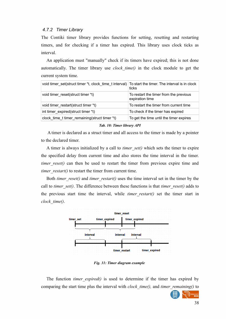
4.7.2 Timer Library
The Contiki timer library provides functions for setting, resetting and restarting
timers, and for checking if a timer has expired. This library uses clock ticks as
interval.
An application must "manually" check if its timers have expired; this is not done
automatically. The timer library use clock_time() in the clock module to get the
current system time.
void timer_set(struct timer *t, clock_time_t interval) To start the timer. The interval is in clock ticks
void timer_reset(struct timer *t) To restart the timer from the previous expiration time
void timer_restart(struct timer *t) To restart the timer from current time
int timer_expired(struct timer *t) To check if the timer has expired
clock_time_t timer_remaining(struct timer *t) To get the time until the timer expires
Tab. 10: Timer library API
A timer is declared as a struct timer and all access to the timer is made by a pointer
to the declared timer.
A timer is always initialized by a call to timer_set() which sets the timer to expire
the specified delay from current time and also stores the time interval in the timer.
timer_reset() can then be used to restart the timer from previous expire time and
timer_restart() to restart the timer from current time.
Both timer_reset() and timer_restart() uses the time interval set in the timer by the
call to timer_set(). The difference between these functions is that timer_reset() adds to
the previous start time the interval, while timer_restart() set the timer start in
clock_time().
The function timer_expired() is used to determine if the timer has expired by
comparing the start time plus the interval with clock_time(), and timer_remaining() to
38
Fig. 31: Timer diagram example
get an estimate of the remaining time until the timer expires. The return value of the
latter function is undefined if the timer already has expired.
4.7.3 Stimer Library
The Contiki stimer library provides a timer mechanism similar to the timer library but
uses time values in seconds, allowing much longer expiration times. The stimer
library use clock_seconds() in the clock module to get the current system time in
seconds.
void stimer_set(struct stimer *t, unsigned long interval) To start the timer
void stimer_reset(struct stimer *t) To restart the stimer from the previous expiration time
void stimer_restart(struct stimer *t) To restart the stimer from current time
int stimer_expired(struct stimer *t) To check if the stimer has expired
unsigned long stimer_remaining(struct stimer *t) To get the time until the timer expires
Tab. 11: Stimer library API
The API for the Contiki stimer library is similar to the timer library. The difference
is that times are specified as seconds instead of clock ticks.
4.7.4 Etimer Library
The Contiki etimer library provides a timer mechanism that generates timed events.
An event timer will post the event PROCESS_EVENT_TIMER to the process that
sets the timer when the event timer expires. The etimer library uses clock_time() in the
clock module to get the current system time.
void etimer_set(struct etimer *t, clock_time_t interval) To start the timer
void etimer_reset(struct etimer *t) To restart the timer from the previous expiration time
void etimer_restart(struct etimer *t) To restart the timer from current time
void etimer_stop(struct etimer *t) To stop the timer
int etimer_expired(struct etimer *t) To check if the timer has expired
int etimer_pending() To check if there are any non-expired event timers
clock_time_t etimer_next_expiration_time() To get the next event timer expiration time
void etimer_request_poll() To inform the etimer library that the system clock has changed
Tab. 12: Etimer library API
An event timer is declared as a struct etimer and all access to the event timer is
made by a pointer to the declared event timer.
39
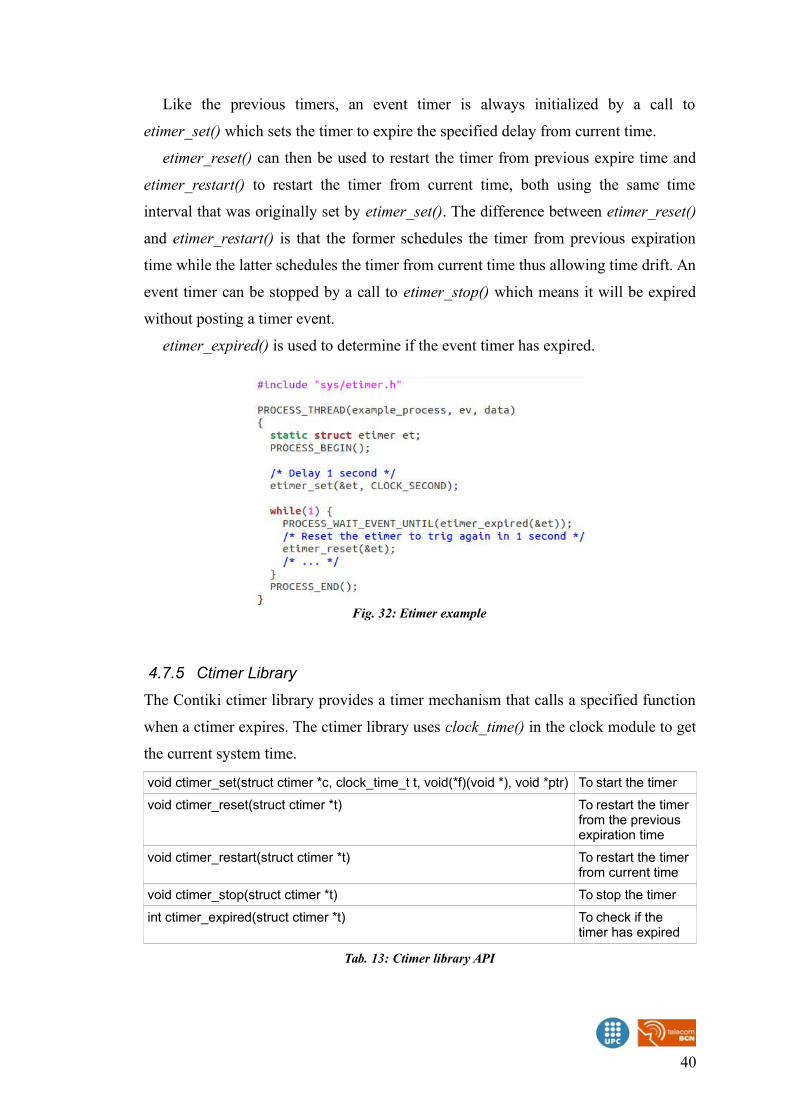
Like the previous timers, an event timer is always initialized by a call to
etimer_set() which sets the timer to expire the specified delay from current time.
etimer_reset() can then be used to restart the timer from previous expire time and
etimer_restart() to restart the timer from current time, both using the same time
interval that was originally set by etimer_set(). The difference between etimer_reset()
and etimer_restart() is that the former schedules the timer from previous expiration
time while the latter schedules the timer from current time thus allowing time drift. An
event timer can be stopped by a call to etimer_stop() which means it will be expired
without posting a timer event.
etimer_expired() is used to determine if the event timer has expired.
4.7.5 Ctimer Library
The Contiki ctimer library provides a timer mechanism that calls a specified function
when a ctimer expires. The ctimer library uses clock_time() in the clock module to get
the current system time.
void ctimer_set(struct ctimer *c, clock_time_t t, void(*f)(void *), void *ptr) To start the timer
void ctimer_reset(struct ctimer *t) To restart the timer from the previous expiration time
void ctimer_restart(struct ctimer *t) To restart the timer from current time
void ctimer_stop(struct ctimer *t) To stop the timer
int ctimer_expired(struct ctimer *t) To check if the timer has expired
Tab. 13: Ctimer library API
40
Fig. 32: Etimer example
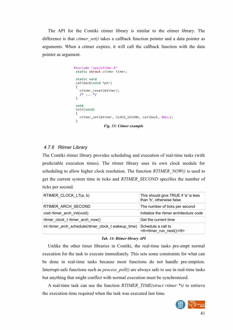
The API for the Contiki ctimer library is similar to the etimer library. The
difference is that ctimer_set() takes a callback function pointer and a data pointer as
arguments. When a ctimer expires, it will call the callback function with the data
pointer as argument.
4.7.6 Rtimer Library
The Contiki rtimer library provides scheduling and execution of real-time tasks (with
predictable execution times). The rtimer library uses its own clock module for
scheduling to allow higher clock resolution. The function RTIMER_NOW() is used to
get the current system time in ticks and RTIMER_SECOND specifies the number of
ticks per second.
RTIMER_CLOCK_LT(a, b) This should give TRUE if 'a' is less than 'b', otherwise false
RTIMER_ARCH_SECOND The number of ticks per second
void rtimer_arch_init(void) Initialize the rtimer architecture code
rtimer_clock_t rtimer_arch_now() Get the current time
int rtimer_arch_schedule(rtimer_clock_t wakeup_time) Schedule a call to <tt>rtimer_run_next()</tt>
Tab. 14: Rtimer library API
Unlike the other timer libraries in Contiki, the real-time tasks pre-empt normal
execution for the task to execute immediately. This sets some constraints for what can
be done in real-time tasks because most functions do not handle pre-emption.
Interrupt-safe functions such as process_poll() are always safe to use in real-time tasks
but anything that might conflict with normal execution must be synchronized.
A real-time task can use the function RTIMER_TIME(struct rtimer *t) to retrieve
the execution time required when the task was executed last time.
41
Fig. 33: Ctimer example
4.8 Rime
The RIME library in Contiki is located in “net/rime.h”. It is a communication protocol
stack over the Physical layer of 802.15.4. There are about 20 different rime primitives,
some of the use another one of the primitives, to achieve more complex network
transmissions.
This document will only explain 3 of the basic primitives, to send single hop
unicast messages, best effort broadcast messages, and mesh routing messages.
4.8.1 Rime buffer management
There is a library to manage the buffer management, located at “net/packetbuf.h”.
This buffer contains the data sent and received in Rime connections.
void packetbuf_clear (void) Clear and reset the packetbuf
void packetbuf_clear_hdr (void) Clear and reset the header of the packetbuf
int packetbuf_copyfrom (const void *from, uint16_t len)
Copy from external data into the packetbuf
void packetbuf_compact (void) Compact the packetbuf
int packetbuf_copyto_hdr (uint8_t *to) Copy the header portion of the packetbuf to an external buffer
int packetbuf_copyto (void *to) Copy the entire packetbuf to an external buffer
int packetbuf_hdralloc (int size) Extend the header of the packetbuf, for outbound packets
int packetbuf_hdrreduce (int size) Reduce the header in the packetbuf, for incoming packets
void packetbuf_set_datalen (uint16_t len) Set the length of the data in the packetbuf
void * packetbuf_dataptr (void) Get a pointer to the data in the packetbuf
void * packetbuf_hdrptr (void) Get a pointer to the header in the packetbuf, for outbound packets
void packetbuf_reference (void *ptr, uint16_t len) Point the packetbuf to external data
int packetbuf_is_reference (void) Check if the packetbuf references external data
void * packetbuf_reference_ptr (void) Get a pointer to external data referenced by the packetbuf
uint16_t packetbuf_datalen (void) Get the length of the data in the packetbuf.
uint8_t packetbuf_hdrlen (void) Get the length of the header in the packetbuf, for outbound packets
uint16_t packetbuf_totlen (void) Get the total length of the header and data in the packetbuf.
Tab. 15: Rime packetbuf API
42
PACKETBUF_SIZE The size of the packetbuf, in bytes (128 by default)
PACKETBUF_HDR_SIZE The size of the packetbuf header, In bytes (48 by default)
Tab. 16: Rime packetbuf macros
Every time a function is called, the buffer only contains one packet. When a packet
is sent, the buffer gets reset, to handle new data. When a packet is received, the buffer
contains only one packet.
4.8.2 Rime addresses
A rime address is contained in the struct rimeaddr_t. It contains an array 'u8' with 2
positions, u8[0] and u8[1] holding an number between 0 and 255 each one.
The address of the device is set in the platform specific configuration in the folder
'platform'. For the Z1 motes, the address is set using the node id.
void rimeaddr_copy (rimeaddr_t *dest, const rimeaddr_t *from) Copy a Rime address
int rimeaddr_cmp (const rimeaddr_t *addr1, const rimeaddr_t *addr2) Compare two Rimeaddresses
void rimeaddr_set_node_addr (rimeaddr_t *addr) Set the address of thecurrent node
Tab. 17: Rime addresses API
rimeaddr_node_addr The Rime address of the node
rimeaddr_null The null Rime address, used in route tables to indicate that the table entry is unused
Tab. 18: Rime addresses variables
4.8.3 Single-hop Unicast
The unicast primitive uses the broadcast primitive and adds the single-hop receiver
address attribute to the outgoing packets. For incoming packets, the unicast module
inspects the single-hop receiver address attribute and discards the packet if the address
does not match the address of the node.
In Fig. 34, there is a process sending the message Hello to a device with the rime
address 1.0.
43
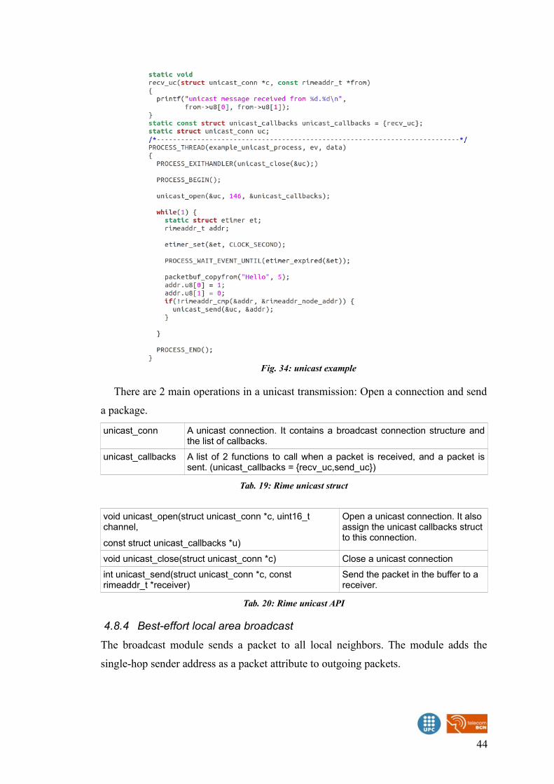
There are 2 main operations in a unicast transmission: Open a connection and send
a package.
unicast_conn A unicast connection. It contains a broadcast connection structure andthe list of callbacks.
unicast_callbacks A list of 2 functions to call when a packet is received, and a packet issent. (unicast_callbacks = {recv_uc,send_uc})
Tab. 19: Rime unicast struct
void unicast_open(struct unicast_conn *c, uint16_t channel,
const struct unicast_callbacks *u)
Open a unicast connection. It also assign the unicast callbacks structto this connection.
void unicast_close(struct unicast_conn *c) Close a unicast connection
int unicast_send(struct unicast_conn *c, const rimeaddr_t *receiver)
Send the packet in the buffer to a receiver.
Tab. 20: Rime unicast API
4.8.4 Best-effort local area broadcast
The broadcast module sends a packet to all local neighbors. The module adds the
single-hop sender address as a packet attribute to outgoing packets.
44
Fig. 34: unicast example
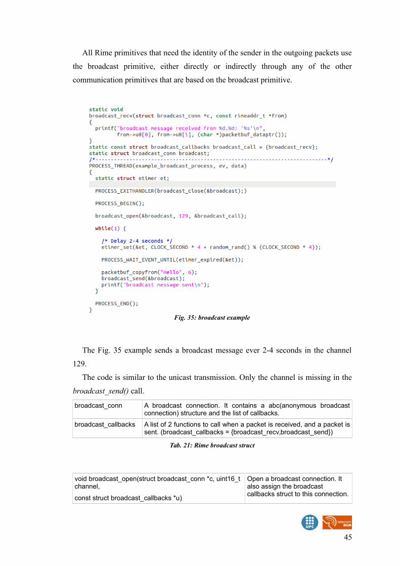
All Rime primitives that need the identity of the sender in the outgoing packets use
the broadcast primitive, either directly or indirectly through any of the other
communication primitives that are based on the broadcast primitive.
The Fig. 35 example sends a broadcast message ever 2-4 seconds in the channel
129.
The code is similar to the unicast transmission. Only the channel is missing in the
broadcast_send() call.
broadcast_conn A broadcast connection. It contains a abc(anonymous broadcastconnection) structure and the list of callbacks.
broadcast_callbacks A list of 2 functions to call when a packet is received, and a packet issent. (broadcast_callbacks = {broadcast_recv,broadcast_send})
Tab. 21: Rime broadcast struct
void broadcast_open(struct broadcast_conn *c, uint16_t channel,
const struct broadcast_callbacks *u)
Open a broadcast connection. It also assign the broadcast callbacks struct to this connection.
45
Fig. 35: broadcast example
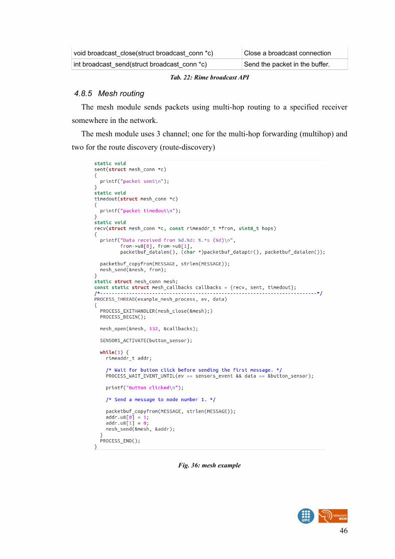
void broadcast_close(struct broadcast_conn *c) Close a broadcast connection
int broadcast_send(struct broadcast_conn *c) Send the packet in the buffer.
Tab. 22: Rime broadcast API
4.8.5 Mesh routing
The mesh module sends packets using multi-hop routing to a specified receiver
somewhere in the network.
The mesh module uses 3 channel; one for the multi-hop forwarding (multihop) and
two for the route discovery (route-discovery)
46
Fig. 36: mesh example
In Fig. 36 example, a message is sent to the address 1.0. Every time a message is
received, is resend to the source address.
Although the structure is similar to the unicast and broadcast examples, there is an
underlaying login in the mesh_conn struct. The struct has 2 connections, a
route_discovery_conn that creates a routing table of destinations, and a
multihop_conn struct, to pass the incoming messages for another destination.
mesh_conn A mesh connection. It contains a multihop_conn struct, aroute_discovery_conn struct, a queuebuf of packets, a rimeaddr_t of thedata destination, and the list of callbacks
mesh_callbacks A list of 2 functions to call when a packet is received, and a packet is sent.(mesh_callbacks = {recv,sent,timeout})
Tab. 23: Rime mesh struct
void mesh_open (struct mesh_conn *c, uint16_t channels,const struct mesh_callbacks *callbacks)
Open a mesh connection
void mesh_close (struct mesh_conn *c) Close an mesh connection
int mesh_send (struct mesh_conn *c, const rimeaddr_t *dest) Send a mesh packet
int mesh_ready (struct mesh_conn *c) Test if mesh is ready to senda packet (or packet isqueued)
Tab. 24: Rime mesh API
4.9 Contiki uIP Stack
The uIP TCP/IP stack is intended to make it possible to communicate using the
TCP/IP protocol suite even on small 8-bit micro-controllers. Despite being small and
simple, uIP does not require their peers to have complex, full-size stacks, but can
communicate with peers running a similarly light-weight stack. The code size is on
the order of a few kilobytes and RAM usage can be configured to be as low as a few
hundred bytes.
To use the uIP stack with IPv6, the Makefile of the application, must contain three
parameters:
WITH_UIP6=1
UIP_CONF_IPV6=1
CFLAGS+= -DUIP_CONF_IPV6_RPL
uip_ip4addr_t An IP address. Either IPv4 address, or IPv6 if IPv6 is activated
union uip_ip4addr_t Representation of an IPv4 address
47
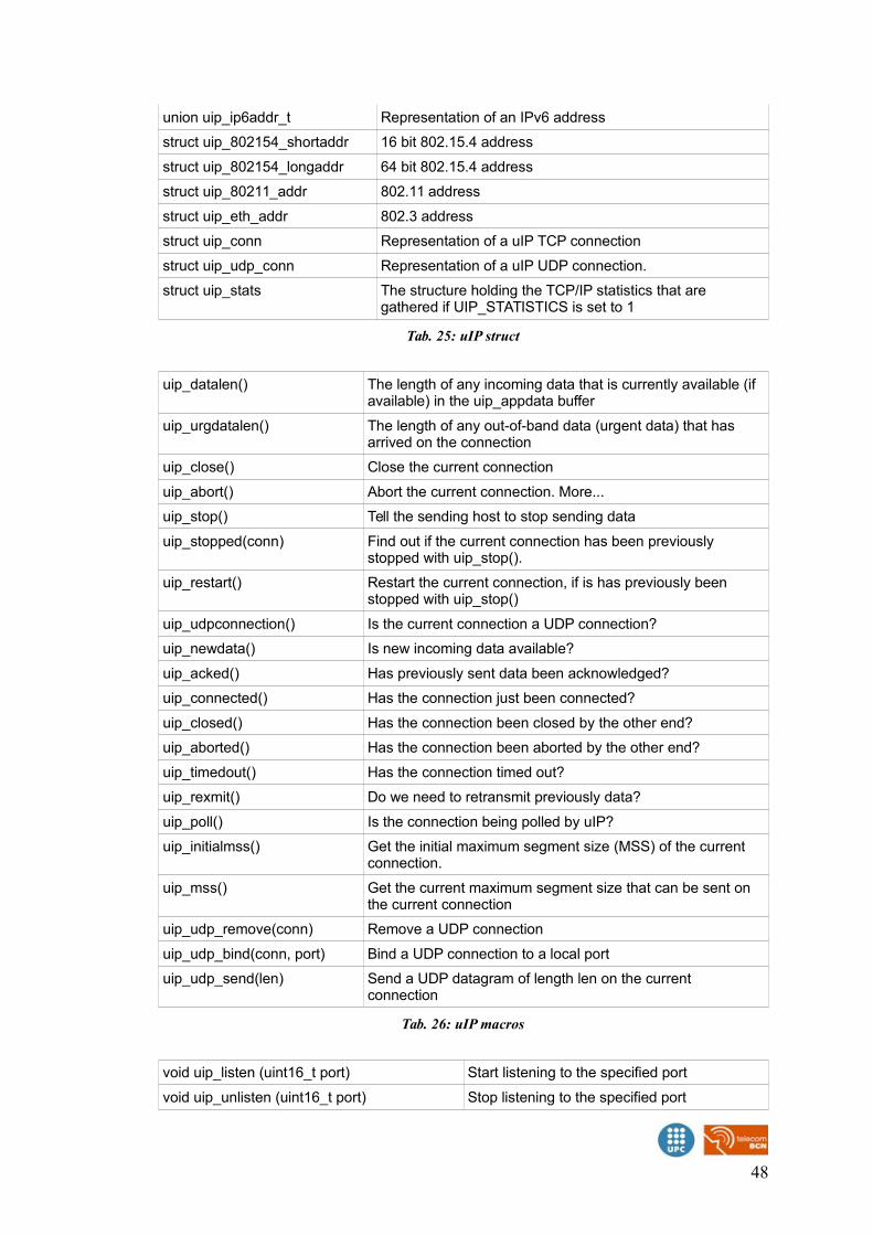
union uip_ip6addr_t Representation of an IPv6 address
struct uip_802154_shortaddr 16 bit 802.15.4 address
struct uip_802154_longaddr 64 bit 802.15.4 address
struct uip_80211_addr 802.11 address
struct uip_eth_addr 802.3 address
struct uip_conn Representation of a uIP TCP connection
struct uip_udp_conn Representation of a uIP UDP connection.
struct uip_stats The structure holding the TCP/IP statistics that are gathered if UIP_STATISTICS is set to 1
Tab. 25: uIP struct
uip_datalen() The length of any incoming data that is currently available (if available) in the uip_appdata buffer
uip_urgdatalen() The length of any out-of-band data (urgent data) that has arrived on the connection
uip_close() Close the current connection
uip_abort() Abort the current connection. More...
uip_stop() Tell the sending host to stop sending data
uip_stopped(conn) Find out if the current connection has been previously stopped with uip_stop().
uip_restart() Restart the current connection, if is has previously been stopped with uip_stop()
uip_udpconnection() Is the current connection a UDP connection?
uip_newdata() Is new incoming data available?
uip_acked() Has previously sent data been acknowledged?
uip_connected() Has the connection just been connected?
uip_closed() Has the connection been closed by the other end?
uip_aborted() Has the connection been aborted by the other end?
uip_timedout() Has the connection timed out?
uip_rexmit() Do we need to retransmit previously data?
uip_poll() Is the connection being polled by uIP?
uip_initialmss() Get the initial maximum segment size (MSS) of the current connection.
uip_mss() Get the current maximum segment size that can be sent on the current connection
uip_udp_remove(conn) Remove a UDP connection
uip_udp_bind(conn, port) Bind a UDP connection to a local port
uip_udp_send(len) Send a UDP datagram of length len on the current connection
Tab. 26: uIP macros
void uip_listen (uint16_t port) Start listening to the specified port
void uip_unlisten (uint16_t port) Stop listening to the specified port
48
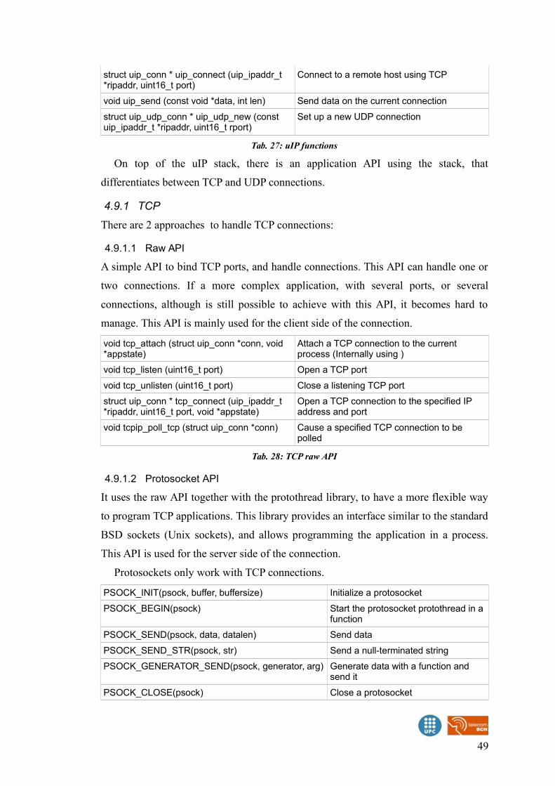
struct uip_conn * uip_connect (uip_ipaddr_t *ripaddr, uint16_t port)
Connect to a remote host using TCP
void uip_send (const void *data, int len) Send data on the current connection
struct uip_udp_conn * uip_udp_new (const uip_ipaddr_t *ripaddr, uint16_t rport)
Set up a new UDP connection
Tab. 27: uIP functions
On top of the uIP stack, there is an application API using the stack, that
differentiates between TCP and UDP connections.
4.9.1 TCP
There are 2 approaches to handle TCP connections:
4.9.1.1 Raw API
A simple API to bind TCP ports, and handle connections. This API can handle one or
two connections. If a more complex application, with several ports, or several
connections, although is still possible to achieve with this API, it becomes hard to
manage. This API is mainly used for the client side of the connection.
void tcp_attach (struct uip_conn *conn, void *appstate)
Attach a TCP connection to the current process (Internally using )
void tcp_listen (uint16_t port) Open a TCP port
void tcp_unlisten (uint16_t port) Close a listening TCP port
struct uip_conn * tcp_connect (uip_ipaddr_t *ripaddr, uint16_t port, void *appstate)
Open a TCP connection to the specified IP address and port
void tcpip_poll_tcp (struct uip_conn *conn) Cause a specified TCP connection to be polled
Tab. 28: TCP raw API
4.9.1.2 Protosocket API
It uses the raw API together with the protothread library, to have a more flexible way
to program TCP applications. This library provides an interface similar to the standard
BSD sockets (Unix sockets), and allows programming the application in a process.
This API is used for the server side of the connection.
Protosockets only work with TCP connections.
PSOCK_INIT(psock, buffer, buffersize) Initialize a protosocket
PSOCK_BEGIN(psock) Start the protosocket protothread in a function
PSOCK_SEND(psock, data, datalen) Send data
PSOCK_SEND_STR(psock, str) Send a null-terminated string
PSOCK_GENERATOR_SEND(psock, generator, arg) Generate data with a function and send it
PSOCK_CLOSE(psock) Close a protosocket
49
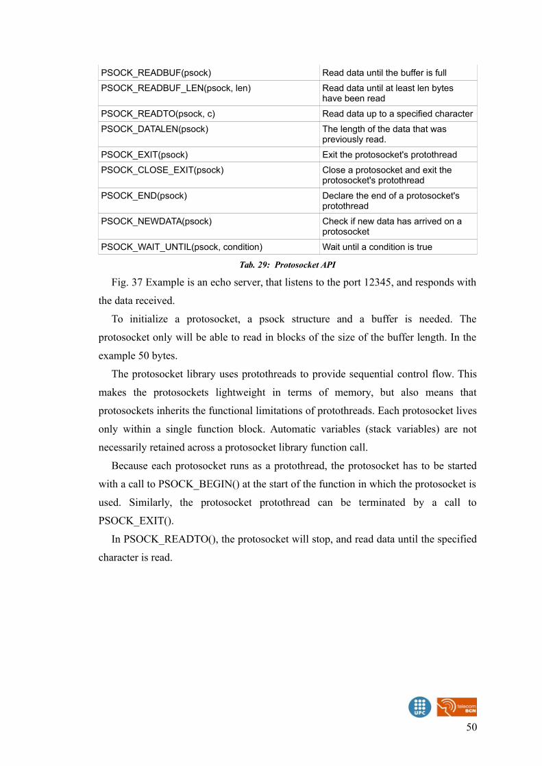
PSOCK_READBUF(psock) Read data until the buffer is full
PSOCK_READBUF_LEN(psock, len) Read data until at least len bytes have been read
PSOCK_READTO(psock, c) Read data up to a specified character
PSOCK_DATALEN(psock) The length of the data that was previously read.
PSOCK_EXIT(psock) Exit the protosocket's protothread
PSOCK_CLOSE_EXIT(psock) Close a protosocket and exit the protosocket's protothread
PSOCK_END(psock) Declare the end of a protosocket's protothread
PSOCK_NEWDATA(psock) Check if new data has arrived on a protosocket
PSOCK_WAIT_UNTIL(psock, condition) Wait until a condition is true
Tab. 29: Protosocket API
Fig. 37 Example is an echo server, that listens to the port 12345, and responds with
the data received.
To initialize a protosocket, a psock structure and a buffer is needed. The
protosocket only will be able to read in blocks of the size of the buffer length. In the
example 50 bytes.
The protosocket library uses protothreads to provide sequential control flow. This
makes the protosockets lightweight in terms of memory, but also means that
protosockets inherits the functional limitations of protothreads. Each protosocket lives
only within a single function block. Automatic variables (stack variables) are not
necessarily retained across a protosocket library function call.
Because each protosocket runs as a protothread, the protosocket has to be started
with a call to PSOCK_BEGIN() at the start of the function in which the protosocket is
used. Similarly, the protosocket protothread can be terminated by a call to
PSOCK_EXIT().
In PSOCK_READTO(), the protosocket will stop, and read data until the specified
character is read.
50

51
Fig. 37: TCP protosocket example
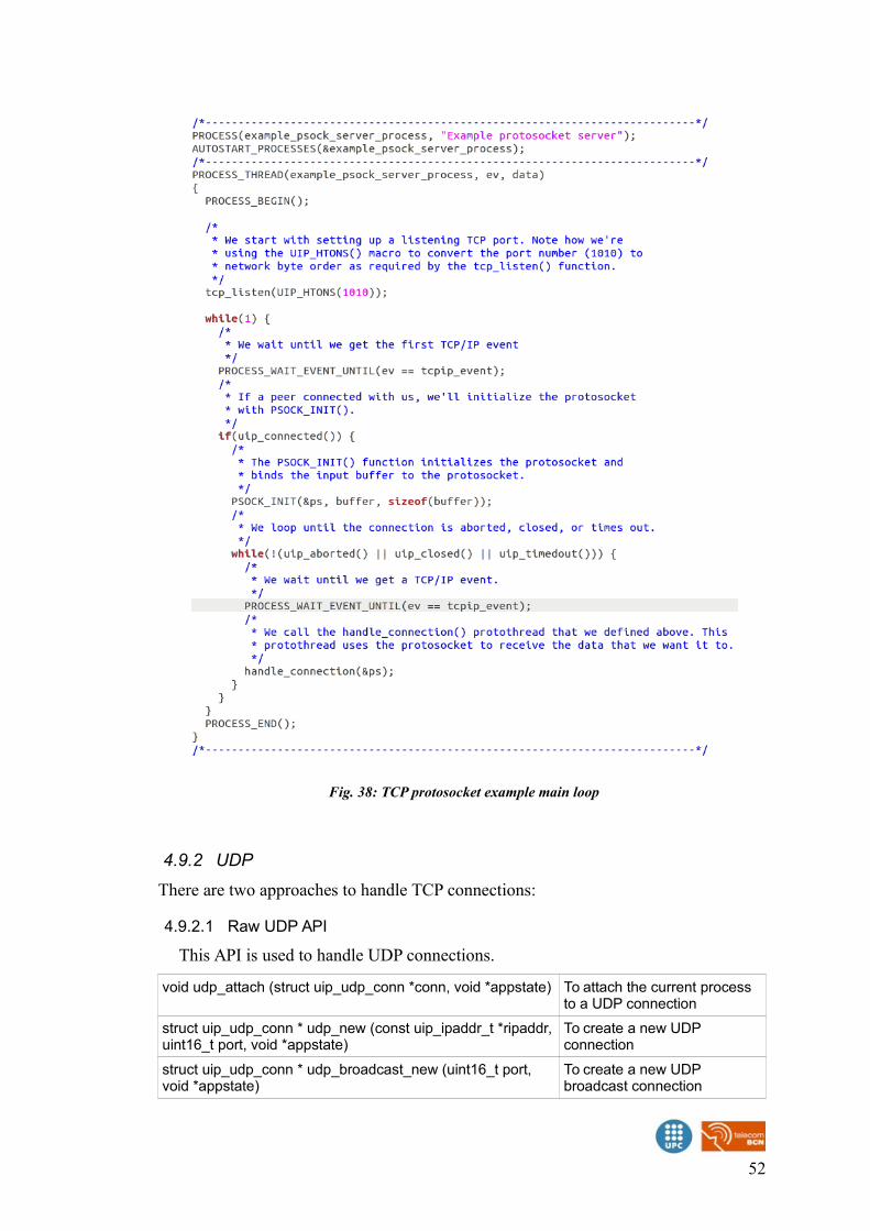
4.9.2 UDP
There are two approaches to handle TCP connections:
4.9.2.1 Raw UDP API
This API is used to handle UDP connections.
void udp_attach (struct uip_udp_conn *conn, void *appstate) To attach the current process to a UDP connection
struct uip_udp_conn * udp_new (const uip_ipaddr_t *ripaddr,uint16_t port, void *appstate)
To create a new UDP connection
struct uip_udp_conn * udp_broadcast_new (uint16_t port, void *appstate)
To create a new UDP broadcast connection
52
Fig. 38: TCP protosocket example main loop
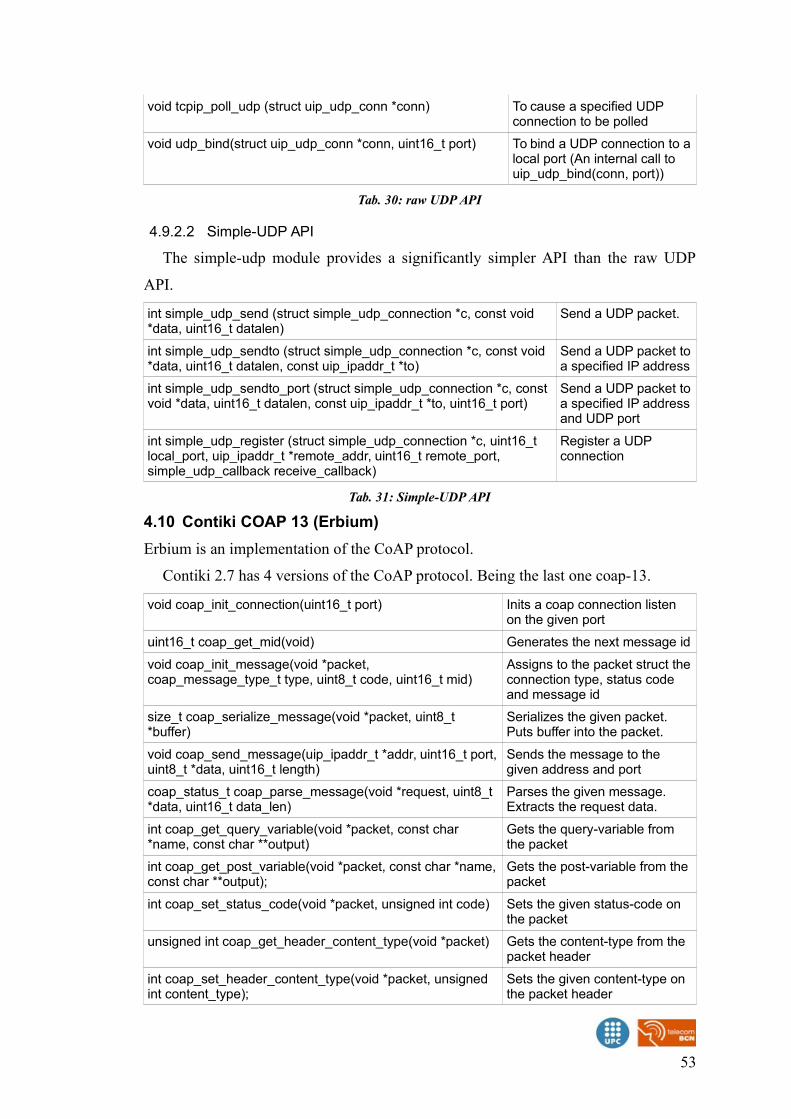
void tcpip_poll_udp (struct uip_udp_conn *conn) To cause a specified UDP connection to be polled
void udp_bind(struct uip_udp_conn *conn, uint16_t port) To bind a UDP connection to alocal port (An internal call to uip_udp_bind(conn, port))
Tab. 30: raw UDP API
4.9.2.2 Simple-UDP API
The simple-udp module provides a significantly simpler API than the raw UDP
API.
int simple_udp_send (struct simple_udp_connection *c, const void *data, uint16_t datalen)
Send a UDP packet.
int simple_udp_sendto (struct simple_udp_connection *c, const void *data, uint16_t datalen, const uip_ipaddr_t *to)
Send a UDP packet toa specified IP address
int simple_udp_sendto_port (struct simple_udp_connection *c, const void *data, uint16_t datalen, const uip_ipaddr_t *to, uint16_t port)
Send a UDP packet toa specified IP addressand UDP port
int simple_udp_register (struct simple_udp_connection *c, uint16_t local_port, uip_ipaddr_t *remote_addr, uint16_t remote_port, simple_udp_callback receive_callback)
Register a UDP connection
Tab. 31: Simple-UDP API
4.10 Contiki COAP 13 (Erbium)
Erbium is an implementation of the CoAP protocol.
Contiki 2.7 has 4 versions of the CoAP protocol. Being the last one coap-13.
void coap_init_connection(uint16_t port) Inits a coap connection listen on the given port
uint16_t coap_get_mid(void) Generates the next message id
void coap_init_message(void *packet, coap_message_type_t type, uint8_t code, uint16_t mid)
Assigns to the packet struct theconnection type, status code and message id
size_t coap_serialize_message(void *packet, uint8_t *buffer)
Serializes the given packet. Puts buffer into the packet.
void coap_send_message(uip_ipaddr_t *addr, uint16_t port,uint8_t *data, uint16_t length)
Sends the message to the given address and port
coap_status_t coap_parse_message(void *request, uint8_t *data, uint16_t data_len)
Parses the given message. Extracts the request data.
int coap_get_query_variable(void *packet, const char *name, const char **output)
Gets the query-variable from the packet
int coap_get_post_variable(void *packet, const char *name,const char **output);
Gets the post-variable from the packet
int coap_set_status_code(void *packet, unsigned int code) Sets the given status-code on the packet
unsigned int coap_get_header_content_type(void *packet) Gets the content-type from the packet header
int coap_set_header_content_type(void *packet, unsigned int content_type);
Sets the given content-type on the packet header
53
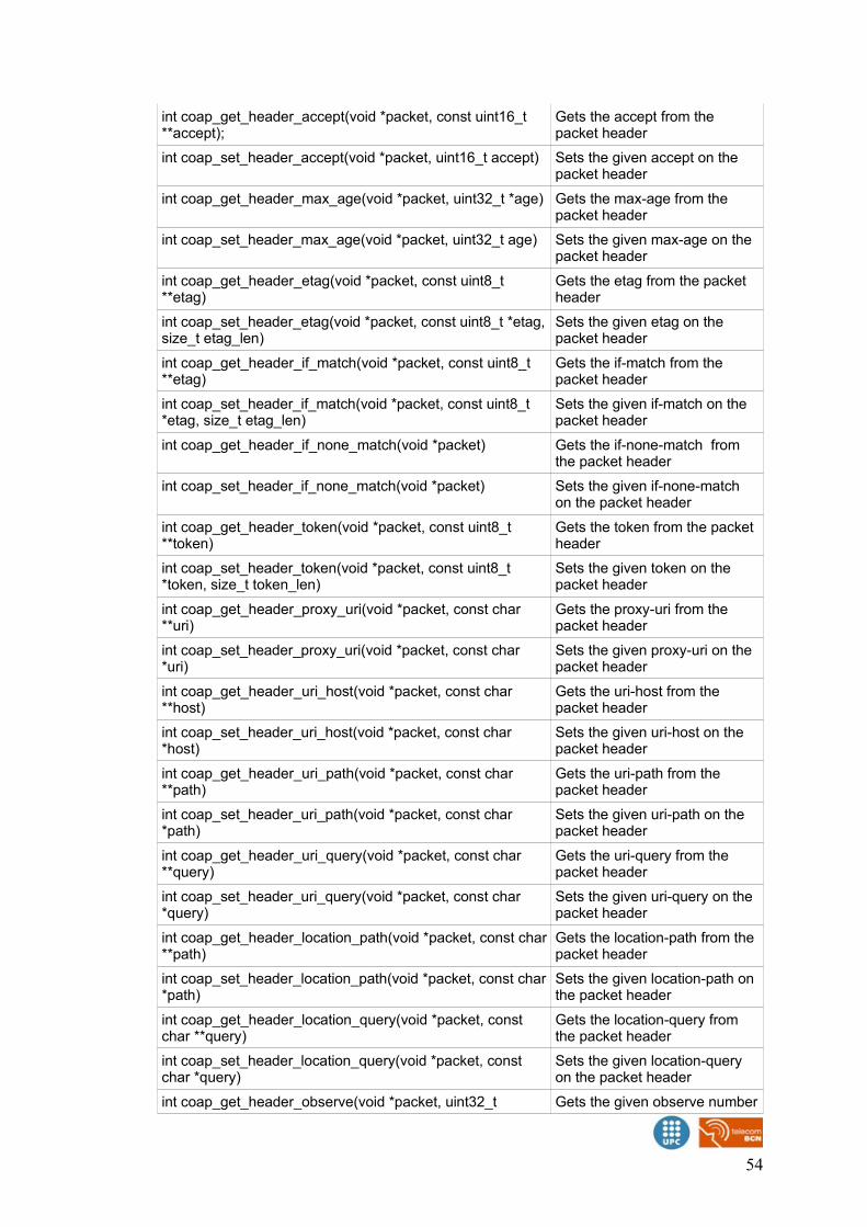
int coap_get_header_accept(void *packet, const uint16_t **accept);
Gets the accept from the packet header
int coap_set_header_accept(void *packet, uint16_t accept) Sets the given accept on the packet header
int coap_get_header_max_age(void *packet, uint32_t *age) Gets the max-age from the packet header
int coap_set_header_max_age(void *packet, uint32_t age) Sets the given max-age on the packet header
int coap_get_header_etag(void *packet, const uint8_t **etag)
Gets the etag from the packet header
int coap_set_header_etag(void *packet, const uint8_t *etag,size_t etag_len)
Sets the given etag on the packet header
int coap_get_header_if_match(void *packet, const uint8_t **etag)
Gets the if-match from the packet header
int coap_set_header_if_match(void *packet, const uint8_t *etag, size_t etag_len)
Sets the given if-match on the packet header
int coap_get_header_if_none_match(void *packet) Gets the if-none-match from the packet header
int coap_set_header_if_none_match(void *packet) Sets the given if-none-match on the packet header
int coap_get_header_token(void *packet, const uint8_t **token)
Gets the token from the packet header
int coap_set_header_token(void *packet, const uint8_t *token, size_t token_len)
Sets the given token on the packet header
int coap_get_header_proxy_uri(void *packet, const char **uri)
Gets the proxy-uri from the packet header
int coap_set_header_proxy_uri(void *packet, const char *uri)
Sets the given proxy-uri on the packet header
int coap_get_header_uri_host(void *packet, const char **host)
Gets the uri-host from the packet header
int coap_set_header_uri_host(void *packet, const char *host)
Sets the given uri-host on the packet header
int coap_get_header_uri_path(void *packet, const char **path)
Gets the uri-path from the packet header
int coap_set_header_uri_path(void *packet, const char *path)
Sets the given uri-path on the packet header
int coap_get_header_uri_query(void *packet, const char **query)
Gets the uri-query from the packet header
int coap_set_header_uri_query(void *packet, const char *query)
Sets the given uri-query on the packet header
int coap_get_header_location_path(void *packet, const char**path)
Gets the location-path from the packet header
int coap_set_header_location_path(void *packet, const char*path)
Sets the given location-path on the packet header
int coap_get_header_location_query(void *packet, const char **query)
Gets the location-query from the packet header
int coap_set_header_location_query(void *packet, const char *query)
Sets the given location-query on the packet header
int coap_get_header_observe(void *packet, uint32_t Gets the given observe number
54
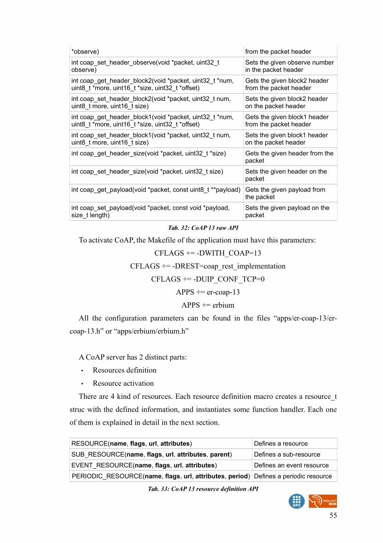
*observe) from the packet header
int coap_set_header_observe(void *packet, uint32_t observe)
Sets the given observe numberin the packet header
int coap_get_header_block2(void *packet, uint32_t *num, uint8_t *more, uint16_t *size, uint32_t *offset)
Gets the given block2 header from the packet header
int coap_set_header_block2(void *packet, uint32_t num, uint8_t more, uint16_t size)
Sets the given block2 header on the packet header
int coap_get_header_block1(void *packet, uint32_t *num, uint8_t *more, uint16_t *size, uint32_t *offset)
Gets the given block1 header from the packet header
int coap_set_header_block1(void *packet, uint32_t num, uint8_t more, uint16_t size)
Sets the given block1 header on the packet header
int coap_get_header_size(void *packet, uint32_t *size) Gets the given header from thepacket
int coap_set_header_size(void *packet, uint32_t size) Sets the given header on the packet
int coap_get_payload(void *packet, const uint8_t **payload) Gets the given payload from the packet
int coap_set_payload(void *packet, const void *payload, size_t length)
Sets the given payload on the packet
Tab. 32: CoAP 13 raw API
To activate CoAP, the Makefile of the application must have this parameters:
CFLAGS += -DWITH_COAP=13
CFLAGS += -DREST=coap_rest_implementation
CFLAGS += -DUIP_CONF_TCP=0
APPS += er-coap-13
APPS += erbium
All the configuration parameters can be found in the files “apps/er-coap-13/er-
coap-13.h” or “apps/erbium/erbium.h”
A CoAP server has 2 distinct parts:
• Resources definition
• Resource activation
There are 4 kind of resources. Each resource definition macro creates a resource_t
struc with the defined information, and instantiates some function handler. Each one
of them is explained in detail in the next section.
RESOURCE(name, flags, url, attributes) Defines a resource
SUB_RESOURCE(name, flags, url, attributes, parent) Defines a sub-resource
EVENT_RESOURCE(name, flags, url, attributes) Defines an event resource
PERIODIC_RESOURCE(name, flags, url, attributes, period) Defines a periodic resource
Tab. 33: CoAP 13 resource definition API
55
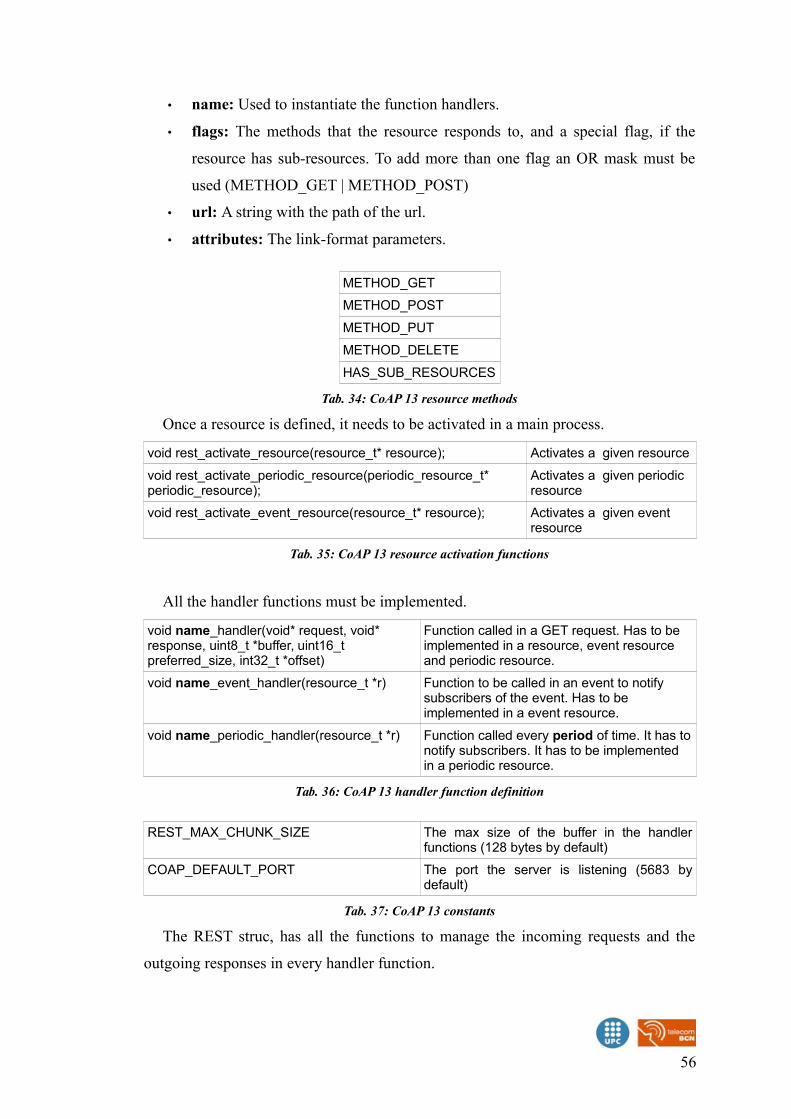
• name: Used to instantiate the function handlers.
• flags: The methods that the resource responds to, and a special flag, if the
resource has sub-resources. To add more than one flag an OR mask must be
used (METHOD_GET | METHOD_POST)
• url: A string with the path of the url.
• attributes: The link-format parameters.
METHOD_GET
METHOD_POST
METHOD_PUT
METHOD_DELETE
HAS_SUB_RESOURCES
Tab. 34: CoAP 13 resource methods
Once a resource is defined, it needs to be activated in a main process.
void rest_activate_resource(resource_t* resource); Activates a given resource
void rest_activate_periodic_resource(periodic_resource_t* periodic_resource);
Activates a given periodic resource
void rest_activate_event_resource(resource_t* resource); Activates a given event resource
Tab. 35: CoAP 13 resource activation functions
All the handler functions must be implemented.
void name_handler(void* request, void* response, uint8_t *buffer, uint16_t preferred_size, int32_t *offset)
Function called in a GET request. Has to be implemented in a resource, event resource and periodic resource.
void name_event_handler(resource_t *r) Function to be called in an event to notify subscribers of the event. Has to be implemented in a event resource.
void name_periodic_handler(resource_t *r) Function called every period of time. It has tonotify subscribers. It has to be implemented in a periodic resource.
Tab. 36: CoAP 13 handler function definition
REST_MAX_CHUNK_SIZE The max size of the buffer in the handlerfunctions (128 bytes by default)
COAP_DEFAULT_PORT The port the server is listening (5683 bydefault)
Tab. 37: CoAP 13 constants
The REST struc, has all the functions to manage the incoming requests and the
outgoing responses in every handler function.
56
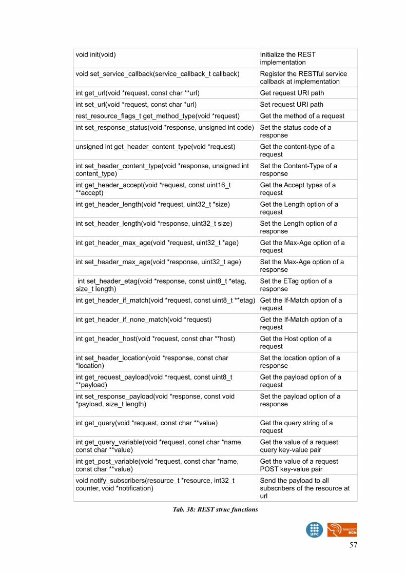
void init(void) Initialize the REST implementation
void set_service_callback(service_callback_t callback) Register the RESTful service callback at implementation
int get_url(void *request, const char **url) Get request URI path
int set_url(void *request, const char *url) Set request URI path
rest_resource_flags_t get_method_type(void *request) Get the method of a request
int set_response_status(void *response, unsigned int code) Set the status code of a response
unsigned int get_header_content_type(void *request) Get the content-type of a request
int set_header_content_type(void *response, unsigned int content_type)
Set the Content-Type of a response
int get_header_accept(void *request, const uint16_t **accept)
Get the Accept types of a request
int get_header_length(void *request, uint32_t *size) Get the Length option of a request
int set_header_length(void *response, uint32_t size) Set the Length option of a response
int get_header_max_age(void *request, uint32_t *age) Get the Max-Age option of a request
int set_header_max_age(void *response, uint32_t age) Set the Max-Age option of a response
int set_header_etag(void *response, const uint8_t *etag, size_t length)
Set the ETag option of a response
int get_header_if_match(void *request, const uint8_t **etag) Get the If-Match option of a request
int get_header_if_none_match(void *request) Get the If-Match option of a request
int get_header_host(void *request, const char **host) Get the Host option of a request
int set_header_location(void *response, const char *location)
Set the location option of a response
int get_request_payload(void *request, const uint8_t **payload)
Get the payload option of a request
int set_response_payload(void *response, const void *payload, size_t length)
Set the payload option of a response
int get_query(void *request, const char **value) Get the query string of a request
int get_query_variable(void *request, const char *name, const char **value)
Get the value of a request query key-value pair
int get_post_variable(void *request, const char *name, const char **value)
Get the value of a request POST key-value pair
void notify_subscribers(resource_t *resource, int32_t counter, void *notification)
Send the payload to all subscribers of the resource at url
Tab. 38: REST struc functions
57

type.TEXT_PLAIN
type.TEXT_XML
type.TEXT_CSV
type.TEXT_HTML
type.IMAGE_GIF
type.IMAGE_JPEG
type.IMAGE_PNG
type.IMAGE_TIFF
type.AUDIO_RAW
type.VIDEO_RAW
type.APPLICATION_LINK_FORMAT
type.APPLICATION_XML
type.APPLICATION_OCTET_STREAM
type.APPLICATION_RDF_XML
type.APPLICATION_SOAP_XML
type.APPLICATION_ATOM_XML
type.APPLICATION_XMPP_XML
type.APPLICATION_EXI
type.APPLICATION_FASTINFOSET
type.APPLICATION_SOAP_FASTINFOSET
type.APPLICATION_JSON
type.APPLICATION_X_OBIX_BINARY
Tab. 39: REST content-type constants
status.OK CONTENT_2_05, OK_200
status.CREATED CREATED_2_01, CREATED_201
status.CHANGED CHANGED_2_04, NO_CONTENT_204
status.DELETED DELETED_2_02, NO_CONTENT_204
status.NOT_MODIFIED VALID_2_03, NOT_MODIFIED_304
status.BAD_REQUEST BAD_REQUEST_4_00, BAD_REQUEST_400
status.UNAUTHORIZED UNAUTHORIZED_4_01, UNAUTHORIZED_401
status.BAD_OPTION BAD_OPTION_4_02, BAD_REQUEST_400
status.FORBIDDEN FORBIDDEN_4_03, FORBIDDEN_403
status.NOT_FOUND NOT_FOUND_4_04, NOT_FOUND_404
status.METHOD_NOT_ALLOWED METHOD_NOT_ALLOWED_4_05, METHOD_NOT_ALLOWED_405
status.NOT_ACCEPTABLE NOT_ACCEPTABLE_4_06, NOT_ACCEPTABLE_406
status.REQUEST_ENTITY_TOO_LARGE REQUEST_ENTITY_TOO_LARGE_4_13, REQUEST_ENTITY_TOO_LARGE_413
status.UNSUPPORTED_MEDIA_TYPE UNSUPPORTED_MEDIA_TYPE_4_15, UNSUPPORTED_MEDIA_TYPE_415
58
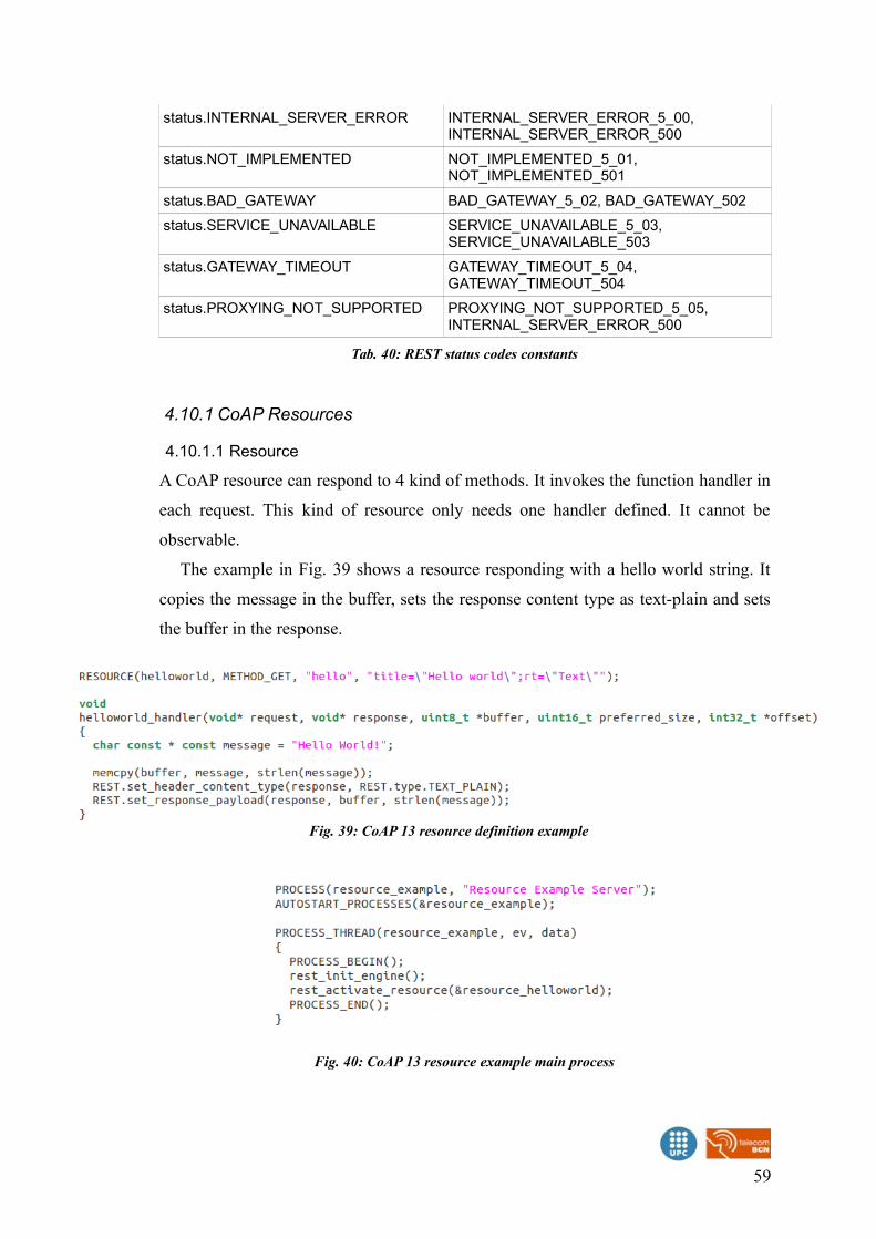
status.INTERNAL_SERVER_ERROR INTERNAL_SERVER_ERROR_5_00, INTERNAL_SERVER_ERROR_500
status.NOT_IMPLEMENTED NOT_IMPLEMENTED_5_01, NOT_IMPLEMENTED_501
status.BAD_GATEWAY BAD_GATEWAY_5_02, BAD_GATEWAY_502
status.SERVICE_UNAVAILABLE SERVICE_UNAVAILABLE_5_03, SERVICE_UNAVAILABLE_503
status.GATEWAY_TIMEOUT GATEWAY_TIMEOUT_5_04, GATEWAY_TIMEOUT_504
status.PROXYING_NOT_SUPPORTED PROXYING_NOT_SUPPORTED_5_05, INTERNAL_SERVER_ERROR_500
Tab. 40: REST status codes constants
4.10.1 CoAP Resources
4.10.1.1 Resource
A CoAP resource can respond to 4 kind of methods. It invokes the function handler in
each request. This kind of resource only needs one handler defined. It cannot be
observable.
The example in Fig. 39 shows a resource responding with a hello world string. It
copies the message in the buffer, sets the response content type as text-plain and sets
the buffer in the response.
59
Fig. 39: CoAP 13 resource definition example
Fig. 40: CoAP 13 resource example main process
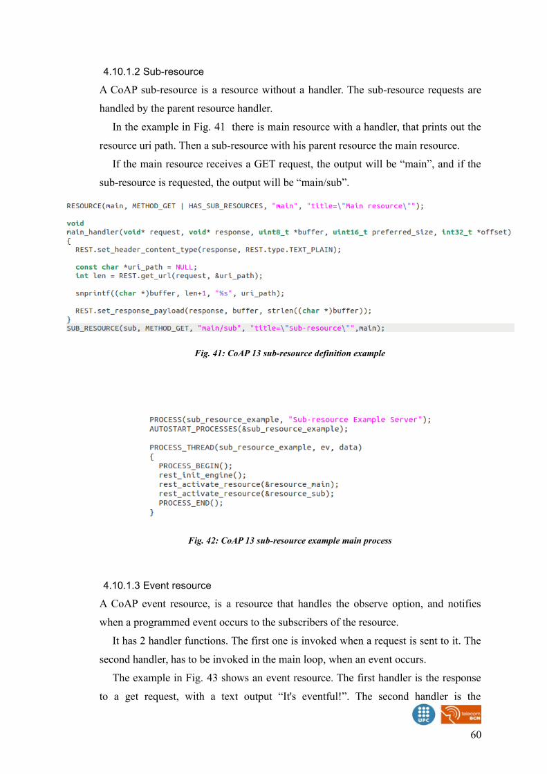
4.10.1.2 Sub-resource
A CoAP sub-resource is a resource without a handler. The sub-resource requests are
handled by the parent resource handler.
In the example in Fig. 41 there is main resource with a handler, that prints out the
resource uri path. Then a sub-resource with his parent resource the main resource.
If the main resource receives a GET request, the output will be “main”, and if the
sub-resource is requested, the output will be “main/sub”.
4.10.1.3 Event resource
A CoAP event resource, is a resource that handles the observe option, and notifies
when a programmed event occurs to the subscribers of the resource.
It has 2 handler functions. The first one is invoked when a request is sent to it. The
second handler, has to be invoked in the main loop, when an event occurs.
The example in Fig. 43 shows an event resource. The first handler is the response
to a get request, with a text output “It's eventful!”. The second handler is the
60
Fig. 41: CoAP 13 sub-resource definition example
Fig. 42: CoAP 13 sub-resource example main process
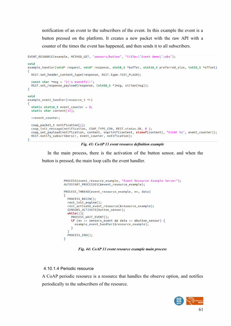
notification of an event to the subscribers of the event. In this example the event is a
button pressed on the platform. It creates a new packet with the raw API with a
counter of the times the event has happened, and then sends it to all subscribers.
In the main process, there is the activation of the button sensor, and when the
button is pressed, the main loop calls the event handler.
4.10.1.4 Periodic resource
A CoAP periodic resource is a resource that handles the observe option, and notifies
periodically to the subscribers of the resource.
61
Fig. 43: CoAP 13 event resource definition example
Fig. 44: CoAP 13 event resource example main process
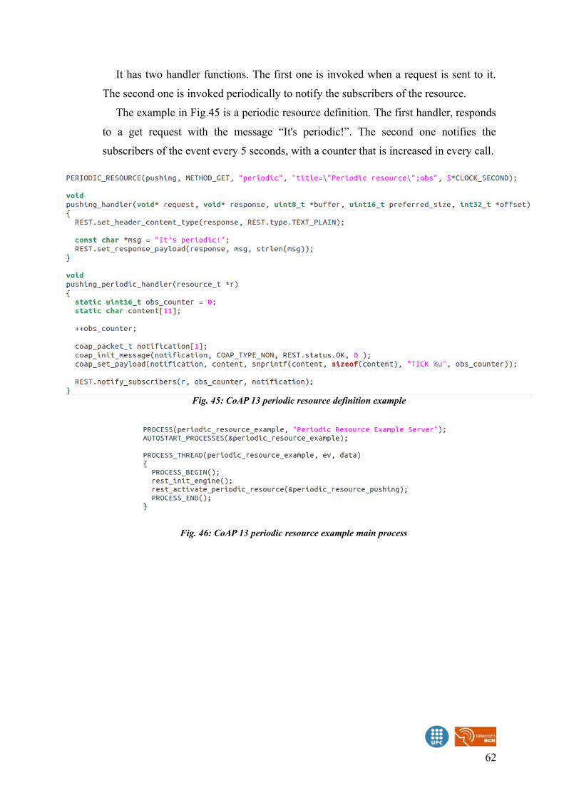
It has two handler functions. The first one is invoked when a request is sent to it.
The second one is invoked periodically to notify the subscribers of the resource.
The example in Fig.45 is a periodic resource definition. The first handler, responds
to a get request with the message “It's periodic!”. The second one notifies the
subscribers of the event every 5 seconds, with a counter that is increased in every call.
62
Fig. 45: CoAP 13 periodic resource definition example
Fig. 46: CoAP 13 periodic resource example main process
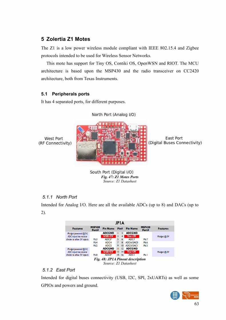
5 Zolertia Z1 Motes
The Z1 is a low power wireless module compliant with IEEE 802.15.4 and Zigbee
protocols intended to be used for Wireless Sensor Networks.
This mote has support for Tiny OS, Contiki OS, OpenWSN and RIOT. The MCU
architecture is based upon the MSP430 and the radio transceiver on CC2420
architecture, both from Texas Instruments.
5.1 Peripherals ports
It has 4 separated ports, for different purposes.
5.1.1 North Port
Intended for Analog I/O. Here are all the available ADCs (up to 8) and DACs (up to
2).
5.1.2 East Port
Intended for digital buses connectivity (USB, I2C, SPI, 2xUARTs) as well as some
GPIOs and powers and ground.
63
Fig. 47: Z1 Motes PortsSource: Z1 Datasheet
Fig. 48: JP1A Pinout descriptionSource: Z1 Datasheet
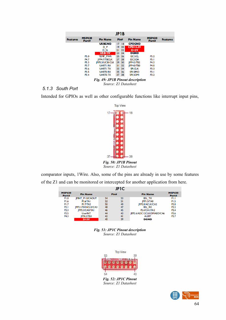
5.1.3 South Port
Intended for GPIOs as well as other configurable functions like interrupt input pins,
comparator inputs, 1Wire. Also, some of the pins are already in use by some features
of the Z1 and can be monitored or intercepted for another application from here.
64
Fig. 49: JP1B Pinout descriptionSource: Z1 Datasheet
Fig. 50: JP1B PinoutSource: Z1 Datasheet
Fig. 51: JP1C Pinout descriptionSource: Z1 Datasheet
Fig. 52: JP1C PinoutSource: Z1 Datasheet
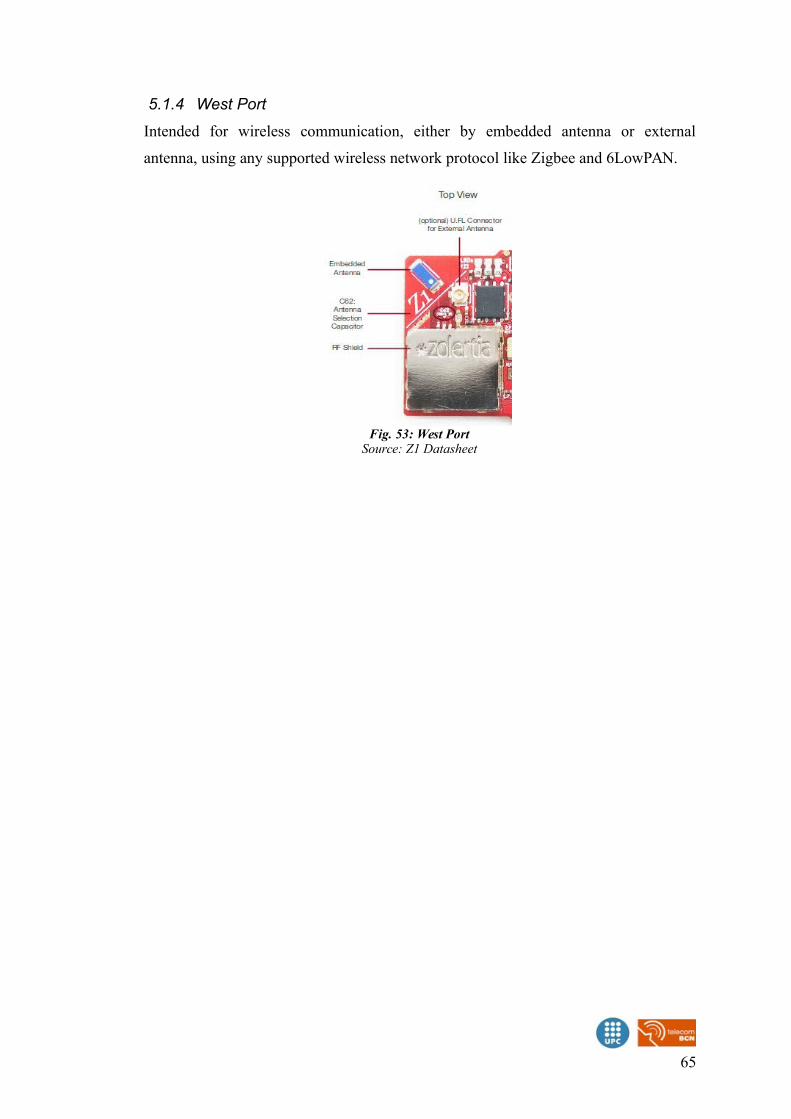
5.1.4 West Port
Intended for wireless communication, either by embedded antenna or external
antenna, using any supported wireless network protocol like Zigbee and 6LowPAN.
65
Fig. 53: West PortSource: Z1 Datasheet
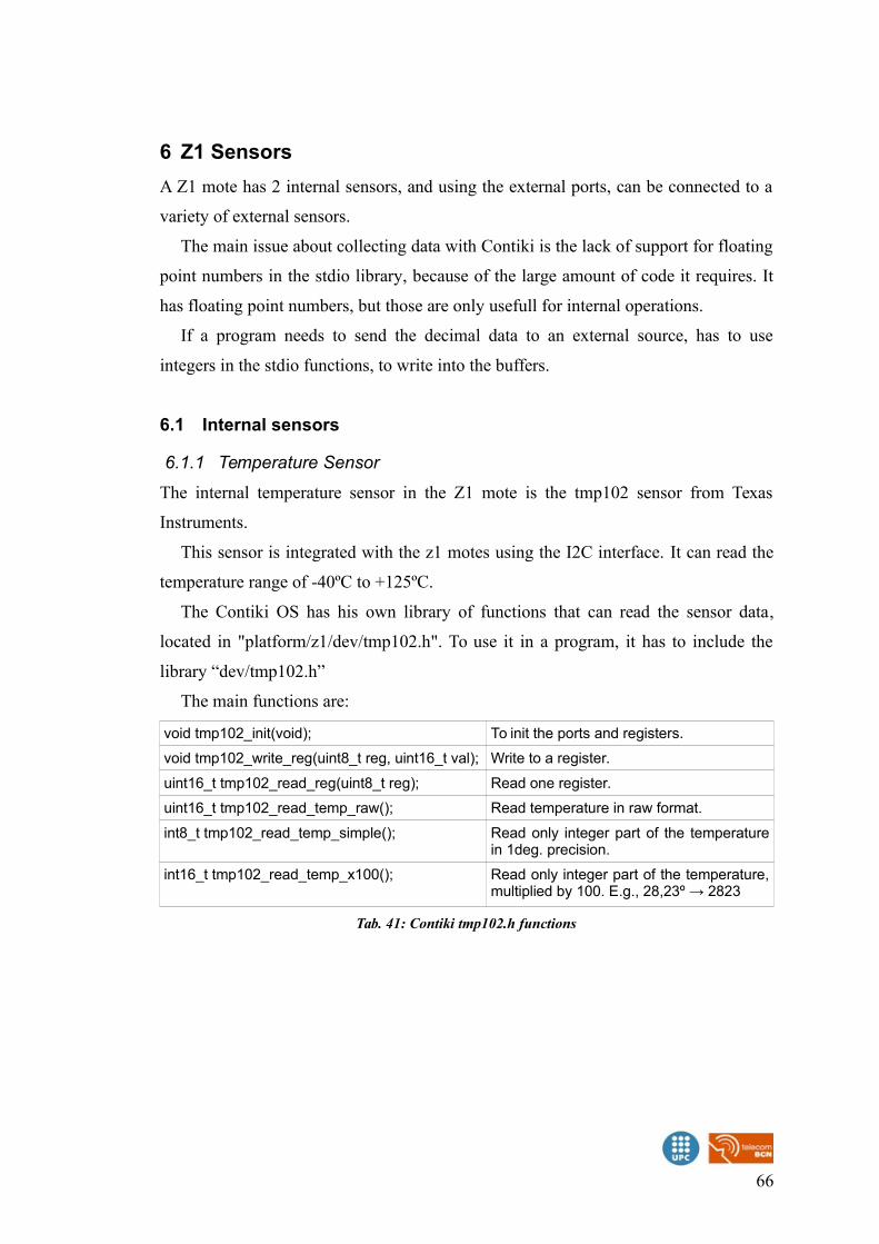
6 Z1 Sensors
A Z1 mote has 2 internal sensors, and using the external ports, can be connected to a
variety of external sensors.
The main issue about collecting data with Contiki is the lack of support for floating
point numbers in the stdio library, because of the large amount of code it requires. It
has floating point numbers, but those are only usefull for internal operations.
If a program needs to send the decimal data to an external source, has to use
integers in the stdio functions, to write into the buffers.
6.1 Internal sensors
6.1.1 Temperature Sensor
The internal temperature sensor in the Z1 mote is the tmp102 sensor from Texas
Instruments.
This sensor is integrated with the z1 motes using the I2C interface. It can read the
temperature range of -40ºC to +125ºC.
The Contiki OS has his own library of functions that can read the sensor data,
located in "platform/z1/dev/tmp102.h". To use it in a program, it has to include the
library “dev/tmp102.h”
The main functions are:
void tmp102_init(void); To init the ports and registers.
void tmp102_write_reg(uint8_t reg, uint16_t val); Write to a register.
uint16_t tmp102_read_reg(uint8_t reg); Read one register.
uint16_t tmp102_read_temp_raw(); Read temperature in raw format.
int8_t tmp102_read_temp_simple(); Read only integer part of the temperaturein 1deg. precision.
int16_t tmp102_read_temp_x100(); Read only integer part of the temperature,multiplied by 100. E.g., 28,23º → 2823
Tab. 41: Contiki tmp102.h functions
66
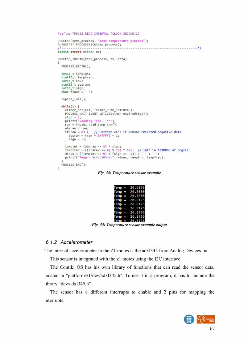
6.1.2 Accelerometer
The internal accelerometer in the Z1 motes is the adxl345 from Analog Devices Inc.
This sensor is integrated with the z1 motes using the I2C interface.
The Contiki OS has his own library of functions that can read the sensor data,
located in "platform/z1/dev/adxl345.h". To use it in a program, it has to include the
library “dev/adxl345.h”
The sensor has 8 different interrupts to enable and 2 pins for mapping the
interrupts.
67
Fig. 54: Temperature sensor example
Fig. 55: Temperature sensor example output
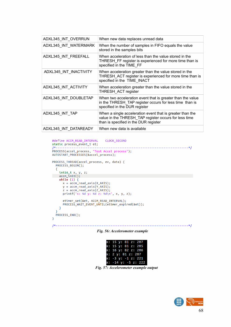
ADXL345_INT_OVERRUN When new data replaces unread data
ADXL345_INT_WATERMARK When the number of samples in FIFO equals the value stored in the samples bits
ADXL345_INT_FREEFALL When acceleration of less than the value stored in the THRESH_FF register is experienced for more time than is specified in the TIME_FF
ADXL345_INT_INACTIVITY When acceleration greater than the value stored in the THRESH_ACT register is experienced for more time than is specified in the TIME_INACT
ADXL345_INT_ACTIVITY When acceleration greater than the value stored in the THRESH_ACT register
ADXL345_INT_DOUBLETAP When two acceleration event that is greater than the value in the THRESH_TAP register occurs for less time than is specified in the DUR register
ADXL345_INT_TAP When a single acceleration event that is greater than the value in the THRESH_TAP register occurs for less time than is specified in the DUR register
ADXL345_INT_DATAREADY When new data is available
68
Fig. 56: Accelerometer example
Fig. 57: Accelerometer example output
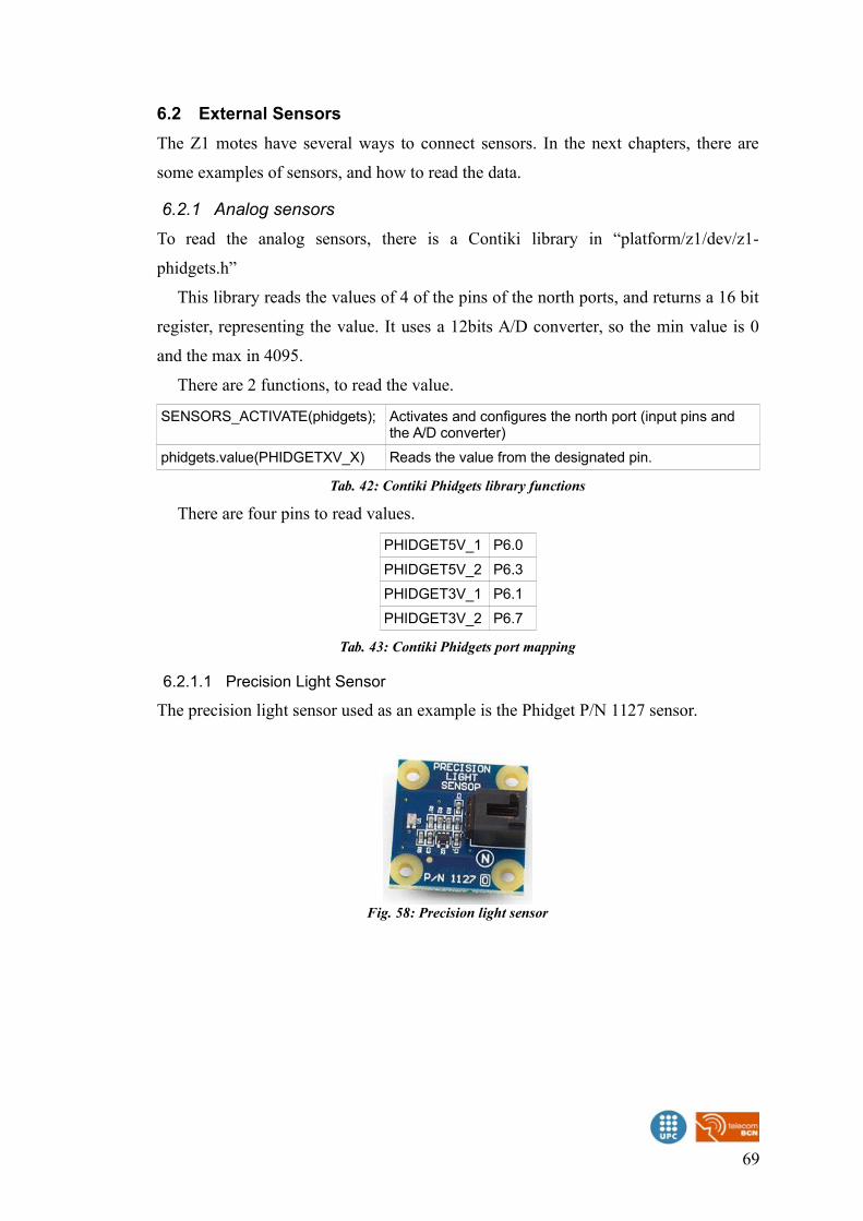
6.2 External Sensors
The Z1 motes have several ways to connect sensors. In the next chapters, there are
some examples of sensors, and how to read the data.
6.2.1 Analog sensors
To read the analog sensors, there is a Contiki library in “platform/z1/dev/z1-
phidgets.h”
This library reads the values of 4 of the pins of the north ports, and returns a 16 bit
register, representing the value. It uses a 12bits A/D converter, so the min value is 0
and the max in 4095.
There are 2 functions, to read the value.
SENSORS_ACTIVATE(phidgets); Activates and configures the north port (input pins and the A/D converter)
phidgets.value(PHIDGETXV_X) Reads the value from the designated pin.
Tab. 42: Contiki Phidgets library functions
There are four pins to read values.
PHIDGET5V_1 P6.0
PHIDGET5V_2 P6.3
PHIDGET3V_1 P6.1
PHIDGET3V_2 P6.7
Tab. 43: Contiki Phidgets port mapping
6.2.1.1 Precision Light Sensor
The precision light sensor used as an example is the Phidget P/N 1127 sensor.
69
Fig. 58: Precision light sensor

This sensor is an analog sensor that measures light intensities of up to 1000 lux. It
is a non-radiometric sensor. The output value does not depend on the input voltage,
but the input voltage will limit the maximum measurement value.
The sensor can be connected to the north port of the Z1 motes, into the 3V port or
the 5V port.
Light Level Min 1lx
Light Level Max (3.3V) 660 lx
Light Level Max (5V) 1 Klx
Tab. 44: Precision light measurement range
70
Fig. 60: Light sensor example code
Fig. 59: Precision light sensor with Z1
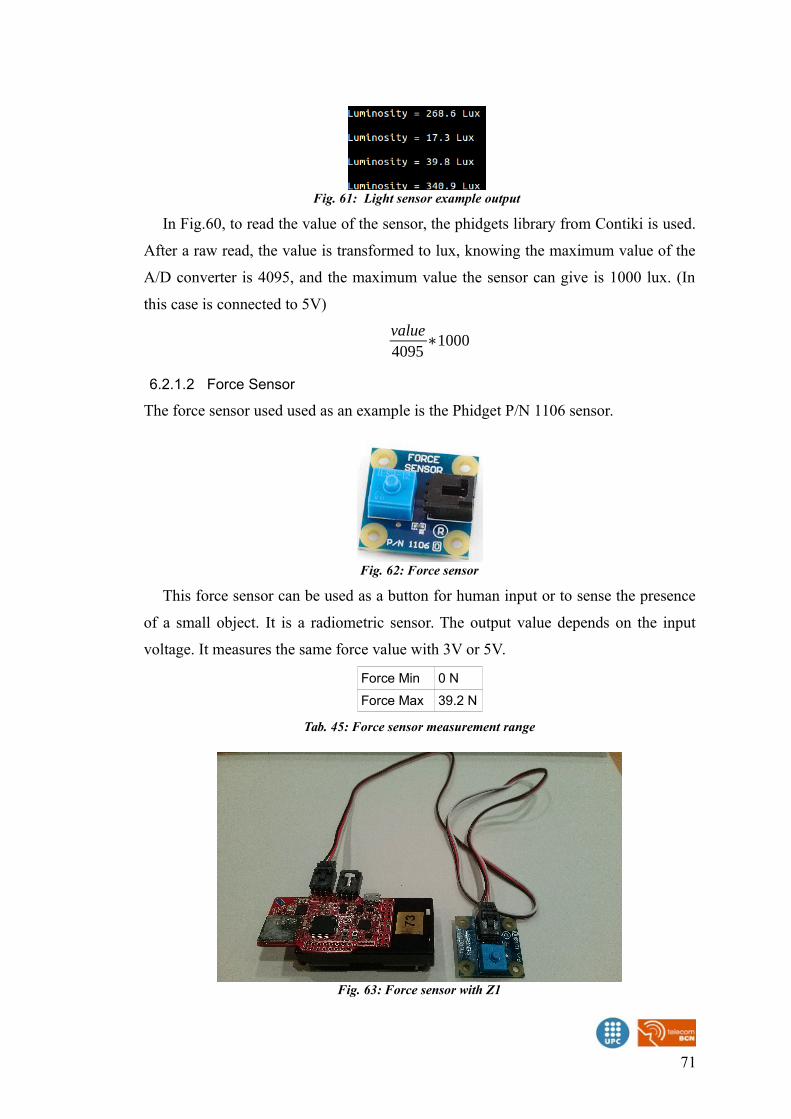
In Fig.60, to read the value of the sensor, the phidgets library from Contiki is used.
After a raw read, the value is transformed to lux, knowing the maximum value of the
A/D converter is 4095, and the maximum value the sensor can give is 1000 lux. (In
this case is connected to 5V)
value4095
∗1000
6.2.1.2 Force Sensor
The force sensor used used as an example is the Phidget P/N 1106 sensor.
This force sensor can be used as a button for human input or to sense the presence
of a small object. It is a radiometric sensor. The output value depends on the input
voltage. It measures the same force value with 3V or 5V.
Force Min 0 N
Force Max 39.2 N
Tab. 45: Force sensor measurement range
71
Fig. 62: Force sensor
Fig. 63: Force sensor with Z1
Fig. 61: Light sensor example output
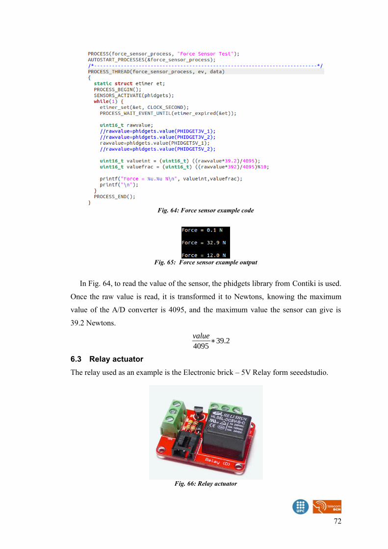
In Fig. 64, to read the value of the sensor, the phidgets library from Contiki is used.
Once the raw value is read, it is transformed it to Newtons, knowing the maximum
value of the A/D converter is 4095, and the maximum value the sensor can give is
39.2 Newtons.
value4095
∗39.2
6.3 Relay actuator
The relay used as an example is the Electronic brick – 5V Relay form seeedstudio.
72
Fig. 66: Relay actuator
Fig. 64: Force sensor example code
Fig. 65: Force sensor example output
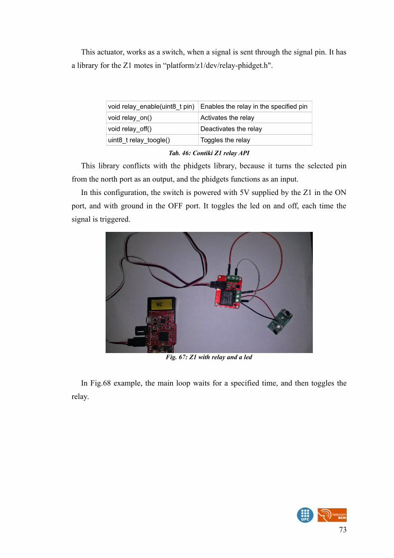
This actuator, works as a switch, when a signal is sent through the signal pin. It has
a library for the Z1 motes in “platform/z1/dev/relay-phidget.h".
void relay_enable(uint8_t pin) Enables the relay in the specified pin
void relay_on() Activates the relay
void relay_off() Deactivates the relay
uint8_t relay_toogle() Toggles the relay
Tab. 46: Contiki Z1 relay API
This library conflicts with the phidgets library, because it turns the selected pin
from the north port as an output, and the phidgets functions as an input.
In this configuration, the switch is powered with 5V supplied by the Z1 in the ON
port, and with ground in the OFF port. It toggles the led on and off, each time the
signal is triggered.
In Fig.68 example, the main loop waits for a specified time, and then toggles the
relay.
73
Fig. 67: Z1 with relay and a led
6.3.1 Distance sensor
The distance sensor used as an example is the SEN-12784 from SparkFun. It has an
VL6180 digital sensor integrated, that can read light and distance.
It uses the an I2C interface to extract the values from the sensor registers.
Contiki has a I2C interface library adapter for the Z1 motes in
“platform/z1/dev/i2cmater.h” To use it in a program, it has to include the library
“dev/i2cmaster.h”
74
Fig. 69: SEN-12784
Fig. 70: Z1 with distance sensor
Fig. 68: Relay toggle example
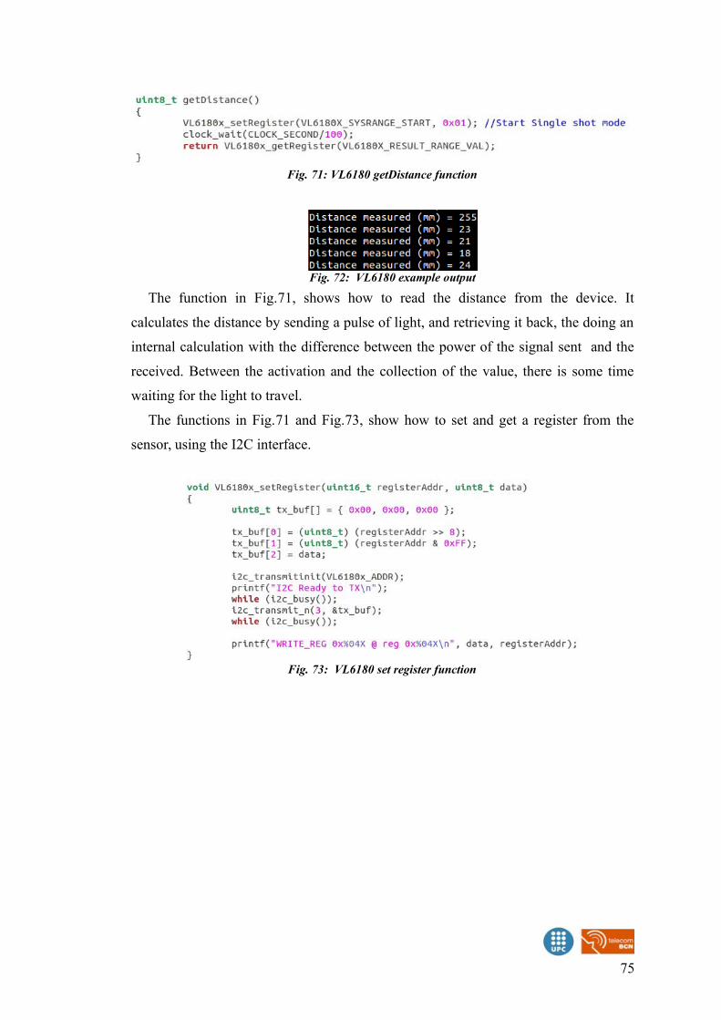
The function in Fig.71, shows how to read the distance from the device. It
calculates the distance by sending a pulse of light, and retrieving it back, the doing an
internal calculation with the difference between the power of the signal sent and the
received. Between the activation and the collection of the value, there is some time
waiting for the light to travel.
The functions in Fig.71 and Fig.73, show how to set and get a register from the
sensor, using the I2C interface.
75
Fig. 73: VL6180 set register function
Fig. 71: VL6180 getDistance function
Fig. 72: VL6180 example output
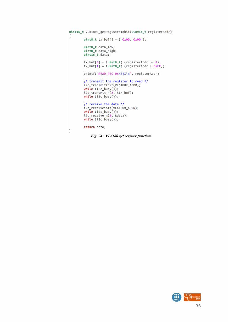
76
Fig. 74: VL6180 get register function
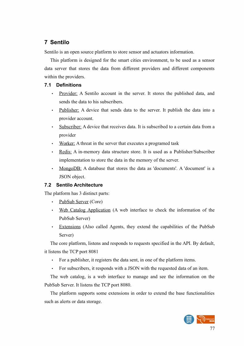
7 Sentilo
Sentilo is an open source platform to store sensor and actuators information.
This platform is designed for the smart cities environment, to be used as a sensor
data server that stores the data from different providers and different components
within the providers.
7.1 Definitions
• Provider: A Sentilo account in the server. It stores the published data, and
sends the data to his subscribers.
• Publisher: A device that sends data to the server. It publish the data into a
provider account.
• Subscriber: A device that receives data. It is subscribed to a certain data from a
provider
• Worker: A threat in the server that executes a programed task
• Redis: A in-memory data structure store. It is used as a Publisher/Subscriber
implementation to store the data in the memory of the server.
• MongoDB: A database that stores the data as 'documents'. A 'document' is a
JSON object.
7.2 Sentilo Architecture
The platform has 3 distinct parts:
• PubSub Server (Core)
• Web Catalog Application (A web interface to check the information of the
PubSub Server)
• Extensions (Also called Agents, they extend the capabilities of the PubSub
Server)
The core platform, listens and responds to requests specified in the API. By default,
it listens the TCP port 8081
• For a publisher, it registers the data sent, in one of the platform items.
• For subscribers, it responds with a JSON with the requested data of an item.
The web catalog, is a web interface to manage and see the information on the
PubSub Server. It listens the TCP port 8080.
The platform supports some extensions in order to extend the base functionalities
such as alerts or data storage.
77
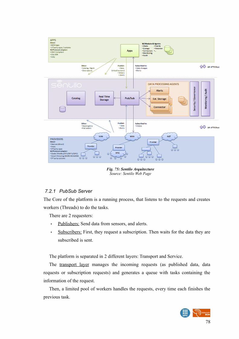
7.2.1 PubSub Server
The Core of the platform is a running process, that listens to the requests and creates
workers (Threads) to do the tasks.
There are 2 requesters:
• Publishers: Send data from sensors, and alerts.
• Subscribers: First, they request a subscription. Then waits for the data they are
subscribed is sent.
The platform is separated in 2 different layers: Transport and Service.
The transport layer manages the incoming requests (as published data, data
requests or subscription requests) and generates a queue with tasks containing the
information of the request.
Then, a limited pool of workers handles the requests, every time each finishes the
previous task.
78
Fig. 75: Sentilo ArquitectureSource: Sentilo Web Page
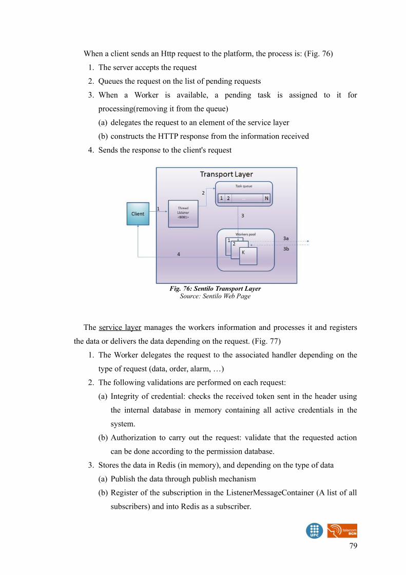
When a client sends an Http request to the platform, the process is: (Fig. 76)
1. The server accepts the request
2. Queues the request on the list of pending requests
3. When a Worker is available, a pending task is assigned to it for
processing(removing it from the queue)
(a) delegates the request to an element of the service layer
(b) constructs the HTTP response from the information received
4. Sends the response to the client's request
The service layer manages the workers information and processes it and registers
the data or delivers the data depending on the request. (Fig. 77)
1. The Worker delegates the request to the associated handler depending on the
type of request (data, order, alarm, …)
2. The following validations are performed on each request:
(a) Integrity of credential: checks the received token sent in the header using
the internal database in memory containing all active credentials in the
system.
(b) Authorization to carry out the request: validate that the requested action
can be done according to the permission database.
3. Stores the data in Redis (in memory), and depending on the type of data
(a) Publish the data through publish mechanism
(b) Register of the subscription in the ListenerMessageContainer (A list of all
subscribers) and into Redis as a subscriber.
79
Fig. 76: Sentilo Transport LayerSource: Sentilo Web Page
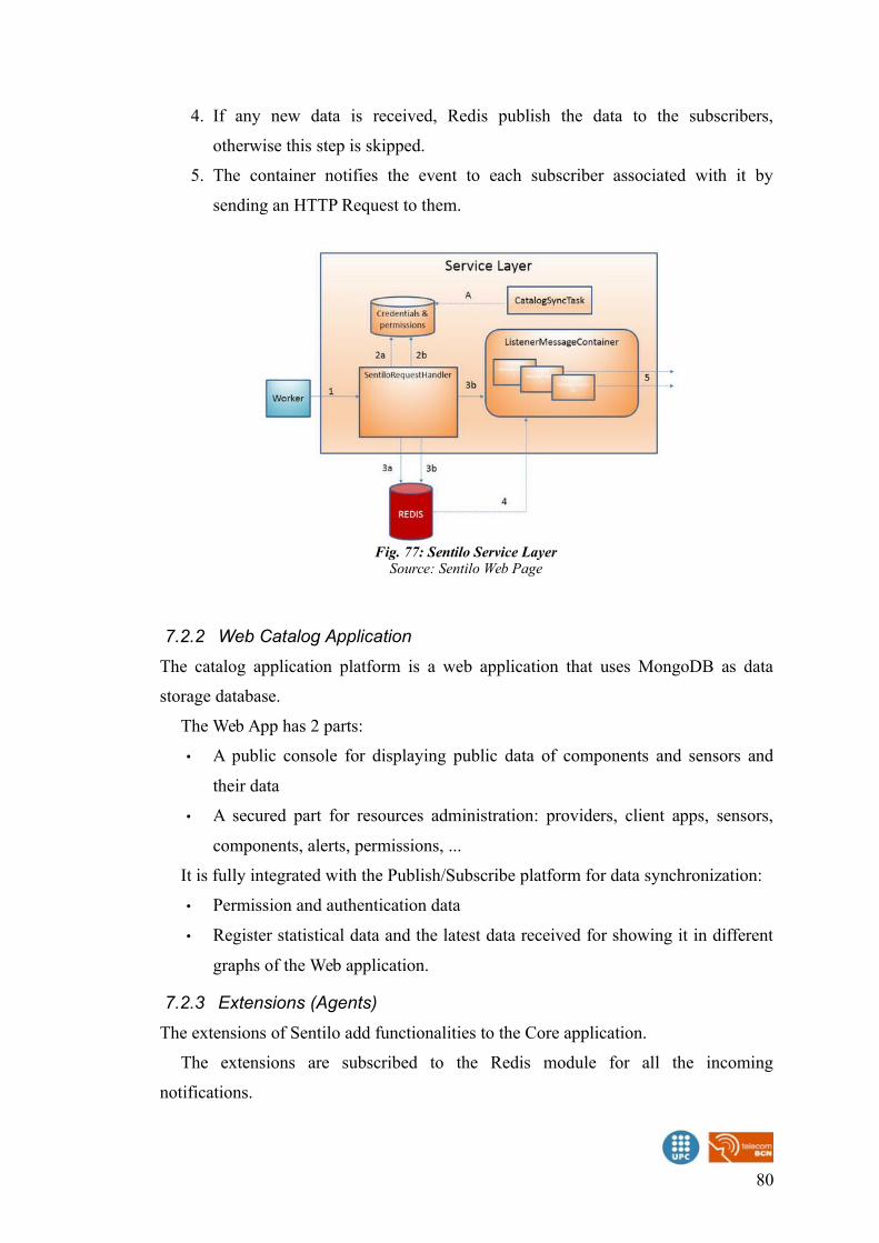
4. If any new data is received, Redis publish the data to the subscribers,
otherwise this step is skipped.
5. The container notifies the event to each subscriber associated with it by
sending an HTTP Request to them.
7.2.2 Web Catalog Application
The catalog application platform is a web application that uses MongoDB as data
storage database.
The Web App has 2 parts:
• A public console for displaying public data of components and sensors and
their data
• A secured part for resources administration: providers, client apps, sensors,
components, alerts, permissions, ...
It is fully integrated with the Publish/Subscribe platform for data synchronization:
• Permission and authentication data
• Register statistical data and the latest data received for showing it in different
graphs of the Web application.
7.2.3 Extensions (Agents)
The extensions of Sentilo add functionalities to the Core application.
The extensions are subscribed to the Redis module for all the incoming
notifications.
80
Fig. 77: Sentilo Service LayerSource: Sentilo Web Page
When Redis receives a publication of data, sends a message to all subscribers,
including all the agents.
The agent gets the data, and carries out his task.
Currently there are 3 Sentilo agents:
• Relational database agent
◦ Stores all the incoming data in a external database
• Alarm agent
◦ Manages the internal alerts defined into the Web Catalog and published an
alert if the condition is met.
• Location updater agent
◦ Is responsible of updating automatically the component location according
to the location of the published observations.
7.3 Sentilo structure
The platform has 5 main items:
• Component
• Sensor
• Alert
• Alarm
• Order
A component is the item where a set of sensors is attached.
A sensor is a representation of a physical sensor, it is attached to a component. The
data published is sent for a specific sensor.
An alert is a trigger registered in Sentilo when an event happens. There a 2 types of
alerts: internal and external.
The internal alerts are related to specific sensors and it's logic is defined using
basic math rules or configuring an inactivity time.
The external alerts are defined by third party entities, which will be the responsible
of calculating their logic and throw the related alarms when applies.
An alarm is the message sent to the subscribers of an alert when it is triggered.
Must be attached to an alert.
An order is a message registered for a specific sensor or component. It is received
by the subscribers of the sensor or component orders.
81
7.4 Sentilo API
The Application Programming Interface (API) define a set of commands, functions
and protocols that must be followed by who wants to interact with the platform from
external systems, like sensors/actuators or applications.
The requests are HTTP requests with 3 fields in the header:
• The Request Method: GET, POST, PUT
• IDENTITY_KEY: The authentication token
• Content-Type: application/json
The platform has 3 operations for publishers:
• Retrieve data: Using the GET method, any kind of data can be consulted, the
response is in JSON format
• Register data: Using the POST method, can be registered components, sensors
alerts, alarms or orders.
• Update data: Using the PUT method, components, sensors alerts, alarms and
orders data can be updated. Also sensor data can be published.
It also has 3 kind of subscriptions:
• To sensor data
• To orders
• To alerts
All the documentation of the Application Programming Interface can be found in:
• http://www.sentilo.io/xwiki/bin/view/APIDocs/WebHome
82
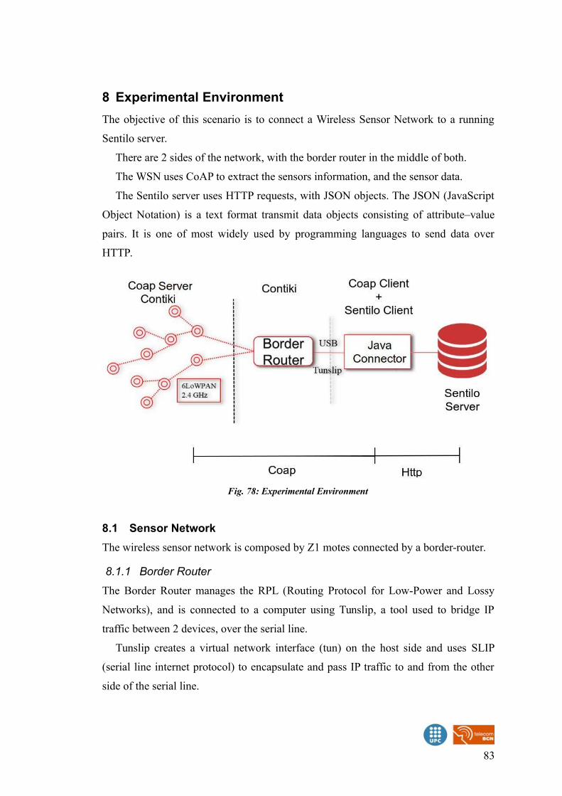
8 Experimental Environment
The objective of this scenario is to connect a Wireless Sensor Network to a running
Sentilo server.
There are 2 sides of the network, with the border router in the middle of both.
The WSN uses CoAP to extract the sensors information, and the sensor data.
The Sentilo server uses HTTP requests, with JSON objects. The JSON (JavaScript
Object Notation) is a text format transmit data objects consisting of attribute–value
pairs. It is one of most widely used by programming languages to send data over
HTTP.
8.1 Sensor Network
The wireless sensor network is composed by Z1 motes connected by a border-router.
8.1.1 Border Router
The Border Router manages the RPL (Routing Protocol for Low-Power and Lossy
Networks), and is connected to a computer using Tunslip, a tool used to bridge IP
traffic between 2 devices, over the serial line.
Tunslip creates a virtual network interface (tun) on the host side and uses SLIP
(serial line internet protocol) to encapsulate and pass IP traffic to and from the other
side of the serial line.
83
Fig. 78: Experimental Environment
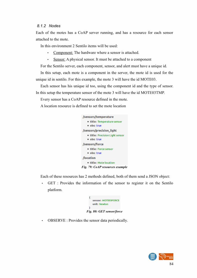
8.1.2 Nodes
Each of the motes has a CoAP server running, and has a resource for each sensor
attached to the mote.
In this environment 2 Sentilo items will be used:
• Component: The hardware where a sensor is attached.
• Sensor: A physical sensor. It must be attached to a component
For the Sentilo server, each component, sensor, and alert must have a unique id.
In this setup, each mote is a component in the server, the mote id is used for the
unique id in sentilo. For this example, the mote 3 will have the id MOTE03.
Each sensor has his unique id too, using the component id and the type of sensor.
In this setup the temperature sensor of the mote 3 will have the id MOTE03TMP.
Every sensor has a CoAP resource defined in the mote.
A location resource is defined to set the mote location
Each of these resources has 2 methods defined, both of them send a JSON object:
• GET : Provides the information of the sensor to register it on the Sentilo
platform.
• OBSERVE : Provides the sensor data periodically.
84
Fig. 79: CoAP resources example
Fig. 80: GET sensor/force
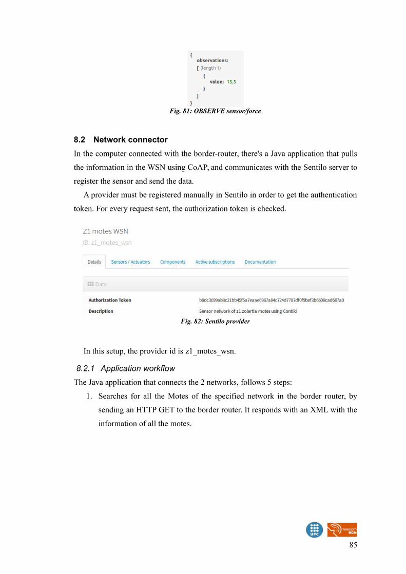
8.2 Network connector
In the computer connected with the border-router, there's a Java application that pulls
the information in the WSN using CoAP, and communicates with the Sentilo server to
register the sensor and send the data.
A provider must be registered manually in Sentilo in order to get the authentication
token. For every request sent, the authorization token is checked.
In this setup, the provider id is z1_motes_wsn.
8.2.1 Application workflow
The Java application that connects the 2 networks, follows 5 steps:
1. Searches for all the Motes of the specified network in the border router, by
sending an HTTP GET to the border router. It responds with an XML with the
information of all the motes.
85
Fig. 82: Sentilo provider
Fig. 81: OBSERVE sensor/force
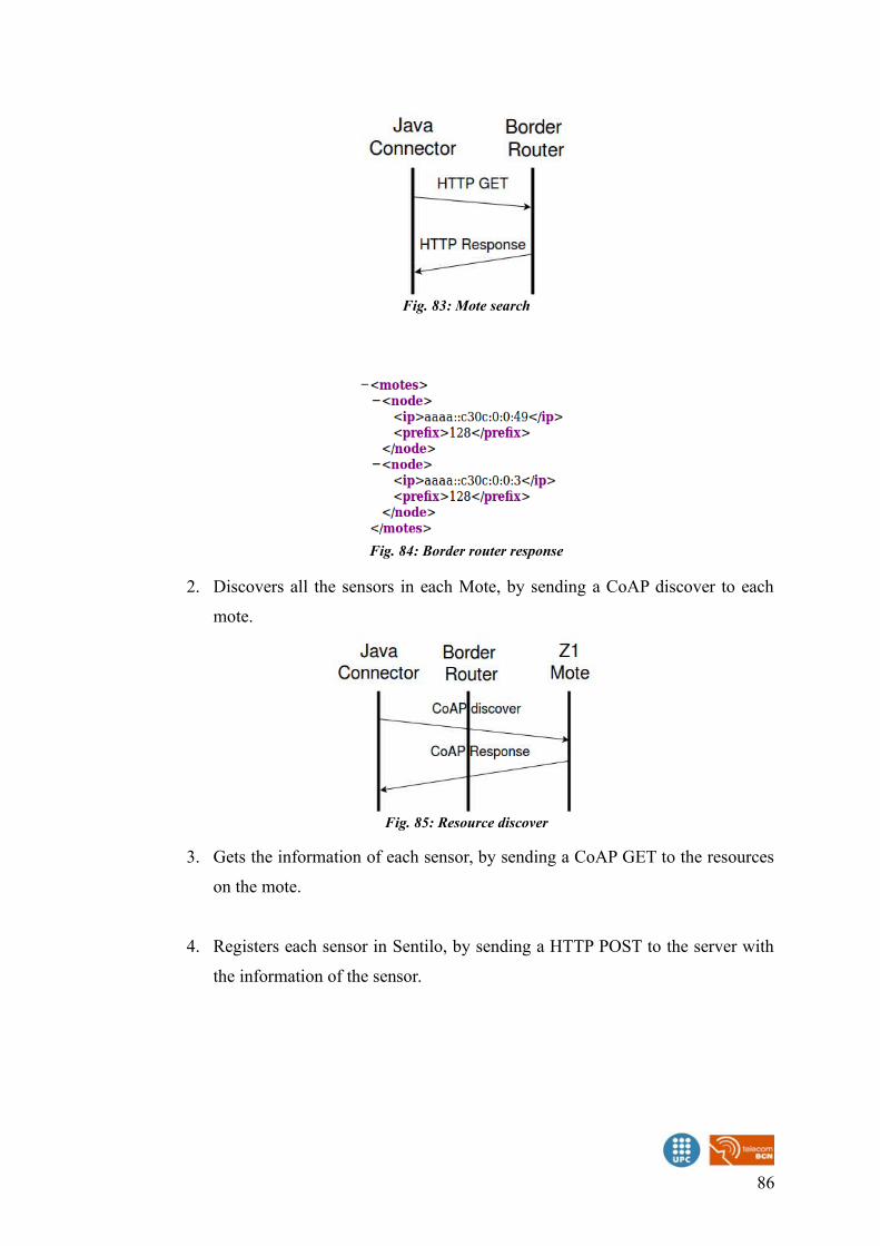
2. Discovers all the sensors in each Mote, by sending a CoAP discover to each
mote.
3. Gets the information of each sensor, by sending a CoAP GET to the resources
on the mote.
4. Registers each sensor in Sentilo, by sending a HTTP POST to the server with
the information of the sensor.
86
Fig. 83: Mote search
Fig. 84: Border router response
Fig. 85: Resource discover
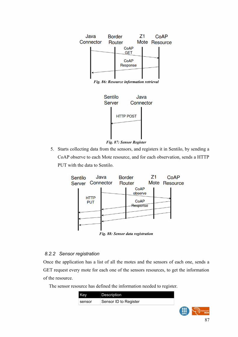
5. Starts collecting data from the sensors, and registers it in Sentilo, by sending a
CoAP observe to each Mote resource, and for each observation, sends a HTTP
PUT with the data to Sentilo.
8.2.2 Sensor registration
Once the application has a list of all the motes and the sensors of each one, sends a
GET request every mote for each one of the sensors resources, to get the information
of the resource.
The sensor resource has defined the information needed to register.
Key Description
sensor Sensor ID to Register
87
Fig. 86: Resource information retrieval
Fig. 87: Sensor Register
Fig. 88: Sensor data registration
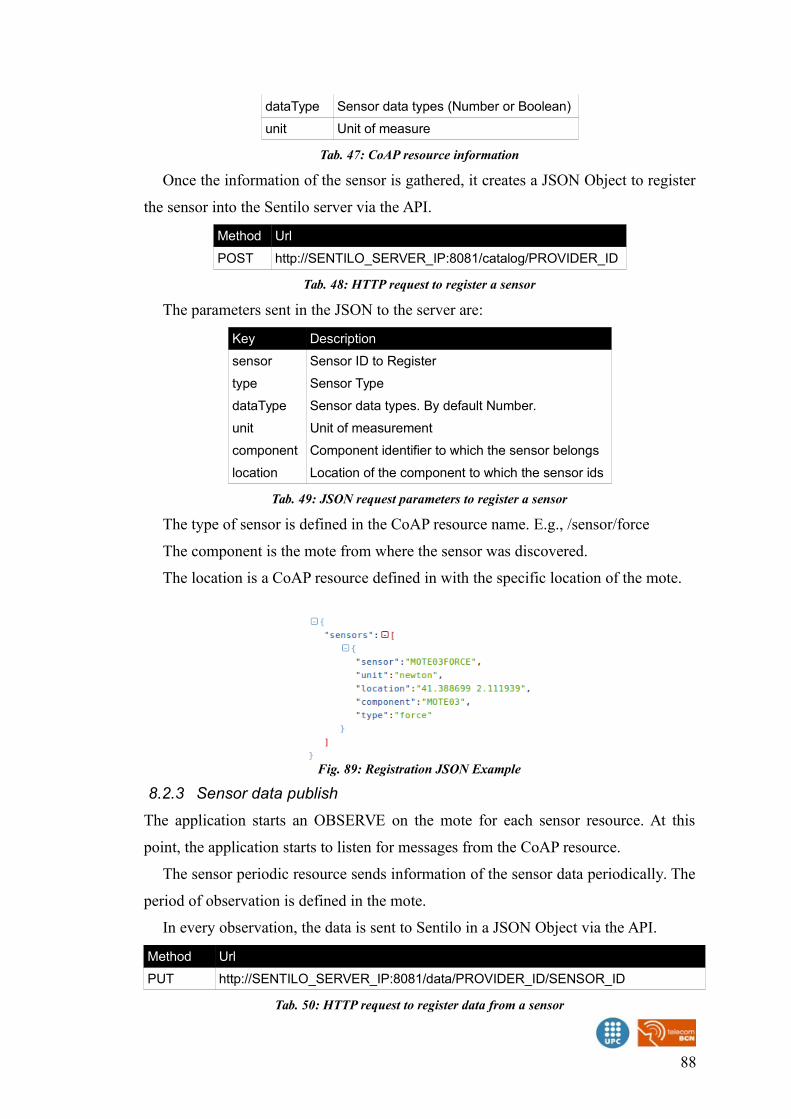
dataType Sensor data types (Number or Boolean)
unit Unit of measure
Tab. 47: CoAP resource information
Once the information of the sensor is gathered, it creates a JSON Object to register
the sensor into the Sentilo server via the API.
Method Url
POST http://SENTILO_SERVER_IP:8081/catalog/PROVIDER_ID
Tab. 48: HTTP request to register a sensor
The parameters sent in the JSON to the server are:
Key Description
sensor Sensor ID to Register
type Sensor Type
dataType Sensor data types. By default Number.
unit Unit of measurement
component Component identifier to which the sensor belongs
location Location of the component to which the sensor ids
Tab. 49: JSON request parameters to register a sensor
The type of sensor is defined in the CoAP resource name. E.g., /sensor/force
The component is the mote from where the sensor was discovered.
The location is a CoAP resource defined in with the specific location of the mote.
8.2.3 Sensor data publish
The application starts an OBSERVE on the mote for each sensor resource. At this
point, the application starts to listen for messages from the CoAP resource.
The sensor periodic resource sends information of the sensor data periodically. The
period of observation is defined in the mote.
In every observation, the data is sent to Sentilo in a JSON Object via the API.
Method Url
PUT http://SENTILO_SERVER_IP:8081/data/PROVIDER_ID/SENSOR_ID
Tab. 50: HTTP request to register data from a sensor
88
Fig. 89: Registration JSON Example

The parameters sent in the JSON to the server are:
Key Description
value Observation value to register (number or boolean)
Tab. 51: JSON request parameters to register data from a sensor
89
Fig. 90: Publication JSON Example
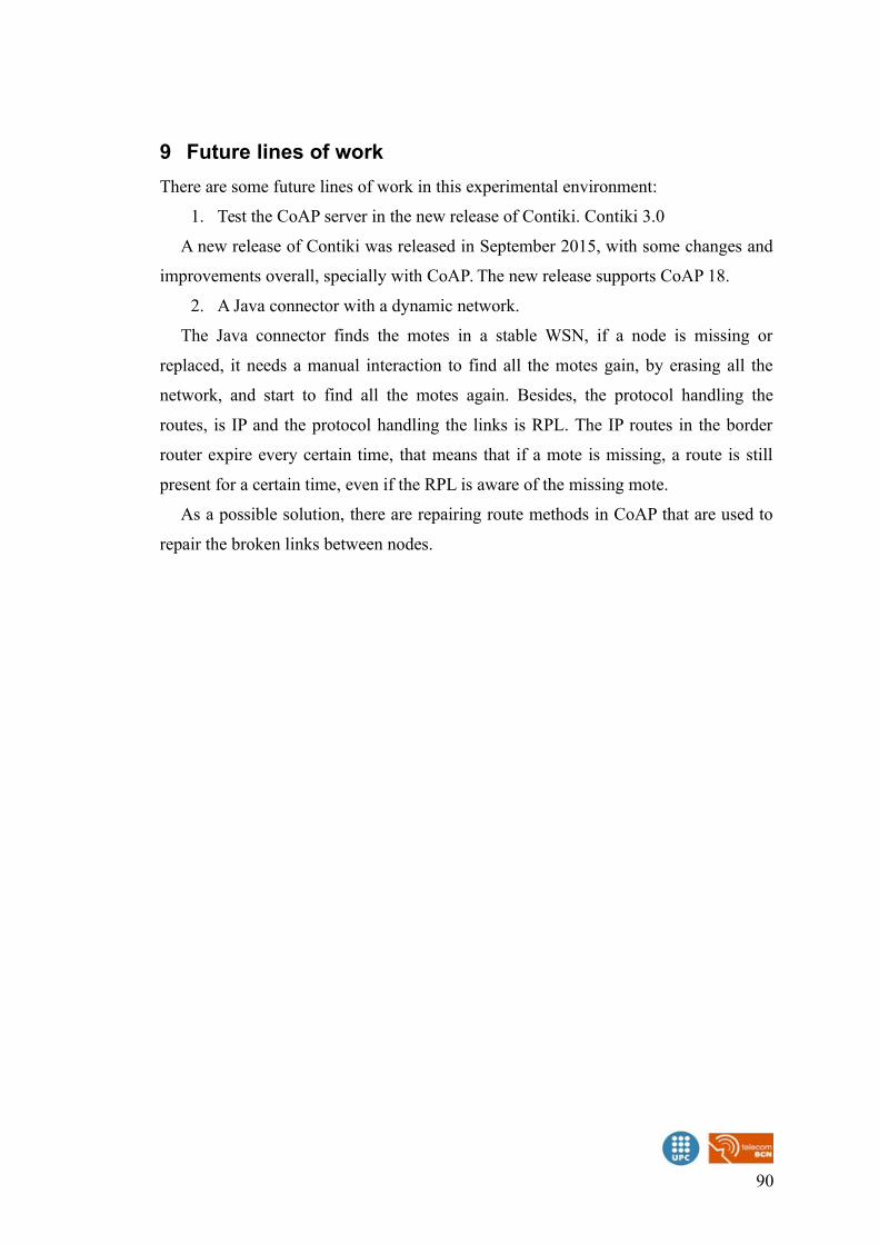
9 Future lines of work
There are some future lines of work in this experimental environment:
1. Test the CoAP server in the new release of Contiki. Contiki 3.0
A new release of Contiki was released in September 2015, with some changes and
improvements overall, specially with CoAP. The new release supports CoAP 18.
2. A Java connector with a dynamic network.
The Java connector finds the motes in a stable WSN, if a node is missing or
replaced, it needs a manual interaction to find all the motes gain, by erasing all the
network, and start to find all the motes again. Besides, the protocol handling the
routes, is IP and the protocol handling the links is RPL. The IP routes in the border
router expire every certain time, that means that if a mote is missing, a route is still
present for a certain time, even if the RPL is aware of the missing mote.
As a possible solution, there are repairing route methods in CoAP that are used to
repair the broken links between nodes.
90
10 Conclusion
The Contiki OS, collects all the technologies needed for the development of
centralized data collectors, for the sensors. This platform combined with Sentilo,
creates a real application platform, to be able to deploy in several possible real
environments.
The main advantages of Contiki, are how easy is to create code, and generate
concurrent scenarios inside the same mote, being able to have a web server at the
same time a root node of a WSN is running, without complexity.
At the same time , the application level library as COAP, with the complete
examples of this libraries, makes this system a powerful and versatile tool.
A disadvantage of this platform, is the lack of documentation and examples,
outside the inner code. There's a lot of time and test to make, for a more complex
application.
Secondly, the Sentilo platform, is an easy to install, use and program applications
with. It has a wide set of options and tools, that need to be understand carefully for a
rich application that uses all the functionalities properly.
The combinations of both, makes a good, simple and potentially improvable
scenario, for centralize data collection.
91
11 Appendix I: Contiki OS 2.7 workspace in Ubuntu 14.04
To setup the environment, we need to:
• Download Contiki OS
• Install msp430 toolchain (To compile and upload to the Z1 motes)
• Install Java Development Kit.
• Install libncurses5 (Library needed for the native examples of Contiki)
• Install Ant (To use the cooja simulator)
• Install msp430-gcc 4.7 and configure the sudo PATH in Ubuntu
◦ There’s an unresolved issue in the version 4.6.3 from the repository
• Install ia32-libs (ONLY if the Ubuntu distribution is x64)
11.1 Download Contiki OS 2.7
The Contiki OS 2.7 can be found in the official web page of the project:
https://codeload.github.com/contiki-os/contiki/zip/2.7
After the download, we will need to unzip the file, and place the folder in our
working directory (E.g., The home user path: /home/your_user)
11.2 Installing the tools
To be able to compile the code into the specific processor of the Z1 motes, we need
some specific build tools.
In addition to this tools, we can install the Ant library and the Java 7 JDK, to use
the Cooja simulator, to test applications without the need to upload the hardware to
the motes.
sudo apt-get install build-essential binutils-msp430 gcc-msp430 msp430-libc msp430mcu mspdebug openjdk-7-jdk libncurses5-dev ant
11.3 Install msp430-gcc 4.7
There’s an issue with the msp430-gcc 4.6.3 version of this compiler provided by the
repository, regarding the serial communication. The script used to dump the prints
from the mote, doesn’t work correctly with it.
To fix it, there’s a higher version of the compiler, but it needs to be downloaded
manually.
92
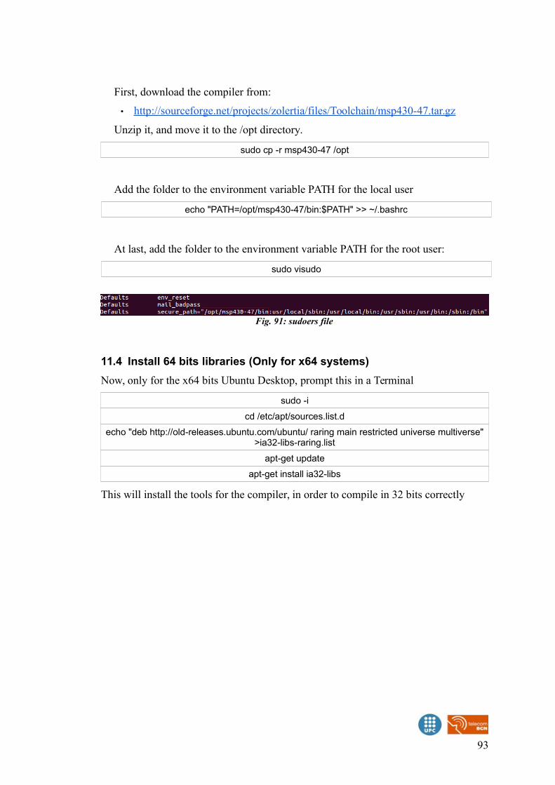
First, download the compiler from:
• http://sourceforge.net/projects/zolertia/files/Toolchain/msp430-47.tar.gz
Unzip it, and move it to the /opt directory.
sudo cp -r msp430-47 /opt
Add the folder to the environment variable PATH for the local user
echo "PATH=/opt/msp430-47/bin:$PATH" >> ~/.bashrc
At last, add the folder to the environment variable PATH for the root user:
sudo visudo
11.4 Install 64 bits libraries (Only for x64 systems)
Now, only for the x64 bits Ubuntu Desktop, prompt this in a Terminal
sudo -i
cd /etc/apt/sources.list.d
echo "deb http://old-releases.ubuntu.com/ubuntu/ raring main restricted universe multiverse">ia32-libs-raring.list
apt-get update
apt-get install ia32-libs
This will install the tools for the compiler, in order to compile in 32 bits correctly
93
Fig. 91: sudoers file
12 Appendix II: Installation of Sentilo in Ubuntu 14.04
To install the sentilo server we need to:
• Install the dependencies:
◦ git
◦ maven2
◦ redis
◦ mysql
◦ tomcat
• Configure Redis
• Configure MongoDB
• Configure Mysql
12.1 Install dependencies
First we need to install all the dependencies for the server
sudo apt-get install git install maven2 redis-server mongodb mysql-server tomcat7
The installation of mysql-server, needs a root password, it will be asked during the
installation.
12.2 Download and build codeThe source code of the project can be obtained from git, cloning the remote project in a local directory named sentilo:
git clone https://github.com/sentilo/sentilo.git sentilo
Then we need to build the project with maven in order to create the executables
cd sentilo
mvn clean install
mvn eclipse:clean eclipse:eclipse
12.3 Configure Redis
The default configuration of redis listens to the port 6379, but the password is
disabled.
To enable it edit the file
sudo gedit /etc/redis/redis.conf
Then find the line on this file to edit the password
94
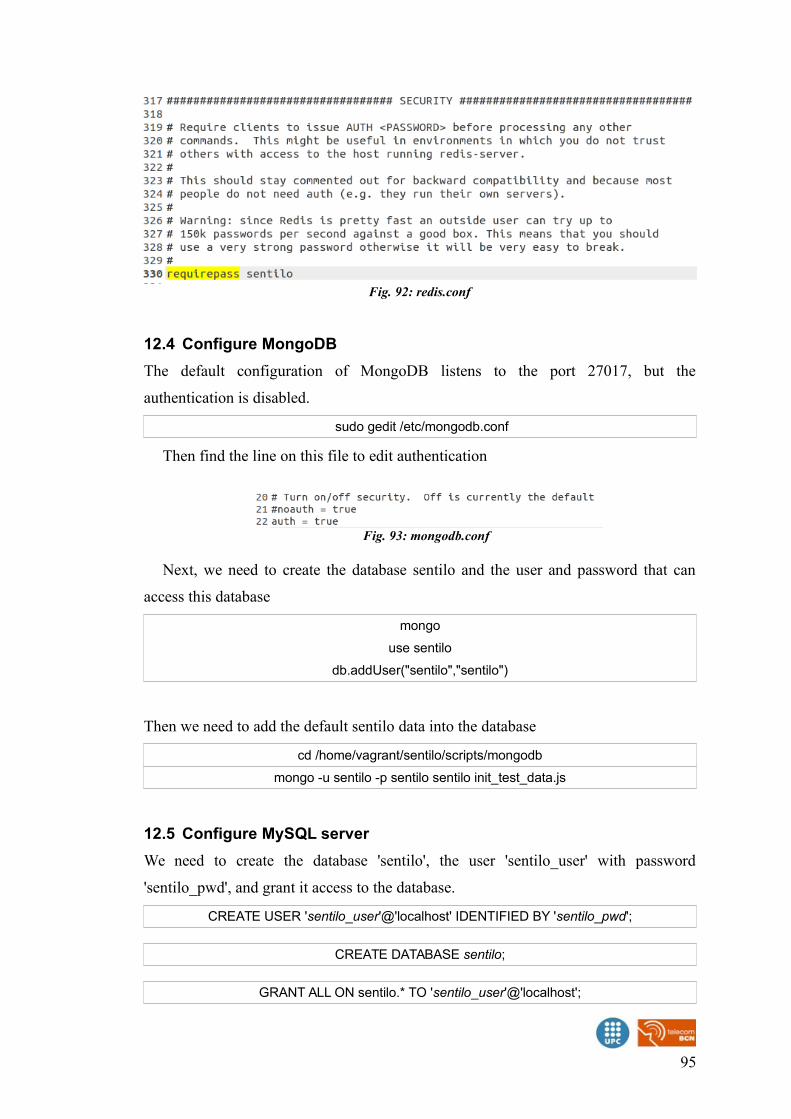
12.4 Configure MongoDB
The default configuration of MongoDB listens to the port 27017, but the
authentication is disabled.
sudo gedit /etc/mongodb.conf
Then find the line on this file to edit authentication
Next, we need to create the database sentilo and the user and password that can
access this database
mongo
use sentilo
db.addUser("sentilo","sentilo")
Then we need to add the default sentilo data into the database
cd /home/vagrant/sentilo/scripts/mongodb
mongo -u sentilo -p sentilo sentilo init_test_data.js
12.5 Configure MySQL server
We need to create the database 'sentilo', the user 'sentilo_user' with password
'sentilo_pwd', and grant it access to the database.
CREATE USER 'sentilo_user'@'localhost' IDENTIFIED BY 'sentilo_pwd';
CREATE DATABASE sentilo;
GRANT ALL ON sentilo.* TO 'sentilo_user'@'localhost';
95
Fig. 92: redis.conf
Fig. 93: mongodb.conf
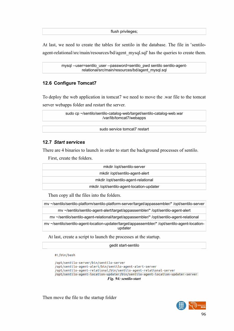
flush privileges;
At last, we need to create the tables for sentilo in the database. The file in 'sentilo-
agent-relational/src/main/resources/bd/agent_mysql.sql' has the queries to create them.
mysql --user=sentilo_user --password=sentilo_pwd sentilo sentilo-agent-relational/src/main/resources/bd/agent_mysql.sql
12.6 Configure Tomcat7
To deploy the web application in tomcat7 we need to move the .war file to the tomcat
server webapps folder and restart the server.
sudo cp ~/sentilo/sentilo-catalog-web/target/sentilo-catalog-web.war/var/lib/tomcat7/webapps
sudo service tomcat7 restart
12.7 Start services
There are 4 binaries to launch in order to start the background processes of sentilo.
First, create the folders.
mkdir /opt/sentilo-server
mkdir /opt/sentilo-agent-alert
mkdir /opt/sentilo-agent-relational
mkdir /opt/sentilo-agent-location-updater
Then copy all the files into the folders.
mv ~/sentilo/sentilo-platform/sentilo-platform-server/target/appassembler/* /opt/sentilo-server
mv ~/sentilo/sentilo-agent-alert/target/appassembler/* /opt/sentilo-agent-alert
mv ~/sentilo/sentilo-agent-relational/target/appassembler/* /opt/sentilo-agent-relational
mv ~/sentilo/sentilo-agent-location-updater/target/appassembler/* /opt/sentilo-agent-location-updater
At last, create a script to launch the processes at the startup.
gedit start-sentilo
Then move the file to the startup folder
96
Fig. 94: sentilo-start

sudo mv sentilo-start /etc/init.d/
sudo chmod +x /etc/init.d/ sentilo-start
And launch it
sudo /etc/init.d/ sentilo-start
97

13 Bibliography
Dunkels, Adam; Grönval, Björn; Voigt, Thimeo (2014): Contiki - a Lightweight and Flexible
Operating System for Tiny Networked Sensors, Swedish Institute of Computer
Science, URL: http://www.dunkels.com/adam/dunkels04contiki.pdf
Schönwälder, Jürgen (2010): Internet of Things: 802.15.4, 6LoWPAN, RPL, COAP, Jacobs
University, URL:
https://www.utwente.nl/ewi/dacs/colloquium/archive/2010/slides/2010-utwente-
6lowpan-rpl-coap.pdf
Olsson, Jonas (2014): 6LoWPAN demystified, URL:
http://www.ti.com/lit/wp/swry013/swry013.pdf
Zolertia (2010): Z1 Datasheet, URL:
http://zolertia.sourceforge.net/wiki/images/e/e8/Z1_RevC_Datasheet.pdf
Contiki OS Wiki, URL: https://github.com/contiki-os/contiki/wiki
98
Related Documents