CONTENTS Safety instruction ………………………………………………………………………1 General instruction ………………………………………………………………………. 1 Alignment instruction ……………………………………………………………………2 Alignment flow ..…………………………………………………………………….. 2 Alignment method ………………………………………………………………….. 3 BLOCK DIAGRAM………………………………………………………………………... 8 MAIN IC ……………………………………………………………………………….. 9 Exploded view ……………………………………………………………… ........ 1 3 Part list …………………….………………………………………………. ......... 15 Schematic diagram …………………………………………………………………. . 32

Welcome message from author
This document is posted to help you gain knowledge. Please leave a comment to let me know what you think about it! Share it to your friends and learn new things together.
Transcript
CONTENTS Safety instruction………………………………………………………………………1 General instruction……………………………………………………………………….1 Alignment instruction……………………………………………………………………2 Alignment f low . .……………………………………………………………………..2 Al ignment method…………………………………………………………………..3 BLOCK DIAGRAM………………………………………………………………………... 8 MAIN IC……………………………………………………………………………….. 9 Exp loded v iew……………………………………………………………… . . . . . . . .13 Par t l i s t …………………….………………………………………………. . . . . . . . . .15 Schematic diagram…………………………………………………………………..32
1
1 safety instruction
1.1 X-RAY radiation precaution 1.1.1 Excessive voltage will cause harmful X-ray. To avoid this radiation hazard, the high voltage should fall within the limitation. The appliance works at AC 120V, 60Hz. The high voltage of zero beam current should be within 29.0kV on condition that the main power (B+) voltage is AC135V. And it should not exceed 30kV in any condition. * Keep the main power voltage at 135V when checking the high voltage. 1.1.2 The primary source of X-RAY RADIATION is the CRT. The CRT of this TV set have gotten the approval of safety authentication inspection. The replacement CRT should be exactly the same type and specification CRT which has gotten a similar safety approval, and check the high voltage according to the HIGH VOLTAGE CHECK procedure. 1.2 safety precaution a. Since the power supply circuit of this receiver is directly connected to the AC power line, an isolation transformer is necessary during dynamic service to avoid possible shock hazard. b. Always discharge the graphite layer conductor when moving the CRT. c. Disconnect the power cord before replacing parts. d. When replacing high-power resistor, keep the resistor 10 mm away from the circuit board. 1.3 Component safety precaution Many electrical and mechanical parts in the chassis have special safety-related characteristics. These characteristics are often passed unnoticed by a visual inspection. Replacement parts which have these special safety characteristics are identified in this manual and its supplement electrical components having such features are shaded or marked by on the schematic diagram and the parts list. Before replacing any of these components, read the parts list in this manual carefully. The use of substitute replacement parts which do not have the same characteristic as specified in the parts list may create shock, fire, X-RAY RADIATION or other hazards. 2.General instruction 2.1 Copy the standard model data to let EEPROM of the chassis have those data before placing it on the unit, do “factory adjustment” if necessary. If use a blank EEPROM directly, you should preset IIC data and then do other common adjustment. Refer to TABLE1 to preset EEPROM. 2.2 the adjustment should be done under following circumstances without additional instruction a) Alternating current 120V/60Hz b) Preheat at least 30 min 2.3The unit has auto degaussing circuit, the auto degaussing process can be finished within 1s when the main power. only when turn on the unit at least 30min after last time turn off TV does the auto degaussing circuit work. 2.4 If the CRT with magnetism affects color purity and convergence, when the auto degaussing eraser. if the color purity and convergence are still not very good, then corresponding adjustment should be done. Refer to picture tube adjustment method for adjustment.
3 Alignment instruction
Note: This service manual is only for professional service personnel’s reference. Beforeservicing the unit, please read the following items carefully.
2
3.1 Debugging item a)adjust mode instruction b)B+ voltage adjustment c)RFAGC voltage adjustment d)focus adjustment e)Screen-grid voltage white balance, sub brightness adjustment f)filed scan center, line , amplitude adjustment g)H-scan center adjustment
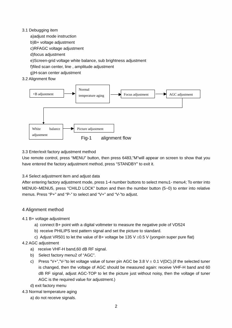
3.2 Alignment flow
3.3 Enter/exit factory adjustment method Use remote control, press “MENU” button, then press 6483,”M”will appear on screen to show that you have entered the factory adjustment method, press “STANDBY” to exit it.
3.4 Select adjustment item and adjust data After entering factory adjustment mode, press 1-4 number buttons to select menu1- menu4; To enter into MENU0~MENU5, press “CHILD LOCK” button and then the number button (5~0) to enter into relative menus. Press “P+” and “P-” to select and “V+” and “V-”to adjust.
4 Alignment method
4.1 B+ voltage adjustment a) connect B+ point with a digital voltmeter to measure the negative pole of VD524 b) receive PHILIPS test pattern signal and set the picture to standard. c) Adjust VR501 to let the value of B+ voltage be 135 V ±0.5 V (yongxin super pure flat)
4.2 AGC adjustment a) receive VHF-H band,60 dB RF signal. b) Select factory menu2 of “AGC”. c) Press “V+”,”V-”to let voltage value of tuner pin AGC be 3.8 V ± 0.1 V(DC).(if the selected tuner
is changed, then the voltage of AGC should be measured again: receive VHF-H band and 60 dB RF signal, adjust AGC-TOP to let the picture just without noisy, then the voltage of tuner AGC is the required value for adjustment.)
d) exit factory menu 4.3 Normal temperature aging
a) do not receive signals.
Fig-1 alignment flow
Normal
temperature aging+B adjustment Focus adjustment
White balance
adjustment
Picture adjustment
AGC adjustment
3
b) under ”M” condition, set the accelerator to an appropriate point for aging. 4.4 Accelerator adjustment
a) do not receive signals; b) select “SC” of factory menu3 to let the field scanning stop working. c) adjust acceleration potentiometer to let bright lines just appears on screen. d) exit SC menu.
4.5 High voltage check Note: the main power voltage (B+=135 V)can affect the high voltage directly, so be sure to let the B+ power voltage accurate. Under any state, the high voltage should not exceed 30 kV.
a) connect an accurate high voltage meter between the second anode cap of picture tube and ground.
b) turn on TV and receive testing card signal. c) set picture to standard, the high voltage should be 27 kV± 1 kV. d) the high voltage should not exceed 30KV with minimum brightness and contrast.
4.6 Focus adjustment a) receive PHILIPS signal b) adjust focus electrode potentiometer on FBT to optimize B area focus of screen.
4.7 White balance adjustment (color temperature 12000°K± 8MPCD,X=0.270± 0.008,Y=0.283± 0.008) a) receive full white signal b) select factory menu3 c) on the basis of blue, adjustment RD,GD of M3, let to white balance coincide with standard.
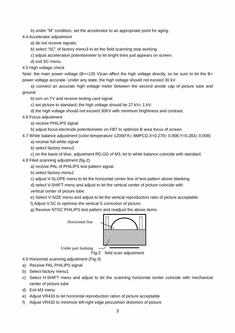
4.8 Filed scanning adjustment (fig-2) a) receive PAL of PHILIPS test pattern signal. b) select factory menu1 c) adjust V-SLOPE menu to let the horizontal center line of test pattern above blanking. d) select V-SHIFT menu and adjust to let the vertical center of picture coincide with vertical center of picture tube.
e) Select V-SIZE menu and adjust to let the vertical reproduction ratio of picture acceptable. f) Adjust V.SC to optimise the vertical S correction of picture. g) Receive NTSC PHILIPS test pattern and readjust the above items.
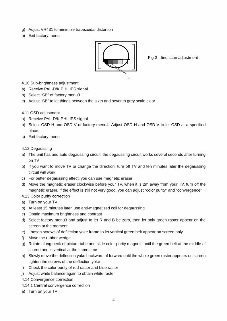
Fig-2 field scan adjustment 4.9 Horizontal scanning adjustment (Fig-3) a) Receive PAL PHILIPS signal b) Select factory menu1 c) Select H.SHIFT menu and adjust to let the scanning horizontal center coincide with mechanical
center of picture tube d) Exit M3 menu e) Adjust VR433 to let horizontal reproduction ration of picture acceptable f) Adjust VR432 to minimize left-right edge pincushion distortion of picture
Horizontal line
Under part banking
4
g) Adjust VR431 to minimize trapezoidal distortion h) Exit factory menu
4.10 Sub-brightness adjustment a) Receive PAL-D/K PHILIPS signal b) Select “SB” of factory menu3 c) Adjust “SB” to let things between the sixth and seventh grey scale clear 4.11 OSD adjustment a) Receive PAL-D/K PHILIPS signal b) Select OSD H and OSD V of factory menu4. Adjust OSD H and OSD V to let OSD at a specified
place. c) Exit factory menu
4.12 Degaussing a) The unit has and auto degaussing circuit, the degaussing circuit works several seconds after turning
on TV b) If you want to move TV or change the direction, turn off TV and ten minutes later the degaussing
circuit will work c) For better degaussing effect, you can use magnetic eraser d) Move the magnetic eraser clockwise before your TV, when it is 2m away from your TV, turn off the
magnetic eraser. If the effect is still not very good, you can adjust “color purity” and “convergence” 4.13 Color purity correction a) Turn on your TV b) At least 15 minutes later, use anti-magnetized coil for degaussing c) Obtain maximum brightness and contrast d) Select factory menu3 and adjust to let R and B be zero, then let only green raster appear on the
screen at the moment e) Loosen screws of deflection yoke frame to let vertical green belt appear on screen only f) Move the rubber wedge g) Rotate along neck of picture tube and slide color-purity magnets until the green belt at the middle of
screen and is vertical at the same time h) Slowly move the deflection yoke backward of forward until the whole green raster appears on screen,
tighten the screws of the deflection yoke i) Check the color purity of red raster and blue raster j) Adjust white balance again to obtain white raster 4.14 Convergence correction 4.14.1 Central convergence correction a) Turn on your TV
a
Fig-3 line scan adjustment
5
b) At least 15 minutes later, receive square test pattern signal c) Adjust brightness and contrast to get the best picture d) Adjust the angle of two tetrode magnetic rings to let the red vertical line coincide with the blue
vertical line at middle of screen e) Keep the angle unchanged, move the two tetrode magnetic rings at the same time to let the red and
blue horizontal lines coincide at middle of screen f) Adjust two hexode magnetic rings to let the green line coincide with the mixed line of red and blue.
Adjust the angle between them will affect the vertical line, move them together will affect the horizontal line.
g) Repeat d), e), f) and observe the movement of red, green and blue. 4.14.2 Ambient convergence correction a) Turn on your TV b) At least 15 minutes later, loosen the screws of the deflection yoke c) Fixate the rubber wedge temporarily under the deflection yoke d) Move the deflection yoke upward or downward to get best convergence, push the rubber wedge into
space between picture tube and deflection yoke to fixate the deflection yoke temporarily e) Place the rubber wedge whose overlay paper has been removed at the bottom space f) Move the deflection yoke left and right to get best convergence g) Keep the condition unchanged, place another rubber wedge whose overlay paper has been
removed also at the upper space at the same time h) Remove the interim rubber wedge, adhere it to picture tube and deflection yoke i) After placing three rubber wedges, check all the convergence again j) Stick three transparent viscous belts to the rubber wedge
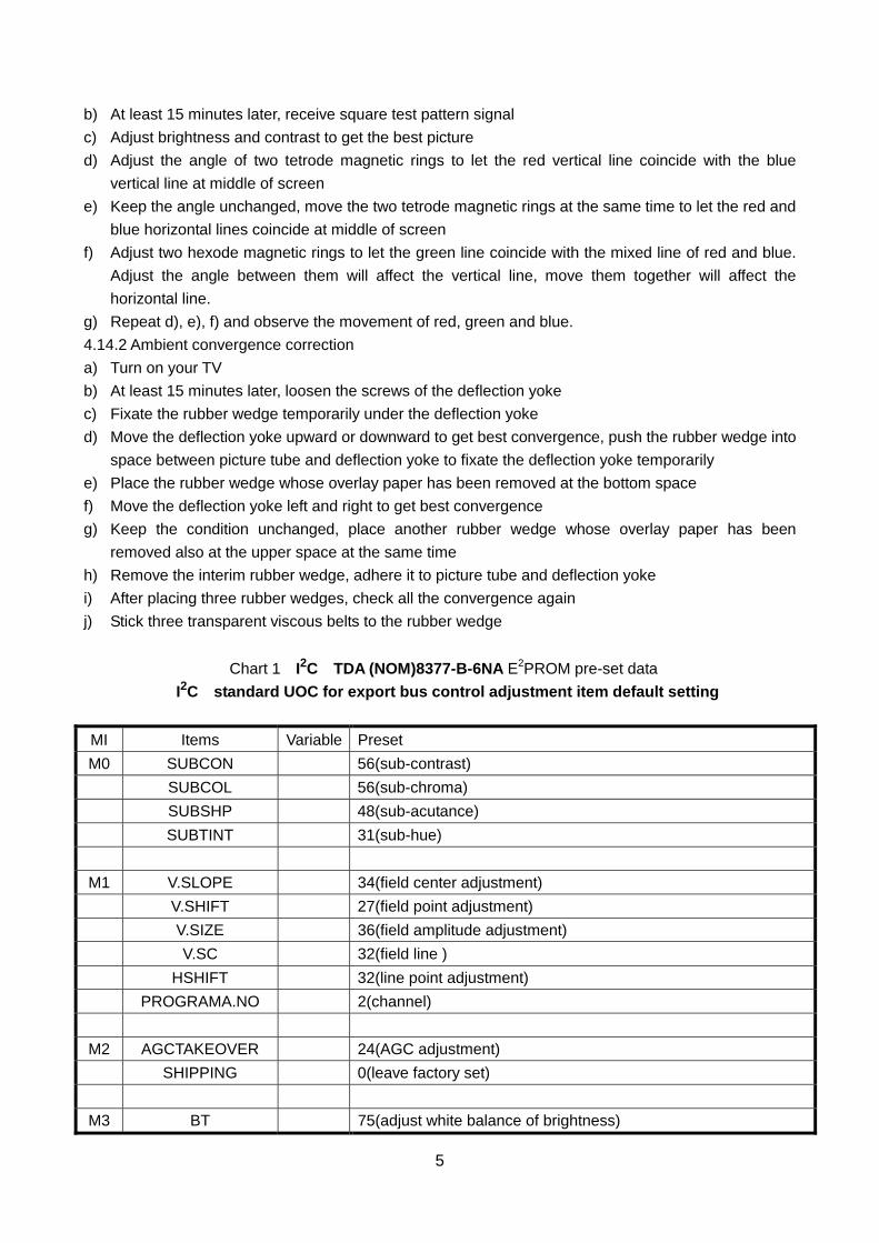
Chart 1 I2C TDA (NOM)8377-B-6NA E2PROM pre-set data
I2C standard UOC for export bus control adjustment item default setting
MI Items Variable Preset M0 SUBCON 56(sub-contrast)
SUBCOL 56(sub-chroma) SUBSHP 48(sub-acutance) SUBTINT 31(sub-hue)
M1 V.SLOPE 34(field center adjustment) V.SHIFT 27(field point adjustment) V.SIZE 36(field amplitude adjustment) V.SC 32(field line ) HSHIFT 32(line point adjustment) PROGRAMA.NO 2(channel)
M2 AGCTAKEOVER 24(AGC adjustment) SHIPPING 0(leave factory set)
M3 BT 75(adjust white balance of brightness)
6
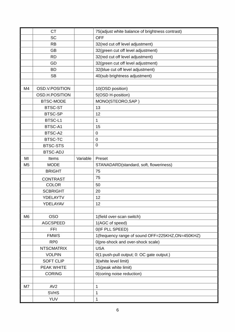
CT 75(adjust white balance of brightness contrast) SC OFF RB 32(red cut off level adjustment) GB 32(green cut off level adjustment) RD 32(red cut off level adjustment) GD 32(green cut off level adjustment) BD 32(blue cut off level adjustment) SB 40(sub brightness adjustment)
M4 OSD.V.POSITION 10(OSD position) OSD.H.POSITION 5(OSD H-position) BTSC-MODE MONO(STEORO,SAP ) BTSC-ST 13 BTSC-SP 12 BTSC-L1 1 BTSC-A1 15 BTSC-A2 0 BTSC-TC 0 BTSC-STS 0
BTSC-ADJ MI Items Variable Preset M5 MODE STANADARD(standard, soft, floweriness)
BRIGHT 75 CONTRAST 75
COLOR 50 SCBRIGHT 20 YDELAYTV 12 YDELAYAV 12
M6 OSO 1(field over-scan switch) AGCSPEED 1(AGC of speed) FFI 0(IF PLL SPEED) FMWS 1(frequency range of sound OFF=225KHZ,ON=450KHZ) RP0 0(pre-shock and over-shock scale) NTSCMATRIX USA VOLPIN 0(1:push-pull output; 0: OC gate output.) SOFT CLIP 3(white level limit) PEAK WHITE 15(peak white limit) CORING 0(coring noise reduction)
M7 AV2 1 SVHS 1 YUV 1
7
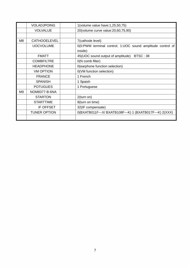
VOLADJPOING 1(volume value have:1,25,50,75) VOLVALUE 20(volume curve value:20,60,75,90)
M8 CATHOOELEVEL 7(cathode level) UOCVOLUME 0(0:PWM terminal control; 1:UOC sound amplitude control of
inside) FMATT 45(UOC sound output of amplitude) BTSC : 38 COMBFILTRE 0(N comb filter) HEADPHONE 0(earphone function selection) VM OPTION 0(VM function selection) FRANCE 1 French SPANISH 1 Spaish POTUGUES 1 Portuguese
M9 NOM8377-B-6NA STARTON 2(turn on) STARTTIME 8(turn on time) IF OFFSET 32(IF compensate) TUNER OPTION 0(BXATB011F---X/ BXATB108F---K) 1 (BXATB017F---K) 2(XXX)
8
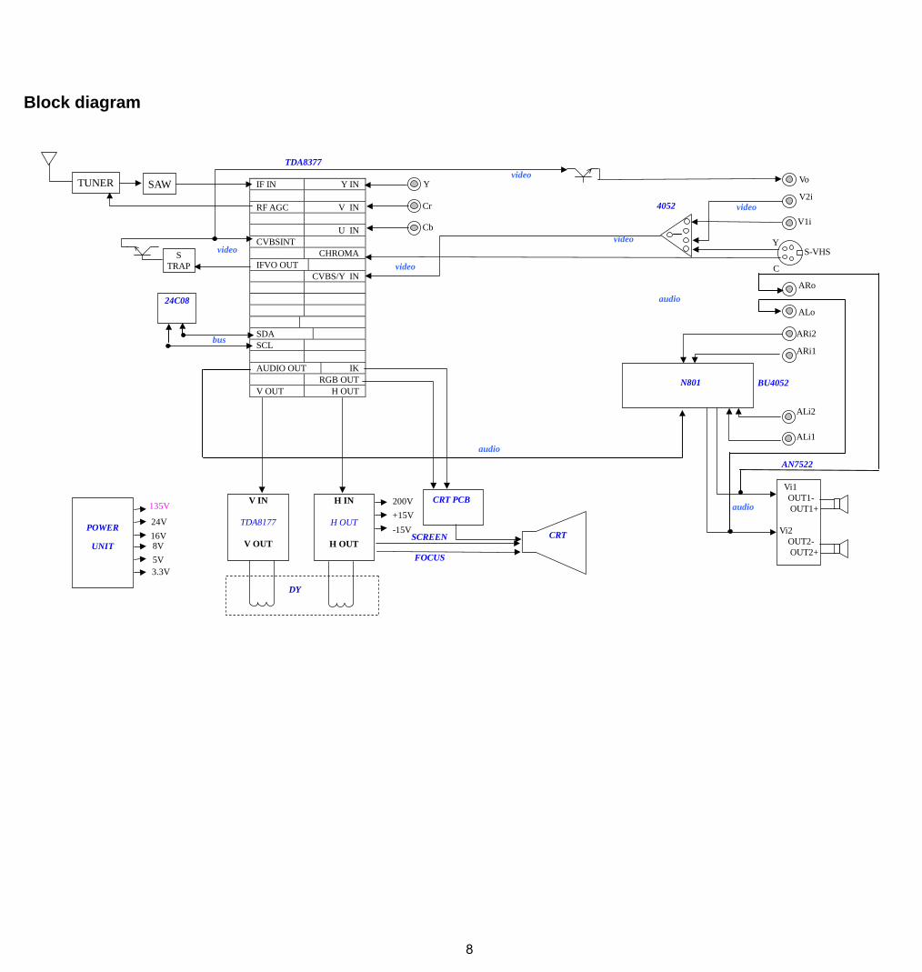
Block diagram
TUNER SAW IF IN Y IN RF AGC V IN U INCVBSINT CHROMAIFVO OUT CVBS/Y IN SDA SCL AUDIO OUT IK RGB OUTV OUT H OUT
S TRAP
Vo
V2i
V1i
Y
Cr
Cb
ARi2
ARi1
ALi2
ALi1
S-VHS
24C08
POWER
UNIT
135V
24V 16V 8V 5V 3.3V
CRT PCB V IN
TDA8177
V OUT
H IN
H OUT
H OUT
DY
200V+15V-15V
SCREEN
FOCUS
TDA8377
Vi1 OUT1-OUT1+
Vi2
OUT2-OUT2+
AN7522
CRT
ALo
ARo
C
Y
4052
BU4052
audio
audio
audio
video
video
bus
video
video
video
N801
9
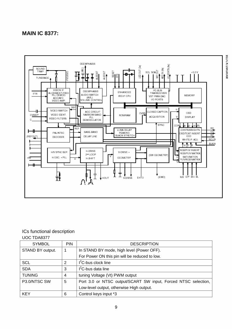
MAIN IC 8377:
ICs functional description UOC TDA8377
SYMBOL PIN DESCRIPTION STAND BY output. 1 In STAND BY mode, high level (Power OFF).
For Power ON this pin will be reduced to low. SCL 2 I2C-bus clock line SDA 3 I2C-bus data line TUNING 4 tuning Voltage (Vt) PWM output P3.0/NTSC SW 5 Port 3.0 or NTSC output/SCART SW input, Forced NTSC selection,
Low-level output, otherwise High output. KEY 6 Control keys input *3
10
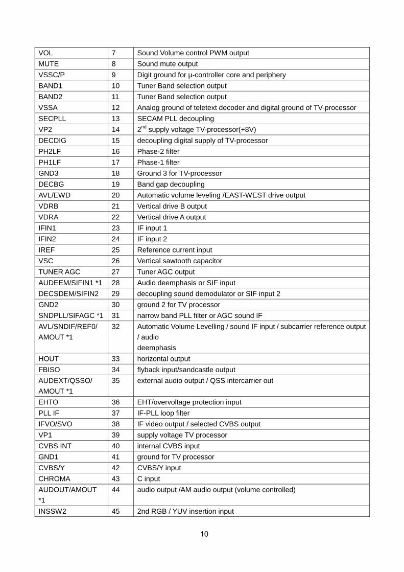
VOL 7 Sound Volume control PWM output MUTE 8 Sound mute output VSSC/P 9 Digit ground for µ-controller core and periphery BAND1 10 Tuner Band selection output BAND2 11 Tuner Band selection output VSSA 12 Analog ground of teletext decoder and digital ground of TV-processor SECPLL 13 SECAM PLL decoupling VP2 14 2nd supply voltage TV-processor(+8V) DECDIG 15 decoupling digital supply of TV-processor PH2LF 16 Phase-2 filter PH1LF 17 Phase-1 filter GND3 18 Ground 3 for TV-processor DECBG 19 Band gap decoupling AVL/EWD 20 Automatic volume leveling /EAST-WEST drive output VDRB 21 Vertical drive B output VDRA 22 Vertical drive A output IFIN1 23 IF input 1 IFIN2 24 IF input 2 IREF 25 Reference current input VSC 26 Vertical sawtooth capacitor TUNER AGC 27 Tuner AGC output AUDEEM/SIFIN1 *1 28 Audio deemphasis or SIF input DECSDEM/SIFIN2 29 decoupling sound demodulator or SIF input 2 GND2 30 ground 2 for TV processor SNDPLL/SIFAGC *1 31 narrow band PLL filter or AGC sound IF AVL/SNDIF/REF0/ AMOUT *1
32 Automatic Volume Levelling / sound IF input / subcarrier reference output / audio deemphasis
HOUT 33 horizontal output FBISO 34 flyback input/sandcastle output AUDEXT/QSSO/ AMOUT *1
35 external audio output / QSS intercarrier out
EHTO 36 EHT/overvoltage protection input PLL IF 37 IF-PLL loop filter IFVO/SVO 38 IF video output / selected CVBS output VP1 39 supply voltage TV processor CVBS INT 40 internal CVBS input GND1 41 ground for TV processor CVBS/Y 42 CVBS/Y input CHROMA 43 C input AUDOUT/AMOUT *1
44 audio output /AM audio output (volume controlled)
INSSW2 45 2nd RGB / YUV insertion input
11
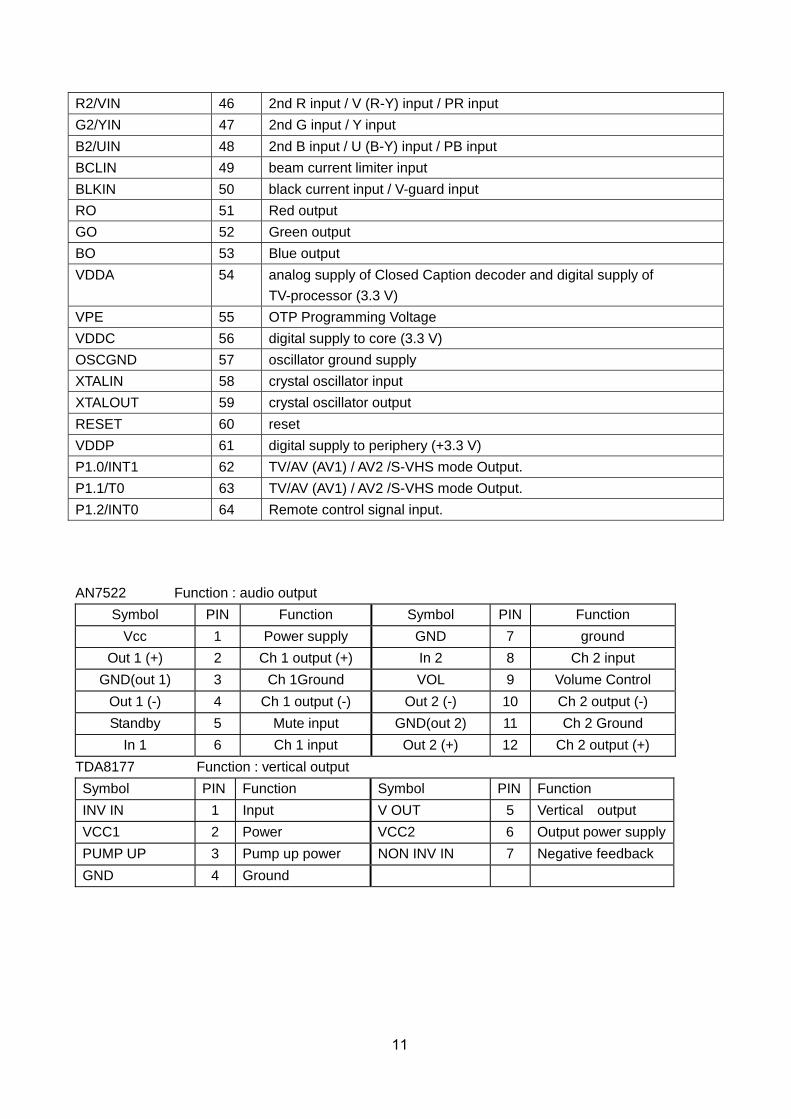
R2/VIN 46 2nd R input / V (R-Y) input / PR input G2/YIN 47 2nd G input / Y input B2/UIN 48 2nd B input / U (B-Y) input / PB input BCLIN 49 beam current limiter input BLKIN 50 black current input / V-guard input RO 51 Red output GO 52 Green output BO 53 Blue output VDDA 54 analog supply of Closed Caption decoder and digital supply of
TV-processor (3.3 V) VPE 55 OTP Programming Voltage VDDC 56 digital supply to core (3.3 V) OSCGND 57 oscillator ground supply XTALIN 58 crystal oscillator input XTALOUT 59 crystal oscillator output RESET 60 reset VDDP 61 digital supply to periphery (+3.3 V) P1.0/INT1 62 TV/AV (AV1) / AV2 /S-VHS mode Output. P1.1/T0 63 TV/AV (AV1) / AV2 /S-VHS mode Output. P1.2/INT0 64 Remote control signal input. AN7522 Function : audio output
Symbol PIN Function Symbol PIN Function Vcc 1 Power supply GND 7 ground
Out 1 (+) 2 Ch 1 output (+) In 2 8 Ch 2 input GND(out 1) 3 Ch 1Ground VOL 9 Volume Control
Out 1 (-) 4 Ch 1 output (-) Out 2 (-) 10 Ch 2 output (-) Standby 5 Mute input GND(out 2) 11 Ch 2 Ground
In 1 6 Ch 1 input Out 2 (+) 12 Ch 2 output (+) TDA8177 Function : vertical output Symbol PIN Function Symbol PIN Function INV IN 1 Input V OUT 5 Vertical output VCC1 2 Power VCC2 6 Output power supplyPUMP UP 3 Pump up power NON INV IN 7 Negative feedback GND 4 Ground
12
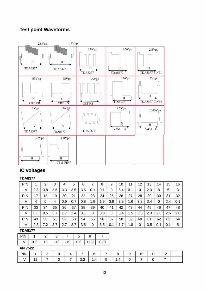
Test point Waveforms
IC voltages TDA8377
PIN 1 2 3 4 5 6 7 8 9 10 11 12 13 14 15 16 V 2.8 3.8 3.6 3.3 3.5 3.5 0.1 0.1 0 5.4 0.1 0 2.3 8 5 3 PIN 17 18 19 20 21 22 23 24 25 26 27 28 29 30 31 32 V 4 0 4 0.9 0.7 0.8 1.9 1.9 3.9 3.8 1.6 3.2 3.4 0 2.4 0.1PIN 33 34 35 36 37 38 39 40 41 42 43 44 45 46 47 48 V 0.6 0.5 3.7 1.7 2.4 3.1 8 3.8 0 3.4 1.5 3.6 2.3 2.6 2.6 2.6PIN 49 50 51 52 53 54 55 56 57 58 59 60 61 62 63 64 V 2.3 7.2 2.7 2.7 2.7 3.5 0 3.5 0.1 1.7 1.8 0 3.5 0.1 0.1 5
TDA8177 PIN 1 2 3 4 5 6 7 V 0.7 15 -12 -15 0.3 15.9 -0.07
AN 7522 PIN 1 2 3 4 5 6 7 8 9 10 11 12 V 12 7 0 7 3.3 1.4 0 1.4 0 7 0 7
V451 C
5Vpp 0.9Vpp
1000Vpp
H H
1Vpp
V H H
CRT KB CRT KG CRT KR
95Vpp 95Vpp 95Vpp
H H H
T511 PIN7
300Vpp 22Vpp
H H
V451 B
2.7Vpp
TDA8377
2.5Vpp 2.5Vpp 3.8Vpp
H H H TDA8377 TDA8377 PIN51
TDA8377 TDA8377 PIN34
0.8Vpp
V TDA8377 TDA8377 TDA8377
1.2Vpp 2.6Vpp
H H
TDA8377 TDA8377
13
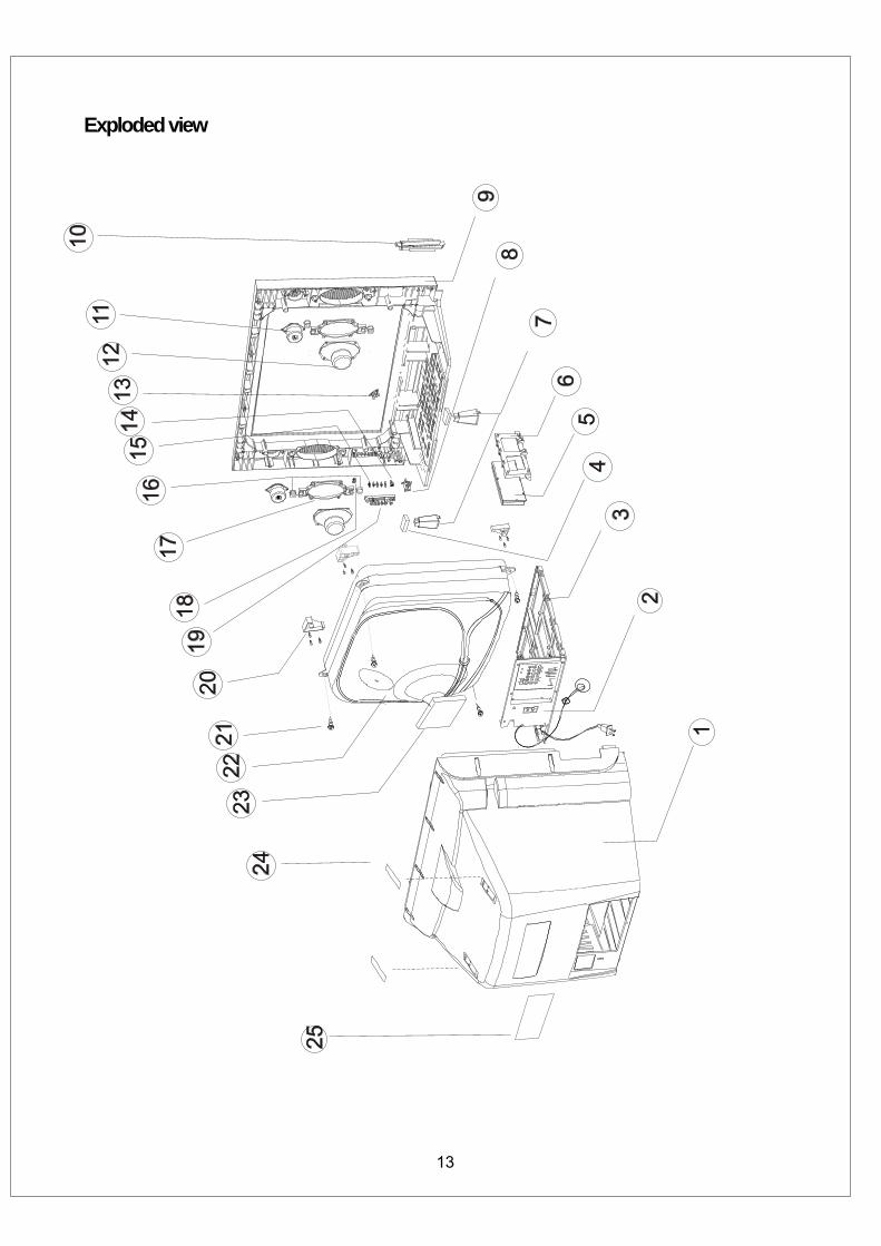
Exploded view
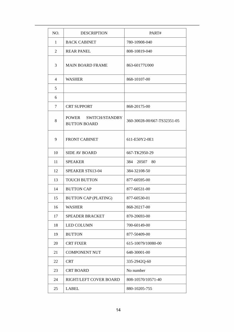
NO. DESCRIPTION PART#
1 BACK CABINET 780-10908-040
2 REAR PANEL 808-10819-040
3 MAIN BOARD FRAME 863-60177U000
4 WASHER 868-10107-00
5
6
7 CRT SUPPORT 868-20175-00
8 POWER SWITCH/STANDBY BUTTON BOARD
360-30028-00/667-TS32351-05
9 FRONT CABINET 611-E50Y2-0E1
10 SIDE AV BOARD 667-TK2950-29
11 SPEAKER 384-20507-80
12 SPEAKER ST613-04 384-32108-50
13 TOUCH BUTTON 877-60595-00
14 BUTTON CAP 877-60531-00
15 BUTTON CAP (PLATING) 877-60530-01
16 WASHER 868-20217-00
17 SPEADER BRACKET 870-20693-00
18 LED COLUMN 700-60149-00
19 BUTTON 877-50409-00
20 CRT FIXER 615-10079/10080-00
21 COMPONENT NUT 648-30001-00
22 CRT 335-2942Q-60
23 CRT BOARD No number
24 RIGHT/LEFT COVER BOARD 808-10570/10571-40
25 LABEL 880-10205-755
14
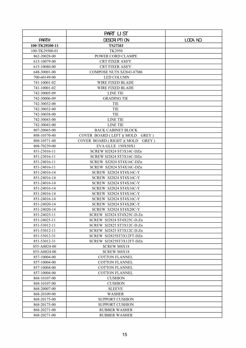
PART LISTPART# DESCRIPTION LOCA.NO.
100-TK29500-11 TS2750J100-TK29500-01 TK2950
862-20028-00 POWER CORD CLAMPE615-10079-00 CRT FIXER ASS'Y 615-10080-00 CRT FIXER ASS'Y 648-30001-00 COMPOSE NUTS SJ2843-87M6700-60149-00 LED COLUMN741-10001-02 WIRE FIXED BLADE 741-10001-02 WIRE FIXED BLADE 742-30005-09 LINE TIE 742-30006-09 GRADING TIE 742-30032-00 TIE 742-30032-00 TIE 742-30038-00 TIE 742-30043-00 LINE TIE 742-30043-00 LINE TIE 807-20065-00 BACK CABINET BLOCK808-10570-40 COVER BOARD ( LEFT )( MOLD GREY )808-10571-40 COVER BOARD ( RIGHT )( MOLD GREY )808-70239-00 EVA GLUE 150X50X1851-23016-11 SCREW SJ2824 ST3X16C-DZn851-23016-11 SCREW SJ2824 ST3X16C-DZn851-24016-11 SCREW SJ2824 ST4X16C-DZn851-24016-11 SCREW SJ2824 ST4X16C-DZn851-24016-14 SCREW SJ2824 ST4X16C-Y851-24016-14 SCREW SJ2824 ST4X16C-Y851-24016-14 SCREW SJ2824 ST4X16C-Y851-24016-14 SCREW SJ2824 ST4X16C-Y851-24016-14 SCREW SJ2824 ST4X16C-Y851-24016-14 SCREW SJ2824 ST4X16C-Y851-24020-14 SCREW SJ2824 ST4X20C-Y851-24020-14 SCREW SJ2824 ST4X20C-Y851-24025-11 SCREW SJ2824 ST4X25C-D.Zn851-24025-11 SCREW SJ2824 ST4X25C-D.Zn851-53012-11 SCREW SJ2825 ST3X12C-D.Zn851-53012-11 SCREW SJ2825 ST3X12C-D.Zn851-53012-31 SCREW SJ2825ST3X12FT-DZn851-53012-31 SCREW SJ2825ST3X12FT-DZn855-A0024-00 SCREW M4X18855-A0024-00 SCREW M4X18857-10004-00 COTTON FLANNEL 857-10004-00 COTTON FLANNEL 857-10004-00 COTTON FLANNEL 857-10004-00 COTTON FLANNEL 868-10107-00 CUSHION868-10107-00 CUSHION868-20007-00 SLEEVE 868-20109-00 WASHER 868-20175-00 SUPPORT CUSHION 868-20175-00 SUPPORT CUSHION 868-20271-00 RUBBER WASHER 868-20271-00 RUBBER WASHER
15
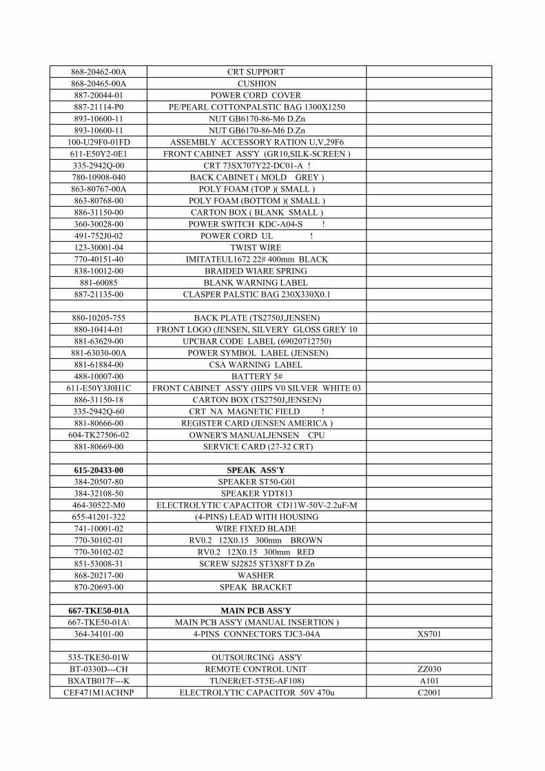
868-20462-00A CRT SUPPORT 868-20465-00A CUSHION887-20044-01 POWER CORD COVER 887-21114-P0 PE/PEARL COTTONPALSTIC BAG 1300X1250893-10600-11 NUT GB6170-86-M6 D.Zn893-10600-11 NUT GB6170-86-M6 D.Zn
100-U29F0-01FD ASSEMBLY ACCESSORY RATION U,V,29F6 611-E50Y2-0E1 FRONT CABINET ASS'Y (GR10,SILK-SCREEN )335-2942Q-00 CRT 73SX707Y22-DC01-A !780-10908-040 BACK CABINET ( MOLD GREY )863-80767-00A POLY FOAM (TOP )( SMALL )863-80768-00 POLY FOAM (BOTTOM )( SMALL )886-31150-00 CARTON BOX ( BLANK SMALL )360-30028-00 POWER SWITCH KDC-A04-S !491-752J0-02 POWER CORD UL !123-30001-04 TWIST WIRE 770-40151-40 IMITATEUL1672 22# 400mm BLACK 838-10012-00 BRAIDED WIARE SPRING
881-60085 BLANK WARNING LABEL 887-21135-00 CLASPER PALSTIC BAG 230X330X0.1
880-10205-755 BACK PLATE (TS2750J,JENSEN)880-10414-01 FRONT LOGO (JENSEN, SILVERY GLOSS GREY 10881-63629-00 UPCBAR CODE LABEL (69020712750)
881-63030-00A POWER SYMBOL LABEL (JENSEN)881-61884-00 CSA WARNING LABEL 488-10007-00 BATTERY 5#
611-E50Y3J0H1C FRONT CABINET ASS'Y (HIPS V0 SILVER WHITE 03886-31150-18 CARTON BOX (TS2750J,JENSEN)335-2942Q-60 CRT NA MAGNETIC FIELD !881-80666-00 REGISTER CARD (JENSEN AMERICA )
604-TK27506-02 OWNER'S MANUALJENSEN CPU881-80669-00 SERVICE CARD (27-32 CRT)
615-20433-00 SPEAK ASS'Y 384-20507-80 SPEAKER ST50-G01384-32108-50 SPEAKER YDT813464-30522-M0 ELECTROLYTIC CAPACITOR CD11W-50V-2.2uF-M655-41201-322 (4-PINS) LEAD WITH HOUSING 741-10001-02 WIRE FIXED BLADE 770-30102-01 RV0.2 12X0.15 300mm BROWN 770-30102-02 RV0.2 12X0.15 300mm RED 851-53008-31 SCREW SJ2825 ST3X8FT D.Zn868-20217-00 WASHER 870-20693-00 SPEAK BRACKET
667-TKE50-01A MAIN PCB ASS'Y 667-TKE50-01A\ MAIN PCB ASS'Y (MANUAL INSERTION )
364-34101-00 4-PINS CONNECTORS TJC3-04A XS701
535-TKE50-01W OUTSOURCING ASS'Y BT-0330D---CH REMOTE CONTROL UNIT ZZ030BXATB017F---K TUNER(ET-5T5E-AF108) A101
CEF471M1ACHNP ELECTROLYTIC CAPACITOR 50V 470u C2001
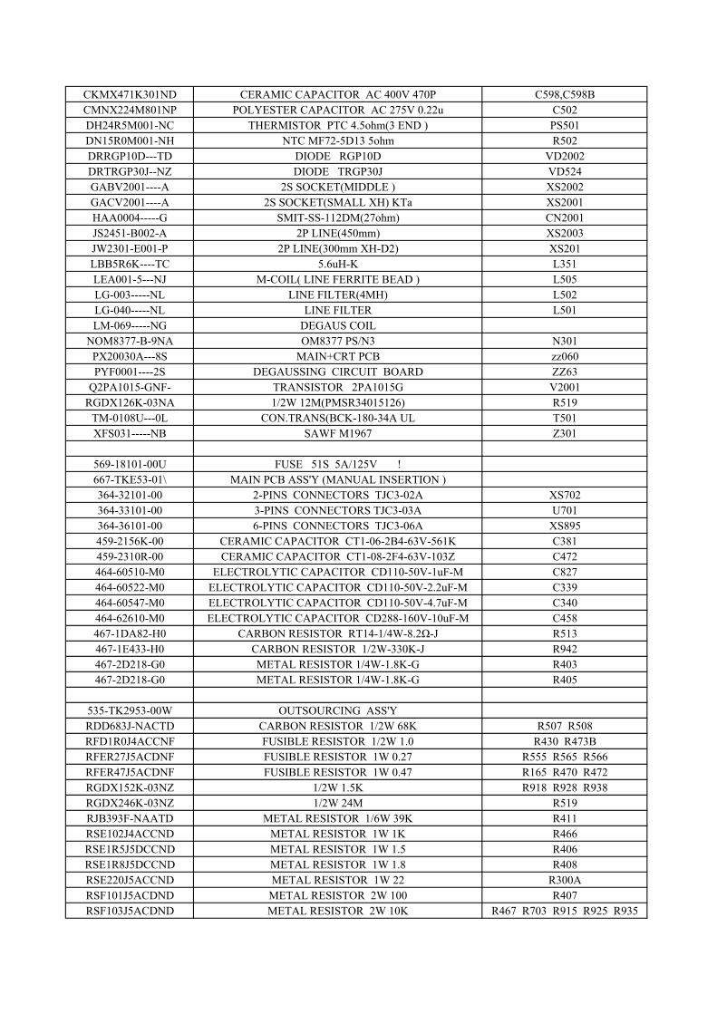
CKMX471K301ND CERAMIC CAPACITOR AC 400V 470P C598,C598BCMNX224M801NP POLYESTER CAPACITOR AC 275V 0.22u C502DH24R5M001-NC THERMISTOR PTC 4.5ohm(3 END ) PS501DN15R0M001-NH NTC MF72-5D13 5ohm R502DRRGP10D---TD DIODE RGP10D VD2002DRTRGP30J--NZ DIODE TRGP30J VD524GABV2001----A 2S SOCKET(MIDDLE ) XS2002GACV2001----A 2S SOCKET(SMALL XH) KTa XS2001HAA0004-----G SMIT-SS-112DM(27ohm) CN2001JS2451-B002-A 2P LINE(450mm) XS2003JW2301-E001-P 2P LINE(300mm XH-D2) XS201LBB5R6K----TC 5.6uH-K L351LEA001-5---NJ M-COIL( LINE FERRITE BEAD ) L505LG-003-----NL LINE FILTER(4MH) L502LG-040-----NL LINE FILTER L501LM-069-----NG DEGAUS COIL
NOM8377-B-9NA OM8377 PS/N3 N301PX20030A---8S MAIN+CRT PCB zz060PYF0001----2S DEGAUSSING CIRCUIT BOARD ZZ63
Q2PA1015-GNF- TRANSISTOR 2PA1015G V2001RGDX126K-03NA 1/2W 12M(PMSR34015126) R519
TM-0108U---0L CON.TRANS(BCK-180-34A UL T501XFS031-----NB SAWF M1967 Z301
569-18101-00U FUSE 51S 5A/125V !667-TKE53-01\ MAIN PCB ASS'Y (MANUAL INSERTION )364-32101-00 2-PINS CONNECTORS TJC3-02A XS702364-33101-00 3-PINS CONNECTORS TJC3-03A U701364-36101-00 6-PINS CONNECTORS TJC3-06A XS895459-2156K-00 CERAMIC CAPACITOR CT1-06-2B4-63V-561K C381459-2310R-00 CERAMIC CAPACITOR CT1-08-2F4-63V-103Z C472464-60510-M0 ELECTROLYTIC CAPACITOR CD110-50V-1uF-M C827464-60522-M0 ELECTROLYTIC CAPACITOR CD110-50V-2.2uF-M C339464-60547-M0 ELECTROLYTIC CAPACITOR CD110-50V-4.7uF-M C340464-62610-M0 ELECTROLYTIC CAPACITOR CD288-160V-10uF-M C458467-1DA82-H0 CARBON RESISTOR RT14-1/4W-8.2Ω-J R513467-1E433-H0 CARBON RESISTOR 1/2W-330K-J R942467-2D218-G0 METAL RESISTOR 1/4W-1.8K-G R403467-2D218-G0 METAL RESISTOR 1/4W-1.8K-G R405
535-TK2953-00W OUTSOURCING ASS'Y RDD683J-NACTD CARBON RESISTOR 1/2W 68K R507 R508RFD1R0J4ACCNF FUSIBLE RESISTOR 1/2W 1.0 R430 R473BRFER27J5ACDNF FUSIBLE RESISTOR 1W 0.27 R555 R565 R566RFER47J5ACDNF FUSIBLE RESISTOR 1W 0.47 R165 R470 R472RGDX152K-03NZ 1/2W 1.5K R918 R928 R938RGDX246K-03NZ 1/2W 24M R519RJB393F-NAATD METAL RESISTOR 1/6W 39K R411RSE102J4ACCND METAL RESISTOR 1W 1K R466RSE1R5J5DCCND METAL RESISTOR 1W 1.5 R406RSE1R8J5DCCND METAL RESISTOR 1W 1.8 R408RSE220J5ACCND METAL RESISTOR 1W 22 R300ARSF101J5ACDND METAL RESISTOR 2W 100 R407RSF103J5ACDND METAL RESISTOR 2W 10K R467 R703 R915 R925 R935
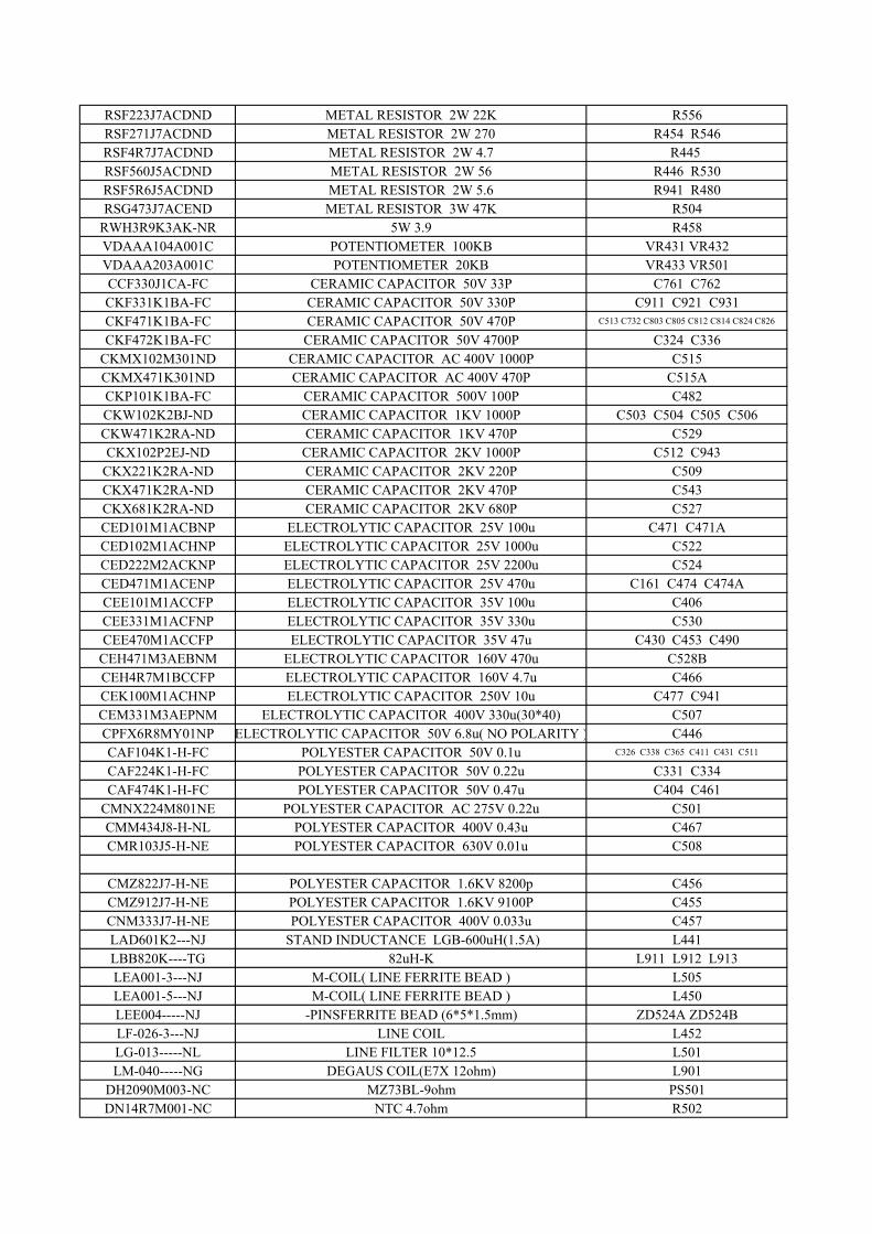
RSF223J7ACDND METAL RESISTOR 2W 22K R556RSF271J7ACDND METAL RESISTOR 2W 270 R454 R546RSF4R7J7ACDND METAL RESISTOR 2W 4.7 R445 RSF560J5ACDND METAL RESISTOR 2W 56 R446 R530RSF5R6J5ACDND METAL RESISTOR 2W 5.6 R941 R480RSG473J7ACEND METAL RESISTOR 3W 47K R504
RWH3R9K3AK-NR 5W 3.9 R458VDAAA104A001C POTENTIOMETER 100KB VR431 VR432VDAAA203A001C POTENTIOMETER 20KB VR433 VR501CCF330J1CA-FC CERAMIC CAPACITOR 50V 33P C761 C762CKF331K1BA-FC CERAMIC CAPACITOR 50V 330P C911 C921 C931CKF471K1BA-FC CERAMIC CAPACITOR 50V 470P C513 C732 C803 C805 C812 C814 C824 C826
CKF472K1BA-FC CERAMIC CAPACITOR 50V 4700P C324 C336CKMX102M301ND CERAMIC CAPACITOR AC 400V 1000P C515CKMX471K301ND CERAMIC CAPACITOR AC 400V 470P C515ACKP101K1BA-FC CERAMIC CAPACITOR 500V 100P C482CKW102K2BJ-ND CERAMIC CAPACITOR 1KV 1000P C503 C504 C505 C506CKW471K2RA-ND CERAMIC CAPACITOR 1KV 470P C529CKX102P2EJ-ND CERAMIC CAPACITOR 2KV 1000P C512 C943
CKX221K2RA-ND CERAMIC CAPACITOR 2KV 220P C509CKX471K2RA-ND CERAMIC CAPACITOR 2KV 470P C543CKX681K2RA-ND CERAMIC CAPACITOR 2KV 680P C527CED101M1ACBNP ELECTROLYTIC CAPACITOR 25V 100u C471 C471ACED102M1ACHNP ELECTROLYTIC CAPACITOR 25V 1000u C522CED222M2ACKNP ELECTROLYTIC CAPACITOR 25V 2200u C524CED471M1ACENP ELECTROLYTIC CAPACITOR 25V 470u C161 C474 C474ACEE101M1ACCFP ELECTROLYTIC CAPACITOR 35V 100u C406CEE331M1ACFNP ELECTROLYTIC CAPACITOR 35V 330u C530CEE470M1ACCFP ELECTROLYTIC CAPACITOR 35V 47u C430 C453 C490
CEH471M3AEBNM ELECTROLYTIC CAPACITOR 160V 470u C528BCEH4R7M1BCCFP ELECTROLYTIC CAPACITOR 160V 4.7u C466CEK100M1ACHNP ELECTROLYTIC CAPACITOR 250V 10u C477 C941CEM331M3AEPNM ELECTROLYTIC CAPACITOR 400V 330u(30*40) C507CPFX6R8MY01NP ELECTROLYTIC CAPACITOR 50V 6.8u( NO POLARITY ) C446CAF104K1-H-FC POLYESTER CAPACITOR 50V 0.1u C326 C338 C365 C411 C431 C511
CAF224K1-H-FC POLYESTER CAPACITOR 50V 0.22u C331 C334CAF474K1-H-FC POLYESTER CAPACITOR 50V 0.47u C404 C461
CMNX224M801NE POLYESTER CAPACITOR AC 275V 0.22u C501CMM434J8-H-NL POLYESTER CAPACITOR 400V 0.43u C467CMR103J5-H-NE POLYESTER CAPACITOR 630V 0.01u C508
CMZ822J7-H-NE POLYESTER CAPACITOR 1.6KV 8200p C456CMZ912J7-H-NE POLYESTER CAPACITOR 1.6KV 9100P C455CNM333J7-H-NE POLYESTER CAPACITOR 400V 0.033u C457LAD601K2---NJ STAND INDUCTANCE LGB-600uH(1.5A) L441LBB820K----TG 82uH-K L911 L912 L913LEA001-3---NJ M-COIL( LINE FERRITE BEAD ) L505LEA001-5---NJ M-COIL( LINE FERRITE BEAD ) L450LEE004-----NJ -PINSFERRITE BEAD (6*5*1.5mm) ZD524A ZD524BLF-026-3---NJ LINE COIL L452LG-013-----NL LINE FILTER 10*12.5 L501LM-040-----NG DEGAUS COIL(E7X 12ohm) L901
DH2090M003-NC MZ73BL-9ohm PS501DN14R7M001-NC NTC 4.7ohm R502
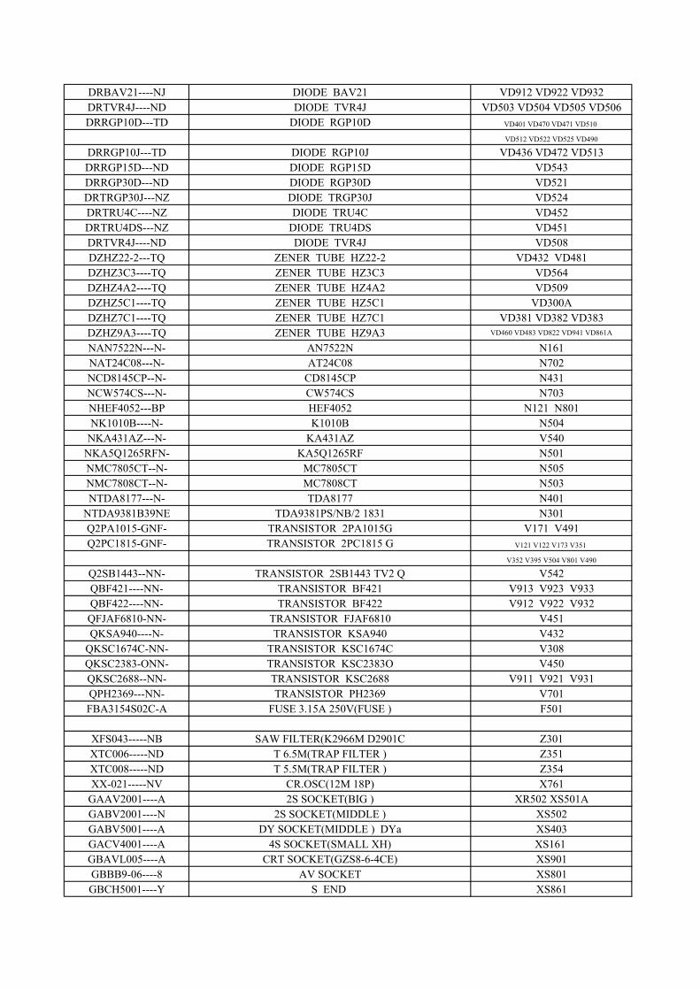
DRBAV21----NJ DIODE BAV21 VD912 VD922 VD932DRTVR4J----ND DIODE TVR4J VD503 VD504 VD505 VD506DRRGP10D---TD DIODE RGP10D VD401 VD470 VD471 VD510
VD512 VD522 VD525 VD490
DRRGP10J---TD DIODE RGP10J VD436 VD472 VD513DRRGP15D---ND DIODE RGP15D VD543DRRGP30D---ND DIODE RGP30D VD521DRTRGP30J---NZ DIODE TRGP30J VD524DRTRU4C----NZ DIODE TRU4C VD452DRTRU4DS---NZ DIODE TRU4DS VD451DRTVR4J----ND DIODE TVR4J VD508DZHZ22-2---TQ ZENER TUBE HZ22-2 VD432 VD481DZHZ3C3----TQ ZENER TUBE HZ3C3 VD564DZHZ4A2----TQ ZENER TUBE HZ4A2 VD509DZHZ5C1----TQ ZENER TUBE HZ5C1 VD300ADZHZ7C1----TQ ZENER TUBE HZ7C1 VD381 VD382 VD383DZHZ9A3----TQ ZENER TUBE HZ9A3 VD460 VD483 VD822 VD941 VD861A
NAN7522N---N- AN7522N N161NAT24C08---N- AT24C08 N702NCD8145CP--N- CD8145CP N431NCW574CS---N- CW574CS N703NHEF4052---BP HEF4052 N121 N801NK1010B----N- K1010B N504
NKA431AZ---N- KA431AZ V540NKA5Q1265RFN- KA5Q1265RF N501NMC7805CT--N- MC7805CT N505NMC7808CT--N- MC7808CT N503NTDA8177---N- TDA8177 N401
NTDA9381B39NE TDA9381PS/NB/2 1831 N301Q2PA1015-GNF- TRANSISTOR 2PA1015G V171 V491Q2PC1815-GNF- TRANSISTOR 2PC1815 G V121 V122 V173 V351
V352 V395 V504 V801 V490
Q2SB1443--NN- TRANSISTOR 2SB1443 TV2 Q V542QBF421----NN- TRANSISTOR BF421 V913 V923 V933QBF422----NN- TRANSISTOR BF422 V912 V922 V932QFJAF6810-NN- TRANSISTOR FJAF6810 V451QKSA940----N- TRANSISTOR KSA940 V432
QKSC1674C-NN- TRANSISTOR KSC1674C V308QKSC2383-ONN- TRANSISTOR KSC2383O V450QKSC2688--NN- TRANSISTOR KSC2688 V911 V921 V931QPH2369---NN- TRANSISTOR PH2369 V701FBA3154S02C-A FUSE 3.15A 250V(FUSE ) F501
XFS043-----NB SAW FILTER(K2966M D2901C Z301XTC006-----ND T 6.5M(TRAP FILTER ) Z351XTC008-----ND T 5.5M(TRAP FILTER ) Z354XX-021-----NV CR.OSC(12M 18P) X761
GAAV2001----A 2S SOCKET(BIG ) XR502 XS501AGABV2001----N 2S SOCKET(MIDDLE ) XS502GABV5001----A DY SOCKET(MIDDLE ) DYa XS403GACV4001----A 4S SOCKET(SMALL XH) XS161 GBAVL005----A CRT SOCKET(GZS8-6-4CE) XS901GBBB9-06----8 AV SOCKET XS801GBCH5001----Y S END XS861
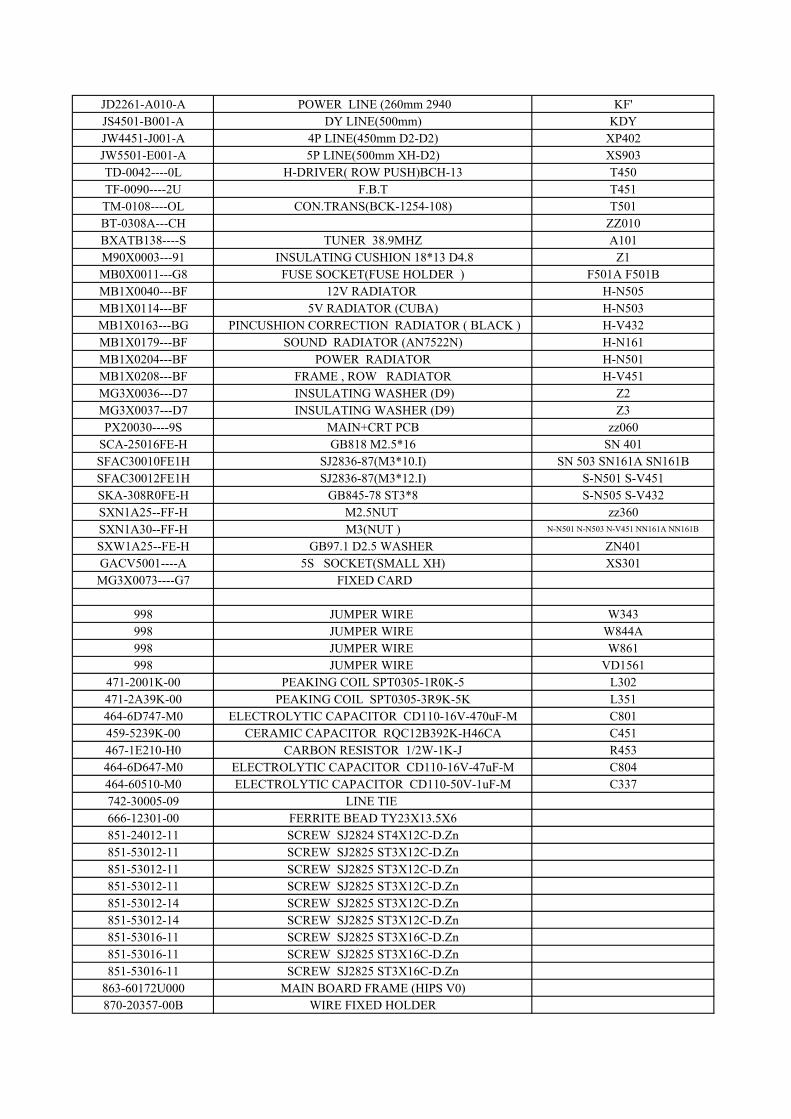
JD2261-A010-A POWER LINE (260mm 2940 KF'JS4501-B001-A DY LINE(500mm) KDYJW4451-J001-A 4P LINE(450mm D2-D2) XP402JW5501-E001-A 5P LINE(500mm XH-D2) XS903TD-0042----0L H-DRIVER( ROW PUSH)BCH-13 T450TF-0090----2U F.B.T T451TM-0108----OL CON.TRANS(BCK-1254-108) T501BT-0308A---CH ZZ010BXATB138----S TUNER 38.9MHZ A101M90X0003---91 INSULATING CUSHION 18*13 D4.8 Z1MB0X0011---G8 FUSE SOCKET(FUSE HOLDER ) F501A F501BMB1X0040---BF 12V RADIATOR H-N505MB1X0114---BF 5V RADIATOR (CUBA) H-N503MB1X0163---BG PINCUSHION CORRECTION RADIATOR ( BLACK ) H-V432MB1X0179---BF SOUND RADIATOR (AN7522N) H-N161MB1X0204---BF POWER RADIATOR H-N501MB1X0208---BF FRAME , ROW RADIATOR H-V451MG3X0036---D7 INSULATING WASHER (D9) Z2MG3X0037---D7 INSULATING WASHER (D9) Z3PX20030----9S MAIN+CRT PCB zz060
SCA-25016FE-H GB818 M2.5*16 SN 401SFAC30010FE1H SJ2836-87(M3*10.I) SN 503 SN161A SN161BSFAC30012FE1H SJ2836-87(M3*12.I) S-N501 S-V451SKA-308R0FE-H GB845-78 ST3*8 S-N505 S-V432SXN1A25--FF-H M2.5NUT zz360SXN1A30--FF-H M3(NUT ) N-N501 N-N503 N-V451 NN161A NN161B
SXW1A25--FE-H GB97.1 D2.5 WASHER ZN401GACV5001----A 5S SOCKET(SMALL XH) XS301MG3X0073----G7 FIXED CARD
998 JUMPER WIRE W343998 JUMPER WIRE W844A998 JUMPER WIRE W861998 JUMPER WIRE VD1561
471-2001K-00 PEAKING COIL SPT0305-1R0K-5 L302471-2A39K-00 PEAKING COIL SPT0305-3R9K-5K L351464-6D747-M0 ELECTROLYTIC CAPACITOR CD110-16V-470uF-M C801459-5239K-00 CERAMIC CAPACITOR RQC12B392K-H46CA C451467-1E210-H0 CARBON RESISTOR 1/2W-1K-J R453464-6D647-M0 ELECTROLYTIC CAPACITOR CD110-16V-47uF-M C804464-60510-M0 ELECTROLYTIC CAPACITOR CD110-50V-1uF-M C337742-30005-09 LINE TIE 666-12301-00 FERRITE BEAD TY23X13.5X6851-24012-11 SCREW SJ2824 ST4X12C-D.Zn851-53012-11 SCREW SJ2825 ST3X12C-D.Zn851-53012-11 SCREW SJ2825 ST3X12C-D.Zn851-53012-11 SCREW SJ2825 ST3X12C-D.Zn851-53012-14 SCREW SJ2825 ST3X12C-D.Zn851-53012-14 SCREW SJ2825 ST3X12C-D.Zn851-53016-11 SCREW SJ2825 ST3X16C-D.Zn851-53016-11 SCREW SJ2825 ST3X16C-D.Zn851-53016-11 SCREW SJ2825 ST3X16C-D.Zn
863-60172U000 MAIN BOARD FRAME (HIPS V0)870-20357-00B WIRE FIXED HOLDER
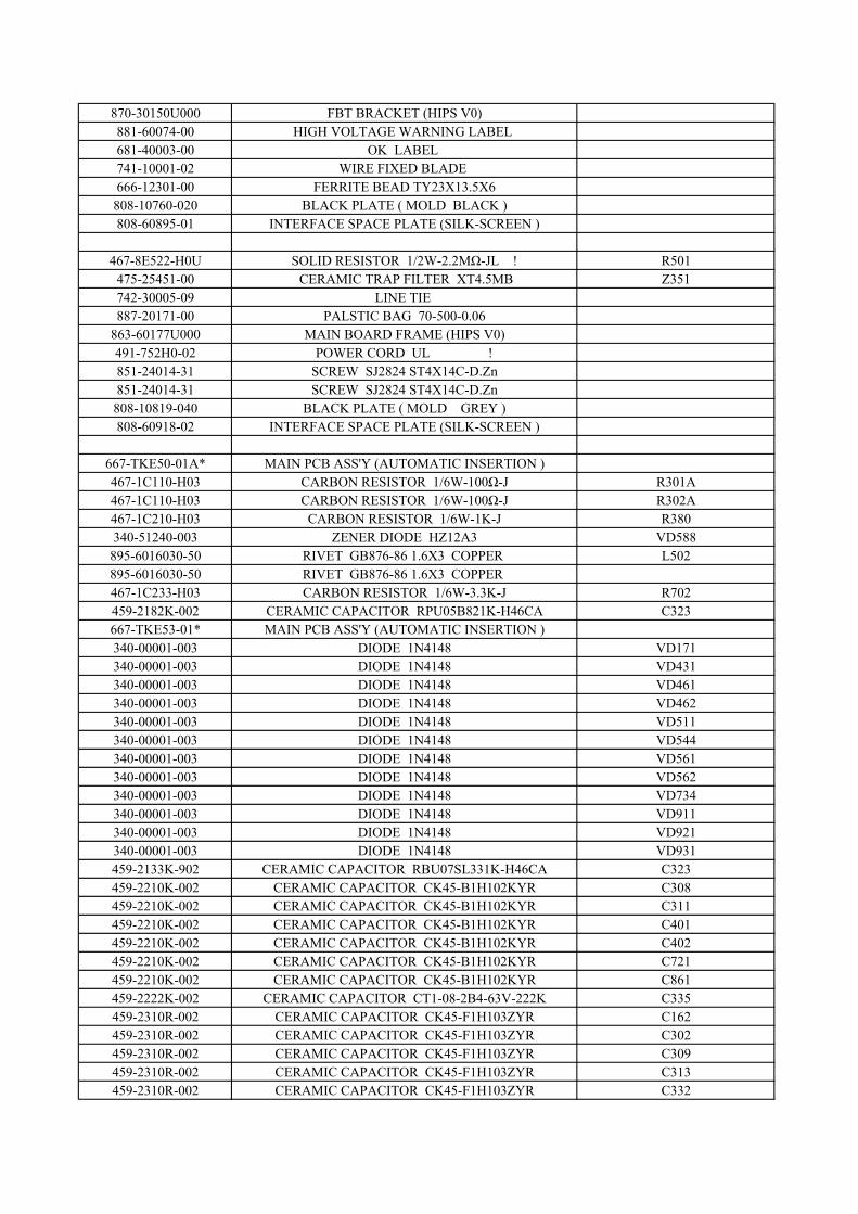
870-30150U000 FBT BRACKET (HIPS V0)881-60074-00 HIGH VOLTAGE WARNING LABEL 681-40003-00 OK LABEL 741-10001-02 WIRE FIXED BLADE 666-12301-00 FERRITE BEAD TY23X13.5X6
808-10760-020 BLACK PLATE ( MOLD BLACK )808-60895-01 INTERFACE SPACE PLATE (SILK-SCREEN )
467-8E522-H0U SOLID RESISTOR 1/2W-2.2MΩ-JL ! R501475-25451-00 CERAMIC TRAP FILTER XT4.5MB Z351742-30005-09 LINE TIE 887-20171-00 PALSTIC BAG 70-500-0.06
863-60177U000 MAIN BOARD FRAME (HIPS V0)491-752H0-02 POWER CORD UL !851-24014-31 SCREW SJ2824 ST4X14C-D.Zn851-24014-31 SCREW SJ2824 ST4X14C-D.Zn
808-10819-040 BLACK PLATE ( MOLD GREY )808-60918-02 INTERFACE SPACE PLATE (SILK-SCREEN )
667-TKE50-01A* MAIN PCB ASS'Y (AUTOMATIC INSERTION )467-1C110-H03 CARBON RESISTOR 1/6W-100Ω-J R301A467-1C110-H03 CARBON RESISTOR 1/6W-100Ω-J R302A467-1C210-H03 CARBON RESISTOR 1/6W-1K-J R380340-51240-003 ZENER DIODE HZ12A3 VD588895-6016030-50 RIVET GB876-86 1.6X3 COPPER L502895-6016030-50 RIVET GB876-86 1.6X3 COPPER 467-1C233-H03 CARBON RESISTOR 1/6W-3.3K-J R702459-2182K-002 CERAMIC CAPACITOR RPU05B821K-H46CA C323667-TKE53-01* MAIN PCB ASS'Y (AUTOMATIC INSERTION )340-00001-003 DIODE 1N4148 VD171340-00001-003 DIODE 1N4148 VD431340-00001-003 DIODE 1N4148 VD461340-00001-003 DIODE 1N4148 VD462340-00001-003 DIODE 1N4148 VD511340-00001-003 DIODE 1N4148 VD544340-00001-003 DIODE 1N4148 VD561340-00001-003 DIODE 1N4148 VD562340-00001-003 DIODE 1N4148 VD734340-00001-003 DIODE 1N4148 VD911340-00001-003 DIODE 1N4148 VD921340-00001-003 DIODE 1N4148 VD931459-2133K-902 CERAMIC CAPACITOR RBU07SL331K-H46CA C323459-2210K-002 CERAMIC CAPACITOR CK45-B1H102KYR C308459-2210K-002 CERAMIC CAPACITOR CK45-B1H102KYR C311459-2210K-002 CERAMIC CAPACITOR CK45-B1H102KYR C401459-2210K-002 CERAMIC CAPACITOR CK45-B1H102KYR C402459-2210K-002 CERAMIC CAPACITOR CK45-B1H102KYR C721459-2210K-002 CERAMIC CAPACITOR CK45-B1H102KYR C861459-2222K-002 CERAMIC CAPACITOR CT1-08-2B4-63V-222K C335459-2310R-002 CERAMIC CAPACITOR CK45-F1H103ZYR C162459-2310R-002 CERAMIC CAPACITOR CK45-F1H103ZYR C302459-2310R-002 CERAMIC CAPACITOR CK45-F1H103ZYR C309459-2310R-002 CERAMIC CAPACITOR CK45-F1H103ZYR C313459-2310R-002 CERAMIC CAPACITOR CK45-F1H103ZYR C332
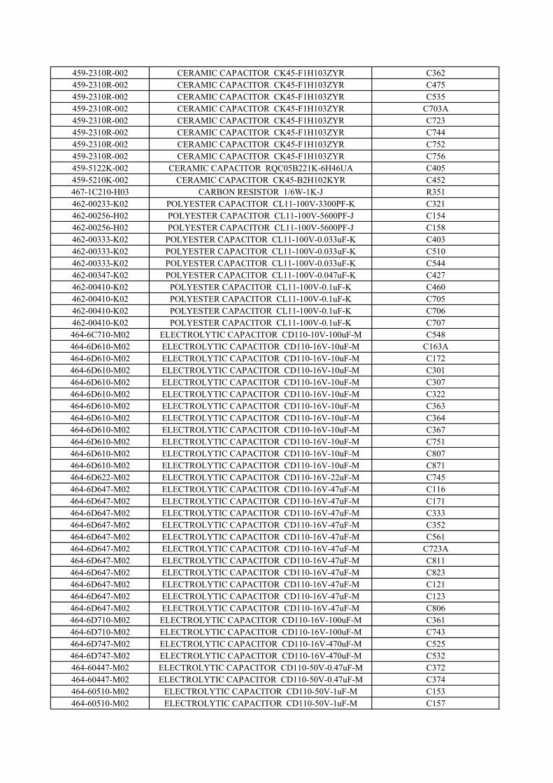
459-2310R-002 CERAMIC CAPACITOR CK45-F1H103ZYR C362459-2310R-002 CERAMIC CAPACITOR CK45-F1H103ZYR C475459-2310R-002 CERAMIC CAPACITOR CK45-F1H103ZYR C535459-2310R-002 CERAMIC CAPACITOR CK45-F1H103ZYR C703A459-2310R-002 CERAMIC CAPACITOR CK45-F1H103ZYR C723459-2310R-002 CERAMIC CAPACITOR CK45-F1H103ZYR C744459-2310R-002 CERAMIC CAPACITOR CK45-F1H103ZYR C752459-2310R-002 CERAMIC CAPACITOR CK45-F1H103ZYR C756459-5122K-002 CERAMIC CAPACITOR RQC05B221K-6H46UA C405459-5210K-002 CERAMIC CAPACITOR CK45-B2H102KYR C452467-1C210-H03 CARBON RESISTOR 1/6W-1K-J R351462-00233-K02 POLYESTER CAPACITOR CL11-100V-3300PF-K C321462-00256-H02 POLYESTER CAPACITOR CL11-100V-5600PF-J C154462-00256-H02 POLYESTER CAPACITOR CL11-100V-5600PF-J C158462-00333-K02 POLYESTER CAPACITOR CL11-100V-0.033uF-K C403462-00333-K02 POLYESTER CAPACITOR CL11-100V-0.033uF-K C510462-00333-K02 POLYESTER CAPACITOR CL11-100V-0.033uF-K C544462-00347-K02 POLYESTER CAPACITOR CL11-100V-0.047uF-K C427462-00410-K02 POLYESTER CAPACITOR CL11-100V-0.1uF-K C460462-00410-K02 POLYESTER CAPACITOR CL11-100V-0.1uF-K C705462-00410-K02 POLYESTER CAPACITOR CL11-100V-0.1uF-K C706462-00410-K02 POLYESTER CAPACITOR CL11-100V-0.1uF-K C707464-6C710-M02 ELECTROLYTIC CAPACITOR CD110-10V-100uF-M C548464-6D610-M02 ELECTROLYTIC CAPACITOR CD110-16V-10uF-M C163A464-6D610-M02 ELECTROLYTIC CAPACITOR CD110-16V-10uF-M C172464-6D610-M02 ELECTROLYTIC CAPACITOR CD110-16V-10uF-M C301464-6D610-M02 ELECTROLYTIC CAPACITOR CD110-16V-10uF-M C307464-6D610-M02 ELECTROLYTIC CAPACITOR CD110-16V-10uF-M C322464-6D610-M02 ELECTROLYTIC CAPACITOR CD110-16V-10uF-M C363464-6D610-M02 ELECTROLYTIC CAPACITOR CD110-16V-10uF-M C364464-6D610-M02 ELECTROLYTIC CAPACITOR CD110-16V-10uF-M C367464-6D610-M02 ELECTROLYTIC CAPACITOR CD110-16V-10uF-M C751464-6D610-M02 ELECTROLYTIC CAPACITOR CD110-16V-10uF-M C807464-6D610-M02 ELECTROLYTIC CAPACITOR CD110-16V-10uF-M C871464-6D622-M02 ELECTROLYTIC CAPACITOR CD110-16V-22uF-M C745464-6D647-M02 ELECTROLYTIC CAPACITOR CD110-16V-47uF-M C116464-6D647-M02 ELECTROLYTIC CAPACITOR CD110-16V-47uF-M C171464-6D647-M02 ELECTROLYTIC CAPACITOR CD110-16V-47uF-M C333464-6D647-M02 ELECTROLYTIC CAPACITOR CD110-16V-47uF-M C352464-6D647-M02 ELECTROLYTIC CAPACITOR CD110-16V-47uF-M C561464-6D647-M02 ELECTROLYTIC CAPACITOR CD110-16V-47uF-M C723A464-6D647-M02 ELECTROLYTIC CAPACITOR CD110-16V-47uF-M C811464-6D647-M02 ELECTROLYTIC CAPACITOR CD110-16V-47uF-M C823464-6D647-M02 ELECTROLYTIC CAPACITOR CD110-16V-47uF-M C121464-6D647-M02 ELECTROLYTIC CAPACITOR CD110-16V-47uF-M C123464-6D647-M02 ELECTROLYTIC CAPACITOR CD110-16V-47uF-M C806464-6D710-M02 ELECTROLYTIC CAPACITOR CD110-16V-100uF-M C361464-6D710-M02 ELECTROLYTIC CAPACITOR CD110-16V-100uF-M C743464-6D747-M02 ELECTROLYTIC CAPACITOR CD110-16V-470uF-M C525464-6D747-M02 ELECTROLYTIC CAPACITOR CD110-16V-470uF-M C532464-60447-M02 ELECTROLYTIC CAPACITOR CD110-50V-0.47uF-M C372464-60447-M02 ELECTROLYTIC CAPACITOR CD110-50V-0.47uF-M C374464-60510-M02 ELECTROLYTIC CAPACITOR CD110-50V-1uF-M C153464-60510-M02 ELECTROLYTIC CAPACITOR CD110-50V-1uF-M C157
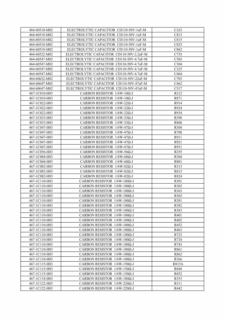
464-60510-M02 ELECTROLYTIC CAPACITOR CD110-50V-1uF-M C163464-60510-M02 ELECTROLYTIC CAPACITOR CD110-50V-1uF-M C813464-60510-M02 ELECTROLYTIC CAPACITOR CD110-50V-1uF-M C815464-60510-M02 ELECTROLYTIC CAPACITOR CD110-50V-1uF-M C825464-60510-M02 ELECTROLYTIC CAPACITOR CD110-50V-1uF-M C862464-60522-M02 ELECTROLYTIC CAPACITOR CD110-50V-2.2uF-M C755464-60547-M02 ELECTROLYTIC CAPACITOR CD110-50V-4.7uF-M C303464-60547-M02 ELECTROLYTIC CAPACITOR CD110-50V-4.7uF-M C304464-60547-M02 ELECTROLYTIC CAPACITOR CD110-50V-4.7uF-M C325464-60547-M02 ELECTROLYTIC CAPACITOR CD110-50V-4.7uF-M C464464-60622-M02 ELECTROLYTIC CAPACITOR CD110-50V-22uF-M C703464-60647-M02 ELECTROLYTIC CAPACITOR CD110-50V-47uF-M C462464-60647-M02 ELECTROLYTIC CAPACITOR CD110-50V-47uF-M C517467-1C010-H03 CARBON RESISTOR 1/6W-10Ω-J R312467-1C010-H03 CARBON RESISTOR 1/6W-10Ω-J R871467-1C022-H03 CARBON RESISTOR 1/6W-22Ω-J R914467-1C022-H03 CARBON RESISTOR 1/6W-22Ω-J R924467-1C022-H03 CARBON RESISTOR 1/6W-22Ω-J R934467-1C033-H03 CARBON RESISTOR 1/6W-33Ω-J R398467-1C033-H03 CARBON RESISTOR 1/6W-33Ω-J R806467-1C047-H03 CARBON RESISTOR 1/6W-47Ω-J R368467-1C047-H03 CARBON RESISTOR 1/6W-47Ω-J R708467-1C047-H03 CARBON RESISTOR 1/6W-47Ω-J R911467-1C047-H03 CARBON RESISTOR 1/6W-47Ω-J R921467-1C047-H03 CARBON RESISTOR 1/6W-47Ω-J R931467-1C056-H03 CARBON RESISTOR 1/6W-56Ω-J R355467-1C068-H03 CARBON RESISTOR 1/6W-68Ω-J R304467-1C068-H03 CARBON RESISTOR 1/6W-68Ω-J R801467-1C082-H03 CARBON RESISTOR 1/6W-82Ω-J R313467-1C082-H03 CARBON RESISTOR 1/6W-82Ω-J R815467-1C082-H03 CARBON RESISTOR 1/6W-82Ω-J R824467-1C110-H03 CARBON RESISTOR 1/6W-100Ω-J R301467-1C110-H03 CARBON RESISTOR 1/6W-100Ω-J R302467-1C110-H03 CARBON RESISTOR 1/6W-100Ω-J R363467-1C110-H03 CARBON RESISTOR 1/6W-100Ω-J R365467-1C110-H03 CARBON RESISTOR 1/6W-100Ω-J R381467-1C110-H03 CARBON RESISTOR 1/6W-100Ω-J R382467-1C110-H03 CARBON RESISTOR 1/6W-100Ω-J R383467-1C110-H03 CARBON RESISTOR 1/6W-100Ω-J R401467-1C110-H03 CARBON RESISTOR 1/6W-100Ω-J R402467-1C110-H03 CARBON RESISTOR 1/6W-100Ω-J R452467-1C110-H03 CARBON RESISTOR 1/6W-100Ω-J R463467-1C110-H03 CARBON RESISTOR 1/6W-100Ω-J R723467-1C110-H03 CARBON RESISTOR 1/6W-100Ω-J R724467-1C110-H03 CARBON RESISTOR 1/6W-100Ω-J R743467-1C110-H03 CARBON RESISTOR 1/6W-100Ω-J R861467-1C110-H03 CARBON RESISTOR 1/6W-100Ω-J R862467-1C110-H03 CARBON RESISTOR 1/6W-100Ω-J R366467-1C115-H03 CARBON RESISTOR 1/6W-150Ω-J R815A467-1C115-H03 CARBON RESISTOR 1/6W-150Ω-J R848467-1C115-H03 CARBON RESISTOR 1/6W-150Ω-J R852467-1C118-H03 CARBON RESISTOR 1/6W-180Ω-J R353467-1C122-H03 CARBON RESISTOR 1/6W-220Ω-J R311467-1C122-H03 CARBON RESISTOR 1/6W-220Ω-J R442
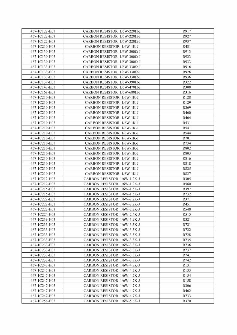
467-1C122-H03 CARBON RESISTOR 1/6W-220Ω-J R917467-1C122-H03 CARBON RESISTOR 1/6W-220Ω-J R927467-1C122-H03 CARBON RESISTOR 1/6W-220Ω-J R937467-1C210-H03 CARBON RESISTOR 1/6W-1K-J R481467-1C130-H03 CARBON RESISTOR 1/6W-300Ω-J R913467-1C130-H03 CARBON RESISTOR 1/6W-300Ω-J R923467-1C130-H03 CARBON RESISTOR 1/6W-300Ω-J R933467-1C133-H03 CARBON RESISTOR 1/6W-330Ω-J R916467-1C133-H03 CARBON RESISTOR 1/6W-330Ω-J R926467-1C133-H03 CARBON RESISTOR 1/6W-330Ω-J R936467-1C139-H03 CARBON RESISTOR 1/6W-390Ω-J R322467-1C147-H03 CARBON RESISTOR 1/6W-470Ω-J R308467-1C168-H03 CARBON RESISTOR 1/6W-680Ω-J R316467-1C210-H03 CARBON RESISTOR 1/6W-1K-J R128467-1C210-H03 CARBON RESISTOR 1/6W-1K-J R129467-1C210-H03 CARBON RESISTOR 1/6W-1K-J R369467-1C210-H03 CARBON RESISTOR 1/6W-1K-J R460467-1C210-H03 CARBON RESISTOR 1/6W-1K-J R464467-1C210-H03 CARBON RESISTOR 1/6W-1K-J R531467-1C210-H03 CARBON RESISTOR 1/6W-1K-J R541467-1C210-H03 CARBON RESISTOR 1/6W-1K-J R544467-1C210-H03 CARBON RESISTOR 1/6W-1K-J R701467-1C210-H03 CARBON RESISTOR 1/6W-1K-J R734467-1C210-H03 CARBON RESISTOR 1/6W-1K-J R802467-1C210-H03 CARBON RESISTOR 1/6W-1K-J R803467-1C210-H03 CARBON RESISTOR 1/6W-1K-J R816467-1C210-H03 CARBON RESISTOR 1/6W-1K-J R818467-1C210-H03 CARBON RESISTOR 1/6W-1K-J R825467-1C210-H03 CARBON RESISTOR 1/6W-1K-J R827467-1C212-H03 CARBON RESISTOR 1/6W-1.2K-J R305467-1C212-H03 CARBON RESISTOR 1/6W-1.2K-J R560467-1C215-H03 CARBON RESISTOR 1/6W-1.5K-J R397467-1C215-H03 CARBON RESISTOR 1/6W-1.5K-J R732467-1C222-H03 CARBON RESISTOR 1/6W-2.2K-J R371467-1C222-H03 CARBON RESISTOR 1/6W-2.2K-J R451467-1C222-H03 CARBON RESISTOR 1/6W-2.2K-J R540467-1C224-H03 CARBON RESISTOR 1/6W-2.4K-J R515467-1C239-H03 CARBON RESISTOR 1/6W-3.9K-J R321467-1C233-H03 CARBON RESISTOR 1/6W-3.3K-J R721467-1C233-H03 CARBON RESISTOR 1/6W-3.3K-J R722467-1C233-H03 CARBON RESISTOR 1/6W-3.3K-J R728467-1C233-H03 CARBON RESISTOR 1/6W-3.3K-J R735467-1C233-H03 CARBON RESISTOR 1/6W-3.3K-J R736467-1C233-H03 CARBON RESISTOR 1/6W-3.3K-J R737467-1C233-H03 CARBON RESISTOR 1/6W-3.3K-J R741467-1C233-H03 CARBON RESISTOR 1/6W-3.3K-J R742467-1C247-H03 CARBON RESISTOR 1/6W-4.7K-J R131467-1C247-H03 CARBON RESISTOR 1/6W-4.7K-J R133467-1C247-H03 CARBON RESISTOR 1/6W-4.7K-J R154467-1C247-H03 CARBON RESISTOR 1/6W-4.7K-J R158467-1C247-H03 CARBON RESISTOR 1/6W-4.7K-J R306467-1C247-H03 CARBON RESISTOR 1/6W-4.7K-J R462467-1C247-H03 CARBON RESISTOR 1/6W-4.7K-J R733467-1C256-H03 CARBON RESISTOR 1/6W-5.6K-J R370
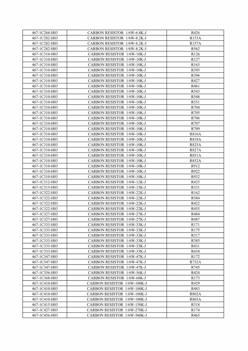
467-1C268-H03 CARBON RESISTOR 1/6W-6.8K-J R426467-1C282-H03 CARBON RESISTOR 1/6W-8.2K-J R153A467-1C282-H03 CARBON RESISTOR 1/6W-8.2K-J R157A467-1C282-H03 CARBON RESISTOR 1/6W-8.2K-J R562467-1C310-H03 CARBON RESISTOR 1/6W-10K-J R126467-1C310-H03 CARBON RESISTOR 1/6W-10K-J R127467-1C310-H03 CARBON RESISTOR 1/6W-10K-J R163467-1C310-H03 CARBON RESISTOR 1/6W-10K-J R395467-1C310-H03 CARBON RESISTOR 1/6W-10K-J R396467-1C310-H03 CARBON RESISTOR 1/6W-10K-J R427467-1C310-H03 CARBON RESISTOR 1/6W-10K-J R461467-1C310-H03 CARBON RESISTOR 1/6W-10K-J R543467-1C310-H03 CARBON RESISTOR 1/6W-10K-J R548467-1C310-H03 CARBON RESISTOR 1/6W-10K-J R551467-1C310-H03 CARBON RESISTOR 1/6W-10K-J R704467-1C310-H03 CARBON RESISTOR 1/6W-10K-J R705467-1C310-H03 CARBON RESISTOR 1/6W-10K-J R706467-1C310-H03 CARBON RESISTOR 1/6W-10K-J R707467-1C310-H03 CARBON RESISTOR 1/6W-10K-J R709467-1C310-H03 CARBON RESISTOR 1/6W-10K-J R816A467-1C310-H03 CARBON RESISTOR 1/6W-10K-J R818A467-1C310-H03 CARBON RESISTOR 1/6W-10K-J R825A467-1C310-H03 CARBON RESISTOR 1/6W-10K-J R827A467-1C310-H03 CARBON RESISTOR 1/6W-10K-J R851A467-1C310-H03 CARBON RESISTOR 1/6W-10K-J R852A467-1C310-H03 CARBON RESISTOR 1/6W-10K-J R912467-1C310-H03 CARBON RESISTOR 1/6W-10K-J R922467-1C310-H03 CARBON RESISTOR 1/6W-10K-J R932467-1C312-H03 CARBON RESISTOR 1/6W-12K-J R425467-1C315-H03 CARBON RESISTOR 1/6W-15K-J R331467-1C322-H03 CARBON RESISTOR 1/6W-22K-J R162467-1C322-H03 CARBON RESISTOR 1/6W-22K-J R384467-1C322-H03 CARBON RESISTOR 1/6W-22K-J R422467-1C322-H03 CARBON RESISTOR 1/6W-22K-J R455467-1C327-H03 CARBON RESISTOR 1/6W-27K-J R484467-1C327-H03 CARBON RESISTOR 1/6W-27K-J R487467-1C333-H03 CARBON RESISTOR 1/6W-33K-J R171467-1C333-H03 CARBON RESISTOR 1/6W-33K-J R175467-1C333-H03 CARBON RESISTOR 1/6W-33K-J R317467-1C333-H03 CARBON RESISTOR 1/6W-33K-J R385467-1C333-H03 CARBON RESISTOR 1/6W-33K-J R431467-1C333-H03 CARBON RESISTOR 1/6W-33K-J R434467-1C347-H03 CARBON RESISTOR 1/6W-47K-J R172467-1C347-H03 CARBON RESISTOR 1/6W-47K-J R732A467-1C347-H03 CARBON RESISTOR 1/6W-47K-J R745467-1C356-H03 CARBON RESISTOR 1/6W-56K-J R424467-1C368-H03 CARBON RESISTOR 1/6W-68K-J R173467-1C410-H03 CARBON RESISTOR 1/6W-100K-J R429467-1C410-H03 CARBON RESISTOR 1/6W-100K-J R483467-1C410-H03 CARBON RESISTOR 1/6W-100K-J R802A467-1C410-H03 CARBON RESISTOR 1/6W-100K-J R803A467-1C415-H03 CARBON RESISTOR 1/6W-150K-J R318467-1C427-H03 CARBON RESISTOR 1/6W-270K-J R174467-1C456-H03 CARBON RESISTOR 1/6W-560K-J R465
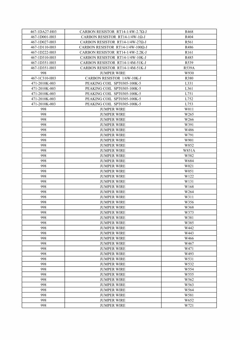
467-1DA27-H03 CARBON RESISTOR RT14-1/4W-2.7Ω-J R468467-1D001-H03 CARBON RESISTOR RT14-1/4W-1Ω-J R404467-1D027-H03 CARBON RESISTOR RT14-1/4W-27Ω-J R561467-1D110-H03 CARBON RESISTOR RT14-1/4W-100Ω-J R486467-1D222-H03 CARBON RESISTOR RT14-1/4W-2.2K-J R161467-1D310-H03 CARBON RESISTOR RT14-1/4W-10K-J R485467-1D351-H03 CARBON RESISTOR RT14-1/4M-51K-J R539467-1D351-H03 CARBON RESISTOR RT14-1/4M-51K-J R539A
998 JUMPER WIRE W930467-1C310-H03 CARBON RESISTOR 1/6W-10K-J R380471-2010K-003 PEAKING COIL SPT0305-100K-5 L331471-2010K-003 PEAKING COIL SPT0305-100K-5 L361471-2010K-003 PEAKING COIL SPT0305-100K-5 L751471-2010K-003 PEAKING COIL SPT0305-100K-5 L752471-2010K-003 PEAKING COIL SPT0305-100K-5 L753
998 JUMPER WIRE W011998 JUMPER WIRE W265998 JUMPER WIRE W266998 JUMPER WIRE W391998 JUMPER WIRE W486998 JUMPER WIRE W791998 JUMPER WIRE W901998 JUMPER WIRE W852998 JUMPER WIRE W851A998 JUMPER WIRE W582998 JUMPER WIRE W684998 JUMPER WIRE W021998 JUMPER WIRE W051998 JUMPER WIRE W122998 JUMPER WIRE W131998 JUMPER WIRE W168998 JUMPER WIRE W264998 JUMPER WIRE W311998 JUMPER WIRE W356998 JUMPER WIRE W368998 JUMPER WIRE W373998 JUMPER WIRE W381998 JUMPER WIRE W385998 JUMPER WIRE W442998 JUMPER WIRE W443998 JUMPER WIRE W466998 JUMPER WIRE W467998 JUMPER WIRE W471998 JUMPER WIRE W493998 JUMPER WIRE W531998 JUMPER WIRE W532998 JUMPER WIRE W554998 JUMPER WIRE W555998 JUMPER WIRE W562998 JUMPER WIRE W563998 JUMPER WIRE W564998 JUMPER WIRE W581998 JUMPER WIRE W652998 JUMPER WIRE W721
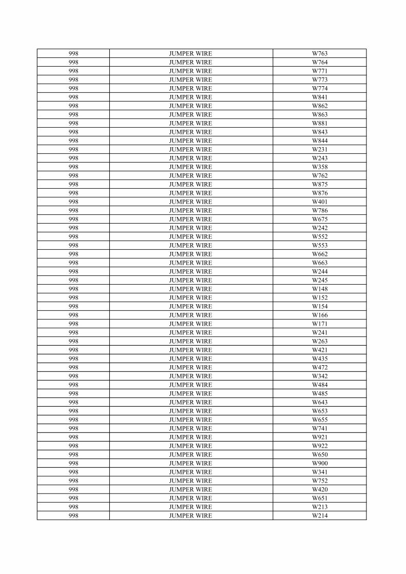
998 JUMPER WIRE W763998 JUMPER WIRE W764998 JUMPER WIRE W771998 JUMPER WIRE W773998 JUMPER WIRE W774998 JUMPER WIRE W841998 JUMPER WIRE W862998 JUMPER WIRE W863998 JUMPER WIRE W881998 JUMPER WIRE W843998 JUMPER WIRE W844998 JUMPER WIRE W231998 JUMPER WIRE W243998 JUMPER WIRE W358998 JUMPER WIRE W762998 JUMPER WIRE W875998 JUMPER WIRE W876998 JUMPER WIRE W401998 JUMPER WIRE W786998 JUMPER WIRE W675998 JUMPER WIRE W242998 JUMPER WIRE W552998 JUMPER WIRE W553998 JUMPER WIRE W662998 JUMPER WIRE W663998 JUMPER WIRE W244998 JUMPER WIRE W245998 JUMPER WIRE W148998 JUMPER WIRE W152998 JUMPER WIRE W154998 JUMPER WIRE W166998 JUMPER WIRE W171998 JUMPER WIRE W241998 JUMPER WIRE W263998 JUMPER WIRE W421998 JUMPER WIRE W435998 JUMPER WIRE W472998 JUMPER WIRE W342998 JUMPER WIRE W484998 JUMPER WIRE W485998 JUMPER WIRE W643998 JUMPER WIRE W653998 JUMPER WIRE W655998 JUMPER WIRE W741998 JUMPER WIRE W921998 JUMPER WIRE W922998 JUMPER WIRE W650998 JUMPER WIRE W900998 JUMPER WIRE W341998 JUMPER WIRE W752998 JUMPER WIRE W420998 JUMPER WIRE W651998 JUMPER WIRE W213998 JUMPER WIRE W214
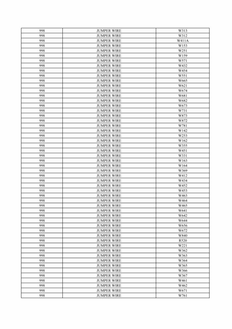
998 JUMPER WIRE W313998 JUMPER WIRE W312998 JUMPER WIRE W411A998 JUMPER WIRE W153998 JUMPER WIRE W251998 JUMPER WIRE W159998 JUMPER WIRE W571998 JUMPER WIRE W432998 JUMPER WIRE W454998 JUMPER WIRE W551998 JUMPER WIRE W665998 JUMPER WIRE W621998 JUMPER WIRE W674998 JUMPER WIRE W681998 JUMPER WIRE W682998 JUMPER WIRE W673998 JUMPER WIRE W731998 JUMPER WIRE W873998 JUMPER WIRE W872998 JUMPER WIRE W781998 JUMPER WIRE W142998 JUMPER WIRE W253998 JUMPER WIRE W162998 JUMPER WIRE W355998 JUMPER WIRE W451998 JUMPER WIRE W331998 JUMPER WIRE W163998 JUMPER WIRE W164998 JUMPER WIRE W369998 JUMPER WIRE W412998 JUMPER WIRE W434998 JUMPER WIRE W452998 JUMPER WIRE W453998 JUMPER WIRE W463998 JUMPER WIRE W464998 JUMPER WIRE W465998 JUMPER WIRE W641998 JUMPER WIRE W642998 JUMPER WIRE W644998 JUMPER WIRE W656998 JUMPER WIRE W672998 JUMPER WIRE W840998 JUMPER WIRE R520998 JUMPER WIRE W221998 JUMPER WIRE W362998 JUMPER WIRE W363998 JUMPER WIRE W364998 JUMPER WIRE W365998 JUMPER WIRE W366998 JUMPER WIRE W367998 JUMPER WIRE W461998 JUMPER WIRE W462998 JUMPER WIRE W671998 JUMPER WIRE W761
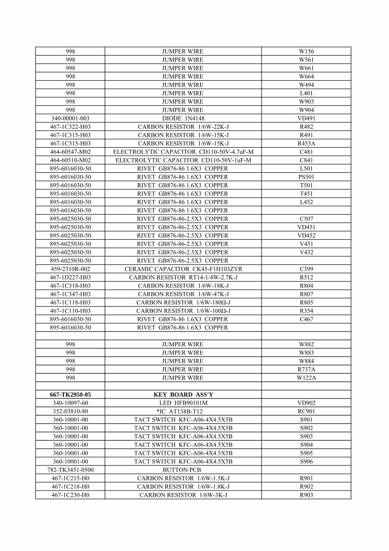
998 JUMPER WIRE W156998 JUMPER WIRE W561998 JUMPER WIRE W661998 JUMPER WIRE W664998 JUMPER WIRE W494998 JUMPER WIRE L401998 JUMPER WIRE W903998 JUMPER WIRE W904
340-00001-003 DIODE 1N4148 VD491467-1C322-H03 CARBON RESISTOR 1/6W-22K-J R482467-1C315-H03 CARBON RESISTOR 1/6W-15K-J R491467-1C315-H03 CARBON RESISTOR 1/6W-15K-J R453A464-60547-M02 ELECTROLYTIC CAPACITOR CD110-50V-4.7uF-M C481464-60510-M02 ELECTROLYTIC CAPACITOR CD110-50V-1uF-M C841895-6016030-50 RIVET GB876-86 1.6X3 COPPER L501895-6016030-50 RIVET GB876-86 1.6X3 COPPER PS501895-6016030-50 RIVET GB876-86 1.6X3 COPPER T501895-6016030-50 RIVET GB876-86 1.6X3 COPPER T451895-6016030-50 RIVET GB876-86 1.6X3 COPPER L452895-6016030-50 RIVET GB876-86 1.6X3 COPPER 895-6025030-50 RIVET GB876-86-2.5X3 COPPER C507895-6025030-50 RIVET GB876-86-2.5X3 COPPER VD451895-6025030-50 RIVET GB876-86-2.5X3 COPPER VD452895-6025030-50 RIVET GB876-86-2.5X3 COPPER V451895-6025030-50 RIVET GB876-86-2.5X3 COPPER V432895-6025030-50 RIVET GB876-86-2.5X3 COPPER 459-2310R-002 CERAMIC CAPACITOR CK45-F1H103ZYR C399467-1D227-H03 CARBON RESISTOR RT14-1/4W-2.7K-J R512467-1C318-H03 CARBON RESISTOR 1/6W-18K-J R804467-1C347-H03 CARBON RESISTOR 1/6W-47K-J R807467-1C118-H03 CARBON RESISTOR 1/6W-180Ω-J R805467-1C110-H03 CARBON RESISTOR 1/6W-100Ω-J R354895-6016030-50 RIVET GB876-86 1.6X3 COPPER C467895-6016030-50 RIVET GB876-86 1.6X3 COPPER
998 JUMPER WIRE W882998 JUMPER WIRE W883998 JUMPER WIRE W884998 JUMPER WIRE R737A998 JUMPER WIRE W122A
667-TK2950-05 KEY BOARD ASS'Y 340-10097-60 LED HFB90101M VD902352-03810-80 *IC AT138B-T12 废 RC901360-10001-00 TACT SWITCH KFC-A06-4X4.5X5B S901360-10001-00 TACT SWITCH KFC-A06-4X4.5X5B S902360-10001-00 TACT SWITCH KFC-A06-4X4.5X5B S903360-10001-00 TACT SWITCH KFC-A06-4X4.5X5B S904360-10001-00 TACT SWITCH KFC-A06-4X4.5X5B S905360-10001-00 TACT SWITCH KFC-A06-4X4.5X5B S906
782-TK3451-0500 BUTTON PCB 467-1C215-H0 CARBON RESISTOR 1/6W-1.5K-J R901467-1C218-H0 CARBON RESISTOR 1/6W-1.8K-J R902467-1C230-H0 CARBON RESISTOR 1/6W-3K-J R903
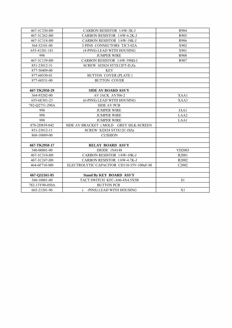
467-1C230-H0 CARBON RESISTOR 1/6W-3K-J R904467-1C262-H0 CARBON RESISTOR 1/6W-6.2K-J R905467-1C318-H0 CARBON RESISTOR 1/6W-18K-J R906364-32101-00 2-PINS CONNECTORS TJC3-02A X902
655-41201-181 (4-PINS) LEAD WITH HOUSING X901998 JUMPER WIRE R908
467-1C139-H0 CARBON RESISTOR 1/6W-390Ω-J R907851-23012-31 SCREW SJ2824 ST3X12FT-D.Zn877-50409-00 KEY 877-60530-01 BUTTON COVER (PLATE )877-60531-00 BUTTON COVER
667-TK2950-29 SIDE AV BOARD ASS'Y 364-93202-00 AV JACK AV306-2 XAA1655-6E301-23 (6-PINS) LEAD WITH HOUSING XAA3
782-Q2751-290A SIDE AV PCB 998 JUMPER WIRE JAA1998 JUMPER WIRE LAA2998 JUMPER WIRE LAA1
870-2D839-042 SIDE AV BRACKET ( MOLD GREY SILK-SCREEN 851-23012-11 SCREW SJ2824 ST3X12C-DZn868-10089-00 CUSHION
667-TK2950-17 RELAY BOARD ASS'Y 340-00001-00 DIODE 1N4148 VD2003467-1C310-H0 CARBON RESISTOR 1/6W-10K-J R2001467-1C247-H0 CARBON RESISTOR 1/6W-4.7K-J R2002464-6F710-M0 ELECTROLYTIC CAPACITOR CD110-35V-100uF-M C2002
667-Q32161-05 Stand By KEY BOARD ASS'Y 360-10001-00 TACT SWITCH KFC-A06-4X4.5X5B S1
782-13Y90-050A BUTTON PCB 665-21201-96 (2-PINS) LEAD WITH HOUSING X1
41
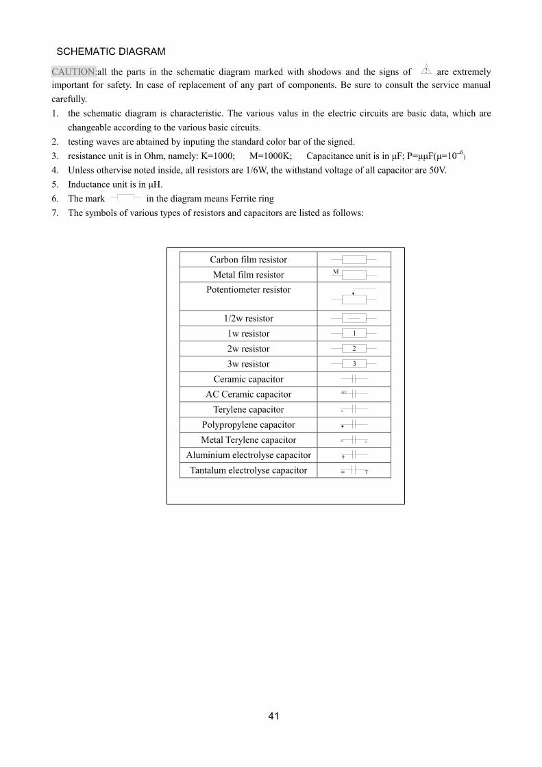
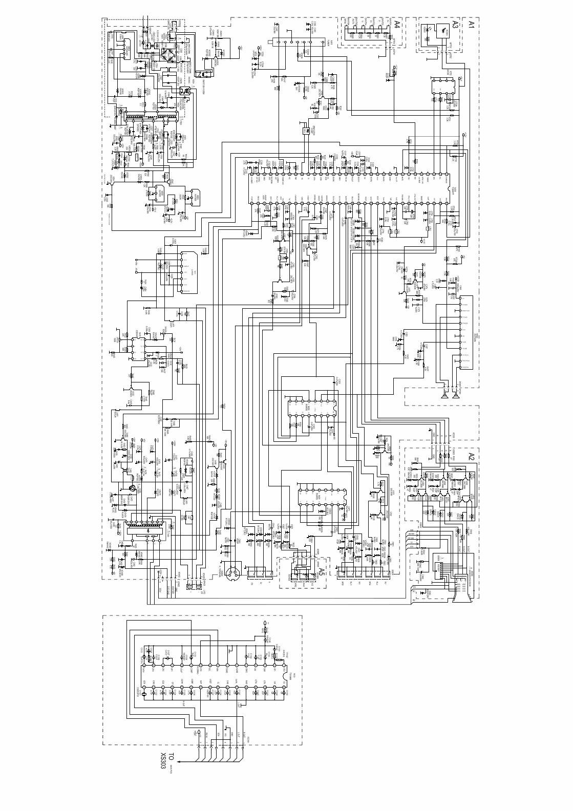
CAUTION:all the parts in the schematic diagram marked with shodows and the signs of are extremely important for safety. In case of replacement of any part of components. Be sure to consult the service manual carefully. 1. the schematic diagram is characteristic. The various valus in the electric circuits are basic data, which are
changeable according to the various basic circuits. 2. testing waves are abtained by inputing the standard color bar of the signed. 3. resistance unit is in Ohm, namely: K=1000; M=1000K; Capacitance unit is in µF; P=µµF(µ=106) 4. Unless othervise noted inside, all resistors are 1/6W, the withstand voltage of all capacitor are 50V. 5. Inductance unit is in µH. 6. The mark in the diagram means Ferrite ring 7. The symbols of various types of resistors and capacitors are listed as follows:
Carbon film resistor Metal film resistor M
Potentiometer resistor
1/2w resistor 1w resistor 1 2w resistor 2 3w resistor 3
Ceramic capacitor AC Ceramic capacitor AC
Terylene capacitor Polypropylene capacitor Metal Terylene capacitor
Aluminium electrolyse capacitor Tantalum electrolyse capacitor T
SCHEMATIC DIAGRAM
dragon
CAUTION:
Related Documents