CONTENTS REQUIRED FOR COURSE FILE 1. Cover Page 2. Syllabus copy 3. Vision of the Department 4. Mission of the Department 5. PEOs and POs 6. Course objectives and outcomes 7. Brief notes on the importance of the course and how it fits into the curriculum 8. prerequisites 9. Instructional Learning Outcomes 10. Course mapping with PEOs and POs 11. Class Time Table 12. Individual Time Table 13. Micro Plan with dates and closure report 14. Detailed notes 15. Additional topics 16. University Question papers of previous years 17. Question Bank 18. Assignment topics 19. Unit wise Quiz Questions 20. Tutorial problems 21. Known gaps ,if any 22. Discussion topics 23. References, Journals, websites and E-links 24. Quality Control Sheets 25. Student List 26. Group-Wise students list for discussion topics

Welcome message from author
This document is posted to help you gain knowledge. Please leave a comment to let me know what you think about it! Share it to your friends and learn new things together.
Transcript
CONTENTS REQUIRED FOR
COURSE FILE
1. Cover Page
2. Syllabus copy
3. Vision of the Department
4. Mission of the Department
5. PEOs and POs
6. Course objectives and outcomes
7. Brief notes on the importance of the course and how it fits into the
curriculum
8. prerequisites
9. Instructional Learning Outcomes
10. Course mapping with PEOs and POs
11. Class Time Table
12. Individual Time Table
13. Micro Plan with dates and closure report
14. Detailed notes
15. Additional topics
16. University Question papers of previous years
17. Question Bank
18. Assignment topics
19. Unit wise Quiz Questions
20. Tutorial problems
21. Known gaps ,if any
22. Discussion topics
23. References, Journals, websites and E-links
24. Quality Control Sheets
25. Student List
26. Group-Wise students list for discussion topics
PRINCIPLES OF ELECTRICAL
ENGINEERING
COURSE FILE
Prepared by
MANJUL KHARE
B. RAMESH BABU
M.PRADEEP
POOJA RANI
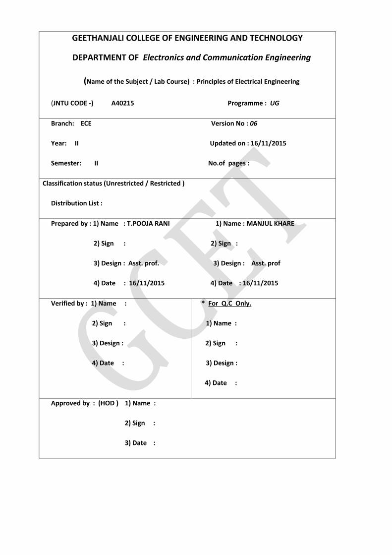
GEETHANJALI COLLEGE OF ENGINEERING AND TECHNOLOGY
DEPARTMENT OF Electronics and Communication Engineering
(Name of the Subject / Lab Course) : Principles of Electrical Engineering
(JNTU CODE -) A40215 Programme : UG
Branch: ECE Version No : 06
Year: II Updated on : 16/11/2015
Semester: II No.of pages :
Classification status (Unrestricted / Restricted )
Distribution List :
Prepared by : 1) Name : T.POOJA RANI 1) Name : MANJUL KHARE
2) Sign : 2) Sign :
3) Design : Asst. prof. 3) Design : Asst. prof
4) Date : 16/11/2015 4) Date : 16/11/2015
Verified by : 1) Name :
2) Sign :
3) Design :
4) Date :
* For Q.C Only.
1) Name :
2) Sign :
3) Design :
4) Date :
Approved by : (HOD ) 1) Name :
2) Sign :
3) Date :
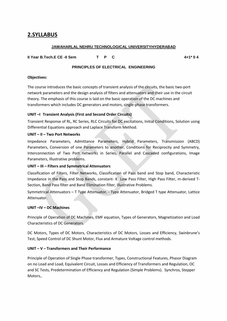
2.SYLLABUS
JAWAHARLAL NEHRU TECHNOLOGICAL UNIVERSITYHYDERABAD
II Year B.Tech.E CE -II Sem T P C 4+1* 0 4
PRINCIPLES OF ELECTRICAL ENGINEERING
Objectives:
The course introduces the basic concepts of transient analysis of the circuits, the basic two-port
network parameters and the design analysis of filters and attenuators and their use in the circuit
theory. The emphasis of this course is laid on the basic operation of the DC machines and
transformers which includes DC generators and motors, single-phase transformers.
UNIT –I Transient Analysis (First and Second Order Circuits)
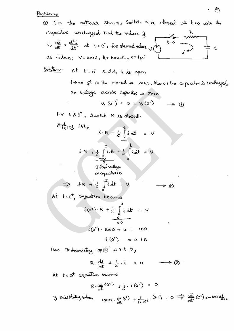
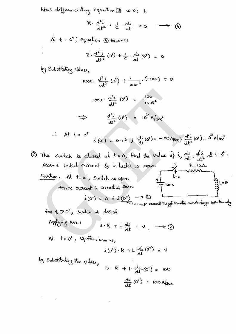
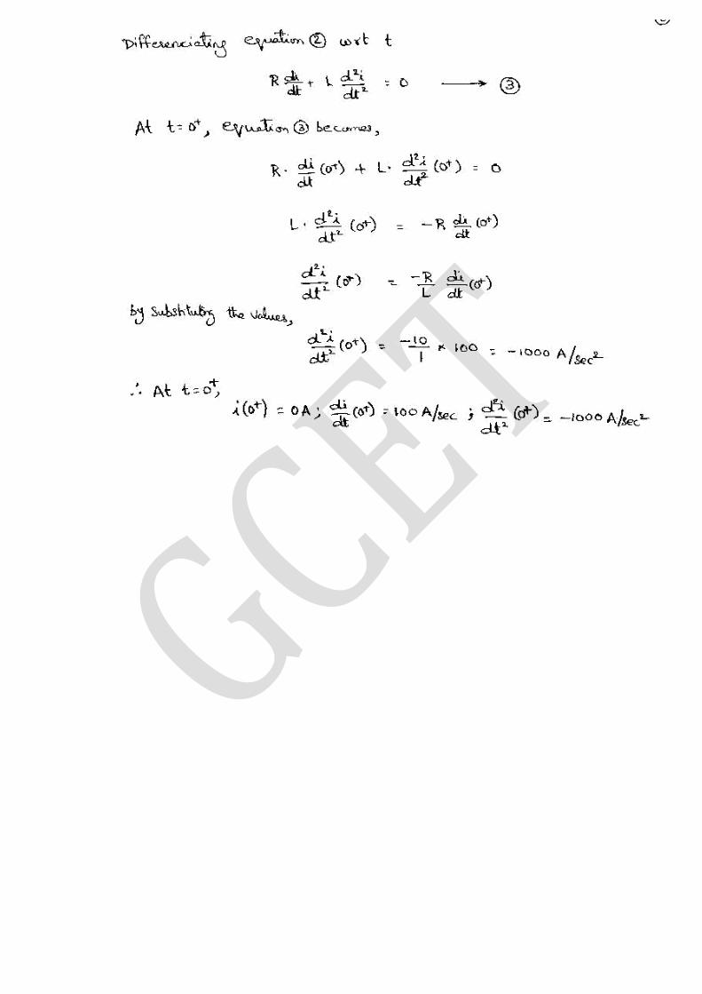
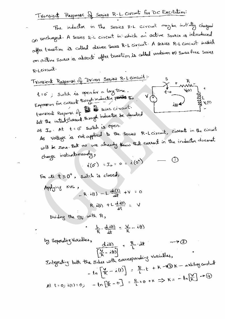
Transient Response of RL, RC Series, RLC Circuits for DC excitations, Initial Conditions, Solution using
Differential Equations approach and Laplace Transform Method.
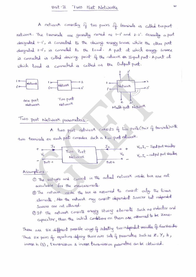
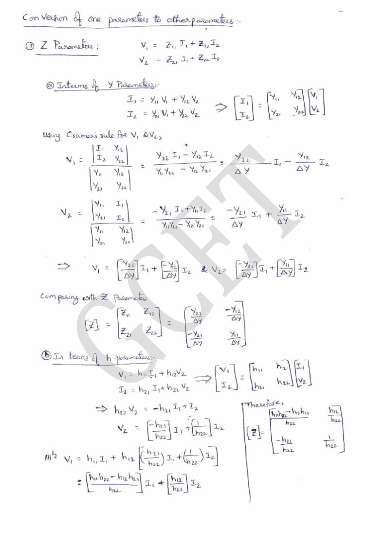
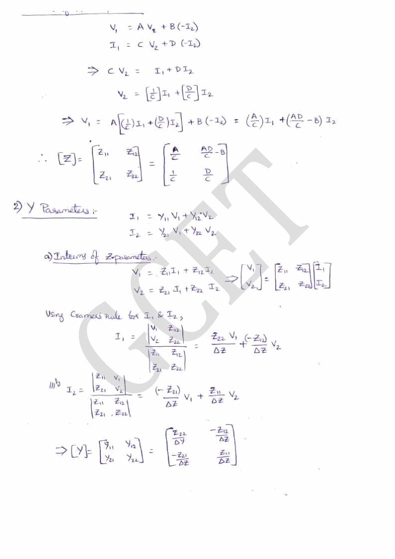
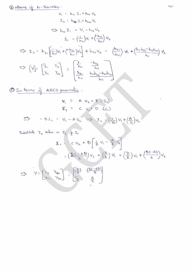
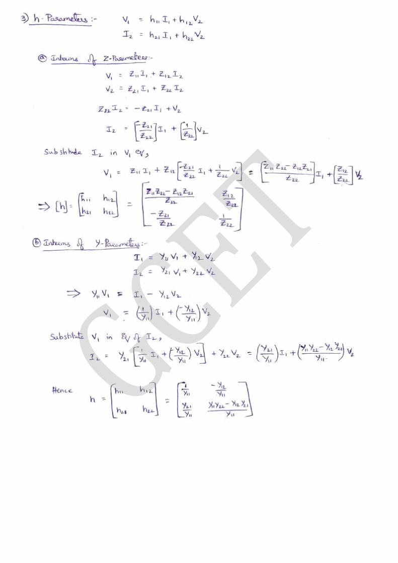
UNIT – II – Two Port Networks
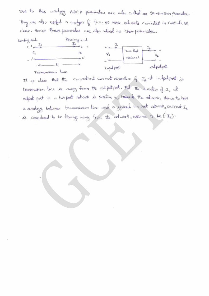
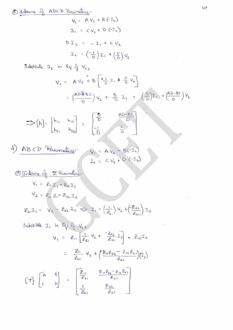
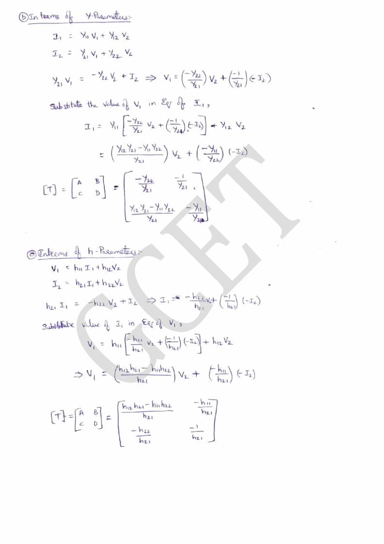
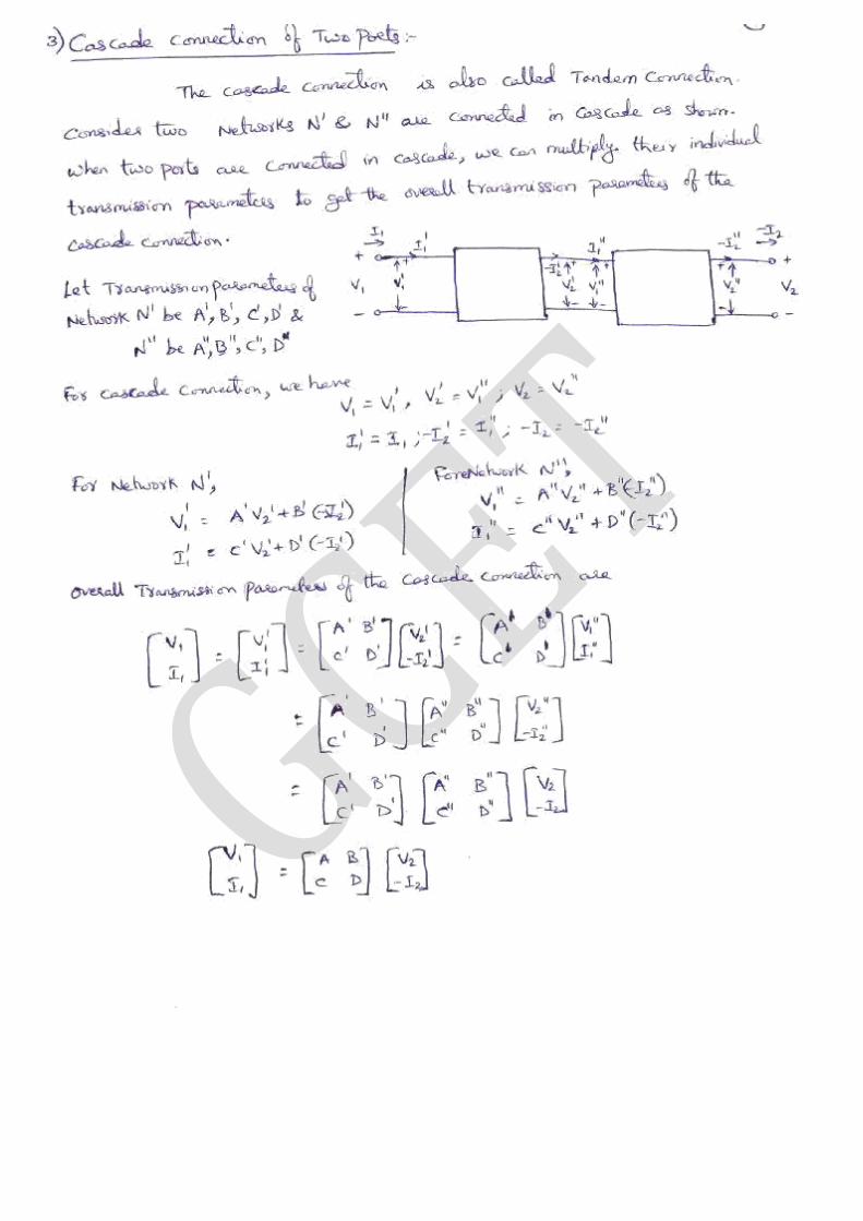
Impedance Parameters, Admittance Parameters, Hybrid Parameters, Transmission (ABCD)
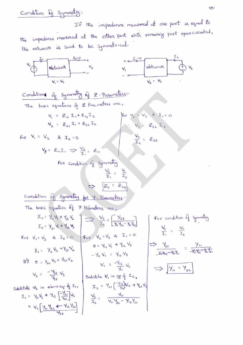
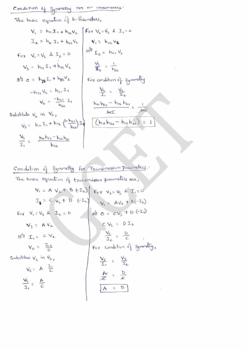
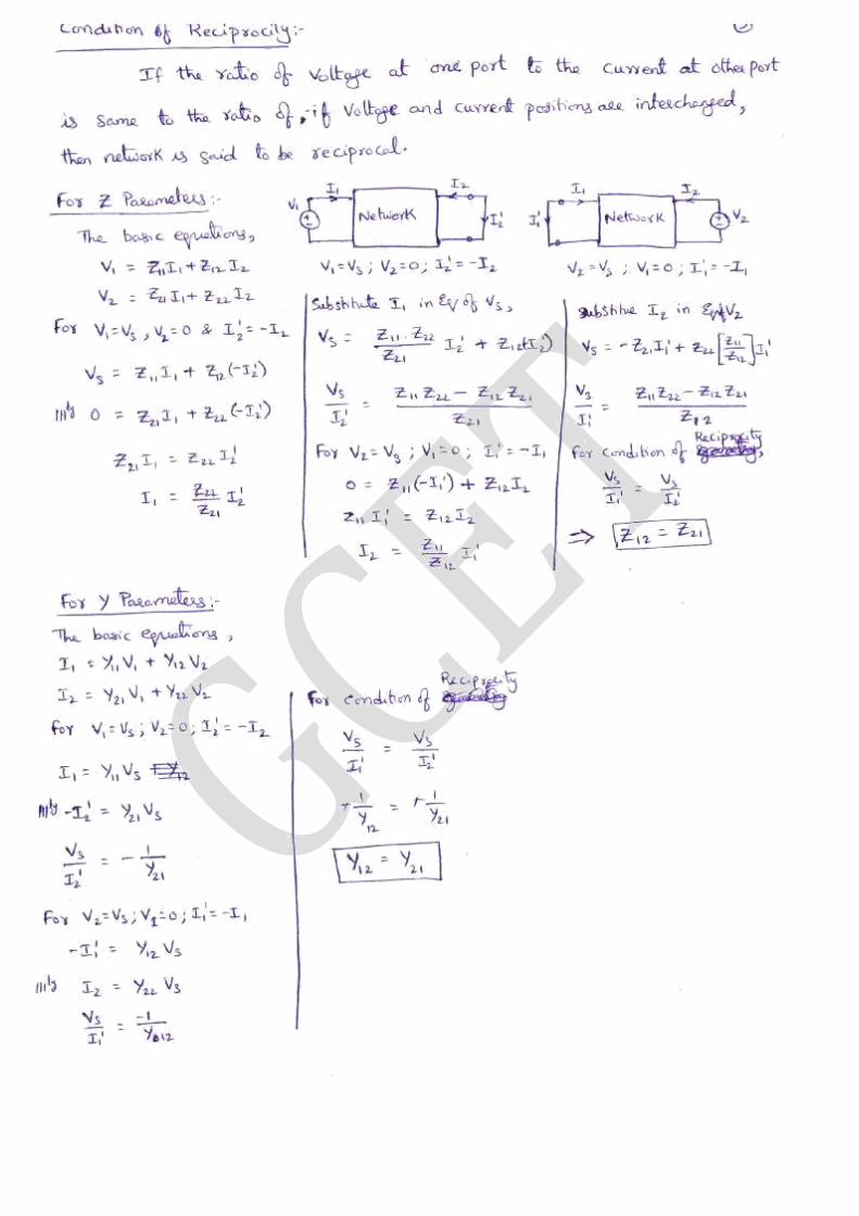
Parameters, Conversion of one Parameters to another, Conditions for Reciprocity and Symmetry,
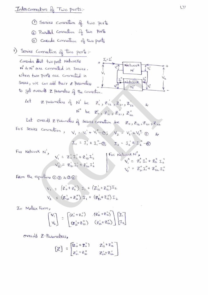
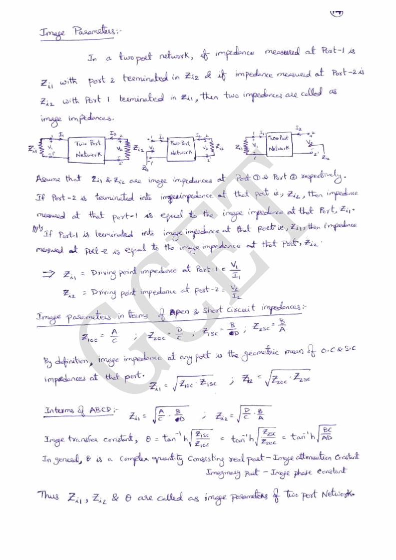
Interconnection of Two Port networks in Series, Parallel and Cascaded configurations, Image
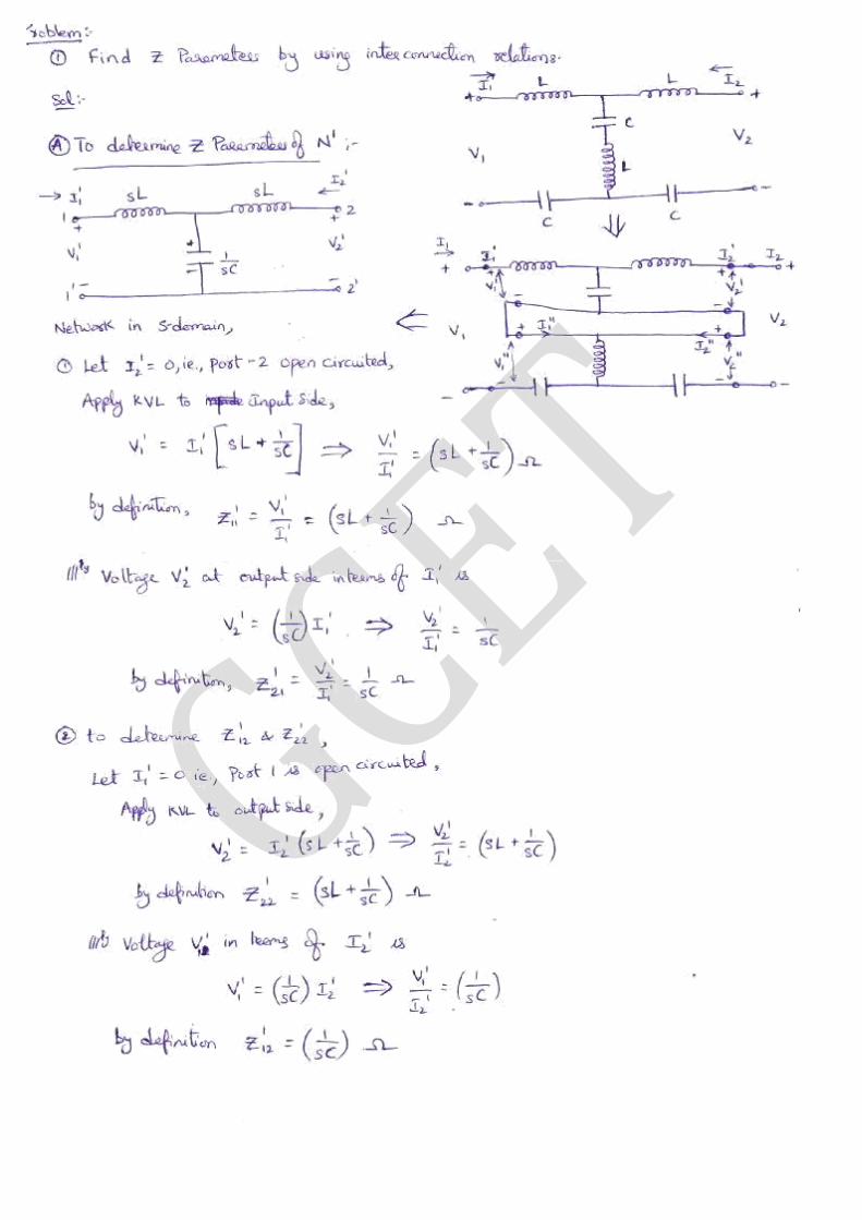
Parameters, Illustrative problems.
UNIT – III – Filters and Symmetrical Attenuators
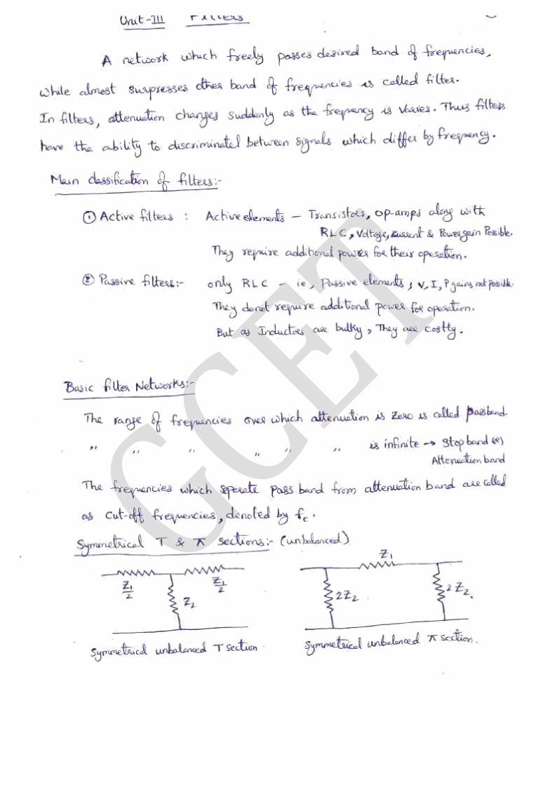
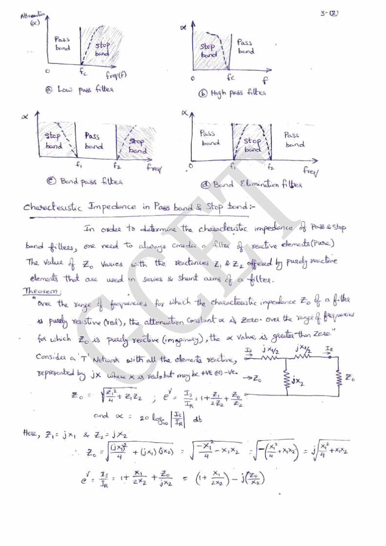
Classification of Filters, Filter Networks, Classification of Pass band and Stop band, Characteristic
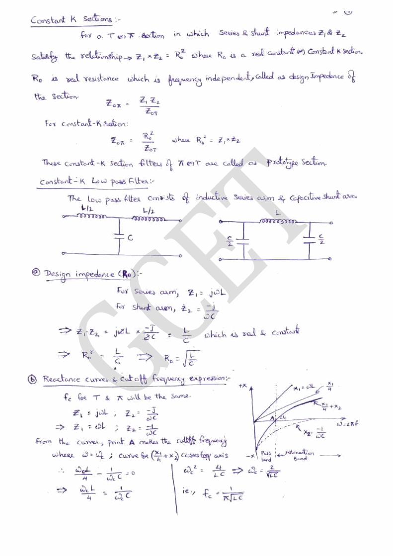
Impedance in the Pass and Stop Bands, constant- K Low Pass Filter, High Pass Filter, m-derived T-
Section, Band Pass filter and Band Elimination filter, Illustrative Problems.
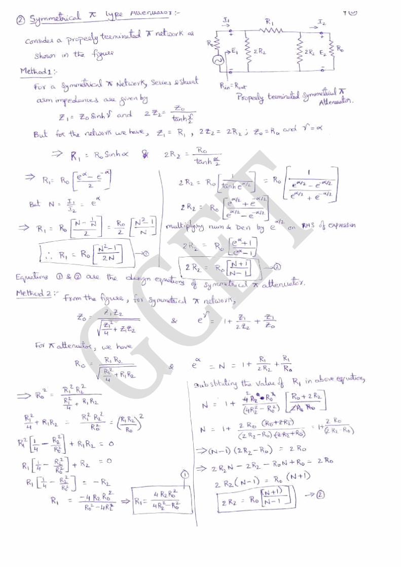
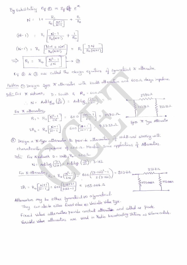
Symmetrical Attenuators – T Type Attenuator, - Type Attenuator, Bridged T type Attenuator, Lattice
Attenuator.
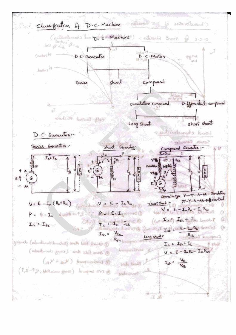
UNIT –IV – DC Machines
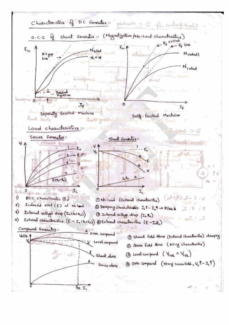
Principle of Operation of DC Machines, EMF equation, Types of Generators, Magnetization and Load
Characteristics of DC Generators.
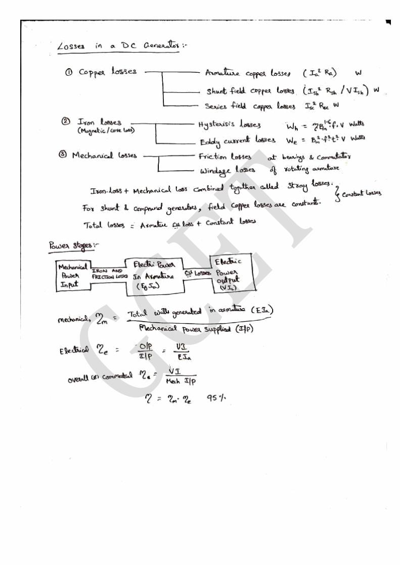
DC Motors, Types of DC Motors, Characteristics of DC Motors, Losses and Efficiency, Swinbrune’s
Test, Speed Control of DC Shunt Motor, Flux and Armature Voltage control methods.
UNIT – V – Transformers and Their Performance
Principle of Operation of Single Phase transformer, Types, Constructional Features, Phasor Diagram
on no Load and Load, Equivalent Circuit, Losses and Efficiency of Transformers and Regulation, OC
and SC Tests, Predetermination of Efficiency and Regulation (Simple Problems). Synchros, Stepper
Motors,.
Text Books :
1. Electric circuits- A.Chakrabarthy, Dhanipat Rai & Sons.
2. Basic concepts of Electrical Engineering- PS Subramanyam, BS Publications
Reference Books :
1. Engineering Circuit Analysis – W.H.Hayt and J. E. Kermmerly and S. M. Durbin 6 ed., 2008 TMH.
2. Basic Electrical Engineering- S.N.Singh, PHI. 3. Electrical Circuits- David A.Bell, Oxford University Press. 4. Electric Circuit Analysis- K.S.Suresh Kumar, Pearson Education.

3.Vision of the Department
To impart quality technical education in Electronics and Communication Engineering
emphasizing analysis, design/synthesis and evaluation of hardware/embedded software using
various Electronic Design Automation (EDA) tools with accent on creativity, innovation and
research thereby producing competent engineers who can meet global challenges with
societal commitment.
4.Mission of the Department
i. To impart quality education in fundamentals of basic sciences, mathematics, electronics
and communication engineering through innovative teaching-learning processes.
ii. To facilitate Graduates define, design, and solve engineering problems in the field of
Electronics and Communication Engineering using various Electronic Design Automation
(EDA) tools.
iii. To encourage research culture among faculty and students thereby facilitating them to be
creative and innovative through constant interaction with R & D organizations and
Industry.
iv. To inculcate teamwork, imbibe leadership qualities, professional ethics and social
responsibilities in students and faculty.
5. Program Educational Objectives and Program outcomes of
B. Tech (ECE) Program
Program Educational Objectives of B. Tech (ECE) Program :
I. To prepare students with excellent comprehension of basic sciences, mathematics and
engineering subjects facilitating them to gain employment or pursue postgraduate
studies with an appreciation for lifelong learning.
II. To train students with problem solving capabilities such as analysis and design with
adequate practical skills wherein they demonstrate creativity and innovation that
would enable them to develop state of the art equipment and technologies of
multidisciplinary nature for societal development.
III. To inculcate positive attitude, professional ethics, effective communication and
interpersonal skills which would facilitate them to succeed in the chosen profession
exhibiting creativity and innovation through research and development both as team
member and as well as leader.
Program Outcomes of B.Tech ECE Program:
1. An ability to apply knowledge of Mathematics, Science, and Engineering to solve
complex engineering problems of Electronics and Communication Engineering
systems.
2. An ability to model, simulate and design Electronics and Communication Engineering
systems, conduct experiments, as well as analyze and interpret data and prepare a
report with conclusions.
3. An ability to design an Electronics and Communication Engineering system,
component, or process to meet desired needs within the realistic constraints such as
economic, environmental, social, political, ethical, health and safety,
manufacturability and sustainability.
4. An ability to function on multidisciplinary teams involving interpersonal skills.
5. An ability to identify, formulate and solve engineering problems of multidisciplinary
nature.
6. An understanding of professional and ethical responsibilities involved in the practice
of Electronics and Communication Engineering profession.
7. An ability to communicate effectively with a range of audience on complex
engineering problems of multidisciplinary nature both in oral and written form.
8. The broad education necessary to understand the impact of engineering solutions in a
global, economic, environmental and societal context.
9. A recognition of the need for, and an ability to engage in life-long learning and
acquire the capability for the same.
10. A knowledge of contemporary issues involved in the practice of Electronics and
Communication Engineering profession
11. An ability to use the techniques, skills and modern engineering tools necessary for
engineering practice.
12. An ability to use modern Electronic Design Automation (EDA) tools, software and
electronic equipment to analyze, synthesize and evaluate Electronics and
Communication Engineering systems for multidisciplinary tasks.
13. Apply engineering and project management principles to one's own work and also to
manage projects of multidisciplinary nature
6. Course objectives and outcomes:
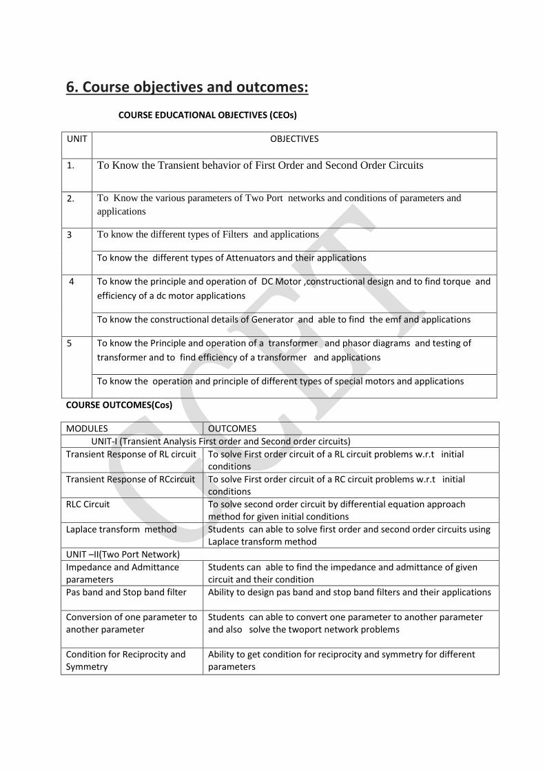
COURSE EDUCATIONAL OBJECTIVES (CEOs)
UNIT OBJECTIVES
1. To Know the Transient behavior of First Order and Second Order Circuits
2. To Know the various parameters of Two Port networks and conditions of parameters and
applications
3 To know the different types of Filters and applications
To know the different types of Attenuators and their applications
4 To know the principle and operation of DC Motor ,constructional design and to find torque and
efficiency of a dc motor applications
To know the constructional details of Generator and able to find the emf and applications
5 To know the Principle and operation of a transformer and phasor diagrams and testing of
transformer and to find efficiency of a transformer and applications
To know the operation and principle of different types of special motors and applications
COURSE OUTCOMES(Cos)
MODULES OUTCOMES
UNIT-I (Transient Analysis First order and Second order circuits)
Transient Response of RL circuit To solve First order circuit of a RL circuit problems w.r.t initial conditions
Transient Response of RCcircuit To solve First order circuit of a RC circuit problems w.r.t initial conditions
RLC Circuit To solve second order circuit by differential equation approach method for given initial conditions
Laplace transform method Students can able to solve first order and second order circuits using Laplace transform method
UNIT –II(Two Port Network)
Impedance and Admittance parameters
Students can able to find the impedance and admittance of given circuit and their condition
Pas band and Stop band filter Ability to design pas band and stop band filters and their applications
Conversion of one parameter to another parameter
Students can able to convert one parameter to another parameter and also solve the twoport network problems
Condition for Reciprocity and Symmetry
Ability to get condition for reciprocity and symmetry for different parameters
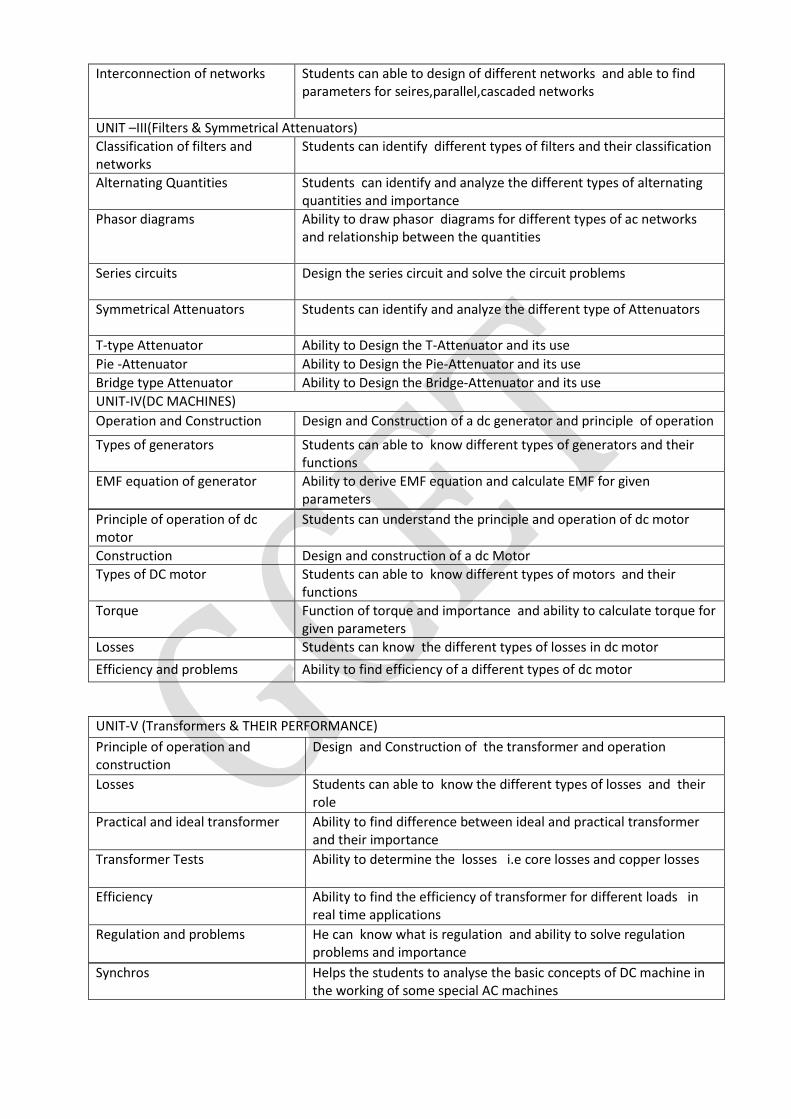
Interconnection of networks Students can able to design of different networks and able to find parameters for seires,parallel,cascaded networks
UNIT –III(Filters & Symmetrical Attenuators)
Classification of filters and networks
Students can identify different types of filters and their classification
Alternating Quantities Students can identify and analyze the different types of alternating quantities and importance
Phasor diagrams Ability to draw phasor diagrams for different types of ac networks and relationship between the quantities
Series circuits Design the series circuit and solve the circuit problems
Symmetrical Attenuators Students can identify and analyze the different type of Attenuators
T-type Attenuator Ability to Design the T-Attenuator and its use
Pie -Attenuator Ability to Design the Pie-Attenuator and its use
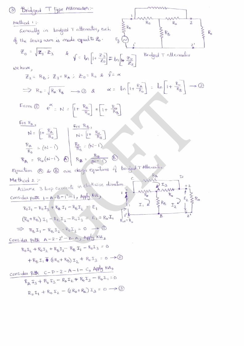
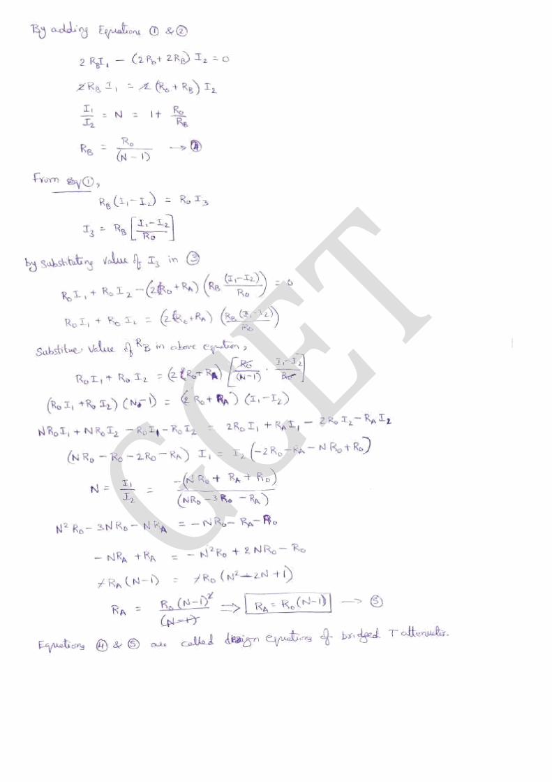
Bridge type Attenuator Ability to Design the Bridge-Attenuator and its use
UNIT-IV(DC MACHINES)
Operation and Construction Design and Construction of a dc generator and principle of operation
Types of generators Students can able to know different types of generators and their functions
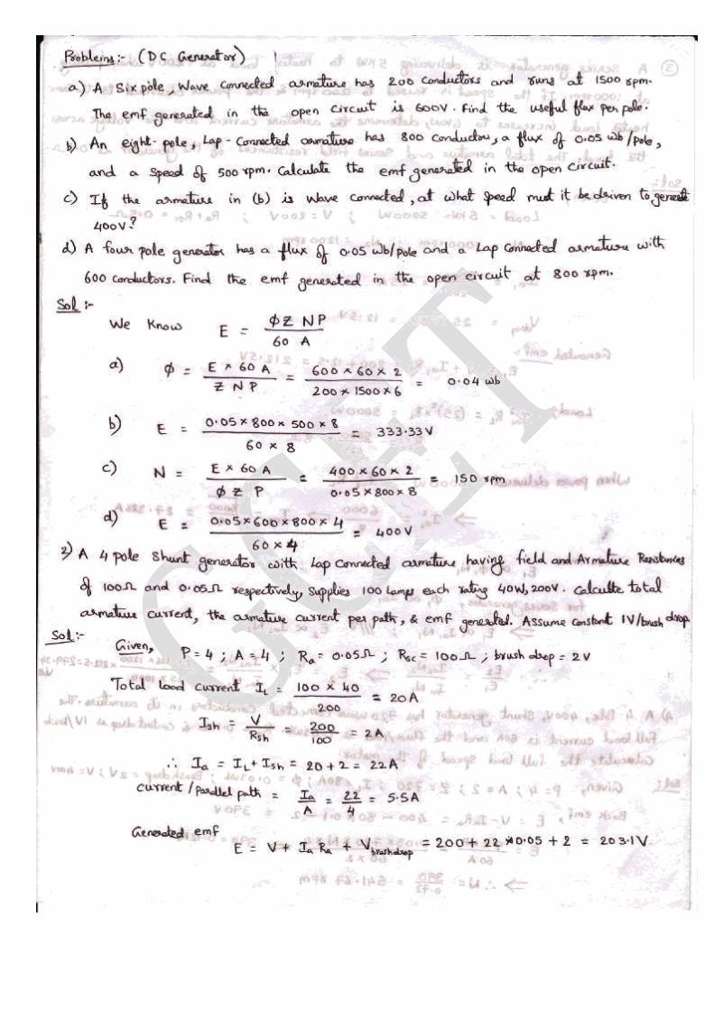
EMF equation of generator Ability to derive EMF equation and calculate EMF for given parameters
UNIT-V (Transformers & THEIR PERFORMANCE)
Principle of operation and construction
Design and Construction of the transformer and operation
Losses Students can able to know the different types of losses and their role
Practical and ideal transformer Ability to find difference between ideal and practical transformer and their importance
Transformer Tests Ability to determine the losses i.e core losses and copper losses
Efficiency Ability to find the efficiency of transformer for different loads in real time applications
Regulation and problems He can know what is regulation and ability to solve regulation problems and importance
Principle of operation of dc motor
Students can understand the principle and operation of dc motor
Construction Design and construction of a dc Motor
Types of DC motor Students can able to know different types of motors and their functions
Torque Function of torque and importance and ability to calculate torque for given parameters
Losses Students can know the different types of losses in dc motor
Efficiency and problems Ability to find efficiency of a different types of dc motor
Synchros Helps the students to analyse the basic concepts of DC machine in the working of some special AC machines
7. Brief notes on the importance of the course and how it fit
into the curriculum
The course introduces the basic concepts of transient analysis of the circuits, the basic two-port
network parameters and the design analysis of filters and attenuators and their use in the circuit
theory. The emphasis of this course is laid on the basic operation of the DC machines and
transformers which includes DC generators and motors, single-phase transformers.
8. Prerequisites
Engineering Physics, Mathematics
9. Instructional Learning Outcomes:
Outcomes
On successful completion of this subject, students will be able to:
1. Understand working principles of electrical devices and circuits. 2. Understand advantages & applications of electrical devices and circuits. 3. Understand design and analysis of electrical circuits.
4. To apply the operating knowledge of major electrical devices like DC generator, DC motor,
Transformers, Syncro transmitter & receiver and advanced filter and attenuator circuits to
identify, formulate & solve Engineering problems by making use of modern
software/hardware tools.
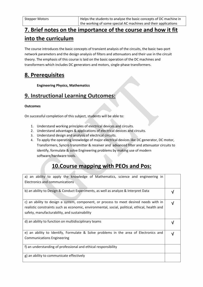
10.Course mapping with PEOs and Pos:
a) an ability to apply the knowledge of Mathematics, science and engineering in
Electronics and communications
b) an ability to Design & Conduct Experiments, as well as analyze & Interpret Data √
c) an ability to design a system, component, or process to meet desired needs with in
realistic constraints such as economic, environmental, social, political, ethical, health and
safety, manufacturability, and sustainability
√
d) an ability to function on multidisciplinary teams √
e) an ability to Identify, Formulate & Solve problems in the area of Electronics and
Communications Engineering √
f) an understanding of professional and ethical responsibility
g) an ability to communicate effectively
Stepper Motors Helps the students to analyse the basic concepts of DC machine in the working of some special AC machines and their applications
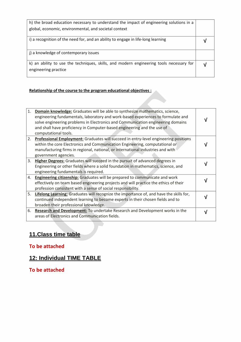
h) the broad education necessary to understand the impact of engineering solutions in a
global, economic, environmental, and societal context
i) a recognition of the need for, and an ability to engage in life-long learning √
j) a knowledge of contemporary issues
k) an ability to use the techniques, skills, and modern engineering tools necessary for
engineering practice √
Relationship of the course to the program educational objectives :
1. Domain knowledge: Graduates will be able to synthesize mathematics, science, engineering fundamentals, laboratory and work-based experiences to formulate and solve engineering problems in Electronics and Communication engineering domains and shall have proficiency in Computer-based engineering and the use of computational tools.
√
2. Professional Employment: Graduates will succeed in entry-level engineering positions within the core Electronics and Communication Engineering, computational or manufacturing firms in regional, national, or international industries and with government agencies.
√
3. Higher Degrees: Graduates will succeed in the pursuit of advanced degrees in Engineering or other fields where a solid foundation in mathematics, science, and engineering fundamentals is required.
√
4. Engineering citizenship: Graduates will be prepared to communicate and work effectively on team based engineering projects and will practice the ethics of their profession consistent with a sense of social responsibility.
√
5. Lifelong Learning: Graduates will recognize the importance of, and have the skills for, continued independent learning to become experts in their chosen fields and to broaden their professional knowledge.
√
6. Research and Development: To undertake Research and Development works in the areas of Electronics and Communication fields.
√
11.Class time table
To be attached
12: Individual TIME TABLE
To be attached
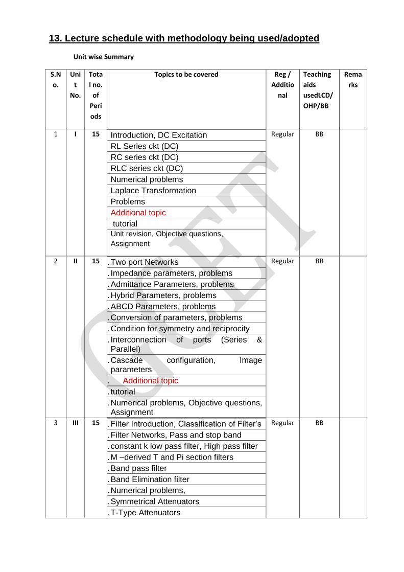
13. Lecture schedule with methodology being used/adopted
Unit wise Summary
S.N
o.
Uni
t
No.
Tota
l no.
of
Peri
ods
Topics to be covered Reg /
Additio
nal
Teaching
aids
usedLCD/
OHP/BB
Rema
rks
1 I 15
1. Introduction, DC Excitation 1
2. RL Series ckt (DC) 1
3. RC series ckt (DC) 1
4. RLC series ckt (DC) 1
5. Numerical problems 2
6. Laplace Transformation 1
7. Problems
8. Additional topic
9. tutorial
Unit revision, Objective questions,
Assignment
Regular BB
2 II 15 10. Two port Networks 1
11. Impedance parameters, problems 1
12. Admittance Parameters, problems 1
13. Hybrid Parameters, problems 1
14. ABCD Parameters, problems 1
15. Conversion of parameters, problems 1
16. Condition for symmetry and reciprocity 1
17. Interconnection of ports (Series & Parallel) 1
18. Cascade configuration, Image parameters
19. Additional topic
20. tutorial
21. Numerical problems, Objective questions, Assignment
Regular BB
3 III 15 22. Filter Introduction, Classification of Filter’s 1
23. Filter Networks, Pass and stop band 1
24. constant k low pass filter, High pass filter 1
25. M –derived T and Pi section filters 1
26. Band pass filter 1
27. Band Elimination filter 1
28. Numerical problems, 2
29. Symmetrical Attenuators 1
30. T-Type Attenuators 1
Regular BB
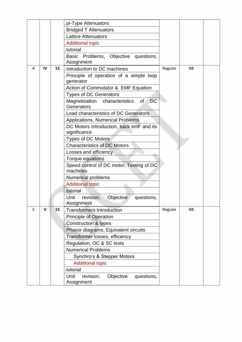
31. pi-Type Attenuators 1
32. Bridged T Attenuators 1
33. Lattice Attenuators
34. Additional topic
35. tutorial
36. Basic Problems, Objective questions, Assignment
4 IV 15 37. Introduction to DC machines 1
38. Principle of operation of a simple loop generator 1
39. Action of Commutator & EMF Equation 1
40. Types of DC Generators 1
41. Magnetization characteristics of DC Generators 2
42. Load characteristics of DC Generators 1
43. Applications, Numerical Problems 1
44. DC Motors Introduction, back emf and its significance 1
45. Types of DC Motors 1
46. Characteristics of DC Motors 1
47. Losses and efficiency 1
48. Torque equations 1
49. Speed control of DC motor, Testing of DC machines 2
50. Numerical problems
51. Additional topic
52. tutorial
53. Unit revision, Objective questions, Assignment
Regular BB
5 V 15 54. Transformers Introduction 1
55. Principle of Operation 1
56. Construction & types 1
57. Phasor diagrams, Equivalent circuits 1
58. Transformer losses, efficiency 1
59. Regulation, OC & SC tests 1
60. Numerical Problems
61. Synchro’s & Stepper Motors
62. Additional topic
63. tutorial
64. Unit revision, Objective questions, Assignment
Regular BB
14. DETAILED NOTES
\


Unit 5 TRANSFORMERS
A transformer is a device that transfers electrical energy from one circuit to another through
inductively coupled conductors—the transformer's coils. A varying current in the first or
primary winding creates a varying magnetic flux in the transformer's core and thus a varying
magnetic field through the secondary winding. This varying magnetic field induces a varying
electromotive force (EMF), or "voltage", in the secondary winding. This effect is called
inductive coupling.
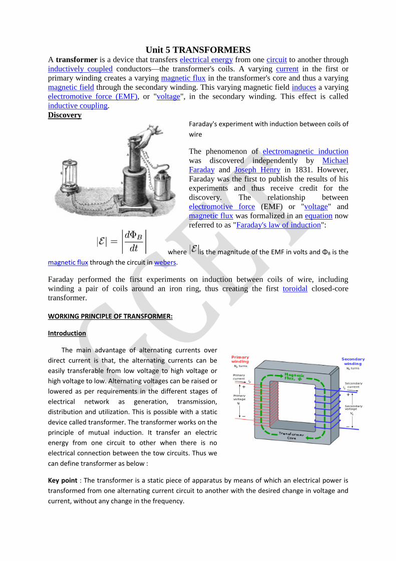
Discovery Faraday's experiment with induction between coils of
wire
The phenomenon of electromagnetic induction
was discovered independently by Michael
Faraday and Joseph Henry in 1831. However,
Faraday was the first to publish the results of his
experiments and thus receive credit for the
discovery. The relationship between
electromotive force (EMF) or "voltage" and
magnetic flux was formalized in an equation now
referred to as "Faraday's law of induction":
where is the magnitude of the EMF in volts and ΦB is the
magnetic flux through the circuit in webers.
Faraday performed the first experiments on induction between coils of wire, including
winding a pair of coils around an iron ring, thus creating the first toroidal closed-core
transformer.
WORKING PRINCIPLE OF TRANSFORMER:
Introduction
The main advantage of alternating currents over
direct current is that, the alternating currents can be
easily transferable from low voltage to high voltage or
high voltage to low. Alternating voltages can be raised or
lowered as per requirements in the different stages of
electrical network as generation, transmission,
distribution and utilization. This is possible with a static
device called transformer. The transformer works on the
principle of mutual induction. It transfer an electric
energy from one circuit to other when there is no
electrical connection between the tow circuits. Thus we
can define transformer as below :
Key point : The transformer is a static piece of apparatus by means of which an electrical power is
transformed from one alternating current circuit to another with the desired change in voltage and
current, without any change in the frequency.
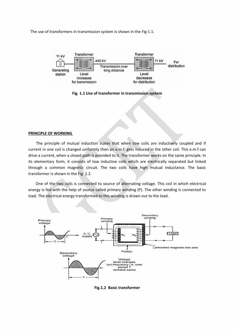
The use of transformers in transmission system is shown in the Fig 1.1.
Fig. 1.1 Use of transformer in transmission system
PRINCIPLE OF WORKING
The principle of mutual induction states that when tow coils are inductively coupled and if
current in one coil is changed uniformly then an e.m.f. gets induced in the other coil. This e.m.f can
drive a current, when a closed path is provided to it. The transformer works on the same principle. In
its elementary form, it consists of tow inductive coils which are electrically separated but linked
through a common magnetic circuit. The two coils have high mutual inductance. The basic
transformer is shown in the Fig 1.2.
One of the two coils is connected to source of alternating voltage. This coil in which electrical
energy is fed with the help of source called primary winding (P). The other winding is connected to
load. The electrical energy transformed to this winding is drawn out to the load.
Fig.1.2 Basic transformer
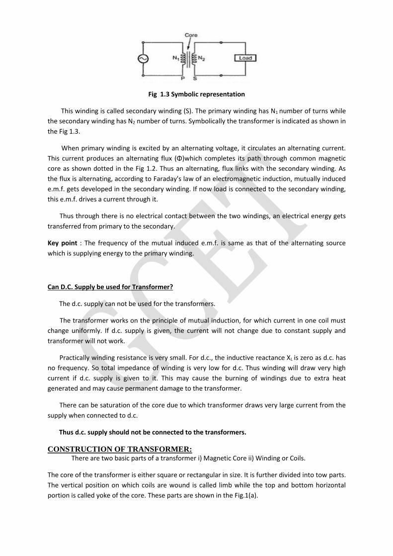
Fig 1.3 Symbolic representation
This winding is called secondary winding (S). The primary winding has N1 number of turns while
the secondary winding has N2 number of turns. Symbolically the transformer is indicated as shown in
the Fig 1.3.
When primary winding is excited by an alternating voltage, it circulates an alternating current.
This current produces an alternating flux (Φ)which completes its path through common magnetic
core as shown dotted in the Fig 1.2. Thus an alternating, flux links with the secondary winding. As
the flux is alternating, according to Faraday's law of an electromagnetic induction, mutually induced
e.m.f. gets developed in the secondary winding. If now load is connected to the secondary winding,
this e.m.f. drives a current through it.
Thus through there is no electrical contact between the two windings, an electrical energy gets
transferred from primary to the secondary.
Key point : The frequency of the mutual induced e.m.f. is same as that of the alternating source
which is supplying energy to the primary winding.
Can D.C. Supply be used for Transformer?
The d.c. supply can not be used for the transformers.
The transformer works on the principle of mutual induction, for which current in one coil must
change uniformly. If d.c. supply is given, the current will not change due to constant supply and
transformer will not work.
Practically winding resistance is very small. For d.c., the inductive reactance XL is zero as d.c. has
no frequency. So total impedance of winding is very low for d.c. Thus winding will draw very high
current if d.c. supply is given to it. This may cause the burning of windings due to extra heat
generated and may cause permanent damage to the transformer.
There can be saturation of the core due to which transformer draws very large current from the
supply when connected to d.c.
Thus d.c. supply should not be connected to the transformers.
CONSTRUCTION OF TRANSFORMER: There are two basic parts of a transformer i) Magnetic Core ii) Winding or Coils.
The core of the transformer is either square or rectangular in size. It is further divided into tow parts.
The vertical position on which coils are wound is called limb while the top and bottom horizontal
portion is called yoke of the core. These parts are shown in the Fig.1(a).
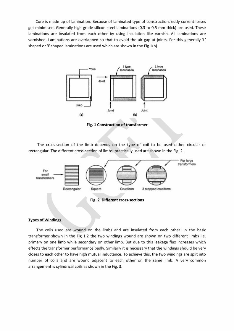
Core is made up of lamination. Because of laminated type of construction, eddy current losses
get minimised. Generally high grade silicon steel laminations (0.3 to 0.5 mm thick) are used. These
laminations are insulated from each other by using insulation like varnish. All laminations are
varnished. Laminations are overlapped so that to avoid the air gap at joints. For this generally 'L'
shaped or 'I' shaped laminations are used which are shown in the Fig 1(b).
Fig. 1 Construction of transformer
The cross-section of the limb depends on the type of coil to be used either circular or
rectangular. The different cross-section of limbs, practically used are shown in the Fig. 2.
Fig. 2 Different cross-sections
Types of Windings
The coils used are wound on the limbs and are insulated from each other. In the basic
transformer shown in the Fig 1.2 the two windings wound are shown on two different limbs i.e.
primary on one limb while secondary on other limb. But due to this leakage flux increases which
effects the transformer performance badly. Similarly it is necessary that the windings should be very
closes to each other to have high mutual inductance. To achieve this, the two windings are split into
number of coils and are wound adjacent to each other on the same limb. A very common
arrangement is cylindrical coils as shown in the Fig. 3.
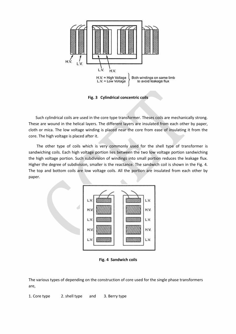
Fig. 3 Cylindrical concentric coils
Such cylindrical coils are used in the core type transformer. Theses coils are mechanically strong.
These are wound in the helical layers. The different layers are insulated from each other by paper,
cloth or mica. The low voltage winding is placed near the core from ease of insulating it from the
core. The high voltage is placed after it.
The other type of coils which is very commonly used for the shell type of transformer is
sandwiching coils. Each high voltage portion lies between the two low voltage portion sandwiching
the high voltage portion. Such subdivision of windings into small portion reduces the leakage flux.
Higher the degree of subdivision, smaller is the reactance. The sandwich coil is shown in the Fig. 4.
The top and bottom coils are low voltage coils. All the portion are insulated from each other by
paper.
Fig. 4 Sandwich coils
The various types of depending on the construction of core used for the single phase transformers
are,
1. Core type 2. shell type and 3. Berry type
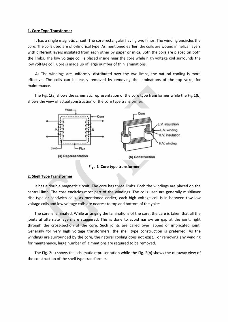
1. Core Type Transformer
It has a single magnetic circuit. The core rectangular having two limbs. The winding encircles the
core. The coils used are of cylindrical type. As mentioned earlier, the coils are wound in helical layers
with different layers insulated from each other by paper or mica. Both the coils are placed on both
the limbs. The low voltage coil is placed inside near the core while high voltage coil surrounds the
low voltage coil. Core is made up of large number of thin laminations.
As The windings are uniformly distributed over the two limbs, the natural cooling is more
effective. The coils can be easily removed by removing the laminations of the top yoke, for
maintenance.
The Fig. 1(a) shows the schematic representation of the core type transformer while the Fig 1(b)
shows the view of actual construction of the core type transformer.
Fig. 1 Core type transformer
2. Shell Type Transformer
It has a double magnetic circuit. The core has three limbs. Both the windings are placed on the
central limb. The core encircles most part of the windings. The coils used are generally multilayer
disc type or sandwich coils. As mentioned earlier, each high voltage coil is in between tow low
voltage coils and low voltage coils are nearest to top and bottom of the yokes.
The core is laminated. While arranging the laminations of the core, the care is taken that all the
joints at alternate layers are staggered. This is done to avoid narrow air gap at the joint, right
through the cross-section of the core. Such joints are called over lapped or imbricated joint.
Generally for very high voltage transformers, the shell type construction is preferred. As the
windings are surrounded by the core, the natural cooling does not exist. For removing any winding
for maintenance, large number of laimnations are required to be removed.
The Fig. 2(a) shows the schematic representation while the Fig. 2(b) shows the outaway view of
the construction of the shell type transformer.
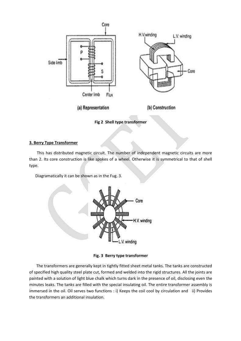
Fig 2 Shell type transformer
3. Berry Type Transformer
This has distributed magnetic circuit. The number of independent magnetic circuits are more
than 2. Its core construction is like spokes of a wheel. Otherwise it is symmetrical to that of shell
type.
Diagramatically it can be shown as in the Fug. 3.
Fig. 3 Berry type transformer
The transformers are generally kept in tightly fitted sheet metal tanks. The tanks are constructed
of specified high quality steel plate cut, formed and welded into the rigid structures. All the joints are
painted with a solution of light blue chalk which turns dark in the presence of oil, disclosing even the
minutes leaks. The tanks are filled with the special insulating oil. The entire transformer assembly is
immersed in the oil. Oil serves two functions : i) Keeps the coil cool by circulation and ii) Provides
the transformers an additional insulation.

The oil should be absolutely free from alkalies, sulphur and specially from moisture. Presence of
very small moisture lowers the dielectric strength of oil, affecting its performance badly. Hence the
tanks are sealed air tight to avoid the contact of oil with atmospheric air and moisture. In large
transformers, the chambers called breather are provided. The breathers prevent the atmospheric
moisture to pass on to the oil. The breathers contain the silica gel crystal which immediately absorb
the atmospheric moisture. Due to long and continuous use, the sludge is formed in the oil which can
contaminate the oil. Hence to keep such sludge separate from the oil in main tank, an air tight metal
drum is provided, which is placed on the top of tank. This is called conservator.

Comparison of Core and Shell Type Transformers
E.M.F EQUATION OF TRANSFORMER: When the primary winding is excited by an alternating voltage V1, it circulates alternating current,
producing an alternating flux Φ. The primary winding has N1 number of turns. The alternating flux Φ
linking with the primary winding itself induces an e.m.f in it denoted as E1. The flux links with
secondary winding through the common magnetic core. It produces induced e.m.f. E2 in the
secondary winding. This is mutually induced e.m.f. Let us derive the equations for E1 and E2.
The primary winding is excited by purely sinusoidal alternating voltage. Hence the flux produced
is also sinusoidal in nature having maximum value of Φm as show in the Fig. 1.
Fig. 1 Sinusoidal flux
The various quantities which affect the magnitude of the induced e.m.f. are :
Φ = Flux
Φm = Maximum value of flux
N1 = Number of primary winding turns
N2 = Number of secondary winding turns
f = Frequency of the supply voltage
E1 = R.M.S. value of the primary induced e.m.f.
E2 = R.M.S. value of the secondary induced e.m.f.
From Faraday's law of electromagnetic induction the voltage e.m.f. induced in each turn is
proportional to the average rate of change of flux.
... average e.m.f. per turn = average rate of change of flux
... average e.m.f. per turn = dΦ/dt
Now dΦ/dt = Change in flux/Time required for change in flux
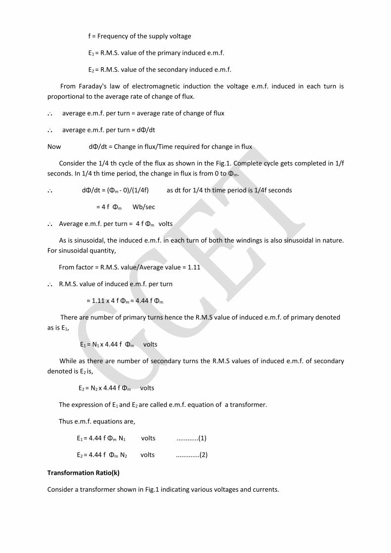
Consider the 1/4 th cycle of the flux as shown in the Fig.1. Complete cycle gets completed in 1/f
seconds. In 1/4 th time period, the change in flux is from 0 to Φm.
... dΦ/dt = (Φm - 0)/(1/4f) as dt for 1/4 th time period is 1/4f seconds
= 4 f Φm Wb/sec
... Average e.m.f. per turn = 4 f Φm volts
As is sinusoidal, the induced e.m.f. in each turn of both the windings is also sinusoidal in nature.
For sinusoidal quantity,
From factor = R.M.S. value/Average value = 1.11
... R.M.S. value of induced e.m.f. per turn
= 1.11 x 4 f Φm = 4.44 f Φm
There are number of primary turns hence the R.M.S value of induced e.m.f. of primary denoted
as is E1,
E1 = N1 x 4.44 f Φm volts
While as there are number of secondary turns the R.M.S values of induced e.m.f. of secondary
denoted is E2 is,
E2 = N2 x 4.44 f Φm volts
The expression of E1 and E2 are called e.m.f. equation of a transformer.
Thus e.m.f. equations are,
E1 = 4.44 f Φm N1 volts ............(1)
E2 = 4.44 f Φm N2 volts .............(2)
Transformation Ratio(k)
Consider a transformer shown in Fig.1 indicating various voltages and currents.
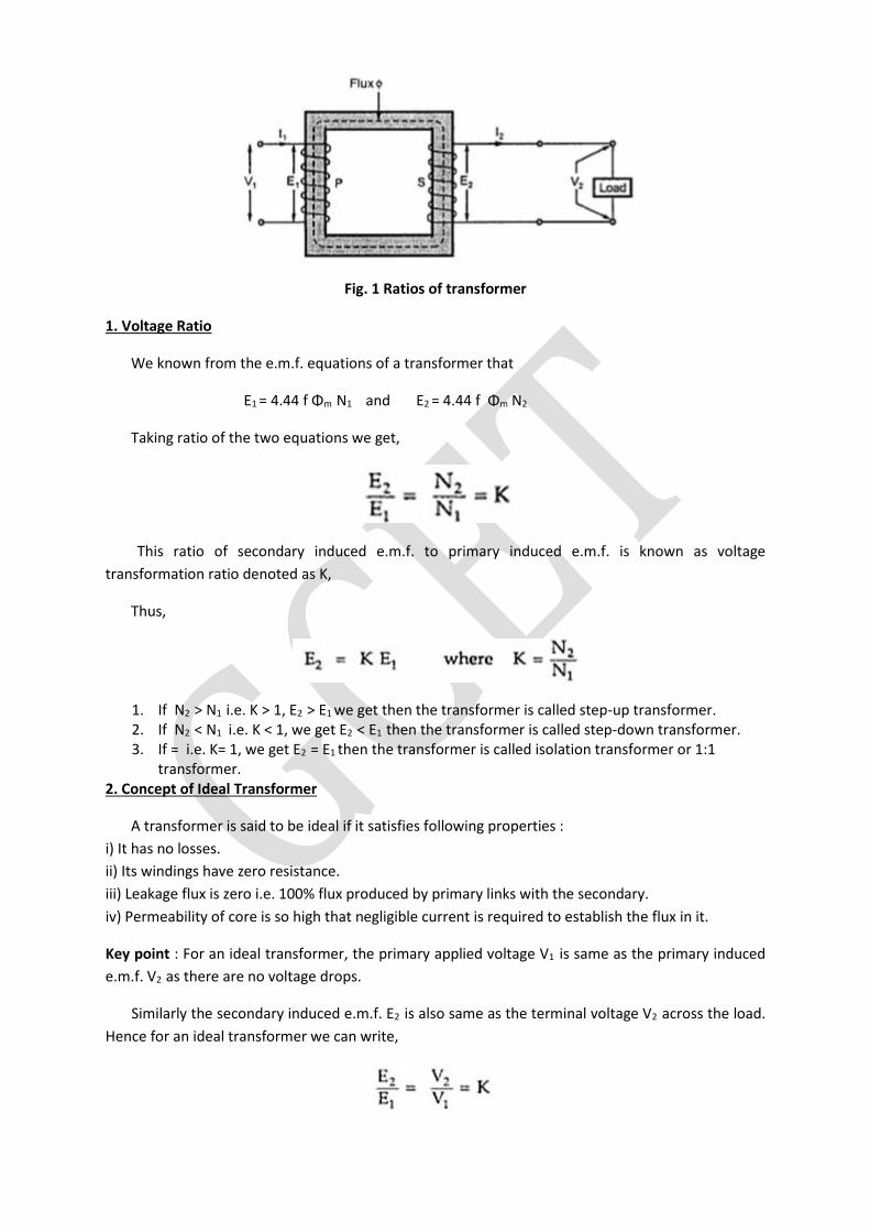
Fig. 1 Ratios of transformer
1. Voltage Ratio
We known from the e.m.f. equations of a transformer that
E1 = 4.44 f Φm N1 and E2 = 4.44 f Φm N2
Taking ratio of the two equations we get,
This ratio of secondary induced e.m.f. to primary induced e.m.f. is known as voltage
transformation ratio denoted as K,
Thus,
1. If N2 > N1 i.e. K > 1, E2 > E1 we get then the transformer is called step-up transformer. 2. If N2 < N1 i.e. K < 1, we get E2 < E1 then the transformer is called step-down transformer. 3. If = i.e. K= 1, we get E2 = E1 then the transformer is called isolation transformer or 1:1
transformer. 2. Concept of Ideal Transformer
A transformer is said to be ideal if it satisfies following properties :
i) It has no losses.
ii) Its windings have zero resistance.
iii) Leakage flux is zero i.e. 100% flux produced by primary links with the secondary.
iv) Permeability of core is so high that negligible current is required to establish the flux in it.
Key point : For an ideal transformer, the primary applied voltage V1 is same as the primary induced
e.m.f. V2 as there are no voltage drops.
Similarly the secondary induced e.m.f. E2 is also same as the terminal voltage V2 across the load.
Hence for an ideal transformer we can write,
No transformer is ideal in practice but the value of E1 is almost equal to V1 for properly designed
transformer.
3. Current ratio
For an ideal transformer there are no losses. Hence the product of primary voltage V1 and
primary current I1, is same as the product of secondary voltage V2 and the secondary current I2.
So V1 I1 = input VA and V2 I2 = output VA
For an ideal transformer,
V1 I1 = V2 I2
Key point : Hence the currents are in the inverse ratio of the voltage transformation ratio.
4. Voltage ampere rating
When electrical power is transferred from primary winding to secondary there are few power
losses in between. These power losses appear in the form of heat which increase the temperature of
the device.Now this temperature must be maintained below certain limiting values as it is always
harmful from insulation point of view. As current is the main cause in producing heat, the output
maximum rating is generally specified as the product of output voltage and output current i.e.V2 I2.
This always indicates that when transformer is operated under this specified rating, its temperature
rise will not be excessive. The copper loss (I2R) in the transformer depends on the current 'I' through
the winding while the iron or core loss depends on the voltage 'V' as frequency of operation is
constant. None of these losses depend on the power factor (cos Φ) of the load. Hence losses decide
the temperature and hence the rating of the transformer. As losses depend on V and I only, the
rating of the transformer is specified as a product of these two parameters VxI.
Key point : Thus the transformer rating is specified as the product of voltage and current called VA
rating.
On both sides, primary and secondary VA rating remains same. This rating is generally expresses
in KVA (kilo volt amperes rating).
Now V1 /V2 = I2 /I1 = K
... V1 I1 = V2 I2
If V1 and V2 are the terminal voltages of primary and secondary then from specified KVA rating
we can decide full load currents of primary and secondary, I1 and I2. This is the safe maximum current
limit which may carry, keeping temperature rise below its limiting value.
Key point : The full load primary and secondary currents indicate the safe maximum values of
currents which transformer windings can carry.
Example 1 : A single phase, 50 Hz transformer has 80 turns on the primary winding and 400 turns on
the secondary winding. The net cross-sectional area of the core is 200 cm2. If the primary winding is
connected at a 240 V , 50 Hz supply, determine :
i) The e.m.f. induced in the secondary winding.
ii) The maximum value of the flux density in the core.
Solution
N1 = 80 , f = 50 Hz , N2 = 400 , a = 200 cm2 = 200 x 10-4 cm2
E1 = 240
K = N2 /N1 = 400/80 = 5/1
... K =E2 /E1 = E2 /240= 5/1
E2 = 5 x 240 = 1200 V
Now E1 = 4.44 f Φm N1
240 = 4.44 x 50 x Φm x 80
... Φm = 240/(4.44 x 50 x 80) = 0.01351 Wb
... Bm = Φm /a = 0.01351/(200 x 10-4) = 0.6756 Wb/m2
Example 2 : For a single phase transformer having primary and secondary turns of 440 and 880
respectively, determine the transformer KVA rating if half load secondary current is 7.5 A and
maximum value of core flux is 2.25 Wb.
Solution
N1 = 440 , N2 = 880 , (I2)H.L. = 7.5 A,
fm = 2.25 mWb , E2 = 4.44 Φm f N2
Assuming f = 50 Hz,
... E2 = 4.44 x 2.25 x 10-3x 50x880 = 439.56 V
(I2)F.L. = KVA rating / E2
And (I2)H.L. = 0.5 (I2)F.L.
... (I2)H.L. = 0.5 x (KVA rating /E2 )
... 7.5 = 0.5 x (KVA rating / 439.56)
... KVA rating = 2 x 7.5 x 439.56 x 10-3
= 6.5934 KVA .....(10-3 for KVA)
Example 3 : A single phase transformer has 350 primary and 1050 secondary turns. The primary is
connected to 400 V, 50 Hz a.c. supply. If the net cross-sectional area of the core is 50 cm2, calculate i)
The maximum value of the flux density in the core ii) The induced e.m.f. in the secondary winding.
Solution
The given value are,
N1 = 350 turns, N2 = 1050 turns
V1 = 400 V , A = 50 cm2= 50 x 10-4 m2
The e.m.f. of the transformer is,
E1 = 4.44 f Φm N1
E1 = 4.44 Bm A f N1 as Φm = Bm A
Flux density Bm = E1 / (4.44 A f N1)
= 400 / (4.44 x 50 x 10-4 x50 x 350) assume E1 = V1
= 1.0296 Wb/m2
K = N2 /N1 = 1050/350 = 3
And K = E2 /E1 = 3
... E2 = 3 x E1 = 3 x 400 = 1200 V
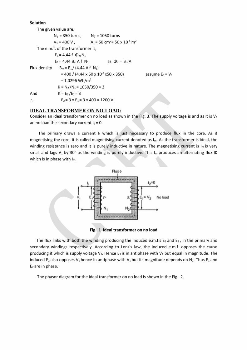
IDEAL TRANSFORMER ON NO-LOAD: Consider an ideal transformer on no load as shown in the Fig. 3. The supply voltage is and as it is V1
an no load the secondary current I2 = 0.
The primary draws a current I1 which is just necessary to produce flux in the core. As it
magnetising the core, it is called magnetising current denoted as Im. As the transformer is ideal, the
winding resistance is zero and it is purely inductive in nature. The magnetising current is Im is very
small and lags V1 by 30o as the winding is purely inductive. This Im produces an alternating flux Φ
which is in phase with Im.
Fig. 1 Ideal transformer on no load
The flux links with both the winding producing the induced e.m.f.s E1 and E2 , in the primary and
secondary windings respectively. According to Lenz's law, the induced e.m.f. opposes the cause
producing it which is supply voltage V1. Hence E1 is in antiphase with V1 but equal in magnitude. The
induced E2 also opposes V1 hence in antiphase with V1 but its magnitude depends on N2. Thus E1 and
E2 are in phase.
The phasor diagram for the ideal transformer on no load is shown in the Fig. .2.
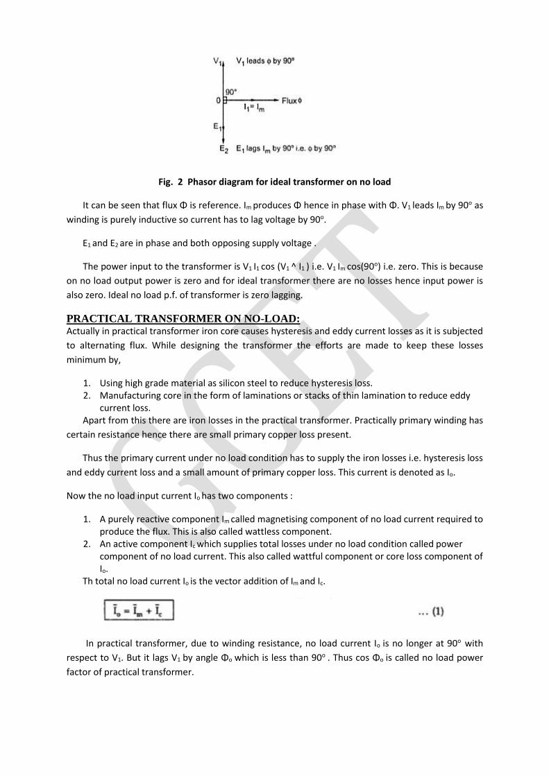
Fig. 2 Phasor diagram for ideal transformer on no load
It can be seen that flux Φ is reference. Im produces Φ hence in phase with Φ. V1 leads Im by 90o as
winding is purely inductive so current has to lag voltage by 90o.
E1 and E2 are in phase and both opposing supply voltage .
The power input to the transformer is V1 I1 cos (V1 ^ I1 ) i.e. V1 Im cos(90o) i.e. zero. This is because
on no load output power is zero and for ideal transformer there are no losses hence input power is
also zero. Ideal no load p.f. of transformer is zero lagging.
PRACTICAL TRANSFORMER ON NO-LOAD: Actually in practical transformer iron core causes hysteresis and eddy current losses as it is subjected
to alternating flux. While designing the transformer the efforts are made to keep these losses
minimum by,
1. Using high grade material as silicon steel to reduce hysteresis loss. 2. Manufacturing core in the form of laminations or stacks of thin lamination to reduce eddy
current loss. Apart from this there are iron losses in the practical transformer. Practically primary winding has
certain resistance hence there are small primary copper loss present.
Thus the primary current under no load condition has to supply the iron losses i.e. hysteresis loss
and eddy current loss and a small amount of primary copper loss. This current is denoted as Io.
Now the no load input current Io has two components :
1. A purely reactive component Im called magnetising component of no load current required to produce the flux. This is also called wattless component.
2. An active component Ic which supplies total losses under no load condition called power component of no load current. This also called wattful component or core loss component of Io.
Th total no load current Io is the vector addition of Im and Ic.
In practical transformer, due to winding resistance, no load current Io is no longer at 90o with
respect to V1. But it lags V1 by angle Φo which is less than 90o . Thus cos Φo is called no load power
factor of practical transformer.
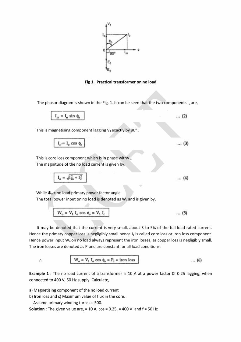
Fig 1. Practical transformer on no load
The phasor diagram is shown in the Fig. 1. It can be seen that the two components Io are,
This is magnetising component lagging V1 exactly by 90o .
This is core loss component which is in phase withV1.
The magnitude of the no load current is given by,
While Φo = no load primary power factor angle
The total power input on no load is denoted as Wo and is given by,
It may be denoted that the current is very small, about 3 to 5% of the full load rated current.
Hence the primary copper loss is negligibly small hence Ic is called core loss or iron loss component.
Hence power input Wo on no load always represent the iron losses, as copper loss is negligibly small.
The iron losses are denoted as Pi and are constant for all load conditions.
Example 1 : The no load current of a transformer is 10 A at a power factor 0f 0.25 lagging, when
connected to 400 V, 50 Hz supply. Calculate,
a) Magnetising component of the no load current
b) Iron loss and c) Maximum value of flux in the core.
Assume primary winding turns as 500.
Solution : The given value are, = 10 A, cos = 0.25, = 400 V and f = 50 Hz
a) Im = Io sin Φo = magnetising component
Φo = cos-1(0.25) = 75.522o
... Im = 10 x sin (75.522o ) = 9.6824 A
b) Pi = iron loss = power input on no load
= Wo = V1 Io cos Φo = 400 x 10 x 0.25
= 1000 W
c) On no load, E1 = V1 = 400 V and N1 = 500
Now E1 = 4.44 f Φm N1
... 400 = 4.44 x 50 x Φm x 500
... Φm = 3.6036 mWb
TRANSFORMER ON LOAD (M.M.F Balancing on Load) When the transformer is loaded, the current I2 flows through the secondary winding. The magnetic
and phase of I2 is determined by the load. If load is inductive, I2 lags V2. If load is capacitive, I2 leads
V2 while for resistive load, I2 is in phase withV2.
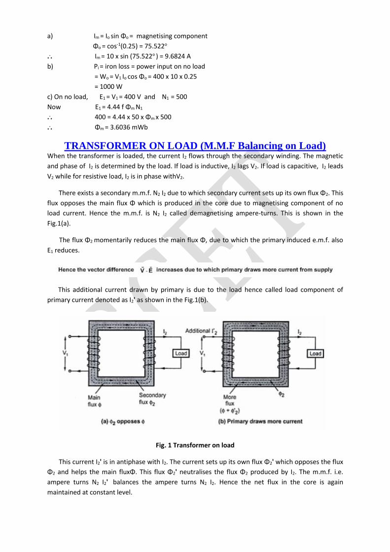
There exists a secondary m.m.f. N2 I2 due to which secondary current sets up its own flux Φ2. This
flux opposes the main flux Φ which is produced in the core due to magnetising component of no
load current. Hence the m.m.f. is N2 I2 called demagnetising ampere-turns. This is shown in the
Fig.1(a).
The flux Φ2 momentarily reduces the main flux Φ, due to which the primary induced e.m.f. also
E1 reduces.
This additional current drawn by primary is due to the load hence called load component of
primary current denoted as I2' as shown in the Fig.1(b).
Fig. 1 Transformer on load
This current I2' is in antiphase with I2. The current sets up its own flux Φ2' which opposes the flux
Φ2 and helps the main fluxΦ. This flux Φ2' neutralises the flux Φ2 produced by I2. The m.m.f. i.e.
ampere turns N2 I2' balances the ampere turns N2 I2. Hence the net flux in the core is again
maintained at constant level.
Key point : Thus for any load condition, no load to full load the flux in the core is practically constant.
The load component current I2' always neutralises the changes in the loads. Hence the
transformer is called constant flux machine.
As the ampere turns are balanced we can write,
N2 I2=N2 I2'
... I2' =(N2/N1) = K I2 ..................(1)
Thus when transformer is loaded, the primary current I1 has two components :
1. The no load current Io which lags V1 by angle Φo. It has two components Im and Ic.
2. The load component I2' which in antiphase with I2. And phase of I2 is decided by the load.
Hence primary current I1 is vector sum of Io and I2'.
... Ī1 = Īo + Ī2 ...............(2)
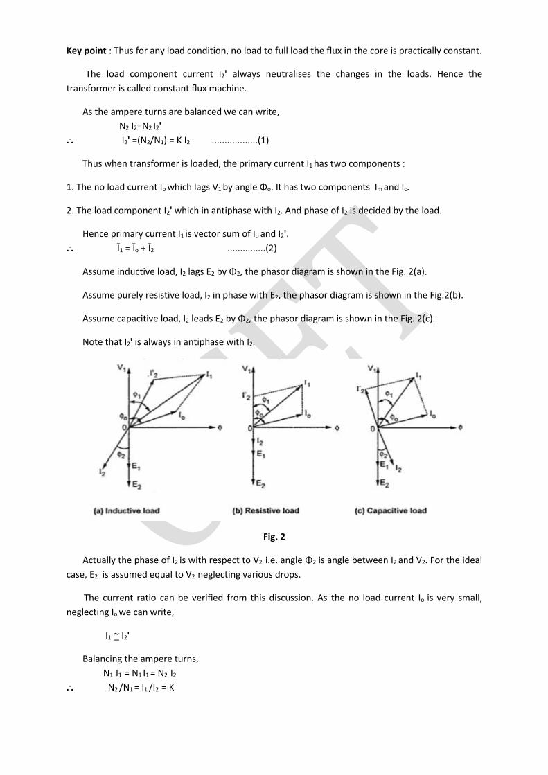
Assume inductive load, I2 lags E2 by Φ2, the phasor diagram is shown in the Fig. 2(a).
Assume purely resistive load, I2 in phase with E2, the phasor diagram is shown in the Fig.2(b).
Assume capacitive load, I2 leads E2 by Φ2, the phasor diagram is shown in the Fig. 2(c).
Note that I2' is always in antiphase with I2.
Fig. 2
Actually the phase of I2 is with respect to V2 i.e. angle Φ2 is angle between I2 and V2. For the ideal
case, E2 is assumed equal to V2 neglecting various drops.
The current ratio can be verified from this discussion. As the no load current Io is very small,
neglecting Io we can write,
I1 ~ I2'
Balancing the ampere turns,
N1 I1 = N1 I1 = N2 I2
... N2 /N1 = I1 /I2 = K
Under full load conditions when Io is very small compared to full load currents, the ratio of
primary and secondary current is constant.
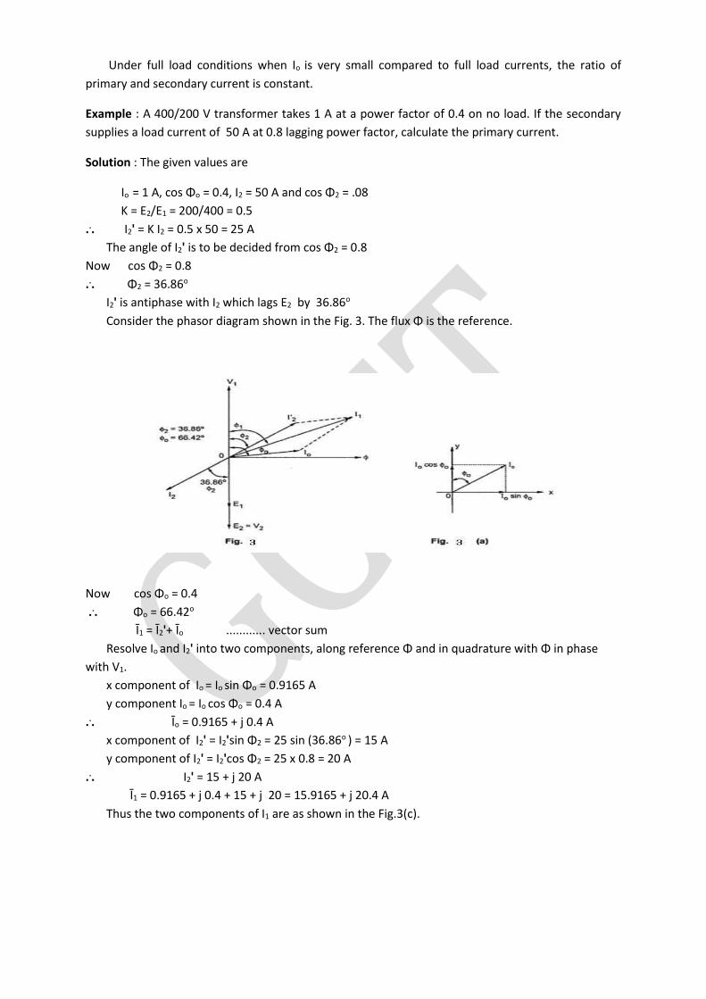
Example : A 400/200 V transformer takes 1 A at a power factor of 0.4 on no load. If the secondary
supplies a load current of 50 A at 0.8 lagging power factor, calculate the primary current.
Solution : The given values are
Io = 1 A, cos Φo = 0.4, I2 = 50 A and cos Φ2 = .08
K = E2/E1 = 200/400 = 0.5
... I2' = K I2 = 0.5 x 50 = 25 A
The angle of I2' is to be decided from cos Φ2 = 0.8
Now cos Φ2 = 0.8
... Φ2 = 36.86o
I2' is antiphase with I2 which lags E2 by 36.86o
Consider the phasor diagram shown in the Fig. 3. The flux Φ is the reference.
Now cos Φo = 0.4
... Φo = 66.42o
Ī1 = Ī2'+ Īo ............ vector sum
Resolve Io and I2' into two components, along reference Φ and in quadrature with Φ in phase
with V1.
x component of Io = Io sin Φo = 0.9165 A
y component Io = Io cos Φo = 0.4 A
... Īo = 0.9165 + j 0.4 A
x component of I2' = I2'sin Φ2 = 25 sin (36.86o ) = 15 A
y component of I2' = I2'cos Φ2 = 25 x 0.8 = 20 A
... I2' = 15 + j 20 A
Ī1 = 0.9165 + j 0.4 + 15 + j 20 = 15.9165 + j 20.4 A
Thus the two components of I1 are as shown in the Fig.3(c).
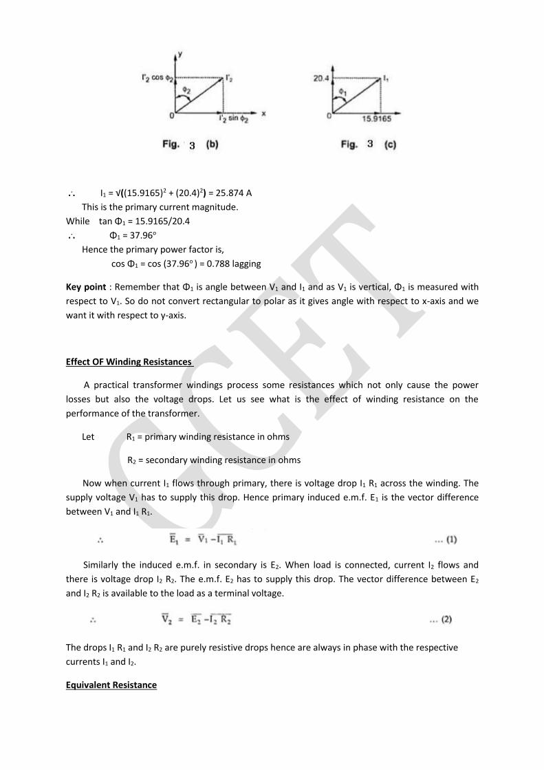
... I1 = √((15.9165)2 + (20.4)2) = 25.874 A
This is the primary current magnitude.
While tan Φ1 = 15.9165/20.4
... Φ1 = 37.96o
Hence the primary power factor is,
cos Φ1 = cos (37.96o ) = 0.788 lagging
Key point : Remember that Φ1 is angle between V1 and I1 and as V1 is vertical, Φ1 is measured with
respect to V1. So do not convert rectangular to polar as it gives angle with respect to x-axis and we
want it with respect to y-axis.
Effect OF Winding Resistances
A practical transformer windings process some resistances which not only cause the power
losses but also the voltage drops. Let us see what is the effect of winding resistance on the
performance of the transformer.
Let R1 = primary winding resistance in ohms
R2 = secondary winding resistance in ohms
Now when current I1 flows through primary, there is voltage drop I1 R1 across the winding. The
supply voltage V1 has to supply this drop. Hence primary induced e.m.f. E1 is the vector difference
between V1 and I1 R1.
Similarly the induced e.m.f. in secondary is E2. When load is connected, current I2 flows and
there is voltage drop I2 R2. The e.m.f. E2 has to supply this drop. The vector difference between E2
and I2 R2 is available to the load as a terminal voltage.
The drops I1 R1 and I2 R2 are purely resistive drops hence are always in phase with the respective
currents I1 and I2.
Equivalent Resistance
The resistance of the two windings can be transferred to any one side either primary or
secondary without affecting the performance of the transformer. The transfer of the resistances on
any one side is advantageous as it makes the calculations very easy. Let us see how to transfer the
resistances on any one side.
The total copper loss due to both the resistances can be obtained as,
total copper loss = I12 R1 + I2
2 R2
= I12 R1 +(I2
2/I12) R2
= I12R1 + (1/K2) R2 .......(3)
Where I2/I1 = 1/K neglecting no load current.
Now the expression (3) indicates that the total copper loss can be expressed as I12 R1 + I1
2 .R2/K2.
This means R2/K2 is the resistance value of R2 shifted to primary side which causes same copper loss
with I1 as R2 causes with. This value of resistance which R2 /K2 is the value of R2 referred to primary is
called equivalent resistance of secondary referred to primary. It is denoted as R2'.
R2' = R2 /K2 ........(4)
Hence the total resistance referred to primary is the addition of R1 and R2' called equivalent
resistance of transformer referred to primary and denoted as R1e.
= R1 + R2'= R1 + R2 /K2 .........(5)
This resistance R1e causes same copper loss with I1 as the total copper loss due to the individual
windings.
total copper loss = I12 R1e = I1
2 R1 + I22 R2 ......(6)
So equivalent resistance simplifies the calculations as we have to calculate parameters on one
side only.
Similarly it is possible to refer the equivalent resistance to secondary winding.
total copper loss = I12 R1 + I2
2 R2
= I22 (I1
2/I22) R1 + R2
= I22 ( K2 R1 + R2) ........(7)
Thus the resistance K2 R1 is primary resistance referred to secondary denoted as R1'.
R1' = K2 R1 .......(8)
Hence the total resistance referred to secondary is the addition of R2 and R1' called equivalent
resistance of transformer referred to secondary and denoted as R2e.
R2e = R2 + R1' = R2 + K2 R1 .........(9)
total copper loss = I22 R2e ........(10)
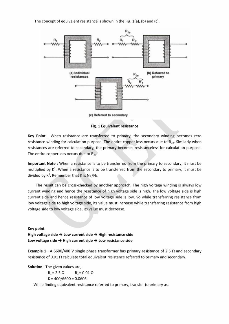
The concept of equivalent resistance is shown in the Fig. 1(a), (b) and (c).
Fig. 1 Equivalent resistance
Key Point : When resistance are transferred to primary, the secondary winding becomes zero
resistance winding for calculation purpose. The entire copper loss occurs due to R1e. Similarly when
resistances are referred to secondary, the primary becomes resistanceless for calculation purpose.
The entire copper loss occurs due to R2e.
Important Note : When a resistance is to be transferred from the primary to secondary, it must be
multiplied by K2. When a resistance is to be transferred from the secondary to primary, it must be
divided by K2. Remember that K is N1 /N2.
The result can be cross-checked by another approach. The high voltage winding is always low
current winding and hence the resistance of high voltage side is high. The low voltage side is high
current side and hence resistance of low voltage side is low. So while transferring resistance from
low voltage side to high voltage side, its value must increase while transferring resistance from high
voltage side to low voltage side, its value must decrease.
Key point :
High voltage side → Low current side → High resistance side
Low voltage side → High current side → Low resistance side
Example 1 : A 6600/400 V single phase transformer has primary resistance of 2.5 Ω and secondary
resistance of 0.01 Ω calculate total equivalent resistance referred to primary and secondary.
Solution : The given values are,
R1 = 2.5 Ω R2 = 0.01 Ω
K = 400/6600 = 0.0606
While finding equivalent resistance referred to primary, transfer to primary as,
R2'= R2 /K2 = 0.01/(0.0606)2 = 2.7225 Ω
R1e = R1 + R2' = 2.5 + 2.7225 = 5.2225 Ω
It can be observed that primary is high voltage hence high resistance side hence while
transferring from low voltage to on high voltage, its value increases.
To find total equivalent resistance referred to secondary, first calculate ,
R1'= K2 R1 = (0.0606)2 x 25 = 0.00918 Ω
R2e = R2 + R1' = 0.01 + 0.00918 = 0.01918 Ω
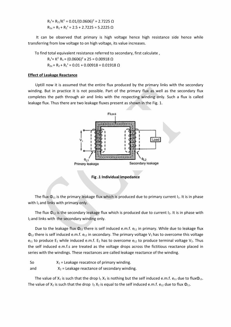
Effect of Leakage Reactance
Uptill now it is assumed that the entire flux produced by the primary links with the secondary
winding. But in practice it is not possible. Part of the primary flux as well as the secondary flux
completes the path through air and links with the respecting winding only. Such a flux is called
leakage flux. Thus there are two leakage fluxes present as shown in the Fig. 1.
Fig .1 Individual impedance
The flux ΦL1 is the primary leakage flux which is produced due to primary current I1. It is in phase
with I1 and links with primary only.
The flux ΦL2 is the secondary leakage flux which is produced due to current I2. It is in phase with
I2 and links with the secondary winding only.
Due to the leakage flux ΦL1 there is self induced e.m.f. eL1 in primary. While due to leakage flux
ΦL2 there is self induced e.m.f. eL2 in secondary. The primary voltage V1 has to overcome this voltage
eL1 to produce E1 while induced e.m.f. E2 has to overcome eL2 to produce terminal voltage V2. Thus
the self induced e.m.f.s are treated as the voltage drops across the fictitious reactance placed in
series with the windings. These reactances are called leakage reactance of the winding.
So X1 = Leakage reacatnce of primary winding.
and X2 = Leakage reactance of secondary winding.
The value of X1 is such that the drop I1 X1 is nothing but the self induced e.m.f. eL1 due to fluxΦL1.
The value of X2 is such that the drop I2 X2 is equal to the self induced e.m.f. eL2 due to flux ΦL1.
Leakage fluxes with the respective windings only and not to both the windings. To reduce the
leakage, as mentioned, int eh construction both the winding's are placed on same limb rather than
on separate limbs.
Equivalent Leakage Reactance
Similar to the resistances, the leakage reactances also can be transferred from primary to
secondary or viceversa. The relation through K2 remains same for the transfer of recatnaces as it is
studied earlier for the resistances.
Let X1 is leakage reactance of primary and X2 is leakage reactance of secondary.
Then the total leakage reacatance referred to primary is X1e given by,
X1e = X1 + X2' where X2' = X2/K2
While the total leakage reacatnce referred to secondary is given by ,
X2e = X2 + X1' where X1' = K2 X1
And K = N2/N1 =transformation ratio
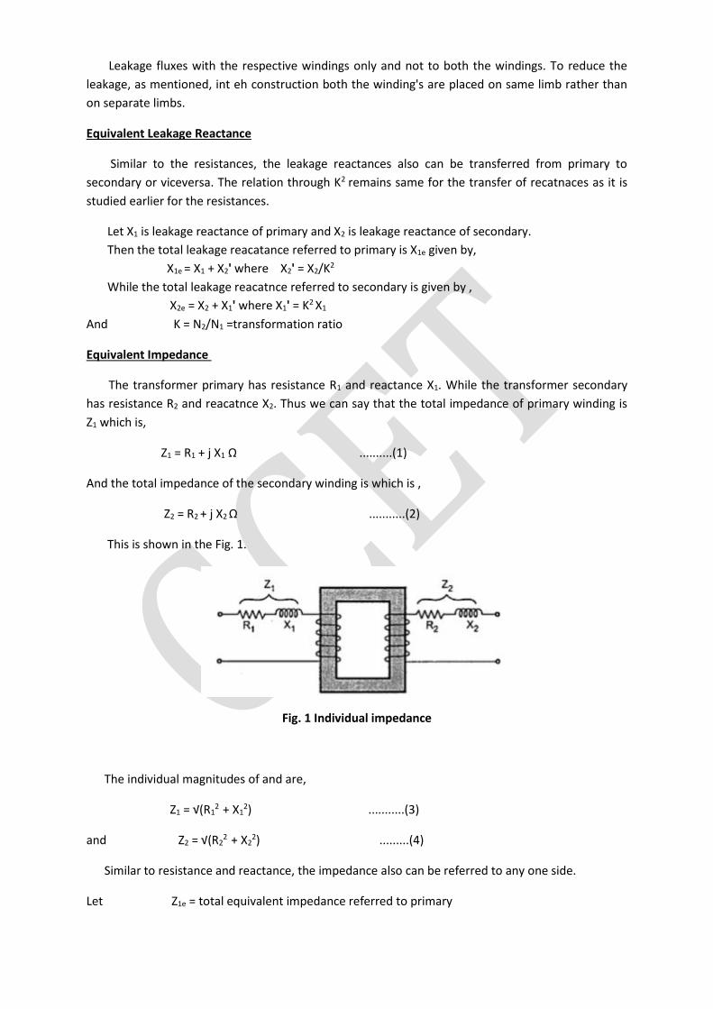
Equivalent Impedance
The transformer primary has resistance R1 and reactance X1. While the transformer secondary
has resistance R2 and reacatnce X2. Thus we can say that the total impedance of primary winding is
Z1 which is,
Z1 = R1 + j X1 Ω ..........(1)
And the total impedance of the secondary winding is which is ,
Z2 = R2 + j X2 Ω ...........(2)
This is shown in the Fig. 1.
Fig. 1 Individual impedance
The individual magnitudes of and are,
Z1 = √(R12 + X1
2) ...........(3)
and Z2 = √(R22 + X2
2) .........(4)
Similar to resistance and reactance, the impedance also can be referred to any one side.
Let Z1e = total equivalent impedance referred to primary
then Z1e = R1e + j X1e
Z1e = Z1 + Z2' = Z1 + Z2/K2 ............(5)
Similarly Z2e = total equivalent impedance referred to secondary
then Z2e = R2e + j X2e
Z2e = Z2 + Z1' = Z2 + K2 Z1 ............(6)
The magnitude of Z1e and Z2e are,
Z1e = √(R1e2 + X1e
2) ........(7)
and Z2e = √(R2e2 + X2e
2) ...........(8)
It can be denoted that,
Z2e = K2 Z1e and Z1e = Z2e /K2
The concept of equivalent impedance is shown in the Fig. 2.
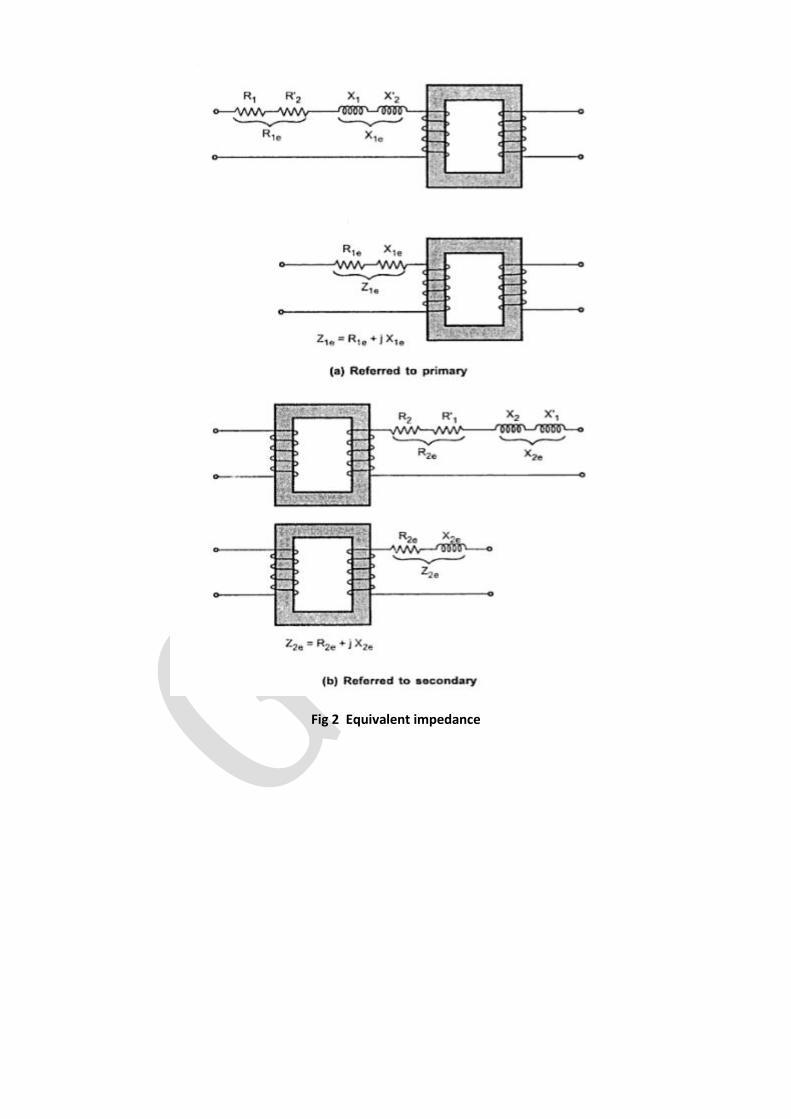
Fig 2 Equivalent impedance
Example 1 :A 15 KVA, 2200/110 V transformer has R1 = 1.75Ω, R2 = 0.0045 Ω the leakage reactance
are X1 = 2.6 Ω and X2 = 0.0075 Ω Calculate,
a) equivalent resistance referred to primary
b) equivalent resistance referred to secondary
c) equivalent reactance referred to primary
d) equivalent reactance referred tosecondary
e) equivalent impedance referred to primary
f) equivalent impedance referred to secondary
g) total copper loss
Solution : The given values are, R1 = 1.75 Ω, R2 = 0.0045Ω, X1 = 2.6 Ω, X2 = 0.0075 Ω
K = 110/2200 = 1/20 = 0.05
a) R1e = R1 + R2' = R1 + R2 /K2 = 1.75 + 0.0045/0.052 = 3.55 Ω
b) R2e = R2 + R1' = R2 + K2 R1 =
= 0.0045 + (0.05)2 x 1.75 = 0.00887 Ω
c) X1e = X1 + X2' = X1 + X2/K2 = 2.6 + 0.0075/(0.05)2 = 5.6 Ω
d) X2e = X2 + X1'= X2 + K2 X1
= 0.0075 + (0.05)2 x 2.6 = 0.014 Ω
e) Z1e = R1e + j X1e= 3.55 + j 5.6 Ω
Z1e = √(3.552 + 5.62) = 6.6304 Ω
f) Z2e = R2e + j X2e = 0.00887 + j 0.014 Ω
Z2e = √(0.008872 + 0.014 2) = 0.01657 Ω
g) To find the load copper loss, calculate full load current.
(I1) F.L. = (KVA x 1000)/V1 = (25 x 1000)/2200 = 11.3636 A
total copper loss = ((I1)F.L.)2 R1e = (11.3636)2 x 355 = 458.4194 W
This can be checked as,
(I2) F.L.= (KVA x 1000)/V2 = (25 x 1000/110 = 227.272 A
total copper loss = I12 R1 + I2
2 R2
= (11.3636)2 x 1.75 + (227.373)2 x 0.0045
= 225.98 + 232.4365 = 458.419 W
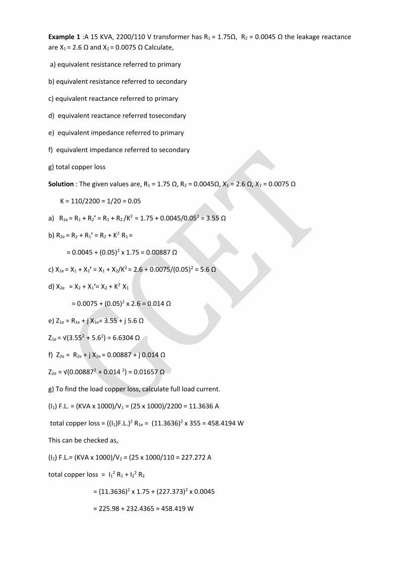
Equivalent circuit of Transformer
The term equivalent circuit of a machine means the combination of fixed and variable
resistances and reactances, which exactly simulates performance and working of the machine.
For a transformer, no load primary current has two components,
Im = Io sinΦo = Magnetizing component
Ic = Io cosΦo = Active component
Im produces the flux and is assumed to flow through reactance Xo called no load reractance while
Ic is active component representing core losses hence is assumed to flow through the reactance Ro.
Hence equivalent circuit on no load can be shown as in the Fig. 1. This circuit consisting of Ro and Xo
in parallel is called exciting circuit. From the equivalent circuit we can write,
Ro = V1/Ic
and Xo= V1/Im
Fig. 1 No load equivalent circuit
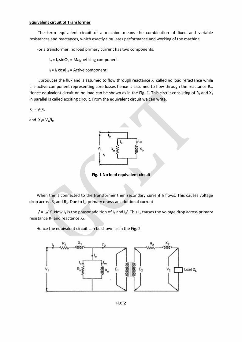
When the is connected to the transformer then secondary current I2 flows. This causes voltage
drop across R2 and R2. Due to I2, primary draws an additional current
I2' = I2/ K. Now I1 is the phasor addition of Io and I2'. This I1 causes the voltage drop across primary
resistance R1 and reactance X1.
Hence the equivalent circuit can be shown as in the Fig. 2.
Fig. 2
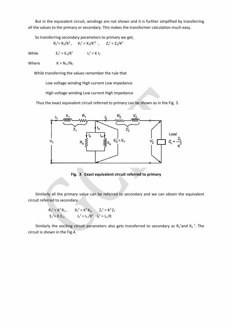
But in the equivalent circuit, windings are not shown and it is further simplified by transferring
all the values to the primary or secondary. This makes the transformer calculation much easy.
So transferring secondary parameters to primary we get,
R2'= R2/K2 , X2' = X2/K2' , Z2' = Z2/K2
While E2' = E2/K' I2' = K I2
Where K = N2 /N1
While transferring the values remember the rule that
Low voltage winding High current Low impedance
High voltage winding Low current High impedance
Thus the exact equivalent circuit referred to primary can be shown as in the Fig. 3.
Fig. 3 Exact equivalent circuit referred to primary
Similarly all the primary value can be referred to secondary and we can obtain the equivalent
circuit referred to secondary.
R1' = K2 R1 , X1' = K2 X1, Z1' = K2 Z1
E1'= K E1, Io' = I1 /K' Io' = Io /K
Similarly the exciting circuit parameters also gets transferred to secondary as Ro'and Xo '. The
circuit is shown in the Fig.4.
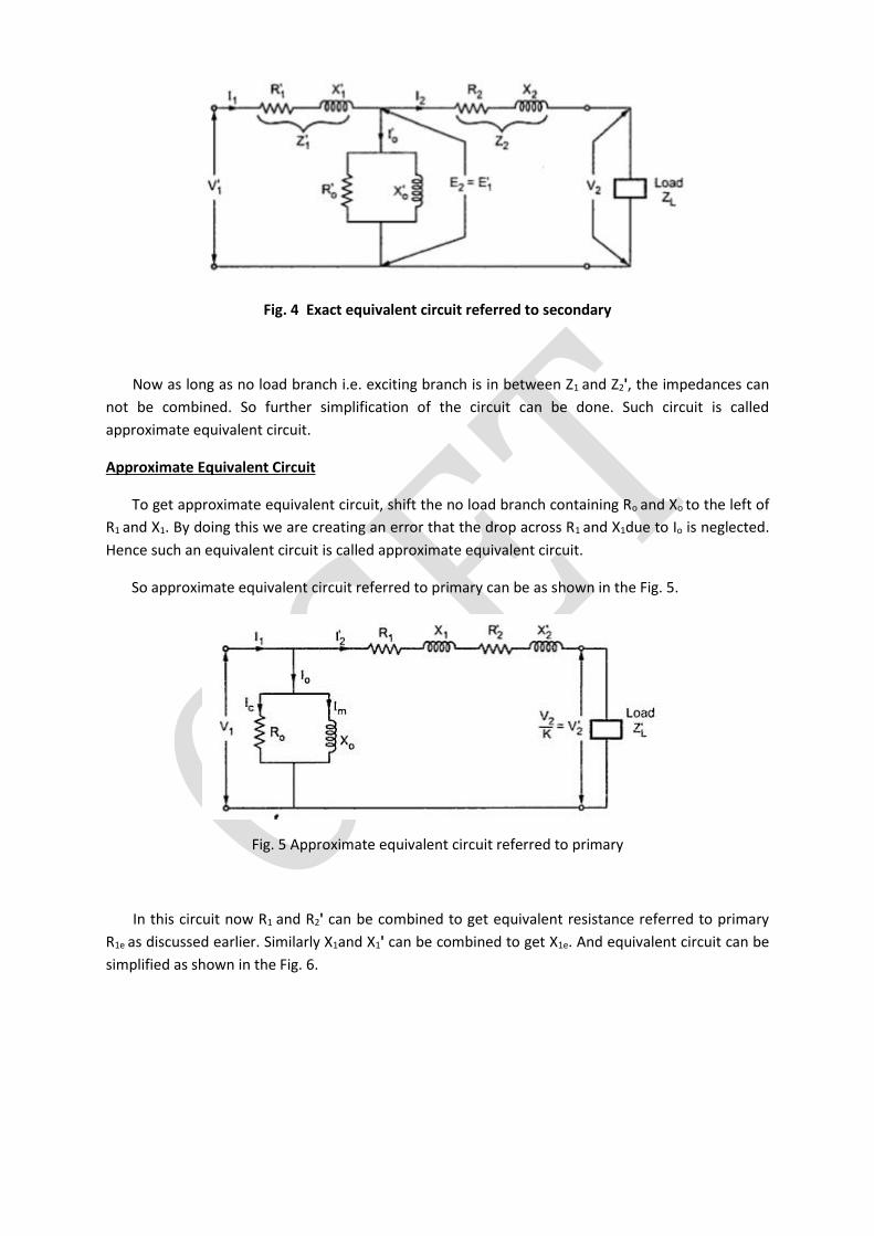
Fig. 4 Exact equivalent circuit referred to secondary
Now as long as no load branch i.e. exciting branch is in between Z1 and Z2', the impedances can
not be combined. So further simplification of the circuit can be done. Such circuit is called
approximate equivalent circuit.
Approximate Equivalent Circuit
To get approximate equivalent circuit, shift the no load branch containing Ro and Xo to the left of
R1 and X1. By doing this we are creating an error that the drop across R1 and X1due to Io is neglected.
Hence such an equivalent circuit is called approximate equivalent circuit.
So approximate equivalent circuit referred to primary can be as shown in the Fig. 5.
Fig. 5 Approximate equivalent circuit referred to primary
In this circuit now R1 and R2' can be combined to get equivalent resistance referred to primary
R1e as discussed earlier. Similarly X1and X1' can be combined to get X1e. And equivalent circuit can be
simplified as shown in the Fig. 6.
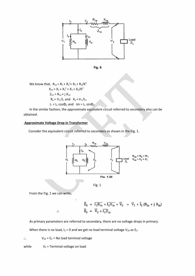
Fig. 6
We know that, R1e = R1 + R2'= R1 + R2/K2
X1e = X1 + X2' = X1 + X2/K2
Z1e = R1e + j X1e
Ro = V1 /Ic and Xo = V1 /Im
Ic = Io cosΦo and Im = Io sinΦo
In the similar fashion, the approximate equivalent circuit referred to secondary also can be
obtained.
Approximate Voltage Drop in Transformer
Consider the equivalent circuit referred to secondary as shown in the Fig. 1.
Fig. 1
From the Fig. 1 we can write,
As primary parameters are referred to secondary, there are no voltage drops in primary.
When there is no load, I2 = 0 and we get no load terminal voltage V20 as E2.
... V20 = E2 = No load terminal voltage
while V2 = Terminal voltage on load
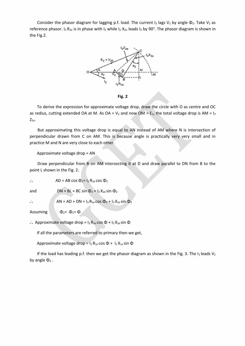
Consider the phasor diagram for lagging p.f. load. The current I2 lags V2 by angle Φ2. Take V2 as
reference phasor. I2 R2e is in phase with I2 while I2 X2e leads I2 by 90o. The phasor diagram is shown in
the Fig.2.
Fig. 2
To derive the expression for approximate voltage drop, draw the circle with O as centre and OC
as redius, cutting extended OA at M. As OA = V2 and now OM = E2, the total voltage drop is AM = I2
Z2e.
But approximating this voltage drop is equal to AN instead of AM where N is intersection of
perpendicular drawn from C on AM. This is because angle is practically very very small and in
practice M and N are very close to each other.
Approximate voltage drop = AN
Draw perpendicular from B on AM intersecting it at D and draw parallel to DN from B to the
point L shown in the Fig. 2.
... AD = AB cos Φ2= I2 R2e cos Φ2
and DN = BL = BC sin Φ2 = I2 X2e sin Φ2
... AN = AD + DN = I2 R2e cos Φ2 + I2 X2e sin Φ2
Assuming Φ2= Φ1= Φ
... Approximate voltage drop = I2 R2e cos Φ + I2 X2e sin Φ
If all the parameters are referred to primary then we get,
Approximate voltage drop = I1 R1e cos Φ + I1 X1e sin Φ
If the load has leading p.f. then we get the phasor diagram as shown in the Fig. 3. The I2 leads V2
by angle Φ2 .
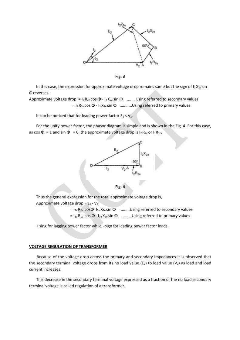
Fig. 3
In this case, the expression for approximate voltage drop remains same but the sign of I2 X2e sin
Φ reverses.
Approximate voltage drop = I2 R2e cos Φ - I2 X2e sin Φ ....... Using referred to secondary values
= I1 R1e cos Φ - I1 X1e sin Φ ...........Using referred to primary values
It can be noticed that for leading power factor E2 < V2.
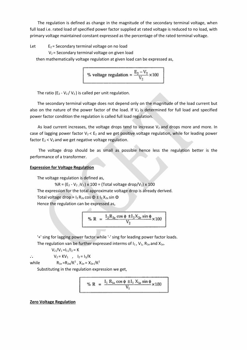
For the unity power factor, the phasor diagram is simple and is shown in the Fig. 4. For this case,
as cos Φ = 1 and sin Φ = 0, the approximate voltage drop is I2 R2e or I1R1e.
Fig. 4
Thus the general expression for the total approximate voltage drop is,
Approximate voltage drop = E2 - V2
= I2e R2e cosΦ I2e X2e sin Φ ........Using referred to secondary values
= I1e R1e cos Φ I1e X1e sin Φ ........Using referred to primary values
+ sing for lagging power factor while - sign for leading power factor loads.
VOLTAGE REGULATION OF TRANSFORMER
Because of the voltage drop across the primary and secondary impedances it is observed that
the secondary terminal voltage drops from its no load value (E2) to load value (V2) as load and load
current increases.
This decrease in the secondary terminal voltage expressed as a fraction of the no load secondary
terminal voltage is called regulation of a transformer.
The regulation is defined as change in the magnitude of the secondary terminal voltage, when
full load i.e. rated load of specified power factor supplied at rated voltage is reduced to no load, with
primary voltage maintained constant expressed as the percentage of the rated terminal voltage.
Let E2 = Secondary terminal voltage on no load
V2 = Secondary terminal voltage on given load
then mathematically voltage regulation at given load can be expressed as,
The ratio (E2 - V2 / V2 ) is called per unit regulation.
The secondary terminal voltage does not depend only on the magnitude of the load current but
also on the nature of the power factor of the load. If V2 is determined for full load and specified
power factor condition the regulation is called full load regulation.
As load current increases, the voltage drops tend to increase V2 and drops more and more. In
case of lagging power factor V2 < E2 and we get positive voltage regulation, while for leading power
factor E2 < V2 and we get negative voltage regulation.
The voltage drop should be as small as possible hence less the regulation better is the
performance of a transformer.
Expression for Voltage Regulation
The voltage regulation is defined as,
%R = (E2 - V2 /V2 ) x 100 = (Total voltage drop/V2) x 100
The expression for the total approximate voltage drop is already derived.
Total voltage drop = I2 R2e cos Φ ± I2 X2e sin Φ
Hence the regulation can be expressed as,
'+' sing for lagging power factor while '-' sing for leading power factor loads.
The regulation van be further expressed interms of I1 , V1, R1e and X1e.
V2 /V1 =I1 /I2 = K
... V2 = KV1 , I2 = I1/K
while R1e =R2e/K2 , X1e = X2e /K2
Substituting in the regulation expression we get,
Zero Voltage Regulation
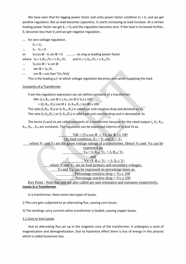
We have seen that for lagging power factor and unity power factor condition V2 < E2 and we get
positive regulation. But as load becomes capacitive, V2 starts increasing as load increase. At a certain
leading power factor we get E2 = V2 and the regulation becomes zero. If the load is increased further,
E2 becomes less than V2 and we get negative regulation.
... for zero voltage regulation,
E2 = V2
... E2 - V2 = 0
or VR cos Φ - Vx sin Φ = 0 .......... -ve sing as leading power factor
where VR = I2 R2e /V2 = I1 R1e /V1 and Vx = I2 X2e /V2 = I1 X1e /V1
... VR cos Φ = Vx sin Φ
... tan Φ = VR /Vx
... cos Φ = cos tan-1(VR /Vx)
This is the leading p.f. at which voltage regulation becomes zero while supplying the load.
Constants of a Transformer
From the regulation expression we can define constants of a transformer.
%R= (( I2 R2e cos Φ ± I2 X2e sin Φ )/ E2) x 100
= (I2 R2e /E2) cos Φ ± (I2 X2e/E2 ) sin Φ x 100
The ratio (I2 R2e /E2) or (I1 R1e /E1) is called per unit resistive drop and denoted as VR.
The ratio (I2 X2e/E2 ) or (I1 X1e/E1) is called per unit reactive drop and is denoted as Vx.
The terms VR and Vx are called constants of a transformer because for the rated output I2, E2, R1e,
X1e, R2e , X2e are constants. The regulation can be expressed interms of VR and Vx as,
%R = (VR cos Φ ± Vx sin Φ ) x 100
On load condition, E2 = V2 and E1= V1
where V1 and V2 are the given voltage ratings of a transformer. Hence VR and Vx can be
expressed as,
VR = I2 R2e/ V2 = I1 R1e/ V1
and
Vx =I2 R2e/ V2 = I1 X1e/ V1
where V1and V2 are no load primary and secondary voltages,
VR and Vx can be expressed on percentage basis as,
Percentage resistive drop = VR x 100
Percentage reactive drop = Vx x 100
Key Point : Note that and are also called per unit resistance and reactance respectively. Losses in a Transformer
In a transformer, there exists two types of losses.
i) The core gets subjected to an alternating flux, causing core losses.
ii) The windings carry currents when transformer is loaded, causing copper losses.
1.1 Core or Iron Losses
Due to alternating flux set up in the magnetic core of the transformer, it undergoes a cycle of
magnetisation and demagnetisation. Due to hysteresis effect there is loss of energy in this process
which is called hysteresis loss.
It is given by, hysteresis loss = Kh Bm
1.67 f v watts
where Kh = Hysteresis constant depends on material.
Bm = Maximum flux density.
f = Frequency.
v = Volume of the core.
The induced e.m.f. in the core tries to set up eddy currents in the core and hence responsible for
the eddy current losses. The eddy current loss is given by,
Eddy current loss = Ke Bm
2 f2 t2 watts/ unit volume
where Ke = Eddy current constant
t = Thickness of the core
As seen earlier, the flux in the core is almost constant as supply voltage V1 at rated frequency f is
always constant. Hence the flux density Bm in the core and hence both hysteresis and eddy current
losses are constants at all the loads. Hence the core or iron losses are also called constant losses. The
iron losses are denoted as Pi.
The iron losses are minimized by using high grade core material like silicon steel having very low
hysteresis loop by manufacturing the core in the form of laminations.
1.2 Copper Losses
The copper losses are due to the power wasted in the form of I2 R loss due to the resistances of
the primary and secondary windings. The copper loss depends on the magnitude of the currents
flowing through the windings.
Total Cu loss = I12
R1 + I22
R2 = I12
( R1 + R2' )= I22
( R2 +R1' )
= I12
R1e = I22
R2e
The copper looses are denoted as. If the current through the windings is full load current, we get
copper losses at full load. If the load on transformer is half then we get copper losses at half load
which are less than full load copper losses. Thus copper losses are called variable losses. For
transformer VA rating is or. As is constant, we can say that copper losses are proportional to the
square of the KVA rating.
So, Pcu α I2 α (KVA)2
Thus for a transformer,
Total losses = Iron losses + Copper losses
= Pi + Pcu
Key point : It is seen that the iron losses depend on the supply voltage while the copper losses
depend on the current. The losses are not dependent on the phase angle between voltage and
current. Hence the rating of the transformer is expressed as a product of voltage and current and
called VA rating of transformer. It is not expressed in watts or kilo watts. Most of the times, rating is
expressed in KVA.
Losses: Additional Study:
Transformer losses are divided into losses in the windings, termed copper loss, and those in
the magnetic circuit, termed iron loss. Losses in the transformer arise from: Winding resistance
Current flowing through the windings causes resistive heating of the conductors. At higher
frequencies, skin effect and proximity effect create additional winding resistance and losses.
Hysteresis losses
Each time the magnetic field is reversed, a small amount of energy is lost due to hysteresis
within the core. For a given core material, the loss is proportional to the frequency, and is a
function of the peak flux density to which it is subjected.[42]
Eddy currents
Ferromagnetic materials are also good conductors and a core made from such a material
also constitutes a single short-circuited turn throughout its entire length. Eddy currents
therefore circulate within the core in a plane normal to the flux, and are responsible for
resistive heating of the core material. The eddy current loss is a complex function of the
square of supply frequency and inverse square of the material thickness.[42] Eddy current
losses can be reduced by making the core of a stack of plates electrically insulated from each
other, rather than a solid block; all transformers operating at low frequencies use laminated
or similar cores.
Magnetostriction
Magnetic flux in a ferromagnetic material, such as the core, causes it to physically expand
and contract slightly with each cycle of the magnetic field, an effect known as
magnetostriction. This produces the buzzing sound commonly associated with
transformers[29] that can cause losses due to frictional heating. This buzzing is particularly
familiar from low-frequency (50 Hz or 60 Hz) mains hum, and high-frequency (15,734 Hz
(NTSC) or 15,625 Hz (PAL)) CRT noise.
Mechanical losses
In addition to magnetostriction, the alternating magnetic field causes fluctuating forces
between the primary and secondary windings. These incite vibrations within nearby
metalwork, adding to the buzzing noise and consuming a small amount of power.[43]
Stray losses
Leakage inductance is by itself largely lossless, since energy supplied to its magnetic fields is
returned to the supply with the next half-cycle. However, any leakage flux that intercepts
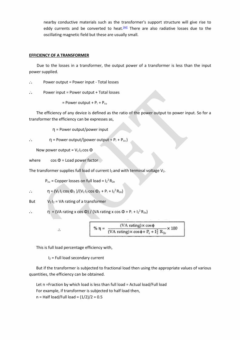
nearby conductive materials such as the transformer's support structure will give rise to
eddy currents and be converted to heat.[44] There are also radiative losses due to the
oscillating magnetic field but these are usually small.
EFFICIENCY OF A TRANSFORMER
Due to the losses in a transformer, the output power of a transformer is less than the input
power supplied.
... Power output = Power input - Total losses
... Power input = Power output + Total losses
= Power output + Pi + Pcu
The efficiency of any device is defined as the ratio of the power output to power input. So for a
transformer the efficiency can be expresses as,
η = Power output/power input
... η = Power output/(power output + Pi + Pcu )
Now power output = V2 I2 cos Φ
where cos Φ = Load power factor
The transformer supplies full load of current I2 and with terminal voltage V2.
Pcu = Copper losses on full load = I22
R2e
... η = (V2 I2 cos Φ2 )/(V2 I2 cos Φ2 + Pi + I22
R2e)
But V2 I2 = VA rating of a transformer
... η = (VA rating x cos Φ) / (VA rating x cos Φ + Pi + I22
R2e)
This is full load percentage efficiency with,
I2 = Full load secondary current
But if the transformer is subjected to fractional load then using the appropriate values of various
quantities, the efficiency can be obtained.
Let n =Fraction by which load is less than full load = Actual load/Full load
For example, if transformer is subjected to half load then,
n = Half load/Full load = (1/2)/2 = 0.5
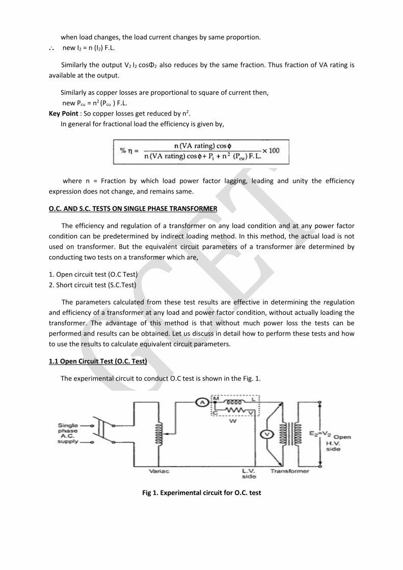
when load changes, the load current changes by same proportion.
... new I2 = n (I2) F.L.
Similarly the output V2 I2 cosΦ2 also reduces by the same fraction. Thus fraction of VA rating is
available at the output.
Similarly as copper losses are proportional to square of current then,
new Pcu = n2 (Pcu ) F.L.
Key Point : So copper losses get reduced by n2.
In general for fractional load the efficiency is given by,
where n = Fraction by which load power factor lagging, leading and unity the efficiency
expression does not change, and remains same.
O.C. AND S.C. TESTS ON SINGLE PHASE TRANSFORMER
The efficiency and regulation of a transformer on any load condition and at any power factor
condition can be predetermined by indirect loading method. In this method, the actual load is not
used on transformer. But the equivalent circuit parameters of a transformer are determined by
conducting two tests on a transformer which are,
1. Open circuit test (O.C Test)
2. Short circuit test (S.C.Test)
The parameters calculated from these test results are effective in determining the regulation
and efficiency of a transformer at any load and power factor condition, without actually loading the
transformer. The advantage of this method is that without much power loss the tests can be
performed and results can be obtained. Let us discuss in detail how to perform these tests and how
to use the results to calculate equivalent circuit parameters.
1.1 Open Circuit Test (O.C. Test)
The experimental circuit to conduct O.C test is shown in the Fig. 1.
Fig 1. Experimental circuit for O.C. test
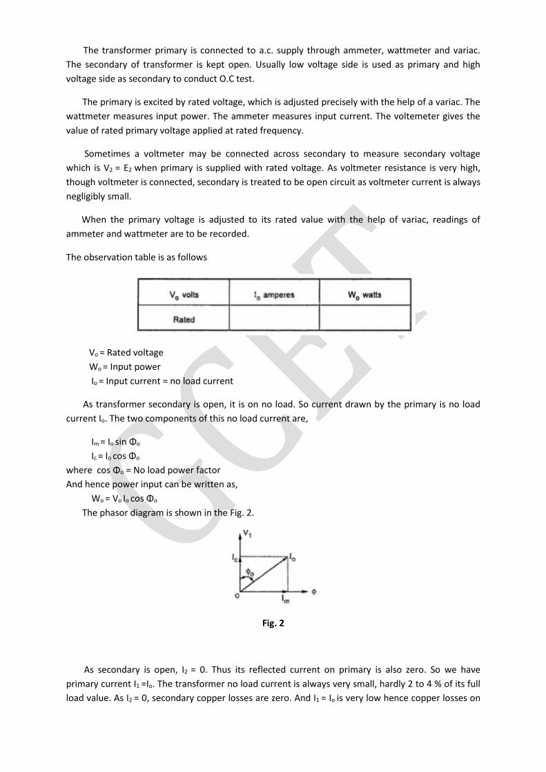
The transformer primary is connected to a.c. supply through ammeter, wattmeter and variac.
The secondary of transformer is kept open. Usually low voltage side is used as primary and high
voltage side as secondary to conduct O.C test.
The primary is excited by rated voltage, which is adjusted precisely with the help of a variac. The
wattmeter measures input power. The ammeter measures input current. The voltemeter gives the
value of rated primary voltage applied at rated frequency.
Sometimes a voltmeter may be connected across secondary to measure secondary voltage
which is V2 = E2 when primary is supplied with rated voltage. As voltmeter resistance is very high,
though voltmeter is connected, secondary is treated to be open circuit as voltmeter current is always
negligibly small.
When the primary voltage is adjusted to its rated value with the help of variac, readings of
ammeter and wattmeter are to be recorded.
The observation table is as follows
Vo = Rated voltage
Wo = Input power
Io = Input current = no load current
As transformer secondary is open, it is on no load. So current drawn by the primary is no load
current Io. The two components of this no load current are,
Im = Io sin Φo
Ic = Io cos Φo
where cos Φo = No load power factor
And hence power input can be written as,
Wo = Vo Io cos Φo
The phasor diagram is shown in the Fig. 2.
Fig. 2
As secondary is open, I2 = 0. Thus its reflected current on primary is also zero. So we have
primary current I1 =Io. The transformer no load current is always very small, hardly 2 to 4 % of its full
load value. As I2 = 0, secondary copper losses are zero. And I1 = Io is very low hence copper losses on
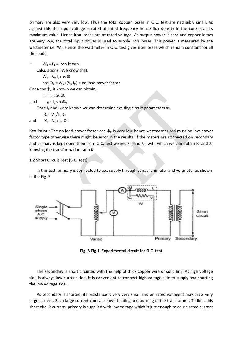
primary are also very very low. Thus the total copper losses in O.C. test are negligibly small. As
against this the input voltage is rated at rated frequency hence flux density in the core is at its
maximum value. Hence iron losses are at rated voltage. As output power is zero and copper losses
are very low, the total input power is used to supply iron losses. This power is measured by the
wattmeter i.e. Wo. Hence the wattmeter in O.C. test gives iron losses which remain constant for all
the loads.
... Wo = Pi = Iron losses
Calculations : We know that,
Wo = Vo Io cos Φ
cos Φo = Wo /(Vo Io ) = no load power factor
Once cos Φo is known we can obtain,
Ic = Io cos Φo
and Im = Io sin Φo
Once Ic and Im are known we can determine exciting circuit parameters as,
Ro = Vo /Ic Ω
and Xo = Vo /Im Ω
Key Point : The no load power factor cos Φo is very low hence wattmeter used must be low power
factor type otherwise there might be error in the results. If the meters are connected on secondary
and primary is kept open then from O.C. test we get Ro' and Xo' with which we can obtain Ro and Xo
knowing the transformation ratio K.
1.2 Short Circuit Test (S.C. Test)
In this test, primary is connected to a.c. supply through variac, ammeter and voltmeter as shown
in the Fig. 3.
Fig. 3 Fig 1. Experimental circuit for O.C. test
The secondary is short circuited with the help of thick copper wire or solid link. As high voltage
side is always low current side, it is convenient to connect high voltage side to supply and shorting
the low voltage side.
As secondary is shorted, its resistance is very very small and on rated voltage it may draw very
large current. Such large current can cause overheating and burning of the transformer. To limit this
short circuit current, primary is supplied with low voltage which is just enough to cause rated current
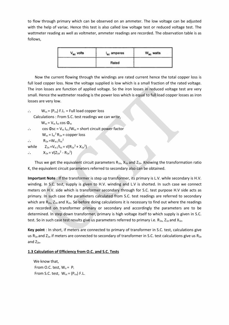
to flow through primary which can be observed on an ammeter. The low voltage can be adjusted
with the help of variac. Hence this test is also called low voltage test or reduced voltage test. The
wattmeter reading as well as voltmeter, ammeter readings are recorded. The observation table is as
follows,
Now the current flowing through the windings are rated current hence the total copper loss is
full load copper loss. Now the voltage supplied is low which is a small fraction of the rated voltage.
The iron losses are function of applied voltage. So the iron losses in reduced voltage test are very
small. Hence the wattmeter reading is the power loss which is equal to full load copper losses as iron
losses are very low.
... Wsc = (Pcu) F.L. = Full load copper loss
Calculations : From S.C. test readings we can write,
Wsc = Vsc Isc cos Φsc
... cos Φsc = Vsc Isc /Wsc = short circuit power factor
Wsc = Isc2 R1e = copper loss
... R1e =Wsc /Isc2
while Z1e =Vsc /Isc = √(R1e2
+ X1e2)
... X1e = √(Z1e
2 - R1e2)
Thus we get the equivalent circuit parameters R1e, X1e and Z1e. Knowing the transformation ratio
K, the equivalent circuit parameters referred to secondary also can be obtained.
Important Note : If the transformer is step up transformer, its primary is L.V. while secondary is H.V.
winding. In S.C. test, supply is given to H.V. winding and L.V is shorted. In such case we connect
meters on H.V. side which is transformer secondary through for S.C. test purpose H.V side acts as
primary. In such case the parameters calculated from S.C. test readings are referred to secondary
which are R2e, Z2e and X2e. So before doing calculations it is necessary to find out where the readings
are recorded on transformer primary or secondary and accordingly the parameters are to be
determined. In step down transformer, primary is high voltage itself to which supply is given in S.C.
test. So in such case test results give us parameters referred to primary i.e. R1e, Z1e and X1e.
Key point : In short, if meters are connected to primary of transformer in S.C. test, calculations give
us R1e and Z1e if meters are connected to secondary of transformer in S.C. test calculations give us R2e
and Z2e.
1.3 Calculation of Efficiency from O.C. and S.C. Tests
We know that,
From O.C. test, Wo = Pi
From S.C. test, Wsc = (Pcu) F.L.
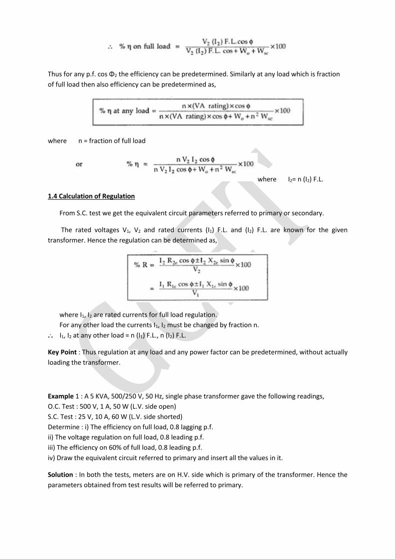
Thus for any p.f. cos Φ2 the efficiency can be predetermined. Similarly at any load which is fraction
of full load then also efficiency can be predetermined as,
where n = fraction of full load
where I2= n (I2) F.L.
1.4 Calculation of Regulation
From S.C. test we get the equivalent circuit parameters referred to primary or secondary.
The rated voltages V1, V2 and rated currents (I1) F.L. and (I2) F.L. are known for the given
transformer. Hence the regulation can be determined as,
where I1, I2 are rated currents for full load regulation.
For any other load the currents I1, I2 must be changed by fraction n.
... I1, I2 at any other load = n (I1) F.L., n (I2) F.L.
Key Point : Thus regulation at any load and any power factor can be predetermined, without actually
loading the transformer.
Example 1 : A 5 KVA, 500/250 V, 50 Hz, single phase transformer gave the following readings,
O.C. Test : 500 V, 1 A, 50 W (L.V. side open)
S.C. Test : 25 V, 10 A, 60 W (L.V. side shorted)
Determine : i) The efficiency on full load, 0.8 lagging p.f.
ii) The voltage regulation on full load, 0.8 leading p.f.
iii) The efficiency on 60% of full load, 0.8 leading p.f.
iv) Draw the equivalent circuit referred to primary and insert all the values in it.
Solution : In both the tests, meters are on H.V. side which is primary of the transformer. Hence the
parameters obtained from test results will be referred to primary.
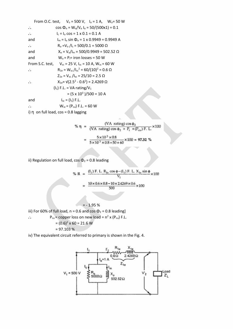
From O.C. test, Vo = 500 V, Io = 1 A, Wo= 50 W
... cos Φo = Wo/Vo Io = 50/(500x1) = 0.1
... Ic = Io cos = 1 x 0.1 = 0.1 A
and Im = Io sin Φo = 1 x 0.9949 = 0.9949 A
... Ro =Vo /Ic = 500/0.1 = 5000 Ω
and Xo = Vo/Im = 500/0.9949 = 502.52 Ω
and Wo = Pi= iron losses = 50 W
From S.C. test, Vsc = 25 V, Isc = 10 A, Wsc = 60 W
... R1e = Wsc /Isc2 = 60/(10)2 = 0.6 Ω
Z1e = Vsc /Isc = 25/10 = 2.5 Ω
... X1e= √(2.52 - 0.62) = 2.4269 Ω
(I1) F.L. = VA rating/V1
= (5 x 10³ )/500 = 10 A
and Isc = (I1) F.L.
... Wsc = (Pcu) F.L. = 60 W
i) η on full load, cos = 0.8 lagging
ii) Regulation on full load, cos Φ2 = 0.8 leading
= - 1.95 %
iii) For 60% of full load, n = 0.6 and cos Φ2 = 0.8 leading]
... Pcu = copper loss on new load = n2 x (Pcu) F.L.
= (0.6)2 x 60 = 21.6 W
= 97.103 %
iv) The equivalent circuit referred to primary is shown in the Fig. 4.
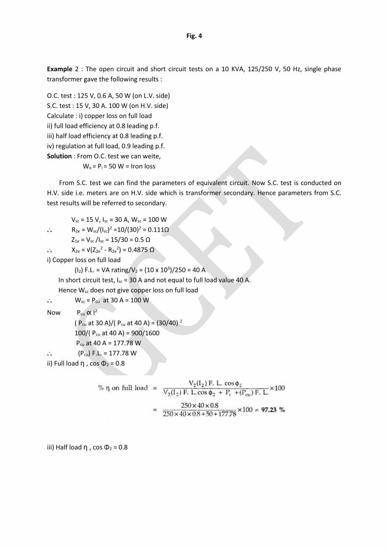
Fig. 4
Example 2 : The open circuit and short circuit tests on a 10 KVA, 125/250 V, 50 Hz, single phase
transformer gave the following results :
O.C. test : 125 V, 0.6 A, 50 W (on L.V. side)
S.C. test : 15 V, 30 A. 100 W (on H.V. side)
Calculate : i) copper loss on full load
ii) full load efficiency at 0.8 leading p.f.
iii) half load efficiency at 0.8 leading p.f.
iv) regulation at full load, 0.9 leading p.f.
Solution : From O.C. test we can weite,
Wo = Pi = 50 W = Iron loss
From S.C. test we can find the parameters of equivalent circuit. Now S.C. test is conducted on
H.V. side i.e. meters are on H.V. side which is transformer secondary. Hence parameters from S.C.
test results will be referred to secondary.
Vsc = 15 V, Isc = 30 A, Wsc = 100 W
... R2e = Wsc/(Isc)2 =10/(30)2 = 0.111Ω
Z1e = Vsc /Isc = 15/30 = 0.5 Ω
... X2e = √(Z2e2 - R2e
2) = 0.4875 Ω
i) Copper loss on full load
(I2) F.L. = VA rating/V2 = (10 x 103)/250 = 40 A
In short circuit test, Isc = 30 A and not equal to full load value 40 A.
Hence Wsc does not give copper loss on full load
... Wsc = Pcu at 30 A = 100 W
Now Pcu α I2
( Pcu at 30 A)/( Pcu at 40 A) = (30/40) 2
100/( Pcu at 40 A) = 900/1600
Pcu at 40 A = 177.78 W
... (Pcu) F.L. = 177.78 W
ii) Full load η , cos Φ2 = 0.8
iii) Half load η , cos Φ2 = 0.8
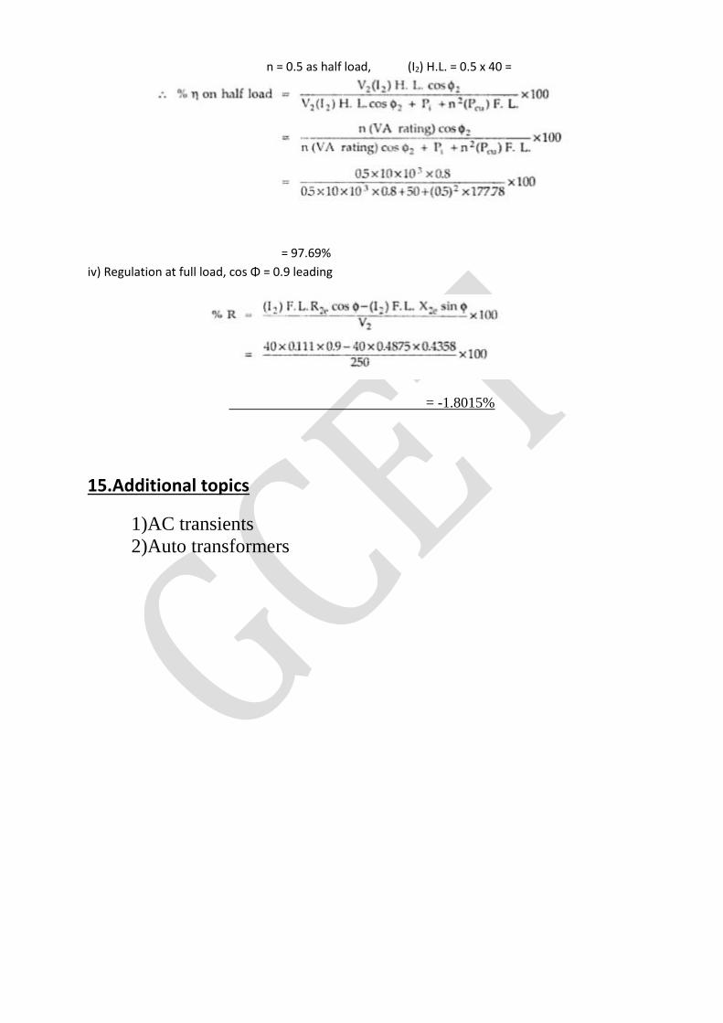
n = 0.5 as half load, (I2) H.L. = 0.5 x 40 =
= 97.69%
iv) Regulation at full load, cos Φ = 0.9 leading
= -1.8015%
15.Additional topics
1)AC transients
2)Auto transformers
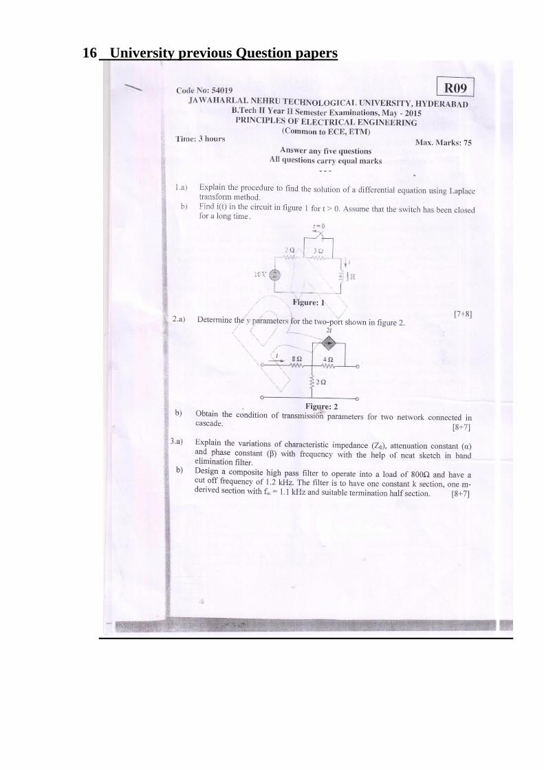
16 University previous Question papers
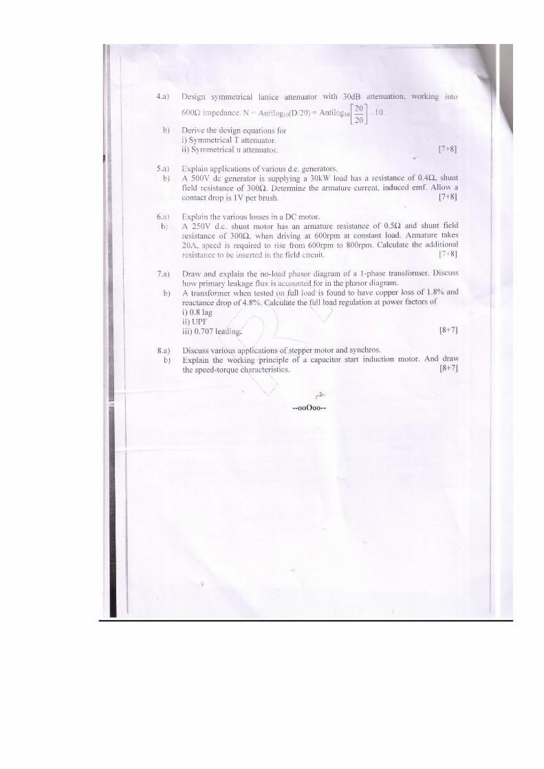
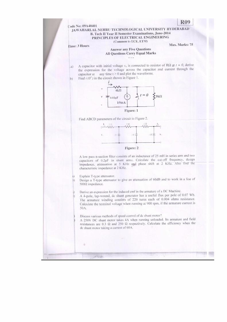
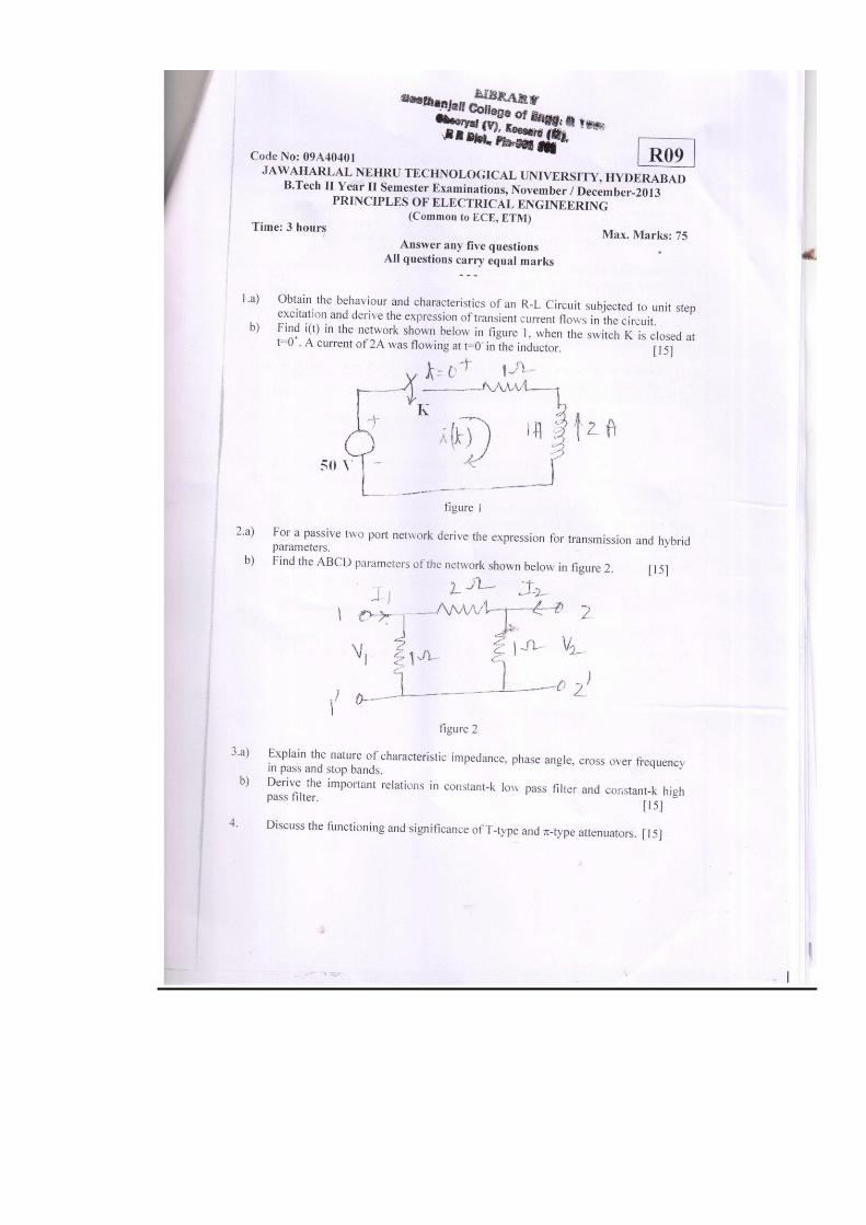
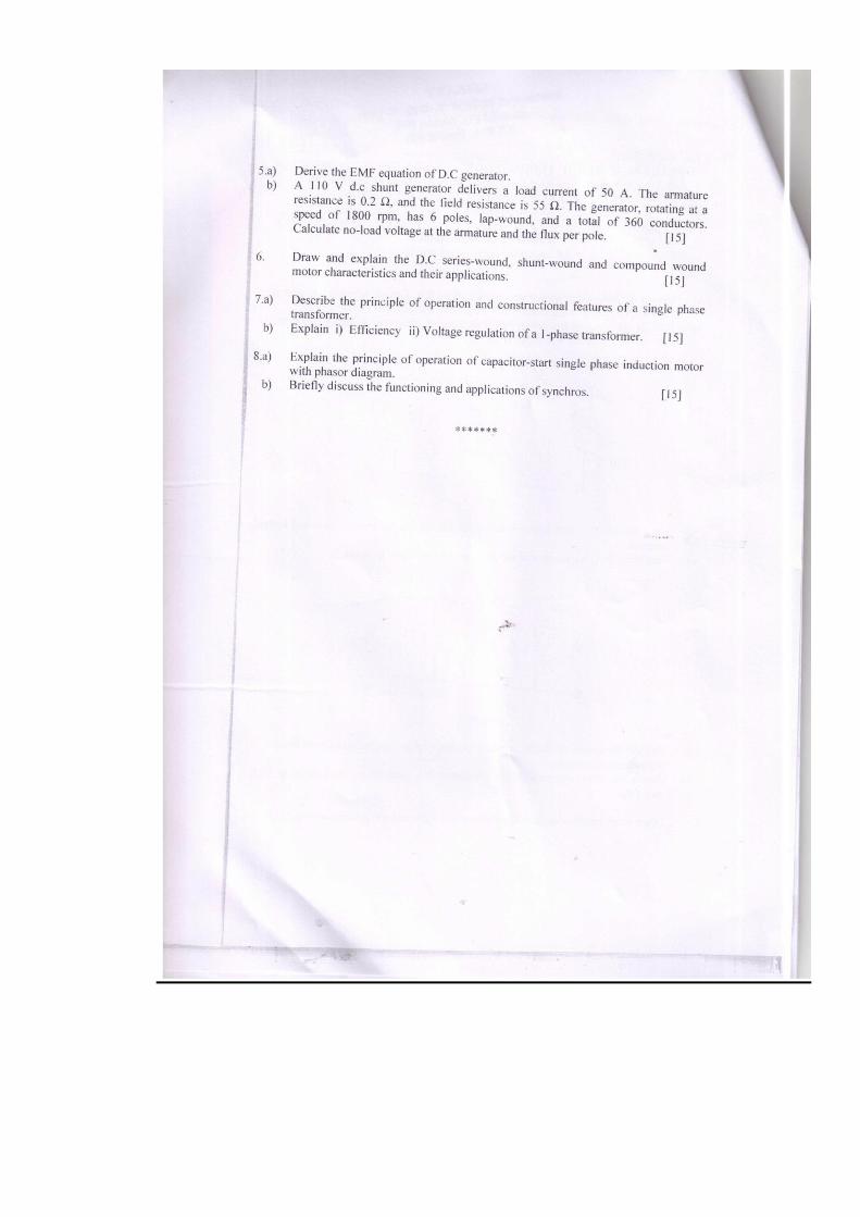
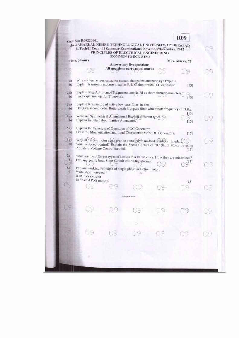
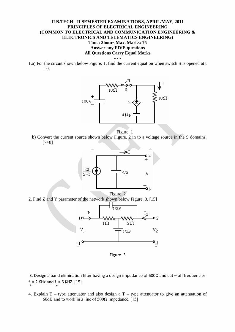
II B.TECH - II SEMESTER EXAMINATIONS, APRIL/MAY, 2011
PRINCIPLES OF ELECTRICAL ENGINEERING
(COMMON TO ELECTRICAL AND COMMUNICATION ENGINEERING &
ELECTRONICS AND TELEMATICS ENGINEERING)
Time: 3hours Max. Marks: 75
Answer any FIVE questions
All Questions Carry Equal Marks
- - - 1.a) For the circuit shown below Figure. 1, find the current equation when switch S is opened at t
= 0.
Figure. 1
b) Convert the current source shown below Figure. 2 in to a voltage source in the S domains.
[7+8]
Figure. 2
2. Find Z and Y parameter of the network shown below Figure. 3. [15]
Figure. 3
3. Design a band elimination filter having a design impedance of 600Ω and cut – off frequencies
f1
= 2 KHz and f2
= 6 KHZ. [15]
4. Explain T – type attenuator and also design a T – type attenuator to give an attenuation of
60dB and to work in a line of 500Ω impedance. [15]
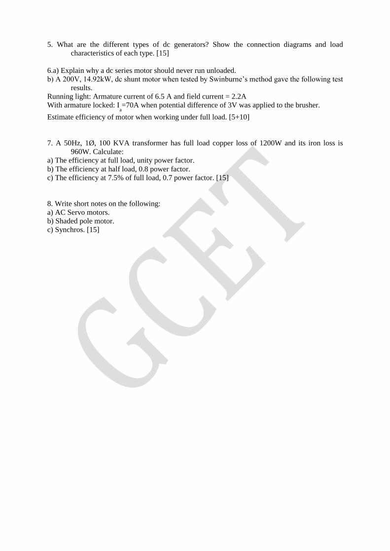
5. What are the different types of dc generators? Show the connection diagrams and load
characteristics of each type. [15]
6.a) Explain why a dc series motor should never run unloaded.
b) A 200V, 14.92kW, dc shunt motor when tested by Swinburne’s method gave the following test
results.
Running light: Armature current of 6.5 A and field current = 2.2A
With armature locked: Ia=70A when potential difference of 3V was applied to the brusher.
Estimate efficiency of motor when working under full load. [5+10]
7. A 50Hz, 1Ø, 100 KVA transformer has full load copper loss of 1200W and its iron loss is
960W. Calculate:
a) The efficiency at full load, unity power factor.
b) The efficiency at half load, 0.8 power factor.
c) The efficiency at 7.5% of full load, 0.7 power factor. [15]
8. Write short notes on the following:
a) AC Servo motors.
b) Shaded pole motor.
c) Synchros. [15]
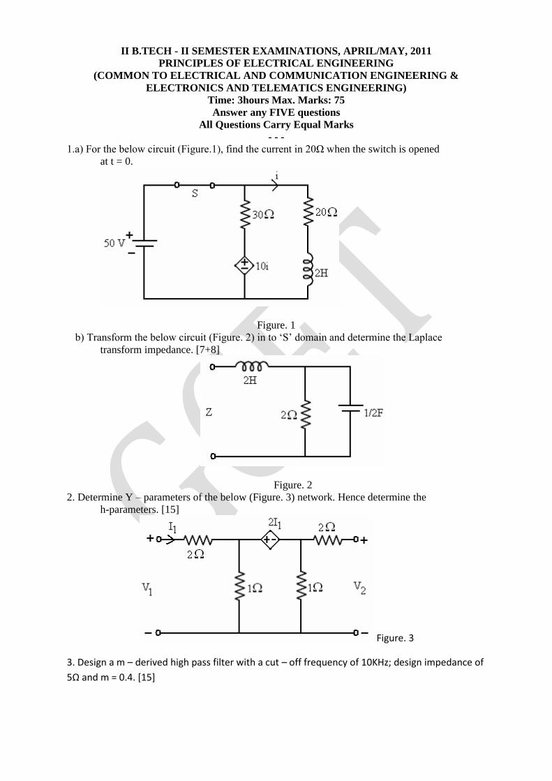
II B.TECH - II SEMESTER EXAMINATIONS, APRIL/MAY, 2011
PRINCIPLES OF ELECTRICAL ENGINEERING
(COMMON TO ELECTRICAL AND COMMUNICATION ENGINEERING &
ELECTRONICS AND TELEMATICS ENGINEERING)
Time: 3hours Max. Marks: 75
Answer any FIVE questions
All Questions Carry Equal Marks
- - - 1.a) For the below circuit (Figure.1), find the current in 20Ω when the switch is opened
at t = 0.
Figure. 1
b) Transform the below circuit (Figure. 2) in to ‘S’ domain and determine the Laplace
transform impedance. [7+8]
Figure. 2
2. Determine Y – parameters of the below (Figure. 3) network. Hence determine the
h-parameters. [15]
Figure. 3
3. Design a m – derived high pass filter with a cut – off frequency of 10KHz; design impedance of
5Ω and m = 0.4. [15]
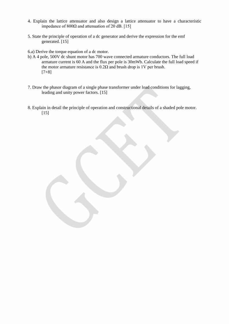
4. Explain the lattice attenuator and also design a lattice attenuator to have a characteristic
impedance of 800Ω and attenuation of 20 dB. [15]
5. State the principle of operation of a dc generator and derive the expression for the emf
generated. [15]
6.a) Derive the torque equation of a dc motor.
b) A 4 pole, 500V dc shunt motor has 700 wave connected armature conductors. The full load
armature current is 60 A and the flux per pole is 30mWb. Calculate the full load speed if
the motor armature resistance is 0.2Ω and brush drop is 1V per brush.
[7+8]
7. Draw the phasor diagram of a single phase transformer under load conditions for lagging,
leading and unity power factors. [15]
8. Explain in detail the principle of operation and constructional details of a shaded pole motor.
[15]
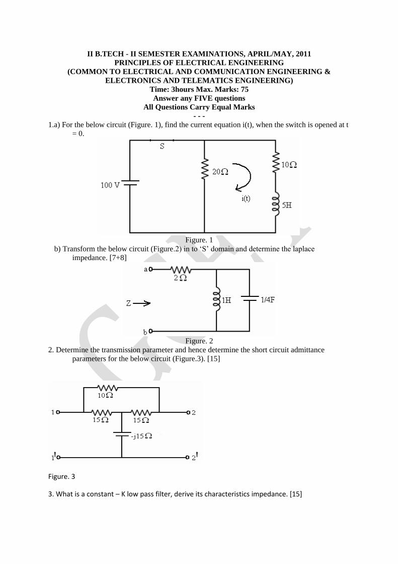
II B.TECH - II SEMESTER EXAMINATIONS, APRIL/MAY, 2011
PRINCIPLES OF ELECTRICAL ENGINEERING
(COMMON TO ELECTRICAL AND COMMUNICATION ENGINEERING &
ELECTRONICS AND TELEMATICS ENGINEERING)
Time: 3hours Max. Marks: 75
Answer any FIVE questions
All Questions Carry Equal Marks
- - - 1.a) For the below circuit (Figure. 1), find the current equation i(t), when the switch is opened at t
= 0.
Figure. 1
b) Transform the below circuit (Figure.2) in to ‘S’ domain and determine the laplace
impedance. [7+8]
Figure. 2
2. Determine the transmission parameter and hence determine the short circuit admittance
parameters for the below circuit (Figure.3). [15]
Figure. 3
3. What is a constant – K low pass filter, derive its characteristics impedance. [15]
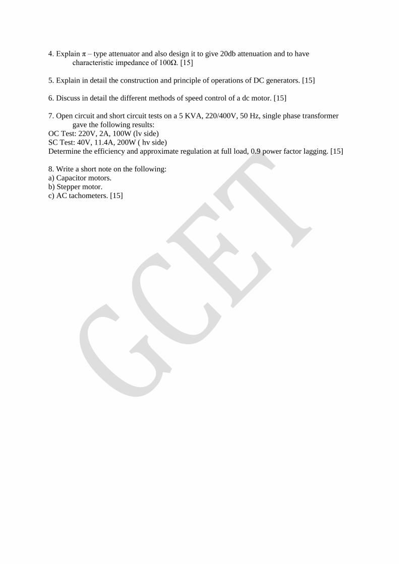
4. Explain π – type attenuator and also design it to give 20db attenuation and to have
characteristic impedance of 100Ω. [15]
5. Explain in detail the construction and principle of operations of DC generators. [15]
6. Discuss in detail the different methods of speed control of a dc motor. [15]
7. Open circuit and short circuit tests on a 5 KVA, 220/400V, 50 Hz, single phase transformer
gave the following results:
OC Test: 220V, 2A, 100W (lv side)
SC Test: 40V, 11.4A, 200W ( hv side)
Determine the efficiency and approximate regulation at full load, 0.9 power factor lagging. [15]
8. Write a short note on the following:
a) Capacitor motors.
b) Stepper motor.
c) AC tachometers. [15]
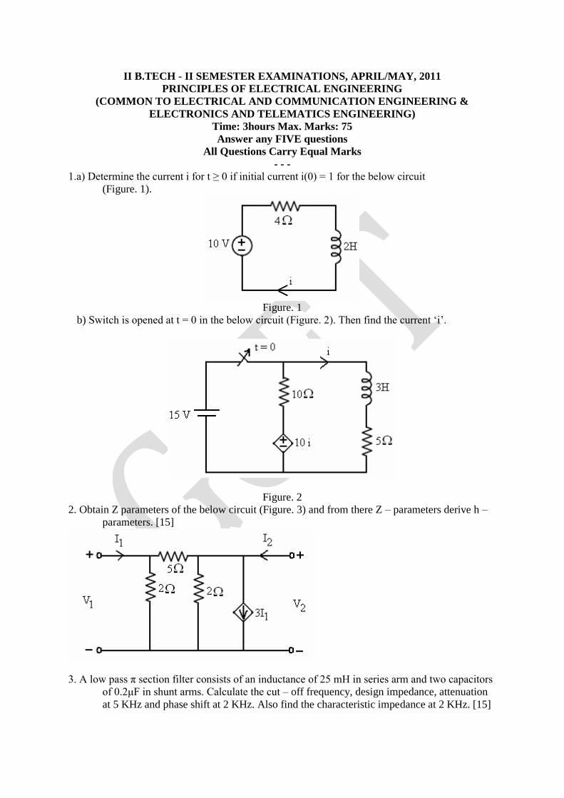
II B.TECH - II SEMESTER EXAMINATIONS, APRIL/MAY, 2011
PRINCIPLES OF ELECTRICAL ENGINEERING
(COMMON TO ELECTRICAL AND COMMUNICATION ENGINEERING &
ELECTRONICS AND TELEMATICS ENGINEERING)
Time: 3hours Max. Marks: 75
Answer any FIVE questions
All Questions Carry Equal Marks
- - - 1.a) Determine the current i for t ≥ 0 if initial current i(0) = 1 for the below circuit
(Figure. 1).
Figure. 1
b) Switch is opened at t = 0 in the below circuit (Figure. 2). Then find the current ‘i’.
Figure. 2
2. Obtain Z parameters of the below circuit (Figure. 3) and from there Z – parameters derive h –
parameters. [15]
3. A low pass π section filter consists of an inductance of 25 mH in series arm and two capacitors
of 0.2μF in shunt arms. Calculate the cut – off frequency, design impedance, attenuation
at 5 KHz and phase shift at 2 KHz. Also find the characteristic impedance at 2 KHz. [15]
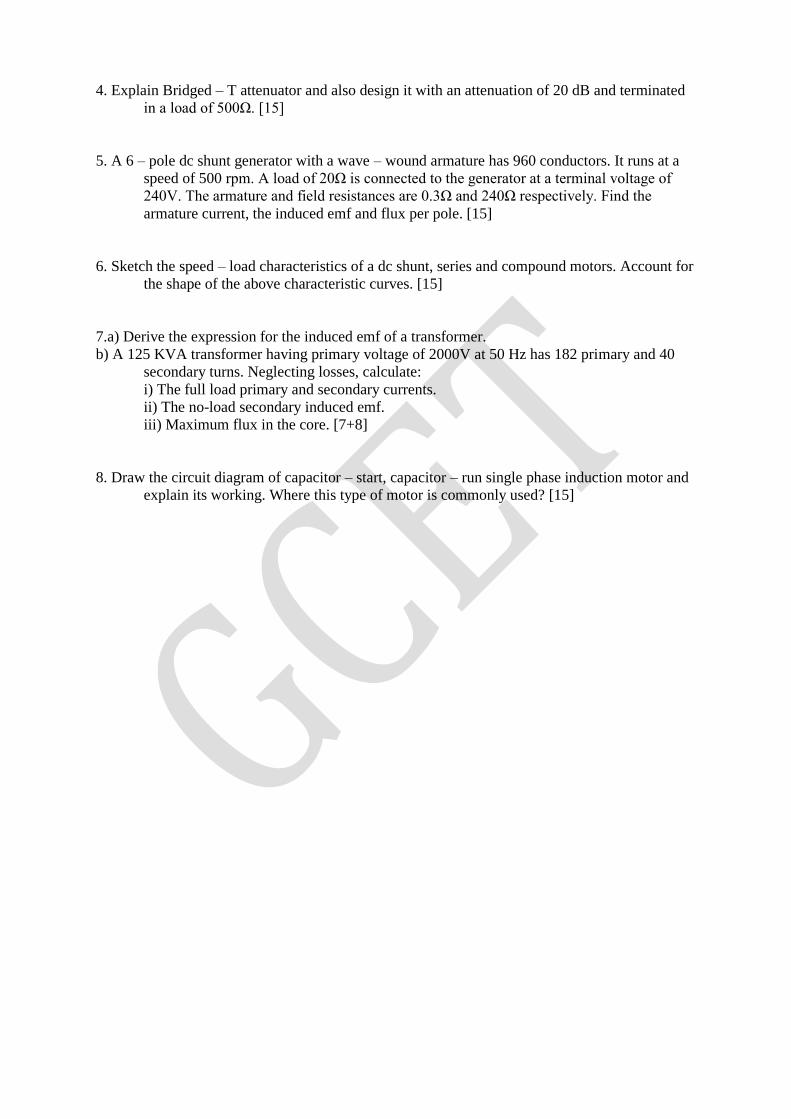
4. Explain Bridged – T attenuator and also design it with an attenuation of 20 dB and terminated
in a load of 500Ω. [15]
5. A 6 – pole dc shunt generator with a wave – wound armature has 960 conductors. It runs at a
speed of 500 rpm. A load of 20Ω is connected to the generator at a terminal voltage of
240V. The armature and field resistances are 0.3Ω and 240Ω respectively. Find the
armature current, the induced emf and flux per pole. [15]
6. Sketch the speed – load characteristics of a dc shunt, series and compound motors. Account for
the shape of the above characteristic curves. [15]
7.a) Derive the expression for the induced emf of a transformer.
b) A 125 KVA transformer having primary voltage of 2000V at 50 Hz has 182 primary and 40
secondary turns. Neglecting losses, calculate:
i) The full load primary and secondary currents.
ii) The no-load secondary induced emf.
iii) Maximum flux in the core. [7+8]
8. Draw the circuit diagram of capacitor – start, capacitor – run single phase induction motor and
explain its working. Where this type of motor is commonly used? [15]
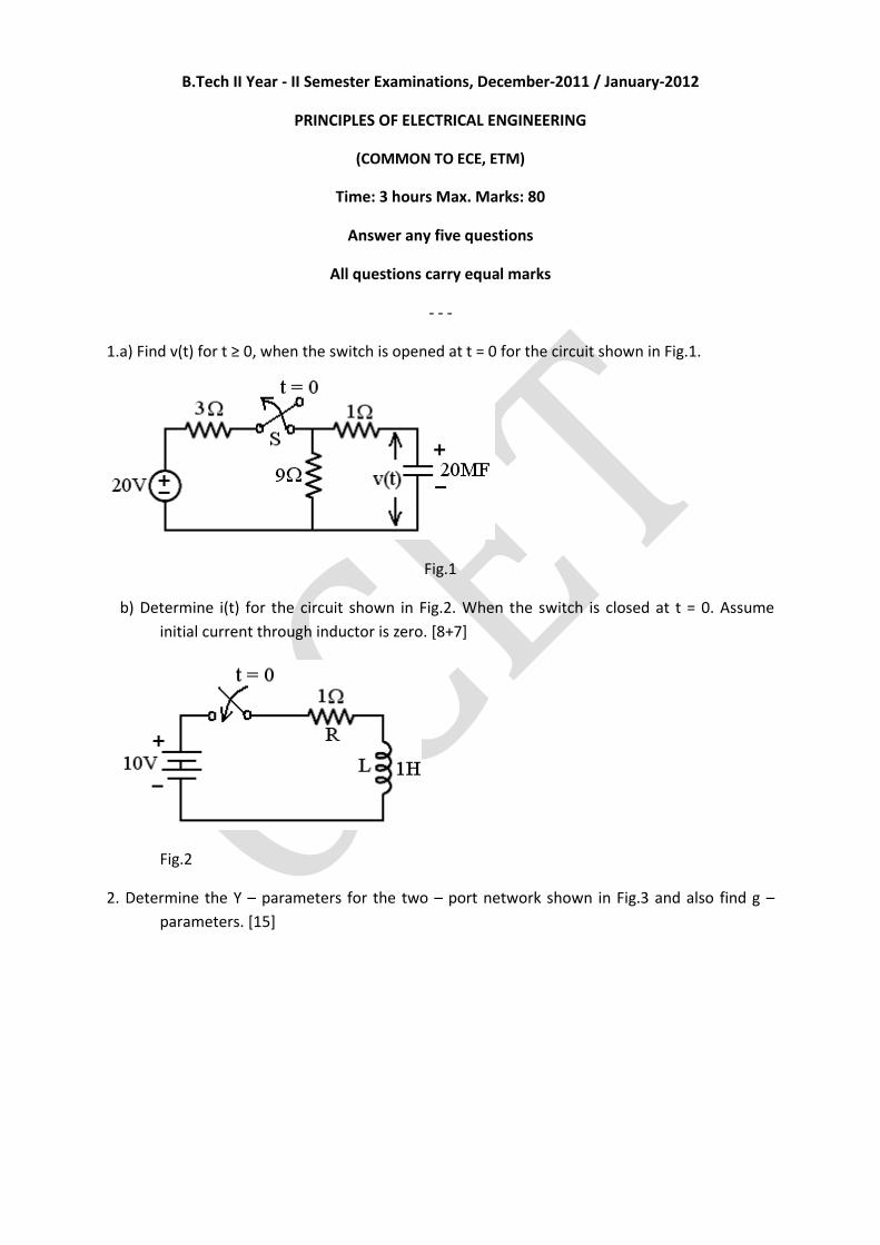
B.Tech II Year - II Semester Examinations, December-2011 / January-2012
PRINCIPLES OF ELECTRICAL ENGINEERING
(COMMON TO ECE, ETM)
Time: 3 hours Max. Marks: 80
Answer any five questions
All questions carry equal marks
- - -
1.a) Find v(t) for t ≥ 0, when the switch is opened at t = 0 for the circuit shown in Fig.1.
Fig.1
b) Determine i(t) for the circuit shown in Fig.2. When the switch is closed at t = 0. Assume
initial current through inductor is zero. [8+7]
Fig.2
2. Determine the Y – parameters for the two – port network shown in Fig.3 and also find g –
parameters. [15]
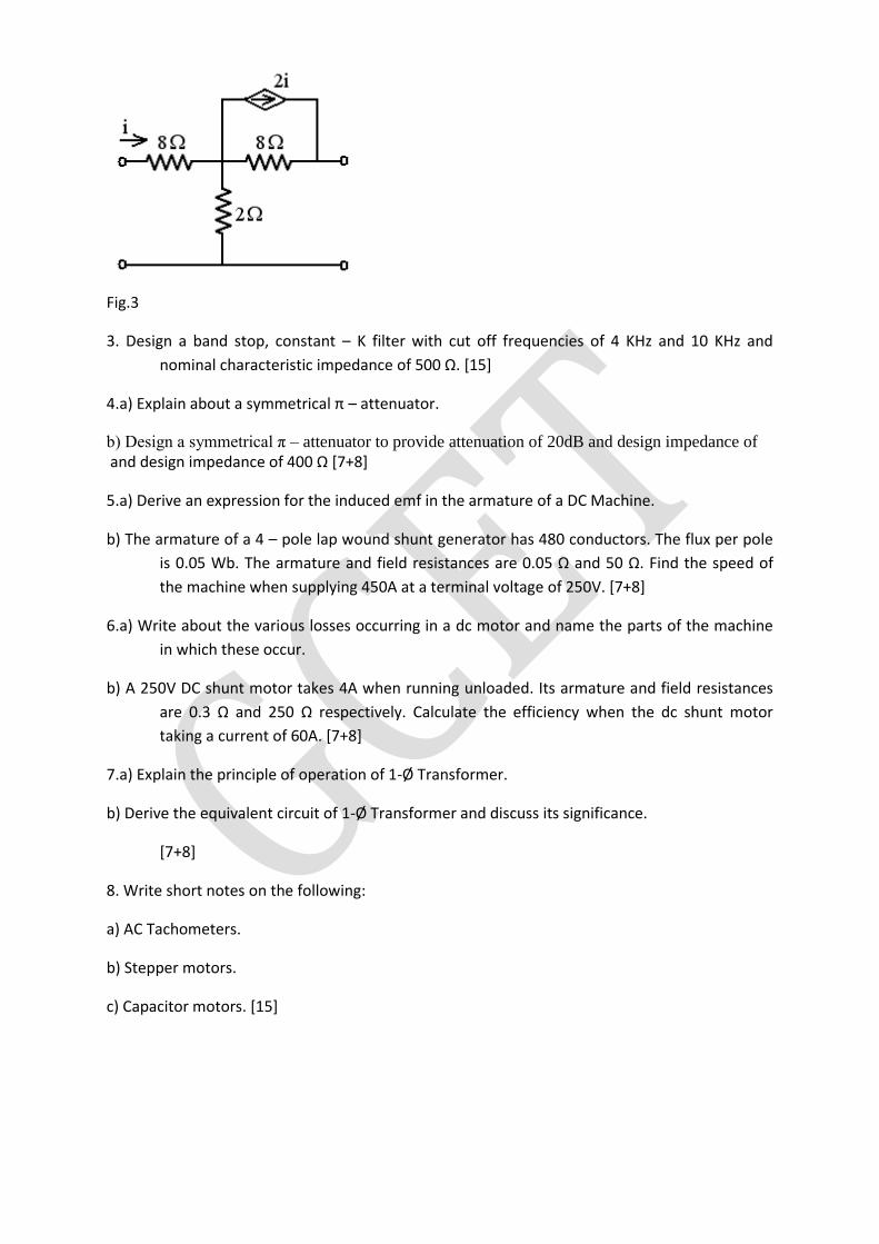
Fig.3
3. Design a band stop, constant – K filter with cut off frequencies of 4 KHz and 10 KHz and
nominal characteristic impedance of 500 Ω. [15]
4.a) Explain about a symmetrical π – attenuator.
b) Design a symmetrical π – attenuator to provide attenuation of 20dB and design impedance of and design impedance of 400 Ω [7+8]
5.a) Derive an expression for the induced emf in the armature of a DC Machine.
b) The armature of a 4 – pole lap wound shunt generator has 480 conductors. The flux per pole
is 0.05 Wb. The armature and field resistances are 0.05 Ω and 50 Ω. Find the speed of
the machine when supplying 450A at a terminal voltage of 250V. [7+8]
6.a) Write about the various losses occurring in a dc motor and name the parts of the machine
in which these occur.
b) A 250V DC shunt motor takes 4A when running unloaded. Its armature and field resistances
are 0.3 Ω and 250 Ω respectively. Calculate the efficiency when the dc shunt motor
taking a current of 60A. [7+8]
7.a) Explain the principle of operation of 1-Ø Transformer.
b) Derive the equivalent circuit of 1-Ø Transformer and discuss its significance.
[7+8]
8. Write short notes on the following:
a) AC Tachometers.
b) Stepper motors.
c) Capacitor motors. [15]
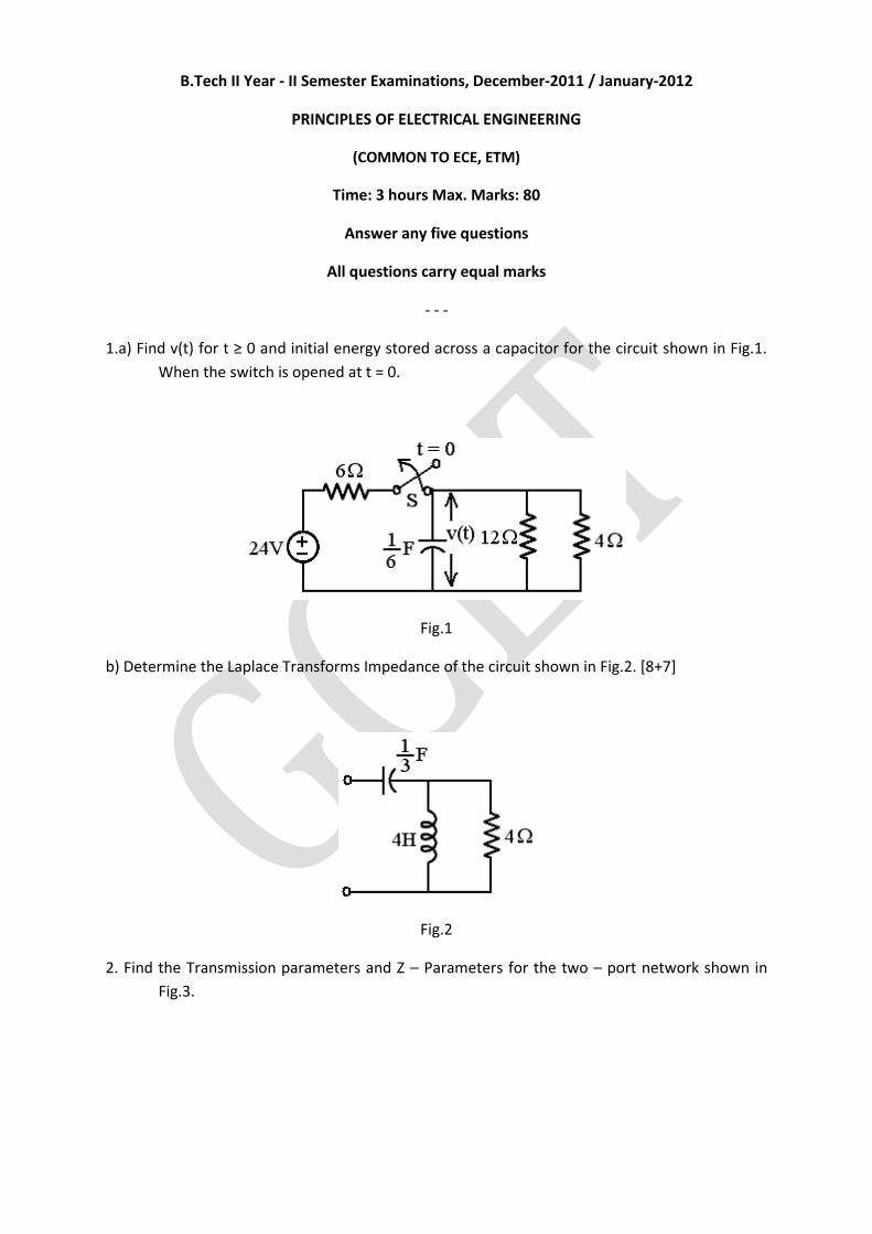
B.Tech II Year - II Semester Examinations, December-2011 / January-2012
PRINCIPLES OF ELECTRICAL ENGINEERING
(COMMON TO ECE, ETM)
Time: 3 hours Max. Marks: 80
Answer any five questions
All questions carry equal marks
- - -
1.a) Find v(t) for t ≥ 0 and initial energy stored across a capacitor for the circuit shown in Fig.1.
When the switch is opened at t = 0.
Fig.1
b) Determine the Laplace Transforms Impedance of the circuit shown in Fig.2. [8+7]
Fig.2
2. Find the Transmission parameters and Z – Parameters for the two – port network shown in
Fig.3.
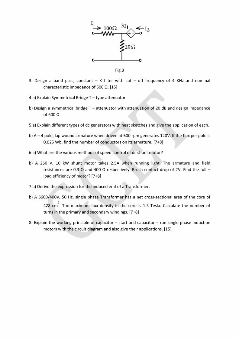
Fig.3
3. Design a band pass, constant – K filter with cut – off frequency of 4 KHz and nominal
characteristic impedance of 500 Ω. [15]
4.a) Explain Symmetrical Bridge T – type attenuator.
b) Design a symmetrical bridge T – attenuator with attenuation of 20 dB and design impedance
of 600 Ω.
5.a) Explain different types of dc generators with neat sketches and give the application of each.
b) A – 4 pole, lap wound armature when driven at 600 rpm generates 120V. If the flux per pole is
0.025 Wb, find the number of conductors on its armature. [7+8]
6.a) What are the various methods of speed control of dc shunt motor?
b) A 250 V, 10 kW shunt motor takes 2.5A when running light. The armature and field
resistances are 0.3 Ω and 400 Ω respectively. Brush contact drop of 2V. Find the full –
load efficiency of motor? [7+8]
7.a) Derive the expression for the induced emf of a Transformer.
b) A 6600/400V, 50 Hz, single phase Transformer has a net cross-sectional area of the core of
428 cm2. The maximum flux density in the core is 1.5 Tesla. Calculate the number of
turns in the primary and secondary windings. [7+8]
8. Explain the working principle of capacitor – start and capacitor – run single phase induction
motors with the circuit diagram and also give their applications. [15]
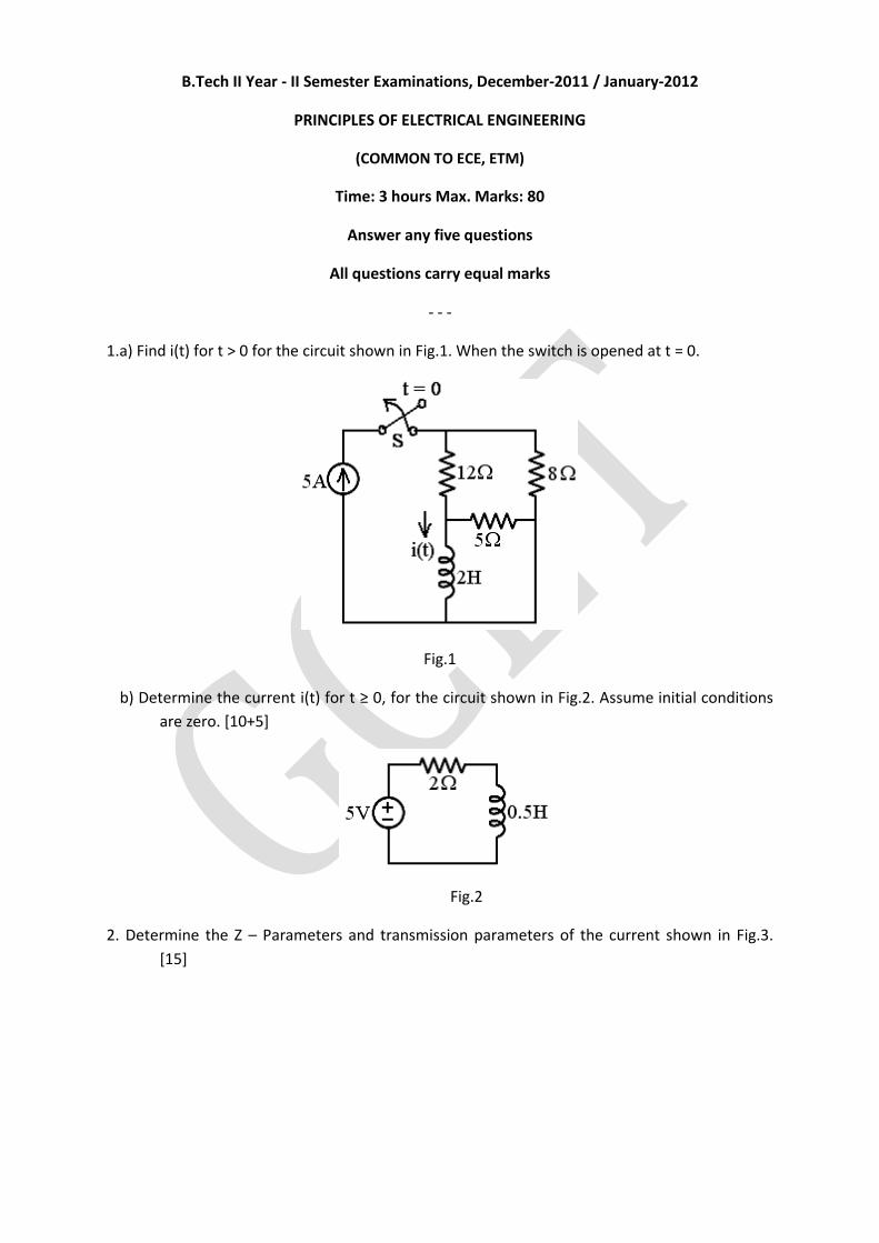
B.Tech II Year - II Semester Examinations, December-2011 / January-2012
PRINCIPLES OF ELECTRICAL ENGINEERING
(COMMON TO ECE, ETM)
Time: 3 hours Max. Marks: 80
Answer any five questions
All questions carry equal marks
- - -
1.a) Find i(t) for t > 0 for the circuit shown in Fig.1. When the switch is opened at t = 0.
Fig.1
b) Determine the current i(t) for t ≥ 0, for the circuit shown in Fig.2. Assume initial conditions
are zero. [10+5]
Fig.2
2. Determine the Z – Parameters and transmission parameters of the current shown in Fig.3.
[15]
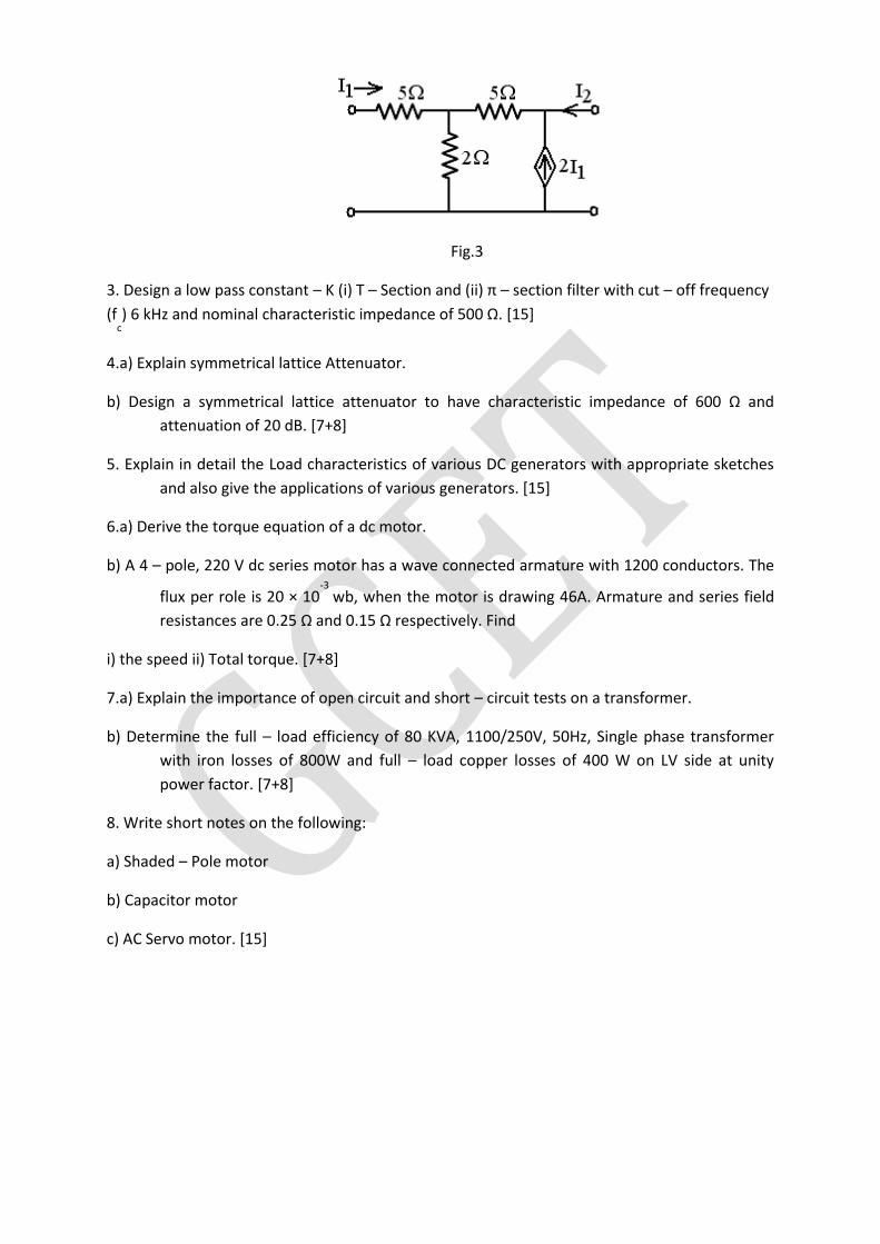
Fig.3
3. Design a low pass constant – K (i) T – Section and (ii) π – section filter with cut – off frequency
(fc) 6 kHz and nominal characteristic impedance of 500 Ω. [15]
4.a) Explain symmetrical lattice Attenuator.
b) Design a symmetrical lattice attenuator to have characteristic impedance of 600 Ω and
attenuation of 20 dB. [7+8]
5. Explain in detail the Load characteristics of various DC generators with appropriate sketches
and also give the applications of various generators. [15]
6.a) Derive the torque equation of a dc motor.
b) A 4 – pole, 220 V dc series motor has a wave connected armature with 1200 conductors. The
flux per role is 20 × 10-3
wb, when the motor is drawing 46A. Armature and series field
resistances are 0.25 Ω and 0.15 Ω respectively. Find
i) the speed ii) Total torque. [7+8]
7.a) Explain the importance of open circuit and short – circuit tests on a transformer.
b) Determine the full – load efficiency of 80 KVA, 1100/250V, 50Hz, Single phase transformer
with iron losses of 800W and full – load copper losses of 400 W on LV side at unity
power factor. [7+8]
8. Write short notes on the following:
a) Shaded – Pole motor
b) Capacitor motor
c) AC Servo motor. [15]
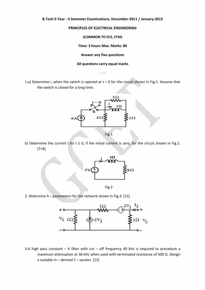
B.Tech II Year - II Semester Examinations, December-2011 / January-2012
PRINCIPLES OF ELECTRICAL ENGINEERING
(COMMON TO ECE, ETM)
Time: 3 hours Max. Marks: 80
Answer any five questions
All questions carry equal marks
- - -
1.a) Determine i, when the switch is opened at t = 0 for the circuit shown in Fig.1. Assume that
the switch is closed for a long time.
Fig.1
b) Determine the current i for t ≥ 0, if the initial current is zero, for the circuit shown in Fig.2.
[7+8]
Fig.2
2. Determine h – parameters for the network shown in Fig.3. [15]
3.A high pass constant – K filter with cut – off frequency 40 kHz is required to procedure a
maximum attenuation at 36 kHz when used with terminated resistance of 500 Ω. Design
a suitable m – derived T – section. [15]
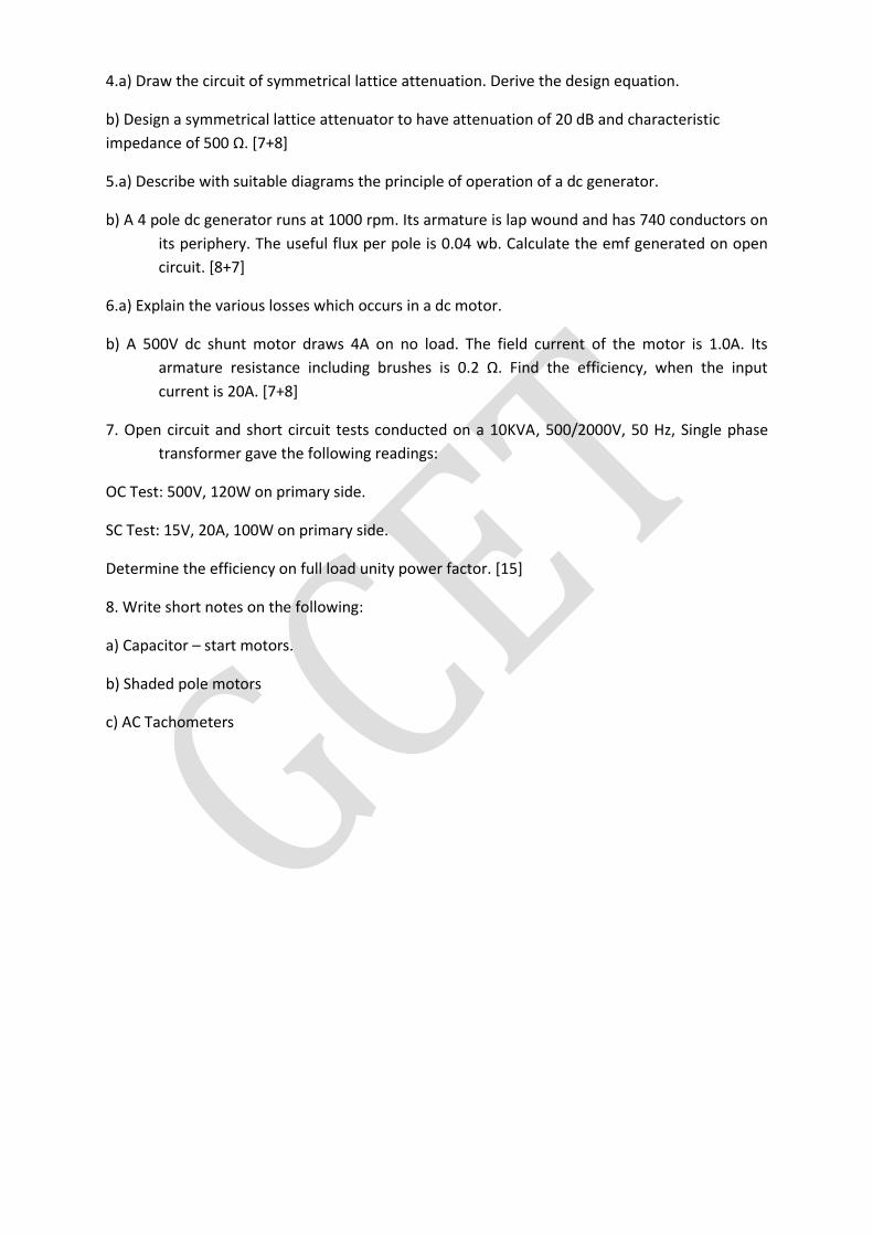
4.a) Draw the circuit of symmetrical lattice attenuation. Derive the design equation.
b) Design a symmetrical lattice attenuator to have attenuation of 20 dB and characteristic
impedance of 500 Ω. [7+8]
5.a) Describe with suitable diagrams the principle of operation of a dc generator.
b) A 4 pole dc generator runs at 1000 rpm. Its armature is lap wound and has 740 conductors on
its periphery. The useful flux per pole is 0.04 wb. Calculate the emf generated on open
circuit. [8+7]
6.a) Explain the various losses which occurs in a dc motor.
b) A 500V dc shunt motor draws 4A on no load. The field current of the motor is 1.0A. Its
armature resistance including brushes is 0.2 Ω. Find the efficiency, when the input
current is 20A. [7+8]
7. Open circuit and short circuit tests conducted on a 10KVA, 500/2000V, 50 Hz, Single phase
transformer gave the following readings:
OC Test: 500V, 120W on primary side.
SC Test: 15V, 20A, 100W on primary side.
Determine the efficiency on full load unity power factor. [15]
8. Write short notes on the following:
a) Capacitor – start motors.
b) Shaded pole motors
c) AC Tachometers
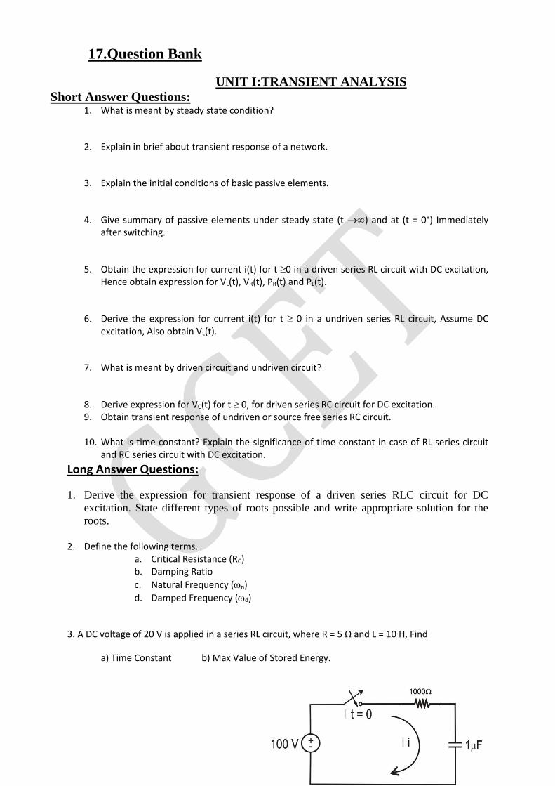
17.Question Bank
UNIT I:TRANSIENT ANALYSIS
Short Answer Questions: 1. What is meant by steady state condition?
2. Explain in brief about transient response of a network.
3. Explain the initial conditions of basic passive elements.
4. Give summary of passive elements under steady state (t ) and at (t = 0+) Immediately after switching.
5. Obtain the expression for current i(t) for t 0 in a driven series RL circuit with DC excitation, Hence obtain expression for VL(t), VR(t), PR(t) and PL(t).
6. Derive the expression for current i(t) for t 0 in a undriven series RL circuit, Assume DC excitation, Also obtain VL(t).
7. What is meant by driven circuit and undriven circuit?
8. Derive expression for VC(t) for t 0, for driven series RC circuit for DC excitation. 9. Obtain transient response of undriven or source free series RC circuit.
10. What is time constant? Explain the significance of time constant in case of RL series circuit
and RC series circuit with DC excitation.
Long Answer Questions:
1. Derive the expression for transient response of a driven series RLC circuit for DC
excitation. State different types of roots possible and write appropriate solution for the
roots.
2. Define the following terms.
a. Critical Resistance (RC) b. Damping Ratio
c. Natural Frequency (n)
d. Damped Frequency (d)
3. A DC voltage of 20 V is applied in a series RL circuit, where R = 5 Ω and L = 10 H, Find
a) Time Constant b) Max Value of Stored Energy.
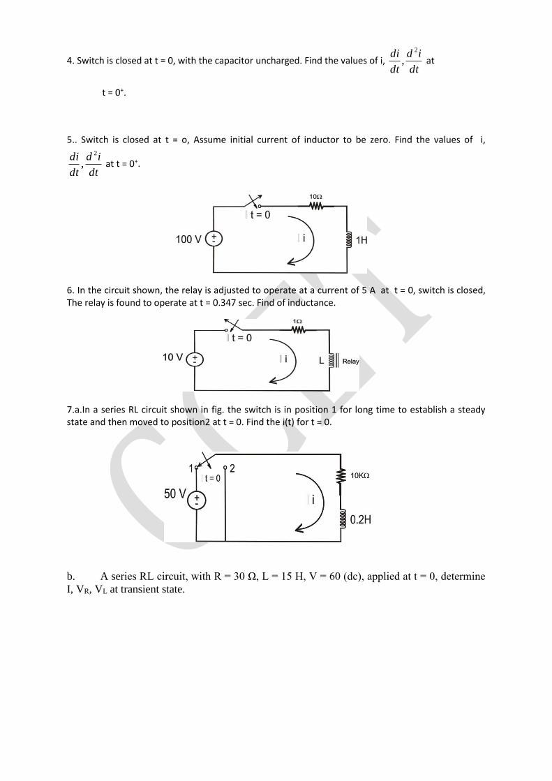
4. Switch is closed at t = 0, with the capacitor uncharged. Find the values of i, dt
id
dt
di 2
, at
t = 0+.
5.. Switch is closed at t = o, Assume initial current of inductor to be zero. Find the values of i,
dt
id
dt
di 2
, at t = 0+.
6. In the circuit shown, the relay is adjusted to operate at a current of 5 A at t = 0, switch is closed, The relay is found to operate at t = 0.347 sec. Find of inductance.
7.a.In a series RL circuit shown in fig. the switch is in position 1 for long time to establish a steady state and then moved to position2 at t = 0. Find the i(t) for t = 0.
b. A series RL circuit, with R = 30 Ω, L = 15 H, V = 60 (dc), applied at t = 0, determine
I, VR, VL at transient state.
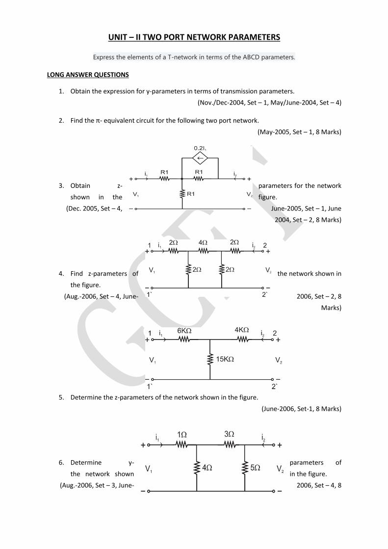
UNIT – II TWO PORT NETWORK PARAMETERS
Express the elements of a T-network in terms of the ABCD parameters.
LONG ANSWER QUESTIONS
1. Obtain the expression for y-parameters in terms of transmission parameters.
(Nov./Dec-2004, Set – 1, May/June-2004, Set – 4)
2. Find the π- equivalent circuit for the following two port network.
(May-2005, Set – 1, 8 Marks)
3. Obtain z- parameters for the network
shown in the figure.
(Dec. 2005, Set – 4, June-2005, Set – 1, June
2004, Set – 2, 8 Marks)
4. Find z-parameters of the network shown in
the figure.
(Aug.-2006, Set – 4, June- 2006, Set – 2, 8
Marks)
5. Determine the z-parameters of the network shown in the figure.
(June-2006, Set-1, 8 Marks)
6. Determine y- parameters of
the network shown in the figure.
(Aug.-2006, Set – 3, June- 2006, Set – 4, 8
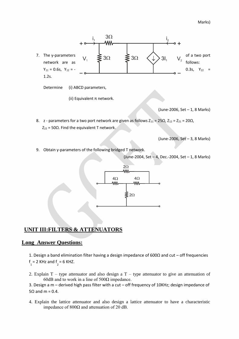
Marks)
7. The y-parameters of a two port
network are as follows:
Y11 = 0.6s, Y12 = - 0.3s, Y22 =
1.2s.
Determine (i) ABCD parameters,
(ii) Equivalent π network.
(June-2006, Set – 1, 8 Marks)
8. z - parameters for a two port network are given as follows Z11 = 25Ω, Z12 = Z21 = 20Ω,
Z22 = 50Ω. Find the equivalent T network.
(June-2006, Set – 3, 8 Marks)
9. Obtain y-parameters of the following bridged T network.
(June-2004, Set – 4, Dec.-2004, Set – 1, 8 Marks)
UNIT III:FILTERS & ATTENUATORS
Long Answer Questions:
1. Design a band elimination filter having a design impedance of 600Ω and cut – off frequencies
f1
= 2 KHz and f2
= 6 KHZ.
2. Explain T – type attenuator and also design a T – type attenuator to give an attenuation of
60dB and to work in a line of 500Ω impedance.
3. Design a m – derived high pass filter with a cut – off frequency of 10KHz; design impedance of
5Ω and m = 0.4.
4. Explain the lattice attenuator and also design a lattice attenuator to have a characteristic
impedance of 800Ω and attenuation of 20 dB.
5. What is a constant – K low pass filter, derive its characteristics impedance.
6. Explain π – type attenuator and also design it to give 20db attenuation and to have
characteristic impedance of 100Ω.
8. Design a band stop, constant – K filter with cut off frequencies of 4 KHz and 10 KHz and
nominal characteristic impedance of 500 Ω.
9.a) Explain about a symmetrical π – attenuator.
b) Design a symmetrical π – attenuator to provide attenuation of 20dB and design impedance of and design impedance of 400 Ω
10. Design a band pass, constant – K filter with cut – off frequency of 4 KHz and nominal
characteristic impedance of 500 Ω.
11.a) Explain Symmetrical Bridge T – type attenuator.
b) Design a symmetrical bridge T – attenuator with attenuation of 20 dB and design impedance of 600 Ω
UNIT IV:DC. MACHINES
Short Answer Questions:
1. What is a Machine?
2. What is a Generator?
3. Classify different types of Generators.
4. Classify different types of DC Generators.
5. What is a Motor?
6. Classify different types of Motors.
7. Classify different types of DC Motors.
8. State Fleming’s right hand rule?
9. State Fleming’s Left hand rule?
10. State various parts in a DC machine
Long Answer Questions:
1. Draw a detailed sketch of a d.c. machine and identify the different parts. Briefly
explain the function of each major part?
2. a) Explain constructional features and working principle of d.c. generator?
b) State Fleming’s right hand rule?
3. a) Derive the expression of induced e.m.f. of d.c. generator?
b) A 4 pole, lap wound d.c. generator has a useful flux of 0.07wb per pole. Calculate the
generated e.m.f when it is rotated at a speed of 900r.p.m with the help of prime mover.
armature consists of 440 number of conductors. Also calculate the generated e.m.f if lap wound
armature is replaced by wave wound armature.
4. Explain the characteristics of DC generators
5. Differentiate between slip rings and commutator in a d.c. machine?
6. What are the main parts of a d.c. machine? State the function of each part with relevant figures.
7. a ) Based on the type of excitation classify the d.c. generators?
b) A dynamo has a rated armature current of 250A.what is the current per path of the armature
if the armature winding is lap or wave connected? The machine has 12 poles.
8. What is the construction and working principle of D.C motor?
9. Explain the different types of D.C motors and their characteristics?
10. Derive an expression for the speed of a D.C. motor in terms of back emf and flux per pole.
11. Explain speed current and speed torque characteristics of D.C. shunt motor.
12. What are the applications of a D.C motor and D.C generator?
13. Derive the expressions for various torques developed in a dc motor?
14. Explain the different methods of speed control of a dc shunt motor
15. What are the different losses occurring in a d c machine? Derive the condition for maximum
efficiency of a dc motor
16. Explain the following
a. Swinburne’s test b. Brake test
UNIT V:TRANSFORMERS & THEIR APPLICATIONS
Short Answer Questions:
1.Define tansformer.
2.Why is the rating of transformer in KVA and why not in KW?
3.Classify various types of transformers depending on their construction
4. Classify various types of transformers depending on their operation.
5. What is the construction and working principle of Transformer?
Long Answer Questions:
1. What is the construction and working principle of Transformer?
2. Derive an e.m.f. equation of a single phase transformer. The maximum flux density in the core of
250/3000 volts, 50 Hz single phase transformer is 1.2 webers per square meter. If the emf per
turn is 8 volts determine primary and secondary turns and area of the core.
3. The primary winding of a 50 Hz single phase transformer has 480 turns and fed from 6400 v
supply. The secondary winding has 20 turns. Find the peak value of flux in the core and the
secondary voltage.
4. Derive an expression for voltage per turn of a transformer.
5. What are the different losses occurring in a transformer on load? How can these losses be
determined experimentally?
6. Define the voltage regulation of a transformer. Deduce the expressions for the voltage
regulation and the conditions for maximum voltage and zero voltage regulations.
7. The number of turns on the primary and secondary windings of a single phase transformer are
350 and 35 respectively. If the primary is connected to a 2.2kV,50 Hz supply, determine the
secondary voltage.
8. Draw the phasor diagrams of a single phase transformer for the following load power factors
a. Leading b. Leading c. Unity
9. Draw the equivalent circuits of a single phase transformer referred to primary as well as
secondary
10. Explain double field revolving theory
12. Explain why a single phase motor is not self starting?
13. Explain the following with phasor diagrams
a. Capacitor start and run motor b. Shaded pole motor
c. Synchro’s d. Stepper motor
e. A C tachometers f. Servomotors
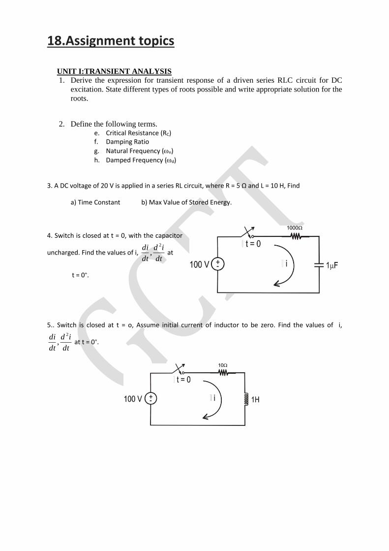
18.Assignment topics
UNIT I:TRANSIENT ANALYSIS
1. Derive the expression for transient response of a driven series RLC circuit for DC
excitation. State different types of roots possible and write appropriate solution for the
roots.
2. Define the following terms. e. Critical Resistance (RC) f. Damping Ratio
g. Natural Frequency (n)
h. Damped Frequency (d)
3. A DC voltage of 20 V is applied in a series RL circuit, where R = 5 Ω and L = 10 H, Find
a) Time Constant b) Max Value of Stored Energy.
4. Switch is closed at t = 0, with the capacitor
uncharged. Find the values of i, dt
id
dt
di 2
, at
t = 0+.
5.. Switch is closed at t = o, Assume initial current of inductor to be zero. Find the values of i,
dt
id
dt
di 2
, at t = 0+.
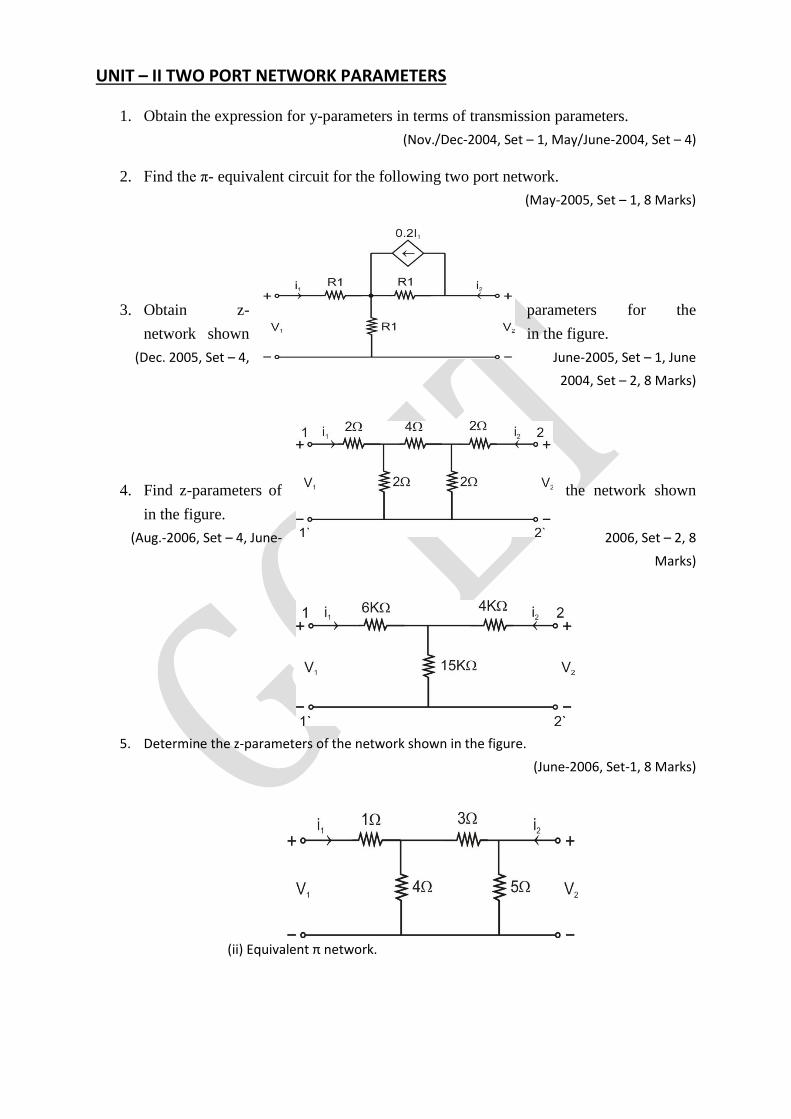
UNIT – II TWO PORT NETWORK PARAMETERS
1. Obtain the expression for y-parameters in terms of transmission parameters.
(Nov./Dec-2004, Set – 1, May/June-2004, Set – 4)
2. Find the π- equivalent circuit for the following two port network.
(May-2005, Set – 1, 8 Marks)
3. Obtain z- parameters for the
network shown in the figure.
(Dec. 2005, Set – 4, June-2005, Set – 1, June
2004, Set – 2, 8 Marks)
4. Find z-parameters of the network shown
in the figure.
(Aug.-2006, Set – 4, June- 2006, Set – 2, 8
Marks)
5. Determine the z-parameters of the network shown in the figure.
(June-2006, Set-1, 8 Marks)
(ii) Equivalent π network.
UNIT III:FILTERS & ATTENUATORS
1. Design a band elimination filter having a design impedance of 600Ω and cut – off frequencies
f1
= 2 KHz and f2
= 6 KHZ. [15]
2. Explain T – type attenuator and also design a T – type attenuator to give an attenuation of
60dB and to work in a line of 500Ω impedance. [15]
3. Design a m – derived high pass filter with a cut – off frequency of 10KHz; design impedance of
5Ω and m = 0.4. [15]
4. Explain the lattice attenuator and also design a lattice attenuator to have a characteristic
impedance of 800Ω and attenuation of 20 dB. [15]
UNIT IV:DC. MACHINES
1. Draw a detailed sketch of a d.c. machine and identify the different parts. Briefly
explain the function of each major part?
2. a) Explain constructional features and working principle of d.c. generator?
b) State Fleming’s right hand rule?
3. a) Derive the expression of induced e.m.f. of d.c. generator?
b) A 4 pole, lap wound d.c. generator has a useful flux of 0.07wb per pole. Calculate the
generated e.m.f when it is rotated at a speed of 900r.p.m with the help of prime mover.
armature consists of 440 number of conductors. Also calculate the generated e.m.f if lap wound
armature is replaced by wave wound armature.
4. What is the construction and working principle of D.C motor?
5. Explain the different types of D.C motors and their characteristics?
6. Derive an expression for the speed of a D.C. motor in terms of back emf and flux per pole.
UNIT V:TRANSFORMERS & THEIR APPLICATIONS
1. What is the construction and working principle of Transformer?
2. Derive an e.m.f. equation of a single phase transformer. The maximum flux density in the core of
250/3000 volts, 50 Hz single phase transformer is 1.2 webers per square meter. If the emf per
turn is 8 volts determine primary and secondary turns and area of the core.
3. The primary winding of a 50 Hz single phase transformer has 480 turns and fed from 6400 v
supply. The secondary winding has 20 turns. Find the peak value of flux in the core and the
secondary voltage.
4. Derive an expression for voltage per turn of a transformer.
5. What are the different losses occurring in a transformer on load? How can these losses be
determined experimentally?
19. Unit Wise Objective Questions:
UNIT I:TRANSIENT ANALYSIS
1. Laplace transform analysis gives a. time domain response only
b. Frequency domain response only.
c. Both a and b options.
2. Match the following :
(i ) Undamped a) = 0
(ii) Under damped b) = 1
(iii) Critically damped c) 1 < <
(iv) Over damped d) 0 < < 1
e) 1 > >
f) = -1
3. Match the following:
(i) Critical Resistance (RC) a) 2
R
LC
(ii) Damping ratio () b) n21
(iii) Natural frequency (n) c) LC
1
(iv) Damping frequency (d) d) 2C
L
e) RC
1
f) LC
1
4. The time constant of below network is _________________________ seconds.
5. Match the following
(i) Time const of series RL Circuit is a) only memory (L, C) elements
(ii) Time const of series RC circuit is b) only memoryless ® elements
(iii) Transient response occur’s in c) RC
(iv) Inductor do not allow sudden d) RC
1
(v) Capacitor do not allow sudden e) changes in currents.
(vi) Capacitor do not allow sudden f) changes in voltages
g) R
L
h) L
R
UNIT – II TWO PORT NETWORK PARAMETERS
1. An attenuator is a
(A) R’s network. (B) RL network.
(C) RC network. (D) LC network.
Ans: A
2. For a two port reciprocal network, the three transmission parameters are given by A = 4,
B = 7 and C = 5. The value of D is equal to
(A) 8.5 (B) 9
(C) 9.5 (D) 8
Ans: B
3.A symmetrical T network has characteristic impedance Z and propagation constant oγ .
Then the series element Z1 and shunt element Z2 are given by
(A) Z = Z sinh γ and Z 2Z tanh γ
(B) Z = Z sinh γ and Z 2Z tanh 2γ
(C) Z 2Z tan 2 γ and Z = Z sinh γ
(D) Z Z tanh 2 γ and Z = 2Z sinh γ
Ans: C
4 For a linear passive bilateral network
(A) h21 = h12 (B) h21 = −h12 (C) h12 = g12 (D) h12 = −g12
Ans: B
5. For a symmetrical network
(A) Z11 = Z22 (B) Z12 = Z21
(C) Z11 = Z22 and Z12 = Z21 (D) Z11 x Z22 – Z122=0
Ans: C
6. Bridged T network can be used as:
(A) Attenuator (B) Low pass filter
(C) High pass filter (D) Band pass filter
Ans: A
UNIT III:FILTERS & ATTENUATORS
1.The Characteristic Impedance of a low pass filter in attenuation Band is
(A) Purely imaginary. (B) Zero.
(C) Complex quantity. (D) Real value.
Ans: A
2. The purpose of an Attenuator is to:
(A) increase signal strength. (B) provide impedance matching.
(C) decrease reflections. (D) decrease value of signal strength.
Ans: D
3. In a transmission line terminated by characteristic impedance, Zo
(A) There is no reflection of the incident wave.
(B) The reflection is maximum due to termination.
(C) There are a large number of maximum and minimum on the line.
(D) The incident current is zero for any applied signal.
Ans: A
4. All pass filter
(A) passes whole of the audio band.
(B) passes whole of the radio band.
(C) passes all frequencies with very low attenuation.
(D) passes all frequencies without attenuation but phase is changed.
Ans: D
5. If ' 'α is attenuation in nepers then
(A) attenuation in dB = α / 0.8686. (B) attenuation in dB = 8.686 α.
(C) attenuation in dB = 0.1 α. (D) attenuation in dB = 0.01 α.
Ans: B
6. For an m-derived high pass filter, the cut off frequency is 4KHz and the filter has an
infinite attenuation at 3.6 KHz, the value of m is
(A) 0.436 (B) 4.36
(C) 0.34 (D) 0.6
Ans: A
7.In a variable bridged T-attenuator, with , RA = Ro zero dB attenuation can be obtained if bridge
arm RB and shunt arm R are set as C
(A) R B = ,0 RC = ∞ (B) 0 RB = ∞,RC =
(C) R B = ,R RC = ∞ (D) RB = ,0 RC = R
Ans: A
8.A constant K band-pass filter has pass-band from 1000 to 4000 Hz. The resonance frequency of
shunt and series arm is a
(A) 2500 Hz. (B) 500 Hz.
(C) 2000 Hz. (D) 3000 Hz.
Ans: C
9.A constant k low pass T-section filter has Z0 = 600Ω at zero frequency. At f = fc the characteristic
impedance is
(A) 600Ω (B) 0
(C) ∞ (D) More than 600Ω
Ans: B
10. In m-derived terminating half sections, m =
(A) 0.1 (B) 0.3
(C) 0.6 (D) 0.95
Ans: C
11. In the m-derived HPF, the resonant frequency is to be chosen so that it is
(A) above the cut-off frequency. (B) Below the cut-off frequency.
(C) equal to the cut-off frequency. (D) None of these.
12. An A transmission line works as an
(A) Attenuator (B) LPF
(C) HPF (D) Neither of the above
Ans: B
UNIT IV:DC MACHINES
1. A machine that converts mechanical energy into electrical energy of d.c in nature is called
a) a.c motor b) d.c. generator
c) a.c generator d) d.c motor
2. The basic principle of working of a d.c. generator is by
a) Faradays law of electromagnetic induction b) Maxwells cork screw rule
c) Flemings left hand rule d) Amperes thumb rule
3. The basic essential parts of electrical generator are
a) Magnetic field and insulator b) Electric field and insulator
c) Magnetic field and conductor d) Electric field and conductor
4. The direction of induced e.m.f in a generator depends upon the direction of
a) Electric field b) Magnetic field
c) motion of the conductor d) none of the above
5. The direction of the motion of conductor in generator is given by
a) Flemings left hand rule b) Flemings right hand rule
c) Amperes thumb rule d) Maxwells cork screw rule
6. The armature of the d.c .generator is made up of cast iron or cast steel because
a) it has to provide low reluctance path b) it has to provide high reluctance path
c) both d) none
7. Which of the following is applicable to a d.c. machine with respect to the field windings?
a) It is always placed on stator b) It is always placed on rotor
c) Sometimes on rotor d) May be on rotor or stator.
8. The armature core of d.c. machine is made up of __________
a) solid aluminum b) laminated aluminum
c) solid steel d) laminated steel.
9. Which of the following is function of the brushes in case of d.c. machine?
a) To convert a.c. to d.c. b) To convert to d.c. to a.c.
c) To collect current and deliver to the load
d) May be conversion for a.c. to d.c. or d.c. to a.c.
10. The number of commutator segments must be __________
a) twice the number of armature coils b) equal to the number of armature coils
c) half the number of armature coils d) thrice the number of armature coils.
11. The direction of generated e.m.f. in d.c. generator is determined by _________
a) Lenz’s law b) Faraday’s law
c) Fleming’s left hand rule d) Fleming’s right hand rule.
12. Which of the following gives the expression for the generated voltage in a d.c. generator?
a) 4.44 Z NP b) 4.44/ Z NP
c) Z NP / A 60 d) zero.
13. Which of the following forms of energy conversion take place in an electrical energy system?
a) Mechanical to electrical b) Electrical to mechanical
c) Mechanical to thermal d) Thermal to Mechanical
14. Which of the following is a function of the commutator in d.c. generator?
a) to act as a rectifier b) to act as a inverter
c) to act as a junction box per connection the armature winding ends.
d) to act as a chopper.
15. A shunt generator cannot excite, if the field resistance is ________ critical value.
a) less than b) more than
c) equal to d) none
16. Laminations are used in d.c. machine to reduce
a) eddy current losses b) Hysteresis losses
c) copper losses d) none
17. In a cumulative compound generator flux produced by shunt field winding and series field
winding ---------------- each other
a) aids b) opposes
c) nullifies d) none
18. In a differential compound generator flux produced by shunt field winding and series field
winding ------------ each other
a) aids b) opposes c) nullifies d) none
19. The field winding is also called as
a) exciting winding b) armature winding
c) both d) none
20. Brushes are normally made up of soft material like
a) carbon b) aluminum
c) cast steel d) cast iron
21. A d.c motor is used to……….
a) generate power
b) change mechanical energy to electrical energy
c) change electrical energy to mechanical energy d) increase energy put into it
22. A d.c motor is still used in industrial applications because it…..
a) is cheap b) is simple in construction
c) provides fine speed control d) none of the above
23. Carbon brushes are preferable to Copper brushes because….
a) they have longer life b) they reduce armature reaction
c) they have lower resistance d) they reduce sparking
24. The field poles and armature of d.c machine are laminated to…..
a) reduce the weight of the machine b) decreases the speed
c) reduce eddy currents d) reduce armature reaction
25. The back e.m.f in a d.c motor………
a) oppose the applied voltage b) aids the applied voltage
c) adds the armature current d) none of the above
26. The value of back e.m.f ( bE ) in a d.c motor is maximum at…..
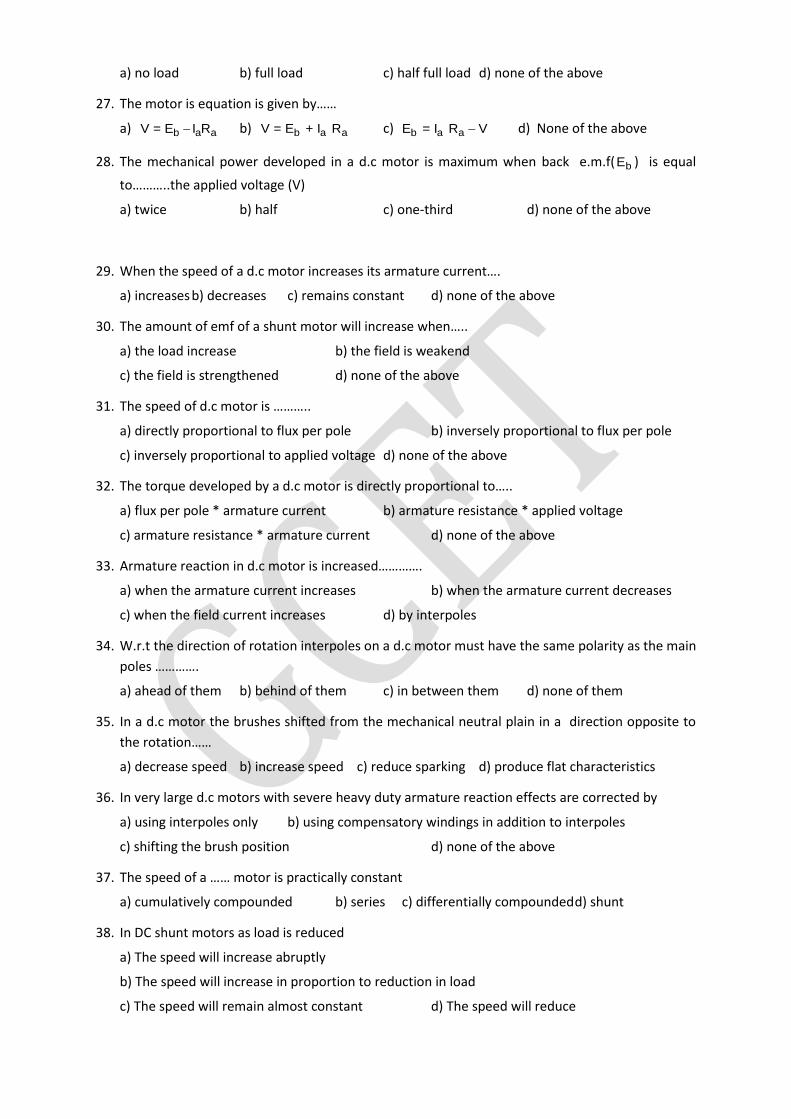
a) no load b) full load c) half full load d) none of the above
27. The motor is equation is given by……
a) b a aV = E I R b) b a aV = E + I R c) b a aE = I R V d) None of the above
28. The mechanical power developed in a d.c motor is maximum when back e.m.f( bE ) is equal
to………..the applied voltage (V)
a) twice b) half c) one-third d) none of the above
29. When the speed of a d.c motor increases its armature current….
a) increases b) decreases c) remains constant d) none of the above
30. The amount of emf of a shunt motor will increase when…..
a) the load increase b) the field is weakend
c) the field is strengthened d) none of the above
31. The speed of d.c motor is ………..
a) directly proportional to flux per pole b) inversely proportional to flux per pole
c) inversely proportional to applied voltage d) none of the above
32. The torque developed by a d.c motor is directly proportional to…..
a) flux per pole * armature current b) armature resistance * applied voltage
c) armature resistance * armature current d) none of the above
33. Armature reaction in d.c motor is increased………….
a) when the armature current increases b) when the armature current decreases
c) when the field current increases d) by interpoles
34. W.r.t the direction of rotation interpoles on a d.c motor must have the same polarity as the main
poles ………….
a) ahead of them b) behind of them c) in between them d) none of them
35. In a d.c motor the brushes shifted from the mechanical neutral plain in a direction opposite to
the rotation……
a) decrease speed b) increase speed c) reduce sparking d) produce flat characteristics
36. In very large d.c motors with severe heavy duty armature reaction effects are corrected by
a) using interpoles only b) using compensatory windings in addition to interpoles
c) shifting the brush position d) none of the above
37. The speed of a …… motor is practically constant
a) cumulatively compounded b) series c) differentially compounded d) shunt
38. In DC shunt motors as load is reduced
a) The speed will increase abruptly
b) The speed will increase in proportion to reduction in load
c) The speed will remain almost constant d) The speed will reduce

39. What will happen if the back emf of a DC motor vanishes
a) The motor will stop b) The motor will continue to run
c) The armature may burn d) The motor will run noisy
40. Small DC motors up to 5HP usually have
a) 2 poles b) 4 poles c) 6 poles d) 8 poles
UNIT V:TRANSFORMERS & THEIR APPLICATIONS
1. A transformer will work on _________
a) a.c only b) d.c only
c) a.c as well as d.c d) none of the above
2. The primary and secondary of a transformer are ………………. Coupled
a) electrically b)magnetically
c) electrically & magnetically d) none of the above
3. A transformer is an efficient device because it ………………
a) is a static device b) uses inductive coupling
c) Uses capacitve coupling d) Uses electric coupling
4. The voltage per turn of the primary of transformer is……. The voltage for turn of the secondary
a) more than b) less than
c) the same as d) none of the above
5. The iron core is used to…….. of the transformer
a) increase the weight b) provide tight magnetic coupling
c) reduce core losses d) none of the above
6. The maximum flux produced in the core of a transformer
a) directly proportional to supply frequency
b) inversely proportional to supply frequency
c) inversely proportional to primary voltage
d) none of the above
7. When the primary of a transformer is connected to a d.c supply…………
a) primary draws small current
b) primary leakage reactance is increased
c) core losses are increased
d) primary may burn out
8. An ideal transformer is one which………
a) has no losses and leakage reactance
b) does not work
c) as same number of primary and secondary turns
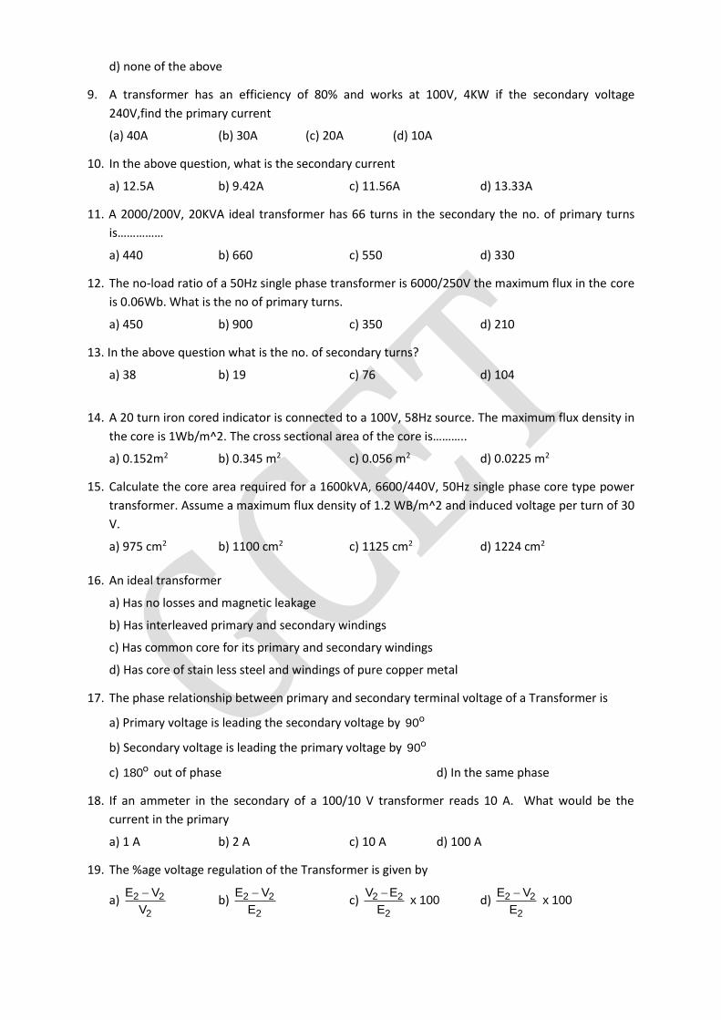
d) none of the above
9. A transformer has an efficiency of 80% and works at 100V, 4KW if the secondary voltage
240V,find the primary current
(a) 40A (b) 30A (c) 20A (d) 10A
10. In the above question, what is the secondary current
a) 12.5A b) 9.42A c) 11.56A d) 13.33A
11. A 2000/200V, 20KVA ideal transformer has 66 turns in the secondary the no. of primary turns
is……………
a) 440 b) 660 c) 550 d) 330
12. The no-load ratio of a 50Hz single phase transformer is 6000/250V the maximum flux in the core
is 0.06Wb. What is the no of primary turns.
a) 450 b) 900 c) 350 d) 210
13. In the above question what is the no. of secondary turns?
a) 38 b) 19 c) 76 d) 104
14. A 20 turn iron cored indicator is connected to a 100V, 58Hz source. The maximum flux density in
the core is 1Wb/m^2. The cross sectional area of the core is………..
a) 0.152m2 b) 0.345 m2 c) 0.056 m2 d) 0.0225 m2
15. Calculate the core area required for a 1600kVA, 6600/440V, 50Hz single phase core type power
transformer. Assume a maximum flux density of 1.2 WB/m^2 and induced voltage per turn of 30
V.
a) 975 cm2 b) 1100 cm2 c) 1125 cm2 d) 1224 cm2
16. An ideal transformer
a) Has no losses and magnetic leakage
b) Has interleaved primary and secondary windings
c) Has common core for its primary and secondary windings
d) Has core of stain less steel and windings of pure copper metal
17. The phase relationship between primary and secondary terminal voltage of a Transformer is
a) Primary voltage is leading the secondary voltage by ο90
b) Secondary voltage is leading the primary voltage by ο90
c) ο180 out of phase d) In the same phase
18. If an ammeter in the secondary of a 100/10 V transformer reads 10 A. What would be the
current in the primary
a) 1 A b) 2 A c) 10 A d) 100 A
19. The %age voltage regulation of the Transformer is given by
a) 2 2
2
E V
V
b) 2 2
2
E V
E
c) 2 2
2
V E x 100
E
d) 2 2
2
E V x 100
E
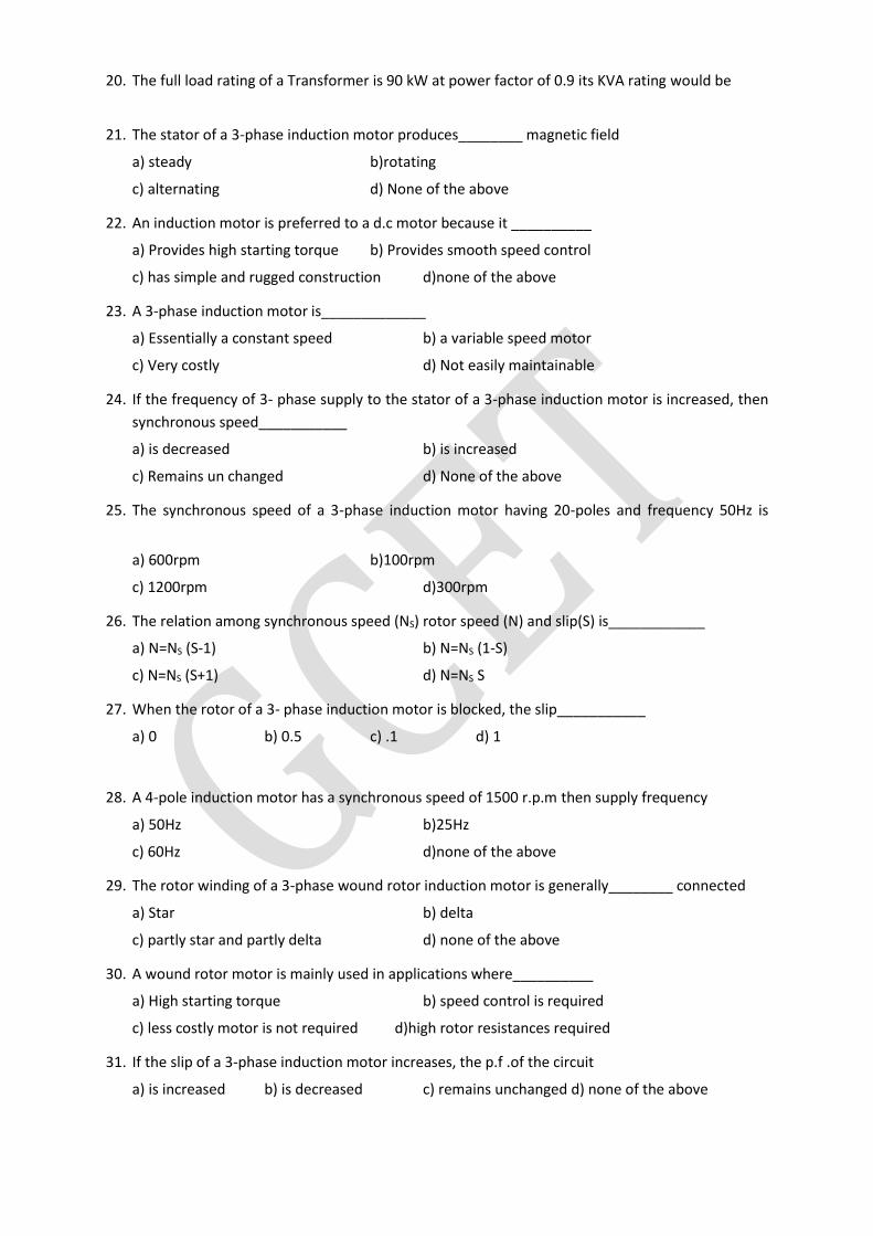
20. The full load rating of a Transformer is 90 kW at power factor of 0.9 its KVA rating would be
21. The stator of a 3-phase induction motor produces________ magnetic field
a) steady b)rotating
c) alternating d) None of the above
22. An induction motor is preferred to a d.c motor because it __________
a) Provides high starting torque b) Provides smooth speed control
c) has simple and rugged construction d)none of the above
23. A 3-phase induction motor is_____________
a) Essentially a constant speed b) a variable speed motor
c) Very costly d) Not easily maintainable
24. If the frequency of 3- phase supply to the stator of a 3-phase induction motor is increased, then
synchronous speed___________
a) is decreased b) is increased
c) Remains un changed d) None of the above
25. The synchronous speed of a 3-phase induction motor having 20-poles and frequency 50Hz is
a) 600rpm b)100rpm
c) 1200rpm d)300rpm
26. The relation among synchronous speed (NS) rotor speed (N) and slip(S) is____________
a) N=NS (S-1) b) N=NS (1-S)
c) N=NS (S+1) d) N=NS S
27. When the rotor of a 3- phase induction motor is blocked, the slip___________
a) 0 b) 0.5 c) .1 d) 1
28. A 4-pole induction motor has a synchronous speed of 1500 r.p.m then supply frequency
a) 50Hz b)25Hz
c) 60Hz d)none of the above
29. The rotor winding of a 3-phase wound rotor induction motor is generally________ connected
a) Star b) delta
c) partly star and partly delta d) none of the above
30. A wound rotor motor is mainly used in applications where__________
a) High starting torque b) speed control is required
c) less costly motor is not required d)high rotor resistances required
31. If the slip of a 3-phase induction motor increases, the p.f .of the circuit
a) is increased b) is decreased c) remains unchanged d) none of the above
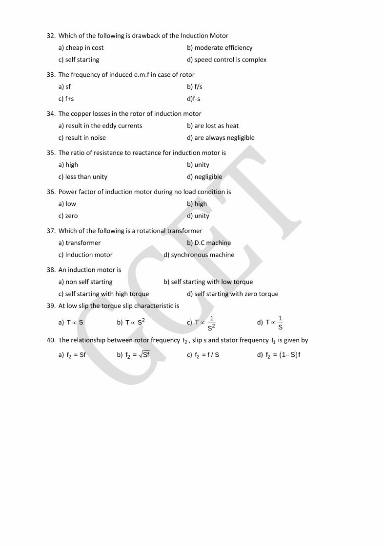
32. Which of the following is drawback of the Induction Motor
a) cheap in cost b) moderate efficiency
c) self starting d) speed control is complex
33. The frequency of induced e.m.f in case of rotor
a) sf b) f/s
c) f+s d)f-s
34. The copper losses in the rotor of induction motor
a) result in the eddy currents b) are lost as heat
c) result in noise d) are always negligible
35. The ratio of resistance to reactance for induction motor is
a) high b) unity
c) less than unity d) negligible
36. Power factor of induction motor during no load condition is
a) low b) high
c) zero d) unity
37. Which of the following is a rotational transformer
a) transformer b) D.C machine
c) Induction motor d) synchronous machine
38. An induction motor is
a) non self starting b) self starting with low torque
c) self starting with high torque d) self starting with zero torque
39. At low slip the torque slip characteristic is
a) T S b) 2T S c) 2
1T
S d)
1T
S
40. The relationship between rotor frequency 2f , slip s and stator frequency 1f is given by
a) 2f = Sf b) 2f = Sf c) 2f = f / S d) 2f = 1 S f
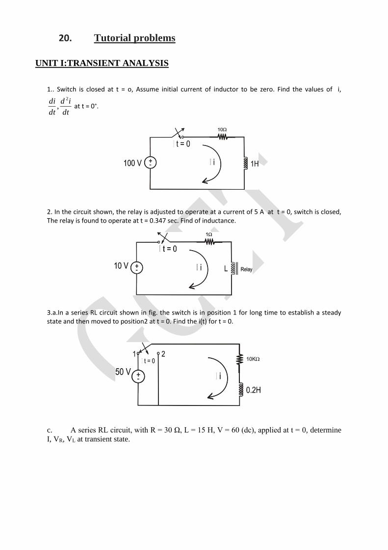
20. Tutorial problems
UNIT I:TRANSIENT ANALYSIS
1.. Switch is closed at t = o, Assume initial current of inductor to be zero. Find the values of i,
dt
id
dt
di 2
, at t = 0+.
2. In the circuit shown, the relay is adjusted to operate at a current of 5 A at t = 0, switch is closed, The relay is found to operate at t = 0.347 sec. Find of inductance.
3.a.In a series RL circuit shown in fig. the switch is in position 1 for long time to establish a steady state and then moved to position2 at t = 0. Find the i(t) for t = 0.
c. A series RL circuit, with R = 30 Ω, L = 15 H, V = 60 (dc), applied at t = 0, determine
I, VR, VL at transient state.
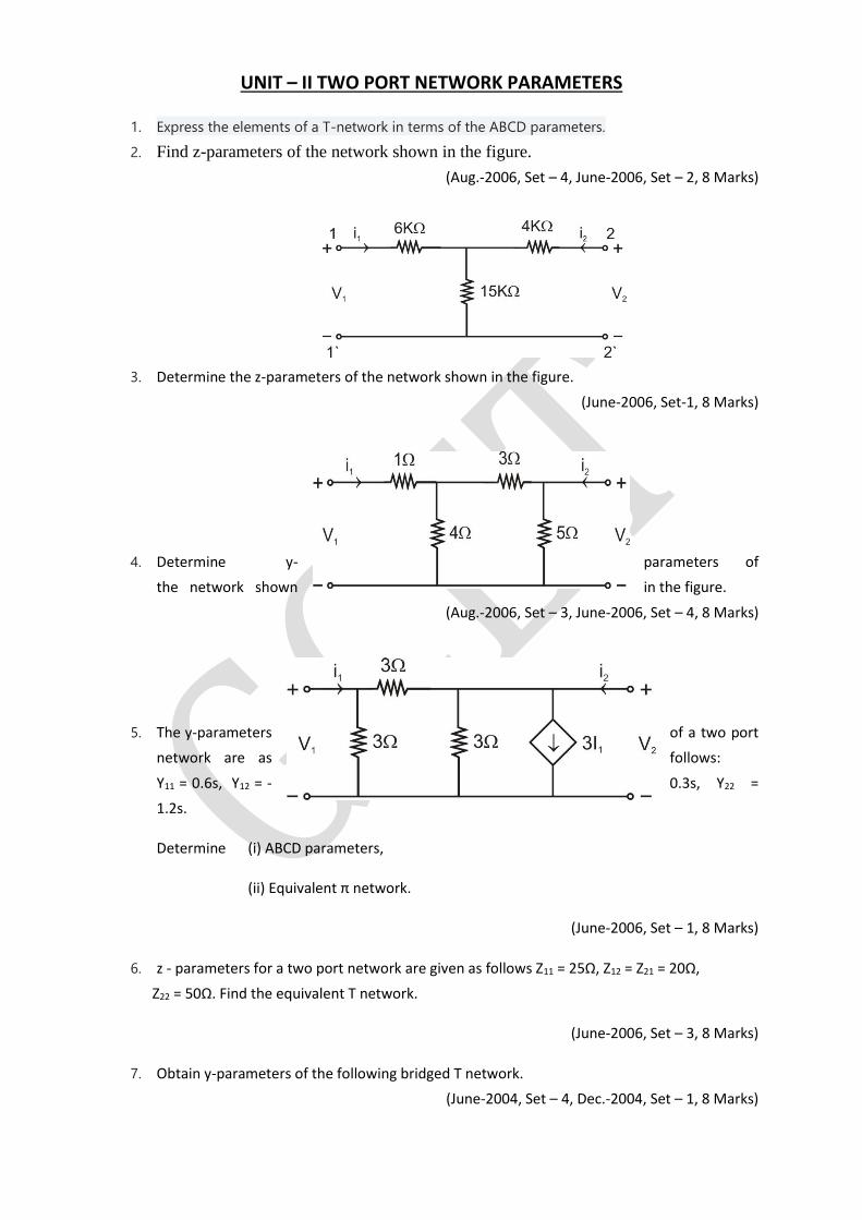
UNIT – II TWO PORT NETWORK PARAMETERS
1. Express the elements of a T-network in terms of the ABCD parameters.
2. Find z-parameters of the network shown in the figure.
(Aug.-2006, Set – 4, June-2006, Set – 2, 8 Marks)
3. Determine the z-parameters of the network shown in the figure.
(June-2006, Set-1, 8 Marks)
4. Determine y- parameters of
the network shown in the figure.
(Aug.-2006, Set – 3, June-2006, Set – 4, 8 Marks)
5. The y-parameters of a two port
network are as follows:
Y11 = 0.6s, Y12 = - 0.3s, Y22 =
1.2s.
Determine (i) ABCD parameters,
(ii) Equivalent π network.
(June-2006, Set – 1, 8 Marks)
6. z - parameters for a two port network are given as follows Z11 = 25Ω, Z12 = Z21 = 20Ω,
Z22 = 50Ω. Find the equivalent T network.
(June-2006, Set – 3, 8 Marks)
7. Obtain y-parameters of the following bridged T network.
(June-2004, Set – 4, Dec.-2004, Set – 1, 8 Marks)
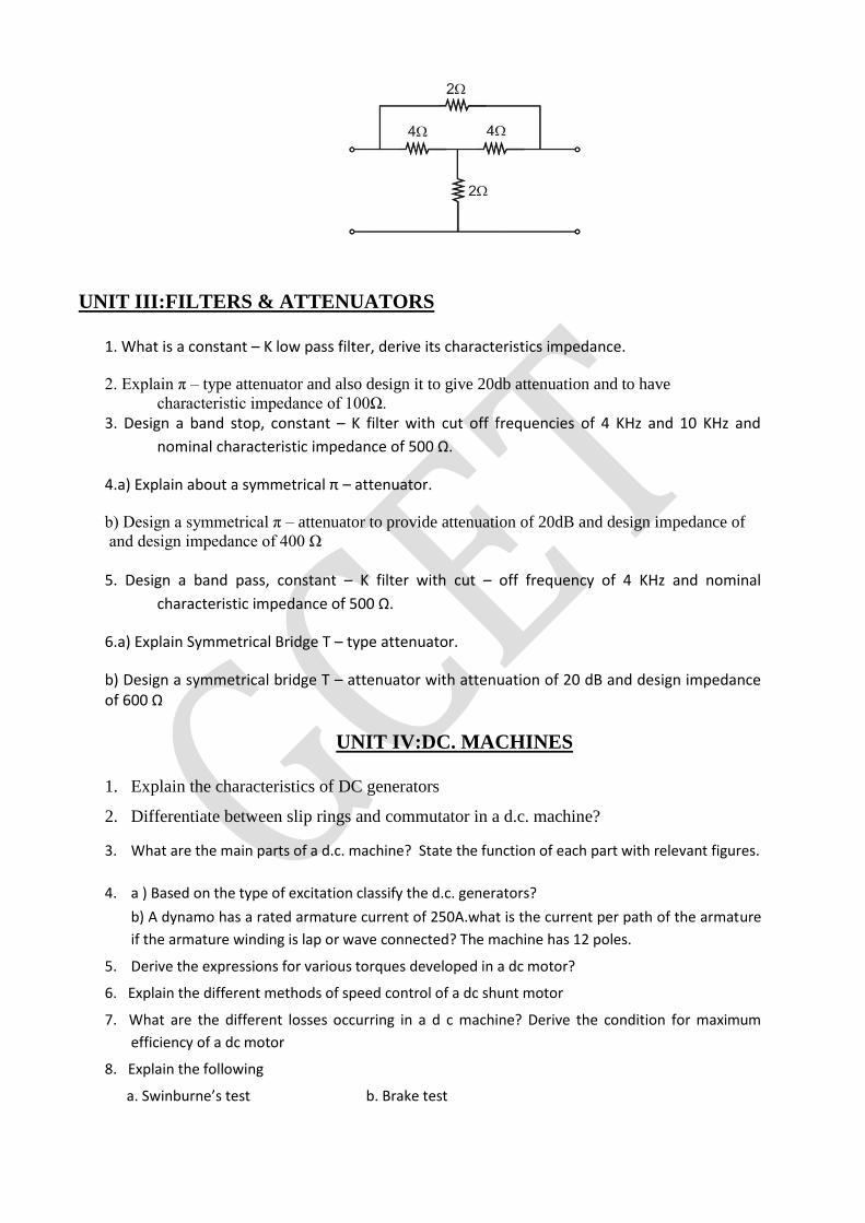
UNIT III:FILTERS & ATTENUATORS
1. What is a constant – K low pass filter, derive its characteristics impedance.
2. Explain π – type attenuator and also design it to give 20db attenuation and to have
characteristic impedance of 100Ω.
3. Design a band stop, constant – K filter with cut off frequencies of 4 KHz and 10 KHz and
nominal characteristic impedance of 500 Ω.
4.a) Explain about a symmetrical π – attenuator.
b) Design a symmetrical π – attenuator to provide attenuation of 20dB and design impedance of and design impedance of 400 Ω
5. Design a band pass, constant – K filter with cut – off frequency of 4 KHz and nominal
characteristic impedance of 500 Ω.
6.a) Explain Symmetrical Bridge T – type attenuator.
b) Design a symmetrical bridge T – attenuator with attenuation of 20 dB and design impedance of 600 Ω
UNIT IV:DC. MACHINES
1. Explain the characteristics of DC generators
2. Differentiate between slip rings and commutator in a d.c. machine?
3. What are the main parts of a d.c. machine? State the function of each part with relevant figures.
4. a ) Based on the type of excitation classify the d.c. generators?
b) A dynamo has a rated armature current of 250A.what is the current per path of the armature
if the armature winding is lap or wave connected? The machine has 12 poles.
5. Derive the expressions for various torques developed in a dc motor?
6. Explain the different methods of speed control of a dc shunt motor
7. What are the different losses occurring in a d c machine? Derive the condition for maximum
efficiency of a dc motor
8. Explain the following
a. Swinburne’s test b. Brake test
UNIT V:TRANSFORMERS & THEIR APPLICATIONS
1. Derive an e.m.f. equation of a single phase transformer. The maximum flux density in the core of
250/3000 volts, 50 Hz single phase transformer is 1.2 webers per square meter. If the emf per
turn is 8 volts determine primary and secondary turns and area of the core.
2. The primary winding of a 50 Hz single phase transformer has 480 turns and fed from 6400 v
supply. The secondary winding has 20 turns. Find the peak value of flux in the core and the
secondary voltage.
3 The number of turns on the primary and secondary windings of a single phase transformer are
350 and 35 respectively. If the primary is connected to a 2.2kV,50 Hz supply, determine the
secondary voltage.
4. Draw the phasor diagrams of a single phase transformer for the following load power factors
a. Leading b. Leading c. Unity
5. Draw the equivalent circuits of a single phase transformer referred to primary as well as
secondary
6. a. Capacitor start and run motor b. Shaded pole motor
c. Synchro’s d. Stepper motor
e. A C tachometers f. Servomotors
21. Known gaps if any
NIL
22. Discussion questions
UNIT1: 1) Derive expression for transient response of a driven series RLC circuit for DC excitation.State different types of roots possible and write appropriate solution for the roots 2)What is time constant?Explain the significance of time constant in case of series RC circuit 3)Obtain transient response of undriven or sourse free series RC CIRCUIT UNIT 2: 1) Obtain the expression for y-parameters in terms of transmission
parameters.
2) Define h parameters and draw the equivalent circuit for the same
3) Derive condition of symmetry for ABCD parameters
UNIT 3:
1) Explain about a symmetrical π – attenuator
2) Design a band stop, constant – K filter with cut off frequencies of 4 KHz and 10
KHz and nominal characteristic impedance of 500 Ω. [15]
3) Explain Symmetrical Bridge T – type attenuator.
UNIT 4:
1)Derive the expressions for various torques developed in a dc
motor?
2) Explain constructional features and working principle of d.c.
generator?
UNIT5:
1) Draw the equivalent circuits of a single phase transformer referred
to primary as well secondary
2) Derive the expression for the induced emf of a transformer
23. References, Journals, websites and E-links 1Electric circuits- A.Chakrabarthy, Dhanipat Rai & Sons.
2.Basic concepts of Electrical Engineering- PS Subramanyam, BS Publications
3.Engineering Circuit Analysis – W.H.Hayt and J. E. Kermmerly and S. M. Durbin 6 ed., 2008 TMH. 4.Basic Electrical Engineering- S.N.Singh, PHI. 6. Electrical Circuits- David A.Bell, Oxford University Press. 7. Electric Circuit Analysis- K.S.Suresh Kumar, Pearson Education. 8. Electrical Circuits- N.Sreenivasulu.
24:Quality sheets:
To be attached
25. Student List
To be attached
26. GroupWise Student List for discussion topics
To be attached
Related Documents