February 2007 CA08101001E For more information visit: www.eaton.com Contents Power System Studies, Field Services & Retrofits 27-1 27 Asset Optimization, Knowledge Management, Power System Modernization Power System Studies, Field Services & Retrofits Power System Studies, Field Services & Retrofits Overview of Services . . . . . . . . . . . . . . . . . . . . . . . . . . . . . . . . . . . . . . . . . . 27-2 Asset Optimization, Knowledge Management & Product Life Extension . . . . . . . . . . . . . . . . . . . . . . . . . . . . . . . . . . . 27-4 Power Systems Automation Group . . . . . . . . . . . . . . . . . . . . . . . . . . . . 27-6 Instant Response Center Services . . . . . . . . . . . . . . . . . . . . . . . . . . . . . 27-7 Customized High Resistance Grounding Units . . . . . . . . . . . . . . . . . . . 27-7 Power System Studies . . . . . . . . . . . . . . . . . . . . . . . . . . . . . . . . . . . . . . . . . 27-8 Arc Flash, Short Circuit and Coordination Studies . . . . . . . . . . . . . . . . 27-8 Load Flow/Power Factor Correction Studies . . . . . . . . . . . . . . . . . . . . . 27-10 Harmonic Analysis Study . . . . . . . . . . . . . . . . . . . . . . . . . . . . . . . . . . . . 27-11 Field Engineering Services . . . . . . . . . . . . . . . . . . . . . . . . . . . . . . . . . . . . . 27-12 Predictive Diagnostics . . . . . . . . . . . . . . . . . . . . . . . . . . . . . . . . . . . . . . . . . 27-18 Partial Discharge Testing . . . . . . . . . . . . . . . . . . . . . . . . . . . . . . . . . . . . 27-18 Online Monitoring and Analysis . . . . . . . . . . . . . . . . . . . . . . . . . . . . . . 27-21 Retrofit Services — Life Extension & Modernization Services . . . . . . . . . 27-22 Medium Voltage Vacuum Replacement Circuit Breakers. . . . . . . . . . . 27-22 AR Series Low Voltage Replacement Breakers . . . . . . . . . . . . . . . . . . . 27-27 Low Voltage Power Circuit Breaker Reconditioning . . . . . . . . . . . . . . . 27-28 Arc Flash Retrofit . . . . . . . . . . . . . . . . . . . . . . . . . . . . . . . . . . . . . . . . . . . 27-31 Digitrip Microprocessor Trip Unit Retrofit Kits . . . . . . . . . . . . . . . . . . . 27-32 DS/DSII Breaker Vacuum Starter Replacement . . . . . . . . . . . . . . . . . . 27-35 MCC Replacement Units . . . . . . . . . . . . . . . . . . . . . . . . . . . . . . . . . . . . . 27-37 Full Service Providers: System Audits, Studies, Modernization, Life Extension, Preventive and Predictive Maintenance, Startup and Complete Turnkey Projects Asset Optimization, Knowledge Management, Integrated Project and Power System Engineering Solutions; Power Systems Modernization; New Equipment Services; Field Services

Welcome message from author
This document is posted to help you gain knowledge. Please leave a comment to let me know what you think about it! Share it to your friends and learn new things together.
Transcript

February 2007
CA08101001E For more information visit:
www.eaton.com
Contents
Power System Studies, Field Services & Retrofits 27-1
27
Asset Optimization, Knowledge Management, Power System Modernization
Po
wer
Syste
m S
tud
ies,
Fie
ld S
erv
ices &
Retr
ofi
ts
Power System Studies, Field Services & Retrofits
Overview of Services . . . . . . . . . . . . . . . . . . . . . . . . . . . . . . . . . . . . . . . . . .
27-2
Asset Optimization, Knowledge Management & Product Life Extension . . . . . . . . . . . . . . . . . . . . . . . . . . . . . . . . . . .
27-4
Power Systems Automation Group. . . . . . . . . . . . . . . . . . . . . . . . . . . .
27-6
Instant Response Center Services . . . . . . . . . . . . . . . . . . . . . . . . . . . . .
27-7
Customized High Resistance Grounding Units. . . . . . . . . . . . . . . . . . .
27-7
Power System Studies . . . . . . . . . . . . . . . . . . . . . . . . . . . . . . . . . . . . . . . . .
27-8
Arc Flash, Short Circuit and Coordination Studies. . . . . . . . . . . . . . . .
27-8
Load Flow/Power Factor Correction Studies. . . . . . . . . . . . . . . . . . . . .
27-10
Harmonic Analysis Study . . . . . . . . . . . . . . . . . . . . . . . . . . . . . . . . . . . .
27-11
Field Engineering Services . . . . . . . . . . . . . . . . . . . . . . . . . . . . . . . . . . . . .
27-12
Predictive Diagnostics . . . . . . . . . . . . . . . . . . . . . . . . . . . . . . . . . . . . . . . . .
27-18
Partial Discharge Testing . . . . . . . . . . . . . . . . . . . . . . . . . . . . . . . . . . . .
27-18
Online Monitoring and Analysis . . . . . . . . . . . . . . . . . . . . . . . . . . . . . .
27-21
Retrofit Services — Life Extension & Modernization Services . . . . . . . . .
27-22
Medium Voltage Vacuum Replacement Circuit Breakers. . . . . . . . . . .
27-22
AR Series Low Voltage Replacement Breakers. . . . . . . . . . . . . . . . . . .
27-27
Low Voltage Power Circuit Breaker Reconditioning. . . . . . . . . . . . . . .
27-28
Arc Flash Retrofit. . . . . . . . . . . . . . . . . . . . . . . . . . . . . . . . . . . . . . . . . . .
27-31
Digitrip Microprocessor Trip Unit Retrofit Kits . . . . . . . . . . . . . . . . . . .
27-32
DS/DS
II
Breaker Vacuum Starter Replacement . . . . . . . . . . . . . . . . . .
27-35
MCC Replacement Units. . . . . . . . . . . . . . . . . . . . . . . . . . . . . . . . . . . . .
27-37
Full Service Providers: System Audits, Studies, Modernization, Life Extension, Preventive and Predictive Maintenance, Startup and Complete Turnkey Projects
Asset Optimization, Knowledge Management, Integrated Project and Power System Engineering Solutions; Power Systems Modernization; New Equipment Services; Field Services

February 2007
27-2
For more information visit:
www.eaton.com
CA08101001E
Power System Studies, Field Services & Retrofits
27
Overview of Services
General Description
Overview
Eaton Electrical Services & Systems (EESS) provides intelligent solutions for existing, evolving, unexpected ser-vice needs and PowerChain Manage-ment
�
. The solutions can improve electrical system reliability, reduce downtime, extend the useful life of the power distribution system, and minimize electrical operating and maintenance costs.
General Description
This organization supports consultants and end-users on new construction, integrated engineering solutions and facility expansion projects.
Eaton Electrical Services & Systems (EESS) can package a complete power
distribution system with Cutler-Hammer
�
manufactured products, supplemented by other OEM components to best sat-isfy the end-user requirements. EESS can provide optimization of owner’s electrical power assets with guarantees and savings.
Also provided is a full complement of services to maintain and modernize electrical power distribution, and process control systems.
End-users include industrials, com-mercial facilities, utilities, municipali-ties, institutions, government and military locations.
Service capabilities include:
■
Turnkey project management.
■
System integration.
■
Training.
■
Startup and commissioning.
■
Predictive and preventive maintenance.
■
Electrical system modernization.
■
Circuit breaker specialized services.
Division-wide capabilities support regional service centers located throughout the U.S. and Canada. Service centers are equipped with the most technologically advanced test and diagnostic equipment. The Power Systems Engineering Group utilizes industry standard software with advanced system modeling and analysis capabilities.
In addition to the local Service Centers, Aftermarket Centers of Excellence can furnish the full complement of Circuit Breaker Specialized Services.
Division-wide Safety and Quality Pro-grams ensure customer satisfaction, while maintaining safety as a first priority.
Experienced Professional Engineers, Graduate Engineers, Field Engineers and Technicians are trained on both Cutler-Hammer products and com-petitive electrical power distribution products. This cross-OEM experience allows for the application of new prod-ucts and services to all manufacturer’s electrical equipment.
Turnkey Project Management
The following is a detailed listing of engineering service offerings.
Project Team
■
Substation design, management and construction.
■
Electrical, mechanical andinstrumentation services.
■
Power system studies:
❑
Short circuit
❑
Coordination
❑
Load flow, etc.
■
Power quality and harmonic studies.
■
Failure/root-cause analysis.
■
CAD services.
■
Equipment relocation.
■
PCB transformer and capacitor replacements.
System Integration and Training
Computer Diagnostics
■
Plant monitoring, protectionand control:
❑
Digitrip
�
/Advantage
�
❑
PowerNet
�
❑
DeviceNet/PLC Interface
■
Energy management/load shedding.
■
Distributed generation.
■
Generator/emergency power systems.
■
PLC/PC control and open automation systems.
■
Drive and MCC systems training (scheduled and on-site):
❑
Distribution systems analysis
❑
Power quality and grounding
❑
Electrical equipment maintenance
❑
PLCs and drive systems
❑
Customized training programs
Predictive Diagnostics
Cutler-Hammer Predictive Diagnostics (CHPD) leads the industry in predictive diagnostic tools and services. With the growing demand for reduced outages and increased uptime, online monitor-ing of electrical insulation systems is becoming an integral part of efficient plant maintenance in the utility, indus-trial and commercial markets. Cutler-Hammer Predictive Diagnostics pro-vides online monitoring services of insulation systems via the effective measurement and analysis of partial discharges. This allows for detection of traditional corona damage, or surface tracking, prior to equipment failure. This advanced technology is applied to medium voltage systems such as: generators, motors, switchgear, transformers and cable systems. Services are implemented through the network of EESS field locations.
Field Data Collection
■
MV generator and MV motor partial discharge detection using existing RTDs with temporary or permanent sensors.

February 2007
CA08101001E For more information visit:
www.eaton.com
27-3Power System Studies, Field Services & Retrofits
27
Overview of Services
General Description
■
MV switchgear partial discharge detection using temporary or permanent sensors. Permanent sensors differentiate cable-related PD to switchgear PD.
■
Transformers (34.5 kV primary and above) partial discharge detection using permanent sensors connected to bushing capacitive taps.
■
Transformer (34.5 kV primary and above) bushing monitoring, with permanent sensors, of any change in power factor and bushing capacitance.
■
Transformer online vibro-acoustics testing, with temporary sensors, for internal looseness.
■
Integration into RCM (Reliability-Centered Maintenance) Trending Program.
Startup, Commissioning andMaintenance
Field Startup
■
Installation support and supervision.
■
Acceptance testing.
■
Commissioning and energizing.
■
Startup, training and warranty support.
■
Exclusive Cutler-Hammer products 2-year warranty.
■
Ground fault certifications.
■
Ground grid testing.
■
Cable testing and fault identification.
■
Relay testing and calibration.
■
PM program design and implementation.
■
Thermograph surveys.
■
Predictive, preventive maintenance and troubleshooting:
❑
Transformers and tap changers
❑
High voltage systems
❑
Substations MV/LV
❑
Relay systems
❑
Automatic transfer schemes
❑
Battery systems
❑
LV/MV breakers
❑
Motors
❑
SF6, OCB, WLI components
❑
Network protectors
❑
Motor control centers and molded case breakers
■
Drive systems.
■
PLC/Control and open automation systems.
■
Nuclear Class 1E safety-related field service.
Electrical System Modernization
Equipment Inspection
■
Switchgear bus MVA upgrading.
■
Bus insulation systems.
■
MV vacuum breaker roll-in replacements.
■
LV breaker replacement.
■
LV and MV motor starting upgrades.
■
LV breaker (all OEMs) trip system upgrades — Digitrip.
■
MV and LV cell retrofits.
■
Molded case breaker upgrades.
■
Motor control center buckets upgrades.
■
Protection, metering, and communications:
❑
LV breakers: Digitrip/PowerNet
❑
Overload protection
❑
Metering systems: IQ Family
❑
PowerNet implementation
❑
Harmonic measurements
■
Distribution and substation automation systems.
■
Power factor control andcorrection (filtered).
■ Ground fault detection systems.■ Surge/lightning protection systems.■ Automatic transfer scheme upgrades.■ Network protector service/relaying
systems.
■ High resistance grounding and detection.
■ Generator voltage regulation.■ Generator static excitation systems.■ Cogeneration switchgear interface
relaying.■ Reduced voltage/soft starters.■ Drive/PLC system upgrades.■ Synchronous field application
upgrades.
Trip Unit Upgrade
Circuit Breaker Specialized Services■ LV and MV replacement breakers.■ LV retrofits (all OEMs: Digitrip
RMS kits).■ MV vacuum roll-in breakers
(all OEMs).■ LV and MV recondition and
remanufacture.■ MCC recondition and remanufacture.■ Network protector service.■ Navy shipboard breakers.■ Nuclear Class 1E safety-related
circuit breakers.
Manufacturer’s Equipment Serviced■ Cutler-Hammer■ Westinghouse�
■ Square D�
■ General Electric�
■ ITE�/BBC/ABB�
■ Allis Chalmers/Siemens�
■ Federal Pacific�
■ Challenger�■ Obsolete equipment
ReferencesElectrical System Modernization utilizes advanced Cutler-Hammer products.

February 2007
27-4
For more information visit: www.eaton.com CA08101001E
Power System Studies, Field Services & Retrofits
27
Overview of ServicesGeneral Description
Asset Optimization, Knowledge Management & Product Life ExtensionA company’s facilities exist for a single purpose: to support the mission and objectives of the company’s business. It is essential that the power distribu-tion equipment and energy assets that sustain production and services are working as efficiently and effectively as possible.
The core business of Eaton Electrical Services & Systems (EESS) centers on power distribution and energy man-agement.
1. We offer Powerchain Management solutions and we take care of your systems so you can take care of your business.
2. One area of the Powerchain is maintenance solutions.
We know that a successful maintenance program has the following characteristics:
■ Enables you to schedule mainte-nance based on actual device operation history.
■ Eliminates unnecessary maintenance work and related production outages.
■ Reduction of spare parts require-ments due to increased accuracy of equipment history.
■ Reduction of overall maintenance costs.
Performance-Based Maintenance (PBM) Program We offer centrally coordinated man-agement of all procurement, installa-tion, startup and systems required to implement powerful solutions. Whether you have a single site or mul-tiple sites, we have the solutions that fit various project needs.
The PBM Program offers a definitive result and at a guaranteed price. We integrate four proven maintenance programs to positively impact your key business drivers and give you high returns on investment.
1. Planned Maintenance Module: addressing operational perfor-mance, as-left conditions, environ-mental considerations, and testing and calibration results.
2. Predictive Diagnostic Module: focusing on visual observations, environmental and thermal condi-tions, and predictive indicator results.
3. Reliability-Centered Maintenance Module: concentrating on the potential for injuries, environmen-tal hazards and product losses or process interruptions.
4. Periodic Observations Module: centering on equipment loading, and visual and environmental observations.
Getting a Performanced-Based Maintenance Program StartedGetting started with a PBM Program is easy. Highly qualified EESS engineers visit your facility and perform a com-prehensive site audit and needs assessment. While implementing elec-trical system testing and maintenance, EESS engineers review both the “con-dition” and the “criticality” of each component with plant personnel.
The condition is determined via tradi-tional preventive maintenance proce-dures (industry-standard, time-based) combined with predictive diagnostic technologies. The criticality rating of each component is established though application of a reliability-centered maintenance approach, taking into account its potential impact on critical processes, safety and the environment.
Then, EESS recommends a mainte-nance interval (short-, mid- or long-term) for each component, as well as work scopes and periodic observation frequency.
Cost savings are realized when the long-term maintenance interval is lengthened or by the scope of mainte-nance work during scheduled outages is reduced. Uptime and reliability improve when preventive mainte-
nance is performed more frequently on components with the short-term designation. Additional reliability improvements can result from redirecting some of the savings to performing additional predictive diag-nostics and equipment modernization.
EESS delivers a periodic scorecard to plant personnel, summarizing the recommendations, performance and results of the program.
Elements of a Performance-Based Maintenance Program■ Site audit and maintenance needs
assessment.■ Condition-based maintenance.■ Reliability centered maintenance
(RCM).■ Predictive diagnostics.■ Efficient algorithms to integrate
equipment condition results, RCM input, predictive diagnostics and periodic observations.
■ Recommendations for immediate action, automation, remote monitor-ing, life extension, spare parts or upgrading.
■ Periodic observations while energized and operating.
■ Maintenance implemented based on equipment condition and criticality.
■ Root-cause failure analysis.■ Periodic scorecard and customized
reporting of results.■ Continuous improvement.■ Optional ensured performance
improvements and ensured savings — typically, 15% savings over two performance cycles.
Figure 27-1. PBM Program Flowchart
ContinuousImprovement
Site Audit & Needs
Assessment
PeriodicScorecard
EnsuredSavings
Periodic Observations whileEnergized & Operating
Traditional-Planned Maintenance
ContinuousImprovement
Root-CauseFailure Analysis
Integrated Maintenance
Predictive Diagnostics
Condition-Based Maintenance
Reliability-Centered Maintenance

February 2007
CA08101001E For more information visit: www.eaton.com
27-5Power System Studies, Field Services & Retrofits
27
Overview of ServicesGeneral Description
Asset Optimization ServicesThe Electrical Distribution System (EDS) not only represents a significant capital investment, it is essential to maintaining production and critical processes. In order to ensure the maxi-mum possible return on this invest-ment and ensure that power to critical processes is maintained, EESS offers a suite of Asset Optimization services. This is not just a maintenance pro-gram — we combine years of EDS experience, as well as power system engineering and power quality exper-tise, with the latest in predictive diag-nostic and remote monitoring, and knowledge management technology, to deliver a comprehensive program designed to optimize EDS assets. This means lower operating and mainte-nance costs and improved system reli-ability and uptime. By outsourcing responsibility for the electrical distri-bution system assets to EESS, owners can focus on their core business while we deliver maximum return on your investment via increased uptime and decreased operation and maintenance costs. Energy management services and performance contracts are also available by which we will guarantee specific measurable results related to energy savings, system uptime, equip-ment reliability, and operation and maintenance cost reductions. With a reputation as the best-in-class power solution strategists, it is obvious why more and more industry leaders are turning to Eaton for uncompromising safe and reliable electrical power dis-tribution systems, in the PowerChain.
By providing the right technology and intellectual resources through out-sourcing the ownership, operation and maintenance of the plant electrical dis-tribution system, value can be realized in three areas:
1. Capital funds previously spent on non-core assets are made avail-able to invest in core processes and/or increase shareholder value.
2. Operation and maintenance costs (salary/benefits; risk and insurance related to NFPA and OSHA; train-ing; engineering and purchasing/procurement; test equipment; tools; safety equipment; and parts inventory) are significantly reduced or eliminated completely.
3. Performance guarantees and ser-vice level agreements related to uptime, energy, and operating and maintenance costs are realized.
Knowledge ManagementEaton has the expertise for electrical distribution systems with a variety of technologies and expert analytical ser-vices through our Instant Response CenterSM. We aggregate data gathered from your system and use the infor-mation to predict equipment failure and identify energy cost reduction opportunities.
Our practices can help you:
■ Increase uptime:❑ Avoid outages by predicting
equipment failure or system problems
❑ Decrease duration of outages (remote troubleshooting 24/7)
■ Reduce operating and maintenance costs:❑ Service equipment based on real-
time information rather than tra-ditional time-based maintenance
❑ Better maintenance with less man-hours
■ Reduce energy costs:❑ Optimize utility rate structure❑ Automated demand management❑ Energy usage accountability
Power Systems Engineering SolutionsNot only do we have one of the largest teams of Power Systems Engineers strategically located throughout the world, but many of these professionals have influenced industry standards and are sought after because of their expertise. With an emphasis on preci-sion and accuracy, our highly trained engineers provide the most focused and systematic approach available to enhance your system’s performance. Your system can save you money and increase productivity while meeting the growing and changing demands of your business. Through surveys, stud-ies, predictive maintenance solutions, energy management, monitoring and evaluation we’ll help you:
■ Maintain IEEE recommended power quality levels, including proper operating voltages.
■ Reduce costly system disturbances.■ Minimize harmonic disturbances
created by non-linear loads.■ Provide arc flash levels and per-
sonal protective equipment to develop customer safety programs.
■ With virtually all types of software packages.
We offer more than 15 standard and specialized Power System Studies to precisely target and help correct your specific power issues.

February 2007
27-6
For more information visit: www.eaton.com CA08101001E
Power System Studies, Field Services & Retrofits
27
Overview of ServicesGeneral Description
Power Systems Automation Group
PSA Group
The Power Systems Automation (PSA) group is a full-service systems integrator. We ensure your hardware, software and communication networks perform as a seamless system. PSA provides a unique alternative to conventional manufacturer-integrator-contractor teams by:
■ Offering project management and single-point responsibility direct from a major manufacturer of power management and control systems.
■ Providing unsurpassed expertise in power management and power system control applications across a broad range of industries and end users.
■ Focusing on applying new products effectively and appropriately, and integrating seamlessly with all major manufacturers’ equipment, new or existing.
■ Bringing a wide range of Eaton resources into a project to address geographic and technical chal-lenges, and managing subcontrac-tors and manufacturers to handle products and services not provided directly by Eaton Electrical Services & Systems.
PSA provides turnkey systems integration projects including system design, programming, panel building, installation, project management, startup, customer training and com-plete documentation — integrating Eaton’s and all major OEM’s hardware, software and systems. The following is a summary of services.
Example of a Fully Automated Generator Paralleling and Emergency Power Transfer Scheme for a Mission-Critical Application
Power Systems Automation■ Power monitoring, management
and control systems.■ Cutler-Hammer IQ, PowerNet,
and existing IMPACC systems.■ Energy cost allocation.■ Lighting management systems
(Cutler-Hammer Pow-R-Command�).■ Load management systems.■ Load shed and load transfer
schemes.■ Generator paralleling systems.■ Backup and emergency generation
systems.■ Demand management systems.■ Generator and ATS system monitor-
ing control and remote testing.■ Utility rate plan optimization.■ Healthcare emergency power
supply systems monitoring.■ Energy reporting and analysis tools
and services such as Eaton’s Energy DirectorSM.
■ Web-based monitoring services.
General Capabilities■ System design — functional
specification.■ System network architecture.■ CAD drawings.■ PC control and open automation.■ DeviceNet� applications.■ Open protocol systems.
■ PLC design and programming:❑ Cutler-Hammer❑ Allen-Bradley�
❑ Modicon�
❑ GE Fanuc�
❑ Siemens■ Human Machine Interface/
Graphical User Interface design and configuration:❑ Cutler-Hammer PanelMate� and
PanelMate PC❑ ICONICS GENESIS� and WebHMI�❑ Wonderware�
❑ Intellution❑ PanelView� and RSView�
❑ Citect❑ CIMPLICITY
■ Full service custom panel shop:❑ UL� listing for industrial control
panels❑ Motor starter panels❑ PLC enclosures and operator
consoles❑ Design and testing❑ Turnkey capabilities
■ Project management — contractors, systems integrators, other OEMs, etc.:❑ Installation❑ Startup and commissioning❑ Instruction manuals❑ Customized training❑ Complete documentation❑ Service contracts and mainte-
nance agreements❑ Single-point responsibility

February 2007
CA08101001E For more information visit: www.eaton.com
27-7Power System Studies, Field Services & Retrofits
27
Overview of ServicesGeneral Description
Instant Response Center Services
Eaton’s Instant Response Center
Our Instant Response CenterSM (IRC) is staffed by power systems engineering and power quality experts, monitoring your electrical distribution system in real-time. The IRC continuously monitors power distribution equipment for changes in performance or other conditions that could signal an impending power failure. When changes exceed prede-termined thresholds, the IRC issues alerts to service personnel via Internet e-mail or wireless page. Our power systems experts can then remotely and securely access real-time data from the subscriber’s system, often correcting a problem before electrical service is impacted, delivering to customers a quantifiable return on investment based on maximum uptime, extended equipment lifetime, and reduced energy costs.
System outages can be prevented or mitigated, equipment life extended, and operating, maintenance and energy costs reduced by monitoring key system wellness parameters such as:
■ Current, voltage and energy.■ Power quality and harmonic content.■ Partial discharge.■ Vibration.■ Temperature.■ Environmental (such as presence
of water).■ Power factor (transformer bushings).■ Key events (oscilligraphy).
The Instant Response Center is the vanguard of Eaton’s Knowledge Management Services. Knowledge Management is a broad term that describes the application of a variety of related technologies and expert analytical services that transform data into information, and information into knowledge. Data is collected by remotely monitoring customers’ elec-trical distribution and related systems via the Internet and trending key parameters related to energy and utilities, power quality, predictive diag-nostics, environment and key events. This data is converted to information through expert analysis by power systems engineering, power quality, and energy management experts. This information is then transformed into knowledge using data mining tech-niques and the application of predictive algorithms to extract trends and pat-terns that will predict equipment failure and identify energy cost reduction opportunities. Using the latest com-munications technologies, such as wireless videography, it is also possible to extend this high-end expertise to field technicians or customer personnel to guide them through sophisticated problem diagnosis, troubleshooting or repairs.
Customized High Resistance Grounding UnitsEaton Electrical Services & Systems builds custom medium voltage High Resistance Grounding Units (HRGUs). They eliminate the possibility of exces-sive transient overvoltages due to arcing ground faults on ungrounded systems. There are three categories:
■ General Industry — these HRGUs typically are freestanding and come with a pulsing contactor design to aid in finding the ground fault.
■ Medium Voltage Generators — new IEEE research has proven high risk for low resistance grounded generators with internal ground faults. These systems require low resistance grounding for the system but when an internal generator ground fault occurs, massive damage can result. Eaton Electrical Services & Systems has developed a Hybrid High Resis-tance Grounding Unit (HHRG) that allows the system to be low resis-tance grounded for external ground faults but quickly reverts to high resistance grounded only for internal ground faults.
■ Oil Field Wells — Electrical Submers-ible Pumps used in oil well applica-tions traditionally have been designed to operate ungrounded with the expected history of insula-tion type failures due to arcing ground faults on ungrounded sys-tems. These HRGU versions are cus-tom designed to match the unique voltages, size and locations (land or platforms) for the oil field industry and supply the proven service conti-nuity and safety High Resistance Grounding provides.
Oil Field HRG-3

February 2007
27-8
For more information visit: www.eaton.com CA08101001E
Power System Studies, Field Services & Retrofits
27
Power System StudiesArc Flash, Short Circuit and Coordination Studies
Arc Flash, Short Circuit and Coordination Studies
General DescriptionEaton Electrical Services & Systems (EESS) can perform short circuit and coordination studies per the following standards, and others.
■ Institute of Electrical and Electronics Engineers, Inc. (IEEE):❑ IEEE 141, Recommended Practice
for Electric Power Distribution for Industrial Plants
❑ IEEE 242, Recommended Practice for Protection and Coordination of Industrial and Commercial Power Systems
❑ IEEE 399, Recommended Practice for Industrial and Commercial Power System Analysis
❑ IEEE 241, Recommended Practice for Electric Power Systems in Commercial Buildings
❑ IEEE 1015, Recommended Prac-tice for Applying Low Voltage Circuit Breakers Used in Industrial and Commercial Power Systems
❑ IEEE 1594, Methods for calculat-ing flash protection boundary dis-tance and incident energy values. Determine hazard risk category. Select protective clothing and PPE (Personal Protective Equipment)
■ American National StandardsInstitute (ANSI):❑ ANSI C57.12.00: Standard Gen-
eral Requirements for Liquid-Immersed Distribution, Power, and Regulating Transformers
❑ ANSI C37.13: Standard for Low Voltage ac Power Circuit Breakers Used in Enclosures
❑ ANSI C37.010: Standard Applica-tion Guide for ac High Voltage Circuit Breakers Rated on a Symmetrical Current Basis
❑ ANSI C37.41: Standard Design Tests for High Voltage Fuses, Distribution Enclosed Single-Pole Air Switches, Fuse Disconnecting Switches and Accessories
■ The National Fire Protection Association 70E, National Electrical Code, latest edition. Use methods to calculate Flash protection boundary distance and incident energy values.
Eaton Corporation Quality AssuranceThe short circuit and coordination studies will be conducted under the supervision and approval of a Regis-tered Professional Electrical Engineer skilled in performing and interpreting the power system studies. The Regis-tered Professional Electrical Engineer will be a full-time employee of EESS.
The field engineering service division can administer the power system stud-ies, including acceptance and startup testing. Equipment and component titles used in the studies shall be iden-tical to the equipment and component titles shown on the Customer’s one-line drawings. The power system studies will be performed with the aid of a digital computer program and will be in accordance with the latest applicable IEEE and ANSI standards.
Following the completion of all studies, acceptance testing and startup by EESS, a 2-year warranty will be provided on all components manufac-tured by Eaton.
Sequencing and SchedulingThe short circuit and protective device coordination studies will be submitted to the design engineer prior to receiv-ing final approval of the distribution equipment shop drawings and/or prior to release of equipment drawings for manufacturing. If formal completion of the studies may cause delay in equipment manufacturing, approval from the engineer may be requested for preliminary submittal of sufficient study data to ensure that the selection of device ratings and characteristics will be satisfactory.
Data CollectionThe owner’s Contractor, under the direction of the equipment manufac-turer, shall furnish all data as required by the power system studies. The engineer performing the short circuit and coordination studies will furnish the equipment manufacturer and Contractor with a listing of required data immediately after award of the contract. The Contractor should expedite collection of the data to ensure completion of the studies as required for final approval of the distribution equipment shop drawings and/or prior to the release of the equipment for manufacturing. Provisions shall be included by the Contractor to obtain the services of the equipment manufacturer to support the proper data collection.
Source combination may include present and future motors and generators.
Load data utilized may include existing and proposed loads obtained from Contract Documents provided by Owner, or Contractor.
Fault contribution of existing motors is included in the study, with motors <100 horsepower grouped together. The Contractor to obtain required existing equipment data, if necessary to satisfy the study requirements.
Short Circuit and Protective Device Evaluation Study DetailsTypical conductor impedances based on IEEE Std. 141-1993 are utilized.
Transformer design impedances are used when test impedances are not available.
The following is included as part of the study:
■ Calculation methods and assumptions.
■ Selected base per unit quantities.■ One-line diagram of the system
being evaluated.■ Source impedance data, including
electric utility system and motor fault contribution characteristics.
■ Typical calculations.■ Tabulations of calculated quantities.■ Results, conclusions and
recommendations.
A calculation of short circuit momentary and interrupting duties for a 3-phase bolted fault is made for the following locations:
■ Electric utility’s supply termination point.
■ Incoming switchgear.■ Unit substation primary and
secondary terminals.■ Low voltage switchgear.■ Motor control centers.■ Standby generators and automatic
transfer switches■ Branch circuit panelboards.■ Other significant locations through-
out the system.
For grounded systems, a bolted line-to-ground fault current study for areas as defined for the 3-phase bolted fault short circuit study will be provided.

February 2007
CA08101001E For more information visit: www.eaton.com
27-9Power System Studies, Field Services & Retrofits
27
Power System StudiesShort Circuit and Coordination Studies
Protective Device EvaluationThe protective device evaluation portion of the study will:
■ Evaluate equipment and protective devices and compare to short circuit ratings.
■ Determine the adequacy of switch-gear, motor control centers, and panelboard bus bars to withstand short circuit stresses.
■ Determine the adequacy of trans-former windings to withstand short circuit stresses.
■ Determine the adequacy of cable and busway sizes to withstand short circuit heating.
■ Notify Owner in writing, of existing circuit protective devices improperly rated for the calculated available fault current.
Protective Device Coordination Study■ Proposed protective device coordi-
nation time-current curves will be graphically displayed on log-log scale paper.
■ Included on each curve sheet will be a complete title and one-line diagram with legend identifying the specific portion of the system covered.
■ The device characteristic curves will be terminated at a point reflecting maximum symmetrical or asymmet-rical fault current to which device is exposed.
■ Identification of the device associated with each curve by manufacturer type, function, and, if applicable, tap, time delay, and instantaneous settings recommended.
The following characteristics will be plot-ted on the curve sheets, where applicable:■ Electric utility’s protective device.■ Medium voltage equipment relays.■ Medium and low voltage fuses,
including manufacturer’s minimum melt, total clearing, tolerance and damage bands.
■ Low voltage equipment circuit breaker trip devices, including manufacturer’s tolerance bands.
■ Transformer full-load current, mag-netizing inrush current, and ANSI transformer withstand parameters.
■ Conductor damage curves.■ Ground fault protective devices,
as applicable.
■ Pertinent motor starting characteris-tics and motor damage points.
■ Pertinent generator short circuit decrement curve and generator damage point.
■ Other system load protective devices for the largest branch circuit and the largest feeder circuit breaker in each motor control center.
Adequate time margins will be provided between device characteristics such that selective operation is provided, while providing proper protection.
TabulationsThe following tabulations will be provided as part of the study:
Input Data■ Short circuit reactance of rotating
machines.■ Cable and conduit materials.■ Bus ducts.■ Transformers.■ Reactors.■ Aerial lines.■ Circuit resistance and reactance
values.
Short Circuit Data■ Source fault impedance and
generator contributions.■ X to R ratios.■ Asymmetry factors.■ Motor contributions.■ Short circuit kVA.■ Symmetrical and asymmetrical
fault currents.
Recommended Protective Device Settings■ Phase and ground relays:
❑ Current transformer ratio❑ Current setting❑ Time setting❑ Instantaneous setting❑ Specialty non-overcurrent
device settings❑ Recommendations on improved
relaying systems, if applicable■ Circuit breakers:
❑ Adjustable pickups and time delays (Long time, short time, ground)
❑ Adjustable time-current characteristic
❑ Adjustable instantaneous pickup
SubmittalsThe results of the short circuit and coordination studies will be summa-rized in a final report. Five (5) bound copies of the final complete report are included. For large system studies with submittals requiring more than five (5) copies of the report, these are normally provided without the section containing the computer printout of the short circuit input and output data.
The report will include the following sections:
■ One-line diagram.■ Descriptions, purpose, basis and
scope of the study.■ Tabulations of circuit breaker,
fuse and other protective device ratings versus calculated short circuit duties.
■ Protective device time versus current coordination curves, tabula-tions of relay and circuit breaker trip unit settings, fuse selection.
■ Fault current calculations including a definition of terms and guide for interpretation of the computer printout.
■ Recommendations for system improvements, where needed.
■ Executive summary.
In addition to the report, EESS can provide field services (at additional cost) to:
■ Adjust relay and protective device settings according to the recom-mended settings table provided by the coordination study. Field adjustments to be completed by the engineering service division of the equipment manufacturer under the Startup and Acceptance Testing contract portion.
■ Make minor modifications to equipment as required to accom-plish conformance with the short circuit and protective device coordination studies.
■ Notify Owner in writing of any required major equipment modifications.

February 2007
27-10
For more information visit: www.eaton.com CA08101001E
Power System Studies, Field Services & Retrofits
27
Power System StudiesLoad Flow Studies
Load Flow/Power Factor Correction Study
BackgroundThe primary function of the electrical power distribution system is to provide real and reactive powers demanded by the various loads connected to the system. Simulta-neously, the frequency and various bus voltages must be kept within specified tolerances, even though the load demands may undergo large and unpredictable changes.
The Load Flow Study is an analysis of the system capability to supply the connected load under steady-state conditions. Optimal management of the power system can be achieved through the use of this analytical tool. Necessary in the planning or expan-sion of electrical power systems, a load flow study demonstrates the distribution of power and voltage levels throughout the system for selected operating scenarios. These scenarios may include normal and emergency operating modes, present and future circuit arrangements, and alternative designs and equipment components.
Study results include real (kW) and reactive (kvar) power flow through transformers and cables, voltage levels at system buses, power factor, and system losses. These values allow the power system engineer to identify overloaded transformers and cables, provide recommendations for proper transformer tap settings, and deter-mine the need for power factor correction capacitors.
The Load Flow Study is a prerequisite to developing optimum generating strategies and systems controls.
Study ProcedureInvestigate the system loading conditions for the normal and contingent operating conditions. All system loads (kW and kvar components) and power sources are included in the analysis.
The study is processed utilizing state-of-the-art software, which utilizes an iterative technique to calculate real, and reactive power flows and bus voltage levels throughout the system.
The data base for the load flow analysis is established from existing design or nameplate load data or by monitoring the existing feeders with a digital power monitor. Each feeder is monitored for a minimum of two (2) hours, during typical operating periods. The following system data is utilized as input to the load flow program:
■ Current and voltage.■ kW, kvar and kVA.■ Power factor.
The study for the electrical system is based on both present and future loading considerations and switching configurations. A maximum of three (3) load flow study cases are performed to analyze power flow, voltage regulation, power factor, transformer tap settings and other load considerations.
An evaluation of the existing utility billing contract will determine whether power factor correction should be incorporated in the power system. If power factor correction is needed, the appropriate hardware is recom-mended and located to maintain desired power factor at the metering point. The study also indicates any switching of power factor correction equipment that may be necessary to maintain proper voltage levels.
If the study results indicate that power factor correction equipment is neces-sary, the approximate payback period will be calculated for equipment purchase and installation.
ResultsThe Load Flow Study includes the following for each circuit condition analyzed:
■ Bus voltages, line currents, power factor, and transformer loading in actual quantities and in percent of the device base values.
■ Recommended transformer tap settings.
■ Recommended generator dispatch schedules.
■ Complete set of capacitor recom-mendations, including calculated payback period based upon energy savings, if additional shunt compen-sation is required for power factor improvement or voltage support.
■ Recommended equipment upgrades or circuit reconfigurations to optimize the power flow from the source to the loads.
Data RequirementsIn addition to the data required for the short circuit study, the following data is required to complete the load flow study:
■ Ratings and connections of all power factor correction capacitors.
■ Reactor impedance and ratings.■ Power flow measurements
(when available) at utilization transformers.

February 2007
CA08101001E For more information visit: www.eaton.com
27-11Power System Studies, Field Services & Retrofits
27
Power System StudiesHarmonic Studies
Harmonic Analysis Study
BackgroundThe operation of non-linear loads and in particular variable frequency drives (VFDs) in a power distribution system creates harmonic currents that flow throughout the power system. When considering VFDs, the frequencies and magnitudes of the harmonic currents are functions of the number of drive rectifier pulses, as well as the ac system impedances. Harmonic voltages result from the harmonic current flowing back into the harmonic impedances of the distribution system. The order of the harmonic currents generated is np +/- 1, where n is any integer and p is the number of drive pulses. Therefore, for 6-pulse drive, the order of harmonics is 5th, 7th, 11th, 13th, 17th, 19th, etc. For 12-pulse drive, the order of harmonics is 11th, 13th, 23rd, 25th, 35th, 37th, etc.
Harmonic studies can provide calculation of the current and voltage harmonics throughout the electrical distribution system when the gener-ated harmonic current magnitudes and the system 60 hertz impedances are known.
Significant harmonic current and voltage magnitudes can have adverse effects on system components and overall system operation. Harmonic currents cause increased power losses in transformers, motors and cables. The higher power losses increase equipment-operating temperatures, increasing the possibility of overload, increasing thermal stress on insulation, and reducing overall system efficiency.
Power factor correction capacitor banks are particularly vulnerable to the detrimental effects of power system harmonics. Most capacitors are designed to operate at a maximum of 110% of rated voltage and 135% of rated kvar. Large magnitudes of voltage and current harmonics can exceed these design limits, and cause severe capacitor bank damage. Since capacitive reactance is inversely proportional to frequency, capacitor banks act as sinks for current harmonics in the system. This often causes capacitor fuses to open or capacitor damage when fuses are not present or improperly sized.
A serious condition, with potential for substantial damage, occurs as a result of harmonic parallel resonance. As frequency increases, capacitive reactance decreases and inductive reactance increases. Harmonic resonance occurs at the frequency when the inductive reactance of the source-side circuit equals the capacitive reactance of the power factor correction capacitor. Looking back into the circuit from the harmonic source, the capacitor is in parallel with the substation transformer. The circuit total impedance (including the capacitor) is very high at the resonance frequency. If the VFDs generate harmonic current at the resonance frequency, large harmonic voltages will be developed at the capacitor and transformer bus, and serious equipment damage can occur.
IEEE Std 519-1992 establishes recom-mended limits for harmonic voltages and currents in power systems.
Study ProcedureHarmonic analysis of the electrical distribution system for the circuit conditions listed below.
■ Existing system configuration.■ System with new VFDs or other
non-linear harmonic creating loads in operation.
The power system is modeled for the fundamental frequency and appropriate harmonic frequencies. System impedances are calculated for the fundamental frequency as well as for each appropriate harmonic frequency.
The following is calculated for each study:
■ System harmonic voltages in rms and % THD.
■ System harmonic currents in rms and % THD.
■ An IEEE 519 analysis at the point of common coupling with incoming utility.
■ Capacitor bank evaluations on the basis of voltage, current and kVA.
■ The payback period of the total cost (filter equipment, installation and/or relocation) for the three most feasible filter options.
In addition, the drive’s harmonic generation based upon the drive’s loading and characteristics is calculated. If specified, field measurement of the VFD current harmonic generation
during the process operation can be made. Each harmonic component is then successively injected into the simulated system, and the resulting harmonic currents and voltages are computed throughout the system.
If the calculated magnitudes of harmonic voltages and/or currents are excessive, the optimal corrective solution will be determined to reduce the harmonic quantities to within acceptable limits. When a harmonic filter is recommended, a complete equipment specification will be pro-vided. A final study case is conducted to verify that the harmonic filtering equipment will reduce harmonic levels to within acceptable standards.
ResultsAt the conclusion of the Harmonic Analysis the following will be submit-ted for each circuit condition analyzed:
■ Description, purpose, basis and scope of the harmonic study and a single-line diagram of the portion of the power system which is included within the scope of the study.
■ Tables listing the individual har-monic voltages and currents and total harmonic distortions (THDs) for all major buses within the electrical distribution system. Waveforms for all of the calculated harmonic volt-ages and currents will be displayed.
■ Plots of frequency vs. impedance (harmonic resonance scans) for all shunt capacitor locations.
■ Complete recommendations for harmonic filters, shunt capacitors and series reactors, required for harmonic suppression.
■ All computer output and an interpretation guide.
Data RequirementsIn addition to the data required for a load flow analysis, the following data is also required:
■ Complete text report of each measurement location sorted by voltage and current, and listing the individual harmonic component and the total harmonic distortion (THD).
■ Waveforms of each measurement sample.
■ Detailed harmonic spectrums of the harmonic generating loads.
February 2007
27-12
For more information visit: www.eaton.com CA08101001E
Power System Studies, Field Services & Retrofits
27
Field Engineering ServicesSelection Tables
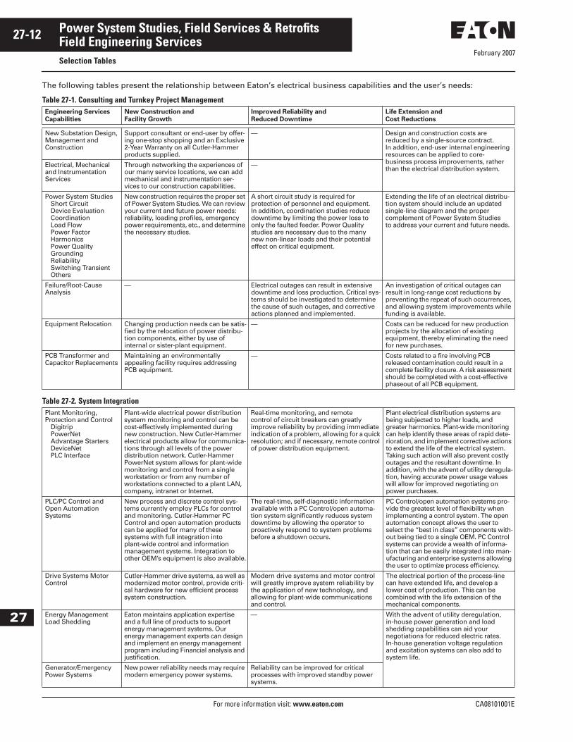
The following tables present the relationship between Eaton’s electrical business capabilities and the user’s needs:
Table 27-1. Consulting and Turnkey Project Management
Table 27-2. System Integration
Engineering Services
Capabilities
New Construction and
Facility Growth
Improved Reliability and
Reduced Downtime
Life Extension and
Cost Reductions
New Substation Design,Management andConstruction
Support consultant or end-user by offer-ing one-stop shopping and an Exclusive 2-Year Warranty on all Cutler-Hammer products supplied.
— Design and construction costs are reduced by a single-source contract. In addition, end-user internal engineering resources can be applied to core-business process improvements, rather than the electrical distribution system.
Electrical, Mechanical and Instrumentation Services
Through networking the experiences of our many service locations, we can add mechanical and instrumentation ser-vices to our construction capabilities.
—
Power System StudiesShort CircuitDevice EvaluationCoordinationLoad FlowPower FactorHarmonicsPower QualityGroundingReliabilitySwitching TransientOthers
New construction requires the proper set of Power System Studies. We can review your current and future power needs: reliability, loading profiles, emergency power requirements, etc., and determine the necessary studies.
A short circuit study is required for protection of personnel and equipment. In addition, coordination studies reduce downtime by limiting the power loss to only the faulted feeder. Power Quality studies are necessary due to the many new non-linear loads and their potential effect on critical equipment.
Extending the life of an electrical distribu-tion system should include an updated single-line diagram and the proper complement of Power System Studies to address your current and future needs.
Failure/Root-Cause Analysis
— Electrical outages can result in extensive downtime and loss production. Critical sys-tems should be investigated to determine the cause of such outages, and corrective actions planned and implemented.
An investigation of critical outages can result in long-range cost reductions by preventing the repeat of such occurrences, and allowing system improvements while funding is available.
Equipment Relocation Changing production needs can be satis-fied by the relocation of power distribu-tion components, either by use of internal or sister-plant equipment.
— Costs can be reduced for new production projects by the allocation of existing equipment, thereby eliminating the need for new purchases.
PCB Transformer and Capacitor Replacements
Maintaining an environmentally appealing facility requires addressing PCB equipment.
— Costs related to a fire involving PCB released contamination could result in a complete facility closure. A risk assessment should be completed with a cost-effective phaseout of all PCB equipment.
Plant Monitoring, Protection and Control
DigitripPowerNetAdvantage StartersDeviceNetPLC Interface
Plant-wide electrical power distribution system monitoring and control can be cost-effectively implemented during new construction. New Cutler-Hammer electrical products allow for communica-tions through all levels of the power distribution network. Cutler-Hammer PowerNet system allows for plant-wide monitoring and control from a single workstation or from any number of workstations connected to a plant LAN, company, intranet or Internet.
Real-time monitoring, and remotecontrol of circuit breakers can greatly improve reliability by providing immediate indication of a problem, allowing for a quick resolution; and if necessary, remote control of power distribution equipment.
Plant electrical distribution systems are being subjected to higher loads, and greater harmonics. Plant-wide monitoring can help identify these areas of rapid dete-rioration, and implement corrective actions to extend the life of the electrical system. Taking such action will also prevent costly outages and the resultant downtime. In addition, with the advent of utility deregula-tion, having accurate power usage values will allow for improved negotiating on power purchases.
PLC/PC Control and Open AutomationSystems
New process and discrete control sys-tems currently employ PLCs for control and monitoring. Cutler-Hammer PC Control and open automation products can be applied for many of these systems with full integration into plant-wide control and information management systems. Integration to other OEM’s equipment is also available.
The real-time, self-diagnostic information available with a PC Control/open automa-tion system significantly reduces system downtime by allowing the operator to proactively respond to system problems before a shutdown occurs.
PC Control/open automation systems pro-vide the greatest level of flexibility when implementing a control system. The open automation concept allows the user to select the “best in class” components with-out being tied to a single OEM. PC Control systems can provide a wealth of informa-tion that can be easily integrated into man-ufacturing and enterprise systems allowing the user to optimize process efficiency.
Drive Systems MotorControl
Cutler-Hammer drive systems, as well as modernized motor control, provide criti-cal hardware for new efficient process system construction.
Modern drive systems and motor control will greatly improve system reliability by the application of new technology, and allowing for plant-wide communications and control.
The electrical portion of the process-line can have extended life, and develop a lower cost of production. This can be combined with the life extension of the mechanical components.
Energy Management Load Shedding
Eaton maintains application expertise and a full line of products to support energy management systems. Our energy management experts can design and implement an energy management program including Financial analysis and justification.
— With the advent of utility deregulation, in-house power generation and load shedding capabilities can aid your negotiations for reduced electric rates. In-house generation voltage regulation and excitation systems can also add to system life.
Generator/Emergency Power Systems
New power reliability needs may require modern emergency power systems.
Reliability can be improved for critical processes with improved standby power systems.

February 2007
CA08101001E For more information visit: www.eaton.com
27-13Power System Studies, Field Services & Retrofits
27
Field Engineering ServicesSelection Tables
Table 27-3. Training
Table 27-4. Startup and Commissioning
Engineering Services
Capabilities
New Construction and
Facility Growth
Improved Reliability and
Reduced Downtime
Life Extension and
Cost Reductions
New Product TrainingElectrical Power EquipmentDrive SystemsPLC Systems
Training is offered on all new products supplied by Eaton’s electrical business. The construction phase is a beneficial time to incorporate training, from equipment and a funding standpoint.
— —
Distribution Systems Analysis Training
— Plant engineers require an understand-ing of the dynamics of electrical power distribution systems. This training addresses topics to improve existing electrical systems, as well as plan for future expansions.
Life extension of the power distribu-tion system requires a proper analysis by the plant electrical engineer. Appropriate investigations can be completed and recommendations planned for implementation.
Power Quality and Grounding Training
— Power quality and grounding issues are affecting new sensitive process equip-ment. This training can provide short- and long-term solutions, as well as recommending methods to accurately measure power quality.
—
Electrical Equipment Maintenance Training
— Completing proper, and timely mainte-nance on electrical equipment will improve reliability and reduce down-time. This training shall identify simple, yet effective, maintenance tasks, which can be completed by plant personnel.
Proper equipment maintenance will result in system life extension, indi-rectly by reducing failures. In addi-tion, training in-house personnel to complete several maintenance duties can reduce costs.
Customized TrainingScheduledOn-site
In conjunction with new construction, training can also be integrated to include existing electrical components, regardless of manufacturer. This allows for effective one-time training, on-site if desired, and incorporated into the con-struction project. A site review would be conducted to identify the training needs, and associated equipment.
A plant-wide custom training program can address specific reliability needs, as well as goals for reduced downtime.
Cost reductions can be achieved by providing maintenance training to operation personnel, thereby possibly combining operating and mainte-nance duties. This training will also provide operators with a better under-standing of the needs of electrical equipment, thereby resulting in life extension through reduced fatigue.
Installation Support and Supervision
Electrical construction of sophisticated power distribution equipment requires support and/or supervision by factory trained personnel.
Proper installation techniques have been proven to reduce short-termoperation problems and the resultant downtime.
Proper installation will result in an extended life, through the proper application of stress and tensions on various electrical components.
Acceptance TestingElectrical Power Equipment:
SwitchgearOutdoor UnitsCircuit BreakersPowerNet, etc. StartersMotor ControlTransformersTap ChangersNetwork Protection
Drive SystemsPLC SystemsNuclear Safety Related 1E
Startup testing should be completed by an independent division of a major electrical equipment manufacturer. Eaton Corporation provides an Exclusive 2-Year Warranty on all Cutler-Hammer products supplied, when EESS completes engineering studies, startup and acceptance testing.
Proper acceptance testing provides baseline data for future maintenance. This allows the development of predictive maintenance programs, thereby anticipating outages, and identifying correction actions. EESS offers comprehensive ongoing predictive, and preventive maintenance programs.
Proper acceptance testing will iden-tify any areas requiring corrective action, thereby resulting in a system with the longest life expectancy.
Startup, Training andWarranty Support
Trained individuals should complete equipment startup. Voltage levels, phasing and proper grounding requires attention to ensure a safe startup. Specific equipment testing and adjustments are also necessary to ensure all electrical safety interlocks are operational and ready for long-term service. Training can be provided immediately following, or during the startup process. Warranty issues can be quickly identified and corrected by factory trained personnel.
Long-term reliability is ensured by the proper startup, training and warranty support, all of which are provided by EESS.
Allowing the training cycle to commence immediately following, or during, the startup of the equipment can reduce training costs. Travel and set-up costs are minimized, and plant personnel witness the operation of all associated electrical equipment, as part of the training session.
Exclusive 2-Year Warranty Eaton has identified that warranty-related costs may be associated with improper startup and acceptance testing by groups which are not factory trained. This results in construction delays, as well as possible long-term reliabil-ity issues. Eaton Corporation offers an Exclusive 2-Year Warranty on Cutler-Hammer products, when all engineering studies, startup and acceptance testing is completed by EESS.
Startup costs are reduced by allow-ing EESS to complete all functions since the required OEM presence for equipment installation support can be incorporated into the acceptance testing.
February 2007
27-14
For more information visit: www.eaton.com CA08101001E
Power System Studies, Field Services & Retrofits
27
Field Engineering ServicesSelection Tables
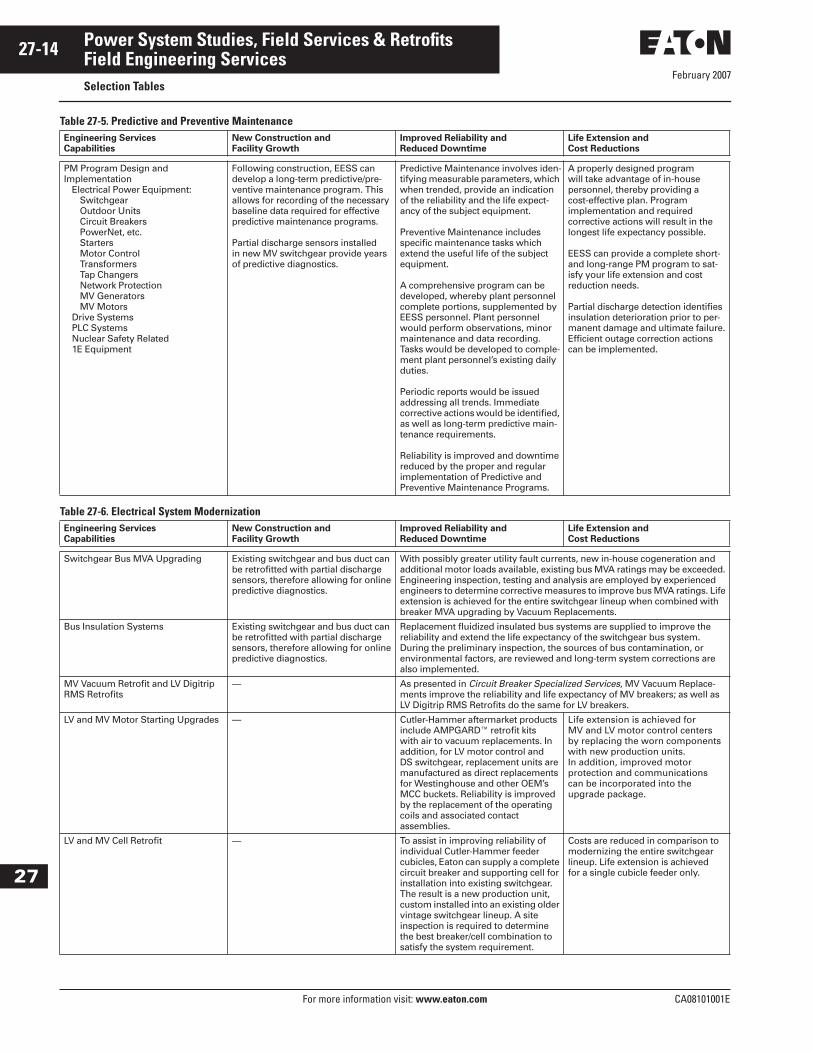
Table 27-5. Predictive and Preventive Maintenance
Table 27-6. Electrical System Modernization
Engineering Services
Capabilities
New Construction and
Facility Growth
Improved Reliability and
Reduced Downtime
Life Extension and
Cost Reductions
PM Program Design and Implementation
Electrical Power Equipment:SwitchgearOutdoor UnitsCircuit BreakersPowerNet, etc. StartersMotor ControlTransformersTap ChangersNetwork ProtectionMV GeneratorsMV Motors
Drive SystemsPLC SystemsNuclear Safety Related1E Equipment
Following construction, EESS can develop a long-term predictive/pre-ventive maintenance program. This allows for recording of the necessary baseline data required for effective predictive maintenance programs.
Partial discharge sensors installed in new MV switchgear provide years of predictive diagnostics.
Predictive Maintenance involves iden-tifying measurable parameters, which when trended, provide an indication of the reliability and the life expect-ancy of the subject equipment.
Preventive Maintenance includes specific maintenance tasks which extend the useful life of the subject equipment.
A comprehensive program can be developed, whereby plant personnel complete portions, supplemented by EESS personnel. Plant personnel would perform observations, minor maintenance and data recording. Tasks would be developed to comple-ment plant personnel’s existing daily duties.
Periodic reports would be issued addressing all trends. Immediate corrective actions would be identified, as well as long-term predictive main-tenance requirements.
Reliability is improved and downtime reduced by the proper and regular implementation of Predictive and Preventive Maintenance Programs.
A properly designed program will take advantage of in-house personnel, thereby providing a cost-effective plan. Program implementation and required corrective actions will result in the longest life expectancy possible.
EESS can provide a complete short- and long-range PM program to sat-isfy your life extension and cost reduction needs.
Partial discharge detection identifies insulation deterioration prior to per-manent damage and ultimate failure. Efficient outage correction actions can be implemented.
Engineering Services
Capabilities
New Construction and
Facility Growth
Improved Reliability and
Reduced Downtime
Life Extension and
Cost Reductions
Switchgear Bus MVA Upgrading Existing switchgear and bus duct can be retrofitted with partial discharge sensors, therefore allowing for online predictive diagnostics.
With possibly greater utility fault currents, new in-house cogeneration and additional motor loads available, existing bus MVA ratings may be exceeded. Engineering inspection, testing and analysis are employed by experienced engineers to determine corrective measures to improve bus MVA ratings. Life extension is achieved for the entire switchgear lineup when combined with breaker MVA upgrading by Vacuum Replacements.
Bus Insulation Systems Existing switchgear and bus duct can be retrofitted with partial discharge sensors, therefore allowing for online predictive diagnostics.
Replacement fluidized insulated bus systems are supplied to improve the reliability and extend the life expectancy of the switchgear bus system. During the preliminary inspection, the sources of bus contamination, or environmental factors, are reviewed and long-term system corrections are also implemented.
MV Vacuum Retrofit and LV Digitrip RMS Retrofits
— As presented in Circuit Breaker Specialized Services, MV Vacuum Replace-ments improve the reliability and life expectancy of MV breakers; as well as LV Digitrip RMS Retrofits do the same for LV breakers.
LV and MV Motor Starting Upgrades — Cutler-Hammer aftermarket products include AMPGARD� retrofit kits with air to vacuum replacements. In addition, for LV motor control and DS switchgear, replacement units are manufactured as direct replacements for Westinghouse and other OEM’s MCC buckets. Reliability is improved by the replacement of the operating coils and associated contact assemblies.
Life extension is achieved for MV and LV motor control centers by replacing the worn components with new production units. In addition, improved motor protection and communications can be incorporated into the upgrade package.
LV and MV Cell Retrofit — To assist in improving reliability of individual Cutler-Hammer feeder cubicles, Eaton can supply a complete circuit breaker and supporting cell for installation into existing switchgear. The result is a new production unit, custom installed into an existing older vintage switchgear lineup. A site inspection is required to determine the best breaker/cell combination to satisfy the system requirement.
Costs are reduced in comparison to modernizing the entire switchgear lineup. Life extension is achieved for a single cubicle feeder only.

February 2007
CA08101001E For more information visit: www.eaton.com
27-15Power System Studies, Field Services & Retrofits
27
Field Engineering ServicesSelection Tables
Table 27-6. Electrical System Modernization (Continued)Engineering Services
Capabilities
New Construction and
Facility Growth
Improved Reliability and
Reduced Downtime
Life Extension and
Cost Reductions
Molded CaseCircuit Breaker Upgrades
— Older style molded case breakers can be replaced with new Cutler-Hammer standard or the high interrupting Series C class of molded case break-ers. Long-term reliability is improved.
Life extension is achieved for the entire lineup by application of new production units into the existing switchboard lineup.
Plant Monitoring, Protectionand Control
DigitripPowerNetAdvantage StartersDeviceNetPLC Interface
— Real-time monitoring and remote control of circuit breakers can greatly improve reliability by providing immediate indication of a problem, allowing for a quick resolution; and if necessary, remote control of power distribution equipment.
Plant electrical system life extension can be achieved by improving the monitoring, protection and control of the individual components in a planned and unified manner. Plant electrical distribution systems are being subjected to higher loads and greater harmonics. Plantwide moni-toring can help identify these areas of rapid deterioration, and implement corrective actions to extend the life of the electrical system. In addition, with the advent of utility deregulation, having accurate power usage values will allow for improved negotiating on power purchases.
Power Factor Controland Correction
— — Utility rates, as well as internal electri-cal system losses, are related to power factor. Cost reductions are achieved through proper power factor control and correction. For systems with harmonics, filtered power factor capacitor banks should be designed and installed.
Ground Fault Detection Systems — Improved system reliability and per-sonnel safety are achieved by a prop-erly applied Ground Fault detection system. Systems can be applied at MV, or LV levels by the use of Cutler-Hammer products.
Costly outages, and faults related to repeated arcing grounds, can be eliminated, as well as providing an improved environment for personnel safety.
High Resistance Groundingand Detection
— High resistance grounding systems can be installed on ungrounded sys-tems. These systems will limit the ground fault current, thereby reduc-ing ground fault damage. The advan-tages of an ungrounded system are maintained with the added feature of ground detection and correction while maintaining system operation.
Costs are reduced by limiting the damaging effects of ground fault current and reducing the trouble-shooting time to locate grounds. Ground fault pulsing allows for locating the ground, with portable hand-held sensing devices, during online operation.
Surge/Lightning Protection Systems — Outages can be prevented, related to surges or lightning by the proper application of protective devices.
Costly equipment damage can be eliminated.
Automatic Transfer Scheme Upgrades
— Older automatic transfer schemes employ old relay systems. The relay coils may be at the end of their useful life, and operation can not be assured for the next required automatic trans-fer. Unfortunately, most defective transfer schemes are not detected until a failed operation has occurred.
Cost reductions related to downtime are eliminated, by a review and upgrade of older transfer schemes, before the first failed automatic trans-fer operation occurs.
Network Protector Service/Relaying Systems
— Network Protector relaying systems require service and testing to ensure continued proper operation. Older relaying systems can be upgraded, and complete Network Protector ser-vice is available to improve reliability.
Life extension is achieved by proper servicing, and/or upgrading of Network Protector components. Complete Network Protector reconditioning is also available from Eaton.
Generator Voltage Regulation andStatic Excitation Systems
— Many older in-house cogeneration units have antiquated voltage regula-tion and excitation systems. These older systems can not function with the precision of modern replace-ments, and often require extensive maintenance. Eaton offers a complete range of products to apply to these older systems, thereby improving overall system reliability and reducingdowntime.
With the advent of utility deregula-tion, in-house cogeneration has become a critical source of supple-mental electrical power, for peak-shaving and negotiating competitive power usage rates. With the associ-ated maintenance of the mechanical and rotating components, the life expectancy can be extended with the inclusion of a modern electrical control system.

February 2007
27-16
For more information visit: www.eaton.com CA08101001E
Power System Studies, Field Services & Retrofits
27
Field Engineering ServicesSelection Tables
Table 27-6. Electrical System Modernization (Continued)Engineering Services
Capabilities
New Construction and
Facility Growth
Improved Reliability and
Reduced Downtime
Life Extension and
Cost Reductions
Reduced Voltage and Soft Starters — Application of current production starters will improve reliability due to the new components installed.
Starter retrofits can be easily justified based on energy cost savings, and reduced wear-and-tear on the process line during starting.
Synchronous Motor Field Application — Many older synchronous motors employ field application panels which are obsolete, with parts support no longer available. Applying a new Cutler-Hammer field application package will improve reliability and reduce future downtime.
Life extension can be achieved for the synchronous motor field application system by applying the new Eaton’sCutler-Hammer products.
Drive SystemsPLC Process Systems
— Retrofitting older drive and relay-logic process systems with new Drives and PLCs provides for greater reliability and reduced downtime. Older devices are eliminated, thereby eliminating nuisance control problems.
Process cost reductions will be realized by Drive System PLC improvements due to greater control of production parameters. Cutler-Hammer sensors, in conjunction with Drive and PLCs, can provide a com-plete modernized production system.
All OEMs UpgradedWestinghouse/GE/ITEBBC/ABB/Square DAllis Chalmers/Siemens/Federal Pacific/Roller Smith
— Field personnel are experienced in Cutler-Hammer equipment, as well as other manufacturer’s equipment. This cross-OEM experience allows the application of singular new products to satisfy many OEM upgrading needs and provide uniformity across the various OEM’s equipment.

February 2007
CA08101001E For more information visit: www.eaton.com
27-17Power System Studies, Field Services & Retrofits
27
Field Engineering ServicesSelection Tables
Table 27-7. Circuit Breaker Specialized ServicesEngineering Services
Capabilities
New Construction and
Facility Growth
Improved Reliability and
Reduced Downtime
Life Extension and
Cost Reductions
LV and MV ReplacementCircuit Breakers
Spare cubicles, part of new construc-tion with a planned expansion, can be equipped with LV and MV replace-ment breakers. Cutler-Hammer circuit breakers and other OEM circuit break-ers can be supplied.
Downtime can be substantially reduced by allowing our Aftermarket Centers of Excellence to provide spare replacement breakers.
Aging circuit breakers can be replaced with direct roll-in replace-ments, thereby extending the life of the entire switchgear assembly.
AR-Series LV Replacement BreakersWestinghouseAllis-ChalmersFederal Pacificand Others
— Eaton’s Cutler-Hammer AR-Series Low Voltage Replacement Breakers provide a solution tailored to meet safety and reliability concerns while eliminating the need for new switch-gear. AR-Series breakers are 100% new and are designed to be electrical and mechanical equivalents of the vintage breakers they replace. They are not “retrofits” and do not reuse any parts from the original breaker. The same safety, reliability and maintainability of new switchgear are obtained for a fraction of the total installed cost.
Life Extension is achieved by upgrad-ing existing breakers to the most current breaker technology. The AR-Series Solution will result in a num-ber of reduced costs associated with maintaining or replacing vintage equipment. These cost reductions include: reduced maintenance time, decreased outages due to readily available parts, elimination of field engineering costs, reduced spare parts investment increase safety.
LV RetrofitsDigitrip RMS Kits
WestinghouseCutler-HammerGEITE/BBC/ABBAllis-ChalmersSiemensFederal PacificSquare DRoller Smith
— Cutler-Hammer Digitrip RMS Kits have been widely used to modernized LV circuit breakers. They offer advanced RMS sensing, digital display of current, improved protec-tion, fault indication, self-testing and communications to the Cutler-Hammer PowerNet system. Retrofits greatly improve reliability by applying the latest technology to existing circuit breakers.
Life extension is achieved by upgrad-ing the critical trip system on low voltage circuit breakers. In addition, future testing costs are reduced, and in-house testing can be applied by the purchase of a portable test set.
MV Vacuum Roll-in Circuit BreakersCutler-Hammer New Production
Breaker ElementFull ANSI Design TestingIncreased MVA ratings availableField Installation and Startup
— Older air circuit breaker contacts, arc chutes, mechanisms, secondary disconnects, etc., are replaced with current production vacuum breakers, incorporating all of the above into a single, fully ANSI tested device. Long-term reliability is improved.
Life extension of MV switchgear assemblies can be accomplished by the replacement of existing air circuit breakers with new vacuum breakers. Eaton’s electrical business manufac-tures widely used vacuum breaker elements for this purpose.
LV and MV ReconditionAftermarket Centers of Excellence (ACE)
— All components are refurbished, or replaced, depending on the extent of service contracted. Spares are available for interchanging units during scheduled outages, resulting in long-term reliability gains without costly unexpected outages.
The LV and MV breaker life is substantially extended. In addition, the service can include the applica-tion of modernized rms sensing trip systems. Specialized Navy, or Nuclear Safety Related 1E units are also serviced.
MCC Motor Starter Buckets — Replacements provide all new components and added reliability.
Spares are available to provide extended life, during schedule outages.
MCC Replacement Buckets for Other Manufacturers
Add buckets or increase starter sizes in existing equipment.
Replacement Units are newly manufactured including stabs and all breaker and control components. They utilize state-of-the-art technology increasingly reliability and uptime.
Many designs of vintage MCC are no longer supported. Cutler-Hammer replacement units offer a cost-effec-tive means to extend the life or mod-ernize existing equipment without the need to replace the original MCC.

February 2007
27-18
For more information visit: www.eaton.com CA08101001E
Power System Studies, Field Services & Retrofits
27
Predictive DiagnosticsPartial Discharge Testing
Partial Discharge Testing
General Description
ApplicationEaton Electrical Services & Systems has developed state-of-the-art technology to allow for the long-term predictive diagnostics of MV equipment. New or existing MV switchgear line-ups are equipped with Partial Discharge Sensors to measure partial discharges within the cubicles. The sensing technology pro-vides measurement of all discharges through noninvasive sensing of the electrical power signal. Measurements are performed online, while switchgear equipment is energized under normal operational conditions, using measure-ment equipment specifically designed for this purpose.
FunctionalityPartial Discharge (PD) sensors detect partial discharges, which are the initial indicators of corona or surface tracking. Corona and surface tracking are the pri-mary root-causes of insulation deterio-ration in MV electrical equipment. The sensitivity of PD sensors and measure-ment technology is sufficient to detect early stages of defect development by measuring PDs of low levels (less than 50 pico-coulombs). PDs occurring within the cubicles as well as PDs emanated by external sources (cable terminations, cables, bus ducts, con-nected transformers, motors, etc.) within a limited distance are identified. Sensors allow for periodic partial dis-charge sensing from the front of each switchgear cubicle without the need to open cubicle doors, using measure-ment equipment specifically for this purpose. Eaton provides a partial dis-charge sensor for each cubicle within the switchgear lineup. Sensing for par-tial discharges at the ends of the switchgear lineups only is not accept-able due to the signal attenuation of partial discharges. The sensing must occur in each individual cubicle to ensure maximum sensitivity and pre-dictive value of the measurements.
Calibration and Baseline MeasurementsNew switchgear can be monitored at the factory prior to shipment, and a baseline signature of partial discharges is provided with the switchgear. Field startup service includes obtaining a post-installation signature of the partial discharges. In-service MV switchgear, which is retrofitted with PD sensors, will have an initial baseline measure-ment obtained, whereas our database of switchgear PD measurements does allow us to provide immediate results concerning the insulation condition.
Partial Discharge Analysis Instrumentation (for use during periodic PD measurements)Cutler-Hammer measurement and anal-ysis instrumentation is capable of peri-odically detecting partial discharges related to MV switchgear, MV motors and generators, MV cables, Transform-ers and other MV electrical equipment. It completes concurrent sampling of a minimum of four (4) channels, able to effectively suppress electrical noise, eliminate cross-coupling of measured PD signals, maintain a detection sensi-tivity of 50 pC or better and disseminate the type of discharge measured. Imme-diate report documentation is incor-porated within the instrumentation software, with analysis and recommen-dations included in the final report.
Transformer Predictive Diagnostics
(Bushing Power Factor, Partial Discharge and Vibro-Acoustics)Transformers, with a primary voltage at or above 68 kV, and containing capacitive taps on the primary bush-ing, should be equipped with a contin-uous monitoring system to allow for pre- and post-shipment measurement of bushing power factor and internal partial discharges. In addition, vibro-acoustics testing can be completed both prior to shipment and after final installation. Vibro-acoustics testing will indicate any initial internal wind-ing or core looseness prior to ship-ment, and confirm that no additional internal stress has occurred during shipment and installation. This addi-tional field-testing provides for imme-diate indication of any problem related to the manufacturer, transportation, installation and startup. Vibro-acous-tics also provides indication of internal looseness related to over-drying out of insulation during oil processing, and can provide diagnostic information in preparation for a transformer internal inspection. In addition, these systems provide a method to complete future predictive diagnostics, online, without any equipment outage, therefore providing extended life and increased equipment uptime.

February 2007
CA08101001E For more information visit: www.eaton.com
27-19Power System Studies, Field Services & Retrofits
27
Predictive DiagnosticsPartial Discharge Testing
Transformer Bushing Monitoring SystemEaton’s Cutler-Hammer system moni-tors the changes in the bushing insula-tion, for the set of three bushings in a group, based on changes in bushing capacitance or bushing power factor.
The system detects changes of the power frequency current through the bushing insulation. If the transformer has 6 or 9 bushings (two or three windings), additional systems can be installed as required. The measured current through the bushing insulation can not be less then 2 mA. The system also provides provisions for the con-nection of instrumentation for periodi-cal partial discharge measurements using portable equipment without requiring a transformer outage, or any modifications to the sensing circuit.
SensorsThe Power Factor sensors are con-nected to the bushing capacitance taps. All sensors are designed for outdoor installation within the ambient temper-ature minus 50°C to plus 50°C. Insula-tion level (withstand 1 minute ac voltage) between primary and second-ary circuits is: bushing sensor 1.5 kV plus overvoltage protection; neutral sensor 15 kV; tank, core or cable shield grounding 2.5 kV; and 5 sheath 1.5 kV. The sensor system also includes overvoltage protection to suppress all overvoltages, arising dur-ing transformer operation, below this level. Temperature sensor, if used with a digital device, is of a standard RTD type. Sensors also provide provisions for periodic partial discharge measure-ments online, using separate instru-mentation designed for this purpose.
InstrumentationCutler-Hammer predictive analysis instrumentation is capable of precise continuous measurement of the capacitive current through the bushing insulation while the transformer is energized. The minimum detectable change in current is 0.1% of the initial current. The temperature deviation of the signal is the same order. The display is available from the bushing monitoring instrumentation for one complex PF signal per bushing group, which will include the display of the current power factor value. The follow-ing output signals can also be pro-vided as required: Two alarm signals (dry contacts) for a local alarm system, and additionally 4 – 20 mA dc output for an analog re-transmitting or serial interface for digital re-transmitting. Instrumentation is completely isolated from high voltages and feature immu-nity to high voltage transients. Full field calibration procedures are sup-plied with the instrument’s operation manual. All necessary connections for the selected options are supplied with startup and baseline calibration.
Software (digital option)The Cutler-Hammer monitoring soft-ware is compatible with Microsoft� Windows� 95 or high O/S based systems with the following features: display of the Power Factor (PF) value for the group of three bushings (up to three groups), storage and trending of the PF value for all monitored groups (up to three), trending PF readings versus temperature, alarm threshold setting, alarming upon PF reaching the preset thresholds, printing and plotting of the historical data.
Calibration, Manuals and Baseline MeasurementsEaton provides full field calibration and startup. A separate independent power factor test is performed of each bush-ing as part of the startup and calibra-tion process. Transformer bushings are calibrated and baseline measurements obtained. Part of the field startup ser-vice includes obtaining a post-installa-tion baseline measurements to ensure no detects have resulted during bush-ing installation and/or transformer transportation, installation and startup. A report with any recommendations is also provided. A complete manual is supplied for both the instrumentation and the software describing the opera-tion of the instrumentation, calibration and troubleshooting.
Online Transformer Partial Discharge MonitoringEaton also installs partial discharge sensors to allow for online PD measurements within a transformer. Partial discharge measurement can be periodically obtained while the trans-former is online and in normal opera-tion, using separate instrumentation designed for this purpose. The measure-ment system can assess the insulation condition based on PD measurement of the bushings and the transformer windings insulation. The system is also capable of detecting sparking in the core, sparking associated with connections and sparking associated with the static electrical discharges.
Sensors and InstrumentationSensors are noninvasive and have no connection to the energized components. Sensors are designed for outdoor installation within the ambient installation within the ambient temperature minus 50ºC to plus 50ºC. Sensors are connected, as required based on the field conditions, to the following locations: bushing capacitor taps, transformer neutral connection, tank grounding, core grounding, electrostatic shield grounding, surge arresters, isophase bus enclosure bonds and grounds. The sensor fre-quency range of operation is 500 kHz to 50 MHz. Insulation level (withstand 1 minute ac voltage) between primary and secondary circuits is: bushing sen-sor 1.5 kV plus overvoltage protection; neutral sensor 15 kV; tank, core or cable shield grounding 2.5 kV; and isophase sheath 1.5 kV. The sensor system also includes overvoltage protection to sup-press all overvoltages, arising during transformer operation, below this level. Part of the field startup service includes obtaining post-installation baseline measurements to ensure no defects have resulted during bushing installa-tion and/or transformer transportation, installation and startup. A report with any recommendations is also provided.
February 2007
27-20
For more information visit: www.eaton.com CA08101001E
Power System Studies, Field Services & Retrofits
27
Predictive DiagnosticsPartial Discharge Testing
Measurement ParametersThe Cutler-Hammer instrumentation measures the following: apparent partial discharge magnitude of each impulse, number of impulses per cycle, phase position of each discharge impulse, impulse repetition rate, impulse dis-charge power, and peak discharge magnitude of the impulses. The follow-ing quantities are plotted and displayed in a report format: apparent discharge magnitude of each impulse, number of impulses per cycle, phase position of each discharge impulse, impulse reple-tion rate, impulse discharge power, peak discharge magnitude of the impulses, impulse count and PD magnitude vs. phase position representation and impulse PD power. The above informa-tion is provided to support the findings and recommendations, which are contained in a field report.
Vibro-Acoustic Analysis of TransformersEaton can perform vibro-acoustics testing prior to shipment and after final installation. Vibro-acoustics testing indicates any initial internal winding or core looseness prior to shipment, and confirms that no additional internal stress has occurred during shipment and installation.
Periodic Partial Discharge Analysis SoftwareThe Cutler-Hammer expert monitoring system applies analysis software, during periodic measurements, with the following features: display of PD data, statistical processing of the PD data, data storage and editing, and instrumentation control. All data from the test is automatically saved to a hard disk in a database format. The stored data format is compatible with Microsoft Windows applications Word�, Excel�, Access� and others. All standard “Microsoft Windows” control functions such as printing and cut and paste operations are available within the software. Upon initiation, the soft-ware performs self-diagnostic proce-dures to ensure all components are operating correctly.
Calibration, Manuals and Baseline MeasurementsPart of the field startup service includes obtaining post-installation baseline measurements to ensure no defects have resulted during bushing install-ation and/or transformer transportation, installation and startup. A report with recommendations is also provided.
MeasurementsVibro-acoustics is based on collecting steady-state vibro-acoustic data from the outside of the transformer tank under two load conditions and subsequent automated analysis of the energy distri-bution among different frequencies in this vibration data. The first measure-ment at no-load will be obtained prior to shipment. A subsequent, post-installation, no-load, vibro-acoustic measurement is also completed on-site to verify no internal stresses resulted during shipment or installation. After the unit is loaded to approximately 50%, or greater, a second set of measurements shall be obtained. Two subsequent mea-surements, at 6 and 12 months, follow-ing continuous online operation, are recommended. Further follow-up mea-surements will be on an as-determined basis. Measurements are made at 12 locations on the transformer tank, 6 on the HV side of the transformer tank and 6 on the LV side (the HV side indicates the side with HV bushings, and the LV side indicates the side with the LV bushings).
Traditional Transformer Startup and Acceptance TestingThe above transformer predictive diagnostic systems and field startup testing is completed by Eaton in addi-tion to traditional transformer factory and field acceptance testing in accor-dance with ANSI, IEEE, and other appli-cable testing standards. For example, a separate independent power factor test is required of each bushing as part of the startup and calibration process. These additional tests provide for immediate indication of any problem related to manufacturer, transportation, installation and startup. In addition, Cutler-Hammer Predictive Diagnostics provides a method to complete future predictive diagnostics, online, without any equipment outage, therefore pro-viding extended life and increased equipment uptime.

February 2007
CA08101001E For more information visit: www.eaton.com
27-21Power System Studies, Field Services & Retrofits
27
Predictive DiagnosticsPartial Discharge Testing
Medium and High Voltage Predictive Diagnostics Online Monitoring and Partial Discharge AnalysisCutler-Hammer Predictive Diagnostics (CHPD) offers predictive diagnostic equipment and systems for medium and high voltage equipment. Much of our technology is based on the mea-surement and analysis of partial dis-charges (PD). Partial discharges are a well-known and an industry-accepted indicator of insulation deterioration that lead to equipment failure.
Studies have shown that approxi-mately 80 percent of all equipment failures occur on a random basis and are not age related. The statistic indi-cates that whatever we are doing today in terms of preventive mainte-nance is not overly effective and that there are opportunities for major improvements. Certainly, a well-designed, time-based preventive maintenance program will have a pro-found positive effect on failure rates, but they are generally invasive in nature. This invasiveness has a ten-dency to increase failure rates due to the introduction of new defects, result-ing in infant-mortality failure patterns.
With industry moving towards fewer and shorter outages, companies are looking for alternative and predictive technologies to protect their invest-ment, lower maintenance costs and increase system reliability. Use of the technologies provided by Eaton will do just that.
InsulGard Predictive Relay for Continuous Monitoring and Analysis of Partial DischargesApplications of the InsulGard System are available for equipment that are rated for 4,000 volts to 38,000 volts and include:
■ Motors/generators (RTDs are also used as sensors).
■ Switchgear systems.■ Bus ducts.■ Power center transformers.■ Gas insulated substations.■ Splices and terminations of cables.
InsulGard G2 — Transformer Monitoring SystemData gathered from Doble conferences and other scientific papers indicate that bushing failures are responsible for up to 35 percent of all large power transformer failures. This data also states that 52 percent of bushing fail-ures are violent in nature, which pre-sents safety concerns, as well as concerns related to environmental damage.
Among our capabilities is the ability to continuously monitor the changes in the C1 capacitance, as well as any changes in the dielectric losses of the bushing (bushing power factor). It’s like having a continuous online Doble test of the bushings under TRUE elec-trical stress and temperature. We also have the ability to test the bushings and the power transformer windings for partial discharge on a periodic basis, while the equipment is in operation.
Cutler-Hammer comprehensive trans-former monitoring system incorpo-rates permanent partial discharge sensors to timely detect a wide range of electrical problems (PDs, surface tracking, arcing, sparking) in bushings, winding insulation, core, laminations, tap changer connections, ground con-nections, pressboard barriers, etc. Ideal system for critical transformers or to keep your troublesome unit out of trouble! Implementation of Eaton’s Cutler-Hammer Predictive Diagnostics provides an analysis of your critical equipment to reduce the risk of failure and increase uptime.
InsulGard Predictive Relay
Benefits of Using the InsulGard Systems■ Saves money.■ No labor is required to conduct test.■ More efficient deployment of per-
sonnel. Labor can be reallocated to fix problems (instead of look for them) and take care of other impor-tant matters.
■ Tests are performed online.■ No loss of asset productivity.■ More accurate data as tests are con-
ducted under actual operating con-ditions.
■ No infant-mortality patterns that are commonly introduced via invasive testing procedures.
■ Tests are continuous.■ Finding a problem is not left to
chance (like interval testing). You will know when a problem started and how rapidly it is progressing.
■ No surprises and no forced outages. Increased safety — you will always be aware of conditions/problems.
■ Allows trending of other variables that affect PD activity such as load, temperature and humidity.
■ Unnecessary maintenance is reduced because you are constantly testing and have more accurate data on which to base decisions.
■ You have achieved predictive/condi-tioned-based maintenance versus interval/chance maintenance.
■ You can prioritize which equipment receives service first — a true main-tenance planning tool.
February 2007
27-22
For more information visit: www.eaton.com CA08101001E
Power System Studies, Field Services & Retrofits
27
Retrofit ServicesMedium Voltage Vacuum Replacement Circuit Breakers
Retrofit Services — Medium Voltage Vacuum Replacement Circuit Breakers
General Description
ApplicationEaton’s Cutler-Hammer vacuum replacement (VR) circuit breakers are fully engineered and tested to provide the user with a means of modernizing electrical power distribution systems, and in most cases, extending the life of the equipment while improving performance and system reliability.
Medium Voltage (MV) Type VR circuit breakers are available for 5 kV through 15 kV distribution systems.
Ratings■ Maximum voltages:
4.76 kV, 8.25 kV and 15 kV■ Interrupting ratings:
4.76 kV: 250 MVA (29 kA) 4.77 kV: 350 MVA (41 kA) 8.25 kV: 500 MVA (33 kA) 15 kV: 500 MVA (18 kA) 750 MVA (28 kA)
1000 MVA (37 kA)1500 MVA (63 kA)
■ Continuous current:1200 A, 2000 A, 3000 A (5 – 15 kV)4000 A forced cooled (5 – 15 kV)
History and TechnologyMost medium voltage air magnetic power circuit breakers have been in service for 25 years and some for as long as 60 years. They were reliable and for many years maintainable. Increased short circuit capabilities in utility and industrial power systems has created “over-duty” situations with many of these breakers. Parts availability has also increased the cost of maintaining the breakers in peak condition.
In the mid 1970s, circuit breaker manu-facturers began introducing vacuum technology for MV power circuit break-ers. It was desirable and feasible to incorporate the advantages of vacuum technology into replacement breakers that would directly interchange with the existing MV air magnetic power circuit breakers to extend the useful life of their existing switchgear. Most users wanted a replacement that was functionally interchangeable, both electrically and mechanically, with their existing MV air magnetic power
circuit breakers. The market responded by offering “retrofits” that utilized the existing breaker trucks (frames) and vacuum circuit breaker modules. These alternatives provided extended life for electrical equipment, reduced maintenance, and allowed increased capabilities for many distribution sys-tems. IEEE/ANSI established a stan-dard for retrofits (IEEE/ANSI C37.59) in 1991 that put consistency in the retrofit process. However, retrofits were costly, caused inconvenience for users, required months to complete, and the lack of configuration control made it difficult to standardize designs.
Eaton now offers new VR circuit break-ers that can be supplied in place of the old retrofit technology. Unlike retrofits, VR power circuit breakers are new from the ground up and offer improved performance, maintainabil-ity and convenience over retrofits. They can be supplied in large quanti-ties to facilitate complete substation upgrades in a single outage. System upgrades to handle higher short circuit levels are available.
FeaturesEaton Corporation is a world leader in circuit breaker technology. The same reliable vacuum technology is used in our VR circuit breakers. The Cutler-Hammer vacuum interrupter is used in many manufacturers’ switchgear breakers worldwide. Many of the com-ponents and sub-assemblies in our MV VacClad-W Metal-Clad Switchgear are the same as those used to manu-facture the VR product line. This helps reduce spare parts inventories and the amount of required mainte-nance training.
Cutler-Hammer vacuum technology reduces maintenance since the contacts are sealed from contaminants in the environment, no adjustments or clean-ing of the main contacts are required, and the main contacts require no special gauges or devices to measure wear or contact pressure. Annual lubri-cation and testing can be performed in a fraction of the time required for air magnetic circuit breakers.
The Cutler-Hammer non-sliding cur-rent transfer system eliminates the need to check and tighten connections between the vacuum interrupter stem and the main conductors or the circuit breaker. The connection is permanent and provides high conductivity without creating hotspots and Holm effect as found in half-clamp connections.
SURE CLOSE MOC operators are available to provide dependable MOC operation that is decoupled from the main closing function of the VR circuit breaker mechanism. This prevents the VR circuit breaker from stalling or failing to latch during the closing operation. SURE CLOSE mechanisms also have adjustable stop positions to control over-travel of MOC switch operators.
Service LifeMost MV air magnetic circuit breakers have been in service for 25 to 60 years. As long as the bus structures, insula-tion systems and general mechanical condition of the switchgear cells/structures are maintained in good condition, equipment life can easily be prolonged with the addition of VR circuit breakers.
AvailabilityVR breakers are available in a wide range of ratings and models to replace medium voltage (MV), air magnetic circuit breakers originally manufactured by:
■ Westinghouse■ General Electric■ Allis-Chalmers/Siemens■ Federal Pacific Electric■ ITE/ABB■ McGraw-Edison
Required InformationIn order to obtain the correct VR circuit breaker, the following information should be provided to Eaton:
■ Original switchgear manufacturer.■ Original breaker manufacturer.■ Breaker type or catalog number.■ Maximum voltage rating continuous
current rating and maximum short circuit or MVA rating.
■ Control voltages.■ List of options and/or modifications.■ Copy of schematic and wiring
diagram.■ Year of manufacture of original
breaker and switchgear.■ MOC requirement.
For site-specific specifications, contact your local General Field Sales Force office, your local Engineering Services center, or call 1-800-498-2678.

February 2007
CA08101001E For more information visit: www.eaton.com
27-23Power System Studies, Field Services & Retrofits
27
Retrofit ServicesMedium Voltage Vacuum Replacement Circuit Breakers
Detailed Requirements
GeneralThis section covers the design, testing and manufacturing requirements for new vacuum replacement (VR) circuit breakers for use in medium voltage (MV) metal-clad switchgear. The VR circuit breakers will be functional replacements (both mechanically and electrically) for the air magnetic circuit breakers they replace. The VR circuit breakers will be interchangeable (within the limits of the original switchgear) between different types of cells (structures) of the same voltage, MVA and ampere class without cell (structure) modifications. Retrofits, as defined by IEEE/ANSI C37.59-1996 6.1.4.2 are not covered and will not be considered as an alternative or substi-tute for new VR circuit breakers.
Scope of WorkEaton’s electrical business will pro-vide all project management, factory and field engineering, short circuit and coordination studies (if required and at an additional charge), supervision, labor, material, tools, rental, test equipment and transportation as defined for a complete VR circuit breaker replacement of the required existing medium voltage switchgear circuit breakers. The VR circuit break-ers will be designed for maximum voltages of either 4.76 kV, 8.25 kV or 15 kV as required.
MVA Ratings The available MVA rating of the VR circuit breakers are as follows:
Table 27-8. VR Ratings
� 26-inch (660.4 mm) wide cells only.
All Cutler-Hammer switchgear struc-tures designated for VR circuit breakers with increased MVA levels will have the existing bus bracing analyzed. EESS will determine if bus bracing is capable of withstanding the maximum (peak) momentary ratings per ANSI C37.09.4.6.2.4 and ANSI C37.20.2.5.2.4
capabilities of the new VR circuit break-ers. EESS will provide documentation to verify that the switchgear bus is sufficiently braced to handle the new ratings or supply the cost as a separate item to increase the bus bracing of all designated switchgear structures in the lineup to comply with the increased MVA ratings. Following the study and/or the bracing modifications, Eaton’s service engineer will affix a nameplate to each switchgear structure stating the new MVA rating, the manufacturer’s name and the date of verification or upgrade.
Cubicle ModificationsThe VR circuit breakers shall be inter-changeable with existing breakers of the same continuous current and MVA ratings without required modifications to the existing cubicles. Existing cell coding systems shall be retained where possible.
VR circuit breakers with upgraded/increased MVA or continuous current ratings do require modifications to the cubicle coding system to prevent the insertion of breakers that do not have the same ratings as the upgraded VR circuit breakers.
Applicable StandardsAll VR breakers will be designed, man-ufactured and tested in accordance with the applicable sections of:
■ ANSI C37.59-1996 (cell interface and testing criteria)
■ ANSI C37.04■ ANSI C37.06■ ANSI C37.09■ ANSI C37.20.2■ ANSI C37.55■ ANSI C37.100■ IEEE STD 4-1995
MaterialsAll materials used in the manufacturing of the new VR circuit breakers will be new and unused. No parts or materials from the original air-magnetic circuit breakers will be reconditioned and reused in the manufacture of the new VR circuit breakers. All components used in the manufacturing of the new VR circuit breakers including, mecha-nism, vacuum interrupters, and frame components will all be manufactured by Eaton to ensure single-source reli-ability and responsibility.
Manufacturer’s QualificationsEaton is currently engaged in the design and manufacturing of MV vac-uum circuit breakers and switchgear structures. Eaton Corporation has a minimum of 50 years experience in switchgear manufacturing, is a mem-ber of the National Electrical Manufac-turers Association (NEMA), and has representation on IEEE C37 Switch-gear Working and Balloting Groups, and owns and operates an engineering services organization.
Eaton Electrical Services & Systems (EESS)■ Experienced, factory-trained field
engineers and technicians familiar with the installation and startup of MV VR circuit breakers.
■ A minimum of 30 field service locations staffed with engineers that are available on a 24-hour basis for emergency service.
■ Capabilities of on-site cell alignment, breaker levering system repairs, and control system modifications.
■ Capabilities to perform computer-generated short circuit, coordina-tion, and load flow studies for final breaker trip settings. All studies will be conducted under the supervision and approval of a Registered Profes-sional Electrical Engineer skilled in interpreting studies and test results regarding MV VR circuit breakers. The Registered Professional Electri-cal Engineer is a full-time employee of EESS.
Vacuum Circuit Breaker Module FeaturesThe VR circuit breakers will utilize vacuum circuit breaker modules manufactured by Eaton. Acceptable conversion modules are the VCP-18WR, VCP-20WR, VCP-29WR and the VCP-29WRSE.
Common Pole ShaftThe circuit breaker mechanism will open and close all three phases and any auxiliary devices via a common operating shaft to ensure consistent and simultaneous operation of the main contacts. The shaft will be supported at the ends and along its length with bearings. The main drive shaft will be connected to the individual vacuum interrupters via insulated drive links.
Volts kV Original MVA New MVA
4.76 4.77 8.2515
100 – 250 �100 – 250 �150 – 500150 – 500150 – 500150 – 500750150 – 1000
250 350 500 500 750100010001500
February 2007
27-24
For more information visit: www.eaton.com CA08101001E
Power System Studies, Field Services & Retrofits
27
Retrofit ServicesMedium Voltage Vacuum Replacement Circuit Breakers
Insulated Drive LinksThe mechanism drive shaft will be connected to each moving contact via an insulated drive link made of glass-reinforced polyester for element types VCP-18WR, VCP-20WR and VCP-29WR and cycloaliphatic epoxy for the VCP-29WRSE. The insulated link material is non-hydroscopic and meets the flame-retardant requirements as set forth in ANSI C37.20.2.5.2.7. The drive links are easily removable with single clevis pins at each end and spring retaining clips.
Shock Absorber SystemThe mechanism will contain a shock absorber system to dampen the opening force of the circuit breaker. The shock absorber has sufficient resilience to prevent contact bounce that could cause a restrike of the main contacts during the opening of the circuit breaker or during a spring discharge. The VCP-20WR, VCP-29WR and VCP-29WRSE vacuum conversion element’s mechanism consists of a series of parallel steel plates with spring separators that spread the plates during breaker opening. The shock absorber has a design life of 10,000 breaker opening and closing cycles without the need for repair, replacement or adjustment. The VCP-18WR has a sealed replaceable shock absorber and is capable of being adjusted if replaced or during initial mechanism assembly.
Manual Trip and CloseThe mechanism has front accessible manual close and trip operators that are directly connected to the breaker operating mechanism and are an integral part of the electrical close and trip coils.
Operations CounterEach VR circuit breaker mechanism has a five (5) digit non-resetting mechanical operations counter connected to the operating shaft as manufactured by Veeder-Root.
Spring Charged IndicatorEach operating mechanism will be equipped with a visible indicator to show the state of the stored energy mechanism. The indicator will show when the spring is fully charged or discharged.
Auxiliary ContactsThe breaker will have a low inertia, rotary operated auxiliary switch connected to the main pole shaft assembly. Connections will be made via insulated ring-tongue terminals.
Vacuum Bottle AssemblyThe vacuum bottle assembly will be constructed from virgin materials and manufactured by Eaton. The contacts will be principally composed of pow-dered metal, chromium-copper con-tact material. The powdered metal is fused under high pressure to form a consistent contact material. The con-tacts are machined to form spiral petal contacts to assist in the swirling of the arc during interruption.
The edges of the ceramic components will be “metallized” and fired prior to assembly. The components are inspected and assembled in a Class 1000 clean room prior to sealing the components. The components are inserted into a vacuum heat chamber and sealed under vacuum. No “pinch tubes” are used.
A stainless steel corrugated bellows achieves isolation of the ambient air and the vacuum. The moving contact stem of the vacuum interrupter has a machined groove to prevent rotation of the contact within the vacuum chamber.
The vacuum interrupter has a visual method of identifying contact wear without the use of gauges or other devices. In addition, a separate visual “T-cutout” is used to verify that the mechanism is applying adequate spring pressure to the contacts when the breaker is in the closed position.
The contacts are self-aligning and do not require adjustments for the life of the vacuum interrupter assembly. The contacts also have a spring system to apply proper contact pressure. The operation of the contacts cause a wip-ing action to clean the contact surfaces.
Insulated Pole AssembliesPole assemblies are insulated from ground with non-hydroscopic insulat-ing materials manufactured from glass-reinforced polyester.
Current Transfer SystemThe current transfer from the conductor stem to the primary bushing assem-blies is via a non-sliding current trans-fer system consisting of a fused stem assembly and a V-flex silver-plated copper leaf conductor or folded leaf copper shunts. The stems have the adjoining conductors mechanically fused with the stem material. This junction forms a solid current transfer.
Trip-Free OperationThe new VR circuit breaker operation mechanism is a “true Trip-Free” design. When the trip function is mechanically engaged and held and the close function is initiated either electrically or mechanically, the con-tacts do not close. The contacts are restricted to 10% of the total travel.
Mechanical Status IndicatorEach new VR circuit breaker has a mechanical status indicator with the word “CLOSED” on a red background when the breakers are closed and the word “OPEN” on a green background when the breakers are open.
Breaker Truck/Frame Assembly
Frame Materials and PlatingThe frame is constructed from steel, utilizing a combination of bolting and welding to assemble the frames. All frames are zinc-plated with a yellow dichromate finish (commonly referred to as yellow-zinc dichromate).
Wheels and Casters for TransportVR circuit breakers are supplied with transport system that is a functional replacement of the transport system of the original design. The transport system conforms to the requirements of the original design.
HardwareAll hardware is a minimum grade five (5), zinc-plated with a yellow dichromate finish or black oxide.
Bushing and Interface Conductor MaterialPrimary and power frequency inter-face conductors are constructed of 100% IACS electrical grade conductive copper. Conductors are either silver- or tin-plated to a thickness of .0001 – .0002 for non-sliding surfaces and .001 – .002 for sliding surfaces. The power fre-quency conductors are sized to carry the full load ampacity of the circuit breaker without exceeding the temper-ature rise established in ANSI C37.09.
Insulation SystemsAll bushings utilize either glass-reinforced polyester or molded cycloaliphatic epoxy insulation systems or engineer approved equal. Fluidized epoxy coatings are used to insulate interface conductors when necessary.
Phase barriers are manufactured from GPO-3 glass-reinforced polyester or equivalent and designed to isolate individual phase conductors. Open-ings are minimized to reduce the possibility of ionized gas propagation between phases.

February 2007
CA08101001E For more information visit: www.eaton.com
27-25Power System Studies, Field Services & Retrofits
27
Retrofit ServicesMedium Voltage Vacuum Replacement Circuit Breakers
Corona ShieldsAll 8.25 kV and 15 kV class breakers have internal corona shields when bushings are mounted on metallic back planes. The corona shields are permanently grounded. Bushings mounted on nonmetallic back planes do not have internal corona shields.
Primary ConnectionsPrimary connections (finger clusters) are new and designed to carry the full nameplate rating of the replacement breaker without exceeding the allow-able temperature rise as stated in ANSI C37.04.5.4.2-1979. In addition, the primary connections are capable of withstanding the full momentary/close and latch rating as well as the K*I current rating for two seconds without melting, arcing or pitting the contact surface.
Ground ContactsA metal-plated, self-coupling, separable grounding contact shall be supplied.
Control Circuit WiringControl wiring is SIS cross-linked poly-ethylene, #14 AWG minimum except for short runs such as coil and motor leads. Insulated ring tongue terminals are used. Solder or “fast-on” type con-nections are not used. Upfront, easy access terminal blocks are provided for maintenance and troubleshooting.
Stored Energy DischargeThe replacement breaker incorporates a manual and an automatic system to completely discharge all stored energy before the circuit breaker is fully with-drawn from the switchgear housing. The system will never intentionally discharge the stored energy while in the connected position.
Passive InterlocksThe mechanism will have a passive interlock to block the insertion or removal of a closed breaker. The system also prevents the insertion of the levering tool at any time the breaker is in the closed position.
Active InterlocksEach breaker has an active interlock system. The system is operated by the insertion or removal of the VR circuit breaker. In the event the passive inter-lock is defeated, active interlock sys-tem will trip and open a connected, closed breaker if an attempt is made to remove it from the connected position. The system also holds the breaker in the “trip-free” position at all times between the test and fully connected positions.
Locking MeansLocking means is provided to lock the circuit breaker while in the fully connected or disconnected positions. The lock prevents the insertion or removal of the breaker. The lock will not prevent the breaker from being operated while in the fully connected position.
Secondary Contact BlockControl wiring connections between stationary structure and the removable breaker are provided with automatic, self-coupling contacts. The secondary blocks will be mold cycloaliphatic epoxy insulation. The pins are drilled and tapped to accept standard 8-32 screws for ease of maintenance and wiring changes. The secondary contact block is made of cycloaliphatic epoxy.
MOC OperatorAll breakers will be furnished with MOC operators unless specified. The MOC operator will have sufficient power to operate the largest MOC switch or combination of switches in the switchgear lineup without affect-ing the breaker’s ability to completely close and latch. The MOC driver is completely “decoupled” from the main breaker operating shaft and shall be powered by separate operating springs. The system is SURE CLOSE as manufactured by Eaton’s electrical business.
Cell Coding SystemEaton will supply or interface with the cell coding system to prevent the acci-dental insertion of a breaker into a cell of a different voltage, current, inter-rupting capacity or physical arrange-ment than the type intended for the switchgear cell receiving the breaker.
Design and Certification (Type) TestingEach new VR circuit breaker supplied will have type tests performed on its base design to certify it to IEEE/ANSI standards. All Certification (Type) shall will be performed in a switchgear cell/structure when required or an equiva-lent structure where permitted by ANSI C37.09. Written test reports, data logs and digital reproductions of the pulse used to perform the BIL test will be on hand for review by the buyer.
BIL — 60 kV for 4.76 kV applications, 95 kV for 8.25 and 15 kV applications as a minimum> crest with 1.2 µsec x 50 µsec x 50% wave shape per ANSI C37.09.4.5.4. The tests will be con-ducted per IEEE STD 4-1995. This test shall be performed in a breaker cell or cell equivalent with controlled humidity levels. Corrections for barometric pressure and ambient temperature will be applied to the test parameters. The breaker must pass a total of 54 shots.
Mechanical operations tests of each breaker design are performed in a switchgear cell designed to accommo-date MOC switches. The maximum number of auxiliary MOC devices or their equivalent force will be applied during the test to ensure that the vacuum breaker has sufficient power to operate the auxiliary devices, suc-cessfully closes and latches during each operation, and that no fatigue or failure occurs. Consideration is given to designing a system that will not damage the MOC switch in the switchgear cell structure.
Momentary tests per IEEE/ANSI C37.20.2.5.2.4 will be performed of the completed vacuum replacement breaker including the vacuum breaker element, bushings, primary discon-nects (finger clusters), all bus in the breaker unit, and all insulators and braces per ANSI C37.09, 4.6.2.4. This test is to prove the mechanical strength and integrity of the conductor and frame assembly of the complete new vacuum replacement breaker. This test is performed in a switchgear cell designed to accommodate the circuit breaker being tested. Anti-rotation devices may be added to the cell if required to prevent rotation. If anti-rotation devices are used in the test breaker, then they will be installed in all the switchgear cells intended to accommodate the new breakers.
Short Time current tests for three (3) seconds at K*I current will be per-formed to confirm the breakers I2t capability. The test will be performed in a switchgear cell.
Continuous rated current testing per ANSI C37.04-1979 without exceeding 65°C hotspot rise with a maximum ambient not to exceed 40°C. This test is performed in a breaker cell or a cell structure of the same equivalent vol-ume, dimensions and ventilation as the original switchgear structure.

February 2007
27-26
For more information visit: www.eaton.com CA08101001E
Power System Studies, Field Services & Retrofits
27
Retrofit ServicesMedium Voltage Vacuum Replacement Circuit Breakers
Low Frequency Withstand — 19 kV rms for 4.76 kV applications, 36 kV rms for 8.25 kV and 15 kV applications — per ANSI 37.09, 4.5.3.1.
Interlock functional test per ANSI C37.20.2, 6.2.4.
All production tests as stated in ANSI C37.09-1979.5. Timing values per pole will be provided for the vacuum element in msec.
ExecutionEaton’s factory trained and certified field service engineer(s) can perform the commissioning of each breaker at the customer’s site. The field engineer will be familiar with the VR circuit breaker to the point that he/she can offer initial training to the owner’s on-site operators and maintenance per-sonnel while performing the commissioning.
VR-Series Breakers

February 2007
CA08101001E For more information visit: www.eaton.com
27-27Power System Studies, Field Services & Retrofits
27
Retrofit ServicesAR Series Low Voltage Replacement Breakers
Retrofit Services —AR Series Low Voltage Replacement Breakers
General Description
ApplicationMaximum life extension. All AR-Series breakers are brand new from the ground up. They are designed to be electrical and mechanical equivalents of the breakers they replace. Cell modifications, if required, are kept to a minimum. They are not “Retrofits” and no parts are reused from the original breakers. This reduces out-of-service time, yielding consistent product designs, while reducing initial installa-tion costs. AR-Series breakers correctly interface with compartment cell switches, and safety interlocks are maintained or improved.
Solve Parts Availability Problems for Old BreakersReplacement parts for old breakers are becoming harder and harder to find as technology continually advances. Parts availability issues are basically eliminated with AR-Series breakers. Mechanism parts and control compo-nents are current production items and are in stock. Additionally, AR-Series breakers use common components across the product line. This can save in future spare parts investment.
Reduce Maintenance Cost and Downtime with Reliable Magnum DS Breaker TechnologyMaintenance procedures commonly associated with vintage air magnetic circuit breakers take 8 – 12 hours on average per breaker. Eaton's Magnum DS Breaker technology reduces nor-mal maintenance to 2 – 6 hours per breaker. The arc chutes, contacts, mechanism and control components can be easily inspected and minor maintenance (such as lubricating the mechanism) can be easily accom-plished. Arc chutes can easily be removed with two bolts and visually inspected or replaced. By removing the arc chutes, viewing the main con-tacts along with their contact wear indicator results in a quick and simple decision to replace if necessary. Spare parts inventory is considerably reduced because AR-Series breakers use common parts throughout the entire product line, including new Magnum DS Switchgear assemblies.
For more information on Magnum DS Breaker Elements, see Section 19.
Increase Interruption Rating Dynamic changes resulting from larger transformers, bus ties, parallel generation, and new sources of incom-ing power can drastically increase the level of available short circuit current in LV power distribution systems. The bus system's momentary capability can be increased and the entire switch-gear structure can be re-certified to the new higher levels by Eaton's factory qualified service engineers. Many of the AR-Series breakers are available to increase interrupting capabilities while still maintaining the original circuit breaker dimensions. This provides a savings versus the cost of replacing the switchgear. Cell-to-breaker coding systems are maintained or corrected to comply with IEEE/ANSI standards.
Increase Continuous Current RatingChanges to industrial and commercial facilities, such as increased manufac-turing operations, will typically increase the demand for electrical power within the facility. Often, an increase in electrical demand can cause the load on a circuit to exceed the circuit breaker's continuous cur-rent rating. Eaton's factory qualified service engineers can inspect existing LV metal-enclosed switchgear, includ-ing the existing breaker cubicles, line and load power stabs, load cables, and bus system to verify the application for a circuit breaker ampacity upgrade. Many of the AR-Series breakers are available with increased continuous current ratings.
StandardsAll AR-Series LV power air circuit breakers are designed and tested to meet or exceed IEEE/ANSI C37.59-2002 standards. This ensures compatibility with existing installations and IEEE/ANSI application guidelines. IEEE/ANSI certification and certified factory production test reports are available.
Features■ AR Replacement Breakers are 100%
rated, UL listed, and built and tested in an ISO 9001 and 14001 certified facility.
■ Safety: the cell door can remain closed with the breaker in connect, test or disconnect position. Simulta-neously, the trip unit, open-close controls, and breaker nameplate data are all readily visible.
■ Designed for easy access, inspec-tion, and minimal maintenance. The stored energy mechanism, control devices, accessories, and second-ary contacts are easily accessible by
removing the front cover. The con-tact wear indicator eliminates the need for elaborate testing to deter-mine if the contact assembly needs replacing. The arc chutes can also be easily removed and inspected.
■ Installation savings and robust inter-face reduce installation and com-missioning time with our unique design concept. No modifications required to the original line/load power stabs or secondary discon-nect contacts. Modifications to the original cubicle are often eliminated with an easy-to-install cubicle adapter (cassette). The cassette includes new extension rails and levering-in adapters, resulting in a more robust breaker-to-cubicle interface. We also provide a new door to match the replacement breaker.
AvailabilityDesigns available for:
■ Westinghouse■ General Electric■ Allis-Chalmers■ Federal Pacific■ ITE/ABB■ McGraw-Edison
FP-25 Original Magnetic Circuit Breaker
FP25-AR Air Replacement Breaker

February 2007
27-28
For more information visit: www.eaton.com CA08101001E
Power System Studies, Field Services & Retrofits
27
Retrofit ServicesLow Voltage Power Circuit Breaker Reconditioning
Retrofit Services —Low Voltage Power Circuit Breaker Reconditioning
General Description
ApplicationLow voltage power circuit breakers are designed to be serviceable devices over a long service life. These breakers and the associated switchgear have been available in the industry for over 50 years, and a large installed base of equipment by many manufacturers exists throughout the United States and Canada.
The low voltage switchgear is essen-tially static. It consists of structures, buswork, control wiring and metering components. If periodically cleaned, it will last almost indefinitely.
The low voltage power breakers are the essential elements of the switch-gear. They are required to properly conduct the normal load current for the vast majority of time, and still provide the means of interrupting an overload or fault current whenever it may occur.
These breakers contain insulation systems (600 Vac normal 3-phase voltage or less), conductors (from 225 to over 5000 continuous amperes), a mechanism to open and close the breaker, a trip system to provide protection of the circuit and the circuit breaker, and an interruption system (arc chutes and contact structures) that can handle fault currents as high as 100,000 amperes.
While some breakers are fixed mounted (bolted into the switchgear), the vast majority are drawout for ease of inspection and maintenance of the breaker, as well as to provide maximum isolation of the load. These drawout breakers include primary disconnects (for the 3-phase conductors), second-ary disconnects (for breaker control wiring), a levering-in mechanism (to assist in the insertion and withdrawal of the breaker) and an interlock system (to ensure that a closed breaker cannot be inserted or withdrawn from the connected position).
Additional common options to low voltage power circuit breakers include electric operation of the mechanism, shunt trip and close coils for remote operation of the breaker, undervoltage trip systems, and additional auxiliary switches for annunciation and control schemes.
Factors that affect the life of these circuit breaker subsystems include time, ambient temperature, humidity, cleanliness of the environment (contamination and corrosive ele-ments), number of normal load operations, number of fault current interruptions, load current magnitude, and maintenance cycle.
While periodic maintenance, cleaning, lubrication and testing of the circuit breaker can and will prolong its life, at some point, the circuit breaker must either be completely reconditioned or replaced. Failure or mis-operation of any of the breaker’s subsystems will render it to be ineffective for its intended purpose and dangerous for personnel or downstream equipment.
Class 1 reconditioning of the low voltage power circuit breaker is a cost-effective method to restore all of the breaker’s subsystems to full functionality and prolong the life of the breaker for many additional years.
ManufacturersClass 1 reconditioning is available for all major manufacturers’ low voltage power circuit breakers that have been produced over the last 50 years. These breakers are rated at 600 Vac, 225 to 5000 amperes continuous, 15,000 to 100,000 amperes interrupting. The manufacturers include, but are not limited to:
■ Westinghouse■ Cutler-Hammer■ General Electric■ ITE■ ABB■ Allis-Chalmers■ Siemens■ Square D■ Federal Pacific■ Federal Pioneer
AdvantagesEaton’s electrical business is the world leader in Low Voltage Power Circuit Breaker and Trip Systems technology. EESS is uniquely positioned to provide Class 1 reconditioning of low voltage power circuit breakers.
All Class 1 reconditioning is done at facilities dedicated to the purpose. These are known as Aftermarket Centers of Excellence (ACEs). These facilities utilize state-of-the-art equip-ment in cleaning, plating, assembly and testing of the breakers. Each facility utilizes identical standards and procedures in the reconditioning process. The reconditioned breakers are tested to the same standards as new production breakers. The breaker test results are stored in a North American database (Pow-R Test), facilitating predictive maintenance and trending. All manufacturers’ breaker information is stored in our Pow-R Master Database and available to every ACE performing the work. Breaker trip systems are upgraded to the latest Digitrip technology, the same trip system used in new production DS and SPB breakers. Original OEM replacement parts are exclusively used to replace broken, out of specification or missing components.
StandardsThe retrofitted breaker will be designed, manufactured, applied, installed, and certification tested in accordance with the latest applicable sections of:
■ IEEE/ANSI C37.13■ IEEE/ANSI C37.16■ IEEE/ANSI C37.17■ IEEE/ANSI C37.50■ IEEE/ANSI C37.59-1996■ IEEE/ANSI C37.100■ UL 1066 (For originally UL listed
and labeled designs)

February 2007
CA08101001E For more information visit: www.eaton.com
27-29Power System Studies, Field Services & Retrofits
27
Retrofit ServicesLow Voltage Power Circuit Breaker Reconditioning
Quality Control and National StandardsAll reconditioning will be conducted under the direction of a quality control and reconditioning standard, pursuant to ISO� 9001 certification. A quality certificate will document the progress of each breaker through the recondi-tioning process. Eaton has multiple locations (minimum of five) strategi-cally located throughout North America that share best practices of reconditioning and work to a consis-tent national standard. They utilize the same task-specific equipment for cleaning and testing at all locations to ensure the quality of the product.
Receiving and Data CollectionUpon receipt at the reconditioning center, the following process will be performed on each breaker.
■ Assign a unique job and breaker identification number.
■ Record all nameplate data, cus-tomer identification, existing trip settings, and all numbers unique to each breaker by direct entry into a national computer database archive for future use and retrieval.
■ If electrically operated, record all accessories included on the circuit breaker, as well as the close, trip and charge volts. The latest copy of the customer’s control schematic will be obtained prior to disassembly and/or test. Eaton will have the capabil-ity of retrieving control schematics for the breakers it manufactured.
■ The circuit breaker will be inspected for physical damage. Parts that need to be replaced will be recorded. A quotation will be issued to the customer for replacement of the defective part(s).
Preliminary Testing and InspectionThe breaker will be manually and/or electrically operated. The following tests will be performed.
■ All breakers:❑ Each primary pole insulator will
be tested for dielectric integrity by applying 1000 Vdc between each conductor and ground and between line and load
❑ With the breaker closed, the con-tact resistance using a 10 ampere conductor will be measured
❑ Measure the trip bar force using a force gauge
❑ Measure the trip button/actuator device force using a force gauge
❑ Verify continuity of current limiting fuses (if equipped) and measure the resistance using a 10 ampere conductor; check blown fuse indicators’ integrity
❑ Verify overcurrent trip device operation via primary injection (not required if a trip unit retrofit is to be installed)
■ Additional tests for Electrically Operated Breakers:❑ Charge the breaker; close and
trip electrically❑ Verify undervoltage, pickup and
dropout (if equipped)❑ Check auxiliary switch operation
and condition
Centralized DatabaseThe results of all the above tests and measurements shall be entered into the Eaton centralized database.
Breaker Disassembly, Cleaning and Preparation■ The circuit breaker will be completely
disassembled to its component parts. All parts will be inspected for wear and physical damage.
■ All heavily carbonized components will be cleaned and degreased in a Vaque� Wet Blast System to produce a smooth finish without degrading the component’s surface.
■ All current carrying parts, main/arcing contacts, ground contacts and primary disconnects will be cleaned, burnished, and polished in a TOREX� vibratory system loaded with a medium specifically designed to clean silver plating. Dry blasting or other abrasive cleaning systems which can remove silver plating or distort the contacts’ surfaces will not be used.
■ All pole piece moldings and insulat-ing components will be cleaned in a Giant� ceramic polisher that cleans and polishes the components surface without scratching.
After cleaning, each component shall be dried to obtain 1000 megohms when megger tested at 1000 Vdc. They will be sealed with a dielectric grade sealant.
■ All heavily soiled and/or greasy items including mechanisms will be initially cleaned in a non-abrasive agitator filled with a biodegradable cleaning solution capable of degreasing, de-scaling, and de-burring without degrading the components surface and with-out the introduction or embedding of grit or other abrasive materials.
■ All frames will be stripped to bare metal in preparation for plating.
■ After cleaning, all ferrous metal frames, mechanism parts, and link-ages will be yellow zinc dichromate plated to provide superior rust resis-tance to exposed and hidden sur-faces. Painting of covers, handles and indicators will be done.
■ A detailed inspection will be performed of all mechanism compo-nents and linkages to detect stress fractures and excessive wear that can cause premature failure. Magni-fication will be used on small components if necessary.
■ Arc chutes will be hand-wiped and cleaned with a clean dry cloth. They will be megger tested at 1000 Vdc. If the megger value is less than 1000 megohms, the arc chute assembly will be dried and retested. If the retest value is greater than 1000 megohms, then arc chute surface will be sealed with the manufacturer’s recom-mended dielectric grade clear sealant. If the retest value is still less than 1000 megohms, then the arc chute will be replaced.
■ Charging motor (if so equipped) will be removed. The drive shaft bush-ings will be inspected and replaced if worn. The motor will be cleaned and reconditioned. All ratchet pawls and springs will be inspected and replaced or repaired if necessary.
■ Gearbox (if equipped) will be removed, disassembled and fully inspected. Any defective or leaking components will be repaired and cleaned.

February 2007
27-30
For more information visit: www.eaton.com CA08101001E
Power System Studies, Field Services & Retrofits
27
Retrofit ServicesLow Voltage Power Circuit Breaker Reconditioning
Circuit Breaker Reassembly and Adjustment will Include:■ The circuit breaker frame will be
reassembled using new yellow zinc dichromate plated hardware.
■ A database of instruction books that list the original manufacturer’s infor-mation on recommended lubricants. When the recommended lubricants are no longer available or have been changed, the reconditioner’s new breaker design group may analyze and recommend newer, high tech-nology lubricants as a substitute.
■ The operating mechanism will be reassembled, lubricated and rein-stalled on the circuit breaker frame.
■ Reassemble and install the main and arcing contact components and lubricate as recommended by the original manufacturer’s Information.
■ Reassemble, lubricate, install and align the racking mechanism and the electrical and/or mechanical charging mechanism (if applicable).
■ Install all electrical components and secure wiring harness (if applicable).
■ Align the contacts for proper surface wipe and mating. Perform a contact wipe test. Verify that the percent contact wipe and the wipe width are per the original manufacturer’s information.
■ Adjust the main contacts for proper gap, pressure and contact resis-tance, and adjust arcing contacts for proper gap per the original manufacturer’s Information.
■ Install new Cutler-Hammer Digitrip microprocessor trip system where specified.
■ When a new trip device is added to the breaker or when changes are made to the original mechanism or arc interruption system, an additional nameplate shall be installed in accordance with IEEE/ANSI C37.59-1996 section 8.3 and shall include the unique serial/identification number.
Test Procedures
General Production TestingEach reconditioned LV power circuit breaker will be tested to the applicable sections of IEEE/ANSI C37.50 Section 6 and UL 1066 if the breaker was originally UL labeled. The testing will include but not be limited to:
■ Measuring and recording trip bar force.
■ Setting of the microprocessor trip.■ Performing control and secondary
wiring and device check tests.■ Performing dielectric withstand tests.■ Performing no-load operations tests.■ Verifying interlock and cell interface.■ Test position dielectric withstand
(original UL labeled breakers only).
Trip Bar Force MeasurementMeasure and record the circuit breaker’s trip bar force.
Microprocessor Trip Device SettingDirect-acting trip devices will be tested/calibrated to determine their conformance to published trip characteristic curves. Each breaker will be primary injection tested using a sinusoidal-wave-shape, single-phase 60 Hz current at a convenient voltage. The primary injection test device will be computer controlled to assure accuracy in the applied currents. The primary injection test device will be capable of direct output of the test results to a printer or storage device. The applicable tests will be performed.
■ Long-time-delay-element pickup.■ Short-time-delay-element pickup.■ Instantaneous-element pickup.■ Time delay of long-time-delay-
element.■ Time delay of short-time-delay-
element.■ Ground-element pickup.■ Time delay of the ground element.
Control, Secondary Wiring and Devices Check TestPerform control, secondary wiring, and devices checks per IEEE/ANSI C37.50.6.3 to verify that all connec-tions are correct per the wiring diagram. Those circuits for which operation or testing is not feasible will be checked for continuity.
Dielectric Withstand TestsPerform dielectric withstand tests per IEEE/ANSI C37.50.6.4. The applied test voltages will be essentially sinusoidal (within 20% of the rated frequency of the circuit breaker being tested) and will have a minimum crest value equal to 1.414 times the specified test volt-age potentials. The potential will be increased gradually from zero so as to reach the required test value in five to ten seconds, and will be held at that value for one minute, except for the momentary control voltages (listed in number 4 below). The following test values are applied to Class 1 recondi-tioned LV power circuit breakers.
1. 2200 Vac for the primary circuit of a completely assembled circuit breaker.
2. 1500 Vac for secondary control wiring and control devices, includ-ing current sensors and magnetic latch, except (3), (4) and (5).
3. 1000 Vac for new or reconditioned motors.
4. 500 Vac momentary for control devices and circuitry operating at 80 Vac rms (110 Vdc) or less that are not connected directly to the primary circuit or external, secondary control circuits.
5. Twice rated voltage plus 1000 Vac for undervoltage trip devices oper-ating at a voltage above 250 Vac.
No-Load Operation TestPerform no-load operation test per IEEE/ANSI C37.50.6.5.1 (for electrically operated breakers).
■ Five closing and five opening opera-tions at minimum control voltage.
■ Five closing, five opening, and five trip-free operations at maximum control voltage.

February 2007
CA08101001E For more information visit: www.eaton.com
27-31Power System Studies, Field Services & Retrofits
27
Retrofit ServicesLow Voltage Power Circuit Breaker Reconditioning
■ Two operations to check antipumping which will be performed in the following manner:❑ Apply uninterrupted control
power to the closing circuit of the open circuit breaker as the closing signal
❑ Trip the circuit breaker; the circuit to remain open until closing circuit power has been interrupted and then restored
■ Check all other devices, both electrical and mechanical, for proper operation
Perform no-load operation tests per IEEE/ANSI C37.50.6.5.2 (For manually operated breakers):
■ Five closing and five opening operations.
■ When shunt trip is used, a minimum of five openings using the shunt trip at the minimum control voltage specified for the coil.
■ Five trip-free operations.■ Check all other devices for proper
mechanical operation.
Interlock and Cell InterfaceVerify the functional operation of all circuit breaker interlocks and cell inter-faces in a cell structure, preferably a cell in the reconditioner’s facility.
Test Position Dielectric Withstand (UL Listed Breakers Only)Original UL listed breakers will have their dielectric withstand verified by placing the breaker in the test position, closing the breaker, and applying 2200 Vac across the cell’s primary conductors for one minute. No dielectric breakdown shall occur.
Open-fuse Trip Device (if Included)Test the trip device mechanically or by application of proper voltage to the device to establish positive tripping of the fused circuit breaker.
Undervoltage TestThe undervoltage device will be tested for pickup and dropout voltages.
Breaker Data History All breaker information, unique identification number, and Cutler-Hammer test results shall be recorded on the reconditioner test form and in the Eaton centralized database to track each breaker for predictive maintenance. A copy of the test form, with the test results and a quality certificate, shall be delivered with each circuit breaker.
WarrantyEach Class 1 reconditioned LV power circuit breaker will include Eaton’sCutler-Hammer 2-year warranty.
Arc Flash Retrofit
Arcflash Reduction Maintenance Switch� RetrofitA circuit breaker equipped with an Arcflash Reduction Maintenance Switch retrofit can improve safety by providing the worker with a simple and reliable method to reduce fault clearing time. A lockable switch that can be incorporated into a Lock Out Tag Out (LOTO) procedure controls the Arcflash Reduction Maintenance Switch. Workers can easily create and control fast tripping time at the work location by using this new solution. Work locations downstream of a circuit breaker with this retrofit can have a significantly lower incident energy level. The Arcflash Reduction Maintenance Switch can be applied to any retrofitted LV power breaker by modifying an existing Digitrip� trip unit or retrofitting a breaker with a Digitrip retrofit kit.
Benefits of the Arcflash Reduction Maintenance Switch■ Increases worker safety by limiting
exposure to arc flash energy.■ Extremely easy to use.■ Enabled with the circuit breaker door
closed by a door-mounted lockable switch (no special PPE required).
■ Used only for the time required to perform the work and is not enabled continuously.
■ Preserves overcurrent coordination under normal conditions.
■ Reduces the arc flash hazard level for the time to perform the work task.
■ Improves worker comfort and mobility via reduction in incident energy levels which may permit reduced levels of PPE.

February 2007
27-32
For more information visit: www.eaton.com CA08101001E
Power System Studies, Field Services & Retrofits
27
Retrofit ServicesDigitrip Microprocessor Trip Unit Retrofit Kits
Retrofit Services —Digitrip Microprocessor Trip Unit Retrofit Kits
General Description
ApplicationEaton’s Cutler-Hammer type Digitrip RMS Retrofit Kits are fully engineered, field installable retrofit kits that enable the user to completely replace an existing tripping system. They are applicable to (600 Vac) low voltage power breakers and are designed for application on both Cutler-Hammer power breakers and non-Cutler-Hammer power breakers.
Digitrip RMS Retrofit Kits provide true rms sensing, the most accurate and current state-of-the-art technology for measuring amperage loads. True rms sensing removes the possibility of false tripping due to harmonic distortion of the power waveform and enables greater accuracy in selective coor-dination of the power distribution system. The microprocessor-based Digitrip Trip Unit also allows communi-cations for remote monitoring to a host computer or local AEM via the PowerNet communication system.
RatingsDigitrip RMS Retrofit Kits are available for a wide variety of both Cutler-Hammer and non-Cutler-Hammer low-voltage power breaker frames. Ratings range from 100 to 4000 amperes. Digitrip Ret-rofit Kits provide the user with adaptive flexibility due to multi-tapped current sensors and interchangeable rating plugs and programmable pickup and time delay settings.
Retrofit Kits
History and TechnologyIn the past there have been three types of automatic control for low voltage power breakers. Electromechanical (EM) Trip Units, Solid-State Peak Sensing Trip Units, and state-of-the-art True rms Sensing Trip Units.
EM trip units were initially used in the early 1950s and phased out by all
manufacturers in the mid-1970s. EM trip units were composed of a solenoid, springs, a diaphragm, seals and air venting apertures. Three trip units were required per breaker. Due to age or harsh environments, these devices would fail or lose calibration. They required a great deal of preventive maintenance.
Peak Sensing trip units were an improvement and provided improved reliability and accuracy. Only one trip unit was required per breaker; how-ever, peak sensing trip units were not able to handle harmonic conditions. They caused nuisance tripping and unnecessary downtime.
True rms trip units enable the measur-ing of current rather than the sensing of current. Since they are microprocessor-based digital devices, they are capable of taking discrete samples of the current waveform in each phase. By applying a mathematical algorithm, the current is accurately mapped out and measured. This method of measurement provides the ability to adapt to a changing har-monic content while providing repeat-able and reliable protection.
Kit Components
FeaturesDigitrip Retrofit Kits come in several different model types. Among these types, they provide a variety of accom-modating features (see Kit Type Table 27-9).
True rms measurement and protec-tion. Extremely accurate and able to accommodate harmonic content and disturbances.
Ground fault protection may be added to an existing power breaker. Ground fault protection is offered in a 3-wire and a 4-wire version.
Zone interlocking is available on the short time and ground fault modes of protection. This enables enhanced selectivity for high fault and ground fault coordination between the main and feeder breakers.
Local monitoring via a display. A red LED display enables the user to step through and read currents and energy readings for each phase and ground.
Communications via the PowerNet system. This allows all pertinent information, regarding static and dynamic operation of the breaker, to be remotely monitored either by a host computer or local display monitor. This facilitates energy management and power management. Remember: “If you can't measure it, you can't manage it.”
Retrofit Breaker
Trip FunctionsAll Digitrip RMS Retrofit Kit types are available with the necessary combina-tions of Long, Short, Instantaneous, and Ground Fault (LSIG) modes of protection as depicted and deemed necessary by industry standards.
The combinations of modes of protection are:
■ LI■ LS■ LSI■ LIG■ LSG■ LSIG
The Packaged KitEach Digitrip RMS Retrofit Kit includes a Digitrip Trip Unit, an auxiliary CT module, a Direct Trip Actuator (DTA), quantity (3 or 4) current sensors, a rating plug, interconnecting wiring harnesses, mounting brackets, copper connectors (when required), hardware, and installation instructions. Digitrip RMS Retrofit Kits are complete tripping systems engineered specifically for each breaker type and frame rating. All kits are designed for field installation.

February 2007
CA08101001E For more information visit: www.eaton.com
27-33Power System Studies, Field Services & Retrofits
27
Retrofit ServicesDigitrip Microprocessor Trip Unit Retrofit Kits
Application and Service ConditionIn order to ensure that Digitrip RMS Retrofit Kits are successfully applied, installation must only be done by a qualified individual. Appropriate testing must be performed to qualify the retro-fitted breaker prior to placing the breaker in service. Digitrip RMS Retrofit kits will provide protection in accor-dance with their published time-current characteristic curves and in accordance with the original breaker manufacturers specifications on breakers that have been maintained properly and operate in accordance with the original manu-facturer’s operating instructions.
Service LifeThe physical structure, the bus assem-blies, and control wiring of switchgear are normally in good condition. The
replacement of the trip system coupled along with either refurbishment or reconditioning of the breaker will pro-long the life of the switchgear and pro-vide modern state-of-the-art protection.
AvailabilityDigitrip Retrofit Kits are currently available for select breaker frames for the following manufacturers:
■ Cutler-Hammer■ Westinghouse■ General Electric■ ITE■ Allis-Chalmers■ Federal Pacific■ Roller Smith■ Siemens-Allis
However, due to customer demands, new kits are being developed constantly. Please contact Eaton for an up-to-date listing of manufacturers and breaker frames that are on the market.
Additional and Future Offerings■ Retrofit kits using OPTIM 750 and
1050 Trip Units are available for use on DB and DS breakers.
■ Retrofit kits using Magnum 520M, 520MC and 1150 trip units will be available for use on DB and DS breakers early 2005.
■ For application and availability questions on trip unit retrofit kits using OPTIM or Magnum Technology, contact the Retrofit Kit Service Center at 1-800-937-5487.
Table 27-9. Kit TypeFeatures of
Digitrip Kits
RMS
510
RMS
510 Zone
RMS
610
RMS
810
RMS
910
Cause of trip LED indicators ● ● ● ● ●
Integral self test ● ● ● ● ●
Trip reset button ● ● ● ● ●
Thermal memory hardware driven — — — — —
Thermal memory software driven selectable (on/off) ● ● ● ● ●
Discriminator circuit on LS and LSG protection modes — — — — —
Discriminator circuit on LS and LSG protection modes selectable (on/off) ● ● ● ● ●
Zone protective interlocking for short time and ground fault modes of protection — ● ● ● ●
Auxiliary contact for long time, short circuit, and ground fault functions — ● ● ● ●
Local display of phase currents — — ● ● ●
Local display of ground currents — — ● ● ●
Local display of cause of trip — — ● ● ●
Local display of energy (MWh) — — — ● ●
Local display of peak demand (MW) — — — ● ●
Local display of present demand (MW) — — — ● ●
Communication with PowerNet communicated data includes:All display valuesTrip unit statusHigh load alarmCause of tripRating plug statusBreaker statusReason for breaker status
— — — ● ●
Trip Settings — — — ● ●
Power Factor — — — ● ●
Control via the PowerNet system (open/close) — — — ● ●
Voltage phase-to-phase, displayed on trip unit and communicated via PowerNet communication
— — — — ●
Total current harmonic distortion (THD); phase A, B, C. Displayed on trip unit and communicated via PowerNet communication
— — — — ●
Total current harmonic distortion per harmonic from the 2nd through the 27th harmonic displayed on trip unit and communicated via PowerNet communication
— — — — ●
System power factor. Displayed on trip unit and communicated via PowerNet communication
— — — — ●
Waveform analysis data to PowerNet computer — — — — ●

February 2007
27-34
For more information visit: www.eaton.com CA08101001E
Power System Studies, Field Services & Retrofits
27
Retrofit ServicesDigitrip Microprocessor Trip Unit Retrofit Kits
Customer Required InformationIn order to obtain the proper kit, the following information should be pro-vided to Eaton:
■ Breaker nameplate information:❑ Manufacturer❑ Breaker type❑ Ampere frame size❑ Manually or electrically operated
■ Drawout or fixed mounting.■ Fused or non-fused.■ Digitrip Trip Unit type required:
510, 610, 810, 910.■ Protective functions required:
LI, LSI, LS, LIG, LSG, LSIG■ Continuous Current Rating required
(Trip Rating of Breaker).■ 3-wire or 4-wire system (determines
number of sensors required).
To properly select options, the follow-ing questions need to be answered:
■ Will customer supply 120 Vac con-trol power or is breaker-mounted CPT needed? Applies only to Digitrip 610, 810 and 910.
■ Are zone interlocks required?■ Does the application require relay
outputs from the Digitrip 610, 810 or 910 for remote indication?
■ Does the breaker have an existing Amptector or Digitrip Trip Unit installed? If so, what is it?
Further InformationSales Brochure for Digitrip RMS Retrofit Kits . . . . . . . . . . . . . . . . . . . . . . B.22D.01.S.EInstructions for the Application of Digitrip RMS Retrofit Kits on Power Circuit Breakers . . . . . . . . . . . . . . . . . . AD 33-855- 4Digitrip RMS 510 Trip Unit. . . . . . . . . . . . IL 29-885-BDigitrip RMS 610 Trip Unit. . . . . . . . . . . . IL 29-886-ADigitrip RMS 810 Trip Unit. . . . . . . . . . . . IL 29-888-ADigitrip RMS 910 Trip Unit. . . . . . . . . . . . IL 29-889-ATime Current Curves for DS and DSL Circuit Breakers . . . . . . . . . . . . . . . . . AD 32-870Retrofit Kit Product Guide call 1-800-937-5487. . . . . . . . . . . . . . . Doc. #9375487Illustrates catalog number system for each engineered kit . . . . . . . . . . . . . . YES Catalog Tab 17

February 2007
CA08101001E For more information visit: www.eaton.com
27-35Power System Studies, Field Services & Retrofits
27
Retrofit ServicesDS/DSII Breaker Drawout Vacuum Starter Replacement
Retrofit Services —DS/DSII Breaker Drawout Vacuum Starter Replacement
General Description
ApplicationEaton’s Cutler-Hammer DS/DSII-VSR is a self-contained vacuum starter replacement for a DS drawout air circuit breaker used for motor starting applications.
Type DS Air Circuit Breakers have been manufactured for over 25 years and have proven their quality and dependability in applications for which they were designed.
In some cases, DS Air Circuit Breakers are used for motor starting applica-tions. Air circuit breakers are not designed to withstand the frequent switching service and mechanical stresses associated with repetitive motor starting duty. This is due to the breaker mechanism which must be designed to close and latch against a fault. In order to meet these require-ments, the mechanism must close at high speeds with a great deal of force. Frequent closing operations stress and deteriorate the breaker mechanisms.
The Cutler-Hammer DS-VSR is a self-contained replacement vacuum starter for a DS drawout air circuit breaker. The DS-VSR is interchangeable with all quarter-high DS breaker elements and requires no cell modifications.
Ratings The DS-VSR vacuum starter is rated as follows:
Maximum Continuous Current . 540 A
Maximum Voltage Rating . . . . . . 600 V
Short Circuit Ratingat 240 – 600 V . . . . . . . . . . . . . . 100 kA
Maximum Motor hp at 480 V . . . 400 hp
Maximum Motor hp at 240 V . . . 125 hp
Maximum Motor hp at 600 V . . . 500 hp
Advantages The use of a DS-VSR vacuum starter can prolong device life and signifi-cantly reduce maintenance repair and downtime.
DS-VSR-540 Front
A DS-206 air circuit breaker has an effective life of 4,000 operations while a DS-VSR vacuum starter has an effective life of 1,000,000 opera-tions. For example, a motor starting application that required 2 starts per hour on continuous duty would require a major rebuild of the DS breaker within three months. The expected life of a DS-VSR vacuum starter would be over 50 years.
The DS-VSR vacuum starter fits in a DS-206, DS-206H, DS-416, DS-416S, DS-420 cell without modifications to the switchgear assembly. Since it is a roll-out, roll-in solution, no costly downtime is associated with this change-out.
The DS-VSR vacuum starter uses state-of-the-art Cutler-Hammer vac-uum interrupters. The interrupters employ the latest vacuum technology with long life, resistance to environ-mental contaminants, and positive contact wear indicators.
The integral, solid-state, trip units used on the DS breakers are designed primarily for cable and transformer protection. Motors require more precisely set overcurrent devices that prevent motor damage as well as avoiding nuisance tripping. A solid-state relay, Cutler-Hammer Type IQ 500, provides overload protection, and phase unbalance protection. This relay was designed exclusively for motor protection.
Features
Motor Starter The DS-VSR consists of a Cutler-Hammer V201 vacuum contactor, Class J current limiting fuses, IQ 500 multi-function motor protective relay, three (3) current transformers and an integral control power transformer.
Vacuum Contactor The Cutler-Hammer V201 vacuum contactor is designed for starting and controlling 3-phase, 50/60 Hz ac motors. Current interruption is con-tained within the vacuum bottles and no arc by-products are vented to the outside environment. Contact condition is given by wear indicators.
Series Current Limiting Fuses Class J current limiting fuses provide short circuit protection and allow a combination rating of 100 kA at 480 or 600 volts.
IQ 500 Motor Protective Relay The Cutler-Hammer IQ 500 multi-function solid-state, motor protection relay provides the following features:
■ Overload protection, Class 5, 10, 20 or 30.
■ Phase unbalance protection, 10%, 20% or 50%.
■ Manual or automatic reset.■ Isolated alarm relay output contact.■ LED status indication.■ PowerNet communication (option).■ JAM overtorque protection (option).■ Long acceleration (option).■ Underload protection (option).■ Load control (option).
VSR DesignsThese are available for other manufac-turers and breaker frames including:
■ Westinghouse DB■ GE■ ITE■ and others
Contact EESS in Baton Rouge at 225-756-1543 for more details.

February 2007
27-36
For more information visit: www.eaton.com CA08101001E
Power System Studies, Field Services & Retrofits
27
Retrofit ServicesDS/DSII Breaker Drawout Vacuum Starter Replacement
Life Exceptional electrical and mechanical life is offered by the V201 contactor — up to 1,000,000 electrical operations and 2,500,000 mechanical operations, even under harsh conditions.
Drawout CapabilityThe DS-VSR is mounted on a drawout frame and maintains the safety inter-locking system of the DS switchgear.
Ease of InstallationThe DS-VSR may be inserted into a standard DS breaker compartment without modification to the compart-ment. The primary and secondary contact structures and drawout mechanism are identical. The DS-VSR control scheme will interface with standard DS switchgear wiring with no cell modifications and remote control schemes, if existing, are maintained.
UL ListingThe DS-VSR is UL listed and suitable for incorporation into UL 1558 listed DS switchgear assemblies without violating the UL 1558 label. In addition, all components of the DS-VSR vacuum starter are UL labeled or recognized.
Safety FeaturesThe DS-VSR vacuum starter retains all the safety features of the DS switchgear including:
■ Racking the DS-VSR vacuum starter is prevented while the contactor is in the closed position. Closing the DS-VSR vacuum starter is prevented while racking.
■ Breaker position indication is provided (Connected, Test, Disconnect, Remove).
■ The DS-VSR vacuum starter is pad-lockable (optional) in either the Con-nect, Test or Disconnect positions.
■ Positive ground connection is maintained.
■ Closed door tripping.■ Closed-door control, if existing,
can be maintained.
PowerNet CompatibilityEaton’s Cutler-Hammer PowerNet communication system is used for the monitoring and control of electrical power systems. By the addition of a Product Operated Network Interface (PONI) on the IQ 500 relay, the DS-VSR vacuum contactor can be included into the overall PowerNet system.
DS-VSR Control FeaturesDS-VSR vacuum starter offers the following standard control features. Other devices can be supplied on request.
■ Start-stop pushbuttons and run pilot light.
■ IQ 500 solid-state overload relay.■ 2A/2B auxiliary contact.■ 1A/1B trip contact (overload or
short circuit).■ Provision for remote control
operation.■ Integral control power transformer.■ Custom designed wiring schemes.
Ease of MaintenanceThe DS-VSR control components are front mounted for easy access.
The DS-VSR uses the same line and load finger clusters, secondary contact assemblies and drawout mechanism as the DS Circuit Breaker. Renewal parts are readily available.
Figure 27-2. DS-VSR-540 Schematic
ØA
A
H4
H4 H3 H2 H1
150VA
H1
See Fig. 1 – 3for Wiring240, 480 &
600 VACCPT WiringWire H1 toH1 = 600VH2 = 480VH3 = 240VH4 = Common to All
FNQ
-R1.
5A
FNQ
-R
B
ØB
ØC
Line Stabs(Top)
Power FusesSize 5 = 400ASize 6 = 600A
Type LPJ
Size 5 & 6Vacuum
ContactorType V201
CurrentSensor
Load Stabs(Bottom)
M
10 500
C1 C2 C3 C0
FNQ10A
EF
R1
1.5A
Control PowerTransformer
RemoteReset
X3X2X1120VAC
F
R2
Left-Pin
Right-Pin
Left-Pin
Right-Pin
Line-1Line-2
(Micro-SW)
Line-1Line-2
(Micro-SW)
9
TRU V J STOP START
RUN
3K
CR
7 4
M-1A
B
OTR
R
N
M
T
98
96
OL
95
OL
M
AUX1
AUX2
OL
A
BA
X1
IQ502A3.4-66 AMP Trip (secondary AMPs)
Remote Reset Connection Contactor Interlock Layout
Normally-Open Interlock
Front View of Contactor From Rear of DSVSR
Normally-Closed
Interlock
Mechanically Operated Electrically Operated
Auxiliary Contacts Alarm Contacts
BellAlarm(OTS)
Remove Jumper
Customer-SuppliedContact
Customer Wiring
To Reset the OL Relay from a Remote Location, Remove the Factory-Supplied Jumper and Add a NC Contact Connected to Switchgear secondary Contact Terminals & , When this Contact is Opened, the OL relay will Reset and Allow the Motor to Restart.
WARNING:Do Not Use this Feature if a Remote Restart May Cause Injury or Equipment Damage.
R1 R2
X2 T
G
Available Voltages120VAC 240VAC48VDC 110VDC
+
CLOSE
OPEN
CLOSE
3
8
1B TR 17
2BM
4
–
CR
G
B A
R2AM
TR
100 Ohms50 Watts
Typical Existing Switchgear Control Wiring & Devices
** CAUTION:Mis-Coordination Between Breaker Cell Wiring and theDS-VSR May Cause Injury or Severe Equipment Damage.
Many DS Breaker Cells Will be Compatible with this Schematic.
Verify that all Existing Breaker Cell Wiring Will Coordinate withthis Scheme. If in Doubt, Contact Cutler-Hammer Before Installingthe New Unit in the Cell
B A
Trip
1A
1B
2A
2B
3A
3B
4A
4B
MA B 13
14
3AM
21
22
3BM
15
16
4AM
23
24
4BM
37
38
AUX1
45
46
AUX1
41
42
AUX2
43
44
AUX2
11
12
9
Device
Device Terminal Number
Wire Number10
**
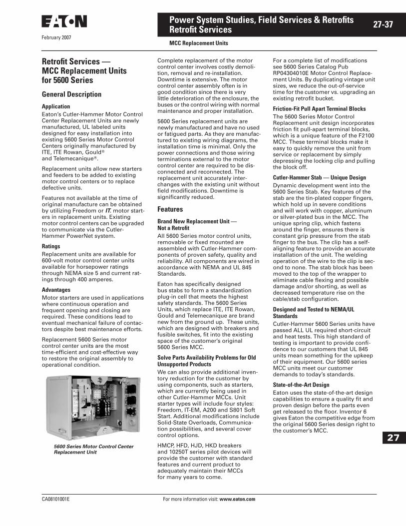
February 2007
CA08101001E For more information visit: www.eaton.com
27-37Power System Studies, Field Services & Retrofits
27
Retrofit ServicesMCC Replacement Units
Retrofit Services —MCC Replacement Unitsfor 5600 Series
General Description
ApplicationEaton’s Cutler-Hammer Motor Control Center Replacement Units are newly manufactured, UL labeled units designed for easy installation into existing 5600 Series Motor Control Centers originally manufactured by ITE, ITE Rowan, Gould� and Telemecanique�.
Replacement units allow new starters and feeders to be added to existing motor control centers or to replace defective units.
Features not available at the time of original manufacture can be obtained by utilizing Freedom or IT. motor start-ers in replacement units. Existing motor control centers can be upgraded to communicate via the Cutler-Hammer PowerNet system.
RatingsReplacement units are available for 600-volt motor control center units available for horsepower ratings through NEMA size 5 and current rat-ings through 400 amperes.
AdvantagesMotor starters are used in applications where continuous operation and frequent opening and closing are required. These conditions lead to eventual mechanical failure of contac-tors despite best maintenance efforts.
Replacement 5600 Series motor control center units are the most time-efficient and cost-effective way to restore the original assembly to operational condition.
5600 Series Motor Control CenterReplacement Unit
Complete replacement of the motor control center involves costly demoli-tion, removal and re-installation. Downtime is extensive. The motor control center assembly often is in good condition since there is very little deterioration of the enclosure, the buses or the control wiring with normal maintenance and proper installation.
5600 Series replacement units are newly manufactured and have no used or fatigued parts. As they are manufac-tured to existing wiring diagrams, the installation time is minimal. Only the power connections and those wiring terminations external to the motor control center are required to be dis-connected and reconnected. The replacement unit accurately inter-changes with the existing unit without field modifications. Downtime is significantly reduced.
Features
Brand New Replacement Unit — Not a RetrofitAll 5600 Series motor control units, removable or fixed mounted are assembled with Cutler-Hammer com-ponents of proven safety, quality and reliability. All components are wired in accordance with NEMA and UL 845 Standards.
Eaton has specifically designed bus stabs to form a standardization plug-in cell that meets the highest safety standards. The 5600 Series Units, which replace ITE, ITE Rowan, Gould and Telemecanique are brand new from the ground up. These units, which are designed with breakers and fusible switches, fit into the existing space of the customer’s original 5600 Series MCC.
Solve Parts Availability Problems for Old Unsupported ProductsWe can also provide additional inven-tory reduction for the customer by using components, such as starters, which are currently being used in other Cutler-Hammer MCCs. Unit starter types will include four styles: Freedom, IT-EM, A200 and S801 Soft Start. Additional modifications include Solid-State Overloads, Communica-tion possibilities, and several cover control options.
HMCP, HFD, HJD, HKD breakers and 10250T series pilot devices will provide the customer with standard features and current product to adequately maintain their MCCs for many years to come.
For a complete list of modifications see 5600 Series Catalog Pub RP04304010E Motor Control Replace-ment Units. By duplicating vintage unit sizes, we reduce the out-of-service time for the customer vs. upgrading an existing retrofit bucket.
Friction-Fit Pull Apart Terminal BlocksThe 5600 Series Motor Control Replacement unit design incorporates friction fit pull-apart terminal blocks, which is a unique feature of the F2100 MCC. These terminal blocks make it easy to quickly remove the unit from service or replacement by simply depressing the locking clip and pulling the block off.
Cutler-Hammer Stab — Unique Design Dynamic development went into the 5600 Series Stab. Key features of the stab are the tin-plated copper fingers, which hold up in severe conditions and will work with copper, aluminum or silver-plated bus in the MCC. The unique spring clip, which fastens around the finger, ensures there is constant grip pressure from the stab finger to the bus. The clip has a self-aligning feature to provide an accurate installation of the unit. The welding operation of the wire to the clip is sec-ond to none. The stab block has been moved to the top of the wrapper to eliminate cable flexing and possible damage and/or shorting, as well as decreased temperature rise on the cable/stab configuration.
Designed and Tested to NEMA/UL StandardsCutler-Hammer 5600 Series units have passed ALL UL required short-circuit and heat tests. This high standard of testing is important to provide confi-dence to our customers that UL 845 units mean something for the upkeep of their equipment. Our 5600 series MCC units meet our customer demands to today’s standards.
State-of-the-Art Design Eaton uses the state-of-the-art design capabilities to ensure a quality fit and proven design before the parts even get released to the floor. Inventor 6 gives Eaton the competitive edge from the original 5600 Series design right to the customer’s MCC.

February 2007
27-38
For more information visit: www.eaton.com CA08101001E
Power System Studies, Field Services & Retrofits
27
Retrofit ServicesMCC Replacement Units
Table 27-10. Standard Unit Combinations for the 5600 Series MCC Buckets
� Any two breaker combinations cannot exceed 150 amperes.
Unit Flexibility■ Four starter options.■ CPTs — 50, 100, 150 in 12 inches.■ For complete list of options,
see Catalog RP04304010E.
For additional information, contact 1-800-OLD-UNIT or your local Eaton Service Center.
Cutler-Hammer Designed Stabs
New Stab Design■ Tin-plated clip surface.■ Spring clip for extra pressure.■ Sufficient insulating surface.
Side Item Stab
Unit Features■ Holes for top and bottom
incoming line.■ Self aligning stab to bus.■ Door device panel.■ Knockout for terminal blocks.
Door Latch Closed
Door Features■ Door latch — 1/4 turn.■ Door hinge opens farther.
Inside IT. Freedom
Unit Features■ Easy lock-out handle mechanism.■ Easy lock-in bucket tabs.■ HMCP/HFD breakers 65k rated.■ Additional ground clip.■ 10250T series lights.
NEMA Type Starter OL Type Amperes/hp Voltage CPT Disconnect Options/Device Panel in Door
1 – 5 FVNR IT-EM,Freedom
Bi-Metallic,SSOL
400/200 Max. 480 Max. Standard HMCP 3 – 4 Pilot Devices, 21 Terminal Points
1 – 4 FVR IT-EM,Freedom
Bi-Metallic,SSOL
150/100 Max. 480 Max. Standard HMCP 3 – 4 Pilot Devices, 21 Terminal Points
1 – 4 2S1W IT-EM,Freedom
Bi-Metallic,SSOL
150/100 Max. 480 Max. Standard HMCP 3 – 4 Pilot Devices, 21 Terminal Points
1 – 4 2S2W IT-EM,Freedom
Bi-Metalic,SSOL
150/100 Max. 480 Max. Standard HMCP 3 – 4 Pilot Devices, 21 Terminal Points
— SingleBreaker
— — 150 Max. — — HFD —
— Dual Breaker
— — 150 Max.Combined �
— — HFD —
— SingleBreaker
— — 250 Max. — — HJD —
— SingleBreaker
— — 400 Max. — — HKD —
1 – 5 ITSS IT Soft Start SSOL 400/200 Max. 480 Max. Standard HMCP 3 – 4 Pilot Devices, 21 Terminal Points
Consult Factory for Release Fusible
Freedom Starter IT-EM Starter

February 2007
CA08101001E For more information visit: www.eaton.com
27-39Power System Studies, Field Services & Retrofits
27
Retrofit ServicesMCC Replacement Units
F2100 Replacement Starter Unit (1995 to Present)
Freedom Unitrol Replacement Starter Unit (1988 to 1994)
Type W Replacement Starter Unit (1965 to 1975)
AvailabilityReplacement units are available for all Motor Control Centers manufactured by Eaton or Westinghouse. Units are available as follows:
Cutler-Hammer:F2100 1995 to PresentFreedom Unitrol 1988 to 1994F-10 Unitrol 1972 to 19899800 Unitrol 1956 to 1974
Westinghouse:Advantage 1992 to PresentSeries 2100 1987 to 19955 Star 1975 to 1987Type W 1965 to 197511-300 1935 to 1965
All replacement units utilize Cutler-Hammer HMCP motor circuit protec-tors allowing the units to be UL 508 combination rated 65 kA. The units can be supplied with either Freedom, Advantage, A200, or Citation starters.
Advantage Replacement Starter Unit (1992 to Present)
5-Star Replacement Starter Unit(1975 to 1987)
9800 Unitrol Replacement Starter Unit (1956 to 1974)
Communication CapabilityMotor Control Center Units equipped with Advantage starters are communi-cation ready. By the addition of a PONI (Product Operated Network Interface) communication module, the Advantage starter can be connected to Eaton’s Cutler-Hammer PowerNet system or to a PLC or DCS system via a MINT (Master Incom Network Translator) unit.
The following parameters are reported to the communication system:
■ Starter status (open-closed).■ Cause of trip.■ Time of trip.■ Phase and ground currents.■ Control voltage.■ Starter type.■ Starter size.■ Protective features resident.■ Overload relay settings.■ Overload relay class — 10, 20 or 30.■ Manual or automatic reset.
Series 2100 Replacement Starter Unit (1987 to 1995)
F-10 Unitrol Replacement Starter Unit (1972 to 1989)
11-300 Replacement Starter Unit (1935 to 1965)
At the user’s discretion, the starters may be controlled over the PowerNet system.
For a local network, up to 99 Advantage starters can be connected to a Cutler-Hammer Central Monitoring Unit (CMU) via shielded twisted pair. The CMU can be located up to 7,500 feet 2,286 m) away from the last starter and will report the same information as available over the PowerNet network.
Information RequiredIn order to obtain the proper replace-ment unit, the following information should be provided to Eaton:
■ Motor Control Center manufacturer.■ Motor Control Center type.■ Required starter hp rating.■ Type of starter (i.e., FVNR, FVR,
2S2W, etc.)■ Desired protective features.■ Desired control devices.■ Desired control scheme.

February 2007
27-40
For more information visit: www.eaton.com CA08101001E
Power System Studies, Field Services & Retrofits
27
National Electrical Code and NEC are registered trade-marks of the National Fire Protection Association, Quincy, Mass. NEMA is the registered trademark and service mark of the National Electrical Manufacturers Association. UL is a federally registered trademark of Underwriters Laboratories Inc. ISO is the registered trademark and sole property of the International Orga-nization for Standardization. Square D is a federally registered trademark of SNA Holdings Inc. General Electric is a federally registered trademark of General Electric Company. Federal Pacific is a federally regis-tered name of Electro-Mechanical Corporation. Federal Pioneer is a federally registered name of Electro-Mechanical Corporation. Challenger is a registered trademark of Eaton Corporation. McGraw-Edison is a federally registered trademark of Cooper Industries, Inc. TOREX is a registered trademark of Gravi-Flo Corporation. ITE is a federally registered trademark of Integrated Technologies Engineering (ITE). ABB is a federally registered trademark of the ABB Group.
Cutler-Hammer is a federally registered trademark of Eaton Corporation. Westinghouse is a registered trade-mark of Westinghouse Electric Company LLC. Siemens is a federally registered trademark of Siemens AG. Modicon is a registered trademark of Schneider Elec-tric Industries SA. GE Fanuc is a federally registered trademark of GE Industrial Systems. Allen-Bradley is a federally registered trademark of Rockwell Automa-tion. GENESIS is a registered trademark of ICONICS, Inc. WebHMI is a registered trademark of ICONICS, Inc. Wonderware is a registered trademark of Invensys plc, its subsidiaries and affiliates. Microsoft, Word, Win-dows, Excel, and Access are registered trademarks of Microsoft Corporation. Gould is a federally registered trademark of Gould Electronics Inc. Telemecanique is a federally registered trademark of Schneider Electric SA.
Related Documents