System Manual ClassicController CR0020 CR0505 CoDeSys ® V2.3 Target V05 7390663 / 02 10 / 2009

Welcome message from author
This document is posted to help you gain knowledge. Please leave a comment to let me know what you think about it! Share it to your friends and learn new things together.
Transcript

System ManualClassicController
CR0020CR0505
CoDeSys® V2.3Target V05
7390
663
/ 02
1
0 / 2
009
2
ifm System Manual ecomatmobile ClassicController (CR0020, CR0505) V05
Contents
Contents
1 About this manual 7 1.1 What do the symbols and formats mean?.........................................................................7 1.2 How is this manual structured? .........................................................................................8
2 Safety instructions 9 2.1 General..............................................................................................................................9 2.2 What previous knowledge is required? ...........................................................................10
3 System description 11 3.1 Information concerning the device ..................................................................................11 3.2 Information concerning the software ...............................................................................11 3.3 PLC configuration............................................................................................................12
4 Monitoring concept 13 4.1 Hardware structure..........................................................................................................13 4.2 Operating principle of the delayed switch-off ..................................................................14
4.2.1 Connect terminal VBBS (23) to the ignition switch .......................................14 4.2.2 Connect terminal VBBO (5) to battery (not switched)...................................14 4.2.3 Latching.........................................................................................................14
4.3 Operating principle of the monitoring concept.................................................................15 4.3.1 Monitoring of the supply voltage VBBR (34).................................................15 4.3.2 Monitoring and securing mechanisms ..........................................................16
4.4 Feedback on bidirectional inputs/outputs........................................................................18 4.5 Feedback in case of externally supplied outputs ............................................................19
5 Configurations 20 5.1 Set up programming system ...........................................................................................20
5.1.1 Set up programming system manually..........................................................20 5.1.2 Set up programming system via templates...................................................22 5.1.3 ifm demo programs .......................................................................................32
5.2 Function configuration of the inputs and outputs ............................................................36 5.2.1 Configure inputs ............................................................................................37 5.2.2 Configure outputs..........................................................................................41
5.3 Hints to wiring diagrams ..................................................................................................44
6 Operating states and operating system 45 6.1 Operating states ..............................................................................................................45
6.1.1 Reset .............................................................................................................45 6.1.2 Run state.......................................................................................................45 6.1.3 Stop state ......................................................................................................45 6.1.4 Fatal error......................................................................................................45 6.1.5 No operating system .....................................................................................46
3
ifm System Manual ecomatmobile ClassicController (CR0020, CR0505) V05
Contents
6.2 Status LED ......................................................................................................................46 6.3 Load the operating system..............................................................................................47 6.4 Operating modes.............................................................................................................48
6.4.1 TEST mode ...................................................................................................48 6.4.2 SERIAL_MODE.............................................................................................48 6.4.3 DEBUG mode ...............................................................................................48
7 Error codes and diagnostic information 49 7.1 Response to the system error .........................................................................................50
7.1.1 Notes on devices with monitoring relay ........................................................50 7.1.2 Example process for response to a system error .........................................51
8 Programming and system resources 52 8.1 Above-average stress .....................................................................................................52 8.2 Limits of the ClassicController.........................................................................................53 8.3 Watchdog behaviour .......................................................................................................54 8.4 Available memory............................................................................................................54 8.5 Program creation and download in the PLC ...................................................................55
9 CAN in the ecomatmobile controller 57 9.1 General about CAN .........................................................................................................57
9.1.1 Topology .......................................................................................................57 9.1.2 CAN interfaces ..............................................................................................57 9.1.3 System configuration.....................................................................................58
9.2 Exchange of CAN data....................................................................................................59 9.2.1 CAN-ID..........................................................................................................59 9.2.2 Data reception...............................................................................................60 9.2.3 Data transmission .........................................................................................60
9.3 Physical connection of CAN............................................................................................61 9.3.1 Network structure ..........................................................................................61 9.3.2 Bus level........................................................................................................62 9.3.3 Bus cable length............................................................................................63 9.3.4 Wire cross-sections.......................................................................................64 9.3.5 Physical structure of ISO 11992-1 ................................................................64
9.4 Software for CAN and CANopen.....................................................................................65 9.5 CAN errors and error handling ........................................................................................65
9.5.1 Error message...............................................................................................65 9.5.2 Error counter .................................................................................................66 9.5.3 Participant, error active .................................................................................66 9.5.4 Participant, error passive ..............................................................................66 9.5.5 Participant, bus off ........................................................................................67
9.6 Description of the CAN functions ....................................................................................68 9.6.1 Function CAN1_BAUDRATE ........................................................................69 9.6.2 Function CAN1_DOWNLOADID...................................................................71 9.6.3 Function CAN1_EXT.....................................................................................73 9.6.4 Function CAN1_EXT_TRANSMIT ................................................................75 9.6.5 Function CAN1_EXT_RECEIVE...................................................................77 9.6.6 Function CAN1_EXT_ERRORHANDLER ....................................................79 9.6.7 Function CAN2..............................................................................................80 9.6.8 Function CANx_TRANSMIT .........................................................................82 9.6.9 Function CANx_RECEIVE ............................................................................84 9.6.10 Function CANx_RECEIVE_RANGE .............................................................86 9.6.11 Function CANx_EXT_RECEIVE_ALL...........................................................89 9.6.12 Function CANx_ERRORHANDLER..............................................................91
4
ifm System Manual ecomatmobile ClassicController (CR0020, CR0505) V05
Contents
9.7 ifm CANopen library ........................................................................................................93 9.7.1 CANopen support by CoDeSys ....................................................................93 9.7.2 CANopen master...........................................................................................95 9.7.3 Start-up of the network without [Automatic startup] ................................... 106 9.7.4 CAN device ................................................................................................ 109 9.7.5 CAN network variables............................................................................... 117 9.7.6 Information on the EMCY and error codes ................................................ 122 9.7.7 Library for the CANopen master ................................................................ 127 9.7.8 Library for the CANopen slave................................................................... 139 9.7.9 Further ifm libraries for CANopen .............................................................. 149
9.8 Summary CAN / CANopen........................................................................................... 154 9.9 Use of the CAN interfaces to SAE J1939..................................................................... 155
9.9.1 Function J1939_x....................................................................................... 158 9.9.2 Function J1939_x_RECEIVE..................................................................... 160 9.9.3 Function J1939_x_TRANSMIT .................................................................. 162 9.9.4 Function J1939_x_RESPONSE................................................................. 164 9.9.5 Function J1939_x_SPECIFIC_REQUEST................................................. 166 9.9.6 Function J1939_x_GLOBAL_REQUEST................................................... 168
10 PWM in the ecomatmobile controller 170 10.1 PWM signal processing................................................................................................ 171
10.1.1 PWM functions and their parameters (general) ......................................... 171 10.1.2 Function PWM............................................................................................ 176 10.1.3 Function PWM100...................................................................................... 178 10.1.4 Function PWM1000.................................................................................... 180
10.2 Current control with PWM ............................................................................................ 182 10.2.1 Current measurement with PWM channels ............................................... 182 10.2.2 Function OUTPUT_CURRENT_CONTROL .............................................. 183 10.2.3 Function OCC_TASK................................................................................. 185 10.2.4 Function OUTPUT_CURRENT.................................................................. 187
10.3 Hydraulic control in PWM............................................................................................. 188 10.3.1 The purpose of this library? – An introduction ........................................... 188 10.3.2 What does a PWM output do? ................................................................... 189 10.3.3 What is the dither? ..................................................................................... 190 10.3.4 Functions of the library "ifm_HYDRAULIC_16bitOS05_Vxxyyzz.Lib" ....... 193 10.3.5 Function CONTROL_OCC......................................................................... 194 10.3.6 Function JOYSTICK_0............................................................................... 197 10.3.7 Function JOYSTICK_1............................................................................... 201 10.3.8 Function JOYSTICK_2............................................................................... 205 10.3.9 Function NORM_HYDRAULIC .................................................................. 208
11 More functions in the ecomatmobile controller 211 11.1 Counter functions for frequency and period measurement.......................................... 211
11.1.1 Applications................................................................................................ 211 11.1.2 Use as digital inputs ................................................................................... 212 11.1.3 Function FREQUENCY.............................................................................. 213 11.1.4 Function PERIOD....................................................................................... 215 11.1.5 Function PERIOD_RATIO ......................................................................... 217 11.1.6 Function PHASE ........................................................................................ 219 11.1.7 Function INC_ENCODER .......................................................................... 221 11.1.8 Function FAST_COUNT ............................................................................ 224
11.2 Software reset .............................................................................................................. 226 11.2.1 Function SOFTRESET............................................................................... 226
5
ifm System Manual ecomatmobile ClassicController (CR0020, CR0505) V05
Contents
11.3 Saving, reading and converting data in the memory.................................................... 227 11.3.1 Automatic saving of data............................................................................ 227 11.3.2 Function MEMORY_RETAIN_PARAM...................................................... 228 11.3.3 Manual data storage .................................................................................. 229 11.3.4 Function MEMCPY..................................................................................... 230 11.3.5 Function FLASHWRITE ............................................................................. 231 11.3.6 Function FLASHREAD............................................................................... 233 11.3.7 Function FRAMWRITE............................................................................... 234 11.3.8 Function FRAMREAD ................................................................................ 235
11.4 Data access and data check ........................................................................................ 236 11.4.1 Function SET_DEBUG............................................................................... 237 11.4.2 Function SET_IDENTITY........................................................................... 238 11.4.3 Function GET_IDENTITY........................................................................... 240 11.4.4 Function SET_PASSWORD ...................................................................... 242 11.4.5 Function CHECK_DATA ............................................................................ 244
11.5 Processing interrupts.................................................................................................... 246 11.5.1 Function SET_INTERRUPT_XMS............................................................. 247 11.5.2 Function SET_INTERRUPT_I.................................................................... 250
11.6 Use of the serial interface............................................................................................. 253 11.6.1 Function SERIAL_SETUP ......................................................................... 254 11.6.2 Function SERIAL_TX................................................................................. 256 11.6.3 Function SERIAL_RX................................................................................. 257 11.6.4 Function SERIAL_PENDING ..................................................................... 259
11.7 Reading the system time.............................................................................................. 260 11.7.1 Function TIMER_READ ............................................................................. 260 11.7.2 Function TIMER_READ_US ...................................................................... 261
11.8 Processing analogue input values................................................................................ 262 11.8.1 Function INPUT_ANALOG......................................................................... 263 11.8.2 Function INPUT_VOLTAGE ...................................................................... 265 11.8.3 Function INPUT_CURRENT...................................................................... 266
11.9 Adapting analogue values ............................................................................................ 267 11.9.1 Function NORM ......................................................................................... 268
12 Controller functions in the ecomatmobile controller 270 12.1 General......................................................................................................................... 270
12.1.1 Self-regulating process .............................................................................. 270 12.1.2 Controlled system without inherent regulation........................................... 271 12.1.3 Controlled system with delay ..................................................................... 271
12.2 Setting rule for a controller ........................................................................................... 271 12.2.1 Setting control ............................................................................................ 271 12.2.2 Damping of overshoot ................................................................................ 272
12.3 Functions for controllers ............................................................................................... 272 12.3.1 Function DELAY......................................................................................... 273 12.3.2 Function PT1.............................................................................................. 275 12.3.3 Function PID1 ............................................................................................ 277 12.3.4 Function PID2 ............................................................................................ 279 12.3.5 Function GLR ............................................................................................. 282
13 Annex 284 13.1 Adress assignment and I/O operating modes .............................................................. 284
13.1.1 Addresses / variables of the I/Os ............................................................... 284 13.1.2 Possible operating modes inputs / outputs ................................................ 286 13.1.3 Address assignment inputs / outputs ......................................................... 288
13.2 System flags ................................................................................................................. 290

6
ifm System Manual ecomatmobile ClassicController (CR0020, CR0505) V05
Contents
13.3 Overview of the files and libraries used ....................................................................... 292 13.3.1 General overview ....................................................................................... 292 13.3.2 What are the individual files and libraries used for? .................................. 294
14 Glossary of Terms 299
15 Index 311
ifm System Manual ecomatmobile ClassicController (CR0020, CR0505) V05
7
About this manual What do the symbols and formats mean?
1 About this manual What do the symbols and formats mean?...................................................................................7 How is this manual structured? ...................................................................................................8
In this chapter you will find an overview of the following points:
• What do the symbols and formats stand for?
• How is this manual structured?
In the additional "Programming Manual for CoDeSys® V2.3" you will obtain more details about the use of the programming system "CoDeSys for Automation Alliance™". This manual can be downloaded free of charge from ifm's website: → www.ifm.com > select country/language > [Service] > [Download] > [Control systems] → ifm-CD "Software, tools and documentation"
Nobody is perfect. Send us your suggestions for improvements to this manual and you will receive a little gift from us to thank you.
© All rights reserved by ifm electronic gmbh. No part of this manual may be reproduced and used without the consent of ifm electronic gmbh.
All product names, pictures, companies or other brands used on our pages are the property of the respective rights owners.
1.1 What do the symbols and formats mean? The following symbols or pictograms depict different kinds of remarks in our manuals:
DANGER Death or serious irreversible injuries are to be expected.
WARNING Death or serious irreversible injuries are possible.
CAUTION Slight reversible injuries are possible.
NOTICE Property damage is to be expected or possible.
NOTE Important notes to faults and errors.
ifm System Manual ecomatmobile ClassicController (CR0020, CR0505) V05
8
About this manual How is this manual structured?
Info Further hints.
► ... Required action
> ... Response, effect
→ ... "see"
abc Cross references (links)
[...] Designations of keys, buttons or display
1.2 How is this manual structured? This documentation is a combination of different types of manuals. It is for beginners and also a reference for advanced users.
How to use this documentation:
• Refer to the table of contents to select a specific subject.
• At the beginning of a chapter we will give you a brief overview of its contents.
• Abbreviations and technical terms are listed in the glossary.
• The print version of the manual contains a search index in the annex.
In case of malfunctions or uncertainties please contact the manufacturer at: → www.ifm.com > select country/language > [Contact]
We reserve the right to make alterations which can result in a change of contents of the documentation. You can find the current version on ifm's website at: → www.ifm.com > select country/language > [Service] > [Download] > [Control systems]
ifm System Manual ecomatmobile ClassicController (CR0020, CR0505) V05
9
Safety instructions General
2 Safety instructions General ........................................................................................................................................9 What previous knowledge is required?......................................................................................10
2.1 General No characteristics are warranted with the information, notes and examples provided in this manual. The drawings, representations and examples imply no responsibility for the system and no application-specific particularities.
The manufacturer of the machine/equipment is responsible for the safety of the machine/equipment.
WARNING Property damage or bodily injury possible when the notes in this manual are not adhered to! ifm electronic gmbh does not assume any liability in this regard.
► The acting person must have read and understood the safety instructions and the corresponding chapters of this manual before performing any work on or with this device.
► The acting person must be authorised to work on the machine/equipment.
► Adhere to the technical data of the devices! You can find the current data sheet on ifm's homepage at: → www.ifm.com > select country/language > [Data sheet direct] > (Article no.) > [Technical data in PDF format]
► Note the installation and wiring information as well as the functions and features of the devices! → supplied installation instructions or on ifm's homepage: → www.ifm.com > select country/language > [Data sheet direct] > (Article no.) > [Operating instructions]
ATTENTION The driver module of the serial interface can be damaged!
Disconnecting the serial interface while live can cause undefined states which damage the driver module.
► Do not disconnect the serial interface while live.
Start-up behaviour of the controller
The manufacturer of the machine/equipment must ensure with his application program that when the controller starts or restarts no dangerous movements can be triggered.
A restart can, for example, be caused by:
• voltage restoration after power failure
• reset after watchdog response because of too long a cycle time

ifm System Manual ecomatmobile ClassicController (CR0020, CR0505) V05
10
Safety instructions What previous knowledge is required?
2.2 What previous knowledge is required? This document is intended for people with knowledge of control technology and PLC programming with IEC 61131-3.
If this device contents a PLC, in addition these persons should know the CoDeSys® software.
The document is intended for specialists. These specialists are people who are qualified by their training and their experience to see risks and to avoid possible hazards that may be caused during operation or maintenance of a product. The document contains information about the correct handling of the product.
Read this document before use to familiarise yourself with operating conditions, installation and operation. Keep the document during the entire duration of use of the device.
Adhere to the safety instructions.
ifm System Manual ecomatmobile ClassicController (CR0020, CR0505) V05
11
System description Information concerning the device
3 System description Information concerning the device.............................................................................................11 Information concerning the software .........................................................................................11 PLC configuration ......................................................................................................................12
3.1 Information concerning the device This manual describes the ecomatmobile controller family of ifm electronic gmbh with a 16-bit microcontroller for mobile vehicles:
• ClassicController: CR0020, CR0505
3.2 Information concerning the software The controller operates with CoDeSys®, version 2.3.9.1 or higher.
In the "programming manual CoDeSys ® 2.3" you will find more details about how to use the programming system "CoDeSys for Automation Alliance". This manual can be downloaded free of charge from ifm's website at: → www.ifm.com > select country/language > [Service] > [Download] > [Control systems] → ifm-CD "Software, tools and documentation"
The application software can be easily designed by the user with the programming system CoDeSys®.
Moreover the user must take into account which software version is used (in particular for the operating system and the function libraries).
NOTE: The software versions suitable for the selected target must always be used:
• of the operating system (CRnnnn_Vxxyyyzz.H86),
• of the PLC configuration (CRnnnn_Vxx.CFG),
• of the device library (CRnnnn_Vxxyyyzz.LIB),
• and the further files (→ chapter Overview of the files and libraries used, → page 292)
CRnnnn device article number Vxx: 00...99 target version number yy: 00...99 release number zz: 00...99 patch number
The basic file name (e.g. "CR0032") and the software version number "xx" (e.g. "02") must always have the same value! Otherwise the controller goes to the STOP mode.
The values for "yy" (release number) and "zz" (patch number) do not have to match.
Also note: the following files must also be loaded:
• The for the project required internal libraries (designed in IEC1131),
• the configuration files (*.CFG)
• and the target files (*.TRG).
ifm System Manual ecomatmobile ClassicController (CR0020, CR0505) V05
12
System description PLC configuration
Also note:
The target for CRnn32 must be > V02, for all other devices > V05.
The user is responsible for the reliable function of the application programs he designed. If necessary, he must additionally carry out an approval test by corresponding supervisory and test organisations according to the national regulations.
3.3 PLC configuration The control system ecomatmobile is a device concept for series use. This means that the controllers can be configured in an optimum manner for the applications. If necessary, special functions and hardware solutions can be implemented. In addition, the current version of the ecomatmobile software can be downloaded from our website at: www.ifm.com.
Before using the controllers it must be checked whether certain functions, hardware options, inputs and outputs described in the documentation are available in the hardware.
ifm System Manual ecomatmobile ClassicController (CR0020, CR0505) V05
13
Monitoring concept Hardware structure
4 Monitoring concept Hardware structure ....................................................................................................................13 Operating principle of the delayed switch-off.............................................................................14 Operating principle of the monitoring concept...........................................................................15 Feedback on bidirectional inputs/outputs ..................................................................................18 Feedback in case of externally supplied outputs.......................................................................19
The controller monitors the supply voltages and the system error flags. Depending on the status the controller switches off the internal relays or the controller.
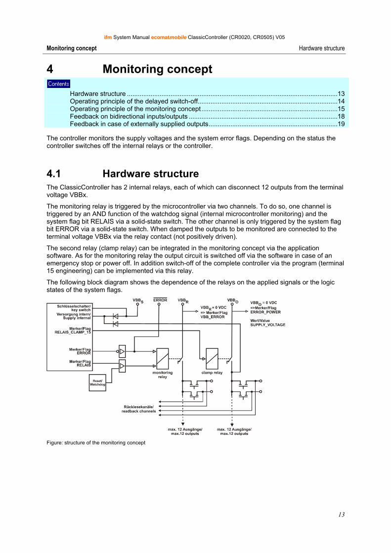
4.1 Hardware structure The ClassicController has 2 internal relays, each of which can disconnect 12 outputs from the terminal voltage VBBx.
The monitoring relay is triggered by the microcontroller via two channels. To do so, one channel is triggered by an AND function of the watchdog signal (internal microcontroller monitoring) and the system flag bit RELAIS via a solid-state switch. The other channel is only triggered by the system flag bit ERROR via a solid-state switch. When damped the outputs to be monitored are connected to the terminal voltage VBBx via the relay contact (not positively driven).
The second relay (clamp relay) can be integrated in the monitoring concept via the application software. As for the monitoring relay the output circuit is switched off via the software in case of an emergency stop or power off. In addition switch-off of the complete controller via the program (terminal 15 engineering) can be implemented via this relay.
The following block diagram shows the dependence of the relays on the applied signals or the logic states of the system flags.
Figure: structure of the monitoring concept
ifm System Manual ecomatmobile ClassicController (CR0020, CR0505) V05
14
Monitoring concept Operating principle of the delayed switch-off
4.2 Operating principle of the delayed switch-off
If the ecomatmobile controllers are disconnected from the supply voltage (ignition off), all outputs are normally switched off at once, input signals are no longer read and processing of the controller software (operating system and application program) is interrupted. This happens irrespective of the current program step of the controller.
If this is not requested, the controller must be switched off via the program. After switch-off of the ignition this enables, for example, saving of memory states.
The ClassicControllers can be switched off via the program by means of a corresponding connection of the supply voltage inputs and the evaluation of the related system flags. The block diagram in the chapter Hardware set-up (→ page 13) shows the context of the individual current paths.
4.2.1 Connect terminal VBBS (23) to the ignition switch Via terminal 23 the controller is supplied and can be switched off by an ignition switch.
In automotive engineering the potential is called "clamp 15".
This terminal is monitored internally. If no supply voltage is applied, the system flag CLAMP_15 is set to FALSE. The reset of the flag CLAMP_15 can be monitored by the application program.
4.2.2 Connect terminal VBBO (5) to battery (not switched) Up to 12 outputs of the output group VBBO can be supplied via terminal 5. At the same time latching of the control electronics is supplied via this terminal.
4.2.3 Latching Latching is active if voltage is applied to VBBO and the system flag RELAIS_CLAMP_15 (and so the relay [Clamp]) is set.
If the system flag RELAIS_CLAMP_15 is reset, the relay [Clamp] is de-energised. If at this moment no voltage is applied to terminal 23, latching is removed and the controller switches off completely.
ifm System Manual ecomatmobile ClassicController (CR0020, CR0505) V05
15
Monitoring concept Operating principle of the monitoring concept
4.3 Operating principle of the monitoring concept
During program processing the monitoring relay is completely controlled via the software by the user. So a parallel contact of the safety chain, for example, can be evaluated as an input signal and the monitoring relay can be switched off accordingly. To be on the safe side, the corresponding applicable national regulations must be complied with.
If an error occurs during program processing, the relay can be switched off using the system flag bit ERROR to disconnect critical plant sections.
By resetting the system flag bit RELAIS (via the system flag bit ERROR or directly) all outputs are switched off. The outputs in the current path VBBR are disconnected directly by means of the monitoring relay. So the outputs in the current path VBBO are only disconnected via the software.
WARNING Danger due to unintentional and dangerous start of machine or plant sections!
► When creating the program, the programmer must ensure that no unintentional and dangerous start of machines or plant sections after a fault (e.g. e-stop) and the following fault elimination can occur.
► To do so, the required outputs must be additionally switched off and the logic states must be linked to the relay state and evaluated.
If an output to be monitored is continuously switched and the contact of the monitoring relay is stuck, the corresponding output cannot be switched off!
NOTE If a watchdog error occurs, the program processing is interrupted automatically and the controller is reset. The controller then starts again as after power on.
4.3.1 Monitoring of the supply voltage VBBR (34) Up to 12 outputs of the output group VBBR can be supplied via terminal 34. In addition, application of the terminal voltage is indicated via the system flag ERROR_VBBR. If ERROR_VBBR is set (TRUE), no supply voltage is applied. This information can then be processed in the application program.
Only ExtendedController:
NOTE Note that for the two controller halves of the ExtendedController terminal 23 is connected to and switched off by the ignition switch. The two system flags RELAIS_CLAMP_15 and RELAIS_CLAMP_15_E must also be reset to switch off the controller completely.
ifm System Manual ecomatmobile ClassicController (CR0020, CR0505) V05
16
Monitoring concept Operating principle of the monitoring concept
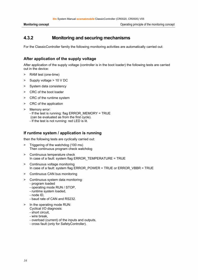
4.3.2 Monitoring and securing mechanisms
For the ClassicController family the following monitoring activities are automatically carried out:
After application of the supply voltage After application of the supply voltage (controller is in the boot loader) the following tests are carried out in the device:
> RAM test (one-time)
> Supply voltage > 10 V DC
> System data consistency
> CRC of the boot loader
> CRC of the runtime system
> CRC of the application
> Memory error: - If the test is running: flag ERROR_MEMORY = TRUE (can be evaluated as from the first cycle). - If the test is not running: red LED is lit.
If runtime system / application is running then the following tests are cyclically carried out:
> Triggering of the watchdog (100 ms) Then continuous program check watchdog
> Continuous temperature check In case of a fault: system flag ERROR_TEMPERATURE = TRUE
> Continuous voltage monitoring In case of a fault: system flag ERROR_POWER = TRUE or ERROR_VBBR = TRUE
> Continuous CAN bus monitoring
> Continuous system data monitoring: - program loaded - operating mode RUN / STOP, - runtime system loaded, - node ID, - baud rate of CAN and RS232.
> In the operating mode RUN: Cyclical I/O diagnosis: - short circuit, - wire break, - overload (current) of the inputs and outputs, - cross fault (only for SafetyController).
ifm System Manual ecomatmobile ClassicController (CR0020, CR0505) V05
17
Monitoring concept Operating principle of the monitoring concept
Only for SafetyController:
> Monitoring of the PIC controller (PIC = coprocessor of the controller): - PIC available and active, - quarz clock signal
> RELAY test
> Monitoring of the memory
> Controller command check
In case of a fault:
> red LED is lit,
> Controller passes to the STOP mode.
If the TEST pin is not active > Write protection for system data in FRAM, e.g.:
- runtime system loaded, - calibration data. Implemented via hardware and software.
> Write protection for application program (in the flash memory)
> DEBUG mode
One-time mechanisms > CRC monitoring during download or upload.
> It must be checked that the runtime system and the application are assigned to the same device.
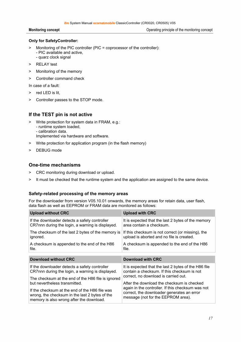
Safety-related processing of the memory areas For the downloader from version V05.10.01 onwards, the memory areas for retain data, user flash, data flash as well as EEPROM or FRAM data are monitored as follows:
Upload without CRC Upload with CRC
If the downloader detects a safety controller CR7nnn during the login, a warning is displayed.
The checksum of the last 2 bytes of the memory is ignored.
A checksum is appended to the end of the H86 file.
It is expected that the last 2 bytes of the memory area contain a checksum.
If this checksum is not correct (or missing), the upload is aborted and no file is created.
A checksum is appended to the end of the H86 file.
Download without CRC Download with CRC
If the downloader detects a safety controller CR7nnn during the login, a warning is displayed.
The checksum at the end of the H86 file is ignored but nevertheless transmitted.
If the checksum at the end of the H86 file was wrong, the checksum in the last 2 bytes of the memory is also wrong after the download.
It is expected that the last 2 bytes of the H86 file contain a checksum. If this checksum is not correct, no download is carried out.
After the download the checksum is checked again in the controller. If this checksum was not correct, the downloader generates an error message (not for the EEPROM area).
ifm System Manual ecomatmobile ClassicController (CR0020, CR0505) V05
18
Monitoring concept Feedback on bidirectional inputs/outputs
4.4 Feedback on bidirectional inputs/outputs Some terminals of the controller can be configured as well as input or as output (→ data sheet).
NOTICE Destruction of outputs if there is inadmissible feedback!
If bidirectional inputs/outputs are operated at the same time with normal inputs and outputs, the corresponding output bar must not become potential-free.
Otherwise the terminal voltage is fed back to the output bar via the protective diode integrated in the output driver. A possibly set output thus triggers its connected load. The load current destroys the output which feeds back.
► Continuously set the flag RELAIS in the application program to TRUE: TRUE ----- RELAIS
This has to be adhered to...
• in particular if the device and output voltage supply are protected separately and
• if the output bars VBBO/VBBR are switched off by the integrated relays via the software. O
I
RELAIS
VBBo
I1 (Q1)
Q2
S1
K2
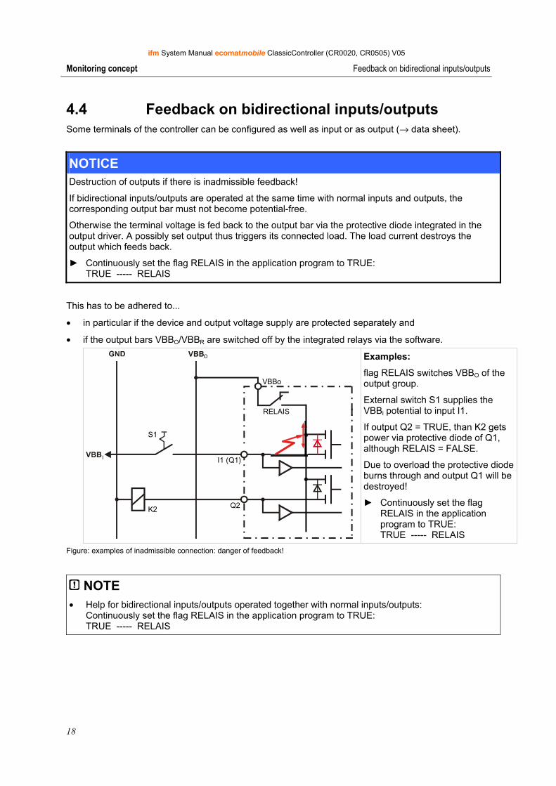
Examples:
flag RELAIS switches VBBO of the output group.
External switch S1 supplies the VBBi potential to input I1.
If output Q2 = TRUE, than K2 gets power via protective diode of Q1, although RELAIS = FALSE.
Due to overload the protective diode burns through and output Q1 will be destroyed!
► Continuously set the flag RELAIS in the application program to TRUE: TRUE ----- RELAIS
Figure: examples of inadmissible connection: danger of feedback!
NOTE • Help for bidirectional inputs/outputs operated together with normal inputs/outputs:
Continuously set the flag RELAIS in the application program to TRUE: TRUE ----- RELAIS
ifm System Manual ecomatmobile ClassicController (CR0020, CR0505) V05
19
Monitoring concept Feedback in case of externally supplied outputs
4.5 Feedback in case of externally supplied outputs In some applications actuators are not only controlled by outputs of the PLC but additionally by external switches. In such cases the externally supplied outputs must be protected with blocking diodes (→ see graphics below).
ATTENTION Destruction of outputs if there is inadmissible feedback!
If actuators are externally controlled, the corresponding output bar must not become potential-free (e.g. for RELAIS = FALSE).
Otherwise the terminal voltage VBBx is fed back to the potential bar of the output group via the protective diode integrated in the output driver. A possibly set output thus triggers its connected load. The load current destroys the output which feeds back.
► Protect externally supplied outputs by means of blocking diodes!
O
RELAIS
Q1
Q2
S1
VBBo
K1
V2V1
K2
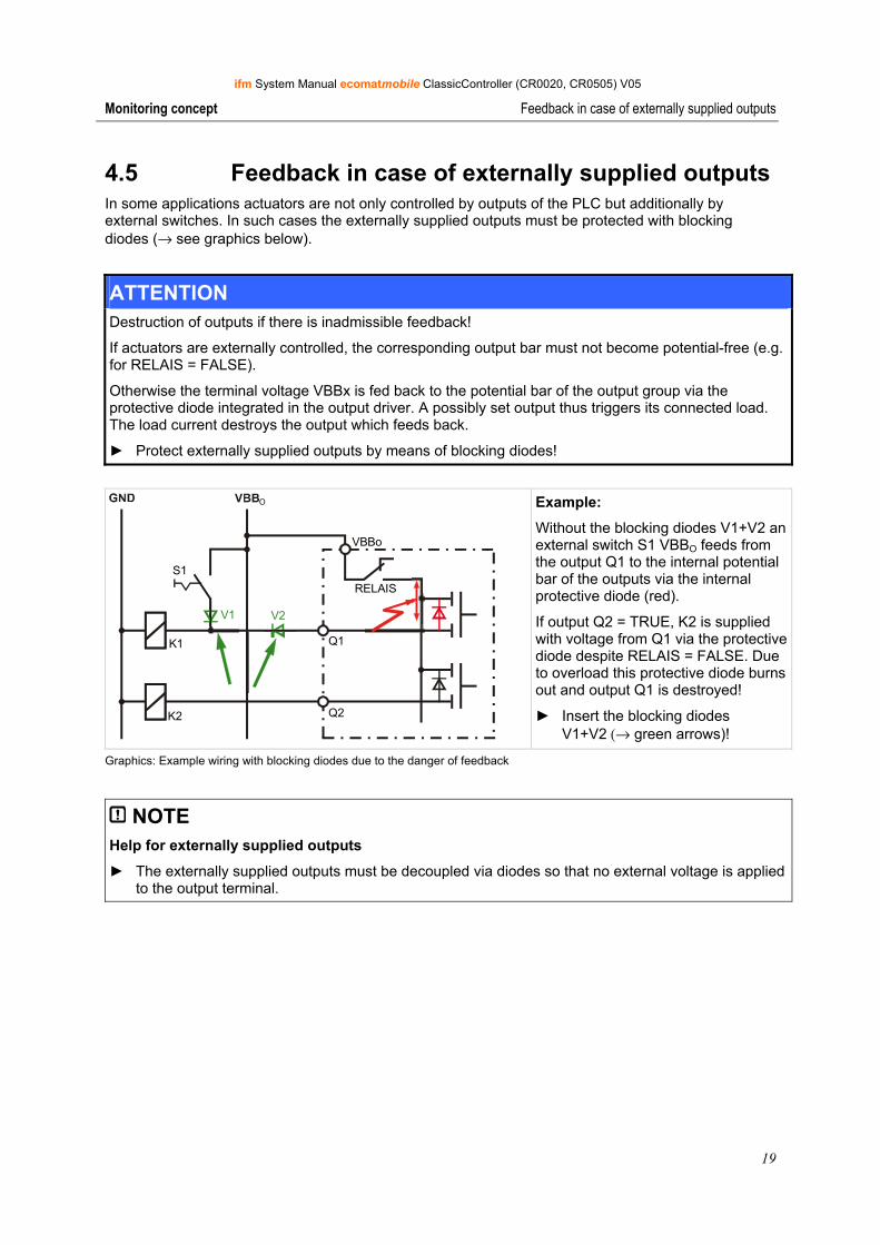
Example:
Without the blocking diodes V1+V2 an external switch S1 VBBO feeds from the output Q1 to the internal potential bar of the outputs via the internal protective diode (red).
If output Q2 = TRUE, K2 is supplied with voltage from Q1 via the protective diode despite RELAIS = FALSE. Due to overload this protective diode burns out and output Q1 is destroyed!
► Insert the blocking diodes V1+V2 (→ green arrows)!
Graphics: Example wiring with blocking diodes due to the danger of feedback
NOTE Help for externally supplied outputs
► The externally supplied outputs must be decoupled via diodes so that no external voltage is applied to the output terminal.
ifm System Manual ecomatmobile ClassicController (CR0020, CR0505) V05
20
Configurations Set up programming system
5 Configurations Set up programming system......................................................................................................20 Function configuration of the inputs and outputs.......................................................................36 Hints to wiring diagrams ............................................................................................................44
5.1 Set up programming system
5.1.1 Set up programming system manually
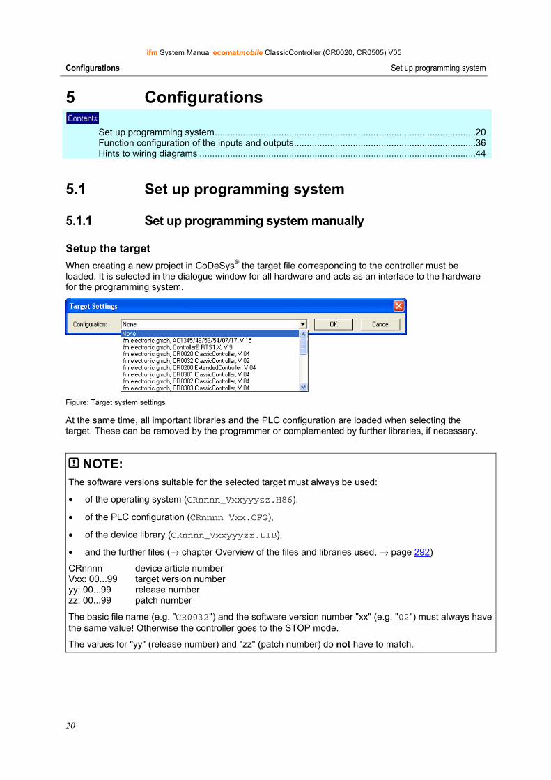
Setup the target When creating a new project in CoDeSys® the target file corresponding to the controller must be loaded. It is selected in the dialogue window for all hardware and acts as an interface to the hardware for the programming system.
Figure: Target system settings
At the same time, all important libraries and the PLC configuration are loaded when selecting the target. These can be removed by the programmer or complemented by further libraries, if necessary.
NOTE: The software versions suitable for the selected target must always be used:
• of the operating system (CRnnnn_Vxxyyyzz.H86),
• of the PLC configuration (CRnnnn_Vxx.CFG),
• of the device library (CRnnnn_Vxxyyyzz.LIB),
• and the further files (→ chapter Overview of the files and libraries used, → page 292)
CRnnnn device article number Vxx: 00...99 target version number yy: 00...99 release number zz: 00...99 patch number
The basic file name (e.g. "CR0032") and the software version number "xx" (e.g. "02") must always have the same value! Otherwise the controller goes to the STOP mode.
The values for "yy" (release number) and "zz" (patch number) do not have to match.
ifm System Manual ecomatmobile ClassicController (CR0020, CR0505) V05
21
Configurations Set up programming system
Also note: the following files must also be loaded:
• The for the project required internal libraries (designed in IEC1131),
• the configuration files (*.CFG)
• and the target files (*.TRG).
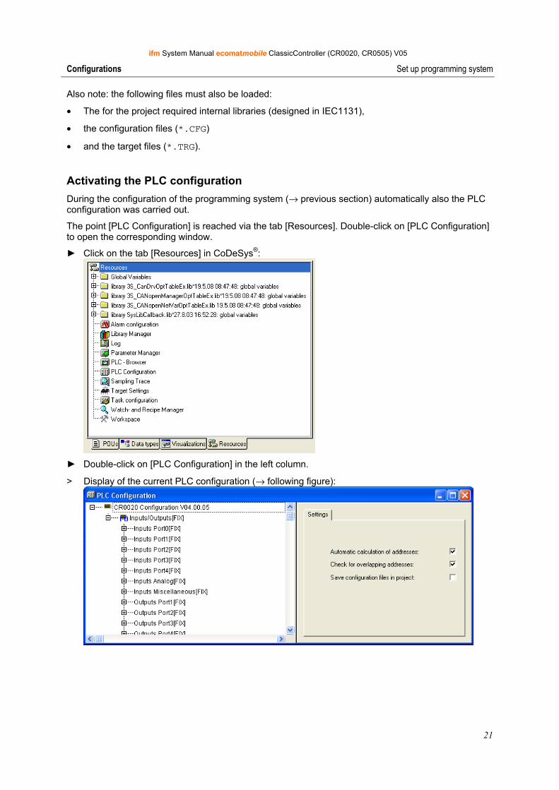
Activating the PLC configuration During the configuration of the programming system (→ previous section) automatically also the PLC configuration was carried out.
The point [PLC Configuration] is reached via the tab [Resources]. Double-click on [PLC Configuration] to open the corresponding window.
► Click on the tab [Resources] in CoDeSys®:
► Double-click on [PLC Configuration] in the left column.
> Display of the current PLC configuration (→ following figure):
ifm System Manual ecomatmobile ClassicController (CR0020, CR0505) V05
22
Configurations Set up programming system
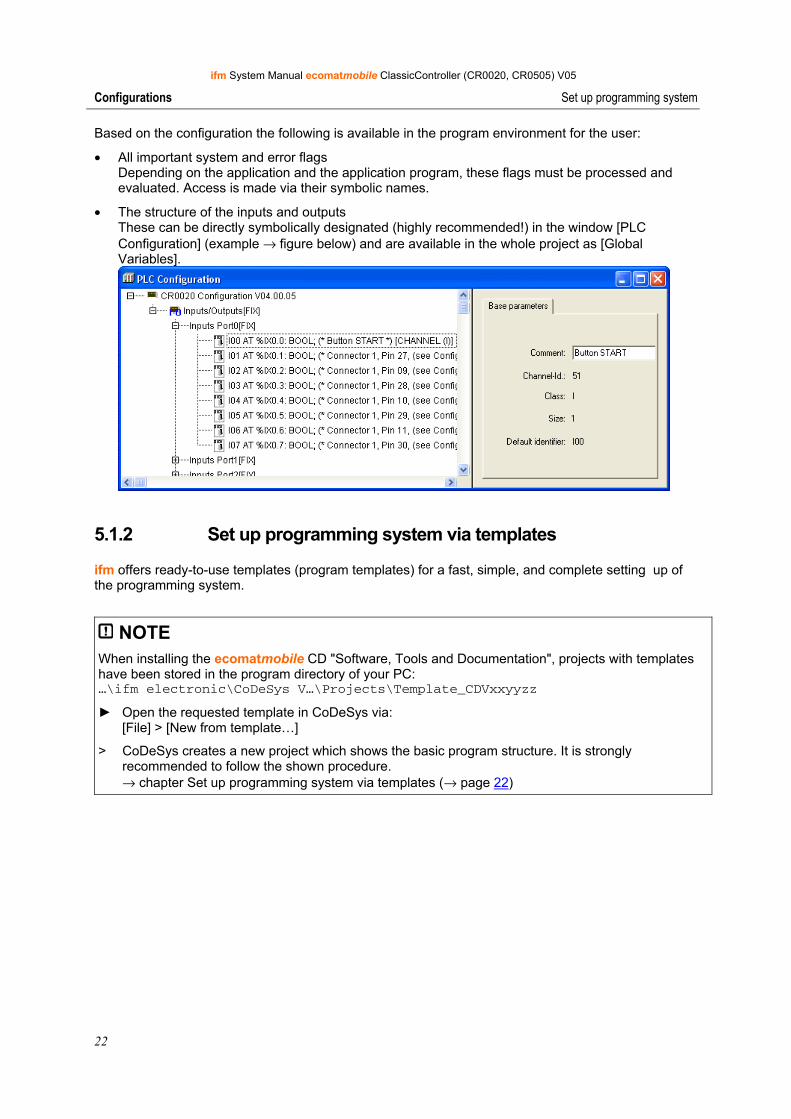
Based on the configuration the following is available in the program environment for the user:
• All important system and error flags Depending on the application and the application program, these flags must be processed and evaluated. Access is made via their symbolic names.
• The structure of the inputs and outputs These can be directly symbolically designated (highly recommended!) in the window [PLC Configuration] (example → figure below) and are available in the whole project as [Global Variables].
5.1.2 Set up programming system via templates
ifm offers ready-to-use templates (program templates) for a fast, simple, and complete setting up of the programming system.
NOTE When installing the ecomatmobile CD "Software, Tools and Documentation", projects with templates have been stored in the program directory of your PC: …\ifm electronic\CoDeSys V…\Projects\Template_CDVxxyyzz
► Open the requested template in CoDeSys via: [File] > [New from template…]
> CoDeSys creates a new project which shows the basic program structure. It is strongly recommended to follow the shown procedure. → chapter Set up programming system via templates (→ page 22)
ifm System Manual ecomatmobile ClassicController (CR0020, CR0505) V05
23
Configurations Set up programming system
How do you set up the programming system fast and simply?
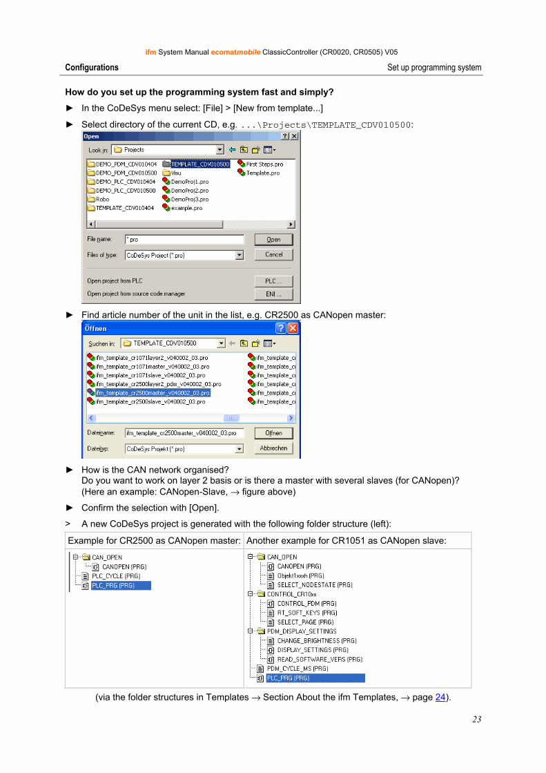
► In the CoDeSys menu select: [File] > [New from template...]
► Select directory of the current CD, e.g. ...\Projects\TEMPLATE_CDV010500:
► Find article number of the unit in the list, e.g. CR2500 as CANopen master:
► How is the CAN network organised?
Do you want to work on layer 2 basis or is there a master with several slaves (for CANopen)? (Here an example: CANopen-Slave, → figure above)
► Confirm the selection with [Open].
> A new CoDeSys project is generated with the following folder structure (left):
Example for CR2500 as CANopen master: Another example for CR1051 as CANopen slave:
(via the folder structures in Templates → Section About the ifm Templates, → page 24).
ifm System Manual ecomatmobile ClassicController (CR0020, CR0505) V05
24
Configurations Set up programming system
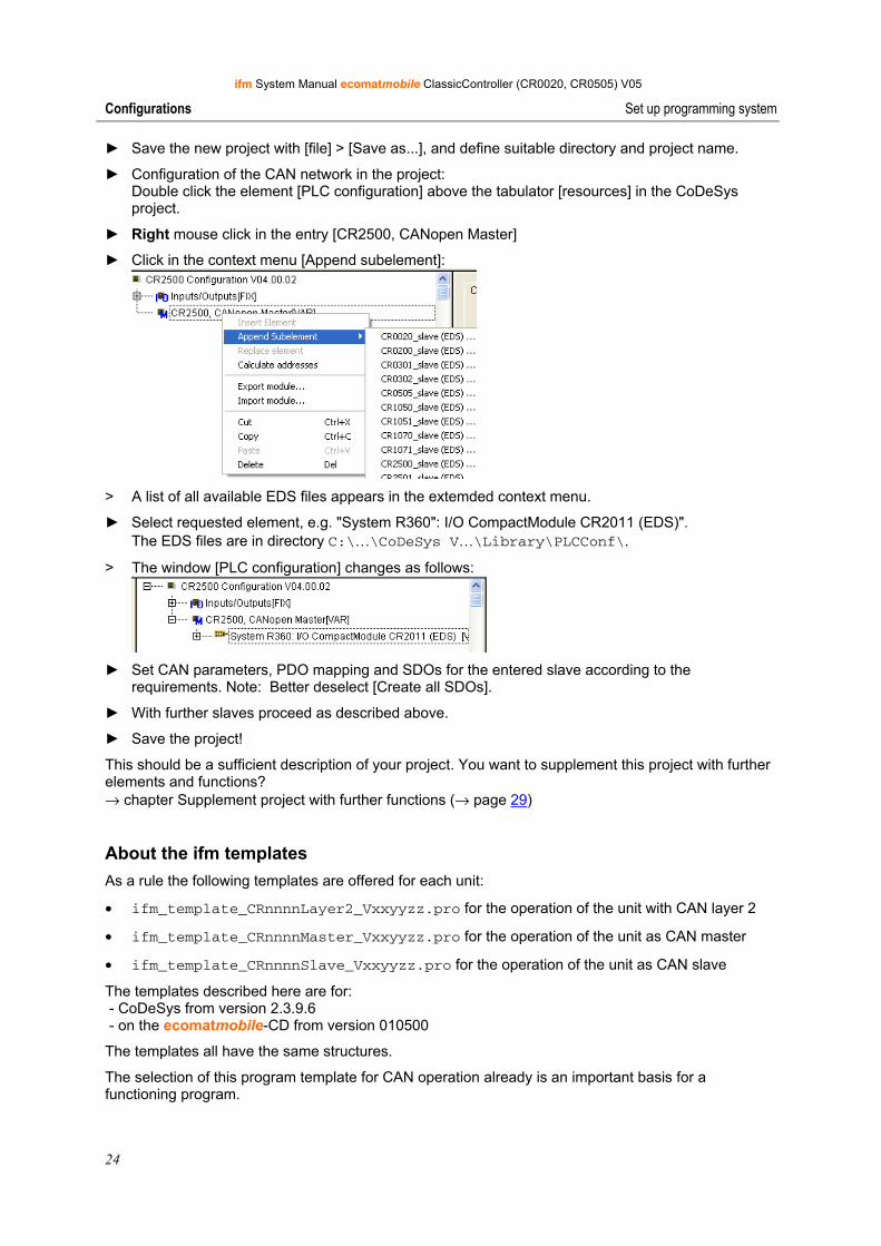
► Save the new project with [file] > [Save as...], and define suitable directory and project name.
► Configuration of the CAN network in the project: Double click the element [PLC configuration] above the tabulator [resources] in the CoDeSys project.
► Right mouse click in the entry [CR2500, CANopen Master]
► Click in the context menu [Append subelement]:
> A list of all available EDS files appears in the extemded context menu.
► Select requested element, e.g. "System R360": I/O CompactModule CR2011 (EDS)". The EDS files are in directory C:\…\CoDeSys V…\Library\PLCConf\.
> The window [PLC configuration] changes as follows:
► Set CAN parameters, PDO mapping and SDOs for the entered slave according to the
requirements. Note: Better deselect [Create all SDOs].
► With further slaves proceed as described above.
► Save the project!
This should be a sufficient description of your project. You want to supplement this project with further elements and functions? → chapter Supplement project with further functions (→ page 29)
About the ifm templates As a rule the following templates are offered for each unit:
• ifm_template_CRnnnnLayer2_Vxxyyzz.pro for the operation of the unit with CAN layer 2
• ifm_template_CRnnnnMaster_Vxxyyzz.pro for the operation of the unit as CAN master
• ifm_template_CRnnnnSlave_Vxxyyzz.pro for the operation of the unit as CAN slave
The templates described here are for: - CoDeSys from version 2.3.9.6 - on the ecomatmobile-CD from version 010500
The templates all have the same structures.
The selection of this program template for CAN operation already is an important basis for a functioning program.
ifm System Manual ecomatmobile ClassicController (CR0020, CR0505) V05
25
Configurations Set up programming system
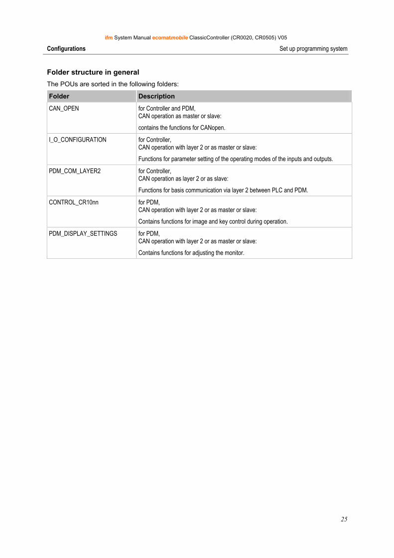
Folder structure in general The POUs are sorted in the following folders:
Folder Description
CAN_OPEN for Controller and PDM, CAN operation as master or slave:
contains the functions for CANopen.
I_O_CONFIGURATION for Controller, CAN operation with layer 2 or as master or slave:
Functions for parameter setting of the operating modes of the inputs and outputs.
PDM_COM_LAYER2 for Controller, CAN operation as layer 2 or as slave:
Functions for basis communication via layer 2 between PLC and PDM.
CONTROL_CR10nn for PDM, CAN operation with layer 2 or as master or slave:
Contains functions for image and key control during operation.
PDM_DISPLAY_SETTINGS for PDM, CAN operation with layer 2 or as master or slave:
Contains functions for adjusting the monitor.
ifm System Manual ecomatmobile ClassicController (CR0020, CR0505) V05
26
Configurations Set up programming system
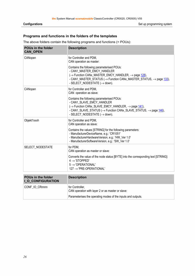
Programs and functions in the folders of the templates The above folders contain the following programs and functions (= POUs):
POUs in the folder CAN_OPEN
Description
CANopen for Controller and PDM, CAN operation as master:
Contains the following parameterised POUs: - CAN1_MASTER_EMCY_HANDLER (→ Function CANx_MASTER_EMCY_HANDLER, → page 128), - CAN1_MASTER_STATUS (→ Function CANx_MASTER_STATUS, → page 133), - SELECT_NODESTATE (→ down).
CANopen for Controller and PDM, CAN operation as slave:
Contains the following parameterised POUs: - CAN1_SLAVE_EMCY_HANDLER (→ Function CANx_SLAVE_EMCY_HANDLER, → page 141), - CAN1_SLAVE_STATUS (→ Function CANx_SLAVE_STATUS, → page 146), - SELECT_NODESTATE (→ down).
Objekt1xxxh for Controller and PDM, CAN operation as slave:
Contains the values [STRING] for the following parameters: - ManufacturerDeviceName, e.g.: 'CR1051' - ManufacturerHardwareVersion, e.g.: 'HW_Ver 1.0' - ManufacturerSoftwareVersion, e.g.: 'SW_Ver 1.0'
SELECT_NODESTATE for PDM, CAN operation as master or slave:
Converts the value of the node status [BYTE] into the corresponding text [STRING]: 4 → 'STOPPED' 5 → 'OPERATIONAL' 127 → 'PRE-OPERATIONAL'
POUs in the folder I_O_CONFIGURATION
Description
CONF_IO_CRnnnn for Controller, CAN operation with layer 2 or as master or slave:
Parameterises the operating modes of the inputs and outputs.
ifm System Manual ecomatmobile ClassicController (CR0020, CR0505) V05
27
Configurations Set up programming system
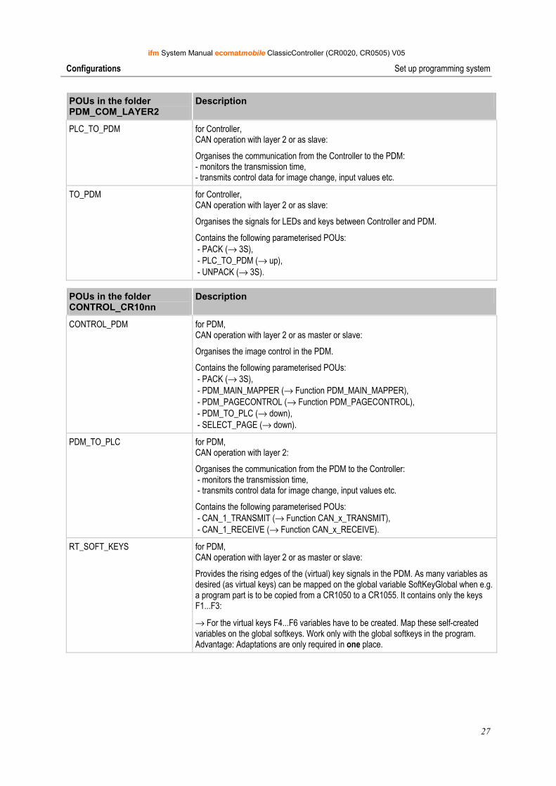
POUs in the folder PDM_COM_LAYER2
Description
PLC_TO_PDM for Controller, CAN operation with layer 2 or as slave:
Organises the communication from the Controller to the PDM: - monitors the transmission time, - transmits control data for image change, input values etc.
TO_PDM for Controller, CAN operation with layer 2 or as slave:
Organises the signals for LEDs and keys between Controller and PDM.
Contains the following parameterised POUs: - PACK (→ 3S), - PLC_TO_PDM (→ up), - UNPACK (→ 3S).
POUs in the folder CONTROL_CR10nn
Description
CONTROL_PDM for PDM, CAN operation with layer 2 or as master or slave:
Organises the image control in the PDM.
Contains the following parameterised POUs: - PACK (→ 3S), - PDM_MAIN_MAPPER (→ Function PDM_MAIN_MAPPER), - PDM_PAGECONTROL (→ Function PDM_PAGECONTROL), - PDM_TO_PLC (→ down), - SELECT_PAGE (→ down).
PDM_TO_PLC for PDM, CAN operation with layer 2:
Organises the communication from the PDM to the Controller: - monitors the transmission time, - transmits control data for image change, input values etc.
Contains the following parameterised POUs: - CAN_1_TRANSMIT (→ Function CAN_x_TRANSMIT), - CAN_1_RECEIVE (→ Function CAN_x_RECEIVE).
RT_SOFT_KEYS for PDM, CAN operation with layer 2 or as master or slave:
Provides the rising edges of the (virtual) key signals in the PDM. As many variables as desired (as virtual keys) can be mapped on the global variable SoftKeyGlobal when e.g. a program part is to be copied from a CR1050 to a CR1055. It contains only the keys F1...F3:
→ For the virtual keys F4...F6 variables have to be created. Map these self-created variables on the global softkeys. Work only with the global softkeys in the program. Advantage: Adaptations are only required in one place.
ifm System Manual ecomatmobile ClassicController (CR0020, CR0505) V05
28
Configurations Set up programming system
POUs in the folder CONTROL_CR10nn
Description
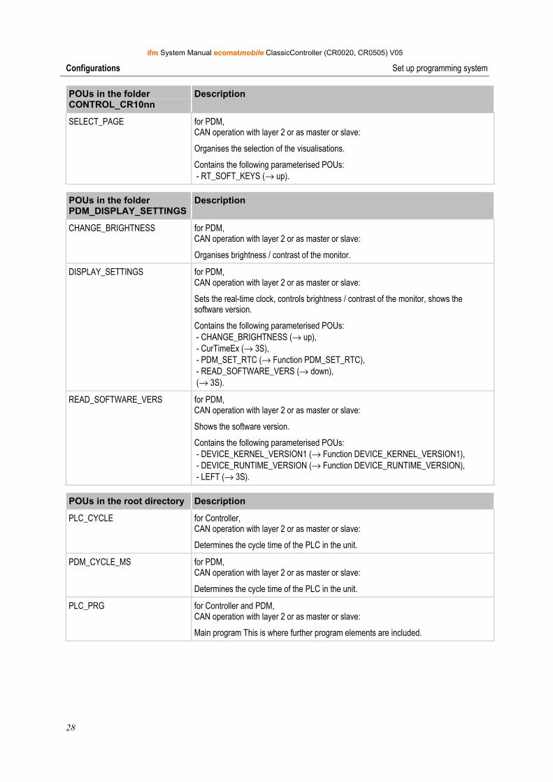
SELECT_PAGE for PDM, CAN operation with layer 2 or as master or slave:
Organises the selection of the visualisations.
Contains the following parameterised POUs: - RT_SOFT_KEYS (→ up).
POUs in the folder PDM_DISPLAY_SETTINGS
Description
CHANGE_BRIGHTNESS for PDM, CAN operation with layer 2 or as master or slave:
Organises brightness / contrast of the monitor.
DISPLAY_SETTINGS for PDM, CAN operation with layer 2 or as master or slave:
Sets the real-time clock, controls brightness / contrast of the monitor, shows the software version.
Contains the following parameterised POUs: - CHANGE_BRIGHTNESS (→ up), - CurTimeEx (→ 3S), - PDM_SET_RTC (→ Function PDM_SET_RTC), - READ_SOFTWARE_VERS (→ down), (→ 3S).
READ_SOFTWARE_VERS for PDM, CAN operation with layer 2 or as master or slave:
Shows the software version.
Contains the following parameterised POUs: - DEVICE_KERNEL_VERSION1 (→ Function DEVICE_KERNEL_VERSION1), - DEVICE_RUNTIME_VERSION (→ Function DEVICE_RUNTIME_VERSION), - LEFT (→ 3S).
POUs in the root directory Description
PLC_CYCLE for Controller, CAN operation with layer 2 or as master or slave:
Determines the cycle time of the PLC in the unit.
PDM_CYCLE_MS for PDM, CAN operation with layer 2 or as master or slave:
Determines the cycle time of the PLC in the unit.
PLC_PRG for Controller and PDM, CAN operation with layer 2 or as master or slave:
Main program This is where further program elements are included.
ifm System Manual ecomatmobile ClassicController (CR0020, CR0505) V05
29
Configurations Set up programming system
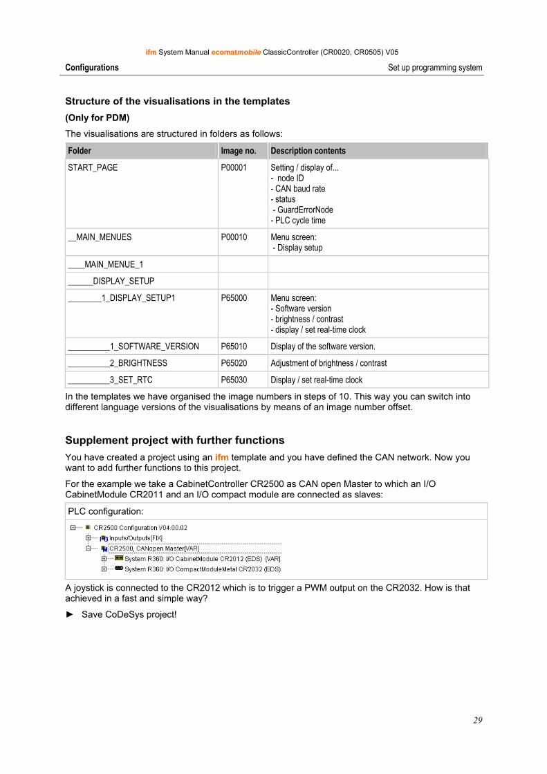
Structure of the visualisations in the templates (Only for PDM)
The visualisations are structured in folders as follows:
Folder Image no. Description contents
START_PAGE P00001 Setting / display of... - node ID - CAN baud rate - status - GuardErrorNode - PLC cycle time
__MAIN_MENUES P00010 Menu screen: - Display setup
____MAIN_MENUE_1
______DISPLAY_SETUP
________1_DISPLAY_SETUP1 P65000 Menu screen: - Software version - brightness / contrast - display / set real-time clock
__________1_SOFTWARE_VERSION P65010 Display of the software version.
__________2_BRIGHTNESS P65020 Adjustment of brightness / contrast
__________3_SET_RTC P65030 Display / set real-time clock
In the templates we have organised the image numbers in steps of 10. This way you can switch into different language versions of the visualisations by means of an image number offset.
Supplement project with further functions You have created a project using an ifm template and you have defined the CAN network. Now you want to add further functions to this project.
For the example we take a CabinetController CR2500 as CAN open Master to which an I/O CabinetModule CR2011 and an I/O compact module are connected as slaves:
PLC configuration:
A joystick is connected to the CR2012 which is to trigger a PWM output on the CR2032. How is that achieved in a fast and simple way?
► Save CoDeSys project!
ifm System Manual ecomatmobile ClassicController (CR0020, CR0505) V05
30
Configurations Set up programming system
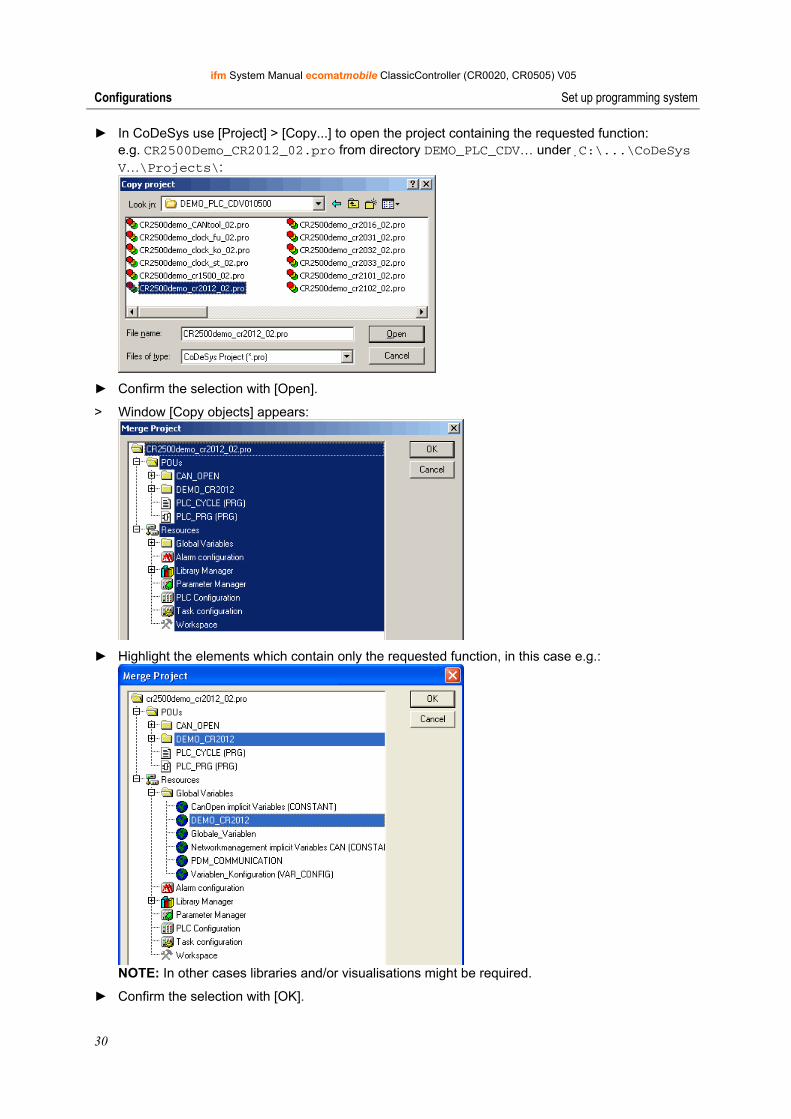
► In CoDeSys use [Project] > [Copy...] to open the project containing the requested function: e.g. CR2500Demo_CR2012_02.pro from directory DEMO_PLC_CDV… underC:\...\CoDeSys V…\Projects\:
► Confirm the selection with [Open].
> Window [Copy objects] appears:
► Highlight the elements which contain only the requested function, in this case e.g.:
NOTE: In other cases libraries and/or visualisations might be required.
► Confirm the selection with [OK].

ifm System Manual ecomatmobile ClassicController (CR0020, CR0505) V05
31
Configurations Set up programming system
> In our example project the elements selected in the demo project have been added:
POUs: Resources:
► Insert the program [CR2012] in the main program [PLC_PRG] e.g.:
► The comments of the POUs and global variables usually contain information on how the individual
elements have to be configured, included or excluded. This information has to be followed.
► Adapt input and output variables as well as parameters and possible visualisations to your own conditions.
► [Project] > [Save] and [Project] > [Rebuild all].
► After possibly required corrections and addition of missing libraries (→ Error messages after rebuild) save the project again.
► Follow this principle to step by step (!) add further functions from other projects and check the results.
► [Project] > [Save] and [Project] > [Rebuild all].
ifm System Manual ecomatmobile ClassicController (CR0020, CR0505) V05
32
Configurations Set up programming system
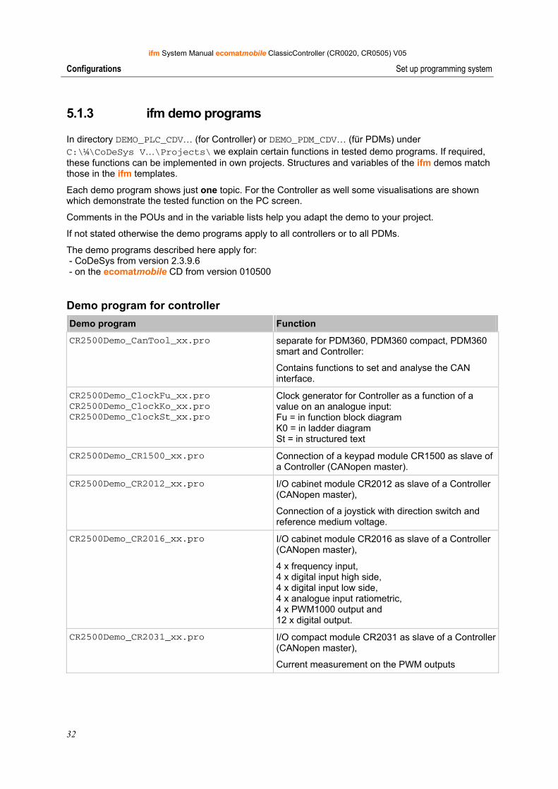
5.1.3 ifm demo programs
In directory DEMO_PLC_CDV… (for Controller) or DEMO_PDM_CDV… (für PDMs) under C:\¼\CoDeSys V…\Projects\ we explain certain functions in tested demo programs. If required, these functions can be implemented in own projects. Structures and variables of the ifm demos match those in the ifm templates.
Each demo program shows just one topic. For the Controller as well some visualisations are shown which demonstrate the tested function on the PC screen.
Comments in the POUs and in the variable lists help you adapt the demo to your project.
If not stated otherwise the demo programs apply to all controllers or to all PDMs.
The demo programs described here apply for: - CoDeSys from version 2.3.9.6 - on the ecomatmobile CD from version 010500
Demo program for controller Demo program Function
CR2500Demo_CanTool_xx.pro separate for PDM360, PDM360 compact, PDM360 smart and Controller:
Contains functions to set and analyse the CAN interface.
CR2500Demo_ClockFu_xx.pro CR2500Demo_ClockKo_xx.pro CR2500Demo_ClockSt_xx.pro
Clock generator for Controller as a function of a value on an analogue input: Fu = in function block diagram K0 = in ladder diagram St = in structured text
CR2500Demo_CR1500_xx.pro Connection of a keypad module CR1500 as slave of a Controller (CANopen master).
CR2500Demo_CR2012_xx.pro I/O cabinet module CR2012 as slave of a Controller (CANopen master),
Connection of a joystick with direction switch and reference medium voltage.
CR2500Demo_CR2016_xx.pro I/O cabinet module CR2016 as slave of a Controller (CANopen master),
4 x frequency input, 4 x digital input high side, 4 x digital input low side, 4 x analogue input ratiometric, 4 x PWM1000 output and 12 x digital output.
CR2500Demo_CR2031_xx.pro I/O compact module CR2031 as slave of a Controller (CANopen master),
Current measurement on the PWM outputs
ifm System Manual ecomatmobile ClassicController (CR0020, CR0505) V05
33
Configurations Set up programming system
Demo program Function
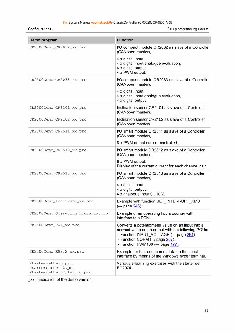
CR2500Demo_CR2032_xx.pro I/O compact module CR2032 as slave of a Controller (CANopen master),
4 x digital input, 4 x digital input analogue evaluation, 4 x digital output, 4 x PWM output.
CR2500Demo_CR2033_xx.pro I/O compact module CR2033 as slave of a Controller (CANopen master),
4 x digital input, 4 x digital input analogue evaluation, 4 x digital output,
CR2500Demo_CR2101_xx.pro Inclination sensor CR2101 as slave of a Controller (CANopen master).
CR2500Demo_CR2102_xx.pro Inclination sensor CR2102 as slave of a Controller (CANopen master).
CR2500Demo_CR2511_xx.pro I/O smart module CR2511 as slave of a Controller (CANopen master),
8 x PWM output current-controlled.
CR2500Demo_CR2512_xx.pro I/O smart module CR2512 as slave of a Controller (CANopen master),
8 x PWM output. Display of the current current for each channel pair.
CR2500Demo_CR2513_xx.pro I/O smart module CR2513 as slave of a Controller (CANopen master),
4 x digital input, 4 x digital output, 4 x analogue input 0...10 V.
CR2500Demo_Interrupt_xx.pro Example with function SET_INTERRUPT_XMS (→ page 246).
CR2500Demo_Operating_hours_xx.pro Example of an operating hours counter with interface to a PDM.
CR2500Demo_PWM_xx.pro Converts a potentiometer value on an input into a normed value on an output with the following POUs: - Function INPUT_VOLTAGE (→ page 264), - Function NORM (→ page 267), - Function PWM100 (→ page 177).
CR2500Demo_RS232_xx.pro Example for the reception of data on the serial interface by means of the Windows hyper terminal.
StartersetDemo.pro StartersetDemo2.pro StartersetDemo2_fertig.pro
Various e-learning exercises with the starter set EC2074.
_xx = indication of the demo version
ifm System Manual ecomatmobile ClassicController (CR0020, CR0505) V05
34
Configurations Set up programming system
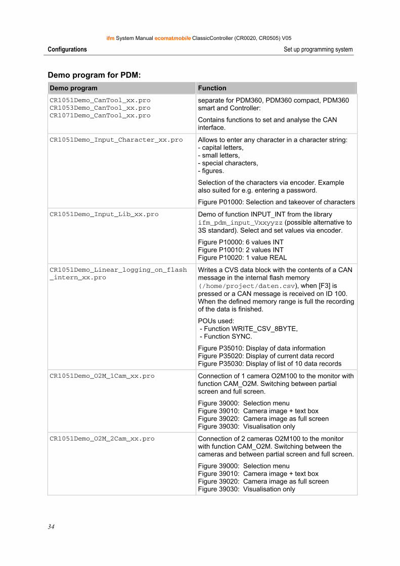
Demo program for PDM: Demo program Function
CR1051Demo_CanTool_xx.pro CR1053Demo_CanTool_xx.pro CR1071Demo_CanTool_xx.pro
separate for PDM360, PDM360 compact, PDM360 smart and Controller:
Contains functions to set and analyse the CAN interface.
CR1051Demo_Input_Character_xx.pro Allows to enter any character in a character string: - capital letters, - small letters, - special characters, - figures.
Selection of the characters via encoder. Example also suited for e.g. entering a password.
Figure P01000: Selection and takeover of characters
CR1051Demo_Input_Lib_xx.pro Demo of function INPUT_INT from the library ifm_pdm_input_Vxxyyzz (possible alternative to 3S standard). Select and set values via encoder.
Figure P10000: 6 values INT Figure P10010: 2 values INT Figure P10020: 1 value REAL
CR1051Demo_Linear_logging_on_flash _intern_xx.pro
Writes a CVS data block with the contents of a CAN message in the internal flash memory (/home/project/daten.csv), when [F3] is pressed or a CAN message is received on ID 100. When the defined memory range is full the recording of the data is finished.
POUs used: - Function WRITE_CSV_8BYTE, - Function SYNC.
Figure P35010: Display of data information Figure P35020: Display of current data record Figure P35030: Display of list of 10 data records
CR1051Demo_O2M_1Cam_xx.pro Connection of 1 camera O2M100 to the monitor with function CAM_O2M. Switching between partial screen and full screen.
Figure 39000: Selection menu Figure 39010: Camera image + text box Figure 39020: Camera image as full screen Figure 39030: Visualisation only
CR1051Demo_O2M_2Cam_xx.pro Connection of 2 cameras O2M100 to the monitor with function CAM_O2M. Switching between the cameras and between partial screen and full screen.
Figure 39000: Selection menu Figure 39010: Camera image + text box Figure 39020: Camera image as full screen Figure 39030: Visualisation only
ifm System Manual ecomatmobile ClassicController (CR0020, CR0505) V05
35
Configurations Set up programming system
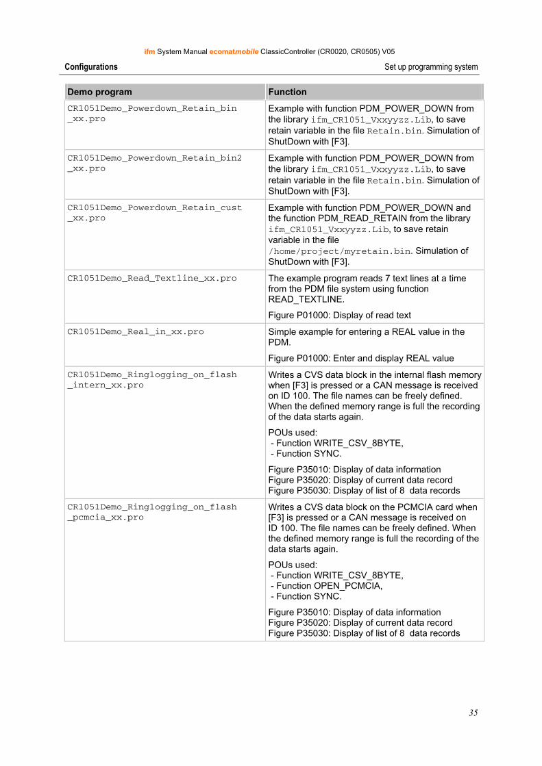
Demo program Function
CR1051Demo_Powerdown_Retain_bin _xx.pro
Example with function PDM_POWER_DOWN from the library ifm_CR1051_Vxxyyzz.Lib, to save retain variable in the file Retain.bin. Simulation of ShutDown with [F3].
CR1051Demo_Powerdown_Retain_bin2 _xx.pro
Example with function PDM_POWER_DOWN from the library ifm_CR1051_Vxxyyzz.Lib, to save retain variable in the file Retain.bin. Simulation of ShutDown with [F3].
CR1051Demo_Powerdown_Retain_cust _xx.pro
Example with function PDM_POWER_DOWN and the function PDM_READ_RETAIN from the library ifm_CR1051_Vxxyyzz.Lib, to save retain variable in the file /home/project/myretain.bin. Simulation of ShutDown with [F3].
CR1051Demo_Read_Textline_xx.pro The example program reads 7 text lines at a time from the PDM file system using function READ_TEXTLINE.
Figure P01000: Display of read text
CR1051Demo_Real_in_xx.pro Simple example for entering a REAL value in the PDM.
Figure P01000: Enter and display REAL value
CR1051Demo_Ringlogging_on_flash _intern_xx.pro
Writes a CVS data block in the internal flash memory when [F3] is pressed or a CAN message is received on ID 100. The file names can be freely defined. When the defined memory range is full the recording of the data starts again.
POUs used: - Function WRITE_CSV_8BYTE, - Function SYNC.
Figure P35010: Display of data information Figure P35020: Display of current data record Figure P35030: Display of list of 8 data records
CR1051Demo_Ringlogging_on_flash _pcmcia_xx.pro
Writes a CVS data block on the PCMCIA card when [F3] is pressed or a CAN message is received on ID 100. The file names can be freely defined. When the defined memory range is full the recording of the data starts again.
POUs used: - Function WRITE_CSV_8BYTE, - Function OPEN_PCMCIA, - Function SYNC.
Figure P35010: Display of data information Figure P35020: Display of current data record Figure P35030: Display of list of 8 data records
ifm System Manual ecomatmobile ClassicController (CR0020, CR0505) V05
36
Configurations Function configuration of the inputs and outputs
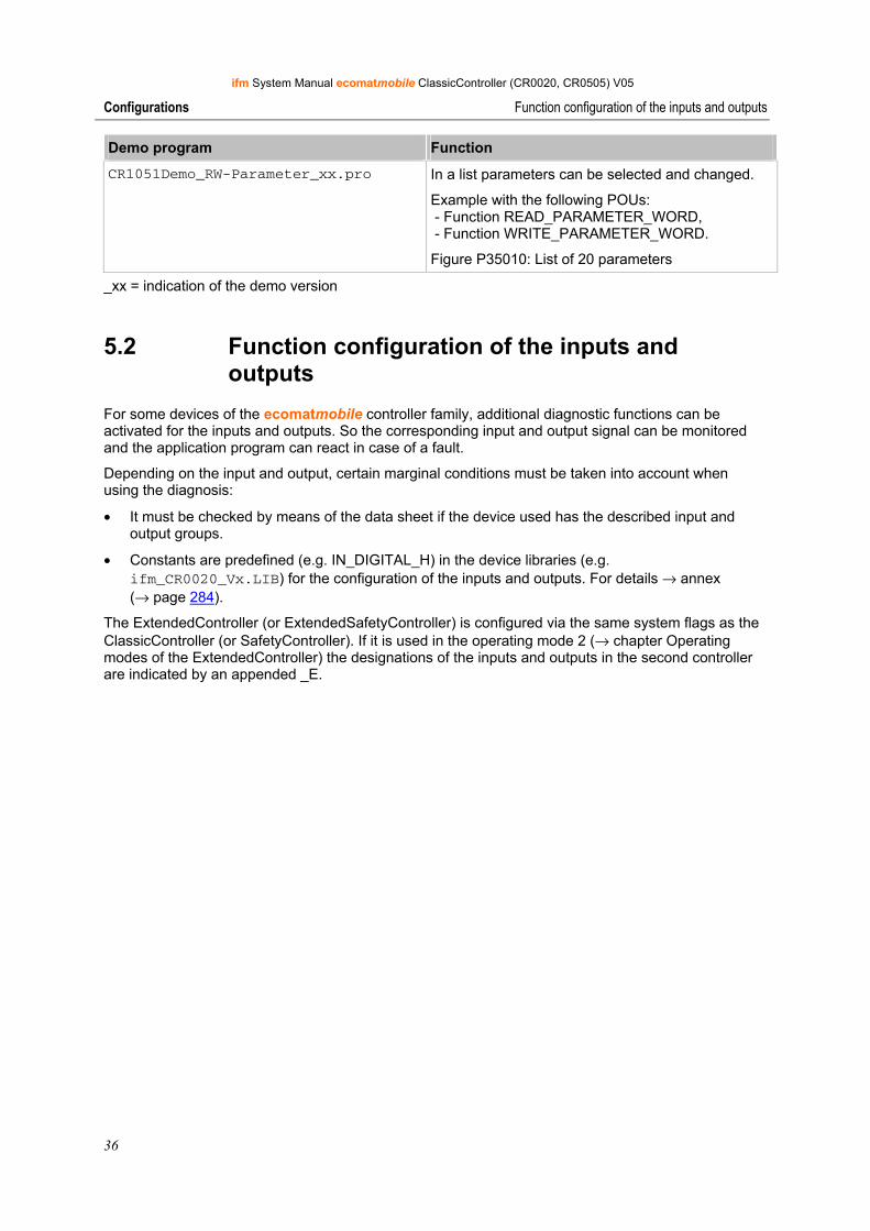
Demo program Function
CR1051Demo_RW-Parameter_xx.pro In a list parameters can be selected and changed.
Example with the following POUs: - Function READ_PARAMETER_WORD, - Function WRITE_PARAMETER_WORD.
Figure P35010: List of 20 parameters
_xx = indication of the demo version
5.2 Function configuration of the inputs and outputs
For some devices of the ecomatmobile controller family, additional diagnostic functions can be activated for the inputs and outputs. So the corresponding input and output signal can be monitored and the application program can react in case of a fault.
Depending on the input and output, certain marginal conditions must be taken into account when using the diagnosis:
• It must be checked by means of the data sheet if the device used has the described input and output groups.
• Constants are predefined (e.g. IN_DIGITAL_H) in the device libraries (e.g. ifm_CR0020_Vx.LIB) for the configuration of the inputs and outputs. For details → annex (→ page 284).
The ExtendedController (or ExtendedSafetyController) is configured via the same system flags as the ClassicController (or SafetyController). If it is used in the operating mode 2 (→ chapter Operating modes of the ExtendedController) the designations of the inputs and outputs in the second controller are indicated by an appended _E.
ifm System Manual ecomatmobile ClassicController (CR0020, CR0505) V05
37
Configurations Function configuration of the inputs and outputs
5.2.1 Configure inputs
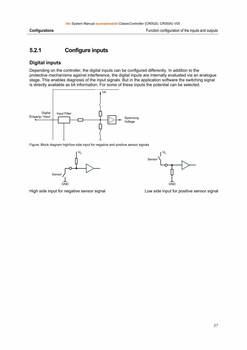
Digital inputs Depending on the controller, the digital inputs can be configured differently. In addition to the protective mechanisms against interference, the digital inputs are internally evaluated via an analogue stage. This enables diagnosis of the input signals. But in the application software the switching signal is directly available as bit information. For some of these inputs the potential can be selected.
SpannungVoltage
Input FilterDigitalEingang / Input
UB
Figure: Block diagram high/low side input for negative and positive sensor signals
GND
Sensor
UB
GND
Sensor
UB
High side input for negative sensor signal Low side input for positive sensor signal
ifm System Manual ecomatmobile ClassicController (CR0020, CR0505) V05
38
Configurations Function configuration of the inputs and outputs
Fast inputs In addition, the ecomatmobile controllers have up to 16 fast counter/pulse inputs for an input frequency up to 50 kHz (→ data sheet). If, for example, mechanical switches are connected to these inputs, there may be faulty signals in the controller due to contact bouncing. Using the application software, these "faulty signals" must be filtered if necessary.
Furthermore it has to be noted whether the pulse inputs are designed for frequency measurement (FRQx) and/or period measurement (CYLx) (→ data sheet).
The following functions, for example, can be used here:
On FRQx inputs:
• Frequency measurement with function FREQUENCY (→ page 212)
• Fast counter with function FAST_COUNT (→ page 223)
On CYLx inputs:
• Period measurement with function PERIOD (→ page 214) or with function PERIOD_RATIO (→ page 216)
• Phase position of 2 fast inputs compared via the function PHASE (→ page 218)
Info When using this function, the parameterised inputs and outputs are automatically configured, so the programmer of the application does not have to do this.
ifm System Manual ecomatmobile ClassicController (CR0020, CR0505) V05
39
Configurations Function configuration of the inputs and outputs
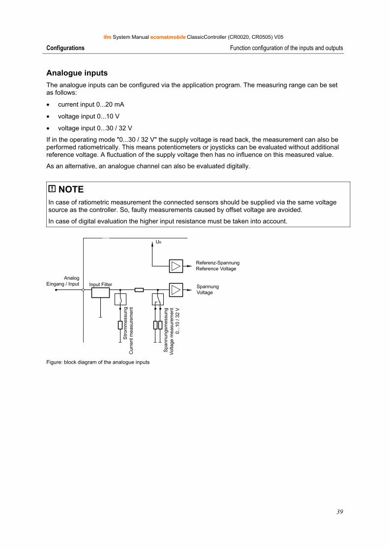
Analogue inputs The analogue inputs can be configured via the application program. The measuring range can be set as follows:
• current input 0...20 mA
• voltage input 0...10 V
• voltage input 0...30 / 32 V
If in the operating mode "0...30 / 32 V" the supply voltage is read back, the measurement can also be performed ratiometrically. This means potentiometers or joysticks can be evaluated without additional reference voltage. A fluctuation of the supply voltage then has no influence on this measured value.
As an alternative, an analogue channel can also be evaluated digitally.
NOTE In case of ratiometric measurement the connected sensors should be supplied via the same voltage source as the controller. So, faulty measurements caused by offset voltage are avoided.
In case of digital evaluation the higher input resistance must be taken into account.
UB
AnalogEingang / Input Input Filter
Str
omm
essu
ngC
urre
nt m
easu
rem
ent
Spa
nnun
gsm
essu
ngV
olta
ge m
easu
rem
ent
0...1
0 / 3
2 V
Referenz-SpannungReference Voltage
SpannungVoltage
Figure: block diagram of the analogue inputs
ifm System Manual ecomatmobile ClassicController (CR0020, CR0505) V05
40
Configurations Function configuration of the inputs and outputs
Input group I0 (ANALOG0...7 or %IX0.0...%IX0.7) These inputs are a group of analogue channels which can also be evaluated digitally.
If used as analogue channels, they have diagnostic capabilities at all times via the permanent analogue value in the system variables ANALOG0...ANALOG7 (or ANALOG0_E...ANALOG7_E).
If the analogue inputs are configured for current measurement, the device switches to the safe voltage measurement range (0...30V DC) and the corresponding error bit in the flag byte ERROR_I0 is set when the final value (> 21 mA) is exceeded. When the value is again below the limit value, the input automatically switches back to the current measurement range.
Info When using the analogue input functions the diagnosis does not have to be activated via the system variable I0x_MODE.
The configuration of the inputs and outputs is carried out via the application software in the latest generation of ecomatmobile controllers. The function INPUT_ANALOG (→ page 262) configures the operating mode of the selected analogue channel via the function input MODE. Accordingly, the function of the PWM channels is also set via functions (→ following example).
INPUT_ANALOG
ENABLEMODECHANNEL
OUT
As an alternative the inputs and outputs can also be directly set by setting a system variable Ixx_MODE.
Example:
The assignment sets the selected input to the operating mode IN_DIGITAL_H with diagnosis:
If the diagnosis is to be used, it must be activated in addition. The system flag bit DIAGNOSE indicates wire break or short circuit of the input signal as group error.
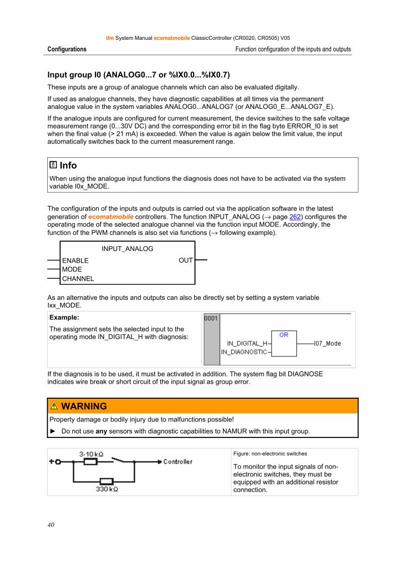
WARNING Property damage or bodily injury due to malfunctions possible!
► Do not use any sensors with diagnostic capabilities to NAMUR with this input group.
Figure: non-electronic switches
To monitor the input signals of non-electronic switches, they must be equipped with an additional resistor connection.
ifm System Manual ecomatmobile ClassicController (CR0020, CR0505) V05
41
Configurations Function configuration of the inputs and outputs
5.2.2 Configure outputs
Digital and PWM outputs Three types of controller outputs can be distinguished:
• High side digital outputs with and without diagnostic function,
• High side digital outputs with and without diagnostic function and additional PWM mode,
• Low side digital outputs with and without diagnostic function,
• PWM outputs which can be operated with and without current control function. Current-controlled PWM outputs are mainly used for triggering proportional hydraulic functions.
WARNING Property damage or bodily injury due to malfunctions possible!
Outputs which are operated in the PWM mode do not support any diagnostic functions and no ERROR flags are set. This is due to the structure of the outputs.
The function OUT_OVERLOAD_PROTECTION is not active in this mode!
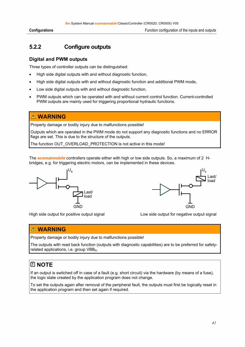
The ecomatmobile controllers operate either with high or low side outputs. So, a maximum of 2 H-bridges, e.g. for triggering electric motors, can be implemented in these devices.
GND
UB
Last/load
GND
UB
Last/load
High side output for positive output signal Low side output for negative output signal
WARNING Property damage or bodily injury due to malfunctions possible!
The outputs with read back function (outputs with diagnostic capabilities) are to be preferred for safety-related applications, i.e. group VBBR.
NOTE If an output is switched off in case of a fault (e.g. short circuit) via the hardware (by means of a fuse), the logic state created by the application program does not change.
To set the outputs again after removal of the peripheral fault, the outputs must first be logically reset in the application program and then set again if required.
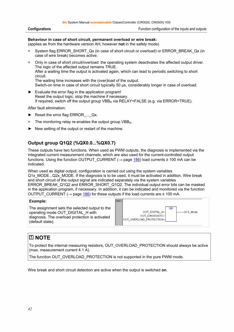
ifm System Manual ecomatmobile ClassicController (CR0020, CR0505) V05
42
Configurations Function configuration of the inputs and outputs
Behaviour in case of short circuit, permanent overload or wire break: (applies as from the hardware version AH, however not in the safety mode)
> System flag ERROR_SHORT_Qx (in case of short circuit or overload) or ERROR_BREAK_Qx (in case of wire break) becomes active.
> Only in case of short circuit/overload: the operating system deactivates the affected output driver. The logic of the affected output remains TRUE. After a waiting time the output is activated again, which can lead to periodic switching to short circuit. The waiting time increases with the (over)load of the output. Switch-on time in case of short circuit typically 50 µs, considerably longer in case of overload.
► Evaluate the error flag in the application program! Reset the output logic, stop the machine if necessary. If required, switch off the output group VBBR via RELAY=FALSE (e.g. via ERROR=TRUE).
After fault elimination:
► Reset the error flag ERROR_..._Qx.
> The monitoring relay re-enables the output group VBBR.
► New setting of the output or restart of the machine.
Output group Q1Q2 (%QX0.0...%QX0.7) These outputs have two functions. When used as PWM outputs, the diagnosis is implemented via the integrated current measurement channels, which are also used for the current-controlled output functions. Using the function OUTPUT_CURRENT (→ page 186) load currents ≥ 100 mA can be indicated.
When used as digital output, configuration is carried out using the system variables Q1x_MODE...Q2x_MODE. If the diagnosis is to be used, it must be activated in addition. Wire break and short circuit of the output signal are indicated separately via the system variables ERROR_BREAK_Q1Q2 and ERROR_SHORT_Q1Q2. The individual output error bits can be masked in the application program, if necessary. In addition, it can be indicated and monitored via the function OUTPUT_CURRENT (→ page 186) for these outputs if the load currents are ≥ 100 mA.
Example:
The assignment sets the selected output to the operating mode OUT_DIGITAL_H with diagnosis. The overload protection is activated (default state).
NOTE To protect the internal measuring resistors, OUT_OVERLOAD_PROTECTION should always be active (max. measurement current 4.1 A).
The function OUT_OVERLOAD_PROTECTION is not supported in the pure PWM mode.
Wire break and short circuit detection are active when the output is switched on.
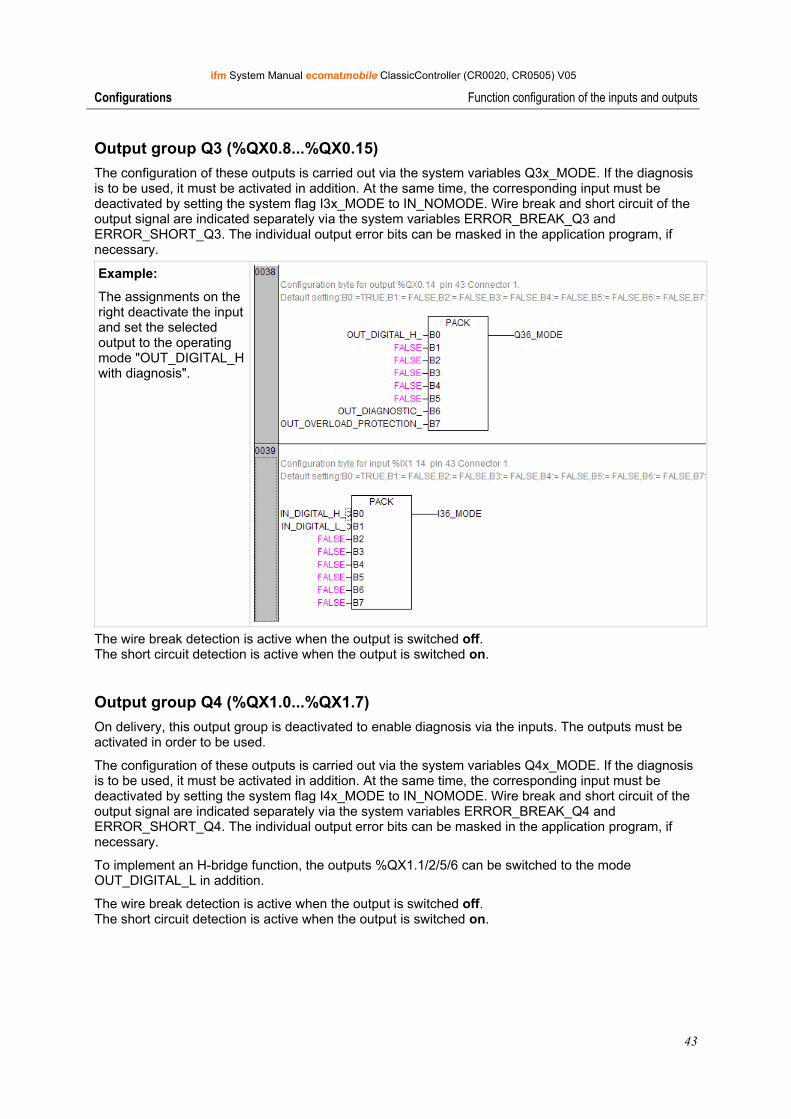
ifm System Manual ecomatmobile ClassicController (CR0020, CR0505) V05
43
Configurations Function configuration of the inputs and outputs
Output group Q3 (%QX0.8...%QX0.15) The configuration of these outputs is carried out via the system variables Q3x_MODE. If the diagnosis is to be used, it must be activated in addition. At the same time, the corresponding input must be deactivated by setting the system flag I3x_MODE to IN_NOMODE. Wire break and short circuit of the output signal are indicated separately via the system variables ERROR_BREAK_Q3 and ERROR_SHORT_Q3. The individual output error bits can be masked in the application program, if necessary.
Example:
The assignments on the right deactivate the input and set the selected output to the operating mode "OUT_DIGITAL_H with diagnosis".
The wire break detection is active when the output is switched off. The short circuit detection is active when the output is switched on.
Output group Q4 (%QX1.0...%QX1.7) On delivery, this output group is deactivated to enable diagnosis via the inputs. The outputs must be activated in order to be used.
The configuration of these outputs is carried out via the system variables Q4x_MODE. If the diagnosis is to be used, it must be activated in addition. At the same time, the corresponding input must be deactivated by setting the system flag I4x_MODE to IN_NOMODE. Wire break and short circuit of the output signal are indicated separately via the system variables ERROR_BREAK_Q4 and ERROR_SHORT_Q4. The individual output error bits can be masked in the application program, if necessary.
To implement an H-bridge function, the outputs %QX1.1/2/5/6 can be switched to the mode OUT_DIGITAL_L in addition.
The wire break detection is active when the output is switched off. The short circuit detection is active when the output is switched on.
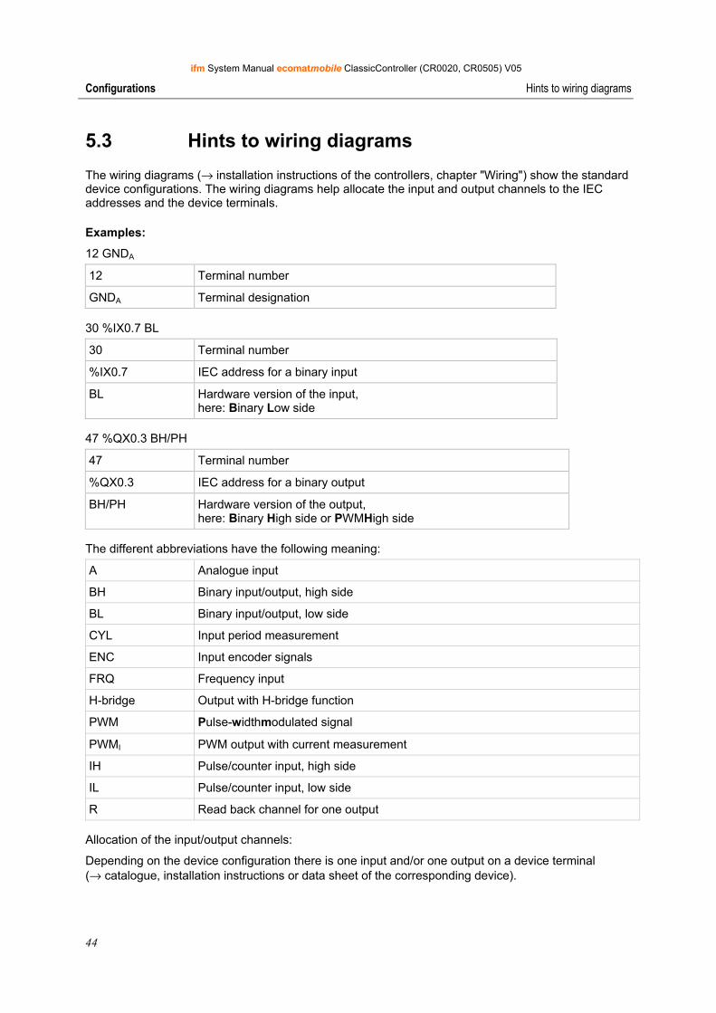
ifm System Manual ecomatmobile ClassicController (CR0020, CR0505) V05
44
Configurations Hints to wiring diagrams
5.3 Hints to wiring diagrams
The wiring diagrams (→ installation instructions of the controllers, chapter "Wiring") show the standard device configurations. The wiring diagrams help allocate the input and output channels to the IEC addresses and the device terminals.
Examples:
12 GNDA
12 Terminal number
GNDA Terminal designation
30 %IX0.7 BL
30 Terminal number
%IX0.7 IEC address for a binary input
BL Hardware version of the input, here: Binary Low side
47 %QX0.3 BH/PH
47 Terminal number
%QX0.3 IEC address for a binary output
BH/PH Hardware version of the output, here: Binary High side or PWMHigh side
The different abbreviations have the following meaning:
A Analogue input
BH Binary input/output, high side
BL Binary input/output, low side
CYL Input period measurement
ENC Input encoder signals
FRQ Frequency input
H-bridge Output with H-bridge function
PWM Pulse-widthmodulated signal
PWMI PWM output with current measurement
IH Pulse/counter input, high side
IL Pulse/counter input, low side
R Read back channel for one output
Allocation of the input/output channels:
Depending on the device configuration there is one input and/or one output on a device terminal (→ catalogue, installation instructions or data sheet of the corresponding device).
ifm System Manual ecomatmobile ClassicController (CR0020, CR0505) V05
45
Operating states and operating system Operating states
6 Operating states and operating system Operating states ........................................................................................................................45 Status LED.................................................................................................................................46 Load the operating system ........................................................................................................47 Operating modes .......................................................................................................................48
6.1 Operating states After power on the ecomatmobile controller can be in one of five possible operating states:
6.1.1 Reset This state is passed through after every power on reset:
• The operating system is initialised.
• Various checks are carried out.
• This temporary state is replaced by the Run or Stop state.
> The LED lights orange for a short time.
6.1.2 Run state This state is reached in the following cases:
• From the reset state (autostart)
• From the stop state by the Run command - only for the operating mode = Test (→ chapter TEST mode, → page 48)
6.1.3 Stop state This state is reached in the following cases:
• From the reset state if no program is loaded
• From the Run state if: - the stop command is sent via the interface - AND: operating mode = Test (→ chapter TEST mode→ page 48)
6.1.4 Fatal error The ecomatmobile controller goes to this state if a non tolerable error was found. This state can only be left by a reset.
> The LED lights red.
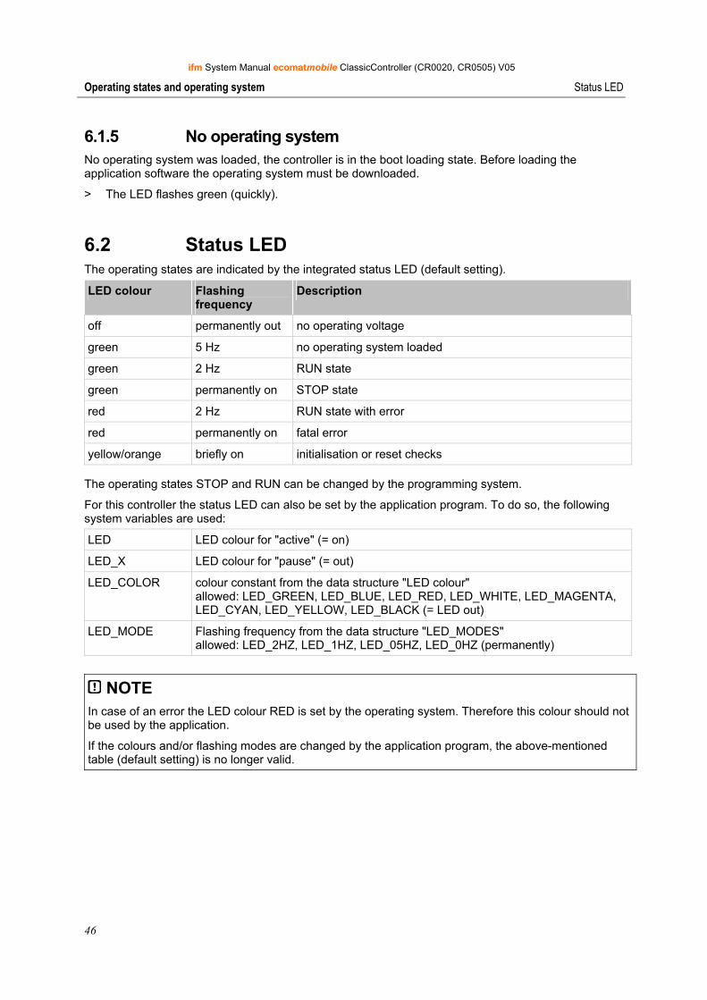
ifm System Manual ecomatmobile ClassicController (CR0020, CR0505) V05
46
Operating states and operating system Status LED
6.1.5 No operating system No operating system was loaded, the controller is in the boot loading state. Before loading the application software the operating system must be downloaded.
> The LED flashes green (quickly).
6.2 Status LED The operating states are indicated by the integrated status LED (default setting).
LED colour Flashing frequency
Description
off permanently out no operating voltage
green 5 Hz no operating system loaded
green 2 Hz RUN state
green permanently on STOP state
red 2 Hz RUN state with error
red permanently on fatal error
yellow/orange briefly on initialisation or reset checks
The operating states STOP and RUN can be changed by the programming system.
For this controller the status LED can also be set by the application program. To do so, the following system variables are used:
LED LED colour for "active" (= on)
LED_X LED colour for "pause" (= out)
LED_COLOR colour constant from the data structure "LED colour" allowed: LED_GREEN, LED_BLUE, LED_RED, LED_WHITE, LED_MAGENTA, LED_CYAN, LED_YELLOW, LED_BLACK (= LED out)
LED_MODE Flashing frequency from the data structure "LED_MODES" allowed: LED_2HZ, LED_1HZ, LED_05HZ, LED_0HZ (permanently)
NOTE In case of an error the LED colour RED is set by the operating system. Therefore this colour should not be used by the application.
If the colours and/or flashing modes are changed by the application program, the above-mentioned table (default setting) is no longer valid.
ifm System Manual ecomatmobile ClassicController (CR0020, CR0505) V05
47
Operating states and operating system Load the operating system
6.3 Load the operating system On delivery of the ecomatmobile controller no operating system is normally loaded (LED flashes green at 5 Hz). Only the boot loader is active in this operating mode. It provides the minimum functions for loading the operating system (e.g. RS232, CAN).
Normally it is necessary to download the operating system only once. The application program can then be loaded to the controller (also several times) without influencing the operating system. Advantage:
• No EPROM replacement is necessary for an update of the operating system.
The operating system is provided with this documentation on a separate data carrier. In addition, the current version can be downloaded from the website of ifm electronic gmbh at: → www.ifm.com > select country/language > [Service] > [Download] > [Control systems]
NOTE: The software versions suitable for the selected target must always be used:
• of the operating system (CRnnnn_Vxxyyyzz.H86),
• of the PLC configuration (CRnnnn_Vxx.CFG),
• of the device library (CRnnnn_Vxxyyyzz.LIB),
• and the further files (→ chapter Overview of the files and libraries used, → page 292)
CRnnnn device article number Vxx: 00...99 target version number yy: 00...99 release number zz: 00...99 patch number
The basic file name (e.g. "CR0032") and the software version number "xx" (e.g. "02") must always have the same value! Otherwise the controller goes to the STOP mode.
The values for "yy" (release number) and "zz" (patch number) do not have to match.
Also note: the following files must also be loaded:
• The for the project required internal libraries (designed in IEC1131),
• the configuration files (*.CFG)
• and the target files (*.TRG).
The operating system is transferred to the controller using the separate program "downloader". (The downloader is on the ecomatmobile CD "Software, Tools and Documentation" or can be downloaded from ifm's website, if necessary).
Normally the application program is loaded to the controller via the programming system. But it can also be loaded using the downloader if it was first read from the controller (→ upload).
ifm System Manual ecomatmobile ClassicController (CR0020, CR0505) V05
48
Operating states and operating system Operating modes
6.4 Operating modes Independent of the operating states the ecomatmobile controller can be operated in different modes. The corresponding control bits can be set and reset with the programming software CoDeSys (window: Global Variables) via the application software or in test mode (→ chapter TEST mode, → page 48).
6.4.1 TEST mode This operating mode is reached by applying a high level (supply voltage) to the test input (→ installation instructions, chapter "wiring"). The ecomatmobile controller can now receive commands via one of the interfaces in the RUN or STOP mode and, for example, communicate with the programming system. Moreover the software can only be downloaded to the controller in this operating state.
The state of the application program can be queried via the flag TEST.
NOTICE Loss of the stored software possible!
In the test mode there is no protection of the stored operating system and application software.
6.4.2 SERIAL_MODE The serial interface is available for the exchange of data in the application. Debugging the application software is then only possible via the CAN interface. For CRnn32: Debugging of the application software is then only possible via all 4 CAN interfaces or via USB.
This function is switched off as standard (FALSE). Via the flag SERIAL_MODE the state can be controlled and queried via the application program or the programming system.
→ chapter Use of the serial interface (→ page 253)
6.4.3 DEBUG mode If the input DEBUG of the function SET_DEBUG (→ page 236) is set to TRUE, the programming system or the downloader, for example, can communicate with the controller and execute system commands (e.g. for service functions via the GSM modem CANremote).
In this operating mode a software download is not possible because the test input (→ chapter TEST mode, → page 48) is not connected to supply voltage.
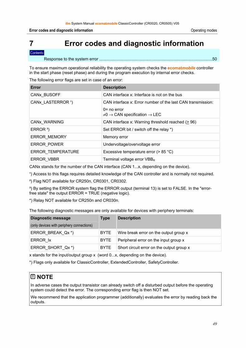
ifm System Manual ecomatmobile ClassicController (CR0020, CR0505) V05
49
Error codes and diagnostic information Operating modes
7 Error codes and diagnostic information Response to the system error ...................................................................................................50
To ensure maximum operational reliability the operating system checks the ecomatmobile controller in the start phase (reset phase) and during the program execution by internal error checks.
The following error flags are set in case of an error:
Error Description
CANx_BUSOFF CAN interface x: Interface is not on the bus
CANx_LASTERROR ¹) CAN interface x: Error number of the last CAN transmission:
0= no error ≠0 → CAN specification → LEC
CANx_WARNING CAN interface x: Warning threshold reached (> 96)
ERROR ³) Set ERROR bit / switch off the relay *)
ERROR_MEMORY Memory error
ERROR_POWER Undervoltage/overvoltage error
ERROR_TEMPERATURE Excessive temperature error (> 85 °C)
ERROR_VBBR Terminal voltage error VBBR
CANx stands for the number of the CAN interface (CAN 1...x, depending on the device).
¹) Access to this flags requires detailed knowledge of the CAN controller and is normally not required.
²) Flag NOT available for CR250n, CR0301, CR0302.
³) By setting the ERROR system flag the ERROR output (terminal 13) is set to FALSE. In the "error-free state" the output ERROR = TRUE (negative logic).
*) Relay NOT available for CR250n and CR030n.
The following diagnostic messages are only available for devices with periphery terminals:
Diagnostic message
(only devices with periphery connections)
Type Description
ERROR_BREAK_Qx *) BYTE Wire break error on the output group x
ERROR_Ix BYTE Peripheral error on the input group x
ERROR_SHORT_Qx *) BYTE Short circuit error on the output group x
x stands for the input/output group x (word 0...x, depending on the device).
*) Flags only available for ClassicController, ExtendedController, SafetyController.
NOTE In adverse cases the output transistor can already switch off a disturbed output before the operating system could detect the error. The corresponding error flag is then NOT set.
We recommend that the application programmer (additionally) evaluates the error by reading back the outputs.
ifm System Manual ecomatmobile ClassicController (CR0020, CR0505) V05
50
Error codes and diagnostic information Response to the system error
Complete list of the device-specific error codes and diagnostic messages → chapter system flags (→ page 290).
7.1 Response to the system error In principle, the programmer is responsible to react to the error flags (system flags) in the application program.
The specific error bits and bytes should be processed in the application program. An error description is provided via the error flag. These error bits/bytes can be further processed if necessary.
In principle, all error flags must be reset by the application program. Without explicit reset of the error flags the flags remain set with the corresponding effect on the application program.
In case of serious errors the system flag bit ERROR can also be set. At the same time this also has the effect that the operation LED (if available) lights red, the ERROR output is set to FALSE and the monitoring relays (if available) are de-energised. So the outputs protected via these relays are switched off.
7.1.1 Notes on devices with monitoring relay Only available for the following controllers:
• ClassicController: CR0020, CR0505
• ExtendedController: CR0200
• SafetyController: CR7020, CR7505, CR7200
Using the logic function via the system flag RELAIS or RELAIS_CLAMP_15 (→ chapter Latching, → page 14) all other outputs are also switched off.
Depending on the application it must now be decided whether by resetting the system flag bit ERROR the relay – and so also the outputs – may be switched on again.
In addition it is also possible to set the system flag bit ERROR as "defined error" by the application program.
NOTICE Premature wear of the relay contacts possible.
► Only use this function for a general switch-off of the outputs in case of an "emergency".
► In normal operation switch off the relays only without load! To do so, first switch off the outputs via the application program!
ifm System Manual ecomatmobile ClassicController (CR0020, CR0505) V05
51
Error codes and diagnostic information Response to the system error
7.1.2 Example process for response to a system error The system determines an excessive temperature in the controller.
The operating system sets the error bit ERROR_TEMPERATURE.
The application program recognises this state by querying the corresponding bits.
> The application program switches off outputs.
If necessary, the error bit ERROR can be set additionally via the application program.
> Consequences: - operation LED flashes red - safety relay is de-energised - supply voltage of all outputs is switched off - level of the output ERROR*) is LOW
► Rectify the cause of the error.
> The operating system resets the error bit ERROR_TEMPERATURE.
► If set, the error bit ERROR must be deleted via the application program.
> The relay is energised again and the LED flashes green again.
*) Output not available for CR0301, CR0302, CS0015.
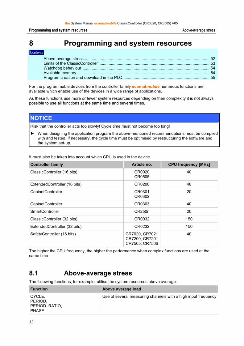
ifm System Manual ecomatmobile ClassicController (CR0020, CR0505) V05
52
Programming and system resources Above-average stress
8 Programming and system resources Above-average stress................................................................................................................52 Limits of the ClassicController ...................................................................................................53 Watchdog behaviour..................................................................................................................54 Available memory ......................................................................................................................54 Program creation and download in the PLC..............................................................................55
For the programmable devices from the controller family ecomatmobile numerous functions are available which enable use of the devices in a wide range of applications.
As these functions use more or fewer system resources depending on their complexity it is not always possible to use all functions at the same time and several times.
NOTICE Risk that the controller acts too slowly! Cycle time must not become too long!
► When designing the application program the above-mentioned recommendations must be complied with and tested. If necessary, the cycle time must be optimised by restructuring the software and the system set-up.
It must also be taken into account which CPU is used in the device.
Controller family Article no. CPU frequency [MHz]
ClassicController (16 bits) CR0020 CR0505
40
ExtendedController (16 bits) CR0200 40
CabinetController CR0301 CR0302
20
CabinetController CR0303 40
SmartController CR250n 20
ClassicController (32 bits) CR0032 150
ExtendedController (32 bits) CR0232 150
SafetyController (16 bits) CR7020, CR7021CR7200, CR7201CR7505; CR7506
40
The higher the CPU frequency, the higher the performance when complex functions are used at the same time.
8.1 Above-average stress The following functions, for example, utilise the system resources above average:
Function Above average load
CYCLE, PERIOD, PERIOD_RATIO, PHASE
Use of several measuring channels with a high input frequency
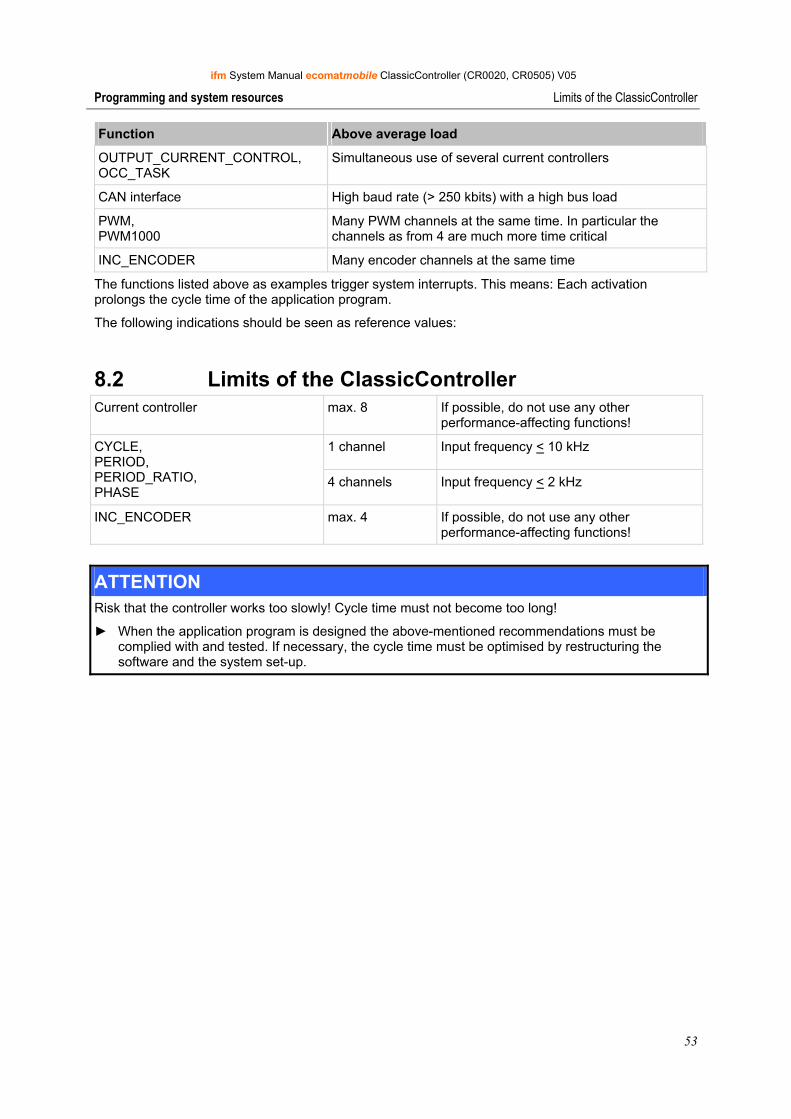
ifm System Manual ecomatmobile ClassicController (CR0020, CR0505) V05
53
Programming and system resources Limits of the ClassicController
Function Above average load
OUTPUT_CURRENT_CONTROL, OCC_TASK
Simultaneous use of several current controllers
CAN interface High baud rate (> 250 kbits) with a high bus load
PWM, PWM1000
Many PWM channels at the same time. In particular the channels as from 4 are much more time critical
INC_ENCODER Many encoder channels at the same time
The functions listed above as examples trigger system interrupts. This means: Each activation prolongs the cycle time of the application program.
The following indications should be seen as reference values:
8.2 Limits of the ClassicController Current controller max. 8 If possible, do not use any other
performance-affecting functions!
1 channel Input frequency < 10 kHz CYCLE, PERIOD, PERIOD_RATIO, PHASE
4 channels Input frequency < 2 kHz
INC_ENCODER max. 4 If possible, do not use any other performance-affecting functions!
ATTENTION Risk that the controller works too slowly! Cycle time must not become too long!
► When the application program is designed the above-mentioned recommendations must be complied with and tested. If necessary, the cycle time must be optimised by restructuring the software and the system set-up.
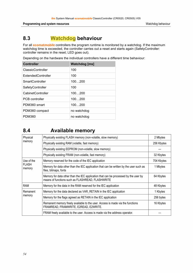
ifm System Manual ecomatmobile ClassicController (CR0020, CR0505) V05
54
Programming and system resources Watchdog behaviour
8.3 Watchdog behaviour For all ecomatmobile controllers the program runtime is monitored by a watchdog. If the maximum watchdog time is exceeded, the controller carries out a reset and starts again (SafetyController: controller remains in the reset; LED goes out).
Depending on the hardware the individual controllers have a different time behaviour:
Controller Watchdog [ms]
ClassicController 100
ExtendedController 100
SmartController 100…200
SafetyController 100
CabinetController 100…200
PCB controller 100…200
PDM360 smart 100…200
PDM360 compact no watchdog
PDM360 no watchdog
8.4 Available memory Physically existing FLASH memory (non-volatile, slow memory) 2 Mbytes
Physically existing RAM (volatile, fast memory) 256 Kbytes
Physically existing EEPROM (non-volatile, slow memory) ---
Physical memory
Physically existing FRAM (non-volatile, fast memory) 32 Kbytes
Memory reserved for the code of the IEC application 704 Kbytes
Memory for data other than the IEC application that can be written by the user such as files, bitmaps, fonts
1 Mbytes
Use of the FLASH memory
Memory for data other than the IEC application that can be processed by the user by means of functions such as FLASHREAD, FLASHWRITE
64 Kbytes
RAM Memory for the data in the RAM reserved for the IEC application 48 Kbytes
Memory for the data declared as VAR_RETAIN in the IEC application 1 Kbytes
Memory for the flags agreed as RETAIN in the IEC application 256 bytes
Remanent memory freely available to the user. Access is made via the functions FRAMREAD, FRAMWRITE, E2READ, E2WRITE.
16 Kbytes
Remanent memory
FRAM freely available to the user. Access is made via the address operator. ---
Administrator
Highlight
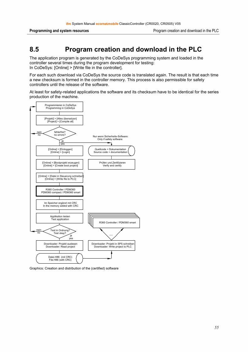
ifm System Manual ecomatmobile ClassicController (CR0020, CR0505) V05
55
Programming and system resources Program creation and download in the PLC
8.5 Program creation and download in the PLC The application program is generated by the CoDeSys programming system and loaded in the controller several times during the program development for testing: In CoDeSys: [Online] > [Write file in the controller].
For each such download via CoDeSys the source code is translated again. The result is that each time a new checksum is formed in the controller memory. This process is also permissible for safety controllers until the release of the software.
At least for safety-related applications the software and its checksum have to be identical for the series production of the machine.
Programmieren in CoDeSysProgramming in CoDeSys
jayes
neinno
Applikation testenTest application
jayes
neinno
Downloader: Projekt auslesenDownloader: Read project
Downloader: Projekt in SPS schreibenDownloader: Write project to PLC
R360 / PDM360 smartR360 / PDM360 smartR360 / PDM360 smartR360 / PDM360 smartR360 Controller / PDM360 smart
[Projekt] > [Alles übersetzen][Project] > [Compile all]
fehlerfrei?no errors?
[Online] > [Datei in Steuerung schreiben][Online] > [Write file to PLC]
R360 Controller / PDM360PDM360 compact / PDM360 smart
[Online] > [Bootprojekt erzeugen][Online] > [Create boot project]
[Online] > [Einloggen][Online] > [Login]
Prüfen und ZertifizierenVerify and certify
Im Speicher ergänzt mit CRCIn the memory added with CRC
Test in Ordnung?Test okay? ...
Datei.H86 (mit CRC)File.H86 (with CRC)
Quellcode + DokumentationSource code + documentation
Nur wenn Sicherheits-Software:Only if safety software:
Graphics: Creation and distribution of the (certified) software
ifm System Manual ecomatmobile ClassicController (CR0020, CR0505) V05
56
Programming and system resources Program creation and download in the PLC
ifm downloader
The ifm downloader serves for easy transfer of the program code from the programming station to the controller. As a matter of principle each application software can be copied to the controllers using the ifm downloader. Advantage: A programming system with CoDeSys licence is not required.
Safety-related application software MUST be copied to the controllers using the ifm downloader so as not to falsify the checksum by which the software has been identified.
NOTE The ifm downloader cannot be used for the following devices: - PDM360: CR1050, CR1051, CR1060, - PDM360 compact: CR1052, CR1053, CR1055, CR1056.
Certification and distribution of the safety-related software
Only safety-related application software must be certified before it is copied to the series machine and used.
• Saving the approved software After completion of program development and approval of the entire system by the responsible certification body (e.g. TÜV, BiA) the latest version of the application program loaded in the controller using the ifm downloader has to be read from the controller and saved on a data carrier using the name name_of the_project file.H86. Only this process ensures that the application software and its checksums are stored.
• Download of the approved software. To equip all machines of a series production with an identical software only this file may be loaded in the controllers using the ifm downloader.
• An error in the data of this file is automatically recognised by the integrated checksum when loaded again using the ifm downloader.
Changing the safety-relevant software after certification
Changes to the application software using the CoDeSys programming system automatically create a new application file which may only be copied to the safety-related controllers after a new certification. To do so, follow again the process described above!
Under the following conditions the new certification may not be necessary:
• a new risk assessment was made for the change,
• NO safety-related elements were changed, added or removed,
• the change was correctly documented.
ifm System Manual ecomatmobile ClassicController (CR0020, CR0505) V05
57
CAN in the ecomatmobile controller General about CAN
9 CAN in the ecomatmobile controller General about CAN ...................................................................................................................57 Exchange of CAN data ..............................................................................................................59 Physical connection of CAN ......................................................................................................61 Software for CAN and CANopen ...............................................................................................65 CAN errors and error handling ..................................................................................................65 Description of the CAN functions...............................................................................................68 ifm CANopen library...................................................................................................................93 Summary CAN / CANopen ..................................................................................................... 154 Use of the CAN interfaces to SAE J1939............................................................................... 155
9.1 General about CAN The CAN bus (Controller Area Network) belongs to the fieldbuses.
It is an asynchronous serial bus system which was developed for the networking of control devices in automotives by Bosch in 1983 and presented together with Intel in 1985 to reduce cable harnesses (up to 2 km per vehicle) thus saving weight.
9.1.1 Topology The CAN network is set up in a line structure. A limited number of spurs is allowed. Moreover, a ring type bus (infotainment area) and a star type bus (central locking) are possible. Compared to the line type bus both variants have one disadvantage:
In the ring type bus all control devices are connected in series so that the complete bus fails if one control device fails.
The star type bus is mostly controlled by a central processor as all information must flow through this processor. Consequently no information can be transferred if the central processor fails. If an individual control device fails, the bus continues to function.
The linear bus has the advantage that all control devices are in parallel of a central cable. Only if this fails, the bus no longer functions.
The disadvantage of spurs and star-type bus is that the wave resistance is difficult to determine. In the worst case the bus no longer functions.
For a high-speed bus (> 125 kbits/s) 2 terminating resistors of 120 Ω (between CAN_HIGH and CAN_LOW) must additionally be used at the cable ends.
9.1.2 CAN interfaces The controllers have several CAN interfaces depending on the hardware structure. In principle, all interfaces can be used with the following functions independently of each other:
• CAN at level 2 (layer 2)
• CANopen (→ page 93) protocol to CiA 301/401 for master/slave operation (via CoDeSys)
• CAN Network variables (→ page 117) (via CoDeSys)
• Protocol SAE J1939 (→ page 155) (for engine management)
• Bus load detection
• Error frame counter
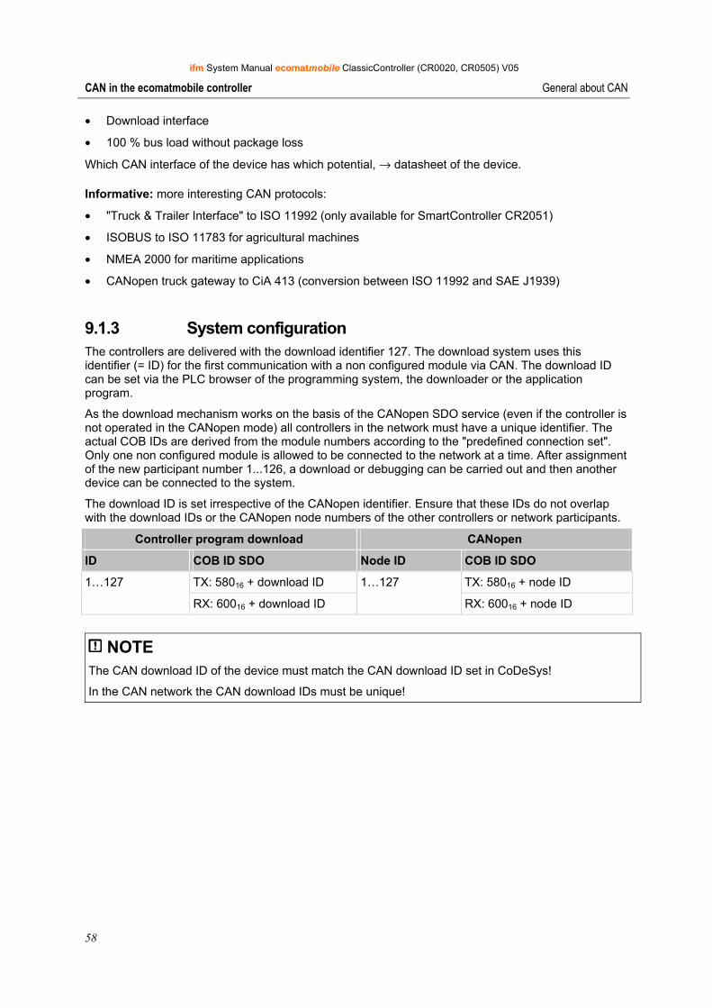
ifm System Manual ecomatmobile ClassicController (CR0020, CR0505) V05
58
CAN in the ecomatmobile controller General about CAN
• Download interface
• 100 % bus load without package loss
Which CAN interface of the device has which potential, → datasheet of the device.
Informative: more interesting CAN protocols:
• "Truck & Trailer Interface" to ISO 11992 (only available for SmartController CR2051)
• ISOBUS to ISO 11783 for agricultural machines
• NMEA 2000 for maritime applications
• CANopen truck gateway to CiA 413 (conversion between ISO 11992 and SAE J1939)
9.1.3 System configuration The controllers are delivered with the download identifier 127. The download system uses this identifier (= ID) for the first communication with a non configured module via CAN. The download ID can be set via the PLC browser of the programming system, the downloader or the application program.
As the download mechanism works on the basis of the CANopen SDO service (even if the controller is not operated in the CANopen mode) all controllers in the network must have a unique identifier. The actual COB IDs are derived from the module numbers according to the "predefined connection set". Only one non configured module is allowed to be connected to the network at a time. After assignment of the new participant number 1...126, a download or debugging can be carried out and then another device can be connected to the system.
The download ID is set irrespective of the CANopen identifier. Ensure that these IDs do not overlap with the download IDs or the CANopen node numbers of the other controllers or network participants.
Controller program download CANopen
ID COB ID SDO Node ID COB ID SDO
TX: 58016 + download ID TX: 58016 + node ID 1…127
RX: 60016 + download ID
1…127
RX: 60016 + node ID
NOTE The CAN download ID of the device must match the CAN download ID set in CoDeSys!
In the CAN network the CAN download IDs must be unique!
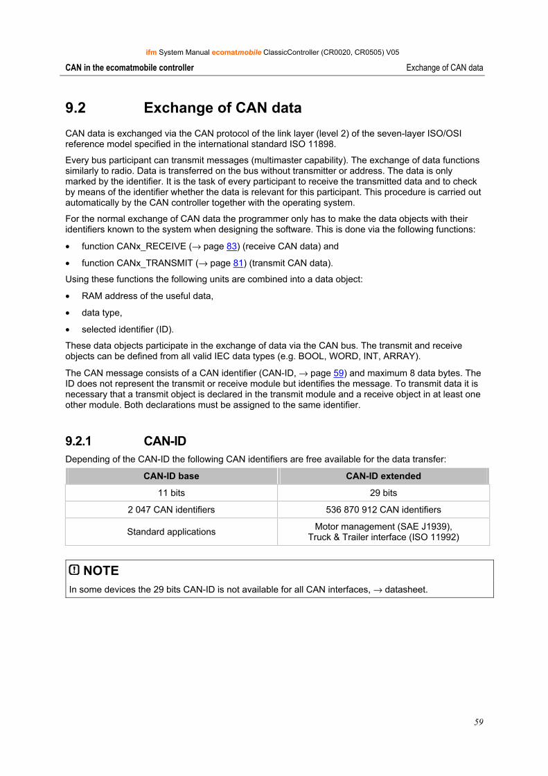
ifm System Manual ecomatmobile ClassicController (CR0020, CR0505) V05
59
CAN in the ecomatmobile controller Exchange of CAN data
9.2 Exchange of CAN data
CAN data is exchanged via the CAN protocol of the link layer (level 2) of the seven-layer ISO/OSI reference model specified in the international standard ISO 11898.
Every bus participant can transmit messages (multimaster capability). The exchange of data functions similarly to radio. Data is transferred on the bus without transmitter or address. The data is only marked by the identifier. It is the task of every participant to receive the transmitted data and to check by means of the identifier whether the data is relevant for this participant. This procedure is carried out automatically by the CAN controller together with the operating system.
For the normal exchange of CAN data the programmer only has to make the data objects with their identifiers known to the system when designing the software. This is done via the following functions:
• function CANx_RECEIVE (→ page 83) (receive CAN data) and
• function CANx_TRANSMIT (→ page 81) (transmit CAN data).
Using these functions the following units are combined into a data object:
• RAM address of the useful data,
• data type,
• selected identifier (ID).
These data objects participate in the exchange of data via the CAN bus. The transmit and receive objects can be defined from all valid IEC data types (e.g. BOOL, WORD, INT, ARRAY).
The CAN message consists of a CAN identifier (CAN-ID, → page 59) and maximum 8 data bytes. The ID does not represent the transmit or receive module but identifies the message. To transmit data it is necessary that a transmit object is declared in the transmit module and a receive object in at least one other module. Both declarations must be assigned to the same identifier.
9.2.1 CAN-ID Depending of the CAN-ID the following CAN identifiers are free available for the data transfer:
CAN-ID base CAN-ID extended
11 bits 29 bits
2 047 CAN identifiers 536 870 912 CAN identifiers
Standard applications Motor management (SAE J1939), Truck & Trailer interface (ISO 11992)
NOTE In some devices the 29 bits CAN-ID is not available for all CAN interfaces, → datasheet.
Administrator
Typewriter
2^11
Administrator
Typewriter
2^29
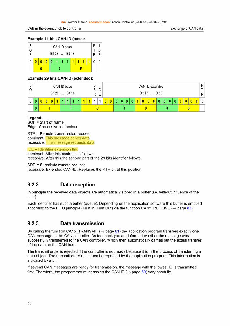
ifm System Manual ecomatmobile ClassicController (CR0020, CR0505) V05
60
CAN in the ecomatmobile controller Exchange of CAN data
Example 11 bits CAN-ID (base):
S O F
CAN-ID base
Bit 28 ... Bit 18
RTR
IDE
0 0 0 0 0 1 1 1 1 1 1 1 0 0
0 7 F
Example 29 bits CAN-ID (extended):
S O F
CAN-ID base
Bit 28 ... Bit 18
SRR
IDE
CAN-ID extended
Bit 17 ... Bit 0
RTR
0 0 0 0 0 1 1 1 1 1 1 1 1 1 0 0 0 0 0 0 0 0 0 0 0 0 0 0 0 0 0 0 0
0 1 F C 0 0 0 0
Legend: SOF = Start of frame Edge of recessive to dominant
RTR = Remote transmission request dominant: This message sends data recessive: This message requests data
IDE = Identifier extension flag dominant: After this control bits follows recessive: After this the second part of the 29 bits identifier follows
SRR = Substitute remote request recessive: Extended CAN-ID: Replaces the RTR bit at this position
9.2.2 Data reception In principle the received data objects are automatically stored in a buffer (i.e. without influence of the user).
Each identifier has such a buffer (queue). Depending on the application software this buffer is emptied according to the FIFO principle (First In, First Out) via the function CANx_RECEIVE (→ page 83).
9.2.3 Data transmission By calling the function CANx_TRANSMIT (→ page 81) the application program transfers exactly one CAN message to the CAN controller. As feedback you are informed whether the message was successfully transferred to the CAN controller. Which then automatically carries out the actual transfer of the data on the CAN bus.
The transmit order is rejected if the controller is not ready because it is in the process of transferring a data object. The transmit order must then be repeated by the application program. This information is indicated by a bit.
If several CAN messages are ready for transmission, the message with the lowest ID is transmitted first. Therefore, the programmer must assign the CAN ID (→ page 59) very carefully.
Administrator
Highlight
Administrator
Highlight
Administrator
Highlight
Administrator
Typewriter
0
Administrator
Typewriter
1
Administrator
Typewriter
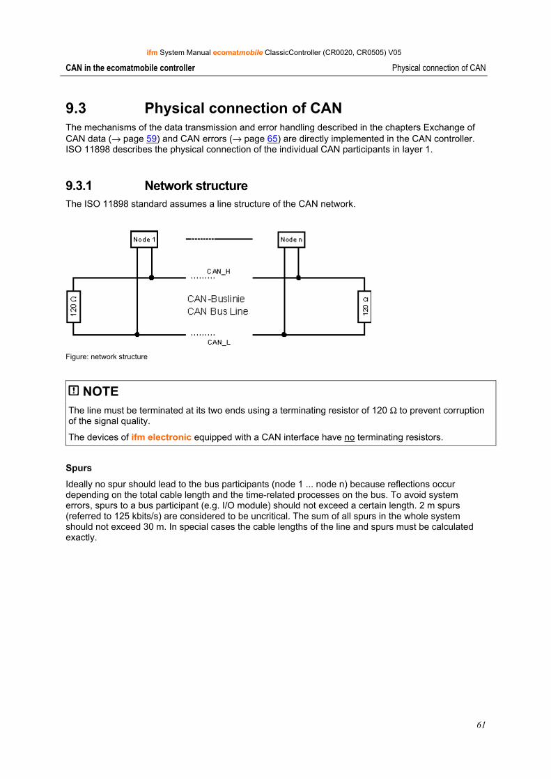
ifm System Manual ecomatmobile ClassicController (CR0020, CR0505) V05
61
CAN in the ecomatmobile controller Physical connection of CAN
9.3 Physical connection of CAN The mechanisms of the data transmission and error handling described in the chapters Exchange of CAN data (→ page 59) and CAN errors (→ page 65) are directly implemented in the CAN controller. ISO 11898 describes the physical connection of the individual CAN participants in layer 1.
9.3.1 Network structure The ISO 11898 standard assumes a line structure of the CAN network.
Figure: network structure
NOTE The line must be terminated at its two ends using a terminating resistor of 120 Ω to prevent corruption of the signal quality.
The devices of ifm electronic equipped with a CAN interface have no terminating resistors.
Spurs
Ideally no spur should lead to the bus participants (node 1 ... node n) because reflections occur depending on the total cable length and the time-related processes on the bus. To avoid system errors, spurs to a bus participant (e.g. I/O module) should not exceed a certain length. 2 m spurs (referred to 125 kbits/s) are considered to be uncritical. The sum of all spurs in the whole system should not exceed 30 m. In special cases the cable lengths of the line and spurs must be calculated exactly.
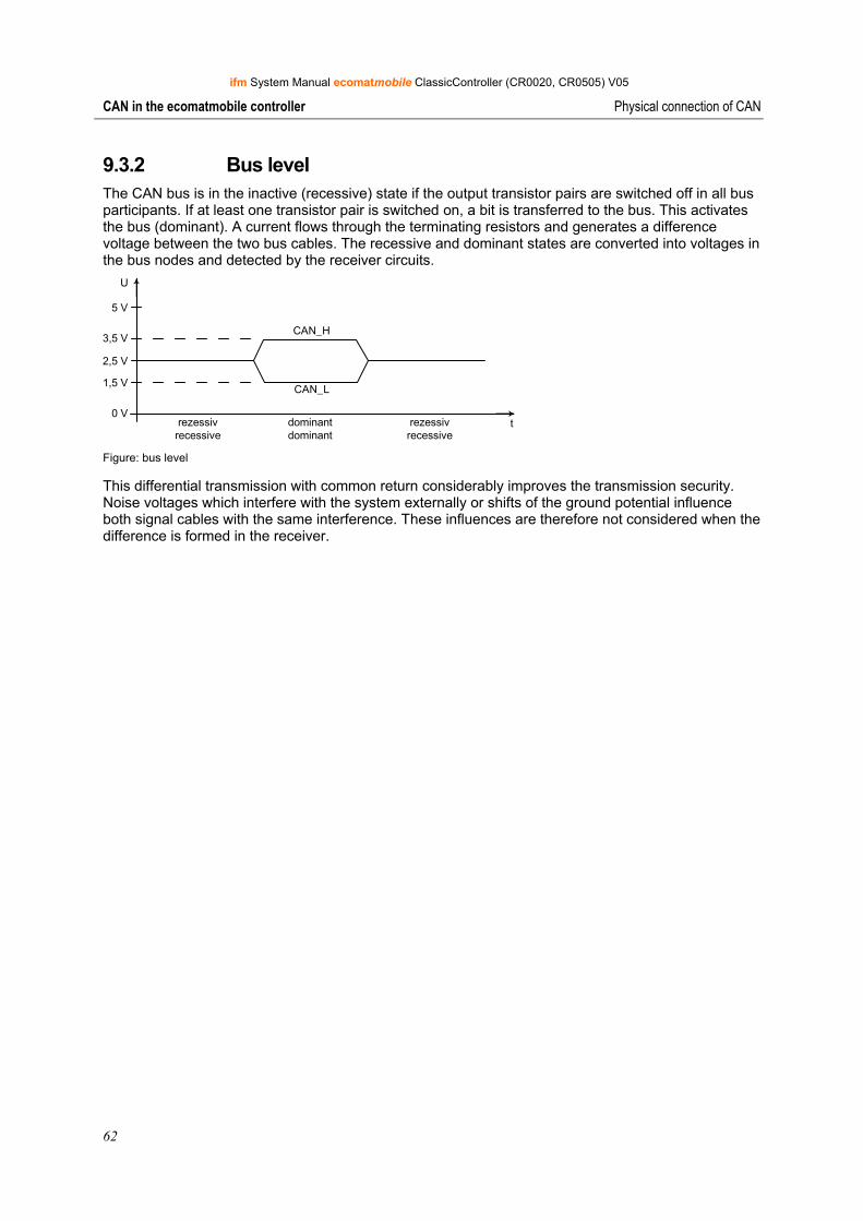
ifm System Manual ecomatmobile ClassicController (CR0020, CR0505) V05
62
CAN in the ecomatmobile controller Physical connection of CAN
9.3.2 Bus level The CAN bus is in the inactive (recessive) state if the output transistor pairs are switched off in all bus participants. If at least one transistor pair is switched on, a bit is transferred to the bus. This activates the bus (dominant). A current flows through the terminating resistors and generates a difference voltage between the two bus cables. The recessive and dominant states are converted into voltages in the bus nodes and detected by the receiver circuits.
5 V
3,5 V
2,5 V
1,5 V
0 V
U
t
CAN_H
CAN_L
rezessivrecessive
rezessivrecessive
dominantdominant
Figure: bus level
This differential transmission with common return considerably improves the transmission security. Noise voltages which interfere with the system externally or shifts of the ground potential influence both signal cables with the same interference. These influences are therefore not considered when the difference is formed in the receiver.
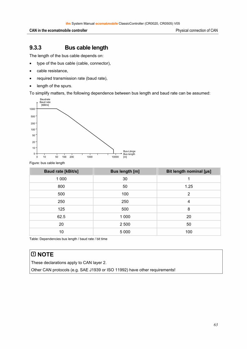
ifm System Manual ecomatmobile ClassicController (CR0020, CR0505) V05
63
CAN in the ecomatmobile controller Physical connection of CAN
9.3.3 Bus cable length The length of the bus cable depends on:
• type of the bus cable (cable, connector),
• cable resistance,
• required transmission rate (baud rate),
• length of the spurs.
To simplify matters, the following dependence between bus length and baud rate can be assumed:
100 50 1000 100005
10
20
50
100
200
500
1000
Bus-LängeBus length[m]
BaudrateBaud rate
[kBit/s]
Figure: bus cable length
Baud rate [kBit/s] Bus length [m] Bit length nominal [µs]
1 000 30 1
800 50 1.25
500 100 2
250 250 4
125 500 8
62.5 1 000 20
20 2 500 50
10 5 000 100 Table: Dependencies bus length / baud rate / bit time
NOTE These declarations apply to CAN layer 2.
Other CAN protocols (e.g. SAE J1939 or ISO 11992) have other requirements!
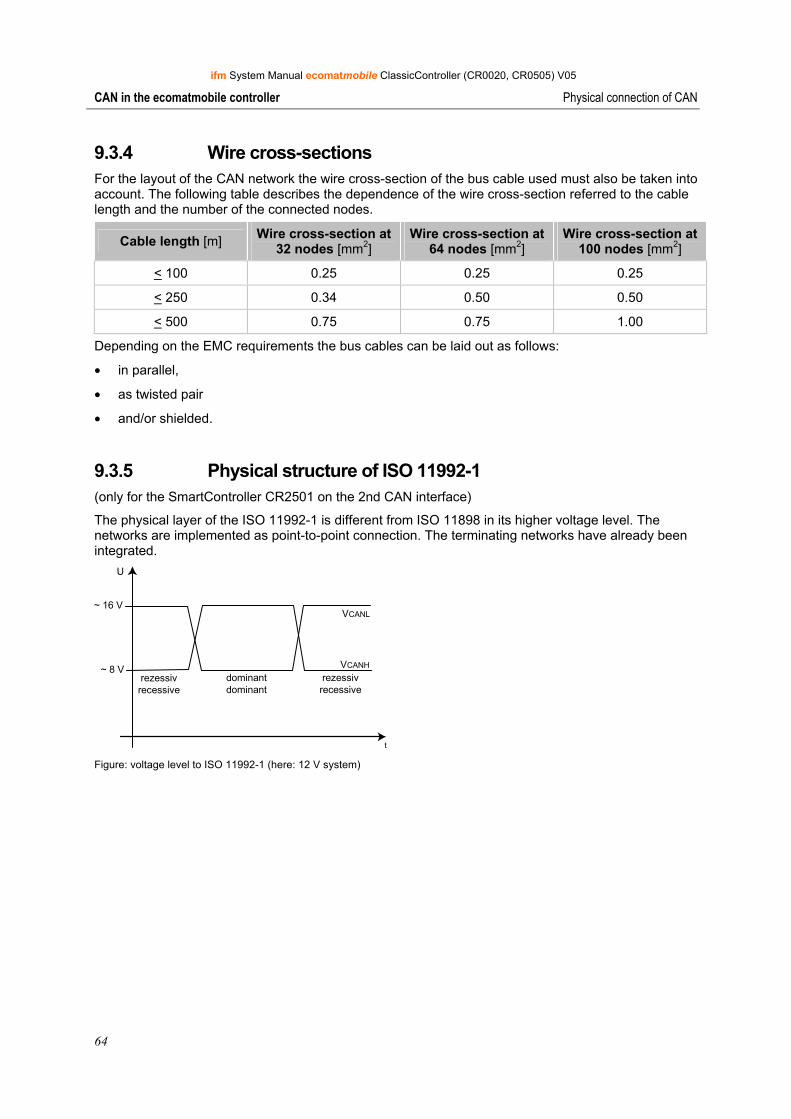
ifm System Manual ecomatmobile ClassicController (CR0020, CR0505) V05
64
CAN in the ecomatmobile controller Physical connection of CAN
9.3.4 Wire cross-sections For the layout of the CAN network the wire cross-section of the bus cable used must also be taken into account. The following table describes the dependence of the wire cross-section referred to the cable length and the number of the connected nodes.
Cable length [m] Wire cross-section at32 nodes [mm2]
Wire cross-section at 64 nodes [mm2]
Wire cross-section at 100 nodes [mm2]
< 100 0.25 0.25 0.25
< 250 0.34 0.50 0.50
< 500 0.75 0.75 1.00
Depending on the EMC requirements the bus cables can be laid out as follows:
• in parallel,
• as twisted pair
• and/or shielded.
9.3.5 Physical structure of ISO 11992-1 (only for the SmartController CR2501 on the 2nd CAN interface)
The physical layer of the ISO 11992-1 is different from ISO 11898 in its higher voltage level. The networks are implemented as point-to-point connection. The terminating networks have already been integrated.
U
~ 16 V
~ 8 Vrezessivrecessive
dominantdominant
rezessivrecessive
VCANL
VCANH
t Figure: voltage level to ISO 11992-1 (here: 12 V system)
ifm System Manual ecomatmobile ClassicController (CR0020, CR0505) V05
65
CAN in the ecomatmobile controller Software for CAN and CANopen
9.4 Software for CAN and CANopen In principle, ecomatmobile controllers can directly participate in the CAN communication (layer 2) by using the functions CANx_TRANSMIT and CANx_RECEIVE. In the operating mode CANopen the programmer is provided with the defined services from the programming system CoDeSys.
The following points must be considered:
• In the operating mode CAN layer 2 the programmer is responsible for all services. The controller is in this state after the following events: - after a program download or - after a reset command by the programming system
• The operating mode CANopen is activated by integrating the CoDeSys CANopen system libraries (activate functions in the target settings). Depending on the selected function the controller operates as CANopen master or slave (→ from chapter ifm CANopen library, → page 93).
9.5 CAN errors and error handling
The error mechanisms described are automatically processed by the CAN controller integrated in the controller. This cannot be influenced by the user. (Depending on the application) the user should react to signalled errors in the application software.
Goal of the CAN error mechanisms:
• Ensuring uniform data objects in the complete CAN network
• Permanent functionality of the network even in case of a faulty CAN participant
• Differentiation between temporary and permanent disturbance of a CAN participant
• Localisation and self-deactivation of a faulty participant in 2 steps: - error passive - disconnection from the bus (bus off) This gives a temporarily disturbed participant a "rest".
To give the interested user an overview of the behaviour of the CAN controller in case of an error, error handling is easily described below. After error detection the information is automatically prepared and made available to the programmer as CAN error bits in the application software.
9.5.1 Error message If a bus participant detects an error condition, it immediately transmits an error flag. The transmission is then aborted or the correct messages already received by other participants are rejected. This ensures that correct and uniform data is available to all participants. Since the error flag is directly transmitted the sender can immediately start to repeat the disturbed message as opposed to other fieldbus systems (they wait until a defined acknowledgement time has elapsed). This is one of the most important features of CAN.
One of the basic problems of serial data transmission is that a permanently disturbed or faulty bus participant can block the complete system. Error handling for CAN would increase such a risk. To exclude this, a mechanism is required which detects the fault of a participant and disconnects this participant from the bus, if necessary.
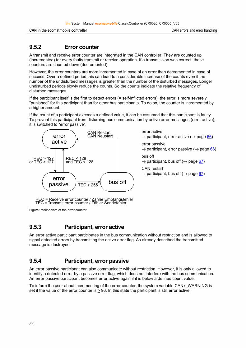
ifm System Manual ecomatmobile ClassicController (CR0020, CR0505) V05
66
CAN in the ecomatmobile controller CAN errors and error handling
9.5.2 Error counter A transmit and receive error counter are integrated in the CAN controller. They are counted up (incremented) for every faulty transmit or receive operation. If a transmission was correct, these counters are counted down (decremented).
However, the error counters are more incremented in case of an error than decremented in case of success. Over a defined period this can lead to a considerable increase of the counts even if the number of the undisturbed messages is greater than the number of the disturbed messages. Longer undisturbed periods slowly reduce the counts. So the counts indicate the relative frequency of disturbed messages.
If the participant itself is the first to detect errors (= self-inflicted errors), the error is more severely "punished" for this participant than for other bus participants. To do so, the counter is incremented by a higher amount.
If the count of a participant exceeds a defined value, it can be assumed that this participant is faulty. To prevent this participant from disturbing bus communication by active error messages (error active), it is switched to "error passive".
errorpassive
erroractive
bus off
REC > 127or TEC > 127
REC < 128and TEC < 128
TEC > 255
CAN RestartCAN Neustart
REC = Receive error counter / Zähler EmpfangsfehlerTEC = Transmit error counter / Zähler Sendefehler
Figure: mechanism of the error counter
error active → participant, error active (→ page 66)
error passive → participant, error passive (→ page 66)
bus off → participant, bus off (→ page 67)
CAN restart → participant, bus off (→ page 67)
9.5.3 Participant, error active An error active participant participates in the bus communication without restriction and is allowed to signal detected errors by transmitting the active error flag. As already described the transmitted message is destroyed.
9.5.4 Participant, error passive An error passive participant can also communicate without restriction. However, it is only allowed to identify a detected error by a passive error flag, which does not interfere with the bus communication. An error passive participant becomes error active again if it is below a defined count value.
To inform the user about incrementing of the error counter, the system variable CANx_WARNING is set if the value of the error counter is > 96. In this state the participant is still error active.

ifm System Manual ecomatmobile ClassicController (CR0020, CR0505) V05
67
CAN in the ecomatmobile controller CAN errors and error handling
9.5.5 Participant, bus off If the error count value continues to be incremented, the participant is disconnected from the bus (bus off) after exceeding a maximum count value.
To indicate this state the flag CANx_BUSOFF is set in the application program.
NOTE The error CANx_BUSOFF is automatically handled and reset by the operating system. If the error is to be handled or evaluated more precisely via the application program, the function CANx_ERRORHANDLER (→ page 90) must be used. The error CANx_BUSOFF must then be reset explicitly by the application program.

ifm System Manual ecomatmobile ClassicController (CR0020, CR0505) V05
68
CAN in the ecomatmobile controller Description of the CAN functions
9.6 Description of the CAN functions
The CAN functions are described for use in the application program.
NOTE To use the full capacity of CAN it is absolutely necessary for the programmer to define an exact bus concept before starting to work:
• How many data objects are needed with what identifiers?
• How is the ecomatmobile controller to react to possible CAN errors?
• How often must data be transmitted? The functions CANx_TRANSMIT and CANx_RECEIVE must be called accordingly. → chapter function CANx_TRANSMIT (→ page 81) and function CANx_RECEIVE (→ page 83)
► Check whether the transmit orders were successfully assigned to CANx_TRANSMIT (FB output RESULT) or ensure that the received data is read from the data buffer of the queue using CANx_RECEIVE and processed in the rest of the program immediately.
To be able to set up a communication connection, the same transmission rate (baud rate) must first be set for all participants of the CAN network. For the controller this is done using the function CAN1_BAUDRATE (→ page 68) (for the 1st CAN interface) or via the function CAN2 (→ page 79) (for the 2nd CAN interface).
Irrespective of whether the devices support one or several CAN interfaces the functions related to the interface are specified by a number in the CAN function (e.g. CAN1_TRANSMIT or CAN2_RECEIVE). To simplify matters the designation (e.g. CANx_TRANSMIT) is used for all variants in the documentation.
NOTE When installing the ecomatmobile CD "Software, Tools and Documentation", projects with templates have been stored in the program directory of your PC: …\ifm electronic\CoDeSys V…\Projects\Template_CDVxxyyzz
► Open the requested template in CoDeSys via: [File] > [New from template…]
> CoDeSys creates a new project which shows the basic program structure. It is strongly recommended to follow the shown procedure. → chapter Set up programming system via templates (→ page 22)
In this example data objects are exchanged with other CAN participants via the identifiers 1 and 2. To do so, a receive identifier must exist for the transmit identifier (or vice versa) in the other participant.
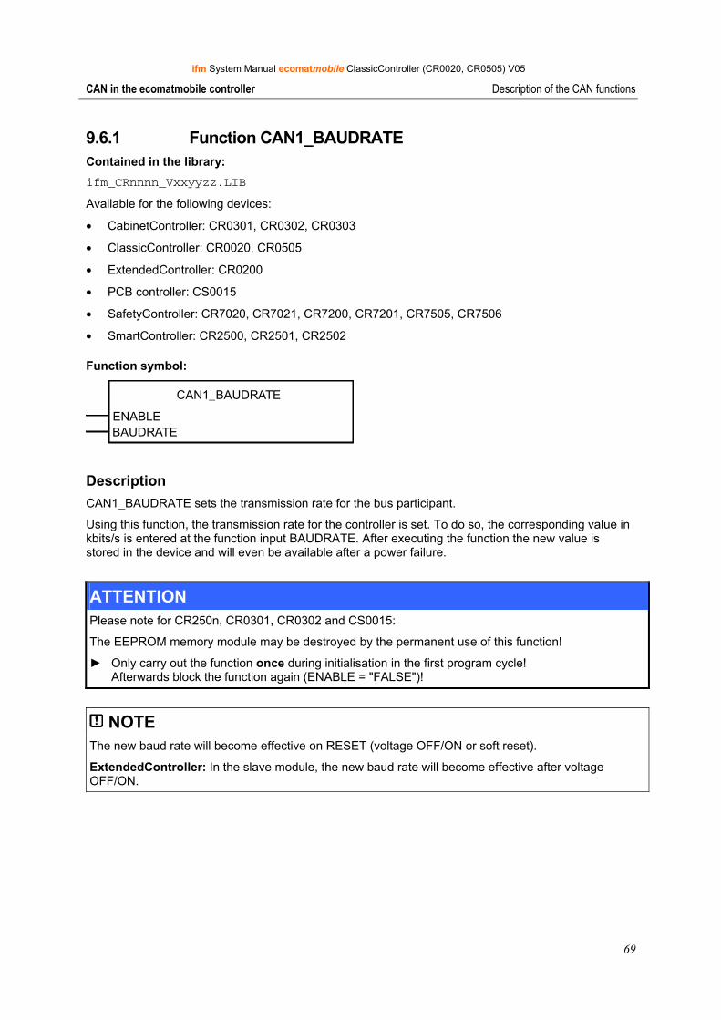
ifm System Manual ecomatmobile ClassicController (CR0020, CR0505) V05
69
CAN in the ecomatmobile controller Description of the CAN functions
9.6.1 Function CAN1_BAUDRATE Contained in the library: ifm_CRnnnn_Vxxyyzz.LIB
Available for the following devices:
• CabinetController: CR0301, CR0302, CR0303
• ClassicController: CR0020, CR0505
• ExtendedController: CR0200
• PCB controller: CS0015
• SafetyController: CR7020, CR7021, CR7200, CR7201, CR7505, CR7506
• SmartController: CR2500, CR2501, CR2502
Function symbol:
CAN1_BAUDRATE
ENABLEBAUDRATE
Description CAN1_BAUDRATE sets the transmission rate for the bus participant.
Using this function, the transmission rate for the controller is set. To do so, the corresponding value in kbits/s is entered at the function input BAUDRATE. After executing the function the new value is stored in the device and will even be available after a power failure.
ATTENTION Please note for CR250n, CR0301, CR0302 and CS0015:
The EEPROM memory module may be destroyed by the permanent use of this function!
► Only carry out the function once during initialisation in the first program cycle! Afterwards block the function again (ENABLE = "FALSE")!
NOTE The new baud rate will become effective on RESET (voltage OFF/ON or soft reset).
ExtendedController: In the slave module, the new baud rate will become effective after voltage OFF/ON.
ifm System Manual ecomatmobile ClassicController (CR0020, CR0505) V05
70
CAN in the ecomatmobile controller Description of the CAN functions
Parameters of the function inputs Name Data type Description
ENABLE BOOL TRUE (only 1 cycle): function is executed
FALSE: function is not executed
BAUDRATE WORD Baud rate [kbits/s] Permissible values: 50, 100, 125, 250, 500, 1000 Preset value = 125 kbits/s
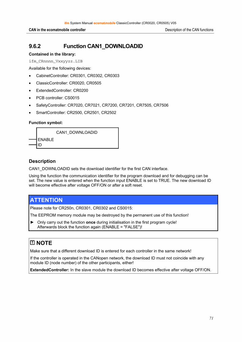
ifm System Manual ecomatmobile ClassicController (CR0020, CR0505) V05
71
CAN in the ecomatmobile controller Description of the CAN functions
9.6.2 Function CAN1_DOWNLOADID Contained in the library: ifm_CRnnnn_Vxxyyzz.LIB
Available for the following devices:
• CabinetController: CR0301, CR0302, CR0303
• ClassicController: CR0020, CR0505
• ExtendedController: CR0200
• PCB controller: CS0015
• SafetyController: CR7020, CR7021, CR7200, CR7201, CR7505, CR7506
• SmartController: CR2500, CR2501, CR2502
Function symbol:
CAN1_DOWNLOADID
ENABLEID
Description CAN1_DOWNLOADID sets the download identifier for the first CAN interface.
Using the function the communication identifier for the program download and for debugging can be set. The new value is entered when the function input ENABLE is set to TRUE. The new download ID will become effective after voltage OFF/ON or after a soft reset.
ATTENTION Please note for CR250n, CR0301, CR0302 and CS0015:
The EEPROM memory module may be destroyed by the permanent use of this function!
► Only carry out the function once during initialisation in the first program cycle! Afterwards block the function again (ENABLE = "FALSE")!
NOTE Make sure that a different download ID is entered for each controller in the same network!
If the controller is operated in the CANopen network, the download ID must not coincide with any module ID (node number) of the other participants, either!
ExtendedController: In the slave module the download ID becomes effective after voltage OFF/ON.

ifm System Manual ecomatmobile ClassicController (CR0020, CR0505) V05
72
CAN in the ecomatmobile controller Description of the CAN functions
Parameters of the function inputs Name Data type Description
ENABLE BOOL TRUE (only 1 cycle): ID is set
FALSE: function is not executed
ID BYTE Download identifier Permissible values: 1…127
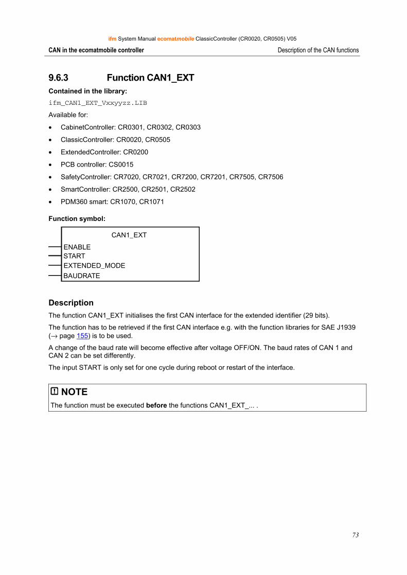
ifm System Manual ecomatmobile ClassicController (CR0020, CR0505) V05
73
CAN in the ecomatmobile controller Description of the CAN functions
9.6.3 Function CAN1_EXT Contained in the library: ifm_CAN1_EXT_Vxxyyzz.LIB
Available for:
• CabinetController: CR0301, CR0302, CR0303
• ClassicController: CR0020, CR0505
• ExtendedController: CR0200
• PCB controller: CS0015
• SafetyController: CR7020, CR7021, CR7200, CR7201, CR7505, CR7506
• SmartController: CR2500, CR2501, CR2502
• PDM360 smart: CR1070, CR1071
Function symbol:
CAN1_EXT
ENABLESTARTEXTENDED_MODE
BAUDRATE
Description The function CAN1_EXT initialises the first CAN interface for the extended identifier (29 bits).
The function has to be retrieved if the first CAN interface e.g. with the function libraries for SAE J1939 (→ page 155) is to be used.
A change of the baud rate will become effective after voltage OFF/ON. The baud rates of CAN 1 and CAN 2 can be set differently.
The input START is only set for one cycle during reboot or restart of the interface.
NOTE The function must be executed before the functions CAN1_EXT_... .
Administrator
Typewriter
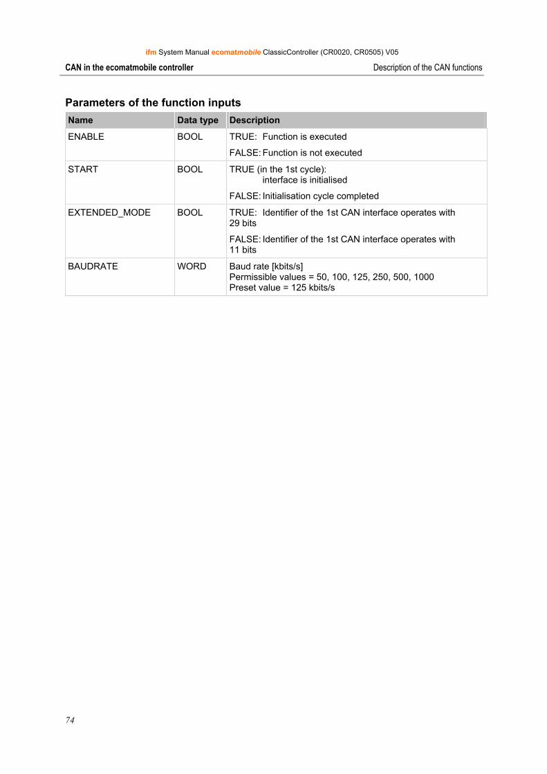
ifm System Manual ecomatmobile ClassicController (CR0020, CR0505) V05
74
CAN in the ecomatmobile controller Description of the CAN functions
Parameters of the function inputs Name Data type Description
ENABLE BOOL TRUE: Function is executed
FALSE: Function is not executed
START BOOL TRUE (in the 1st cycle): interface is initialised
FALSE: Initialisation cycle completed
EXTENDED_MODE BOOL TRUE: Identifier of the 1st CAN interface operates with 29 bits
FALSE: Identifier of the 1st CAN interface operates with 11 bits
BAUDRATE WORD Baud rate [kbits/s] Permissible values = 50, 100, 125, 250, 500, 1000 Preset value = 125 kbits/s
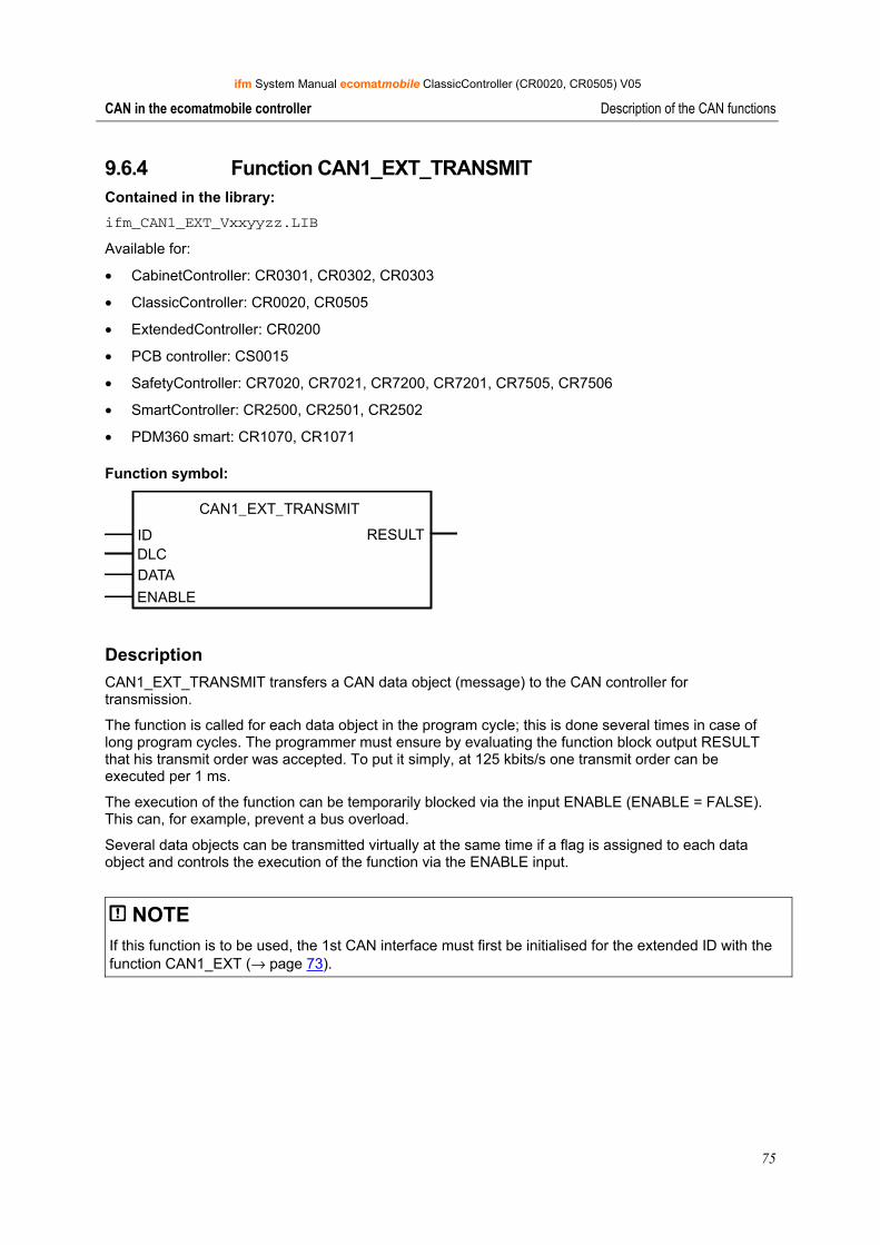
ifm System Manual ecomatmobile ClassicController (CR0020, CR0505) V05
75
CAN in the ecomatmobile controller Description of the CAN functions
9.6.4 Function CAN1_EXT_TRANSMIT Contained in the library: ifm_CAN1_EXT_Vxxyyzz.LIB
Available for:
• CabinetController: CR0301, CR0302, CR0303
• ClassicController: CR0020, CR0505
• ExtendedController: CR0200
• PCB controller: CS0015
• SafetyController: CR7020, CR7021, CR7200, CR7201, CR7505, CR7506
• SmartController: CR2500, CR2501, CR2502
• PDM360 smart: CR1070, CR1071
Function symbol:
CAN1_EXT_TRANSMIT
ID RESULTDLCDATA
ENABLE
Description CAN1_EXT_TRANSMIT transfers a CAN data object (message) to the CAN controller for transmission.
The function is called for each data object in the program cycle; this is done several times in case of long program cycles. The programmer must ensure by evaluating the function block output RESULT that his transmit order was accepted. To put it simply, at 125 kbits/s one transmit order can be executed per 1 ms.
The execution of the function can be temporarily blocked via the input ENABLE (ENABLE = FALSE). This can, for example, prevent a bus overload.
Several data objects can be transmitted virtually at the same time if a flag is assigned to each data object and controls the execution of the function via the ENABLE input.
NOTE If this function is to be used, the 1st CAN interface must first be initialised for the extended ID with the function CAN1_EXT (→ page 73).
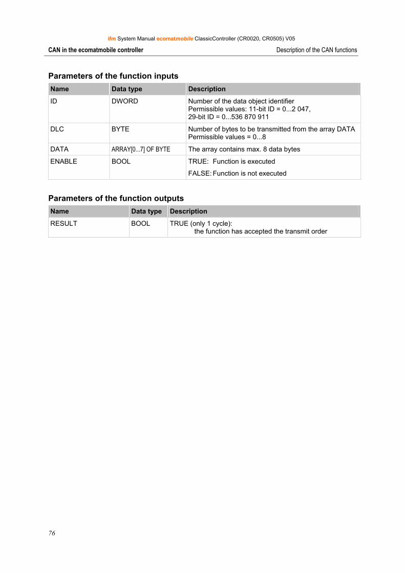
ifm System Manual ecomatmobile ClassicController (CR0020, CR0505) V05
76
CAN in the ecomatmobile controller Description of the CAN functions
Parameters of the function inputs Name Data type Description
ID DWORD Number of the data object identifier Permissible values: 11-bit ID = 0...2 047, 29-bit ID = 0...536 870 911
DLC BYTE Number of bytes to be transmitted from the array DATAPermissible values = 0...8
DATA ARRAY[0...7] OF BYTE The array contains max. 8 data bytes
ENABLE BOOL TRUE: Function is executed
FALSE: Function is not executed
Parameters of the function outputs Name Data type Description
RESULT BOOL TRUE (only 1 cycle): the function has accepted the transmit order
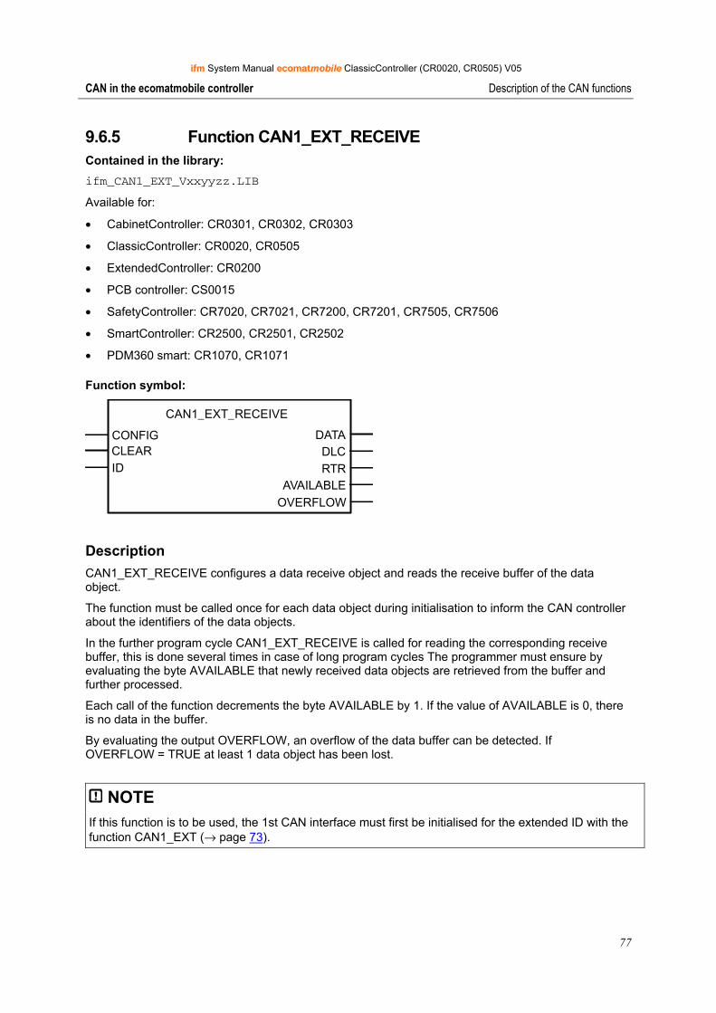
ifm System Manual ecomatmobile ClassicController (CR0020, CR0505) V05
77
CAN in the ecomatmobile controller Description of the CAN functions
9.6.5 Function CAN1_EXT_RECEIVE Contained in the library: ifm_CAN1_EXT_Vxxyyzz.LIB
Available for:
• CabinetController: CR0301, CR0302, CR0303
• ClassicController: CR0020, CR0505
• ExtendedController: CR0200
• PCB controller: CS0015
• SafetyController: CR7020, CR7021, CR7200, CR7201, CR7505, CR7506
• SmartController: CR2500, CR2501, CR2502
• PDM360 smart: CR1070, CR1071
Function symbol:
CAN1_EXT_RECEIVE
CONFIG DATACLEAR DLCID RTR
AVAILABLE OVERFLOW
Description CAN1_EXT_RECEIVE configures a data receive object and reads the receive buffer of the data object.
The function must be called once for each data object during initialisation to inform the CAN controller about the identifiers of the data objects.
In the further program cycle CAN1_EXT_RECEIVE is called for reading the corresponding receive buffer, this is done several times in case of long program cycles The programmer must ensure by evaluating the byte AVAILABLE that newly received data objects are retrieved from the buffer and further processed.
Each call of the function decrements the byte AVAILABLE by 1. If the value of AVAILABLE is 0, there is no data in the buffer.
By evaluating the output OVERFLOW, an overflow of the data buffer can be detected. If OVERFLOW = TRUE at least 1 data object has been lost.
NOTE If this function is to be used, the 1st CAN interface must first be initialised for the extended ID with the function CAN1_EXT (→ page 73).
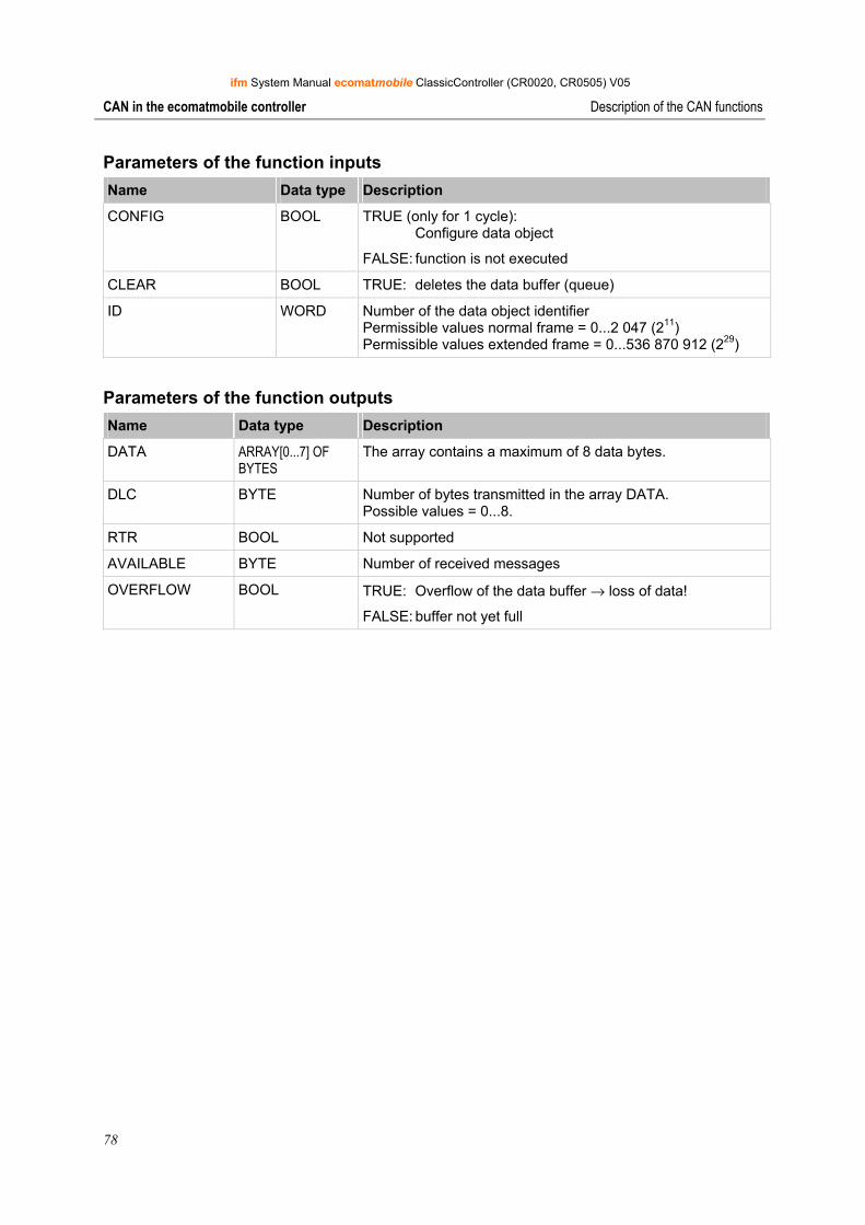
ifm System Manual ecomatmobile ClassicController (CR0020, CR0505) V05
78
CAN in the ecomatmobile controller Description of the CAN functions
Parameters of the function inputs Name Data type Description
CONFIG BOOL TRUE (only for 1 cycle): Configure data object
FALSE: function is not executed
CLEAR BOOL TRUE: deletes the data buffer (queue)
ID WORD Number of the data object identifier Permissible values normal frame = 0...2 047 (211) Permissible values extended frame = 0...536 870 912 (229)
Parameters of the function outputs Name Data type Description
DATA ARRAY[0...7] OF BYTES
The array contains a maximum of 8 data bytes.
DLC BYTE Number of bytes transmitted in the array DATA. Possible values = 0...8.
RTR BOOL Not supported
AVAILABLE BYTE Number of received messages
OVERFLOW BOOL TRUE: Overflow of the data buffer → loss of data!
FALSE: buffer not yet full
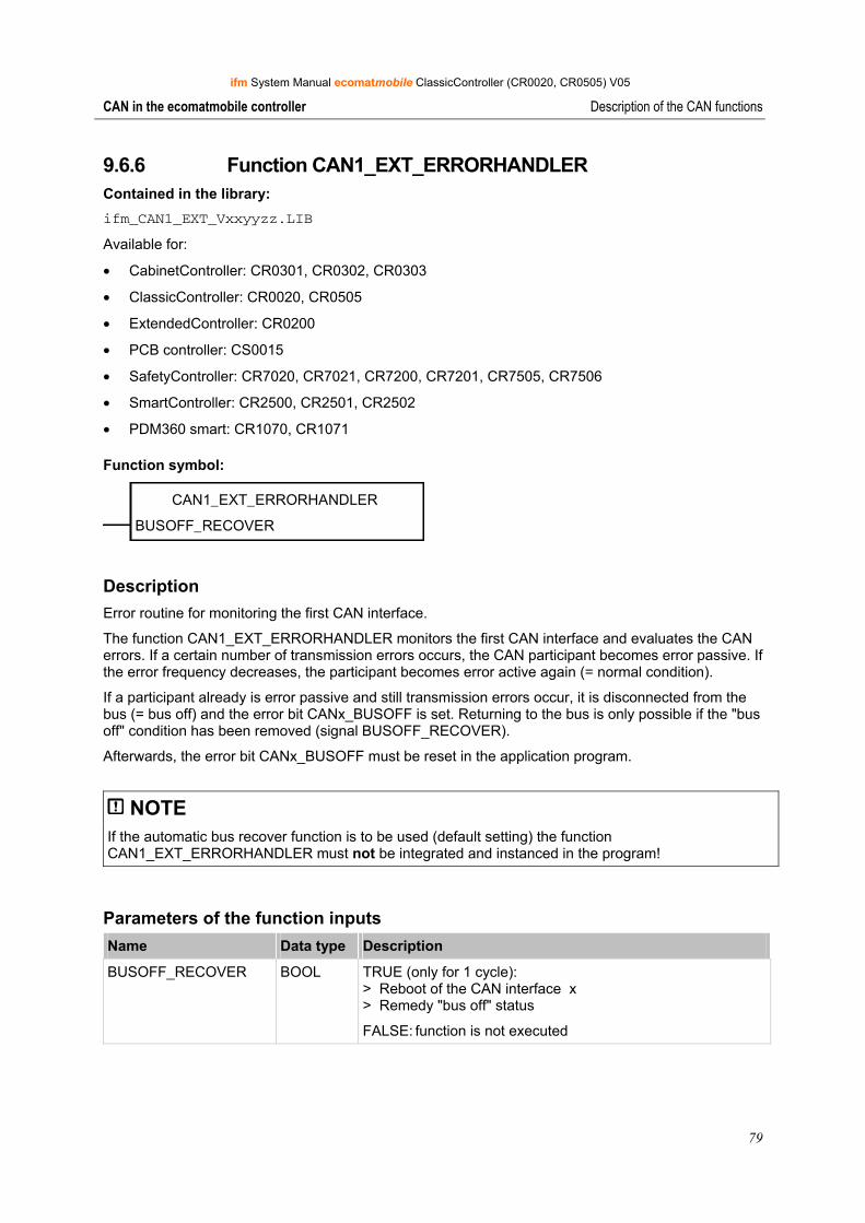
ifm System Manual ecomatmobile ClassicController (CR0020, CR0505) V05
79
CAN in the ecomatmobile controller Description of the CAN functions
9.6.6 Function CAN1_EXT_ERRORHANDLER Contained in the library: ifm_CAN1_EXT_Vxxyyzz.LIB
Available for:
• CabinetController: CR0301, CR0302, CR0303
• ClassicController: CR0020, CR0505
• ExtendedController: CR0200
• PCB controller: CS0015
• SafetyController: CR7020, CR7021, CR7200, CR7201, CR7505, CR7506
• SmartController: CR2500, CR2501, CR2502
• PDM360 smart: CR1070, CR1071
Function symbol:
CAN1_EXT_ERRORHANDLER
BUSOFF_RECOVER
Description Error routine for monitoring the first CAN interface.
The function CAN1_EXT_ERRORHANDLER monitors the first CAN interface and evaluates the CAN errors. If a certain number of transmission errors occurs, the CAN participant becomes error passive. If the error frequency decreases, the participant becomes error active again (= normal condition).
If a participant already is error passive and still transmission errors occur, it is disconnected from the bus (= bus off) and the error bit CANx_BUSOFF is set. Returning to the bus is only possible if the "bus off" condition has been removed (signal BUSOFF_RECOVER).
Afterwards, the error bit CANx_BUSOFF must be reset in the application program.
NOTE If the automatic bus recover function is to be used (default setting) the function CAN1_EXT_ERRORHANDLER must not be integrated and instanced in the program!
Parameters of the function inputs Name Data type Description
BUSOFF_RECOVER BOOL TRUE (only for 1 cycle): > Reboot of the CAN interface x > Remedy "bus off" status
FALSE: function is not executed
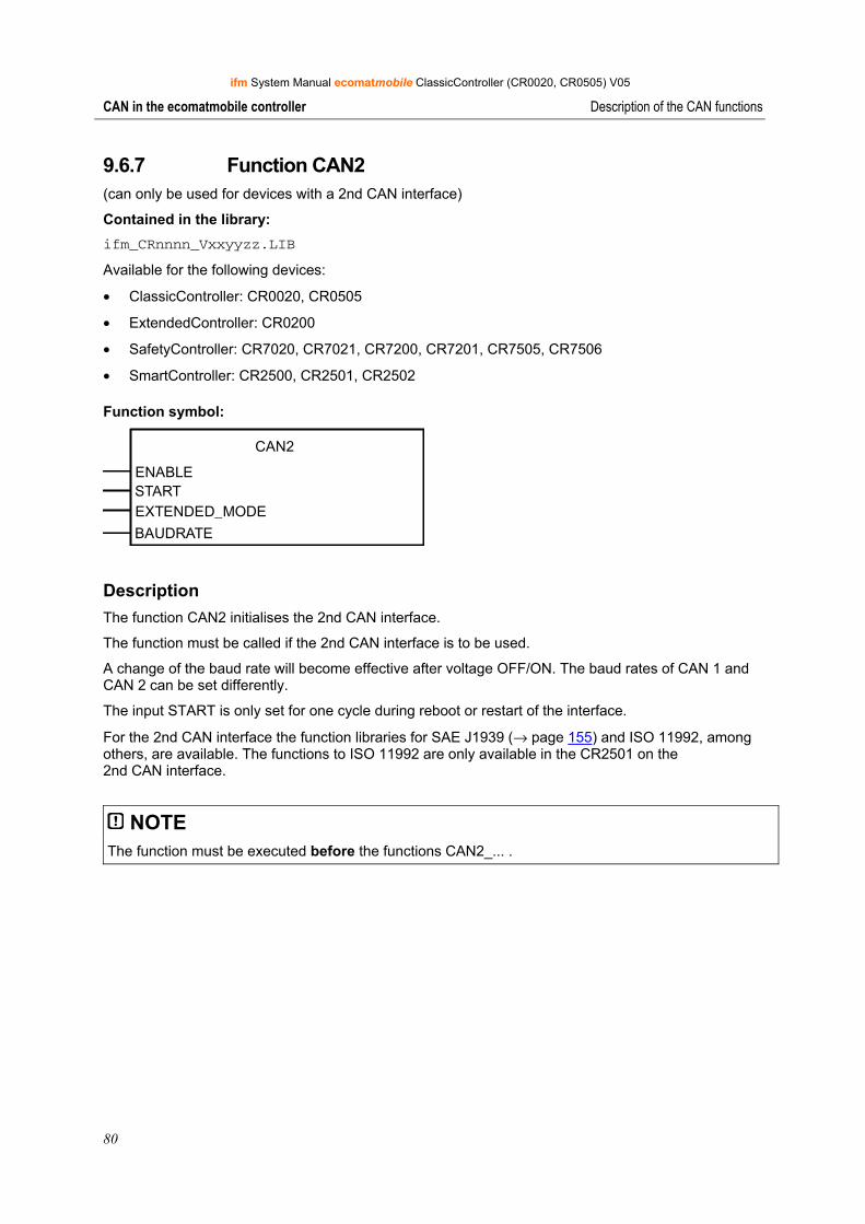
ifm System Manual ecomatmobile ClassicController (CR0020, CR0505) V05
80
CAN in the ecomatmobile controller Description of the CAN functions
9.6.7 Function CAN2 (can only be used for devices with a 2nd CAN interface)
Contained in the library: ifm_CRnnnn_Vxxyyzz.LIB
Available for the following devices:
• ClassicController: CR0020, CR0505
• ExtendedController: CR0200
• SafetyController: CR7020, CR7021, CR7200, CR7201, CR7505, CR7506
• SmartController: CR2500, CR2501, CR2502
Function symbol:
CAN2
ENABLESTARTEXTENDED_MODE
BAUDRATE
Description The function CAN2 initialises the 2nd CAN interface.
The function must be called if the 2nd CAN interface is to be used.
A change of the baud rate will become effective after voltage OFF/ON. The baud rates of CAN 1 and CAN 2 can be set differently.
The input START is only set for one cycle during reboot or restart of the interface.
For the 2nd CAN interface the function libraries for SAE J1939 (→ page 155) and ISO 11992, among others, are available. The functions to ISO 11992 are only available in the CR2501 on the 2nd CAN interface.
NOTE The function must be executed before the functions CAN2_... .
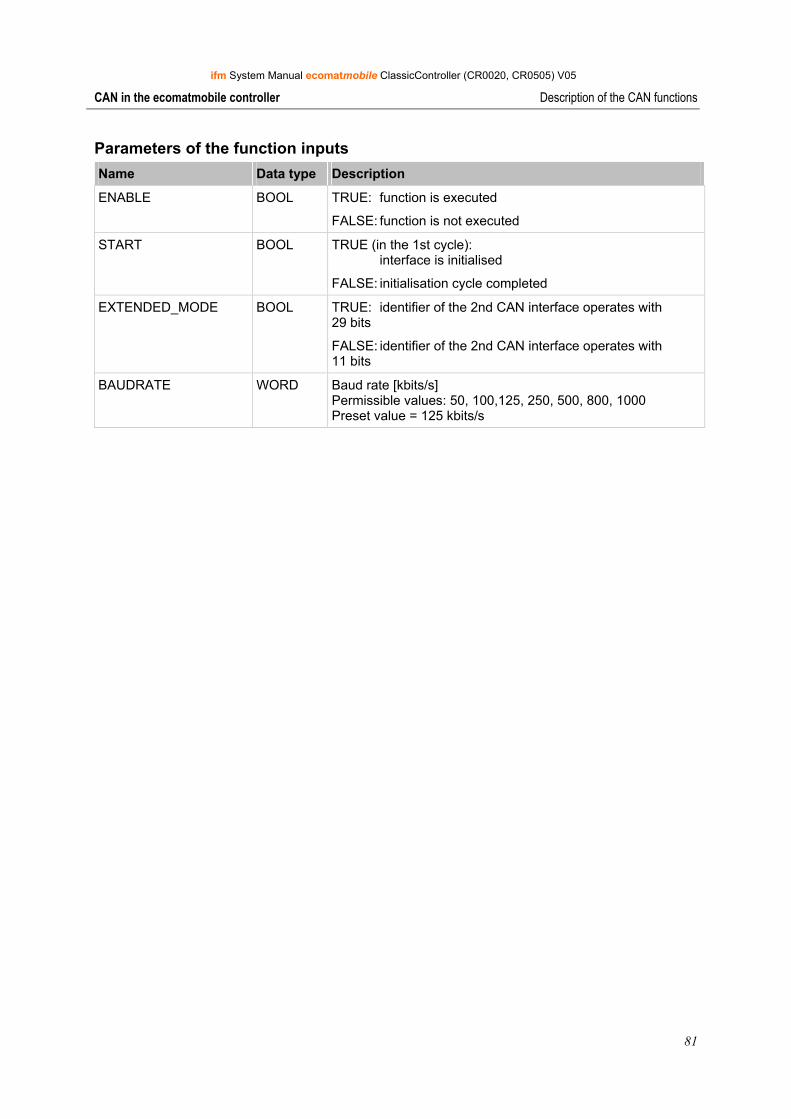
ifm System Manual ecomatmobile ClassicController (CR0020, CR0505) V05
81
CAN in the ecomatmobile controller Description of the CAN functions
Parameters of the function inputs Name Data type Description
ENABLE BOOL TRUE: function is executed
FALSE: function is not executed
START BOOL TRUE (in the 1st cycle): interface is initialised
FALSE: initialisation cycle completed
EXTENDED_MODE BOOL TRUE: identifier of the 2nd CAN interface operates with 29 bits
FALSE: identifier of the 2nd CAN interface operates with 11 bits
BAUDRATE WORD Baud rate [kbits/s] Permissible values: 50, 100,125, 250, 500, 800, 1000 Preset value = 125 kbits/s
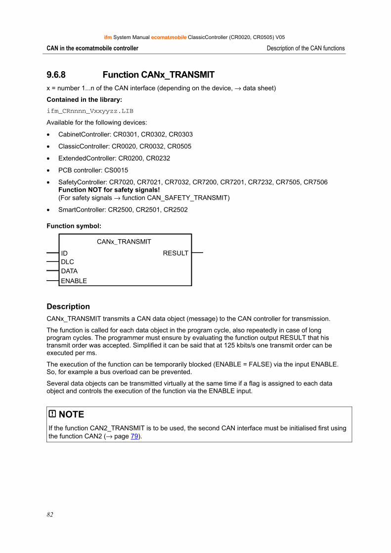
ifm System Manual ecomatmobile ClassicController (CR0020, CR0505) V05
82
CAN in the ecomatmobile controller Description of the CAN functions
9.6.8 Function CANx_TRANSMIT x = number 1...n of the CAN interface (depending on the device, → data sheet)
Contained in the library: ifm_CRnnnn_Vxxyyzz.LIB
Available for the following devices:
• CabinetController: CR0301, CR0302, CR0303
• ClassicController: CR0020, CR0032, CR0505
• ExtendedController: CR0200, CR0232
• PCB controller: CS0015
• SafetyController: CR7020, CR7021, CR7032, CR7200, CR7201, CR7232, CR7505, CR7506 Function NOT for safety signals! (For safety signals → function CAN_SAFETY_TRANSMIT)
• SmartController: CR2500, CR2501, CR2502
Function symbol:
CANx_TRANSMIT
ID RESULTDLCDATA
ENABLE
Description CANx_TRANSMIT transmits a CAN data object (message) to the CAN controller for transmission.
The function is called for each data object in the program cycle, also repeatedly in case of long program cycles. The programmer must ensure by evaluating the function output RESULT that his transmit order was accepted. Simplified it can be said that at 125 kbits/s one transmit order can be executed per ms.
The execution of the function can be temporarily blocked (ENABLE = FALSE) via the input ENABLE. So, for example a bus overload can be prevented.
Several data objects can be transmitted virtually at the same time if a flag is assigned to each data object and controls the execution of the function via the ENABLE input.
NOTE If the function CAN2_TRANSMIT is to be used, the second CAN interface must be initialised first using the function CAN2 (→ page 79).
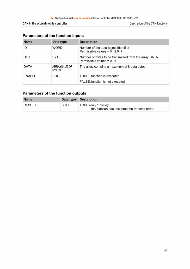
ifm System Manual ecomatmobile ClassicController (CR0020, CR0505) V05
83
CAN in the ecomatmobile controller Description of the CAN functions
Parameters of the function inputs Name Data type Description
ID WORD Number of the data object identifier Permissible values = 0...2 047
DLC BYTE Number of bytes to be transmitted from the array DATA Permissible values = 0...8
DATA ARRAY[0...7] OF BYTES
The array contains a maximum of 8 data bytes
ENABLE BOOL TRUE: function is executed
FALSE: function is not executed
Parameters of the function outputs Name Data type Description
RESULT BOOL TRUE (only 1 cycle): the function has accepted the transmit order
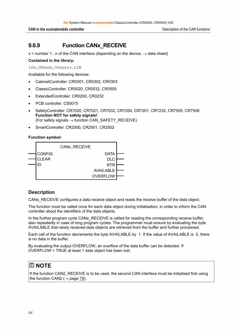
ifm System Manual ecomatmobile ClassicController (CR0020, CR0505) V05
84
CAN in the ecomatmobile controller Description of the CAN functions
9.6.9 Function CANx_RECEIVE x = number 1...n of the CAN interface (depending on the device, → data sheet)
Contained in the library: ifm_CRnnnn_Vxxyyzz.LIB
Available for the following devices:
• CabinetController: CR0301, CR0302, CR0303
• ClassicController: CR0020, CR0032, CR0505
• ExtendedController: CR0200, CR0232
• PCB controller: CS0015
• SafetyController: CR7020, CR7021, CR7032, CR7200, CR7201, CR7232, CR7505, CR7506 Function NOT for safety signals! (For safety signals → function CAN_SAFETY_RECEIVE)
• SmartController: CR2500, CR2501, CR2502
Function symbol:
CANx_RECEIVE
CONFIG DATACLEAR DLCID RTR
AVAILABLE OVERFLOW
Description CANx_RECEIVE configures a data receive object and reads the receive buffer of the data object.
The function must be called once for each data object during initialisation, in order to inform the CAN controller about the identifiers of the data objects.
In the further program cycle CANx_RECEIVE is called for reading the corresponding receive buffer, also repeatedly in case of long program cycles. The programmer must ensure by evaluating the byte AVAILABLE that newly received data objects are retrieved from the buffer and further processed.
Each call of the function decrements the byte AVAILABLE by 1. If the value of AVAILABLE is 0, there is no data in the buffer.
By evaluating the output OVERFLOW, an overflow of the data buffer can be detected. If OVERFLOW = TRUE at least 1 data object has been lost.
NOTE If the function CAN2_RECEIVE is to be used, the second CAN interface must be initialised first using the function CAN2 (→ page 79).
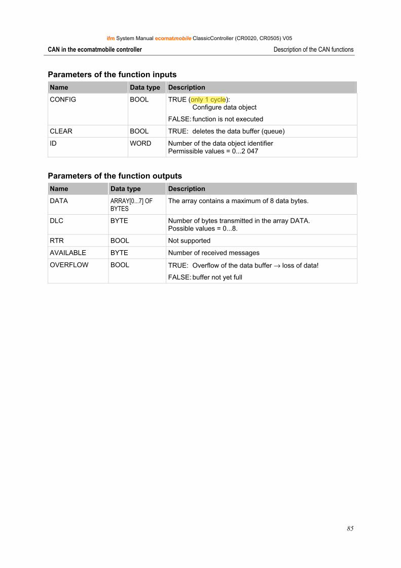
ifm System Manual ecomatmobile ClassicController (CR0020, CR0505) V05
85
CAN in the ecomatmobile controller Description of the CAN functions
Parameters of the function inputs Name Data type Description
CONFIG BOOL TRUE (only 1 cycle): Configure data object
FALSE: function is not executed
CLEAR BOOL TRUE: deletes the data buffer (queue)
ID WORD Number of the data object identifier Permissible values = 0...2 047
Parameters of the function outputs Name Data type Description
DATA ARRAY[0...7] OF BYTES
The array contains a maximum of 8 data bytes.
DLC BYTE Number of bytes transmitted in the array DATA. Possible values = 0...8.
RTR BOOL Not supported
AVAILABLE BYTE Number of received messages
OVERFLOW BOOL TRUE: Overflow of the data buffer → loss of data!
FALSE: buffer not yet full
Administrator
Highlight
Administrator
Typewriter
so don't set it to be TRUE all the time, it won't work
Administrator
Typewriter
Administrator
Typewriter
Administrator
Typewriter
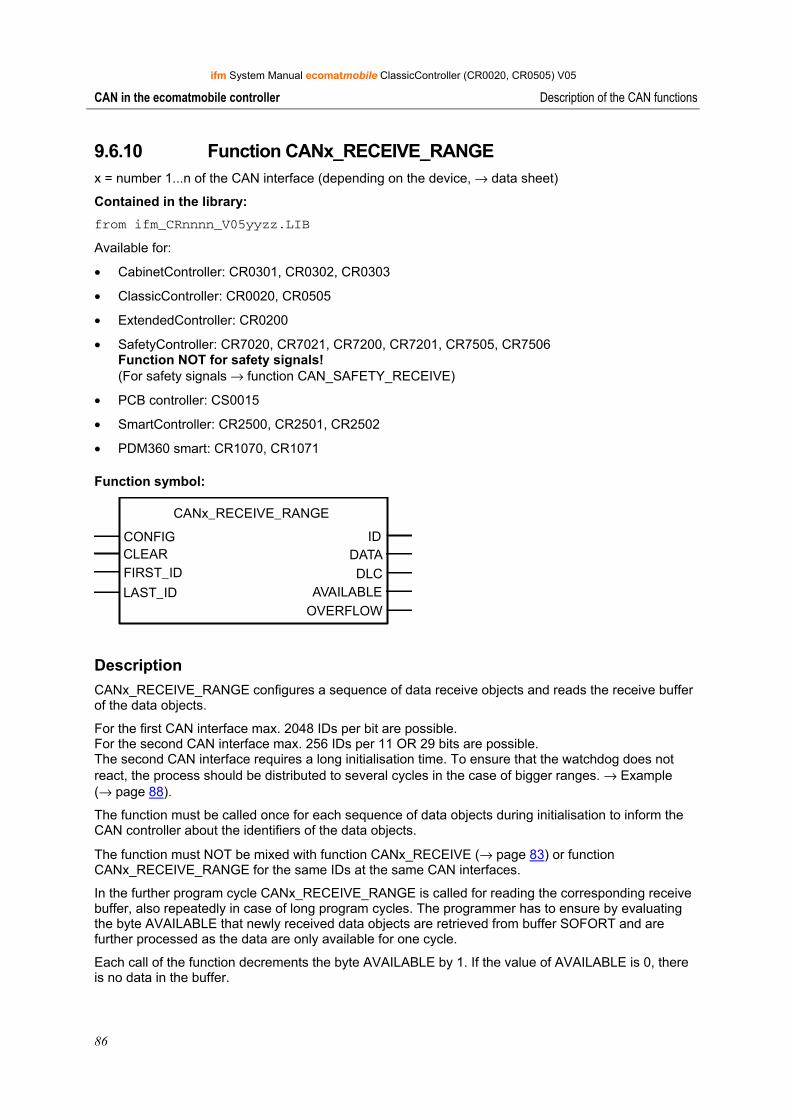
ifm System Manual ecomatmobile ClassicController (CR0020, CR0505) V05
86
CAN in the ecomatmobile controller Description of the CAN functions
9.6.10 Function CANx_RECEIVE_RANGE x = number 1...n of the CAN interface (depending on the device, → data sheet)
Contained in the library: from ifm_CRnnnn_V05yyzz.LIB
Available for:
• CabinetController: CR0301, CR0302, CR0303
• ClassicController: CR0020, CR0505
• ExtendedController: CR0200
• SafetyController: CR7020, CR7021, CR7200, CR7201, CR7505, CR7506 Function NOT for safety signals! (For safety signals → function CAN_SAFETY_RECEIVE)
• PCB controller: CS0015
• SmartController: CR2500, CR2501, CR2502
• PDM360 smart: CR1070, CR1071
Function symbol:
CANx_RECEIVE_RANGE
CONFIG IDCLEAR DATAFIRST_ID DLCLAST_ID AVAILABLE
OVERFLOW
Description CANx_RECEIVE_RANGE configures a sequence of data receive objects and reads the receive buffer of the data objects.
For the first CAN interface max. 2048 IDs per bit are possible. For the second CAN interface max. 256 IDs per 11 OR 29 bits are possible. The second CAN interface requires a long initialisation time. To ensure that the watchdog does not react, the process should be distributed to several cycles in the case of bigger ranges. → Example (→ page 88).
The function must be called once for each sequence of data objects during initialisation to inform the CAN controller about the identifiers of the data objects.
The function must NOT be mixed with function CANx_RECEIVE (→ page 83) or function CANx_RECEIVE_RANGE for the same IDs at the same CAN interfaces.
In the further program cycle CANx_RECEIVE_RANGE is called for reading the corresponding receive buffer, also repeatedly in case of long program cycles. The programmer has to ensure by evaluating the byte AVAILABLE that newly received data objects are retrieved from buffer SOFORT and are further processed as the data are only available for one cycle.
Each call of the function decrements the byte AVAILABLE by 1. If the value of AVAILABLE is 0, there is no data in the buffer.
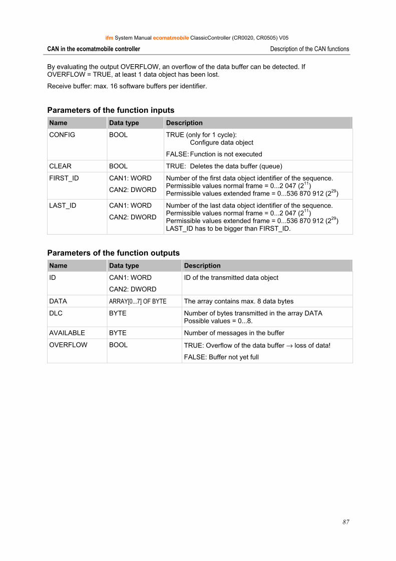
ifm System Manual ecomatmobile ClassicController (CR0020, CR0505) V05
87
CAN in the ecomatmobile controller Description of the CAN functions
By evaluating the output OVERFLOW, an overflow of the data buffer can be detected. If OVERFLOW = TRUE, at least 1 data object has been lost.
Receive buffer: max. 16 software buffers per identifier.
Parameters of the function inputs Name Data type Description
CONFIG BOOL TRUE (only for 1 cycle): Configure data object
FALSE: Function is not executed
CLEAR BOOL TRUE: Deletes the data buffer (queue)
FIRST_ID CAN1: WORD
CAN2: DWORD
Number of the first data object identifier of the sequence. Permissible values normal frame = 0...2 047 (211) Permissible values extended frame = 0...536 870 912 (229)
LAST_ID CAN1: WORD
CAN2: DWORD
Number of the last data object identifier of the sequence. Permissible values normal frame = 0...2 047 (211) Permissible values extended frame = 0...536 870 912 (229) LAST_ID has to be bigger than FIRST_ID.
Parameters of the function outputs Name Data type Description
ID CAN1: WORD
CAN2: DWORD
ID of the transmitted data object
DATA ARRAY[0...7] OF BYTE The array contains max. 8 data bytes
DLC BYTE Number of bytes transmitted in the array DATA Possible values = 0...8.
AVAILABLE BYTE Number of messages in the buffer
OVERFLOW BOOL TRUE: Overflow of the data buffer → loss of data!
FALSE: Buffer not yet full
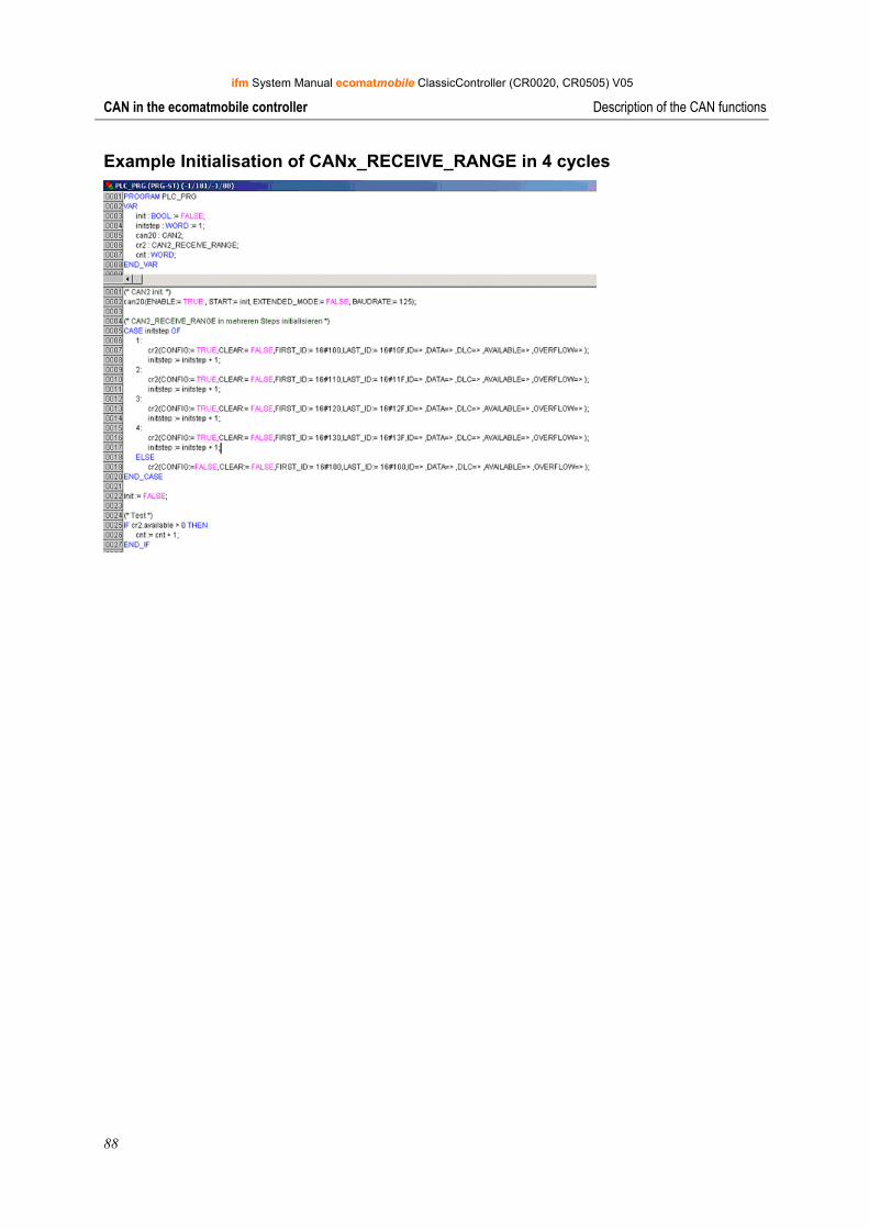
ifm System Manual ecomatmobile ClassicController (CR0020, CR0505) V05
88
CAN in the ecomatmobile controller Description of the CAN functions
Example Initialisation of CANx_RECEIVE_RANGE in 4 cycles
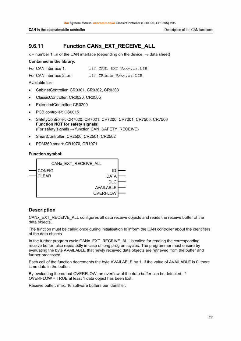
ifm System Manual ecomatmobile ClassicController (CR0020, CR0505) V05
89
CAN in the ecomatmobile controller Description of the CAN functions
9.6.11 Function CANx_EXT_RECEIVE_ALL x = number 1...n of the CAN interface (depending on the device, → data sheet)
Contained in the library:
For CAN interface 1: ifm_CAN1_EXT_Vxxyyzz.LIB
For CAN interface 2...n: ifm_CRnnnn_Vxxyyzz.LIB
Available for:
• CabinetController: CR0301, CR0302, CR0303
• ClassicController: CR0020, CR0505
• ExtendedController: CR0200
• PCB controller: CS0015
• SafetyController: CR7020, CR7021, CR7200, CR7201, CR7505, CR7506 Function NOT for safety signals! (For safety signals → function CAN_SAFETY_RECEIVE)
• SmartController: CR2500, CR2501, CR2502
• PDM360 smart: CR1070, CR1071
Function symbol:
CANx_EXT_RECEIVE_ALL
CONFIG IDCLEAR DATA
DLCAVAILABLE
OVERFLOW
Description CANx_EXT_RECEIVE_ALL configures all data receive objects and reads the receive buffer of the data objects.
The function must be called once during initialisation to inform the CAN controller about the identifiers of the data objects.
In the further program cycle CANx_EXT_RECEIVE_ALL is called for reading the corresponding receive buffer, also repeatedly in case of long program cycles. The programmer must ensure by evaluating the byte AVAILABLE that newly received data objects are retrieved from the buffer and further processed.
Each call of the function decrements the byte AVAILABLE by 1. If the value of AVAILABLE is 0, there is no data in the buffer.
By evaluating the output OVERFLOW, an overflow of the data buffer can be detected. If OVERFLOW = TRUE at least 1 data object has been lost.
Receive buffer: max. 16 software buffers per identifier.
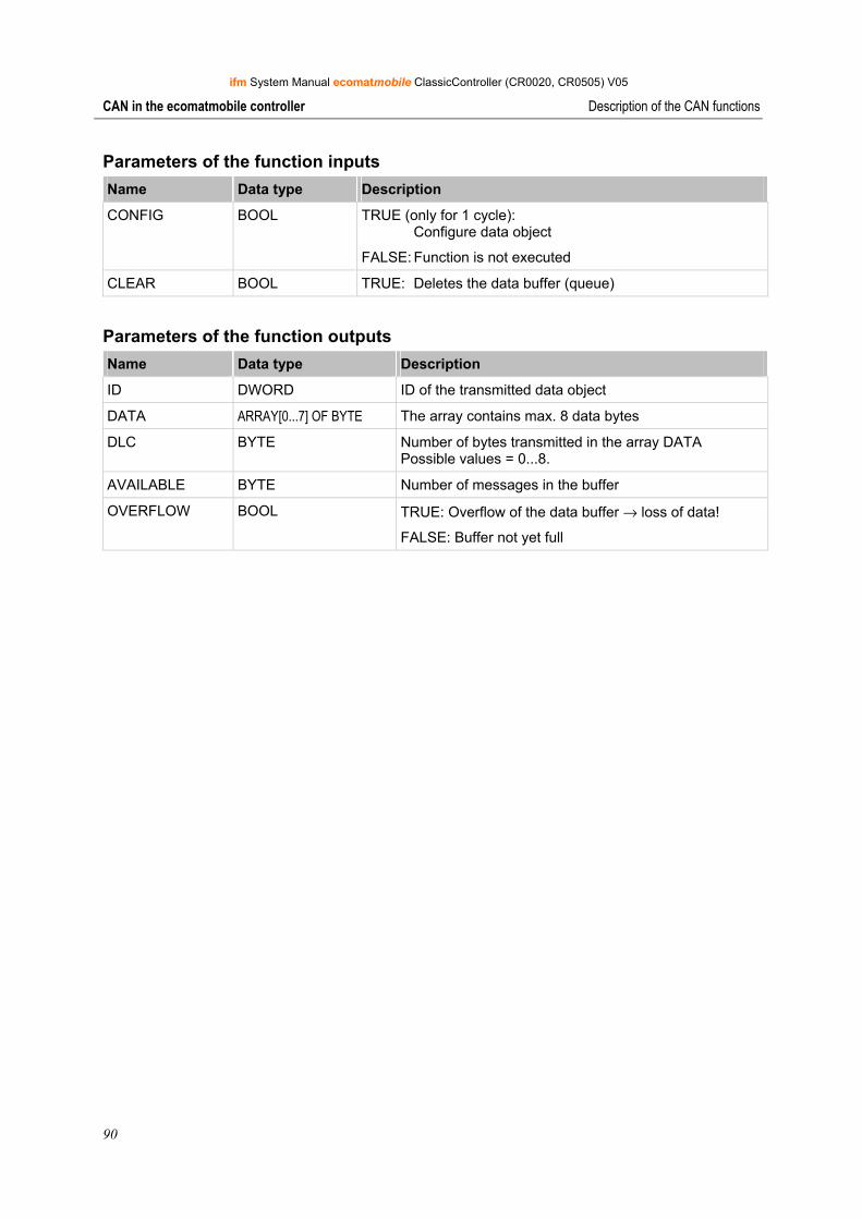
ifm System Manual ecomatmobile ClassicController (CR0020, CR0505) V05
90
CAN in the ecomatmobile controller Description of the CAN functions
Parameters of the function inputs Name Data type Description
CONFIG BOOL TRUE (only for 1 cycle): Configure data object
FALSE: Function is not executed
CLEAR BOOL TRUE: Deletes the data buffer (queue)
Parameters of the function outputs Name Data type Description
ID DWORD ID of the transmitted data object
DATA ARRAY[0...7] OF BYTE The array contains max. 8 data bytes
DLC BYTE Number of bytes transmitted in the array DATA Possible values = 0...8.
AVAILABLE BYTE Number of messages in the buffer
OVERFLOW BOOL TRUE: Overflow of the data buffer → loss of data!
FALSE: Buffer not yet full
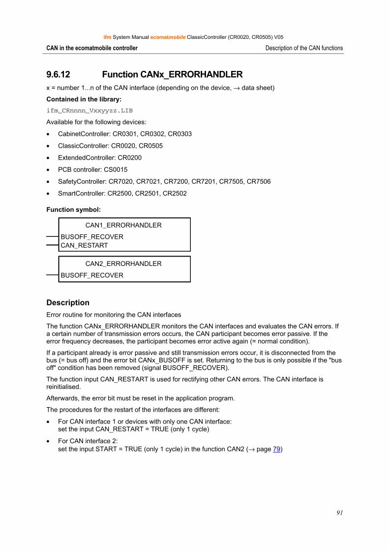
ifm System Manual ecomatmobile ClassicController (CR0020, CR0505) V05
91
CAN in the ecomatmobile controller Description of the CAN functions
9.6.12 Function CANx_ERRORHANDLER x = number 1...n of the CAN interface (depending on the device, → data sheet)
Contained in the library: ifm_CRnnnn_Vxxyyzz.LIB
Available for the following devices:
• CabinetController: CR0301, CR0302, CR0303
• ClassicController: CR0020, CR0505
• ExtendedController: CR0200
• PCB controller: CS0015
• SafetyController: CR7020, CR7021, CR7200, CR7201, CR7505, CR7506
• SmartController: CR2500, CR2501, CR2502
Function symbol:
CAN1_ERRORHANDLER
BUSOFF_RECOVERCAN_RESTART
CAN2_ERRORHANDLER
BUSOFF_RECOVER
Description Error routine for monitoring the CAN interfaces
The function CANx_ERRORHANDLER monitors the CAN interfaces and evaluates the CAN errors. If a certain number of transmission errors occurs, the CAN participant becomes error passive. If the error frequency decreases, the participant becomes error active again (= normal condition).
If a participant already is error passive and still transmission errors occur, it is disconnected from the bus (= bus off) and the error bit CANx_BUSOFF is set. Returning to the bus is only possible if the "bus off" condition has been removed (signal BUSOFF_RECOVER).
The function input CAN_RESTART is used for rectifying other CAN errors. The CAN interface is reinitialised.
Afterwards, the error bit must be reset in the application program.
The procedures for the restart of the interfaces are different:
• For CAN interface 1 or devices with only one CAN interface: set the input CAN_RESTART = TRUE (only 1 cycle)
• For CAN interface 2: set the input START = TRUE (only 1 cycle) in the function CAN2 (→ page 79)
ifm System Manual ecomatmobile ClassicController (CR0020, CR0505) V05
92
CAN in the ecomatmobile controller Description of the CAN functions
NOTE In principle, the function CAN2 (→ page 79) must be executed to initialise the second CAN interface, before functions can be used for it.
If the automatic bus recover function is to be used (default setting) the function CANx_ERRORHANDLER must not be integrated and instanced in the program!
Parameters of the function inputs Name Data type Description
BUSOFF_RECOVER BOOL TRUE (only 1 cycle): Remedy 'bus off' status
FALSE: function is not executed
CAN_RESTART BOOL TRUE (only 1 cycle): Completely reinitialise CAN interface 1
FALSE: function is not executed
ifm System Manual ecomatmobile ClassicController (CR0020, CR0505) V05
93
CAN in the ecomatmobile controller ifm CANopen library
9.7 ifm CANopen library
CANopen network configuration, status and error handling
For all programmable devices the CANopen interface of CoDeSys is used. Whereas the network configuration and parameter setting of the connected devices are directly carried out via the programming software, the error messages can only be reached via nested variable structures in the CANopen stack. The documentation below shows you the structure and use of the network configuration and describes the functions of the ifm CANopen device libraries.
The chapters CANopen support by CoDeSys (→ page 93), CANopen master (→ page 95), CAN device (→ page 109) and CAN network variables (→ page 117) describe the internal functions of the CoDeSys CANopen stacks and their use. They also give information of how to use the network configurator.
The chapters concerning the libraries ifm_CRnnnn_CANopenMaster_Vxxyyzz.lib and ifm_CRnnnn_CANopenSlave_Vxxyyzz.lib describe all functions for error handling and polling the device status when used as master or slave (CAN device).
NOTE Irrespective of the device used the structure of the function interfaces of all libraries is the same. The slight differences (e.g. CANOPEN_LED_STATUS) are directly described in the corresponding functions.
It is absolutely necessary to use only the corresponding device-specific library. The context can be seen from the integrated article number of the device, e.g.:
CR0020: → ifm_CR0020_CANopenMaster_V040003.lib
→ chapter Setup the target (→ page 20)
When other libraries are used the device can no longer function correctly.
9.7.1 CANopen support by CoDeSys
General information about CANopen with CoDeSys CoDeSys® is one of the leading systems for programming control systems to the international standard IEC 61131. To make CoDeSys® more interesting for users many important functions were integrated in the programming system, among them a configurator for CANopen. This CANopen configurator enables configuration of CANopen networks (with some restrictions) under CoDeSys®.
CANopen is implemented as a CoDeSys® library in IEC 61131-3. The library is based on simple basic CAN functions called CAN driver.
Implementation of the CANopen functions as CoDeSys® library enables simple scaling of the target system. The CANopen function only uses target system resources if the function is really used. To use target system resources carefully CoDeSys® automatically generates a data basis for the CANopen master function which exactly corresponds to the configuration.
From the CoDeSys® programming system version 2.3.6.0 onwards an ecomatmobile controller can be used as CANopen master and slave (CAN device).
ifm System Manual ecomatmobile ClassicController (CR0020, CR0505) V05
94
CAN in the ecomatmobile controller ifm CANopen library
NOTE: For all ecomatmobile controllers and the PDM360 smart you must use CANopen libraries with the following addition:
• For CR0032 target version up to V01, all other devices up to V04.00.05: "OptTable"
• For CR0032 target version from V02 onwards, all other devices from V05 onwards: "OptTableEx"
If a new project is created, these libraries are in general automatically loaded. If you add the libraries via the library manager, you must ensure a correct selection.
The CANopen libraries without this addition are used for all other programmable devices (e.g. PDM360 compact).
CANopen terms and implementation According to the CANopen specification there are no masters and slaves in a CAN network. Instead of this there is an NMT master (NMT = network management), a configuration master, etc. according to CANopen. It is always assumed that all participants of a CAN network have equal rights.
Implementation assumes that a CAN network serves as periphery of a CoDeSys programmable controller. As a result of this an ecomatmobile controller or a PDM360 display is called CAN master in the CAN configurator of CoDeSys. This master is an NMT master and configuration master. Normally the master ensures that the network is put into operation. The master takes the initiative to start the individual nodes (= network nodes) known via the configuration. These nodes are called slaves.
To bring the master closer to the status of a CANopen node an object directory was introduced for the master. The master can also act as an SDO server (SDO = Service Data Object) and not only as SDO client in the configuration phase of the slaves.
"Addresses" in CANopen In CANopen there are different types of addresses (IDs):
• COB ID The CAN Object Identifier addresses the message (= the CAN object) in the list of devices. Identical messages have the same COB ID. The COB ID entries in the object directory contain the CAN identifier (CAN ID) among others.
• CAN ID The CAN Identifier identifies CAN messages in the complete network. The CAN ID is part of the COB ID in the object directory.
• Node ID The Node Identifier identifies the CANopen devices in the complete network. The Node ID is part of some predefined CAN IDs (lower 7 bits).
ifm System Manual ecomatmobile ClassicController (CR0020, CR0505) V05
95
CAN in the ecomatmobile controller ifm CANopen library
9.7.2 CANopen master
Differentiation from other CANopen libraries The CANopen library implemented by 3S (Smart Software Solutions) differentiates from the systems on the market in various points. It was not developed to make other libraries of renowned manufacturers unnecessary but was deliberately optimised for use with the CoDeSys programming and runtime system.
The libraries are based on the specifications of CiA DS301, V402.
For users the advantages of the CoDeSys CANopen library are as follows:
• Implementation is independent of the target system and can therefore be directly used on every controller programmable with CoDeSys.
• The complete system contains the CANopen configurator and integration in the development system.
• The CANopen functionality is reloadable. This means that the CANopen functions can be loaded and updated without changing the operating system.
• The resources of the target system are used carefully. Memory is allocated depending on the used configuration, not for a maximum configuration.
• Automatic updating of the inputs and outputs without additional measures.
The following functions defined in CANopen are at present supported by the ifm CANopen library:
• Transmitting PDOs: master transmits to slaves (slave = node, device) Transmitting event-controlled (i.e. in case of a change), time-controlled (RepeatTimer) or as synchronous PDOs, i.e. always when a SYNC was transmitted by the master. An external SYNC source can also be used to initiate transmission of synchronous PDOs.
• Receiving PDOs: master receives from slave Depending on the slave: event-controlled, request-controlled, acyclic and cyclic.
• PDO mapping Assignment between a local object directory and PDOs from/to the CAN device (if supported by the slave).
• Transmitting and receiving SDOs (unsegmented, i.e. 4 bytes per entry in the object directory) Automatic configuration of all slaves via SDOs at the system start. Application-controlled transmission and reception of SDOs to/from configured slaves.
• Synchronisation Automatic transmission of SYNC messages by the CANopen master.
• Nodeguarding Automatic transmission of guarding messages and lifetime monitoring for every slave configured accordingly. We recommend: It is better to work with the heartbeat function for current devices since then the bus load is lower.
• Heartbeat Automatic transmission and monitoring of heartbeat messages.
• Emergency Reception of emergency messages from the configured slaves and message storage.
• Set Node-ID and baud rate in the slaves By calling a simple function, node ID and baud rate of a slave can be set at runtime of the application.
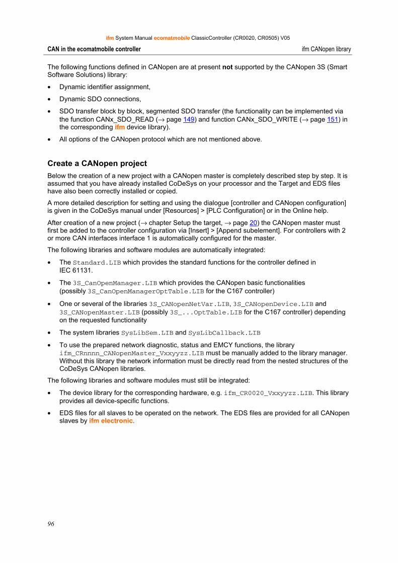
ifm System Manual ecomatmobile ClassicController (CR0020, CR0505) V05
96
CAN in the ecomatmobile controller ifm CANopen library
The following functions defined in CANopen are at present not supported by the CANopen 3S (Smart Software Solutions) library:
• Dynamic identifier assignment,
• Dynamic SDO connections,
• SDO transfer block by block, segmented SDO transfer (the functionality can be implemented via the function CANx_SDO_READ (→ page 149) and function CANx_SDO_WRITE (→ page 151) in the corresponding ifm device library).
• All options of the CANopen protocol which are not mentioned above.
Create a CANopen project Below the creation of a new project with a CANopen master is completely described step by step. It is assumed that you have already installed CoDeSys on your processor and the Target and EDS files have also been correctly installed or copied.
A more detailed description for setting and using the dialogue [controller and CANopen configuration] is given in the CoDeSys manual under [Resources] > [PLC Configuration] or in the Online help.
After creation of a new project (→ chapter Setup the target, → page 20) the CANopen master must first be added to the controller configuration via [Insert] > [Append subelement]. For controllers with 2 or more CAN interfaces interface 1 is automatically configured for the master.
The following libraries and software modules are automatically integrated:
• The Standard.LIB which provides the standard functions for the controller defined in IEC 61131.
• The 3S_CanOpenManager.LIB which provides the CANopen basic functionalities (possibly 3S_CanOpenManagerOptTable.LIB for the C167 controller)
• One or several of the libraries 3S_CANopenNetVar.LIB, 3S_CANopenDevice.LIB and 3S_CANopenMaster.LIB (possibly 3S_...OptTable.LIB for the C167 controller) depending on the requested functionality
• The system libraries SysLibSem.LIB and SysLibCallback.LIB
• To use the prepared network diagnostic, status and EMCY functions, the library ifm_CRnnnn_CANopenMaster_Vxxyyzz.LIB must be manually added to the library manager. Without this library the network information must be directly read from the nested structures of the CoDeSys CANopen libraries.
The following libraries and software modules must still be integrated:
• The device library for the corresponding hardware, e.g. ifm_CR0020_Vxxyyzz.LIB. This library provides all device-specific functions.
• EDS files for all slaves to be operated on the network. The EDS files are provided for all CANopen slaves by ifm electronic.
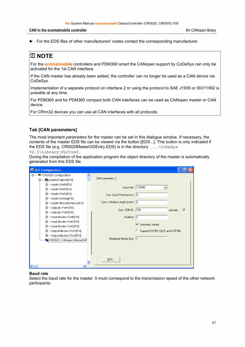
ifm System Manual ecomatmobile ClassicController (CR0020, CR0505) V05
97
CAN in the ecomatmobile controller ifm CANopen library
► For the EDS files of other manufacturers' nodes contact the corresponding manufacturer.
NOTE For the ecomatmobile controllers and PDM360 smart the CANopen support by CoDeSys can only be activated for the 1st CAN interface.
If the CAN master has already been added, the controller can no longer be used as a CAN device via CoDeSys.
Implementation of a separate protocol on interface 2 or using the protocol to SAE J1939 or ISO11992 is possible at any time.
For PDM360 and for PDM360 compact both CAN interfaces can be used as CANopen master or CAN device.
For CRnn32 devices you can use all CAN interfaces with all protocols.
Tab [CAN parameters] The most important parameters for the master can be set in this dialogue window. If necessary, the contents of the master EDS file can be viewed via the button [EDS...]. This button is only indicated if the EDS file (e.g. CR0020MasterODEntry.EDS) is in the directory ...\CoDeSys V2.3\Library\PLCConf. During the compilation of the application program the object directory of the master is automatically generated from this EDS file.
Baud rate Select the baud rate for the master. It must correspond to the transmission speed of the other network participants.
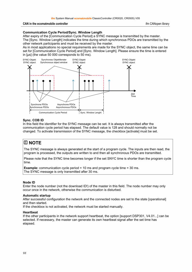
ifm System Manual ecomatmobile ClassicController (CR0020, CR0505) V05
98
CAN in the ecomatmobile controller ifm CANopen library
Communication Cycle Period/Sync. Window Length After expiry of the [Communication Cycle Period] a SYNC message is transmitted by the master. The [Sync. Window Length] indicates the time during which synchronous PDOs are transmitted by the other network participants and must be received by the master. As in most applications no special requirements are made for the SYNC object, the same time can be set for [Communication Cycle Period] and [Sync. Window Length]. Please ensure the time is entered in [µs] (the value 50 000 corresponds to 50 ms). SYNC-ObjektSYNC object
SYNC-ObjektSYNC object
SYNC-ObjektSYNC object
Synchrone PDOsSynchronous PDOs
Asynchrone PDOsAsynchronous PDOs
Synchrones ObjektfensterSynchronous object window
ZeitTime
Communication Cycle Period Sync. Window Lenght
Sync. COB ID In this field the identifier for the SYNC message can be set. It is always transmitted after the communication cycle period has elapsed. The default value is 128 and should normally not be changed. To activate transmission of the SYNC message, the checkbox [activate] must be set.
NOTE The SYNC message is always generated at the start of a program cycle. The inputs are then read, the program is processed, the outputs are written to and then all synchronous PDOs are transmitted.
Please note that the SYNC time becomes longer if the set SNYC time is shorter than the program cycle time.
Example: communication cycle period = 10 ms and program cycle time = 30 ms. The SYNC message is only transmitted after 30 ms.
Node ID Enter the node number (not the download ID!) of the master in this field. The node number may only occur once in the network, otherwise the communication is disturbed.
Automatic startup After successful configuration the network and the connected nodes are set to the state [operational] and then started. If the checkbox is not activated, the network must be started manually.
Heartbeat If the other participants in the network support heartbeat, the option [support DSP301, V4.01...] can be selected. If necessary, the master can generate its own heartbeat signal after the set time has elapsed.
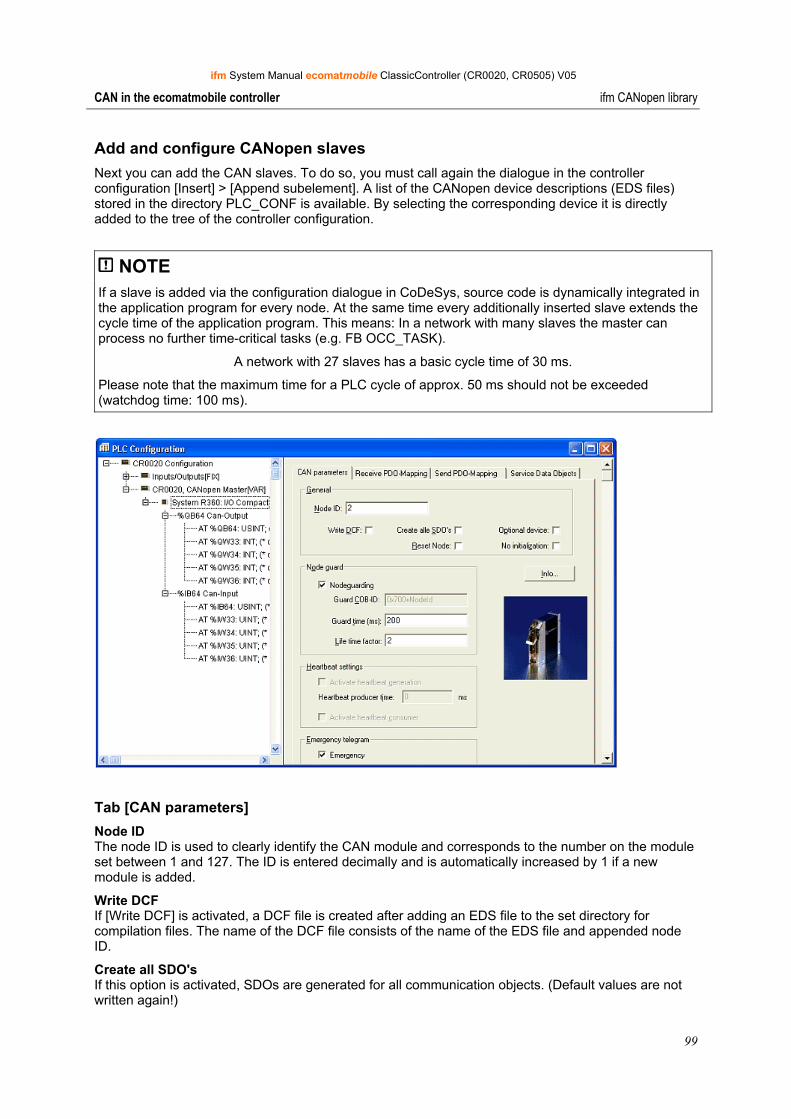
ifm System Manual ecomatmobile ClassicController (CR0020, CR0505) V05
99
CAN in the ecomatmobile controller ifm CANopen library
Add and configure CANopen slaves Next you can add the CAN slaves. To do so, you must call again the dialogue in the controller configuration [Insert] > [Append subelement]. A list of the CANopen device descriptions (EDS files) stored in the directory PLC_CONF is available. By selecting the corresponding device it is directly added to the tree of the controller configuration.
NOTE If a slave is added via the configuration dialogue in CoDeSys, source code is dynamically integrated in the application program for every node. At the same time every additionally inserted slave extends the cycle time of the application program. This means: In a network with many slaves the master can process no further time-critical tasks (e.g. FB OCC_TASK).
A network with 27 slaves has a basic cycle time of 30 ms.
Please note that the maximum time for a PLC cycle of approx. 50 ms should not be exceeded (watchdog time: 100 ms).
Tab [CAN parameters] Node ID The node ID is used to clearly identify the CAN module and corresponds to the number on the module set between 1 and 127. The ID is entered decimally and is automatically increased by 1 if a new module is added.
Write DCF If [Write DCF] is activated, a DCF file is created after adding an EDS file to the set directory for compilation files. The name of the DCF file consists of the name of the EDS file and appended node ID.
Create all SDO's If this option is activated, SDOs are generated for all communication objects. (Default values are not written again!)
ifm System Manual ecomatmobile ClassicController (CR0020, CR0505) V05
100
CAN in the ecomatmobile controller ifm CANopen library
Node reset The slave is reset ("load") as soon as the configuration is loaded to the controller.
Optional device If the option [optional device] is activated, the master tries only once to read from this node. In case of a missing response, the node is ignored and the master goes to the normal operating state. If the slave is connected to the network and detected at a later point in time, it is automatically started. To do so, you must have selected the option [Automatic startup] in the CAN parameters of the master.
No initialization If this option is activated, the master immediately takes the node into operation without transmitting configuration SDOs. (Nevertheless, the SDO data is generated and stored in the controller.)
Nodeguarding / heartbeat settings Depending on the device [nodeguarding] and [life time factor] or [heartbeat] must be set. We recommend: It is better to work with the heartbeat function for current devices since then the bus load is lower.
Emergency telegram This option is normally selected. The EMCY messages are transferred with the specified identifier.
Communication cycle In special applications a monitoring time for the SYNC messages generated by the master can be set here. Please note that this time must be longer than the SYNC time of the master. The optimum value must be determined experimentally, if necessary. In most cases nodeguarding and heartbeat are sufficient for node monitoring.
Tab [Receive PDO-Mapping] and [Send PDO-Mapping] With the tabs [Receive PDO-Mapping] and [Send PDO-Mapping] in the configuration dialogue of a CAN module the module mapping (assignment between local object directory and PDOs from/to the CAN device) described in the EDS file can be changed (if supported by the CAN module). All [mappable] objects of the EDS file are available on the left and can be added to or removed from the PDOs (Process Data Objects) on the right. The [StandardDataTypes] can be added to generate spaces in the PDO.
Insert With the button [Insert] you can generate more PDOs and insert the corresponding objects. The inputs and outputs are assigned to the IEC addresses via the inserted PDOs. In the controller configuration the settings made can be seen after closing the dialogue. The individual objects can be given symbolic names.
Properties The PDO properties defined in the standard can be edited in a dialogue via properties.
COB-ID Every PDO message requires a clear COB ID (communication object identifier). If an option is not supported by the module or the value must not be changed, the field is grey and cannot be edited.
Inhibit Time The inhibit time (100 µs) is the minimum time between two messages of this PDO so that the messages which are transferred when the value is changed are not transmitted too often. The unit is 100 µs.
ifm System Manual ecomatmobile ClassicController (CR0020, CR0505) V05
101
CAN in the ecomatmobile controller ifm CANopen library
Transmission Type
For transmission type you receive a selection of possible transmission modes for this module:
acyclic – synchronous After a change the PDO is transferred with the next SYNC.
cyclic – synchronous The PDO is transferred synchronously. [Number of SYNCs] indicates the number of the synchronisation messages between two transmissions of this PDO.
asynchronous – device profile specific The PDO is transmitted on event, i.e. when the value is changed. The device profile defines which data can be transferred in this way.
asynchronous – manufacturer specific The PDO is transmitted on event, i.e. when the value is changed. The device manufacturer defines which data is transferred in this way.
(a)synchronous – RTR only These services are not implemented.
Number of SYNCs Depending on the transmission type this field can be edited to enter the number of synchronisation messages (definition in the CAN parameter dialogue of [Com. Cycle Period], [Sync Window Length], [Sync. COB ID]) after which the PDO is to be transmitted again.
Event-Time Depending on the transmission type the period in milliseconds [ms] required between two transmissions of the PDO is indicated in this field.
Tab [Service Data Objects] Index, name, value, type and default Here all objects of the EDS or DCF file are listed which are in the range from index 200016 to 9FFF16 and defined as writable. Index, name, value, type and default are indicated for every object. The value can be changed. Select the value and press the [space bar]. After the change you can confirm the value with the button [Enter] or reject it with [ESC].
For the initialisation of the CAN bus the set values are transferred as SDOs (Service Data Object) to the CAN module thus having direct influence on the object directory of the CAN slave. Normally they are written again at every start of the application program – irrespective of whether they are permanently stored in the CAN device.
ifm System Manual ecomatmobile ClassicController (CR0020, CR0505) V05
102
CAN in the ecomatmobile controller ifm CANopen library
Master at runtime Here you find information about the functionality of the CANopen master libraries at runtime.
The CANopen master library provides the CoDeSys application with implicit services which are sufficient for most applications. These services are integrated for users in a transparent manner and are available in the application without additional calls. The following description assumes that the library ifm_CRnnnn_CANopenMaster_Vxxyyzz.LIB was manually added to the library manager to use the network diagnostic, status and EMCY functions.
Services of the CANopen master library:
Reset of all configured slaves on the bus at the system start To reset the slaves, the NMT command "Reset Remote Node" is used as standard explicitly for every slave separately. (NMT stands for Network Management according to CANopen. The individual commands are described in the CAN document DSP301.) In order to avoid overload of slaves having less powerful CAN controllers it is useful to reset the slaves using the command "All Remote Nodes". The service is performed for all configured slaves using the function CANx_MASTER_STATUS (→ page 133) with GLOBAL_START=TRUE. If the slaves are to be reset individually, this input must be set to FALSE.
Polling of the slave device type using SDO (polling for object 100016) and comparison with the configured slave ID Indication of an error status for the slaves from which a wrong device type was received. The request is repeated after 0.5 s if no device type was received AND the slave was not identified as optional in the configuration AND the timeout has not elapsed.
Configuration of all correctly detected devices using SDO Every SDO is monitored for a response and repeated if the slave does not respond within the monitoring time.
Automatic configuration of slaves using SDOs while the bus is in operation Prerequisite: The slave logged in the master via a bootup message.
Start of all correctly configured slaves after the end of the configuration of the corresponding slave To start the slaves the NMT command "Start remote node" is normally used. As for the "reset" this command can be replaced by "Start All Remote Nodes". The service can be called via the function CANx_Master_STATUS with GLOBAL_START=TRUE.
Cyclical transmission of the SYNC message This value can only be set during the configuration.
Setting of nodeguarding with lifetime monitoring for every slave possible The error status can be monitored for max. 8 slaves via the function CANx_MASTER_STATUS with ERROR_CONTROL=TRUE. We recommend: It is better to work with the heartbeat function for current devices since then the bus load is lower.
Heartbeat from the master to the slaves and monitoring of the heartbeats of the slaves The error status can be monitored for max. 8 slaves via the function CANx_MASTER_STATUS with ERROR_CONTROL=TRUE.
Reception of emergency messages for every slave, the emergency messages received last are stored separately for every slave The error messages can be read via the function CANx_MASTER_STATUS with EMERGENCY_OBJECT_SLAVES=TRUE. In addition this function provides the EMCY message generated last on the output GET_EMERGENCY.
ifm System Manual ecomatmobile ClassicController (CR0020, CR0505) V05
103
CAN in the ecomatmobile controller ifm CANopen library
Start the network Here you find information about how to start the CANopen network.
After downloading the project to the controller or a reset of the application the master starts up the CAN network again. This always happens in the same order of actions:
• All slaves are reset unless they are marked as "No initialization" in the configurator. They are reset individually using the NMT command "Reset Node" (8116) with the node ID of the slave. If the flag GLOBAL_START was set via the function CANx_MASTER_STATUS (→ page 133), the command is used once with the node ID 0 to start up the network.
• All slaves are configured. To do so, the object 100016 of the slave is polled. If the slave responds within the monitoring time of 0.5 s, the next configuration SDO is
transmitted. If a slave is marked as "optional" and does not respond to the polling for object 100016
within the monitoring time, it is marked as not available and no further SDOs are transmitted to it.
If a slave responds to the polling for object 100016 with a type other than the configured one (in the lower 16 bits), it is configured but marked as a wrong type.
All SDOs are repeated as long as a response of the slave was seen within the monitoring time. Here the application can monitor start-up of the individual slaves and possibly react by setting the flag SET_TIMEOUT_STATE in the NODE_STATE_SLAVE array of the function CANx_MASTER_STATUS.
• If the master configured a heartbeat time unequal to 0, the heartbeat is generated immediately after the start of the master controller.
• After all slaves have received their configuration SDOs, guarding starts for slaves with configured nodeguarding.
• If the master was configured to [Automatic startup], all slaves are now started individually by the master. To do so, the NMT command "Start Remote Node" (116) is used. If the flag GLOBAL_START was set via the function CANx_Master_STATUS, the command is used with the node ID 0 and so all slaves are started with "Start all Nodes".
• All configured TX-PDOs are transmitted at least once (for the slaves RX-PDOs).
• If [Automatic startup] is deactivated, the slaves must be started separately via the flag START_NODE in the NODE_STATE_SLAVE array or via the function input GLOBAL_START of the function CANx_MASTER_STATUS.
Network states Here you read how to interpret the states of the CANopen network and how to react.
For the start-up (→ page 103) of the CANopen network and during operation the individual functions of the library pass different states.
NOTE In the monitor mode (online mode) of CoDeSys the states of the CAN network can be seen in the global variable list "CANOpen implicit variables". This requires exact knowledge of CANopen and the structure of the CoDeSys CANopen libraries.
To facilitate access the function CANx_MASTER_STATUS (→ page 133) from the library ifm_CRnnnn_CANopenMaster_Vxxyyzz.LIB is available.
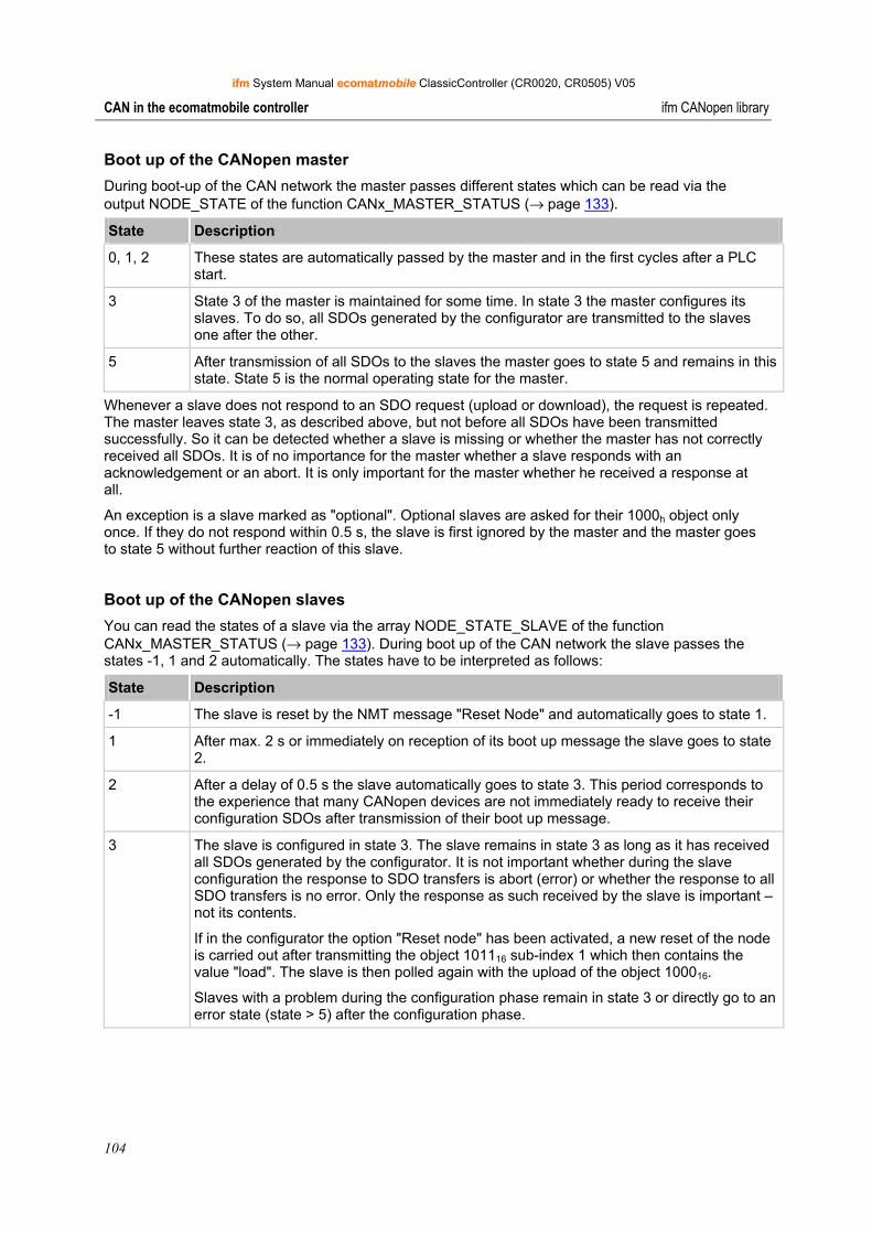
ifm System Manual ecomatmobile ClassicController (CR0020, CR0505) V05
104
CAN in the ecomatmobile controller ifm CANopen library
Boot up of the CANopen master During boot-up of the CAN network the master passes different states which can be read via the output NODE_STATE of the function CANx_MASTER_STATUS (→ page 133).
State Description
0, 1, 2 These states are automatically passed by the master and in the first cycles after a PLC start.
3 State 3 of the master is maintained for some time. In state 3 the master configures its slaves. To do so, all SDOs generated by the configurator are transmitted to the slaves one after the other.
5 After transmission of all SDOs to the slaves the master goes to state 5 and remains in this state. State 5 is the normal operating state for the master.
Whenever a slave does not respond to an SDO request (upload or download), the request is repeated. The master leaves state 3, as described above, but not before all SDOs have been transmitted successfully. So it can be detected whether a slave is missing or whether the master has not correctly received all SDOs. It is of no importance for the master whether a slave responds with an acknowledgement or an abort. It is only important for the master whether he received a response at all.
An exception is a slave marked as "optional". Optional slaves are asked for their 1000h object only once. If they do not respond within 0.5 s, the slave is first ignored by the master and the master goes to state 5 without further reaction of this slave.
Boot up of the CANopen slaves You can read the states of a slave via the array NODE_STATE_SLAVE of the function CANx_MASTER_STATUS (→ page 133). During boot up of the CAN network the slave passes the states -1, 1 and 2 automatically. The states have to be interpreted as follows:
State Description
-1 The slave is reset by the NMT message "Reset Node" and automatically goes to state 1.
1 After max. 2 s or immediately on reception of its boot up message the slave goes to state 2.
2 After a delay of 0.5 s the slave automatically goes to state 3. This period corresponds to the experience that many CANopen devices are not immediately ready to receive their configuration SDOs after transmission of their boot up message.
3 The slave is configured in state 3. The slave remains in state 3 as long as it has received all SDOs generated by the configurator. It is not important whether during the slave configuration the response to SDO transfers is abort (error) or whether the response to all SDO transfers is no error. Only the response as such received by the slave is important – not its contents.
If in the configurator the option "Reset node" has been activated, a new reset of the node is carried out after transmitting the object 101116 sub-index 1 which then contains the value "load". The slave is then polled again with the upload of the object 100016.
Slaves with a problem during the configuration phase remain in state 3 or directly go to an error state (state > 5) after the configuration phase.
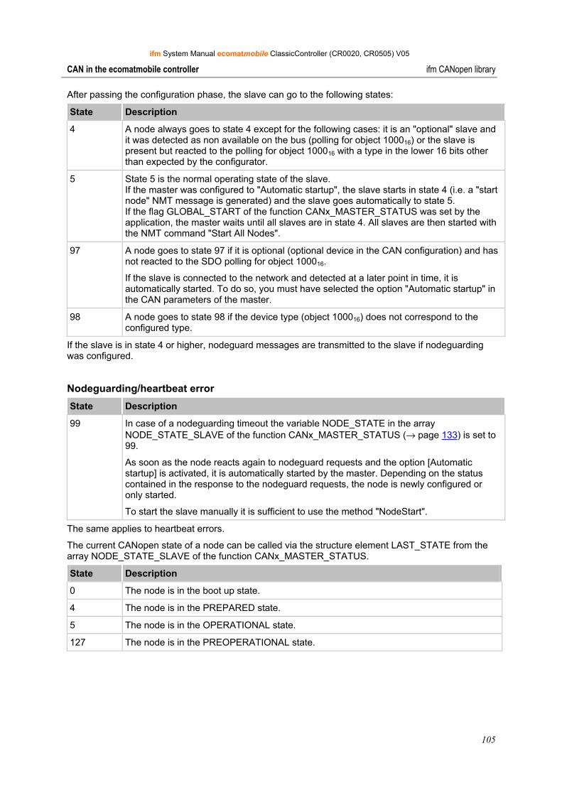
ifm System Manual ecomatmobile ClassicController (CR0020, CR0505) V05
105
CAN in the ecomatmobile controller ifm CANopen library
After passing the configuration phase, the slave can go to the following states:
State Description
4 A node always goes to state 4 except for the following cases: it is an "optional" slave and it was detected as non available on the bus (polling for object 100016) or the slave is present but reacted to the polling for object 100016 with a type in the lower 16 bits other than expected by the configurator.
5 State 5 is the normal operating state of the slave. If the master was configured to "Automatic startup", the slave starts in state 4 (i.e. a "start node" NMT message is generated) and the slave goes automatically to state 5. If the flag GLOBAL_START of the function CANx_MASTER_STATUS was set by the application, the master waits until all slaves are in state 4. All slaves are then started with the NMT command "Start All Nodes".
97 A node goes to state 97 if it is optional (optional device in the CAN configuration) and has not reacted to the SDO polling for object 100016.
If the slave is connected to the network and detected at a later point in time, it is automatically started. To do so, you must have selected the option "Automatic startup" in the CAN parameters of the master.
98 A node goes to state 98 if the device type (object 100016) does not correspond to the configured type.
If the slave is in state 4 or higher, nodeguard messages are transmitted to the slave if nodeguarding was configured.
Nodeguarding/heartbeat error State Description
99 In case of a nodeguarding timeout the variable NODE_STATE in the array NODE_STATE_SLAVE of the function CANx_MASTER_STATUS (→ page 133) is set to 99.
As soon as the node reacts again to nodeguard requests and the option [Automatic startup] is activated, it is automatically started by the master. Depending on the status contained in the response to the nodeguard requests, the node is newly configured or only started.
To start the slave manually it is sufficient to use the method "NodeStart".
The same applies to heartbeat errors.
The current CANopen state of a node can be called via the structure element LAST_STATE from the array NODE_STATE_SLAVE of the function CANx_MASTER_STATUS.
State Description
0 The node is in the boot up state.
4 The node is in the PREPARED state.
5 The node is in the OPERATIONAL state.
127 The node is in the PREOPERATIONAL state.
ifm System Manual ecomatmobile ClassicController (CR0020, CR0505) V05
106
CAN in the ecomatmobile controller ifm CANopen library
9.7.3 Start-up of the network without [Automatic startup] Sometimes it is necessary that the application determines the instant to start the CANopen slaves. To do so, the option [Automatic startup] of the CAN master must be deactivated in the configuration. It is then up to the application to start the slaves.
To start a slave via the application, the structure element START_NODE in the array NODE_STATE_SLAVES must be set. The array is assigned to the function CANx_MASTER_STATUS via the ADR operator.
Starting the network with GLOBAL_START In a CAN network with many participants (in most cases more than 8) it often happens that NMT messages in quick succession are not detected by all (mostly slow) IO nodes (e.g. CompactModules CR2013). The reason for this is that these nodes must listen to all messages with the ID 0. NMT messages transmitted at too short intervals overload the receive buffer of such nodes.
A help for this is to reduce the number of NMT messages in quick succession.
► To do so, set the input GLOBAL_START of the function CANx_Master_STATUS (→ page 133) to TRUE (with [Automatic startup]).
> The CANopen master library uses the command "Start All Nodes" instead of starting all nodes individually using the command "Start Node".
> GLOBAL_START is executed only once when the network is initialised.
> If this input is set, the controller also starts nodes with status 98 (see above). However, the PDOs for these nodes remain deactivated.
Starting the network with START_ALL_NODES If the network is not automatically started with GLOBAL_START of the function CANx_Master_STATUS (→ page 133), it can be started at any time, i.e. every node one after the other. If this is not requested, the option is as follows:
► Set the function input START_ALL_NODES of the function CANx_Master_STATUS to TRUE. START_ALL_NODES is typically set by the application program at runtime.
> If this input is set, nodes with status 98 (see above) are started. However, the PDOs for these nodes remain deactivated.
Initialisation of the network with RESET_ALL_NODES The same reasons which apply to the command START_ALL_NODES also apply to the NMT command RESET_ALL_NODES (instead of RESET_NODES for every individual node).
► To do so, the input RESET_ALL_NODES of the function CANx_MASTER_STATUS (On page 133) must be set to TRUE.
> This resets all nodes once at the same time.
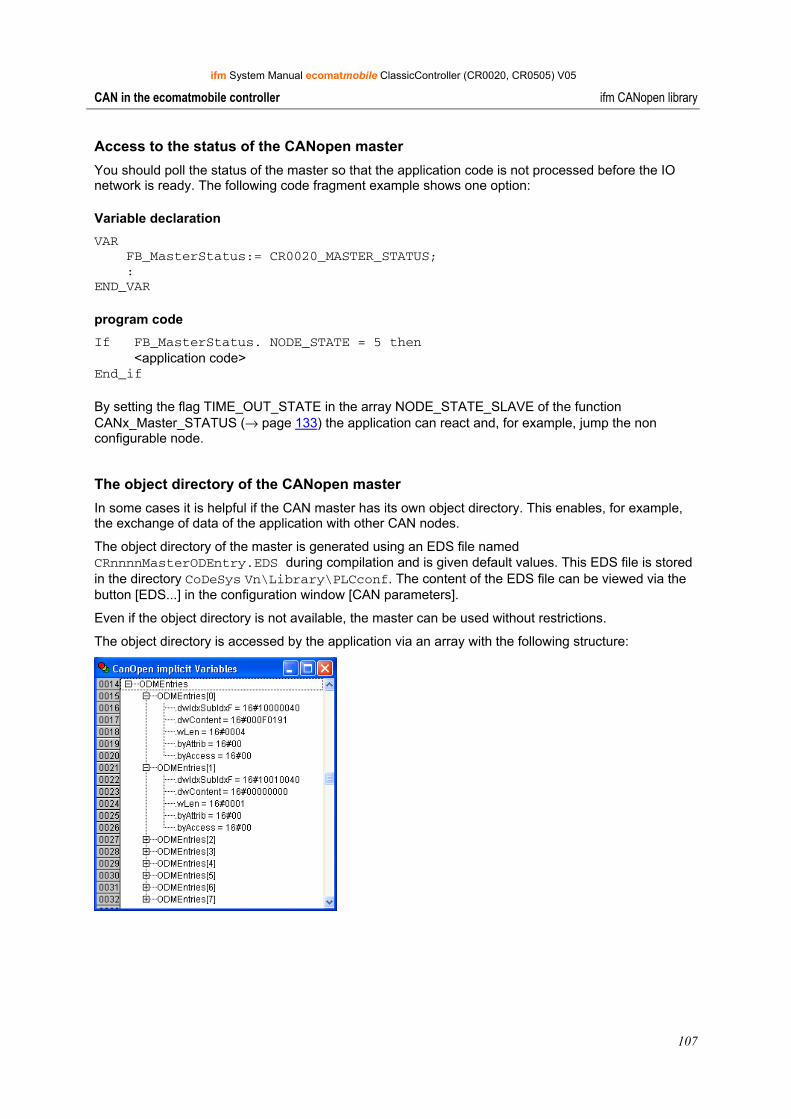
ifm System Manual ecomatmobile ClassicController (CR0020, CR0505) V05
107
CAN in the ecomatmobile controller ifm CANopen library
Access to the status of the CANopen master You should poll the status of the master so that the application code is not processed before the IO network is ready. The following code fragment example shows one option:
Variable declaration VAR FB_MasterStatus:= CR0020_MASTER_STATUS; : END_VAR
program code If FB_MasterStatus. NODE_STATE = 5 then <application code> End_if
By setting the flag TIME_OUT_STATE in the array NODE_STATE_SLAVE of the function CANx_Master_STATUS (→ page 133) the application can react and, for example, jump the non configurable node.
The object directory of the CANopen master In some cases it is helpful if the CAN master has its own object directory. This enables, for example, the exchange of data of the application with other CAN nodes.
The object directory of the master is generated using an EDS file named CRnnnnMasterODEntry.EDS during compilation and is given default values. This EDS file is stored in the directory CoDeSys Vn\Library\PLCconf. The content of the EDS file can be viewed via the button [EDS...] in the configuration window [CAN parameters].
Even if the object directory is not available, the master can be used without restrictions.
The object directory is accessed by the application via an array with the following structure:
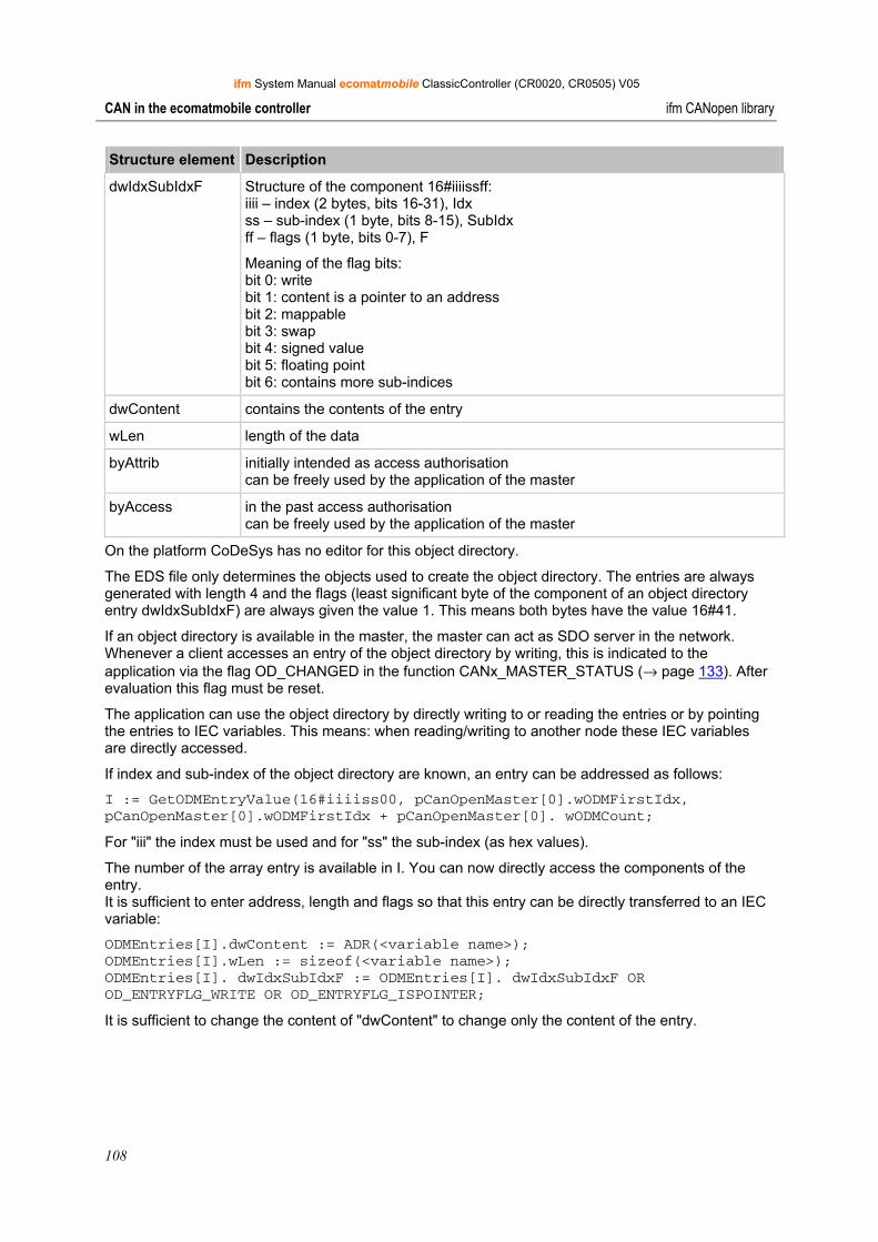
ifm System Manual ecomatmobile ClassicController (CR0020, CR0505) V05
108
CAN in the ecomatmobile controller ifm CANopen library
Structure element Description
dwIdxSubIdxF Structure of the component 16#iiiissff: iiii – index (2 bytes, bits 16-31), Idx ss – sub-index (1 byte, bits 8-15), SubIdx ff – flags (1 byte, bits 0-7), F
Meaning of the flag bits: bit 0: write bit 1: content is a pointer to an address bit 2: mappable bit 3: swap bit 4: signed value bit 5: floating point bit 6: contains more sub-indices
dwContent contains the contents of the entry
wLen length of the data
byAttrib initially intended as access authorisation can be freely used by the application of the master
byAccess in the past access authorisation can be freely used by the application of the master
On the platform CoDeSys has no editor for this object directory.
The EDS file only determines the objects used to create the object directory. The entries are always generated with length 4 and the flags (least significant byte of the component of an object directory entry dwIdxSubIdxF) are always given the value 1. This means both bytes have the value 16#41.
If an object directory is available in the master, the master can act as SDO server in the network. Whenever a client accesses an entry of the object directory by writing, this is indicated to the application via the flag OD_CHANGED in the function CANx_MASTER_STATUS (→ page 133). After evaluation this flag must be reset.
The application can use the object directory by directly writing to or reading the entries or by pointing the entries to IEC variables. This means: when reading/writing to another node these IEC variables are directly accessed.
If index and sub-index of the object directory are known, an entry can be addressed as follows:
I := GetODMEntryValue(16#iiiiss00, pCanOpenMaster[0].wODMFirstIdx, pCanOpenMaster[0].wODMFirstIdx + pCanOpenMaster[0]. wODMCount;
For "iii" the index must be used and for "ss" the sub-index (as hex values).
The number of the array entry is available in I. You can now directly access the components of the entry. It is sufficient to enter address, length and flags so that this entry can be directly transferred to an IEC variable:
ODMEntries[I].dwContent := ADR(<variable name>); ODMEntries[I].wLen := sizeof(<variable name>); ODMEntries[I]. dwIdxSubIdxF := ODMEntries[I]. dwIdxSubIdxF OR OD_ENTRYFLG_WRITE OR OD_ENTRYFLG_ISPOINTER;
It is sufficient to change the content of "dwContent" to change only the content of the entry.
ifm System Manual ecomatmobile ClassicController (CR0020, CR0505) V05
109
CAN in the ecomatmobile controller ifm CANopen library
9.7.4 CAN device CAN device is another name for a CANopen slave or CANopen node.
A CoDeSys programmable controller can also be a CANopen slave in a CAN network.
Functionality The CAN device library in combination with the CANopen configurator provides the user with the following options:
• In CoDeSys configuration of the properties for nodeguarding/heartbeat, emergency, node ID and baud rate at which the device is to operate.
• Together with the parameter manager in CoDeSys, a default PDO mapping can be created which can be changed by the master at runtime. The PDO mapping is changed by the master during the configuration phase. By means of mapping IEC variables of the application can be mapped to PDOs. This means IEC variables are assigned to the PDOs to be able to easily evaluate them in the application program.
• The CAN device library provides an object directory. The size of this object directory is defined while compiling CoDeSys. This directory contains all objects which describe the CAN device and in addition the objects defined by the parameter manager. In the parameter manager only the list types parameters and variables can be used for the CAN device.
• The library manages the access to the object directory, i.e. it acts as SDO server on the bus.
• The library monitors nodeguarding or the heartbeat consumer time (always only of one producer) and sets corresponding error flags for the application.
• An EDS file can be generated which describes the configured properties of the CAN device so that the device can be integrated and configured as a slave under a CAN master.
The CAN device library explicitly does not provide the following functionalities described in CANopen (all options of the CANopen protocol which are not indicated here or in the above section are not implemented either):
• Dynamic SDO and PDO identifiers
• SDO block transfer
• Automatic generation of emergency messages. Emergency messages must always be generated by the application using the function CANx_SLAVE_EMCY_HANDLER (→ page 141) and the function CANx_SLAVE_SEND_EMERGENCY (→ page 143). To do so, the library ifm_CRnnnn_CANopenSlave_Vxxyyzz.LIB provides these functions.
• Dynamic changes of the PDO properties are currently only accepted on arrival of a StartNode NMT message, not with the mechanisms defined in CANopen.
CAN device configuration To use the controller as CANopen slave (device) the CANopen slave must first be added via [Insert] > [Append subelement]. For controllers with 2 or more CAN interfaces the CAN interface 1 is automatically configured as a slave. All required libraries are automatically added to the library manager.
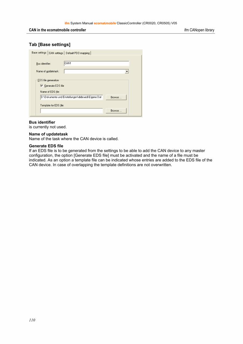
ifm System Manual ecomatmobile ClassicController (CR0020, CR0505) V05
110
CAN in the ecomatmobile controller ifm CANopen library
Tab [Base settings]
Bus identifier is currently not used.
Name of updatetask Name of the task where the CAN device is called.
Generate EDS file If an EDS file is to be generated from the settings to be able to add the CAN device to any master configuration, the option [Generate EDS file] must be activated and the name of a file must be indicated. As an option a template file can be indicated whose entries are added to the EDS file of the CAN device. In case of overlapping the template definitions are not overwritten.
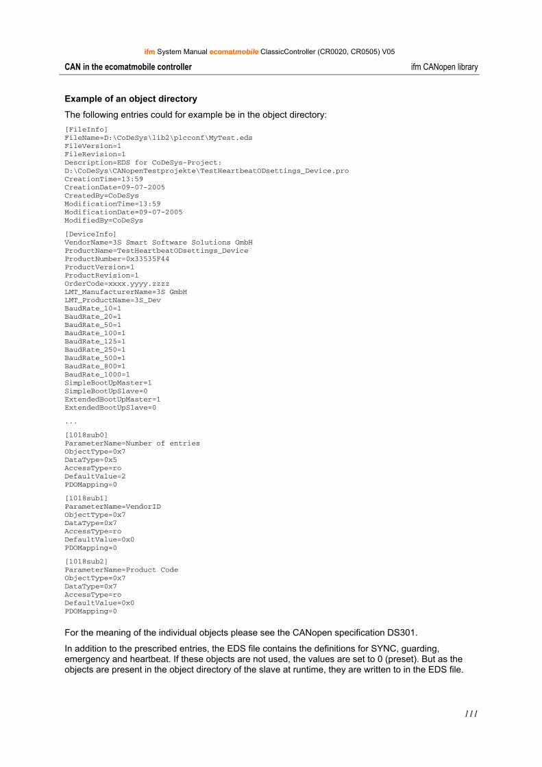
ifm System Manual ecomatmobile ClassicController (CR0020, CR0505) V05
111
CAN in the ecomatmobile controller ifm CANopen library
Example of an object directory
The following entries could for example be in the object directory: [FileInfo] FileName=D:\CoDeSys\lib2\plcconf\MyTest.eds FileVersion=1 FileRevision=1 Description=EDS for CoDeSys-Project: D:\CoDeSys\CANopenTestprojekte\TestHeartbeatODsettings_Device.pro CreationTime=13:59 CreationDate=09-07-2005 CreatedBy=CoDeSys ModificationTime=13:59 ModificationDate=09-07-2005 ModifiedBy=CoDeSys
[DeviceInfo] VendorName=3S Smart Software Solutions GmbH ProductName=TestHeartbeatODsettings_Device ProductNumber=0x33535F44 ProductVersion=1 ProductRevision=1 OrderCode=xxxx.yyyy.zzzz LMT_ManufacturerName=3S GmbH LMT_ProductName=3S_Dev BaudRate_10=1 BaudRate_20=1 BaudRate_50=1 BaudRate_100=1 BaudRate_125=1 BaudRate_250=1 BaudRate_500=1 BaudRate_800=1 BaudRate_1000=1 SimpleBootUpMaster=1 SimpleBootUpSlave=0 ExtendedBootUpMaster=1 ExtendedBootUpSlave=0
...
[1018sub0] ParameterName=Number of entries ObjectType=0x7 DataType=0x5 AccessType=ro DefaultValue=2 PDOMapping=0
[1018sub1] ParameterName=VendorID ObjectType=0x7 DataType=0x7 AccessType=ro DefaultValue=0x0 PDOMapping=0
[1018sub2] ParameterName=Product Code ObjectType=0x7 DataType=0x7 AccessType=ro DefaultValue=0x0 PDOMapping=0
For the meaning of the individual objects please see the CANopen specification DS301.
In addition to the prescribed entries, the EDS file contains the definitions for SYNC, guarding, emergency and heartbeat. If these objects are not used, the values are set to 0 (preset). But as the objects are present in the object directory of the slave at runtime, they are written to in the EDS file.
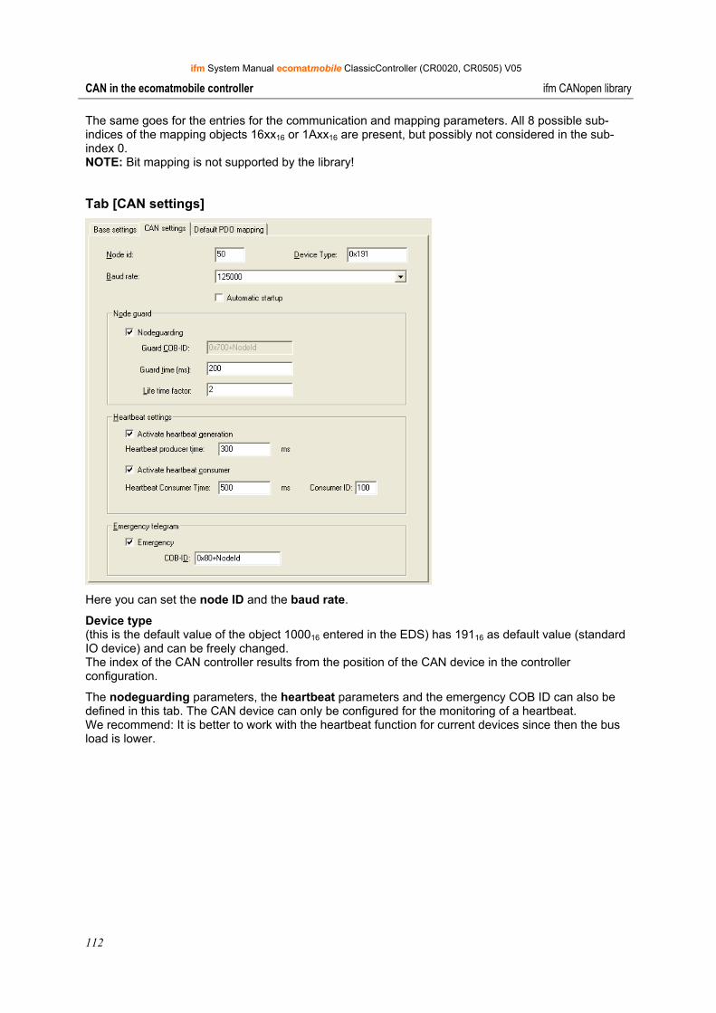
ifm System Manual ecomatmobile ClassicController (CR0020, CR0505) V05
112
CAN in the ecomatmobile controller ifm CANopen library
The same goes for the entries for the communication and mapping parameters. All 8 possible sub-indices of the mapping objects 16xx16 or 1Axx16 are present, but possibly not considered in the sub-index 0. NOTE: Bit mapping is not supported by the library!
Tab [CAN settings]
Here you can set the node ID and the baud rate.
Device type (this is the default value of the object 100016 entered in the EDS) has 19116 as default value (standard IO device) and can be freely changed. The index of the CAN controller results from the position of the CAN device in the controller configuration.
The nodeguarding parameters, the heartbeat parameters and the emergency COB ID can also be defined in this tab. The CAN device can only be configured for the monitoring of a heartbeat. We recommend: It is better to work with the heartbeat function for current devices since then the bus load is lower.
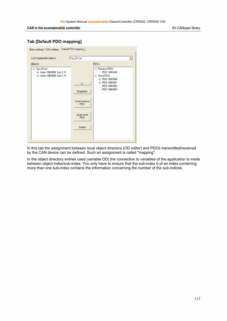
ifm System Manual ecomatmobile ClassicController (CR0020, CR0505) V05
113
CAN in the ecomatmobile controller ifm CANopen library
Tab [Default PDO mapping]
In this tab the assignment between local object directory (OD editor) and PDOs transmitted/received by the CAN device can be defined. Such an assignment is called "mapping".
In the object directory entries used (variable OD) the connection to variables of the application is made between object index/sub-index. You only have to ensure that the sub-index 0 of an index containing more than one sub-index contains the information concerning the number of the sub-indices.
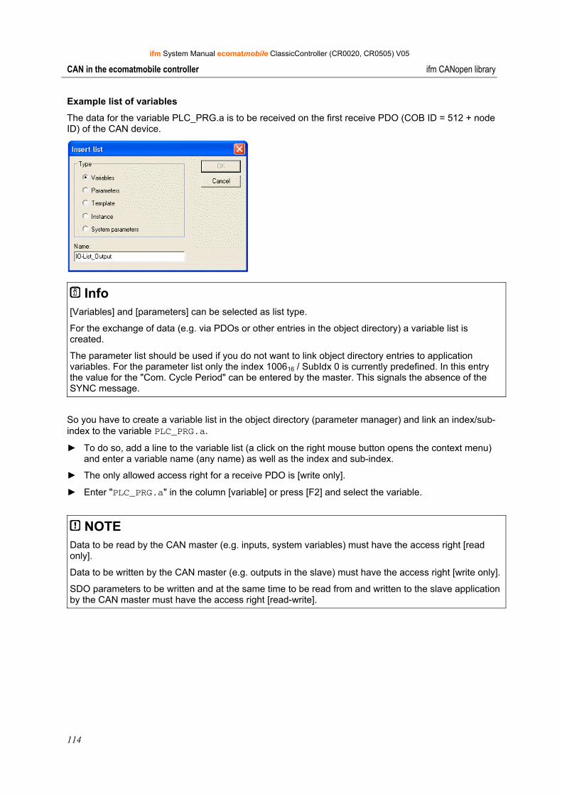
ifm System Manual ecomatmobile ClassicController (CR0020, CR0505) V05
114
CAN in the ecomatmobile controller ifm CANopen library
Example list of variables
The data for the variable PLC_PRG.a is to be received on the first receive PDO (COB ID = 512 + node ID) of the CAN device.
Info [Variables] and [parameters] can be selected as list type.
For the exchange of data (e.g. via PDOs or other entries in the object directory) a variable list is created.
The parameter list should be used if you do not want to link object directory entries to application variables. For the parameter list only the index 100616 / SubIdx 0 is currently predefined. In this entry the value for the "Com. Cycle Period" can be entered by the master. This signals the absence of the SYNC message.
So you have to create a variable list in the object directory (parameter manager) and link an index/sub-index to the variable PLC_PRG.a.
► To do so, add a line to the variable list (a click on the right mouse button opens the context menu) and enter a variable name (any name) as well as the index and sub-index.
► The only allowed access right for a receive PDO is [write only].
► Enter "PLC_PRG.a" in the column [variable] or press [F2] and select the variable.
NOTE Data to be read by the CAN master (e.g. inputs, system variables) must have the access right [read only].
Data to be written by the CAN master (e.g. outputs in the slave) must have the access right [write only].
SDO parameters to be written and at the same time to be read from and written to the slave application by the CAN master must have the access right [read-write].
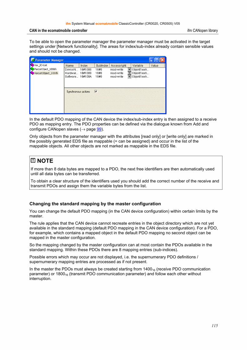
ifm System Manual ecomatmobile ClassicController (CR0020, CR0505) V05
115
CAN in the ecomatmobile controller ifm CANopen library
To be able to open the parameter manager the parameter manager must be activated in the target settings under [Network functionality]. The areas for index/sub-index already contain sensible values and should not be changed.
In the default PDO mapping of the CAN device the index/sub-index entry is then assigned to a receive PDO as mapping entry. The PDO properties can be defined via the dialogue known from Add and configure CANopen slaves (→ page 99).
Only objects from the parameter manager with the attributes [read only] or [write only] are marked in the possibly generated EDS file as mappable (= can be assigned) and occur in the list of the mappable objects. All other objects are not marked as mappable in the EDS file.
NOTE If more than 8 data bytes are mapped to a PDO, the next free identifiers are then automatically used until all data bytes can be transferred.
To obtain a clear structure of the identifiers used you should add the correct number of the receive and transmit PDOs and assign them the variable bytes from the list.
Changing the standard mapping by the master configuration You can change the default PDO mapping (in the CAN device configuration) within certain limits by the master.
The rule applies that the CAN device cannot recreate entries in the object directory which are not yet available in the standard mapping (default PDO mapping in the CAN device configuration). For a PDO, for example, which contains a mapped object in the default PDO mapping no second object can be mapped in the master configuration.
So the mapping changed by the master configuration can at most contain the PDOs available in the standard mapping. Within these PDOs there are 8 mapping entries (sub-indices).
Possible errors which may occur are not displayed, i.e. the supernumerary PDO definitions / supernumerary mapping entries are processed as if not present.
In the master the PDOs must always be created starting from 140016 (receive PDO communication parameter) or 180016 (transmit PDO communication parameter) and follow each other without interruption.
ifm System Manual ecomatmobile ClassicController (CR0020, CR0505) V05
116
CAN in the ecomatmobile controller ifm CANopen library
Access to the CAN device at runtime
Setting of the node numbers and the baud rate of a CAN device For the CAN device the node number and the baud rate can be set at runtime of the application program.
► For setting the node number the function CANx_SLAVE_NODEID (→ page 140) of the library ifm_CRnnnn_CANopenSlave_Vxxyyzz.lib is used.
► For setting the baud rate the function CAN1_BAUDRATE (→ page 68) or the function CAN1_EXT (→ page 73) or the function CANx of the corresponding device library is used for the controllers and the PDM360 smart. For PDM360 or PDM360 compact the function CANx_SLAVE_BAUDRATE is available via the library ifm_CRnnnn_CANopenSlave_Vxxyyzz.lib.
Access to the OD entries by the application program As standard, there are entries in the object directory which are mapped to variables (parameter manager).
However, there are also automatically generated entries of the CAN device which cannot be mapped to the contents of a variable via the parameter manager. Via the function CANx_SLAVE_STATUS (→ page 146) these entries are available in the library ifm_CRnnnn_CANopenSlave_Vxxyyzz.LIB.
Change the PDO properties at runtime If the properties of a PDO are to be changed at runtime, this is done by another node via SDO write access as described by CANopen.
As an alternative, it is possible to directly write a new property, e.g. the "event time" of a send PDO and then transmit a command "StartNode-NMT" to the node although it has already been started. As a result of this the device reinterprets the values in the object directory.
Transmit emergency messages via the application program To transmit an emergency message via the application program the function CANx_SLAVE_EMCY_HANDLER (→ page 141) and the function CANx_SLAVE_SEND_EMERGENCY (→ page 143) can be used. The library ifm_CRnnnn_CANopenSlave_Vxxyyzz.LIB provides these functions.
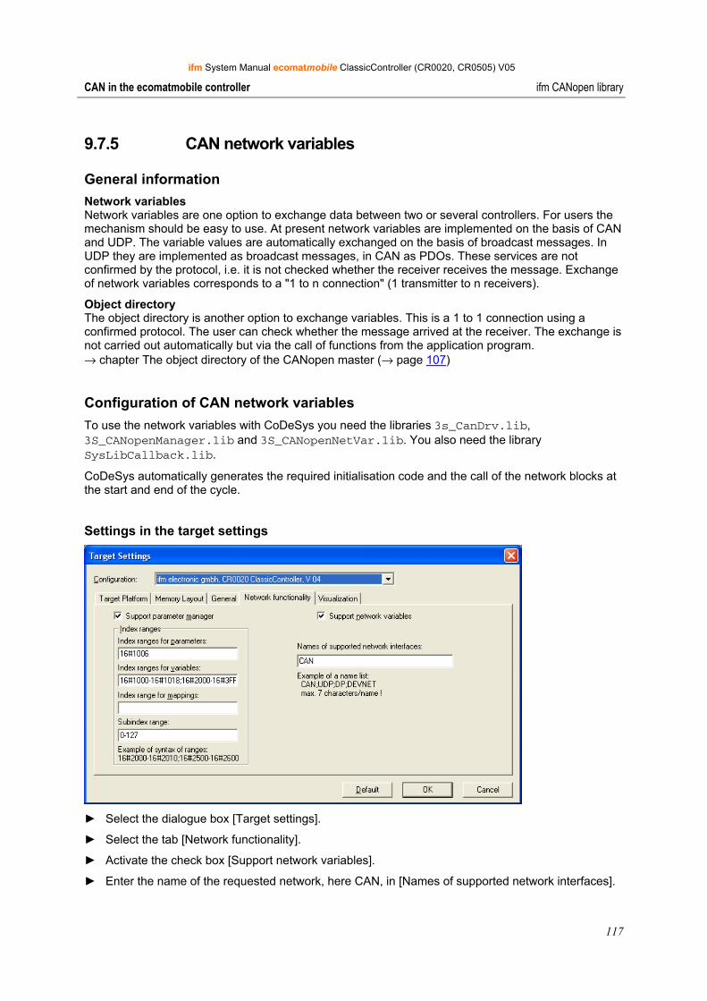
ifm System Manual ecomatmobile ClassicController (CR0020, CR0505) V05
117
CAN in the ecomatmobile controller ifm CANopen library
9.7.5 CAN network variables
General information Network variables Network variables are one option to exchange data between two or several controllers. For users the mechanism should be easy to use. At present network variables are implemented on the basis of CAN and UDP. The variable values are automatically exchanged on the basis of broadcast messages. In UDP they are implemented as broadcast messages, in CAN as PDOs. These services are not confirmed by the protocol, i.e. it is not checked whether the receiver receives the message. Exchange of network variables corresponds to a "1 to n connection" (1 transmitter to n receivers).
Object directory The object directory is another option to exchange variables. This is a 1 to 1 connection using a confirmed protocol. The user can check whether the message arrived at the receiver. The exchange is not carried out automatically but via the call of functions from the application program. → chapter The object directory of the CANopen master (→ page 107)
Configuration of CAN network variables To use the network variables with CoDeSys you need the libraries 3s_CanDrv.lib, 3S_CANopenManager.lib and 3S_CANopenNetVar.lib. You also need the library SysLibCallback.lib.
CoDeSys automatically generates the required initialisation code and the call of the network blocks at the start and end of the cycle.
Settings in the target settings
► Select the dialogue box [Target settings].
► Select the tab [Network functionality].
► Activate the check box [Support network variables].
► Enter the name of the requested network, here CAN, in [Names of supported network interfaces].
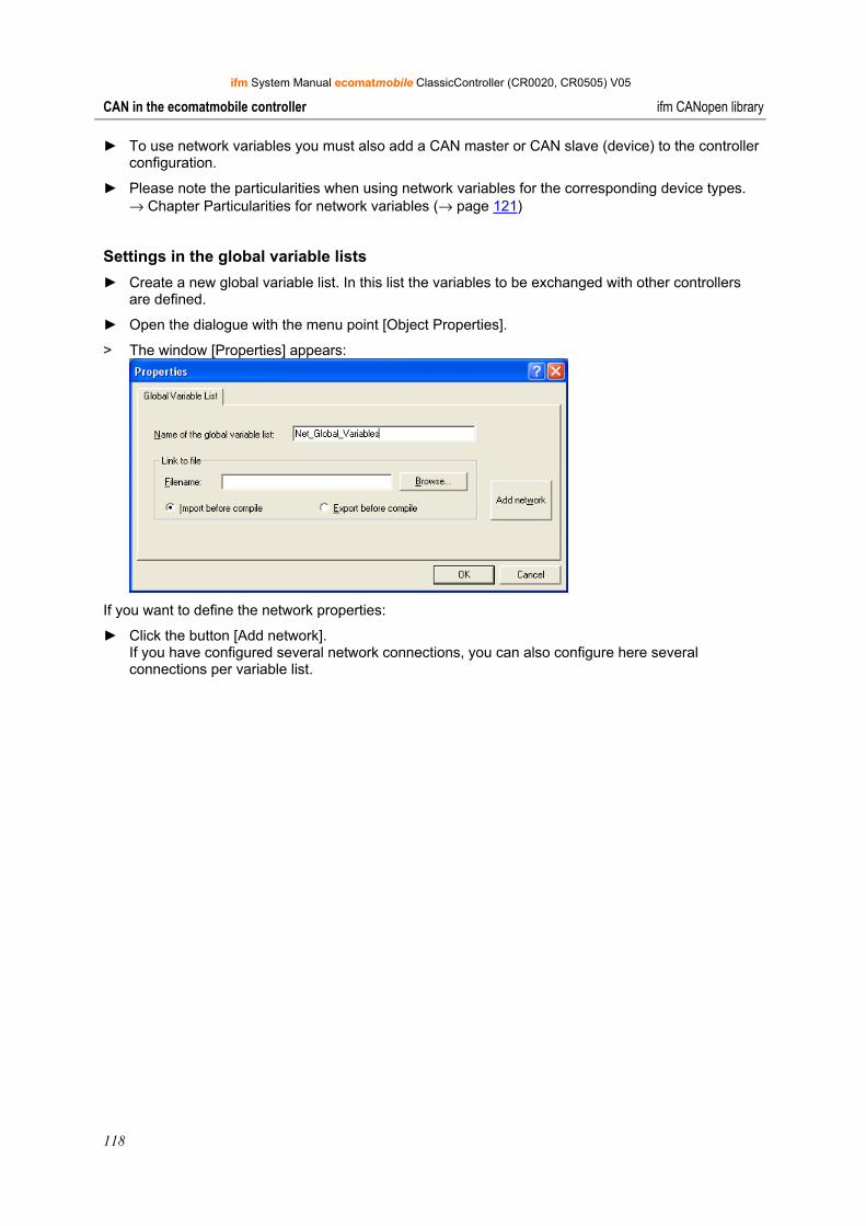
ifm System Manual ecomatmobile ClassicController (CR0020, CR0505) V05
118
CAN in the ecomatmobile controller ifm CANopen library
► To use network variables you must also add a CAN master or CAN slave (device) to the controller configuration.
► Please note the particularities when using network variables for the corresponding device types. → Chapter Particularities for network variables (→ page 121)
Settings in the global variable lists ► Create a new global variable list. In this list the variables to be exchanged with other controllers
are defined.
► Open the dialogue with the menu point [Object Properties].
> The window [Properties] appears:
If you want to define the network properties:
► Click the button [Add network]. If you have configured several network connections, you can also configure here several connections per variable list.
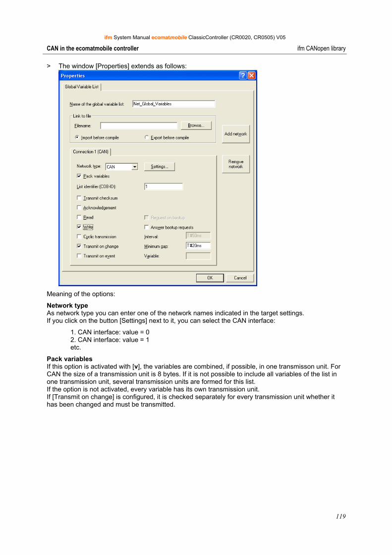
ifm System Manual ecomatmobile ClassicController (CR0020, CR0505) V05
119
CAN in the ecomatmobile controller ifm CANopen library
> The window [Properties] extends as follows:
Meaning of the options:
Network type As network type you can enter one of the network names indicated in the target settings. If you click on the button [Settings] next to it, you can select the CAN interface:
1. CAN interface: value = 0 2. CAN interface: value = 1 etc.
Pack variables If this option is activated with [v], the variables are combined, if possible, in one transmisson unit. For CAN the size of a transmission unit is 8 bytes. If it is not possible to include all variables of the list in one transmission unit, several transmission units are formed for this list. If the option is not activated, every variable has its own transmission unit. If [Transmit on change] is configured, it is checked separately for every transmission unit whether it has been changed and must be transmitted.
ifm System Manual ecomatmobile ClassicController (CR0020, CR0505) V05
120
CAN in the ecomatmobile controller ifm CANopen library
List identifier (COB-ID) The basic identifier is used as a unique identification to exchange variable lists of different projects. Variable lists with identical basic identifier are exchanged. Ensure that the definitions of the variable lists with the same basic identifier match in the different projects.
NOTE In CAN networks the basic identifier is directly used as COB-ID of the CAN messages. It is not checked whether the identifier is also used in the remaining CAN configuration.
To ensure a correct exchange of data between two controllers the global variable lists in the two projects must match. To ensure this you can use the feature [Link to file]. A project can export the variable list file before compilation, the other projects should import this file before compilation.
In addition to simple data types a variable list can also contain structures and arrays. The elements of these combined data types are transmitted separately.
Strings must not be transmitted via network variables as otherwise a runtime error will occur and the watchdog will be activated.
If a variable list is larger than a PDO of the corresponding network, the data is split up to several PDOs. Therefore it cannot be ensured that all data of the variable list is received in one cycle. Parts of the variable list can be received in different cycles. This is also possible for variables with structure and array types.
Transmit checksum This option is not supported.
Acknowledgement This option is not supported.
Read The variable values of one (or several) controllers are read.
Write The variables of this list are transmitted to other controllers.
NOTE You should only select one of these options for every variable list, i.e. either only read or only write.
If you want to read or write several variables of a project, please use several variable lists (one for reading, one for writing).
In a network the same variable list should only be exchanged between two participants.
Cyclic transmission Only valid if [write] is activated. The values are transmitted in the specified [interval] irrespective of whether they have changed.
Transmit on change The variable values are only transmitted if one of the values has been changed. With [Minimum gap] (value > 0) a minimum time between the message packages can be defined.
Transmit on event If this option is selected, the CAN message is only transmitted if the indicated binary [variable] is set to TRUE. This variable cannot be selected from the list of the defined variables via the input help.
ifm System Manual ecomatmobile ClassicController (CR0020, CR0505) V05
121
CAN in the ecomatmobile controller ifm CANopen library
Particularities for network variables Device Description
ClassicController: CR0020, CR0505
ExtendedController: CR0200
SafetyController: CR7020, CR7021, CR7200, CR7201, CR7505, CR7506
Network variables are only supported on interface 1 (enter the value 0).
CAN master Transmit and receive lists are processed directly. You only have to make the settings described above.
CAN device Transmit lists are processed directly. For receive lists you must also map the identifier area in the object directory to receive PDOs. It is sufficient to create only two receive PDOs and to assign the first object the first identifier and the second object the last identifier. If the network variables are only transferred to one identifier, you only have to create one receive PDO with this identifier.
Important! Please note that the identifier of the network variables and of the receive PDOs must be entered as decimal value.
ClassicController: CR0032
ExtendedController: CR0232
Network variables are supported on all CAN interfaces. (All other informations as above)
PDM360 smart: CR1070, CR1071
Only one interface is available (enter value = 0).
CAN master Transmit and receive lists are processed directly. You only have to make the settings described above.
CAN device Transmit lists are processed directly. For receive lists you must additionally map the identifier area in the object directory to receive PDOs. It is sufficient to create only two receive PDOs and to assign the first object the first identifier and the second object the last identifier. If the network variables are only transferred to one identifier, you only have to create one receive PDO with this identifier.
Important! Please note that the identifier of the network variables and of the receive PDOs must be entered as decimal value.
ifm System Manual ecomatmobile ClassicController (CR0020, CR0505) V05
122
CAN in the ecomatmobile controller ifm CANopen library
Device Description
PDM360: CR1050, CR1051, CR1060
PDM360 compact: CR1052, CR1053, CR1055, CR1056
Network variables are supported on interface 1 (value = 0) and 2 (value = 1).
CAN master Transmit and receive lists are processed directly. You only have to make the settings described above.
CAN device Transmit and receive lists are processed directly. You only have to make the settings described above.
Important! If [support network variables] is selected in the PDM360 or PDM360 compact, you must at least create one variable in the global variable list and call it once in the application program. Otherwise the following error message is generated when compiling the program:
Error 4601: Network variables 'CAN': No cyclic or freewheeling task for network variable exchange found.
9.7.6 Information on the EMCY and error codes
Structure of an EMCY message Under CANopen error states are indicated via a simple standardised mechanism. For a CANopen device every occurrence of an error is indicated via a special message which details the error.
If an error or its cause disappears after a certain time, this event is also indicated via the EMCY message. The errors occurred last are stored in the object directory (object 100316) and can be read via an SDO access (→ function CANx_SDO_READ, → page 149). In addition, the current error situation is reflected in the error register (object 100116).
A distinction is made between the following errors:
• Communication error The CAN controller signals CAN errors.
(The frequent occurrence is an indication of physical problems. These errors can considerably affect the transmission behaviour and thus the data rate of a network.)
Life guarding or heartbeat error
• Application error Short circuit or wire break Temperature too high
Structure of an error message
The structure of an error message (EMCY message) is as follows:
Byte 0 Byte 1 Byte 2 Byte 3 Byte 4 Byte 5 Byte 6 Byte 7
EMCY error code as entered in the object
100316
object 100116
manufacturer-specific information
ifm System Manual ecomatmobile ClassicController (CR0020, CR0505) V05
123
CAN in the ecomatmobile controller ifm CANopen library
Identifier
The identifier for the error message consists of the sum of the following elements:
EMCY default identifier 128 (8016) + node ID
EMCY error code
It gives detailed information which error occurred. A list of possible error codes has already been defined in the communication profile. Error codes which only apply to a certain device class are defined in the corresponding device profile of this device class.
Object 100316 (error field)
The object 100316 represents the error memory of a device. The sub-indices contain the errors occurred last which triggered an error message.
If a new error occurs, its EMCY error code is always stored in the sub-index 116. All other older errors are moved back one position in the error memory, i.e. the sub-index is incremented by 1. If all supported sub-indices are used, the oldest error is deleted. The sub-index 016 is increased to the number of the stored errors. After all errors have been rectified the value "0" is written to the error field of the sub-index 116.
To delete the error memory the value "0" can be written to the sub-index 016. Other values must not be entered.
Signalling of device errors As described, EMCY messages are transmitted if errors occur in a device. In contrast to programmable devices error messages are automatically transmitted by decentralised input/output modules (e.g. CompactModules CR2033). Corresponding error codes → corresponding device manual.
Programmable devices only generate an EMCY message automatically (e.g. short circuit on an output) if the function CANx_MASTER_EMCY_HANDLER (→ page 128) or function CANx_SLAVE_EMCY_HANDLER (On page 141) is integrated in the application program.
Overview of the automatically transmitted EMCY error codes for all ifm devices programmable with CoDeSys → chapter Overview of the CANopen error codes (→ page 124).
If in addition application-specific errors are to be transmitted by the application program, the function CANx_MASTER_SEND_EMERGENCY (→ page 130) or function CANx_SLAVE_SEND_EMERGENCY (→ page 143) are used.
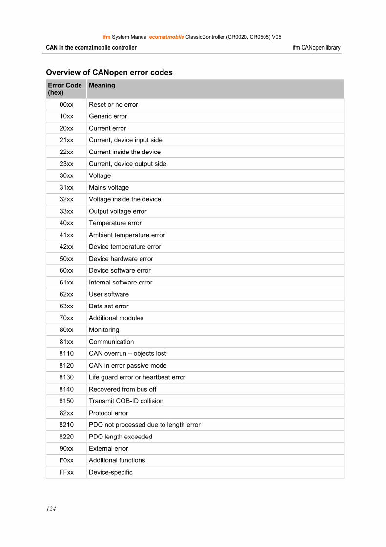
ifm System Manual ecomatmobile ClassicController (CR0020, CR0505) V05
124
CAN in the ecomatmobile controller ifm CANopen library
Overview of CANopen error codes Error Code (hex)
Meaning
00xx Reset or no error
10xx Generic error
20xx Current error
21xx Current, device input side
22xx Current inside the device
23xx Current, device output side
30xx Voltage
31xx Mains voltage
32xx Voltage inside the device
33xx Output voltage error
40xx Temperature error
41xx Ambient temperature error
42xx Device temperature error
50xx Device hardware error
60xx Device software error
61xx Internal software error
62xx User software
63xx Data set error
70xx Additional modules
80xx Monitoring
81xx Communication
8110 CAN overrun – objects lost
8120 CAN in error passive mode
8130 Life guard error or heartbeat error
8140 Recovered from bus off
8150 Transmit COB-ID collision
82xx Protocol error
8210 PDO not processed due to length error
8220 PDO length exceeded
90xx External error
F0xx Additional functions
FFxx Device-specific
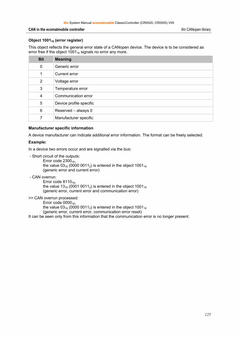
ifm System Manual ecomatmobile ClassicController (CR0020, CR0505) V05
125
CAN in the ecomatmobile controller ifm CANopen library
Object 100116 (error register)
This object reflects the general error state of a CANopen device. The device is to be considered as error free if the object 100116 signals no error any more.
Bit Meaning
0 Generic error
1 Current error
2 Voltage error
3 Temperature error
4 Communication error
5 Device profile specific
6 Reserved – always 0
7 Manufacturer specific
Manufacturer specific information
A device manufacturer can indicate additional error information. The format can be freely selected.
Example:
In a device two errors occur and are signalled via the bus:
- Short circuit of the outputs: Error code 230016, the value 0316 (0000 00112) is entered in the object 100116 (generic error and current error)
- CAN overrun: Error code 811016, the value 1316 (0001 00112) is entered in the object 100116 (generic error, current error and communication error)
>> CAN overrun processed: Error code 000016, the value 0316 (0000 00112) is entered in the object 100116 (generic error, current error, communication error reset) It can be seen only from this information that the communication error is no longer present.
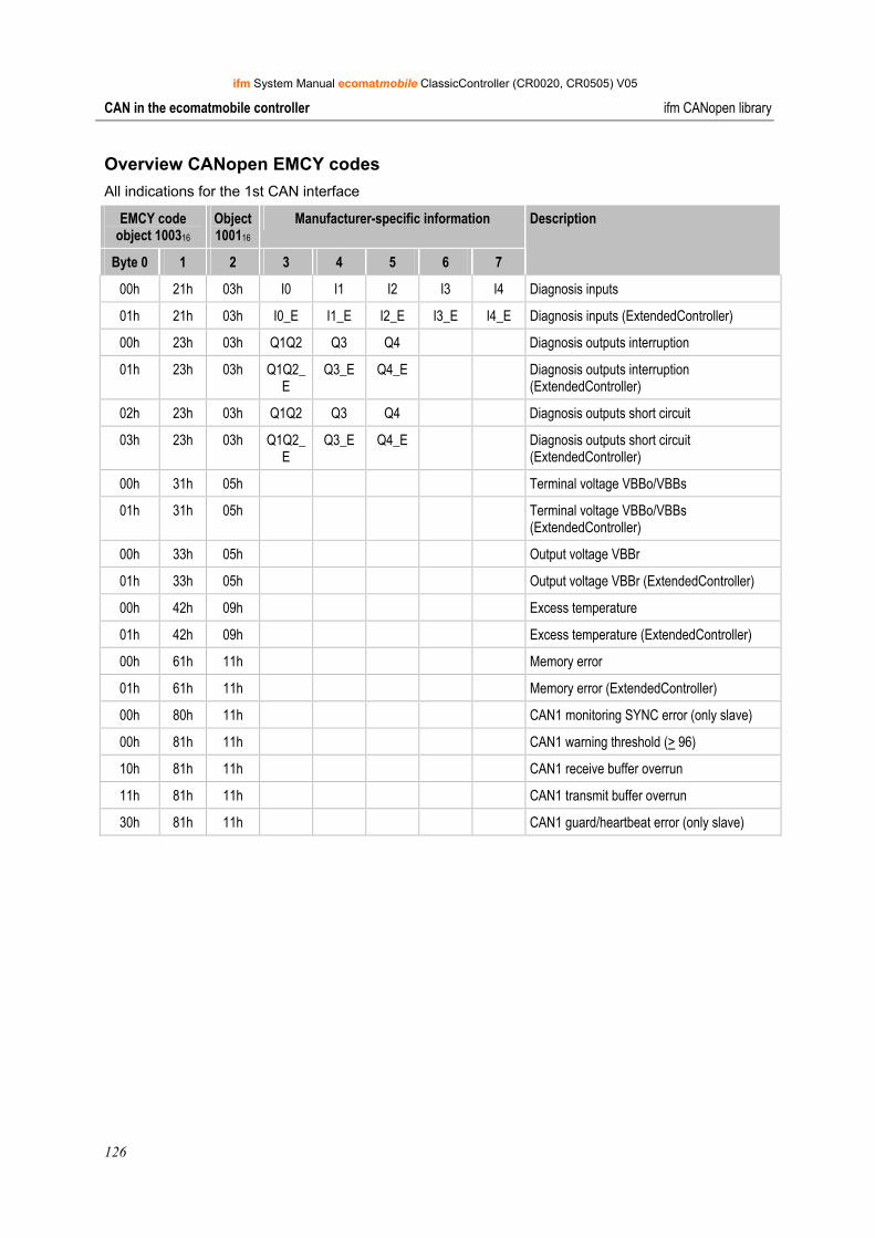
ifm System Manual ecomatmobile ClassicController (CR0020, CR0505) V05
126
CAN in the ecomatmobile controller ifm CANopen library
Overview CANopen EMCY codes All indications for the 1st CAN interface
EMCY code object 100316
Object 100116
Manufacturer-specific information
Byte 0 1 2 3 4 5 6 7
Description
00h 21h 03h I0 I1 I2 I3 I4 Diagnosis inputs
01h 21h 03h I0_E I1_E I2_E I3_E I4_E Diagnosis inputs (ExtendedController)
00h 23h 03h Q1Q2 Q3 Q4 Diagnosis outputs interruption
01h 23h 03h Q1Q2_E
Q3_E Q4_E Diagnosis outputs interruption (ExtendedController)
02h 23h 03h Q1Q2 Q3 Q4 Diagnosis outputs short circuit
03h 23h 03h Q1Q2_E
Q3_E Q4_E Diagnosis outputs short circuit (ExtendedController)
00h 31h 05h Terminal voltage VBBo/VBBs
01h 31h 05h Terminal voltage VBBo/VBBs (ExtendedController)
00h 33h 05h Output voltage VBBr
01h 33h 05h Output voltage VBBr (ExtendedController)
00h 42h 09h Excess temperature
01h 42h 09h Excess temperature (ExtendedController)
00h 61h 11h Memory error
01h 61h 11h Memory error (ExtendedController)
00h 80h 11h CAN1 monitoring SYNC error (only slave)
00h 81h 11h CAN1 warning threshold (> 96)
10h 81h 11h CAN1 receive buffer overrun
11h 81h 11h CAN1 transmit buffer overrun
30h 81h 11h CAN1 guard/heartbeat error (only slave)

ifm System Manual ecomatmobile ClassicController (CR0020, CR0505) V05
127
CAN in the ecomatmobile controller ifm CANopen library
9.7.7 Library for the CANopen master
The library ifm_CRnnnn_CANopenMaster_Vxxyyzz.LIB provides a number of functions for the CANopen master which will be explained below.
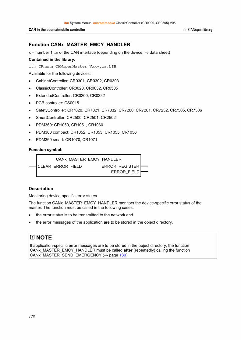
ifm System Manual ecomatmobile ClassicController (CR0020, CR0505) V05
128
CAN in the ecomatmobile controller ifm CANopen library
Function CANx_MASTER_EMCY_HANDLER x = number 1...n of the CAN interface (depending on the device, → data sheet)
Contained in the library: ifm_CRnnnn_CANopenMaster_Vxxyyzz.LIB
Available for the following devices:
• CabinetController: CR0301, CR0302, CR0303
• ClassicController: CR0020, CR0032, CR0505
• ExtendedController: CR0200, CR0232
• PCB controller: CS0015
• SafetyController: CR7020, CR7021, CR7032, CR7200, CR7201, CR7232, CR7505, CR7506
• SmartController: CR2500, CR2501, CR2502
• PDM360: CR1050, CR1051, CR1060
• PDM360 compact: CR1052, CR1053, CR1055, CR1056
• PDM360 smart: CR1070, CR1071
Function symbol:
CANx_MASTER_EMCY_HANDLER
CLEAR_ERROR_FIELD ERROR_REGISTERERROR_FIELD
Description Monitoring device-specific error states
The function CANx_MASTER_EMCY_HANDLER monitors the device-specific error status of the master. The function must be called in the following cases:
• the error status is to be transmitted to the network and
• the error messages of the application are to be stored in the object directory.
NOTE If application-specific error messages are to be stored in the object directory, the function CANx_MASTER_EMCY_HANDLER must be called after (repeatedly) calling the function CANx_MASTER_SEND_EMERGENCY (→ page 130).
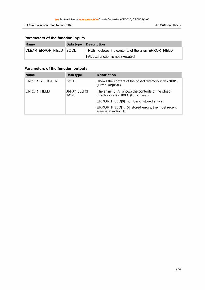
ifm System Manual ecomatmobile ClassicController (CR0020, CR0505) V05
129
CAN in the ecomatmobile controller ifm CANopen library
Parameters of the function inputs Name Data type Description
CLEAR_ERROR_FIELD BOOL TRUE: deletes the contents of the array ERROR_FIELD
FALSE: function is not executed
Parameters of the function outputs Name Data type Description
ERROR_REGISTER BYTE Shows the content of the object directory index 1001h (Error Register).
ERROR_FIELD ARRAY [0...5] OF WORD
The array [0...5] shows the contents of the object directory index 1003h (Error Field).
ERROR_FIELD[0]: number of stored errors.
ERROR_FIELD[1...5]: stored errors, the most recent error is in index [1].

ifm System Manual ecomatmobile ClassicController (CR0020, CR0505) V05
130
CAN in the ecomatmobile controller ifm CANopen library
Function CANx_MASTER_SEND_EMERGENCY x = number 1...n of the CAN interface (depending on the device, → data sheet)
Contained in the library: ifm_CRnnnn_CANopenMaster_Vxxyyzz.LIB
Available for the following devices:
• CabinetController: CR0301, CR0302, CR0303
• ClassicController: CR0020, CR0032, CR0505
• ExtendedController: CR0200, CR0232
• PCB controller: CS0015
• SafetyController: CR7020, CR7021, CR7032, CR7200, CR7201, CR7232, CR7505, CR7506
• SmartController: CR2500, CR2501, CR2502
• PDM360: CR1050, CR1051, CR1060
• PDM360 compact: CR1052, CR1053, CR1055, CR1056
• PDM360 smart: CR1070, CR1071
Function symbol:
CANx_MASTER_SEND_EMERGENCY
ENABLEERRORERROR_CODE
ERROR_REGISTERMANUFACTURER_ERROR_FIELD
Description Transmission of application-specific error states.
The function CANx_MASTER_SEND_EMERGENCY transmits application-specific error states. The function is called if the error status is to be transmitted to other devices in the network.
NOTE If application-specific error messages are to be stored in the object directory, the function CANx_MASTER_EMCY_HANDLER (→ page 128) must be called after (repeatedly) calling the function CANx_MASTER_SEND_EMERGENCY.
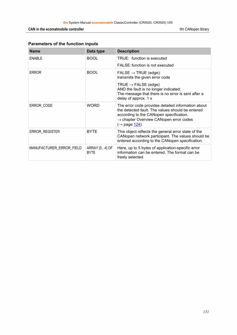
ifm System Manual ecomatmobile ClassicController (CR0020, CR0505) V05
131
CAN in the ecomatmobile controller ifm CANopen library
Parameters of the function inputs Name Data type Description
ENABLE BOOL TRUE: function is executed
FALSE: function is not executed
ERROR BOOL FALSE → TRUE (edge): transmits the given error code
TRUE → FALSE (edge) AND the fault is no longer indicated: The message that there is no error is sent after a delay of approx. 1 s
ERROR_CODE WORD The error code provides detailed information about the detected fault. The values should be entered according to the CANopen specification. → chapter Overview CANopen error codes (→ page 124)
ERROR_REGISTER BYTE This object reflects the general error state of the CANopen network participant. The values should be entered according to the CANopen specification.
MANUFACTURER_ERROR_FIELD ARRAY [0...4] OF BYTE
Here, up to 5 bytes of application-specific error information can be entered. The format can be freely selected.
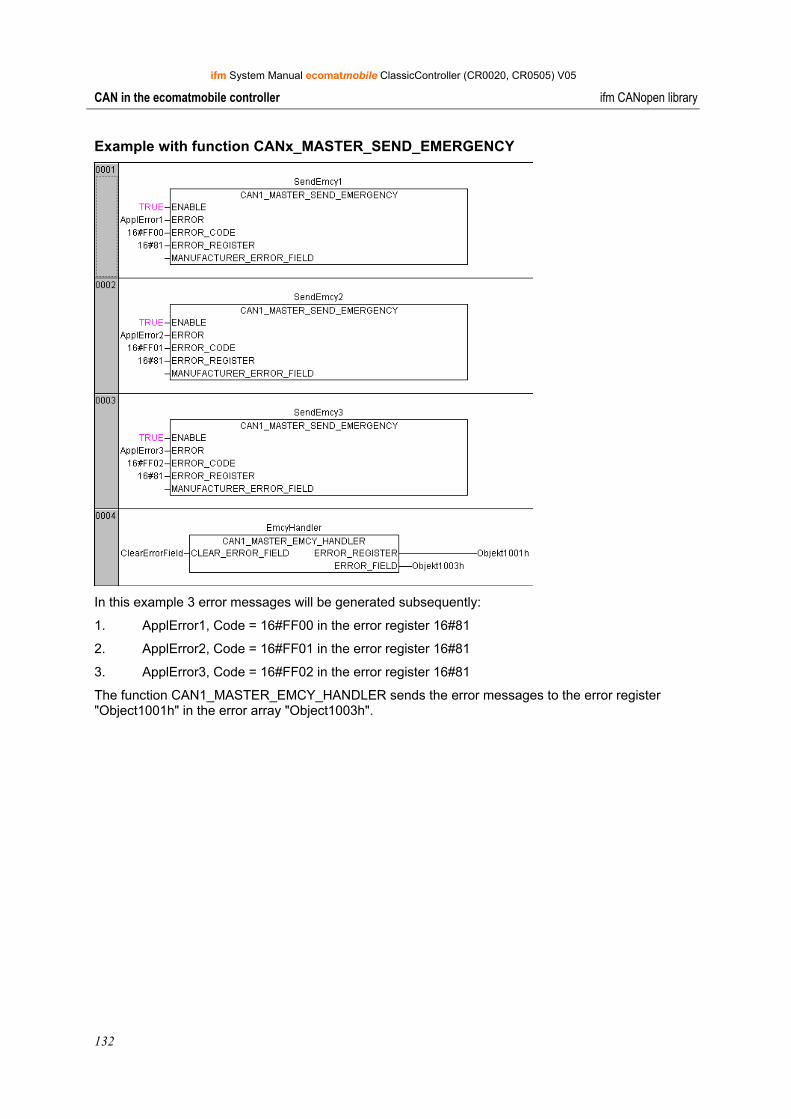
ifm System Manual ecomatmobile ClassicController (CR0020, CR0505) V05
132
CAN in the ecomatmobile controller ifm CANopen library
Example with function CANx_MASTER_SEND_EMERGENCY
In this example 3 error messages will be generated subsequently:
1. ApplError1, Code = 16#FF00 in the error register 16#81
2. ApplError2, Code = 16#FF01 in the error register 16#81
3. ApplError3, Code = 16#FF02 in the error register 16#81
The function CAN1_MASTER_EMCY_HANDLER sends the error messages to the error register "Object1001h" in the error array "Object1003h".
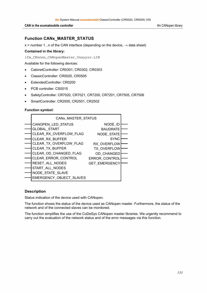
ifm System Manual ecomatmobile ClassicController (CR0020, CR0505) V05
133
CAN in the ecomatmobile controller ifm CANopen library
Function CANx_MASTER_STATUS x = number 1...n of the CAN interface (depending on the device, → data sheet)
Contained in the library: ifm_CRnnnn_CANopenMaster_Vxxyyzz.LIB
Available for the following devices:
• CabinetController: CR0301, CR0302, CR0303
• ClassicController: CR0020, CR0505
• ExtendedController: CR0200
• PCB controller: CS0015
• SafetyController: CR7020, CR7021, CR7200, CR7201, CR7505, CR7506
• SmartController: CR2500, CR2501, CR2502
Function symbol:
CANx_MASTER_STATUS
CANOPEN_LED_STATUS NODE_IDGLOBAL_START BAUDRATECLEAR_RX_OVERFLOW_FLAG NODE_STATECLEAR_RX_BUFFER SYNCCLEAR_TX_OVERFLOW_FLAGCLEAR_TX_BUFFERCLEAR_OD_CHANGED_FLAGCLEAR_ERROR_CONTROLRESET_ALL_NODESSTART_ALL_NODES
RX_OVERFLOWTX_OVERFLOW OD_CHANGED
ERROR_CONTROL
NODE_STATE_SLAVEEMERGENCY_OBJECT_SLAVES
GET_EMERGENCY
Description Status indication of the device used with CANopen.
The function shows the status of the device used as CANopen master. Furthermore, the status of the network and of the connected slaves can be monitored.
The function simplifies the use of the CoDeSys CANopen master libraries. We urgently recommend to carry out the evaluation of the network status and of the error messages via this function.
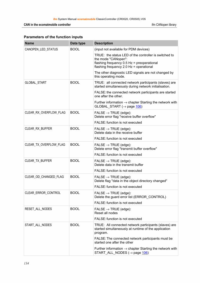
ifm System Manual ecomatmobile ClassicController (CR0020, CR0505) V05
134
CAN in the ecomatmobile controller ifm CANopen library
Parameters of the function inputs Name Data type Description
CANOPEN_LED_STATUS BOOL (input not available for PDM devices)
TRUE: the status LED of the controller is switched to the mode "CANopen": flashing frequency 0.5 Hz = preoperational flashing frequency 2.0 Hz = operational
The other diagnostic LED signals are not changed by this operating mode.
GLOBAL_START BOOL TRUE: all connected network participants (slaves) are started simultaneously during network initialisation.
FALSE: the connected network participants are started one after the other.
Further information → chapter Starting the network with GLOBAL_START (→ page 106)
CLEAR_RX_OVERFLOW_FLAG BOOL FALSE → TRUE (edge): Delete error flag "receive buffer overflow"
FALSE: function is not executed
CLEAR_RX_BUFFER BOOL FALSE → TRUE (edge): Delete data in the receive buffer
FALSE: function is not executed
CLEAR_TX_OVERFLOW_FLAG BOOL FALSE → TRUE (edge): Delete error flag "transmit buffer overflow"
FALSE: function is not executed
CLEAR_TX_BUFFER BOOL FALSE → TRUE (edge): Delete data in the transmit buffer
FALSE: function is not executed
CLEAR_OD_CHANGED_FLAG BOOL FALSE → TRUE (edge): Delete flag "data in the object directory changed"
FALSE: function is not executed
CLEAR_ERROR_CONTROL BOOL FALSE → TRUE (edge): Delete the guard error list (ERROR_CONTROL)
FALSE: function is not executed
RESET_ALL_NODES BOOL FALSE → TRUE (edge): Reset all nodes
FALSE: function is not executed
START_ALL_NODES BOOL TRUE: All connected network participants (slaves) are started simultaneously at runtime of the application program.
FALSE: The connected network participants must be started one after the other
Further information → chapter Starting the network with START_ALL_NODES (→ page 106)
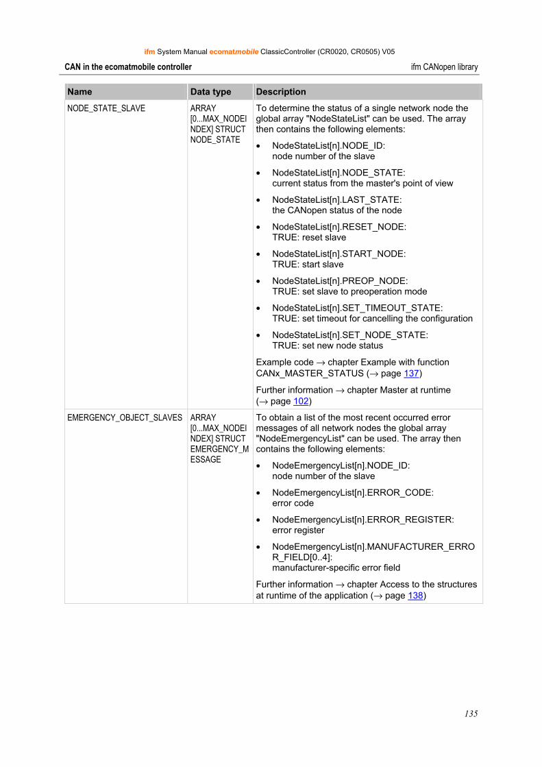
ifm System Manual ecomatmobile ClassicController (CR0020, CR0505) V05
135
CAN in the ecomatmobile controller ifm CANopen library
Name Data type Description
NODE_STATE_SLAVE ARRAY [0...MAX_NODEINDEX] STRUCT NODE_STATE
To determine the status of a single network node the global array "NodeStateList" can be used. The array then contains the following elements:
• NodeStateList[n].NODE_ID: node number of the slave
• NodeStateList[n].NODE_STATE: current status from the master's point of view
• NodeStateList[n].LAST_STATE: the CANopen status of the node
• NodeStateList[n].RESET_NODE: TRUE: reset slave
• NodeStateList[n].START_NODE: TRUE: start slave
• NodeStateList[n].PREOP_NODE: TRUE: set slave to preoperation mode
• NodeStateList[n].SET_TIMEOUT_STATE: TRUE: set timeout for cancelling the configuration
• NodeStateList[n].SET_NODE_STATE: TRUE: set new node status
Example code → chapter Example with function CANx_MASTER_STATUS (→ page 137)
Further information → chapter Master at runtime (→ page 102)
EMERGENCY_OBJECT_SLAVES ARRAY [0...MAX_NODEINDEX] STRUCT EMERGENCY_MESSAGE
To obtain a list of the most recent occurred error messages of all network nodes the global array "NodeEmergencyList" can be used. The array then contains the following elements:
• NodeEmergencyList[n].NODE_ID: node number of the slave
• NodeEmergencyList[n].ERROR_CODE: error code
• NodeEmergencyList[n].ERROR_REGISTER: error register
• NodeEmergencyList[n].MANUFACTURER_ERROR_FIELD[0..4]: manufacturer-specific error field
Further information → chapter Access to the structures at runtime of the application (→ page 138)
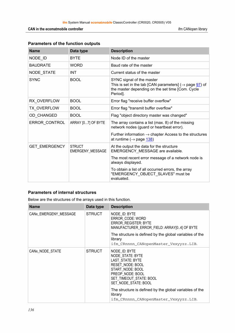
ifm System Manual ecomatmobile ClassicController (CR0020, CR0505) V05
136
CAN in the ecomatmobile controller ifm CANopen library
Parameters of the function outputs Name Data type Description
NODE_ID BYTE Node ID of the master
BAUDRATE WORD Baud rate of the master
NODE_STATE INT Current status of the master
SYNC BOOL SYNC signal of the master This is set in the tab [CAN parameters] (→ page 97) of the master depending on the set time [Com. Cycle Period].
RX_OVERFLOW BOOL Error flag "receive buffer overflow"
TX_OVERFLOW BOOL Error flag "transmit buffer overflow"
OD_CHANGED BOOL Flag "object directory master was changed"
ERROR_CONTROL ARRAY [0...7] OF BYTE The array contains a list (max. 8) of the missing network nodes (guard or heartbeat error).
Further information → chapter Access to the structures at runtime (→ page 138)
GET_EMERGENCY STRUCT EMERGENY_MESSAGE
At the output the data for the structure EMERGENCY_MESSAGE are available.
The most recent error message of a network node is always displayed.
To obtain a list of all occurred errors, the array "EMERGENCY_OBJECT_SLAVES" must be evaluated.
Parameters of internal structures Below are the structures of the arrays used in this function.
Name Data type Description
CANx_EMERGENY_MESSAGE STRUCT NODE_ID: BYTE ERROR_CODE: WORD ERROR_REGISTER: BYTE MANUFACTURER_ERROR_FIELD: ARRAY[0..4] OF BYTE The structure is defined by the global variables of the library ifm_CRnnnn_CANopenMaster_Vxxyyzz.LIB.
CANx_NODE_STATE STRUCT NODE_ID: BYTE NODE_STATE: BYTE LAST_STATE: BYTE RESET_NODE: BOOL START_NODE: BOOL PREOP_NODE: BOOL SET_TIMEOUT_STATE: BOOL SET_NODE_STATE: BOOL The structure is defined by the global variables of the library ifm_CRnnnn_CANopenMaster_Vxxyyzz.LIB.
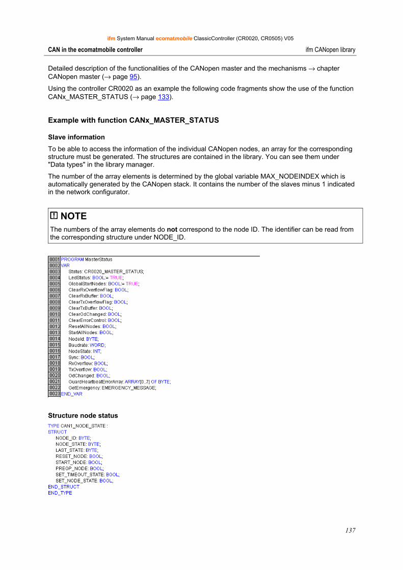
ifm System Manual ecomatmobile ClassicController (CR0020, CR0505) V05
137
CAN in the ecomatmobile controller ifm CANopen library
Detailed description of the functionalities of the CANopen master and the mechanisms → chapter CANopen master (→ page 95).
Using the controller CR0020 as an example the following code fragments show the use of the function CANx_MASTER_STATUS (→ page 133).
Example with function CANx_MASTER_STATUS
Slave information
To be able to access the information of the individual CANopen nodes, an array for the corresponding structure must be generated. The structures are contained in the library. You can see them under "Data types" in the library manager.
The number of the array elements is determined by the global variable MAX_NODEINDEX which is automatically generated by the CANopen stack. It contains the number of the slaves minus 1 indicated in the network configurator.
NOTE The numbers of the array elements do not correspond to the node ID. The identifier can be read from the corresponding structure under NODE_ID.
Structure node status
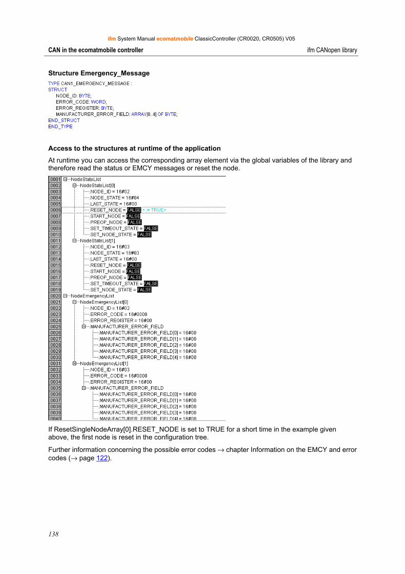
ifm System Manual ecomatmobile ClassicController (CR0020, CR0505) V05
138
CAN in the ecomatmobile controller ifm CANopen library
Structure Emergency_Message
Access to the structures at runtime of the application
At runtime you can access the corresponding array element via the global variables of the library and therefore read the status or EMCY messages or reset the node.
If ResetSingleNodeArray[0].RESET_NODE is set to TRUE for a short time in the example given above, the first node is reset in the configuration tree.
Further information concerning the possible error codes → chapter Information on the EMCY and error codes (→ page 122).

ifm System Manual ecomatmobile ClassicController (CR0020, CR0505) V05
139
CAN in the ecomatmobile controller ifm CANopen library
9.7.8 Library for the CANopen slave
The library ifm_CRnnnn_CANopenSlave_Vxxyyzz.LIB provides a number of functions for the CANopen slave (= CANopen device = CANopen node) which will be explained below.
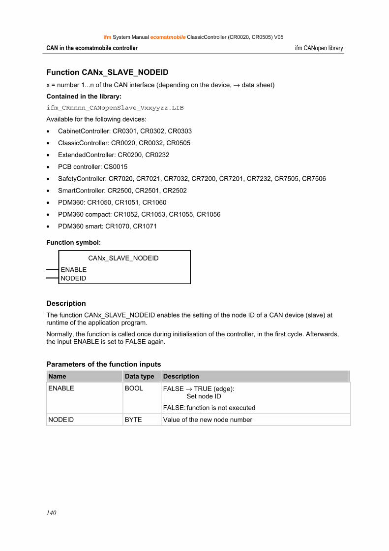
ifm System Manual ecomatmobile ClassicController (CR0020, CR0505) V05
140
CAN in the ecomatmobile controller ifm CANopen library
Function CANx_SLAVE_NODEID x = number 1...n of the CAN interface (depending on the device, → data sheet)
Contained in the library: ifm_CRnnnn_CANopenSlave_Vxxyyzz.LIB
Available for the following devices:
• CabinetController: CR0301, CR0302, CR0303
• ClassicController: CR0020, CR0032, CR0505
• ExtendedController: CR0200, CR0232
• PCB controller: CS0015
• SafetyController: CR7020, CR7021, CR7032, CR7200, CR7201, CR7232, CR7505, CR7506
• SmartController: CR2500, CR2501, CR2502
• PDM360: CR1050, CR1051, CR1060
• PDM360 compact: CR1052, CR1053, CR1055, CR1056
• PDM360 smart: CR1070, CR1071
Function symbol:
CANx_SLAVE_NODEID
ENABLENODEID
Description The function CANx_SLAVE_NODEID enables the setting of the node ID of a CAN device (slave) at runtime of the application program.
Normally, the function is called once during initialisation of the controller, in the first cycle. Afterwards, the input ENABLE is set to FALSE again.
Parameters of the function inputs Name Data type Description
ENABLE BOOL FALSE → TRUE (edge): Set node ID
FALSE: function is not executed
NODEID BYTE Value of the new node number
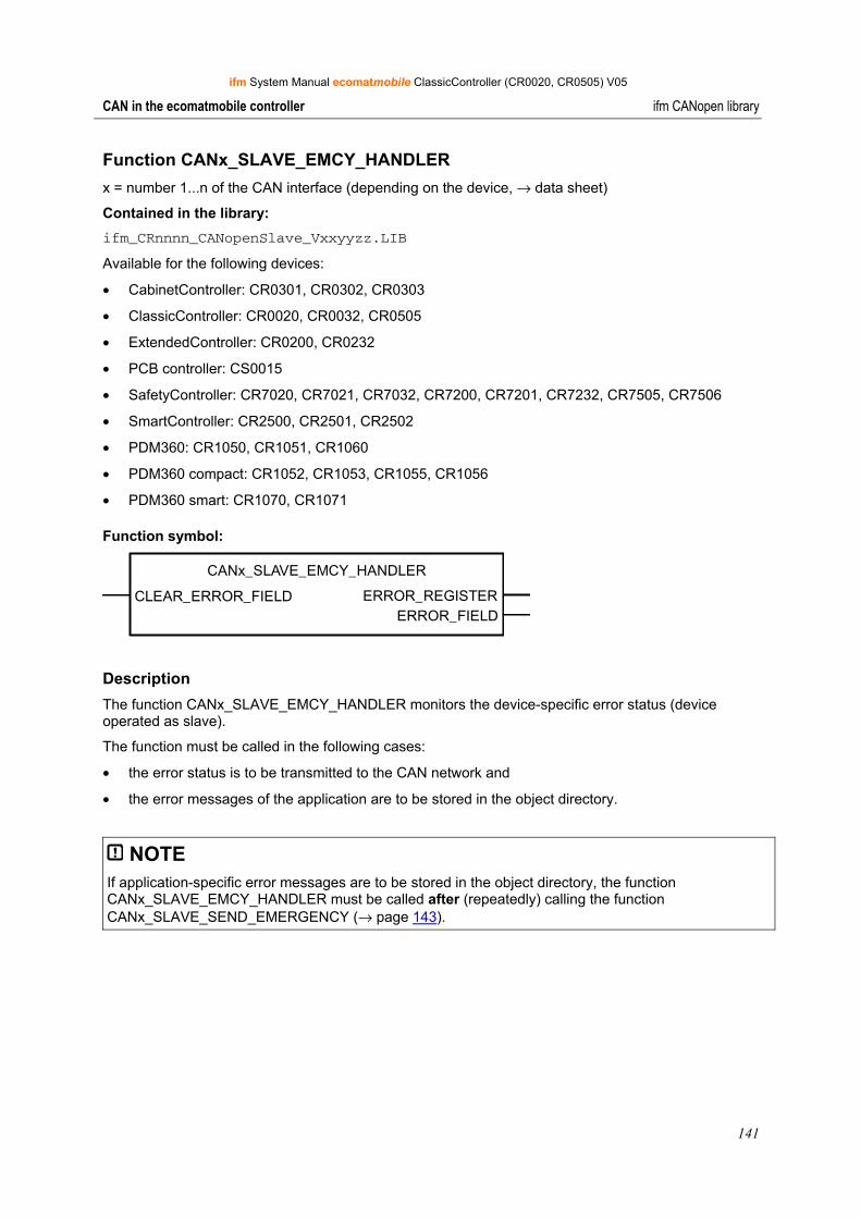
ifm System Manual ecomatmobile ClassicController (CR0020, CR0505) V05
141
CAN in the ecomatmobile controller ifm CANopen library
Function CANx_SLAVE_EMCY_HANDLER x = number 1...n of the CAN interface (depending on the device, → data sheet)
Contained in the library: ifm_CRnnnn_CANopenSlave_Vxxyyzz.LIB
Available for the following devices:
• CabinetController: CR0301, CR0302, CR0303
• ClassicController: CR0020, CR0032, CR0505
• ExtendedController: CR0200, CR0232
• PCB controller: CS0015
• SafetyController: CR7020, CR7021, CR7032, CR7200, CR7201, CR7232, CR7505, CR7506
• SmartController: CR2500, CR2501, CR2502
• PDM360: CR1050, CR1051, CR1060
• PDM360 compact: CR1052, CR1053, CR1055, CR1056
• PDM360 smart: CR1070, CR1071
Function symbol:
CANx_SLAVE_EMCY_HANDLER
CLEAR_ERROR_FIELD ERROR_REGISTERERROR_FIELD
Description The function CANx_SLAVE_EMCY_HANDLER monitors the device-specific error status (device operated as slave).
The function must be called in the following cases:
• the error status is to be transmitted to the CAN network and
• the error messages of the application are to be stored in the object directory.
NOTE If application-specific error messages are to be stored in the object directory, the function CANx_SLAVE_EMCY_HANDLER must be called after (repeatedly) calling the function CANx_SLAVE_SEND_EMERGENCY (→ page 143).
ifm System Manual ecomatmobile ClassicController (CR0020, CR0505) V05
142
CAN in the ecomatmobile controller ifm CANopen library
Parameters of the function inputs Name Data type Description
CLEAR_ERROR_FIELD BOOL FALSE → TRUE (edge): Delete ERROR FIELD
FALSE: function is not executed
Parameters of the function outputs Name Data type Description
ERROR_REGISTER BYTE Shows the contents of the object directory index 1001h (Error Register).
ERROR_FIELD ARRAY [0...5] OF WORD
The array [0...5] shows the contents of the object directory index 1003h (Error Field):
• ERROR_FIELD[0]: Number of stored errors
• ERROR_FIELD[1...5]: stored errors, the most recent error is in index [1].
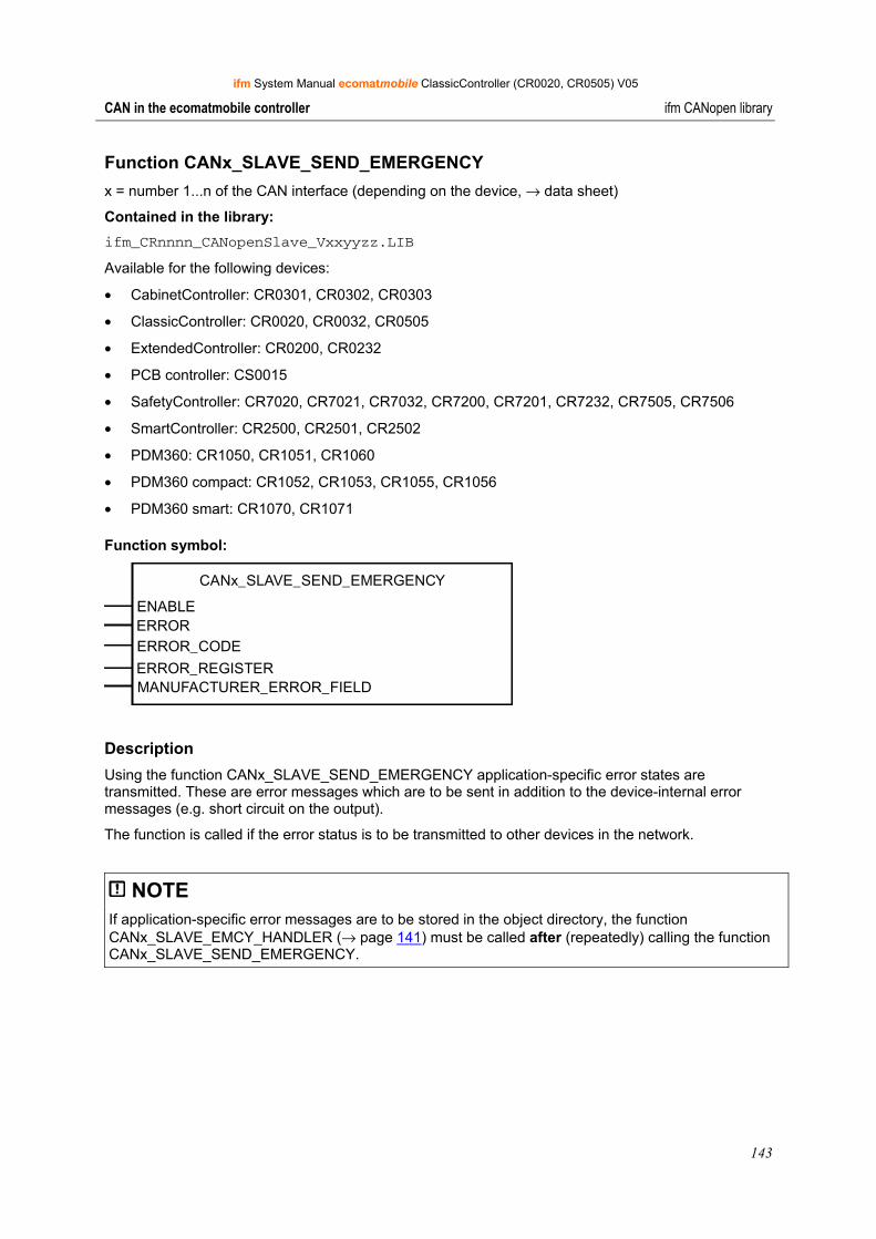
ifm System Manual ecomatmobile ClassicController (CR0020, CR0505) V05
143
CAN in the ecomatmobile controller ifm CANopen library
Function CANx_SLAVE_SEND_EMERGENCY x = number 1...n of the CAN interface (depending on the device, → data sheet)
Contained in the library: ifm_CRnnnn_CANopenSlave_Vxxyyzz.LIB
Available for the following devices:
• CabinetController: CR0301, CR0302, CR0303
• ClassicController: CR0020, CR0032, CR0505
• ExtendedController: CR0200, CR0232
• PCB controller: CS0015
• SafetyController: CR7020, CR7021, CR7032, CR7200, CR7201, CR7232, CR7505, CR7506
• SmartController: CR2500, CR2501, CR2502
• PDM360: CR1050, CR1051, CR1060
• PDM360 compact: CR1052, CR1053, CR1055, CR1056
• PDM360 smart: CR1070, CR1071
Function symbol:
CANx_SLAVE_SEND_EMERGENCY
ENABLEERRORERROR_CODE
ERROR_REGISTERMANUFACTURER_ERROR_FIELD
Description Using the function CANx_SLAVE_SEND_EMERGENCY application-specific error states are transmitted. These are error messages which are to be sent in addition to the device-internal error messages (e.g. short circuit on the output).
The function is called if the error status is to be transmitted to other devices in the network.
NOTE If application-specific error messages are to be stored in the object directory, the function CANx_SLAVE_EMCY_HANDLER (→ page 141) must be called after (repeatedly) calling the function CANx_SLAVE_SEND_EMERGENCY.
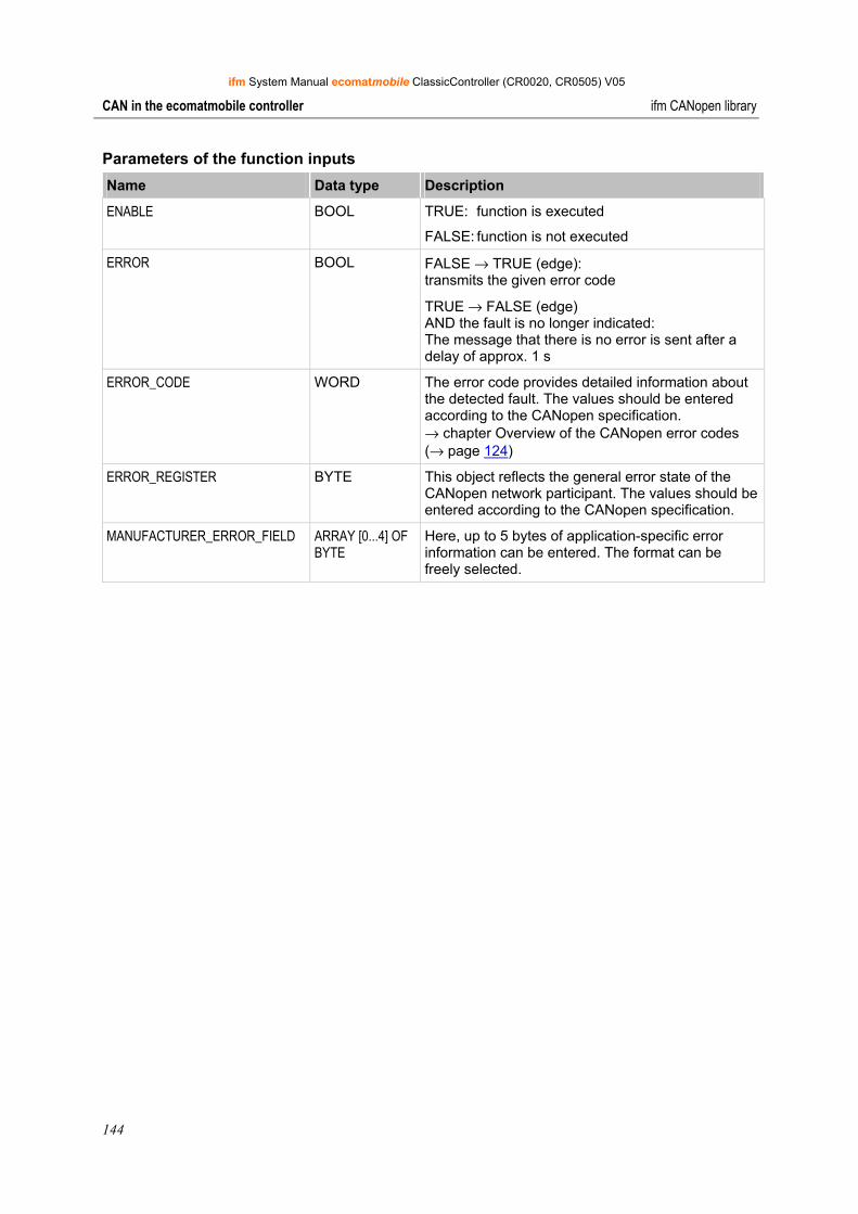
ifm System Manual ecomatmobile ClassicController (CR0020, CR0505) V05
144
CAN in the ecomatmobile controller ifm CANopen library
Parameters of the function inputs Name Data type Description
ENABLE BOOL TRUE: function is executed
FALSE: function is not executed
ERROR BOOL FALSE → TRUE (edge): transmits the given error code
TRUE → FALSE (edge) AND the fault is no longer indicated: The message that there is no error is sent after a delay of approx. 1 s
ERROR_CODE WORD The error code provides detailed information about the detected fault. The values should be entered according to the CANopen specification. → chapter Overview of the CANopen error codes (→ page 124)
ERROR_REGISTER BYTE This object reflects the general error state of the CANopen network participant. The values should be entered according to the CANopen specification.
MANUFACTURER_ERROR_FIELD ARRAY [0...4] OF BYTE
Here, up to 5 bytes of application-specific error information can be entered. The format can be freely selected.
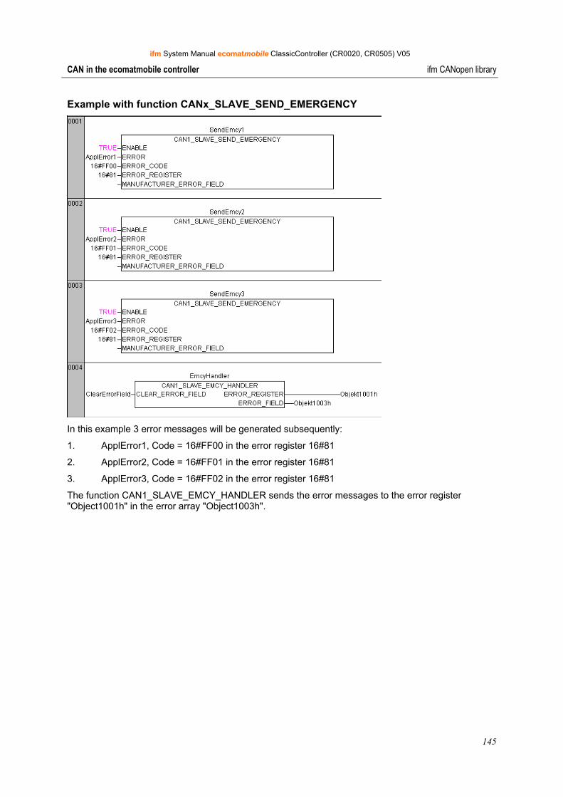
ifm System Manual ecomatmobile ClassicController (CR0020, CR0505) V05
145
CAN in the ecomatmobile controller ifm CANopen library
Example with function CANx_SLAVE_SEND_EMERGENCY
In this example 3 error messages will be generated subsequently:
1. ApplError1, Code = 16#FF00 in the error register 16#81
2. ApplError2, Code = 16#FF01 in the error register 16#81
3. ApplError3, Code = 16#FF02 in the error register 16#81
The function CAN1_SLAVE_EMCY_HANDLER sends the error messages to the error register "Object1001h" in the error array "Object1003h".
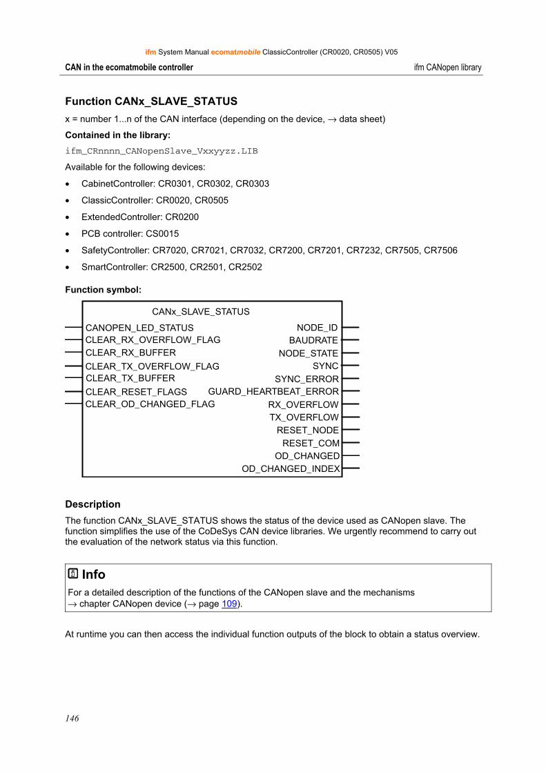
ifm System Manual ecomatmobile ClassicController (CR0020, CR0505) V05
146
CAN in the ecomatmobile controller ifm CANopen library
Function CANx_SLAVE_STATUS x = number 1...n of the CAN interface (depending on the device, → data sheet)
Contained in the library: ifm_CRnnnn_CANopenSlave_Vxxyyzz.LIB
Available for the following devices:
• CabinetController: CR0301, CR0302, CR0303
• ClassicController: CR0020, CR0505
• ExtendedController: CR0200
• PCB controller: CS0015
• SafetyController: CR7020, CR7021, CR7032, CR7200, CR7201, CR7232, CR7505, CR7506
• SmartController: CR2500, CR2501, CR2502
Function symbol:
CANx_SLAVE_STATUS
CANOPEN_LED_STATUS NODE_IDCLEAR_RX_OVERFLOW_FLAG BAUDRATECLEAR_RX_BUFFER NODE_STATECLEAR_TX_OVERFLOW_FLAG SYNCCLEAR_TX_BUFFER
CLEAR_RESET_FLAGSCLEAR_OD_CHANGED_FLAG
SYNC_ERROR GUARD_HEARTBEAT_ERROR
RX_OVERFLOWTX_OVERFLOW
RESET_NODERESET_COM
OD_CHANGEDOD_CHANGED_INDEX
Description The function CANx_SLAVE_STATUS shows the status of the device used as CANopen slave. The function simplifies the use of the CoDeSys CAN device libraries. We urgently recommend to carry out the evaluation of the network status via this function.
Info For a detailed description of the functions of the CANopen slave and the mechanisms → chapter CANopen device (→ page 109).
At runtime you can then access the individual function outputs of the block to obtain a status overview.
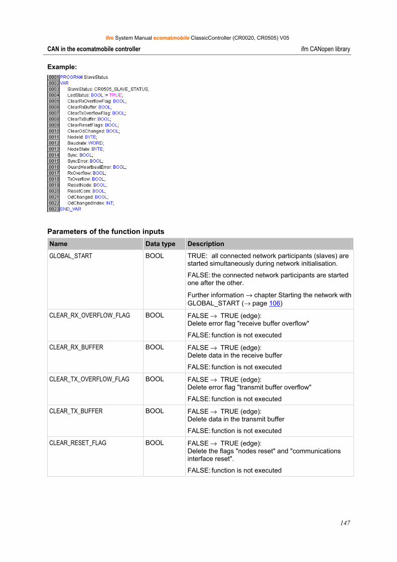
ifm System Manual ecomatmobile ClassicController (CR0020, CR0505) V05
147
CAN in the ecomatmobile controller ifm CANopen library
Example:
Parameters of the function inputs Name Data type Description
GLOBAL_START BOOL TRUE: all connected network participants (slaves) are started simultaneously during network initialisation.
FALSE: the connected network participants are started one after the other.
Further information → chapter Starting the network with GLOBAL_START (→ page 106)
CLEAR_RX_OVERFLOW_FLAG BOOL FALSE → TRUE (edge): Delete error flag "receive buffer overflow"
FALSE: function is not executed
CLEAR_RX_BUFFER BOOL FALSE → TRUE (edge): Delete data in the receive buffer
FALSE: function is not executed
CLEAR_TX_OVERFLOW_FLAG BOOL FALSE → TRUE (edge): Delete error flag "transmit buffer overflow"
FALSE: function is not executed
CLEAR_TX_BUFFER BOOL FALSE → TRUE (edge): Delete data in the transmit buffer
FALSE: function is not executed
CLEAR_RESET_FLAG BOOL FALSE → TRUE (edge): Delete the flags "nodes reset" and "communications interface reset".
FALSE: function is not executed
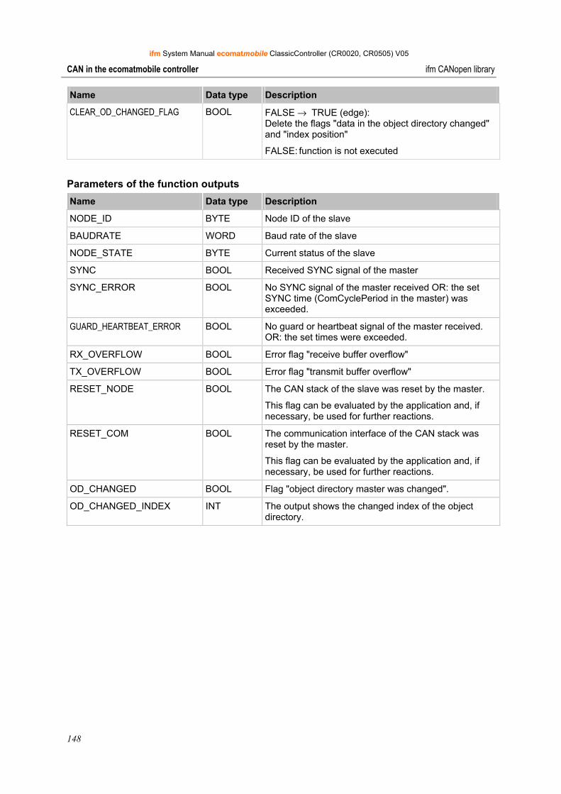
ifm System Manual ecomatmobile ClassicController (CR0020, CR0505) V05
148
CAN in the ecomatmobile controller ifm CANopen library
Name Data type Description
CLEAR_OD_CHANGED_FLAG BOOL FALSE → TRUE (edge): Delete the flags "data in the object directory changed" and "index position"
FALSE: function is not executed
Parameters of the function outputs Name Data type Description
NODE_ID BYTE Node ID of the slave
BAUDRATE WORD Baud rate of the slave
NODE_STATE BYTE Current status of the slave
SYNC BOOL Received SYNC signal of the master
SYNC_ERROR BOOL No SYNC signal of the master received OR: the set SYNC time (ComCyclePeriod in the master) was exceeded.
GUARD_HEARTBEAT_ERROR BOOL No guard or heartbeat signal of the master received. OR: the set times were exceeded.
RX_OVERFLOW BOOL Error flag "receive buffer overflow"
TX_OVERFLOW BOOL Error flag "transmit buffer overflow"
RESET_NODE BOOL The CAN stack of the slave was reset by the master.
This flag can be evaluated by the application and, if necessary, be used for further reactions.
RESET_COM BOOL The communication interface of the CAN stack was reset by the master.
This flag can be evaluated by the application and, if necessary, be used for further reactions.
OD_CHANGED BOOL Flag "object directory master was changed".
OD_CHANGED_INDEX INT The output shows the changed index of the object directory.

ifm System Manual ecomatmobile ClassicController (CR0020, CR0505) V05
149
CAN in the ecomatmobile controller ifm CANopen library
9.7.9 Further ifm libraries for CANopen
Here we present further ifm functions which are sensible additions for CANopen.
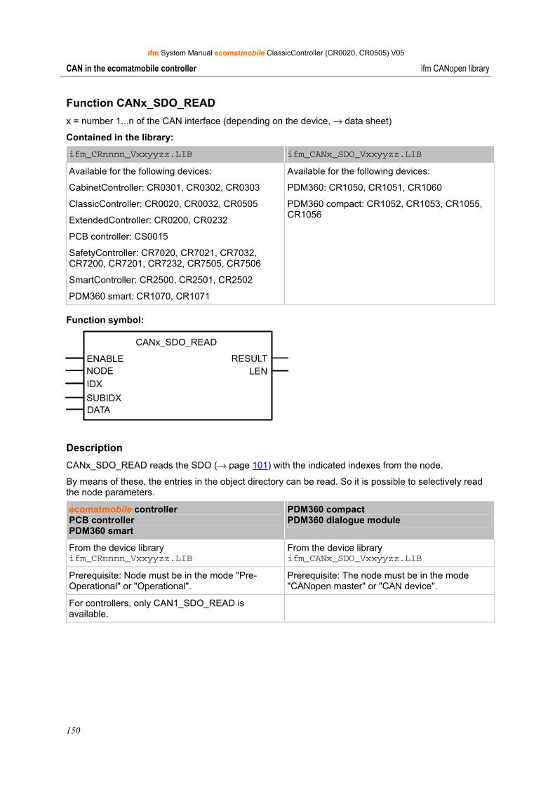
ifm System Manual ecomatmobile ClassicController (CR0020, CR0505) V05
150
CAN in the ecomatmobile controller ifm CANopen library
Function CANx_SDO_READ x = number 1...n of the CAN interface (depending on the device, → data sheet)
Contained in the library:
ifm_CRnnnn_Vxxyyzz.LIB ifm_CANx_SDO_Vxxyyzz.LIB
Available for the following devices:
CabinetController: CR0301, CR0302, CR0303
ClassicController: CR0020, CR0032, CR0505
ExtendedController: CR0200, CR0232
PCB controller: CS0015
SafetyController: CR7020, CR7021, CR7032, CR7200, CR7201, CR7232, CR7505, CR7506
SmartController: CR2500, CR2501, CR2502
PDM360 smart: CR1070, CR1071
Available for the following devices:
PDM360: CR1050, CR1051, CR1060
PDM360 compact: CR1052, CR1053, CR1055, CR1056
Function symbol:
CANx_SDO_READ
ENABLE RESULTNODEIDX
SUBIDXDATA
LEN
Description CANx_SDO_READ reads the SDO (→ page 101) with the indicated indexes from the node.
By means of these, the entries in the object directory can be read. So it is possible to selectively read the node parameters.
ecomatmobile controller PCB controller PDM360 smart
PDM360 compact PDM360 dialogue module
From the device library ifm_CRnnnn_Vxxyyzz.LIB
From the device library ifm_CANx_SDO_Vxxyyzz.LIB
Prerequisite: Node must be in the mode "Pre-Operational" or "Operational".
Prerequisite: The node must be in the mode "CANopen master" or "CAN device".
For controllers, only CAN1_SDO_READ is available.
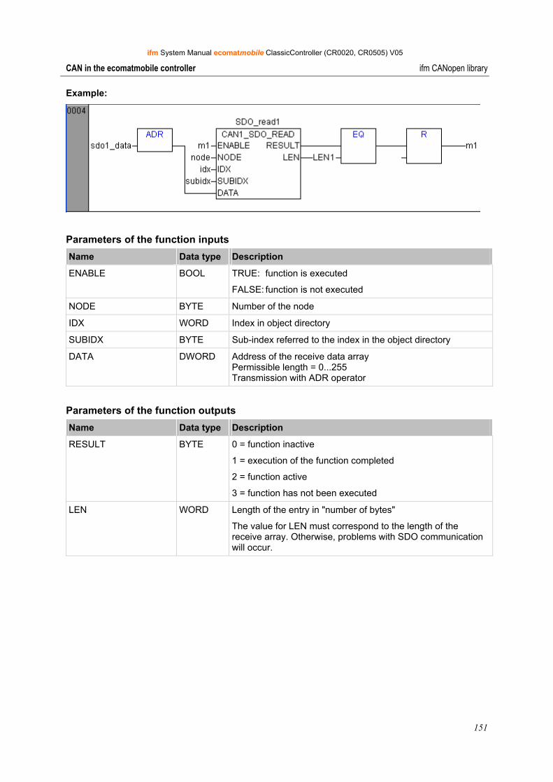
ifm System Manual ecomatmobile ClassicController (CR0020, CR0505) V05
151
CAN in the ecomatmobile controller ifm CANopen library
Example:
Parameters of the function inputs Name Data type Description
ENABLE BOOL TRUE: function is executed
FALSE: function is not executed
NODE BYTE Number of the node
IDX WORD Index in object directory
SUBIDX BYTE Sub-index referred to the index in the object directory
DATA DWORD Address of the receive data array Permissible length = 0...255 Transmission with ADR operator
Parameters of the function outputs Name Data type Description
RESULT BYTE 0 = function inactive
1 = execution of the function completed
2 = function active
3 = function has not been executed
LEN WORD Length of the entry in "number of bytes"
The value for LEN must correspond to the length of the receive array. Otherwise, problems with SDO communication will occur.
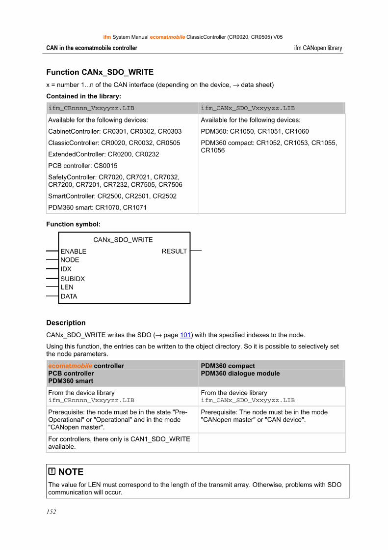
ifm System Manual ecomatmobile ClassicController (CR0020, CR0505) V05
152
CAN in the ecomatmobile controller ifm CANopen library
Function CANx_SDO_WRITE x = number 1...n of the CAN interface (depending on the device, → data sheet)
Contained in the library:
ifm_CRnnnn_Vxxyyzz.LIB ifm_CANx_SDO_Vxxyyzz.LIB
Available for the following devices:
CabinetController: CR0301, CR0302, CR0303
ClassicController: CR0020, CR0032, CR0505
ExtendedController: CR0200, CR0232
PCB controller: CS0015
SafetyController: CR7020, CR7021, CR7032, CR7200, CR7201, CR7232, CR7505, CR7506
SmartController: CR2500, CR2501, CR2502
PDM360 smart: CR1070, CR1071
Available for the following devices:
PDM360: CR1050, CR1051, CR1060
PDM360 compact: CR1052, CR1053, CR1055, CR1056
Function symbol:
CANx_SDO_WRITE
ENABLE RESULTNODEIDX
SUBIDXLENDATA
Description CANx_SDO_WRITE writes the SDO (→ page 101) with the specified indexes to the node.
Using this function, the entries can be written to the object directory. So it is possible to selectively set the node parameters.
ecomatmobile controller PCB controller PDM360 smart
PDM360 compact PDM360 dialogue module
From the device library ifm_CRnnnn_Vxxyyzz.LIB
From the device library ifm_CANx_SDO_Vxxyyzz.LIB
Prerequisite: the node must be in the state "Pre-Operational" or "Operational" and in the mode "CANopen master".
Prerequisite: The node must be in the mode "CANopen master" or "CAN device".
For controllers, there only is CAN1_SDO_WRITE available.
NOTE The value for LEN must correspond to the length of the transmit array. Otherwise, problems with SDO communication will occur.
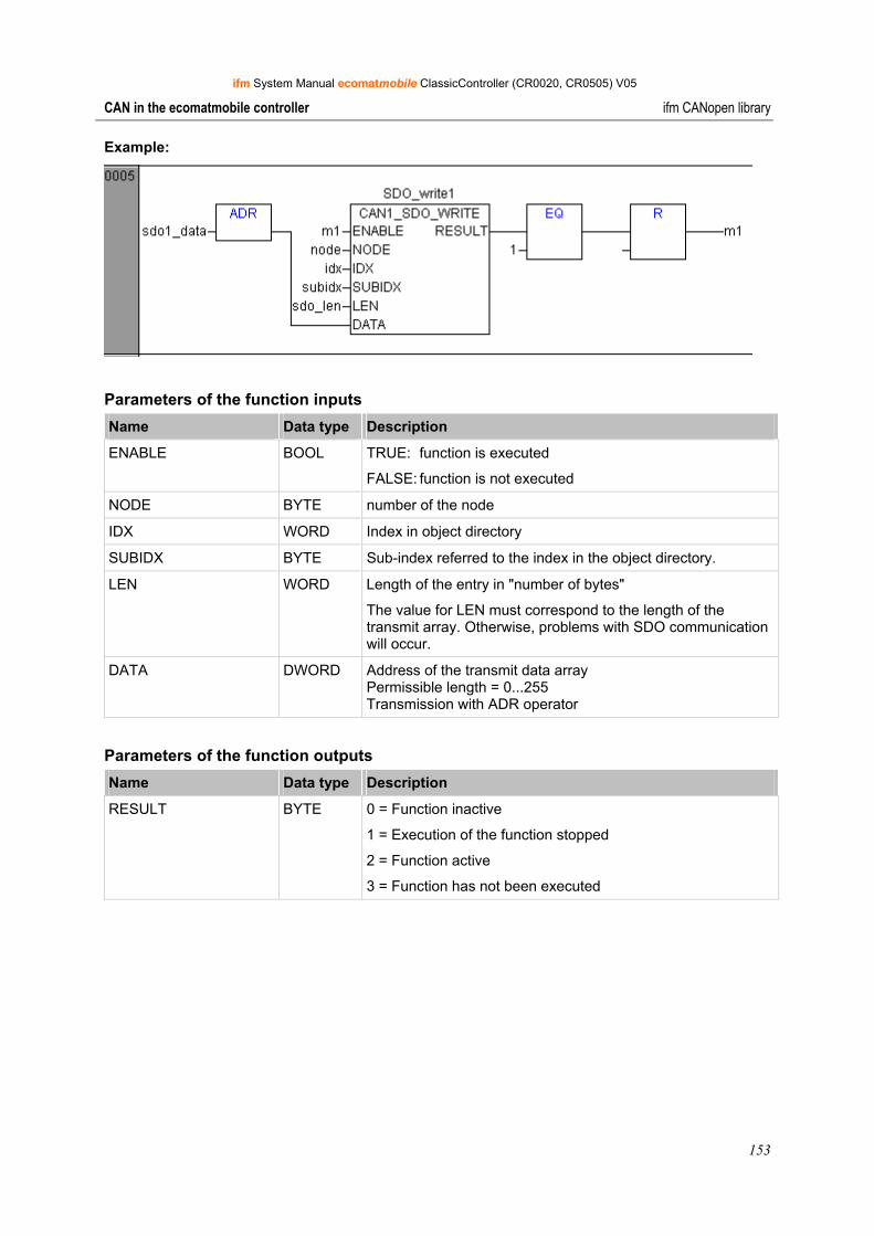
ifm System Manual ecomatmobile ClassicController (CR0020, CR0505) V05
153
CAN in the ecomatmobile controller ifm CANopen library
Example:
Parameters of the function inputs Name Data type Description
ENABLE BOOL TRUE: function is executed
FALSE: function is not executed
NODE BYTE number of the node
IDX WORD Index in object directory
SUBIDX BYTE Sub-index referred to the index in the object directory.
LEN WORD Length of the entry in "number of bytes"
The value for LEN must correspond to the length of the transmit array. Otherwise, problems with SDO communication will occur.
DATA DWORD Address of the transmit data array Permissible length = 0...255 Transmission with ADR operator
Parameters of the function outputs Name Data type Description
RESULT BYTE 0 = Function inactive
1 = Execution of the function stopped
2 = Function active
3 = Function has not been executed

ifm System Manual ecomatmobile ClassicController (CR0020, CR0505) V05
154
CAN in the ecomatmobile controller Summary CAN / CANopen
9.8 Summary CAN / CANopen • The COB ID of the network variables must differ from the CANopen Device ID in the controller
configuration and from the IDs of the functions CANx_TRANSMIT and CANx_RECEIVE!
• If more than 8 bytes of network variables are put into one COB ID, CANopen automatically expands the data packet to several successive COB IDs. This can lead to conflicts with manually defined COB IDs!
• Network variables cannot transport any string variables.
• Network variables can be transported... - if a variable becomes TRUE (Event), - in case of data changes in the network variable or - cyclically when the timer has elapsed.
• The interval time is the period between transmissions if cyclical transmission has been selected. The minimum distance is the waiting time between two transmissions, if the variable changes too often.
• To reduce the bus load, split the messages via network variables or CANx_TRANSMIT to several plc cycles using several events.
• Each call of CANx_TRANSMIT or CANx_RECEIVE generates a message packet of 8 bytes.
• In the controller configuration the values for [Com Cycle Period] and [Sync. Window Length] should be identical. These values must be higher than the plc cycle time.
• If [Com Cycle Period] is selected for a slave, the slave searches for a Sync object of the master during exactly this period. This is why the value for [Com Cycle Period] must be higher than the [Master Synch Time].
• We recommend to select "optional startup" for slaves and "automatic startup" for the network. This reduces unnecessary bus load and allows a briefly lost slave to integrate into the network again.
• Since we have no inhibit timer, we recommend to set analogue inputs to "synchronous transmission" to avoid bus overload.
• Binary inputs, especially the irregularly switching ones, should best be set to "asynchronous transmission" using an event timer.
• To be considered during the monitoring of the slave status: - after the start of the slaves it takes a while until the slaves are operational. - When the system is switched off, slaves can indicate an incorrect status change due to early voltage loss.
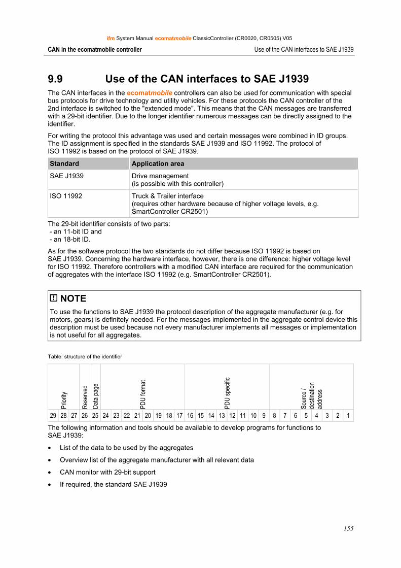
ifm System Manual ecomatmobile ClassicController (CR0020, CR0505) V05
155
CAN in the ecomatmobile controller Use of the CAN interfaces to SAE J1939
9.9 Use of the CAN interfaces to SAE J1939 The CAN interfaces in the ecomatmobile controllers can also be used for communication with special bus protocols for drive technology and utility vehicles. For these protocols the CAN controller of the 2nd interface is switched to the "extended mode". This means that the CAN messages are transferred with a 29-bit identifier. Due to the longer identifier numerous messages can be directly assigned to the identifier.
For writing the protocol this advantage was used and certain messages were combined in ID groups. The ID assignment is specified in the standards SAE J1939 and ISO 11992. The protocol of ISO 11992 is based on the protocol of SAE J1939.
Standard Application area
SAE J1939 Drive management (is possible with this controller)
ISO 11992 Truck & Trailer interface (requires other hardware because of higher voltage levels, e.g. SmartController CR2501)
The 29-bit identifier consists of two parts: - an 11-bit ID and - an 18-bit ID.
As for the software protocol the two standards do not differ because ISO 11992 is based on SAE J1939. Concerning the hardware interface, however, there is one difference: higher voltage level for ISO 11992. Therefore controllers with a modified CAN interface are required for the communication of aggregates with the interface ISO 11992 (e.g. SmartController CR2501).
NOTE To use the functions to SAE J1939 the protocol description of the aggregate manufacturer (e.g. for motors, gears) is definitely needed. For the messages implemented in the aggregate control device this description must be used because not every manufacturer implements all messages or implementation is not useful for all aggregates.
Table: structure of the identifier
Prior
ity
Rese
rved
Data
page
PDU
forma
t
PDU
spec
ific
Sour
ce /
desti
natio
n ad
dres
s
29 28 27 26 25 24 23 22 21 20 19 18 17 16 15 14 13 12 11 10 9 8 7 6 5 4 3 2 1
The following information and tools should be available to develop programs for functions to SAE J1939:
• List of the data to be used by the aggregates
• Overview list of the aggregate manufacturer with all relevant data
• CAN monitor with 29-bit support
• If required, the standard SAE J1939
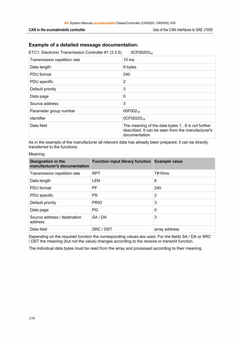
ifm System Manual ecomatmobile ClassicController (CR0020, CR0505) V05
156
CAN in the ecomatmobile controller Use of the CAN interfaces to SAE J1939
Example of a detailed message documentation: ETC1: Electronic Transmission Controller #1 (3.3.5) 0CF0020316
Transmission repetition rate 10 ms
Data length: 8 bytes
PDU format 240
PDU specific 2
Default priority 3
Data page 0
Source address 3
Parameter group number 00F00216
Identifier 0CF0020316
Data field The meaning of the data bytes 1...8 is not further described. It can be seen from the manufacturer's documentation.
As in the example of the manufacturer all relevant data has already been prepared, it can be directly transferred to the functions.
Meaning:
Designation in the manufacturer's documentation
Function input library function Example value
Transmission repetition rate RPT T#10ms
Data length LEN 8
PDU format PF 240
PDU specific PS 2
Default priority PRIO 3
Data page PG 0
Source address / destination address
SA / DA 3
Data field SRC / DST array address
Depending on the required function the corresponding values are used. For the fields SA / DA or SRC / DST the meaning (but not the value) changes according to the receive or transmit function.
The individual data bytes must be read from the array and processed according to their meaning.
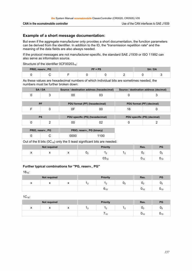
ifm System Manual ecomatmobile ClassicController (CR0020, CR0505) V05
157
CAN in the ecomatmobile controller Use of the CAN interfaces to SAE J1939
Example of a short message documentation: But even if the aggregate manufacturer only provides a short documentation, the function parameters can be derived from the identifier. In addition to the ID, the "transmission repetition rate" and the meaning of the data fields are also always needed.
If the protocol messages are not manufacturer-specific, the standard SAE J1939 or ISO 11992 can also serve as information source.
Structure of the identifier 0CF0020316: PRIO, reserv., PG PF + PS SA / DA
0 C F 0 0 2 0 3
As these values are hexadecimal numbers of which individual bits are sometimes needed, the numbers must be further broken down:
SA / DA Source / destination address (hexadecimal) Source / destination address (decimal)
0 3 00 03 0 3
PF PDU format (PF) (hexadecimal) PDU format (PF) (decimal)
F 0 0F 00 16 0
PS PDU specific (PS) (hexadecimal) PDU specific (PS) (decimal)
0 2 00 02 0 2
PRIO, reserv., PG PRIO, reserv., PG (binary)
0 C 0000 1100
Out of the 8 bits (0C16) only the 5 least significant bits are needed: Not required Priority Res. PG
x x x 02 12 12 02 02
0310 010 010
Further typical combinations for "PG, reserv., PG"
1816: Not required Priority Res. PG
x x x 12 12 02 02 02
610 010 010
1C16: Not required Priority Res. PG
x x x 12 12 12 02 02
710 010 010
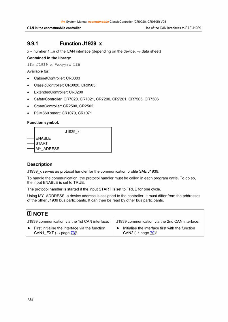
ifm System Manual ecomatmobile ClassicController (CR0020, CR0505) V05
158
CAN in the ecomatmobile controller Use of the CAN interfaces to SAE J1939
9.9.1 Function J1939_x x = number 1...n of the CAN interface (depending on the device, → data sheet)
Contained in the library: ifm_J1939_x_Vxxyyzz.LIB
Available for:
• CabinetController: CR0303
• ClassicController: CR0020, CR0505
• ExtendedController: CR0200
• SafetyController: CR7020, CR7021, CR7200, CR7201, CR7505, CR7506
• SmartController: CR2500, CR2502
• PDM360 smart: CR1070, CR1071
Function symbol:
J1939_x
ENABLESTARTMY_ADRESS
Description J1939_x serves as protocol handler for the communication profile SAE J1939.
To handle the communication, the protocol handler must be called in each program cycle. To do so, the input ENABLE is set to TRUE.
The protocol handler is started if the input START is set to TRUE for one cycle.
Using MY_ADDRESS, a device address is assigned to the controller. It must differ from the addresses of the other J1939 bus participants. It can then be read by other bus participants.
NOTE J1939 communication via the 1st CAN interface:
► First initialise the interface via the function CAN1_EXT (→ page 73)!
J1939 communication via the 2nd CAN interface:
► Initialise the interface first with the function CAN2 (→ page 79)!

ifm System Manual ecomatmobile ClassicController (CR0020, CR0505) V05
159
CAN in the ecomatmobile controller Use of the CAN interfaces to SAE J1939
Parameters of the function inputs Name Data type Description
ENABLE BOOL TRUE: function is executed
FALSE: function is not executed
START BOOL TRUE (only for 1 cycle): protocol handler started
FALSE: during cyclical processing of the program
MY_ADRESS BYTE Device address of the controller
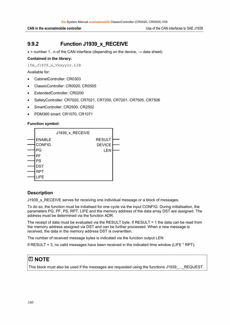
ifm System Manual ecomatmobile ClassicController (CR0020, CR0505) V05
160
CAN in the ecomatmobile controller Use of the CAN interfaces to SAE J1939
9.9.2 Function J1939_x_RECEIVE x = number 1...n of the CAN interface (depending on the device, → data sheet)
Contained in the library: ifm_J1939_x_Vxxyyzz.LIB
Available for:
• CabinetController: CR0303
• ClassicController: CR0020, CR0505
• ExtendedController: CR0200
• SafetyController: CR7020, CR7021, CR7200, CR7201, CR7505, CR7506
• SmartController: CR2500, CR2502
• PDM360 smart: CR1070, CR1071
Function symbol:
J1939_x_RECEIVE
ENABLE RESULTCONFIG DEVICEPG LENPFPSDSTRPTLIFE
Description J1939_x_RECEIVE serves for receiving one individual message or a block of messages.
To do so, the function must be initialised for one cycle via the input CONFIG. During initialisation, the parameters PG, PF, PS, RPT, LIFE and the memory address of the data array DST are assigned. The address must be determined via the function ADR.
The receipt of data must be evaluated via the RESULT byte. If RESULT = 1 the data can be read from the memory address assigned via DST and can be further processed. When a new message is received, the data in the memory address DST is overwritten.
The number of received message bytes is indicated via the function output LEN.
If RESULT = 3, no valid messages have been received in the indicated time window (LIFE * RPT).
NOTE This block must also be used if the messages are requested using the functions J1939_..._REQUEST.
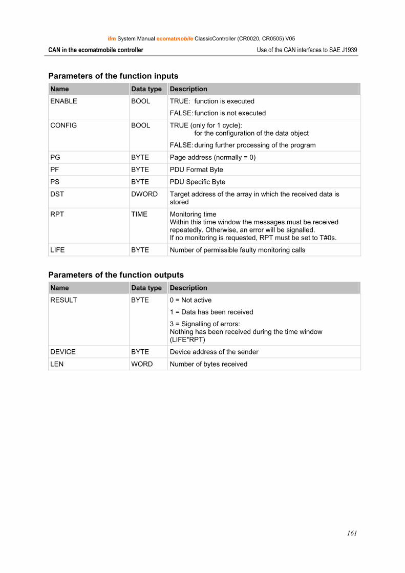
ifm System Manual ecomatmobile ClassicController (CR0020, CR0505) V05
161
CAN in the ecomatmobile controller Use of the CAN interfaces to SAE J1939
Parameters of the function inputs Name Data type Description
ENABLE BOOL TRUE: function is executed
FALSE: function is not executed
CONFIG BOOL TRUE (only for 1 cycle): for the configuration of the data object
FALSE: during further processing of the program
PG BYTE Page address (normally = 0)
PF BYTE PDU Format Byte
PS BYTE PDU Specific Byte
DST DWORD Target address of the array in which the received data is stored
RPT TIME Monitoring time Within this time window the messages must be received repeatedly. Otherwise, an error will be signalled. If no monitoring is requested, RPT must be set to T#0s.
LIFE BYTE Number of permissible faulty monitoring calls
Parameters of the function outputs Name Data type Description
RESULT BYTE 0 = Not active
1 = Data has been received
3 = Signalling of errors: Nothing has been received during the time window (LIFE*RPT)
DEVICE BYTE Device address of the sender
LEN WORD Number of bytes received
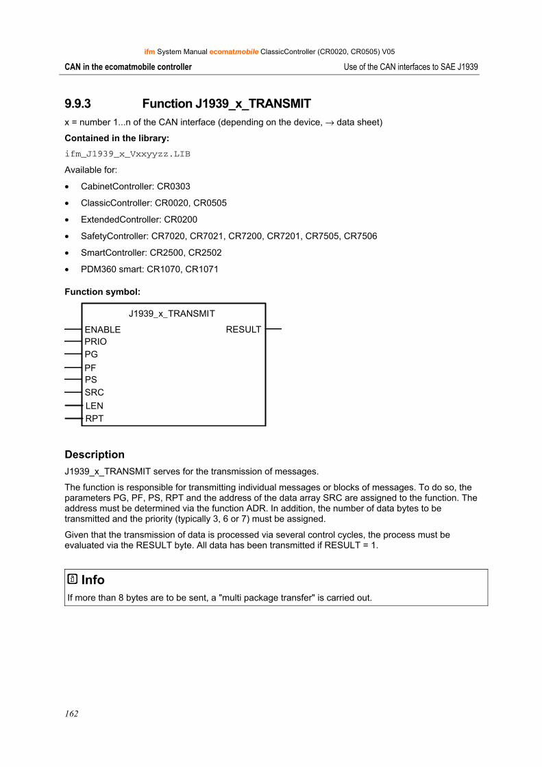
ifm System Manual ecomatmobile ClassicController (CR0020, CR0505) V05
162
CAN in the ecomatmobile controller Use of the CAN interfaces to SAE J1939
9.9.3 Function J1939_x_TRANSMIT x = number 1...n of the CAN interface (depending on the device, → data sheet)
Contained in the library: ifm_J1939_x_Vxxyyzz.LIB
Available for:
• CabinetController: CR0303
• ClassicController: CR0020, CR0505
• ExtendedController: CR0200
• SafetyController: CR7020, CR7021, CR7200, CR7201, CR7505, CR7506
• SmartController: CR2500, CR2502
• PDM360 smart: CR1070, CR1071
Function symbol:
J1939_x_TRANSMIT
ENABLE RESULTPRIOPG
PFPSSRC
LENRPT
Description J1939_x_TRANSMIT serves for the transmission of messages.
The function is responsible for transmitting individual messages or blocks of messages. To do so, the parameters PG, PF, PS, RPT and the address of the data array SRC are assigned to the function. The address must be determined via the function ADR. In addition, the number of data bytes to be transmitted and the priority (typically 3, 6 or 7) must be assigned.
Given that the transmission of data is processed via several control cycles, the process must be evaluated via the RESULT byte. All data has been transmitted if RESULT = 1.
Info If more than 8 bytes are to be sent, a "multi package transfer" is carried out.
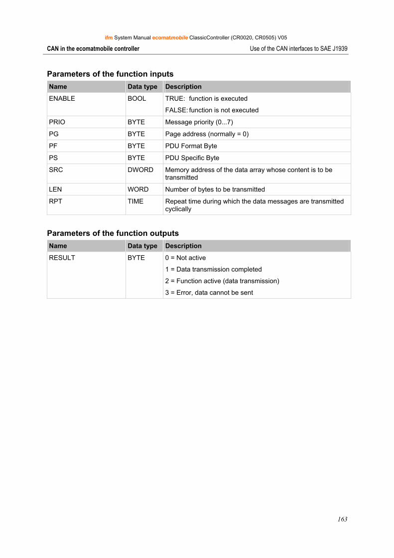
ifm System Manual ecomatmobile ClassicController (CR0020, CR0505) V05
163
CAN in the ecomatmobile controller Use of the CAN interfaces to SAE J1939
Parameters of the function inputs Name Data type Description
ENABLE BOOL TRUE: function is executed
FALSE: function is not executed
PRIO BYTE Message priority (0...7)
PG BYTE Page address (normally = 0)
PF BYTE PDU Format Byte
PS BYTE PDU Specific Byte
SRC DWORD Memory address of the data array whose content is to be transmitted
LEN WORD Number of bytes to be transmitted
RPT TIME Repeat time during which the data messages are transmitted cyclically
Parameters of the function outputs Name Data type Description
RESULT BYTE 0 = Not active
1 = Data transmission completed
2 = Function active (data transmission)
3 = Error, data cannot be sent
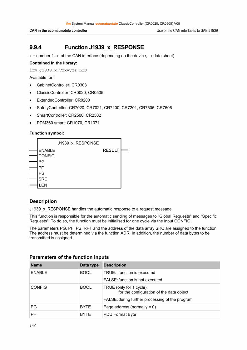
ifm System Manual ecomatmobile ClassicController (CR0020, CR0505) V05
164
CAN in the ecomatmobile controller Use of the CAN interfaces to SAE J1939
9.9.4 Function J1939_x_RESPONSE x = number 1...n of the CAN interface (depending on the device, → data sheet)
Contained in the library: ifm_J1939_x_Vxxyyzz.LIB
Available for:
• CabinetController: CR0303
• ClassicController: CR0020, CR0505
• ExtendedController: CR0200
• SafetyController: CR7020, CR7021, CR7200, CR7201, CR7505, CR7506
• SmartController: CR2500, CR2502
• PDM360 smart: CR1070, CR1071
Function symbol:
J1939_x_RESPONSE
ENABLE RESULTCONFIGPG
PFPSSRC
LEN
Description J1939_x_RESPONSE handles the automatic response to a request message.
This function is responsible for the automatic sending of messages to "Global Requests" and "Specific Requests". To do so, the function must be initialised for one cycle via the input CONFIG.
The parameters PG, PF, PS, RPT and the address of the data array SRC are assigned to the function. The address must be determined via the function ADR. In addition, the number of data bytes to be transmitted is assigned.
Parameters of the function inputs Name Data type Description
ENABLE BOOL TRUE: function is executed
FALSE: function is not executed
CONFIG BOOL TRUE (only for 1 cycle): for the configuration of the data object
FALSE: during further processing of the program
PG BYTE Page address (normally = 0)
PF BYTE PDU Format Byte
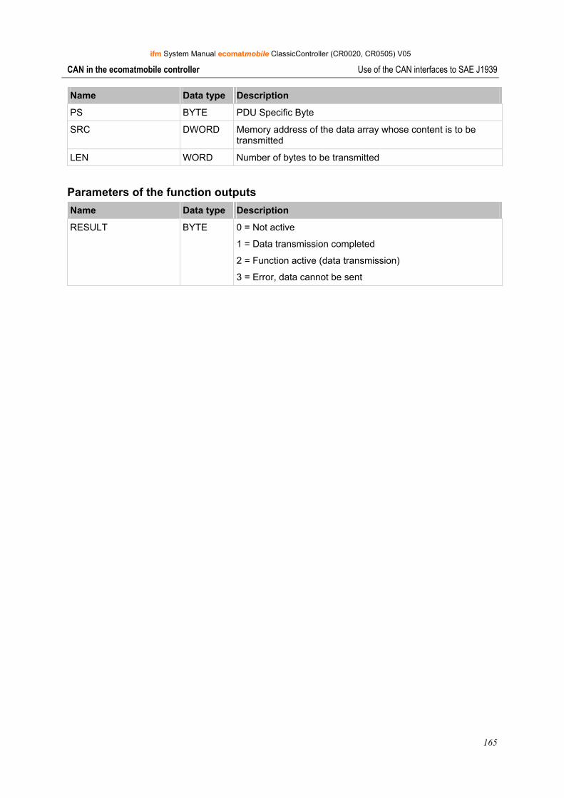
ifm System Manual ecomatmobile ClassicController (CR0020, CR0505) V05
165
CAN in the ecomatmobile controller Use of the CAN interfaces to SAE J1939
Name Data type Description
PS BYTE PDU Specific Byte
SRC DWORD Memory address of the data array whose content is to be transmitted
LEN WORD Number of bytes to be transmitted
Parameters of the function outputs Name Data type Description
RESULT BYTE 0 = Not active
1 = Data transmission completed
2 = Function active (data transmission)
3 = Error, data cannot be sent
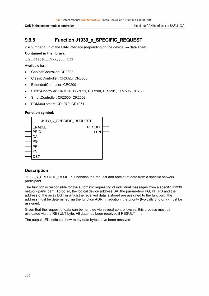
ifm System Manual ecomatmobile ClassicController (CR0020, CR0505) V05
166
CAN in the ecomatmobile controller Use of the CAN interfaces to SAE J1939
9.9.5 Function J1939_x_SPECIFIC_REQUEST x = number 1...n of the CAN interface (depending on the device, → data sheet)
Contained in the library: ifm_J1939_x_Vxxyyzz.LIB
Available for:
• CabinetController: CR0303
• ClassicController: CR0020, CR0505
• ExtendedController: CR0200
• SafetyController: CR7020, CR7021, CR7200, CR7201, CR7505, CR7506
• SmartController: CR2500, CR2502
• PDM360 smart: CR1070, CR1071
Function symbol:
J1939_x_SPECIFIC_REQUEST
ENABLE RESULTPRIO LENDA
DST
PG
PFPS
Description J1939_x_SPECIFIC_REQUEST handles the request and receipt of data from a specific network participant.
The function is responsible for the automatic requesting of individual messages from a specific J1939 network participant. To do so, the logical device address DA, the parameters PG, PF, PS and the address of the array DST in which the received data is stored are assigned to the function. The address must be determined via the function ADR. In addition, the priority (typically 3, 6 or 7) must be assigned.
Given that the request of data can be handled via several control cycles, this process must be evaluated via the RESULT byte. All data has been received if RESULT = 1.
The output LEN indicates how many data bytes have been received.
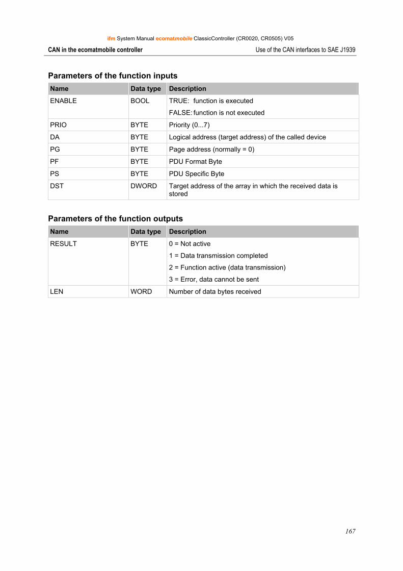
ifm System Manual ecomatmobile ClassicController (CR0020, CR0505) V05
167
CAN in the ecomatmobile controller Use of the CAN interfaces to SAE J1939
Parameters of the function inputs Name Data type Description
ENABLE BOOL TRUE: function is executed
FALSE: function is not executed
PRIO BYTE Priority (0...7)
DA BYTE Logical address (target address) of the called device
PG BYTE Page address (normally = 0)
PF BYTE PDU Format Byte
PS BYTE PDU Specific Byte
DST DWORD Target address of the array in which the received data is stored
Parameters of the function outputs Name Data type Description
RESULT BYTE 0 = Not active
1 = Data transmission completed
2 = Function active (data transmission)
3 = Error, data cannot be sent
LEN WORD Number of data bytes received
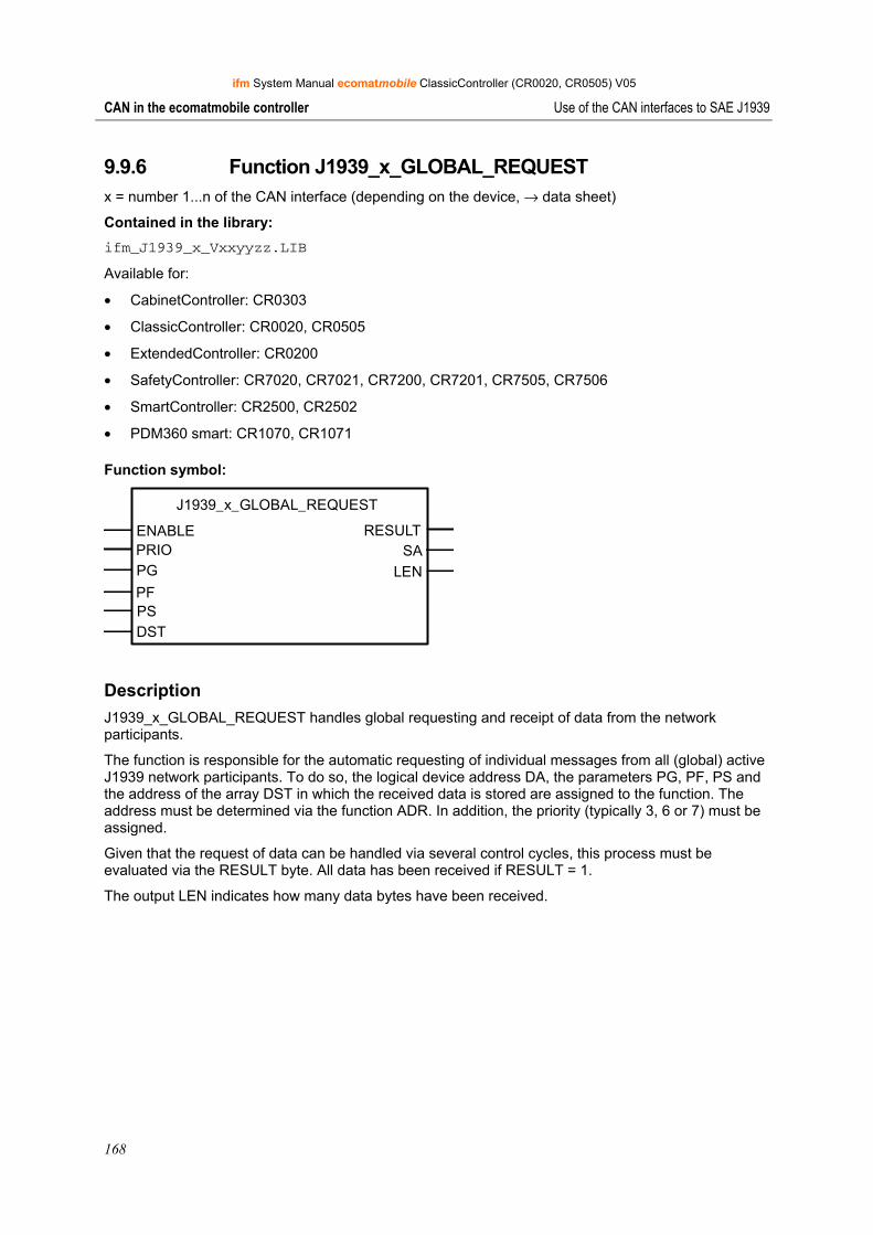
ifm System Manual ecomatmobile ClassicController (CR0020, CR0505) V05
168
CAN in the ecomatmobile controller Use of the CAN interfaces to SAE J1939
9.9.6 Function J1939_x_GLOBAL_REQUEST x = number 1...n of the CAN interface (depending on the device, → data sheet)
Contained in the library: ifm_J1939_x_Vxxyyzz.LIB
Available for:
• CabinetController: CR0303
• ClassicController: CR0020, CR0505
• ExtendedController: CR0200
• SafetyController: CR7020, CR7021, CR7200, CR7201, CR7505, CR7506
• SmartController: CR2500, CR2502
• PDM360 smart: CR1070, CR1071
Function symbol:
J1939_x_GLOBAL_REQUEST
ENABLE RESULTPRIO SAPG LENPFPSDST
Description J1939_x_GLOBAL_REQUEST handles global requesting and receipt of data from the network participants.
The function is responsible for the automatic requesting of individual messages from all (global) active J1939 network participants. To do so, the logical device address DA, the parameters PG, PF, PS and the address of the array DST in which the received data is stored are assigned to the function. The address must be determined via the function ADR. In addition, the priority (typically 3, 6 or 7) must be assigned.
Given that the request of data can be handled via several control cycles, this process must be evaluated via the RESULT byte. All data has been received if RESULT = 1.
The output LEN indicates how many data bytes have been received.
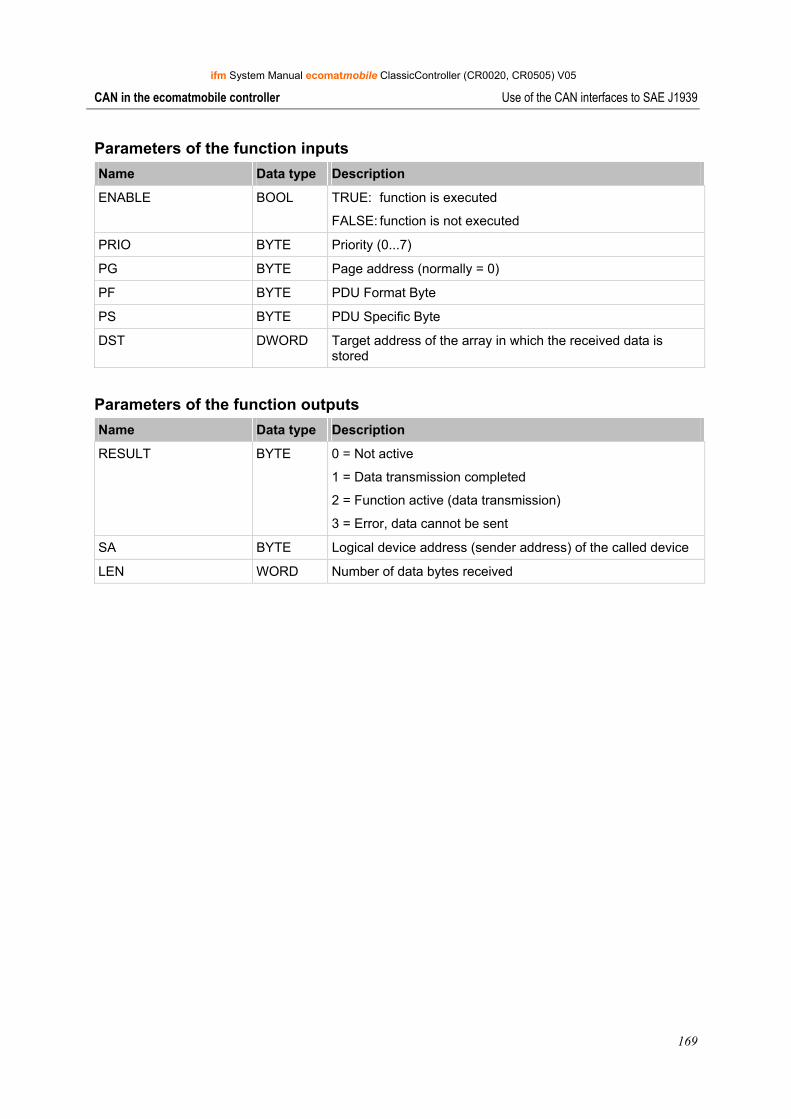
ifm System Manual ecomatmobile ClassicController (CR0020, CR0505) V05
169
CAN in the ecomatmobile controller Use of the CAN interfaces to SAE J1939
Parameters of the function inputs Name Data type Description
ENABLE BOOL TRUE: function is executed
FALSE: function is not executed
PRIO BYTE Priority (0...7)
PG BYTE Page address (normally = 0)
PF BYTE PDU Format Byte
PS BYTE PDU Specific Byte
DST DWORD Target address of the array in which the received data is stored
Parameters of the function outputs Name Data type Description
RESULT BYTE 0 = Not active
1 = Data transmission completed
2 = Function active (data transmission)
3 = Error, data cannot be sent
SA BYTE Logical device address (sender address) of the called device
LEN WORD Number of data bytes received
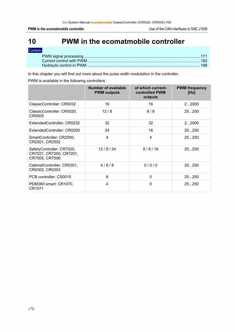
ifm System Manual ecomatmobile ClassicController (CR0020, CR0505) V05
170
PWM in the ecomatmobile controller Use of the CAN interfaces to SAE J1939
10 PWM in the ecomatmobile controller PWM signal processing .......................................................................................................... 171 Current control with PWM....................................................................................................... 182 Hydraulic control in PWM ....................................................................................................... 188
In this chapter you will find out more about the pulse width modulation in the controller.
PWM is available in the following controllers:
Number of available PWM outputs
of which current-controlled PWM
outputs
PWM frequency [Hz]
ClassicController: CR0032 16 16 2...2000
ClassicController: CR0020, CR0505
12 / 8 8 / 8 25...250
ExtendedController: CR0232 32 32 2...2000
ExtendedController: CR0200 24 16 25...250
SmartController: CR2500, CR2501, CR2502
4 4 25...250
SafetyController: CR7020, CR7021, CR7200, CR7201, CR7505, CR7506
12 / 8 / 24 8 / 8 / 16 25...250
CabinetController: CR0301, CR0302, CR0303
4 / 8 / 8 0 / 0 / 0 25...250
PCB controller: CS0015 8 0 25...250
PDM360 smart: CR1070, CR1071
4 0 25...250
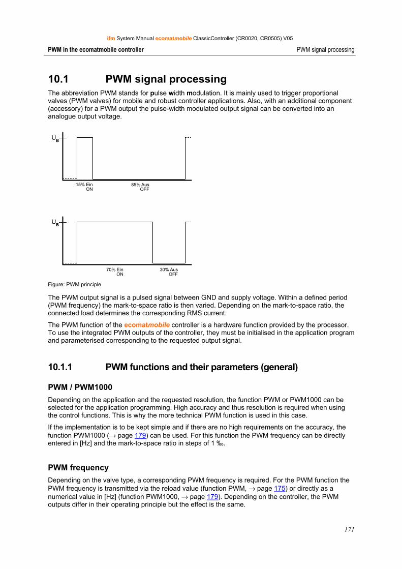
ifm System Manual ecomatmobile ClassicController (CR0020, CR0505) V05
171
PWM in the ecomatmobile controller PWM signal processing
10.1 PWM signal processing The abbreviation PWM stands for pulse width modulation. It is mainly used to trigger proportional valves (PWM valves) for mobile and robust controller applications. Also, with an additional component (accessory) for a PWM output the pulse-width modulated output signal can be converted into an analogue output voltage.
UB
15% EinON
85% AusOFF
UB
70% EinON
30% AusOFF
Figure: PWM principle
The PWM output signal is a pulsed signal between GND and supply voltage. Within a defined period (PWM frequency) the mark-to-space ratio is then varied. Depending on the mark-to-space ratio, the connected load determines the corresponding RMS current.
The PWM function of the ecomatmobile controller is a hardware function provided by the processor. To use the integrated PWM outputs of the controller, they must be initialised in the application program and parameterised corresponding to the requested output signal.
10.1.1 PWM functions and their parameters (general)
PWM / PWM1000 Depending on the application and the requested resolution, the function PWM or PWM1000 can be selected for the application programming. High accuracy and thus resolution is required when using the control functions. This is why the more technical PWM function is used in this case.
If the implementation is to be kept simple and if there are no high requirements on the accuracy, the function PWM1000 (→ page 179) can be used. For this function the PWM frequency can be directly entered in [Hz] and the mark-to-space ratio in steps of 1 ‰.
PWM frequency Depending on the valve type, a corresponding PWM frequency is required. For the PWM function the PWM frequency is transmitted via the reload value (function PWM, → page 175) or directly as a numerical value in [Hz] (function PWM1000, → page 179). Depending on the controller, the PWM outputs differ in their operating principle but the effect is the same.
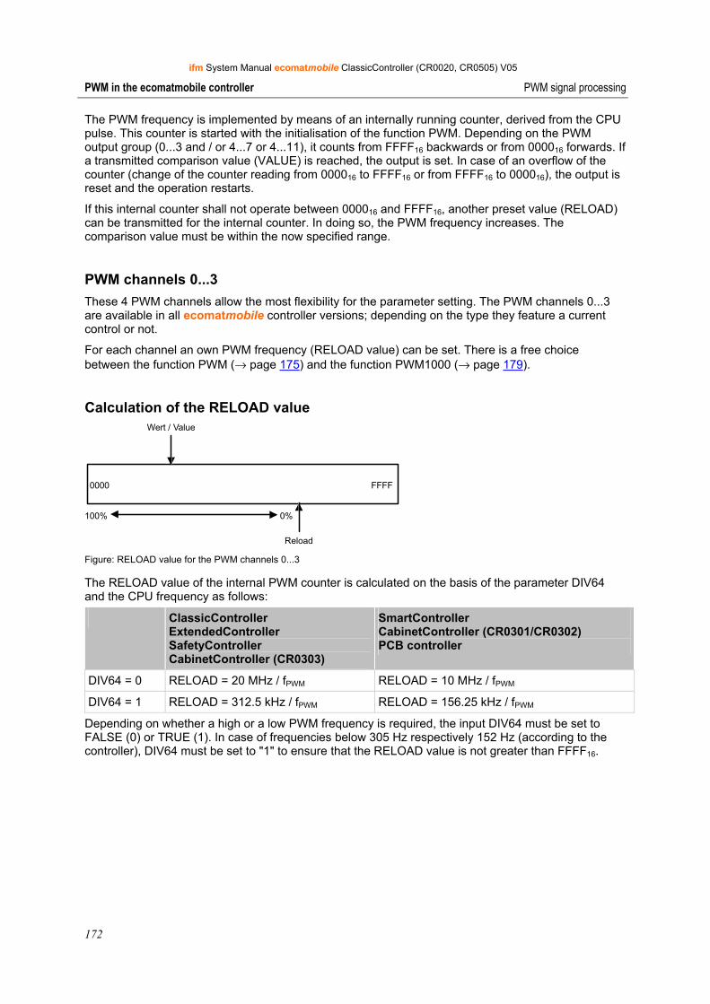
ifm System Manual ecomatmobile ClassicController (CR0020, CR0505) V05
172
PWM in the ecomatmobile controller PWM signal processing
The PWM frequency is implemented by means of an internally running counter, derived from the CPU pulse. This counter is started with the initialisation of the function PWM. Depending on the PWM output group (0...3 and / or 4...7 or 4...11), it counts from FFFF16 backwards or from 000016 forwards. If a transmitted comparison value (VALUE) is reached, the output is set. In case of an overflow of the counter (change of the counter reading from 000016 to FFFF16 or from FFFF16 to 000016), the output is reset and the operation restarts.
If this internal counter shall not operate between 000016 and FFFF16, another preset value (RELOAD) can be transmitted for the internal counter. In doing so, the PWM frequency increases. The comparison value must be within the now specified range.
PWM channels 0...3 These 4 PWM channels allow the most flexibility for the parameter setting. The PWM channels 0...3 are available in all ecomatmobile controller versions; depending on the type they feature a current control or not.
For each channel an own PWM frequency (RELOAD value) can be set. There is a free choice between the function PWM (→ page 175) and the function PWM1000 (→ page 179).
Calculation of the RELOAD value
0000 FFFF
100% 0%
Reload
Wert / Value
Figure: RELOAD value for the PWM channels 0...3
The RELOAD value of the internal PWM counter is calculated on the basis of the parameter DIV64 and the CPU frequency as follows:
ClassicController ExtendedController SafetyController CabinetController (CR0303)
SmartController CabinetController (CR0301/CR0302) PCB controller
DIV64 = 0 RELOAD = 20 MHz / fPWM RELOAD = 10 MHz / fPWM
DIV64 = 1 RELOAD = 312.5 kHz / fPWM RELOAD = 156.25 kHz / fPWM
Depending on whether a high or a low PWM frequency is required, the input DIV64 must be set to FALSE (0) or TRUE (1). In case of frequencies below 305 Hz respectively 152 Hz (according to the controller), DIV64 must be set to "1" to ensure that the RELOAD value is not greater than FFFF16.
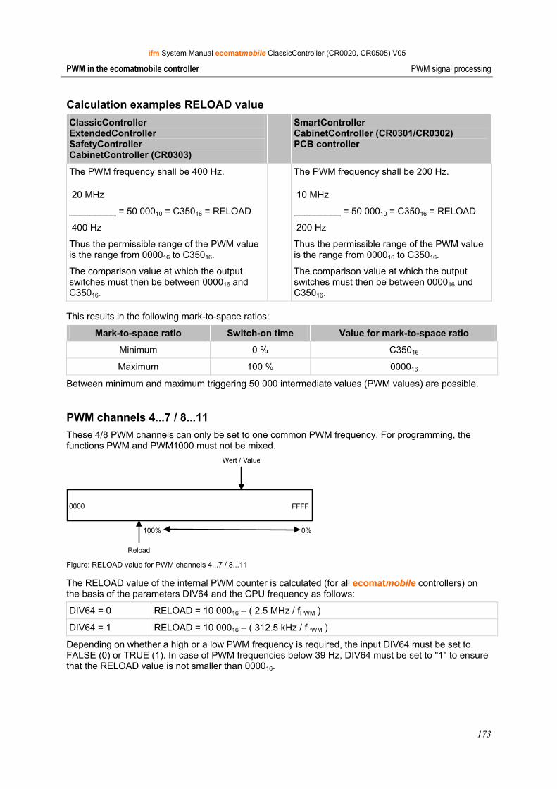
ifm System Manual ecomatmobile ClassicController (CR0020, CR0505) V05
173
PWM in the ecomatmobile controller PWM signal processing
Calculation examples RELOAD value ClassicController ExtendedController SafetyController CabinetController (CR0303)
SmartController CabinetController (CR0301/CR0302) PCB controller
The PWM frequency shall be 400 Hz.
20 MHz
_________ = 50 00010 = C35016 = RELOAD
400 Hz
Thus the permissible range of the PWM value is the range from 000016 to C35016.
The comparison value at which the output switches must then be between 000016 and C35016.
The PWM frequency shall be 200 Hz.
10 MHz
_________ = 50 00010 = C35016 = RELOAD
200 Hz
Thus the permissible range of the PWM value is the range from 000016 to C35016.
The comparison value at which the output switches must then be between 000016 und C35016.
This results in the following mark-to-space ratios:
Mark-to-space ratio Switch-on time Value for mark-to-space ratio
Minimum 0 % C35016
Maximum 100 % 000016
Between minimum and maximum triggering 50 000 intermediate values (PWM values) are possible.
PWM channels 4...7 / 8...11 These 4/8 PWM channels can only be set to one common PWM frequency. For programming, the functions PWM and PWM1000 must not be mixed.
0000 FFFF
100% 0%
Reload
Wert / Value
Figure: RELOAD value for PWM channels 4...7 / 8...11
The RELOAD value of the internal PWM counter is calculated (for all ecomatmobile controllers) on the basis of the parameters DIV64 and the CPU frequency as follows:
DIV64 = 0 RELOAD = 10 00016 – ( 2.5 MHz / fPWM )
DIV64 = 1 RELOAD = 10 00016 – ( 312.5 kHz / fPWM )
Depending on whether a high or a low PWM frequency is required, the input DIV64 must be set to FALSE (0) or TRUE (1). In case of PWM frequencies below 39 Hz, DIV64 must be set to "1" to ensure that the RELOAD value is not smaller than 000016.
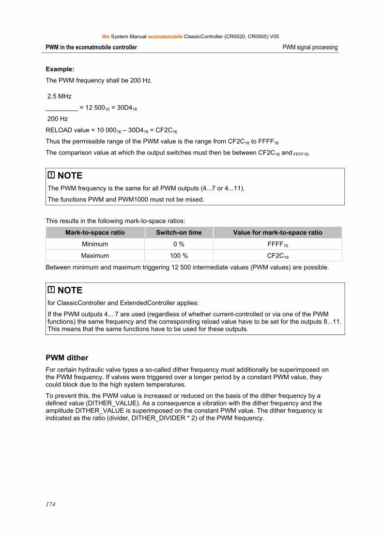
ifm System Manual ecomatmobile ClassicController (CR0020, CR0505) V05
174
PWM in the ecomatmobile controller PWM signal processing
Example:
The PWM frequency shall be 200 Hz.
2.5 MHz
_________ = 12 50010 = 30D416
200 Hz
RELOAD value = 10 00016 – 30D416 = CF2C16
Thus the permissible range of the PWM value is the range from CF2C16 to FFFF16
The comparison value at which the output switches must then be between CF2C16 and FFFF16.
NOTE The PWM frequency is the same for all PWM outputs (4...7 or 4...11).
The functions PWM and PWM1000 must not be mixed.
This results in the following mark-to-space ratios:
Mark-to-space ratio Switch-on time Value for mark-to-space ratio
Minimum 0 % FFFF16
Maximum 100 % CF2C16
Between minimum and maximum triggering 12 500 intermediate values (PWM values) are possible.
NOTE for ClassicController and ExtendedController applies:
If the PWM outputs 4... 7 are used (regardless of whether current-controlled or via one of the PWM functions) the same frequency and the corresponding reload value have to be set for the outputs 8...11. This means that the same functions have to be used for these outputs.
PWM dither For certain hydraulic valve types a so-called dither frequency must additionally be superimposed on the PWM frequency. If valves were triggered over a longer period by a constant PWM value, they could block due to the high system temperatures.
To prevent this, the PWM value is increased or reduced on the basis of the dither frequency by a defined value (DITHER_VALUE). As a consequence a vibration with the dither frequency and the amplitude DITHER_VALUE is superimposed on the constant PWM value. The dither frequency is indicated as the ratio (divider, DITHER_DIVIDER * 2) of the PWM frequency.
ifm System Manual ecomatmobile ClassicController (CR0020, CR0505) V05
175
PWM in the ecomatmobile controller PWM signal processing
Ramp function In order to prevent abrupt changes from one PWM value to the next, e.g. from 15 % ON to 70 % ON (→ figure in PWM signal processing, → page 171), it is possible to delay the increase by using the function PT1. The ramp function used for PWM is based on the CoDeSys library UTIL.LIB. This allows a smooth start e.g. for hydraulic systems.
NOTE When installing the ecomatmobile CD "Software, Tools and Documentation", projects with examples have been stored in the program directory of your PC: …\ifm electronic\CoDeSys V…\Projects\DEMO_PLC_CDV… (for controllers) or …\ifm electronic\CoDeSys V…\Projects\DEMO_PDM_CDV… (for PDMs).
There you also find projects with examples regarding this subject. It is strongly recommended to follow the shown procedure. → chapter ifm demo programs (→ page 32)
NOTE The PWM function of the controller is a hardware function provided by the processor. The PWM function remains set until a hardware reset (switching on and off the supply voltage) has been carried out at the controller.
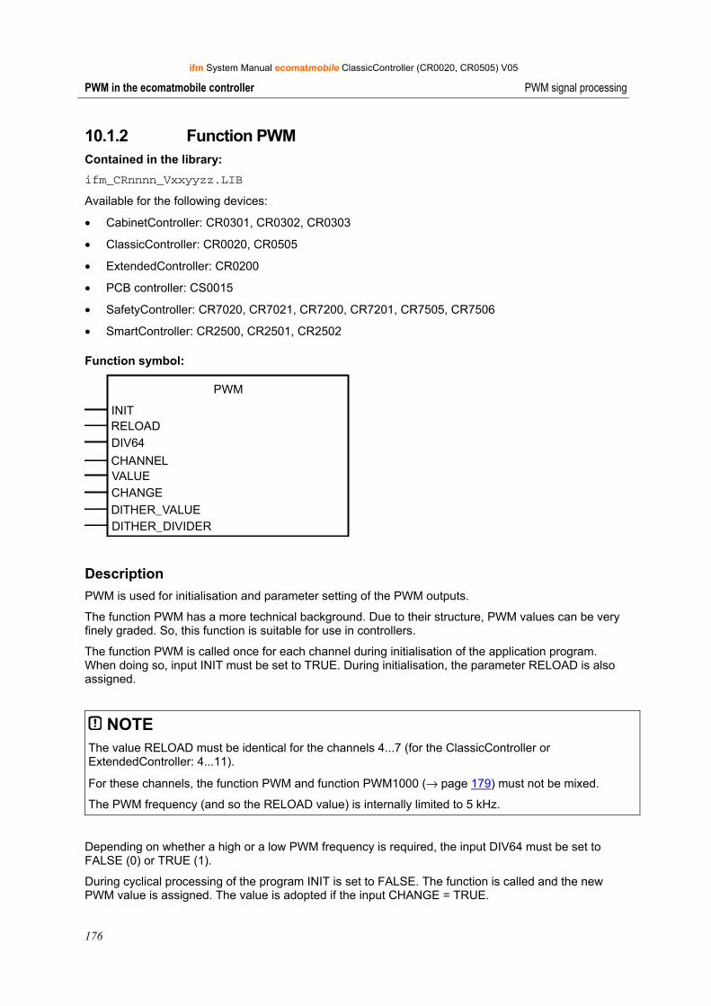
ifm System Manual ecomatmobile ClassicController (CR0020, CR0505) V05
176
PWM in the ecomatmobile controller PWM signal processing
10.1.2 Function PWM Contained in the library: ifm_CRnnnn_Vxxyyzz.LIB
Available for the following devices:
• CabinetController: CR0301, CR0302, CR0303
• ClassicController: CR0020, CR0505
• ExtendedController: CR0200
• PCB controller: CS0015
• SafetyController: CR7020, CR7021, CR7200, CR7201, CR7505, CR7506
• SmartController: CR2500, CR2501, CR2502
Function symbol:
PWM
INITRELOADDIV64
CHANNELVALUECHANGEDITHER_VALUEDITHER_DIVIDER
Description PWM is used for initialisation and parameter setting of the PWM outputs.
The function PWM has a more technical background. Due to their structure, PWM values can be very finely graded. So, this function is suitable for use in controllers.
The function PWM is called once for each channel during initialisation of the application program. When doing so, input INIT must be set to TRUE. During initialisation, the parameter RELOAD is also assigned.
NOTE The value RELOAD must be identical for the channels 4...7 (for the ClassicController or ExtendedController: 4...11).
For these channels, the function PWM and function PWM1000 (→ page 179) must not be mixed.
The PWM frequency (and so the RELOAD value) is internally limited to 5 kHz.
Depending on whether a high or a low PWM frequency is required, the input DIV64 must be set to FALSE (0) or TRUE (1).
During cyclical processing of the program INIT is set to FALSE. The function is called and the new PWM value is assigned. The value is adopted if the input CHANGE = TRUE.
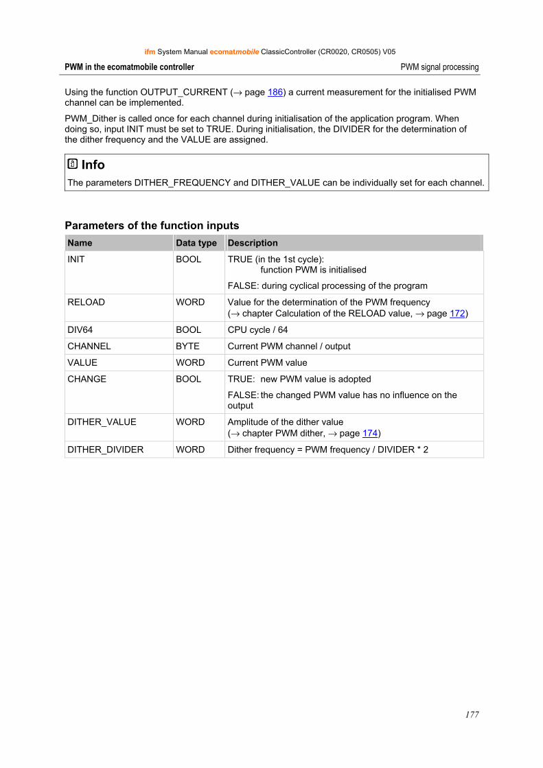
ifm System Manual ecomatmobile ClassicController (CR0020, CR0505) V05
177
PWM in the ecomatmobile controller PWM signal processing
Using the function OUTPUT_CURRENT (→ page 186) a current measurement for the initialised PWM channel can be implemented.
PWM_Dither is called once for each channel during initialisation of the application program. When doing so, input INIT must be set to TRUE. During initialisation, the DIVIDER for the determination of the dither frequency and the VALUE are assigned.
Info The parameters DITHER_FREQUENCY and DITHER_VALUE can be individually set for each channel.
Parameters of the function inputs Name Data type Description
INIT BOOL TRUE (in the 1st cycle): function PWM is initialised
FALSE: during cyclical processing of the program
RELOAD WORD Value for the determination of the PWM frequency (→ chapter Calculation of the RELOAD value, → page 172)
DIV64 BOOL CPU cycle / 64
CHANNEL BYTE Current PWM channel / output
VALUE WORD Current PWM value
CHANGE BOOL TRUE: new PWM value is adopted
FALSE: the changed PWM value has no influence on the output
DITHER_VALUE WORD Amplitude of the dither value (→ chapter PWM dither, → page 174)
DITHER_DIVIDER WORD Dither frequency = PWM frequency / DIVIDER * 2
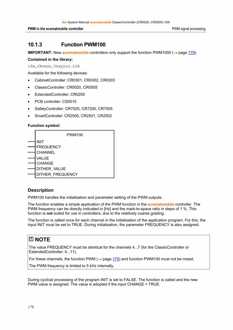
ifm System Manual ecomatmobile ClassicController (CR0020, CR0505) V05
178
PWM in the ecomatmobile controller PWM signal processing
10.1.3 Function PWM100 IMPORTANT: New ecomatmobile controllers only support the function PWM1000 (→ page 179).
Contained in the library: ifm_CRnnnn_Vxxyyzz.LIB
Available for the following devices:
• CabinetController: CR0301, CR0302, CR0303
• ClassicController: CR0020, CR0505
• ExtendedController: CR0200
• PCB controller: CS0015
• SafetyController: CR7020, CR7200, CR7505
• SmartController: CR2500, CR2501, CR2502
Function symbol:
PWM100
INITFREQUENCYCHANNEL
VALUECHANGEDITHER_VALUEDITHER_FREQUENCY
Description PWM100 handles the initialisation and parameter setting of the PWM outputs.
The function enables a simple application of the PWM function in the ecomatmobile controller. The PWM frequency can be directly indicated in [Hz] and the mark-to-space ratio in steps of 1 %. This function is not suited for use in controllers, due to the relatively coarse grading.
The function is called once for each channel in the initialisation of the application program. For this, the input INIT must be set to TRUE. During initialisation, the parameter FREQUENCY is also assigned.
NOTE The value FREQUENCY must be identical for the channels 4...7 (for the ClassicController or ExtendedController: 4...11).
For these channels, the function PWM (→ page 175) and function PWM100 must not be mixed.
The PWM frequency is limited to 5 kHz internally.
During cyclical processing of the program INIT is set to FALSE. The function is called and the new PWM value is assigned. The value is adopted if the input CHANGE = TRUE.
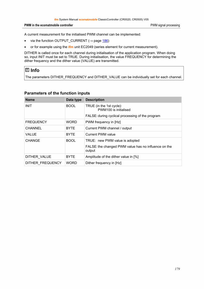
ifm System Manual ecomatmobile ClassicController (CR0020, CR0505) V05
179
PWM in the ecomatmobile controller PWM signal processing
A current measurement for the initialised PWM channel can be implemented:
• via the function OUTPUT_CURRENT (→ page 186)
• or for example using the ifm unit EC2049 (series element for current measurement).
DITHER is called once for each channel during initialisation of the application program. When doing so, input INIT must be set to TRUE. During initialisation, the value FREQUENCY for determining the dither frequency and the dither value (VALUE) are transmitted.
Info The parameters DITHER_FREQUENCY and DITHER_VALUE can be individually set for each channel.
Parameters of the function inputs Name Data type Description
INIT BOOL TRUE (in the 1st cycle): PWM100 is initialised
FALSE: during cyclical processing of the program
FREQUENCY WORD PWM frequency in [Hz]
CHANNEL BYTE Current PWM channel / output
VALUE BYTE Current PWM value
CHANGE BOOL TRUE: new PWM value is adopted
FALSE: the changed PWM value has no influence on the output
DITHER_VALUE BYTE Amplitude of the dither value in [%]
DITHER_FREQUENCY WORD Dither frequency in [Hz]
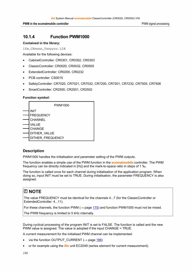
ifm System Manual ecomatmobile ClassicController (CR0020, CR0505) V05
180
PWM in the ecomatmobile controller PWM signal processing
10.1.4 Function PWM1000 Contained in the library: ifm_CRnnnn_Vxxyyzz.LIB
Available for the following devices:
• CabinetController: CR0301, CR0302, CR0303
• ClassicController: CR0020, CR0032, CR0505
• ExtendedController: CR0200, CR0232
• PCB controller: CS0015
• SafetyController: CR7020, CR7021, CR7032, CR7200, CR7201, CR7232, CR7505, CR7506
• SmartController: CR2500, CR2501, CR2502
Function symbol:
PWM1000
INITFREQUENCYCHANNEL
VALUECHANGEDITHER_VALUEDITHER_FREQUENCY
Description PWM1000 handles the initialisation and parameter setting of the PWM outputs.
The function enables a simple use of the PWM function in the ecomatmobile controller. The PWM frequency can be directly indicated in [Hz] and the mark-to-space ratio in steps of 1 ‰.
The function is called once for each channel during initialisation of the application program. When doing so, input INIT must be set to TRUE. During initialisation, the parameter FREQUENCY is also assigned.
NOTE The value FREQUENCY must be identical for the channels 4...7 (for the ClassicController or ExtendedController: 4...11).
For these channels, the function PWM (→ page 175) and function PWM1000 must not be mixed.
The PWM frequency is limited to 5 kHz internally.
During cyclical processing of the program INIT is set to FALSE. The function is called and the new PWM value is assigned. The value is adopted if the input CHANGE = TRUE.
A current measurement for the initialised PWM channel can be implemented:
• via the function OUTPUT_CURRENT (→ page 186)
• or for example using the ifm unit EC2049 (series element for current measurement).
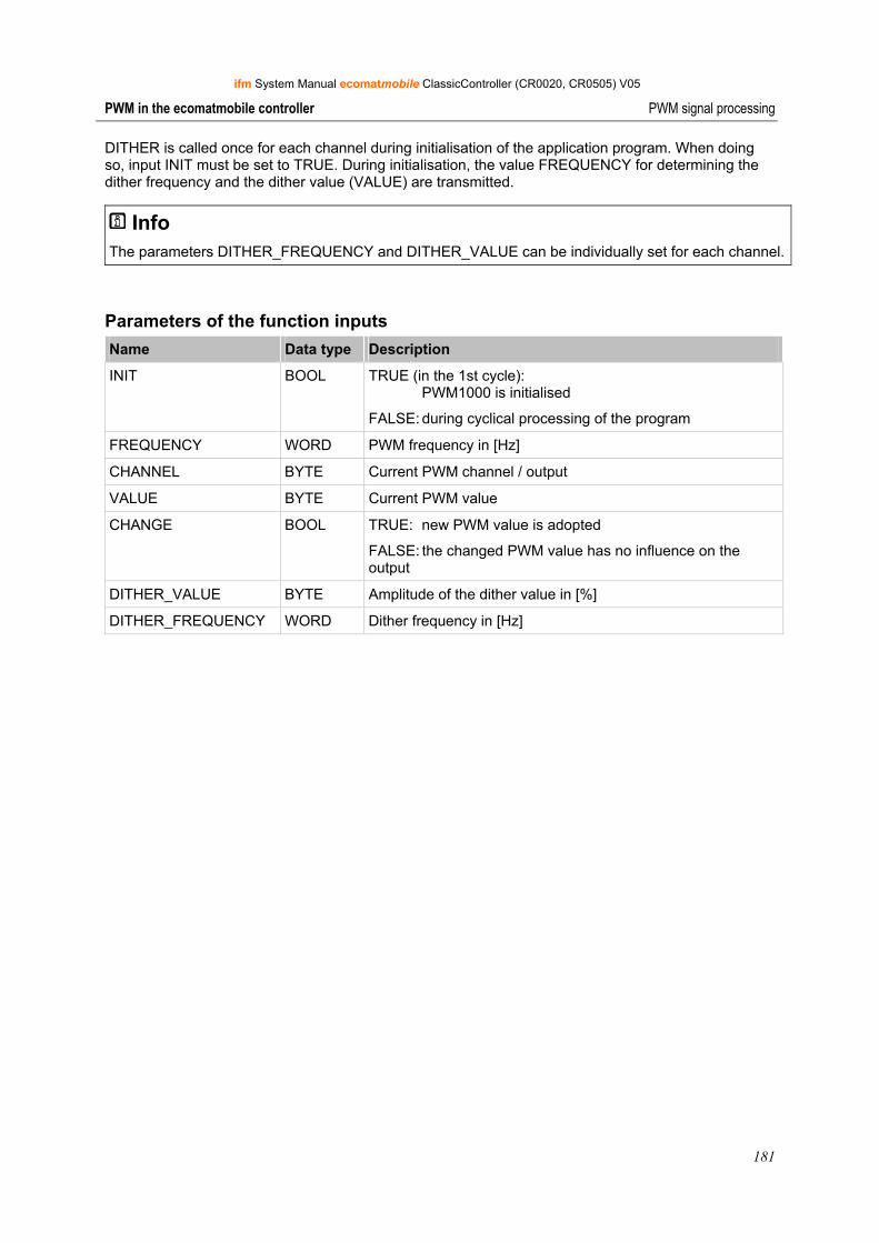
ifm System Manual ecomatmobile ClassicController (CR0020, CR0505) V05
181
PWM in the ecomatmobile controller PWM signal processing
DITHER is called once for each channel during initialisation of the application program. When doing so, input INIT must be set to TRUE. During initialisation, the value FREQUENCY for determining the dither frequency and the dither value (VALUE) are transmitted.
Info The parameters DITHER_FREQUENCY and DITHER_VALUE can be individually set for each channel.
Parameters of the function inputs Name Data type Description
INIT BOOL TRUE (in the 1st cycle): PWM1000 is initialised
FALSE: during cyclical processing of the program
FREQUENCY WORD PWM frequency in [Hz]
CHANNEL BYTE Current PWM channel / output
VALUE BYTE Current PWM value
CHANGE BOOL TRUE: new PWM value is adopted
FALSE: the changed PWM value has no influence on the output
DITHER_VALUE BYTE Amplitude of the dither value in [%]
DITHER_FREQUENCY WORD Dither frequency in [Hz]
ifm System Manual ecomatmobile ClassicController (CR0020, CR0505) V05
182
PWM in the ecomatmobile controller Current control with PWM
10.2 Current control with PWM
This device of the ecomatmobile controller family can measure the actually flowing current on certain outputs and use the signal for further processing. For this purpose ifm electronic provides the user with some functions.
10.2.1 Current measurement with PWM channels Current measurement of the coil current can be carried out via the current measurement channels integrated in the ecomatmobile controller. This allows for example that the current can be re-adjusted if the coil heats up. Thus the hydraulic conditions in the system remain the same.
NOTICE Overload protection with ClassicConroller and ExtendedController:
In principle, the current-controlled outputs are protected against short circuit. In the event of overload, in which the currents are limited by cable lengths and cross sections to for example between 8 A and 20 A, the measuring resistors (shunts) are thermally overloaded.
► Since the maximum permissible current cannot always be preset, the operating mode OUT_OVERLOAD_PROTECTION should always be selected for the outputs in the application program. With currents > 4.1 A the respective output is switched off automatically.
> If the output is no longer overloaded, the output is automatically switched on again.
The function OUT_OVERLOAD_PROTECTION is not active in the PWM mode (without current control)!
NOTE The following applies to ClassicController and ExtendedController:
The current-control function OCC_TASK (→ page 184) and function OUTPUT_CURRENT_CONTROL (→ page 182) are based on the function PWM (→ page 175). If the current control functions are used, only the PWM function may be used for channels 8...11. The RELOAD value corresponding to the frequency must be calculated.
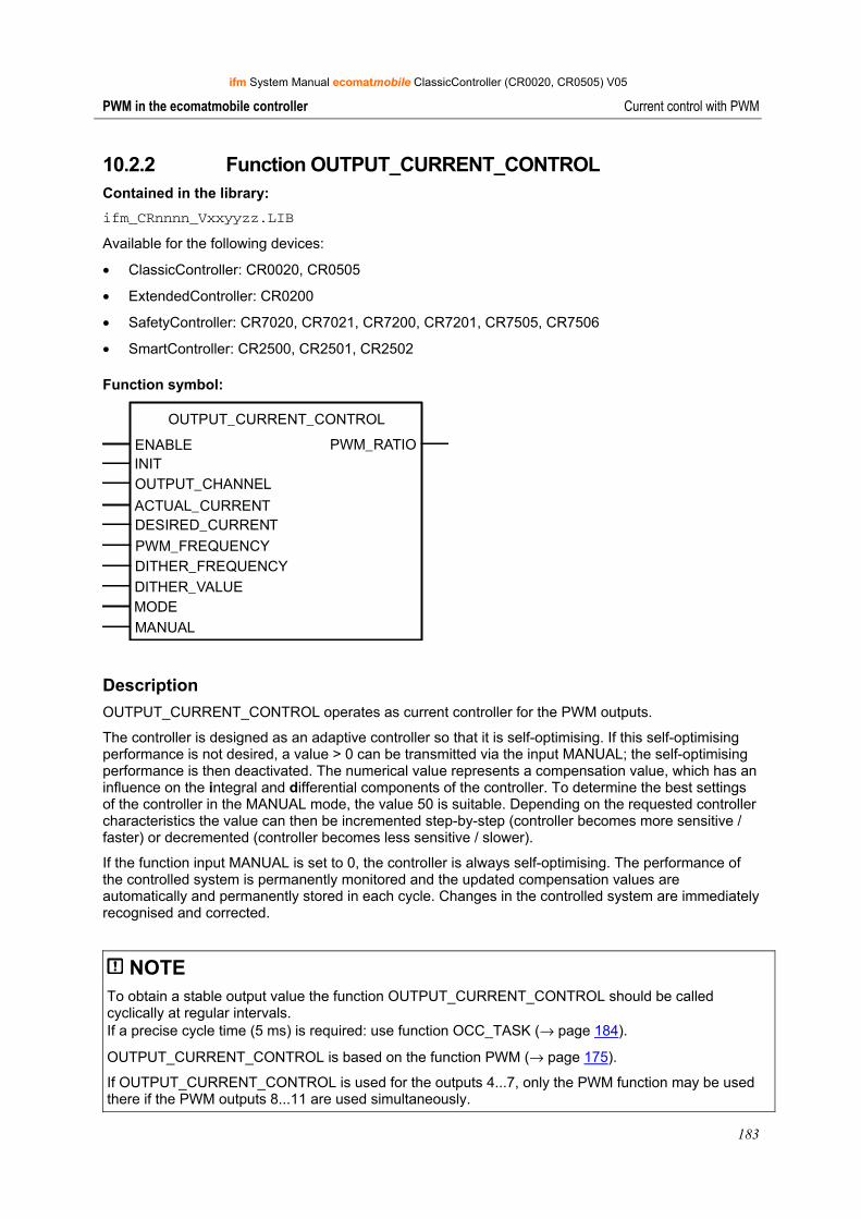
ifm System Manual ecomatmobile ClassicController (CR0020, CR0505) V05
183
PWM in the ecomatmobile controller Current control with PWM
10.2.2 Function OUTPUT_CURRENT_CONTROL Contained in the library: ifm_CRnnnn_Vxxyyzz.LIB
Available for the following devices:
• ClassicController: CR0020, CR0505
• ExtendedController: CR0200
• SafetyController: CR7020, CR7021, CR7200, CR7201, CR7505, CR7506
• SmartController: CR2500, CR2501, CR2502
Function symbol:
OUTPUT_CURRENT_CONTROL
ENABLE PWM_RATIOINITOUTPUT_CHANNEL
ACTUAL_CURRENT
PWM_FREQUENCYDITHER_FREQUENCYDITHER_VALUEMODEMANUAL
DESIRED_CURRENT
Description OUTPUT_CURRENT_CONTROL operates as current controller for the PWM outputs.
The controller is designed as an adaptive controller so that it is self-optimising. If this self-optimising performance is not desired, a value > 0 can be transmitted via the input MANUAL; the self-optimising performance is then deactivated. The numerical value represents a compensation value, which has an influence on the integral and differential components of the controller. To determine the best settings of the controller in the MANUAL mode, the value 50 is suitable. Depending on the requested controller characteristics the value can then be incremented step-by-step (controller becomes more sensitive / faster) or decremented (controller becomes less sensitive / slower).
If the function input MANUAL is set to 0, the controller is always self-optimising. The performance of the controlled system is permanently monitored and the updated compensation values are automatically and permanently stored in each cycle. Changes in the controlled system are immediately recognised and corrected.
NOTE To obtain a stable output value the function OUTPUT_CURRENT_CONTROL should be called cyclically at regular intervals. If a precise cycle time (5 ms) is required: use function OCC_TASK (→ page 184).
OUTPUT_CURRENT_CONTROL is based on the function PWM (→ page 175).
If OUTPUT_CURRENT_CONTROL is used for the outputs 4...7, only the PWM function may be used there if the PWM outputs 8...11 are used simultaneously.
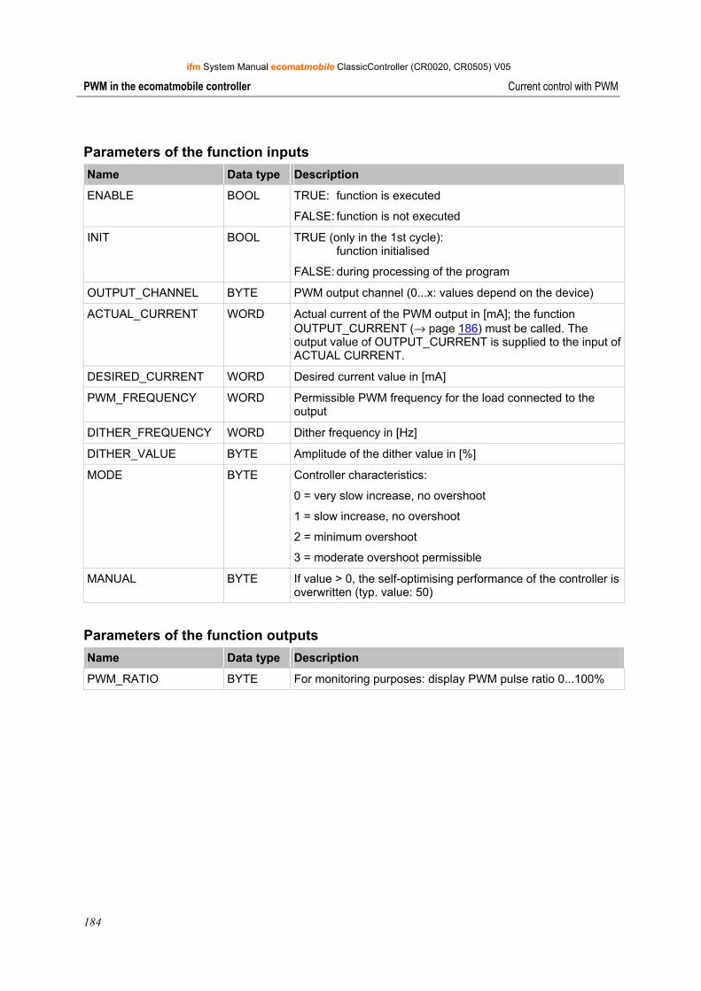
ifm System Manual ecomatmobile ClassicController (CR0020, CR0505) V05
184
PWM in the ecomatmobile controller Current control with PWM
Parameters of the function inputs Name Data type Description
ENABLE BOOL TRUE: function is executed
FALSE: function is not executed
INIT BOOL TRUE (only in the 1st cycle): function initialised
FALSE: during processing of the program
OUTPUT_CHANNEL BYTE PWM output channel (0...x: values depend on the device)
ACTUAL_CURRENT WORD Actual current of the PWM output in [mA]; the function OUTPUT_CURRENT (→ page 186) must be called. The output value of OUTPUT_CURRENT is supplied to the input of ACTUAL CURRENT.
DESIRED_CURRENT WORD Desired current value in [mA]
PWM_FREQUENCY WORD Permissible PWM frequency for the load connected to the output
DITHER_FREQUENCY WORD Dither frequency in [Hz]
DITHER_VALUE BYTE Amplitude of the dither value in [%]
MODE BYTE Controller characteristics:
0 = very slow increase, no overshoot
1 = slow increase, no overshoot
2 = minimum overshoot
3 = moderate overshoot permissible
MANUAL BYTE If value > 0, the self-optimising performance of the controller is overwritten (typ. value: 50)
Parameters of the function outputs Name Data type Description
PWM_RATIO BYTE For monitoring purposes: display PWM pulse ratio 0...100%
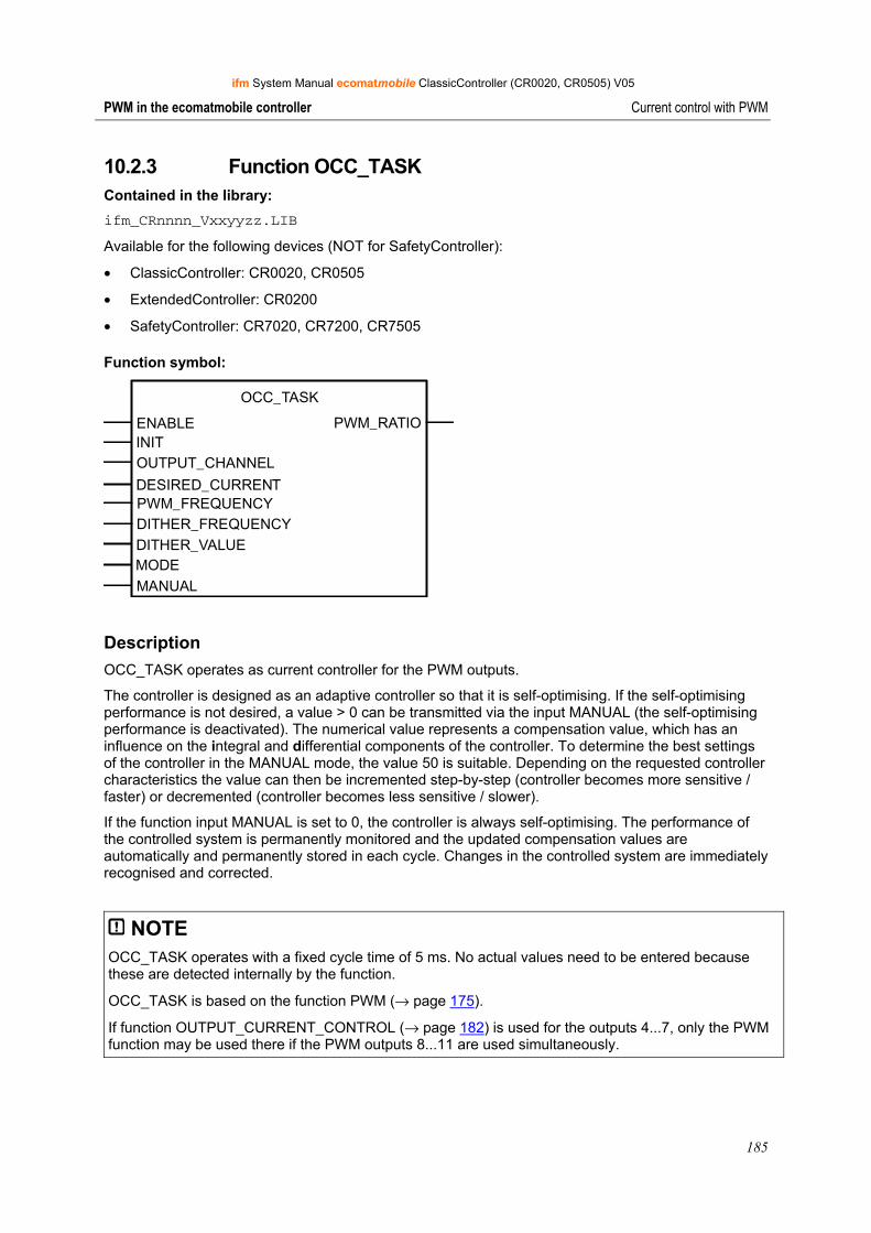
ifm System Manual ecomatmobile ClassicController (CR0020, CR0505) V05
185
PWM in the ecomatmobile controller Current control with PWM
10.2.3 Function OCC_TASK Contained in the library: ifm_CRnnnn_Vxxyyzz.LIB
Available for the following devices (NOT for SafetyController):
• ClassicController: CR0020, CR0505
• ExtendedController: CR0200
• SafetyController: CR7020, CR7200, CR7505
Function symbol:
OCC_TASK
ENABLE PWM_RATIOINITOUTPUT_CHANNEL
DESIRED_CURRENTPWM_FREQUENCYDITHER_FREQUENCYDITHER_VALUEMODEMANUAL
Description OCC_TASK operates as current controller for the PWM outputs.
The controller is designed as an adaptive controller so that it is self-optimising. If the self-optimising performance is not desired, a value > 0 can be transmitted via the input MANUAL (the self-optimising performance is deactivated). The numerical value represents a compensation value, which has an influence on the integral and differential components of the controller. To determine the best settings of the controller in the MANUAL mode, the value 50 is suitable. Depending on the requested controller characteristics the value can then be incremented step-by-step (controller becomes more sensitive / faster) or decremented (controller becomes less sensitive / slower).
If the function input MANUAL is set to 0, the controller is always self-optimising. The performance of the controlled system is permanently monitored and the updated compensation values are automatically and permanently stored in each cycle. Changes in the controlled system are immediately recognised and corrected.
NOTE OCC_TASK operates with a fixed cycle time of 5 ms. No actual values need to be entered because these are detected internally by the function.
OCC_TASK is based on the function PWM (→ page 175).
If function OUTPUT_CURRENT_CONTROL (→ page 182) is used for the outputs 4...7, only the PWM function may be used there if the PWM outputs 8...11 are used simultaneously.
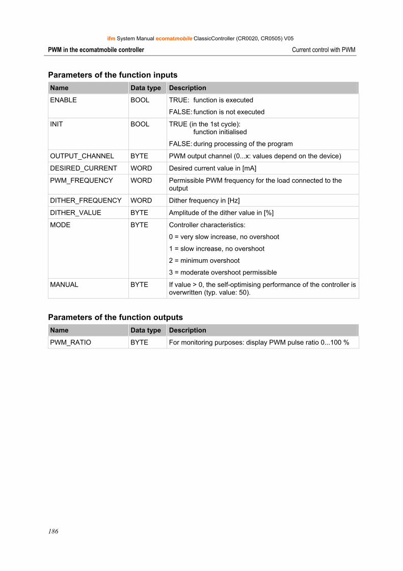
ifm System Manual ecomatmobile ClassicController (CR0020, CR0505) V05
186
PWM in the ecomatmobile controller Current control with PWM
Parameters of the function inputs Name Data type Description
ENABLE BOOL TRUE: function is executed
FALSE: function is not executed
INIT BOOL TRUE (in the 1st cycle): function initialised
FALSE: during processing of the program
OUTPUT_CHANNEL BYTE PWM output channel (0...x: values depend on the device)
DESIRED_CURRENT WORD Desired current value in [mA]
PWM_FREQUENCY WORD Permissible PWM frequency for the load connected to the output
DITHER_FREQUENCY WORD Dither frequency in [Hz]
DITHER_VALUE BYTE Amplitude of the dither value in [%]
MODE BYTE Controller characteristics:
0 = very slow increase, no overshoot
1 = slow increase, no overshoot
2 = minimum overshoot
3 = moderate overshoot permissible
MANUAL BYTE If value > 0, the self-optimising performance of the controller is overwritten (typ. value: 50).
Parameters of the function outputs Name Data type Description
PWM_RATIO BYTE For monitoring purposes: display PWM pulse ratio 0...100 %
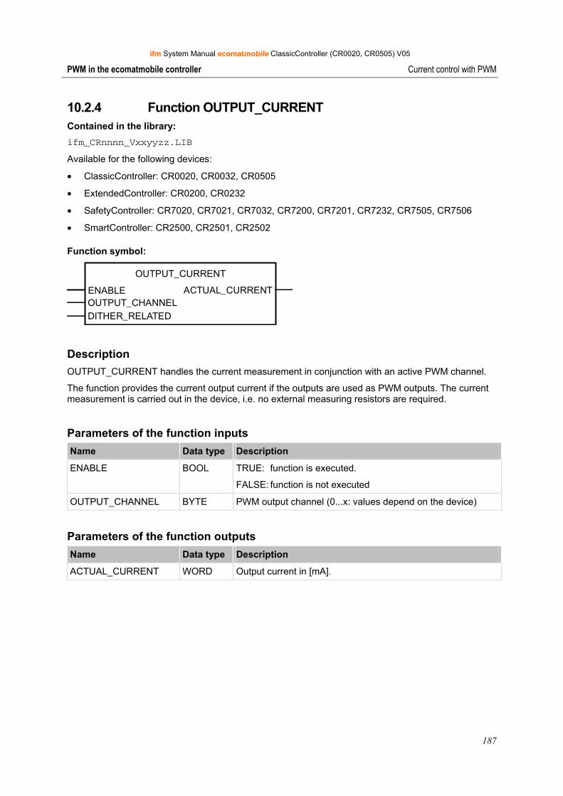
ifm System Manual ecomatmobile ClassicController (CR0020, CR0505) V05
187
PWM in the ecomatmobile controller Current control with PWM
10.2.4 Function OUTPUT_CURRENT Contained in the library: ifm_CRnnnn_Vxxyyzz.LIB
Available for the following devices:
• ClassicController: CR0020, CR0032, CR0505
• ExtendedController: CR0200, CR0232
• SafetyController: CR7020, CR7021, CR7032, CR7200, CR7201, CR7232, CR7505, CR7506
• SmartController: CR2500, CR2501, CR2502
Function symbol:
OUTPUT_CURRENT
ENABLE ACTUAL_CURRENTOUTPUT_CHANNELDITHER_RELATED
Description OUTPUT_CURRENT handles the current measurement in conjunction with an active PWM channel.
The function provides the current output current if the outputs are used as PWM outputs. The current measurement is carried out in the device, i.e. no external measuring resistors are required.
Parameters of the function inputs Name Data type Description
ENABLE BOOL TRUE: function is executed.
FALSE: function is not executed
OUTPUT_CHANNEL BYTE PWM output channel (0...x: values depend on the device)
Parameters of the function outputs Name Data type Description
ACTUAL_CURRENT WORD Output current in [mA].
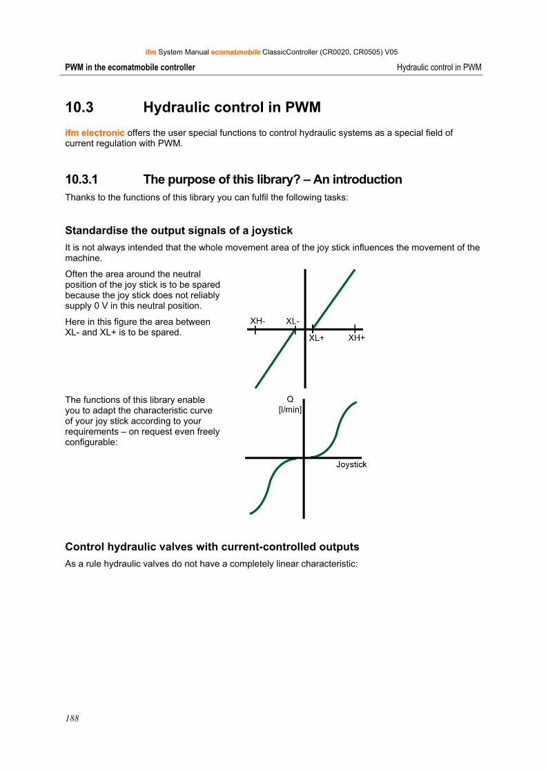
ifm System Manual ecomatmobile ClassicController (CR0020, CR0505) V05
188
PWM in the ecomatmobile controller Hydraulic control in PWM
10.3 Hydraulic control in PWM
ifm electronic offers the user special functions to control hydraulic systems as a special field of current regulation with PWM.
10.3.1 The purpose of this library? – An introduction Thanks to the functions of this library you can fulfil the following tasks:
Standardise the output signals of a joystick It is not always intended that the whole movement area of the joy stick influences the movement of the machine.
Often the area around the neutral position of the joy stick is to be spared because the joy stick does not reliably supply 0 V in this neutral position.
Here in this figure the area between XL- and XL+ is to be spared.
The functions of this library enable you to adapt the characteristic curve of your joy stick according to your requirements – on request even freely configurable:
Control hydraulic valves with current-controlled outputs As a rule hydraulic valves do not have a completely linear characteristic:
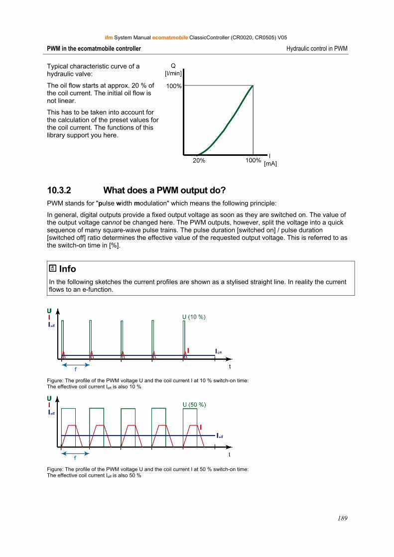
ifm System Manual ecomatmobile ClassicController (CR0020, CR0505) V05
189
PWM in the ecomatmobile controller Hydraulic control in PWM
Typical characteristic curve of a hydraulic valve:
The oil flow starts at approx. 20 % of the coil current. The initial oil flow is not linear.
This has to be taken into account for the calculation of the preset values for the coil current. The functions of this library support you here.
10.3.2 What does a PWM output do? PWM stands for "pulse width modulation" which means the following principle:
In general, digital outputs provide a fixed output voltage as soon as they are switched on. The value of the output voltage cannot be changed here. The PWM outputs, however, split the voltage into a quick sequence of many square-wave pulse trains. The pulse duration [switched on] / pulse duration [switched off] ratio determines the effective value of the requested output voltage. This is referred to as the switch-on time in [%].
Info In the following sketches the current profiles are shown as a stylised straight line. In reality the current flows to an e-function.
Figure: The profile of the PWM voltage U and the coil current I at 10 % switch-on time: The effective coil current Ieff is also 10 %
Figure: The profile of the PWM voltage U and the coil current I at 50 % switch-on time: The effective coil current Ieff is also 50 %
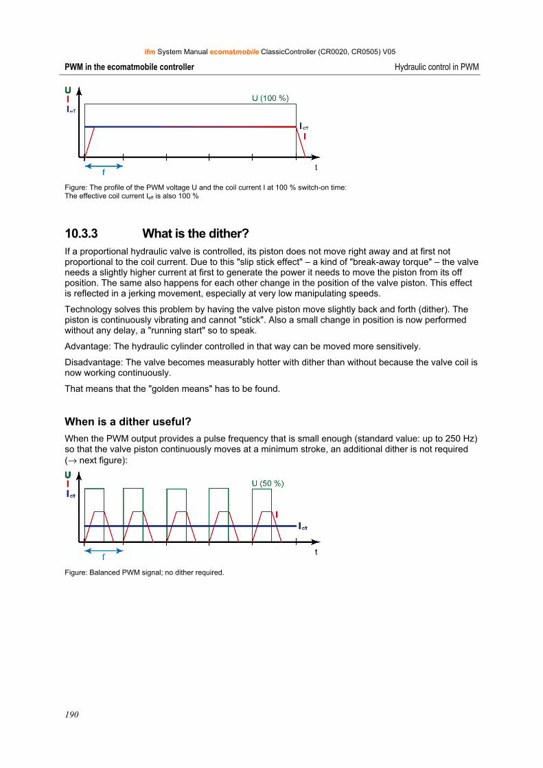
ifm System Manual ecomatmobile ClassicController (CR0020, CR0505) V05
190
PWM in the ecomatmobile controller Hydraulic control in PWM
Figure: The profile of the PWM voltage U and the coil current I at 100 % switch-on time: The effective coil current Ieff is also 100 %
10.3.3 What is the dither? If a proportional hydraulic valve is controlled, its piston does not move right away and at first not proportional to the coil current. Due to this "slip stick effect" – a kind of "break-away torque" – the valve needs a slightly higher current at first to generate the power it needs to move the piston from its off position. The same also happens for each other change in the position of the valve piston. This effect is reflected in a jerking movement, especially at very low manipulating speeds.
Technology solves this problem by having the valve piston move slightly back and forth (dither). The piston is continuously vibrating and cannot "stick". Also a small change in position is now performed without any delay, a "running start" so to speak.
Advantage: The hydraulic cylinder controlled in that way can be moved more sensitively.
Disadvantage: The valve becomes measurably hotter with dither than without because the valve coil is now working continuously.
That means that the "golden means" has to be found.
When is a dither useful? When the PWM output provides a pulse frequency that is small enough (standard value: up to 250 Hz) so that the valve piston continuously moves at a minimum stroke, an additional dither is not required (→ next figure):
Figure: Balanced PWM signal; no dither required.
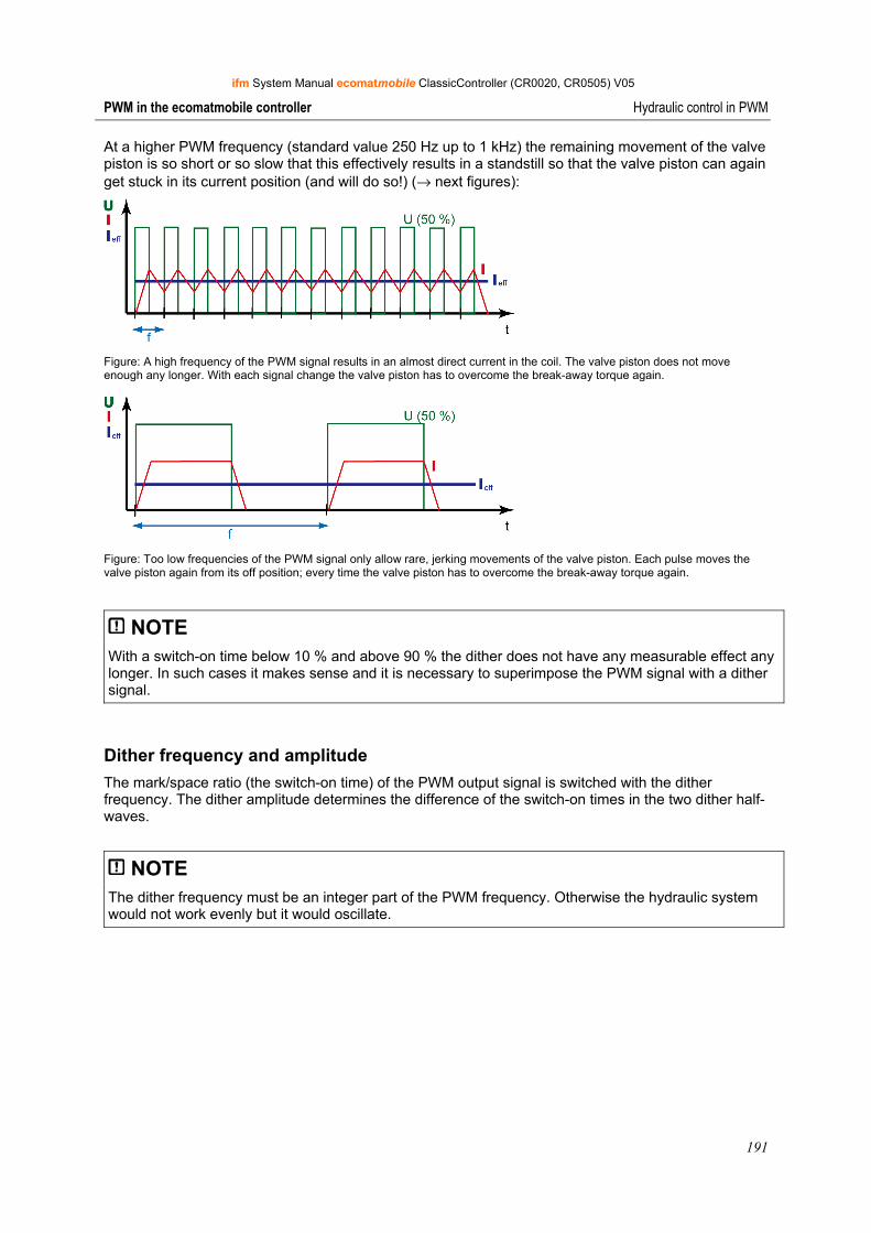
ifm System Manual ecomatmobile ClassicController (CR0020, CR0505) V05
191
PWM in the ecomatmobile controller Hydraulic control in PWM
At a higher PWM frequency (standard value 250 Hz up to 1 kHz) the remaining movement of the valve piston is so short or so slow that this effectively results in a standstill so that the valve piston can again get stuck in its current position (and will do so!) (→ next figures):
Figure: A high frequency of the PWM signal results in an almost direct current in the coil. The valve piston does not move enough any longer. With each signal change the valve piston has to overcome the break-away torque again.
Figure: Too low frequencies of the PWM signal only allow rare, jerking movements of the valve piston. Each pulse moves the valve piston again from its off position; every time the valve piston has to overcome the break-away torque again.
NOTE With a switch-on time below 10 % and above 90 % the dither does not have any measurable effect any longer. In such cases it makes sense and it is necessary to superimpose the PWM signal with a dither signal.
Dither frequency and amplitude The mark/space ratio (the switch-on time) of the PWM output signal is switched with the dither frequency. The dither amplitude determines the difference of the switch-on times in the two dither half-waves.
NOTE The dither frequency must be an integer part of the PWM frequency. Otherwise the hydraulic system would not work evenly but it would oscillate.
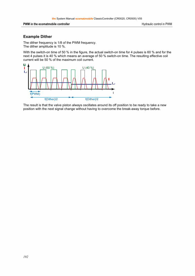
ifm System Manual ecomatmobile ClassicController (CR0020, CR0505) V05
192
PWM in the ecomatmobile controller Hydraulic control in PWM
Example Dither The dither frequency is 1/8 of the PWM frequency. The dither amplitude is 10 %.
With the switch-on time of 50 % in the figure, the actual switch-on time for 4 pulses is 60 % and for the next 4 pulses it is 40 % which means an average of 50 % switch-on time. The resulting effective coil current will be 50 % of the maximum coil current.
The result is that the valve piston always oscillates around its off position to be ready to take a new position with the next signal change without having to overcome the break-away torque before.
ifm System Manual ecomatmobile ClassicController (CR0020, CR0505) V05
193
PWM in the ecomatmobile controller Hydraulic control in PWM
10.3.4 Functions of the library "ifm_HYDRAULIC_16bitOS05_Vxxyyzz.Lib"
The library ifm_HYDRAULIC_16bitOS05_Vxxyyzz.Lib contains the following functions:
• Function CONTROL_OCC (→ page 194) *) This function uses the function OUTPUT_CURRENT_CONTROL (→ page 182) and the function OUTPUT_CURRENT (→ page 186) from the library ifm_CRnnnn_Vxxyyzz.Lib.
• Function JOYSTICK_0 (→ page 197)
• Function JOYSTICK_1 (→ page 201)
• Function JOYSTICK_2 (→ page 205)
• Function NORM_HYDRAULIC (→ page 207)
* OCC stands for Output Current Control.
The following functions are needed from the library UTIL.Lib (in the CoDeSys®package):
• Function RAMP_INT
• Function CHARCURVE
These functions are automatically activated by the functions of ifm_HYDRAULIC_16bitOS05_Vxxyyzz.Lib and configured.
The following packages are needed from the library ifm_CRnnnn_Vxxyyzz.Lib:
• Function OUTPUT_CURRENT (→ page 186)
• Function OUTPUT_CURRENT_CONTROL (→ page 182)
• Function OCC_TASK (→ page 184)
These functions (→ chapter PWM signal processing, → page 171) are automatically activated and configured by the functions of ifm _HYDRAULIC_16bitOS05_Vxxyyzz.Lib.
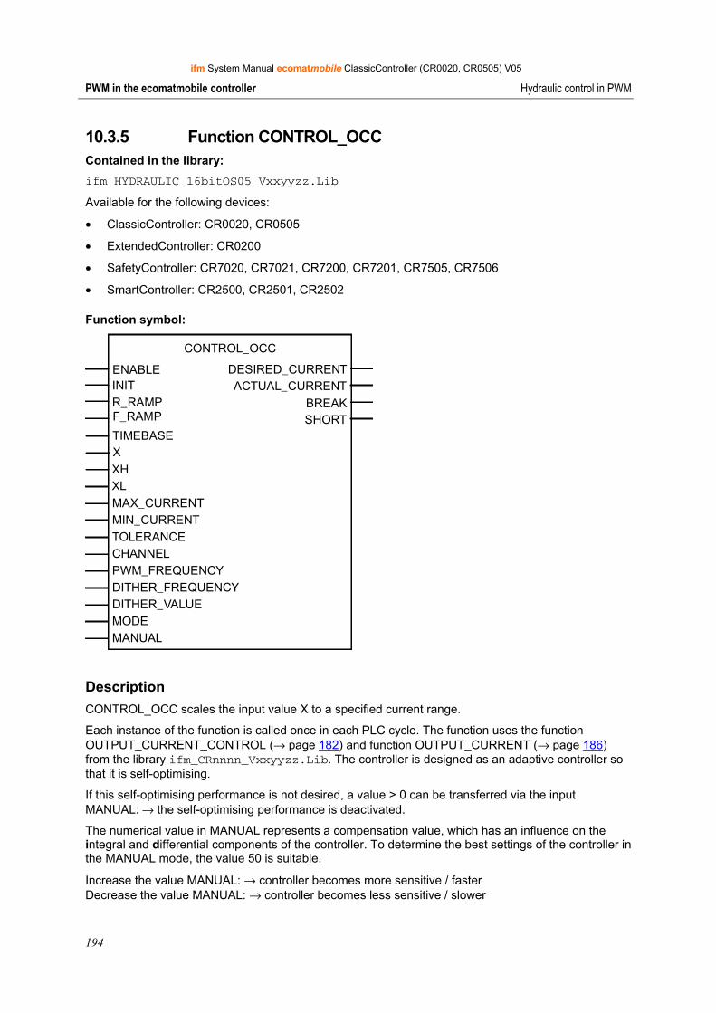
ifm System Manual ecomatmobile ClassicController (CR0020, CR0505) V05
194
PWM in the ecomatmobile controller Hydraulic control in PWM
10.3.5 Function CONTROL_OCC Contained in the library: ifm_HYDRAULIC_16bitOS05_Vxxyyzz.Lib
Available for the following devices:
• ClassicController: CR0020, CR0505
• ExtendedController: CR0200
• SafetyController: CR7020, CR7021, CR7200, CR7201, CR7505, CR7506
• SmartController: CR2500, CR2501, CR2502
Function symbol:
CONTROL_OCC
ENABLE DESIRED_CURRENTINIT ACTUAL_CURRENT
BREAKR_RAMP SHORTF_RAMP
TIMEBASE
XHXLMAX_CURRENTMIN_CURRENTTOLERANCECHANNELPWM_FREQUENCYDITHER_FREQUENCYDITHER_VALUEMODEMANUAL
X
Description CONTROL_OCC scales the input value X to a specified current range.
Each instance of the function is called once in each PLC cycle. The function uses the function OUTPUT_CURRENT_CONTROL (→ page 182) and function OUTPUT_CURRENT (→ page 186) from the library ifm_CRnnnn_Vxxyyzz.Lib. The controller is designed as an adaptive controller so that it is self-optimising.
If this self-optimising performance is not desired, a value > 0 can be transferred via the input MANUAL: → the self-optimising performance is deactivated.
The numerical value in MANUAL represents a compensation value, which has an influence on the integral and differential components of the controller. To determine the best settings of the controller in the MANUAL mode, the value 50 is suitable.
Increase the value MANUAL: → controller becomes more sensitive / faster Decrease the value MANUAL: → controller becomes less sensitive / slower
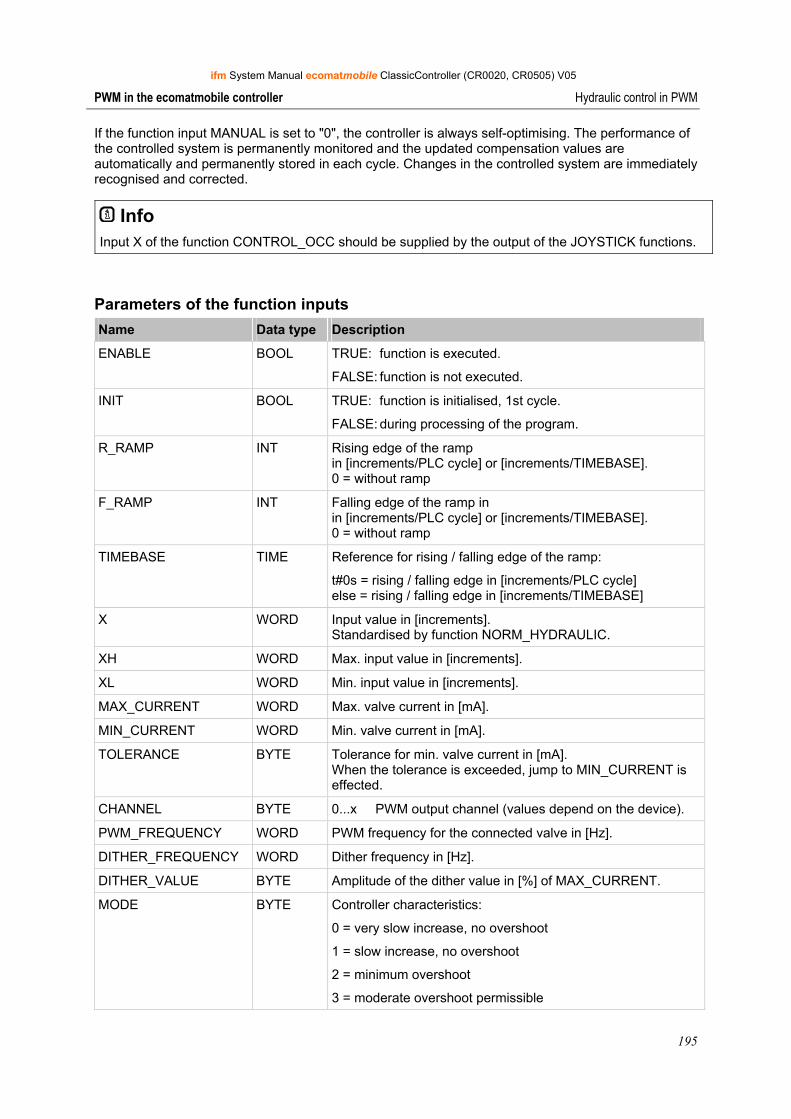
ifm System Manual ecomatmobile ClassicController (CR0020, CR0505) V05
195
PWM in the ecomatmobile controller Hydraulic control in PWM
If the function input MANUAL is set to "0", the controller is always self-optimising. The performance of the controlled system is permanently monitored and the updated compensation values are automatically and permanently stored in each cycle. Changes in the controlled system are immediately recognised and corrected.
Info Input X of the function CONTROL_OCC should be supplied by the output of the JOYSTICK functions.
Parameters of the function inputs Name Data type Description
ENABLE BOOL TRUE: function is executed.
FALSE: function is not executed.
INIT BOOL TRUE: function is initialised, 1st cycle.
FALSE: during processing of the program.
R_RAMP INT Rising edge of the ramp in [increments/PLC cycle] or [increments/TIMEBASE]. 0 = without ramp
F_RAMP INT Falling edge of the ramp in in [increments/PLC cycle] or [increments/TIMEBASE]. 0 = without ramp
TIMEBASE TIME Reference for rising / falling edge of the ramp:
t#0s = rising / falling edge in [increments/PLC cycle] else = rising / falling edge in [increments/TIMEBASE]
X WORD Input value in [increments]. Standardised by function NORM_HYDRAULIC.
XH WORD Max. input value in [increments].
XL WORD Min. input value in [increments].
MAX_CURRENT WORD Max. valve current in [mA].
MIN_CURRENT WORD Min. valve current in [mA].
TOLERANCE BYTE Tolerance for min. valve current in [mA]. When the tolerance is exceeded, jump to MIN_CURRENT is effected.
CHANNEL BYTE 0...x PWM output channel (values depend on the device).
PWM_FREQUENCY WORD PWM frequency for the connected valve in [Hz].
DITHER_FREQUENCY WORD Dither frequency in [Hz].
DITHER_VALUE BYTE Amplitude of the dither value in [%] of MAX_CURRENT.
MODE BYTE Controller characteristics:
0 = very slow increase, no overshoot
1 = slow increase, no overshoot
2 = minimum overshoot
3 = moderate overshoot permissible
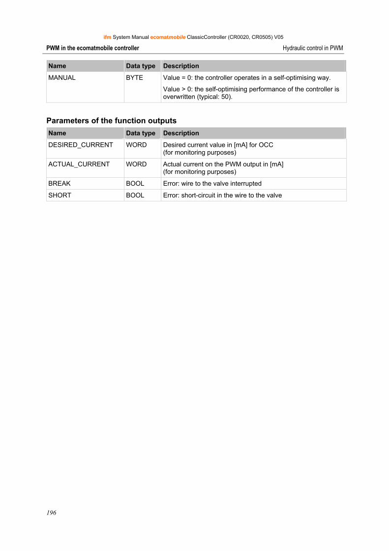
ifm System Manual ecomatmobile ClassicController (CR0020, CR0505) V05
196
PWM in the ecomatmobile controller Hydraulic control in PWM
Name Data type Description
MANUAL BYTE Value = 0: the controller operates in a self-optimising way.
Value > 0: the self-optimising performance of the controller is overwritten (typical: 50).
Parameters of the function outputs Name Data type Description
DESIRED_CURRENT WORD Desired current value in [mA] for OCC (for monitoring purposes)
ACTUAL_CURRENT WORD Actual current on the PWM output in [mA] (for monitoring purposes)
BREAK BOOL Error: wire to the valve interrupted
SHORT BOOL Error: short-circuit in the wire to the valve
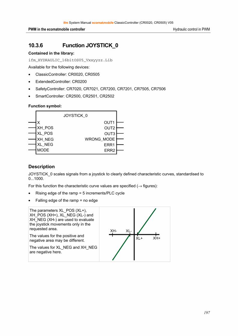
ifm System Manual ecomatmobile ClassicController (CR0020, CR0505) V05
197
PWM in the ecomatmobile controller Hydraulic control in PWM
10.3.6 Function JOYSTICK_0 Contained in the library: ifm_HYDRAULIC_16bitOS05_Vxxyyzz.Lib
Available for the following devices:
• ClassicController: CR0020, CR0505
• ExtendedController: CR0200
• SafetyController: CR7020, CR7021, CR7200, CR7201, CR7505, CR7506
• SmartController: CR2500, CR2501, CR2502
Function symbol:
JOYSTICK_0
X OUT1XH_POS OUT2
ERR1ERR2
XL_POS OUT3XH_NEG WRONG_MODEXL_NEGMODE
Description JOYSTICK_0 scales signals from a joystick to clearly defined characteristic curves, standardised to 0...1000.
For this function the characteristic curve values are specified (→ figures):
• Rising edge of the ramp = 5 increments/PLC cycle
• Falling edge of the ramp = no edge
The parameters XL_POS (XL+), XH_POS (XH+), XL_NEG (XL-) and XH_NEG (XH-) are used to evaluate the joystick movements only in the requested area.
The values for the positive and negative area may be different.
The values for XL_NEG and XH_NEG are negative here.
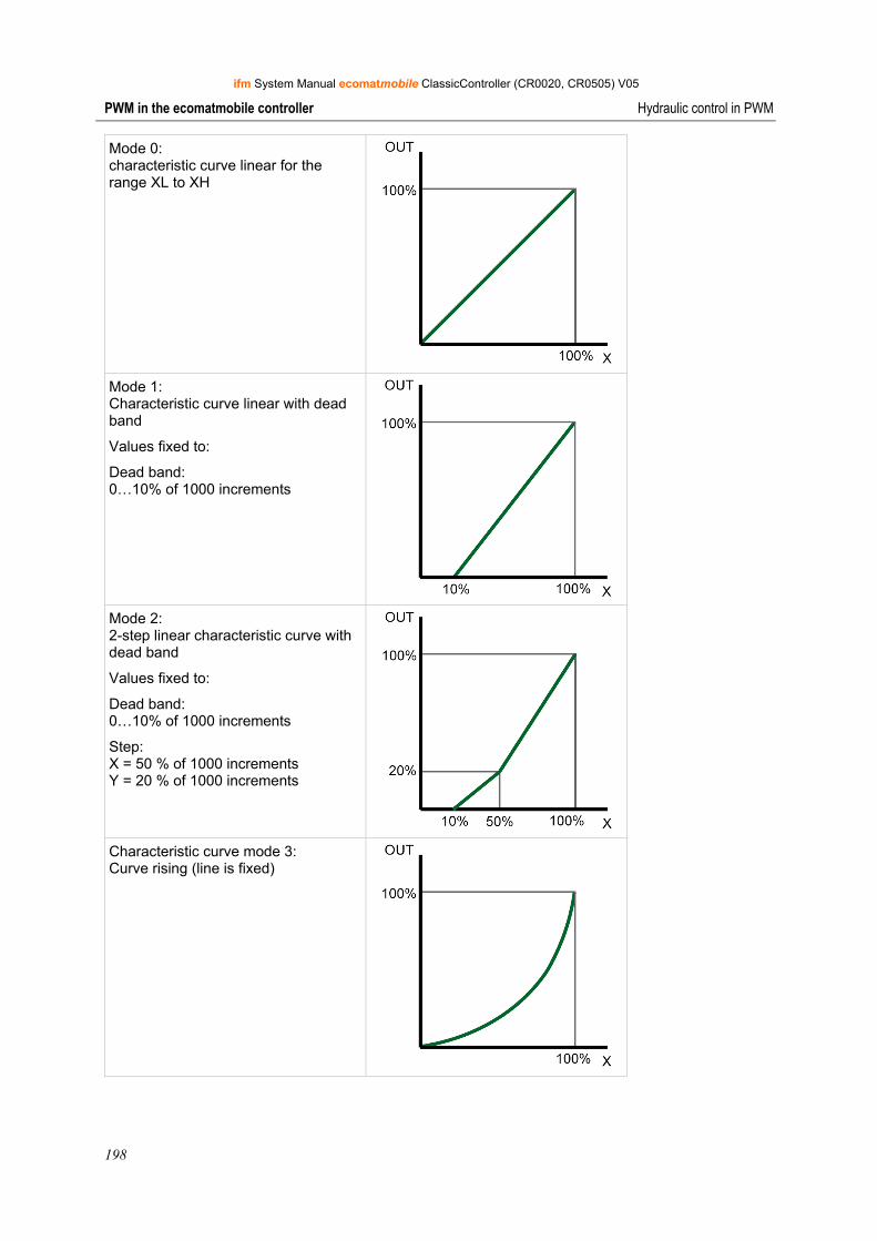
ifm System Manual ecomatmobile ClassicController (CR0020, CR0505) V05
198
PWM in the ecomatmobile controller Hydraulic control in PWM
Mode 0: characteristic curve linear for the range XL to XH
Mode 1: Characteristic curve linear with dead band
Values fixed to:
Dead band: 0…10% of 1000 increments
Mode 2: 2-step linear characteristic curve with dead band
Values fixed to:
Dead band: 0…10% of 1000 increments
Step: X = 50 % of 1000 increments Y = 20 % of 1000 increments
Characteristic curve mode 3: Curve rising (line is fixed)
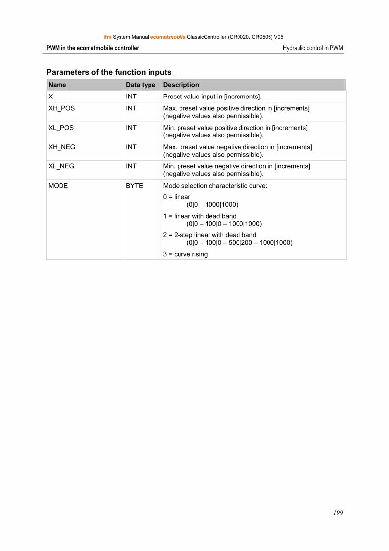
ifm System Manual ecomatmobile ClassicController (CR0020, CR0505) V05
199
PWM in the ecomatmobile controller Hydraulic control in PWM
Parameters of the function inputs Name Data type Description
X INT Preset value input in [increments].
XH_POS INT Max. preset value positive direction in [increments] (negative values also permissible).
XL_POS INT Min. preset value positive direction in [increments] (negative values also permissible).
XH_NEG INT Max. preset value negative direction in [increments] (negative values also permissible).
XL_NEG INT Min. preset value negative direction in [increments] (negative values also permissible).
MODE BYTE Mode selection characteristic curve:
0 = linear (0|0 – 1000|1000)
1 = linear with dead band (0|0 – 100|0 – 1000|1000)
2 = 2-step linear with dead band (0|0 – 100|0 – 500|200 – 1000|1000)
3 = curve rising

ifm System Manual ecomatmobile ClassicController (CR0020, CR0505) V05
200
PWM in the ecomatmobile controller Hydraulic control in PWM
Parameters of the function outputs Name Data type Description
OUT1 WORD Standardised output value pairs of values 0 to 10 [increments] e.g. for valve left
OUT2 WORD Standardised output value pairs of values 0 to 10 [increments] e.g. for valve right
OUT3 INT Standardised output value pairs of values 0 to 10 [increments] e.g. for valve on output module (e.g. CR2011 or CR2031)
WRONG_MODE BOOL Error: invalid mode
ERR1 BYTE Error code for rising edge:
0 = no error
1 = error in array: wrong sequence
2 = initial value IN not contained in value range of array
4 = invalid number N for array
ERR2 BYTE Error code for falling edge:
0 = no error
1 = error in array: wrong sequence
2 = initial value IN not contained in value range of array
4 = invalid number N for array
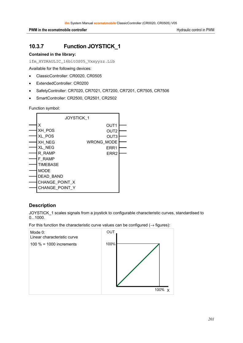
ifm System Manual ecomatmobile ClassicController (CR0020, CR0505) V05
201
PWM in the ecomatmobile controller Hydraulic control in PWM
10.3.7 Function JOYSTICK_1 Contained in the library: ifm_HYDRAULIC_16bitOS05_Vxxyyzz.Lib
Available for the following devices:
• ClassicController: CR0020, CR0505
• ExtendedController: CR0200
• SafetyController: CR7020, CR7021, CR7200, CR7201, CR7505, CR7506
• SmartController: CR2500, CR2501, CR2502
Function symbol:
JOYSTICK_1
X OUT1XH_POS OUT2
ERR1 ERR2
XL_POS OUT3XH_NEG WRONG_MODEXL_NEGR_RAMPF_RAMPTIMEBASE
MODEDEAD_BANDCHANGE_POINT_XCHANGE_POINT_Y
Description JOYSTICK_1 scales signals from a joystick to configurable characteristic curves, standardised to 0...1000.
For this function the characteristic curve values can be configured (→ figures):
Mode 0: Linear characteristic curve
100 % = 1000 increments
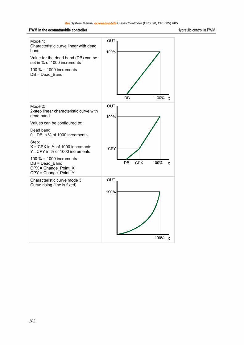
ifm System Manual ecomatmobile ClassicController (CR0020, CR0505) V05
202
PWM in the ecomatmobile controller Hydraulic control in PWM
Mode 1: Characteristic curve linear with dead band
Value for the dead band (DB) can be set in % of 1000 increments
100 % = 1000 increments DB = Dead_Band
Mode 2: 2-step linear characteristic curve with dead band
Values can be configured to:
Dead band: 0…DB in % of 1000 increments
Step: X = CPX in % of 1000 increments Y= CPY in % of 1000 increments
100 % = 1000 increments DB = Dead_Band CPX = Change_Point_X CPY = Change_Point_Y
Characteristic curve mode 3: Curve rising (line is fixed)
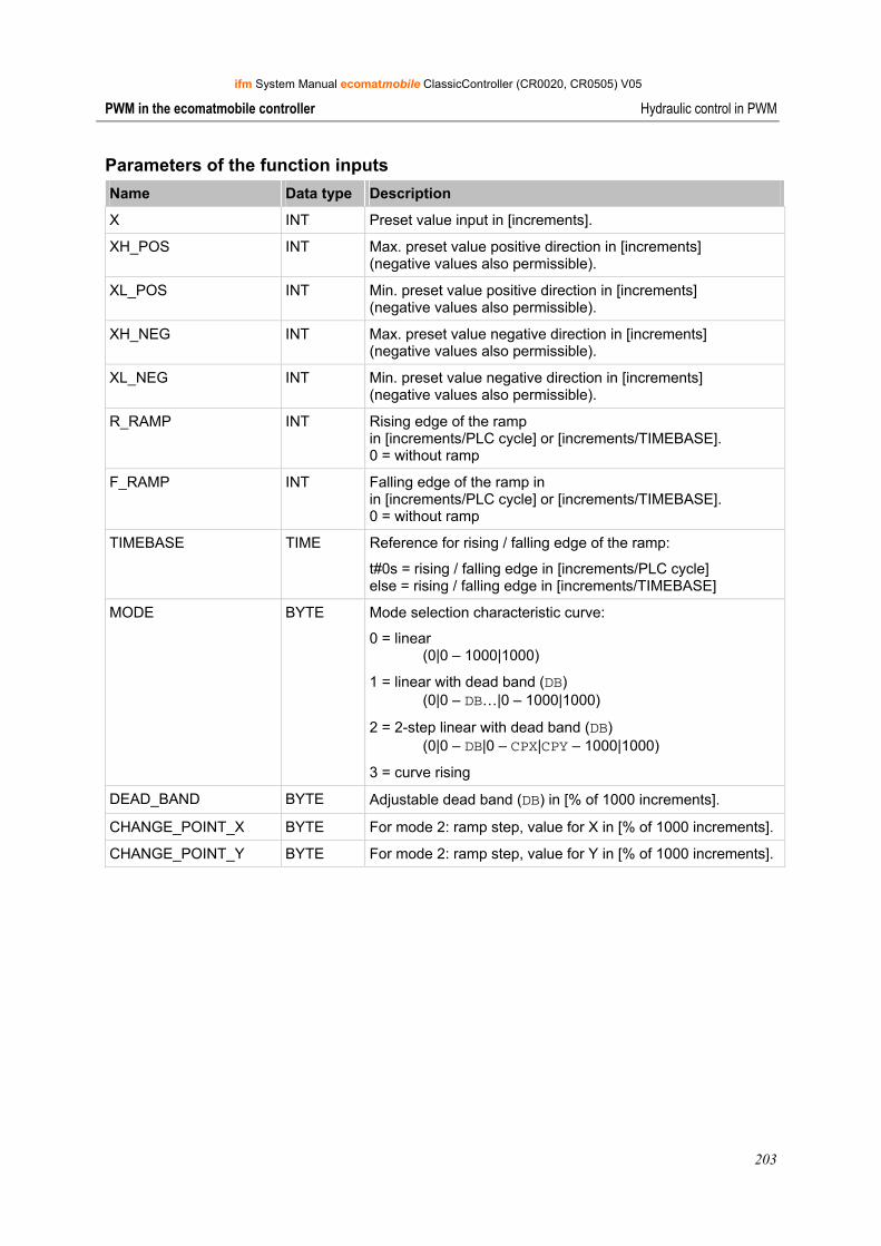
ifm System Manual ecomatmobile ClassicController (CR0020, CR0505) V05
203
PWM in the ecomatmobile controller Hydraulic control in PWM
Parameters of the function inputs Name Data type Description
X INT Preset value input in [increments].
XH_POS INT Max. preset value positive direction in [increments] (negative values also permissible).
XL_POS INT Min. preset value positive direction in [increments] (negative values also permissible).
XH_NEG INT Max. preset value negative direction in [increments] (negative values also permissible).
XL_NEG INT Min. preset value negative direction in [increments] (negative values also permissible).
R_RAMP INT Rising edge of the ramp in [increments/PLC cycle] or [increments/TIMEBASE]. 0 = without ramp
F_RAMP INT Falling edge of the ramp in in [increments/PLC cycle] or [increments/TIMEBASE]. 0 = without ramp
TIMEBASE TIME Reference for rising / falling edge of the ramp:
t#0s = rising / falling edge in [increments/PLC cycle] else = rising / falling edge in [increments/TIMEBASE]
MODE BYTE Mode selection characteristic curve:
0 = linear (0|0 – 1000|1000)
1 = linear with dead band (DB) (0|0 – DB…|0 – 1000|1000)
2 = 2-step linear with dead band (DB) (0|0 – DB|0 – CPX|CPY – 1000|1000)
3 = curve rising
DEAD_BAND BYTE Adjustable dead band (DB) in [% of 1000 increments].
CHANGE_POINT_X BYTE For mode 2: ramp step, value for X in [% of 1000 increments].
CHANGE_POINT_Y BYTE For mode 2: ramp step, value for Y in [% of 1000 increments].
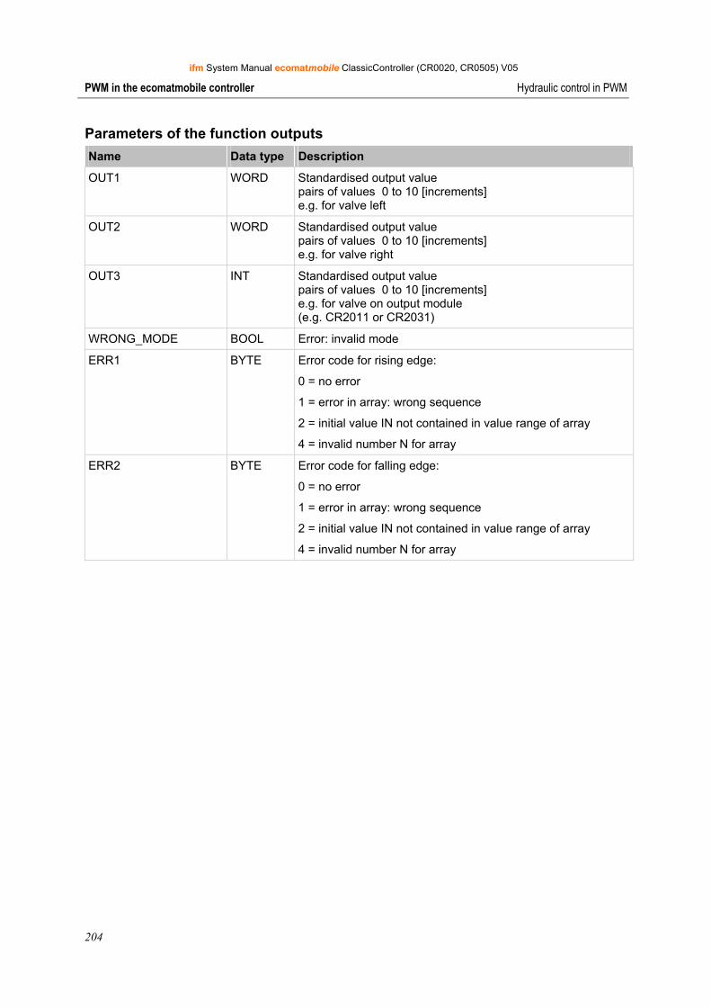
ifm System Manual ecomatmobile ClassicController (CR0020, CR0505) V05
204
PWM in the ecomatmobile controller Hydraulic control in PWM
Parameters of the function outputs Name Data type Description
OUT1 WORD Standardised output value pairs of values 0 to 10 [increments] e.g. for valve left
OUT2 WORD Standardised output value pairs of values 0 to 10 [increments] e.g. for valve right
OUT3 INT Standardised output value pairs of values 0 to 10 [increments] e.g. for valve on output module (e.g. CR2011 or CR2031)
WRONG_MODE BOOL Error: invalid mode
ERR1 BYTE Error code for rising edge:
0 = no error
1 = error in array: wrong sequence
2 = initial value IN not contained in value range of array
4 = invalid number N for array
ERR2 BYTE Error code for falling edge:
0 = no error
1 = error in array: wrong sequence
2 = initial value IN not contained in value range of array
4 = invalid number N for array
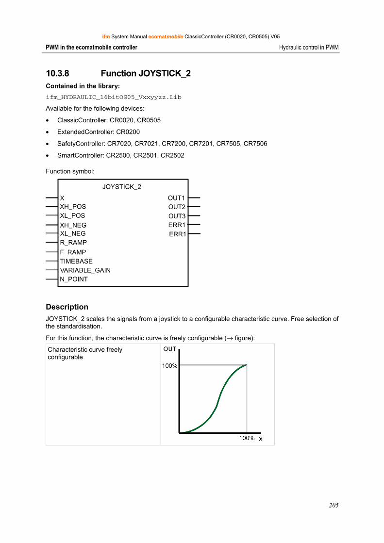
ifm System Manual ecomatmobile ClassicController (CR0020, CR0505) V05
205
PWM in the ecomatmobile controller Hydraulic control in PWM
10.3.8 Function JOYSTICK_2 Contained in the library: ifm_HYDRAULIC_16bitOS05_Vxxyyzz.Lib
Available for the following devices:
• ClassicController: CR0020, CR0505
• ExtendedController: CR0200
• SafetyController: CR7020, CR7021, CR7200, CR7201, CR7505, CR7506
• SmartController: CR2500, CR2501, CR2502
Function symbol:
JOYSTICK_2
X OUT1XH_POS OUT2XL_POS OUT3XH_NEG ERR1XL_NEGR_RAMP
F_RAMPTIMEBASE
ERR1
VARIABLE_GAINN_POINT
Description JOYSTICK_2 scales the signals from a joystick to a configurable characteristic curve. Free selection of the standardisation.
For this function, the characteristic curve is freely configurable (→ figure):
Characteristic curve freely configurable
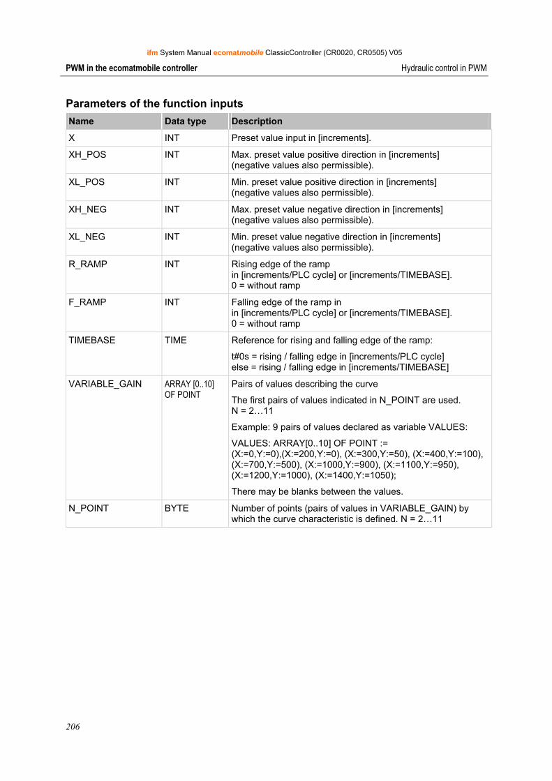
ifm System Manual ecomatmobile ClassicController (CR0020, CR0505) V05
206
PWM in the ecomatmobile controller Hydraulic control in PWM
Parameters of the function inputs Name Data type Description
X INT Preset value input in [increments].
XH_POS INT Max. preset value positive direction in [increments] (negative values also permissible).
XL_POS INT Min. preset value positive direction in [increments] (negative values also permissible).
XH_NEG INT Max. preset value negative direction in [increments] (negative values also permissible).
XL_NEG INT Min. preset value negative direction in [increments] (negative values also permissible).
R_RAMP INT Rising edge of the ramp in [increments/PLC cycle] or [increments/TIMEBASE]. 0 = without ramp
F_RAMP INT Falling edge of the ramp in in [increments/PLC cycle] or [increments/TIMEBASE]. 0 = without ramp
TIMEBASE TIME Reference for rising and falling edge of the ramp:
t#0s = rising / falling edge in [increments/PLC cycle] else = rising / falling edge in [increments/TIMEBASE]
VARIABLE_GAIN ARRAY [0..10] OF POINT
Pairs of values describing the curve
The first pairs of values indicated in N_POINT are used. N = 2…11
Example: 9 pairs of values declared as variable VALUES:
VALUES: ARRAY[0..10] OF POINT := (X:=0,Y:=0),(X:=200,Y:=0), (X:=300,Y:=50), (X:=400,Y:=100), (X:=700,Y:=500), (X:=1000,Y:=900), (X:=1100,Y:=950), (X:=1200,Y:=1000), (X:=1400,Y:=1050);
There may be blanks between the values.
N_POINT BYTE Number of points (pairs of values in VARIABLE_GAIN) by which the curve characteristic is defined. N = 2…11
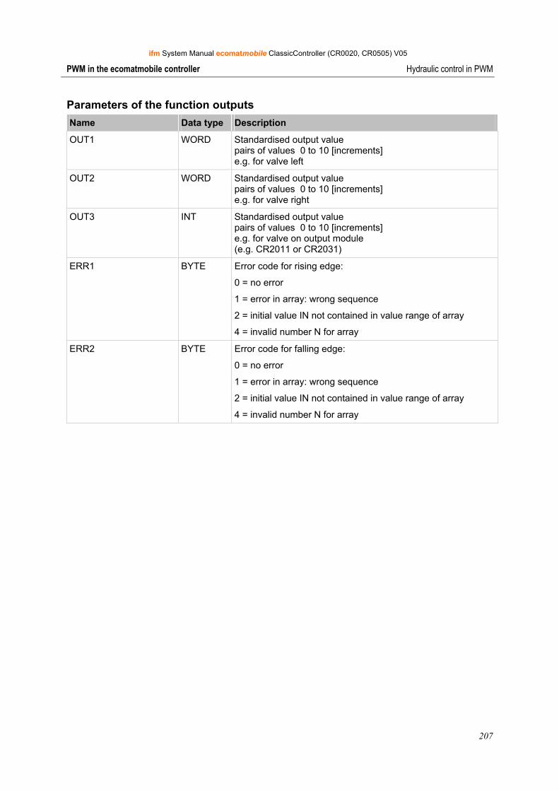
ifm System Manual ecomatmobile ClassicController (CR0020, CR0505) V05
207
PWM in the ecomatmobile controller Hydraulic control in PWM
Parameters of the function outputs Name Data type Description
OUT1 WORD Standardised output value pairs of values 0 to 10 [increments] e.g. for valve left
OUT2 WORD Standardised output value pairs of values 0 to 10 [increments] e.g. for valve right
OUT3 INT Standardised output value pairs of values 0 to 10 [increments] e.g. for valve on output module (e.g. CR2011 or CR2031)
ERR1 BYTE Error code for rising edge:
0 = no error
1 = error in array: wrong sequence
2 = initial value IN not contained in value range of array
4 = invalid number N for array
ERR2 BYTE Error code for falling edge:
0 = no error
1 = error in array: wrong sequence
2 = initial value IN not contained in value range of array
4 = invalid number N for array
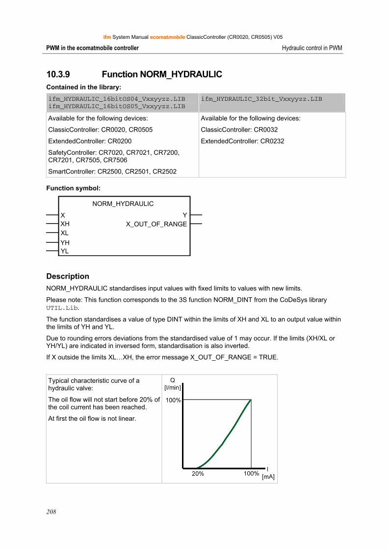
ifm System Manual ecomatmobile ClassicController (CR0020, CR0505) V05
208
PWM in the ecomatmobile controller Hydraulic control in PWM
10.3.9 Function NORM_HYDRAULIC Contained in the library:
ifm_HYDRAULIC_16bitOS04_Vxxyyzz.LIB ifm_HYDRAULIC_16bitOS05_Vxxyyzz.LIB
ifm_HYDRAULIC_32bit_Vxxyyzz.LIB
Available for the following devices:
ClassicController: CR0020, CR0505
ExtendedController: CR0200
SafetyController: CR7020, CR7021, CR7200, CR7201, CR7505, CR7506
SmartController: CR2500, CR2501, CR2502
Available for the following devices:
ClassicController: CR0032
ExtendedController: CR0232
Function symbol:
NORM_HYDRAULIC
X YXHXL
YHYL
X_OUT_OF_RANGE
Description NORM_HYDRAULIC standardises input values with fixed limits to values with new limits.
Please note: This function corresponds to the 3S function NORM_DINT from the CoDeSys library UTIL.Lib.
The function standardises a value of type DINT within the limits of XH and XL to an output value within the limits of YH and YL.
Due to rounding errors deviations from the standardised value of 1 may occur. If the limits (XH/XL or YH/YL) are indicated in inversed form, standardisation is also inverted.
If X outside the limits XL…XH, the error message X_OUT_OF_RANGE = TRUE.
Typical characteristic curve of a hydraulic valve:
The oil flow will not start before 20% of the coil current has been reached.
At first the oil flow is not linear.
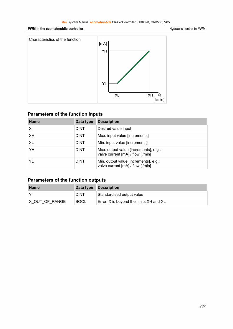
ifm System Manual ecomatmobile ClassicController (CR0020, CR0505) V05
209
PWM in the ecomatmobile controller Hydraulic control in PWM
Characteristics of the function
Parameters of the function inputs Name Data type Description
X DINT Desired value input
XH DINT Max. input value [increments]
XL DINT Min. input value [increments]
YH DINT Max. output value [increments], e.g.: valve current [mA] / flow [l/min]
YL DINT Min. output value [increments], e.g.: valve current [mA] / flow [l/min]
Parameters of the function outputs Name Data type Description
Y DINT Standardised output value
X_OUT_OF_RANGE BOOL Error: X is beyond the limits XH and XL
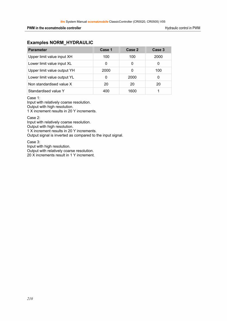
ifm System Manual ecomatmobile ClassicController (CR0020, CR0505) V05
210
PWM in the ecomatmobile controller Hydraulic control in PWM
Examples NORM_HYDRAULIC Parameter Case 1 Case 2 Case 3
Upper limit value input XH 100 100 2000
Lower limit value input XL 0 0 0
Upper limit value output YH 2000 0 100
Lower limit value output YL 0 2000 0
Non standardised value X 20 20 20
Standardised value Y 400 1600 1
Case 1: Input with relatively coarse resolution. Output with high resolution. 1 X increment results in 20 Y increments.
Case 2: Input with relatively coarse resolution. Output with high resolution. 1 X increment results in 20 Y increments. Output signal is inverted as compared to the input signal.
Case 3: Input with high resolution. Output with relatively coarse resolution. 20 X increments result in 1 Y increment.
ifm System Manual ecomatmobile ClassicController (CR0020, CR0505) V05
211
More functions in the ecomatmobile controller Counter functions for frequency and period measurement
11 More functions in the ecomatmobile controller
Counter functions for frequency and period measurement .................................................... 211 Software reset......................................................................................................................... 226 Saving, reading and converting data in the memory .............................................................. 227 Data access and data check .................................................................................................. 236 Processing interrupts .............................................................................................................. 246 Use of the serial interface....................................................................................................... 253 Reading the system time ........................................................................................................ 260 Processing analogue input values.......................................................................................... 262 Adapting analogue values ...................................................................................................... 267
In this chapter you will find more functions that you can use in the ecomatmobile controller.
11.1 Counter functions for frequency and period measurement
Depending on the controller up to 16 fast inputs are supported which can process input frequencies of up to 30 kHz. Further to the pure frequency measurement at the inputs FRQ, the inputs ENC can be also used to evaluate incremental encoders (counter function) with a maximum frequency of 10 kHz. The inputs CYL are used for period measurement of slow signals.
Input Frequency [kHz] Description
FRQ 0 / ENC 0 30 / 10 frequency measurement / encoder 1, channel A
FRQ 1 / ENC 0 30 / 10 frequency measurement / encoder 1, channel B
FRQ 2 / ENC 1 30 / 10 frequency measurement / encoder 2, channel A
FRQ 3 / ENC 1 30 / 10 frequency measurement / encoder 2, channel B
CYL 0 / ENC 2 10 period measurement / encoder 3, channel A
CYL 1 / ENC 2 10 period measurement / encoder 3, channel B
CYL 2 / ENC 3 10 period measurement / encoder 4, channel A
CYL 3 / ENC 3 10 period measurement / encoder 4, channel B
The following functions are available for easy evaluation:
11.1.1 Applications It must be taken into account that the different measuring methods can cause errors in the frequency detection.
The function FREQUENCY (→ page 212) is suitable for frequencies between 100 Hz and 30 kHz; the error decreases at high frequencies.
The function PERIOD (→ page 214) carries out a period measurement. It is thus suitable for frequencies lower than 1000 Hz. In principle it can also measure higher frequencies, but this has a significant impact on the cycle time. This must be taken into account when setting up the application software.

ifm System Manual ecomatmobile ClassicController (CR0020, CR0505) V05
212
More functions in the ecomatmobile controller Counter functions for frequency and period measurement
11.1.2 Use as digital inputs If the fast inputs (FRQx / CYLx) are used as "normal" digital inputs, the increased sensitivity to interfering pulses must be taken into account (e.g. contact bouncing for mechanical contacts). The standard digital input has an input frequency of 50 Hz. If necessary, the input signal must be debounced by means of the software.
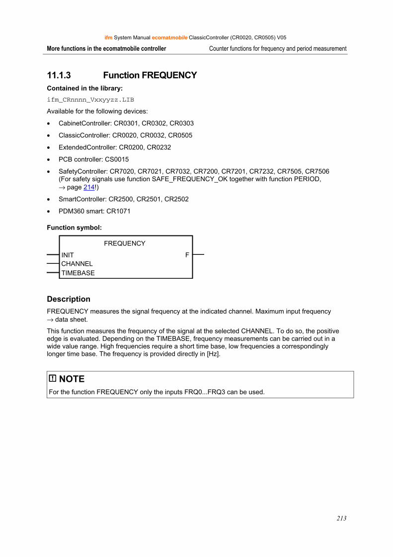
ifm System Manual ecomatmobile ClassicController (CR0020, CR0505) V05
213
More functions in the ecomatmobile controller Counter functions for frequency and period measurement
11.1.3 Function FREQUENCY Contained in the library: ifm_CRnnnn_Vxxyyzz.LIB
Available for the following devices:
• CabinetController: CR0301, CR0302, CR0303
• ClassicController: CR0020, CR0032, CR0505
• ExtendedController: CR0200, CR0232
• PCB controller: CS0015
• SafetyController: CR7020, CR7021, CR7032, CR7200, CR7201, CR7232, CR7505, CR7506 (For safety signals use function SAFE_FREQUENCY_OK together with function PERIOD, → page 214!)
• SmartController: CR2500, CR2501, CR2502
• PDM360 smart: CR1071
Function symbol:
FREQUENCY
INIT FCHANNELTIMEBASE
Description FREQUENCY measures the signal frequency at the indicated channel. Maximum input frequency → data sheet.
This function measures the frequency of the signal at the selected CHANNEL. To do so, the positive edge is evaluated. Depending on the TIMEBASE, frequency measurements can be carried out in a wide value range. High frequencies require a short time base, low frequencies a correspondingly longer time base. The frequency is provided directly in [Hz].
NOTE For the function FREQUENCY only the inputs FRQ0...FRQ3 can be used.
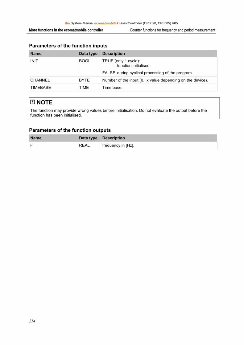
ifm System Manual ecomatmobile ClassicController (CR0020, CR0505) V05
214
More functions in the ecomatmobile controller Counter functions for frequency and period measurement
Parameters of the function inputs Name Data type Description
INIT BOOL TRUE (only 1 cycle): function initialised.
FALSE: during cyclical processing of the program.
CHANNEL BYTE Number of the input (0...x value depending on the device).
TIMEBASE TIME Time base.
NOTE The function may provide wrong values before initialisation. Do not evaluate the output before the function has been initialised.
Parameters of the function outputs Name Data type Description
F REAL frequency in [Hz].
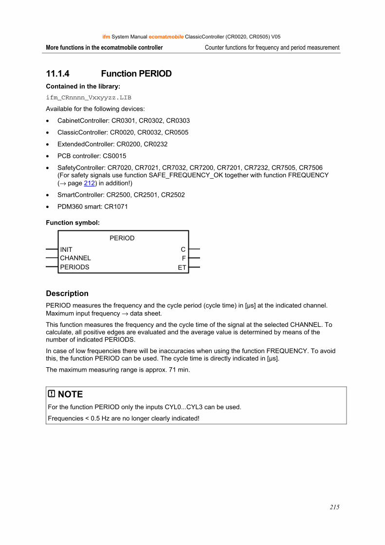
ifm System Manual ecomatmobile ClassicController (CR0020, CR0505) V05
215
More functions in the ecomatmobile controller Counter functions for frequency and period measurement
11.1.4 Function PERIOD Contained in the library: ifm_CRnnnn_Vxxyyzz.LIB
Available for the following devices:
• CabinetController: CR0301, CR0302, CR0303
• ClassicController: CR0020, CR0032, CR0505
• ExtendedController: CR0200, CR0232
• PCB controller: CS0015
• SafetyController: CR7020, CR7021, CR7032, CR7200, CR7201, CR7232, CR7505, CR7506 (For safety signals use function SAFE_FREQUENCY_OK together with function FREQUENCY (→ page 212) in addition!)
• SmartController: CR2500, CR2501, CR2502
• PDM360 smart: CR1071
Function symbol:
PERIOD
INIT CCHANNEL FPERIODS ET
Description PERIOD measures the frequency and the cycle period (cycle time) in [µs] at the indicated channel. Maximum input frequency → data sheet.
This function measures the frequency and the cycle time of the signal at the selected CHANNEL. To calculate, all positive edges are evaluated and the average value is determined by means of the number of indicated PERIODS.
In case of low frequencies there will be inaccuracies when using the function FREQUENCY. To avoid this, the function PERIOD can be used. The cycle time is directly indicated in [µs].
The maximum measuring range is approx. 71 min.
NOTE For the function PERIOD only the inputs CYL0...CYL3 can be used.
Frequencies < 0.5 Hz are no longer clearly indicated!
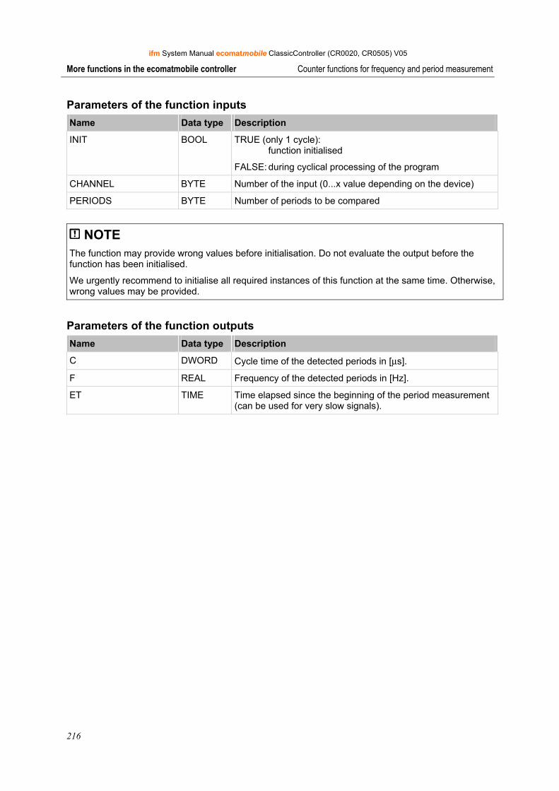
ifm System Manual ecomatmobile ClassicController (CR0020, CR0505) V05
216
More functions in the ecomatmobile controller Counter functions for frequency and period measurement
Parameters of the function inputs Name Data type Description
INIT BOOL TRUE (only 1 cycle): function initialised
FALSE: during cyclical processing of the program
CHANNEL BYTE Number of the input (0...x value depending on the device)
PERIODS BYTE Number of periods to be compared
NOTE The function may provide wrong values before initialisation. Do not evaluate the output before the function has been initialised.
We urgently recommend to initialise all required instances of this function at the same time. Otherwise, wrong values may be provided.
Parameters of the function outputs Name Data type Description
C DWORD Cycle time of the detected periods in [μs].
F REAL Frequency of the detected periods in [Hz].
ET TIME Time elapsed since the beginning of the period measurement (can be used for very slow signals).
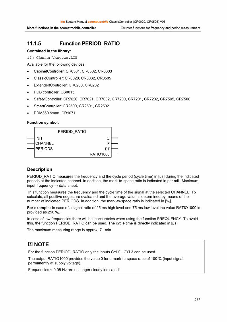
ifm System Manual ecomatmobile ClassicController (CR0020, CR0505) V05
217
More functions in the ecomatmobile controller Counter functions for frequency and period measurement
11.1.5 Function PERIOD_RATIO Contained in the library: ifm_CRnnnn_Vxxyyzz.LIB
Available for the following devices:
• CabinetController: CR0301, CR0302, CR0303
• ClassicController: CR0020, CR0032, CR0505
• ExtendedController: CR0200, CR0232
• PCB controller: CS0015
• SafetyController: CR7020, CR7021, CR7032, CR7200, CR7201, CR7232, CR7505, CR7506
• SmartController: CR2500, CR2501, CR2502
• PDM360 smart: CR1071
Function symbol:
PERIOD_RATIO
INIT CCHANNEL FPERIODS ET
RATIO1000
Description PERIOD_RATIO measures the frequency and the cycle period (cycle time) in [µs] during the indicated periods at the indicated channel. In addition, the mark-to-space ratio is indicated in per mill. Maximum input frequency → data sheet.
This function measures the frequency and the cycle time of the signal at the selected CHANNEL. To calculate, all positive edges are evaluated and the average value is determined by means of the number of indicated PERIODS. In addition, the mark-to-space ratio is indicated in [‰].
For example: In case of a signal ratio of 25 ms high level and 75 ms low level the value RATIO1000 is provided as 250 ‰.
In case of low frequencies there will be inaccuracies when using the function FREQUENCY. To avoid this, the function PERIOD_RATIO can be used. The cycle time is directly indicated in [µs].
The maximum measuring range is approx. 71 min.
NOTE For the function PERIOD_RATIO only the inputs CYL0...CYL3 can be used.
The output RATIO1000 provides the value 0 for a mark-to-space ratio of 100 % (input signal permanently at supply voltage).
Frequencies < 0.05 Hz are no longer clearly indicated!
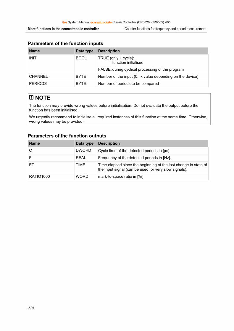
ifm System Manual ecomatmobile ClassicController (CR0020, CR0505) V05
218
More functions in the ecomatmobile controller Counter functions for frequency and period measurement
Parameters of the function inputs Name Data type Description
INIT BOOL TRUE (only 1 cycle): function initialised
FALSE: during cyclical processing of the program
CHANNEL BYTE Number of the input (0...x value depending on the device)
PERIODS BYTE Number of periods to be compared
NOTE The function may provide wrong values before initialisation. Do not evaluate the output before the function has been initialised.
We urgently recommend to initialise all required instances of this function at the same time. Otherwise, wrong values may be provided.
Parameters of the function outputs Name Data type Description
C DWORD Cycle time of the detected periods in [μs].
F REAL Frequency of the detected periods in [Hz].
ET TIME Time elapsed since the beginning of the last change in state of the input signal (can be used for very slow signals).
RATIO1000 WORD mark-to-space ratio in [‰].
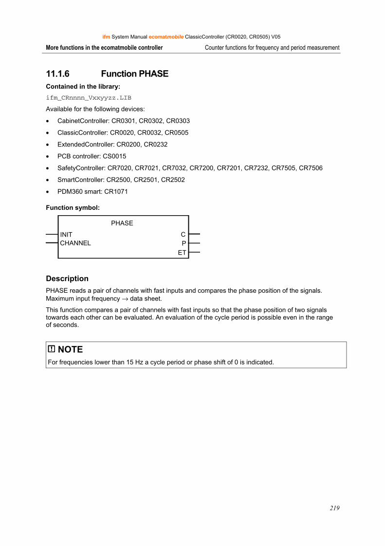
ifm System Manual ecomatmobile ClassicController (CR0020, CR0505) V05
219
More functions in the ecomatmobile controller Counter functions for frequency and period measurement
11.1.6 Function PHASE Contained in the library: ifm_CRnnnn_Vxxyyzz.LIB
Available for the following devices:
• CabinetController: CR0301, CR0302, CR0303
• ClassicController: CR0020, CR0032, CR0505
• ExtendedController: CR0200, CR0232
• PCB controller: CS0015
• SafetyController: CR7020, CR7021, CR7032, CR7200, CR7201, CR7232, CR7505, CR7506
• SmartController: CR2500, CR2501, CR2502
• PDM360 smart: CR1071
Function symbol:
PHASE
INIT CCHANNEL P
ET
Description PHASE reads a pair of channels with fast inputs and compares the phase position of the signals. Maximum input frequency → data sheet.
This function compares a pair of channels with fast inputs so that the phase position of two signals towards each other can be evaluated. An evaluation of the cycle period is possible even in the range of seconds.
NOTE For frequencies lower than 15 Hz a cycle period or phase shift of 0 is indicated.
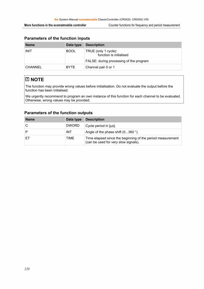
ifm System Manual ecomatmobile ClassicController (CR0020, CR0505) V05
220
More functions in the ecomatmobile controller Counter functions for frequency and period measurement
Parameters of the function inputs Name Data type Description
INIT BOOL TRUE (only 1 cycle): function is initialised
FALSE: during processing of the program
CHANNEL BYTE Channel pair 0 or 1
NOTE The function may provide wrong values before initialisation. Do not evaluate the output before the function has been initialised.
We urgently recommend to program an own instance of this function for each channel to be evaluated. Otherwise, wrong values may be provided.
Parameters of the function outputs Name Data type Description
C DWORD Cycle period in [μs].
P INT Angle of the phase shift (0...360 °).
ET TIME Time elapsed since the beginning of the period measurement (can be used for very slow signals).
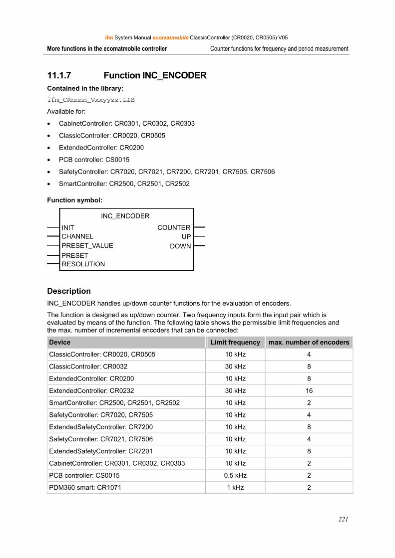
ifm System Manual ecomatmobile ClassicController (CR0020, CR0505) V05
221
More functions in the ecomatmobile controller Counter functions for frequency and period measurement
11.1.7 Function INC_ENCODER Contained in the library: ifm_CRnnnn_Vxxyyzz.LIB
Available for:
• CabinetController: CR0301, CR0302, CR0303
• ClassicController: CR0020, CR0505
• ExtendedController: CR0200
• PCB controller: CS0015
• SafetyController: CR7020, CR7021, CR7200, CR7201, CR7505, CR7506
• SmartController: CR2500, CR2501, CR2502
Function symbol:
INC_ENCODER
INIT COUNTERCHANNEL UPPRESET_VALUE DOWNPRESETRESOLUTION
Description INC_ENCODER handles up/down counter functions for the evaluation of encoders.
The function is designed as up/down counter. Two frequency inputs form the input pair which is evaluated by means of the function. The following table shows the permissible limit frequencies and the max. number of incremental encoders that can be connected:
Device Limit frequency max. number of encoders
ClassicController: CR0020, CR0505 10 kHz 4
ClassicController: CR0032 30 kHz 8
ExtendedController: CR0200 10 kHz 8
ExtendedController: CR0232 30 kHz 16
SmartController: CR2500, CR2501, CR2502 10 kHz 2
SafetyController: CR7020, CR7505 10 kHz 4
ExtendedSafetyController: CR7200 10 kHz 8
SafetyController: CR7021, CR7506 10 kHz 4
ExtendedSafetyController: CR7201 10 kHz 8
CabinetController: CR0301, CR0302, CR0303 10 kHz 2
PCB controller: CS0015 0.5 kHz 2
PDM360 smart: CR1071 1 kHz 2
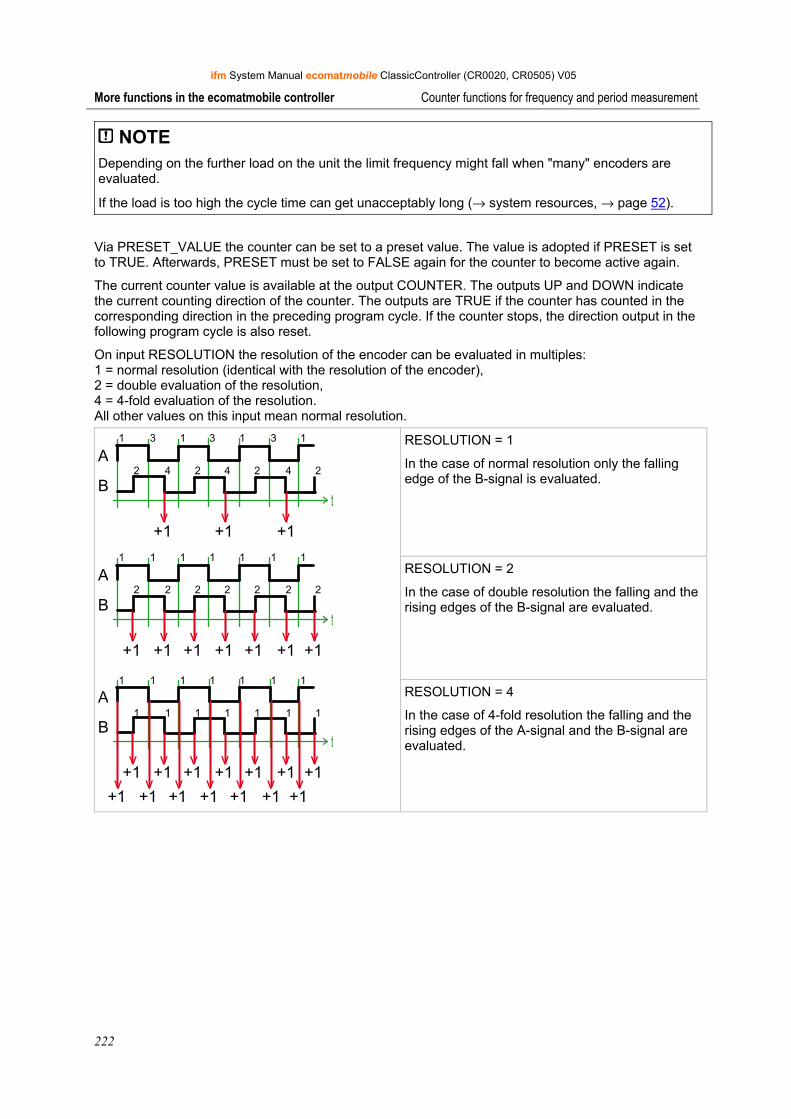
ifm System Manual ecomatmobile ClassicController (CR0020, CR0505) V05
222
More functions in the ecomatmobile controller Counter functions for frequency and period measurement
NOTE Depending on the further load on the unit the limit frequency might fall when "many" encoders are evaluated.
If the load is too high the cycle time can get unacceptably long (→ system resources, → page 52).
Via PRESET_VALUE the counter can be set to a preset value. The value is adopted if PRESET is set to TRUE. Afterwards, PRESET must be set to FALSE again for the counter to become active again.
The current counter value is available at the output COUNTER. The outputs UP and DOWN indicate the current counting direction of the counter. The outputs are TRUE if the counter has counted in the corresponding direction in the preceding program cycle. If the counter stops, the direction output in the following program cycle is also reset.
On input RESOLUTION the resolution of the encoder can be evaluated in multiples: 1 = normal resolution (identical with the resolution of the encoder), 2 = double evaluation of the resolution, 4 = 4-fold evaluation of the resolution. All other values on this input mean normal resolution.
RESOLUTION = 1
In the case of normal resolution only the falling edge of the B-signal is evaluated.
RESOLUTION = 2
In the case of double resolution the falling and the rising edges of the B-signal are evaluated.
A
B
+1 +1 +1
A
B
+1+1 +1 +1 +1+1 +1
+1+1 +1 +1 +1+1 +1
+1+1 +1 +1 +1+1 +1
A
B
1 3 1 3 1 3 1
2 4 2 4 2 4 2
1 1 1 1 1 1 1
2 2 2 2 2 2 2
1 1 1 1 1 1 1
1 1 1 1 1 1 1
v v v
v v v vv v v
v v v vv v v
v v v vv v v
RESOLUTION = 4
In the case of 4-fold resolution the falling and the rising edges of the A-signal and the B-signal are evaluated.
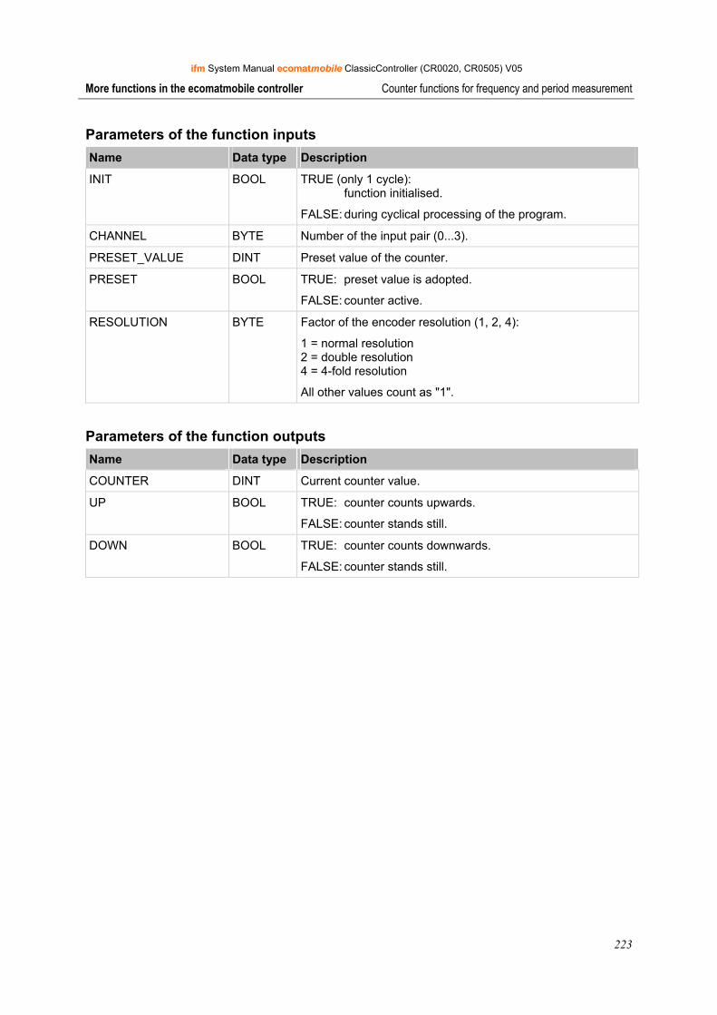
ifm System Manual ecomatmobile ClassicController (CR0020, CR0505) V05
223
More functions in the ecomatmobile controller Counter functions for frequency and period measurement
Parameters of the function inputs Name Data type Description
INIT BOOL TRUE (only 1 cycle): function initialised.
FALSE: during cyclical processing of the program.
CHANNEL BYTE Number of the input pair (0...3).
PRESET_VALUE DINT Preset value of the counter.
PRESET BOOL TRUE: preset value is adopted.
FALSE: counter active.
RESOLUTION BYTE Factor of the encoder resolution (1, 2, 4):
1 = normal resolution 2 = double resolution 4 = 4-fold resolution
All other values count as "1".
Parameters of the function outputs Name Data type Description
COUNTER DINT Current counter value.
UP BOOL TRUE: counter counts upwards.
FALSE: counter stands still.
DOWN BOOL TRUE: counter counts downwards.
FALSE: counter stands still.
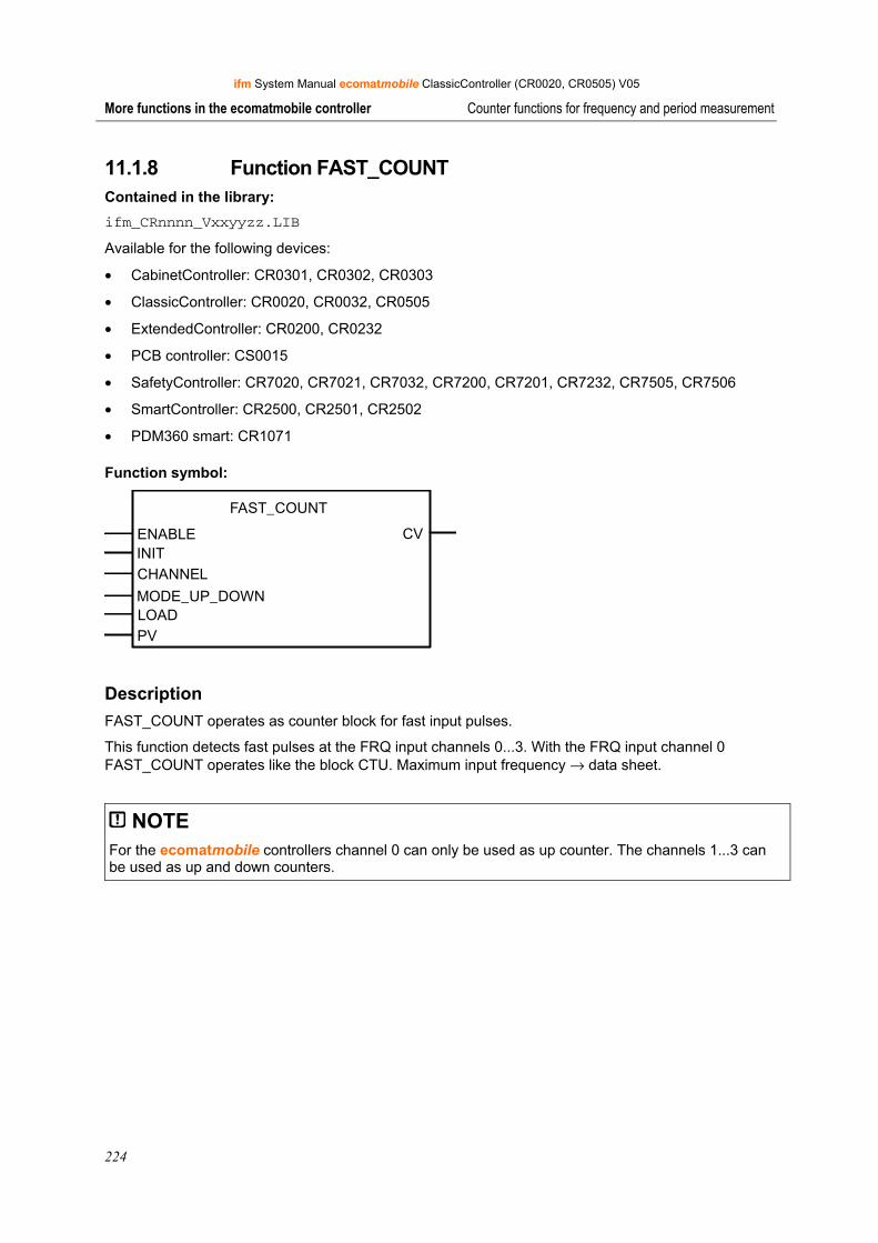
ifm System Manual ecomatmobile ClassicController (CR0020, CR0505) V05
224
More functions in the ecomatmobile controller Counter functions for frequency and period measurement
11.1.8 Function FAST_COUNT Contained in the library: ifm_CRnnnn_Vxxyyzz.LIB
Available for the following devices:
• CabinetController: CR0301, CR0302, CR0303
• ClassicController: CR0020, CR0032, CR0505
• ExtendedController: CR0200, CR0232
• PCB controller: CS0015
• SafetyController: CR7020, CR7021, CR7032, CR7200, CR7201, CR7232, CR7505, CR7506
• SmartController: CR2500, CR2501, CR2502
• PDM360 smart: CR1071
Function symbol:
FAST_COUNT
ENABLE CVINITCHANNEL
MODE_UP_DOWNLOADPV
Description FAST_COUNT operates as counter block for fast input pulses.
This function detects fast pulses at the FRQ input channels 0...3. With the FRQ input channel 0 FAST_COUNT operates like the block CTU. Maximum input frequency → data sheet.
NOTE For the ecomatmobile controllers channel 0 can only be used as up counter. The channels 1...3 can be used as up and down counters.
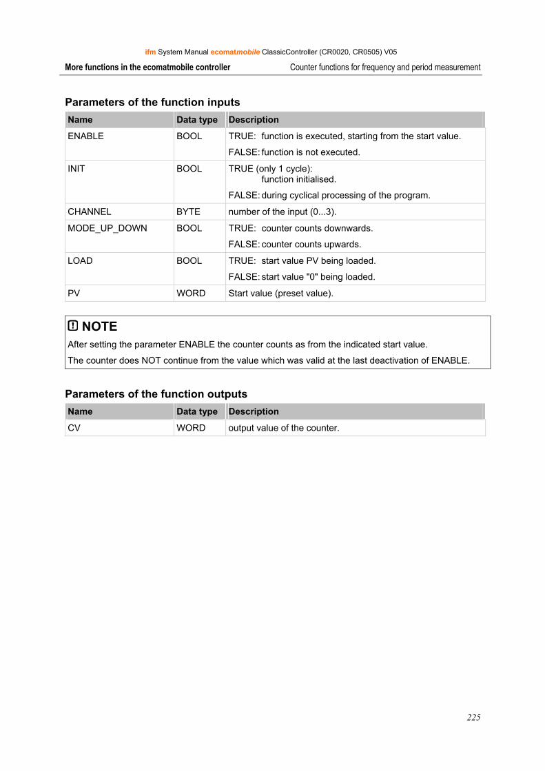
ifm System Manual ecomatmobile ClassicController (CR0020, CR0505) V05
225
More functions in the ecomatmobile controller Counter functions for frequency and period measurement
Parameters of the function inputs Name Data type Description
ENABLE BOOL TRUE: function is executed, starting from the start value.
FALSE: function is not executed.
INIT BOOL TRUE (only 1 cycle): function initialised.
FALSE: during cyclical processing of the program.
CHANNEL BYTE number of the input (0...3).
MODE_UP_DOWN BOOL TRUE: counter counts downwards.
FALSE: counter counts upwards.
LOAD BOOL TRUE: start value PV being loaded.
FALSE: start value "0" being loaded.
PV WORD Start value (preset value).
NOTE After setting the parameter ENABLE the counter counts as from the indicated start value.
The counter does NOT continue from the value which was valid at the last deactivation of ENABLE.
Parameters of the function outputs Name Data type Description
CV WORD output value of the counter.
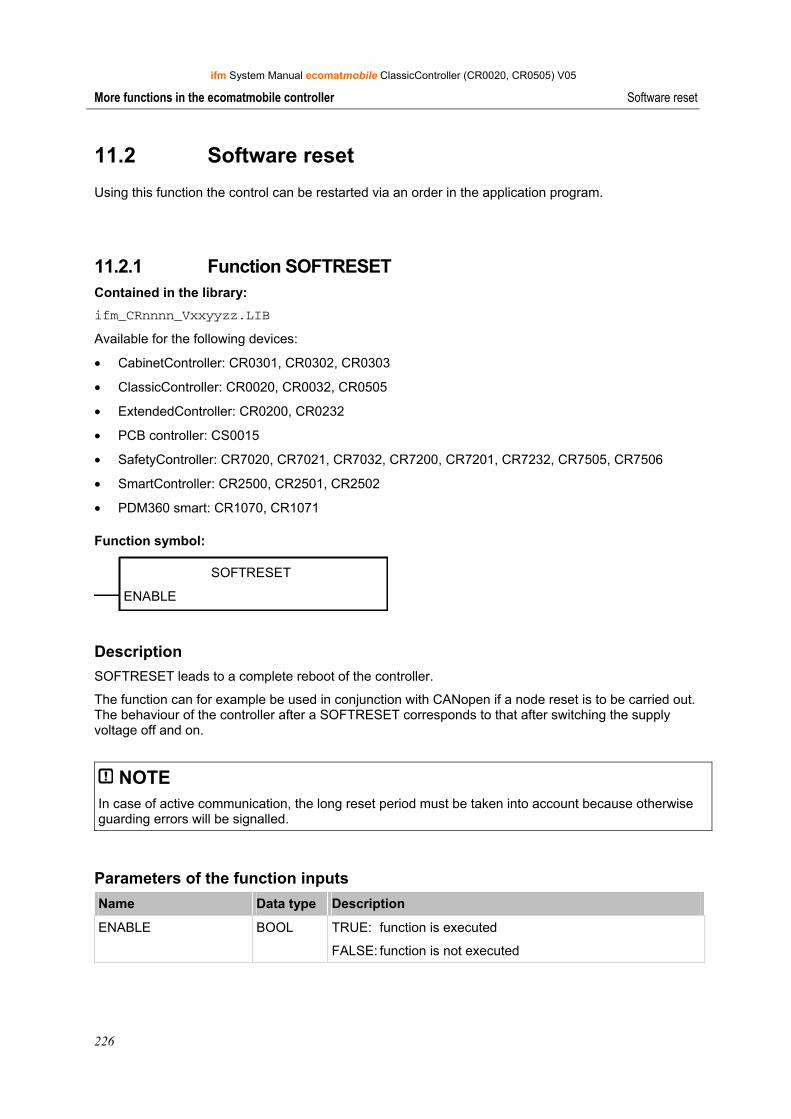
ifm System Manual ecomatmobile ClassicController (CR0020, CR0505) V05
226
More functions in the ecomatmobile controller Software reset
11.2 Software reset
Using this function the control can be restarted via an order in the application program.
11.2.1 Function SOFTRESET Contained in the library: ifm_CRnnnn_Vxxyyzz.LIB
Available for the following devices:
• CabinetController: CR0301, CR0302, CR0303
• ClassicController: CR0020, CR0032, CR0505
• ExtendedController: CR0200, CR0232
• PCB controller: CS0015
• SafetyController: CR7020, CR7021, CR7032, CR7200, CR7201, CR7232, CR7505, CR7506
• SmartController: CR2500, CR2501, CR2502
• PDM360 smart: CR1070, CR1071
Function symbol:
SOFTRESET
ENABLE
Description SOFTRESET leads to a complete reboot of the controller.
The function can for example be used in conjunction with CANopen if a node reset is to be carried out. The behaviour of the controller after a SOFTRESET corresponds to that after switching the supply voltage off and on.
NOTE In case of active communication, the long reset period must be taken into account because otherwise guarding errors will be signalled.
Parameters of the function inputs Name Data type Description
ENABLE BOOL TRUE: function is executed
FALSE: function is not executed
ifm System Manual ecomatmobile ClassicController (CR0020, CR0505) V05
227
More functions in the ecomatmobile controller Saving, reading and converting data in the memory
11.3 Saving, reading and converting data in the memory
11.3.1 Automatic saving of data The ecomatmobile controllers allow to save data (BOOL, BYTE, WORD, DWORD) non-volatilely (= saved in case of voltage failure) in the memory. If the supply voltage drops, the backup operation is automatically started. Therefore it is necessary that the data is defined as RETAIN variables (→ CoDeSys).
A distinction is made between variables declared as RETAIN and variables in the flag area which can be configured as a remanent block with the Function MEMORY_RETAIN_PARAM (→ page 228).
The advantage of the automatic backup is that also in case of a sudden voltage drop or an interruption of the supply voltage, the storage operation is triggered and thus the current values of the data are saved (e.g. counter values).
If the supply voltage returns, the saved data is read from the memory via the operating system and written back in the flag area.

ifm System Manual ecomatmobile ClassicController (CR0020, CR0505) V05
228
More functions in the ecomatmobile controller Saving, reading and converting data in the memory
11.3.2 Function MEMORY_RETAIN_PARAM Contained in the library: ifm_CRnnnn_Vxxyyzz.LIB
Available for the following devices:
• ClassicController: CR0032
• ExtendedController: CR0232
Function symbol:
MEMORY_RETAIN_PARAM
ENABLELENMODE
Description MEMORY_RETAIN_PARAM determines the retain behaviour for various events.
For selectable groups this function determines how many data bytes (from flag byte %MB0 onwards) shall have retain behaviour even if they were not explicitly declared as VAR_RETAIN.
Event MODE = 0 VAR_RETAIN
MODE = 0 MODE = 1 MODE = 2 MODE = 3
Power OFF → ON yes -- yes yes yes
Warm reset yes -- yes yes yes
Cold reset -- -- -- yes yes
Reset initial state -- -- -- yes yes
Loading the application program
-- -- -- yes yes
Loading runtime system -- -- -- -- yes
"yes" = after this event the variables are loaded from the indicated memory area.
If MODE = 0, only those flag bytes have retain behaviour which were explicitly declared as VAR_RETAIN.
Parameters of the function inputs Name Data type Description
ENABLE BOOL TRUE: function is executed.
FALSE: function is not executed.
LEN WORD Number of data bytes from flag address %MB0 onwards which shall have retain behaviour (1...4 096).
MODE BYTE Events for which these variables shall have retain behaviour (→ table above).
ifm System Manual ecomatmobile ClassicController (CR0020, CR0505) V05
229
More functions in the ecomatmobile controller Saving, reading and converting data in the memory
11.3.3 Manual data storage
Besides the possibility to store the data automatically, user data can be stored manually, via function calls, in integrated memories from where they can also be read.
Depending on the controller the following memories are available:
• EEPROM memory: Only for SmartController, CabinetController CR0301 / CR0302, PCB controller. Slow writing and reading. Limited writing and reading frequency. Any memory area can be selected. Storing data with the function E2WRITE. Reading data with the function E2READ.
• FRAM memory Only for ClassicController, ExtendedController, SafetyController, CabinetController CR0303, PDM360 smart. Fast writing and reading. Unlimited writing and reading frequency. Any memory area can be selected. Storing data with the function FRAMWRITE (→ page 233). Reading data with the function FRAMREAD (→ page 234).
• Flash memory For all above mentioned controllers. Fast writing and reading. Limited writing and reading frequency. Really useful only for storing large data quantities. Before anew writing, the memory contents must be deleted. Storing data with the function FLASHWRITE (→ page 230). Reading data with the function FLASHREAD (→ page 232).
Info By means of the storage partitioning (→ data sheet or operating instructions) the programmer can find out which memory area is available.
Administrator
Underline
Administrator
Underline
Administrator
Underline
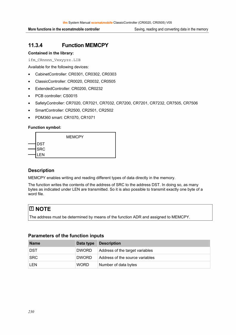
ifm System Manual ecomatmobile ClassicController (CR0020, CR0505) V05
230
More functions in the ecomatmobile controller Saving, reading and converting data in the memory
11.3.4 Function MEMCPY Contained in the library: ifm_CRnnnn_Vxxyyzz.LIB
Available for the following devices:
• CabinetController: CR0301, CR0302, CR0303
• ClassicController: CR0020, CR0032, CR0505
• ExtendedController: CR0200, CR0232
• PCB controller: CS0015
• SafetyController: CR7020, CR7021, CR7032, CR7200, CR7201, CR7232, CR7505, CR7506
• SmartController: CR2500, CR2501, CR2502
• PDM360 smart: CR1070, CR1071
Function symbol:
MEMCPY
DSTSRCLEN
Description MEMCPY enables writing and reading different types of data directly in the memory.
The function writes the contents of the address of SRC to the address DST. In doing so, as many bytes as indicated under LEN are transmitted. So it is also possible to transmit exactly one byte of a word file.
NOTE The address must be determined by means of the function ADR and assigned to MEMCPY.
Parameters of the function inputs Name Data type Description
DST DWORD Address of the target variables
SRC DWORD Address of the source variables
LEN WORD Number of data bytes
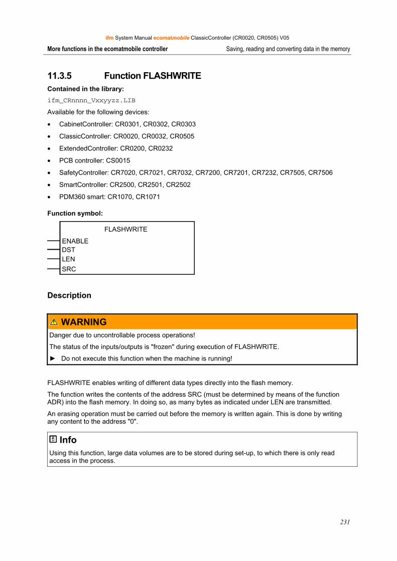
ifm System Manual ecomatmobile ClassicController (CR0020, CR0505) V05
231
More functions in the ecomatmobile controller Saving, reading and converting data in the memory
11.3.5 Function FLASHWRITE Contained in the library: ifm_CRnnnn_Vxxyyzz.LIB
Available for the following devices:
• CabinetController: CR0301, CR0302, CR0303
• ClassicController: CR0020, CR0032, CR0505
• ExtendedController: CR0200, CR0232
• PCB controller: CS0015
• SafetyController: CR7020, CR7021, CR7032, CR7200, CR7201, CR7232, CR7505, CR7506
• SmartController: CR2500, CR2501, CR2502
• PDM360 smart: CR1070, CR1071
Function symbol:
FLASHWRITE
ENABLEDSTLEN
SRC
Description
WARNING Danger due to uncontrollable process operations!
The status of the inputs/outputs is "frozen" during execution of FLASHWRITE.
► Do not execute this function when the machine is running!
FLASHWRITE enables writing of different data types directly into the flash memory.
The function writes the contents of the address SRC (must be determined by means of the function ADR) into the flash memory. In doing so, as many bytes as indicated under LEN are transmitted.
An erasing operation must be carried out before the memory is written again. This is done by writing any content to the address "0".
Info Using this function, large data volumes are to be stored during set-up, to which there is only read access in the process.
ifm System Manual ecomatmobile ClassicController (CR0020, CR0505) V05
232
More functions in the ecomatmobile controller Saving, reading and converting data in the memory
Parameters of the function inputs Name Data type Description
ENABLE BOOL TRUE: function is executed
FALSE: function is not executed
DST INT Relative start address in the memory. Memory access only word-by-word; permissible values: 0, 2, 4, 6, 8, ...
LEN INT Number of data bytes (max. 65 536 bytes)
SRC DWORD Address of the source variables
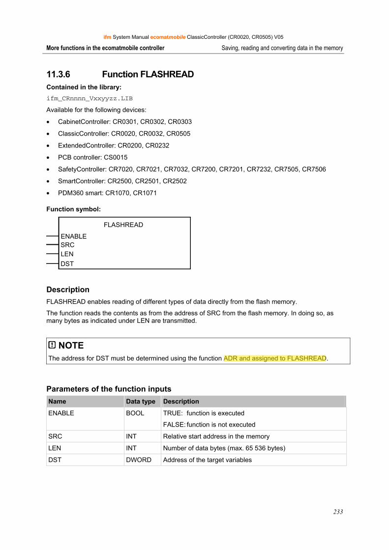
ifm System Manual ecomatmobile ClassicController (CR0020, CR0505) V05
233
More functions in the ecomatmobile controller Saving, reading and converting data in the memory
11.3.6 Function FLASHREAD Contained in the library: ifm_CRnnnn_Vxxyyzz.LIB
Available for the following devices:
• CabinetController: CR0301, CR0302, CR0303
• ClassicController: CR0020, CR0032, CR0505
• ExtendedController: CR0200, CR0232
• PCB controller: CS0015
• SafetyController: CR7020, CR7021, CR7032, CR7200, CR7201, CR7232, CR7505, CR7506
• SmartController: CR2500, CR2501, CR2502
• PDM360 smart: CR1070, CR1071
Function symbol:
FLASHREAD
ENABLESRCLEN
DST
Description FLASHREAD enables reading of different types of data directly from the flash memory.
The function reads the contents as from the address of SRC from the flash memory. In doing so, as many bytes as indicated under LEN are transmitted.
NOTE The address for DST must be determined using the function ADR and assigned to FLASHREAD.
Parameters of the function inputs Name Data type Description
ENABLE BOOL TRUE: function is executed
FALSE: function is not executed
SRC INT Relative start address in the memory
LEN INT Number of data bytes (max. 65 536 bytes)
DST DWORD Address of the target variables
Administrator
Highlight
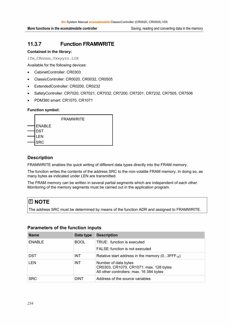
ifm System Manual ecomatmobile ClassicController (CR0020, CR0505) V05
234
More functions in the ecomatmobile controller Saving, reading and converting data in the memory
11.3.7 Function FRAMWRITE Contained in the library: ifm_CRnnnn_Vxxyyzz.LIB
Available for the following devices:
• CabinetController: CR0303
• ClassicController: CR0020, CR0032, CR0505
• ExtendedController: CR0200, CR0232
• SafetyController: CR7020, CR7021, CR7032, CR7200, CR7201, CR7232, CR7505, CR7506
• PDM360 smart: CR1070, CR1071
Function symbol:
FRAMWRITE
ENABLEDSTLEN
SRC
Description FRAMWRITE enables the quick writing of different data types directly into the FRAM memory.
The function writes the contents of the address SRC to the non-volatile FRAM memory. In doing so, as many bytes as indicated under LEN are transmitted.
The FRAM memory can be written in several partial segments which are independent of each other. Monitoring of the memory segments must be carried out in the application program.
NOTE The address SRC must be determined by means of the function ADR and assigned to FRAMWRITE.
Parameters of the function inputs Name Data type Description
ENABLE BOOL TRUE: function is executed
FALSE: function is not executed
DST INT Relative start address in the memory (0...3FFF16)
LEN INT Number of data bytes CR0303, CR1070, CR1071: max. 128 bytes All other controllers: max. 16 384 bytes
SRC DINT Address of the source variables
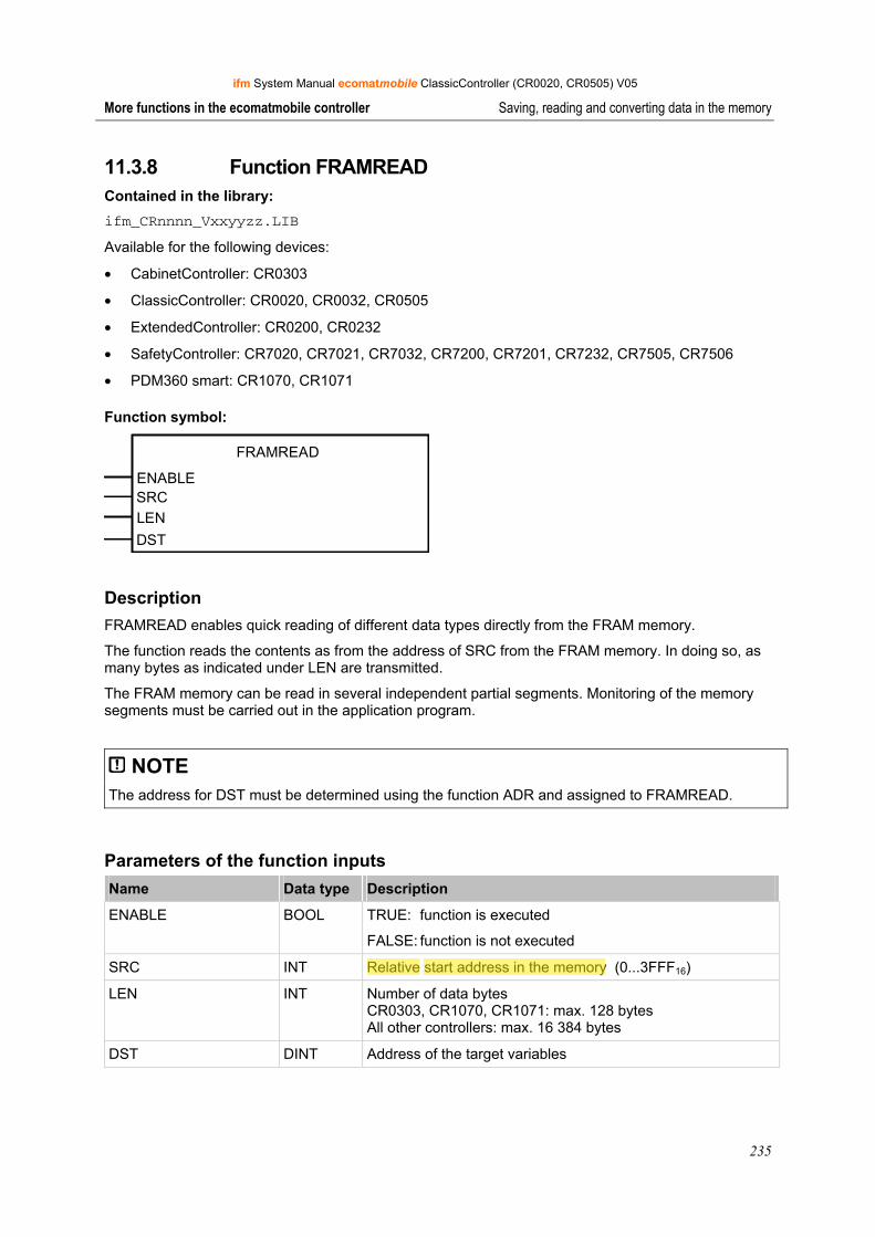
ifm System Manual ecomatmobile ClassicController (CR0020, CR0505) V05
235
More functions in the ecomatmobile controller Saving, reading and converting data in the memory
11.3.8 Function FRAMREAD Contained in the library: ifm_CRnnnn_Vxxyyzz.LIB
Available for the following devices:
• CabinetController: CR0303
• ClassicController: CR0020, CR0032, CR0505
• ExtendedController: CR0200, CR0232
• SafetyController: CR7020, CR7021, CR7032, CR7200, CR7201, CR7232, CR7505, CR7506
• PDM360 smart: CR1070, CR1071
Function symbol:
FRAMREAD
ENABLESRCLEN
DST
Description FRAMREAD enables quick reading of different data types directly from the FRAM memory.
The function reads the contents as from the address of SRC from the FRAM memory. In doing so, as many bytes as indicated under LEN are transmitted.
The FRAM memory can be read in several independent partial segments. Monitoring of the memory segments must be carried out in the application program.
NOTE The address for DST must be determined using the function ADR and assigned to FRAMREAD.
Parameters of the function inputs Name Data type Description
ENABLE BOOL TRUE: function is executed
FALSE: function is not executed
SRC INT Relative start address in the memory (0...3FFF16)
LEN INT Number of data bytes CR0303, CR1070, CR1071: max. 128 bytes All other controllers: max. 16 384 bytes
DST DINT Address of the target variables
Administrator
Highlight
Administrator
Highlight
Administrator
Strikeout

ifm System Manual ecomatmobile ClassicController (CR0020, CR0505) V05
236
More functions in the ecomatmobile controller Data access and data check
11.4 Data access and data check
The functions described in this chapter control the data access and enable a data check.
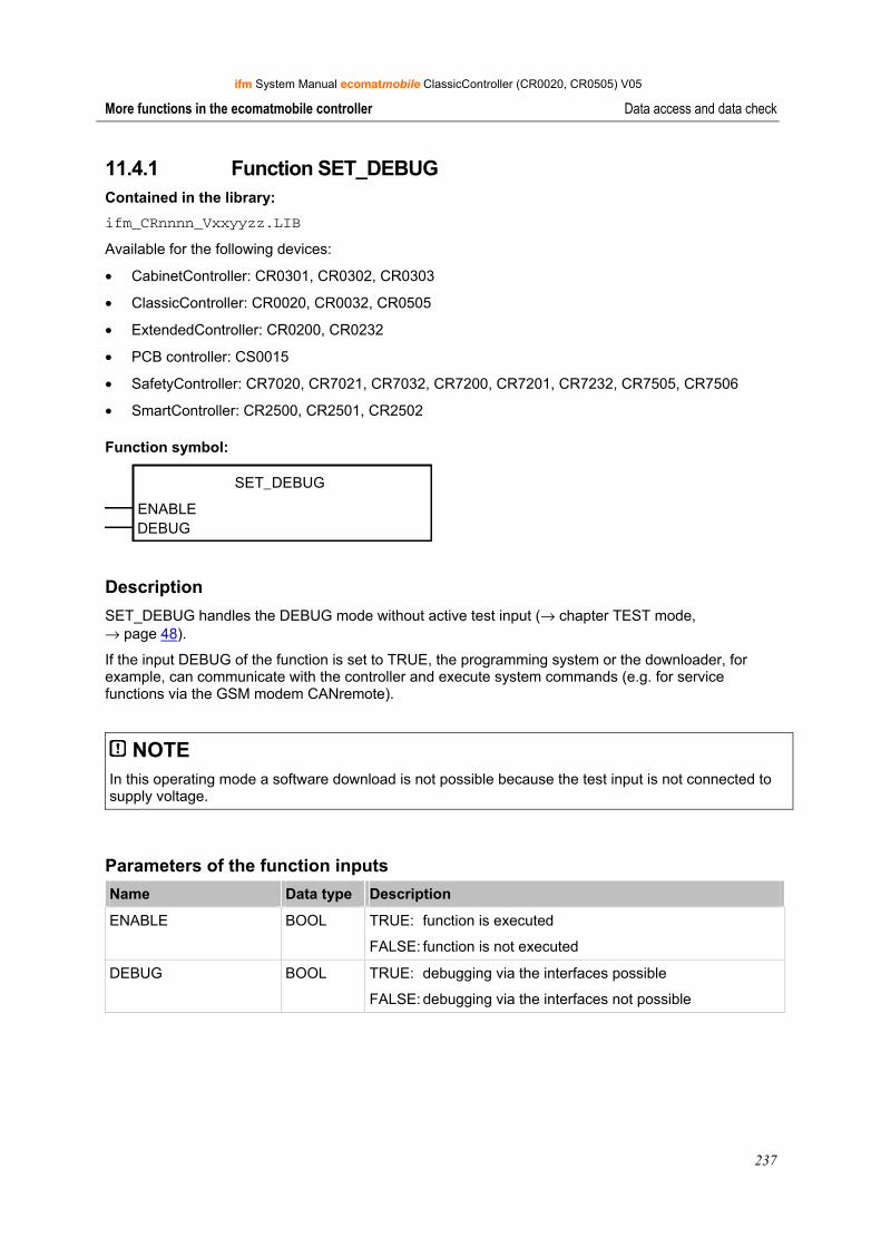
ifm System Manual ecomatmobile ClassicController (CR0020, CR0505) V05
237
More functions in the ecomatmobile controller Data access and data check
11.4.1 Function SET_DEBUG Contained in the library: ifm_CRnnnn_Vxxyyzz.LIB
Available for the following devices:
• CabinetController: CR0301, CR0302, CR0303
• ClassicController: CR0020, CR0032, CR0505
• ExtendedController: CR0200, CR0232
• PCB controller: CS0015
• SafetyController: CR7020, CR7021, CR7032, CR7200, CR7201, CR7232, CR7505, CR7506
• SmartController: CR2500, CR2501, CR2502
Function symbol:
SET_DEBUG
ENABLEDEBUG
Description SET_DEBUG handles the DEBUG mode without active test input (→ chapter TEST mode, → page 48).
If the input DEBUG of the function is set to TRUE, the programming system or the downloader, for example, can communicate with the controller and execute system commands (e.g. for service functions via the GSM modem CANremote).
NOTE In this operating mode a software download is not possible because the test input is not connected to supply voltage.
Parameters of the function inputs Name Data type Description
ENABLE BOOL TRUE: function is executed
FALSE: function is not executed
DEBUG BOOL TRUE: debugging via the interfaces possible
FALSE: debugging via the interfaces not possible
ifm System Manual ecomatmobile ClassicController (CR0020, CR0505) V05
238
More functions in the ecomatmobile controller Data access and data check
11.4.2 Function SET_IDENTITY Contained in the library: ifm_CRnnnn_Vxxyyzz.LIB
Available for the following devices:
• CabinetController: CR0301, CR0302, CR0303
• ClassicController: CR0020, CR0032, CR0505
• ExtendedController: CR0200, CR0232
• PCB controller: CS0015
• SafetyController: CR7020, CR7021, CR7032, CR7200, CR7201, CR7232, CR7505, CR7506
• SmartController: CR2500, CR2501, CR2502
• PDM360 smart: CR1070, CR1071
Function symbol:
SET_IDENTITY
ID
Description SET_IDENTITY sets an application-specific program identification.
Using this function, a program identification can be created by the application program. This identification (i.e. the software version) can be read via the software tool DOWNLOADER.EXE in order to identify the loaded program.
The following figure shows the correlations of the different identifications as indicated by the different software tools. (Example: ClassicController CR0020):
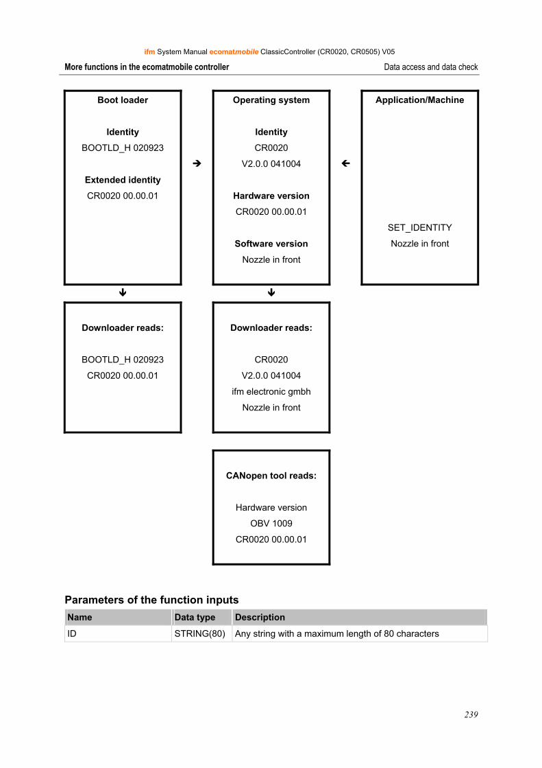
ifm System Manual ecomatmobile ClassicController (CR0020, CR0505) V05
239
More functions in the ecomatmobile controller Data access and data check
Boot loader
Identity
BOOTLD_H 020923
Extended identity
CR0020 00.00.01
Operating system
Identity
CR0020
V2.0.0 041004
Hardware version
CR0020 00.00.01
Software version
Nozzle in front
Application/Machine
SET_IDENTITY
Nozzle in front
Downloader reads:
BOOTLD_H 020923
CR0020 00.00.01
Downloader reads:
CR0020
V2.0.0 041004
ifm electronic gmbh
Nozzle in front
CANopen tool reads:
Hardware version
OBV 1009
CR0020 00.00.01
Parameters of the function inputs Name Data type Description
ID STRING(80) Any string with a maximum length of 80 characters
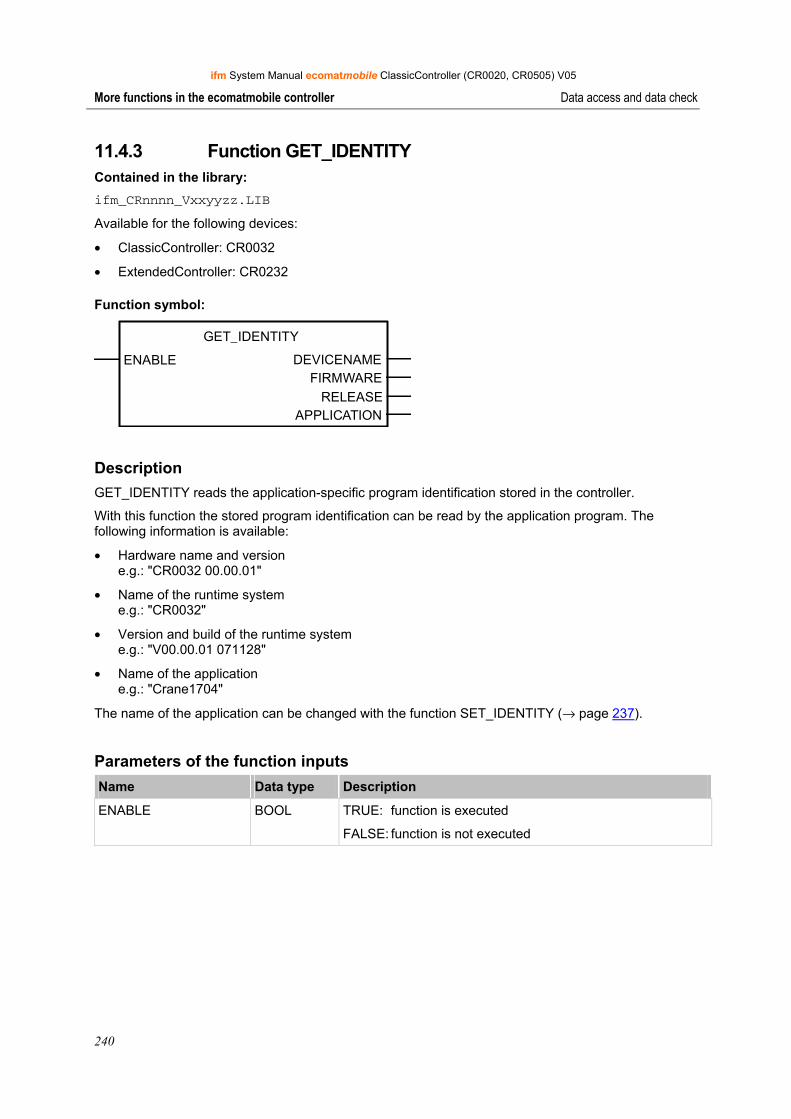
ifm System Manual ecomatmobile ClassicController (CR0020, CR0505) V05
240
More functions in the ecomatmobile controller Data access and data check
11.4.3 Function GET_IDENTITY Contained in the library: ifm_CRnnnn_Vxxyyzz.LIB
Available for the following devices:
• ClassicController: CR0032
• ExtendedController: CR0232
Function symbol:
GET_IDENTITY
ENABLE DEVICENAME FIRMWARE
RELEASEAPPLICATION
Description GET_IDENTITY reads the application-specific program identification stored in the controller.
With this function the stored program identification can be read by the application program. The following information is available:
• Hardware name and version e.g.: "CR0032 00.00.01"
• Name of the runtime system e.g.: "CR0032"
• Version and build of the runtime system e.g.: "V00.00.01 071128"
• Name of the application e.g.: "Crane1704"
The name of the application can be changed with the function SET_IDENTITY (→ page 237).
Parameters of the function inputs Name Data type Description
ENABLE BOOL TRUE: function is executed
FALSE: function is not executed
ifm System Manual ecomatmobile ClassicController (CR0020, CR0505) V05
241
More functions in the ecomatmobile controller Data access and data check
Parameters of the function outputs Name Data type Description
DEVICENAME STRING(31) Hardware name and version as string of max. 31 characters e.g.: "CR0032 00.00.01"
FIRMWARE STRING(31) Name of the runtime system as string of max. 31 characters e.g.: "CR0032"
RELEASE STRING(31) Version and build of the runtime system as string of max. 31 characters e.g.: "V00.00.01 071128"
APPLICATION STRING(79) Name of the application as string of max. 79 characters e.g.: "Crane1704"
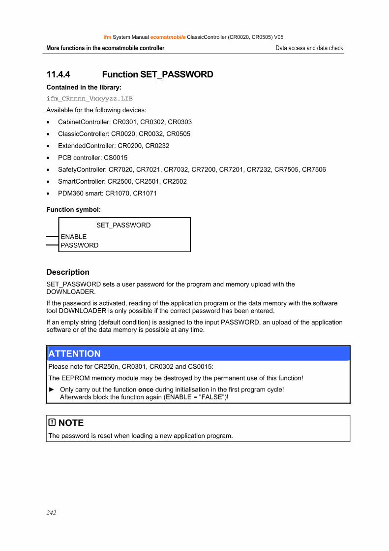
ifm System Manual ecomatmobile ClassicController (CR0020, CR0505) V05
242
More functions in the ecomatmobile controller Data access and data check
11.4.4 Function SET_PASSWORD Contained in the library: ifm_CRnnnn_Vxxyyzz.LIB
Available for the following devices:
• CabinetController: CR0301, CR0302, CR0303
• ClassicController: CR0020, CR0032, CR0505
• ExtendedController: CR0200, CR0232
• PCB controller: CS0015
• SafetyController: CR7020, CR7021, CR7032, CR7200, CR7201, CR7232, CR7505, CR7506
• SmartController: CR2500, CR2501, CR2502
• PDM360 smart: CR1070, CR1071
Function symbol:
SET_PASSWORD
ENABLEPASSWORD
Description SET_PASSWORD sets a user password for the program and memory upload with the DOWNLOADER.
If the password is activated, reading of the application program or the data memory with the software tool DOWNLOADER is only possible if the correct password has been entered.
If an empty string (default condition) is assigned to the input PASSWORD, an upload of the application software or of the data memory is possible at any time.
ATTENTION Please note for CR250n, CR0301, CR0302 and CS0015:
The EEPROM memory module may be destroyed by the permanent use of this function!
► Only carry out the function once during initialisation in the first program cycle! Afterwards block the function again (ENABLE = "FALSE")!
NOTE The password is reset when loading a new application program.

ifm System Manual ecomatmobile ClassicController (CR0020, CR0505) V05
243
More functions in the ecomatmobile controller Data access and data check
Parameters of the function inputs Name Data type Description
ENABLE BOOL TRUE (only 1 cycle): ID set
FALSE: function is not executed
PASSWORD STRING Password (maximum string length 16)
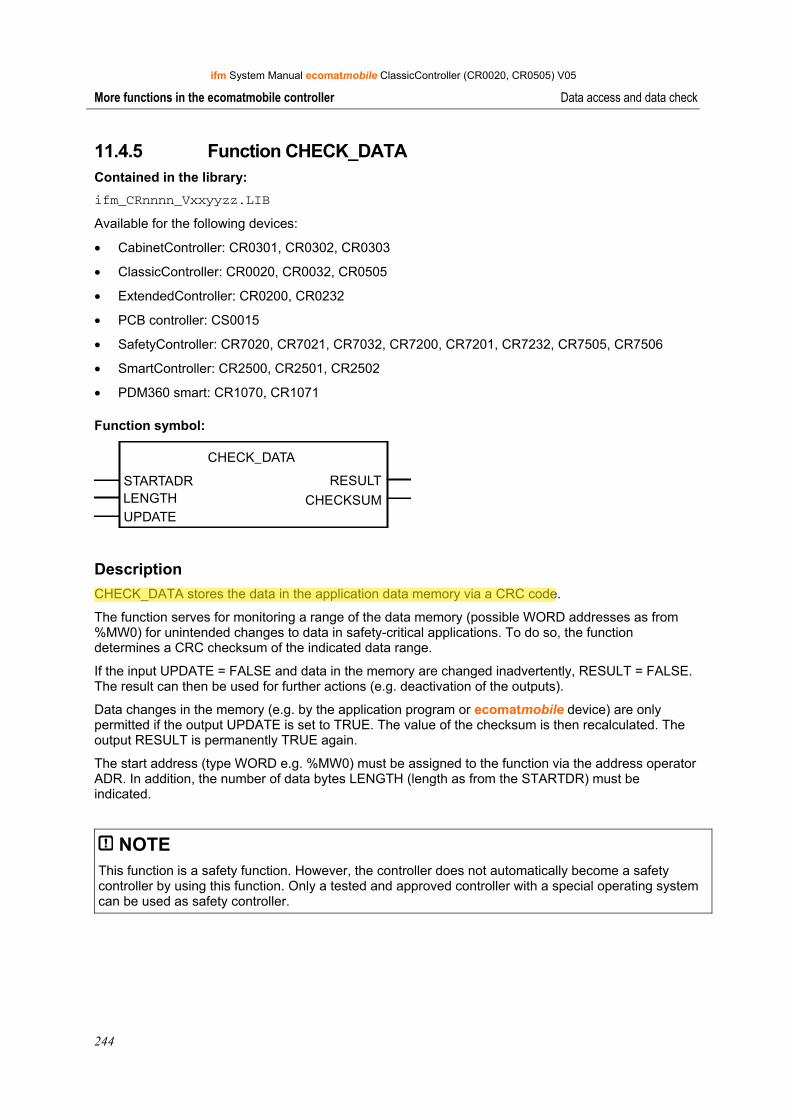
ifm System Manual ecomatmobile ClassicController (CR0020, CR0505) V05
244
More functions in the ecomatmobile controller Data access and data check
11.4.5 Function CHECK_DATA Contained in the library: ifm_CRnnnn_Vxxyyzz.LIB
Available for the following devices:
• CabinetController: CR0301, CR0302, CR0303
• ClassicController: CR0020, CR0032, CR0505
• ExtendedController: CR0200, CR0232
• PCB controller: CS0015
• SafetyController: CR7020, CR7021, CR7032, CR7200, CR7201, CR7232, CR7505, CR7506
• SmartController: CR2500, CR2501, CR2502
• PDM360 smart: CR1070, CR1071
Function symbol:
CHECK_DATA
STARTADR RESULTLENGTHUPDATE
CHECKSUM
Description CHECK_DATA stores the data in the application data memory via a CRC code.
The function serves for monitoring a range of the data memory (possible WORD addresses as from %MW0) for unintended changes to data in safety-critical applications. To do so, the function determines a CRC checksum of the indicated data range.
If the input UPDATE = FALSE and data in the memory are changed inadvertently, RESULT = FALSE. The result can then be used for further actions (e.g. deactivation of the outputs).
Data changes in the memory (e.g. by the application program or ecomatmobile device) are only permitted if the output UPDATE is set to TRUE. The value of the checksum is then recalculated. The output RESULT is permanently TRUE again.
The start address (type WORD e.g. %MW0) must be assigned to the function via the address operator ADR. In addition, the number of data bytes LENGTH (length as from the STARTDR) must be indicated.
NOTE This function is a safety function. However, the controller does not automatically become a safety controller by using this function. Only a tested and approved controller with a special operating system can be used as safety controller.
Administrator
Highlight
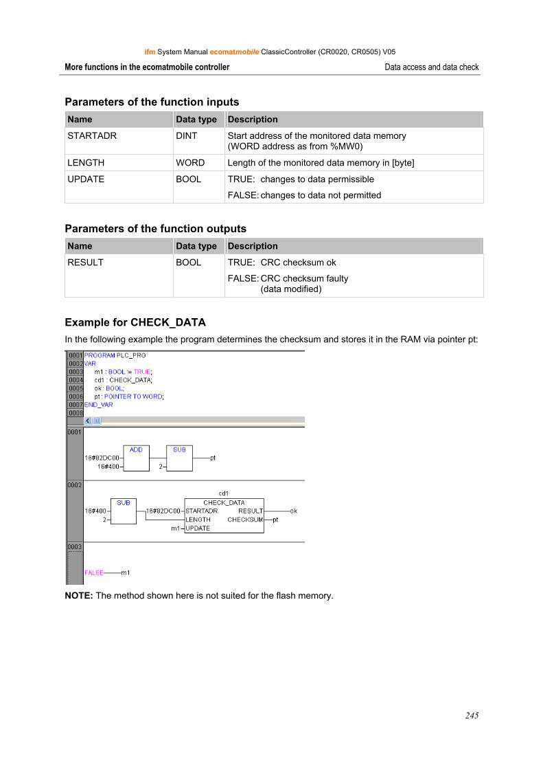
ifm System Manual ecomatmobile ClassicController (CR0020, CR0505) V05
245
More functions in the ecomatmobile controller Data access and data check
Parameters of the function inputs Name Data type Description
STARTADR DINT Start address of the monitored data memory (WORD address as from %MW0)
LENGTH WORD Length of the monitored data memory in [byte]
UPDATE BOOL TRUE: changes to data permissible
FALSE: changes to data not permitted
Parameters of the function outputs Name Data type Description
RESULT BOOL TRUE: CRC checksum ok
FALSE: CRC checksum faulty (data modified)
Example for CHECK_DATA In the following example the program determines the checksum and stores it in the RAM via pointer pt:
NOTE: The method shown here is not suited for the flash memory.

ifm System Manual ecomatmobile ClassicController (CR0020, CR0505) V05
246
More functions in the ecomatmobile controller Processing interrupts
11.5 Processing interrupts
The PLC cyclically processes the stored application program in its full length. The cycle time can vary due to program branchings which depend e.g. on external events (= conditional jumps). This can have negative effects on certain functions.
By means of systematic interrupts of the cyclic program it is possible to call time-critical processes independently of the cycle in fixed time periods or in case of certain events.
Since interrupt functions are principally not permitted for SafetyControllers, they are thus not available.
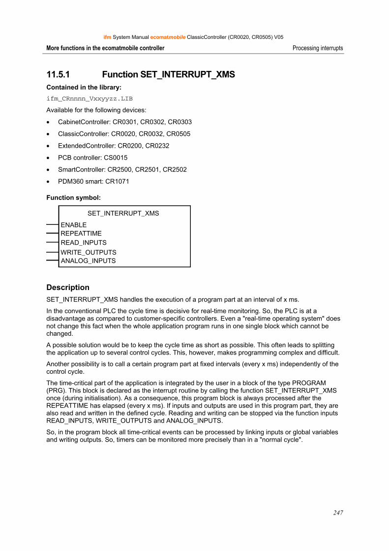
ifm System Manual ecomatmobile ClassicController (CR0020, CR0505) V05
247
More functions in the ecomatmobile controller Processing interrupts
11.5.1 Function SET_INTERRUPT_XMS Contained in the library: ifm_CRnnnn_Vxxyyzz.LIB
Available for the following devices:
• CabinetController: CR0301, CR0302, CR0303
• ClassicController: CR0020, CR0032, CR0505
• ExtendedController: CR0200, CR0232
• PCB controller: CS0015
• SmartController: CR2500, CR2501, CR2502
• PDM360 smart: CR1071
Function symbol:
SET_INTERRUPT_XMS
ENABLEREPEATTIMEREAD_INPUTS
WRITE_OUTPUTSANALOG_INPUTS
Description SET_INTERRUPT_XMS handles the execution of a program part at an interval of x ms.
In the conventional PLC the cycle time is decisive for real-time monitoring. So, the PLC is at a disadvantage as compared to customer-specific controllers. Even a "real-time operating system" does not change this fact when the whole application program runs in one single block which cannot be changed.
A possible solution would be to keep the cycle time as short as possible. This often leads to splitting the application up to several control cycles. This, however, makes programming complex and difficult.
Another possibility is to call a certain program part at fixed intervals (every x ms) independently of the control cycle.
The time-critical part of the application is integrated by the user in a block of the type PROGRAM (PRG). This block is declared as the interrupt routine by calling the function SET_INTERRUPT_XMS once (during initialisation). As a consequence, this program block is always processed after the REPEATTIME has elapsed (every x ms). If inputs and outputs are used in this program part, they are also read and written in the defined cycle. Reading and writing can be stopped via the function inputs READ_INPUTS, WRITE_OUTPUTS and ANALOG_INPUTS.
So, in the program block all time-critical events can be processed by linking inputs or global variables and writing outputs. So, timers can be monitored more precisely than in a "normal cycle".
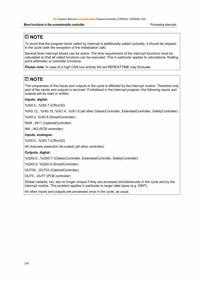
ifm System Manual ecomatmobile ClassicController (CR0020, CR0505) V05
248
More functions in the ecomatmobile controller Processing interrupts
NOTE To avoid that the program block called by interrupt is additionally called cyclically, it should be skipped in the cycle (with the exception of the initialisation call).
Several timer interrupt blocks can be active. The time requirement of the interrupt functions must be calculated so that all called functions can be executed. This in particular applies to calculations, floating point arithmetic or controller functions.
Please note: In case of a high CAN bus activity the set REPEATTIME may fluctuate.
NOTE The uniqueness of the inputs and outputs in the cycle is affected by the interrupt routine. Therefore only part of the inputs and outputs is serviced. If initialised in the interrupt program, the following inputs and outputs will be read or written.
Inputs, digital:
%IX0.0...%IX0.7 (CRnn32)
%IX0.12...%IX0.15, %IX1.4...%IX1.8 (all other ClassicController, ExtendedController, SafetyController)
%IX0.0, %IX0.8 (SmartController)
IN08...IN11 (CabinetController)
IN0...IN3 (PCB controller)
Inputs, analogue:
%IX0.0...%IX0.7 (CRnn32)
All channels (selection bit-coded) (all other controller)
Outputs, digital:
%QX0.0...%QX0.7 (ClassicController, ExtendedController, SafetyController)
%QX0.0, %QX0.8 (SmartController)
OUT00...OUT03 (CabinetController)
OUT0...OUT7 (PCB controller)
Global variants, too, are no longer unique if they are accessed simultaneously in the cycle and by the interrupt routine. This problem applies in particular to larger data types (e.g. DINT).
All other inputs and outputs are processed once in the cycle, as usual.
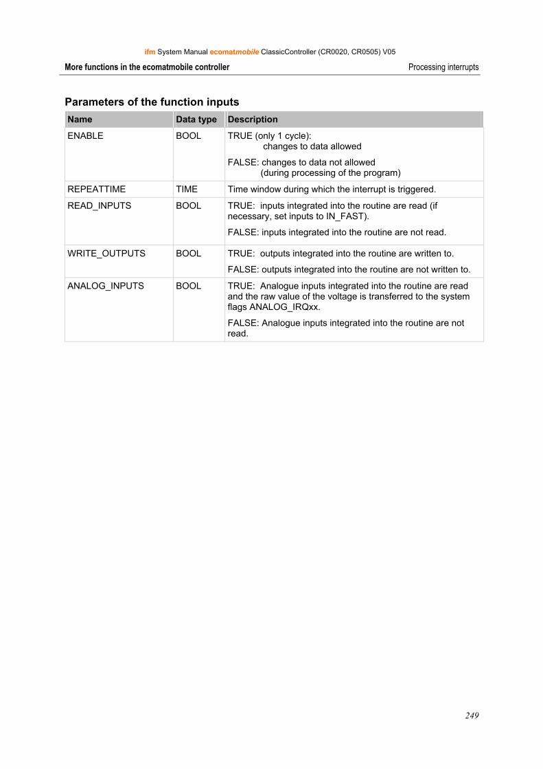
ifm System Manual ecomatmobile ClassicController (CR0020, CR0505) V05
249
More functions in the ecomatmobile controller Processing interrupts
Parameters of the function inputs Name Data type Description
ENABLE BOOL TRUE (only 1 cycle): changes to data allowed
FALSE: changes to data not allowed (during processing of the program)
REPEATTIME TIME Time window during which the interrupt is triggered.
READ_INPUTS BOOL TRUE: inputs integrated into the routine are read (if necessary, set inputs to IN_FAST).
FALSE: inputs integrated into the routine are not read.
WRITE_OUTPUTS BOOL TRUE: outputs integrated into the routine are written to.
FALSE: outputs integrated into the routine are not written to.
ANALOG_INPUTS BOOL TRUE: Analogue inputs integrated into the routine are read and the raw value of the voltage is transferred to the system flags ANALOG_IRQxx.
FALSE: Analogue inputs integrated into the routine are not read.
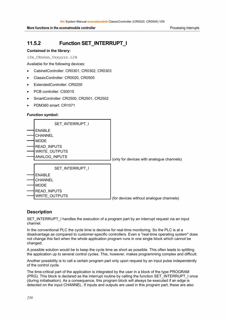
ifm System Manual ecomatmobile ClassicController (CR0020, CR0505) V05
250
More functions in the ecomatmobile controller Processing interrupts
11.5.2 Function SET_INTERRUPT_I Contained in the library: ifm_CRnnnn_Vxxyyzz.LIB
Available for the following devices:
• CabinetController: CR0301, CR0302, CR0303
• ClassicController: CR0020, CR0505
• ExtendedController: CR0200
• PCB controller: CS0015
• SmartController: CR2500, CR2501, CR2502
• PDM360 smart: CR1071
Function symbol:
SET_INTERRUPT_I
ENABLECHANNELMODE
READ_INPUTSWRITE_OUTPUTSANALOG_INPUTS (only for devices with analogue channels)
SET_INTERRUPT_I
ENABLECHANNELMODE
READ_INPUTSWRITE_OUTPUTS (for devices without analogue channels)
Description SET_INTERRUPT_I handles the execution of a program part by an interrupt request via an input channel.
In the conventional PLC the cycle time is decisive for real-time monitoring. So the PLC is at a disadvantage as compared to customer-specific controllers. Even a "real-time operating system" does not change this fact when the whole application program runs in one single block which cannot be changed.
A possible solution would be to keep the cycle time as short as possible. This often leads to splitting the application up to several control cycles. This, however, makes programming complex and difficult.
Another possibility is to call a certain program part only upon request by an input pulse independently of the control cycle.
The time-critical part of the application is integrated by the user in a block of the type PROGRAM (PRG). This block is declared as the interrupt routine by calling the function SET_INTERRUPT_I once (during initialisation). As a consequence, this program block will always be executed if an edge is detected on the input CHANNEL. If inputs and outputs are used in this program part, these are also
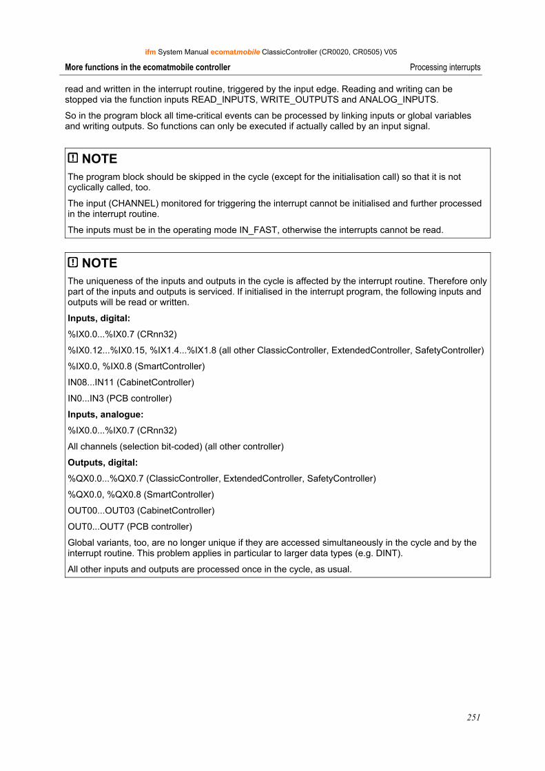
ifm System Manual ecomatmobile ClassicController (CR0020, CR0505) V05
251
More functions in the ecomatmobile controller Processing interrupts
read and written in the interrupt routine, triggered by the input edge. Reading and writing can be stopped via the function inputs READ_INPUTS, WRITE_OUTPUTS and ANALOG_INPUTS.
So in the program block all time-critical events can be processed by linking inputs or global variables and writing outputs. So functions can only be executed if actually called by an input signal.
NOTE The program block should be skipped in the cycle (except for the initialisation call) so that it is not cyclically called, too.
The input (CHANNEL) monitored for triggering the interrupt cannot be initialised and further processed in the interrupt routine.
The inputs must be in the operating mode IN_FAST, otherwise the interrupts cannot be read.
NOTE The uniqueness of the inputs and outputs in the cycle is affected by the interrupt routine. Therefore only part of the inputs and outputs is serviced. If initialised in the interrupt program, the following inputs and outputs will be read or written.
Inputs, digital:
%IX0.0...%IX0.7 (CRnn32)
%IX0.12...%IX0.15, %IX1.4...%IX1.8 (all other ClassicController, ExtendedController, SafetyController)
%IX0.0, %IX0.8 (SmartController)
IN08...IN11 (CabinetController)
IN0...IN3 (PCB controller)
Inputs, analogue:
%IX0.0...%IX0.7 (CRnn32)
All channels (selection bit-coded) (all other controller)
Outputs, digital:
%QX0.0...%QX0.7 (ClassicController, ExtendedController, SafetyController)
%QX0.0, %QX0.8 (SmartController)
OUT00...OUT03 (CabinetController)
OUT0...OUT7 (PCB controller)
Global variants, too, are no longer unique if they are accessed simultaneously in the cycle and by the interrupt routine. This problem applies in particular to larger data types (e.g. DINT).
All other inputs and outputs are processed once in the cycle, as usual.
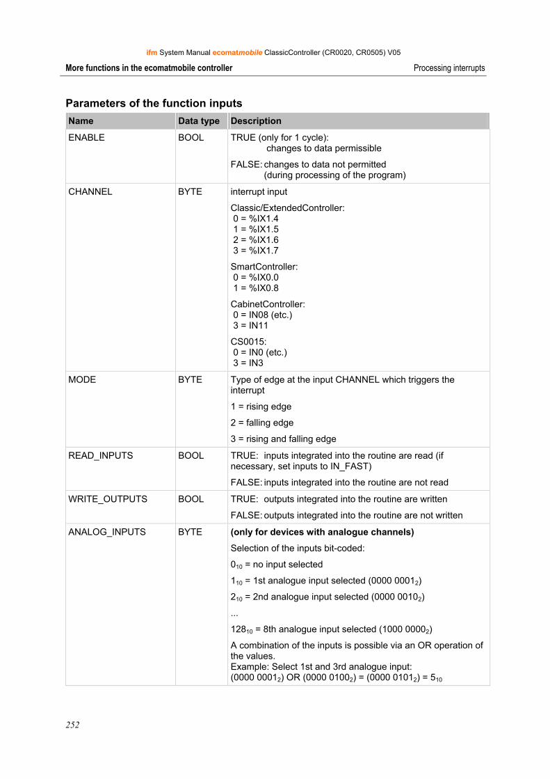
ifm System Manual ecomatmobile ClassicController (CR0020, CR0505) V05
252
More functions in the ecomatmobile controller Processing interrupts
Parameters of the function inputs Name Data type Description
ENABLE BOOL TRUE (only for 1 cycle): changes to data permissible
FALSE: changes to data not permitted (during processing of the program)
CHANNEL BYTE interrupt input
Classic/ExtendedController: 0 = %IX1.4 1 = %IX1.5 2 = %IX1.6 3 = %IX1.7
SmartController: 0 = %IX0.0 1 = %IX0.8
CabinetController: 0 = IN08 (etc.) 3 = IN11
CS0015: 0 = IN0 (etc.) 3 = IN3
MODE BYTE Type of edge at the input CHANNEL which triggers the interrupt
1 = rising edge
2 = falling edge
3 = rising and falling edge
READ_INPUTS BOOL TRUE: inputs integrated into the routine are read (if necessary, set inputs to IN_FAST)
FALSE: inputs integrated into the routine are not read
WRITE_OUTPUTS BOOL TRUE: outputs integrated into the routine are written
FALSE: outputs integrated into the routine are not written
ANALOG_INPUTS BYTE (only for devices with analogue channels)
Selection of the inputs bit-coded:
010 = no input selected
110 = 1st analogue input selected (0000 00012)
210 = 2nd analogue input selected (0000 00102)
...
12810 = 8th analogue input selected (1000 00002)
A combination of the inputs is possible via an OR operation of the values. Example: Select 1st and 3rd analogue input: (0000 00012) OR (0000 01002) = (0000 01012) = 510
ifm System Manual ecomatmobile ClassicController (CR0020, CR0505) V05
253
More functions in the ecomatmobile controller Use of the serial interface
11.6 Use of the serial interface
NOTE In principle, the serial interface is not available for the user because it is used for program download and debugging.
The interface can be freely used if the user sets the system flag bit SERIAL_MODE to TRUE. Then however, program download and debugging are only possible via the CAN interface. For CRnn32: Debugging of the application software is then only possible via all 4 CAN interfaces or via USB.
The serial interface can be used in the application program by means of the following functions.
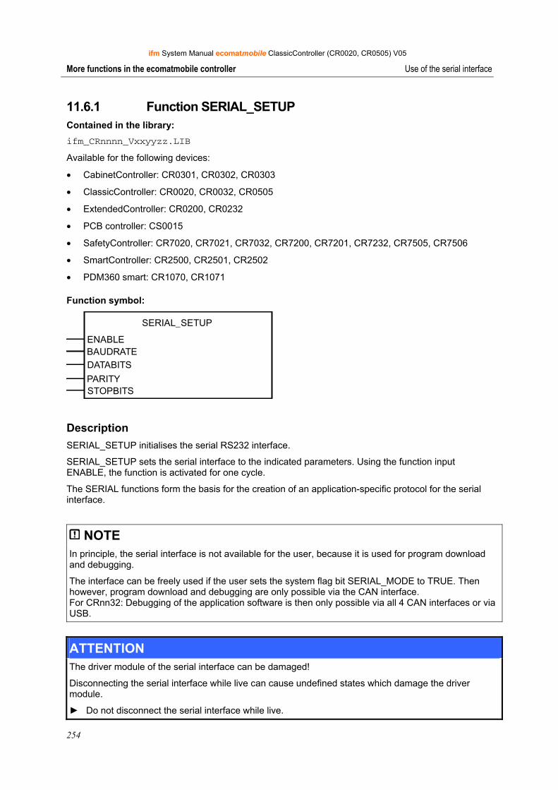
ifm System Manual ecomatmobile ClassicController (CR0020, CR0505) V05
254
More functions in the ecomatmobile controller Use of the serial interface
11.6.1 Function SERIAL_SETUP Contained in the library: ifm_CRnnnn_Vxxyyzz.LIB
Available for the following devices:
• CabinetController: CR0301, CR0302, CR0303
• ClassicController: CR0020, CR0032, CR0505
• ExtendedController: CR0200, CR0232
• PCB controller: CS0015
• SafetyController: CR7020, CR7021, CR7032, CR7200, CR7201, CR7232, CR7505, CR7506
• SmartController: CR2500, CR2501, CR2502
• PDM360 smart: CR1070, CR1071
Function symbol:
SERIAL_SETUP
ENABLEBAUDRATEDATABITS
PARITYSTOPBITS
Description SERIAL_SETUP initialises the serial RS232 interface.
SERIAL_SETUP sets the serial interface to the indicated parameters. Using the function input ENABLE, the function is activated for one cycle.
The SERIAL functions form the basis for the creation of an application-specific protocol for the serial interface.
NOTE In principle, the serial interface is not available for the user, because it is used for program download and debugging.
The interface can be freely used if the user sets the system flag bit SERIAL_MODE to TRUE. Then however, program download and debugging are only possible via the CAN interface. For CRnn32: Debugging of the application software is then only possible via all 4 CAN interfaces or via USB.
ATTENTION The driver module of the serial interface can be damaged!
Disconnecting the serial interface while live can cause undefined states which damage the driver module.
► Do not disconnect the serial interface while live.
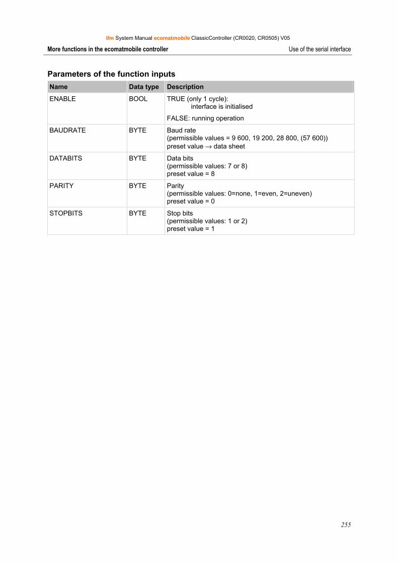
ifm System Manual ecomatmobile ClassicController (CR0020, CR0505) V05
255
More functions in the ecomatmobile controller Use of the serial interface
Parameters of the function inputs Name Data type Description
ENABLE BOOL TRUE (only 1 cycle): interface is initialised
FALSE: running operation
BAUDRATE BYTE Baud rate (permissible values = 9 600, 19 200, 28 800, (57 600)) preset value → data sheet
DATABITS BYTE Data bits (permissible values: 7 or 8) preset value = 8
PARITY BYTE Parity (permissible values: 0=none, 1=even, 2=uneven) preset value = 0
STOPBITS BYTE Stop bits (permissible values: 1 or 2) preset value = 1
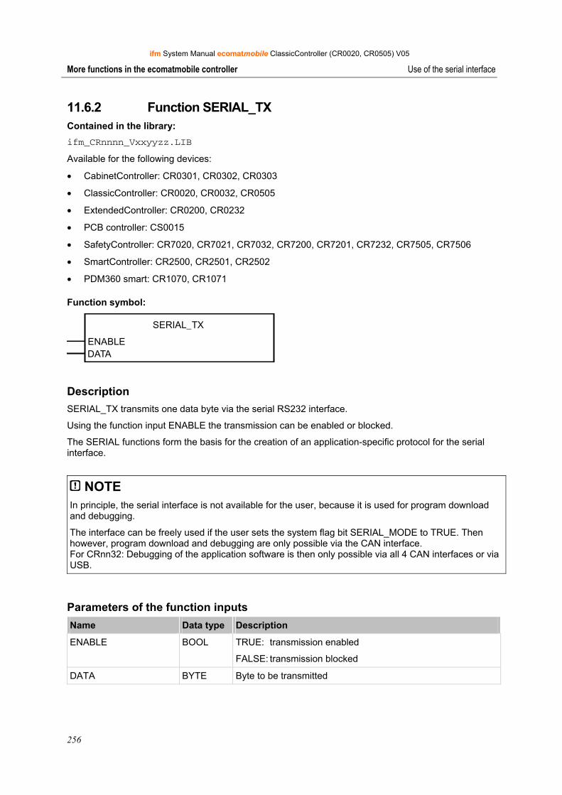
ifm System Manual ecomatmobile ClassicController (CR0020, CR0505) V05
256
More functions in the ecomatmobile controller Use of the serial interface
11.6.2 Function SERIAL_TX Contained in the library: ifm_CRnnnn_Vxxyyzz.LIB
Available for the following devices:
• CabinetController: CR0301, CR0302, CR0303
• ClassicController: CR0020, CR0032, CR0505
• ExtendedController: CR0200, CR0232
• PCB controller: CS0015
• SafetyController: CR7020, CR7021, CR7032, CR7200, CR7201, CR7232, CR7505, CR7506
• SmartController: CR2500, CR2501, CR2502
• PDM360 smart: CR1070, CR1071
Function symbol:
SERIAL_TX
ENABLEDATA
Description SERIAL_TX transmits one data byte via the serial RS232 interface.
Using the function input ENABLE the transmission can be enabled or blocked.
The SERIAL functions form the basis for the creation of an application-specific protocol for the serial interface.
NOTE In principle, the serial interface is not available for the user, because it is used for program download and debugging.
The interface can be freely used if the user sets the system flag bit SERIAL_MODE to TRUE. Then however, program download and debugging are only possible via the CAN interface. For CRnn32: Debugging of the application software is then only possible via all 4 CAN interfaces or via USB.
Parameters of the function inputs Name Data type Description
ENABLE BOOL TRUE: transmission enabled
FALSE: transmission blocked
DATA BYTE Byte to be transmitted
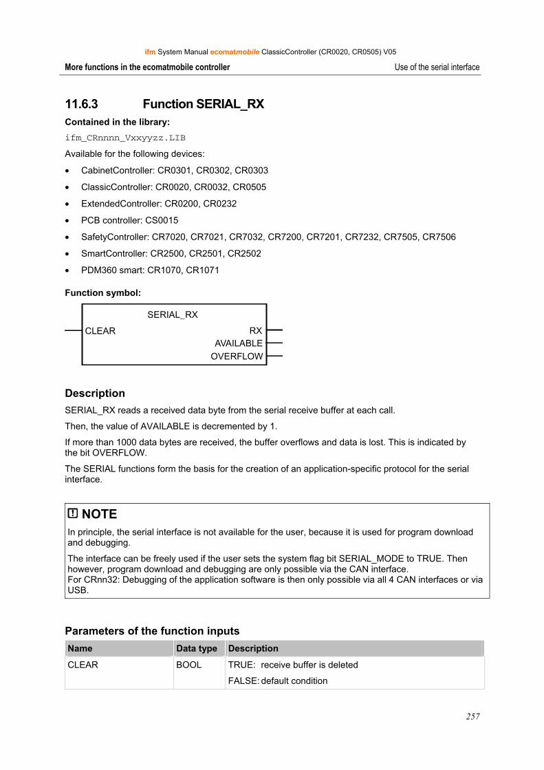
ifm System Manual ecomatmobile ClassicController (CR0020, CR0505) V05
257
More functions in the ecomatmobile controller Use of the serial interface
11.6.3 Function SERIAL_RX Contained in the library: ifm_CRnnnn_Vxxyyzz.LIB
Available for the following devices:
• CabinetController: CR0301, CR0302, CR0303
• ClassicController: CR0020, CR0032, CR0505
• ExtendedController: CR0200, CR0232
• PCB controller: CS0015
• SafetyController: CR7020, CR7021, CR7032, CR7200, CR7201, CR7232, CR7505, CR7506
• SmartController: CR2500, CR2501, CR2502
• PDM360 smart: CR1070, CR1071
Function symbol:
SERIAL_RX
CLEAR RXAVAILABLE
OVERFLOW
Description SERIAL_RX reads a received data byte from the serial receive buffer at each call.
Then, the value of AVAILABLE is decremented by 1.
If more than 1000 data bytes are received, the buffer overflows and data is lost. This is indicated by the bit OVERFLOW.
The SERIAL functions form the basis for the creation of an application-specific protocol for the serial interface.
NOTE In principle, the serial interface is not available for the user, because it is used for program download and debugging.
The interface can be freely used if the user sets the system flag bit SERIAL_MODE to TRUE. Then however, program download and debugging are only possible via the CAN interface. For CRnn32: Debugging of the application software is then only possible via all 4 CAN interfaces or via USB.
Parameters of the function inputs Name Data type Description
CLEAR BOOL TRUE: receive buffer is deleted
FALSE: default condition
ifm System Manual ecomatmobile ClassicController (CR0020, CR0505) V05
258
More functions in the ecomatmobile controller Use of the serial interface
Parameters of the function outputs Name Data type Description
RX BYTE Byte data received from the receive buffer
AVAILABLE WORD Number of data bytes received
0 = no valid data available
OVERFLOW BOOL Overflow of the data buffer, loss of data!
Example: 3 bytes are received:
1st call of SERIAL_RX 1 valid value at output RX → AVAILABLE = 3
2nd call of SERIAL_RX 1 valid value at output RX → AVAILABLE = 2
3rd call of SERIAL_RX 1 valid value at output RX → AVAILABLE = 1
4th call of SERIAL_RX invalid value at the output RX → AVAILABLE = 0
If AVAILABLE = 0, the function can be skipped during processing of the program.
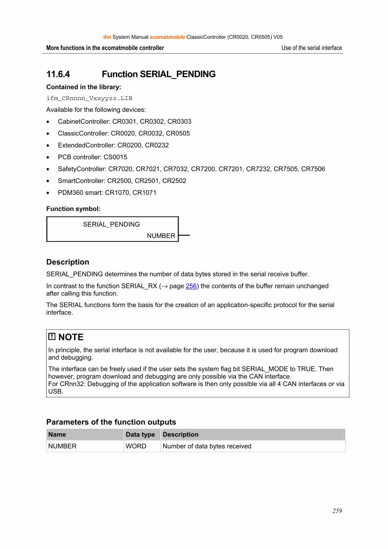
ifm System Manual ecomatmobile ClassicController (CR0020, CR0505) V05
259
More functions in the ecomatmobile controller Use of the serial interface
11.6.4 Function SERIAL_PENDING Contained in the library: ifm_CRnnnn_Vxxyyzz.LIB
Available for the following devices:
• CabinetController: CR0301, CR0302, CR0303
• ClassicController: CR0020, CR0032, CR0505
• ExtendedController: CR0200, CR0232
• PCB controller: CS0015
• SafetyController: CR7020, CR7021, CR7032, CR7200, CR7201, CR7232, CR7505, CR7506
• SmartController: CR2500, CR2501, CR2502
• PDM360 smart: CR1070, CR1071
Function symbol:
SERIAL_PENDING
NUMBER
Description SERIAL_PENDING determines the number of data bytes stored in the serial receive buffer.
In contrast to the function SERIAL_RX (→ page 256) the contents of the buffer remain unchanged after calling this function.
The SERIAL functions form the basis for the creation of an application-specific protocol for the serial interface.
NOTE In principle, the serial interface is not available for the user, because it is used for program download and debugging.
The interface can be freely used if the user sets the system flag bit SERIAL_MODE to TRUE. Then however, program download and debugging are only possible via the CAN interface. For CRnn32: Debugging of the application software is then only possible via all 4 CAN interfaces or via USB.
Parameters of the function outputs Name Data type Description
NUMBER WORD Number of data bytes received
ifm System Manual ecomatmobile ClassicController (CR0020, CR0505) V05
260
More functions in the ecomatmobile controller Reading the system time
11.7 Reading the system time
The following functions offered by ifm electronic allow you to read the continually running system time of the controller and to evaluate it in the application program.
11.7.1 Function TIMER_READ Contained in the library: ifm_CRnnnn_Vxxyyzz.LIB
Available for the following devices:
• CabinetController: CR0301, CR0302, CR0303
• ClassicController: CR0020, CR0032, CR0505
• ExtendedController: CR0200, CR0232
• PCB controller: CS0015
• SafetyController: CR7020, CR7021, CR7032, CR7200, CR7201, CR7232, CR7505, CR7506
• SmartController: CR2500, CR2501, CR2502
• PDM360 smart: CR1070, CR1071
Function symbol:
TIMER_READ
T
Description TIMER_READ reads the current system time.
When the supply voltage is applied, the controller generates a clock pulse which is counted upwards in a register. This register can be read using the function call and can for example be used for time measurement.
NOTE The system timer goes up to FFFF FFFF16 at the maximum (corresponds to about 49.7 days) and then starts again from 0.
Parameters of the function outputs Name Data type Description
T TIME Current system time (resolution [ms])
ifm System Manual ecomatmobile ClassicController (CR0020, CR0505) V05
261
More functions in the ecomatmobile controller Reading the system time
11.7.2 Function TIMER_READ_US Contained in the library: ifm_CRnnnn_Vxxyyzz.LIB
Available for the following devices:
• CabinetController: CR0301, CR0302, CR0303
• ClassicController: CR0020, CR0032, CR0505
• ExtendedController: CR0200, CR0232
• PCB controller: CS0015
• SafetyController: CR7020, CR7021, CR7032, CR7200, CR7201, CR7232, CR7505, CR7506
• SmartController: CR2500, CR2501, CR2502
• PDM360 smart: CR1070, CR1071
Function symbol:
TIMER_READ_US
TIME_US
Description TIMER_READ_US reads the current system time in [µs].
When the supply voltage is applied, the controller generates a clock pulse which is counted upwards in a register. This register can be read by means of the function call and can for example be used for time measurement.
Info The system timer runs up to the counter value 4 294 967 295 µs at the maximum and then starts again from 0.
4 294 967 295 µs = 71 582.8 min = 1 193 h = 49.7 d
Parameters of the function outputs Name Data type Description
TIME_US DWORD Current system time (resolution [μs])

ifm System Manual ecomatmobile ClassicController (CR0020, CR0505) V05
262
More functions in the ecomatmobile controller Processing analogue input values
11.8 Processing analogue input values
In this chapter we show you functions which allow you to read and process the values of analogue voltages or currents at the controller input.
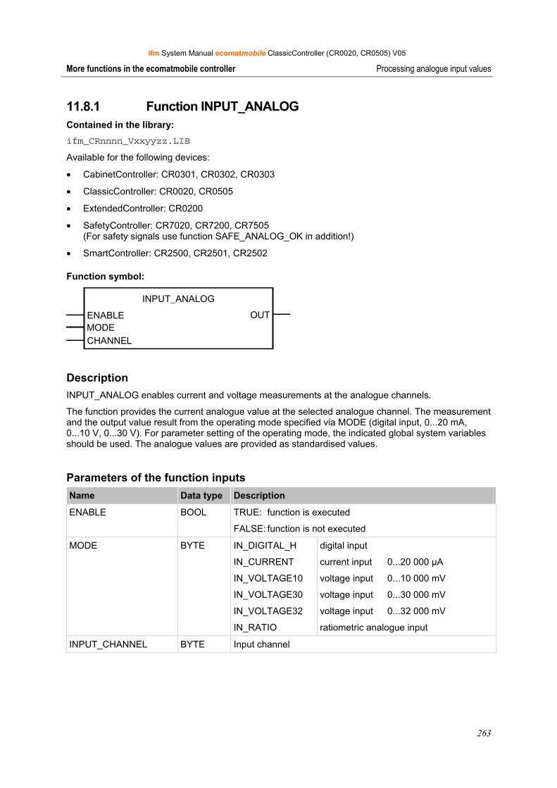
ifm System Manual ecomatmobile ClassicController (CR0020, CR0505) V05
263
More functions in the ecomatmobile controller Processing analogue input values
11.8.1 Function INPUT_ANALOG Contained in the library: ifm_CRnnnn_Vxxyyzz.LIB
Available for the following devices:
• CabinetController: CR0301, CR0302, CR0303
• ClassicController: CR0020, CR0505
• ExtendedController: CR0200
• SafetyController: CR7020, CR7200, CR7505 (For safety signals use function SAFE_ANALOG_OK in addition!)
• SmartController: CR2500, CR2501, CR2502
Function symbol:
INPUT_ANALOG
ENABLEMODECHANNEL
OUT
Description INPUT_ANALOG enables current and voltage measurements at the analogue channels.
The function provides the current analogue value at the selected analogue channel. The measurement and the output value result from the operating mode specified via MODE (digital input, 0...20 mA, 0...10 V, 0...30 V). For parameter setting of the operating mode, the indicated global system variables should be used. The analogue values are provided as standardised values.
Parameters of the function inputs Name Data type Description
ENABLE BOOL TRUE: function is executed
FALSE: function is not executed
MODE BYTE IN_DIGITAL_H
IN_CURRENT
IN_VOLTAGE10
IN_VOLTAGE30
IN_VOLTAGE32
IN_RATIO
digital input
current input 0...20 000 μA
voltage input 0...10 000 mV
voltage input 0...30 000 mV
voltage input 0...32 000 mV
ratiometric analogue input
INPUT_CHANNEL BYTE Input channel

ifm System Manual ecomatmobile ClassicController (CR0020, CR0505) V05
264
More functions in the ecomatmobile controller Processing analogue input values
Parameters of the function outputs Name Data type Description
OUT WORD Output value
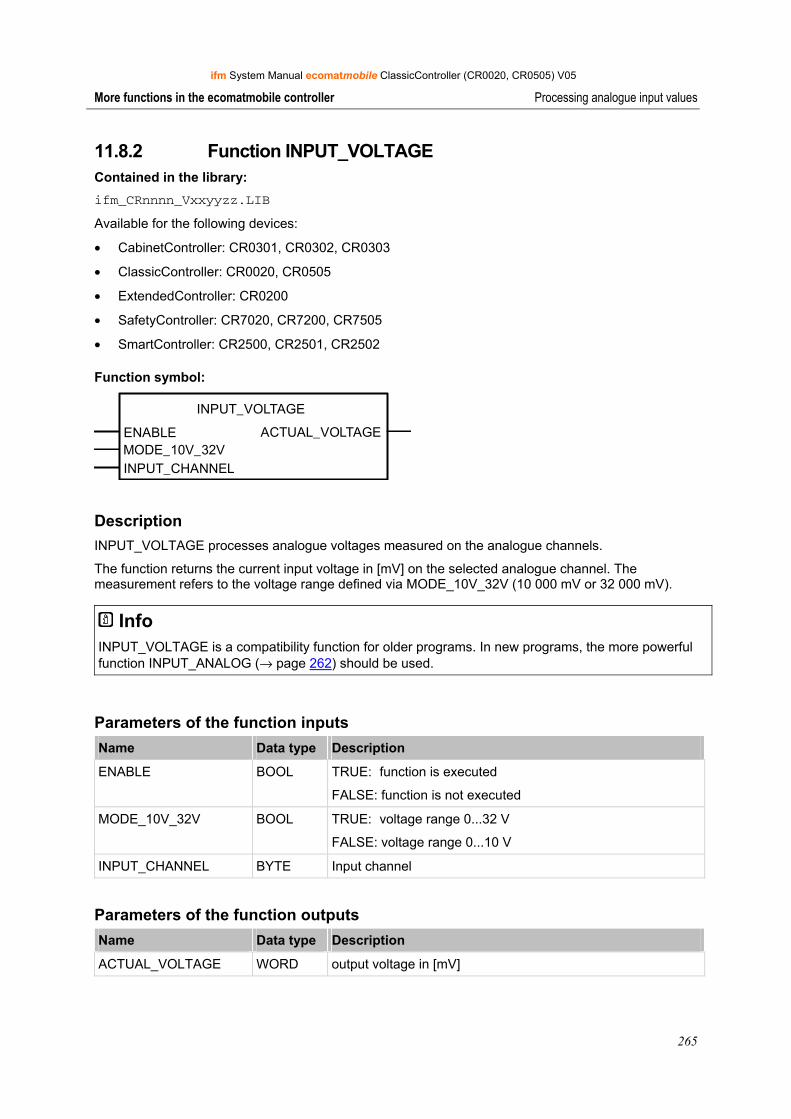
ifm System Manual ecomatmobile ClassicController (CR0020, CR0505) V05
265
More functions in the ecomatmobile controller Processing analogue input values
11.8.2 Function INPUT_VOLTAGE Contained in the library: ifm_CRnnnn_Vxxyyzz.LIB
Available for the following devices:
• CabinetController: CR0301, CR0302, CR0303
• ClassicController: CR0020, CR0505
• ExtendedController: CR0200
• SafetyController: CR7020, CR7200, CR7505
• SmartController: CR2500, CR2501, CR2502
Function symbol:
INPUT_VOLTAGE
ENABLE ACTUAL_VOLTAGEMODE_10V_32VINPUT_CHANNEL
Description INPUT_VOLTAGE processes analogue voltages measured on the analogue channels.
The function returns the current input voltage in [mV] on the selected analogue channel. The measurement refers to the voltage range defined via MODE_10V_32V (10 000 mV or 32 000 mV).
Info INPUT_VOLTAGE is a compatibility function for older programs. In new programs, the more powerful function INPUT_ANALOG (→ page 262) should be used.
Parameters of the function inputs Name Data type Description
ENABLE BOOL TRUE: function is executed
FALSE: function is not executed
MODE_10V_32V BOOL TRUE: voltage range 0...32 V
FALSE: voltage range 0...10 V
INPUT_CHANNEL BYTE Input channel
Parameters of the function outputs Name Data type Description
ACTUAL_VOLTAGE WORD output voltage in [mV]
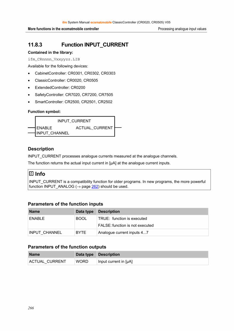
ifm System Manual ecomatmobile ClassicController (CR0020, CR0505) V05
266
More functions in the ecomatmobile controller Processing analogue input values
11.8.3 Function INPUT_CURRENT Contained in the library: ifm_CRnnnn_Vxxyyzz.LIB
Available for the following devices:
• CabinetController: CR0301, CR0302, CR0303
• ClassicController: CR0020, CR0505
• ExtendedController: CR0200
• SafetyController: CR7020, CR7200, CR7505
• SmartController: CR2500, CR2501, CR2502
Function symbol:
INPUT_CURRENT
ENABLE ACTUAL_CURRENTINPUT_CHANNEL
Description INPUT_CURRENT processes analogue currents measured at the analogue channels.
The function returns the actual input current in [µA] at the analogue current inputs.
Info INPUT_CURRENT is a compatibility function for older programs. In new programs, the more powerful function INPUT_ANALOG (→ page 262) should be used.
Parameters of the function inputs Name Data type Description
ENABLE BOOL TRUE: function is executed
FALSE: function is not executed
INPUT_CHANNEL BYTE Analogue current inputs 4...7
Parameters of the function outputs Name Data type Description
ACTUAL_CURRENT WORD Input current in [µA]

ifm System Manual ecomatmobile ClassicController (CR0020, CR0505) V05
267
More functions in the ecomatmobile controller Adapting analogue values
11.9 Adapting analogue values
If the values of analogue inputs or the results of analogue functions must be adapted, the following functions will help you.
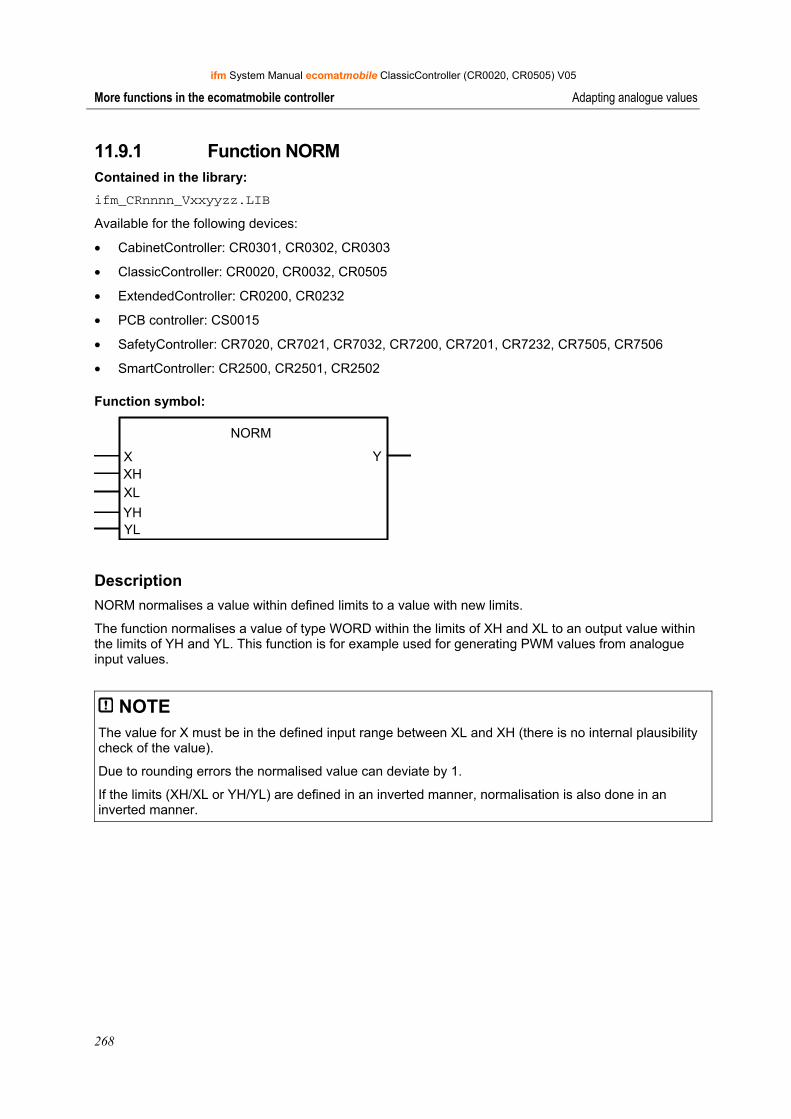
ifm System Manual ecomatmobile ClassicController (CR0020, CR0505) V05
268
More functions in the ecomatmobile controller Adapting analogue values
11.9.1 Function NORM Contained in the library: ifm_CRnnnn_Vxxyyzz.LIB
Available for the following devices:
• CabinetController: CR0301, CR0302, CR0303
• ClassicController: CR0020, CR0032, CR0505
• ExtendedController: CR0200, CR0232
• PCB controller: CS0015
• SafetyController: CR7020, CR7021, CR7032, CR7200, CR7201, CR7232, CR7505, CR7506
• SmartController: CR2500, CR2501, CR2502
Function symbol:
NORM
X YXHXL
YHYL
Description NORM normalises a value within defined limits to a value with new limits.
The function normalises a value of type WORD within the limits of XH and XL to an output value within the limits of YH and YL. This function is for example used for generating PWM values from analogue input values.
NOTE The value for X must be in the defined input range between XL and XH (there is no internal plausibility check of the value).
Due to rounding errors the normalised value can deviate by 1.
If the limits (XH/XL or YH/YL) are defined in an inverted manner, normalisation is also done in an inverted manner.
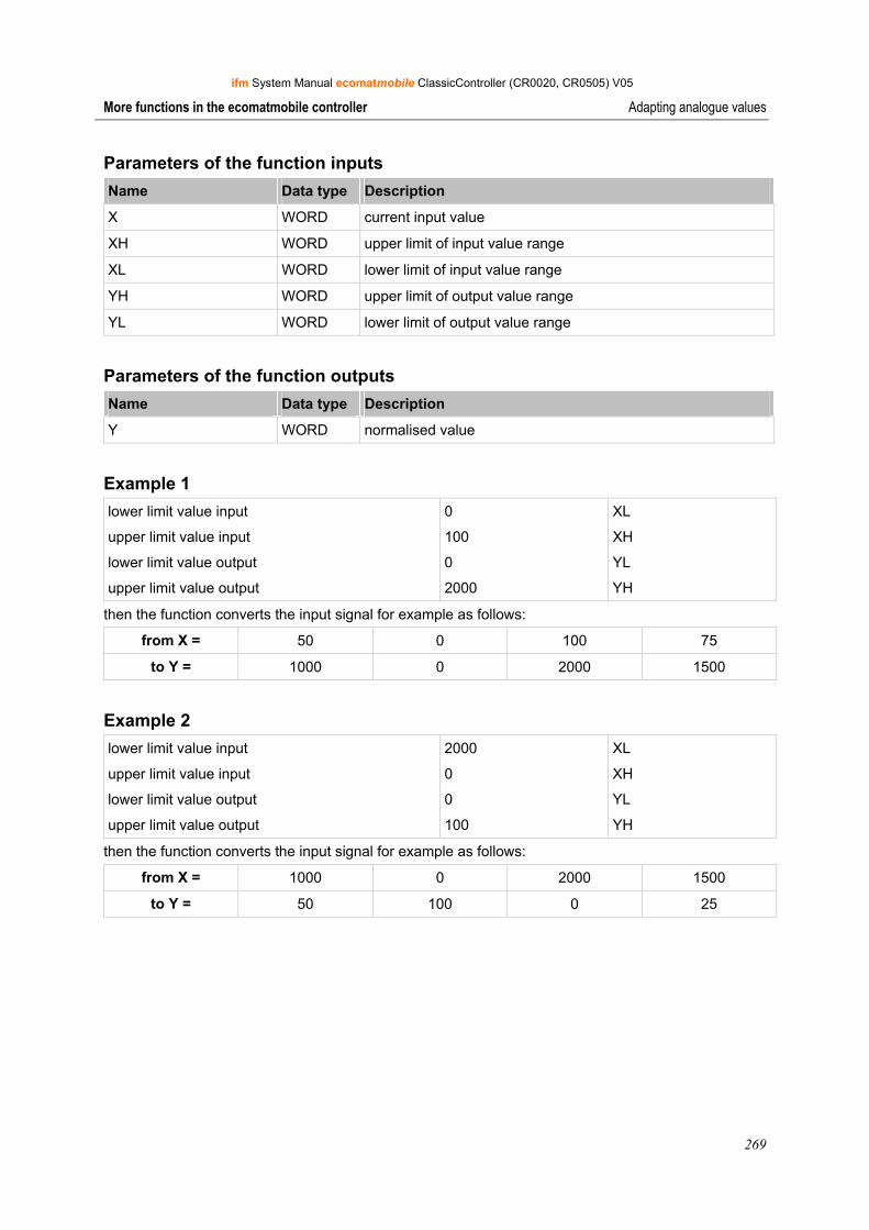
ifm System Manual ecomatmobile ClassicController (CR0020, CR0505) V05
269
More functions in the ecomatmobile controller Adapting analogue values
Parameters of the function inputs Name Data type Description
X WORD current input value
XH WORD upper limit of input value range
XL WORD lower limit of input value range
YH WORD upper limit of output value range
YL WORD lower limit of output value range
Parameters of the function outputs Name Data type Description
Y WORD normalised value
Example 1 lower limit value input
upper limit value input
lower limit value output
upper limit value output
0
100
0
2000
XL
XH
YL
YH
then the function converts the input signal for example as follows:
from X = 50 0 100 75
to Y = 1000 0 2000 1500
Example 2 lower limit value input
upper limit value input
lower limit value output
upper limit value output
2000
0
0
100
XL
XH
YL
YH
then the function converts the input signal for example as follows:
from X = 1000 0 2000 1500
to Y = 50 100 0 25
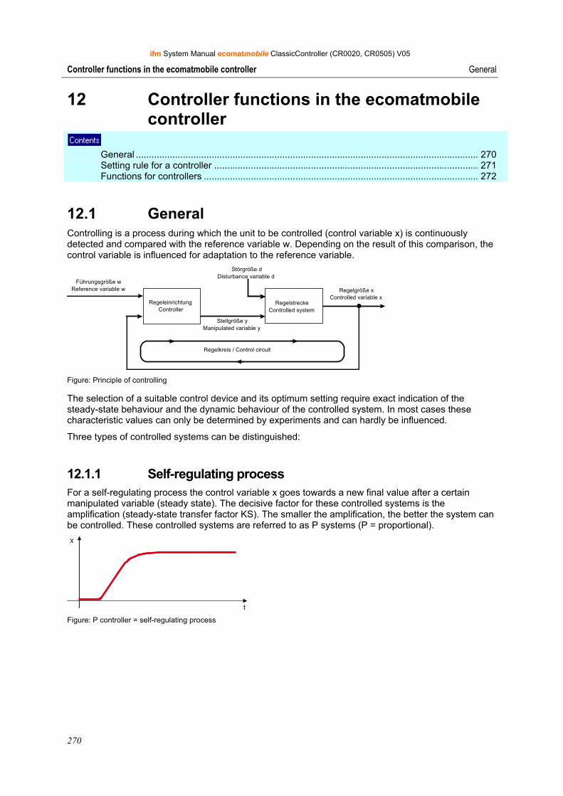
ifm System Manual ecomatmobile ClassicController (CR0020, CR0505) V05
270
Controller functions in the ecomatmobile controller General
12 Controller functions in the ecomatmobile controller
General ................................................................................................................................... 270 Setting rule for a controller ..................................................................................................... 271 Functions for controllers ......................................................................................................... 272
12.1 General Controlling is a process during which the unit to be controlled (control variable x) is continuously detected and compared with the reference variable w. Depending on the result of this comparison, the control variable is influenced for adaptation to the reference variable.
RegeleinrichtungController
RegelstreckeControlled system
Störgröße dDisturbance variable d
Regelkreis / Control circuit
Regelgröße xControlled variable x
Führungsgröße wReference variable w
Stellgröße yManipulated variable y
Figure: Principle of controlling
The selection of a suitable control device and its optimum setting require exact indication of the steady-state behaviour and the dynamic behaviour of the controlled system. In most cases these characteristic values can only be determined by experiments and can hardly be influenced.
Three types of controlled systems can be distinguished:
12.1.1 Self-regulating process For a self-regulating process the control variable x goes towards a new final value after a certain manipulated variable (steady state). The decisive factor for these controlled systems is the amplification (steady-state transfer factor KS). The smaller the amplification, the better the system can be controlled. These controlled systems are referred to as P systems (P = proportional).
Figure: P controller = self-regulating process
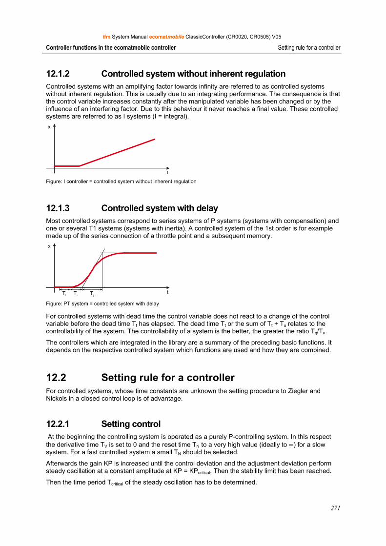
ifm System Manual ecomatmobile ClassicController (CR0020, CR0505) V05
271
Controller functions in the ecomatmobile controller Setting rule for a controller
12.1.2 Controlled system without inherent regulation Controlled systems with an amplifying factor towards infinity are referred to as controlled systems without inherent regulation. This is usually due to an integrating performance. The consequence is that the control variable increases constantly after the manipulated variable has been changed or by the influence of an interfering factor. Due to this behaviour it never reaches a final value. These controlled systems are referred to as I systems (I = integral).
Figure: I controller = controlled system without inherent regulation
12.1.3 Controlled system with delay Most controlled systems correspond to series systems of P systems (systems with compensation) and one or several T1 systems (systems with inertia). A controlled system of the 1st order is for example made up of the series connection of a throttle point and a subsequent memory.
Figure: PT system = controlled system with delay
For controlled systems with dead time the control variable does not react to a change of the control variable before the dead time Tt has elapsed. The dead time Tt or the sum of Tt + Tu relates to the controllability of the system. The controllability of a system is the better, the greater the ratio Tg/Tu.
The controllers which are integrated in the library are a summary of the preceding basic functions. It depends on the respective controlled system which functions are used and how they are combined.
12.2 Setting rule for a controller For controlled systems, whose time constants are unknown the setting procedure to Ziegler and Nickols in a closed control loop is of advantage.
12.2.1 Setting control At the beginning the controlling system is operated as a purely P-controlling system. In this respect the derivative time TV is set to 0 and the reset time TN to a very high value (ideally to ∞) for a slow system. For a fast controlled system a small TN should be selected.
Afterwards the gain KP is increased until the control deviation and the adjustment deviation perform steady oscillation at a constant amplitude at KP = KPcritical. Then the stability limit has been reached.
Then the time period Tcritical of the steady oscillation has to be determined.
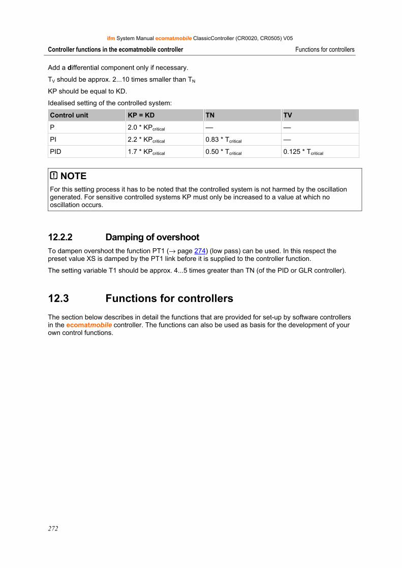
ifm System Manual ecomatmobile ClassicController (CR0020, CR0505) V05
272
Controller functions in the ecomatmobile controller Functions for controllers
Add a differential component only if necessary.
TV should be approx. 2...10 times smaller than TN
KP should be equal to KD.
Idealised setting of the controlled system:
Control unit KP = KD TN TV
P 2.0 * KPcritical –– ––
PI 2.2 * KPcritical 0.83 * Tcritical ––
PID 1.7 * KPcritical 0.50 * Tcritical 0.125 * Tcritical
NOTE For this setting process it has to be noted that the controlled system is not harmed by the oscillation generated. For sensitive controlled systems KP must only be increased to a value at which no oscillation occurs.
12.2.2 Damping of overshoot To dampen overshoot the function PT1 (→ page 274) (low pass) can be used. In this respect the preset value XS is damped by the PT1 link before it is supplied to the controller function.
The setting variable T1 should be approx. 4...5 times greater than TN (of the PID or GLR controller).
12.3 Functions for controllers
The section below describes in detail the functions that are provided for set-up by software controllers in the ecomatmobile controller. The functions can also be used as basis for the development of your own control functions.
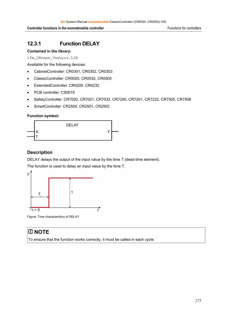
ifm System Manual ecomatmobile ClassicController (CR0020, CR0505) V05
273
Controller functions in the ecomatmobile controller Functions for controllers
12.3.1 Function DELAY Contained in the library: ifm_CRnnnn_Vxxyyzz.LIB
Available for the following devices:
• CabinetController: CR0301, CR0302, CR0303
• ClassicController: CR0020, CR0032, CR0505
• ExtendedController: CR0200, CR0232
• PCB controller: CS0015
• SafetyController: CR7020, CR7021, CR7032, CR7200, CR7201, CR7232, CR7505, CR7506
• SmartController: CR2500, CR2501, CR2502
Function symbol:
DELAY
X YT
Description DELAY delays the output of the input value by the time T (dead-time element).
The function is used to delay an input value by the time T.
Tt
1
y
tt = 0 Figure: Time characteristics of DELAY
NOTE To ensure that the function works correctly, it must be called in each cycle.

ifm System Manual ecomatmobile ClassicController (CR0020, CR0505) V05
274
Controller functions in the ecomatmobile controller Functions for controllers
Parameters of the function inputs Name Data type Description
X WORD Input value
T TIME Time delay (dead time)
Parameters of the function outputs Name Data type Description
Y WORD Input value, delayed by the time T
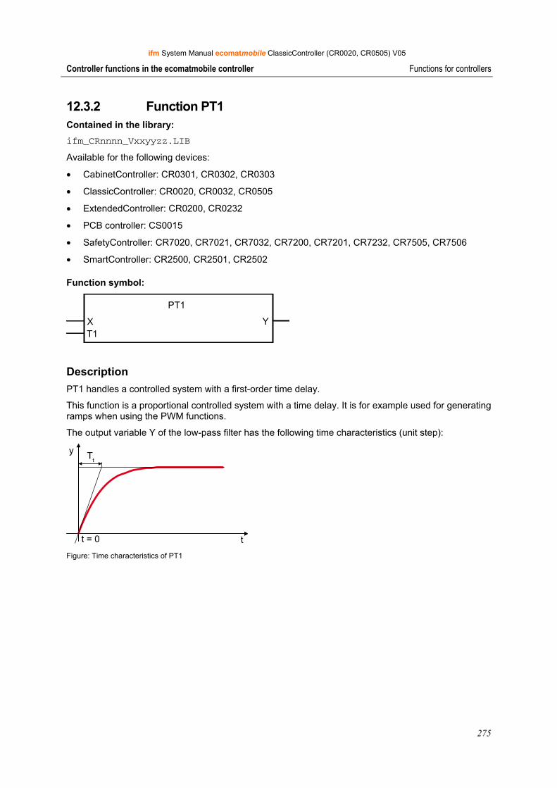
ifm System Manual ecomatmobile ClassicController (CR0020, CR0505) V05
275
Controller functions in the ecomatmobile controller Functions for controllers
12.3.2 Function PT1 Contained in the library: ifm_CRnnnn_Vxxyyzz.LIB
Available for the following devices:
• CabinetController: CR0301, CR0302, CR0303
• ClassicController: CR0020, CR0032, CR0505
• ExtendedController: CR0200, CR0232
• PCB controller: CS0015
• SafetyController: CR7020, CR7021, CR7032, CR7200, CR7201, CR7232, CR7505, CR7506
• SmartController: CR2500, CR2501, CR2502
Function symbol:
PT1
X YT1
Description PT1 handles a controlled system with a first-order time delay.
This function is a proportional controlled system with a time delay. It is for example used for generating ramps when using the PWM functions.
The output variable Y of the low-pass filter has the following time characteristics (unit step):
y
t
Tt
t = 0 Figure: Time characteristics of PT1

ifm System Manual ecomatmobile ClassicController (CR0020, CR0505) V05
276
Controller functions in the ecomatmobile controller Functions for controllers
Parameters of the function inputs Name Data type Description
X INT Input value
T1 TIME Delay time (time constant)
Parameters of the function outputs Name Data type Description
Y INT Output variable
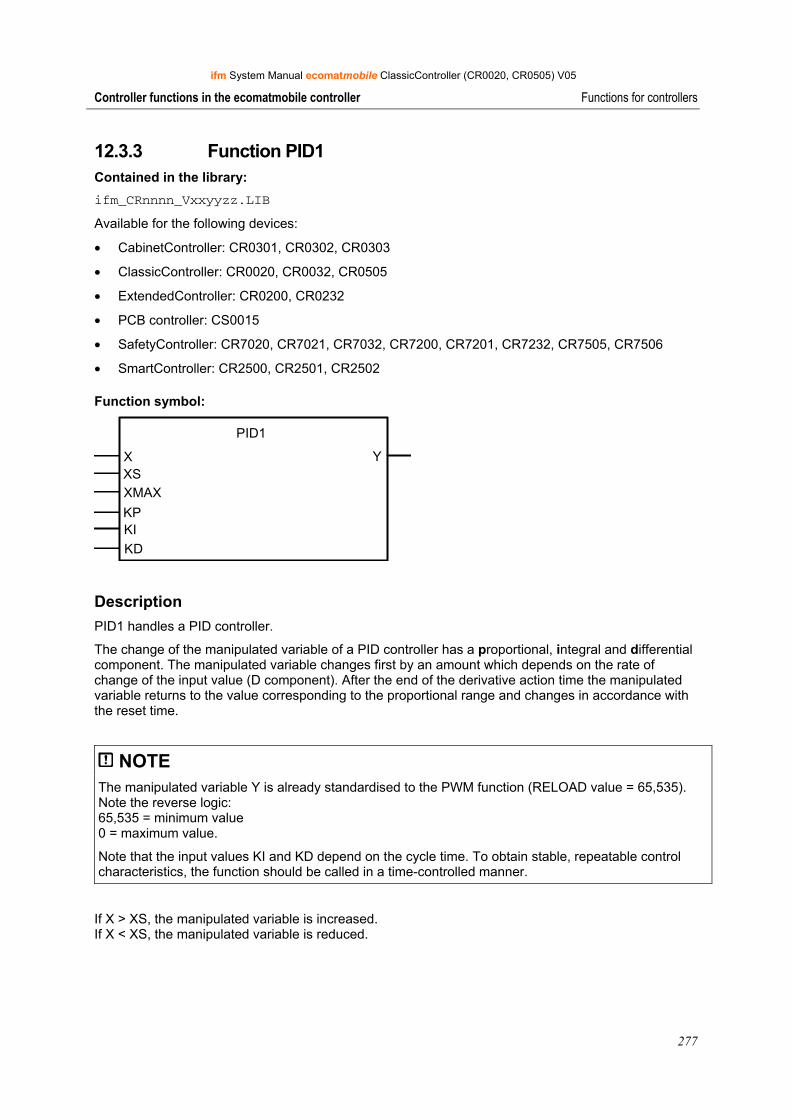
ifm System Manual ecomatmobile ClassicController (CR0020, CR0505) V05
277
Controller functions in the ecomatmobile controller Functions for controllers
12.3.3 Function PID1 Contained in the library: ifm_CRnnnn_Vxxyyzz.LIB
Available for the following devices:
• CabinetController: CR0301, CR0302, CR0303
• ClassicController: CR0020, CR0032, CR0505
• ExtendedController: CR0200, CR0232
• PCB controller: CS0015
• SafetyController: CR7020, CR7021, CR7032, CR7200, CR7201, CR7232, CR7505, CR7506
• SmartController: CR2500, CR2501, CR2502
Function symbol:
PID1
X YXSXMAX
KPKIKD
Description PID1 handles a PID controller.
The change of the manipulated variable of a PID controller has a proportional, integral and differential component. The manipulated variable changes first by an amount which depends on the rate of change of the input value (D component). After the end of the derivative action time the manipulated variable returns to the value corresponding to the proportional range and changes in accordance with the reset time.
NOTE The manipulated variable Y is already standardised to the PWM function (RELOAD value = 65,535). Note the reverse logic: 65,535 = minimum value 0 = maximum value.
Note that the input values KI and KD depend on the cycle time. To obtain stable, repeatable control characteristics, the function should be called in a time-controlled manner.
If X > XS, the manipulated variable is increased. If X < XS, the manipulated variable is reduced.
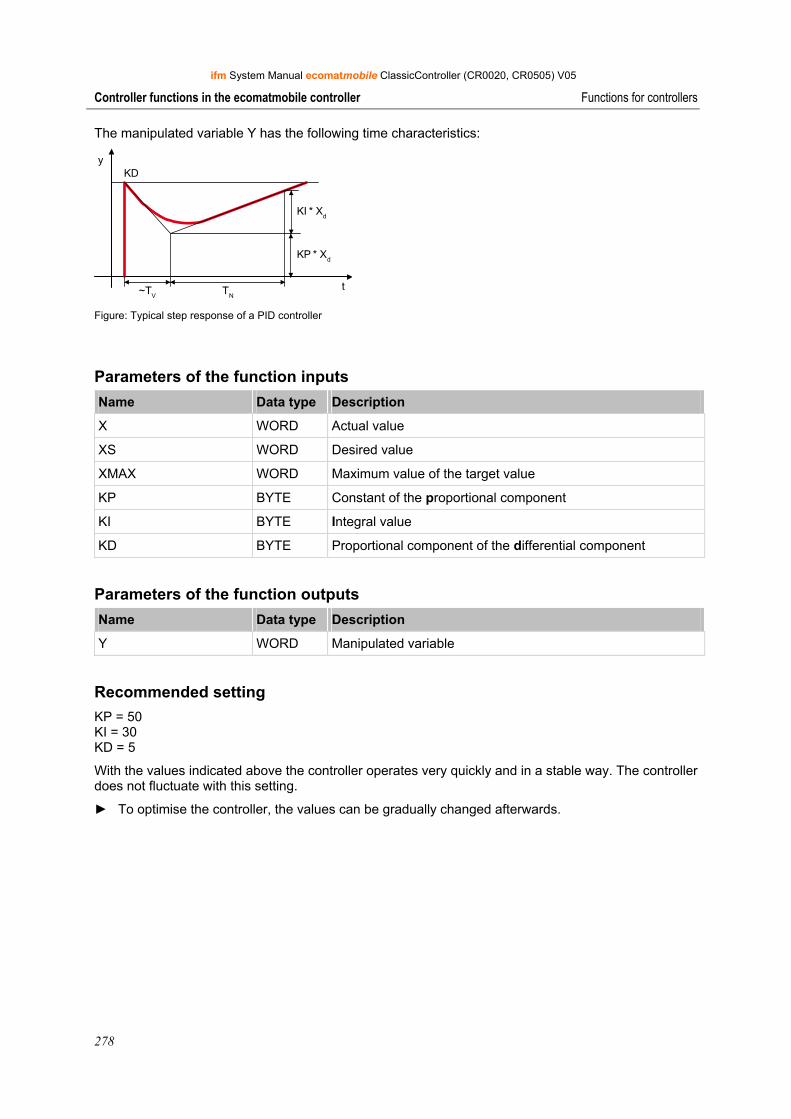
ifm System Manual ecomatmobile ClassicController (CR0020, CR0505) V05
278
Controller functions in the ecomatmobile controller Functions for controllers
The manipulated variable Y has the following time characteristics:
y
t~TV TN
KI * Xd
KP * Xd
KD
Figure: Typical step response of a PID controller
Parameters of the function inputs Name Data type Description
X WORD Actual value
XS WORD Desired value
XMAX WORD Maximum value of the target value
KP BYTE Constant of the proportional component
KI BYTE Integral value
KD BYTE Proportional component of the differential component
Parameters of the function outputs Name Data type Description
Y WORD Manipulated variable
Recommended setting KP = 50 KI = 30 KD = 5
With the values indicated above the controller operates very quickly and in a stable way. The controller does not fluctuate with this setting.
► To optimise the controller, the values can be gradually changed afterwards.
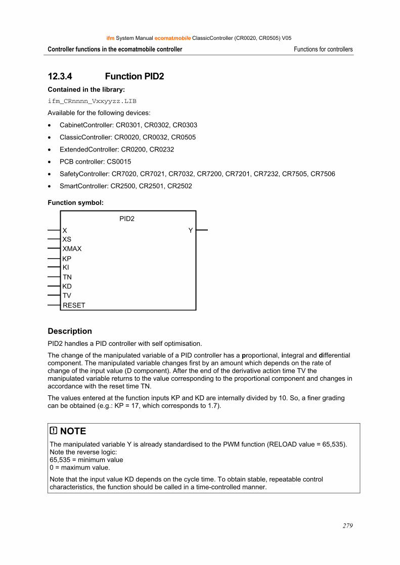
ifm System Manual ecomatmobile ClassicController (CR0020, CR0505) V05
279
Controller functions in the ecomatmobile controller Functions for controllers
12.3.4 Function PID2 Contained in the library: ifm_CRnnnn_Vxxyyzz.LIB
Available for the following devices:
• CabinetController: CR0301, CR0302, CR0303
• ClassicController: CR0020, CR0032, CR0505
• ExtendedController: CR0200, CR0232
• PCB controller: CS0015
• SafetyController: CR7020, CR7021, CR7032, CR7200, CR7201, CR7232, CR7505, CR7506
• SmartController: CR2500, CR2501, CR2502
Function symbol:
PID2
X YXSXMAX
KPKITNKDTVRESET
Description PID2 handles a PID controller with self optimisation.
The change of the manipulated variable of a PID controller has a proportional, integral and differential component. The manipulated variable changes first by an amount which depends on the rate of change of the input value (D component). After the end of the derivative action time TV the manipulated variable returns to the value corresponding to the proportional component and changes in accordance with the reset time TN.
The values entered at the function inputs KP and KD are internally divided by 10. So, a finer grading can be obtained (e.g.: KP = 17, which corresponds to 1.7).
NOTE The manipulated variable Y is already standardised to the PWM function (RELOAD value = 65,535). Note the reverse logic: 65,535 = minimum value 0 = maximum value.
Note that the input value KD depends on the cycle time. To obtain stable, repeatable control characteristics, the function should be called in a time-controlled manner.
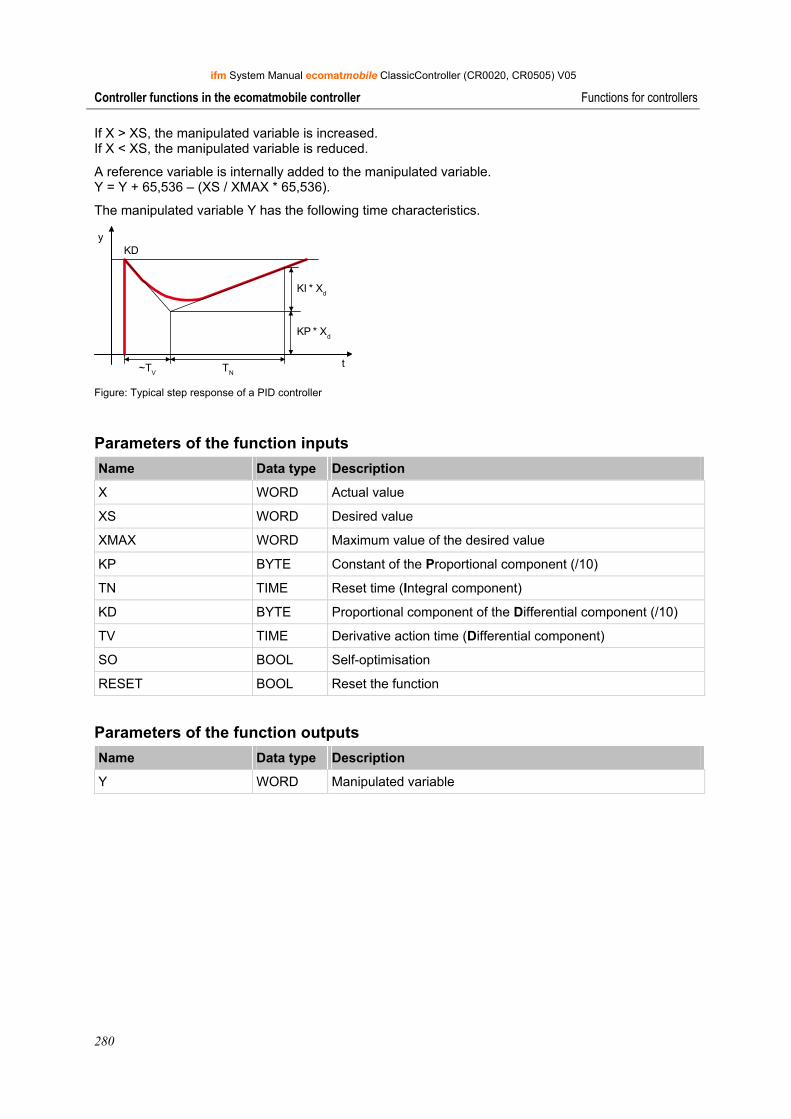
ifm System Manual ecomatmobile ClassicController (CR0020, CR0505) V05
280
Controller functions in the ecomatmobile controller Functions for controllers
If X > XS, the manipulated variable is increased. If X < XS, the manipulated variable is reduced.
A reference variable is internally added to the manipulated variable. Y = Y + 65,536 – (XS / XMAX * 65,536).
The manipulated variable Y has the following time characteristics.
y
t~TV TN
KI * Xd
KP * Xd
KD
Figure: Typical step response of a PID controller
Parameters of the function inputs Name Data type Description
X WORD Actual value
XS WORD Desired value
XMAX WORD Maximum value of the desired value
KP BYTE Constant of the Proportional component (/10)
TN TIME Reset time (Integral component)
KD BYTE Proportional component of the Differential component (/10)
TV TIME Derivative action time (Differential component)
SO BOOL Self-optimisation
RESET BOOL Reset the function
Parameters of the function outputs Name Data type Description
Y WORD Manipulated variable

ifm System Manual ecomatmobile ClassicController (CR0020, CR0505) V05
281
Controller functions in the ecomatmobile controller Functions for controllers
Recommended setting ► Select TN according to the time characteristics of the system:
fast system = small TN slow system = large TN
► Slowly increment KP gradually, up to a value at which still definitely no fluctuation will occur.
► Readjust TN if necessary.
► Add differential component only if necessary: Select a TV value approx. 2...10 times smaller than TN. Select a KD value more or less similar to KP.
Note that the maximum control deviation is + 127. For good control characteristics this range should not be exceeded, but it should be exploited to the best possible extent.
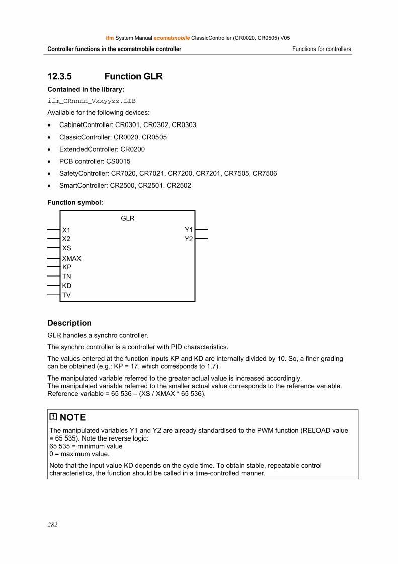
ifm System Manual ecomatmobile ClassicController (CR0020, CR0505) V05
282
Controller functions in the ecomatmobile controller Functions for controllers
12.3.5 Function GLR Contained in the library: ifm_CRnnnn_Vxxyyzz.LIB
Available for the following devices:
• CabinetController: CR0301, CR0302, CR0303
• ClassicController: CR0020, CR0505
• ExtendedController: CR0200
• PCB controller: CS0015
• SafetyController: CR7020, CR7021, CR7200, CR7201, CR7505, CR7506
• SmartController: CR2500, CR2501, CR2502
Function symbol:
GLR
X1X2XS
XMAXKPTNKDTV
Y1Y2
Description GLR handles a synchro controller.
The synchro controller is a controller with PID characteristics.
The values entered at the function inputs KP and KD are internally divided by 10. So, a finer grading can be obtained (e.g.: KP = 17, which corresponds to 1.7).
The manipulated variable referred to the greater actual value is increased accordingly. The manipulated variable referred to the smaller actual value corresponds to the reference variable. Reference variable = 65 536 – (XS / XMAX * 65 536).
NOTE The manipulated variables Y1 and Y2 are already standardised to the PWM function (RELOAD value = 65 535). Note the reverse logic: 65 535 = minimum value 0 = maximum value.
Note that the input value KD depends on the cycle time. To obtain stable, repeatable control characteristics, the function should be called in a time-controlled manner.
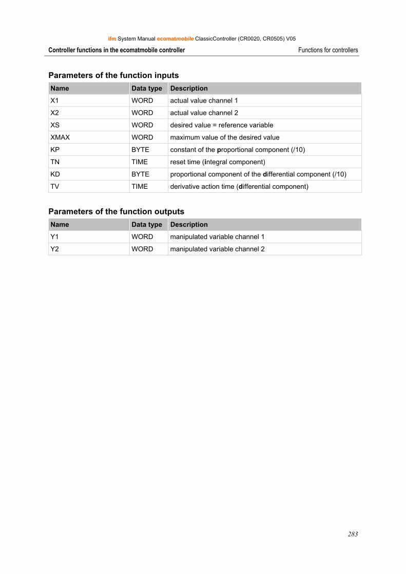
ifm System Manual ecomatmobile ClassicController (CR0020, CR0505) V05
283
Controller functions in the ecomatmobile controller Functions for controllers
Parameters of the function inputs Name Data type Description
X1 WORD actual value channel 1
X2 WORD actual value channel 2
XS WORD desired value = reference variable
XMAX WORD maximum value of the desired value
KP BYTE constant of the proportional component (/10)
TN TIME reset time (integral component)
KD BYTE proportional component of the differential component (/10)
TV TIME derivative action time (differential component)
Parameters of the function outputs Name Data type Description
Y1 WORD manipulated variable channel 1
Y2 WORD manipulated variable channel 2
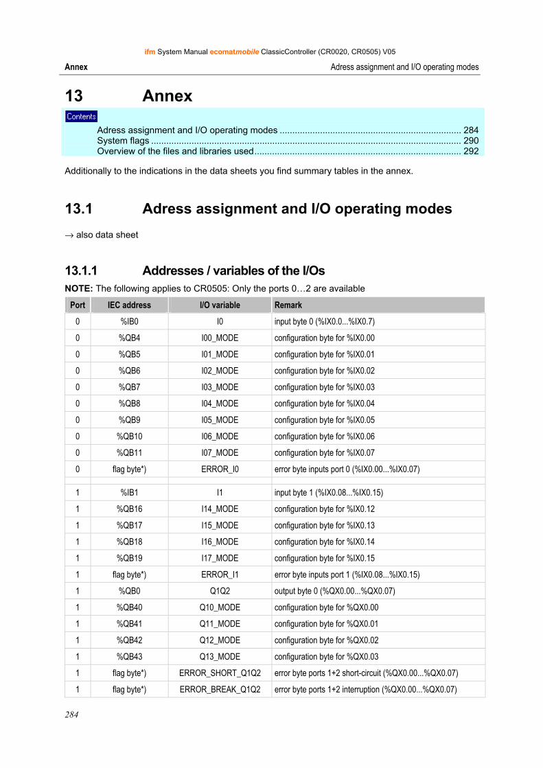
ifm System Manual ecomatmobile ClassicController (CR0020, CR0505) V05
284
Annex Adress assignment and I/O operating modes
13 Annex Adress assignment and I/O operating modes ........................................................................ 284 System flags ........................................................................................................................... 290 Overview of the files and libraries used.................................................................................. 292
Additionally to the indications in the data sheets you find summary tables in the annex.
13.1 Adress assignment and I/O operating modes
→ also data sheet
13.1.1 Addresses / variables of the I/Os NOTE: The following applies to CR0505: Only the ports 0…2 are available
Port IEC address I/O variable Remark
0 %IB0 I0 input byte 0 (%IX0.0...%IX0.7)
0 %QB4 I00_MODE configuration byte for %IX0.00
0 %QB5 I01_MODE configuration byte for %IX0.01
0 %QB6 I02_MODE configuration byte for %IX0.02
0 %QB7 I03_MODE configuration byte for %IX0.03
0 %QB8 I04_MODE configuration byte for %IX0.04
0 %QB9 I05_MODE configuration byte for %IX0.05
0 %QB10 I06_MODE configuration byte for %IX0.06
0 %QB11 I07_MODE configuration byte for %IX0.07
0 flag byte*) ERROR_I0 error byte inputs port 0 (%IX0.00...%IX0.07)
1 %IB1 I1 input byte 1 (%IX0.08...%IX0.15)
1 %QB16 I14_MODE configuration byte for %IX0.12
1 %QB17 I15_MODE configuration byte for %IX0.13
1 %QB18 I16_MODE configuration byte for %IX0.14
1 %QB19 I17_MODE configuration byte for %IX0.15
1 flag byte*) ERROR_I1 error byte inputs port 1 (%IX0.08...%IX0.15)
1 %QB0 Q1Q2 output byte 0 (%QX0.00...%QX0.07)
1 %QB40 Q10_MODE configuration byte for %QX0.00
1 %QB41 Q11_MODE configuration byte for %QX0.01
1 %QB42 Q12_MODE configuration byte for %QX0.02
1 %QB43 Q13_MODE configuration byte for %QX0.03
1 flag byte*) ERROR_SHORT_Q1Q2 error byte ports 1+2 short-circuit (%QX0.00...%QX0.07)
1 flag byte*) ERROR_BREAK_Q1Q2 error byte ports 1+2 interruption (%QX0.00...%QX0.07)
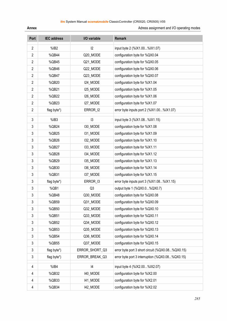
ifm System Manual ecomatmobile ClassicController (CR0020, CR0505) V05
285
Annex Adress assignment and I/O operating modes
Port IEC address I/O variable Remark
2 %IB2 I2 input byte 2 (%IX1.00...%IX1.07)
2 %QB44 Q20_MODE configuration byte for %QX0.04
2 %QB45 Q21_MODE configuration byte for %QX0.05
2 %QB46 Q22_MODE configuration byte for %QX0.06
2 %QB47 Q23_MODE configuration byte for %QX0.07
2 %QB20 I24_MODE configuration byte for %IX1.04
2 %QB21 I25_MODE configuration byte for %IX1.05
2 %QB22 I26_MODE configuration byte for %IX1.06
2 %QB23 I27_MODE configuration byte for %IX1.07
2 flag byte*) ERROR_I2 error byte inputs port 2 (%IX1.00...%IX1.07)
3 %IB3 I3 input byte 3 (%IX1.08...%IX1.15)
3 %QB24 I30_MODE configuration byte for %IX1.08
3 %QB25 I31_MODE configuration byte for %IX1.09
3 %QB26 I32_MODE configuration byte for %IX1.10
3 %QB27 I33_MODE configuration byte for %IX1.11
3 %QB28 I34_MODE configuration byte for %IX1.12
3 %QB29 I35_MODE configuration byte for %IX1.13
3 %QB30 I36_MODE configuration byte for %IX1.14
3 %QB31 I37_MODE configuration byte for %IX1.15
3 flag byte*) ERROR_I3 error byte inputs port 3 (%IX1.08...%IX1.15)
3 %QB1 Q3 output byte 1 (%QX0.0...%QX0.7)
3 %QB48 Q30_MODE configuration byte for %QX0.08
3 %QB59 Q31_MODE configuration byte for %QX0.09
3 %QB50 Q32_MODE configuration byte for %QX0.10
3 %QB51 Q33_MODE configuration byte for %QX0.11
3 %QB52 Q34_MODE configuration byte for %QX0.12
3 %QB53 Q35_MODE configuration byte for %QX0.13
3 %QB54 Q36_MODE configuration byte for %QX0.14
3 %QB55 Q37_MODE configuration byte for %QX0.15
3 flag byte*) ERROR_SHORT_Q3 error byte port 3 short circuit (%QX0.08...%QX0.15)
3 flag byte*) ERROR_BREAK_Q3 error byte port 3 interruption (%QX0.08...%QX0.15)
4 %IB4 I4 input byte 4 (%IX2.00...%IX2.07)
4 %QB32 I40_MODE configuration byte for %IX2.00
4 %QB33 I41_MODE configuration byte for %IX2.01
4 %QB34 I42_MODE configuration byte for %IX2.02
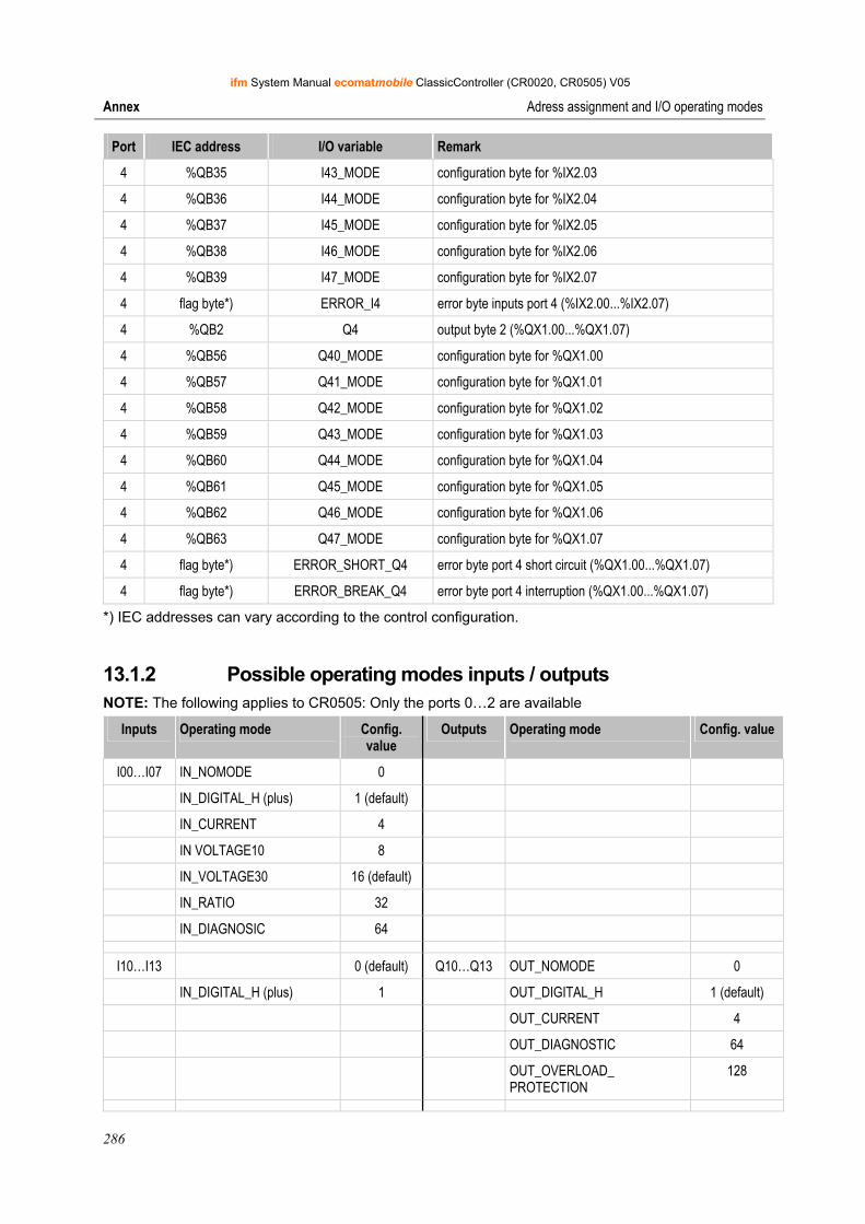
ifm System Manual ecomatmobile ClassicController (CR0020, CR0505) V05
286
Annex Adress assignment and I/O operating modes
Port IEC address I/O variable Remark
4 %QB35 I43_MODE configuration byte for %IX2.03
4 %QB36 I44_MODE configuration byte for %IX2.04
4 %QB37 I45_MODE configuration byte for %IX2.05
4 %QB38 I46_MODE configuration byte for %IX2.06
4 %QB39 I47_MODE configuration byte for %IX2.07
4 flag byte*) ERROR_I4 error byte inputs port 4 (%IX2.00...%IX2.07)
4 %QB2 Q4 output byte 2 (%QX1.00...%QX1.07)
4 %QB56 Q40_MODE configuration byte for %QX1.00
4 %QB57 Q41_MODE configuration byte for %QX1.01
4 %QB58 Q42_MODE configuration byte for %QX1.02
4 %QB59 Q43_MODE configuration byte for %QX1.03
4 %QB60 Q44_MODE configuration byte for %QX1.04
4 %QB61 Q45_MODE configuration byte for %QX1.05
4 %QB62 Q46_MODE configuration byte for %QX1.06
4 %QB63 Q47_MODE configuration byte for %QX1.07
4 flag byte*) ERROR_SHORT_Q4 error byte port 4 short circuit (%QX1.00...%QX1.07)
4 flag byte*) ERROR_BREAK_Q4 error byte port 4 interruption (%QX1.00...%QX1.07)
*) IEC addresses can vary according to the control configuration.
13.1.2 Possible operating modes inputs / outputs NOTE: The following applies to CR0505: Only the ports 0…2 are available
Inputs Operating mode Config. value
Outputs Operating mode Config. value
I00…I07 IN_NOMODE 0
IN_DIGITAL_H (plus) 1 (default)
IN_CURRENT 4
IN VOLTAGE10 8
IN_VOLTAGE30 16 (default)
IN_RATIO 32
IN_DIAGNOSIC 64
I10…I13 0 (default) Q10…Q13 OUT_NOMODE 0
IN_DIGITAL_H (plus) 1 OUT_DIGITAL_H 1 (default)
OUT_CURRENT 4
OUT_DIAGNOSTIC 64
OUT_OVERLOAD_ PROTECTION
128
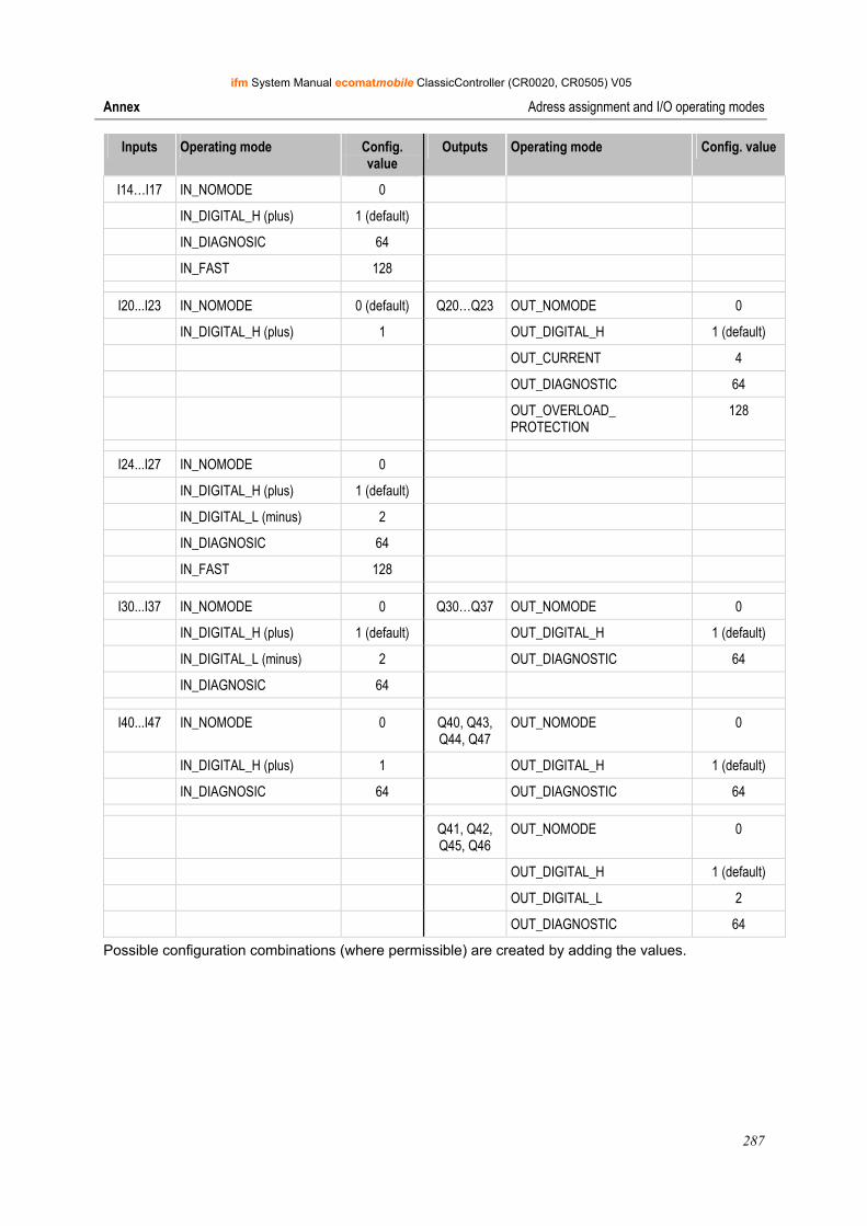
ifm System Manual ecomatmobile ClassicController (CR0020, CR0505) V05
287
Annex Adress assignment and I/O operating modes
Inputs Operating mode Config. value
Outputs Operating mode Config. value
I14…I17 IN_NOMODE 0
IN_DIGITAL_H (plus) 1 (default)
IN_DIAGNOSIC 64
IN_FAST 128
I20...I23 IN_NOMODE 0 (default) Q20…Q23 OUT_NOMODE 0
IN_DIGITAL_H (plus) 1 OUT_DIGITAL_H 1 (default)
OUT_CURRENT 4
OUT_DIAGNOSTIC 64
OUT_OVERLOAD_ PROTECTION
128
I24...I27 IN_NOMODE 0
IN_DIGITAL_H (plus) 1 (default)
IN_DIGITAL_L (minus) 2
IN_DIAGNOSIC 64
IN_FAST 128
I30...I37 IN_NOMODE 0 Q30…Q37 OUT_NOMODE 0
IN_DIGITAL_H (plus) 1 (default) OUT_DIGITAL_H 1 (default)
IN_DIGITAL_L (minus) 2 OUT_DIAGNOSTIC 64
IN_DIAGNOSIC 64
I40...I47 IN_NOMODE 0 Q40, Q43, Q44, Q47
OUT_NOMODE 0
IN_DIGITAL_H (plus) 1 OUT_DIGITAL_H 1 (default)
IN_DIAGNOSIC 64 OUT_DIAGNOSTIC 64
Q41, Q42, Q45, Q46
OUT_NOMODE 0
OUT_DIGITAL_H 1 (default)
OUT_DIGITAL_L 2
OUT_DIAGNOSTIC 64
Possible configuration combinations (where permissible) are created by adding the values.
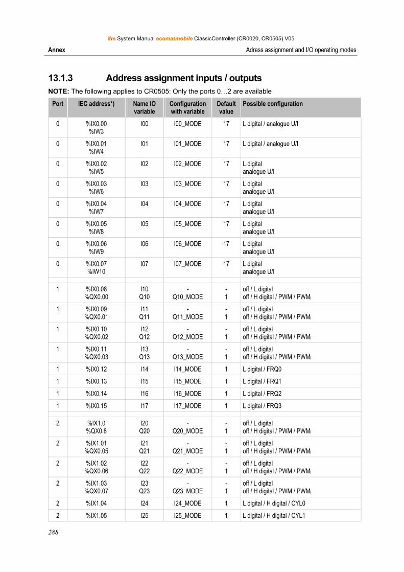
ifm System Manual ecomatmobile ClassicController (CR0020, CR0505) V05
288
Annex Adress assignment and I/O operating modes
13.1.3 Address assignment inputs / outputs NOTE: The following applies to CR0505: Only the ports 0…2 are available
Port IEC address*) Name IO variable
Configuration with variable
Default value
Possible configuration
0 %IX0.00 %IW3
I00 I00_MODE 17 L digital / analogue U/I
0 %IX0.01 %IW4
I01 I01_MODE 17 L digital / analogue U/I
0 %IX0.02 %IW5
I02 I02_MODE 17 L digital analogue U/I
0 %IX0.03 %IW6
I03 I03_MODE 17 L digital analogue U/I
0 %IX0.04 %IW7
I04 I04_MODE 17 L digital analogue U/I
0 %IX0.05 %IW8
I05 I05_MODE 17 L digital analogue U/I
0 %IX0.06 %IW9
I06 I06_MODE 17 L digital analogue U/I
0 %IX0.07 %IW10
I07 I07_MODE 17 L digital analogue U/I
1 %IX0.08 %QX0.00
I10 Q10
- Q10_MODE
- 1
off / L digital off / H digital / PWM / PWMI
1 %IX0.09 %QX0.01
I11 Q11
- Q11_MODE
- 1
off / L digital off / H digital / PWM / PWMI
1 %IX0.10 %QX0.02
I12 Q12
- Q12_MODE
- 1
off / L digital off / H digital / PWM / PWMI
1 %IX0.11 %QX0.03
I13 Q13
- Q13_MODE
- 1
off / L digital off / H digital / PWM / PWMI
1 %IX0.12 I14 I14_MODE 1 L digital / FRQ0
1 %IX0.13 I15 I15_MODE 1 L digital / FRQ1
1 %IX0.14 I16 I16_MODE 1 L digital / FRQ2
1 %IX0.15 I17 I17_MODE 1 L digital / FRQ3
2 %IX1.0 %QX0.8
I20 Q20
- Q20_MODE
- 1
off / L digital off / H digital / PWM / PWMI
2 %IX1.01 %QX0.05
I21 Q21
- Q21_MODE
- 1
off / L digital off / H digital / PWM / PWMI
2 %IX1.02 %QX0.06
I22 Q22
- Q22_MODE
- 1
off / L digital off / H digital / PWM / PWMI
2 %IX1.03 %QX0.07
I23 Q23
- Q23_MODE
- 1
off / L digital off / H digital / PWM / PWMI
2 %IX1.04 I24 I24_MODE 1 L digital / H digital / CYL0
2 %IX1.05 I25 I25_MODE 1 L digital / H digital / CYL1
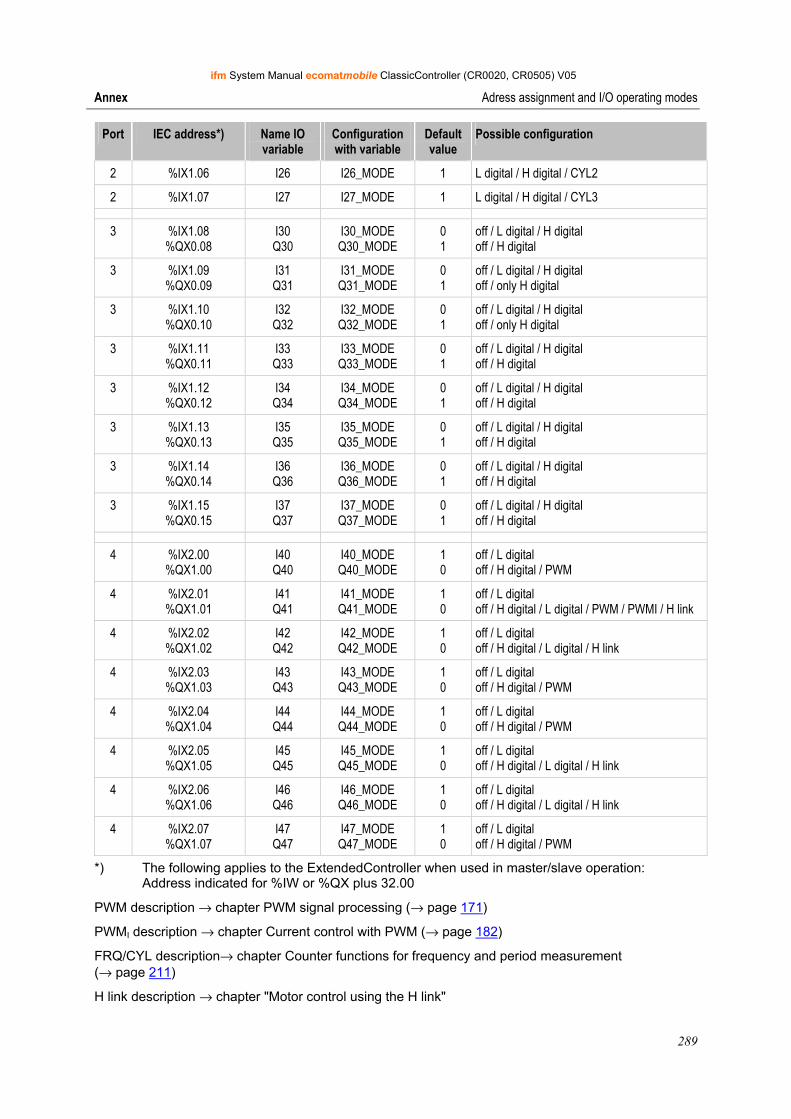
ifm System Manual ecomatmobile ClassicController (CR0020, CR0505) V05
289
Annex Adress assignment and I/O operating modes
Port IEC address*) Name IO variable
Configuration with variable
Default value
Possible configuration
2 %IX1.06 I26 I26_MODE 1 L digital / H digital / CYL2
2 %IX1.07 I27 I27_MODE 1 L digital / H digital / CYL3
3 %IX1.08 %QX0.08
I30 Q30
I30_MODE Q30_MODE
0 1
off / L digital / H digital off / H digital
3 %IX1.09 %QX0.09
I31 Q31
I31_MODE Q31_MODE
0 1
off / L digital / H digital off / only H digital
3 %IX1.10 %QX0.10
I32 Q32
I32_MODE Q32_MODE
0 1
off / L digital / H digital off / only H digital
3 %IX1.11 %QX0.11
I33 Q33
I33_MODE Q33_MODE
0 1
off / L digital / H digital off / H digital
3 %IX1.12 %QX0.12
I34 Q34
I34_MODE Q34_MODE
0 1
off / L digital / H digital off / H digital
3 %IX1.13 %QX0.13
I35 Q35
I35_MODE Q35_MODE
0 1
off / L digital / H digital off / H digital
3 %IX1.14 %QX0.14
I36 Q36
I36_MODE Q36_MODE
0 1
off / L digital / H digital off / H digital
3 %IX1.15 %QX0.15
I37 Q37
I37_MODE Q37_MODE
0 1
off / L digital / H digital off / H digital
4 %IX2.00 %QX1.00
I40 Q40
I40_MODE Q40_MODE
1 0
off / L digital off / H digital / PWM
4 %IX2.01 %QX1.01
I41 Q41
I41_MODE Q41_MODE
1 0
off / L digital off / H digital / L digital / PWM / PWMI / H link
4 %IX2.02 %QX1.02
I42 Q42
I42_MODE Q42_MODE
1 0
off / L digital off / H digital / L digital / H link
4 %IX2.03 %QX1.03
I43 Q43
I43_MODE Q43_MODE
1 0
off / L digital off / H digital / PWM
4 %IX2.04 %QX1.04
I44 Q44
I44_MODE Q44_MODE
1 0
off / L digital off / H digital / PWM
4 %IX2.05 %QX1.05
I45 Q45
I45_MODE Q45_MODE
1 0
off / L digital off / H digital / L digital / H link
4 %IX2.06 %QX1.06
I46 Q46
I46_MODE Q46_MODE
1 0
off / L digital off / H digital / L digital / H link
4 %IX2.07 %QX1.07
I47 Q47
I47_MODE Q47_MODE
1 0
off / L digital off / H digital / PWM
*) The following applies to the ExtendedController when used in master/slave operation: Address indicated for %IW or %QX plus 32.00
PWM description → chapter PWM signal processing (→ page 171)
PWMI description → chapter Current control with PWM (→ page 182)
FRQ/CYL description→ chapter Counter functions for frequency and period measurement (→ page 211)
H link description → chapter "Motor control using the H link"
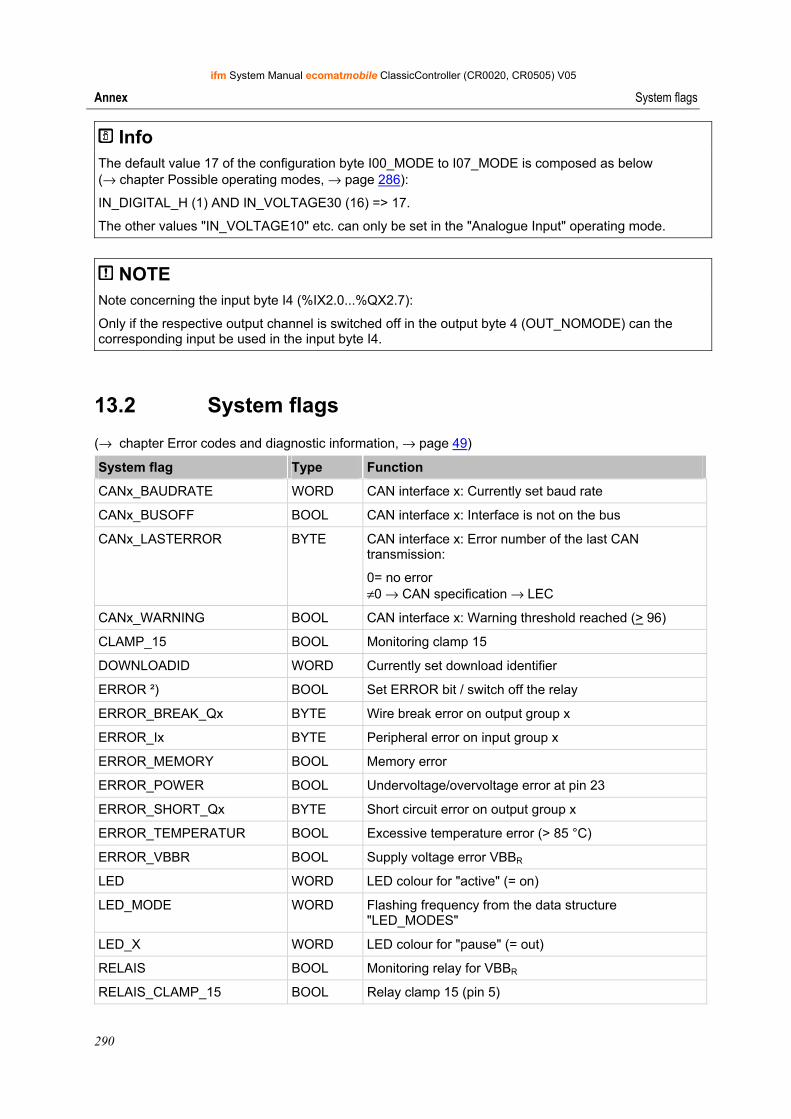
ifm System Manual ecomatmobile ClassicController (CR0020, CR0505) V05
290
Annex System flags
Info The default value 17 of the configuration byte I00_MODE to I07_MODE is composed as below (→ chapter Possible operating modes, → page 286):
IN_DIGITAL_H (1) AND IN_VOLTAGE30 (16) => 17.
The other values "IN_VOLTAGE10" etc. can only be set in the "Analogue Input" operating mode.
NOTE Note concerning the input byte I4 (%IX2.0...%QX2.7):
Only if the respective output channel is switched off in the output byte 4 (OUT_NOMODE) can the corresponding input be used in the input byte I4.
13.2 System flags
(→ chapter Error codes and diagnostic information, → page 49)
System flag Type Function
CANx_BAUDRATE WORD CAN interface x: Currently set baud rate
CANx_BUSOFF BOOL CAN interface x: Interface is not on the bus
CANx_LASTERROR BYTE CAN interface x: Error number of the last CAN transmission:
0= no error ≠0 → CAN specification → LEC
CANx_WARNING BOOL CAN interface x: Warning threshold reached (> 96)
CLAMP_15 BOOL Monitoring clamp 15
DOWNLOADID WORD Currently set download identifier
ERROR ²) BOOL Set ERROR bit / switch off the relay
ERROR_BREAK_Qx BYTE Wire break error on output group x
ERROR_Ix BYTE Peripheral error on input group x
ERROR_MEMORY BOOL Memory error
ERROR_POWER BOOL Undervoltage/overvoltage error at pin 23
ERROR_SHORT_Qx BYTE Short circuit error on output group x
ERROR_TEMPERATUR BOOL Excessive temperature error (> 85 °C)
ERROR_VBBR BOOL Supply voltage error VBBR
LED WORD LED colour for "active" (= on)
LED_MODE WORD Flashing frequency from the data structure "LED_MODES"
LED_X WORD LED colour for "pause" (= out)
RELAIS BOOL Monitoring relay for VBBR
RELAIS_CLAMP_15 BOOL Relay clamp 15 (pin 5)
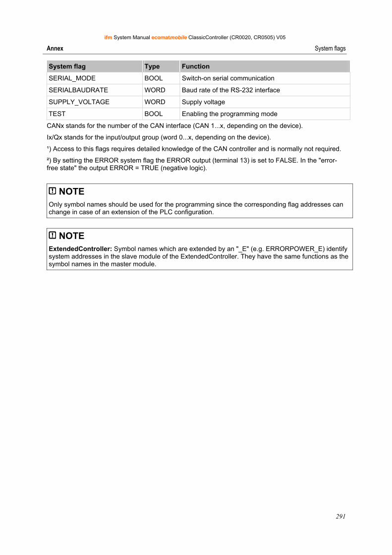
ifm System Manual ecomatmobile ClassicController (CR0020, CR0505) V05
291
Annex System flags
System flag Type Function
SERIAL_MODE BOOL Switch-on serial communication
SERIALBAUDRATE WORD Baud rate of the RS-232 interface
SUPPLY_VOLTAGE WORD Supply voltage
TEST BOOL Enabling the programming mode
CANx stands for the number of the CAN interface (CAN 1...x, depending on the device).
Ix/Qx stands for the input/output group (word 0...x, depending on the device).
¹) Access to this flags requires detailed knowledge of the CAN controller and is normally not required.
²) By setting the ERROR system flag the ERROR output (terminal 13) is set to FALSE. In the "error-free state" the output ERROR = TRUE (negative logic).
NOTE Only symbol names should be used for the programming since the corresponding flag addresses can change in case of an extension of the PLC configuration.
NOTE ExtendedController: Symbol names which are extended by an "_E" (e.g. ERRORPOWER_E) identify system addresses in the slave module of the ExtendedController. They have the same functions as the symbol names in the master module.
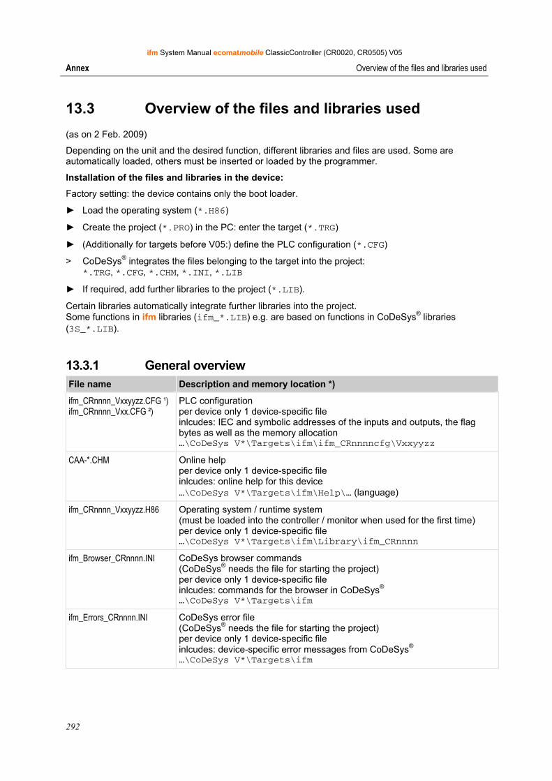
ifm System Manual ecomatmobile ClassicController (CR0020, CR0505) V05
292
Annex Overview of the files and libraries used
13.3 Overview of the files and libraries used
(as on 2 Feb. 2009)
Depending on the unit and the desired function, different libraries and files are used. Some are automatically loaded, others must be inserted or loaded by the programmer.
Installation of the files and libraries in the device:
Factory setting: the device contains only the boot loader.
► Load the operating system (*.H86)
► Create the project (*.PRO) in the PC: enter the target (*.TRG)
► (Additionally for targets before V05:) define the PLC configuration (*.CFG)
> CoDeSys® integrates the files belonging to the target into the project: *.TRG, *.CFG, *.CHM, *.INI, *.LIB
► If required, add further libraries to the project (*.LIB).
Certain libraries automatically integrate further libraries into the project. Some functions in ifm libraries (ifm_*.LIB) e.g. are based on functions in CoDeSys® libraries (3S_*.LIB).
13.3.1 General overview File name Description and memory location *)
ifm_CRnnnn_Vxxyyzz.CFG ¹)ifm_CRnnnn_Vxx.CFG ²)
PLC configuration per device only 1 device-specific file inlcudes: IEC and symbolic addresses of the inputs and outputs, the flag bytes as well as the memory allocation …\CoDeSys V*\Targets\ifm\ifm_CRnnnncfg\Vxxyyzz
CAA-*.CHM Online help per device only 1 device-specific file inlcudes: online help for this device …\CoDeSys V*\Targets\ifm\Help\… (language)
ifm_CRnnnn_Vxxyyzz.H86 Operating system / runtime system (must be loaded into the controller / monitor when used for the first time) per device only 1 device-specific file …\CoDeSys V*\Targets\ifm\Library\ifm_CRnnnn
ifm_Browser_CRnnnn.INI CoDeSys browser commands (CoDeSys® needs the file for starting the project) per device only 1 device-specific file inlcudes: commands for the browser in CoDeSys® …\CoDeSys V*\Targets\ifm
ifm_Errors_CRnnnn.INI CoDeSys error file (CoDeSys® needs the file for starting the project) per device only 1 device-specific file inlcudes: device-specific error messages from CoDeSys® …\CoDeSys V*\Targets\ifm
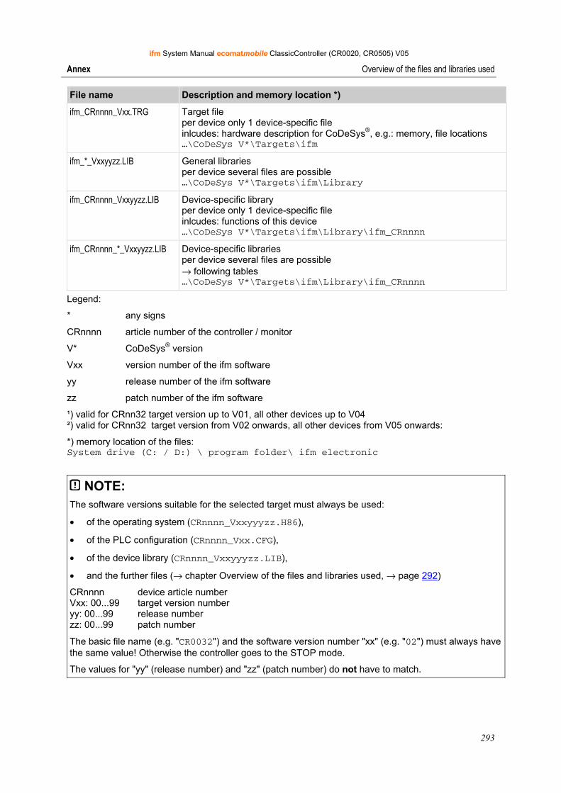
ifm System Manual ecomatmobile ClassicController (CR0020, CR0505) V05
293
Annex Overview of the files and libraries used
File name Description and memory location *)
ifm_CRnnnn_Vxx.TRG Target file per device only 1 device-specific file inlcudes: hardware description for CoDeSys®, e.g.: memory, file locations …\CoDeSys V*\Targets\ifm
ifm_*_Vxxyyzz.LIB General libraries per device several files are possible …\CoDeSys V*\Targets\ifm\Library
ifm_CRnnnn_Vxxyyzz.LIB Device-specific library per device only 1 device-specific file inlcudes: functions of this device …\CoDeSys V*\Targets\ifm\Library\ifm_CRnnnn
ifm_CRnnnn_*_Vxxyyzz.LIB Device-specific libraries per device several files are possible → following tables …\CoDeSys V*\Targets\ifm\Library\ifm_CRnnnn
Legend:
* any signs
CRnnnn article number of the controller / monitor
V* CoDeSys® version
Vxx version number of the ifm software
yy release number of the ifm software
zz patch number of the ifm software
¹) valid for CRnn32 target version up to V01, all other devices up to V04 ²) valid for CRnn32 target version from V02 onwards, all other devices from V05 onwards:
*) memory location of the files: System drive (C: / D:) \ program folder\ ifm electronic
NOTE: The software versions suitable for the selected target must always be used:
• of the operating system (CRnnnn_Vxxyyyzz.H86),
• of the PLC configuration (CRnnnn_Vxx.CFG),
• of the device library (CRnnnn_Vxxyyyzz.LIB),
• and the further files (→ chapter Overview of the files and libraries used, → page 292)
CRnnnn device article number Vxx: 00...99 target version number yy: 00...99 release number zz: 00...99 patch number
The basic file name (e.g. "CR0032") and the software version number "xx" (e.g. "02") must always have the same value! Otherwise the controller goes to the STOP mode.
The values for "yy" (release number) and "zz" (patch number) do not have to match.
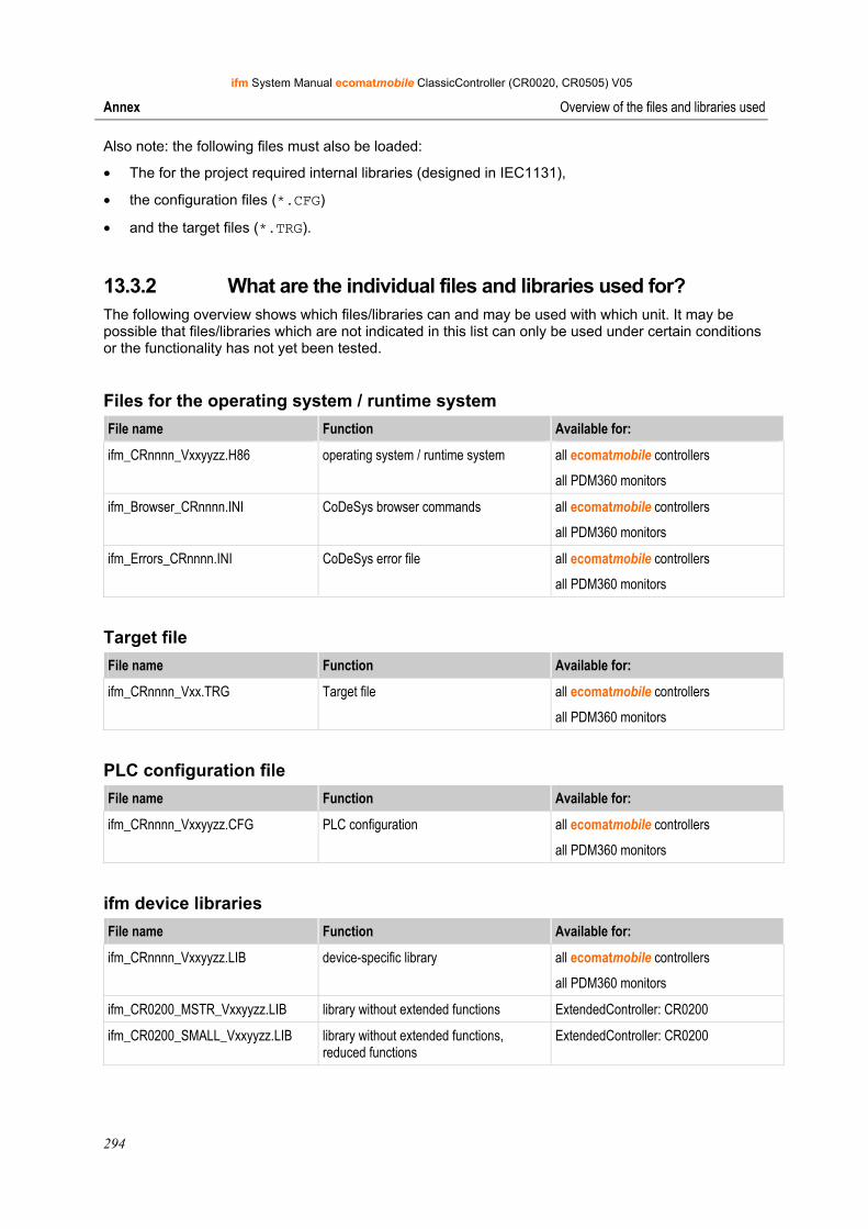
ifm System Manual ecomatmobile ClassicController (CR0020, CR0505) V05
294
Annex Overview of the files and libraries used
Also note: the following files must also be loaded:
• The for the project required internal libraries (designed in IEC1131),
• the configuration files (*.CFG)
• and the target files (*.TRG).
13.3.2 What are the individual files and libraries used for? The following overview shows which files/libraries can and may be used with which unit. It may be possible that files/libraries which are not indicated in this list can only be used under certain conditions or the functionality has not yet been tested.
Files for the operating system / runtime system File name Function Available for:
ifm_CRnnnn_Vxxyyzz.H86 operating system / runtime system all ecomatmobile controllers
all PDM360 monitors
ifm_Browser_CRnnnn.INI CoDeSys browser commands all ecomatmobile controllers
all PDM360 monitors
ifm_Errors_CRnnnn.INI CoDeSys error file all ecomatmobile controllers
all PDM360 monitors
Target file File name Function Available for:
ifm_CRnnnn_Vxx.TRG Target file all ecomatmobile controllers
all PDM360 monitors
PLC configuration file File name Function Available for:
ifm_CRnnnn_Vxxyyzz.CFG PLC configuration all ecomatmobile controllers
all PDM360 monitors
ifm device libraries File name Function Available for:
ifm_CRnnnn_Vxxyyzz.LIB device-specific library all ecomatmobile controllers
all PDM360 monitors
ifm_CR0200_MSTR_Vxxyyzz.LIB library without extended functions ExtendedController: CR0200
ifm_CR0200_SMALL_Vxxyyzz.LIB library without extended functions, reduced functions
ExtendedController: CR0200
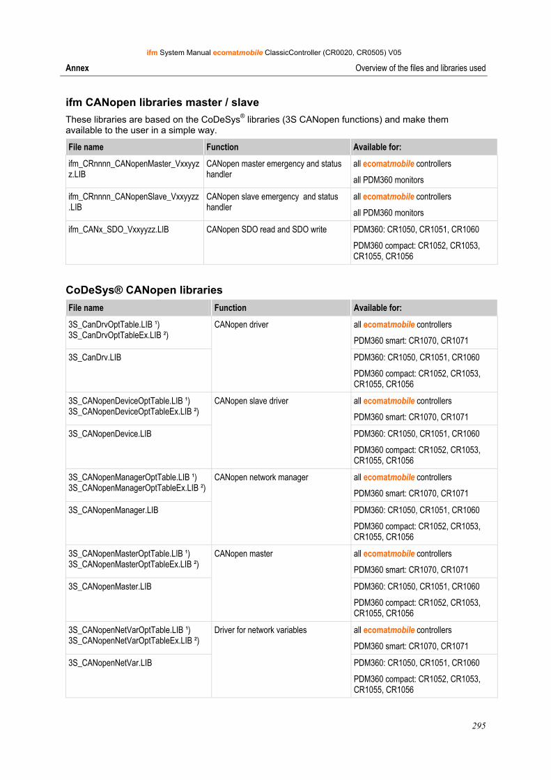
ifm System Manual ecomatmobile ClassicController (CR0020, CR0505) V05
295
Annex Overview of the files and libraries used
ifm CANopen libraries master / slave These libraries are based on the CoDeSys® libraries (3S CANopen functions) and make them available to the user in a simple way.
File name Function Available for:
ifm_CRnnnn_CANopenMaster_Vxxyyzz.LIB
CANopen master emergency and status handler
all ecomatmobile controllers
all PDM360 monitors
ifm_CRnnnn_CANopenSlave_Vxxyyzz.LIB
CANopen slave emergency and status handler
all ecomatmobile controllers
all PDM360 monitors
ifm_CANx_SDO_Vxxyyzz.LIB CANopen SDO read and SDO write PDM360: CR1050, CR1051, CR1060
PDM360 compact: CR1052, CR1053, CR1055, CR1056
CoDeSys® CANopen libraries File name Function Available for:
3S_CanDrvOptTable.LIB ¹) 3S_CanDrvOptTableEx.LIB ²)
all ecomatmobile controllers
PDM360 smart: CR1070, CR1071
3S_CanDrv.LIB
CANopen driver
PDM360: CR1050, CR1051, CR1060
PDM360 compact: CR1052, CR1053, CR1055, CR1056
3S_CANopenDeviceOptTable.LIB ¹) 3S_CANopenDeviceOptTableEx.LIB ²)
all ecomatmobile controllers
PDM360 smart: CR1070, CR1071
3S_CANopenDevice.LIB
CANopen slave driver
PDM360: CR1050, CR1051, CR1060
PDM360 compact: CR1052, CR1053, CR1055, CR1056
3S_CANopenManagerOptTable.LIB ¹) 3S_CANopenManagerOptTableEx.LIB ²)
all ecomatmobile controllers
PDM360 smart: CR1070, CR1071
3S_CANopenManager.LIB
CANopen network manager
PDM360: CR1050, CR1051, CR1060
PDM360 compact: CR1052, CR1053, CR1055, CR1056
3S_CANopenMasterOptTable.LIB ¹) 3S_CANopenMasterOptTableEx.LIB ²)
all ecomatmobile controllers
PDM360 smart: CR1070, CR1071
3S_CANopenMaster.LIB
CANopen master
PDM360: CR1050, CR1051, CR1060
PDM360 compact: CR1052, CR1053, CR1055, CR1056
3S_CANopenNetVarOptTable.LIB ¹) 3S_CANopenNetVarOptTableEx.LIB ²)
all ecomatmobile controllers
PDM360 smart: CR1070, CR1071
3S_CANopenNetVar.LIB
Driver for network variables
PDM360: CR1050, CR1051, CR1060
PDM360 compact: CR1052, CR1053, CR1055, CR1056
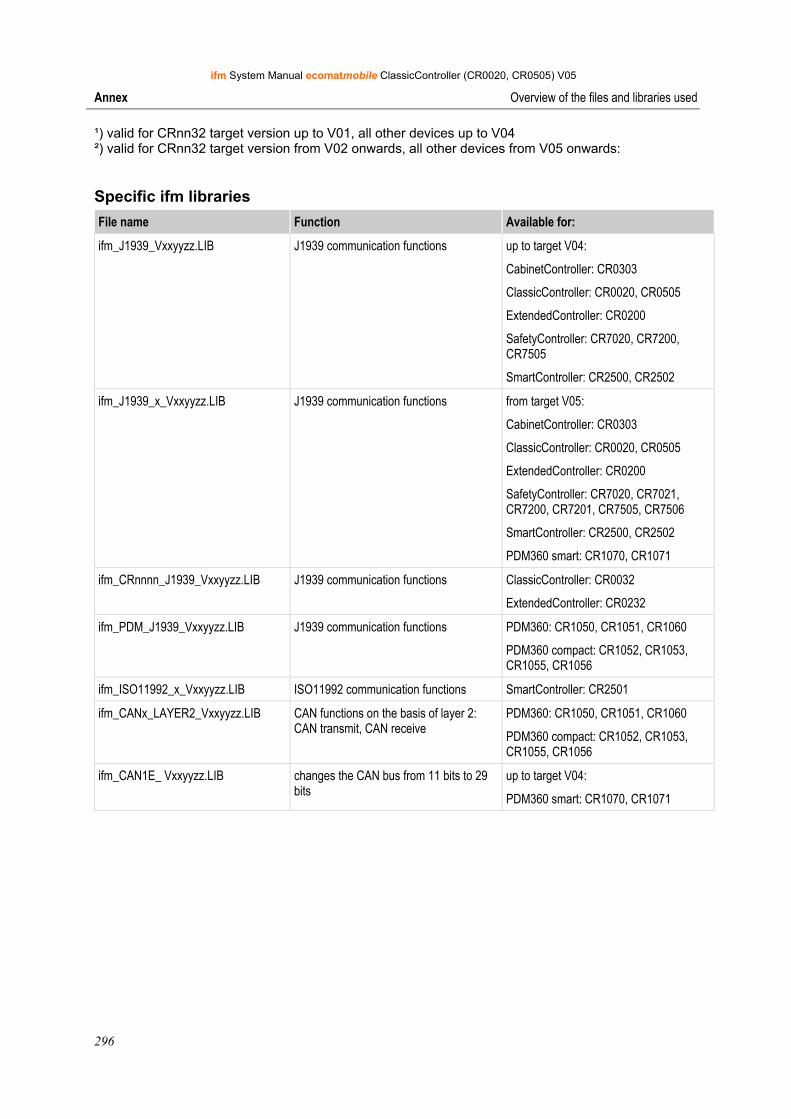
ifm System Manual ecomatmobile ClassicController (CR0020, CR0505) V05
296
Annex Overview of the files and libraries used
¹) valid for CRnn32 target version up to V01, all other devices up to V04 ²) valid for CRnn32 target version from V02 onwards, all other devices from V05 onwards:
Specific ifm libraries File name Function Available for:
ifm_J1939_Vxxyyzz.LIB J1939 communication functions up to target V04:
CabinetController: CR0303
ClassicController: CR0020, CR0505
ExtendedController: CR0200
SafetyController: CR7020, CR7200, CR7505
SmartController: CR2500, CR2502
ifm_J1939_x_Vxxyyzz.LIB J1939 communication functions from target V05:
CabinetController: CR0303
ClassicController: CR0020, CR0505
ExtendedController: CR0200
SafetyController: CR7020, CR7021, CR7200, CR7201, CR7505, CR7506
SmartController: CR2500, CR2502
PDM360 smart: CR1070, CR1071
ifm_CRnnnn_J1939_Vxxyyzz.LIB J1939 communication functions ClassicController: CR0032
ExtendedController: CR0232
ifm_PDM_J1939_Vxxyyzz.LIB J1939 communication functions PDM360: CR1050, CR1051, CR1060
PDM360 compact: CR1052, CR1053, CR1055, CR1056
ifm_ISO11992_x_Vxxyyzz.LIB ISO11992 communication functions SmartController: CR2501
ifm_CANx_LAYER2_Vxxyyzz.LIB CAN functions on the basis of layer 2: CAN transmit, CAN receive
PDM360: CR1050, CR1051, CR1060
PDM360 compact: CR1052, CR1053, CR1055, CR1056
ifm_CAN1E_ Vxxyyzz.LIB changes the CAN bus from 11 bits to 29 bits
up to target V04:
PDM360 smart: CR1070, CR1071
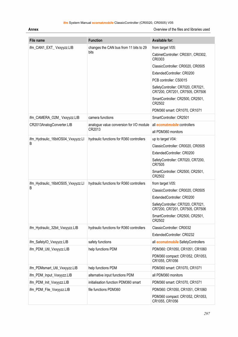
ifm System Manual ecomatmobile ClassicController (CR0020, CR0505) V05
297
Annex Overview of the files and libraries used
File name Function Available for:
ifm_CAN1_EXT_ Vxxyyzz.LIB changes the CAN bus from 11 bits to 29 bits
from target V05:
CabinetController: CR0301, CR0302, CR0303
ClassicController: CR0020, CR0505
ExtendedController: CR0200
PCB controller: CS0015
SafetyController: CR7020, CR7021, CR7200, CR7201, CR7505, CR7506
SmartController: CR2500, CR2501, CR2502
PDM360 smart: CR1070, CR1071
ifm_CAMERA_O2M_ Vxxyyzz.LIB camera functions SmartController: CR2501
CR2013AnalogConverter.LIB analogue value conversion for I/O module CR2013
all ecomatmobile controllers
all PDM360 monitors
ifm_Hydraulic_16bitOS04_Vxxyyzz.LIB
hydraulic functions for R360 controllers up to target V04:
ClassicController: CR0020, CR0505
ExtendedController: CR0200
SafetyController: CR7020, CR7200, CR7505
SmartController: CR2500, CR2501, CR2502
ifm_Hydraulic_16bitOS05_Vxxyyzz.LIB
hydraulic functions for R360 controllers from target V05:
ClassicController: CR0020, CR0505
ExtendedController: CR0200
SafetyController: CR7020, CR7021, CR7200, CR7201, CR7505, CR7506
SmartController: CR2500, CR2501, CR2502
ifm_Hydraulic_32bit_Vxxyyzz.LIB hydraulic functions for R360 controllers ClassicController: CR0032
ExtendedController: CR0232
ifm_SafetyIO_Vxxyyzz.LIB safety functions all ecomatmobile SafetyControllers
ifm_PDM_Util_Vxxyyzz.LIB help functions PDM PDM360: CR1050, CR1051, CR1060
PDM360 compact: CR1052, CR1053, CR1055, CR1056
ifm_PDMsmart_Util_Vxxyyzz.LIB help functions PDM PDM360 smart: CR1070, CR1071
ifm_PDM_Input_Vxxyyzz.LIB alternative input functions PDM all PDM360 monitors
ifm_PDM_Init_Vxxyyzz.LIB initialisation function PDM360 smart PDM360 smart: CR1070, CR1071
ifm_PDM_File_Vxxyyzz.LIB file functions PDM360 PDM360: CR1050, CR1051, CR1060
PDM360 compact: CR1052, CR1053, CR1055, CR1056

ifm System Manual ecomatmobile ClassicController (CR0020, CR0505) V05
298
Annex Overview of the files and libraries used
File name Function Available for:
Instrumente_x.LIB predefined display instruments all PDM360 monitors
Symbols_x.LIB predefined symbols PDM360: CR1050, CR1051, CR1060
PDM360 compact: CR1052, CR1053, CR1055, CR1056
Segment_x.LIB predefined 7-segment displays PDM360: CR1050, CR1051, CR1060
PDM360 compact: CR1052, CR1053, CR1055, CR1056
Further libraries on request.
ifm System Manual ecomatmobile ClassicController (CR0020, CR0505) V05
299
Glossary of Terms
14 Glossary of Terms
A
Address This is the "name" of the bus participant. All participants need a unique address so that the signals can be exchanged without problem.
Application software Software specific to the application, implemented by the machine manufacturer, generally containing logic sequences, limits and expressions that control the appropriate inputs, outputs, calculations and decisions
Necessary to meet the specific (→SRP/CS) requirements. → Programming language, safety-related
Architecture Specific configuration of hardware and software elements in a system.
B
Baud Baud, abbrev.: Bd = unit for the data transmission speed. Do not confuse baud with "bits per second" (bps, bits/s). Baud indicates the number of changes of state (steps, cycles) per second over a transmission length. But it is not defined how many bits per step are transmitted. The name baud can be traced back to the French inventor J. M. Baudot whose code was used for telex machines.
1 MBd = 1024 x 1024 Bd = 1 048 576 Bd
Bus Serial data transmission of several participants on the same cable.
C
CAN CAN = Controller Area Network
CAN is a priority controlled fieldbus system for larger data volumes. It is available in different variants, e.g. "CANopen" or "CAN in Automation" (CiA).
Category (CAT) Classification of the safety-related parts of a control system in respect of their resistance to faults and their subsequent behaviour in the fault condition. This safety is achieved by the structural arrangement of the parts, fault detection and/or by their reliability. (→ EN 954).
CCF Common Cause Failure Failures of different items, resulting from a common event, where these failures are not consequences of each other.
CiA CiA = CAN in Automation e.V.
User and manufacturer organisation in Germany / Erlangen. Definition and control body for CAN and CAN-based network protocols.
Homepage → http://www.can-cia.org
CiA DS 304 DS = Draft Standard
CAN device profile CANopen safety for safety-related communication.
CiA DS 401 DS = Draft Standard
CAN device profile for digital and analogue I/O modules
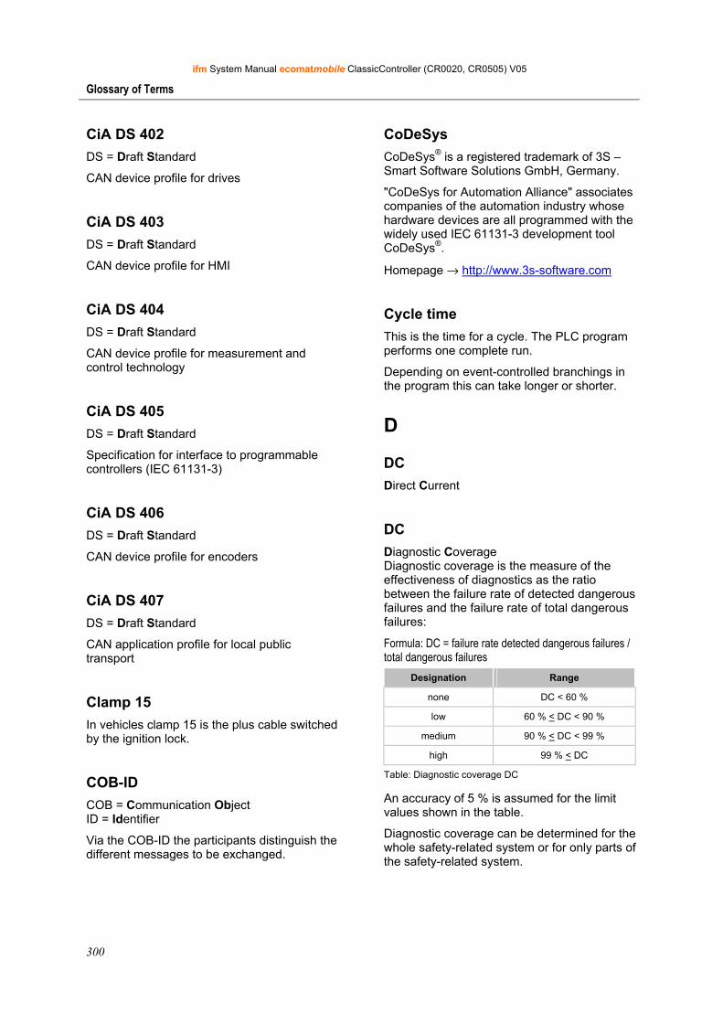
ifm System Manual ecomatmobile ClassicController (CR0020, CR0505) V05
300
Glossary of Terms
CiA DS 402 DS = Draft Standard
CAN device profile for drives
CiA DS 403 DS = Draft Standard
CAN device profile for HMI
CiA DS 404 DS = Draft Standard
CAN device profile for measurement and control technology
CiA DS 405 DS = Draft Standard
Specification for interface to programmable controllers (IEC 61131-3)
CiA DS 406 DS = Draft Standard
CAN device profile for encoders
CiA DS 407 DS = Draft Standard
CAN application profile for local public transport
Clamp 15 In vehicles clamp 15 is the plus cable switched by the ignition lock.
COB-ID COB = Communication Object ID = Identifier
Via the COB-ID the participants distinguish the different messages to be exchanged.
CoDeSys CoDeSys® is a registered trademark of 3S – Smart Software Solutions GmbH, Germany.
"CoDeSys for Automation Alliance" associates companies of the automation industry whose hardware devices are all programmed with the widely used IEC 61131-3 development tool CoDeSys®.
Homepage → http://www.3s-software.com
Cycle time This is the time for a cycle. The PLC program performs one complete run.
Depending on event-controlled branchings in the program this can take longer or shorter.
D
DC Direct Current
DC Diagnostic Coverage Diagnostic coverage is the measure of the effectiveness of diagnostics as the ratio between the failure rate of detected dangerous failures and the failure rate of total dangerous failures:
Formula: DC = failure rate detected dangerous failures / total dangerous failures
Designation Range
none DC < 60 %
low 60 % < DC < 90 %
medium 90 % < DC < 99 %
high 99 % < DC
Table: Diagnostic coverage DC
An accuracy of 5 % is assumed for the limit values shown in the table.
Diagnostic coverage can be determined for the whole safety-related system or for only parts of the safety-related system.
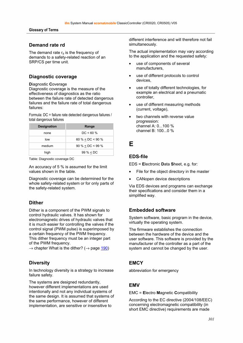
ifm System Manual ecomatmobile ClassicController (CR0020, CR0505) V05
301
Glossary of Terms
Demand rate rd The demand rate rd is the frequency of demands to a safety-related reaction of an SRP/CS per time unit.
Diagnostic coverage Diagnostic Coverage Diagnostic coverage is the measure of the effectiveness of diagnostics as the ratio between the failure rate of detected dangerous failures and the failure rate of total dangerous failures:
Formula: DC = failure rate detected dangerous failures / total dangerous failures
Designation Range
none DC < 60 %
low 60 % < DC < 90 %
medium 90 % < DC < 99 %
high 99 % < DC
Table: Diagnostic coverage DC
An accuracy of 5 % is assumed for the limit values shown in the table.
Diagnostic coverage can be determined for the whole safety-related system or for only parts of the safety-related system.
Dither Dither is a component of the PWM signals to control hydraulic valves. It has shown for electromagnetic drives of hydraulic valves that it is much easier for controlling the valves if the control signal (PWM pulse) is superimposed by a certain frequency of the PWM frequency. This dither frequency must be an integer part of the PWM frequency. → chapter What is the dither? (→ page 190)
Diversity In technology diversity is a strategy to increase failure safety.
The systems are designed redundantly, however different implementations are used intentionally and not any individual systems of the same design. It is assumed that systems of the same performance, however of different implementation, are sensitive or insensitive to
different interference and will therefore not fail simultaneously.
The actual implementation may vary according to the application and the requested safety:
• use of components of several manufacturers,
• use of different protocols to control devices,
• use of totally different technologies, for example an electrical and a pneumatic controller,
• use of different measuring methods (current, voltage),
• two channels with reverse value progression: channel A: 0...100 % channel B: 100...0 %
E
EDS-file EDS = Electronic Data Sheet, e.g. for:
• File for the object directory in the master
• CANopen device descriptions
Via EDS devices and programs can exchange their specifications and consider them in a simplified way.
Embedded software System software, basic program in the device, virtually the operating system.
The firmware establishes the connection between the hardware of the device and the user software. This software is provided by the manufacturer of the controller as a part of the system and cannot be changed by the user.
EMCY abbreviation for emergency
EMV EMC = Electro Magnetic Compatibility
According to the EC directive (2004/108/EEC) concerning electromagnetic compatibility (in short EMC directive) requirements are made
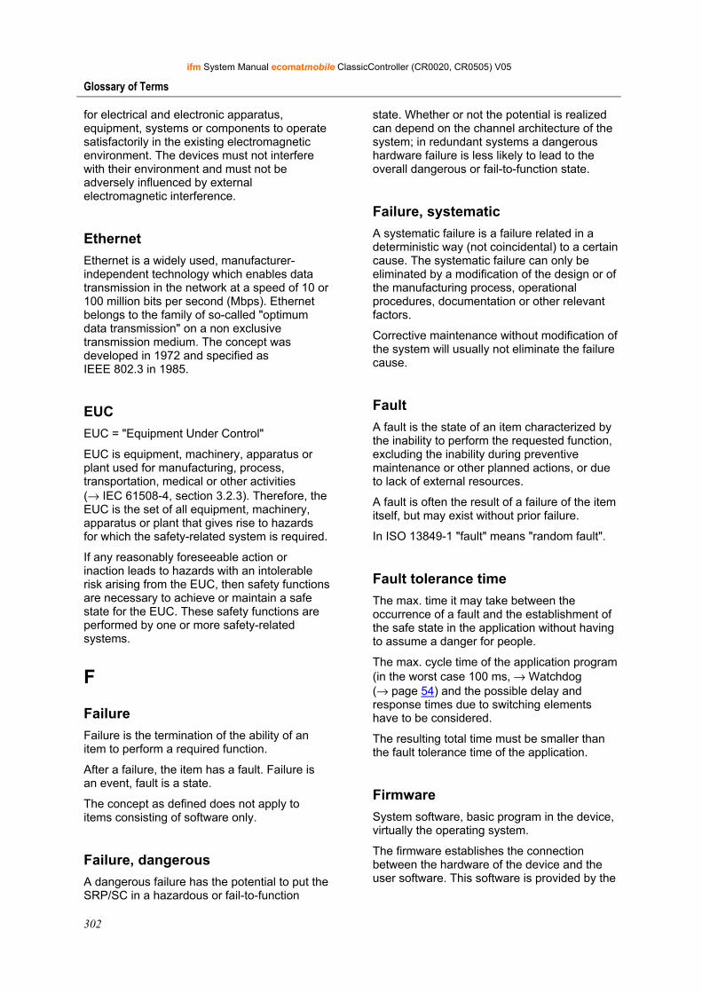
ifm System Manual ecomatmobile ClassicController (CR0020, CR0505) V05
302
Glossary of Terms
for electrical and electronic apparatus, equipment, systems or components to operate satisfactorily in the existing electromagnetic environment. The devices must not interfere with their environment and must not be adversely influenced by external electromagnetic interference.
Ethernet Ethernet is a widely used, manufacturer-independent technology which enables data transmission in the network at a speed of 10 or 100 million bits per second (Mbps). Ethernet belongs to the family of so-called "optimum data transmission" on a non exclusive transmission medium. The concept was developed in 1972 and specified as IEEE 802.3 in 1985.
EUC EUC = "Equipment Under Control"
EUC is equipment, machinery, apparatus or plant used for manufacturing, process, transportation, medical or other activities (→ IEC 61508-4, section 3.2.3). Therefore, the EUC is the set of all equipment, machinery, apparatus or plant that gives rise to hazards for which the safety-related system is required.
If any reasonably foreseeable action or inaction leads to hazards with an intolerable risk arising from the EUC, then safety functions are necessary to achieve or maintain a safe state for the EUC. These safety functions are performed by one or more safety-related systems.
F
Failure Failure is the termination of the ability of an item to perform a required function.
After a failure, the item has a fault. Failure is an event, fault is a state.
The concept as defined does not apply to items consisting of software only.
Failure, dangerous A dangerous failure has the potential to put the SRP/SC in a hazardous or fail-to-function
state. Whether or not the potential is realized can depend on the channel architecture of the system; in redundant systems a dangerous hardware failure is less likely to lead to the overall dangerous or fail-to-function state.
Failure, systematic A systematic failure is a failure related in a deterministic way (not coincidental) to a certain cause. The systematic failure can only be eliminated by a modification of the design or of the manufacturing process, operational procedures, documentation or other relevant factors.
Corrective maintenance without modification of the system will usually not eliminate the failure cause.
Fault A fault is the state of an item characterized by the inability to perform the requested function, excluding the inability during preventive maintenance or other planned actions, or due to lack of external resources.
A fault is often the result of a failure of the item itself, but may exist without prior failure.
In ISO 13849-1 "fault" means "random fault".
Fault tolerance time The max. time it may take between the occurrence of a fault and the establishment of the safe state in the application without having to assume a danger for people.
The max. cycle time of the application program (in the worst case 100 ms, → Watchdog (→ page 54) and the possible delay and response times due to switching elements have to be considered.
The resulting total time must be smaller than the fault tolerance time of the application.
Firmware System software, basic program in the device, virtually the operating system.
The firmware establishes the connection between the hardware of the device and the user software. This software is provided by the
ifm System Manual ecomatmobile ClassicController (CR0020, CR0505) V05
303
Glossary of Terms
manufacturer of the controller as a part of the system and cannot be changed by the user.
First fault occurrence time Time until the first failure of a safety element.
The operating system verifies the controller by means of the internal monitoring and test routines within a period of max. 30 s.
This "test cycle time" must be smaller than the statistical first fault occurrence time for the application.
Functional safety Part of the overall safety referred to the →EUC and the EUC control system which depends on the correct functioning of the electric or electronic safety-related system, safety-related systems of other technologies and external devices for risk reduction.
H
Harm Physical injury or damage to health.
Hazard Hazard is the potential source of harm.
A distinction is made between the source of the hazard, e.g.: - mechanical hazard, - electrical hazard, or the nature of the potential harm, e.g.: - electric shock hazard, - cutting hazard, - toxic hazard.
The hazard envisaged in this definition is either permanently present during the intended use of the machine, e.g.: - motion of hazardous moving elements, - electric arc during a welding phase, - unhealthy posture, - noise emission, - high temperature, or the hazard may appear unexpectedly, e.g.: - explosion, - crushing hazard as a consequence of an unintended/unexpected start-up, - ejection as a consequence of a breakage,
- fall as a consequence of acceleration/deceleration.
Heartbeat The participants regularly send short signals. In this way the other participants can verify if a participant has failed. No master is necessary.
I
ID ID = Identifier
Name to differentiate the devices / participants connected to a system or the message packets transmitted between the participants.
Instructions Superordinate word for one of the following terms: installation instructions, data sheet, user information, operating instructions, device manual installation information, online help, system manual, programming manual, etc.
Intended use Use of a product in accordance with the information provided in the instructions for use.
IP address IP = Internet Protocol
The IP address is a number which is necessary to clearly identify an internet participant. For the sake of clarity the number is written in 4 decimal values, e.g. 127.215.205.156.
L
LED LED = Light Emitting Diode
Light emitting diode, also called luminescent diode, an electronic element of high coloured luminosity at small volume with negligible power loss.
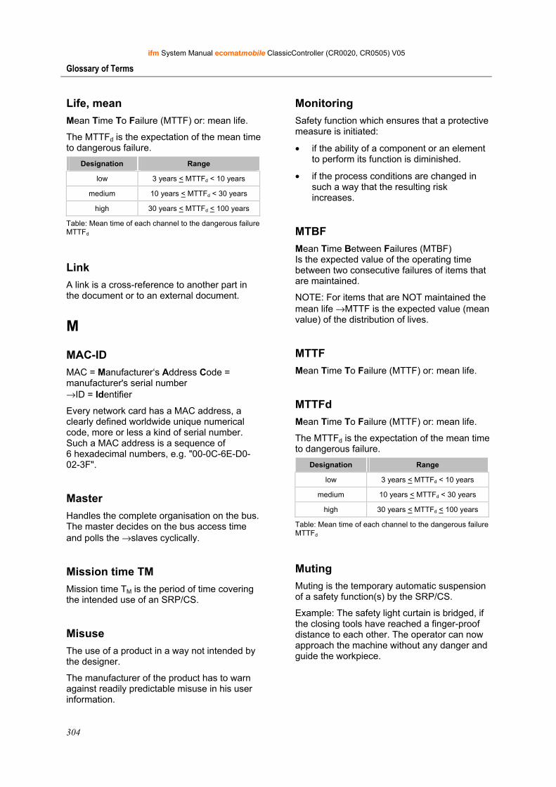
ifm System Manual ecomatmobile ClassicController (CR0020, CR0505) V05
304
Glossary of Terms
Life, mean Mean Time To Failure (MTTF) or: mean life.
The MTTFd is the expectation of the mean time to dangerous failure.
Designation Range
low 3 years < MTTFd < 10 years
medium 10 years < MTTFd < 30 years
high 30 years < MTTFd < 100 years
Table: Mean time of each channel to the dangerous failure MTTFd
Link A link is a cross-reference to another part in the document or to an external document.
M
MAC-ID MAC = Manufacturer‘s Address Code = manufacturer's serial number →ID = Identifier
Every network card has a MAC address, a clearly defined worldwide unique numerical code, more or less a kind of serial number. Such a MAC address is a sequence of 6 hexadecimal numbers, e.g. "00-0C-6E-D0-02-3F".
Master Handles the complete organisation on the bus. The master decides on the bus access time and polls the →slaves cyclically.
Mission time TM Mission time TM is the period of time covering the intended use of an SRP/CS.
Misuse The use of a product in a way not intended by the designer.
The manufacturer of the product has to warn against readily predictable misuse in his user information.
Monitoring Safety function which ensures that a protective measure is initiated:
• if the ability of a component or an element to perform its function is diminished.
• if the process conditions are changed in such a way that the resulting risk increases.
MTBF Mean Time Between Failures (MTBF) Is the expected value of the operating time between two consecutive failures of items that are maintained.
NOTE: For items that are NOT maintained the mean life →MTTF is the expected value (mean value) of the distribution of lives.
MTTF Mean Time To Failure (MTTF) or: mean life.
MTTFd Mean Time To Failure (MTTF) or: mean life.
The MTTFd is the expectation of the mean time to dangerous failure.
Designation Range
low 3 years < MTTFd < 10 years
medium 10 years < MTTFd < 30 years
high 30 years < MTTFd < 100 years
Table: Mean time of each channel to the dangerous failure MTTFd
Muting Muting is the temporary automatic suspension of a safety function(s) by the SRP/CS.
Example: The safety light curtain is bridged, if the closing tools have reached a finger-proof distance to each other. The operator can now approach the machine without any danger and guide the workpiece.
ifm System Manual ecomatmobile ClassicController (CR0020, CR0505) V05
305
Glossary of Terms
N
NMT NMT = Network Management = (here: in the CAN bus)
The NMT master controls the operating states of the NMT slaves.
Node This means a participant in the network.
Node Guarding Network participant
Configurable cyclic monitoring of each slave configured accordingly. The master verfies if the slaves reply in time. The slaves verify if the master regularly sends requests. In this way failed network participants can be quickly identified and reported.
O
Obj / object Term for data / messages which can be exchanged in the CANopen network.
Object directory Contains all CANopen communication parameters of a device as well as device-specific parameters and data.
OBV Contains all CANopen communication parameters of a device as well as device-specific parameters and data.
Operating system Basic program in the device, establishes the connection between the hardware of the device and the user software.
Operational Operating state of a CANopen participant. In this mode SDOs, NMT commands and PDOs can be transferred.
P
PC card →PCMCIA card
PCMCIA card PCMCIA = Personal Computer Memory Card International Association, a standard for expansion cards of mobile computers. Since the introduction of the cardbus standard in 1995 PCMCIA cards have also been called PC card.
PDO PDO = Process Data Object
The time-critical process data is transferred by means of the "process data objects" (PDOs). The PDOs can be freely exchanged between the individual nodes (PDO linking). In addition it is defined whether data exchange is to be event-controlled (asynchronous) or synchronised. Depending on the type of data to be transferred the correct selection of the type of transmission can lead to considerable relief for the CAN bus.
These services are not confirmed by the protocol, i.e. it is not checked whether the message reaches the receiver. Exchange of network variables corresponds to a "1 to n connection" (1 transmitter to n receivers).
Performance Level Performance Level According to ISO 13849-1, a specification (PL a...e) of safety-related parts of control systems to perform a safety function under foreseeable conditions.
PES Programmable Electronic System A programmable electronic system is a system...
ifm System Manual ecomatmobile ClassicController (CR0020, CR0505) V05
306
Glossary of Terms
- for control, protection or monitoring, - dependent for its operation on one or more programmable electronic devices, - including all elements of the system such as input and output devices.
Pictogram Pictograms are figurative symbols which convey information by a simplified graphic representation.
→ Chapter What do the symbols and formats stand for? (→ page 7)
PL Performance Level According to ISO 13849-1, a specification (PL a...e) of safety-related parts of control systems to perform a safety function under foreseeable conditions.
PLr Using the "required performance level" PLr the risk reduction for each safety function according to ISO 13849 is achieved.
For each selected safety function to be carried out by a SRP/CS, a PLr shall be determined and documented. The determination of the PLr is the result of the risk assessment and refers to the amount of the risk reduction.
Pre-Op Pre-Op = Preoperational mode
Operating status of a CANopen participant. After application of the supply voltage each participant automatically passes into this state. In the CANopen network only SDOs and NMT commands can be transferred in this mode but no process data.
prepared Operating status of a CANopen participant. In this mode only NMT commands are transferred.
Programming language, safety-related Only the following programming languages shall be used for safety-related applications:
• Limited variability language (LVL) that provides the capability of combining predefined, application-specific library functions. In CoDeSys these are LD (ladder diagram) and FBD (function block diagram).
• Full variability language (FVL) provides the capability of implementing a wide variety of functions. These include e.g. C, C++, Assembler. In CoDeSys it is ST (structured text).
► Structured text is recommended exclusively in separate, certified functions, usually in embedded software.
► In the "normal" application program only LD and FBD should be used. The following minimum requirements shall be met.
In general the following minimum requirements are made on the safety-related application software (SRASW):
► Modular and clear structure of the program. Consequence: simple testability.
► Functions are represented in a comprehensible manner: - for the operator on the screen (navigation) - readability of a subsequent print of the document.
► Use symbolic variables (no IEC addresses).
► Use meaningful variable names and comments.
► Use easy functions (no indirect addressing, no variable fields).
► Defensive programming.
► Easy extension or adaptation of the program possible.
Protective measure Measure intended to achieve risk reduction, e.g.: - fault-excluding design, - safeguarding measures (guards), - complementary protective measures (user
ifm System Manual ecomatmobile ClassicController (CR0020, CR0505) V05
307
Glossary of Terms
information), - personal protective equipment (helmet, protective goggles).
PWM PWM = pulse width modulation
Via PWM a digital output (capability provided by the device) can provide an almost analogue voltage by means of regular fast pulses. The PWM output signal is a pulsed signal between GND and supply voltage.
Within a defined period (PWM frequency) the mark-to-space ratio is varied. Depending on the mark-to-space ratio, the connected load determines the corresponding RMS current. → chapter PWM signal processing (→ page 171) → chapter What does a PWM output do? (→ page 189)
R
Ratio Measurements can also be performed ratiometrically. The input signal generates an output signal which is in a defined ratio to the input signal. This means that analogue input signals can be evaluated without additional reference voltage. A fluctuation of the supply voltage has no influence on this measured value. → Chapter Counter functions (→ page 211)
redundant Redundancy is the presence of more than the necessary means so that a function unit performs a requested function or that data can represent information.
Several kinds of redundancy are distinguished:
• Functional redundancy aims at designing safety-related systems in multiple ways in parallel so that in the event of a failure of one component the others ensure the task.
• In addition it is tried to separate redundant systems from each other with regard to space. Thus the risk that they are affected by a common interference is minimised.
• Finally, components from different manufacturers are sometimes used to
avoid that a systematic fault causes all redundant systems to fail (diverse redundancy).
The software of redundant systems should differ in the following aspects:
• specification (different teams),
• specification language,
• programming (different teams),
• programming language,
• compiler.
remanent Remanent data is protected against data loss in case of power failure.
The operating system for example automatically copies the remanent data to a flash memory as soon as the voltage supply falls below a critical value. If the voltage supply is available again, the operating system loads the remanent data back to the RAM memory.
The data in the RAM memory of a controller, however, is volatile and normally lost in case of power failure.
Reset, manual The manual reset is an internal function within the SRP/CS used to restore manually one or more safety functions before re-starting a machine.
Residual risk Risk remaining after protective measures have been taken. The residual risk has to be clearly warned against in operating instructions and on the machine.
Risk Combination of the probability of occurrence of harm and the severity of that harm.
Risk analysis Combination of ...
• the specification of the limits of the machine (intended use, time limits),
ifm System Manual ecomatmobile ClassicController (CR0020, CR0505) V05
308
Glossary of Terms
• hazard identification (intervention of people, operating status of the machine, foreseeable misuse) and
• the risk estimation (degree of injury, extent of damage, frequency and duration of the risk, probability of occurrence, possibility of avoiding the hazard or limiting the harm).
Risk assessment Overall process comprising risk analysis and risk evaluation.
According to Machinery Directive 2006/42/EU the following applies: "The manufacturer of machinery or his authorised representative must ensure that a risk assessment is carried out in order to determine the health and safety requirements which apply to the machinery. The machinery must then be designed and constructed taking into account the results of the risk assessment." (→ Annex 1, General principles)
Risk evaluation Judgement, on the basis of the risk analysis, of whether risk reduction objectives have been achieved.
ro RO = read only for reading only
Unidirectional data transmission: Data can only be read and not changed.
rw RW = read/ write
Bidirectional data transmission: Data can be read and also changed.
S
Safety function Function of the machine whose failure can result in an immediate increase of the risk(s). The designer of such a machine therefore has to: - safely prevent a failure of the safety function, - reliably detect a failure of the safety function in time,
- bring the machine into a safe state in time in the event of a failure of the safety function.
Safety-standard types The safety standards in the field of machines are structured as below:
Type-A standards (basic safety standards) giving basic concepts, principles for design, and general aspects that can be applied to all machinery. Examples: basic terminology, methodology (ISO 12100-1), technical principles (ISO 12100-2), risk assessment (ISO 14121), ...
Type-B standards (generic safety standards) dealing with one safety aspect or one type of safeguard that can be used across a wide range of machinery.
• Type-B1 standards on particular safety aspects. Examples: safety distances (EN 294), hand/arm speeds (EN 999), safety-related parts of control systems (ISO 13849), temperatures, noise, ...
• Type-B2 standards on safeguards. Examples: emergency stop circuits ((ISO 13850), two-hand controls, interlocking devices or electro-sensitive protective equipment (ISO 61496), ...
Type-C standards (machine safety standards) dealing with detailed safety requirements for a particular machine or group of machines.
SCT In CANopen safety the Safeguard Cycle Time (SCT) monitors the correct function of the periodic transmission (data refresh) of the SRDOs. The data must have been repeated within the set time to be valid. Otherwise the receiving controller signals a fault and passes into the safe state (= outputs switched off).
SDO SDO = Service Data Object.
SDO is a specification for a manufacturer-dependent data structure for standardised data access. "Clients" ask for the requested data from "servers". The SDOs always consist of 8 bytes. Longer data packages are distributed to several messages.
Examples:
ifm System Manual ecomatmobile ClassicController (CR0020, CR0505) V05
309
Glossary of Terms
• Automatic configuration of all slaves via SDOs at the system start,
• reading error messages from the object directory.
Every SDO is monitored for a response and repeated if the slave does not respond within the monitoring time.
SIL According to IEC 62061 the safety-integrity level SIL is a classification (SIL CL 1...4) of the safety integrity of the safety functions. It is used for the evaluation of electrical/electronic/programmable electronic (E/E/EP) systems with regard to the reliability of safety functions. The safety-related design principles that have to be adhered to so that the risk of a malfunction can be minimised result from the required level.
Slave Passive participant on the bus, only replies on request of the →master. Slaves have a clearly defined and unique →address in the bus.
SRDO Safe data is exchanged via SRDOs (Safety-Related Data Objects). An SRDO always consists of two CAN messages with different identifiers:
• message 1 contains the original user data,
• message 2 contains the same data which are inverted bit by bit.
SRP/CS Safety-Related Part of a Control System
Part of a control system that responds to safety-related input signals and generates safety-related output signals. The combined safety-related parts of a control system start at the point where the safety-related input signals are initiated (including, for example, the actuating cam and the roller of the position switch) and end at the output of the power control elements (including, for example, the main contacts of a contactor).
SRVT The SRVT (Safety-Related Object Validation Time) ensures with CANopen safety that the time between the SRDO-message pairs is adhered to.
Only if the redundant, inverted message has been transmitted after the original message within the SRVT set are the transmitted data valid. Otherwise the receiving controller signals a fault and will pass into the safe state (= outputs switched off).
State, safe The state of a machine is said to be safe when there is no more hazard formed by it. This is usually the case if all possible dangerous movements are switched off and cannot start again unexpectedly.
Symbols Pictograms are figurative symbols which convey information by a simplified graphic representation.
→ Chapter What do the symbols and formats stand for? (→ page 7)
T
Target The target indicates the target system where the PLC program is to run. The target contains the files (drivers and if available specific help files) required for programming and parameter setting.
TCP The Transmission Control Protocol is part of the TCP/IP protocol family. Each TCP/IP data connection has a transmitter and a receiver. This principle is a connection-oriented data transmission. In the TCP/IP protocol family the TCP as the connection-oriented protocol assumes the task of data protection, data flow control and takes measures in the event of data loss.
(compare: →UDP)
ifm System Manual ecomatmobile ClassicController (CR0020, CR0505) V05
310
Glossary of Terms
Template A template can be filled with content. Here: A structure of pre-configured software elements as basis for an application program.
Test rate rt The test rate rt is the frequency of the automatic tests to detect errors in an SRP/CS in time.
U
UDP UDP (User Datagram Protocol) is a minimal connectionless network protocol which belongs to the transport layer of the internet protocol family. The task of UDP is to ensure that data which is transmitted via the internet is passed to the right application.
At present network variables based on CAN and UDP are implemented. The values of the variables are automatically exchanged on the basis of broadcast messages. In UDP they are implemented as broadcast messages, in CAN as PDOs. These services are not confirmed by the protocol, i.e. it is not checked whether the message is received. Exchange of network variables corresponds to a "1 to n connection" (1 transmitter to n receivers).
Uptime, mean Mean Time Between Failures (MTBF) Is the expected value of the operating time between two consecutive failures of items that are maintained.
NOTE: For items that are NOT maintained the mean life →MTTF is the expected value (mean value) of the distribution of lives.
Use, intended Use of a product in accordance with the information provided in the instructions for use.
W
Watchdog In general the term watchdog is used for a component of a system which watches the function of other components. If a possible malfunction is detected, this is either signalled or suitable program branchings are activated. The signal or branchings serve as a trigger for other co-operating system components to solve the problem.
wo WO = write only
Unidirectional data transmission: Data can only be changed and not read.
ifm System Manual ecomatmobile ClassicController (CR0020, CR0505) V05
311
Index
15 Index About the ifm templates ....................................... 24
About this manual .................................................. 7
Above-average stress ........................................... 52
Access to the CAN device at runtime ................ 116
Access to the OD entries by the application program.............................................................. 116
Access to the status of the CANopen master ..... 107
Access to the structures at runtime of the application.......................................................... 138
Activating the PLC configuration ........................ 21
Adapting analogue values .................................. 267
Add and configure CANopen slaves............ 99, 115
Address .............................................................. 299
Address assignment inputs / outputs .................. 288
Addresses / variables of the I/Os........................ 284
Adress assignment and I/O operating modes ..... 284
After application of the supply voltage ................ 16
Analogue inputs ................................................... 39
Annex........................................................... 36, 284
Application software .......................................... 299
Applications ....................................................... 211
Architecture........................................................ 299
Automatic saving of data ................................... 227
Available memory................................................ 54
Baud ................................................................... 299
Boot up of the CANopen master ........................ 104
Boot up of the CANopen slaves......................... 104
Bus ..................................................................... 299
Bus cable length ................................................... 63
Bus level .............................................................. 62
Calculation examples RELOAD value .............. 173
Calculation of the RELOAD value .................... 172
CAN................................................................... 299
CAN device.................................................. 93, 109
CAN device configuration ................................. 109
CAN errors and error handling ...................... 61, 65
CAN in the ecomatmobile controller ................... 57
CAN interfaces..................................................... 57
CAN network variables...........................57, 93, 117
CAN-ID ..........................................................59, 60
CANopen master.....................................93, 95, 137
CANopen support by CoDeSys ........................... 93
CANopen terms and implementation................... 94
Category (CAT) ................................................. 299
CCF.................................................................... 299
Change the PDO properties at runtime .............. 116
Changing the standard mapping by the master configuration...................................................... 115
CiA..................................................................... 299
CiA DS 304........................................................ 299
CiA DS 401........................................................ 299
CiA DS 402........................................................ 300
CiA DS 403........................................................ 300
CiA DS 404........................................................ 300
CiA DS 405........................................................ 300
CiA DS 406........................................................ 300
CiA DS 407........................................................ 300
Clamp 15............................................................ 300
COB-ID.............................................................. 300
CoDeSys ............................................................ 300
CoDeSys® CANopen libraries .......................... 295
Configuration of CAN network variables .......... 117
Configurations ..................................................... 20
Configure inputs .................................................. 37
Configure outputs ................................................ 41
Connect terminal VBBO (5) to battery (not switched).............................................................. 14
Connect terminal VBBS (23) to the ignition switch............................................................................. 14
Control hydraulic valves with current-controlled outputs................................................................ 188
Controlled system with delay............................. 271
Controlled system without inherent regulation ................................................................................... 271
Controller functions in the ecomatmobile controller........................................................................... 270
Counter functions for frequency and period measurement .......................................211, 289, 307
Create a CANopen project ................................... 96
ifm System Manual ecomatmobile ClassicController (CR0020, CR0505) V05
312
Index
Current control with PWM ........................ 182, 289
Current measurement with PWM channels........ 182
Cycle time .......................................................... 300
Damping of overshoot........................................ 272
Data access and data check ................................ 236
Data reception ...................................................... 60
Data transmission................................................. 60
DC...................................................................... 300
DEBUG mode...................................................... 48
Demand rate rd................................................... 301
Demo program for controller ............................... 32
Demo program for PDM:..................................... 34
Description of the CAN functions........................ 68
Diagnostic coverage........................................... 301
Differentiation from other CANopen libraries..... 95
Digital and PWM outputs .................................... 41
Digital inputs........................................................ 37
Dither ................................................................. 301
Dither frequency and amplitude......................... 191
Diversity............................................................. 301
EDS-file ............................................................. 301
Embedded software............................................ 301
EMCY................................................................ 301
EMV................................................................... 301
Error codes and diagnostic information ....... 49, 290
Error counter ........................................................ 66
Error message....................................................... 65
Ethernet .............................................................. 302
EUC ................................................................... 302
Example 1 .......................................................... 269
Example 2 .......................................................... 269
Example Dither .................................................. 192
Example for CHECK_DATA ............................ 245
Example Initialisation of CANx_RECEIVE_RANGE in 4 cycles......... 86, 88
Example of an object directory .......................... 111
Example process for response to a system error ................................................................................... 51
Example with function CANx_MASTER_SEND_EMERGENCY........ 132
Example with function CANx_MASTER_STATUS........................................................................... 137
Example with function CANx_SLAVE_SEND_EMERGENCY ........... 145
Examples NORM_HYDRAULIC ..................... 210
Exchange of CAN data ...................................59, 61
Failure ................................................................ 302
Failure, dangerous.............................................. 302
Failure, systematic ............................................. 302
Fast inputs ............................................................ 38
Fatal error............................................................. 45
Fault ................................................................... 302
Fault tolerance time ........................................... 302
Feedback in case of externally supplied outputs................................................................................... 19
Feedback on bidirectional inputs/outputs............. 18
Files for the operating system / runtime system.................................................................................. 294
Firmware............................................................ 302
First fault occurrence time ................................. 303
Folder structure in general ................................... 25
Function CAN1_BAUDRATE ...............68, 69, 116
Function CAN1_DOWNLOADID ...................... 71
Function CAN1_EXT ...................................73, 116
Function CAN1_EXT_ERRORHANDLER........ 79
Function CAN1_EXT_RECEIVE ....................... 77
Function CAN1_EXT_TRANSMIT.................... 75
Function CAN2.........................................68, 80, 91
Function CANx_ERRORHANDLER.................. 91
Function CANx_EXT_RECEIVE_ALL.............. 89
Function CANx_MASTER_EMCY_HANDLER....................................................................123, 128
Function CANx_MASTER_SEND_EMERGENCY....................................................................123, 130
Function CANx_MASTER_STATUS.........................................102, 103, 104, 106, 107, 108, 133, 137
Function CANx_RECEIVE ................59, 60, 84, 86
Function CANx_RECEIVE_RANGE ................. 86
Function CANx_SDO_READ ......................96, 150
ifm System Manual ecomatmobile ClassicController (CR0020, CR0505) V05
313
Index
Function CANx_SDO_WRITE ................... 96, 152
Function CANx_SLAVE_EMCY_HANDLER...........................................................109, 116, 123, 141
Function CANx_SLAVE_NODEID.......... 116, 140
Function CANx_SLAVE_SEND_EMERGENCY....................................................109, 116, 123, 143
Function CANx_SLAVE_STATUS .......... 116, 146
Function CANx_TRANSMIT........................ 59, 82
Function CHECK_DATA.................................. 244
Function configuration of the inputs and outputs.................................................................................. 36
Function CONTROL_OCC ....................... 193, 194
Function DELAY............................................... 273
Function FAST_COUNT............................. 38, 224
Function FLASHREAD............................. 229, 233
Function FLASHWRITE ........................... 229, 231
Function FRAMREAD .............................. 229, 235
Function FRAMWRITE ............................ 229, 234
Function FREQUENCY ...............38, 211, 213, 215
Function GET_IDENTITY ................................ 240
Function GLR .................................................... 282
Function INC_ENCODER................................. 221
Function INPUT_ANALOG........................ 40, 263
Function INPUT_CURRENT ............................ 266
Function INPUT_VOLTAGE............................ 265
Function J1939_x............................................... 158
Function J1939_x_GLOBAL_REQUEST......... 168
Function J1939_x_RECEIVE ............................ 160
Function J1939_x_RESPONSE......................... 164
Function J1939_x_SPECIFIC_REQUEST ........ 166
Function J1939_x_TRANSMIT......................... 162
Function JOYSTICK_0.............................. 193, 197
Function JOYSTICK_1.............................. 193, 201
Function JOYSTICK_2.............................. 193, 205
Function MEMCPY ........................................... 230
Function MEMORY_RETAIN_PARAM................................................................................... 227, 228
Function NORM ................................................ 268
Function NORM_HYDRAULIC............... 193, 208
Function OCC_TASK................................ 185, 193
Function OUTPUT_CURRENT............................................................42, 177, 179, 180, 187, 193, 194
Function OUTPUT_CURRENT_CONTROL .....................................................................183, 193, 194
Function PERIOD.........................38, 211, 213, 215
Function PERIOD_RATIO...........................38, 217
Function PHASE...........................................38, 219
Function PID1.................................................... 277
Function PID2.................................................... 279
Function PT1...............................................272, 275
Function PWM....................................171, 172, 176
Function PWM100............................................. 178
Function PWM1000....................171, 172, 178, 180
Function SERIAL_PENDING........................... 259
Function SERIAL_RX................................257, 259
Function SERIAL_SETUP ................................ 254
Function SERIAL_TX....................................... 256
Function SET_DEBUG ................................48, 237
Function SET_IDENTITY..........................238, 240
Function SET_INTERRUPT_I .......................... 250
Function SET_INTERRUPT_XMS..............33, 247
Function SET_PASSWORD ............................. 242
Function SOFTRESET ...................................... 226
Function TIMER_READ................................... 260
Function TIMER_READ_US............................ 261
Functional safety................................................ 303
Functionality ...................................................... 109
Functions for controllers .................................... 272
Functions of the library...................................... 193
Further ifm libraries for CANopen .................... 149
General............................................................9, 270
General about CAN ............................................. 57
General information........................................... 117
General information about CANopen with CoDeSys .............................................................. 93
General overview............................................... 292
Hardware structure..........................................13, 14
Harm .................................................................. 303
Hazard................................................................ 303
ifm System Manual ecomatmobile ClassicController (CR0020, CR0505) V05
314
Index
Heartbeat ............................................................ 303
Hints to wiring diagrams...................................... 44
How is this manual structured? .............................. 8
Hydraulic control in PWM................................. 188
ID ....................................................................... 303
If runtime system / application is running............ 16
If the TEST pin is not active ................................ 17
ifm CANopen libraries master / slave ................ 295
ifm CANopen library ..................................... 57, 93
ifm demo programs .............................................. 32
ifm device libraries............................................. 294
Information concerning the device....................... 11
Information concerning the software ................... 11
Information on the EMCY and error codes................................................................................. 122, 138
Initialisation of the network with RESET_ALL_NODES ...................................... 106
Input group I0 (ANALOG0...7 or %IX0.0...%IX0.7) ................................................ 40
Instructions......................................................... 303
Intended use ....................................................... 303
IP address ........................................................... 303
Latching ............................................................... 14
LED.................................................................... 303
Library for the CANopen master ....................... 127
Library for the CANopen slave.......................... 139
Life, mean .......................................................... 304
Limits of the ClassicController ............................ 53
Link.................................................................... 304
Load the operating system ................................... 47
MAC-ID............................................................. 304
Manual data storage ........................................... 229
Master ................................................................ 304
Master at runtime ............................................... 102
Mission time TM................................................ 304
Misuse................................................................ 304
Monitoring ......................................................... 304
Monitoring and securing mechanisms.................. 16
Monitoring concept .............................................. 13
Monitoring of the supply voltage VBBR (34) ..... 15
More functions in the ecomatmobile controller .................................................................................. 211
MTBF ................................................................ 304
MTTF................................................................. 304
MTTFd............................................................... 304
Muting................................................................ 304
Network states.................................................... 103
Network structure ................................................ 61
NMT .................................................................. 305
No operating system ............................................ 46
Node................................................................... 305
Node Guarding................................................... 305
Nodeguarding/heartbeat error ............................ 105
Notes on devices with monitoring relay............... 50
Obj / object ........................................................ 305
Object directory ................................................. 305
OBV................................................................... 305
One-time mechanisms.......................................... 17
Operating modes .................................................. 48
Operating principle of the delayed switch-off ..... 14
Operating principle of the monitoring concept .... 15
Operating states.................................................... 45
Operating states and operating system................. 45
Operating system ............................................... 305
Operational ........................................................ 305
Output group Q1Q2 (%QX0.0...%QX0.7)........... 42
Output group Q3 (%QX0.8...%QX0.15).............. 43
Output group Q4 (%QX1.0...%QX1.7)................ 43
Overview CANopen EMCY codes .................... 126
Overview of CANopen error codes ............123, 124
Overview of the files and libraries used............. 292
Parameters of internal structures........................ 136
Participant, bus off ............................................... 67
Participant, error active........................................ 66
Participant, error passive...................................... 66
Particularities for network variables ...........118, 121
PC card............................................................... 305
PCMCIA card .................................................... 305
ifm System Manual ecomatmobile ClassicController (CR0020, CR0505) V05
315
Index
PDO ................................................................... 305
Performance Level ............................................. 305
PES..................................................................... 305
Physical connection of CAN................................ 61
Physical structure of ISO 11992-1 ....................... 64
Pictogram ........................................................... 306
PL....................................................................... 306
PLC configuration................................................ 12
PLC configuration file ....................................... 294
PLr ..................................................................... 306
Possible operating modes inputs / outputs ......... 286
Pre-Op................................................................ 306
prepared ............................................................. 306
Processing analogue input values....................... 262
Processing interrupts .......................................... 246
Program creation and download in the PLC ........ 55
Programming and system resources..................... 52
Programming language, safety-related............... 306
Programs and functions in the folders of the templates .............................................................. 26
Protective measure ............................................. 306
PWM.................................................................. 307
PWM / PWM1000 ............................................. 171
PWM channels 0...3 ........................................... 172
PWM channels 4...7 / 8...11 ............................... 173
PWM dither........................................................ 174
PWM frequency ................................................. 171
PWM functions and their parameters (general) .................................................................................. 171
PWM in the ecomatmobile controller ................ 170
PWM signal processing ..................... 171, 289, 307
Ramp function.................................................... 175
Ratio................................................................... 307
Reading the system time .................................... 260
Recommended setting ................................ 278, 281
redundant............................................................ 307
remanent............................................................. 307
Reset..................................................................... 45
Reset, manual..................................................... 307
Residual risk ...................................................... 307
Response to the system error ............................... 50
Risk .................................................................... 307
Risk analysis ...................................................... 307
Risk assessment ................................................. 308
Risk evaluation .................................................. 308
ro........................................................................ 308
Run state .............................................................. 45
rw ....................................................................... 308
Safety function................................................... 308
Safety instructions.................................................. 9
Safety-related processing of the memory areas.... 17
Safety-standard types ......................................... 308
Saving, reading and converting data in the memory........................................................................... 227
SCT.................................................................... 308
SDO ................................................................... 308
Self-regulating process....................................... 270
SERIAL_MODE.................................................. 48
Set up programming system................................. 20
Set up programming system manually................. 20
Set up programming system via templates........... 22
Setting control.................................................... 271
Setting of the node numbers and the baud rate of a CAN device........................................................ 116
Setting rule for a controller ................................ 271
Settings in the global variable lists .................... 118
Settings in the target settings ............................. 117
Setup the target ...............................................20, 96
Signalling of device errors ................................. 123
SIL ..................................................................... 309
Slave .................................................................. 309
Slave information............................................... 137
Software for CAN and CANopen ........................ 65
Software reset .................................................... 226
Specific ifm libraries.......................................... 296
SRDO................................................................. 309
SRP/CS .............................................................. 309
SRVT ................................................................. 309
ifm System Manual ecomatmobile ClassicController (CR0020, CR0505) V05
316
Index
Standardise the output signals of a joystick ....... 188
Start the network ................................................ 103
Starting the network with GLOBAL_START ... 106
Starting the network with START_ALL_NODES........................................................................... 106
State, safe ........................................................... 309
Status LED........................................................... 46
Stop state.............................................................. 45
Structure Emergency_Message.......................... 138
Structure node status .......................................... 137
Structure of an EMCY message......................... 122
Structure of the visualisations in the templates .... 29
Summary CAN / CANopen ............................... 154
Supplement project with further functions..... 24, 29
Symbols ............................................................. 309
System configuration ........................................... 58
System description ............................................... 11
System flags ................................................. 50, 290
Tab [Base settings]............................................. 110
Tab [CAN parameters]................................... 97, 99
Tab [CAN settings] ............................................ 112
Tab [Default PDO mapping].............................. 113
Tab [Receive PDO-Mapping] and [Send PDO-Mapping]............................................................ 100
Tab [Service Data Objects] ................ 101, 150, 152
Target ................................................................. 309
Target file........................................................... 294
TCP .................................................................... 309
Template ............................................................ 310
TEST mode .......................................................... 48
Test rate rt .......................................................... 310
The object directory of the CANopen master ............................................................................. 107, 117
The purpose of this library? – An introduction ................................................................................... 188
Topology.............................................................. 57
Transmit emergency messages via the application program.............................................................. 116
UDP ................................................................... 310
Uptime, mean..................................................... 310
Use as digital inputs ........................................... 212
Use of the CAN interfaces to SAE J1939 ..........................................................................57, 73, 80, 155
Use of the serial interface .............................48, 253
Use, intended ..................................................... 310
Watchdog........................................................... 310
Watchdog behaviour .....................................54, 302
What are the individual files and libraries used for?........................................................................... 294
What do the symbols and formats mean? ................................................................................7, 306, 309
What does a PWM output do? ....................189, 307
What is the dither? ......................................190, 301
What previous knowledge is required? ................ 10
When is a dither useful?..................................... 190
Wire cross-sections .............................................. 64
wo ...................................................................... 310
Related Documents