2 1 3 4 5 6 8 9 10 2 1 3 4 5 6 7 8 9 10 Contents chapter 7 US Safety Standards Introduction 7/2 OSHA and other standards 7/2 Topics of interest 7/5 Emergency stop 7/8 Stop categories 7/11 Safety relays 7/11 Safety controllers and safety PLCs 7/11 Guards, barriers and interlocking 7/12 Light curtains 7/14 Two hand control 7/15 Foot switches 7/15 Summary 7/16 Additional information on US safety standards 7/17 7/1 7

Welcome message from author
This document is posted to help you gain knowledge. Please leave a comment to let me know what you think about it! Share it to your friends and learn new things together.
Transcript
2
1
3
4
5
6
8
9
10
2
1
3
4
5
6
7
8
9
10
Contents chapter 7
US Safety Standards
Introduction . . . . . . . . . . . . . . . . . . . . . . . . . . . . . . . . . . . . . . . .7/2
OSHA and other standards . . . . . . . . . . . . . . . . . . . . . . . . . . . .7/2
Topics of interest . . . . . . . . . . . . . . . . . . . . . . . . . . . . . . . . . . . .7/5
Emergency stop . . . . . . . . . . . . . . . . . . . . . . . . . . . . . . . . . . . . .7/8
Stop categories . . . . . . . . . . . . . . . . . . . . . . . . . . . . . . . . . . . . 7/11
Safety relays . . . . . . . . . . . . . . . . . . . . . . . . . . . . . . . . . . . . . . 7/11
Safety controllers and safety PLCs . . . . . . . . . . . . . . . . . . . . 7/11
Guards, barriers and interlocking . . . . . . . . . . . . . . . . . . . . .7/12
Light curtains . . . . . . . . . . . . . . . . . . . . . . . . . . . . . . . . . . . . . .7/14
Two hand control . . . . . . . . . . . . . . . . . . . . . . . . . . . . . . . . . . .7/15
Foot switches . . . . . . . . . . . . . . . . . . . . . . . . . . . . . . . . . . . . . .7/15
Summary . . . . . . . . . . . . . . . . . . . . . . . . . . . . . . . . . . . . . . . . .7/16
Additional information on US safety standards . . . . . . . . . .7/17
7/1
7
2
1
3
4
5
6
8
9
10
2
1
3
4
5
6
7
8
9
10
7
7/2
Introduction
There are many organizations and standards that affect safety in the United States. Some are legally required (such as OSHA regulations) and others are consensus standards guidelines by various associations. The most significant of the legally required standards are OSHA and the related ANSI standards. The OSHA standards, however, are the minimum legally required standards in the United States. Many companies have adopted ANSI and NFPA (as well as others) as part of their corporate standards, and this trend is increasing as interest in improved safety is growing. The most pertinent standards dealing with machinery and machine safety are listed below. We have not attempted to provide details on these standards since there are volumes of additional information available from OSHA, ANSI, and NFPA as well as other sources. There are other codes and standards that also need to be referenced and followed such as the National Electrical Code (NEC - NFPA 70), as well as regional and local requirements.
This section provides portions of the referenced standards from OSHA, ANSI and NFPA. This material is provided to help users better understand some of the issues that need to be taken into consideration when designing new applications or upgrading current applications when the safety of personnel is concerned. The complete versions of the referenced standards must be used, read, and referenced whenever designing safety solutions, as more detailed information and additional information is provided in the complete versions of these standards.
Hazards to Personnel
When considering potential safety hazards for personnel, it is easy for everyone to recognize examples of some safety hazards, such as presses or saws, because they are easy to visualize. Some hazards that are often overlooked but are no less dangerous to personnel are:
• Chemical
• Thermal - both heat and cold
• Electrical and shock
• Magnetic
• Toxicity
• Hydraulic
• Pneumatic
• Mechanical
• Kinetic
• Movement of mechanical components, whether related to the equipment under consideration or not
• Plus many more
OSHA 29 CFR1910 Occupational Safety and Health Standards
OSHA began as the Occupational Safety and Health Act of 1970, passed as an act of Congress “to assure so far as possible every working man and woman in the Nation safe and healthful working conditions and to preserve our national resources.” This act is mandatory and legally binding in the United States.
The Occupational Safety and Health Administration (OSHA) standards cover a number of topics regarding safety and health, from A to Z, including Work Surfaces, Hazardous Materials, Personal Protective Equipment, as well as many others.
While OSHA does cover a great deal of topics and areas of safety, there are other organizations that are not government agencies that have developed standards for various industries or situations. OSHA has, in many cases, chosen to use existing consensus standards instead of developing new ones. Many of these existing standards are referenced in OSHA 1910, and according to 1910.6, these “organizations which are not agencies of the U.S. Government which are incorporated by reference in this part, have the same force and effect as other standards in this part”. OSHA has incorporated the standards of two primary standards groups, the American National Standards Institute (ANSI) and the National Fire Protection Association (NFPA), into its set of standards.
Subpart O of 1910 deals with Machinery and Machinery Guarding. Subpart R deals with Special Industries. The topics for Subpart O and R are listed below; followed by Subparts J and S which are of interest to anyone involved with machinery.
General US safety standardsIntroduction and OSHA

2
1
3
4
5
6
8
9
10
2
1
3
4
5
6
7
8
9
10
7
7/3
OSHA 29 CFR1910 Occupational Safety and Health Standards (continued)OSHA 1910, Subpart O, Machinery and Machine Guarding
1910.211 Definitions
1910.212 General Requirements for all Machines
1910.213 Woodworking Machinery Requirements
1910.214 Cooperage Machinery
1910.215 Abrasive Wheel Machinery
1910.216 Mills and Calenders in the Rubber and Plastics Industries
1910.217 Mechanical Power Presses
1910.218 Forging Machines
1910.219 Mechanical Power Transmission Apparatus
1910.220 Effective Dates
1910.221 Source of Standards
1910.222 Standards Organizations
OSHA 1910, Subpart R, Special Industries
1910.261 Pulp, Paper, and Paperboard Mills
1910.262 Textiles
1910.263 Bakery Equipment
1910.264 Laundry Machinery and Operations
1910.265 Sawmills
1910.266 Logging Operations
1910.267 Agricultural Operations
1910.268 Telecommunications
1910.269 Electric Power Generation, Transmission, and Distribution
1910.272 Grain Handling Facilities
OSHA 1910 Subpart J, General Environmental Controls
1910.147 Control of Hazardous Energy (also known as Lockout/Tagout)
This standard was effective as of January 2, 1990. It was adopted to help safeguard personnel from hazardous energy while maintaining or servicing equipment. Before maintenance is performed, the hazardous energy must be turned off to the machine, and an energy-isolating device must be used to either lockout or tagout the machine.
This energy source can be electrical, mechanical, hydraulic, pneumatic, chemical, thermal, or other forms of energy. Multiple energy sources may need to be locked out/tagged out before service or maintenance can be performed on the equipment. Section (b) of this standard states “Push buttons, selector switches, and other control circuit type devices are not energy isolating devices.” This would include limit switches, safety interlock switches, cable pull switches, and other types of control equipment. 1910.147 may be the most far reaching standard OSHA has adopted, covering virtually all equipment in use today.
The lockout/tagout is similar in principle to the European Machinery Directive 98/37/EC, Annex 1, Isolation of Energy Sources. OSHA 1910 Subpart S, Electrical
This subpart addresses electrical safety requirements that are necessary for the practical safeguarding of employees in their workplaces.
General US safety standardsOSHA

2
1
3
4
5
6
8
9
10
2
1
3
4
5
6
7
8
9
10
7
7/4
The American National Standards Institute (ANSI)
The American National Standards Institute (ANSI) is a private, nonprofit membership organization supported by a diverse constituency of private and public sector organizations, founded in 1918. ANSI does not develop standards, but acts as a facilitator in establishing voluntary consensus standards with various groups. They promote US standards internationally and encourage the adoption of international standards as national standards. ANSI was a founding member of the ISO, and is still active in governing it. They are also strong members of the IEC.
ANSI B11.19, Performance Criteria for Safeguarding
Of the many ANSI standards available, the ANSI B11 Series standards are the most pertinent to machines and machine safety. One of the most pertinent of these standards for general industrial use is: “ANSI B11.19, Performance Criteria for Safeguarding”
B11.1 Mechanical Power Presses – Safety Requirements for Construction, Care and Use
B11.2 Hydraulic Power Presses – Safety Requirements for Construction, Care and Use
B11.3 Safety Requirements for Power Press Brakes
B11.4 Safety Requirements for Shears
B11.5 Iron Workers - Safety Requirements for Construction, Care and Use
B11.6 Safety Requirements for Manual Turning Machines
B11.7 Cold Headers and Cold Formers - Safety Requirements for Construction, Care and Use
B11.8 Safety Requirements for Manual Milling, Drilling and Boring Machines
B11.9 Safety Requirements for Construction, Care and Use of Grinding Machines
B11.10 Safety Requirements for Metal Sawing Machines
B11.11 Safety Requirements for Gear and Spline Cutting Machines
B11.12 Safety Requirements for Roll Forming and Roll Bending Machines
B11.13 Automatic Screw/Bar and Chucking Machines – Safety Requirements for Construction, Care and Use
B11.14 Coil Slitting Machines – Safety Requirements for Construction, Care and Use
B11.15 Safety Requirements for Pipe, Tube, and Shape Bending Machines
B11.16 Safety Requirements for Powder/Metal Compacting Presses
B11.17 Safety Requirements for Horizontal Hydraulic Extrusion Presses
B11.18 Safety Requirements for Machines Processing or Slitting Coiled or Non-Coiled Metal
B11.19 Performance Criteria for Safeguarding
B11.20 Safety Requirements for Integrated Manufacturing Systems
B11.21 Safety Requirements for Machine Tools Using Lasers for Processing Materials
B11.22 Safety Requirements for Turning Centers and Automatic, Numerically Controlled Turning Machines
B11.23 Safety Requirements for Machining Centers and Automatic, Numerically Controlled Milling, Drilling and Boring Machines
B11.24 Safety Requirements for Transfer Machines.
Technical Reports and Explanatory Information
B11.TR1 Ergonomic Guidelines for the Design, Installation and Use of Machine Tools
B11.TR2 Mist Control Considerations for the Design, Installation and Use of Machine Tools Using Metalworking Fluids
B11.TR3 Risk Assessment and Risk Reduction – A guide to estimate, evaluate and reduce risks associated with machine tools.
B11.TR4 Selection of Programmable Electronic Systems (PES/PLC) for Machine Tools
General US safety standardsANSI

2
1
3
4
5
6
8
9
10
2
1
3
4
5
6
7
8
9
10
7
7/5
Additional StandardsIndustrial Robots and Robot System Safety
OSHA has recommended • That robots comply with ANSI/RIA R15.06 (1999), Manufacturing, Remanufacture and Rebuild of Robots. Some of the sections of this standard deal with: manufacture, remanufacture, and rebuild of robots (section 4), performance requirements of safeguarding devices (section 5), installation of robots and robot systems (section 6), safeguarding of personnel (section 7, 8, and 9). In addition, robots and robot systems must comply with OSHA 1910.333 and 1910.147.
• This recommendation is a part of OSHA instruction TED 1.15, September 1995, from the Office of Science and Technology Assessment.
National Fire Protection Association (NFPA)
The NFPA has developed many standards covering a wide variety of subjects over the past 100 years. While they began out of a need to standardize on automatic sprinkler system standards, they grew to become the major recognized group in fire protection in the United States, and are recognized internationally as well. NFPA 79 began in 1941, with an NFPA subcommittee. It appeared as a supplement to the 1940 NEC in Article 670 - Machine Tools, and remained in Article 670 through the 1959 edition of the NEC. It was officially adopted as a stand alone standard in 1962, but continues to be referenced in Article 670 of the NEC. NFPA 79 – Electrical Standard for Industrial Machinery, as its title indicates, covers all industrial machinery in the US and should be a frequently referred to standard in all industrial facilities.
Topics of interest
Several topics on safety have generated significant interest over the past few years, and these topics are discussed below for general industrial applications. There are standards specific to particular industries in the various standards, and these need to be consulted separately. There are also standards specific to certain types of machinery, and these need to be consulted separately as well. Below are topics that are of the most interest for general industrial machinery. Similarities between the US standards are noted, as well as similarities to European EN and IEC standards. There has been significant interest in the European and IEC standards recently, and it is interesting to note the similarities between the European standards and US nationally accepted consensus standards and OSHA. As many of the various standards evolve, the US, IEC, and EN standards are becoming more similar, resulting in fewer differences than just a decade ago. Companies doing business globally are already familiar with the EN and IEC standards and their requirements. References to these standards are provided in the sections below for reference only. The complete versions of the referenced standards must be used, read, and referenced whenever designing safety solutions, as more detailed information and additional information is provided in the complete versions of these standards.
Safety systems and qualified persons
Safety systems are comprised of many components. No one safety component will insure the safety of the system. The design of the complete safety system should be considered before you begin. It is very important to follow applicable safety standards when installing and wiring these components. OSHA has a similar definition of safety systems in their standards. OSHA and ANSI have also defined an “authorized (qualified) person” to perform tasks, and that the authority is given by the employer to this person. This person has also received training on the hazards involved in the tasks they are to perform. It important that appropriately trained and qualified personnel design, develop and maintain safety equipment and systems to provide an appropriate safety level for all personnel.
OSHA 1910.211 Definitions - Safety System
(d)(60) (d) (62) “Safety system” means the integrated total system, including the pertinent elements of the press, the controls, the safeguarding, and any required supplemental safeguarding, and their interfaces with the operator, and the environment, designed, constructed, and arranged to operate together as a unit, such that a single failure or single operating error will not cause injury to personnel due to point of operation hazards.
OSHA 1910.211 Definitions – Authorized Person
(d) (63) “Authorized person” means one to whom the authority and responsibility to perform a specific assignment has been given by the employer.
NFPA 79 3.3.79 – Definitions: Qualified Person.
One who has skills and knowledge related to the construction and operation of the electrical equipment and installations and has received safety training on the hazards involved.
General US safety standardsAdditional standards and topics of interest

2
1
3
4
5
6
8
9
10
2
1
3
4
5
6
7
8
9
10
7
7/6
Topics of interest (continued)User’s Responsibilities
The user (employer) is responsible for ensuring the safeguarding equipment is installed and maintained correctly, and that the various personnel are trained in the operation and maintenance of the safeguarding
ANSI B11.19 – 3.74: User: An entity that utilizes machines, systems, and related equipment.
ANSI B11.20 – 3.38: User: An individual, corporation, partnership, or other legal entity or form of business that employs individuals to operate and maintain manufacturing systems/cells.
ANSI B11.19 – 4.2.1: SAFEGUARDING USER
The user shall be responsible for ensuring that safeguarding is provided, integrated, installed, maintained, and used in accordance with the requirements of this standard.
ANSI B11.19 – 4.2.2: SAFEGUARDING USER
The user shall be responsible for ensuring that supervisors, operators, maintenance and service personnel are trained in the proper installation, adjustment, operation and maintenance of the safeguarding, within the scope of their work activity.
Control Reliability
The sections identified below for control reliability are very similar to the intent of Category 3 and 4 as defined in European Harmonized Standard EN 954-1 and EN/ISO 13849-1. In all cases- if a single component fails, it shall not prevent the normal stopping action of the machine, and it does prevent the machine from re-starting.
It stands to reason that if a single component fails, there must be a similar component available to complete the stopping action, and that there must be some type of checking circuit to acknowledge that single component failure and prevent a re-start of the machine. This would suggest some type of redundancy of the various components and self checking circuitry would be required if a circuit is to be control reliable.
OSHA 1910.217 (b) (13) Control Reliability
The control system shall be constructed so that a failure within the system does not prevent the normal stopping action from being applied to the press when required, but does prevent initiation of a successive stroke until the failure is corrected. The failure shall be detectable by a simple test, or indicated by the control system. This requirement does not apply to those elements of the control system which have no effect on the protection against point of operation injuries.
ANSI B11.19: 6.1 Performance of the Safety Related Function(s)
When a component, module, device or system failure occurs, such that it or a subsequent failure of another component, module, device or system would lead to the inability of the safety-related function(s) to respond to a normal stop command or an immediate stop command, the safety-related function shall:
• Prevent initiation of hazardous machine motion (or situation) until the failure is corrected or until the control system is manually reset, or:
• Initiate an immediate stop command and prevent re-initiation of hazardous machine motion (or situation) until the failure is corrected or until the control system is manually reset; or
• Prevent re-initiation of hazardous machine motion (or situation) at the next normal stop command until the failure is corrected or until the control system is manually reset.
In the Explanatory Information are the following comments:
• Control Reliability:
— Is one of the strategies that may be used to meet these requirements;
— Cannot prevent a repeat cycle in the event of a major mechanical failure or in the presence of multiple simultaneous component failures;
— Is not provided by simple redundancy. There must be monitoring to assure that redundancy is maintained.
ANSI B11.20: 6.13 Control Component Failure Protection (Control Reliability)
The control system shall be designed, constructed, and installed such that a single control component failure within the system does not prevent stopping action from taking place but will prevent successive system cycles until the failure has been corrected.
This requirement only applies to those components whose failure can result in a hazardous condition.
In the Explanatory Information it states: Protection against the consequences of failure of control components should not depend solely upon simple redundancy. Additionally: Control component failure protection does not mean “fail safe”. “fail-safe” is a magnitude of reliability that is not practically achievable.
ANSI/RIA R15.06: 4.5.4 Control Reliable provides a similar definition of control reliability as above.
General US safety standardsTopics of interest

2
1
3
4
5
6
8
9
10
2
1
3
4
5
6
7
8
9
10
7
7/7
Topics of interest (continued)Electrical Equipment
Many standards require conformance to NFPA 79 for electrical equipment and emergency stop devices. Two examples are identified below.
ANSI B11.19: 12.9 STOP AND EMERGENCY STOP DEVICES Stop and emergency stop devices shall meet the requirements of ANSI/NFPA 79
ANSI B11.20: 6.2 ELECTRICAL EQUIPMENT The electrical equipment shall meet the requirements of ANSI/NFPA 70, ANSI/NFPA 79, and ANSI/NFPA 70E
General US safety standardsTopics of interest
2
1
3
4
5
6
8
9
10
2
1
3
4
5
6
7
8
9
10
7
7/8
Requirements for individual products
There are many products used in control systems for safety, and each of these products perform different functions in their application, either as emergency stopping or for guarding personnel. The various safety standards have specific requirements for each of these devices, and a summary of some of these requirements are listed in the following sections. Some of the requirements listed here have been in the US standards for a long time, while many of the requirements have changed over the past few years. As these standards evolve, it is important to keep up to date on the changes as they will affect the design of your equipment.
The information listed here is intended to help make the reader aware of some of the US safety requirements. The complete versions of the referenced standards must be used, read, and referenced whenever designing safety solutions, as more detailed information and additional information is provided in the complete versions of these standards.
Emergency Stop
This section is divided into 5 different groups, due to the amount of information available and to make it easier to locate the information required. Most of the references in this section are from NFPA 79, since ANSI B11.19 states that Stop and emergency stop devices shall meet the requirements of NFPA 79.
General Emergency Stop Requirements
Listed below are highlights of the requirements for emergency stop devices per NFPA 79. More detail on all of these highlights are provided in the information below, but for full information, please refer to NFPA 79 - 2007.
• Emergency stop devices must have absolute priority over all other functions (NFPA 79: 9.2.5.4.1.1)
• Must have stop or emergency stop capability at each operator workstation and other locations where emergency stop is required (NFPA 79: 10.7.1.2)
• Every machine must have a category 0 emergency stop (NFPA 79: 9.2.5.3.1) or category 1 emergency stop (NFPA 79: 9.2.5.4.1.3)
• Actuators of push button devices shall be of the palm or mushroom button type (NFPA 79: 10.7.3)
• Emergency stop devices shall include push button (per 10.7.3), pull-cord (cable pull) or foot switch (without cover) (NFPA 79: 10.7.2.1, 10.8.2.1)
• Emergency stop switches shall not be flat switches or graphic representations based on software applications (NFPA 79: 10.7.2.3, 10.8.2.3)
• Must have self latching means (i.e.: pull to release or rotate) (NFPA 79: 10.7.2.2)
• Shall be initiated by a single human action (NFPA 79: 9.2.5.4.2)
• Must be manually reset (NFPA 79: 10.8.3)
• Resetting of the e-stop shall not restart the machinery but only permit restarting (NFPA 79: 9.2.5.4.1.1)
• Must have positive/direct opening contacts (NFPA 79: 10.7.2.2)
• RED actuator with a YELLOW background (NFPA 79: 10.7.3)
• The emergency stop devices must be continuously operable and readily accessible (NFPA 79: 10.7.1.1)
ANSI has some additional information on emergency stops as follows:
ANSI B11.19: 12.9 STOP AND EMERGENCY STOP DEVICES
Stop and emergency stop devices are not safeguarding devices. They are complimentary to the guards, safeguarding devices, awareness barriers, signals and signs, safeguarding methods and safeguarding procedures in clauses 7 through 11.
Stop and emergency stop devices shall meet the requirements of ANSI/ NFPA 79.
ANSI B11.19: E12.9 EXPLANATORY INFORMATION
A safeguarding device detects or prevents inadvertent access to a hazard, typically without overt action by the individual or others. Since an individual must actuate an emergency stop device to issue the stop command, usually in reaction to an event or hazardous situation, it neither detects nor prevents exposure to a hazard.
ANSI/RIA R15.06 states in 4.6.1 that the emergency stop shall be fully compliant to NFPA 79.
General US safety standardsIndividual products and emergency stop
2
1
3
4
5
6
8
9
10
2
1
3
4
5
6
7
8
9
10
7
7/9
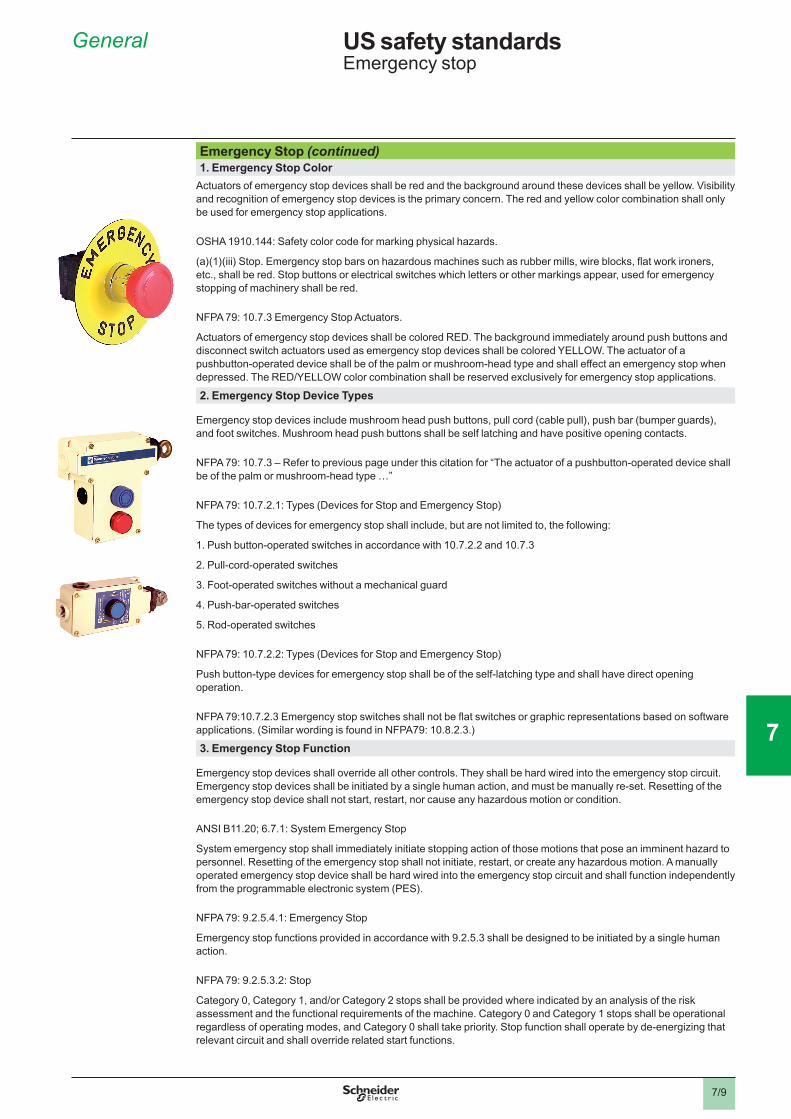
Emergency Stop (continued)1. Emergency Stop Color
Actuators of emergency stop devices shall be red and the background around these devices shall be yellow. Visibility and recognition of emergency stop devices is the primary concern. The red and yellow color combination shall only be used for emergency stop applications.
OSHA 1910.144: Safety color code for marking physical hazards.
(a)(1)(iii) Stop. Emergency stop bars on hazardous machines such as rubber mills, wire blocks, flat work ironers, etc., shall be red. Stop buttons or electrical switches which letters or other markings appear, used for emergency stopping of machinery shall be red.
NFPA 79: 10.7.3 Emergency Stop Actuators.
Actuators of emergency stop devices shall be colored RED. The background immediately around push buttons and disconnect switch actuators used as emergency stop devices shall be colored YELLOW. The actuator of a pushbutton-operated device shall be of the palm or mushroom-head type and shall effect an emergency stop when depressed. The RED/YELLOW color combination shall be reserved exclusively for emergency stop applications.
2. Emergency Stop Device Types
Emergency stop devices include mushroom head push buttons, pull cord (cable pull), push bar (bumper guards), and foot switches. Mushroom head push buttons shall be self latching and have positive opening contacts.
NFPA 79: 10.7.3 – Refer to previous page under this citation for “The actuator of a pushbutton-operated device shall be of the palm or mushroom-head type …”
NFPA 79: 10.7.2.1: Types (Devices for Stop and Emergency Stop)
The types of devices for emergency stop shall include, but are not limited to, the following:
1. Push button-operated switches in accordance with 10.7.2.2 and 10.7.3
2. Pull-cord-operated switches
3. Foot-operated switches without a mechanical guard
4. Push-bar-operated switches
5. Rod-operated switches
NFPA 79: 10.7.2.2: Types (Devices for Stop and Emergency Stop)
Push button-type devices for emergency stop shall be of the self-latching type and shall have direct opening operation.
NFPA 79:10.7.2.3 Emergency stop switches shall not be flat switches or graphic representations based on software applications. (Similar wording is found in NFPA79: 10.8.2.3.)
3. Emergency Stop Function
Emergency stop devices shall override all other controls. They shall be hard wired into the emergency stop circuit. Emergency stop devices shall be initiated by a single human action, and must be manually re-set. Resetting of the emergency stop device shall not start, restart, nor cause any hazardous motion or condition.
ANSI B11.20; 6.7.1: System Emergency Stop
System emergency stop shall immediately initiate stopping action of those motions that pose an imminent hazard to personnel. Resetting of the emergency stop shall not initiate, restart, or create any hazardous motion. A manually operated emergency stop device shall be hard wired into the emergency stop circuit and shall function independently from the programmable electronic system (PES).
NFPA 79: 9.2.5.4.1: Emergency Stop
Emergency stop functions provided in accordance with 9.2.5.3 shall be designed to be initiated by a single human action.
NFPA 79: 9.2.5.3.2: Stop
Category 0, Category 1, and/or Category 2 stops shall be provided where indicated by an analysis of the risk assessment and the functional requirements of the machine. Category 0 and Category 1 stops shall be operational regardless of operating modes, and Category 0 shall take priority. Stop function shall operate by de-energizing that relevant circuit and shall override related start functions.
General US safety standardsEmergency stop

2
1
3
4
5
6
8
9
10
2
1
3
4
5
6
7
8
9
10
7
7/10
Emergency Stop (continued)3. Emergency Stop Function (continued)
NFPA 79: 9.2.5.3.3 Stop
Where required, provisions to connect protective devices and interlocks shall be provided. Where applicable, the stop function shall signal the logic of the control system that such a condition exists. The reset of the stop function shall not initiate any hazardous conditions.
NFPA 79: 9.2.5.4.1.1: Emergency Stop In addition to the requirements for stop, the emergency stop shall have the following requirements:
1. It shall override all other functions and operations in all modes. 2. Power to the machine actuators, which causes a hazardous condition(s), shall be removed as quickly as possible without creating other hazards (e.g., by the provision of mechanical means of stopping requiring no external power, by reverse current braking for a Category 1 stop). 3. The reset of the command shall not restart the machinery but only permit restarting.
NFPA 79: 9.2.5.4.2 Emergency Switching Off. Where the emergency switching off function is used, it shall be initiated by a single human action.
NFPA 79: 10.8.3 Restoration of Normal Function After Emergency Switching Off. It shall not be possible to restore an emergency switching off circuit until the emergency switching off circuit has been manually reset.
4. Emergency Stop Location
Emergency stop devices shall be at every operator workstation and other locations where required; continuously operable; readily accessible; and easily distinguishable from other controls.
NFPA 79: 10.7.1.1 Location and Operation Stop and emergency stop push buttons shall be continuously operable and readily accessible.
NFPA 79: 10.7.1.2 Location and Operation Stop or emergency stop push buttons shall be located at each operator control station and at other locations where emergency stop is required.
5. Emergency Stop and Related Components
NFPA 79: 9.2.5.4.1.4 Emergency Stop
Where a Category 0 or Category 1 stop is used for the emergency stop function, it shall have a circuitry design (including sensors, logic, and actuators) according to the relevant risk as required by section 4.1 and 9.4.1. Final removal of power to the machine actuators shall be ensured and shall be by means of electromechanical components. Where relays are used to accomplish a Category 0 emergency stop function, they shall be nonretentive relays
Exception: Drives, or solid state output devices designed for safety-related functions shall be allowed to be the final switching element, when designed according to relevant safety standards.
NFPA 79: 9.4.3 – Control Systems Incorporating Software and Firmware Based Controllers contains detailed information regarding the use of software and firmware based controllers in standard and safety related functions.
General US safety standardsEmergency stop
2
1
3
4
5
6
8
9
10
2
1
3
4
5
6
7
8
9
10
7
7/11
Stop Categories
The NFPA 79 Stop Category 0, 1 and 2 identified below are very similar to the same Stop Categories in IEC/EN 60204-1. There are no similar stop categories identified in OSHA 1910. The choice of stop category to use is determined by the type of machine and control circuit used, plus the hazards available to personnel.
NFPA 79: 9.2.2 Stop Functions. The three categories of stop functions shall be as follows:
1. Category 0 is an uncontrolled stop by immediately removing power to the machine actuators. 2. Category 1 is a controlled stop with power to the machine actuators available to achieve the stop then remove power when the stop is achieved. 3. Category 2 is a controlled stop with power left available to the machine actuators.
NFPA 79: 9.2.5.3.1 Stop Each machine shall be equipped with a Category 0 stop.
NFPA 79: 9.2.5.3.2 Stop Category 0, Category 1, and/or Category 2 stops shall be provided where indicated by an analysis of the risk assessment and the functional requirements of the machine. Category 0 and Category 1 stops shall be operational regardless of operating modes, and Category 0 shall take priority. Stop function shall operate by de-energizing that relevant circuit and shall override related start functions.
NFPA 79: 9.2.5.4.1.3 Emergency Stop The emergency stop shall function as either a Category 0 or a Category 1 stop (see 9.2.2). The choice of the category of the emergency stop shall be determined by the risk assessment of the machine.
NFPA 79: 9.2.5.4.1.4 Emergency Stop Where a Category 0 or Category 1 stop is used for the emergency stop function, it shall have a circuitry design (including sensors, logic, and actuators) according to the relevant risk as required by section 4.1 and 9.4.1. Final removal of power to the machine actuators shall be ensured and shall be by means of electromechanical components. Where relays are used to accomplish a Category 0 emergency stop function, they shall be nonretentive relays
Exception: Drives, or solid state output devices designed for safety-related functions shall be allowed to be the final switching element, when designed according to relevant safety standards.
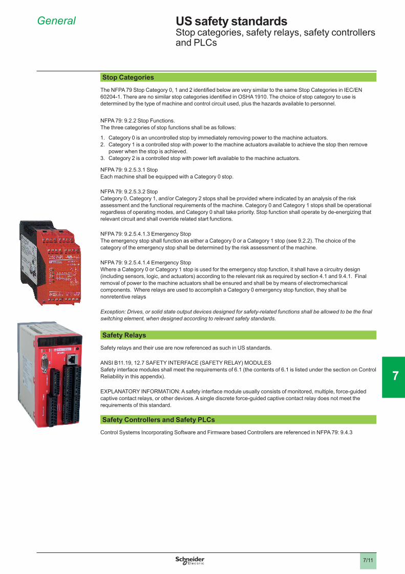
Safety Relays
Safety relays and their use are now referenced as such in US standards.
ANSI B11.19, 12.7 SAFETY INTERFACE (SAFETY RELAY) MODULES Safety interface modules shall meet the requirements of 6.1 (the contents of 6.1 is listed under the section on Control Reliability in this appendix).
EXPLANATORY INFORMATION: A safety interface module usually consists of monitored, multiple, force-guided captive contact relays, or other devices. A single discrete force-guided captive contact relay does not meet the requirements of this standard.
Safety Controllers and Safety PLCs
Control Systems Incorporating Software and Firmware based Controllers are referenced in NFPA 79: 9.4.3
General US safety standardsStop categories, safety relays, safety controllers and PLCs

2
1
3
4
5
6
8
9
10
2
1
3
4
5
6
7
8
9
10
7
7/12
Guards, Barriers and Interlocking
There are many ways to protect personnel: guards and barriers, two hand controls, light curtains, and sometimes distance. All of these methods are discussed in this section. Guards will be discussed first.
Guards need to prevent personnel from being in the hazardous zones when the machine is operating, and machinery cannot be operated with the guards open. It is clear that the responsibility for these guards falls on the employer per OSHA.
General Requirements
Some of the requirements of guards and interlocks are:
• Guards or interlocks shall be difficult to defeat. • Devices used in safety related functions shall have positive (direct) opening contacts. • Closing of the guard or interlock shall not initiate machine motion or any hazardous condition • When doors or guards are opened and open, no hazardous motion or condition can exist • Machinery is allowed to start and run only when gates and guards are closed. • Switches and interlocks shall be installed so they will not be damaged on over-travel.
When guards, barriers, light curtains or other safeguarding is used to protect personnel, there is always a minimum safety distance required to protect personnel from harm. With hard guards or barriers, this distance may be determined by the size of the openings in the guard and using a table or chart for the correct minimum safety distance, i.e.: OSHA 1910.217 Table O-10. Other safeguarding devices, such as light curtains or two hand control devices, need to be located a minimum distance away from the hazard such that the hazardous situation can be eliminated before an individual can be injured. ANSI B11.19, Annex D – Safety Distance is an excellent resource for determining these minimum safety distances. It covers a wide variety of safeguarding techniques and methods to determine the minimum safety distances and the factors that need to be considered.
Standards References
The ANSI B11 and NFPA 79 references below are very similar to the European Harmonized Standard EN 1088, Locking and Interlocking Devices.
OSHA 1910.212 General Requirements for all Machines (a) (1) Types of guarding. One or more methods of machine guarding shall be provided to protect the operator and other employees in the machine area from hazards such as those created by point of operation, ingoing nip points, rotating parts, flying chips, and sparks. Examples of guarding methods are: barrier guards, two-hand tripping devices, and electronic safety devices.
OSHA 1910.212 General Requirements for all Machines (a) (3) (ii) The point of operation of machines whose operation exposes an employee to injury, shall be guarded. The guarding device shall be in conformity with any appropriate standards therefore, or, in the absence of applicable specific standards, shall be so designed and constructed as to prevent the operator from having any part of his body in the danger zone during the operating cycle.
OSHA 1910.217 Mechanical Power presses (c) (1) (i) It shall be the responsibility of the employer to provide and ensure the usage of “point of operation guards” or properly applied and adjusted point of operation devices on every operation performed on a mechanical power press. See Table O-10.
OSHA 1910.217 Table O-10 identifies the minimum distance from the barrier or guard to the point of operation hazard based on the size of the opening. If there are any openings in the guard, such as holes or openings in a mesh guard, the maximum dimensions of these openings are used as the basis for use with Table O-10
ANSI B11.19: 6.2 SAFETY DISTANCE When required by this standard, the guard or safeguarding device shall be located at a distance from its associated hazard such that individuals cannot reach the hazard before cessation of hazardous motion (or situation).
ANSI B11.19: E6.2 EXPLANATORY INFORMATION The Explanatory information states that guards and safeguarding devices should be located at a safety distance in accordance with (ANSI B11.19) Annex D. This annex provides a thorough coverage of safety distances of all types of guards and barriers.
General US safety standardsGuards, barriers and interlocking

2
1
3
4
5
6
8
9
10
2
1
3
4
5
6
7
8
9
10
7
7/13
Guards, Barriers and Interlocking (continued)Standards References (continued)
ANSI B11-19: 7.1.3 Guards. Design and Construction The design and construction of the barrier guard shall ensure that individuals can not reach the hazard by reaching over, under, around or through the barrier guard. Note: Similar wording is included in ANSI B11-19: 7.2.1 and ANSI B11.19: 7.2.2
ANSI B11-19: 7.2.4 Guards. Installation and Operation The interlocked section of the interlocking barrier guard(s) shall be prevented from opening until hazardous motion has ceased, or shall be located so that an individual cannot reach the hazard before cessation of the hazardous motion when the interlocked section is open.
ANSI B11-19: 7.1.6 Design and Construction Interlocking barrier guards shall be designed and constructed to meet the following additional requirements:
1. Interlock devices used in conjunction with barrier guards shall be specifically designed and constructed for use in safeguarding applications. 2. Handles placed on interlocking barrier guards shall be secured to the guard so as not to create a pinch point between the handles of the guard, frame or machine
ANSI B11-19: 7.2.6: Installation and Operation The user shall ensure that barrier guards are installed, maintained and operated so as to protect against:
a. Unauthorized adjustment or circumvention b. Hazards between the guard and the moving machine or tooling parts c. Operation such that when the interlock is opened, re-closing of the interlock shall not, in or of itself, cause any hazardous motion of the machine
ANSI B11-19; 8.1.1.3 Movable Barrier Devices The initiation of the machine cycle shall require:
a. The movable device to be in the closed position; and b. that the cycle initiation means be actuated
NFPA 79: 9.2.3.3 Operating Modes: Safeguarding means shall remain effective for all operating modes.
NFPA 79: 9.3.1 Re-closing or Resetting of an Interlocking Safeguard.
The re-closing or resetting of an interlocking safeguard shall not initiate machine motion or operation that results in a hazardous condition.
NFPA 79: 9.3.6 Protective Interlock Where doors or guards have interlocked switches used in circuits with safety related functions, the interlocking devices shall be listed, have either positive (direct) opening operation, or provide similar reliability and prevent the operation of the equipment when the doors or guards are open (difficult to defeat or bypass).
NFPA 79: 10.1.4.1 Position Sensors Position sensors (e.g., limit switches, position switches, proximity switches) shall be arranged so that they will not be damaged in the event of overtravel.
NFPA 79: 10.1.4.2 Position Sensors Position sensors used in circuits with safety-related control functions either shall have direct opening operation or shall provide similar reliability.
NFPA 79: 11.6.2 Machine Mounted Control Equipment All limit switches or position sensors shall be installed so that accidental over-travel by the machine will not damage the limit switch or sensor.
General US safety standardsGuards, barriers and interlocking
NO
NO
NO

2
1
3
4
5
6
8
9
10
2
1
3
4
5
6
7
8
9
10
7
7/14
Light CurtainsThe application, use, and installation of light curtains is covered in much greater detail in Section 5 of this catalog. The safety distance formulas in Section 5 must be used to determine the minimum safety distance a light curtain must be mounted away from the hazardous activity, based on the particular machine and light curtain used. Listed below are some highlights from ANSI B11.19 regarding light curtains.
Also included are two additional topics that may be of concern for some light curtain applications: Muting and PSDI. These are included here for information only and references for more information on these topics are provided.
ANSI B11.19: 8.3.1.5 The presence sensing device shall incorporate visual means to indicate that the device is detecting an individual within the sensing field of the device.
ANSI B11.19: 8.3.2.1 Exposure to the hazard(s) shall not be possible by reaching over, under or around the sensing field of the device. Additional guards or safeguarding devices shall be provided to protect these areas.
The effective sensing field shall be of adequate height, width and depth so that entry of the individual into the hazard area is detected.
Explanatory Information: If individuals can place themselves between the sensing field and the hazard area, additional safeguarding should be used in conjunction with the device to prevent the individual from exposure to the hazard.
ANSI B11.19: 8.3.2.2 The presence sensing device shall be installed at a location so that the effective sensing field prevents individuals from reaching the hazard(s) during the hazardous portion of the machine cycle
Explanatory Information: See Annex D of ANSI B11.19 for the formula(e) to calculate the sensing distance. This appendix gives excellent detailed information on calculating the safe distances.
ANSI B11.19: 8.3.2.3 The presence-sensing device shall protect individuals from hazards by initiating an immediate stop command to the machine control system when the sensing field of the device is interrupted during the hazardous portion of the machine cycle. It shall require re-initiation of the normal actuating means prior to the start or continuation of the motion of the machine
When an individual can pass through the sensing field of the presence-sensing device, the device shall initiate an immediate stop command to the machine control system and shall require that the device be manually reset before hazardous motion can occur.
The reset device shall be located outside of the safeguarded area such that it cannot be reached from the safeguarded area. Reset of the device or machine control shall not occur until verification that the safeguarded area is clear of individuals.
Explanatory Information: The operator should ensure that no individual is in the safeguarded area before re-setting the device or machine control and initiating hazardous motion.
Other items of interest regarding light curtains are listed below:
• Muting: See ANSI B11.19: 8.3.2.5 • Presence Sensing Device Initiation (PSDI): See OSHA 1910.217 (h)
General US safety standardsLight curtains
2
1
3
4
5
6
8
9
10
2
1
3
4
5
6
7
8
9
10
7
7/15
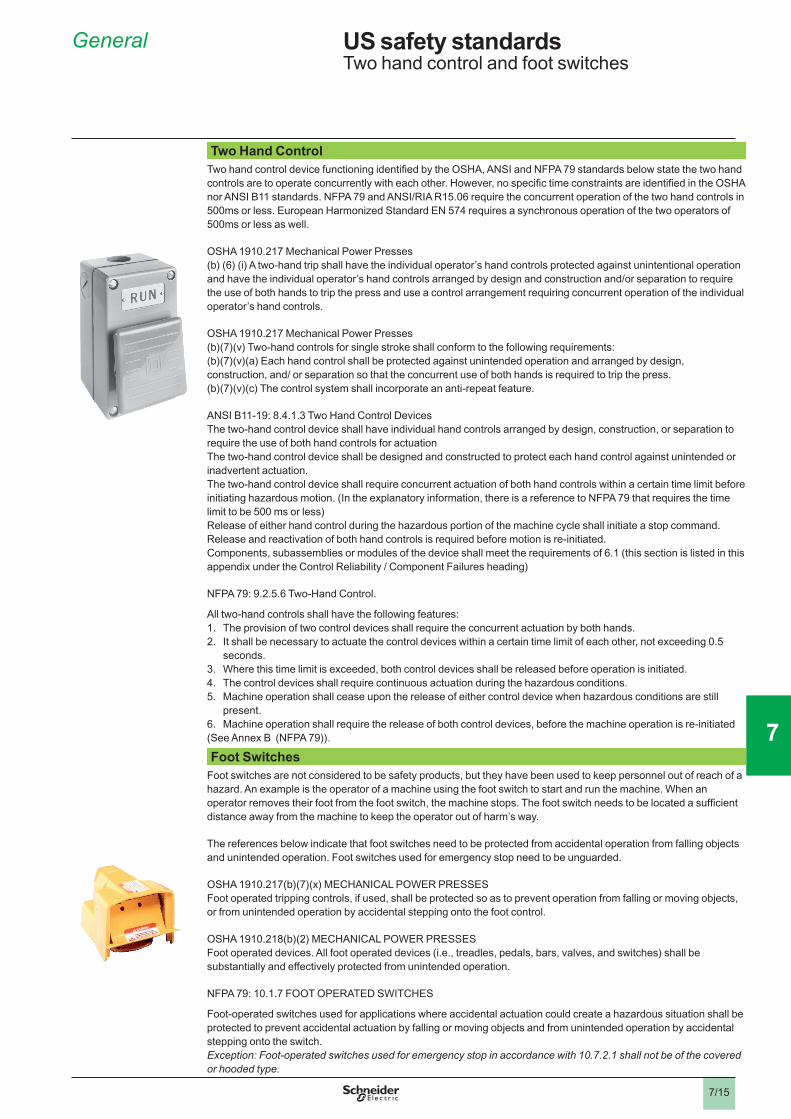
Two Hand ControlTwo hand control device functioning identified by the OSHA, ANSI and NFPA 79 standards below state the two hand controls are to operate concurrently with each other. However, no specific time constraints are identified in the OSHA nor ANSI B11 standards. NFPA 79 and ANSI/RIA R15.06 require the concurrent operation of the two hand controls in 500ms or less. European Harmonized Standard EN 574 requires a synchronous operation of the two operators of 500ms or less as well.
OSHA 1910.217 Mechanical Power Presses (b) (6) (i) A two-hand trip shall have the individual operator’s hand controls protected against unintentional operation and have the individual operator’s hand controls arranged by design and construction and/or separation to require the use of both hands to trip the press and use a control arrangement requiring concurrent operation of the individual operator’s hand controls.
OSHA 1910.217 Mechanical Power Presses (b)(7)(v) Two-hand controls for single stroke shall conform to the following requirements: (b)(7)(v)(a) Each hand control shall be protected against unintended operation and arranged by design, construction, and/ or separation so that the concurrent use of both hands is required to trip the press. (b)(7)(v)(c) The control system shall incorporate an anti-repeat feature.
ANSI B11-19: 8.4.1.3 Two Hand Control Devices The two-hand control device shall have individual hand controls arranged by design, construction, or separation to require the use of both hand controls for actuation The two-hand control device shall be designed and constructed to protect each hand control against unintended or inadvertent actuation. The two-hand control device shall require concurrent actuation of both hand controls within a certain time limit before initiating hazardous motion. (In the explanatory information, there is a reference to NFPA 79 that requires the time limit to be 500 ms or less) Release of either hand control during the hazardous portion of the machine cycle shall initiate a stop command. Release and reactivation of both hand controls is required before motion is re-initiated. Components, subassemblies or modules of the device shall meet the requirements of 6.1 (this section is listed in this appendix under the Control Reliability / Component Failures heading)
NFPA 79: 9.2.5.6 Two-Hand Control.
All two-hand controls shall have the following features: 1. The provision of two control devices shall require the concurrent actuation by both hands. 2. It shall be necessary to actuate the control devices within a certain time limit of each other, not exceeding 0.5 seconds. 3. Where this time limit is exceeded, both control devices shall be released before operation is initiated. 4. The control devices shall require continuous actuation during the hazardous conditions. 5. Machine operation shall cease upon the release of either control device when hazardous conditions are still present. 6. Machine operation shall require the release of both control devices, before the machine operation is re-initiated (See Annex B (NFPA 79)).
Foot SwitchesFoot switches are not considered to be safety products, but they have been used to keep personnel out of reach of a hazard. An example is the operator of a machine using the foot switch to start and run the machine. When an operator removes their foot from the foot switch, the machine stops. The foot switch needs to be located a sufficient distance away from the machine to keep the operator out of harm’s way.
The references below indicate that foot switches need to be protected from accidental operation from falling objects and unintended operation. Foot switches used for emergency stop need to be unguarded.
OSHA 1910.217(b)(7)(x) MECHANICAL POWER PRESSES Foot operated tripping controls, if used, shall be protected so as to prevent operation from falling or moving objects, or from unintended operation by accidental stepping onto the foot control.
OSHA 1910.218(b)(2) MECHANICAL POWER PRESSES Foot operated devices. All foot operated devices (i.e., treadles, pedals, bars, valves, and switches) shall be substantially and effectively protected from unintended operation.
NFPA 79: 10.1.7 FOOT OPERATED SWITCHES
Foot-operated switches used for applications where accidental actuation could create a hazardous situation shall be protected to prevent accidental actuation by falling or moving objects and from unintended operation by accidental stepping onto the switch. Exception: Foot-operated switches used for emergency stop in accordance with 10.7.2.1 shall not be of the covered or hooded type.
General US safety standardsTwo hand control and foot switches

2
1
3
4
5
6
8
9
10
2
1
3
4
5
6
7
8
9
10
7
7/16
Summary
Safety systems are comprised of many components. No one safety component will insure the safety of the system. The design of the complete safety system should be considered before you begin. It is very important to follow applicable safety standards when installing and wiring these components.
This appendix provides portions of the references standards from OSHA, ANSI and NFPA. This material is provided to help users better understand some of the issues that need to be taken into consideration when designing new applications or upgrading current applications when the safety of personnel is concerned. The complete versions of the referenced standards must be used, read, and referenced whenever designing safety solutions, as more detailed information and additional information is provided in the complete versions of these standards.
Reprinted with permission from NFPA 79, Electrical Standard for Industrial Machinery Copyright © 2002, National Fire Protection Association, Quincy, MA 02269. This reprinted material is not the complete and official position of the National Fire Protection Association, on the referenced subject which is represented only by the standard in its entirety.
This material is reproduced from American National Standard ANSI B11.19 copyright 2003 and ANSI B11.20 copyright 1996 with permission of the American National Standards Institute. No part of this material may be copied or reproduced in any form, electronic retrieval system or otherwise or made available on the Internet, a public network, by satellite or otherwise without the prior written consent of the American National Standards Institute. Copies of this standard may be purchased from the American National Standards Institute, 11 West 42nd Street, New York, NY 10036.
General US safety standardsSummary
2
1
3
4
5
6
8
9
10
2
1
3
4
5
6
7
8
9
10
7
7/17
Additional information on US Safety Standards
There are many sources of information on US safety standards, and below is a partial list of these sources. This information was taken from literature, personal contacts, and from the internet. While we believe this information to be correct, there may have been changes in phone numbers and addresses from when we acquired this information. If you need any additional information regarding the US safety standards, please contact any of the sources listed below:
American National Standards Institute (ANSI)1819 L Street, NW, 6th Floor, Washington, DC 20036 Phone: 202-293-8020 Fax: 202-293-9287http://web.ansi.org
American Society of Mechanical Engineers (ASME)1828 L St, N.W., Suite 906, Washington, DC 20036-5104 Phone: 202-785-3756 Fax: 202-429-9417 http://www.asme.org
American Society for Testing and Materials (ASTM)100 Barr Harbor Drive, West Conshohocken, Pennsylvania, USA 19428-2959
Phone: 610 832-9500
Fax: 610 832-9555 http://www.astm.org
Association for Manufacturing Technology (AMT)7901 Westpark Dr., McLean, VA 22102-4206
Phone: 703-893-2900
Fax: 703-893-1151 http://www.mfgtech.org
IHS15 Inverness Way East, Englewood, Colorado 80112 Phone: 800-854-7179 Fax: 303-397-2740 http://global.ihs.com
Institute of Electrical and Electronics Engineers (IEEE) Operations Center, 445 Hoes Lane, Piscataway, New Jersey 08854-5997
Phone: 732-981-0060
http://www.ieee.org
National Fire Protection Association (NFPA)1 Batterymarch Park, Quincy, MA 02169-7471 Phone: 617-770-3000 Fax: 617-770-0700 http://www.nfpa.org
National Institute for Occupational Safety and Health (NIOSH)Phone: 800-232-4636 http://www.cdc.gov/niosh/
National Safety Council1121 Spring Lake Dr., Itasca, IL 60143-3201 Phone: 800-621-7615 http://www.nsc.org
NEMA1300 N. 17th Street, Suite 1752, Rosslyn, VA, 22209.
Phone: 703-841-3200
Fax: 703-841-5900, http://www.nema.org
General US safety standards Additional information

2
1
3
4
5
6
8
9
10
2
1
3
4
5
6
7
8
9
10
7
7/18
Additional information on US Safety Standards (continued)
NIST (National Institute of Standards and Technology)100 Bureau Drive, Stop 2100, Gaithersburg, MD 20899-2100
Phone: 301-975-4040 http://www.nist.gov/
Occupational Safety and Health Administration (OSHA)http://www.osha.gov
Precision Metalforming Association (PMA) 6363 Oak Tree Blvd., Independence, Ohio 44131-2500 Phone: 216-901-8800 ---- Fax: 216-901-9190 http://www.pma.org
Robotic Industries Association900 Victors Way, Suite 140, Ann Arbor, Michigan 48106 Phone: 313-994-6088 http://www.robotics.org
Society of Automotive Engineers (SAE)400 Commonwealth Drive, Warrendale, PA 15096-0001 Phone: 724-776-4841 Fax: 724-776-4841 http://www.sae.org
Underwriters Laboratories Inc.333 Pfingsten Rd., Northbrook, IL 60062 Phone: 847-272-8800 Fax: 847-272-8129 http://www.ul.com
General US safety standardsAdditional information

2
1
3
4
5
6
8
9
10
2
1
3
4
5
6
7
8
9
10
7
7/19
Related Documents