Product catalogue Container securing systems

Welcome message from author
This document is posted to help you gain knowledge. Please leave a comment to let me know what you think about it! Share it to your friends and learn new things together.
Transcript
Product catalogue
Container securing systems


Passion for performance – united by the seaMacGregor is a family of innovators. By engineering solutions that make the sea more accessible, safe and reliable, we support you whose livelihood depends on the changing conditions of the sea. To enable that we have a variety of strong product brands and committed experts with a passion for solving challenges – and the power of the sea is sure to provide those.
Our founders braved new frontiers in different times and places. Those origins merge at today’s MacGregor, inspiring us to continue the stories, and create new ones. The spirit of our founders lives on in the pride we have for what we do, and our determination to find new solutions for the people we work with. Together with you we will write the next chapters.
We are a global team of professionals, who create value for you; the shipbuilders, owners and operators,
in the offshore and marine industries. Understanding your business and way of life is key to our work. It is the foundation to addressing your needs with tailored solutions for load handling, cargo handling, mooring or essential auxiliary equipment. Your productivity, sustainability, and equipment lifetime benefit from our combination of expertise and technology. As innovators, we work together with you to set benchmarks in innovative solutions and value creation. Our deep respect for and experience of the sea lays the foundation for adapting to its challenging conditions. Wherever we work around the world, we work together with a passion for performance and a love of challenges — united by the sea. Our shared values - integrity, quality and safety - propel us forward, and are an important factor in our ability to continue to deliver what our customers need to succeed; solutions that are designed to perform with the sea.

Edition 201601, February 2016
For the latest information, please visit our website www.macgregor.com
MacGregor Finland OyHallimestarinkatu 6
FI-20780 Kaarina, Finland
Tel: +358-2-41211
Fax: +358-2-4121 256
Cargotec Marine GmbHReichsbahnstrasse 72
DE-22525 Hamburg, Germany
Tel: +49-40-25 444 0
Fax: +49-40-25 444 444
Cargotec CHS Asia Pacific Pte LtdNo. 15, Tukang Innovation Drive
Singapore 618299
Tel: +65-6597 3888
Fax: +65-6597 3799
Distributor for United States, Canada and Mexico:Buffers USA Inc
10180 New Berlin Road
Jacksonville, FL 32226 USA
Tel: +1-904-696-0010
Email: [email protected]
www.buffersusa.com
Agent for Taiwan:Heng Cherng Enterprises Co.,Ltd
Tel: +886-2-25 65 20 63 or 25 65 20 64
Fax: +886-02-25 63 40 62
E-Mail: [email protected]
E-mail: [email protected]
Contacts:

Pictures: Arthur Lu, Frank Knöller, Magnus Ahlström, Clivia Bergmann, Jukka Rastas/Kuvakasvot, Cargotec and MacGregor archives
6
The birth of a ship .................................................................9
Container stowage solutions ............................................10
Container lashings from drawing board to operation ........12
Container securing ..........................................................14
Commissioning and training .............................................32
Always in the lead ...............................................................34
Lifetime support .................................................................36
Cargo securing systems ...................................................38
PRODUCT SECTIONProduct Catalogue .............................................................47
Lashmate stowage calculation software .........................48
Loose container fittings .....................................................49
Automatic twistlocks ........................................................50
Semi-automatic twistlocks ...............................................51
Manual twistlocks ............................................................54
Dovetail twistlocks ...........................................................56
Terminal stackers .............................................................58
Midlocks ..........................................................................63
Turnbuckles .....................................................................65
Lashing bars ....................................................................72
Operating rods .................................................................81
Stacking cones ................................................................83
Bridge fittings ...................................................................85
Pressure elements ...........................................................86
Pressure adapters ............................................................87
Terminal pressure stackers ...............................................88
Tension pressure elements ...............................................89
Flat racks and storage bins ..............................................90
Reefer platform ................................................................91
Accessories .....................................................................92
Contents
Fixed container fittings ......................................................93
Twistlock foundations .......................................................94
Lifting foundations ..........................................................103
Dovetail foundations ......................................................104
Sliding foundations ........................................................105
Twistlock pockets ..........................................................108
Guide fittings ..................................................................110
Lashing rings .................................................................111
Lashing eyes ..................................................................113
Lashing plates ................................................................114
Lashing pots ..................................................................117
Doubling plates ..............................................................118
Welding cones ...............................................................119
Counter bearings ...........................................................120
Stack splitter ..................................................................122
Tools ..............................................................................124
7
8
A vessel designed for its cargoBuilding a new vessel is a major investment and the decisions taken at the early design phase will define the loading capacity throughout the vessel’s lifetime. Optimisation of the loading capacity can lead to increased earnings. For example, a lower centre of gravity allows a better cargo mix, or in a best case scenario, the vessel may be able to carry one extra tier of loaded containers.
We can be your advisor from when the earliest ideas for your new vessel are conceived, your design expert during the project through to delivery, and your service partner throughout the vessel’s lifetime.
MacGregor’s involvement at an early stage in the process makes it possible to achieve an optimised custom-made container stowage solution, with a lashing system designed for all operational criteria.
The design of the container stowage solution for a new vessel involves many different steps. At MacGregor we know what is needed to ensure that all parties get the correct information at all stages of the project. We can deliver the total solution including all documentation from, for example, the initial loading concept and full vessel stack weight calculations to the offset drawing needed for fixed fitting welding positions and the final cargo securing manual.
Before the final design is fixed we perform a full scale mock-up test to verify the performance of the lashing system. We also consider elements such as the locations of hand rails and other structures that might interfere with lashing equipment. When everything is designed, tested, manufactured and approved, all relevant documentation is made available in the cargo securing manual needed on board for the vessel’s maiden voyage.
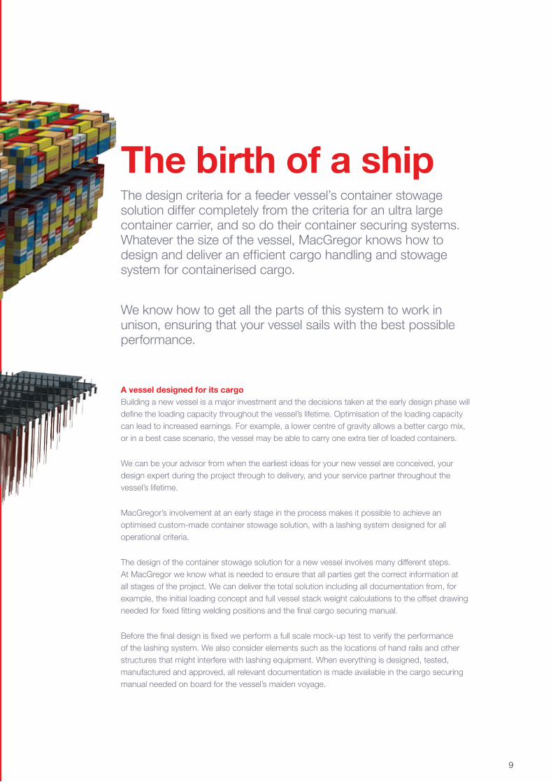
The birth of a shipThe design criteria for a feeder vessel’s container stowage solution differ completely from the criteria for an ultra large container carrier, and so do their container securing systems. Whatever the size of the vessel, MacGregor knows how to design and deliver an efficient cargo handling and stowage system for containerised cargo.
We know how to get all the parts of this system to work in unison, ensuring that your vessel sails with the best possible performance.
9
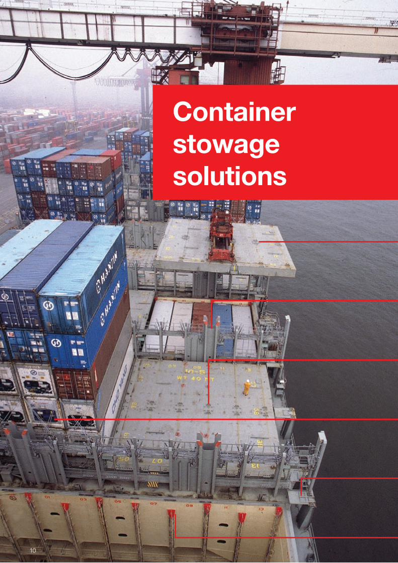
Container stowage solutions
10
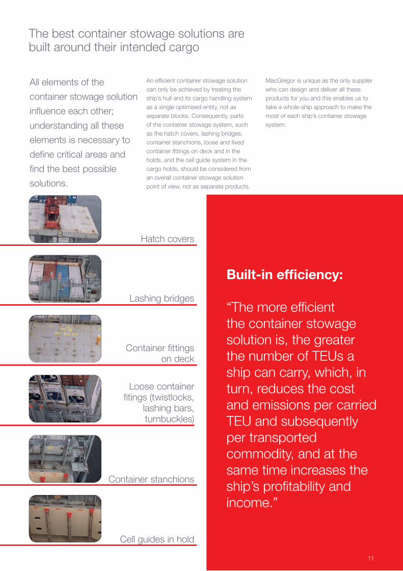
The best container stowage solutions are built around their intended cargo
All elements of the
container stowage solution
influence each other;
understanding all these
elements is necessary to
define critical areas and
find the best possible
solutions.
An efficient container stowage solution can only be achieved by treating the ship’s hull and its cargo handling system as a single optimised entity, not as separate blocks. Consequently, parts of the container stowage system, such as the hatch covers, lashing bridges, container stanchions, loose and fixed container fittings on deck and in the holds, and the cell guide system in the cargo holds, should be considered from an overall container stowage solution point of view, not as separate products.
Built-in efficiency:
“The more efficient the container stowage solution is, the greater the number of TEUs a ship can carry, which, in turn, reduces the cost and emissions per carried TEU and subsequently per transported commodity, and at the same time increases the ship’s profitability and income.”
MacGregor is unique as the only supplier who can design and deliver all these products for you and this enables us to take a whole-ship approach to make the most of each ship’s container stowage system.
Cell guides in hold
Container stanchions
Loose container fitings (twistlocks,
lashing bars, turnbuckles)
Hatch covers
Lashing bridges
Container fittings on deck
11
With the right indicators, which lead to the right design parameters for your vessel and its cargo handling system, we can maximise the amount of cargo carried in relation to deadweight tonnage. The onboard distribution of heavy and light containers, and subsequently total cargo weight, should therefore be one of the main factors when making decisions around a new vessel project.
We believe that defining the cargo profile should be the cornerstone and starting point for the ship design process and its container stowage solution. A container
One of the cornerstones of the way we work is to improve the productivity of our customers’ cargo handling systems, helping them to increase both their competitiveness and their environmental efficiency.
vessel is designed to carry a maximum number of containers loaded in hold and on deck. The traditional method for deciding this figure has been twofold: the first being the total number of boxes allowed by visibility rules from the bridge; and the second one is the homogeneous loading limited by the displacement of the hull. Both of these considerations lead to different maximum capacity calculations, with a significant dispersion. To avoid this we need to know more about the ship’s cargo profile at an early stage of the project.
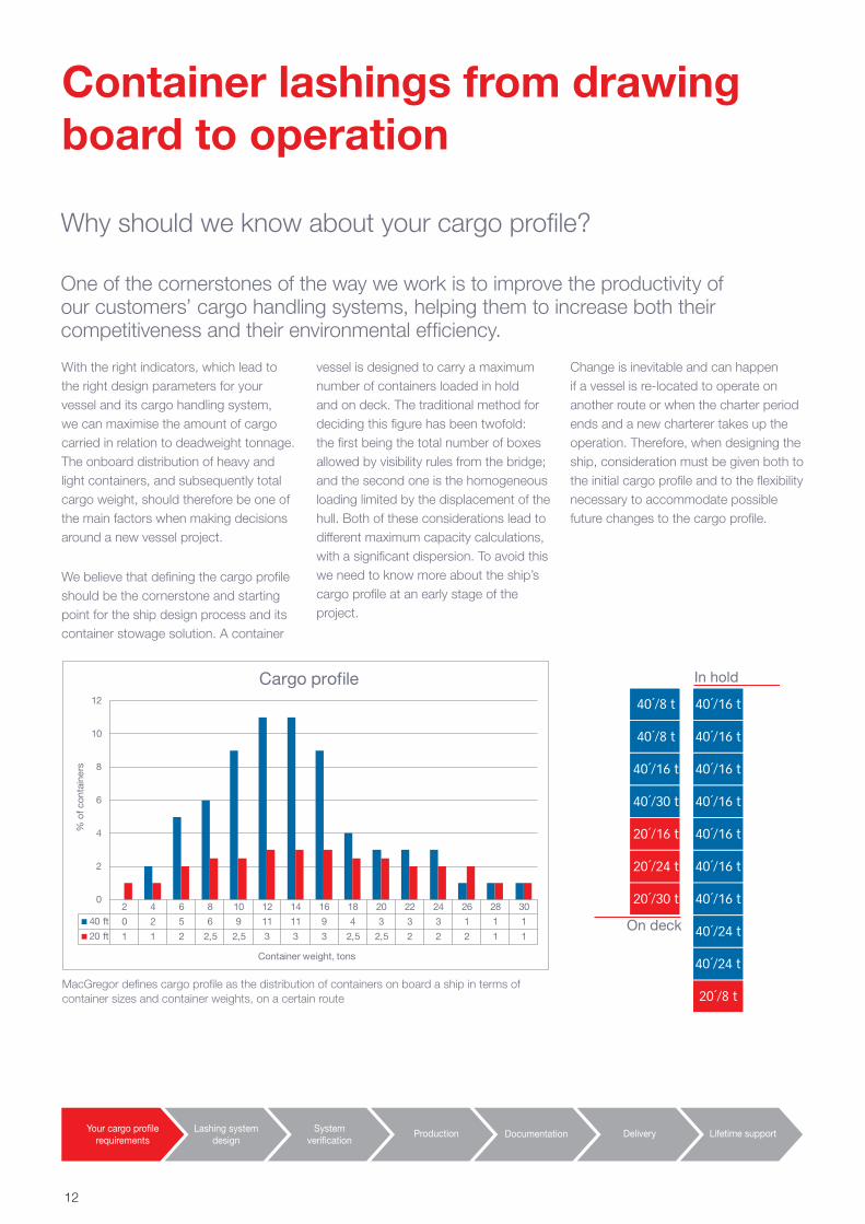
MacGregor defines cargo profile as the distribution of containers on board a ship in terms of container sizes and container weights, on a certain route
Change is inevitable and can happen if a vessel is re-located to operate on another route or when the charter period ends and a new charterer takes up the operation. Therefore, when designing the ship, consideration must be given both to the initial cargo profile and to the flexibility necessary to accommodate possible future changes to the cargo profile.
Container lashings from drawing board to operation
Your cargo profilerequirements
Lashing systemdesign
Systemverification
Production Documentation Delivery Lifetime support
2 4 6 8 10 12 14 16 18 20 22 24 26 28 30
40 ft 0 2 5 6 9 11 11 9 4 3 3 3 1 1 1
20 ft 1 1 2 2,5 2,5 3 3 3 2,5 2,5 2 2 2 1 1
0
2
4
6
8
10
12
% o
f con
tain
ers
Container weight, tons
Cargo profile
On deck
In hold
40´/8 t 40´/16 t
40´/8 t 40´/16 t
40´/16 t 40´/16 t
40´/30 t 40´/16 t
20´/16 t 40´/16 t
20´/24 t 40´/16 t
20´/30 t 40´/16 t
40´/24 t
40´/24 t
20´/8 t
Why should we know about your cargo profile?
12
Cargo system index value of 20’ containers
Cargo system index value of mixed stowage
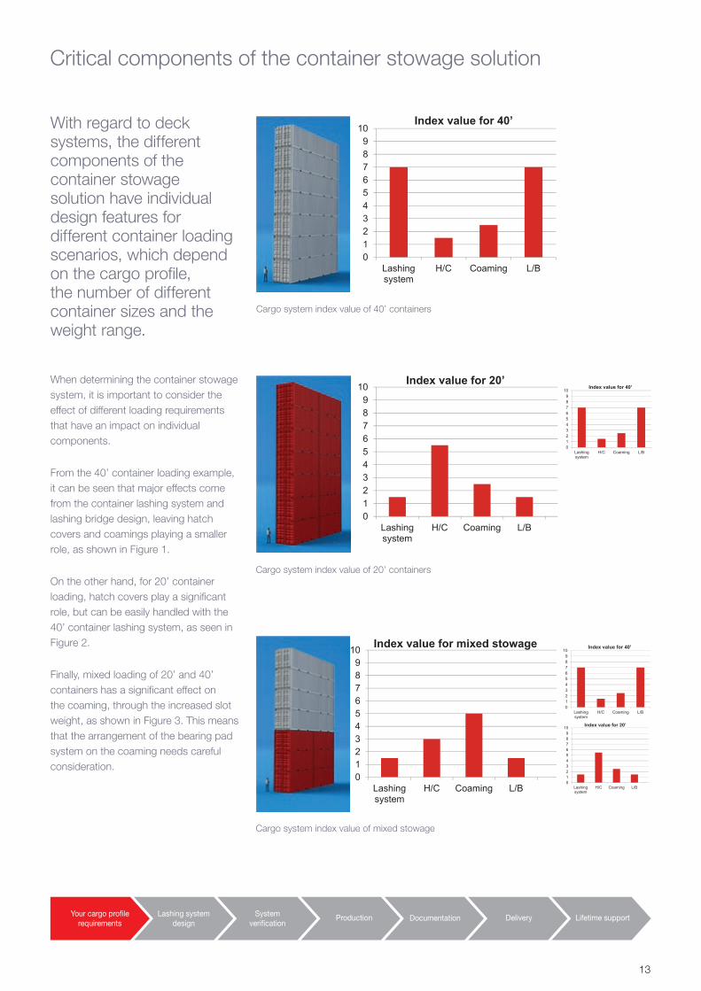
Cargo system index value of 40’ containers
With regard to deck systems, the different components of the container stowage solution have individual design features for different container loading scenarios, which depend on the cargo profile, the number of different container sizes and the weight range.
When determining the container stowage system, it is important to consider the effect of different loading requirements that have an impact on individual components.
From the 40’ container loading example, it can be seen that major effects come from the container lashing system and lashing bridge design, leaving hatch covers and coamings playing a smaller role, as shown in Figure 1.
On the other hand, for 20’ container loading, hatch covers play a significant role, but can be easily handled with the 40’ container lashing system, as seen in Figure 2.
Finally, mixed loading of 20’ and 40’ containers has a significant effect on the coaming, through the increased slot weight, as shown in Figure 3. This means that the arrangement of the bearing pad system on the coaming needs careful consideration.
Critical components of the container stowage solution
Your cargo profilerequirements
Lashing systemdesign
Systemverification
Production Documentation Delivery Lifetime support
0123456789
10
Lashingsystem
H/C Coaming L/B
Index value for 40’
0123456789
10
Lashingsystem
H/C Coaming L/B
Index value for 20’
0123456789
10
Lashingsystem
H/C Coaming L/B
Index value for 40’
0123456789
10
Lashingsystem
H/C Coaming L/B
Index value for 20’
0123456789
10
Lashingsystem
H/C Coaming L/B
Index value for 40’
0123456789
10
Lashingsystem
H/C Coaming L/B
Index value for mixed stowage
13
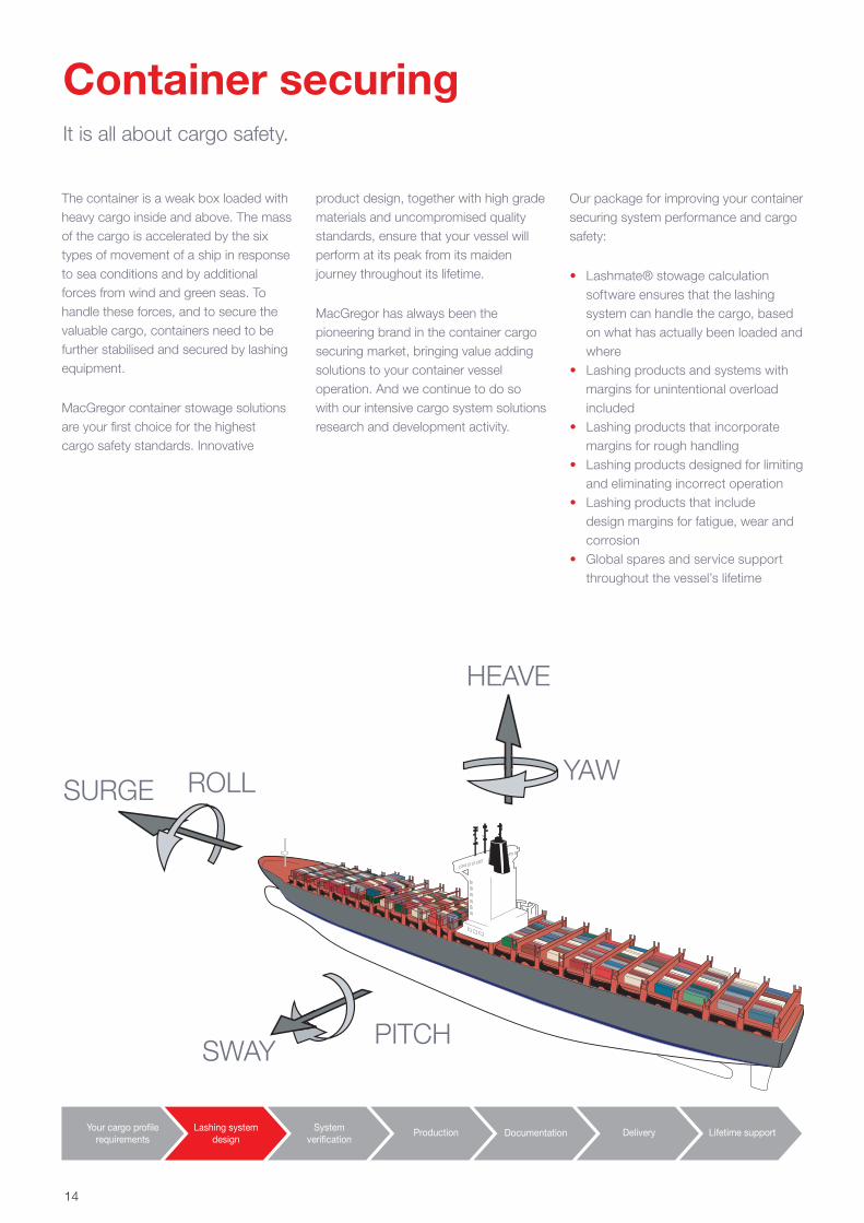
It is all about cargo safety.
The container is a weak box loaded with heavy cargo inside and above. The mass of the cargo is accelerated by the six types of movement of a ship in response to sea conditions and by additional forces from wind and green seas. To handle these forces, and to secure the valuable cargo, containers need to be further stabilised and secured by lashing equipment.
MacGregor container stowage solutions are your first choice for the highest cargo safety standards. Innovative
product design, together with high grade materials and uncompromised quality standards, ensure that your vessel will perform at its peak from its maiden journey throughout its lifetime.
MacGregor has always been the pioneering brand in the container cargo securing market, bringing value adding solutions to your container vessel operation. And we continue to do so with our intensive cargo system solutions research and development activity.
Container securing
SURGE ROLL
SWAYPITCH
YAW
HEAVE
Our package for improving your container securing system performance and cargo safety:
• Lashmate® stowage calculation software ensures that the lashing system can handle the cargo, based on what has actually been loaded and where
• Lashing products and systems with margins for unintentional overload included
• Lashing products that incorporate margins for rough handling
• Lashing products designed for limiting and eliminating incorrect operation
• Lashing products that include design margins for fatigue, wear and corrosion
• Global spares and service support throughout the vessel’s lifetime
Your cargo profilerequirements
Lashing systemdesign
Systemverification
Documentation Delivery Lifetime supportProduction
14
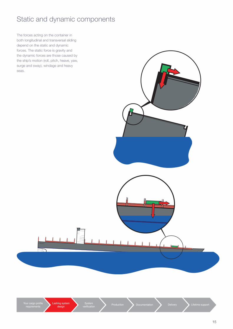
Static and dynamic components
The forces acting on the container in both longitudinal and transversal sliding depend on the static and dynamic forces. The static force is gravity and the dynamic forces are those caused by the ship’s motion (roll, pitch, heave, yaw, surge and sway), windage and heavy seas.
Your cargo profilerequirements
Lashing systemdesign
Systemverification
Documentation Delivery Lifetime supportProduction
15
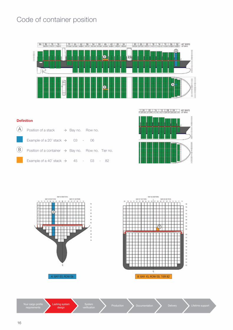
Code of container position
Your cargo profilerequirements
Lashing systemdesign
Systemverification
Documentation Delivery Lifetime supportProduction
Definition
Position of a stack → Bay no. Row no.
Example of a 20’ stack → 03 - 06
Position of a container → Bay no. Row no. Tier no.
Example of a 40’ stack → 45 - 03 - 82
16
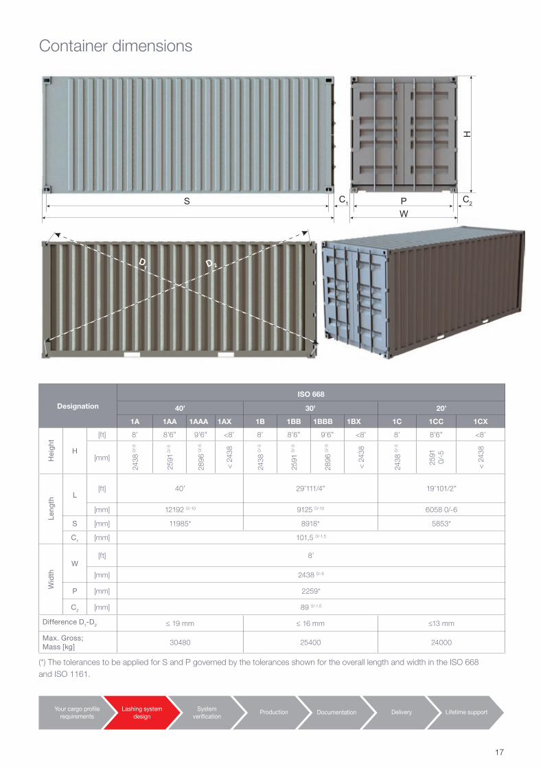
Container dimensions
Designation
ISO 668
40’ 30’ 20’
1A 1AA 1AAA 1AX 1B 1BB 1BBB 1BX 1C 1CC 1CX
Hei
ght
H
[ft] 8’ 8’6” 9’6” <8’ 8’ 8’6” 9’6” <8’ 8’ 8’6” <8’
[mm]
2438
0/-5
2591
0/-
5
2896
0/-5
< 2
438
2438
0/-5
2591
0/-5
2896
0/-5
< 2
438
2438
0/-5
2591
0/
-5
< 2
438
Leng
th
L[ft] 40’ 29’111/4” 19’101/2”
[mm] 12192 0/-10 9125 0/-10 6058 0/-6
S [mm] 11985* 8918* 5853*
C1 [mm] 101,5 0/-1.5
Wid
th
W[ft] 8’
[mm] 2438 0/-5
P [mm] 2259*
C2 [mm] 89 0/-1.5
Difference D1-D2 ≤ 19 mm ≤ 16 mm ≤13 mm
Max. Gross;Mass [kg]
30480 25400 24000
(*) The tolerances to be applied for S and P governed by the tolerances shown for the overall length and width in the ISO 668 and ISO 1161.
Your cargo profilerequirements
Lashing systemdesign
Systemverification
Documentation Delivery Lifetime supportProduction
S
D2D1
WPC1
H
C2
17
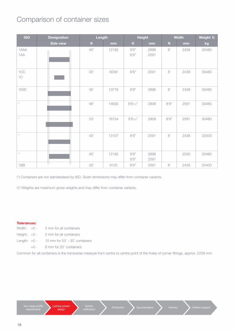
Comparison of container sizes
ISO Designation Length Height Width Weight 1)
Side view ft mm ft mm ft mm kg
1AAA1AA
40’ 12192 9’6”8’6”
28962591
8’ 2438 30480
1CC1C
20’ 6058 8’6” 2591 8’ 2438 30480
1EEE 45’ 13716 9’6” 2896 8’ 2438 30480
* 48’ 14630 9’61/2” 2908 8’6” 2591 30480
* 53’ 16154 9’61/2” 2908 8’6” 2591 30480
* 43’ 13107 8’6” 2591 8’ 2438 32500
* 40’ 12192 9’6”8’6”
28962591
2500 30480
1BB 30’ 9125 8’6” 2591 8’ 2438 25400
(*) Containers are not standardised by ISO. Given dimensions may differ from container variants.
(1) Weights are maximum gross weights and may differ from container variants.
Tolerances:Width: +0 - 5 mm for all containers
Height: +0 - 5 mm for all containers
Length: +0 - 10 mm for 53’ - 30’ containers
+0 - 6 mm for 20’ containers
Common for all containers is the transverse measure from centre to centre point of the holes of corner fittings, approx. 2259 mm.
Your cargo profilerequirements
Lashing systemdesign
Systemverification
Documentation Delivery Lifetime supportProduction
18
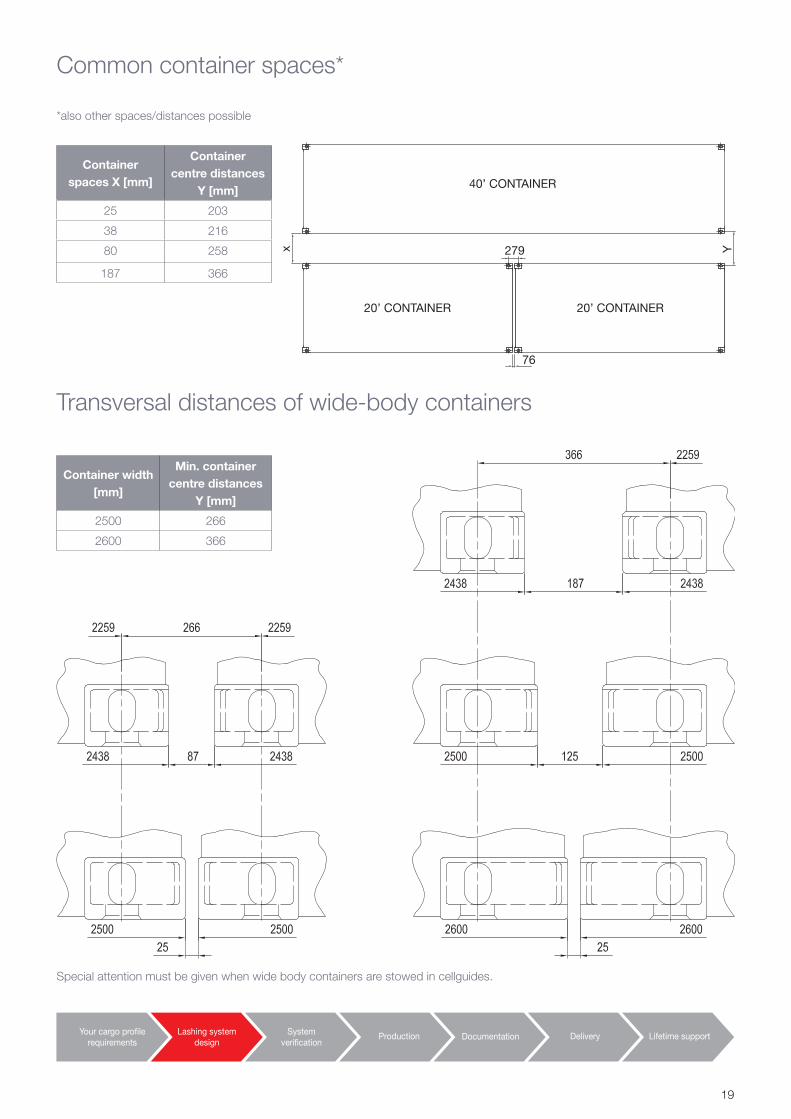
Common container spaces*
*also other spaces/distances possible
Transversal distances of wide-body containers
Special attention must be given when wide body containers are stowed in cellguides.
Container spaces X [mm]
Container centre distances
Y [mm]
25 203
38 216
80 258
187 366
Container width [mm]
Min. container centre distances
Y [mm]
2500 266
2600 366
40’ CONTAINER
279
76
20’ CONTAINER 20’ CONTAINER
x Y
Your cargo profilerequirements
Lashing systemdesign
Systemverification
Documentation Delivery Lifetime supportProduction
19
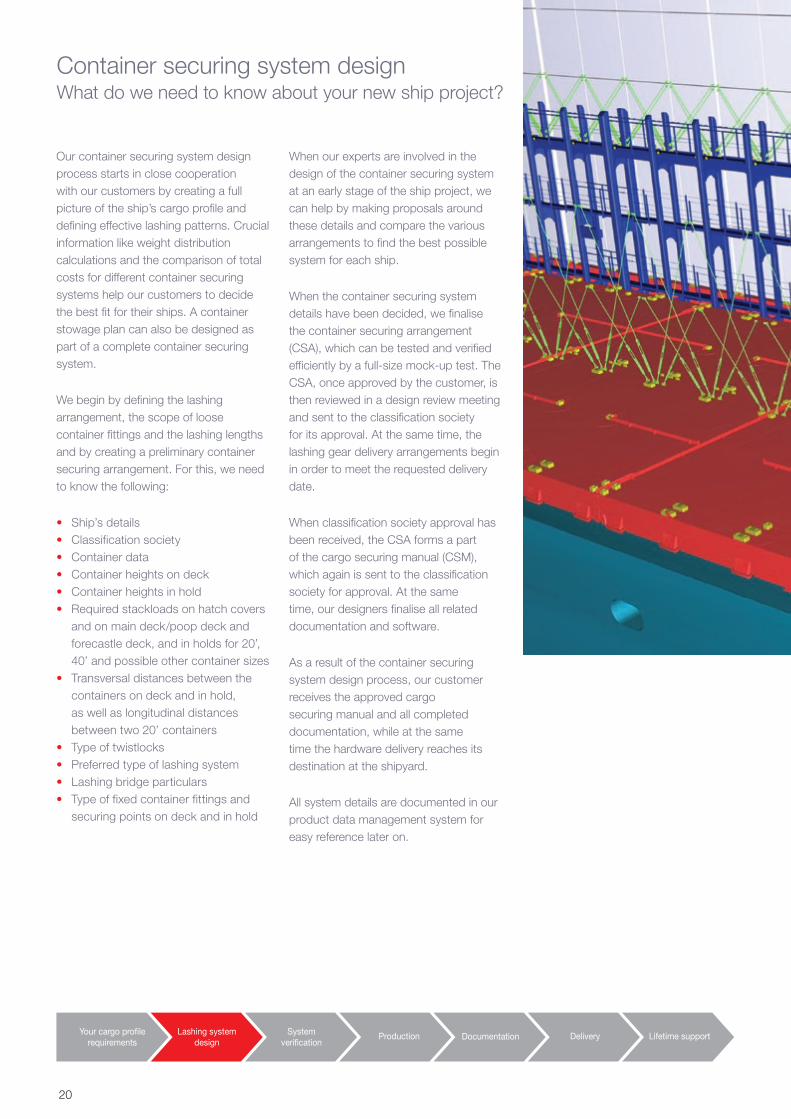
Container securing system designWhat do we need to know about your new ship project?
Our container securing system design process starts in close cooperation with our customers by creating a full picture of the ship’s cargo profile and defining effective lashing patterns. Crucial information like weight distribution calculations and the comparison of total costs for different container securing systems help our customers to decide the best fit for their ships. A container stowage plan can also be designed as part of a complete container securing system.
We begin by defining the lashing arrangement, the scope of loose container fittings and the lashing lengths and by creating a preliminary container securing arrangement. For this, we need to know the following:
• Ship’s details• Classification society• Container data• Container heights on deck• Container heights in hold• Required stackloads on hatch covers
and on main deck/poop deck and forecastle deck, and in holds for 20’, 40’ and possible other container sizes
• Transversal distances between the containers on deck and in hold, as well as longitudinal distances between two 20’ containers
• Type of twistlocks• Preferred type of lashing system• Lashing bridge particulars• Type of fixed container fittings and
securing points on deck and in hold
When our experts are involved in the design of the container securing system at an early stage of the ship project, we can help by making proposals around these details and compare the various arrangements to find the best possible system for each ship.
When the container securing system details have been decided, we finalise the container securing arrangement (CSA), which can be tested and verified efficiently by a full-size mock-up test. The CSA, once approved by the customer, is then reviewed in a design review meeting and sent to the classification society for its approval. At the same time, the lashing gear delivery arrangements begin in order to meet the requested delivery date.
When classification society approval has been received, the CSA forms a part of the cargo securing manual (CSM), which again is sent to the classification society for approval. At the same time, our designers finalise all related documentation and software.
As a result of the container securing system design process, our customer receives the approved cargo securing manual and all completed documentation, while at the same time the hardware delivery reaches its destination at the shipyard.
All system details are documented in our product data management system for easy reference later on.
Your cargo profilerequirements
Lashing systemdesign
Systemverification
Documentation Delivery Lifetime supportProduction
20
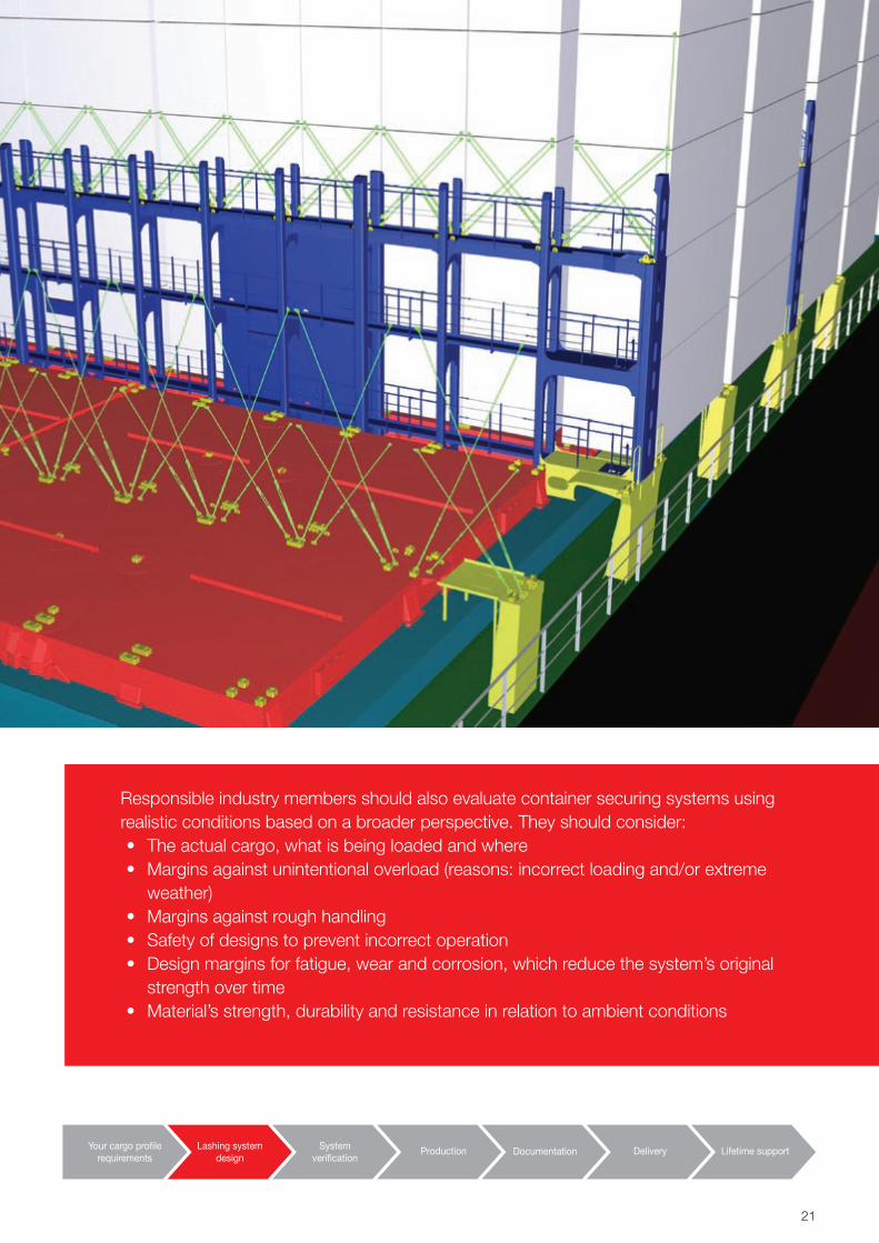
Responsible industry members should also evaluate container securing systems using realistic conditions based on a broader perspective. They should consider:• The actual cargo, what is being loaded and where• Margins against unintentional overload (reasons: incorrect loading and/or extreme
weather)• Margins against rough handling• Safety of designs to prevent incorrect operation• Design margins for fatigue, wear and corrosion, which reduce the system’s original
strength over time• Material’s strength, durability and resistance in relation to ambient conditions
Your cargo profilerequirements
Lashing systemdesign
Systemverification
Documentation Delivery Lifetime supportProduction
21
Your cargo profilerequirements
Lashing systemdesign
Systemverification
Documentation Delivery Lifetime supportProduction
22
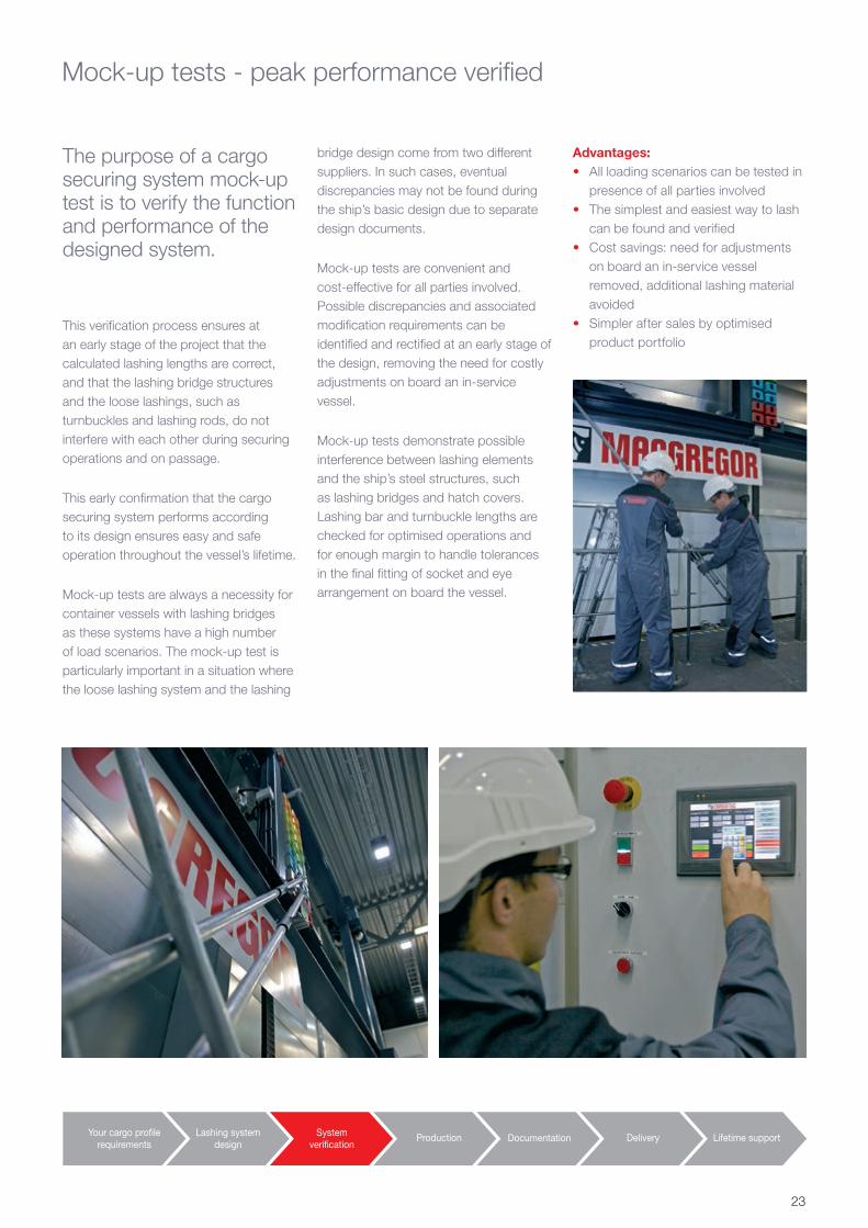
The purpose of a cargo securing system mock-up test is to verify the function and performance of the designed system.
This verification process ensures at an early stage of the project that the calculated lashing lengths are correct, and that the lashing bridge structures and the loose lashings, such as turnbuckles and lashing rods, do not interfere with each other during securing operations and on passage.
This early confirmation that the cargo securing system performs according to its design ensures easy and safe operation throughout the vessel’s lifetime.
Mock-up tests are always a necessity for container vessels with lashing bridges as these systems have a high number of load scenarios. The mock-up test is particularly important in a situation where the loose lashing system and the lashing
Mock-up tests - peak performance verified
bridge design come from two different suppliers. In such cases, eventual discrepancies may not be found during the ship’s basic design due to separate design documents.
Mock-up tests are convenient and cost-effective for all parties involved. Possible discrepancies and associated modification requirements can be identified and rectified at an early stage of the design, removing the need for costly adjustments on board an in-service vessel.
Mock-up tests demonstrate possible interference between lashing elements and the ship’s steel structures, such as lashing bridges and hatch covers. Lashing bar and turnbuckle lengths are checked for optimised operations and for enough margin to handle tolerances in the final fitting of socket and eye arrangement on board the vessel.
Your cargo profilerequirements
Lashing systemdesign
Systemverification
Documentation Delivery Lifetime supportProduction
Advantages:• All loading scenarios can be tested in
presence of all parties involved• The simplest and easiest way to lash
can be found and verified • Cost savings: need for adjustments
on board an in-service vessel removed, additional lashing material avoided
• Simpler after sales by optimised product portfolio
23
Today’s open global markets call for competitive pricing and allow for no compromise on quality.A highly qualified and motivated workforce equipped with the most modern designs, planning instruments and production techniques, coupled with sophisticated logistics, ensures that our products are successful everywhere in the world.
Our own quality assurance ensures consistent and continuously controlled production.
Our production processes comply with classification society rules and ISO standards. We have approved partner suppliers and permanent quality control at their premises.
Our production is located close to our customers and consists of a network of carefully chosen partner suppliers to ensure a steady supply flow and competitive prices.
All deliveries are tested and approved by the relevant classification societies. All approval tests, reports and documents are delivered in accordance with the technical requirements and regulations relevant to classification society rules.
Development of new and advanced systems and products is the daily business of our R&D team, as well as optimising products for production-friendly design and improved onboard operations.
All new products under development are carefully tested with dedicated
Approved production methods ensure quality and competitiveness
equipment and on-the-spot follow-up prior to undertaking mass production.
Practical testing employs mock-up devices where functionality is verified at the full scale level. Further tests are carried out on our dynamic load test machine. Our mock-up arrangements allow for product demonstration, practical instruction and customer training, along with internal trials for new system investigations.
Priority number one - production qualityQuality is the highest priority at all our production facilities. All components are sourced from leading, certified industry manufactures and the manufacturing equipment in use is calibrated by recognised authorities.
All suppliers are approved by the corresponding classification societies and, in addition, we carry out regular audits of our suppliers. During an audit, the supplier’s quality management system is monitored, the production processes are reviewed, and improvements, based on related non-conformity reports, are examined.
Continuous internal training ensures that our specialists’ knowledge is always up to date.
All our personnel are also trained to report any non-conformities. For smooth communications, all non-conformities or possible claims are handled by our contract managers who are familiar with our customers and their projects. Corrective actions are recorded and followed up by our Quality Assurance team and improvements are implemented.
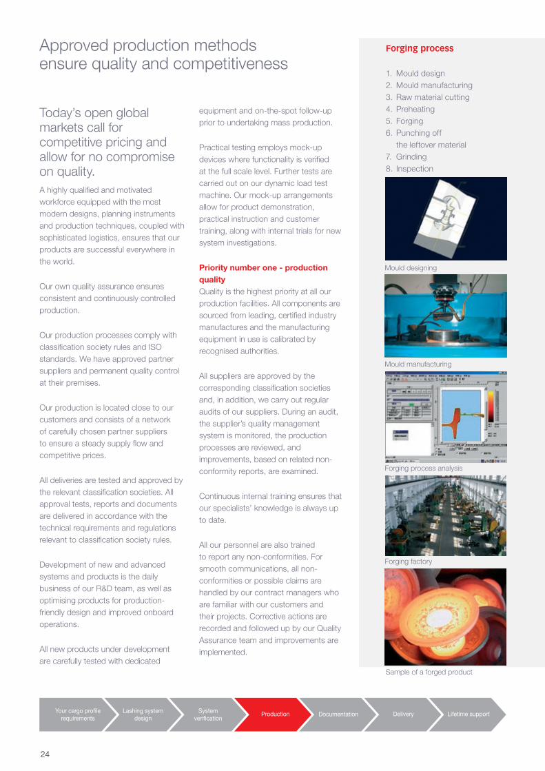
Forging process
1. Mould design 2. Mould manufacturing3. Raw material cutting4. Preheating5. Forging 6. Punching off
the leftover material7. Grinding8. Inspection
Your cargo profilerequirements
Lashing systemdesign
Systemverification
Documentation Delivery Lifetime supportProduction
Sample of a forged product
Mould designing
Mould manufacturing
Forging process analysis
Forging factory
24
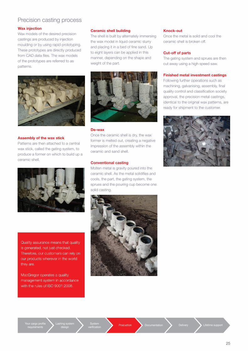
Knock-outOnce the metal is solid and cool the ceramic shell is broken off.
Cut-off of partsThe gating system and sprues are then cut away using a high speed saw.
Finished metal investment castingsFollowing further operations such as machining, galvanising, assembly, final quality control and classification society approval, the precision metal castings, identical to the original wax patterns, are ready for shipment to the customer.
Ceramic shell buildingThe shell is built by alternately immersing the wax model in liquid ceramic slurry and placing it in a bed of fine sand. Up to eight layers can be applied in this manner, depending on the shape and weight of the part.
De-waxOnce the ceramic shell is dry, the wax former is melted out, creating a negative impression of the assembly within the ceramic and sand shell.
Conventional castingMolten metal is gravity poured into the ceramic shell. As the metal solidifies and cools, the part, the gating system, the sprues and the pouring cup become one solid casting.
Precision casting processWax injectionWax models of the desired precision castings are produced by injection moulding or by using rapid prototyping. These prototypes are directly produced from CAD data files. The wax models of the prototypes are referred to as patterns.
Assembly of the wax stickPatterns are then attached to a central wax stick, called the gating system, to produce a former on which to build up a ceramic shell.
Your cargo profilerequirements
Lashing systemdesign
Systemverification
Documentation Delivery Lifetime supportProduction
Quality assurance means that quality is generated, not just checked. Therefore, our customers can rely on our products wherever in the world they are.
MacGregor operates a quality management system in accordance with the rules of ISO 9001:2008.
25
Your cargo profilerequirements
Lashing systemdesign
Systemverification
Documentation Delivery Lifetime supportProduction
26
Documentation
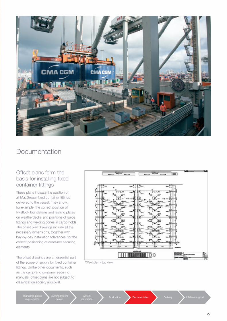
Offset plan - top view
Your cargo profilerequirements
Lashing systemdesign
Systemverification
Documentation Delivery Lifetime supportProduction
Offset plans form the basis for installing fixed container fittings These plans indicate the position of all MacGregor fixed container fittings delivered to the vessel. They show, for example, the correct position of twistlock foundations and lashing plates on weatherdecks and positions of guide fittings and welding cones in cargo holds. The offset plan drawings include all the necessary dimensions, together with bay-by-bay installation tolerances, for the correct positioning of container securing elements.
The offset drawings are an essential part of the scope of supply for fixed container fittings. Unlike other documents, such as the cargo and container securing manuals, offset plans are not subject to classification society approval.
27
Your cargo profilerequirements
Lashing systemdesign
Systemverification
Documentation Delivery Lifetime supportProduction
Clear documentation ensures safe and efficient loading of containers.
System verification documentationThe cargo securing system function is verified by a mock-up test, during which all crucial lashing cases are tested. The test is carefully documented and the results are used for adjusting the arrangement where needed to provide the best possible lashing system.
• General information• Securing equipment
- Loose fittings - Fixed fittings - Operation, inspection & service
• Stowage and securing of non-standard cargo
• Stowage and securing of containers - Container securing arrangement
(CSA) - Calculation examples
• Annexes
Delivery documentationDelivery documentation consists of documents that are vital from the ship’s operational point of view. Some of them are required by classification societies, while others are optional and delivered on request to further support the vessel’s smooth operation.
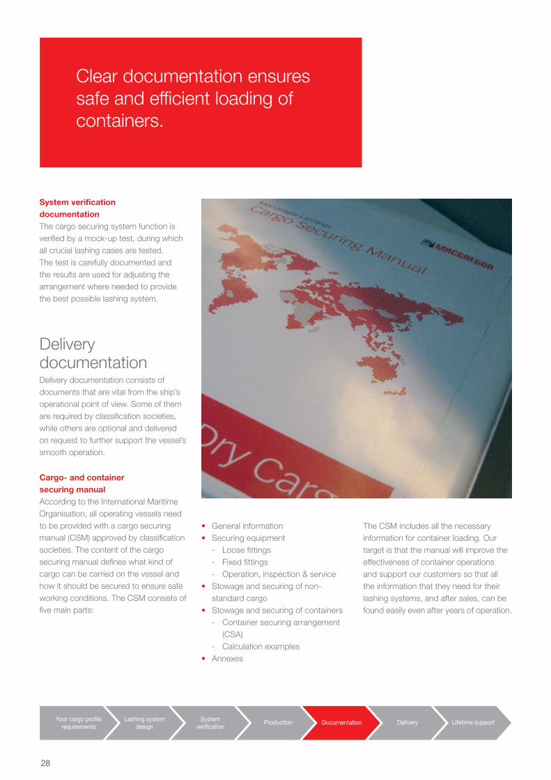
Cargo- and container securing manualAccording to the International Maritime Organisation, all operating vessels need to be provided with a cargo securing manual (CSM) approved by classification societies. The content of the cargo securing manual defines what kind of cargo can be carried on the vessel and how it should be secured to ensure safe working conditions. The CSM consists of five main parts:
The CSM includes all the necessary information for container loading. Our target is that the manual will improve the effectiveness of container operations and support our customers so that all the information that they need for their lashing systems, and after sales, can be found easily even after years of operation.
28
LASHING PATTERN LASHING BRIDGE - BAY 82-02
20ft containers
40ft and 45ft containers
Lashing poster
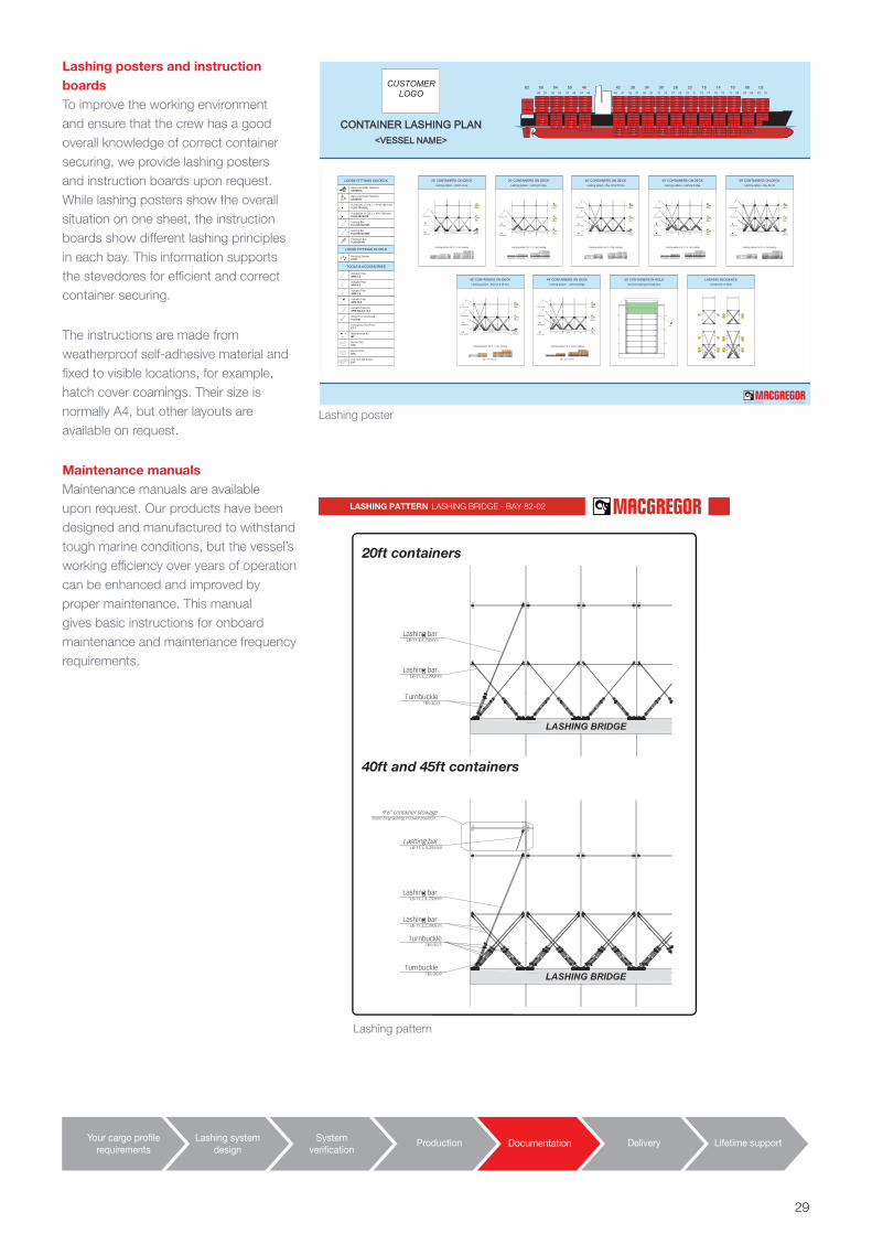
Lashing posters and instruction boardsTo improve the working environment and ensure that the crew has a good overall knowledge of correct container securing, we provide lashing posters and instruction boards upon request. While lashing posters show the overall situation on one sheet, the instruction boards show different lashing principles in each bay. This information supports the stevedores for efficient and correct container securing.
The instructions are made from weatherproof self-adhesive material and fixed to visible locations, for example, hatch cover coamings. Their size is normally A4, but other layouts are available on request.
Maintenance manualsMaintenance manuals are available upon request. Our products have been designed and manufactured to withstand tough marine conditions, but the vessel’s working efficiency over years of operation can be enhanced and improved by proper maintenance. This manual gives basic instructions for onboard maintenance and maintenance frequency requirements.
Lashing pattern
Your cargo profilerequirements
Lashing systemdesign
Systemverification
Documentation Delivery Lifetime supportProduction
LOOSE FITTINGS ON DECK
LOOSE FITTINGS IN HOLD
TOOLS & ACCESSORIES
Hanging StackerC12C
Semi-Automatic TwistlockC5AM-HC
Semi-Automatic TwistlockC5AM-DF
Lashing BarFLX-RD-50/2355
Turnbuckle L1375, L = 1140-1610 mmFLX5-TB-50/2L
Turnbuckle L1125, L = 970-1280 mmFLX5-TB-50/2S
Extension BarFLX2-EP-50
Lashing BarFLX-RD-50/4650
Actuator PoleAPB-1,5
Actuator PoleAPB-4,5
Actuator PoleAPB-7,5
Actuator PoleAPB-10,5
Actuator Pole 2-6APB-TQ-2,9-13,4
Wrench for turnbuckleFLX5-W
Bin for SATE16
Bin for HASE16
Flat rack 20ft 8 binsE17
Emergency Tool FrontET-1
Maintenance KitMT
4243 41
3839 37
3435 33
3031 29
222627 25 23 21
141819 17 15 13
061011 09 07 05 03
0201
465051 49 47 45
545859 57 55 53
62
6
2
2
2
24
6 6
10
6
22
2 2
4 2
4 2
4 4
10 812
4
2
4
4 4
2 2
4 4
6 4
6 6
8 6
10 8
12 10
12
14
14
6
4
6
66
4 4
8 6
10
8
12
8
8
10
14
14
14
8
6
10
8 8
6 6
10 10
12 12
12 10
14 1214
14
14
14
10
8
12
1010
8 8
12 12
14 14
14 12
14
14
14
14
12
10
14
12 12
10 10
14 14
14
14
14
14
14
14
14
14
14
12
14
14 14
12 12
14 14
14
14
14
14
14
14
14
14
1414
12 12
14 14
14 14
14 14
14
14
14
14
14
12
14
1414
12 12
14 14
14
14
14
14
14
14
14
14
14
12
10
14
12
10 10
14
12
1414
1414
14
14
5
1
8
5
1
8
7
2
8
88
88
14
14
10
14
14 14
10 10
14 14
1414
1414
14
14
4
14
1414
4 4
14 14
14 14
14
12
4
14
1412
4 6
14 14
14 14
14 14
12
12
12
12
12 12
1212
1212
12
1212
1212
14
14
14
14
14
1414
14
14
14
14
14
14
14 14
16
16
16
16
16
16
16 16
16
16
16
16
16
16
16
16
16
16
16
16
16
16
16
16
16 16
16
16
16
16
16
16
16
16
16
16
16
16
16
16
16
16
16 16
16
16
16
16
16
16
16
16
16
16
16
16
16
16
16
16
16 16
16
16
16
16
16
16
16
16
16
16
16
16
16
16
16
16
16 16
16
16
16
16
16
16
16
16
16
16
16
16
16
16
16
16
16 16
16
16
16
16
16
16
16
16
16
16
16
16
16
16
16
16
16 16
16
16
16
16
16
16
16
16
16
16
16
16
16
16
16
16
16 16
16
16
16
16
16
16
16
16
16
16
16
16
16
16
16
16
16 16
16
16
16
16
16
16
16
16
16
16
16
16
16
16
16
16
16 16
16
16
16
16
16
16
16
16
16
16
16
16
16
16
16
16
16 16
16
16
16
16
16
16
16
16
16
16
16
16
16
16
16
16
16 16
16
16
16
16
16
16
16
16
16
16
16
16
16
16
16
16
16 16
16
16
16
16
16
16
16
16
16
16
16
16
16
16
16
16
CONTAINER LASHING PLAN<VESSEL NAME>
C12C
20' CONTAINERS IN HOLDGeneral Lashing Arrangement
Lashing pattern for 2 - 6 tier loading
FLX5-TB-50/2L
FLX3-RD-50/2355
FLX5-TB-50/2SC5AM-HC
1st tier use only
Hatch cover
20' CONTAINERS ON DECKLashing pattern - Hatch cover
C5AM-DF
C5AM-DF
Lashing pattern for 2 - 6 tier loading
FLX5-TB-50/2L
FLX3-RD-50/2355
C5AM-DF
C5AM-DF
FLX5-TB-50/2S
Lashing bridge
1'st tier 1'st tier 1'st tier
20' CONTAINERS ON DECKLashing pattern - Lashing bridge
C5AM-DF
264-POST-A of 2002-04-09 Cargotec Finland Oy
Lashing pattern for 2 - 5 tier loading
FLX3-RD-50/4650
FLX5-TB-50/2L
FLX3-RD-50/2355
FLX5-TB-50/2S
Hatch coverC5AM-HC
1st tier use only
40' CONTAINERS ON DECKLashing pattern - Bay 02 & 06 fore
C5AM-DF
C5AM-DF
C5AM-DF
Lashing pattern for 2 - 6 tier loading
Lashing bridge
1'st tier 1'st tier 1'st tier
FLX3-RD-50/4650
FLX5-TB-50/2L
FLX3-RD-50/2355
FLX5-TB-50/2S
C5AM-DF
C5AM-DF
40' CONTAINERS ON DECKLashing pattern - Lashing bridge
= 45ft Container
Lashing pattern for 3 - 6 tier loading
Lashing bridge
1'st tier 1'st tier 1'st tier
45' CONTAINERS ON DECKLashing pattern - Lashing bridge
FLX3-RD-50/4650
FLX5-TB-50/2L
FLX3-RD-50/2355
FLX5-TB-50/2S
C5AM-DF
C5AM-DF
C5AM-DF
= 45ft Container
Lashing pattern for 3 - 5 tier loading
FLX3-RD-50/4650
FLX5-TB-50/2L
FLX3-RD-50/2355
FLX5-TB-50/2S
Hatch coverC5AM-HC
1st tier use only
C5AM-DF
C5AM-DF
45' CONTAINERS ON DECKLashing pattern - Bay 02 & 06 fore
12
3124
12
34
56
7568
12
34
LASHING SEQUENCEContainers on Deck
Lashing pattern for 2 - 6 tier loading
Lashing platform
FLX3-RD-50/4650
FLX5-TB-50/2L
FLX3-RD-50/2355
FLX5-TB-50/2SC5AM-HC
1st tier use only
C5AM-DF
C5AM-DF
40' CONTAINERS ON DECKLashing pattern - Bay 62 aft
CUSTOMERLOGO
29
Your cargo profilerequirements
Lashing systemdesign
Systemverification
Documentation Delivery Lifetime supportProduction
30
Your cargo profilerequirements
Lashing systemdesign
Systemverification
Documentation Delivery Lifetime supportProduction
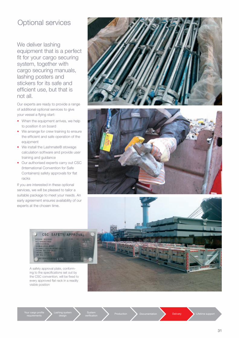
Optional services
We deliver lashing equipment that is a perfect fit for your cargo securing system, together with cargo securing manuals, lashing posters and stickers for its safe and efficient use, but that is not all.Our experts are ready to provide a range of additional optional services to give your vessel a flying start:
• When the equipment arrives, we help to position it on board
• We arrange for crew training to ensure the efficient and safe operation of the equipment
• We install the Lashmate® stowage calculation software and provide user training and guidance
• Our authorised experts carry out CSC (International Convention for Safe Containers) safety approvals for flat racks
If you are interested in these optional services, we will be pleased to tailor a suitable package to meet your needs. An early agreement ensures availability of our experts at the chosen time.
A safety approval plate, conform-ing to the specifications set out by the CSC convention, will be fixed to every approved flat rack in a readily visible position
31
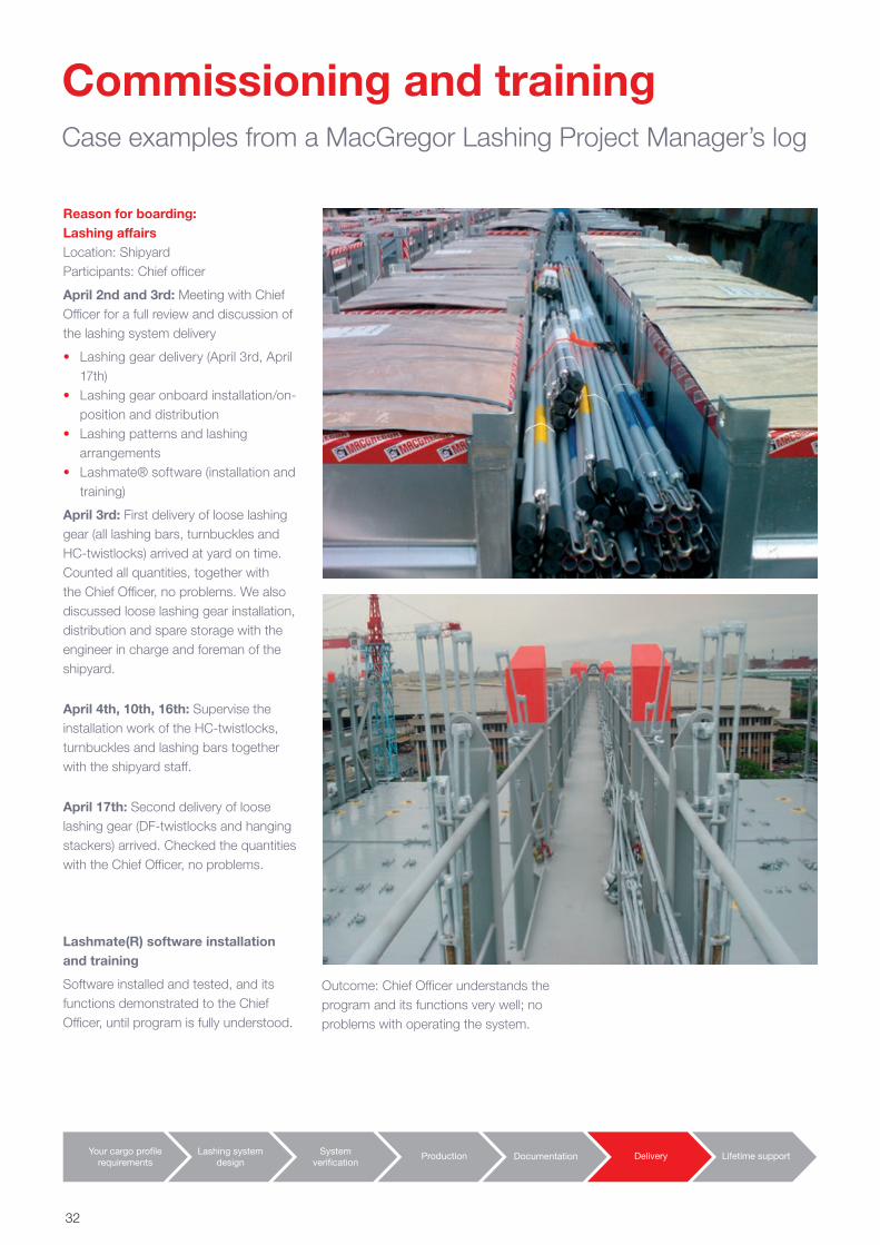
Commissioning and trainingCase examples from a MacGregor Lashing Project Manager’s log
Lashmate(R) software installation and training
Software installed and tested, and its functions demonstrated to the Chief Officer, until program is fully understood.
Your cargo profilerequirements
Lashing systemdesign
Systemverification
Documentation Delivery Lifetime supportProduction
Reason for boarding: Lashing affairsLocation: Shipyard Participants: Chief officer
April 2nd and 3rd: Meeting with Chief Officer for a full review and discussion of the lashing system delivery
• Lashing gear delivery (April 3rd, April 17th)
• Lashing gear onboard installation/on-position and distribution
• Lashing patterns and lashing arrangements
• Lashmate® software (installation and training)
April 3rd: First delivery of loose lashing gear (all lashing bars, turnbuckles and HC-twistlocks) arrived at yard on time. Counted all quantities, together with the Chief Officer, no problems. We also discussed loose lashing gear installation, distribution and spare storage with the engineer in charge and foreman of the shipyard.
April 4th, 10th, 16th: Supervise the installation work of the HC-twistlocks, turnbuckles and lashing bars together with the shipyard staff.
April 17th: Second delivery of loose lashing gear (DF-twistlocks and hanging stackers) arrived. Checked the quantities with the Chief Officer, no problems.
Outcome: Chief Officer understands the program and its functions very well; no problems with operating the system.
32
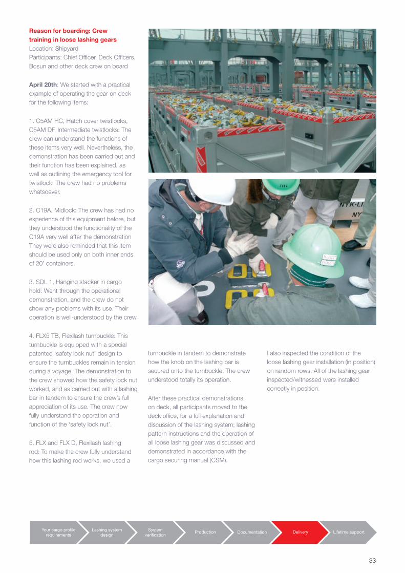
Reason for boarding: Crew training in loose lashing gearsLocation: Shipyard Participants: Chief Officer, Deck Officers, Bosun and other deck crew on board
April 20th: We started with a practical example of operating the gear on deck for the following items:
1. C5AM HC, Hatch cover twistlocks, C5AM DF, Intermediate twistlocks: The crew can understand the functions of these items very well. Nevertheless, the demonstration has been carried out and their function has been explained, as well as outlining the emergency tool for twistlock. The crew had no problems whatsoever.
2. C19A, Midlock: The crew has had no experience of this equipment before, but they understood the functionality of the C19A very well after the demonstration They were also reminded that this item should be used only on both inner ends of 20’ containers.
3. SDL 1, Hanging stacker in cargo hold: Went through the operational demonstration, and the crew do not show any problems with its use. Their operation is well-understood by the crew.
4. FLX5 TB, Flexilash turnbuckle: This turnbuckle is equipped with a special patented ‘safety lock nut’ design to ensure the turnbuckles remain in tension during a voyage. The demonstration to the crew showed how the safety lock nut worked, and as carried out with a lashing bar in tandem to ensure the crew’s full appreciation of its use. The crew now fully understand the operation and function of the ‘safety lock nut’.
5. FLX and FLX D, Flexilash lashing rod: To make the crew fully understand how this lashing rod works, we used a
Your cargo profilerequirements
Lashing systemdesign
Systemverification
Documentation Delivery Lifetime supportProduction
turnbuckle in tandem to demonstrate how the knob on the lashing bar is secured onto the turnbuckle. The crew understood totally its operation.
After these practical demonstrations on deck, all participants moved to the deck office, for a full explanation and discussion of the lashing system; lashing pattern instructions and the operation of all loose lashing gear was discussed and demonstrated in accordance with the cargo securing manual (CSM).
I also inspected the condition of the loose lashing gear installation (in position) on random rows. All of the lashing gear inspected/witnessed were installed correctly in position.
33
EZ-lock safety-lock for turnbuckles
2005Top lashing bridge system
2004
Heavy-duty bottom CV-8B twistlock
2004Advanced mixed stowage system with SDL-1 terminal stacker
Speedlash with bending moment eliminator
Slack-reducer for turnbuckles
2002
Combined bottom and intermediate AFC-1 Midlock introduced
2001
Hanging stacker C16A developed
1999
OSHA pressure stacker introduced
1999
Lashmate lashing calculationsoftware developed
1998
First symmetrical dualsemi-automatic twistlock,
CV-20, introduced
1996
First midlock (AFC-1) and dual-functiontwistlock (C5AM-DF) introduced
1993
Conver-OSR acquired by MacGregor-Navire
1992 Semi-automatic twistlock, C5-AM,
Equalash lashing system developed
1990First lashing bridges introduced
Slewing eyes, SAT CV-14, introduced
1989
Allset Marine Lashing establishedOne-wire semiautomatic twistlock C5A
1988
First semi-automatic CV-11/CV-12 twistlocks developed
1986
Sliding foundation, four-knob Multilash system introduced
1985
Sawfish tension/pressure element developed
1983
Paralash system introduced
1982
Removable 20’ slim cell guides introduced
1976
First one-piece twistlock housingdeveloped, the CV-1
1975
Lashing company Conver established
1971
First MacGregor steel hatchcover patent accepted
1929
Allset Marine acquired by MacGregor
2005
Fully automatic twistlock C8A
2011
A-class lashing bar
2013Ultra strength lashing bar
2008
LashSet calculation software launched
1991
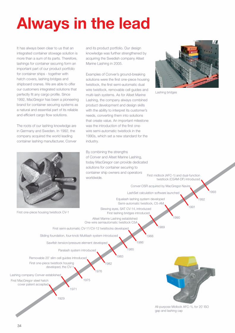
It has always been clear to us that an integrated container stowage solution is more than a sum of its parts. Therefore, lashings for container securing form an important part of our product portfolio for container ships - together with hatch covers, lashing bridges and shipboard cranes. We are able to offer our customers integrated solutions that perfectly fit any cargo profile. Since 1992, MacGregor has been a pioneering brand for container securing systems as a natural and essential part of its reliable and efficient cargo flow solutions.
The roots of our lashing knowledge are in Germany and Sweden. In 1992, the company acquired the world leading container lashing manufacturer, Conver
Always in the leadand its product portfolio. Our design knowledge was further strengthened by acquiring the Swedish company Allset Marine Lashing in 2005.
Examples of Conver’s ground-breaking solutions were the first one-piece housing twistlock, the first semi-automatic dual wire twistlock, removable cell guides and multi-lash systems. As for Allset Marine Lashing, the company always combined product development and design skills with the ability to interpret its customer’s needs, converting them into solutions that create value. An important milestone was the introduction of the first one-wire semi-automatic twistlock in the 1990s, which set a new standard for the industry.
By combining the strengths of Conver and Allset Marine Lashing, today MacGregor can provide dedicated solutions for container securing to container ship owners and operators worldwide.
All-purpose Midlock AFC-1L for 20´ ISO gap and lashing cap
First one-piece housing twistlock CV-1
Lashing bridges
34
EZ-lock safety-lock for turnbuckles
2005Top lashing bridge system
2004
Heavy-duty bottom CV-8B twistlock
2004Advanced mixed stowage system with SDL-1 terminal stacker
Speedlash with bending moment eliminator
Slack-reducer for turnbuckles
2002
Combined bottom and intermediate AFC-1 Midlock introduced
2001
Hanging stacker C16A developed
1999
OSHA pressure stacker introduced
1999
Lashmate lashing calculationsoftware developed
1998
First symmetrical dualsemi-automatic twistlock,
CV-20, introduced
1996
First midlock (AFC-1) and dual-functiontwistlock (C5AM-DF) introduced
1993
Conver-OSR acquired by MacGregor-Navire
1992 Semi-automatic twistlock, C5-AM,
Equalash lashing system developed
1990First lashing bridges introduced
Slewing eyes, SAT CV-14, introduced
1989
Allset Marine Lashing establishedOne-wire semiautomatic twistlock C5A
1988
First semi-automatic CV-11/CV-12 twistlocks developed
1986
Sliding foundation, four-knob Multilash system introduced
1985
Sawfish tension/pressure element developed
1983
Paralash system introduced
1982
Removable 20’ slim cell guides introduced
1976
First one-piece twistlock housingdeveloped, the CV-1
1975
Lashing company Conver established
1971
First MacGregor steel hatchcover patent accepted
1929
Allset Marine acquired by MacGregor
2005
Fully automatic twistlock C8A
2011
A-class lashing bar
2013Ultra strength lashing bar
2008
LashSet calculation software launched
1991
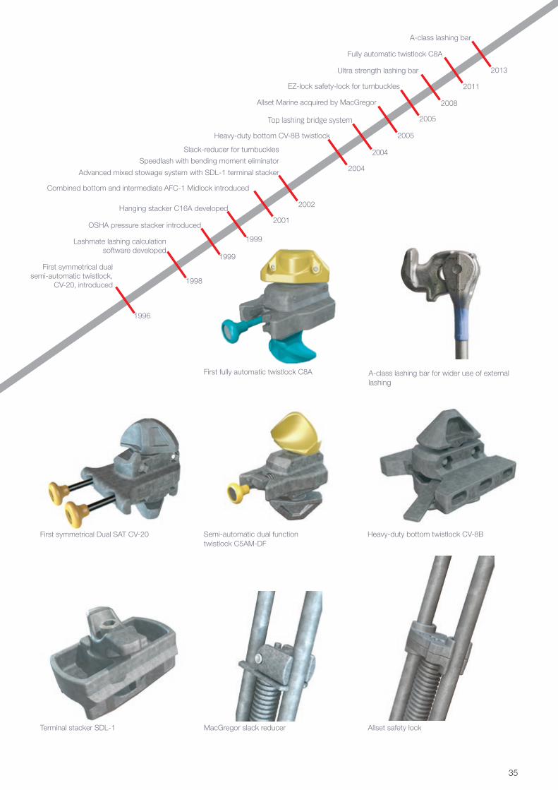
Terminal stacker SDL-1
First symmetrical Dual SAT CV-20
MacGregor slack reducer
Semi-automatic dual function twistlock C5AM-DF
Allset safety lock
Heavy-duty bottom twistlock CV-8B
First fully automatic twistlock C8A A-class lashing bar for wider use of external lashing
35
Your cargo profilerequirements
Lashing systemdesign
Systemverification
Production Documentation Delivery Lifetime support
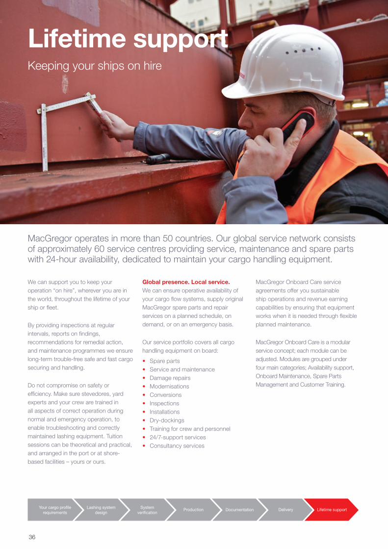
We can support you to keep your operation “on hire”, wherever you are in the world, throughout the lifetime of your ship or fleet.
By providing inspections at regular intervals, reports on findings, recommendations for remedial action, and maintenance programmes we ensure long-term trouble-free safe and fast cargo securing and handling.
Do not compromise on safety or efficiency. Make sure stevedores, yard experts and your crew are trained in all aspects of correct operation during normal and emergency operation, to enable troubleshooting and correctly maintained lashing equipment. Tuition sessions can be theoretical and practical, and arranged in the port or at shore-based facilities – yours or ours.
Global presence. Local service.We can ensure operative availability of your cargo flow systems, supply original MacGregor spare parts and repair services on a planned schedule, on demand, or on an emergency basis.
Our service portfolio covers all cargo handling equipment on board:
• Spare parts• Service and maintenance• Damage repairs• Modernisations• Conversions• Inspections• Installations• Dry-dockings• Training for crew and personnel• 24/7-support services• Consultancy services
MacGregor Onboard Care service agreements offer you sustainable ship operations and revenue earning capabilities by ensuring that equipment works when it is needed through flexible planned maintenance.
MacGregor Onboard Care is a modular service concept; each module can be adjusted. Modules are grouped under four main categories; Availability support, Onboard Maintenance, Spare Parts Management and Customer Training.
Lifetime supportKeeping your ships on hire
MacGregor operates in more than 50 countries. Our global service network consists of approximately 60 service centres providing service, maintenance and spare parts with 24-hour availability, dedicated to maintain your cargo handling equipment.
36
Your cargo profilerequirements
Lashing systemdesign
Systemverification
Production Documentation Delivery Lifetime support
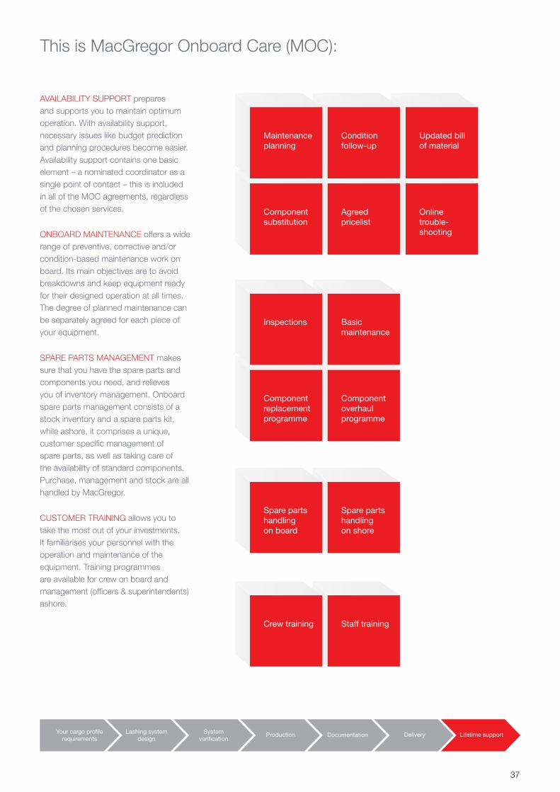
This is MacGregor Onboard Care (MOC):
AVAILABILITY SUPPORT prepares and supports you to maintain optimum operation. With availability support, necessary issues like budget prediction and planning procedures become easier. Availability support contains one basic element – a nominated coordinator as a single point of contact – this is included in all of the MOC agreements, regardless of the chosen services.
ONBOARD MAINTENANCE offers a wide range of preventive, corrective and/or condition-based maintenance work on board. Its main objectives are to avoid breakdowns and keep equipment ready for their designed operation at all times. The degree of planned maintenance can be separately agreed for each piece of your equipment.
SPARE PARTS MANAGEMENT makes sure that you have the spare parts and components you need, and relieves you of inventory management. Onboard spare parts management consists of a stock inventory and a spare parts kit, while ashore, it comprises a unique, customer specific management of spare parts, as well as taking care of the availability of standard components. Purchase, management and stock are all handled by MacGregor.
CUSTOMER TRAINING allows you to take the most out of your investments. It familiarises your personnel with the operation and maintenance of the equipment. Training programmes are available for crew on board and management (officers & superintendents) ashore.
Onlinetrouble-shooting
Agreedpricelist
Componentsubstitution
Updated billof material
Conditionfollow-up
Maintenanceplanning
Component overhaulprogramme
Componentreplacementprogramme
Spare partshandlingon shore
Spare partshandlingon board
Staff trainingCrew training
Basicmaintenance
Inspections
37
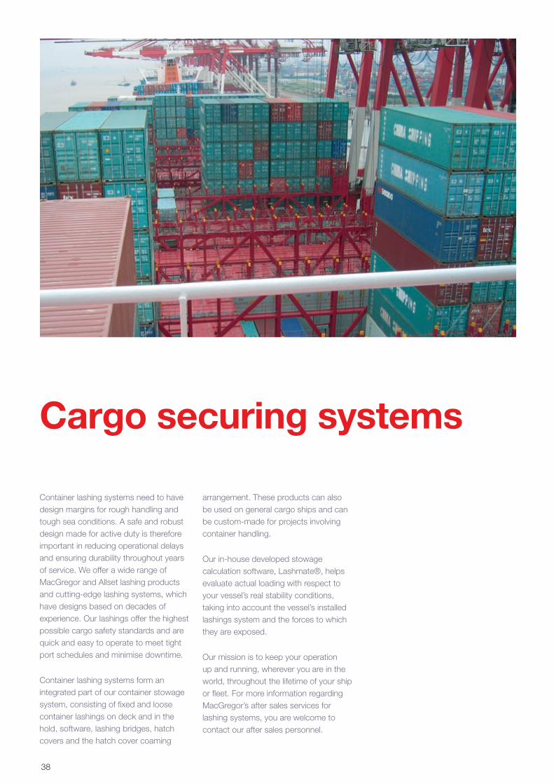
Container lashing systems need to have design margins for rough handling and tough sea conditions. A safe and robust design made for active duty is therefore important in reducing operational delays and ensuring durability throughout years of service. We offer a wide range of MacGregor and Allset lashing products and cutting-edge lashing systems, which have designs based on decades of experience. Our lashings offer the highest possible cargo safety standards and are quick and easy to operate to meet tight port schedules and minimise downtime.
Container lashing systems form an integrated part of our container stowage system, consisting of fixed and loose container lashings on deck and in the hold, software, lashing bridges, hatch covers and the hatch cover coaming
arrangement. These products can also be used on general cargo ships and can be custom-made for projects involving container handling.
Our in-house developed stowage calculation software, Lashmate®, helps evaluate actual loading with respect to your vessel’s real stability conditions, taking into account the vessel’s installed lashings system and the forces to which they are exposed.
Our mission is to keep your operation up and running, wherever you are in the world, throughout the lifetime of your ship or fleet. For more information regarding MacGregor’s after sales services for lashing systems, you are welcome to contact our after sales personnel.
Cargo securing systems
38
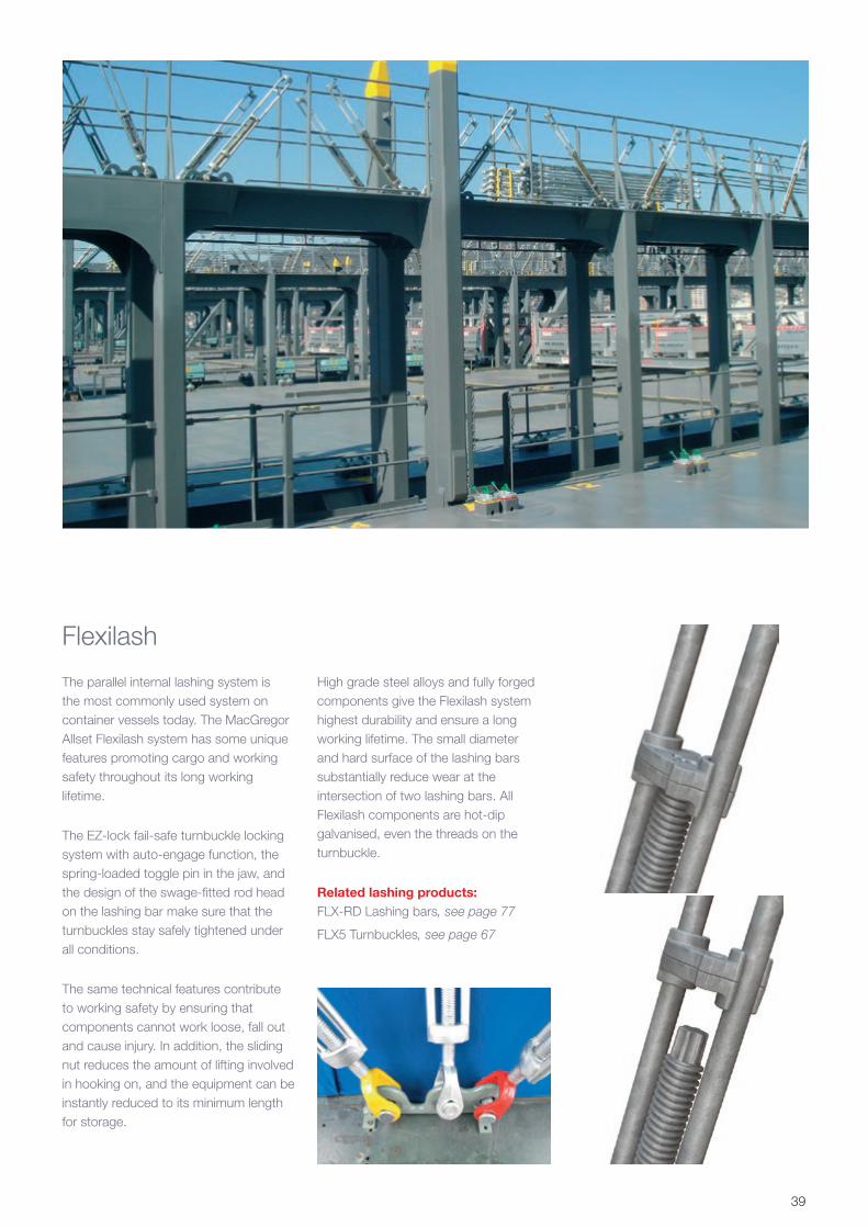
Flexilash
The parallel internal lashing system is the most commonly used system on container vessels today. The MacGregor Allset Flexilash system has some unique features promoting cargo and working safety throughout its long working lifetime.
The EZ-lock fail-safe turnbuckle locking system with auto-engage function, the spring-loaded toggle pin in the jaw, and the design of the swage-fitted rod head on the lashing bar make sure that the turnbuckles stay safely tightened under all conditions.
The same technical features contribute to working safety by ensuring that components cannot work loose, fall out and cause injury. In addition, the sliding nut reduces the amount of lifting involved in hooking on, and the equipment can be instantly reduced to its minimum length for storage.
High grade steel alloys and fully forged components give the Flexilash system highest durability and ensure a long working lifetime. The small diameter and hard surface of the lashing bars substantially reduce wear at the intersection of two lashing bars. All Flexilash components are hot-dip galvanised, even the threads on the turnbuckle.
Related lashing products:FLX-RD Lashing bars, see page 77
FLX5 Turnbuckles, see page 67
39
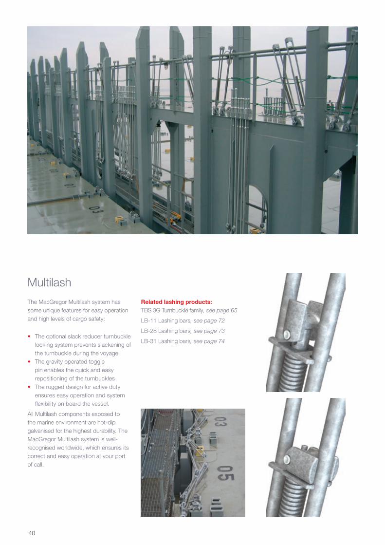
Multilash
The MacGregor Multilash system has some unique features for easy operation and high levels of cargo safety:
• The optional slack reducer turnbuckle locking system prevents slackening of the turnbuckle during the voyage
• The gravity operated toggle pin enables the quick and easy repositioning of the turnbuckles
• The rugged design for active duty ensures easy operation and system flexibility on board the vessel.
All Multilash components exposed to the marine environment are hot-dip galvanised for the highest durability. The MacGregor Multilash system is well-recognised worldwide, which ensures its correct and easy operation at your port of call.
Related lashing products:TBS 3G Turnbuckle family, see page 65
LB-11 Lashing bars, see page 72
LB-28 Lashing bars, see page 73
LB-31 Lashing bars, see page 74
40
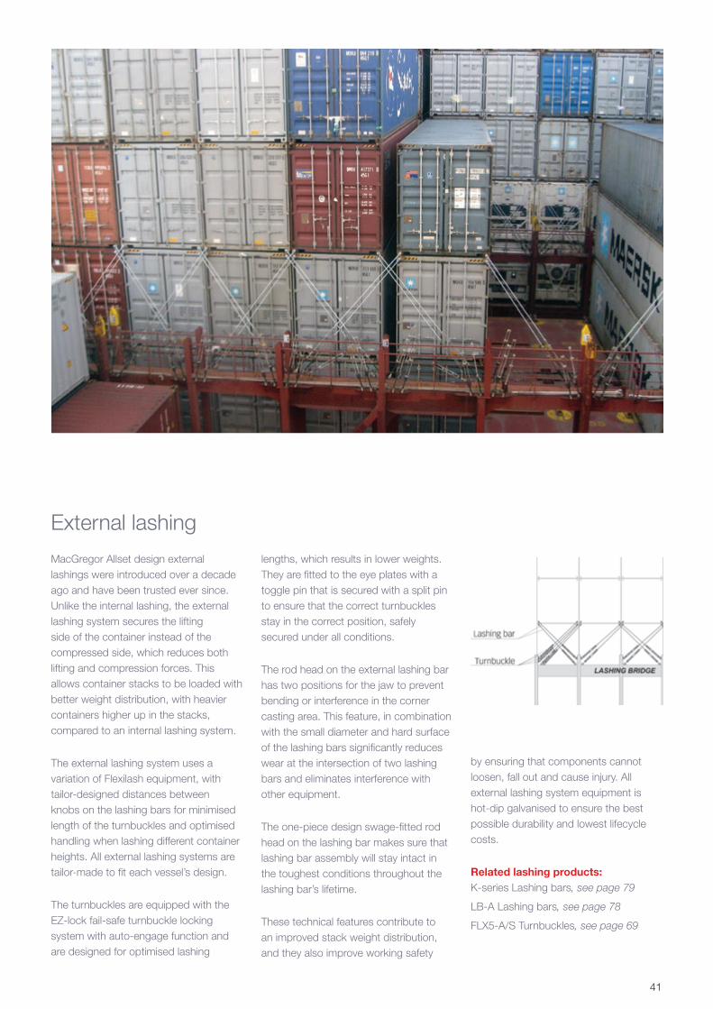
MacGregor Allset design external lashings were introduced over a decade ago and have been trusted ever since. Unlike the internal lashing, the external lashing system secures the lifting side of the container instead of the compressed side, which reduces both lifting and compression forces. This allows container stacks to be loaded with better weight distribution, with heavier containers higher up in the stacks, compared to an internal lashing system.
The external lashing system uses a variation of Flexilash equipment, with tailor-designed distances between knobs on the lashing bars for minimised length of the turnbuckles and optimised handling when lashing different container heights. All external lashing systems are tailor-made to fit each vessel’s design.
The turnbuckles are equipped with the EZ-lock fail-safe turnbuckle locking system with auto-engage function and are designed for optimised lashing
lengths, which results in lower weights. They are fitted to the eye plates with a toggle pin that is secured with a split pin to ensure that the correct turnbuckles stay in the correct position, safely secured under all conditions.
The rod head on the external lashing bar has two positions for the jaw to prevent bending or interference in the corner casting area. This feature, in combination with the small diameter and hard surface of the lashing bars significantly reduces wear at the intersection of two lashing bars and eliminates interference with other equipment.
The one-piece design swage-fitted rod head on the lashing bar makes sure that lashing bar assembly will stay intact in the toughest conditions throughout the lashing bar’s lifetime.
These technical features contribute to an improved stack weight distribution, and they also improve working safety
by ensuring that components cannot loosen, fall out and cause injury. All external lashing system equipment is hot-dip galvanised to ensure the best possible durability and lowest lifecycle costs.
Related lashing products:K-series Lashing bars, see page 79
LB-A Lashing bars, see page 78
FLX5-A/S Turnbuckles, see page 69
External lashing
41
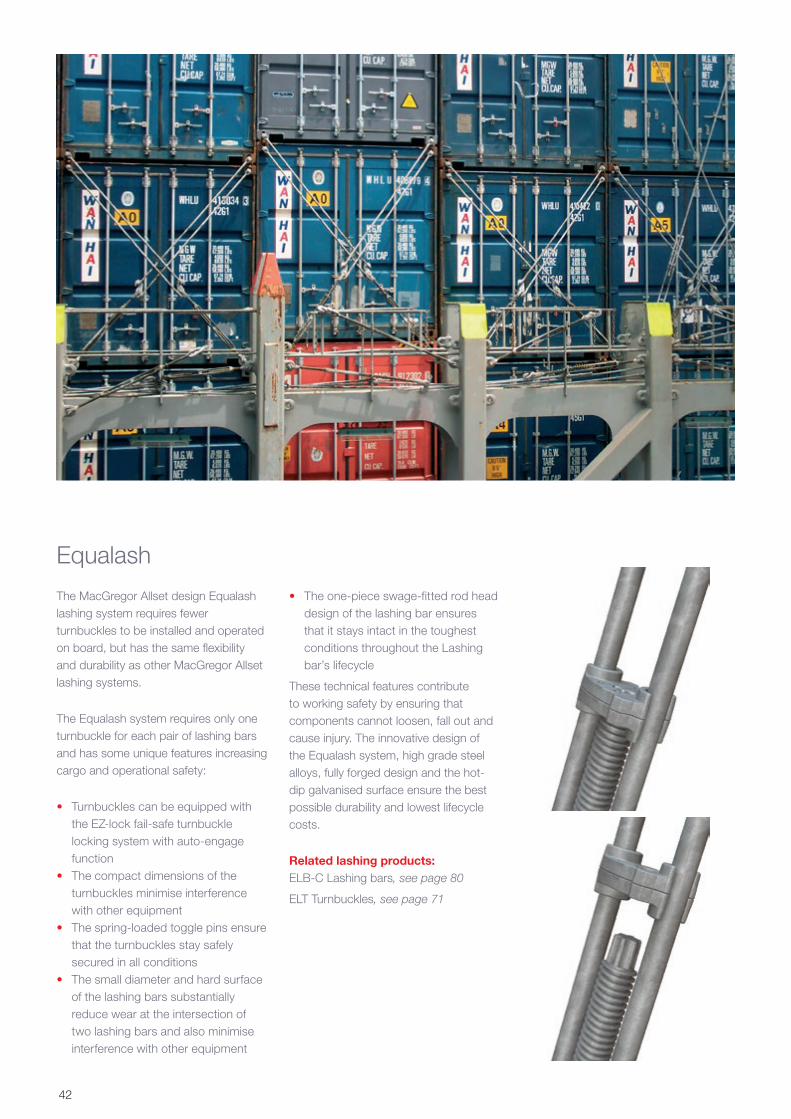
Equalash
The MacGregor Allset design Equalash lashing system requires fewer turnbuckles to be installed and operated on board, but has the same flexibility and durability as other MacGregor Allset lashing systems.
The Equalash system requires only one turnbuckle for each pair of lashing bars and has some unique features increasing cargo and operational safety:
• Turnbuckles can be equipped with the EZ-lock fail-safe turnbuckle locking system with auto-engage function
• The compact dimensions of the turnbuckles minimise interference with other equipment
• The spring-loaded toggle pins ensure that the turnbuckles stay safely secured in all conditions
• The small diameter and hard surface of the lashing bars substantially reduce wear at the intersection of two lashing bars and also minimise interference with other equipment
• The one-piece swage-fitted rod head design of the lashing bar ensures that it stays intact in the toughest conditions throughout the Lashing bar’s lifecycle
These technical features contribute to working safety by ensuring that components cannot loosen, fall out and cause injury. The innovative design of the Equalash system, high grade steel alloys, fully forged design and the hot-dip galvanised surface ensure the best possible durability and lowest lifecycle costs.
Related lashing products:ELB-C Lashing bars, see page 80
ELT Turnbuckles, see page 71
42
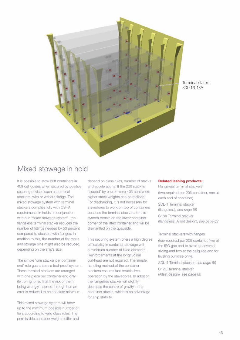
It is possible to stow 20ft containers in 40ft cell guides when secured by positive securing devices such as terminal stackers, with or without flange. The mixed stowage system with terminal stackers complies fully with OSHA requirements in holds. In conjunction with our ‘mixed stowage system’, the flangeless terminal stacker reduces the number of fittings needed by 50 percent compared to stackers with flanges. In addition to this, the number of flat racks and storage bins might also be reduced, depending on the ship’s size.
The simple ‘one stacker per container end’ rule guarantees a fool-proof system. These terminal stackers are arranged with one piece per container end only (left or right), so that the risk of them being wrongly inserted through human error is reduced to an absolute minimum.
This mixed stowage system will stow up to the maximum possible number of tiers according to valid class rules. The permissible container weights differ and
depend on class rules, number of stacks and accelerations. If the 20ft stack is ‘topped’ by one or more 40ft containers higher stack weights can be realised. For discharging, it is not necessary for stevedores to work on top of containers because the terminal stackers for this system remain on the lower container corner of the lifted container and will be dismantled on the quayside.
This securing system offers a high degree of flexibility in container stowage with a minimum number of fixed elements. Reinforcements at the longitudinal bulkhead are not required. The simple handling method of the container stackers ensures fast trouble-free operation by the stevedores. In addition, the flangeless stacker will slightly decrease the centre of gravity in the container stacks, which is an advantage for ship stability.
Related lashing products:Flangeless terminal stackers
(two required per 20ft container, one at each end of container)
SDL-1 Terminal stacker (flangeless), see page 58
C18A Terminal stacker (flangeless, Allset design), see page 62
Terminal stackers with flanges
(four required per 20ft container, two at the ISO gap end to avoid transversal sliding and two at the cellguide end for leveling purpose only).
SDL-4 Terminal stacker, see page 59
C12C Terminal stacker (Allset design), see page 60
Mixed stowage in hold
Terminal stackerSDL-1/C18A
43
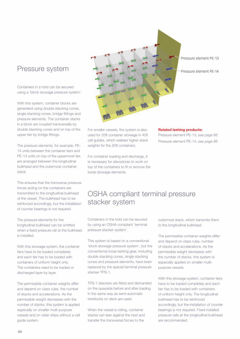
Pressure system
Containers in a hold can be secured using a ‘block stowage pressure system’.
With this system, container blocks are generated using double stacking cones, single stacking cones, bridge fittings and pressure elements. The container stacks in a block are coupled transversally by double stacking cones and on top of the upper tier by bridge fittings.
The pressure elements, for example, PE-14 units between the container tiers and PE-13 units on top of the uppermost tier, are arranged between the longitudinal bulkhead and the outermost container stack.
This ensures that the transverse pressure forces acting on the containers are transmitted to the longitudinal bulkhead of the vessel. The bulkhead has to be reinforced accordingly, but the installation of counter bearings is not required.
The pressure elements for the longitudinal bulkhead can be omitted when a fixed pressure rail at the bulkhead is installed.
With this stowage system, the container tiers have to be loaded completely and each tier has to be loaded with containers of uniform height only. The containers need to be loaded or discharged layer by layer.
The permissible container weights differ and depend on class rules, the number of stacks and accelerations. As the permissible weight decreases with the number of stacks, this system is applied especially on smaller multi-purpose vessels and on older ships without a cell guide system.
For smaller vessels, the system is also used for 20ft container stowage in 40ft cell guides, which realises higher stack weights for the 20ft containers.
For container loading and discharge, it is necessary for stevedores to work on top of the containers to fit or remove the loose stowage elements.
Containers in the hold can be secured by using an OSHA compliant ‘terminal pressure stacker system’.
This system is based on a conventional ‘block stowage pressure system’, but the conventional loose lashing gear, including double stacking cones, single stacking cones and pressure elements, have been replaced by the special terminal pressure stacker TPS-1.
TPS-1 stackers are fitted and dismantled on the quayside before and after loading in the same way as semi-automatic twistlocks on deck are used.
When the vessel is rolling, container stacks can lean against the next and transfer the transversal forces to the
outermost stack, which transmits them to the longitudinal bulkhead.
The permissible container weights differ and depend on class rules, number of stacks and accelerations. As the permissible weight decreases with the number of stacks, this system is especially applied on smaller multi-purpose vessels.
With this stowage system, container tiers have to be loaded completely and each tier has to be loaded with containers of uniform height only. The longitudinal bulkhead has to be reinforced accordingly, but the installation of counter bearings is not required. Fixed installed pressure rails at the longitudinal bulkhead are recommended.
OSHA compliant terminal pressure stacker system
Related lashing products:Pressure element PE-13, see page 86
Pressure element PE-14, see page 86
Pressure element PE-13
Pressure element PE-14
44

The TPS-1 facilitates the safe handling of containers in accordance with OSHA requirements, which effectively ban stevedores from climbing on top of containers to release securing devices. Moreover, the TPS-1 allows independent and flexible loading and unloading of both 20ft and 40ft containers without restriction and without the need to reduce weights in accordance with Germanischer Lloyd requirements
Related lashing products:Terminal pressure stacker TPS-1, see page 88
Containers in a hold can be secured by the use of a ‘block stowage tension/pressure system’.
This system generates container blocks by using double stacking cones, single stacking cones, bridge fittings and tension/pressure elements. To avoid the effect of external forces from the vessel’s deflections, generally two container blocks are created per bay.
The container stacks in a block are coupled transversally by double stacking cones and on the top of the upper tier by bridge fittings.
The tension/pressure elements – for example, TPE-13 units between the container tiers and TPE-25 on the top of the uppermost tier – are arranged between the longitudinal bulkhead and the outermost container stack. Single stacking cones are used in the transverse gap between the container blocks.
The transversal tension and pressure forces on the containers are transmitted to the vessel’s longitudinal bulkhead. The bulkhead has to be reinforced accordingly and counter bearings for the tension/pressure elements at the longitudinal bulkheads are necessary.
The blocks of container tiers have to be loaded completely and each tier has to
TPS-1 against side of the hold
TPS-1 between the containers
Counter bearing CB-8
Tension pressure element TPE-25
Tension pressure element TPE-13
be loaded with containers of uniform height only. The containers need to be loaded or discharged layer by layer.
The permissible container weights differ and depend on class rules, number of stacks and accelerations. In comparison with a pressure system, either the permissible container weight is higher or the number of stacks is larger with similar weights. So this system is especially applied on multi-purpose vessels with high stack weights, on con-bulkers and on older vessels without a cell guide system.
For container loading and discharge, it is necessary for stevedores to work on top of containers to fit or remove the loose stowage elements.
Also a mixture of tension/pressure system is possible. The container stacks in one bay form three blocks. One on each side works as the described tension pressure system and the centre block works as a pressure system. The centre block leans towards the adjacent block on the port or starboard side according to the vessel’s direction of roll.
Related lashing products:Tension pressure element TPE-13, see page 89
Tension pressure element TPE 25, see page 89
Counter bearing CB-8, see page 121
Tension pressure system
45
46
Macgregor Finland OyHallimestarinkatu 6
FI-20780 Kaarina, Finland
Tel: +358-2-41211
Fax: +358-2-4121 256
Cargotec Marine GmbHReichsbahnstrasse 72
DE-22525 Hamburg, Germany
Tel: +49-40-25 444 0
Fax: +49-40-25 444 444
Cargotec CHS Asia Pacific Pte LtdNo. 15, Tukang Innovation Drive
Singapore 618299
Tel: +65-6597 3888
Fax: +65-6597 3799
Distributor for United States, Canada and Mexico:Buffers USA Inc
10180 New Berlin Road
Jacksonville, FL 32226 USA
Tel: +1-904-696-0010
Email: [email protected]
www.buffersusa.com
Agent for Taiwan:Heng Cherng Enterprises Co.,Ltd
Tel: +886-2-25 65 20 63 or 25 65 20 64
Fax: +886-02-25 63 40 62
E-Mail: [email protected]
E-mail: [email protected]
Contacts:
Product Catalogue
Contacts:
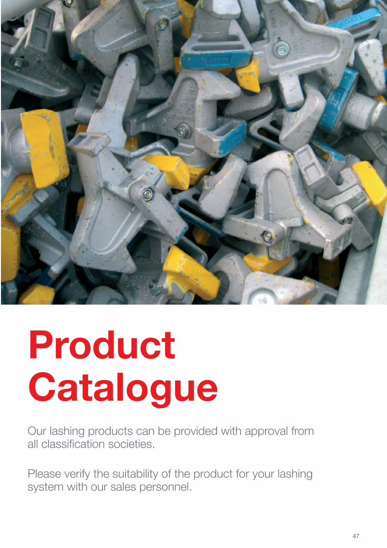
Our lashing products can be provided with approval from all classification societies.
Please verify the suitability of the product for your lashing system with our sales personnel.
47
48
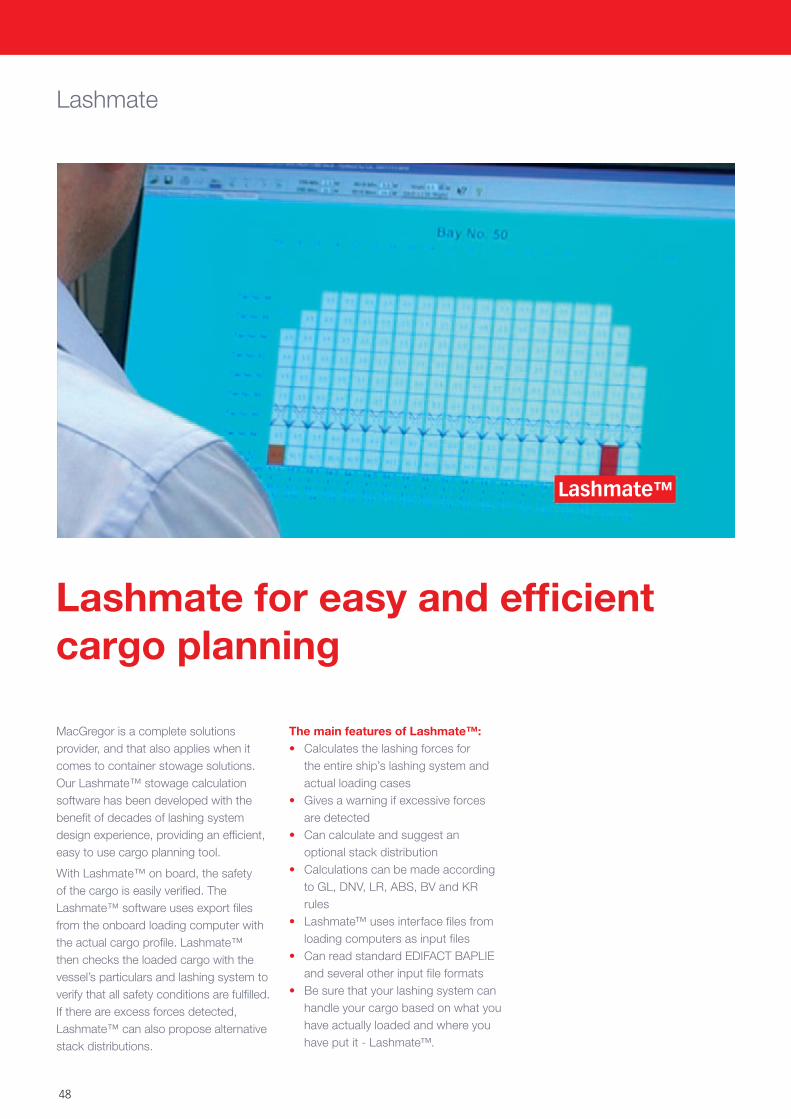
MacGregor is a complete solutions provider, and that also applies when it comes to container stowage solutions. Our Lashmate™ stowage calculation software has been developed with the benefit of decades of lashing system design experience, providing an efficient, easy to use cargo planning tool.
With Lashmate™ on board, the safety of the cargo is easily verified. The Lashmate™ software uses export files from the onboard loading computer with the actual cargo profile. Lashmate™ then checks the loaded cargo with the vessel’s particulars and lashing system to verify that all safety conditions are fulfilled. If there are excess forces detected, Lashmate™ can also propose alternative stack distributions.
Lashmate
The main features of Lashmate™:• Calculates the lashing forces for
the entire ship’s lashing system and actual loading cases
• Gives a warning if excessive forces are detected
• Can calculate and suggest an optional stack distribution
• Calculations can be made according to GL, DNV, LR, ABS, BV and KR rules
• Lashmate™ uses interface files from loading computers as input files
• Can read standard EDIFACT BAPLIE and several other input file formats
• Be sure that your lashing system can handle your cargo based on what you have actually loaded and where you have put it - Lashmate™.
Lashmate for easy and efficient cargo planning
Lashmate™
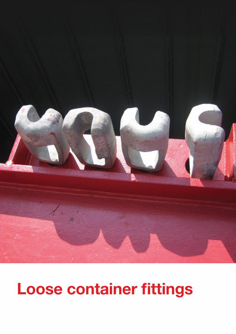
Loose container fittings
49
50
Automatic twistlocks
C8A-DF, C8A-HCAutomatic dual function twistlock
C8A
Order number Product
Weight kg
Shaft material
Housing material Handle material Treatment
Safe Working Load Tension, automatic mode, kN
Safe Working Load Tension, locked mode, kN
Safe Working Load Shear, kN Details Counter part Design
1186663 C8A-DF 7.4Forged high tensile steel
Forged steel
Stainless steel wire with plastic end knob
Hot-dip galvanised 230 250 210
Automatic twistlock, dual function
Container castings, twistlock foundations, operating rod APB-C8A MacGregor
1197597 C8A-HC 8.3Forged high tensile steel
Forged steel
Stainless steel wire with plastic end knob
Hot-dip galvanised 230 250 210
Automatic twistlock for bottom tiers
Container castings, twistlock foundations MacGregor
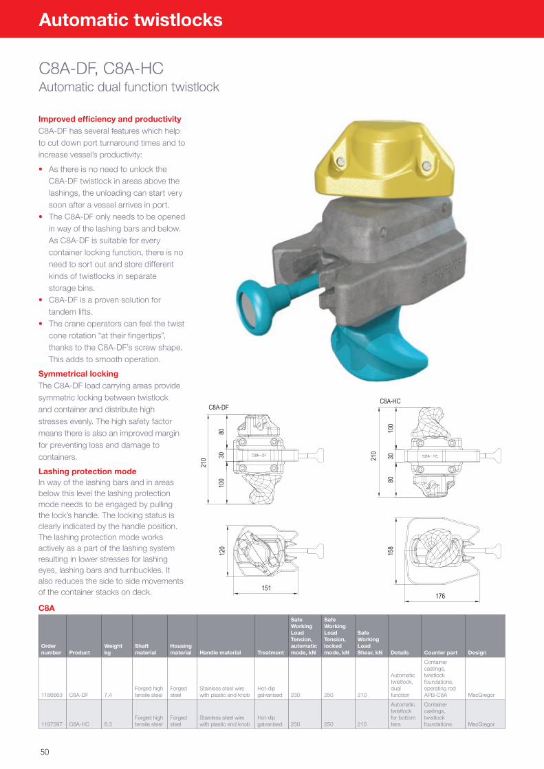
Improved efficiency and productivityC8A-DF has several features which help to cut down port turnaround times and to increase vessel’s productivity:
• As there is no need to unlock the C8A-DF twistlock in areas above the lashings, the unloading can start very soon after a vessel arrives in port.
• The C8A-DF only needs to be opened in way of the lashing bars and below. As C8A-DF is suitable for every container locking function, there is no need to sort out and store different kinds of twistlocks in separate storage bins.
• C8A-DF is a proven solution for tandem lifts.
• The crane operators can feel the twist cone rotation “at their fingertips”, thanks to the C8A-DF’s screw shape. This adds to smooth operation.
Symmetrical lockingThe C8A-DF load carrying areas provide symmetric locking between twistlock and container and distribute high stresses evenly. The high safety factor means there is also an improved margin for preventing loss and damage to containers.
Lashing protection modeIn way of the lashing bars and in areas below this level the lashing protection mode needs to be engaged by pulling the lock’s handle. The locking status is clearly indicated by the handle position. The lashing protection mode works actively as a part of the lashing system resulting in lower stresses for lashing eyes, lashing bars and turnbuckles. It also reduces the side to side movements of the container stacks on deck.
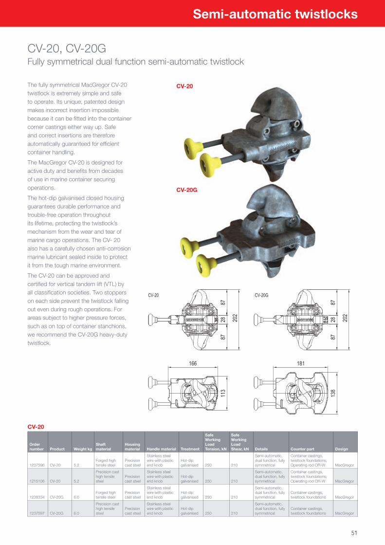
51
CV-20, CV-20GFully symmetrical dual function semi-automatic twistlock
The fully symmetrical MacGregor CV-20 twistlock is extremely simple and safe to operate. Its unique, patented design makes incorrect insertion impossible because it can be fitted into the container corner castings either way up. Safe and correct insertions are therefore automatically guaranteed for efficient container handling.
The MacGregor CV-20 is designed for active duty and benefits from decades of use in marine container securing operations.
The hot-dip galvanised closed housing guarantees durable performance and trouble-free operation throughout its lifetime, protecting the twistlock’s mechanism from the wear and tear of marine cargo operations. The CV- 20 also has a carefully chosen anti-corrosion marine lubricant sealed inside to protect it from the tough marine environment.
The CV-20 can be approved and certified for vertical tandem lift (VTL) by all classification societies. Two stoppers on each side prevent the twistlock falling out even during rough operations. For areas subject to higher pressure forces, such as on top of container stanchions, we recommend the CV-20G heavy-duty twistlock.
CV-20
Order number Product Weight kg
Shaft material
Housing material Handle material Treatment
Safe Working Load Tension, kN
Safe Working Load Shear, kN Details Counter part Design
1237596 CV-20 5.2Forged high tensile steel
Precision cast steel
Stainless steel wire with plastic end knob
Hot-dip galvanised 250 210
Semi-automatic, dual function, fully symmetrical
Container castings, twistlock foundations, Operating rod OR-W MacGregor
1215106 CV-20 5.2
Precision cast high tensile steel
Precision cast steel
Stainless steel wire with plastic end knob
Hot-dip galvanised 250 210
Semi-automatic, dual function, fully symmetrical
Container castings, twistlock foundations, Operating rod OR-W MacGregor
1238334 CV-20G 6.0Forged high tensile steel
Precision cast steel
Stainless steel wire with plastic end knob
Hot-dip galvanised 250 210
Semi-automatic, dual function, fully symmetrical
Container castings, twistlock foundations MacGregor
1237597 CV-20G 6.0
Precision cast high tensile steel
Precision cast steel
Stainless steel wire with plastic end knob
Hot-dip galvanised 250 210
Semi-automatic, dual function, fully symmetrical
Container castings, twistlock foundations MacGregor
Semi-automatic twistlocks
CV-20
CV-20G
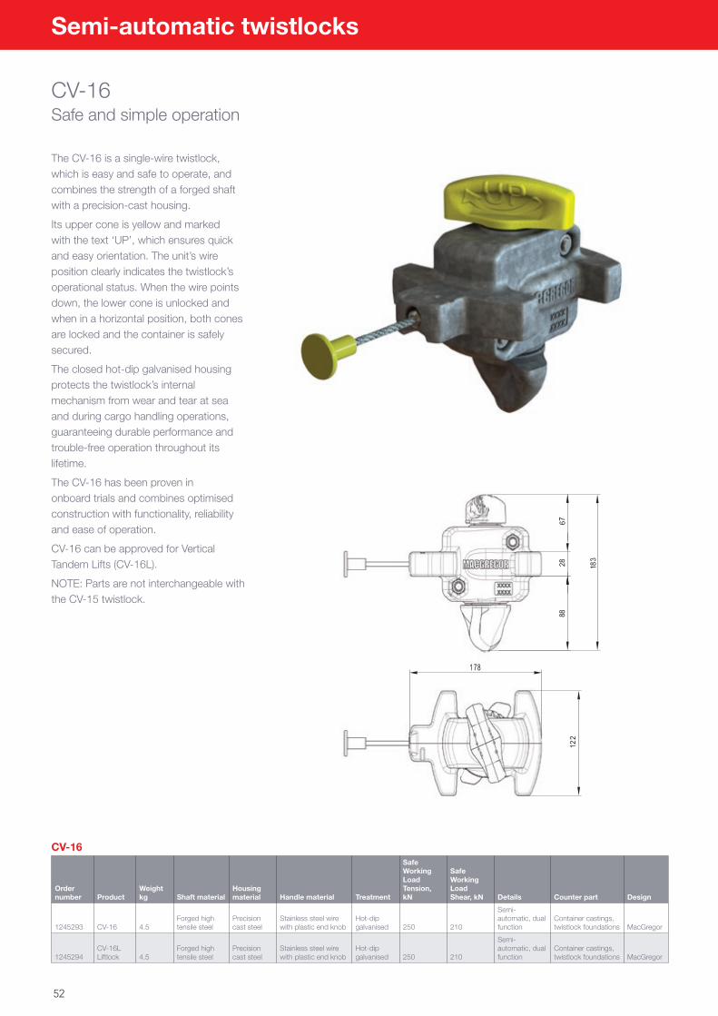
52
CV-16Safe and simple operation
CV-16
Order number Product
Weight kg Shaft material
Housing material Handle material Treatment
Safe Working Load Tension, kN
Safe Working Load Shear, kN Details Counter part Design
1245293 CV-16 4.5Forged high tensile steel
Precision cast steel
Stainless steel wire with plastic end knob
Hot-dip galvanised 250 210
Semi-automatic, dual function
Container castings, twistlock foundations MacGregor
1245294CV-16L Liftlock 4.5
Forged high tensile steel
Precision cast steel
Stainless steel wire with plastic end knob
Hot-dip galvanised 250 210
Semi-automatic, dual function
Container castings, twistlock foundations MacGregor
The CV-16 is a single-wire twistlock, which is easy and safe to operate, and combines the strength of a forged shaft with a precision-cast housing.
Its upper cone is yellow and marked with the text ‘UP’, which ensures quick and easy orientation. The unit’s wire position clearly indicates the twistlock’s operational status. When the wire points down, the lower cone is unlocked and when in a horizontal position, both cones are locked and the container is safely secured.
The closed hot-dip galvanised housing protects the twistlock’s internal mechanism from wear and tear at sea and during cargo handling operations, guaranteeing durable performance and trouble-free operation throughout its lifetime.
The CV-16 has been proven in onboard trials and combines optimised construction with functionality, reliability and ease of operation.
CV-16 can be approved for Vertical Tandem Lifts (CV-16L).
NOTE: Parts are not interchangeable with the CV-15 twistlock.
Semi-automatic twistlocks
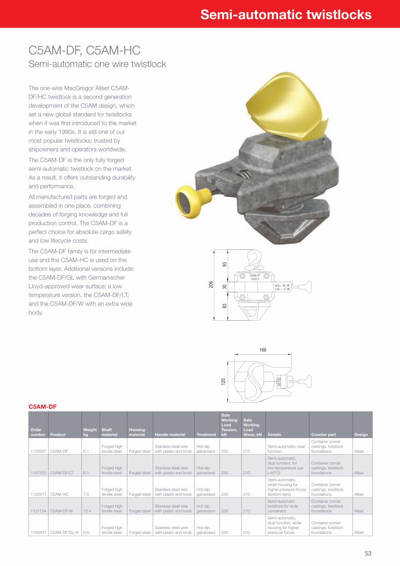
53
C5AM-DF, C5AM-HCSemi-automatic one wire twistlock
The one-wire MacGregor Allset C5AM-DF/HC twistlock is a second generation development of the C5AM design, which set a new global standard for twistlocks when it was first introduced to the market in the early 1990s. It is still one of our most popular twistlocks; trusted by shipowners and operators worldwide.
The C5AM-DF is the only fully forged semi-automatic twistlock on the market. As a result, it offers outstanding durability and performance.
All manufactured parts are forged and assembled in one place, combining decades of forging knowledge and full production control. The C5AM-DF is a perfect choice for absolute cargo safety and low lifecycle costs.
The C5AM-DF family is for intermediate use and the C5AM-HC is used on the bottom layer. Additional versions include: the C5AM-DF/GL with Germanischer Lloyd-approved wear surface; a low temperature version, the C5AM-DF/LT; and the C5AM-DF/W with an extra wide body.
C5AM-DF
Order number Product
Weight kg
Shaft material
Housing material Handle material Treatment
Safe Working Load Tension, kN
Safe Working Load Shear, kN Details Counter part Design
1120907 C5AM-DF 6.1Forged high tensile steel Forged steel
Stainless steel wire with plastic end knob
Hot-dip galvanised 250 210
Semi-automatic, dual function
Container corner castings, twistlock foundations Allset
1187322 C5AM-DF/LT 6.1Forged high tensile steel Forged steel
Stainless steel wire with plastic end knob
Hot-dip galvanised 250 210
Semi-automatic, dual function, for low temperature use (-40°C)
Container corner castings, twistlock foundations Allset
1120911 C5AM-HC 7.9Forged high tensile steel Forged steel
Stainless steel wire with plastic end knob
Hot-dip galvanised 250 210
Semi-automatic, wider housing for higher pressure forces (bottom tiers)
Container corner castings, twistlock foundations Allset
1131134 C5AM-DF/W 10.4Forged high tensile steel Forged steel
Stainless steel wire with plastic end knob
Hot-dip galvanised 250 210
Semi-automatic twistlock for wide containers
Container corner castings, twistlock foundations Allset
1193431 C5AM-DF/GL-N 6.8Forged high tensile steel Forged steel
Stainless steel wire with plastic end knob
Hot-dip galvanised 250 210
Semi-automatic, dual function, wider housing for higher pressure forces
Container corner castings, twistlock foundations Allset
Semi-automatic twistlocks
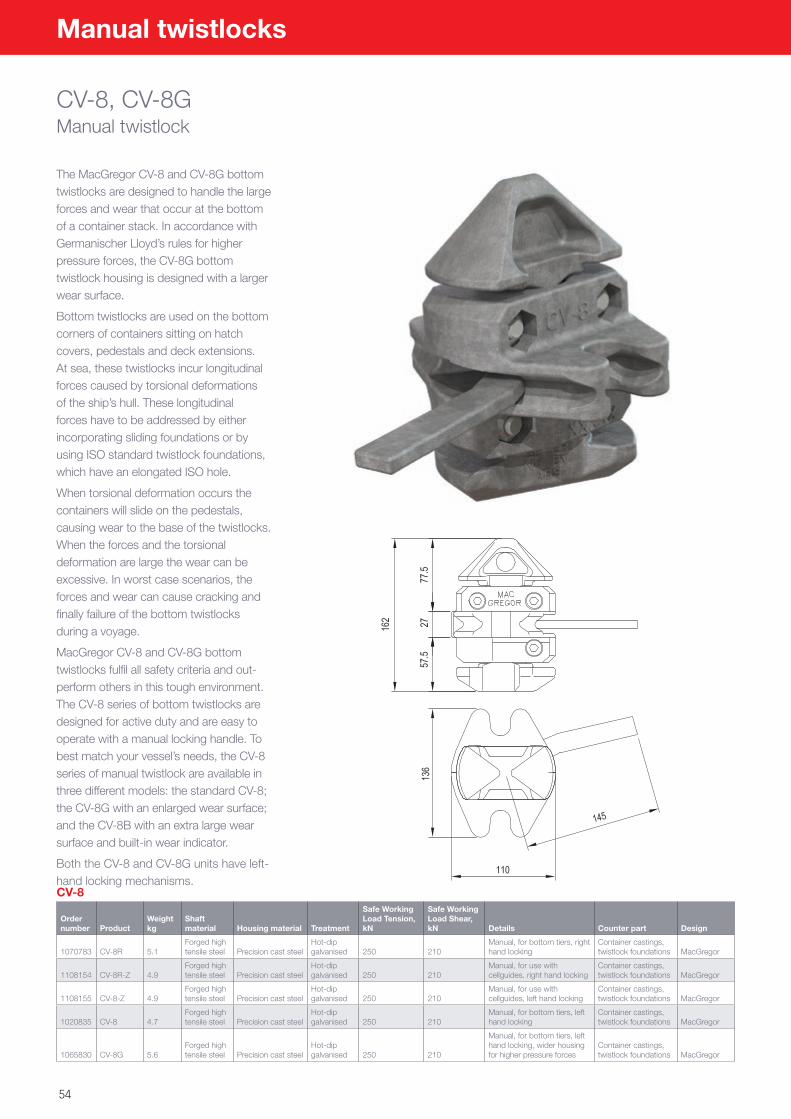
54
Manual twistlocks
CV-8, CV-8GManual twistlock
The MacGregor CV-8 and CV-8G bottom twistlocks are designed to handle the large forces and wear that occur at the bottom of a container stack. In accordance with Germanischer Lloyd’s rules for higher pressure forces, the CV-8G bottom twistlock housing is designed with a larger wear surface.
Bottom twistlocks are used on the bottom corners of containers sitting on hatch covers, pedestals and deck extensions. At sea, these twistlocks incur longitudinal forces caused by torsional deformations of the ship’s hull. These longitudinal forces have to be addressed by either incorporating sliding foundations or by using ISO standard twistlock foundations, which have an elongated ISO hole.
When torsional deformation occurs the containers will slide on the pedestals, causing wear to the base of the twistlocks. When the forces and the torsional deformation are large the wear can be excessive. In worst case scenarios, the forces and wear can cause cracking and finally failure of the bottom twistlocks during a voyage.
MacGregor CV-8 and CV-8G bottom twistlocks fulfil all safety criteria and out-perform others in this tough environment. The CV-8 series of bottom twistlocks are designed for active duty and are easy to operate with a manual locking handle. To best match your vessel’s needs, the CV-8 series of manual twistlock are available in three different models: the standard CV-8; the CV-8G with an enlarged wear surface; and the CV-8B with an extra large wear surface and built-in wear indicator.
Both the CV-8 and CV-8G units have left-hand locking mechanisms.CV-8
Order number Product
Weight kg
Shaft material Housing material Treatment
Safe Working Load Tension, kN
Safe Working Load Shear, kN Details Counter part Design
1070783 CV-8R 5.1Forged high tensile steel Precision cast steel
Hot-dip galvanised 250 210
Manual, for bottom tiers, right hand locking
Container castings, twistlock foundations MacGregor
1108154 CV-8R-Z 4.9Forged high tensile steel Precision cast steel
Hot-dip galvanised 250 210
Manual, for use with cellguides, right hand locking
Container castings, twistlock foundations MacGregor
1108155 CV-8-Z 4.9Forged high tensile steel Precision cast steel
Hot-dip galvanised 250 210
Manual, for use with cellguides, left hand locking
Container castings, twistlock foundations MacGregor
1020835 CV-8 4.7Forged high tensile steel Precision cast steel
Hot-dip galvanised 250 210
Manual, for bottom tiers, left hand locking
Container castings, twistlock foundations MacGregor
1065830 CV-8G 5.6Forged high tensile steel Precision cast steel
Hot-dip galvanised 250 210
Manual, for bottom tiers, left hand locking, wider housing for higher pressure forces
Container castings, twistlock foundations MacGregor
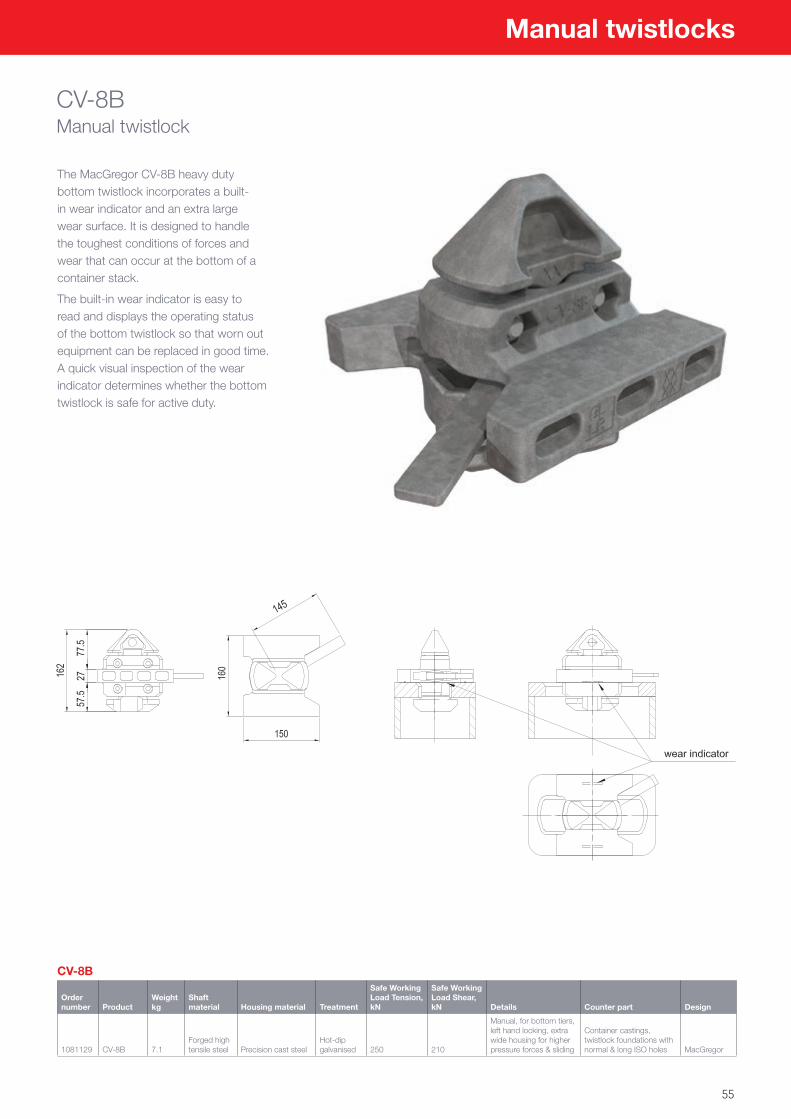
55
Manual twistlocks
CV-8BManual twistlock
The MacGregor CV-8B heavy duty bottom twistlock incorporates a built-in wear indicator and an extra large wear surface. It is designed to handle the toughest conditions of forces and wear that can occur at the bottom of a container stack.
The built-in wear indicator is easy to read and displays the operating status of the bottom twistlock so that worn out equipment can be replaced in good time. A quick visual inspection of the wear indicator determines whether the bottom twistlock is safe for active duty.
CV-8B
Order number Product
Weight kg
Shaft material Housing material Treatment
Safe Working Load Tension, kN
Safe Working Load Shear, kN Details Counter part Design
1081129 CV-8B 7.1Forged high tensile steel Precision cast steel
Hot-dip galvanised 250 210
Manual, for bottom tiers, left hand locking, extra wide housing for higher pressure forces & sliding
Container castings, twistlock foundations with normal & long ISO holes MacGregor
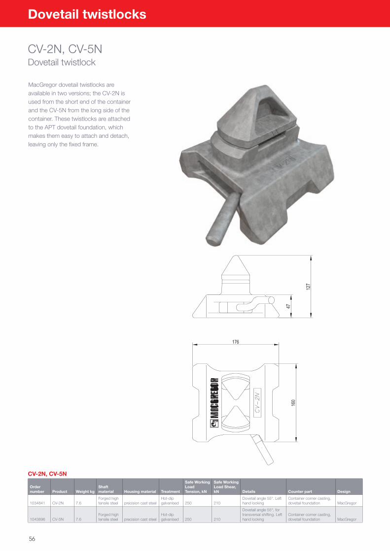
56
Dovetail twistlocks
CV-2N, CV-5NDovetail twistlock
MacGregor dovetail twistlocks are available in two versions; the CV-2N is used from the short end of the container and the CV-5N from the long side of the container. These twistlocks are attached to the APT dovetail foundation, which makes them easy to attach and detach, leaving only the fixed frame.
CV-2N, CV-5N
Order number Product Weight kg
Shaft material Housing material Treatment
Safe Working Load Tension, kN
Safe Working Load Shear, kN Details Counter part Design
1034841 CV-2N 7.6Forged high tensile steel precision cast steel
Hot-dip galvanised 250 210
Dovetail angle 55°. Left hand locking
Container corner casting, dovetail foundation MacGregor
1043896 CV-5N 7.6Forged high tensile steel precision cast steel
Hot-dip galvanised 250 210
Dovetail angle 55°, for transversal shifting. Left hand locking
Container corner casting, dovetail foundation MacGregor
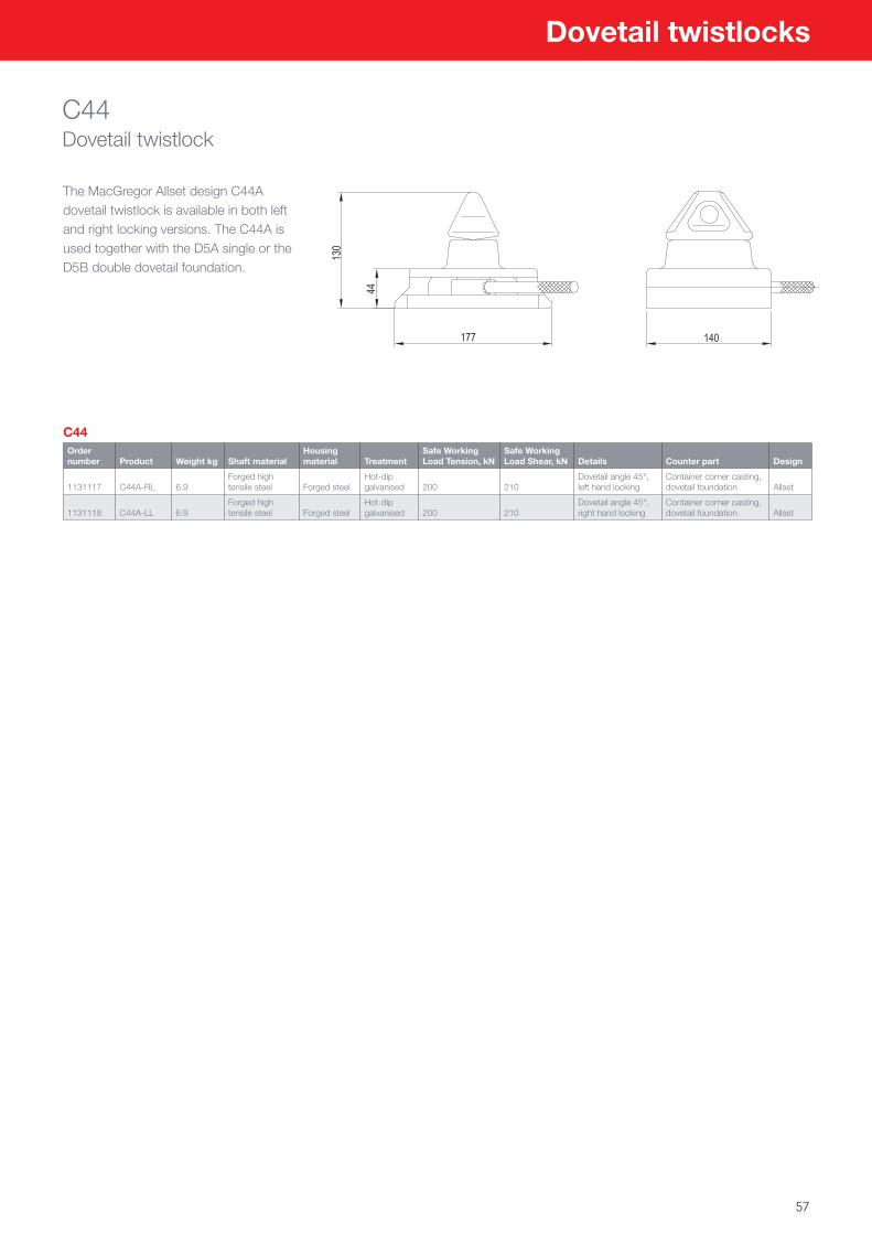
57
Dovetail twistlocks
C44Dovetail twistlock
The MacGregor Allset design C44A dovetail twistlock is available in both left and right locking versions. The C44A is used together with the D5A single or the D5B double dovetail foundation.
C44Order number Product Weight kg Shaft material
Housing material Treatment
Safe Working Load Tension, kN
Safe Working Load Shear, kN Details Counter part Design
1131117 C44A-RL 6.9Forged high tensile steel Forged steel
Hot-dip galvanised 200 210
Dovetail angle 45°, left hand locking
Container corner casting, dovetail foundation Allset
1131118 C44A-LL 6.9Forged high tensile steel Forged steel
Hot-dip galvanised 200 210
Dovetail angle 45°, right hand locking
Container corner casting, dovetail foundation Allset
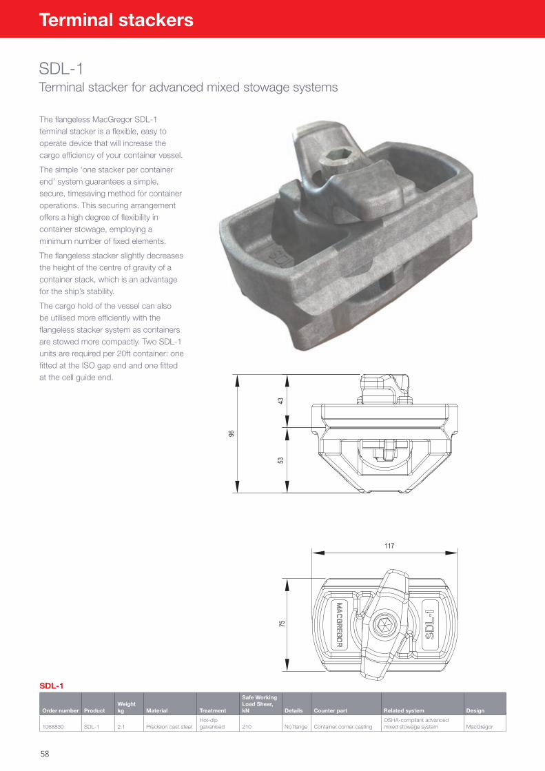
58
Terminal stackers
SDL-1Terminal stacker for advanced mixed stowage systems
The flangeless MacGregor SDL-1 terminal stacker is a flexible, easy to operate device that will increase the cargo efficiency of your container vessel.
The simple ‘one stacker per container end’ system guarantees a simple, secure, timesaving method for container operations. This securing arrangement offers a high degree of flexibility in container stowage, employing a minimum number of fixed elements.
The flangeless stacker slightly decreases the height of the centre of gravity of a container stack, which is an advantage for the ship’s stability.
The cargo hold of the vessel can also be utilised more efficiently with the flangeless stacker system as containers are stowed more compactly. Two SDL-1 units are required per 20ft container: one fitted at the ISO gap end and one fitted at the cell guide end.
SDL-1
Order number ProductWeight kg Material Treatment
Safe Working Load Shear, kN Details Counter part Related system Design
1068830 SDL-1 2.1 Precision cast steelHot-dip galvanised 210 No flange Container corner casting
OSHA-compliant advanced mixed stowage system MacGregor
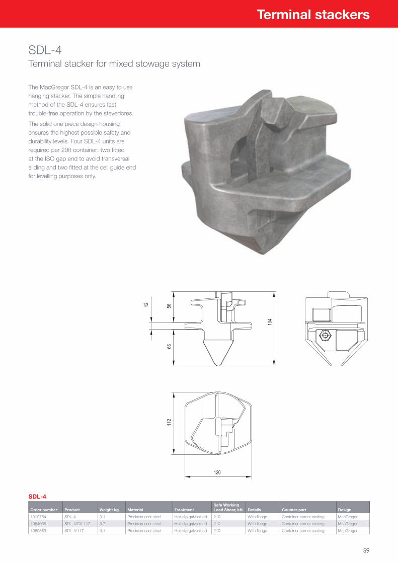
59
Terminal stackers
SDL-4Terminal stacker for mixed stowage system
The MacGregor SDL-4 is an easy to use hanging stacker. The simple handling method of the SDL-4 ensures fast trouble-free operation by the stevedores.
The solid one piece design housing ensures the highest possible safety and durability levels. Four SDL-4 units are required per 20ft container: two fitted at the ISO gap end to avoid transversal sliding and two fitted at the cell guide end for levelling purposes only.
SDL-4
Order number Product Weight kg Material TreatmentSafe Working Load Shear, kN Details Counter part Design
1019754 SDL-4 3.1 Precision cast steel Hot-dip galvanised 210 With flange Container corner casting MacGregor
1064036 SDL-4/CV-117 3.7 Precision cast steel Hot-dip galvanised 210 With flange Container corner casting MacGregor
1080889 SDL-4/117 3.1 Precision cast steel Hot-dip galvanised 210 With flange Container corner casting MacGregor

60
C12CHanging stacker
The MacGregor Allset C12C is a fully forged hanging stacker. The fully forged design offers the highest durability and low lifecycle costs. It is easy to use and handle and is designed for active duty in tough marine conditions, all to ensure fast trouble-free operation by the stevedores.
Four C12C units are required per 20ft container: two fitted at the ISO gap end to avoid transversal sliding and two fitted at the cell guide end for levelling purposes only.
C12C
Order number Product Weight kg Material TreatmentSafe Working Load Shear, kN Details Counter part Design
1120850 C12C 3.4 Forged steel Hot-dip galvanised 210 With flange Container corner casting Allset
Terminal stackers
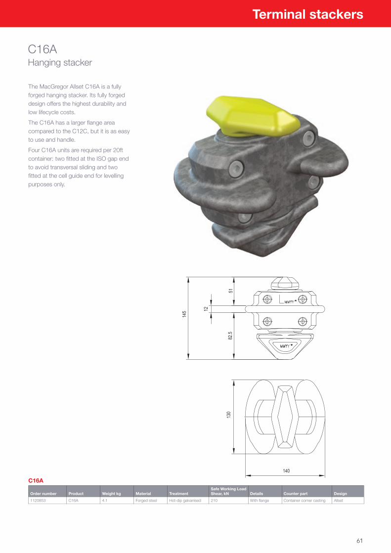
61
Terminal stackers
C16AHanging stacker
The MacGregor Allset C16A is a fully forged hanging stacker. Its fully forged design offers the highest durability and low lifecycle costs.
The C16A has a larger flange area compared to the C12C, but it is as easy to use and handle.
Four C16A units are required per 20ft container: two fitted at the ISO gap end to avoid transversal sliding and two fitted at the cell guide end for levelling purposes only.
C16A
Order number Product Weight kg Material TreatmentSafe Working Load Shear, kN Details Counter part Design
1120853 C16A 4.1 Forged steel Hot-dip galvanised 210 With flange Container corner casting Allset
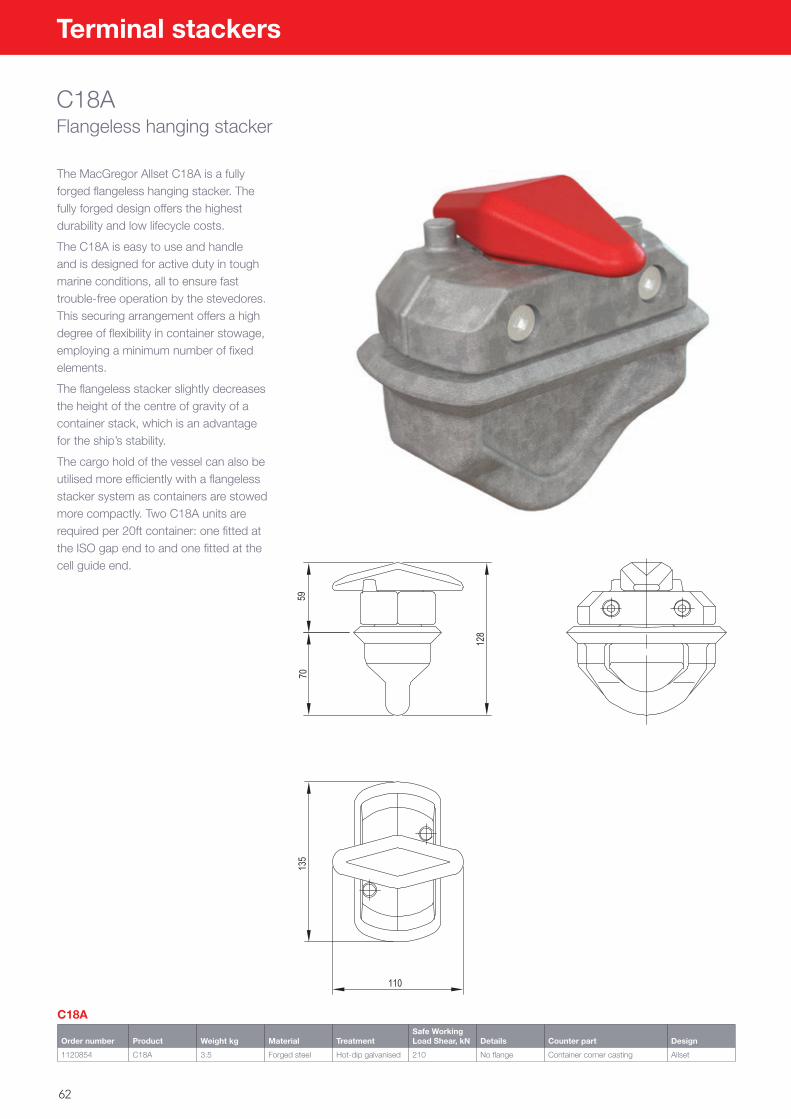
62
Terminal stackers
C18AFlangeless hanging stacker
The MacGregor Allset C18A is a fully forged flangeless hanging stacker. The fully forged design offers the highest durability and low lifecycle costs.
The C18A is easy to use and handle and is designed for active duty in tough marine conditions, all to ensure fast trouble-free operation by the stevedores. This securing arrangement offers a high degree of flexibility in container stowage, employing a minimum number of fixed elements.
The flangeless stacker slightly decreases the height of the centre of gravity of a container stack, which is an advantage for the ship’s stability.
The cargo hold of the vessel can also be utilised more efficiently with a flangeless stacker system as containers are stowed more compactly. Two C18A units are required per 20ft container: one fitted at the ISO gap end to and one fitted at the cell guide end.
C18A
Order number Product Weight kg Material TreatmentSafe Working Load Shear, kN Details Counter part Design
1120854 C18A 3.5 Forged steel Hot-dip galvanised 210 No flange Container corner casting Allset
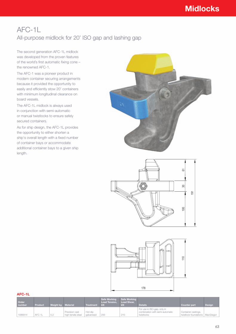
63
Midlocks
AFC-1LAll-purpose midlock for 20’ ISO gap and lashing gap
The second generation AFC-1L midlock was developed from the proven features of the world’s first automatic fixing cone – the renowned AFC-1.
The AFC-1 was a pioneer product in modern container securing arrangements because it provided the opportunity to easily and efficiently stow 20’ containers with minimum longitudinal clearance on board vessels.
The AFC-1L midlock is always used in conjunction with semi-automatic or manual twistlocks to ensure safely secured containers.
As for ship design, the AFC-1L provides the opportunity to either shorten a ship‘s overall length with a fixed number of container bays or accommodate additional container bays to a given ship length.
AFC-1L
Order number Product Weight kg Material Treatment
Safe Working Load Tension, kN
Safe Working Load Shear, kN Details Counter part Design
1086914 AFC-1L 5.2Precision cast high tensile steel
Hot-dip galvanised 250 210
For use in ISO-gap, only in combination with semi-automatic twistlocks
Container castings, twistlock foundations MacGregor
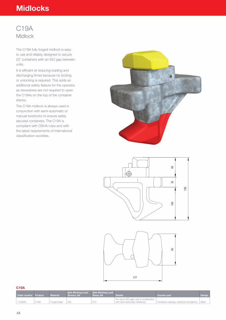
64
Midlocks
C19AMidlock
The C19A fully forged midlock is easy to use and reliably designed to secure 20’ containers with an ISO gap between units.
It is efficient at reducing loading and discharging times because no locking or unlocking is required. This adds an additional safety feature for the operator, as stevedores are not required to open the C19As on the top of the container stacks.
The C19A midlock is always used in conjunction with semi-automatic or manual twistlocks to ensure safely secured containers. The C19A is compliant with OSHA rules and with the latest requirements of international classification societies.
C19A
Order number Product MaterialSafe Working Load Tension, kN
Safe Working Load Shear, kN Details Counter part Design
1120845 C19A Forged steel 250 210For use in ISO-gap, only in combination with semi-automatic twistlocks Container castings, twistlock foundations Allset
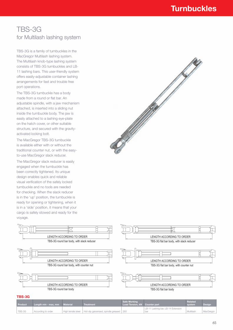
65
Turnbuckles
TBS-3Gfor Multilash lashing system
TBS-3G is a family of turnbuckles in the MacGregor Multilash lashing system. The Multilash knob-type lashing system consists of TBS-3G turnbuckles and LB-11 lashing bars. This user-friendly system offers easily-adjustable container lashing arrangements for fast and trouble free port operations.
The TBS-3G turnbuckle has a body made from a round or flat bar. An adjustable spindle, with a jaw mechanism attached, is inserted into a sliding nut inside the turnbuckle body. The jaw is easily attached to a lashing eye-plate on the hatch cover, or other suitable structure, and secured with the gravity-activated locking bolt.
The MacGregor TBS-3G turnbuckle is available either with or without the traditional counter nut, or with the easy-to-use MacGregor slack reducer.
The MacGregor slack reducer is easily engaged when the turnbuckle has been correctly tightened. Its unique design enables quick and reliable visual verification of the safely locked turnbuckle and no tools are needed for checking. When the slack reducer is in the ‘up’ position, the turnbuckle is ready for opening or tightening, when it is in a ‘side’ position, it means that your cargo is safely stowed and ready for the voyage.
TBS-3G
Product Length min - max, mm Material TreatmentSafe Working Load Tension, kN Counter part
Related system Design
TBS-3G According to order High tensile steel Hot-dip galvanised, spindle greased 250LB-11 Lashing bar, LB-14 Extension bar Multilash MacGregor
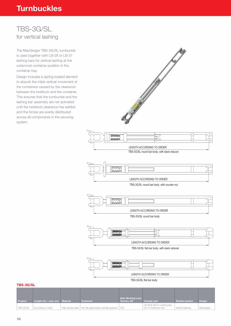
66
Turnbuckles
TBS-3G/SLfor vertical lashing
The MacGregor TBS-3G/SL turnbuckle is used together with LB-28 or LB-31 lashing bars for vertical lashing at the outermost container position in the container bay.
Design includes a spring-loaded element to absorb the initial vertical movement of the containers caused by the clearance between the twistlock and the container. This ensures that the turnbuckle and the lashing bar assembly are not activated until the twistlock clearance has settled and the forces are evenly distributed across all components in the securing system.
TBS-3G/SL
Product Length min - max, mm Material TreatmentSafe Working Load Tension, kN Counter part Related system Design
TBS-3G/SL According to order High tensile steel Hot-dip galvanised, spindle greased 250LB-28 & LB-31 Lashing bar, LB-14 Extension bar Vertical lashing MacGregor
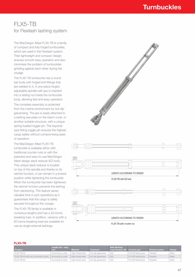
67
Turnbuckles
FLX5-TB for Flexilash lashing system
The MacGregor Allset FLX5-TB is a family of compact and fully forged turnbuckles, which are used in the Flexilash system. Their lightweight and compact design ensures smooth easy operation and also minimises the problem of turnbuckles grinding against each other during the voyage.
The FLX5-TB turnbuckle has a round bar body with forged end fittings that are welded to it. A one-piece forged adjustable spindle with jaw is inserted into a sliding nut inside the turnbuckle body, allowing fast and easy operation.
The complete assembly is protected from the marine environment by hot-dip galvanising. The jaw is easily attached to a lashing eye-plate on the hatch cover, or another suitable structure, with a unique spring-loaded toggle pin. The bayonet-type fitting toggle pin ensures the highest cargo safety without compromising ease of operation.
The MacGregor Allset FLX5-TB turnbuckle is available either with traditional counter nuts or with the patented and easy-to-use MacGregor Allset design slack reducer (EZ-lock). This unique slack reducer is located on top of the spindle and thanks to its ratchet function, it can remain in a locked position while tightening the turnbuckle. When the turnbuckle has been tightened, the ratchet function prevents the lashing from slackening. This feature saves valuable time in port operations as it guarantees that the cargo is safely secured throughout the voyage.
The FLX5-TB family is available in numerous lengths and has a 50-tonne breaking load. In addition, versions with a 60-tonne breaking load are available for use as single external lashings.
FLX5-TB
ProductLength min - max, mm Material Treatment
Safe Working Load Tension, kN Counter part Related system Design
FLX5-TB-50 According to order High tensile steel Hot-dip galvanised 250 FLX-RD lashing bar Flexilash Allset
FLX5-TB-50 with two connection points According to order High tensile steel Hot-dip galvanised 250 FLX-RD lashing bar Flexilash Allset
FLX5-TB-60 According to order High tensile steel Hot-dip galvanised 300 FLX-RD lashing bar Flexilash Allset
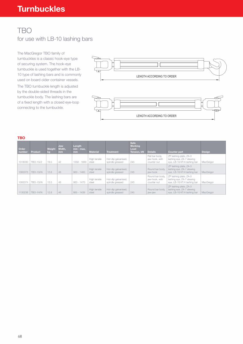
68
Turnbuckles
TBOfor use with LB-10 lashing bars
The MacGregor TBO family of turnbuckles is a classic hook-eye type of securing system. The hook-eye turnbuckle is used together with the LB-10 type of lashing bars and is commonly used on board older container vessels.
The TBO turnbuckle length is adjusted by the double-sided threads in the turnbuckle body. The lashing bars are of a fixed length with a closed eye-loop connecting to the turnbuckle.
TBO
Order number Product
Weight kg
Jaw Width, mm
Length min - max, mm Material Treatment
Safe Working Load Tension, kN Details Counter part Design
1018030 TBO-1G/2 19.5 42 1058 - 1660High tensile steel
Hot-dip galvanised, spindle greased 245
Flat bar body, jaw-hook, with counter nut
ZP lashing plate, ZA-3 lashing eye, ZA-7 slewing eye, LB-10/4T/4 lashing bar MacGregor
1065373 TBO-1G/N 12.6 46 900 - 1460High tensile steel
Hot-dip galvanised, spindle greased 245
Round bar body, jaw-hook
ZP lashing plate, ZA-3 lashing eye, ZA-7 slewing eye, LB-10/4T/4 lashing bar MacGregor
1065374 TBO-1G/N 13.5 46 900 - 1470High tensile steel
Hot-dip galvanised, spindle greased 245
Round bar body, jaw-hook, with counter nut
ZP lashing plate, ZA-3 lashing eye, ZA-7 slewing eye, LB-10/4T/4 lashing bar MacGregor
1130238 TBO-1H/N 12.8 46 865 - 1439High tensile steel
Hot-dip galvanised, spindle greased 245
Round bar body, jaw-jaw
ZP lashing plate, ZA-3 lashing eye, ZA-7 slewing eye, LB-10/4T/4 lashing bar MacGregor
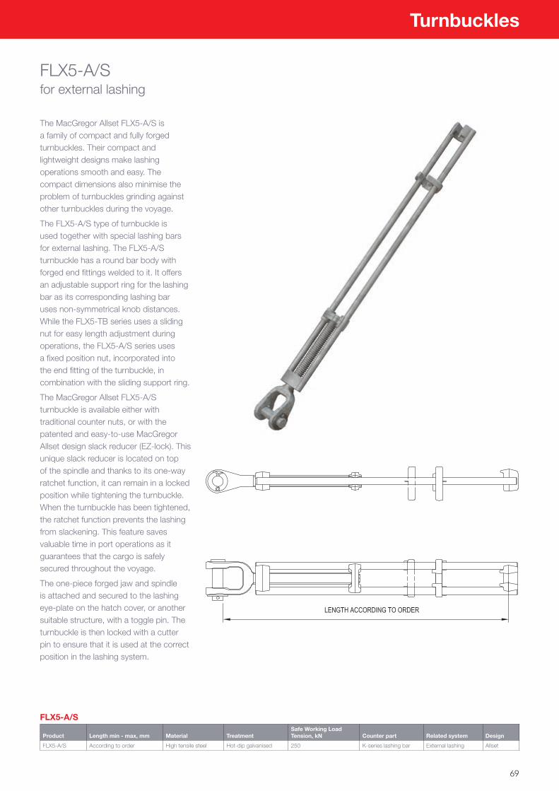
69
Turnbuckles
FLX5-A/Sfor external lashing
The MacGregor Allset FLX5-A/S is a family of compact and fully forged turnbuckles. Their compact and lightweight designs make lashing operations smooth and easy. The compact dimensions also minimise the problem of turnbuckles grinding against other turnbuckles during the voyage.
The FLX5-A/S type of turnbuckle is used together with special lashing bars for external lashing. The FLX5-A/S turnbuckle has a round bar body with forged end fittings welded to it. It offers an adjustable support ring for the lashing bar as its corresponding lashing bar uses non-symmetrical knob distances. While the FLX5-TB series uses a sliding nut for easy length adjustment during operations, the FLX5-A/S series uses a fixed position nut, incorporated into the end fitting of the turnbuckle, in combination with the sliding support ring.
The MacGregor Allset FLX5-A/S turnbuckle is available either with traditional counter nuts, or with the patented and easy-to-use MacGregor Allset design slack reducer (EZ-lock). This unique slack reducer is located on top of the spindle and thanks to its one-way ratchet function, it can remain in a locked position while tightening the turnbuckle. When the turnbuckle has been tightened, the ratchet function prevents the lashing from slackening. This feature saves valuable time in port operations as it guarantees that the cargo is safely secured throughout the voyage.
The one-piece forged jaw and spindle is attached and secured to the lashing eye-plate on the hatch cover, or another suitable structure, with a toggle pin. The turnbuckle is then locked with a cutter pin to ensure that it is used at the correct position in the lashing system.
FLX5-A/S
Product Length min - max, mm Material TreatmentSafe Working Load Tension, kN Counter part Related system Design
FLX5-A/S According to order High tensile steel Hot-dip galvanised 250 K-series lashing bar External lashing Allset
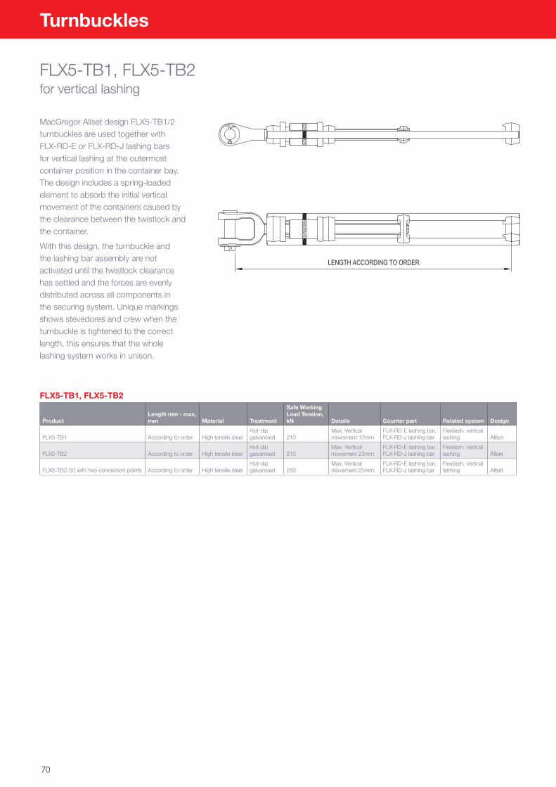
70
Turnbuckles
FLX5-TB1, FLX5-TB2for vertical lashing
MacGregor Allset design FLX5-TB1/2 turnbuckles are used together with FLX-RD-E or FLX-RD-J lashing bars for vertical lashing at the outermost container position in the container bay. The design includes a spring-loaded element to absorb the initial vertical movement of the containers caused by the clearance between the twistlock and the container.
With this design, the turnbuckle and the lashing bar assembly are not activated until the twistlock clearance has settled and the forces are evenly distributed across all components in the securing system. Unique markings shows stevedores and crew when the turnbuckle is tightened to the correct length, this ensures that the whole lashing system works in unison.
FLX5-TB1, FLX5-TB2
ProductLength min - max, mm Material Treatment
Safe Working Load Tension, kN Details Counter part Related system Design
FLX5-TB1 According to order High tensile steelHot-dip galvanised 210
Max. Vertical movement 13mm
FLX-RD-E lashing bar, FLX-RD-J lashing bar
Flexilash, vertical lashing Allset
FLX5-TB2 According to order High tensile steelHot-dip galvanised 210
Max. Vertical movement 23mm
FLX-RD-E lashing bar, FLX-RD-J lashing bar
Flexilash, vertical lashing Allset
FLX5-TB2-50 with two connection points According to order High tensile steelHot-dip galvanised 250
Max. Vertical movement 23mm
FLX-RD-E lashing bar, FLX-RD-J lashing bar
Flexilash, vertical lashing Allset
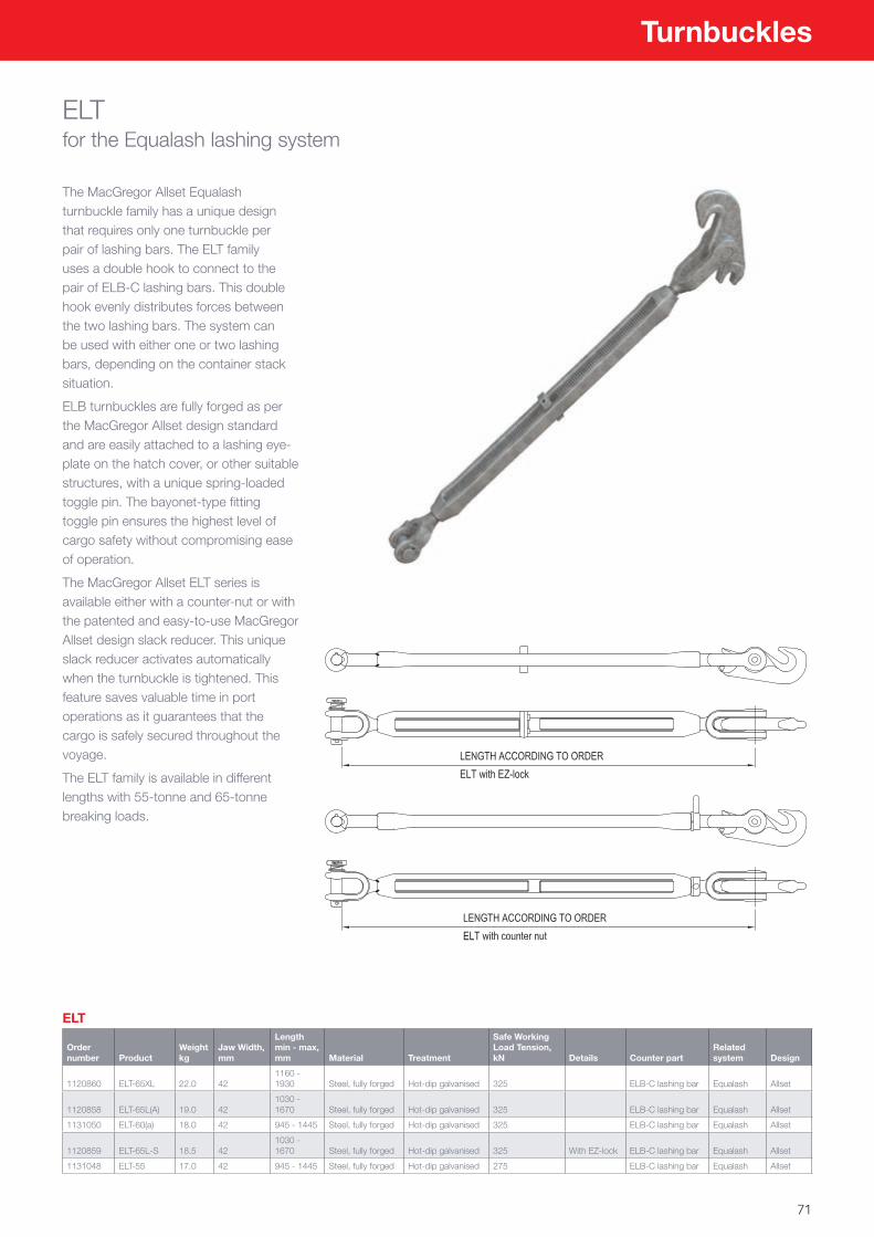
71
Turnbuckles
ELTfor the Equalash lashing system
The MacGregor Allset Equalash turnbuckle family has a unique design that requires only one turnbuckle per pair of lashing bars. The ELT family uses a double hook to connect to the pair of ELB-C lashing bars. This double hook evenly distributes forces between the two lashing bars. The system can be used with either one or two lashing bars, depending on the container stack situation.
ELB turnbuckles are fully forged as per the MacGregor Allset design standard and are easily attached to a lashing eye-plate on the hatch cover, or other suitable structures, with a unique spring-loaded toggle pin. The bayonet-type fitting toggle pin ensures the highest level of cargo safety without compromising ease of operation.
The MacGregor Allset ELT series is available either with a counter-nut or with the patented and easy-to-use MacGregor Allset design slack reducer. This unique slack reducer activates automatically when the turnbuckle is tightened. This feature saves valuable time in port operations as it guarantees that the cargo is safely secured throughout the voyage.
The ELT family is available in different lengths with 55-tonne and 65-tonne breaking loads.
ELT
Order number Product
Weight kg
Jaw Width, mm
Length min - max, mm Material Treatment
Safe Working Load Tension, kN Details Counter part
Related system Design
1120860 ELT-65XL 22.0 421160 - 1930 Steel, fully forged Hot-dip galvanised 325 ELB-C lashing bar Equalash Allset
1120858 ELT-65L(A) 19.0 421030 - 1670 Steel, fully forged Hot-dip galvanised 325 ELB-C lashing bar Equalash Allset
1131050 ELT-60(a) 18.0 42 945 - 1445 Steel, fully forged Hot-dip galvanised 325 ELB-C lashing bar Equalash Allset
1120859 ELT-65L-S 18.5 421030 - 1670 Steel, fully forged Hot-dip galvanised 325 With EZ-lock ELB-C lashing bar Equalash Allset
1131048 ELT-55 17.0 42 945 - 1445 Steel, fully forged Hot-dip galvanised 275 ELB-C lashing bar Equalash Allset
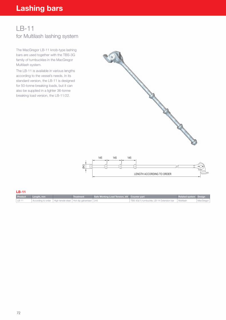
72
Lashing bars
LB-11for Multilash lashing system
The MacGregor LB-11 knob-type lashing bars are used together with the TBS-3G family of turnbuckles in the MacGregor Multilash system.
The LB-11 is available in various lengths according to the vessel’s needs. In its standard version, the LB-11 is designed for 50-tonne breaking loads, but it can also be supplied in a lighter 36-tonne breaking load version, the LB-11/22.
LB-11Product Length, mm Treatment Safe Working Load Tension, kN Counter part Related system Design
LB-11 According to order High tensile steel Hot-dip galvanised 245 TBS 3G(/1) turnbuckle, LB-14 Extension bar Multilash MacGregor
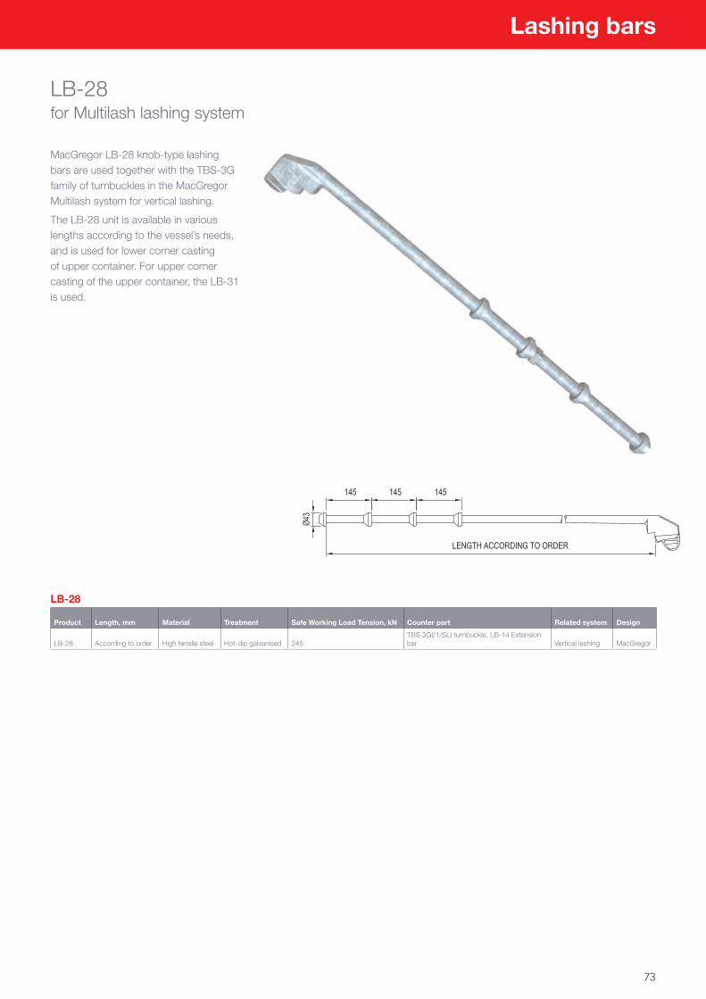
73
Lashing bars
LB-28for Multilash lashing system
MacGregor LB-28 knob-type lashing bars are used together with the TBS-3G family of turnbuckles in the MacGregor Multilash system for vertical lashing.
The LB-28 unit is available in various lengths according to the vessel’s needs, and is used for lower corner casting of upper container. For upper corner casting of the upper container, the LB-31 is used.
LB-28
Product Length, mm Material Treatment Safe Working Load Tension, kN Counter part Related system Design
LB-28 According to order High tensile steel Hot-dip galvanised 245TBS 3G(/1/SL) turnbuckle, LB-14 Extension bar Vertical lashing MacGregor
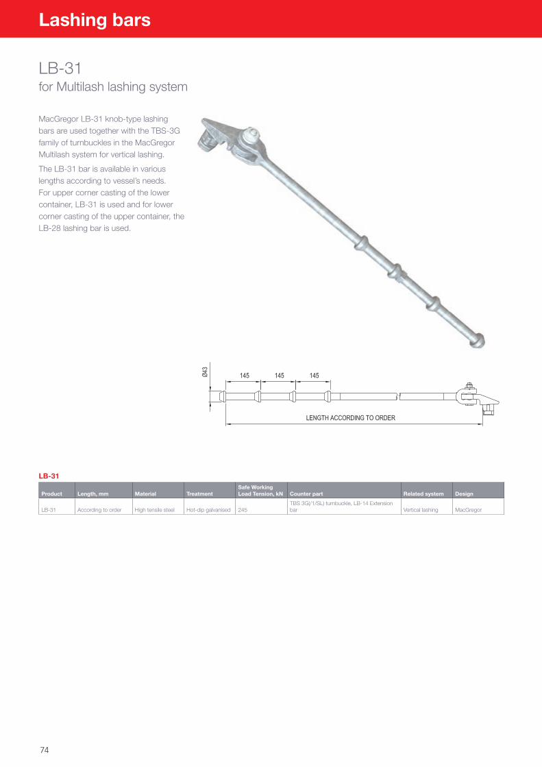
74
Lashing bars
LB-31for Multilash lashing system
MacGregor LB-31 knob-type lashing bars are used together with the TBS-3G family of turnbuckles in the MacGregor Multilash system for vertical lashing.
The LB-31 bar is available in various lengths according to vessel’s needs. For upper corner casting of the lower container, LB-31 is used and for lower corner casting of the upper container, the LB-28 lashing bar is used.
LB-31
Product Length, mm Material TreatmentSafe Working Load Tension, kN Counter part Related system Design
LB-31 According to order High tensile steel Hot-dip galvanised 245TBS 3G(/1/SL) turnbuckle, LB-14 Extension bar Vertical lashing MacGregor
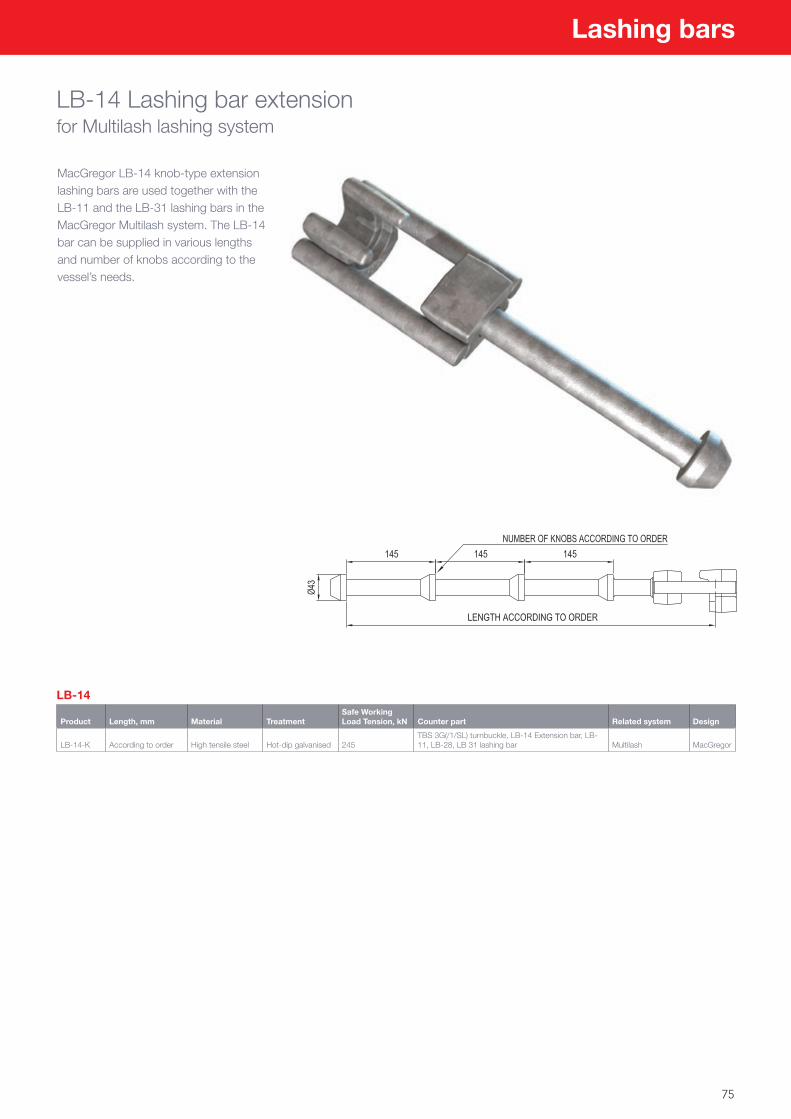
75
Lashing bars
LB-14 Lashing bar extensionfor Multilash lashing system
MacGregor LB-14 knob-type extension lashing bars are used together with the LB-11 and the LB-31 lashing bars in the MacGregor Multilash system. The LB-14 bar can be supplied in various lengths and number of knobs according to the vessel’s needs.
LB-14
Product Length, mm Material TreatmentSafe Working Load Tension, kN Counter part Related system Design
LB-14-K According to order High tensile steel Hot-dip galvanised 245TBS 3G(/1/SL) turnbuckle, LB-14 Extension bar, LB-11, LB-28, LB 31 lashing bar Multilash MacGregor
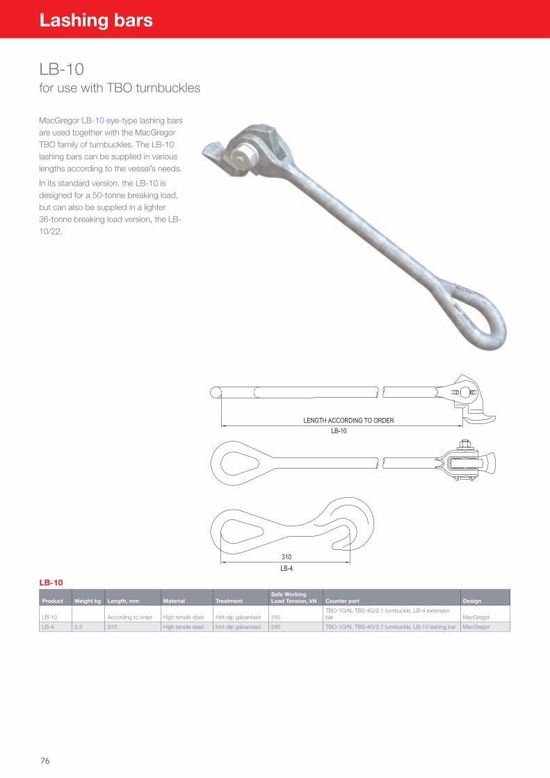
76
Lashing bars
LB-10for use with TBO turnbuckles
MacGregor LB-10 eye-type lashing bars are used together with the MacGregor TBO family of turnbuckles. The LB-10 lashing bars can be supplied in various lengths according to the vessel’s needs.
In its standard version, the LB-10 is designed for a 50-tonne breaking load, but can also be supplied in a lighter 36-tonne breaking load version, the LB-10/22.
LB-10
Product Weight kg Length, mm Material TreatmentSafe Working Load Tension, kN Counter part Design
LB-10 According to order High tensile steel Hot-dip galvanised 245TBO-1G/N, TBS-4G/2.1 turnbuckle, LB-4 extension bar MacGregor
LB-4 3.3 310 High tensile steel Hot-dip galvanised 245 TBO-1G/N, TBS-4G/2.1 turnbuckle, LB-10 lashing bar MacGregor
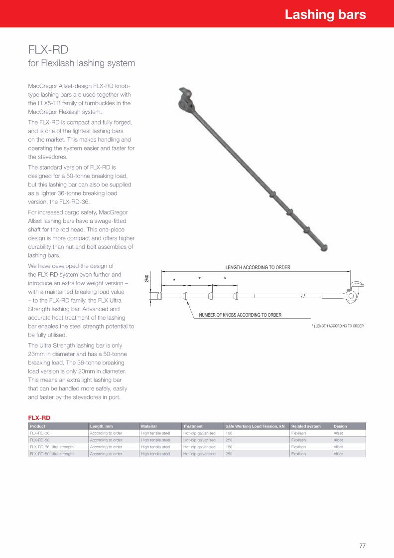
77
Lashing bars
FLX-RDfor Flexilash lashing system
MacGregor Allset-design FLX-RD knob-type lashing bars are used together with the FLX5-TB family of turnbuckles in the MacGregor Flexilash system.
The FLX-RD is compact and fully forged, and is one of the lightest lashing bars on the market. This makes handling and operating the system easier and faster for the stevedores.
The standard version of FLX-RD is designed for a 50-tonne breaking load, but this lashing bar can also be supplied as a lighter 36-tonne breaking load version, the FLX-RD-36.
For increased cargo safety, MacGregor Allset lashing bars have a swage-fitted shaft for the rod head. This one-piece design is more compact and offers higher durability than nut and bolt assemblies of lashing bars.
We have developed the design of the FLX-RD system even further and introduce an extra low weight version – with a maintained breaking load value – to the FLX-RD family, the FLX Ultra Strength lashing bar. Advanced and accurate heat treatment of the lashing bar enables the steel strength potential to be fully utilised.
The Ultra Strength lashing bar is only 23mm in diameter and has a 50-tonne breaking load. The 36-tonne breaking load version is only 20mm in diameter. This means an extra light lashing bar that can be handled more safely, easily and faster by the stevedores in port.
FLX-RDProduct Length, mm Material Treatment Safe Working Load Tension, kN Related system Design
FLX-RD-36 According to order High tensile steel Hot-dip galvanised 180 Flexilash Allset
FLX-RD-50 According to order High tensile steel Hot-dip galvanised 250 Flexilash Allset
FLX-RD-36 Ultra strength According to order High tensile steel Hot-dip galvanised 180 Flexilash Allset
FLX-RD-50 Ultra strength According to order High tensile steel Hot-dip galvanised 250 Flexilash Allset
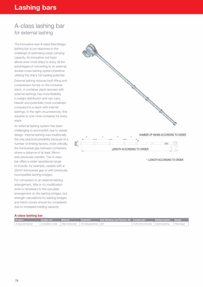
78
Lashing bars
A-class lashing barfor external lashing
The innovative new A-class MacGregor lashing bar is our response to the challenge of optimising cargo carrying capacity. Its innovative rod head allows even more ships to enjoy all the advantages of converting to an external double-cross lashing system,therefore utilising the ship’s full loading potential.
External lashing reduces both lifting and compression forces on the container stack. A container stack secured with external lashings has more flexibility in weight distribution and can carry heavier and potentially more containers compared to a stack with internal lashings. In the right circumstances, this equates to one more container for every stack.
An external lashing system has been challenging to accomplish due to vessel design. Internal lashing was traditionally the only practical possibility because of a number of limiting factors, most critically, the transversal gap between containers, where a distance of at least 38mm was previously needed. The A-class bar offers a wider operational range to include, for example, vessels with a 25mm transversal gap or with previously incompatible lashing bridges.
For conversion to an external lashing arrangement, little or no modification work is necessary to the eye plate arrangement on the lashing bridges, but strength calculations for lashing bridges and hatch covers should be considered due to increased loading capacity.
A-class lashing barProduct Length, mm Material Treatment Safe Working Load Tension, kN Counter part Related system Design
A-class lashing bar According to order High tensile steel Hot-dip galvanised 250 FLX5-A/S turnbuckle External lashing MacGregor
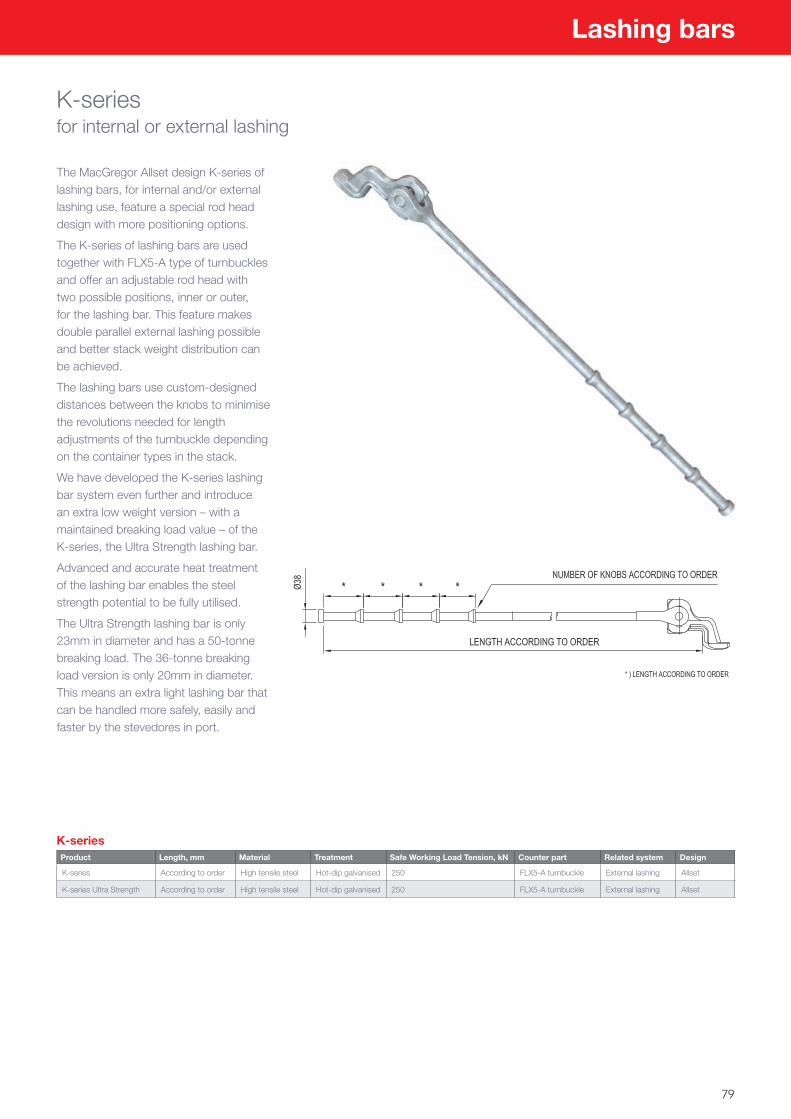
79
Lashing bars
K-seriesfor internal or external lashing
The MacGregor Allset design K-series of lashing bars, for internal and/or external lashing use, feature a special rod head design with more positioning options.
The K-series of lashing bars are used together with FLX5-A type of turnbuckles and offer an adjustable rod head with two possible positions, inner or outer, for the lashing bar. This feature makes double parallel external lashing possible and better stack weight distribution can be achieved.
The lashing bars use custom-designed distances between the knobs to minimise the revolutions needed for length adjustments of the turnbuckle depending on the container types in the stack.
We have developed the K-series lashing bar system even further and introduce an extra low weight version – with a maintained breaking load value – of the K-series, the Ultra Strength lashing bar.
Advanced and accurate heat treatment of the lashing bar enables the steel strength potential to be fully utilised.
The Ultra Strength lashing bar is only 23mm in diameter and has a 50-tonne breaking load. The 36-tonne breaking load version is only 20mm in diameter. This means an extra light lashing bar that can be handled more safely, easily and faster by the stevedores in port.
K-seriesProduct Length, mm Material Treatment Safe Working Load Tension, kN Counter part Related system Design
K-series According to order High tensile steel Hot-dip galvanised 250 FLX5-A turnbuckle External lashing Allset
K-series Ultra Strength According to order High tensile steel Hot-dip galvanised 250 FLX5-A turnbuckle External lashing Allset
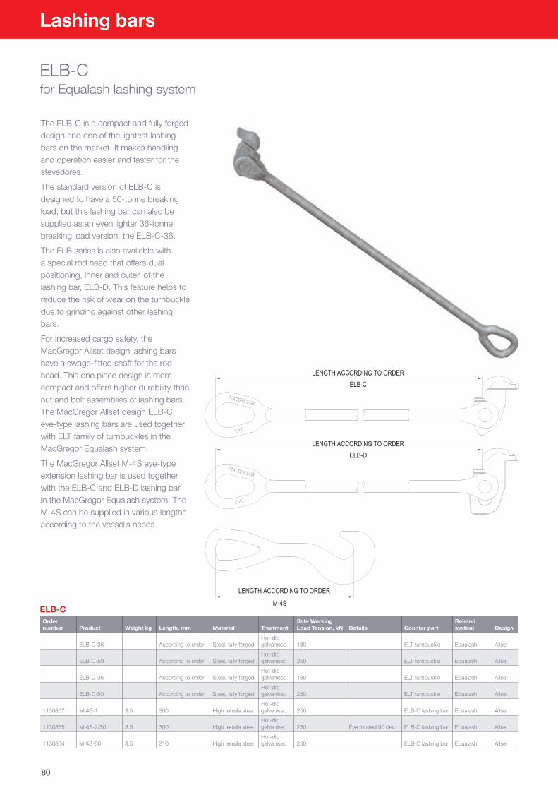
80
Lashing bars
ELB-Cfor Equalash lashing system
The ELB-C is a compact and fully forged design and one of the lightest lashing bars on the market. It makes handling and operation easier and faster for the stevedores.
The standard version of ELB-C is designed to have a 50-tonne breaking load, but this lashing bar can also be supplied as an even lighter 36-tonne breaking load version, the ELB-C-36.
The ELB series is also available with a special rod head that offers dual positioning, inner and outer, of the lashing bar, ELB-D. This feature helps to reduce the risk of wear on the turnbuckle due to grinding against other lashing bars.
For increased cargo safety, the MacGregor Allset design lashing bars have a swage-fitted shaft for the rod head. This one piece design is more compact and offers higher durability than nut and bolt assemblies of lashing bars. The MacGregor Allset design ELB-C eye-type lashing bars are used together with ELT family of turnbuckles in the MacGregor Equalash system.
The MacGregor Allset M-4S eye-type extension lashing bar is used together with the ELB-C and ELB-D lashing bar in the MacGregor Equalash system. The M-4S can be supplied in various lengths according to the vessel’s needs.
ELB-COrder number Product Weight kg Length, mm Material Treatment
Safe Working Load Tension, kN Details Counter part
Related system Design
ELB-C-36 According to order Steel, fully forgedHot-dip galvanised 180 ELT turnbuckle Equalash Allset
ELB-C-50 According to order Steel, fully forgedHot-dip galvanised 250 ELT turnbuckle Equalash Allset
ELB-D-36 According to order Steel, fully forgedHot-dip galvanised 180 ELT turnbuckle Equalash Allset
ELB-D-50 According to order Steel, fully forgedHot-dip galvanised 250 ELT turnbuckle Equalash Allset
1130857 M-4S-1 3.5 300 High tensile steelHot-dip galvanised 250 ELB-C lashing bar Equalash Allset
1130855 M-4S-2/50 3.5 300 High tensile steelHot-dip galvanised 250 Eye rotated 90 dec. ELB-C lashing bar Equalash Allset
1130854 M-4S-50 3.5 310 High tensile steelHot-dip galvanised 250 ELB-C lashing bar Equalash Allset
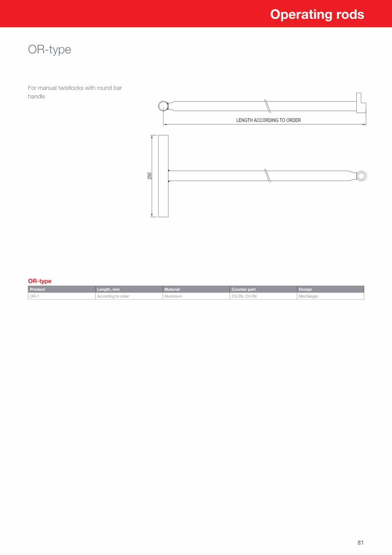
81
Operating rods
OR-type
For manual twistlocks with round bar handle
OR-typeProduct Length, mm Material Counter part Design
OR-1 According to order Aluminium CV-2N, CV-5N MacGregor
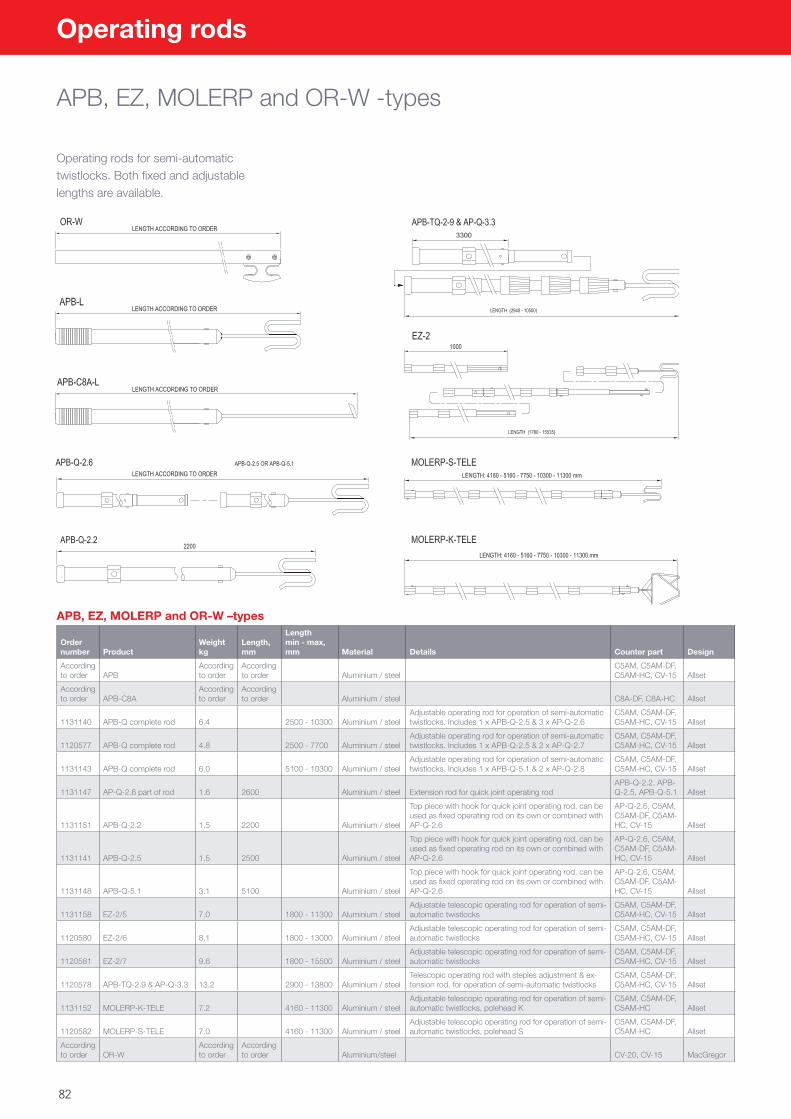
82
Operating rods
APB, EZ, MOLERP and OR-W -types
Operating rods for semi-automatic twistlocks. Both fixed and adjustable lengths are available.
APB, EZ, MOLERP and OR-W –types
Order number Product
Weight kg
Length, mm
Length min - max, mm Material Details Counter part Design
According to order APB
According to order
According to order Aluminium / steel
C5AM, C5AM-DF, C5AM-HC, CV-15 Allset
According to order APB-C8A
According to order
According to order Aluminium / steel C8A-DF, C8A-HC Allset
1131140 APB-Q complete rod 6.4 2500 - 10300 Aluminium / steelAdjustable operating rod for operation of semi-automatic twistlocks. Includes 1 x APB-Q-2.5 & 3 x AP-Q-2.6
C5AM, C5AM-DF, C5AM-HC, CV-15 Allset
1120577 APB-Q complete rod 4.8 2500 - 7700 Aluminium / steelAdjustable operating rod for operation of semi-automatic twistlocks. Includes 1 x APB-Q-2.5 & 2 x AP-Q-2.7
C5AM, C5AM-DF, C5AM-HC, CV-15 Allset
1131143 APB-Q complete rod 6.0 5100 - 10300 Aluminium / steelAdjustable operating rod for operation of semi-automatic twistlocks. Includes 1 x APB-Q-5.1 & 2 x AP-Q-2.8
C5AM, C5AM-DF, C5AM-HC, CV-15 Allset
1131147 AP-Q-2.6 part of rod 1.6 2600 Aluminium / steel Extension rod for quick joint operating rodAPB-Q-2.2, APB-Q-2.5, APB-Q-5.1 Allset
1131151 APB-Q-2.2 1.5 2200 Aluminium / steel
Top piece with hook for quick joint operating rod, can be used as fixed operating rod on its own or combined with AP-Q-2.6
AP-Q-2.6, C5AM, C5AM-DF, C5AM-HC, CV-15 Allset
1131141 APB-Q-2.5 1.5 2500 Aluminium / steel
Top piece with hook for quick joint operating rod, can be used as fixed operating rod on its own or combined with AP-Q-2.6
AP-Q-2.6, C5AM, C5AM-DF, C5AM-HC, CV-15 Allset
1131148 APB-Q-5.1 3.1 5100 Aluminium / steel
Top piece with hook for quick joint operating rod, can be used as fixed operating rod on its own or combined with AP-Q-2.6
AP-Q-2.6, C5AM, C5AM-DF, C5AM-HC, CV-15 Allset
1131158 EZ-2/5 7.0 1800 - 11300 Aluminium / steelAdjustable telescopic operating rod for operation of semi-automatic twistlocks
C5AM, C5AM-DF, C5AM-HC, CV-15 Allset
1120580 EZ-2/6 8.1 1800 - 13000 Aluminium / steelAdjustable telescopic operating rod for operation of semi-automatic twistlocks
C5AM, C5AM-DF, C5AM-HC, CV-15 Allset
1120581 EZ-2/7 9.6 1800 - 15500 Aluminium / steelAdjustable telescopic operating rod for operation of semi-automatic twistlocks
C5AM, C5AM-DF, C5AM-HC, CV-15 Allset
1120578 APB-TQ-2.9 & AP-Q-3.3 13.2 2900 - 13800 Aluminium / steelTelescopic operating rod with steples adjustment & ex-tension rod, for operation of semi-automatic twistlocks
C5AM, C5AM-DF, C5AM-HC, CV-15 Allset
1131152 MOLERP-K-TELE 7.2 4160 - 11300 Aluminium / steelAdjustable telescopic operating rod for operation of semi-automatic twistlocks, polehead K
C5AM, C5AM-DF, C5AM-HC Allset
1120582 MOLERP-S-TELE 7.0 4160 - 11300 Aluminium / steelAdjustable telescopic operating rod for operation of semi-automatic twistlocks, polehead S
C5AM, C5AM-DF, C5AM-HC Allset
According to order OR-W
According to order
According to order Aluminium/steel CV-20, CV-15 MacGregor
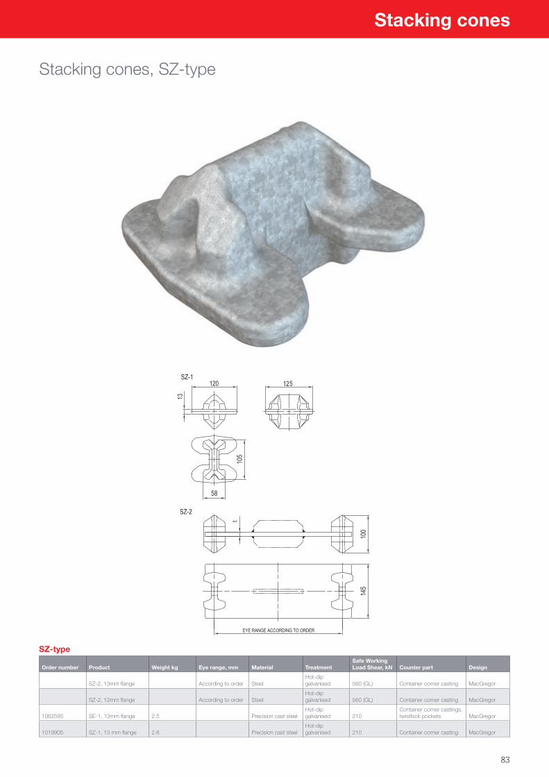
83
Stacking cones
Stacking cones, SZ-type
SZ-type
Order number Product Weight kg Eye range, mm Material TreatmentSafe Working Load Shear, kN Counter part Design
SZ-2, 13mm flange According to order SteelHot-dip galvanised 560 (GL) Container corner casting MacGregor
SZ-2, 12mm flange According to order SteelHot-dip galvanised 560 (GL) Container corner casting MacGregor
1062595 SE-1, 13mm flange 2.5 Precision cast steelHot-dip galvanised 210
Container corner castings, twistlock pockets MacGregor
1019905 SZ-1, 13 mm flange 2.6 Precision cast steelHot-dip galvanised 210 Container corner casting MacGregor
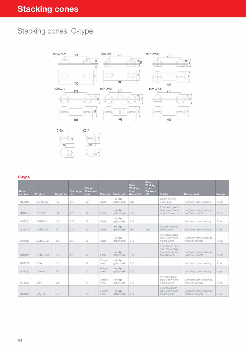
84
Stacking cones
Stacking cones, C-type
C-type
Order number Product Weight kg
Eye range, mm
Flange thickness, mm Material Treatment
Safe Working Load Shear, kN
Safe Working Load Pressure, kN Details Counter part Design
1155893 C9B-279J2 7.0 279 12 SteelHot-dip galvanised 200
Cones only on upper side Container corner casting Allset
1131019 C9B-279B 6.4 279 12 SteelHot-dip galvanised 210
Full cones upper side, below cone height 25mm
Container corner castings, twistlock pockets Allset
1131020 C92B-279 6.9 279 12 SteelHot-dip galvanised 210 Container corner casting Allset
1131018 C92B-279E 8.0 279 12 SteelHot-dip galvanised 200 200
Stacker with anti-rack spacer Container corner casting Allset
1131023 C92B-279B 6.4 279 12 SteelHot-dip galvanised 210
Full cones upper side, below cone height 22mm
Container corner castings, twistlock pockets Allset
1131024 C92B-279C 6.7 279 12 SteelHot-dip galvanised 210
Full cone on one end, below cone height 22mm on the other end
Container corner castings, twistlock pockets Allset
1131021 C15A 2.8 12Forged steel
Hot-dip galvanised 210 Container corner casting Allset
1131028 C15A-M 2.9 13Forged steel
Hot-dip galvanised 210 Container corner casting Allset
1131022 C21A 2.6 12Forged steel
Hot-dip galvanised 210
Full cone upper side, below cone height 22mm
Container corner castings, twistlock pockets Allset
1131029 C21A-M 2.7 13Forged steel
Hot-dip galvanised 210
Full cone upper side, below cone height 22mm
Container corner castings, twistlock pockets Allset
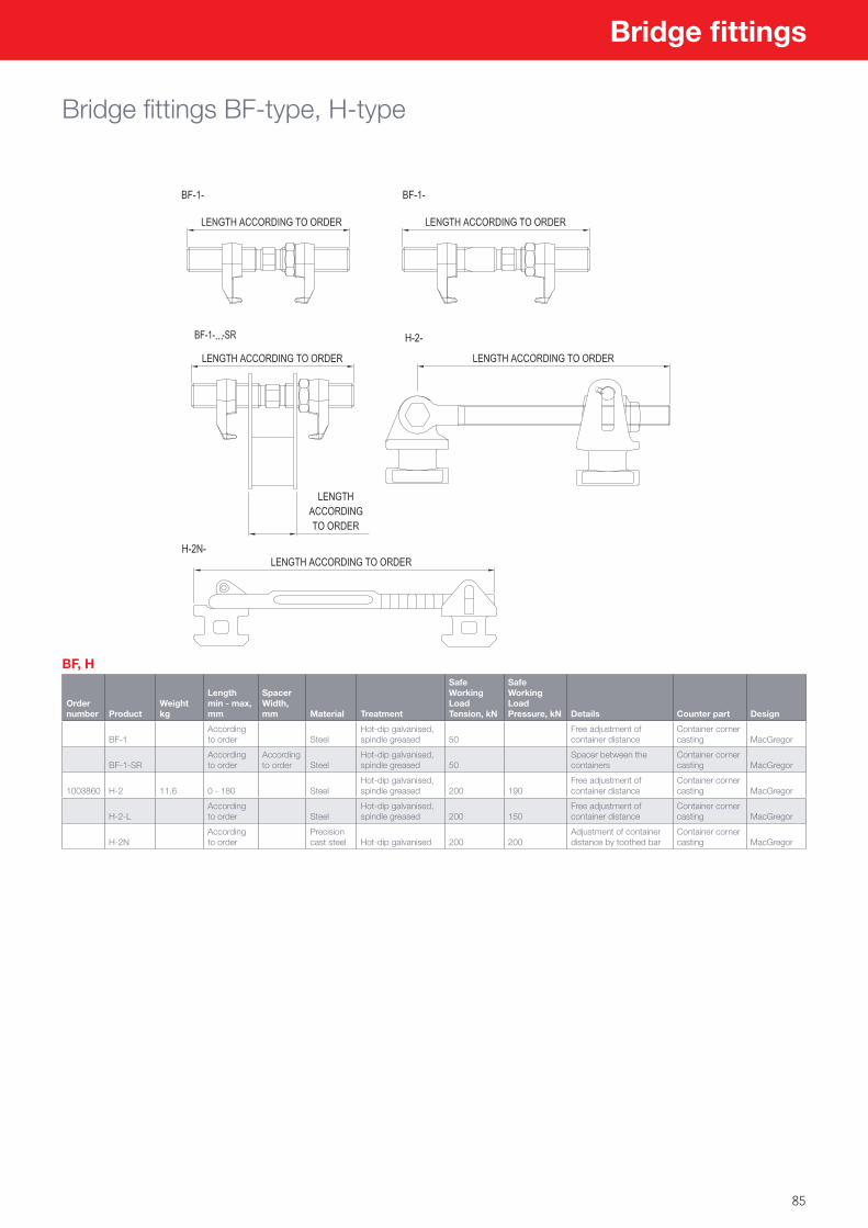
85
Bridge fittings
Bridge fittings BF-type, H-type
BF, H
Order number Product
Weight kg
Length min - max, mm
Spacer Width, mm Material Treatment
Safe Working Load Tension, kN
Safe Working Load Pressure, kN Details Counter part Design
BF-1According to order Steel
Hot-dip galvanised, spindle greased 50
Free adjustment of container distance
Container corner casting MacGregor
BF-1-SRAccording to order
According to order Steel
Hot-dip galvanised, spindle greased 50
Spacer between the containers
Container corner casting MacGregor
1003860 H-2 11.6 0 - 180 SteelHot-dip galvanised, spindle greased 200 190
Free adjustment of container distance
Container corner casting MacGregor
H-2-LAccording to order Steel
Hot-dip galvanised, spindle greased 200 150
Free adjustment of container distance
Container corner casting MacGregor
H-2NAccording to order
Precision cast steel Hot-dip galvanised 200 200
Adjustment of container distance by toothed bar
Container corner casting MacGregor
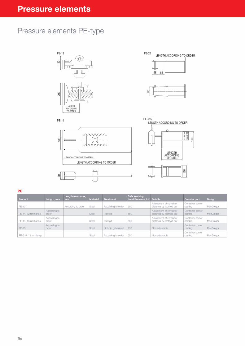
86
Pressure elements
Pressure elements PE-type
PE
Product Length, mmLength min - max, mm Material Treatment
Safe Working Load Pressure, kN Details Counter part Design
PE-13 According to order Steel According to order 250Adjustment of container distance by toothed bar
Container corner casting MacGregor
PE-14, 12mm flangeAccording to order Steel Painted 650
Adjustment of container distance by toothed bar
Container corner casting MacGregor
PE-14, 15mm flangeAccording to order Steel Painted 650
Adjustment of container distance by toothed bar
Container corner casting MacGregor
PE-25According to order Steel Hot-dip galvanised 250 Non adjustable
Container corner casting MacGregor
PE-515, 12mm flange Steel According to order 650 Non adjustableContainer corner casting MacGregor
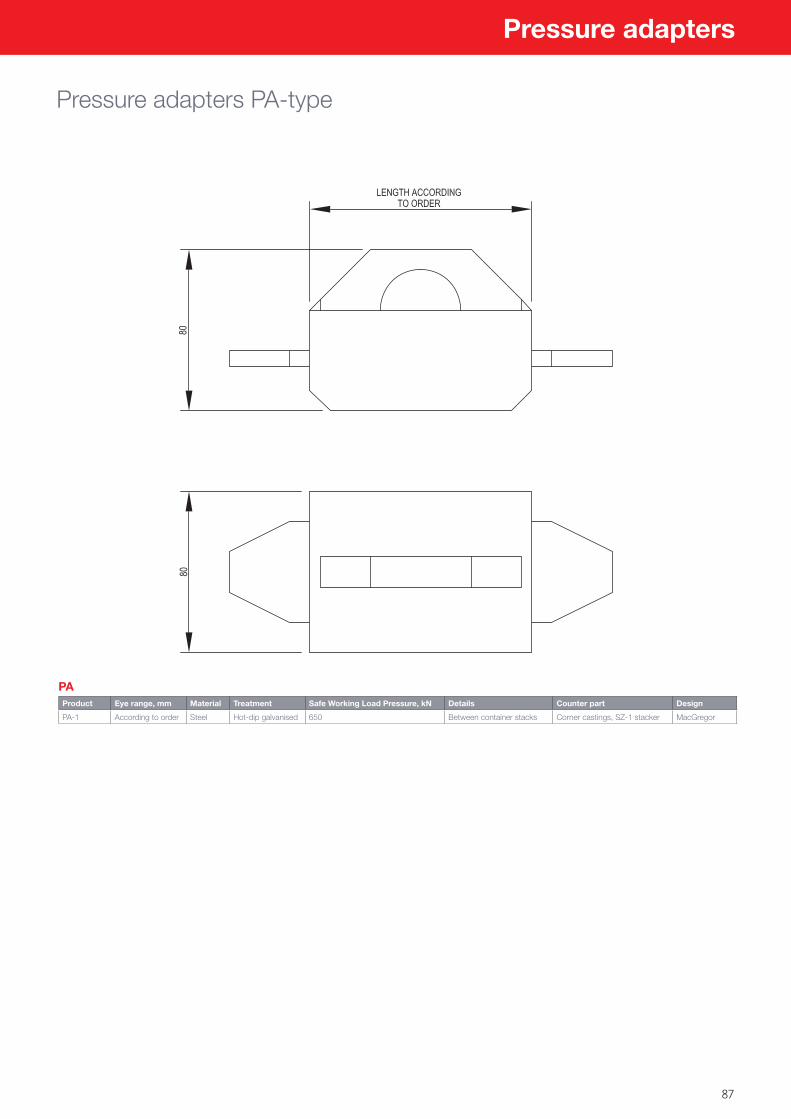
87
Pressure adapters
Pressure adapters PA-type
PAProduct Eye range, mm Material Treatment Safe Working Load Pressure, kN Details Counter part Design
PA-1 According to order Steel Hot-dip galvanised 650 Between container stacks Corner castings, SZ-1 stacker MacGregor
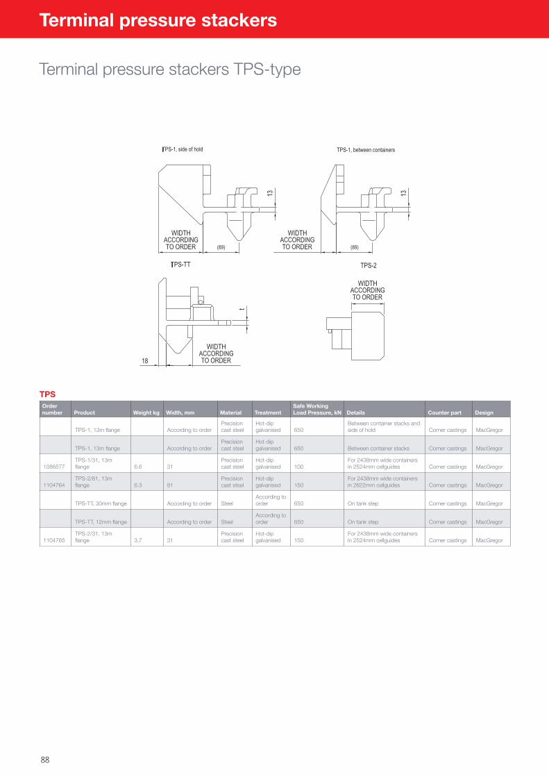
88
Terminal pressure stackers
Terminal pressure stackers TPS-type
TPSOrder number Product Weight kg Width, mm Material Treatment
Safe Working Load Pressure, kN Details Counter part Design
TPS-1, 13m flange According to orderPrecision cast steel
Hot-dip galvanised 650
Between container stacks and side of hold Corner castings MacGregor
TPS-1, 13m flange According to orderPrecision cast steel
Hot-dip galvanised 650 Between container stacks Corner castings MacGregor
1086577TPS-1/31, 13m flange 6.6 31
Precision cast steel
Hot-dip galvanised 100
For 2438mm wide containers in 2524mm cellguides Corner castings MacGregor
1104764TPS-2/81, 13m flange 6.3 81
Precision cast steel
Hot-dip galvanised 150
For 2438mm wide containers in 2622mm cellguides Corner castings MacGregor
TPS-TT, 30mm flange According to order SteelAccording to order 650 On tank step Corner castings MacGregor
TPS-TT, 12mm flange According to order SteelAccording to order 650 On tank step Corner castings MacGregor
1104765TPS-2/31, 13m flange 3.7 31
Precision cast steel
Hot-dip galvanised 150
For 2438mm wide containers in 2524mm cellguides Corner castings MacGregor
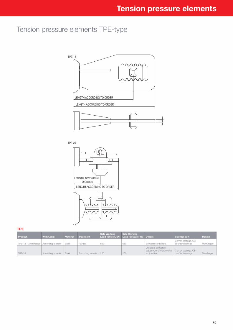
89
Tension pressure elements
Tension pressure elements TPE-type
TPE
Product Width, mm Material TreatmentSafe Working Load Tension, kN
Safe Working Load Pressure, kN Details Counter part Design
TPE-13, 12mm flange According to order Steel Painted 650 650 Between containersCorner castings, CB-counter bearings MacGregor
TPE-25 According to order Steel According to order 250 250
On top of containers, adjustment of distance by toothed bar
Corner castings, CB-counter bearings MacGregor
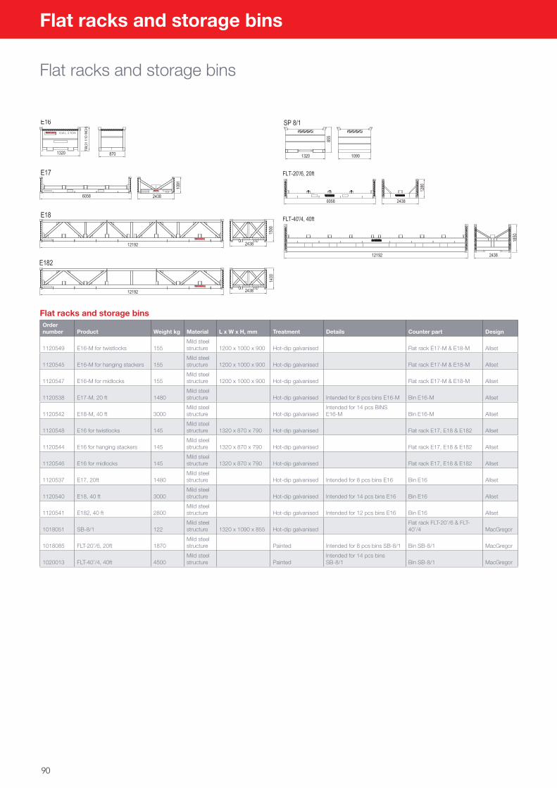
90
Flat racks and storage bins
Flat racks and storage bins
Flat racks and storage binsOrder number Product Weight kg Material L x W x H, mm Treatment Details Counter part Design
1120549 E16-M for twistlocks 155Mild steel structure 1200 x 1000 x 900 Hot-dip galvanised Flat rack E17-M & E18-M Allset
1120545 E16-M for hanging stackers 155Mild steel structure 1200 x 1000 x 900 Hot-dip galvanised Flat rack E17-M & E18-M Allset
1120547 E16-M for midlocks 155Mild steel structure 1200 x 1000 x 900 Hot-dip galvanised Flat rack E17-M & E18-M Allset
1120538 E17-M, 20 ft 1480Mild steel structure Hot-dip galvanised Intended for 8 pcs bins E16-M Bin E16-M Allset
1120542 E18-M, 40 ft 3000Mild steel structure Hot-dip galvanised
Intended for 14 pcs BINS E16-M Bin E16-M Allset
1120548 E16 for twistlocks 145Mild steel structure 1320 x 870 x 790 Hot-dip galvanised Flat rack E17, E18 & E182 Allset
1120544 E16 for hanging stackers 145Mild steel structure 1320 x 870 x 790 Hot-dip galvanised Flat rack E17, E18 & E182 Allset
1120546 E16 for midlocks 145Mild steel structure 1320 x 870 x 790 Hot-dip galvanised Flat rack E17, E18 & E182 Allset
1120537 E17, 20ft 1480Mild steel structure Hot-dip galvanised Intended for 8 pcs bins E16 Bin E16 Allset
1120540 E18, 40 ft 3000Mild steel structure Hot-dip galvanised Intended for 14 pcs bins E16 Bin E16 Allset
1120541 E182, 40 ft 2800Mild steel structure Hot-dip galvanised Intended for 12 pcs bins E16 Bin E16 Allset
1018051 SB-8/1 122Mild steel structure 1320 x 1090 x 855 Hot-dip galvanised
Flat rack FLT-20’/6 & FLT-40’/4 MacGregor
1018085 FLT-20’/6, 20ft 1870Mild steel structure Painted Intended for 8 pcs bins SB-8/1 Bin SB-8/1 MacGregor
1020013 FLT-40’/4, 40ft 4500Mild steel structure Painted
Intended for 14 pcs bins SB-8/1 Bin SB-8/1 MacGregor
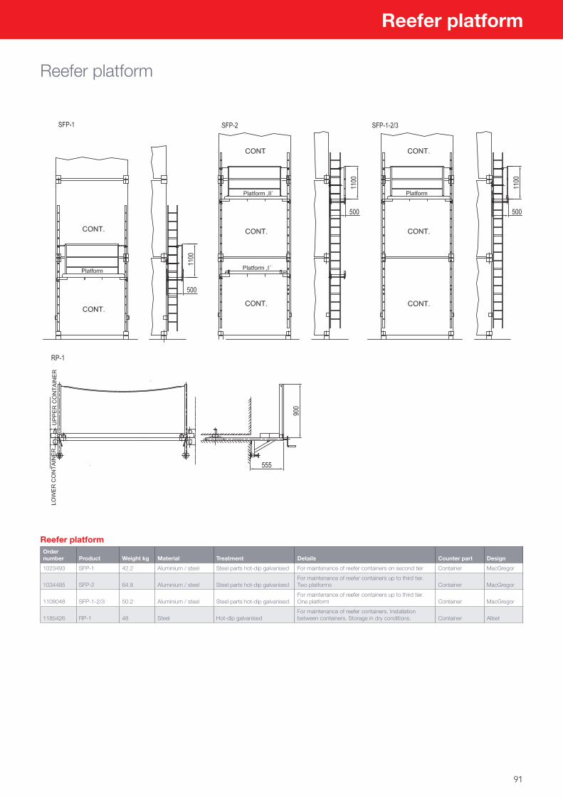
91
Reefer platform
Reefer platform
Reefer platformOrder number Product Weight kg Material Treatment Details Counter part Design
1023493 SFP-1 42.2 Aluminium / steel Steel parts hot-dip galvanised For maintenance of reefer containers on second tier Container MacGregor
1034485 SFP-2 64.8 Aluminium / steel Steel parts hot-dip galvanisedFor maintenance of reefer containers up to third tier. Two platforms Container MacGregor
1108048 SFP-1-2/3 50.2 Aluminium / steel Steel parts hot-dip galvanisedFor maintenance of reefer containers up to third tier. One platform Container MacGregor
1185426 RP-1 48 Steel Hot-dip galvanisedFor maintenance of reefer containers. Installation between containers. Storage in dry conditions. Container Allset
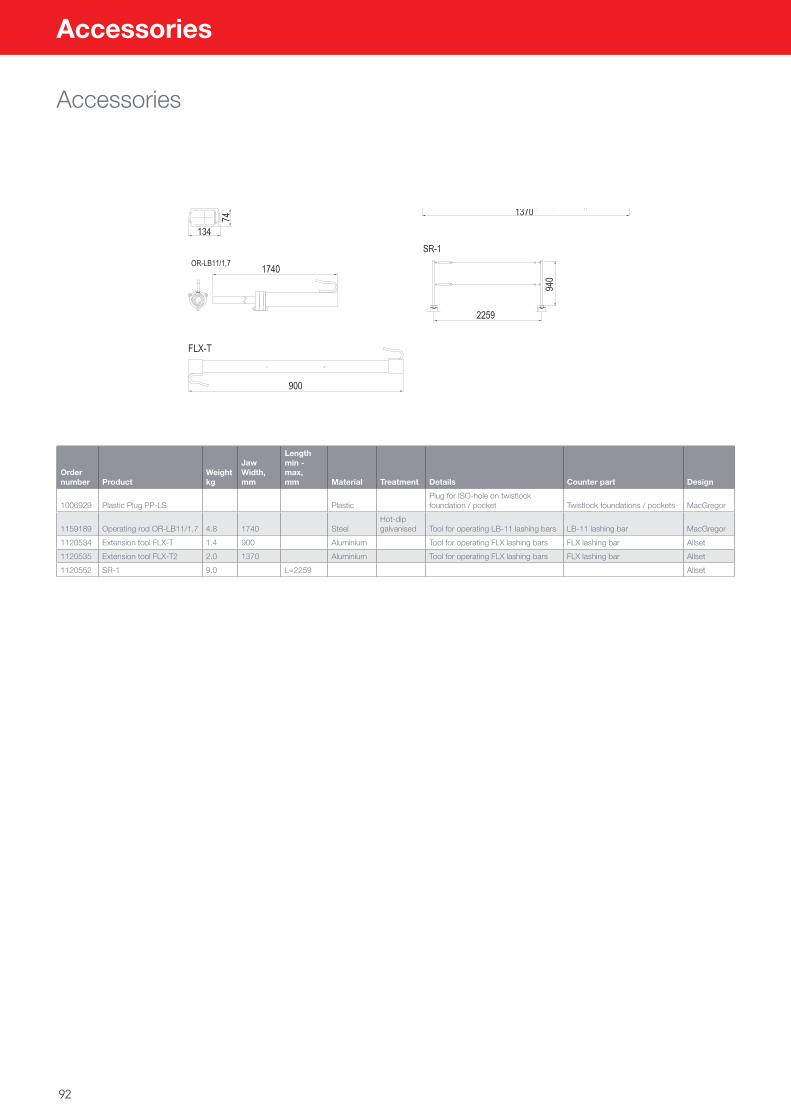
92
Accessories
Accessories
Order number Product
Weight kg
Jaw Width, mm
Length min - max, mm Material Treatment Details Counter part Design
1006929 Plastic Plug PP-LS PlasticPlug for ISO-hole on twistlock foundation / pocket Twistlock foundations / pockets MacGregor
1159189 Operating rod OR-LB11/1,7 4.8 1740 SteelHot-dip galvanised Tool for operating LB-11 lashing bars LB-11 lashing bar MacGregor
1120534 Extension tool FLX-T 1.4 900 Aluminium Tool for operating FLX lashing bars FLX lashing bar Allset
1120535 Extension tool FLX-T2 2.0 1370 Aluminium Tool for operating FLX lashing bars FLX lashing bar Allset
1120552 SR-1 9.0 L=2259 Allset
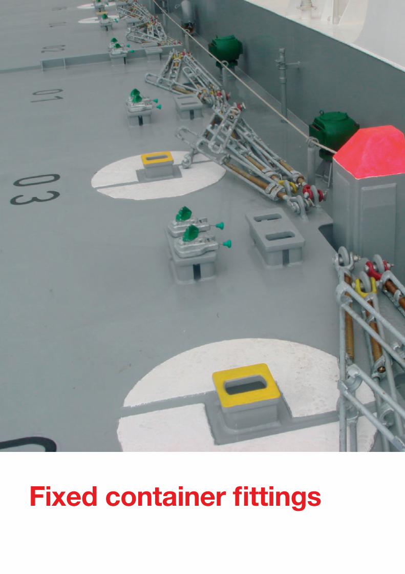
Fixed container fittings
93
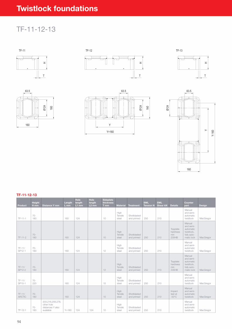
94
Twistlock foundations
TF-11-12-13
TF-11-12-13
ProductHeight H mm Distance Y mm
Length L mm
Hole lengthL1 mm
Hole lengthL2 mm
Sideplate thickness T mm Material Treatment
SWL Tension N
SWL Shear kN Details
Counter part Design
TF-11-170-180 160 124 10
High Tensile steel
Shotblasted and primed 250 210
Manual and semi-automatic twistlock MacGregor
TF-11-270-180 160 124 10
High Tensile steel
Shotblasted and primed 250 210
Topplate hardness min 235HB
Manual and semi-automatic twistlock, fully auto-matic lock MacGregor
TF-11/SP12-1
70-180 160 124 12
High Tensile steel
Shotblasted and primed 250 210
Manual and semi-automatic twistlock MacGregor
TF-11/SP12-2
70-180 160 124 12
High Tensile steel
Shotblasted and primed 250 210
Topplate hardness min 235HB
Manual and semi-automatic twistlock, fully auto-matic lock MacGregor
TF-11/SP15-1
70-220 160 124 15
High Tensile steel
Shotblasted and primed 250 210
Manual and semi-automatic twistlock MacGregor
TF-11/ARCTIC
70-180 160 124 10
High Tensile steel
Shotblasted and primed 250 210
Impact test at -50°C
Manual and semi-automatic twistlock MacGregor
TF-12-170-180
203,216,258,278, other hole distances Y also available Y+160 124 124 10
High Tensile steel
Shotblasted and primed 250 210
Manual and semi-automatic twistlock MacGregor
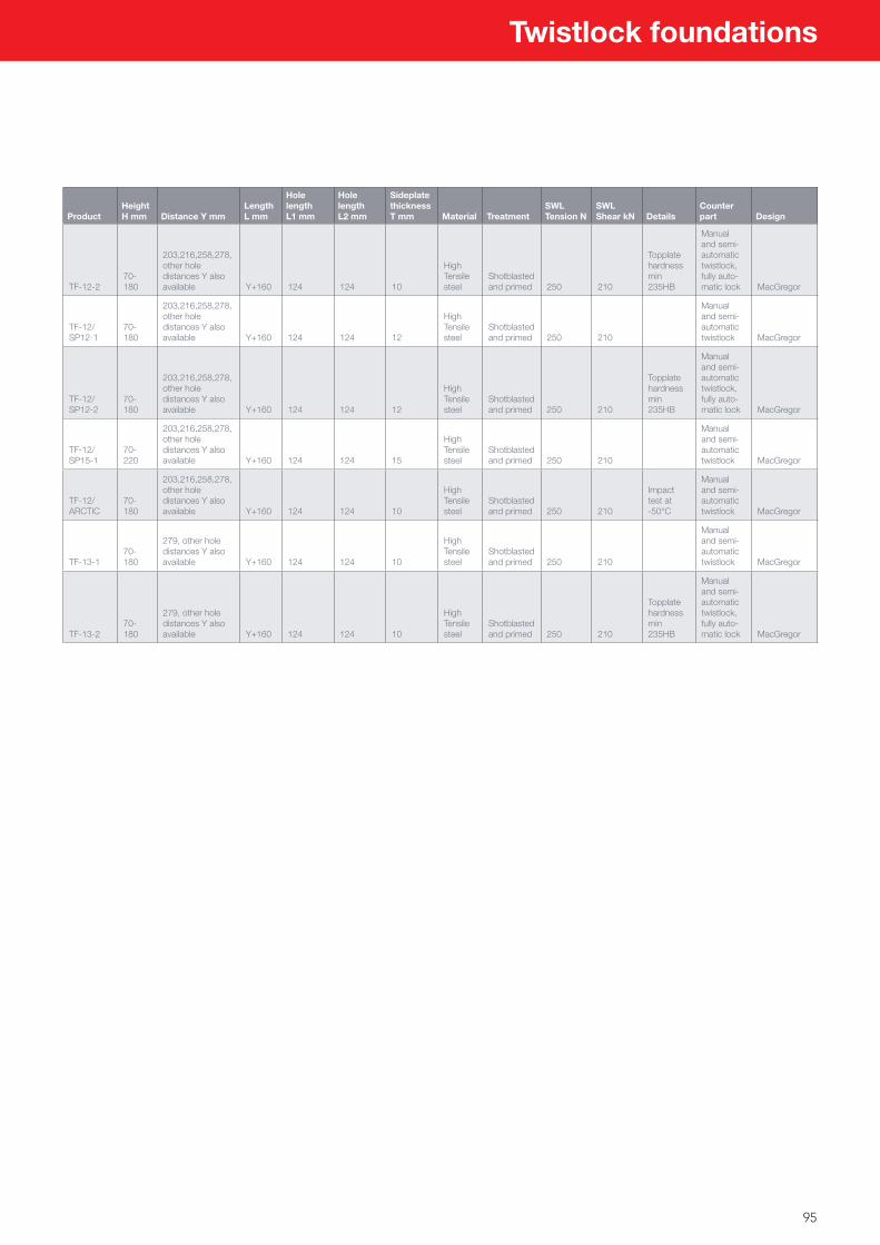
95
Twistlock foundations
ProductHeight H mm Distance Y mm
Length L mm
Hole lengthL1 mm
Hole lengthL2 mm
Sideplate thickness T mm Material Treatment
SWL Tension N
SWL Shear kN Details
Counter part Design
TF-12-270-180
203,216,258,278, other hole distances Y also available Y+160 124 124 10
High Tensile steel
Shotblasted and primed 250 210
Topplate hardness min 235HB
Manual and semi-automatic twistlock, fully auto-matic lock MacGregor
TF-12/SP12-1
70-180
203,216,258,278, other hole distances Y also available Y+160 124 124 12
High Tensile steel
Shotblasted and primed 250 210
Manual and semi-automatic twistlock MacGregor
TF-12/SP12-2
70-180
203,216,258,278, other hole distances Y also available Y+160 124 124 12
High Tensile steel
Shotblasted and primed 250 210
Topplate hardness min 235HB
Manual and semi-automatic twistlock, fully auto-matic lock MacGregor
TF-12/SP15-1
70-220
203,216,258,278, other hole distances Y also available Y+160 124 124 15
High Tensile steel
Shotblasted and primed 250 210
Manual and semi-automatic twistlock MacGregor
TF-12/ARCTIC
70-180
203,216,258,278, other hole distances Y also available Y+160 124 124 10
High Tensile steel
Shotblasted and primed 250 210
Impact test at -50°C
Manual and semi-automatic twistlock MacGregor
TF-13-170-180
279, other hole distances Y also available Y+160 124 124 10
High Tensile steel
Shotblasted and primed 250 210
Manual and semi-automatic twistlock MacGregor
TF-13-270-180
279, other hole distances Y also available Y+160 124 124 10
High Tensile steel
Shotblasted and primed 250 210
Topplate hardness min 235HB
Manual and semi-automatic twistlock, fully auto-matic lock MacGregor
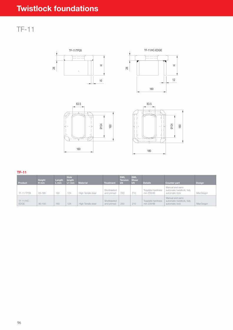
96
Twistlock foundations
TF-11
TF-11
ProductHeight H mm
Length L mm
Hole length L1 mm Material Treatment
SWL Tension kN
SWL Shear kN Details Counter part Design
TF-11/TP28 65-180 160 124 High Tensile steelShotblasted and primed 250 210
Topplate hardness min 235HB
Manual and semi-automatic twistlock, fully automatic lock MacGregor
TF-11/HC-EDGE 90-150 160 124 High Tensile steel
Shotblasted and primed 250 210
Topplate hardness min 235HB
Manual and semi-automatic twistlock, fully automatic lock MacGregor
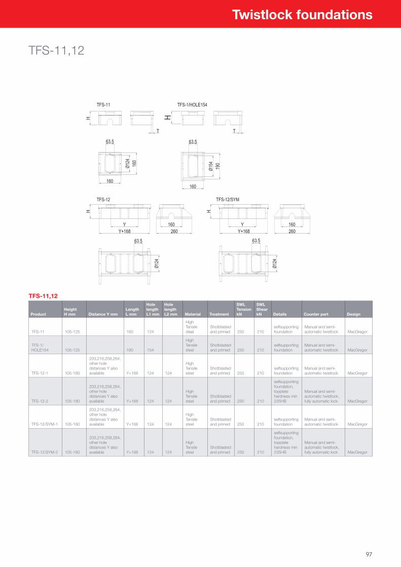
97
Twistlock foundations
TFS-11,12
TFS-11,12
ProductHeightH mm Distance Y mm
Length L mm
Hole lengthL1 mm
Hole length L2 mm Material Treatment
SWL Tension kN
SWL Shear kN Details Counter part Design
TFS-11 105-125 160 124
High Tensile steel
Shotblasted and primed 250 210
selfsupporting foundation
Manual and semi-automatic twistlock MacGregor
TFS-1/HOLE154 105-125 190 154
High Tensile steel
Shotblasted and primed 250 210
selfsupporting foundation
Manual and semi-automatic twistlock MacGregor
TFS-12-1 105-180
203,216,258,264, other hole distances Y also available Y+168 124 124
High Tensile steel
Shotblasted and primed 250 210
selfsupporting foundation
Manual and semi-automatic twistlock MacGregor
TFS-12-2 105-180
203,216,258,264, other hole distances Y also available Y+168 124 124
High Tensile steel
Shotblasted and primed 250 210
selfsupporting foundation, topplate hardness min 235HB
Manual and semi-automatic twistlock, fully automatic lock MacGregor
TFS-12/SYM-1 105-180
203,216,258,264, other hole distances Y also available Y+168 124 124
High Tensile steel
Shotblasted and primed 250 210
selfsupporting foundation
Manual and semi-automatic twistlock MacGregor
TFS-12/SYM-2 105-180
203,216,258,264, other hole distances Y also available Y+168 124 124
High Tensile steel
Shotblasted and primed 250 210
selfsupporting foundation, topplate hardness min 235HB
Manual and semi-automatic twistlock, fully automatic lock MacGregor
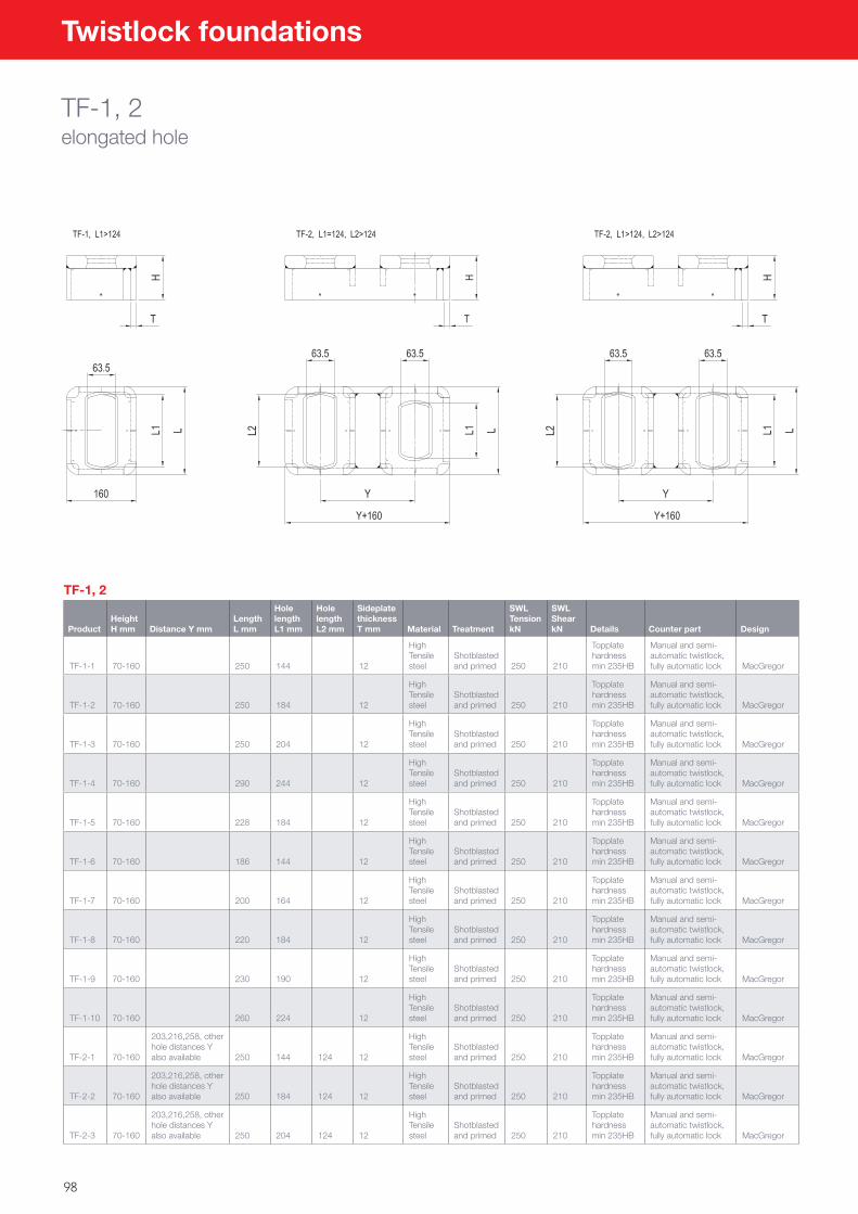
98
Twistlock foundations
TF-1, 2elongated hole
TF-1, 2
ProductHeight H mm Distance Y mm
Length L mm
Hole length L1 mm
Hole length L2 mm
Sideplate thickness T mm Material Treatment
SWL Tension kN
SWL Shear kN Details Counter part Design
TF-1-1 70-160 250 144 12
High Tensile steel
Shotblasted and primed 250 210
Topplate hardness min 235HB
Manual and semi-automatic twistlock, fully automatic lock MacGregor
TF-1-2 70-160 250 184 12
High Tensile steel
Shotblasted and primed 250 210
Topplate hardness min 235HB
Manual and semi-automatic twistlock, fully automatic lock MacGregor
TF-1-3 70-160 250 204 12
High Tensile steel
Shotblasted and primed 250 210
Topplate hardness min 235HB
Manual and semi-automatic twistlock, fully automatic lock MacGregor
TF-1-4 70-160 290 244 12
High Tensile steel
Shotblasted and primed 250 210
Topplate hardness min 235HB
Manual and semi-automatic twistlock, fully automatic lock MacGregor
TF-1-5 70-160 228 184 12
High Tensile steel
Shotblasted and primed 250 210
Topplate hardness min 235HB
Manual and semi-automatic twistlock, fully automatic lock MacGregor
TF-1-6 70-160 186 144 12
High Tensile steel
Shotblasted and primed 250 210
Topplate hardness min 235HB
Manual and semi-automatic twistlock, fully automatic lock MacGregor
TF-1-7 70-160 200 164 12
High Tensile steel
Shotblasted and primed 250 210
Topplate hardness min 235HB
Manual and semi-automatic twistlock, fully automatic lock MacGregor
TF-1-8 70-160 220 184 12
High Tensile steel
Shotblasted and primed 250 210
Topplate hardness min 235HB
Manual and semi-automatic twistlock, fully automatic lock MacGregor
TF-1-9 70-160 230 190 12
High Tensile steel
Shotblasted and primed 250 210
Topplate hardness min 235HB
Manual and semi-automatic twistlock, fully automatic lock MacGregor
TF-1-10 70-160 260 224 12
High Tensile steel
Shotblasted and primed 250 210
Topplate hardness min 235HB
Manual and semi-automatic twistlock, fully automatic lock MacGregor
TF-2-1 70-160
203,216,258, other hole distances Y also available 250 144 124 12
High Tensile steel
Shotblasted and primed 250 210
Topplate hardness min 235HB
Manual and semi-automatic twistlock, fully automatic lock MacGregor
TF-2-2 70-160
203,216,258, other hole distances Y also available 250 184 124 12
High Tensile steel
Shotblasted and primed 250 210
Topplate hardness min 235HB
Manual and semi-automatic twistlock, fully automatic lock MacGregor
TF-2-3 70-160
203,216,258, other hole distances Y also available 250 204 124 12
High Tensile steel
Shotblasted and primed 250 210
Topplate hardness min 235HB
Manual and semi-automatic twistlock, fully automatic lock MacGregor
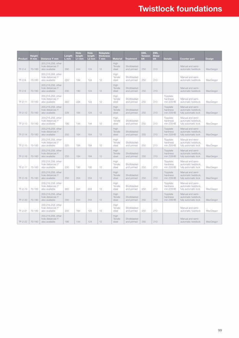
99
Twistlock foundations
ProductHeight H mm Distance Y mm
Length L mm
Hole length L1 mm
Hole length L2 mm
Sideplate thickness T mm Material Treatment
SWL Tension kN
SWL Shear kN Details Counter part Design
TF-2-4 70-160
203,216,258, other hole distances Y also available 290 244 124 12
High Tensile steel
Shotblasted and primed 250 210
Manual and semi-automatic twistlock MacGregor
TF-2-8 70-160
203,216,258, other hole distances Y also available 220 184 124 12
High Tensile steel
Shotblasted and primed 250 210
Manual and semi-automatic twistlock MacGregor
TF-2-9 70-160
203,216,258, other hole distances Y also available 230 190 124 12
High Tensile steel
Shotblasted and primed 250 210
Manual and semi-automatic twistlock MacGregor
TF-2-11 70-160
203,216,258, other hole distances Y also available 260 224 124 12
High Tensile steel
Shotblasted and primed 250 210
Topplate hardness min 235HB
Manual and semi-automatic twistlock MacGregor
TF-2-12 70-160
203,216,258, other hole distances Y also available 228 184 124 12
High Tensile steel
Shotblasted and primed 250 210
Topplate hardness min 235HB
Manual and semi-automatic twistlock, fully automatic lock MacGregor
TF-2-13 70-160
203,216,258, other hole distances Y also available 186 144 144 12
High Tensile steel
Shotblasted and primed 250 210
Topplate hardness min 235HB
Manual and semi-automatic twistlock, fully automatic lock MacGregor
TF-2-14 70-160
203,216,258, other hole distances Y also available 200 164 164 12
High Tensile steel
Shotblasted and primed 250 210
Topplate hardness min 235HB
Manual and semi-automatic twistlock, fully automatic lock MacGregor
TF-2-15 70-160
203,216,258, other hole distances Y also available 220 184 184 12
High Tensile steel
Shotblasted and primed 250 210
Topplate hardness min 235HB
Manual and semi-automatic twistlock, fully automatic lock MacGregor
TF-2-16 70-160
203,216,258, other hole distances Y also available 250 184 184 12
High Tensile steel
Shotblasted and primed 250 210
Topplate hardness min 235HB
Manual and semi-automatic twistlock, fully automatic lock MacGregor
TF-2-17 70-160
203,216,258, other hole distances Y also available 230 190 190 12
High Tensile steel
Shotblasted and primed 250 210
Topplate hardness min 235HB
Manual and semi-automatic twistlock, fully automatic lock MacGregor
TF-2-18 70-160
203,216,258, other hole distances Y also available 250 204 204 12
High Tensile steel
Shotblasted and primed 250 210
Topplate hardness min 235HB
Manual and semi-automatic twistlock, fully automatic lock MacGregor
TF-2-19 70-160
203,216,258, other hole distances Y also available 260 224 224 12
High Tensile steel
Shotblasted and primed 250 210
Topplate hardness min 235HB
Manual and semi-automatic twistlock, fully automatic lock MacGregor
TF-2-20 70-160
203,216,258, other hole distances Y also available 290 244 244 12
High Tensile steel
Shotblasted and primed 250 210
Topplate hardness min 235HB
Manual and semi-automatic twistlock, fully automatic lock MacGregor
TF-2-21 70-160
203,216,258, other hole distances Y also available 200 164 124 12
High Tensile steel
Shotblasted and primed 250 210
Manual and semi-automatic twistlock MacGregor
TF-2-22 70-160
203,216,258, other hole distances Y also available 186 144 124 12
High Tensile steel
Shotblasted and primed 250 210
Manual and semi-automatic twistlock MacGregor
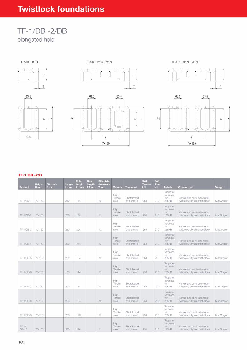
100
Twistlock foundations
TF-1/DB -2/DBelongated hole
TF-1/DB -2/B
ProductHeight H mm
DistanceY mm
LengthL mm
Hole lengthL1 mm
Hole length L2 mm
Sideplate thickness T mm Material Treatment
SWL Tension kN
SWL Shear kN Details Counter part Design
TF-1/DB-1 70-160 250 144 12
High Tensile steel
Shotblasted and primed 250 210
Topplate hardness min 235HB
Manual and semi-automatic twistlock, fully automatic lock MacGregor
TF-1/DB-2 70-160 250 184 12
High Tensile steel
Shotblasted and primed 250 210
Topplate hardness min 235HB
Manual and semi-automatic twistlock, fully automatic lock MacGregor
TF-1/DB-3 70-160 250 204 12
High Tensile steel
Shotblasted and primed 250 210
Topplate hardness min 235HB
Manual and semi-automatic twistlock, fully automatic lock MacGregor
TF-1/DB-4 70-160 290 244 12
High Tensile steel
Shotblasted and primed 250 210
Topplate hardness min 235HB
Manual and semi-automatic twistlock, fully automatic lock MacGregor
TF-1/DB-5 70-160 228 184 12
High Tensile steel
Shotblasted and primed 250 210
Topplate hardness min 235HB
Manual and semi-automatic twistlock, fully automatic lock MacGregor
TF-1/DB-6 70-160 186 144 12
High Tensile steel
Shotblasted and primed 250 210
Topplate hardness min 235HB
Manual and semi-automatic twistlock, fully automatic lock MacGregor
TF-1/DB-7 70-160 200 164 12
High Tensile steel
Shotblasted and primed 250 210
Topplate hardness min 235HB
Manual and semi-automatic twistlock, fully automatic lock MacGregor
TF-1/DB-8 70-160 220 184 12
High Tensile steel
Shotblasted and primed 250 210
Topplate hardness min 235HB
Manual and semi-automatic twistlock, fully automatic lock MacGregor
TF-1/DB-9 70-160 230 190 12
High Tensile steel
Shotblasted and primed 250 210
Topplate hardness min 235HB
Manual and semi-automatic twistlock, fully automatic lock MacGregor
TF-1/DB-10 70-160 260 224 12
High Tensile steel
Shotblasted and primed 250 210
Topplate hardness min 235HB
Manual and semi-automatic twistlock, fully automatic lock MacGregor
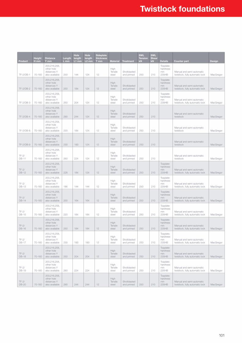
101
Twistlock foundations
ProductHeight H mm
DistanceY mm
LengthL mm
Hole lengthL1 mm
Hole length L2 mm
Sideplate thickness T mm Material Treatment
SWL Tension kN
SWL Shear kN Details Counter part Design
TF-2/DB-1 70-160
203,216,258, other hole distances Y also available 250 144 124 12
High Tensile steel
Shotblasted and primed 250 210
Topplate hardness min 235HB
Manual and semi-automatic twistlock, fully automatic lock MacGregor
TF-2/DB-2 70-160
203,216,258, other hole distances Y also available 250 184 124 12
High Tensile steel
Shotblasted and primed 250 210
Topplate hardness min 235HB
Manual and semi-automatic twistlock, fully automatic lock MacGregor
TF-2/DB-3 70-160
203,216,258, other hole distances Y also available 250 204 124 12
High Tensile steel
Shotblasted and primed 250 210
Topplate hardness min 235HB
Manual and semi-automatic twistlock, fully automatic lock MacGregor
TF-2/DB-4 70-160
203,216,258, other hole distances Y also available 290 244 124 12
High Tensile steel
Shotblasted and primed 250 210
Manual and semi-automatic twistlock MacGregor
TF-2/DB-8 70-160
203,216,258, other hole distances Y also available 220 184 124 12
High Tensile steel
Shotblasted and primed 250 210
Manual and semi-automatic twistlock MacGregor
TF-2/DB-9 70-160
203,216,258, other hole distances Y also available 230 190 124 12
High Tensile steel
Shotblasted and primed 250 210
Manual and semi-automatic twistlock MacGregor
TF-2/DB-11 70-160
203,216,258, other hole distances Y also available 260 224 124 12
High Tensile steel
Shotblasted and primed 250 210
Manual and semi-automatic twistlock MacGregor
TF-2/DB-12 70-160
203,216,258, other hole distances Y also available 228 184 124 12
High Tensile steel
Shotblasted and primed 250 210
Topplate hardness min 235HB
Manual and semi-automatic twistlock, fully automatic lock MacGregor
TF-2/DB-13 70-160
203,216,258, other hole distances Y also available 186 144 144 12
High Tensile steel
Shotblasted and primed 250 210
Topplate hardness min 235HB
Manual and semi-automatic twistlock, fully automatic lock MacGregor
TF-2/DB-14 70-160
203,216,258, other hole distances Y also available 200 164 164 12
High Tensile steel
Shotblasted and primed 250 210
Topplate hardness min 235HB
Manual and semi-automatic twistlock, fully automatic lock MacGregor
TF-2/DB-15 70-160
203,216,258, other hole distances Y also available 220 184 184 12
High Tensile steel
Shotblasted and primed 250 210
Topplate hardness min 235HB
Manual and semi-automatic twistlock, fully automatic lock MacGregor
TF-2/DB-16 70-160
203,216,258, other hole distances Y also available 250 184 184 12
High Tensile steel
Shotblasted and primed 250 210
Topplate hardness min 235HB
Manual and semi-automatic twistlock, fully automatic lock MacGregor
TF-2/DB-17 70-160
203,216,258, other hole distances Y also available 230 190 190 12
High Tensile steel
Shotblasted and primed 250 210
Topplate hardness min 235HB
Manual and semi-automatic twistlock, fully automatic lock MacGregor
TF-2/DB-18 70-160
203,216,258, other hole distances Y also available 250 204 204 12
High Tensile steel
Shotblasted and primed 250 210
Topplate hardness min 235HB
Manual and semi-automatic twistlock, fully automatic lock MacGregor
TF-2/DB-19 70-160
203,216,258, other hole distances Y also available 260 224 224 12
High Tensile steel
Shotblasted and primed 250 210
Topplate hardness min 235HB
Manual and semi-automatic twistlock, fully automatic lock MacGregor
TF-2/DB-20 70-160
203,216,258, other hole distances Y also available 290 244 244 12
High Tensile steel
Shotblasted and primed 250 210
Topplate hardness min 235HB
Manual and semi-automatic twistlock, fully automatic lock MacGregor
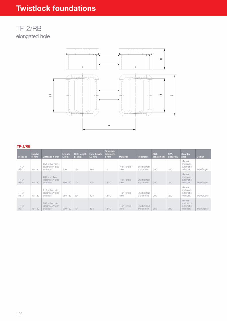
102
Twistlock foundations
TF-2/RBelongated hole
TF-2/RB
ProductHeight H mm Distance Y mm
Length L mm
Hole length L1 mm
Hole length L2 mm
Sideplate thickness T mm Material Treatment
SWL Tension kN
SWL Shear kN
Counter part Design
TF-2/RB-1 70-180
258, other hole distances Y also available 200 164 164 12
High Tensile steel
Shotblasted and primed 250 210
Manual and semi-automatic twistlock MacGregor
TF-2/RB-2 70-180
203 other hole distances Y also available 190/160 164 124 12/10
High Tensile steel
Shotblasted and primed 250 210
Manual and semi-automatic twistlock MacGregor
TF-2/RB-3 70-180
216, other hole distances Y also available 260/160 224 124 12/10
High Tensile steel
Shotblasted and primed 250 210
Manual and semi-automatic twistlock MacGregor
TF-2/RB-4 70-180
203, other hole distances Y also available 200/160 164 124 12/10
High Tensile steel
Shotblasted and primed 250 210
Manual and semi-automatic twistlock MacGregor
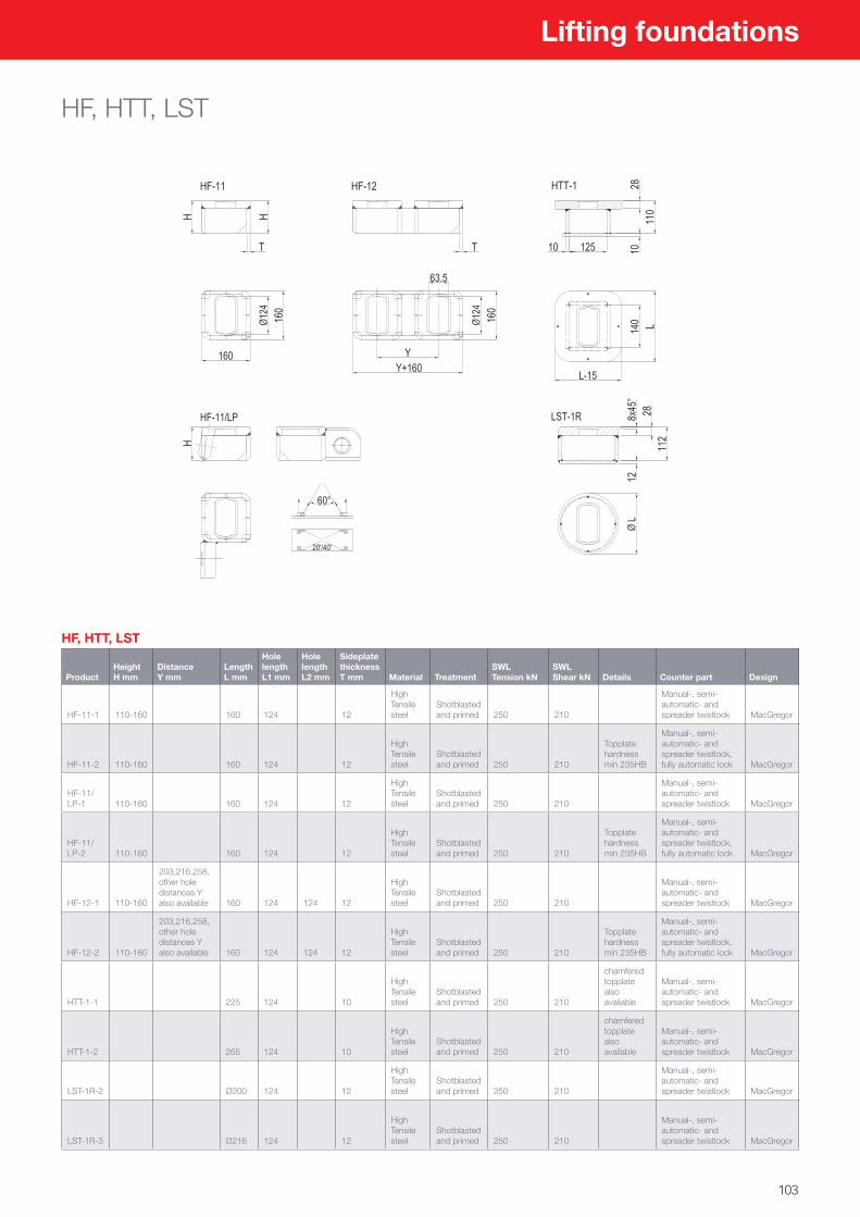
103
Lifting foundations
HF, HTT, LST
HF, HTT, LST
ProductHeight H mm
DistanceY mm
Length L mm
Hole length L1 mm
Hole length L2 mm
Sideplate thickness T mm Material Treatment
SWL Tension kN
SWL Shear kN Details Counter part Design
HF-11-1 110-160 160 124 12
High Tensile steel
Shotblasted and primed 250 210
Manual-, semi-automatic- and spreader twistlock MacGregor
HF-11-2 110-160 160 124 12
High Tensile steel
Shotblasted and primed 250 210
Topplate hardness min 235HB
Manual-, semi-automatic- and spreader twistlock, fully automatic lock MacGregor
HF-11/LP-1 110-160 160 124 12
High Tensile steel
Shotblasted and primed 250 210
Manual-, semi-automatic- and spreader twistlock MacGregor
HF-11/LP-2 110-160 160 124 12
High Tensile steel
Shotblasted and primed 250 210
Topplate hardness min 235HB
Manual-, semi-automatic- and spreader twistlock, fully automatic lock MacGregor
HF-12-1 110-160
203,216,258, other hole distances Y also available 160 124 124 12
High Tensile steel
Shotblasted and primed 250 210
Manual-, semi-automatic- and spreader twistlock MacGregor
HF-12-2 110-160
203,216,258, other hole distances Y also available 160 124 124 12
High Tensile steel
Shotblasted and primed 250 210
Topplate hardness min 235HB
Manual-, semi-automatic- and spreader twistlock, fully automatic lock MacGregor
HTT-1-1 225 124 10
High Tensile steel
Shotblasted and primed 250 210
chamfered topplate also available
Manual-, semi-automatic- and spreader twistlock MacGregor
HTT-1-2 265 124 10
High Tensile steel
Shotblasted and primed 250 210
chamfered topplate also available
Manual-, semi-automatic- and spreader twistlock MacGregor
LST-1R-2 Ø200 124 12
High Tensile steel
Shotblasted and primed 250 210
Manual-, semi-automatic- and spreader twistlock MacGregor
LST-1R-3 Ø216 124 12
High Tensile steel
Shotblasted and primed 250 210
Manual-, semi-automatic- and spreader twistlock MacGregor
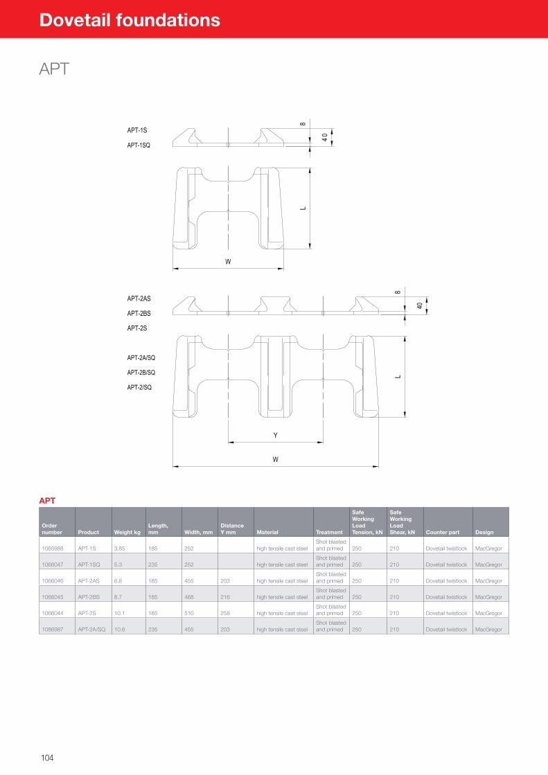
104
Dovetail foundations
APT
APT
Order number Product Weight kg
Length, mm Width, mm
DistanceY mm Material Treatment
Safe Working Load Tension, kN
Safe Working Load Shear, kN Counter part Design
1065988 APT-1S 3.85 185 252 high tensile cast steelShot blasted and primed 250 210 Dovetail twistlock MacGregor
1066047 APT-1SQ 5.3 235 252 high tensile cast steelShot blasted and primed 250 210 Dovetail twistlock MacGregor
1066046 APT-2AS 6.8 185 455 203 high tensile cast steelShot blasted and primed 250 210 Dovetail twistlock MacGregor
1066045 APT-2BS 8.7 185 468 216 high tensile cast steelShot blasted and primed 250 210 Dovetail twistlock MacGregor
1066044 APT-2S 10.1 185 510 258 high tensile cast steelShot blasted and primed 250 210 Dovetail twistlock MacGregor
1086987 APT-2A/SQ 10.6 235 455 203 high tensile cast steelShot blasted and primed 250 210 Dovetail twistlock MacGregor
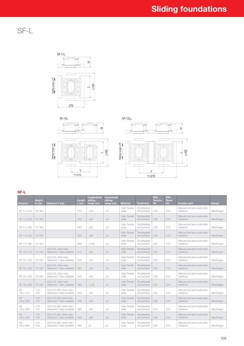
105
Sliding foundations
SF-L
SF-L
ProductHeight H mm Distance Y mm
Length L mm
longitudinal sliding range mm
transversal sliding range mm Material Treatment
SWL Tension kN
SWL Shear kN Counter part Design
SF-11L-210 70-180 210 ±30 ±0High Tensile steel
Shotblasted and primed 250 210
Manual and semi-automatic twistlock MacGregor
SF-11L-230 70-180 230 ±40 ±0High Tensile steel
Shotblasted and primed 250 210
Manual and semi-automatic twistlock MacGregor
SF-11L-280 70-180 280 ±65 ±0High Tensile steel
Shotblasted and primed 250 210
Manual and semi-automatic twistlock MacGregor
SF-11L-320 70-180 320 ±85 ±0High Tensile steel
Shotblasted and primed 250 210
Manual and semi-automatic twistlock MacGregor
SF-11L-360 70-180 360 ±105 ±0High Tensile steel
Shotblasted and primed 250 210
Manual and semi-automatic twistlock MacGregor
SF-12L-210 70-180203,216, other hole distances Y also available 210 ±30 ±0
High Tensile steel
Shotblasted and primed 250 210
Manual and semi-automatic twistlock MacGregor
SF-12L-230 70-180203,216, other hole distances Y also available 230 ±40 ±0
High Tensile steel
Shotblasted and primed 250 210
Manual and semi-automatic twistlock MacGregor
SF-12L-280 70-180203,216, other hole distances Y also available 280 ±65 ±0
High Tensile steel
Shotblasted and primed 250 210
Manual and semi-automatic twistlock MacGregor
SF-12L-320 70-180203,216, other hole distances Y also available 320 ±85 ±0
High Tensile steel
Shotblasted and primed 250 210
Manual and semi-automatic twistlock MacGregor
SF-12L-360 70-180203,216, other hole distances Y also available 360 ±105 ±0
High Tensile steel
Shotblasted and primed 250 210
Manual and semi-automatic twistlock MacGregor
SF-12LL-210
110-140
203,216,258, other hole distances Y also available 210 ±30 ±0
High Tensile steel
Shotblasted and primed 250 210
Manual and semi-automatic twistlock MacGregor
SF-12LL-230
110-140
203,216,258, other hole distances Y also available 230 ±40 ±0
High Tensile steel
Shotblasted and primed 250 210
Manual and semi-automatic twistlock MacGregor
SF-12LL-280
110-140
203,216,258, other hole distances Y also available 280 ±65 ±0
High Tensile steel
Shotblasted and primed 250 210
Manual and semi-automatic twistlock MacGregor
SF-12LL-320
110-140
203,216,258, other hole distances Y also available 320 ±85 ±0
High Tensile steel
Shotblasted and primed 250 210
Manual and semi-automatic twistlock MacGregor
SF-12LL-360
110-140
203,216,258, other hole distances Y also available 360 ±0 ±0
High Tensile steel
Shotblasted and primed 250 210
Manual and semi-automatic twistlock MacGregor
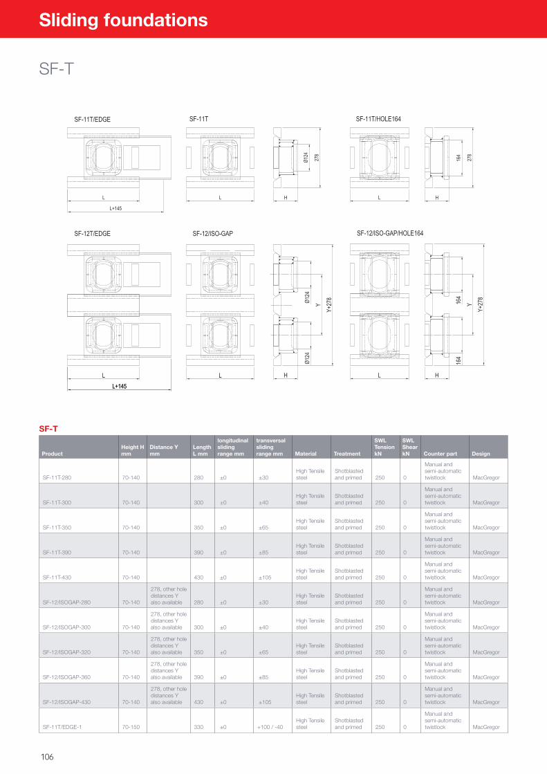
106
Sliding foundations
SF-T
SF-T
ProductHeight H mm
Distance Y mm
Length L mm
longitudinal sliding range mm
transversal sliding range mm Material Treatment
SWL Tension kN
SWL Shear kN Counter part Design
SF-11T-280 70-140 280 ±0 ±30High Tensile steel
Shotblasted and primed 250 0
Manual and semi-automatic twistlock MacGregor
SF-11T-300 70-140 300 ±0 ±40High Tensile steel
Shotblasted and primed 250 0
Manual and semi-automatic twistlock MacGregor
SF-11T-350 70-140 350 ±0 ±65High Tensile steel
Shotblasted and primed 250 0
Manual and semi-automatic twistlock MacGregor
SF-11T-390 70-140 390 ±0 ±85High Tensile steel
Shotblasted and primed 250 0
Manual and semi-automatic twistlock MacGregor
SF-11T-430 70-140 430 ±0 ±105High Tensile steel
Shotblasted and primed 250 0
Manual and semi-automatic twistlock MacGregor
SF-12/ISOGAP-280 70-140
278, other hole distances Y also available 280 ±0 ±30
High Tensile steel
Shotblasted and primed 250 0
Manual and semi-automatic twistlock MacGregor
SF-12/ISOGAP-300 70-140
278, other hole distances Y also available 300 ±0 ±40
High Tensile steel
Shotblasted and primed 250 0
Manual and semi-automatic twistlock MacGregor
SF-12/ISOGAP-320 70-140
278, other hole distances Y also available 350 ±0 ±65
High Tensile steel
Shotblasted and primed 250 0
Manual and semi-automatic twistlock MacGregor
SF-12/ISOGAP-360 70-140
278, other hole distances Y also available 390 ±0 ±85
High Tensile steel
Shotblasted and primed 250 0
Manual and semi-automatic twistlock MacGregor
SF-12/ISOGAP-430 70-140
278, other hole distances Y also available 430 ±0 ±105
High Tensile steel
Shotblasted and primed 250 0
Manual and semi-automatic twistlock MacGregor
SF-11T/EDGE-1 70-150 330 ±0 +100 / -40High Tensile steel
Shotblasted and primed 250 0
Manual and semi-automatic twistlock MacGregor
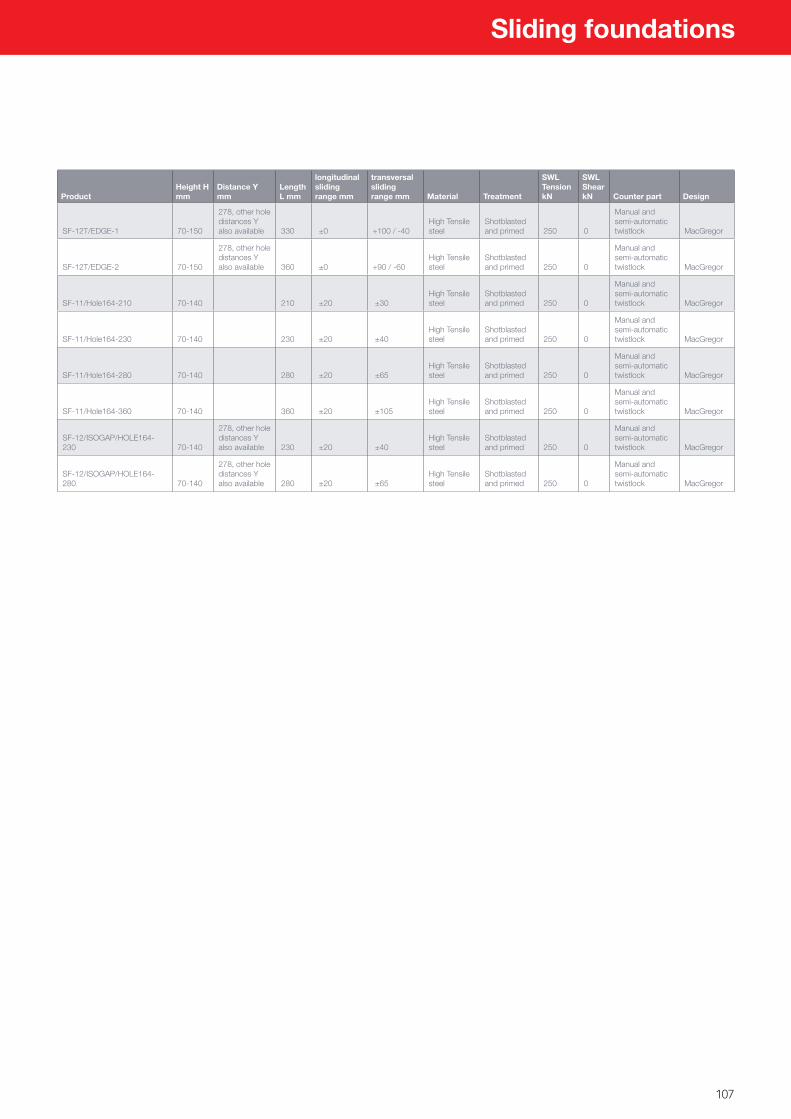
107
Sliding foundations
ProductHeight H mm
Distance Y mm
Length L mm
longitudinal sliding range mm
transversal sliding range mm Material Treatment
SWL Tension kN
SWL Shear kN Counter part Design
SF-12T/EDGE-1 70-150
278, other hole distances Y also available 330 ±0 +100 / -40
High Tensile steel
Shotblasted and primed 250 0
Manual and semi-automatic twistlock MacGregor
SF-12T/EDGE-2 70-150
278, other hole distances Y also available 360 ±0 +90 / -60
High Tensile steel
Shotblasted and primed 250 0
Manual and semi-automatic twistlock MacGregor
SF-11/Hole164-210 70-140 210 ±20 ±30High Tensile steel
Shotblasted and primed 250 0
Manual and semi-automatic twistlock MacGregor
SF-11/Hole164-230 70-140 230 ±20 ±40High Tensile steel
Shotblasted and primed 250 0
Manual and semi-automatic twistlock MacGregor
SF-11/Hole164-280 70-140 280 ±20 ±65High Tensile steel
Shotblasted and primed 250 0
Manual and semi-automatic twistlock MacGregor
SF-11/Hole164-360 70-140 360 ±20 ±105High Tensile steel
Shotblasted and primed 250 0
Manual and semi-automatic twistlock MacGregor
SF-12/ISOGAP/HOLE164-230 70-140
278, other hole distances Y also available 230 ±20 ±40
High Tensile steel
Shotblasted and primed 250 0
Manual and semi-automatic twistlock MacGregor
SF-12/ISOGAP/HOLE164-280 70-140
278, other hole distances Y also available 280 ±20 ±65
High Tensile steel
Shotblasted and primed 250 0
Manual and semi-automatic twistlock MacGregor
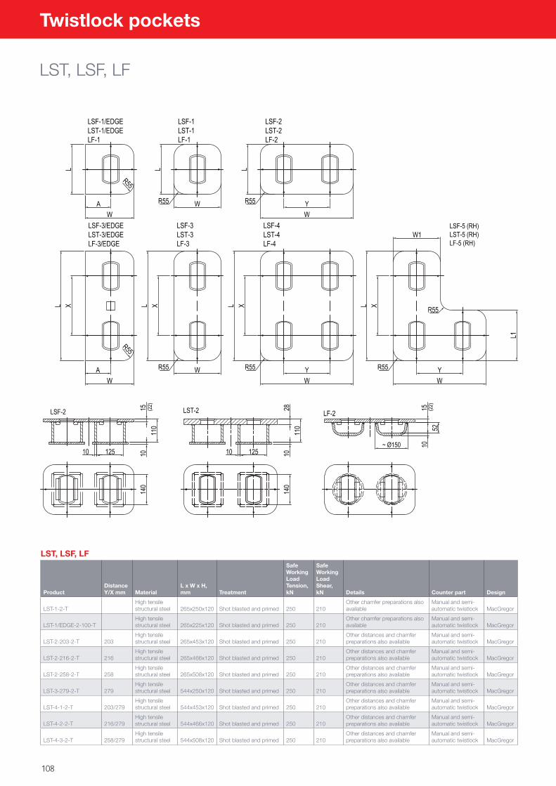
108
Twistlock pockets
LST, LSF, LF
LST, LSF, LF
ProductDistance Y/X mm Material
L x W x H, mm Treatment
Safe Working Load Tension, kN
Safe Working Load Shear, kN Details Counter part Design
LST-1-2-THigh tensile structural steel
265x250x120 Shot blasted and primed 250 210
Other chamfer preparations also available
Manual and semi-automatic twistlock MacGregor
LST-1/EDGE-2-100-THigh tensile structural steel 265x225x120 Shot blasted and primed 250 210
Other chamfer preparations also available
Manual and semi-automatic twistlock MacGregor
LST-2-203-2-T 203High tensile structural steel 265x453x120 Shot blasted and primed 250 210
Other distances and chamfer preparations also available
Manual and semi-automatic twistlock MacGregor
LST-2-216-2-T 216High tensile structural steel 265x466x120 Shot blasted and primed 250 210
Other distances and chamfer preparations also available
Manual and semi-automatic twistlock MacGregor
LST-2-258-2-T 258High tensile structural steel 265x508x120 Shot blasted and primed 250 210
Other distances and chamfer preparations also available
Manual and semi-automatic twistlock MacGregor
LST-3-279-2-T 279High tensile structural steel 544x250x120 Shot blasted and primed 250 210
Other distances and chamfer preparations also available
Manual and semi-automatic twistlock MacGregor
LST-4-1-2-T 203/279High tensile structural steel 544x453x120 Shot blasted and primed 250 210
Other distances and chamfer preparations also available
Manual and semi-automatic twistlock MacGregor
LST-4-2-2-T 216/279High tensile structural steel 544x466x120 Shot blasted and primed 250 210
Other distances and chamfer preparations also available
Manual and semi-automatic twistlock MacGregor
LST-4-3-2-T 258/279High tensile structural steel 544x508x120 Shot blasted and primed 250 210
Other distances and chamfer preparations also available
Manual and semi-automatic twistlock MacGregor
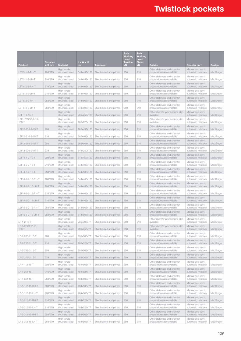
109
ProductDistance Y/X mm Material
L x W x H, mm Treatment
Safe Working Load Tension, kN
Safe Working Load Shear, kN Details Counter part Design
LST-5-1-2-RH-T 203/279High tensile structural steel 544x453x120 Shot blasted and primed 250 210
Other distances and chamfer preparations also available
Manual and semi-automatic twistlock MacGregor
LST-5-1-2-LH-T 203/279High tensile structural steel 544x453x120 Shot blasted and primed 250 210
Other distances and chamfer preparations also available
Manual and semi-automatic twistlock MacGregor
LST-5-2-2-RH-T 216/279High tensile structural steel 544x466x120 Shot blasted and primed 250 210
Other distances and chamfer preparations also available
Manual and semi-automatic twistlock MacGregor
LST-5-2-2-LH-T 216/279High tensile structural steel 544x466x120 Shot blasted and primed 250 210
Other distances and chamfer preparations also available
Manual and semi-automatic twistlock MacGregor
LST-5-3-2-RH-T 258/279High tensile structural steel 544x508x120 Shot blasted and primed 250 210
Other distances and chamfer preparations also available
Manual and semi-automatic twistlock MacGregor
LST-5-3-2-LH-T 258/279High tensile structural steel 544x508x120 Shot blasted and primed 250 210
Other distances and chamfer preparations also available
Manual and semi-automatic twistlock MacGregor
LSF-1-2-15-THigh tensile structural steel 265x250x120 Shot blasted and primed 250 210
Other chamfer preparations also available
Manual and semi-automatic twistlock MacGregor
LSF-1/EDGE-2-15-100-T
High tensile structural steel 265x225x120 Shot blasted and primed 250 210
Other chamfer preparations also available
Manual and semi-automatic twistlock MacGregor
LSF-2-203-2-15-T 203High tensile structural steel 265x453x120 Shot blasted and primed 250 210
Other distances and chamfer preparations also available
Manual and semi-automatic twistlock MacGregor
LSF-2-216-2-15-T 216High tensile structural steel 265x466x120 Shot blasted and primed 250 210
Other distances and chamfer preparations also available
Manual and semi-automatic twistlock MacGregor
LSF-2-258-2-15-T 258High tensile structural steel 265x508x120 Shot blasted and primed 250 210
Other distances and chamfer preparations also available
Manual and semi-automatic twistlock MacGregor
LSF-3-279-2-15-T 279High tensile structural steel 544x250x120 Shot blasted and primed 250 210
Other distances and chamfer preparations also available
Manual and semi-automatic twistlock MacGregor
LSF-4-1-2-15-T 203/279High tensile structural steel 544x453x120 Shot blasted and primed 250 210
Other distances and chamfer preparations also available
Manual and semi-automatic twistlock MacGregor
LSF-4-2-2-15-T 216/279High tensile structural steel 544x466x120 Shot blasted and primed 250 210
Other distances and chamfer preparations also available
Manual and semi-automatic twistlock MacGregor
LSF-4-3-2-15-T 258/279High tensile structural steel 544x508x120 Shot blasted and primed 250 210
Other distances and chamfer preparations also available
Manual and semi-automatic twistlock MacGregor
LSF-5-1-2-15-RH-T 203/279High tensile structural steel 544x453x120 Shot blasted and primed 250 210
Other distances and chamfer preparations also available
Manual and semi-automatic twistlock MacGregor
LSF-5-1-2-15-LH-T 203/279High tensile structural steel 544x453x120 Shot blasted and primed 250 210
Other distances and chamfer preparations also available
Manual and semi-automatic twistlock MacGregor
LSF-5-2-2-15-RH-T 216/279High tensile structural steel 544x466x120 Shot blasted and primed 250 210
Other distances and chamfer preparations also available
Manual and semi-automatic twistlock MacGregor
LSF-5-2-2-15-LH-T 216/279High tensile structural steel 544x466x120 Shot blasted and primed 250 210
Other distances and chamfer preparations also available
Manual and semi-automatic twistlock MacGregor
LSF-5-3-2-15-RH-T 258/279High tensile structural steel 544x508x120 Shot blasted and primed 250 210
Other distances and chamfer preparations also available
Manual and semi-automatic twistlock MacGregor
LSF-5-3-2-15-LH-T 258/279High tensile structural steel 544x508x120 Shot blasted and primed 250 210
Other distances and chamfer preparations also available
Manual and semi-automatic twistlock MacGregor
LF-1-2-15-THigh tensile structural steel 205x305x77 Shot blasted and primed 250 210
Other chamfer preparations also available
Manual and semi-automatic twistlock MacGregor
LF-1/EDGE-2-15-100-T
High tensile structural steel 205x253x77 Shot blasted and primed 250 210
Other chamfer preparations also available
Manual and semi-automatic twistlock MacGregor
LF-2-203-2-15-T 203High tensile structural steel 205x508x77 Shot blasted and primed 250 210
Other distances and chamfer preparations also available
Manual and semi-automatic twistlock MacGregor
LF-2-216-2-15-T 216High tensile structural steel 205x521x77 Shot blasted and primed 250 210
Other distances and chamfer preparations also available
Manual and semi-automatic twistlock MacGregor
LF-2-258-2-15-T 258High tensile structural steel 205x563x77 Shot blasted and primed 250 210
Other distances and chamfer preparations also available
Manual and semi-automatic twistlock MacGregor
LF-3-279-2-15-T 279High tensile structural steel 484x305x77 Shot blasted and primed 250 210
Other distances and chamfer preparations also available
Manual and semi-automatic twistlock MacGregor
LF-4-1-2-15-T 203/279High tensile structural steel 484x508x77 Shot blasted and primed 250 210
Other distances and chamfer preparations also available
Manual and semi-automatic twistlock MacGregor
LF-4-2-2-15-T 216/279High tensile structural steel 484x521x77 Shot blasted and primed 250 210
Other distances and chamfer preparations also available
Manual and semi-automatic twistlock MacGregor
LF-4-3-2-15-T 258/279High tensile structural steel 484x563x77 Shot blasted and primed 250 210
Other distances and chamfer preparations also available
Manual and semi-automatic twistlock MacGregor
LF-5-1-2-15-RH-T 203/279High tensile structural steel 484x508x77 Shot blasted and primed 250 210
Other distances and chamfer preparations also available
Manual and semi-automatic twistlock MacGregor
LF-5-1-2-15-LH-T 203/279High tensile structural steel 484x508x77 Shot blasted and primed 250 210
Other distances and chamfer preparations also available
Manual and semi-automatic twistlock MacGregor
LF-5-2-2-15-RH-T 216/279High tensile structural steel 484x521x77 Shot blasted and primed 250 210
Other distances and chamfer preparations also available
Manual and semi-automatic twistlock MacGregor
LF-5-2-2-15-LH-T 216/279High tensile structural steel 484x521x77 Shot blasted and primed 250 210
Other distances and chamfer preparations also available
Manual and semi-automatic twistlock MacGregor
LF-5-3-2-15-RH-T 258/279High tensile structural steel 484x563x77 Shot blasted and primed 250 210
Other distances and chamfer preparations also available
Manual and semi-automatic twistlock MacGregor
LF-5-3-2-15-LH-T 258/279High tensile structural steel 484x563x77 Shot blasted and primed 250 210
Other distances and chamfer preparations also available
Manual and semi-automatic twistlock MacGregor
Twistlock pockets
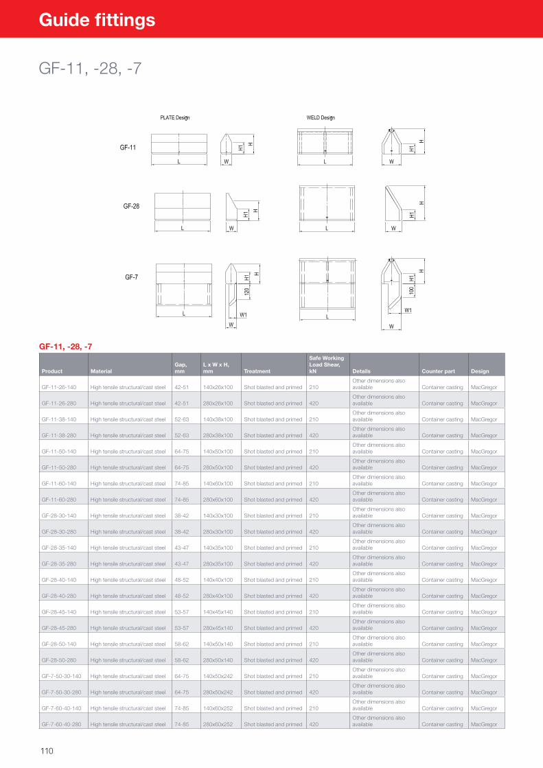
110
Guide fittings
GF-11, -28, -7
GF-11, -28, -7
Product MaterialGap, mm
L x W x H, mm Treatment
Safe Working Load Shear, kN Details Counter part Design
GF-11-26-140 High tensile structural/cast steel 42-51 140x26x100 Shot blasted and primed 210Other dimensions also available Container casting MacGregor
GF-11-26-280 High tensile structural/cast steel 42-51 280x26x100 Shot blasted and primed 420Other dimensions also available Container casting MacGregor
GF-11-38-140 High tensile structural/cast steel 52-63 140x38x100 Shot blasted and primed 210Other dimensions also available Container casting MacGregor
GF-11-38-280 High tensile structural/cast steel 52-63 280x38x100 Shot blasted and primed 420Other dimensions also available Container casting MacGregor
GF-11-50-140 High tensile structural/cast steel 64-75 140x50x100 Shot blasted and primed 210Other dimensions also available Container casting MacGregor
GF-11-50-280 High tensile structural/cast steel 64-75 280x50x100 Shot blasted and primed 420Other dimensions also available Container casting MacGregor
GF-11-60-140 High tensile structural/cast steel 74-85 140x60x100 Shot blasted and primed 210Other dimensions also available Container casting MacGregor
GF-11-60-280 High tensile structural/cast steel 74-85 280x60x100 Shot blasted and primed 420Other dimensions also available Container casting MacGregor
GF-28-30-140 High tensile structural/cast steel 38-42 140x30x100 Shot blasted and primed 210Other dimensions also available Container casting MacGregor
GF-28-30-280 High tensile structural/cast steel 38-42 280x30x100 Shot blasted and primed 420Other dimensions also available Container casting MacGregor
GF-28-35-140 High tensile structural/cast steel 43-47 140x35x100 Shot blasted and primed 210Other dimensions also available Container casting MacGregor
GF-28-35-280 High tensile structural/cast steel 43-47 280x35x100 Shot blasted and primed 420Other dimensions also available Container casting MacGregor
GF-28-40-140 High tensile structural/cast steel 48-52 140x40x100 Shot blasted and primed 210Other dimensions also available Container casting MacGregor
GF-28-40-280 High tensile structural/cast steel 48-52 280x40x100 Shot blasted and primed 420Other dimensions also available Container casting MacGregor
GF-28-45-140 High tensile structural/cast steel 53-57 140x45x140 Shot blasted and primed 210Other dimensions also available Container casting MacGregor
GF-28-45-280 High tensile structural/cast steel 53-57 280x45x140 Shot blasted and primed 420Other dimensions also available Container casting MacGregor
GF-28-50-140 High tensile structural/cast steel 58-62 140x50x140 Shot blasted and primed 210Other dimensions also available Container casting MacGregor
GF-28-50-280 High tensile structural/cast steel 58-62 280x50x140 Shot blasted and primed 420Other dimensions also available Container casting MacGregor
GF-7-50-30-140 High tensile structural/cast steel 64-75 140x50x242 Shot blasted and primed 210Other dimensions also available Container casting MacGregor
GF-7-50-30-280 High tensile structural/cast steel 64-75 280x50x242 Shot blasted and primed 420Other dimensions also available Container casting MacGregor
GF-7-60-40-140 High tensile structural/cast steel 74-85 140x60x252 Shot blasted and primed 210Other dimensions also available Container casting MacGregor
GF-7-60-40-280 High tensile structural/cast steel 74-85 280x60x252 Shot blasted and primed 420Other dimensions also available Container casting MacGregor
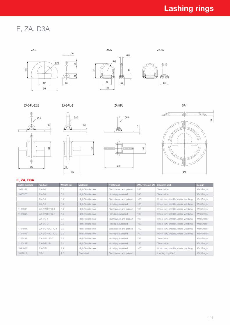
111
Lashing rings
E, ZA, D3A
E, ZA, D3AOrder number Product Weight kg Material Treatment SWL Tension kN Counter part Design
1021154 ZA-3-1 5.1 High Tensile steel Shotblasted and primed 245 Turnbuckle MacGregor
1035376 ZA-3-2 5.1 High Tensile steel Hot-dip galvanised 245 Turnbuckle MacGregor
ZA-5-1 1.7 High Tensile steel Shotblasted and primed 100 Hook, jaw, shackle, chain, webbing MacGregor
ZA-5-2 1.7 High Tensile steel Hot-dip galvanised 100 Hook, jaw, shackle, chain, webbing MacGregor
1194596 ZA-5/ARCTIC-1 1.7 High Tensile steel Shotblasted and primed 100 Hook, jaw, shackle, chain, webbing MacGregor
1194597 ZA-5/ARCTIC-2 1.7 High Tensile steel Hot-dip galvanised 100 Hook, jaw, shackle, chain, webbing MacGregor
ZA-5/2-1 2.9 High Tensile steel Shotblasted and primed 100 Hook, jaw, shackle, chain, webbing MacGregor
ZA-5/2-2 2.9 High Tensile steel Hot-dip galvanised 100 Hook, jaw, shackle, chain, webbing MacGregor
1194594 ZA-5/2-ARCTIC-1 2.9 High Tensile steel Shotblasted and primed 100 Hook, jaw, shackle, chain, webbing MacGregor
1194595 ZA-5/2-ARCTIC-2 2.9 High Tensile steel Hot-dip galvanised 100 Hook, jaw, shackle, chain, webbing MacGregor
1166438 ZA-3-PL-S2-2 7.8 High Tensile steel Hot-dip galvanised 245 Turnbuckle MacGregor
1166439 ZA-3-PL-S1 7.4 High Tensile steel Hot-dip galvanised 245 Turnbuckle MacGregor
1094867 ZA-5/PL 2.7 High Tensile steel Hot-dip galvanised 100 Hook, jaw, shackle, chain, webbing MacGregor
1012812 SR-1 7.6 Cast steel Shotblasted and primed Lashing ring ZA-3 MacGregor
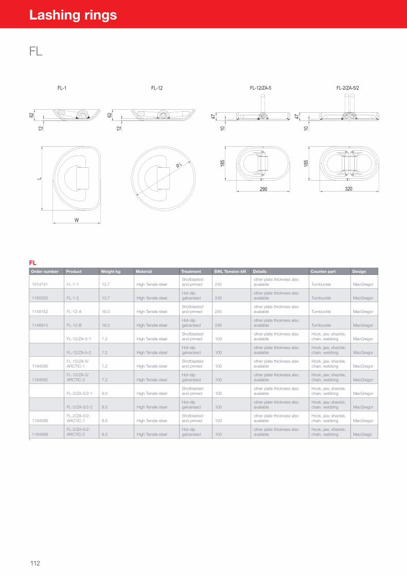
112
Lashing rings
FL
FLOrder number Product Weight kg Material Treatment SWL Tension kN Details Counter part Design
1014741 FL-1-1 13.7 High Tensile steelShotblasted and primed 245
other plate thickness also available Turnbuckle MacGregor
1180332 FL-1-2 13.7 High Tensile steelHot-dip galvanised 245
other plate thickness also available Turnbuckle MacGregor
1149152 FL-12-A 16.0 High Tensile steelShotblasted and primed 245
other plate thickness also available Turnbuckle MacGregor
1148910 FL-12-B 16.0 High Tensile steelHot-dip galvanised 245
other plate thickness also available Turnbuckle MacGregor
FL-12/ZA-5-1 7.2 High Tensile steelShotblasted and primed 100
other plate thickness also available
Hook, jaw, shackle, chain, webbing MacGregor
FL-12/ZA-5-2 7.2 High Tensile steelHot-dip galvanised 100
other plate thickness also available
Hook, jaw, shackle, chain, webbing MacGregor
1194590FL-12/ZA-5/ARCTIC-1 7.2 High Tensile steel
Shotblasted and primed 100
other plate thickness also available
Hook, jaw, shackle, chain, webbing MacGregor
1194592FL-12/ZA-5/ARCTIC-2 7.2 High Tensile steel
Hot-dip galvanised 100
other plate thickness also available
Hook, jaw, shackle, chain, webbing MacGregor
FL-2/ZA-5/2-1 9.0 High Tensile steelShotblasted and primed 100
other plate thickness also available
Hook, jaw, shackle, chain, webbing MacGregor
FL-2/ZA-5/2-2 9.0 High Tensile steelHot-dip galvanised 100
other plate thickness also available
Hook, jaw, shackle, chain, webbing MacGregor
1194588FL-2/ZA-5/2-ARCTIC-1 9.0 High Tensile steel
Shotblasted and primed 100
other plate thickness also available
Hook, jaw, shackle, chain, webbing MacGregor
1194589FL-2/ZA-5/2-ARCTIC-2 9.0 High Tensile steel
Hot-dip galvanised 100
other plate thickness also available
Hook, jaw, shackle, chain, webbing MacGrego
r
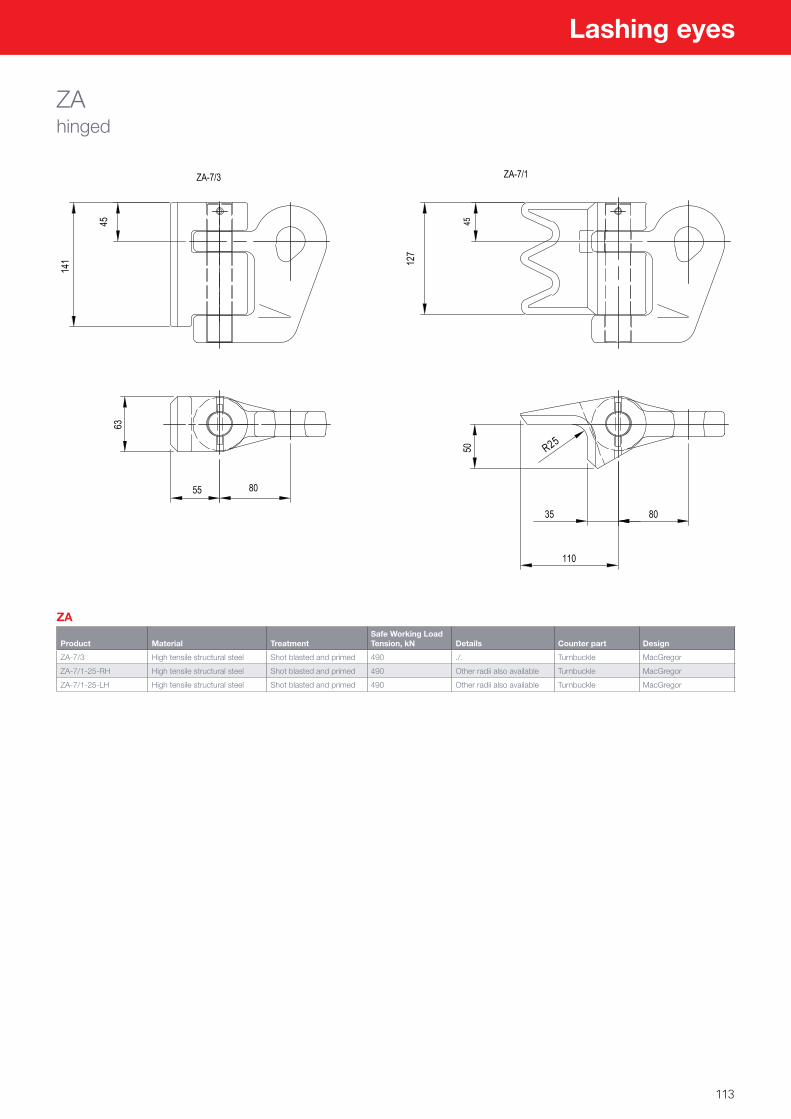
113
Lashing eyes
ZAhinged
ZA
Product Material TreatmentSafe Working Load Tension, kN Details Counter part Design
ZA-7/3 High tensile structural steel Shot blasted and primed 490 ./. Turnbuckle MacGregor
ZA-7/1-25-RH High tensile structural steel Shot blasted and primed 490 Other radii also available Turnbuckle MacGregor
ZA-7/1-25-LH High tensile structural steel Shot blasted and primed 490 Other radii also available Turnbuckle MacGregor
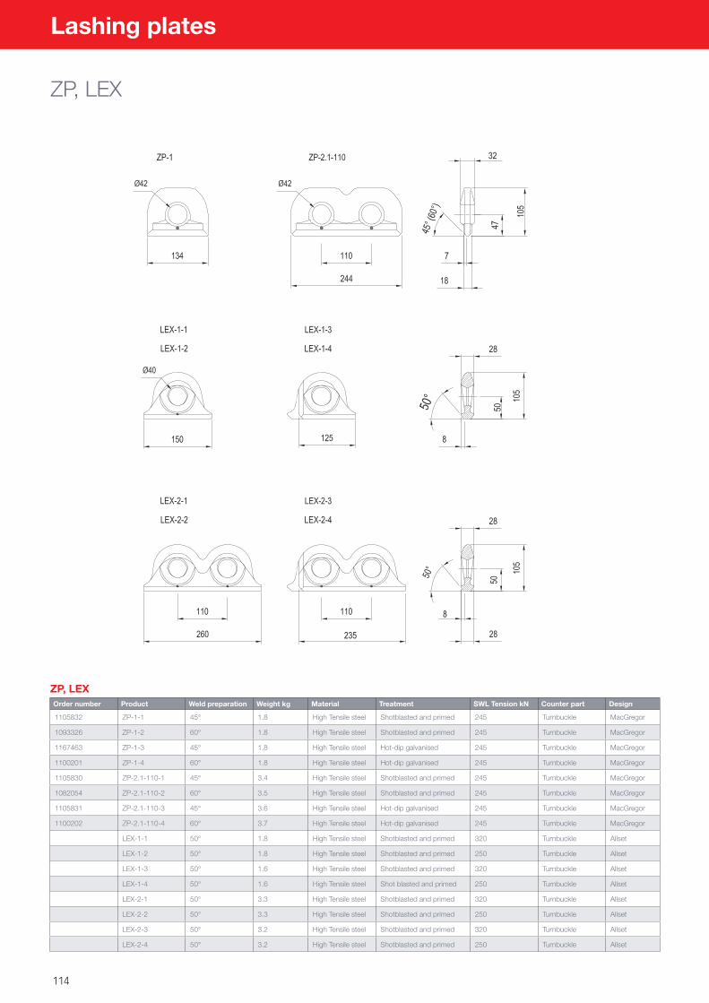
114
Lashing plates
ZP, LEX
ZP, LEXOrder number Product Weld preparation Weight kg Material Treatment SWL Tension kN Counter part Design
1105832 ZP-1-1 45° 1.8 High Tensile steel Shotblasted and primed 245 Turnbuckle MacGregor
1093326 ZP-1-2 60° 1.8 High Tensile steel Shotblasted and primed 245 Turnbuckle MacGregor
1167463 ZP-1-3 45° 1.8 High Tensile steel Hot-dip galvanised 245 Turnbuckle MacGregor
1100201 ZP-1-4 60° 1.8 High Tensile steel Hot-dip galvanised 245 Turnbuckle MacGregor
1105830 ZP-2.1-110-1 45° 3.4 High Tensile steel Shotblasted and primed 245 Turnbuckle MacGregor
1082054 ZP-2.1-110-2 60° 3.5 High Tensile steel Shotblasted and primed 245 Turnbuckle MacGregor
1105831 ZP-2.1-110-3 45° 3.6 High Tensile steel Hot-dip galvanised 245 Turnbuckle MacGregor
1100202 ZP-2.1-110-4 60° 3.7 High Tensile steel Hot-dip galvanised 245 Turnbuckle MacGregor
LEX-1-1 50° 1.8 High Tensile steel Shotblasted and primed 320 Turnbuckle Allset
LEX-1-2 50° 1.8 High Tensile steel Shotblasted and primed 250 Turnbuckle Allset
LEX-1-3 50° 1.6 High Tensile steel Shotblasted and primed 320 Turnbuckle Allset
LEX-1-4 50° 1.6 High Tensile steel Shot blasted and primed 250 Turnbuckle Allset
LEX-2-1 50° 3.3 High Tensile steel Shotblasted and primed 320 Turnbuckle Allset
LEX-2-2 50° 3.3 High Tensile steel Shotblasted and primed 250 Turnbuckle Allset
LEX-2-3 50° 3.2 High Tensile steel Shotblasted and primed 320 Turnbuckle Allset
LEX-2-4 50° 3.2 High Tensile steel Shotblasted and primed 250 Turnbuckle Allset
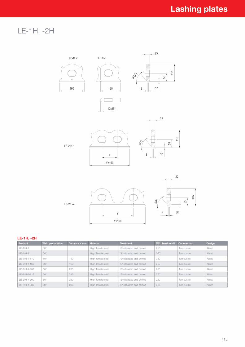
115
Lashing plates
LE-1H, -2H
LE-1H, -2HProduct Weld preparation Distance Y mm Material Treatment SWL Tension kN Counter part Design
LE-1/H-1 50° High Tensile steel Shotblasted and primed 250 Turnbuckle Allset
LE-1/H-3 50° High Tensile steel Shotblasted and primed 250 Turnbuckle Allset
LE-2/H-1-110 50° 110 High Tensile steel Shotblasted and primed 250 Turnbuckle Allset
LE-2/H-1-150 50° 150 High Tensile steel Shotblasted and primed 250 Turnbuckle Allset
LE-2/H-4-203 50° 203 High Tensile steel Shotblasted and primed 250 Turnbuckle Allset
LE-2/H-4-216 50° 216 High Tensile steel Shotblasted and primed 250 Turnbuckle Allset
LE-2/H-4-260 50° 260 High Tensile steel Shotblasted and primed 250 Turnbuckle Allset
LE-2/H-4-280 50° 280 High Tensile steel Shotblasted and primed 250 Turnbuckle Allset
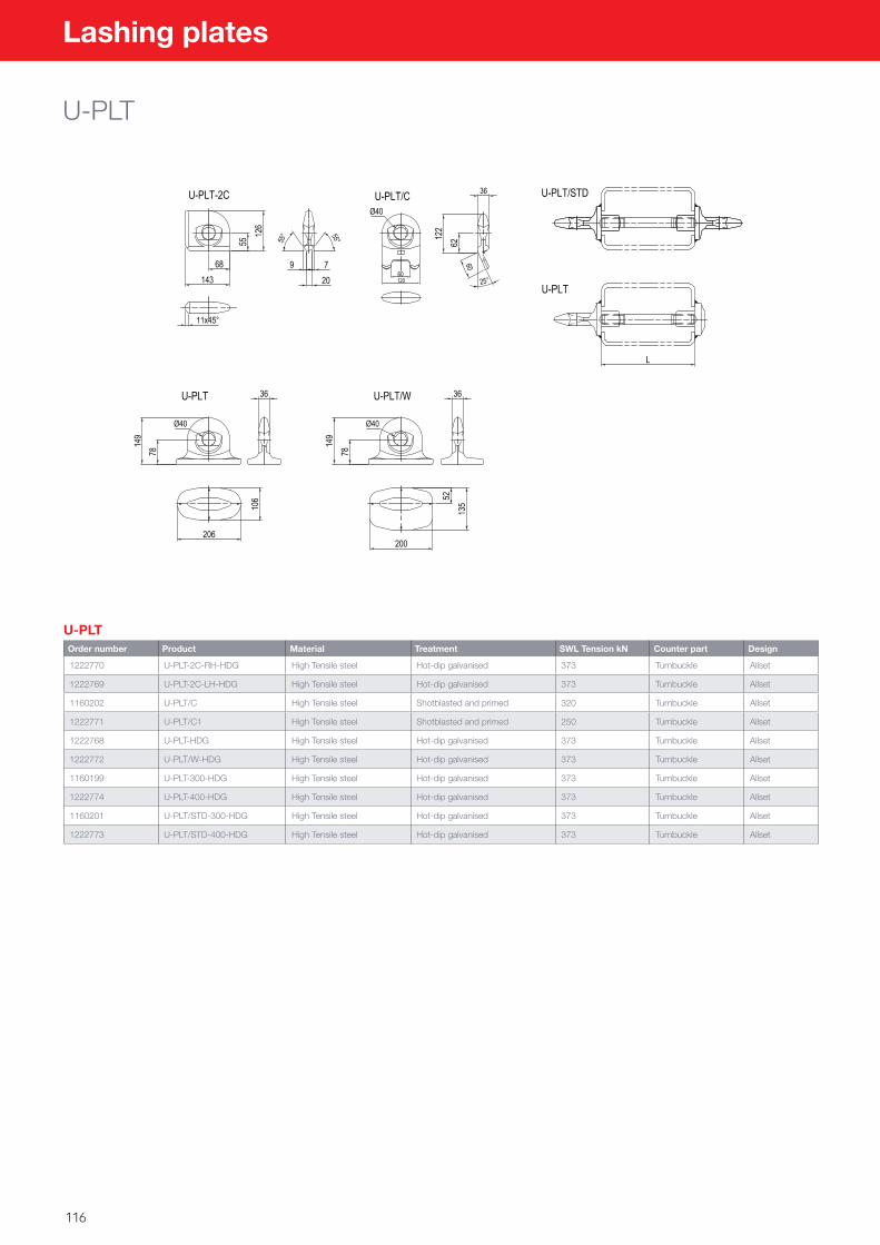
116
Lashing plates
U-PLT
U-PLTOrder number Product Material Treatment SWL Tension kN Counter part Design
1222770 U-PLT-2C-RH-HDG High Tensile steel Hot-dip galvanised 373 Turnbuckle Allset
1222769 U-PLT-2C-LH-HDG High Tensile steel Hot-dip galvanised 373 Turnbuckle Allset
1160202 U-PLT/C High Tensile steel Shotblasted and primed 320 Turnbuckle Allset
1222771 U-PLT/C1 High Tensile steel Shotblasted and primed 250 Turnbuckle Allset
1222768 U-PLT-HDG High Tensile steel Hot-dip galvanised 373 Turnbuckle Allset
1222772 U-PLT/W-HDG High Tensile steel Hot-dip galvanised 373 Turnbuckle Allset
1160199 U-PLT-300-HDG High Tensile steel Hot-dip galvanised 373 Turnbuckle Allset
1222774 U-PLT-400-HDG High Tensile steel Hot-dip galvanised 373 Turnbuckle Allset
1160201 U-PLT/STD-300-HDG High Tensile steel Hot-dip galvanised 373 Turnbuckle Allset
1222773 U-PLT/STD-400-HDG High Tensile steel Hot-dip galvanised 373 Turnbuckle Allset
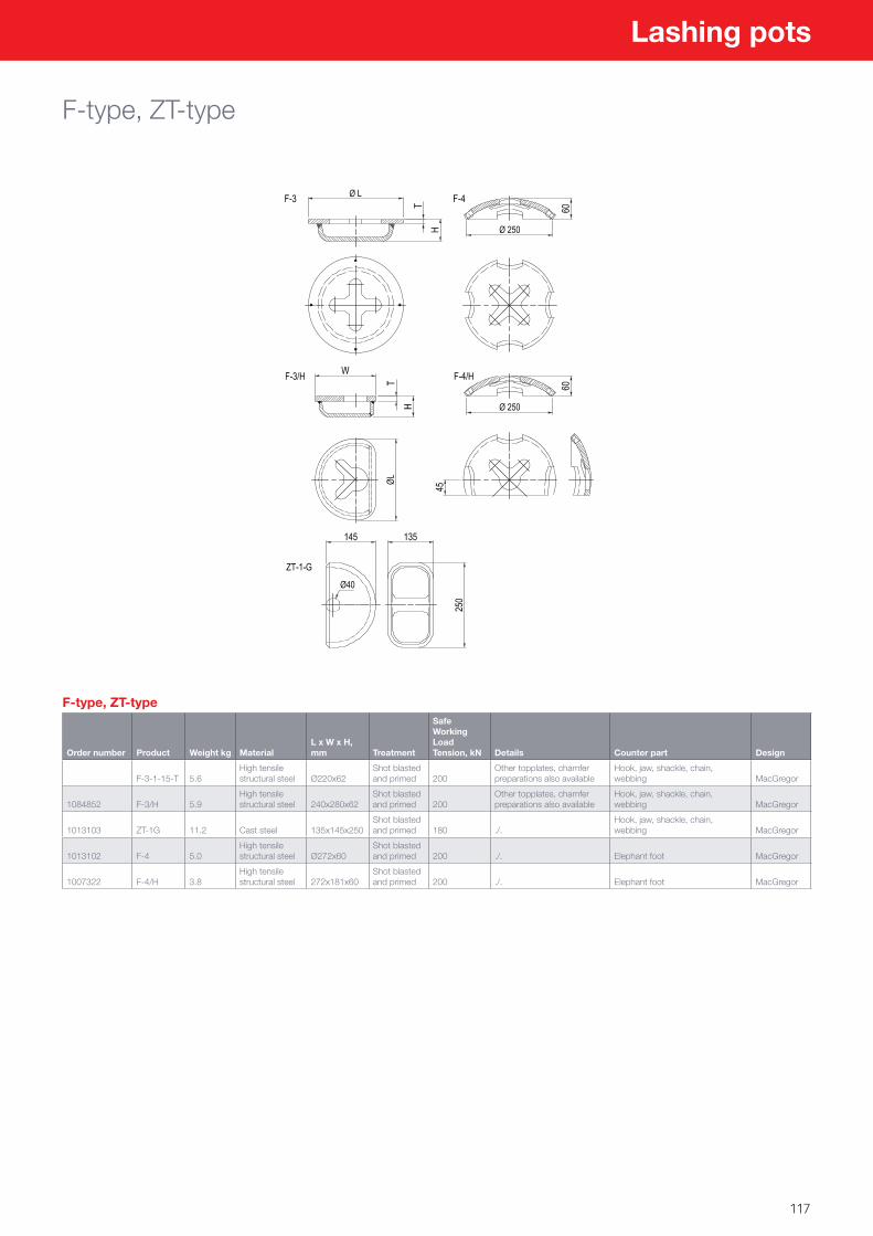
117
Lashing pots
F-type, ZT-type
F-type, ZT-type
Order number Product Weight kg MaterialL x W x H, mm Treatment
Safe Working Load Tension, kN Details Counter part Design
F-3-1-15-T 5.6High tensile structural steel Ø220x62
Shot blasted and primed 200
Other topplates, chamfer preparations also available
Hook, jaw, shackle, chain, webbing MacGregor
1084852 F-3/H 5.9High tensile structural steel 240x280x62
Shot blasted and primed 200
Other topplates, chamfer preparations also available
Hook, jaw, shackle, chain, webbing MacGregor
1013103 ZT-1G 11.2 Cast steel 135x145x250Shot blasted and primed 180 ./.
Hook, jaw, shackle, chain, webbing MacGregor
1013102 F-4 5.0High tensile structural steel Ø272x60
Shot blasted and primed 200 ./. Elephant foot MacGregor
1007322 F-4/H 3.8High tensile structural steel 272x181x60
Shot blasted and primed 200 ./. Elephant foot MacGregor
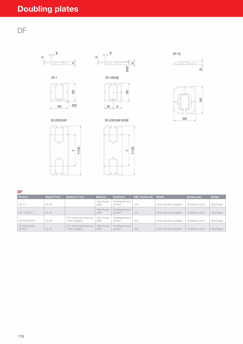
118
Doubling plates
DF
DFProduct Height H mm Distance Y mm Material Treatment SWL Tension kN Details Counter part Design
DF-1-1 25-45High Tensile steel
Shotblasted and primed 210 other chamfers available Container corner MacGregor
DF-1/EDGE-1 25-45High Tensile steel
Shotblasted and primed 210 other chamfers available Container corner MacGregor
DF-2/ISOGAP-1 25-45279, other hole distances Y also available
High Tensile steel
Shotblasted and primed 420 other chamfers available Container corner MacGregor
DF-2/ISOGAP-EDGE-1 25-45
279, other hole distances Y also available
High Tensile steel
Shotblasted and primed 420 other chamfers available Container corner MacGregor

119
Welding cones
12-1, 2 & 40
12-1, 2 & 40
Order number Product Weight kg Material L x W x H, mm TreatmentSafe Working Load Shear, kN Details
Counter part Design
1109150 TYPE 12-1 1.8High tensile structural/cast steel 100x55x60
Shot blasted and primed 210
Other chamfer preparations also available
Container corner MacGregor
1235129 TYPE 12-2High tensile structural/cast steel 100x55x90
Shot blasted and primed 210
Container corner MacGregor
1130042 TYPE 40 1.2High tensile structural/cast steel 100x40x60
Shot blasted and primed 210
Container corner MacGregor
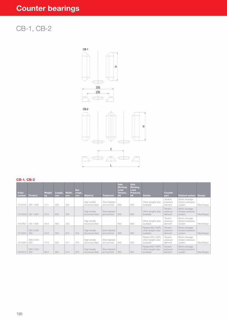
120
Counter bearings
CB-1, CB-2
CB-1, CB-2
Order number Product
Weight kg
Length, mm
Width, mm
Eye range, mm Material Treatment
Safe Working Load Tension, kN
Safe Working Load Pressure, kN Details
Counter part Related system Design
1013245 CB-1-300 14.1 300 335High tensile structural steel
Shot blasted and primed 850 850
Other lengths also available
Tension pressure element
Block stowage tension pressure system MacGregor
1013246 CB-1-600 27.6 600 335High tensile structural steel
Shot blasted and primed 850 850
Other lengths also available
Tension pressure element
Block stowage tension pressure system MacGregor
1007807 CB-1-900 43.4 900 335High tensile structural steel 850 850
Other lengths also available
Tension pressure element
Block stowage tension pressure system MacGregor
1013254CB-2-235-300 24.5 300 614 279
High tensile structural steel
Shot blasted and primed 850 850
Raised (ISO-GAP), other lengths also available
Tension pressure element
Block stowage tension pressure system MacGregor
1013255CB-2-235-600 47.9 600 614 279
High tensile structural steel
Shot blasted and primed 850 850
Raised (ISO-GAP), other lengths also available
Tension pressure element
Block stowage tension pressure system MacGregor
1007816CB-2-235-900 69.5 900 614 279
High tensile structural steel
Shot blasted and primed 850 850
Raised (ISO-GAP), other lengths also available
Tension pressure element
Block stowage tension pressure system MacGregor
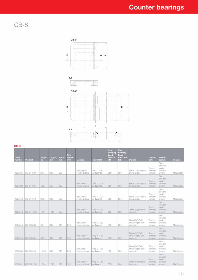
121
Counter bearings
CB-8
CB-8
Order number Product
Weight kg
Length, mm
Width, mm
Eye range, mm Material Treatment
Safe Working Load Tension, kN
Safe Working Load Pressure, kN Details
Counter part
Related system Design
1007835 CB-8/1-330 27.5 330 339High tensile structural steel
Shot blasted and primed 850 850
Flush, other lengths also available
Tension pressure element
Block stowage tension pressure system MacGregor
1007839 CB-8/1-635 53.2 635 339High tensile structural steel
Shot blasted and primed 850 850
Flush, other lengths also available
Tension pressure element
Block stowage tension pressure system MacGregor
1007842 CB-8/1-940 81.2 940 339High tensile structural steel
Shot blasted and primed 850 850
Flush, other lengths also available
Tension pressure element
Block stowage tension pressure system MacGregor
1007843 CB-8/1-1245 107.7 1245 339High tensile structural steel
Shot blasted and primed 850 850
Other lengths also available
Tension pressure element
Block stowage tension pressure system MacGregor
1007846 CB-8/3-330 46.1 330 618 279High tensile structural steel
Shot blasted and primed 850 850
Flush (ISO-GAP), other lengths also available
Tension pressure element
Block stowage tension pressure system MacGregor
1007849 CB-8/3-635 89.9 635 618 279High tensile structural steel
Shot blasted and primed 850 850
Flush (ISO-GAP), other lengths also available
Tension pressure element
Block stowage tension pressure system MacGregor
1007850 CB-8/3-940 135.6 940 618 279High tensile structural steel
Shot blasted and primed 850 850
Flush (ISO-GAP), other lengths also available
Tension pressure element
Block stowage tension pressure system MacGregor
1007851 CB-8/3-1245 179.4 1245 618 279High tensile structural steel
Shot blasted and primed 850 850
Other lengths also available
Tension pressure element
Block stowage tension pressure system MacGregor
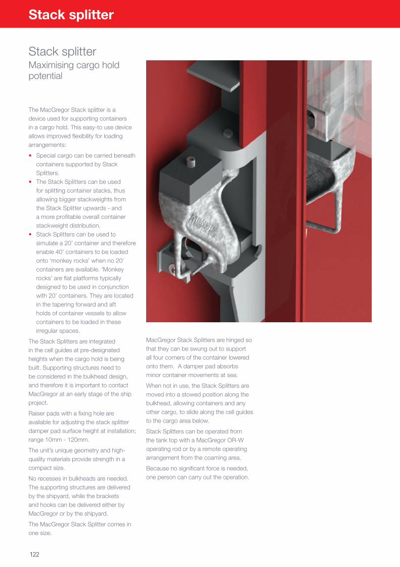
122
Stack splitter
Stack splitterMaximising cargo hold potential
The MacGregor Stack splitter is a device used for supporting containers in a cargo hold. This easy-to use device allows improved flexibility for loading arrangements:
• Special cargo can be carried beneath containers supported by Stack Splitters.
• The Stack Splitters can be used for splitting container stacks, thus allowing bigger stackweights from the Stack Splitter upwards - and a more profitable overall container stackweight distribution.
• Stack Splitters can be used to simulate a 20’ container and therefore enable 40’ containers to be loaded onto ‘monkey rocks’ when no 20’ containers are available. ‘Monkey rocks’ are flat platforms typically designed to be used in conjunction with 20’ containers. They are located in the tapering forward and aft holds of container vessels to allow containers to be loaded in these irregular spaces.
The Stack Splitters are integrated in the cell guides at pre-designated heights when the cargo hold is being built. Supporting structures need to be considered in the bulkhead design, and therefore it is important to contact MacGregor at an early stage of the ship project.
Raiser pads with a fixing hole are available for adjusting the stack splitter damper pad surface height at installation; range 10mm - 120mm.
The unit’s unique geometry and high-quality materials provide strength in a compact size.
No recesses in bulkheads are needed. The supporting structures are delivered by the shipyard, while the brackets and hooks can be delivered either by MacGregor or by the shipyard.
The MacGregor Stack Splitter comes in one size.
MacGregor Stack Splitters are hinged so that they can be swung out to support all four corners of the container lowered onto them. A damper pad absorbs minor container movements at sea.
When not in use, the Stack Splitters are moved into a stowed position along the bulkhead, allowing containers and any other cargo, to slide along the cell guides to the cargo area below.
Stack Splitters can be operated from the tank top with a MacGregor OR-W operating rod or by a remote operating arrangement from the coaming area.
Because no significant force is needed, one person can carry out the operation.
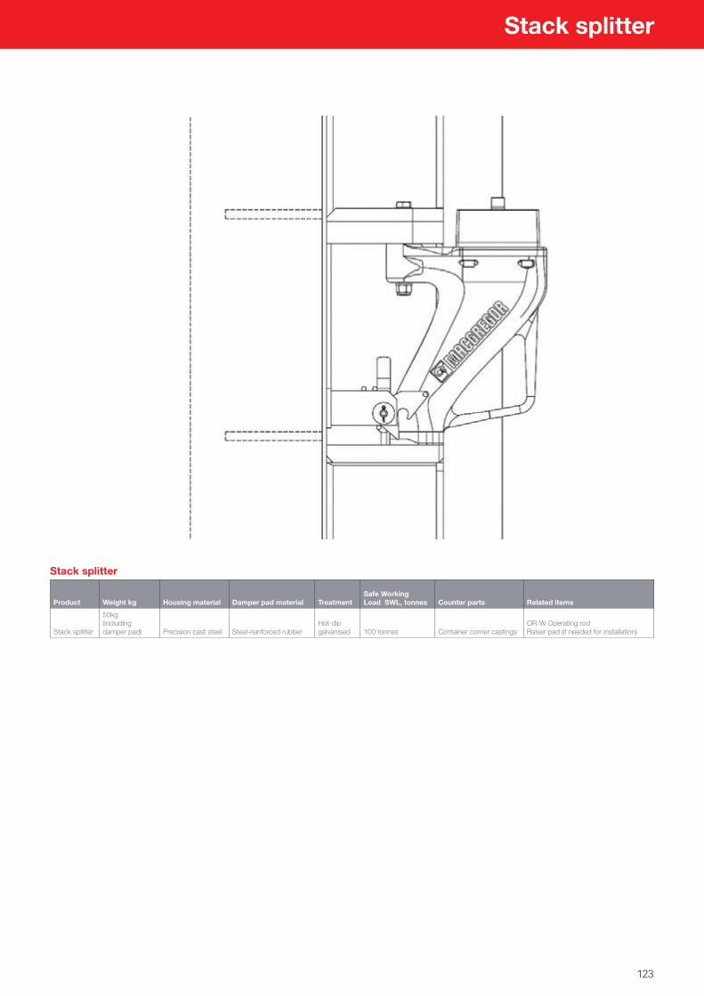
123
Stack splitter
Stack splitter
Product Weight kg Housing material Damper pad material TreatmentSafe Working Load SWL, tonnes Counter parts Related items
Stack splitter
50kg (including damper pad) Precision cast steel Steel-reinforced rubber
Hot-dip galvanised 100 tonnes Container corner castings
OR-W Operating rod Raiser pad (if needed for installation)
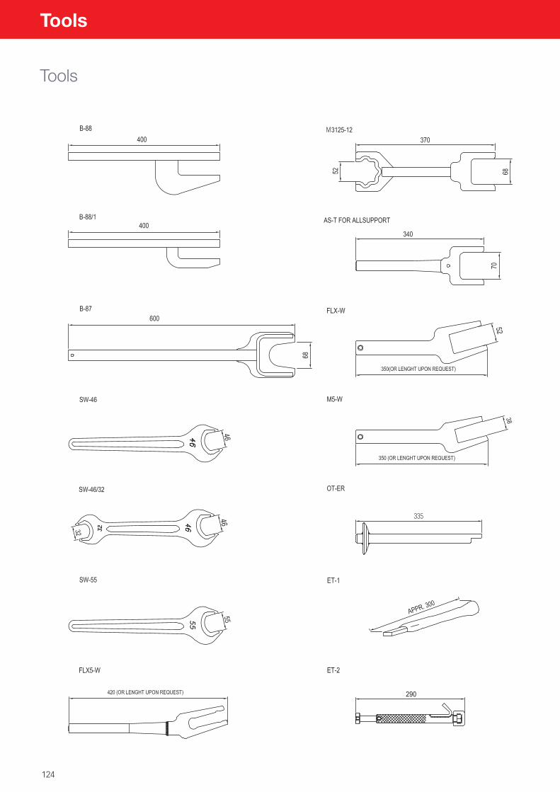
124
Tools
Tools
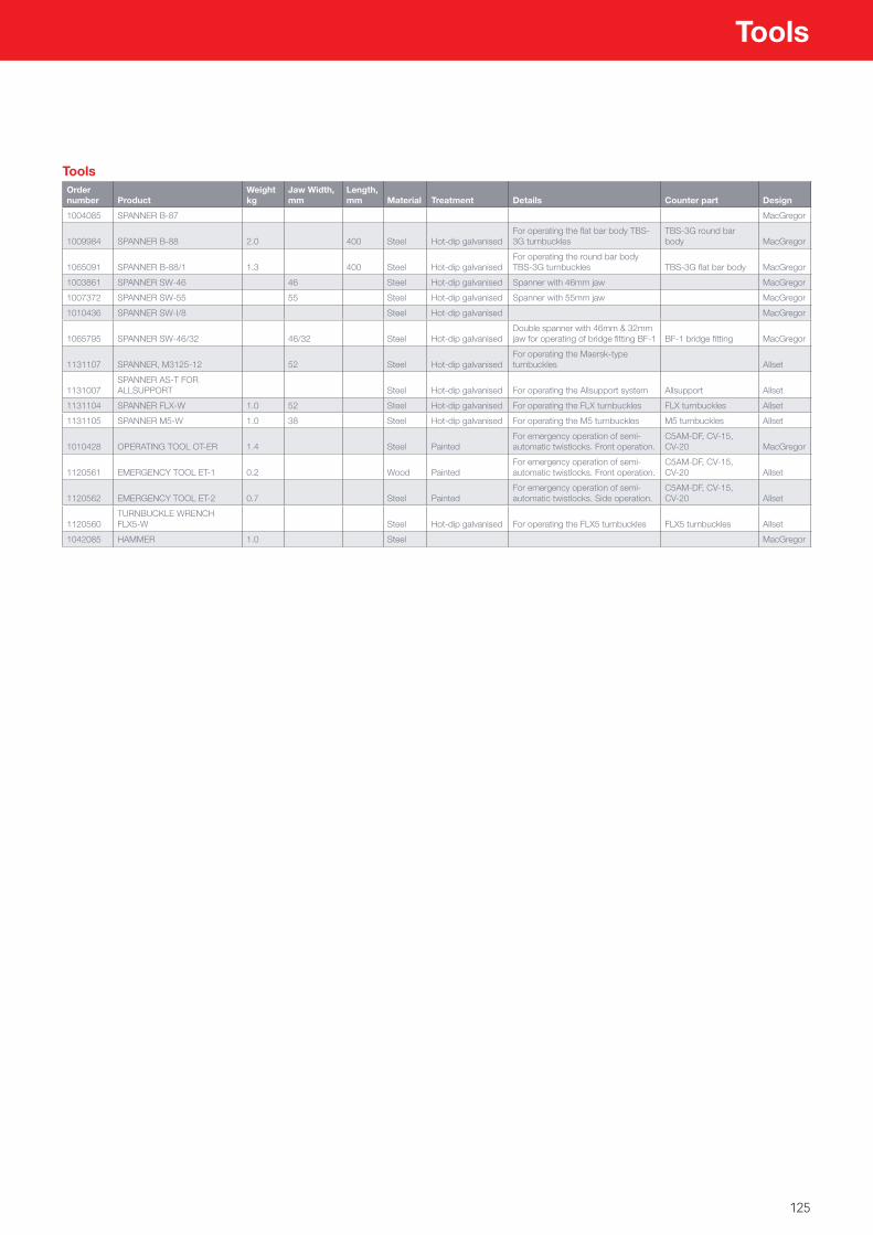
125
ToolsOrder number Product
Weight kg
Jaw Width, mm
Length, mm Material Treatment Details Counter part Design
1004085 SPANNER B-87 MacGregor
1009984 SPANNER B-88 2.0 400 Steel Hot-dip galvanisedFor operating the flat bar body TBS-3G turnbuckles
TBS-3G round bar body MacGregor
1065091 SPANNER B-88/1 1.3 400 Steel Hot-dip galvanisedFor operating the round bar body TBS-3G turnbuckles TBS-3G flat bar body MacGregor
1003861 SPANNER SW-46 46 Steel Hot-dip galvanised Spanner with 46mm jaw MacGregor
1007372 SPANNER SW-55 55 Steel Hot-dip galvanised Spanner with 55mm jaw MacGregor
1010436 SPANNER SW-I/8 Steel Hot-dip galvanised MacGregor
1065795 SPANNER SW-46/32 46/32 Steel Hot-dip galvanisedDouble spanner with 46mm & 32mm jaw for operating of bridge fitting BF-1 BF-1 bridge fitting MacGregor
1131107 SPANNER, M3125-12 52 Steel Hot-dip galvanisedFor operating the Maersk-type turnbuckles Allset
1131007SPANNER AS-T FOR ALLSUPPORT Steel Hot-dip galvanised For operating the Allsupport system Allsupport Allset
1131104 SPANNER FLX-W 1.0 52 Steel Hot-dip galvanised For operating the FLX turnbuckles FLX turnbuckles Allset
1131105 SPANNER M5-W 1.0 38 Steel Hot-dip galvanised For operating the M5 turnbuckles M5 turnbuckles Allset
1010428 OPERATING TOOL OT-ER 1.4 Steel PaintedFor emergency operation of semi-automatic twistlocks. Front operation.
C5AM-DF, CV-15, CV-20 MacGregor
1120561 EMERGENCY TOOL ET-1 0.2 Wood PaintedFor emergency operation of semi-automatic twistlocks. Front operation.
C5AM-DF, CV-15, CV-20 Allset
1120562 EMERGENCY TOOL ET-2 0.7 Steel PaintedFor emergency operation of semi-automatic twistlocks. Side operation.
C5AM-DF, CV-15, CV-20 Allset
1120560TURNBUCKLE WRENCH FLX5-W Steel Hot-dip galvanised For operating the FLX5 turnbuckles FLX5 turnbuckles Allset
1042085 HAMMER 1.0 Steel MacGregor
Tools

126
Notes


Wherever needed, you can rely on our support.
MacGregor shapes the offshore and marine industries by offering world-leading engineering solutions and services with a strong portfolio of MacGregor, Hatlapa, Porsgrunn, Pusnes and Triplex brands. Shipbuilders, owners and operators are able to optimise the lifetime profitability, safety, reliability and environmental sustainability of their operations by working in close cooperation with MacGregor. MacGregor solutions and services for handling marine cargoes, vessel operations, offshore loads, crude/LNG transfer and offshore mooring are all designed to perform with the sea. www.macgregor.com MacGregor is part of Cargotec. Cargotec’s (Nasdaq Helsinki: CGCBV) sales in 2015 totalled approximately EUR 3.7 billion and it employs almost 11,000 people. www.cargotec.com
Cargo Handling [email protected]
Related Documents