kansikuva_bw Contactor Controlled Motor Drives CT Requirements and Protection Application and Setting Guide

Welcome message from author
This document is posted to help you gain knowledge. Please leave a comment to let me know what you think about it! Share it to your friends and learn new things together.
Transcript
Contactor Controlled Motor Drives CT Requirements and Protection Application and Setting Guide
kansikuva_bw

Contactor Controlled Motor Drives CT Requirements and Protection
Application and Setting GuideIssued: 18.04.2006Version: A/12.04.2006
1MRS 756085
Contents:1. Scope .......................................................................................52. Introduction ............................................................................63. Technical implementation ......................................................7
3.1. CT requirements........................................................................ 73.1.1. Rated primary current ....................................................73.1.2. Rated secondary current and burden ............................73.1.3. Accuracy ........................................................................83.1.4. Accuracy limit factor ......................................................8
3.2. Relays for contactor controlled motor drives .............................93.3. Setting considerations .............................................................10
3.3.1. Stall protection .............................................................103.3.2. Earth-fault protection ...................................................11
4. References ............................................................................13
3
1MRS 756085Contactor Controlled Motor Drives CT Requirements and Protection
CopyrightsThe information in this document is subject to change without notice and should not be construed as a commitment by ABB Oy. ABB Oy assumes no responsibility for any errors that may appear in this docu-ment.In no event shall ABB Oy be liable for direct, indirect, special, incidental or consequential damages of any nature or kind arising from the use of this document, nor shall ABB Oy be liable for incidental or con-sequential damages arising from use of any software or hardware described in this document.This document and parts thereof must not be reproduced or copied without written permission from ABB Oy, and the contents thereof must not be imparted to a third party nor used for any unauthorized pur-pose.The software or hardware described in this document is furnished under a license and may be used, copied, or disclosed only in accordance with the terms of such license.
Copyright © 2006 ABB Oy
All rights reserved.
4
1MRS 756085 Contactor Controlled Motor Drives CT Requirements and Protection
1. Scope
The present document discusses the requirements to be made on current transformers (CT) in contactor controlled motor drives. Further, the document describes how the protection of contactor controlled motor drives differs from the protection of circuit breaker controlled motor drives.
The information in this document is applicable for the motor protection relays SPAM 150 C and REM 610.
KEYWORDS: motor protection, current transformer, current transformer saturation, stall protection, jam protection, earth-fault protection, stabilizing resistor
5
1MRS 756085Contactor Controlled Motor Drives CT Requirements and Protection
2. Introduction
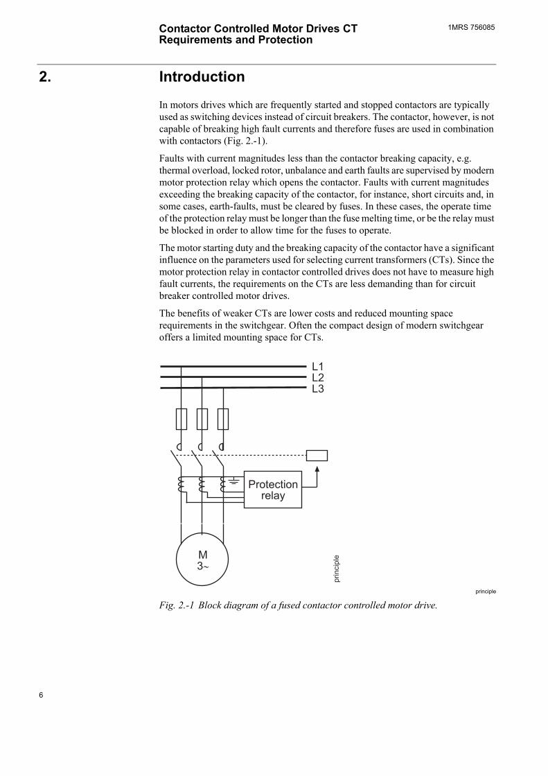
In motors drives which are frequently started and stopped contactors are typically used as switching devices instead of circuit breakers. The contactor, however, is not capable of breaking high fault currents and therefore fuses are used in combination with contactors (Fig. 2.-1).
Faults with current magnitudes less than the contactor breaking capacity, e.g. thermal overload, locked rotor, unbalance and earth faults are supervised by modern motor protection relay which opens the contactor. Faults with current magnitudes exceeding the breaking capacity of the contactor, for instance, short circuits and, in some cases, earth-faults, must be cleared by fuses. In these cases, the operate time of the protection relay must be longer than the fuse melting time, or be the relay must be blocked in order to allow time for the fuses to operate.
The motor starting duty and the breaking capacity of the contactor have a significant influence on the parameters used for selecting current transformers (CTs). Since the motor protection relay in contactor controlled drives does not have to measure high fault currents, the requirements on the CTs are less demanding than for circuit breaker controlled motor drives.
The benefits of weaker CTs are lower costs and reduced mounting space requirements in the switchgear. Often the compact design of modern switchgear offers a limited mounting space for CTs.
principle
Fig. 2.-1 Block diagram of a fused contactor controlled motor drive.
6
1MRS 756085 Contactor Controlled Motor Drives CT Requirements and Protection
3. Technical implementation
3.1. CT requirements
3.1.1. Rated primary currentModern microprocessor relays allow the motor full load current (FLC) to be set. The thermal overload protection function will open the contactor if the measured phase current exceeds the set value by more than 5% for an extended period of time.
The motor full load current setting Iθ in the SPAM 150 C relay is adjustable within the range 0.501.50 x In. The selection of the CT rated primary current, for example, 2 x FLC, can be compensated for in the relay by setting the scaling factor Iθ = IFLC/ICT = 0.5.
The REM 610 relay has a protected unit (PU scale) setting adjustable within the range 0.502.50 for correcting the difference between the CT rated primary current and the motor full load current. The selection of the CT rated primary current, for example, 2 x FLC can be compensated for in the relay by setting the scaling factor ICT/IFLC = 2.0.
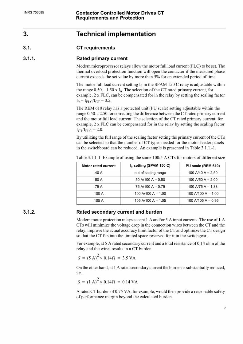
By utilizing the full range of the scaling factor setting the primary current of the CTs can be selected so that the number of CT types needed for the motor feeder panels in the switchboard can be reduced. An example is presented in Table 3.1.1.-1.
Table 3.1.1-1 Example of using the same 100/5 A CTs for motors of different size
Motor rated current Iθ setting (SPAM 150 C) PU scale (REM 610)
40 A out of setting range 100 A/40 A = 2.50
50 A 50 A/100 A = 0.50 100 A/50 A = 2.00
75 A 75 A/100 A = 0.75 100 A/75 A = 1.33
100 A 100 A/100 A = 1.00 100 A/100 A = 1.00
105 A 105 A/100 A = 1.05 100 A/105 A = 0.95
3.1.2. Rated secondary current and burdenModern motor protection relays accept 1 A and/or 5 A input currents. The use of 1 A CTs will minimize the voltage drop in the connection wires between the CT and the relay, improve the actual accuracy limit factor of the CT and optimize the CT design so that the CT fits into the limited space reserved for it in the switchgear.
For example, at 5 A rated secondary current and a total resistance of 0.14 ohm of the relay and the wires results in a CT burden
S (5 A)2 0.14Ω× 3.5 VA= =
On the other hand, at 1 A rated secondary current the burden is substantially reduced, i.e.
S (1 A)2 0.14Ω× 0.14 VA= =
A rated CT burden of 0.75 VA, for example, would then provide a reasonable safety of performance margin beyond the calculated burden.
7
1MRS 756085Contactor Controlled Motor Drives CT Requirements and Protection
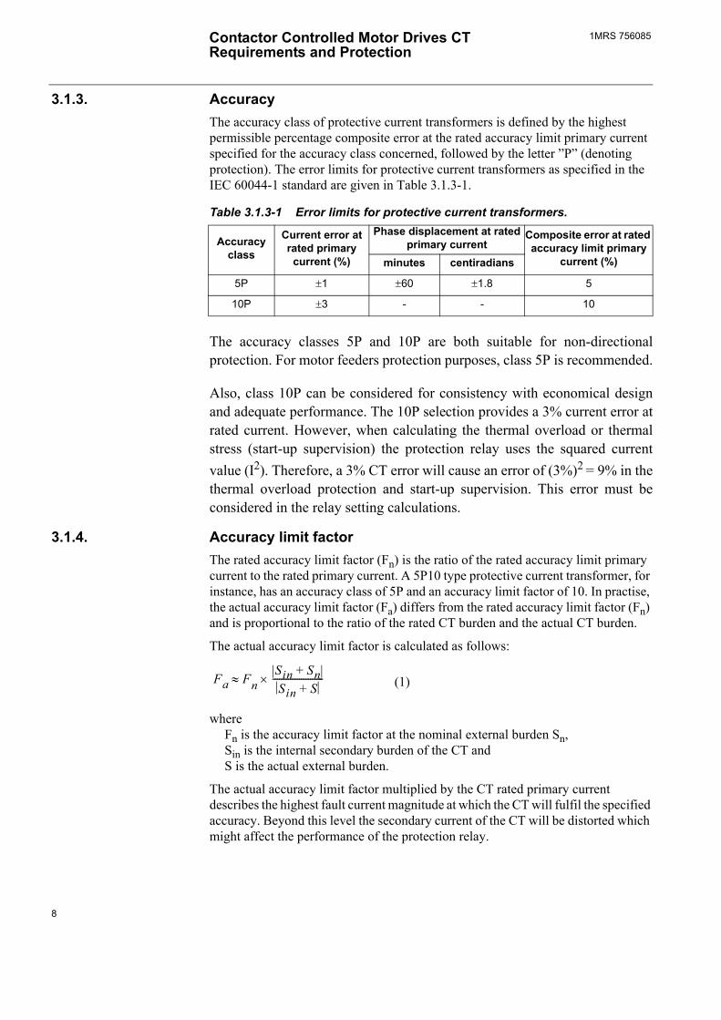
3.1.3. AccuracyThe accuracy class of protective current transformers is defined by the highest permissible percentage composite error at the rated accuracy limit primary current specified for the accuracy class concerned, followed by the letter P (denoting protection). The error limits for protective current transformers as specified in the IEC 60044-1 standard are given in Table 3.1.3-1.
Table 3.1.3-1 Error limits for protective current transformers.
Accuracy class
Current error at rated primary current (%)
Phase displacement at rated primary current
Composite error at rated accuracy limit primary
current (%)minutes centiradians
5P ±1 ±60 ±1.8 5
10P ±3 - - 10
The accuracy classes 5P and 10P are both suitable for non-directional protection. For motor feeders protection purposes, class 5P is recommended.
Also, class 10P can be considered for consistency with economical design and adequate performance. The 10P selection provides a 3% current error at rated current. However, when calculating the thermal overload or thermal stress (start-up supervision) the protection relay uses the squared current value (I2). Therefore, a 3% CT error will cause an error of (3%)2 = 9% in the thermal overload protection and start-up supervision. This error must be considered in the relay setting calculations.
3.1.4. Accuracy limit factorThe rated accuracy limit factor (Fn) is the ratio of the rated accuracy limit primary current to the rated primary current. A 5P10 type protective current transformer, for instance, has an accuracy class of 5P and an accuracy limit factor of 10. In practise, the actual accuracy limit factor (Fa) differs from the rated accuracy limit factor (Fn) and is proportional to the ratio of the rated CT burden and the actual CT burden.
The actual accuracy limit factor is calculated as follows:
Fa FnSin Sn+Sin S+
-----------------------×≈
where Fn is the accuracy limit factor at the nominal external burden Sn, Sin is the internal secondary burden of the CT and S is the actual external burden.
The actual accuracy limit factor multiplied by the CT rated primary current describes the highest fault current magnitude at which the CT will fulfil the specified accuracy. Beyond this level the secondary current of the CT will be distorted which might affect the performance of the protection relay.
(1)
8
1MRS 756085 Contactor Controlled Motor Drives CT Requirements and Protection
For example, a 5P10, 0.75 VA CT with an internal secondary winding resistance of 0.6 Ω and 1 A secondary current is used. The resistance of the relay and connection wires is 0.2 Ω. The actual accuracy limit factor will then be:
Fa 10 1A2 0.6Ω 0.75VA+×
1A2 0.6Ω 1A2 0.2Ω×+×--------------------------------------------------------------- 16.8=×≈
An accuracy limit factor of 10 provides a generous performance range. In a contactor controlled motor drives fuses are used to interrupt fault currents exceeding the motor stall / starting current and the contactor breaking capacity. Motor overload, stall and starting currents typically have values from 4 to 8 times the motor full load current (FLC). Therefore, the protection relay does not impose high requirements on the accuracy limit factor of the CTs.
The use of 1 A rated secondary currents typically improves the actual accuracy limit factor as shown above. Further, a CT rated primary current above the FLC also improves the situation. For example, if the FLC = 45 A, the CT rated primary current = 50 A and Fa = 16, the maximum primary current at which the CT will stay within its accuracy class is 16 x 50 A / 45 A = 17.8 times the FLC. A CT rated primary current of 75 A would result in a value that is 26.7 times the FLC.
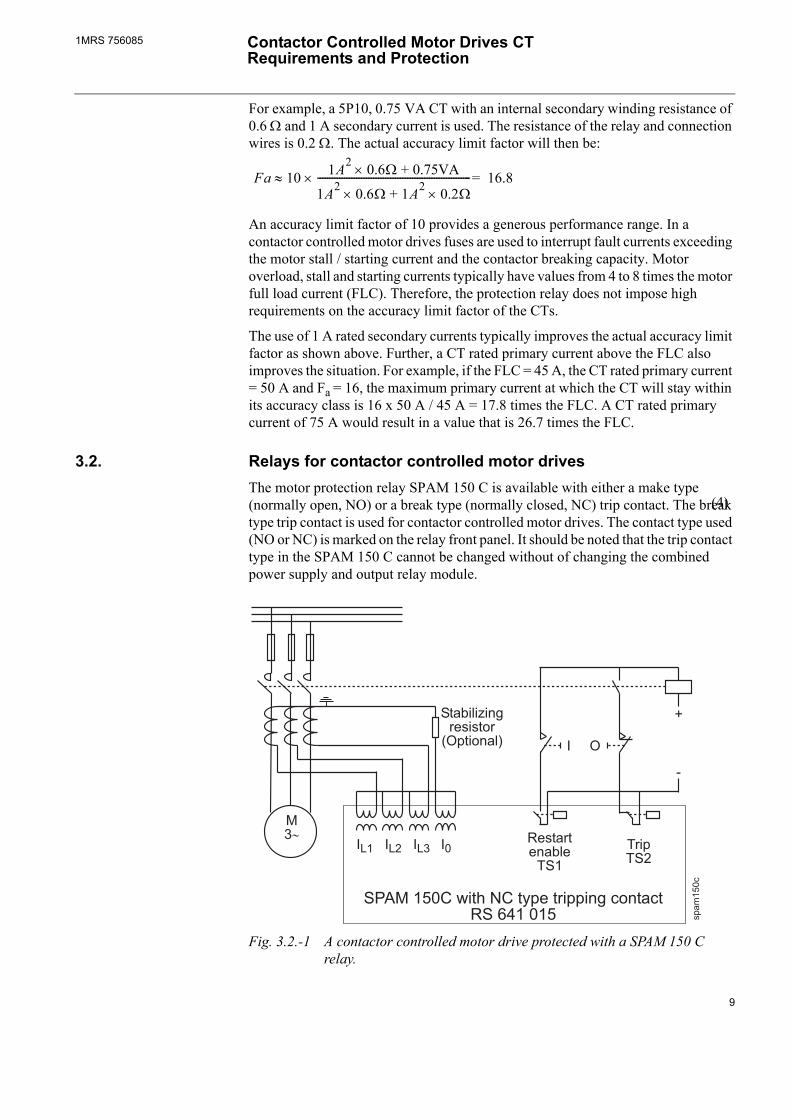
3.2. Relays for contactor controlled motor drivesThe motor protection relay SPAM 150 C is available with either a make type (normally open, NO) or a break type (normally closed, NC) trip contact. The break type trip contact is used for contactor controlled motor drives. The contact type used (NO or NC) is marked on the relay front panel. It should be noted that the trip contact type in the SPAM 150 C cannot be changed without of changing the combined power supply and output relay module.
!"# $%&
'$()
Fig. 3.2.-1 A contactor controlled motor drive protected with a SPAM 150 C relay.
(4)
9
1MRS 756085Contactor Controlled Motor Drives CT Requirements and Protection
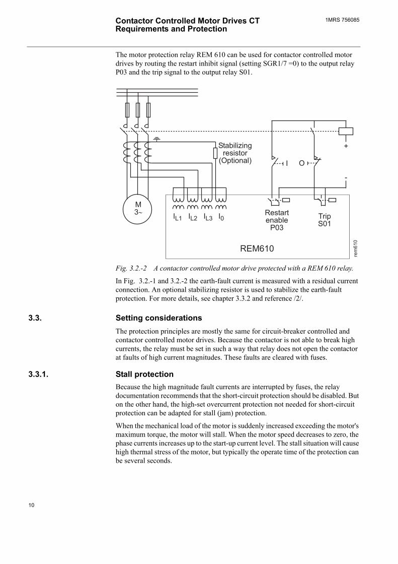
The motor protection relay REM 610 can be used for contactor controlled motor drives by routing the restart inhibit signal (setting SGR1/7 =0) to the output relay P03 and the trip signal to the output relay S01.
%
*%
'$()
Fig. 3.2.-2 A contactor controlled motor drive protected with a REM 610 relay.
In Fig. 3.2.-1 and 3.2.-2 the earth-fault current is measured with a residual current connection. An optional stabilizing resistor is used to stabilize the earth-fault protection. For more details, see chapter 3.3.2 and reference /2/.
3.3. Setting considerationsThe protection principles are mostly the same for circuit-breaker controlled and contactor controlled motor drives. Because the contactor is not able to break high currents, the relay must be set in such a way that relay does not open the contactor at faults of high current magnitudes. These faults are cleared with fuses.
3.3.1. Stall protectionBecause the high magnitude fault currents are interrupted by fuses, the relay documentation recommends that the short-circuit protection should be disabled. But on the other hand, the high-set overcurrent protection not needed for short-circuit protection can be adapted for stall (jam) protection.
When the mechanical load of the motor is suddenly increased exceeding the motor's maximum torque, the motor will stall. When the motor speed decreases to zero, the phase currents increases up to the start-up current level. The stall situation will cause high thermal stress of the motor, but typically the operate time of the protection can be several seconds.
10
1MRS 756085 Contactor Controlled Motor Drives CT Requirements and Protection
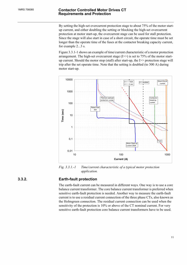
By setting the high-set overcurrent protection stage to about 75% of the motor start-up current, and either doubling the setting or blocking the high-set overcurrent protection at motor start-up, the overcurrent stage can be used for stall protection. Since the stage will also start in case of a short circuit, the operate time must be set longer than the operate time of the fuses at the contactor breaking capacity current, for example 2...3 s.
Figure 3.3.1-1 shows an example of time/current characteristic of a motor protection arrangement. The high-set overcurrent stage (I>>) is set to 75% of the motor start-up current. Should the motor stop (stall) after start-up, the I>> protection stage will trip after the set operate time. Note that the setting is doubled (to 300 A) during motor start-up.
0,01
0,1
1
10
100
1000
10000
10 100 1000
Current (A)
Tim
e (s
ec)
Thermal overloadprotection curves
FuseMotor Start-upcurrent 200A
Rated load30A
I>> = 150At>> = 2 sec
I>> doubled Short-Circuitcurrent
Contactorbreaking current
Fig. 3.3.1.-1 Time/current characteristic of a typical motor protection application.
3.3.2. Earth-fault protectionThe earth-fault current can be measured in different ways. One way is to use a core balance current transformer. The core balance current transformer is preferred when sensitive earth-fault protection is needed. Another way to measure the earth-fault current is to use a residual current connection of the three phase CTs, also known as the Holmgreen connection. The residual current connection can be used when the sensitivity of the protection is 10% or above of the CT nominal current. For very sensitive earth-fault protection core balance current transformers have to be used.
11
1MRS 756085Contactor Controlled Motor Drives CT Requirements and Protection
The breaking capacity of the contactor may be exceeded if the earth fault occur close to the motor terminals, especially in case of a 2-phase or 3-phase short circuit with earth contact. In these cases, the fuses should interrupt the fault current. Therefore, either the operate time of the earth-fault protection should be long enough or the protection should be automatically blocked at high phase currents.
In SPAM 150 C, blocking is selected with the switches SGF/3 and SGF/4 and in REM 610 with the switches SGF4/1 and SGF4/2. The recommended setting for the blocking is 4 x FLC (i.e. less than the motor start-up current).
A common problem with the residual current connection is that the earth-fault protection may operate at the beginning of the motor start-up due to CT saturation caused by the DC component of the current. Because of the high currents involved the same may happen at short circuit. The problem can be handled either by extending the operate time (1...2 s) or by adding a stabilizing resistor to the earth-fault measuring circuit. The connection of the stabilizing resistor is shown in Fig. 3.2.-1 and 3.2.-2. For more details, see reference /2/.
12
1MRS 756085 Contactor Controlled Motor Drives CT Requirements and Protection
4. References
/1/ 1MRS 755481 Calculation of the Current Transformer Accuracy Limit Factor. Application Note.
/2/ 1MRS 755627 Stabilizing Resistor in Motor Earth-Fault Protection. Application note.
/3/ 1MRS 752263-MUM REM 610 Motor Protection Relay. Technical Reference Manual.
/4/ 1MRS 750637-MUM SPAM 150 C Motor Protection Relay. User's manual and Technical description.
13

ADP.FFTeFw
1MR
S 7
5608
5 E
N 0
4.20
06
BB Oyistribution Automation O. Box 699 I-65101 Vaasa INLANDl. +358 10 22 11
ax. +358 10 224 1094ww.abb.com/substationautomation
Related Documents