03/19/2014 HPL-ED2014 V2.13 EN 1 / 11 Contactor, 3p+2N/O+2N/C, 160kW/400V/AC3 Part no. DILM300A- S/22(110-120V50/60HZ) Article no. 139558 Catalog No. XTCS300L22A Delivery programme Product range Contactors Application Contactors for Motors Subrange Standard devices greater than 170 A Utilization category AC-1: Non-inductive or slightly inductive loads, resistance furnaces AC-3: Squirrel-cage motors: starting, switching off during running AC-4: Squirrel-cage motors: starting, plugging, reversing, inching Connection technique Screw connection Rated operational current AC-3 380 V 400 V I e A 300 AC-1 Conventional free air thermal current, 3 pole, 50 - 60 Hz Open at 40 °C I th =I e A 490 enclosed I th A 315 Conventional free air thermal current, 1 pole open I th A 875 enclosed I th A 785 Max. rating for three-phase motors, 50 - 60 Hz AC-3 220 V 230 V P kW 90 380 V 400 V P kW 160 660 V 690 V P kW 240 1000 V P kW 132 AC-4 220 V 230 V P kW 75 380 V 400 V P kW 132 660 V 690 V P kW 160 1000 V P kW 109 Contact sequence Can be combined with auxiliary contact DILM820-XHI… Actuating voltage 110 - 120 V 50/60 Hz Voltage AC/DC AC operation Contacts N/O = Normally open 2 N/O N/C = Normally closed 2 NC Auxiliary contacts possible variants at auxiliary contact module fitting options on the side: 2 x DILM820-XHI11(V)-SI; 2 x DILM820-XHI11-SA Side mounting auxiliary contacts Instructions integrated suppressor circuit in actuating electronics 660 V, 690 V or 1000 V: not directly reversing Notes DILM…-S contactors are triggered in the conventional manner Standstill in an emergency (Emergency-Stop) Approvals Product Standards IEC/EN 60947-4-1; UL 508; CSA-C22.2 No. 14-05; CE marking UL File No. E29096 UL Category Control No. NLDX CSA File No. 1017510 CSA Class No. 3211-04 North America Certification UL listed, CSA certified Specially designed for North America No General Standards IEC/EN 60947, VDE 0660, UL, CSA Lifespan, mechanical

Welcome message from author
This document is posted to help you gain knowledge. Please leave a comment to let me know what you think about it! Share it to your friends and learn new things together.
Transcript
03/19/2014 HPL-ED2014 V2.13 EN 1 / 11
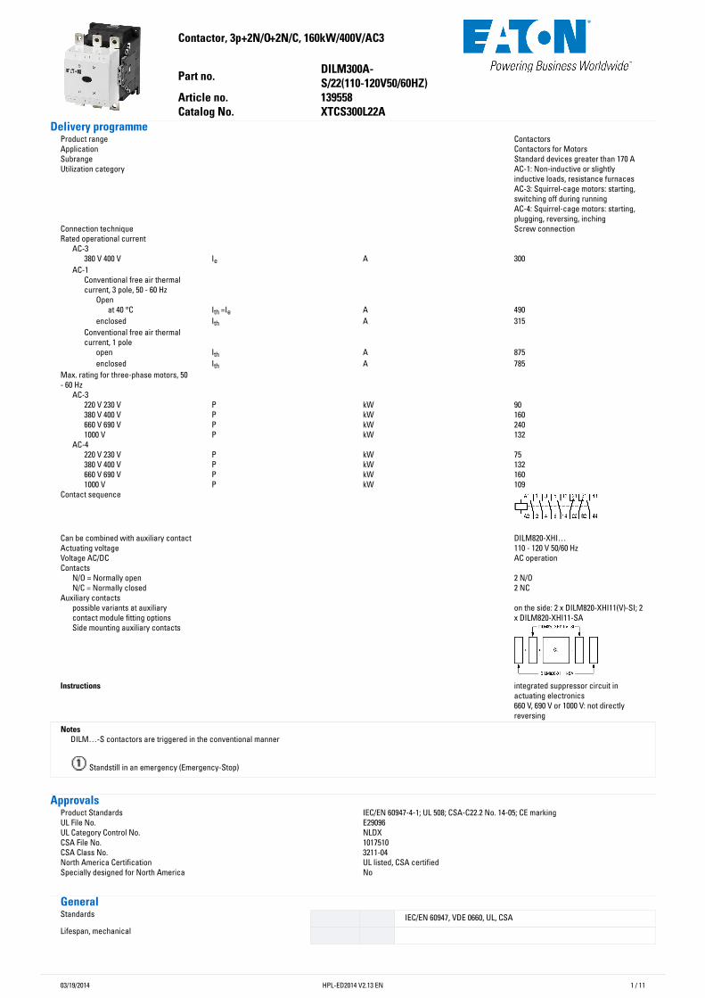
Contactor,3p+2N/O+2N/C,160kW/400V/AC3
Partno. DILM300A-S/22(110-120V50/60HZ)
Articleno. 139558CatalogNo. XTCS300L22A
DeliveryprogrammeProduct range ContactorsApplication Contactors for MotorsSubrange Standard devices greater than 170 AUtilization category AC-1: Non-inductive or slightly
inductive loads, resistance furnacesAC-3: Squirrel-cage motors: starting,switching off during runningAC-4: Squirrel-cage motors: starting,plugging, reversing, inching
Connection technique Screw connectionRated operational current
AC-3 380 V 400 V Ie A 300
AC-1 Conventional free air thermalcurrent, 3 pole, 50 - 60 Hz
Open at 40 °C Ith =Ie A 490
enclosed Ith A 315Conventional free air thermalcurrent, 1 pole
open Ith A 875enclosed Ith A 785
Max. rating for three-phase motors, 50- 60 Hz
AC-3 220 V 230 V P kW 90380 V 400 V P kW 160660 V 690 V P kW 2401000 V P kW 132
AC-4 220 V 230 V P kW 75380 V 400 V P kW 132660 V 690 V P kW 1601000 V P kW 109
Contact sequence
Can be combined with auxiliary contact DILM820-XHI…Actuating voltage 110 - 120 V 50/60 HzVoltage AC/DC AC operationContacts
N/O = Normally open 2 N/ON/C = Normally closed 2 NC
Auxiliary contacts possible variants at auxiliarycontact module fitting options
on the side: 2 x DILM820-XHI11(V)-SI; 2x DILM820-XHI11-SA
Side mounting auxiliary contacts
Instructions integrated suppressor circuit inactuating electronics660 V, 690 V or 1000 V: not directlyreversing
Notes DILM…-S contactors are triggered in the conventional manner
Standstill in an emergency (Emergency-Stop)
ApprovalsProduct Standards IEC/EN 60947-4-1; UL 508; CSA-C22.2 No. 14-05; CE markingUL File No. E29096UL Category Control No. NLDXCSA File No. 1017510CSA Class No. 3211-04North America Certification UL listed, CSA certifiedSpecially designed for North America No
GeneralStandards IEC/EN 60947, VDE 0660, UL, CSALifespan, mechanical
03/19/2014 HPL-ED2014 V2.13 EN 2 / 11
AC operated Operations x106
10
DC operated Operations x106
10
Operating frequency, mechanical AC operated Operations/
h 3000
DC operated Operations/h
3000
Climatic proofing Damp heat, constant, to IEC 60068-2-78Damp heat, cyclic, to IEC 60068-2-30
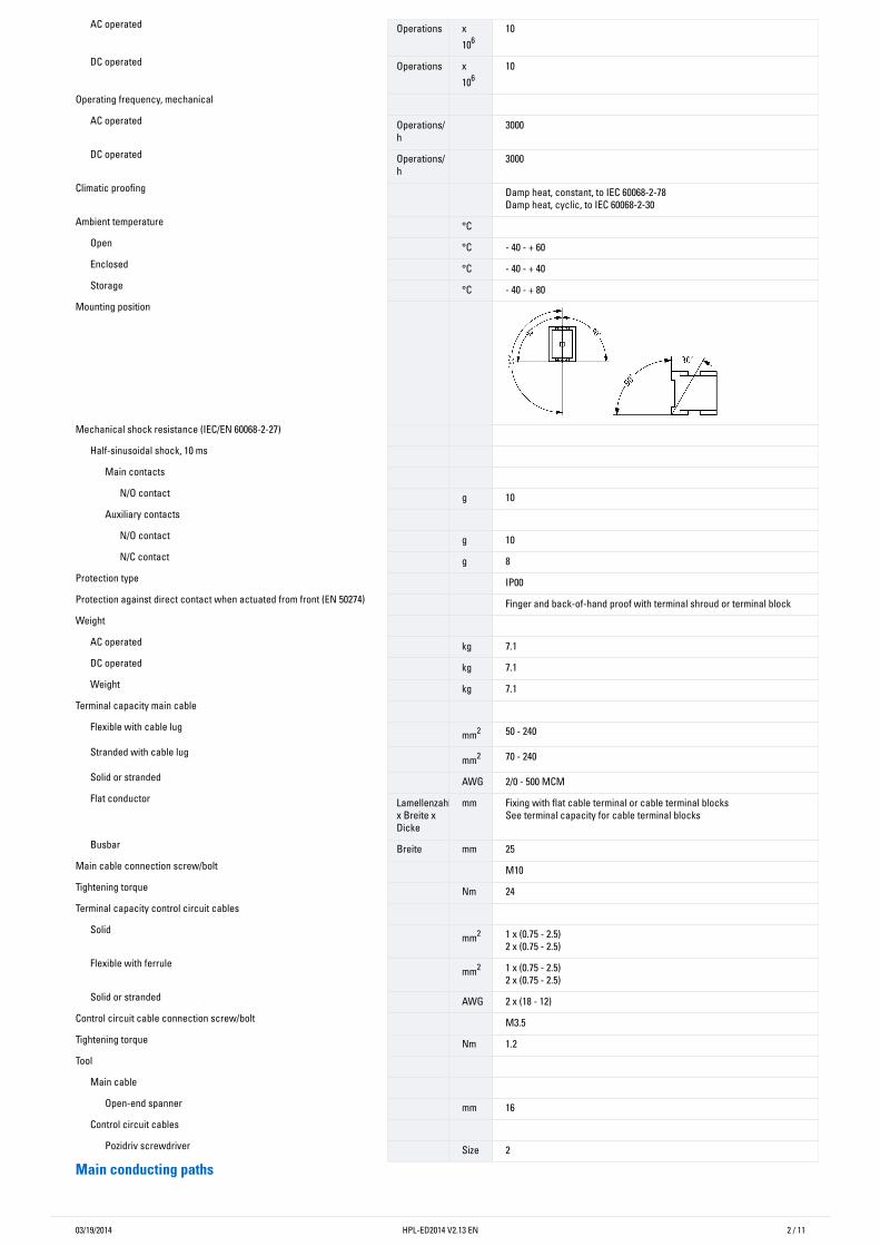
Ambient temperature °C Open °C - 40 - + 60Enclosed °C - 40 - + 40Storage °C - 40 - + 80
Mounting position
Mechanical shock resistance (IEC/EN 60068-2-27)
Half-sinusoidal shock, 10 ms Main contacts
N/O contact g 10Auxiliary contacts
N/O contact g 10N/C contact g 8
Protection type IP00Protection against direct contact when actuated from front (EN 50274) Finger and back-of-hand proof with terminal shroud or terminal blockWeight
AC operated kg 7.1DC operated kg 7.1Weight kg 7.1
Terminal capacity main cable Flexible with cable lug mm2 50 - 240
Stranded with cable lug mm2 70 - 240
Solid or stranded AWG 2/0 - 500 MCMFlat conductor Lamellenzahl
x Breite xDicke
mm Fixing with flat cable terminal or cable terminal blocksSee terminal capacity for cable terminal blocks
Busbar Breite mm 25Main cable connection screw/bolt M10Tightening torque Nm 24Terminal capacity control circuit cables
Solid mm2 1 x (0.75 - 2.5)2 x (0.75 - 2.5)
Flexible with ferrule mm2 1 x (0.75 - 2.5)2 x (0.75 - 2.5)
Solid or stranded AWG 2 x (18 - 12)Control circuit cable connection screw/bolt M3.5Tightening torque Nm 1.2Tool
Main cable Open-end spanner mm 16
Control circuit cables Pozidriv screwdriver Size 2
Mainconductingpaths
03/19/2014 HPL-ED2014 V2.13 EN 3 / 11
Rated impulse withstand voltage Uimp VAC
8000
Overvoltage category/pollution degree III/3Rated insulation voltage Ui V
AC1000
Rated operational voltage Ue VAC
1000
Safe isolation to EN 61140 between coil and contacts V
AC500
between the contacts VAC
500
Making capacity (p.f. to IEC/EN 60947) A 3600Breaking capacity
220 V 230 V A 3000380 V 400 V A 3000500 V A 3000660 V 690 V A 30001000 V A 950
Component lifespan AC1: See -> Engineering, characteristic curves
AC3: See -> Engineering, characteristic curvesAC4: See -> Engineering, characteristic curves
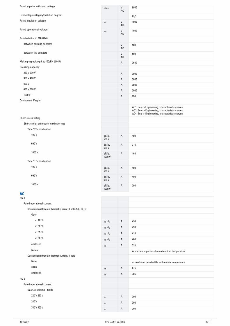
Short-circuit rating Short-circuit protection maximum fuse
Type “2” coordination 400 V gG/gL
500 VA 400
690 V gG/gL690 V
A 315
1000 V gG/gL1000 V
A 160
Type “1” coordination 400 V gG/gL
500 VA 400
690 V gG/gL690 V
A 400
1000 V gG/gL1000 V
A 200
ACAC-1
Rated operational current Conventional free air thermal current, 3 pole, 50 - 60 Hz
Open at 40 °C Ith =Ie A 490at 50 °C Ith =Ie A 438at 55 °C Ith =Ie A 418at 60 °C Ith =Ie A 400
enclosed Ith A 315Notes At maximum permissible ambient air temperature.
Conventional free air thermal current, 1 pole Note at maximum permissible ambient air temperatureopen Ith A 875enclosed Ith A 785
AC-3 Rated operational current
Open, 3-pole: 50 – 60 Hz 220 V 230 V Ie A 300240 V Ie A 300380 V 400 V Ie A 300
03/19/2014 HPL-ED2014 V2.13 EN 4 / 11
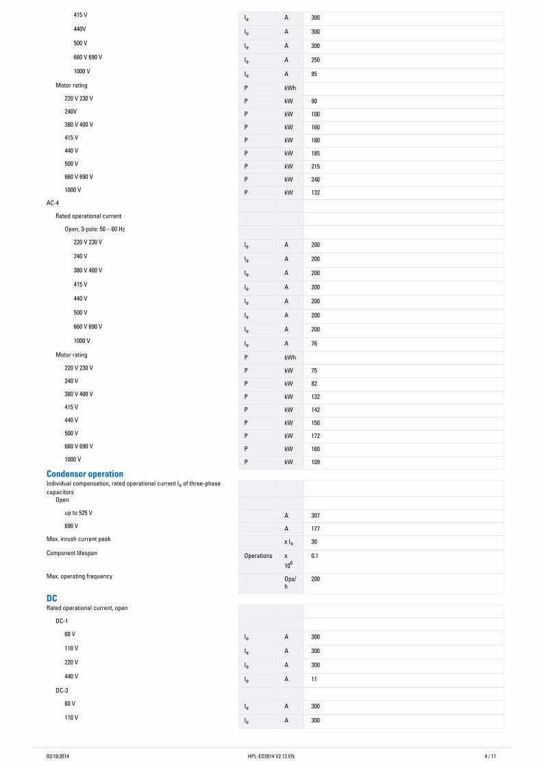
415 V Ie A 300440V Ie A 300500 V Ie A 300660 V 690 V Ie A 2501000 V Ie A 95
Motor rating P kWh 220 V 230 V P kW 90240V P kW 100380 V 400 V P kW 160415 V P kW 180440 V P kW 185500 V P kW 215660 V 690 V P kW 2401000 V P kW 132
AC-4 Rated operational current
Open, 3-pole: 50 – 60 Hz 220 V 230 V Ie A 200240 V Ie A 200380 V 400 V Ie A 200415 V Ie A 200440 V Ie A 200500 V Ie A 200660 V 690 V Ie A 2001000 V Ie A 76
Motor rating P kWh 220 V 230 V P kW 75240 V P kW 82380 V 400 V P kW 132415 V P kW 142440 V P kW 150500 V P kW 172660 V 690 V P kW 1601000 V P kW 109
CondensoroperationIndividual compensation, rated operational current Ie of three-phasecapacitors
Open up to 525 V A 307690 V A 177
Max. inrush current peak x Ie 30Component lifespan Operations x
1060.1
Max. operating frequency Ops/h
200
DCRated operational current, open
DC-1 60 V Ie A 300110 V Ie A 300220 V Ie A 300440 V Ie A 11
DC-3 60 V Ie A 300110 V Ie A 300
03/19/2014 HPL-ED2014 V2.13 EN 5 / 11
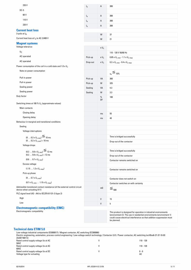
220 V Ie A 300DC-5
60 V Ie A 300110 V Ie A 300220 V Ie A 300
Currentheatloss3-pole at Ith W 37Current heat loss at Ie to AC-3/400 V W 21
MagnetsystemsVoltage tolerance x Uc
UC 110 - 120 V 50/60 HzAC operated Pick-up x Uc 0.85 x Uc min - 1.1 x Uc max
AC operated Drop-out x Uc 0.2 x Uc min - 0.4 x Uc max
Power consumption of the coil in a cold state and 1.0 x Uc Note on power consumption
uk 10%Pull-in power Pick-up VA 360Pull-in power Pick-up W 325Sealing power Sealing VA 4.3Sealing power Sealing W 3.3
Duty factor %DF
100
Switching times at 100 % Uc (approximate values) Main contacts
Closing delay ms 55Opening delay ms 40
Behaviour in marginal and transitional conditions Sealing
Voltage interruptions
(0 … 0.2 x Uc min) 10 ms Time is bridged successfully(0 … 0.2 x Uc min) > 10 ms Drop-out of the contactor
Voltage drops
(0.2 … 0.6 x Uc min) 12 ms Time is bridged successfully(0.2 … 0.6 x Uc min) > 12 ms Drop-out of the contactor(0.6 … 0.7 x Uc min) Contactor remains switched on
Excess voltage (1.15 … 1.3 x Uc max) Contactor remains switched on
Pick-up phase (0 … 0.7 x Uc min) Contactor does not switch on(0.7 x Uc min … 1.15 x Uc max) Contactor switches on with certainty
Admissible transitional contact resistance (of the external control circuitdevice when actuating A11)
mΩ 500
PLC signal level (A3 - A4) to IEC/EN 61131-2 (type 2) High V 15Low V 5
Electromagneticcompatibility(EMC)Electromagnetic compatibility This product is designed for operation in industrial environments
(environment 2). The use in residential environments (environment 1)could cause electrical interference so that addition suppression mustbe planned.
TechnicaldataETIM5.0Low-voltage industrial components (EG000017) / Magnet contactor, AC-switching (EC000066)Electric engineering, automation, process control engineering / Low-voltage switch technology / Contactor (LV) / Power contactor, AC switching (ecl@ss8-27-37-10-03[AAB718011])Rated control supply voltage Us at AC50HZ
V 110 - 120
Rated control supply voltage Us at AC60HZ
V 110 - 120
Rated control supply voltage Us at DC V 0 - 0Voltage type for actuating AC
03/19/2014 HPL-ED2014 V2.13 EN 6 / 11
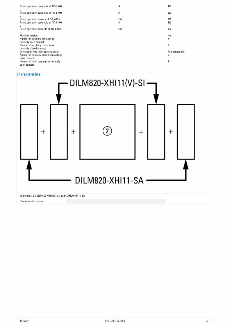
Rated operation current Ie at AC-1, 400V
A 490
Rated operation current Ie at AC-3, 400V
A 300
Rated operation power at AC-3, 400 V kW 160Rated operation current Ie at AC-4, 400V
A 240
Rated operation power Ie at AC-4, 400V
kW 132
Modular version NoNumber of auxiliary contacts asnormally open contact
2
Number of auxiliary contacts asnormally closed contact
2
Connection type main current circuit Rail connectionNumber of normally closed contacts asmain contact
0
Number of main contacts as normallyopen contact
3
Characteristics
on the side: 2 x DILM820-XHI11(V)-SI; 2 x DILM820-XHI11-SA
Characteristic curves
03/19/2014 HPL-ED2014 V2.13 EN 7 / 11
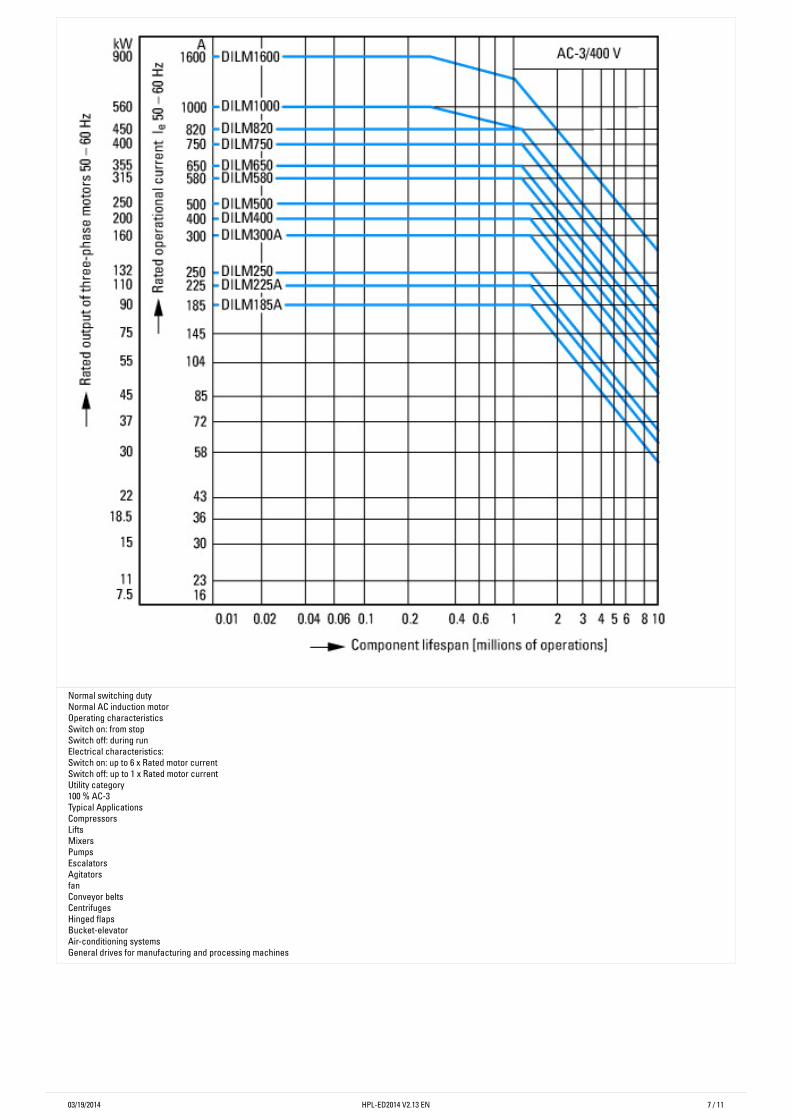
Normal switching dutyNormal AC induction motorOperating characteristicsSwitch on: from stopSwitch off: during runElectrical characteristics:Switch on: up to 6 x Rated motor currentSwitch off: up to 1 x Rated motor currentUtility category100 % AC-3Typical ApplicationsCompressorsLiftsMixersPumpsEscalatorsAgitatorsfanConveyor beltsCentrifugesHinged flapsBucket-elevatorAir-conditioning systemsGeneral drives for manufacturing and processing machines
03/19/2014 HPL-ED2014 V2.13 EN 8 / 11
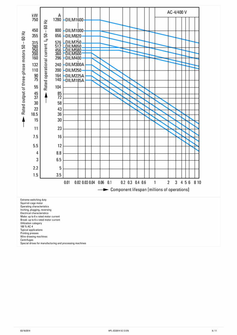
Extreme switching dutySquirrel-cage motorOperating characteristicsInching, plugging, reversingElectrical characteristicsMake: up to 6 x rated motor currentBreak: up to 6 x rated motor currentUtilization category100 % AC-4Typical applicationsPrinting pressesWire-drawing machinesCentrifugesSpecial drives for manufacturing and processing machines
03/19/2014 HPL-ED2014 V2.13 EN 9 / 11
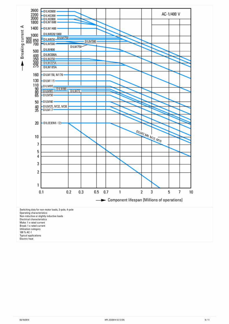
Switching duty for non-motor loads, 3-pole, 4-poleOperating characteristicsNon-inductive or slightly inductive loadsElectrical characteristicsMake: 1 x rated currentBreak: 1 x rated currentUtilization category100 % AC-1Typical applicationsElectric heat
03/19/2014 HPL-ED2014 V2.13 EN 10 / 11
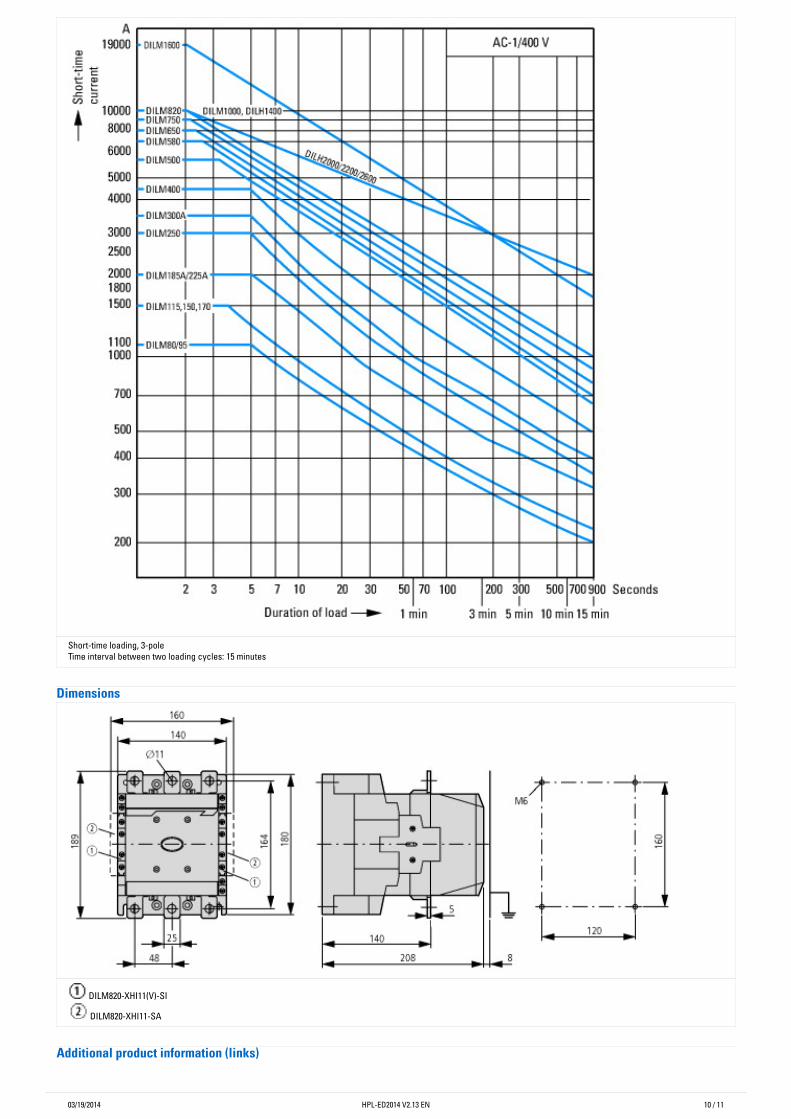
Short-time loading, 3-poleTime interval between two loading cycles: 15 minutes
Dimensions
DILM820-XHI11(V)-SI
DILM820-XHI11-SA
Additionalproductinformation(links)
03/19/2014 Eaton Industries GmbHhttp://www.eaton.eu
© 02/2014 by Eaton Industries GmbHHPL-ED2014 V2.13 EN
11 / 11
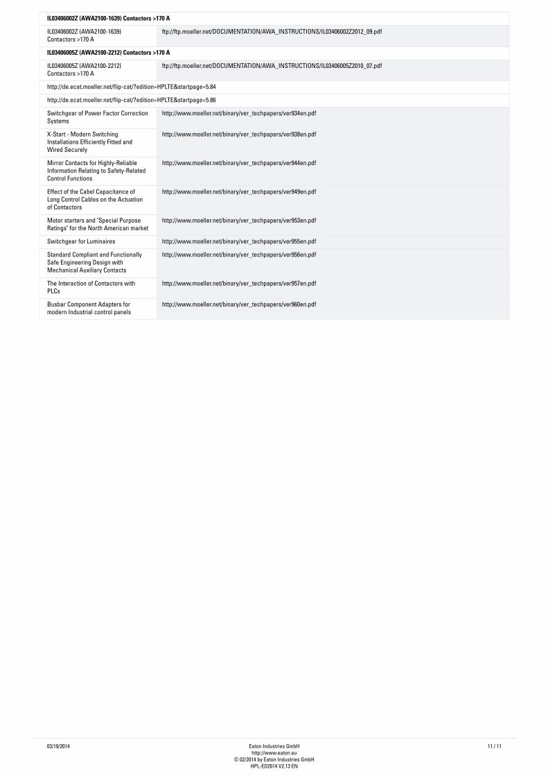
IL03406002Z(AWA2100-1639)Contactors>170A
IL03406002Z (AWA2100-1639)Contactors >170 A
ftp://ftp.moeller.net/DOCUMENTATION/AWA_INSTRUCTIONS/IL03406002Z2012_09.pdf
IL03406005Z(AWA2100-2212)Contactors>170A
IL03406005Z (AWA2100-2212)Contactors >170 A
ftp://ftp.moeller.net/DOCUMENTATION/AWA_INSTRUCTIONS/IL03406005Z2010_07.pdf
http://de.ecat.moeller.net/flip-cat/?edition=HPLTE&startpage=5.84
http://de.ecat.moeller.net/flip-cat/?edition=HPLTE&startpage=5.86
Switchgear of Power Factor CorrectionSystems
http://www.moeller.net/binary/ver_techpapers/ver934en.pdf
X-Start - Modern SwitchingInstallations Efficiently Fitted andWired Securely
http://www.moeller.net/binary/ver_techpapers/ver938en.pdf
Mirror Contacts for Highly-ReliableInformation Relating to Safety-RelatedControl Functions
http://www.moeller.net/binary/ver_techpapers/ver944en.pdf
Effect of the Cabel Capacitance ofLong Control Cables on the Actuationof Contactors
http://www.moeller.net/binary/ver_techpapers/ver949en.pdf
Motor starters and "Special PurposeRatings" for the North American market
http://www.moeller.net/binary/ver_techpapers/ver953en.pdf
Switchgear for Luminaires http://www.moeller.net/binary/ver_techpapers/ver955en.pdf
Standard Compliant and FunctionallySafe Engineering Design withMechanical Auxiliary Contacts
http://www.moeller.net/binary/ver_techpapers/ver956en.pdf
The Interaction of Contactors withPLCs
http://www.moeller.net/binary/ver_techpapers/ver957en.pdf
Busbar Component Adapters formodern Industrial control panels
http://www.moeller.net/binary/ver_techpapers/ver960en.pdf
Related Documents