Construction Specification Guideline for Concrete Streets and Local Roads This document provides guideline specifications useful for developing concrete pavement project specifica- tions for local roads and streets. These guidelines should not be used as a specification reference in contract documents. A contracting agency must modify these guidelines for local conditions, preferences and con- struction practices. A contracting agency also must choose amongst the available material standards and test methods provided in these guidelines. This document references appropriate material stan- dards, test methods and specifications of American Association of State Highway and Transportation Officials (AASHTO), the American So- ciety of Testing Materials (ASTM), and Canadian Stan- dards Association (CSA). These references assume that the Contractor and the Engineer will use the appli- cable standards or methods that are in effect when bids are solicited for the project. It also assumes that the speci- fication writer will choose the standard or test most suit- able for their agency/project. Footnotes, pictures and diagrams accompany some specification requirements. These added details pro- vide specific guidance, list important references, and describe specification features and choices for clarity to the specification writer. The acceptance criteria for strength are based upon quality assurance methods for testing and accepting pavement concrete that are not normally used for streets and local roads. Presently, many highway and airport agencies are using or developing specifications encom- passing quality assurance/quality control (QA/QC) con- cepts. These concepts are not currently in wide use in the engineering of local road and streets. While, it is not clear whether QA/QC concepts are beneficial or cost- effective for smaller projects, in time they are likely to be used for larger local road and street projects. QA/QC specifications are a combination of end-result specifica- tions and materials and methods specifications. These statistical specfications use methods such as random sampling and lot-by-lot test- ing. The contractor is respon- sible for quality control (pro- cess control), and the owner/ engineer is responsible for acceptance of the product. In this specification, the acceptance passage re- quires the contractor to submit a strength evaluation plan to the engineer. The test- ing for both assurance and acceptance are performed by a certified agent of the contractor. Some QA/QC specifications require the engineer and the contractor to run tests separately; the engineer takes random tests to validate the contractor's on-going testing procedures. This method requires more tests and personnel, which could be difficult for some local public works agencies. By requiring the contractor to employ certified testing firms, this specification reduces the burden on the public works agency. The agency can rely on the contractor's tests without committing personnel to the project testing. 1

Construction Specification Guideline for Concrete Streets and Local Roads IS119P 4
Dec 11, 2015
specification
Welcome message from author
This document is posted to help you gain knowledge. Please leave a comment to let me know what you think about it! Share it to your friends and learn new things together.
Transcript

Construction Specification Guideline forConcrete Streets and Local RoadsThis document provides guideline specifications usefulfor developing concrete pavement project specifica-tions for local roads and streets. These guidelines shouldnot be used as a specification reference in contractdocuments. A contracting agency must modify theseguidelines for local conditions, preferences and con-struction practices. A contracting agency also mustchoose amongst the available material standards andtest methods provided in these guidelines.
This document referencesappropriate material stan-dards, test methods andspecifications of AmericanAssociation of State Highwayand Transportation Officials(AASHTO), the American So-ciety of Testing Materials(ASTM), and Canadian Stan-dards Association (CSA).These references assumethat the Contractor and theEngineer will use the appli-cable standards or methodsthat are in effect when bidsare solicited for the project. Italso assumes that the speci-fication writer will choose thestandard or test most suit-able for their agency/project.
Footnotes, pictures and diagrams accompany somespecification requirements. These added details pro-vide specific guidance, list important references, anddescribe specification features and choices for clarity tothe specification writer.
The acceptance criteria for strength are based uponquality assurance methods for testing and acceptingpavement concrete that are not normally used for streetsand local roads. Presently, many highway and airport
agencies are using or developing specifications encom-passing quality assurance/quality control (QA/QC) con-cepts. These concepts are not currently in wide use inthe engineering of local road and streets. While, it is notclear whether QA/QC concepts are beneficial or cost-effective for smaller projects, in time they are likely to beused for larger local road and street projects. QA/QCspecifications are a combination of end-result specifica-tions and materials and methods specifications. These
statistical specfications usemethods such as randomsampling and lot-by-lot test-ing. The contractor is respon-sible for quality control (pro-cess control), and the owner/engineer is responsible foracceptance of the product.
In this specification, theacceptance passage re-quires the contractor tosubmit a strength evaluationplan to the engineer. The test-ing for both assurance andacceptance are performedby a certified agent of thecontractor. Some QA/QCspecifications require theengineer and the contractorto run tests separately; the
engineer takes random tests to validate the contractor'son-going testing procedures. This method requires moretests and personnel, which could be difficult for somelocal public works agencies. By requiring the contractorto employ certified testing firms, this specificationreduces the burden on the public works agency.The agency can rely on the contractor's tests withoutcommitting personnel to the project testing.
1

Definitions and Assumptions Approval: Written authorization or acceptance from the Engineer prior to commencing an activity.
Construction Stakes, Lines, and Grades: The Engineer positions construction stakes to establish lines and grades for street work and for structures. The engineer stakes the centerline and furnishes bench marks necessary to correctly lay out the pavement. The contractor maintains these lines, grades, and bench marks and uses them to lay out the work under the contract. The contractor must carefully preserve stakes and bench marks.
Contractor, The: The contracted construction firm or its subcontractor hired to perform all or part of the work under the contract specifications and drawings.
Design Strength: The concrete strength used by the designer in the thickness design method or software to determine the Plan thickness.
Engineer, The: The owner or an agent of the owner, that issues drawings and specifications, or administers the work under contract specifications and drawings, or both.
Intent of the Contract: For the contractor to build the pavement in accordance with the specification and in reasonably close conformity with the lines, grades, thickness, and typical cross sections shown in the project plans or as established by the engineer/owner. Construction methods are generally left to the discretion of the contractor, as long as progress and workmanship are satisfactory.
Lot: Term used for strength acceptance testing, representing the concrete pavement placed in one day, or with one construction method (i.e. slipform vs. fixed form), or with one unique concrete mixture (i.e. standard vs. accelerated-strength).
Pavement Placement Unit: The concrete pavement placed in one day, or with one construction method (i.e. slipform vs. fixed form), or with one unique concrete mixture (i.e. standard vs. accelerated-strength). Alternately called a lot for strength acceptance testing.
Pay Strength: The mean (average) strength of all sublot test results minus one standard deviation of the sublot test results.
Plan Thickness: The nominal concrete slab thickness shown in the Plans.
Sublot: The volume, area or lineal quantity requiring a sample test(s) for acceptance.
Supplementary Cementitious Materials: Substances that alone have hydraulic cementing properties (set and harden in the presence of water), such as natural pozzolans, fly ash or ground-granulated blast furnace slag.
Testing Laboratory: An organization that measures, examines, performs tests, or otherwise determines the characteristics or performance of materials or products. This may include organizations that offer commer-cial testing services, an in-house quality control function, or other organizations providing the required testing services. These firms must meet requirements of ASTM C 1077, "Standard Practice for Laboratories Testing Concrete and Concrete Aggregates for Use in Construction and Criteria for Laboratory Evaluation."
Testing Technician: Person or persons that are either engineers, engineering technicians, or experienced craftsman with qualifications in the appropriate field equivalent to ACI (American Concrete Institute) Level I Technician, or NICET (National Institute for Certification in Engineering Technologies) Level II.
The Plans: The drawings, diagrams, details or standards describing the dimension, elevation, form, location or size of the pavement or any of its components, including the foundation and any existing infrastructure.
2
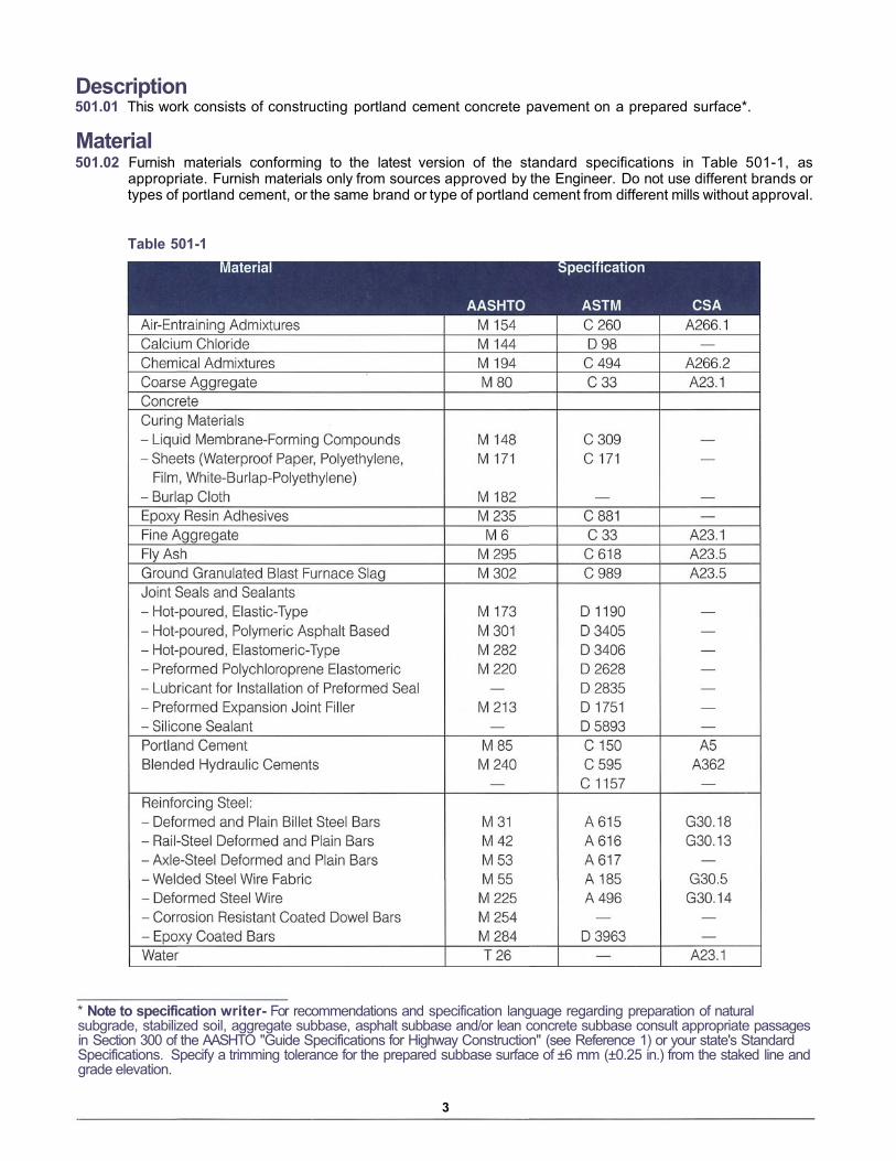
Description501.01 This work consists of constructing portland cement concrete pavement on a prepared surface*.
Material501.02 Furnish materials conforming to the latest version of the standard specifications in Table 501-1, as
appropriate. Furnish materials only from sources approved by the Engineer. Do not use different brands ortypes of portland cement, or the same brand or type of portland cement from different mills without approval.
Table 501-1
* Note to specification writer- For recommendations and specification language regarding preparation of naturalsubgrade, stabilized soil, aggregate subbase, asphalt subbase and/or lean concrete subbase consult appropriate passagesin Section 300 of the AASHTO "Guide Specifications for Highway Construction" (see Reference 1) or your state's StandardSpecifications. Specify a trimming tolerance for the prepared subbase surface of ±6 mm (±0.25 in.) from the staked line andgrade elevation.
3

Equipment501.03 Furnish equipment conforming to the following:
1. Batching Plant and Equipment. Use a batching plant conforming to AASHTO M 157, ASTM C 94 or CSAA23.1. The scales for weighing aggregates and cement must meet the requirements of AASHTO M 157,ASTM C 94 or CSA A23.1, and subsection 109.01 of the AASHTO "Guide Specifications for HighwayConstruction."(1)
2. Mixers. Mix the concrete in a central-mix plant or in truck mixers conforming to AASHTO M 157, ASTMC 94 or CSA A23.1. Operate all equipment within the manufacturer's recommended capacity to produceconcrete of uniform consistency.
A) Central-mix Plant. Combine aggregates, cement, admixtures and water in the mixer. Dispense liquidadmixtures through controlled flow-meters or use dispensers with sufficient capacity to measure, atone time, the full quantity of each admixture required for a batch. If the mixture requires more thanone admixture, dispense each with separate equipment.
B) Truck Mixers and Truck Agitators. Use truck mixers for mixing and hauling concrete and truckagitators for hauling central-mixed concrete that meet the requirements of AASHTO M 157, ASTMC 94 or CSA A23.1. Do not use truck mixers with blade wear more than 25 mm (1 in.) from themanufactured dimension, or with accumulations of hard concrete or mortar on the inside of the drum.
C) Non-Agitator Trucks. Use non-agitator trucks for hauling central-mixed concrete that meet therequirements of AASHTO M 157, ASTM C 94 or CSA A23.1.
3. Paving Equipment. Furnish the paving and finishing equipment applicable to the type of constructionin this contract, as follows:
A) Slipform machines. If slipforming, furnish machines capable of spreading, consolidating, screeding,and finishing the freshly placed concrete in one pass to provide a dense and homogeneouspavement requiring minimal hand finishing.
Equip the paving machine with the following:
1) Automatic controls to control line andgrade from either or both sides of themachine, or from averaging-skis thatreference the grade.
2) Vibrators to consolidate the concretefor the full width and depth of the stripof pavement being placed.
3) A positive interlock system to stop allvibration and tamping elements whenforward motion of the machine stops.
B) Self-Propelled Form-Riding Machines. Where used, furnish mechanical, self-pro-pelled spreading and finishing machinescapable of consolidating and finishing theconcrete with minimal hand finishing. Donot use machines that displace the fixedside forms.
Furnish internal immersed tube or multiplespud vibrators. Attach vibrators to thespreader or finishing machine, or attachthem on a separate carriage that precedesthe finishing machine.
4

C) Manual Fixed-Form Paving Machines. Where needed,furnish spreading and finishing machines capable of con-solidating and finishing concrete up to 200 mm (8 in.) thick.
D) Vibrators. Furnish internal immersed tube or multiplespud vibrators for all paving more than 200 mm (8 in.)thick. Operate the vibrators at frequencies within 5000-8000 vibrations/minute.
Furnish a surface pan vibrator as an alternate to im-mersed tube or multiple spud vibrators for consolidationof 200-mm (8-in.) or thinner concrete slabs. Operate thesurface pan vibrator at a frequency no less than 3500vibrations/minute.
For construction of irregular areas, use handheld vibra-tors. Operate the vibrator at a frequency in the rangerecommended by the manufacturer for the vibrator'shead diameter.
Concrete Saws†. Furnish concrete saws thatare capable of sawing new concrete for crackcontrol on all concrete pavement in this con-tract. Equip all saws with blade guards andguides or devices to control alignment anddepth.
Forms. Furnish straight, steel forms with a height equal to the nominal pavement thick-ness at the edge. For curved edges with radiiless than 30 m (100 ft), furnish flexible orcurved forms. Conform to the following:
A) Use straight forms that are 3 m (10 ft)minimum in length.
B) Use forms with a maximum top face de-viation of 3 mm in 3 m (1/8 in. in 10 ft).
C) Use forms with a maximum inside facedeviation of 6 mm in 3 m (1/4 in. in 10 ft)
D) Equip each form with devices to ad-equately secure the form to the subbaseor subgrade, and to withstand operationof the paving equipment and pressure ofthe concrete.
E) Equip each form with devices to tightlyjoin and lock each end to abutting formsections.
6. Joint Sealing. Furnish joint sealing equip-ment, if required, according to the sealant manufacturer's recommendations for the sealant specifiedin the Plans.
7. Finishing tools. Furnish aluminum, magnesium or wooden hand finishing tools.
† Note to specification writer - It is advisable not to specify a specific type or style of saw for your project and to allow thecontractor to choose the saws depending upon previous experiences. Providing the contractor this freedom ensures thehighest degree of success in jointing the pavement.It is often necessary for the contractor to saw at night to prevent random cracking. The noise generated from sawingoperations may exceed that allowable by local municipal noise-ordinances. Experienced agencies and contractors meetwith law-enforcement agencies before starting a project to explain the necessity of night sawing and to receive specialpermission to violate a noise ordinance. To avoid late-night sawing a contractor may also choose to use an early-entry drysaw that permits joint sawing sooner than a wet-diamond saw. Early-entry dry saws are also much quiter.
5
4.
5.
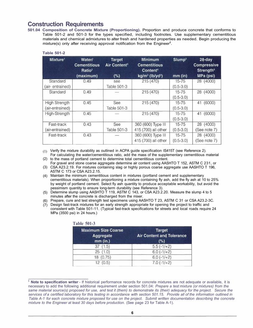
Construction Requirements501.04 Composition of Concrete Mixture (Proportioning). Proportion and produce concrete that conforms to
Table 501-2 and 501-3 for the types specified, including footnotes. Use supplementary cementitiousmaterials and chemical admixtures to alter fresh and hardened properties as needed. Begin producing themixture(s) only after receiving approval notification from the Engineer‡.
Table 501-2
(1)
(2)
(3)
(4)
(5)
(6)(7)
Verify the mixture durability as outlined in ACPA guide specification IS415T (see Reference 2).For calculating the water/cementitious ratio, add the mass of the supplementary cementitious materialto the mass of portland cement to determine total cementitious content.For gravel and stone coarse aggregate determine air content using AASHTO T 152, ASTM C 231, orCSA A23.2.19. For mixtures containing slag or highly porous coarse aggregate use AASHTO T 196,ASTM C 173 or CSA A23.2.15.Maintain the minimum cementitious content in mixtures (portland cement and supplementarycementitious materials). When proportioning a mixture containing fly ash, add the fly ash at 10 to 25%by weight of portland cement. Select fly ash quantity to produce acceptable workability, but avoid thepessimism quantity to ensure long-term durability (see Reference 3).Determine slump using AASHTO T 119, ASTM C 143, or CSA A23.2.20. Measure the slump 4 to 5 minutes after the concrete is discharged from the mixer.Prepare, cure and test strength test specimens using AASHTO T 23, ASTM C 31 or CSA A23.2-3C.Design fast-track mixtures for an early strength appropriate for opening the project to traffic andconsistent with Table 501-11. (Typical fast-track specifications for streets and local roads require 24MPa (3500 psi) in 24 hours.)
Table 501-3
‡ Note to specification writer - If historical performance records for concrete mixtures are not adequate or available, it isnecessary to add the following additional requirement under section 501.04: Prepare a test mixture (or mixtures) from the same material source(s) proposed for use, and test it (them) to demonstrate its (their) adequacy for the project. Secure the services of a certified laboratory for this testing in accordance with section 501.15. Provide all of the information outlined in Table A-1 for each concrete mixture proposed for use on the project. Submit written documentation describing the concrete mixture to the Engineer at least 30 days before production. (See page 23 for Table A-1).
6

501.05 Producing Concrete. Conform to applicable sections of AASHTO M 157, ASTM C 94 or CSA A23.1, and thefollowing requirements for storing and handling material, and for batching, mixing and delivering concrete.
1. Storing and Handling Material. Store and handle all material in a manner that prevents segregation,contamination, or other harmful effects. Do not use any material that has been stored for a periodexceeding the manufacturer's recommended shelf life. Do not use cement or fly ash containing evidenceof moisture contamination. Store and handle aggregate in a manner that ensures reasonably uniformmoisture content at the time of batching. Where recommended by the manufacturer, agitate chemicaladmixtures to ensure consistency during batching.
2. Batching Concrete. Batch the concrete following to the approved mixture proportions and within thetolerances in Table 501-4.
Table 501-43. Mixing Concrete. Produce the mixture(s)
according to the approved proportionsexcept as necessary for the followingconditions:
A) For air-entrained concrete, adjust pro-portions or mixing procedures appropri-ately to maintain the air content of theconcrete within the specified zone.
B) If concrete of the desired plasticity and workability cannot be produced, change the mixtureproportions as necessary without adjusting the design cement content, except as provided in 3Cand 3D below.
C) If concrete having the required consistency cannot be produced without adding water to the mixture,increase the quantity of cementitious materials at an equal weight to the quantity of extra waternecessary. Always remain below the maximum allowable water-cementitiuous ratio.
D) If a new mixture is necessary or desired, submit a revised mixture design for approval before makingany changes in the supply sources or character of the materials. Do not use unapproved concretemixtures.
In a central mixer, mix each batch for the minimum time recommended by the plant's manufacture§.Begin counting the mixing time after all cement and aggregate enters the drum. End the mixing time whenthe discharge chute opens. Transfer time in multiple-drum mixers is included in the mixing time. Removethe contents of an individual drum before a succeeding batch is charged into the drum. Discharge theconcrete mixture without segregation.
In a truck mixer, charge the batch into thedrum so a portion of the mixing water entersin advance of the cement. Mix each batch ofconcrete not less than 70 nor more than 100revolutions of the drum or blades at mixingspeed. Begin the count of mixing revolu-tions as soon as all material, including wa-ter, is in the mixer drum.
Delivering Concrete. Deliver concrete withagitating or non-agitating trucks. Coordinatedelivery to permit continuous placing, withno concrete achieving initial set before plac-ing adjacent concrete. Minimize rehandlingof the concrete. Conform to Table 501-5.
§ Note to specification writer - Mixing time requirements vary depending upon batch plant mixer design and era of manu-facturing. Consult the plant manufacturer to verify the time appropriate for the plant provided by the contractor or set themixing time requirement based on a performance test (see ASTM C 94) performed by the contractor before the project is fullyunderway. In lieu of a manufacturer's specific recommendation or a performance test, specify a minimum time of 60 seconds.
7
4.

Table 501-5
(1) ASTM C150, C595 and C1157 cement types listed here. Substitute AASHTO or CSA designations asappropriate.
(2) For delivery in truck mixers, additional water and admixtures (if in the approved mixture) may beadded to obtain the required slump or air content at the paving site, providing the total of all water inthe mixture is less than the maximum required by the water/cementitiuous ratio. Remix concrete within45 minutes (75 minutes for Type I, IA, II, IIA or GU cements with water reducing/retarding admixture)after the initial introduction of mixing water to cement or cement to aggregates. Do not add additionalwater and admixtures if the concrete has obtained initial set.
501.06 Paving. Uniformly dampen the prepared roadbed surface before paving. Do not place concrete onfrozen subgrade or subbase. If operating vehicles on subbase or subgrade before or while paving, repairexcessive rutting or other damages before placing concrete at the direction of the Engineer.
Place concrete with fixed-form or slipform paving equipment. Operate the paving equipment with a continuous forward movement, as practicable, and coordinate mixing, delivering, and spreading concreteto provide uniform progress. Except in an emergency, apply no tractive force to a slipform-paving machine, except that which is controlled from the machine.
Place reinforcing steel as shown in the plans. Either firmly position the reinforcement on acceptable supportsbefore placing the concrete or mechanically insert the reinforcement into the plastic concrete to the requiredlocation and alignment tolerances.
In irregular areas or areas inaccessible to self-propelled paving equipment, construct the pavement usingfixed forms and manual fixed-form paving equipment. Thoroughly and uniformly vibrate and consolidate theconcrete during placement without segregating the material. Use handheld internal vibrators along formsand around embedded objects, including dowel baskets and utility fixtures, where necessary to ensureadequate consolidation.
When paving in extremely cool or warm air temperatures, use adequate concrete protection measures.**Concrete that the Engineer suspects was damaged by frost action or excessive heat is subject to additionaltesting to determine its quality.
501.07 Joints††. Construct transverse and longitudinal joints, by forming or sawing, to the details, dimensions andspacing shown on the Plans, using approved equipment. Use construction-style joints at any longitudinaljoint necessary to facilitate construction staging.
Extend all transverse joints the entire width of paving. When constructing curbs or medians integral with thepavement, construct transverse joints continuous through the curb or median. When the pavement abuts anexisting pavement or curb and gutter, construct transverse joints in the pavement at locations matchingtransverse joints or cracks in the existing pavement, or use an isolation joint to separate the new pavementfrom the old.
** Note to specification writer - You may reference your state's cold-weather and hot-weather requirements, or referenceACI 306R and ACI 305R respectively to define the minimally acceptable practice for protection in your area. We specify noair or concrete temperature limitations in this guideline, assuming that adequate protection will control potential problems.†† Note to specification writer - It is advisable to review and revise your standard joint details to conform to the nomencla-ture, and principles outlined by this specification. Page 21 and 22 provide details for transverse and longitudinal joints, andfor boxing out utility fixtures within the pavement.
8

1. Contraction joints. Construct by forming or sawing‡‡ to control cracking. When forming joints, install a parting strip that remains in place or depress a forming tool into the concrete.
When sawing joints, begin as soon as the concrete hardens sufficiently to prevent excessive ravelingalong the saw cut and finish before conditions induce uncontrolled cracking, regardless of the time orweather. Saw longitudinal contraction joints immediately after sawing transverse joints. Do not stopsawing, except as follows: (1) Do not saw a joint at or near any location where a shrinkage crack is visible;(2) Do not continue to saw a joint if a crack forms ahead of the saw cut while sawing.
If uncontrolled cracking occurs, follow requirements of Section 501.20.
2. Construction joints. Construct a transverse construction joint at the end of each day's work or whereconcrete placement is interrupted long enough that the concrete begins to harden. Use a metal orwooden bulkhead to form the joint, or saw completely through the concrete and remove excess materialto expose solid concrete. Metal or wooden bulkhead forms must match the pavement cross-section andpermit the installation of dowel bars. Construct longitudinal construction joints where needed, conform-ing to the details shown on the Plans.
3. Isolation joints. Construct transverse and longitudinal isolation joints by sawing or by installing a preformedjoint filler in the concrete. Install the preformed joint filler full-depth, perpendicular to the subgrade, andconform to the details shown on the Plans. Remove all concrete that leaks into the joint closure space.Construct longitudinal isolation joints where needed, conforming to the details shown on the Plans.
4. Dowel bars, Tie bars, Hookbolts, Reinforcing Steel or Mesh. Where required, place dowel bars,tiebars, hook bolts and reinforcing steel, as follows:
A) Dowel bars for contraction joints. Place dowel bars at the location, depth and spacing shown in theplans. Fasten the dowels to rigid baskets or insert them while the concrete is plastic. Align dowelsvertically and horizontally within 3.0% of true alignment in all directions, and provide a minimumembedment length of 150 mm (6.0 in.) on either side of the joint. Fasten dowel baskets securely tothe subbase or subgrade using stakes or nails. Use dowels with a factory-applied debonding agentor coat each bar with form-release oil before paving.
B) Dowel bars for construction joints. Place dowel bars in transverse construction joints at the location,depth and spacing shown on the Plans. Drill holes and epoxy dowels into position in a sawed jointface, or insert them through holes in a bulkhead form taking care to maintain proper alignment.Dowels must meet the tolerance specified in 501.07.4(A).
C) Dowel bars for isolation joints. Place dowel bars in transverse isolation joints at the location, depthand spacing shown on the plans. Fasten the dowels to an expansion basket that remains in thepavement, provides joint closure space and holds each dowel parallel to the surface and center lineof the slab. Dowels must meet the tolerance specified in 501.07.4(A). Attach expansion caps to eachdowel bar as shown on the Plans.
D) Tie bars. Place tie bars reasonably perpendicular to the longitudinal joints with mechanical insertionequipment or rigidly secured chairs without damaging or disrupting the concrete. Do not bend andstraighten tie bars into correct position by more than 90°. Repair or replace broken or badly damagedtie bars.
E) Threaded hook bolts. As an option, use threaded hook bolts instead of tie bars. Fasten hook boltsto the fixed forms securely.
F) Reinforcing Steel or Mesh reinforcement. Place deformed reinforcing steel, or mesh reinforcementat the location and orientation shown on the Plans. If required, use plastic or metal chairs to supportreinforcement, conforming to the Plans.
‡‡ Note to specification writer - Avoid specification language dictating the methodology or specific timing for joint sawing orforming. The purpose of this passage is to define the expected result, while giving just enough guidance to define appropri-ate practice. Direct specific sawing methodology decisions and the accompanying responsibility for crack control to thecontractor. If uncontrolled cracking occurs, the contractor's crew will determine whether to start sawing sooner, skip joints,use early-entry dry sawing or increase the number of saws. As a rule, some raveling of green concrete is expected in orderfor sawing to prevent uncontrolled cracking. It is also acceptable practice when using conventional saws to saw every thirdtransverse contraction joint and then return to saw the intermediate joints as soon as possible.
9

501.08 Surface Finishing. Hand-float the surface only as needed to produce a uniform surface, and sharp corners;do not use excess mortar to build up slab edges or round the slab corners. Before the concrete's initial set,work the pavement edges along each side of transverse isolation joints, formed joints, transverseconstruction joints, and fixed forms to produce a 6-mm (1/4-in.) continuous radius and a smooth, densemortar finish. As needed, check the surface of the fresh concrete with a long-handled straightedge that is3 m (10 ft) or longer. Remove high areas indicated by the straightedge. Overlap each successive pass ofthe straightedge by about 1.5 m (5 ft).
Protect the surface from rain damage.§§
501.09 Texturing. After surface finishing, texture all concrete surfaces that will be used by traffic. Use either hand-operated or mechanical tools to produce a uniform texture that conforms to the dimensions shown on thePlans and the following:
1. Design Speed less than 80 km/h (50 mph). Apply a burlap-drag, turf-drag or broom texture.
For a burlap-drag texture, drag two layers of moistened burlap along the pavement in the direction ofpaving. The burlap must be sufficiently long and wide enough to cover the entire pavement width andproduce a uniform texture with corrugations about 1.5 mm (1/16 in.) deep. Clean the burlap periodicallyto remove encrusted mortar or replace with new burlap.
For a turf-drag texture, drag plastic turf along the pavement in the direction of paving. The plastic turf mustbe sufficiently long and wide enough to cover the entire pavement width and produce a uniform texturewith corrugations about 1.5 mm (1/16 in.) deep. Use turf with a blade density of 77500 blades/m2 (7200blades/ft2) and each blade at least 20 mm (0.75 in.) long.
For a broom texture, use a stiff-bristled broom, drawing it from the pavement center to the edges. Overlapstrokes slightly to produce a uniform texture with corrugations about 1.5 mm (1/16 in.) deep.
2. Design Speed greater than 80 km/h (50 mph). Apply a longitudinal or transverse texture*** inconformance with the plans.
501.10 Curing. After texturing, and immediately after bleed water leaves the surface, coat the surface of theslab, and for slipform construction the sides of the slab, with approved curing compound. For fixed-formwork, coat the sides of the pavement after removing forms. Conform to these additional requirements:
1. Apply the compound at a rate of 5.0 m2/L (200 ft2/gal) for standard mixtures and applications. Usean application rate of 3.75 m2/L (150 ft2/gal) for fast-track concrete, and an application rate of 2.5 m2/L(100 ft2/gal) for slabs thinner than 125 mm (5.0 in.).
2. Omit the application of curing compound when choosing an alternate curing method: water spray or fog,wet burlap sheets, or plastic sheets. Demonstrate the alternate curing method and receive the engineer'sapproval before substituting for curing compound.
3. For sheet curing materials, extend the sheets beyond the edges of the slab to a distance at least twicethe thickness of the pavement. Place and maintain the sheets in complete contact with the surface.
§§ For more information see reference 4.*** Note to specification writer - Either transverse or longitudinal tine textures can provide adequate skid resistance andlow-noise qualities (for more information see reference 5).For transverse tine textures include this requirement in the specification or by note on the plans: Space transverse tines randomly as follows: minimum spacing 10 mm (1/2 in.), maximum spacing 40 mm (1-1/2 in.), with no more than 50% of the tines apart by more than 25 mm (1 in.). Use tines that are 3 mm (1/8 in.) wide, with a tolerance of ±0.5 mm (±3/16 in.) and apply them to a depth of 3-6 mm (1/8-1/4 in.).
For longitudinal tine textures include this requirement in the specification or by note on the plans: Apply a longitudinal tine texture parallel to the pavement centerline. Space tines uniformly at 20 mm (3/4 in.). Use tines that are 3 mm (1/8 in.) wide and apply them to a depth of 3-6 mm (1/8-1/4 in.).
10
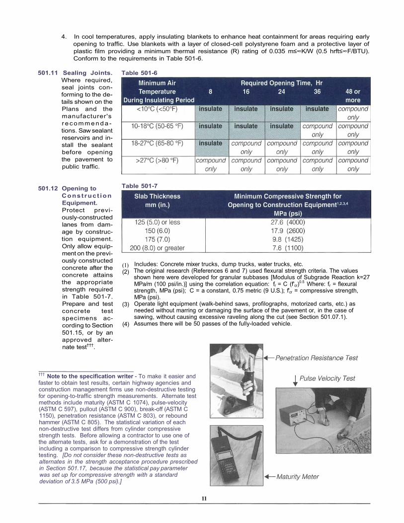
4. In cool temperatures, apply insulating blankets to enhance heat containment for areas requiring earlyopening to traffic. Use blankets with a layer of closed-cell polystyrene foam and a protective layer ofplastic film providing a minimum thermal resistance (R) rating of 0.035 m≤∞K/W (0.5 hrft≤∞F/BTU).Conform to the requirements in Table 501-6.
501.11 Sealing Joints.Where required,seal joints con-forming to the de-tails shown on thePlans and themanufacturer'sr e c o m m e n d a -tions. Saw sealantreservoirs and in-stall the sealantbefore openingthe pavement topublic traffic.
Table 501-6
(1)(2)
(3)
(4)
501.12 Opening toConstruct ionEquipment.Protect previ-ously-constructedlanes from dam-age by construc-tion equipment.Only allow equip-ment on the previ-ously constructedconcrete after theconcrete attainsthe appropriatestrength requiredin Table 501-7.Prepare and testconcrete testspecimens ac-cording to Section501.15, or by anapproved alter-nate test†††.
††† Note to the specification writer - To make it easier andfaster to obtain test results, certain highway agencies andconstruction management firms use non-destructive testingfor opening-to-traffic strength measurements. Alternate testmethods include maturity (ASTM C 1074), pulse-velocity(ASTM C 597), pullout (ASTM C 900), break-off (ASTM C 1150), penetration resistance (ASTM C 803), or reboundhammer (ASTM C 805). The statistical variation of eachnon-destructive test differs from cylinder compressivestrength tests. Before allowing a contractor to use one ofthe alternate tests, ask for a demonstration of the testincluding a comparison to compressive strength cylindertesting. [Do not consider these non-destructive tests asalternates in the strength acceptance procedure prescribed in Section 501.17, because the statistical pay parameter was set up for compressive strength with a standard deviation of 3.5 MPa (500 psi).]
Includes: Concrete mixer trucks, dump trucks, water trucks, etc.The original research (References 6 and 7) used flexural strength criteria. The valuesshown here were developed for granular subbases [Modulus of Subgrade Reaction k=27MPa/m (100 psi/in.)] using the correlation equation: fr = C (f'cr)0.5 Where: fr = flexuralstrength, MPa (psi); C = a constant, 0.75 metric (9 U.S.); f'cr = compressive strength,MPa (psi).Operate light equipment (walk-behind saws, profilographs, motorized carts, etc.) asneeded without marring or damaging the surface of the pavement or, in the case ofsawing, without causing excessive raveling along the cut (see Section 501.07.1).Assumes there will be 50 passes of the fully-loaded vehicle.
11
Table 501-7

Acceptance Criteria‡‡‡
501.13 Smoothness. After the concrete has sufficiently hardened, measure the finished surface smoothness of thepavement as specified below. Move all equipment, objects and debris that may interfere with the measuringequipment or affect the measurement results.
1. Profilograph measurement. Using a California Profilograph§§§, or an approved equivalent, measure thesmoothness of each lane parallel to the centerline according to ACPA Technical Bulletin TB006P.(8)
A) Exclusions: Exclude the following areas from must-grind bump and profile index determination:
• Any section less than 15 m (50 ft).• Side streets less than or equal to 150 m (500 ft.) in length.• Sections 15 m (50 ft.) from bridge approaches or an existing pavement.• Acceleration and deceleration lanes, turning lanes, auxiliary lanes, or storage lanes.• Curves with radius less than or equal to 300 m (1000 ft.) including superelevation transitions, such
as at ramps.• Surfaces near manholes, inlets and other in-pavement utility castings.• Driveway aprons.• Bridge decks.
Locate bumps in any of these excludedareas using a 3-m (10-ft) straightedge inaccordance with 501.13.2, unless other-wise specified.
D) Defective areas: Defective areas aremust-grind bumps and profile indicesexceeding the index shown in Table501-8. Defective areas require correc-tion as outlined in Section 501.13.3.
E) Must grind bumps: Correct bumps (areas represented by high points on the profile trace) havingdeviations in excess of 10 mm (0.4 in.) in 7.62 m (25 ft).
F) Profile Index: From the profile trace, calculate a profile index for each 0.1 km (0.1 mi) segment of laneusing a 5-mm (0.2-in.) wide blanking band. Include the profile trace for pavement lengths less than0.1 km (0.1 mi) with the next segment for that lane when calculating the profile index. Determine theprofile index as prescribed in ACPA Technical Bulletin TB006P.(8)
Refer to section 501.13.4 and Table 501-9 for specific profile index requirements and to determinethe smoothness pay factor.
‡‡‡ Note to specification writer - This section contains acceptance criteria for smoothness, thickness, opening strength andquality-assurance strength. Quality assurance testing for strength is applicable only to larger projects [17,500 m3 (21,000yd3) recommended] that will generate enough testing data to produce reasonable average values. On small projects, erraticstrength test results on any day might overly influence a project's strength statistics, producing an untrue mean and riskingacceptance of poor quality concrete or rejection of good quality concrete. To avoid this situation, omit quality-assurancestrength testing (Section 501.17) for smaller projects. Instead, use a more traditional approach and specify a mixture to thecontractor. If necessary, consult your state's standards or your local ready-mix suppliers for their recommendations on a mixture for your application.
§§§ Note to specification writer - The California profilograph is the predominantsmoothness-measuring tool used in North America for evaluating newly con-structed pavement (see reference 8). Many agencies and contractors employ a California profilograph because it can provide results faster than most otherdevices. However, its use may not be appropriate for some street and local roadprojects if the paving lengths are too short. The California profilograph is notrecommended if paving segments are less than 150 m (500 ft). In these situations,apply straightedge measurement as prescribed in 501.13.2.
12
Table 501-8

2. Straightedge measurement. Use a 3-m (10-ft) metal straightedge to measure parallel to the centerline.Where there is more than 6 mm in 3 m (1 /4 in. in 10 ft), between any two contacts of the straightedge withthe surface, the surface requires correction. Pavement surfaces that have been purposely warped tomeet fixtures (manholes, drainage inlets, catch basins), existing curb and gutter, or cross- and side-roadconnections are exempt from this straightedge requirement.
3. Defective area correction. Correct defective areas using anapproved grinding device****. After correction, verify the cor-rective work by measuring the smoothness according to 501.13.1or 501.13.2, as appropriate.
At your (the contractor's) option, where measuring by CaliforniaProfilograph, correct the profile of any segment to improve theprofile index before determining the smoothness incentive. Thecontractor is responsible to pay for correcting all defective areas.
4. Determine smoothness Table 501-9incentive. California Profilograph: Use Table501-9 to determine the payincentive for each pavingsegment subject tosmoothness evaluation byCalifornia Profilograph.
Straightedge: There is nopayment incentive forproperly corrected pave-ment, which is subject tosmoothness measurementby 3-m (10-ft) straight-edge. If bump grindingdoes not correct a defec-tive area, and the Engi-neer determines that thedefective area shall remainin place, it is subjectto payment at 50% ofthe area unit price. The En-gineer may elect to requireremoval and replacementof any defective area that Where: PIthe Contractor cannot cor- lsrect adequately.
= Measured Profile Index.= Smoothness Incentive.
501.14 Tolerance in Pavement Thickness: Determine the pavement thickness from cores by average calipermeasurements in accordance with AASHTO T 148 or ASTM C 174. Extract one core for each 140 m2
(1500 yd2) of concrete pavement placed in each lane. For pavement placement units consisting of less than140 m2 (1500 yd2) of concrete, include the pavement with the previous or next placement unit.
Full payment will be made for pavement represented by cores that are no less than the Plan thickness minus6 mm (0.25 in.)††††.
**** Note to specification writer - A grinding machine for bump grinding typically uses a cutting head with many diamondsaw-blades. The grinding head produces 164-197 grooves/meter (50-60 grooves/foot) and can remove 3-20 mm (1/8-3/4 in.from the pavement surface. Carbide milling or other impact equipment may not produce as smooth a surface and are notnormally acceptable.†††† Note to specification writer - See footnote on page 3 for prepared roadbed-trimming tolerance.
13

Pavement represented by cores that are lessthan the Plan thickness minus 6 mm (0.25 in.)are subject to further evaluation. Take two addi-tional cores, one about 10 m (30 ft) before andanother about 10 m (30 ft) after the original core(within the same placement unit). The work issubject to full payment if the average thicknessof the three cores is no less than the Planthickness minus 6 mm (0.25 in.). Adjust the areacontract unit price as shown in Table 501-10 ifthe average of three cores is no less than 25 mm(1 in.) below the Plan thickness. If the average ofthree cores is less than 25 mm (1 in.) below thePlan thickness, and the Engineer determinesthat the placement unit should remain in place,it is subject to a 50% reduction to the area unitbid price.
501.15 Testing and Test Specimens: Employ only testing laboratories meeting the requirements of ASTM C 1077for preparing, handling, coring, storing and testing concrete specimens. Obtain the written qualifications ofthe testing firm, indicating their compliance with ASTM E 329 "Standards of Recommended Practice forInspection and Testing Agencies for Concrete, Steel, and Bituminous Materials as Used in Construction."Obtain the most recent certificates of calibration for testing equipment, showing that the equipment has beencalibrated at a minimum 12-month interval by devices of accuracy traceable to either National Bureau ofStandards or an established value. Submit to the Engineer all certification records for the testing firm andequipment with the Strength Evaluation Plan according to section 501.17.1.
Obtain, handle and cure concrete test specimens for opening strength and thickness evaluation accordingto applicable sections of AASHTO T 23 or ASTM C 31 or CSA A23.2-3C. Test the specimens according toapplicable sections of AASHTO T 22 or ASTM C 39 or CSA A23.2-9C.
The Engineer pays for the costs of coring and acceptance testing. The Contractor is responsible for costsof extra or exploratory cores or tests to determine the extent of thickness or strength deficiencies.
Improper handling and testing of concrete cylinders is found to contribute to low strength in a majority of strength investigations. It is essential to employ trained testing personnel that are able to properly follow these strength-testing standard procedures for field-made, laboratory-cured cylinders: 1. Sample concrete in two increments after discharging some from the chute or truck. 2. Transport sample to field curing location where it will remain for first clay. 3. Remix the sample concrete to ensure homogeneity. 4. Add concrete to cylinder molds that conform to standards- rod the concrete in three layers and tap sides of the
mold to close rod holes. 5. Finish top smooth and level with mold. 6. If necessary move cylinders immediately after molding; support the cylinder bottoms. 7. Field-cure cylinders at 15 to 27°C (60 to 80°F) and protect from loss of moisture. 8. Gently transport clay-old cylinders to the laboratory. 9. De-mold cylinders and promptly place in 21 to 24°C (70 to 76°F) moist curing environment. 10. Maintain water on cylinder surfaces at all times. 11. Before testing, cap cylinders with 34.5 MPa (5000 psi) capping material-make caps flat, true and no greater
than 5 mm (3/16 in.) thick. 12. Wait at least two hours for sulfur caps to harden. 13. Measure cylinder diameter and check cap quality, including alignment. 14. Using calibrated testing machine, center cylinder in testing head and load using proper loading rate. 15. Observe break pattern (vertical cracks through the cap indicate improper load distribution). Nearly all deficiencies in handling and testing cylinders will lower measured strength. The most common errors include: leaving cylinders for extra days of field-curing; allowing cylinders to fall, tip over or bounce during transpor-tation; delaying moist-curing in the lab; and testing with improperly made and aligned caps.
Table 501-10.
14
15 Steps in Properly Making, Handling, Storing and Testing Concrete Cylinder Specimens

501.16 Opening to Public Traffic. Cast at least three sets of three concrete cylinder specimens from eachpavement placement unit that exceeds 50 m3 (50 yd3) for testing the opening strength. Cast at least one setof three cylinder specimens for pavement placement units less than 50 m3 (50 yd3) for testing the openingstrength.
Choose‡‡‡‡ a time to test one cylinder specimenfrom each of the three sets and average theresults to establish a test value. If the test valuecomplies with the specified opening strength,open the pavement represented by the testvalue. If the test value is not adequate for open-ing, test a second specimen (and third if neces-sary) from each of the three sets at later times toestablish additional test values. If the second(and third where necessary) test value exceedsor complies with the specified opening strength,open the pavement placement unit representedby the test value.
In the event that none of the three average testvalues exceed or comply with the specifiedopening strength, plot the test values on a graphand draw a straight line through the points insuch a manner as to establish a linear age-strength relationship. Project the line to 14 days,and open the pavement at the age where the lineindicates opening strength compliance. If thetime between the first and third test is not at least4 days, then consult the Engineer on alternatestrength testing at your (the contractor's)expense.
Do not allow public traffic on the pavement untilthe concrete attains the appropriate strengthrequired in Table 501-11.
Table 501-11
(1) Test strength test specimens using AASHTO T 23 orASTM C 31 or CSA A23.2-3C.
(2) The original research (Reference 4) used flexuralstrength criteria. The values shown here were devel-oped for granular subbases [Modulus of SubgradeReaction k=27 MPa/m (100 psi/in.)] using the correla-tion equation: fr = C (f'cr)0.5 Where: fr = flexuralstrength, MPa (psi); C = a constant, 0.75 metric(9 U.S.); f'cr = compressive strength, MPa (psi).
(3) Assumes there will be 500 one-way equivalent singleaxle load (ESAL) repetitions between time of openingand time concrete reaches design strength (28-daystrength).
‡‡‡‡ Note to specification writer - Consider four days for initially testing normal concrete, 3 days for accelerated concreteand 24 hours for fast-track concrete. Consider taking subsequent tests every 2 days for normal mixtures, 1 day for acceler-ated and fast-track mixtures. Opening requirements may necessitate testing earlier than 24 hours for projects using fast-track mixtures. As an alternate to compressive, consider non-destructive methods (see note, page 11).
15
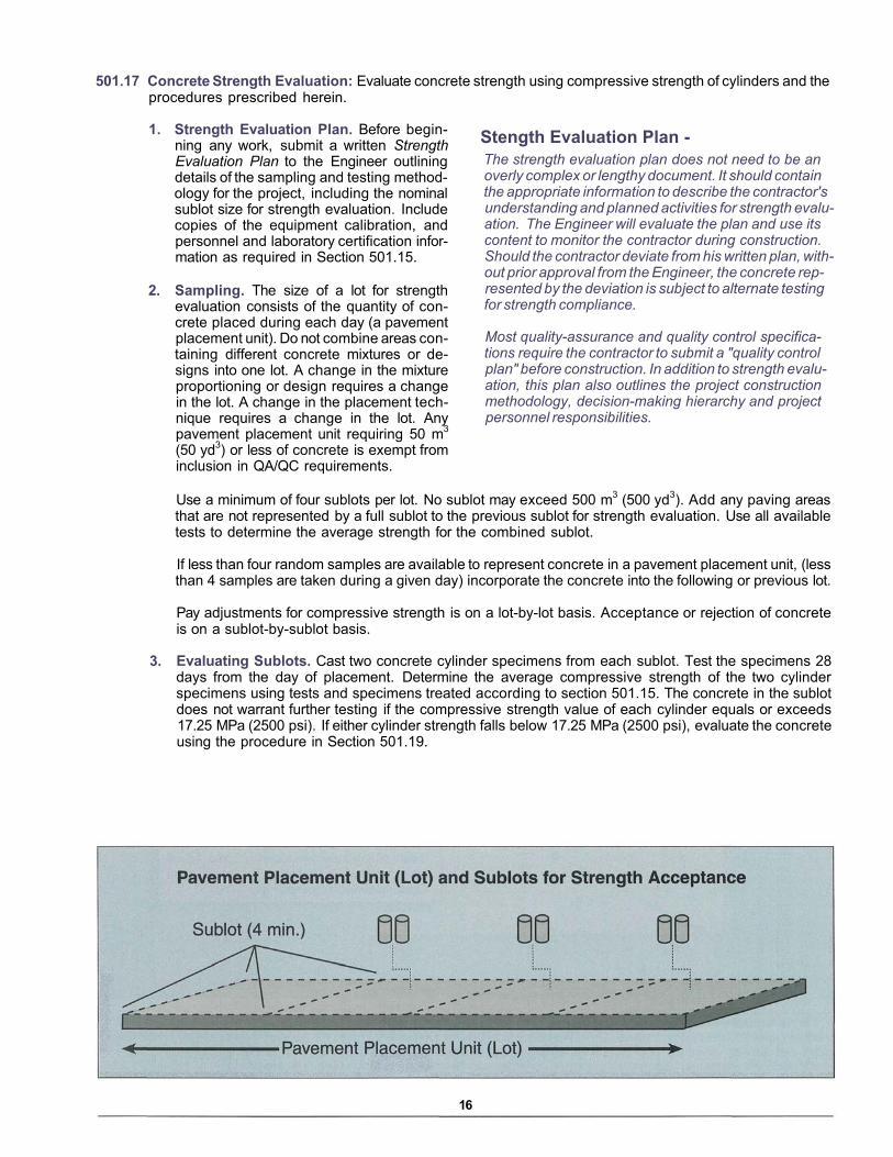
501.17 Concrete Strength Evaluation: Evaluate concrete strength using compressive strength of cylinders and theprocedures prescribed herein.
1. Strength Evaluation Plan. Before begin-ning any work, submit a written Strength Evaluation Plan to the Engineer outliningdetails of the sampling and testing method-ology for the project, including the nominalsublot size for strength evaluation. Includecopies of the equipment calibration, andpersonnel and laboratory certification infor-mation as required in Section 501.15.
2. Sampling. The size of a lot for strengthevaluation consists of the quantity of con-crete placed during each day (a pavementplacement unit). Do not combine areas con-taining different concrete mixtures or de-signs into one lot. A change in the mixtureproportioning or design requires a changein the lot. A change in the placement tech-nique requires a change in the lot. Anypavement placement unit requiring 50 m3
(50 yd3) or less of concrete is exempt frominclusion in QA/QC requirements.
The strength evaluation plan does not need to be an overly complex or lengthy document. It should contain the appropriate information to describe the contractor's understanding and planned activities for strength evalu-ation. The Engineer will evaluate the plan and use its content to monitor the contractor during construction. Should the contractor deviate from his written plan, with-out prior approval from the Engineer, the concrete rep-resented by the deviation is subject to alternate testing for strength compliance.
Most quality-assurance and quality control specifica-tions require the contractor to submit a "quality control plan" before construction. In addition to strength evalu-ation, this plan also outlines the project construction methodology, decision-making hierarchy and project personnel responsibilities.
Use a minimum of four sublots per lot. No sublot may exceed 500 m3 (500 yd3). Add any paving areasthat are not represented by a full sublot to the previous sublot for strength evaluation. Use all availabletests to determine the average strength for the combined sublot.
If less than four random samples are available to represent concrete in a pavement placement unit, (lessthan 4 samples are taken during a given day) incorporate the concrete into the following or previous lot.
Pay adjustments for compressive strength is on a lot-by-lot basis. Acceptance or rejection of concreteis on a sublot-by-sublot basis.
3. Evaluating Sublots. Cast two concrete cylinder specimens from each sublot. Test the specimens 28days from the day of placement. Determine the average compressive strength of the two cylinderspecimens using tests and specimens treated according to section 501.15. The concrete in the sublotdoes not warrant further testing if the compressive strength value of each cylinder equals or exceeds17.25 MPa (2500 psi). If either cylinder strength falls below 17.25 MPa (2500 psi), evaluate the concreteusing the procedure in Section 501.19.
16
Stength Evaluation Plan -
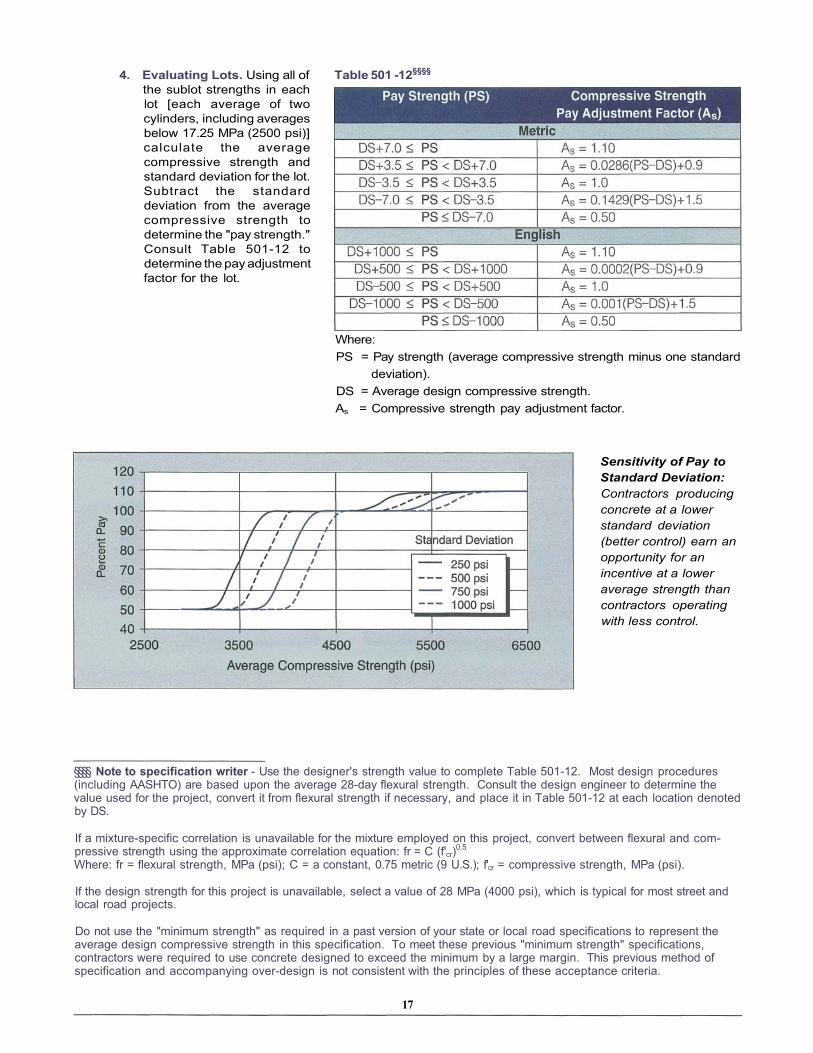
4. Evaluating Lots. Using all ofthe sublot strengths in eachlot [each average of twocylinders, including averagesbelow 17.25 MPa (2500 psi)]calculate the averagecompressive strength andstandard deviation for the lot.Subtract the standarddeviation from the averagecompressive strength todetermine the "pay strength."Consult Table 501-12 todetermine the pay adjustmentfactor for the lot.
Table 501 -12§§§§
Where:PS = Pay strength (average compressive strength minus one standard
deviation).DS = Average design compressive strength.As = Compressive strength pay adjustment factor.
Sensitivity of Pay to Standard Deviation: Contractors producing concrete at a lower standard deviation (better control) earn an opportunity for an incentive at a lower average strength than contractors operating with less control.
§§§§ Note to specification writer - Use the designer's strength value to complete Table 501-12. Most design procedures(including AASHTO) are based upon the average 28-day flexural strength. Consult the design engineer to determine thevalue used for the project, convert it from flexural strength if necessary, and place it in Table 501-12 at each location denotedby DS.
If a mixture-specific correlation is unavailable for the mixture employed on this project, convert between flexural and com-pressive strength using the approximate correlation equation: fr = C (f'cr)0.5
Where: fr = flexural strength, MPa (psi); C = a constant, 0.75 metric (9 U.S.); f'cr = compressive strength, MPa (psi).
If the design strength for this project is unavailable, select a value of 28 MPa (4000 psi), which is typical for most street andlocal road projects.
Do not use the "minimum strength" as required in a past version of your state or local road specifications to represent theaverage design compressive strength in this specification. To meet these previous "minimum strength" specifications,contractors were required to use concrete designed to exceed the minimum by a large margin. This previous method ofspecification and accompanying over-design is not consistent with the principles of these acceptance criteria.
17

This method assumes that the standard deviation of compressive strength in the design is 3.5 MPa (500 psi). This standard deviation is essentially consistent with the recommendation in American Concrete Institute 318(9), [3.8 MPa (550 psi)] and the experience of ready-mix producers for good quality concrete. The range of strength between the average design compressive strength (DS) and one standard deviation above and below accounts for variability in design and construction.
Contingency Criteria501.19 Referee Testing: Apply referee testing for any of the following conditions:
• When compressive strength evaluation in Section 501.17.3 indicates the concrete is not above 17.25MPa (2500 psi).
• Test specimens are of suspect quality, fabrication, transport or curing.• Testing procedures or test machines are of suspect quality or calibration.
Remove three cores at random locations in the suspect area after the concrete pavement is at least 28 daysold. Remove, handle and test the compressive strength of the three cores according to AASHTO T 24 orASTM C 42, or CSA A23.2-14C.
Determine the mean and standard deviation of the compressive strength of the three cores.***** If the meanexceeds 14.85 MPa (2150 psi), and no one core test is less than 12.93 MPa (1875 psi), the concrete in thesublot is subject to payment according to Table 501-12 using the results from the cores. Otherwise, theconcrete is not acceptable and may be removed and replaced at the Engineer's option.
***** Note to specification writer - The compressive strength of cores is normally 85 percent or less than the compressivestrength of 28-day cylinder specimens that have been properly made, cured and tested. This referee method applies this 85percent relationship to validate the cylinder test results. The mean minus one standard deviation of the compressivestrengths of the three cores becomes a pay strength test result if it indicates that the concrete (by valid cylinder testing)would exceed 17.25 MPa (2500 psi). This method is adapted from ACI 318(9).
18

501.20 Repairing Defects:††††† Repair defects in conformance with Table 501-13. Do not begin corrective work untilafter submitting a plan and receiving the Engineer's approval for repair methods.
Table 501-13 Repair Methods for Defects in New Pavement
1. 1 m = 3.28 ft2. HMWM = High molecular weight methacrylate poured over surface and sprinkled with sand for skid resistance.3. LTR = load-transfer restoration; 3 dowel bars per wheel path grouted into slots sawed across the crack; Slots must be
parallel to each other and the longitudinal joint.4. FDR = full-depth repair; 3 m (10 ft) long by one lane wide. Extend to nearest transverse contraction joint if 3-m (10-ft)
repair would leave a segment of pavement less than 3 m (10 ft) long.5. PDR = partial-depth repair; Saw around spall leaving 50 mm (2 in.) between spall and 50-mm (2-in.) deep perimeter saw
cuts. Chip concrete free, then clean and apply bond-breaker to patch area. Place a separating medium along anyabutting joint or crack. Fill area with patching mixture.
6. Cross-stitching; for longitudinal cracks only, drill holes at 35° angle, alternating from each side of joint on 750-1000 mm(30-36 in.) spacing. Epoxy deformed steel tiebars into holes.
††††† For details on the recommended practices for design and construction of the repair methods recommended in Table501-13, see references 10-13.
19

Final Completion501.21 Final Completion. Complete all items in accordance with the Plans and these specifications before seeking
final acceptance. Remove all equipment, surplus material, and construction debris from the project area.
Measurement501.22 Measurement: Measure the pavement by area for placing and by volume for furnishing concrete.
Determine the total area quantity for payment by adding all non-rectangular paved areas to the primarypaved area in this contract. The width for calculating the primary paved area is the width of the pavementshown on the cross-section in the plans, including any additional widening required by the Engineer. Thelength for calculating the primary paved area is the distance along the pavement centerline. For intersec-tions, tapers and other non-rectangular areas, calculate the area of each unusual shape separately.
Determine the volume of each different concrete mixture furnished for the project by adding the quantitiesindicated on the batch tickets.
Payment501.23 Payment: The area unit price is compensation for furnishing all labor, equipment, and materials to place,
finish, texture, cure, saw joints and seal joints, in accordance with the Plans and these specifications. Theconcrete volume unit price is compensation for furnishing all raw materials, and for proportioning, mixingand delivering concrete to the paving machine. All pavement accepted by the Engineer will be paid at thecontract price per unit for the pay items shown in the bid schedule, except as follows:
• Each lot/pavement placement unit is subject to the requirements in Section 501.17 and adjustment tothe concrete volume unit bid price as follows:
PPV = UBPV • As
Where: PPV = Price paid per unit volumeUBPV = Volume unit bid priceAs = Strength pay adjustment factor determined in Table 501-12
• Each lot/pavement placement unit is subject to the requirements of Section 501.13 and 501.14 andadjustment to the area unit bid price as follows:
PPA = (UBPA + l s ) . ( PFT)
Where: PPA = Price paid per unit areaUBPA = Area unit bid pricels = Smoothness incentive determined in Table 501-9PFT = Pay factor determined in Table 501-10
20

Joint DetailsContraction:
Construction:
Isolation:
21
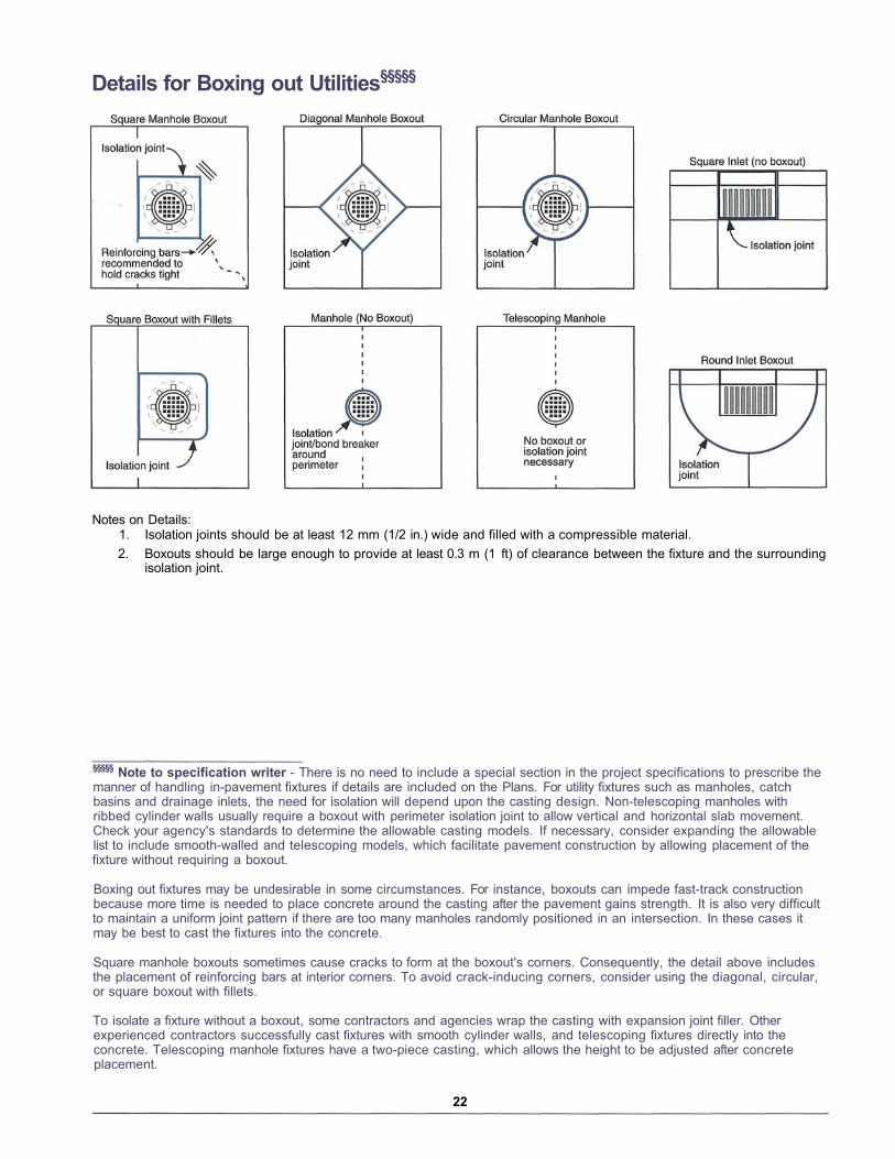
Details for Boxing out Utilities§§§§§
Notes on Details:1. Isolation joints should be at least 12 mm (1/2 in.) wide and filled with a compressible material.2. Boxouts should be large enough to provide at least 0.3 m (1 ft) of clearance between the fixture and the surrounding
isolation joint.
§§§§§ Note to specification writer - There is no need to include a special section in the project specifications to prescribe themanner of handling in-pavement fixtures if details are included on the Plans. For utility fixtures such as manholes, catchbasins and drainage inlets, the need for isolation will depend upon the casting design. Non-telescoping manholes withribbed cylinder walls usually require a boxout with perimeter isolation joint to allow vertical and horizontal slab movement.Check your agency's standards to determine the allowable casting models. If necessary, consider expanding the allowablelist to include smooth-walled and telescoping models, which facilitate pavement construction by allowing placement of thefixture without requiring a boxout.
Boxing out fixtures may be undesirable in some circumstances. For instance, boxouts can impede fast-track constructionbecause more time is needed to place concrete around the casting after the pavement gains strength. It is also very difficultto maintain a uniform joint pattern if there are too many manholes randomly positioned in an intersection. In these cases itmay be best to cast the fixtures into the concrete.
Square manhole boxouts sometimes cause cracks to form at the boxout's corners. Consequently, the detail above includesthe placement of reinforcing bars at interior corners. To avoid crack-inducing corners, consider using the diagonal, circular,or square boxout with fillets.
To isolate a fixture without a boxout, some contractors and agencies wrap the casting with expansion joint filler. Otherexperienced contractors successfully cast fixtures with smooth cylinder walls, and telescoping fixtures directly into theconcrete. Telescoping manhole fixtures have a two-piece casting, which allows the height to be adjusted after concreteplacement.
22

23
Identification:
1. Project.
2. Name and address of Contractor and concrete producer.
3. Mixture designation.
4. Class of concrete and intended use.
Table A-1
Materials and Proportions:
1. Name and location of material sources for aggregate, cement, admixtures, and water.
2. Type of cement and additives (if used).
3. Cement content in kilograms per cubic meter (pounds per cubic yard) of concrete.
4. The water/cement ratio for modified concrete is the ratio of the mass of water to the combined masses ofportland cement and supplementary cementitious material.
5. The saturated surface dry batch mass of the coarse and fine aggregate in kilograms per cubic meter (poundsper cubic yard) of concrete.
6. Water content (including free moisture in the aggregate plus water in the drum, exclusive of absorbed moisturein the aggregate) in kilograms per cubic meter (pounds per cubic yard) of concrete.
7. Target water/cementitious ratio.
8. Dosage of admixture(s). Entrained air may be obtained either by the use of an air-entraining portland cement orby the use of an air-entraining admixture.
9. Sieve analysis of aggregates.
10. Absorption of fine and coarse aggregate.
11. Bulk specific gravity (dry and saturated surface dry) of fine and coarse aggregate.
12. Dry rodded unit mass of coarse aggregate in kilograms per cubic meter (pounds per cubic yard).
13. Fineness modulus (FM) of fine aggregate.
14. Concrete unit mass.
15. Material certifications for portland cement, admixtures, and aggregate.
Plastic and Hardened Properties:
1. Target values for concrete slump (provide slump targets with and without high-range water reducers, where themixture incorporates high-range water reducers).
2. Target values for concrete air content. Include the proposed range of air content for concrete to be incorpo-rated into the work. Describe the methods by which air content will be monitored and controlled. Provide ac-ceptable documentation that the slump and compressive strength of the concrete are within specified limitsthroughout the full range of proposed air content.
3. Average compressive strength of concrete at 7, 14 and 28-days. Report compressive strength at other times asnecessary for expected opening to traffic requirements.
4. Correlation factor for compressive to flexural strength.

References1. Guide Specifications for Highway Construction, American Association of State Highway and Transportation
Officials, Washington, DC, 1993.
2. Guide Specifications for Concrete Subject to Alkali-Aggregate Reactions, IS415T, Portland Cement Association,American Concrete Pavement Association, Skokie, IL, 1995.
3. Farny, J., Kosmatka, S., Diagnosis and Control of Alkali-Aggregate Reactions in Concrete, IS413T, PortlandCement Association, American Concrete Pavement Association, Skokie, IL, 1997.
4. Guidelines for Protection and Repair of Concrete Pavements Exposed to Rain During Construction, AmericanConcrete Pavement Association, Arlington Heights, IL, 1987.
5. Concrete Pavement Surface Textures, SR902P, American Concrete Pavement Association, Skokie, IL, 1998.
6. Okamoto, P. and others, Guidelines for Timing Joint Sawing and Earliest Loading for Concrete Pavement, Volume1 - Final Report, FHWA-RD-91-079, Federal Highway Administration, Washington, DC, February 1994.
7. Fast-Track Concrete Pavements, TB004P, American Concrete Pavement Association, Skokie, IL, 1994.
8. Constructing Smooth Concrete Pavements, TB006P, American Concrete Pavement Association,Skokie, IL, 1990.
9. Building Code Requirements for Reinforced Concrete, ACI 318-95, American Concrete Institute,Detroit, Ml, 1995.
10. Guidelines for Full-Depth Repair, TB002P, American Concrete Pavement Association, Skokie, IL, 1995.
11. Guidelines for Partial-Depth Repair, TB003P, American Concrete Pavement Association, Skokie, IL, 1998.
12. Joint and Crack Sealing and Repair for Concrete Pavements, TB012P, American Concrete Pavement Associa-tion, Skokie, IL, 1993.
13. Concrete Pavement Rehabilitation Guide for Load Transfer Restoration, JP001P, American Concrete PavementAssociation, Skokie, IL, 1997.
14. Quality Assurance Guide Specification, Subcommittee on Construction, American Association of Highway andTransportation Officials, Washington, DC, February 1996.
24
This publication is intended SOLELY for use by PROFESSIONAL PERSONNEL who are competent to evaluate the significance andlimitations of the information provided herein, and who will accept total responsibility for the application of this information.The American Concrete Pavement Association DISCLAIMS any and all RESPONSIBILITY and LIABILITY for the accuracy of andthe application of the information contained in this publication to the full extent permitted by law.
American Concrete Pavement Association 5420 Old Orchard Road, Suite A100, Skokie, Illinois 60077-1083 (847) 966-2272, FAX (847) 966-9970, Web [email protected]
A national organization with the mission to increase the useof concrete pavement in construction and rehabilitation oftransportation facilities in North America, by continuallyproviding a quality product that is safe, cost effective andenvironmentally sound.
IS119.02PPrinted in U.S.A.
Related Documents


