Construction of Academic Block (G+3) Including Internal & External including Internal & External Civil, Electrical & Mechanical and other related services and Site Development works along with Retaining Wall & Boundary Wall on Engineering, Procurement and Construction (EPC) basis (TENDER NO. –WAP/RD/CIPET Baddi/ EPC/2020) Bidding Documents VOLUME-II (Introduction, Objective, Employers’ Requirement, Design Overview, Scope of work, Specifications &Finishing Schedule) WAPCOS LIMITED (A GOVT. OF INDIA UNDERTAKING) Ministry of Jal Shakti 76-C, INSTITUTIONAL AREA, SECTOR-18, GURUGRAM, HARYANA- 122015 March-2020

Welcome message from author
This document is posted to help you gain knowledge. Please leave a comment to let me know what you think about it! Share it to your friends and learn new things together.
Transcript
Construction of Academic Block (G+3) Including Internal & External including
Internal & External Civil, Electrical & Mechanical and other related services
and Site Development works along with Retaining Wall & Boundary Wall on
Engineering, Procurement and Construction (EPC) basis
(TENDER NO. –WAP/RD/CIPET Baddi/ EPC/2020)
Bidding Documents
VOLUME-II
(Introduction, Objective, Employers’ Requirement, Design Overview, Scope of
work, Specifications &Finishing Schedule)
WAPCOS LIMITED
(A GOVT. OF INDIA UNDERTAKING)
Ministry of Jal Shakti
76-C, INSTITUTIONAL AREA, SECTOR-18, GURUGRAM, HARYANA-
122015
March-2020
Construction of Academic Block at
CIPET Baddi, Himachal Pradesh
Page 2
TABLE OF CONTENT
S. No. Description
1. Introduction
2. Project Objective
3. Employer's Requirements
4. Design Overview
5. Scope of Work
6. MEP Design Objective
7. Specification: Civil Works
8. Specification: External Services
9. Specification: Electrical Works
10. Specification: HVAC Works
11. Specification: Plumbing and Fire Fighting
12. Specification: Horticulture works
13. Finishing Schedule
14. List of Approved makes
1. INTRODUCTION
Construction of Academic Block at
CIPET Baddi, Himachal Pradesh
Page 3
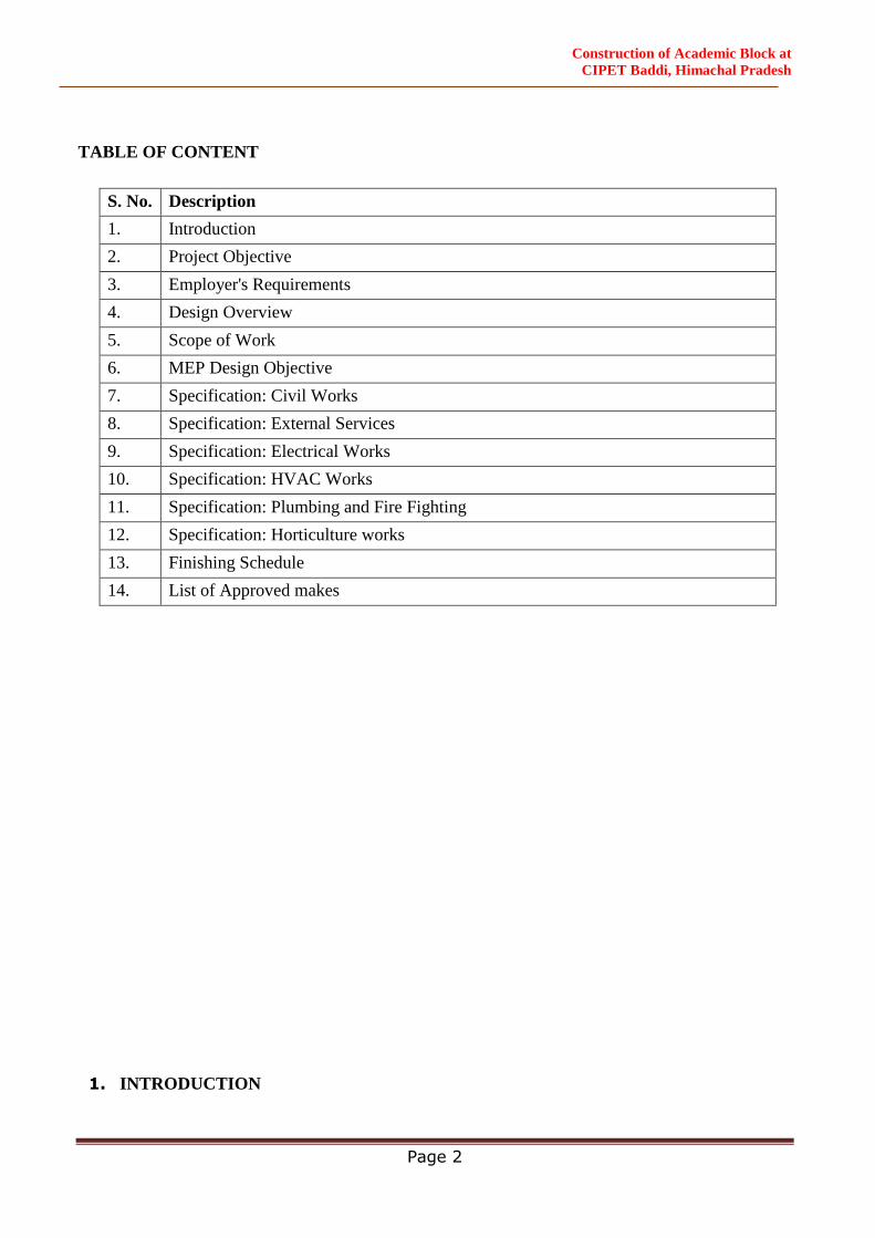
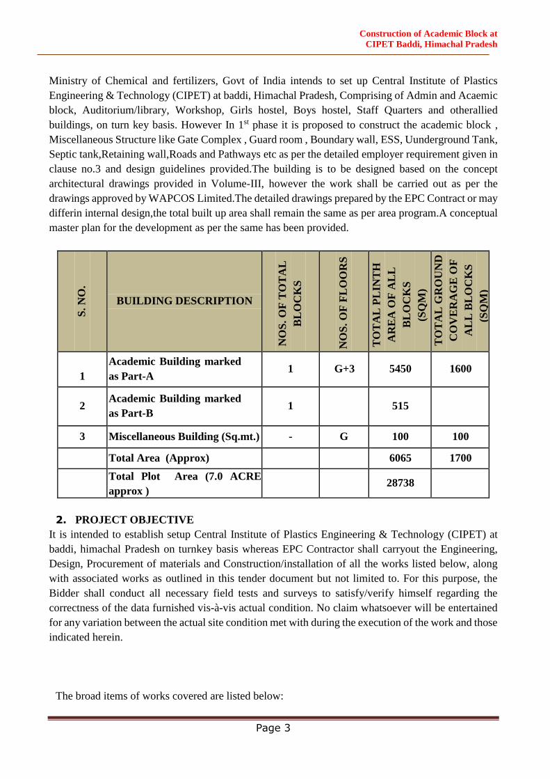
Ministry of Chemical and fertilizers, Govt of India intends to set up Central Institute of Plastics
Engineering & Technology (CIPET) at baddi, Himachal Pradesh, Comprising of Admin and Acaemic
block, Auditorium/library, Workshop, Girls hostel, Boys hostel, Staff Quarters and otherallied
buildings, on turn key basis. However In 1st phase it is proposed to construct the academic block ,
Miscellaneous Structure like Gate Complex , Guard room , Boundary wall, ESS, Uunderground Tank,
Septic tank,Retaining wall,Roads and Pathways etc as per the detailed employer requirement given in
clause no.3 and design guidelines provided.The building is to be designed based on the concept
architectural drawings provided in Volume-III, however the work shall be carried out as per the
drawings approved by WAPCOS Limited.The detailed drawings prepared by the EPC Contract or may
differin internal design,the total built up area shall remain the same as per area program.A conceptual
master plan for the development as per the same has been provided.
S. N
O.
BUILDING DESCRIPTION
NO
S. O
F T
OT
AL
BL
OC
KS
NO
S. O
F F
LO
OR
S
TO
TA
L P
LIN
TH
AR
EA
OF
AL
L
BL
OC
KS
(SQ
M)
TO
TA
L G
RO
UN
D
CO
VE
RA
GE
OF
AL
L B
LO
CK
S
(SQ
M)
1
Academic Building marked
as Part-A 1 G+3 5450 1600
2 Academic Building marked
as Part-B 1 515
3 Miscellaneous Building (Sq.mt.) - G 100 100
Total Area (Approx) 6065 1700
Total Plot Area (7.0 ACRE
approx ) 28738
2. PROJECT OBJECTIVE
It is intended to establish setup Central Institute of Plastics Engineering & Technology (CIPET) at
baddi, himachal Pradesh on turnkey basis whereas EPC Contractor shall carryout the Engineering,
Design, Procurement of materials and Construction/installation of all the works listed below, along
with associated works as outlined in this tender document but not limited to. For this purpose, the
Bidder shall conduct all necessary field tests and surveys to satisfy/verify himself regarding the
correctness of the data furnished vis-à-vis actual condition. No claim whatsoever will be entertained
for any variation between the actual site condition met with during the execution of the work and those
indicated herein.
The broad items of works covered are listed below:

Construction of Academic Block at
CIPET Baddi, Himachal Pradesh
Page 4
Design development based on the indicative concept site plan (Volume-III) including
preparation of architectural brief, design concept, concept for services etc.
Detailed design engineering including architectural design and construction documents (based
on the approved option), structural engineering, electrical engineering, DG sets, Lifts, PHE, Fire
Fighting, ventilation plans, communication (with EPBAX system) and networking plan, fire
detection and protection plan and waste management, car parking, substation, WTP, RWH,
Solar water heater system, CCTV, Fire Alarm & PA System, HVAC system, entrance gate
complex for all entries and exits, guard room,boundary wall nearby gate, Internal roads and path,
culverts, retaining walls, street lighting, landscaping, plantation of tree, site logistics including
emergency evacuation, internal & external signage’s etc as required to complete the project.
Site clearance and dismantling of obstructions and tree cutting (if any) for locating the buildings
as shown in the Master Plan (Bid Volume III), before commencement of work after obtaining
all statutory approvals.
3. EMPLOYER'S REQUIREMENTS
3.1. General Scope of Work:
1. The detailed scopes of work, as mentioned in the Volume-I are project specific. However, any
item of work required to be carried out as per the Contract for proper satisfactory completion of
the work with good standard of workmanship shall be deemed to be included in the scope of
work, with no additional cost for such items, whether, or not it is specifically included/described
in the tender documents.
2. The EPC Contractor shall ensure to meet the schedule milestones, quality and safety
requirements of all works as mentioned in the bid documents.
3. The EPC Contractor shall work in close co-ordination with the Engineer-in-Charge and
Employer’s Representative and shall attend various meetings to meet the schedule and quality
requirements of the Work.
4. The EPC Contractor shall make his own arrangement for the protection and safety of his material
and equipment at site. The Contractor shall also make his own arrangement for the electricity
and water for construction purpose. Alternatively the EPC Contractor may be allowed to drill
bore well/s in the institute and use the water. However after completion of the work the
contractor has to handover the bore well/s, casing, pump, piping & control panel, if any, to the
WAPCOS without additional charge. Water to be tested and approved before use. The EPC
Contractormustensures the proper housekeeping of the Site at all times to the satisfaction of
Engineer-in-charge so as to Work in a very safe and clean manner.
5. The EPC Contractor shall ensure timely submission of all reports, test results, samples.
6. The EPC Contractor shall arrange his own access to the Site and nothing shall be paid extra for
temporary roads/ access to the site. The contractor shall maintain and keep in good condition all
the access to the site at his own cost.
7. The EPC Contractor shall carry out all the survey & layout works in relation to the work. The
EPC Contractor shall make the reference pillars etc. required for setting out of the buildings and
shall be responsible for safeguarding them till the completion of the Contract.
8. The EPC Contractor shall submit his detailed Construction Program within 15 days from award
of Letter of commencement of work /work order based on the milestones given in the Bid
Construction of Academic Block at
CIPET Baddi, Himachal Pradesh
Page 5
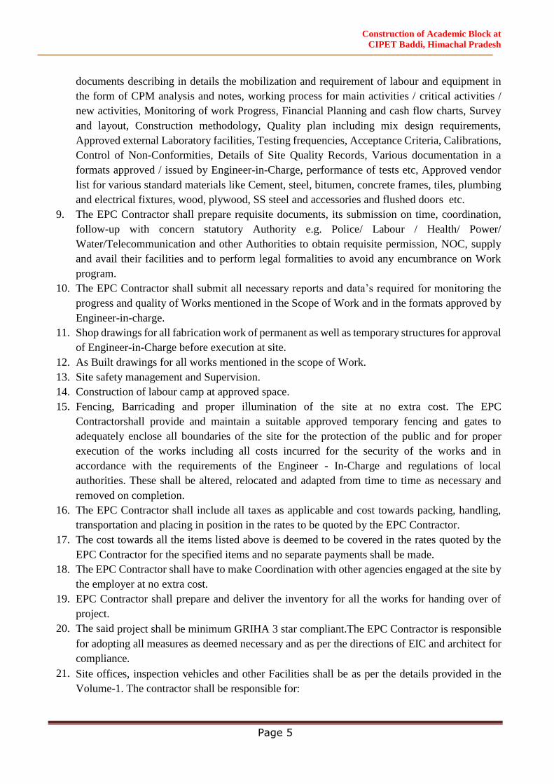
documents describing in details the mobilization and requirement of labour and equipment in
the form of CPM analysis and notes, working process for main activities / critical activities /
new activities, Monitoring of work Progress, Financial Planning and cash flow charts, Survey
and layout, Construction methodology, Quality plan including mix design requirements,
Approved external Laboratory facilities, Testing frequencies, Acceptance Criteria, Calibrations,
Control of Non-Conformities, Details of Site Quality Records, Various documentation in a
formats approved / issued by Engineer-in-Charge, performance of tests etc, Approved vendor
list for various standard materials like Cement, steel, bitumen, concrete frames, tiles, plumbing
and electrical fixtures, wood, plywood, SS steel and accessories and flushed doors etc.
9. The EPC Contractor shall prepare requisite documents, its submission on time, coordination,
follow-up with concern statutory Authority e.g. Police/ Labour / Health/ Power/
Water/Telecommunication and other Authorities to obtain requisite permission, NOC, supply
and avail their facilities and to perform legal formalities to avoid any encumbrance on Work
program.
10. The EPC Contractor shall submit all necessary reports and data’s required for monitoring the
progress and quality of Works mentioned in the Scope of Work and in the formats approved by
Engineer-in-charge.
11. Shop drawings for all fabrication work of permanent as well as temporary structures for approval
of Engineer-in-Charge before execution at site.
12. As Built drawings for all works mentioned in the scope of Work.
13. Site safety management and Supervision.
14. Construction of labour camp at approved space.
15. Fencing, Barricading and proper illumination of the site at no extra cost. The EPC
Contractorshall provide and maintain a suitable approved temporary fencing and gates to
adequately enclose all boundaries of the site for the protection of the public and for proper
execution of the works including all costs incurred for the security of the works and in
accordance with the requirements of the Engineer - In-Charge and regulations of local
authorities. These shall be altered, relocated and adapted from time to time as necessary and
removed on completion.
16. The EPC Contractor shall include all taxes as applicable and cost towards packing, handling,
transportation and placing in position in the rates to be quoted by the EPC Contractor.
17. The cost towards all the items listed above is deemed to be covered in the rates quoted by the
EPC Contractor for the specified items and no separate payments shall be made.
18. The EPC Contractor shall have to make Coordination with other agencies engaged at the site by
the employer at no extra cost.
19. EPC Contractor shall prepare and deliver the inventory for all the works for handing over of
project.
20. The said project shall be minimum GRIHA 3 star compliant.The EPC Contractor is responsible
for adopting all measures as deemed necessary and as per the directions of EIC and architect for
compliance.
21. Site offices, inspection vehicles and other Facilities shall be as per the details provided in the
Volume-1. The contractor shall be responsible for:
Construction of Academic Block at
CIPET Baddi, Himachal Pradesh
Page 6
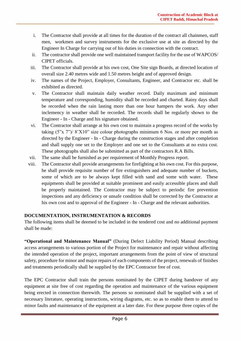
i. The Contractor shall provide at all times for the duration of the contract all chainmen, staff
men, workmen and survey instruments for the exclusive use at site as directed by the
Engineer In Charge for carrying out of his duties in connection with the contract.
ii. The contractor shall provide one well maintained transport facility for the use of WAPCOS/
CIPET officials.
iii. The Contractor shall provide at his own cost, One Site sign Boards, at directed location of
overall size 2.40 metres wide and 1.50 metres height and of approved design.
iv. The names of the Project, Employer, Consultants, Engineer, and Contractor etc. shall be
exhibited as directed.
v. The Contractor shall maintain daily weather record. Daily maximum and minimum
temperature and corresponding, humidity shall be recorded and charted. Rainy days shall
be recorded when the rain lasting more than one hour hampers the work. Any other
inclemency in weather shall be recorded. The records shall be regularly shown to the
Engineer - In - Charge and his signature obtained.
vi. The Contractor shall arrange at his own cost to maintain a progress record of the works by
taking (5”x 7”)/ 8’X10” size colour photographs minimum 6 Nos. or more per month as
directed by the Engineer - In - Charge during the construction stages and after completion
and shall supply one set to the Employer and one set to the Consultants at no extra cost.
These photographs shall also be submitted as part of the contractors R.A Bills.
vii. The same shall be furnished as per requirement of Monthly Progress report.
viii. The Contractor shall provide arrangements for firefighting at his own cost. For this purpose,
he shall provide requisite number of fire extinguishers and adequate number of buckets,
some of which are to be always kept filled with sand and some with water. These
equipments shall be provided at suitable prominent and easily accessible places and shall
be properly maintained. The Contractor may be subject to periodic fire prevention
inspections and any deficiency or unsafe condition shall be corrected by the Contractor at
his own cost and to approval of the Engineer - In - Charge and the relevant authorities.
DOCUMENTATION, INSTRUMENTATION & RECORDS
The following items shall be deemed to be included in the tendered cost and no additional payment
shall be made:
“Operational and Maintenance Manual” (During Defect Liability Period) Manual describing
access arrangements to various portion of the Project for maintenance and repair without affecting
the intended operation of the project, important arrangements from the point of view of structural
safety, procedure for minor and major repairs of each components of the project, renewals of finishes
and treatments periodically shall be supplied by the EPC Contractor free of cost.
The EPC Contractor shall train the persons nominated by the CIPET during handover of any
equipment at site free of cost regarding the operation and maintenance of the various equipment
being erected in connection therewith. The persons so nominated shall be supplied with a set of
necessary literature, operating instructions, wiring diagrams, etc. so as to enable them to attend to
minor faults and maintenance of the equipment at a later date. For these purpose three copies of the

Construction of Academic Block at
CIPET Baddi, Himachal Pradesh
Page 7
operating instructions, literature, wiring diagrams etc. shall be supplied to the employer soon after
Installation, Testing and commissioning of the said equipments.
“Quality Assurance Manual” covering mix-designs, materials, testing, statistical quality control,
etc. shall be prepared and supplied by the EPC Contractor free of cost well before starting the work.
“Construction manual” covering various aspects of construction methods, difficulties faced and
how they were overcome during execution etc. shall be supplied by the EPC Contractor free of cost
at the time of completion of work.
All the records of testing material reports, material challans, labour reports, etc. are to be
maintained by the EPC Contractor.
Records connected with the execution of the work should be maintained in a proper manner. The
registers/files, wherein important data such as record of the mandatory test, record of hindrances,
record of receipt and supply of materials, record of issue of drawings/design etc. are kept should be
properly bound and page numbered. These records should be maintained under the signature of
designated senior officials.
Following check-points are suggested:
i. The registers are to be properly bound and having machine numbered pages.
ii. The registers to keep record of important data like mandatory test, hindrances etc are to be
issued under the signature of designated senior officer/ Engineer in charge.
iii. Records to be maintained properly with signatures of EPC Contractor/ his authorized
representative and attestation of the designated officers/ Engineer in charge.
iv. No tampering/manipulation is permitted in these records. Corrections, if any, shall be duly
signed and attested by the Engineer in charge/ Senior Officer.
The EPC Contractor will sign the following registers whether by himself or through his authorised
representative.
i. Cement register
ii. Road metal consolidation register
iii. Bitumen Register/ Premix Bitumen Concrete Register
iv. Log book of Machinery
v. Paints register
vi. Testing of materials Register.
vii. All Field Records
viii. Site order Book
ix. Materials at site account
x. Hindrance Register
xi. Sieve analysis Register
xii. Ready Mix Concrete Batch Register
xiii. Drawing Register
Construction of Academic Block at
CIPET Baddi, Himachal Pradesh
Page 8
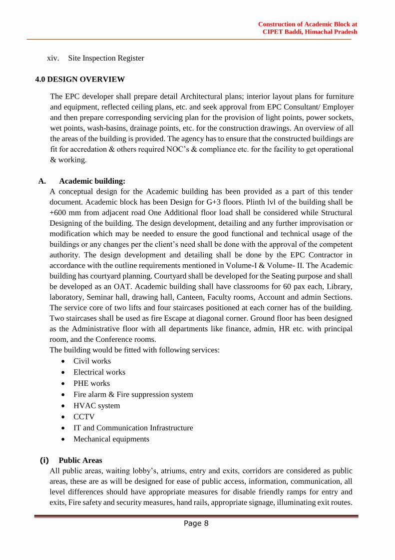
xiv. Site Inspection Register
4.0 DESIGN OVERVIEW
The EPC developer shall prepare detail Architectural plans; interior layout plans for furniture
and equipment, reflected ceiling plans, etc. and seek approval from EPC Consultant/ Employer
and then prepare corresponding servicing plan for the provision of light points, power sockets,
wet points, wash-basins, drainage points, etc. for the construction drawings. An overview of all
the areas of the building is provided. The agency has to ensure that the constructed buildings are
fit for accredation & others required NOC’s & compliance etc. for the facility to get operational
& working.
A. Academic building:
A conceptual design for the Academic building has been provided as a part of this tender
document. Academic block has been Design for G+3 floors. Plinth lvl of the building shall be
+600 mm from adjacent road One Additional floor load shall be considered while Structural
Designing of the building. The design development, detailing and any further improvisation or
modification which may be needed to ensure the good functional and technical usage of the
buildings or any changes per the client’s need shall be done with the approval of the competent
authority. The design development and detailing shall be done by the EPC Contractor in
accordance with the outline requirements mentioned in Volume-I & Volume- II. The Academic
building has courtyard planning. Courtyard shall be developed for the Seating purpose and shall
be developed as an OAT. Academic building shall have classrooms for 60 pax each, Library,
laboratory, Seminar hall, drawing hall, Canteen, Faculty rooms, Account and admin Sections.
The service core of two lifts and four staircases positioned at each corner has of the building.
Two staircases shall be used as fire Escape at diagonal corner. Ground floor has been designed
as the Administrative floor with all departments like finance, admin, HR etc. with principal
room, and the Conference rooms.
The building would be fitted with following services:
Civil works
Electrical works
PHE works
Fire alarm & Fire suppression system
HVAC system
CCTV
IT and Communication Infrastructure
Mechanical equipments
(i) Public Areas
All public areas, waiting lobby’s, atriums, entry and exits, corridors are considered as public
areas, these are as will be designed for ease of public access, information, communication, all
level differences should have appropriate measures for disable friendly ramps for entry and
exits, Fire safety and security measures, hand rails, appropriate signage, illuminating exit routes.
Construction of Academic Block at
CIPET Baddi, Himachal Pradesh
Page 9
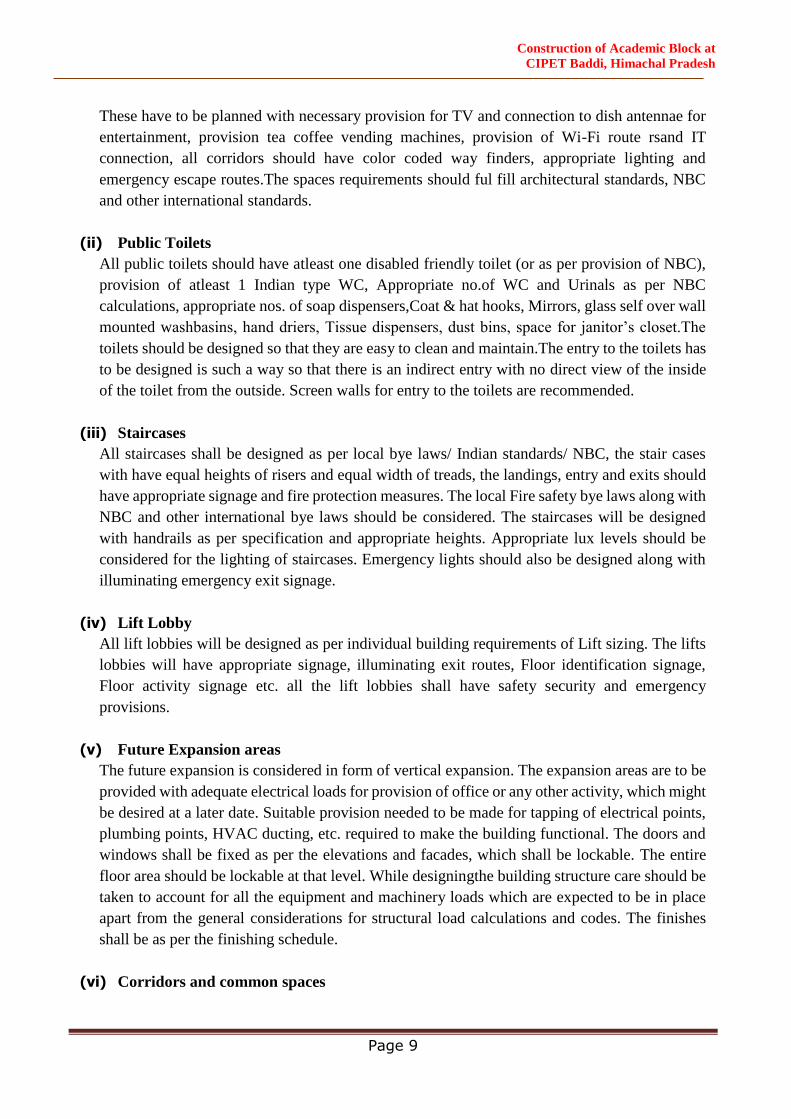
These have to be planned with necessary provision for TV and connection to dish antennae for
entertainment, provision tea coffee vending machines, provision of Wi-Fi route rsand IT
connection, all corridors should have color coded way finders, appropriate lighting and
emergency escape routes.The spaces requirements should ful fill architectural standards, NBC
and other international standards.
(ii) Public Toilets
All public toilets should have atleast one disabled friendly toilet (or as per provision of NBC),
provision of atleast 1 Indian type WC, Appropriate no.of WC and Urinals as per NBC
calculations, appropriate nos. of soap dispensers,Coat & hat hooks, Mirrors, glass self over wall
mounted washbasins, hand driers, Tissue dispensers, dust bins, space for janitor’s closet.The
toilets should be designed so that they are easy to clean and maintain.The entry to the toilets has
to be designed is such a way so that there is an indirect entry with no direct view of the inside
of the toilet from the outside. Screen walls for entry to the toilets are recommended.
(iii) Staircases
All staircases shall be designed as per local bye laws/ Indian standards/ NBC, the stair cases
with have equal heights of risers and equal width of treads, the landings, entry and exits should
have appropriate signage and fire protection measures. The local Fire safety bye laws along with
NBC and other international bye laws should be considered. The staircases will be designed
with handrails as per specification and appropriate heights. Appropriate lux levels should be
considered for the lighting of staircases. Emergency lights should also be designed along with
illuminating emergency exit signage.
(iv) Lift Lobby
All lift lobbies will be designed as per individual building requirements of Lift sizing. The lifts
lobbies will have appropriate signage, illuminating exit routes, Floor identification signage,
Floor activity signage etc. all the lift lobbies shall have safety security and emergency
provisions.
(v) Future Expansion areas
The future expansion is considered in form of vertical expansion. The expansion areas are to be
provided with adequate electrical loads for provision of office or any other activity, which might
be desired at a later date. Suitable provision needed to be made for tapping of electrical points,
plumbing points, HVAC ducting, etc. required to make the building functional. The doors and
windows shall be fixed as per the elevations and facades, which shall be lockable. The entire
floor area should be lockable at that level. While designingthe building structure care should be
taken to account for all the equipment and machinery loads which are expected to be in place
apart from the general considerations for structural load calculations and codes. The finishes
shall be as per the finishing schedule.
(vi) Corridors and common spaces

Construction of Academic Block at
CIPET Baddi, Himachal Pradesh
Page 10
All corridors shall be ventilated and lighted adequately with provision of one drinking water
place in each floor. Common terraces shall be enclosed with grills with a provision for drying
cloths on common terraces.
B. Gate complex with Guard room:
The entry gate complex will have guard room approximately 3m x 3m and security room 4m x
6m, electrical/meter rooms (as required), including intercom, telephone line connectivity, video
surveillance, separate pedestrian and vehicular movement. The stainless steel of grade 304 shall
be used for gates. The gate shall be stainless steel gates, sliding gates with electrical boom
barriers as per approved design & drawings.
The boundary wall is proposed to be constructed having minimum height of 1800mm from the
formation Level and shall consist of RCC columns, brick work and decorative grill as per
approved design & drawings. No old material shall be used such as bricks , reinforcement, grill
etc.
The trees & shurbs shall be planted along all the four boundary walls as per approved drawings.
Main Entrance gate complex with guard room shall be provided as per location marked in the
LOP. 2 nos. Guard rooms to be provided with the toilet facility. Steel gate of 6.0 m Wide along
with the Wicket gate of 1.5 mtr wide shall be provided. Name with Logo in SS letters of the
Institute shall be affixed on Gate complex.
C. External Development with Landscaping
The Academic block is proposed with road network, pathways, services layout, and street light
layouts, inter connecting all the buildings as per site plan (but not limited to) provided. All other
service layouts such as septic tank, WTP, Underground water tank, Fire tank shall be suitably located
and connected to respective service lines. The external development will include new construction
of boundary wall wherever required. It would also include the landscape and horticulture works as
per the detailed landscape specification. The un-utilized site will be neatly dressed with grassing and
plantation as required. If there is any level differences in site the connecting roads will be laid to
appropriate slope and will be designed as per IRC standards.
Sculptures and artifacts shall be planned and provided and integrated in the landscape design.
D. Under ground water storage tanks:
The UG tanks shall be 450 mm high from the adjacent ground level. The top slab of the tank shall
be covered with grass. Care should be taken to ensure proper water proofing and slope of the slab to
take care of surface water run off.
Note: The detailed engineering service requirements for all the building and individual rooms and
site development are being provided in the concept DBRs and service requirements, scope of work.
5.0 SCOPE OF WORK
Construction of Academic Block at
CIPET Baddi, Himachal Pradesh
Page 11
Mobilizing of Design Team
The EPC Contractor shall mobilize the design team required to design the project and intimate the
EPC consultant with the detailed CV of the design team within 15 days of the award of the contract.
The design team shall closely work in association with EPC consultant's office at Gurgaon to get the
detailed design approved.
Preparation of submission drawings
The EPC Contractor would be required to prepare, submit and obtain all necessary statutory
approvals before commencing any construction activity at site.
Preparation of Detailed Design drawings for construction
The EPC Contractor will prepare submit and seek approval from WAPCOS Limited for all materials
for Construction drawings for architectural, structural, MEP, Medical services, etc.
Site Acceptance and Mobilization/Demobilization
a) Acceptance of Site: In accordance with these specifications, the EPC Contractor shall have
examined the site and familiarized himself with all existing conditions. He shall accept the site
in its existing condition at the time of award of contract.
b) Mobilization: Upon award of the Contract and within a reasonable time but not exceeding 30
days the EPC Contractor shall mobilize all such labour, equipment and materials that are
necessary to complete the project in due time.
c) Demobilization: Upon due performance of the Contract and before the Taking Over Certificate
is issued to the EPC Contractor, he (the EPC Contractor) shall demobilize all such labour,
equipment and materials that are necessary to clear the site within one (1) month to the EPC
Consultant/ Employer’s satisfaction.
d) Access: The EPC Contractor shall provide and maintain adequate access to the project site and
all areas related to the works at his expense. If existing roads are to be used for access to the
site, the EPC Contractor shall maintain such roads to the satisfaction of EPC Consultant/
Employer for the duration of their use.
e) Permits and Licenses: Except as expressly stated in the Employer’s Responsibilities, the EPC
Contractor shall obtain all permits and licenses necessary for the execution and completion of
the Works. The EPC Contractor shall pay all associated fees including royalty. He shall also
give the Employer a copy of all relevant correspondence and other documents relating to the
EPC Contractor’s permits and licenses.
Temporary Works

Construction of Academic Block at
CIPET Baddi, Himachal Pradesh
Page 12
The EPC Contractor shall design, install and maintain all temporary facilities required for the
construction of facilities under this contract Package, which he requires on or at the site
throughout the execution of the work, and remove the same on completion of the works. He
shall provide all such buoying, fencing, watching, lighting, connections to public utilities etc. as
he needs or as required by authorities and shall install and use his temporary facilities in
accordance with all statutory regulations and the requirement of the relevant authorities.
The EPC Contractor shall submit his plan for temporary works to the Employer/ EPC
Consultant, for approval, within 30 days of award of contract.
Temporary construction shall be adequate for intended uses and for all loads imposed without
excessive settlement, deflection or deformation. All parts and members shall be properly
strengthened to prevent displacement or failure.
Before or upon completion of work, unless otherwise required or directed, preparatory
structures, installations and utility services shall be disconnected and removed from the site.
Utilities
Temporary utilities used for construction shall have to be adequate for the intended uses and not
to be overloaded or otherwise used or arranged in any manner endangering persons, premises or
works. Connections shall be properly made, lines and wiring securely anchored in place and
protected against accidents.
a) Water
The EPC Contractor shall provide his own arrangements for sourcing and for distribution
adequate supply water for the Project including:
Drinking water: Providing and maintaining canisters, coolers or connected drinking fountains
of sufficient number to reasonably serve the Project.
Construction water: Providing and maintaining temporary water service and distribution of
adequate capacity for construction.The water shall be fit for construction.Moreover, If water is
not found to be suitable for construction purpose, EPC Contractor shall arrange sufficient
quantity of water fit for construction as per IS 456 2000. The cost shall be borne by EPC
Contractor.
b) Electricity
The EPC Contractor shall make his own arrangement for power supply.
If found necessary, the EPC Contractor shall provide and maintain generators including a stand-
by generator of adequate capacity to meet his additional Power requirements.
The EPC Contractor shall make his own arrangements as outlined hereunder:
Distribution of adequate capacity for power, lighting and other construction needs.
As necessary to properly and safely perform work at enclosed spaces or under hazardous
conditions. Likewise, providing lights for night work/ protection as necessary.
Temporary electrical systems shall comply with the local codes and regulations.
Construction of Academic Block at
CIPET Baddi, Himachal Pradesh
Page 13
c) Waste and Rubbish
The EPC Contractor shall provide regular daily clean-up and removal of trash, waste, scraps,
construction debris, etc. from site and temporary work yard and shall arrange for disposal of
waste and rubbish to appropriate disposal areas.
d) First Aid and Fire Protection
i. Emergencies: The EPC Contractor shall maintain the contact number/ lists of nearest
available police, hospital or medical services at the EPC Contractor’s Site Office and the
same are to be displayed at a number of locations & work places.
ii. Fire Protection: The EPC Contractor shall establish and submit the following measures
to the EPC Consultant/ Employer.
Establish appropriate emergency escape routes and procedures;
Maintain fire extinguishers, connected hoses and other facilities necessary for
reasonable fire-fighting action at the site and temporary work yard;
Provide and maintain a first aid kit containing bandages, medicines and sterilized
materials for first aid treatment of minor injuries at the EPC Contractor’s Site
Office.
e) Excavations
Trenches intersecting roads shall have to be provided with crossings suitable to carry the type
of traffic involved. Vehicular kerbs and pedestrian railings shall be provided as necessary. Open
pits and in openings in floors and other accessible surfaces shall be protected by barricades or
railings.
f) Access
Access to structures such as scaffolds, ladders, ramps, hoists etc. shall be provided, maintained
and operated as necessary.
g) Storage Areas
Storage and shop areas shall be provided, arranged and maintained at approved locations as
necessary to properly store, handle and fabricate the various materials and equipment required.
h) Protection of the Public
The EPC Contractor shall provide barricades and enclosures as necessary for public protection.
EPC Contractor’s Laboratory & Equipment
The EPC Contractor shall provide site laboratory in order to carry out the specified tests. This
laboratory shall be completely staffed and properly equipped to the satisfaction of the EPC
Consultant/ Employer to carry out the tests as specified.
The EPC Contractor’s site laboratory shall be available for the use of or inspection by the EPC
Consultant/Employer as required by him. The EPC Consultant/Employer may require his
Construction of Academic Block at
CIPET Baddi, Himachal Pradesh
Page 14
representative to be present during any test and at any time during the working hours of the
laboratory.
The EPC Contractor shall furnish and maintain the laboratory, apparatus and supplies necessary to
permit execution of the tests required by the Specifications. The EPC Contractor shall submit to the
EPC Consultant/Employer for his approval, within 28 days after award of work, a complete list of
the equipment, apparatus and supplies he proposes to furnish the laboratory. The list shall include
the manufacturer’s name and descriptive literature.
Environmental Protection
The EPC Contractor shall comply with all the conditions stipulated by the relevant statutory and
regulatory organizations like NGT , Govt. of Uttar Pradesh / Govt. of India etc.
Fires
Fires and burning of rubbish on the Site are not permitted.Where fires or burning is permitted, the
EPC Contractor shall prevent the structures which are to be preserved from staining, smoke and
damage. The EPC Contractor shall restore, clean and make good stained or damaged work to new
condition.
Disposal of Waste and Cleanliness
The EPC Contractor shall not bury rubbish and solid waste materials on the Site and he shall not
dispose of waste or volatile materials, such as mineral spirits, oil or paint thinner into the waterways,
storm water drainage or sanitary sewers.The EPC Contractor shall keep all pavements and areas
leading to and from the site, clean and free of mud, dirt, and debris at all times for movement of
vehicles and pedestrians.
Drainage
The EPC Contractor shall provide temporary drainage and pumping facilities as necessary to keep
the areas of work site and adjoining areas free from water logging and flooding.
Pollution Control
The EPC Contractor shall cover or wet down dry materials and rubbish to prevent blowing dust and
debris, and provide dust control for temporary roads and yards.The EPC Contractor shall take all
measures necessary to ensure that no pollution of the waterways or any land areas occurs as a result
of his activities. He shall undertake at his own expense all measures necessary to clean up or
otherwise rectify any pollution arising from his activities under this Contract to the satisfaction of
the EPC Consultant/ Employer.
Environment
The EPC Contractor prior to the commencement of works shall prepare and implement an
Environment Management Programme. The EPC Contractor shall deploy most suitable construction
equipment to minimize the suspension of fine sediments at the work site.

Construction of Academic Block at
CIPET Baddi, Himachal Pradesh
Page 15
Submission of Documents during Project Execution
Programme of Works
The EPC Contractor shall prepare and submit (both hard copy and soft copy) to the EPC Consultant/
Employer within 30 days of receipt of Letter of Award the following:
Detailed CPM Schedule showing the various activities of the Work using MS Project
List of designs/drawings/documents along with their schedule of submission.
The above shall be updated every month and submitted to the EPC Consultant/ Employer.
Work Schedules, Survey Data & Drawings
The EPC Contractor shall prepare and submit construction schedules, survey data, and field drawings
to illustrate the appropriate portion of work. The work items shall be described and related to
responsibility, fabrication, layout, and setting or erection details as specified in appropriate Sections.
The EPC Contractor shall keep allowance in program of works for any stoppages during monsoon
period, and he has to take all necessary measures to protect his equipment and the partly completed
structures. The EPC Contractor is expected to build such stoppages of work during monsoon in his
overall schedule for completion. The EPC Consultant/ Employer will not entertain any claims from
the EPC Contractor on this account.
All the drawings shall be submitted in six sets in hard copy and a soft copy (in AutoCAD format).
Maintenance Plan
General
The EPC Contractor shall prepare maintenance plan covering all aspects of the works for the review
of the EPC Consultant/ Employer. This plan shall be prepared to ensure that the design life periods
stated are met in full and where no design life periods are stated, the maintenance plan shall be
prepared to maximize the serviceable life.
Maintenance Document
The EPC Contractor shall provide six copies of the maintenance plan and manuals to the EPC
Consultant/ employer to retain by the EPC Consultant/ Employer upon the request of the EPC
Consultant/ Employer or following receipt of attention to the EPC Consultant/ Employer's
comments.
Weekly and Monthly Progress Reports
The EPC Contractor shall maintain a daily log describing the important events pertaining to the
Works, (the working hours, the number of laborers employed, effective operation time of equipment,
overtime hours), progress made in the Works. This daily log shall be submitted to the EPC Consultant
/ Employerby 1:00 PM of the following day. Compilation of these logs and their summary shall be
submitted to the EPC Consultant/ Employer as Weekly Progress Report in three (3) copies by middle
of the next week.

Construction of Academic Block at
CIPET Baddi, Himachal Pradesh
Page 16
The monthly progress reports shall include progress photographs taken at a fixed point and angle.
The photographs shall be sufficient in numbers and locations to record the exact progress of works.
The colour photographs shall be in size 200 mm x 250 mm and the soft copy containing the digital
version of the same shall be provided.
The EPC Contractor shall furnish the EPC Consultant/ Employer with three (3) copies along with
soft copy of the monthly progress reports within seven (7) days after the end of every month.
Design & Drawing Submissions
Design Submissions – General
The scope of drawings listed in this Volume is issued for information and guidance to the extent
mentioned in the Tender document. EPC Contractor shall make all arrangement of design& drawings
and submit the same for checking to the EPC Consultant/ Employer and will have to be proof
checked from reputed IIT as approved by the EPC consultant before final approval of WAPCOS.
Detailed Engineering shall be done by the EPC Contractor.EPC Contractor shall duly submit the
analysis (in STAAD Pro) design and calculations alongwith the drawings. The EPC Contractor shall
not be entitled to any extension of time for completing construction/commissioning or any other
relief on account of delay caused due to providing any clarifications or in resubmitting any designs
and drawings.
The EPC Contractor shall not change any design and drawings reviewed by EPC Consultant /
Employer, without submitting such revised designs and drawings for the review of Employer.
The EPC Contractor shall submit for the approval of EPC Consultant/ Employer, progressively from
the date of receipt of the Letter of Award, six (6) copies along with soft copy (AutoCAD) of the
following:
a) Detailed Design Basis reports for Architectural, structural, MEP, Acoustic and Medical services
b) Layout of Master Plan
c) Detailed Design drawings for Architectural, structural, MEP, Acoustic and Medical services
d) Elevations (all), sections (as required), 3D views of all the buildings with actual finishing
schedule, interior views with actual finishing schedule, bird's eye view, fly around and walk
through
e) Detailed drawings of landscaping and horticulture drawings along with plantation plan.
f) Detailed site development drawings showing road cross sections, road slopes, coordinated
services layouts
g) Area calculation
h) General arrangement drawings of all structures
i) Cross sections and other details showing important particulars such as overall dimensions,
clearances, etc.
j) Specification/catalogues of all standard bought-out items.
k) All drawings including shop fabrication/manufacturing drawings. These will include, but not be
limited to assembly, sub-assembly, key components, etc. However, two week prior to
Construction of Academic Block at
CIPET Baddi, Himachal Pradesh
Page 17
fabrication, fabrication and part drawings shall be made available to the EPC Consultant/
Employer.
l) Wiring drawings and equipment inter-connection diagrams of local control panels & Single Line
Diagram of facility power distribution.
m) All design calculations pertaining to all structuresand services along with STAAD pro files.
n) A further digital copy (in AutoCAD format and other relevant format) of the submission shall
be given on soft editable format. This digital copy shall include the full submission with scanned
copies of any documents prepared by hand.
o) Technical data sheet for all the equipments/ fixtures
The list of submission will however be discussed with the EPC Contractor after the award of work.
Submission of Calculations
All calculations submitted to the EPC Consultant/ Employer’s approval shall comply with the
followings:
a) Each calculation page shall be uniquely numbered.
b) Each section of calculations shall have a cover sheet, listing the subject of the calculations,
document number and date of submission, name and qualifications of the Designer(s), the name
and qualifications of the Design Verification engineer(s), and the relevant Standards, books and
drawings which are the basis of the calculations.
c) Each section of calculations shall have a Table of Contents, including page numbers.
d) Calculations shall be accompanied by all necessary sketches or extracts from drawings.
e) Calculations shall include introductions explaining the purpose of the calculations and the
methods and design philosophies adopted. This shall clearly state the Standards on which the
calculations are based.
f) Equations and values from International Standards and Codes of Practice are to be clearly
referenced which are used in the design shall be attached to the submission.
g) Where values used in the calculations are brought forward from previous calculation pages, the
page reference shall be included.
h) At the end of each section there shall be a summary, listing the conclusions of the calculations,
and referring to construction drawings.
i) If calculations are revised due to design changes or corrections or comments of the EPC
Consultant/ Employer, the calculations sheets shall be clearly marked with a revision letter.
j) All calculations shall be signed/initialed by the designer and design verification engineer.
k) The design calculations shall be written in English. In case any software is utilized to perform
the calculations a sample set of manual calculations with references of various formulae used
shall also be submitted for proper verification.
Submission of Drawings
All drawings submitted for the EPC Consultant/ Employer’s approval shall comply with the
following:

Construction of Academic Block at
CIPET Baddi, Himachal Pradesh
Page 18
a) All drawings shall be in metric system, and be finally prepared in ink with legible lettering on
appropriate size drawings using AutoCAD format compatible with AutoCAD 2016 or lower
version. The submitted prints shall be clearly legible throughout and there shall be no ambiguity.
b) All drawings shall be submitted in digital format in soft copy, as well as six (6) hard copy print
outs.
c) Drafting Standards employed in the preparation of all drawings shall be sufficient to produce
legible drawings.
d) Drawings from various sub-contracting services, specialist suppliers etc. shall also be presented
in a similar manner (identical title blocks/format etc.) to provide a matched set of drawings.
e) All drawings shall clearly show the status and revision of the drawings. Revised drawings shall
clearly indicate the nature and details of the revision work and also revision cloud & revision
mark shall be marked wherever revised.
f) All drawings shall clearly identify the drafts-person responsible together with the identity of the
drawings checker.
g) Each drawing shall show the scale(s) of the components illustrated by the drawing related to the
original drawing size, A0, A1, A3 etc.
Inspection of Drawings at Site
The EPC Consultant/ Employer shall have the right at all reasonable times to inspect all drawings at
the premises of the EPC Contractor or call for any drawing to be given to EPC Consultant/
Employer’s office.
Manuals and Technical Data
A) Manuals
The EPC Contractor shall supply Five (5) hard copies along with One (1) soft copy (in editable
format) of Erection & Installation Manuals, Operation Manuals, Spare Parts Manuals and Inspection
and Maintenance Manuals and safety manual prior to the starting of erection. Recommendations of
the manufacturer in respect of preventive maintenance, trouble shooting, and breakdown
maintenance and over haul shall be brought out in the inspection and maintenance manuals. Soft
copies of all drawings shall be supplied.
B) Technical Data
(i) On completion of the works and before handing over possession to Employer, the EPC
Contractor shall supply six (6) hard copies together with One (1) soft copy of the following:
Shop drawings of all wearing parts and also major assemblies and minor assemblies which
require unit replacement;
All “As Built” Drawings of equipment, civil / structural, all engineering services.
(ii) Complete technical data and dimensional drawings of all bought out product/ items in the
system, shall be furnished - six (6) hard copies together with One (1) soft copy of the
following:

Construction of Academic Block at
CIPET Baddi, Himachal Pradesh
Page 19
List of recommended spare parts.
Parts catalogues in the case of all equipment /assemblies illustrated with part numbers in
drawings both for electrical and mechanical items
Tools and Maintenance Equipment
A list of complete set of tools/tackles and instruments required to be provided for satisfactory
maintenance of the Works shall be furnished.
As Built Drawings, Design and Final Construction Report
Before submitting a request for Taking over Certificate, the EPC Contractor shall ensure that it has
furnished to the EPC Consultant/ Employer all required documents including but not limited to Two
(2) sets of as-built drawings in hard copy and One (1) set in soft copy, final design report in the
supporting of as-built drawings and a final construction report as draft. And within thirty (30)
calendar days after receipt of comments from the EPC Consultant/ Employer, the EPC Contractor
shall submit six (6) sets of the Final Construction Report and six (6) sets of Final As-built drawings
& Design documents. As-built drawings of the works consists of two (2) sets of original size copies
(white print) and two (2) sets of bound copies reduced to A3 size. All documents and drawings will
be also delivered in editable soft copy (drawings in Auto-CAD format, documents in other required
formats and soft copy of the file used in software on which design was carried out).
Before submitting a request for Taking over Certificate, the EPC Contractor shall ensure that it has
furnished to the EPC Consultant/ Employer all required documents including but not limited to six
copies of manuals for equipment installation, commissioning, operation and maintenance and the
drawings/ documents etc., covering all aspects of the Works for review. This plan shall be prepared
to ensure that the design life periods stated are met in full and where no design life periods are stated,
the maintenance plan shall be prepared to maximize the serviceable life. In the event the EPC
Contractor makes any changes effecting such submission the EPC Contractor shall submit afresh
such document duly revising to that extent.
Quality Control and Assurance
The EPC Contractor will be required to adopt a system of self-certification in accordance with his
general quality plan and the appropriate detailed quality procedures. The quality system shall
comply with Standards of ISO 9001. The EPC Contractor shall submit quality control manual for
ready reference for quality procedures for construction.
Quality Plan and Quality Procedures
The EPC Contractor will be required to submit his complete General Quality Plan to the EPC
Consultant/ Employer within four weeks of the Commencement Date. A designer’s quality plan
will be accepted as an interim measure to permit design work to be started in advance of the
preparation of the General Quality Plan.
Detailed Quality Procedures for each element or item of work must be submitted to the EPC
Consultant/ Employer for review at least four weeks before that work is due to commence.
Detailed Quality Procedures are required for all items manufactured prior to delivery to site.

Construction of Academic Block at
CIPET Baddi, Himachal Pradesh
Page 20
The EPC Contractor shall monitor his performance of executing his Works against two levels
of certification:
The completion of individual work items
The completion of activities listed in the Programme.
In addition to the certification of the completion of work items and activities, the EPC
Contractor shall be required to issue the Quality Assurance (QA) certificates concerning the
Quality Plan, Quality Procedures and Construction Documents.
The EPC Consultant/ Employer may monitor the EPC Contractor’s work against the EPC
Contractor’s Quality Plan and Quality procedures. The EPC Consultant/ Employer may do this
by spot checks, and/or by continuous monitoring of the work. The EPC Consultant/ Employer
may also do this by carrying out compliance audits periodically against the EPC Contractors
Quality Procedures. The frequency and intensity of such checks will depend on the proven
reliability of the EPC Contractor as work progresses. Each non-compliance with the Quality
Plan shall be notified promptly to the EPC Consultant/ Employer by the EPC Contractor,
together with proposals for remedy of the non-compliance. The absence of monitoring of or
commenting on quality aspects as above by the Employer shall not absolve the EPC Contractor
from any of its contractual obligations and/or shall not entitle the EPC Contractor for any claim.
Improper Certification of Unsatisfactory Work
If the EPC Contractor or its personnel repeatedly confirms/declares a work as being satisfactory
when such work is not satisfactory, the EPC Consultant may reject such work any time during
the currency of the Contract and instruct the EPC Contractor to re-execute such work in full or
a part thereof without any implication to the EPC Consultant/ Employer. In case of improper
certification and/or EPC Contractor’s failure to rectify, the EPC Consultant/ Employer may
proceed as per the Contract including terminating the Contract.
Submission and Certification of Construction Documents
The EPC Contractor shall submit a Design Certificate (in duplicate) and Design Check Certificate
whenever he is submitting Construction Documents to the EPC Consultant/ Employer for review.
Construction Documents submitted without the relevant Design Certificate will not be reviewed.
The EPC Contractor is to ensure that all Construction Documents submissions are in a form that
enables the EPC Consultant/ Employer to review the Construction Documents as required by the
Contract without delaying completion of the Works.
Certificates for Work Item Completion
Readily identifiable Work Items must be certified as checked and found satisfactory by
a) EPC Contractor’s surveyor responsible for checking and certification
b) EPC Contractor’s supervisor responsible for checking temporary works, material cleanliness,
dimensions (not checked in (a) above), workmanship and all other matters to enable him to
certify that the item of work complies in every respect to the contract.
Construction of Academic Block at
CIPET Baddi, Himachal Pradesh
Page 21
The Work Item Completion Certificate shall be checked and approved by the EPC Contractor’s
Quality Manager.
Each Work Item Completion Certificate must be identified by a unique and appropriate reference
number.
If the EPC Consultant/ Employer is not satisfied that the works have been carried out satisfactorily
as certified, the EPC Consultant/ Employer shall raise a non-conformance report to which the EPC
Contractor shall respond stating his proposals for rectifying the non-conforming item and what
action will be taken to prevent recurrence. The EPC Consultant/ Employer may reject such work any
time during the currency of the Contract and instruct the EPC Contractor to re-execute such work in
full or a part thereof without any implication to the Employer. In case of recurrence/failure of the
EPC Contractor to rectify, the EPC Consultant/ Employer may adjust the Contract price by deducting
the value of such work.
Any consequences in respect of any revisions arising out of Work Item Completion Certificates
being returned with comments shall not be treated as a compensation event.
Certificates for Activity Completion
When a section of work has been completed satisfactorily, the EPC Contractor shall certify that the
activity has been completed in accordance with the Contract.
The Activity Completion Certificate shall be checked by the EPC Contractor’s Quality Manager and
confirmed by the EPC Contractor. The Designer’s Representative shall also certify that the activity
has been completed in conformance with the relevant Construction Documents and the Employer’s
Requirements.
The Activity Completion Certificate shall list the reference numbers and dates of Work Item
Completion certificates that have been relied upon by the signatories to the Activity Completion
Certificate.
Each Activity Completion Certificate shall have attached to it, copies of any materials test certificates
which were received after signing the relevant Work Item Completion Certificates and which have
not been submitted to the EPC Consultant/ Employer under separate cover during the period between
the signing of the Work Item Completion Certificate and the preparation of the Activity Completion
Certificate.
Field Surveys and Investigations
General
The EPC Contractor shall carryout the engineering design and prepare drawings for the various
components under this specification, based on the data on field surveys and investigations carried
out by him, including that of Temporary Works.
Construction of Academic Block at
CIPET Baddi, Himachal Pradesh
Page 22
The EPC Contractor may carry out all necessary investigations to complete his design data such as:
Topographic survey.
Soil investigation work.
The EPC Contractor shall, at his own expense, carry out all the necessary surveys, measurements
and setting out of the works and shall for this purpose engage well qualified, experienced and
competent land surveyors. The minimum geotechnical investigation that shall be carried out is
mentioned in the Volume-I of the tender documents.
Setting Out
The EPC Contractor shall establish working bench marks related to the Reference Bench Mark in
the area soon after taking possession of the site. The Employer shall provide the EPC Contractor
with one Permanent Bench Mark and its datum. A schedule of reference dimensions shall be prepared
and supplied by the EPC Contractor to the EPC Consultant/ Employer. These marks shall be
maintained until the works reach finished formation level and are accepted by the EPC Consultant/
Employer.
The EPC Contractor shall be solely responsible for safe-guarding all survey monuments, bench
marks etc. All dimensions and levels shown on the drawings or mentioned in documents forming
part of or issue under the Contract shall be verified by the EPC Contractor on the site and he shall
immediately inform the EPC Consultant/ Employer of any apparent errors or discrepancies in such
dimensions and levels.
Topographic Surveys
The EPC Contractor shall conduct a precision triangulation survey to establish primary and
secondary survey stations.
Survey stations and other control devices required by the EPC Contractor for his execution of the
work shall be established by the EPC Contractor at his own expense, and shall be removed upon
completion of the works.
Geotechnical Investigations
TheEPC Contractor shall carry out geotechnical investigations/survey in the Works area as required
and mentioned in Volume III of Bid Document.
Post Construction Survey
The completion of the works will be examined by the EPC Contractor in the presence of the EPC
Consultant/ Employer. During these examinations, the EPC Contractor shall perform the survey,
which shall be used to prepare a final drawing showing all dimensions, elevations and cross sections
of the “As Built” conditions of the structures. The EPC Contractor shall be required to remove excess
materials or place additional materials, as directed by the EPC Consultant/ Employer, in order to
comply with the Contract Documents. EPC Contractor shall submit the final location of all structures
with reference to the Master Grid, which shall show the actual position of each structure and
deviation from the theoretical position.

Construction of Academic Block at
CIPET Baddi, Himachal Pradesh
Page 23
APPROVALS
All Statutory approvals wherever required such as approval & NOC from local Authorities for
building plans, water supply & sewer connection, electricity Connection, tree cutting, shifting and
rerouting of services including electrical, Permit, licensing, labour & safety clearances, are the
responsibility of the contractor. However, any statutory payment/licensing fees etc to be made to local
bodies etc. shall be reimbursed from Client in actual to the contractor on submission of proper documents.
6.0 MEP Design Objective
The MEP design objective is to achieve a sustainable building that are energy and resource efficient
and promote a healthier environment for building occupants & also to Compliance GRIHA 3
Certification. This goal shall be achieved by adopting the following fundamental principles:-
By Optimizing Site Potential
By Optimizing Energy Use
By Protecting & Conserving Water
By Optimizing Building Space & Material Use
By Enhancing Indoor Environmental Quality
By Optimizing Operational & Maintenance Practices
Proposed building envelope shall be efficiently designed having very less exposed area in West
/ South-West / North-West direction
High energy efficient glass shall be used having U factor & Solar Factor less than 0.4 Btu/Hr
Sft °F & 0.25 respectively
MEP system design shall be based on compliance with the local and national codes, standards, bye-
laws & regulations such as latest NBC, BIS, SP-35, ASHRAE, ECBC, LEED India, NEC, NFPA,
NFC and IEC etc.
The scope of MEP work shall include complete design, approval from client/architect/consultant,
supply, installation, testing, commissioning & handing over in satisfactory working condition.
Specification & list of make given in the tender shall be followed. The detailed scope of MEP work
shall be as under:-
HVAC WORK
The HVAC work shall include
Heating, Ventilation & Air-conditioning (HVAC)
Smoke Management System (As Per Fire Department Approval)
Pressurization of Lift, Staircase & Lobby (As Per Fire Department Approval)
Automation System for complete HVAC Work
Design Criteria for HVAC Work
The design of HVAC system shall be based on the following standard & philosophy:
The design standard followed in HVAC shall be as under:-
ASHRAE Standard-170-2013 or latest -Health Care Facilities
Construction of Academic Block at
CIPET Baddi, Himachal Pradesh
Page 24
ASHRAE 90.1-2010 or latest – Energy Standards for Building
ASHRAE 62.1-2010 or Latest – Indoor Air Quality
ASHRAE 52.2-2007 or Latest – Filter Selection & Efficiency
ASHRAE Handbooks
National Building Code 2016 - Fire & Life Safety, For Ventilation & Smoke Extraction
Energy Conservation Building Code 2017
SMACNA – Sheet Metal & Air-conditioning Contractors National Association – For Air
Distribution
CPWD HVAC General Specification 2017
Mechanical Ventilation Work: Forced mechanical ventilation system shall be provided for
Toilets, Kitchen, Pantry, Electrical Panel Room, Transformer Room, and Plumbing& Fire
Fighting Pump Room etc as required.
Pressurization of Lift Lobby, Lift Well, Staircase & Staircase Lobby
All the staircases shall be pressurized to maintain 50 Pa pressure.
All the staircases lobbies shall be pressurized to maintain 25 Pa pressure.
All the lift well shall be pressurized through multi level air injection to maintain 50 Pa
pressure.
All the lift lobby shall be pressurized through multi level air injection to maintain 25 Pa
pressure.
Latest NBC norms prevailing at the time of approval & execution to be followed.
Kitchen shall be provided with evaporative cooling system & exhaust shall be through
dry scrubber.
Fresh Air Supply & Smoke Extraction From Passage / Fire Escape Route:
Each passage / escape route on upper floors shall also have Compartmentalisation & each
compartment shall have fresh air supply at floor level & smoke extraction at ceiling level.
Each compartment shall have separate smoke extraction fan & fresh air supply can be
common for two or more fire zones. All the ICU shall also have smoke management.
Latest NBC norms prevailing at the time of approval & execution to be followed.
ELECTRICAL INSTALLATION
The electrical system design shall be based on receipt of Bulk Supply Connection from state
electricity board. The scope of work will include but not necessary be limited to.
a. Preparation of necessary Single line diagram (SLD), Power Distribution etc. of all electrical
installation for each floor as well as electrical conduit layout drawing of each room, corridor,
verandas etc.
b. Submit Detailed Project Report including preliminary drawings to the Architect in respect of
internal & external electrification considering all electrical requirements of all electrical loads
such as luminaries, fans, electrically operated Medical equipments & instruments, lifts ,
Construction of Academic Block at
CIPET Baddi, Himachal Pradesh
Page 25
HVAC etc. with distribution panels, distribution boxes showing their actual positions in
drawings for incorporating suggested changes, additions and alterations and secure approval
of the EPC Consultant.
Fire Detection & Alarm and Public Address System
a. To submit detailed design & drawings of fire detection & alarm system. The addressable
analogue system with floor vise repeater panel to installed. SLD of the total distribution
system of Fire alarm, intelligent fire &smoke detection, public address system, control wiring
etc shall be required. The drawing and design for actual position of smoke & heat detectors,
MCP (manual call points), Hooter, Addressable Automatic control Panel & floor wise
repeater panels as per fire department requirement.
b. The fire control room shall be showed on the drawing at ground floor level and as requirement
of local fire authority.
CCTV
IP Based low wattage CCTVs and Access Control systems using open and non-proprietary
standards powered by the network switch (PoE), Hybrid energy efficient Road Blockers and
boom barriers for outdoor access control, Metal Detection Systems, Perimeter Intrusion Detection
Systems, and Events based Remote Site Monitoring and storage.
ACCESS CONTROL & BOOM BARRIER SYSTEM
Access control system shall be provided as per requirement of hospital & boom barrier system
shall be provided for each entry / exit gate.
Computer Network
The bidder should design a efficient computer network including a Data Centre with networking
for storage of electronic copies of all documents created from admission to discharge of a patient
with electronic reports, usually clinical testing or billing information, into a single electronic folder
to reduce labour, eliminate lost files and ‘Loose sheets,’ improve access to authorized users,
increase security and provide documentation for claims more quickly showing exact position of
each component in the blue print.
The objective of this report is to give an overview of services designed for the propoject. The
scope of design is in the areas of:
a) Local Area Network (LAN), Wireless Network Access, Telephone, Closed Circuit Television
(CCTV), Access Control, Servers & Data Storage, Data Security.
b) Cat 6 cable shall be used for LAN and Telephone outlet from point to hub room. From hub
room to main server room fibre cable shall be used.
c) EPABX system.
Construction of Academic Block at
CIPET Baddi, Himachal Pradesh
Page 26
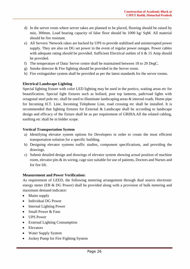
d) In the server room where server rakes are planned to be placed, flooring should be raised by
min, 300mm. Load bearing capacity of false floor should be 1000 kg/ SqM. All material
should be fire resistant.
e) All Servers/ Network rakes are backed by UPS to provide stabilised and uninterrupted power
supply. They are also on DG set power in the event of regular power outages. Power cables
with adequate rating should be provided. Sufficient Electrical outlets of 6 & 15 Amp should
be provided.
f) The temperature of Data/ Server centre shall be maintained between 18 to 20 DegC.
g) Smoke detector & Fire fighting should be provided in the Server room.
h) Fire extinguisher system shall be provided as per the latest standards for the server rooms.
Electrical Landscape Lighting
Special lighting fixture with color LED lighting may be used in the portico, waiting areas etc for
beautification. Special light fixtures such as bollard, post top lanterns, path/road lights with
octagonal steel pole etc. shall be used to illuminate landscaping areas & internal roads. Hume pipe
for Incoming H.T. Line, Incoming Telephone Line, road crossing etc shall be installed. It is
recommended that lighting fixtures for External & Landscape shall be according to landscape
design and efficacy of the fixture shall be as per requirement of GRIHA.All the related cabling,
earthing etc shall be in bidder scope.
Vertical Transportation System
a) Identifying elevator system options for Developers in order to create the most efficient
transportation solution for a specific building.
b) Designing elevator systems traffic studies, component specifications, and providing the
drawings.
c) Submit detailed design and drawings of elevator system showing actual position of machine
room, elevator pits & its wiring, cage size suitable for use of patients, Doctors and Nurses and
for fire lift.
Measurement and Power Verification:
As requirement of LEED, the following metering arrangement through dual source electronic
energy meter (EB & DG Power) shall be provided along with a provision of bulk metering and
maximum demand indicator:
Mains supply
Individual DG Power
Internal Lighting Power
Small Power & Fans
UPS Power
External Lighting Consumption
Elevators
Water Supply System
Jockey Pump for Fire Fighting System

Construction of Academic Block at
CIPET Baddi, Himachal Pradesh
Page 27
Earthing System:
Considering the hazardous nature of electrical energy, safety measures in using this energy is of
paramount importance. Earthing system shall be provided in accordance with Indian Standards IS-
3043-1987 / BS 7430 and other statutory regulations.
All non current carrying metal parts forming the Electrical System shall be connected to the Earthing
System as per the requirements of Indian Electricity Rules and local statutory requirements. The
earthing system shall be so designed that the resistance of the earthing network shall be less than 1.0
ohm at any point of the system.
All the Cable Trays shall be provided with suitable size of 2 Nos. G.I. strip in full length. Separate
Earthing shall be provided for Computers/UPS Network and entire earthing shall be insulated with
PVC sleeve.
The Earthing System is proposed as follows:
Substation Equipments:
a. Transformer Neutral Earthing : Copper
b. Transformer Body Earthing : Copper
c. H.T. Switch-Gear Earthing : Copper
d. D. G. Set Neutral Earthing : Copper
e. D.G. Set Body Earthing : Copper
Panel and other Equipment:
a. L.T. Panels Earthing : Copper
b. Distribution Boards Earthing : copper Wires
c. UPS Neutral Earthing : Copper
d. Lighting / Power Point : PVC Cu Wire
e. EPABX/Server etc : Copper
f. Medical Equipment : Copper
Plumbing & Fire Fighting Work
The Plumbing work shall include
Source of water supply
Water treatment process from raw water to potable water
Soft water treatment process from STP treated water to soft water
Storage Tanks of Raw water, potable water (Hot & Cold), non potable water & soft water
Potable water storage tank will be pumped to overhead water tank through two sets of VFD
pumps one will be working & other will be Stand by.
Internal water supply including Hot & Cold
Sanitary ware & Water conservation using low flow Chrome Plated (CP) Fixtures fittings.
Hot water supply System
Internal Soil, waste and rain water pipes disposal to 1st manhole

Construction of Academic Block at
CIPET Baddi, Himachal Pradesh
Page 28
Disposal to external sewerage system
Cooling towers Make-up
Disposal of surplus treated effluent to external sewer
Storm Water Drainage System
Rain water harvesting for recharging aquifer and disposal of surplus storm water to nearby
Authority drain.
Garden Hydrant system consisting pumps, piping and hydrants
Hot water generator with Solar preheating & allied system
Reverse Osmosis System (RO)
Solid Waste/Waste Water Management
Steam Boiler System for Laundary, Kitchen & CSSD
Fire fighting work shall include
Static water storage tanks
Fire Pumps & Accessories
External Fire Hydrants
Wet Riser System
Fire Sprinkler System
Water Curtain System
Portable Fire extinguishers
Clean agent suppression system
BMS Work
The BMS work shall include:
Complete HVAC Work
Smoke Management
Pressurization of Lift Well, Lift Lobby, Staircase & Staircase Lobby.
DG Set, HT, LT, Transformer, UPS, Façade Lighting & Electrical System Integration.
Lift
STP, ETP, Plumbing Plant, Fire Fighting Plant etc.
The Building Management / Automation System shall have a fully integrated building automation
system, incorporating direct digital control (DDC) for energy management, equipment monitoring and
control, suitable for the building usage. The control strategies shall be developed to ensure that the
specified environmental conditions are maintained, whilst giving due regard to minimizing of energy
consumption.
The system design shall utilize the latest technology in “open” network architecture, distributive
intelligence and processing, and direct digital control. The BACS system offered should be from the

Construction of Academic Block at
CIPET Baddi, Himachal Pradesh
Page 29
latest offerings and should be of freely programmable management and automation stations for the
full spectrum of today’s building application services.
All peripheral equipment e.g. sensors, pressure switches, control valves and actuators, shall be of the
same manufacture as the direct digital control modules and outstations.
The system offered shall be completely modular in structure and freely expandable at any stage from
the smallest system through to large distributed systems. Each level of the system shall operate
independently of the next level up.
The system shall fully be consistent with the latest industry standards, operating on Windows 2007 or
later, allowing the user to make full use of the features provided with these operating systems.
To provide maximum flexibility and to respond to changes in the building use, the system offered
shall support the use of BACnet, LON, Profibus and Ethernet TCP/IP communication technologies.

Construction of Academic Block at
CIPET Baddi, Himachal Pradesh
Page 30
SPECIFICATIONS
(CIVIL WORKS)

Construction of Academic Block at
CIPET Baddi, Himachal Pradesh
Page 31
1.1. General
The EPC Contractor shall be responsible for furnishing all materials required for execution of the
Works. The EPC Contractor shall submit the source and method of execution for the EPC
Consultant/Employer’s review before any execution. All materials used in the construction of
permanent works required under this Contract shall be of 1st class quality as specified herein and
comply with the latest IS Codes or equivalent. The material shall be tested before bringing it to the
site.
This specification establishes and defines the requirements of various materials to be used in Civil
and Structural works. Whenever any reference to IS Codes is made, the same shall be taken as the
latest revision (with all amendments issued thereto) as on the date of submission of the Tender. Apart
from the IS Codes mentioned in particular in various clauses of this specification, all other relevant
codes related to specific job under consideration regarding quality, tests, testing and/or inspection
procedures shall be applicable. Reference to some of the codes in various clauses of this
specification does not limit or restrict the scope of applicability of other referred or relevant codes.
In case of any variation/contradiction between the provision of IS Codes and this section, the
provision given in this sectionshall be followed, unless the Employer agrees/consents to follow IS
codes or other proposal of the EPC Contractor as provided in the Contract.
All materials shall be of standard quality and shall be procured from renowned
sources/manufacturers approved by the EPC Consultant/Employer. It shall be the responsibility of
the EPC Contractor, to get all materials/manufacturers approved by the EPC Consultant/Employer
prior to procurement and placement of order.
Wherever brand is not mentioned, EPC Contractor shall take prior approval of brand complying with
the tender specifications however mentioning the brand considered in the Bid submission shall
prevail if specified earlier.
Whenever called for by the EPC Consultant/Employer, all tests of the materials as specified by the
relevant IS Codes shall be carried out by the EPC Contractor in an approved laboratory and test
reports duly authenticated by the laboratory, shall be submitted to the EPC Consultant/Employer for
his approval. If so desired by the EPC Consultant, tests shall be conducted in the presence of the
EPC Consultant or his authorized nominee.
Quality and acceptability of materials not covered under this sectionshall be governed by the relevant
IS Codes. In case IS code is not available for the particular material, other codes e.g. B.S. or DIN
or API/ASTM etc. shall be considered. The decision of EPC Consultant/Employer in this regard
shall be final and binding on the EPC Contractor.
Whenever asked for, the EPC Contractor shall submit representative samples of materials to the EPC
Consultant/ Employer for his inspection and approval. Approval of any samples does not necessarily

Construction of Academic Block at
CIPET Baddi, Himachal Pradesh
Page 32
exempt the EPC Contractor from submitting necessary test reports for the approved material, as per
the specification/relevant IS Codes.
The EPC Contractor shall submit manufacturer’s test reports on quality and suitability of any
material procured from them and their recommendation on storage, application, workmanship etc.
for the intended use. Submission of manufacturer’s test reports does not restrict the EPC Consultant/
Employer from asking fresh test results from an approved laboratory of the actual material supplied
from an approved manufacturer/source at any stage of execution of work.
All costs relating to or arising out of the tests and submission of test reports and or samples to the
EPC Consultant/ Employer for his approval till the date of issuance of Performance Certificate shall
be borne by the EPC Contractor.
Materials for approval shall be separately stored and marked, as directed by the EPC
Consultant/Employer and shall not be used in the Works till these are approved.
All rejected materials shall be immediately removed from the site by the EPC Contractor at his own
cost.
1.2. General Standards
The new facilities shall be completed to high standards of construction and specification. The
facilities shall be technically and functionally suitable to meet the Employer's objectives:
i. The Architectural finishes shall be of such quality that will ensure better hygienic conditions.
ii. The design of building shall ensure control of noise due to walking, movement of trolleys
and banging of doors etc.
iii. The architectural design should take into account the requirements of physically challenged
persons
iv. All the material procured or to be used should be to the satisfaction of the Engineer before
being used for the works intended to.
v. All sanitary/ water supply fixture and fittings shall be of approved make confirming to IS
specifications and with ISI Marks.
vi. There should be separate inlets for hot and cold water in all the buildings. The buildings
should have sufficient number of water coolers and filters points to cater to the needs of
different users.
vii. The design should provide for underground& overhead water tank with necessary pumping
arrangement for both potable and fire fighting requirements.
viii. The design should incorporate fire fighting system with pumps, hydrants, sprinklers, fire
extinguishers and fire alarm system in accordance with the rules and regulations of the local
fire authority and that of the Tariff Advisory Committee (TAC) of the Insurance Association
of India, as amended up to date.
Construction of Academic Block at
CIPET Baddi, Himachal Pradesh
Page 33
ix. Lighting should confirm to NBC for Lighting. All electrical system, fixtures, fittings etc.
should confirm to CPWD specifications, latest IS code etc.
x. The planning should include landscaping and horticulture to increase the comfort conditions
inside the building. The EPC Contractor shall create parking, approach roads and other
requirements for the building.
xi. Provision should be made for internal and external signages, display boards, public address
system in the required area.
xii. All the buildings should have power back up systems for emergency services.
xiii. Mechanical services shall be designed and installed with provisions to contain noise and the
transmission of vibration generated by moving plant and equipment schedules to achieve
acceptable noise and vibration with respect to human beings specified by ISO standards.
xiv. All moving plant, machinery and apparatus be statically and dynamically balanced at
manufactures work and certificate issued.
xv. All aspects including Bio Medical Waste (Management & Handling) Rules 1998 with
Subsequent amendments, if any, issued by the Ministry of Environment and Forest,
Government of India should be addressed in the provision for waste Management.
1.3. Statutory, Industry and Local Standards
The following standards shall apply unless otherwise stated:
The standards set out in National Building Code of India 2016& BIS Codes.
The relevant Development Control Rules/Planning Act/Development Act/Municipal Act/any
other applicable statutes and local by-laws
The National Electrical Code, 1985
The Indian Electricity Act 2003
Requirements of the local Water Supply Company, Electricity Supply Company/ Department
Requirements of the Pollution Control Board, Environment clearances, NOC from Fire
department, Forest Department for tree cutting, Lift license, Explosive department, Aviation
authorities if applicable
Any other statutory requirement for execution of work and to occupy the buildings and run
the services in all respects.
EPC Contractor shall organise all inspections of concerned authorities & obtain the NOC’s
within the time for completion.
The EPC Contractor is required to submit the relevant drawings like completion Drawings
and any other statutory documentary requirements of local bodies in copies as per requirement
to obtain the approval etc. at their own cost.
1.4. Unacceptable Materials and Processes
The materials and processes given below must not be used in the New Facilities or in connection
with the New Facilities.
High alumina cement in structural elements
Calcium chloride as a concrete additive
Construction of Academic Block at
CIPET Baddi, Himachal Pradesh
Page 34
Sea dredged aggregates or aggregates for use in reinforced concrete
Asbestos cement products; or asbestos in any other form including vermiculite containing
asbestos fibrous dust
Lead or any products containing lead for use in connection with drinking water
Materials which are generally composed of mineral fibres either man made or naturally
occurring which have a diameter of 3 microns or less and a length of 200 microns or less or
which contain any fibres not scaled or otherwise stabilised to ensure that fibre migration is
prevented
Urea formaldehyde
Plastics for water storage and delivery that release toxic materials
Materials containing vinyl chloride unless risk form carcinogen is shown to be negligible.
Vermiculite containing asbestos fibrous dust
Cellulose fibre
Polyurethane foam or polyisocyanurate foam unless the risk is shown to be negligible
Plywood with glues, resins and surface treatments that produce irritant volatiles
Decorative finishes containing lead or asbestos
Materials containing chlorofluorocarbons (CFCs)
Paints and wood preservatives containing pentachlorophenois (PCPs) tributyl tin oxide
(TBTO) or Lindane
Any treatment of materials either before or after installation which give rise to toxic or
hazardous emissions or particles
Any other substances generally known at the time of use to be deleterious to health and safety
or to the durability of the works in the particular circumstances they are used.
General Specification
The work shall be carried out strictly as per CPWD specifications unless or otherwise specified.The
broad items & specifications to be followed are given below showing references of DSR items. The
reference of DSR items are only illustitative. The specifications & items which are not mentioned
shall deemeed to be included in the turn key cost and shall be executedas per direction of Engineer-
in-Charge with reference to relevant DSR items/CPWD Specifications
Sl.No. Items of Work Specifications – CPWD 2019 Vol. I &
II Ref.to DSR 2018 Item
1 Site Development
Earth work in surface excavation 2.1
Earth work in excavation by mechanical
means 2.6
Earth work in rough excavation, banking
excavated earth
2.2+Carriage of
excavated materials, if
required.
2 Carriage of Materials
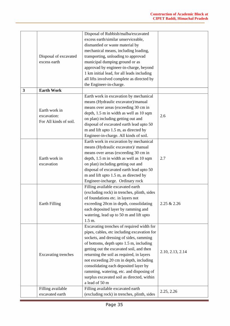
Construction of Academic Block at
CIPET Baddi, Himachal Pradesh
Page 35
Disposal of excavated
excess earth
Disposal of Rubbish/malba/excavated
excess earth/similar unserviceable,
dismantled or waste material by
mechanical means, including loading,
transporting, unloading to approvad
municipal dumping ground or as
approvad by engineer-in-charge, beyond
1 km initial lead, for all leads including
all lifts involved complete as directed by
the Engineer-in-charge.
3 Earth Work
Earth work in
excavation:
For All kinds of soil.
Earth work in excavation by mechanical
means (Hydraulic excavator)/manual
means over areas (exceeding 30 cm in
depth, 1.5 m in width as well as 10 sqm
on plan) including getting out and
disposal of excavated earth lead upto 50
m and lift upto 1.5 m, as directed by
Engineer-in-charge. All kinds of soil.
2.6
Earth work in
excavation
Earth work in excavation by mechanical
means (Hydraulic excavator)/ manual
means over areas (exceeding 30 cm in
depth, 1.5 m in width as well as 10 sqm
on plan) including getting out and
disposal of excavated earth lead upto 50
m and lift upto 1.5 m, as directed by
Engineer-incharge. Ordinary rock
2.7
Earth Filling
Filling available excavated earth
(excluding rock) in trenches, plinth, sides
of foundations etc. in layers not
exceeding 20cm in depth, consolidating
each deposited layer by ramming and
watering, lead up to 50 m and lift upto
1.5 m.
2.25 & 2.26
Excavating trenches
Excavating trenches of required width for
pipes, cables, etc including excavation for
sockets, and dressing of sides, ramming
of bottoms, depth upto 1.5 m, including
getting out the excavated soil, and then
returning the soil as required, in layers
not exceeding 20 cm in depth, including
consolidating each deposited layer by
ramming, watering, etc. and disposing of
surplus excavated soil as directed, within
a lead of 50 m
2.10, 2.13, 2.14
Filling available
excavated earth
Filling available excavated earth
(excluding rock) in trenches, plinth, sides 2.25, 2.26
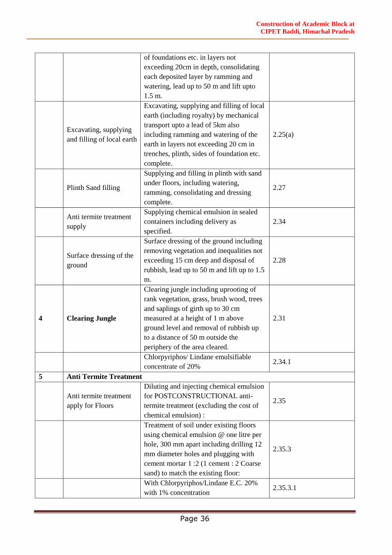
Construction of Academic Block at
CIPET Baddi, Himachal Pradesh
Page 36
of foundations etc. in layers not
exceeding 20cm in depth, consolidating
each deposited layer by ramming and
watering, lead up to 50 m and lift upto
1.5 m.
Excavating, supplying
and filling of local earth
Excavating, supplying and filling of local
earth (including royalty) by mechanical
transport upto a lead of 5km also
including ramming and watering of the
earth in layers not exceeding 20 cm in
trenches, plinth, sides of foundation etc.
complete.
2.25(a)
Plinth Sand filling
Supplying and filling in plinth with sand
under floors, including watering,
ramming, consolidating and dressing
complete.
2.27
Anti termite treatment
supply
Supplying chemical emulsion in sealed
containers including delivery as
specified.
2.34
Surface dressing of the
ground
Surface dressing of the ground including
removing vegetation and inequalities not
exceeding 15 cm deep and disposal of
rubbish, lead up to 50 m and lift up to 1.5
m.
2.28
4 Clearing Jungle
Clearing jungle including uprooting of
rank vegetation, grass, brush wood, trees
and saplings of girth up to 30 cm
measured at a height of 1 m above
ground level and removal of rubbish up
to a distance of 50 m outside the
periphery of the area cleared.
2.31
Chlorpyriphos/ Lindane emulsifiable
concentrate of 20% 2.34.1
5 Anti Termite Treatment
Anti termite treatment
apply for Floors
Diluting and injecting chemical emulsion
for POSTCONSTRUCTIONAL anti-
termite treatment (excluding the cost of
chemical emulsion) :
2.35
Treatment of soil under existing floors
using chemical emulsion @ one litre per
hole, 300 mm apart including drilling 12
mm diameter holes and plugging with
cement mortar 1 :2 (1 cement : 2 Coarse
sand) to match the existing floor:
2.35.3
With Chlorpyriphos/Lindane E.C. 20%
with 1% concentration 2.35.3.1
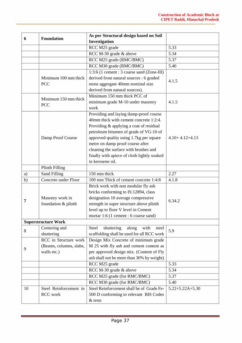
Construction of Academic Block at
CIPET Baddi, Himachal Pradesh
Page 37
6 Foundation As per Structural design based on Soil
Investigation
RCC M25 grade 5.33
RCC M-30 grade & above 5.34
RCC M25 grade (RMC/BMC) 5.37
RCC M30 grade (RMC/BMC) 5.40
Minimum 100 mm thick
PCC
1:3:6 (1 cement : 3 coarse sand (Zone-III)
derived from natural sources : 6 graded
stone aggregate 40mm nominal size
derived from natural sources).
4.1.5
Minimum 150 mm thick
PCC
Minimum 150 mm thick PCC of
minimum grade M-10 under masonry
work
4.1.5
Damp Proof Course
Providing and laying damp-proof course
40mm thick with cement concrete 1:2:4.
Providing & applying a coat of residual
petroleum bitumen of grade of VG-10 of
approved quality using 1.7kg per square
metre on damp proof course after
cleaning the surface with brushes and
finally with apiece of cloth lightly soaked
in kerosene oil.
4.10+ 4.12+4.13
Plinth Filling
a) Sand Filling 150 mm thick 2.27
b) Concrete under Floor 100 mm Thick of cement concrete 1:4:8 4.1.8
7 Masonry work in
foundation & plinth
Brick work with non modular fly ash
bricks conforming to IS:12894, class
designation 10 average compressive
strength in super structure above plinth
level up to floor V level in Cement
mortar 1:6 (1 cement : 6 coarse sand)
6.34.2
Superstructure Work
8 Centering and
shuttering
Steel shuttering along with steel
scaffolding shall be used for all RCC work 5.9
9
RCC in Structure work
(Beams, columns, slabs,
walls etc.)
Design Mix Concrete of minimum grade
M 25 with fly ash and cement content as
per approved design mix. (Content of Fly
ash shall not be more than 30% by weight)
RCC M25 grade 5.33
RCC M-30 grade & above 5.34
RCC M25 grade (for RMC/BMC) 5.37
RCC M30 grade (for RMC/BMC) 5.40
10 Steel Reinforcement in
RCC work
Steel Reinforcement shall be of Grade Fe-
500 D conforming to relevant BIS Codes
& tests
5.22+5.22A+5.30
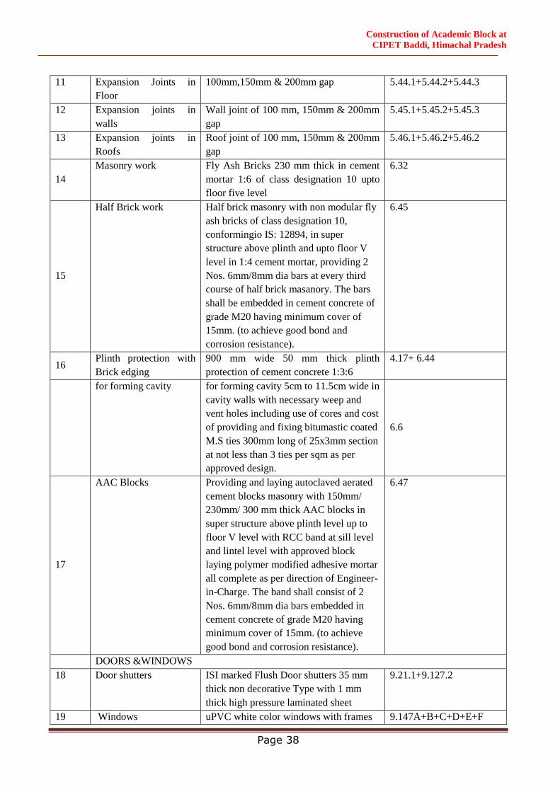
Construction of Academic Block at
CIPET Baddi, Himachal Pradesh
Page 38
11 Expansion Joints in
Floor
100mm,150mm & 200mm gap 5.44.1+5.44.2+5.44.3
12 Expansion joints in
walls
Wall joint of 100 mm, 150mm & 200mm
gap
5.45.1+5.45.2+5.45.3
13 Expansion joints in
Roofs
Roof joint of 100 mm, 150mm & 200mm
gap
5.46.1+5.46.2+5.46.2
14
Masonry work Fly Ash Bricks 230 mm thick in cement
mortar 1:6 of class designation 10 upto
floor five level
6.32
15
Half Brick work Half brick masonry with non modular fly
ash bricks of class designation 10,
conformingio IS: 12894, in super
structure above plinth and upto floor V
level in 1:4 cement mortar, providing 2
Nos. 6mm/8mm dia bars at every third
course of half brick masanory. The bars
shall be embedded in cement concrete of
grade M20 having minimum cover of
15mm. (to achieve good bond and
corrosion resistance).
6.45
16 Plinth protection with
Brick edging
900 mm wide 50 mm thick plinth
protection of cement concrete 1:3:6
4.17+ 6.44
for forming cavity for forming cavity 5cm to 11.5cm wide in
cavity walls with necessary weep and
vent holes including use of cores and cost
of providing and fixing bitumastic coated
M.S ties 300mm long of 25x3mm section
at not less than 3 ties per sqm as per
approved design.
6.6
17
AAC Blocks Providing and laying autoclaved aerated
cement blocks masonry with 150mm/
230mm/ 300 mm thick AAC blocks in
super structure above plinth level up to
floor V level with RCC band at sill level
and lintel level with approved block
laying polymer modified adhesive mortar
all complete as per direction of Engineer-
in-Charge. The band shall consist of 2
Nos. 6mm/8mm dia bars embedded in
cement concrete of grade M20 having
minimum cover of 15mm. (to achieve
good bond and corrosion resistance).
6.47
DOORS &WINDOWS
18 Door shutters ISI marked Flush Door shutters 35 mm
thick non decorative Type with 1 mm
thick high pressure laminated sheet
9.21.1+9.127.2
19 Windows uPVC white color windows with frames 9.147A+B+C+D+E+F
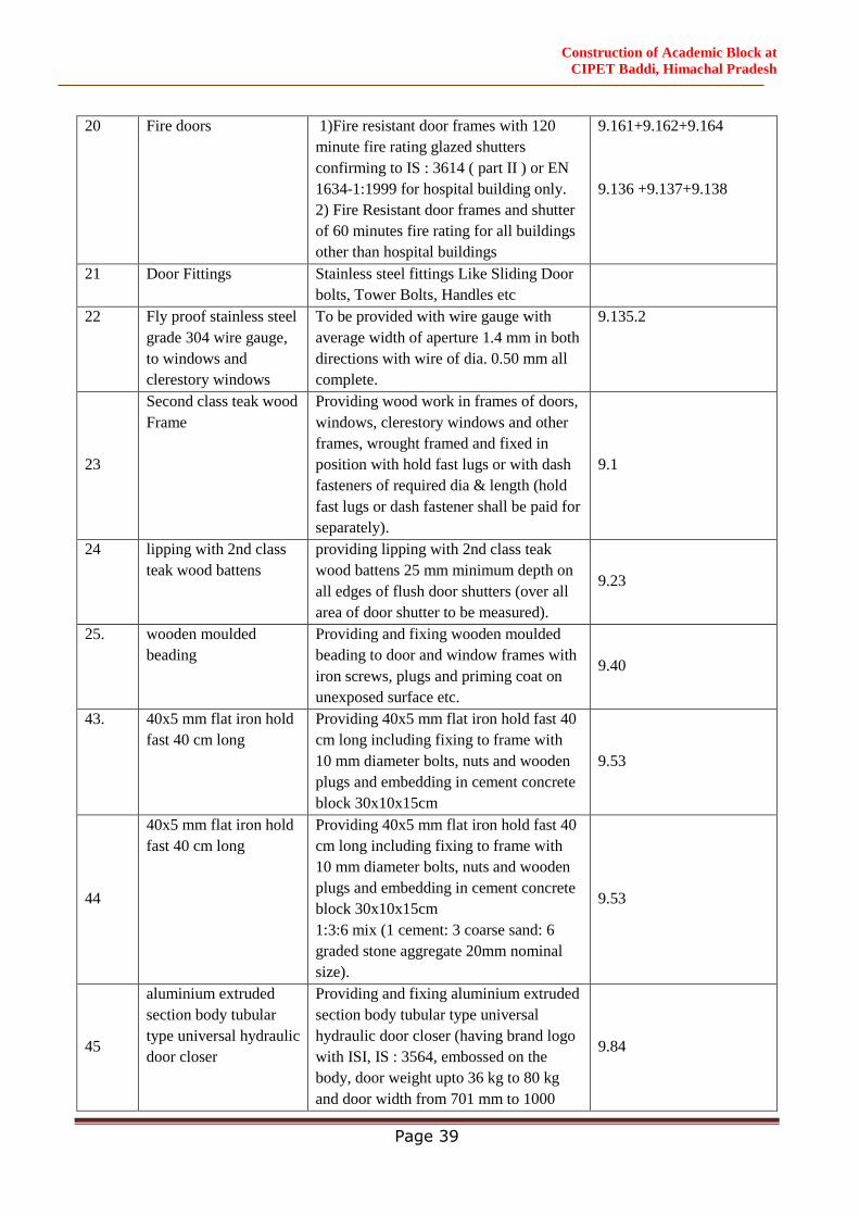
Construction of Academic Block at
CIPET Baddi, Himachal Pradesh
Page 39
20 Fire doors
1)Fire resistant door frames with 120
minute fire rating glazed shutters
confirming to IS : 3614 ( part II ) or EN
1634-1:1999 for hospital building only.
2) Fire Resistant door frames and shutter
of 60 minutes fire rating for all buildings
other than hospital buildings
9.161+9.162+9.164
9.136 +9.137+9.138
21 Door Fittings Stainless steel fittings Like Sliding Door
bolts, Tower Bolts, Handles etc
22 Fly proof stainless steel
grade 304 wire gauge,
to windows and
clerestory windows
To be provided with wire gauge with
average width of aperture 1.4 mm in both
directions with wire of dia. 0.50 mm all
complete.
9.135.2
23
Second class teak wood
Frame
Providing wood work in frames of doors,
windows, clerestory windows and other
frames, wrought framed and fixed in
position with hold fast lugs or with dash
fasteners of required dia & length (hold
fast lugs or dash fastener shall be paid for
separately).
9.1
24
lipping with 2nd class
teak wood battens
providing lipping with 2nd class teak
wood battens 25 mm minimum depth on
all edges of flush door shutters (over all
area of door shutter to be measured).
9.23
25. wooden moulded
beading
Providing and fixing wooden moulded
beading to door and window frames with
iron screws, plugs and priming coat on
unexposed surface etc.
9.40
43. 40x5 mm flat iron hold
fast 40 cm long
Providing 40x5 mm flat iron hold fast 40
cm long including fixing to frame with
10 mm diameter bolts, nuts and wooden
plugs and embedding in cement concrete
block 30x10x15cm
9.53
44
40x5 mm flat iron hold
fast 40 cm long
Providing 40x5 mm flat iron hold fast 40
cm long including fixing to frame with
10 mm diameter bolts, nuts and wooden
plugs and embedding in cement concrete
block 30x10x15cm
1:3:6 mix (1 cement: 3 coarse sand: 6
graded stone aggregate 20mm nominal
size).
9.53
45
aluminium extruded
section body tubular
type universal hydraulic
door closer
Providing and fixing aluminium extruded
section body tubular type universal
hydraulic door closer (having brand logo
with ISI, IS : 3564, embossed on the
body, door weight upto 36 kg to 80 kg
and door width from 701 mm to 1000
9.84
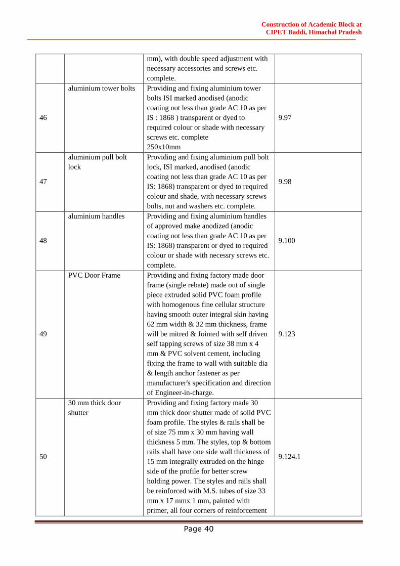
Construction of Academic Block at
CIPET Baddi, Himachal Pradesh
Page 40
mm), with double speed adjustment with
necessary accessories and screws etc.
complete.
46
aluminium tower bolts Providing and fixing aluminium tower
bolts ISI marked anodised (anodic
coating not less than grade AC 10 as per
IS : 1868 ) transparent or dyed to
required colour or shade with necessary
screws etc. complete
250x10mm
9.97
47
aluminium pull bolt
lock
Providing and fixing aluminium pull bolt
lock, ISI marked, anodised (anodic
coating not less than grade AC 10 as per
IS: 1868) transparent or dyed to required
colour and shade, with necessary screws
bolts, nut and washers etc. complete.
9.98
48
aluminium handles Providing and fixing aluminium handles
of approved make anodized (anodic
coating not less than grade AC 10 as per
IS: 1868) transparent or dyed to required
colour or shade with necessry screws etc.
complete.
9.100
49
PVC Door Frame Providing and fixing factory made door
frame (single rebate) made out of single
piece extruded solid PVC foam profile
with homogenous fine cellular structure
having smooth outer integral skin having
62 mm width & 32 mm thickness, frame
will be mitred & Jointed with self driven
self tapping screws of size 38 mm x 4
mm & PVC solvent cement, including
fixing the frame to wall with suitable dia
& length anchor fastener as per
manufacturer's specification and direction
of Engineer-in-charge.
9.123
50
30 mm thick door
shutter
Providing and fixing factory made 30
mm thick door shutter made of solid PVC
foam profile. The styles & rails shall be
of size 75 mm x 30 mm having wall
thickness 5 mm. The styles, top & bottom
rails shall have one side wall thickness of
15 mm integrally extruded on the hinge
side of the profile for better screw
holding power. The styles and rails shall
be reinforced with M.S. tubes of size 33
mm x 17 mmx 1 mm, painted with
primer, all four corners of reinforcement
9.124.1
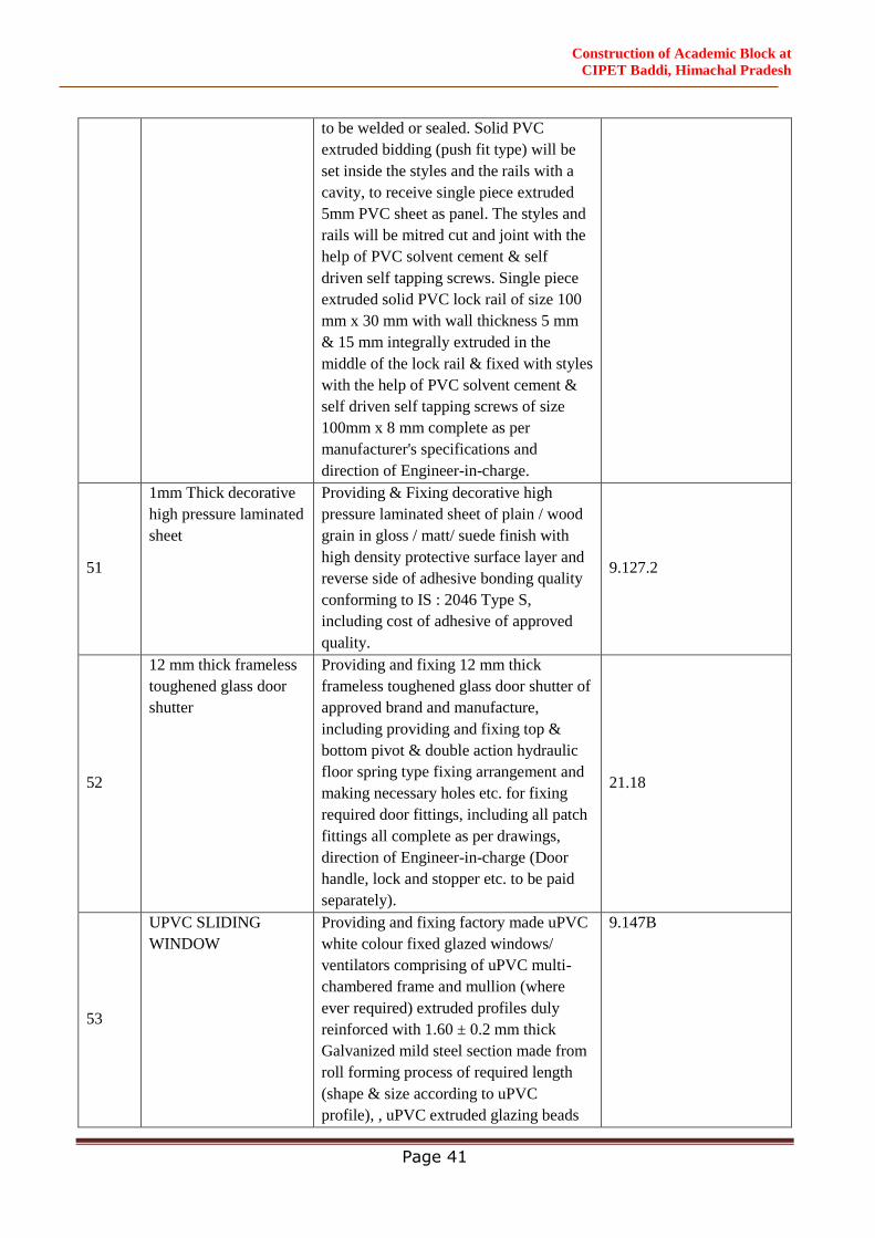
Construction of Academic Block at
CIPET Baddi, Himachal Pradesh
Page 41
to be welded or sealed. Solid PVC
extruded bidding (push fit type) will be
set inside the styles and the rails with a
cavity, to receive single piece extruded
5mm PVC sheet as panel. The styles and
rails will be mitred cut and joint with the
help of PVC solvent cement & self
driven self tapping screws. Single piece
extruded solid PVC lock rail of size 100
mm x 30 mm with wall thickness 5 mm
& 15 mm integrally extruded in the
middle of the lock rail & fixed with styles
with the help of PVC solvent cement &
self driven self tapping screws of size
100mm x 8 mm complete as per
manufacturer's specifications and
direction of Engineer-in-charge.
51
1mm Thick decorative
high pressure laminated
sheet
Providing & Fixing decorative high
pressure laminated sheet of plain / wood
grain in gloss / matt/ suede finish with
high density protective surface layer and
reverse side of adhesive bonding quality
conforming to IS : 2046 Type S,
including cost of adhesive of approved
quality.
9.127.2
52
12 mm thick frameless
toughened glass door
shutter
Providing and fixing 12 mm thick
frameless toughened glass door shutter of
approved brand and manufacture,
including providing and fixing top &
bottom pivot & double action hydraulic
floor spring type fixing arrangement and
making necessary holes etc. for fixing
required door fittings, including all patch
fittings all complete as per drawings,
direction of Engineer-in-charge (Door
handle, lock and stopper etc. to be paid
separately).
21.18
53
UPVC SLIDING
WINDOW
Providing and fixing factory made uPVC
white colour fixed glazed windows/
ventilators comprising of uPVC multi-
chambered frame and mullion (where
ever required) extruded profiles duly
reinforced with 1.60 ± 0.2 mm thick
Galvanized mild steel section made from
roll forming process of required length
(shape & size according to uPVC
profile), , uPVC extruded glazing beads
9.147B
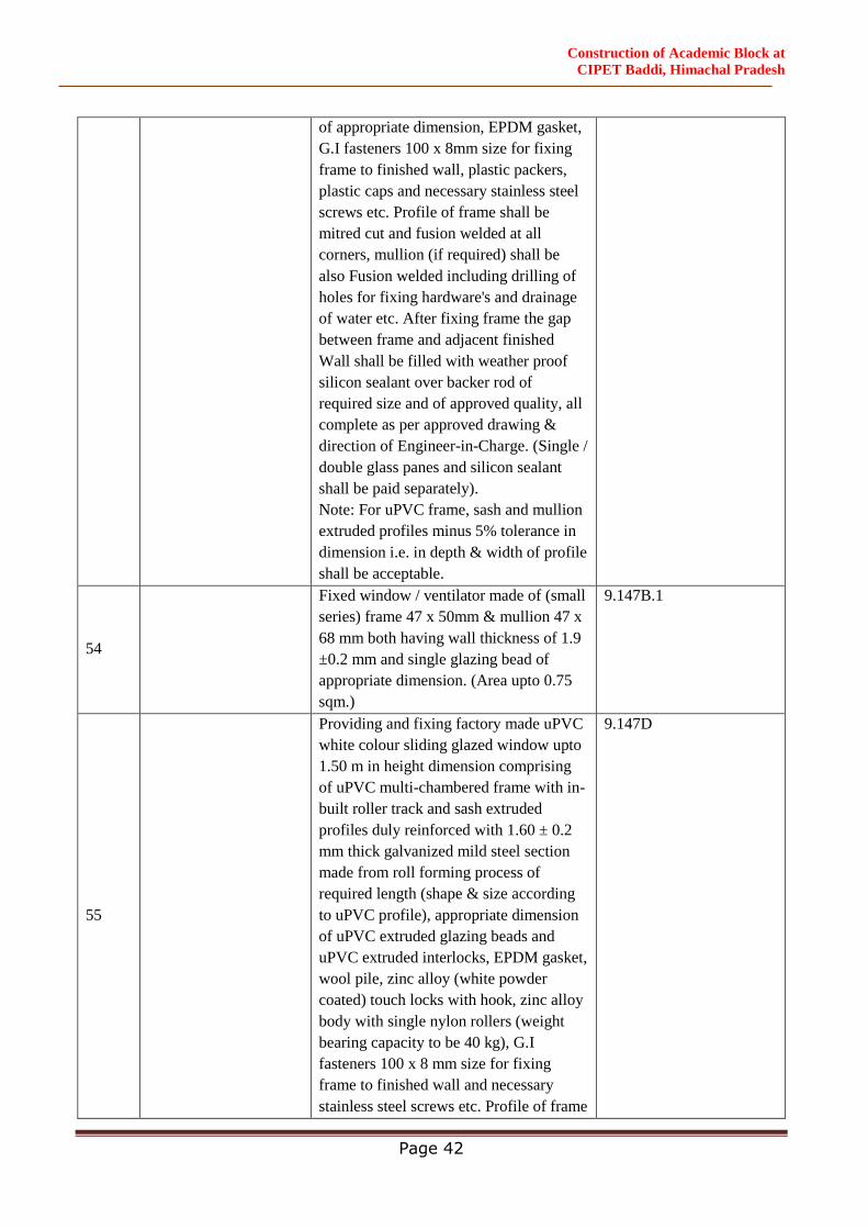
Construction of Academic Block at
CIPET Baddi, Himachal Pradesh
Page 42
of appropriate dimension, EPDM gasket,
G.I fasteners 100 x 8mm size for fixing
frame to finished wall, plastic packers,
plastic caps and necessary stainless steel
screws etc. Profile of frame shall be
mitred cut and fusion welded at all
corners, mullion (if required) shall be
also Fusion welded including drilling of
holes for fixing hardware's and drainage
of water etc. After fixing frame the gap
between frame and adjacent finished
Wall shall be filled with weather proof
silicon sealant over backer rod of
required size and of approved quality, all
complete as per approved drawing &
direction of Engineer-in-Charge. (Single /
double glass panes and silicon sealant
shall be paid separately).
Note: For uPVC frame, sash and mullion
extruded profiles minus 5% tolerance in
dimension i.e. in depth & width of profile
shall be acceptable.
54
Fixed window / ventilator made of (small
series) frame 47 x 50mm & mullion 47 x
68 mm both having wall thickness of 1.9
±0.2 mm and single glazing bead of
appropriate dimension. (Area upto 0.75
sqm.)
9.147B.1
55
Providing and fixing factory made uPVC
white colour sliding glazed window upto
1.50 m in height dimension comprising
of uPVC multi-chambered frame with in-
built roller track and sash extruded
profiles duly reinforced with 1.60 ± 0.2
mm thick galvanized mild steel section
made from roll forming process of
required length (shape & size according
to uPVC profile), appropriate dimension
of uPVC extruded glazing beads and
uPVC extruded interlocks, EPDM gasket,
wool pile, zinc alloy (white powder
coated) touch locks with hook, zinc alloy
body with single nylon rollers (weight
bearing capacity to be 40 kg), G.I
fasteners 100 x 8 mm size for fixing
frame to finished wall and necessary
stainless steel screws etc. Profile of frame
9.147D
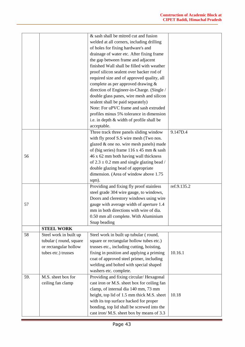
Construction of Academic Block at
CIPET Baddi, Himachal Pradesh
Page 43
& sash shall be mitred cut and fusion
welded at all corners, including drilling
of holes for fixing hardware's and
drainage of water etc. After fixing frame
the gap between frame and adjacent
finished Wall shall be filled with weather
proof silicon sealent over backer rod of
required size and of approved quality, all
complete as per approved drawing &
direction of Engineer-in-Charge. (Single /
double glass panes, wire mesh and silicon
sealent shall be paid separately)
Note: For uPVC frame and sash extruded
profiles minus 5% tolerance in dimension
i.e. in depth & width of profile shall be
acceptable.
56
Three track three panels sliding window
with fly proof S.S wire mesh (Two nos.
glazed & one no. wire mesh panels) made
of (big series) frame 116 x 45 mm & sash
46 x 62 mm both having wall thickness
of 2.3 ± 0.2 mm and single glazing bead /
double glazing bead of appropriate
dimension. (Area of window above 1.75
sqm).
9.147D.4
57
Providing and fixing fly proof stainless
steel grade 304 wire gauge, to windows,
Doors and clerestory windows using wire
gauge with average width of aperture 1.4
mm in both directions with wire of dia.
0.50 mm all complete. With Aluminium
Snap beading
ref.9.135.2
STEEL WORK
58 Steel work in built up
tubular ( round, square
or rectangular hollow
tubes etc.) trusses
Steel work in built up tubular ( round,
square or rectangular hollow tubes etc.)
trusses etc., including cutting, hoisting,
fixing in position and applying a priming
coat of approved steel primer, including
welding and bolted with special shaped
washers etc. complete.
10.16.1
59. M.S. sheet box for
ceiling fan clamp
Providing and fixing circular/ Hexagonal
cast iron or M.S. sheet box for ceiling fan
clamp, of internal dia 140 mm, 73 mm
height, top lid of 1.5 mm thick M.S. sheet
with its top surface hacked for proper
bonding, top lid shall be screwed into the
cast iron/ M.S. sheet box by means of 3.3
10.18
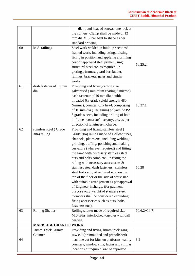
Construction of Academic Block at
CIPET Baddi, Himachal Pradesh
Page 44
mm dia round headed screws, one lock at
the corners. Clamp shall be made of 12
mm dia M.S. bar bent to shape as per
standard drawing.
60 M.S. railings Steel work welded in built up sections/
framed work, including utting,hoisting,
fixing in position and applying a priming
coat of approved steel primer using
structural steel etc. as required. In
gratings, frames, guard bar, ladder,
railings, brackets, gates and similar
works
10.25.2
61 dash fastener of 10 mm
dia
Providing and fixing carbon steel
galvanised ( minimum coating 5 micron)
dash fastener of 10 mm dia double
threaded 6.8 grade (yield strength 480
N/mm2), counter sunk head, comprising
of 10 mm dia (10x60mm) polyamide PA
6 grade sleeve, including drilling of hole
in frame , concrete/ masonry, etc. as per
direction of Engineer-incharge.
10.27.1
62 stainless steel ( Grade
304) railing
Providing and fixing stainless steel (
Grade 304) railing made of Hollow tubes,
channels, plates etc., including welding,
grinding, buffing, polishing and making
curvature (wherever required) and fitting
the same with necessary stainless steel
nuts and bolts complete, i/c fixing the
railing with necessary accessories &
stainless steel dash fasteners , stainless
steel bolts etc., of required size, on the
top of the floor or the side of waist slab
with suitable arrangement as per approval
of Engineer-incharge, (for payment
purpose only weight of stainless steel
members shall be considered excluding
fixing accessories such as nuts, bolts,
fasteners etc.).
10.28
63 Rolling Shutter Rolling shutter made of required size
M.S laths, interlocked together with ball
bearing
10.6.2+10.7
MARBLE & GRANITE WORK
64
18mm Thick Granite
Counter
Providing and fixing 18mm thick gang
saw cut (premoulded and prepolished)
machine cut for kitchen platforms, vanity
counters, window sills, facias and similar
locations of required size of approved
8.2
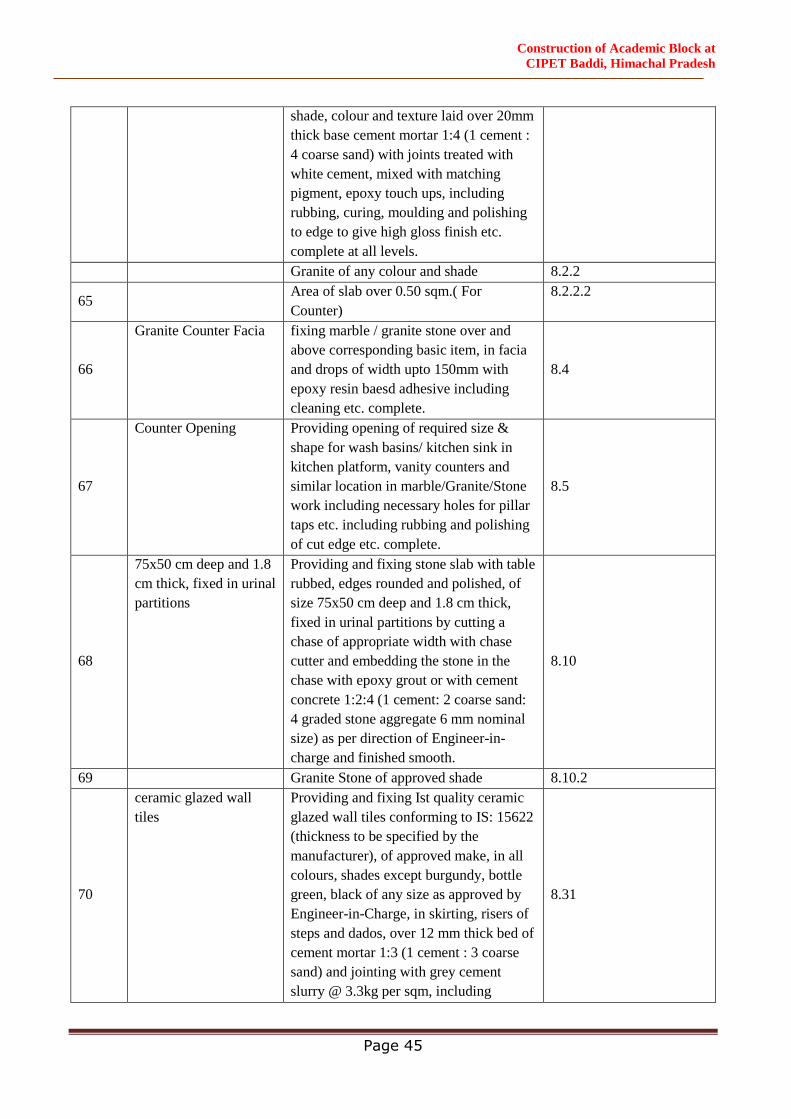
Construction of Academic Block at
CIPET Baddi, Himachal Pradesh
Page 45
shade, colour and texture laid over 20mm
thick base cement mortar 1:4 (1 cement :
4 coarse sand) with joints treated with
white cement, mixed with matching
pigment, epoxy touch ups, including
rubbing, curing, moulding and polishing
to edge to give high gloss finish etc.
complete at all levels.
Granite of any colour and shade 8.2.2
65 Area of slab over 0.50 sqm.( For
Counter)
8.2.2.2
66
Granite Counter Facia
fixing marble / granite stone over and
above corresponding basic item, in facia
and drops of width upto 150mm with
epoxy resin baesd adhesive including
cleaning etc. complete.
8.4
67
Counter Opening Providing opening of required size &
shape for wash basins/ kitchen sink in
kitchen platform, vanity counters and
similar location in marble/Granite/Stone
work including necessary holes for pillar
taps etc. including rubbing and polishing
of cut edge etc. complete.
8.5
68
75x50 cm deep and 1.8
cm thick, fixed in urinal
partitions
Providing and fixing stone slab with table
rubbed, edges rounded and polished, of
size 75x50 cm deep and 1.8 cm thick,
fixed in urinal partitions by cutting a
chase of appropriate width with chase
cutter and embedding the stone in the
chase with epoxy grout or with cement
concrete 1:2:4 (1 cement: 2 coarse sand:
4 graded stone aggregate 6 mm nominal
size) as per direction of Engineer-in-
charge and finished smooth.
8.10
69 Granite Stone of approved shade 8.10.2
70
ceramic glazed wall
tiles
Providing and fixing Ist quality ceramic
glazed wall tiles conforming to IS: 15622
(thickness to be specified by the
manufacturer), of approved make, in all
colours, shades except burgundy, bottle
green, black of any size as approved by
Engineer-in-Charge, in skirting, risers of
steps and dados, over 12 mm thick bed of
cement mortar 1:3 (1 cement : 3 coarse
sand) and jointing with grey cement
slurry @ 3.3kg per sqm, including
8.31
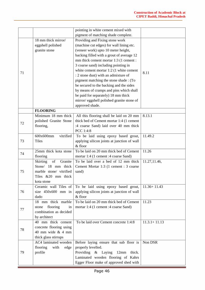
Construction of Academic Block at
CIPET Baddi, Himachal Pradesh
Page 46
pointing in white cement mixed with
pigment of matching shade complete.
71
18 mm thick mirror/
eggshell polished
granite stone
Providing and Fixing stone work
(machine cut edges) for wall lining etc.
(veneer work) upto 10 meter height,
backing filled with a grout of average 12
mm thick cement mortar 1:3 (1 cement :
3 coarse sand) including pointing in
white cement mortar 1:2 (1 white cement
: 2 stone dust) with an admixture of
pigment matching the stone shade : (To
be secured to the backing and the sides
by means of cramps and pins which shall
be paid for separately) 18 mm thick
mirror/ eggshell polished granite stone of
approved shade.
8.11
FLOORING
72
Minimum 18 mm thick
polished Granite Stone
flooring,
All this flooring shall be laid on 20 mm
thick bed of Cement mortar 1:4 (1 cement
:4 coarse Sand) laid over 40 mm thick
PCC 1:4:8
8.13.1
73
600x600mm vitrified
Tiles
To be laid using epoxy based grout,
applying silicon joints at junction of wall
& floor
11.49.2
74 25mm thick kota stone
flooring
To be laid on 20 mm thick bed of Cement
mortar 1:4 (1 cement :4 coarse Sand)
11.26
75
Skirting of Granite
Stone/ 18 mm thick
marble stone/ vitrified
Tiles &20 mm thick
kota stone
To be laid over a bed of 12 mm thick
Cement Mortar 1:3 (1 cement : 3 coarse
sand)
11.27,11.46,
76
Ceramic wall Tiles of
size 450x600 mm in
dado
To be laid using epoxy based grout,
applying silicon joints at junction of wall
& floor
11.36+ 11.43
77
18 mm thick marble
stone flooring in
combination as decided
by architect
To be laid on 20 mm thick bed of Cement
mortar 1:4 (1 cement :4 coarse Sand)
11.23
78
40 mm thick cement
concrete flooring using
40 mm wide & 4 mm
thick glass stirrups
To be laid over Cement concrete 1:4:8 11.3.1+ 11.13
79
AC4 laminated wooden
flooring with edge
profile
Before laying ensure that sub floor is
properly levelled.
Providing & Laying 12mm thick.
Laminated wooden flooring of Kahrs
Egger Floor make of approved shed with
Non DSR
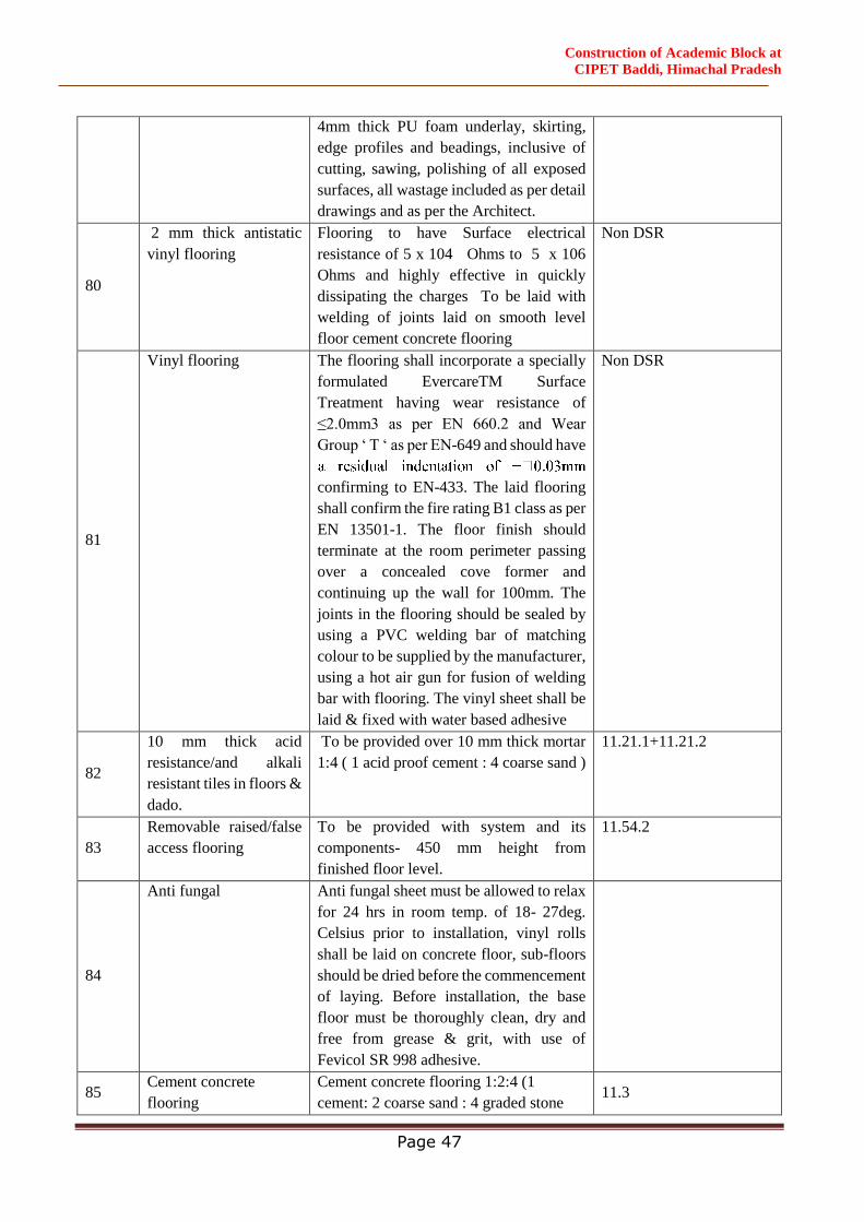
Construction of Academic Block at
CIPET Baddi, Himachal Pradesh
Page 47
4mm thick PU foam underlay, skirting,
edge profiles and beadings, inclusive of
cutting, sawing, polishing of all exposed
surfaces, all wastage included as per detail
drawings and as per the Architect.
80
2 mm thick antistatic
vinyl flooring
Flooring to have Surface electrical
resistance of 5 x 10⁴ Ohms to 5 x 10⁶
Ohms and highly effective in quickly
dissipating the charges To be laid with
welding of joints laid on smooth level
floor cement concrete flooring
Non DSR
81
Vinyl flooring The flooring shall incorporate a specially
formulated EvercareTM Surface
Treatment having wear resistance of
≤2.0mm3 as per EN 660.2 and Wear
Group ‘ T ‘ as per EN-649 and should have
confirming to EN-433. The laid flooring
shall confirm the fire rating B1 class as per
EN 13501-1. The floor finish should
terminate at the room perimeter passing
over a concealed cove former and
continuing up the wall for 100mm. The
joints in the flooring should be sealed by
using a PVC welding bar of matching
colour to be supplied by the manufacturer,
using a hot air gun for fusion of welding
bar with flooring. The vinyl sheet shall be
laid & fixed with water based adhesive
Non DSR
82
10 mm thick acid
resistance/and alkali
resistant tiles in floors &
dado.
To be provided over 10 mm thick mortar
1:4 ( 1 acid proof cement : 4 coarse sand )
11.21.1+11.21.2
83
Removable raised/false
access flooring
To be provided with system and its
components- 450 mm height from
finished floor level.
11.54.2
84
Anti fungal Anti fungal sheet must be allowed to relax
for 24 hrs in room temp. of 18- 27deg.
Celsius prior to installation, vinyl rolls
shall be laid on concrete floor, sub-floors
should be dried before the commencement
of laying. Before installation, the base
floor must be thoroughly clean, dry and
free from grease & grit, with use of
Fevicol SR 998 adhesive.
85 Cement concrete
flooring
Cement concrete flooring 1:2:4 (1
cement: 2 coarse sand : 4 graded stone 11.3
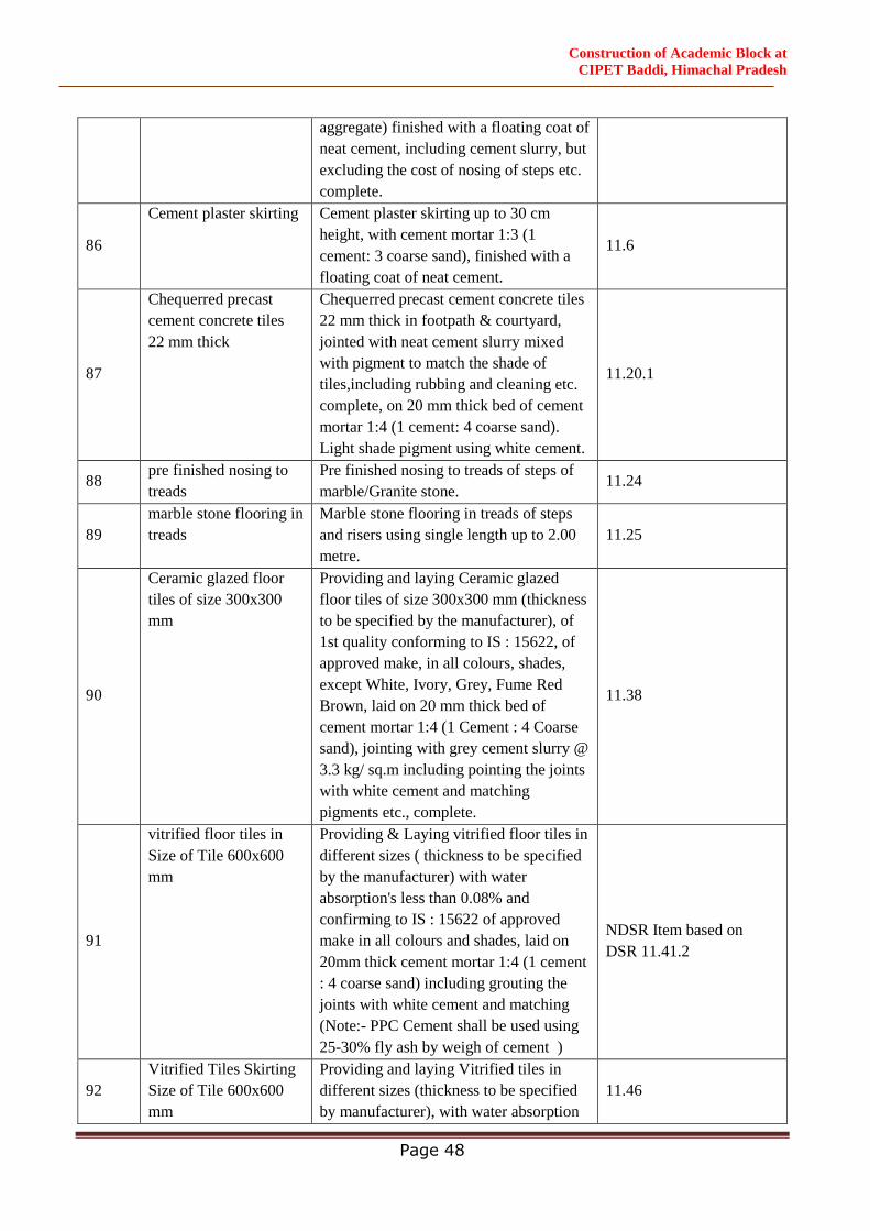
Construction of Academic Block at
CIPET Baddi, Himachal Pradesh
Page 48
aggregate) finished with a floating coat of
neat cement, including cement slurry, but
excluding the cost of nosing of steps etc.
complete.
86
Cement plaster skirting Cement plaster skirting up to 30 cm
height, with cement mortar 1:3 (1
cement: 3 coarse sand), finished with a
floating coat of neat cement.
11.6
87
Chequerred precast
cement concrete tiles
22 mm thick
Chequerred precast cement concrete tiles
22 mm thick in footpath & courtyard,
jointed with neat cement slurry mixed
with pigment to match the shade of
tiles,including rubbing and cleaning etc.
complete, on 20 mm thick bed of cement
mortar 1:4 (1 cement: 4 coarse sand).
Light shade pigment using white cement.
11.20.1
88 pre finished nosing to
treads
Pre finished nosing to treads of steps of
marble/Granite stone. 11.24
89
marble stone flooring in
treads
Marble stone flooring in treads of steps
and risers using single length up to 2.00
metre.
11.25
90
Ceramic glazed floor
tiles of size 300x300
mm
Providing and laying Ceramic glazed
floor tiles of size 300x300 mm (thickness
to be specified by the manufacturer), of
1st quality conforming to IS : 15622, of
approved make, in all colours, shades,
except White, Ivory, Grey, Fume Red
Brown, laid on 20 mm thick bed of
cement mortar 1:4 (1 Cement : 4 Coarse
sand), jointing with grey cement slurry @
3.3 kg/ sq.m including pointing the joints
with white cement and matching
pigments etc., complete.
11.38
91
vitrified floor tiles in
Size of Tile 600x600
mm
Providing & Laying vitrified floor tiles in
different sizes ( thickness to be specified
by the manufacturer) with water
absorption's less than 0.08% and
confirming to IS : 15622 of approved
make in all colours and shades, laid on
20mm thick cement mortar 1:4 (1 cement
: 4 coarse sand) including grouting the
joints with white cement and matching
(Note:- PPC Cement shall be used using
25-30% fly ash by weigh of cement )
NDSR Item based on
DSR 11.41.2
92
Vitrified Tiles Skirting
Size of Tile 600x600
mm
Providing and laying Vitrified tiles in
different sizes (thickness to be specified
by manufacturer), with water absorption
11.46
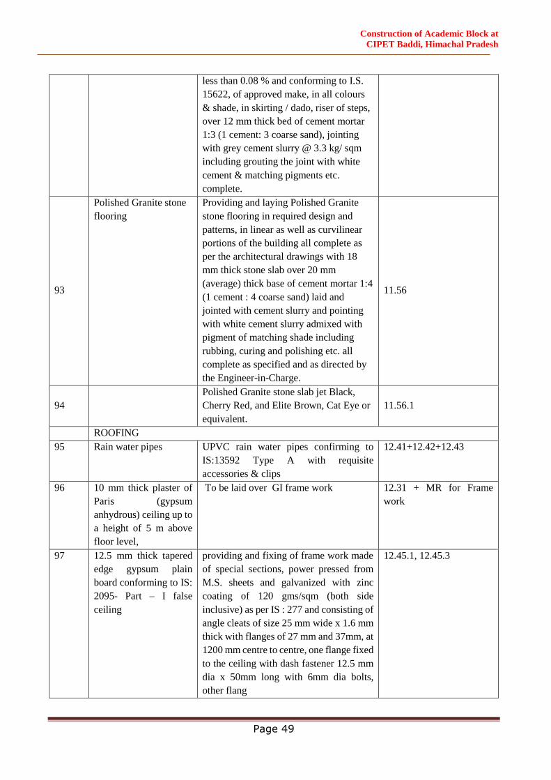
Construction of Academic Block at
CIPET Baddi, Himachal Pradesh
Page 49
less than 0.08 % and conforming to I.S.
15622, of approved make, in all colours
& shade, in skirting / dado, riser of steps,
over 12 mm thick bed of cement mortar
1:3 (1 cement: 3 coarse sand), jointing
with grey cement slurry @ 3.3 kg/ sqm
including grouting the joint with white
cement & matching pigments etc.
complete.
93
Polished Granite stone
flooring
Providing and laying Polished Granite
stone flooring in required design and
patterns, in linear as well as curvilinear
portions of the building all complete as
per the architectural drawings with 18
mm thick stone slab over 20 mm
(average) thick base of cement mortar 1:4
(1 cement : 4 coarse sand) laid and
jointed with cement slurry and pointing
with white cement slurry admixed with
pigment of matching shade including
rubbing, curing and polishing etc. all
complete as specified and as directed by
the Engineer-in-Charge.
11.56
94
Polished Granite stone slab jet Black,
Cherry Red, and Elite Brown, Cat Eye or
equivalent.
11.56.1
ROOFING
95 Rain water pipes UPVC rain water pipes confirming to
IS:13592 Type A with requisite
accessories & clips
12.41+12.42+12.43
96 10 mm thick plaster of
Paris (gypsum
anhydrous) ceiling up to
a height of 5 m above
floor level,
To be laid over GI frame work 12.31 + MR for Frame
work
97 12.5 mm thick tapered
edge gypsum plain
board conforming to IS:
2095- Part – I false
ceiling
providing and fixing of frame work made
of special sections, power pressed from
M.S. sheets and galvanized with zinc
coating of 120 gms/sqm (both side
inclusive) as per IS : 277 and consisting of
angle cleats of size 25 mm wide x 1.6 mm
thick with flanges of 27 mm and 37mm, at
1200 mm centre to centre, one flange fixed
to the ceiling with dash fastener 12.5 mm
dia x 50mm long with 6mm dia bolts,
other flang
12.45.1, 12.45.3
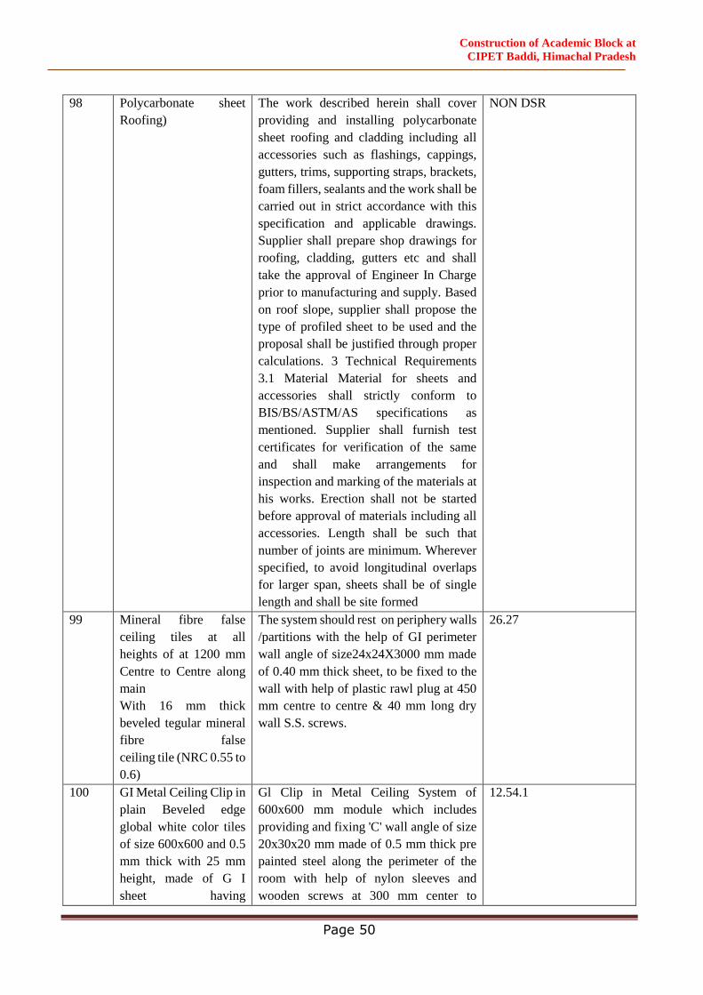
Construction of Academic Block at
CIPET Baddi, Himachal Pradesh
Page 50
98 Polycarbonate sheet
Roofing)
The work described herein shall cover
providing and installing polycarbonate
sheet roofing and cladding including all
accessories such as flashings, cappings,
gutters, trims, supporting straps, brackets,
foam fillers, sealants and the work shall be
carried out in strict accordance with this
specification and applicable drawings.
Supplier shall prepare shop drawings for
roofing, cladding, gutters etc and shall
take the approval of Engineer In Charge
prior to manufacturing and supply. Based
on roof slope, supplier shall propose the
type of profiled sheet to be used and the
proposal shall be justified through proper
calculations. 3 Technical Requirements
3.1 Material Material for sheets and
accessories shall strictly conform to
BIS/BS/ASTM/AS specifications as
mentioned. Supplier shall furnish test
certificates for verification of the same
and shall make arrangements for
inspection and marking of the materials at
his works. Erection shall not be started
before approval of materials including all
accessories. Length shall be such that
number of joints are minimum. Wherever
specified, to avoid longitudinal overlaps
for larger span, sheets shall be of single
length and shall be site formed
NON DSR
99 Mineral fibre false
ceiling tiles at all
heights of at 1200 mm
Centre to Centre along
main
With 16 mm thick
beveled tegular mineral
fibre false
ceiling tile (NRC 0.55 to
0.6)
The system should rest on periphery walls
/partitions with the help of GI perimeter
wall angle of size24x24X3000 mm made
of 0.40 mm thick sheet, to be fixed to the
wall with help of plastic rawl plug at 450
mm centre to centre & 40 mm long dry
wall S.S. screws.
26.27
100 GI Metal Ceiling Clip in
plain Beveled edge
global white color tiles
of size 600x600 and 0.5
mm thick with 25 mm
height, made of G I
sheet having
Gl Clip in Metal Ceiling System of
600x600 mm module which includes
providing and fixing 'C' wall angle of size
20x30x20 mm made of 0.5 mm thick pre
painted steel along the perimeter of the
room with help of nylon sleeves and
wooden screws at 300 mm center to
12.54.1
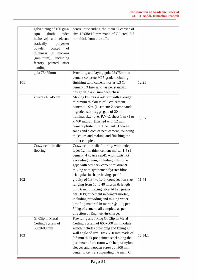
Construction of Academic Block at
CIPET Baddi, Himachal Pradesh
Page 51
galvanizing of 100 gms/
sqm (both sides
inclusive) and electro
statically polyester
powder coated of
thickness 60 microns
(minimum), including
factory painted after
bending.
centre, suspending the main C carrier of
size 10x38x10 mm made of G.I steel 0.7
mm thick from the soffit
101
gola 75x75mm Providing and laying gola 75x75mm in
cement concrete M15 grade including
finishing with cement mortar 1:3 (1
cement : 3 fine sand) as per standard
design in 75x75 mm deep chase.
12.21
khurras 45x45 cm Making khurras 45x45 cm with average
minimum thickness of 5 cm cement
concrete 1:2:4 (1 cement: 2 coarse sand:
4 graded stone aggregate of 20 mm
nominal size) over P.V.C. sheet 1 m x1 m
x 400 micron, finished with 12 mm
cement plaster 1:3 (1 cement: 3 coarse
sand) and a coat of neat cement, rounding
the edges and making and finishing the
outlet complete.
12.22
102
Crazy ceramic tile
flooring
Crazy ceramic tile flooring, with under
layer 12 mm thick cement mortar 1:4 (1
cement: 4 coarse sand), with joints not
exceeding 5 mm, including filling the
gaps with ordinary cement mixture &
mixing with synthetic polyester fibre,
triangular in shape having specific
gravity of 1.34 to 1.40, cross section size
ranging from 10 to 40 micron & length
upto 6 mm , mixing fibre @ 125 grams
per 50 kg of cement in cement mortar,
including providing and mixing water
proofing material in mortar @ 1 kg per
50 kg of cement, all complete as per
direction of Engineer-in-charge.
11.44
103
Gl Clip in Metal
Ceiling System of
600x600 mm
Providing and fixing Gl Clip in Metal
Ceiling System of 600x600 mm module
which includes providing and fixing 'C'
wall angle of size 20x30x20 mm made of
0.5 mm thick pre painted steel along the
perimeter of the room with help of nylon
sleeves and wooden screws at 300 mm
center to centre, suspending the main C
12.54.1
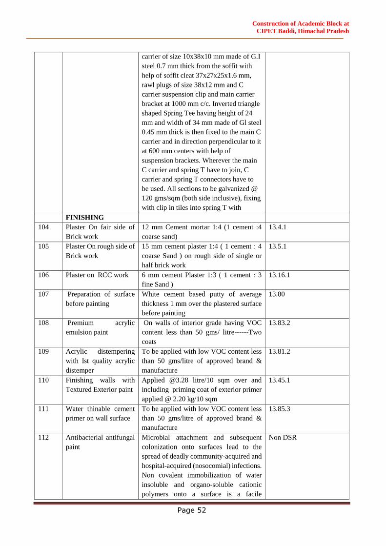
Construction of Academic Block at
CIPET Baddi, Himachal Pradesh
Page 52
carrier of size 10x38x10 mm made of G.I
steel 0.7 mm thick from the soffit with
help of soffit cleat 37x27x25x1.6 mm,
rawl plugs of size 38x12 mm and C
carrier suspension clip and main carrier
bracket at 1000 mm c/c. Inverted triangle
shaped Spring Tee having height of 24
mm and width of 34 mm made of Gl steel
0.45 mm thick is then fixed to the main C
carrier and in direction perpendicular to it
at 600 mm centers with help of
suspension brackets. Wherever the main
C carrier and spring T have to join, C
carrier and spring T connectors have to
be used. All sections to be galvanized @
120 gms/sqm (both side inclusive), fixing
with clip in tiles into spring T with
FINISHING
104 Plaster On fair side of
Brick work
12 mm Cement mortar 1:4 (1 cement :4
coarse sand)
13.4.1
105 Plaster On rough side of
Brick work
15 mm cement plaster 1:4 ( 1 cement : 4
coarse Sand ) on rough side of single or
half brick work
13.5.1
106 Plaster on RCC work 6 mm cement Plaster 1:3 ( 1 cement : 3
fine Sand )
13.16.1
107 Preparation of surface
before painting
White cement based putty of average
thickness 1 mm over the plastered surface
before painting
13.80
108 Premium acrylic
emulsion paint
On walls of interior grade having VOC
content less than 50 gms/ litre------Two
coats
13.83.2
109 Acrylic distempering
with Ist quality acrylic
distemper
To be applied with low VOC content less
than 50 gms/litre of approved brand &
manufacture
13.81.2
110 Finishing walls with
Textured Exterior paint
Applied @3.28 litre/10 sqm over and
including priming coat of exterior primer
applied @ 2.20 kg/10 sqm
13.45.1
111 Water thinable cement
primer on wall surface
To be applied with low VOC content less
than 50 gms/litre of approved brand &
manufacture
13.85.3
112 Antibacterial antifungal
paint
Microbial attachment and subsequent
colonization onto surfaces lead to the
spread of deadly community-acquired and
hospital-acquired (nosocomial) infections.
Non covalent immobilization of water
insoluble and organo-soluble cationic
polymers onto a surface is a facile
Non DSR
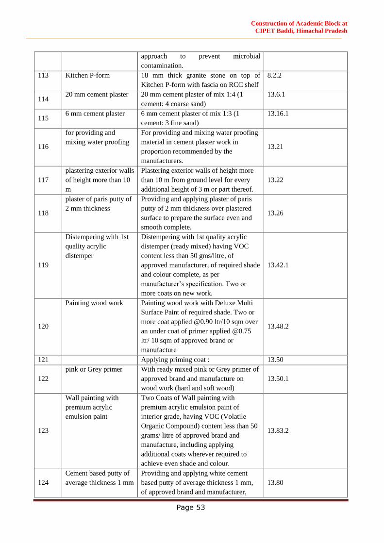
Construction of Academic Block at
CIPET Baddi, Himachal Pradesh
Page 53
approach to prevent microbial
contamination.
113 Kitchen P-form 18 mm thick granite stone on top of
Kitchen P-form with fascia on RCC shelf
8.2.2
114 20 mm cement plaster 20 mm cement plaster of mix 1:4 (1
cement: 4 coarse sand)
13.6.1
115 6 mm cement plaster 6 mm cement plaster of mix 1:3 (1
cement: 3 fine sand)
13.16.1
116
for providing and
mixing water proofing
For providing and mixing water proofing
material in cement plaster work in
proportion recommended by the
manufacturers.
13.21
117
plastering exterior walls
of height more than 10
m
Plastering exterior walls of height more
than 10 m from ground level for every
additional height of 3 m or part thereof.
13.22
118
plaster of paris putty of
2 mm thickness
Providing and applying plaster of paris
putty of 2 mm thickness over plastered
surface to prepare the surface even and
smooth complete.
13.26
119
Distempering with 1st
quality acrylic
distemper
Distempering with 1st quality acrylic
distemper (ready mixed) having VOC
content less than 50 gms/litre, of
approved manufacturer, of required shade
and colour complete, as per
manufacturer’s specification. Two or
more coats on new work.
13.42.1
120
Painting wood work Painting wood work with Deluxe Multi
Surface Paint of required shade. Two or
more coat applied @0.90 ltr/10 sqm over
an under coat of primer applied @0.75
ltr/ 10 sqm of approved brand or
manufacture
13.48.2
121 Applying priming coat : 13.50
122
pink or Grey primer With ready mixed pink or Grey primer of
approved brand and manufacture on
wood work (hard and soft wood)
13.50.1
123
Wall painting with
premium acrylic
emulsion paint
Two Coats of Wall painting with
premium acrylic emulsion paint of
interior grade, having VOC (Volatile
Organic Compound) content less than 50
grams/ litre of approved brand and
manufacture, including applying
additional coats wherever required to
achieve even shade and colour.
13.83.2
124
Cement based putty of
average thickness 1 mm
Providing and applying white cement
based putty of average thickness 1 mm,
of approved brand and manufacturer,
13.80
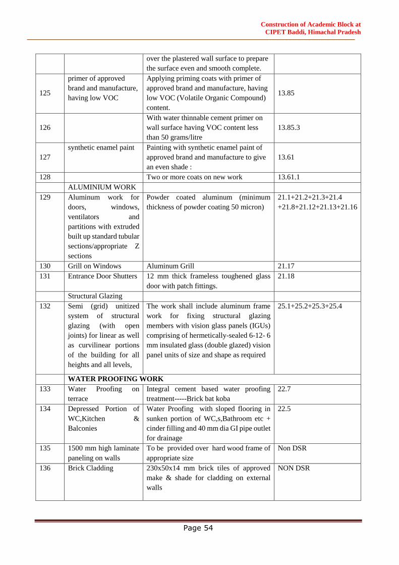
Construction of Academic Block at
CIPET Baddi, Himachal Pradesh
Page 54
over the plastered wall surface to prepare
the surface even and smooth complete.
125
primer of approved
brand and manufacture,
having low VOC
Applying priming coats with primer of
approved brand and manufacture, having
low VOC (Volatile Organic Compound)
content.
13.85
126
With water thinnable cement primer on
wall surface having VOC content less
than 50 grams/litre
13.85.3
127
synthetic enamel paint Painting with synthetic enamel paint of
approved brand and manufacture to give
an even shade :
13.61
128 Two or more coats on new work 13.61.1
ALUMINIUM WORK
129 Aluminum work for
doors, windows,
ventilators and
partitions with extruded
built up standard tubular
sections/appropriate Z
sections
Powder coated aluminum (minimum
thickness of powder coating 50 micron)
21.1+21.2+21.3+21.4
+21.8+21.12+21.13+21.16
130 Grill on Windows Aluminum Grill 21.17
131 Entrance Door Shutters 12 mm thick frameless toughened glass
door with patch fittings.
21.18
Structural Glazing
132 Semi (grid) unitized
system of structural
glazing (with open
joints) for linear as well
as curvilinear portions
of the building for all
heights and all levels,
The work shall include aluminum frame
work for fixing structural glazing
members with vision glass panels (IGUs)
comprising of hermetically-sealed 6-12- 6
mm insulated glass (double glazed) vision
panel units of size and shape as required
25.1+25.2+25.3+25.4
WATER PROOFING WORK
133 Water Proofing on
terrace
Integral cement based water proofing
treatment-----Brick bat koba
22.7
134 Depressed Portion of
WC,Kitchen &
Balconies
Water Proofing with sloped flooring in
sunken portion of WC,s,Bathroom etc +
cinder filling and 40 mm dia GI pipe outlet
for drainage
22.5
135 1500 mm high laminate
paneling on walls
To be provided over hard wood frame of
appropriate size
Non DSR
136 Brick Cladding 230x50x14 mm brick tiles of approved
make & shade for cladding on external
walls
NON DSR
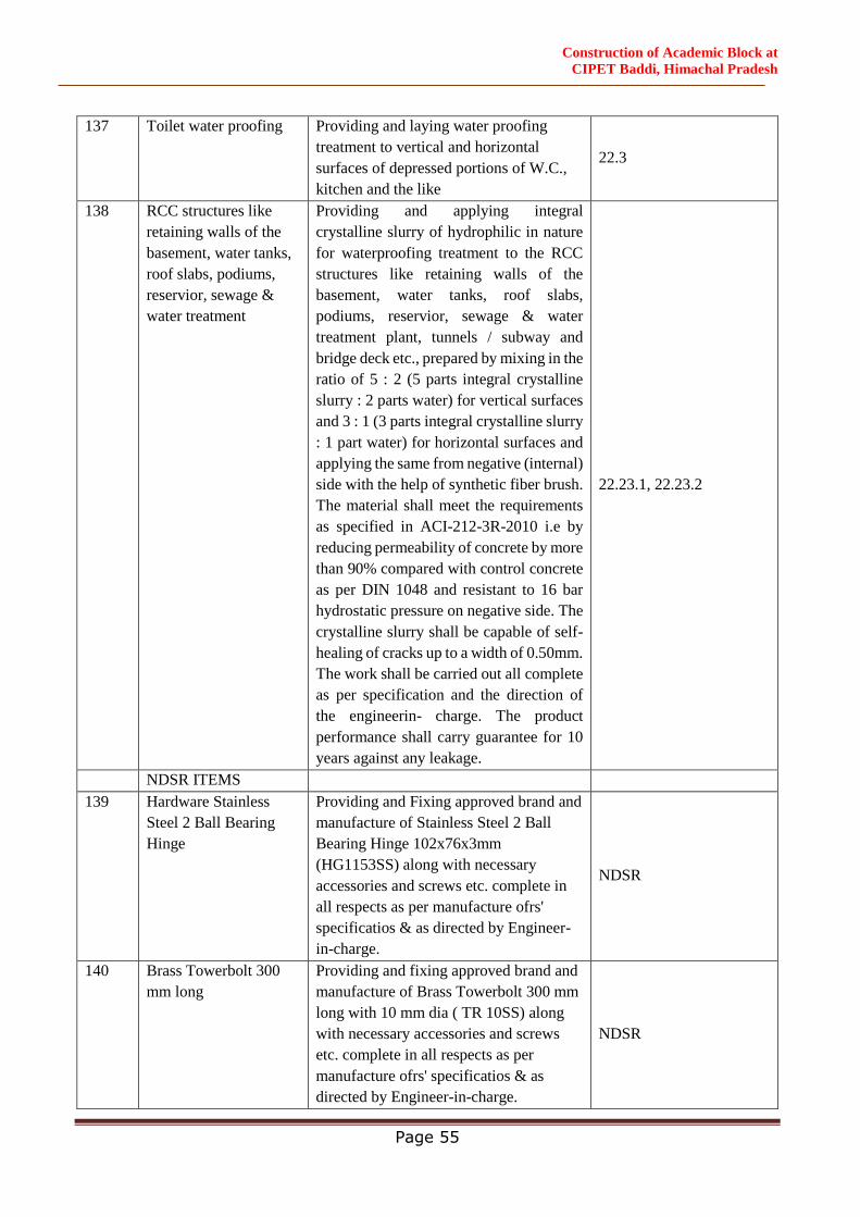
Construction of Academic Block at
CIPET Baddi, Himachal Pradesh
Page 55
137 Toilet water proofing Providing and laying water proofing
treatment to vertical and horizontal
surfaces of depressed portions of W.C.,
kitchen and the like
22.3
138 RCC structures like
retaining walls of the
basement, water tanks,
roof slabs, podiums,
reservior, sewage &
water treatment
Providing and applying integral
crystalline slurry of hydrophilic in nature
for waterproofing treatment to the RCC
structures like retaining walls of the
basement, water tanks, roof slabs,
podiums, reservior, sewage & water
treatment plant, tunnels / subway and
bridge deck etc., prepared by mixing in the
ratio of 5 : 2 (5 parts integral crystalline
slurry : 2 parts water) for vertical surfaces
and 3 : 1 (3 parts integral crystalline slurry
: 1 part water) for horizontal surfaces and
applying the same from negative (internal)
side with the help of synthetic fiber brush.
The material shall meet the requirements
as specified in ACI-212-3R-2010 i.e by
reducing permeability of concrete by more
than 90% compared with control concrete
as per DIN 1048 and resistant to 16 bar
hydrostatic pressure on negative side. The
crystalline slurry shall be capable of self-
healing of cracks up to a width of 0.50mm.
The work shall be carried out all complete
as per specification and the direction of
the engineerin- charge. The product
performance shall carry guarantee for 10
years against any leakage.
22.23.1, 22.23.2
NDSR ITEMS
139 Hardware Stainless
Steel 2 Ball Bearing
Hinge
Providing and Fixing approved brand and
manufacture of Stainless Steel 2 Ball
Bearing Hinge 102x76x3mm
(HG1153SS) along with necessary
accessories and screws etc. complete in
all respects as per manufacture ofrs'
specificatios & as directed by Engineer-
in-charge.
NDSR
140 Brass Towerbolt 300
mm long
Providing and fixing approved brand and
manufacture of Brass Towerbolt 300 mm
long with 10 mm dia ( TR 10SS) along
with necessary accessories and screws
etc. complete in all respects as per
manufacture ofrs' specificatios & as
directed by Engineer-in-charge.
NDSR
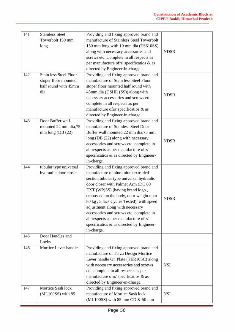
Construction of Academic Block at
CIPET Baddi, Himachal Pradesh
Page 56
141 Stainless Steel
Towerbolt 150 mm
long
Providing and fixing approved brand and
manufacture of Stainless Steel Towerbolt
150 mm long with 10 mm dia (TS610SS)
along with necessary accessories and
screws etc. Complete in all respects as
per manufacture ofrs' specificatios & as
directed by Engineer-in-charge.
NDSR
142 Stain less Steel Floor
stoper floor mounted
half round with 45mm
dia
Providing and fixing approved brand and
manufacture of Stain less Steel Floor
stoper floor mounted half round with
45mm dia (DSHR (SS)) along with
necessary accessories and screws etc.
complete in all respects as per
manufacture ofrs' specificatios & as
directed by Engineer-in-charge.
NDSR
143 Door Buffer wall
mounted 22 mm dia,75
mm long (DB (22)
Providing and fixing approved brand and
manufacture of Stainless Steel Door
Buffer wall mounted 22 mm dia,75 mm
long (DB (22) along with necessary
accessories and screws etc. complete in
all respects as per manufacture ofrs'
specificatios & as directed by Engineer-
in-charge.
NDSR
144 tubular type universal
hydraulic door closer
Providing and fixing approved brand and
manufacture of aluminium extruded
section tubular type universal hydraulic
door closer with Palmet Arm (DC 80
EXT (WP)SS) (having brand logo ,
embossed on the body, door weight upto
80 kg , 5 lacs Cycles Tested), with speed
adjustment along with necessary
accessories and screws etc. complete in
all respects as per manufacture ofrs'
specificatios & as directed by Engineer-
in-charge.
NDSR
145 Door Handles and
Locks
146 Mortice Lever handle Providing and fixing approved brand and
manufacture of Terza Design Mortice
Lever handle On Plate (TER10SC) along
with necessary accessories and screws
etc. complete in all respects as per
manufacture ofrs' specificatios & as
directed by Engineer-in-charge.
NSI
147 Mortice Sash lock
(ML100SS) with 85
Providing and fixing approved brand and
manufacture of Mortice Sash lock
(ML100SS) with 85 mm CD & 50 mm
NSI
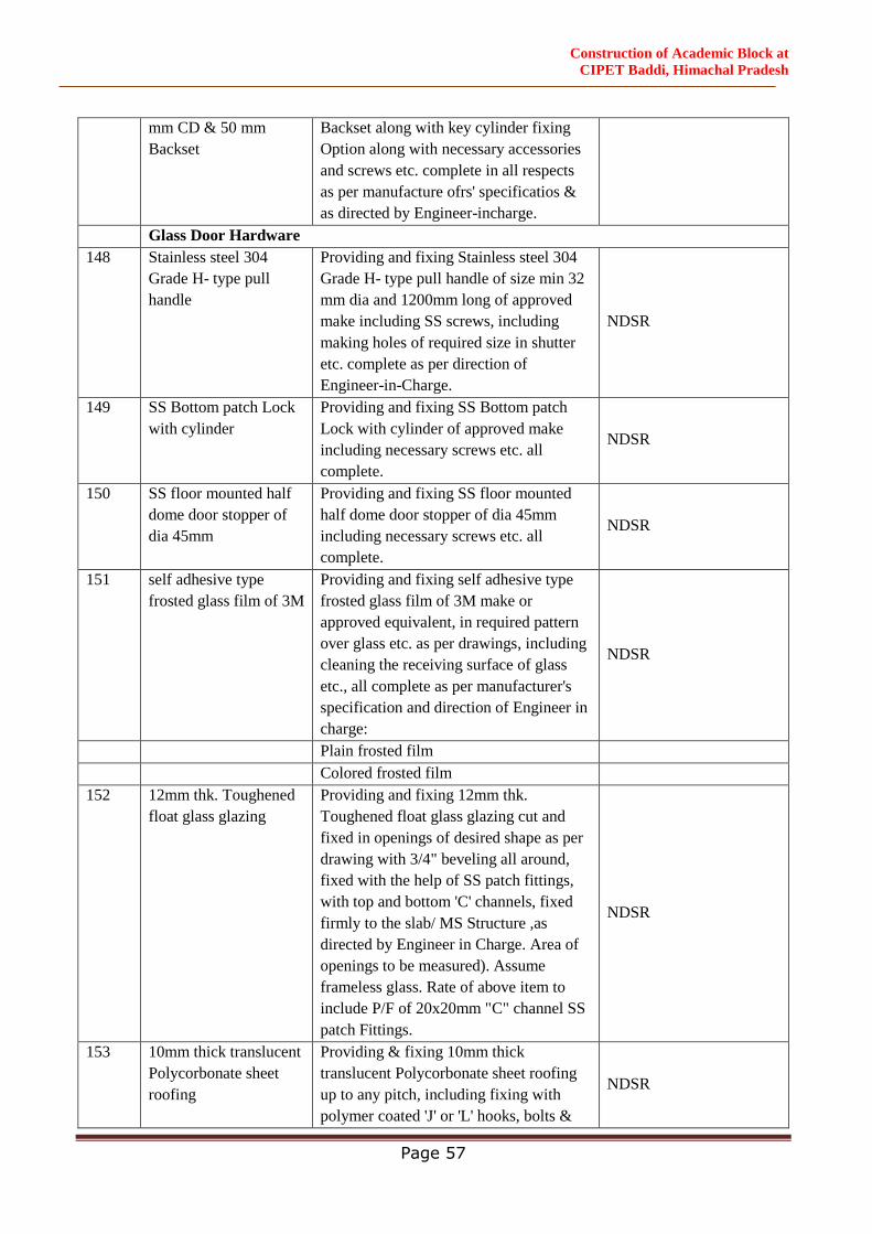
Construction of Academic Block at
CIPET Baddi, Himachal Pradesh
Page 57
mm CD & 50 mm
Backset
Backset along with key cylinder fixing
Option along with necessary accessories
and screws etc. complete in all respects
as per manufacture ofrs' specificatios &
as directed by Engineer-incharge.
Glass Door Hardware
148 Stainless steel 304
Grade H- type pull
handle
Providing and fixing Stainless steel 304
Grade H- type pull handle of size min 32
mm dia and 1200mm long of approved
make including SS screws, including
making holes of required size in shutter
etc. complete as per direction of
Engineer-in-Charge.
NDSR
149 SS Bottom patch Lock
with cylinder
Providing and fixing SS Bottom patch
Lock with cylinder of approved make
including necessary screws etc. all
complete.
NDSR
150 SS floor mounted half
dome door stopper of
dia 45mm
Providing and fixing SS floor mounted
half dome door stopper of dia 45mm
including necessary screws etc. all
complete.
NDSR
151 self adhesive type
frosted glass film of 3M
Providing and fixing self adhesive type
frosted glass film of 3M make or
approved equivalent, in required pattern
over glass etc. as per drawings, including
cleaning the receiving surface of glass
etc., all complete as per manufacturer's
specification and direction of Engineer in
charge:
NDSR
Plain frosted film
Colored frosted film
152 12mm thk. Toughened
float glass glazing
Providing and fixing 12mm thk.
Toughened float glass glazing cut and
fixed in openings of desired shape as per
drawing with 3/4" beveling all around,
fixed with the help of SS patch fittings,
with top and bottom 'C' channels, fixed
firmly to the slab/ MS Structure ,as
directed by Engineer in Charge. Area of
openings to be measured). Assume
frameless glass. Rate of above item to
include P/F of 20x20mm "C" channel SS
patch Fittings.
NDSR
153 10mm thick translucent
Polycorbonate sheet
roofing
Providing & fixing 10mm thick
translucent Polycorbonate sheet roofing
up to any pitch, including fixing with
polymer coated 'J' or 'L' hooks, bolts &
NDSR
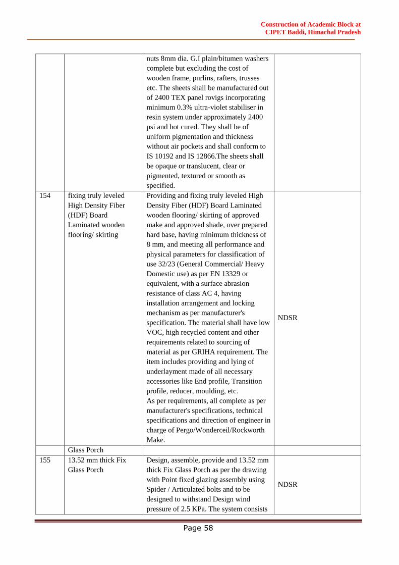
Construction of Academic Block at
CIPET Baddi, Himachal Pradesh
Page 58
nuts 8mm dia. G.I plain/bitumen washers
complete but excluding the cost of
wooden frame, purlins, rafters, trusses
etc. The sheets shall be manufactured out
of 2400 TEX panel rovigs incorporating
minimum 0.3% ultra-violet stabiliser in
resin system under approximately 2400
psi and hot cured. They shall be of
uniform pigmentation and thickness
without air pockets and shall conform to
IS 10192 and IS 12866.The sheets shall
be opaque or translucent, clear or
pigmented, textured or smooth as
specified.
154 fixing truly leveled
High Density Fiber
(HDF) Board
Laminated wooden
flooring/ skirting
Providing and fixing truly leveled High
Density Fiber (HDF) Board Laminated
wooden flooring/ skirting of approved
make and approved shade, over prepared
hard base, having minimum thickness of
8 mm, and meeting all performance and
physical parameters for classification of
use 32/23 (General Commercial/ Heavy
Domestic use) as per EN 13329 or
equivalent, with a surface abrasion
resistance of class AC 4, having
installation arrangement and locking
mechanism as per manufacturer's
specification. The material shall have low
VOC, high recycled content and other
requirements related to sourcing of
material as per GRIHA requirement. The
item includes providing and lying of
underlayment made of all necessary
accessories like End profile, Transition
profile, reducer, moulding, etc.
As per requirements, all complete as per
manufacturer's specifications, technical
specifications and direction of engineer in
charge of Pergo/Wonderceil/Rockworth
Make.
NDSR
Glass Porch
155 13.52 mm thick Fix
Glass Porch
Design, assemble, provide and 13.52 mm
thick Fix Glass Porch as per the drawing
with Point fixed glazing assembly using
Spider / Articulated bolts and to be
designed to withstand Design wind
pressure of 2.5 KPa. The system consists
NDSR
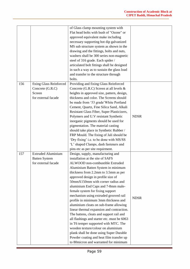
Construction of Academic Block at
CIPET Baddi, Himachal Pradesh
Page 59
of Glass clamp mounting system with
Flat head bolts with bush of "Ozone" or
approved equivalent make including
necessary supporting hot dip galvanized
MS sub structure system as shown in the
drawing and the fittings, bolts and nuts,
washers shall be 300 series non-magnetic
steel of 316 grade. Each spider /
articulated bolt fittings shall be designed
in such a way as to sustain the glass load
and transfer to the structure through
bolts.
156 fixing Glass Reinforced
Concrete (G.R.C)
Screen
for external facade
Providing and fixing Glass Reinforced
Concrete (G.R.C) Screen at all levels &
heights in approved size, pattern, design,
thickness and color. The Screens should
be made from ‘53 grade’White Portland
Cement, Quartz, Fine Silica Sand, Alkali
Resistant Glass Fiber, Super Plasticizers,
Polymers and U.V resistant Synthetic
inorganic pigments should be used for
pigmentation. The material casting
should take place in Synthetic Rubber /
FRP Mould. The fixing of Jali should be
‘Dry fixing’ i.e. to be done with MS/SS
‘L’ shaped Clamps, dash fasteners and
pins etc as per site requirment.
NDSR
157 Extruded Aluminium
Batten System
for external facade
Design, supply, manufacturing and
installation at the site of SAFS
ALWOOD non-combustible Extruded
Aluminium Batten System in minimum
thickness from 2.2mm to 3.5mm as per
approved design in profile size of
50mmX150mm with corner radius and
aluminium End Caps and 7-8mm male-
female system for fixing support
mechanism using extruded grooved rail
profile in minimum 3mm thickness and
aluminium cleats on sub-frame allowing
linear thermal expansion and contraction.
The battens, cleats and support rail and
all flashings and starter etc. must be 6063
in T6 temper supported with MTC. The
wooden texture/colour on aluminium
plank shall be done using Super Durable
Powder coating and heat film transfer up
to 80micron and warranted for minimum
NDSR
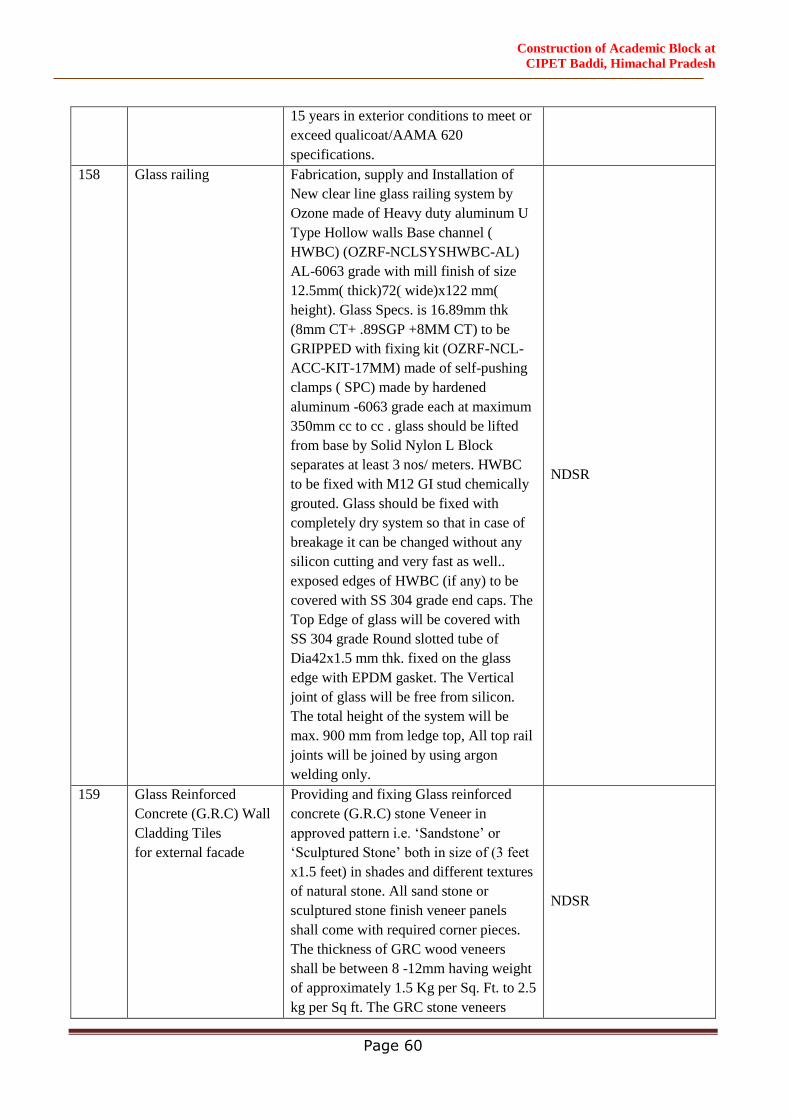
Construction of Academic Block at
CIPET Baddi, Himachal Pradesh
Page 60
15 years in exterior conditions to meet or
exceed qualicoat/AAMA 620
specifications.
158 Glass railing Fabrication, supply and Installation of
New clear line glass railing system by
Ozone made of Heavy duty aluminum U
Type Hollow walls Base channel (
HWBC) (OZRF-NCLSYSHWBC-AL)
AL-6063 grade with mill finish of size
12.5mm( thick)72( wide)x122 mm(
height). Glass Specs. is 16.89mm thk
(8mm CT+ .89SGP +8MM CT) to be
GRIPPED with fixing kit (OZRF-NCL-
ACC-KIT-17MM) made of self-pushing
clamps ( SPC) made by hardened
aluminum -6063 grade each at maximum
350mm cc to cc . glass should be lifted
from base by Solid Nylon L Block
separates at least 3 nos/ meters. HWBC
to be fixed with M12 GI stud chemically
grouted. Glass should be fixed with
completely dry system so that in case of
breakage it can be changed without any
silicon cutting and very fast as well..
exposed edges of HWBC (if any) to be
covered with SS 304 grade end caps. The
Top Edge of glass will be covered with
SS 304 grade Round slotted tube of
Dia42x1.5 mm thk. fixed on the glass
edge with EPDM gasket. The Vertical
joint of glass will be free from silicon.
The total height of the system will be
max. 900 mm from ledge top, All top rail
joints will be joined by using argon
welding only.
NDSR
159 Glass Reinforced
Concrete (G.R.C) Wall
Cladding Tiles
for external facade
Providing and fixing Glass reinforced
concrete (G.R.C) stone Veneer in
approved pattern i.e. ‘Sandstone’ or
‘Sculptured Stone’ both in size of (3 feet
x1.5 feet) in shades and different textures
of natural stone. All sand stone or
sculptured stone finish veneer panels
shall come with required corner pieces.
The thickness of GRC wood veneers
shall be between 8 -12mm having weight
of approximately 1.5 Kg per Sq. Ft. to 2.5
kg per Sq ft. The GRC stone veneers
NDSR
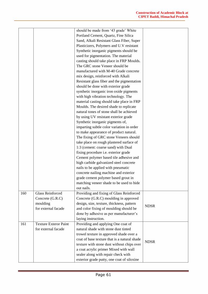
Construction of Academic Block at
CIPET Baddi, Himachal Pradesh
Page 61
should be made from ‘43 grade’ White
Portland Cement, Quartz, Fine Silica
Sand, Alkali Resistant Glass Fiber, Super
Plasticizers, Polymers and U.V resistant
Synthetic inorganic pigments should be
used for pigmentation. The material
casting should take place in FRP Moulds.
The GRC stone Veneer should be
manufactured with M-40 Grade concrete
mix design, reinforced with Alkali
Resistant glass fiber and the pigmentation
should be done with exterior grade
synthetic inorganic iron oxide pigments
with high vibration technology. The
material casting should take place in FRP
Moulds. The desired shade to replicate
natural tones of stone shall be achieved
by using UV resistant exterior grade
Synthetic inorganic pigments of,
imparting subtle color variation in order
to make appearance of product natural.
The fixing of GRC stone Veneers should
take place on rough plastered surface of
1:3 (cement: coarse sand) with Dual
fixing procedure i.e. exterior grade
Cement polymer based tile adhesive and
high carbide galvanized steel concrete
nails to be applied with pneumatic
concrete nailing machine and exterior
grade cement polymer based grout in
matching veneer shade to be used to hide
out nails.
160 Glass Reinforced
Concrete (G.R.C)
moulding
for external facade
Providing and fixing of Glass Reinforced
Concrete (G.R.C) moulding in approved
design, size, texture, thickness, pattern
and color fixing of moulding should be
done by adhesive as per manufacturer’s
laying instruction.
NDSR
161 Texture Exteror Paint
for external facade
Providing and applying One coat of
natural shade with stone dust tinted
trowel texture in approved shade over a
coat of base texture that is a natural shade
texture with stone dust without chips over
a coat acrylic primer Mixed with wall
sealer along with repair check with
exterior grade putty, one coat of siloxine
NDSR
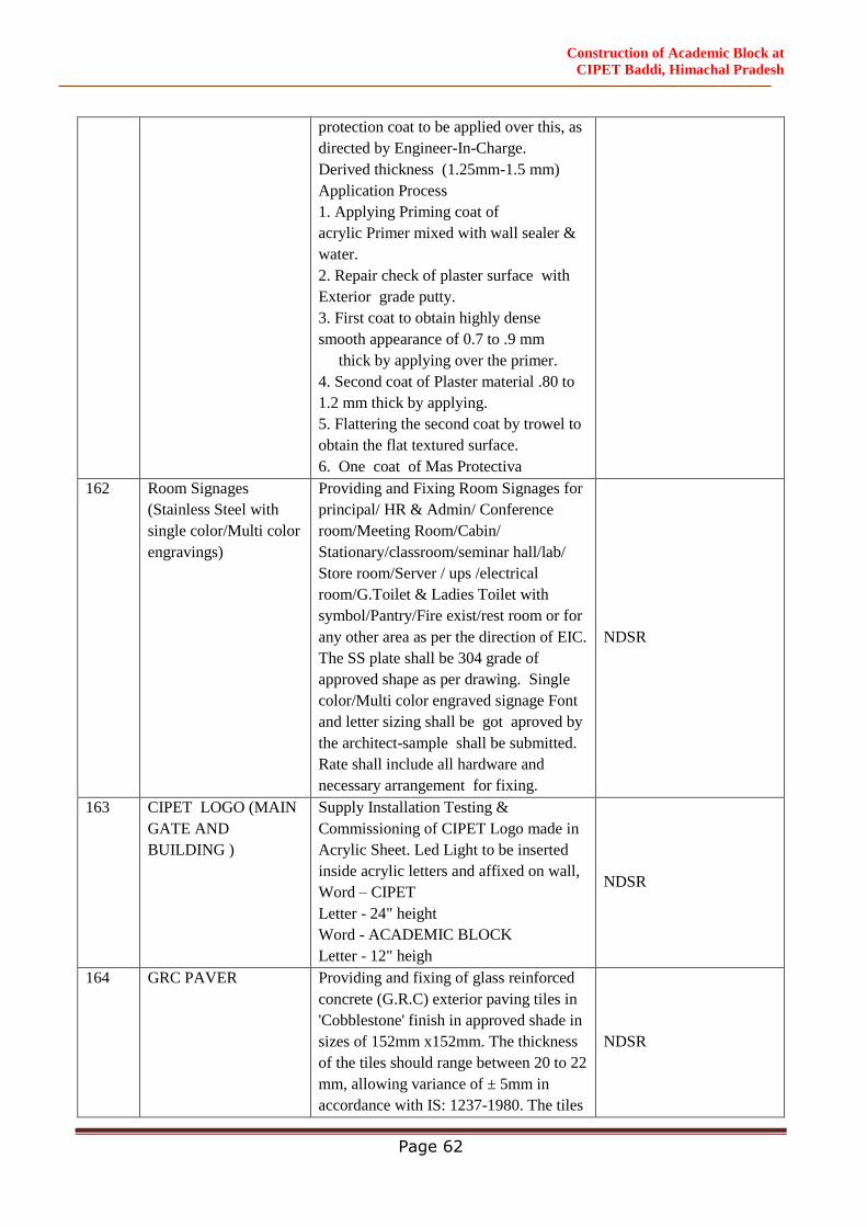
Construction of Academic Block at
CIPET Baddi, Himachal Pradesh
Page 62
protection coat to be applied over this, as
directed by Engineer-In-Charge.
Derived thickness (1.25mm-1.5 mm)
Application Process
1. Applying Priming coat of
acrylic Primer mixed with wall sealer &
water.
2. Repair check of plaster surface with
Exterior grade putty.
3. First coat to obtain highly dense
smooth appearance of 0.7 to .9 mm
thick by applying over the primer.
4. Second coat of Plaster material .80 to
1.2 mm thick by applying.
5. Flattering the second coat by trowel to
obtain the flat textured surface.
6. One coat of Mas Protectiva
162 Room Signages
(Stainless Steel with
single color/Multi color
engravings)
Providing and Fixing Room Signages for
principal/ HR & Admin/ Conference
room/Meeting Room/Cabin/
Stationary/classroom/seminar hall/lab/
Store room/Server / ups /electrical
room/G.Toilet & Ladies Toilet with
symbol/Pantry/Fire exist/rest room or for
any other area as per the direction of EIC.
The SS plate shall be 304 grade of
approved shape as per drawing. Single
color/Multi color engraved signage Font
and letter sizing shall be got aproved by
the architect-sample shall be submitted.
Rate shall include all hardware and
necessary arrangement for fixing.
NDSR
163 CIPET LOGO (MAIN
GATE AND
BUILDING )
Supply Installation Testing &
Commissioning of CIPET Logo made in
Acrylic Sheet. Led Light to be inserted
inside acrylic letters and affixed on wall,
Word – CIPET
Letter - 24" height
Word - ACADEMIC BLOCK
Letter - 12" heigh
NDSR
164 GRC PAVER Providing and fixing of glass reinforced
concrete (G.R.C) exterior paving tiles in
'Cobblestone' finish in approved shade in
sizes of 152mm x152mm. The thickness
of the tiles should range between 20 to 22
mm, allowing variance of ± 5mm in
accordance with IS: 1237-1980. The tiles
NDSR
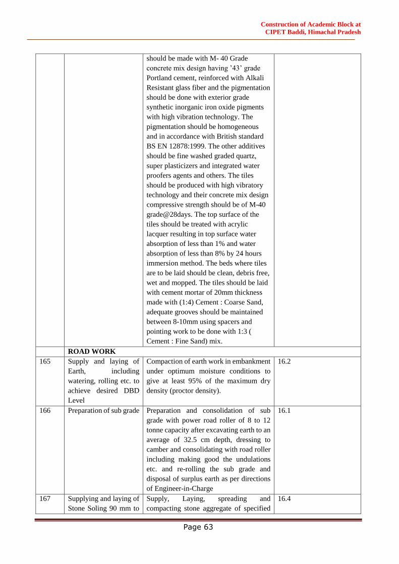
Construction of Academic Block at
CIPET Baddi, Himachal Pradesh
Page 63
should be made with M- 40 Grade
concrete mix design having ’43’ grade
Portland cement, reinforced with Alkali
Resistant glass fiber and the pigmentation
should be done with exterior grade
synthetic inorganic iron oxide pigments
with high vibration technology. The
pigmentation should be homogeneous
and in accordance with British standard
BS EN 12878:1999. The other additives
should be fine washed graded quartz,
super plasticizers and integrated water
proofers agents and others. The tiles
should be produced with high vibratory
technology and their concrete mix design
compressive strength should be of M-40
grade@28days. The top surface of the
tiles should be treated with acrylic
lacquer resulting in top surface water
absorption of less than 1% and water
absorption of less than 8% by 24 hours
immersion method. The beds where tiles
are to be laid should be clean, debris free,
wet and mopped. The tiles should be laid
with cement mortar of 20mm thickness
made with (1:4) Cement : Coarse Sand,
adequate grooves should be maintained
between 8-10mm using spacers and
pointing work to be done with 1:3 (
Cement : Fine Sand) mix.
ROAD WORK
165 Supply and laying of
Earth, including
watering, rolling etc. to
achieve desired DBD
Level
Compaction of earth work in embankment
under optimum moisture conditions to
give at least 95% of the maximum dry
density (proctor density).
16.2
166 Preparation of sub grade Preparation and consolidation of sub
grade with power road roller of 8 to 12
tonne capacity after excavating earth to an
average of 32.5 cm depth, dressing to
camber and consolidating with road roller
including making good the undulations
etc. and re-rolling the sub grade and
disposal of surplus earth as per directions
of Engineer-in-Charge
16.1
167 Supplying and laying of
Stone Soling 90 mm to
Supply, Laying, spreading and
compacting stone aggregate of specified
16.4
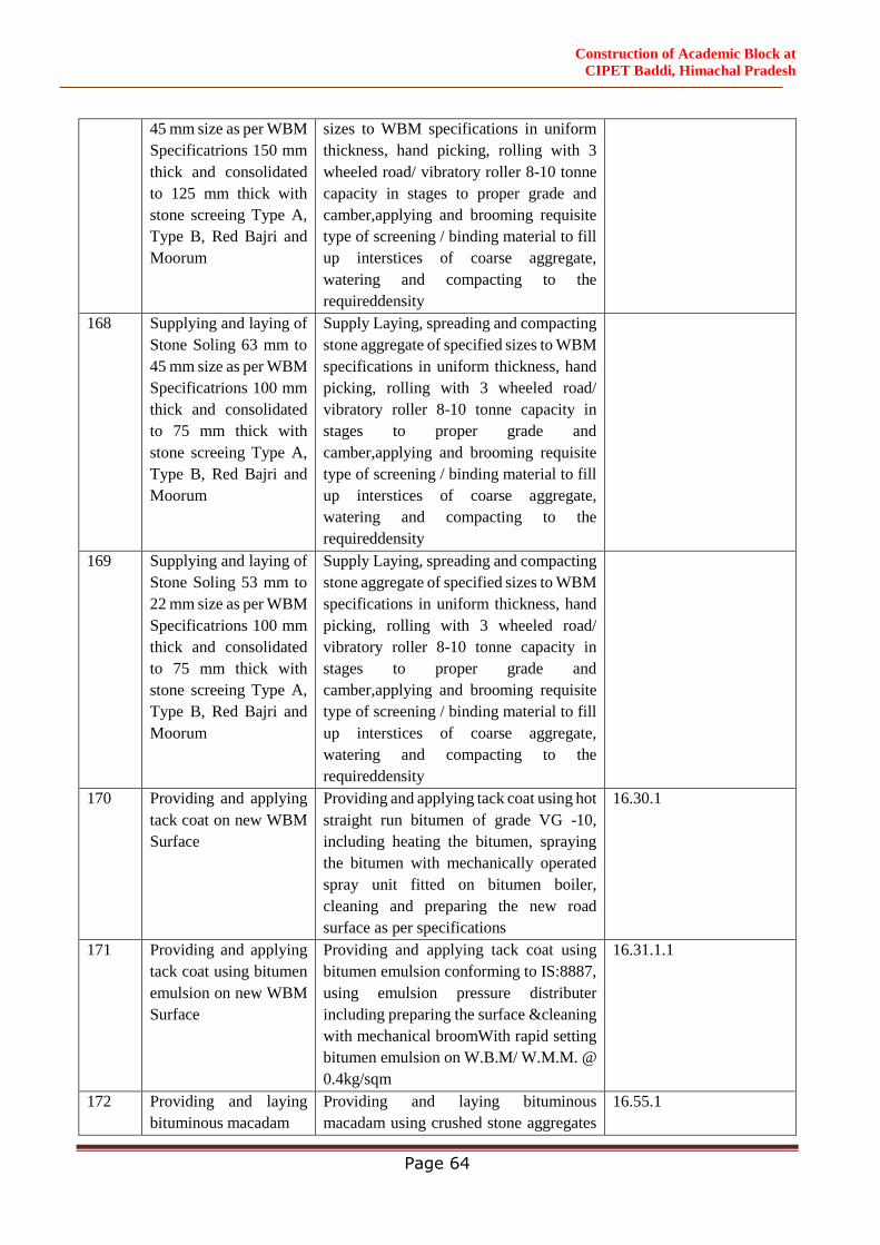
Construction of Academic Block at
CIPET Baddi, Himachal Pradesh
Page 64
45 mm size as per WBM
Specificatrions 150 mm
thick and consolidated
to 125 mm thick with
stone screeing Type A,
Type B, Red Bajri and
Moorum
sizes to WBM specifications in uniform
thickness, hand picking, rolling with 3
wheeled road/ vibratory roller 8-10 tonne
capacity in stages to proper grade and
camber,applying and brooming requisite
type of screening / binding material to fill
up interstices of coarse aggregate,
watering and compacting to the
requireddensity
168 Supplying and laying of
Stone Soling 63 mm to
45 mm size as per WBM
Specificatrions 100 mm
thick and consolidated
to 75 mm thick with
stone screeing Type A,
Type B, Red Bajri and
Moorum
Supply Laying, spreading and compacting
stone aggregate of specified sizes to WBM
specifications in uniform thickness, hand
picking, rolling with 3 wheeled road/
vibratory roller 8-10 tonne capacity in
stages to proper grade and
camber,applying and brooming requisite
type of screening / binding material to fill
up interstices of coarse aggregate,
watering and compacting to the
requireddensity
169 Supplying and laying of
Stone Soling 53 mm to
22 mm size as per WBM
Specificatrions 100 mm
thick and consolidated
to 75 mm thick with
stone screeing Type A,
Type B, Red Bajri and
Moorum
Supply Laying, spreading and compacting
stone aggregate of specified sizes to WBM
specifications in uniform thickness, hand
picking, rolling with 3 wheeled road/
vibratory roller 8-10 tonne capacity in
stages to proper grade and
camber,applying and brooming requisite
type of screening / binding material to fill
up interstices of coarse aggregate,
watering and compacting to the
requireddensity
170 Providing and applying
tack coat on new WBM
Surface
Providing and applying tack coat using hot
straight run bitumen of grade VG -10,
including heating the bitumen, spraying
the bitumen with mechanically operated
spray unit fitted on bitumen boiler,
cleaning and preparing the new road
surface as per specifications
16.30.1
171 Providing and applying
tack coat using bitumen
emulsion on new WBM
Surface
Providing and applying tack coat using
bitumen emulsion conforming to IS:8887,
using emulsion pressure distributer
including preparing the surface &cleaning
with mechanical broomWith rapid setting
bitumen emulsion on W.B.M/ W.M.M. @
0.4kg/sqm
16.31.1.1
172 Providing and laying
bituminous macadam
Providing and laying bituminous
macadam using crushed stone aggregates
16.55.1
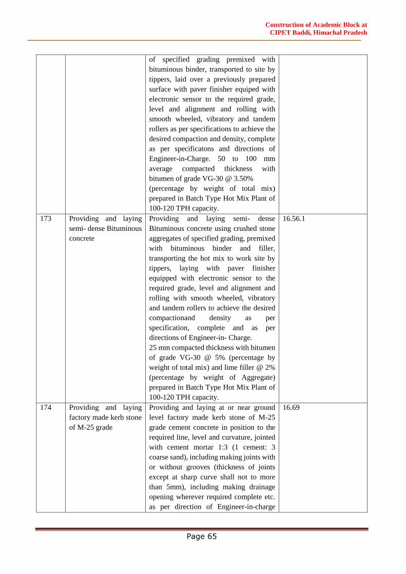
Construction of Academic Block at
CIPET Baddi, Himachal Pradesh
Page 65
of specified grading premixed with
bituminous binder, transported to site by
tippers, laid over a previously prepared
surface with paver finisher equiped with
electronic sensor to the required grade,
level and alignment and rolling with
smooth wheeled, vibratory and tandem
rollers as per specifications to achieve the
desired compaction and density, complete
as per specificatons and directions of
Engineer-in-Charge. 50 to 100 mm
average compacted thickness with
bitumen of grade VG-30 @ 3.50%
(percentage by weight of total mix)
prepared in Batch Type Hot Mix Plant of
100-120 TPH capacity.
173 Providing and laying
semi- dense Bituminous
concrete
Providing and laying semi- dense
Bituminous concrete using crushed stone
aggregates of specified grading, premixed
with bituminous binder and filler,
transporting the hot mix to work site by
tippers, laying with paver finisher
equipped with electronic sensor to the
required grade, level and alignment and
rolling with smooth wheeled, vibratory
and tandem rollers to achieve the desired
compactionand density as per
specification, complete and as per
directions of Engineer-in- Charge.
25 mm compacted thickness with bitumen
of grade VG-30 @ 5% (percentage by
weight of total mix) and lime filler @ 2%
(percentage by weight of Aggregate)
prepared in Batch Type Hot Mix Plant of
100-120 TPH capacity.
16.56.1
174 Providing and laying
factory made kerb stone
of M-25 grade
Providing and laying at or near ground
level factory made kerb stone of M-25
grade cement concrete in position to the
required line, level and curvature, jointed
with cement mortar 1:3 (1 cement: 3
coarse sand), including making joints with
or without grooves (thickness of joints
except at sharp curve shall not to more
than 5mm), including making drainage
opening wherever required complete etc.
as per direction of Engineer-in-charge
16.69
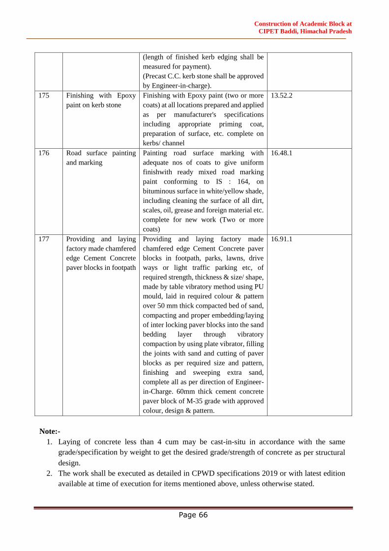
Construction of Academic Block at
CIPET Baddi, Himachal Pradesh
Page 66
(length of finished kerb edging shall be
measured for payment).
(Precast C.C. kerb stone shall be approved
by Engineer-in-charge).
175 Finishing with Epoxy
paint on kerb stone
Finishing with Epoxy paint (two or more
coats) at all locations prepared and applied
as per manufacturer's specifications
including appropriate priming coat,
preparation of surface, etc. complete on
kerbs/ channel
13.52.2
176 Road surface painting
and marking
Painting road surface marking with
adequate nos of coats to give uniform
finishwith ready mixed road marking
paint conforming to IS : 164, on
bituminous surface in white/yellow shade,
including cleaning the surface of all dirt,
scales, oil, grease and foreign material etc.
complete for new work (Two or more
coats)
16.48.1
177 Providing and laying
factory made chamfered
edge Cement Concrete
paver blocks in footpath
Providing and laying factory made
chamfered edge Cement Concrete paver
blocks in footpath, parks, lawns, drive
ways or light traffic parking etc, of
required strength, thickness & size/ shape,
made by table vibratory method using PU
mould, laid in required colour & pattern
over 50 mm thick compacted bed of sand,
compacting and proper embedding/laying
of inter locking paver blocks into the sand
bedding layer through vibratory
compaction by using plate vibrator, filling
the joints with sand and cutting of paver
blocks as per required size and pattern,
finishing and sweeping extra sand,
complete all as per direction of Engineer-
in-Charge. 60mm thick cement concrete
paver block of M-35 grade with approved
colour, design & pattern.
16.91.1
Note:-
1. Laying of concrete less than 4 cum may be cast-in-situ in accordance with the same
grade/specification by weight to get the desired grade/strength of concrete as per structural
design.
2. The work shall be executed as detailed in CPWD specifications 2019 or with latest edition
available at time of execution for items mentioned above, unless otherwise stated.
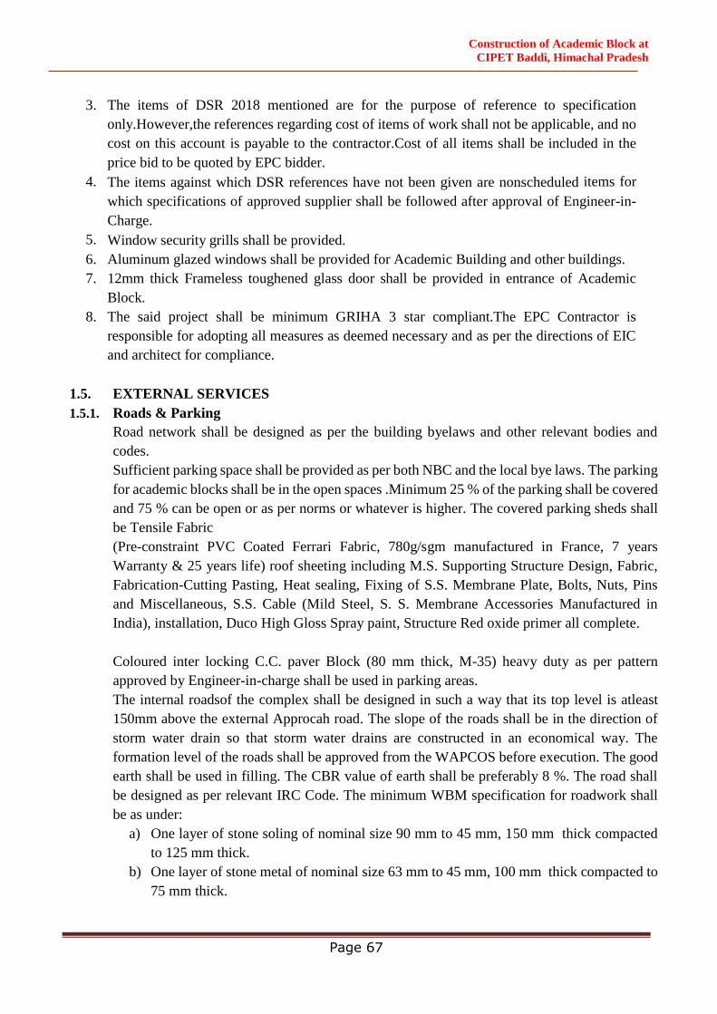
Construction of Academic Block at
CIPET Baddi, Himachal Pradesh
Page 67
3. The items of DSR 2018 mentioned are for the purpose of reference to specification
only.However,the references regarding cost of items of work shall not be applicable, and no
cost on this account is payable to the contractor.Cost of all items shall be included in the
price bid to be quoted by EPC bidder.
4. The items against which DSR references have not been given are nonscheduled items for
which specifications of approved supplier shall be followed after approval of Engineer-in-
Charge.
5. Window security grills shall be provided.
6. Aluminum glazed windows shall be provided for Academic Building and other buildings.
7. 12mm thick Frameless toughened glass door shall be provided in entrance of Academic
Block.
8. The said project shall be minimum GRIHA 3 star compliant.The EPC Contractor is
responsible for adopting all measures as deemed necessary and as per the directions of EIC
and architect for compliance.
1.5. EXTERNAL SERVICES
1.5.1. Roads & Parking
Road network shall be designed as per the building byelaws and other relevant bodies and
codes.
Sufficient parking space shall be provided as per both NBC and the local bye laws. The parking
for academic blocks shall be in the open spaces .Minimum 25 % of the parking shall be covered
and 75 % can be open or as per norms or whatever is higher. The covered parking sheds shall
be Tensile Fabric
(Pre-constraint PVC Coated Ferrari Fabric, 780g/sgm manufactured in France, 7 years
Warranty & 25 years life) roof sheeting including M.S. Supporting Structure Design, Fabric,
Fabrication-Cutting Pasting, Heat sealing, Fixing of S.S. Membrane Plate, Bolts, Nuts, Pins
and Miscellaneous, S.S. Cable (Mild Steel, S. S. Membrane Accessories Manufactured in
India), installation, Duco High Gloss Spray paint, Structure Red oxide primer all complete.
Coloured inter locking C.C. paver Block (80 mm thick, M-35) heavy duty as per pattern
approved by Engineer-in-charge shall be used in parking areas.
The internal roadsof the complex shall be designed in such a way that its top level is atleast
150mm above the external Approcah road. The slope of the roads shall be in the direction of
storm water drain so that storm water drains are constructed in an economical way. The
formation level of the roads shall be approved from the WAPCOS before execution. The good
earth shall be used in filling. The CBR value of earth shall be preferably 8 %. The road shall
be designed as per relevant IRC Code. The minimum WBM specification for roadwork shall
be as under:
a) One layer of stone soling of nominal size 90 mm to 45 mm, 150 mm thick compacted
to 125 mm thick.
b) One layer of stone metal of nominal size 63 mm to 45 mm, 100 mm thick compacted to
75 mm thick.
Construction of Academic Block at
CIPET Baddi, Himachal Pradesh
Page 68
c) One layer of Stone metal of nominal size 53 mm to 22 mm, 100 mm thick each
compacted to 75 mm.
d) One layer of 50 mm to 100 mm thick BM as per CPWD Specifications/ IRC
Specifications
e) 25 mm thick SDBC.
NOTE: The road junctions shall be designed as per relevant code/ CPWD Guidelines/ IRC
Specifications. The road design shall be got approved from WAPCOS before execution.
KERBS AND CHANNELS
All the roads and parkings shall have factory made kerbs and channels made of M 25 grade as
approved by Engineering in charge. The kerbs and channels shall be painted with the colour
scheme after approval of Engineer in charge.
FOOTPATH
Interlocking pavers of 60 mm thick as per shape and pattern in cement colour (Red, Green,
Yellow, Greyetc.) of M 25 grade as per approval of Engineering in charge. The interlocking
pavers shall be laid over 100 mm thick 1:3:6 and 50 mm thick sand filling.
ROAD PAINTING
Painting road surface marking with adequate nos of coatsto give uniform finish with ready
mixed road marking paint conforming to IS: 164, on bituminous surfacein white/yellow shade,
including cleaning the surface of all dirt, scales, oil, greaseand foreign material etc. complete.
1.5.2. WATER SUPPLY SYSTEM-
i. External water supply shall be designed based on total water requirement for the
individual building. All water supply lines are to designed based on Indian Standards and
Manuals with latest editions and correction slip, if any.
Design Standards
a. CPHEEO:1999–manual on water supply and treatment
b. CPHEEO:1993–manual on sewage and sewage treatment
c. SP35:1987–handbook on water supply and drainage
d. NBC 2016
e. UPC–india:2011 or latest
f. Relevant Indian standards
ii. The ultimate source of water supply for the proposed buildings shallbe municipal water
supply. The external pipeline upto underground water tank shall be designed keeping in
view the water supply demand. However, during construction period and till the municipal
water supply is recieved, the source of water supply shall be tubewells/ borewells. If water
is not found suitable for construction, epc contractor shall make alternate arrangements
for getting water fit for constructions at his cost. Nothing extra shall be paid for the same.
Construction of Academic Block at
CIPET Baddi, Himachal Pradesh
Page 69
iii. The borewells will be installed inside the identified land of the proposed Academic block
having sufficient number of bore holes with adequate yield capacity to meet the daily
water requirement, which shall be included in scope of work. Moreover, arranging water
supply from local Municipal Corporation and other approvals is the responsiblity of the
epc contractor.
iv. Overhead tank (OHT) at terrace and underground tank (UGT) will be designed
accordingly.
v. UGT shall be having capacity of one day of daily water requirement plus requirement of
fire-fighting water and OHT shall be half day capacity of daily water requirement.
Suitable arrangement for disinfection of bore water shall be made on the basis of chemical
analysis and bectriological report. Disinfection with the help of bleaching powder/gas
chlorination should be done.
vi. Submersible pump will be used for pumping raw water from bore well to UGT and
vertical inline multistage pumping set for pumping water from UGT to OHT of the
building.Capacityof pumps will be determined based on standard practice and stipulation
of relevant IS code.
vii. The water treatment plant (WTP) if required may be placed to treat the raw water from
the borewell.The capacity of pressure sand filter, activated carbon filter and softener filter
shall be suitably determined. The location of WTP shall beproposed accordingly
preferably near pump room.
viii. The RO plant shall be located in the terrace of building and has a feed from the building
OHT.The treated RO water shall be stored in a separate SS-304 tank
ix. Domestic water supply distribution from OHT shall be formed, as a loop/branch network
by gravity and upper two floors feed by separate booster pumps.
x. The external pipeline shall be designed in such a way that lying of parallel/ duplicate pipe
is avoided.
xi. The external pipeline shall be of S & S (Socket and Spigot) Ductile Iron pipe of Grade K
9.
xii. Fittings shall be of S&S D.I. Standard fittings (Heavy Class)
xiii. Sluice Valve/ Fire breeching shall be of C.I. complete with bolts and nuts, rubber insertion
etc. The chambers for Sluice Valve/ Fire breeching shall be as per requirement of CPWD
specifications.
xiv. Thrust Blocks shall of M 25 grade.
xv. The structural design of external sewerage pipe shall be done as per relevant IS Code and
CPWD Specifications. SW Pipe of Grade A quality shall be used. Suitable Manholes of
suitable size as per relevant IS Code/ CPWD Guidelines shall be provided at all the
junctions and along the roads/ parking area at an interval not exceeding 30 m distance.
Construction of Academic Block at
CIPET Baddi, Himachal Pradesh
Page 70
xvi. External storm water shall be designed keeping in view the run off as 25 mm/ hour with
coefficient as per relevant local bye-laws and IS codes. The diameter of the pipe shall be
taken as per hydraulic design calculation and specification of pipe to be adopted such as
NP-3 or NP-4 etc. shall be taken as per structural design calculation keeping in view the
earth load and relevant IS code etc. Minimum RCC Pipe shall be of grade NP-3. In order
to dispose of the storm water from roads and parking areas, it is proposed to provide road
gullies of stable size as per the site requirement at the junctions and along the road/ parking
at an interval not exceeding 30 m. The road gullies shall be connected with main storm
water line through 400 mm internal diameter NP-3 RCC Pipe. Vertical or horizontal or
both type road gullies shall be provided as per site requirement. The road gullies shall be
covered with SFRC gratings. Structural designof the storm water line and road gullies
shall be done as per relevant IS Code/ CPWD Guidelines and same shall be got approved
from WAPCOS before execution.
1.5.3. Water
Water used in construction for all civil & structural works shall be clean and free from injurious
amount of oil, acids, alkalis, organic matters or other harmful substances, which may be
deleterious to concrete, masonry or steel. The ph value of water sample shall be not less than
6. Potable water shall be considered satisfactory.
Tests on water samples shall be carried out in accordance with IS: 3025 and they shall fulfill
all the guidelines and requirements given in IS: 456.
The EPC Consultant/ Employer may require the EPC Contractor to prove, that the concrete
prepared with water, proposed to be used, shall not have average 28 days compressive strength
lower than 90% of the strength of concrete prepared with distilled water.
The EPC Contractor is required to get the water tested from an approved laboratory before
starting the construction work and in case the water contains any oil/organic matter or an excess
of acid, alkalis or any injurious amount of salts etc., beyond the permissible maximum limits
given in IS:456, the EPC Consultant/ Employer may refuse to permit its use. In case there is
any change in source of water, water samples shall be tested again to meet the specified
requirements.
Water shall be stored in tin barrels, steel tanks or water tight reservoirs made with bricks/stone
or reinforced concrete. Brick/stone masonry reservoirs shall have RCC base slab and shall be
plastered inside, with 1 part of cement and 4 parts of sand and finished with neat cement
punning. These reservoirs shall be of sufficient capacity to meet the water requirements, at any
stage of construction.
Water for curing shall be of the same quality as used for concreting and masonry works. Sea
water shall not be used for preparation of cement mortar, concrete as well as for curing of
plain/reinforced concrete and masonry works. Sea water shall not be used for hydro testing
and checking the leakage of liquid retaining structures also.

Construction of Academic Block at
CIPET Baddi, Himachal Pradesh
Page 71
1.5.4. Cement
Portland Pozzalanic cement conforming to IS 1489 Part 1 shall be used. The cement must have
25-30% fly ash content mixed at the time of manufacturing cement. No Fly ash shall be added
while producing the concrete. However, in case of concrete is produced in Ready Mix Concrete
Plant, OPC may also be used by mixing 25-30% of fly ash by weight.
1.5.5. Reinforcement Steel
TMT bars of Fe500D grade/ conforming to IS: 1786 (latest edition) and IS13920-2016,
IS456:2000 (with update amendments) and relevant CPWD specification shall be used.
In design calculation, stresses in reinforcement in Stirrups shall be taken as 415N/mm2 as per IS:
456-2000 and other relevant Codes.
NOTE:
Minimum M 25 (Design Mix) to be used for slabs and beams etc. of all RCC structures,
unless specified.
Minimum M 30 (Design Mix) to be used for columns in Hospital and Academic
building, RCC walls in basement and any other places.
Minimum M 30 (Design Mix) to be used for water retaining structures
Materials of following specification are to be used in work.The Bidders are expected to possess
and be well conversant with the following IS standard and code of practice.
1. Cement Portland Pozzalaniccement (grade43)
conformingtoIS1489Part1shall be used
2. Steel IS 1786, IS 456, IS 13920
3. Vibrator I.S. 7246
4. Aggregate I.S. 383, I.S. 515
5. Water for mixing andcuring
Shall be clean, free from injurious amount of oil,
salt, acid, vegetable materials and other substances
and harmful to concrete in conformity to I.S. 456
and I. S. 2025.
6. Sand/ Fine Aggregate I.S. 2116, 383
7. Binding wire I.S. 280 (galvanised minimum 1.25 mm)
8. Rain water pipe I.S. 2527
9. Construction joints I.S. 3414
10. Steel Window Frame I.S. 1038/83
11. Steel Door Frame I.S. 4351/75
12. Fitting & Fixtures for
joinery works
Conforming to I. S. 7452/82 strictly conform to I.S.
specification and as per direction of Engineer-in-
Charge.

Construction of Academic Block at
CIPET Baddi, Himachal Pradesh
Page 72
Note: For road work (Approach Road) specification as per road and bridges (latest edition)
published by I.R.C&M.O.S.T.shall be followed. Incase of any doubt and absence of provision,
regarding specification I.S.shall be referred (Indian standard).
Item of Work:
1. Plain and Reinforced Concrete shall be with conformity to I.S.456 and relevant BIS Codes/
CPWD Guidelines.
2. Foundation shall be with conformity to I.S.1080 and relevant BIS Codes/CPWD Guidelines.
3. Stone masonry (R.R.) shall be with conformity to I.S.1597 (Part-I)and relevant BIS Codes/
CPWD Guidelines.
4. C.R.Masonry shall be with conformity to I.S.1597and relevant BIS Codes/CPWD
Guidelines.
5. Brick masonry shall be with conformity to I.S.2212and relevant BIS Codes/CPWD
Guidelines.
6. Cement plastering shall be with conformity to I.S.9103&6925 and relevant BIS Codes/
CPWD Guidelines.
7. Mortar shall be with conformity to I.S.2250 and relevant BIS Codes/CPWD Guidelines.
8. White and colour washing shall be with conformity to I.S.6278 and relevant BIS Codes /
CPWD Guidelines.
9. CC in foundation shall be with conformity to I.S.2571 and relevant BIS Codes/ CPWD
Guidelines.
10. Anti-Termite Treatment shall be with conformity to I.S.6813.(Part–I &PartII)and relevant
BIS Codes/ CPWD Guidelines.
11. Painting to all surfaces shall be with conformity to I.S.2395 (Part–I &Part– II)
12. DPC shall be with conformity to I.S.3067 and relevant BIS Codes/ CPWD Guidelines.
13. Tarfelt treatment should be with conformity to I.S.1346 and relevant BISCodes/ CPWD
Guidelines.
14. Mosaic flooring with conformity to I.S.2114 and relevant BISCodes/CPWD Guidelines.
15. Steel painting shall be with conformity to I.S.1477(Part–I&Part–II)I.S.1661 and relevant BIS
Codes/ CPWD Guidelines.
All works shall be executed as per latest CPWD specification document with up to date
correction slips (if any). Specifications not covered in CPWD specifications are as under.
1.PVC Flooring
Providing and fixing of 2mm thick imported vinyl flooring, 100% recycled flexible homogeneous
and monolayer in construction of weight 2750 g/m2 and should be manufactured by calendaring
and pressing process of size 2mtrs. x 20mtrs in approved pattern, to ensure a dense, smooth
surface and non-directional design, color dyed as a raw mixture to ensure even color throughout
the thickness and its surface should be densely compacted for improving wear and ease of
maintenance with Anti-bacterial and Fungicidal properties. The flooring shall incorporate a
specially formulated EvercareTMSurface Treatment having wear resistance of ≤2.0mm3 as per EN
660.2 and Wear Group ‘ T ‘ as per EN-649 and should have a residual indentation of −0.03mm
Construction of Academic Block at
CIPET Baddi, Himachal Pradesh
Page 73
confirming to EN-433. The laid flooring shall confirm the fire rating B1 class as per EN 13501-
1. It should have low VOC contain as TVOC after 28 days <10 µg/m3 as per ISO 16000-6. The
floor finish should terminate at the room perimeter passing over a concealed cove former and
continuing up the wall for 100mm. The joints in the flooring should be sealed by using a PVC
welding bar of matching colour to be supplied by the manufacturer, using a hot air gun for fusion
of welding bar with flooring. The vinyl sheet shall be laid & fixed with water based adhesive
preferably AROBOND-44 of M/s. Arofine make or VC 31 of M/s Pidilite Ind. or equivalent as
per manufacturer’s specification and direction of Engineer-in-charge.
2. Corner Guard
Providing and fixing of Care4 Corner Protector with self adhesive tape with 30mm wide wings
(internal measurement), 900 of 2.0mm thick comprising of smooth and antibacterial PVC
profile achieving class Bs2d0 fire-rating with solid colour. It is provided with two strips of self
adhesive tape for fixing. No heavy metals are used in its manufacture and the calcium-zinc
thermal stabilization process is used.
3. PVC Cladding
Providing and fixing of flexible vinyl sheet wall covering of 1.0mm thick 100% recycled PVC
flexible, homogeneous of total weight 1750 g/m2 in sheet of size 2mtrs. X 30 mtrs. In approved
pattern & colour combination with PUR surface treatment fully resistant to impact, as it acts a
buffer against damage from beds, trolleys and indoor motorized vehicles with Anti-bacterial and
Fungicidal properties & should create safe and hygienic environment. The wall covering shall
confirm the fire rating M1 class as per NFP 92 506. The vinyl wall covering shall be fixed with
water based adhesive preferably AROBOND-44 of M/s. Arofine make or VC 31 of M/s. Pidilite
Ind. or any other make as per manufacturer’s specification as per direction and the entire
satisfaction of Engineer-in-charge complete.
4. Self Leveling Course
Providing of 2 - 3 mm average thick layer of cementations smoothening compound of TT-61
or UZIN NC 149 sh or equivalent as recommended by the Vinyl sheet flooring manufacturer over
and including a priming compound of UZIN PE 360 sh or equivalent as recommended by the
Vinyl sheet flooring manufacturer and installation team on concrete surface to provide a smooth
& homogenous surface for laying of vinyl sheet flooring complete to the entire satisfaction of
Engineer-in-charge.
5. Germ Free Wall Tile
Providingand Fixing of Germ free Ceramic Wall Tile (size 600/450mm x 300mm) of approve
make in dados / skirting and risers of steps on 12mm thick cement plaster (1:3) jointed with neat
cement slurry mixed with pigments to match the shade of the tiles including cost, carriage, cost
of all labour etc. complete as per specification and direction of the Engineer‐in‐Charge.
6. Cement Concrete Tile in Floor
Providing and Fixing of pre polished cement concrete floor tiles confirm to IS: 1237:1980
(Reaffirmed in 1996) for heavy duty tiles (Exterior Grade) of 22‐25mm thick of approve make,

Construction of Academic Block at
CIPET Baddi, Himachal Pradesh
Page 74
as per pattern, size and colour as specified or as approved by Engineer‐in‐Charge to be used in
floor laid over cement mortar (1:4) 20mm thick required neat cement jointing curing and cleaning
complete.
7. Hardware
a)- Stainless Steel hinges for door :- Providing and Fixing approved brand and manufacture of
Stainless Steel 2 Ball Bearing Hinge 102x76x3mm ( HG1153SS) along with necessary
accessories and screws etc. complete in all respects as per manufacturers' specificatios & as
directed by Engineer-in-charge.
b)- Brass Towerbolt:- Providing and fixing approved brand and manufacture of Brass Towerbolt
300 mm long with 10 mm dia ( TR 1210SS) along with necessary accessories and screws etc.
complete in all respects as per manufacture ofrs' specificatios & as directed by Engineer-in-
charge.
c)- Stainless Steel Towerbolt:- Providing and fixing approved brand and manufacture of
Stainless Steel Towerbolt 150 mm long with 10 mm dia ( TS 610SS) along with necessary
accessories and screws etc. complete in all respects as per manufacture ofrs' specificatios & as
directed by Engineer-in-charge.
d)- Stain less Steel Floor stopper:- Providing and fixing approved brand and manufacture of
Stain less Steel Floor stoper floor mounted half round with 45mm dia (DSHR (SS)) along with
necessary accessories and screws etc. complete in all respects as per manufacture ofrs'
specificatios & as directed by Engineer-in-charge.
d)- Stain less Steel Door stopper:- Providing and fixing approved brand and manufacture of
Stainless Steel Door Buffer wall mounted 22 mm dia,75 mm long (DB (22) along with necessary
accessories and screws etc. complete in all respects as per manufacture ofrs' specificatios & as
directed by Engineer-in-charge.
e) Door closer:- Providing and fixing approved brand and manufacture of aluminium extruded
section tubular type universal hydraulic door closer with Palmet Arm (DC 80 EXT (WP)SS)
(having brand logo , embossed on the body, door weight upto 80 kg , 5 lacs Cycles Tested), with
speed adjustment along with necessary accessories and screws etc. complete in all respects as per
manufacture ofrs' specificatios & as directed by Engineer-in-charge.
8. Door Handles and Locks
a)- Door handle :- Providing and fixing approved brand and manufacture of Terza Design
Mortice Lever handle On Plate (TER10SC) along with necessary accessories and screws etc.
complete in all respects as per manufacture ofrs' specificatios & as directed by Engineer-in-
charge.
Construction of Academic Block at
CIPET Baddi, Himachal Pradesh
Page 75
b)- Door Locks :- Providing and fixing approved brand and manufacture of Mortice Sash lock
(ML100SS) with 85 mm CD & 50 mm Backset along with key cylinder fixing Option along with
necessary accessories and screws etc. complete in all respects as per manufacture ofrs'
specificatios & as directed by Engineer-incharge.
9. Glass Door Hardware
a) Stainless steel 304 Grade H- handle :- Providing and fixing Stainless steel 304 Grade H- type
pull handle of size min 32 mm dia and 1200mm long of approved make including SS screws,
including making holes of required size in shutter etc. complete as per direction of Engineer-in-
Charge.
b) SS Bottom patch Lock:- Providing and fixing SS Bottom patch Lock with cylinder of
approved make including necessary screws etc. all complete.
c) SS floor mounted door stopper:- Providing and fixing SS floor mounted half dome door
stopper of dia 45mm including necessary screws etc. all complete.
d) frosted glass film:- Providing and fixing self adhesive type frosted glass film of 3M make or
approved equivalent, in required pattern over glass etc. as per drawings, including cleaning the
receiving surface of glass etc., all complete as per manufacturer's specification and direction of
Engineer in charge:
i- Plain frosted film
ii- Colored frosted film
10. Toughened float glass Door :-
Providing and fixing 12mm thk. Toughened float glass glazing cut and fixed in openings of
desired shape as per drawing with 3/4" beveling all around, fixed with the help of SS patch
fittings, with top and bottom 'C' channels, fixed firmly to the slab/ MS Structure ,as directed by
Engineer in Charge. Area of openings to be measured). Assume frameless glass. Rate of above
item to include P/F of: 20x20mm "C" channel SS patch Fittings.
11. Polycorbonate sheet roofing:-
Providing & fixing 10mm thick translucent Polycorbonate sheet roofing up to any pitch, including
fixing with polymer coated 'J' or 'L' hooks, bolts & nuts 8mm dia. G.I plain/bitumen washers
complete but excluding the cost of wooden frame, purlins, rafters, trusses etc. The sheets shall be
manufactured out of 2400 TEX panel rovigs incorporating minimum 0.3% ultra-violet stabiliser
in resin system under approximately 2400 psi and hot cured. They shall be of uniform
pigmentation and thickness without air pockets and shall conform to IS 10192 and IS 12866.The
sheets shall be opaque or translucent, clear or pigmented, textured or smooth as specified.
12. High Density Fiber (HDF) Board Laminated wooden flooring:-
Providing and fixing truly leveled High Density Fiber (HDF) Board Laminated wooden flooring/
skirting of approved make and approved shade, over prepared hard base, having minimum
Construction of Academic Block at
CIPET Baddi, Himachal Pradesh
Page 76
thickness of 8 mm, and meeting all performance and physical parameters for classification of use
32/23 (General Commercial/ Heavy Domestic use) as per EN 13329 or equivalent, with a surface
abrasion resistance of class AC 4, having installation arrangement and locking mechanism as per
manufacturer's specification. The material shall have low VOC, high recycled content and other
requirements related to sourcing of material as per GRIHA requirement. The item includes
providing and laying of underlayment made of all necessary accessories like End profile,
Transition profile, reducer, moulding, etc. as per requirements, all complete as per manufacturer's
specifications, technical specifications and direction of engineer in charge of
Pergo/Wonderceil/Rockworth Make.
13. Glass Porch:-
Design, assemble, provide and 13.52 mm thick Fix Glass Porch as per the drawing with Point
fixed glazing assembly using Spider / Articulated bolts and to be designed to withstand Design
wind pressure of 2.5 KPa. The system consists of Glass clamp mounting system with Flat head
bolts with bush of "Ozone" or approved equivalent make including necessary supporting hot dip
galvanized MS sub structure system as shown in the drawing and the fittings, bolts and nuts,
washers shall be 300 series non-magnetic steel of 316 grade. Each spider / articulated bolt fittings
shall be designed in such a way as to sustain the glass load and transfer to the structure through
bolts.
14. Glass Reinforced Concrete (G.R.C) Screens:-
Providing and fixing Glass Reinforced Concrete (G.R.C) Screens casted with 'Spray Mix'
concrete design in approved size, pattern, thickness of 50mm on the outer Border & 25-30mm
for internal member and shade. The Screens should be made from ‘53 grade’ White Portland
Cement. White Quartz fine graded sieved Silica Sand, Alkali Resistant Glass Fibre. Super
Plasticizers. U.V resistant Synthetic inorganic pigments should be used for pigmentation. The
Screens casting shall take place with layering methodology using- Direct Power Spray machines.
The GRC Screens flexural strength average L.O.P should be above or equivalent to 6 N/mm2 &
M.O.R should be above or equivalent to 15 N/mm2 for tests done on 28 days cured samples. The
fixing of Screens should be done using ‘Dry fixing’ method onto structural support members i.e.
R.C.C, Brick work, MS Framework. SS / MS Galvanized CLAMPS & PINS also if required
fasteners to be used of. All cast in socket to be epoxy primer coated. Electrodes to be used. Vendor
shall submit shop drawings of same, the drawings to be duly approved from Engineer in charge
at site.
15. Non-Combustible Extruded Aluminium louvers:-
Design, supply, manufacturing and installation at the site of non-combustible Extruded
Aluminium Batten System in minimum thickness from 2.2mm to 3.5mm as per approved design
in profile size of 50mmX150mm with corner radius and aluminium End Caps and 7-8mm male-
female system for fixing support mechanism using extruded grooved rail profile in minimum
3mm thickness and aluminium cleats on sub-frame Allowing linear thermal expansion and
contraction.
Construction of Academic Block at
CIPET Baddi, Himachal Pradesh
Page 77
The battens, cleats and support rail and all flashings and starter etc. must be 6063 in T6 temper
supported with MTC. The wooden texture/colour on aluminium plank shall be done using
Super Durable Powder coating and heat film transfer up to 80micron and warranted for
minimum 15 years in exterior conditions to meet or exceed qualicoat/AAMA 620
specifications.
16. Glass Railing :-
'Fabrication, supply and Installation of New clear line glass railing system by Ozone made of
Heavy duty aluminum U Type Hollow walls Base channel ( HWBC) (OZRF-NCLSYS- HWBC-
AL) AL-6063 grade with mill finish of size 12.5mm( thick)72( wide)x122 mm( height). Glass
Specs. is 16.89mm thk (8mm CT+ .89SGP+8MM CT) to be GRIPPED with fixing kit (OZRF-
NCL-ACC-KIT-17MM) made of self-pushing clamps ( SPC) made by hardened aluminum -6063
grade each at maximum 350mm cc to cc . glass should be lifted from base by Solid Nylon L
Block separates at least 3 nos/ meters. HWBC to be fixed with M12 GI stud chemically grouted.
Glass should be fixed with completely dry system so that in case of breakage it can be changed
without any silicon cutting and very fast as well.. Exposed edges of HWBC (if any) to be covered
with SS 304 grade end caps. The Top Edge of glass will be covered with SS 304 grade Round
slotted tube of Dia42x1.5 mm thk. Fixed on the glass edge with EPDM gasket. The Vertical joint
of glass will be free from silicon. The total height of the system will be max. 900 mm from ledge
top, All top rail joints will be joined by using argon welding only.
17. Glass reinforced concrete (G.R.C) stone Veneer cladding:-
Providing and fixing Glass reinforced concrete (G.R.C) stone Veneer in approved pattern i.e.
‘Sandstone’ or ‘Sculptured Stone’ both in size of (3 feet x1.5 feet) in shades and different textures
of natural stone. All sand stone or Sculptured stone finish veneer panels shall come with required
corner pieces. The thickness of GRC wood veneers shall be between 8 -12mm having weight of
approximately 1.5 Kg per Sq. Ft. to 2.5 kg per Sq ft. The GRC stone veneers should be made
from ‘43 grade’ White Portland Cement manufactured The material casting should take place in
FRP Moulds. The GRC stone Veneer should be manufactured with M-40 Grade concrete mix
design having ’43’ grade Portland cement, reinforced with Alkali Resistant glass fiber and the
pigmentation should be done with exterior grade synthetic inorganic iron oxide pigments with
high vibration technology. The material casting should take place in FRP Moulds. The desired
shade to replicate natural tones of stone shall be achieved by using UV resistant exterior grade
Synthetic inorganic pigments, imparting subtle color variation in order to make appearance of
product natural. The fixing of GRC stone Veneers should take place on rough plastered surface
of 1:3 (cement: coarse sand) with Dual fixing procedure i.e. exterior grade Cement polymer based
tile adhesive and high carbide galvanized steel concrete nails to be applied
With pneumatic concrete nailing machine and exterior grade cement polymer based grout in
matching veneer shade to be used to hide out nails.
Construction of Academic Block at
CIPET Baddi, Himachal Pradesh
Page 78
18. Glass Reinforced Concrete (G.R.C) moulding:-
Providing and fixing Glass Reinforced Concrete (G.R.C) moulding in approved design, size,
texture, thickness, pattern and color fixing of moulding should be done by ‘adhesive or equivalent
as per manufacturer’s laying instruction.
19. Texture Exterior Paint :-
Providing and applying One coat of natural shade with stone dust tinted trowel texture in
approved shade over a coat of base texture that is a natural shade texture with stone dust without
chips over a coat acrylic primer Mixed with wall sealer along with repair check with exterior
grade putty, one coat of siloxine protection coat to be applied over this, as directed by Engineer-
In-Charge.
Derived thickness (1.25mm-1.5 mm)
20. Room Signages (Stainless Steel with single color/Multi Color engravings):-
Providing and Fixing Room Signages for principal/ HR & Admin/ Conference room/Meeting
Room/Cabin/ Stationary/classroom/seminar hall/lab/ Store room/Server / ups /electrical
room/G.Toilet & Ladies Toilet with symbol/Pantry/Fire exist/rest room or for any other area as
per the direction of EIC. The SS plate shall be 304 grade of approved shape as per drawing.
single color/Multi color engraved signage Font and letter sizing shall be got aproved by the
architect-sample shall be submitted. Rate shall include all hardware and necessary arrangement
for fixing.
21. CIPET LOGO (Main Gate And Building ):-
Supply Installation Testing & Commissioning of CIPET Logo made in Acrylic Sheet. Led Light
to be inserted inside acrylic letters and affixed on wall, Word
- CIPET
Letter - 24" height
Word - ACADEMIC BLOCK
Letter - 12" height
22. GRC PAVER
Providing and fixing of glass reinforced concrete (G.R.C) exterior paving tiles in 'Cobblestone'
finish in approved shade in sizes of 152mm x152mm. The thickness of the tiles should range
between 20 to 22 mm, allowing variance of ± 5mm in accordance with IS: 1237-1980. The tiles
should be made with M- 40 Grade concrete mix design having ’43’ grade Portland cement,
reinforced with Alkali Resistant glass fiber and the pigmentation should be done with exterior
grade synthetic inorganic iron oxide pigments manufactured by ‘BAYFERROX (Germany)’ or
equivalent with high vibration technology. The pigmentation should be homogeneous and in
accordance with British standard BS EN 12878:1999. The other additives should be fine washed
graded quartz, super plasticizers and integrated water proofers agents and others. The tiles should
be produced with high vibratory technology and their concrete mix design compressive strength
should be of M-40 grade@28days. The top surface of the tiles should be treated with acrylic
lacquer resulting in top surface water absorption of less than 1% and water absorption of less than
Construction of Academic Block at
CIPET Baddi, Himachal Pradesh
Page 79
8% by 24 hours immersion method. The beds where tiles are to be laid should be clean, debris
free, wet and mopped. The tiles should be laid with cement mortar of 20mm thickness made with
(1:4) Cement : Coarse Sand, adequate grooves should be maintained between 8-10mm using
spacers and pointing work to be done with 1:3 ( Cement : Fine Sand) mix.
23. Granite Wall lining & Dado: Granite work gang saw cut (polished and machine cut) of thickness
18mm for wall lining, skirting and dado (veneer work) in cement mortar 1:3 (1 cement: 3 coarse
sand) including pointing with white cement mortar 1:2 (1 white cement: 2 marble dust) with an
admixture of pigment to match the marble shade: (To be secured to the backing by means of
cramps.)
General
Granite Stone shall be of the type specified and the material promptly in accordance with
specifications, it shall be hard sound durable and tough free from cracks, and defects like cavities
cracks flaws holes etc. Before starting the work the contractor shall get the sample approved by
the Engineer – in –Charge.
Materials
Granite Standard: Granite shall comply Standard Specification for material characteristics,
physical requirements, and sampling for selection of granite.
All granite shall be of standard architectural grade, free of cracks, seams, or starts, which may
impair its structural integrity or function. Color or other visual characteristics indigenous to the
particular material and adequately demonstrated in the sampling will be accepted provided they
do not compromise the structural or durability capabilities of the material. Texture and finish shall
be within the range of samples approved by the Engineer – in -charge.
Shop Drawings
The Contractor shall submit: copies of required shop drawings to the Engineer-in-charge for
approval. These drawings shall show all bedding, bonding, jointing and anchoring details, and
the dimensions of each piece of granite. No final sizing or finishing shall be done until the shop
drawings for that part of the work have been approved.
Stone Installation
Proceed with the installation of the stonework in accordance with Drawings and using skilled
mechanics capable of proper handling of the setting of the stone and able to field cut where
necessary with sharp and true edges. Set stone with joints uniform in appearance and stone edges
and faces aligned tolerances indicated. Clean surfaces that are dirty or stained. Scrub with fiber
brushes, and then rinse with clear water. Provide expansion, control, and pressure-relieving joints
of widths and at locations shown on Drawings.
Cleaning
After installation and pointing or caulking are completed, the contractor shall carefully clean the
Construction of Academic Block at
CIPET Baddi, Himachal Pradesh
Page 80
granite, removing all dirt, excess mortar, weld splatter, stains, and/or other site incident
defacements Stainless steel wire brushes or wool may be used, but the use of other wire brushes
or of acid or other solutions which may cause discoloration is expressly prohibited. Fabricator
should be contacted before cleaners other than detergents are used.
Protection of Finished Work
After the granite work is installed, the granite shall be properly and adequately protected from
damage. Boxing or other suitable protection shall be provided wherever required, but no lumber
which may stain or deface the granite shall be used. All nails used shall be non-corrosive. All
granite work in progress shall be protected at all times during construction by use of a suitable
strong, impervious film or fabric securely held in place.
24. Granite Flooring:Granite stone flooring with 18mm thick stone flooring (sample of shall be
approved by Engineer-in-charge) over 20 mm (average) thick base of cement mortar 1:4 (1
cement: 4 coarse sand) laid and jointed with grey cement slurry including rubbing and polishing
complete with:
General
Granite Stone shall be of the type specified and the material promptly in accordance with
specifications, it shall be hard sound durable and tough free from cracks, and defects like cavities
cracks flaws holes etc. Before starting the work the contractor shall get the sample approved by
the Engineer – in –Charge.
Materials
Granite Standard: Granite shall comply Standard Specification for material characteristics,
physical requirements, and sampling for selection of granite.
All granite shall be of standard architectural grade, free of cracks, seams, or starts, which may
impair its structural integrity or function. Color or other visual characteristics indigenous to the
particular material and adequately demonstrated in the sampling will be accepted provided they
do not compromise the structural or durability capabilities of the material. Texture and finish shall
be within the range of samples approved by the Engineer – in -charge.
Shop Drawings
The Contractor shall submit: copies of required shop drawings to the Engineer-in-charge for
approval. These drawings shall show all bedding, bonding, jointing details, and the dimensions
of each piece of granite. No final sizing or finishing shall be done until the shop drawings for that
part of the work have been approved.
Stone Installation
Proceed with the installation of the stonework in accordance with Drawings and using skilled
mechanics capable of proper handling of the setting of the stone and able to field cut where
necessary with sharp and true edges. Set stone with joints uniform in appearance and stone edges
and faces aligned tolerances indicated. Clean surfaces that are dirty or stained. Scrub with fiber
Construction of Academic Block at
CIPET Baddi, Himachal Pradesh
Page 81
brushes, and then rinse with clear water. Provide expansion, control, and pressure-relieving joints
of widths and at locations shown on Drawings.
Cleaning
After installation and pointing or caulking are completed, the contractor shall carefully clean the
granite, removing all dirt, excess mortar, weld splatter, stains, and/or other site incident
defacements Stainless steel wire brushes or wool may be used, but the use of other wire brushes
or of acid or other solutions which may cause discoloration is expressly prohibited. Fabricator
should be contacted before cleaners other than detergents are used.
Protection of Finished Work
After the granite work is installed, the granite shall be properly and adequately protected from
damage. Boxing or other suitable protection shall be provided wherever required, but no lumber
which may stain or deface the granite shall be used. All nails used shall be non-corrosive. All
granite work in progress shall be protected at all times during construction by use of a suitable
strong, impervious film or fabric securely held in place.
24.1. General Requirements
a) Profile
The profile is to be extruded from a compound that has been blended to ensure quality
and consistency. The material shall be pristine white high impact modified window grade
UPVC and shall be colour fast and conform to BS EN 12608:2003 as follows:
Description of Material Required Value
Flexural modulus of Elasticity Shall not be less than 2200 N/ mm2
Resistance to impact by falling mass
at. 10 °C for Class II (falling mass
1000g ; falling height 1500mm – as
per BS EN 12608:2003)
not more than 1 test specimen shall show
rupture in wall
Mean Breaking Stress for welded
Corners
Shall not be less than 35N/mm2 for
compression bending test or 25N/mm2 for
tensile bending test
b) Fabrication of window/door
i. The window units shall be designed with all corner/mullion/transom joints can be
mechanical joined or welded as per system supplier recommendation
ii. All excess material is to be neatly trimmed and neatly feature grooved/raised nib finish
at corners, transom joints and mullion joints.
iii. No polishing flush of any joints will be permitted.
iv. The window units shall be designed so that the route of drainage is prevented from
passing through the reinforcement chamber.
Construction of Academic Block at
CIPET Baddi, Himachal Pradesh
Page 82
v. The finished product shall be free from all sharp edges, burrs and the like that may be
hazardous to the user.
vi. The dimensional tolerances on the finished outer frame height and width shall be +/-
3mm. Frame assemblies shall be such that they can be installed square within a
maximum difference in the diagonals of 4mm. Minimum overlap of sash on frame
shall be 8mm
vii. In all window units, adequate drainage should be provided to permit the escape of
water from platforms or horizontal members beneath each sealed unit. The drainage
slots shall not penetrate into the reinforcement chambers.
c) Reinforcement
i. Reinforcement shall be made from galvanized mild steel of not less then 1.5mm
thickness as per strength requirement unless otherwise approved by Engineer in
Charge.
ii. Steel reinforcement shall conform to IS 277:2003 or equivalent – Base material of
steel shall conform to IS 513:2008. Drawing Grade
iii. The reinforcement shall be installed in accordance with the recommended actions.
The reinforcement shall conform to the wind load requirements of IS 875: Part 3. The
reinforcement shall be in one continuous length and should be installed minimum
5mm and maximum 10mm from the face of the profile to be welded.
iv. The reinforcement shall be secured to the profile so that it does not move or rattle and
it maintains the structural integrity of the frame and satisfactory thermal separation.
Reinforcement is to be fixed at a maximum of 100mm from the ends and then at a
maximum of 300mm centers.
24.2. Glazing and Weather seals
a) GLAZING
Window/door shall be such that glazing or re-glazing on site is possible without the need
to remove the outer frames from the structure of the building.
i. Window shall be such that glazing or re-glazing on site is possible without the need
to remove the outer frames from the structure of the building.
ii. All glazing is to be packed in accordance with the system supplier’s recommendations
to prevent any kind of damage during handling
iii. All beads will be cut at the correct degree recommended by the manufacturer. Glass
retention clips shall be fitted in accordance with the Systems supplier’s
recommendations. Windows will be with 21mm thick hermetically sealed glass units
having 6-10-5 arrangement
Construction of Academic Block at
CIPET Baddi, Himachal Pradesh
Page 83
b) Weather Seals
The weather seals shall be EPDM/ Silicone seals. ASTM- D412 and ASTM- D2240 are
standard specifying test methods for Tensile strength and Hardness of the gasket whereas
the required value shall be specified
c) Ultimate tensile strength min >7.5 N/mm2
The weather seals are to be fitted in continuous lengths and grooves. The joints in the vent
weather seal are to be positioned at the bottom and in the outer frames at the top.
d) Security and Safety
Fasteners shall be designed so that they cannot be released from the outside by the
insertion of a thin blade.
No opening light shall be openable or removable from the outside, when it is fastened in
the closed position, except by use of special tools or breaking part of the window.
24.3. QUALITY CONTROL AND TESTING OF MATERIALS
a) Raw Material
The material from which the profiles are made shall consist substantially from white
polyvinyl chloride as per BS EN 12608:20003. Only those additives and pigments may
be used that are needed for the manufacture of the compound and its subsequent
conversion into sound, durable extrusions of good surface finish and mechanical strength,
as assessed by the requirements of this specification.
24.4. Profile Properties
a) Appearance and Finish
The color of the profile shall be uniform and the color of all profiles in a system shall be
uniform. The profile shall be free from foreign bodies, cracks or sink marks when viewed
by normal corrected vision at 90o to the surface and at a distance of 1 meter in normal
diffused north light.
b) Dimensions and Weights
The profiles shall be straight such that the longitudinal axis of the profile, as measured on
the face surfaces, may deviate from the straight line by no more than 1mm per meter. The
cross section of the profile shall conform in shape and dimensions and may deviate by no
more than +/- 0.5mm; glazing channels and seal grooves may deviate by not more than
+/- 0.3mm. The weight of the profile per meter shall not be more than 5% below the
nominal value.
24.5. Resistance to wind load
All load bearing members shall be adequately reinforced so as to resist the wind load
requirements of IS 875: Part 3. Calculations shall be submitted for all window designs.
Construction of Academic Block at
CIPET Baddi, Himachal Pradesh
Page 84
24.6. Installation of Frame
i. Before installation the Installation Team is to make sure that the opening has been
prepared and any repair work has been carried out. Allow a 5mm gap between the
frame and the opening. The new window shall be set in the prepared opening. Allow
for suitable packing blocks. The dimension tolerance on the aperture opening should
be +/ - 5mm. any deviation in opening shall be brought in knowledge of contractor by
installation team. the contractor should repair the same within specified dimension
tolerance
ii. The window shall be fixed into the aperture, by drilling and fixing through the outer
frame, to the existing structure using 10x100 mm with white cap in existing pre-
finished wall.
iii. The fixings shall be between 150mm – 200mm and no more than 700mm from
corners or transoms/mullions and at no more than 600mm centers.
iv. When the frame is securely fixed in position then fit glass and glazing beads. Allow
for any necessary glazing blocks and glass lock devices.
v. Check windows for correct operation before proceeding with making good.
vi. No fixings are to penetrate the drainage channels.
vii. The windows shall be first treated with Polyurethane Foam (PU Foam) to enhance
insulation against heat and Noise. The gap between masonry and the frame is to be
filled with Neutral Cure Silicon (exposed to sun surface) and/or Acrylic Sealant (only
for the internal surface). The windows shall be first treated with Polyurethane Foam
(PU Foam) to enhance insulation against heat and Noise
viii. Window/Door shall be installed only after first coat of paint.
24.7. Making Good
Making good to the external surface of the window frame and finish with a compatible
approved low modular silicone sealant to BS5889. All trims and quadrants are to be
approved by the Engineer- in- Charge prior to fixing.
24.8. Guarantees
Manufacturer to offer a warrantee on the window profile used in the manufacture of
UPVC window/door systems for a period of 10 years from the date of installation. The
Warrantee has to cover all abnormal defects in workmanship/quality. The guarantee has
to be underwritten by a Company nominated Executive and also signed by the contractor.
The contractor should ensure that no damage is caused after the installation of
Window/Door at site.
24.9. Window Hardware
i. All door/windows are to be provided with multi point locking arrangement
with/without key locking facility as per the requirement. The hardware to be of
approved make.
ii. Casement window friction stays are to be of approved make of appropriate size and
weight bearing capacity, made of SS304.
Construction of Academic Block at
CIPET Baddi, Himachal Pradesh
Page 85
25. Structural Glazing:
General
Framing system: Aluminium Powder coated/ Anodised extruded sections manufactured by
reputed manufacturers. For all types of members like brackets, mullions, transom etc.
Sealant As specified in the item of silicon sealant
Insulation 50mm thick glass wool of minimum density 48kg/cum sandwiched with black
polythene sheet 100 micron on one side and aluminium foil of 100 Micro on the other side
or as specified by manufacturer at spandrel area. The surface after fixing insulation shall be
plain without any distortion.
Heat reflective Toughened Glass Brown or Grey Colour or any shade approved by the EPC
Consultant/ Employer.
SCOPE OF WORK
Preliminary Requirements:
The EPC Contractor shall design, test, fabricate, deliver, install and guarantee all construction
necessary to provide a complete curtain wall system for the proposed building, all in
conformity with the drawings as shown.
Specification and all relevant construction regulations including providing any measures that
may be required to that end, notwithstanding any omissions or inadequacies of the drawings.
The curtain wall system shall also include the following activities:
Metal frames, glass glazing, spandrels, ventilators, finish hardware, copings, metal
closure, windows etc.
All anchors attachments, reinforcement and steel reinforcing for the systems required
for the complete installations.
All thermal insulation associated with the system
All fire protection associated with the system
All copings and closure and metal cladding to complete the system
All sealing and flushing including sealing at junctions with other trades to achieve
complete water tightness in the system.
Isolation of dissimilar metals and moving parts.
Anticorrosive treatment on all metals used in the system.
Polyester powder coating aluminium sections.
The EPC Contractor shall also be responsible for providing the following:
Engineering proposal, shop drawings, engineering data and structural calculations in
connection with the design of the curtain wall system.
Mock-ups, samples and test units.
Performance testing of the curtain wall framing and glazing assembly.
Co-ordination with the work of other trade.
Insulation with glass wool 48 kg/ cum at spandrels area.
Protection.
Construction of Academic Block at
CIPET Baddi, Himachal Pradesh
Page 86
All final exterior and interior cleaning and finishing of the curtain wall system.
As built record drawings and photographs.
Guarantees and warranties.
All hoisting, scaffolding, staging and temporary services.
Conceptualizing and design of a suitable maintenance system for curtain glazing.
The water tightness and structural stability of the whole curtain wall system are prime
responsibility of the EPC Contractor. Any defect or leakage found within the
guarantee period shall be sealed and made good at all the risk and cost of the EPC
Contractor.
The curtain wall system shall be designed to provide for expansion and contraction of
components which will be caused by an ambient temperature range without causing
buckling, stress on glass, failure of joint sealants, undue stress on structural elements
or other detrimental effects, specific details should be designed to accommodate
thermal and building movements.
Quality Consideration and Other Activities
The EPC Contractor while submitting the detailed design calculations should submit the
following information on the quality of materials to be used and other aspects as detailed
below:
Metal quality, finishes and thickness
Glass quality, coating and thickness and proposed manufacturer’s brand names
Aluminum extruded sections including mullions and transoms together with structural
calculations and proposed manufacturer’s brand name and also the name of agency
proposed for fabrication work
Arrangement and jointing of components.
Field connections especially mullion to mullion and transom to mullion.
Fixing and anchorage system of typical wall unit together with structural calculations.
Drainage system and provision in respect of water leakage in the curtain wall system
Provisions for thermal movements.
Sealant and sealing methods.
Glazing method.
Wind load and seismic load and any other specific load considered in the design
Design concept over lightening protection link-up system of the curtain wall for connection
and incorporation into the lightening conductor system of the building (Lightening conductor
system of the building to be done by any other agency)
The maximum permissible structural tolerances of the building that the system has been
designed to accommodate in case these tolerances exceed those specified in the specification.
Tolerances
Any parts of the curtain wall, when completed, shall be within the following tolerances:
Construction of Academic Block at
CIPET Baddi, Himachal Pradesh
Page 87
Deviation from plumb, level or dimensioned angle must not exceed 3mm per 3.5m length of
any member or 6mm in any total run in any line.
Deviation from theoretical position on plan or elevation, including deviation from plumb,
level or dimensioned angle must not exceed 9mm total at any location.
Change in deviation must not exceed 3mm for any 3.5m run in any deviation.
Test of Wind Pressure
The equivalent load of wind pressure or wind suction shall be given to the test unit as
increasing or decreasing the inside pressure in the “pressure chamber” at which the test unit
is fixed.
The static wind pressure shall be applied up to 1.5 kpa at maximum wind pressure.
The variation of dynamic pressure shall be of any approximate sine curve line.
Deflection on each observational points of the test unit shall be observed and recorded under
static pressure as described above.
Any damage and harmful permanent deformation on any parts except sealing materials shall
not be found at maximum wind pressure.
The deflection on the main structural parts in this condition shall not exceed:
1/175 of the span between supports or 20mm, whichever is less for vertical elements.
1/250 of the span between supports for horizontal elements.
The extent of recovery of deformation, 15 minutes after the removal of the test load,
is to be at least 95%.
Test of Lateral Deflection per Floor Height
Lateral deflection per floor height shall occur on the test unit, when the structural frame which
fixes the test unit is deflected horizontally.
The deflection of every + 2.5mm shall be increased up to + 13mm on the test unit (static
deflection test)
The dynamic deflection shall be applied up to + 13mm.
The variation of dynamic deflection shall be of an approximate sine curve line, on period of
3 seconds.
The dimensions of the deflection on each observational point of the test unit shall be measured
under the condition as described above and the dame shall be observed.
Any damage and harmful permanent deformation shall not be found in any parts of the curtain
wall except the damage to sealant at maximum deflection.
Water Tightness Test
Water shall be sprinkled to the ‘Test Unit’ under wind pressure.
Pressure shall not be applied to the test unit
The volume of the sprinkling water in one minute shall be 5 liters per sqmt minimum (01.gal/
sq.ft.)
All water leakage and drainage system at the joint and the open able sash of the curtain wall
system shall be observed from the outside of the chamber.
Construction of Academic Block at
CIPET Baddi, Himachal Pradesh
Page 88
Hold the test two times, in sequence as described below, conforming to the above mentioned
conditions.
Install the test unit.
Hold first water tightness test
Hold test of wind pressure as described above
Hold second water tightness test.
Lateral deflection test
Water leakage shall not be observed inside at all parts of the test unit during first water
tightness test.
26. Anti Termite Treatment:Providing anti‐termite treatment using approved quality of chemical
emulsion, spraying the mixture uniformly by sprayer as pre‐constructional anti termite treatment
and creating a chemical barrier under and around the column pits, wall trenches, top surface
of plinth filling, junction of walls & floors along with external perimeter of the building,
expansion joints , surrounding the pipes and conduits etc. complete at the rate as directed by the
manufacturer confirming to IS:6313 (Part‐II) and as per direction of Engineer‐in‐charge including
cost of all materials , labour, taxes , sundries, T&P etc. complete.) Note:‐ The Contractor shall
have to furnish 10 years Guarantee to maintain the anti‐termite treated area / structures free from
termite.
27. Anti Skid Vitrified Floor Tiles:Fixing of Anti skid Vitrified floor tiles of premium grade
having minimum thickness 10mm confirming to IS 13756 of size 60cm x 60cm coloured / printed
series in floors, Trades of steps & Landing over 20mm thick bed of cement mortar 1:4 jointed
with cement slurry mixed with pigments to match the shade of the tiles, including rubbing &
polishing etc. complete
28. Wooden Laminate Flooring: Providing & fixing of EGGER laminate wooden flooring - Class
32(AC4) conforming to EN13329 standards,(No Asian Manufacturing),thickness of plank
minimum 8mm, size of plank- 1291mmx193mm,HDF core board to be swell stop plus with
minimum density of 930 kg/m3 according to and conforming to EN622 type 5 standard. Product
to be PEFC, FSC & Blue Angel certifications. Fixing to be done using 2mm PE foam and 0.2mm
vapor barrier. Product to offer 20 years Guarantee for Residential/domestic use and 5years
Guarantee for commercial usage according to manufacturers guarantee document (Equivalent to
Floor Master).Laminated wooden flooring should be glue less Just Click patented locking
system. Classification of use 32/23 with a surface abrasion resistance of class AC4/ IP >
4.00,slip resistance class R- 10 conforming to DIN EN 51130 standard, Impact Resistance IC 2,
Formaldehyde Emission E1, Light fastness Level 6, Flame resistance- Cfl, Castor chair Type W,
heat passing resistance 0.07 m2 K/W, static indentation EN 433 < 0.01, surface soundness EN
13329 > 1.4,e of plank size 1291x193x8 mm laminated flooring will be Laid over hard surface
(Cement sand aggregate screed).
Construction of Academic Block at
CIPET Baddi, Himachal Pradesh
Page 89
29. Automatic Sensor Door:Frameless Glass door with censor operated made with 12mm Clear
Toughened Glass with SS patch fittings Of Ozone/ Dorma make or equivalent complete with all
necessary fittings such as handles, Lock, Floor Springs. All complete (inclusive of taxes etc.)
30. Frameless Glass door with patch fitting:
Frameless Glass door made with 12mm Clear Toughened Glass with SS patch fittings of Ozone/
dorma make or equivalent complete with all necessary fittings such as handles, Lock, Floor
Springs. All complete (inclusive of taxes etc.)
31. Metal Fire Door:
Providing & Fixing of Fire Door made from Hollow metal CE Marked fire rated doors from ISO
9001-2008 certified Manufacturer. Fire door should be as per IS 3614 part-II & part-2 and BS
476 part 2. Fire doors should be tested at CBRI Roorkee for maximum rating of 2hrs with vision
panel. Pressed Galvanized steel Single /Double leaf door, shutter, infill and finish as detailed
below and conforming to IS 277 complete as per directions of Engineer-in-charge. Door frame
shall be double rebate profile made out of 1.60mm (16gauge) thick galvanized steel sheet.
DoorFrames shall have butt joint and field assembled with self tabs / nut bolts. All provision
should be mortised, drilled and tapped for receiving appropriate hardware. Frames should be
provided with back plate bracket and anchor fasteners for installation on a finished plastered
masonry wall opening. Door to be fixed with fire rated hinges 5 Knuckle, 2 bearing butt hinges
size 4" x 3" x 3mm, in SS 304 and in satin stainless steel. As per EN 1935, CE Marked. Suitable
for door weights upto 120kgs, Panic bar as per door leaf (single leaf/ double leaf) Panic Hardware
consisting of Main Panic Latch component, End Component, Push bar, Striker Kit, end caps,
complete set with screws & fixing accessories, Externaltrim, having fire rated door closer TS
71/68 rack and pinion door closer EN size 3/4, with std. arm and with two independent closing
valves and latching speed adjustable by arm. Full plastic cover should be as per EN 1154 life
cycle 500,000 with seals and door stopper of approved make.
32. Excluded Hollow Clay Facade Tile:
Providing and fixing of Extruded Hollow Clay / Terracotta Ventilated Rain screen Façade Tiles
of approved make of grid dimensions 300mm (c/c) x 600mm (c/c) x 16mm thickness in a
horizontal direction on the building facade. The extruded hollow clay tile cladding material shall
be rigid and of adequate strength and shall have a minimum total thickness of 16 mm (±10%).
The tiles shall be installed using the ventilated rain screen principle, with provision for natural
ventilation of the space between the façade tiles and the structural wall.
The clay tiles shall be of the hollow type, fixed to a supporting aluminium framework consisting
of vertical tubular / 'T' / 'L' - sections measuring 40x40x2mm / 80x60x2mm spaced at maximum
1200mm c/c intervals and continuous horizontal aluminium 'C'-sections/ runners fixed on top of
the vertical sections.
The vertical tubular /'T' / 'L' - sections shall be fixed to the wall using HDG Steel L-brackets and
Hilti/ Fischer stainless steel anchor fasteners for brickwork/ RCC as applicable, spaced at
Construction of Academic Block at
CIPET Baddi, Himachal Pradesh
Page 90
maximum 1500mm c/c vertically (actual spacing to be based on a structural/ static calculation).
The brackets shall be fixed to the vertical aluminium tubular/ T profiles using two stainless-steel
self-drilling/ self-tapping screws of dimensions 5.5 x 25mm.
Continuous horizontal aluminium 'C'-sections/ runners measuring 56x25x2.5mm shall be fixed
on top of the vertical aluminium tubular / 'T' / 'L' - sections from front using stainless steel self-
drilling/ self-tapping screws at maximum 1200mm intervals horizontally and at maximum
300mm c/c intervals vertically matching to the tile-grid. The tiles shall be mounted on the
continuous horizontal C-sections such that the tiles are continuously supported along their length
at top and bottom. The tiles shall be additionally secured to the horizontal channels using special
c-shaped stainless steel clips which shall be screwed to be channels holding the tiles. In certain
cases, instead of fixing with clips, the tiles shall be glued at points to the horizontal channels
using MS Polymer Sealent adhesive. The vertical joint between adjacent tiles to be a 6mm open
groove.
33. Wall Panelling:
Providing and fixing wall panelling consisting well seasoned hard wood sections, treated with
preservatives, minimum 50x25 mm, at suitable horizontal/vertical spacing not exceeding 600 mm
c/c.applying both way finished with 1.5 mm thick laminate/ 4 mm veneer of same or combination
shades of approved brand over 12 mm thick BWR grade ply with grooves / pattern allcomplete
as per direction of Engineer-in-charge.
34. Wooden False Ceiling:
Providing and fixing wooden false ceiling consisting well seasoned hard wood sections, treated
with preservatives, minimum 50x50 mm, at suitable horizontal/vertical spacing not exceeding
600 mm c/c.applying finished with 1 mm thick laminate of same or combination shades of
approved brand over 12 mm thick BWR grade ply with grooves / pattern all complete as per
drawings and direction of Engineer-in-charge, including, cutting / making, opening for services
like diffusers, grills, light fittings, fixtures, smoke detectors etc wherever, required.
35. Lacquer Glass:
Providing and fixing of 6mm thick humid resistance & poly urethane lacquer glass of approved
make and colour by architect with clear neutral silicon of make GE winsil 20/ silpruf or Dow
Corning 995 on a perfectly levelled water proof non conventional plywood (preferably marine
plywood) of minimum 12mm thickness mounted on the RCC wall/any other structure complete
as per, drawings and direction of Engineer-in-charge. .
36. Carpet:
Providing and Fixing Carpet(Tip-Sheared Loop Pattern/Pattern Cut pile or Pattern scroll) make
of yarn content Avalar/Aqua approved SD Nylon with Puralex /Continuous Filament 6.6 Nylon,
yarn weight 26 to 36 oz/sq yd, with Primary backing of Master line/Polypropylene and Secondary
backing of Woven Polypropylene with Post consumer Recycled content. 1/8,1/10 and 1/12 gauge,
7.3 to 14 stitches /inch, The carpet shall be flame resistant as per DOC FF-I-70,Smoke density
Construction of Academic Block at
CIPET Baddi, Himachal Pradesh
Page 91
should be less than 450(ASTM E-662),Soil resistant as per commercial Anti-Soil Protection and
Carpet is CRI Green Label plus certified # GLP7078 The carpet shall be pasted with appropriate
adhesive suitable for pasting on existing floor, complete job as per manufacturer's specifications.
37. Glass Block:
Providing& fixing in position glass block of Size 180mm x 180 mm/approved size partition with
approved make of glass block of approved sizes given with approved design & colour, including
fixing & grouting the joints with white cement and matching pigments etc., complete. Rate to
include all glass blocks, joints, plastic spacers if required, etc. complete in all respects as per
manufactures specifications and direction of Engineer-in-Charge
38. Designer Cement Tile:
Designer cement tiles work in cladding / dado/skirting (upto 2 m height) over 12 mm thick bed
of cement mortar 1:3 (1 cement :3 coarse sand) and jointed with grey cement slurry @ 3.3
kg/sum including pointing in white cement mixed with pigment of matching shade complete.
39. Polycarbonate Sheet:
Providing & fixing 10 mm thick multi-wall polycarbonate sheet skylight over the cut outs & other
locations as shown on drawings, fixing the polycarbonate sheets to the MS closed structure by
means of aluminium extruded sections, EPDM gasket screwed to the steel structure & sealing the
joints completely with approved sealent to make them waterproof, inclusive of closing the vertical
gaps with the same sheet, cleaning,finishing neat, scaffolding upto any height etc. complete in
all respects as per manufactures specifications and direction of Engineer-in-Charge. The rate to
include for all the laps & wastages, flashings etc. Only net laid area of the sheet shall be measured
for payment.
40. Murals and Signages:
(i) Murals and planters shall be designed of appropriate shape, size, area and material as
directed by Engierer-in-Charge and provided at the entrance lobbies of building blocks and
on the external walls near the building entrances. Sculptures and artifacts shall be provided
in the hospital premises at strategic locations from the aesthetic point of view. The overall
scheme shall be in tune with the architectural design of the building and landscape.
(ii) Providing & fixing Solid letters made of SS sheet of 5 mm/1.5 mm thickness as required
in all heights and locations Letters made up of Stainless steel, grade 316 of approved make
made out of laser cut shape in required design, language & font, including buffing,
polishing and fixing by sufficient numbers of fastener high quality chemical tape/
adhesive/fast of approved make, all complete as per architectural drawings and direction
of Engineer in charge.
(iii) Providing & fixing pictograms in 304 grade 2 mm thick brush finished Stainless steel at
all levels and locations prepared using silk printing technology/ etching, filling with
industrial paint in required colours and baking to the required condition at required
temperature for obtaining desired shine and gloss, in required font, design, pattern and size
including buffing, polishing etc. and fixing by high quality chemical tape/ adhesive of
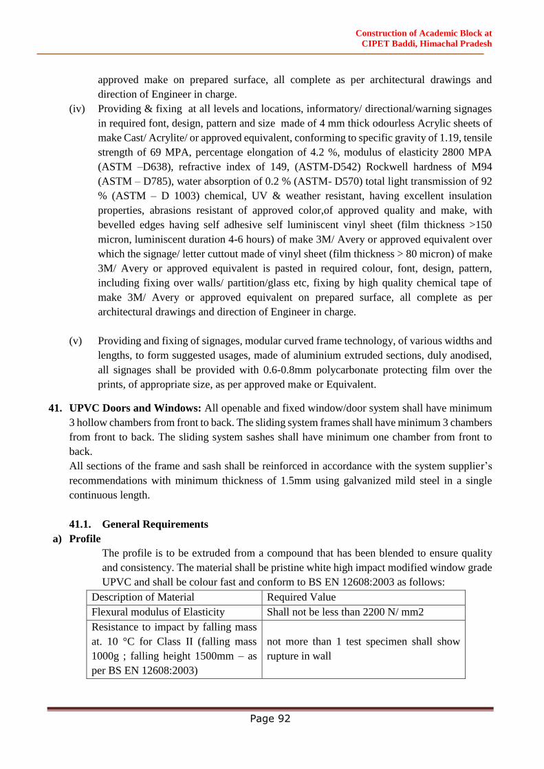
Construction of Academic Block at
CIPET Baddi, Himachal Pradesh
Page 92
approved make on prepared surface, all complete as per architectural drawings and
direction of Engineer in charge.
(iv) Providing & fixing at all levels and locations, informatory/ directional/warning signages
in required font, design, pattern and size made of 4 mm thick odourless Acrylic sheets of
make Cast/ Acrylite/ or approved equivalent, conforming to specific gravity of 1.19, tensile
strength of 69 MPA, percentage elongation of 4.2 %, modulus of elasticity 2800 MPA
(ASTM –D638), refractive index of 149, (ASTM-D542) Rockwell hardness of M94
(ASTM – D785), water absorption of 0.2 % (ASTM- D570) total light transmission of 92
% (ASTM – D 1003) chemical, UV & weather resistant, having excellent insulation
properties, abrasions resistant of approved color,of approved quality and make, with
bevelled edges having self adhesive self luminiscent vinyl sheet (film thickness >150
micron, luminiscent duration 4-6 hours) of make 3M/ Avery or approved equivalent over
which the signage/ letter cuttout made of vinyl sheet (film thickness > 80 micron) of make
3M/ Avery or approved equivalent is pasted in required colour, font, design, pattern,
including fixing over walls/ partition/glass etc, fixing by high quality chemical tape of
make 3M/ Avery or approved equivalent on prepared surface, all complete as per
architectural drawings and direction of Engineer in charge.
(v) Providing and fixing of signages, modular curved frame technology, of various widths and
lengths, to form suggested usages, made of aluminium extruded sections, duly anodised,
all signages shall be provided with 0.6-0.8mm polycarbonate protecting film over the
prints, of appropriate size, as per approved make or Equivalent.
41. UPVC Doors and Windows: All openable and fixed window/door system shall have minimum
3 hollow chambers from front to back. The sliding system frames shall have minimum 3 chambers
from front to back. The sliding system sashes shall have minimum one chamber from front to
back.
All sections of the frame and sash shall be reinforced in accordance with the system supplier’s
recommendations with minimum thickness of 1.5mm using galvanized mild steel in a single
continuous length.
41.1. General Requirements
a) Profile
The profile is to be extruded from a compound that has been blended to ensure quality
and consistency. The material shall be pristine white high impact modified window grade
UPVC and shall be colour fast and conform to BS EN 12608:2003 as follows:
Description of Material Required Value
Flexural modulus of Elasticity Shall not be less than 2200 N/ mm2
Resistance to impact by falling mass
at. 10 °C for Class II (falling mass
1000g ; falling height 1500mm – as
per BS EN 12608:2003)
not more than 1 test specimen shall show
rupture in wall
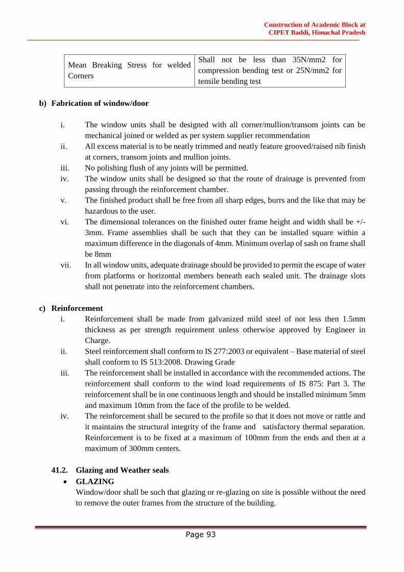
Construction of Academic Block at
CIPET Baddi, Himachal Pradesh
Page 93
Mean Breaking Stress for welded
Corners
Shall not be less than 35N/mm2 for
compression bending test or 25N/mm2 for
tensile bending test
b) Fabrication of window/door
i. The window units shall be designed with all corner/mullion/transom joints can be
mechanical joined or welded as per system supplier recommendation
ii. All excess material is to be neatly trimmed and neatly feature grooved/raised nib finish
at corners, transom joints and mullion joints.
iii. No polishing flush of any joints will be permitted.
iv. The window units shall be designed so that the route of drainage is prevented from
passing through the reinforcement chamber.
v. The finished product shall be free from all sharp edges, burrs and the like that may be
hazardous to the user.
vi. The dimensional tolerances on the finished outer frame height and width shall be +/-
3mm. Frame assemblies shall be such that they can be installed square within a
maximum difference in the diagonals of 4mm. Minimum overlap of sash on frame shall
be 8mm
vii. In all window units, adequate drainage should be provided to permit the escape of water
from platforms or horizontal members beneath each sealed unit. The drainage slots
shall not penetrate into the reinforcement chambers.
c) Reinforcement
i. Reinforcement shall be made from galvanized mild steel of not less then 1.5mm
thickness as per strength requirement unless otherwise approved by Engineer in
Charge.
ii. Steel reinforcement shall conform to IS 277:2003 or equivalent – Base material of steel
shall conform to IS 513:2008. Drawing Grade
iii. The reinforcement shall be installed in accordance with the recommended actions. The
reinforcement shall conform to the wind load requirements of IS 875: Part 3. The
reinforcement shall be in one continuous length and should be installed minimum 5mm
and maximum 10mm from the face of the profile to be welded.
iv. The reinforcement shall be secured to the profile so that it does not move or rattle and
it maintains the structural integrity of the frame and satisfactory thermal separation.
Reinforcement is to be fixed at a maximum of 100mm from the ends and then at a
maximum of 300mm centers.
41.2. Glazing and Weather seals
GLAZING
Window/door shall be such that glazing or re-glazing on site is possible without the need
to remove the outer frames from the structure of the building.

Construction of Academic Block at
CIPET Baddi, Himachal Pradesh
Page 94
i. Window shall be such that glazing or re-glazing on site is possible without the need to
remove the outer frames from the structure of the building.
ii. All glazing is to be packed in accordance with the system supplier’s recommendations
to prevent any kind of damage during handling
iii. All beads will be cut at the correct degree recommended by the manufacturer. Glass
retention clips shall be fitted in accordance with the Systems supplier’s
recommendations. Windows will be with 21mm thick hermetically sealed glass units
having 6-10-5 arrangement
WEATHER SEALS
The weather seals shall be EPDM/ Silicone seals. ASTM- D412 and ASTM- D2240 are
standard specifying test methods for Tensile strength and Hardness of the gasket whereas
the required value shall be specified
Ultimate tensile strength min >7.5 N/mm2
The weather seals are to be fitted in continuous lengths and grooves. The joints in the vent
weather seal are to be positioned at the bottom and in the outer frames at the top.
Security and Safety
Fasteners shall be designed so that they cannot be released from the outside by the
insertion of a thin blade.
No opening light shall be openable or removable from the outside, when it is fastened in
the closed position, except by use of special tools or breaking part of the window.
41.3. QUALITY CONTROL AND TESTING OF MATERIALS
a) Raw Material
The material from which the profiles are made shall consist substantially from white
polyvinyl chloride as per BS EN 12608:20003. Only those additives and pigments may
be used that are needed for the manufacture of the compound and its subsequent
conversion into sound, durable extrusions of good surface finish and mechanical strength,
as assessed by the requirements of this specification.
41.4. Profile Properties
a) Appearance and Finish
The color of the profile shall be uniform and the color of all profiles in a system shall be
uniform. The profile shall be free from foreign bodies, cracks or sink marks when viewed
by normal corrected vision at 90o to the surface and at a distance of 1 meter in normal
diffused north light.
b) Dimensions and Weights
The profiles shall be straight such that the longitudinal axis of the profile, as measured on
the face surfaces, may deviate from the straight line by no more than 1mm per meter. The
Construction of Academic Block at
CIPET Baddi, Himachal Pradesh
Page 95
cross section of the profile shall conform in shape and dimensions and may deviate by no
more than +/- 0.5mm; glazing channels and seal grooves may deviate by not more than
+/- 0.3mm. The weight of the profile per meter shall not be more than 5% below the
nominal value.
41.5. Resistance to wind load
All load bearing members shall be adequately reinforced so as to resist the wind load
requirements of IS 875: Part 3. Calculations shall be submitted for all window designs.
41.6. Installation of Frame
i. Before installation the Installation Team is to make sure that the opening has been
prepared and any repair work has been carried out. Allow a 5mm gap between the
frame and the opening. The new window shall be set in the prepared opening. Allow
for suitable packing blocks. The dimension tolerance on the aperture opening should
be +/ - 5mm. any deviation in opening shall be brought in knowledge of contractor by
installation team. the contractor should repair the same within specified dimension
tolerance
ii. The window shall be fixed into the aperture, by drilling and fixing through the outer
frame, to the existing structure using 10x100 mm with white cap in existing pre-
finished wall.
iii. The fixings shall be between 150mm – 200mm and no more than 700mm from
corners or transoms/mullions and at no more than 600mm centers.
iv. When the frame is securely fixed in position then fit glass and glazing beads. Allow
for any necessary glazing blocks and glass lock devices.
v. Check windows for correct operation before proceeding with making good.
vi. No fixings are to penetrate the drainage channels.
vii. The windows shall be first treated with Polyurethane Foam (PU Foam) to enhance
insulation against heat and Noise. The gap between masonry and the frame is to be
filled with Neutral Cure Silicon (exposed to sun surface) and/or Acrylic Sealant (only
for the internal surface). The windows shall be first treated with Polyurethane Foam
(PU Foam) to enhance insulation against heat and Noise
viii. Window/Door shall be installed only after first coat of paint.
41.7. Making Good
Making good to the external surface of the window frame and finish with a compatible
approved low modular silicone sealant to BS5889. All trims and quadrants are to be
approved by the Engineer- in- Charge prior to fixing.
41.8. Guarantees
Manufacturer to offer a warrantee on the window profile used in the manufacture of
UPVC window/door systems for a period of 10 years from the date of installation. The
Warrantee has to cover all abnormal defects in workmanship/quality. The guarantee has
to be underwritten by a Company nominated Executive and also signed by the contractor.
Construction of Academic Block at
CIPET Baddi, Himachal Pradesh
Page 96
The contractor should ensure that no damage is caused after the installation of
Window/Door at site.
41.9. Window Hardware
i. All door/windows are to be provided with multi point locking arrangement
with/without key locking facility as per the requirement. The hardware to be of
approved make.
ii. Casement window friction stays are to be of approved make of appropriate size and
weight bearing capacity, made of SS304.
42. AAC Blocks
If the contractor uses AAC blocks, the same shall be used with precautions during constructions to
avoid cracks.
Concrete block masonary is very much prone to shrinkage cracks. It requires to be dried
for a period of at least 28 days after curing so that the blocks undergo initial shrinkage
before use in masanory work. (Refer clause 4.1.2 of Section 4 of SP:20)
The exposed walls shall require close inspection in every year before monsoon, and
cracks, if any, need to be sealed properly with ement grout and painted with two coats of
cement paint (clause 13.1 of IS 6041-1985)
To avoid shrinkage cracks chicken mesh plast is required
In buildings in earthquake-prone regions, it is essential to provide RCC bond beams and
studs used as structural members (Clause 4.7 of IS 6041-1985)
In localities where rainfall is heave or the walls are exposed to sea weather, cellular
concrete block masonary shall be rendered with two coats of plaster. First coat (backing
coat) shall be of 15mm thickness of 1:1:6 cement-lime-sand mortar or 1:6 cement-sand
mortar. Second coat (finishing coat) shall be of 5 to 10 mm thickness of 1:1:6 to 1:2:9
cement-lime-sand mortar. (Clause 12.1.3 of IS 6041-1985)
Construction of Academic Block at
CIPET Baddi, Himachal Pradesh
Page 97
SPECIFICATIONS
(ELECTRICAL WORKS)

Construction of Academic Block at
CIPET Baddi, Himachal Pradesh
Page 98
GENERAL SCOPE OF WORK: ALL ELECTRICAL WORKS IS TO BE CARRIED OUT
AS PER DRAWINGS, BOQ, AND TECHNICAL SPECIFICATION.
GENERAL
To provide a complete electrical system for the distribution of electric power from the point of
supply (SEB), D.G.s to the utilization equipment, and described in these specifications. It will be
the bidder’s responsibility to work out the exact quantities with drawings as per area program &
from work site, which trade provides said equipments, materials, tools and labor.
SCOPE
The bidder shall supply, install and commission along with requisite spare, maintenance tools and
tackles the following equipments and system in the Building. The scope also covers the detailed
engineering and calculations of the various equipments/system mentioned hereunder and the same
shall be approved by the WAPCOS Limited prior to execution of the job.
1. 33 KV H.T. Switchgears.
2. Specification of Distribution Transformers
3. Specification of L.T panels and switchgears.
4. Specification for Lighting Protection system.
5. Specification for Capacitor Bank and Capacitor Control Panels.
6. Specification of HT cable (XLPE) (33KV) / L.T. Cables & Wires
7. Specification for Internal Electrical Works.
8. Specification for wiring.
9. Specification for D.G Set.
10. Specification for Intelligent Reporting Fire Detection System
11. Specification for PA system
12. Surveillance Closed Circuit Television (CCTV) System.
13. Specification for Conduiting and Wiring for Telephone System.
14. Specification ofHeat Ventilation &AirConditioning System.
15. Specification for Nurse Call System.
16. Specification ofSignage.
17. Specification of Lift.
18. Solar System
19. U.P.S System
This specification defines the basic guidelines to develop a suitable electrical system as
necessary for the all buildings. All data required in this regard shall be taken into consideration
to develop a detailed engineering of the system. Compliance with these specifications and/or
approval of any of the Contractor’s documents shall in no case relieve the Contractor of his
contractual obligations. All work to be performed and supplies shall be affected as a part of
contract requires specific approval/review of Owner or his authorized representative. Major
activities requiring approval/review shall include but not be limited to the following:
The engineering activities shall comprise the submission for approval of the following:
Construction of Academic Block at
CIPET Baddi, Himachal Pradesh
Page 99
a) Basic engineering documents e.g. overall single line diagram, area classification
drawing, overall cable layout, testing, type test report, guaranteed particulars of all
equipments and maintenance manuals.
b) Quality assurance procedures.
c) Field testing and commissioning procedures.
d) Control and protection schemes.
e) Load sharing and annunciation scheme,
f) Preparation of power supply distribution drawing.
Bidder shall be responsible for:
a) Detailed co-ordination with other services, shop drawings for various electrical layouts such
as equipment layout, lighting layouts, cabling layouts, earthing and lightning protection
layouts, including equipment installation and cable termination details etc. prior to start of
work.
b) Preparation of bill of materials for cabling, lighting, earthing and miscellaneous items etc,
Cable schedule, Lighting/power panel schedule, Interconnection drawing, Protection co-
ordination drawings/tables for complete power system, Shop inspection and testing
procedures, Field testing and commissioning procedures,
c) Preparation of as built drawings.
Bidder shall also be responsible for:
Any other work/activity which is not listed above however is necessary for completeness
of electrical system.
CODES & STANDARDS
The design engineering manufacturing and the installation shall be in accordance with established
codes, sound engineering, practices, and specifications and shall conform to the statutory regulations
applicable in the country. Contractor shall obtain all approvals from statutory authorities’ e.g.
Electrical inspector, pollution control boards, SEB as applicable before commissioning of
electrical/DGs, Indian Electricity Act, Indian Electricity Rules, Factory Act, Pollution Control Act,
Central Pollution Control Act.
IS-732: Code of practice for electrical wiring installation system voltage not exceeding 650V.
IS-3043: Earthing.
IS-2309: Code of practice for the protection of buildings and allied structure against Lightning
IS-7689: Guide for control of undesirable static electricity.
IS-3716: Insulation co-ordination application guide.
IS-8130: Conductors for insulated electrical cables and flexible cords.
IS-5831: PVC insulation and sheath of electric cables.
Construction of Academic Block at
CIPET Baddi, Himachal Pradesh
Page 100
IS-3975: Mild steel wire, strips & tapes for armouring cable.
IS-3961: Current rating of cables
IS-694: PVC insulated (heavy duty) electric cables for working Voltage up to and including 1100
volts.
IS-424- 1475 (F-3): Power cable flexibility test.
IEC-439/IS-7098: Specification for cross linked polyethylene insulated PVC sheathed cable for
working voltage up to 1.1 KV.
IS-1554: PVC insulated cables up to 1100 volts.
IS-10810: Test procedures for cables.
IS-6121: Cable glands.
IS-10418: Cable drums.
IEC-754(1): FRLS PVC insulated cable.
ASTM-D-2863: Standard method for measuring minimum oxygen concentration to support candle
like combustion of plastic (oxygen index).
ASTM-D-2843: Standard test method for measuring the density of smoke from burning or
decomposition.
ASTM E-662/IEC 754(A)
Standard test method for specific optical density of smoke generated by solid materials.
IEEE-383: Standard for type test class-IE, electric cables, field splicers and connections for power
generation station.
IS 13947/IEC 947: Air circuit breaker/moulded case circuit breaker.
IS-8623: Specification for factory built assemblies of switch gear and control gear for voltage upto
and including 1000vac/1200vdc
IS 1018: Switchgear and control gear selection/installation and maintenance
IS-1248: Direct acting indicating analogue electrical measuring instruments and testing accessories.
IS-13779: Digital measuring instruments and testing accessories.
IS-3156: Voltage transformer
IS-2705: Current transformer for metering and protection with classification burden and insulation.
IS -2147: Degree of protection provided by enclosures for low voltage.
PART 1, 11, 111 Switchgear and control gear
IS-3427: Metal enclosed switchgear and controlgear
BS-162: Safety clearance
IS-3202: Code of practice for climate proofing of electrical equipment.
IS-375: Marking and arrangement for switchgear, busbars, main connections and auxiliary wiring.
IS-722: Ac electric meters
IS-3231: Electrical relays for power system protection.
IEC-255: Electrical Relays
IS-5082: Electrolytic copper/aluminium bus bars
IS-2834: Capacitors
IS-2713: Steel tubular pole
IS-335: Specification for insulating oil
IS-3837: Specifications for accessories for rigid steel conduit for electrical wiring.
Construction of Academic Block at
CIPET Baddi, Himachal Pradesh
Page 101
IS-2026&335: Distribution transformer
(PART I, II, III)GI/STEEL /PVC conduit pipe for electrical wiring.
IS-2274: Code of practice for electrical wiring installation system voltages exceeding 650 volts.
IS-6665: Code of practice for industrial lighting
IS-3646: Interior insulation part 1&2
a) Supply Voltage 11 KV or 6 KV as applicable
b) Neutral Earthing Solid Earthing
c) Voltage Regulation + 10%
d) Frequency Regulations + 3%
IS-1944: Code of practice for lighting of public through fares.
IS-7752: Guide for improvement of power factor consumers installation.
IS-13346: General requirement for electrical for explosive gas atmosphere.
IS-13408: Code of practice for the selection, installation and maintenance of electrical apparatus for
use in potentially explosive atmospheres
IS-12360: Voltage and frequency for ac transmission & distribution system.
IS-5572: Classification of hazardous area for electrical installations.
IS-5571: Guide for selection of electrical equipment for hazardous area.
IS-4201: Application guide for Current Transformer
IS-4146: Application guide for Voltage Transformer
IS-10028: Code of practice for installation and maintenance of transformer
IS-8478: Application guide for on load tap changer
IS-10561: Application guide for power transformer
IS-1646: Code of practice for fire safety of buildings electrical installation
IS-3034: Code of practice for fire safety of industrial building-electrical generating and distribution
station
IP-30: National electrical code (NEC) BIS publication.
IS-4722: Rotating electrical machines.
IS-4889: Method of determination of efficiency of rotating electrical machines.
IS-325: Three phase induction motors.
IS-4729: Measurement and evaluation of vibration of rotating electrical machines.
IS-900: Installation and maintenance of induction motors.
IS-4029: Air break switches.
IS-2208-9224: HRC cartridge fuses.
IS-2959: Contactors.
IS-9537: Rigid steel conduit.
IS-1030-1982: Specification for carbon steel castings for general engineering purpose.
IS-1601/ BS-649: Performance& testing of Internal Combustion (IC) engines for general purpose.
AIEE-606(1959): Recommended specification for speed governing of I.C. engine generator units.
BS-5514/IS-3046 8528(Part-2): Reciprocating IC engine driven A.C. generators.
Any other standard may be followed provided it is equivalent or more stringent than the standards
specified above. In case of any deviation /conflict of this specification with the codes & standards,
Construction of Academic Block at
CIPET Baddi, Himachal Pradesh
Page 102
the following order of precedence shall govern. Specification, particular specification if any, and
drawings. Indian regulations/codes and standards.
CONDITIONS:
1. All internal electrical works shall be carried out with MS/ PVC conduit. All switches, sockets,
AC ON & OFF Starter, IP Phone socket, Data sockets, stepped type (2 modules) fan
regulators, bell push and accessories along with matching mounting boxes shall be of modular
type. Power point for computer shall have 3 sockets and 1 16Amp switches in one box.
2. All mounting boxes for plate type accessories shall be of metallic construction and of the
same make as that of the plate type switches and accessories.
3. The wires used for the point wiring and power wiring shall be of 650/ 1100 Volts
4. Grade FRLS (flame Retardant low Smoke) Insulated multi stranded copper conductor single
core cables.
5. All lighting fixtures should be LED type having efficacy more than 130 Lumen / Watt except
for down lighter for which efficacy shall be more than 120 lumen/watt and CRI >80, THD
<5%, LM 79 & LM 80 test report from NABL accredited lab should be submitted by the
agency. Color temperature may be 3000/4000/6000K as per site requirement. The compound
light shall be IK 10, IP 66 rating fitting.
6. Lighting Design should be carried out as per National Lighting Code 2010/NBC/ECBC
guidelines. Wherever range of illumination for space is mentioned, higher side of Lux level
must be taken for design purpose.
7. Ceiling fans will also be provided everywhere except stairs/toilets / Bathrooms. Only 5 Star
rating type ceiling fans of size 1200 / 900 mm shall be used. Optimum size and number of
ceiling fans for rooms of different size shall be as per provision laid down in CPWD
specifications for internal E.I. work – 2013 and NBC 2016.
8. Wiring for Telephone system shall be terminated in suitable size of G.I. box and terminated
in Modular Telephone outlet Socket at one end and Crone Type Telephone Tag box at another
end. The wiring shall be suitably tagged/marked mentioning the location of each point.
9. Wiring for TV system shall be terminated in suitable size of G.I. box and terminated in
Modular TV outlet Socket at one end and Dish TV box at another end. The wiring shall be
suitably tagged/marked mentioning the location of each point.
10. Minimum size of copper conductor for power wiring shall be 4 Sq mm and for light and fan
points wiring shall be 1.5 sq mm.

Construction of Academic Block at
CIPET Baddi, Himachal Pradesh
Page 103
11. UPS, Essential & non-essential DBs shall be separate. The size of DBs at one location shall
be same irrespective of number of circuits connected from the DBs.
12. The wiring and conduit route plan/drawings shall be submitted by the contractor and shall be
got approved from the Engineer-in-charge.
13. To facilitate drawing of wires, 18 SWG GI fish wire shall be provided in recessed conduit.
Conduits laid for other services, like fire alarm, PA system etc., where wiring is not done
along IEI works; fish wire shall be invariably drawn.
14. The connection between incoming switch / isolator and bus bar shall be made with suitable
size of thimble and cable.
15. Power supply to DBs for Machine room Lifts at suitable location as approved by Engineer-
in-charge shall be done using suitable XLPE insulated armored cable. Supply of cable shall
be in the scope of work.
16. Size of distribution board shall be as per number of light / power circuits. All distribution
boards shall be double door type. RCCB of suitable rating shall be provided as main incomer
in all DBs’
17. In vertical DBs used for power distribution main incomer shall be MCCB of 35/36KA rating
breaking capacity.
18. LT panel shall be cubicle type with IP 42 protection class and fabricated from approved
fabricator as per accepted list attached and shall be equipped with digital type measuring
instruments like ammeter, voltmeter, frequency meter, watt meter, multi- function meter etc.
as per drawing approved by Engineer – in – charge. Any Cable end Box, looping/ Connection
Box, Loose wire box above DB’s required for termination of cable is to be provided by the
agency and no extra cost to be paid.
19. Each floor Panel shall be fabricated from 2 mm thick M.S. sheet powder coated with 9 tank
process and shall be equipped with 4 pole MCCBs, MCBs, Bus bar, digital Multifunction
meter, LED indicating lamp extended rotary handle and all accessories as required.
20. MCCB, if used as incomer then it should have earth fault protection and time delay within
the MCCB.Earth leakage modules are not acceptable.
21. Inside the lift shaft there shall be arrangement of one light point at each floor level and one
light point at overhead, one light point in lift pit. All light points shall be in group controlled
and wired with 2.5 sq mm FRLS copper conductor cable. 15 amp power plug and 5 amp
power plug shall be provided at each floor. Wiring of these power plugs shall be done with 4
Construction of Academic Block at
CIPET Baddi, Himachal Pradesh
Page 104
sq mm FRLS copper wires. LED Bulk head fittings of suitable rating to provide minimum
100 lux shall be connected with each point of lift shaft.
22. The breaking capacity of MCCB for all types of panel boards except DBs shall be as per fault
level of that location. The rated service breaking capacity should be equal to rated ultimate
breaking capacities (Ics=Icu=100%). Where Ics is service breaking capacity and Icu is
ultimate breaking capacity and they should be of approved make. MCCBs above 200A of 35
/36 KA breaking capacity rating shall be provided with microprocessor relay with suitable
fault level with adjustable O/L, S/C, protection and upto 200A with Thermal Magnetic release
of suitable fault level having adjustable settings for O/L and S/C.
23. All types of panel shall be fabricated from approved firms and strictly as per CPWD
specifications. The drawing of panel boards must be got approved from Engineer – in – charge
before fabrication work. The panel board shall consist of MCCB as incomer and outgoing,
aluminium bus bar, digital type ammeter, voltmeter OR multifunction meter, selector
switches, LED type indication lamps etc as per standard sound engineering practice.
24. While laying conduits for fire alarm system, sufficient junction outlets are to be provided as
per the direction of the Engineer-in-Charge for detectors as required.
25. After completing the work, necessary test results as envisaged in CPWD General
Specifications Part-I (Internal)-2013 & Indian Electricity Rules 1956, shall be recorded and
submitted to the department.
26. Lightning arresters shall be provided for building as per IS; 2309-1989 as amended up to date
and CPWD specifications for internal work – 2013 & aviation lights (LED Type) shall also
be provided.
27. Earthing system comprising of earth electrode, earth conductor, earth bus, protective
conductor etc for building shall be as per provision laid down in CPWD specifications part –
I, 2013. Earthing system should be designed such as to maintain earth resistance as specified
in CPWD specifications. Earth resistance shall be checked / tested in harsh climatic
conditions.
ADDITIONAL CONDITIONS
1. Specification: - The work shall be executed as per CPWD’s General Specification for Electrical
Works Part-I (Internal)-2013, Part-II (External)-1994, Part-IV (Sub-station)- 2013, IE Rules, Indian
Standards amended upto date and as per direction of Engineer-in-Charge. The additional
specifications are to be read with above and in case of any variations; Specifications given along
with the tender shall apply.
2. Storage: - Responsibility for storage for execution of work shall be of main contractor.

Construction of Academic Block at
CIPET Baddi, Himachal Pradesh
Page 105
3. Power & Water Supply:- Responsibility for supply of power & water for execution of work shall
be of main contractor.
4. The material required to be used in the work shall be got approved from the Engineering-charge
before its use at site. The Engineer-in-charge shall reserve the right to instruct the contractor to
remove the material which, in his opinion, is not as per specifications.
5. Contractor shall preserve the copies of invoices, test certificates; gate passes etc. to prove the
genuineness of material/purchases. The responsibility of procurement, genuine material of
specialized works shall rest with the contractor.
6. No inspection outside the country is permissible if required so the same will be deemed to be
waived off and necessary test reports shall be submitted before the dispatch of equipment.
7. Guarantee: All the equipment’s shall be guaranteed for a period of 36 months from the date of
completion. Any defective materials and equipment shall be replaced free of cost at the direction of
the Engineer-in-Charge.
All other any item to commission the system shall be provided by bidder without any extra cost.
Electrical work as per below:
CPWD General Specification for Electrical Works Part I Internal –2013.
General Specification for Electrical Works (Part III Lifts & Escalators)-2003
CPWD General Specification for Electrical Works Part IV Substation-2013
CPWD General Specification for Electrical Works Part VII DG Sets –2013.
Note: All above Specifications & Other Specification, Codes & Standards Mentioned Elsewhere
in the Bid Document Shall Be Applicable With Revisions/Amendments/Correction Upto
31.03.2020
General
Internal electric installation (IEI)
General Specifications for Electrical Works Part-I (Internal)-2013 and Part-II (External)-1994 with
amendments up to the date of opening of bids and the governing specifications, which are mandatory
including makes for some of the important materials to be used in the work. In case of ambiguity
between the two, the specifications shall prevail.
FRLS insulated Copper conductor wires will be used for points, circuit & sub-main wiring.
Agency shall execute the work as per scale of amenities given elsewhere in document after obtaining
necessary approval of the layout for internal electrification of all houses, common areas and staircases
from Engineer-in-charge. The staircase lighting shall be in group control system.
Construction of Academic Block at
CIPET Baddi, Himachal Pradesh
Page 106
Modular type switches, sockets and stepped type electronic fan regulators, bell push along with
matching mounting boxes of same make shall be used.
TV outlet point wiring of each house shall be terminated in suitable size of G.I. box along with splitter
at every floor. The interconnections of all splitter boxes fixed at all floors shall be done properly with
conduits to form proper distribution system with the prior approval of Engineer-in- charge.
Telephone outlet point wiring of each house shall be terminated in suitable size of G.I. Junction box
in DUs direct from ground floor to each DU. However, conduit for telephone wiring may be provided
through branching by providing suitable size of G.I. box along with suitable tag block at each floor.
The inter connections of all junction boxes fixed at all floors shall be done properly making proper
distribution system with the prior approval of Engineer-in-charge. Providing incoming television /
telephone cables from the site boundary of each building is not covered in the scope of this bid.
However, pipes for laying of these cables shall be provided by the bidder as per direction of Engineer-
in-Charge.
Suitable rain protection covers made of 16 SWG galvanized MS sheet wherever required shall be
provided.
Lighting fixtures of LED Type with wattage and fans for all quarters to be provided by bidder. The
model number of fittings and fans shall be got approved by the Engineer-in-charge before execution.
Separate shaft for each block of houses shall be provided for laying of Electrical, mechanical & fire
services. HDPE / DWC pipes for taking L.T. cables up to Meter Boards in the Meter Rooms along
with brick masonry chambers of suitable size shall be provided by the agency wherever required.
Laying of HDPE / DWC /Hume pipes for road crossing or in pucca portion & CC path etc. for electric
/ telephone / street lighting cables complete with adequate number of cable chambers shall be provided
by the agency.
After completing the work, necessary test results as envisaged in CPWD General Specifications Part-
I (Internal)-2013 & Indian Electricity Rules 2005, shall be recorded and submitted to the department.
The results shall be within the permissible limits. Test report forms duly signed by authorized person
for obtaining electric connections (energy meters) from Power Distribution Company by the agency
shall be given to the allottees.
Ceiling fans exhaust fans & LED light fixture of suitable wattage, call bell in these buildings shall
also be provided by the agency as per direction of Engineer-in-charge.
Lightning arresters as per IS; 2309 -1989 as amended up to date & aviation lights (LED Type) shall
also be provided by successful bidder.
LT CABLES & CABLE TRAYS:
STANDARDS OF CODES
This chapter covers the specifications for supply and laying of Medium Voltage XLPE cables.
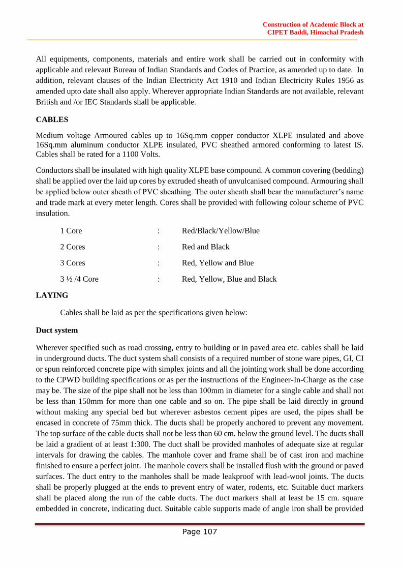
Construction of Academic Block at
CIPET Baddi, Himachal Pradesh
Page 107
All equipments, components, materials and entire work shall be carried out in conformity with
applicable and relevant Bureau of Indian Standards and Codes of Practice, as amended up to date. In
addition, relevant clauses of the Indian Electricity Act 1910 and Indian Electricity Rules 1956 as
amended upto date shall also apply. Wherever appropriate Indian Standards are not available, relevant
British and /or IEC Standards shall be applicable.
CABLES
Medium voltage Armoured cables up to 16Sq.mm copper conductor XLPE insulated and above
16Sq.mm aluminum conductor XLPE insulated, PVC sheathed armored conforming to latest IS.
Cables shall be rated for a 1100 Volts.
Conductors shall be insulated with high quality XLPE base compound. A common covering (bedding)
shall be applied over the laid up cores by extruded sheath of unvulcanised compound. Armouring shall
be applied below outer sheath of PVC sheathing. The outer sheath shall bear the manufacturer’s name
and trade mark at every meter length. Cores shall be provided with following colour scheme of PVC
insulation.
1 Core : Red/Black/Yellow/Blue
2 Cores : Red and Black
3 Cores : Red, Yellow and Blue
3 ½ /4 Core : Red, Yellow, Blue and Black
LAYING
Cables shall be laid as per the specifications given below:
Duct system
Wherever specified such as road crossing, entry to building or in paved area etc. cables shall be laid
in underground ducts. The duct system shall consists of a required number of stone ware pipes, GI, CI
or spun reinforced concrete pipe with simplex joints and all the jointing work shall be done according
to the CPWD building specifications or as per the instructions of the Engineer-In-Charge as the case
may be. The size of the pipe shall not be less than 100mm in diameter for a single cable and shall not
be less than 150mm for more than one cable and so on. The pipe shall be laid directly in ground
without making any special bed but wherever asbestos cement pipes are used, the pipes shall be
encased in concrete of 75mm thick. The ducts shall be properly anchored to prevent any movement.
The top surface of the cable ducts shall not be less than 60 cm. below the ground level. The ducts shall
be laid a gradient of at least 1:300. The duct shall be provided manholes of adequate size at regular
intervals for drawing the cables. The manhole cover and frame shall be of cast iron and machine
finished to ensure a perfect joint. The manhole covers shall be installed flush with the ground or paved
surfaces. The duct entry to the manholes shall be made leakproof with lead-wool joints. The ducts
shall be properly plugged at the ends to prevent entry of water, rodents, etc. Suitable duct markers
shall be placed along the run of the cable ducts. The duct markers shall at least be 15 cm. square
embedded in concrete, indicating duct. Suitable cable supports made of angle iron shall be provided
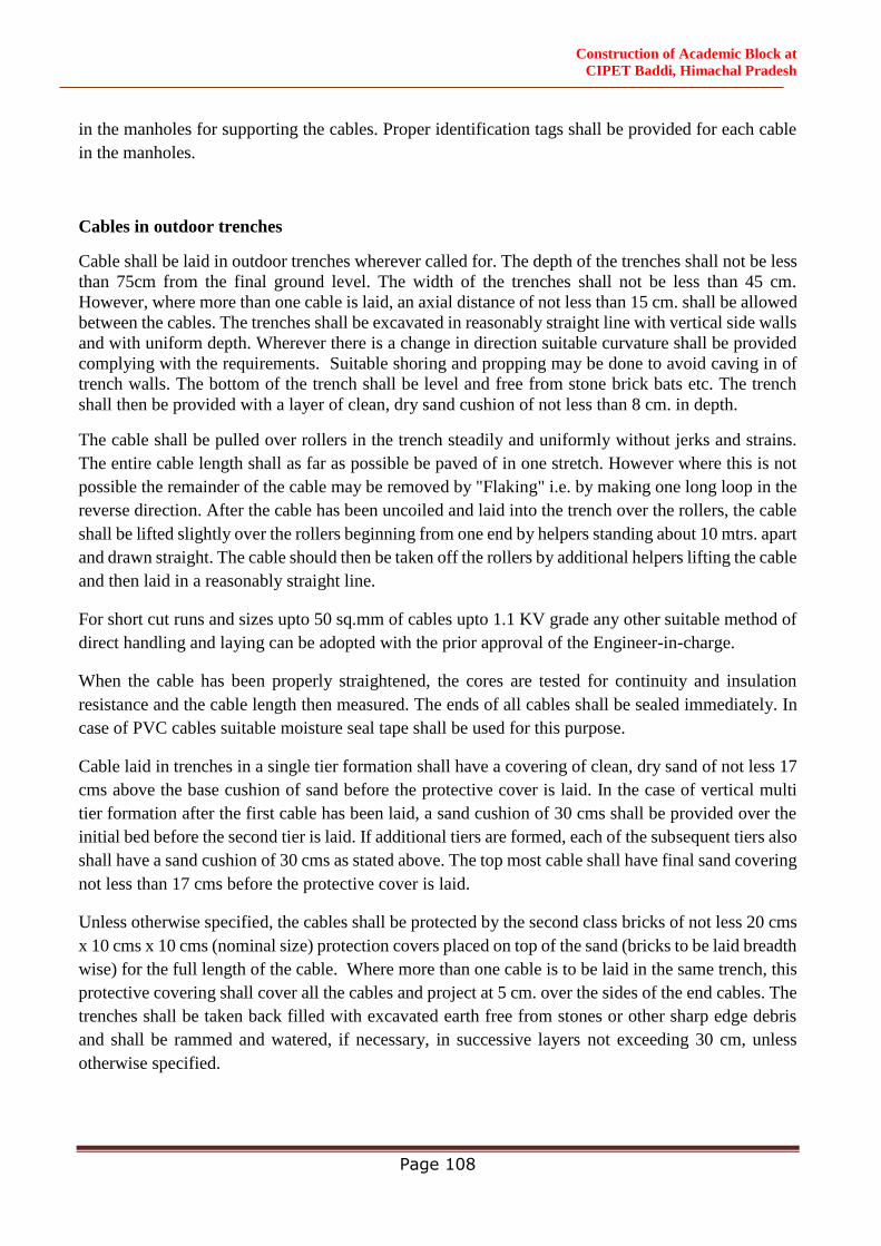
Construction of Academic Block at
CIPET Baddi, Himachal Pradesh
Page 108
in the manholes for supporting the cables. Proper identification tags shall be provided for each cable
in the manholes.
Cables in outdoor trenches
Cable shall be laid in outdoor trenches wherever called for. The depth of the trenches shall not be less
than 75cm from the final ground level. The width of the trenches shall not be less than 45 cm.
However, where more than one cable is laid, an axial distance of not less than 15 cm. shall be allowed
between the cables. The trenches shall be excavated in reasonably straight line with vertical side walls
and with uniform depth. Wherever there is a change in direction suitable curvature shall be provided
complying with the requirements. Suitable shoring and propping may be done to avoid caving in of
trench walls. The bottom of the trench shall be level and free from stone brick bats etc. The trench
shall then be provided with a layer of clean, dry sand cushion of not less than 8 cm. in depth.
The cable shall be pulled over rollers in the trench steadily and uniformly without jerks and strains.
The entire cable length shall as far as possible be paved of in one stretch. However where this is not
possible the remainder of the cable may be removed by "Flaking" i.e. by making one long loop in the
reverse direction. After the cable has been uncoiled and laid into the trench over the rollers, the cable
shall be lifted slightly over the rollers beginning from one end by helpers standing about 10 mtrs. apart
and drawn straight. The cable should then be taken off the rollers by additional helpers lifting the cable
and then laid in a reasonably straight line.
For short cut runs and sizes upto 50 sq.mm of cables upto 1.1 KV grade any other suitable method of
direct handling and laying can be adopted with the prior approval of the Engineer-in-charge.
When the cable has been properly straightened, the cores are tested for continuity and insulation
resistance and the cable length then measured. The ends of all cables shall be sealed immediately. In
case of PVC cables suitable moisture seal tape shall be used for this purpose.
Cable laid in trenches in a single tier formation shall have a covering of clean, dry sand of not less 17
cms above the base cushion of sand before the protective cover is laid. In the case of vertical multi
tier formation after the first cable has been laid, a sand cushion of 30 cms shall be provided over the
initial bed before the second tier is laid. If additional tiers are formed, each of the subsequent tiers also
shall have a sand cushion of 30 cms as stated above. The top most cable shall have final sand covering
not less than 17 cms before the protective cover is laid.
Unless otherwise specified, the cables shall be protected by the second class bricks of not less 20 cms
x 10 cms x 10 cms (nominal size) protection covers placed on top of the sand (bricks to be laid breadth
wise) for the full length of the cable. Where more than one cable is to be laid in the same trench, this
protective covering shall cover all the cables and project at 5 cm. over the sides of the end cables. The
trenches shall be taken back filled with excavated earth free from stones or other sharp edge debris
and shall be rammed and watered, if necessary, in successive layers not exceeding 30 cm, unless
otherwise specified.
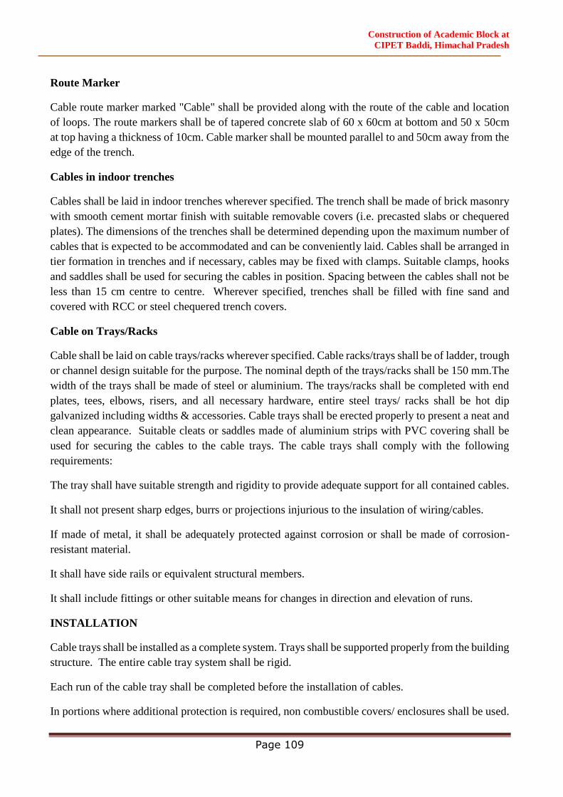
Construction of Academic Block at
CIPET Baddi, Himachal Pradesh
Page 109
Route Marker
Cable route marker marked "Cable" shall be provided along with the route of the cable and location
of loops. The route markers shall be of tapered concrete slab of 60 x 60cm at bottom and 50 x 50cm
at top having a thickness of 10cm. Cable marker shall be mounted parallel to and 50cm away from the
edge of the trench.
Cables in indoor trenches
Cables shall be laid in indoor trenches wherever specified. The trench shall be made of brick masonry
with smooth cement mortar finish with suitable removable covers (i.e. precasted slabs or chequered
plates). The dimensions of the trenches shall be determined depending upon the maximum number of
cables that is expected to be accommodated and can be conveniently laid. Cables shall be arranged in
tier formation in trenches and if necessary, cables may be fixed with clamps. Suitable clamps, hooks
and saddles shall be used for securing the cables in position. Spacing between the cables shall not be
less than 15 cm centre to centre. Wherever specified, trenches shall be filled with fine sand and
covered with RCC or steel chequered trench covers.
Cable on Trays/Racks
Cable shall be laid on cable trays/racks wherever specified. Cable racks/trays shall be of ladder, trough
or channel design suitable for the purpose. The nominal depth of the trays/racks shall be 150 mm.The
width of the trays shall be made of steel or aluminium. The trays/racks shall be completed with end
plates, tees, elbows, risers, and all necessary hardware, entire steel trays/ racks shall be hot dip
galvanized including widths & accessories. Cable trays shall be erected properly to present a neat and
clean appearance. Suitable cleats or saddles made of aluminium strips with PVC covering shall be
used for securing the cables to the cable trays. The cable trays shall comply with the following
requirements:
The tray shall have suitable strength and rigidity to provide adequate support for all contained cables.
It shall not present sharp edges, burrs or projections injurious to the insulation of wiring/cables.
If made of metal, it shall be adequately protected against corrosion or shall be made of corrosion-
resistant material.
It shall have side rails or equivalent structural members.
It shall include fittings or other suitable means for changes in direction and elevation of runs.
INSTALLATION
Cable trays shall be installed as a complete system. Trays shall be supported properly from the building
structure. The entire cable tray system shall be rigid.
Each run of the cable tray shall be completed before the installation of cables.
In portions where additional protection is required, non combustible covers/ enclosures shall be used.
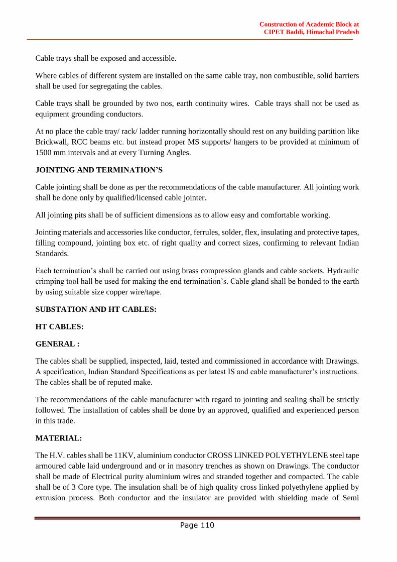
Construction of Academic Block at
CIPET Baddi, Himachal Pradesh
Page 110
Cable trays shall be exposed and accessible.
Where cables of different system are installed on the same cable tray, non combustible, solid barriers
shall be used for segregating the cables.
Cable trays shall be grounded by two nos, earth continuity wires. Cable trays shall not be used as
equipment grounding conductors.
At no place the cable tray/ rack/ ladder running horizontally should rest on any building partition like
Brickwall, RCC beams etc. but instead proper MS supports/ hangers to be provided at minimum of
1500 mm intervals and at every Turning Angles.
JOINTING AND TERMINATION’S
Cable jointing shall be done as per the recommendations of the cable manufacturer. All jointing work
shall be done only by qualified/licensed cable jointer.
All jointing pits shall be of sufficient dimensions as to allow easy and comfortable working.
Jointing materials and accessories like conductor, ferrules, solder, flex, insulating and protective tapes,
filling compound, jointing box etc. of right quality and correct sizes, confirming to relevant Indian
Standards.
Each termination’s shall be carried out using brass compression glands and cable sockets. Hydraulic
crimping tool hall be used for making the end termination’s. Cable gland shall be bonded to the earth
by using suitable size copper wire/tape.
SUBSTATION AND HT CABLES:
HT CABLES:
GENERAL :
The cables shall be supplied, inspected, laid, tested and commissioned in accordance with Drawings.
A specification, Indian Standard Specifications as per latest IS and cable manufacturer’s instructions.
The cables shall be of reputed make.
The recommendations of the cable manufacturer with regard to jointing and sealing shall be strictly
followed. The installation of cables shall be done by an approved, qualified and experienced person
in this trade.
MATERIAL:
The H.V. cables shall be 11KV, aluminium conductor CROSS LINKED POLYETHYLENE steel tape
armoured cable laid underground and or in masonry trenches as shown on Drawings. The conductor
shall be made of Electrical purity aluminium wires and stranded together and compacted. The cable
shall be of 3 Core type. The insulation shall be of high quality cross linked polyethylene applied by
extrusion process. Both conductor and the insulator are provided with shielding made of Semi
Construction of Academic Block at
CIPET Baddi, Himachal Pradesh
Page 111
Conducting compound. Armouring is applied over inner sheath and shall be of flat steel strips. The
outer sheath shall be of heat resisting tropodur (PVC) compound. This shall be of black color.
INSPECTION:
All cables shall be inspected upon receipt at site and checked for any damage during transit.
JOINTS IN CABLES:
The contractor shall take care to see that all the cables received at site are apportioned to various
locations in such a manner as to ensure maximum utilization and avoidance of jointing cable. This
apportioning shall be got approved by the Owner/Consultant before the cables are cut to lengths.
Where joints are unavoidable, the location of such joints shall be got approved by the
Owner/Consultants.
JOINTING BOXES FOR CABLES:
Cable joint boxes shall be of appropriate size, suitable for aluminium conductor XLPE insulated cables
of 11000 volts ratings, and shall be manufactured by CCI & Indian Cable Corporation or approved
equal.
JOINTING CABLES:
All cable joints shall be made in suitable, approved cable joint boxes. Jointing of cables in the joint
boxes and the filling in of compound shall be done in accordance with the best practice in trade, in
accordance with manufacturer's instructions and in an approved manner. All straight T-joints shall be
done in epoxy mould boxes with TROPOLIN/M-SEAL epoxy resin or approved equal. All jointing
accessories shall also be manufactured by Indian Cable Corporation/CCI or approved equal. All
terminal ends of conductors shall be heavily soldered upto at least 50mm length.
All cables shall be jointed color to color and tested for continuity and insulation resistance before
jointing commences. The seals of cables must not be removed until preparations for jointing are
completed. Joints shall be finished on the same day as commenced and sufficient protection for the
weather shall be arranged. Joints shall be made by means of suitable solder for conductors, the
conductors being firmly butted into the connections or thimbles or ferrules and the whole soldered
with proper solder and soldering flux or resin. The conductors shall be efficiently insulated with high
voltage insulating tape and use of spreaders of approved size and pattern. The joints shall be
completely filled with epoxy compound being topped as necessary to ensure that the box is properly
filled.
CABLE TERMINATIONS:
Cable termination shall be done in terminal cable box using cable glands and the cable ends sealed
with sealing compound. The cable boxes of transformers shall be filled with bituminous compound
manufactured by CCI or approved equal.
Construction of Academic Block at
CIPET Baddi, Himachal Pradesh
Page 112
BONDING OF CABLES:
Where a cable enters any piece of apparatus, it shall be connected to the casing by means of an
approved type of armoured clamp and gland. The clamps must grip the armouring firmly to the gland
or casing, so that in the event of ground movement no undue stress is passed into the cable conductors.
LAYING OF CABLES:
H.V. cables shall be laid either buried directly underground or in Masonry/Concrete trenches. The
cable buried underground shall be at minimum depth of 1.2 mtr from the ground level. Sand cushion
of not less than 80mm shall be provided both above and below the cable with a protective concrete
slab on the top of the sand layer. The cable trench shall be back filled and compacted.
PROTECTION OF CABLES:
The cable shall be protected by placing precast reinforced 50mm, thick (1:2:4) concrete slabs 200mm
wide on the top layer of sand for the length of the cable. Where more than one cable is running in the
same trench, the concrete blocks shall cover all the cables and shall project minimum 80mm on either
side of the cables.
Cables under road crossings and any surfaces subjected to heavy traffic shall be protected by running
them through Hume pipes of suitable size.
EXCAVATIONS AND BACK FILL:
All excavations and back fill including timbering, shorting and pumping required for the installation
of the cables shall be carried out by the Contractor in accordance with the drawings and requirements
laid down elsewhere. Trenches shall be dug true to line and grades. Back fill for trenches shall be
filled in layers not exceeding 150 mm. Each layer shall be properly rammed and consolidated before
laying the next layer. The contractor shall restore all surfaces, roadways, sidewalks curbs, walls or
other works cut by excavation to their original condition, satisfactory to the Owner/Consultants.
MARKERS AND WARNING PLATES:
Approved C.I. cable markers shall be provided along the route of the cable at every 30 M Distance
and at both ends of road crossing, indicating H.V. cables. Special C.I. markers shall be provided at all
buried cable joints indicating Electrical cable joint.
TESTING OF CABLES:
Prior to burying cables, following tests shall be carried out:
Insulation between phases and between phase and earth for each length of cables, before and
after jointing.
For H.V. cables, high voltage test by applying 17.5KV DC voltage for 15 minutes for each
core and earth.
Construction of Academic Block at
CIPET Baddi, Himachal Pradesh
Page 113
On completion of cable laying work, the following tests shall be conducted in the presence of
the Owner/Consultants.
Insulation Resistance Test (sectional and overall)
Continuity resistance test.
Sheathing continuity test.
EARTH TEST.
All tests shall be carried out in accordance with relevant Indian standard code of practice and
Electricity Rules. The contractor shall provide necessary instruments, equipment and labour for
conducting the above tests and shall bear all expenses in connection with such tests.
LOW VOLTAG, INTERNAL & EXTERNAL ELECTRICAL SYETEM:
CONDUITING AND WIRING FOR SAMTV SYSTEM:-
3.1.1 CONDUITING
Conduiting for SMATV system shall be carried out in MS/ PVC Conduit. Conduiting shall be carried
out as specified in point wiring head.
3.1.2 OUTLETS
All SMATV outlets shall be provided with modular range of cover plate, box and coaxial outlet. Cover
plate shall match in shape & finish with other light and power accessories.
3.1.3 JUNCTION BOX
Suitable size of metallic junction box shall be provided for termination of conduit for SAMTV system.
Box shall be made of 1.6mm thick MS sheet and shall be treated before painting. Front of the junction
box shall be provided with 3mm thick phenolic laminated sheet cover.
3.1.4 COAXIAL CABLES
The coaxial cable shall be of wideband type (RG-11 for Riser & RG-6 for distribution)
3.1.5 TAP OFF
These shall be of ultra wide bandwidth and of hybrid type. These shall have a flat frequency response
over the entire operating range. These shall have a aluminium cast housing for high frequency
radiation resistance.
The Tap offs shall be in one way, two way and four way configurations.
Construction of Academic Block at
CIPET Baddi, Himachal Pradesh
Page 114
3.1.6 SPLITTERS
These shall be of ultra wide band width and of hybrid type. These shall have a flat frequency response
over the entire operating range. These shall have a aluminium cast housing for high frequency
radiation resistance.
The splitters shall be in 2 way, 3 way & 4 way configurations
3.2 INTERNAL & EXTERNAL ELECTRICAL SYSTEM
General Specifications for Electrical Works Part-I (Internal)-2013 and Part-II (External)-1994 with
amendments up to the date of opening of bids and the governing specifications, which are mandatory
including makes for some of the important materials to be used in the work. In case of ambiguity
between the two, the specifications shall prevail.
4.1 11KV/ 0.433KV TRANSFORMER (Oil Type–with outdoor Enclosure)
CAPACITY OF 11KV / 0.415KV SUBSTATION
1x630 KVA, 11KV/0.415KV, 3 Phase, 4 Wire, 50 Hz, oil type transformer with off load tap changer
may be installed on Ground Floor Level to provide the power to phase-I building with required H.T.
Panel, H.T. Metering Panel.
4.1 GENERAL:
The work shall be carried out as per CPWD General Specifications for Electric al Works (Part -IV-
Sub Station ) 2013 as amended upto date ones conforming to I.S. specifications.
4.2 TRANSFORMER (LEVEL II):
Losses shall be as per Griha 3 and Losses shall be meaured by using calibrated digital meters of class
0.5 or better. For transformers of capacity equivalent or above 200 KVA shall be equipped with
additional current transformers (CTs) and potential transformers (PTs) for loss monitoring.
The transformer shall comply with the latest edition of the relevant Indian Standards / Manual. The
transformer shall be copper double wound core type, oil natural air natural cooled suitable for outdoor
installation. The transformer shall be designed and manufactured as per latest relevant IS / BS with up
to date amendments. Transformer shall be suitable for continuous rating as stated in Specification and
on drawings. The transformer winding shall be of electrolytic copper conductors covered with a
special material having high tensile and dielectric strength. The Core shall be made up of high grade
low loss cold rolled grain oriented steel sheets (CRGO). Core shall be treated with high temperature
resistant paint to prevent corrosion at edges of the core plates. Distribution Transformer with off load
tap changer, Balanced supply and unbalanced load.
INPUT : : 11KV,3Phase,3Wire,50Hz.
OUTPUT : 0.433KV,3Phases,4Wire,50Hz.
RATING : 630 KVA
VECTOR GROUP : Dyn-11
Construction of Academic Block at
CIPET Baddi, Himachal Pradesh
Page 115
OLTC : +/ - 2.5%, +/ - 5% (If red) off load tap changer
AMBIENTTEMP : -5TO+50degreecentigrade OIL
TEMP RISE : As per IS 1180.
WINDING TEMP RISE : As per IS 1180.
LOAD LOSSES : Max.AllowablelossesforOiltypetransformerat11KV
on 50% and 100% of the load shall be as per Energy
Efficiently Level – 2.
4.3 Generally the transformer shall conform to IS:2026 and unless otherwise stated following
standards shall be applicable and latest amended upto date.
i) IS: 1180
ii) IS: 3839
iii) IS: 6600
iv) IS: 335
v) IS: 1271
vi) IS: 2099
vii) IS: 3639
viii) IS: 2147
ix) IS: 3202
x) IS: 2705
xi) IS: 10028 (Part II & III): installation & maintenance of Transformer
4.4 TANKS & RADIATORS
Tanks shall be of MS. plates and structures, electrically welded. The construction shall be robust and
substantial, suitable for road/ rail transport and to withstand vibration. Radiator tubes shall be electrical
resistance welded type, round or elliptica l or rectangular. They may be welded to the transformer tank
or in case of very large sizes to separate detachable radiator banks connected through intermediate
leak proof valves. Detachable radiator banks shall have top and bottom headers with flanged
connections, with drain and vent fittings. Tanks shall be provided with lifting lugs and jacking lugs.
Inspection hole with cover should also be provided for large transformers. Oil conservators shall be
mounted on brackets attached to the top cover on t ank. Dimensions of the conservator shall be such
as to allow change in volume of oil due to change in temperature from 0 oC to 100oC.
Tanks shall be thoroughly cleaned, degreased and sand blasted inside and outside. A coat of rust
resisting primer shall immediately be given on outside surface. Inside surface shall be painted with
oil resistance enamel paint. Tank and radiators shall be hydraulically pressure tested. Tanks shall
also be tested for full vacuum.
4.5 TESTS
The transformer shall be subjected to the following routine tests at the manufacturer's works before
dispatch.
a) Measurement of windingresistance.
Construction of Academic Block at
CIPET Baddi, Himachal Pradesh
Page 116
b) Voltageratio, polarityandphaserelationship.
c) Measurement of impedancevoltage.
d) Loadlosses.
e) Noloadlossesandnoloadcurrent.
f) Induced over voltagewithstand.
g) Separatesourcevoltagewithstands.
h) Vectorgroup.
i) DV/DF Test.
j) Magnetic BalanceTest.
k) High VoltageTest.
l) Insulation ResistanceTest
m) All other test as specified in relevant BS Code.
Transformer shall include all routine tests to be carried out at the manufacturer's works and all
routine tests to be carried out at site as per specifications. The contractor shall quote separately for
type tests, which shall be carried out only on the written instructions of Owner. The supplier shall
give sufficient advance information about the test schedule to enable the owner to appoint his
representative.
4.5.1 Testing at Site:
Prior to commissioning of the transformer the following tests shall be performed.
a) Insulation resistance of the winding between phases and earth of H.Vand M.V. Side.
b) Voltage ratio test at principal tap, minimum tap & maximum tap position.
c) Magnetic Balance Test.
d) Performance/Settings of winding Temperature Indicator, Oil
e) Temperature Indicator.
f) Insulation Resistance Test
4.6 ACCESSORIES:
Accessories as specified in the attached Data Sheet shall be included in the scope of supply.
The tapping and control gears shall be provided on the H.V. side. Tap changer shall be off-
circuit type as specified in Data Sheet. The tap charging equipment shall be suitable for
carrying the fault current.
Earthing Terminals
Two earth terminals of adequate mechanical and electrical capacity shall be provided. One
separate earthing terminal shall also be provided on each separate radiator banks.
Winding Temperature Indicator (WTI)
Shall comprise of :
Construction of Academic Block at
CIPET Baddi, Himachal Pradesh
Page 117
Temperature sensing element
Image coil
Bushing or turret mounted C.T.
Local indicating instrument with electrically independent trip/alarm contact brought out to
separate terminals.
4.7 Painting:
All metal parts shall be thoroughly cleaned to remove rust, scale, grease etc. and painted with two
coats of approved color shade over one coat of rust resisting primer. The paint shall not scale-off,
crinkle or removed due to normal handling. All metal surfaces not accessible for painting shall be
made of corrosion resistant material.
4.8 Rating Plate Details:
Each transformer shall be provided with a rating plate giving the details as per IS:11171 or
latest amendment upto date. The marking shall be indelible and the rating plate shall be located on
the front side. Exact value of transformer % impedance, as determined by tests shall be marked on it
and also on the final submission of nameplate.
4.9 Drawing & Documents:
i. All drawings and documents shall be submitted as per the requirements Specified in
vendor data.
ii. Complete technical particulars as per Appendix-B of IS:11171 latest Amendment
upto date as applicable to Oil Type Transformers shall be Furnished with the quotation.
iv. Make and type of various accessories and protective devices shall be Furnished with
the quotation.
4.10 Guarantee:
The transformer shall be guaranteed for trouble-free service for the
Period of 36 months from the date of commissioning. Any defects discovered during this
period shall be rectified free of charge.
4.11 Information Required with Bids:
4.11.1 Clause-wise deviations to this specification. If the same are not furnished it will be
assumed that the offered equipment meet the enquiry specifications in to.
4.11.2 Information as sought in clause 10.0
4.11.3 GA drawing of each rating covered in Specification.
4.11.4 True un-priced copy of the priced bid.
Construction of Academic Block at
CIPET Baddi, Himachal Pradesh
Page 118
15.0 DRAWINGS
The following drawings shall be submitted to Engineer-in-charge for Approval in the stipulated
time.Weeks after award of contract
15.1 General outline drawings showing plan, front elevation, rear elevation, cable Boxes /
disconnecting chamber section views, location & dimensions of cable Entries, terminals foundation
floor fixing details and weights
15.2 Bushings: Plan, elevation terminals details, mounting details make and type Number, current
and voltage rating, creepage distances and principal Characteristics.
15.3 Rating and diagram plate
15.4 Marshalling box terminal connections, wiring diagram
16.0 TEST REPORTS
Test results shall be corrected to a reference temperature of 75 OC.
16.1 Two copies of test results shall be submitted for the Owner's/Consultants Approval before
dispatch of transformer.
16.2 Additional bound copies, as required by the Owners/Consultants contract, of Complete test
results including all tests on transformer, bushing, and current Transformer (if provided), shall be
furnished with the transformer.
11 KV METERING AND 11 KV VCB PANEL
H.T. METERING PANEL (INDOOR TYPE):
GENERAL
H.T. Metering Panel shall be made as per regulation of Local Electricity Supply Authority.
CODES AND STANDARDS
The 11 H.T. Metering Panel shall comply with the following standards as amended up to date.
IS: 2544 : Bus Bar Supports
IS: 2705 / IEC – 185 : Current Transformer
IS: 3516 / IEC – 186 : Potential Transformer
SUBMITTALS
SHOP DRAWING AND TECHNICAL DATA
The Tenderer shall furnish relevant technical data on H.T. Metering Panel and associated equipment
along with the offer.
The Contractor shall furnish relevant descriptive and illustrative literature on breakers and
associated equipment and the following for approval before manufacture of the panel.

Construction of Academic Block at
CIPET Baddi, Himachal Pradesh
Page 119
a)Complete assembly drawings of the panel showing plan, elevation and typical section views and
locations of cable boxes, bus bar chamber, metering and relay compartment and terminal blocks for
external wiring connections.
b) Foundation plan showing location of foundation channels, anchor bolts and anchors, floor plans
and openings for cables etc.
c)All drawings and data shall be in English.
TYPE AND CONSTRUCTION
The metal clad panel shall be made out of 2.0 mm thick CRCA sheet steel. The steel work should
have undergone a rigorous rust proofing process comprising alkaline degreasing, descaling in dilute
sulphuric acid and recognized phosphating process and shall then be given powder coating
(Electrostatic) paint of manufacturer’s standard shade.
a. C.T. & P.T. Compartment
b. Energy Meter Compartment
c. Cable Termination Compartment
The compartments shall be dust & vermin proof and safe to touch. The H.T. Metering Panel shall be
suitable for cable termination from bottom only. The Panel shall be supplied with all equipment
mentioned in Specification and Drawing or as per regulation of Local Electricity Supply Authority.
11 KV VCB PANEL (AS PER CPWD SPECIFICATION PART IV – SECTION II)
Incomer:
1 No of SCADA Compatible Feeder Protection Relay 50/51(3 phase overcurrent), 50/51N (Earth
overcurrent), 67P (3 phase directional overcurrent), 67N (Earth fault directional overcurrent),
51V(Voltage controlled overcurrent), 37 (3 phase undercurrent), 46 (Negative phase sequence
overcurrent), 59N (Residual over voltage), 32 (Directional Power protection (Under/Over
active/reactive power), 81U/O (Under/over frequency), 49 (Thermal overload), 79 (Auto reclose),
50BF (Circuit breaker failure detection), Cold load pick up, Inrush blocking. Relay will be on Modbus
Protocol
Master Trip Relay
Outgoing Transformer Feeder
1No. of SCADA Compatible Feeder Protection Relay 50/51(3 phaseovercurrent), 50/51N (Earth
overcurrent), 67P(3 phase directional overcurrent), 67N (Earth fault directional overcurrent), 51V
(Voltage controlled overcurrent), 37 (3 phase undercurrent), 46 (Negative phase sequence
overcurrent), 59N (Residual over voltage), 32 (Directional Power protection (Under/Over
active/reactive power), 81U/O (Under/over frequency), 49 (Thermal overload), 79 (Autoreclose),
50BF (Circuit breaker failure detection), Cold load pick up, Inrush blocking. Relay will be on Protocol.

Construction of Academic Block at
CIPET Baddi, Himachal Pradesh
Page 120
Master Trip Relay
Transformer Fault Alarm/Trip Aux. Relay. For Transformer Feeder only.
METERING
Ammeter & voltmeter selector switches shall be four position type. Ammeter selector switches shall
havemake before break feature to prevent open circuiting of CT secondary. Selector switch shall be
suitable for semi flush mounting with only switch front plate and operating handle projecting out.
Multifunction meter: Digital type (Displaying A, V, PF, Hz, KVA, KW, KVAR, KWh, KVARh etc.)
Class 0.5 with RS485 port for communication in Modbus protocol. Make : Schneider EM 6400 or
equivalent shall be provided in all incomers and outgoing feeders
AUXILIARY/CONTROL WIRING
Control supply for closing and tripping shall be 220 or 110Volts D.C. through external battery source.
230 Volts single phase A.C. supply shall also be available for the operation of spring charging motor
and cubicle space heater. Wattage of closing and tripping coils shall be within 250 watts. Aux supply
shall be suitably distributed along with switchgear in loop in loop out fashion.
All Switchgear panels shall be supplied completely wired internally upto the terminal block ready to
receive external cabling.
All the secondary wiring in the panel shall have high quality PVC insulation and the same shall have
conductor size of not less than 1.5 mm2 of copper.
Colors of the secondary/auxiliary wiring should confirm to IS 375/1963 and latest amendment thereof
if any. All wiring shall be neatly run and group of wiring shall be securely fixed by clips so that wiring
can be checked without necessity of removing the clamps. Wiring between fixed and moving portion
of the panel shall be run in flexible tubes and the same shall be so mounted to avoid any damage to
them due to mechanical movements. Ferrules with number shall be provided on both end of the
wiring.
All wires directly connected to trip the circuit breaker shall be distinguished by the addition of a red
colored unlettered ferrule
PRE TREATMENT AND PAINTING
Switchgear front and rear covers shall be painted for aesthetic purposes and Paint shade shall be RAL
7032.
NAME PLATE AND DIAGRAM PLATES
All equipment shall have weather proof and non-corrosive metal plates fixed in suitable position with
full particulars engraved thereon with white letters against black background.
The firm shall affix a name plate on each Switchgear panel having following information:
Construction of Academic Block at
CIPET Baddi, Himachal Pradesh
Page 121
Manufacturer’s name
Type of Panel.
CT Ratio.
Rated Voltage.
Rated Insulation Level
Rated Frequency
Rated Normal Current
Rated Short Circuit Breaking Current.
Order No. and Date
Year of supply.
TESTS
The design of circuit breaker shall be proven through all the routine and type tests in accordance with
IS IEC 62271-200 and any amendment thereof. Photocopy of all the test reports must be enclosed
with the tender. Type test report earlier than 5 years from the date of tender opening shall not be
acceptable.
The Bidder shall submit the type test reports of following type tests for approval of the Purchaser.
Short circuit duty test on circuit breaker, mounted inside the panel offered.
Short time withstand test – on circuit breaker, mount inside panel offered.
Power frequency withstand test on breaker and panel.
Lightning impulse withstand test on breaker and panel.
Temperature rise test on breaker and panel together.
Measurement of resistance of main circuit.
Mechanical endurance test on breaker.
Mechanical operation test.
Internal arc current (IAC) test on individual compartments i.e. Bus bar, VCB and cable
compartment.
QUALIFYING REQUIREMENT.
Having supplied minimum 1000 nos.VCB of minimum 25KA fault rating.
Bidder is a manufacturer of vacuum circuit breaker for past 10 Years
Bidders must meet the above Type Test Criteria.
Bidder should be the manufacturer of Interrupter.
Following system also need to be considered for Griha-3 rating and and to be provided by Contractor.
Automatic lighting shutoff shall be provided through PIR based occupancy sensors.
All Motors shall be as per Griha-3 Clause 8.2.2

Construction of Academic Block at
CIPET Baddi, Himachal Pradesh
Page 122
20% reduction in LPD as per ECBC 2007 or Latest shall be maintained.
All Exterior lighting shall be controlled by photo sensor or astronomical time switch.
Exit signs shall not exceed 5W per face.
Transformer lossed and all Motors shall be as per latest ECBC.
Metering shall be monitored as per following as per Griha – 3 and to be provided by Contractor.
UPS
Lighting (Indoor and Outdoor lighting)
Plumbing systems
Common Areas
Lifts and common areas
MEDIUM VOLTAGE PANELS: (TTA PANEL –IEC 61439)
GENERAL
Medium Voltage power control centers (generally termed as switchboard panels) shall be in sheet
steel clad cubicle pattern, free floor standing type, totally enclosed, compartmentalized design
having multi-tier arrangement of the incomers and feeders as per details given in the schedule of
quantities. The panels shall be of extensible type with provision of bus bar extensions. All panels
shall conform to the requirements of the latest addition of IS and shall be suitable for 415 V, 3 phase
AC supply or 230 V single phase AC supply as required.
CONSTRUCTION
All switch board panels or power control centers of free standing type shall have a bus bar chamber
at the top and the cable compartment at the bottom or as approved by the Developer/Consultants
depending upon the specific requirements of the job. The space between the bus chamber and cable
compartment shall be suitably compartmentalized to accommodate either air circuit breakers or
molded case circuit breaker of various ratings. The cable terminations shall be carried out on the rear
side of the panels for which adequate space and clamping arrangements shall be provided. Where
panels have to be installed with very little access space at the rear, the cable terminations shall be
carried out in suitable cable alleys provided on the front of the panel. All the live parts shall be properly
shrouded with Bakelite barriers. All the equipment shall be accessible from the front. However,
protection relays, KWH meters, etc. may be mounted on the rear side/front side. Arrangements and
marking of bus bars, main connections and wiring shall be in accordance with latest IS code. The
structure of the panel shall be robust and provided with adequate bracing’s to withstand the operation
of the equipment and stresses due to system short circuit. The panels shall be fabricated out of best
quality heavy gauge sheet steel. The panel shall be machine pressed with punched openings for meters,
indicating lamps etc.
Construction of Academic Block at
CIPET Baddi, Himachal Pradesh
Page 123
DIMENSIONS
All power control centers shall have dimensions of not more than that given on the layout drawings.
Panels arranged side by side shall have the same height and depth. The height of the panel should be
limited to 2400 mm. All the operating levers, handles etc. of the highest unit shall not be at a height
more than 1700 mm from F.F.L. For all incoming cables a removable gland plate will be provided in
the panel and a minimum distance of 300 mm will be provided between the gland plate and the nearest
terminal for proper dressing and termination of the cable. All the components of a module will be
mounted on a component plate using the machine screws and taped holes (excepting the components
mounted on the door). These component plates should be fixed with bolts for easy replacement.
Standardization will be adopted while making these plates so that the component plates of the same
size modules can be changed from one module to another. In case of panel of lengths more than 4
meters the fabrication of any single section will be limited to a maximum length of 4 meters for the
purpose of shipping and shifting at the site. These sections will be assembled at the location of
installation with the help of nuts and bolts. While making these sections consideration will be given
to the place of sectionalization and select the location where the minimum electrical connections are
transferred from one section to another. All the hardware used in the assembly will be electroplated
for protection and neat appearance.
BUS BARS
The bus bars shall be suitable for 4 wire, 415 Volts, 50 Hz, system. The main bus bar shall be made
of high conductivity electricity conductor grade electrolytic AL 91E Aluminum and shall be liberally
sized. In case of copper bus bar it shall be electrically conductor grade electrolytic copper and at the
time of joining of two copper buses tinning will be done on the copper strips ends to a length equal to
the lap length of the joint plus one each. The bus bars shall have uniform cross section throughout.
The bus bars shall be capable of carrying the rated current at 415 Volts continuously. The bus bar will
run in a separate busbarchamber using bus insulators made of non-deteriorating, vermin proof, non
hygroscopic materials such as epoxy fiber, reinforced polyester or molding compound. The interval
between the two insulators will be designed after considering:
Strength and safe load rating of the insulator,
The vibrating force generated during a fault,
A Factor of safety of 1.8
A set of insulators at both ends of the bus.
The size of the bus bar calculations must be approved by the consultants. The bus bars shall be
designed to withstand a temperature rise of 45 degree above the ambient. To limit the temperature rise
in the bus bar chamber a set of louvers can be provided at strategically places considering the air
circulation. The louvers provided will have a brass wire mesh covering from inside with more than
100 openings per sq. inch. The overall temperature of bus bar shall not exceed 85°C in any case.
All the bus bars shall be insulated with PVC heat shrinking sleeves suitably throughout (except at
joints) the length. The electro galvanized high tensile steel nuts, bolts, plain or spring washers of
Construction of Academic Block at
CIPET Baddi, Himachal Pradesh
Page 124
suitable size will be used in connecting the various section of the bus bar. A minimum of 1.6 times
the width of bus bar will be the lapping length of each joint.
EARTHING
The panels shall be provided with an aluminum or copper earth bus of suitable size running throughout
the length of the switchboard. Suitable earthling eyes/bolts shall be provided on the main earthing bus
to connect the same to the earth grid at the site. Sufficient number of star washers shall be provided at
the joints to achieve earth continuity between the panels and the sheet metal parts.
INTERLOCKING
The panels shall be provided with the following interlocking arrangement.
The door of the switch-fuse compartments is so interlocked with the switch drive or handle that the
door can be opened only if the switch is in `OFF' position. De-interlocking arrangement shall also be
provided for occasional inspection.
It shall not be possible for the breaker to be withdrawn when in `ON' position.
It shall not be possible for the breakers to be switched on unless it is either in fully inserted positions
or for testing purposes in fully isolated position.
The breaker shall be capable of being raked in to `testing' `isolated' and `maintenance' positions and
kept locked in any of these position.
A safety latch to ensure that the movement of the breaker as it is withdrawn, is checked before it is
completely out of the cubicle shall be provided.
PROTECTION & INSTRUMENTATION
Protection and instrumentation shall be as per standard specifications.
CONTROL WIRING
The control wiring of all the panels will be done with PVC single core flexible copper wires of cross
section 1.5 sq. mm and 2.5 sq. mm. All the wiring involving current transformers or circuits with
currents of more than 5 Amps will be wired with 2.5 sq. mm cross section wire and the others with
1.5 sq. mm. Similarly all the interconnecting between the incoming bus and the outgoing of 100 Amps
and above rating shall be done by insulated copper strips of suitable sizes and equipment below 100
Amps rating shall be wired with insulated copper conductors. All of the control wiring will be done
by properly dressing all the wires in a laminar manner either in a PVC duct of liberal size or bunched
together by PVC strapping tapes at a distance not exceeding 150 mm. Each wire will terminate with a
copper ferule crimped to the wire. The PVC ferules will be used to identify each wire of the circuit
and the same number will be marked on the drawing for the corresponding wire. Only one outgoing
wire will be connected to one connector. When the control wiring is crossing from fixed parts to
moving parts such as door etc. the wire will be run in PVC sleeve of suitable size and the same will
be mechanically clamped at both the ends i.e. one end of the fixed part and the other on the moving
Construction of Academic Block at
CIPET Baddi, Himachal Pradesh
Page 125
part. Under no circumstances the wiring should be under any kind of stress for which sufficient length
of control wiring in the PVC sleeve should be provided. All the potential circuits shall be protected
by fuses mounted near the tap off point from the main connections.
SURFACE TREATMENT
The each part of the fabricated panel will be subjected to seven tank treatment and all sheet metal
accessories and components of power control centers and switchboard panels shall be thoroughly
cleaned, degreased, de-rusted and hot dip phosphatized before red oxide primer is applied. The panel
shall be stove enameled gray shade finish and the Interior surfaces of the panel shall be painted to an
off-white shade.
ENCLOSURE
The panel enclosure shall be totally dust and vermin proof and shall be suitable for indoor installation.
All the cubical will be adopted with front located, outward openings, lockable doors having hidden
hinges and a bolted back cover both using no detoriorating neoprene rubber gasket. Enclosure design
shall be in accordance with degree of protection IP 54 as per latest IS code. All the nut bolts handles,
meters, knobs etc. appearing from outside of the panel should be located in symmetry so as to give a
neat appearance.
NAME PLATE
The panel as well as the feeder compartment doors shall be provided with name plate giving the
switchboard/feeder descriptions as indicated on the drawings. The above shall be mounted in metal
holder with a clear plastic sheet on inside surface of the front door.
TESTING
The power control centers shall be tested at factory after assembling of all components and completion
of all interconnections and wiring. Tests shall be conducted in accordance with the requirements of
BS: 3659.
Insulation Test
Insulation of the main circuit, i.e. the insulation resistance of each pole to the earth and that between
the poles shall be measured.
Insulation resistance to earth of all secondary wiring should be tested with 1000 Volt magger.
Insulation test shall be carried out both before and after high Voltage test. High Voltage Test A high
Voltage test with 2.5 KV for one minute shall be applied between the poles and earth. Test shall be
carried out on each pole in turn with the remaining poles earthed, all units raked in position and the
breakers closed. Original test certificate shall be submitted along with panel.
STORING, ERECTION AND COMMISSIONING
The panels shall be stored in a well ventilated, dry place, with suitable polythene covers shall be
provided for necessary protection against moisture.
Construction of Academic Block at
CIPET Baddi, Himachal Pradesh
Page 126
Erection
Switch boards shall be installed on suitable foundation. Foundation shall be as per the dimensions
supplied by the panel manufacturer. The foundation shall be flat and leveled. Suitable grouting holes
shall be provided in the foundation. Suitable MS base channel shall be embedded in foundation on
which the panel can be directly installed. The switch boards shall be properly aligned and bolted to
the foundation by at least four bolts. Cables shall be terminated on the bottom plate or top plate as the
case may be, by using high quality brass compression glands. The individual cables shall then be led
through the panel to the required feeder compartments for necessary terminations. The cables shall be
clamped to the supporting arrangement. The switchboard earth bus shall be connected to the local
earth grid.
Pre-commission Tests
Panels shall be commissioned only after the successful completion of the following tests.
The tests shall be carried in the presence of Developer/Consultant or their representatives.
All main and auxiliary bus bar connections shall be checked and tightened.
All wiring termination and bus bar joints shall be checked and tightened.
Wiring shall be checked to ensure that it is according to the drawing.
All wiring shall be tested for insulation resistance by a 1000 Volts magger.
Phase rotation tests shall be conducted
Suitable injection tests shall be applied to all the measuring instruments to establish the correctness
and accuracy of calibration and working order.
All relays and protective devices shall be tested for correctness of settings and operation by
introducing a current generator and an Ammeter in the circuit.
METERING, INSTRUMENTATION AND PROTECTION.
Ratings, type and quantity of meters, instruments and protective devices shall be as per Bill of
Quantities.
Current Transformers
CTs shall confirm to latest IS codes in all respects. All CTs used for medium Voltage application shall
be rated for 1 kV. CTs shall have rated primary current, rated burden and class of accuracy as specified
in schedule of quantities/drawings. Rated secondary current shall be 5A unless otherwise stated.
Minimum acceptable class for measurement shall be 0.5 to 1 and for protection class 10. CTs shall be
capable of withstanding magnetic and thermal stresses due to short circuit faults. Terminals of CTs
shall be paired permanently for easy identification of poles. CTs shall be provided with earthing
terminals for earthing chassis, frame work and fixed part of metal casing (if any). Each CT shall be
provided with rating plate indicating:
Construction of Academic Block at
CIPET Baddi, Himachal Pradesh
Page 127
• Name and make
• Serial number
• Transformation ratio
• Rated burden
• Rated Voltage
• Accuracy class
CTs shall be mounded such that they are easily accessible for inspection, maintenance and
replacement. Wiring for CT shall be with copper conductor PVC insulated wires with proper
termination works and wiring shall be bunched with cable straps and fixed to the panel structure in a
neat manner.
Potential Transformer
PTs shall confirm to latest amendment upto to date IS Codes.
Measuring Instruments
Direct reading electrical instruments shall conform to latest IS codes in all respects. Accuracy of direct
reading shall be 1.0 of Voltmeter and 1.5 for Ammeters. Other instruments shall have accuracy of 1.5.
Meters shall be suitable for continuous operation between -100C and +5000C. Meters shall be flush
mounting and shall be enclosed in dust tight housing. The housing shall be of steel or phenolic mould.
Design and manufacture of meters shall ensure prevention of fogging of instrument glass. Pointer shall
be black in color and shall have Zero position adjustment device operable from outside. Direction of
deflection shall be from left to right. Selector switches shall be provided for Ammeters and Volt meters
used in three phase system.
AIR CIRCUIT BREAKER (ACB)
GENERAL:
ACB shall comply with standards IS/IEC 60947-1 & 2.
ACB shall have a rated operational voltage of 415V AC, rated insulation voltage of 1000 volts AC,
rated impulse voltage of 12kV.
ACB shall be of 3pole or 4pole, air break, molded case design for longer life along with less
maintenance requirement.
All ACBs shall preferably be of single frame size up to 2000A to optimize requirement for spares
management.
ACB shall have a Ready to close mechanism preferably having a ready to close mechanical indication
on front of ACB.
All EDO ACBs ready to close indication contact which shall be used to give a single indication via
indicating lamps on panel door if ACB is ready to be closed, after checking all the given conditions
(UV release energized, Shunt release de-energized, spring charged, Breaker is not "ON", Breaker has
Construction of Academic Block at
CIPET Baddi, Himachal Pradesh
Page 128
not tripped on fault, Breaker is not mechanically interlocked with other breaker and ACB is not racked
in completely in service position) ensuring safety for user and electrical distribution.
ACB shall comply with the environmental directives like RoHS.
PERFORMANCE:
ACB shall have the breaking performance Ics = Icu = Icw (1sec) = 50kA
ACB shall have minimum Mechanical life of 20000 operations
The operating mechanism of ACB shall be of the Open/Closed/Open stored-energy spring type. The
closing time shall be less than or equal to 70ms, and of fast opening type with break time of breaker
should be <30ms to ensure higher life of distribution cables.
ACCESSORIES & AUXILIARIES:
Shunt trip and closing coil (having common AC/DC supply upto 250V) shall be continuous rated. For
Incomer ACBs delayed type under voltage release shall be used to avoid nuisance tripping during
voltage surges.
ACBs shall have minimum 4 change-over auxiliary contacts, available to be used for indication and
interlocking, rated at minimum 10A 240/380V 50 Hz and shall be wired on chassis/cradle. There
should be facility to add one more set of 4 contacts if required
Pre wired Fault trip contact should be provided with Release as standard.
Indication lamps to be provided on front door of ACB feeder shall be as shown below: -
Spring charge indication required for EDO ACB only
SAFETY:
Draw-out ACBs shall preferably be provided with a mechanical latch on chassis which latches the
ACB at Connected-Test-Disconnected positions while racking in and racking out the circuit breaker.
This feature will help the operator in placing the circuit breaker at right position inside the chassis and
can help in avoiding the accident.
The racking handle of the breaker shall be stored on the air circuit breaker in such a manner as to be
accessible without defeating the door interlocking.
TERMINATIONS:
All air circuit breakers shall be fully tropicalized as standard & suitable for terminating copper or
aluminium bus bars. Both fixed & draw-out circuit breakers shall have single pole-pitch. ACBs upto
3200A shall be provided with top horizontal and bottom vertical terminal adapters on both sides for
proper cable connections/bus duct connections. Terminal orientation for top and bottom side shall
preferably be possible to be changed from vertical to horizontal or vice versa on site as per cable/bus
duct entry. Rest of the ACBs shall have both side vertical terminal adaptors for better heat dissipation.
Construction of Academic Block at
CIPET Baddi, Himachal Pradesh
Page 129
PROTECTIONS:
Air circuit breaker shall be provided with microprocessor release, which should be self powered type
without the need of any auxiliary power supply during normal operation of the breaker.
The circuit breaker control unit shall measure the true r.m.s value of the current circuit breaker trip
unit shall have a display for measurement of current and voltage. It shall be possible to view last 5 trip
cause on trip unit.
All trip units provided shall have thermal memory as standard
All trip units shall be EMC/EMI tested
The protection release shall have following protections as standard: -
Adjustable over load current (Ir) settings from 40% to 100% of rating of ACB (In). Over load time
setting (tr) from 0.5s, 1s, 2s, 4s…….24s as field selectable curves.
Short circuit setting (Isd) from 1.5 to 10 times of Ir setting, Short circuit time delay adjustable from 0
to 400 msec.
Instantaneous (Ii) protection with an adjustable pick-up and an OFF position.
Earth fault setting adjustable in absolute Ampere with time delay settings from 0 to 400ms.
Separately powered / Self powered, individual fault trip indication LEDs (For overload, short circuit,
earth fault and trip unit failure) shall be available on the trip unit which shall function even if the
display fails.
I2t ON / I2t OFF options shall be available for short-circuit & earth fault protections which can be
used to ensure discrimination with upstream circuit breaker or fuse.
The trip unit shall have integral test facility to verify the healthiness and to avoid external calibration.
It shall be possible to change the protection settings on line and the circuit breaker need not be switched
off while adjusting the settings.
All ACBs in main LT panel shall surely be provided with zone selective interlocking which helps in
reducing the thermal and dynamic stress on installation during short circuit and ground faults. The
releases shall be suitable to communicate between incomer breaker and outgoing breakers enabling
zone selective interlocking. The manufacturer shall supply all equipment like ZSI module, power
supply and wiring connectors to implement ZSI.
It shall be possible to view the percentage loading of three phases at once on trip unit via LEDs or
LCD display to help the user in identifying the current load balancing of the network. This will help
in preventing the deterioration of loads affected by load balancing by identification of the balancing
related issue.
Construction of Academic Block at
CIPET Baddi, Himachal Pradesh
Page 130
All 4 Pole ACBs shall have fully rated neutral equal to rating of the breaker & shall be protected
against over-load faults with provisions for settings neutral unprotected, neutral protection at 0.5In
and neutral protection at 1.0 In to ensure precise neutral protection.
MOLDED CASE CIRCUIT BREAKER (MCCB)
GENERAL:
MCCBs shall comply with standards IS/IEC 60947-1 & 2. The breaking capacity performance
certificates shall be available for category A to the above mentioned standards.
MCCB shall have a rated operational voltage (Ue) of 415V, insulation voltage (Ui) of 690 V (AC
50/60 Hz) & impulse voltage (Uimp) of not less than 8kV.
MCCBs shall be current limiting type preferably having an encapsulated double or single break design
having two fixed contacts, one moving contacts and two arc chutes per pole. The design is required to
minimize the effects of short circuit currents i.e. limit the let through energy and improve the life of
cables.
MCCB shall not have any line load bias
MCCB shall comply with the environmental directives like RoHS and WEEE
800A and above rating MCCBs - shall be microprocessor based, category B type (drawout design in
main panel and fixed type in sub panels) having Icw (1sec) not less than 15kA. Microprocessor trip
unit shall measure current and voltage data with last 5 trip records. Microprocessor based MCCBs in
main panel shall have zone selective interlocking feature. Mechanical life shall be 10000 operations.
PERFORMANCE:
The MCCBs shall have a rated service breaking capacity (Ics) equal to the ultimate breaking capacity
(Icu) at 415V and as per system fault levels (refer SLD).
The limiting capacity of a circuit breaker is expressed by two curves which are a function of the
prospective short-circuit current (the current which would flow if no protection devices were
installed): The thermal stress (A2s), i.e. the energy dissipated by MCCB during fault should be as low
as possible. Cable selection to be done as per Maximum permissible cable stresses for which
manufacture should produce current limiting and energy limiting curves of MCCB's.
SAFETY:
For maximum safety, the power contacts shall be insulated in an enclosure made of a thermosetting
material from other functions such as the operating mechanism, the case, the trip unit and auxiliaries
(ON/OFF/Trip Contact, Shunt, Under Voltage etc.). All poles shall operate simultaneously for circuit
breaker opening, closing and tripping. MCCBs shall be actuated by a toggle or rotary-handle that
clearly indicates the three distinctive positions: ON, OFF and TRIPPED. MCCB shall clearly indicate
the suitability for isolation in the name plate identified by the symbol

Construction of Academic Block at
CIPET Baddi, Himachal Pradesh
Page 131
MCCBs shall be equipped with a “push to trip” button in front to test operation and simultaneous
opening of all poles together.
MCCBs shall be designed to prevent access to live parts when the cover is removed , means main
current path of the circuit breaker should be isolated from auxiliary section i.e. MCCB shall offer class
–II front face as per IEC standards 61140 and 60664-1
The electrical life of MCCBs shall be 8,000 operations up to 250A & 4000 operations up to 630A.
All MCCBs provided shall be of single frame size upto 250A to reduce the requirement of spares
management.
All MCCBs shall have cross bolted or equivalent type termination where bus bars or cable lugs can
be terminated by crossing the bolt between the lugs/bus bars and MCCB connections, to enhance
safety and reliability of the terminations. In case spreaders/rear connectors are used in between MCCB
and bus bar/lugs then the spreaders shall be cross bolted or equivalent with the MCCB connectors.
AUXILIARIES AND ACCESSORIES:
Following separate Field installable auxiliary contacts for signalizing different functions shall be
provided with all MCCBs open/closed position contact trip signaling contact Electrical fault trip
signaling contact Rotary handle shall ensure IP40 for direct type and IP 54 for extended Rotary handle.
MCCB shall have provision for Rear connection - MCCB mounting on a back plate with suitable holes
enables rear connection. The rear connections are simply fitted to the device connection terminals.
PROTECTIONS REQUIREMENTS:
MCCBs shall have thermal magnetic trip units upto 250A and microprocessor trip units above 250A.
Thermal magnetic trip units shall have variable overload settings from 0.8 to 1 Ir and fixed short circuit
settings
Microprocessor trip units shall have variable overload settings from 0.5 to 1 Ir and variable short
circuit settings from 2 to 10Ir
In case of 4 pole microprocessor inbuilt earth fault based MCCBs neutral shall be protected &
adjustable as a Neutral unprotected / Neutral protected at 0.5 In/ Neutral protected at In.
MCCB’s should be provided with auxiliary contacts for signaling different functions, as: open/ closed
position, fault signal and shunt trip coil for remote/emergency tripping of MCCB.
Where ever it is required based on electrical distribution network need, MCCB shall have Earth Fault
Protection as a provision. MCCB Earth Fault Protection should have following settings and features:
Selection of Ir MCCB rating
Earth fault sensitivity selection from 20% – 60% In.
The time delay selection in case of Earth Fault from 0.5 to 3 Sec/ instantaneous.
Construction of Academic Block at
CIPET Baddi, Himachal Pradesh
Page 132
There shall be a separate fault differentiation indication (LED) for Over current and Earth fault.
Indication for over current and earth fault tripping shall be extended to the panel door via indication
lamps
Separate LED shall be there to show healthiness of earth fault protection system
EF protection module shall be suitable for 3P 4W system. It shall take the input from neutral for correct
earth fault protection.
Earth fault module shall have auxiliary contacts for earth fault signaling.
BUS DUCTS/RISING MAINS (SANDWICHED CONSTRUCTION)
SCOPE:
The specification covers design, manufacturing, supply, installation, testing and commissioning of
Sandwich type bus bar trunking for use as feeder bus bars for interconnection between separate
electrical equipment/ load centers, and for use as plug in bus bar risers and it should be suitable for
1000 Meter MSL.
GENERAL:
Bus bar Trunking shall be sandwich type construction. It shall be 3 Phase with 100% Neutral and PE
conductor enclosed in GI / all sheet steel (CRCA) housing.
Bus bar Trunking shall be rated for operational voltage of 690V with insulation voltage of 1000V,
Rated Impulse Voltage withstand-12Kv and shall be suitable for 50Hz frequency.
Sandwich type bus bar shall be suitable for distribution application from 250A to 4000A copper/Al
conductor.
Range shall be suitable for horizontal and riser application and should be complete with feeder/plug
in and all accessories like expansion joints, reducers, end terminal covers etc. as recommended by the
manufacturers. Standard length of bus bar shall not be less than 3000mm & plug in opening shall be
provided at regular intervals with safety shutters. Special length shall be designed to connect the end
piece and some special requirements.
The Plug in Busway shall be suitable for vertical and/or horizontal installation.
All indoor application shall use IP54 and for outdoor application IP65 with canopy should be used.
Busduct /Rising Main shall have mounting Brackets welded to the housing of Bus duct/Rising Main
for Installation of External earth Busbar on both the size, the earthing Contractor shall be Installed in
the rising main with proper Hardware and star washer so that paint on bracket in peeled off and proper
contact of earthing bus bar is insured with housing of rising mains.
SHORT CIRCUIT AND TYPE TEST:
Bus way system shall comply with following standards:
Construction of Academic Block at
CIPET Baddi, Himachal Pradesh
Page 133
IEC 61439-1&6
All type test certificates according to above standards shall be of International Lab of repute such as
CPRI/DEKRA/LOVAG /KEMA or equivalent.
Type test certificate shall be produced for validation before ordering for Rated Short Circuit breaking
capacity for 1sec.
Type Test certificates confirming Mechanical Operation and Temp. Rise of Tap Off Box of similar
design in accordance with IEC-61439 are must.
Busway manufacturer shall produce a Type Test Report determining Rating of Busway at Ambient
Temp. with no deration. Failure to submit such reports will disqualify the manufacturer.
A Type Test report confirming Degree of Protection in accordance with IEC 60529 is must.
The type test for IEC-60068 of seismic with acceleration of 0.4g.certificate of green premium product
from independent test house is a must.
HOUSING:
The bus bar trunking housing shall be constructed of 1.6 mm thick (sheet steel, CRCA housing), IK-
10 on all the sides. It shall be provided with a suitable protective finish of epoxy resin paints.
Housing shall be light in weight for ease of installation and maintenance.
The bus bar trunking housing shall be totally enclosed non-ventilated, for protection against
mechanical damage and dust accumulation.
Modifications of bus bar trunking to make it totally enclosed by other than the bus bar trunking
manufacturer voids the manufacturer’s warranty.
For outdoor/Higher IP protection the housing made by the manufacturer shall be considered based on
adequate type test reports ratifying their use in desired conditions/locations alongside a confirmation
meeting the requirement of basic IP Protection sought above.
Housing shall be non-corrosive and shall be able to withstand 1000 hours of salt spray test.
Enclosure Temperature shall not increase more than 50 degree and Temperature rise should be 45
degree.
BUS BARS:
Bus bar conductors shall be high conductivity Aluminium Alloy.
Each bus bar shall be individually insulated Class F (155 Deg C) insulation with multilayer of reputed
make UL certified insulation insulating film (Certified Insulation Material as per standards), epoxy or
mica insulation not allowed.
Construction of Academic Block at
CIPET Baddi, Himachal Pradesh
Page 134
Both feeder and plug-in bus bar trunking for all ratings shall be of sandwich construction, with no air
gap between bus bars except at plug-in openings.
NEUTRAL BUS BAR:
Internal neutral conductor shall be 100%, which can meet with the requirements of various power
systems in the installations.
PLUG IN OPENINGS:
On plug-in bus bar trunking there shall be three dead front, hinged cover type plug-in openings on
each side of standard three meter lengths.
All openings shall be usable simultaneously.
All contact on joint and plug-in opening should be silver plated copper.
It shall be possible to inspect the plug-in opening and bus bars prior to the installation of the plug-in
unit.
PLUG-IN UNITS:
Plug-in Units circuit breaker type shall be operated with visible rotary quick make and quick-break
mechanism.
All plug in units shall have MCCBs of suitable breaking capacity as per design. MCCB and bus bar
system shall be of same manufacturer. It should also be type tested as per IEC 61439-1&6.
PLUG-IN UNIT SAFETY DEVICES:
Plug-in unit enclosures shall make positive earth connection with the earth bus before the jaws make
contact with the phase bars.
The Earthing method shall be such that it cuts through painted surfaces to make the positive earth
connection.
Plug in box unit shall have an protection of IP 54 along with the housing so that there is no access to
live bus bars once connected.
The plug is provided with internal interlocking mechanism to prevent the plug door being opened
whilst energized, ensuring operational safety.
Plug in Boxes shall be suitably Type Tested / as per IEC 61439.
JOINT:
The bus bar trunking joint shall be of the on-bolt type which utilizes a high strength steel bolt(s) and
washers to maintain proper pressure over a large contact surface area.

Construction of Academic Block at
CIPET Baddi, Himachal Pradesh
Page 135
The bolt shall be two-headed design to indicate when proper torque has been applied and require only
a standard long handle wrench to be properly activated.
Access shall be required to only one side of the bus bar trunking for tightening joint bolts.
On bus bar trunking, it shall be possible to remove any joint connection assembly to allow electrical
isolation or physical removal of a bus bar trunking length without disturbing adjacent bus bar trunking
lengths.
SUPPORT OF BUS BAR TRUNKING:
Hanger spacing shall be noted on layout drawings and shall not exceed manufacturer’s
recommendations.
Indoor Feeder and plug-in bus bar trunking shall be approved for hanger spacing of up to two meters’
for horizontally mounted runs and four meters’ for vertically mounted runs. Outdoor feeder bus bar
trunking shall be approved for spacing of up to 1.2 meters’ for horizontally or vertically mounted runs.
VOLTAGE DROP:
The voltage drop (input voltage minus output voltage) specified shall be based on the bus bar trunking
operating at full rated current and at stabilized operating temperature.
INSTALLATION:
The bus bar trunking construction should be such that no two consecutive pieces be installed as
successive TOP and BOTTOM, i.e., there should be a clear mechanical preventer to prevent
installation of (TOP) RYBN and (BOTTOM) NBYR.
HYBRID POWER FACTOR CORRECTION PANEL (minimum as per Ghira – 3)
SCOPE
Design, assembly / fabrication, installation, testing and commissioning of 3 phase, 440 V, 50 Hz
TP&N PFC system (Auto + manual option) with Super Heavy Duty type capacitors, microprocessor
based controller and Copper wound detuned filter. The unit shall improve the monthly average power
factor and mitigate harmonic distortion on the LV bus.
ENCLOSURE
The panel shall be indoor type, free standing, and floor mounting with IP42 degree of protection. It
shall be completely made of CRCA sheet steel. The enclosure shall have sturdy support structure with
angle supports as necessary and shall be finished with powder coating in the approved color shade/s
to match the color of the other panels. The thickness of powder coating should be minimum 60-80
microns.
Suitable provisions shall be made in the panel for proper heat dissipation. Air aspiration louvers for
heat dissipation shall be provided as a necessary.
Construction of Academic Block at
CIPET Baddi, Himachal Pradesh
Page 136
The front portion shall house the switchgear and the rear portion shall house capacitors and series
reactors. The enclosure is to be suitably sized to accommodate all the components, providing
necessary air clearance between live and non-live parts, providing necessary working clearance.
There should be compliance for the following:
IEC61921: Power capacitors–Low voltage power factor correction banks.
IEC 61439-1: Low-Voltage Switchgear and Control gear Assemblies - Part 1: Type- Tested and
Partially Type-Tested Assemblies.
IEC 62208: Empty enclosures for low-voltage switchgear and control gear assemblies – General
requirements
IEC 62262: Degrees of protection provided by enclosures for electrical equipment against external
mechanical impacts (IK code)
IEC 61326-1 : Electrical equipment for measurement, control and laboratory use - EMC
requirements - Part 1: General requirements.
IEC 61000-6-4: Electromagnetic compatibility – Generic standards – Emission standard for
industrial environments
HPFC PANEL OPERATION:
The HPFC panel shall, in its default configuration, shall implement the following features through
an integrated controller. The integrated controller shall ensure that the reactive current requirement
of the base load shall be drawn through the capacitors and the additional requirement shall be
automatically catered through active filter ensuring stepless compensation of reactive current. The
entire system should function like a single unit delivering complete benefits to the end customer
with respect to the below mentioned parameters:
Step-less Power Factor Correction (for both leading and lagging current), Control response time :
25μs
Harmonics Compensation up to 51st order (2nd priority)
Load Current Balancing in the three phases (3rd priority)
THE HPFC PANEL SHALL COMPRISE:
Incomer
A suitably sized as indicated in Four pole MCCB or ACB having microprocessor based over-current
and short-circuit protection and at least 50kA breaking capacity (100% Ics) as the incomer of the
panel.
Metering and Indication
R, Y, B indication lights for the incomer ACB / MCCB
On, Off & Trip indication lights for the incomer ACB / MCCB

Construction of Academic Block at
CIPET Baddi, Himachal Pradesh
Page 137
A digital multifunction meter showing voltage, current, frequency, PF, THD, kW, kVA, and other
related parameters
Three number of cast resin CTs of suitable rating
One number of three phase digital ammeter showing current in three phases of HPFC panel
An active filter part and a passive filter part; the ratio of the rating of active filter to that of the passive
filter shall be at least 1:1
The exact distribution of total capacity between the active and passive part shall depend on the rating
of the HPFC panel. In this case, we have require a minimum of 300 kVAR (650 Amps) IGBT based
active power filter and 250 kVAR detuned capacitor banks integrated together through a single
controller to achieve hybrid power factor correction system.
ACTIVE POWER FILTER
The Active Power Filter (Type APF) is intended to remove harmonic distortion from the phase
conductors in a 3-phase electrical system resulting in reduced phase current, reduced current distortion
and reduced upstream electrical system harmonic voltage distortion.
PRINCIPLE OF OPERATION
APF should measure level of harmonics in supply line and eliminate it by generating the counter
harmonics. It should employ a DSP which determines the harmonic current amplitude to be injected
in the opposite phase angle of each harmonic order. Along with harmonic compensation, it should be
able to take care of power factor (lead and lag) and unbalance correction at the point of connection.
The active filter shall not only provide harmonic mitigation, but also, power factor correction and
load balancing. Harmonic correction, PF correction and Unbalance correction should be able to set
with priority.
The active harmonic filter shall mitigate harmonics from the 2nd harmonic up to the 50th harmonic
and limit harmonic distortion at their point of connection to within the harmonic limits specified
herein. The active filter shall be connected in parallel (shunt) to the load.
The active filter shall be suitable for connection at an electrical distribution panel, transformer
secondary or at an individual load.
The active filter shall be suitable for connection to a distorted voltage source and its operation shall
not be adversely affected by pre-existing voltage distortion.
The active filter shall be suitable for operation on an electrical system having a generator as its
power source.
AHF should have high attenuation greater than 97% of individual harmonics
AHF shall allow selection of any 20 order of harmonics out off 2nd to 51st harmonics order.
Construction of Academic Block at
CIPET Baddi, Himachal Pradesh
Page 138
It should be possible to use filter for single harmonic elimination
PF compensation should be leading as well as lagging
APF should be capable of unbalance correction
EESSENTIAL REQUIREMENTS FOR THE POINT OF RELIABILITY
For capacities above 200 Amp onwards the filter design should adapt modular construction
The display should be Touch screen SVGA display with true RMS values. The wave form should be
visible on the display.
High grade cooling blowers shall be used.
In case of future repair requirements, the same shall be done through card level replacement and not
the whole module
ELECTRICAL RATINGS:
System Voltage: 400V AC ± 10%, 3ph 4 Wire/3 wire
Line voltage tolerance: ±10%
System Frequency: 50 Hz
Frequency tolerance: 50 Hz ± 5%
Harmonic Cancellation Current: [30, 60, 75,100, 150, 200, 300, 400, 600 amps]. Multiple filter
units for parallel connection may be used to achieve total current requirements for combined power
factor correction and harmonic mitigation.
Possible units of same ratings connected in parallel: Infinite.
Current transformers shall be with Class 0.5 or better with 15VA rating.
Flexibility to select CT ratio shall be also be available.
Surge withstands capability per ANSI/IEEE STD C62.41-1991.
Should comply with IEC/IEEE 62040 – 2 categories C3.
The Active harmonic filter shall be of certified design confirming to IEC 60529, CE
EMC Certification IEC/EN 61439-1, As per International Standard: cULus (UL508, CSA 22.2 No.
14), CE Certified, ABS,CE EMC Certification IEC/EN 60439-1, EN 61000-6-4 Class A, EN
61000-6-2, Seismic rating: Complies with IBC and ASCE7
2 – BASIC PRODUCT REQUIREMENTS
The active harmonic filter shall meet the following basic requirements:

Construction of Academic Block at
CIPET Baddi, Himachal Pradesh
Page 139
Active filters shall include input surge suppression.
Active filters shall include forced air cooling system.
Active filter shall be able to connect in both open loop and closed loop configuration
Active filter should have a HMI touch screen display having the functionality of a power analyzer
and should display parameters as mentioned below:
Current Parameters: Arms, A1rms, iTHD (%), Aunb
Voltage Parameters: Vrms, V1rms, Urms, vTHD (%), Vunb, Frequency
Power Parameters: Active, Reactive, Apparent Power
Power Factor
Displacement Power Factor
Filter Parameters: Apk, Filter Utilization, Stack Temperature, DC Voltage, Filter Runtime,
Fan Runtime, Panel Temperature
Voltage and current waveforms
Voltage and current Harmonic spectrum
Alarm indications & log details
Product warranty period shall be one (1) year.
Active filter shall be isolated from the power supply when powered “off”.
IGBT modules shall be self-protected for maximum reliability.
The response time shall be at least 25μs and the correction time shall be less than 10 ms
AHF shall have auto fold back feature.
Construction:
Constructed on metal panel with minimum IP 42.
Filter shall be suitable for operation upto an ambient temperature 45oC with suitable
ventilation and shall give an alarm signal in case of temperature going beyond a set limit.
Shall be able to work with higher temperature with automatic de-rating (80% capacity at
50oC)
Storage temperature shall be from 0oC to 70oC with suitable packing
Active filters shall be suitable for operation in relative humidity up to 95% non-condensing.
Panel shall have an audible noise level lesser than 65db

Construction of Academic Block at
CIPET Baddi, Himachal Pradesh
Page 140
Panel shall have a filtering efficiency of at least 97%
Panel shall have a reaction time of at least 25 micro-seconds
Power factor correction shall always be set at priority
Priority selection between the remainder features - harmonics compensation and load
balancing - shall be programmable at the time of commissioning. In the default mode,
harmonics compensation is set at 2nd priority and load balancing is set at 3rd priority
Auto fold-back of the HPFC panel if total current requirement exceeds the rated capacity of
the panel
All live parts of the system shall be properly shrouded
Inspection terminal strip, number ferruling, and other labeling shall be suitably provided
Stickers marked with “DANGER” shall be provided wherever required
Detailed drawings and manuals shall be provided wherever required
Following protections shall be provided:
Over voltage (AC) protection
Over voltage (DC) protection
Phase sequence protection
Over current protection
Over temperature protection
Protection circuits for the inverter stack and its components
All components and wiring used in the system shall adhere to the relevant ISI and IEC
standards
SWITCHGEAR & PROTECTION
Incomer switchgear shall be TP&N breaker appropriate rating. Suitable contactor for each step shall
be used and must be capable of capacitor switching duty at each step for short circuit protection.
Bus bars shall be suitably color coded and must be mounted on appropriate insulator supports.
Power cables used shall have superior mechanical, electrical and thermal properties, and shall have
the capability to continuously operate at very high temperatures up to 125 deg.C.
Internal wiring between main bus-bars, breaker, contactor and capacitors shall be made with 1100 V
grade, PVC insulated, copper conductor cable of appropriate size, by using suitable copper crimping
terminal ends etc.
Suitable bus links for input supply cable termination shall be provided.
Construction of Academic Block at
CIPET Baddi, Himachal Pradesh
Page 141
CONTROL CIRCUIT & GENERAL PROTECTION
The control circuit shall be duly protected by using suitable rating MCB.
An emergency stop push button shall be provided to trip the entire system (22.5 mm dia, mushroom
type, press to stop and turn to reset).
Wiring of the control circuit shall be done by using 1.5 sq.mm, 1100 V grade, PVC insulated, multi-
stranded copper control wire.
Inspection terminal strip, number ferruling, labeling etc. shall be provided.
440 V caution board on the panel shall be provided.
CAPACITORS
The capacitor shall comply with the following standards (and their latest amendments): IS 13340-
1993, IS 13341-1992, IEC 60831-1+2
General specifications: 3 phase, delta connected, 50 Hz.
Voltage: Must be designed to withstand system over voltage, increased voltage due to series reactor
and harmonics.
Capacitor type: Super heavy duty with double side metalized capacitor tissue paper. Oil impregnated
and self-healing type with bi-axially oriented polypropylene film shall be fitted with pressure
sensitive disconnector in each individual capacitor cell.
Over voltage +10% (12h / 24h), + 15% (30m / 24h), + 20% (5m), +30% (1m) as per Clause 6.1 of IS
13340-1993.
Over current: 2.5 x In
Peak Inrush current withstand: (350) x In
Total watt-losses including discharge resistors: <0.45 W / k V Ar.
Temperature category: -25 deg.C to 65 deg.C.
Capacitor shall be self-heating type and oil impregnated for longer life. The impregnate shall be non-
PCB, biodegradable type, must be properly treated and de-gasified, so as not to have any degeneration
properties and shall be non-oxidizing.
The design shall be modular for simple mechanical assembly, no extra accessories/ metal parts to be
required. Unit must be free standing with an IP 42 protection level.

Construction of Academic Block at
CIPET Baddi, Himachal Pradesh
Page 142
CAPACITOR CONSTRUCTION
Capacitor Unit
Each step in the Hybrid power factor correction panel shall comprise of single unit or group of units
connected in parallel to form a bank. Each capacitor unit / module shall be provided with Pressure
Sensitive Disconnector or inbuilt fuses for safe disconnection. Each capacitor unit shall comprise of
number of single-phase elements connected Delta configuration. All capacitor unit shall be provided
with discharge resistors, which shall discharge the capacitors to less than 50 V within 1 minutes.
Capacitor Elements
Each element shall be wound from continuous reels of high quality polypropylene film combined with
dual side metalized paper in the dielectric structure to form a cylindrical winding. Elements shall be
vacuum dried, impregnated under high vacuum with non PCB oil.
SERIES REACTOR
Application
LV Harmonic Filters Copper Wound 14% reactor shall be used with harmonic filter duty power
capacitors to mitigate harmonics, improve power factor and avoid electrical resonance in LV
electrical networks. Capacitor voltage shall be minimum 525 V when used with 14% reactors.
Construction, Testing & Protection
The low voltage filter reactor shall be series type having a three phase, iron core construction
suitable for indoor use (IP 00). The reactor shall be air cooled and the layout shall be in accordance
with IEC 60076.
The complete unit shall be impregnated under vacuum and over-pressure in impregnation resin and
shall be suitable for temperature Class H (T60/H) operation.
The reactor shall be tested using a separate source voltage test of 3.0kV (coil to core) for 1 minute as
per IEC 60076/3.
The permitted tolerance of inductance shall be + 3% of rated inductance value.
Reactor tuning factor shall be 14% and the current rating of the reactor shall include the effects of
harmonics and other possible over-currents.
The limit of linearity of inductance of the filter reactor shall be as follows 1.2 with L = 0.95
LN
The reactor shall be fitted with a temperature sensitive micro-switch in the centre coil (normally
open) for connection to trip circuits in case of high operating temperatures.
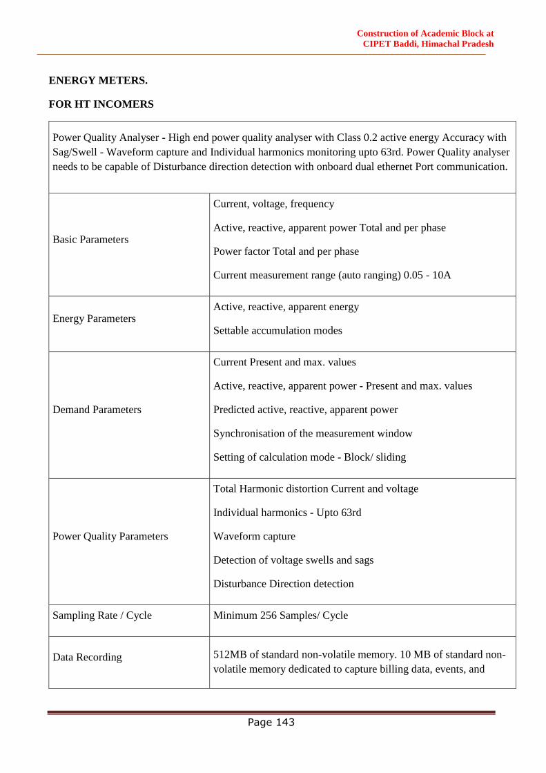
Construction of Academic Block at
CIPET Baddi, Himachal Pradesh
Page 143
ENERGY METERS.
FOR HT INCOMERS
Power Quality Analyser - High end power quality analyser with Class 0.2 active energy Accuracy with
Sag/Swell - Waveform capture and Individual harmonics monitoring upto 63rd. Power Quality analyser
needs to be capable of Disturbance direction detection with onboard dual ethernet Port communication.
Basic Parameters
Current, voltage, frequency
Active, reactive, apparent power Total and per phase
Power factor Total and per phase
Current measurement range (auto ranging) 0.05 - 10A
Energy Parameters Active, reactive, apparent energy
Settable accumulation modes
Demand Parameters
Current Present and max. values
Active, reactive, apparent power - Present and max. values
Predicted active, reactive, apparent power
Synchronisation of the measurement window
Setting of calculation mode - Block/ sliding
Power Quality Parameters
Total Harmonic distortion Current and voltage
Individual harmonics - Upto 63rd
Waveform capture
Detection of voltage swells and sags
Disturbance Direction detection
Sampling Rate / Cycle Minimum 256 Samples/ Cycle
Data Recording 512MB of standard non-volatile memory. 10 MB of standard non-
volatile memory dedicated to capture billing data, events, and
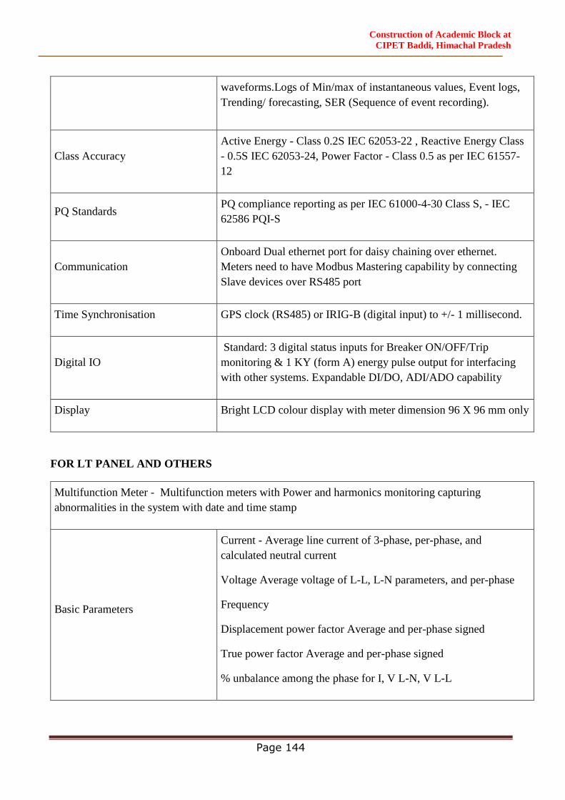
Construction of Academic Block at
CIPET Baddi, Himachal Pradesh
Page 144
waveforms.Logs of Min/max of instantaneous values, Event logs,
Trending/ forecasting, SER (Sequence of event recording).
Class Accuracy
Active Energy - Class 0.2S IEC 62053-22 , Reactive Energy Class
- 0.5S IEC 62053-24, Power Factor - Class 0.5 as per IEC 61557-
12
PQ Standards PQ compliance reporting as per IEC 61000-4-30 Class S, - IEC
62586 PQI-S
Communication
Onboard Dual ethernet port for daisy chaining over ethernet.
Meters need to have Modbus Mastering capability by connecting
Slave devices over RS485 port
Time Synchronisation GPS clock (RS485) or IRIG-B (digital input) to +/- 1 millisecond.
Digital IO
Standard: 3 digital status inputs for Breaker ON/OFF/Trip
monitoring & 1 KY (form A) energy pulse output for interfacing
with other systems. Expandable DI/DO, ADI/ADO capability
Display Bright LCD colour display with meter dimension 96 X 96 mm only
FOR LT PANEL AND OTHERS
Multifunction Meter - Multifunction meters with Power and harmonics monitoring capturing
abnormalities in the system with date and time stamp
Basic Parameters
Current - Average line current of 3-phase, per-phase, and
calculated neutral current
Voltage Average voltage of L-L, L-N parameters, and per-phase
Frequency
Displacement power factor Average and per-phase signed
True power factor Average and per-phase signed
% unbalance among the phase for I, V L-N, V L-L

Construction of Academic Block at
CIPET Baddi, Himachal Pradesh
Page 145
Energy & Power Parameters
Real, reactive, and apparent power Total and per-phase value
Accumulated Active, Reactive and Apparent Energy, Received and
Delivered registers, Net and absolute energy values, time counters
Demand Parameters
Current average, Active power, Reactive power, Apparent power -
Present, Last, Predicted, Peak, and Peak Date Time
Demand sync methods Thermal, Timed, Command Sync, and
Clocked Sync
Demand calculation mode Sliding, fixed and rolling block
Demand intervals - settable from 1 to 60 minutes
Power Quality Parameters
THD as per IEC 61557-12 for THD and individual harmonics up
to
15th over communication
Sampling Rate / Cycle Minimum 64 Samples / Cycle
Class Accuracy Active energy - Class 0.5S as per IEC 62053-22
Communication RS 485 port Modbus RTU and disabling RS485 port against
unauthorized access.
Calibration LED configurable from 1 to 9999000 pulses/k_h (kWh, kVAh, or
kVARh)
Min/Max values instantaneous parameters with timestamp
Display Bright red colour LED display with meter dimension 96 X 96 mm
only
33KV H.T. METERING PANEL (INDOOR TYPE):
GENERAL
H.T. Metering Panel shall be made as per regulation of Local Electricity Supply Authority.
CODES AND STANDARDS
The 33 H.T. Metering Panel shall comply with the following standards as amended up to date.

Construction of Academic Block at
CIPET Baddi, Himachal Pradesh
Page 146
IS: 2544 : Bus Bar Supports
IS: 2705 / IEC – 185 : Current Transformer
IS: 3516 / IEC – 186 : Potential Transformer
SUBMITTALS
SHOP DRAWING AND TECHNICAL DATA
The Tenderer shall furnish relevant technical data on H.T. Metering Panel and associated equipment
along with the offer.
The Contractor shall furnish relevant descriptive and illustrative literature on breakers and
associated equipment and the following for approval before manufacture of the panel.
a) Complete assembly drawings of the panel showing plan, elevation and typical section views
and locations of cable boxes, bus bar chamber, metering and relay compartment and terminal
blocks for external wiring connections.
b) Foundation plan showing location of foundation channels, anchor bolts and anchors, floor
plans and openings for cables etc.
c) All drawings and data shall be in English.
TYPE AND CONSTRUCTION
The metal clad panel shall be made out of 2.0 mm thick CRCA sheet steel. The steel work should
have undergone a rigorous rust proofing process comprising alkaline degreasing, descaling in dilute
sulphuric acid and recognized phosphating process and shall then be given powder coating
(Electrostatic) paint of manufacturer’s standard shade.
a) C.T. & P.T. Compartment
b) Energy Meter Compartment
c) Cable Termination Compartment
The compartments shall be dust & vermin proof and safe to touch. The H.T. Metering Panel shall be
suitable for cable termination from bottom only. The Panel shall be supplied with all equipment and
as per regulation of Local Electricity Supply Authority.
5.0 33KV VCB PANEL (INDOOR TYPE):
GENERAL
Vacuum Circuit Breaker shall be incorporated in H.T. Panel wherever specified. VCB’s shall be
suitable for operation on 33KV, 3 phase, 50Hz, AC supply.
CODES AND STANDARDS
The 11 KV VCB Panel shall comply with the following standards as amended up to date.
IS: 2516 (Part I – Set 3) : Indian Electricity Supply and regulations.
IEC 60298& IEC 60694
IS: 3427 & IS 12729 : Vacuum Circuit Breakers

Construction of Academic Block at
CIPET Baddi, Himachal Pradesh
Page 147
IEC: 298 (1987) (Annex. AA) : Testing for Internal Arc
IEC: 529 : Degree of Protection – IP 55
IS: 2544 : Bus Bar Supports
IS: 2705 / IEC – 185 : Current Transformer
IS: 3516 / IEC – 186 : Potential Transformer
RATING
The rating of the vacuum circuit breaker shall be as per the drawings and schedule of quantities. The
rated/breaking capacity of the breaker shall be 1500 MVA at 33 KV. The rated making capacity
shall be as per the relevant standards.
ACCESSORIES
Circuit Breakers shall be provided with the following accessories.
i. Auxiliary Switch with minimum 6 NO+ 6 NC auxiliary contacts.
ii. Shunt Trip Coil
iii. Mechanical Operation Counter
iv. Spring Charging motor and handle for manual charging.
SUBMITTALS
SHOP DRAWING AND TECHNICAL DATA
The tenderer shall furnish relevant technical data on breakers and associated equipment along with
the offer.
The Contractor shall furnish relevant descriptive and illustrative literature on breakers and
associated equipment and the following for approval before manufacture of the panel.
a) Complete assembly drawings of the panel showing plan, elevation and typical section views
and locations of cable boxes, bus bar chamber, metering and relay compartment and terminal
blocks for external wiring connections.
b) Typical and recommended schematic diagrams for control and supervision of circuit
breakers.
c) Foundation plan showing location of foundation channels, anchor bolts and anchors, floor
plans and openings for cables etc.
d) Type test certificates along with oscillograms for breakers of identical design.
e) All drawings and data shall be in English.
Construction of Academic Block at
CIPET Baddi, Himachal Pradesh
Page 148
TYPE AND CONSTRUCTION
The metal clad panel shall be made out of 2.0 mm thick CRCA sheet steel. The steel work should
have undergone a rigorous rust proofing process comprising alkaline degreasing, descaling in dilute
sulphuric acid and recognized phosphating process and shall then be given powder coating
(Electrostatic) paint of manufacturer’s standard shade. The Switch Board Shall be fully extensible
with following compartment.
a) Circuit Breaker Compartment
b) Bus bar Compartment
c) CT and Cable Termination Compartment
The compartments shall be dust & vermin proof and safe to touch. A separate metering chamber for
fixing the necessary instrumentation metering and protective equipment shall be mounted on the top
/ bottom of the panel at the front. The VCB shall consist of three air insulated poles incorporating
mechanism of interrupters and suitable clearance between phases. The body of interrupters shall be
made of nickel chromium steel supported on insulators made out of metalized aluminium oxide. The
contacts shall be of chromium copper and butt shaped. Vacuum circuit breaker shall be mounted on
truck or a carriage mechanism. The drawout carriage shall have two position for the circuit breaker
viz isolated/test & service position. Bus bars shall be insulated type made of high conductivity copper
supported on cast epoxy mono block designed to withstand full short circuit currents and shall be
provided all along the length of the H.T. board.
It shall be horizontal draw out & isolation type, fully interlocked, with dust and vermin proof
construction, suitable for indoor installation. The panel shall be supplied with the manufacturer’s test
certificates. Certificates with date of manufacture and shall be complete in all respects. The
switchgear constructions shall be such that the operating personnel are not endangered by breaker
operation and internal explosions, and the front of the panel shall be specially designed to withstand
these. Pressure relief flaps shall be provided for safely venting out gases produced inside the high
voltage compartment, bus bar compartment and termination compartment. These flaps shall be
vented upwards and cannot be opened from outside. These relief flaps shall be of such construction
as not to permit ingress of dust/water in harmful quantities under normal working conditions.
Enclosure shall be constructed with sheet steel of at least 2.0mm thickness. It shall have a rigid,
smooth, leveled, flawless finish.
Total height of the H.T. Panel board shall be 2750mm approximately and width 1200mm (approx.).
On the incoming breaker panel, a 100VA burden and Class I accuracy potential transformer 33KV/3
/110V/3 with LT fuses shall be provided. These shall be three single phase PTs cast resin insulated
type. Adequate space at the rear of the panel shall be provided for termination of power & control
cables. The panel shall be provided with suitable terminating arrangement for termination of cables.
The making contact arms (upper & lower) of the circuit breaker shall be encased in polypropylene
tubes. Penetration type bushings shall be provided in the bus bars & cable compartment for the fixed
contacts. Safety shutters shall be provided to cover up the fixed high voltage contacts on bus bar and
cable sides when the carriage is moved to Isolated/Disconnected position. The shutters shall move
Construction of Academic Block at
CIPET Baddi, Himachal Pradesh
Page 149
automatically with the movement of the draw out carriage. It shall, however, be possible to open the
shutters of bus bars side and cable side individually.
Mechanically operated circuit breaker auxiliary switches of minimum 6 NO + 6 NC ways, shall be
provided for control and indication purposes. Control wiring shall be done by using 1.5 sq. mm,
1.1KV grade stranded copper PVC insulated cable. All control fuses shall be HRC link type.
L.T. Terminal blocks for control wiring shall be clamp type suitable for connection of only 2 wires
per terminal and shall be 650 V grade. The L.T. control circuit shall be routine tested to withstand
2.0KV for one minute. Bus bar compartment shall be provided at the rear. Electrolytic copper bus
bars shall be of rectangular cross section and insulated. Bus bars shall be supported properly by cast
epoxy resin insulators so as to withstand thermal and dynamic stresses during system short circuits.
Bus bars shall be provided with necessary colour coding for phases indication. The bus bars shall be
designed to withstand a temperature rise of 60 deg. C above and ambient temperature of 50 deg. C.
The standard clearance between phase bus bars to be maintained.
BUS BAR AND INSULATORS
Bus bars and connections shall be of high conductivity electrolytic copper conforming to relevant IS
standards. They shall be adequately supported on epoxy insulators to withstand electrical and
mechanical stresses due to specified short circuit currents. Bus bar cross section shall be uniform
throughout the length of switch board. Contact surface at all joints shall be properly cleaned and No-
oxide grease applied to ensure an efficient and trouble free connections. All bolted joints shall have
necessary washers for maintaining adequate contact pressure. All connection hardware shall have
high corrosion resistance. Bus bar insulators shall be of track-resistance, high strength, non-
hygroscopic, non-combustible type & shall be suitable to withstand stresses due to over voltages and
short circuit current. Bus bar shall be supported on the insulator such that the conductor expansion
and contraction are allowed without straining the insulators. The temperatures of the bus bars and all
other equipments, when carrying the rated of relevant Indian Standards, duly considering the
specified ambient temperature.
EARTHING AND PROTECTIVE EARTHING
Copper earthing bus shall be provided. It shall be bolted/ welded to the frame work of each panel.
The earth bus shall have sufficient cross time fault currents to earth without exceeding the allowable
temperature rise. Suitable arrangement shall be provided at each end of the earth for bolting Owner’s
earthing conductors and earth bus shall run inside at the back of the panel for entire length. Facilities
shall be provided for integral earthing of bus bars & feeder circuit.
METERING AND PROTECTION
The VCB Panel Board shall be provided with cast resin current transformers for metering and
protection. The CT’s shall conform in all respects to IS 2705-1964 Part-I, II and III. These shall have
accuracy class of 1.0 for metering of 5P10 for protection. Potential transformers shall be epoxy
cast resin type & conform to specifications of IS: 3156-1965 Part-I, II & III and shall be class-1.
Electronic digital type Ammeter and voltmeter to be installed on panel. Electronic type digital energy
analyzer having parameter of KW, KWH power factor, frequency etc. with 30 days memory shall be
provided. All meters shall be tested for 2000V for 1 minute and shall be 96mm square pattern, flush
Construction of Academic Block at
CIPET Baddi, Himachal Pradesh
Page 150
mounting type with necessary selector switches. Necessary indicating lamps of low voltage type with
built in resistors shall be provided (maximum wattage 2.5W). The electronic digital types IDMT
relay (2 O/C + 1 E/F) to be provided as per B.O.Q. description.
INTERLOCKING, SAFETY AND OPERATING MECHANISM
Vacuum Circuit Breaker shall have electrically operated mechanism for spring charging. These
operating mechanisms shall be of the stored energy type. In the closed state of the breaker, the energy
stored in the springs shall be suitable for O-C-O duty. The draw out carriage cannot be moved from
either test/disconnected to service position or vice versa, when the circuit breaker is ‘On’. The circuit
breaker cannot be switched ‘ON’ when the carriage is in any position between test & service position.
The front door of the panel cannot be opened when the breaker is in service position or in an
intermediate position. The low voltage plug & socket cannot be disconnected in any position except
test/isolated position. The door cannot be closed unless the LV plug has been fitted. It shall be
possible to mechanically close and trip the circuit breaker through push buttons with the circuit
breaker in service position and the door closed. Individual explosion vents shall be provided for
breaker, bus bar, cable chambers on the top of the panel to let out the gases under pressure generated
during an unlikely event of a fault inside the panel. Circuit Breaker & sheet metal enclosure shall be
fully earthed. Self locking shutters shall be provided which close automatically and shall be
interlocked with the movement of the draw out carriage mechanism.
ADDITIONAL ACCESSORIES
The loose items to be supplied with the 33KV VCB Panel Board shall comprise of the following:
a) Maintenance Manual.
b) Racking in/out handle.
c) Foundation bolts.
d) One number Earthing Trolley for cable side.
CONTROL SUPPLY
a) The tripping circuit shall be at 24 Volt D.C. through a power pack unit.
INSTALLATION
a) 33 KV switch board shall be installed and levelled on the foundation as per manufacturer's
drawing. Bus bar connections shall be checked after installation. Cable end boxes shall be
sealed after the cable work is completed to prevent absorption of moisture.
TESTS
FACTORY TEST
The circuit breakers panel shall be subjected to routine tests at manufacturers works in accordance
with the details specified in the relevant IS specifications.
The vendor shall submit the type test certificate for following along with the offer.
a) Temperature rise test.
b) Impulse & power frequency voltage test
c) Short time current test on circuit breaker.

Construction of Academic Block at
CIPET Baddi, Himachal Pradesh
Page 151
SITE TEST
GENERAL
1. Verification for completion of equipment, physical damage/ deformities.
2. Alignment of panel, interconnection of bus bars & tightness of bolts & connection etc.
3. Interconnection of panel earth bus bar with plant earthing grid.
4. Inter panel wiring between transport sections.
5. Cleanliness of insulators and general Cleanliness of panel to remove traces of dust, water
etc.
6. Control wiring verification after interconnecting of panel.
7. Check for free movement of circuit breaker, lubrication of moving part & other Parts as per
manufacturers manual.
8. Manual/Electrical operations of the breaker and Functional test as per drawings.
9. Meggar before the Hi Pot test.
10. Meggar after the Hi Pot test.
11. CT/PT ratio/polarity primary injection test.
12. Secondary injection test on relays to practical characteristics.
These tests as per the clauses above will be witnessed by the owner/consultant at the works for
which necessary information has to be given in advance to the owner/ consultant.
6.0 33KV TRANSFORMER (OUTDOOR OR INDOOR TYPE):
GENERAL
The technical specification covers specifications for Indoor Step Down Double Wound Dry
Type (Cast Resin) 33000/415 volts indoor type Transformer suitable for outdoor / indoor
installation as per site condition.
STANDARDS
The following Indian Standards Specifications and Codes of Practice shall apply to the
equipment covered by this Contract. In addition, the relevant clauses of the Indian Electricity
Act 1910 and Indian Electricity Rules 1956 as amended upto date shall also apply. Wherever
appropriate Indian Standards are not available, relevant British and /or IEC standards shall be
applicable.
BIS certified equipment shall be used as a part of the Contract I line with Government
Regulations. Necessary Test Certificates in support of the certification shall be submitted prior
to supply of the equipment.
It is to be noted that updated and current Standards shall be applicable irrespective of those
listed below.
Dry Type Power Transformers IS 11171 – 1985
Dry Type Power Transformers IEC 726
Construction of Academic Block at
CIPET Baddi, Himachal Pradesh
Page 152
OPERATION
The transformer shall be suitable for operation on 33 KV, 3 phase 50 cycle earthed system,
connected Delta on H.V. side and star on the L.V side with neutral brought out for independent
earthing (Vector Group DYn11). The transformer.
MATERIALS
The materials used in the manufacture of the transformer shall be of the best quality of their
respective kind available as per relevant specifications as indicated below.
CORE MATERIAL
The magnetic iron core shall be made of high grade alloy, low loss grain oriented cold rolled
steel stampings.
CORE WINDINGS
The high voltage and low voltage windings shall be of copper conductors completely
impregnated and cast under vacuum into moulds.
INSULATION
The insulation material used shall be insulation Class ‘F’.
TAPPINGS
The transformers shall be provided with off load tap changer as per schedule of Quantities on
H.V. side so as to give a constant voltage on L.V. side.
CHARACTERISTICS
The no load voltage ratio of the transformer shall be 33000/415 volts and the percentage
impedance shall not exceed the limits as below.
2000 KVA rating - 6.25%
TERMINATIONS SUITABLE FOR OUTDOOR TYPE
The transformer shall have cable boxes with suitable glands and cable sockets for receiving
33000 volt grade XLPE cables on the H.V. side as required.
On the L.T. side the transformer shall have a suitable indoor terminal arrangement with
extended bus bars to receive LT bus duct as specified.
TEMPERATURE RISE PARAMETERS
Thermistor sensors shall be embedded in low voltage winding for warning and tripping, for
temperature control. The temperature detectors shall be suitable for 230 volt AC. The
Construction of Academic Block at
CIPET Baddi, Himachal Pradesh
Page 153
temperature when continuously operated of windings by resistance method shall not exceed
100 deg C over 50 deg ambient.
FITTINGS
The transformer shall be manufactured in accordance with the requirements as specified in the
Standards state above and shall be fitted with:
Diagram and Rating plate
Lifting Lugs.
Two earthing terminals on either side of the tank.
Four bi-directional rollers on the under carriage for movement.
Winding temperature Indicator with alarm contacts for alarm and trip circuits.
Marshalling Box.
Off load circuit tapping links.
Terminal marking plate.
Jacking Lugs
H.V. cable box for 3 core XLPE cable as required suitable for indoor installation.
L.V. termination suitable for bus duct as required suitable for indoor installation.
Interlocking of all door switches.
TESTING AT MANUFACTURERS WORKS
Prior to acceptance and dispatch of the transformer, the Client / Consultant reserve the right to
witness the routine tests at manufacturer works.
The transformer shall subjected to the following tests as per IS 11171 at the manufacturers
Works. The test certificates shall be submitted to the Clients for approval prior to dispatch.
a) Measurement of Winding Resistance
b) Ratio polarity and phase relationship
c) No load and load losses
d) Impedance voltage
e) No load and load current.
f) Insulation resistance
g) Induced over voltage with stand
h) Separate source voltage with stand
INSTALLATION OF TRANSFORMER IN INDOOR CONDITION
The transformer shall be installed as per the manufacturer instruction manual and shall
conform to the requirements of IS 10028 Part – I to Part III.
The transformer foundations shall be cast as required. If any lifting is required, the same shall
be done by all the lifting lugs to avoid any imbalance.
Construction of Academic Block at
CIPET Baddi, Himachal Pradesh
Page 154
The transformer wheels shall be locked by suitable locking arrangement to avoid accidental
movement after testing and commissioning.
The transformer cable end boxes shall be sealed to prevent entry of moisture.
The transformer neutral and body earthing shall be as per the requirements of IS 3043 and the
Local Inspecting Authorities.
TESTING AT SITE
Before energizing pre-commissioning checks as per manufacturer recommendation shall be
carried out after installation at site including but not restricted to the following:
Insulation resistance of the winding between phases and phase and earth on the H.T. side
Voltage ratio test shall be carried out by applying low voltage on H.T. side and measuring
the voltage between phases and phase and neutral on the L.T. side for every tap setting.
If necessary the transformer shall be heated by applying low voltage on the H.T. side and
shorting the L.T. side. This shall be done for a period of 48 hours or till the time all the
moisture has been removed from the transformer.
On commissioning the transformer the following tests shall be carried out.
L.T. side voltages at all tap settings.
Temperature rise under no load conditions.
Magnetic balance test on HT side only.
Vector group check test.
Magnetizing current by applying 415 volt on HT side, if HT is 33 kV or more
Transformer protection/control circuit test.
7.0 MAIN L.T. PANEL-
GENERAL
This section covers the detail requirements for Design, Manufacturing, Testing at works. Main
L.T. Panel shall be made out of CRCA sheet steel indoor type, floor mounted, free standing,
totally enclosed, extensible type, air insulated type for use on 415 Volts, 3 phase with neutral,
50 cycles/sec system. D.G. Panel shall have PLC and required Hardware and Software to
achieve the AMF, Synchronizing and Interlocking.
The equipment shall be designed to conform to the requirements of:
i. IS: 8623- Factory Built Assemblies of switchgear and control gear.
ii IS: 4237- General requirements for switchgear and control gear for voltages not
exceeding 1000 volts.
iii. IS: 2147- Degree of protection.
iv. IS: 375- Marking and arrangement of bus bar.
Construction of Academic Block at
CIPET Baddi, Himachal Pradesh
Page 155
Individual equipment housed in the Main L.T. Panels shall conform to the following IS
Specification.
i. Air circuit breakers / moulded case circuit breaker IS: 60947 (Part-II) & IEC
60947(2)
ii. Fuse switch and switch fuse units - IS: 13947 (Part-3) & IEC 947 (3).
iii. HRC fuse links - IS: 13703
iv. Current Transformers - IS :2705
v. Voltage Transformers - IS :3156
vi. Indicating Instruments - IS: 1248
vii. Integrating Instruments - IS : 722
viii. Control Switches & Push Buttons - IS : 6875
ix. Auxiliary Contactors - IS : 13947 (Part-4/Sec.-I) & IEC 947 (4/1)
x. Relays - IS: 3231
SUBMITTALS, SHOP DRAWING AND TECHNICAL DATA
The Contractor shall furnish relevant descriptive and illustrative literature on breakers and
associated equipment and the following for approval before manufacture of the panel.
a) Complete assembly drawings of the panel showing plan, elevation and typical section
views and locations of cable boxes, bus bar chamber, metering and relay compartment
and terminal blocks for external wiring connections.
b) Typical and recommended schematic diagrams for control and supervision of circuit
breakers.
c) Foundation plan showing location of foundation channels, anchor bolts and anchors,
floor plans and openings for cables etc.
d) Type test certificates.
CONSTRUCTION
1. Made out of the requisite vertical sections, which when coupled together shall form
continuous dead front switchboards.
2. The degree of protection being not less than IP 52 to IS: 2147.
3. Suitable for extensible on both sides by the addition of vertical sections after removal
of the end covers.
4. Shall be suitable for cable entry from top / bottom both except wherever indicated
through removable cable gland plate of 3 mm thick. Compression gland shall be
staggered in alleys so as to maintain necessary clearance between cables.
Construction of Academic Block at
CIPET Baddi, Himachal Pradesh
Page 156
5. Fire retardant polycarbonate sheet shall be provided for viewing panels housing
MCB’s at eye level. Cable channels are to be used wherever possible for aesthetic look.
Lifting hooks / angles to be provided on the panel. Panel shall have 20% free space for
future use.
Panel shall be provided with louvers having wire mesh inside for ventilation.
Each vertical section shall comprise of :
i. A minimum 2 mm thickness front framed structure of rolled/folded sheet steel channel
section rigidly bolted together. This structure shall house the components contributing
to the major weight of the equipment, such as circuit breaker cassettes, fuse switch
units, main horizontal bus bars, vertical risers and other front mounted accessories. The
structure shall be mounted on a rigid base frame of folded sheet steel of minimum 3
mm thickness and 100 mm height. The design shall ensure that the weight of the
components is adequately supported without deformation or loss of alignment during
transit or during operation.
ii. Cable chamber housing (In rear of panel) the cable end connections, and power/control
cable terminations. The design shall ensure generous availability of space for ease of
installation and maintenance of cabling, and adequate safety for working in one vertical
section without coming into accidental contact with live parts in an adjacent section.
iii. Front and rear doors fitted with dust including neoprene gaskets with fasteners
designed to ensure proper compression of the gaskets. When covers are provided in
place of doors, generous overlap shall be assured between sheet steel surfaces with
closely spaced fasteners to preclude the entry of dust. All door shall be lockable
mounted lock.
The height of the panels should not be more than 2400 mm. The total depth of the panel should
be adequate to cater to proper cabling space and should not be more than 1500mm. Operating
handle not higher than 1800mm.The minimum height for operating handle shall be 300 mm
from floor level.
Doors and covers shall be of minimum 2mm thick CRCA sheet steel. Sheet steel shrouds and
partitions shall be of minimum 2mm thickness. All sheet panels shall be smoothly finished,
levelled and free from flaws. The corners should be rounded.
The apparatus and circuits in the power control centers shall be so arranged as to facilitate their
operation and maintenance and at the same time to ensure the necessary degree of safety.
Apparatus forming part of the Main L.T. Panel shall have the following minimum clearances.
i. Between phases - 32mm
ii. Between phases and neutral - 26mm
iii. Between phases and earth - 26mm
Construction of Academic Block at
CIPET Baddi, Himachal Pradesh
Page 157
iv. Between neutral and earth - 26mm
For any reason, the above clearances are not available, suitable insulation shall be provided.
Clearances shall be maintained during normal service conditions. Creepage distances shall
comply to those specified in relevant standards. All insulating material used in the construction
of the equipment shall be of non-hygroscopic material, duly treated to withstand the effects of
the high humidity, high temperature tropical ambient service conditions.
Circuit breakers and fuse switches shall be arranged in multi-tier formation, except that not
more than two air circuit breakers shall be housed in a single vertical section. Cable entry for
various feeders shall be from the rear. Panel shall be suitable for termination of bus duct for
incoming breakers.
Metallic/insulated barriers shall be provided within vertical sections and between adjacent
sections to ensure prevention of accidental contact with:
i. Main bus bars and vertical risers during operation, inspection or maintenance of
functional units and front mounted accessories.
ii. Cable termination of one functional unit, when working on those of adjacent unit/units.
All doors/covers providing access to live power equipment/ circuits shall be provided
with tool operated fasteners to prevent unauthorized access.
Provision shall also be made for permanently earthing the frames and other metal parts
of the switchgear by two independent connections.
METAL TREATMENT AND FINISH
All steel work used in the construction of the L.T. cubicle panels should have undergone a
rigorous metal treatment process as follows:
i. Effective cleaning by hot alkaline degreasing solution followed by cold water rinsing
to remove traces of alkaline solution.
ii. Pickling in dilute sulphuric acid to remove oxide scales & rust formation, if any,
followed by cold water rinsing to remove traces of acidic solution.
iii. A recognized phosphating process to facilitate durable coating of the paint on the
metal surfaces and also to prevent the spread of rusting in the event of the paint film
being mechanically damaged. This again, shall be followed by hot water rinsing to
remove traces of phosphate solution.
iv. Passivating in de-oxalite solution to retain and augment the effects of phosphating.
v. Drying with compressed air in a dust free atmosphere.
vi. Powder Coating paint of colour approved by Engineer-in-charge.
Construction of Academic Block at
CIPET Baddi, Himachal Pradesh
Page 158
BUS BAR
The bus bars shall made of high conductivity, high strength aluminium alloy complying with
the requirement of grade E-9IE of IS-5082 and air insulated. The bus bars shall be suitable
braced with non-hygroscopic SMC supports to provide a through fault withstand capacity of
50KA RMS symmetrical for one second and a peak short circuit withstand capacity of 105KA.
The neutral as well as the earth bar should be capable of withstanding the above level. Ridges
shall be provided on the SMC supports to prevent tracking between adjacent bus bars. Large
clearances and creepage distances shall be provided on the bus bar system to minimize
possibilities of fault.
The Panel shall be designed that the cables are not directly terminated on the terminals of
breaker/switch fuse/fuse switch etc. but on cable termination links. Capacity of aluminium
bus bars shall be considered as 0.8 Amp/sq.mm of cross section area of the bus bar. The main
bus bars shall have continuous current rating throughout the length of L.T. Panel. The cross
section of neutral bus bars shall be same as that of phase bus bar for bus bars of capacity up to
200Amp; for higher capacity the neutral bus bar shall not be less than half (50%)the cross
section of that the phase bus bars. The bus bar system shall consists of main horizontal bus
bar and auxiliary vertical bus bars run in bus bar alley/chamber on either side in which the
circuit could be arranged/connected with front access. The minimum size of vertical bus bar
shall be as per fault level of panel i.e 50 KA.
In case of copper bus bars, high conductivity electrolytic grade copper with current density not
less than 1.4 Amp/ sq. mm shall be used. Bus Bar shall be tinned.
Connections from the main bus bars to functional circuit shall be arranged and supported to
withstand without any damage or deformation the thermal and dynamic stresses due to short
circuit currents. Bus bars to be colour coded with PVC sleeves.
Cadmium plated G.I. nuts and bolts shall be used for making bus bar to bus bar connections in
aluminium bus bars.
Whenever copper bus bar and aluminium bus bar are connected to each other, bimetallic strip
shall be used. In case of copper bus bar, tinning shall be done.
Bus bar calculation shall be submitted along with manufacturing drawing of panel for approval
with bus bar manufacturer data sheet.
MEDIUM VOLTAGE AIR CIRCUIT BREAKER
TYPE AND CONSTRUCTION
The ACB shall confirm to the requirements of IEC 60947-2 / IS 60947-2 and shall be type
tested & certified for compliance to standards from–CPRI, ERDA / any accredited
ineternational lab. The circuit breaker shall be suitable for 415 V + 10%, 50 Hz supply system.
Air Circuit Breakers shall be with moulded housing flush front, draw out type and shall be
Construction of Academic Block at
CIPET Baddi, Himachal Pradesh
Page 159
provided with a trip free manual operating mechanism or as per approved drawing with ON /
OFF trip indication.
The ACB shall be 3/ 4 pole with modular construction, draw out, manually or electrically
operated version as specified. The circuit breakers shall be for continuous rating and service
short Circuit Breaking capacity (Ics) shall be as specified on the single line diagram and should
be equal to the Ultimate breaking capacity (Icu) and short circuit withstand values (Icw) for 1
sec. All 4 pole breaker shall have 100% neutral rating.
Icu = Ics = Icw = 50KA for 1 Sec
Circuit breakers shall be designed to ‘close' and `trip' without opening the circuit breaker
compartment door. The operating handle and the mechanical trip push button shall be at the
front of the breakers panel. Inspection of main contacts should be possible without using any
tools. The ACB shall be provided with a door interlock. i.e. door should not be open when
circuit breaker is closed and breaker should not be closed when door is open.
All current carrying parts shall be silver plated and suitable arcing contacts with proper arc
chutes shall be provided to protect the main contacts. The ACB shall have double insulation
(Class-II) with moving and fixed contacts totally enclosed for enhanced safety and in
accessibility to live parts. All electrical closing breaker shall be with electrical motor wound
stored energy spring closing mechanism with mechanical indicator to provide ON/OFF status
of the ACB.
The auxiliary contacts blocks shall be so located as to be accessible from the front. The
auxiliary contacts in the trip circuits shall close before the main contacts have closed. All other
contacts shall close simultaneously with the main contacts. The auxiliary contacts in the trip
circuits shall open after the main contacts open. It should be possible to change settings on
load.
Minimum 4 NO and 4 NC auxiliary contacts shall be provided on each breaker. Break time of
ACB shall not be more than 25m Sec in case of short circuit.
Rated insulation voltage shall be 1000 volts AC.
CRADLE
The cradle shall be so designed and constructed as to permit smooth withdrawal and insertion
of the breaker into it. The movements shall be free from jerks, easy to operate and shall be on
steel balls/rollers and not on flat surfaces.
There shall be 4 distinct and separate position of the circuit breaker on the cradle.
Racking Interlock in Connected/Test/Disconnected Position.
Service Position : Main Isolating contacts and control contacts of the breaker are engaged.
Test Position : Main Isolating contacts are isolated but control contacts are still engaged.
Construction of Academic Block at
CIPET Baddi, Himachal Pradesh
Page 160
Isolated Position : Both main isolating and control contacts are isolated.
There shall be provision for locking the breaker in any or all of the first three positions
mechanically.
The following safety features shall be incorporated:
a. Withdrawal or engagement of Circuit breaker shall not be possible unless it is in open
condition.
b. Operation of Circuit breaker shall not be possible unless it is fully in service, test or
drawn out position.
c. All modules shall be provided with safety shutters operated automatically by
movement of the carriage to cover exposed live parts when the module is withdrawn.
d. All Switchgear module front covers shall have provision for locking.
e. Switchgear operating handles shall be provided with arrangement for locking in ‘OFF’
position.
PROTECTION
All breaker (ACB’s) should be equipped with microprocessor based release having inbuilt
adjustable protection against O/C, S/C, E/F and Instantaneous S/C.
Long time protection.
Short time protection with intentional delay.
Instantaneous protection.
Ground fault protection.
The protection release shall have following features and settings:
(i) TRUE RMS SENSING
The release shall sample the current at the rate of 16 times per cycle to monitor the actual load
current waveform flowing in the system and shall monitor the true RMS value of the load
current. It shall take into account the effect of harmonics also.
(ii) THERMAL MEMORY
When the breaker shall reclose after tripping on overload, then the thermal stresses caused by
the overload if not dissipated completely, shall get stored in the memory of the release and this
thermal memory shall ensure reduced tripping time in case of subsequent overloads. Realistic
Hot/Cold curves shall take into account the integrated heating effects to offer closer protection
to the system.
(iii) DEFINED TIME – CURRENT CHARACTERISTIC
A variety of pick-up and time delay settings shall be available to define the current thresholds
and the delays to be set independently for different protection zones thereby achieving a close-
to-ideal protection curve.
Construction of Academic Block at
CIPET Baddi, Himachal Pradesh
Page 161
(iv) TRIP INDICATION
Individual fault indication for each type of fault should be provided by LEDs for faster fault
diagnosis.
SAFETY FEATURES
(i) The safety shutter shall prevent inadvertent contact with isolating contacts when
breaker is withdrawn from the Cradle.
(ii) It shall not be possible to interchange two circuit breakers of two different thermal
ratings. For Draw-out breakers, an arrangement shall be provided to prevent rating
mismatch between breaker and cradle.
(iii) There shall be provision of positive earth connection between fixed and moving
portion of the ACB either thru connector plug or sliding solid earth mechanism.
Earthing bolts shall be provided on the cradle or body of fixed ACB.
(iv) The incoming panel accommodating ACB shall be provided with indicating lamps
for ON-OFF positions, digital voltmeter and ammeter of size not less than 96 mm
x 96 mm, selector switches, MCB for protection circuit and measuring instrument
circuits.
(v) It shall be possible to bolt the draw out frame not only in connected position but
also in TEST and DISCONNECTED position to prevent dislocation due to
vibration and shocks.
(vi) Drawout breakers should not close unless in distinct Service/Test/Isolated
positions.
(vii) The insulation material used shall conform to Glow wire test as per IEC60695.
(viii) The ACB shall provide in built electrical and mechanical anti-pumping.
TESTING
Testing of each circuit breaker shall be carried out at the works as per relevant IS Code of
Practice and the original test certificate shall be furnished in triplicate. The tests shall
incorporate at least the following.
i. Impulse withstand test.
ii. Power frequency withstand test.
iii. Short circuit test.
iv. Temperature - rise test under rated conditions.
MOULDED CASE CIRCUIT BREAKER
GENERAL
Moulded Case Circuit Breakers shall be incorporated in sub distribution boards wherever
specified. MCCB’s shall conform to IS 13947-2 and / or IEC 947-2 in all respects. MCCB’s
shall be suitable either for single phase AC 230 volts or three phase 415 volts. All MCCB
Construction of Academic Block at
CIPET Baddi, Himachal Pradesh
Page 162
up to 250 amp shall have termal magnetic release with adjustable short circuit & overload
protection & above shall have microprocessor release with adjustable over current & earth
fault protection. MCCB above 100A rating shall have copper spreader and phase barrier. All
MCCB shall be provided with rotary operating mechanism.
FRAME SIZES
The MCCB’s shall have the following frame sizes subject to meeting the fault level specified
elsewhere.
i) Up to 100A rating …………. 100Amp frame.
ii) Above 100A to 200A …………. 200Amp frame.
iii) Above 200A to 250A …………. 250Amp frame.
iv) Above 250A to 400A …………. 400Amp frame.
v) Above 400A to 630A …………. 630Amp frame.
CONSTRUCTIONS
The MCCB cover and case shall be made of high strength heat treatment and flame retardant
thermo-setting insulating material. Operating handle shall be of rotary type quick
make/quick break, trip-free type. The operating handle for simultaneous operation and
tripping of all the three phases.
Suitable fire extinguishing device shall be provided for each contact. Tripping unit shall be
of microprocessor type provided in each pole and connected by a common trip bar such that
tripping of any one pole operates all three poles to open simultaneously. MCCB shall be
line load reversible type. MCCB shall be current limiting type.
Contacts trips shall be made of suitable are resistant, silver alloy for long electrical life.
Terminals shall be of liberal design with adequate clearance.
RUPTURING CAPACITY
The Moulded Case Circuit Breaker shall have a minimum fault breaking capacity (Ics) of
not less than 50KA RMS at 415 volts or as actual requirement.
TESTING
Test certificate of the MCCB as per relevant Indian Standards (IS) shall be furnished.
Pre-commissioning tests on the sub distribution boards incorporating the MCCB shall be
done as per standard.
Construction of Academic Block at
CIPET Baddi, Himachal Pradesh
Page 163
MEASURING INSTRUMENT FOR METERING
GENERAL
The specifications herein-after laid down shall also cover all the meters, instrument and
protective devices required for the electrical works. The ratings, type and quantity of meters,
instruments and protective devices shall be in compliance with client requirements.
DIGITAL AMMETERS
Digital Ammeters shall be confirmed to IS: 13875. It shall be digital type 7 segment LED
display. Ammeter shall be suitable for accuracy class 1.0 and burden 0.2 VA approx. The
ammeters shall be capable of carrying sustained overloads during fault conditions without
damage or loss of accuracy. The meter shall be suitable for working in ambient temp 0 degree
to 50 degree and 95% humidity condition.
DIGITAL VOLTMETERS
Digital Voltmeters shall be confirm to IS: 13875. It shall be digital type 7 segment LED
display. Voltmeter shall be suitable for accuracy class 1.0 and burden 0.2 VA approx. The
range for 3 phase voltmeters shall be 0 to 500 volts. The meter shall be suitable for working
in ambient temp 0 degree to 50 degree and 95% humidity condition. The voltmeter shall be
provided with protection MCB of suitable capacity.
CURRENT TRANSFORMERS
Current transformers shall be in conformity with IS: 2705 (Part I, II & III) in all respects.
All current transformers used for medium voltage applications shall be rated for 1KV Current
transformers shall have rated primary current, rated burden and class of accuracy as required.
However, the rated secondary current shall be 15A unless otherwise specified. The
acceptable minimum class of various applications shall be as given below.
Measuring : Class 1.0
Protection : Class 5 P10
Current transformers shall be capable of withstanding without damage, magnetic and thermal
stresses due to short circuit fault of 50KA on medium voltage system. Terminals of the
current transformer shall be marked permanently for easy identification of poles. Separate
CT shall be provided for measuring instruments and protection relays. Each C.T. shall be
provided with rating plate.
Current transformers shall be mounted such that they are easily accessible for inspection,
maintenance and replacement. The wiring for CT’s shall be copper conductor, PVC
insulated wires with proper termination lugs and wiring shall be bunched with cable straps
and fixed to the panel structure in a neat manner.
Construction of Academic Block at
CIPET Baddi, Himachal Pradesh
Page 164
CONTROL SWITCHES
Control switches shall be of the heavy duty rotary type with escutcheon plates clearly marked
to show the operating position. They shall be semi-flush mounting with only the front plate
and operating handle projecting.
Indicating lamps shall be of the LED type, and with translucent lamps covers. Bulbs &
lenses shall be easily replaced from the front.
Push buttons shall be on the momentary contact, push to actuate type fitted with self reset
contacts & provided with integral escutcheon plates marked with its functions.
CABLE TERMINATION
Cable entries and terminals shall be provided in the sub distribution boards to suit the
number, type and size of aluminium conductor power cable and copper conductor control
cable specified.
Provision shall be made for top or bottom entry of cables as required. Generous size of
cabling chambers shall be provided, with the position of cable gland and terminals such that
cables can be easily and safely terminated. Cable glands shall be brass compression type,
barriers or shrouds shall be provided to permit safe working at the terminals of one circuit
without accidentally touching that of another live circuit.
Cable risers shall be adequately supported to withstand the effects of rated short circuit
currents without damage and without causing secondary faults.
CONTROL WIRING
All control wirings shall be carried out with 1100V grade single core PVC cable conforming
to IS 694/IS 8130 having stranded copper conductors of minimum 1.5 sq. mm for potential
circuits and 2.5 sq. mm for current transformer circuits. Wiring shall be neatly bunched,
adequately supported and properly routed to allow for easy access and maintenance. Wiring
shall be identified by numbering ferrules at each end. All control fuses shall be mounted in
front of the panel and shall be easily accessible.
TERMINAL BLOCK
Terminal blocks shall be 500 Volts grade of the stud type. Insulating barriers shall be
provided between adjacent terminals. Terminals block shall have a minimum current rating
of 10 Amps and shall be shrouded. Provisions shall be made for label inscriptions.
LABELS
Labels shall be of anodized aluminium, with white engraving on black background. They
shall be properly secured with fasteners.
MISCELANEOUS
Construction of Academic Block at
CIPET Baddi, Himachal Pradesh
Page 165
Push buttons shall be of the momentary contact, push to actuate type fitted with self reset
contacts & provided with integral escutcheon plates marked with its functions.
BATTERY AND BATTERY CHARGER
A set of 24V DC power supply shall be provided for indication, relay operation etc. for Main
L.T. Panel. DC Power supply shall be sealed maintenance free batteries of suitable capacity.
Suitable battery chargers shall also be provided to charge the battery to perform during mains
failure.
DIESEL GENERATOR SETS
DG set
DG sets outdoor type with radiator cooled, as per CPWD General Specifications for Electrical Works
Part VII DG Set - 2013.DG Set shall be within an acoustic hood as per CPCB norms.
Each DG Set shall be provided with its own day oil tank suitable for at least 10 hrs operations.
LOCATION OF D.G. SET & SUBSTATION
D.G. Set & Transformer shall be installed on Ground Floor Level.
STARTING METHOD FOR D.G. SET
D.G. set shall be suitable for Manual/Auto start through D.G. Set Controller.
D.G. COOLING METHOD
D.G. Set shall be radiator cooled.
EARTHING SYSTEM
The earthing system to be provided for the D.G. set system as required as per IS: 3048.
CAPACITY OF D.G. SET
1x250 KVA, 415 Volt radiator cooled D.G. Set with acoustic enclosure may be installed on Ground
Floor Level to provide the power backup as per requirement in case of power cut / break down of Grid
Supply.
INTENT OF SPECIFICATION:
This specification covers the design, manufacture, assembly, packing, dispatch, transportation to site,
supply, erection, testing, commissioning, performance and guarantee testing of Diesel Gen-Sets,
complete in all respects with all equipment, fitting and accessories for efficient and trouble free
operation as specified here under.

Construction of Academic Block at
CIPET Baddi, Himachal Pradesh
Page 166
SCOPE OF WORK
Scope of Supply & Services:
General Scope of work shall include design, manufacture, assembly, packing, dispatch, transportation
to site, supply, erection, testing and commissioning of the following:
Diesel engine complete with all accessories, an Alternator directly coupled to the engine through
flexible/rigid coupling complete with all accessories for starting, regulation and control, including
base frame, interconnecting piping and accessories, power and control cable, glands and lugs etc.
D.G. Local/Remote control panel including all type of control cables, special cables (if any) between
D.G. Set’s, instrument panel, PLC control panel and Main LT panel etc.
Equipment necessary for engine cooling system, Radiator Type, inter connecting pipes etc.
Equipment necessary for fuel storing and distribution, day oil tank (990 Lt.), pipings, pumps, valves,
level indicators etc.
Exhaust piping, flexible connections and residential type silencer of exhaust system, including thermal
lagging, cladding etc.
Batteries with good quality iron battery stand and battery charging equipment, including their
connections as necessary, along with tools & accessories for battery maintenance. (Contractor shall
submit the list of tools along with Tender)
Anti Vibration Mountings etc.
Power & Control cabling, cable tray etc.
Preparing all related shop drawings for approval from CPWD/consultant and all statutory bodies as
required and as applicable.
Obtaining statutory approval of the installation including permission for operation of Diesel
Generators by the Electrical Inspectorate, Pollution Control bodies and any other statutory bodies as
applicable.
Minor civil works like chasing, grouting etc. for execution of jobs.
Carrying out performance and guarantee test at site at available load which shall not be more than the
capacity of D.G. Set.
SPECIFIC EXCLUSIONS
Following items of works are excluded from the scope of works under this specification:
All civil works relating to DG Sets, Exhaust & foundations etc.

Construction of Academic Block at
CIPET Baddi, Himachal Pradesh
Page 167
CODES AND STANDARDS
The equipment furnish under this specification shall conform to the latest Indian and BS Amendment
upto date standard, except where modified or supplemented by this specification:
The installation work shall conform to Indian Electricity act and Indian Electricity Rules as amended
upto the date of installation.
The fuel oil installation shall meet all statutory requirements of Govt. of India as amended upto the
date of installation. Any approval required from statutory authorities shall be obtained by the
Contractor. Nothing in this specification shall be construed to relieve the contractor of these
responsibilities.
The Indian standards are available from:
Indian Standards Institution
Manak Bhawan,
9, Bahadur Shah Zafar Marg,
New Delhi - 110 002 (INDIA).
The Indian electricity Rules and the Electricity act mentioned above can be obtained from:
Equipment conforming to any other National/International Standard which ensures equal or better
quality may be accepted. In such case the bidder shall furnish copies of the standards in English along
with his bid and shall clearly bring out the salient features of comparison with corresponding listed
standards.
The equipment furnished under this specification have to operate in a tropical climate and shall be
given tropical and fungicidal treatment as per relevant specification
PERIOD OF OPERATION/DUTY CYCLE
The sets are intended to supply power only during an emergency for all services and may be idle for
long periods except for periodic routine tests once in a week. When there is a total failure of main
power supply, the sets shall be required to operate continuously at full load for a period which at times
may exceed even 24 hours.
ENGINE
Type:
The diesel engine shall be of stationary type four stroke (Prime Duty) with vertical in line or (V) type
cylinder arrangement, Turbo-charged, cooled with Radiator Type.
Construction of Academic Block at
CIPET Baddi, Himachal Pradesh
Page 168
Rating:
Power BHP rating of the engine shall be such that the DG set deliver the specified net electrical output
while supplying power/driving all electrical and mechanical auxiliaries connected to alternator
terminals and engine shaft at specified site conditions and ambient temperature of 50OC. (The engine
and alternator shall be suitably rated for 50OC ambient operating condition.
It shall also be capable of satisfactorily driving the alternator at 10% over load at the rated speed for
one hour in any period of 12 hours of continuous running.
The bidder shall have to furnish copy of deration chart from the original manual of the engine
manufacturer and supporting calculations to arrive at diesel engine rating.
Speed and Vibration Levels:
Speed shall be 1500 revolutions per minute. Speed governor/over speed protection shall be provided.
At due running conditions, speed shall be stabilized at plus or minus 2% nominal speed, regardless of
load. At transient condition, engine speed shall vary not more than 10% plus or minus. Governor class
shall be A1 (4% drop) for normal application unless otherwise specified.
The engine vibration level shall be as latest upto date amended BS standard.
Lubrications:
The engine shall have a closed cycle forced & splash lubricating system with positive oil pressure and
a crank chamber for collection/storage of the lubricating oil during circulation. Lubricating oil shall
be circulated in the engine by an engine driven pump.
A lubricating oil filter of an efficient full flow type of ample capacity shall be provided for operation
under normal conditions for a period of 300 hours without the necessity of its replacement or cleaning.
Filters shall be capable of removing all foreign matter above a particle size of 5 microns.
In case lubricating oil coolers are required it shall be supplied as an integral part of the Diesel
Generator Set.
Necessary temperature and pressure gauges and other instruments shall be supplied and fitted on the
lubrication system.
A lubricating oil level dipstick suitably graduated shall be provided and located in the accessible
position.
The tenderers shall state the guaranteed lubricating oil consumption in litres per hour.
Fuel System:
The engine shall be capable of satisfactory running on all types of diesel fuel oil normally available
locally/ in India.
Construction of Academic Block at
CIPET Baddi, Himachal Pradesh
Page 169
The fuel consumption of the engine shall be expressed by the Contractor in the bid in litres per
gross/net kWh output from the alternator (after supplying the requirements of auxiliaries) at full, three
quarters and half of its rated power output and at 0.8 and unitary power factor.
If guaranteed fuel consumption is exceeded, the contractor shall make such amendments or alterations
as are necessary to bring the consumption to within the guaranteed figures. Tolerance of +5% as
defined in latest upto date BS shall be allowed.
A fuel service tank of 990 liters capacity with each D.G. Set shall be provided on a suitably fabricated
steel platform. The tank shall be complete with level indicator marked in liters, filling inlet with
removable screen, an outlet, a drain plug, an air vent and necessary piping. The fuel tank shall be
painted with oil resistant paint. All pipe joints should be brazed/welded.
Air Intake System:
The diesel engine shall be provided with special dry type air filters having low resistance to air
passage, high dust retaining efficiency and provision for easy cleaning. Filters shall be suitable for
achieving satisfactory engine operation and ensuring the engine life under tropical humid conditions,
with sulphur dioxide fumes, abrasive dust and coal particles of 5 to 100 microns present in the
atmosphere. The minimum efficiency of filters shall be 90% down to 5 micron size.
Engine Governor:
The governor shall be Electronic ISO-Chronous type to maintain zero speed rate or regulation and
shall be Al type as per latest BS in order to take care of heavy motor starting. It shall have necessary
characteristics to maintain the speed substantially constant even with sudden variation in load.
However, a tripping shall be provided if speed exceeds maximum permissible limit. The governor
shall be suitable for operation without external power supply.
Turbo Charger:
It shall be of a robust construction, suitable of being driven by engine exhaust having a common shaft
for the turbine and blower. It shall draw air from filter of adequate capacity to suit the requirements
of the engine.
Quietness Of Operation:
The engine shall be designed to achieve maximum quietness of operation.
Efficient residential silencer shall be provided as per engine manufacturer’s approved make only for
the exhaust.
Noise level of the DG set shall be as per The CPCB Norms
Engine Starting:
Engine starting shall be by electric starting motor complete with manual/automatic starting
arrangement. The starter motor shall conform to latest IS and shall be of adequate power for its duty
Construction of Academic Block at
CIPET Baddi, Himachal Pradesh
Page 170
and be of inertia or pre-engaged type. The pinion shall positively disengage when the engine starts up
or when the motor is de-energized. The engine cranking shall be only from the panel both for AMF &
DG sets (Manual) and any engine starting devices etc. that are given as original fitment on the engine
by engine manufacturers shall be either removed or padlocking arrangement given for this so that all
normal start/stop operations could be done only from panel whether the set is AMF or manual.
The engine wiring shall be appropriately modified, ferruled to totally match with schematic drawings
of the panel.
Time for Run-up to Speed:
From the initial operation of the starting device, the engine shall start, run up to normal speed and be
capable of accepting 60% of full load in steps within a maximum time of 20 seconds, and full load
within a further 20 second.
Starter Battery:
The battery shall conform to the requirement of latest IS. Starting battery each of 12 V, heavy duty
high performance approved make/quality shall be provided to enable crank & start the engine even in
cold/winter morning conditions. Type/voltage/AH capacity of same on 20 hour rated discharge period
shall be indicated in the offer. The battery set shall be capable of performing at least (5) five normal
starts without recharging.
The battery shall be provided with good quality iron battery stand painted with acid proof black paint
with min 3mm thick rubber mat below the battery.
Batteries shall be of load container type only and not with PVC moulded sealed container so that each
individual cells are available for individual monitoring during its life span. Each cell shall be provided
with electrolyte filling cap with level floats for easy monitoring of electrolytic level.
The battery shall be provided with 2 Nos. cables, minimum 1.5m long heavy duty rubber/PVC
insulated cabling with brazed tinned lug at one end and with brazed tinned brass terminal lug at battery
end - for connecting batteries to cranking system - with 0.25 m long inter battery connecting cable.
The lugs shall be clearly stamped (+) or (-) and positive cable also red sleeved for easy identification.
The batteries Set shall be supplied fully filled and first charged ready to use.
Batteries set shall be supplied with spring type hydrometer, thermometer with specific gravity
correction scale and cell testing voltmeter etc.
BATTERY CHARGING SYSTEM
Float rate charging and quick rate charging system shall be provided at the generator panel with
appropriate bridge charger system, LC network, rate selector switch and generously rated charging
transformer and silicon one rectifier bridge, so that the cranking battery system can be kept fully
charged at all times from E.B. supply network with quick charging rate limited to 0.8 times rated
discharge current with provision in control transformer and Si rectifier present to enable boost

Construction of Academic Block at
CIPET Baddi, Himachal Pradesh
Page 171
charging the battery at 2 times rated discharge current in case of emergencies. To this and in the mode
selector switch boost charge position shall be present which however shall be kept disconnected at
mode selector switch normally.
DC ammeters to clearly indicate float charging current and quick/boost charging current shall be
provided.
Dropper resistor network on the load side of battery charger system shall be provided so that higher
charger voltages in quick or boost conditions does not get impressed on the I/L and Contactor coils,
which voltage shall remain well within +10% of rated voltage.
Battery charging subsystem shall be designed for continuous operation at cubicle ambient of 50OC
corresponding to 45OC ambient outside and should be designed to operate at 1.5 times rated maximum
current corresponding to boost charge current which can reach in practice as high as 2.5 times or 3
times rated discharge current.
Any charger dynamo and dynamo charging current network present on the set shall be made in
operative so that both for AMF and manual application the cranking battery system is kept charged
from the charger at the panels at all times during or shut down periods of the set.
To the above and in case of manual DG sets, the input to charger subsystem viz., 240 V AC is foreseen
to be provided from customer network from the portion that is normally supplied by manual DG Set
during DG operation or being fed by E.B. System.
Battery charger shall form part of D. G. protection and PLC panel.
ENGINE FITMENTS
The engine shall be provided with but not limited to following essential basic fitments:
Crank case breather - Dry type element (Breather outlet shall be fitted with a filtercap
capable of preventing entry of dust).
Air Cleaner - Dry type mounted.
Corrosion resistor - to control acidity and impurities from coolant
Lubricating Oil Cooler
Filters - Lub oil & fuel oil, paper element type.
Coolant Pump - Gear Driven.
Fuel Pumps - Priming & Transfer
Governor - Electronic Class A1.
Turbo Charger - Exhaust gas driven in case of turbo charged engines.
Flywheel with flywheel housing - SAE Type

Construction of Academic Block at
CIPET Baddi, Himachal Pradesh
Page 172
Vibration dampers - One Set
Exhaust/Intake manifolds
Oil Sump (crank case) with dip stick
Engine Supports
Residential type silencer in exhaust system
Electrical starter 24 V
Safety controls & instruments
Flexible coupling with guard
Engine Instrumentation
The following instruments mounted on instrument panel shall be essentially present as minimum:
Engine speed tachometer with service hour counter
Lub oil pressure gauge
Coolant water temperature gauge
The instrument panel shall be mounted on engine using rubber dampers for vibration isolation.
The gauges shall have clear red marking to identify the limiting dangerous levels, `Zone Markings’
on the scale to indicate the normal healthy & abnormal operating zones for the parameters concerned.
The metering could be either normal electro-mechanical analogue type or electronic digital type, latter
being preferred as manufacturers fitment only.
The engine control panel must be supplied by the engine manufacturer only.
MOUNTINGS AND FOUNDATIONS
The engine and direct coupled attenuator shall be rigidly secured to a common rigid base frame
fabricated from MS section.
The DG set shall be placed on the RCC floor with approved make anti-vibration mountings. A lifting
hook of required capacity shall be provided above the finalized location of the DG set to facilitate
installation and subsequent maintenance of the DG Sets.
The design of mounting arrangement with anti-vibration mountings shall be as recommended by the
DG manufacturers and shall be such that a maximum of 2% vibration are transmitted to the structure.
The tenderer shall confirm the type & design of mountings provided and the vibration isolation
efficiency in the tender.
Construction of Academic Block at
CIPET Baddi, Himachal Pradesh
Page 173
EXHAUST PIPING:
The engine shall be fitted with a residential type silencer (design approved by manufacturer) to reduce
the noise level. Silencer outlet shall be connected to exhaust piping carried to the top of the building
through shafts provided for the purpose. Exhaust piping shall be fabricated from class ‘B’ MS pipes
of size suitable to limit back pressure to within permissible limit (2.5” of Hg.). Tenderer shall submit
design calculation in support of the back pressure being within limits along with the tender.
It is important to ensure that the surface temperature of the exhaust piping does not exceed 50OC. For
this purpose, the entire length of exhaust piping shall be treated as mentioned in the Bill of Quantities.
Exhaust piping shall connected to the engine by means of flexible section or an expansion joint and
shall also be graded to a drain pocket inside the building. The pocket shall be fitted with a drain cock.
TOOLS:
Two sets of standard tools kit for maintenance shall be provided by Contractor. Tenderer shall submit
a list of the tools along with the tender.
SAFETY CONTROLS:
Low Lubricating Oil Pressure:
Pressure sensors shall be fitted such that in the event of a fall in the lub oil pressure, an alarm and
indication shall be actuated. In addition, the engine shall be automatically shut down in the event of
lub oil pressure dropping to a predetermined low value.
Over Seed:
Speed control shall be so arranged that a 10% increase over normal rated speed shall cut off fuel
supply, thus stopping.
Overload Protection:
The engine shall be adequately protected against operating under overload conditions. The
requirements shall be met by the provision of a fixed overload limit stop on the fuel pump rack control
rod to prevent the set being subject to a load exceeding the site rating plus 10%.
Excess Starting Time:
The starting circuit for the automatic mains failure diesel generator sets shall be arranged to attempt
upto three starting cycles, each not exceeding 10 seconds duration with a similar OFF period between
each cycle. If the set fails to start upon completion of the third attempt the starting circuit shall be
locked out until it is restored manually. An alarm shall be given and “Set failed to start” indication
given on the panel.
Construction of Academic Block at
CIPET Baddi, Himachal Pradesh
Page 174
Fuel Level Protection:
A level sensor shall be provided in the day fuel tanks to give visual and audible alarms if the level in
the tank falls to below ¼ of full.
ALTERNATOR:
The alternator shall have brushless type with rotating field and static excitation circuit controlled by
field control unit suitably compounded for voltage and load current for a self excited self regulated
system.
The alternator shall be in SP-DP enclosure, foot mounted with ball and roller bearings on end shields.
The alternator shall conform to latest IS/BS and shall be suitable for tropical conditions.
The alternator shall comply with the following specifications:
Rating - 1 No.x 250KVA DG Sets
Shall be capable of 10% over loading at the rated speed for one hour of 12 hours
continuous running without exceeding permissible temperature rise.
Phase - 3 phase, 4 wire
Voltage - 415 V
Regulation- To be filled by the Tenderer
Speed - 1500 RPM
Frequency- 50 Hz.
P.F. - 0.8 lag
Enclosure - IP:23
Insulation - H
Execution - Self excited, self-regulated with brushless system and separately excited with
PMG static voltage control unit suitably compounded for voltage and current to maintain terminal
voltage constant at ± 5% at all load for p.f. not less than 0.8. lag.
Terminal Box - Bus duct chamber
Earthing Studs - 2 Nos. for each DG Set.
Neutral Point:
The winding of the alternator shall be star-connected with the neutral connection brought out to a
separate terminal.
Construction of Academic Block at
CIPET Baddi, Himachal Pradesh
Page 175
Terminal Box and Connection:
The alternator output terminals shall be enclosed in a terminal box mounted in an accessible position
on the alternator frame. As far as possible, connections between the exciter and alternator shall be
contained within the machine frame and connections carrying A.C. and D.C. shall be segregated from
each other. The terminal box shall be of sufficient size to conveniently terminate the size and number
of the Owner’s cables, which shall be intimated during detailed engineering. Suitable tinned copper
pads shall be provided for power cable termination along with all necessary hardware and cable lugs.
Glands and lugs shall be provided for control cables also. For single phase cables, gland plate shall be
of non-magnetic material. Gland plate shall be removable type.
The generating set shall be so designed that it is capable of reaching its full voltage and frequency and
shall be ready to take full load within 30 seconds of a remote starting impulse being received.
ENGINE SAFEGUARDS:
Safeguards shall be provided and arranged when necessary to stop the engine automatically by the
following:
Energising a solenoid coupled to the stop lever on the fuel injection pump rack.
De-energising the “fuel on” solenoid
Energising the “fuel - cut off” solenoid.
The operation of the safeguard shall at the same time give individual warning of the failure by
illuminating an appropriate local visual indicator and remote alarm at generator panel.
The contactors, relays and other devices necessary for signal and control, for above purposes shall be
provided at Generator panel.
At the set at a easily accessible place an “EMERGENCY STOP” mushroom head stay put type P.B
shall provided to stop the set in emergency mode.
The safe guard to “STOP THE SET” shall stop the set irrespective of mode selection of the set viz
Auto, Manual or test for following cases, with simultaneous isolation of alternator ckt.
Emergency stop P.B’s operation
Over speed.
Low lube oil pressure.
Earth fault
Over current
High water temperature

Construction of Academic Block at
CIPET Baddi, Himachal Pradesh
Page 176
TESTS:
The alternator of each type and rating shall be type tested for the following tests as per latest IS/BS.
Test certificates to be provided for routine and type tests from the manufacturers.
ERECTION, TESTING, COMMISSIONING AND PERFORMANCE & GUARAANTEE
TESTS/PROCEDURE AT SITE:
The entire work of erection, testing and commissioning of equipment supplied under this package
shall be carried out by contractor and performance and guarantee tests to be conducted at site are also
included under the scope of this specification. For this purpose the contractor shall depute suitable
qualified technical supervisor to site on advance intimation to the Owner along with all special testing
equipment required for testing and performance and guarantee tests. The supervisor(s) shall be
responsible for the installation, testing, commissioning checks and performance & guarantee tests
mentioned in relevant clauses of this volume and the checks recommend by the contractor.
The contractor shall ensure that the equipment supplied by him are installed in a neat workman like
manner such that they are leveled, properly aligned and well oriented. The tolerances shall be
established in Contractors drawings and/or as stipulated by the Owner.
All special tools and tackles and spares required for erection, testing and commissioning of equipment
shall be supplied by the contractor.
Erection, testing and commissioning manuals and procedures shall be supplied, prior to dispatch of
the equipment.
The contractor shall ensure that the drawings, instruction and recommendations are correctly followed
while handling, setting, testing and commissioning the equipment.
Commissioning Check Tests/Performance and Guarantee Test:
In addition to the checks and test recommended by the manufacturer, the contractor shall supervise
the following acceptance tests to be carried out on each test at site.
Load Test:
The DG Set shall be given load test at site for a period of at least 6 hours depending upon the actual
power factor of the load and set shall be subjected to the maximum achievable load without exceeding
the engine or alternator capacity.
This full load test is to be followed immediately by a 10% overload run for one hour.The performance
of the engine, alternator shall be satisfactory at the end of this overload run.
During the load test half hourly records of the following shall be taken:
Ambient temperature
Cooling water temp.
Construction of Academic Block at
CIPET Baddi, Himachal Pradesh
Page 177
Lubricating oil pressure.
Speed
Voltage, wattage and current output.
Oil tank level
Speed and Governing:
The speed of the engine shall be verified to ensure that it conforms to the requirement of latest BS.
Check of Fuel Consumption:
A check of the fuel consumption shall be made through out the test run of constant full load and
constant overload.
Noise Level:
The noise level shall be as per latest CPCB norms.
PRE-COMMISSIONING CHECKS:
All standards checks including the ones elaborated in the specifications to ensure that the installation
of the DG sets and associated systems has been carried out satisfactorily shall be done on completion
of installation. These shall include:
DG Sets:
Checking of piping interconnections
Checking of electrical interconnections
Checking of insulation resistance
Checking of earthing
Checking of instruments and controls
Checking of alignment
Checking of vibration transmission to building a structure
Checking of expansion joints
Exhaust System:
Checking of silencer operation
Checking of surface temperature of exhaust piping
Checking of back pressure.
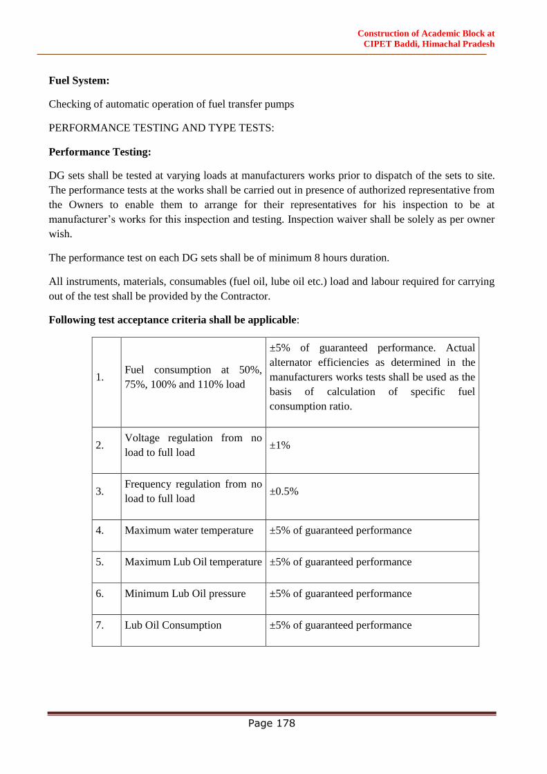
Construction of Academic Block at
CIPET Baddi, Himachal Pradesh
Page 178
Fuel System:
Checking of automatic operation of fuel transfer pumps
PERFORMANCE TESTING AND TYPE TESTS:
Performance Testing:
DG sets shall be tested at varying loads at manufacturers works prior to dispatch of the sets to site.
The performance tests at the works shall be carried out in presence of authorized representative from
the Owners to enable them to arrange for their representatives for his inspection to be at
manufacturer’s works for this inspection and testing. Inspection waiver shall be solely as per owner
wish.
The performance test on each DG sets shall be of minimum 8 hours duration.
All instruments, materials, consumables (fuel oil, lube oil etc.) load and labour required for carrying
out of the test shall be provided by the Contractor.
Following test acceptance criteria shall be applicable:
1. Fuel consumption at 50%,
75%, 100% and 110% load
±5% of guaranteed performance. Actual
alternator efficiencies as determined in the
manufacturers works tests shall be used as the
basis of calculation of specific fuel
consumption ratio.
2. Voltage regulation from no
load to full load ±1%
3. Frequency regulation from no
load to full load ±0.5%
4. Maximum water temperature ±5% of guaranteed performance
5. Maximum Lub Oil temperature ±5% of guaranteed performance
6. Minimum Lub Oil pressure ±5% of guaranteed performance
7. Lub Oil Consumption ±5% of guaranteed performance

Construction of Academic Block at
CIPET Baddi, Himachal Pradesh
Page 179
Type Test:
Copies of manufacturer’s type test for the engine and the alternator of all ratings shall be enclosed
along with the dispatch of the DG sets.
Exhaust Blower:
The exhaust fans shall be propeller type with steel hub and blades, mounted directly on the shaft of a
totally enclosed motor.
The fan blades shall be of pressed steel of aerofoil design for high efficiency and static pressure.
The mounting frame shall be of cast /sheet steel brackets to connect the frame, with the fan/motor
assembly. Rubber mounts shall be provided between the mounting frame and the mounting brackets.
The fan motor shall be totally enclosed squirrel cage type.
DG CONTROL AND OPERATION:
Operation of DG Sets shall be monitored and controlled by a programmable logic controller (PLC)
based logic panel. Vendor shall coordinate the Main MV Panel Contractor.
SPECIAL INSTRUCTIONS TO TENDERERS
Compatibility & Coordination with PLC
A microprocessor based PLC panel for Automatic Mains Failure, Auto Changeover/ Interlocking and
Auto Load Sharing, Auto Load Management and auto synchronizing functions of the DG sets is
incorporated with the Main LT Panel of the system being provided through the electrical contractor
to be appointed by the Owners. Control cabling between the DG sets and the PLC is to be done under
this contract. All parts of the DG set installation covered by this contract shall be compatible for being
integrated with the PLC operation. The DG Contractor shall coordinate his work with that of electrical
Contractor for achieving a fully coordinated and trouble free operation of the DG sets and their sub-
systems through the PLC panel.
Completeness of contract
The Contractors shall undertake the complete installation and shall be responsible for the overall
satisfactory operation of the DG sets with the associated accessories. The tenderer shall confirm as
part of the tender that the associated equipments are suitable for the DG sets and the total system shall
be compatible in all respects.
All equipments described hereafter shall be in accordance with the specifications.
All equipments shall be selected and installed for the lowest operating noise level.
Supply of various equipments shall include cost of correspondence with manufacturers, submission
of shop drawings and documents and their approval by the Consulting Engineer, procurement of
equipment, transportation, shipping, payment of all taxes and levies, storage, supply of equipments at

Construction of Academic Block at
CIPET Baddi, Himachal Pradesh
Page 180
site of installation, furnishing all technical literature required, replacement of defective components
and warranty obligations for the individual equipment.
Statutory approvals from all concerned authorities (State Electricity Authority, HERC, Pollution
Control Board, Department of Explosive etc.)
Installation of various equipments shall include all material and labour associated with hoisting and
lowering of equipment in position, insulation of the components where ever required, vibration
isolation as required, grouting and anchoring or suspension arrangements and all incidentals
associated with the installation as per the specifications and manufacturer’s recommendation.
Vibration isolators shall be installed with components as required. Performance ratings, power
consumption and sound power data for each component shall be verified at the time of testing and
commissioning of the installation, against the data submitted with the tenders.
Shop coats of paint that have become marred during shipment or erection shall be cleaned off with
mineral spirit, wire brushed and spot primed over the affected areas, then coated with enamel paint to
match the finish over the adjoining shop painted surfaces.
Testing and commissioning shall include furnishing all labour, materials, equipment, instruments, fuel
oil and incidentals necessary for complete testing ofeach component as per the specifications and
manufacturer’srecommendations, submission of test results to the Project In-charge and obtaining
their approval and submission of necessary documents and completion drawings.
All piping shall be installed conforming to the relevant Indian standards, approved shop drawings and
shall be tested as per Standards.
Fuel piping and installation shall be as per the requirement of Department of Explosive. Quoted rate
shall include cost of radiographic tests of welded joints randomly selected by Project In-charge in
addition to hydrostatic pressure testing.
Piping installation shall include all costs toward supplying and fixing pipes and fittings (elbows,
tees, reducers) cutting, threading, joining, welding, soldering and effecting connection as required;
providing non hardening sealing material as well as neoprene rubber gaskets for screwed flanges,
providing and installing adequate number of clamps, hangers, saddles, brackets, rawl plugs and other
accessories for pipe supports, providing minor dressing of walls and floor, providing and installing
pipe sleeves etc. as required.
Exposed steel pipes shall be given two coats of approved paint as per the relevant Indian standards
for color coding of pipes and direction of flow of fluid in the pipes shall be visibly marked with
identifying arrows.
All buried pipes shall be wrapped with Pipekote 4 mm thick wrapping as per manufacturer’s
standards.
Valves, unions, strainers, drain and air valves, expansion joints, pressure gauges and thermometers
shall be provided in the various pipe lines as per the approved shop drawings and specifications.
Construction of Academic Block at
CIPET Baddi, Himachal Pradesh
Page 181
After completion of the installation, the entire piping system shall be tested for leakage as required.
Proper co-ordination shall be done with Engineer-in-Charges and Project In-charges for civil works
such as Fuel lorry platform, bulk fuel area fencing etc. as required.
Lift
Provision of lifts in the buildings will be kept as per National Building Code-2016 / CPWD
Specifications & as per architectural plan considering no of floors, height of the building and speed of
elevators which shall be submitted to Engineer-in charge for approval before commencement of work.
As per CPWD manual for barrier free provision min 13 passengers lift to be provided.
CABLE LAYING DIRECT IN GROUND
GENERAL
This method shall be adopted where the cable route is through open country along roads/lanes etc.
and where no frequent excavation are encountered and where excavation is easily possible without
affecting other services.
TRENCHING
WIDTH OF TRENCH: - The width of trench shall be determined on the following basis:
a) The minimum width of trench for laying single cable shall be 35 cm.
b) Where more than one cable is to be laid in the same trench in horizontal formation, the width
of trench shall be increased such that the inter-axial spacing between the cables, except where
otherwise specified shall be at least 20 cm.
c) There shall be a clearance of at least 15 cm between axis of the end cables and the sides of
the trench.
DEPTH OF TRENCH: - The depth of trench shall be determined on the following basis:
a) Where cables are laid in single tier formation, the total depth of trench shall not be less than
75 cm. for cables up to 1.1 KV and 1.20 m for cables 33 KV.
b) When more than one tier of cables is unavoidable and vertical formation of laying is adopted,
depth of trench in a (i) above shall be increased by 30 cm. for each additional tier to be
formed.
EXCAVATION OF TRENCHES
a) The trenches shall be excavated in reasonably straight lines. Wherever there is a change in
direction, suitable curvature shall be provided complying with the requirements.
b) Where gradients and changes in depth are unavoidable, these shall be gradual.
c) Excavation shall be done by any suitable means-manual or mechanical. The excavated soil
shall be stacked firmly by the side of the trench such that it may not fall back into the trench.
d) Adequate precautions shall be taken not to damage any existing cables, pipes or other such
installations in the proposed route during excavation. Wherever bricks, tiles or protective
Construction of Academic Block at
CIPET Baddi, Himachal Pradesh
Page 182
covers or bare cables are encountered, further excavation shall not be carried without the
approval of the Engineer-in-Charge.
e) Existing property exposed during trenching shall be temporarily supported or propped
adequately as directed by the Engineer in charge. The trenching in such cases shall be done
in short lengths, necessary pipes laid for passing cables therein and the trench refilled.
f) If there is any danger of a trench collapsing and endangering adjacent structures, the sides
should be well shored up with timbering and/or sheeting as the excavation proceeds. Where
necessary, these may even be left in places when back filling the trench.
g) Excavation through lawns shall be done in consultation with the staff of the
department/Owner concerned.
h) The bottom of the trench shall be level and free from stone, brick bats etc. The trench shall
then be provided with a layer of clean, dry sand cushion of not less than 8 cm. in depth.
LAYING OF CABLE IN TRENCH
a) At the time of issue of cable for laying, the cores shall be tested for continuity and insulation
resistance.
b) The cable drum shall be properly mounted on jacks or on a cable wheel, at a suitable location,
making sure that the spindle, jack etc. are strong enough to carry the weight of the drum
without failure and that the spindle is horizontal in the bearings so as to prevent the drum
creeping to one side while rotating.
c) The cable shall be pulled over rollers in the trench steadily and uniformly without jerks and
strains. The entire cable length shall as far as possible be pulled of in one stretch. However,
where this is not possible the remainder of the cable may be removed by 'Flaking' i.e. by
making one long loop in the reverse direction.
d) i) After the cable has been uncoiled and laid into the trench over the rollers, the cable shall
be lifted slightly over the rollers beginning from one end by helpers standing about 10 m
apart and drawn straight. The cable should then be taken off the rollers by additional helpers
lifting the cable and then laid in a reasonably straight line.
ii)For short runs and sizes up to 50 Sq. mm of cables up to 1.1 KV grade, any other suitable
method of direct handling and laying can be adopted with the prior approval of the Engineer-
in-Charge.
e) When the cable has been properly straightened, the cores shall be tested for continuity and
insulation resistance. In case of PVC cables, suitable moisture seal tape shall be used for this
purpose.
f) i) Cable laid in trenches in a single tier formation shall have a covering of clean, dry sand of
not less than 17 cm above the base cushion of sand before the protective cover is laid.
ii) In the case of vertical multi-tier formation after the first cable has been laid, a sand cushion
of 30 cm shall be provided over the initial bed before the second tier is laid. If additional
tiers are formed, each of the subsequent tiers also shall have a sand cushion of 30 cm. as
Construction of Academic Block at
CIPET Baddi, Himachal Pradesh
Page 183
stated above. The top most cable shall have a final sand covering not less than 17 cm. before
the protective cover is laid.
g) At the time of original installation, approximately 3 m of surplus cable shall be left on each
end the cable and on each side of underground joints (Straight through/Tee/Termination) and
at entries and places as may be decided by the Engineer-in-Charge. The surplus cable shall
be left in the form of a loop. Where there are long runs of cable length loose cable may be
left at suitable intervals as specified by the Engineer-in-Charge.
h) A final protection to cables shall be laid in accordance with Clause j to provide warning to
future excavators of the presence of the cable and also to protect the cable against accidental
mechanical damage by pick-axe blows etc.
i) Unless otherwise specified, the cables shall be protected by second class bricks of not less
than 20 cm x 10 cm x 10 cm (nominal size) as per CPWD Building Specification or protection
covers placed on top of the sand, (bricks to be laid breadth wise) for the full length of the
cable to the satisfaction of the Engineer-in-Charge. Where more than one cable is to be laid
in the same trench, this protective covering shall cover all the cables and project at least 5
cm. over the sides of the end cables.
BACK FILLING
b) The trenches shall be back-filled with excavated earth free from stones or other sharp edged
debris and shall be rammed and watered, if necessary, in successive layers not exceeding 30
cm. Unless otherwise specified, a crown of earth not less than 50 mm. in the centre and
tapering towards the sides of the trench shall be left to allow for subsidence. The crown of
earth however should not exceed 10 cm. so as not to be a hazard to vehicular traffic. The
temporary re-instatements of roadways should be inspected at regular intervals, particularly
during the wet weather, and any settlement should be made good. Further trenches cut
through roadways or other paved areas shall be restored to the same density and material as
the surrounding area and repaved in accordance with the relevant Specifications to the
satisfaction of the Engineer-in-Charge.
c) Where road berm or lawns have been cut or kerb stones displaced, the same shall be repaired
and made good except turfing/asphalting to the satisfaction of the Engineer-in-Charge and all
surplus earth or rock removed to places as specified.
ROUTE MARKERS:
a) Route markers shall be provided along straight runs of the cables at locations approved by
the Engineer-in-Charge and generally at intervals not exceeding 100 m. Markers shall also
be provided to identify change in the direction of the cable route and also for location of
every underground joint.
Construction of Academic Block at
CIPET Baddi, Himachal Pradesh
Page 184
b) Route markers shall be made out of 100 mm x 100 mm x 5 mm GI/Aluminium plate, welded
or bolted on to 35 mm x 35 mm x 6 mm angle iron 60 cm. long. Such plate markers shall
be mounted parallel to and 0.5 m or so away from the edge of the trench.
Alternatively cement concrete 1:2:4 (1 cement : 2 coarse sand : 4 graded stone aggregate of
20 mm nominal size) marker 60 cm x 60 cm 10 cm in size shall be laid flat and centred over
the cable. The concrete markers unless otherwise instructed by the Engineer-in-Charge shall
project over the surrounding surface so as to make the cable route easily identifiable.
c) The work 'cable' and other details such as voltage grading, size etc. as furnished by the
Engineer-in-Charge shall be inscribed on the marker.
LAYING IN PIPES/CLOSED DUCTS:
In location such as road crossing, entry to building, on poles, in paved areas etc. cables shall be laid
in pipes or closed ducts.
GI or Hume Pipes (spun reinforced concrete pipes) shall be used for such purposes. In the case of
new construction, pipes as required shall be laid along with the Civil works and jointed according to
the instructions of the Engineer-in-Charge as the case may be. The size of pipe shall be as indicated
in the electrical drawings. GI pipe shall be laid directly in ground without any special bed. Hume
pipe (Spun reinforced concrete pipe) shall be laid over 10 cm. thick cement concrete 1:5:10 (1
cement: 5 coarse sand: 10 graded stone aggregate of 40mm nominal size) bed, after which it shall be
completely embedded in concrete. No sand cushioning or tiles need be used in such situations. Unless
otherwise specified, the top surface of pipes shall be at a minimum depth of 1mtr. from the ground
level when laid under roads, pavement etc.
Where steel pipes are employed for protection of single core cables feeding AC load, the pipe should
be large enough to contain both cables in the case of single phase system and all cables in the case
of poly phase system.
The pipes on road crossing shall preferably be on the skew to reduce the angle of bends as the cable
enters and leaves the crossings. This is particularly important for high voltage cables.
Manholes of adequate size as decided by the Engineer-in-Charge shall be provided to facilitate
feeding/drawing in of cables and to provide working space for persons. They shall be covered by
suitable manhole covers with frame of proper design.
Pipes shall be continuous and clear of debris or concrete before cable is drawn. Sharp edges at ends
shall be smoothened to prevent injury to cable insulation or sheathing.
Pipes for cable entries to the building shall slope downwards from the building and suitably sealed
to prevent entry of water inside the building. Further the mouth of the pipes at the building end shall
be suitably sealed to avoid entry of water. This seal in addition to being waterproof shall also be
fireproof.
Construction of Academic Block at
CIPET Baddi, Himachal Pradesh
Page 185
All chases and passages necessary for laying of service cable connections to buildings shall be cut
as required and made good to the original finish and to the satisfaction of the Engineer-in-Charge.
Cable grips/draw wires and winches etc. may be employed for drawing cables through pipes/closed
ducts etc.
LAYING ON CABLE TRAY
Cables, where indicated in approved shop drawings, shall be laid on overhead cable trays which are
suspended from ceiling or supported from wall, by anchor fasteners as required.
The Contractor shall provide for all accessories for the installation of the cable trays, such as bends,
tees, reducers coupler plates, and structural steel members (comprising of channels, angles, flats,
rods) for structural supports for cable trays etc.
CABLE TRAY MOUNTING
Unless otherwise specifically noted on the relevant layout drawing, all cable tray mounting works to
be carried out ensuring the following:
a) Cable tray mounting arrangement type to be as marked on layout drawing.
b) Assembly of tray mounting structure shall be supplied, fabricated, erected & painted by the
contractor.
c) Cable tray running along the wall should be supported at intervals not exceeding 1.5 m. In
case of branching, there should be a support on all branches at a distance of 30 cm from the
point of branching. Support should not be less than 40 mm x 40 mm x 5 mm MS angle-
secured in an approved manner where runs are along the walls. In case of ceiling suspended
cable tray horizontal supports made of 40 mm x 40 mm 5 mm MS angle iron shall be
provided. The horizontal interval between two such supports shall be 1.0 meter. These
supports shall be suspended from C.I. boxes or suitable approved suspension devices such as
dash fastener of suitable sizes in the ceiling by means of 10 mm diameter GI threaded rods.
All above mounting accessories form part of installation of cable trays.
TESTING & COMMISSIONING
INSPECTION
All cables shall be inspected upon receipt at site and checked by the Engineer-in-Charge for
any damage during transit.
TESTING
i. All 650/1100 Volt grade cables before laying shall be tested with a 500 V megger or with
a 2,500/5,000 V megger for cables of higher voltages. The cable cores shall be tested for
continuity, absence of cross phasing, insulation resistance to earth/sheath/amour and
insulation resistance between conductors.
ii. All cables shall be subject to above mentioned tests during laying, before covering the
cables by protective covers and back filling and also before the jointing operations.
Construction of Academic Block at
CIPET Baddi, Himachal Pradesh
Page 186
COMPLETION PLAN AND COMPLETION CERTIFICATE
After completion of the work the Contractor shall draw completion plans to a suitable scale
and shall submit to the Engineer-in-Charge. The completion plans shall, inter-alia, give the
following details
i. Layout of cable work
ii. Length, size, type and grade of cables.
iii. Method of laying i.e. direct in ground, in pipes etc.
iv. Location of each joint with jointing method followed.
v. Route marker and joint maker with respect to permanent land marks available at site.
vi. Wherever the previously laid cable is cut and additional joints are introduced etc., the cable
records shall suitably be amended.
TESTING OF CABLES
The cables shall be tested before and after laying. The Megger value in normal dry weather
shall be 50 Mega ohm for 1.1 KV grade cable. This value shall be 100 Mega ohm for 11 KV
grade cable.
CABLE TAGS
Cable tags shall be made out of 2mm thick aluminium sheets. Each tag shall be 2” in dia or
3” x 3” square with one hole of 2.5mm dia, 6 mm below the periphery, or as approved by
Consultant. Cable designations are to be punched with letters / number punches and the tags
are to be tied to cables with piano wires of approve quality & size. Tags shall be tied inside
the panels beyond the glanding as well as above the glands at cable entries. Along trays tags
are to be tied at all bends. On straight lengths, tags shall be provided at every 5 meters.
Cables shall be secured to cable trays with 3mm thick x 25mm wide aluminium strips/suitable
GI clamp, or as approved by Consultant, at 1000 mm intervals and screwed by means of rust
proof screws and washers, of adequate but not excessive lengths. Cable trays for horizontal
runs suspended from the ceiling will be supported with mild steel straps or brackets, at 1000
mm intervals and the overall tray arrangement shall be of a rigid construction. External
cabling route marker with C.I. plate marked with “DANGER 1.1 KV CABLE” with 0.6 meter
long GI angle iron grouting bracket including 1:3:6 ratio cement concrete base block of
minimum size 200 x 200 x 350 mm to be provided or as approved by Elect. Supply Company.
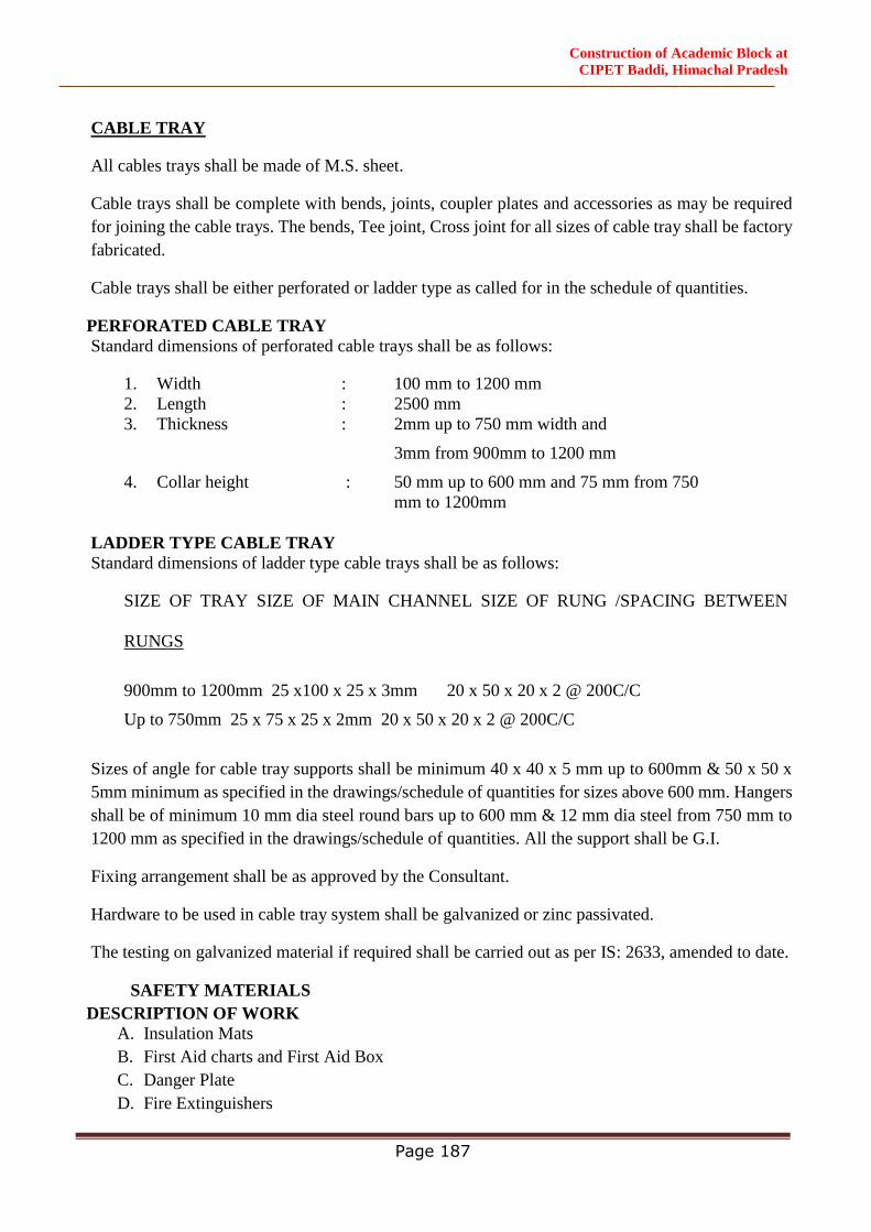
Construction of Academic Block at
CIPET Baddi, Himachal Pradesh
Page 187
CABLE TRAY
All cables trays shall be made of M.S. sheet.
Cable trays shall be complete with bends, joints, coupler plates and accessories as may be required
for joining the cable trays. The bends, Tee joint, Cross joint for all sizes of cable tray shall be factory
fabricated.
Cable trays shall be either perforated or ladder type as called for in the schedule of quantities.
PERFORATED CABLE TRAY
Standard dimensions of perforated cable trays shall be as follows:
1. Width : 100 mm to 1200 mm
2. Length : 2500 mm
3. Thickness : 2mm up to 750 mm width and
3mm from 900mm to 1200 mm
4. Collar height : 50 mm up to 600 mm and 75 mm from 750
mm to 1200mm
LADDER TYPE CABLE TRAY
Standard dimensions of ladder type cable trays shall be as follows:
SIZE OF TRAY SIZE OF MAIN CHANNEL SIZE OF RUNG /SPACING BETWEEN
RUNGS
900mm to 1200mm 25 x100 x 25 x 3mm 20 x 50 x 20 x 2 @ 200C/C
Up to 750mm 25 x 75 x 25 x 2mm 20 x 50 x 20 x 2 @ 200C/C
Sizes of angle for cable tray supports shall be minimum 40 x 40 x 5 mm up to 600mm & 50 x 50 x
5mm minimum as specified in the drawings/schedule of quantities for sizes above 600 mm. Hangers
shall be of minimum 10 mm dia steel round bars up to 600 mm & 12 mm dia steel from 750 mm to
1200 mm as specified in the drawings/schedule of quantities. All the support shall be G.I.
Fixing arrangement shall be as approved by the Consultant.
Hardware to be used in cable tray system shall be galvanized or zinc passivated.
The testing on galvanized material if required shall be carried out as per IS: 2633, amended to date.
SAFETY MATERIALS
DESCRIPTION OF WORK
A. Insulation Mats
B. First Aid charts and First Aid Box
C. Danger Plate
D. Fire Extinguishers
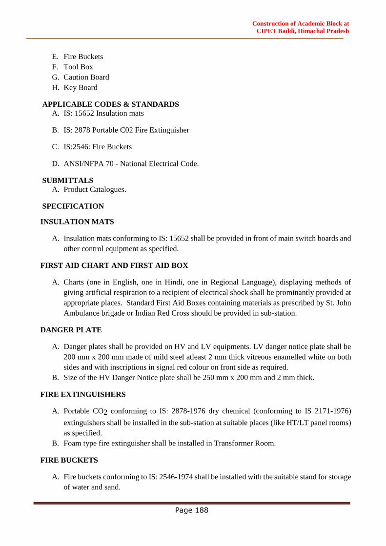
Construction of Academic Block at
CIPET Baddi, Himachal Pradesh
Page 188
E. Fire Buckets
F. Tool Box
G. Caution Board
H. Key Board
APPLICABLE CODES & STANDARDS
A. IS: 15652 Insulation mats
B. IS: 2878 Portable C02 Fire Extinguisher
C. IS:2546: Fire Buckets
D. ANSI/NFPA 70 - National Electrical Code.
SUBMITTALS
A. Product Catalogues.
SPECIFICATION
INSULATION MATS
A. Insulation mats conforming to IS: 15652 shall be provided in front of main switch boards and
other control equipment as specified.
FIRST AID CHART AND FIRST AID BOX
A. Charts (one in English, one in Hindi, one in Regional Language), displaying methods of
giving artificial respiration to a recipient of electrical shock shall be prominantly provided at
appropriate places. Standard First Aid Boxes containing materials as prescribed by St. John
Ambulance brigade or Indian Red Cross should be provided in sub-station.
DANGER PLATE
A. Danger plates shall be provided on HV and LV equipments. LV danger notice plate shall be
200 mm x 200 mm made of mild steel atleast 2 mm thick vitreous enamelled white on both
sides and with inscriptions in signal red colour on front side as required.
B. Size of the HV Danger Notice plate shall be 250 mm x 200 mm and 2 mm thick.
FIRE EXTINGUISHERS
A. Portable CO2 conforming to IS: 2878-1976 dry chemical (conforming to IS 2171-1976)
extinguishers shall be installed in the sub-station at suitable places (like HT/LT panel rooms)
as specified.
B. Foam type fire extinguisher shall be installed in Transformer Room.
FIRE BUCKETS
A. Fire buckets conforming to IS: 2546-1974 shall be installed with the suitable stand for storage
of water and sand.
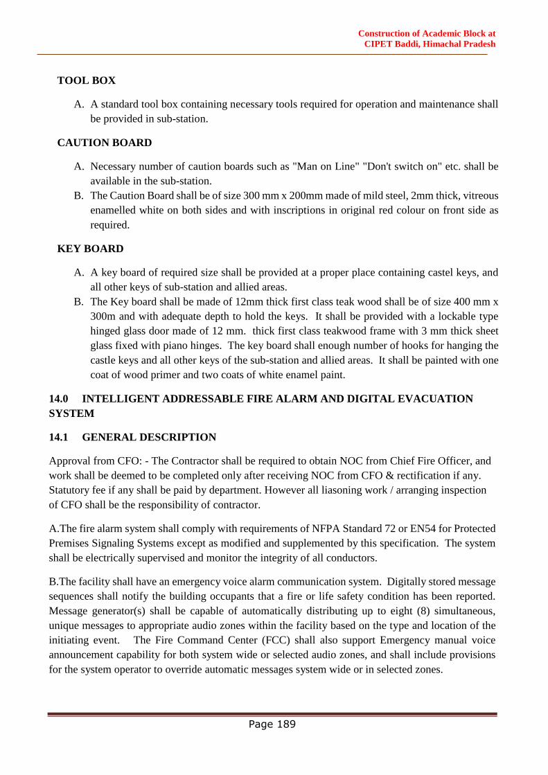
Construction of Academic Block at
CIPET Baddi, Himachal Pradesh
Page 189
TOOL BOX
A. A standard tool box containing necessary tools required for operation and maintenance shall
be provided in sub-station.
CAUTION BOARD
A. Necessary number of caution boards such as "Man on Line" "Don't switch on" etc. shall be
available in the sub-station.
B. The Caution Board shall be of size 300 mm x 200mm made of mild steel, 2mm thick, vitreous
enamelled white on both sides and with inscriptions in original red colour on front side as
required.
KEY BOARD
A. A key board of required size shall be provided at a proper place containing castel keys, and
all other keys of sub-station and allied areas.
B. The Key board shall be made of 12mm thick first class teak wood shall be of size 400 mm x
300m and with adequate depth to hold the keys. It shall be provided with a lockable type
hinged glass door made of 12 mm. thick first class teakwood frame with 3 mm thick sheet
glass fixed with piano hinges. The key board shall enough number of hooks for hanging the
castle keys and all other keys of the sub-station and allied areas. It shall be painted with one
coat of wood primer and two coats of white enamel paint.
14.0 INTELLIGENT ADDRESSABLE FIRE ALARM AND DIGITAL EVACUATION
SYSTEM
14.1 GENERAL DESCRIPTION
Approval from CFO: - The Contractor shall be required to obtain NOC from Chief Fire Officer, and
work shall be deemed to be completed only after receiving NOC from CFO & rectification if any.
Statutory fee if any shall be paid by department. However all liasoning work / arranging inspection
of CFO shall be the responsibility of contractor.
A.The fire alarm system shall comply with requirements of NFPA Standard 72 or EN54 for Protected
Premises Signaling Systems except as modified and supplemented by this specification. The system
shall be electrically supervised and monitor the integrity of all conductors.
B.The facility shall have an emergency voice alarm communication system. Digitally stored message
sequences shall notify the building occupants that a fire or life safety condition has been reported.
Message generator(s) shall be capable of automatically distributing up to eight (8) simultaneous,
unique messages to appropriate audio zones within the facility based on the type and location of the
initiating event. The Fire Command Center (FCC) shall also support Emergency manual voice
announcement capability for both system wide or selected audio zones, and shall include provisions
for the system operator to override automatic messages system wide or in selected zones.
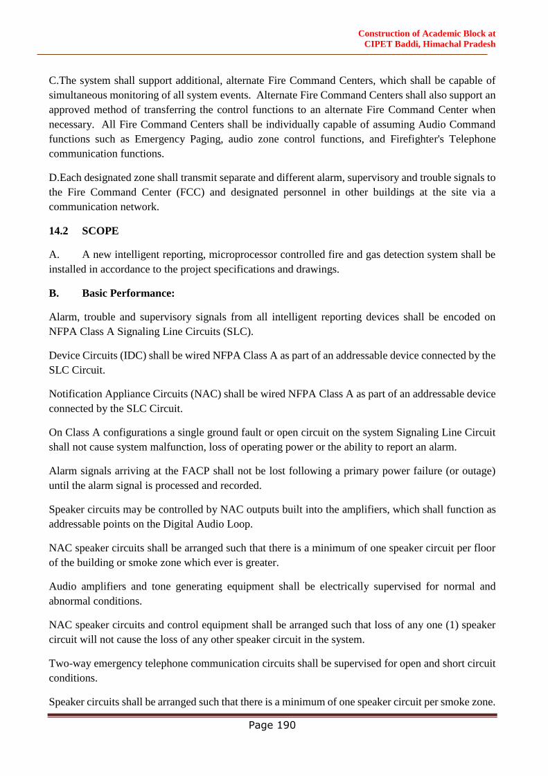
Construction of Academic Block at
CIPET Baddi, Himachal Pradesh
Page 190
C.The system shall support additional, alternate Fire Command Centers, which shall be capable of
simultaneous monitoring of all system events. Alternate Fire Command Centers shall also support an
approved method of transferring the control functions to an alternate Fire Command Center when
necessary. All Fire Command Centers shall be individually capable of assuming Audio Command
functions such as Emergency Paging, audio zone control functions, and Firefighter's Telephone
communication functions.
D.Each designated zone shall transmit separate and different alarm, supervisory and trouble signals to
the Fire Command Center (FCC) and designated personnel in other buildings at the site via a
communication network.
14.2 SCOPE
A. A new intelligent reporting, microprocessor controlled fire and gas detection system shall be
installed in accordance to the project specifications and drawings.
B. Basic Performance:
Alarm, trouble and supervisory signals from all intelligent reporting devices shall be encoded on
NFPA Class A Signaling Line Circuits (SLC).
Device Circuits (IDC) shall be wired NFPA Class A as part of an addressable device connected by the
SLC Circuit.
Notification Appliance Circuits (NAC) shall be wired NFPA Class A as part of an addressable device
connected by the SLC Circuit.
On Class A configurations a single ground fault or open circuit on the system Signaling Line Circuit
shall not cause system malfunction, loss of operating power or the ability to report an alarm.
Alarm signals arriving at the FACP shall not be lost following a primary power failure (or outage)
until the alarm signal is processed and recorded.
Speaker circuits may be controlled by NAC outputs built into the amplifiers, which shall function as
addressable points on the Digital Audio Loop.
NAC speaker circuits shall be arranged such that there is a minimum of one speaker circuit per floor
of the building or smoke zone which ever is greater.
Audio amplifiers and tone generating equipment shall be electrically supervised for normal and
abnormal conditions.
NAC speaker circuits and control equipment shall be arranged such that loss of any one (1) speaker
circuit will not cause the loss of any other speaker circuit in the system.
Two-way emergency telephone communication circuits shall be supervised for open and short circuit
conditions.
Speaker circuits shall be arranged such that there is a minimum of one speaker circuit per smoke zone.

Construction of Academic Block at
CIPET Baddi, Himachal Pradesh
Page 191
Speaker circuits shall be electrically supervised for open and short circuit conditions. If a short circuit
exists on a speaker circuit, it shall not be possible to activate that circuit.
Audio amplifiers and tone generating equipment shall be electrically supervised for abnormal
conditions. Digital amplifiers shall provide built-in speaker circuits, field configurable as four Class
B, or two Class A circuits.
Digital amplifiers shall be capable of storing up to two minutes of digitally recorded audio messages
and tones. The digital amplifiers shall also be capable of supervising the connection to the associated
digital message generator, and upon loss of that connection shall be capable of one of the following
system responses:
The digital amplifier shall automatically broadcast the stored audio message.
The digital amplifier shall switch to a mode where a local bus input on the digital amplifier will accept
an input to initiate a broadcast of the stored message. This bus input shall be connected to a NAC on
a local FACP for the purpose of providing an alternate means of initiating an emergency message
during a communication fault condition.
Speaker circuits shall be either 25 VRMS or 70VRMS. Speaker circuits shall have 20% space capacity
for future expansion or increased power output requirements.
Two-way emergency telephone (Fire Fighter Telephone) communication shall be supported between
the Audio Command Center and up to thirty five (35) remote Fire Fighter's Telephone locations
simultaneously on a conference.
Means shall be provided to connect FFT voice communications to the speaker circuits in order to
allow voice paging over the speaker circuit from a telephone handset.
The digital audio message generator shall be of reliable, non-moving parts, and support the digital
storage of up to 32 minutes of tones and emergency messages, shall support programming options to
string audio segments together to create up to 1000 messages, or to loop messages and parts of
messages to repeat for pre-determined cycles or indefinitely.
The proposed product shall not restrict the buyer to one single organization, not shall it require any
proprietary dongle or other programming tools for after sales & maintenance activity.
The MTBF for the product offered shall be less than 40
14.3 DRAWINGS & TECHNICAL SUBMITTALS
14.3.1 General
Two copies of all submittals shall be submitted to the Engineer-in-Charge/Consultant for review.
All references to manufacturer's model numbers and other pertinent information herein is intended to
establish minimum standards of performance, function and quality. Equivalent compatible ULlisted
Construction of Academic Block at
CIPET Baddi, Himachal Pradesh
Page 192
equipment from other manufacturers may be substituted for the specified equipment as long as the
minimum standards are met.
For equipment other than that specified, the contractor shall supply proof that such substitute
equipment equals or exceeds the features, functions, performance, and quality of the specified
equipment.
14.3.2 Shop Drawings
Sufficient information, clearly presented, shall be included to determine compliance with drawings
and specifications.
Include manufacturer's name(s), model numbers, ratings, power requirements, equipment layout,
device arrangement, complete wiring point-to-point diagrams, and conduit layouts.
Show annunciator layout, configurations, and terminations.
14.3.3 Manuals
Submit simultaneously with the shop drawings, complete operating and maintenance manuals listing
the manufacturer's name(s), including technical data sheets.
Wiring diagrams shall indicate internal wiring for each device and the interconnections between the
items of equipment.
Provide a clear and concise description of operation that gives, in detail, the information required to
properly operate the equipment and system.
14.3.4 Software Modifications
Provide the services of a factory trained and authorized technician to perform all system software
modifications, upgrades or changes. Response time of the technician to the site shall not exceed 4
hours.
Provide all hardware, software, programming tools and documentation necessary to modify the fire
alarm system on site. Modification includes addition and deletion of devices, circuits, zones
andchanges to system operation and custom label changes for devices or zones. The system structure
and software shall place no limit on the type or extent of software modifications on-site.
14.3.5 Certifications
Together with the shop drawing submittal, submit a certification from the major equipment
manufacturer indicating that the proposed supervisor of the installation and the proposed performer of
contract maintenance is an authorized representative of the major equipment manufacturer. Include
names and addresses in the certification.
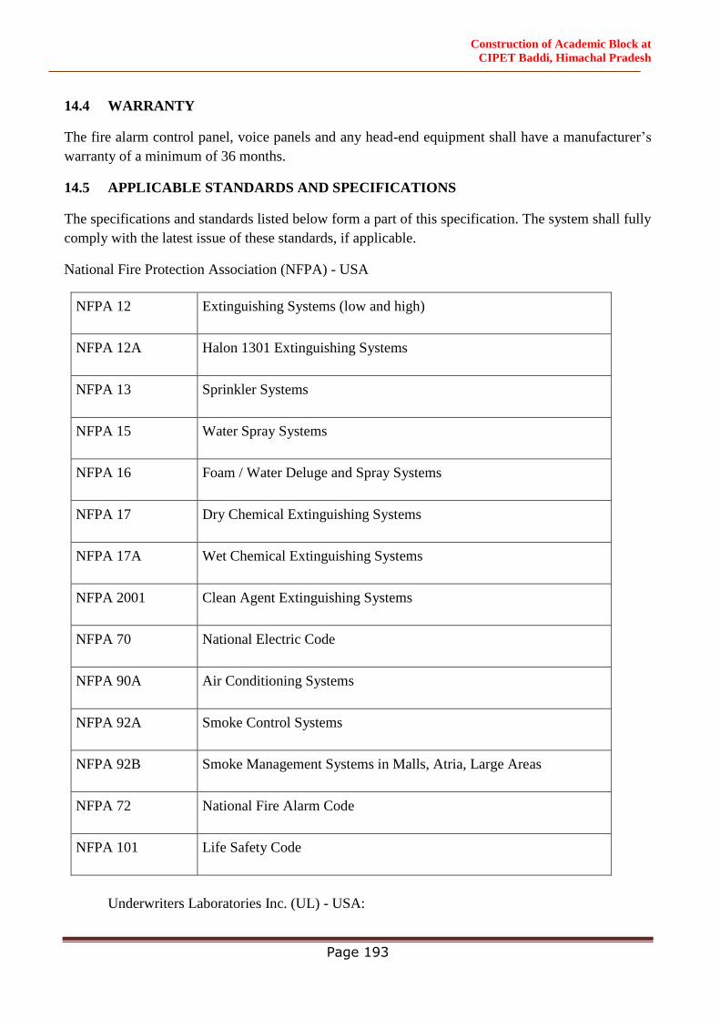
Construction of Academic Block at
CIPET Baddi, Himachal Pradesh
Page 193
14.4 WARRANTY
The fire alarm control panel, voice panels and any head-end equipment shall have a manufacturer’s
warranty of a minimum of 36 months.
14.5 APPLICABLE STANDARDS AND SPECIFICATIONS
The specifications and standards listed below form a part of this specification. The system shall fully
comply with the latest issue of these standards, if applicable.
National Fire Protection Association (NFPA) - USA
NFPA 12 Extinguishing Systems (low and high)
NFPA 12A Halon 1301 Extinguishing Systems
NFPA 13 Sprinkler Systems
NFPA 15 Water Spray Systems
NFPA 16 Foam / Water Deluge and Spray Systems
NFPA 17 Dry Chemical Extinguishing Systems
NFPA 17A Wet Chemical Extinguishing Systems
NFPA 2001 Clean Agent Extinguishing Systems
NFPA 70 National Electric Code
NFPA 90A Air Conditioning Systems
NFPA 92A Smoke Control Systems
NFPA 92B Smoke Management Systems in Malls, Atria, Large Areas
NFPA 72 National Fire Alarm Code
NFPA 101 Life Safety Code
Underwriters Laboratories Inc. (UL) - USA:
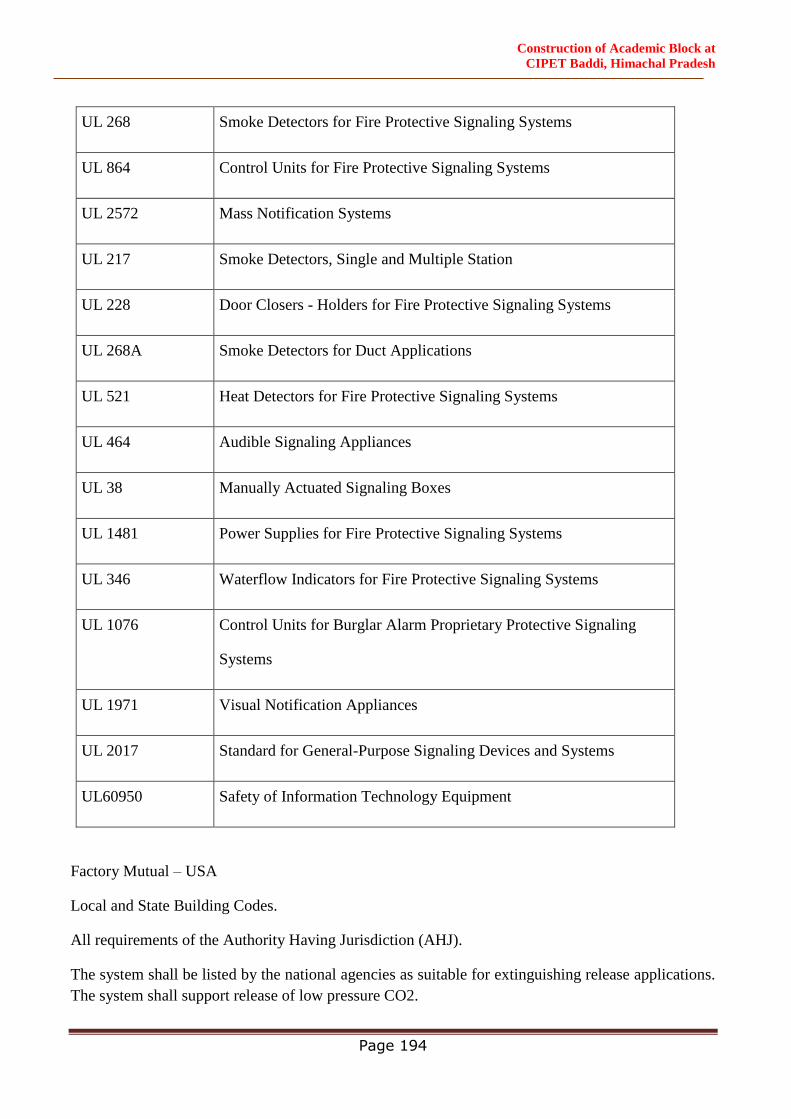
Construction of Academic Block at
CIPET Baddi, Himachal Pradesh
Page 194
UL 268 Smoke Detectors for Fire Protective Signaling Systems
UL 864 Control Units for Fire Protective Signaling Systems
UL 2572 Mass Notification Systems
UL 217 Smoke Detectors, Single and Multiple Station
UL 228 Door Closers - Holders for Fire Protective Signaling Systems
UL 268A Smoke Detectors for Duct Applications
UL 521 Heat Detectors for Fire Protective Signaling Systems
UL 464 Audible Signaling Appliances
UL 38 Manually Actuated Signaling Boxes
UL 1481 Power Supplies for Fire Protective Signaling Systems
UL 346 Waterflow Indicators for Fire Protective Signaling Systems
UL 1076 Control Units for Burglar Alarm Proprietary Protective Signaling
Systems
UL 1971 Visual Notification Appliances
UL 2017 Standard for General-Purpose Signaling Devices and Systems
UL60950 Safety of Information Technology Equipment
Factory Mutual – USA
Local and State Building Codes.
All requirements of the Authority Having Jurisdiction (AHJ).
The system shall be listed by the national agencies as suitable for extinguishing release applications.
The system shall support release of low pressure CO2.

Construction of Academic Block at
CIPET Baddi, Himachal Pradesh
Page 195
The system shall be certified for seismic applications in accordance with the International Building
Code (IBC). The basis for qualification of seismic approval shall be via shake table testing.
The System shall be FM 6320 (Factory Mutual) approved as a Gas Detection system when employed
with the 4-20 monitor module and industry standard 4-20 mA gas detectors.
14.6 DESIGN INTENT
Main fire alarm panel with digital voice command system, Fire fighters telephone, amplifier, zone
selector keypad/ Qwerty and announcement console – Ground floor – As per Drawing.
Active repeater panels at Project Main security cabin
All fire alarm panels connected as pier to pier.
Class - A cabling to loop all detectors, devices & MCP‟s to control panel.
Coverage per detector as per NFPA -2015, considering > 60 ACH
System integration (Soft integration) with all standalone panels such as agent release panels for deluge
valves, Pre-action panels, lift switchboard, DG fresh air switchboard, etc
Emergency communication system, integral with the Main FACP, including voice alarm system
components, microphones, amplifiers, zone selector keypads/ Qwerty and tone generators
Audible Alarm Notifications
Fire fighters telephone system as part of main fire alarm system which is two-way, supervised voice
communication proposed to link between the MFACP and remote fire fighters' telephone stations
throughout the building (at all staircases at all levels)
14.7 DETAILED DESCRIPTION OF THE SYSTEM COMPONENTS:
14.7.1 BASIS OF DESIGN
An Intelligent Modular/ Expandable Fire Alarm System (IFAS) shall be provided to effect total control
over the life safety services required in the building.
The system shall be provided with Addressable fire alarm initiating, annunciating and control devices.
The addressable and intelligent system shall be such that smoke sensors, thermal sensors, manual call
points, etc., can be identified with point address.
The FAS shall be able to recognize normal and alarm conditions, below normal sensor values that
reveal trouble condition, and above normal values that indicate either an alarm condition or the need
of maintenance.
Read-out or address an actual detector location. The operator shall also be able to adjust alarm and
alarm thresholds and other parameters for the smoke sensors.

Construction of Academic Block at
CIPET Baddi, Himachal Pradesh
Page 196
Provide a maintenance/pre-alert/fault alarm capability at smoke sensors to prevent the detectors from
indicating a false alarm due to dust, dirt etc.
Provide alarm verification of individual smoke sensors. Systems that perform alarm verification on a
zone basis shall not be acceptable. Alarm verification shall be printed on the printer at the Control
Station’s printer to enhance system maintenance and identify possible problem areas.
Provide local numeric point address and LED display of device and current condition of the point.
Each detector shall use state-of-the-art Microprocessor Circuitry with error, detector self-diagnostics
and supervision programs.
The detection of the fire shall be taken at the detector level.
Multi-Criteria Detectors shall be offered where by the system logic activation is based on any three
inputs from the detector i.e. smoke, fixed heat or rate of rise heat.
Provide outputs that are addressable, i.e. outputs shall have point address. The operator shall be able
to command such points manually or assign the points to Logical Point Groups (Software Zones) for
pre-programmed operation.
In the event of a fire alarm, but not in a fault condition, the following action shall be performed
automatically.
The System Alarm LED on the main fire alarm control panel shall flash.
A local sounder shall be sounded.
The LCD display on the main fire alarm control panel shall indicate all information associated with
Fire Alarm condition including the type of alarm point and its location within the premises.
Printing and history storage equipment shall log the information associated with the Fire Alarm
Control Panel condition, along with the time and date of occurrence.
All system output programs assigned via control-by-event programs that are to be activated by a
particular point in alarm shall be executed, and the associated system outputs (alarm notification
appliances and/or relays) shall be activated.
14.8 SYSTEM COMPONENTS AND DEVICES:
14.8.1 MAIN FIRE ALARM CONTROL PANEL OR NETWORK NODE:
Main FACP or network node shall contain a microprocessor based Central Processing Unit (CPU) and
power supply. The CPU shall communicate with and control the following types of equipment used
to make up the system: intelligent addressable smoke and thermal (heat) detectors, addressable
modules, printer, annunciators, and other system controlled devices.
In conjunction with intelligent Loop Control Modules and Loop Expander Modules, the main FACP
shall perform the following functions:

Construction of Academic Block at
CIPET Baddi, Himachal Pradesh
Page 197
Supervise and monitor all intelligent addressable detectors and monitor modules connected to the
system for normal, trouble and alarm conditions.
Supervise all initiating signaling and notification circuits throughout the facility by way of connection
to addressable monitor and control modules.
Detect the activation of any initiating device and the location of the alarm condition. Operate all
notification appliances and auxiliary devices as programmed.
14.8.2 System Capacity and General Operation
The FACP shall can communicate on a peer-to-peer, inherently regenerative communication format
and protocol. The network shall support communication speed up to 100 Mbps and support up to 200
panels / nodes per network.
The control panel shall be capable of expansion via up to 8 SLC loops. Each module shall support up
to 240 analog/addressable devices for a maximum system capacity of 1920 points. The Fire Alarm
Control Panel shall include a full featured operator interface control and annunciation panel that shall
include a backlit 600-character liquid crystal display, individual, color coded system status LEDs, and
a QWERTY style alphanumeric QWERTY / keypad for the field programming and control of the fire
alarm system. Said LCD shall also support graphic bit maps capable of displaying the company name
and logo of either come owner or installing company.
All programming or editing of timing or editing of the existing program in the system shall be achieved
without special equipment and without interrupting the alarm monitoring functions of the fire alarm
control panel.
14.9 The FACP shall be able to provide the following software and hardware features:
Pre-signal and Positive Alarm Sequence: The system shall provide means to cause alarm signals to
only sound in specific areas with a delay of the alarm from 60 to up to 180 seconds after start of alarm
processing. In addition, a Positive Alarm Sequence selection shall be available that allows a 15-
second time period for acknowledging an alarm signal from a fire detection/initiating device. If the
alarm is not acknowledged within 15 seconds, all local and remote outputs shall automatically activate
immediately.
Smoke Detector Pre-alarm Indication at Control Panel: To obtain early warning of incipient or
potential fire conditions, the system shall support a programmable option to determine system
response to real-time detector sensing values above the programmed setting. Two levels of Pre-alarm
indication shall be available at the control panel: alert and action.
Alert: It shall be possible to set individual smoke detectors for pre-programmed pre-alarm thresholds.
If the individual threshold is reached, the pre-alarm condition shall be activated.
Action: If programmed for Action and the detector reaches a level exceeding the pre-programmed
level, the control panel shall indicate an action condition. Sounder bases installed with either heat or

Construction of Academic Block at
CIPET Baddi, Himachal Pradesh
Page 198
smoke detectors shall automatically activate on action Pre-Alarm level, with general evacuation on
Alarm level.
The system shall support a detector response time to meet world annunciation requirements of less
than 3 seconds.
Device Blink Control: Means shall be provided to turn off detector/module LED strobes for special
areas.
NFPA 72 Smoke Detector Sensitivity Test: The system shall provide an automatic smoke detector test
function that meets the sensitivity testing requirements of NFPA 72.
Programmable Trouble Reminder: The system shall provide means to automatically initiate a reminder
that troubles exist in the system. The reminder will appear on the system display and (if enabled) will
sound a piezo alarm.
On-line or Off-line programming: The system shall provide means to allow panel programming either
through an off-line software utility program away from the panel or while connected and on-line. The
system shall also support upload and download of programmed database and panel executive system
program to a Personal Computer/laptop. A single change to one CPU database shall not require a
database download to other CPUs.
History Events: The panel shall maintain a history file of atleast last 5000 events, each with a time
and date stamp. History events shall include all alarms, troubles, operator actions, and programming
entries. The control panels shall also maintain a 1000 event Alarm History buffer, which consists of
the 1000 most recent alarm events from the 5000 event history file.
Smoke Control Modes: The system shall provide means to perform Fire Smoke Control Station mode.
This mode controls all dampers, smoke extraction fan, fresh air supply fans, etc. during Fire condition.
Smoke Control to meet NFPA-92A and 90B and HVAC mode to meet NFPA 90A.
The system shall provide means for all SLC devices on any SLC loop to be auto programmed into the
system by specific address. The system shall recognize specific device type ID's and associate that ID
with the corresponding address of the device.
Passwords and Users: The system shall support two password levels, master and user. Up to 9 user
passwords shall be available, each of which may be assigned access to the programming change
menus, the alter status menus, or both. Only the master password shall allow access to password
change screens.
Block Acknowledge: The system shall support a block Acknowledge for Trouble Conditions
Sensitivity Adjust: The system shall provide Automatic Detector Sensitivity Adjust based on
Occupancy schedules including a Holiday list of up to 15 days.
Environmental Drift Control: The system shall provide means for setting Environmental Drift
Compensation by device. When a detector accumulates dust in the chamber and reaches an
unacceptable level but yet still below the allowed limit, the control panel shall indicate a maintenance

Construction of Academic Block at
CIPET Baddi, Himachal Pradesh
Page 199
alert warning. When the detector accumulates dust in the chamber above the allowed limit, the control
panel shall indicate a maintenance urgent warning.
Custom Action Messages: The system shall provide means to enter up to 100 custom action messages
of up to 160 characters each. It shall be possible to assign any of the 100 messages to any point.
Local Mode: If communication is lost to the central processor the system shall provide added
survivability through the intelligent loop control modules. Inputs from devices connected to the SLC
and loop control modules shall activate outputs on the same loop when the inputs and outputs have
been set with point programming to participate in local mode or when the type codes are of the same
type: that is, an input with a fire alarm type code shall activate an output with a fire alarm type code.
Read status preview - enabled and disabled points: Prior to re-enabling points, the system shall inform
the user that a disabled device is in the alarm state. This shall provide notice that the device must be
reset before the device is enabled thereby avoiding activation of the notification circuits.
Custom Graphics: When fitted with an LCD display, the panel shall permit uploading of a custom bit-
mapped graphic to the display screen.
Multi-Cooperating Detectors: The system shall provide means to link one detector with up to two
detectors at other addresses in cooperative multi-detector sensing. The detector shall take feedback
from the other two adjacent detectors to take fast and genuine alarm decision mitigating the risk of
false alarm. There shall be no requirement for mandatory sequential address setting in the detectors to
achieve this function. Multi-cooperative detection shall be a built-in intelligence in the system to take
fast & reliable decision on genuine alarm triggering. The alarm event shall be a result of all
cooperating detector chamber readings considered as a consolidated alarm signal.
ACTIVE EVENT: The system shall provide a Type ID called FIRE CONTROL for purposes of air-
handling shutdown, which shall be intended to override normal operating automatic functions.
Activation of a FIRE CONTROL point shall cause the control panel to (1) initiate the monitor module
Control-by-Event, (2) send a message to the panel display, history buffer, installed printer and
annunciators, (3) shall not light an indicator at the control panel, (4) Shall display ACTIVE on the
LCD as well a display a FIRE CONTROL Type Code and other information specific to the device.
NON-FIRE Alarm Module Reporting: A point with a type ID of NON-FIRE shall be available for use
for energy management or other non-fire situations. NON-FIRE point operation shall not affect
control panel operation nor shall it display a message at the panel LDC. Activation of a NON-FIRE
point shall activate control by event logic but shall not cause any indication on the control panel.
Mass Notification Override: The system shall be UL 2572 listed for Mass Notification and shall be
capable, based on the Risk Analysis, of being programmed so that Mass Notification/Emergency
Communications events take precedence over fire alarm events.
Security Monitor Points: The system shall provide means to monitor any point as a type security.
One-Man Walk Test: The system shall provide both a basic and advanced walk test for testing the
entire fire alarm system. The basic walk test shall allow a single operator to run audible tests on the

Construction of Academic Block at
CIPET Baddi, Himachal Pradesh
Page 200
panel. All logic equation automation shall be suspended during the test and while annunciators can
be enabled for the test, all shall default to the disabled state. During an advanced walk test, field-
supplied output point programming will react to input stimuli such as Control By Event and logic
equations. When points are activated in advanced test mode, each initiating event shall latch the input.
The advanced test shall be audible and shall be used for pull station verification, magnet activated
tests on input devices, input and output device and wiring operation/verification.
Control by Event Functions: CBE software functions shall provide means to program a variety of
output responses based on various initiating events. The control panel shall operate CBE through lists
of zones. A zone shall become listed when it is added to a point's zone map through point
programming. Each input point such as detector, monitor module or panel circuit module shall support
listing of up to 10 zones into its programmed zone map.
Permitted zone types shall be general zone, releasing zone and special zone. Each output point
(control module, panel circuit module) can support a list of up to 10 zones including general zone,
logic zone, releasing zone and trouble zone. It shall be possible for output points to be assigned to list
general alarm. Non-Alarm or Supervisory points shall not activate the general alarm zone.
1000 General Zones: The system shall support up to 1000 general purpose software zones for linking
inputs to outputs. When an input device activates, any general zone programmed into that device's
zone map will be active and any output device that has an active general zone in its map will be active.
It shall also be possible to use general zone as arguments in logic equations.
1000 Logic Equations: The system shall support up to 1000 logic equations for AND, OR, NOT,
ONLY1, ANYX, XZONE or RANGE operators that allow conditional I/O linking. When any logic
equation becomes true, all output points mapped to the logic zone shall activate.
100 trouble equations per device: The system shall provide support for up to 100 trouble equations
for each device, which shall permit programming parameters to be altered, based on specific fault
conditions. If the trouble equation becomes true, all output points mapped to the trouble zone shall
activate.
Control-By-Time: A time based logic function shall be available to delay an action for a specific
period of time based upon a logic input with tracking feature. A latched version shall also be available.
Another version of this shall permit activation on specific days of the week or year with ability to set
and restore based on a 24 hour time schedule on any day of the week or year.
Multiple agent releasing zones: The system shall support up to 10 releasing zones to protect against
10 independent hazards. Releasing zones shall provide up to three cross-zone and four abort options
to satisfy any local jurisdiction requirements.
Alarm Verification, by device, with timer and tally: The system shall provide a user-defined global
software timer function that can be set for a specific detector. The timer function shall delay an alarm
signal for a user-specified time period and the control panel shall ignore the alarm verification timer
if another alarm is detected during the verification period.

Construction of Academic Block at
CIPET Baddi, Himachal Pradesh
Page 201
Secure/Access Operation: The system shall have the capability of configuring input modules to
monitor status of door contact or other security type sensors. These input modules shall be able to be
commanded from the normally ‘Secure’ state to an ‘Access’ state. While in the secure state, the
module will transmit alarm conditions to the controller, which shall be annunciated on the LCD and
LED displays. The modules shall be placed into the Access state either through the LCD display or
through predefined operator keys. While in the Access state, all alarms from the module will be
shunted. Placing the module into the access state shall cause a discrete LED associated with input
point to flash, but no other trouble or disable condition will be annunciated. Change from Secure to
Access and reverse shall be transmitted to the central monitoring station on a per zone basis. Systems
that cause or indicate a trouble or disable condition are unacceptable.
14.10 The FACP shall be capable of communicating with a Distributed Control System
Central Processing Unit
The Central Processing Unit shall contain and execute all control-by-event (including Boolean
functions including but not limited to AND, OR, NOT, ANYx, and CROSSZONE) programs for
specific action to be taken if an alarm condition is detected by the system. Such control-by-event
programs shall be held in non-volatile programmable memory, and shall not be lost with system
primary and secondary power failure.
The Central Processing Unit shall also provide a real-time clock for time annotation, to the second, of
all system events. The time-of-day and date shall not be lost if system primary and secondary power
supplies fail.
The CPU shall be capable of being programmed on site without requiring the use of any external
programming equipment. Systems that require the use of external programmers or change of EPROMs
are not acceptable.
The CPU shall provide an RS-232 interface between the fire alarm control panel and the UL Listed
Electronic Data Processing (EDP) peripherals.
The CPU shall provide two RS-485 ports for the serial connection to annunciation and control
subsystem components.
The RS-232 serial output circuit shall be optically isolated to assure protection from earth ground.
In the event of CPU failure, all SLC loop modules shall fallback to degrade mode. Systems not
offering degrade mode shall offer Redundant CPU. Such degrade mode shall treat the corresponding
SLC loop control modules and associated detection devices as conventional two-wire operation. Any
activation of a detector in this mode shall automatically activate associated Notification Appliance
Circuits.
14.11 Loop (Signaling Line Circuit) Control Module:
The control panel shall be capable of expansion via up to 8 SLC loops. Each module shall support up
to 240 analog/addressable devices for a maximum system capacity of 1920 points.
Construction of Academic Block at
CIPET Baddi, Himachal Pradesh
Page 202
The Loop Control Module shall contain its own microprocessor and shall be capable of operating in a
local/degrade mode (any addressable device input shall be capable of activating any or all addressable
device outputs) in the unlikely event of a failure in the main CPU.
Each loop shall maintain 20% spare capacity for future expansion.
Each Loop shall be capable of operating as a NFPA Class B circuit in case of single open circuit fault
in existing SLC Circuit Fault isolation modules shall be installed between each addressable SLC
device per the manufacturer’s installation instructions. Systems which cannot provide full loop
loading in Style 7 configurations are not acceptable.
The SLC interface board shall receive analog or digital information from all intelligent detectors and
shall process this information to determine whether normal, alarm, or trouble conditions exist for that
particular device. Each SLC Loop shall be isolated and equipped to annunciate an Earth Fault
condition. The SLC interface board software shall include software to automatically maintain the
detector's desired sensitivity level by adjusting for the effects of environmental factors, including the
accumulation of dust in each detector. The analog information may also be used for automatic detector
testing and the automatic determination of detector maintenance requirements.
14.12 Network Communication
The FACP shall communicate over a peer-to-peer communication network, inherently over a
regenerative communication format and protocol. The network shall support communication speed
up to 100 Mbps and support up to 200 Control Panels / Network Nodes, over a single medium (copper
conductor / fiber optic), redundant ring, and communication channel for fire alarm, voice evacuation
and telephone talk-back system. The system shall support up to 200 such networks in a single system.
The network card shall have inbuilt Fiber port for terminating Fiber Optic Cable without any third
party converters.
14.12.1 Digital Voice Command Center
The Digital Voice Command Center located with the FACP, shall contain all equipment required for
all audio control, emergency telephone system control, signaling and supervisory functions. This shall
include speaker zone indication and control, telephone circuit indication and control, digital voice
units, microphone and main telephone handset.
Function: The Voice Command Center equipment shall perform the following functions:
Operate as a supervised multi-channel emergency voice communication system.
Operate as a two-way emergency telephone system control center.
Audibly and visually annunciate the active or trouble condition of every speaker circuit and emergency
telephone circuit.
Audibly and visually annunciate any trouble condition for digital tone and voice units required for
normal operation of the system.

Construction of Academic Block at
CIPET Baddi, Himachal Pradesh
Page 203
Provide all-call Emergency Paging activities through activation of a single control switch.
As required, provide vectored paging control to specific audio zones via dedicated control switches.
Provide a factory recorded "library" of voice messages and tones in standard WAV. File format, which
may be edited and saved on a PC running a current Windows® operating system.
Provide a software utility capable of off-line programming for the DVC operation and the audio
message files. This utility shall support the creation of new programs as well as editing and saving
existing program files. Uploading or downloading the DVC shall not inhibit the emergency operation
of other nodes on the fire alarm network.
Support an optional mode of operation with four analog audio outputs capable of being used with UL
864 fire-listed analog audio amplifiers and SLC controlled switching.
The Digital Voice Command shall be modular in construction, and shall be capable of being field
programmable without requiring the return of any components to the manufacturer and without
requiring use of any external computers or other programming equipment.
The Digital Voice Command and associated equipment shall be protected against unusually high
voltage surges or line transients.
Fire, Voice & Telephone data shall flow through single network cable.
The Voice Evacuation System shall be capable of establishing communication between the master
voice controller and amplifier over fiber optic cable network without using any third party media
converter.
Failure of Fire Panel CPU shall not affect the operation of DVC. Incase DVC / Amplifiers are
controlled by Fire Panel CPU, a separate panel with dedicated CPU shall be considered for each DVC
& Amplifier.
14.13 Power Supply
The Main Power Supply shall operate on 120/240 VAC, 50/60 Hz, and shall provide all necessary
power for the FACP.
The Main Power Supply shall provide the required power to the CPU using a switching 24 VDC
regulator and shall incorporate a battery charger for 24 hours of standby power using dual-rate
charging techniques for fast battery recharge.
The Main Power Supply shall provide a battery charger for 24 hours of standby using dual-rate
charging techniques for fast battery recharge. The supply shall be capable of charging batteries ranging
in capacity from 7-200 amp-hours within a 48-hour period.
The Main Power Supply shall provide a very low frequency sweep earth detect circuit, capable of
detecting earth faults.
The Main Power Supply shall be power-limited per UL864 requirements.

Construction of Academic Block at
CIPET Baddi, Himachal Pradesh
Page 204
The Main Power Supply shall communicate power supply, line voltage, battery status and charger
status to the local LCD display. Any abnormal condition shall be annunciated and logged to the system
alarm history log.
The interface to the power supply from the Fire Alarm Control Panel (FACP) shall be via the Signaling
Line Circuit (SLC) or other multiplexed means Power supplies that do not use an intelligent interface
are not suitable substitutes. The required wiring from the FACP to the addressable power supply shall
be a single unshielded twisted pair wire.
The addressable power supply shall supervise for battery charging failure, AC power loss, power
brownout, battery failure, NAC loss, and optional ground fault detection. In the event of a trouble
condition, the addressable power supply shall report the incident and the applicable address to the
FACP via the SLC.
The addressable power supply shall have an AC Power Loss Delay option. If this option is utilized
and the addressable power supply experiences an AC power loss, reporting of the incident to the FACP
will be delayed. A delay time of zero, two, eight or sixteen hours shall be programmable.
The addressable power supply shall have an option for Canadian Trouble Reporting and this option
shall be programmable.
The addressable power supply mounts in either the FACP backbox or it's own dedicated surface
mounted backbox with cover.
Each of the power supply's four output circuits shall be programmed- for Notification Appliance
Circuit or General Purpose 24 VDC power. Any output circuit shall be able to provide up to 2.5 amps
of 24 VDC power.
The addressable power supply's output circuits shall be individually supervised when they are selected
to be either a Notification Appliance Circuit when wired Class "A" or by the use of and end-of-line
resistor. When the power supply's output circuit is selected as General 24 VDC power, the circuit shall
be individually supervised when an end-of-line relay is used.
When selected for Notification Appliance Circuits, the output circuits shall be individually
programmable for Steady, March Time, Dual Stage or Temporal.
When selected as a Notification Appliance Circuit, the output circuits of the addressable power supply
shall have the option to be coded by the use of a universal zone coder.
The addressable power supply shall interface and synchronize with other power supplies of the same
type. The required wiring to interface multiple addressable power supplies shall be a single unshielded,
twisted pair wire.
An individual or multiple interfaced addressable power supplies shall have the option to use an
external charger for battery charging. Interfaced power supplies shall have the option to share backup
battery power.
Construction of Academic Block at
CIPET Baddi, Himachal Pradesh
Page 205
14.14 Audio Amplifiers
The Audio Amplifiers shall provide Audio Power @ 25 Volts RMS@70 Volts RMS for distributions
to speaker circuits.
Multiple audio amplifiers may be mounted in a single enclosure, either to supply incremental audio
power, or to function as an automatically switched backup amplifier(s).
The audio amplifier shall include an integral power supply, and shall provide built-in LED indicators
for the following conditions:
Earth Fault Detection & Annunciation for Communication bus
Audio Amplifier Failure Trouble Annunciation
External trigger input indication in case of Amplifier failure
Audio Detected on Firefighter's Telephone Riser
Receiving Audio from digital audio riser
Short circuit on detection & annunciation on each speaker circuit
Communication Status
Board failure
Active fiber optic media connection
Power supply monitoring of below conditions – Earth fault, Low Battery, Charger Trouble
Adjustment of the correct audio level for the amplifier shall not require any special tools or test
equipment.
Include audio input and amplified output supervision, back up input, and automatic switch over
function, (if primary amplifier should fail).
System shall be capable of backing up digital amplifiers.
One designated backup amplifier shall be capable of backing up multiple primary amplifiers mounted
in the same or adjacent cabinets.
Multi-channel operation from a single amplifier shall be supported by the addition of an optional plug-
in amplifier card.
System shall support distributed Engineer-in-Chargeure of voice evacuation system to enable remote
installation of amplifiers. Remote Amplifier’s shall communicate with the centrally located Digital
Voice Command.
Construction of Academic Block at
CIPET Baddi, Himachal Pradesh
Page 206
14.15 Controls with associated LED Indicators
Speaker Switches/Indicators
The speaker circuit control switches/indicators shall include visual indication of active and trouble
status for each speaker circuit in the system.
The speaker circuit control panel shall include switches to manually activate or deactivate each
speaker circuit in the system.
Emergency Two-Way Telephone Control Switches/Indicators
The emergency telephone circuit control panel shall include visual indication of active and trouble
status for each telephone circuit in the system.
The telephone circuit control panel shall include switches to manually activate or deactivate each
telephone circuit in the system.
14.16 Field Programming
The system shall be programmable, configurable and expandable in the field without the need for
special tools. There shall be no firmware changes required to field modify the system time, point
information, equations, or annunciator programming/information.
It shall be possible to program through the standard FACP keyboard all system functions. All field
defined programs shall be stored in non-volatile memory. Two levels of password protection shall be
provided in addition to a key-lock cabinet. One level shall be used for status level changes such as
point/zone disable or manual on/off commands (Building Manager). A second (higher-level) shall be
used for actual change of the life safety program (installer). These passwords shall be five (5) digits
at a minimum. Upon entry of an invalid password for the third time within a one minute time period
an encrypted number shall be displayed. This number can be used as a reference for determining a
forgotten password. The system programming shall be "backed" up via an upload/download program,
and stored on compatible removable media. A system back-up disk shall be completed and given in
duplicate to the building owner and/or operator upon completion of the final inspection. The program
that performs this function shall be "non-proprietary", in that, it shall be possible to forward it to the
building owner/operator upon his or her request.
The installer's field programming and hardware shall be functionally tested on a computer against
known parameters/norms which are established by the FACP manufacturer. A software program shall
test Input-to-Output correlations, device Type ID associations, point associations, time equations, etc.
This test shall be performed on an IBM-compatible PC with a verification software package. A report
shall be generated of the test results and two copies turned in to the engineer(s) on record.
14.17 Specific System Operations
Smoke Detector Sensitivity Adjust: A means shall be provided for adjusting the sensitivity of any or
all addressable intelligent detectors in the system from the system keypad. Sensitivity range shall be
within the allowed UL window and have a minimum of 9 levels.
Construction of Academic Block at
CIPET Baddi, Himachal Pradesh
Page 207
Alarm Verification: Each of the intelligent addressable smoke detectors in the system may be
independently selected and enabled to be an alarm verified detector. The alarm verification delay shall
be programmable from 0 to 60 seconds and each detector shall be able to be selected for verification.
The FACP shall keep a count of the number of times that each detector has entered the verification
cycle. These counters may be displayed and reset by the proper operator commands.
14.18 System Point Operations
Any addressable device in the system shall have the capability to be enabled or disabled through the
system keypad or Graphics User Interface.
System output points shall be capable of being turned on or off from the system keypad or the video
terminal.
Point Read: The system shall be able to display the following point status diagnostic functions without
the need for peripheral equipment. Each point shall be annunciated for the parameters listed:
Device Status.
Device Type.
Custom Device Label.
Software Zone Label.
Device Zone Assignments.
Analog Detector Sensitivity.
All Program Parameters.
System History Recording and Reporting: The fire alarm control panel shall contain a history buffer
that will be capable of storing up to 5000 system events. Each of these events will be stored, with time
and date stamp, until an operator requests that the contents be either displayed or printed. The contents
of the history buffer may be manually reviewed; one event at a time, and the actual number of
activations may also be displayed and or printed. History events shall include all alarms, troubles,
operator actions, and programming entries.
The history buffer shall use non-volatile memory. Systems which use volatile memory for history
storage are not acceptable.
Automatic Detector Maintenance Alert: The fire alarm control panel shall automatically interrogate
each intelligent system detector and shall analyze the detector responses over a period of time.
If any intelligent detector in the system responds with a reading that is below or above normal limits,
then the system will enter the trouble mode, and the particular Intelligent Detector will be annunciated
on the system display, and printed on the optional system printer. This feature shall in no way inhibit
the receipt of alarm conditions in the system, nor shall it require any special hardware, special tools
or computer expertise to perform.
Construction of Academic Block at
CIPET Baddi, Himachal Pradesh
Page 208
The system shall include the ability (programmable) to indicate a "pre-alarm" condition. This will be
used to alert maintenance personal when a detector is at 80% of its alarm threshold in a 60 second
period.
System Maintenance Analysis and Reporting
The system shall automatically track NFPA 72 installation and testing requirements for all addressable
devices to ensure that every device is functionally tested upon installation and then periodically as
required by the Code.
If after twelve months any device has not been functionally tested a led shall illuminate on the CPU
or Network annunciator indicating the device that needs testing.
The system shall automatically track device testing to ensure that a visual inspection is performed at
least semi-annually.
If after six months a device has not been indicated as "visually inspected" a led shall illuminate on the
CPU or Network annunciator indicating the device that needs testing.
A hand-held IR tool may be used to interact with each SLC device to indicate that a visual inspection
has been performed. The IR device will explicitly identify the device by loop and address to ensure
the correct visual inspection has been performed.
A comprehensive report shall be available from the laptop programmer which shows a predictive
report of all devices that have upcoming testing requirements. These reports shall be configurable as
either 30, 60 or 90 day predictive, current status, and "all database."
Systems that do not automatically track the individual testing requirements of the field devices will
not be accepted.
14.19 SYSTEM COMPONENTS
14.19.1 Network Control Annunciator
A network control annunciator shall be provided to display all system intelligent points. The NCA
shall be capable of displaying all information for 200,000 points on the network. Network display
devices, which are only capable of displaying a subset of network points, shall not be suitable
substitutes.
The NCA shall include a minimum of 600 characters, backlit by a long life, solid state LCD display.
It shall also include a full QWERTY style keypad with tactile feel. Additionally, the network display
shall include ten soft-keys for screen navigation and the ability to scroll events by type. i.e. Fire Alarm,
Supervisory Alarm, Trouble, etc.
The network control annunciator shall have the ability to display up to eight events in order of priority
and time of occurrence. Counters shall be provided to indicate the total number of events by type.

Construction of Academic Block at
CIPET Baddi, Himachal Pradesh
Page 209
The NCA shall mount in any of the network node fire alarm control panels. Optionally, the network
display may mount in a backbox designed for this useand shall connect to the network over either a
wire or fiber interface.
The network control annunciator shall have an event history buffer capable of storing a minimum of
1000 events in non-volatile memory. Additionally, the NCA shall have a fire alarm history buffer
capable of storing a minimum of 200 events in non-volatile memory. Systems that do not protect fire
alarm events from being overwritten by other events are not suitable substitutes.
The NCA shall include two optically isolated, 9600 baud, industry standard RS-232 ports for UL864
listed printers and CRT's. These peripheral devices shall print or display network activity.
The network control annunciator shall include control switches for system wide control of
Acknowledge, Signal Silence, System Reset, Drill, and local Lamp Test. A mechanical means by
which the controls switches are "locked out", such as a key, shall be available.
The NCA shall include long life LEDs to display Power, Fire Alarm, Pre-Alarm, Security Alarm,
System Trouble, Supervisory, Signals Silenced, Disabled Points, Other (non-fire) Events, and CPU
Failure.
The network control annunciator shall include a Master password and up to nine User passwords.
Each password shall be up to eight alpha-numeric characters in length. The Master password shall be
authorized to access the programming and alter status menus. Each User password may have different
levels of authorization assigned by the Master password.
The NCA shall allow editing of labels for all points within the network; control on/off of outputs;
enable/disable of all network points; alter detector sensitivity; clear detector verification counters for
any analog addressable detector within the network; clear any history log within the network; change
the Time/Date settings; initiate a Walk Test.
The network control annunciator shall support an optional WindowsTM based program utility. This
utility shall allow the user create an NCA database, upload/download an NCA database, and download
an upgrade to the NCA executive. To ensure program validity, this utility shall check stored databases
for errors. A compare function shall be included to identify differences between databases.
For time keeping purposes the NCA shall include a time of day clock.
14.19.2 Network Control Station / Graphics User Interface
The NCS shall utilize a Microsoft(tm) operating system. Each Network Control Station shall be
capable of graphically annunciating and controlling all network activity and at least 2,50,000 network
points. Network display devices that are only capable of displaying a subset of network points shall
not be suitable substitutes.
The NCS shall be an IBM (or compatible) personal computer with the following minimum
requirements: Intel Pentium II(tm)-processor, operating at a minimum of 400 Mhz, 128Mbytes of
RAM, 8 Mbytes Video RAM, 1.44 Mbyte floppy drive, 3.2 Gbyte hard disk, mouse, 32X CD-ROM,
Construction of Academic Block at
CIPET Baddi, Himachal Pradesh
Page 210
3PCI / 1 ISA expansion slots, internal 3.2 Gbyte tape drive, sound card, 200 watt power supply, and
SVGA graphics with a screen resolution of 1024 x 768. The network control station shall include a
19-inch monitor.
The NCS shall be capable of storing over 100,000 network events in a history file. Events shall be
stored on hard disk and shall be capable of back-up storage to a tape drive. The history buffer allows
the operator to view events in a chronological order. A filter shall be available for displaying
chronological events by operator, date, time, fire alarms, troubles (including security, supervisory and
system/device), disabled points/zones, system programming, operator response and operator log in/log
out. The ability to print NCS history files shall also be available.
The NCS shall use a Windows(tm) dialog box technology to address, interrogate, control, and/or
modify intelligent points on each fire alarm node. This shall include, and not be limited to: Activating
outputs, enabling or disabling points, adding or removing intelligent points, viewing intelligent
detector sensitivity levels and modifying point information (custom messages, detector type,
verification, day/night selection etc.)
The NCS shall include the ability to display system information in a graphical (floor plan) form. Each
view, created using standard Windows bitmap files, shall include icons created for intelligent devices.
These icons shall blink and change to the appropriate programmed icon when an event occurs. When
the device has been acknowledged, the icon shall become steady. Once the point has returned to
normal, the normal icon is displayed. In addition to the graphical representation of the device, the
user shall be able to link pictures, documents and sound files to the device. The NCS shall also provide
the ability to auto-vector to the floor plan (screen) of the device that is active. By selecting a device in
the graphic presentation, the operator of the NCS shall have the ability to log onto the corresponding
node and interrogate the associated intelligent point.
The NCS shall have the ability to provide the following information through a Windows(tm) pull
down menu: An Event Counter that contains the number of new and total events on the network. The
information that is displayed shall consist of Fire Alarms, Pre-Alarms, Security Alarms, Supervisory
Alarms, and Troubles. A Detailed Event window that contains all Off-Normal events, both
unacknowledged and acknowledged that are present in the system. It shall contain two views, Fire
events and Non-fire events that shall be user selectable. A Current Event window that shall contain
all network and local events as well as system messages with a maximum of 1,000 events displayed.
A Disabled Device window that shall contain all disabled devices in the system.
The NCS shall have the option, from a Windows pull down menu, to connect to a third party paging
service that allows the NCS to automatically send text-based messages regarding system status to a
typical text pager.
The NCS shall include help screens, available to aid the user without leaving the selected application
screen.
The NCS shall be UL-Listed for fire protection (UL864) and burglary (UL1076).
The NCS shall interface with other panels as a node in the pear to pear network.
Construction of Academic Block at
CIPET Baddi, Himachal Pradesh
Page 211
The operator shall be able to monitor the FFT system from GUI software and shall be able to monitor
and control Integrated Voice Evacuation System.
The NCS shall have a flexible way of assigning operator passwords. There shall be an unlimited
number of possible operators, each with specific levels of control. Each operator shall have his/her
own password. Operator password and control selection shall be available to a high level
"administrator" who shall have complete control over levels of control. If no action has taken place
on the NCS after 10 minutes, the current operator shall be logged out and require a new log-in.
The NCS shall include an industry-standard RS-232 port for a UL864 listed printer.
The NCS shall be a table top hardware configuration.
14.19.3 Interactive Firefighters’ Touchscreen Display
The network will interface and report the individually monitored system’s alarm status via a user-
friendly Graphical User Interface (GUI) based software.
The software shall operate under Microsoft® Windows® XP Embedded platform as manufactured by
Microsoft Corporation.
The GUI based software must be capable of graphically representing the facility being monitored with
floor plans and icons depicting the actual locations of the fire alarm device locations. It shall be
capable of mapping at least 2,50,000 network points
The software shall use a 1280 pixel x 1024 pixel GUI display capable of showing a large primary floor
plan display, a site plan representative of an aerial view of the facility, the first active fire alarm on
the system.
The software shall permit automatic navigation to the screen containing an icon that represents the
first fire alarm device in alarm in the event of an off-normal condition.
The fire alarm device icon shall be visible only when it is in an alarm (or active) condition.
The software shall display the activated smoke detectors in a time sequence to track smoke
progression.
The software shall allow the importation of externally developed floor plans in Windows Metafile
(WMF), JPEG (JPG), Graphics Interchange Format (GIF) and Bitmap (BMP) format.
The software shall provide a intuitive and easy way to navigate to different screens representing floors
and areas within a facility.
The system shall provide for continuous monitoring of all fire alarm conditions regardless of the
current activity displayed on the screen.
The software shall display “YOU ARE HERE” along with icons representing standard building
objects (stairs, elevators, etc) to be shown on the floor plan.
Construction of Academic Block at
CIPET Baddi, Himachal Pradesh
Page 212
The software shall allow icons that represent hazardous materials stored in a facility.
The software shall provide a screen that displays preprogrammed building contact information.
The software shall provide a screen the displays building occupancy and other general building
information.
The software shall allow a site plan to be imported that shows an aerial view of the facility.
The software shall display all active fire, supervisory, and security events within an event list.
14.20 GATEWAY AND WEB SERVERS
BACnet Interface Gateway: The system shall be capable of being interfaced with BACNet compliant.
A BACnet interface supporting BACnet/IP communication shall be available from the fire alarm
control panel manufacturer. BACnet shall support 14000 data points. BACnet gateway shall
communicate with all the panels in a peer to peer network.
MODbus Interface Gateway: The system shall be capable of being interfaced with MODbus
compliant. A MODbus interface supporting MODbus/TCP communication shall be available from the
fire alarm control panel manufacturer.MOD bus shall support 22500 data points.MODbus gateway
shall communicate with all the panels in a peer to peer network.
Webserver: The system shall support a web server allowing remote connection via the Internet or
Intranet. Authorized users will have the ability to view panel/network history, event status and device
properties. The webserver shall also support sending event information via email or text to up to 50
registered users, the webserver shall be available from the fire alarm control panel manufacturer.
Web Portal Interface: The system shall be capable of being interfaced with a web portal to integrate
with Inspection and Service Manager Utilities. The web portal and inspection and service manager
utilities shall be available from the fire alarm control panel manufacturer.
14.21 SYSTEM COMPONENTS - ADDRESSABLE DEVICES
14.21.1 Addressable Devices – General
Addressable devices shall provide an address-setting means using rotary decimal switches.
Addressable devices that require the address be programmed using a programming utility are not an
allowable substitute.
Addressable devices shall use simple to install and maintain decade, decimal address switches.
Addressable devices, which use a binary-coded address setting method, such as a DIP-switch, are not
an allowable substitute. Addressable devices that require the address be programmed using a special
tool or programming utility are not an allowable substitute.
Detectors shall be intelligent (analog) and addressable, and shall connect with two wires to the fire
alarm control panel Signaling Line Circuits.

Construction of Academic Block at
CIPET Baddi, Himachal Pradesh
Page 213
Addressable smoke and thermal detectors shall provide dual alarm and power/polling bi-colour LEDs.
Both LEDs shall flash green under normal conditions, indicating that the detector is operational and
in regular communication with the control panel, and both LEDs shall be placed into steady red
illumination by the control panel, indicating that an alarm condition has been detected. If required, the
LED flash shall have the ability to be removed from the system program. An output connection shall
also be provided in the base to connect an external remote alarm LED.
The fire alarm control panel shall permit detector sensitivity adjustment through field programming
of the system. The panel on a time-of-day basis shall automatically adjust sensitivity.
Using software in the FACP, detectors shall automatically compensate for dust accumulation and other
slow environmental changes that may affect their performance. The detectors shall be listed by UL as
meeting the calibrated sensitivity test requirements of NFPA Standard 72.
The detectors shall be ceiling-mount and shall include a separate twist-lock base with tamper proof
feature. Base options shall include a sounder base with a built-in (local) sounder rated at 85 DBA
minimum, a relay base and an isolator base designed for Style 7 applications.The system shall also
support an intelligent programmable sounder base, the programmable sounder base shall be capable
of providing multiple tones based on programming and at a minimum be capable of providing a Temp-
4 tone for CO (Carbon Monoxide) activation and a Temp-3 tone for fire activations and be capable of
being synchronized with other programmable sounder bases and common area notification appliances;
85 DBA minimum.
Detectors shall also store an internal identifying type code that the control panel shall use to identify
the type of device (PHOTO, THERMAL).
Detectors will operate in an analog fashion, where the detector simply measures its designed
environment variable and transmits an analog value to the FACP based on real-time measured values.
The FACP software, not the detector, shall make the alarm/normal decision, thereby allowing the
sensitivity of each detector to be set in the FACP program and allowing the system operator to view
the current analog value of each detector.
Addressable devices shall store an internal identifying code that the control panel shall use to identify
the type of device.
A magnetic test switch shall be provided to test detectors and modules. Detectors shall report an
indication of an analog value reaching 100% of the alarm threshold.
Addressable modules shall mount in a 4-inch square (101.6 mm square), 2-1/8 inch (54 mm) deep
electrical box. An optional surface mount Lexan enclosure shall be available.
14.21.2 Addressable Manual Call Point (Break Glass / Pull Down Type)
Addressable manual call point shall send data to the panel representing the state of the manual switch
and the addressable communication module status. They shall use a key operated test-reset lock, and
shall be designed so that after actual emergency operation, they cannot be restored to normal use
except by the use of a key.
Construction of Academic Block at
CIPET Baddi, Himachal Pradesh
Page 214
All operated stations shall have a positive, visual indication of operation and utilize a key type reset.
Manual fire alarm boxes shall be constructed of Lexan / ABS Plastic with clearly visible operating
instructions provided on the cover. The word FIRE / Fire Sign shall appear on the front of the stations.
14.21.3 Intelligent Photoelectric Smoke Detector:
The intelligent photoelectric smoke detector shall shall use the photoelectric (light-scattering)
principal to measure smoke density and shall, on command from the control panel, send data to the
panel representing the analog level of smoke density.
14.21.4 Intelligent High Sensitivity Photo Smoke Detector
The intelligent high sensitivity photo smoke detector shall be a spot type detector that incorporates an
extremely bright high sensitivity diode and an integral lens that focuses the light beam to a very small
volume near a receiving photo sensor. The scattering of smoke particles shall activate the photo sensor.
The high sensitivity detector shall have conductive plastic so that dust accumulation is reduced
significantly.
The intelligent high sensitivity photo detector shall have nine sensitivity levels and be sensitive to a
minimum obscuration of 0.02 percent per foot.
The high sensitivity detector shall not require expensive conduit, special fittings or PVC pipe.
The intelligent high sensitivity photo detector shall support standard, relay, isolator and sounder
detector bases.
The high sensitivity photo detector shall not require other cleaning requirements than those listed in
NFPA 72. Replacement, refurbishment or specialized cleaning of the detector head shall not be
required.
The high sensitivity photo detector shall include two bicolor LEDs that flash green in normal operation
and turn on steady red in alarm.
14.21.5 Intelligent Multi Criteria Detector
The intelligent multi-criteria detector shall be an addressable device that is designed to monitor a
minimum of photoelectric and thermal technologies in a single sensing device. The design shall
include the ability to adapt to its environment by utilizing a built-in microprocessor to determine its
environment and choose the appropriate sensing settingsfor early detection and reduction in false
alarm. The detector design shall allow a wide sensitivity window, 0.5 to 2.5% per foot obscuration.
This detector shall utilize advanced electronics that react to slow smoldering fires and thermal
properties all within a single sensing device.
The microprocessor design shall be capable of selecting the appropriate sensitivity levels based on the
environment type it is in (office, manufacturing, kitchen etc.) and then have the ability to automatically
change the setting as the environment changes (as walls are moved or as the occupancy changes).

Construction of Academic Block at
CIPET Baddi, Himachal Pradesh
Page 215
The intelligent multi criteria detection device shall include the ability to combine the signal of the
thermal sensor with the signal of the photoelectric signal in an effort to react hastily in the event of a
fire situation. It shall also include the inherent ability to distinguish between a fire condition and a
false alarm condition by examining the characteristics of the thermal and smoke sensing chambers
and comparing them to a database of actual fire and deceptive phenomena.
14.21.6 Intelligent Thermal Detectors
The intelligent thermal detectors shall be addressable devices rated at 135 degrees Fahrenheit (58
degrees Celsius) and have a rate-of-rise element rated at 15 degrees F (9.4 degrees C) per minute. A
high heat thermal detector rated at 190 degrees Fahrenheit (87.8 degrees Celsius) shall also be
available. The thermal detectors shall connect via two wires to the fire alarm control panel signaling
line circuit.
14.21.7 Intelligent Duct Smoke Detector
The smoke detector housing shall accommodate an intelligent photoelectric detector that provides
continuous analog monitoring and alarm verification from the panel. When sufficient smoke is sensed,
an alarm signal is initiated at the FACP, and appropriate action taken to change over air handling
systems to help prevent the rapid distribution of toxic smoke and fire gases throughout the areas served
by the duct system. The Intelligent Duct Smoke Detector shall support the installation of addressable
Photoelectric detector capable or being tested remotely.
14.21.8 Advanced Multi-Criteria Intelligent Fire/CO Detector
Advanced Multi-Criteria Fire/CO detector be an addressable advanced multi-criteria smoke detector
with a separate signal for carbon monoxide (CO) detection per UL 2075 standards.
The detector shall be comprised of four sensing elements, including a photoelectric (light-scattering)
particulate sensor, an electrochemical CO sensor, a daylight-filtered infrared (IR) sensor and solid
state thermal sensor(s) rated at 135°F (57.2°C). The device shall be able to indicate distinct smoke and
heat alarms.
The advanced multi-criteria detection device shall include the ability to combine the signal of the
photoelectric signal with other sensing elements in order to react quickly in the event of a fire situation.
It shall also include the inherent ability to distinguish between a fire condition and a nuisance alarm
condition. The detector shall be capable of selecting the appropriate sensitivity levels based on the
environment type (office, manufacturing, kitchen, etc.) in which it is installed, and then have the
ability to automatically change the setting as the environment changes.
The CO detector component shall be capable of a functional gas test using a canned test agent to test
the functionality of the CO sensing cell.
The detector shall be capable of automatically adjusting its sensitivity by means of drift compensation
and smoothing algorithms. The device shall provide unique signals to indicate when 20 percent of the
drift range is remaining, when 100 percent of drift range is used, and when there is a chamber fault to
show the unit requires maintenance.
Construction of Academic Block at
CIPET Baddi, Himachal Pradesh
Page 216
The detector shall indicate CO trouble conditions, including six months of sensor life remaining and
sensor life has expired. The detector shall indicate a combined signal for any of the following: low
chamber trouble, thermistor trouble, CO self-test failure, IR self-test failure, and freeze warning.
The detector shall provide address-setting means on the detector head using rotary switches. Because
of the possibility of installation error, systems that use binary jumpers or DIP switches to set the
detector address are not acceptable. The detector shall also store an internal identifying code that the
control panel shall use to identify the type of detector. Systems that require a special programmer to
set the detector address (including temporary connection at the panel) are labor intensive and not
acceptable. Each detector occupies any one of at least 159 possible addresses on the signaling line
circuit (SLC) loop. It responds to regular polls from the system and reports its type and status.
The detector shall provide a test means whereby it will simulate an alarm condition and report that
condition to the control panel. Such a test may be initiated at the detector itself (by activating a switch)
or initiated remotely on command from the control panel. There shall be four test methods: functional
magnet, smoke entry aerosol, carbon monoxide aerosol or direct heat method.
The detector shall provide two LEDs to provide 360° visibility. The LEDs shall be placed into steady
red illumination by the control panel indicating that an alarm condition has been detected. An output
connection shall also be provided in the base to connect an external remote alarm LED. The detector
must be capable of connecting to a sounder base that provides both temporal 3 and temporal 4 patterns
for fire and CO alarm.
Two LEDs on the sensor shall be controlled by the panel to indicate sensor status. Coded signals,
transmitted from the panel, shall cause the LEDs to blink, latch on, or latch off. Refer to the control
panel technical documentation for sensor LED status operation and expected delay to alarm.
The detector shall be plug-in mounted into a twist-lock base. The detector shall be constructed of off-
white, UV-resistant polymer and shall be detachable from the mounting base to simplify installation,
service and maintenance. Mounting base wiring connections shall be made by means of SEMS screws.
The detector shall allow pre-wiring of the base and the head shall be a plug-in type. The mounting
base shall be mounted on a junction box that is at least 1.5 inches (3.81 cm) deep. The mounting base
shall be available to mount to standard junction boxes. Suitable boxes include:
4.0" (10.16 cm) square box with and without plaster ring.
4.0" (10.16 cm) octagonal box.
3.5" (8.89 cm) octagonal box.
Single-gang box.
Double-gang box
Meets Agency Standards
ANSI/UL 268 -Smoke Detectors for Fire Alarm Signaling Systems

Construction of Academic Block at
CIPET Baddi, Himachal Pradesh
Page 217
CAN/ULC-S529- Smoke Detectors for Fire Alarm Systems
FM 3230-3250- Smoke Actuated Detectors for Automatic Fire Alarm Signaling
UL 2075 – Gas and Vapor Detector and Sensors – Systems Connected
14.21.9 Intelligent Addressable Aspiration Detector
The intelligent aspiration detector shall be an addressable aspiration detector that communicates
directly with the fire alarm control panel via the SLC communication protocol, no modules or high
level interfaces shall be required. The fire alarm control panel shall support up to thirty one intelligent
aspiration detectors per SLC loop. The aspiration detector shall have dual source (blue LED and infra-
red laser) optical smoke detection for a wide range of fire detection with enhanced immunity to
nuisance particulates. The FACP shall be capable of monitoring and annunciating up to five smoke
event thresholds and eleven trouble conditions. Each event threshold shall be capable of being
assigned a discrete type ID at the FACP.
14.21.10 Intelligent Addressable Reflected Beam Detector
The intelligent single-ended reflected beam smoke detector shall connect with two wires to the fire
alarm control panel signaling line circuit (SLC). The detectors shall consist of a transmitter/receiver
unit and a reflector and shall send data to the panel representing the analog level of smoke density.
The detector shall be capable of being tested remotely via a keyswitch; It shall be equipped with an
integral sensitivity test feature.
The Beam Detectors shall be long range, projected beam type smoke detectors which consist of a
Transmitter and receiver in a single unit and reflector on the other side.
The Beam Detector shall have a range upto 100 mtrs. There shall be multiple sensitivity levels.
Starting from 25%, 30%, 40%, 50% and acclimate levels also 30% to 50% and 40% to 50%. There
shall be trouble alarm if obscuration block is more than 96%.
14.21.11 Addressable Dry Contact Monitor Module
Addressable monitor modules shall be provided to connect one supervised IDC zone of conventional
alarm initiating devices (any N.O. dry contact device) to one of the fire alarm control panel SLCs.
The IDC zone shall be suitable for Class A or Class B operation. An LED shall be provided that shall
flash under normal conditions, indicating that the monitor module is operational and in regular
communication with the control panel.
14.21.12 Two Wire Detector Monitor Module
Addressable monitor modules shall be provided to connect one supervised IDC zone of conventional
2-wire smoke detectors or alarm initiating devices (any N.O. dry contact device)
Construction of Academic Block at
CIPET Baddi, Himachal Pradesh
Page 218
The IDC zone may be wired for Class A or B operation. An LED shall be provided that shall flash
under normal conditions, indicating that the monitor module is operational and in regular
communication with the control panel.
14.21.13 Addressable Control Module
Addressable control modules shall be provided to supervise and control the operation of one
conventional circuit of compatible Notification Appliances, 24 VDC powered, polarized audio/visual
notification appliances.
The control module NAC may be wired for Class A/B with a current rating of 2 Amps
Audio/visual power shall be provided by a separate supervised circuit from the main fire alarm control
panel or from a supervised UL listed remote supply.
14.21.14 Addressable Releasing Control Module
An addressable releasing module shall be available to supervise and control compatible releasing
agent solenoids
The module shall operate on a redundant protocol for added protection.
The module shall be configurable for Class A/B and support one 24 volt or two 12 volt solenoids.
14.21.15 Addressable 4-20 mA Module
Addressable 4-20 mA module shall be available to monitor industry-standard, linear-scale, 4-20 mA
protocol sensors. The module converts the sensor output to communication protocol that can be
interpreted by the FACP for monitoring and display
The module shall support programming of up to five programmable event thresholds.
The System shall be FM 6320 (Factory Mutual) approved as a Gas Detection system when employed
with the FMM-4-20 monitor module and industry standard 4-20 mA gas detectors.
14.21.16 Addressable Relay Module
Addressable Relay Modules shall be available for HVAC control and other network building functions
The module shall provide two form C relays rated at up to 3 Amps resistive and up to 2.0 Amps
inductive.
The relay coil shall be magnetically latched to reduce wiring connection requirements, and to insure
that 100% of all auxiliary devices energize at the same time on the same pair of wires;
For multiple relay control a module shall be available that provides 6 programmable Form-C relays.
14.21.17 Addressable Two-In / Two-Out Monitor/Relay Module
An addressable Two-In / Two-Out module shall be available.
Construction of Academic Block at
CIPET Baddi, Himachal Pradesh
Page 219
The two-in/two-out module shall provide two Class B/Style B dry-contact input circuits and two
independent Form-C relaysrated at up to 3 Amps resistive and up to 2.0 Amps inductive.
14.21.18 Isolator Module
Isolator modules shall be provided to automatically isolate wire-to-wire short circuits on an SLC Class
A or Class B branch. The isolator module shall limit the number of modules or detectors that may be
rendered inoperative by a short circuit fault on the SLC loop segment or branch. At least one isolator
module shall be provided for each floor or protected zone of the building.
If a wire-to-wire short occurs, the isolator module shall automatically open-circuit (disconnect) the
SLC. When the short circuit condition is corrected, the isolator module shall automatically reconnect
the isolated section.
The isolator module shall not require address-setting, and its operations shall be totally automatic. It
shall not be necessary to replace or reset an isolator module after its normal operation.
The isolator module shall provide a single LED that shall flash to indicate that the isolator is
operational and shall illuminate steadily to indicate that a short circuit condition has been detected and
isolated.
14.21.19 Serially Connected Annunciator
The annunciator shall communicate to the fire alarm control panel via an EIA 485 (multi-drop) two-
wire communications loop. The system shall support two 6,000 ft. RS-485 wire runs. Up to 32
annunciators, each configured up to 96 points, may be connected to the connection, for a system
capacity of 3,000 points of annunciation.
An RS-485 repeater shall be available to extend the RS-485 wire distance in 3,000 ft. increments. The
repeater shall be UL864 approved.
Each annunciator shall provide up to 96 alarm and 97 trouble indications using a long-life
programmable color LED's. Up to 96 control switches shall also be available for the control of Fire
Alarm Control Panel functions. The annunciator will also have an "ON-LINE" LED, local piezo
sounder, local acknowledge and lamp test switch, and custom zone/function identification labels.
The annunciator may be field configured to operate as a "Fan Control Annunciator". When configured
as "Fan Control," the annunciator may be used to manually control fan or damper operation and can
be set to override automatic commands to all fans/dampers programmed to the annunciator.
Annunciator switches may be programmed for System control such as, Global Acknowledge, Global
Signal Silence, Global System Reset, and on/off control of any control point in the system.
An optional module shall be available to utilize annunciator points to drive RS-485 driven relays. This
shall extend the system point capacity by 3,000 remote contacts.
The LED annunciator shall offer an interface to a graphic style annunciator and provide each of the
features listed above.
Construction of Academic Block at
CIPET Baddi, Himachal Pradesh
Page 220
14.21.20 Speakers
The Speaker appliance shall be listed to UL 1480 for Fire Protective Signaling Systems. It shall be a
dual-voltage transformer speaker capable of operation at 25.0 or 70.7 nominal Vrms. The speaker
shall have a frequency range of 400 to 4,000 Hz and shall have an operating temperature between
32°F and 120°F. It shall mount to a 4 x 4 x 2 1/8-inch back box.
A universal mounting plate shall be used for mounting ceiling and wall speaker products. The
notification appliance circuit and amplifier wiring shall terminate at the universal mounting plate.
Speakers shall be plug-in and shall have the ability to check wiring continuity via a shorting spring on
the universal mounting plate. The shorting spring shall also provide tamper resistance via an open
circuit if the device is removed. Speaker design shall isolate speaker components to reduce ground
fault incidents.
The speaker shall have power taps (from ¼ watt to 2 watts) and voltage that are selected by rotary
switches. All models shall have a maximum sound output of 86 dB at 10 feet and shall incorporate an
open back construction.
All notification appliances shall be backward compatible.
14.21.21 Advance Speaker Strobes
The Speaker Strobe appliance shall be listed to UL 1971 and UL 1480 and be approved for fire
protective signaling systems. It shall be a dual-voltage transformer speaker strobe capable of operation
at 25.0 or 70.7 nominal Vrms. The speaker shall have a frequency range of 400 to 4,000 Hz and shall
have an operating temperature between 32°F and 120°F. It shall mount to a 4 x 4 x 2 1/8-inch back
box.
A universal mounting plate shall be used for mounting ceiling and wall speaker strobe products. The
notification appliance circuit and amplifier wiring shall terminate at the universal mounting plate.
Also, Advance speaker strobes shall be powered from a non-coded notification appliance circuit
output and shall operate on a nominal 12 or 24 volts (includes fire alarm panels with built in sync).
12-volt rated notification appliance circuit outputs shall operate between 8.5 and 17.5 volts; 24-volt
rated notification appliance circuit outputs shall operate between 16.5 to 33 volts.
Speaker strobes shall be plug-in and shall have the ability to check wiring continuity via a shorting
spring on the universal mounting plate. The shorting spring shall also provide tamper resistance via
an open circuit if the device is removed. Speaker strobe design shall isolate speaker components to
reduce ground fault incidents.
The speaker strobe shall have power taps (from ¼ watt to 2 watts) and voltage that are selected by
rotary switches. All models shall have a maximum sound output of 86 dB at 10 feet and shall
incorporate an open back construction. The strobe shall consist of a xenon flash tube with associated
lens/reflector system and operate on either 12V or 24V. The strobe shall also feature selectable candela
output, providing options for 15 or 15/75 candela when operating on 12V and 15, 15/75, 30, 75, 110,
or 115 when operating on 24V. The strobe shall comply with NFPA 72 and the Americans with

Construction of Academic Block at
CIPET Baddi, Himachal Pradesh
Page 221
Disabilities Act requirement for visible signaling appliances, flashing at 1 Hz over the strobe’s entire
operating voltage range.
All notification appliances shall be backward compatible.
Strobe lights shall meet the requirements of the ADA, UL Standard 1971and be fully synchronized.
14.21.22 Programmable Directional Sounders
Shall follow NFPA 72 2016 edition Clause A.18.4.7.1 recommendation.
Electronic sounders shall operate on 24 VDC nominal.
Electronic sounders shall be field programmable without the use of special tools, at a sound level of
at least 90 dBA measured at 10 feet from the device.
Shall be capable to broadcast preprogrammed Voice Message.
Shall be flush or surface mounted as shown on plans.
Shall produce broad band directional sound with 20 Hz to 20 Khz frequency band to guide occupants
to safe exists even in complete darkness.
14.21.23 Addressable Portable Emergency Telephone Handset Jack
Portable emergency telephone handset jacks shall be flush mounted on stainless steel plates as
indicated on plans. Handset jacks shall be approved for emergency telephone system application.
Insertion of a remote handset plug into a jack shall send a signal to the fire command center which
shall audibly and visually indicate the on-line condition, and shall sound a ring indication in the
handset.
The two-way emergency telephone system shall support thirty five (35) handsets on line without
degradation of the signal.
Remote Telephone Handset shall be capable of making paging announcement across all the zones in
the system.
14.21.24 Addressable Fixed Emergency Telephone Handset
The telephone cabinet shall be painted red and clearly labeled emergency telephone. The cabinets
shall be located where shown on drawings.
The handset cradle shall have a switch connection such that lifting the handset off of the cradle shall
send a signal to the fire command center which shall audibly and visually indicate its on-line (off-
hook) condition.
The two-way emergency telephone system shall support thirty five (35) handsets on line (off hook)
without degradation of the signal.
Construction of Academic Block at
CIPET Baddi, Himachal Pradesh
Page 222
Remote Telephone Handset shall be capable of making paging announcement across all the zones in
the system.
14.21.25 Batteries
The battery shall have sufficient capacity to power the fire alarm system for not less than 48 hours in
standby plus 2 hours of alarm upon a normal AC power failure.
The batteries are to be completely maintenance free. No liquids are required. Fluid level checks for
refilling, spills, and leakage shall not be required.
If necessary to meet standby requirements, external battery and charger systems may be used.
14.22 EXECUTION
14.22.1 INSTALLATION
Installation shall be in accordance with the NEC, NFPA 72, local and state codes, as shown on the
drawings, and as recommended by the major equipment manufacturer.
All conduit, junction boxes, conduit supports and hangers shall be concealed in finished areas and
may be exposed in unfinished areas. Smoke detectors shall not be installed prior to the system
programming and test period. If construction is ongoing during this period, measures shall be taken to
protect smoke detectors from contamination and physical damage.
All fire detection and alarm system devices, control panels and remote annunciators shall be flush
mounted when located in finished areas and may be surface mounted when located in unfinished areas.
Manual fire alarm boxes shall be suitable for surface mounting or semi-flush mounting as shown on
the plans, and shall be installed not less than 42 inches (1067 mm), nor more than 48 inches (122 mm)
above the finished floor.
14.22.2 CAUSE & EFFECT LOGIC
System shall be programmed as per the approved cause & effect logic.
14.22.3TESTING
The service of a competent, factory-trained engineer or technician authorized by the manufacturer of
the fire alarm equipment shall be provided to technically supervise and participate during all of the
adjustments and tests for the system. All testing shall be in accordance with NFPA 72.
Before energizing the cables and wires, check for correct connections and test for short circuits, ground
faults, continuity, and insulation.
Close each sprinkler system flow valve and verify proper supervisory alarm at the FACP.
Verify activation of all water flow switches.
Open initiating device circuits and verify that the trouble signal actuates.
Construction of Academic Block at
CIPET Baddi, Himachal Pradesh
Page 223
Open and short signaling line circuits and verify that the trouble signal actuates.
Open and short notification appliance circuits and verify that trouble signal actuates.
Ground all circuits and verify response of trouble signals.
Check presence and audibility of tone at all alarm notification devices.
Check installation, supervision, and operation of all intelligent smoke detectors using the walk test.
Each of the alarm conditions that the system is required to detect shall be introduced on the system.
Verify the proper receipt and the proper processing of the signal at the FACP and the correct activation
of the control points.
When the system is equipped with optional features, the manufacturer's manual shall be consulted to
determine the proper testing procedures. This is intended to address such items as verifying controls
performed by individually addressed or grouped devices, sensitivity monitoring, verification
functionality and similar.
14.22.4 FINAL INSPECTION
At the final inspection, a factory-trained representative of the manufacturer of the major equipment
shall demonstrate that the system functions properly in every respect.
14.22.5 INSTRUCTION& TRAINING
Instruction shall be provided as required for operating the system. Hands-on demonstrations of the
operation of all system components and the entire system including program changes and functions
shall be provided.
The contractor and/or the systems manufacturer's representatives shall provide a typewritten
"Sequence of Operation."
14.22.6 SUBMITTALS
Power calculations.
Battery capacity calculations.
Supervisory power requirements for all equipment.
Alarm power requirements for all equipment.
Justification showing power requirements of the system power supplies.
Voltage drop calculations for wiring runs in worst case condition.
Complete manufacturer's catalogue data including supervisory power usage, alarm power usage,
physical dimensions, finish and mounting requirements.

Construction of Academic Block at
CIPET Baddi, Himachal Pradesh
Page 224
Submit panel configuration and interconnection of modules and all other data as required to make an
informed judgment regarding product suitability. As a minimum, data shall be submitted on the
following:
Main system including all fire detection with main and secondary control panels.
Circuit interface panels including all modules.
Power supplies, batteries and battery chargers.
Equipment enclosures.
Intelligent addressable manual pull stations, multi-criterion detectors, heat detectors, analogue smoke
detectors, alarm monitoring modules, and supervised control modules.
Audible and visual evacuation signals and devices.
Software and firmware as required providing a complete functioning system.
Wiring.
System driven remote annunciators.
Interface module and wiring configuration from local system to Fire Command System.
Submit copies of UL listing or FM approval data showing compatibility of the proposed devices or
appliances and the panels being provided.
Submit the following shop drawings.
Floor plans showing all initiating, end of line, supervisory, indicating appliances, and output control
devices; including circuit interface panels, enunciators, printers, Control panel location.
Raceways, marked for size, conductor count with type and size
Calculations and mathematical justification for speakers meet the code required 15 dBA above
ambient for audible warning signals.
Wiring diagrams showing points of connection and terminals used for all electrical connections to the
system devices and panels.
Complete single-line riser diagram showing all equipment and the size type and number of all
conductors.
Submit Method Statement for systems component wiring, installation, testing, commissioning and
operating.
Typical installation drawings
Complete operation and maintenance manual with two sets of proposed installation drawings shall be
submitted.
Construction of Academic Block at
CIPET Baddi, Himachal Pradesh
Page 225
Warranty all system components, devices, peripherals, wiring, for Three years from date of practical
completion Certificate.
Guarantee all wiring and raceways to be free from inherent mechanical or electrical defects for One
years from date of practical completion Certificate.
15 PUBLIC ADDRESS SYSTEM:
15.1 GENERAL DESCRIPTION
The contractor shall supply, install, test, connect and commission a high quality fast-acting Public
Address and Voice Alarm System complying strictly with BS 5839 part8 and EN60849. The technical
design must comply with EN 54-4 for emergency power supply and with EN 54-16 for the VA/PA
system. The Public Address and Voice Evacuation System shall comprise of Audio Matrix Units,
High quality speakers, Audio rack all mounted on a 19” Rack and fully connected and integrated on
the fire alarm loop. The system shall be used for Professional Sound Reproduction for all the areas
where possible special events take place.
Prior to placing order for any equipment, the contractor shall submit comprehensive document
comprising working drawings, catalogues and descriptive literature of components, acoustic
calculation to meet with BS5839 part8 RASTI (Room Acoustic Speech Transmission Index)
requirements of 0.5 on the STI scale and 0,7 on the CIS scale. The contractor shall be required to train
and instruct personnel in the correct use, operation and supervision of the system, preferably prior to
the handing over of the project.
In order to ensure whole site integration capability, the fire and voice alarm system will be awarded
to a single specialist local supplier who will be responsible for the design, global operation,
management and interfacing of the system. The contractor shall make sure that all power tapping of
the speakers must be carried out as specified, even if the acoustic calculations indicates less power
tapings. The contactor must endure minimum of 10dB above the ambient noise levels are achieved.
The system shall be fully programmed to accommodate fire alarm and voice communication zones as
indicated on the drawings and schematics. The system shall be configured to allow on site
modifications with the minimum of disruption using the PC based software to facilitate future changes
or alterations to the buildings.
15.2 APPLICABLE STANDARD:
EVAC Compliant with IEC/EN60849
Loudspeakers -Rated power IEC 60286-Part 5
Tested in accordance with BSEN60268-5
Acoustic models ready for CATT, ULYSSES & EASE
Compliant with BS5839 Part 8
Construction of Academic Block at
CIPET Baddi, Himachal Pradesh
Page 226
Battery backup/charger compliant with EN54 part 4
15.3 SCOPE OF WORK
The Scope of work under this head shall include:
The scope of work under this head shall include designing supplying and installing of Public Address
System. The work under this system shall consist of furnishing all materials, equipment’s and
appliances and labor necessary to install the said system, complete with Speakers, Amplifiers,
Microphone, Zone Selection Panel for interfacing with other systems.
The PA system is designed to serve the dual purpose of making general announcement and Voice
Evacuation at the time of Fire alarm activation.
15.4 SYSTEM DESIGN
For the transmission of alarm signals in the event of a fire or other disaster, as well as for public
announcements and playing music, an emergency audio warning system or a voice alarm system with
self-monitoring functionality and alarm criteria should be installed in compliance with VDE 0833-4
and DIN 33403 standards.
The purpose of the system is to quickly evacuate people in an orderly manner via escape routes through
the use of prepared clear text instructions. In addition, it must also be possible to for all instructions
that are announced live to be sent to circuits and groups.
There must be an intercom function between the digital call stations.
The failure of an amplifier or a loudspeaker circuit should not lead to the failure of a public address
area. For this reason, in addition to the backup amplifier, the loudspeaker circuit also has A/B wiring
in all public areas.
Due to simultaneous program transmissions, there must be up to 120 simultaneous audio transmissions
within the VA/PA system.
It must be possible to assign inputs (including digital call stations) and outputs throughout the system
without any restrictions.
A graphical user interface is used for simple and convenient configuration of the combination of
groups, changes in loudspeaker circuits or key assignments without the need for any mechanical
modifications.
When selecting the loudspeaker systems and rating the electrical and acoustic audio frequencies, the
following sound pressure levels are used:
90 dB in larger public areas and
for fire alarm/evacuation announcements, at least 12 dB higher than the maximum anticipated ambient
noise with speech intelligibility STI > 0.5.
Construction of Academic Block at
CIPET Baddi, Himachal Pradesh
Page 227
Loudness level and speech intelligibility must correspond to all the points of the above areas where
required (e.g. in the event of an alarm or rescue operation) for evacuation purposes and transmission
of information.
The public address system must be designed in accordance with the following basic requirements:
Provision of direct sound to widest possible area +/- 3 dB of the relevant ranges
High level of system reliability (at least 99% availability)
Optimal transmission quality
A fully digital, programmable, network-ready VA/PA system must be provided to ensure that the
system is future-proof, flexible, and can be easily extended.
A 100 Mbit Ethernet LAN, also for proprietary use, serves as a means of transmitting signals.
It must be possible to design a redundant network by means of external modules.
It is particularly important that 100 V lines, power cords, control and modulation lines are properly
isolated.
Amplifiers must have symmetrically audio inputs.
The VA/PA system must fulfill the following requirements:
Fully digital network-capable system with graphical user interface.Operating software for remote
control and diagnosis of all systems states. Software for optional setup (configuration) of functions,
modes and properties of system components, devices and controls including the connection of
loudspeaker lines to public address areas, and the corresponding allocation of a selection key at the
system digital call station;
The user can modify the configuration using any easy-to-understand, menu-driven user interface. Up
to 120 simultaneous audio channels must be available over the network with an available bandwith of
100Mbit/s effective.
Continuous, inaudible monitoring of all signal paths
All errors must be detected, displayed, and recorded (log view) within a matter of seconds.
Ability to easily program digital call stations for selective, group and collective calls (e.g. 1 fire control
PA panel, 3 information call stations, more possible at any time).
Continuous monitoring of power amplifiers with integrated noise detection and inaudible tone. If a
power amplifier should fail, a backup amplifier will automatically and immediately replace the power
amplifier in question.
Double pole connection of 100 V loudspeaker modulation;
Construction of Academic Block at
CIPET Baddi, Himachal Pradesh
Page 228
Continuous processor - controlled line monitoring of all loudspeaker lines for short circuits, idling,
ground faults and impedance value errors, independent of activated announcements. Monitoring must
not be audible. Save error messages with the option for subsequent display; save set points ofline
parameters; Set up and interrogate system with easy-to-understand, menu-driven software. Non-
reactive disconnection of loudspeaker circuits detected to be faulty without any consequence to any
other speaker lines.
To ensure continuous operation, the gooseneck microphone for the digital call station must be
acoustically monitored. Similarly, the malfunction of any button, component, cable, or any logical
connection must be monitored and sent to the operating unit immediately via the LAN. The signal is
transmitted between the digital call station and the central control unit in AHO/EBU digital audio
format.
Intercom function between digital call stations.
To adjust the volume in public address areas with constantly changing noise levels, an automatic
volume control must always be available in real time, independent of the ambient noise level. This
function is activated using software tools from the appropriate central output modules for this area.
Digital storage and playback of at least 16 different alarm signals and texts for 260 seconds in non-
volatile memory.
Input of external signal sources (independent programs/background music) in the VA/PA system via
separate input modules and via NF inputs in the system digital call stations.
Connection to a fire alarm system
15.5 System Features
15.5.1 Audio monitoring
All audio information can be selected locally on the VA/PA system using the monitor button and can
be monitored via the integrated loudspeaker.
The monitor function can be deactivated automatically by pressing a button or via a user-defined
timeout.
15.5.2 Alarm mode
The system switches to an alarm mode for alarm announcements.
Announcements with low priority, such as background music, are stopped.
Standard-compliant alarm signaling.
15.5.3 Digital signal processing (DSP)
Per DAL bus audio stream
Adjustable volume
Construction of Academic Block at
CIPET Baddi, Himachal Pradesh
Page 229
Configurable limiter for the digital call station microphone (DCS, DCSF)
Per Amplifier channel
Adjustable volume
Automatic volume control (AVC)
High-pass filter 2, 4, 6 sequences (cutoff frequency: 20 Hz - 20 kHz)
Low-pass filter 2, 4, 6 sequences (cutoff frequency: 20Hz - 20kHz)
Delay (0-2.000 msec)
Parametric equalizer, 8 bands
Level indicator for audio inputs and outputs.
15.5.4 Audio memory/signals
Audio memory for critical alarms such as evacuation announcements in accordance with IEC EN
60849 on non-volatile flash memory. 16 memory places for 260 sec in total are available. E.g. for
prerecorded audio signals (gongs, signals, texts, etc.) for example in accordance with DIN 33404 and
KTA 3901, in each digital audio distribution and connection system (maximum 24 Loudspeaker lines
each)
System wide audio memory for critical alarms such as evacuation announcements in accordance with
IEC EN 60849 on non-volatile flash memory. The memory capacity is approximately 120 minutes.
Audio memory for non-security relevant announcements such as advertising texts or music on a hard
drive. The memory capacity is approximately 1000 hours.
15.5.5 Connection of a source to a target taking the following into account
Connection time limit
Activation type – press/toggle
Individual volume
With/without automatic volume control
Multisource; an audio source can be used by several connections simultaneously.
Priority (1-250)
Recording the activation or deactivation of the connection.
Saving the announcement
Partial connection
Construction of Academic Block at
CIPET Baddi, Himachal Pradesh
Page 230
Timeout
Warning signal, e.g. an attention signal such a gong
Reconnection
Repetition
15.5.6 Error display
The error message can be displayed based on the location.
Error display either by LED or control contact and by means of an entry in the message list.
Error messages are always reported as “OK” after the underlying cause has been rectified.
Error messages can also be automatically reset – if necessary.
Error messages can also be manually acknowledged by means of key(s) or contact(s).
Potential error-specific signaling to LEDs and control outputs.
Monitoring can be completely switched on or off at the device level for each DOM.
15.5.7 Remote control, remote maintenance
The system can be remotely maintained via an open data protocol.
Building management systems, path control machines, or airline passenger information systems, for
example, can set any individual announcements and obtain status information from the system.
The system can be maintained remotely via ISDN, for example.
Configuration changes and read outs of all events can be performed over long distances.
15.5.8 Graphical user interface
A user interface customized to specific customer requirements can be implemented easily and flexibly.
15.5.9 Backup amplifier
In the event of failure of an amplifier channel, the system automatically switches to a backup amplifier.
The system switches to the backup amplifier dynamically. In the case of two faulty amplifiers within
a group of amp’s which are connected to one backup amp, the priority of the announcement decides
which amplifier is switched to the backup.
This is must be dynamically. That means no fixed backup / amp combination. If another time the
priority of another not available amp is higher, this will be replaced.
The volume from the faulty amplifier channel is transferred over.
Construction of Academic Block at
CIPET Baddi, Himachal Pradesh
Page 231
The ratio and the number of main to backup amplifiers can be defined by the user between 4 and 12
amplifier channels to one backup amp
15.5.10 Intercom call stations
Digital call station to digital call station.
Digital call station to digital call station and other loudspeaker circuits.
Digital call station to several digital call stations.
Digital call station to several digital call stations and other loudspeaker circuits.
15.5.11 Configuration
Configuration via graphical user interface.
Parameters can be read and modified in real time.
Certain user privileges can be allocated via user management.
15.5.12 Volume control
Automatic volume control
Each amplifier channel is regulated dynamically depending on the ambient noise and taking into
account predefined parameters and back ground music.
Announcements (mostly alarms/evacuations) with a certain priority can be played out on a fixed
configured volume, without automatic volume control.
The ratio of ambient noise to changes in volume can be set individually.
The automatic volume control inputs for the sensor microphones can also be used as audio signal
inputs, if necessary.
Background music must not have an influence on the automatic volume control
Manual volume control for all audio inputs/outputs via buttons and contacts.
Alarms/evacuations can be output with maximum volume per configuration
(Manual volume control is ignored).
Time-based volume control for all audio inputs/outputs, e.g. reduced volume at tram stops at night
time.
15.5.13 Message list
All system-related events are recorded in the message list.
Download of error message with a PC/Notebook.
Construction of Academic Block at
CIPET Baddi, Himachal Pradesh
Page 232
“External systems”, e.g. emergency power supplies can create entries in the message list.
15.5.14 Power management
Primary power supply: 230 V AC
Secondary power supply (emergency power): 24 V DC
Less important announcements (e.g. background music) can be switched off when there is an outage
in the primary power supply (230V AC).
15.5.15 Control inputs & control outputs
Keys with associated LEDs or contacts
Any allocation of control inputs and control outputs for functions, e.g. for triggering priority relays
for 100V volume controllers.
15.5.16 Monitoring
Monitoring of connection from digital call station to VA/PA system.
Acoustic monitoring of digital call station microphone or hand microphone (fire control PA panel).
Acoustic monitoring of amplifier channel.
Monitoring of loudspeaker line for short circuits, interruptions and impedance changes via impedance
measurement – independent of connections.
The thresholds for short circuits, open lines, and ground faults can be customized.
Monitoring of loudspeaker line for short circuits or interruptions by means of EOL (end of line
module) – independent of connections.
Monitoring of loudspeaker line for ground faults.
Independent of circuit-entering loudspeaker lines:
Monitoring of the communication of several VA/PA systems on the network.
Lamp tests/contact tests via button or contact.
Error in data interface to fire panels .
Failure in primary and secondary power supply (emergency power)
15.5.17 Wiring
Each required system can be wired quickly and clearly using only a few system cables.
15.5.18 Networking
Construction of Academic Block at
CIPET Baddi, Himachal Pradesh
Page 233
Up to 250 digital audio distribution and connection systems on a network.
Networking via 10, 100 Mbit(recommended) or Gbit Ethernet.
Transmission of various audio data is only restricted by the transmission bandwidth.
Up to 120 audio data channels on a 100 Mbit network.
Up to 16 different audio channels items per digital audio distribution and connection systems can be
processed simultaneously over the network.
SNMP (Simple Network Management Protocol) to monitor network elements from a central station.
Specified delay of local destination for a connection to offset the latency period of the network
destinations.
VLAN ID can be adjusted for integration in existing network structures,
15.5.19 Timer programs
Time-controlled connection for bell systems, e.g. in schools.
Ime-based volume control for all audio inputs/outputs, e.g. reduced volume at tram stops at night-
time.
Time-controlled activation/deactivation of monitoring of loudspeaker lines.
Time-controlled actuation/deactivation of amplifier channels monitoring.
15.5.20 Time synchronization
The individual devices are synchronized. Master/Slave configuration possible.
External time synchronization via NTP (Network Time Protocol) possible.
External time synchronization via GPS possible.
Automatic adjustment for daylight saving changes.
15.5.21 Destination – Group formation
Any circuits (destinations) can be grouped together in pre-selection points.
Circuits can be grouped in any nested format.
15.5.22 Temporary storage of an announcement (automatic)
Announcements can automatically save and played back within a user-defined timeout period when
the required points are released.
Status display and control options via buttons and control contacts.
Construction of Academic Block at
CIPET Baddi, Himachal Pradesh
Page 234
15.5.23 Temporary storage of an announcement (manual)
Record, listen and playback possible.
15.5.24 Audio matrix
Any input can be route to any output without any restrictions
Input can be a call station, analogue audio input, and audio memory
Out put can be a loudspeaker line, call station and analogue audio output
15.6 Interfaces
15.6.1 Connection to fire alarm system
This system also allows for alarm management with prepared texts in the case of an emergency by
means of an interface to the fire detection system. For this, the system must be connected to the
emergency power supply, and the loudspeakers should be installed in such a way that they are fire
resistant in the event of a fire escaping beyond the fire compartment (see instructions). All VA/PA
systems must be approved as alarm detector systems by an authorized testing body.
Interface: RS232
Data rate: 19,200 bps
The interface is monitored continuously; in the event of a failure/interruption, an error message occurs
on the VA/PA system and the fire alarm control panel. The triggering of the alarm can be defined via
control zones. Any other errors that may arise, such as the failure of a power amplifier, digital call
station or routing to the loudspeakers, will be forwarded to the fire alarm control panel as a trouble
alarm. Trouble alarms can be reset via the fire alarm control panel. A date/time synchronization can
be configured between the VA/PA system and the firm alarm control panel.
15.6.2 Connection to a building management system (or safety management system)
A building management system (or safety management system) and the VA/PA system must be linked
by means of the relevant interfaces; mere contact connections/controls are eliminated. The system is
connected to the fire detection system via the fire control settings.
With regard to the VA/PA system that is to be linked to the safety management system, the following
functions at the very least must be in operation or available:
Circuit selection (must also be possible for each available call circuit to be selected from the master
computer)
Group call (groups can be defined freely in terms of software)
Collective call from digital voice memory
Alarm sounds
Construction of Academic Block at
CIPET Baddi, Himachal Pradesh
Page 235
System synchronization (messages, time)
Message fault VA/PA System on building management system ( or safety management system)master
computer
Message fault amplifier on building management system ( or safety management system)master
computer
Message fault digital call station on building management system ( or safety management
system)master computer
Message fault loudspeaker on building management system ( or safety management system)master
computer
Message fault call circuit (by monitoring circuits) on building management system ( or safety
management system)master computer
It must be possible to configure and program the VA/PA system via a PC. The software enables the
loudspeaker matrix and digital call stations to be monitored and controlled remotely. A color graphic
depicting all of the components to help users identify errors more effectively. The PC and the system
are at least connected via a serial interface.
15.6.3 System components
15.6.3.1Digital audio distribution and connection system for up to 8 loudspeaker zones
Module with audio signal processing for connecting and controlling power amplifiers and for
connecting loudspeaker circuits.
Four independent audio outputs for connecting power amplifiers (up to 500 Watt per channel) and for
simultaneous processing of up to four different audio information items per module.
Connection of an audio signal to one or two user-defined loudspeaker zones. In total up to eight
loudspeaker circuits per module. Either up to 8 loudspeaker circuits can be operated as transmission
line technology or as up to 4 loops, where required, the two technologies can be used in combined
mode via the configuration as two loops and 4transmission lines.
Upgrade to a complex alarm/public address system through integrated LAN interfaces.
Continuous monitoring of power amplifiers by means of a test tone. In the event of a failure of a power
amplifier, a backup amplifier will automatically and dynamically replace the faulty power amplifier.
The defined loudness level is also taken into account for the backup amplifier.
Continuous inaudible monitoring of loudspeaker lines (ground faults, short circuits, interruptions, and
impedance deviations with specified tolerances for each loudspeaker circuit), even in power-saving
mode, independent of activated announcements. An end of line module can also optionally be used as
a line termination and the line to the EOL can be monitored.
Construction of Academic Block at
CIPET Baddi, Himachal Pradesh
Page 236
This ensures that short-circuited loudspeaker circuits are disconnected without affecting the rest of the
system.
Continuous monitoring of line and microphone of up to four connectable digital call stations or
universal input modules.
All errors are detected, displayed and recorded (message list) within seconds.
Audio filters such as parametric equalizers, high and low-pass filters and delays per audio channel can
be set.
For each of the four amplifier channels, there are four sensor inputs for optional, continuous and
automatic volume control in real time, independent of the ambient noise level.
It is possible to monitor locally all of the input and output channels via the integrated loudspeaker and
monitor button.
Eight programmable, potential-free contact outputs for controlling external components (e.g. priority
relays) or for signaling various indicator states (collective fault messages).
Four Ethernet 100 Mbit/s interface connections with switch function.
Integrated bus for optional connection of an additional module (e.g. time synchronization Module).
Display for indicating operation status, errors, circuit connection, and active power-saving mode via
multi-colored LEDs.
Emergency control operation during a power failure to preserve battery capacity – this means not
activating background music or low-priority announcements when there is a failure in the primary
power supply. The connected amplifiers are switched to stand-by mode.
Non-volatile audio memory for up to 260 seconds, freely scalable, for user-specific canned
audio.Various gong and alarm signals in accordance with DIN VDE 33404, ZBV.
Emergency 24 V power supply as secondary power supply.
15.6.3.2 System communication unit
The system communication unit acts as a digital audio memory for the VA/PA system.
This allows more than 50 channels of audio data to be recorded and played back at the same time –
regardless of the available bandwidth from the network.
The connection to a VA/PA system network is established via Ethernet and is monitored continuously.
As per IEC EN 60849, the audio data for critical alarms and evacuation messages is stored on non-
volatile flash memory. The memory capacity is approximately 2 hours.
Additional messages, such as announcements, signals or advertising texts, are stored on a hard drive.
The memory capacity is approximately 1,000 hours.

Construction of Academic Block at
CIPET Baddi, Himachal Pradesh
Page 237
The component can also be used for logging and recording announcements. These are stored on the
hard disk and saved with the date, time and trigger information.
Including a call stacker function which allows to stored announcements temporarily and played them
back simultaneously and automatically within a particular time limit when the desired point is
released.
DC emergency power supply as secondary power supply.
15.7 Digital call stations
15.7.1 Digital call station with 12 keys
Fully digital call station with electret microphone (cardioid characteristic) on a flexible 300 mm long
gooseneck.
Integrated broadband loudspeaker for monitoring and previewing purposes as well as intercom
functions.
Continuous acoustic monitoring of microphone capsule. Acoustic monitoring is not only used to check
the functioning of the voice coil but also of the capsule.
12 freely programmable buttons, which can be labeled.
13 integrated and 12 freely programmable LED display elements including a combined operation and
error display.
Digital transmission of control signals and all four audio signals to and from the digital call station
and the supply voltage via DAL link.
The digital call station is connected to the VA/PA system in star-shaped topology via CAT 5E cable
(shielded) and RJ45 socket (up to 300 meters distance).
Optional fiber optic connection for distances up to 2,000 meters.
RJ12 socket for connection with up to 6 expansion modules via daisy chain.
An audio input with 2 cinch sockets at the back of the digital call station for connecting an auxiliary
device allows audio playback outside of the central control unit.
An audio output can be used for monitoring purposes or for audio distribution or recording.
In- and output are independent from the microphone and can be used simultaneously
15.7.2 Digital Keyboard Module
Digital keyboard module for digital call stations
Allows an extension of 18 extra freely programmable keys that can be labeled as well as 18 LED
display elements.
Construction of Academic Block at
CIPET Baddi, Himachal Pradesh
Page 238
Digital transmission of control signals to the digital call station.
The keyboard module is supplied with 24 V DC by the digital call station.
15.8 Interfaces
15.8.1 Universal Interface Module
Interface module for connecting two analogue audio inputs, two analogue audio outputs, and 48
control contacts.
The two audio inputs are both asymmetrical (RCA) and symmetrical (XLR-f).
The two audio outputs are both asymmetrical (RCA) and symmetrical (XLR-m).
The 48 control contacts can be set via software configurations in any combination as potential input
contacts and/or output contacts; eight can be monitored.
Digital transmission of control signals and all audio signals to and from the VA/PA system and the
supply voltage via DAL link.
15.8.2 Volume controller 30 W
10-level volume controller with 24 VDC priority relay suitable for 4-wire installation.
The volume of announcements or background music can be controlled specifically or switched off in
certain rooms. The integrated priority relay ensures that the loudness level of alarm or evacuation
announcements is in accordance with regulations by overriding the volume controller when the
volume is set to a low level or is switched off.
Input 100 V/30 W
Levels 10 + off
Dimensions 86 x 86 mm
Material Plastic
Switch design DC 24 V/6-core
Design Transformer
Weight 0.16 kg
Priority relay 24 V DC
15.8.3 Loop – Isolator – Module (LIM)
Loop isolator module for setting up a short circuit and wire-break tolerant 100 V loudspeaker– loop
wiring system with speaker loop technology. The modules monitor current in the loudspeaker loop.
In the case of an overcurrent, they switch off the faulty section of the loudspeaker loop, for example

Construction of Academic Block at
CIPET Baddi, Himachal Pradesh
Page 239
in the event of a short circuit. The faults in the line are displayed at the DOM and VCM. Each module
has three two-pin terminals for connecting the loop and the loudspeaker. Wires with a cross section of
up to 2.5 mm2 can be connected to the terminals. Additionally, a visual indicator of the operating
status is displayed on the module. The loop isolator module is fitted with a stable, compact IP66
housing with sufficient room for wiring, and thus can be used in projects with difficult surroundings,
e.g. for industry.
15.8.4 GPS time synchronization module
The module is connected to the VA/PA system directly and ensures time synchronization by means
of GPS signals. This allows accurately timed, automated announcements (e.g. bell systems in schools),
time-controlled volume adjustments (e.g. reduced volume at train stations at night-time), or simply
precise time-logging of announcements or trouble alarms.
The module is connected to the VA/PA system directly using a standard CAT5 cable (max. 10m).
A fault in the module or satellite reception is entered in the message list.
The GPS signal is transmitted to the receiver via the antenna and coaxial cable.
15.9 AMPLIFIERS
15.9.1 Power amplifier 4 x 500 W/100 V; class D, 24 V DC
Highly efficient class D power amplifier.
The power amplifier includes the following characteristics:
Complies with IEC BS EN 60268-3, 55013, and 55020 standards
Self-monitoring and self-testing via microcontrollers
Protected against overload, short circuits and over-heating
Built-in fan with temperature-controlled rotation speed control, with airflow from front to back of
device
Monitoring of the fan’s t self, if one is failed – the left fan must set on 100% speed automatically.
LED status display per channel for POWER, SIGNAL, CLIP, and ERROR
LED status display for MAINS POWER; BATT POWER, CPU STATUS, SYS FAULT
Emergency power supply via 24 V DC
Symmetrical audio inputs and control via CAT 5 cable with RJ45 connector
100 V outputs via pre-assembled system cable, lockable
Technology Class D, 100 V outputs with transformers

Construction of Academic Block at
CIPET Baddi, Himachal Pradesh
Page 240
Output power (at 230 V mains supply) 500 W with 25 Ω load
Output power (at 24 V DC emergency power supply) 500 W with 25 Ω load
Mains supply 230 V AC 50/60Hz +10% to -15%
Emergency power supply 21.5 V DC to 28.5 V DC
Frequency response 50 Hz to 22 kHz ± 3dB
Distortion factor < 0.3% at 1 kHz sine
Signal-to-noise ratio 90 dB (A-weighted)
Channel separation > 75 dB
Efficiency at maximum power > 80%
Color RAL 7016
Ambient temperature range -5 °C to +55 °C
Relative humidity up to 90 % (non-condensing)
15.9.2 Power amplifier 2 x 250 W/100 V; class D, 24 V DC
Highly efficient class D power amplifier.
The power amplifier includes the following characteristics:
Complies with IEC BS EN 60268-3, 55013, and 55020 standards
Self-monitoring and self-testing via microcontrollers
Protected against overload, short circuits and over-heating
Built-in fan with temperature-controlled rotation speed control, with airflow from front to back of
device
Monitoring of the fan’s t self, if one is failed – the left fan must set on 100% speed automatically.
LED status display per channel for POWER, SIGNAL, CLIP, and ERROR
LED status display for MAINS POWER; BATT POWER, CPU STATUS, SYS FAULT
Emergency power supply via 24 V DC
Symmetrical audio inputs and control via CAT 5 cable with RJ45 connector
100 V outputs via pre-assembled system cable, lockable
Technology Class D, 100 V outputs with transformers

Construction of Academic Block at
CIPET Baddi, Himachal Pradesh
Page 241
Output power (at 230 V mains supply) 250 W with 40 Ω load
Output power (at 24 VDC emergency power supply) 250 W with 40 Ω load
Mains supply 230 V AC 50/60Hz +10% to -15%
Emergency power supply 21.5 V DC to 28.5 V DC
Frequency response 50 Hz to 22 kHz ± 3dB
Distortion factor < 0.3% at 1 kHz sine
Signal-to-noise ratio 90 dB (A-weighted)
Channel separation > 75 dB
Efficiency at maximum power > 80%
Color RAL 7016
Ambient temperature range -5 °C to +55 °C
Relative humidity up to 90 % (non-condensing)
15.9.3 Power amplifier 2 x 400 W/100 V; class D, 24 V DC
Highly efficient class D power amplifier.
The power amplifier includes the following characteristics:
Complies with IEC BS EN 60268-3, 55013, and 55020 standards
Self-monitoring and self-testing via microcontrollers
Protected against overload, short circuits and over-heating
Built-in fan with temperature-controlled rotation speed control,with airflow from front to back of
device
Monitoring of the fan’s t self, if one is failed – the left fan must set on 100% speed automatically.
LED status display per channel for POWER, SIGNAL, CLIP, and ERROR
LED status display for MAINS POWER; BATT POWER, CPU STATUS, SYS FAULT
Emergency power supply via 24 V DC
Symmetrical audio inputs and control via CAT 5 cable with RJ45 connector
100 V outputs via pre-assembled system cable, lockable
Technology Class D, 100 V outputs with transformers
Construction of Academic Block at
CIPET Baddi, Himachal Pradesh
Page 242
Output power (at 230 V mains supply) 400 W with 25 Ω load
Output power (at 24 VDC emergency power supply) 400 W with 25 Ω load
Mains supply 230 V AC 50/60Hz +10% to -15%
Emergency power supply 21.5 V DC to 28.5 V DC
Frequency response 50 Hz to 22 kHz ± 3dB
Distortion factor < 0.3% at 1 kHz sine
Signal-to-noise ratio 90 dB (A-weighted)
Channel separation > 75 dB
Efficiency at maximum power > 80%
Color RAL 7016
Ambient temperature range -5 °C to +55 °C
Relative humidity up to 90 % (non-condensing)
15.10 SPEAKERS
Speakers shall be especially designed for broadcasting high quality, integrated emergency fire alarm
signals and voice communications and approved by an appropriate authority for use in such situations.
Speakers shall be ceiling, wall mounted or Horn Speaker as shown in the schedule of work and shall
be completed with mounting brackets accessories etc. Speakers shall be in metal enclosures only.
Speaker external appearance shall be approved by the Engineer-in-Charges.
Speakers shall be interconnected in the zone configuration.
15.10.1 Loudspeakers
15.10.1.1 CeilingLoudspeaker
6W Ceiling speaker with metal grille and 6/3W taps
Parameters Values
Max power 9W
Rated power 6W
Power taps @ 100V 6W / 3W
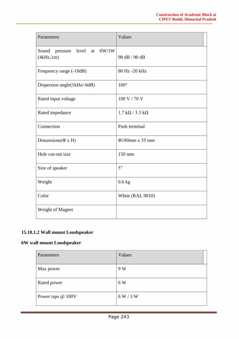
Construction of Academic Block at
CIPET Baddi, Himachal Pradesh
Page 243
Parameters Values
Sound pressure level at 6W/1W
(4kHz,1m) 98 dB / 90 dB
Frequency range (-10dB) 80 Hz -20 kHz
Dispersion angle(1kHz/-6dB) 160°
Rated input voltage 100 V / 70 V
Rated impedance 1.7 kΩ / 3.3 kΩ
Connection Push terminal
Dimensions(Φ x H) Φ180mm x 55 mm
Hole cut-out size 150 mm
Size of speaker 5”
Weight 0.6 kg
Color White (RAL 9010)
Weight of Magnet
15.10.1.2 Wall mount Loudspeaker
6W wall mount Loudspeaker
Parameters Values
Max power 9 W
Rated power 6 W
Power taps @ 100V 6 W / 3 W
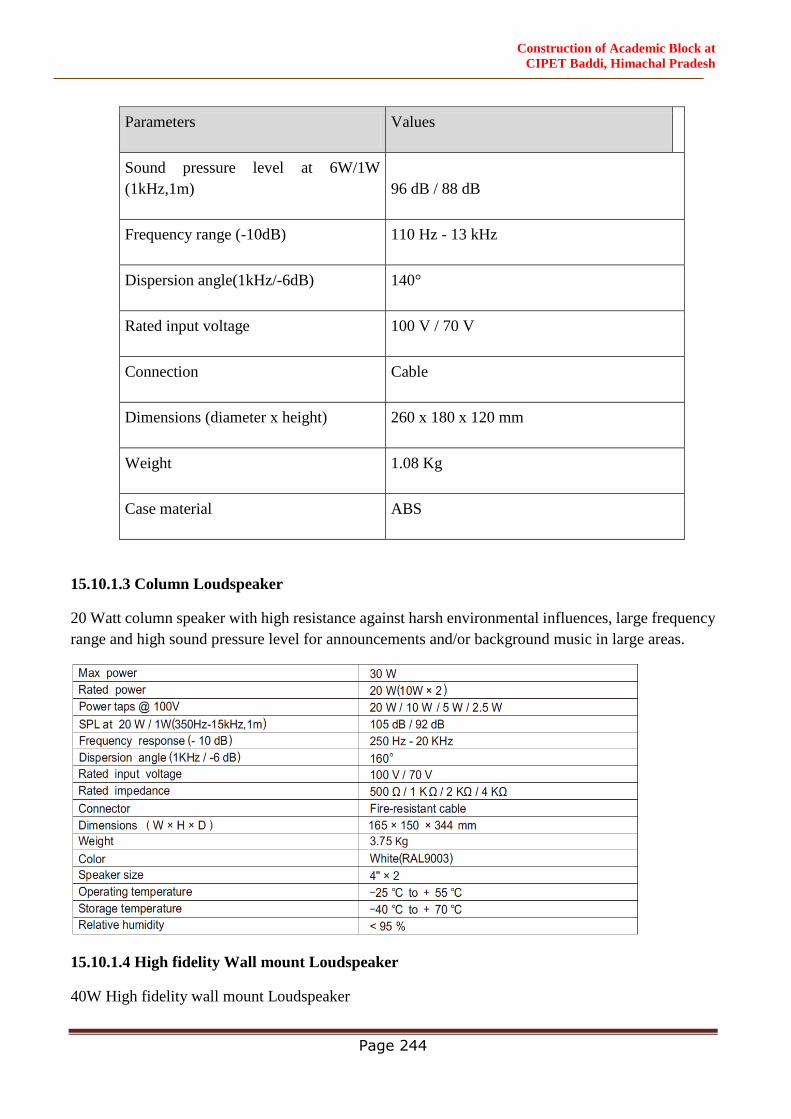
Construction of Academic Block at
CIPET Baddi, Himachal Pradesh
Page 244
Parameters Values
Sound pressure level at 6W/1W
(1kHz,1m) 96 dB / 88 dB
Frequency range (-10dB) 110 Hz - 13 kHz
Dispersion angle(1kHz/-6dB) 140°
Rated input voltage 100 V / 70 V
Connection Cable
Dimensions (diameter x height) 260 x 180 x 120 mm
Weight 1.08 Kg
Case material ABS
15.10.1.3 Column Loudspeaker
20 Watt column speaker with high resistance against harsh environmental influences, large frequency
range and high sound pressure level for announcements and/or background music in large areas.
15.10.1.4 High fidelity Wall mount Loudspeaker
40W High fidelity wall mount Loudspeaker
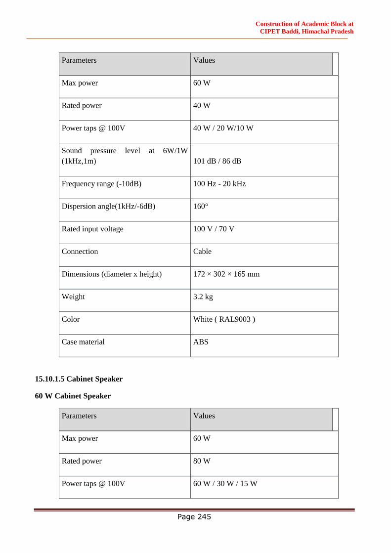
Construction of Academic Block at
CIPET Baddi, Himachal Pradesh
Page 245
Parameters Values
Max power 60 W
Rated power 40 W
Power taps @ 100V 40 W / 20 W/10 W
Sound pressure level at 6W/1W
(1kHz,1m) 101 dB / 86 dB
Frequency range (-10dB) 100 Hz - 20 kHz
Dispersion angle(1kHz/-6dB) 160°
Rated input voltage 100 V / 70 V
Connection Cable
Dimensions (diameter x height) 172 × 302 × 165 mm
Weight 3.2 kg
Color White ( RAL9003 )
Case material ABS
15.10.1.5 Cabinet Speaker
60 W Cabinet Speaker
Parameters Values
Max power 60 W
Rated power 80 W
Power taps @ 100V 60 W / 30 W / 15 W
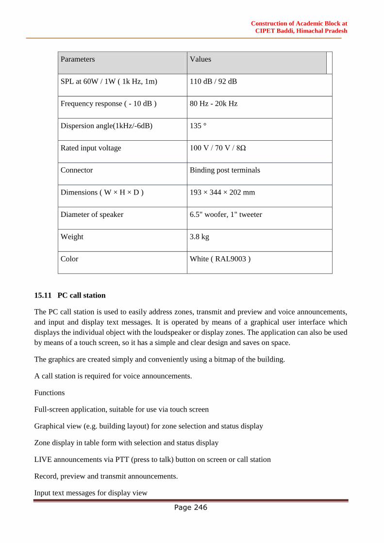
Construction of Academic Block at
CIPET Baddi, Himachal Pradesh
Page 246
Parameters Values
SPL at 60W / 1W ( 1k Hz, 1m) 110 dB / 92 dB
Frequency response ( - 10 dB ) 80 Hz - 20k Hz
Dispersion angle(1kHz/-6dB) 135 °
Rated input voltage 100 V / 70 V / 8Ω
Connector Binding post terminals
Dimensions ( W × H × D ) 193 × 344 × 202 mm
Diameter of speaker 6.5" woofer, 1" tweeter
Weight 3.8 kg
Color White ( RAL9003 )
15.11 PC call station
The PC call station is used to easily address zones, transmit and preview and voice announcements,
and input and display text messages. It is operated by means of a graphical user interface which
displays the individual object with the loudspeaker or display zones. The application can also be used
by means of a touch screen, so it has a simple and clear design and saves on space.
The graphics are created simply and conveniently using a bitmap of the building.
A call station is required for voice announcements.
Functions
Full-screen application, suitable for use via touch screen
Graphical view (e.g. building layout) for zone selection and status display
Zone display in table form with selection and status display
LIVE announcements via PTT (press to talk) button on screen or call station
Record, preview and transmit announcements.
Input text messages for display view
Construction of Academic Block at
CIPET Baddi, Himachal Pradesh
Page 247
Text display in conjunction with voice announcements
Time-controlled text display, in intervals or loops
Status display for each zone – assigned or error
Several PC call stations on one TCP/IP LAN
Project-specific Help function
15.12 PC call station server
Software license with dongle for use with a PC call station and PC call station server on a hardware
basis. Enables an interface to be adapted to an external discipline.
15.13 Remote Paging Microphone
Digital voice evacuation system remote paging microphone.
Each microphone of 8 zone capacity.
Zone expansion by connection with expansion unit. iv. System indicators of AC, DC, fault, Mic status
and test.
6 inputs & mic/line selection buttons.
8 zone selection buttons with three-colored indicators
Reset/Cancel, All Call & Call buttons.
Two RJ45 ports for input and link output.
CAT5 or CAT6 cable communication up to 600 meters.
AC 230V and DC24V battery inputs.
Built-in monitor speaker.
Voice Alarm Controller (VCA)
Digital voice evacuation system all in one amplifier.
Specifications meet the standards of BS EN54-32 & EN608409.
EN54-16 standards certificate is under taken.
Built-in 240W & 500 8 zone class-D amplifier.
Integration of EVAC system, paging system, PA system & BGM system together.
Built-in two separate players for EVAC and alert voice message by SD card.
Built-in 8 zone AB speaker line low impedance supervision.
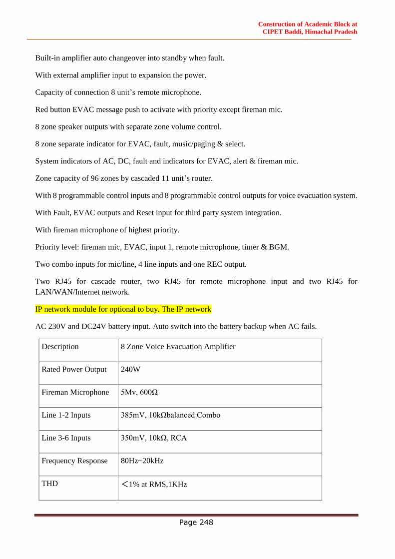
Construction of Academic Block at
CIPET Baddi, Himachal Pradesh
Page 248
Built-in amplifier auto changeover into standby when fault.
With external amplifier input to expansion the power.
Capacity of connection 8 unit’s remote microphone.
Red button EVAC message push to activate with priority except fireman mic.
8 zone speaker outputs with separate zone volume control.
8 zone separate indicator for EVAC, fault, music/paging & select.
System indicators of AC, DC, fault and indicators for EVAC, alert & fireman mic.
Zone capacity of 96 zones by cascaded 11 unit’s router.
With 8 programmable control inputs and 8 programmable control outputs for voice evacuation system.
With Fault, EVAC outputs and Reset input for third party system integration.
With fireman microphone of highest priority.
Priority level: fireman mic, EVAC, input 1, remote microphone, timer & BGM.
Two combo inputs for mic/line, 4 line inputs and one REC output.
Two RJ45 for cascade router, two RJ45 for remote microphone input and two RJ45 for
LAN/WAN/Internet network.
IP network module for optional to buy. The IP network
AC 230V and DC24V battery input. Auto switch into the battery backup when AC fails.
Description 8 Zone Voice Evacuation Amplifier
Rated Power Output 240W
Fireman Microphone 5Mv, 600Ω
Line 1-2 Inputs 385mV, 10kΩbalanced Combo
Line 3-6 Inputs 350mV, 10kΩ, RCA
Frequency Response 80Hz~20kHz
THD <1% at RMS,1KHz
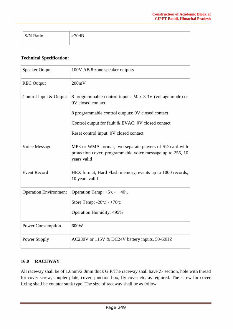
Construction of Academic Block at
CIPET Baddi, Himachal Pradesh
Page 249
S/N Ratio >70dB
Technical Specification:
Speaker Output 100V AB 8 zone speaker outputs
REC Output 200mV
Control Input & Output 8 programmable control inputs: Max 3.3V (voltage mode) or
0V closed contact
8 programmable control outputs: 0V closed contact
Control output for fault & EVAC: 0V closed contact
Reset control input: 0V closed contact
Voice Message MP3 or WMA format, two separate players of SD card with
protection cover, programmable voice message up to 255, 10
years valid
Event Record HEX format, Hard Flash memory, events up to 1000 records,
10 years valid
Operation Environment Operation Temp: +5 ~ +40
Store Temp: -20 ~ +70
Operation Humidity: <95%
Power Consumption 600W
Power Supply AC230V or 115V & DC24V battery inputs, 50-60HZ
16.0 RACEWAY
All raceway shall be of 1.6mm/2.0mm thick G.P.The raceway shall have Z- section, hole with thread
for cover screw, coupler plate, cover, junction box, fly cover etc. as required. The screw for cover
fixing shall be counter sunk type. The size of raceway shall be as follow.
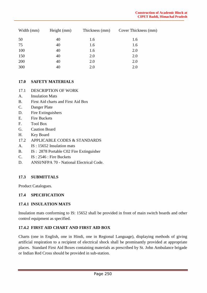
Construction of Academic Block at
CIPET Baddi, Himachal Pradesh
Page 250
Width (mm) Height (mm) Thickness (mm) Cover Thickness (mm)
50 40 1.6 1.6
75 40 1.6 1.6
100 40 1.6 2.0
150 40 2.0 2.0
200 40 2.0 2.0
300 40 2.0 2.0
17.0 SAFETY MATERIALS
17.1 DESCRIPTION OF WORK
A. Insulation Mats
B. First Aid charts and First Aid Box
C. Danger Plate
D. Fire Extinguishers
E. Fire Buckets
F. Tool Box
G. Caution Board
H. Key Board
17.2 APPLICABLE CODES & STANDARDS
A. IS : 15652 Insulation mats
B. IS : 2878 Portable C02 Fire Extinguisher
C. IS : 2546 : Fire Buckets
D. ANSI/NFPA 70 - National Electrical Code.
17.3 SUBMITTALS
Product Catalogues.
17.4 SPECIFICATION
17.4.1 INSULATION MATS
Insulation mats conforming to IS: 15652 shall be provided in front of main switch boards and other
control equipment as specified.
17.4.2 FIRST AID CHART AND FIRST AID BOX
Charts (one in English, one in Hindi, one in Regional Language), displaying methods of giving
artificial respiration to a recipient of electrical shock shall be prominantly provided at appropriate
places. Standard First Aid Boxes containing materials as prescribed by St. John Ambulance brigade
or Indian Red Cross should be provided in sub-station.
Construction of Academic Block at
CIPET Baddi, Himachal Pradesh
Page 251
17.4.3 DANGER PLATE
Danger plates shall be provided on HV and LV equipments. LV danger notice plate shall be 200 mm
x 200 mm made of mild steel atleast 2 mm thick vitreous enamelled white on both sides and with
inscriptions in signal red colour on front side as required.
Size of the HV Danger Notice plate shall be 250 mm x 200 mm and 2 mm thick.
17.4.4 FIRE EXTINGUISHERS
Portable CO2 conforming to IS: 2878-1976 dry chemical (conforming to IS 2171-1976) extinguishers
shall be installed in the sub-station at suitable places (like HT/LT panel rooms) as specified.
Foam type fire extinguisher shall be installed in Transformer Room.
17.4.5 FIRE BUCKETS
Fire buckets conforming to IS: 2546-1974 shall be installed with the suitable stand for storage of water
and sand.
17.4.6 TOOL BOX
A standard tool box containing necessary tools required for operation and maintenance shall be
provided in sub-station.
17.4.7 CAUTION BOARD
Necessary number of caution boards such as "Man on Line" "Don't switch on" etc. shall be available
in the sub-station.
The Caution Board shall be of size 300 mm x 200mm made of mild steel, 2mm thick, vitreous
enamelled white on both sides and with inscriptions in original red colour on front side as required.
17.4.8 KEY BOARD
A key board of required size shall be provided at a proper place containing castel keys, and all other
keys of sub-station and allied areas.
The Key board shall be made of 12mm thick first class teak wood shall be of size 400 mm x 300m
and with adequate depth to hold the keys. It shall be provided with a lockable type hinged glass door
made of 12 mm. thick first class teakwood frame with 3 mm thick sheet glass fixed with piano hinges.
The key board shall enough number of hooks for hanging the castle keys and all other keys of the sub-
station and allied areas. It shall be painted with one coat of wood primer and two coats of white
enamel paint.
18.0 Close Circuit TV (CCTV)
Scope of work involves suitable nos of Day / Night cameras including its support around the boundary
wall at suitable intervals and all the main gates with suitable mounting arrangement in a Vandal Proof
Construction of Academic Block at
CIPET Baddi, Himachal Pradesh
Page 252
Housing. Laying, terminating & connecting copper cables with redundancy between cameras &
control room.
Complete system is to be designed as per above requirements and a scheme along with layout and
inventory is to be submitted to the Engineer-in-Charge for approval, before taking up the installation
work. DISCOM for operation & maintenance of the complete installation.
18.1 IP Verifocal Dome Camera
Camera shall be IP based network color camera suitable for indoor Application with following
minimum features:
H.265, JPEG based hardware compression with built-in web server
Direct IP based (without external converters, cards, etc)
Auto focus
Power over Ethernet/ 12 VDC (Bidder shall provide power convertor required, if any)
Minimum Resolution : 2944 x 1656 (5MP)
Intelligent video capabilities, Face detection, Video Motion Detection, Camera tamper like defocus,
Scene change
Multiple Streaming: min. triple
ONVIF profile S, G features
IK10 & IP67, WDR/DWDR: 80 db
Alarm and audio interface 1/1
Connections : Network: IEEE802.3, 10BaseT/100BaseTX Ethernet networks (RJ-45) for
LAN/WAN TCP, UDP, IGMP, SNMP, HTTP, IPv4/ v6, DHCP, FTP, DNS, SMTP, Security -
802.1x, AES 256, PCI-DSS Compliant
Video
Lens : Varifocal (2.8- 4.5 to 12.0 – 16.5 mm) DC-iris
Progressive Scan : 1/2.9” CMOS or Better
Light sensitivity: Color: 0.014 Lux @ (F1.4, AGC ON), 0 Lux with IR
IR sensitive black/white video at night
Frame: 3MP @ 25 fps or better @ max. resolution
Functions

Construction of Academic Block at
CIPET Baddi, Himachal Pradesh
Page 253
Built-in video motion detection
Scheduled and triggered event functionality with alarm notification Pre and post alarm buffer
Digital time, date code embedded
Password protection for restricted camera access
Certification: UL, FCC or CE for Fixed cameras shall be provided.
Local Storage (support for SD card of minimum 128 GB)
IR illuminators: IR illuminators LED based for minimum 30 meters at 0 lux shall be inbuilt in each
camera
18.2 IP Verifocal Bullet Camera
Camera shall be IP based network color camera suitable for indoor Application with
followingminimum features:
H.265, JPEG based hardware compression with built-in web server
Direct IP based (without external converters, cards, etc)
Auto focus
Power over Ethernet/ 12 VDC (Bidder shall provide power convertor required, if any)
Minimum Resolution: 2944 x 1656 (5MP)
Intelligent video capabilities: Face detection , Face detection, Video Motion Detection, Camera
tamper like defocus, Scene change
Multiple Streaming : min. triple
ONVIF profile S, G features,
IK10 & IP67, WDR/DWDR:80 db
Alarm and audio interface 1/1
Connections : Network: IEEE802.3, 10BaseT/100BaseTX Ethernet networks (RJ-45) for
LAN/WAN TCP, UDP, IGMP, SNMP, HTTP, IPv4/ v6, DHCP, FTP, DNS, SMTP , Security -
802.1x, AES 256, PCI-DSS Compliant
Video
Lens : Varifocal (2.8 - 5.1 to 12.0 – 16.5 mm) DC-iris
Progressive Scan : 1/2.9” CMOS or Better
Light sensitivity: Color: 0.014 Lux @ (F1.4, AGC ON), 0 Lux with IR
Construction of Academic Block at
CIPET Baddi, Himachal Pradesh
Page 254
IR sensitive black/white video at night
Frame: 3MP @ 25 fps or better @ max. resolution
Functions
Built-in video motion detection
Scheduled and triggered event functionality with alarm notification Pre and post alarm buffer
Digital time, date code embedded
Password protection for restricted camera access
UL, FCC or CE for Fixed cameras shall be provided.
Certification:
Local Storage (support for SD card of minimum 128 GB)
IR illuminators : IR illuminators LED based for minimum 50 meters at 0 lux shall be inbuilt in
each camera
18.3 IP PTZ Camera
Camera shall be IP based network color camera suitable for indoor Application with
followingminimum features:
H.265/H.264, JPEG based hardware compression with built-in web server
Direct IP based (without external converters, cards, etc.)
Auto focus and Electronic Image stabilization (EIS)
Support object tracking and rapid focus on object in live view
Optical defog to ensure clear image in foggy condition
Hi-Power over Ethernet / 24 VAC (Bidder shall provide power convertor required, if any)
Minimum Resolution : 1920 x 1080 @ 25/30Fps
Intelligent video capabilities: ,Video Motion Detection, Camera tamper like defocus, Scene change
Movement : configurable, 360° endless, PAN Speed : 0.1°/s to 200°/s preset speed 200°/s and
Movement range : -10 to 90°
Tilt speed :configurable ,from 0.1°/s to 120°/s, preset : 200°/s
Presets 250, patrol 4 pattern scan record
Feature: patrol, power off, Park action preset freezing etc.
Construction of Academic Block at
CIPET Baddi, Himachal Pradesh
Page 255
Camera support network failure recording on board in card, when network reconnect recording push
to recorder.
Simultaneously 20 live view streams
Multiple Streaming : min. triple
ONVIF , CGI , API and 3rd party integration
IK10 & IP67, surge protection
Alarm and audio interface 5 in / 2 out
Connections
Network: IEEE802.3, 10BaseT/100BaseTX Ethernet networks (RJ-45) for LAN/WAN TCP, UDP,
IGMP, SNMP, HTTP, IPv4/ v6, DHCP, FTP, DNS, SMTP
CVbs output , rs485 : pelco-P & D and OEM make
Video
Lens : Varifocal 4.5 -6 to 135 - 180,30x optical zoom) Auto Iris
Progressive Scan : 1/2.9” CMOS or Better
Light sensitivity: Color: 0.01 Lux @ (F1.5, AGC ON), 0 Lux with IR
IR sensitive black/white video at night
Frame: 25/30 fps @ max. resolution
Functions
Built-in video motion detection
Scheduled and triggered event functionality with alarm notification Pre and post alarm buffer
Digital time, date code embedded
Password protection for restricted camera access
WDR: 120dB, HLC, BLC
Privacy mask : 20 or more programmable
Certification: UL, FCC or CE for Fixed cameras shall be provided.
Local Storage (support for SD card of minimum 256 GB)
IR illuminators : IR illuminators LED based for minimum 200 meters at 0 lux shall be inbuilt in
each camera

Construction of Academic Block at
CIPET Baddi, Himachal Pradesh
Page 256
18.4 IP ANPR Camera
Camera shall be IP based network color camera suitable for indoor Application with
followingminimum features:
H.265/H.264, JPEG based hardware compression with built-in web server
Direct IP based (without external converters, cards, etc)
Auto focus
Power over Ethernet/ 12 VDC (Bidder shall provide power convertor required, if any)
Minimum Resolution : 1920 x 1080P (2 MP)
OCR inbuilt in camera
Multiple Streaming: min. triple
ONVIF profile S, G features, CGI, ISAPI
IK10 & IP67, WDR:120Db
Connections: Network: IEEE802.3, 10BaseT/100BaseTX Ethernet networks (RJ-45) for LAN/WAN
TCP, UDP, IGMP, SNMP, HTTP, IPv4/ v6, DHCP, FTP, DNS, SMTP
Video
Lens : Varifocal (2.8-12.0mm/ 8-32mm) DC-iris
Progressive Scan : ½.8” CMOS Light sensitivity
Light sensitivity: Color: 0.01 lux @(F 1.4, AGC ON), 0 lux with IR
IR sensitive black/white video at night
Frame: 25/30 fps or better @ max. resolution
Functions
Built-in video motion detection, Camera tamper like defocus, Scene change
Scheduled and triggered event functionality with alarm notification Pre and post alarm buffer
Digital time, date code embedded
Password protection for restricted camera access
Certification: UL, FCC or CE for Fixed cameras shall be provided.
Local Storage (support for SD card of minimum 128 GB)
Construction of Academic Block at
CIPET Baddi, Himachal Pradesh
Page 257
IR illuminators: IR illuminators LED based for minimum 60 meters at 0 lux shall be inbuilt in each
camera
18.5 NVR
General
NVR shall be a fully IP based integrated Network Video recorder with Network Video Management
Software and IP cameras management suitable for the IP cameras as defined above. The NVR shall
be located at Server Room. The NVR shall be able to connect to all network-connected devices. The
video recording servers shall have disk space for online video storage and access to high capacity
archiving mechanisms for the removal of stored video to off-line media. Video Management
Software and Cameras shall be from same OEM.
Automatic IP camera discovery and configuration
RAID, 1,5,6,10 with 24/7 operation
Receive encoded live video from IP cameras, Play back video while still recording from the same
camera; Store live video to hard disk, Archive previously stored video to off-line storage media,
anywhere, anytime.
Allow alarms/events to initiate recordings
Scheduled recordings up to 12 MP camera , shall support min 64 IP cameras @ 2MP 25fps and
expandable to 12cameras per NVR Server.
Initiate recordings based on video motion detection (on a continuous basis & scheduled for
particular times, days, months, etc)
Report any IP camera failure or recoding failure to the system
Provide a full log of all system status (camera, server availability, etc)
Search for recordings (by camera & time, by motion detection, by alarms/events)
Network management with Security with passwords for each camera.
Support full frame rate on all inputs from the IP network cameras with ANPR camera
Software shall have a provision for Q-CIF, 2CIF and 4CIF configuration minimum or better
Interfaces with IT industry Standard Hardware
Processor : Intel® Xeon® 4-core (64-bit) E3-1225 V5 CPU @ 3.30GHz or Better
Recording bandwidth 512 Mbps , outgoing bandwidth 512Mbps
Ram: 8GB or Better
UL, CE, FCC
Construction of Academic Block at
CIPET Baddi, Himachal Pradesh
Page 258
16 sata with 8 TB HD capacity, SAS interface to expand storage should support
4 RJ-45 10/100/1000 Mbps self-adaptive Ethernet interface, support ANR, N+1
Alarm : 16 input/8 output on NVR or through Cameras
RS 232 and RS 485 and 1 eSata interface
Video Management Software features
It should have open Engineer-in-Chargeure.
It should be capable of providing web based access
With OS Linux or window with necessary software license and shall support mentioned analytic
along number plate recognition etc.
The NVR may be integrated to separate servers with 42” monitor. Monitor should support HDMI,
VGA, and Audio In/Out etc.
Administrators shall be able to view camera details, change camera settings and configure video
settings.
The NVR should have capability of connecting to all the IP cameras in its region as well as further
connectivity with the NVR.
Alartm Monitor : When an alarm occurs in the NVR/Administration server, the live video output of
the camera associated with that alarm should be switched directly to the alarm monitor.
View Option
Single camera view
1/8/16/32/48/64 or better
Sequence view
Must be able to view cameras from NVR
19.0 BOOM BARRIER:
GENERAL:
This specification lays down the general, functional and technical specifications of Automatic Boom
Barriers.
FUNCTION:
The barriers are used at entrances / exits to control and review traffic in and out of the premises.
The operation of Boom Barriers can also be linked to access control systems with safety systems.
Construction of Academic Block at
CIPET Baddi, Himachal Pradesh
Page 259
SYSTEM CONFIGURATION:
The system shall consist of a fixed housing and a movable arm. The housing shall contain the motor,
spring and control unit.
GENERAL FEATURES:
1) Electromechanical barriers for passages up to 4.2m, 5m & 6.5m intensive use.
2) Housing finish: Powder Coated Orange
3) The Housing base frame is of stainless steel so as to protect the housing from rusting from the
bottom
4) Boom: Powder Coated White with refractor strips and LED flashing lights on top.
5) Boom Length: 2 m to 4.2 m for normal lane / 5 m and 6.5 m for extra wide lane.
6) Protection: All housing and internal parts have rust & corrosion free metals / alloys of high
strength with suitable epoxy coating as applicable.
7) Easy to use external manual unlock device.
8) Amperometric anti-crushing control.
9) Slowing down setup thanks to two adjustable limit switches.
10) Soft start and slowing down functions adjustable in opening and closing.
11) 4.2 m white painted aluminum arm is provided with two red rubber profiles.
12) Flashing lights on the arm ensure barrier visibility especially at night.
13) Auto close with timer (1s to 90s).
14) Single / 2 Channel loop detector with programmable features (accessory).
15) Electronic module which allows the synchronized movement of two Barriers.
16) Painted fixed support for bars.
17) Stainless steel version available.
TECHNICAL DATA BOOM BARRIER UP TO 3.0M-
Power supply : 230 Vac
Motor supply : 24 Vdc
Absorbed power : 200 W
Max. absorbed current : 8 A
Construction of Academic Block at
CIPET Baddi, Himachal Pradesh
Page 260
Torque : 300 Nm
Opening speed : 8 sec
Operation cycle : Intensive sue
Protection level : IP 54
Operating temp. : - 20 C/+70 C
Lubrication : Grease
Weight : 105 Kgs
20.0 FIRE SURVIVAL CABLE FOR FIRE DETECTION & PA SYSTEM:
1. The cable shall be MICC (Mineral Insulated copper Conductor) cable confirming to
Underwriters Laboratory UL 2196) (Latest Edition).
2, The cable shall have opening voltage grade of 600V and the outer Seamless sheath be
of copper.
3, The cable shall withstand the test temperature curve per ASTM E119 with a
temperature of 1010°C at 2 hours as per UL 2196
4, Regulatory requirements shall be as follows:
A. Fire-Resistance: All products installed in “fire zone” shall be listed as per UL 2196
(US) for fire rating as required in the NEC (US).
B. Flame Propagation: All products installed in “fire zone” shall be FT4 certified.
C. Low Smoke: All products installed in “fire zone” shall be designated “low smoke”
according to UL 1685 / ST1, “Smoke Release” test.
D. Zero Halogen: All products installed in “fire zone” shall be “zero halogen” per IEC
60754-1.
E. It Should also Confirm to ANSI/NFPA 70.
5, The cable should have a life expectancy in excess of 100 years and should be
manufactured in North America.
6, The cables shall be connected to the various devices with proper termination
kits/glands. Appropriate glands shall be provided where the cable enters the junction
box.
7, Cables are to be supplied along with all accessories, crimped termination etc. Cable is
to be laid by the Trained & Experienced personnel only.
Construction of Academic Block at
CIPET Baddi, Himachal Pradesh
Page 261
8, The cable when running in outdoor area shall not be taken overhead. It shall be laid
underground according to IS 1255-1983 (Latest Edition)
9, The manufacturer shall have their proper sales office and well established service
centre in India.
10, The manufacturer shall have their own adequate number of trained personnel, based in
India, who are specialized for termination and installation of MICC cables, which is
specialty of this cable.
11. The Bidder should submit an authorization letter from OEM in original for the tender
called.
12. Where false ceiling are proposed Cable shall be laid on Surface/ Cable Trey and where
false ceiling are not proposed Cable shall be laid in suitable size of M.S. conduit in
Slab.
21.0 UPS
These specifications define the electrical, mechanical characteristics and requirement for an on line
Double Conversion VFI technology, Modular 2x10 KVA Uninterruptible Power Supply Systems.
The UPS shall be capable of providing high quality AC power for sensitive electronic equipment
loads possibility to configure the system in the inverter cabinet as well as in control panel.
1. Technology : Fully microprocessor controlled PWM IGBT with high
frequency (25 KHz or more) or better Technology.
Converter shall be equipped with 6 pulse SCR with
filter.
2. Power : 100% truly on line double conversion UPS with
upgradability minimum 50% (specify the limit, process
and cost implication for expanding the power rating).
The UPS shall have built in / external isolation
transformer at output.
3. Product Certification /Testing : One of the following
a) ERTL
b) ETDC
c) Sameer
d) STQC
e) I E C
Construction of Academic Block at
CIPET Baddi, Himachal Pradesh
Page 262
4. Operating Temperature : 0-40 degree Centigrade
5. Humidity : Upto 95%
6. Input Voltage : 400 V 20%
7. Output Voltage : 400 V with stepless adjustable (please specify)
8. Input Frequency : 50 Hz 6%
9. Output Frequency : 50 Hz 0.01% Hz
10. Duty : Continuous
11. Wave form : Pure Sine Wave
12. Transient Response : 1% maximum under following conditions:
a) Loss or Return of Input AC supply
b) 100% step load
13. Recovery Time : To nominal voltage in less than 10 milli second.
14. Efficiency (over all) : a) 25% Load
(To be confirmed by tenderer)
b) 50% Load
c) 75% Load
d) 100% Load
15. Input Power Factor : Greater than 0.9 at all loads.
16. Load Power Factor : 0.8 lag to unity. In no case power factor should be less
than 0.8.
17. Crest Factor : Greater than 3:1
18. MTBF : Minimum 100000 hrs.
19. Switch over time : Zero
20. Overload Rating : 110% for 15 minutes
125% for 10 minutes
200% for 1 minutes
21. Noise : Less than 65/75 dB at 1 mtr.

Construction of Academic Block at
CIPET Baddi, Himachal Pradesh
Page 263
22. Switching speed : Minimum 2 KHZ
23. Indication : Mains ON/OFF, /Battery HIGH/LOW, Battery ON,
Invertor ON/TRIP, O/P HIGH/LOW, Battery
HIGH/LOW, Alarm for Battery Discharge.
24. Protection : Input - Over/Under voltage, Over Current.
Battery - Over/Under Voltage, Over Current
Battery Low Alarm/Trip.
Output - Over/Under Voltage, Over Current.
Short Circuit Over Temperature DC
Over Current
25. Control Circuitory : Microprocessor based control circuitory to be provided
and all indications will be digitally displayed using
microprocessor based software.
26. Metering : Digital display with multifunctional key panel to
indicate.
- Output Voltage/Current
- DC Voltage/Current
- Output Frequency
27. Communication Port : RS 232 C
28. Diagnosis & Configuration : Compatible with Unix/Windows.
Software
29. Outlook : Compact size with aesthetically good look (size and
weight to be specified)
30. Battery : S.M.F. batteries for 30 minutes back-up under full load.
31. Harmonic Distortion of wave : Total harmonic distortion (THD) should be below
form 2% for linear load and below 3% for nonlinear load.
32. Input Harmonic Distortion : Less than 5 – 7%.
33. Maintenance by pass switch : The portion of UPS module used to connect the
alternator supply to critical load while electrically
isolating static switch and invertor for maintenance
purpose.
Construction of Academic Block at
CIPET Baddi, Himachal Pradesh
Page 264
34. Battery disconnect switch : MCCB to be used to electrically isolate the storage
batteries from UPS module.
35. Quality assurance : The manufacturer shall have quality assurance program
with check on incoming parts and final products. A final
test procedure for product shall include a check of all
performance specifications and a minimum 24 hour
running.
36. Installation Drawings : Two sets of installation drawings showing outline
dimension, weights and connections and a one line
drawing of the UPS shall be submitted.
37. Product Documentation : Manufacturer shall supply a comprehensive set of
product documentation for:
1. Installation
2. Operation
3. Maintenance
This should include complete outline and external connection drawings and schematic and
physical wiring diagrams as well as parts list and parts layout down to the smallest components
level. It should include startup and service manuals with complete preventive and remedial
maintenance and troubleshooting instructions. This should include all ancillary equipment and
accessories.
38. Training : It is important that at least -2 personnel who are to be
responsible for operation and maintenance of UPS be
trained at the manufacturer site free of cost.
39. Spare parts : The recommended spare parts for 5 years of
maintenance are to be listed and should be quoted along
with main modules.
40. Material and workmanship. : 1) Workmanship shall be first class in every
respect.
2) All material shall be new and of best commercial
grade.
3) Brackets and securing hardware shall be
electroplated with corrosion resistance material.
Construction of Academic Block at
CIPET Baddi, Himachal Pradesh
Page 265
4) Internal wiring conductors shall be combined
into cable or bundles and shall be tied securely
together and numbered or coded to correspond
with documentation.
41. Storage Battery : The storage battery shall be furnished with racks
connecting hardware and standard service resistance
material accessories. The battery shall be delivered
charged and filled ready for service.
42. Service Report : Assigned field service report describing start-up and on
site testing shall be furnished.
43. Maintenance : If the battery is taken out of service for maintenance by
manually opening battery disconnect switch the UPS
shall continue to function and meet all the performance
criteria specified.
44. Invertor Efficiency : 96% minimum
45. Protection Class : IP - 20
46. Test required at site : Battery discharge test
: Harmonic Measurement
: Battery impedance
22.0 Specification of Novec-1230 agent Suppression complete system with LPCB/ UL/ VDS
approved hardware in accordance with the Contract Documents for Panel fire protection system.
This system shall be used for Main LT Panel, Main HVAC Panel, HT Panel, COMPACT
SUBSTATION, Fire Fighting Panel.
1.0 Scope of Work:
a. Clean Agent (Novec 1230) Fire Suppression system designed to provide a uniform concentration
within the electrical panels.
b. All engineering design and materials for a complete agent suppression system including
Novec 1230 storage cylinders with steel bracket, extinguishing agent, detection tube, cylinder valve
and associated accessories including but not limit to; adaptors, pressure switch, tube fittings etc.,
required for complete operation of system.
c. The necessary nomenclature such as pressurization level, agent volume, gross/net weight of
cylinder shall be clearly marked on cylinder.
d. Prior to supply of material at site. Contractor must submit following documents for approval of
Engineer-in-charge.
Construction of Academic Block at
CIPET Baddi, Himachal Pradesh
Page 266
e. Drawing in A-4 size, clearly showing the panel, routing of tube inside the panel, location and fixing
arrangement of cylinder & system components.
f. All doors and holes in the enclosed/ equipment’s should be closed or sealed to maintain
the tightness of enclosure.
2.0 System Description:
a. The detection tube shall be fixed with cylinder valve at top of cylinder. The tube shall be
pressurized with dry nitrogen. In case of reach of pre-determined temperature (115oC), the tube shall
rupture gas shall be released from tube over the protected area.
b. The pressure switch shall be provided for necessary indication of discharge of gas.
c. The Extinguishing Agent shall be stored in cylinder as liquefied compressed gas, super pressurized
with dry nitrogen at 195 psi.
d. The cylinder shall be equipped with brass valve, pressure gauge (to monitor agent pressure) and
isolation valve for maintenance purposes. The cylinder bracket shall be of steel construction with
quick release clamp.
e. The cylinder should be DOT approved as per DOT 4B specs.
f. The detection tube shall be installed throughout the compartments of panel. The location and
spacing of tube shall be above the hazard, to be protected.
g. In case of fire, the tube shall rupture at a point. The rupture of tube shall result in formation of
discharge point and release the agent in uniform pattern.
h. The system must be filled in a UL Listed or FM approved filling station in India.
3.0 System Components:
a. Cylinder of steel construction with standard red epoxy paint finish. Cylinders shall be
accompanied by original manufacturers test certificate confirming the contents of the cylinder with
DOT approval.
b. The cylinders shall be from reputed Manufacturers only. Cylinders shall be super pressurized with
dry nitrogen to an operating pressure and temperature as per manufacturer recommendations.
c. Each cylinder shall have pressure gauze and low pressure switch to provide visual and electrical
supervision of the cylinder pressure. The low pressure switch shall be wired to the Audio Visual
Alarm to provide audible and visual trouble alarm in the event of drop of pressure. The pressure
gauze shall be color coded to provide an easy, visual indication of cylinder pressure.
d. Cylinder shall be provided with a certificate provided by the company who charge with the
NOVEC 1230 agent. The certificate shall be secured around the cylinder with chain fastener.
Construction of Academic Block at
CIPET Baddi, Himachal Pradesh
Page 267
e. The Detection Tube should be Red Colour and pressurized at 13.5 Bar. The Detection Tube to
rupture at 115oC.
4.0 Extinguishing Agent (Novec 1230)
a. The agent shall not contain any Hydroflurocarbons (HFC).
b. The ozone depletion potential should be zero.
c. The Global warming potential should be equal to or less than 1.
d. The Extinguishing Agent should be UL Listed/ FM approved.
5.0 Installation
a. The system shall be installed on basis of approved drawing.
b. The installation / final connections shall carry out in direct supervision of representative of
Manufacturer/authorized distributors.
c. Cylinder shall be located such as so that they are not subjected to mechanical, chemical or other
damage.
d. All system components shall be capable of withstanding heat of fire and severe weather
conditions.
e. Detection Tube to be properly secured inside the panel by Clips/Tie etc.
f. The Detection Tube outside the panel should be protected in flexible conduit.
g. Inspection certificate should be pasted on cylinder clearly marking next due date of inspection.
23.0 Following system also need to be considered for Griha-3 rating and and to be provided by
Contractor.
Automatic lighting shutoff shall be provided through PIR based occupancy sensors.
All Motors shall be as per Griha-3 Clause 8.2.2
20% reduction in LPD as per ECBC 2007 or Latest shall be maintained.
All Exterior lighting shall be controlled by photo sensor or astronomical time switch.
Exit signs shall not exceed 5W per face.
Transformer lossed and all Motors shall be as per latest ECBC.
Metering shall be monitored as per following as per Griha – 3 and to be provided by
Contractor.
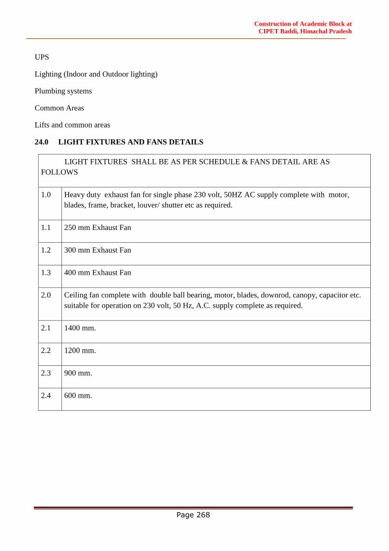
Construction of Academic Block at
CIPET Baddi, Himachal Pradesh
Page 268
UPS
Lighting (Indoor and Outdoor lighting)
Plumbing systems
Common Areas
Lifts and common areas
24.0 LIGHT FIXTURES AND FANS DETAILS
LIGHT FIXTURES SHALL BE AS PER SCHEDULE & FANS DETAIL ARE AS
FOLLOWS
1.0 Heavy duty exhaust fan for single phase 230 volt, 50HZ AC supply complete with motor,
blades, frame, bracket, louver/ shutter etc as required.
1.1 250 mm Exhaust Fan
1.2 300 mm Exhaust Fan
1.3 400 mm Exhaust Fan
2.0 Ceiling fan complete with double ball bearing, motor, blades, downrod, canopy, capacitor etc.
suitable for operation on 230 volt, 50 Hz, A.C. supply complete as required.
2.1 1400 mm.
2.2 1200 mm.
2.3 900 mm.
2.4 600 mm.
Construction of Academic Block at
CIPET Baddi, Himachal Pradesh
Page 269
SPECIFICATIONS
(HVAC WORKS)
Construction of Academic Block at
CIPET Baddi, Himachal Pradesh
Page 270
1 TECHNICAL SPECIFICATION OF EQUIPMENTS
VRV / VRF Outdoor Unit
1.1.1 Scope of Work
The specification for VRV / VRF Units covers the general design, materials, constructional features,
supply, installation, testing, commissioning & carrying out performance test at site.
1.1.2 Codes & Standard
The design, materials, manufacture, inspection, testing & performance of VRV/ VRF shall
comply with all currently applicable codes, regulation & standardsin the locality where the
equipment is to be installed.
1.1.3 General
Each VRV / VRF Unit shall be air cooled, split type multi-system air conditioner consisting of
outdoor units and number of indoor units, each having capability to cool for the requirements of
the individual area to be air-conditioned. The VRV / VRF unit should be capable of connecting
minimum ten different type of indoor units to one refrigerant circuit and controlled individually.
Each VRV / VRF unit shall have minimum two number scroll compressor and out of two number
Compressors one shall be inverter Compressor (With all inverter controller) capable of changing
the rotating speed to follow variations in cooling loads. Each indoor units having capability to cool
or heat for the requirement of the rooms.
Compressor shall be inverter controlled or digital controlled. Compressor installed in each outdoor
module unit shall be equipped with at least one inverter compressor in bigger (if modular) machines
for higher reliability, improved life, better backup and duty cycling purpose. The system shall be
capable of changing the rotating speed of inverter compressor by inverter controller to follow
variations in cooling and heating load.
The Outdoor units shall be suitable for mix-match connection of following type.
Ceiling mounted cassette type (Multi flow)
Please note that the refrigerant piping shall be capable of extending up to 150m with 50m level
difference without any oil traps.
Both indoor and outdoor units shall be factory assembled, tested and filled with first charge of
refrigerant. These being very hi-tech in construction with lots of factory checks being conducted,
hence no sub assembly should be done at site preferably.
1.1.4 Outdoor Unit
The outdoor unit shall be factory assembled, weather proof casing, constructed from heavy gauge
mild steel panels and coated with baked enamel finish. The unit should be completely factory wired,
tested with all necessary controls tested prior to dispatch conforming to the following
specifications.
Construction of Academic Block at
CIPET Baddi, Himachal Pradesh
Page 271
a) All outdoor units shall consist of one / two scroll compressors, preferable with all inverter
drive, capable to operate even when one compressor is unserviceable.
b) Outdoor units when consisting of more than 1 module (e.g. 22 HP = 10 Hp +12 HP), each
should have one separate inverter driven compressors.
c) In such case, the units shall be provided with duty cycling arrangement for multiple inverter
compressors.
d) The outdoor unit shall be modular in design to facilitate installation one after another close
to each other. Preference would be given to compact units having smaller footprint.
e) Outdoor units should be rugged of anti-corrosion design and should have strong base plate
for easy mounting of unit.
f) The outdoor unit shall comprise of sub-cooling feature to effectively use the entire coil
surface through proper circuit/bridge in order to prevent flushing of refrigerant owing to
large length of piping.
g) The condensing unit shall be provided with state-of-the-art microprocessor based control
panel.
h) The outdoor unit shall be provided with provided with Aero spiral design fan exhibiting
low noise level characteristics complete with aero fitting grille to facilitate spiral discharge
of airflow to effect reduction in pressure losses. The fan should be capable to respond to
external static pressure of 5mm.
i) Motor shall be speed controlled to ensure a stable operation for varying ambient, by a
factory fitted direct acting head pressure activated variable speed drive for at least 15 steps
to give precise discharge pressure and minimum power consumption of condenser fan
motor.
j) The condenser shall be complete with provisions for refrigerant piping connections, shut
off valves and any other standard accessories necessary with the equipment supplied.
The condensing unit shall be designed to facilitate fail safe operation when connected to multiple
indoor units. If possible, the system should work on standard operating parameters like discharge
pressures of not more than 300~450 PSI as the ref. Piping will be moving around within a
residential house, otherwise on any misfortune of any leakage it will act like a bullet on higher
pressures. If working on higher operating pressures, vendor to comply with all safety codes of high
pressure safety & testing as recommended by Japanese (being Japanese design product) and give 2
sets of special tools to handle such equipment at site. All brazing should be done by only qualified
trained person who had training on HIGH PRESSURE brazing, special tools & procedures.
1.1.5 Scroll Compressor
The scroll compressor shall be an industrial quality rugged, cast iron, direct hermetic compressor
with scroll plates, suction & discharge service valves. The compressor shall be completely enclosed
in a chamber with no leakage path and providing the capability for scroll plates to separate. The
compressor shall be provided with industrial solid motor mounts internal motor protection and
vibration isolation pads. Each compressor shall be independently wired and piped to its own circuit
for efficient operation & ease of maintenance. The compressor speed shall not exceed 3000~4500
RPM.
Construction of Academic Block at
CIPET Baddi, Himachal Pradesh
Page 272
The compressor shall be highly efficient inverter control. The inverter compressor shall change
the speed in accordance to the variation in cooling or heating load requirement:
a) All outdoor units shall have multiple steps of capacity control to meet load fluctuation and
indoor unit individual control. All parts of compressor shall be sufficiently lubricated
stock. Forced lubrication may also be employed.
b) Oil heater shall be provided in the compressor casing.
c) The inverter compressor shall preferably be efficient & reliable inverter compressor.
1.1.6 Heat Exchanger
The heat exchanger shall be constructed with copper tubes mechanically bonded to aluminum fins
to form a cross fin coil.
a) The aluminum fins shall be covered by anti-corrosion resin film.
b) he unit should be with heat exchanger to optimize the path of heat exchanger and for
better efficiency of condenser.
c) The unit shall be provided with necessary number of direct driven low noise level
propeller type fans arranged for vertical discharge. Each fan shall have a safety guard.
1.1.7 Refrigerant Circuit
The refrigerant circuit shall include liquid & gas shut-off valves and a solenoid valves at
condenser end. The equipment must have inbuilt refrigerant stabilization control for proper
refrigerant distribution.
All necessary safety devices shall be provided to ensure the safely operation of the system.
1.1.8 Refrigerant
The VRV / VRF units shall be selected on R410 refrigerant only. The units should be fully factory
charged with refrigerant & oil & spare refrigerant & oil must be sent along with the machine for
topping up of gas & oil as may be required.
1.1.9 Safety Devices
All necessary safety devices shall be provided to ensure safe operation of the system.
Following safety devices shall be integral part of the out door unit:
High pressure switch
Fan drive overload protection switch
Fusible plug
Overload relay including overload protection for inverter driven compressor.
1.1.10 Oil Recovery System
Entire system shall be designed and capable of oil recovery to ensure stable operation with
long refrigeration piping lengths.
Construction of Academic Block at
CIPET Baddi, Himachal Pradesh
Page 273
The system should have inbuilt (avoid external) oil balancing circuit to avoid poor lubrication.
1.1.11 Transit Damage
The unit shall be restored to original conditions in case of any transit damages by the contractor
at his own cost.
1.1.12 Technical Requirement of VRV / VRF Unit
S/N DescriptionUnitCondition of Service
a) Type - Cool / Heat Type
b) Capacity (cooling) HP (Nominal) Basis of Design
c) Quantity Nos. Basis of Design
d) Connectable No. ofpossible indoor unitNos.As per Shop Drwg
e) Air entering condenser Deg. C DB 50.0
f) Electric Supply -- 415 V/3 Ph/50 Hz
g) Maximum Refrigerant -- 190 RMTPiping Length for One Unit
END OF VRV / VRF OUTDOOR UNIT SPECIFICATION
VRV / VRF Indoor Unit
1.1.1 Scope of Work
This section deals with supply, erection, testing and commissioning of Various Type of Indoor
Units confirming to general specification and suitable for the duty selected. The type, capacity
and size of indoor units shall be as per approved shop drawings.
1.1.2 General
Indoor units shall be either ceiling mounted cassette type, or ceiling mounted ductable type or floor
standing type or wall mounted type or other as specified in approved shop drawings. Each unit shall
have electronic control valve to control refrigerant flow rate respond to load variations of the room.
a) The address of the indoor unit shall be set automatically in case of individual and group
control
The fan shall be dual suction, aerodynamically designed turbo, multi blade type, statically &
dynamically balanced to ensure low noise and vibration free operation of the system. The fan shall be
direct driven type, mounted directly on motor shaft having supported from housing.
The cooling coil shall be made out of seamless copper tubes and have continuous aluminum fins.
The fins shall be spaced by collars forming an integral part. The tubes shall be staggered in the
direction of airflow. The tubes shall be hydraulically/ mechanically expanded for minimum thermal
contact resistance with fins. Each coils shall be factory tested at 21kg/sqm air pressure under water.
Unit shall have cleanable type filter fixed to an integrally moulded plastic frame. The filter shall be
slide away type and neatly inserted.
Construction of Academic Block at
CIPET Baddi, Himachal Pradesh
Page 274
1.1.3 Ceiling Mounted Cassette Type Unit (Multi Flow Type)
The unit shall be ceiling mounted type. The unit shall include pre-filter, fan section and DX-
coil section. The housing of the unit shall bepowder coated galvanized steel. The body shall
be light in weight and shall be able to suspend from four corners. The fan shall be
aerodynamically designed diffuser turbo fan type. Also Units shall have an external attractive
panel for supply and return air. Unit shall have four way supply air grilles on sides and return
air grille in center.
Each unit shall have high lift drain pump, fresh air intake provision (if specified) and very low
operating sound.
All the indoor units regardless of their difference in capacity should have same decorative
panel size for harmonious aesthetic point of view. It should have provision of connecting
branch ducts.
1.1.4 Colour
The colour of indoor units should be white or to suit interiors as approved by the Engineer-in-
Charge.
END OF VRV / VRF INDOOR UNIT SPECIFICATION
Ventilation Fans
1.1.1 Scope of Work
The specification for supplies & exhaust air blowers for mechanical ventilation covers the
design requirement, constructional feature, supply, installation, testing & commissioning.
1.1.2 Type
The blower shall be of Tube Axial Flow fans / Inline fans / Propeller Fans / with or without
ducting system & shall be of floor mounted / ceiling hung type.
1.1.3 Capacity
The capacity of Tube Axial Flow fans / Inline fans / Propeller Fans, diameter, maximum motor
H.P & static pressure etc.
1.1.4 Axial Flow Fans
The exhaust air blower shall be Tube Axial Flow fans connected to the duct & shall be of floor
/ ceiling / wall mounted type as per Shop Drawings. The capacity of tube axial flow fans,
diameter, maximum motor H.P & static pressure etc. shall be according to schedule of
equipment. The noise level of axial fan shall be less than 80 dba at a distance of 2.5 mt from
the fan.
Axial Flow Fan shall be AMCA certified for Air and Sound performance.
The cylindrical casing should be made from welded carbon steel sheet. The inlet & outlet of
the casing shall be fitted with flanges for ductwork connection & other accessories as required.
The casing shall be coated with minimum 2 coats of rust proof primer and enamel paint
thereafter or to be Powder Coated after phosphating process. The blade of axial flow fan shall
Construction of Academic Block at
CIPET Baddi, Himachal Pradesh
Page 275
be made of die cast aluminium alloy. The blade angle shall be set at manufacturing place &
shall also have facility to modify latter. The hub shall consist of two half-hubs pressed in
carbon steel & the centre boss shall be made of die-cast aluminium alloy. The blade feet shall
be locked in two half - hubs. The impeller assembly shall be fixed on the shaft by means of a
double cone type expansion bush. The design shall facilitate the alteration of blade angle
without disconnecting the hub from the motor shaft. The fan shall be directly driven by TEFC
sq. cage induction motor EEF-2 grade. The fan motors shall be 415±10% volts 50HZ ± 5%, 3
phase TEFC SQ. Cage induction motor. The motor shall be specially designed for quiet
operation. After assembling the impeller shall be statically &dynamically balanced. Fan RPM
shall be 960 for normal working & 1450 RPM for working in case of fire.
The mounting ring shall be of CRCA / sheet steel with brackets to connect the frame, with the
Fan / Motor assembly. Rubber mounts shall be provided between the mounting frame and the
mounting brackets.
All the fans selected for smoke extraction shall withstand 250 °C temperature for 2 hours &
shall work satisfactorily at this temperature. Motors selected for this application shall be
certified according to standard BS EN 12101-3:2002 / UL 705 for 250 °C for 2 hours.
Complete Fan assembly for smoke exraction application (Fan Impeller, Fan Casing, Motor
base frame alongwith Motor) shall be tested and approved by Exova Warringtonfire in
accordance with BS EN 12101-3:2002 / UL 705 standard for "Powered Smoke and Heat
Exhaust Ventilators for Smoke Control Systems" for (250 degree C) temperature for a 2 hours
of operation.
All supply fan shall have Class F motor and all exhaust fan shall have Class-H motor.
1.1.5 Accessories
All necessary accessories shall be provided for proper operation and shall also include as part
of Unit Price.
Dunlop cushy foot vibration isolators for the blowers
Double canvas connections at the outlets of each fan
Nuts, Bolts, Shims etc. as required for the grouting of the equipment
Slide rails for mounting the motor and belt adjust
Bird Screens in the Inlet
Detachable and washable fresh air filters at the inlets
1.1.6 Performance Data
All fans shall be selected for the lower operating noise level. Capacity ratings, power
consumption, with operating points clearly indicated shall be submitted and verified at the time
of testing and commissioning of the installation. All the fans should be AMCA certified for
sound and performance.
Construction of Academic Block at
CIPET Baddi, Himachal Pradesh
Page 276
1.1.7 Testing
Capacity of all fans shall be measured by an anemometer. Measured airflow capacities shall
conform to the specified capacities and quoted ratings. Power consumption shall be computed
from measurements of incoming voltage and input current. Contractor has to carry out the field
balancing, if required.
2 SERVICES SPECIFICATION
Air Distribution
2.1.1 Scope of Works
The scope of this section comprises supply, fabrication, installation & testing of all sheet metal
GI ducts as well as supply, installation, testing & balancing of all grills, diffusers & other
accessories in accordance with these specification.
2.1.2 GI Duct (Site Fabricated)
The work under this part shall consist of furnishing labor materials, equipment and
appliances as specified necessary and required to install all sheet metal and other allied
work to make the air conditioning supply, ventilating, and exhaust system ready for
operation as per drawings.
Except as otherwise specified all duct work and related items shall be in accordance with
these specifications.
Ductwork shall mean all ducts, joints, stiffeners and hangers.
2.1.3 Rectangular Duct Work
The ducts shall be fabricated from galvanized steel sheets.
All duct work, sheet metal thickness and fabrication unless otherwise directed, shall strictly
meet requirements, as described in IS: 655-2010 with Amendment-I.
The thickness of the sheet shall be as follows for rectangular duct: -
Rectangular ducts less than 750 mm 24 gauge
Rectangular ducts 751mm to 1500mm 22 gauge
Rectangular ducts 1501mm to 2200mm 20 gauge
Rectangular ducts greater than 2200mm 18 gauge
2.1.4 Raw Material
Ducting
All ducting shall be fabricated of LFQ (Lock Forming Quality) grade prime G.I. raw material
furnished with accompanying Mill test Certificates.
Galvanizing shall be of 120gms/sq.mt. (Total coating on both sides).
In addition, if deemed necessary, samples of raw material, selected at random by owner’s site
representative shall be subject to approval and tested for thickness and zinc coating at contractor’s
expense.
Construction of Academic Block at
CIPET Baddi, Himachal Pradesh
Page 277
The G.I. raw material should be used in coil-form (instead of sheets) so as to limit the longitudinal
joints at the edges only irrespective of cross-section dimensions.
Duct Connectors and Accessories
All transverse duct connectors (flanges/cleats) and accessories/related hardware are such as support
system shall be zinc-coated (galvanized).
Fabrication Standards
All ductwork including straight sections, tapers, elbows, branches, show pieces, collars, terminal
boxes and other transformation pieces must be site-fabricated. Equivalency will require fabrication by
utilizing the following machines and processes to provide the requisite quality of ducts and speed of
supply.
Coil lines to ensure location of longitudinal seams at comes/folded edges only to obtain the required
duct rigidity and low leakage characteristics. No longitudinal seams permitted along any face side of
the duct.
All edges to be machine treated using lock formers, flanges and roller for fuming up edges.
Sealant dispensing equipment for applying built-in sealant in Pittsburgh lock where sealing of
longitudinal joints are specified.
Selection of G.I. Gauge and Transverse Connectors
All transverse connectors shall be the 4-bolt slip-on flange system with built-in sealant if any to avoid
any leakage additional sealant to be used.
The specific class of transverse connector and duct gauge for a given duct dimensions will be 2” (500
Pa) pressure class.
Non-toxic, AC-applications grade P.E. or PVC casketing is required between all mating flanged joints.
Gasket sizes should conform to flange manufacturer’s specification
Duct Construction
The fabricated duct dimensions should be as per approved drawings and all connecting sections are
dimensionally matched to avoid any gaps.
Dimensional Tolerances: All fabricated dimensions will be within ± 1.0 mm of specified dimension.
To obtain required perpendicularity, permissible diagonal tolerances shall be ± 1.0 mm per meter.
Ducts shall be straight and smooth on the inside Longitudinal seams shall be airtight and at corners
only, which shall be either Pittsburgh or Snap Button Punch to ensure air tightness.
Changes in dimensions and shape of ducts shall be gradual (between 1:4 and 1:7). Turning vanes or
air splitters shall be installed in all bends and duct collars designed to permit the air to make the turn
without appreciable turbulence.
Plenums shall be shop/factory fabricated panel type and assembled at site.
Changes in section of ductwork shall be affected by tapering the ducts with as long a taper as possible
but not less than 600mm. All branches shall be taken off at not more than 450. Branch shoe shall be
provided in each branch section. Angle from the axis of the main duct unless otherwise approved by
the Engineer-In-Charge.
Construction of Academic Block at
CIPET Baddi, Himachal Pradesh
Page 278
All ducts shall be supported from the ceiling/slab by means of M.S. Rods of 10 mm (3/8") DIA with
M.S. Angle at the bottom. The rods shall be anchored to R.C. Slab using metallic expansion fasteners.
MISCELLANEOUS
All ducts above 450mm are to be cross broken to provide rigidity to the ducts.
All duct work joints are to be true right angle or approaching with all sharp edges removed.
Sponge rubber gaskets also to be provided behind the flange of all grilles.
Each shoot from the duct, leading to a grille, shall be provided with an air deflector to divert the
air into the grills through the shoot.
Inspection doors measuring at least 450mm x 450mm are to be provided in each system at an
appropriate location.
Diverting vanes must be provided at the bends exceeding 600mm and at branches connected into
the main duct without a neck.
Proper hangers and supports should be provided to hold the duct rigidly, to keep them straight
and to avoid vibrations. Additional supports are to be provided.
The ducts should be routed directly with a minimum of directional change.
The duct work shall be provided with additional supports/hangers, wherever required at no extra
cost.
All duct supports, flanges, hangers and damper boxes etc. shall be given 2 coats of red oxide paint
before installation and one coat of aluminum paint after the erection, at no extra cost.
All angle iron flanges to be welded electrically and holes to be drilled.
All the angle iron flanges to be connected to the G.S.S. ducts by rivets at 100mm centers.
All the flanged joints, to have a 4mm thick felt packing stack to the flanges with shellac varnish.
The holes in the felt packing are to be burnt through.
The G.S.S. ducts should be lapped 6mm across the flanges.
Sheet metal connection pieces, partitions and plenums required, shall be constructed of 1.25
(18 gauge) sheet thoroughly stiffened with 40mm x 40mm x 6mm angle iron braces and fitted
with access doors
2.1.5 Fresh Air Intake Louvers With Bird Screen
The fresh air intake louvers at least 50mm deep will be made of powder coated extruded
aluminum construction. Bird / insect screen will be provided with the intake louvers. The
blades shall be inclined at 45 degree on a 40mm blade pitch to minimize water ingress. The
lowest blade of the assembly shall be extended out slightly to facilitate disposal of rain water
without falling on door / wall on which it is mounted.
The intake louvers shall be provided with factory fitted volume control dampers in black finish.
2.1.6 Painting
All ducts collar / shoot behind the grills / diffuser shall be given at least two coats oil black
enamel paints.
Construction of Academic Block at
CIPET Baddi, Himachal Pradesh
Page 279
2.1.7 Testing
The complete duct system shall be tested for air leakage & complete air distribution system
shall be balanced in accordance with air quantities indicated on the approved drawing.
END OF AIR DISTRIBUTION SYSTEM SPECIFICATION
Insulation / Lining Work
Scope of Works
The scope of this section comprises supply & fixing of thermal insulation of refrigerant pipes
as per the specification given below.
Material & Process of Thermal Insulation of Refrigerant Pipes
The Insulation of refrigerant pipe, drain pipe, etc., shall be carried out as per specifications
given below.
1. Materials
The materials to be used for insulation shall be as follows, unless some other materialis specifically
mentioned elsewhere. The detailed specifications of the materials are listed under respective sub
heads.
Drain Pipe Insulation : Pre formed moulded section of XLPE insulation.
Refrigerant Pipe : XLPE/ closed cell elastomeric nitrile rubber
2. Refrigerant Pipe Insulation
The material for insulation of refrigerant pipes shall be of closed cell XLPE/ closed cell nitrile
rubber insulation.
The thickness of insulation shall be 19 mm / 13 mm thickness.
Construction of Academic Block at
CIPET Baddi, Himachal Pradesh
Page 280
SPECIFICATIONS
(PLUMBING AND FIRE FIGHTING)
Construction of Academic Block at
CIPET Baddi, Himachal Pradesh
Page 281
SPECIFICATIONS
(PLUMBING AND FIRE FIGHTING)
1 PL & FF TECHNICAL SPECIFICATION OF EQUIPMENTS
Sanitary Fixture & Fitting
1.1.1 Scope of Work
Work under this section shall consist of furnishing all labor as necessary and required to
completely install all Sanitary Fixtures, flushing cistern ,Brass and Chromium plated fittings
and accessories as required by the drawings and specified here in after.
Without restricting to the generally of the foregoing the Sanitary Fixtures shall include all
Sanitary Fixtures, C.P. fittings and Accessories etc. necessary and required for the Building.
Whether specifically mentioned or not all Fixtures and appliances shall be provided with all
fixing devices, nuts, bolts, screws, hangers as required.
Testing of all fixture and fittings.
1.1.2 European / Anglo Indian Water Closest
General
The item pertains for providing white or colour glazed vitreous chinaware European or Anglo
Indian water closet with seat and cover of size and colour as specified in the schedule including
fixing.
Material
European type water closet shall be washing down pattern unless otherwise specified. Water
closet shall be vitreous china conforming to IS 2556 (Part-I & II). The closet shall be of one
piece construction and shall have minimum two hole of 6.5 mm diameter for fixing closet to
floor. Closet shall have an integral flushing rim of self draining type. Each water closet shall
have an integral
Trap with either `S` or `P` outlet with and trap shall be uniform and smooth in order to enable
an efficient flush. Plastic seat and cover shall be of black colour or as specified, they shall have
conformity to IS2548 Part I & II.
Fixing
The water closet pan shall be placed in position as shown in the drawing. If the pan trap is
damaged during handling or fixing, it shall be replaced by the contractor at his own cost. The
pan, soil pipe shall be jointed in 1:1 Cement Mortar with hemp yarn caulked. The gap between
W.C. and floor shall be finished with white/matching cement and sand as directed. Seat and
cover shall be fixed to the Pan by two corrosion resistance hinge with 65 mm shank and
threaded to within 25 mm from of flange. Seat shall be fixed in level by providing the washers
of rubber with non ferrous or stainless steel washer to bolt.
1.1.3 Indian Water Closest
General
Construction of Academic Block at
CIPET Baddi, Himachal Pradesh
Page 282
The item pertains for providing white or colour glazed vitreous chinaware Indian 84 water
closet of size and colour as specified in the schedule including fixing.
Material
Squatting Pan (Orissa Pattern) is of white or colour glazed vitreous China conforming IS 2556
Part III. Pan shall have flushing rim and are inlet of self draining type. It shall have weep hole
at the following inlet to the Pan. The flushing inlet shall be in front unless otherwise specified.
The inside of the bottom of the pan shall have sufficient slope from the front to the outlet and
surface shall be uniform and smooth to enable easy and quick disposal while flushing. The
exterior surface of the outlet below the flange shall be an unglazed surface which shall have
groove at right angle to the axis of the outlet. In all the cases pan shall have be provided with
100 mm Glazed Vitreous China `P` or `S` trap with 50 mm water seal and 40 mm size vent
harm
Fixing
The water closet pan shall be placed in position as shown in the drawing. The IWC shall be
supported on brick masonry in CM 1:4 or as directed by the Engineer-in-charge. The pan shall
be fixed slightly lower than the floor level. If the pan or trap is damaged during handling of
fixing, it shall be replaced by the contractor at his own cost. The pan, trap and C.I. pipe shall
be jointed in 1:1 Cement Mortar with hemp yarn caulked. The gap between W.C. and floor
shall be finished with white/matching cement as directed.
1.1.4 Lavatory Basin
General
The item pertains for providing colour or white glazed vitreous chinaware wash basin with or
without pedestal of size and colour as specified in the schedule including fixing.
Material
Wash basins shall be of vitreous china conforming to IS : 2556(Part-IV) of flat back or angle
back as specified shall be of one piece construction including combined over flow, basin shall
be provided with single or double tap holes of size 28 mm square or 30 mm rounded. Each
basin shall have circular waste hole, or 5 sq.cm slot type over flow. Pedestals for wash basin
shall be exactly same glazing that of basin. Pedestal shall be capable of supporting the basin
and completely recessed at the back to accommodate supply and waste pipes and fittings. The
basin shall be supported on pan of C.I Cantilever brackets conforming to IS 775. Use of MS
angle or Tee Section as bracket is not permitted.
Fixing
The wash basin shall be fixed in position as indicated in the drawing. Basin shall be supported
on a pair of C.I brackets which is embedded in cement concrete (1:2:4) block 100 x 75 x 150
mm. Oval shape or round shape wash basins are required to be fixed in RCC platform with
stone tapping either fully sunk in stone top or flush with stone topping. The wall plaster on
seat shall be cut to rest over the top edge of the basin so as not to leave any gap for water
Construction of Academic Block at
CIPET Baddi, Himachal Pradesh
Page 283
seepage through between wall plaster & skirting of basin. The gap between basin and wall
shall be finished with white matching cement.
1.1.5 Urinal
General
The item pertains for providing colour or white glazed vitreous chinaware urinal in single or
range (1, 2 & 3) and size as specified in the schedule with necessary fittings and appliances
including fixing.
Material
Bowl Type with Flushing Rim: Urinal basin shall be flat back or corner wall type lipped in
front. The vitreous china conforming to IS 2556 (Part VI). Urinal shall have and integral
flushing rim and inlet or supply horn for connecting flush pipe. Flushing rim and inlet shall be
of the self draining type. at bottom of basin and outlet horn for connecting outlet shall be
provided. The inside surface of the urinal shall be uniform and smooth throughout to ensure
efficient flushing.
Bowl Type Flat Back without Flushing Rim: They shall be of vitreous china Conforming to
IS: 2556 (Part-VI) constructed in one piece with providing slot or alternative fixing
Arrangement at flat back and where the integral flushing rim is not provided, they shall be
provided with ridges inside the bowl to divert towards the front line of the urinal.
Stall Urinals: The stall urinal and its screen shall be glazed fire clay conforming IS: 771(Part-
III, Sec-2). The inside surface of stall and screen shall be regular and smooth throughout to
ensure efficient flushing.
CP Brass Flush Pipe: The flushing arrangement to urinals for single or in range shall be of
CP brass with CP brass spreader of 15 mm dia conforming to IS: 407. The capacity of flush
pipe for urinal in a range shall be as follows:
Fixing
Bowl Type Flat Back without Flushing Rim: Urinal shall be fixed in position by using rawl
plug, wooden plug, C.P screws etc. It shall be fixed at height of 65 cm from the standing level
to the top of the lip of urinal or as directed by the Engineer-in-charge. Each urinal shall be
connected with 32 mm size waste pipe which shall discharge into channel or a floor trap
Stall Urinals: The stall urinal shall be flush with the finished floor level. The stall urinal shall
be laid over a fine sand cushion on average 25 mm thickness. The gap between wall surface,
finished floor level and urinals shall not be more than 3mm and filled with water proofing
plastic compound.
Nos. of urinals in range Capacity of flush tank
Main Distribution
One 5 litres 15mm 15mm
Two 10 litres 20 mm 15 mm
Three 10 litres 25 mm 15 mm
Size of C.P. brass Flush pipe
Construction of Academic Block at
CIPET Baddi, Himachal Pradesh
Page 284
CP Brass Flush Pipe: The flushing arrangement to urinal in single or range shall be of CP
brass from 25 mm dia to 15 mm dia and CP brass spreader of 15 mm size to each urinal
including the cost of CP brass elbows, tees, coupling, crosses, clamps, clips, union CP brass
check nut and screws etc. CP brass
G.I. Pipes: Waste pipes may be exposed on wall or concealed in chase as directed by the
Engineer-in-Charge. Specifications for waste pipes shall be same as given in Sub Section.
1.1.6 Flushing Cistern
General
The item pertains to provide white or colour glazed chinaware / PVC / Cast Iron flushing
cistern with all inside syphonic fitting including fixing.
Material
The flushing cistern shall be automatic or manually of rates high level or low level as specified
for water closets and urinals. Cisterns shall be of cast iron, vitreous china, enamelled pressed
steel conforming to IS 774 for Flushing Type and IS 2326 for Automatic flushing cistern and
Plastic (IS 7231). Cistern shall be mosquito proof. All working parts shall be designed to
operate smoothly and efficiently. the cistern shall have removable covers which shall fit
closely on it and be screwed against top displacement where operating mechanism is attached
to the cover. This may be made in two section, but the section supporting the mechanism shall
be securely fitted or screwed to the body. The outlet fitting of the cistern shall be securely
connected to the cistern. The nominal internal diameter of the cistern outlet shall not be less
than 32 mm and 38 mm for high level and low level respectively. Length of outlet cistern shall
be 37 +/- 2 mm. Ball valve shall be screwed type 15 mm in diameter and shall confirm of IS
1703. The flat shall be made of polyethylene as specified in IS 9762. A high level cistern is
intended to operate with minimum height of 125 cm and a low level cistern with maximum
height of 30 cm between the top of the pan and under side of the cistern. A G.I chain strong
enough to sustain a sudden applied pull of 10 kg or a dead load of 50 kg without any apparent
or permanent deformation of the chain rings shall be attached to the ring or hook of the level
manually operated high level C.I cistern. In case of low level cistern handle shall be of CP
brass. In case of Plastic cistern, operation of cistern shall be through Push Button at the top for
dual system and beyond plastic handle.The discharge rate of the cistern as per IS 774 shall be
10 +/- .5 litres 6 second and 5 +/- .5 litres in 3 second for cistern capacity 10 ltrs. and 5 ltrs.
respectively. Flush pipe shall be of class `B` G.I pipe of 32 +/- mm diameter for high level.
Polyethylene flush pipe shall be low density confirming to IS 3076 or high density confirming
to IS 4984 or UPVC pipe confirming to IS 4965 of 40 mm outer diameter. Over flow pipe shall
not be less than +/- 5mm B` diameter. It shall be of G.I valve with mosquito proof jalli of 1.25
mm dia.
Fixing
The chinaware flushing cistern shall be placed over a pair of C.I. brackets. C.P. brass flush
pipe shall be fixed to cistern and W.C. pan using check nut, spun yarn, cement mortar etc.The
cast iron flushing cistern shall be placed over a pair of C.I. or G.I. or PVC flush pipe of
Construction of Academic Block at
CIPET Baddi, Himachal Pradesh
Page 285
specified diameter shall be fixed to cistern and W.C. pan by using check nut, white zinc, spun
yarn, cement mortar etc.The PVC flushing cistern shall be placed or fixed as recommended by
the manufacturer, PVC flush pipe of specified diameter shall be fixed to cistern and W.C. pan
by using check nut, white zinc, spun yarn, cement
1.1.7 Stainless Seel Sinks
General
Item includes providing the stainless steel sink with or without drain board of size as specified
in the schedule including fixing.
Material
The sink shall be manufactured from stainless steel of Salem or equivalent steel conforming
to IS: 13983. Stainless steel sink shall be of one piece construction moulded out of 19 SWG
(1mm) stainless steel sheet of grade AISI 304 (18/8) with stainless steel choke – stop strainer
(waste coupling) check nuts conforming to IS 13983.
Fixing
The sink shall be fixed in position as indicated in the drawing. The sink shall be placed over
the brackets or on the platform. Gap between sink and platform / wall shall be finished.
1.1.8 Glazed Fire-Clay / Vitreous China Sink
General
Item includes providing white or colour glazed -fire clay sink for kitchen or vitreous china sink
for lab as specified in the schedule of quantities including fixing.
Material
Laboratory sink shall be of vitreous china confirming to IS 2556 (PART-V) and kitchen sink
shall be of glazed fire-clay conforming to IS 771 (Part-II) and shall have combined over flow
of the weir type and invert shall be 30 mm below the top edge. These shall be of one piece
construction and floor of sink shall gently slope towards the outlet. The outlet of sink should
be suitable for waste fitting having flanges 88 mm diameter and waste hole of 65 mm diameter.
the waster hole shall be either rebated or beveled having the depth of 10 mm. C.I brackets for
supporting sink shall confirm to IS: 775.
Fixing
The sink shall be supported on C.I cantilever brackets, embedded in cement concrete 1:2:4
block of size 100 x 75 x 150 mm. Bracket shall be fixed in the position before dado work is
done. The height of front edge of sink from floor level shall be 80 cm or as directed by the
Engineer-in-charge. The gap between floor/wall and sink shall finish with white cement.
Construction of Academic Block at
CIPET Baddi, Himachal Pradesh
Page 286
1.1.9 Half Round Channel
General
The item pertains for providing colour or white glazed vitreous chinaware half round channel
of size and colour as specified in the schedule including laying and fixing.
Material
The half round channel shall be of white or colour glazed vitreous chinaware of size as
mentioned in the schedule with or without dead end and shall conform to IS 2556 part VII.
Fixing
The channel shall be laid to the correct alignment to required slope. It shall be fixed on 80 mm
thick bed of 1:2:4 cement concrete. The channel shall be used in standard length. Pieces are
not allow except where it is necessary to make up exact length.
1.1.10 Glass Mirror
General
The item providing beveled or plain edges mirror with or without frame of size as mentioned
in the schedule including fixing.
Material
The mirror shall be of superior sheet glass with edges rounded off or beveled, size 600 x 450
mm unless specified in the schedule. It shall be free from flaws, specks or bubbles and
thickness plated and should not be less than 5.0 mm. The back of mirror shall be uniformly
silver plated and should be free from silvering defects. Silvering shall now have a protective
uniform covering of red lid paint, where beveled edge mirror are not available. Fancy looking
mirrors with PVC beading/border or aluminum beading on stainless steel beading/border based
on manufacturer’s specification, provided nothing extra shall be paid on this account. The
backing of mirror shall be provided with 6mm thick marine plywood or environmentally
friendly material other than asbestos cement sheet.
Fixing
Mirror shall be fixed in position with 6mm thick marine ply wood backing. It shall be fixed by
means of 4 nos. of CP brass screws & caps over rubber washers and rawl plug or as per the
manufacturer’s specification unless specified otherwise the longer side shall be fixed
horizontally.
1.1.11 Shower Rose & CP Fittings
General
The item pertains to provide chromium plated brass shower rose of specified diameter with
accessories including fixing.
Construction of Academic Block at
CIPET Baddi, Himachal Pradesh
Page 287
Material
The shower rose & CP fittings shall be CP brass of approved and heavy quality. It’s accessories
shall conform to IS 1239 Part II.
Fixing
Shower rose & CP Fittings shall be fixed to be water supply pipe line with necessary G.I
fittings etc. as required by the Engineer-in-charge. Jointing shall be done with the zinc, spun
yarn etc. A few turns of fine hemp yarn dipped in linseed oil shall be taken over the threaded
ends to obtain complete water tightness. Leaky joint shall be remade to make it leak proof at
his risk & cost.
1.1.12 Accessories
Accessories shall be of any of the following types:
Towel rails
Towel rail shall be C.P brass of size 610mm long and 20mm dia, and fixing with C.P brass
brackets fixed to wooden cleats with C.P. brass screws.
Towel rings
Towel rail shall be C.P brass of size 150mm dia, and fixing with C.P brass brackets fixed
to wooden cleats with C.P. brass screws.
Toilet paper holder
Toilet paper holder shall be of Satin finish stainless steel AISI 316 grade wall mounted
type fixed to wooden cleats with C.P. brass screws.
Hand Dryer
Hand dryer shall be of best quality, to be operated with 230 volts, single phase, with fully
hygienic condition, with all accessories and fixing in the wall as mention in the
Architectural drawing or as directed by Engineer-in-Charge.
Coat hooks
Coat hooks shall be of satin finish stainless steel AISI 316 grade wall mounted coat hooks
fixed to wooden cleats with C.P. brass screws or as directed by Engineer-in-Charge.
Soap dispensers
Soap dispensers shall be of satin finish stainless steel AISI 316 grade wall mounted liquid
soap dispenser with indicator having bottom trough of soap fixed to wooden cleats with
C.P. brass screws or as directed by Engineer-in-Charge.
Accessories shall be fixed with stainless steel half round head screws and cup washers in wall
with rawl plugs or nylon sleeves and shall include cutting and making good.
Porcelain accessories shall be fixed in walls and set in cement mortar 1:2 (1 cement : 2 coarse
sand) and fixed in relation to the tiling work. The flange of the recessed fixture shall cover the
recess in the wall fully.

Construction of Academic Block at
CIPET Baddi, Himachal Pradesh
Page 288
Contractor shall install all Chromium Plated and porcelain accessories as shown on the
drawings or directed by Engineer-in-Charge.
All C.P. Accessories shall be fixed with C.P. brass half round head screws and cup washers in
wall with rawl plugs or nylon sleeves and shall include cutting and making good as required
or directed by Engineer-in-Charge.
Porcelain accessories shall be fixed in walls and set in cement mortar 1:2 (1 cement: 2 coarse
sand) and fixed in relation to the tiling work.
1.1.13 Urinal Partitions
Urinal partitions shall be white glazed vitreous china or 25mm/40 mm thick marble of size of
690x325mm.
Porcelain partitions shall be fixed at proper heights with C.P. brass bolts, anchor fasteners and
M.S. clips as recommended by the manufacturer and directed by Engineer-in-Charge.
1.1.14 Toilet For The Disabled
Where specified, in washroom facilities designed to accommodate physically disabled ,
accessories shall be provided as per the NBC Norms for Disable Persons architectural drawing
or as directed by the Engineer-in-Charge.
Stainless steel grab bars of 600mm long suitable for expose mounting and penned non-slip
gripping surface shall be provided in washroom for disabled persons. The flushing cistern shall
be provided with chromium plated long handles.
1.1.15 Testing And Acceptance
Testing is done as per BS-5572
Internal Drainage Soil, Waste & Vent Pipes
1.1.16 Scope of Work
Work under this section shall consist of furnishing all labor, materials, equipments and
appliances necessary and required to completely install all soil, waste, vent and rainwater pipes
as required by the drawings, specified hereinafter and as directed by the Engineer-in-Charge.
Without restricting to the generally of the foregoing, the soil, waste, vent and rainwater pipes
system shall include the followings:-
Vertical and horizontal Soil, Waste and Vent Pipes, Rainwater Pipes and Fittings, Joints
Clamps and connections to Fixtures.
Connection of pipes to Gully Traps & Manholes etc.
Floor and urinal traps, cleanout plugs, inlet fittings and rainwater heads as specified.
Waste pipes connections from all Fixtures e.g. wash basins, sinks, urinals and kitchen
equipments.
Testing of all pipes.
Construction of Academic Block at
CIPET Baddi, Himachal Pradesh
Page 289
1.1.17 General Requirements
All materials shall be new of the best quality conforming to specifications and subject to the
approval of Engineer-in-Charge.
Soil, waste and vent pipes in shafts, ducts and in concealed areas i.e. (false ceiling) shall consist
of uPVC, SWR Pipe.
Pipes and fittings shall be fixed truly vertical, horizontal or in slopes as required in a neat
workmanlike manner.
Pipes shall be fixed in a manner as to provide easy accessibility for repair and maintenance
and shall not cause obstruction in shafts, passages etc.
Pipes shall be securely fixed to walls and ceilings by suitable clamps at intervals specified.
Pipes shall as far as possible be kept 50mm clear of wall.
Access doors for fittings and cleanouts shall be so located that they are easily accessible for
repair and maintenance.
Every waste pipes shall discharge above the grating of properly trapped gully. Contractor will
ensure that this requirement is adequately met with. Wherever floor traps are provided it shall
be ensured that at-least one washbasin/washing trough is connected to such floor traps to avoid
drying of water seal in the trap.
All traps on branch soil and waste pipes shall also be ventilated at a point not less than 75mm
or more than 300mm from their highest part and on the side nearest to the soil pipe or waste
pipe.
All works shall be executed as directed by Engineer-in-Charge.
1.1.18 Soil, Waste & Vent Pipes
a) The Soil & Waste pipe system above ground has been planned as a "two pipe system"
as defined in IS: 5329, having separate pipes for waste from kitchen sinks, showers,
washbasins, AHU's condensate drains and floor drains . Waste stacks have been
provided with a “P” trap at basement ceiling.
b) All waste water from AHU's, A.C. plant and pump rooms, floor channels in basements
will be provided with a deep seal trap before connecting to the main drain or vertical
stack.
c) Vertical soil & waste stacks shall be connected to a common horizontal drain pipe at
basement ceiling or to an external manhole directly wherever feasible as shown on the
drawings.
d) All soil and waste from areas below general ground level (Basements) will be collected
in sumps and pumped into sewer lines.
e) Anti-siphonage pipe (ASP) shall be provided for soil fittings on vertical stacks. It may
also be provided for waste lines where shown on the drawings.
f) Vent pipes shall be provided at all sewer lines at the starting manholes.
Construction of Academic Block at
CIPET Baddi, Himachal Pradesh
Page 290
1.1.19 Rainwater Pipes
a) All terraces shall be drained by providing down-takes rainwater pipes.
b) A separate piped drainage system for slopping roof with leaders shall be provided.
c) Rainwater pipes are separate and independent connected to the external storm water
drainage system as shown on the drawings.
d) Rainwater in enclosed courtyards shall be collected in catch-basins and connected to
storm water drains.
e) Any dry weather flow from waste appliances, AHU's pump rooms, shall be connected
to the sewerage system only.
1.1.20 Balcony / Planter drainage
Open balconies, terraces, planters and formal landscape areas will be drained by a separate
pipe connected to external storm water drainage system.
1.1.21 C.I pipe for soil & waste
Soil, waste, vent and anti-siphonage pipes, fittings and accessories shall be cast iron pipes. All
pipes shall be straight and smooth and their inside free from irregular bore, blow holes, cracks
and other manufacturing defects. Pipes shall be centrifugally cast (spun) iron soil pipes
conforming to IS: 3989-1984.
1.1.22 Standard weight, dimensions and pig lead required for joints
For pipes conforming to IS:3989-1984 (centrifugally spun soil pipes)
Nomin
al
Diamete
r
Thicknes
s
Overall weight
6’ length 1.83
mm
Internal
diameter of
socket
Depth
of lead
In Mm mm Kg mm mm
2 50 3.5 8.5 73 25
3 75 3.5 12.7 99 25
4 100 4.0 19.2 126 25
5. 150 5.5 35.5 178 38
1.1.23 Tolerance
Acceptable tolerance for pipes to IS:3989 shall be as follows:
a) Wall thickness - 15%
b) Length + 20 mm
c) Weight - 10%
1.1.24 Fittings
Fittings shall conform to the same Indian Standard as for pipes. Contractor shall use pipes and
fittings of matching specifications.
Fittings shall be of the required degree of curvature with or without access door as detailed in
the drawings or as directed.
Construction of Academic Block at
CIPET Baddi, Himachal Pradesh
Page 291
Access door shall be made up with 3mm thick insertion rubber washer and white lead. The
bolts shall be lubricated with grease or white lead for easy removal later. The fixing shall be
air and water tight.
1.1.25 Fixing
All vertical pipes shall be fixed by MS clamps truly vertical. Branch pipes shall be connected
to the stack at the same angle as that of the fittings. No collars shall be used on vertical stacks.
Each stack shall be terminated at top with a cowl (terminal guard).
Horizontal pipes running along ceiling shall be fixed on structural adjustable clamps of special
design shown on the drawings or as directed. Horizontal pipes shall be laid to uniform slope
and the clamps adjusted to the proper levels so that the pipes fully rest on them.
Conractor shall provide all sleeves, openings, hangers, inserts during the construction. He shall
provide all necessary information to the building Contractor for making such provisions in the
structure as necessary. All damages shall be made good by the Contractor at his own cost to
restore the surfaces.
1.1.26 Clamps
Holder bat clamps shall be of standard design fabricated from MS flats 40x3mm thick and
12mm dia MS rod and 6mm nuts and bolts; painted with two coats of black bitumen paint
before fixing. The clamps shall be fixed in cement concrete 1:2:4 mix (1 cement : 2 sand : 4
stone aggregate 20mm nominal size) blocks 100x100x100mm deep.
Where holder bat clamps are to be fixed in RCC column or slotted angles, walls or beam they
shall be fixed with 40x3mm flat iron “U” type clamps with anchor fasteners of approved
design.
Structural clamps shall be fabricated from MS structural members e.g. rods, angles, channels,
flats as per detailed drawing or as directed. Contractor shall provide all nuts, bolts, welding
material and paint the clamps with one coat of red oxide and two or more coats of black enamel
paint to give an even shade.
Wherever MS clamps are required to be anchored directly to brick walls, concrete slabs, beams
or columns, nothing extra shall be payable for clamping arrangement, RCC block and making
good with cement concrete 1:2:4 mix (1 cement : 2 sand : 4 stone aggregate 20mm nominal
size) as directed by the Engineer-in-Charge.
1.1.27 uPVC pipes for rain water system
Pipes
All pipes shall be straight and smooth and inside free from cracks and other manufacturing
defects. Pipes shall be conforming to I.S. 13952 type A for rain water.
Pipes shall be joined by approved type of socket and ‘O’ rubber ring (confirms to I.S. 5382)
joints with rubber lubricant.
Construction of Academic Block at
CIPET Baddi, Himachal Pradesh
Page 292
Fittings
Fittings shall conform to the Indian Standard recommended for the pipes. Pipes and fittings
must be of matching I.S. Specification. Interchange of pipes of one standard with fittings
on the other standard will not be permitted.
Fittings shall be of the required degree of curvature with or without access door.
Connection from a vertical stack or position to a horizontal line shall be made only by a
“Y” junction.
Fixing
All vertical pipes shall be fixed truly vertical to walls with approved type of uPVC saddle
clamp. Branch pipes shall be connected to the stack at the same angle as that of the fittings.
No collars shall be used on vertical stacks. Each stack shall be terminated at top with a cowl
(terminal guard). However shaft where more vertical pipes run, the pipes may be fixed to
the slotted angle/channel supports fixed to walls at intervals specified here under:-
Horizontal pipes running along ceiling shall be fixed on galvanized structural adjustable
clamps (Clevis clamps) of special design shown on the drawings or as directed. Horizontal
pipes shall be laid to uniform slope and the clamps adjusted to the proper levels so that the
pipes fully rest on them.
Contractor shall provide all sleeves, openings, hangers, inserts during the construction. He
shall provide all necessary information to the Engineer-in-charge for making such
provisions in the structure as necessary. All damages shall be made good to restore the
surfaces at no extra cost.
Clamps
Holder bat clamps shall be of standard design and fabricated from galvanized M.S.
standard flats 40x3 mm thick and 12 mm dia M.S. Rod and 6 mm nuts and bolts. Holder
bat clamps shall be fixed in cement concrete 1:2:4 mix blocks 10x10x10 cms deep.
Where holder bat clamps are to be fixed in RCC column or slotted angles, walls or beam
they shall be fixed with galvanized 40x3 mm flat iron "U" type clamps with anchor
fasteners of approved design or 6 mm nuts and bolts.
For SWR pipes conforming to IS 13592 shall be clamped to wall with approved type of
uPVC saddle clamp/ U-clamp or as given in the approved drawing.
Structural clamps shall be fabricated by electro-welding from M.S. structural members e.g.
rods, angles, channels flats as per detailed drawing. Contractor shall provide all nuts &
bolts, welding material. All fabricated clamps, nuts, bolts and washers shall be not dipped
galvanized.
Galvanized slotted angle/channel supports on walls shall be provided wherever shown on
drawings. Angles/channels shall be of sizes shown on drawings or specified in schedule of
quantities. Angles/channels shall be fixed to brick walls with bolts embedded in cement
concrete blocks and to RCC walls with suitable anchor fasteners. The spacing of support
bolts horizontally shall not exceed 1 m.
Wherever M.S. clamps are required to be anchored directly to brick walls, concrete slabs,
beams or columns, nothing extra shall be payable for clamping arrangement and making
good with cement concrete 1:2:4 mix (1 cement :2 coarse sand :4 mm stone aggregate 20
mm nominal size) as directed by the Engineer-in-Charge.
For sleeves, anchor fasteners and clamp spacing chart shall be as follows:
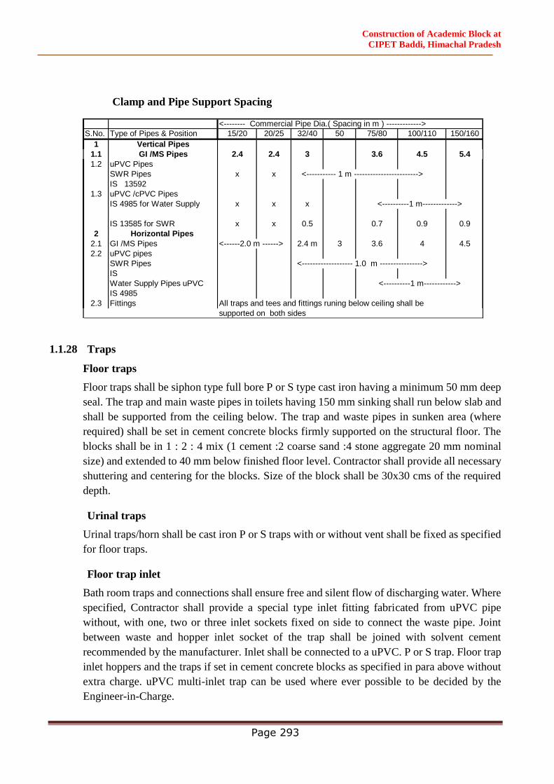
Construction of Academic Block at
CIPET Baddi, Himachal Pradesh
Page 293
Clamp and Pipe Support Spacing
1.1.28 Traps
Floor traps
Floor traps shall be siphon type full bore P or S type cast iron having a minimum 50 mm deep
seal. The trap and main waste pipes in toilets having 150 mm sinking shall run below slab and
shall be supported from the ceiling below. The trap and waste pipes in sunken area (where
required) shall be set in cement concrete blocks firmly supported on the structural floor. The
blocks shall be in 1 : 2 : 4 mix (1 cement :2 coarse sand :4 stone aggregate 20 mm nominal
size) and extended to 40 mm below finished floor level. Contractor shall provide all necessary
shuttering and centering for the blocks. Size of the block shall be 30x30 cms of the required
depth.
Urinal traps
Urinal traps/horn shall be cast iron P or S traps with or without vent shall be fixed as specified
for floor traps.
Floor trap inlet
Bath room traps and connections shall ensure free and silent flow of discharging water. Where
specified, Contractor shall provide a special type inlet fitting fabricated from uPVC pipe
without, with one, two or three inlet sockets fixed on side to connect the waste pipe. Joint
between waste and hopper inlet socket of the trap shall be joined with solvent cement
recommended by the manufacturer. Inlet shall be connected to a uPVC. P or S trap. Floor trap
inlet hoppers and the traps if set in cement concrete blocks as specified in para above without
extra charge. uPVC multi-inlet trap can be used where ever possible to be decided by the
Engineer-in-Charge.
<-------- Commercial Pipe Dia.( Spacing in m ) ------------->
S.No. Type of Pipes & Position 15/20 20/25 32/40 50 75/80 100/110 150/160
1 Vertical Pipes
1.1 GI /MS Pipes 2.4 2.4 3 3.6 4.5 5.4
1.2 uPVC Pipes
SWR Pipes x x <----------- 1 m ------------------------>
IS 13592
1.3 uPVC /cPVC Pipes
IS 4985 for Water Supply x x x
IS 13585 for SWR x x 0.5 0.7 0.9 0.9
2 Horizontal Pipes
2.1 GI /MS Pipes <------2.0 m ------> 2.4 m 3 3.6 4 4.5
2.2 uPVC pipes
SWR Pipes <------------------- 1.0 m ---------------->
IS
Water Supply Pipes uPVC
IS 4985
2.3 Fittings All traps and tees and fittings runing below ceiling shall be
supported on both sides
<----------1 m------------->
<----------1 m------------>
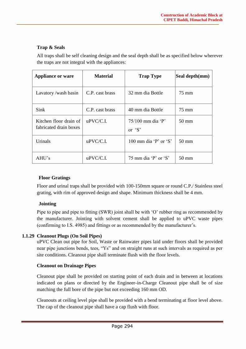
Construction of Academic Block at
CIPET Baddi, Himachal Pradesh
Page 294
Trap & Seals
All traps shall be self cleaning design and the seal depth shall be as specified below wherever
the traps are not integral with the appliances:
Appliance or ware Material Trap Type Seal depth(mm)
Lavatory /wash basin C.P. cast brass 32 mm dia Bottle 75 mm
Sink C.P. cast brass 40 mm dia Bottle 75 mm
Kitchen floor drain of
fabricated drain boxes
uPVC/C.I. 75/100 mm dia ‘P’
or ‘S’
50 mm
Urinals uPVC/C.I. 100 mm dia ‘P’ or ‘S’ 50 mm
AHU’s uPVC/C.I. 75 mm dia ‘P’ or ‘S’ 50 mm
Floor Gratings
Floor and urinal traps shall be provided with 100-150mm square or round C.P./ Stainless steel
grating, with rim of approved design and shape. Minimum thickness shall be 4 mm.
Jointing
Pipe to pipe and pipe to fitting (SWR) joint shall be with ‘O’ rubber ring as recommended by
the manufacturer. Jointing with solvent cement shall be applied to uPVC waste pipes
(confirming to I.S. 4985) and fittings or as recommended by the manufacturer’s.
1.1.29 Cleanout Plugs (On Soil Pipes)
uPVC Clean out pipe for Soil, Waste or Rainwater pipes laid under floors shall be provided
near pipe junctions bends, tees, “Ys” and on straight runs at such intervals as required as per
site conditions. Cleanout pipe shall terminate flush with the floor levels.
Cleanout on Drainage Pipes
Cleanout pipe shall be provided on starting point of each drain and in between at locations
indicated on plans or directed by the Engineer-in-Charge Cleanout pipe shall be of size
matching the full bore of the pipe but not exceeding 160 mm OD.
Cleanouts at ceiling level pipe shall be provided with a bend terminating at floor level above.
The cap of the cleanout pipe shall have a cap flush with floor.
Construction of Academic Block at
CIPET Baddi, Himachal Pradesh
Page 295
1.1.30 Waste pipe from appliances
General
a) Waste pipe from appliances e.g. wash basins, sinks and urinals shall be of uPVC pipes
40, 50 or 63 mm OD conforming to IS:4985 class II (6 kg/cm2 )shown on the drawings.
b) All pipes shall be fixed in gradient towards the outfalls of drains. Pipes inside a toilet
room shall be in chase unless otherwise shown on drawings. Where required pipes may
be run at ceiling level in suitable gradient and supported on galvanized structural
clamps. Spacing for clamps for such pipes shall be as per the pipe spacing chart given
in section 1.
Encasing Pipe in Cement Concrete
C.I (Cast iron) soil and waste pipes and drainage under floor in sunken slabs and in wall
chases (when cut specially for the pipe) shall be encased in cement concrete 1:2:4 mix (1
cement :2 coarse sand : 4 stone aggregate 12 mm size) 75 mm in bed and all-round. When
pipes are running well above the structural slab, the encased pipes shall be supported with
suitable cement concrete pillars of required height at intervals of one meter.
Testing
Testing procedure specified below apply to all soil, waste and vent pipes above ground
including pipes laid along basement ceiling.
Entire drainage system shall be tested for water tightness during and after completion of the
installation. No portion of the system shall remain untested. Contractor must have adequate
number of expandable rubber/bellow plugs, manometers, smoke testing machines, pipe and
fitting work test benches and any other equipment necessary and required to conduct the tests.
All testing equipment/motors etc. shall be certified for its calibration by an approved
laboratory.
All materials obtained and used on site must have manufacturer's Hydraulic Test Certificate
for each batch of materials used on the site.
Testing Soil, Waste and Rainwater Pipes
Apart from factory test all pipes and fittings shall be hydraulically tested for a head of 3 m
preferably on a specially set up work bench. After applying pressure, strike the pipe with a
wooden pallet and inspect for blow holes and cracks. Pressure may be applied for about 2
minutes. Reject and remove all defective pipes.
After installation all connections from fixtures, vertical stacks and horizontal drains including
pipes along ceiling shall be tested to a hydraulic pressure not exceeding 3 m. Such tests shall
be conducted for each floor separately by suitable plugs.
Construction of Academic Block at
CIPET Baddi, Himachal Pradesh
Page 296
After the installation is fully complete, it should be tested by flushing the toilets, running at
least 20% of all taps simultaneously and ensuring that the entire system is self draining, has no
leakages, blockages etc. Rectify and replace where required.
Contractor shall maintain a test register identifying date and time of each area. All tests shall
be conducted in presence of Engineer-in-Charge and signed by both.
Excavation for Pipe Line
1.1.31 Excavation
The excavation for pipe works shall be open cutting unless the permission of the Engineer-in-
Charge for the ground to be tunneled is obtained in writing. Where sewers have to be
constructed along narrow passages, the Engineer-in-Charge may order the excavation to be
made partly in tunnel and in such cases the excavated soil shall be brought back later on for
refilling the trenches or tunnel.
1.1.32 Opening out Trenches
In excavation the trenches, etc. the solid road metal ling, pavement, curbing etc. and turf is to
be placed on one side and preserved for reinstatement when the trenches or other excavation
shall be filled up. Before any road metal is replaced, it shall be carefully shifted. The surface
of all trenches and holes shall be restored and maintained to the satisfaction of the Engineer-
in-Charge and of the Owners of the roads or other property traversed and the Contractor shall
not cut out or break down any live fence of trees in the line of the proposed works but shall
tunnel under them, unless the Engineer-in-Charge shall order to the contrary.
The Contractor shall grub up and clear the surface over the trenches and other excavations of
all trees, stumps roots and all other encumbrances affecting execution of the work and shall
remove them from the site to the approval of the Engineer-in-Charge.
1.1.33 Obstruction of Roads
The Contractor shall not occupy or obstruct by his operation more than one half of the width
of any road or street and sufficient space shall then be left for public and private transit, he
shall remove the materials excavated and bring them back again when the trench is required
to be refilled. The Contractor shall obtain the consent of the Engineer-in-Charge in writing
before closing any road to vehicular traffic and the foot walks must be clear at all times.
1.1.34 Removal of Filth
All night soil, filth or any other offensive matter met with during the execution of the works,
immediately after it is taken out of any trench, sewer or cess pool, shall not be deposited on to
the surface of any street or where it is likely to be a nuisance or passed into any sewer or drain
but shall be at once put into the carts and removed to a suitable place to be provided by the
Contractor.
1.1.35 Excavation to be taken to Proper Depths
The trenches shall be excavated to such a depth that the pipes shall rest on concrete or on firm
bedding as described in the several clauses relating to these so that the inverts may be at the
Construction of Academic Block at
CIPET Baddi, Himachal Pradesh
Page 297
levels given in the sections. In bad ground, the Engineer-in-Charge may order the Contractor
to excavate to a greater depth than that shown on the drawings and to fill up the excavation to
the level of the sewers with concrete, broken stone, gravel or other materials. Nothing extra
shall be paid for the same if the Contractor excavates the trench to a greater depth than is
required without a specific order to that effect in writing of the Engineer-in-Charge.The extra
depth shall have to be filled up with concrete 1:5:10 mix (1 cement: 5 fine sand: 10 stone
aggregate 40mm nominal size) at the Contractor’s own costs and charges to the requirements
and satisfactions of the Engineer-in-Charge.
1.1.36 Refilling
After the pipes or other work has been laid and proved to be water tight, the trench or other
excavations shall be refilled. Utmost care shall be taken in doing this, so that no damage shall
be caused to the sewer and other permanent work. The filling in the haunches and upto 75 cms
above the crown of the sewer shall consist of the finest selected materials placed carefully in
15 cms layers and flooded and consolidated. After this has been laid, the trench and other
excavation shall be refilled carefully in 15 cms layers with materials taken from the excavation,
each layer being watered to assist in the consolidation unless the Engineer-in-Charge shall
otherwise direct.
1.1.37 Contractor to Restore Settlement and Damages
The Contractor shall, at his own costs and charges, make good promptly during the whole
period the works are in hand, any settlement that may occur in the surfaces of roads, beams,
footpaths, gardens, open spaces etc. Whether public or private caused by his trenches or by his
other excavations and he shall be liable for any accidents caused thereby. He shall also, at his
own expenses and charges, repair and make good and damage done to buildings and other
property. If in the opinion of the Engineer-in-Charge he fails to make good such works with
all practicable dispatch, the Engineer-in-Charge shall be at liberty to get the work done by the
Contractor or deducted from any money that may be or become due to him or recovered from
him in any other manner according to the law of the land.
1.1.38 Disposal of Surplus Soil
The Contractor shall at his own costs and charges provide places for disposal of all surplus
materials not required to be used on the works. As each trench is refilled the surplus soil shall
be immediately removed, the surface properly restored and roadways and sides left clear.
1.1.39 Timbering of Sewer and Trenches
The Contractor shall at all times support efficiently and effectively the sides of the sewer
trenches and other excavations by suitable timbering, piling and sheeting and they shall be
close, timbered in loose or sandy strata and below the surface of the sub soil water level.
All timbering, sheeting and piling with their waling and supports shall be of adequate
dimensions and strength and fully braced and strutted so that no risk of collapse or subsidence
of the walls of the trench shall take place.
Construction of Academic Block at
CIPET Baddi, Himachal Pradesh
Page 298
The Contractor shall be held responsible and will be accountable for the sufficiency of all
timbering, branches, sheeting and piling used as also for all damage to persons and property
resulting from improper quality, strength, placing, maintaining or removing of the same.
1.1.40 Shoring of Buildings
The Contractor shall shore up all buildings, walls and other structures, the stability of which
is liable to be endangered by the execution of the work and shall be fully responsible for all
damages to persons or property resulting from any accident.
1.1.41 Removal of Water from Sewer, Trench etc.
The Contractor shall at all times during the progress of the work keep the trenches and
excavations free from water which shall be disposed off by him in a manner as will neither
cause injury to the public health nor to the public or private property nor to the work completed
or in progress nor to the surface of any roads or streets, nor cause any interference with the use
of the same by the public.
1.1.42 Width and Depth of Trench
The Engineer-in-Charge shall have power by giving an order in writing to the Contractor to
increase the maximum width in respect of which payment will be allowed for excavation in
trenches for various classes of sewer, manholes, and other works in certain lengths to be
specifically laid down by him, where on account of bad ground or other unusual conditions,
he considers that such increased widths are necessary in view of the site conditions.
Water Supply System (Cold & Hot)
1.1.43 Scope of Work
Work under this section consists of furnishing all labor, materials equipment and appliances
necessary and required to completely install the water supply system as required by the
drawings & specified hereinafter.
Without restricting to the generality of the foregoing, the water supply system shall include
the following:-
a) Municipal water connection including water meter up to U.G. water tanks.
b) Piping from tube well to raw water tank
c) Over Head Tank filling mains from hydro pneumatic system.
d) Distribution system from overhead tank to toilets and other wet area in the building except
upper three floors.
e) Distribution mains from hydro pneumatic system to all fixtures and appliances for upper
three floors to all buildings.
f) Excavation and refilling of pipes trenches.
g) Control valves, masonry chambers and other appurtenances.
All water lines to different parts of building and making connection from source etc.
Pipe protection and painting.
Providing Hot water supply and return lines and insulation of hot water pipe lines.
Control valves, masonry chambers and other appurtenances.
Connections to all toilets kitchen equipments, tanks and appliances.
Excavation and refilling of pipe trenches, wherever necessary.
Trenches for taking pipe lines for these services if required.

Construction of Academic Block at
CIPET Baddi, Himachal Pradesh
Page 299
1.1.44 General Requirements
All materials shall be new of the best quality conforming to specifications. All works executed
shall be to the satisfaction of the Engineer-in-Charge.
Pipes and Fittings shall be fixed truly vertical, horizontal or in slopes as required in a neat
workmanlike manner.
Short or Long bends shall be used on all main pipe lines as far as possible. Use of Elbows shall
be restricted for short connections.
As far as possible all Bends shall be formed by means of a hydraulic pipe bending machine for
pipes up to 65mm dia.
Pipes shall be fixed in a manner so as to provide easy accessibility for repair and maintenance
and shall not cause obstruction in shafts, passages etc.
Pipes shall be securely fixed to walls and ceilings by suitable clamps at intervals specified.
As far as possible, all piping inside the buildings shall run either concealed or embedded.
Outside the buildings the piping shall be installed at-least 60cms below finished grade. All
galvanized steel piping embedded either in trenches or in concrete and masonry work shall be
tightly wrapped 1mm thick fiberglass tissue laid in bitumen.
Valves and other appurtenances shall be so located as to provide easy accessibility for
operations, maintenance and repairs.
Water Supply System
Contractor should study the site plan and water supply system diagram for an overview of the
system.
Source
a) Water supply will be acquired from Municipal water mains through a service
connection
b) Additional water supply will be obtained from captive tube-wells within the site. The
rising mains will be connected to the main fire static tank and then overflow into the
main domestic water tank.
Water supply piping for garden hydrant and sprinkler and irrigation system will be separate
and independently connected to a different pumping system.
1.1.45 Pipes & Fittings
CI pipes shall be used for main transmissions of potable water up to underground
reservoirs.
All external pipes in trenches along with the road and parking (external pipe network) shall
be DI pipes.
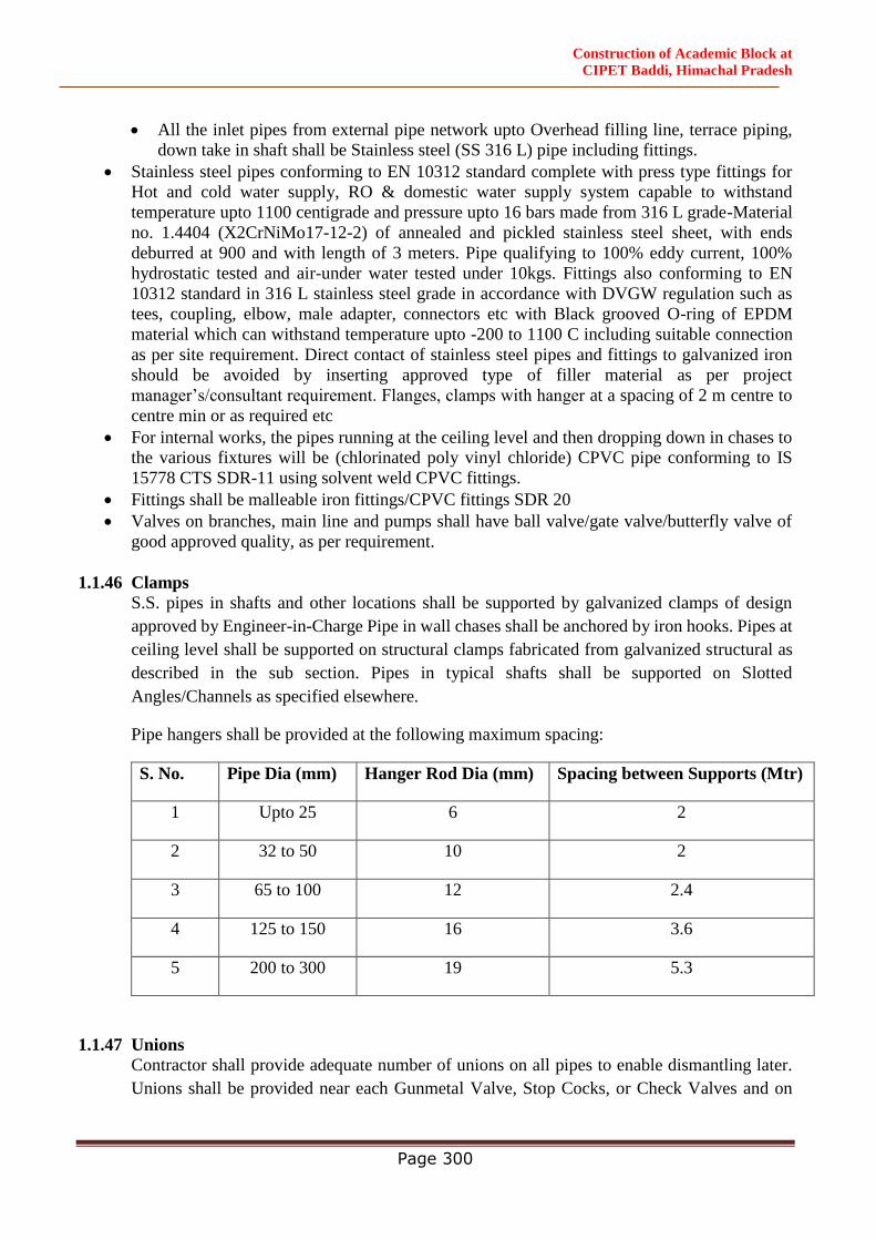
Construction of Academic Block at
CIPET Baddi, Himachal Pradesh
Page 300
All the inlet pipes from external pipe network upto Overhead filling line, terrace piping,
down take in shaft shall be Stainless steel (SS 316 L) pipe including fittings.
Stainless steel pipes conforming to EN 10312 standard complete with press type fittings for
Hot and cold water supply, RO & domestic water supply system capable to withstand
temperature upto 1100 centigrade and pressure upto 16 bars made from 316 L grade-Material
no. 1.4404 (X2CrNiMo17-12-2) of annealed and pickled stainless steel sheet, with ends
deburred at 900 and with length of 3 meters. Pipe qualifying to 100% eddy current, 100%
hydrostatic tested and air-under water tested under 10kgs. Fittings also conforming to EN
10312 standard in 316 L stainless steel grade in accordance with DVGW regulation such as
tees, coupling, elbow, male adapter, connectors etc with Black grooved O-ring of EPDM
material which can withstand temperature upto -200 to 1100 C including suitable connection
as per site requirement. Direct contact of stainless steel pipes and fittings to galvanized iron
should be avoided by inserting approved type of filler material as per project
manager’s/consultant requirement. Flanges, clamps with hanger at a spacing of 2 m centre to
centre min or as required etc
For internal works, the pipes running at the ceiling level and then dropping down in chases to
the various fixtures will be (chlorinated poly vinyl chloride) CPVC pipe conforming to IS
15778 CTS SDR-11 using solvent weld CPVC fittings.
Fittings shall be malleable iron fittings/CPVC fittings SDR 20
Valves on branches, main line and pumps shall have ball valve/gate valve/butterfly valve of
good approved quality, as per requirement.
1.1.46 Clamps
S.S. pipes in shafts and other locations shall be supported by galvanized clamps of design
approved by Engineer-in-Charge Pipe in wall chases shall be anchored by iron hooks. Pipes at
ceiling level shall be supported on structural clamps fabricated from galvanized structural as
described in the sub section. Pipes in typical shafts shall be supported on Slotted
Angles/Channels as specified elsewhere.
Pipe hangers shall be provided at the following maximum spacing:
S. No. Pipe Dia (mm) Hanger Rod Dia (mm) Spacing between Supports (Mtr)
1 Upto 25 6 2
2 32 to 50 10 2
3 65 to 100 12 2.4
4 125 to 150 16 3.6
5 200 to 300 19 5.3
1.1.47 Unions
Contractor shall provide adequate number of unions on all pipes to enable dismantling later.
Unions shall be provided near each Gunmetal Valve, Stop Cocks, or Check Valves and on
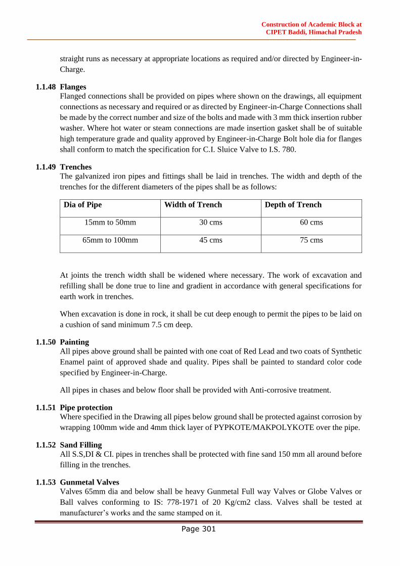
Construction of Academic Block at
CIPET Baddi, Himachal Pradesh
Page 301
straight runs as necessary at appropriate locations as required and/or directed by Engineer-in-
Charge.
1.1.48 Flanges
Flanged connections shall be provided on pipes where shown on the drawings, all equipment
connections as necessary and required or as directed by Engineer-in-Charge Connections shall
be made by the correct number and size of the bolts and made with 3 mm thick insertion rubber
washer. Where hot water or steam connections are made insertion gasket shall be of suitable
high temperature grade and quality approved by Engineer-in-Charge Bolt hole dia for flanges
shall conform to match the specification for C.I. Sluice Valve to I.S. 780.
1.1.49 Trenches
The galvanized iron pipes and fittings shall be laid in trenches. The width and depth of the
trenches for the different diameters of the pipes shall be as follows:
Dia of Pipe Width of Trench Depth of Trench
15mm to 50mm 30 cms 60 cms
65mm to 100mm 45 cms 75 cms
At joints the trench width shall be widened where necessary. The work of excavation and
refilling shall be done true to line and gradient in accordance with general specifications for
earth work in trenches.
When excavation is done in rock, it shall be cut deep enough to permit the pipes to be laid on
a cushion of sand minimum 7.5 cm deep.
1.1.50 Painting
All pipes above ground shall be painted with one coat of Red Lead and two coats of Synthetic
Enamel paint of approved shade and quality. Pipes shall be painted to standard color code
specified by Engineer-in-Charge.
All pipes in chases and below floor shall be provided with Anti-corrosive treatment.
1.1.51 Pipe protection
Where specified in the Drawing all pipes below ground shall be protected against corrosion by
wrapping 100mm wide and 4mm thick layer of PYPKOTE/MAKPOLYKOTE over the pipe.
1.1.52 Sand Filling
All S.S,DI & CI. pipes in trenches shall be protected with fine sand 150 mm all around before
filling in the trenches.
1.1.53 Gunmetal Valves
Valves 65mm dia and below shall be heavy Gunmetal Full way Valves or Globe Valves or
Ball valves conforming to IS: 778-1971 of 20 Kg/cm2 class. Valves shall be tested at
manufacturer’s works and the same stamped on it.
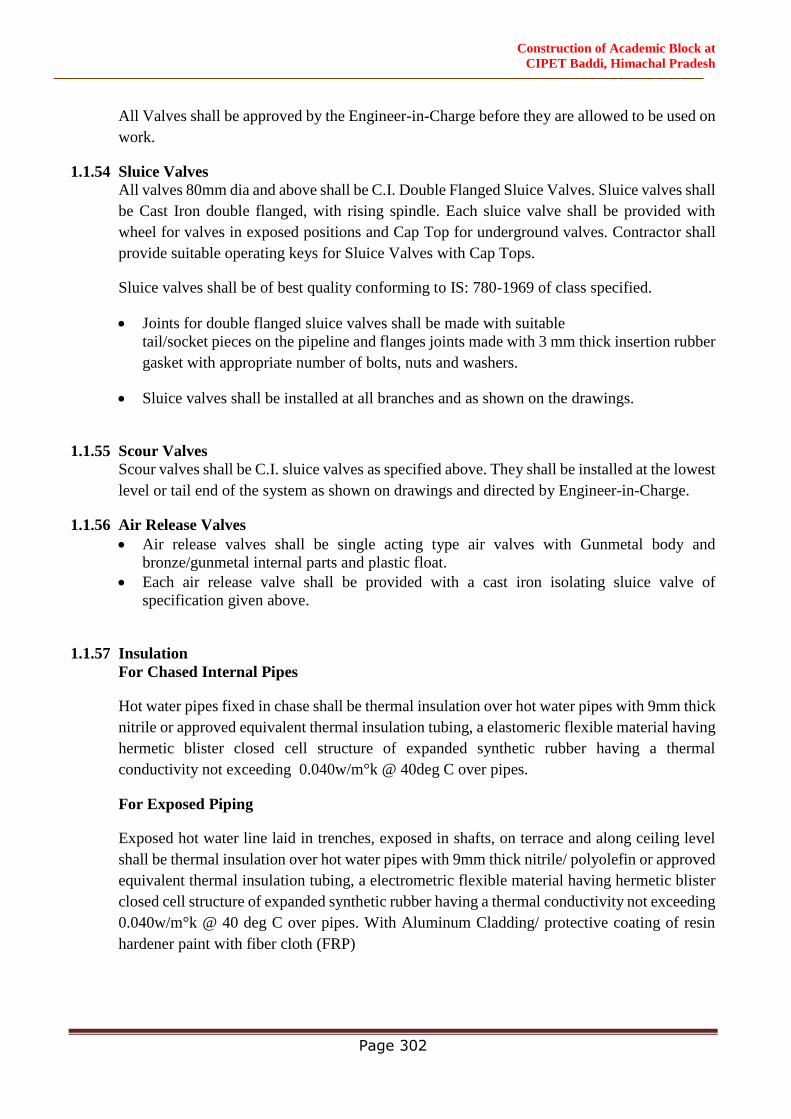
Construction of Academic Block at
CIPET Baddi, Himachal Pradesh
Page 302
All Valves shall be approved by the Engineer-in-Charge before they are allowed to be used on
work.
1.1.54 Sluice Valves
All valves 80mm dia and above shall be C.I. Double Flanged Sluice Valves. Sluice valves shall
be Cast Iron double flanged, with rising spindle. Each sluice valve shall be provided with
wheel for valves in exposed positions and Cap Top for underground valves. Contractor shall
provide suitable operating keys for Sluice Valves with Cap Tops.
Sluice valves shall be of best quality conforming to IS: 780-1969 of class specified.
Joints for double flanged sluice valves shall be made with suitable
tail/socket pieces on the pipeline and flanges joints made with 3 mm thick insertion rubber
gasket with appropriate number of bolts, nuts and washers.
Sluice valves shall be installed at all branches and as shown on the drawings.
1.1.55 Scour Valves
Scour valves shall be C.I. sluice valves as specified above. They shall be installed at the lowest
level or tail end of the system as shown on drawings and directed by Engineer-in-Charge.
1.1.56 Air Release Valves
Air release valves shall be single acting type air valves with Gunmetal body and
bronze/gunmetal internal parts and plastic float.
Each air release valve shall be provided with a cast iron isolating sluice valve of
specification given above.
1.1.57 Insulation
For Chased Internal Pipes
Hot water pipes fixed in chase shall be thermal insulation over hot water pipes with 9mm thick
nitrile or approved equivalent thermal insulation tubing, a elastomeric flexible material having
hermetic blister closed cell structure of expanded synthetic rubber having a thermal
conductivity not exceeding 0.040w/m°k @ 40deg C over pipes.
For Exposed Piping
Exposed hot water line laid in trenches, exposed in shafts, on terrace and along ceiling level
shall be thermal insulation over hot water pipes with 9mm thick nitrile/ polyolefin or approved
equivalent thermal insulation tubing, a electrometric flexible material having hermetic blister
closed cell structure of expanded synthetic rubber having a thermal conductivity not exceeding
0.040w/m°k @ 40 deg C over pipes. With Aluminum Cladding/ protective coating of resin
hardener paint with fiber cloth (FRP)
Construction of Academic Block at
CIPET Baddi, Himachal Pradesh
Page 303
S.No Pipe Size (MM) Thickness of Nitrile Rubber Insulation (MM)
1 15 to 25 9
2 32 to 80 13
3 100 & above 19
1.1.58 Anchor Block
Suitable anchor blocks shall be provided at all bends and tees to encounter the excessive thrust
developed due to water hammer.
1.1.59 Cpvc Pipes
All pipes inside the buildings and where specified, outside the building shall be CPVC pipes
tubes conforming to IS 15778:1996 .Specific Gravity ASTM D 792 at 230C should be 1.55 as
specified. With Tensile Strength as per ASTM D 638 at 230C should be 55N/mm2.
Cutting
Pipes shall be cut either with a wheel type plastic pipe cutting or hacksaw blade and care shall
be taken to make a square cut which provides optimal bonding area within a joint.
Deburing / Beveling
Burrs and fittings should be removed from the outside and inside of pipe with a pocket knife
or file otherwise burrs and fittings may prevent proper contact between pipe and fitting during
assembly.
Fitting Preparation
A clean dry rag/cloth should be used to wipe dirt and moisture on the fitting sockets and tubing
end. The tubing should make contact with the socket wall 1/3 or 2/3 of the way into the fitting
socket.
Solvent Cement Application
Only CPVC solvent cement confirming to ASTM-F493 should be used for joining pipe with
fittings. CPVC schedule 40 & 80 heavy bodied CPVC solvent cement only should be used
confirming to ASTM-F493.
Assembly
After applying the solvent cement on both pipe and fitting socket, pipes should be inserting
into the fitting socket within 30 seconds, and rotating the pipe ¼ to ½ turn while inserting so
as to ensure even distribution of solvent cement with the joint. The assembled system should
be held for 10 seconds (approx) in order to allow the joint to set up.
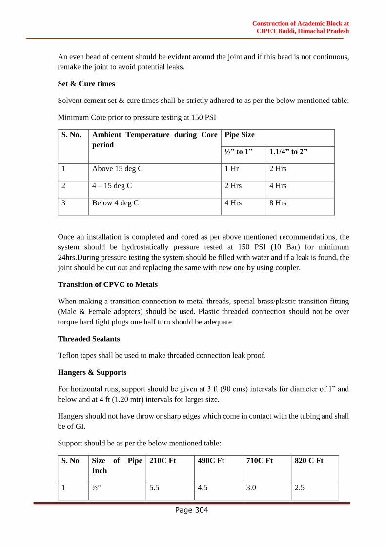
Construction of Academic Block at
CIPET Baddi, Himachal Pradesh
Page 304
An even bead of cement should be evident around the joint and if this bead is not continuous,
remake the joint to avoid potential leaks.
Set & Cure times
Solvent cement set & cure times shall be strictly adhered to as per the below mentioned table:
Minimum Core prior to pressure testing at 150 PSI
S. No. Ambient Temperature during Core
period
Pipe Size
½” to 1” 1.1/4” to 2”
1 Above 15 deg C 1 Hr 2 Hrs
2 4 – 15 deg C 2 Hrs 4 Hrs
3 Below 4 deg C 4 Hrs 8 Hrs
Once an installation is completed and cored as per above mentioned recommendations, the
system should be hydrostatically pressure tested at 150 PSI (10 Bar) for minimum
24hrs.During pressure testing the system should be filled with water and if a leak is found, the
joint should be cut out and replacing the same with new one by using coupler.
Transition of CPVC to Metals
When making a transition connection to metal threads, special brass/plastic transition fitting
(Male & Female adopters) should be used. Plastic threaded connection should not be over
torque hard tight plugs one half turn should be adequate.
Threaded Sealants
Teflon tapes shall be used to make threaded connection leak proof.
Hangers & Supports
For horizontal runs, support should be given at 3 ft (90 cms) intervals for diameter of 1” and
below and at 4 ft (1.20 mtr) intervals for larger size.
Hangers should not have throw or sharp edges which come in contact with the tubing and shall
be of GI.
Support should be as per the below mentioned table:
S. No Size of Pipe
Inch
210C Ft 490C Ft 710C Ft 820 C Ft
1 ½” 5.5 4.5 3.0 2.5
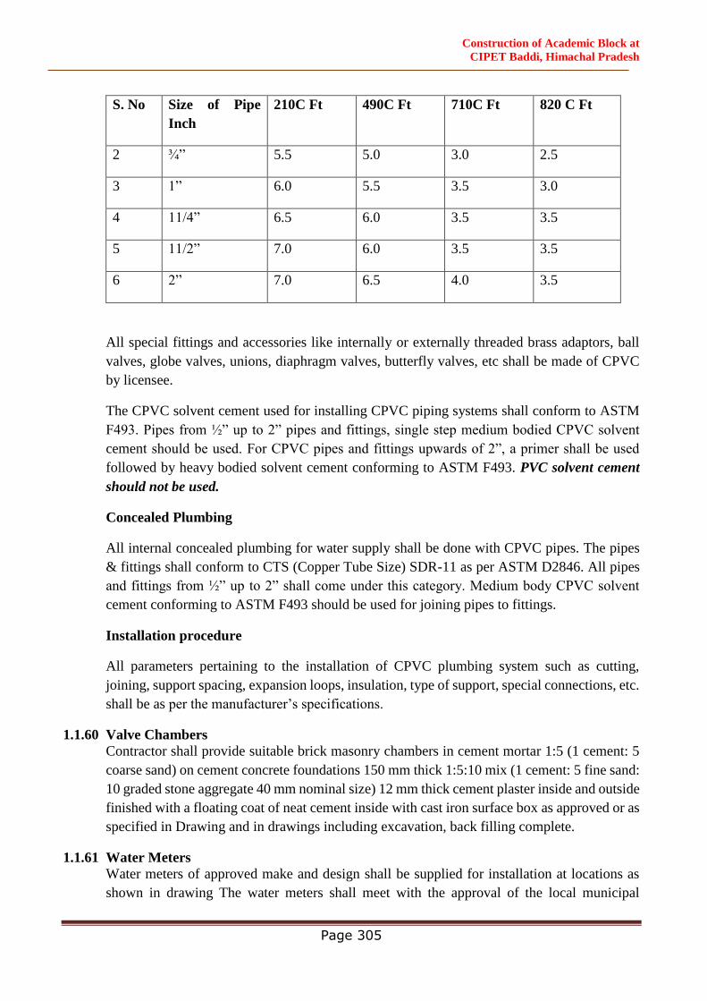
Construction of Academic Block at
CIPET Baddi, Himachal Pradesh
Page 305
S. No Size of Pipe
Inch
210C Ft 490C Ft 710C Ft 820 C Ft
2 ¾” 5.5 5.0 3.0 2.5
3 1” 6.0 5.5 3.5 3.0
4 11/4” 6.5 6.0 3.5 3.5
5 11/2” 7.0 6.0 3.5 3.5
6 2” 7.0 6.5 4.0 3.5
All special fittings and accessories like internally or externally threaded brass adaptors, ball
valves, globe valves, unions, diaphragm valves, butterfly valves, etc shall be made of CPVC
by licensee.
The CPVC solvent cement used for installing CPVC piping systems shall conform to ASTM
F493. Pipes from ½” up to 2” pipes and fittings, single step medium bodied CPVC solvent
cement should be used. For CPVC pipes and fittings upwards of 2”, a primer shall be used
followed by heavy bodied solvent cement conforming to ASTM F493. PVC solvent cement
should not be used.
Concealed Plumbing
All internal concealed plumbing for water supply shall be done with CPVC pipes. The pipes
& fittings shall conform to CTS (Copper Tube Size) SDR-11 as per ASTM D2846. All pipes
and fittings from ½” up to 2” shall come under this category. Medium body CPVC solvent
cement conforming to ASTM F493 should be used for joining pipes to fittings.
Installation procedure
All parameters pertaining to the installation of CPVC plumbing system such as cutting,
joining, support spacing, expansion loops, insulation, type of support, special connections, etc.
shall be as per the manufacturer’s specifications.
1.1.60 Valve Chambers
Contractor shall provide suitable brick masonry chambers in cement mortar 1:5 (1 cement: 5
coarse sand) on cement concrete foundations 150 mm thick 1:5:10 mix (1 cement: 5 fine sand:
10 graded stone aggregate 40 mm nominal size) 12 mm thick cement plaster inside and outside
finished with a floating coat of neat cement inside with cast iron surface box as approved or as
specified in Drawing and in drawings including excavation, back filling complete.
1.1.61 Water Meters
Water meters of approved make and design shall be supplied for installation at locations as
shown in drawing The water meters shall meet with the approval of the local municipal
Construction of Academic Block at
CIPET Baddi, Himachal Pradesh
Page 306
authorities. Suitable valves and chambers to house the meters shall also be provided along-
with the meters.
All meters shall conform to Indian Standard IS: 779-1978 (Water meters-domestic type) and
IS: 2373-1981 (water meters-bulk type). Where called for water meters shall be located in
masonry chambers of appropriated size.
1.1.62 Pipe Hangers Brackets Etc.
Sturdy hangers, brackets and saddles of approved design shall be installed to support all pipe
lengths which are not embedded over their entire run. The hangers and brackets shall be of
adjustable heights and primer coated with red-oxide primer clamps. Collars and saddles to hold
pipes shall be provided with suitable gaskets. The brackets and hangers shall be of Mild Steel
designed to carry the weight of pipes safely and without excessive deflections.
All pipes and fittings shall be supported near every joint and half-way through every pipe
length unless otherwise specified. Where called for, pipe hangers shall also be supplied with
proper sound and vibration dampening devices to minimize noise and vibration transmission.
1.1.63 Testing
All pipes, fittings and valves shall be tested by hydrostatic pressure of min. 1.5 times, the
working pressure and subject to minimum of 7 kg/cm2 in any case and with the consent of
Engineer-in-Charge.
Pressure shall be maintained for a period of at least TWELVE hours without appreciable drop
in the pressure after fixing at site. (+10 %). A test register shall be maintained and all entries
shall be signed and dated by Contractor(s) and Engineer.
In addition to the sectional testing carried out during the construction, Contractor shall test the
entire installation after connections to the overhead tanks or pumping system or mains. He
shall rectify all leakages, and shall replace all defective materials in the system. Any damage
done due to carelessness, open or burst pipes or failure of fittings, to the building, furniture
and Fixtures shall be made good during the defects liability period without any extra cost.
After completion of the water supply system, Plumbing Contractor shall test each valve by
closing and opening it a number of times to observe if it is working efficiently. Valves which
do not effectively operate shall be replaced by new ones at no extra cost and the same shall be
tested as above.
1.1.64 Connections to Water Tanks
The contractor shall provide all inlets, outlets, washouts, vents, ball cocks, overflow, control
valves and all such other piping connections including level indicator to water storage tanks
as called for.
Suitable float controls of an approved make, securely fixed to the tank independent of the inlet
pipe and set in a position so that water inlet into the tank is cut off when filled up to the water
line. The water level in the tanks shall be adjusted to 25mm below the lip of the overflow pipe.
Construction of Academic Block at
CIPET Baddi, Himachal Pradesh
Page 307
Full way gate/ball valves of approved make shall be provided as near the tank as practicable
on every outlet pipe from the storage tank except the overflow pipe.
The overflow pipe shall be so placed as to allow the discharge of water being readily seen. The
overflow pipe shall be of size indicated. A stop valve shall also be provided on the inlet water
connection to the tank. The outlet pipes shall be fixed approximately 75mm above the bottom
of the tank towards which the floor of the tank is sloping to enable the tank to be emptied for
cleaning. The ball valves shall conform to Indian Standard IS:1703-1968
1.1.65 Connections to Mechanical Equipment Supplied by Other Agencies
All inlets, outlets, valves, piping and other incidental work connected with installation of all
mechanical equipment supplied by other agencies shall be carried out by the Plumbing
contractor in accordance with the drawings, requirements for proper performance of
equipment, manufacturer’s instructions and the directions of the Engineer-in-Charge The
equipment to be supplied by other agencies consists mainly of Kitchen, Laundry, Air-
conditioning, Water Treatment and other similar equipment. The connections to the various
equipment shall be effected through proper unions and isolating valves. The work of effecting
connections shall be executed in consultation with and according to the requirements of
equipment suppliers, under the directions of the Engineer-in-Charge. The various aspects of
connection work shall be executed in a manner similar to the work of respective trades
mentioned elsewhere in these specifications.
1.1.66 Disinfection
After completion of the work Contractor shall flush clean the entire system with the city’s
filtered water after connection has been made.
After the first flushing, commercial bleaching powder is to be added to achieve a dosage of 2
to 3 mg/l of water in the system added and flushed. This operation should be performed twice
to ensure that the system is fully disinfected and usable. The Commissioning would not be
considered complete without performing the Disinfection.
1.1.67 Pre Commissioning
Ensure that all pipes are free from debris and obstructions.
Check all valves and fire hydrant for effective opening and closing action. Defects should be
rectified or valves replaced.
Ensure that all Connections to Branches has been made.
Ensure that mains have been connected to the respective pumps, underground and Overhead
tanks.
Water supply should be available at main Underground tank.
All main line Valves should be closed.
Construction of Academic Block at
CIPET Baddi, Himachal Pradesh
Page 308
1.1.68 Commissioning
Fill Underground tank with water. Add 1kg fresh bleaching powder after making a solution to
be added near inlet.
Start Water Supply Pump and allow water to fill main Underground tank. Water will first fill
the fire tank and then overflow to the Raw Water tanks.
After filling Overhead Reservoir drain the same to its one forth capacity through tank scour
valve. (This is to ensure removal of all mud, debris etc. from the tank).
Fill Overhead tank to full.
Release water in the main lines by opening Valves in each circuit. Drain out water in the system
through scour valves or fire hydrant in lower regions. Ensure clean water is now coming out
of the system.
Open valves for individual clusters. Observe for leakages or malfunctions, check pressure &
flow at end of line by opening Hydrants etc. Remove and rectify defects noticed.
Check all outlet points for proper operation by opening each valve and allowing water to flow
for a few minutes. Also check for effective closure of valve.
The entire water supply system should be disinfected with bleaching powder and system flush
cleaned.
Send four samples of water drawn from four extreme locations for testing for bacteriological
test in sterilized bottles obtained from the concerned laboratory. (Laboratory personal may
collect the samples themselves).
1.1.69 Responsibility
Responsibility for various activities in pre-commissioning and commissioning procedures will
rest with the Contractor.
TUBE WELL
1.1.70 General Conditions
All work shall be done in a systematic manner in accordance with a programmer prepared in
consultation with the Engineer-in-Charge. Rates quoted shall be for complete items and
inclusive of all equipment, labor, scaffolding, tackles etc required to do a complete job.
Rates shall be inclusive of all taxes, e.g. GSTetc.
Expected quantity of water required is in the order of 10,000 LPH on 10-12 hours continuous
pumping, but lower flow will be acceptable if the strata yield is such.
No payment shall be made for the abandoned bores.
1.1.71 Water Supply & Power
Contractor shall make his own arrangement for water at site required for his work. He may
obtain the water by boring a trial bore or by obtaining in water tankers at his own cost.
Construction of Academic Block at
CIPET Baddi, Himachal Pradesh
Page 309
Contractor shall also make his own arrangements for power required for his work.
1.1.72 Site Clearance
The Contractor shall clear the site for any trees, growth, grass and rubbish to enable him to
execute the work properly at his own cost.
On successful completion of the work the Contractor shall clear up the site of all his surplus
material equipment and accessories and hand over the same to the Engineer-in-Charge.
1.1.73 Type of Well
a) Tube well shall be bored by a reverse circulation rotary rig with 600 mm dia (24") blind
and slotted pipe. Annular space between pipe and bore shall be gravel packed.
1.1.74 Boring
Boring shall be 600-650 mm dia to an approximate depth of 80-90 m. The depth may be
increased or decreased as per actual site conditions. The depth at which the tube well boring is
to be terminated shall be as agreed upon by the Engineer-in-Charge Sub-soil water shall not
be tapped.
1.1.75 Well and Housing Pipes
Pipes shall be uPVC pressure pipe with couplings.
1.1.76 Slotted Pipes
Slotted pipes shall be 250 mm dia, with slots. Slot size shall be as per soil conditions and shall
be approved by the Engineer-in-Charge. No variation in rate shall be permissible due to size
and dimension of slots.
1.1.77 Special Fittings
Provide all special fittings e.g. blank pipes, socket rings, bail plug, centering guides, pipe slips
and top cap suitable for housing pipe.
1.1.78 Verticality
Well assembly shall be truly vertical as per latest Indian Standard and verticality certificate
shall be furnished by the Contractor.
1.1.79 Gravel Packing
Space between boring and well assembly shall be packed with washed pea gravel 3 to 6 mm
size.
1.1.80 Development
The well shall be developed by an air compressor of 450 cfm capacity and pressure of 10.5
kg/cm2 for a period of at least twenty hours. This period may however be extended in case the
development is not satisfactory.
1.1.81 Water Tests
The Contractor shall get the water tested for its quality from approved Water Testing
laboratory given Annexure I. Tests shall be for drinking water quality as per IS: 10500 for

Construction of Academic Block at
CIPET Baddi, Himachal Pradesh
Page 310
Physical, Chemical & bacteriological parameters. (Tests shall be performed after development
of the well and clear water is available in the discharge).
1.1.82 Sanitary Sealing
The annular space between the bore and its housing pipe shall be grouted with cement concrete
1:2:4 to a depth of 5 m below the ground level. Four 50 mm dia gravel feeding shall be provided
with caps at top. Pipes shall be G.I. to I.S. 1239, medium class.
1.1.83 Bore Log
A bore log in a standard format form shall be maintained at the site and shall give the following
information.
a) Description and depth of strata
b) Spring level below ground.
c) Aquifier opposite which slotted pipes have been placed.
d) Rate of progress of drilling
e) Full particulars of final test
f) Four copies of strata sheets yield and water quality tests shall be handed over on
completion of the well.
g) Suggested depth for the tube well submersible pump.
Garden Hydrant System
1.1.84 Scope Of Work
The scope of this section comprise of the supply, installation testing and commissioning of
piping network for garden hydrant & irrigation system.
Work under this section consists of furnishing all labor, materials equipment and appliances
necessary and required to completely install the garden irrigation system as required by the
drawings, specified hereinafter and given in the Drawing.
Without restricting to the generality of the foregoing, the garden hydrant system shall include
the following:-
All irrigation lines to different parts of site and making connection from source i.e. from
STP etc.
Pipe protection.
Control valves, masonry chambers and other appurtenances.
Connections to all hydrant point.
Excavation and refilling of pipe trenches, wherever necessary.
Trenches for taking pipe lines for these services if required.
Construction of Academic Block at
CIPET Baddi, Himachal Pradesh
Page 311
1.1.85 General Requirements
All materials shall be new of the best quality conforming to specifications. All works executed
shall be to the satisfaction of the Engineer-in-Charge.
Pipes and Fittings shall be fixed truly vertical, horizontal or in slopes as required in a neat
workmanlike manner.
Pipes shall be fixed in a manner so as to provide easy accessibility for repair and maintenance
and shall not cause obstruction in shafts, passages etc.
As far as possible shall be installed at-least 60cms below finished grade.
Valves and other appurtenances shall be so located as to provide easy accessibility for
operations, maintenance and repairs.
1.1.86 HDPE Pipes & Fittings
All pipes used in Garden hydrant & flushing system shall be HDPE (High density Poly
Ethylene pipe and conforming to I.S. 4984 of class IV (6 kg/cmsq)
Fittings shall be HDPE fittings, of approved make.
Pipes and fittings shall be jointed with butt welding joint.
1.1.87 Flanges
Flanged connections shall be provided on pipes where ever required or as directed by
Engineer-in-Charge. Connections shall be made by the correct number and size of the bolts
and made with 3 mm thick insertion rubber washer.
1.1.88 Trenches
The HDPE pipes and fittings shall be laid in trenches. The width and depth of the trenches for
the different diameters of the pipes shall be as follows:
Dia of Pipe Width of Trench Depth of Trench
15mm to 50mm 30 cms 60 cms
65mm to 100mm 45 cms 75 cms
At joints the trench width shall be widened where necessary. The work of excavation and
refilling shall be done true to line and gradient in accordance with general specifications for
earth work in trenches.
When excavation is done in rock, it shall be cut deep enough to permit the pipes to be laid on
a cushion of sand minimum 7.5 cm deep.
1.1.89 Pipe Protection
Where specified in the Drawing all pipes below ground shall be in trenches and protected with
fine sand 150 mm all around before filling in the trenches.
Construction of Academic Block at
CIPET Baddi, Himachal Pradesh
Page 312
Sewerage / Drainage System
1.1.90 Scope of Work
Work under this section shall consist of furnishing all Labor, Materials, Equipments and
Appliances necessary and required to completely finish Sewerage/Drainage system as
specified hereinafter or given in the Drawing.
Without restricting to the generality of the foregoing, the sewerage system shall include:
Internal/External sewer line.
Excavations including refilling etc.
Construction of Collection Chambers, Manholes and Drop Connections.
Construction of Grease Trap etc.
Connection to S.T.P and Disposal of treated effluent.
Storm Water Drainage and Disposal.
Construction of Desalting chamber & Rain water Harvesting tank
Testing of pipe lines
1.1.91 General Requirements
All materials shall be new of the best quality conforming to specifications and subject to the
approval of the Engineer-in-Charge.
Drainage lines shall be laid to the required gradients and profiles.
All piping shall be installed at depth greater than 80cms below finished ground level.
The piping system shall be vented suitably at the starting point of all branch drains, main
drains, and the highest/lowest point of drain and at intervals as shown. All venting arrangement
shall be un-obstructive and concealed.
All drainage work shall be done in accordance with the local Municipal bye-laws.
Wherever the sewerage pipes run above water supply lines, same shall be completely encased
in cement concrete 1:2:4 all round with the prior approval of the Engineer-in-Charge.
Location of all manholes, catch basins etc., shall be got confirmed by the Contractor from the
Engineer-in-Charge before the actual execution of work at site.
All works shall be executed as directed by Engineer-in-Charge.
1.1.92 Alignment and Grade
The sewer pipes shall be laid to alignment and gradient shown on the drawings but subject to
such modifications as shall be ordered by the Engineer-in-Charge from time to time to meet
the requirements of the works. No deviations from the lines, depths of cutting or gradients of
sewers shown on the plans and sections shall be permitted except by the express direction in
writing of the Engineer-in-Charge.
Construction of Academic Block at
CIPET Baddi, Himachal Pradesh
Page 313
1.1.93 Salt Glazed Stoneware Pipes
Stoneware pipes shall be of first class quality salt glazed and free from rough texture inside or
outside and straight. All pipes shall have the manufacturers name marked on it and shall
comply to IS: 651-1971 and shall be of approved makes.
The maximum permissible slope to the various diameters of pipes shall be as follows:
100mm pipe …… 1 in 40 to 1:50
150mm pipe …… 1 in 60 to 1:100
200mm pipe …… 1 in 80 1: 120 to 1: 200
250mm pipe …… 1 in 90 1: 120 to 1: 250
Where necessary, pipe shall be laid on a bed of plain cement concrete 1:3:6 and minimum 150
mm thick, and shall be projected by providing hunching up to half the diameter of the pipes.
The width of the concrete bed for various diameters shall be as follows:
100mm dia pipe …… 380mm wide
150mm dia pipe …… 450mm wide
200mm dia pipe …… 600mm wide
250mm dia pipe …… 700mm wide
Where the pipes are laid on a soft soil, with the maximum water table level, lying at the invert
level of the pipe, the pipe shall be bedded in concrete.
1.1.94 Laying of Pipes
Pipes are liable to be damaged in transit and notwithstanding tests that may have been made
before dispatch each pipe shall be examined carefully on arrival at site. Each pipe shall be rung
with a wooden hammer or mallet and those that do not ring true and clear shall be rejected.
Sound pipes shall be carefully stacked to prevent damage. All defective pipes should be
segregated, marked in a conspicuous manner and their use in the works prevented.
The pipes shall be laid with sockets leading uphill and should rest on solid and even
foundations for the full length of the barrel. Socket holes shall be formed in the foundation
sufficiently deep to allow the pipe jointer room to work right round the pipe and as short as
practicable to admit the socket and allow the joint to be made.
Where pipes are not bedded on concrete the trench bottom shall be left slightly high and
carefully bottomed up as pipe laying proceeds so that the pipe barrels rest on firm ground. If
excavation has been carried too low it shall be made up with cement concrete 1:5:10 mix at
the Contractor’s cost and charges.
Construction of Academic Block at
CIPET Baddi, Himachal Pradesh
Page 314
If the bottom of the trench consists of rock or very hard ground that cannot be easily excavated
to a smooth surface, the pipes shall be laid on cement concrete bed of 1:5:10 mix to ensure
even bearing.
1.1.95 Jointing of Pipes
Tarred gaskin shall first be wrapped round the spigot of each pipe and the spigot shall then be
placed into the socket of the pipe previously laid, the pipe shall then be adjusted and fixed in
its correct position and the gaskin caulked tightly home so as to fill not more than one quarter
of the total length of the socket.
The remainder of the socket shall be filled with stiff mix of cement mortar (1 cement: 1 clear
sharp washed sand). When the socket is filled, a fillet should be formed round the joint with a
trowel forming an angle of 45 degrees with the barrel of the pipe. The mortar shall be beaten
up and used after it has begun to set.
After the joint has been made any extraneous materials shall be removed from inside of the
joint with a suitable scraper or “Badger”. The newly made joints shall be protected until set
from the sun, drying winds, rain or dust. Sacking or other materials, which can be kept damp,
shall be used. The joints shall be exposed and space left all rounds the pipes for inspection by
the Engineer-in-Charge. The inside of the sewer must be left absolutely clear in bore and free
from cement mortar or other obstructions throughout its entire length, and shall efficiently
drain and discharge.
Gully Traps
Gully traps shall be of the same quality as described for stoneware pipes in Clause 5.
Gully traps shall be fixed in cement concrete 1:5:10 mix (1 cement: 5 coarse sand: 10 stone
aggregate 40mm nominal size) and a brick masonry chamber 30x30 cms inside in cement
mortar 1:3 with 10 x 10 cms grating inside and 30x30 cms C.I. sealed cover and frame
weighting not less than 7.2 kg to be constructed as per standard drawing. Where necessary,
sealed cover shall be replaced with C.I. grating of the same size.
Grease Trap
Grease Trap shall be provided on Kitchen waste lines before discharging the waste into the
main sewer line. Grease Trap shall be built in brick masonry and shall be similar in
construction to manholes. The grease trap shall be constructed to size as shown at the
location on drawings. The grease trap shall be provided with drop inlet, drop outlet,
galvanized wrought iron sediment pan and a baffle wall. Grease trap shall be provided with
2 Nos, double seal manhole cover and frame which shall be identified with lettering
`Grease trap" as per the drawing.
o Testing of Grease Trap
All rights of the sewer and drain shall be carefully tested for water tightness by mains
of water pressure maintained for not less than 30 minutes. Testing shall be carried out
for manhole to manhole. All pipes shall be subject to a test pressure of 1.5 meter head
of Water. The test pressure will however, not exceed 6mtr head at any point. The pipes
Construction of Academic Block at
CIPET Baddi, Himachal Pradesh
Page 315
shall be plugged preferably with standard design plugs or with rubber plugs on both
sides, the upper end shall, however, be connected to a pipe for filling with water and
getting the required head poured at one time.
1.1.96 Reinforced Cement Concrete Pipes
All underground storm water drainage pipes and sewer lines where specified (other than those
specified cast iron) shall be centrifugally spun RCC pipes of specified class
conformingtoIS:458(latestversion). Pipes shall be true and straight with uniform bore.
Throughout cracked, warped pipes shall not be used on the work. All pipes shall be tested by
the manufacturer and the Contractor shall produce, when directed a certificate to that effect
from the manufacturer.
1.1.97 Laying
R.C.C. spun pipes shall be laid on cement concrete bed or cradles as specified and shown on
the detailed drawings the cradles may be precast and sufficiently cured to prevent cracks and
breakage in handling. The invert of the cradles shall be left 12mm below the invert level of the
pipe properly placed on the soil to prevent any disturbance. The pipe shall than be placed on
the bed concrete or cradles and set for the line and gradient by means of sight rails and bonding
rods etc. cradles or concrete bed may be omitted, if directed by the Engineer-in-Charge
1.1.98 Encasing (all pipes have to be encased)
The sewer pipes shall be completely encased or surrounded with concrete where :
The maximum water table level is likely to rise above the top of the barrel.
The top (overt) of pipe is less than 200 cms under the road surface.
1.1.99 Jointing
After setting out the pipes the collars shall be centered over the joint and filled in with tarred
gaskin, so that sufficient space is left on either side of the collar to receive the mortar. The
space shall then be filled with cement mortar 1:2 (1 cement: 2 fine sand) and caulked by means
of proper tools all joints shall be finished at an angle of 45 degree to the longitudinal axis of
the pipe on both side of the collars neatly semi flexible type collar joint.
1.1.100 Curing
The joint shall be cured for at least 7 days. Refilling at joints will be permitted only on
satisfactory completion of curing period.
1.1.101 Cement Concrete and Masonry Works for Manholes and Chambers etc.
The manholes shall be constructed of brick masonry or RCC as per site conditions, as directed
by Engineer-in-Charge. The guidelines laid down in IS 4111 shall be followed in this context.
The brick masonry/RCC manholes shall be as per standard specifications of National Building
Code, IS 4111 & CPWD Guidelines.
Manhole Covers

Construction of Academic Block at
CIPET Baddi, Himachal Pradesh
Page 316
Steel fiber reinforced concrete (SFRC) Manhole cover with frame conforming to IS: 12592
shall be provided.
Water
Water used for all the construction purposes shall be clear and free from Oil, Acid, Alkali,
Organic and other harmful matters, which shall deteriorate the strength and/or durability of the
structure. In general, the water suitable for drinking purposes shall be considered well enough
for construction purpose.
Aggregate for Concrete
The aggregate for concrete shall be in accordance with IS: 383 and IS: 515 in general, these
shall be free from all impurities that may cause corrosion of the reinforcement. Before actual
use these shall be washed in water, if required as per the direction of Engineer-in-Charge. The
size of the coarse aggregate shall be done as per I S: 383.
Sand
Sand for various constructional purposes shall comply in all respects with I S: 650 and I S:
2116. It shall be clean, coarse hard and strong, sharp, durable, uncoated, free from any mixture
of clay, dust, vegetable matters, mica, iron impurities soft or flaky and elongated particles,
alkali, organic matters, salt, loam and other impurities which may be considered by the
Engineer-in-Charge as harmful for the construction.
Cement
The cement used for all the constructional purposes shall be ordinary Portland cement or rapid
hardening Portland cement conforming to IS: 269.
Mild Steel Reinforcement
The steel reinforcement bars shall be conforming to all requirements of IS: 1786, IS 456 &
IS13920.
Bricks
Bricks shall have uniform color, thoroughly burnt but not over burnt, shall have plan
rectangular faces with parallel sides and sharp right angled edges. They should give ringing
sound when struck. Brick shall not absorb more than 20% to 22% of water, when immersed in
water for 24 hours. Bricks to be used shall be approved by the Engineer-in-Charge.
Other Materials
Other materials not fully specified in these specifications and which may be required in the
work shall conform to the I S code. All such materials shall be approved by the Engineer-in-
Charge before use.
Construction of Academic Block at
CIPET Baddi, Himachal Pradesh
Page 317
1.1.102 Cement Concrete (Plain or Reinforced)
Cement concrete pipes bedding, cradles, foundations and RCC slabs for all works shall be
mixed by a Mechanical Mixer where quantities of the concrete poured at one time permit.
Hand mixing on properly constructed platforms may be allowed for small quantities by the
Engineer-in-Charge. Rate for cement concrete shall be inclusive of all shuttering and centering
at all depth and heights.
All concrete work shall be cured for a period of at least 7 days. Such work shall be kept moist
by means of gunny bass at all times. All pipe trenches and foundations shall be kept dry during
the curing period.
1.1.103 Masonry Work
Masonry work for manholes, chambers, brick masonry pipe trench and such other works as
required shall be constructed from 1st class bricks or as specified in the Drawing in cement
mortar 1:5 mix (1 cement: 5 coarse sand). All joints shall be properly raked to receive plaster.
1.1.104 Cement Concrete for Pipe Support
The pipe support i.e concrete bed, cradle etc shall be as per IS:783 and CPWD Guidelines. In
case there is difference of out come of the structural design done as per IS 783 and CPWD
guidelines, the decision of WAPCOS shall prevail. Drawings showing the Pipe support
system shall be prepared by EPC Contractor and these drgs. shall be got approved from
WAPCOS.
Foundation of Pipe Bedding:
In case the soil is very weak,a suitable foundation for the pipe bedding shall be designed and
shall be got approved by WAPCOS.Regard in the soilis‘very weak’or not,the decision of the
Engineer –in-charge shall be final and binding.
All Rainwater Collection Chamber shall be of the size 50x45x60cm (internal) with horizontal C.I. grating or SFRC precast Gully Grating as per instructions of Engineer-in-Charge.The grating along with frame shall be of size 500x450 mm grating having total Wt.of app.38 K gand of approved design and quality as per instruction of Engineer-in-Charge.The remaining details of construction shall be same as stated above for the construction of the Manholes etc.
1.1.105 Manholes and Chambers
Where not specified, Manholes will be constructed as follows:-
(All dimensions internal clear in cms)
Size of Manhole
Type
90x80
Rect.
120x90
Rect.
910 dia
Circular
1220 dia
Circular
1520 dia
Circular
Maximum depth 100 245 170 230 Any depth
beyond 230
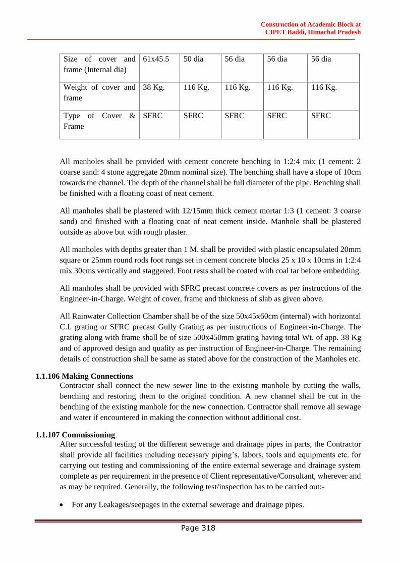
Construction of Academic Block at
CIPET Baddi, Himachal Pradesh
Page 318
Size of cover and
frame (Internal dia)
61x45.5 50 dia 56 dia 56 dia 56 dia
Weight of cover and
frame
38 Kg. 116 Kg. 116 Kg. 116 Kg. 116 Kg.
Type of Cover &
Frame
SFRC SFRC SFRC SFRC SFRC
All manholes shall be provided with cement concrete benching in 1:2:4 mix (1 cement: 2
coarse sand: 4 stone aggregate 20mm nominal size). The benching shall have a slope of 10cm
towards the channel. The depth of the channel shall be full diameter of the pipe. Benching shall
be finished with a floating coast of neat cement.
All manholes shall be plastered with 12/15mm thick cement mortar 1:3 (1 cement: 3 coarse
sand) and finished with a floating coat of neat cement inside. Manhole shall be plastered
outside as above but with rough plaster.
All manholes with depths greater than 1 M. shall be provided with plastic encapsulated 20mm
square or 25mm round rods foot rungs set in cement concrete blocks 25 x 10 x 10cms in 1:2:4
mix 30cms vertically and staggered. Foot rests shall be coated with coal tar before embedding.
All manholes shall be provided with SFRC precast concrete covers as per instructions of the
Engineer-in-Charge. Weight of cover, frame and thickness of slab as given above.
All Rainwater Collection Chamber shall be of the size 50x45x60cm (internal) with horizontal
C.I. grating or SFRC precast Gully Grating as per instructions of Engineer-in-Charge. The
grating along with frame shall be of size 500x450mm grating having total Wt. of app. 38 Kg
and of approved design and quality as per instruction of Engineer-in-Charge. The remaining
details of construction shall be same as stated above for the construction of the Manholes etc.
1.1.106 Making Connections
Contractor shall connect the new sewer line to the existing manhole by cutting the walls,
benching and restoring them to the original condition. A new channel shall be cut in the
benching of the existing manhole for the new connection. Contractor shall remove all sewage
and water if encountered in making the connection without additional cost.
1.1.107 Commissioning
After successful testing of the different sewerage and drainage pipes in parts, the Contractor
shall provide all facilities including necessary piping’s, labors, tools and equipments etc. for
carrying out testing and commissioning of the entire external sewerage and drainage system
complete as per requirement in the presence of Client representative/Consultant, wherever and
as may be required. Generally, the following test/inspection has to be carried out:-
For any Leakages/seepages in the external sewerage and drainage pipes.
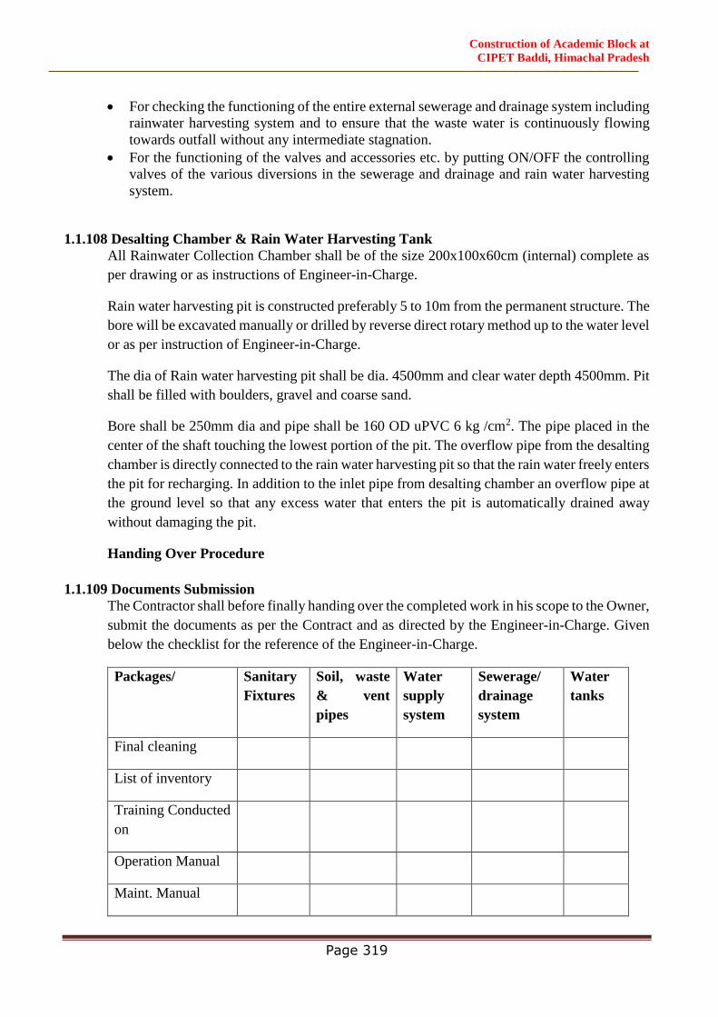
Construction of Academic Block at
CIPET Baddi, Himachal Pradesh
Page 319
For checking the functioning of the entire external sewerage and drainage system including
rainwater harvesting system and to ensure that the waste water is continuously flowing
towards outfall without any intermediate stagnation.
For the functioning of the valves and accessories etc. by putting ON/OFF the controlling
valves of the various diversions in the sewerage and drainage and rain water harvesting
system.
1.1.108 Desalting Chamber & Rain Water Harvesting Tank
All Rainwater Collection Chamber shall be of the size 200x100x60cm (internal) complete as
per drawing or as instructions of Engineer-in-Charge.
Rain water harvesting pit is constructed preferably 5 to 10m from the permanent structure. The
bore will be excavated manually or drilled by reverse direct rotary method up to the water level
or as per instruction of Engineer-in-Charge.
The dia of Rain water harvesting pit shall be dia. 4500mm and clear water depth 4500mm. Pit
shall be filled with boulders, gravel and coarse sand.
Bore shall be 250mm dia and pipe shall be 160 OD uPVC 6 kg /cm2. The pipe placed in the
center of the shaft touching the lowest portion of the pit. The overflow pipe from the desalting
chamber is directly connected to the rain water harvesting pit so that the rain water freely enters
the pit for recharging. In addition to the inlet pipe from desalting chamber an overflow pipe at
the ground level so that any excess water that enters the pit is automatically drained away
without damaging the pit.
Handing Over Procedure
1.1.109 Documents Submission
The Contractor shall before finally handing over the completed work in his scope to the Owner,
submit the documents as per the Contract and as directed by the Engineer-in-Charge. Given
below the checklist for the reference of the Engineer-in-Charge.
Packages/ Sanitary
Fixtures
Soil, waste
& vent
pipes
Water
supply
system
Sewerage/
drainage
system
Water
tanks
Final cleaning
List of inventory
Training Conducted
on
Operation Manual
Maint. Manual
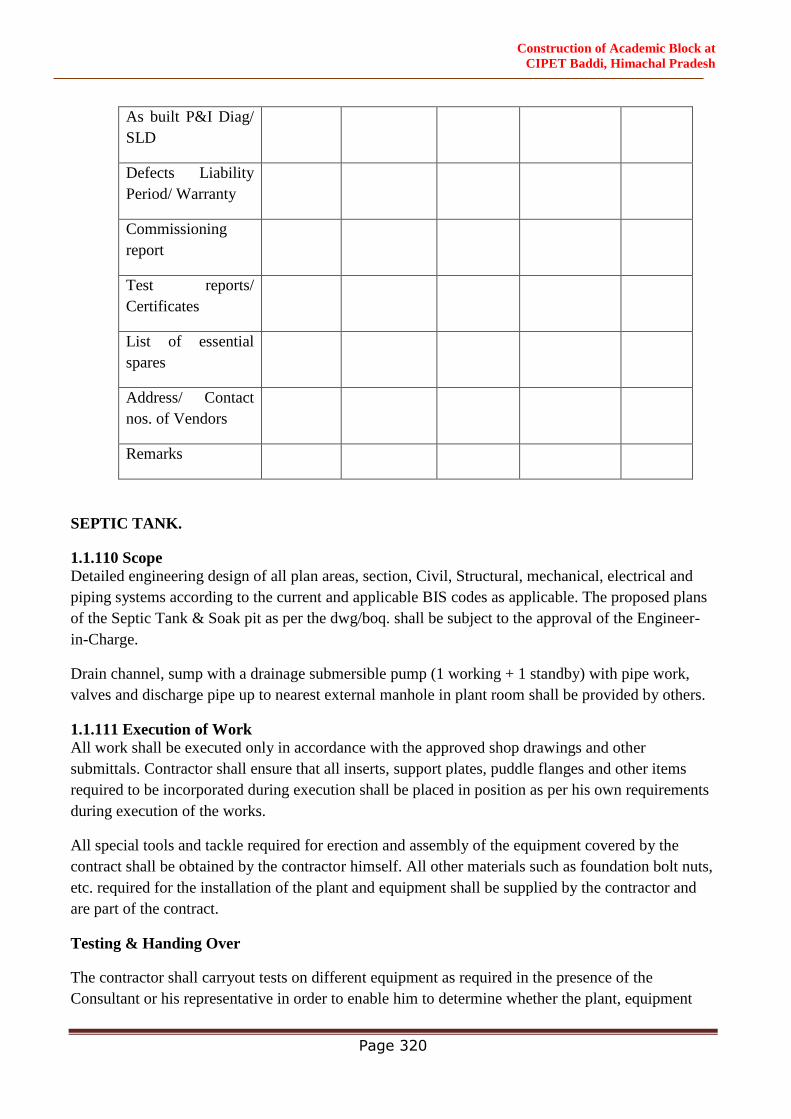
Construction of Academic Block at
CIPET Baddi, Himachal Pradesh
Page 320
As built P&I Diag/
SLD
Defects Liability
Period/ Warranty
Commissioning
report
Test reports/
Certificates
List of essential
spares
Address/ Contact
nos. of Vendors
Remarks
SEPTIC TANK.
1.1.110 Scope
Detailed engineering design of all plan areas, section, Civil, Structural, mechanical, electrical and
piping systems according to the current and applicable BIS codes as applicable. The proposed plans
of the Septic Tank & Soak pit as per the dwg/boq. shall be subject to the approval of the Engineer-
in-Charge.
Drain channel, sump with a drainage submersible pump (1 working + 1 standby) with pipe work,
valves and discharge pipe up to nearest external manhole in plant room shall be provided by others.
1.1.111 Execution of Work
All work shall be executed only in accordance with the approved shop drawings and other
submittals. Contractor shall ensure that all inserts, support plates, puddle flanges and other items
required to be incorporated during execution shall be placed in position as per his own requirements
during execution of the works.
All special tools and tackle required for erection and assembly of the equipment covered by the
contract shall be obtained by the contractor himself. All other materials such as foundation bolt nuts,
etc. required for the installation of the plant and equipment shall be supplied by the contractor and
are part of the contract.
Testing & Handing Over
The contractor shall carryout tests on different equipment as required in the presence of the
Consultant or his representative in order to enable him to determine whether the plant, equipment

Construction of Academic Block at
CIPET Baddi, Himachal Pradesh
Page 321
and installation comply with the specifications, local codes and in accordance with the letter and
intents of the specifications.
The installation shall be handed over to the Engineer-in-Charge only on successful completion,
operational tests and acceptance of the effluent quality by the municipal / pollution control and
statutory authorities.
Fire Fighting System
Technical Specification
Work under this sub-head consists of furnishing all Labor, Materials, equipment and accessories
necessary and required to completely install the Fire Fighting equipment etc., specified hereinafter
and given in the NBC 2016 (Part IV).
Without restricting to the generality of the foregoing the work of Fire Fighting System shall include
the followings:
Providing M.S. black steel (Class C) pressure pipe line main including Valves, Fire Hydrants,
Excavation for Pipe, Laying of pipe, Painting of pipe and Making Connection to supply system.
Black Steel Pipe, Mains Laterals, Branches, Valves, Hangers and Appurtenances.
Hose Reels, Rubberized fabric lined hose pipes, Hose cabinets, Sprinkler heads and Landing Valves.
Portable Fire Extinguishers
Fire Fighting Pumps, diesel operated pumps, panels and all connected accessories including suction
& delivery pipes.
Testing Commissioning and giving live demonstrations to the various Inspection Authorities and
Obtain their “No Objection Certificate” (NOC) for occupation of the building.
General Requirements
All materials shall be of the best quality conforming to the Specifications and subject to the approval
of the Engineer-in-Charge.
Pipes and Fittings shall be fixed truly Vertical, Horizontal or in slopes as required in a neat workman
like manner.
Pipes shall be fixed in a manner so as to provide easy accessibility for repair and maintenance and
shall not cause any obstruction in shaft, passage etc.
Pipes shall be securely fixed to walls and ceiling by suitable clamps at intervals specified. Only
approved type of anchor fasteners shall be used for RCC ceilings.
Valves and other appurtenance shall be so located that they are easily accessible for operation,
repairs and maintenance.

Construction of Academic Block at
CIPET Baddi, Himachal Pradesh
Page 322
Pipes
All pipes within and outside the building in exposed locations and shafts including connections
buried under floor shall be M.S. Pipes as follows:
Pipes 150 mm dia and below IS: 1239 (Class C) Heavy Class
Pipe 200 mm dia and above IS 3589 of thickness specified.
Pipe Fittings
Pipes and fittings means tees, elbows, couplings, flanges, reducers etc. And all such connecting
devices that are needed to complete the piping work in its totality.
Fabricated fittings shall not be permitted for pipe diameters 50 mm and below.
When used, they shall be fabricated, welded and inspected in workshops under supervision of
Engineer-in-Charge whose welding procedures have been approved by the TAC as per TAC rule
4102 for sprinkler system and applicable to hydrant and sprinkler system. For "T" connections, pipes
shall be drilled and reamed. Cutting by gas or electrical welding will not be accepted.
Jointing
Screwed (50 mm dia pipes and below)
Joint for black steel pipes and fittings shall be metal-to-metal thread joints. A small amount of red
lead may be used for lubrication and rust prevention. Joints shall not be welded or caulked. (With
screwed MS forged fittings)
Welding (65 mm dia and above)
Joints between MS pipes and fittings shall be made with the pipes and fittings having "V" groove
and welded with electrical resistance welding in an approved manner. Buried pipes will be subject to
X Ray test from an approved agency as per the TAC norms at the cost of contractor. (With welded
M.S. fittings heavy class with V-Groove). The welding machine shall be 3 Phase rectifier of
required current and capacity. The vendor for welding will be approved by Engineer-in-Charge.
Flanges
Flanged joints shall be provided on:
Straight runs not exceeding 30 m on pipelines 80 mm dia and above.
Both ends of any fabricated fittings e.g. bends, tees etc. of 65 mm dia or larger diameter.
For jointing all types of valves, appurtenances, pumps, connections with other type of pipes, to water
tanks and other places necessary and required as good for engineering practice.
Flanges shall be as per IS 6392-1971, Table 17/18 with appropriate number of G.I. nuts and bolts,
half threaded of with 3 mm insertion neoprene gasket complete.

Construction of Academic Block at
CIPET Baddi, Himachal Pradesh
Page 323
Unions
Provide Approved type of dismountable unions on pipes lines 65 mm and below in similar places as
specified for flanges shall be provided.
Pipe Protection
All pipes above ground and in exposed locations shall be painted with one coat of Red Oxide Primer
and two or more coats of Synthetic Enamel Paint of approved shade.
All black steel pipes under floors or below ground shall be provided with protection against
corrosion by application of 100mm wide and 4mm thick layer of PYPKOTE/ MAKPOLYKOTE
over the pipe, as per manufacturers specifications.
Pipe Supports
All pipes shall be adequately supported from ceiling or walls from existing/new inserts by Structural
clamps fabricated from M.S. Structural e.g. Rods, Channels, Angles and Flats as per details given in
drawings and specifications. All clamps shall be painted with one coat of red lead and two coats of
black Enamel paint.
Where inserts are not provided, the Contractor shall provide anchor fasteners. Anchor fastener shall
be fixed to walls and ceilings by drilling holes with Electrical drill in an approved manner as
recommended by the manufacturer of the fasteners.
Testing
All pipes in the system shall be tested to a hydraulic pressure of 1.5 times of the working pressure or
minimum of 15 kg/cm2 without drop in the pressure for at least 2 hours.
Rectify all leakages, make adjustment and retest as required.
Valves, Gauge and Orifice Plates
Sluice Valves above 65 mm shall be of Cast Iron body and Bronze/Gunmetal seat. They shall conform
to type PN 1.6 of IS:780-1980, valves up to 65mm shall be of Gunmetal Full way Valve with wheel
tested to 20 kg/cm2 class-II as per I.S: 778-1971. Valve wheels shall be of right hand type and have
an arrow head engraved or cast thereon showing the direction for turning open and closing.
Non-return valves shall be of Cast Iron body and Bronze/Gunmetal seat. They shall conform to class
of IS: 5312 and have flanged ends. They shall be swing check type in horizontal runs and lift check
type in vertical runs of piping. They shall not be spring-loaded type.
Internal Hydrants
The Internal Hydrant outlet shall comprise “Single Headed Single Outlet Gunmetal Landing Valve”
conforming to type ‘A’ of IS: 5290-1977. Separate valve on the head shall form part of the landing
valve construction.
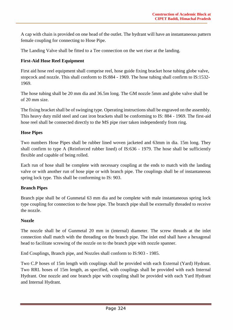
Construction of Academic Block at
CIPET Baddi, Himachal Pradesh
Page 324
A cap with chain is provided on one head of the outlet. The hydrant will have an instantaneous pattern
female coupling for connecting to Hose Pipe.
The Landing Valve shall be fitted to a Tee connection on the wet riser at the landing.
First-Aid Hose Reel Equipment
First aid hose reel equipment shall comprise reel, hose guide fixing bracket hose tubing globe valve,
stopcock and nozzle. This shall conform to IS:884 - 1969. The hose tubing shall confirm to IS:1532-
1969.
The hose tubing shall be 20 mm dia and 36.5m long. The GM nozzle 5mm and globe valve shall be
of 20 mm size.
The fixing bracket shall be of swinging type. Operating instructions shall be engraved on the assembly.
This heavy duty mild steel and cast iron brackets shall be conforming to IS: 884 - 1969. The first-aid
hose reel shall be connected directly to the MS pipe riser taken independently from ring.
Hose Pipes
Two numbers Hose Pipes shall be rubber lined woven jacketed and 63mm in dia. 15m long. They
shall confirm to type A (Reinforced rubber lined) of IS:636 - 1979. The hose shall be sufficiently
flexible and capable of being rolled.
Each run of hose shall be complete with necessary coupling at the ends to match with the landing
valve or with another run of hose pipe or with branch pipe. The couplings shall be of instantaneous
spring lock type. This shall be conforming to IS: 903.
Branch Pipes
Branch pipe shall be of Gunmetal 63 mm dia and be complete with male instantaneous spring lock
type coupling for connection to the hose pipe. The branch pipe shall be externally threaded to receive
the nozzle.
Nozzle
The nozzle shall be of Gunmetal 20 mm in (internal) diameter. The screw threads at the inlet
connection shall match with the threading on the branch pipe. The inlet end shall have a hexagonal
head to facilitate screwing of the nozzle on to the branch pipe with nozzle spanner.
End Couplings, Branch pipe, and Nozzles shall conform to IS:903 - 1985.
Two C.P hoses of 15m length with couplings shall be provided with each External (Yard) Hydrant.
Two RRL hoses of 15m length, as specified, with couplings shall be provided with each Internal
Hydrant. One nozzle and one branch pipe with coupling shall be provided with each Yard Hydrant
and Internal Hydrant.
Construction of Academic Block at
CIPET Baddi, Himachal Pradesh
Page 325
Hose Cabinet
The internal hose cabinet shall accommodate the Hose pipes, branch pipe, Nozzle First aid Hose Reel
and Hydrant Outlets and shall be fabricated from 2 mm thick or 14 mm gauge MS/aluminum sheet.
The overall size shall be 2100x1200x600 mm, or as specified in the Architectural details. This shall
have lockable centre opening glazed doors as per the requirement and as per Architectural details.
Where the niche for wet riser is provided with shutters, separate hose cabinet as above may be
dispensed with.
The hose cabinet shall be painted red and stove enameled and woods FIRE written in front glazed
portion.
Fire Brigade Inlet Connections
Fire Brigade Inlet connection shall be provided near the pump house and to the wet riser system as
specified, for the following purposes:
Fire Brigade suction connection for fire static tank with provision of foot valve.
Fire brigade inlet connection to fire static tank.
Fire brigade inlet connection to the wet riser system. Each connection shall be provided with similar
dia of Sluice valve and Non return valve.
The locations of this Fire brigade connection shall be suitably decided with the approval of
Engineer-in-Chargeand with a view that these are easily accessible to the fire brigade, without any
possible Hindrance.
Hydraulic Siren
A siren shall be provided in the system, to indicate the flow of water in the wet riser system.
Alternative arrangements may also be adopted. This shall be turbine type.
Valve Chambers
Contractor shall provide suitable Brick Masonry Chamber in cement mortar 1:5 (1 cement: 5 coarse
sand) on cement concrete foundations 150 mm thick in 1:5:10 mix (1 cement: 5 fine sand: 10 graded
stone aggregate 40 mm nominal size) 15 mm thick plaster inside and outside finished with a floating
coat of neat cement inside with cast iron surface box approved by fire brigade including excavation,
back filling complete.
Valve chambers shall be of following size:
For depths 100 cm and beyond 90x90x100 cm
Portable Fire Extinguisher
Portable fire extinguishers shall be provided as per the drawing and shall confirm to IS:15683.

Construction of Academic Block at
CIPET Baddi, Himachal Pradesh
Page 326
Two 9 lit. water CO2 type for every 600 m2 area with minimum of 1 extinguishers per floor as per
I.S: 15683
Dry Chemical powder type of 5 Kg. Capacity as per (IS:15683)
CO2 type of 4.5 kg capacity as per (IS:15683)
Shop Drawings & Specifications
The Contractor shall submit to the Consultant two copies of Shop Drawings for Fire Fighting works
as an Advance Copy to the Engineer-in-Charge for approval before start of work. Subsequent to the
approval of the shop drawings, the Contractor shall submit six copies of Shop Drawings for
execution to the Engineer-in-Charge. Also the Contractor shall submit four copies of the Technical
Specifications and Catalogues.
Shop drawings shall be submitted for the following conditions:
Structural supports/hanging/laying and jointing details for all types of pipes as required.
Fire Fighting layout plans as required and for any changes in the layout of Fire
Fighting/Architectural drawings.
The Contractor can only commence the work after the approval of above documents by Consultant.
Water Supply /Fire Fighting Pumps & Equipments and Water Treatment Units etc.
Pumps and Water Treatment Equipment
Work under this sub-head consists of furnishing all labor, materials, equipment and accessories
necessary and required to completely install pumping system for various water supply services and
water treatment as per drawings, specified hereinafter.
Without restricting to the generality of the foregoing, the work of pumps and water treatment
equipment shall include the followings:
Dom.water pumps.
Garden Hydrant Pumps not (by TW).
Sump pumps for disposal of sewage and drainage.
Water treatment unit consisting of filter, softener and chlorination etc.
Fire pumps.
Motor control panels, power and control cabling and allied electrical works.
Pipes, valves, accessories, hangers, supports, delivery and suction feeders and connection to
proposed pipe work.

Construction of Academic Block at
CIPET Baddi, Himachal Pradesh
Page 327
Water Supply Pumps (Dom. Water )
Water supply pumps shall be suitable for clean water. Pumps shall be multistage, monoblock
vertical centrifugal pumps with stainless steel body and stainless steel impeller, stainless steel shaft
and coupled to a TEFC electric motor by means of a flexible coupling. Each pump should operate a
curve 10m below specified head.
Pump and motor shall be mounted on a common M.S. structural base plate or as required as per site
conditions.
Each pump shall be provided with a totally enclosed fan cooled induction motor.
Each pumping set shall be provided with a 150mm dia or of suitable size gunmetal “Burden” type
pressure gauge with gunmetal isolation cock and connecting piping.
Provide vibration-eliminating pads appropriate for each pump.
Provide rate of flow measuring meter with bypass arrangement with every set of pumps.
All water supply pumps shall be provided with mechanical seals.
Detail of Pumps as below.
a) Domestic Water pumps – Cap = 350 lpm,
Head = 30 M,
HP =5 App
Nos 3Nos (1W + 1S)
Sump Pump
Sump pumps shall be submersible type for lifting domestic sewage or muddy water/drainage. Pump
with impeller of approved material shall be mounted on waterproof motor. The impeller shall be
suitable for handling solids upto 46-100mm dia.
The pump shall automatically operate with high water level and stop at low water level in the sump
by means of “Electronic Level Controller”, of the approved make.
The sump pumps shall be complete in all respect and shall be installed as per manufacturer’s
requirement as shown in the drawing. All accessories shall be In-Built as per manufacturer’s
specification.
Sump pumps are compact monoblock dry motor submersible pumps for suitable rating, with non-
clog free flow open impeller, minimum solid handling capacity up to 100mm for sewer & 40 for
storm water . Suitable for operation on 415 volts + 5% -15%, 50 C/s A.C 3 phase supply, speed
960/1440R&M including oil chamber, guide wire for lifting & lowering of pump, M.S. galvanized
lifting chain, duck foot bend.

Construction of Academic Block at
CIPET Baddi, Himachal Pradesh
Page 328
The above pump sets must be supplied complete with following accessories :
Complete piping 100mm dia common delivery upto 1.5m as shone in the drawing. (The pipe should
be preferably heavy duty GI)
Necessary valve i.e Butterfly valve on delivery/suction side and Non return valves are on delivery
side.
Necessary cable from pumps set to control panel.
Electrical switch panel having all necessary accessories & safety devices of standard specifications.
(Panels with sump pumps near each sump as per site conditions)
Automatic built-up water level controller with necessary length of cable upto control panel.
Fire Fighting Pumps
Electrical Operated Terrace Pumps
Pumping sets shall be single stage horizontal centrifugal single outlet with cast iron body and
dynamically balanced bronze impellers. Connecting shaft shall be of stainless steel with bronze
sleeve and grease-lubricated bearings.
Pumps shall be connected to the drive by means of spacer type love-joy coupling which shall be
individually balanced dynamically and statically.
The coupling joining the prime mover with the pump shall be provided with a sheet metal guard.
Pumps shall be provided with approved type of mechanical seals.
Pumps shall be capable of delivering not less than 150% of the rated discharge at a head of not less
than 65% of the rated head. The shut-off head shall not exceed 120% of the rated head.
The System shall meet the requirements of the National building Code 2005 (NBC).
Necessary 'Y' strainer on the suction side and pressure gauge with GM cocks on the delivery side
including bypass arrangement (with 50 valve and up to 5M G.I. Medium pipes) for periodical testing
of the working of the pumping set shall be provided.
Pump shall be mounted on common base frame fabricated from MS channel as per manufacturer’s
specification.
Suitable RCC Pump-foundations as per manufacturer's design and 4 nos. Dunlop (cushy foot) heavy
duty Antivibration mounting pads shall be provided.
Construction of Academic Block at
CIPET Baddi, Himachal Pradesh
Page 329
Detail of Pumps as below :
A) Terrace pumps – Cap - 900 lpm,
Head - 35 M,
HP - 7.5 – 10.0 HP apprx.
Nos - 1 Nos
Motors for Electric Driven Pumps
Electrically driven pumps shall be provided with totally enclosed fan cooled induction motors.
Motors for fire protection pumps shall be at least equivalent to the horse power required to drive the
pump at 150% of its rated discharge and shall be designed for continuous full load duty and shall be
design proven in similar service.
Motors for fire pumps shall meet all requirements and specifications of the tariff advisory
committee.
Motors shall be suitable for 415 volts, 3 Phase, 50 cycles A.C supply and shall be designed for
33OC ambient temperature. Motors shall conform to I.S: 325.
Motors shall be designed for two start system.
Motors shall be capable of handling the required starting torque of the pumps.
Contractor shall provide heating arrangements for the main fire pump motor to ensure that motor
windings shall remain dry.
Anti Vibration Mounting - Suitable vibration mounting duly approved by Engineer-in-Charge shall
be employed for mounting the unit so as to minimise transmission of vibration to the structure. The
isolation efficiency achievable shall be clearly indicated.
Cables
Contractor shall provide all power control cables from the motor control center to various motors,
level controllers and other control devices.
Cables shall conform to I.S: 1554 and carry ISI mark.
Wiring cables shall conform to I.S 694.
All power and wiring cables shall be aluminum conductor PVC insulated armored and PVC
sheathed of 1100 volts grade.
All control cables shall be copper conductor PVC insulated armored and PVC sheathed 1100 Volt
grade.

Construction of Academic Block at
CIPET Baddi, Himachal Pradesh
Page 330
All cables shall have stranded conductors. The cables shall be in drums as far as possible and bear
manufacturer’s name.
All cable joints shall be made in approved manner as per standard practice.
Cable Trays
Contractor shall provide M.S slotted cable trays at locations as shown on the drawings.
Cable trays shall be supported from the bottom of the slab at intervals of 60cms at both ends by
anchor fasteners.
Earthing
There shall be an independent earthing station. The earthing shall consist of an earth tape connected
to an independent plate made of copper or G.I. having a conductivity of not less than 100%
international standard. All electrical apparatus, cable boxes and sheath/armor clamps shall be
connected to the main bar by means of branch earth connections of appropriate size. All joints in the
main bar and between main bar and branch bars shall have the lapping surface properly tinned to
prevent oxidation. The joints shall be riveted and sweated.
Earth plates shall be burried in a pit of 1.20x1.20M at minimum depth of 3M below ground. The
connections between main bar shall be made by means of three 10mm brass studs and fixed at
100mm centers. The pit shall be filled with coke breeze, rock salt and loose soil. A G.I. pipe of
20mm dia with perforations on the periphery shall be placed vertically over the plate to reach ground
level for watering.
A brick masonry manhole 30x30x30cm size shall be provided to surround the pipe for inspection. A
bolted removable link connecting main bar outside the pit portion leading to the plates shall be
accommodated in this manhole for testing.
Control Panels / Starters
Switch board cubicles of approved type shall be fabricated from 16-gauge M.S. sheet with dust and
vermin proof construction. It shall be painted with powder-coated finish of approved make and
shade. It shall be fitted with suitable etched plastic identification plates for each motor. The cubicle
shall comprise of the followings:-
Incoming main isolation MCCB of required capacity.
Fully Aluminum taped Bus Bar of required capacity.
Isolation MCCB one for each motor.
Fully automatic as specified D.O.L/Star Delta starters suitable for motor H.P. with push buttons one
for each motor and on/off indicating neon lamps. (DOL up to 7.5 HP and Star Delta from more than
7.5 H.P)
Single phase preventer of appropriate rating for each motor.

Construction of Academic Block at
CIPET Baddi, Himachal Pradesh
Page 331
Panel type ampere meters one for each motor with selector switch.
Panel type voltmeter on incoming main with rotary selector switch to read voltage between phase to
neutral and phase-to-phase.
Neon phase indicating lamps for incoming main and on/off indicating lamps for each motor.
Rotary switch for manual or auto operation for each pump (manual/auto off).
Fully taped separate aluminum bus bars of required capacity and with required outlets.
Space for liquid level controllers as specified + 1 extra space.
The panel shall be pre-wired with color-coded wiring. All interconnecting wiring from incoming
main to switch gear, meters and accessories within the switchboard panel.
Provision of main incoming cables from the top of the panel.
All switch gears and accessories shall be of approved make such as “Siemens, Larsen & Toubro” or
equivalent.
Switchboard cubicles shall be floor or wall mounted type as recommended by manufacturers. All
floor-mounted switchboards shall rest on minimum 225mm high platform. The contractor shall
provide the shop drawings for base and panels.
Vibration Eliminators
Provide on all suction and delivery lines double flanged reinforced neoprene flexible pipe
connectors. Connectors should be suitable for a working pressure of each pump. Length of the
connector shall be as per manufacturer’s details.
Illuminated Facsimile Annunciator Panel
Scope
Scope of this section comprises the supply, installation, testing and commissioning of illuminated
facsimile annunciation panel.
Illuminated Facsimile Enunciator
Illuminated facsimile enunciator shall be provided with facsimile of the building, constructed of
acrylic panels of suitable dimensions, showing the Basement, Ground floor plans and section
showing the location of Zonal Panels on each typical floor, entry points, various facilities shown
with enamels in various colors.
Alarm lights to indicate fire location shall be arranged within the acrylic panel and shall be either
automatically lighted by operation of any automatic fire detection devices or manual station, or by
control of push button incorporated in the control desk.
Construction of Academic Block at
CIPET Baddi, Himachal Pradesh
Page 332
Indicator of each building or facility shall include two lamps connected in parallel and so arranged
that the failure of either of the lamps is readily apparent when a call or test is made.
Power for the Enunciator shall be supplied from the power supply for the control desk.
Representation of the various plans/Drawings on the acrylic of the Enunciator shall be by negative
film processing with colored Discrimination of various zones for which the drawings shall be
furnished for approval.
Water Filter (If Required as per the Raw Water analysis)
Water filter shall be of dual filter media pressure filter downward or upward flow type suitable for a
rate of filtration.
Filter shall be vertical type of required diameter. The shell shall be fabricated from M.S. plate
suitable to withstand a working pressure as given below. The minimum thickness of shell will be
8mm and dished ends shall be 10mm. The filter shall have at least one pressure tight manhole cover.
Filter shall be provided with screwed or flanged connections for inlet, outlet, individual drain
connections and all other connections necessary and required. Filter shall be painted inside with two
or more coats of non-toxic corrosion resistant paint, one coat of red oxide primer outside with two or
more coats of synthetic enamel paint of approved shade.
Filter Capacity Shall be as follows:-
Discharge : 43750lph
Filtration rate : 17500 Litres/Sqm/hr
Suggested dia app : 1700mm
Under Drain System
Filter shall be provided with an efficient under drain system comprising of collecting pipes,
gunmetal/polypropylene nozzles of manufacturer’s design. The entire under drain system be
provided on M.S. plate or cement concrete supports.
Face Piping
Filter shall be provided with interconnecting face piping comprising of inlet, outlet, and backwash
pipe complete with pipes, valves and accessories, as per requirement. Piping shall be G.I/M.S.
piping, medium duty, as per I.S: 1239 and valves shall be cast iron double flanged sluice valves on
SOUNDERS pattern with C.I. body and Neoprene rubber diaphragm (Suggested make LABLINE,
NKI or equivalent).
Construction of Academic Block at
CIPET Baddi, Himachal Pradesh
Page 333
Accessories
Each filter shall be provided with following accessories:-
Air release valve with connecting piping.
150mm dia dial burden type gunmetal pressure gauges with gunmetal isolation cock and connecting
piping on inlet and outlet.
Sampling cocks on raw water inlet and filtered water outlet.
Individual drain connection with gunmetal full way valve.
Connection with valve for air scouring.
Water Softener (If Required as per the Raw Water analysis)
Softener shall be designed to give zero commercial hardness. Softener shall be with cation exchange
resins.
Softener vessel shall be of mild steel plate with dished ends and self supporting arrangement. Vessel
shall be suitable for a working pressure. The shell shall have a minimum thickness of 8mm and
dished ends 10mm. The vessel shall be painted internally with non-toxic bitumen paint and
externally with one coat of red oxide and two or more coats of synthetic paint to give an even shade.
The vessel shall have an internal collecting and distribution system of manufacturer’s design.
The softener shall have a set of interconnecting face piping consisting of inlet, outlet and brine
injection system with valves and accessories complete as per requirement. Piping shall be M.S.
medium duty, as per I.S: 1239 and valves shall be cast iron double flanged sluice valves on
SOUNDERS pattern, with C.I. body and Neoprene rubber diaphragm (suggested make LABLINE,
NKI or equivalent).
One set of hydraulic injector with control valve, brine delivery pipes with adjustable indicator.
One cylindrical salt saturator and measuring tank of M.S. rubber lined having a capacity of a
minimum of two regenerations for.
One orifice board for indicating wash and rinse rate to be fitted in drain sump.
One charge of supporting gravel, sand and “cation” resin in requisite quantity. Resin shall be Indian
220 or approved equivalent make.
One water testing kit with instructions for testing water samples.
Softener Capacity are as follows:-
Minimum expected rate of flow: 5000 lph
Total soft water to be produced between two regeneration: app. 50000 ltrs

Construction of Academic Block at
CIPET Baddi, Himachal Pradesh
Page 334
Expected raw water hardness : app. 400-700 ppm
Expected treated water hardness: less than 50 ppm
Max. working pressure : 4 Kg/cm2
Piping
Pipes for suction and delivery shall be galvanized/M.S tube (heavy duty) confirming to I.S:1239 up
to 150mm dia and as per I.S:3589 for dia 200mm and above. The M.S flanges shall confirm to
I.S:6392-1971.
Gate valve and check valve above 65mm dia shall be C.I. double flanged conforming to I.S:780
manufactured by the reputed manufacturers or C.I. double flanged butterfly valves.
Full way and check valves 65mm dia and below shall be gunmetal tested to 20Kg/cm2 pressure
certified and conforming to I.S:778.
Suction strainer or foot valves shall be C.I., confirming to I.S:4038 - 1979.
Joints
All pipes and fittings shall be provided with flanged joints, with flanges either screwed or welded
complete and jointed with 1.5mm thick gasket complete with nuts, bolts and washers etc.
Testing
All G.I pipes (except fire pipe) shall be tested hydrostically for a period of 30 minutes to a pressure
of 7 Kg/cm2 without drop in pressure and all G.I pipes for fire shall be tested hydrostically for a
period of 30 minutes to a pressure of 10 Kg/cm2 without drop in pressure.
Guarantee
The contractor shall submit a warranty for all equipment, materials and accessories supplied by him
against manufacturing defects, malfunctioning or under capacity functioning.
The form of warranty shall be as approved by the Engineer-in-Charge.
The warranty shall be valid for a period of one year from the date of commissioning and handing
over.
The warranty shall expressly include replacement of all defective or under capacity equipment,
Engineer-in-Charge may allow repair of certain equipment if the same is found to meet the
requirement for efficient functioning of the system.
The warranty shall include replacement of any equipment found to have capacity lesser than the
rated capacity as accepted in the contract. The replacement equipment shall be approved by the
Engineer-in-Charge.

Construction of Academic Block at
CIPET Baddi, Himachal Pradesh
Page 335
Water Quality
Important Instruction for Quality of Water
The successful contractor will have to carry out a test of raw water from all the sources of water for
the building at their own cost from a reputed lab as approved by the Engineer-in-Charge /
Consultant. On the basis of these results the contractor has to submit his shop drawings, design
calculations and specifications accordingly.
Please note that it is ultimately the responsibility of the contractor to provide treated water for
different use in the building as per International Standard as given in the attached guidelines.
Required Quality of Treated Water
Sl. No. Characteristics Acceptable as per
Indian Standard of
P.H.E.
1 Turbidity (Units on J.T.U scale) 2.5
2 Colour (Units on Platinum Cobalt scale) 5.0
3 Taste and Odour Unobjectionable
4 pH 7.0 to 8.5
5 Total dissolved solids (mg/l) 500
6 Total hardness (mg/l) (as CaCO3) 200
7 Chlorides (as Cl) (mg/l) 200
8 Sulphates (as SO4) 200
9 Fluorides (as F) (mg/l) 1.0
10 Nitrates (as NO3) (mg/l) 45
11 Calcium (as Ca) (mg/l) 75
12 Magnesium (as Mg) (mg/l) > 30
13 Iron (as Fe) (mg/l) 0.1
14 Manganese (as Mn) (mg/l) 0.05
15 Copper (as Cu) (mg/l) 0.05
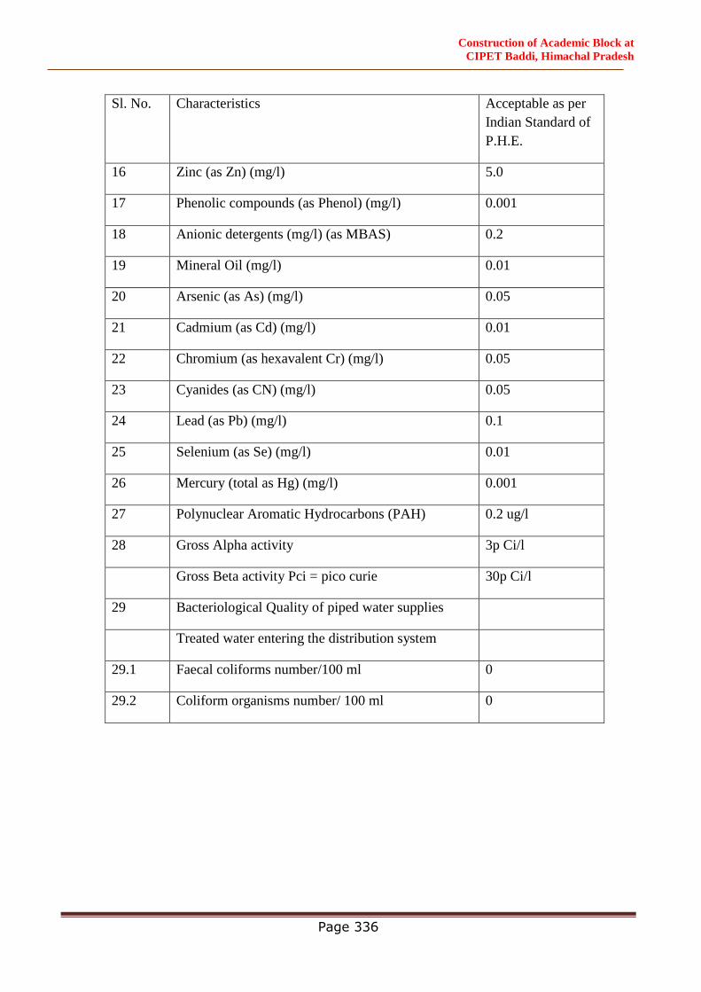
Construction of Academic Block at
CIPET Baddi, Himachal Pradesh
Page 336
Sl. No. Characteristics Acceptable as per
Indian Standard of
P.H.E.
16 Zinc (as Zn) (mg/l) 5.0
17 Phenolic compounds (as Phenol) (mg/l) 0.001
18 Anionic detergents (mg/l) (as MBAS) 0.2
19 Mineral Oil (mg/l) 0.01
20 Arsenic (as As) (mg/l) 0.05
21 Cadmium (as Cd) (mg/l) 0.01
22 Chromium (as hexavalent Cr) (mg/l) 0.05
23 Cyanides (as CN) (mg/l) 0.05
24 Lead (as Pb) (mg/l) 0.1
25 Selenium (as Se) (mg/l) 0.01
26 Mercury (total as Hg) (mg/l) 0.001
27 Polynuclear Aromatic Hydrocarbons (PAH) 0.2 ug/l
28 Gross Alpha activity 3p Ci/l
Gross Beta activity Pci = pico curie 30p Ci/l
29 Bacteriological Quality of piped water supplies
Treated water entering the distribution system
29.1 Faecal coliforms number/100 ml 0
29.2 Coliform organisms number/ 100 ml 0
Construction of Academic Block at
CIPET Baddi, Himachal Pradesh
Page 337
SPECIFICATIONS
(LANDSCAPE &HORTICULTURE WORKS)
HORTICULTURE WORKS
SPECIFICATION FOR HORTICULTURE WORKS
1. The work will be carried out as per CPWD Specifications with upto date correction slips.
2. All liabilities of the labour is the responsibility of the contractor

Construction of Academic Block at
CIPET Baddi, Himachal Pradesh
Page 338
3. Trees, shrubs, ground covers, hedges, creepers etc. will be planted / as per enclosed list and
there may be deviation in the quantity/ variety of plants as per site requirement and as per
direction of officer incharge.
4. Water tankers should be arranged in case of shortage of irrigation water.
5. At least one Tube-well upto 3 Acre area with pump house and irrigation system for lawn area
and planters etc. the maximum distance of the hydrant will be 15 metre.
6. The contractor shall arrange his own T&P required for development as well as maintenance.
7. Tree plants will be protected by the tree guards as directed and proper stacking of plants should
be done by using Bamboo stick/wooden stick.
8. Development of Garden feature will be done in the entire area ( excluding building, roads and
other paved areas.
9. The payment of all operations and material is inclusive in this contract.
10. The existing trees/plants should be preserved and felling of tress/transplantation of tress should
be done as per Forest Act/ Laws as per direction of officer in charge.
11. Cleaning jungle including uprooting rank vegetation, grass etc, removal and disposal of rubbish
with all leads and lifts.
12. Trenching of area up to depth of 60 cm including removal and disposal of rubbish with all leads
and lifts.
13. Earth work in excavation by mechanical means (hydraulic excavator) / manual means over
areas (exceeding 30cm in depth, 1.5m in width as well as 10sq. mt on plan) including disposal
of excavated earth with all leads and lifts.
14. Supplying and stacking of good earth at site including royalty and carriage upto all leads and
lifts and spreading it in required thickness and for preparation of mounds also on required
places.
15. Supplying and stacking of cattle dung manure at site including royalty and carriage upto all
leads and lifts and spreading it over the surface and mixing it.
16. Fine dressing the ground to levels specified and consolidating it by flooding /mechanical means.
17. Grassing with ‘doob’ (selection No. 1) grass including watering and maintenance of the lawn
for 60 days or more till the grass forms a thick lawn, free from weeds and fit for mowing
including supplying good earth if needed. Grass to be planted in rows 5cm apart in both
directions.
18. Grassing may also be done on selected places(required for inauguration) by providing and
laying selection no.1 grass turf with earth 50mm to 60mm thickness on existing ground
prepared with proper level and ramming with required tools wooden and then rolling the surface
with light roller make the surface smoothen and light watering the same,as per direction of
officer incharge
19. Preparation of beds for hedging, edeging, herbs, shrubs, seasonal flowers etc. by excavating
60cm deep and trenching the excavated base to a further depth of 30cm, refilling the excavated
earth after breaking clods and mixing with manure in the ratio of 2:1 (2 part of stacked volume
of earth after reduction by 20%: 1 part of stacked volume of manure after reduction by 8%)
flooding with water, filling with earth – if necessary, watering and finally dressing, leveling
etc. Including stacking and disposal of materials declared unserviceable and surplus earth by
spreading and leveling as directed with all leads and lifts.
Construction of Academic Block at
CIPET Baddi, Himachal Pradesh
Page 339
20. Digging holes in ordinary soil and refilling the same with the excavated earth mixed with
manure or sludge in the ratio 2:1 by volume (2 part of stacked volume of earth after reduction
by 20%: 1 part of stacked volume of cattle dung manure after reduction by 8%) flooding
withwater, dressing including removal of rubbish and surplus earth, if any with all leads and
lifts (cost of manure/extra good earth, if needed is to be provided without any extra cost).
(i) Pits 1.2m dia. and 1.2m deep. (For Trees)
(ii) Pits 60cm dia. and 60cm deep. (For Shrubs)
21. Providing and planting best quality of wellgrown healthy plants in pots / bags of required
height and speciesas specified in the enclosed list. All plants to be got approved by the Officer
In-Charge before planting.
22. Supplying and applying chemical emulsion of approved quality in sealed containers for termites
50ml. per sqm. Including delivery as specified.
23. Providing and fixing M.S. flat iron tree guard/ SFRC tree guard 60 cm dia and 2m high, above
ground consisting 4 Nos. 25x6 mm, 2.25m long and 8 Nos. 25x3 mm, 2m long verticals M.S.
flats, reveted to 3Nos., 25x6 mm M.S. flat iron rings in two halfs, fixing together at site with
required 6 Nos. of 8mm dia 30mm long bolts, including painting two coats with synthetic
enamel paint of approved brand and manufacture over a coat of primer, one name plate of 1
mm thick M.S. sheet of size 250x100 mm shall be welded to the tree guard near the middle
height and lettered any approved name. The tree guard shall be suitably fixed to the ground by
embedding 4 legs of tree guards in pits of suitable dia and to a depth of 25 cm, refilling the pits
with soil and ramming, complete in all respect as per satisfaction and direction of Officer In-
Charge.
GENERAL SCOPE:
1. All plant material shall be healthy, sound, vigorous, free from plant diseases, insects /pests or
their eggs and shall have healthy, well developed root systems. All plants shall be hard under
climatic conditions, similar to those in the locality of the project. Plants supplied shall conform
to the names listed on both the plan and plant list. No plant material will be accepted if branches
are damaged or broken. All materials must be protected from the sun and weather until planted.
All nursery stock shall be inspected and approved by the Engineer-in-charge.
All plants shall conform to the requirements specified in the plant list, except that plants larger
than specified may be used, if approved but use of such plants shall not increase the contract
price.
Plants to be delivered with legible identification labels.
2. Topsoil(Good earth PH range from 6.5 to 7.5):It shall be free of subsoil, stones, earth clods,
sticks, roots or other objectionable extraneous matter of debris. It shall contain no toxic
material. No topsoil shall be delivered in a muddy condition. The PH value of the soil in
between 6.5 to 7.5).\
3. Manure: Dry farm yard manure shall be used.It shall be free from extraneous matter, harmful
bacteria, insects or chemicals.
4. Planting: Care shall be taken that the plant sapling when planted is not buried deeper than in
the nursery, or in the pot/polythene bag. Planting should not be carried out in water logged
soil.
Construction of Academic Block at
CIPET Baddi, Himachal Pradesh
Page 340
Plants / trees at the original soil depth, the soil marks on the stem is an indication of this, and
it should be maintained on the finished level allowing for setting on the soil after planting. All
plastic and other imperishable containers should be removed before planting. Any broken or
damaged roots should be cut back to sound growth.
5. Providing and installing Green waste management machines/composting machines of the
required capacity and its operation.
6. Penalty:
If, at any time during the tenure of the contract, it is found that any material like manure, sweet
earth etc. has not been brought / less quantities utilized in the work – than specified, the cost
of the difference of materials less brought / utilized will be deducted as under :
(i) The cost of the material will be worked out at current market rate as assessed by the
Engineer-in-charge adding 30% (thirty percent) extra of above cost as departmental
overhead charges.
(ii) Once this cost deduction is made as above from the bill, in no case the same will be
refunded.
7. Contractor’s Co-ordination:
If during the progress of the contractor’s work, other works of the department or of the other
contractors are also in progress within the same site, the contractor is to use his best efforts to
work in harmony with all the others and in the best overall interest of the Project / Work.
8. The maintenance of all garden features will start only after successful completion of
development work.
9. Floral decoration and arrangement of floral Bouque as per direction of officer In-charge should
be done by the contractor during inaugraul function of the Building.
10. At least 500 seasonal flowering plants in bloom should be transplanted in the flower beds in
the garden during inaugaration of the building.
11. Folioge plants of different variety in pots (500 nos) and seasonal flowering plants in bloom in
pots (500 nos) should be displayed as per direction of officer In-charge during inauguration of
Building.
12. Complete maintenance of the entire garden features in the garden area i.e. lawn, trees, shurbs,
hedges, flower beds, foliage, creepers etc. including hoeing, weeding, pruming, replacement of
plants, gap filling, watering, mowing of lawn, grass cutting by lawn mover, & brush cutter,
hedge cutting, maintenance of plants in pots, removal of garden waste, applying insecticide,
pesticide & fertilizers (whenever required) top dressing of lawn with good earth & manure &
maintainance of other garden related works as directed by officer In-charge (cost of good earth,
manure, fertilizer, insecticide, pesticides, lawn mover, brush cutter with fuel & other T&P
material / articles shall be paid by the contractor.
13. Grass Joining Pavers-The use of grass jointing pavers will be used in the parking areas and the
less used roads in order to increase surface area of softscape.The roads and parking area near
the residential complex areas also will be covered with grass jointing pavers.
14. The details of grass jointing pavers are as follows-
a. The earth will be excavated as per requirement
b. The earth will be rammed till it is fairely compact.
c. Laying of WBM.

Construction of Academic Block at
CIPET Baddi, Himachal Pradesh
Page 341
d. Laying of Sand
e. Providing and fixing M30 Grass Pavers.
f. Laying mixture of sand & soil in voids of paver blocks.
g.Grassing the paver blocks.
SPECIFICATIONS FOR MAINTENANCE OF HORTICULTURE WORK
1. Maintenance for work of lawn doob grass (Cynodon dectylon)
1.1 Maintenance of Lawn/grass should be done on regular interval or as per direction of officer
In-Charge by using good quality lawn mover/brush cutter. The thickness of the grass shall not
be allowed to increase beyond 60mm. The minimum thickness of grass shall be maintained
as 30mm. The thickness shall be measured from top of the soil surface. The grass shall also
be kept free from all kind of weeds/wild grass etc.
1.2 Manuring of the grass lawns shall also be done regularly so as to keep the grass green. The
manuring of the lawn shall be done in the months of September/October/February/March or
as directed by the Engineer-in-charge.Fertilizers should also be used in winter season on
regular intervals or as per direction of officer In-Charge.
1.3 The existing grass shall be scrapped, if required or as directed by the Engineer-in-charge. The
scrapped materials shall be disposed off at convenient point to be decided by the Engineer-in-
charge. Thereafter, the area will be suitably flooded with water and left for a fortnight for new
grass to come up.
1.4 The lawn should be kept lush green, free from insects and pest and other diseases
Insecticide/fungicide etc may be used as and when required.
1.5 Lawn should also be kept weed free and regular weeding should be done.
1.6 Top dressing of lawn with good earth and manure by mixing in equal quantity should be done in
September/October or as and when required as per direction of officer Incharge.
2. Maintenance plants and trees :
2.1 The area around the tree plants upto a minimum of two feet around, from trunk of the tree
plants shall be kept free from grass and all kinds of weeds. Hoeing of this area around the
trees shall be done regularly. The plants shall also be watered regularly as required and as
directed by the Engineer-in-charge. Hoeing shall also be done after every watering as per
direction of Engineer-in-charge. For proper upkeep of the trees, unwanted branches of the
trees/ tree plants shall be removed at regular intervals as required and as directed by the
Engineer-in-charge. The tree plants / trees shall also be kept free of any diseases, insects or
pest by regularly spraying insecticides as required and as directed by the Engineer-in-charge.
2.2 The complete areas where the tree plants / trees are planted in open field shall be kept free
from grass and all kind of weeds throughout the year.
3. Maintenance of hedges :
3.1 The area around hedges plants shall be kept free from all kinds of grass and weeds. Hoeing of the
area around the hedge plants shall be done regularly as required and as directed by the Engineer-

Construction of Academic Block at
CIPET Baddi, Himachal Pradesh
Page 342
in-charge. The hedge plants shall be watered regularly as required and as directed by the Engineer-
in-charge.
3.2 Pruning and trimming are the most important items for proper shaping of hedges, therefore, special
care and attention shall be paid to prune and cut the hedge as required and as directed by the
Engineer-in-charge.
4. For work of flower beds :
The contractor will maintain seasonal flower beds and rose beds including preparation of bed,
supply of seeds and seeding chemicals, organic manure, watering, inter-culturing etc. as per
direction of the Engineer-in-charge so that maximum healthy flowers / plants are available
throughout the year for flowerbeds as per the requirement. In case any casualty of flower due
to negligence or poor maintenance by the contractor occurs - the same shall be replaced by a
healthy and acceptable plant, as per the direction of Engineer-in-charge.
5. Watering of all garden features :
Water requirements of plants and lawns varies from season to season and also varies on species
of plants. It should be kept in mind and regular ground assessment should be done before
watering. There should be no stagnation of water in plnts, lawns and in pots. The water tankers
should be arranged in case of shortage of irrigation water.
6. Tools, Equipment, Machinery etc:
Tools, equipment, machinery, watering pipes, water sprinklers, spray machines, lawn movers,
brush cutters, tree pruners, hedge shears, cycle rickshaw, tractor, trolley etc should always be
available at site in working condition as per site requirement. Tube wells, water lines, water
hydrants should always remain in working condition.
7. Green waste management machines/ composting machines:
The operation and maintenance of green waste management machines/composting machines
should be done on regular basis. The storage of compost manure and its application to the
garden should also be done as per direction of officer in charge.
8. Maintenance of plants in pots :
The plants displayed in pots should be maintained properly by regular watering, manuring,
pruning, shifting, plant protection, colouring. Broken pots should be replaced immediatel.
Seasonal flower plants in pots should also be prepared at site for display.
ADDITIONAL CONDITIONS/CLARIFICATION :
1. Labour Camp:
The labour camps have to be accommodated within the work site and no separate land will be
provided for this purpose.
LIST OF PLANTS
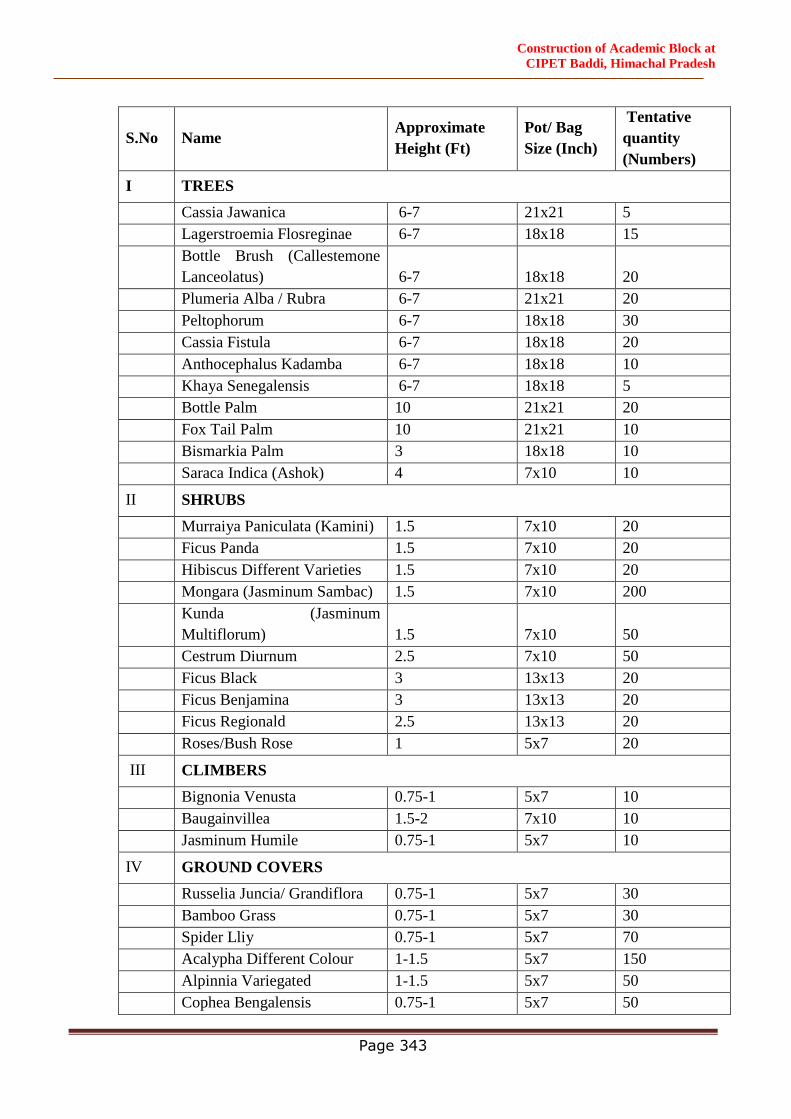
Construction of Academic Block at
CIPET Baddi, Himachal Pradesh
Page 343
S.No Name Approximate
Height (Ft)
Pot/ Bag
Size (Inch)
Tentative
quantity
(Numbers)
I TREES
Cassia Jawanica 6-7 21x21 5
Lagerstroemia Flosreginae 6-7 18x18 15
Bottle Brush (Callestemone
Lanceolatus) 6-7 18x18 20
Plumeria Alba / Rubra 6-7 21x21 20
Peltophorum 6-7 18x18 30
Cassia Fistula 6-7 18x18 20
Anthocephalus Kadamba 6-7 18x18 10
Khaya Senegalensis 6-7 18x18 5
Bottle Palm 10 21x21 20
Fox Tail Palm 10 21x21 10
Bismarkia Palm 3 18x18 10
Saraca Indica (Ashok) 4 7x10 10
II SHRUBS
Murraiya Paniculata (Kamini) 1.5 7x10 20
Ficus Panda 1.5 7x10 20
Hibiscus Different Varieties 1.5 7x10 20
Mongara (Jasminum Sambac) 1.5 7x10 200
Kunda (Jasminum
Multiflorum) 1.5 7x10 50
Cestrum Diurnum 2.5 7x10 50
Ficus Black 3 13x13 20
Ficus Benjamina 3 13x13 20
Ficus Regionald 2.5 13x13 20
Roses/Bush Rose 1 5x7 20
III CLIMBERS
Bignonia Venusta 0.75-1 5x7 10
Baugainvillea 1.5-2 7x10 10
Jasminum Humile 0.75-1 5x7 10
IV GROUND COVERS
Russelia Juncia/ Grandiflora 0.75-1 5x7 30
Bamboo Grass 0.75-1 5x7 30
Spider Lliy 0.75-1 5x7 70
Acalypha Different Colour 1-1.5 5x7 150
Alpinnia Variegated 1-1.5 5x7 50
Cophea Bengalensis 0.75-1 5x7 50
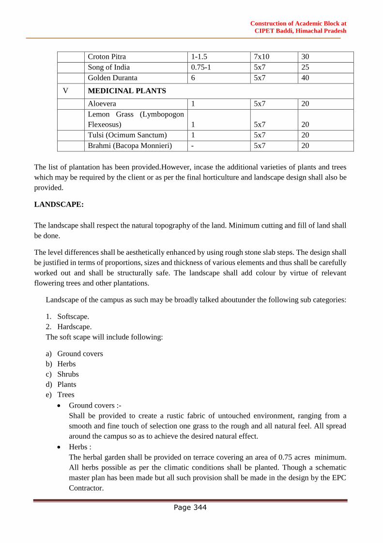
Construction of Academic Block at
CIPET Baddi, Himachal Pradesh
Page 344
Croton Pitra 1-1.5 7x10 30
Song of India 0.75-1 5x7 25
Golden Duranta 6 5x7 40
V MEDICINAL PLANTS
Aloevera 1 5x7 20
Lemon Grass (Lymbopogon
Flexeosus) 1 5x7 20
Tulsi (Ocimum Sanctum) 1 5x7 20
Brahmi (Bacopa Monnieri) - 5x7 20
The list of plantation has been provided.However, incase the additional varieties of plants and trees
which may be required by the client or as per the final horticulture and landscape design shall also be
provided.
LANDSCAPE:
The landscape shall respect the natural topography of the land. Minimum cutting and fill of land shall
be done.
The level differences shall be aesthetically enhanced by using rough stone slab steps. The design shall
be justified in terms of proportions, sizes and thickness of various elements and thus shall be carefully
worked out and shall be structurally safe. The landscape shall add colour by virtue of relevant
flowering trees and other plantations.
Landscape of the campus as such may be broadly talked aboutunder the following sub categories:
1. Softscape.
2. Hardscape.
The soft scape will include following:
a) Ground covers
b) Herbs
c) Shrubs
d) Plants
e) Trees
Ground covers :-
Shall be provided to create a rustic fabric of untouched environment, ranging from a
smooth and fine touch of selection one grass to the rough and all natural feel. All spread
around the campus so as to achieve the desired natural effect.
Herbs :
The herbal garden shall be provided on terrace covering an area of 0.75 acres minimum.
All herbs possible as per the climatic conditions shall be planted. Though a schematic
master plan has been made but all such provision shall be made in the design by the EPC
Contractor.
Construction of Academic Block at
CIPET Baddi, Himachal Pradesh
Page 345
Shrubs :
Shrubs shall primarily add colour to the landscape and shall be such that it affects the
human psychology in a manner of healing. Noticeable is in this case is a blend of colour
and texture with variety of shrubs planted along the pathways to create a mesmerizing
positive effect on ones mind.
Trees andPlants
Asfaraspossibleexistingtressandplantationshallberetainedandintegratedinthe
landscapedesign.Ahostofnativetreesshallprepreservedandcateredtowhile addressing
theamplegreenscape of thesite. Nativetreesencourage thesurvivalof a huge range of
vernacular flora & Fiona, it may also be kept in mindthatasmuch as possible
thelocalvariety of vegetationmaybe taken care of. Apart from the above ornamental
varieties of trees shall also be used for enhancing the aesthetic value of the design.
The landscape has to be a state of art design and executed with attention to the detail.
3. Hard scape.
a. Road network and Paving /flooring
As primary means of connection the pavings and floorings shall be in accordance of
Building bye laws, it should be given prime focus that the materials are easy to walk on,
and do not cause any disorder. Road network shall be designed as per the norms, building
byelaws and other relevant bodies and codes. The materials used and the slopes provided
should be in accordance to disabled friendly norms. The foot paths shall have interlocking
paver blocks and kerb stones. The pathways and areas near entrances shall have
combination of cobble stones and cement concrete pavement. The different materials may
range from cobble stones, running stone pavements, to polished blocks to pavers, and
concrete pavers etc.
b. Landscape furniture
Use of single benches in wrought iron and natural stone cut benches shall be provided for making
the landscape habitable and as such provide the seating places for the users. Closed dust bins shall
be provided in adequate numbers near all the habitable spaces and at convenient intervals. The
dust bins shall aesthetically match with the overall landscape design and easy and convenient to
use.
Sitting areas shall also be provided under shaded trees at comfortable intervals. The hardscape
and soft scape shall be planned in such a manner to achieve maximum points for minimum
GRIHA three star certification. The EPC Contractor shall be responsible for providing the
minimum three star GRIHA certification. Necessary clearances from various departments such
as environment, local bodies etc shall be taken by theEPC Contractor.

Construction of Academic Block at
CIPET Baddi, Himachal Pradesh
Page 346
SITE PLAN FOR REFERENCE

Construction of Academic Block at
CIPET Baddi, Himachal Pradesh
Page 347
FINISHING SCHEDULE
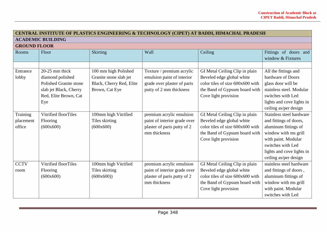
Construction of Academic Block at
CIPET Baddi, Himachal Pradesh
Page 348
CENTRAL INSTITUTE OF PLASTICS ENGINEERING & TECHNOLOGY (CIPET) AT BADDI, HIMACHAL PRADESH
ACADEMIC BUILDING
GROUND FLOOR
Rooms Floor Skirting Wall Ceiling Fittings of doors and
window & Fixtures
Entrance
lobby
20-25 mm thick
diamond polished
Polished Granite stone
slab jet Black, Cherry
Red, Elite Brown, Cat
Eye
100 mm high Polished
Granite stone slab jet
Black, Cherry Red, Elite
Brown, Cat Eye
Texture / premium acrylic
emulsion paint of interior
grade over plaster of paris
putty of 2 mm thickness
GI Metal Ceiling Clip in plain
Beveled edge global white
color tiles of size 600x600 with
the Band of Gypsum board with
Cove light provision
All the fittings and
hardware of Doors
glass door will be
stainless steel. Modular
switches with Led
lights and cove lights in
ceiling as/per design
Training
placement
office
Vitrified floorTiles
Flooring
(600x600)
100mm high Vitrified
Tiles skirting
(600x600)
premium acrylic emulsion
paint of interior grade over
plaster of paris putty of 2
mm thickness
GI Metal Ceiling Clip in plain
Beveled edge global white
color tiles of size 600x600 with
the Band of Gypsum board with
Cove light provision
Stainless steel hardware
and fittings of doors,
aluminum fittings of
window with ms grill
with paint. Modular
switches with Led
lights and cove lights in
ceiling as/per design
CCTV
room
Vitrified floorTiles
Flooring
(600x600)
100mm high Vitrified
Tiles skirting
(600x600))
premium acrylic emulsion
paint of interior grade over
plaster of paris putty of 2
mm thickness
GI Metal Ceiling Clip in plain
Beveled edge global white
color tiles of size 600x600 with
the Band of Gypsum board with
Cove light provision
stainless steel hardware
and fittings of doors ,
aluminum fittings of
window with ms grill
with paint. Modular
switches with Led
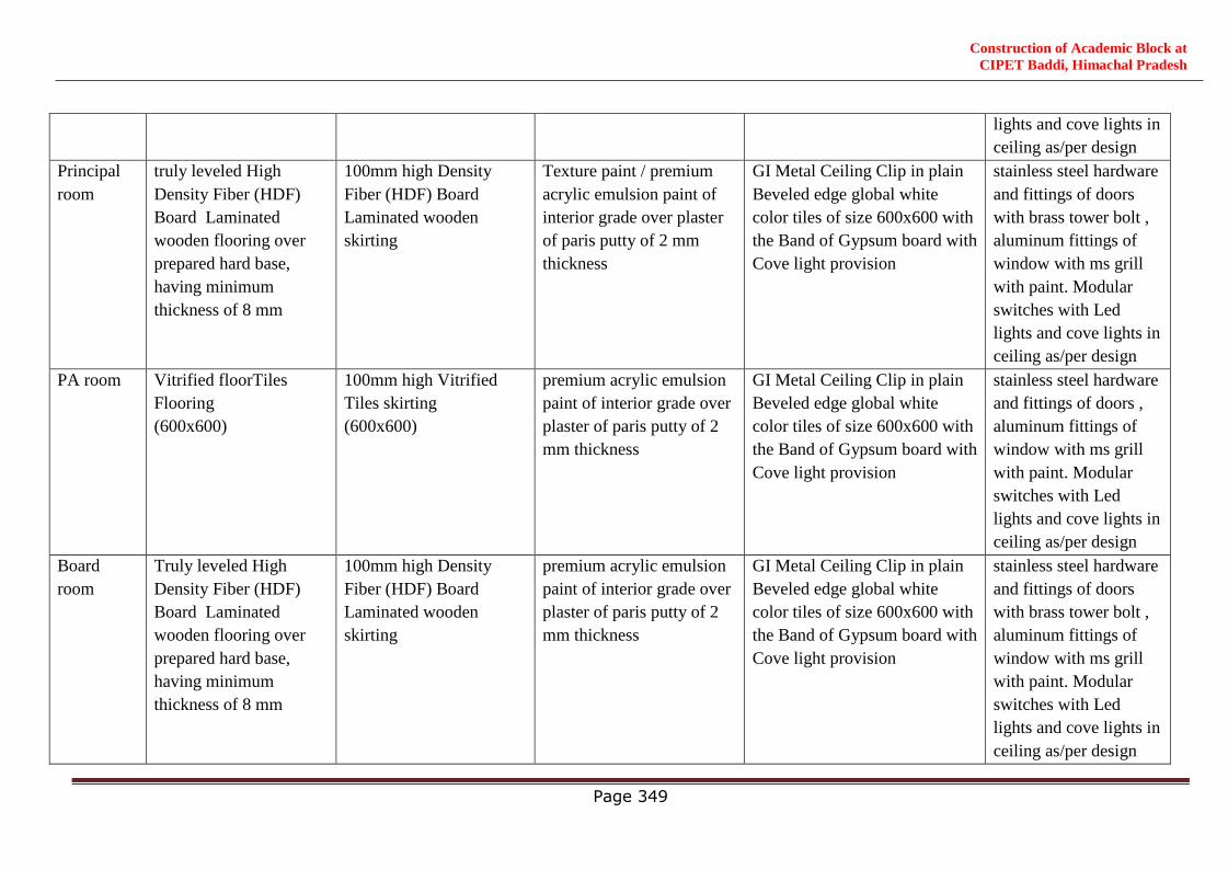
Construction of Academic Block at
CIPET Baddi, Himachal Pradesh
Page 349
lights and cove lights in
ceiling as/per design
Principal
room
truly leveled High
Density Fiber (HDF)
Board Laminated
wooden flooring over
prepared hard base,
having minimum
thickness of 8 mm
100mm high Density
Fiber (HDF) Board
Laminated wooden
skirting
Texture paint / premium
acrylic emulsion paint of
interior grade over plaster
of paris putty of 2 mm
thickness
GI Metal Ceiling Clip in plain
Beveled edge global white
color tiles of size 600x600 with
the Band of Gypsum board with
Cove light provision
stainless steel hardware
and fittings of doors
with brass tower bolt ,
aluminum fittings of
window with ms grill
with paint. Modular
switches with Led
lights and cove lights in
ceiling as/per design
PA room Vitrified floorTiles
Flooring
(600x600)
100mm high Vitrified
Tiles skirting
(600x600)
premium acrylic emulsion
paint of interior grade over
plaster of paris putty of 2
mm thickness
GI Metal Ceiling Clip in plain
Beveled edge global white
color tiles of size 600x600 with
the Band of Gypsum board with
Cove light provision
stainless steel hardware
and fittings of doors ,
aluminum fittings of
window with ms grill
with paint. Modular
switches with Led
lights and cove lights in
ceiling as/per design
Board
room
Truly leveled High
Density Fiber (HDF)
Board Laminated
wooden flooring over
prepared hard base,
having minimum
thickness of 8 mm
100mm high Density
Fiber (HDF) Board
Laminated wooden
skirting
premium acrylic emulsion
paint of interior grade over
plaster of paris putty of 2
mm thickness
GI Metal Ceiling Clip in plain
Beveled edge global white
color tiles of size 600x600 with
the Band of Gypsum board with
Cove light provision
stainless steel hardware
and fittings of doors
with brass tower bolt ,
aluminum fittings of
window with ms grill
with paint. Modular
switches with Led
lights and cove lights in
ceiling as/per design
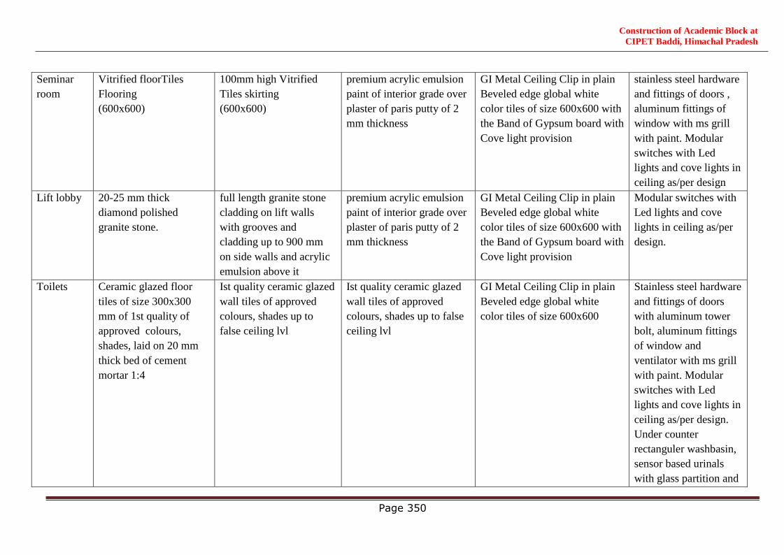
Construction of Academic Block at
CIPET Baddi, Himachal Pradesh
Page 350
Seminar
room
Vitrified floorTiles
Flooring
(600x600)
100mm high Vitrified
Tiles skirting
(600x600)
premium acrylic emulsion
paint of interior grade over
plaster of paris putty of 2
mm thickness
GI Metal Ceiling Clip in plain
Beveled edge global white
color tiles of size 600x600 with
the Band of Gypsum board with
Cove light provision
stainless steel hardware
and fittings of doors ,
aluminum fittings of
window with ms grill
with paint. Modular
switches with Led
lights and cove lights in
ceiling as/per design
Lift lobby 20-25 mm thick
diamond polished
granite stone.
full length granite stone
cladding on lift walls
with grooves and
cladding up to 900 mm
on side walls and acrylic
emulsion above it
premium acrylic emulsion
paint of interior grade over
plaster of paris putty of 2
mm thickness
GI Metal Ceiling Clip in plain
Beveled edge global white
color tiles of size 600x600 with
the Band of Gypsum board with
Cove light provision
Modular switches with
Led lights and cove
lights in ceiling as/per
design.
Toilets Ceramic glazed floor
tiles of size 300x300
mm of 1st quality of
approved colours,
shades, laid on 20 mm
thick bed of cement
mortar 1:4
Ist quality ceramic glazed
wall tiles of approved
colours, shades up to
false ceiling lvl
Ist quality ceramic glazed
wall tiles of approved
colours, shades up to false
ceiling lvl
GI Metal Ceiling Clip in plain
Beveled edge global white
color tiles of size 600x600
Stainless steel hardware
and fittings of doors
with aluminum tower
bolt, aluminum fittings
of window and
ventilator with ms grill
with paint. Modular
switches with Led
lights and cove lights in
ceiling as/per design.
Under counter
rectanguler washbasin,
sensor based urinals
with glass partition and
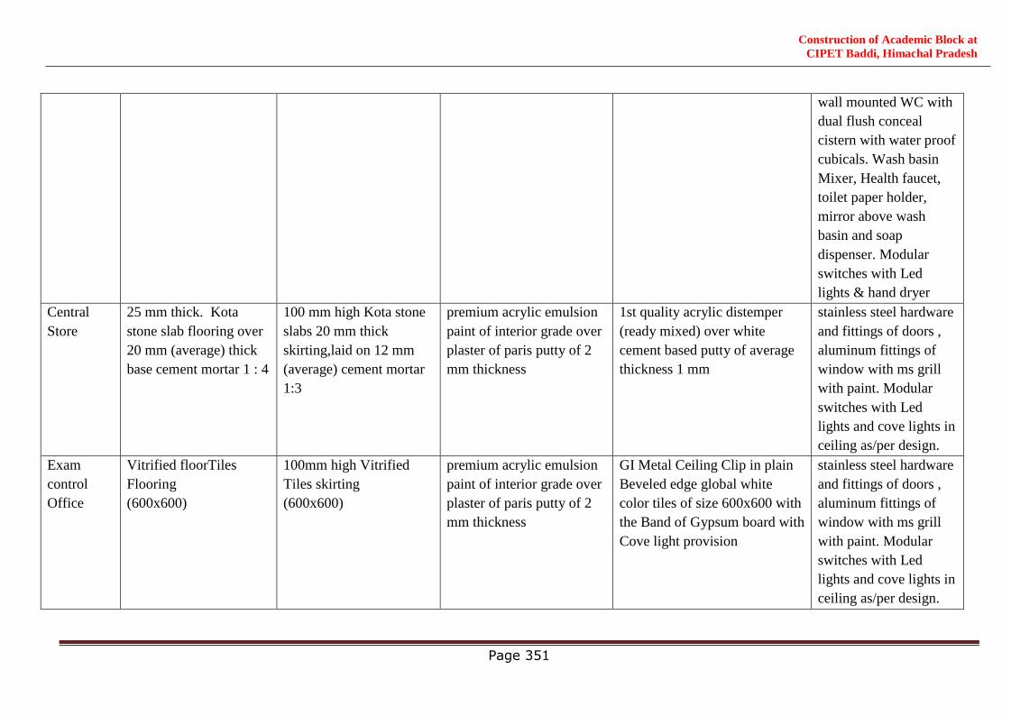
Construction of Academic Block at
CIPET Baddi, Himachal Pradesh
Page 351
wall mounted WC with
dual flush conceal
cistern with water proof
cubicals. Wash basin
Mixer, Health faucet,
toilet paper holder,
mirror above wash
basin and soap
dispenser. Modular
switches with Led
lights & hand dryer
Central
Store
25 mm thick. Kota
stone slab flooring over
20 mm (average) thick
base cement mortar 1 : 4
100 mm high Kota stone
slabs 20 mm thick
skirting,laid on 12 mm
(average) cement mortar
1:3
premium acrylic emulsion
paint of interior grade over
plaster of paris putty of 2
mm thickness
1st quality acrylic distemper
(ready mixed) over white
cement based putty of average
thickness 1 mm
stainless steel hardware
and fittings of doors ,
aluminum fittings of
window with ms grill
with paint. Modular
switches with Led
lights and cove lights in
ceiling as/per design.
Exam
control
Office
Vitrified floorTiles
Flooring
(600x600)
100mm high Vitrified
Tiles skirting
(600x600)
premium acrylic emulsion
paint of interior grade over
plaster of paris putty of 2
mm thickness
GI Metal Ceiling Clip in plain
Beveled edge global white
color tiles of size 600x600 with
the Band of Gypsum board with
Cove light provision
stainless steel hardware
and fittings of doors ,
aluminum fittings of
window with ms grill
with paint. Modular
switches with Led
lights and cove lights in
ceiling as/per design.
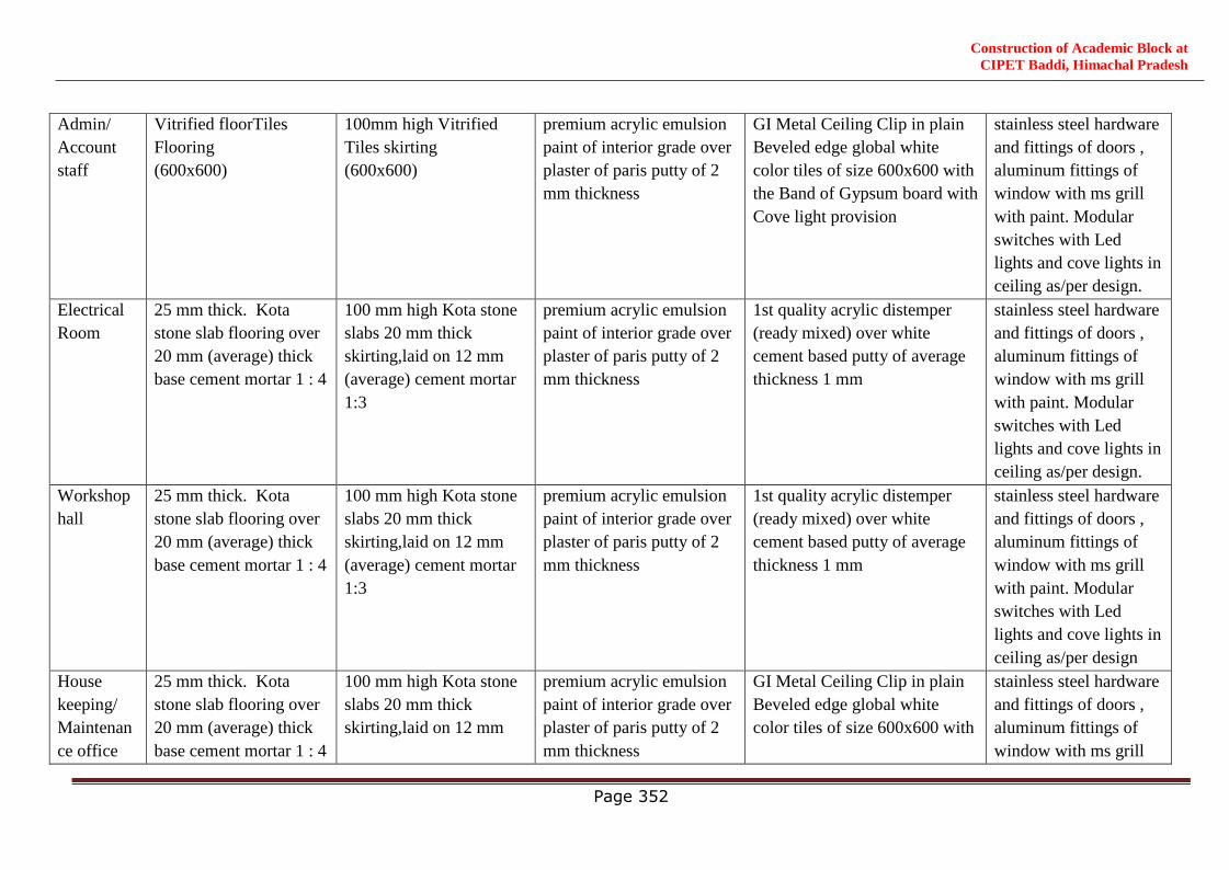
Construction of Academic Block at
CIPET Baddi, Himachal Pradesh
Page 352
Admin/
Account
staff
Vitrified floorTiles
Flooring
(600x600)
100mm high Vitrified
Tiles skirting
(600x600)
premium acrylic emulsion
paint of interior grade over
plaster of paris putty of 2
mm thickness
GI Metal Ceiling Clip in plain
Beveled edge global white
color tiles of size 600x600 with
the Band of Gypsum board with
Cove light provision
stainless steel hardware
and fittings of doors ,
aluminum fittings of
window with ms grill
with paint. Modular
switches with Led
lights and cove lights in
ceiling as/per design.
Electrical
Room
25 mm thick. Kota
stone slab flooring over
20 mm (average) thick
base cement mortar 1 : 4
100 mm high Kota stone
slabs 20 mm thick
skirting,laid on 12 mm
(average) cement mortar
1:3
premium acrylic emulsion
paint of interior grade over
plaster of paris putty of 2
mm thickness
1st quality acrylic distemper
(ready mixed) over white
cement based putty of average
thickness 1 mm
stainless steel hardware
and fittings of doors ,
aluminum fittings of
window with ms grill
with paint. Modular
switches with Led
lights and cove lights in
ceiling as/per design.
Workshop
hall
25 mm thick. Kota
stone slab flooring over
20 mm (average) thick
base cement mortar 1 : 4
100 mm high Kota stone
slabs 20 mm thick
skirting,laid on 12 mm
(average) cement mortar
1:3
premium acrylic emulsion
paint of interior grade over
plaster of paris putty of 2
mm thickness
1st quality acrylic distemper
(ready mixed) over white
cement based putty of average
thickness 1 mm
stainless steel hardware
and fittings of doors ,
aluminum fittings of
window with ms grill
with paint. Modular
switches with Led
lights and cove lights in
ceiling as/per design
House
keeping/
Maintenan
ce office
25 mm thick. Kota
stone slab flooring over
20 mm (average) thick
base cement mortar 1 : 4
100 mm high Kota stone
slabs 20 mm thick
skirting,laid on 12 mm
premium acrylic emulsion
paint of interior grade over
plaster of paris putty of 2
mm thickness
GI Metal Ceiling Clip in plain
Beveled edge global white
color tiles of size 600x600 with
stainless steel hardware
and fittings of doors ,
aluminum fittings of
window with ms grill
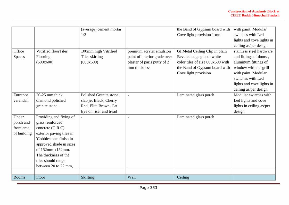
Construction of Academic Block at
CIPET Baddi, Himachal Pradesh
Page 353
(average) cement mortar
1:3
the Band of Gypsum board with
Cove light provision 1 mm
with paint. Modular
switches with Led
lights and cove lights in
ceiling as/per design
Office
Spaces
Vitrified floorTiles
Flooring
(600x600)
100mm high Vitrified
Tiles skirting
(600x600)
premium acrylic emulsion
paint of interior grade over
plaster of paris putty of 2
mm thickness
GI Metal Ceiling Clip in plain
Beveled edge global white
color tiles of size 600x600 with
the Band of Gypsum board with
Cove light provision
stainless steel hardware
and fittings of doors ,
aluminum fittings of
window with ms grill
with paint. Modular
switches with Led
lights and cove lights in
ceiling as/per design
Entrance
verandah
20-25 mm thick
diamond polished
granite stone.
Polished Granite stone
slab jet Black, Cherry
Red, Elite Brown, Cat
Eye on riser and tread
- Laminated glass porch Modular switches with
Led lights and cove
lights in ceiling as/per
design
Under
porch and
front area
of building
Providing and fixing of
glass reinforced
concrete (G.R.C)
exterior paving tiles in
'Cobblestone' finish in
approved shade in sizes
of 152mm x152mm.
The thickness of the
tiles should range
between 20 to 22 mm,
- - Laminated glass porch
Rooms Floor Skirting Wall Ceiling
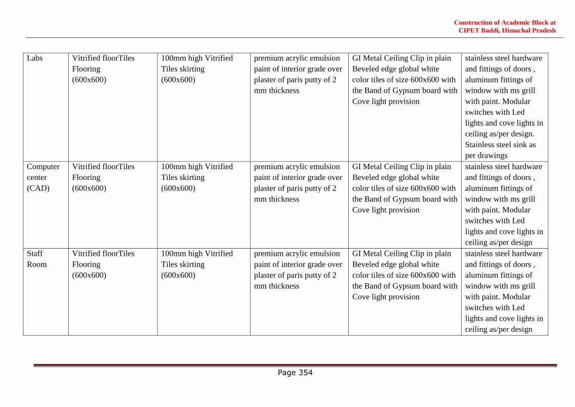
Construction of Academic Block at
CIPET Baddi, Himachal Pradesh
Page 354
Labs Vitrified floorTiles
Flooring
(600x600)
100mm high Vitrified
Tiles skirting
(600x600)
premium acrylic emulsion
paint of interior grade over
plaster of paris putty of 2
mm thickness
GI Metal Ceiling Clip in plain
Beveled edge global white
color tiles of size 600x600 with
the Band of Gypsum board with
Cove light provision
stainless steel hardware
and fittings of doors ,
aluminum fittings of
window with ms grill
with paint. Modular
switches with Led
lights and cove lights in
ceiling as/per design.
Stainless steel sink as
per drawings
Computer
center
(CAD)
Vitrified floorTiles
Flooring
(600x600)
100mm high Vitrified
Tiles skirting
(600x600)
premium acrylic emulsion
paint of interior grade over
plaster of paris putty of 2
mm thickness
GI Metal Ceiling Clip in plain
Beveled edge global white
color tiles of size 600x600 with
the Band of Gypsum board with
Cove light provision
stainless steel hardware
and fittings of doors ,
aluminum fittings of
window with ms grill
with paint. Modular
switches with Led
lights and cove lights in
ceiling as/per design
Staff
Room
Vitrified floorTiles
Flooring
(600x600)
100mm high Vitrified
Tiles skirting
(600x600)
premium acrylic emulsion
paint of interior grade over
plaster of paris putty of 2
mm thickness
GI Metal Ceiling Clip in plain
Beveled edge global white
color tiles of size 600x600 with
the Band of Gypsum board with
Cove light provision
stainless steel hardware
and fittings of doors ,
aluminum fittings of
window with ms grill
with paint. Modular
switches with Led
lights and cove lights in
ceiling as/per design
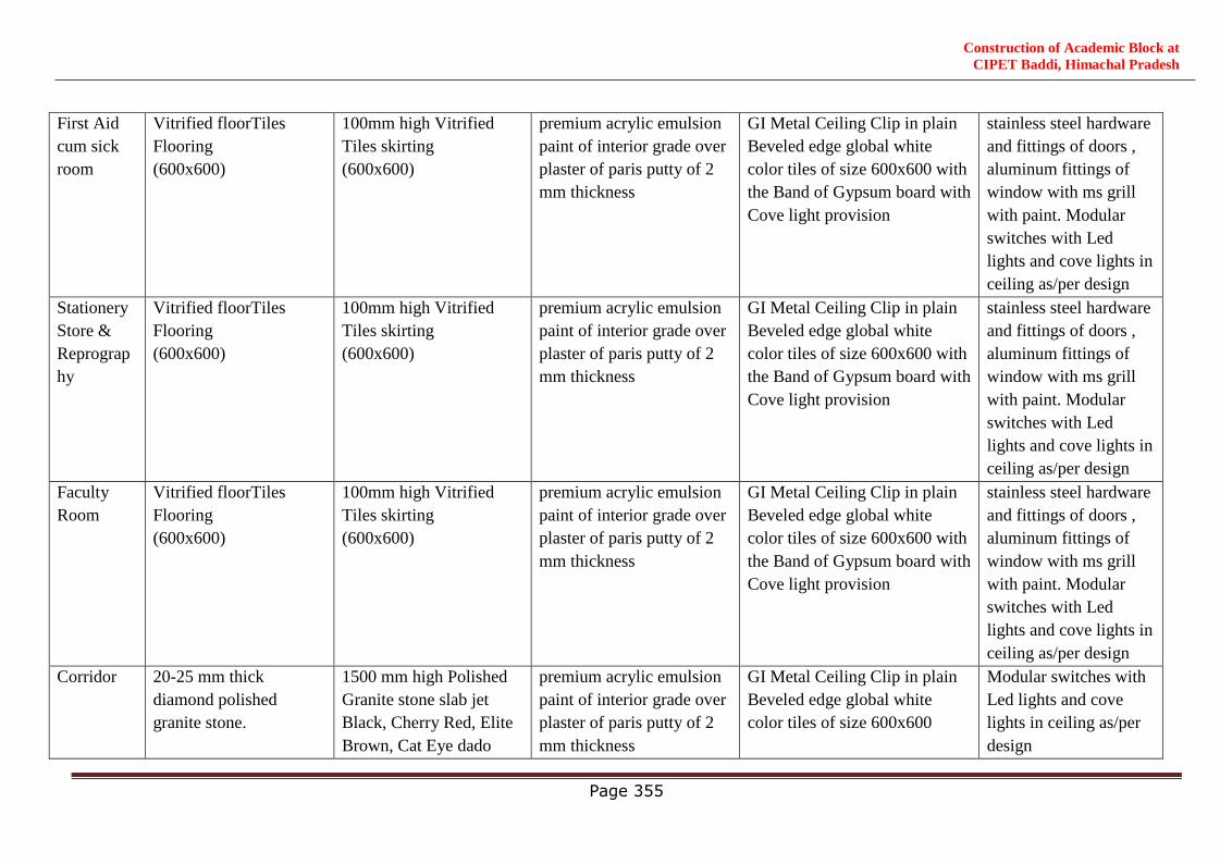
Construction of Academic Block at
CIPET Baddi, Himachal Pradesh
Page 355
First Aid
cum sick
room
Vitrified floorTiles
Flooring
(600x600)
100mm high Vitrified
Tiles skirting
(600x600)
premium acrylic emulsion
paint of interior grade over
plaster of paris putty of 2
mm thickness
GI Metal Ceiling Clip in plain
Beveled edge global white
color tiles of size 600x600 with
the Band of Gypsum board with
Cove light provision
stainless steel hardware
and fittings of doors ,
aluminum fittings of
window with ms grill
with paint. Modular
switches with Led
lights and cove lights in
ceiling as/per design
Stationery
Store &
Reprograp
hy
Vitrified floorTiles
Flooring
(600x600)
100mm high Vitrified
Tiles skirting
(600x600)
premium acrylic emulsion
paint of interior grade over
plaster of paris putty of 2
mm thickness
GI Metal Ceiling Clip in plain
Beveled edge global white
color tiles of size 600x600 with
the Band of Gypsum board with
Cove light provision
stainless steel hardware
and fittings of doors ,
aluminum fittings of
window with ms grill
with paint. Modular
switches with Led
lights and cove lights in
ceiling as/per design
Faculty
Room
Vitrified floorTiles
Flooring
(600x600)
100mm high Vitrified
Tiles skirting
(600x600)
premium acrylic emulsion
paint of interior grade over
plaster of paris putty of 2
mm thickness
GI Metal Ceiling Clip in plain
Beveled edge global white
color tiles of size 600x600 with
the Band of Gypsum board with
Cove light provision
stainless steel hardware
and fittings of doors ,
aluminum fittings of
window with ms grill
with paint. Modular
switches with Led
lights and cove lights in
ceiling as/per design
Corridor 20-25 mm thick
diamond polished
granite stone.
1500 mm high Polished
Granite stone slab jet
Black, Cherry Red, Elite
Brown, Cat Eye dado
premium acrylic emulsion
paint of interior grade over
plaster of paris putty of 2
mm thickness
GI Metal Ceiling Clip in plain
Beveled edge global white
color tiles of size 600x600
Modular switches with
Led lights and cove
lights in ceiling as/per
design
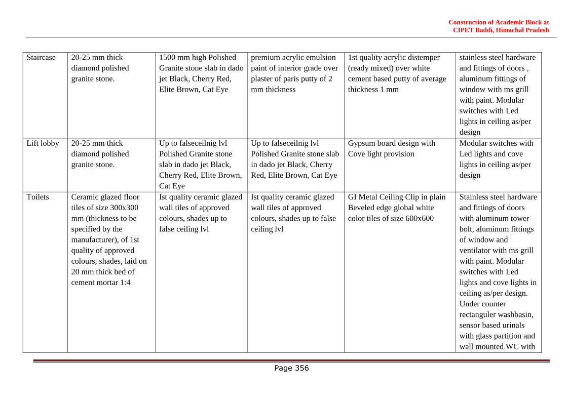
Construction of Academic Block at
CIPET Baddi, Himachal Pradesh
Page 356
Staircase 20-25 mm thick
diamond polished
granite stone.
1500 mm high Polished
Granite stone slab in dado
jet Black, Cherry Red,
Elite Brown, Cat Eye
premium acrylic emulsion
paint of interior grade over
plaster of paris putty of 2
mm thickness
1st quality acrylic distemper
(ready mixed) over white
cement based putty of average
thickness 1 mm
stainless steel hardware
and fittings of doors ,
aluminum fittings of
window with ms grill
with paint. Modular
switches with Led
lights in ceiling as/per
design
Lift lobby 20-25 mm thick
diamond polished
granite stone.
Up to falseceilnig lvl
Polished Granite stone
slab in dado jet Black,
Cherry Red, Elite Brown,
Cat Eye
Up to falseceilnig lvl
Polished Granite stone slab
in dado jet Black, Cherry
Red, Elite Brown, Cat Eye
Gypsum board design with
Cove light provision
Modular switches with
Led lights and cove
lights in ceiling as/per
design
Toilets Ceramic glazed floor
tiles of size 300x300
mm (thickness to be
specified by the
manufacturer), of 1st
quality of approved
colours, shades, laid on
20 mm thick bed of
cement mortar 1:4
Ist quality ceramic glazed
wall tiles of approved
colours, shades up to
false ceiling lvl
Ist quality ceramic glazed
wall tiles of approved
colours, shades up to false
ceiling lvl
GI Metal Ceiling Clip in plain
Beveled edge global white
color tiles of size 600x600
Stainless steel hardware
and fittings of doors
with aluminum tower
bolt, aluminum fittings
of window and
ventilator with ms grill
with paint. Modular
switches with Led
lights and cove lights in
ceiling as/per design.
Under counter
rectanguler washbasin,
sensor based urinals
with glass partition and
wall mounted WC with
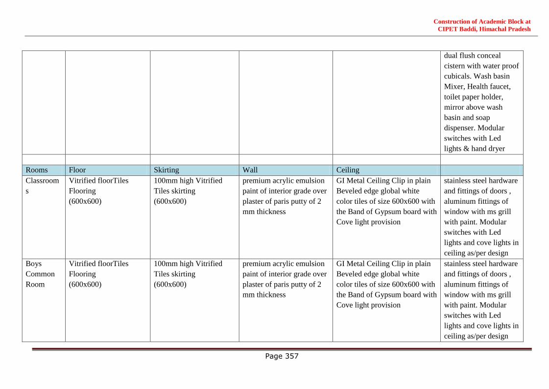
Construction of Academic Block at
CIPET Baddi, Himachal Pradesh
Page 357
dual flush conceal
cistern with water proof
cubicals. Wash basin
Mixer, Health faucet,
toilet paper holder,
mirror above wash
basin and soap
dispenser. Modular
switches with Led
lights & hand dryer
Rooms Floor Skirting Wall Ceiling
Classroom
s
Vitrified floorTiles
Flooring
(600x600)
100mm high Vitrified
Tiles skirting
(600x600)
premium acrylic emulsion
paint of interior grade over
plaster of paris putty of 2
mm thickness
GI Metal Ceiling Clip in plain
Beveled edge global white
color tiles of size 600x600 with
the Band of Gypsum board with
Cove light provision
stainless steel hardware
and fittings of doors ,
aluminum fittings of
window with ms grill
with paint. Modular
switches with Led
lights and cove lights in
ceiling as/per design
Boys
Common
Room
Vitrified floorTiles
Flooring
(600x600)
100mm high Vitrified
Tiles skirting
(600x600)
premium acrylic emulsion
paint of interior grade over
plaster of paris putty of 2
mm thickness
GI Metal Ceiling Clip in plain
Beveled edge global white
color tiles of size 600x600 with
the Band of Gypsum board with
Cove light provision
stainless steel hardware
and fittings of doors ,
aluminum fittings of
window with ms grill
with paint. Modular
switches with Led
lights and cove lights in
ceiling as/per design
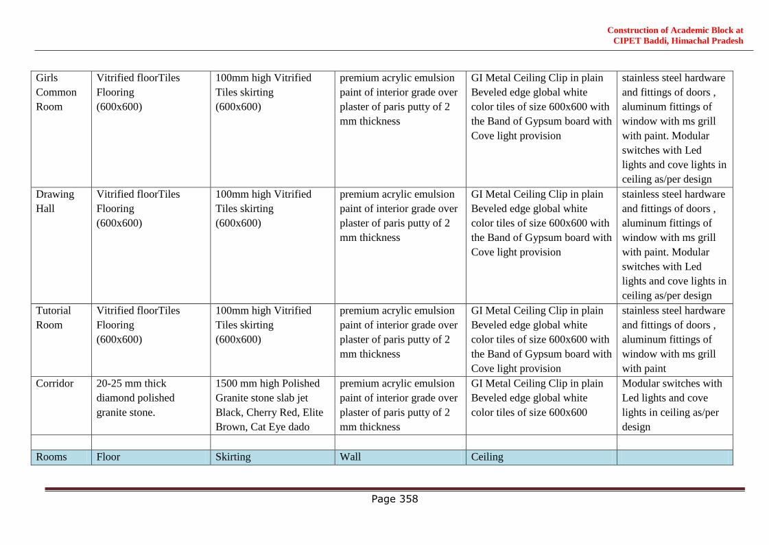
Construction of Academic Block at
CIPET Baddi, Himachal Pradesh
Page 358
Girls
Common
Room
Vitrified floorTiles
Flooring
(600x600)
100mm high Vitrified
Tiles skirting
(600x600)
premium acrylic emulsion
paint of interior grade over
plaster of paris putty of 2
mm thickness
GI Metal Ceiling Clip in plain
Beveled edge global white
color tiles of size 600x600 with
the Band of Gypsum board with
Cove light provision
stainless steel hardware
and fittings of doors ,
aluminum fittings of
window with ms grill
with paint. Modular
switches with Led
lights and cove lights in
ceiling as/per design
Drawing
Hall
Vitrified floorTiles
Flooring
(600x600)
100mm high Vitrified
Tiles skirting
(600x600)
premium acrylic emulsion
paint of interior grade over
plaster of paris putty of 2
mm thickness
GI Metal Ceiling Clip in plain
Beveled edge global white
color tiles of size 600x600 with
the Band of Gypsum board with
Cove light provision
stainless steel hardware
and fittings of doors ,
aluminum fittings of
window with ms grill
with paint. Modular
switches with Led
lights and cove lights in
ceiling as/per design
Tutorial
Room
Vitrified floorTiles
Flooring
(600x600)
100mm high Vitrified
Tiles skirting
(600x600)
premium acrylic emulsion
paint of interior grade over
plaster of paris putty of 2
mm thickness
GI Metal Ceiling Clip in plain
Beveled edge global white
color tiles of size 600x600 with
the Band of Gypsum board with
Cove light provision
stainless steel hardware
and fittings of doors ,
aluminum fittings of
window with ms grill
with paint
Corridor 20-25 mm thick
diamond polished
granite stone.
1500 mm high Polished
Granite stone slab jet
Black, Cherry Red, Elite
Brown, Cat Eye dado
premium acrylic emulsion
paint of interior grade over
plaster of paris putty of 2
mm thickness
GI Metal Ceiling Clip in plain
Beveled edge global white
color tiles of size 600x600
Modular switches with
Led lights and cove
lights in ceiling as/per
design
Rooms Floor Skirting Wall Ceiling
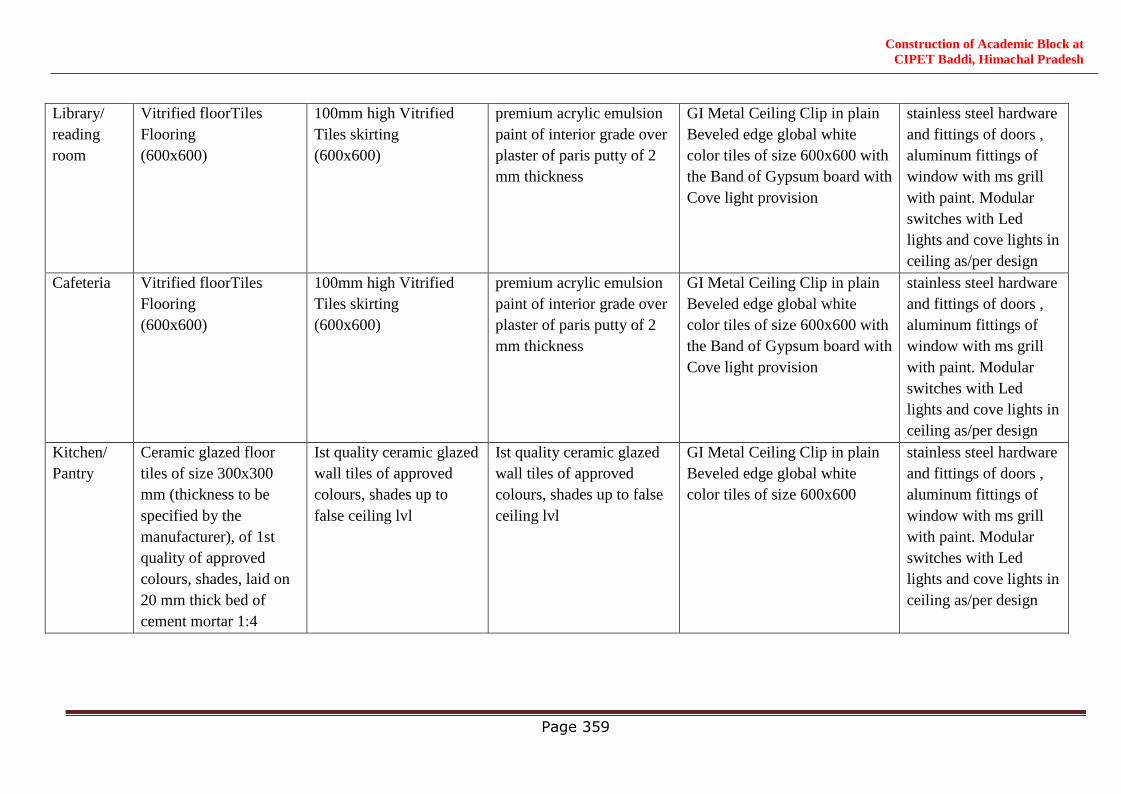
Construction of Academic Block at
CIPET Baddi, Himachal Pradesh
Page 359
Library/
reading
room
Vitrified floorTiles
Flooring
(600x600)
100mm high Vitrified
Tiles skirting
(600x600)
premium acrylic emulsion
paint of interior grade over
plaster of paris putty of 2
mm thickness
GI Metal Ceiling Clip in plain
Beveled edge global white
color tiles of size 600x600 with
the Band of Gypsum board with
Cove light provision
stainless steel hardware
and fittings of doors ,
aluminum fittings of
window with ms grill
with paint. Modular
switches with Led
lights and cove lights in
ceiling as/per design
Cafeteria Vitrified floorTiles
Flooring
(600x600)
100mm high Vitrified
Tiles skirting
(600x600)
premium acrylic emulsion
paint of interior grade over
plaster of paris putty of 2
mm thickness
GI Metal Ceiling Clip in plain
Beveled edge global white
color tiles of size 600x600 with
the Band of Gypsum board with
Cove light provision
stainless steel hardware
and fittings of doors ,
aluminum fittings of
window with ms grill
with paint. Modular
switches with Led
lights and cove lights in
ceiling as/per design
Kitchen/
Pantry
Ceramic glazed floor
tiles of size 300x300
mm (thickness to be
specified by the
manufacturer), of 1st
quality of approved
colours, shades, laid on
20 mm thick bed of
cement mortar 1:4
Ist quality ceramic glazed
wall tiles of approved
colours, shades up to
false ceiling lvl
Ist quality ceramic glazed
wall tiles of approved
colours, shades up to false
ceiling lvl
GI Metal Ceiling Clip in plain
Beveled edge global white
color tiles of size 600x600
stainless steel hardware
and fittings of doors ,
aluminum fittings of
window with ms grill
with paint. Modular
switches with Led
lights and cove lights in
ceiling as/per design
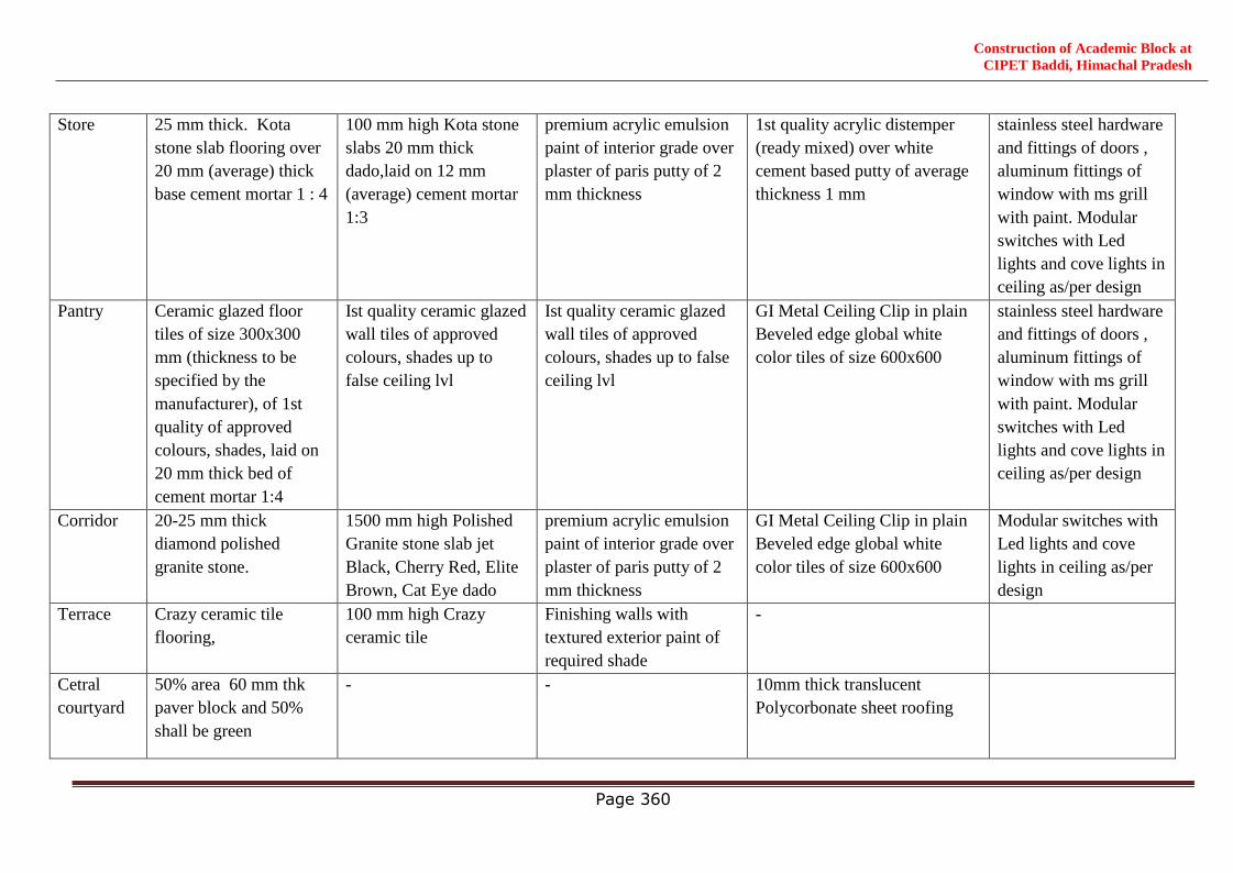
Construction of Academic Block at
CIPET Baddi, Himachal Pradesh
Page 360
Store 25 mm thick. Kota
stone slab flooring over
20 mm (average) thick
base cement mortar 1 : 4
100 mm high Kota stone
slabs 20 mm thick
dado,laid on 12 mm
(average) cement mortar
1:3
premium acrylic emulsion
paint of interior grade over
plaster of paris putty of 2
mm thickness
1st quality acrylic distemper
(ready mixed) over white
cement based putty of average
thickness 1 mm
stainless steel hardware
and fittings of doors ,
aluminum fittings of
window with ms grill
with paint. Modular
switches with Led
lights and cove lights in
ceiling as/per design
Pantry Ceramic glazed floor
tiles of size 300x300
mm (thickness to be
specified by the
manufacturer), of 1st
quality of approved
colours, shades, laid on
20 mm thick bed of
cement mortar 1:4
Ist quality ceramic glazed
wall tiles of approved
colours, shades up to
false ceiling lvl
Ist quality ceramic glazed
wall tiles of approved
colours, shades up to false
ceiling lvl
GI Metal Ceiling Clip in plain
Beveled edge global white
color tiles of size 600x600
stainless steel hardware
and fittings of doors ,
aluminum fittings of
window with ms grill
with paint. Modular
switches with Led
lights and cove lights in
ceiling as/per design
Corridor 20-25 mm thick
diamond polished
granite stone.
1500 mm high Polished
Granite stone slab jet
Black, Cherry Red, Elite
Brown, Cat Eye dado
premium acrylic emulsion
paint of interior grade over
plaster of paris putty of 2
mm thickness
GI Metal Ceiling Clip in plain
Beveled edge global white
color tiles of size 600x600
Modular switches with
Led lights and cove
lights in ceiling as/per
design
Terrace Crazy ceramic tile
flooring,
100 mm high Crazy
ceramic tile
Finishing walls with
textured exterior paint of
required shade
-
Cetral
courtyard
50% area 60 mm thk
paver block and 50%
shall be green
- - 10mm thick translucent
Polycorbonate sheet roofing
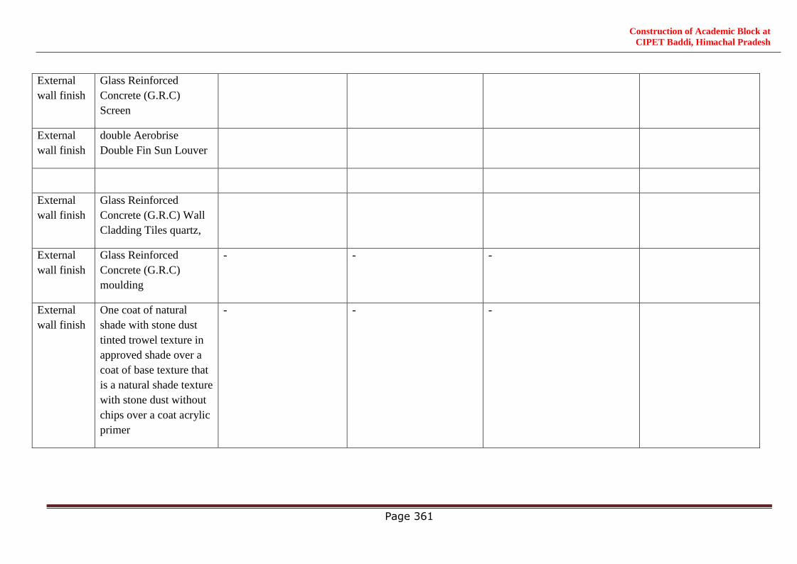
Construction of Academic Block at
CIPET Baddi, Himachal Pradesh
Page 361
External
wall finish
Glass Reinforced
Concrete (G.R.C)
Screen
External
wall finish
double Aerobrise
Double Fin Sun Louver
External
wall finish
Glass Reinforced
Concrete (G.R.C) Wall
Cladding Tiles quartz,
External
wall finish
Glass Reinforced
Concrete (G.R.C)
moulding
- - -
External
wall finish
One coat of natural
shade with stone dust
tinted trowel texture in
approved shade over a
coat of base texture that
is a natural shade texture
with stone dust without
chips over a coat acrylic
primer
- - -
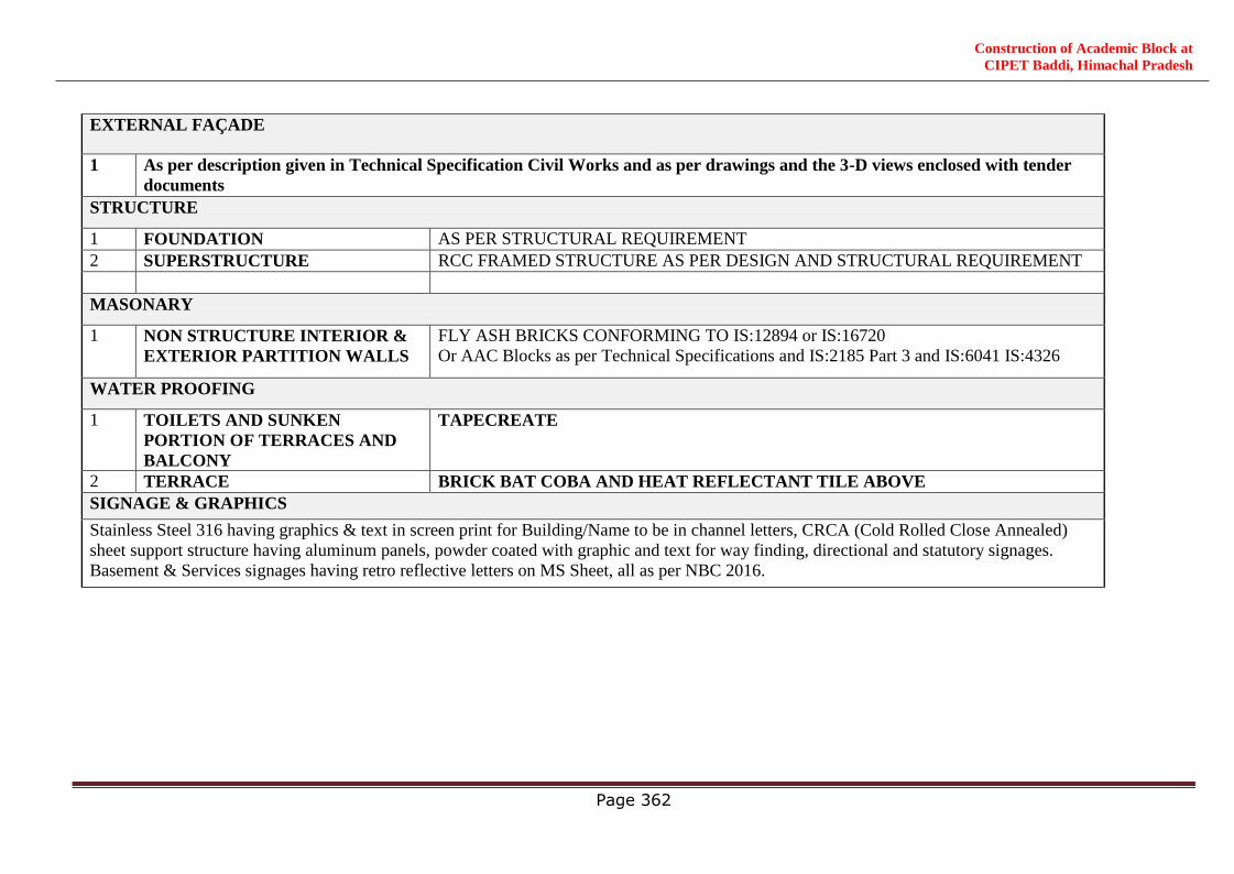
Construction of Academic Block at
CIPET Baddi, Himachal Pradesh
Page 362
EXTERNAL FAÇADE
1 As per description given in Technical Specification Civil Works and as per drawings and the 3-D views enclosed with tender
documents
STRUCTURE
1 FOUNDATION AS PER STRUCTURAL REQUIREMENT
2 SUPERSTRUCTURE RCC FRAMED STRUCTURE AS PER DESIGN AND STRUCTURAL REQUIREMENT
MASONARY
1 NON STRUCTURE INTERIOR &
EXTERIOR PARTITION WALLS
FLY ASH BRICKS CONFORMING TO IS:12894 or IS:16720
Or AAC Blocks as per Technical Specifications and IS:2185 Part 3 and IS:6041 IS:4326
WATER PROOFING
1 TOILETS AND SUNKEN
PORTION OF TERRACES AND
BALCONY
TAPECREATE
2 TERRACE BRICK BAT COBA AND HEAT REFLECTANT TILE ABOVE
SIGNAGE & GRAPHICS
Stainless Steel 316 having graphics & text in screen print for Building/Name to be in channel letters, CRCA (Cold Rolled Close Annealed)
sheet support structure having aluminum panels, powder coated with graphic and text for way finding, directional and statutory signages.
Basement & Services signages having retro reflective letters on MS Sheet, all as per NBC 2016.
Construction of Academic Block at
CIPET Baddi, Himachal Pradesh
Page 363
QUALITY ASSURANCE &
QUALITY CONTROL (QA & QC)

Construction of Academic Block at
CIPET Baddi, Himachal Pradesh
Page 364
QUALITY ASSURANCE & QUALITY CONTROL (QA&QC)
1. Introduction
Tests to be carried out to achieve Quality as mentioned in bid document.
The Contractor shall set up on site quality testing and material testing laboratory with necessary
equipment and apparatus. The Contractor shall maintain and implement a Quality Management System
that shall remain in effect during the execution of the Works. The Contractor‘s organisation is required
to operate a Quality Management System based on International Standard ISO 9001: 2015 for its scope
of Works and in compliance with the requirements of the Contract Agreement. The Contractor shall
submit his Quality Management System documentation for review and Notice of No Objection by
WAPCOS as specified herein below. The Contractor shall implement a Quality Plan that shall
incorporate a comprehensive and documented approach to achieve the Project quality requirements that
is capable of ensuring that all aspects of the Works, including but not limited to, design,
procurement, fabrication, installation, inspection, construction and modifications will comply with
the requirements of the contract agreement.
The Contractor‘s Quality Plan shall ensure that all goods and materials, whether onshore in India or off-
shore before shipping, workmanship, plant and equipment procured and supplied, inspecting, handling,
assembling, testing, storing, fabrication, suppliers and vendors are in compliance with the Contract
Agreement. Plan(s) and/or Procedures to be prepared by others (suppliers, subcontractors, sub-
consultants) and their incorporation in the overall Quality Plan of the Contractor, shall be identified.
Construction / Installation shall be deemed to include manufacturing, fabrication, assembling, testing &
commissioning, integrated testing and commissioning and Trial runs wherever necessary. The Contractor
shall assist in the independent audit review, checking, sampling testing and examination of the Works by
WAPCOS. The Contractor shall provide full and timely access for such work by WAPCOS, including
inspection of records and documentation. Such access shall include direct access to the Site, work areas,
storage facilities, fabrication sites, Contractor‘s offices, laboratories, manufacturers/ suppliers
facilities and similar areas and facilities where any work isbeing conducted. For design and/or activities
occurring outside of India / within India which require WAPCOS to inspect, the Contractor shall provide
facilities at a cost of the contractor:
a) Right to inspect;
b) Facilities to carry out their work; and
c) Assistance in travel and accommodation arrangements.
2. Quality ManagementSystems
The Contractor‘s Quality Management System shall be capable of demonstrating by self-certification that
all relevant standards, regulations, testing requirements etc. are being met. Self-certification is the
process whereby the Contractor can demonstrate that all requirements of the Contract Agreement have
been fulfilled. The Contractor shall designate a Quality Assurance Manager (QA Manager) who shall be
classified as one of the Key Personnel and shall be responsible for overseeing the implementation of the
overall Quality Plan for the Contractor. The Quality Assurance Manager shall not report to the
Contractor‘s Project Manager, but shall be directly responsible to and report to a joint venture board,

Construction of Academic Block at
CIPET Baddi, Himachal Pradesh
Page 365
senior management or similar level of the Contractor‘s organization that is not directly responsible for
design or construction. The Contractor shall be required to provide the Quality Assurance Manager with
adequate resources and authority to enable the quality of the workon the Contract Agreement to be
managed effectively. Those resources shall be required to fulfil the requirements for quality assurance,
inspection and testing and self-certification as detailed in these requirements.
The Contractor shall be required to provide appropriate training to all personnel in the operation of the
Quality Management System and maintain records to demonstrate competence in its application. The
Contractor shall submit his Quality Management System documentation for review and approval by
WAPCOS as specified in this Section. It is anticipated that the Contractor‘s Quality Management System
documentation shall include, but not limited to, the following:
a) Quality Plan, identifying its Quality Procedures;
b) Manufacturing Quality Plan;
c) Design Quality Plan;
d) Method Statements;
e) Inspection and Test Plans
The Contractor shall plan, perform and record all quality control activities to ensure that all work is
performed in accordance with the requirements of the Contract Agreement and of his Quality
Management System. Documentation which have been reviewed and approved by WAPCOS, such
activities shall include, without limitation, the inspections and/or tests implied or expressly required by
the Contract Agreement. WAPCOS shall designate, if necessary, Quality “Hold Points” into the
Contractor‘s Inspection and Test Plans for the Contractor‘s Quality Department to adhere to, or for
WAPCOS to attend, on a case-by-case basis at his discretion. The Contractor shall coordinate the
Inspection and Testing necessary to demonstrate that all specified requirements have been met. All
non-conformances are to be documented and resolved, before final acceptance of the Works or any
section of it. The Client, WAPCOS and statutory authorities, reserve the right to and shall conduct
periodic audits and inspections on the Works and services provided either on its own, and will sample,
test and measure material used within the Works completed by the Contractor or its subcontractors of all
tiers and suppliers/vendors and to observe the execution of these activities.
The Contractor, his consultant, subcontractors of all tiers and suppliers thereof shall make available for
audit all records necessary to demonstrate that the Works have been executed in accordance with the
Contract Agreement. They shall also provide WAPCOS with documents that demonstrate that the Works
are progressing in accordance with the specified requirements. These shall be provided in a timely manner
to enable non-conformities to be rectified satisfactorily.
Contractor shall maintain site register as prescribed format approved by WAPCOS. Frequency chart to
be submitted to WAPCOS every 15 days and shall be ready on site to inspect at any given time.

Construction of Academic Block at
CIPET Baddi, Himachal Pradesh
Page 366
1. Quality SystemRequirements
The organization of the Contractor‘s Project Plan shall comply with ISO 10005 (2005):
Quality Management-Guidelines for Quality Assurance Plan.
On-Site sample testing laboratory shall fulfil the norms and regulations followed by NABL
(National Accreditation Board of Testing and Calibration Laboratories) or internationally
accredited laboratory as per ISO 17025: 2005.
A fully equipped concrete laboratory shall be installed at Site along with laboratory
technicians and support staff. Testing machines shall be periodically calibrated in accordance
with NABL requirements.
WAPCOS may require the Contractor to stop using a particular laboratory and find an
alternative if WAPCOS has reasonable grounds to be dissatisfied with its performance.
All testing of systems, software, plant and materials must be carried out by persons accredited
to meet the requirements and Standards.
Within thirty (30) days of the Commencement Date, The Contractor shall submit to WAPCOS
for his review, comment and Notice of No Objection the following, as appropriate:
a) Quality Plan;
b) Design Quality Plan and Delivery Schedule; and
c) Manufacturing Quality Plan and Delivery Schedule.
The Contractor shall promptly supply WAPCOS with six (6) controlled copies of his Quality Plans,
Inspection and Test Plan(s), related procedures / instructions / forms upon such documents being
reviewed and approved by WAPCOS. The Contractor shall maintain such controlled documentation
throughout the duration of the Contract Agreement. For any amendment to the quality system
documentation, the Contractor shall as soon as practicable prepare and submit the proposed amendment
for review by WAPCOS. In addition, WAPCOS may request further copies of the quality system
documents and these documents shall reach WAPCOS‘s office within fourteen (14) days of notification,
at no additional cost to the Contract Agreement.The Contractor shall maintain and make available for
inspection by WAPCOS at its site, a complete, up-to-date, organized file of all submittals (plans,
procedures, Method Statements etc.), including an index and locator system which identifies the status
of each submittal.
4. Types of Quality Plans
No design, procurement, construction, installation, commissioning or maintenance activity shall
commence without a suitable Quality Plan that has been submitted to WAPCOS for a Notice of No
Objection.
The Contractor shall submit to WAPCOS the following Quality Plans for his review and approval:
a) A Quality Plan for the control of all management related activities;
b) Design Quality Plan(s) for the control of all design related activities for the Permanent
Works or Plant and/or Temporary Works;
c) Manufacturing and construction Quality Plan(s), for the control of activities within each
category of work or discrete element of construction, manufacture, installation, commissioning,
maintenance or servicing of the Permanent Works or Plant and/or Temporary Works or for the
control of outstanding work during the Agreement Period, as the same may be required by the
Contract Agreement and/or directed by WAPCOS;

Construction of Academic Block at
CIPET Baddi, Himachal Pradesh
Page 367
5. Formatof Quality Plans
The Quality Plan(s) shall define all measures necessary to meet the objectives and requirements of the
Contract Agreement at all appropriate phases of the work.
6. Quality Plan
The Contractor shall prepare construction Quality Plan(s) for the construction, installation, testing and
commissioning activities. Separate construction quality plan(s) shall be prepared for subcontractor‘s off
Site activities. Each constructionquality plan shall identify the scope of work to be controlled. The
Quality Plan shall include a directory and organizational chart showing all of the Contractor‘s Key
Personnel. The directory shall be kept updated throughout the Contract Agreementas changes occur and
submitted to WAPCOS for his approval. The directory shall include the names, titles, areas of
responsibility, office address and location, office phone and fax numbers, cellular phone number(s). The
Contractor shall provide information sufficient for WAPCOS to contact any of the Key Personnel on a
twenty- four (24-hour) basis for the duration of the Contract Agreement. The Quality Plan(s) shall ensure
that conditions adverse to quality such as failures, malfunctions, deficiencies and defects in materials and
equipment shall be promptly identified and recorded as Non-Conforming Product and specific
procedures to rectify non- conformities raised. This includes systems non-conformities raised as a result
of both internal audit by the Contractor and external audits by WAPCOS. The Quality Plan(s) shall
address the controls to be applied by its organisation to its subcontractors, suppliers and lower tier Sub-
contractors thereof, both directly and by identifying the quality system documentation that
subcontractors, suppliers and lower tiers thereof are required to produce. The Contractor shall ensure that
subcontractors, suppliers and lower tiers thereof agree to and implement the applicable controls specified
in the Contractor Quality Plan and the identified Quality Management System documentation.
7. Design Quality Plan
The Contractor shall be responsible for the management of the design of the Works. While not being
responsible to do any design for any Interfacing Party, the Contractor shall use his best endeavours to
manage and resolve the interface, including those with designers. The Contractor shall be responsible for
coordinating with and obtaining necessary approvals from the concerned authorities for temporary and
permanent diversions of services. The Contractor shall coordinate WAPCOS on all correspondence with
the concerned authorities and shall note any problems in the Progress Narrative submitted with the
Monthly Progress Report.
The Contractor shall ensure that the designs of the Works are properly checked and dealt with by an
Engineering Manager (Design & Technical Support). The Engineering Manager (Design & Technical
Support) shall be either in-house or external consultant responsible for the detailed checking of
Deliverables prior to submission and ensure that the design can meet all its obligations under the Contract
Agreement and for the Contractor to do likewise. The Engineering Manager (Design & Technical
Support) or his authorized representative shall check the designs for various disciplines as the case may
be. The Engineering Manager (Design & Technical Support) shall issue a certificate of the same to
WAPCOS, as per the approved proforma. The Engineering Manager (Design & Technical Support) shall
not be associated with or be involved in the actual design, producing design documents or conducting
construction site supervision for the Contractor. In the event that WAPCOS identifies significant errors

Construction of Academic Block at
CIPET Baddi, Himachal Pradesh
Page 368
or inconsistencies in the Deliverables, then WAPCOS shall request for the concerned representative of
Engineering Manager (Design & Technical Support) to be immediately removed from the Design Team
and be replaced with a competent person.
The procedures for the checking of design of Permanent Works shall also apply to design of Temporary
Works and construction sequences that affect the PermanentWorks or Safety during construction /
installation. The procedures for the control ofdesign changes shall be defined in order that design changes
are reviewed, verified, validated and approved before implementation. All design documents (drawings,
plans, specifications, calculations and reports) prepared by the EPC Developer and
same shall be checked by the Designer and the Engineering Manager (Design & Technical Support), who
shall issue a certificate of the same to WAPCOS. The Contractor shall maintain records showing design
calculation and data supporting design review activities. WAPCOS reserves the right to inspect and audit
these documents at any time to verify the effectiveness of design reviews. The Design Quality Plan(s)
shall define the Contractor's policy for the design of the Permanent Works or Plant and/or Temporary
Works and shall, without limitation, specify the same. The Contractor shall maintain joint inspection
reports of WAPCOS and the Contractor, and instruction register of construction activities. Daily reports
shall also be maintained.
8. Manufacturing Quality Plan
Each Manufacturing Quality Plan shall identify the scope of work to be controlled. The same shall be
approved by WAPCOS.
9. QualityAudit,Reviews and Updates
The Contractor shall submit with his Quality Plan a schedule of internal, consultant, subcontractor and
supplier audits that are to be conducted by his personnel at least every six (6) months. The schedule,
scope and method of the audits shall be sufficient enough, such that the Contractor can verify that all
aspects of the Works are being conducted in accordance with the contractual requirements. The schedule
and any amendments are subject to the acceptance by WAPCOS. The schedule shall be reviewed every
four (4) weeks by WAPCOS.
The Contractor shall ensure that audits of all the activities in each quality plan are carried out to ensure
the continuing suitability and effectiveness of the Quality Management System. Reports of each such
audit shall be submitted promptly to WAPCOS for his information. The Contractor shall audit his
consultants, subcontractors, sub-consultants and suppliers.
The Contractor shall allow WAPCOS to observe/participate in these audits and to conduct additional
independent audits, as they consider appropriate to provide assurance that the Works are being conducted
in accordance with contractual requirements. The Contractor shall provide the facilities and access
necessary for these audits to be carried out effectively. All audits as described in this section are to be
carried out in compliance with established ISO 9001 auditing principles and in accordance with ISO
19011.

Construction of Academic Block at
CIPET Baddi, Himachal Pradesh
Page 369
10. Plan reviews andupdates:
The Contractor shall conduct Management Reviews of its quality system, at least annually. As work
progresses, the Contractor shall update the Quality Plan to reflect current conditions. The need for
revisions to the Quality Plan may be identified by the Contractor and/or WAPCOS. The Contractor shall
submit any revisions or updates to the Quality Plan to WAPCOS for his Notice of No Objection within
thirty (30) days of the identification of the need for a revision.
11. Method Statements
Contractor shall prepare Method Statements for each area and/or type of activity conducted, and submits
to WAPCOS for his review, comment and Notice of No Objection prior to commencing construction on
any Temporary or Permanent Works. Methods Statements shall be prepared for all Temporary and
Permanent Works and shall be specific to the work being constructed and to the location of work.
All Methods Statements shall be consistent with Design Drawings and Works Specifications that
have been subjected to checks and reviews as specified. Any deviations from the requirements of the
Design Drawings or Works Specifications shall require written agreement of the Designer, certified by
the Engineering Manager (Design & Technical Support) and shall be submitted to WAPCOS for his
review and Notice of No Objection. Approved Methods Statements shall be available for examination
by WAPCOS upon request at site.
12.Inspection andTestPlans
The Contractor, and through him, his consultants, subcontractors and suppliers engaged in supplying,
manufacturing, construction, installation, commissioning and testing or any other service connected with
the Works, shall maintain Inspection and Test Plans (ITP) appropriate for the services they provide that
are accepted by WAPCOS. These accepted ITPs will stipulate the necessary level and frequency of tests
and inspections for each aspect of the Works, and also stipulate, without limitation:
The Contractor shall conduct inspections and tests in accordance with his detailed plans as stipulated in
the ITP. Records shall be kept of the completion of the inspections and tests that identify the record of
the results which shall be made available for review during WAPCOS audit.
13.QualityPersonnel
The Contractor shall appoint suitably qualified and experienced persons as the ‘Construction Quality
Assurance Manager’ and the ‘Design Quality Assurance Manager’ to be responsible for the task of
ensuring that the requirements of the Quality Management System are implemented and maintained. The
Contractor shall, at the time of submission of the proposed Key Staff, shall submit for a notice from
WAPCOS, details of the qualifications, experience, authority and responsibility of the proposed Quality
Assurance Managers as required.
The Contractor shall ensure that the Quality Assurance Managers are able to discharge their duties
without hindrance or constraint. In addition, the Contractor shall make available any such resources
that are necessary to ensure the effectiveimplementation of the quality system and all quality plans.
The Contractor shall appoint suitably qualified and experienced persons as ‘Quality Control Managers’
to lead teams of Quality Control Engineers for carrying out, independent from other teams, inspections
of the Works as identified as the Quality ‘Hold Point’, ‘Witness Point’ (W), ‘Observation Point’ (O). The

Construction of Academic Block at
CIPET Baddi, Himachal Pradesh
Page 370
Contractor shall, at the time of submission of the proposed Key Staff, submit for review by WAPCOS
details of the qualifications, experience, authority and responsibility of the proposed QualityControl
Manager.
The Contractor shall ensure that the Quality Control Managers are able to discharge their duties without
hindrance or constraint, including but not limited to, the authority to suspend works as considered
necessary. In addition, the Contractor shall make available any such resources that are necessary to ensure
the effective implementation of the quality system and all quality plans.
14. Quality Control Engineers:
The Contractor shall assign Quality Control Engineers, (QCE), for each shift for each location/activities
where work is being performed. Each QCE shall be suitably qualified and experienced in all the
construction activities being conducted at the Site.
Quality Control Engineers shall have a minimum of ten (10) years construction / installation experience
with at least five (5)years’ experience in the inspection, sampling and testing of works of the type being
constructed. If required on the instruction of WAPCOS additional inspectors shall be appointed, at the
cost of the Contractor.
15.Materials Technicians:
The Contractor shall assign suitably qualified and experienced Materials Technicians to conduct to be
based in the Site Laboratory, for the sampling and testing of materials, goods and supplies, both on
and off site, for the Contract Agreement.
16. Staffing Levels:
The actual size of the QA/QC staff shall reflect the complexity, needs, shifts and composition of Quality
Control activities consistent with work in progress. The staffing levels shall be consistent with the
Contractor‘s Quality Plan and the Project Baseline Programme, the relative locations of work in progress
and the nature of the work. The Quality Plan shall identify administrative/clerical support for the
maintenance and management of records/documents pertinent to Quality Control activities.
17.Monthly Progress Report
The Contractor shall continuously monitor the performance of his Quality Management System,
which shall be included in each Monthly Progress Report (MPR).
18.Quality Certifications:
The Contractor shall submit a written certification by the Quality Assurance Manager certifying that:
a) The Quality Plan and all of the measures and procedures provided therein are functioning
properly and are being fully complied with, except as specifically noted in the certification.
b) All work, including that of the Designer, and all other designers, subcontractors at all tiers,
suppliers and fabricators, has been checked and/or inspected by the Contractor‘s Designer
Checker, except as specifically noted in the certification, conforms to the requirements of the
Contract Agreement.
Construction of Academic Block at
CIPET Baddi, Himachal Pradesh
Page 371
19. Weekly Records
Weekly records shall be prepared and maintained that provide factual evidence that required activities
and/or tests have been performed, including the following:
WAPCOS reserves the right to inspect and audit these documents at any time.
20. Quality Control Requirements
The Contractor shall, in accordance with the quality control requirements of the Specification and other
documents included in the Contract Agreement, prepare and maintain quality item lists which establish
the criteria for control of each major component or activity during design, construction and/or
manufacture and installation, commissioning and servicing in accordance with the need to ensure the
desired quality requirements of the Works. All inspection and testing shall be the responsibility of the
Contractor, at Contractor's cost. In all cases, the cost of materials for such tests shall be borne by the
Contractor.
The work shall conform to high standards of material, design and workmanship. The Contractor shall
conform to the Quality standards prescribed in the Contract Agreement. At Site, the Contractor shall
arrange the materials, their stacking/storage in appropriate manner to ensure that the quality of the
materials is not compromised. The Contractor shall provide all the necessary equipment and qualified
manpower to test the quality of materials, assemblies etc. The tests shall be conducted at specified
intervals and the results of tests properly documented.
WAPCOS shall be free to carry out such additional tests as may be decided by him at his sole discretion,
from time to time, in addition to those specified in this document. WAPCOS shall also be free to appoint
any third party for inspection and testing of specialized works at contractor’s cost. The Contractor shall
provide the samples and labour for collecting the samples. No extra payment shall be payable to the
Contractor for samples or for the collection of the samples. The results of such additional tests and third
party inspection shall be binding on the Contractor. Wherever possible test(s) shall be conducted at the
Contractor‘s Site laboratory which shall be established by the Contractor or at any other external
laboratory given a notice by WAPCOS. The Contractor shall transport the sealed samples to the
laboratory for which nothing extra shall be payable. In the event of the Contractor failing to arrange
transportation of the samples in proper time, WAPCOSshall have them transported and recover two times
the actual cost from the Contractor. All sampling and testing shall be performed in the presence of
assigned Contractor Quality Personnel. Testing should be witnessed by the Contractor at the Standard
External Laboratory. Whether witnessed by the Contractor or not, the test results shall be binding on the
Contractor. WAPCOS shall have the right at all times to inspect all operations including the source of
materials, procurement, layout and storage of materials, all equipment including the concrete batching
and mixing equipment, and the quality control system. Such an inspection shall be arranged by the
Contractor and WAPCOS's notice obtained prior to starting of the particular item of work. This shall
however, not relieve the Contractor of his responsibilities. All materials which do not conform to the
Specifications shall be rejected and shall be removed from the Site immediately. WAPCOS shall have
the power to cause the Contractors to purchase and use materials from any particular source, as May, in
WAPCOS's opinion, be necessary for the proper Execution of Works.
Construction of Academic Block at
CIPET Baddi, Himachal Pradesh
Page 372
21. Field/Site Laboratory
a. All the materials to be used in the work and tested in the laboratory shall comply with the Client’s
Requirements or such recognized specifications as acceptable to WAPCOS.
b. The testing machines shall be recalibrated periodically as per Contractor Quality Plan and
applicable regulatory Standards. The calibration shall be from an authorized laboratory as approved
by WAPCOS.
c. The Contractor or his authorized representative shall assist in the collection, preparation,
forwarding and testing of such samples.
d. The cost of such samples and tests shall be borne by the Contractor. The Contractor shall give not
less than seven (7) days’ notice for all tests. On expiration of the period of notice, the Contractor
may proceed with the inspections and/or tests not withstanding the absence of WAPCOS or
of any response to the said notice.
e. Witness by WAPCOS shall not discharge the Contractor of the responsibility to provide acceptable
product, nor shall it preclude subsequent rejection by WAPCOS.
f. Two (2) copies of all test certificates shall be supplied by the Contractor to WAPCOS for approval
immediately after the completion of the tests. Test certificates must be supplied to WAPCOS before
the materials or components are used in the works, unless WAPCOS directs otherwise.
22. Frequency of Testing
All materials shall be tested as per the requirements specified in the Contractor‘s Quality Plan. All test
reports shall be documented in hard copy as well as soft copy. Frequency chart to be submitted to
WAPCOS every 15 days. Material tests as specified in codal provisions – 80 % in field lab and 20 % in
Govt. laboratory. In the eventuality of testing method not available for certain materials in EPC developer
laboratory, the same shall be carried out in government laboratory as approved by WAPCOS. However,
if WAPCOS feels the reconfirmation of test results of any material, in addition, the same shall be got
tested from any other laboratory at the discretion of WAPCOS at the cost of the Contractor. All testing
shall be carried out as per relevant IS codes.
23. Unsuitable Materials
If at any stage during the execution of the Works, WAPCOS finds that the particular material is not
suitable to be used in any component of the work, WAPCOS may order retesting of the material from
any other laboratory at the discretion of WAPCOS at the cost of the Contractor. The rejected material
either after the initial test or after re- testing, as the case may be, shall be immediately removed from the
Site by the Contractor at his own cost. In case of default on the part of the Contractor in removing rejected
materials and any work executed with such unaccepted materials, WAPCOS shall be at liberty to have
them removed and/or dismantled by other means at the riskand cost of the Contractor.
24. Notification of Non-conformities
If the Contractor has used or proposes to use or repair any item of the Works which does not conform to
the requirements of the Contract Agreement , he shall immediately submit for review by WAPCOS a
proposal for rectification, and supply full particulars of the nonconformity and, if appropriate, of the
proposed means of repair. If WAPCOS issues nonconformity reports, either product based as a Non-
Conformance Report (NCR) or procedural through quality audit as a Corrective Action Request (CAR) or
similar documents to notify the Contractor of any item of the Works which does not conform to the

Construction of Academic Block at
CIPET Baddi, Himachal Pradesh
Page 373
requirements of the Contract Agreement, the Contractor shall promptly investigate the matter and submit
for review, within fourteen (14) days of notification by WAPCOS, the remedial measures to be taken and
stating the reasons for the measures and the corrective and preventive action. The Contractor shall maintain
a Non Conformity Register to indicate the status of all nonconformities which have been identified by
WAPCOS and the Contractor. WAPCOS reserves the right to inspect and audit these documents at any
time
25. Notice of Place of Manufactureand / or Source of Supply
The Contractor shall notify WAPCOS of the places of manufacture and/or the source of supply of all goods
and materials to be incorporated into the Works and shall give reasonable notice (which shall not in any
event be less than sixty (60) days) to WAPCOS before the start of any manufacturing and/or the supply of
goods and materials.
26. Notice of Inspection, Test, Trials by the Contractor
In relation to all Quality Control points and Quality ‘Hold Points’ involving inspection and/or witness
testing by WAPCOS, the Contractor shall give WAPCOS notice of when the relevant work will be
inspected and/or tested. The period of notice shall be as follows; unless otherwise agreed by WAPCOS:
a) In case of work carried out off-Site, such notice shall be given not less than fourteen (14) days before
the work is to be inspected and/or tested.
b) In case of work carried out off-Site, such notice shall be given not less than fourteen (14) days before
the work is to be inspected and/or tested.
27.Witness by WAPCOS
In relation to all Quality Control Points involving inspection and/or testing by the Contractor, WAPCOS
may select to witness such inspections and/or tests but, on expiration of the period of notice pursuant to
clause 27, the Contractor may proceed with the inspections and/or tests notwithstanding the absence of the
WAPCOS or of any response to the said notice. Witness by WAPCOS shall not discharge the Contractor
of the responsibility to provide acceptable product, nor shall it preclude subsequent rejection by WAPCOS.
28. Certificate of Manufactured Goods or Materials
The Contractor shall obtain certificates for each batch of manufactured goods and documentary evidence
that goods, supplies and materials and Contractor‘s Equipment conform to the Contract Agreement
requirements for incorporation in the Works. Each certificate and/or proofing document shall include all
reports of inspections and/or tests carried out at the place of manufacture.
The Contractor shall make available at the Site not less than twenty-four (24) hours prior to installation or
use of such goods, supplies or materials and Contractor‘s Equipment all certificates and/or proofing
document(s). WAPCOS reserves the right to inspect and audit these documents at any time.
29.Materials Certificateof Compliance:
Within seven (7) days of the issue of a Completion Certificate for a Section or for all the Works, the
Contractor shall submit a Certificate of Compliance signed by the Project Manager and the Quality
Assurance Manager indicating that all materials, goods and supplies incorporated in the Works conform to
the requirements of the Contract Agreement.

Construction of Academic Block at
CIPET Baddi, Himachal Pradesh
Page 374
30. Reports of Inspections, Tests and Trials
The Contractor shall compile reports of each inspection and/or test. Such reports shall show the results of
all the inspections and/or tests carried out and shall certify that the work has been inspected and/or tested
in accordance with the requirements of the Contract Agreement and that the work complies with the
requirements of the Contract Agreement. Any analysis of the results required to confirm that the work
complies with the requirements of the Contract Agreement shall be compiled in accordance with this clause
and report shall be submitted to WAPCOS in accordance with clause 32.
Each report of inspection and/or test shall be signed by a representative of the Contractor who has been
allocated the requisite authority under the relevant Inspection and Test Plan and signed by the
Contractor‘s Quality Assurance Manager.
WAPCOS reserves the right to inspect and audit these documents at any time. Time Limit for Filing of
Reports for Inspections and/or Tests:
The Contractor shall ensure that a signed copy report of each in-situ and each off- site inspection / test is
filed in his Records Office within 3 (three) working days and within seven (7) working days of the date
of completion of the test process respectively.
31. Quality Control Register
The Contractor shall provide and maintain at all stages of the work a quality control register or registers to
identify the status of inspections, sampling and testing of the work and all certificates. Each register shall:
WAPCOS reserves the right to inspect and audit these documents at any time.
32. Summaries of Inspection and/or Test
The Contractor shall submit to WAPCOS for his information summaries based on each quality control
register showing the type and amount of certification received and the sampling, inspection, and/or
testing undertaken on each element of the Works during the previous week as part of the Weekly Report.
The summaries shall identify and demonstrate the compliance of such certification, sampling, inspection
and/or testing with the requirements of the Contract Agreement and shall identify any item which does
not conform to the requirements of the Contract Agreement.
33. Samples
The Contractor shall ensure those concrete compression test specimens are controlled as per the
standard procedure & as directed by WAPCOS.
34. Additional Samples
The Contractor shall provide additional samples for testing if in the opinion of WAPCOS:
a) The material previously tested no longer complies with the specified requirements; or
b) The material has been handled or stored in such a manner that it is no longer represented by the
previously tested samples.
35. Trials
Trials shall be carried out as stated by WAPCOS to demonstrate that the proposed materials, equipment
or methods of construction comply with the Contract Agreement.

Construction of Academic Block at
CIPET Baddi, Himachal Pradesh
Page 375
36. Timing for Inspection by WAPCOS.
The Contractor shall allow WAPCOS a reasonable time to carry out any inspection and/or witness
testing and to assess the result of any inspection and/or test before proceeding with the Works. Unless
WAPCOS has issued a notice, all inspections and/or tests to be witnessed by WAPCOS shall be carried
out between 0800 and 1800 hours, Monday to Saturday.
37. Failure of Contractor to Inspect the Works.
WAPCOS may reject the work in question, or require it to be uncovered, in the event of any failure by
the Contractor to inspect and/or test at a Quality ‘Hold Point’ by Contractor‘s Quality Department.
38. Failure of the Contractor toTest the Works.
If the Contractor fails to test, either type test or routine test or qualification test, for each batch of goods
or elements of the Works, then WAPCOS shall arrange for third party inspection. WAPCOS shall recover
two times the actual cost associated with testing, including the services of any specialised personnel or
independent assessors, and will deduct such cost from the Contractor.

Construction of Academic Block at
CIPET Baddi, Himachal Pradesh
Page 376
LIST OF APPROVED MAKES
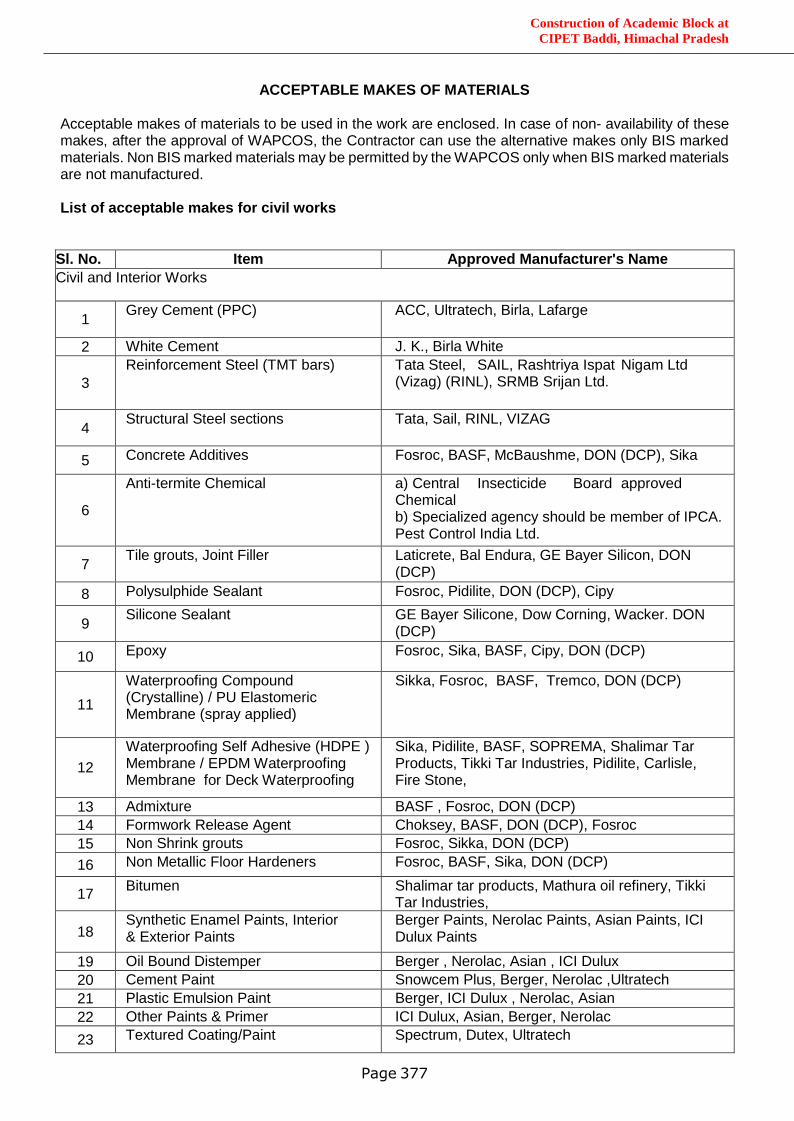
Construction of Academic Block at
CIPET Baddi, Himachal Pradesh
Page 377
ACCEPTABLE MAKES OF MATERIALS Acceptable makes of materials to be used in the work are enclosed. In case of non- availability of these makes, after the approval of WAPCOS, the Contractor can use the alternative makes only BIS marked materials. Non BIS marked materials may be permitted by the WAPCOS only when BIS marked materials are not manufactured. List of acceptable makes for civil works
Sl. No. Item Approved Manufacturer's Name
Civil and Interior Works
1 Grey Cement (PPC) ACC, Ultratech, Birla, Lafarge
2 White Cement J. K., Birla White
3
Reinforcement Steel (TMT bars) Tata Steel, SAIL, Rashtriya Ispat Nigam Ltd (Vizag) (RINL), SRMB Srijan Ltd.
4 Structural Steel sections Tata, Sail, RINL, VIZAG
5 Concrete Additives Fosroc, BASF, McBaushme, DON (DCP), Sika
6
Anti-termite Chemical a) Central Insecticide Board approved Chemical b) Specialized agency should be member of IPCA. Pest Control India Ltd.
7 Tile grouts, Joint Filler Laticrete, Bal Endura, GE Bayer Silicon, DON
(DCP)
8 Polysulphide Sealant Fosroc, Pidilite, DON (DCP), Cipy
9 Silicone Sealant GE Bayer Silicone, Dow Corning, Wacker. DON
(DCP)
10 Epoxy Fosroc, Sika, BASF, Cipy, DON (DCP)
11
Waterproofing Compound (Crystalline) / PU Elastomeric Membrane (spray applied)
Sikka, Fosroc, BASF, Tremco, DON (DCP)
12
Waterproofing Self Adhesive (HDPE ) Membrane / EPDM Waterproofing Membrane for Deck Waterproofing
Sika, Pidilite, BASF, SOPREMA, Shalimar Tar Products, Tikki Tar Industries, Pidilite, Carlisle, Fire Stone,
13 Admixture BASF , Fosroc, DON (DCP)
14 Formwork Release Agent Choksey, BASF, DON (DCP), Fosroc
15 Non Shrink grouts Fosroc, Sikka, DON (DCP)
16 Non Metallic Floor Hardeners Fosroc, BASF, Sika, DON (DCP)
17 Bitumen Shalimar tar products, Mathura oil refinery, Tikki
Tar Industries,
18 Synthetic Enamel Paints, Interior & Exterior Paints
Berger Paints, Nerolac Paints, Asian Paints, ICI Dulux Paints
19 Oil Bound Distemper Berger , Nerolac, Asian , ICI Dulux
20 Cement Paint Snowcem Plus, Berger, Nerolac ,Ultratech
21 Plastic Emulsion Paint Berger, ICI Dulux , Nerolac, Asian
22 Other Paints & Primer ICI Dulux, Asian, Berger, Nerolac
23 Textured Coating/Paint Spectrum, Dutex, Ultratech
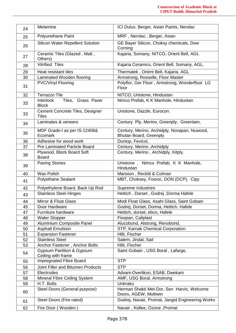
Construction of Academic Block at
CIPET Baddi, Himachal Pradesh
Page 378
24 Melamine ICI Dulux. Berger, Asian Paints, Nerolac
25 Polyurethane Paint MRF , Nerolac , Berger, Asian
26 Silicon Water Repellent Solution GE Bayer Silicon, Choksy chemicals, Dow
Corning Endura, BASF
27 Ceramic Tiles (Glazed , Matt , Others)
Kajaria, Somany, NITCO, Orient Bell, AGL
28 Vitrified Tiles Kajaria Ceramics, Orient Bell, Somany, AGL,
29 Heat resistant tiles Thermatek , Orient Bell, Kajaria, AGL
30 Laminated Wooden flooring Armstrong, Rosselle, Floor Master
31 PVC/Vinyl Flooring Polyflor, Ger Floor , Armstrong, Wonderfloor LG
Floor
32 Terrazzo Tile NITCO, Unistone, Hindustan
33 Interlock Tiles, Grass Paver Block
Nimco Prefab, K K Manhole, Hindustan
33 Cement Concrete Tiles, Designer Tiles
Unistone, Dazzle, Eurocon.
34 Laminates & veneers Century Ply, Merino, Greenply, Greenlam,
35 MDF Grade-I as per IS-12406& Ecomark
Century, Merino, Archidply, Novapan, Nuwood, Bhutan Board, Greenply
36 Adhesive for wood work Dunlop, Fevicol,
37 Pre Laminated Particle Board Century, Merino ,Archidply
38 Plywood, Block Board Soft Board
Century, Merino , Archidply, Kitply.
39 Paving Stones Unistone , Nimco Prefab, K K Manhole,
Hindustan
40 Wax Polish Mansion , Reckitt & Colman
41 Polyethane Sealant MBT, Choksey, Fosroc, DON (DCP), Cipy
42 Polyethylene Board, Back Up Rod Supreme Industries
43 Stainless Steel Hinges Hettich , Dorset , Godrej ,Dorma Hafele
44 Mirror & Float Glass Modi Float Glass, Asahi Glass, Saint Gobain
45 Door Hardware Godrej, Dorset, Dorma, Hettich. Hafele
47 Furniture hardware Hettich, dorset, ebco, Hafele
48 Water Stopper Fixopan, Caliplast
49 Aluminium Composite Panel Alucobond, Alstrong, Renobond,
50 Asphalt Emulsion STP, Karnak Chemical Corporation.
51 Expansion Fastener Hilti, Fischer
52 Stainless Steel Salem, Jindal, Sail
53 Anchor Fastener , Anchor Bolts Hilti, Fischer
54 Gypsum Partition & Gypsum Ceiling with frame
Saint Gobain , USG Boral , Lafarge,
55 Impregnated Fibre Board STP
56 Joint Filler and Bitumen Products STP
57 Electrodes Advani-Overlikon, ESAB, Dwekam
58 Mineral Fibre Ceiling System AMF, USG Boral, Armstrong
59 H.T. Bolts Unbrako
60 Steel Doors (General purpose) Herman Shakti Met-Dor, Sen Harvic, Welcome
Doors, AGEW, Multiwin
61 Steel Doors (Fire rated) Godrej, Navair, Promat, Jangid Engineering Works
62 Fire Door ( Wooden ) Navair , Kidlee, Ozone ,Promat
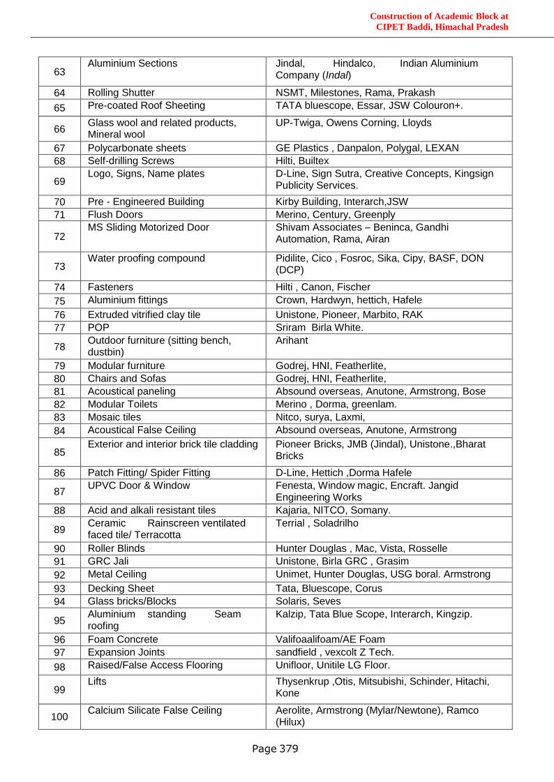
Construction of Academic Block at
CIPET Baddi, Himachal Pradesh
Page 379
63 Aluminium Sections Jindal, Hindalco, Indian Aluminium
Company (Indal)
64 Rolling Shutter NSMT, Milestones, Rama, Prakash
65 Pre-coated Roof Sheeting TATA bluescope, Essar, JSW Colouron+.
66 Glass wool and related products, Mineral wool
UP-Twiga, Owens Corning, Lloyds
67 Polycarbonate sheets GE Plastics , Danpalon, Polygal, LEXAN
68 Self-drilling Screws Hilti, Builtex
69 Logo, Signs, Name plates D-Line, Sign Sutra, Creative Concepts, Kingsign
Publicity Services.
70 Pre - Engineered Building Kirby Building, Interarch,JSW
71 Flush Doors Merino, Century, Greenply
72 MS Sliding Motorized Door Shivam Associates – Beninca, Gandhi
Automation, Rama, Airan
73 Water proofing compound Pidilite, Cico , Fosroc, Sika, Cipy, BASF, DON
(DCP)
74 Fasteners Hilti , Canon, Fischer
75 Aluminium fittings Crown, Hardwyn, hettich, Hafele
76 Extruded vitrified clay tile Unistone, Pioneer, Marbito, RAK
77 POP Sriram Birla White.
78 Outdoor furniture (sitting bench, dustbin)
Arihant
79 Modular furniture Godrej, HNI, Featherlite,
80 Chairs and Sofas Godrej, HNI, Featherlite,
81 Acoustical paneling Absound overseas, Anutone, Armstrong, Bose
82 Modular Toilets Merino , Dorma, greenlam.
83 Mosaic tiles Nitco, surya, Laxmi,
84 Acoustical False Ceiling Absound overseas, Anutone, Armstrong
85 Exterior and interior brick tile cladding Pioneer Bricks, JMB (Jindal), Unistone.,Bharat
Bricks
86 Patch Fitting/ Spider Fitting D-Line, Hettich ,Dorma Hafele
87 UPVC Door & Window Fenesta, Window magic, Encraft. Jangid
Engineering Works
88 Acid and alkali resistant tiles Kajaria, NITCO, Somany.
89 Ceramic Rainscreen ventilated faced tile/ Terracotta
Terrial , Soladrilho
90 Roller Blinds Hunter Douglas , Mac, Vista, Rosselle
91 GRC Jali Unistone, Birla GRC , Grasim
92 Metal Ceiling Unimet, Hunter Douglas, USG boral. Armstrong
93 Decking Sheet Tata, Bluescope, Corus
94 Glass bricks/Blocks Solaris, Seves
95 Aluminium standing Seam roofing
Kalzip, Tata Blue Scope, Interarch, Kingzip.
96 Foam Concrete Valifoaalifoam/AE Foam
97 Expansion Joints sandfield , vexcolt Z Tech.
98 Raised/False Access Flooring Unifloor, Unitile LG Floor.
99 Lifts Thysenkrup ,Otis, Mitsubishi, Schinder, Hitachi,
Kone
100 Calcium Silicate False Ceiling Aerolite, Armstrong (Mylar/Newtone), Ramco
(Hilux)
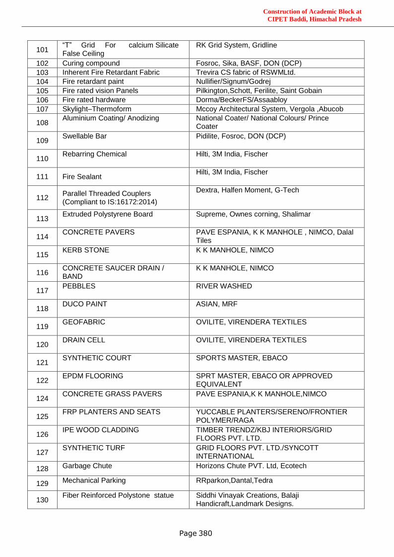
Construction of Academic Block at
CIPET Baddi, Himachal Pradesh
Page 380
101 “T” Grid For calcium Silicate False Ceiling
RK Grid System, Gridline
102 Curing compound Fosroc, Sika, BASF, DON (DCP)
103 Inherent Fire Retardant Fabric Trevira CS fabric of RSWMLtd.
104 Fire retardant paint Nullifier/Signum/Godrej
105 Fire rated vision Panels Pilkington,Schott, Ferilite, Saint Gobain
106 Fire rated hardware Dorma/BeckerFS/Assaabloy
107 Skylight–Thermoform Mccoy Architectural System, Vergola ,Abucob
108 Aluminium Coating/ Anodizing National Coater/ National Colours/ Prince
Coater
109 Swellable Bar Pidilite, Fosroc, DON (DCP)
110 Rebarring Chemical Hilti, 3M India, Fischer
111 Fire Sealant Hilti, 3M India, Fischer
112 Parallel Threaded Couplers (Compliant to IS:16172:2014)
Dextra, Halfen Moment, G-Tech
113 Extruded Polystyrene Board Supreme, Ownes corning, Shalimar
114 CONCRETE PAVERS PAVE ESPANIA, K K MANHOLE , NIMCO, Dalal
Tiles
115 KERB STONE K K MANHOLE, NIMCO
116 CONCRETE SAUCER DRAIN / BAND
K K MANHOLE, NIMCO
117 PEBBLES RIVER WASHED
118 DUCO PAINT ASIAN, MRF
119 GEOFABRIC OVILITE, VIRENDERA TEXTILES
120 DRAIN CELL OVILITE, VIRENDERA TEXTILES
121 SYNTHETIC COURT SPORTS MASTER, EBACO
122 EPDM FLOORING SPRT MASTER, EBACO OR APPROVED
EQUIVALENT
124 CONCRETE GRASS PAVERS PAVE ESPANIA,K K MANHOLE,NIMCO
125 FRP PLANTERS AND SEATS YUCCABLE PLANTERS/SERENO/FRONTIER
POLYMER/RAGA
126 IPE WOOD CLADDING TIMBER TRENDZ/KBJ INTERIORS/GRID
FLOORS PVT. LTD.
127 SYNTHETIC TURF GRID FLOORS PVT. LTD./SYNCOTT
INTERNATIONAL
128 Garbage Chute Horizons Chute PVT. Ltd, Ecotech
129 Mechanical Parking RRparkon,Dantal,Tedra
130 Fiber Reinforced Polystone statue Siddhi Vinayak Creations, Balaji
Handicraft,Landmark Designs.
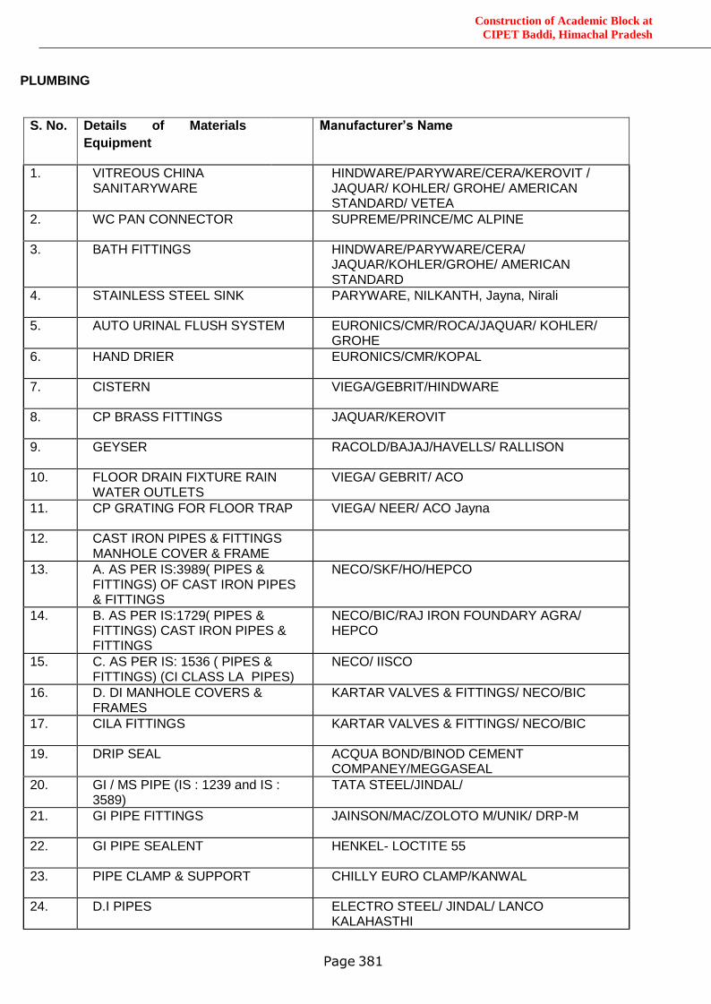
Construction of Academic Block at
CIPET Baddi, Himachal Pradesh
Page 381
PLUMBING
S. No. Details of Materials /
Equipment
Manufacturer’s Name
1. VITREOUS CHINA SANITARYWARE
HINDWARE/PARYWARE/CERA/KEROVIT / JAQUAR/ KOHLER/ GROHE/ AMERICAN STANDARD/ VETEA
2. WC PAN CONNECTOR SUPREME/PRINCE/MC ALPINE
3. BATH FITTINGS HINDWARE/PARYWARE/CERA/ JAQUAR/KOHLER/GROHE/ AMERICAN STANDARD
4. STAINLESS STEEL SINK PARYWARE, NILKANTH, Jayna, Nirali
5. AUTO URINAL FLUSH SYSTEM EURONICS/CMR/ROCA/JAQUAR/ KOHLER/ GROHE
6. HAND DRIER EURONICS/CMR/KOPAL
7. CISTERN VIEGA/GEBRIT/HINDWARE
8. CP BRASS FITTINGS JAQUAR/KEROVIT
9. GEYSER RACOLD/BAJAJ/HAVELLS/ RALLISON
10. FLOOR DRAIN FIXTURE RAIN WATER OUTLETS
VIEGA/ GEBRIT/ ACO
11. CP GRATING FOR FLOOR TRAP VIEGA/ NEER/ ACO Jayna
12. CAST IRON PIPES & FITTINGS MANHOLE COVER & FRAME
13. A. AS PER IS:3989( PIPES & FITTINGS) OF CAST IRON PIPES & FITTINGS
NECO/SKF/HO/HEPCO
14. B. AS PER IS:1729( PIPES & FITTINGS) CAST IRON PIPES & FITTINGS
NECO/BIC/RAJ IRON FOUNDARY AGRA/ HEPCO
15. C. AS PER IS: 1536 ( PIPES & FITTINGS) (CI CLASS LA PIPES)
NECO/ IISCO
16. D. DI MANHOLE COVERS & FRAMES
KARTAR VALVES & FITTINGS/ NECO/BIC
17. CILA FITTINGS KARTAR VALVES & FITTINGS/ NECO/BIC
19. DRIP SEAL ACQUA BOND/BINOD CEMENT COMPANEY/MEGGASEAL
20. GI / MS PIPE (IS : 1239 and IS : 3589)
TATA STEEL/JINDAL/
21. GI PIPE FITTINGS JAINSON/MAC/ZOLOTO M/UNIK/ DRP-M
22. GI PIPE SEALENT HENKEL- LOCTITE 55
23. PIPE CLAMP & SUPPORT CHILLY EURO CLAMP/KANWAL
24. D.I PIPES ELECTRO STEEL/ JINDAL/ LANCO KALAHASTHI
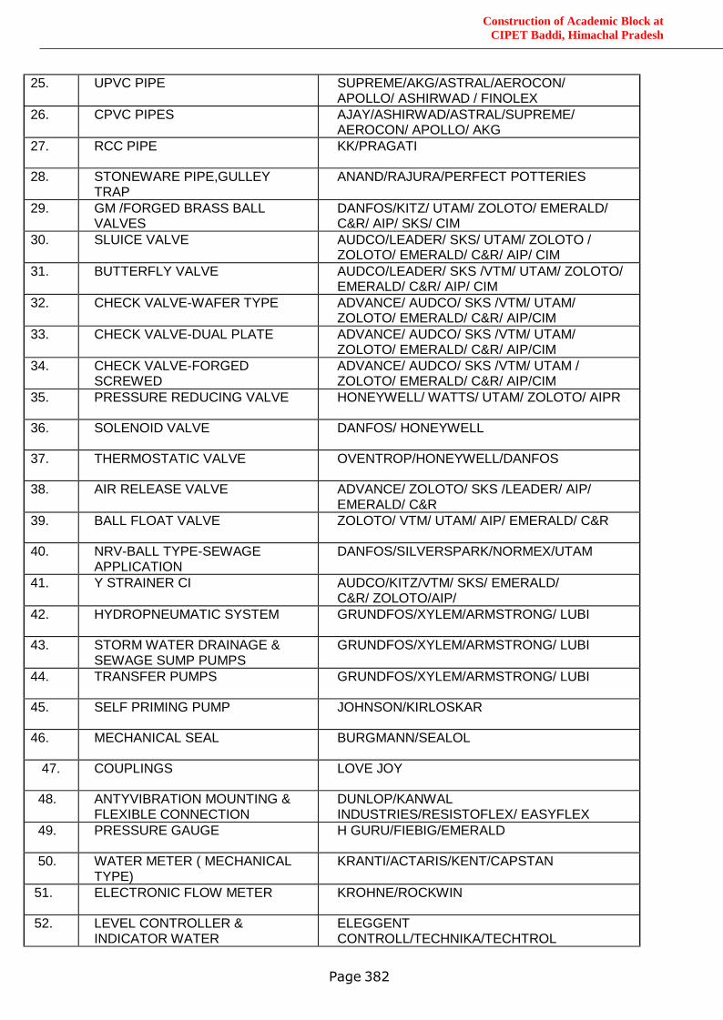
Construction of Academic Block at
CIPET Baddi, Himachal Pradesh
Page 382
25. UPVC PIPE SUPREME/AKG/ASTRAL/AEROCON/ APOLLO/ ASHIRWAD / FINOLEX
26. CPVC PIPES AJAY/ASHIRWAD/ASTRAL/SUPREME/ AEROCON/ APOLLO/ AKG
27. RCC PIPE KK/PRAGATI
28. STONEWARE PIPE,GULLEY TRAP
ANAND/RAJURA/PERFECT POTTERIES
29. GM /FORGED BRASS BALL VALVES
DANFOS/KITZ/ UTAM/ ZOLOTO/ EMERALD/ C&R/ AIP/ SKS/ CIM
30. SLUICE VALVE AUDCO/LEADER/ SKS/ UTAM/ ZOLOTO / ZOLOTO/ EMERALD/ C&R/ AIP/ CIM
31. BUTTERFLY VALVE AUDCO/LEADER/ SKS /VTM/ UTAM/ ZOLOTO/ EMERALD/ C&R/ AIP/ CIM
32. CHECK VALVE-WAFER TYPE ADVANCE/ AUDCO/ SKS /VTM/ UTAM/ ZOLOTO/ EMERALD/ C&R/ AIP/CIM
33. CHECK VALVE-DUAL PLATE ADVANCE/ AUDCO/ SKS /VTM/ UTAM/ ZOLOTO/ EMERALD/ C&R/ AIP/CIM
34. CHECK VALVE-FORGED SCREWED
ADVANCE/ AUDCO/ SKS /VTM/ UTAM / ZOLOTO/ EMERALD/ C&R/ AIP/CIM
35. PRESSURE REDUCING VALVE HONEYWELL/ WATTS/ UTAM/ ZOLOTO/ AIPR
36. SOLENOID VALVE DANFOS/ HONEYWELL
37. THERMOSTATIC VALVE OVENTROP/HONEYWELL/DANFOS
38. AIR RELEASE VALVE ADVANCE/ ZOLOTO/ SKS /LEADER/ AIP/ EMERALD/ C&R
39. BALL FLOAT VALVE ZOLOTO/ VTM/ UTAM/ AIP/ EMERALD/ C&R
40. NRV-BALL TYPE-SEWAGE APPLICATION
DANFOS/SILVERSPARK/NORMEX/UTAM
41. Y STRAINER CI AUDCO/KITZ/VTM/ SKS/ EMERALD/ C&R/ ZOLOTO/AIP/
42. HYDROPNEUMATIC SYSTEM GRUNDFOS/XYLEM/ARMSTRONG/ LUBI
43. STORM WATER DRAINAGE & SEWAGE SUMP PUMPS
GRUNDFOS/XYLEM/ARMSTRONG/ LUBI
44. TRANSFER PUMPS GRUNDFOS/XYLEM/ARMSTRONG/ LUBI
45. SELF PRIMING PUMP JOHNSON/KIRLOSKAR
46. MECHANICAL SEAL BURGMANN/SEALOL
47. COUPLINGS LOVE JOY
48. ANTYVIBRATION MOUNTING & FLEXIBLE CONNECTION
DUNLOP/KANWAL INDUSTRIES/RESISTOFLEX/ EASYFLEX
49. PRESSURE GAUGE H GURU/FIEBIG/EMERALD
50. WATER METER ( MECHANICAL TYPE)
KRANTI/ACTARIS/KENT/CAPSTAN
51. ELECTRONIC FLOW METER KROHNE/ROCKWIN
52. LEVEL CONTROLLER & INDICATOR WATER
ELEGGENT CONTROLL/TECHNIKA/TECHTROL
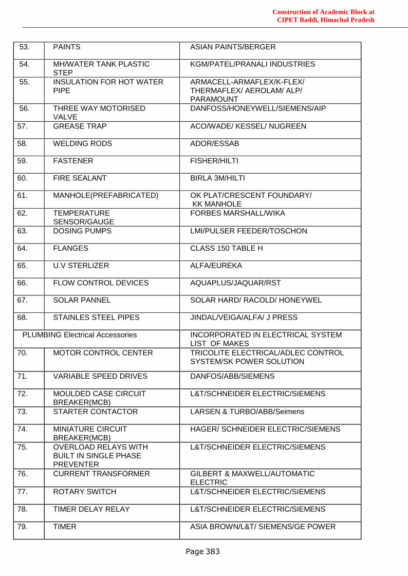
Construction of Academic Block at
CIPET Baddi, Himachal Pradesh
Page 383
53. PAINTS ASIAN PAINTS/BERGER
54. MH/WATER TANK PLASTIC STEP
KGM/PATEL/PRANALI INDUSTRIES
55. INSULATION FOR HOT WATER PIPE
ARMACELL-ARMAFLEX/K-FLEX/ THERMAFLEX/ AEROLAM/ ALP/ PARAMOUNT
56. THREE WAY MOTORISED VALVE
DANFOSS/HONEYWELL/SIEMENS/AIP
57. GREASE TRAP ACO/WADE/ KESSEL/ NUGREEN
58. WELDING RODS ADOR/ESSAB
59. FASTENER FISHER/HILTI
60. FIRE SEALANT BIRLA 3M/HILTI
61. MANHOLE(PREFABRICATED) OK PLAT/CRESCENT FOUNDARY/ KK MANHOLE
62. TEMPERATURE SENSOR/GAUGE
FORBES MARSHALL/WIKA
63. DOSING PUMPS LMI/PULSER FEEDER/TOSCHON
64. FLANGES CLASS 150 TABLE H
65. U.V STERLIZER ALFA/EUREKA
66. FLOW CONTROL DEVICES AQUAPLUS/JAQUAR/RST
67. SOLAR PANNEL SOLAR HARD/ RACOLD/ HONEYWEL
68. STAINLES STEEL PIPES JINDAL/VEIGA/ALFA/ J PRESS
PLUMBING Electrical Accessories INCORPORATED IN ELECTRICAL SYSTEM LIST OF MAKES
70. MOTOR CONTROL CENTER TRICOLITE ELECTRICAL/ADLEC CONTROL SYSTEM/SK POWER SOLUTION
71. VARIABLE SPEED DRIVES DANFOS/ABB/SIEMENS
72. MOULDED CASE CIRCUIT BREAKER(MCB)
L&T/SCHNEIDER ELECTRIC/SIEMENS
73. STARTER CONTACTOR LARSEN & TURBO/ABB/Seimens
74. MINIATURE CIRCUIT BREAKER(MCB)
HAGER/ SCHNEIDER ELECTRIC/SIEMENS
75. OVERLOAD RELAYS WITH BUILT IN SINGLE PHASE PREVENTER
L&T/SCHNEIDER ELECTRIC/SIEMENS
76. CURRENT TRANSFORMER GILBERT & MAXWELL/AUTOMATIC ELECTRIC
77. ROTARY SWITCH L&T/SCHNEIDER ELECTRIC/SIEMENS
78. TIMER DELAY RELAY L&T/SCHNEIDER ELECTRIC/SIEMENS
79. TIMER ASIA BROWN/L&T/ SIEMENS/GE POWER
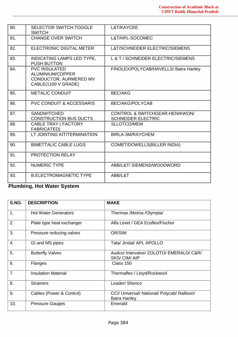
Construction of Academic Block at
CIPET Baddi, Himachal Pradesh
Page 384
80. SELECTOR SWITCH,TOGGLE SWITCH
L&T/KAYCEE
81. CHANGE OVER SWITCH L&T/HPL-SOCOMEC
82. ELECTRONIC DIGITAL METER L&T/SCHNEIDER ELECTRIC/SIEMENS
83. INDICATING LAMPS LED TYPE, PUSH BUTTON
L & T / SCHNEIDER ELECTRIC/SIEMENS
84. PVC INSULATED ALUMINIUM/COPPER CONDUCTOR, AURMERED MV CABLE(1100 V GRADE)
FINOLEX/POLYCAB/HAVELLS/ Batra Hanley
85. METALIC CONDUIT BEC/AKG
86. PVC CONDUIT & ACCESSARIS BEC/AKG/POLYCAB
87. SANDWITCHED CONSTRUCTION BUS DUCTS
CONTROL & SWITCHGEAR-HENIKWON/ SCHNEIDER ELECTRIC
88. CABLE TRAY ( FACTORY FABRICATED)
SLLOTCO/MEM
89. LT JOINTING KIT/TERMINATION BIRLA-3M/RAYCHEM
90. BIMETTALIC CABLE LUGS COMET/DOWELLS(BILLER INDIA)
91. PROTECTION RELAY
92. NUMERIC TYPE ABB/L&T/ SIEMENS/WOODWORD
93. B.ELECTROMAGNETIC TYPE ABB/L&T
Plumbing, Hot Water System
S.NO. DESCRIPTION MAKE
1. Hot Water Generators Thermax /Mxima /Olympia/
2. Plate type heat exchanger Alfa Level / GEA Ecoflex/Fischor
3. Pressure reducing valves OR/SIM
4. GI and MS pipes Tata/ Jindal/ APL APOLLO
5. Butterfly Valves Audco/ Intervalve/ ZOLOTO/ EMERALD/ C&R/ SKS/ CIM/ AIP
6. Flanges Class 150
7. Insulation Material Thermaflex / Lloyd/Rockwool
8. Strainers Leader/ Shenco
9. Cables (Power & Control) CCI/ Universal/ National/ Polycab/ Rallison/ Batra Hanley
10. Pressure Gauges Emerald
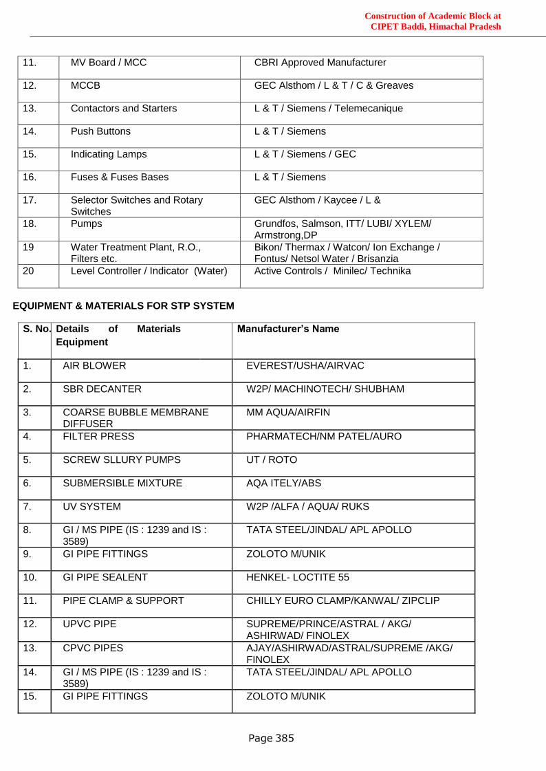
Construction of Academic Block at
CIPET Baddi, Himachal Pradesh
Page 385
11. MV Board / MCC CBRI Approved Manufacturer
12. MCCB GEC Alsthom / L & T / C & Greaves
13. Contactors and Starters L & T / Siemens / Telemecanique
14. Push Buttons L & T / Siemens
15. Indicating Lamps L & T / Siemens / GEC
16. Fuses & Fuses Bases L & T / Siemens
17. Selector Switches and Rotary Switches
GEC Alsthom / Kaycee / L &
18. Pumps Grundfos, Salmson, ITT/ LUBI/ XYLEM/ Armstrong,DP
19 Water Treatment Plant, R.O., Filters etc.
Bikon/ Thermax / Watcon/ Ion Exchange / Fontus/ Netsol Water / Brisanzia
20 Level Controller / Indicator (Water) Active Controls / Minilec/ Technika
EQUIPMENT & MATERIALS FOR STP SYSTEM
S. No. Details of Materials /
Equipment
Manufacturer’s Name
1. AIR BLOWER EVEREST/USHA/AIRVAC
2. SBR DECANTER W2P/ MACHINOTECH/ SHUBHAM
3. COARSE BUBBLE MEMBRANE DIFFUSER
MM AQUA/AIRFIN
4. FILTER PRESS PHARMATECH/NM PATEL/AURO
5. SCREW SLLURY PUMPS UT / ROTO
6. SUBMERSIBLE MIXTURE AQA ITELY/ABS
7. UV SYSTEM W2P /ALFA / AQUA/ RUKS
8. GI / MS PIPE (IS : 1239 and IS : 3589)
TATA STEEL/JINDAL/ APL APOLLO
9. GI PIPE FITTINGS ZOLOTO M/UNIK
10. GI PIPE SEALENT HENKEL- LOCTITE 55
11. PIPE CLAMP & SUPPORT CHILLY EURO CLAMP/KANWAL/ ZIPCLIP
12. UPVC PIPE SUPREME/PRINCE/ASTRAL / AKG/ ASHIRWAD/ FINOLEX
13. CPVC PIPES AJAY/ASHIRWAD/ASTRAL/SUPREME /AKG/ FINOLEX
14. GI / MS PIPE (IS : 1239 and IS : 3589)
TATA STEEL/JINDAL/ APL APOLLO
15. GI PIPE FITTINGS ZOLOTO M/UNIK
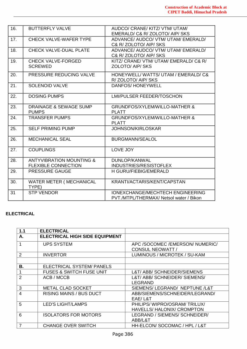
Construction of Academic Block at
CIPET Baddi, Himachal Pradesh
Page 386
16. BUTTERFLY VALVE AUDCO/ CRANE/ KITZ/ VTM/ UTAM/ EMERALD/ C& R/ ZOLOTO/ AIP/ SKS
17. CHECK VALVE-WAFER TYPE ADVANCE/ AUDCO/ VTM/ UTAM/ EMERALD/ C& R/ ZOLOTO/ AIP/ SKS
18. CHECK VALVE-DUAL PLATE ADVANCE/ AUDCO/ VTM/ UTAM/ EMERALD/ C& R/ ZOLOTO/ AIP/ SKS
19. CHECK VALVE-FORGED SCREWED
KITZ/ CRANE/ VTM/ UTAM/ EMERALD/ C& R/ ZOLOTO/ AIP/ SKS
20. PRESSURE REDUCING VALVE HONEYWELL/ WATTS/ UTAM / EMERALD/ C& R/ ZOLOTO/ AIP/ SKS
21. SOLENOID VALVE DANFOS/ HONEYWELL
22. DOSING PUMPS LMI/PULSER FEEDER/TOSCHON
23. DRAINAGE & SEWAGE SUMP PUMPS
GRUNDFOS/XYLEM/WILLO-MATHER & PLATT
24. TRANSFER PUMPS GRUNDFOS/XYLEM/WILLO-MATHER & PLATT
25. SELF PRIMING PUMP JOHNSON/KIRLOSKAR
26. MECHANICAL SEAL BURGMANN/SEALOL
27. COUPLINGS LOVE JOY
28. ANTYVIBRATION MOUNTING & FLEXIBLE CONNECTION
DUNLOP/KANWAL INDUSTRIES/RESISTOFLEX
29. PRESSURE GAUGE H GURU/FIEBIG/EMERALD
30. WATER METER ( MECHANICAL TYPE)
KRANTI/ACTARIS/KENT/CAPSTAN
31 STP VENDOR IONEXCHANGE/MECHTECH ENGINEERING PVT./MTPL/THERMAX/ Netsol water / Bikon
ELECTRICAL
1.1 ELECTRICAL
A. ELECTRICAL HIGH SIDE EQUIPMENT
1 UPS SYSTEM APC /SOCOMEC /EMERSON/ NUMERIC/ CONSUL NEOWATT /
2 INVERTOR LUMINOUS / MICROTEK / SU-KAM
B. ELECTRICAL SYSTEM/ PANELS
1 FUSES & SWITCH FUSE UNIT L&T/ ABB/ SCHNEIDER/SIEMENS
2 ACB / MCCB L&T/ ABB/ SCHNEIDER/ SIEMENS/ LEGRAND
3 METAL CLAD SOCKET SIEMENS/ LEGRAND/ NEPTUNE /L&T
4 RISING MAINS / BUS DUCT ABB/SIEMENS/SCHNEIDER/LEGRAND/ EAE/ L&T
5 LED'S LIGHT/LAMPS PHILIPS/ WIPRO/OSRAM/ TRILUX/ HAVELLS/ HALONIX/ CROMPTON
6 ISOLATORS FOR MOTORS LEGRAND / SIEMENS/ SCHNEIDER/ ABB/L&T
7 CHANGE OVER SWITCH HH-ELCON/ SOCOMAC / HPL / L&T
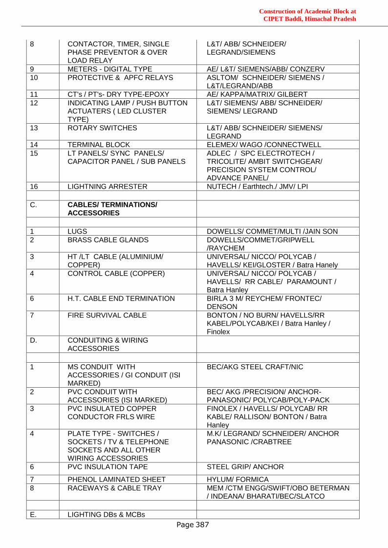
Construction of Academic Block at
CIPET Baddi, Himachal Pradesh
Page 387
8 CONTACTOR, TIMER, SINGLE PHASE PREVENTOR & OVER LOAD RELAY
L&T/ ABB/ SCHNEIDER/ LEGRAND/SIEMENS
9 METERS - DIGITAL TYPE AE/ L&T/ SIEMENS/ABB/ CONZERV
10 PROTECTIVE & APFC RELAYS ASLTOM/ SCHNEIDER/ SIEMENS / L&T/LEGRAND/ABB
11 CT's / PT's- DRY TYPE-EPOXY AE/ KAPPA/MATRIX/ GILBERT
12 INDICATING LAMP / PUSH BUTTON ACTUATERS ( LED CLUSTER TYPE)
L&T/ SIEMENS/ ABB/ SCHNEIDER/ SIEMENS/ LEGRAND
13 ROTARY SWITCHES L&T/ ABB/ SCHNEIDER/ SIEMENS/ LEGRAND
14 TERMINAL BLOCK ELEMEX/ WAGO /CONNECTWELL
15 LT PANELS/ SYNC PANELS/ CAPACITOR PANEL / SUB PANELS
ADLEC / SPC ELECTROTECH / TRICOLITE/ AMBIT SWITCHGEAR/ PRECISION SYSTEM CONTROL/ ADVANCE PANEL/
16 LIGHTNING ARRESTER NUTECH / Earthtech./ JMV/ LPI
C. CABLES/ TERMINATIONS/ ACCESSORIES
1 LUGS DOWELLS/ COMMET/MULTI /JAIN SON
2 BRASS CABLE GLANDS DOWELLS/COMMET/GRIPWELL /RAYCHEM
3 HT /LT CABLE (ALUMINIUM/ COPPER)
UNIVERSAL/ NICCO/ POLYCAB / HAVELLS/ KEI/GLOSTER / Batra Hanely
4 CONTROL CABLE (COPPER) UNIVERSAL/ NICCO/ POLYCAB / HAVELLS/ RR CABLE/ PARAMOUNT / Batra Hanley
6 H.T. CABLE END TERMINATION BIRLA 3 M/ REYCHEM/ FRONTEC/ DENSON
7 FIRE SURVIVAL CABLE BONTON / NO BURN/ HAVELLS/RR KABEL/POLYCAB/KEI / Batra Hanley / Finolex
D. CONDUITING & WIRING ACCESSORIES
1 MS CONDUIT WITH ACCESSORIES / GI CONDUIT (ISI MARKED)
BEC/AKG STEEL CRAFT/NIC
2 PVC CONDUIT WITH ACCESSORIES (ISI MARKED)
BEC/ AKG /PRECISION/ ANCHOR-PANASONIC/ POLYCAB/POLY-PACK
3 PVC INSULATED COPPER CONDUCTOR FRLS WIRE
FINOLEX / HAVELLS/ POLYCAB/ RR KABLE/ RALLISON/ BONTON / Batra Hanley
4 PLATE TYPE - SWITCHES / SOCKETS / TV & TELEPHONE SOCKETS AND ALL OTHER WIRING ACCESSORIES
M.K/ LEGRAND/ SCHNEIDER/ ANCHOR PANASONIC /CRABTREE
6 PVC INSULATION TAPE STEEL GRIP/ ANCHOR
7 PHENOL LAMINATED SHEET HYLUM/ FORMICA
8 RACEWAYS & CABLE TRAY MEM /CTM ENGG/SWIFT/OBO BETERMAN / INDEANA/ BHARATI/BEC/SLATCO
E. LIGHTING DBs & MCBs
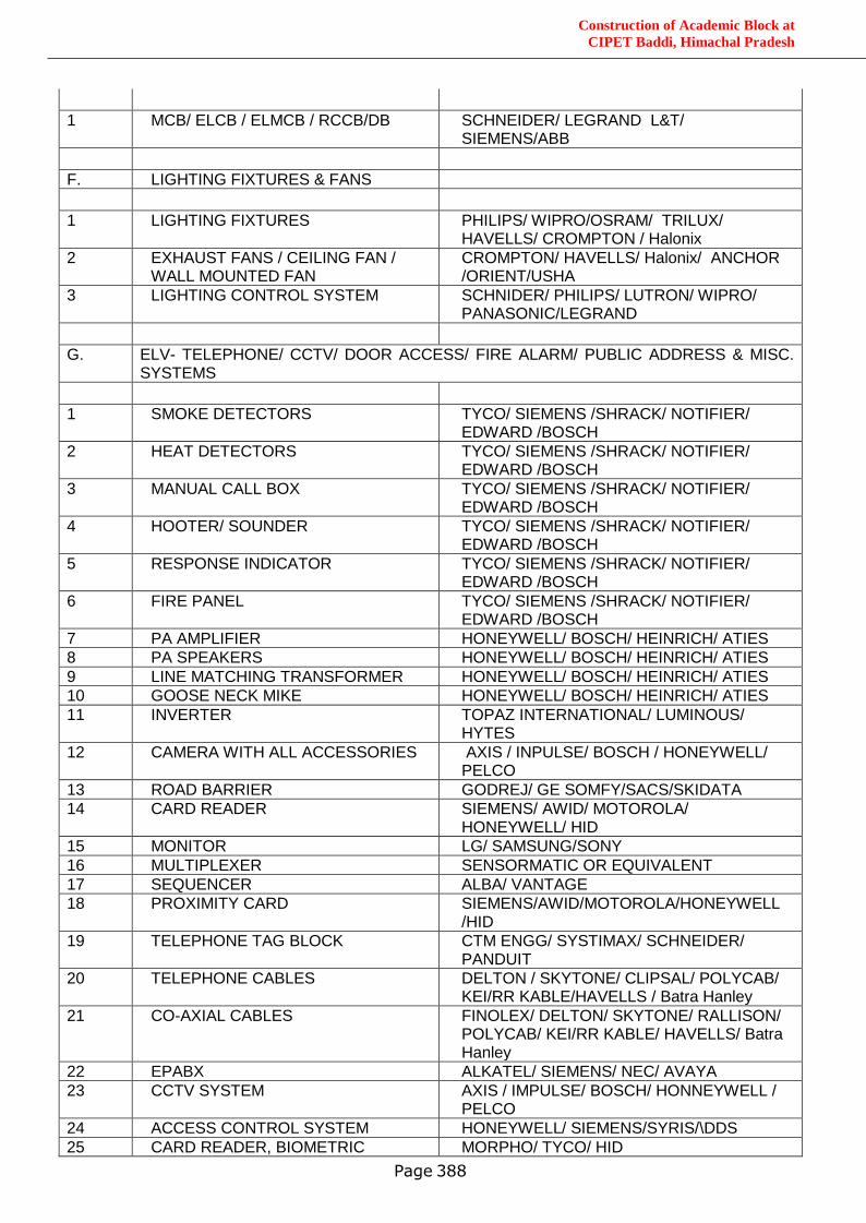
Construction of Academic Block at
CIPET Baddi, Himachal Pradesh
Page 388
1 MCB/ ELCB / ELMCB / RCCB/DB SCHNEIDER/ LEGRAND L&T/ SIEMENS/ABB
F. LIGHTING FIXTURES & FANS
1 LIGHTING FIXTURES PHILIPS/ WIPRO/OSRAM/ TRILUX/ HAVELLS/ CROMPTON / Halonix
2 EXHAUST FANS / CEILING FAN / WALL MOUNTED FAN
CROMPTON/ HAVELLS/ Halonix/ ANCHOR /ORIENT/USHA
3 LIGHTING CONTROL SYSTEM SCHNIDER/ PHILIPS/ LUTRON/ WIPRO/ PANASONIC/LEGRAND
G. ELV- TELEPHONE/ CCTV/ DOOR ACCESS/ FIRE ALARM/ PUBLIC ADDRESS & MISC. SYSTEMS
1 SMOKE DETECTORS TYCO/ SIEMENS /SHRACK/ NOTIFIER/ EDWARD /BOSCH
2 HEAT DETECTORS TYCO/ SIEMENS /SHRACK/ NOTIFIER/ EDWARD /BOSCH
3 MANUAL CALL BOX TYCO/ SIEMENS /SHRACK/ NOTIFIER/ EDWARD /BOSCH
4 HOOTER/ SOUNDER TYCO/ SIEMENS /SHRACK/ NOTIFIER/ EDWARD /BOSCH
5 RESPONSE INDICATOR TYCO/ SIEMENS /SHRACK/ NOTIFIER/ EDWARD /BOSCH
6 FIRE PANEL TYCO/ SIEMENS /SHRACK/ NOTIFIER/ EDWARD /BOSCH
7 PA AMPLIFIER HONEYWELL/ BOSCH/ HEINRICH/ ATIES
8 PA SPEAKERS HONEYWELL/ BOSCH/ HEINRICH/ ATIES
9 LINE MATCHING TRANSFORMER HONEYWELL/ BOSCH/ HEINRICH/ ATIES
10 GOOSE NECK MIKE HONEYWELL/ BOSCH/ HEINRICH/ ATIES
11 INVERTER TOPAZ INTERNATIONAL/ LUMINOUS/ HYTES
12 CAMERA WITH ALL ACCESSORIES AXIS / INPULSE/ BOSCH / HONEYWELL/ PELCO
13 ROAD BARRIER GODREJ/ GE SOMFY/SACS/SKIDATA
14 CARD READER SIEMENS/ AWID/ MOTOROLA/ HONEYWELL/ HID
15 MONITOR LG/ SAMSUNG/SONY
16 MULTIPLEXER SENSORMATIC OR EQUIVALENT
17 SEQUENCER ALBA/ VANTAGE
18 PROXIMITY CARD SIEMENS/AWID/MOTOROLA/HONEYWELL/HID
19 TELEPHONE TAG BLOCK CTM ENGG/ SYSTIMAX/ SCHNEIDER/ PANDUIT
20 TELEPHONE CABLES DELTON / SKYTONE/ CLIPSAL/ POLYCAB/ KEI/RR KABLE/HAVELLS / Batra Hanley
21 CO-AXIAL CABLES FINOLEX/ DELTON/ SKYTONE/ RALLISON/ POLYCAB/ KEI/RR KABLE/ HAVELLS/ Batra Hanley
22 EPABX ALKATEL/ SIEMENS/ NEC/ AVAYA
23 CCTV SYSTEM AXIS / IMPULSE/ BOSCH/ HONNEYWELL / PELCO
24 ACCESS CONTROL SYSTEM HONEYWELL/ SIEMENS/SYRIS/\DDS
25 CARD READER, BIOMETRIC MORPHO/ TYCO/ HID
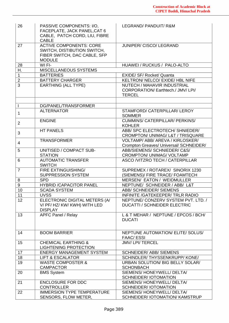
Construction of Academic Block at
CIPET Baddi, Himachal Pradesh
Page 389
26
PASSIVE COMPONENTS: I/O, FACEPLATE, JACK PANEL,CAT 6 CABLE, PATCH CORD, LIU, FIBRE CABLE
LEGRAND/ PANDUIT/ R&M
27 ACTIVE COMPONENTS: CORE SWITCH, DISTIBUTION SWITCH, FIBER SWITCH, DAC CABLE, SFP MODULE
JUNIPER/ CISCO/ LEGRAND
28 WI FI- HUAWEI / RUCKUS / PALO-ALTO
H. MISCELLANEOUS SYSTEMS
1 BATTERIES EXIDE/ SF/ Rocket/ Quanta
2 BATTERY CHARGER KELTRON/ NELCO/ EXIDE/ HBL NIFE
3 EARTHING (ALL TYPE) NUTECH / MAHAVIR INDUSTRIAL CORPORATION/ Earthtech./ JMV/ LPI/ TERCEL
I DG/PANEL/TRANSFORMER
1 ALTERNATOR STAMFORD/ CATERPILLAR/ LEROY
SOMMER
2 ENGINE CUMMINS/ CATERPILLAR/ PERKINS/
KOHLER
3 HT PANELS ABB/ SPC ELECTROTECH/ SHNIEDER/
CROMPTON/ UNIMAG/ L&T / TRISQUARE
4 TRANSFORMER VOLTAMP/ ABB/ AREVA / KIRLOSKER/
Crompton Greaves/ Universal/ SCHNEIDER/
5 UNITISED / COMPACT SUB-STATION
ABB/SIEMENS/ SCHNIEDER/ C&S/ CROMPTON/ UNIMAG/ VOLTAMP
6 AUTOMATIC TRANSFER SWITCH
ASCO /VITZRO TECH / CATERPILLAR
7 FIRE EXTINGUISHING/ SUPPRESSION SYSTEM
SUPREMEX / ROTAREX/ SINORIX 1230 (SIEMENS)/ FIRE TRACE/ FOAMTECH
8 SPD MERSEN/ EATON / WEIDMULLER
9 HYBRID /CAPACITOR PANEL NEPTUNE/ SCHNEIDER / ABB/ L&T
10 SCADA SYSTEM ABB/ SCHNEIDER/ SIEMENS
11 UVSS INFINITE /GATEKEEPER/ TRLR RADIO
12 ELECTRONIC DIGITAL METERS (A/ V/ PF/ HZ/ KW/ KWH) WITH LED DISPLAY
NEPTUNE/ CONZERV SYSTEM PVT. LTD. / DUCATTI / SCHNEIDER ELECTRIC
13 APFC Panel / Relay L & T MEHAR / NEPTUNE / EPCOS / BCH/ DUCATI
14 BOOM BARRIER NEPTUNE AUTOMATION/ ELITE/ SOLUS/ FAAC/ ESSI
15 CHEMICAL EARTHING & LIGHTENING PROTECTION
JMV/ LPI/ TERCEL
17 ENERGY MANAGEMENT SYSTEM SCHNEIDER/ ABB/ SIEMENS
18 LIFT & ESCALATOR SCHINDLER/ THYSSENKRUPP/ KONE/
19 WASTE COMPOSTER & CAMPACTOR
URBAN SOLUTION/ BIG BELLY SOLAR/ SCHONBACH
20 BMS System SIEMENS/ HONEYWELL/ DELTA/ SCHNEIDER/ IOTOMATION
21 ENCLOSURE FOR DDC CONTROLLER
SIEMENS/ HONEYWELL/ DELTA/ SCHNEIDER/ IOTOMATION
22 IMMERSION TYPE TEMPERATURE SENSORS, FLOW METER,
SIEMENS/ HONEYWELL/ DELTA/ SCHNEIDER/ IOTOMATION/ KAMSTRUP
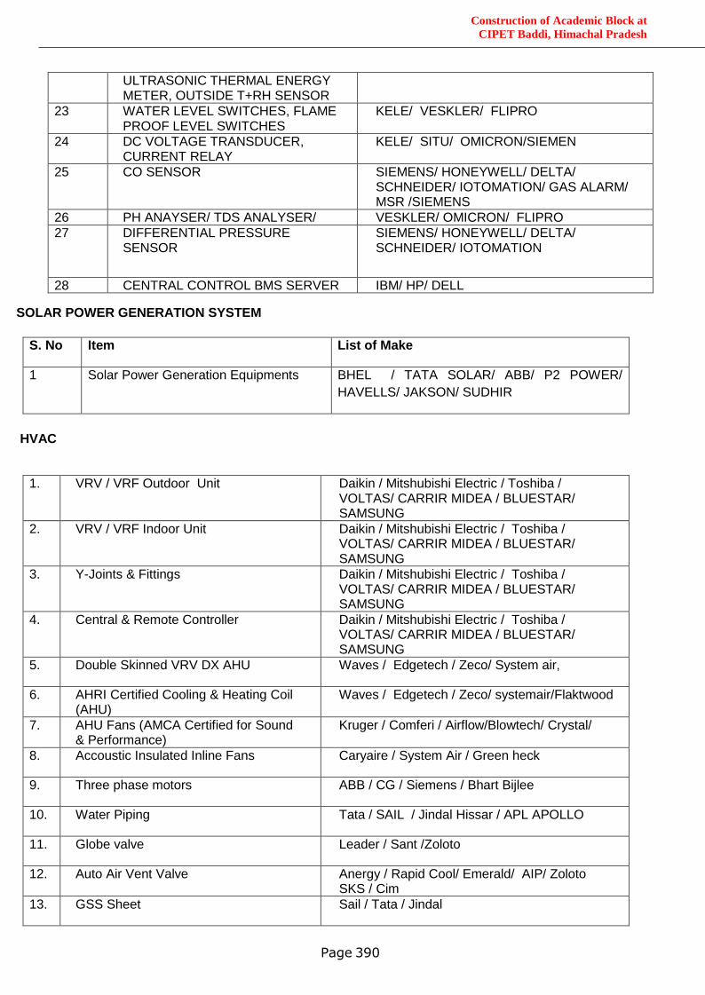
Construction of Academic Block at
CIPET Baddi, Himachal Pradesh
Page 390
SOLAR POWER GENERATION SYSTEM
S. No Item List of Make
1 Solar Power Generation Equipments BHEL / TATA SOLAR/ ABB/ P2 POWER/
HAVELLS/ JAKSON/ SUDHIR
HVAC
1. VRV / VRF Outdoor Unit Daikin / Mitshubishi Electric / Toshiba / VOLTAS/ CARRIR MIDEA / BLUESTAR/ SAMSUNG
2. VRV / VRF Indoor Unit Daikin / Mitshubishi Electric / Toshiba / VOLTAS/ CARRIR MIDEA / BLUESTAR/ SAMSUNG
3. Y-Joints & Fittings Daikin / Mitshubishi Electric / Toshiba / VOLTAS/ CARRIR MIDEA / BLUESTAR/ SAMSUNG
4. Central & Remote Controller Daikin / Mitshubishi Electric / Toshiba / VOLTAS/ CARRIR MIDEA / BLUESTAR/ SAMSUNG
5. Double Skinned VRV DX AHU Waves / Edgetech / Zeco/ System air,
6. AHRI Certified Cooling & Heating Coil (AHU)
Waves / Edgetech / Zeco/ systemair/Flaktwood
7. AHU Fans (AMCA Certified for Sound & Performance)
Kruger / Comferi / Airflow/Blowtech/ Crystal/
8. Accoustic Insulated Inline Fans Caryaire / System Air / Green heck
9. Three phase motors ABB / CG / Siemens / Bhart Bijlee
10. Water Piping Tata / SAIL / Jindal Hissar / APL APOLLO
11. Globe valve Leader / Sant /Zoloto
12. Auto Air Vent Valve Anergy / Rapid Cool/ Emerald/ AIP/ Zoloto SKS / Cim
13. GSS Sheet Sail / Tata / Jindal
ULTRASONIC THERMAL ENERGY METER, OUTSIDE T+RH SENSOR
23 WATER LEVEL SWITCHES, FLAME PROOF LEVEL SWITCHES
KELE/ VESKLER/ FLIPRO
24 DC VOLTAGE TRANSDUCER, CURRENT RELAY
KELE/ SITU/ OMICRON/SIEMEN
25 CO SENSOR SIEMENS/ HONEYWELL/ DELTA/ SCHNEIDER/ IOTOMATION/ GAS ALARM/ MSR /SIEMENS
26 PH ANAYSER/ TDS ANALYSER/ VESKLER/ OMICRON/ FLIPRO
27 DIFFERENTIAL PRESSURE SENSOR
SIEMENS/ HONEYWELL/ DELTA/ SCHNEIDER/ IOTOMATION
28 CENTRAL CONTROL BMS SERVER IBM/ HP/ DELL
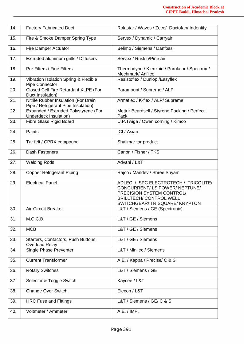
Construction of Academic Block at
CIPET Baddi, Himachal Pradesh
Page 391
14. Factory Fabricated Duct Rolastar / Waves / Zeco/ Ductofab/ Indentify
15. Fire & Smoke Damper Spring Type Servex / Dynamic / Carryair
16. Fire Damper Actuator Belimo / Siemens / Danfoss
17. Extruded aluminum grills / Diffusers Servex / Ruskin/Pine air
18. Pre Filters / Fine Filters Thermodyne / Klenzoid / Purolator / Spectrum/ Mechmark/ Anfilco
19. Vibration Isolation Spring & Flexible Pipe Connector
Resistoflex / Dunlop /Easyflex
20. Closed Cell Fire Retardant XLPE (For Duct Insulation)
Paramount / Supreme / ALP
21. Nitrile Rubber Insulation (For Drain Pipe / Refrigerant Pipe Insulation)
Armaflex / K-flex / ALP/ Supreme
22. Expanded / Extruded Polystyrene (For Underdeck Insulation)
Mettur Beardsell / Styrene Packing / Perfect Pack
23. Fibre Glass Rigid Board U.P.Twiga / Owen corning / Kimco
24. Paints ICI / Asian
25. Tar felt / CPRX compound Shalimar tar product
26. Dash Fasteners Canon / Fisher / TKS
27. Welding Rods Advani / L&T
28. Copper Refrigerant Piping Rajco / Mandev / Shree Shyam
29. Electrical Panel ADLEC / SPC ELECTROTECH / TRICOLITE/ CONCURRENT/ LS POWER/ NEPTUNE/ PRECISION SYSTEM CONTROL/ BRILLTECH/ CONTROL WELL SWITCHGEAR/ TRISQUARE/ KRYPTON
30. Air-Circuit Breaker L&T / Siemens / GE (Spectronic)
31. M.C.C.B. L&T / GE / Siemens
32. MCB L&T / GE / Siemens
33. Starters, Contactors, Push Buttons, Overload Relay
L&T / GE / Siemens
34. Single Phase Preventer L&T / Minilec / Siemens
35. Current Transformer A.E. / Kappa / Precise/ C & S
36. Rotary Switches L&T / Siemens / GE
37. Selector & Toggle Switch Kaycee / L&T
38. Change Over Switch Elecon / L&T
39. HRC Fuse and Fittings L&T / Siemens / GE/ C & S
40. Voltmeter / Ammeter A.E. / IMP.
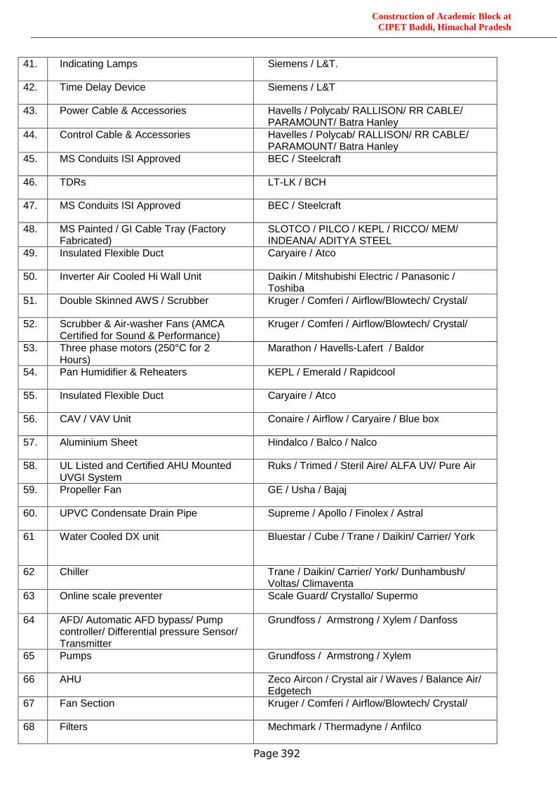
Construction of Academic Block at
CIPET Baddi, Himachal Pradesh
Page 392
41. Indicating Lamps Siemens / L&T.
42. Time Delay Device Siemens / L&T
43. Power Cable & Accessories Havells / Polycab/ RALLISON/ RR CABLE/ PARAMOUNT/ Batra Hanley
44. Control Cable & Accessories Havelles / Polycab/ RALLISON/ RR CABLE/ PARAMOUNT/ Batra Hanley
45. MS Conduits ISI Approved BEC / Steelcraft
46. TDRs LT-LK / BCH
47. MS Conduits ISI Approved BEC / Steelcraft
48. MS Painted / GI Cable Tray (Factory Fabricated)
SLOTCO / PILCO / KEPL / RICCO/ MEM/ INDEANA/ ADITYA STEEL
49. Insulated Flexible Duct Caryaire / Atco
50. Inverter Air Cooled Hi Wall Unit Daikin / Mitshubishi Electric / Panasonic / Toshiba
51. Double Skinned AWS / Scrubber Kruger / Comferi / Airflow/Blowtech/ Crystal/
52. Scrubber & Air-washer Fans (AMCA Certified for Sound & Performance)
Kruger / Comferi / Airflow/Blowtech/ Crystal/
53. Three phase motors (250°C for 2 Hours)
Marathon / Havells-Lafert / Baldor
54. Pan Humidifier & Reheaters KEPL / Emerald / Rapidcool
55. Insulated Flexible Duct Caryaire / Atco
56. CAV / VAV Unit Conaire / Airflow / Caryaire / Blue box
57. Aluminium Sheet Hindalco / Balco / Nalco
58. UL Listed and Certified AHU Mounted UVGI System
Ruks / Trimed / Steril Aire/ ALFA UV/ Pure Air
59. Propeller Fan GE / Usha / Bajaj
60. UPVC Condensate Drain Pipe Supreme / Apollo / Finolex / Astral
61 Water Cooled DX unit Bluestar / Cube / Trane / Daikin/ Carrier/ York
62 Chiller Trane / Daikin/ Carrier/ York/ Dunhambush/ Voltas/ Climaventa
63 Online scale preventer Scale Guard/ Crystallo/ Supermo
64 AFD/ Automatic AFD bypass/ Pump controller/ Differential pressure Sensor/ Transmitter
Grundfoss / Armstrong / Xylem / Danfoss
65 Pumps Grundfoss / Armstrong / Xylem
66 AHU Zeco Aircon / Crystal air / Waves / Balance Air/ Edgetech
67 Fan Section Kruger / Comferi / Airflow/Blowtech/ Crystal/
68 Filters Mechmark / Thermadyne / Anfilco
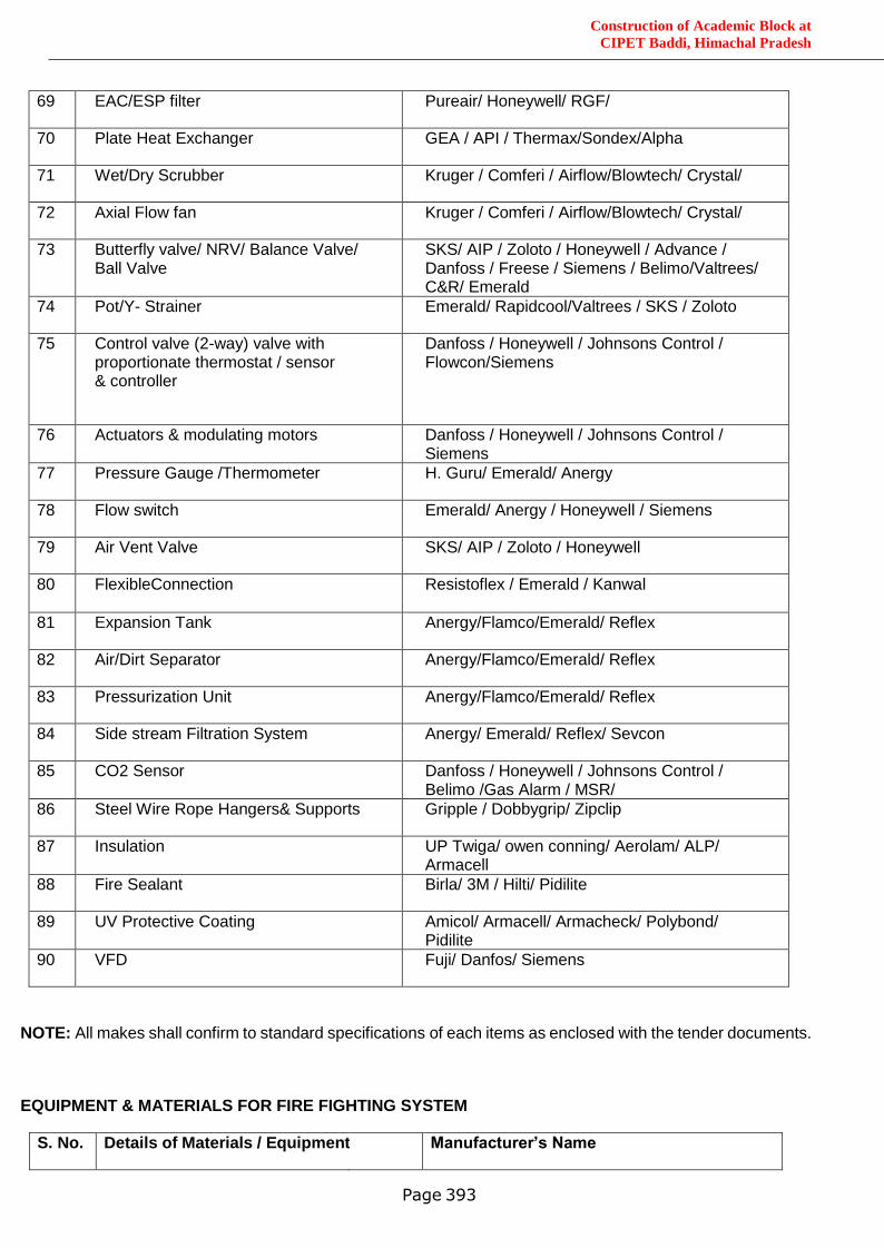
Construction of Academic Block at
CIPET Baddi, Himachal Pradesh
Page 393
69 EAC/ESP filter Pureair/ Honeywell/ RGF/
70 Plate Heat Exchanger GEA / API / Thermax/Sondex/Alpha
71 Wet/Dry Scrubber Kruger / Comferi / Airflow/Blowtech/ Crystal/
72 Axial Flow fan Kruger / Comferi / Airflow/Blowtech/ Crystal/
73 Butterfly valve/ NRV/ Balance Valve/ Ball Valve
SKS/ AIP / Zoloto / Honeywell / Advance / Danfoss / Freese / Siemens / Belimo/Valtrees/ C&R/ Emerald
74 Pot/Y- Strainer Emerald/ Rapidcool/Valtrees / SKS / Zoloto
75 Control valve (2-way) valve with proportionate thermostat / sensor & controller
Danfoss / Honeywell / Johnsons Control / Flowcon/Siemens
76 Actuators & modulating motors Danfoss / Honeywell / Johnsons Control / Siemens
77 Pressure Gauge /Thermometer H. Guru/ Emerald/ Anergy
78 Flow switch Emerald/ Anergy / Honeywell / Siemens
79 Air Vent Valve SKS/ AIP / Zoloto / Honeywell
80 FlexibleConnection
Resistoflex / Emerald / Kanwal
81 Expansion Tank Anergy/Flamco/Emerald/ Reflex
82 Air/Dirt Separator Anergy/Flamco/Emerald/ Reflex
83 Pressurization Unit Anergy/Flamco/Emerald/ Reflex
84 Side stream Filtration System Anergy/ Emerald/ Reflex/ Sevcon
85 CO2 Sensor Danfoss / Honeywell / Johnsons Control / Belimo /Gas Alarm / MSR/
86 Steel Wire Rope Hangers& Supports Gripple / Dobbygrip/ Zipclip
87 Insulation UP Twiga/ owen conning/ Aerolam/ ALP/ Armacell
88 Fire Sealant Birla/ 3M / Hilti/ Pidilite
89 UV Protective Coating Amicol/ Armacell/ Armacheck/ Polybond/ Pidilite
90 VFD Fuji/ Danfos/ Siemens
NOTE: All makes shall confirm to standard specifications of each items as enclosed with the tender documents.
EQUIPMENT & MATERIALS FOR FIRE FIGHTING SYSTEM
S. No. Details of Materials / Equipment Manufacturer’s Name
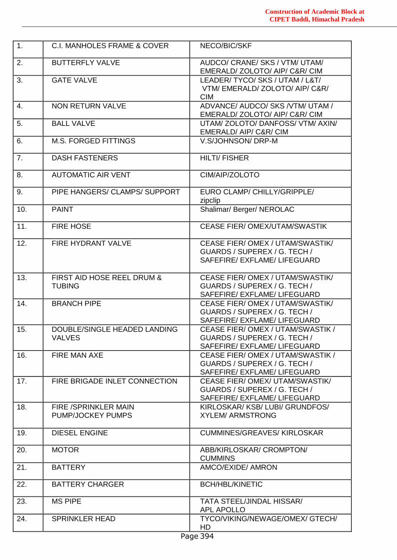
Construction of Academic Block at
CIPET Baddi, Himachal Pradesh
Page 394
1. C.I. MANHOLES FRAME & COVER NECO/BIC/SKF
2. BUTTERFLY VALVE AUDCO/ CRANE/ SKS / VTM/ UTAM/ EMERALD/ ZOLOTO/ AIP/ C&R/ CIM
3. GATE VALVE LEADER/ TYCO/ SKS / UTAM / L&T/ VTM/ EMERALD/ ZOLOTO/ AIP/ C&R/ CIM
4. NON RETURN VALVE ADVANCE/ AUDCO/ SKS /VTM/ UTAM / EMERALD/ ZOLOTO/ AIP/ C&R/ CIM
5. BALL VALVE UTAM/ ZOLOTO/ DANFOSS/ VTM/ AXIN/ EMERALD/ AIP/ C&R/ CIM
6. M.S. FORGED FITTINGS V.S/JOHNSON/ DRP-M
7. DASH FASTENERS HILTI/ FISHER
8. AUTOMATIC AIR VENT CIM/AIP/ZOLOTO
9. PIPE HANGERS/ CLAMPS/ SUPPORT EURO CLAMP/ CHILLY/GRIPPLE/ zipclip
10. PAINT Shalimar/ Berger/ NEROLAC
11. FIRE HOSE CEASE FIER/ OMEX/UTAM/SWASTIK
12. FIRE HYDRANT VALVE CEASE FIER/ OMEX / UTAM/SWASTIK/ GUARDS / SUPEREX / G. TECH / SAFEFIRE/ EXFLAME/ LIFEGUARD
13. FIRST AID HOSE REEL DRUM & TUBING
CEASE FIER/ OMEX / UTAM/SWASTIK/ GUARDS / SUPEREX / G. TECH / SAFEFIRE/ EXFLAME/ LIFEGUARD
14. BRANCH PIPE CEASE FIER/ OMEX / UTAM/SWASTIK/ GUARDS / SUPEREX / G. TECH / SAFEFIRE/ EXFLAME/ LIFEGUARD
15. DOUBLE/SINGLE HEADED LANDING VALVES
CEASE FIER/ OMEX / UTAM/SWASTIK / GUARDS / SUPEREX / G. TECH / SAFEFIRE/ EXFLAME/ LIFEGUARD
16. FIRE MAN AXE CEASE FIER/ OMEX / UTAM/SWASTIK / GUARDS / SUPEREX / G. TECH / SAFEFIRE/ EXFLAME/ LIFEGUARD
17. FIRE BRIGADE INLET CONNECTION CEASE FIER/ OMEX/ UTAM/SWASTIK/ GUARDS / SUPEREX / G. TECH / SAFEFIRE/ EXFLAME/ LIFEGUARD
18. FIRE /SPRINKLER MAIN PUMP/JOCKEY PUMPS
KIRLOSKAR/ KSB/ LUBI/ GRUNDFOS/ XYLEM/ ARMSTRONG
19. DIESEL ENGINE CUMMINES/GREAVES/ KIRLOSKAR
20. MOTOR ABB/KIRLOSKAR/ CROMPTON/ CUMMINS
21. BATTERY AMCO/EXIDE/ AMRON
22. BATTERY CHARGER BCH/HBL/KINETIC
23. MS PIPE TATA STEEL/JINDAL HISSAR/ APL APOLLO
24. SPRINKLER HEAD TYCO/VIKING/NEWAGE/OMEX/ GTECH/ HD
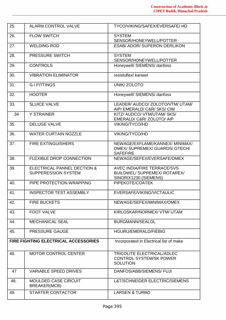
Construction of Academic Block at
CIPET Baddi, Himachal Pradesh
Page 395
25. ALARM CONTROL VALVE TYCO/VIKING/SAFEX/EVERSAFE/ HD
26. FLOW SWITCH SYSTEM SENSOR/HONEYWELL/POTTER
27. WELDING ROD ESAB/ ADOR/ SUPERON OERLIKON
28. PRESSURE SWITCH SYSTEM SENSOR/HONEYWELL/POTTER
29. CONTROLS Honeywell/ SIEMENS/ danfoss
30. VIBRATION ELIMINATOR resistoflex/ kanwel
31. G.I FITTINGS UNIK/ ZOLOTO
32. HOOTER Honeywell/ SIEMENS/ danfoss
33. SLUICE VALVE LEADER/ AUDCO/ ZOLOTO/VTM/ UTAM/ AIP/ EMERALD/ C&R/ SKS/ CIM
34 Y STRAINER KITZ/ AUDCO/ VTM/UTAM/ SKS/ EMERALD/ C&R/ ZOLOTO/ AIP
35. DELUGE VALVE VIKING/TYCO/HD
36. WATER CURTAIN NOZZLE VIKING/TYCO/HD
37. FIRE EXTINGUISHERS NEWAGE/EXFLAME/KANNEX/ MINIMAX/ OMEX/ SUPREMEX/ GUARDS/ GTECH/ SAFEFIRE
38. FLEXIBLE DROP CONNECTION NEWAGE/SEFEX/EVERSAFE/OMEX
39. ELECTRICAL PANNEL DECTION & SUPPERESSION SYSTEM
AVEC INDIA/FIRE TERRACE/SVS BUILDWEL/ SUPREMEX/ ROTAREX/ SINORIX1230 (SIEMENS)
40. PIPE PROTECTION WRAPPING PIPEKOTE/COATEK
41. INSPECTOR TEST ASSEMBLY EVERSAFE/VIKING/VICTAULIC
42. FIRE BUCKETS NEWAGE/SEFEX/MINIMAX/OMEX
43. FOOT VALVE KIRLOSKAR/NORMEX/ VTM/ UTAM
44. MECHANICAL SEAL BURGMANN/SEALOL
45. PRESSURE GAUGE HGURU/EMERALD/FIEBIG
FIRE FIGHTING ELECTRICAL ACCESSORIES Incorporated in Electrical list of make
46. MOTOR CONTROL CENTER TRICOLITE ELECTRICAL/ADLEC CONTROL SYSTEM/SK POWER SOLUTION
47 VARIABLE SPEED DRIVES DANFOS/ABB/SIEMENS/ FUJI
48. MOULDED CASE CIRCUIT BREAKER(MCB)
L&T/SCHNEIDER ELECTRIC/SIEMENS
49. STARTER CONTACTOR LARSEN & TURBO
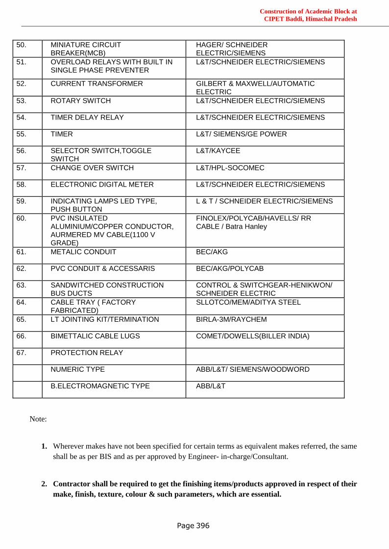
Construction of Academic Block at
CIPET Baddi, Himachal Pradesh
Page 396
50. MINIATURE CIRCUIT BREAKER(MCB)
HAGER/ SCHNEIDER ELECTRIC/SIEMENS
51. OVERLOAD RELAYS WITH BUILT IN SINGLE PHASE PREVENTER
L&T/SCHNEIDER ELECTRIC/SIEMENS
52. CURRENT TRANSFORMER GILBERT & MAXWELL/AUTOMATIC ELECTRIC
53. ROTARY SWITCH L&T/SCHNEIDER ELECTRIC/SIEMENS
54. TIMER DELAY RELAY L&T/SCHNEIDER ELECTRIC/SIEMENS
55. TIMER L&T/ SIEMENS/GE POWER
56. SELECTOR SWITCH,TOGGLE SWITCH
L&T/KAYCEE
57. CHANGE OVER SWITCH L&T/HPL-SOCOMEC
58. ELECTRONIC DIGITAL METER L&T/SCHNEIDER ELECTRIC/SIEMENS
59. INDICATING LAMPS LED TYPE, PUSH BUTTON
L & T / SCHNEIDER ELECTRIC/SIEMENS
60. PVC INSULATED ALUMINIUM/COPPER CONDUCTOR, AURMERED MV CABLE(1100 V GRADE)
FINOLEX/POLYCAB/HAVELLS/ RR CABLE / Batra Hanley
61. METALIC CONDUIT BEC/AKG
62. PVC CONDUIT & ACCESSARIS BEC/AKG/POLYCAB
63. SANDWITCHED CONSTRUCTION BUS DUCTS
CONTROL & SWITCHGEAR-HENIKWON/ SCHNEIDER ELECTRIC
64. CABLE TRAY ( FACTORY FABRICATED)
SLLOTCO/MEM/ADITYA STEEL
65. LT JOINTING KIT/TERMINATION BIRLA-3M/RAYCHEM
66. BIMETTALIC CABLE LUGS COMET/DOWELLS(BILLER INDIA)
67. PROTECTION RELAY
NUMERIC TYPE ABB/L&T/ SIEMENS/WOODWORD
B.ELECTROMAGNETIC TYPE ABB/L&T
Note:
1. Wherever makes have not been specified for certain terms as equivalent makes referred, the same
shall be as per BIS and as per approved by Engineer- in-charge/Consultant.
2. Contractor shall be required to get the finishing items/products approved in respect of their
make, finish, texture, colour & such parameters, which are essential.
Related Documents