Construction of a Wind Turbine and a Charge Controller May 2013 1 CONSTRUCTION OF A WIND TURBINE AND A CHARGE CONTROLLER by Daniel Munarriz Antona A project report submitted to the School of Science and Technology in partial fulfillment of the requirements for the Bachelor of Engineering In Renewable Energy and Sustainable Technologies May 2013 Supervised by: Dr Frank Welcomme

Welcome message from author
This document is posted to help you gain knowledge. Please leave a comment to let me know what you think about it! Share it to your friends and learn new things together.
Transcript
Construction of a Wind Turbine and a Charge Controller May 2013
1
CONSTRUCTION OF A WIND TURBINE
AND
A CHARGE CONTROLLER by
Daniel Munarriz Antona
A project report submitted to the
School of Science and Technology
in partial fulfillment of the requirements for the
Bachelor of Engineering
In
Renewable Energy and Sustainable Technologies
May 2013
Supervised by: Dr Frank Welcomme
Construction of a Wind Turbine and a Charge Controller May 2013
2
CONSTRUCTION OF A WIND TURBINE
AND
A CHARGE CONTROLLER

Construction of a Wind Turbine and a Charge Controller May 2013
3
Author’s declaration Statement 1
This work has not previously been presented in any form to Glyndwr University or at
any other institutional body whether for assessment or for any other purposes. Save for
any express acknowledgements, references, and/or bibliographies cited in the work, I
confirm that the intellectual content of the work is the results of my own efforts and no
other person.
Statement 2
It is acknowledged that the author of this work shall own the copyright. However, by
submitting this copyright work for assessment, the author grants to the university a
perpetual royalty-free license to do all or any of those things referred to in section 16(I)
of the copyright, designs, and patents act 1988 (viz: to copy work; to issue copies to the
public; to perform or show or play the work in public, to broadcast the work or make an
adaptation of the work).
Signed:_______________________________________
Date:_________________________________________
Construction of a Wind Turbine and a Charge Controller May 2013
4
Table of contents
AUTHOR’S DECLARATION………………………………………………………….3
LIST OF FIGURES……………………………………………………………………...7
LIST OF TABLES……………………………………………………………………….9
1.PROJECT PROPOSAL…………………………………………………...…………9
1.1 BACKGROUND……………………………………………….…....………9
1.2 AIMS…………………………………………………………………….…10
1.3 OBJETIVES……………………………………...…………...……………10
1.4 TIME PLAN………………………………………………..………………11
1.5 INITIAL COST……………...…………………………..…………………11
2. INTRODUCTION………………………………………………………….………12
2.1 Location……………………………………………………….……………12
2.2 Wind graphic of Dolau………………………………..……………………13
2.3 Mini wind energy……………………………………...……………………13
2.4 Wind characterization………………………………………………………16
2.5 Choice of technology……………………………………….………………18
2.6 The performance of the turbine……………………….……………………18
2.7 Domestic consumption…………………………………..…………………18
3. GENERATOR………………………………………………………...……………20
3.1 Synchronous-Machine…………………………………...…………………20
3.1.1 - Principle of operation……………………...……………………20
3.1.2 - Advantages and disadvantages of the synchronous machine as a generator:………………………………………….……………………30
3.2 - Choice of motor: …………………………………………………………30
3.2.1 - Engine specifications GE150-240-225…………………………33
Construction of a Wind Turbine and a Charge Controller May 2013
5
3.2.2 - Vacuum and short circuit tests…………………..………………35
3.2.2.1 - Disadvantages of the motor as a generator……………36
3.2.3 - Solution adopted to decrease voltage……………………...……37
4. CONVERTER CHARGE CONTROLLER…………….……………...…………41
4.1 - Structure of the converter…………………………….……………...……………41
4.2 - Components of the converter………………………….………….………………42
4.2.1 - THE IGBT………………………….………………...…………42
4.2.2 – DIODE……………………………….…………………………46
4.2.3 – INDUCTANCE……………………..…….……………………48
4.3 DC-DC Buck Converter (Buck) …………..……………………….………49
4.3.1 - Construction and operation of the buck converter……….…..…49
4.4 - Construction of electronic converter…………………………..….………50
4.4.1 - Components used in the converter……………….…..…………50
4.4.1.1 - Three phase rectifier…………………..………………50
4.4.1.2 - Continuous Bus buck converter……………….………53
4.4.1.3 - Switch block……………………………………..……53
4.4.1.4 - Decoupling capacitor……………….…………………54
4.4.1.5 - Inductance……………………………………..………55
4.4.2-Control of the electronic converter……………….………………55
4.4.2.1 - Current Loop……………………………….…………55
4.4.2.2 - Measurement of voltage and current……….…………56
4.4.2.3 - PI controller……………………………….……..……57
4.4.2.4 - Maximum power point tracking MPPT………………57
4.5 – Driver…………………………………………………………….………57
4.5.1 - Structure of the driver……………………………………..……58
4.5.2 - Setting the driver pin……………………………………………59
Construction of a Wind Turbine and a Charge Controller May 2013
6
4.5.2.1 - Input Pins…………………………………...…………59
4.5.2.2 - Output Pines……………………………...……………60
4.6 Protections……………………………………………….…………………62
4.6.1 - Temperature protection…………………………………………62
4.6.1.1 – Inductance……………………………………………62
4.6.1.2 – Semiconductors…………………………………...…………62
4.6.2 - Protection against overcharging of batteries…………...………63
4.6.3 - Protection against short circuit …………………...……………64
5. BATTERIES………………………………………………….……………………66
5.1 Introduction: ………………………………………………………………66
5.2 Types of batteries: …………………………………...……………………66
5.2.1 Batteries Lead-Acid……………………………...………………66
5.2.2 Alkaline battery…………………………………….……………67
5.2.3 Nickel-iron (Ni-Fe) …………………………………..…………67
5.2.4 Alkaline manganese batteries……………………………………67
5.2.5 Nickel-Cadmium (Ni-Cd) ………………………………………67
5.2.6 Nickel-Metal Hydride (Ni-MH) ……………..…………………67
5.2.7 Lithium-ion battery (LI-ION) ……………………….…………67
5.2.8 Lithium Polymer Batteries (LIPO) ………………….…………67
5.3 Characteristics of the Lead-Acid Battery: …………………….…………68
5.3.1 Load cycle…………………………...…………………………68
5.3.2 Discharge cycle…………………………...……………………69
5.3.3 Cautions should be taken with batteries…….…………………69
5.4 Battery Choice………………………………….…………….…………70
5.5 Installing the Batteries………………………………………..…………70

Construction of a Wind Turbine and a Charge Controller May 2013
7
CONCLUSIONS………………………………………………………….……………72
Success of Project………………………………………………………………………72
Final Costing……………………………………………………………………………72
Further Work…………………………………………………………...………………73
REFERENCES…………………………………………………………………………73
List of figures Fig.2.1 Dolau’s image from google maps……………..………………………………12
Fig.2.2 Wind speed graphic of Dolau …………………………………….……………13
Fig. 2.3 Example of a domestic wind turbine. …………………………………………15
Fig.2.4 Basic scheme of a domestic wind turbine. ………………………….…………16
Fig. 2.5 Wind characterization…………………………………………………………17
Fig. 2.6 Wind of Roses………………………………………………………….………19
Fig.3.1 Schematic of a three-phase synchronous generator…………...………………21
Fig.3.2 Phase system voltages………………………………………….………………22
Fig.3.3 Four-pole synchronous machine……………………………….………………23
Fig.3.4 Star connection of the stator windings…………………………………………24
Fig.3.5 Permanent magnet rotor with two pairs of poles………………………………25
Fig.3.6 Load test circuit of a synchronous generator………………….………………26
Fig.3.7 Voltage- current curve…………………………………………………………27
Fig.3.8 Short circuit test of synchronous generator……………………………………28
Fig.3.9 Curve generator circuit Synchronous……………………….…………………28
Fig.3.10 Empty curve of a permanent magnet synchronous generator………...………29
Fig.3.11 Rear view engine………………………………………………………...……34
Fig.3.12 Side view of the motor…………………………………………………...……34

Construction of a Wind Turbine and a Charge Controller May 2013
8
Fig.3.13 Voltage as a function speed………………………………………..…………36
Fig.3.14 Three parallel branches composed of two coils in series…………….………39
Fig.4.1System Schematic……………………………………………………….………42
Fig.4.2 Current and voltage in IGBT …………………………………………………42
Fig.4.3 Static characteristic in positive IGBT ………………………………...………42
Fig.4.4 Equivalent circuit of an IGBT…………………………………….……………43
Fig.4.5 A switching circuit IGBT…………………………………………….…………44
Fig.4.6 Turn on characteristic of an IGBT. ……………………………………………44
Fig.4.7 Shutdown characteristic of an IGBT……………………………...……………45
Fig.4.8 Static characteristic of the diode………………………………………………46 Fig.4.9 Equivalent Circuit diode………………………………………….……………47 Fig.4.10 On and off of a diode………………………………………….………………47 Fig.4.11 System Schematic……………………..………………………………………50 Fig.4.12 Three phase rectifier…………………….……………………………………51 Fig.4.13 Three Phase RectifierVishay……………….…………………………………52 Fig.4.14 Switchblock SKM150GAR12T4………………………………………………53 . Fig.4.15 Wiring diagram switching block. …………….………………………………54 Fig.4.16 Bypass capacitor……………………………….……..………………………54 Fig.4.17 Block diagram of the current loop……………………………………………56 Fig.4.18 Tension transducer scheme………………………...…………………………56 Fig.4.19 Driver scheme…………………………………………………...……………58 Fig.4.20 Configuration input pins………………………………...……………………59 Fig.4.21Configuring the output pins……………………………...……………………61 Fig.4.22 Order overheating stop by inductance……………………..…………………62 Fig.4.23 Measuring the temperature in the radiator…………………...………………63
Construction of a Wind Turbine and a Charge Controller May 2013
9
Fig.4.24 Command to stop the battery from overcharging……………………………64 Fig.5.1 Lead-Acid Battery…………………………………………..…………………68 Fig.5.2 Battery connections……………………………………………………………71
List of Tables Table 2.1 Domestic Consumption………………………………………………………19 Table 3.1 Relationship between Wind speed and rpm ……………………….…………….32 Table 3.2 Vacumm Voltage in Star and Triangle………………………………………37 Table 3.3 Vacuum Voltage in different connections……………………………………38 Table 3.4 Changed stator results…………………………………………….…………40
1. PROJECT PROPOSAL 1.1BACKGROUND
Wind is an indirect manifestation of solar energy, produced as a result of the different degree of warming of Earth's surface by the sun and the rotation of the Earth on itself. Wind is caused by differences in pressure. When a difference in pressure exists, the air is accelerated from higher to lower pressure.
Economic: Wind power has low ongoing costs, but a moderate capital cost. The marginal cost of wind energy once a plant is constructed is usually less than 1 cent per kW·h. as wind turbine technology improves, costs are coming down. There are now longer and lighter wind turbine blades, improvements in turbine performance and increased power generation efficiency. Also, wind project capital and maintenance costs have continued to decline.
Social: Surveys of public attitudes across Europe and in many other countries show strong public support for wind power. About 80 percent of EU citizens support wind power. In Germany, where wind power has gained very high social acceptance, hundreds of thousands of people have invested in citizens' wind farms across the country and thousands of small and medium sized enterprises are running successful businesses in a new sector that in 2008 employed 90,000 people and generated 8 percent of Germany's electricity
Construction of a Wind Turbine and a Charge Controller May 2013
10
Some of the reasons that make this type of energy is reaching such importance in recent years is that wind power does not pollute, is inexhaustible and slows the depletion of fossil fuels, helping to prevent climate change. It is also one of the cheapest sources, which today can compete in performance with other traditional energy sources like coal plants and even nuclear energy, when considering the costs of remedying environmental damage.
The energy generated in the absence of a combustion process or a thermal processing step is from environmental point of view, a very favourable method, being clean and free of pollution problems.
Other advantages to highlight wind energy are that it can be installed in areas unsuitable for other purposes, such as in desert areas, in areas not suitable for cultivation, etc. Its use in combination with other types of energy, usually solar, energy self-sufficiency allows housing, thus ending the need to connect to grids, can be achieved autonomy of several days without power from any of the two systems.
The only types of problems involving the use of wind energy are the visual impact, noise produced by the rotation of the rotor and the death of some birds colliding with the blades. But obviously, these drawbacks are minimal compared to any other form of energy. Therefore, wind energy is clearly a step forward and a viable strategy in the future of energy generation.
1.2 AIM
Design a domestic wind turbine and a charge controller, to reduce the electricity bill and avoid power outages in the home.
1.3 OBJECTIVES
• Choose the best wind turbine that can be used for a particular house. • Construction of converter charge controller. • Choose the best place and ideal height to install the wind turbine. • Design of electric circuit. • Design of electronic circuit.
Construction of a Wind Turbine and a Charge Controller May 2013
11
1.4 TIME PLAN
OCTOBER • Write a project proposal.
NOVEMBER
• Find information about working of wind turbines. • Investigate about different ways to take energy from the wind. • Investigate about the performance of the turbine.
DICEMBER • First presentation
JANUARY • Investigate about what kind of generator is better for particular case.
• Choose the systems regulating the speed of rotation. FEBRUARY • Choose converter components.
• Control of the electronic converter. MARCH • Protections.
• System simulation. APRIL • Complete all parts of the project
• Start doing the last presentation • Review all calculations
MAY • Final presentation
1.5 INITIAL COST Electric things: 2000 Electronic things: 3000 Batteries: 1000 Total cost = 2000 + 3000 + 1000 = £6000 approximately.
Construction of a Wind Turbine and a Charge Controller May 2013
12
2. INTRODUCTION The objective of this project is the use of wind energy in rural areas, which have sufficient resources to support themselves energetically. In Wales there are many villages that are far from the cities and many of them have many outages due to network electric problems. These network failures hinder life in these rural areas, where most of the population lives in the first sector, such as livestock and a power outage can mean total stop their activity and can generate large losses if the cut is extended. These problems occur in rural areas can be solved with other electrical energy sources such as solar, micro-hydro and small wind. With only one of these would be enough, but the combination of the three is the best way to ensure autonomous power. This draft defines the construction of a wind turbine for a house is located in a rural area.The house is connected to a single phase of 300mts processing center, with a significant loss of power at full load, as the section of cable with the line is very thin. The wind turbine will help to prevent voltage drops, to reduce spending power consumption and solution to power cuts that often lead in winter.
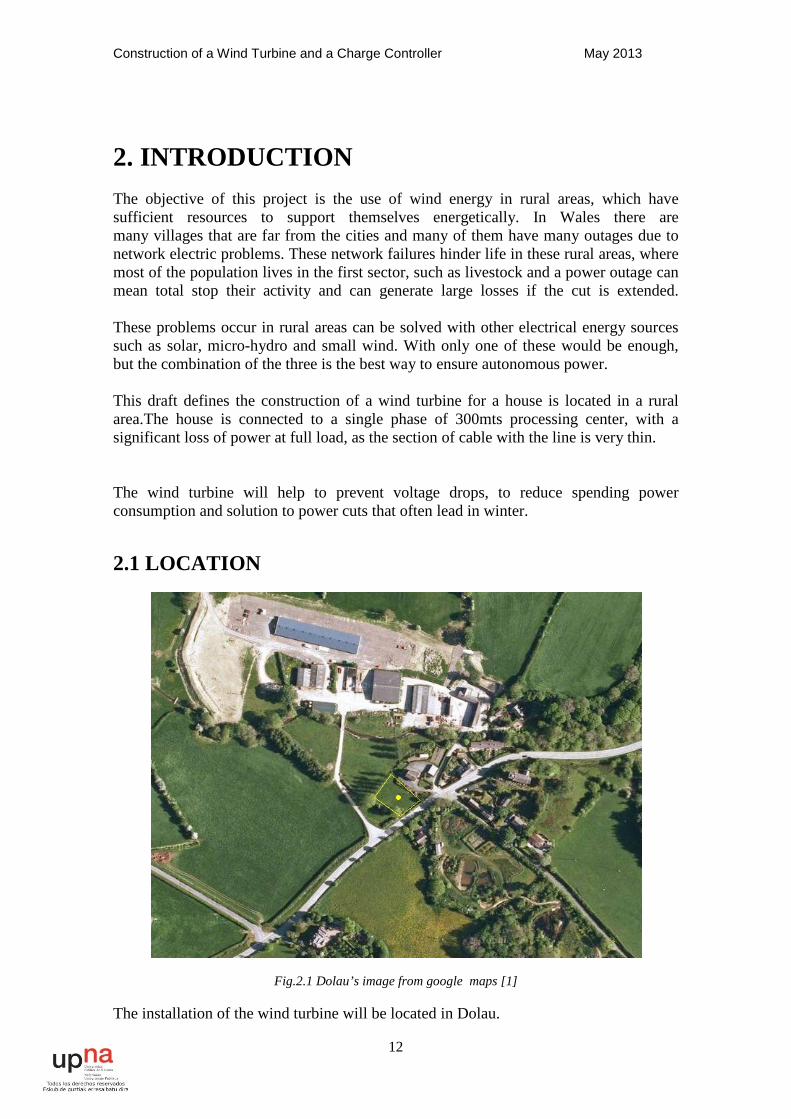
2.1 LOCATION
Fig.2.1 Dolau’s image from google maps [1]
The installation of the wind turbine will be located in Dolau.
Construction of a Wind Turbine and a Charge Controller May 2013
13
Dolau is a small village in Powys, mid Wales and near Llandrindoad. The wind turbine will be in front of the house and near to a great chicken farm. There are not many people living, and people who live in this area are agree with the installation of the wind turbine. It is a good condition because not many people will be visually affected.
The buildings in this area are not very high and there is not any tree near the place.
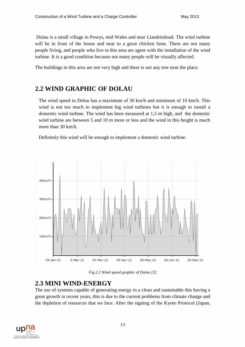
2.2 WIND GRAPHIC OF DOLAU
The wind speed in Dolau has a maximum of 30 km/h and minimum of 10 km/h. This wind is not too much to implement big wind turbines but it is enough to install a domestic wind turbine. The wind has been measured at 1,5 m high, and the domestic wind turbine are between 5 and 10 m more or less and the wind in this height is much more than 30 km/h.
Definitely this wind will be enough to implement a domestic wind turbine.
Fig.2.2 Wind speed graphic of Dolau [2]
2.3 MINI WIND-ENERGY The use of systems capable of generating energy in a clean and sustainable this having a great growth in recent years, this is due to the current problems from climate change and the depletion of resources that we face. After the signing of the Kyoto Protocol (Japan,

Construction of a Wind Turbine and a Charge Controller May 2013
14
1997) the search for clean energy solutions and sustainable has increased considerably.
In Europe, in recent years there has been boom called "Wind Farms" (production sites of wind turbines over 500 kW)like north hoyle offshore wind farm into the sea, and this has helped to reduce technology costs. Although due to its large size and the strong environmental impact, mainly visual, has difficulty to get licenses. However, this is where wind farms are small whose impact visual can be very small and can be used in applications other than industrial homes, tourism infrastructure, isolated populations, etc. Besides all above, the difficulty to extend the electricity grid and the deregulated electricity market development are helping to promote mini-wind technology.
We refer to micro systems with a power of a few kilowatts, which just no no need for installation requirements, in which electrical energy can be produced in a sustainable and environmentally friendly. There is no conventional classification that defines the micro-wind, but often refers to this concept of power facilities less than 100 kW, and the total income of these facilities are usually comprised between 0.30 and 0.60, that is lower than industrial dimensions.
In relation to the very low power wind turbines, power below 10 kW, traditionally used for water pumping (windpumps multiblade) and mini generators farms for electricity production (usually forming mixed sets wind-pv in isolated houses), it should be noted that although the number of installations predictable and potentially made in the coming years is high, their energy contribution is very low. It is estimated that by 2010 there may be a total installed capacity of about 13,000 Kw. In UK there are currently two manufacturers of small wind turbines and several importers, especially U.S. manufacturers. According to one of these sources manufacturers, the potential market for this type of facility in UK could be estimated at wind around 600-700 per year, which could significantly increase if there is more support from government.
The environmental impact of micro-wind installations have in common with large installations (large land take, visual impact, noise, interference in telecommunications, negative effects on wildlife and vegetation effects Electromagnetic ...), as it interferes with the same natural elements, even if different perceptual results.
First, the micro-turbines have a much smaller size than the large wind turbines and therefore require less space and are relatively inconspicuous. However, they are often installed near other elements and may incur a loss space that could be allocated to other purposes, a visual impact (this is a presence invasive to live with, but can be nice from the aesthetic point of view) communications interference and electromagnetic effects. Although is not relevant these problems have to be taken into account in the preliminary feasibility study of Project.
Construction of a Wind Turbine and a Charge Controller May 2013
15
The majority of micro-generators are horizontal axis Upwind (the Wind is first blades and then the tower), plus usually zero taper. Different configurations of wind turbines: bladed, three bladed, twin-bladed, multiblade. The increased number of blades aerodynamic rotation speed decreases and increases the performance but increases the price of turbines. For this reason, the market has focused bladed and three-bladed rotors, the latter being the most common configuration, because the generator operates more uniformly, and therefore its duration is greater, plus the energy produced is slightly higher, with a consequent increase in performance and also visually less aggressive, by possessing a configuration symmetric, a lower rotation speed, more relaxing for the eyes of the beholder.
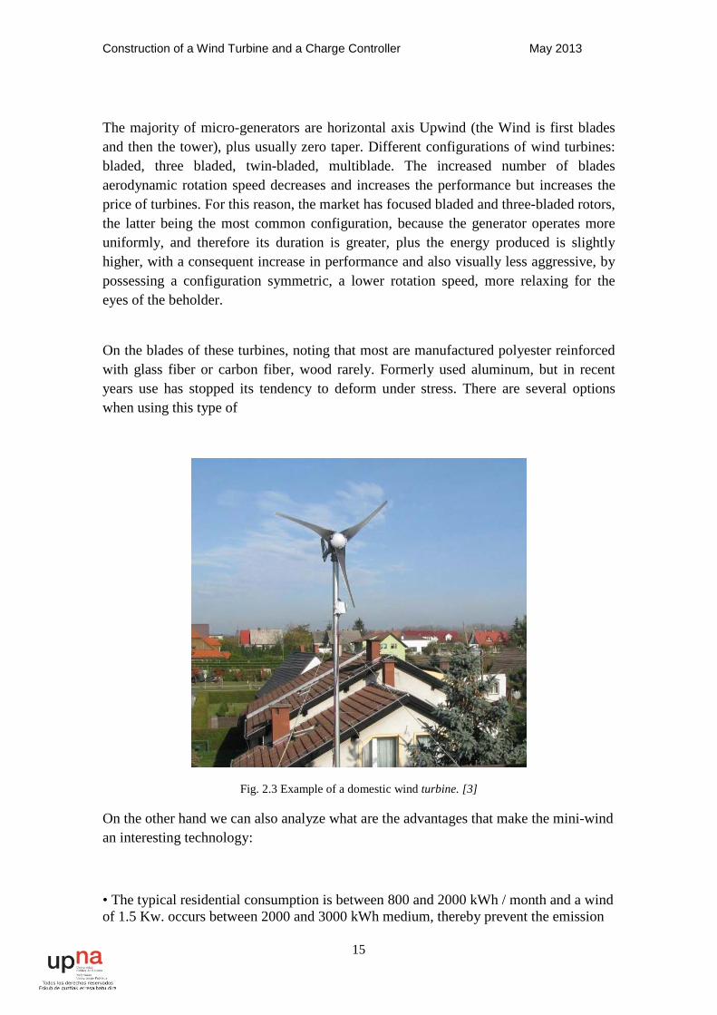
On the blades of these turbines, noting that most are manufactured polyester reinforced with glass fiber or carbon fiber, wood rarely. Formerly used aluminum, but in recent years use has stopped its tendency to deform under stress. There are several options when using this type of
Fig. 2.3 Example of a domestic wind turbine. [3]
On the other hand we can also analyze what are the advantages that make the mini-wind an interesting technology:
• The typical residential consumption is between 800 and 2000 kWh / month and a wind of 1.5 Kw. occurs between 2000 and 3000 kWh medium, thereby prevent the emission
Construction of a Wind Turbine and a Charge Controller May 2013
16
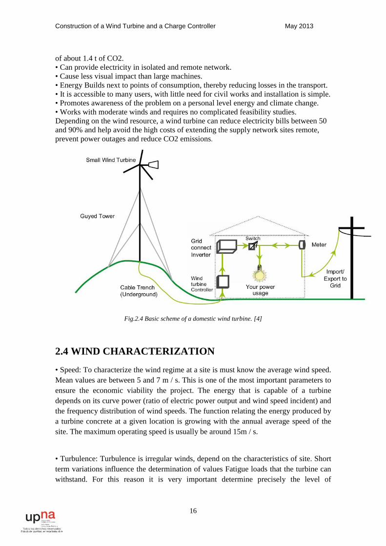
of about 1.4 t of CO2. • Can provide electricity in isolated and remote network. • Cause less visual impact than large machines. • Energy Builds next to points of consumption, thereby reducing losses in the transport. • It is accessible to many users, with little need for civil works and installation is simple. • Promotes awareness of the problem on a personal level energy and climate change. • Works with moderate winds and requires no complicated feasibility studies. Depending on the wind resource, a wind turbine can reduce electricity bills between 50 and 90% and help avoid the high costs of extending the supply network sites remote, prevent power outages and reduce CO2 emissions.
Fig.2.4 Basic scheme of a domestic wind turbine. [4]
2.4 WIND CHARACTERIZATION
• Speed: To characterize the wind regime at a site is must know the average wind speed. Mean values are between 5 and 7 m / s. This is one of the most important parameters to ensure the economic viability the project. The energy that is capable of a turbine depends on its curve power (ratio of electric power output and wind speed incident) and the frequency distribution of wind speeds. The function relating the energy produced by a turbine concrete at a given location is growing with the annual average speed of the site. The maximum operating speed is usually be around 15m / s.
• Turbulence: Turbulence is irregular winds, depend on the characteristics of site. Short term variations influence the determination of values Fatigue loads that the turbine can withstand. For this reason it is very important determine precisely the level of

Construction of a Wind Turbine and a Charge Controller May 2013
17
turbulence on each site, since life useful and the availability of wind turbines depends largely on this factor.
• gustiness: What are the maximum, or peak wind gusts involving abrupt changes in structural dynamic stresses.
Fig. 2.5 Wind characterization
• Vertical profile of the location: The air friction with the earth's surface causes the wind is not equal at all heights, but is increasing with height. As can be seen in the following image, depending on the amount and size of obstacles and rugged terrain, wind speed grows faster or slower with height.
• Weibull Distribution: It is the most widely used analytical expression studies of wind energy to represent the probability of wind speeds
• Distribution directional wind. It's called "wind rose" representing percentage of time when the wind comes from a certain direction (the direction Wind is always referred to the place from whence the air stream). Normally, also reflected in the wind rose the speed distribution of directional wind for each interval. In the next picture you can see the rosette wind speeds and the histogram of the site that have the turbine of this project.
• Energy Distribution Sector. Wind speeds associated with energy generated in said direction.
• IEC Class site parameters: annual average speed, speed reference and turbulence
Construction of a Wind Turbine and a Charge Controller May 2013
18
2.5 CHOICE OF TECHNOLOGY
For the choice of technology to be used, it should be noted:
• IEC Class (technical characteristics of the wind turbine). Is determined from the Wind statistical parameters on site: average speed, speed reference index of turbulence. Must be ratified by the manufacturer.
• Vertical profile (height of the generator). Determines the height of the turbine shaft. It must measure the wind at different heights so that all points on the rotor value of the wind speed is similar.
• site density (power curve to use.). It is of great importance for be a factor directly proportional to production. Is calculated from the altitude medium and applying the UNE 28-533-85 (ISO2533) in normal atmosphere. Also from the pressure and temperature.
2.6 THE PERFORMANCE OF THE TURBINE
The wind machine performance depends on the intensity of the wind: a equal diameter of the blades, with increasing wind speed, the power theoretically extractable increases exponentially. Therefore, before deciding to install a wind system is essential to know well wind characteristics in the place where you plan to install the turbines. These knowledge obtained previously made an exhaustive study of the frequency of the speed, duration and direction of the wind.
Wind intensity depends on the topographic features of the land. A roughness is critical circumstances thereof: plain or sea the wind blows greater intensity than in the country or around the cities. Another factor to take into account is the altitude of the terrain: the more you climb higher the wind speed, but less is its density. The wind machines operate within minimum and maximum parameters of speed wind. Roughly speaking:
• They can be activated with variable wind 2-4 m / s (cut-in speed)
• When the wind speed reaches 10 to 14 m / s (or nominal cutting speed), is active device power control.
• They stop when the wind speed exceeds 20-25 m / s (speed cut-off).
2.7 DOMESTIC CONSUMPTION
In the next picture is a table with estimated consumption of housing, in the turbine will be installed.
Construction of a Wind Turbine and a Charge Controller May 2013
19
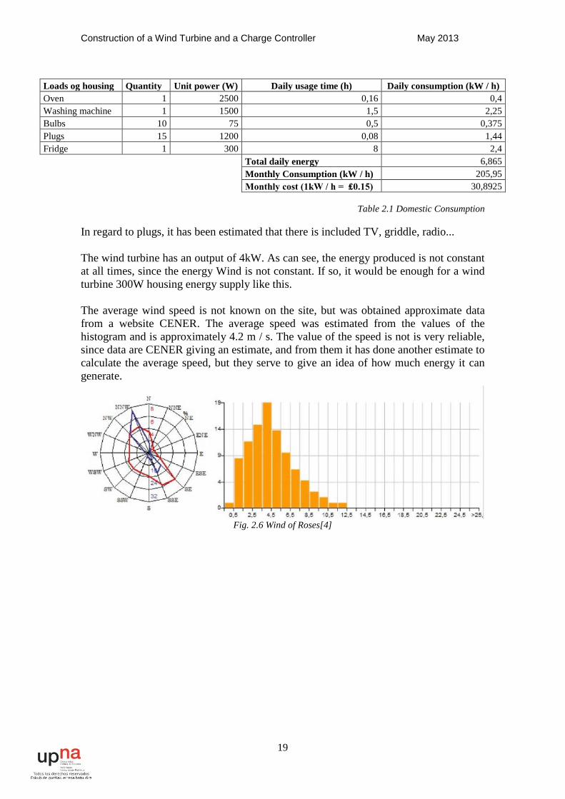
Loads og housing Quantity Unit power (W) Daily usage time (h) Daily consumption (kW / h) Oven 1 2500 0,16 0,4 Washing machine 1 1500 1,5 2,25 Bulbs 10 75 0,5 0,375 Plugs 15 1200 0,08 1,44 Fridge 1 300 8 2,4
Total daily energy 6,865 Monthly Consumption (kW / h) 205,95 Monthly cost (1kW / h = ₤0.15) 30,8925
Table 2.1 Domestic Consumption
In regard to plugs, it has been estimated that there is included TV, griddle, radio... The wind turbine has an output of 4kW. As can see, the energy produced is not constant at all times, since the energy Wind is not constant. If so, it would be enough for a wind turbine 300W housing energy supply like this. The average wind speed is not known on the site, but was obtained approximate data from a website CENER. The average speed was estimated from the values of the histogram and is approximately 4.2 m / s. The value of the speed is not is very reliable, since data are CENER giving an estimate, and from them it has done another estimate to calculate the average speed, but they serve to give an idea of how much energy it can generate.
Fig. 2.6 Wind of Roses[4]
Construction of a Wind Turbine and a Charge Controller May 2013
20
3. GENERATOR
3.1 Synchronous-Machine
The synchronous machine is characterized in that the relationship between engine speed and frequency is always constant, and is a function of the number of pole pairs. The output voltage is independent of the rotational speed for the wound rotor synchronous motor, but for the permanent magnet, the output voltage is proportional to speed.
The synchronous machines have very good characteristics for use as a generator:
• In isolated systems can independently control the frequency (a from velocity) and the amplitude of the voltage (current from excitation).
• For network connection, you can independently control powers active (from the prime mover) and reactive from the excitation current.
The synchronous machine dominates the market for electricity generation, both large as small power plants and in isolated systems. Note that the synchronous machine is less usual use as a motor, although it is interesting to use in some applications where a power necessary large volume.
3.1.1 - Principle of operation
The synchronous machine is composed of two parts:
• A fixed or stator consists of a pack of laminations forming a cylinder with a series of longitudinal grooves, which are placed on conductors connected together, so as to create a coil assembly.
• a movable part or rotor, located within the stator and consisting of an electromagnet
DC powered.
Rotation of the rotor is produced by a driving machine (diesel engine, turbine steam, gas, hydro, wind), which maintains a constant speed. Feeding electromagnet is achieved through a pair of slip rings that allow electrical continuity between a fixed and a movable part.
Some power alternators have exciter, which is in turn a generator three phase alternating current (whose inductor is mounted on the stator of the alternator and induced on the rotor), at whose output there is a three phase rectifier, which feeds the electromagnet, thereby avoiding the mentioned rings, which cause losses in the same and tear on the coals.
Construction of a Wind Turbine and a Charge Controller May 2013
21
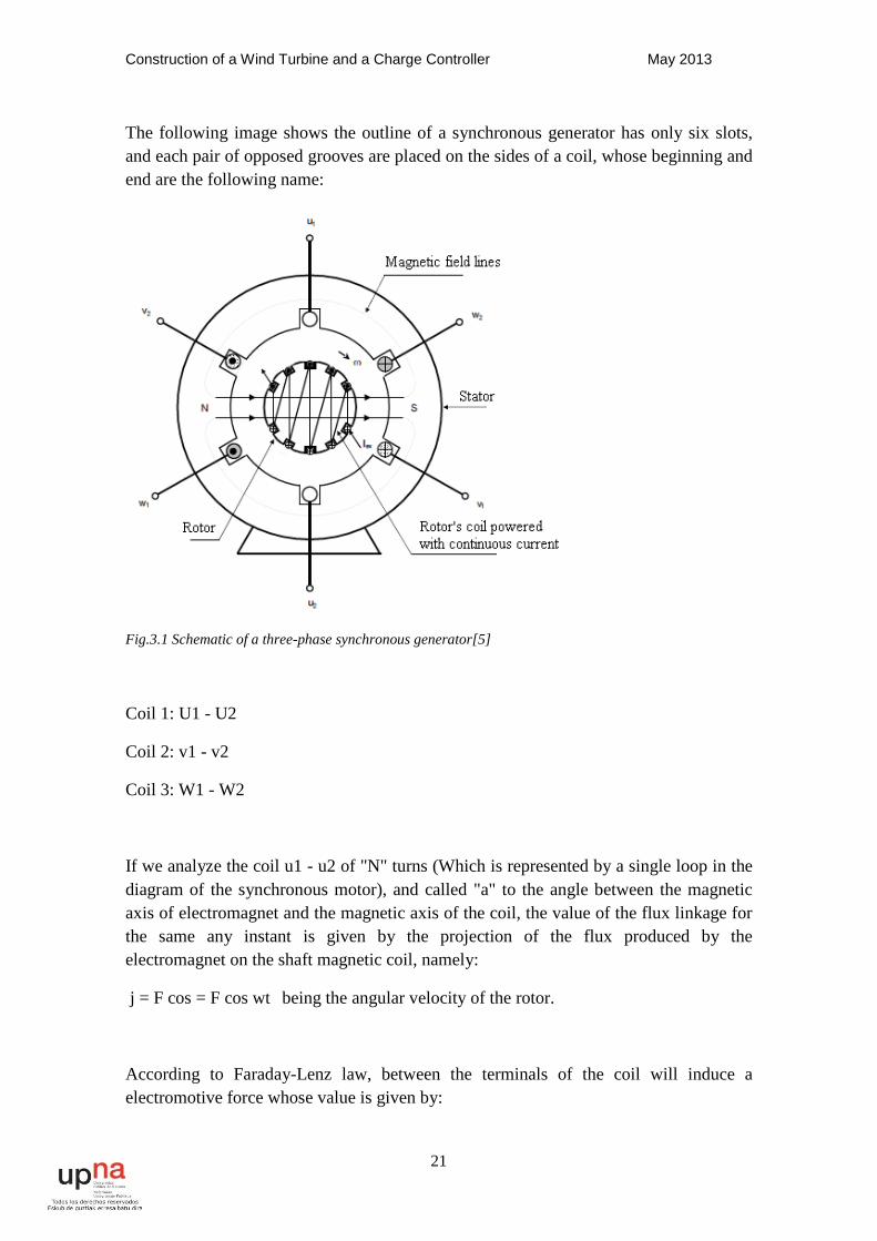
The following image shows the outline of a synchronous generator has only six slots, and each pair of opposed grooves are placed on the sides of a coil, whose beginning and end are the following name:
Fig.3.1 Schematic of a three-phase synchronous generator[5]
Coil 1: U1 - U2
Coil 2: v1 - v2
Coil 3: W1 - W2
If we analyze the coil u1 - u2 of "N" turns (Which is represented by a single loop in the diagram of the synchronous motor), and called "a" to the angle between the magnetic axis of electromagnet and the magnetic axis of the coil, the value of the flux linkage for the same any instant is given by the projection of the flux produced by the electromagnet on the shaft magnetic coil, namely:
j = F cos = F cos wt being the angular velocity of the rotor.
According to Faraday-Lenz law, between the terminals of the coil will induce a electromotive force whose value is given by:
Construction of a Wind Turbine and a Charge Controller May 2013
22
eu1-u2 = - N dj / dt = N F w sin wt
Substituting Emax. = N F w
We have: eu1-u2 = Emax. sin wt
If we analyze the coil v1 - v2, we see that the phenomenon is repeated but with a delay of 120 °, due to the geometric arrangement in which the same are placed:
ev1-v2 = Emax. (sin wt - 2p / 3)
The same happens with the coil w1 - w2:
ew1-w2 = Emax. (sin wt - 4p / 3)
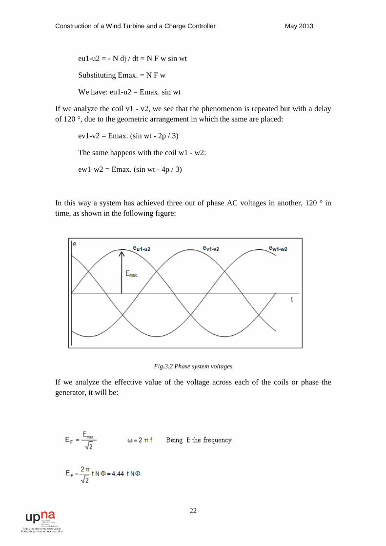
In this way a system has achieved three out of phase AC voltages in another, 120 ° in time, as shown in the following figure:
Fig.3.2 Phase system voltages
If we analyze the effective value of the voltage across each of the coils or phase the generator, it will be:
Construction of a Wind Turbine and a Charge Controller May 2013
23
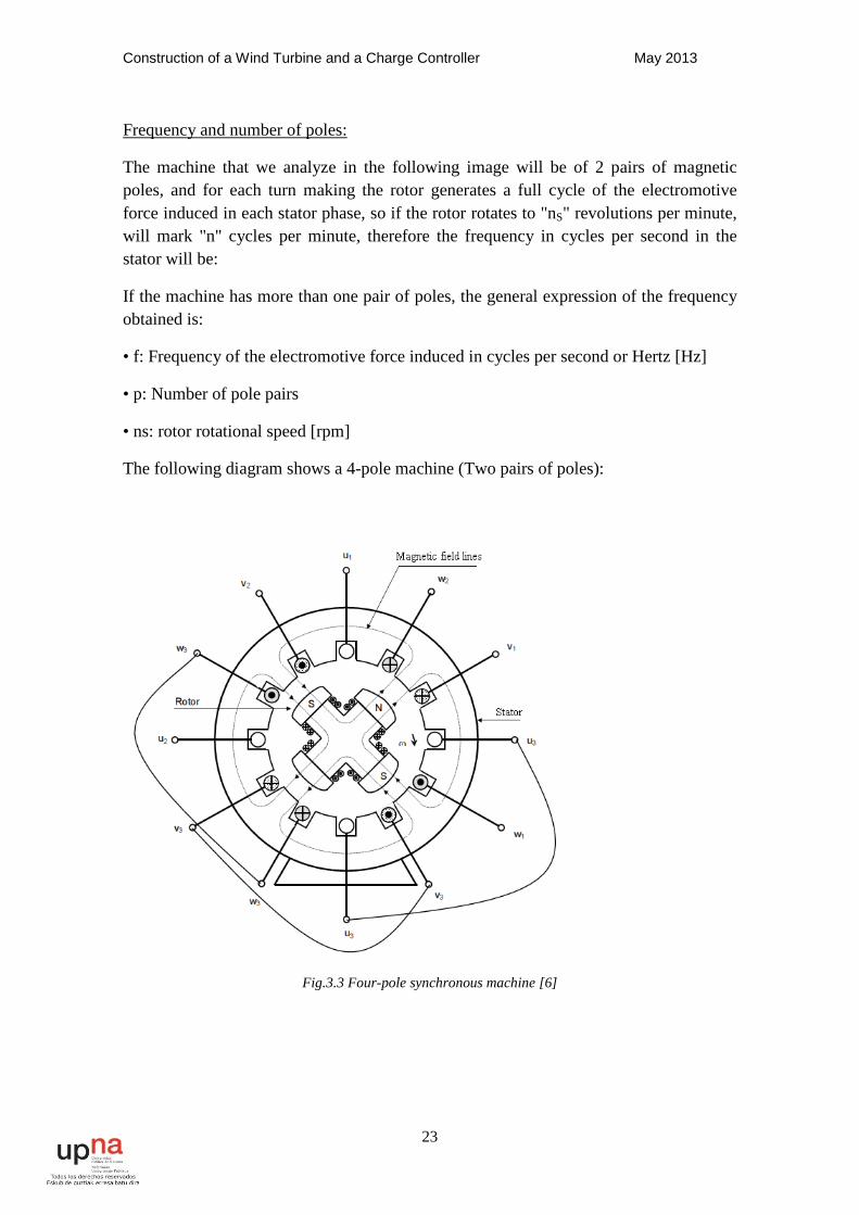
Frequency and number of poles:
The machine that we analyze in the following image will be of 2 pairs of magnetic poles, and for each turn making the rotor generates a full cycle of the electromotive force induced in each stator phase, so if the rotor rotates to "nS" revolutions per minute, will mark "n" cycles per minute, therefore the frequency in cycles per second in the stator will be:
If the machine has more than one pair of poles, the general expression of the frequency obtained is:
• f: Frequency of the electromotive force induced in cycles per second or Hertz [Hz]
• p: Number of pole pairs
• ns: rotor rotational speed [rpm]
The following diagram shows a 4-pole machine (Two pairs of poles):
Fig.3.3 Four-pole synchronous machine [6]
Construction of a Wind Turbine and a Charge Controller May 2013
24
This machine has two pairs of poles on the rotor and the stator. The amount of slots is twice that in the previous case, so that each phase occupies double slits, being formed each of two coils connected in series, with the same axle magnetic, as follows:
• Phase 1: u1 - u3 - u3 - u2
• Phase 2: v1 - v3 - v3 - v2
• Phase 3: w1 - w3 - w3 - w2
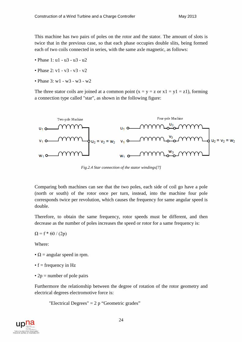
The three stator coils are joined at a common point (x = y = z or x1 = y1 = z1), forming a connection type called "star", as shown in the following figure:
Fig.2.4 Star connection of the stator windings[7]
Comparing both machines can see that the two poles, each side of coil go have a pole (north or south) of the rotor once per turn, instead, into the machine four pole corresponds twice per revolution, which causes the frequency for same angular speed is double.
Therefore, to obtain the same frequency, rotor speeds must be different, and then decrease as the number of poles increases the speed or rotor for a same frequency is:
Ω = f * 60 / (2p)
Where:
• Ω = angular speed in rpm.
• f = frequency in Hz
• 2p = number of pole pairs
Furthermore the relationship between the degree of rotation of the rotor geometry and electrical degrees electromotive force is:
"Electrical Degrees" = 2 p “Geometric grades”
Construction of a Wind Turbine and a Charge Controller May 2013
25
Driven machines steam or gas turbines are high speed, so in this applications use in machines with one or two pairs of poles, whereby the rotor has the form of a slotted cylinder (Rotor smooth), as represented in the first scheme, so that the dynamic balance requirements are best met.
The machines are driven by the low speed turbine, which makes the need to have many pairs of poles and a large diameter of the stator, the rotor being constructed by salient poles.
Permanent Magnets:
As for the permanent magnets should be noted that synchronous machines built with permanent magnet has a smaller volume compared to the others.
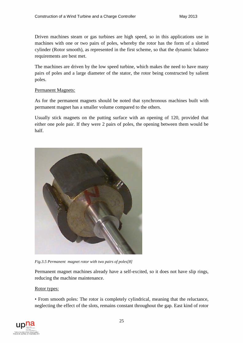
Usually stick magnets on the putting surface with an opening of 120, provided that either one pole pair. If they were 2 pairs of poles, the opening between them would be half.
Fig.3.5 Permanent magnet rotor with two pairs of poles[8]
Permanent magnet machines already have a self-excited, so it does not have slip rings, reducing the machine maintenance.
Rotor types:
• From smooth poles: The rotor is completely cylindrical, meaning that the reluctance, neglecting the effect of the slots, remains constant throughout the gap. East kind of rotor
Construction of a Wind Turbine and a Charge Controller May 2013
26
is used in alternators must rotate at high speeds, as can be used in power stations and gas turbines driving element or steam. Due to mechanical stresses associated with high speed, the rotor must constructed in a cylindrical piece forged steel high strength, where machined slots to accommodate the rotor winding.
The power of these alternators approximately is proportional to their volume (R2L). Due to the centrifugal forces associated with high speeds the diameter of the rotor is limited (maximum value around 1.5 m to 3000 rpm), so machines tend to be very elongated. To this group belong the machines higher electric power unit with power higher than 1600-2000MW.
• O pole: In this case the rotor is best suited for mechanically construction machines more than 2 pairs of poles. Therefore, power is used in where the prime movers hydraulic turbines are Pelton, Francis and Kaplan, with rotational speeds of 300 to 750 rpm, that is, from 10 to 4 pairs of poles respectively.
Another recent application is called multipole machines, "used much renewable energy as wind turbines. " Wind turbines have very low speeds so that the number of pole pairs may be exceed 30.
The higher power unit are lower than those found in the case of smooth and lie around 820MVA.
Vacuum feature:
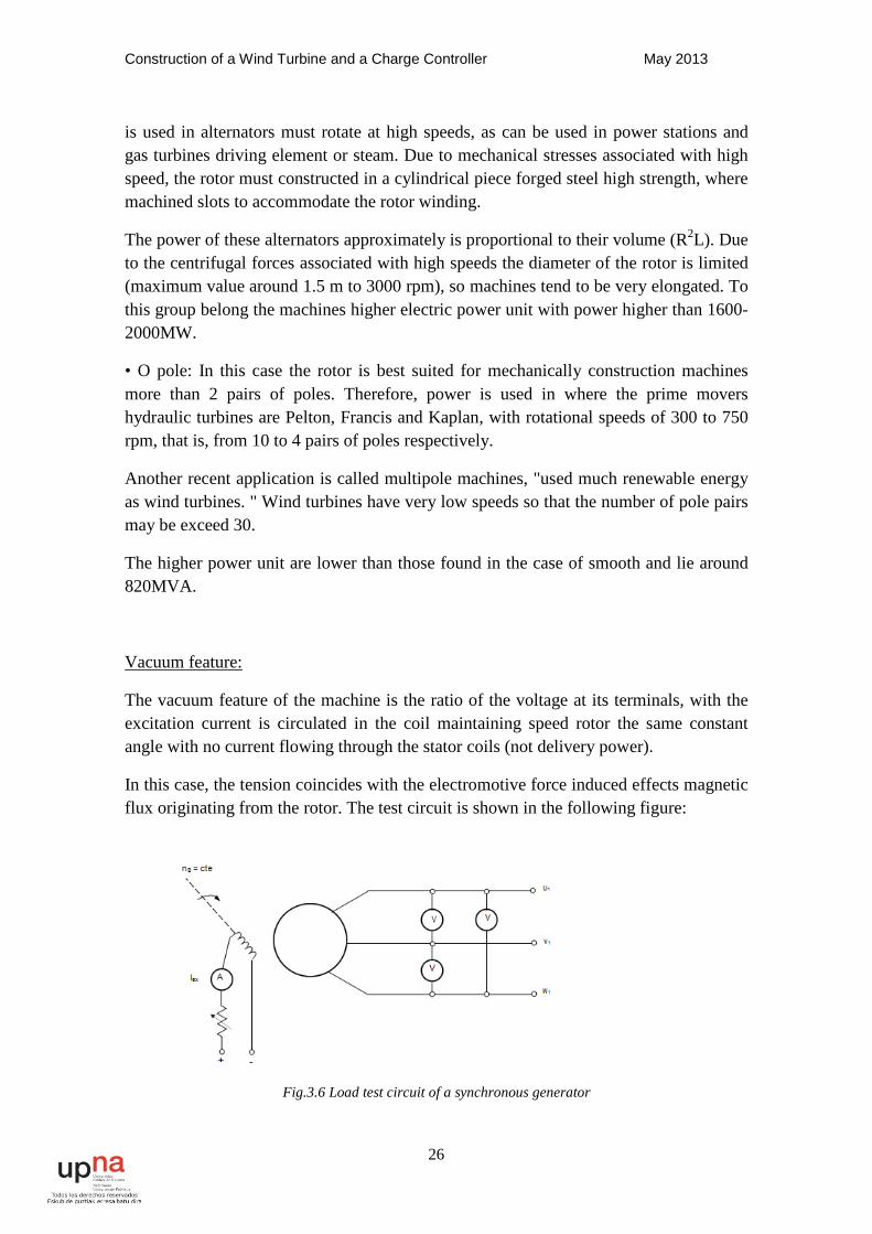
The vacuum feature of the machine is the ratio of the voltage at its terminals, with the excitation current is circulated in the coil maintaining speed rotor the same constant angle with no current flowing through the stator coils (not delivery power).
In this case, the tension coincides with the electromotive force induced effects magnetic flux originating from the rotor. The test circuit is shown in the following figure:
Fig.3.6 Load test circuit of a synchronous generator

Construction of a Wind Turbine and a Charge Controller May 2013
27
Feeding a DC source the rotor coil by varying the intensity thereof and effecting the reading of the voltmeters curve is obtained as follows:
Fig.3.7 Voltage- current curve
From the curve we note that the first part is a linear relationship between the current excitation and the electromotive force, then saturation appears elbow and finally an area saturated in which to an increase in the excitation current, are achieved little increases tension.
The analysis we performed on the machine we do within the linear region to the In order to simplify the concepts.
This curve corresponds to the magnetization of the machine (for a given rotor speed), since the voltage is a function of the flow and intensity of magnetic field is proportional to the excitation current.
Machine in the permanent magnet rotor, the value of the excitation is fixed, so at each speed that corresponds to a voltage.
Short Feature:
The shorting feature is the relationship between the stator current and the current excitation with the terminals shorted.
This test is performed by shorting the terminals of the generator, measuring current lka with ammeters, and maintaining constant speed, varying the excitation current and readings made stator current, using the circuit in the following figure:
Construction of a Wind Turbine and a Charge Controller May 2013
28
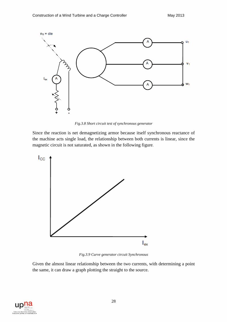
Fig.3.8 Short circuit test of synchronous generator
Since the reaction is net demagnetizing armor because itself synchronous reactance of the machine acts single load, the relationship between both currents is linear, since the magnetic circuit is not saturated, as shown in the following figure.
Fig.3.9 Curve generator circuit Synchronous
Given the almost linear relationship between the two currents, with determining a point the same, it can draw a graph plotting the straight to the source.
Construction of a Wind Turbine and a Charge Controller May 2013
29
Features vacuum test and short for excitement machine with magnets
Permanent:
•Empty Assay:
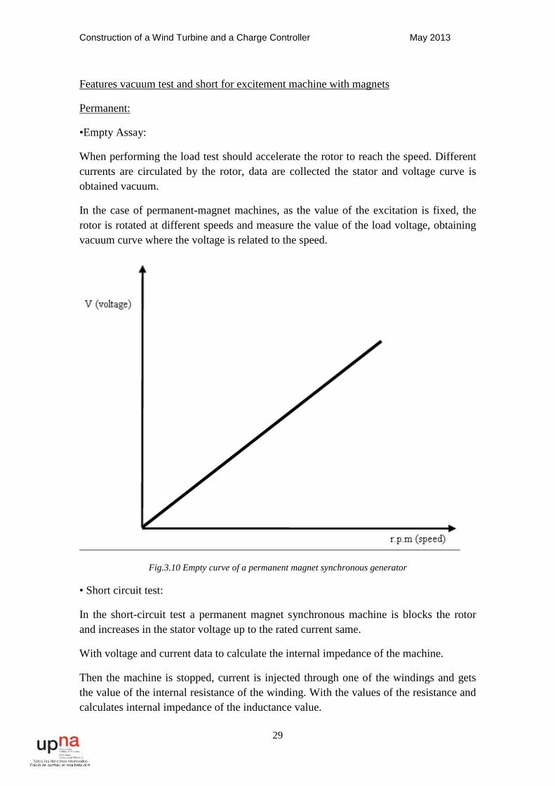
When performing the load test should accelerate the rotor to reach the speed. Different currents are circulated by the rotor, data are collected the stator and voltage curve is obtained vacuum.
In the case of permanent-magnet machines, as the value of the excitation is fixed, the rotor is rotated at different speeds and measure the value of the load voltage, obtaining vacuum curve where the voltage is related to the speed.
Fig.3.10 Empty curve of a permanent magnet synchronous generator
• Short circuit test:
In the short-circuit test a permanent magnet synchronous machine is blocks the rotor and increases in the stator voltage up to the rated current same.
With voltage and current data to calculate the internal impedance of the machine.
Then the machine is stopped, current is injected through one of the windings and gets the value of the internal resistance of the winding. With the values of the resistance and calculates internal impedance of the inductance value.
Construction of a Wind Turbine and a Charge Controller May 2013
30
X =√Z2-R2
Where:
• Z = impedance of the stator winding.
• R = Resistance of stator winding.
• X = stator winding inductance.
3.1.2 - Advantages and disadvantages of the synchronous machine as a generator:
Advantages:
• There is no slippage in the rotor speed.
• It is capable of generating reactive power.
• For motors with magnets, the power ratio is the best volume them all.
• When to use these machines as generator are easier to control.
• In the case of machines with permanent magnet rotor, maintenance is virtually nil.
Disadvantages:
• The wound rotor machines have maintained rather large due to the brushes and slip rings.
• In the case of permanent magnet machines there is no output voltage control.
3.2 - Choice of motor:
When we build a wind turbine we have to consider well the machine that we are going to choose, because it will be the element that will transform the energy that we want. The power generated by the wind turbine must be stored in the batteries, so we must to find a motor whose output voltages approach the voltage rating of the batteries.
In the market we can find several types of motor:
• DC Machine:
◦ Wound stator.
◦ Permanent magnet stator.
• Asynchronous Machine:
Construction of a Wind Turbine and a Charge Controller May 2013
31
◦ Squirrel cage.
◦ Rotor winding.
• Synchronous Machine:
◦ Rotor winding.
◦ Rotor permanent magnets.
Among all these machines we analyze the advantages and disadvantages of each them to choose the one best features have. The most important features consider are the following:
• Suitable Voltages
• Power-to-volume ratio
• Robustness
• Price-performance ratio
Considering the above factors, the machine that most closely those features are the permanent magnet synchronous machine.
These machines called permanent magnets have a very characteristic important than previously mentioned. In the case of the wind turbine, it is possible that due to a problem is to stop the mill, with short-circuit the stator of the machine is enough. The output voltage is a function of velocity, by shorting the stator, it makes virtually zero tension, so that the mill is stopped.
This can only be done in aerofoil bladed wind turbines, since the shorting, the power extracted from the blades is very high and they exit the system aerodynamic, so do practically shaft torque, with other generators slower they have much torque can not be used because this system stops the motor end burning.
Construction of a Wind Turbine and a Charge Controller May 2013
32
Wind Speed(m/s) rpm motor
0 0
0,5 13,64
1 27,28
1,5 40,93
2 54,57
2,5 68,21
3 81,85
3,5 95,49
4 109,13
4,5 122,78
5 136,42
5,5 150,06
6 163,7
6,5 177,34
7 190,99
7,5 204,63
8 218,27
8,5 231,91
9 245,55
9,5 259,2
10 272,84
10,5 286,48
11 300,12
11,5 313,76
12 327,4
12,5 341,05
13 354,69
13,5 368,33
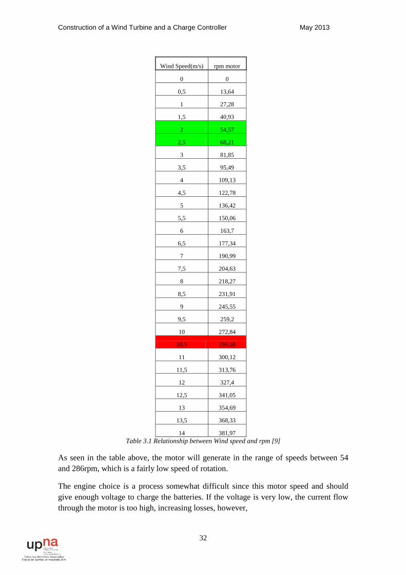
14 381,97 Table 3.1 Relationship between Wind speed and rpm [9]
As seen in the table above, the motor will generate in the range of speeds between 54 and 286rpm, which is a fairly low speed of rotation.
The engine choice is a process somewhat difficult since this motor speed and should give enough voltage to charge the batteries. If the voltage is very low, the current flow through the motor is too high, increasing losses, however,
Construction of a Wind Turbine and a Charge Controller May 2013
33
If the tensions are too high, even though the currents are lower, tension could pierce isolation, breaking the generator.
The market for the sale of permanent magnet synchronous motors is very small, they are used in very specific applications. We have chosen an elevator motor 6 pole pairs, since the construction of these motors is made to a nearby company and have enough models. The company is called PERMAGSA and the model that has been chosen is the GE150-240-225
3.2.1 - Engine specifications GE150-240-225
The GE150-240-225 is the engine that has been chosen to develop the following project, as it met with the best characteristics for the turbine.
We have chosen this engine for the following reasons:
• Easy procurement.
• Rated power 4kw around
• Affordability
• Robustness
• Great Stamina rotor torque. What connects the blades directly to generator.
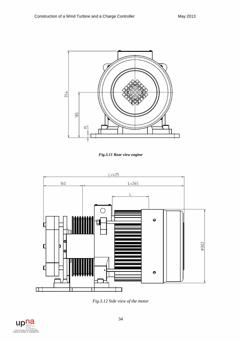
The engine, being for an elevator, brings a pulley, an encoder and a brake. For construction of the wind turbine must be to remove unnecessary burdens shaft minimizing friction losses. This gives you the starting torque is lower, so that the turbine will start at lower wind speeds. Although winds do not provide much power, is very important to use them, because they are very common and if not used, it is much energy is wasted.
Below we present the plans for the motor:
Construction of a Wind Turbine and a Charge Controller May 2013
34
Fig.3.11 Rear view engine
Fig.3.12 Side view of the motor
Construction of a Wind Turbine and a Charge Controller May 2013
35
Electrical data:
Rated current (A) 10
Maximum current (A) 27.7
Voltage (v) 340
Rated power (kw) 4.3
Hertz (Hz) 15.9
Brake Vdc (V) 210
pole 12
Keep in mind that these features are for the use of the machine as
engine, whereas in this case work as a generator. For the design of the wind turbine
most important data are the following:
• Number of poles.
• Rated current.
• Torque.
The number of poles determines the rated motor speed, few more poles have, the higher the output voltage for each speed. The rated current indicates the power maximum that can be extracted for each engine speed. To determine the internal motor characteristics for use as generator must be performed tests empty and short.
3.2.2 - Vacuum and short circuit tests
To make a vacuum test, you have to rotate the generator with a motor and machine measuring the voltage values at each speed.
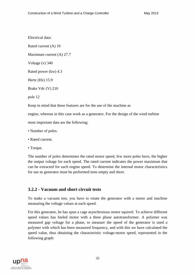
For this generator, he has spun a cage asynchronous motor squirrel. To achieve different speed values has fueled motor with a three phase autotransformer. A polymer was measured gap voltage for a phase, to measure the speed of the generator is used a polymer with which has been measured frequency, and with this we have calculated the speed value, thus obtaining the characteristic voltage-motor speed, represented in the following graph:
Construction of a Wind Turbine and a Charge Controller May 2013
36
Fig.3.13 Voltage as a function speed
As can be seen these voltages are phase. This means that the voltage in star will be √3 bigger.
To perform the assay shorting rotor crashes. This will be analyzing the characteristics of the stator winding. This phase must be connected to a AC voltage source variable value, which is obtained with an autotransformer and raise voltage to nominal current to flow through the stator. Thus, measuring the voltage and two multimeters current impedance is calculated. After measuring the value of the resistance of each winding is used for this current source and measure the voltage and current to calculate the resistance. With the value of the impedance and resistance calculates the value of inductance. In this case, not done this test, since the value of the load voltages is too high and should be taken first solution to this problem.
3.2.2.1 - Disadvantages of the motor as a generator:
The values of the generator voltage to the speeds at the working turbine are very high, since the rectified voltage values which appear in the electronic converter reaching up to 1000V, which is a difficult and dangerous voltage electronic conversion, because the required inductance value would be very great.
Construction of a Wind Turbine and a Charge Controller May 2013
37
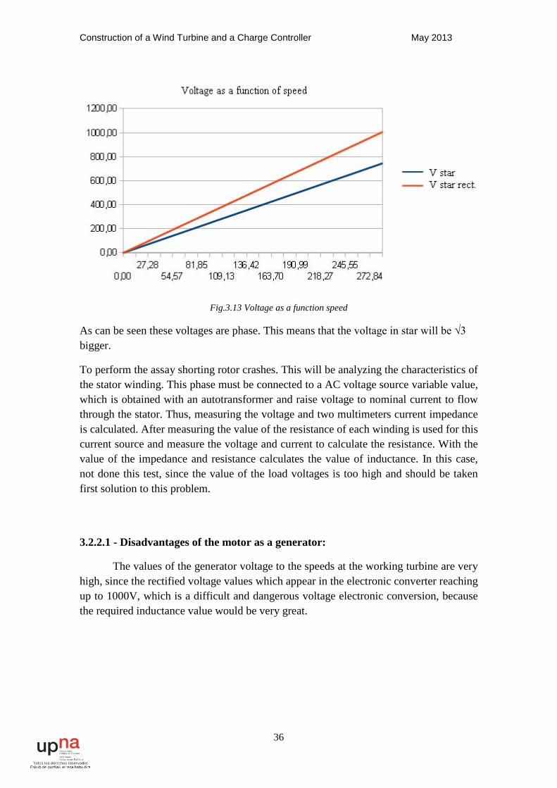
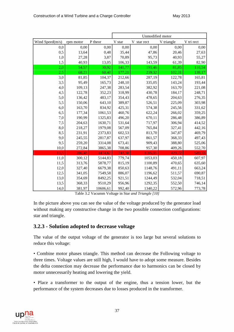
Unmodified motor Wind Speed(m/s) rpm motor P theor V star V star rect V triangle V tri rect
0,0 0,00 0,00 0,00 0,00 0,00 0,00 0,5 13,64 0,48 35,44 47,86 20,46 27,63 1,0 27,28 3,87 70,89 95,73 40,93 55,27 1,5 40,93 13,05 106,33 143,59 61,39 82,90 2,0 54,57 30,92 141,77 191,46 81,85 110,54 2,5 68,21 60,40 177,21 239,32 102,31 138,17 3,0 81,85 104,37 212,66 287,19 122,78 165,81 3,5 95,49 165,73 248,10 335,05 143,24 193,44 4,0 109,13 247,38 283,54 382,92 163,70 221,08 4,5 122,78 352,23 318,99 430,78 184,17 248,71 5,0 136,42 483,17 354,43 478,65 204,63 276,35 5,5 150,06 643,10 389,87 526,51 225,09 303,98 6,0 163,70 834,92 425,31 574,38 245,56 331,62 6,5 177,34 1061,53 460,76 622,24 266,02 359,25 7,0 190,99 1325,83 496,20 670,11 286,48 386,89 7,5 204,63 1630,71 531,64 717,97 306,94 414,52 8,0 218,27 1979,08 567,09 765,84 327,41 442,16 8,5 231,91 2373,83 602,53 813,70 347,87 469,79 9,0 245,55 2817,87 637,97 861,57 368,33 497,43 9,5 259,20 3314,08 673,41 909,43 388,80 525,06
10,0 272,84 3865,38 708,86 957,30 409,26 552,70 10,5 286,48 4474,67 744,30 1005,16 429,72 580,33 11,0 300,12 5144,83 779,74 1053,03 450,18 607,97 11,5 313,76 5878,77 815,19 1100,89 470,65 635,60 12,0 327,40 6679,38 850,63 1148,76 491,11 663,24 12,5 341,05 7549,58 886,07 1196,62 511,57 690,87 13,0 354,69 8492,25 921,51 1244,49 532,04 718,51 13,5 368,33 9510,29 956,96 1292,35 552,50 746,14 14,0 381,97 10606,61 992,40 1340,22 572,96 773,78
Table 3.2 Vacumm Voltage in Star and Triangle [10]
In the picture above you can see the value of the voltage produced by the generator load without making any constructive change in the two possible connection configurations: star and triangle.
3.2.3 - Solution adopted to decrease voltage
The value of the output voltage of the generator is too large but several solutions to reduce this voltage:
• Combine motor phases triangle. This method can decrease the Following voltage to three times. Voltage values are still high, I would have to adopt some measure. Besides the delta connection may decrease the performance due to harmonics can be closed by motor unnecessarily heating and lowering the yield.
• Place a transformer to the output of the engine, thus a tension lower, but the performance of the system decreases due to losses produced in the transformer.
Construction of a Wind Turbine and a Charge Controller May 2013
38
• Place a one speed reduction between the blades of the wind turbine and the generator. This provides the motor to rotate slower and hence the voltage output is lower. The major disadvantages are that the gears need maintenance, performance decreases due to friction and is a cost.
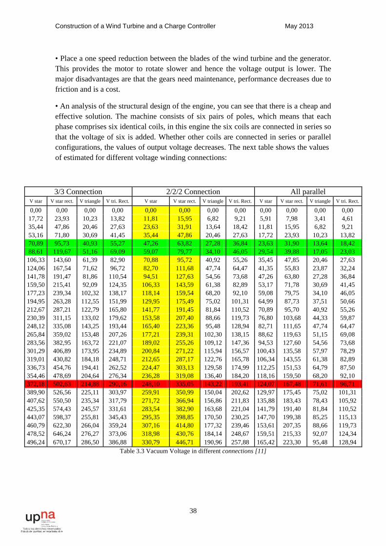
• An analysis of the structural design of the engine, you can see that there is a cheap and effective solution. The machine consists of six pairs of poles, which means that each phase comprises six identical coils, in this engine the six coils are connected in series so that the voltage of six is added. Whether other coils are connected in series or parallel configurations, the values of output voltage decreases. The next table shows the values of estimated for different voltage winding connections:
3/3 Connection 2/2/2 Connection All parallel V star V star rect. V triangle V tri. Rect. V star V star rect. V triangle V tri. Rect. V star V star rect. V triangle V tri. Rect.
0,00 0,00 0,00 0,00 0,00 0,00 0,00 0,00 0,00 0,00 0,00 0,00 17,72 23,93 10,23 13,82 11,81 15,95 6,82 9,21 5,91 7,98 3,41 4,61 35,44 47,86 20,46 27,63 23,63 31,91 13,64 18,42 11,81 15,95 6,82 9,21 53,16 71,80 30,69 41,45 35,44 47,86 20,46 27,63 17,72 23,93 10,23 13,82 70,89 95,73 40,93 55,27 47,26 63,82 27,28 36,84 23,63 31,90 13,64 18,42 88,61 119,67 51,16 69,09 59,07 79,77 34,10 46,05 29,54 39,88 17,05 23,03 106,33 143,60 61,39 82,90 70,88 95,72 40,92 55,26 35,45 47,85 20,46 27,63 124,06 167,54 71,62 96,72 82,70 111,68 47,74 64,47 41,35 55,83 23,87 32,24 141,78 191,47 81,86 110,54 94,51 127,63 54,56 73,68 47,26 63,80 27,28 36,84 159,50 215,41 92,09 124,35 106,33 143,59 61,38 82,89 53,17 71,78 30,69 41,45 177,23 239,34 102,32 138,17 118,14 159,54 68,20 92,10 59,08 79,75 34,10 46,05 194,95 263,28 112,55 151,99 129,95 175,49 75,02 101,31 64,99 87,73 37,51 50,66 212,67 287,21 122,79 165,80 141,77 191,45 81,84 110,52 70,89 95,70 40,92 55,26 230,39 311,15 133,02 179,62 153,58 207,40 88,66 119,73 76,80 103,68 44,33 59,87 248,12 335,08 143,25 193,44 165,40 223,36 95,48 128,94 82,71 111,65 47,74 64,47 265,84 359,02 153,48 207,26 177,21 239,31 102,30 138,15 88,62 119,63 51,15 69,08 283,56 382,95 163,72 221,07 189,02 255,26 109,12 147,36 94,53 127,60 54,56 73,68 301,29 406,89 173,95 234,89 200,84 271,22 115,94 156,57 100,43 135,58 57,97 78,29 319,01 430,82 184,18 248,71 212,65 287,17 122,76 165,78 106,34 143,55 61,38 82,89 336,73 454,76 194,41 262,52 224,47 303,13 129,58 174,99 112,25 151,53 64,79 87,50 354,46 478,69 204,64 276,34 236,28 319,08 136,40 184,20 118,16 159,50 68,20 92,10 372,18 502,63 214,88 290,16 248,10 335,05 143,22 193,41 124,07 167,48 71,61 96,71 389,90 526,56 225,11 303,97 259,91 350,99 150,04 202,62 129,97 175,45 75,02 101,31 407,62 550,50 235,34 317,79 271,72 366,94 156,86 211,83 135,88 183,43 78,43 105,92 425,35 574,43 245,57 331,61 283,54 382,90 163,68 221,04 141,79 191,40 81,84 110,52 443,07 598,37 255,81 345,43 295,35 398,85 170,50 230,25 147,70 199,38 85,25 115,13 460,79 622,30 266,04 359,24 307,16 414,80 177,32 239,46 153,61 207,35 88,66 119,73 478,52 646,24 276,27 373,06 318,98 430,76 184,14 248,67 159,51 215,33 92,07 124,34 496,24 670,17 286,50 386,88 330,79 446,71 190,96 257,88 165,42 223,30 95,48 128,94
Table 3.3 Vacuum Voltage in different connections [11]
Construction of a Wind Turbine and a Charge Controller May 2013
39
It was decided to change the configuration of the windings because it is a solution that does not decreases system performance and is not a financial expense.
Before choosing a configuration of winding or another, must take into account the type of connection. The star connection is more appropriate than the triangle for two reasons, the first is that there is neutral connection, so you can connect this to the start of land the mill. The second reason is that for harmonics appearing on the generator, if the triangle connection is, these may be closed by the winding, lowering the yield and heating the generator.
To choose the most appropriate coil configuration, we must look at the value of the tension to the wind speed at which it begins to generate, and the value for the voltage maximum power. The minimum voltage must be greater than the battery voltage (48V) and maximum should not be too high, because the higher the value of the inductance of the converter must be higher, increasing the cost of electronics.
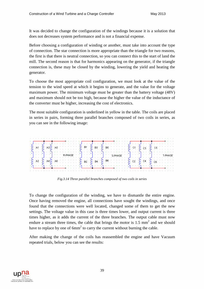
The most suitable configuration is underlined in yellow in the table. The coils are placed in series in pairs, forming three parallel branches composed of two coils in series, as you can see in the following image:
Fig.3.14 Three parallel branches composed of two coils in series
To change the configuration of the winding, we have to dismantle the entire engine. Once having removed the engine, all connections have sought the windings, and once found that the connections were well located, changed some of them to get the new settings. The voltage value in this case is three times lower, and output current is three times higher, as it adds the current of the three branches. The output cable must now endure a stream three times, the cable that brings the motor is 1.5 mm2 and we should have to replace by one of 6mm2 to carry the current without burning the cable.
After making the change of the coils has reassembled the engine and have Vacuum repeated trials, below you can see the results:

Construction of a Wind Turbine and a Charge Controller May 2013
40
Changed Stator Wind Speed rpm motor P theor V line V DC I motor I DC
0,0 0,00 0,00 0,00 0 0,00 0,00 0,5 13,64 0,48 15,95 22,52 0,02 0,01 1,0 27,28 3,87 31,91 45,03 0,07 0,08 1,5 40,93 13,05 47,86 67,55 0,15 0,26 2,0 54,57 30,92 63,82 90,06 0,27 0,62 2,5 68,21 60,40 79,77 112,58 0,42 1,21 3,0 81,85 104,37 95,72 135,093 0,60 2,09 3,5 95,49 165,73 111,68 157,608 0,82 3,31 4,0 109,13 247,38 127,63 180,123 1,07 4,95 4,5 122,78 352,23 143,59 202,64 1,36 7,04 5,0 136,42 483,17 159,54 225,15 1,67 9,66 5,5 150,06 643,10 175,49 247,668 2,02 12,86 6,0 163,70 834,92 191,45 270,183 2,41 16,70 6,5 177,34 1061,53 207,40 292,698 2,83 21,23 7,0 190,99 1325,83 223,36 315,21 3,28 26,52 7,5 204,63 1630,71 239,31 337,73 3,76 32,61 8,0 218,27 1979,08 255,26 360,243 4,28 39,58 8,5 231,91 2373,83 271,22 382,758 4,84 47,48 9,0 245,55 2817,87 287,17 405,273 5,42 56,36 9,5 259,20 3314,08 303,13 427,79 6,04 66,28
10,0 272,84 3865,38 319,08 450,30 6,69 77,31 10,5 286,48 4474,67 335,05 472,818 7,36 89,49 11,0 300,12 5144,83 350,99 495,333 8,10 102,90 11,5 313,76 5878,77 366,94 517,848 8,85 117,58 12,0 327,40 6679,38 382,90 540,36 9,64 133,59 12,5 341,05 7549,58 398,85 562,88 10,46 150,99 13,0 354,69 8492,25 414,80 585,393 11,31 169,84 13,5 368,33 9510,29 430,76 607,908 12,20 190,21 14,0 381,97 10606,61 446,71 630,423 13,12 212,13
Table 3.4 Changed stator results[12]
The value of the load voltage of the machine is somewhat higher than estimated before making winding change, but their values are in an acceptable range. The current through the motor reaches almost to the thirteen amps, but being the windings in parallel, the generator rated current is three times higher (30A) and there is no danger of burning the motor overheating.
With voltage and current characteristics of the generator, and can design the electronic system to charge the batteries and control the mill.
Construction of a Wind Turbine and a Charge Controller May 2013
41
4. CONVERTER CHARGE CONTROLLER 4.1 - Structure of the converter
To store the energy generated by the wind turbine need a converter to adjust the generator voltage to the battery voltage. The alternating voltage is generated phase, and the battery voltage is continuous, so that converter is necessary. The converter can be constructed only with a diode rectifier bridge, which rectifies voltage. The rectified voltage value is variable, depending on the speed of the wind turbine, only a diode rectifier is sufficient to charge the batteries, but they impose its voltage, so also impose a rotational speed of the turbine, significantly decreasing performance.
To obtain better performance, the speed of the turbine must be proportional to the wind, since the tip speed of the blades needs to be six times greater than the wind for optimum performance. To achieve this we use DC converter, obtaining a variable speed wind turbine. Since the batteries do not impose the speed of rotation of the blades, efforts suffer batteries are smaller, increasing its life, the turbine will also suffer less because wind gusts to accelerate their speed, so the mechanical stresses suffers bursts are lower.
The wind turbine produces energy at a range of speeds between 50 and 300rpm. The value of the battery voltage is 48V and the voltage values of the generator, once rectified, are always greater than those of the batteries, so that the converter always have to reduce stress. The type of converter that will be used a reducer (Buck).
The maximum power is delivered 4KW wind turbine, so that the current to the 80A output will be maximum. For the current ripple has chosen a maximum value allowable 10%. The switching frequency is 10KHz, we have chosen this value due to current converter, ideally switch to 20Khz, but lost to is frequency would be too great. Converters manufacturers rarely use for these frequencies as high current values.
A power converter comprises semiconductor devices which make the time of circuit breakers. The converters can be classified as controlled and controlled by the type of semiconductor that have. In this case we will focus on controlled converters, because the converter that deals in this project is controlled. It is said that a converter is controlled when the switches that constitute it can be controlled in their power (Thyristor) or, on and off (BJT Transistors, MOSFET, IGBT).
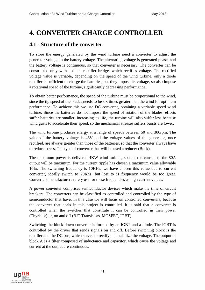
Switching the block down converter is formed by an IGBT and a diode. The IGBT is controlled by the driver that sends signals on and off. Before switching block is the rectifier and the DC bus, which serves to rectify and stabilize the voltage. The output of block A is a filter composed of inductance and capacitor, which cause the voltage and current at the output are continuous.
Construction of a Wind Turbine and a Charge Controller May 2013
42
Fig.4.1System Schematic
In the picture above you can see a global scheme of the power converter that has been built for the wind turbine.
4.2 - Components of the converter
The following sections describe one by one the various components of electronic converter.
4.2.1 - THE IGBT
An IGBT (From the acronym, Isolated Gate Bipolar Transistor) is a hybrid of MOSFET field effect transistor and bipolar junction transistor BJT, and uses the advantages of both: control voltage on and off (MOSFET) and values voltage and current, cutting and driving respectively, high (BJT and MOSFET).
This semiconductor is formed by three terminals, the collector (C), the gate (G), and emitter (E). Its performance is established based on three characteristics:
1.- Characteristic - controllability: As mentioned above has control on and off.
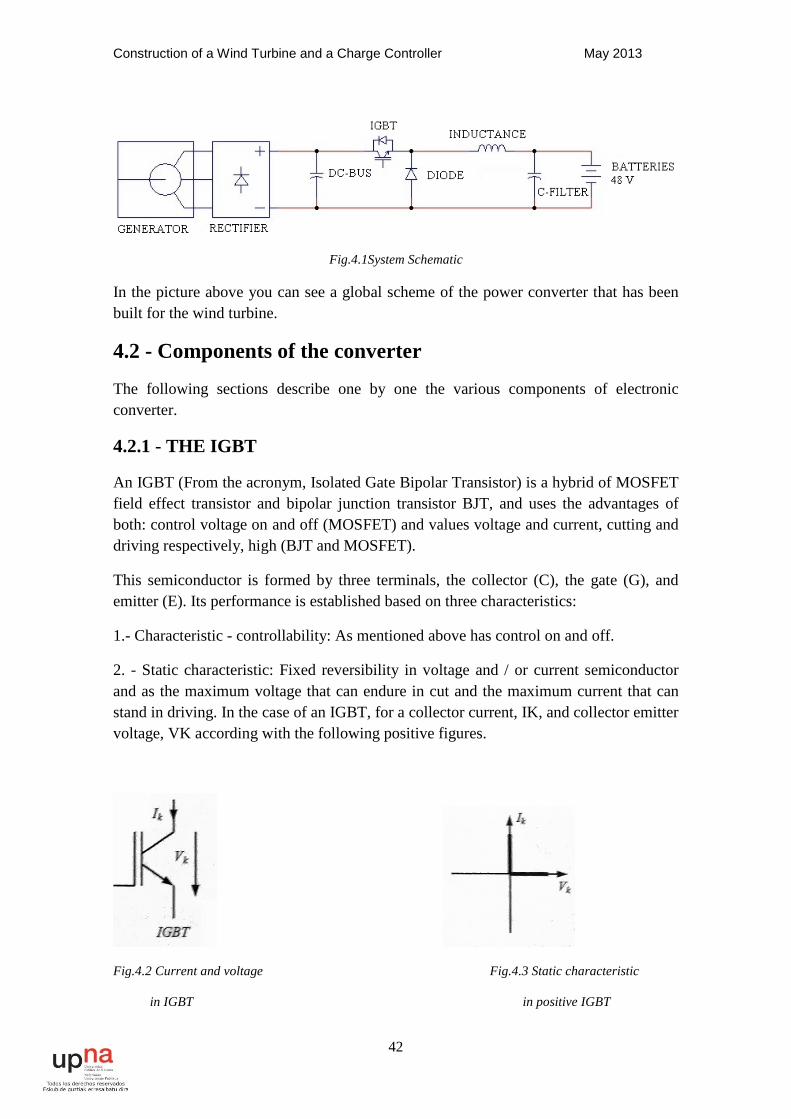
2. - Static characteristic: Fixed reversibility in voltage and / or current semiconductor and as the maximum voltage that can endure in cut and the maximum current that can stand in driving. In the case of an IGBT, for a collector current, IK, and collector emitter voltage, VK according with the following positive figures.
Fig.4.2 Current and voltage Fig.4.3 Static characteristic
in IGBT in positive IGBT
Construction of a Wind Turbine and a Charge Controller May 2013
43
According to the figure above, the court only supports IGBT VCE> 0 and current driving goes from collector to emitter in which case IC> 0, and can easily be deduced that it is reversible or in voltage or current.
The IGBT driving or is in section on the VGE, and in both cases the VCE> 0:
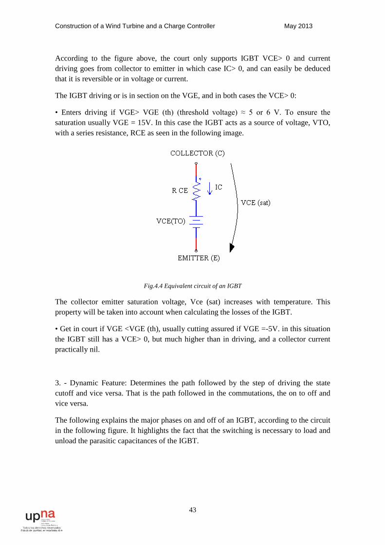
• Enters driving if VGE> VGE (th) (threshold voltage) ≈ 5 or 6 V. To ensure the saturation usually VGE = 15V. In this case the IGBT acts as a source of voltage, VTO, with a series resistance, RCE as seen in the following image.
Fig.4.4 Equivalent circuit of an IGBT
The collector emitter saturation voltage, Vce (sat) increases with temperature. This property will be taken into account when calculating the losses of the IGBT.
• Get in court if VGE <VGE (th), usually cutting assured if VGE =-5V. in this situation the IGBT still has a VCE> 0, but much higher than in driving, and a collector current practically nil.
3. - Dynamic Feature: Determines the path followed by the step of driving the state cutoff and vice versa. That is the path followed in the commutations, the on to off and vice versa.
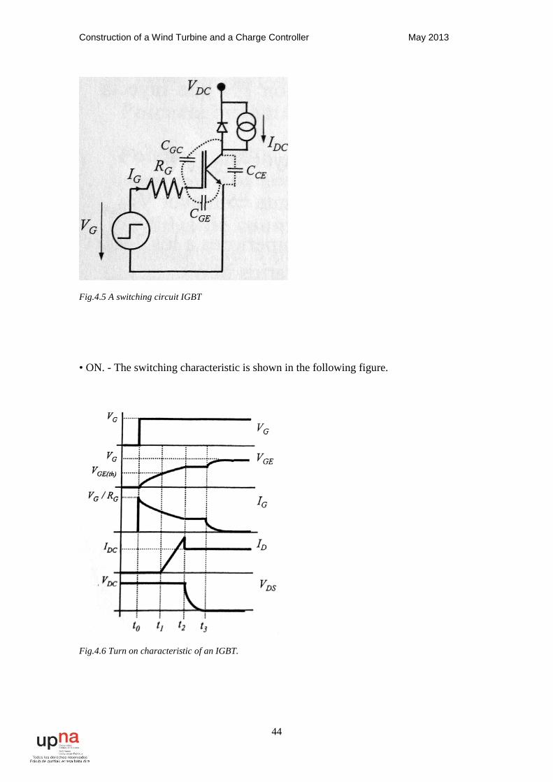
The following explains the major phases on and off of an IGBT, according to the circuit in the following figure. It highlights the fact that the switching is necessary to load and unload the parasitic capacitances of the IGBT.
Construction of a Wind Turbine and a Charge Controller May 2013
44
Fig.4.5 A switching circuit IGBT
• ON. - The switching characteristic is shown in the following figure.
Fig.4.6 Turn on characteristic of an IGBT.
Construction of a Wind Turbine and a Charge Controller May 2013
45
1. - Since VG goes high (+15 V assume) until the VGE = VGE (th) (voltage threshold) has the ignition delay time, ton. During this time the IGBT remains off and its duration depends on the input parasitic capacitance Cies = / / (CGC and CGE) of the
RG (gate resistance) and VG.
2. - Since the threshold voltage reaches the collector current, IC, begins to rise. It is known as rise time, tr, the interval at which CI takes to go from 10% to 90% of its final value. During this interval the CGA continues to increase.
3. - Miller effect is presented, in which the IG is absorbed by discharging the CGC capacity so the VGE remains virtually constant. Moreover, with the diode
Serial blocked anti voltage VCE begins to decrease.
4. - Once the IGBT switching VGE continues to increase until it reaches the VG value. The value of input capacitance Cies varies with VCE being greater the smaller is this tension. During the live power voltage and current values rather large causing great losses in this range.
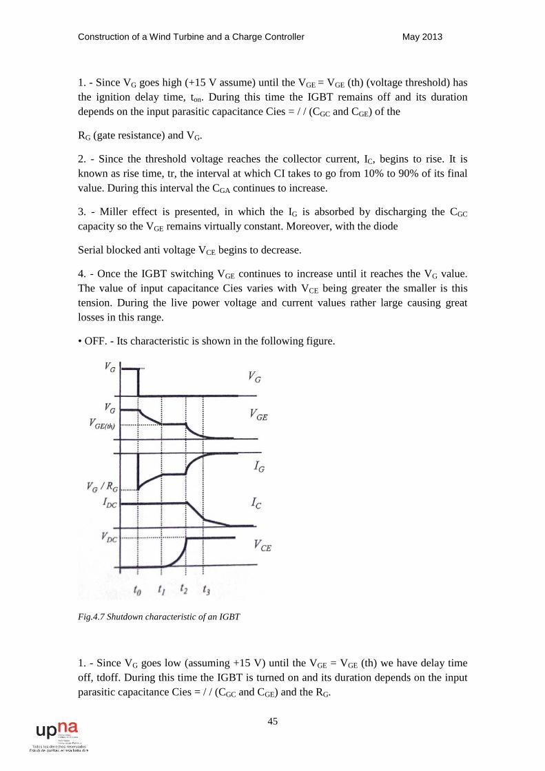
• OFF. - Its characteristic is shown in the following figure.
Fig.4.7 Shutdown characteristic of an IGBT
1. - Since VG goes low (assuming +15 V) until the VGE = VGE (th) we have delay time off, tdoff. During this time the IGBT is turned on and its duration depends on the input parasitic capacitance Cies = / / (CGC and CGE) and the RG.
Construction of a Wind Turbine and a Charge Controller May 2013
46
Generally met: tdoff >> tdon because Cies is larger when the IGBT is Ignition → VCE is small (as stated before and VCE Cies are inversely proportional.
This is an important feature for determining what the trigger sent by the driver to the IGBT.
2. - Once the threshold voltage is reached, VGE (th), presents the Miller effect on the IG is absorbed by the load capacity implying that CGC VGE is constant and VCE increases to reach the value of the blocking voltage, VDC.
3. - The collector current, IC, starts to decrease. It gives the fall time, tf, in which IDC takes to go from 90% to 10%. During this interval the cutting VCE joins fall voltage in the parasitic inductances of the cables, which involves an over voltage on the IGBT. In addition there is a tail current due to slower off internal BJT which increases shutdown losses.
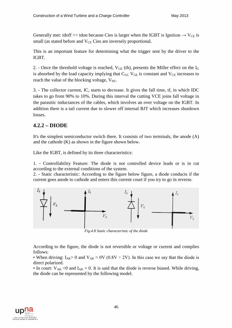
4.2.2 – DIODE It's the simplest semiconductor switch there. It consists of two terminals, the anode (A) and the cathode (K) as shown in the figure shown below. Like the IGBT, is defined by its three characteristics: 1. - Controllability Feature: The diode is not controlled device leads or is in cut according to the external conditions of the system. 2. - Static characteristic: According to the figure below figure, a diode conducts if the current goes anode to cathode and enters this current court if you try to go in reverse.
Fig.4.8 Static characteristic of the diode
According to the figure, the diode is not reversible or voltage or current and complies follows: • When driving: IAK> 0 and VAK ≈ 0V (0.8V ÷ 2V). In this case we say that the diode is direct polarized. • In court: VAK <0 and IAK = 0. It is said that the diode is reverse biased. While driving, the diode can be represented by the following model.
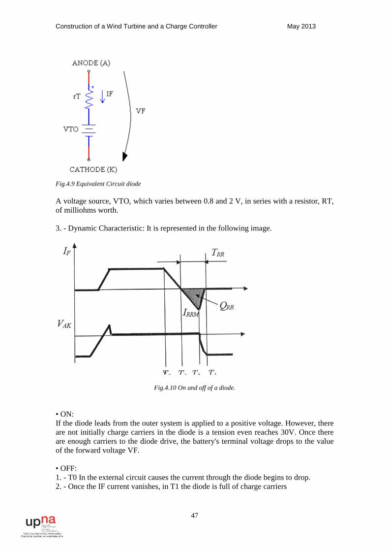
Construction of a Wind Turbine and a Charge Controller May 2013
47
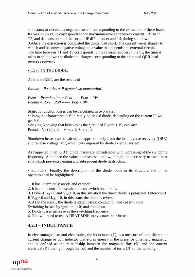
Fig.4.9 Equivalent Circuit diode A voltage source, VTO, which varies between 0.8 and 2 V, in series with a resistor, RT, of milliohms worth. 3. - Dynamic Characteristic: It is represented in the following image.
Fig.4.10 On and off of a diode. • ON: If the diode leads from the outer system is applied to a positive voltage. However, there are not initially charge carriers in the diode is a tension even reaches 30V. Once there are enough carriers to the diode drive, the battery's terminal voltage drops to the value of the forward voltage VF. • OFF: 1. - T0 In the external circuit causes the current through the diode begins to drop. 2. - Once the IF current vanishes, in T1 the diode is full of charge carriers
Construction of a Wind Turbine and a Charge Controller May 2013
48
so it starts to circulate a negative current corresponding to the extraction of these loads. Its maximum value corresponds to the maximum reverse recovery current, IRRM in T2, and depends on both the current IF dIF of onset and / dt during shutdown. 3.-Once the extraction is completed the diode load short. The current varies sharply to vanish and becomes negative voltage to a value that depends the external circuit. The time between T1 and T3 corresponds to the reverse recovery time trr, the time it takes to shut down the diode and charges corresponding to the extracted QRR load reverse recovery. • LOST IN THE DIODE: As in the IGBT, are the results of: Pdiode = P statics + P dynamics(conmutation) Pstat = Pconduction + Pcut ----- Pcut = 0W Pconm = Pon + Poff ------ Pon = 0W Static conduction losses can be calculated in two ways: • Using the characteristic VI directly polarized diode, depending on the current IF we get VF. • driving Knowing that behaves as the circuit of Figure 1.19, can say: Pcond = VF (IF) X IF = V TO X IF + rT X I2
F
Shutdown losses can be calculated approximately from the load reverse recovery (QRR) and reverse voltage, VR, which cuts imposed by diode external system. As happened in an IGBT, diode losses are considerable with increasing of the switching frequency. And since the value, as discussed below, is high, be necessary to use a heat sink which prevents heating and subsequent diode destruction. • Summary: Finally, the description of the diode, both in its structure and in its operation can be highlighted: 1. It has 2 terminals: anode and cathode. 2. It is an uncontrolled semiconductor switch on and off. 3. Drive if IAK> 0 and VAK> 0, in this situation the direct diode is polarized. Enterccourt if VAK <0 and IAK = 0, in this state, the diode is reverse. 4. As in the IGBT, the diode is static losses: conduction and cut (≈ 0) and Switching losses: by ignition (≈ 0) and shutdown. 5. Diode losses increase as the switching frequency. 6. You will need to use A HEAT SINK to evacuate their losses. 4.2.3 – INDUCTANCE In electromagnetism and electronics, the inductance (L), is a measure of opposition to a current change or coil inductor that stores energy in the presence of a field magnetic, and is defined as the relationship between the magnetic flux (Φ) and the current electrical (I) flowing through the coil and the number of turns (N) of the winding:
Construction of a Wind Turbine and a Charge Controller May 2013
49
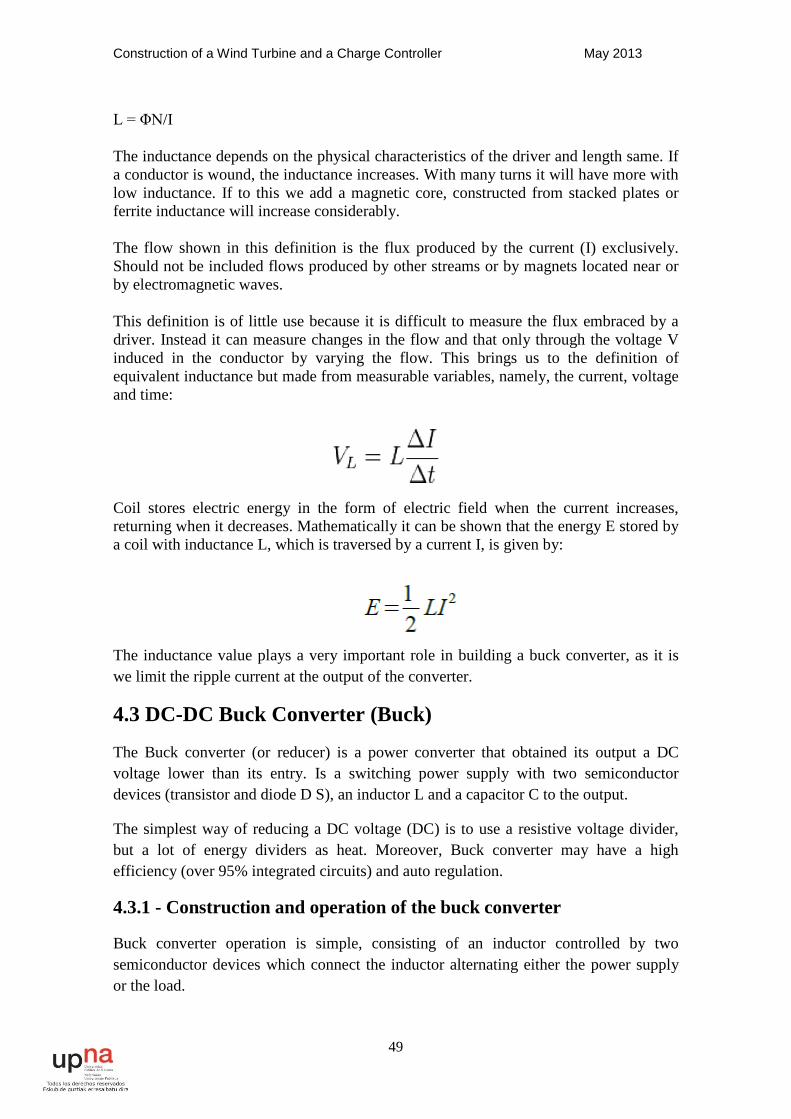
L = ΦN/I The inductance depends on the physical characteristics of the driver and length same. If a conductor is wound, the inductance increases. With many turns it will have more with low inductance. If to this we add a magnetic core, constructed from stacked plates or ferrite inductance will increase considerably. The flow shown in this definition is the flux produced by the current (I) exclusively. Should not be included flows produced by other streams or by magnets located near or by electromagnetic waves. This definition is of little use because it is difficult to measure the flux embraced by a driver. Instead it can measure changes in the flow and that only through the voltage V induced in the conductor by varying the flow. This brings us to the definition of equivalent inductance but made from measurable variables, namely, the current, voltage and time:
Coil stores electric energy in the form of electric field when the current increases, returning when it decreases. Mathematically it can be shown that the energy E stored by a coil with inductance L, which is traversed by a current I, is given by:
The inductance value plays a very important role in building a buck converter, as it is we limit the ripple current at the output of the converter.
4.3 DC-DC Buck Converter (Buck)
The Buck converter (or reducer) is a power converter that obtained its output a DC voltage lower than its entry. Is a switching power supply with two semiconductor devices (transistor and diode D S), an inductor L and a capacitor C to the output.
The simplest way of reducing a DC voltage (DC) is to use a resistive voltage divider, but a lot of energy dividers as heat. Moreover, Buck converter may have a high efficiency (over 95% integrated circuits) and auto regulation.
4.3.1 - Construction and operation of the buck converter
Buck converter operation is simple, consisting of an inductor controlled by two semiconductor devices which connect the inductor alternating either the power supply or the load.
Construction of a Wind Turbine and a Charge Controller May 2013
50
4.4 - Construction of electronic converter
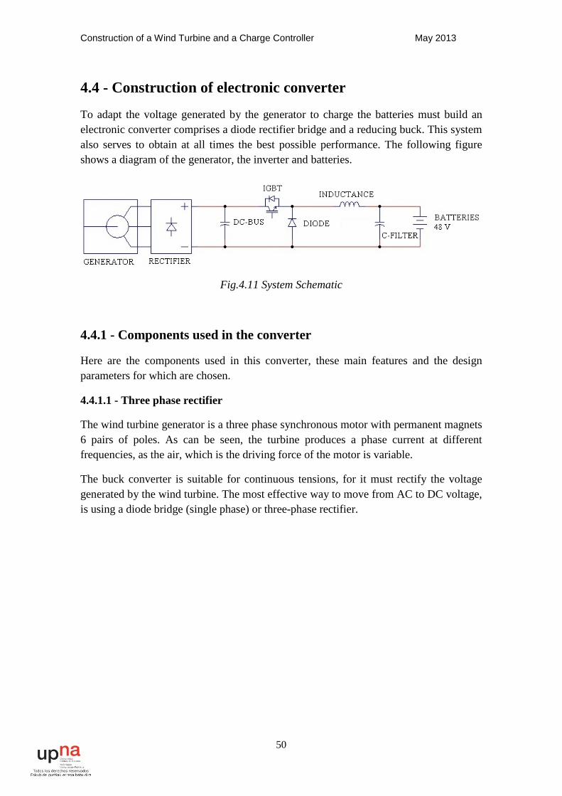
To adapt the voltage generated by the generator to charge the batteries must build an electronic converter comprises a diode rectifier bridge and a reducing buck. This system also serves to obtain at all times the best possible performance. The following figure shows a diagram of the generator, the inverter and batteries.
Fig.4.11 System Schematic
4.4.1 - Components used in the converter
Here are the components used in this converter, these main features and the design parameters for which are chosen.
4.4.1.1 - Three phase rectifier
The wind turbine generator is a three phase synchronous motor with permanent magnets 6 pairs of poles. As can be seen, the turbine produces a phase current at different frequencies, as the air, which is the driving force of the motor is variable.
The buck converter is suitable for continuous tensions, for it must rectify the voltage generated by the wind turbine. The most effective way to move from AC to DC voltage, is using a diode bridge (single phase) or three-phase rectifier.

Construction of a Wind Turbine and a Charge Controller May 2013
51
Fig.4.12 Three phase rectifier
This will get a DC voltage that is suitable for buck converter.
This type of semiconductor employed as the rectifier diode. They are called this way because you can control the output power, ie for a fixed input voltage output voltage is also fixed. In an uncontrolled three-phase rectifier circuit 6 pulse, diodes are listed in the order of the driving sequences and each conducted for 120 ° of the period. The driving sequences for the diodes are D1-D2, D3-D2, D3, D4, D5, D6 D1-D6.
In a balanced three-phase system the line-to-neutral voltages are defined by:
The voltages corresponding line by line (VLL) are:
Construction of a Wind Turbine and a Charge Controller May 2013
52
The average output voltage can be determined by:
The rms value of the output voltage is given by:
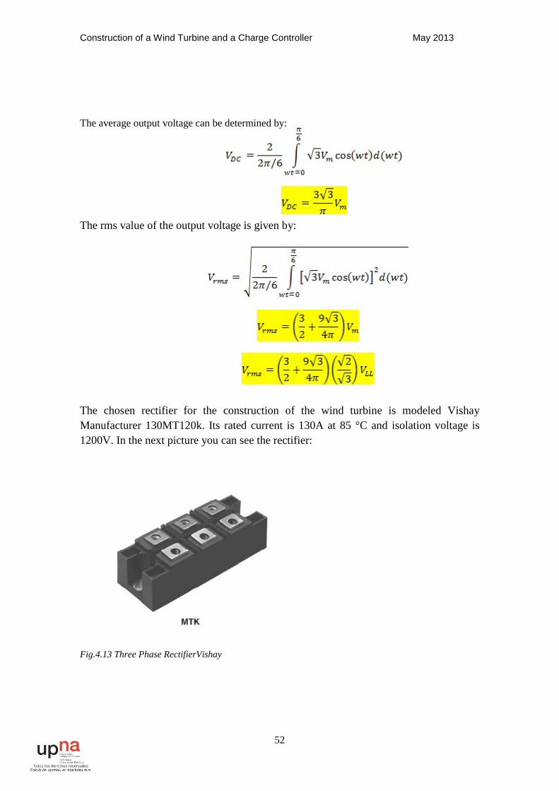
The chosen rectifier for the construction of the wind turbine is modeled Vishay Manufacturer 130MT120k. Its rated current is 130A at 85 °C and isolation voltage is 1200V. In the next picture you can see the rectifier:
Fig.4.13 Three Phase RectifierVishay
Construction of a Wind Turbine and a Charge Controller May 2013
53
4.4.1.2 - Continuous Bus buck converter
The three-phase rectifier gives generates a voltage ripple on the DC bus. To minimize this ripple were used 10 electrolytic capacitors with a voltage of 400 volt isolation capability 470μ and F, are combined in series and pairs couples are connected in parallel. Thus has been achieved with continuous bus an insulation voltage of 800 Volts and 2350μ F. With this capability is the ripple voltage is less than 5%.
4.4.1.3 - Switch block
Starting as a basis for our converter has to support at least 450 Vdc and a current of 80 amps must find a corresponding switching block to these features:
• A IGBT and a diode in series (anti-parallel diode)
• 1200V isolation voltage dc. This voltage is significantly higher than the bus for this is because voltages generated by the inductances when switching block parasitic peaks may have a block of no 600V can support.
• It must withstand 80 amps minimum to work when the wind turbine is at full power.
• The IGBT must be going on to +15 V to-8V and off, since the driver works that tension.
• Must be able to commute to 10KHz.
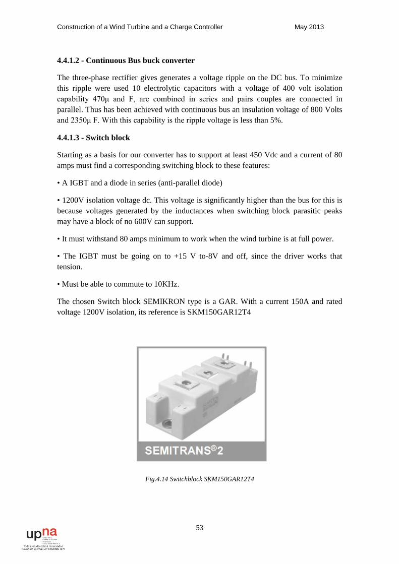
The chosen Switch block SEMIKRON type is a GAR. With a current 150A and rated voltage 1200V isolation, its reference is SKM150GAR12T4
Fig.4.14 Switchblock SKM150GAR12T4
Construction of a Wind Turbine and a Charge Controller May 2013
54
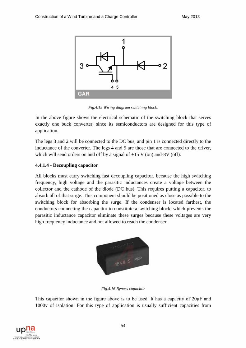
Fig.4.15 Wiring diagram switching block.
In the above figure shows the electrical schematic of the switching block that serves exactly one buck converter, since its semiconductors are designed for this type of application.
The legs 3 and 2 will be connected to the DC bus, and pin 1 is connected directly to the inductance of the converter. The legs 4 and 5 are those that are connected to the driver, which will send orders on and off by a signal of +15 V (on) and-8V (off).
4.4.1.4 - Decoupling capacitor
All blocks must carry switching fast decoupling capacitor, because the high switching frequency, high voltage and the parasitic inductances create a voltage between the collector and the cathode of the diode (DC bus). This requires putting a capacitor, to absorb all of that surge. This component should be positioned as close as possible to the switching block for absorbing the surge. If the condenser is located farthest, the conductors connecting the capacitor to constitute a switching block, which prevents the parasitic inductance capacitor eliminate these surges because these voltages are very high frequency inductance and not allowed to reach the condenser.
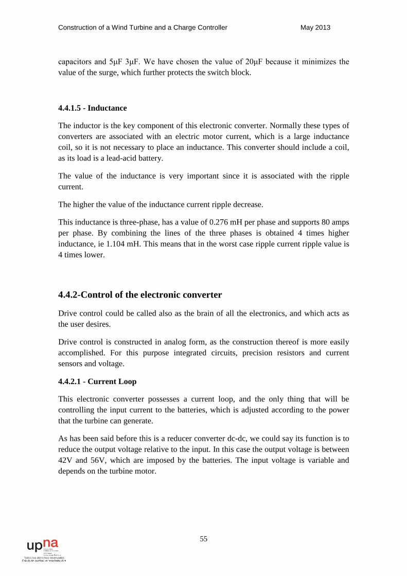
Fig.4.16 Bypass capacitor
This capacitor shown in the figure above is to be used. It has a capacity of 20μF and 1000v of isolation. For this type of application is usually sufficient capacities from
Construction of a Wind Turbine and a Charge Controller May 2013
55
capacitors and 5μF 3μF. We have chosen the value of 20μF because it minimizes the value of the surge, which further protects the switch block.
4.4.1.5 - Inductance
The inductor is the key component of this electronic converter. Normally these types of converters are associated with an electric motor current, which is a large inductance coil, so it is not necessary to place an inductance. This converter should include a coil, as its load is a lead-acid battery.
The value of the inductance is very important since it is associated with the ripple current.
The higher the value of the inductance current ripple decrease.
This inductance is three-phase, has a value of 0.276 mH per phase and supports 80 amps per phase. By combining the lines of the three phases is obtained 4 times higher inductance, ie 1.104 mH. This means that in the worst case ripple current ripple value is 4 times lower.
4.4.2-Control of the electronic converter
Drive control could be called also as the brain of all the electronics, and which acts as the user desires.
Drive control is constructed in analog form, as the construction thereof is more easily accomplished. For this purpose integrated circuits, precision resistors and current sensors and voltage.
4.4.2.1 - Current Loop
This electronic converter possesses a current loop, and the only thing that will be controlling the input current to the batteries, which is adjusted according to the power that the turbine can generate.
As has been said before this is a reducer converter dc-dc, we could say its function is to reduce the output voltage relative to the input. In this case the output voltage is between 42V and 56V, which are imposed by the batteries. The input voltage is variable and depends on the turbine motor.
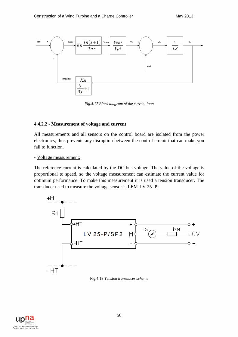
Construction of a Wind Turbine and a Charge Controller May 2013
56
Fig.4.17 Block diagram of the current loop
4.4.2.2 - Measurement of voltage and current
All measurements and all sensors on the control board are isolated from the power electronics, thus prevents any disruption between the control circuit that can make you fail to function.
• Voltage measurement:
The reference current is calculated by the DC bus voltage. The value of the voltage is proportional to speed, so the voltage measurement can estimate the current value for optimum performance. To make this measurement it is used a tension transducer. The transducer used to measure the voltage sensor is LEM-LV 25 -P.
Fig.4.18 Tension transducer scheme
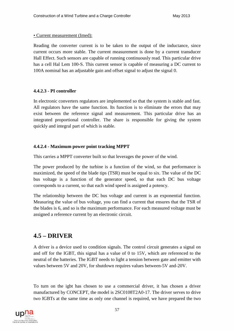
Construction of a Wind Turbine and a Charge Controller May 2013
57
• Current measurement (Imed):
Reading the converter current is to be taken to the output of the inductance, since current occurs more stable. The current measurement is done by a current transducer Hall Effect. Such sensors are capable of running continuously read. This particular drive has a cell Hal Lem 100-S. This current sensor is capable of measuring a DC current to 100A nominal has an adjustable gain and offset signal to adjust the signal 0.
4.4.2.3 - PI controller
In electronic converters regulators are implemented so that the system is stable and fast. All regulators have the same function. Its function is to eliminate the errors that may exist between the reference signal and measurement. This particular drive has an integrated proportional controller. The share is responsible for giving the system quickly and integral part of which is stable.
4.4.2.4 - Maximum power point tracking MPPT
This carries a MPPT converter built so that leverages the power of the wind.
The power produced by the turbine is a function of the wind, so that performance is maximized, the speed of the blade tips (TSR) must be equal to six. The value of the DC bus voltage is a function of the generator speed, so that each DC bus voltage corresponds to a current, so that each wind speed is assigned a potency.
The relationship between the DC bus voltage and current is an exponential function. Measuring the value of bus voltage, you can find a current that ensures that the TSR of the blades is 6, and so is the maximum performance. For each measured voltage must be assigned a reference current by an electronic circuit.
4.5 – DRIVER
A driver is a device used to condition signals. The control circuit generates a signal on and off for the IGBT, this signal has a value of 0 to 15V, which are referenced to the neutral of the batteries. The IGBT needs to light a tension between gate and emitter with values between 5V and 20V, for shutdown requires values between-5V and-20V.
To turn on the igbt has chosen to use a commercial driver, it has chosen a driver manufactured by CONCEPT, the model is 2SC0108T2A0-17. The driver serves to drive two IGBTs at the same time as only one channel is required, we have prepared the two
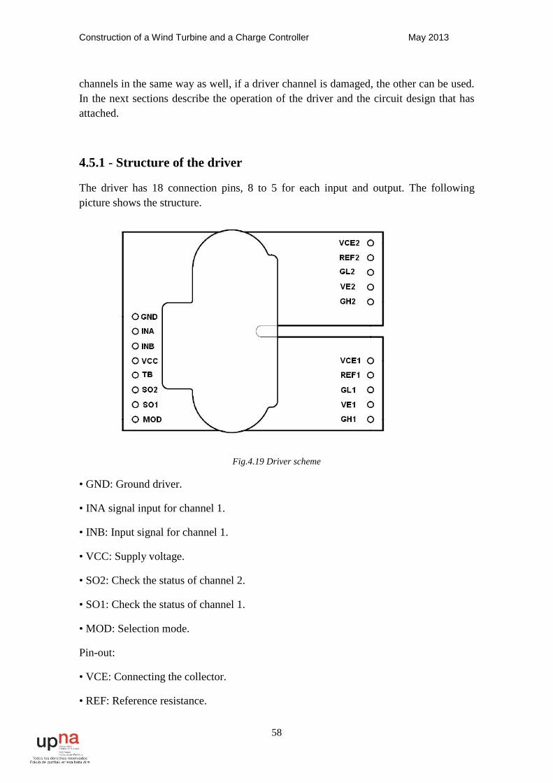
Construction of a Wind Turbine and a Charge Controller May 2013
58
channels in the same way as well, if a driver channel is damaged, the other can be used. In the next sections describe the operation of the driver and the circuit design that has attached.
4.5.1 - Structure of the driver
The driver has 18 connection pins, 8 to 5 for each input and output. The following picture shows the structure.
Fig.4.19 Driver scheme
• GND: Ground driver.
• INA signal input for channel 1.
• INB: Input signal for channel 1.
• VCC: Supply voltage.
• SO2: Check the status of channel 2.
• SO1: Check the status of channel 1.
• MOD: Selection mode.
Pin-out:
• VCE: Connecting the collector.
• REF: Reference resistance.
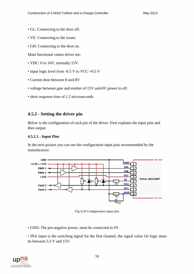
Construction of a Wind Turbine and a Charge Controller May 2013
59
• GL: Connecting to the door off.
• VE: Connecting to the issuer.
• GH: Connecting to the door on.
Main functional values driver are:
• VDC: 0 to 16V, normally 15V.
• input logic level from -0.5 V to VCC +0.5 V
• Current door between 8 and-8V
• voltage between gate and emitter of 15V and-8V power to off.
• short response time of 1.2 microseconds.
4.5.2 - Setting the driver pin
Below is the configuration of each pin of the driver. First explains the input pins and then output.
4.5.2.1 - Input Pins
In the next picture you can see the configuration input pins recommended by the manufacturer:
Fig.4.20 Configuration input pins
• GND: The pin negative power, must be connected to 0V.
• INA input is the switching signal for the first channel, the signal value On logic must be between 3.3 V and 15V.
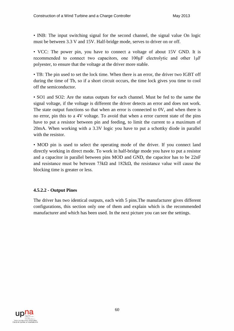
Construction of a Wind Turbine and a Charge Controller May 2013
60
• INB: The input switching signal for the second channel, the signal value On logic must be between 3.3 V and 15V. Half-bridge mode, serves to driver on or off.
• VCC: The power pin, you have to connect a voltage of about 15V GND. It is recommended to connect two capacitors, one 100μF electrolytic and other 1μF polyester, to ensure that the voltage at the driver more stable.
• TB: The pin used to set the lock time. When there is an error, the driver two IGBT off during the time of Tb, so if a short circuit occurs, the time lock gives you time to cool off the semiconductor.
• SO1 and SO2: Are the status outputs for each channel. Must be fed to the same the signal voltage, if the voltage is different the driver detects an error and does not work. The state output functions so that when an error is connected to 0V, and when there is no error, pin this to a 4V voltage. To avoid that when a error current state of the pins have to put a resistor between pin and feeding, to limit the current to a maximum of 20mA. When working with a 3.3V logic you have to put a schottky diode in parallel with the resistor.
• MOD pin is used to select the operating mode of the driver. If you connect land directly working in direct mode. To work in half-bridge mode you have to put a resistor and a capacitor in parallel between pins MOD and GND, the capacitor has to be 22nF and resistance must be between 73kΩ and 182kΩ, the resistance value will cause the blocking time is greater or less.
4.5.2.2 - Output Pines
The driver has two identical outputs, each with 5 pins.The manufacturer gives different configurations, this section only one of them and explain which is the recommended manufacturer and which has been used. In the next picture you can see the settings.
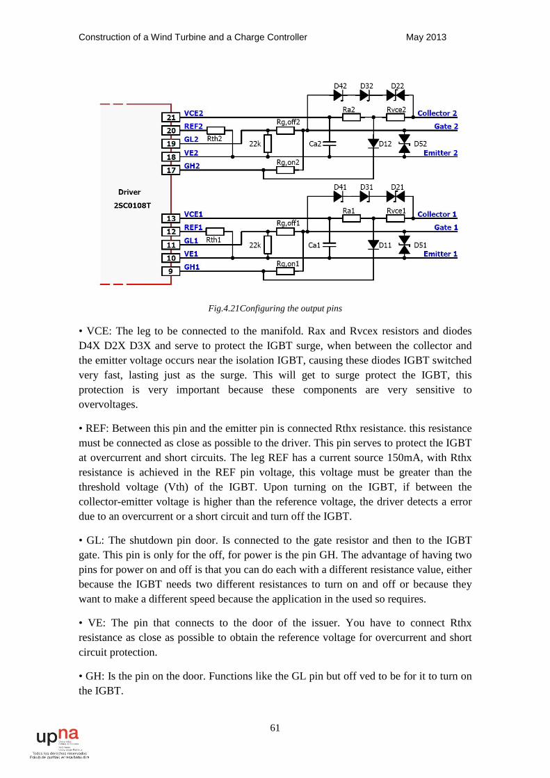
Construction of a Wind Turbine and a Charge Controller May 2013
61
Fig.4.21Configuring the output pins
• VCE: The leg to be connected to the manifold. Rax and Rvcex resistors and diodes D4X D2X D3X and serve to protect the IGBT surge, when between the collector and the emitter voltage occurs near the isolation IGBT, causing these diodes IGBT switched very fast, lasting just as the surge. This will get to surge protect the IGBT, this protection is very important because these components are very sensitive to overvoltages.
• REF: Between this pin and the emitter pin is connected Rthx resistance. this resistance must be connected as close as possible to the driver. This pin serves to protect the IGBT at overcurrent and short circuits. The leg REF has a current source 150mA, with Rthx resistance is achieved in the REF pin voltage, this voltage must be greater than the threshold voltage (Vth) of the IGBT. Upon turning on the IGBT, if between the collector-emitter voltage is higher than the reference voltage, the driver detects a error due to an overcurrent or a short circuit and turn off the IGBT.
• GL: The shutdown pin door. Is connected to the gate resistor and then to the IGBT gate. This pin is only for the off, for power is the pin GH. The advantage of having two pins for power on and off is that you can do each with a different resistance value, either because the IGBT needs two different resistances to turn on and off or because they want to make a different speed because the application in the used so requires.
• VE: The pin that connects to the door of the issuer. You have to connect Rthx resistance as close as possible to obtain the reference voltage for overcurrent and short circuit protection.
• GH: Is the pin on the door. Functions like the GL pin but off ved to be for it to turn on the IGBT.
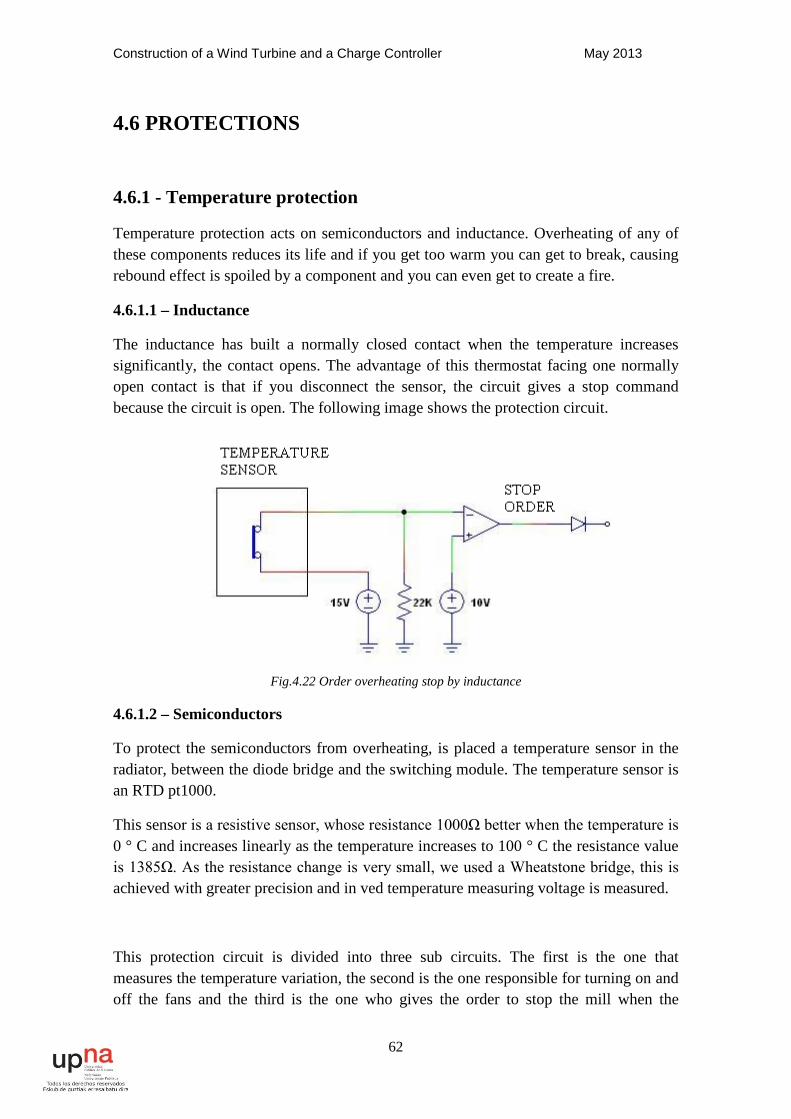
Construction of a Wind Turbine and a Charge Controller May 2013
62
4.6 PROTECTIONS
4.6.1 - Temperature protection
Temperature protection acts on semiconductors and inductance. Overheating of any of these components reduces its life and if you get too warm you can get to break, causing rebound effect is spoiled by a component and you can even get to create a fire.
4.6.1.1 – Inductance
The inductance has built a normally closed contact when the temperature increases significantly, the contact opens. The advantage of this thermostat facing one normally open contact is that if you disconnect the sensor, the circuit gives a stop command because the circuit is open. The following image shows the protection circuit.
Fig.4.22 Order overheating stop by inductance
4.6.1.2 – Semiconductors
To protect the semiconductors from overheating, is placed a temperature sensor in the radiator, between the diode bridge and the switching module. The temperature sensor is an RTD pt1000.
This sensor is a resistive sensor, whose resistance 1000Ω better when the temperature is 0 ° C and increases linearly as the temperature increases to 100 ° C the resistance value is 1385Ω. As the resistance change is very small, we used a Wheatstone bridge, this is achieved with greater precision and in ved temperature measuring voltage is measured.
This protection circuit is divided into three sub circuits. The first is the one that measures the temperature variation, the second is the one responsible for turning on and off the fans and the third is the one who gives the order to stop the mill when the
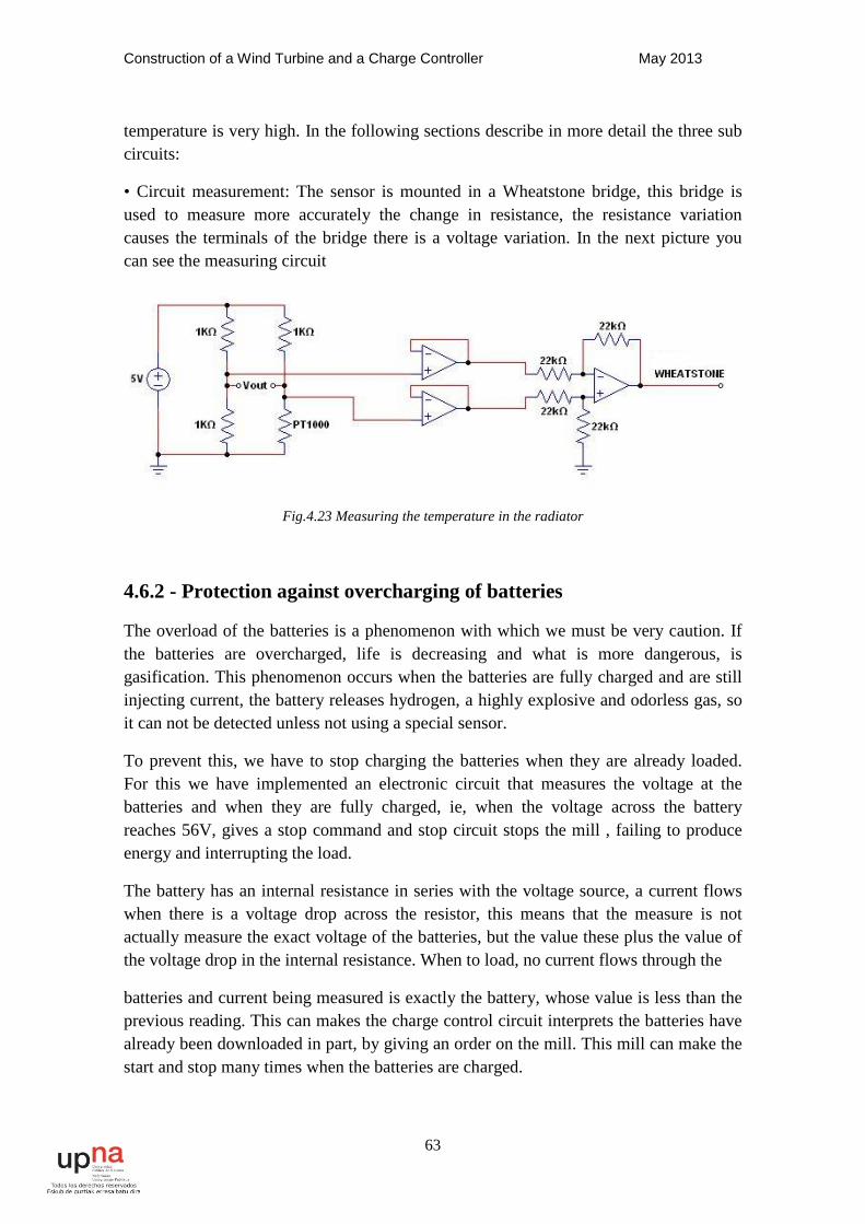
Construction of a Wind Turbine and a Charge Controller May 2013
63
temperature is very high. In the following sections describe in more detail the three sub circuits:
• Circuit measurement: The sensor is mounted in a Wheatstone bridge, this bridge is used to measure more accurately the change in resistance, the resistance variation causes the terminals of the bridge there is a voltage variation. In the next picture you can see the measuring circuit
Fig.4.23 Measuring the temperature in the radiator
4.6.2 - Protection against overcharging of batteries
The overload of the batteries is a phenomenon with which we must be very caution. If the batteries are overcharged, life is decreasing and what is more dangerous, is gasification. This phenomenon occurs when the batteries are fully charged and are still injecting current, the battery releases hydrogen, a highly explosive and odorless gas, so it can not be detected unless not using a special sensor.
To prevent this, we have to stop charging the batteries when they are already loaded. For this we have implemented an electronic circuit that measures the voltage at the batteries and when they are fully charged, ie, when the voltage across the battery reaches 56V, gives a stop command and stop circuit stops the mill , failing to produce energy and interrupting the load.
The battery has an internal resistance in series with the voltage source, a current flows when there is a voltage drop across the resistor, this means that the measure is not actually measure the exact voltage of the batteries, but the value these plus the value of the voltage drop in the internal resistance. When to load, no current flows through the
batteries and current being measured is exactly the battery, whose value is less than the previous reading. This can makes the charge control circuit interprets the batteries have already been downloaded in part, by giving an order on the mill. This mill can make the start and stop many times when the batteries are charged.
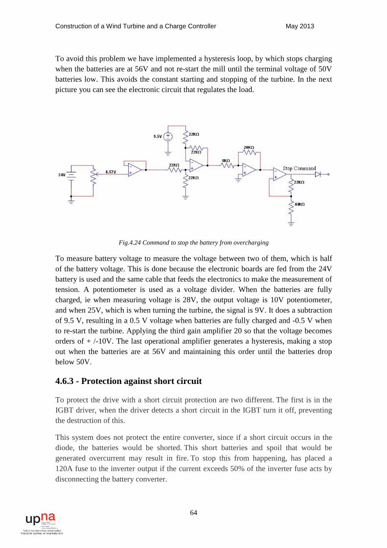
Construction of a Wind Turbine and a Charge Controller May 2013
64
To avoid this problem we have implemented a hysteresis loop, by which stops charging when the batteries are at 56V and not re-start the mill until the terminal voltage of 50V batteries low. This avoids the constant starting and stopping of the turbine. In the next picture you can see the electronic circuit that regulates the load.
Fig.4.24 Command to stop the battery from overcharging
To measure battery voltage to measure the voltage between two of them, which is half of the battery voltage. This is done because the electronic boards are fed from the 24V battery is used and the same cable that feeds the electronics to make the measurement of tension. A potentiometer is used as a voltage divider. When the batteries are fully charged, ie when measuring voltage is 28V, the output voltage is 10V potentiometer, and when 25V, which is when turning the turbine, the signal is 9V. It does a subtraction of 9.5 V, resulting in a 0.5 V voltage when batteries are fully charged and -0.5 V when to re-start the turbine. Applying the third gain amplifier 20 so that the voltage becomes orders of + /-10V. The last operational amplifier generates a hysteresis, making a stop out when the batteries are at 56V and maintaining this order until the batteries drop below 50V.
4.6.3 - Protection against short circuit
To protect the drive with a short circuit protection are two different. The first is in the IGBT driver, when the driver detects a short circuit in the IGBT turn it off, preventing the destruction of this.
This system does not protect the entire converter, since if a short circuit occurs in the diode, the batteries would be shorted. This short batteries and spoil that would be generated overcurrent may result in fire. To stop this from happening, has placed a 120A fuse to the inverter output if the current exceeds 50% of the inverter fuse acts by disconnecting the battery converter.
Construction of a Wind Turbine and a Charge Controller May 2013
65
Not been made smaller fuse since current peaks may occur that do not affect the operation of the converter, since the semiconductor withstand currents above 120A, and inductance can endure, but not continuously, if there are manyovercurrents less than 120A, but the fuse not detect if any of the components are heated more than necessary, act protections against overheating by cooling the converter and if need be stopping it. Upstream converter no protection system, only stop the wind turbine system.Fuses can not be positioned upstream of the converter, since in case of overcurrent or short-circuit these would melt, so that the mill would pack and the stop mechanism may act not be disconnected because the turbine.
Construction of a Wind Turbine and a Charge Controller May 2013
66
5. BATTERIES 5.1 Introduction:
The energy created by the wind turbine, can be consumed by a load or but must accumulate in batteries. In the case of the turbine, all the energy generated passes 48V batteries, and then connected to an inverter, so that no energy consumed by the inverter is accumulated in the batteries. In times when the turbine generates less energy than the load demand, the investor obtains the necessary energy batteries.
The energy storage capacity varies with type of installation. An installation isolated from the power supply, we must take into account that there may be several days in the that the energy generated is insufficient, so that the batteries should have a range several days, if the installation is connected to the network, you do not need a large autonomy, since at the time the batteries are discharged can be consumed power network, this is achieved by reducing the cost of installation, since the batteries are not cheap. In the case of combining multiple power generation, such as the photovoltaic panels or micro-hydraulic storage capacity is smaller, since when there is no wind, it is possible that this generating electricity from another source.
It is called the device battery that stores electrical energy, using electrochemical methods and subsequently returns almost completely. Is secondary electrical generator, namely a generator that can not run without being Electricity is supplied in advance by so-called charging.
5.2 Types of batteries:
In it the markets there are different types of batteries, each type is the least suitable for each application. These are the most common batteries:
5.2.1 Batteries Lead-Acid
Such batteries are formed by the electrodes of lead, and it is used them in automobiles.
Regarding the functioning in the process of loading it, he lead sulfate convert in lead metal in it for the negative cathode. For another part in it at the anode is positive produces the formation of lead oxide.
In the downloading process, the processes mentioned above are made in inverted form. From this way lead oxide is reduced to lead sulfate, and in the anode the lead begins to oxidize, making lead sulfate.
However, this type of transformation can not be repeated indefinitely. After a time, the lead sulfate crystals form, and it is possible to perform the process reversibly. This is the moment when the battery is sulfated and you can not return to use it.
Construction of a Wind Turbine and a Charge Controller May 2013
67
5.2.2 Alkaline battery
Such piles are formed by sodium chloride or potassium. They have Power stability and large current because of the extensive mobility of ions through electrolyte.
Alkaline batteries are shielded in order not to spill the components thereof.
5.2.3 Nickel-iron (Ni-Fe)
This kind of battery was developed by Edison in the early twentieth century. It conformed by rows of tubes composed of nickel plated steel, which contained hydroxide nickel. The positive pole contained nickel plated steel with ferrous oxide dust.
Nickel-based batteries are simple to manufacture, low cost and can be overloaded or discharged repeatedly without losing its capacity.
5.2.4 Alkaline manganese batteries
They are similar to alkaline batteries, except that they are made up potassium hydroxide. Its casing is made of steel and zinc powder is located in the center.
Alkaline manganese batteries are of high value and are used in machines high energy consumption and motorized toys.
5.2.5 Nickel-Cadmium (Ni-Cd)
This type of battery operates from a cadmium anode and a cathode consisting nickel hydroxide. For its part, the electrolyte is potassium hydroxide. They can be recharged worn once, but have little capacity.
5.2.6 Nickel-Metal Hydride (Ni-MH)
Employ a nickel hydroxide anode and a cathode comprising an alloy of metal hydride. They are reluctant to contact with the low temperatures, decreasing largely their effectiveness.
5.2.7 Lithium-ion battery (LI-ION)
This type of battery has a graphite anode, while the cathode operates at from cobalt oxide, manganese oxide or trifiline. Do not allow the discharge and capable to attain high powers. However affected by temperature changes.
5.2.8 Lithium Polymer Batteries (LIPO)
They have characteristics similar to lithium-ion batteries, although their density is greater. They are small sized so are often used in small teams.
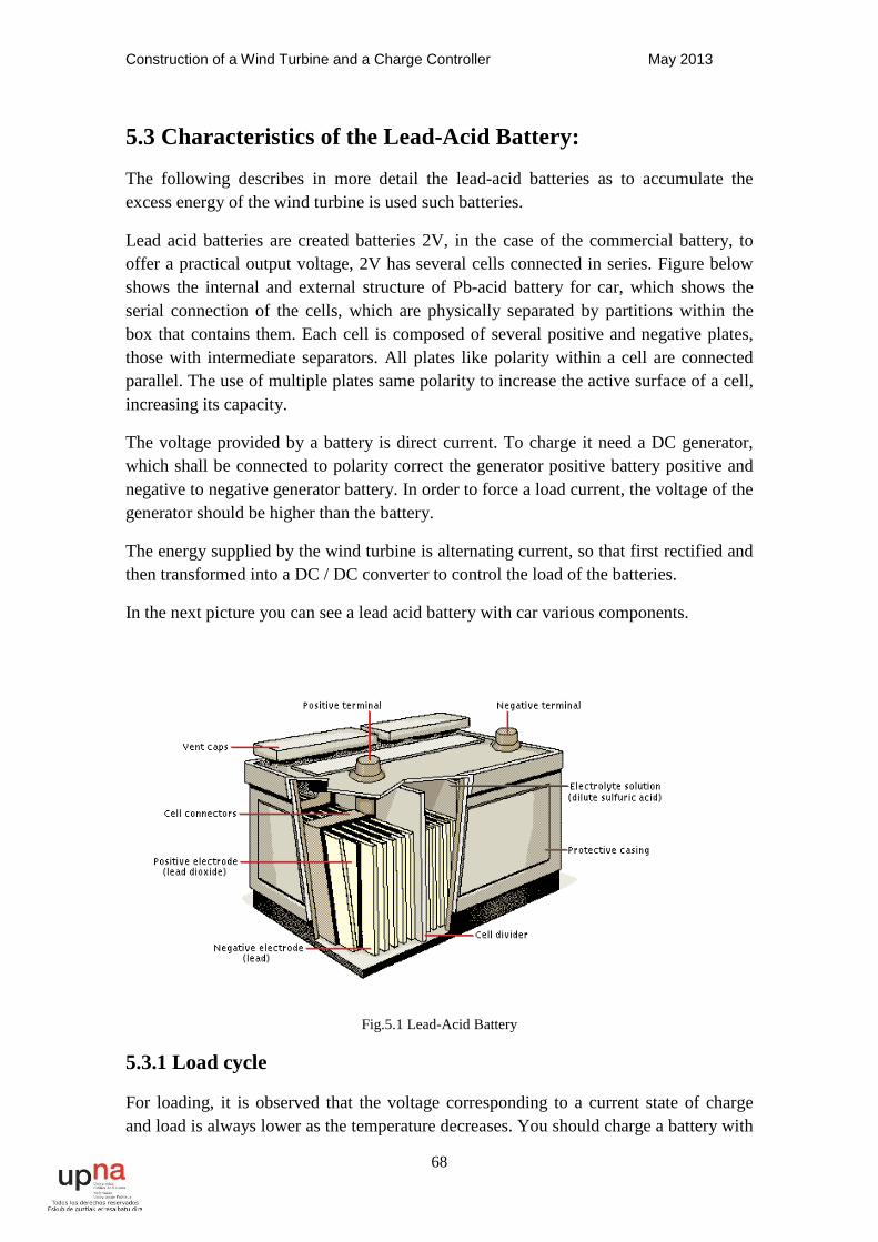
Construction of a Wind Turbine and a Charge Controller May 2013
68
5.3 Characteristics of the Lead-Acid Battery:
The following describes in more detail the lead-acid batteries as to accumulate the excess energy of the wind turbine is used such batteries.
Lead acid batteries are created batteries 2V, in the case of the commercial battery, to offer a practical output voltage, 2V has several cells connected in series. Figure below shows the internal and external structure of Pb-acid battery for car, which shows the serial connection of the cells, which are physically separated by partitions within the box that contains them. Each cell is composed of several positive and negative plates, those with intermediate separators. All plates like polarity within a cell are connected parallel. The use of multiple plates same polarity to increase the active surface of a cell, increasing its capacity.
The voltage provided by a battery is direct current. To charge it need a DC generator, which shall be connected to polarity correct the generator positive battery positive and negative to negative generator battery. In order to force a load current, the voltage of the generator should be higher than the battery.
The energy supplied by the wind turbine is alternating current, so that first rectified and then transformed into a DC / DC converter to control the load of the batteries.
In the next picture you can see a lead acid battery with car various components.
Fig.5.1 Lead-Acid Battery
5.3.1 Load cycle
For loading, it is observed that the voltage corresponding to a current state of charge and load is always lower as the temperature decreases. You should charge a battery with
Construction of a Wind Turbine and a Charge Controller May 2013
69
a current level less than or equal to 10% of its capacity. If the current value is larger battery overheating during charging, the losses will be greater and decrease battery life.
The process is reversible battery. If we disconnect the generator and connect one electrical charge to the battery, a current will flow through it in a direction opposite to that of load, causing chemical reactions at the electrodes that return the system to its condition initial. In principle, the charge-discharge cycle can be repeated indefinitely. In practice there are limitations to the maximum number of them, because the electrodes lose part of each discharge material.
5.3.2 Discharge cycle
For discharge of a battery, the output current may be much greater than that of load. In fact, many of these batteries are designed for very fast downloads and deep, but what is not good is that they remain unloaded for a long time.
The higher the discharge current, the value of the internal resistance becomes greater, warming worse performance and battery.
Discharge curves show that at low temperature the voltage drop is much more severe than that observed, for the same current, 78 °F. The low temperature slows chemical reaction, resulting in an abrupt increase in internal resistance battery, which causes a greater voltage drop. It also notes that maintaining electrolyte temperature constant, the voltage drop is always higher (increased internal resistance) when the discharge current increases.
.
5.3.3 Cautions should be taken with batteries
To work with lead-acid batteries need to take several precautions both for safety and to extend the life of these:
• Transport: When moving batteries and forth must be very careful to not spill sulphuric acid within. Many batteries led-acid are hermetically sealed, but there are some that do not. The acid can produce skin burns, and if spilled on the ground is very detrimental to the environment.
• Gasification: When a lead-acid battery is about to reach 100% of its load, the amount of water in the electrolyte has been severely limited. Ions it provides become scarcer, reducing the possibility for hydrogen ion (negative electrode) and oxygen ion (positive electrode) to react chemically to form lead dioxide and lead, respectively. If the current load continues at the same level, excess electrolyte escapes gases producing a intense bubbling, which is known as "gassing". This mass gasification many Sometimes it escaping through the oxide cap and the breathing battery terminals by acid. This means that the acid electrolyte is reduced, and in turns the ability charging of the battery.
Construction of a Wind Turbine and a Charge Controller May 2013
70
Gasification is dangerous because the gas that comes out is hydrogen and is highly explosive. To prevent this from happening you have to control very well the state of charge of the batteries, so you never exceed 100%.
•Sulphation: We have seen that the discharge of lead-acid batteries brings a deposit of lead sulphate in both plates. Typically this deposit is consists of small crystals, which are easily decomposed during load. If, however, the battery has been repeatedly discharged below specified minimum, is poorly loaded or unloaded for long stays, The crystallite size increases, and only a part of them involved in the process of load. This translates into a decrease of the active surface of the electrode, decreasing storage capacity. This phenomenon is known by the name of battery sulphating. In places where cloudy periods are long-lasting batteries can lie low load, long, inducing sulphating of the plates. A load high current regime can dissolve this crystal formation (equalization process).
5.4 Battery Choice
When selecting batteries as energy storage, we chose those Lead-acid because they are the cheapest in the market and easy to acquire a low price. In our case we use car batteries.
The batteries can be connected in series or in parallel depending on the needs of each application.
As you can see in the picture above you can see the possible combinations you can do with batteries. When combined in parallel, what is intended is maintain tension and increase capacity, being able to give more power to the load. In turn, in series that is done is to increase the tension and maintaining the current, another way to increase the capacity.
The battery capacity is measured in Ah, means the amount of amperes can to discharge the battery in one hour. If a battery is 12V and 55Ah, means that for download it completely for an hour must extract 55A, or can give a stream of 1A for 55h. The value of the capacity of 660W / h.
5.5 Installing the Batteries
The installation of the batteries have a voltage of 48V, so you have to put 4 batteries car in series to achieve the necessary voltage. The capacity of each battery is 55Ah, with In order to have a greater capacity get four branches of four batteries in parallel, with a total capacity of 220Ah. The total stored energy of 10.56 kW / h, which according to daily demand calculations, is a range of almost two days. In the next image can see the battery connections.
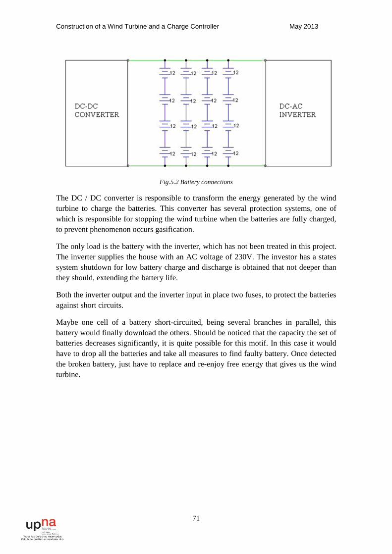
Construction of a Wind Turbine and a Charge Controller May 2013
71
Fig.5.2 Battery connections
The DC / DC converter is responsible to transform the energy generated by the wind turbine to charge the batteries. This converter has several protection systems, one of which is responsible for stopping the wind turbine when the batteries are fully charged, to prevent phenomenon occurs gasification.
The only load is the battery with the inverter, which has not been treated in this project. The inverter supplies the house with an AC voltage of 230V. The investor has a states system shutdown for low battery charge and discharge is obtained that not deeper than they should, extending the battery life.
Both the inverter output and the inverter input in place two fuses, to protect the batteries against short circuits.
Maybe one cell of a battery short-circuited, being several branches in parallel, this battery would finally download the others. Should be noticed that the capacity the set of batteries decreases significantly, it is quite possible for this motif. In this case it would have to drop all the batteries and take all measures to find faulty battery. Once detected the broken battery, just have to replace and re-enjoy free energy that gives us the wind turbine.
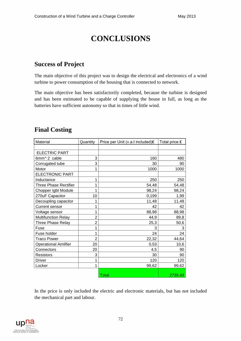
Construction of a Wind Turbine and a Charge Controller May 2013
72
CONCLUSIONS
Success of Project
The main objective of this project was to design the electrical and electronics of a wind turbine to power consumption of the housing that is connected to network.
The main objective has been satisfactorily completed, because the turbine is designed and has been estimated to be capable of supplying the house in full, as long as the batteries have sufficient autonomy so that in times of little wind.
Final Costing
Material Quantity Price per Unit (v.a.t included)₤ Total price ₤ ELECTRIC PART 6mm^ 2 cable 3 160 480 Corrugated tube 3 30 90 Motor 1 1000 1000 ELECTRONIC PART Inductance 1 250 250 Three Phase Rectifier 1 54,48 54,48 Chopper Igbt Module 1 98,24 98,24 270uF Capacitor 10 0,199 1,99 Decoupling capacitor 1 11,48 11,48 Current sensor 1 42 42 Voltage sensor 1 88,98 88,98 Multifunction Relay 2 44,9 89,8 Three Phase Relay 2 25,3 50,6 Fuse 1 3 3 Fuse holder 1 24 24 Traco Power 2 22,32 44,64 Operational Amlifier 20 0,53 10,6 Connectors 20 4,5 90 Resistors 3 30 90 Driver 1 120 120 Locker 1 99,62 99,62 Total 2739,43
In the price is only included the electric and electronic materials, but has not included the mechanical part and labour.

Construction of a Wind Turbine and a Charge Controller May 2013
73
Further Work
Here are several ideas to improve the project in the future. The main objectives are to reduce cost and improve performance.
• A wind turbine of this style have drunk little engine rated voltage and high current, since it would save in the converter.
• They should investigate new ways Wind guidance and protection from strong winds, thus simplifying the system could be disorienting.
• As for the electronics necessary to emphasize the converter, which could be digital. This would greatly simplify the circuits, may offer better protection and better control.
REFERENCES [1] https://maps.google.co.uk
[2] http://en.eltiempo.es/dolau.html?v=historico
[3] http://ecolosfera.com/energia-aire/
[4] http://www.cener.com/es/index.asp
[5] [6] http://www.user.tu-berlin.de/h.gevrek/ordner/ilse/wind/wind5e.html
[7] PSIM Software
[8] http://www.ewh.ieee.org/soc/es/Nov1997/09/INDEX.HTM
[9][10] [11][12] Practices carried out in the UPNA with permanent magnet synchronous motors
http://www.xcweather.co.uk
http://www.bbc.co.uk/weather/
http://www.ewea.org
http://www.renewableuk.com/
http://www.decc.gov.uk/
http://www.bornay.com/eolica/es/aerogeneradores/4/soporte-preguntas-frecuentes/18
Construction of a Wind Turbine and a Charge Controller May 2013
74
Bibliography
• Book "Renewable Energy Practice", publisher PAMIELA 2003 edition, Iñaki and Sebastian Urkia.
• Girl Michelangelo PFC Sanchez: Bridge in H current control for a dc machine.
• Ivan PFC Enrique Cuenca and Faci Tambo Cantero: Study and construction of a permanent magnet wind turbine.
• Notes of the following subjects:
◦ "Electric Drive"
◦ "Power Electronics"
◦ "Electrical Machines I"
◦ "Electrical Machines II"
◦ "Circuits"
◦ "Electrical Computer Aided Design"
◦ "Industrial Electronics"
◦ "Automatic adjustment"
◦ "Theory of mechanisms and structures"
◦ "Instrumentation"
◦ "Converting wind energy systems" the master of renewable energies.
• Computer Software:
◦ PSIM
Related Documents