THE REPUBLIC OF IRAQ MINISTRY OF ELECTRICITY (MoE) ENERGY DISTRIBUTION OFFICE Construction of 33/11kV Substations (2 x 31.5 MVA) Section (1) TECHNICAL SPECIFICATIONS Rev. 0 March 2012

Welcome message from author
This document is posted to help you gain knowledge. Please leave a comment to let me know what you think about it! Share it to your friends and learn new things together.
Transcript

THE REPUBLIC OF IRAQ MINISTRY OF ELECTRICITY (MoE) ENERGY DISTRIBUTION OFFICE
Construction of 33/11kV Substations
(2 x 31.5 MVA)
Section (1)
TECHNICAL SPECIFICATIONS
Rev. 0 March 2012

Technical Specification Table of Contents Page 1 of 8 Rev. 0
Table of Contents
Part-1 General Specification
Section-1.1 : Project Description
1.1.1 Scope of Work
1.1.2 Deleted
1.1.3 Implementation Program
1.1.4 Deleted
1.1.5 Technical Documents
1.1.6 TrainingError! Bookmark not defined.
1.1.7 Tests and Inspections
1.1.8 Packing for Shipmen
1.1.9 Delivery
1.1.10 Guarantee by the Contractor
Part-2 General Technical Design Data
Section-2.1: General Technical Specification
2.1.1 Standards and Design Conditions
2.1.2 Design, Material and Workmanship
2.1.3 Phase Arrangement of Electrical Equipment
2.1.4 Color Identification of Electrical Conductors and Equipment
2.1.5 Control and instrument wiring and terminal boards
2.1.6 : Identification of wires
Part-3 Particular Requirement for Substation equipment
Section-3.1: 33 kV Metal-Clad Switchgear
3.1.1 General
3.1.2 General Arrangement
3.1.3 Degree of protection
3.1.4 Current Rating
3.1.5 Bus-bars and connection
3.1.6 Circuit breakers
3.1.7 Disconnector
3.1.8 Earthing Switch
3.1.9 Lightning arrester
3.1.10 Low tension and control circuit and equipment

Technical Specification Table of Contents Page 2 of 8 Rev. 0
3.1.11 Indicators and alarms
3.1.12 Instrument and protection
3.1.13 Instruments and relays
3.1.14 Protection
Section-3.2: 33/11.5kV 31.5MVA Power Transformer
3.2.1 General
3.2.2 Characteristics of the transformers
3.2.3 Cable Boxes(Air insulated type)
3.2.4 Fittings and Accessories
3.2.5 Painting
3.2.6 Tolerance
3.2.7 Labels, Rating plates
3.2.8 On load tap changer
3.2.9 Control and instrument wiring and terminal boards
3.2.10 Insulating oil
3.2.11 Continuous Maximum Rating, temperature rise and overload
3.2.12 Short circuit guarantee
3.2.13 Insulation levels
3.2.14 Loss Evaluation and Penalty
3.2.15 Earthing resister and others of Transformer Neutral
3.2.16 Spare parts and special tools
Section-3.3: 11 kV Metal-Clad Switchgear
3.3.1 General
3.3.2 General Arrangement
3.3.3 Degree of protection
3.3.4 Current Rating
3.3.5 Bus-bars and connection
3.3.6 Circuit breakers
3.3.8 Earthing Switch
3.3.9 Deleted
3.3.10 Low tension and control circuit and equipment
3.3.11 Indicators and alarms
3.3.12 Instrument and protection
3.3.13 Instruments and relays
3.3.14 Protection
3.3.15 Capacitor Bank Interlocking
3.3.16 Interlocking of 11kV Bus Section Circuit Breaker

Technical Specification Table of Contents Page 3 of 8 Rev. 0
Section-3.4: Remote control and indication
3.4.1 General
3.4.2.1 Controls/Commands
3.4.2.2 Status/Indication
3.4.2.3 Alarms
3.4.2.4 Analogue Measurements
3.4.3 Technical Requirements of transducers
Section-3.5: Substation Control System
3.5.1 General
3.5.2 Design Principles
3.5.3 System Architecture
3.5.4 System Functions
3.5.5 System Capacity
3.5.6 System Performance
3.5.7 Software Requirements
3.5.8 Hardware Requirements
3.5.9 Maintenance and Spares
3.5.10 Documentation
3.5.11 Warranty and Support
3.5.12 SCS Testing
3.5.13 Overall Signal Point List
Section-3.6: Wireless UHF Communication System
3.6.1 General
3.6.2 Remote Terminals
3.6.3 Coaxial cable for Antenna feeder
3.6.4 Antenna
3.6.5 Tower
Section-3.7: 11/0.416kV Auxiliary transformer
Section-3.8: Station DC System
3.8.1 General
3.8.2 110V System
3.8.3 Deleted
Section-3.9: Station LV AC System
Section-3.10: Cables
3.10.1 General
3.10.2 Medium Voltage Power Cables

Technical Specification Table of Contents Page 4 of 8 Rev. 0
3.10.3 Low voltage Power Cables
3.10.4 Control & Auxiliary Cables
3.10.5 Termination of cables and wires
3.10.6 Cable installation requirement
3.10.7 Cable trays, racks, ladders and associated materials
3.10.8 Conduit and installation of conduit system
3.10.9 Painting
Section-3.11: Earthing System
Section-3.12 Inspection and Tests
3.12.1 General
3.12.2 Inspection and Tests
3.12.3 Test at manufacture's work
Part-4 Civil Specification
1. General
1.1 Scope of Work:
1.1.1 Extent of Work
1.1.2 Site Facilities for the Owner & Consultant / Contractor:
1.1.3 Standards and Design Criteria
1.1.4 Design Loading
1.1.5 Load Combinations and Factors of Safety
1.1.6 Submittals
1.1.7 Soil Investigations
1.1.8 Topography and Finished Grade Elevation
1.2 Clearing and Site Preparation
1.2.1 General
1.2.2 Clearing and Grubbing
1.2.3 Stripping of Topsoil
1.3 Excavation
1.3.1 General
1.3.2 Excavation for Foundations
1.3.3 Excavation for Underground Services
1.3.4 Excavation for Roads Areas
1.3.5 Disposal of Excavated Materials
1.4 Fill and Back Fill
1.4.1 Materials
1.4.2 Workmanship

Technical Specification Table of Contents Page 5 of 8 Rev. 0
1.5 Concrete and Asphalt Paving, Finish Grading and Reinstatement
1.5.1 General
1.5.2 Concrete Paved Service Roads
1.5.3 General Site Grading and Landscaping
1.5.4 Asphalt Paved Access Road
1.5.5 Kerbs and Paving Slabs
1.5.6 Reinstatement
1.6 Building and Associated Work
1.7 Oil Containment for Transformer Bunds, and Firewalls
1.8 Concrete
1.8.1 Design, Materials and Workmanship
1.8.2 Testing General
1.8.3 Ready Mixed Concrete
1.8.4 Cements - General
1.8.5 Cement Total Alkali Content
1.8.6 Cement Delivery and Storage
1.8.7 Cement Test Certificates and Samples
1.8.8 Aggregates General
1.8.9 Aggregate Chemical Requirements
1.8.10 Aggregate Storage
1.8.11 Aggregate Sampling and Testing
1.8.12 Water for Concrete
1.8.13 Admixtures
1.8.14 Plant
1.8.15 Concrete Strength Requirements
1.8.16 Concrete Mixing
1.8.17 Workability
1.8.18 Transportation
1.8.19 Placing
1.8.20 Compaction of Concrete
1.8.21 Vibrators
1.8.22 Construction Joints
1.8.23 Construction Bays
1.8.24 Joining New Concrete Work to Existing
1.8.25 Curing
1.8.26 Trial Mixes
Technical Specification Table of Contents Page 6 of 8 Rev. 0
1.8.27 Works Test Cubes
1.8.28 Compliance of Works Test Cubes with Specification
1.8.29 Failure of Concrete to Meet Test Requirements
1.8.30 Formwork
1.8.31 Removal of Formwork
1.8.32 Finishes of Concrete
1.8.33 Formed Finishes for Concrete
1.8.34 Unformed Finishes to Concrete
1.8.35 Surface Treatments
1.8.36 Reinforcement
1.8.37 Testing of Reinforcement
1.8.38 Bar Bending Schedules
1.8.39 Bituminous Protection of Concrete
1.8.40 Additional Requirements in Hot Weather
1.8.41 Additional Requirements in Cold Weather
1.8.42 Foundations for all Buildings and Structures
1.8.43 Cable Trenches, Drawpits and Duct Banks
1.9 Water Supply, Drainage and Disposal
1.9.1 Water Storage Tank
1.9.2 Drainage and Sewage Disposal
1.10 Boundary Walls
1.10.1 General
1.10.2. Boundary Wall
1.10.3 Gates
2. Architectural Works
2.1 General
2.2 Scope of Work
2.3 Materials
2.4 Signage
2.5 Masonry
2.6 Cement Rendering
2.7 Roofing
2.8 Precast Concrete
2.9 Aluminum Windows
2.10 Steel Door and Frame
2.11 Door Hardware

Technical Specification Table of Contents Page 7 of 8 Rev. 0
2.12 Gypsum Plaster
2.13 Tile Work
2.14 Carpentry
2.15 Miscellaneous Metal
2.16 Bronze Plaque
2.17 Painting
2.18 Furnishings
3. Building Services
3.1 General:
3.2 Scope of Works
3.3 Design Standards for Building Services
3.4 Electrical Power Supplies
3.5 Lighting and Small Power
3.5.1 General
3.5.2 Scope of Supply and Services
3.5.3 Equipment Requirements
3.5.4 Cables
3.5.5 Socket Outlets and Plugs
3.5.6 Lighting
3.6 Earthing and Bonding
3.7 Lightning protection
3.8 Fire Detection and Alarm System
3.8.1 General
3.8.2 Scope of Supply and Services
3.8.3 Equipment Requirements
3.8.4 Control Panel Provisions
3.8.5 Alarm Signals to Control Centre
3.8.6 Automatic Detectors
3.8.7 Manual Call Points
3.8.8 Alarm Bells and Sounders
3.9 Fire Fighting System
3.9.1 General
3.9.2 Scope of Supply and Services
3.9.3 Equipment Requirements
3.10 Building Arrangements

Technical Specification Table of Contents Page 8 of 8 Rev. 0
3.11 Plumbing Services
3.11.1 General
3.11.2 Pipe Materials
3.11.3 Pipe Installations
3.11.4 Plumbing Fixtures
3.11.5 Disinfection
3.12 Telephone Installation
3.13 Heating, Ventilation & Air Conditioning
3.13.1 Technical Requirements and Design of Heating Ventilation and Air Conditioning
3.13.2 Design Standards for Heating, Ventilation and Air Conditioning
3.13.3 Scope of Works
3.13.4 HVAC Design Conditions
3.13.5 Functional Scheme Requirements
3.13.6 External Louvers
3.14 Inspection and Tests
3.14.1 General
3.14.2 Insulation Tests
3.14.3 Special Equipment and Tools
3.14.4 Spare Parts
3.14.5 Packaging, Shipping and Transport
3.14.6 Training
3.14.7 Documentation
Appendices
Appendix-A: Schedule of Materials for 2x31.5MVA Substation
Appendix D: Reference Drawings
THE GOVERNMENT OF THE REPUBLIC OF IRAQ MINISTRY OF ELECTRICITY
CONSTRUCTION OF 33/11kV SUBSTATIONS
TECHNICAL SPECIFICATIONS
Table of Contents
Part -1: General Specification Part- 2: General Technical Design Data Part -3: Particular Requirement for Substation equipment Part -4: Civil Specification Appendices

Construction of 33/11kV Substation Technical Specification Page 1 of 211 Rev. 0
Part-1 General Specification
1.1.1 Scope of Work
The work includes the design, manufacturing, training, testing and inspection at factory, export packing, shipping and delivery to each site, erection/installation, testing and commissioning for the following 33/11kV SS equipment including civil works.
The Tenderer is allowed to visit and examine the existing 33/11kV substations and the new designated place, obtain for himself on his own responsibility all information that may be necessary for preparing the Offer and detailed design.
The costs of visiting each site shall be at the Tenderer's own expense.
Failure to investigate the Site shall not relieve the Tenderer from responsibility for his estimation of the offer price and detailed design.
(a) 2 sets of the 33kV Indoor Disconnector Metal-Clad Switchgear for incoming circuit.
(b) 2 sets of the 33kV Indoor Circuit Breaker Metal-Clad Switchgear for Power Transformer circuits.
(c) 2 sets of 33/11.5kV 31.5MVA Power transformers. (d) 2 sets of 11kV Neutral earthing resistor with lightning arrester & load break
switch. (e) 20 circuits of 11kV metal clad switchgear. (f) 1 set of 11/0.416kV 250 kVA auxiliary transformer. (g) 1 set of DC system (one DC 110 V battery bank, two battery chargers and one
DC distribution panel). (h) 1 set of 400/230V low voltage AC distribution panel. (i) MV/LV/Control cables and cable trays, conduit pipe and fittings (j) Earthing system
(k) Tools and handling equipment. (l) Specified spare parts for five years normal operation.
(m) Recommended spare parts( Optional Work, will be supplied upon Owner request)
(n) 1 set of Substation Control System (SCS) , communication equipments and 1 set of DAS panels.
Construction of 33/11kV Substation Technical Specification Page 2 of 211 Rev. 0
1.1.2 Deleted
1.1.3 Implementation Program
The Contractor shall submit the detailed project implementation schedules to Owner for approval within one month after the award of the contract, showing the detailed program time schedule (in bar/Gantt chart) for design, manufacturing, factory tests, delivery to the site (shipping/inland transportation), installation and commissioning for equipment and civil/building construction.
1.1.4 Deleted
1.1.5 Technical Documents
1.1.5.1 General
The Contractor shall submit all technical documents for the equipment, apparatus and materials including detailed engineering drawings, design calculations and specifications showing full details of the equipment, apparatus and materials to be used as well as all arrangement, foundation, civil design and architecture drawings to the Owner for approval.
Prior to the commencement of manufacturing at factories, the Contractor shall submit all technical documents and drawings to the Owner for approval.
The Owner will review and send to the contractor his comments within 4 weeks from receiving them, the commented drawings/ documents will be marked by “Approved”, “Approved with Conditions”, or “Not Approved”.
Any comments given by the Owner shall be taken into account before commencement of manufacturing process at factories and if any modification or change is directed by Owner, the documents shall be revised and resubmitted for approval within less than two (2) weeks after the modification or change has been directed.
Approval of the documents shall in no way relieve the Contractor from any of his contractual obligations.
All costs and expenses for preparation and submission of the documents shall be borne by the Contractor including those for revision and submission of the documents.
1)Units
All quantities, values and dimensions on design drawings and documents shall be stated in the International System of Units (SI).
2) Language
English shall be the formal language. Hence all documents, correspondence,

Construction of 33/11kV Substation Technical Specification Page 3 of 211 Rev. 0
drawings, reports, schedules, instructions, name plates, rating plates, caution plates and notices shall be written in English. All documents to be submitted shall be in English. Technical terms in English shall preferably be referred to IEC standards as much as applicable.
3) Symbols, Marks and Abbreviations
All symbols, marks and abbreviations, etc., used on any documents shall be clearly explained by a legend on the same document or on separate sheets.
The abbreviations and marks used for an individual device shall be identical throughout whole documentation so as to avoid confusion and misunderstanding.
4) Sizes and Identifications of Documents
The size of the drawings shall be standardized as follows:
- Al (594 mm x 841mm)
- A2 (420 mm x 594 mm)
- A3 (297 mm x 420mm)
- A4 (210 mm x 297mm)
Design calculations, specifications, lists, instruction manuals and other documents shall preferably be prepared and submitted in A4 size.
All documents shall have a uniform title block at the bottom right hand corner, irrespective of the origin of the documents. The title block shall show the drawing title with equipment name with rating such as capacity or voltage etc., drawing number, revision number or letter, date to have been prepared, name of the Contractor and/or manufacturer and the signature of the Contractor's authorized representative. Project title block will be informed from the Owner after contract.
A spare blank space shall be provided above the title block of each document for the Owner comments.
1.1.5.2 Typical Technical Documents to be Submitted with the Offer
The following documents and drawings shall be submitted with the Offer for each substation:
(a) Single line diagrams of the substations. (b) General layout drawing of the substations (c) General arrangement and overall dimension drawings of the switchgear.
(d) General arrangement drawing of the power transformer.
(e) Catalogues, literature and reference list of switchgear, protection equipment and SCS.
(f) Type test certificates of 33kV & 11kV.
(g) Quality Management System Manual and ISO Certificate of the equipment manufacturer of 33kV and 11kV metal clad switchgear, power transformer, SCS, battery charger and communication equipment.

Construction of 33/11kV Substation Technical Specification Page 4 of 211 Rev. 0
1.1.5.3 Technical Documents to be Submitted after Contract
The Contractor shall submit the following technical documents along with Master List of drawings and documents;
1) Master List of Drawings and Documents (Document Control List)
After contract agreement, the Contractor shall create and submit a master list of drawings and documents to the Owner for approval, for the purpose of monitoring and smooth processing of document approval, which shall contain document title and number, its size, date to be submitted, re-submission date, approval date etc. underneath each column of relevant document classification or category.
2) Specifications
The Contractor shall prepare specifications for all major equipment/materials for Owner approval. The specification shall contain the type, ratings, design, construction, materials, dimensions, corrosion protection and other necessary performance of the equipment.
3) Drawings
The Contractor shall submit for approval the following drawings as the period stated
in the schedules, but not limited to; (a) Time schedule (Electrical & Civil) of all activities for each substations
(b) Single Line Diagrams
(c) Substation general arrangement.
(d) Dimensioned outline drawings of the equipment( Plan and sections)
(e) Schematic diagrams of all equipment
(f) Interconnection/ wiring diagrams
(g) Earthing system drawing.
(h) All cables layout drawings including typical connection details
(i) Multicore cable connection schedule and terminal diagrams
(j) Civil Engineering drawings (As detailed in Part 4 for civil works)
4) Calculation sheets
The Contractor shall submit design calculation sheets for approval, but not limited to;
(a) 400V AC sizing calculations.
(b) CT/VT sizing calculation (total burden, Knee point, etc)
(c) DC load profile and sizing calculations.
(d) 33/11kV cable sizing calculation
(e) Earthing system calculations
(f) Protection relay settings calculations and recommendations.
(g) Detailed civil design calculations(as Part 4).

Construction of 33/11kV Substation Technical Specification Page 5 of 211 Rev. 0
5) Lists
The following lists shall be submitted for approval, but not limited to:
(a) Cable Lists.
(b) Relay Setting List.
(c) List of Test Equipment and Special Tools.
(d) List of Specified Spare Parts.
6) Factory Test Time Schedules
7) Factory Test Procedures
8) Wittnessed and signed Factory Test Reports
9)Instruction Manuals for storage installation, testing and commissioning,
maintenance of all equipment
10) Monthly progress report
11) Site Acceptance Test Time Schedule
12) Site Acceptance Test Procedures
13) Site Acceptance Test Reports
14) Red marked as built drawings
15) As-Built Drawings
1.1.5.4 Required Numbers of Documents
Numbers of the documents to be submitted to Owner shall be as follows:
1) Before & During the Course of Manufacturing Works
• Documents for approval 6 copies
• Reference documents 6 copies
2) After Completion of the Works
• Complete sets of bound prints of as-built documents: 4 copies for each substation.
• CD ROM containing as-built documents as PDF: 4 sets for each substation
Construction of 33/11kV Substation Technical Specification Page 6 of 211 Rev. 0
1.1.6 Training The Contractor shall be required to train the Owner‟s staff at the factory during the contract period. This is to enable the Owner‟s technicians and skilled personnel to gain skill and experience in the techniques required for maintain the works. All costs associated with the training are deemed to be included in the contract price.
The Training for the following equipment shall be provided.
(a) One (1) time about Eight (8) members of Substation Control System (SCS) for two (2) weeks
(b) One (1) time about Eight (8) members of 33kV Switchgear with Numerical relay protection for one (1) week
(c) One (1) time about Eight (8) members of Transformer with OLTC for one (1) week
(d) One (1) time about Eight (8) members of 11kV Switchgear with Numerical relay protection for one (1) week
Note: the breakdown for the coast of training each member should be mentioned in
case of changing the number of trainees during the contract negotiations.
1.1.7 Tests and Inspections
1.1.7.1 Factory Tests
1) General
Before any item of equipment is packed or delivered from the manufacturer's factory, all tests itemized in Clause 3.13 of this specification shall be carried out by the Contractor as far as practicable to prove compliance with the requirement of the Specifications. According to the Owner practice; qualified/well known international third party inspector (or company) should witness all factory tests. This third party should be hired by the Contractor after the approval of the Owner. The Owner may attend the factory acceptance tests along with the international third party hired inspector. All tests shall be carried out in accordance with IEC requirements and the approved test procedures. All measuring, testing instruments and devices used for the testing of the equipment should be accredited by a valid calibration certificate and issued from a well recognised firm .
All results of tests shall be approved by Owner. In the event an additional test requested by the Owner or its representative indicates Noncompliance with the terms of the Contract, the Contractor shall, at his own expense, make all necessary repairs and perform additional test(s) required to ensure compliance with the terms of the Contract.
Acceptance of shipment of the equipment after the satisfactory factory test shall be given from the Owner. The Contractor shall provide Form of Release Note to the Owner for signature.
The approval of the tests, acceptance of the test certificates or waiving of witnessing tests by the Owner shall not relieve the contractor from his contractual obligations.

Construction of 33/11kV Substation Technical Specification Page 7 of 211 Rev. 0
All costs and expenses associated with such tests and inspections shall be borne by the Contractor.
2) The Owner‟s Witness of Factory Acceptance Testing
The Contractor shall give access and necessary facilities for Three (3) Owner‟s staff and/or his assigned representatives to attend and witness the tests for one (1) week excluding travelling days of major equipment at manufacturer's factory. All costs related to the travelling (air tickets and transportations), residence, meals, pocket money and any other expenses are deemed to be included. The witness items will be as follows;
(a) One (1) visit of 33kV Metalclad Switchgears
(b) One (1) visit of 33/11.5 kV, 31.5MVA Transformers
(c) One (1) visit of 11kV Metalclad Switchgears
(d) One (1) visit of Substation control system (SCS)
(e) One (1) visit of MOE staff to witness the type test of the protection relays as described in clause 3.12.3.1.5 of this specifications.
Routine, type and special tests shall be carried out in accordance with IEC 60076 for Transformers.
The Tenderer shall submit Type Test Report on same type and rating of switchgear to be applied for this project in accordance with IEC 62271-200, IEC 62271-100, IEC 60694 and IEC 62271-110 by independent International Testing Authority not associated with the manufacturers.
3) Date for Testing
A notification of the exact date, time and place of the test to be attended as well as all necessary information shall be given to the Owner and/or his assigned representative in writing not later than four (4) weeks prior to the date of the test.
4) Factory Test Reports
The Contractor shall compile all factory test results, test certificates, type test records etc. into a test report for each item of the equipment. The test report shall include sufficient information such as the subject of the test, project name, contract number, document number and the test date.
The factory test report shall be countersigned by the independent third party and the owner witnessed the test. One (1) copy of the test report or its draft shall be handed over to each person witnessing the test.
Four (4) copies of the factory test report shall be submitted officially to the Owner immediately after execution of each test. The delivery of the equipment shall be subject to Owner approval to the test reports.
After completion of all factory tests, the Contractor shall bind all test reports, test certificates, type test records etc. properly into books of A4 format and submit four (4) sets of the bound factory test reports to Owner in addition to two soft copies of the full factory test reports.
Construction of 33/11kV Substation Technical Specification Page 88 of 211 Rev. 0
5) Rectification of Deficiencies
All deficiencies revealed during the tests shall be rectified by the Contractor under the approval of the Owner. The components or parts to have been rectified shall be re-tested. All costs and expenses for rectification and re-testing shall be borne by the Contractor.
1.1.7.2 Tests at the Site
The Contractor shall carry out the Site acceptance Test & Commissioning in the presence of the Owner.
1.1.8 Packing for Shipment
The Contractor shall be responsible for any loss or damage arising from careless packing or protection up to the place of final destination. After completion of the inspection and tests at the factory each item shall be packed for export shipment.
The Contractor shall provide a clear means of identification for items concerning each individual substation, and is requested to propose specific color to be painted on the upper corners of each package in order to facilitate distinguishing the materials. Equipment and material items belonging to each individual substation shall not be mixed with items belonging to other substations.
The method of packing shall be such as to protect all of the items against excessive corrosion or dampness, and shall afford adequate protection against breakage or other injury, or loss due to breakage of cases or crates from the time shipped at the factory until finally installed at the substation.
Each crate of package shall contain a packing list and the copies in triplicate shall be forwarded to the Owner prior to delivery. All items of materials shall clearly be tabulated for easy identification on the packing list. All cases and packages shall be clearly marked on the outside to indicate the total weight, to show where the weight is bearing and the correct position of the slings and shall bear an identification mark allocating them to the appropriate shipping documents.

Construction of 33/11kV Substation Technical Specification Page 99 of 211 Rev. 0
Cases or packages which cannot be marked as above shall have tags made of metal or other durable materials with the necessary marking on them. The shipping mark shall bear typically the following information in sequence and in a frame commensurate with size of package:
Consignee Ministry of Electricity Iraq
Project Name:
Substation Name:
Contract No.:
Port of destination:
Case Number, if applicable:
Case Number in sequence:
Description of contents:
Net and Gross weight:
Dimension:
1.1.9 Delivery
1.1.9.1 General
The Contractor shall deliver all equipment and materials in such time to meet the contractual completion date. The Contractor shall notify the delivery information to the Owner and each notification shall include:
(a) a complete shipping list of the contents of each package to be delivered (b) the anticipated date of delivery (c) the serial number for each component to be used for identification (d) evidence of the insurance
The Contractor shall at his responsibility inspect the cargo at site upon arrival and shall report in writing the particulars, quantities, conditions, damages if any, of the delivered cargo to site. This inspection should start within seven (7) days after arrival to site. The Contractor is responsible to arrange all needed equipment and labor for unloading, unpacking for detailed inspection at substation site.
1.1.9.2 Inland Transportation and Security
The Contractor shall be responsible for inland transportation of equipment and materials from the unloading port to designated substation site. The Contractor shall furnish insurance for inland transportation to the site with some security guards, if required. Such cost shall be included in the Contract Prices.

Construction of 33/11kV Substation Technical Specification Page 1010 of 211 Rev. 0
1.1.10 Guarantee by the Contractor
All equipment and materials under the contract shall be guaranteed for 18 months (and limited to 24 months maximum) after issue of the Taking Over Acceptance Certificate (TOAC). TOAC will be issued from Owner after completion of the inspection of all contractual equipment and installation work for a complete and ready Substation for energization.
The warranty shall cover manufacturer's technical defects which might be caused from design, materials, workmanship, installation and deviations from the latest IEC or EN (or BS & DIN) , and ITU-T, IEEE standard.
It does not cover defects arising from the Owner‟s faulty maintenance or operation, or from alterations carried out without the Contractor‟s consent in writing, or from repairs carried out improperly by Owner.

Construction of 33/11kV Substation Technical Specification Page 1111 of 211 Rev. 0
Part-2 General Technical Design Data
Section-2.1: General Technical Specification
2.1.1 Standards and Design Conditions
2.1.1.1 Specification and Applicable Standards
All electrical equipment and materials for substations shall be designed, manufactured and tested and inspected in accordance with this Specification. All data and the specification mentioned hereinafter are according to international standards such as IEC or EN (or BS & DIN), and ITU-T, IEEE standard.
Unless IEC or EN (or BS & DIN), and ITU-T, IEEE standards cover certain issues, other relevant international or national standards may be applied upon written approval of Owner.
If this Specification conflict with any or all of the above standards, this Specification, upon confirmation of Owner, shall have the precedence and shall govern the disputed case.
2.1.1.2 Referenced Drawings for Tendering
The drawings for Tender are provided in Appendix D.

Construction of 33/11kV Substation Technical Specification Page 1212 of 211 Rev. 0
2.1.1.3 Service Conditions
The service and climatic conditions under which all equipment are required to operate satisfactorily are as follows:
No.
Item
Description
Specification
1 Ambient temperature Maximum outdoor peak- in shade(for about 6 hours per day), which shall be considered as the maximum design ambient temperature
+55 °C
Maximum daily average +40 °C
Maximum yearly average +30 °C
Minimum yearly average - 10 °C
Maximum temperature of all metal part exposed in direct sunshine
+80 °C
Maximum ground temp. at depth of 1 m
+35 °C
2 Air Humidity Maximum 92% at 40°C
Minimum 12%
Yearly average 44 %
3 Wind Max. wind velocity for design purpose 145 km/hr or 40.2m/sec
4 Altitudes above sea level
Maximum 1,000 m
Minimum 0m
5 Barometric pressure Yearly average 0.101 MPa
6 Rain fall (Annual Total Rainfall)
Maximum 500 mm
Minimum 50 mm
Maximum in one day 72 mm
Yearly average 150.8 mm 7 Sand and Thunder
Storms
Average number of dust storms (days/year)
21.5
Average number of thunder storms(days/year)
15
8 Pollution Level HEAVY airborne contamination
9 Ice loading, radial thickness mm
NIL NIL
10 Seismic Loading Uniform Building Code Zone 3
Construction of 33/11kV Substation Technical Specification Page 1313 of 211 Rev. 0
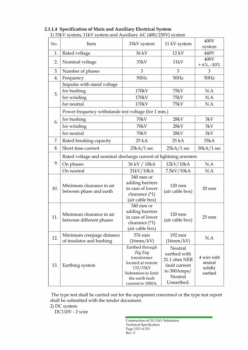
2.1.1.4 Specification of Main and Auxiliary Electrical System 1) 33kV system, 11kV system and Auxiliary AC (400/230V) system
No.
Item
33kV system
11 kV system 400V
system
1. Rated voltage 36 kV 12 kV 440V
2.
Nominal voltage
33kV
11kV 400V
+ 6%, -10%
3. Number of phases 3 3 3
4. Frequency 50Hz 50Hz 50Hz
5.
Impulse with stand voltage
for bushing 170kV 75kV N.A
for winding 170kV 75kV N.A
for neutral 170kV 75kV N.A
6.
Power frequency withstands test voltage (for 1 min.)
for bushing 70kV 28kV 3kV
for winding 70kV 28kV 3kV
for neutral 70kV 28kV 3kV
7. Rated breaking capacity 25 kA 25 kA 35kA
8. Short time current 25kA/1 sec 25kA/1 sec 30kA/1 sec
9.
Rated voltage and nominal discharge current of lightning arresters
On phases 36 kV / 10kA 12kV/10kA N.A
On neutral 21kV/10kA 7.5kV/10kA N.A
10.
Minimum clearance in air between phase and earth
340 mm or adding barriers in case of lower clearance (*1) (air cable box)
120 mm (air cable box)
20 mm
11.
Minimum clearance in air between different phases
340 mm or adding barriers in case of lower clearance (*1) (air cable box)
120 mm (air cable box)
25 mm
12. Minimum creepage distance of insulator and bushing
576 mm (16mm/kV)
192 mm (16mm/kV)
N.A
13.
Earthing system
Earthed through Zig Zag
transformer located at remote
132/33kV Substation to limit
the earth fault current to 1000A.
Neutral earthed with
21.1 ohm NER fault current to 300Amps/
Neutral Unearthed.
4 wire with
neutral
solidly
earthed
The type test shall be carried out for the equipment concerned or the type test report shall be submitted with the tender document. 2) DC system
DC110V - 2 wire

Construction of 33/11kV Substation Technical Specification Page 1414 of 211 Rev. 0
2.1.2 Design, Material and Workmanship
2.1.2.1 General Requirements
The equipment shall be designed for continuous satisfactory operation as continuity of supply is at prime importance. The design shall allow all necessary precaution for the safety at the operation and maintenance personal.
All equipment shall be designed to obviate the risk of accidental short circuit or damage due to birds and vermin. All openings for ventilation must have wire mesh with filter. It shall be the responsibility of the Contractor to furnish equipment, which shall meet in all respects the performance specification and will have satisfactory durability for prevailing site conditions.
The Contractor shall furnish all material and labour not herein specifically mentioned or included, but which may be necessary to complete any part of the work or work as a whole, in compliance with the requirements of this specification.
The Contractor shall be totally responsible for any discrepancies, errors or omissions in the particulars and guarantees, even if such particulars and guarantees have been approved by the Owner or not.
In no cases shall the Contractor cut or relocate any existing equipment to install electrical equipment or facilitate conduit installations without having previously received approval in writing, from Owner field construction engineer.
In order to ensure a sufficient mechanical strength for all equipment to withstand any prospective load and working stress, the considerable safety factors shall be taken to all components and especially to the design of all parts suffered from repeating stresses or shocks.
During the course of contract, the Owner reserves the right to monitor the implementation of the Contractor‟s quality assurance for equipment, documentation, drawing, delivery, construction, installation and commissioning.
Monitoring may be by means of programmed of formal audits and/or surveillance of activities at the work locations.
Where deficiencies requiring corrective actions are identified, the Contractor shall take approved corrective action to rectify them. The Owner shall be afforded unrestricted access at all reasonable times to ensure the implementation of such corrective actions.
The electric equipment shall be designed to endure the mechanical stress against the prospective maximum short-circuit current without thermal and mechanical damage for Three (3) second.
The Contractor shall be responsible for specifying the quality assurances requirements applicable to subcontractors and suppliers, for reviewing the implementation of

Construction of 33/11kV Substation Technical Specification Page 1515 of 211 Rev. 0
subcontractor‟s quality assurance arrangements and for ensuring compliance with the requirements.
All items of equipment shall be designed to minimize a risk of fire and other decisive damage, and to prevent ingress of vermin, dust and dirt, and inadvertent contact with electrically-live or moving parts. All mechanisms of equipment shall be designed to avoid a sticking due to rust or corrosion.
All similar parts of equipment, including spare parts, should be interchangeable.
The Contractor shall keep the site, stores and the substation clean and healthy, removing all waste material. On completion of the works the site shall be left clean and tidy to the satisfaction of the Owner. Any damage done to buildings, structures and equipment or property belonging to the Owner shall be repaired into the original condition Contractor's expense.
The Contractor shall ensure that all work carried out under the contract is performed by suitably qualified and that good quality materials, which meet relevant international standard specifications. The works shall comply with the general particulars and guarantees stated in the schedules.
2.1.2.2 Temperature Rise
Considering the climatically severe conditions, allowable temperature rise of all equipment to be determined in accordance with the relevant IEC shall be reduced so that the final attained temperatures at site shall not exceed the final temperature imputed by the IEC reference temperature.
Special consideration shall be taken into account to the effect of direct solar insulation on outdoor equipment and the effects of temperatures difference occurring in equipment due to the direct impingement of sunshine (protection against condensation).
2.1.2.3 Current Ratings:
Every current carrying part of the equipment, including circuit breakers, current transformers, disconnector, busbars, connections and joints, etc. shall be capable of carrying its rated current continuously, and in no part the permissible max. temperature shall be exceeded. All current ratings specified are the minimum continuous values required under the specified service conditions.
2.1.3 Phase Arrangement of Electrical Equipment
The phase designation of AC circuit shall be assigned as R for the first phase, Y for the second phase, B for the third phase and N for the neutral phase.
Construction of 33/11kV Substation Technical Specification Page 1616 of 211 Rev. 0
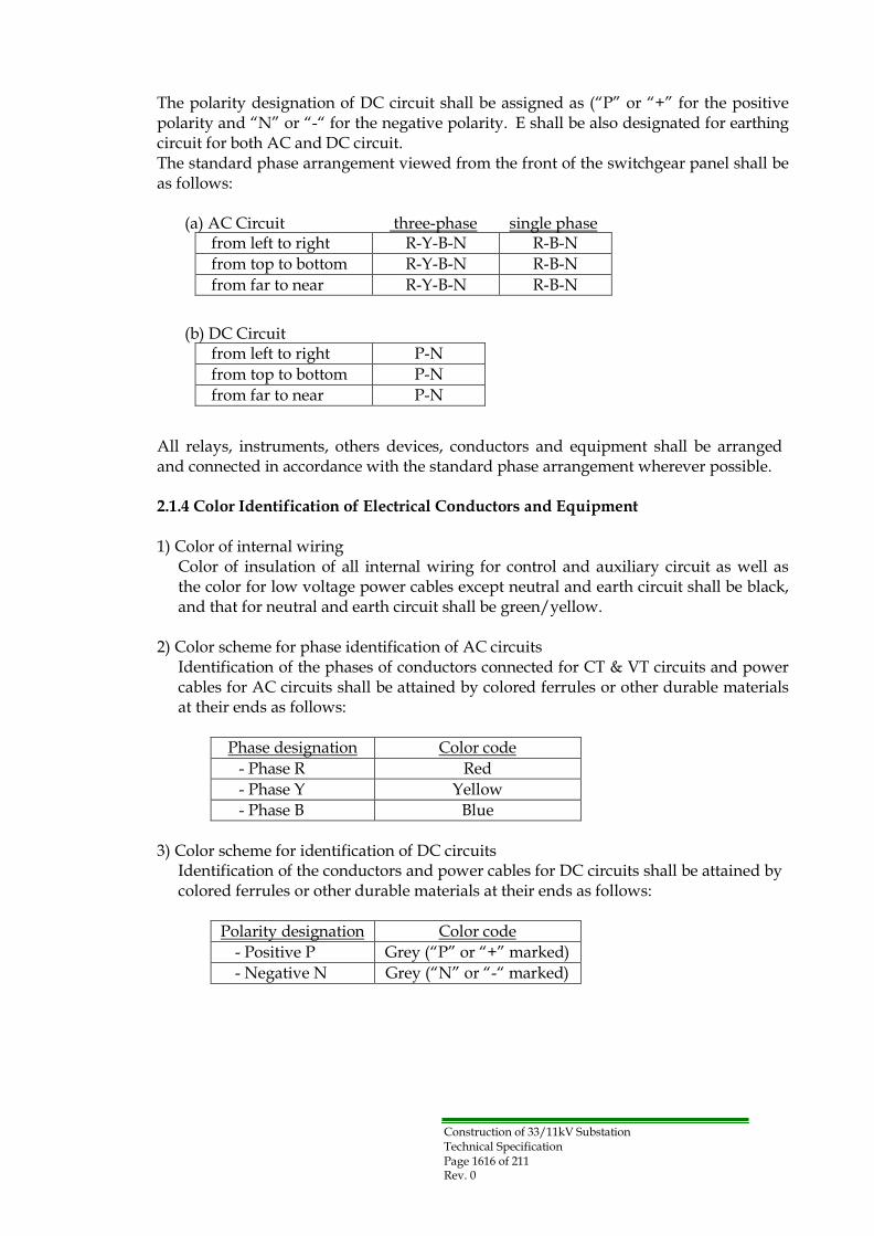
The polarity designation of DC circuit shall be assigned as (“P” or “+” for the positive polarity and “N” or “-“ for the negative polarity. E shall be also designated for earthing circuit for both AC and DC circuit. The standard phase arrangement viewed from the front of the switchgear panel shall be as follows:
(a) AC Circuit three-phase single phase
from left to right R-Y-B-N R-B-N
from top to bottom R-Y-B-N R-B-N
from far to near R-Y-B-N R-B-N
(b) DC Circuit from left to right P-N
from top to bottom P-N
from far to near P-N
All relays, instruments, others devices, conductors and equipment shall be arranged and connected in accordance with the standard phase arrangement wherever possible.
2.1.4 Color Identification of Electrical Conductors and Equipment
1) Color of internal wiring
Color of insulation of all internal wiring for control and auxiliary circuit as well as the color for low voltage power cables except neutral and earth circuit shall be black, and that for neutral and earth circuit shall be green/yellow.
2) Color scheme for phase identification of AC circuits
Identification of the phases of conductors connected for CT & VT circuits and power cables for AC circuits shall be attained by colored ferrules or other durable materials at their ends as follows:
Phase designation Color code
- Phase R Red
- Phase Y Yellow
- Phase B Blue
3) Color scheme for identification of DC circuits Identification of the conductors and power cables for DC circuits shall be attained by colored ferrules or other durable materials at their ends as follows:
Polarity designation Color code
- Positive P Grey (“P” or “+” marked) - Negative N Grey (“N” or “-“ marked)

Construction of 33/11kV Substation Technical Specification Page 17 of 211 Rev. 0
2.1.5 Control and instrument wiring and terminal boards
All electrical equipment mounted in or on control panels and relay panels shall have readily accessible connections and shall be wired down to terminal blocks for the external cabling. Both ends of every wire shall be fitted with interlocking ferrules of white insulating tube engraved in black letters with the wire number.
All wires which if interfered with, might cause tripping ferrule engraved "TRIP” or "T". All wiring shall have cross section of not less than 2.5mm2 and shall be supported with insulating cleats, connections to apparatus mounted on door or between movable points shall be secured by a flexible cover or tube so that they can be endorsed to torsion rather than bending.
2.1.6 : Identification of wires
The insulated covering of internal wiring in switchgear shall be colored as follows:
Color of Wire Circuit Particulars
Red, Yellow, Blue Phase connection for the circuits of current and voltage transformers.
Black Neutral connections for the circuits of current and voltage transformers.
Yellow/Green Connections to earth
Black Connections in AC circuits
Grey Connections to DC circuits
Alternatively if suppliers color code is adopted for the wiring, then both ends of each wire must have plastic rings or equivalent one or (similar) in the above mentioned colors.
2.1.7 : Method of Marking For Connections: 1. All connections should be marked as per the example below. 2. The identification of equipments and relavent terminals should be shown in all
the electrical diagrams. 3. The double marking of conductors is applied for all the customized circuits
(external circuits, CT‟s, VT‟s, ES‟s, ..etc) except for the internal circuits of the VCB‟s and instruments).

Construction of 33/11kV Substation Technical Specification Page 1818 of 211 Rev. 0
2.1.8 : Representation of Components With Movable Parts: All Circuit breakers and Disconnectors should be represented in the schematic diagrams in (OFF) position ready for energized (connect position).

Construction of 33/11kV Substation Technical Specification Page 1919 of 211 Rev. 0
Part-3 Particular Requirement for Substation equipment Section-3.1: 33 kV Metal-Clad Switchgear
3.1.1 General
33 kV switchgear system of each substation shall consist of four (4) switchgear cubicles such as two (2) incoming circuits and two (2) transformer circuits in accordance with the attached single line diagram and layout drawing. The complete switchgear shall comprise a floor mounted, air-insulated metal-clad switchgear suitable for indoor use and shall be constructed in accordance with IEC 62271-1 and 62271-200. The 33kV switchgear should have at least 3 years of service experience.
The mimic diagrams showing the main components and their connections shall be featured on the front panel of each switchgear compartment.
• 33kV – Green
All cubicles, and other enclosures shall be dust, damp and vermin protected. All cable connection shall be arranged to suit cables, which will rise to the switchgear from a cable trench or, running along the rear of the switchgear. All control cable shall be separated from the power cables.
3.1.2 General Arrangement
The 33kV switchgear assembly shall comprise an interconnected units, as shown on the attached substation layout drawing.
The 33 kV switchgear on each incoming circuit shall contain the followings as main components:
(a) Circuit Breaker 1250A, 25 kA
(b) Disconnector 1250A, 25 kA with earthing switch (The earthing switch should be fault making earthing switch)
(c) Lightning Arresters 36kV, 10kA
(d) Voltage Transformers
(e) Current Transformers
(f) Protection & Measurement
(e) Cable compartments for incoming and outgoing
3.1.3 Degree of protection
The degree of protection of persons against hazardous approach to live part shall be IEC 60529.
- For enclosures : IP40
- For cable and breaker : IP41
- For instruments : IP50
- For busbar : IP51

Construction of 33/11kV Substation Technical Specification Page 2020 of 211 Rev. 0
3.1.4 Current Rating
Every current carrying part of the equipment including circuit breakers, current transformers, disconnector, busbars, connection and joints shall be capable of carrying its rated current continuously and in no part shall the permissible temperature rise be exceeded.
In addition all parts of the switchgear, including current transformers, shall be capable of withstanding without thermal or mechanical damage, the instantaneous peak and short time currents corresponding to the rated symmetrical breaking capacity of the circuit breakers.
All current ratings specified are the minimum continuous values required under the service conditions specified.
3.1.5 Bus-bars and connection
The 33 kV switchgear shall be of single copper bus-bar type, rated continuously 1250 Amps, the bus bars connections and branches shall be suitably insulated by proper insulating material and shall be of constant cross section area.
The bus-bar chamber is to be air insulated and shall be of constant cross sectional area throughout their length with connection as short and straight as possible.
Bus-bars shall be contained in a separate compartment within the switchgear cubicle, but bus-bar barriers shall be provided between switchgear equipment to prevent the spreading of ionized gases during faults.
Access to bus-bar and the connections shall be achieved by the removal of the bolted covers. Such cover shall be clearly marked (BUSBARS).
All branch bus-bar to the cable box chambers shall be protected with proper insulation sheets between the phases and the earth. Suitable pressure relief facilities to discharge pressurized gases produced by fault inside the switchgear shall be provided.
Note: For (GIS) substation:
• Fully insulated Bus-Bar with all it's branches and connection points with suitable insulation material or any alternatives.
• All the connections between the bus-bar and the C.B – SF6 chamber should be throuth fully insulated plug-in type connection or any alternatives.

Construction of 33/11kV Substation Technical Specification Page 2121 of 211 Rev. 0
3.1.6 Circuit breakers
The circuit breakers shall comply with the requirements of IEC62271-100.
The circuit breaker shall be vacuum type, withdrawable type.
The breaking current capacity of the circuit breaker shall be 25 kA.
3.1.6.1 Interchange ability and isolation of circuit breaker:
Circuit breakers of the same type and current rating shall be interchangeable electrically and mechanically. The circuit breakers shall incorporate horizontal isolation facilities and be mounted on horizontal draw-out trucks. Rollers and their guide rails shall be designed to facilitate alignment and leveling of the trucks during the truck is put into the breaker compartment. Each circuit breaker shall be connected to the feeder circuit through plug and socket type isolating devices, the devices shall be of the off load type but shall be suitable for operation whilst the bars or feeder circuits are alive.
3.1.6.2 Interlocks
Disconnector connected in series with circuit breaker can close only when the circuit breaker opens and none of the adjacent earthing switches are closed. 36 kV earthing switch can close only when disconnector is opened.
Interlocking between the disconnector and the circuit breaker shall be carried out by an electrical means and the interlocking between disconnector and earthing switch shall be of mechanical type.
All mechanical and electrical interlocks shall be of the preventive type and shall be arranged to prevent mal-operation. Interlocks shall prevent any unsafe operation of the switchgear and shall ensure that the operator follows safe and logical sequence of switching device operations. Interlock arrangements shall be as stated in 5.11 of IEC 62271-200.
3.1.6.3 Safety Shutters
A set of metal shutters shall be provided to cover all live parts. Each set shall be capable of being individually operated and individually padlocked. The shutters shall open automatically by positive drive initiated by the movement of circuit breaker carriage.
The closing operation shall also be possible when padlock is closed. The shutters shall completely cover the stationary alive contacts. All shutters shall be effectively earthed.

Construction of 33/11kV Substation Technical Specification Page 2222 of 211 Rev. 0
3.1.6.4 Circuit breaker operating mechanism
Circuit breaker operating mechanism shall be of the spring powered stored energy with provision for automatic reclosing for feeder circuits only. Each equipment shall be provided with visual indicating device to show the circuit breaker "Open" and "Closed". It shall be operative when the circuit breaker is in the "Service" and "Out of Service" positions. It shall be possible to complete the closing tripping indication and interlock circuits when the circuit breaker at the position “Out of Service”.
Locking facilities shall be provided so that the circuit breaker can be locked in each position. The mechanism shall be provided with electrical release coils and shall be of trip-free type and fitted with anti-pumping device. It shall be possible to charge the mechanism spring with circuit breaker in either the "Open" or the "Closed" position.
Provision shall be made for manually closing and opening of the circuit breaker for maintenance purposes, but it shall not be possible to this facility when the circuit breaker is in the “Service”.
In normal operation the recharging of the operating spring mechanism shall be commenced immediately and automatically upon completion of the circuit breaker closure. A visual mechanical indicating device shall be provided to indicate the state of the spring "Spring Charged" when the spring is in condition to close the circuit breaker and "Spring Free" when the spring is not in a condition to close the circuit breaker. A counter to indicate the total number of operation performed is to be fitted in the operating mechanism.
The mechanism shall be fitted with local manual spring release preferably by push bottom, shrouded to prevent inadvertent operation. The mechanism shall be suitable for motor and hand rewinding (motor should be for a system of DC 110V) and shall be suitable for remote control for both closing and opening operations.

Construction of 33/11kV Substation Technical Specification Page 2323 of 211 Rev. 0
3.1.8 Earthing Switch
Earthing switches shall comply with the requirements of IEC 62271-102.
Note: for (GIS) substation:
• The life parts of vacuum C.B. and 3-position disconnector device (ON-OFF- Earth) should be insulated inside the SF6 chamber.
• All the connections to the Bus-Bar and to the line circuit should be done through plug-in bushings.
• All the switching operations can be done without opening the panel door.
• The circuit breaker should be vacuum type with life not less than 10,000 operations.
3.1.7 Disconnector
The disconnector shall be load break type with suitable rated current. Disconnector shall comply with the requirements of IEC 62271-102. Disconnector shall be accommodated in the 33 kV incoming switchgear and shall be interlocked with 33 kV incoming Circuit Breaker and the associated earthing switch. The operating mechanisms shall open and close all three phases simultaneously and shall have self-locking system in both open and closed positions.
(a) Rate voltage : 36 kV
(b) Rated Short Time Withstand Capacity : 25kA
(c) Rated making current capacity : ≥ 60kA
Earthing switch shall be annexed to disconnector and so arranged that the earthing switch and disconnector shall be interlocked mechanically.
Earthing switches shall be from the fault making type, hand-operated and shall basically comply with the same requirements as for the disconnector. The earthing switch is used for earthing the incoming feeders, the type selected should suit the application.
Note: for (GIS) substation: • The earthing switch located inside the SF6 chamber.
3.1.9 Lightning arrester Lightning arresters shall comply with the requirements of IEC 60099 and shall be of metal oxide gapless type.
(a) Rate voltage : 36 kV
(b) Normal discharge current : 10 kA
(c) Line discharge class : 2
Note: for (GIS) substation: • The lightning arrestor located outside the SF6 chamber.

Construction of 33/11kV Substation Technical Specification Page 2424 of 211 Rev. 0
3.1.10 Low tension and control circuit and equipment
These shall be installed in a separate compartment. All kinds of protection equipment and relays should be installed in such away so that not to be effected by vibration due to the sequence of operation of the circuit breaker L.T. shall be made by wiring trunking passing from panel to panel. Visible terminals of the L.T wiring and equipment
shall be covered by insulation cap suitably.
Wiring shall be supported by insulating cleats connection to apparatus mounted on doors, or between points and subjected to relative movement shall be made in a flexible corrugated pipes arranged in such away that have to be under torsion not bending.
3.1.11 Indicators and alarms
On the switchgear panel, the Disconnector & Circuit breaker shall be provided with indicating lamps (LED) to indicate:
(a) Circuit breaker closed.
(b) Circuit breaker open.
(c) Disconnector ON/OFF position
(d) Earth switch ON/ OFF position
(e) Trip circuit healthy.
(f) Voltage indication.
(g) Protection operated.
A common audible alarm shall be provided to indicate any circuit breaker has tripped or when any alarm is initiated.
Means shall be provided for silencing the audible alarm whilst leaving it free to sound when any other alarm is initiated, but the associated alarm indications shall continue until cancelled.
3.1.12 Instrument and protection
3.1.12.1 Current Transformer
Current transformers shall comply with the requirements of the latest issue of the IEC 60044-1, and shall be capable of withstanding without damage the peak short time current with a suitable saturation factor protecting the pertaining instruments on a short circuit fault.
All current transformers shall have rated secondary currents of 5 Amps, except for current transformers supplying differential relays which shall have rated secondary currents of 1 Amp. The rated volt-ampere out-put of each current transformer shall not be less than the connected burden as installed in service, the burden of cable connections taking into account with 20% additional output capacity. The secondary

Construction of 33/11kV Substation Technical Specification Page 2525 of 211 Rev. 0
winding of each set of current transformers shall be earthed at one point only.
Current transformers used for energizing indicating instruments and those used for energizing integrating measurements shall be in accordance with the latest issue of IEC specifications.
Current transformers for protective purposes shall be designed to suit the particular requirements of the associated protection which shall in general be in accordance with the recommendations given in IEC specifications.
In this connection, current transformers for differential relays shall be matched with those supplied by others. Magnetization curves and DC resistance values shall be submitted for each current transformer used for protective purposes. The connections and the ratio in use shall be indicated on all connection diagrams.
For 33 kV CTs should be 600/5/5/1A as per single line drawing.
The accuracy classes of the current transformer should be as follows :
- For measurement : class 1
- For protection and instruments : 5P10
- For differential protection : 5P20
The characteristic of each current transformer including calculated maximum burden and knee point voltage shall be submitted for approval.
Note: for (GIS) substation:
• The current transformer should be insulated (exe. Ring type) and mounted
direct on the outgoing of the C.B. SF6 Chamber in the cable cabinet.
3.1.12.2 Voltage Transformer
Voltage transformers shall comply with the latest issue of IEC 60044-2, and shall be of accuracy class 1 for metering and 3P for protective relays. It should be protected by means of easily accessible fuses on the high voltage sides and MCB‟s on the low voltage side. The secondary voltage shall be 110 volts between phases.
On the 33kV side, the voltage transformers shall be 3-single phase (star/star) type. The secondary star winding shall be used for metering.

Construction of 33/11kV Substation Technical Specification Page 2626 of 211 Rev. 0
The high voltage windings of the voltage transformer shall be so designed that saturation of the cores dose not occurs when 1.732 times normal voltage is applied to both primary and secondary windings. They shall have a voltage factor of 1.2 continuous and 1.9 for 8 hours. Voltage transformers used in the cable feeder circuit and capacitor bank circuit should be sized to discharge the current after tripping the circuit breaker.
The rated volt-ampere output of each voltage transformer shall not be less than the connected burden as installed in service, the burden of cable connections being taken into account, with 20% additional output, capacity.
Relevant documents shall be submitted for approval of the voltage transformer.
Note: for (GIS) substation:
• The voltage transformer should be outside the SF6 chamber.
• The three position insulating device for the V.T. should be inside the SF6 chamber.
• The V.T. must be protected by a high voltage HRC fuse which can be replaced without need to break the main circuit of the TR feeder.
• All the V.T. high voltage connection and the fuse should be fully insulated.
3.1.13 Instruments and relays
All indicating instruments and energy meter shall be of the flush mounting type and designed for tropical climate with dust proof cases and must be capable of carrying continuously the full load current and must not be damaged by fault current.
The wattmeter shall be designed for three phase, three wire unbalanced load system. The relay shall be of the flush mounting type and shall be provided with glass windows so that the settings and visual indications could be observed without having to open the relay case. Whenever possible the relay shall be of the withdrawable type.
The limits of error shall not exceed plus or minus 1% for MWh and 2% for KVArh meters at all loads from 10% to 120% at any power factor between 0.7 lag and 0.9 lead. MWh and KVArh meters shall be of the impulse type. The number of pulses shall be as minimum as possible (such as few hundred pulses per hour).
The scales of all direct current instruments and all alternating current indicating wattmeters shall be arranged so that the instruments will read 10% of the full scale reading below zero and this part of the scale shall be marked in red. In two directional circuits however center zero instruments shall be used.
The voltmeters shall be calibrated while hot. Auxiliary relays shall also be mounted with dust-proof covers. All metal bases and frames of relays shall be earthed as necessary.
Multi-functional numeric display of each measure quantity on LCD face shall be selectable by a front push button switch.

Construction of 33/11kV Substation Technical Specification Page 2727 of 211 Rev. 0
Relays for 33kV switchgear shall be mounted on instrument panels forming part of the switchgear equipment and these instrument panels shall have anti-vibration mountings.
The communication facility should allow all information available locally at the relay front panel to be accessed remotely. It should also be possible to carry out bulk transfer of settings; fault record information etc using the appropriate PC based software.
All relays which are connected to complete either the tripping circuit of a circuit breaker or the coil circuit of an auxiliary tripping relay shall be provided with approved operation indicators.
Indicators shall also be provided on such additional relay elements as will enable the type or phase of the fault condition to be identified.
Each indicator shall be capable of being reset by hand or SCS without opening the relay case. Each indicator shall be so designed that it cannot move before the relay has completed its operation.
All DC relays used for tripping shall be operated when the supply voltage is reduced to 70% of the rated voltage. In order to minimize the effects of electrolysis, operation indicator coils and DC relay operating coil shall be so placed in the circuit that they are not connected to the positive pole of the battery except through contacts which are normally open.
All auxiliary supplies, AC and DC, essential for the operation of the protection relay scheme shall be monitored and the loss of any supply shall be indicated on the panel and an alarm given.
3.1.14 Protection
The following protection relays shall be mounted on the 33kV low voltage compartment, the effective protection equipment for each circuit should be as indicated at the Single Line Diagram.
Note: The protection should be fully separated from the SCS system and all the signals from the protection relay to the SCS should be done through dry contacts.
3.1.14.1 Overcurrent and Earth fault
The Over Current and Earth Fault relays shall be from the numerical inverse definite minimum time lag (I.D.M.T.L) in the accordance with IEC 60225-151, Current / Time characteristics of all relays shall cover the normal inverse, long inverse, very inverse, extremely inverse, instaneous and definite time characteristics.

Construction of 33/11kV Substation Technical Specification Page 2828 of 211 Rev. 0
Cable sealing boxes and/or glands shall be supplied.
Auxiliary wiring, Relays, IED for SCS, port to region DCC, control switches, alarm lamps and indicating instruments shall be provided with the switchboard.
3.1.14.2 Trip Circuit Supervision
Means shall be provided to continuously supervise the integrity of the circuit breaker tripping circuits and to give alarm in case of having any fault in this circuit.
All protection systems shall be provided with an integral local operator interface facility to enable communication with the relay without the use of external equipment. Any facilities provided for connection to an external computer shall be an additional feature to the local operator interface
3.1.14.3 Transformer Neutral point relay (SBEF)
This protection employed shall be of the numerical type including all standard characteristics (i.e. definite time up to 10 sec) The relay shall be connected to the earthing resistance current transformer and located at 33kV panel. Operation of this relay shall trip both the 33kV and 11kV transformer circuit breakers.
3.1.14.4 Transformer Neutral Over voltage relay
The relay shall be connected to the voltage transformer fitted at the 11kV neutral of the transformer. The location of this relay should be at the 11kV metalclad switch gear of the main transformer.

Construction of 33/11kV Substation Technical Specification Page 2929 of 211 Rev. 0
Section-3.2: 33/11.5kV 31.5MVA Power Transformer
3.2.1 General
The transformer shall comply with the requirements of IEC 60076 and be suitable for outdoor location under the specified service conditions. The transformer shall be 33/11.5kV 31.5MVA with a self-cooled type of cooling system (ONAN) complete with all necessary fittings accessories and On-load Tap Changer (vacuum type) with totally clad cable and boxes on both Primary and Secondary sides, and shall be shipped with insulating oil filled. Each transformer shall be equipped with on load tap changer suitable for the rated current (+20% overload).
3.2.2 Characteristics of the transformers:
Item Description
1. Rated output 31.5MVA
2. Duty step-down outdoor service
3. Type core, double wound 3-Phase
4.
Nominal voltage at no load for transformers
Primary: Secondary:
33kV 11.5 kV
5. System Frequency 50 Hz
6.
Interphase connection Primary: Secondary:
DELTA STAR with neutral brought out
7. Vector relationship Dyn 11
8. Type of cooling ONAN
9. Temperature rise (i) 45 K in top oil by thermometer Temperature rise (ii) 50 K in winding by resistance.
10.
Impedance voltage
The impedance voltage at 75º C at the principal tapping shall be 10.5%. ONAN rating with tolerance stated in the latest issue of IEC specifications
11.
Terminal arrangement Primary: Secondary:
33 kV totally clad cable box 11.5 kV totally clad cable box
Note. The neutral of 11kV side shall be brought out through an outdoor 7.5kV bushing connected with lightning arrestor.
12. Load break switch To isolate the neutral from the earth
13.
Taps
On-load taps provided on the Primary side for variation of HV in equal steps of 1.5% each from plus 7.5% to minus 10.5%
14.
Noise level
Transformer noise level should not exceed 55 dB at distance of 0.3 meters from the transformers in accordance with IEC 60076-10.

Construction of 33/11kV Substation Technical Specification Page 3030 of 211 Rev. 0
3.2.3 Cable Boxes(Air insulated type)
The transformers shall be equipped with cable boxes to accommodate XLPE single core copper cables. The Contractor shall provide Owner with calculations to substantiate the rating of the cables installed.
High voltage cable box complete with all jointing materials and with gland suitable for XLPE single core cables designed for 33kV earthed system and rating of 1000Amps, and should withstand a continuous load of 31.5MVA transformers and overload of 20% during 2 hours in load conditions.
The exact specifications of the cables shall be submitted by Contractor to Owner for approval. Owner standardize on the size of cables used on connections between transformers and switchgear and typically the cables shall be of XLPE single core type and according to the following sizes:
(a) 33 kV side 400 mm2 (Cu) (b) 11 kV side 400 mm2 (Cu)
The cable box shall be so designed that in the event of the transformer is to be replaced it should not be necessary to break up the cable jointing at the terminal. The Secondary cable box to be identical to the Primary side but suitable for XLPE single core cables.
The cable boxes shall be provided with earth wire connection with the main tank of the transformer.
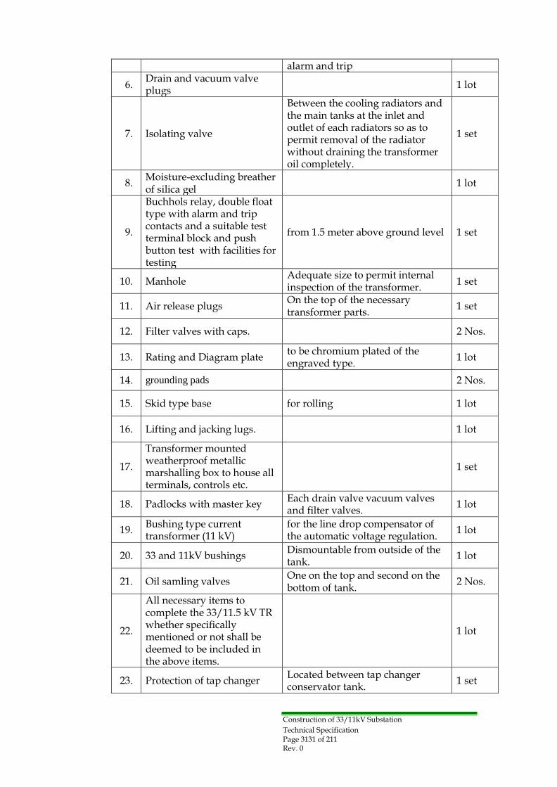
3.2.4 Fittings and Accessories
The following fittings and accessories shall be provided:
No. Item Specification for component Q‟ty
1.
Conservator
with filter cap and drain valve and a shut-off valve between the conservator and the main tank
1 set
2.
Magnetic oil level gauges
marked to indicate normal level at 20 °C, one on each side of the conservator.
1 set
3. Pressure relief valve with one set of contacts for trip. 1 set
4.
Dial type thermometer to indicate top oil temperature
with maximum reading pointer and 2 sets of contacts suitable for alarm and trip.
1 set
5.
Winding temperature indicator
to indicate the hottest spot temperature of winding by resistance with maximum reading pointer and two sets of contacts for
1 set
Technical Specification Page 3131 of 211 Rev. 0
alarm and trip
6. Drain and vacuum valve plugs
1 lot
7.
Isolating valve
Between the cooling radiators and the main tanks at the inlet and outlet of each radiators so as to permit removal of the radiator without draining the transformer oil completely.
1 set
8. Moisture-excluding breather of silica gel
1 lot
9.
Buchhols relay, double float type with alarm and trip contacts and a suitable test terminal block and push button test with facilities for testing
from 1.5 meter above ground level
1 set
10.
Manhole Adequate size to permit internal inspection of the transformer.
1 set
11.
Air release plugs On the top of the necessary transformer parts.
1 set
12.
Filter valves with caps.
2 Nos.
13.
Rating and Diagram plate to be chromium plated of the engraved type.
1 lot
14. grounding pads 2 Nos.
15.
Skid type base
for rolling
1 lot
16.
Lifting and jacking lugs.
1 lot
17.
Transformer mounted weatherproof metallic marshalling box to house all terminals, controls etc.
1 set
18.
Padlocks with master key Each drain valve vacuum valves and filter valves.
1 lot
19. Bushing type current transformer (11 kV)
for the line drop compensator of the automatic voltage regulation.
1 lot
20.
33 and 11kV bushings Dismountable from outside of the tank.
1 lot
21.
Oil samling valves One on the top and second on the bottom of tank.
2 Nos.
22.
All necessary items to complete the 33/11.5 kV TR whether specifically mentioned or not shall be deemed to be included in the above items.
1 lot
23.
Protection of tap changer Located between tap changer conservator tank.
1 set
Construction of 33/11kV Substation

Construction of 33/11kV Substation Technical Specification Page 3232 of 211 Rev. 0
3.2.5 Painting
A primary coat to be applied immediately after cleaning all ungalvanized metallic parts thoroughly. An oil and weather resistant type with a second coat shall then be applied and the transformer finished in aluminum paint. Any alternative finishing which gives better heat radiation is acceptable and must be confirmed by calculation.
3.2.6 Tolerance
All tolerances are to be in accordance with IEC except for loss evaluation and the compensation for excess of temperature rise where clause 3.2.14 will be applicable.
3.2.7 Labels, Rating plates
All labels, rating and name plates shall be in English and shall be non-deteriorating and non-wrapping. All equipment supplied and all apparatus there on shall be clearly labeled in an approved manner.
The function of each relay, control, indication, alarm devices, fuses and links shall be separately labeled, each indoor control and relay panel, and the like shall have a circuit designation table mounted at both the front and rear. Rating plates, which shall generally comply with the material requirements for labels, shall be in accordance with the relevant IEC specifications.
3.2.8 On load tap changer
3.2.8.1 General
The On-load tap-changer shall comply with IEC 60214 and shall be capable of 300,000 tap changing operations without the necessity of maintenance.
The tap changer shall be designed so that the selector or diverter (vacuum switch) is accommodated in an oil-filled chamber separated from the transformer tank. The selector and diverter shall be accessible via a removable cover on the tap changer chamber without removing the cover of the transformer main tank.
The tap changer shall be designed for load control through AVR, push buttons and also for control from the remote panel in the MV switchgear room as well as from SCS and the Regional DCC.
3.2.8.2 Tap changing gear
It shall not be possible to operate the electric drive when the manual handle is used nor shall it be possible to operate the manual handle when the electric drive is in operation. The necessary interlock shall be provided to prevent a simultaneous operations of manual and electric drive.
The tap changer motor shall be designed for a 3-phase, 400 volts AC supply.
Each transformer shall be equipped with on load tap changer suitable for the rated

Construction of 33/11kV Substation Technical Specification Page 3333 of 211 Rev. 0
current (+20% overload) of modern design and robust construction complying with the latest version of IEC60214.
The tap changer shall be so designed that once initiated, the tap changing shall be completed even in case of power failure to the driving motor. It shall not be possible to be left in an intermediate position.
Limit switches shall be provided to prevent overrunning of the mechanism and shall be directly inserted in the main supply circuit to the driving motor to cut off. However, the limit switches may be connected in the control circuit of the driving motor instead of the main circuit, provided that a mechanical declutching system is incorporated in the mechanism. In addition, a mechanical stopping or other available means shall be fitted to prevent over-running of the mechanism under any situational condition.
Tap changer control circuit shall have a protective mean to prevent the operation during a short circuit fault on main power circuit has happened. The driving motor, fuses and relays shall be housed in suitable weather proof metallic cabinets (motor drive unit) mounted on the transformer.
3.2.8.3 Tap changer control panel
It is to be noted that the two 31.5MVA transformers will have 11 kV single bus-bar (The sectionalizer being normally open).
The tap changer can be operated either manually or automatic by using the automatic voltage regulator (AVR). A three position selector switch, for the selection of manual operation and automatic control, shall be located at the remote control panel to allow the control of the tap changer from remote control panel, Substation Control System or from AVR.
The tap changer can be controlled manually from the following locations:
(a) Locally from the motor mechanism drive located at the transformer. (b) Remote control panel located in the control room. (c) From the substation control system( SCS) and Distribution Control Center.
For transfer the control from transformer location to the remote control panel, a selector switch located at the motor mechanism drive is to be provided to select the control of the tap changer either from transformer location or from the remote control panel.
To control the tap changer manually from SCS or DCC. The location of control can be
selected by a command from DCC to an electronic selector switch inside the SCS.
Each transformer shall be supplied complete with a suitable sheet steel free standing indoor remote control panel. All remote control, indication alarm and tripping devices of the transformer shall be mounted on this panel in addition to any fitting which may be required for the satisfactory operation of the tap changer.
All alarms of 31.5MVA power transformer, 33kV and 11kV switchgear circuits are to be collected at the relevant AVR Panel located inside the control room. Also all other common alarms of the substation are to be transferred to the same control room.
Construction of 33/11kV Substation Technical Specification Page 3434 of 211 Rev. 0
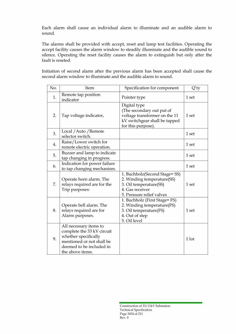
Each alarm shall cause an individual alarm to illuminate and an audible alarm to sound.
The alarms shall be provided with accept, reset and lamp test facilities. Operating the accept facility causes the alarm window to steadily illuminate and the audible sound to silence. Operating the reset facility causes the alarm to extinguish but only after the fault is reseted.
Initiation of second alarm after the previous alarm has been accepted shall cause the second alarm window to illuminate and the audible alarm to sound.
No. Item Specification for component Q‟ty
1. Remote tap position indicator
Pointer type
1 set
2.
Tap voltage indicator,
Digital type (The secondary out put of voltage transformer on the 11 kV switchgear shall be tapped for this purpose).
1 set
3. Local /Auto /Remote selector switch.
1 set
4. Raise/Lower switch for remote electric operation.
1 set
5. Buzzer and lamp to indicate tap changing in progress.
1 set
6. Indication for power failure to tap changing mechanism.
1 set
7.
Operate horn alarm. The relays required are for the Trip purposes:
1. Buchholz(Second Stage= SS) 2. Winding temperature(SS) 3. Oil temperature(SS) 4. Gas receiver 5. Pressure relief valves
1 set
8.
Operate bell alarm. The relays required are for Alarm purposes.
1. Buchholz (First Stage= FS) 2. Winding temperature(FS) 3. Oil temperature(FS) 4. Out of step 5. Oil level
1 set
9.
All necessary items to complete the 33 kV circuit whether specifically mentioned or not shall be deemed to be included in the above items.
1 lot

Construction of 33/11kV Substation Technical Specification Page 3535 of 211 Rev. 0
3.2.8.4 Automatic voltage regulator (AVR)
Automatic voltage regulator (AVR) complete with line drop compensator shall be provided to operate with motor-driven tap-changers and have facilities to keep the voltage constant.
The motor-driven mechanism receives the corresponding control signals from the voltage controller. With these signals, the tap-changer moves to the next position and the transformer‟s voltage value is adapted to preset reference voltage level.
The voltage set point can be varied locally. The recommended preset range is between 10.7 - 11.3 kV on 11kV side of the transformer. Facilities to operate the tap changer i.e. Auto - Remote - Local and Raise - Lower switches or push button should be provided. A full description of AVR and its controls should be submitted with the Tender. Failure of AVR should keep tap-changer in position and gives an alarm.
The control equipment (AVR) and Line drop compensation shall be housed in the transformer remote control panel inside the switchgear room.
3.2.8.5 Sub-contractor for tap changer
In the event the on-load tap changing equipment is supplied by subcontractor the Tenderer shall give an under taking that he shall be responsible on behalf of the sub- contractor to Owner with all spare parts. Operation and maintenance instructions and other technical information during the life-time of the transformer.
3.2.9 Control and instrument wiring and terminal boards
All electrical equipment mounted in or on control panels, relay panels and the like shall have readily accessible connections and shall be wired down to terminal blocks for the reception of external cabling. Both ends of every wire shall be fitted with interlocking ferrules of white insulating material engraved in black.
All wires which if interfered with may cause tripping currents to flow shall be fitted with an additional red ferrule. Wiring shall be supported by insulating cleats connection to apparatus mounted on doors, or between points and subjected to relative movement shall be made in a flexible corrugated pipes arranged in such away that have to be under torsion not bending. Terminal boards shall have separate terminals for internal and external connections and not more than two wires shall be connected to each terminal. For CT and VT secondary terminals, it should be used a shorting to earth/open terminal type, to allow short circuit to earth or to CT in case of testing.
3.2.10 Insulating oil
The transformer shall be supplied with first filling oil together with 10% extra quantity which will be kept as spare. The insulating oil shall be complying with IEC60296 and with this specification and should be approved by Owner.

Construction of 33/11kV Substation Technical Specification Page 3636 of 211 Rev. 0
3.2.11 Continuous Maximum Rating, temperature rise and overload
The transformers shall be capable of delivering their rated kVA under steady load conditions without exceeding the limits of temperature-rise specified in the following table when the rated primary voltage. At the rated frequency is applied to the principal primary tapping and as tested in accordance with IEC regulations.
IEC cooling Temperature rise li it
Classification Winding by resistance K Oil by thermometer K
ONAN 50 45
The transformers shall be capable of operation, continuously without injurious heating at their Continuous Maximum Rating (C.M.R) at any ratio and with the voltage of the untapped winding maintained at the no-load voltage stated. The transformers shall comply with the temperature rise limit specified on all tapping.
3.2.12 Short circuit guarantee
The transformers shall be capable of withstanding without damage an external short- circuit between phases, and between one phase and earth on either winding when the fault-free winding is energized at full design voltage in accordance with the latest issues of IEC specification.
3.2.13 Insulation levels
The first unit of transformers manufactured in the contract shall be tested and subject to Owner approval to prove the impulse withstand-voltage as specified in IEC 60076. The transformers shall be liable to impulse testing to prove the impulse voltage withstand values specified by the following a) & b).
1) Winding designed for use on 33kV system shall comply with the following
provisions of IEC recommendations.
a. Highest system Voltage 36 kV
b. Insulation to earth uniform
c. Impulse test voltage 170 kV peak
d. Power frequency test voltage 70 kV R.M.S
2) Winding designed for connection to the unearthed 11 kV System shall comply with
the following provisions.
a. Highest system Voltage 12 kV
b. Insulation uniform
c. Impulse test voltage 75 kV peak
d. Power frequency test voltage 28 kV R.M.S

Construction of 33/11kV Substation Technical Specification Page 3737 of 211 Rev. 0
3.2.14 Loss Evaluation and Penalty
The power transformer losses shall be capitalized for tender evaluation as below mentioned and also shall be subjected to the reduction of the contract price as penalty;
(1) Ie= Iron (No-load) losses: 1800USD per kW at rated voltage and frequency
(2) Cu=Copper (Load) losses: 600USD per kW at rated power and principle tapping
at 75oC
Loss Evaluated Cost = Q x (Guaranteed Ie x 1800 + Guaranteed Cu x 600)
Where, Q is quantity of the transformers.
The auxiliary transformer losses will not be considered in the capitalization of the tender.
The maximum permissive tolerance is +10% of the individual Guaranteed Losses, otherwise the transformer shall be rejected.
For transformer with losses exceeding the Guaranteed values, the contract price shall be reduced by the difference between the evaluated cost of the measured individual losses and the 100% of the guaranteed individual losses according to the individual kW price as following: Penalty= Q x (Measured- Guaranteed) Ie x 1800 + (Measured - Guaranteed) Cu x 600)]
For any transformer with individual losses less than 100% of the guaranteed losses, no variation to the contract price shall be made.
3.2.15 Earthing resister and others of Transformer Neutral
3.2.15.1 General
Neutral Earthing Resistor shall be provided in order to protect from damaging fault currents of power transformer. Earthing of the Neutral is limited the ground fault current of a high-level by operation of protective fault relays. These devices are then able to quickly clear the fault, usually within a few seconds.
Neutral Earthing Resistor shall be suitable for outdoor service with 300Amp rated current for 30 sec rated time is to be connected via a load breaking disconnector and 11kV cable to the Neutral of transformer, and shall be mounted in an enclosure.
The Outdoor type enclosure shall contain resistor, lightning arrester, disconnector and CT & VT. The Neutral Earthing Resistor shall be designed and factory-tested to IEEE Standard 32, and it shall be designed to conform to Seismic, Zone 3.

Construction of 33/11kV Substation Technical Specification Page 3838 of 211 Rev. 0
3.2.15.2 Specification
- System Voltage : 11kV
- Line-to-Neutral Voltage : 11kV/√3
- Type: Outdoor use
The transformer neutral earthing circuit shall comprise the following:
No. Item Specification for component Q‟ty
1.
On load disconnector
400 A, 25kA
1 pc
2. Lightning arrester 7.5 kV, 10 kA 1 pc
3.
Neutral earthing resistor
21.1 Ohm 300A, 30sec
1 pc
4.
Current transformer
300-150/5A
1 pc
5.
Voltage transformer ( outdoor type ) with suitable fuses on the HT and LT sides ( Single phase)
11kV/110 V Class 3P
1 pc
6.
Transformer neutral XLPE cables complete with all necessary jointing materials.
Terminals, cable glands and cleats, etc for 11 kV, XLPE 1c x 150mm2
1 set
7.
Earth fault relay (51N) with test terminal blocks (location shall be 33kV Metal-Clad switchgear)
Numerical type, IDMTL characteristic
1 set
8.
Over-voltage relay (59) with test terminal blocks (location shall be 11kV Metal- Clad cubicle)
Numerical type, Instantaneous characteristic
1 set
9.
Outdoor type enclosure
Punched (IP 33)
1 set
10.
All necessary items to complete the 33 kV and 11kV circuit whether specifically mentioned or not shall be deemed to be included in the above items.
1 lot
3.2.15.3 Design Details
The Neutral Earthing Resistor shall be provided with an outdoor safety enclosure. The enclosure will have a solid top, screened bottom, side covers, and top mounted eye- bolts for handling ease. The enclosure finish will be hot- dipped galvanized steel. The enclosure will have 10 cm legs unless otherwise specified.
The Resistor will consist of stainless steel stamped grid elements for higher currents or edge wound Resistors for lower currents, double insulated. The Resistor terminals must be stainless steel. All Resistor end frames, hardware, and non-current carrying

Construction of 33/11kV Substation Technical Specification Page 3939 of 211 Rev. 0
spacers must be zinc plated steel at a minimum. Neutral Earthing Resistor must be delivered to the jobsite completely assembled and ready for installation.
The Neutral Earthing Resistor shall be provided with a nameplate which shall be fixed to the exterior of the enclosure.
The Contractor shall submit approval drawings in most suitable time and shall submit certified test reports in accordance with IEEE Standard 32-1972.
The Contractor shall submit complete Instruction and Maintenance manuals at the time of shipment. The manuals shall give complete and detailed instructions for unpacking, installation, inspection, connection, and maintenance.
3.2.16 Spare parts and special tools
3.2.16.1 Spare parts
The Contractor shall provide spare parts for 5 years normal operation itemized prices as SECTION 3 – SCHEDULE OF QUANTITIES AND PRICES.
The Contractor shall recommend the spare parts of itemized prices for Transformer & On load tap changer shall be quoted.
3.2.16.2 Special tools
All special tools and handling equipment are to be listed in the tender proposal and to be included in the tender price.
Construction of 33/11kV Substation Technical Specification Page 4040 of 211 Rev. 0
Section-3.3: 11 kV Metal-Clad Switchgear
3.3.1 General
The 11 kV switchgear shall be of the metal clad type suitable for indoor installation as per attached single line diagram and shall consist of a single insulated bus-bar in air insulated busbar chamber metal clad, floor mounted unit, incorporating enclosures for the circuit breaker units, voltage transformers, current transformers and auxiliary wiring, relays, IEDs for SCS, port to SCADA of region DCC, potential transformers control switches, alarm lamps and indicating instruments and shall be constructed in accordance with IEC 62271-1 and 62271-200.
The switchgear assembly consists of individually-grounded, compartmentalized steel structures. Each compartment has doors, barriers, and removable access panels to isolate the separate working functions. The mimic diagrams showing the main components and their connections shall be featured on the front panel of each switchgear compartment.
• 11kV – Red
All cubicles, and other enclosures shall be dust, damp and vermin protected. All cable connection shall be arranged to suit cables, which will rise to the switchgear from a cable trench or, running along the rear of the switchgear. All control cable shall be separated from the power cables.
3.3.2 General Arrangement
The 11kV switchgear arrangement is made up of several interconnected functional units, as shown attached layout drawing of each substation.
The 11 kV switchgear system shall consist of the followings: Twenty (20) switchgear panels such as two(2)Incoming switchgear panel and one (1)Bus section switchgear panel and one (1) Aux. Transformer switchgear panel, two (2) future Capacitor bank panel and fourteen (14) Outgoing switchgear panel.
The main composition of each cubicle are described to c) - g) of Appendix-A.
Construction of 33/11kV Substation Technical Specification Page 4141 of 211 Rev. 0
3.3.3 Degree of protection
The degree of protection of persons against hazardous approach to live part shall be IEC 60529.
- For enclosures : IP40 - For cable and breaker : IP41 - For instruments : IP50 - For busbar : IP51
3.3.4 Current Rating
Every current carrying part of the equipment including circuit breakers, current transformers, busbars, connection and joints shall be capable of carrying its rated current continuously and in no part shall the permissible temperature rise be exceeded, unless otherwise specified.
In addition all parts of the switchgear, including current transformers, shall be capable of withstanding without thermal or mechanical damage, the instantaneous peak and short time currents corresponding to the rated symmetrical breaking capacity of the circuit breakers.
All current ratings specified are the minimum continuous values required under the service conditions specified in section 2.1.1.3 The circuit breaker ratings shall be as follows:
(a) 2500A, 25 kA for transformer circuits. (b) 2500A, 25 kA for bus-section circuit. (c) 630A, 25kA for feeder circuits and Aux. transformer circuit
3.3.5 Bus-bars and connection
The 11 kV switchgear shall be of single copper bus-bar type, rated continuously 2500 Amps, the bus bars connections and branches shall be suitably insulated by proper insulating material and shall be of constant cross section area.
The bus-bar chamber is to be air insulated and shall be of constant cross sectional area throughout their length with connection as short and straight as possible.
Bus-bars shall be contained in a separate compartment within the switchgear cubicle, but bus-bar barriers shall be provided between switchgear equipment to prevent the spreading of ionized gases during faults.
Access to bus-bar and the connections shall be achieved by the removal of the bolted covers. Such cover shall be clearly marked (BUSBARS).
Construction of 33/11kV Substation Technical Specification Page 4242 of 211 Rev. 0
All branch bus-bar to the cable box chambers shall be protected with proper insulation sheets between the phases and the earth. Suitable pressure relief facilities to discharge pressurized gases produced by fault inside the switchgear shall be provided.
Note: For (GIS) substation:
• Fully insulated Bus-Bar with all it's branches and connection points with suitable insulation material.
• All the connections between the bus-bar and the C.B – SF6 chamber should be throuth fully insulated plug-in type connection.
3.3.6 Circuit breakers
The circuit breakers shall comply with the requirements of IEC62271-100. The circuit breaker shall be vacuum type, withdrawable type. The breaking capacity of the circuit breaker shall be 25 kA.
Note: for (GIS) substation:
• The life parts of vacuum C.B. and 3-position disconnector device (ON-OFF- Earth) should be insulated inside the SF6 chamber.
• All the connections to the Bus-Bar and to the line circuit should be done through plug-in bushings.
• All the switching operations can be done without opening the panel door.
• The circuit breaker should be vacuum type with life not less than 10,000 operations.
3.3.6.1 Interchange ability and isolation of circuit breaker
Circuit breakers of the same type and current rating shall be interchangeable electrically and mechanically. The circuit breakers shall incorporate horizontal isolation facilities and be mounted on horizontal draw-out trucks. Rollers and their guide rails shall be designed to facilitate alignment and leveling of the trucks during the truck is put into the breaker compartment.
Each circuit breaker shall be connected to the feeder circuit through plug and socket type isolating devices, the devices shall be of the off load type but shall be suitable for operation whilst the bars or feeder circuits are alive.
3.3.6.2 Interlocks
Disconnector connected in series with circuit breaker can close only when the circuit breaker opens and none of the adjacent earthing switches are closed. 36 kV earthing switch can close only when disconnector is opened.
Interlocking between the disconnector and the circuit breaker shall be carried out by an electrical means and the interlocking between disconnector and earthing switch shall be of mechanical type.
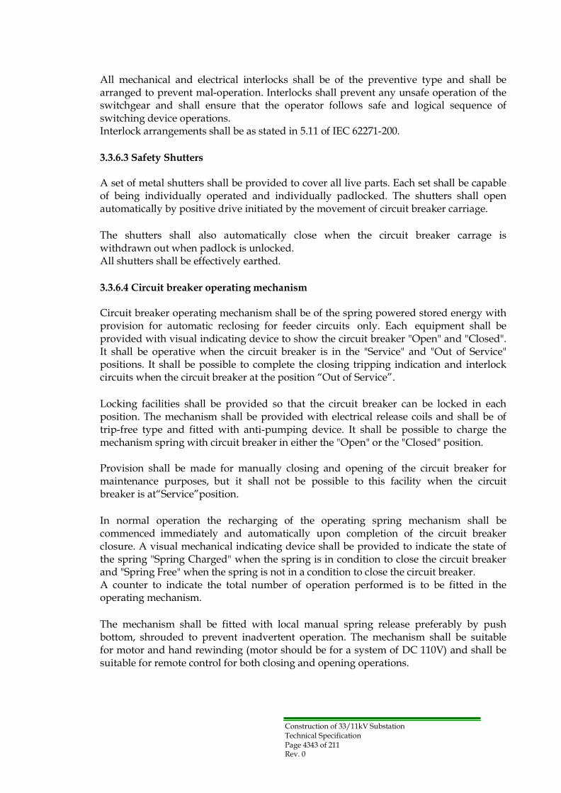
Construction of 33/11kV Substation Technical Specification Page 4343 of 211 Rev. 0
All mechanical and electrical interlocks shall be of the preventive type and shall be arranged to prevent mal-operation. Interlocks shall prevent any unsafe operation of the switchgear and shall ensure that the operator follows safe and logical sequence of switching device operations. Interlock arrangements shall be as stated in 5.11 of IEC 62271-200.
3.3.6.3 Safety Shutters
A set of metal shutters shall be provided to cover all live parts. Each set shall be capable of being individually operated and individually padlocked. The shutters shall open automatically by positive drive initiated by the movement of circuit breaker carriage.
The shutters shall also automatically close when the circuit breaker carrage is withdrawn out when padlock is unlocked. All shutters shall be effectively earthed.
3.3.6.4 Circuit breaker operating mechanism
Circuit breaker operating mechanism shall be of the spring powered stored energy with provision for automatic reclosing for feeder circuits only. Each equipment shall be provided with visual indicating device to show the circuit breaker "Open" and "Closed". It shall be operative when the circuit breaker is in the "Service" and "Out of Service" positions. It shall be possible to complete the closing tripping indication and interlock circuits when the circuit breaker at the position “Out of Service”.
Locking facilities shall be provided so that the circuit breaker can be locked in each position. The mechanism shall be provided with electrical release coils and shall be of trip-free type and fitted with anti-pumping device. It shall be possible to charge the mechanism spring with circuit breaker in either the "Open" or the "Closed" position.
Provision shall be made for manually closing and opening of the circuit breaker for maintenance purposes, but it shall not be possible to this facility when the circuit breaker is at“Service”position.
In normal operation the recharging of the operating spring mechanism shall be commenced immediately and automatically upon completion of the circuit breaker closure. A visual mechanical indicating device shall be provided to indicate the state of the spring "Spring Charged" when the spring is in condition to close the circuit breaker and "Spring Free" when the spring is not in a condition to close the circuit breaker. A counter to indicate the total number of operation performed is to be fitted in the operating mechanism.
The mechanism shall be fitted with local manual spring release preferably by push bottom, shrouded to prevent inadvertent operation. The mechanism shall be suitable for motor and hand rewinding (motor should be for a system of DC 110V) and shall be suitable for remote control for both closing and opening operations.
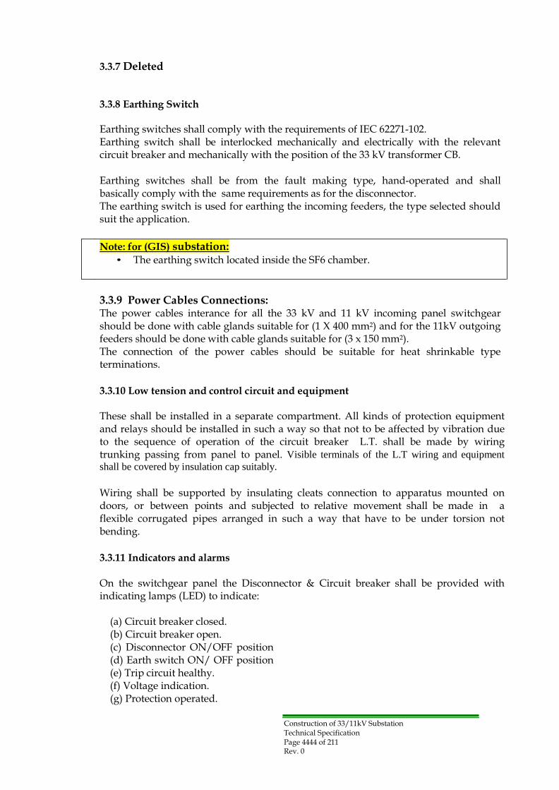
Construction of 33/11kV Substation Technical Specification Page 4444 of 211 Rev. 0
3.3.7 Deleted
3.3.8 Earthing Switch
Earthing switches shall comply with the requirements of IEC 62271-102. Earthing switch shall be interlocked mechanically and electrically with the relevant circuit breaker and mechanically with the position of the 33 kV transformer CB.
Earthing switches shall be from the fault making type, hand-operated and shall basically comply with the same requirements as for the disconnector. The earthing switch is used for earthing the incoming feeders, the type selected should suit the application.
Note: for (GIS) substation:
• The earthing switch located inside the SF6 chamber.
3.3.9 Power Cables Connections: The power cables interance for all the 33 kV and 11 kV incoming panel switchgear should be done with cable glands suitable for (1 X 400 mm2) and for the 11kV outgoing feeders should be done with cable glands suitable for (3 x 150 mm2). The connection of the power cables should be suitable for heat shrinkable type terminations.
3.3.10 Low tension and control circuit and equipment
These shall be installed in a separate compartment. All kinds of protection equipment and relays should be installed in such a way so that not to be affected by vibration due to the sequence of operation of the circuit breaker L.T. shall be made by wiring trunking passing from panel to panel. Visible terminals of the L.T wiring and equipment
shall be covered by insulation cap suitably.
Wiring shall be supported by insulating cleats connection to apparatus mounted on doors, or between points and subjected to relative movement shall be made in a flexible corrugated pipes arranged in such a way that have to be under torsion not bending.
3.3.11 Indicators and alarms
On the switchgear panel the Disconnector & Circuit breaker shall be provided with indicating lamps (LED) to indicate:
(a) Circuit breaker closed. (b) Circuit breaker open. (c) Disconnector ON/OFF position (d) Earth switch ON/ OFF position (e) Trip circuit healthy. (f) Voltage indication. (g) Protection operated.

Construction of 33/11kV Substation Technical Specification Page 4545 of 211 Rev. 0
A common audible alarm shall be provided to indicate circuit breaker has tripped or when any alarm is initiated.
Means shall be provided for silencing the audible alarm whilst leaving it free to sound when any other alarm is initiated, but the associated alarm indications shall continue until cancelled.
3.3.12 Instrument and protection
3.3.12.1 Current Transformer
Current transformers shall comply with the requirements of the latest issue of the IEC 60044-1, and shall be capable of withstanding without damage the peak short time current with a suitable saturation factor protecting the pertaining instruments on a short circuit fault.
All current transformers shall have rated secondary currents of 5 Amps, except for current transformers supplying differential relays which shall have rated secondary currents of 1 Amp. The rated volt-ampere out-put of each current transformer shall not be less than “twice” the connected burden as installed in service, the burden of cable connections taking into account with 20% additional output capacity. The secondary winding of each set of current transformers shall be earthed at one point only.
Current transformers used for energizing indicating instruments and those used for energizing integrating measurements shall be in accordance with the latest issue of IEC specifications.
Current transformers for protective purposes shall be designed to suit the particular requirements of the associated protection which shall in general be in accordance with the recommendations given in IEC specifications.
In this connection, current transformers for differential relays shall be matched with those supplied by others. Magnetization curves and DC resistance values shall be submitted for each current transformer used for protective purposes. The connections and the ratio in use shall be indicated on all connection diagrams.
For 11 kV transformer circuits with circuit breakers the CTs should be 1800/5/5/1A as per single line drawing.
The accuracy classes of the current transformer should be as follows :
- For measurement : class 1 - For protection and instruments : 5P10 - For differential protection : 5P20
For 11 kV bus section feeder with circuit breakers the CTs should be 1800/5/5A, 11 kV outgoing feeders and Future capacitor bank with circuit breakers the CTs should be
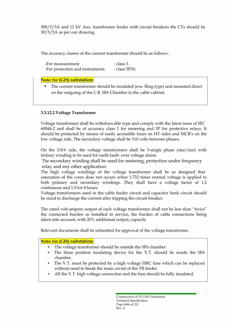
Construction of 33/11kV Substation Technical Specification Page 4646 of 211 Rev. 0
300/5/5A and 11 kV Aux. transformer feeder with circuit breakers the CTs should be 30/5/5A as per our drawing .
The accuracy classes of the current transformer should be as follows :
-For measurement : class 1. -For protection and instruments : class 5P10.
Note: for (GIS) substation:
• The current transformer should be insulated (exe. Ring type) and mounted direct
on the outgoing of the C.B. SF6 Chamber in the cable cabinet.
3.3.12.2 Voltage Transformer
Voltage transformer shall be withdrawable type and comply with the latest issue of IEC 60044-2 and shall be of accuracy class 1 for metering and 3P for protective relays. It should be protected by means of easily accessible fuses on HT sides and MCB‟s on the low voltage side. The secondary voltage shall be 110 volts between phases.
On the 11kV side, the voltage transformers shall be 3-single phase (star/star) with tertiary winding to be used for earth fault- over voltage alarm.
The secondary winding shall be used for metering, protection under frequency relay and any other application.
The high voltage windings of the voltage transformer shall be so designed that saturation of the cores dose not occurs when 1.732 times normal voltage is applied to both primary and secondary windings. They shall have a voltage factor of 1.2 continuous and 1.9 for 8 hours. Voltage transformers used in the cable feeder circuit and capacitor bank circuit should be sized to discharge the current after tripping the circuit breaker.
The rated volt-ampere output of each voltage transformer shall not be less than “twice” the connected burden as installed in service, the burden of cable connections being taken into account, with 20% additional output, capacity.
Relevant documents shall be submitted for approval of the voltage transformer.
Note: for (GIS) substation:
• The voltage transformer should be outside the SF6 chamber.
• The three position insulating device for the V.T. should be inside the SF6 chamber.
• The V.T. must be protected by a high voltage HRC fuse which can be replaced without need to break the main circuit of the TR feeder.
• All the V.T. high voltage connection and the fuse should be fully insulated.

Construction of 33/11kV Substation Technical Specification Page 4747 of 211 Rev. 0
3.3.13 Instruments and relays
All indicating instruments and energy meter shall be of the flush mounting type and designed for tropical climate with dust proof cases and must be capable of carrying continuously the full load current and must not be damaged by fault current.
The wattmeter shall be designed for three phase, three wire unbalanced load system. The relay shall be of the flush mounting type and shall be provided with glass windows so that the settings and visual indications could be observed without having to open the relay case. Whenever possible the relay shall be of the withdrawable type.
The limits of error shall not exceed plus or minus 1% for MWh and 2% for KVArh meters at all loads from 10% to 120% at any power factor between 0.7 lag and 0.9 lead. MWh and KVArh meters shall be of the impulse type. The number of pulses shall be as minimum as possible (such as few hundred pulses per hour).
All power factor indicators shall have the star point of their current coils brought out to separate terminal which shall be connected to the star point of the instrument current transformer secondary windings.
All of the feeders should be provided with two kinds of ampermeters, one is for instant reading and the other is thermal ammeters with max. demand red indicator, 15 minutes time lag reset except the transformer feeder the ampermeter should for instant reading only the scale of the ampermeter should be from 0 to 125% of the rated current. The scales of all direct current instruments and all alternating current indicating wattmeters shall be arranged so that the instruments will read 10% of the full scale reading below zero and this part of the scale shall be marked in red. In two directional circuits however center zero instruments shall be used.
The voltmeters shall be calibrated while hot. Auxiliary relays shall also be mounted with dust-proof covers. All metal bases and frames of relays shall be earthed as necessary.
Multi-functional numeric display of each measure quantity on LCD face shall be selectable by a front push button switch.
Relays for 11kV switchgear shall be mounted on instrument panels forming part of the switchgear equipment and these instrument panels shall have anti-vibration mountings.
The communication facility should allow all information available locally at the relay front panel and to be accessed remotely. It should also be possible to carry out bulk transfer of settings; fault record information etc using the appropriate PC based software.
All relays which are connected to complete either the tripping circuit of a circuit breaker or the coil circuit of an auxiliary tripping relay shall be provided with approved operation indicators.

Construction of 33/11kV Substation Technical Specification Page 4848 of 211 Rev. 0
Indicators shall also be provided on such additional relay elements as will enable the type or phase of the fault condition to be identified.
Each indicator shall be capable of being reset by hand or SCS without opening the relay case. Each indicator shall be so designed that it cannot move before the relay has completed its operation.
All DC relays used for tripping shall be operated when the supply voltage is reduced to 50% of the rated voltage. In order to minimize the effects of electrolysis, operation indicator coils and DC relay operating coil shall be so placed in the circuit that they are not connected to the positive pole of the battery except through contacts which are normally open.
Trip Circuit Supervision shall be provided to continuously supervise the integrity of the circuit breaker tripping circuits and give an alarm.
All auxiliary supplies, AC and DC, essential for the operation of the protection relay scheme shall be monitored and the loss of any supply shall be indicated on the panel and an alarm given.
3.3.14 Protection
The following protection relays shall be mounted on the 11kV low voltage compartment, the effective protection equipment for each circuit should be as indicated at the Single Line Diagram.
3.3.14.1 The 11 kV Transformer side
The protection relays, a microprocessor-based numerical and multiple function type of relays is preferred for availability and maintainability of relays .
1) The Over Current and Earth Fault relays shall be from the numerical inverse definite
minimum time lag (I.D.M.T.L) in the accordance with IEC 60225-151, Current / Time characteristics of all relays shall cover the normal inverse, long inverse, very inverse, extremely inverse, instaneous and definite time characteristics.
Note: A separate back-up protection with same above specifications above (Over Current and Earth Fault relays) to be operated in case there is no 110 VDC in the substation.
2) Biased differential relays for the transformers shall be designed in such a way that
they shall not operate on initial magnetization inrush current when the transformer is switched on no load. The sensitivity shall be set in such a way that no fault tripping can occur on any tapping of the transformer.
All over-current, earth-fault and differential relays shall be provided with suitable numbers of free contacts for purpose of signaling etc.

Construction of 33/11kV Substation Technical Specification Page 4949 of 211 Rev. 0
3) Voltage earth fault relay: A voltage earth fault relay shall be provided for 11kV circuit of transformer and to be connected to the open delta tertiary winding of the 11kV VT. This relay should initiate alarm signal.
4) Power factor control relay.
3.3.14.2 11 kV feeders protection
These circuits shall be protected by over current and earth fault relays whose specifications are the same as those on (clause 3.3.14.1) above.
3.3.14.3 Under frequency relays
Load shedding devices shall trip outgoing feeders if frequency of system falls under 50Hz. The protection consists of definite time lag under frequency relay, with at least four independent frequency settings enabling to be set between 45- 50Hz in 0.1Hz step, with time lag of 0-5 sec. of precision electronic type relay. The relays should be connected to voltage transformer section of 11kV busbars.
Four Independent load shedding busbars corresponding to each “ stage 1”, “stage 2”, “stage 3” and “stage 4” shall be provided to send tripping pulses to all circuit breakers of feeders connected to the respective busbar of the stage.
The outgoing feeders shall be provided with a selector switch in the tripping circuit of each circuit breaker to permit to put the load shedding out of service for that respective circuit breaker.
When microprocessor based multi functional numerical protection relays are used, the protection of main power transformer shall be provided two independent protection relays, i.e., a main protection relay and a back-up protection relay which are each operated independently on a separate microprocessor.
Recommended setting of each protection relay shall be submitted for approval and contractor shall set approved setting values into each relay at factory.
All protection systems shall be provided with an integral local operator interface facility to enable communication with the relay without the use of external equipment. Any facilities provided for connection to an external computer shall be an additional feature to the local operator interface.

Construction of 33/11kV Substation Technical Specification Page 5050 of 211 Rev. 0
3.3.15 Capacitor Bank Interlocking
The following additional interlocking for each capacitor bank circuits are to be incorporated: 1) The capacitor bank circuit breaker shall be tripped when the associated transformer
11kV circuit breaker is tripped for any reason including manual opening.
2) The 11kV Capacitor bank circuit breaker shall not be closed unless the time delay has
elapsed after the last opening of the circuit breaker to allow the associated capacitor bank to discharge.
3) Locking device of the capacitor fence gate( to be provided under this contract) and
the line side 11kV earth switch of the switchgear shall have the following: (a) The fence gate cannot be opened unless the earth switch of the associate capacitor
bank is closed. (b) The earth switch cannot be opened unless the associated fence gate is closed.
3.3.16 Interlocking of 11kV Bus Section Circuit Breaker
The closing of the 11kV circuit breakers of Main Power Transformer 1, transformer 2 and Bus Section is to be allowed for any two circuit breakers out of three.
In normal service condition, the circuit breakers of Main transformer 1 and transformer 2 are closed.
For closing the 11kV bus section circuit breaker, a two way selector switch of selections, i.e., Manual and Automatic, is to be incorporated in the closing circuit so as:
(a) One Main Power Transformer 11kV circuit breaker is to be opened and to be on
OFF status.
(b) The circuit breaker of the main transformer is not tripped by overcurrent or earth
fault protection relays.
(c) If the power transformer has no supply from the source, a voltage relay fitted to
the 11kV side should open the 11kV transformer circuit breaker then the bus section breaker should close automatically.
(d) A time delay contact should be incorporated in the closing circuit of the bus
section circuit breaker to allow the closing after the set time is passed.
To restore the transformer back to normal service, the opening of the bus section circuit breaker and closing the transformer circuit breaker should be done manually.

Construction of 33/11kV Substation Technical Specification Page 5151 of 211 Rev. 0
Section-3.4: Remote control and indication
3.4.1 General
The substations shall be remotely controlled and monitored from DCC .
All the requirements to connect the substation to DCC should be part of this contract.
Note: Specification of the communication equipment shall be submitted by clinet prior
to the contract agreement.
For the remote control of 33/11kV substations, a selector switch shall be used to select remote/local, when the selector switch is selected to remote, the substation equipment will be controlled from SCS in substation or the DCC. In case of selecting the switch to local, the control shall be only from the front of 33kV, 11kV switchgear and transformer control panel.
The measurement readings of A, V, MW, MVAR…. , tariff metering readings, position indications and alarms shall be continuously displayed on the SCS and VDU of the DCC independently of the remote/ local selector switch.

Construction of 33/11kV Substation Technical Specification Page 5252 of 211 Rev. 0
3.4.2 Commands and indications list
The substation equipment shall be provided to give the following facilities at the substation SCS and DCC.
3.4.2.1 Controls/Commands
Item No.
Description SCS DCC
1. 33kV Circuit Breakers Open √ √
2. 33kV Circuit breakers Close √ √
3. 33kV Transformer On Load Tap Changer
Raise tap
√
√
4. 33kV Transformer On Load Tap Changer
Lower tap
√
√
5. 33kV Transformer AVR Auto √ ـــــــ
6. 33kV Transformer AVR Manua √ ـــــــ
7. 11kV Circuit breakers Open √ √
8. 11kV Circuit breakers Close √ √
9. Trip relays Reset √ √
10. MWh counter Reset √ √
11. MVArh counter Reset √ √
12. Acceptance of all active alarms incoming from a substation ( Alarms Accept)
√
√
13. Delete of all active alarms incoming from a substation (Alarms Reset)
√
√
14. 11kV Load shedding Stage 1 √ √
15. 11kV Load shedding Stage 2 √ √
16. 11kV Load shedding Stage 3 √ √
17. 11kV Load shedding Stage 4 √ √

Construction of 33/11kV Substation Technical Specification Page 5353 of 211 Rev. 0
3.4.2.2 Status/Indication
Item
No. Description SCS DCC
1. 33kV Circuit breakers Open √ √
2. 33kV Circut breakers Close √ √
3. 33kV Circuit Breakers selector switch Remote √ √
4. 33kV Circuit Breakers selector switch Local √ √
5. 33kV Circuit Breakers Out of service √ √
6. 33kV Disconnecting Switch Open √ √
7. 33kV Disconnecting Switch Close √ √
8 33kV Earthing Switch Open √ √
9. 33kV Earthing Switch Close √ √
10. NER switch position Open √ √
11. NER switch position Close √ √
12. 33kV Tap position 1-n √ √
13. 33kV Transformer On Load Tap Changer
In progress
√
√
14. 33kV Transformer AVR set voltage 4 digits √ √
15. 33kV Transformer AVR Auto √ √
16. 33kV Transformer AVR Manual √ √
17. 33kV Transformer AVR Off √ √
18. 11kV Circuit breakers Open √ √
19. 11kV Circuit breakers Close √ √
20. 11kV Circuit Breakers selector switch Remote √ √
21. 11kV Circuit Breakers selector switch Local √ √
22. 11kV Circuit breakers Out of service √ √
23. 11kV Earthing Switch Open √ √
24. 11kV Earthing Switch Close √ √
25. 11kV Load shedding Stage 1 Feeder No. √ √
26 11kV Load shedding Stage 2 Feeder No. √ √
27. 11kV Load shedding Stage 3 Feeder No. √ √
28. 11kV Load shedding Stage 4 Feeder No. √ √
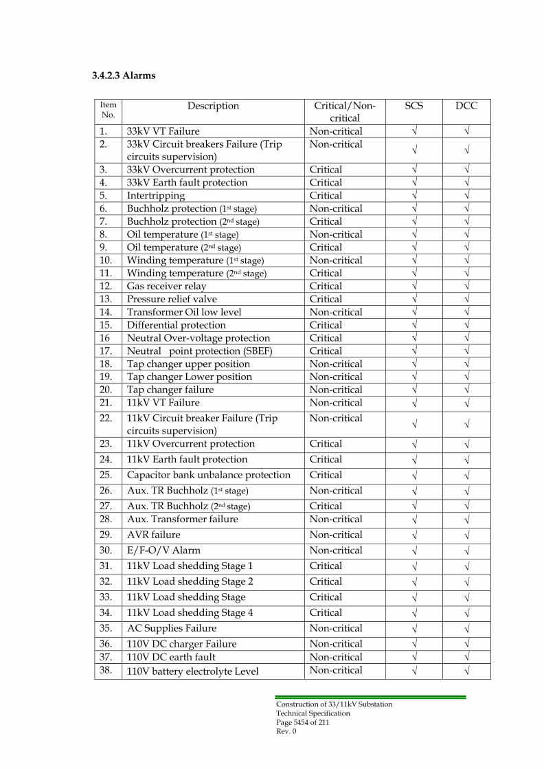
Construction of 33/11kV Substation Technical Specification Page 5454 of 211 Rev. 0
3.4.2.3 Alarms
Item No.
Description Critical/Non- critical
SCS DCC
1. 33kV VT Failure Non-critical √ √
2. 33kV Circuit breakers Failure (Trip circuits supervision)
Non-critical
√
√
3. 33kV Overcurrent protection Critical √ √
4. 33kV Earth fault protection Critical √ √
5. Intertripping Critical √ √
6. Buchholz protection (1st stage) Non-critical √ √
7. Buchholz protection (2nd stage) Critical √ √
8. Oil temperature (1st stage) Non-critical √ √
9. Oil temperature (2nd stage) Critical √ √
10. Winding temperature (1st stage) Non-critical √ √
11. Winding temperature (2nd stage) Critical √ √
12. Gas receiver relay Critical √ √
13. Pressure relief valve Critical √ √
14. Transformer Oil low level Non-critical √ √
15. Differential protection Critical √ √
16 Neutral Over-voltage protection Critical √ √
17. Neutral point protection (SBEF) Critical √ √
18. Tap changer upper position Non-critical √ √
19. Tap changer Lower position Non-critical √ √
20. Tap changer failure Non-critical √ √
21. 11kV VT Failure Non-critical √ √
22. 11kV Circuit breaker Failure (Trip circuits supervision)
Non-critical
√
√
23. 11kV Overcurrent protection Critical √ √
24. 11kV Earth fault protection Critical √ √
25. Capacitor bank unbalance protection Critical √ √
26. Aux. TR Buchholz (1st stage) Non-critical √ √
27. Aux. TR Buchholz (2nd stage) Critical √ √
28. Aux. Transformer failure Non-critical √ √
29. AVR failure Non-critical √ √
30. E/F-O/V Alarm Non-critical √ √
31. 11kV Load shedding Stage 1 Critical √ √
32. 11kV Load shedding Stage 2 Critical √ √
33. 11kV Load shedding Stage Critical √ √
34. 11kV Load shedding Stage 4 Critical √ √
35. AC Supplies Failure Non-critical √ √
36. 110V DC charger Failure Non-critical √ √
37. 110V DC earth fault Non-critical √ √
38. 110V battery electrolyte Level Non-critical √ √

Construction of 33/11kV Substation Technical Specification Page 5555 of 211 Rev. 0
39. DC station service undervoltage Non-critical √ √
40. Inverter Failure Non-critical √ √
41. Annunciator fail Non-critical √ √
42. Substation Control System Faulty critical √ √
43. Supervisory command Failure critical √ √
45. Communication "TX" Failure Non-critical √ √
46. Communication "RX" Failure Non-critical √ √
47. PABX Failure Non-critical √ √
48. Fire Alarm (Switchgear Building) Non-critical √ √
49. Fire Alarm (Guard House) Non-critical √ √
50. Door open Alarm (Switchgear Building
Non-critical
√
√
3.4.2.4 Analogue Measurements
Item No.
Description SCS DCC
Span
1. 33kV Transformer voltage 0-36 kV √ √
2. 33kV Transformer current 0-80 A √ √
3. 11kV Busbar voltage 0-13 kV √ √
4. 11kV Transformer current 0-1 00 √ √
5. 11kV Transformer MW 0-31.5 MW √ √
6. 11kV Bus Section current 0-2000 A √ √
7. 11kV Feeders current 0-300 A √ √
8. 11kV Aux. transformer current 0-30 A √ √
9. 31.5 MVA Transformer ncomer (33kV) MWh
√
√
10. 31.5 MVA Transformer Incomer (33kV) MVarh
√
√
11. 31.5 MVA Transformer Output (11kV) MWh (MDI)
√
√
12. 31.5 MVA Transformer Output (11kV) MVArh (MDI)
√
√
13. 11kV Capacitor Bank MVArh √ √

Construction of 33/11kV Substation Technical Specification Page 5656 of 211 Rev. 0
3.4.3 Technical Requirements of transducers
Where the contractor needs to use transducers for transmitting the measured values, the output of these transducers should be in accordance with the following technical specifications:
No. Item Specification for component
1. Nominal voltage input 120 volt 2. Nominal current input 5 Amps 3. Full scale calibration 1000 volts 4. Output at full scale (D.C) 4-20 mA
5.
Output load required 0-2000 ohms(with max 3000 ohms)
6. Accuracy/linearity at 20 ºC ± 0.5 at full scale 7. Power factor range 0 lag- l - 0 lead 8. Temp : range + 10 ºC to + 60ºC 9. Temp effects on accuracy ( max) ± 10%
10. Frequency range 45 to 55 Hz 11. AC component ( peak ) 1%
12. Response time to 99% of final value
200 milliseconds
13. Voltage range 85 to 135 volts 14. Input overload limit voltage 150 volts
15.
Input overload limit current 10 Amps. continuous and 100 Amp for l sec.
16. Voltage burden ( max for element )
4 VA
17. Current burden ( max for element )
2 VA
18. Calibration adjustment 0 to 110% 19. Zero adjustment ± 2%
20. Dielectric test - Input to output
1500 volts r.m.s.
21. Dielectric test - Input to earth
1500 volts r.m.s.
3.4.4 S/S Humidity and Temperature Measurement
One set of humidity and temperature measuring instruments/ transmitters and their associated transducers shall be provided for each new substation. The output of these transducers will be wired to the SCS interface cubicle to transmit the measured values to the DCC.

Construction of 33/11kV Substation Technical Specification Page 5757 of 211 Rev. 0
Section-3.5: Substation Control System
3.5.1 General
The Substation control system (SCS) shall be installed as a Local SCADA system to monitor, measure and control the substation.
The SCS shall be provided to enable the substation equipment to be monitored, measured and controlled from a substation control room. The SCS shall also be capable of serving as an RTU to the DCC, acquiring and transmitting substation data to the DCC and executing commands sent from the DCC.
The interface between SCS and substation equipment shall be done by Intelligent Electronic Devices (IEDs) and/or the bay control unit (BCU).
The SCS shall conform to the latest editions of the International Electro technical Commission (IEC) Standards, ISO Standards, IEEE Standards, International Telecommunications Union (ITU) Specifications and the this Technical Specification. Equivalent national standards may be acceptable subject to approval by the Owner.
3.5.2 Design Principles
The SCS shall be designed to achieve a high level of availability, reliability and safety in operation. The design shall be „fail safe‟ such that failure of any single component shall not result in all functions affected.
The failure of any single component within the overall system shall not affect the ability of the remaining healthy components in the system to continue to operate normally and for its functionality to remain available.
Essential functionality i.e. that required for the continued overall operation of the SCS shall be tolerant to single component failures. The communications links between components within the overall SCS shall be regarded as essential functionality and the SCS must continue to operate with full functionality if any Single communications link is out of service.
The system shall continuously monitor its own health and produce alarms for all detected failures.
These alarms shall be presented in the alarms lists on the operator workstation and, as far as possible, by lighting „fault‟ warning LEDs on the affected equipment itself, e.g. on individual circuit cards. There shall be no cases in which undetected failures could occur anywhere within the overall SCS, including within the communications links between the components of the system.
The equipment and the enclosures it is mounted in shall be designed to facilitate easy maintenance, particularly fault-finding and replacement of components, e.g.

Construction of 33/11kV Substation Technical Specification Page 5858 of 211 Rev. 0
replacement of rack mounted circuit cards. As far as possible, and consistent with safe operation, it shall be possible to „Hot swap‟ components such as I/O cards.
The equipment shall be robust, suitable for the operating environment in which it is installed and require minimal maintenance.
Each sub-system within the SCS shall be designed to meet an overall availability of at least 99.98 % based on MTTR (a Mean Time To Repair) of 8 hours. The Contractor shall provide a Functional Design Specification that will allow the Employer to review and approve the facilities being provided in the SCS, and on which the testing documentation can be based.
The functional system configuration diagram as shown refer to Dwg. No. IQP8- SP06/07-E-005 .
3.5.3 System Architecture
The SCS shall be based on a distributed architecture complying with the relevant IEC Standards. The proposed configuration of the equipment and the availability and security provided by the proposed architecture shall be described fully in the Tender proposal.
The SCS shall typically comprise the following components:
(a) Two Master Control Units (MCUs)
(b) Intelligent Electronic Devices (IEDs) and/or the Bay control unit (BCU) (c) Two Workstations for Operator / Engineer
(d) Local Area Network (LAN)
(e) Communication Links to DCC
(f) GPS Receiver with Antenna
The MCU shall typically provide overall supervision and management of the entire SCS. It may also provide communications ports supporting various data transfer protocols to enable the substation connected to SCS to be monitored and controlled from operator workstations in the substation control room and from DCC.
The IED and/or BCU shall normally be mounted on 33/11kV switchgears and transformer control cubicles. They shall be connected to the control and indication circuits of each cubicle to provide the interface between the substation and the SCS.
The IED and/or BCU shall include facilities for the control, status indication (in a mimic diagram format), analog readings and alarms of the switchgear and transformer taps, and general alarms /information (fire alarms, power supply alarms, etc.) for substation.
At least two workstations shall be provided comprising a graphical user interface for monitoring and control of the substation.
Although normally one workstation is used for Operator and the other for Engineering, both of the two workstations shall have full access to all of the SCS facilities at the same
Construction of 33/11kV Substation Technical Specification Page 5959 of 211 Rev. 0
time. They shall be located in the control room and each shall be powered from UPS source to ensure continued operation.
A GPS receiver with antenna, for time synchronization of the SCS internal real-time clock, shall be provided in order to provide accurate time stamping of alarms and recorded events. The GPS receiver shall be equipped to cater for the specified requirements and, in addition, be equipped with three spare ports.
3.5.4 System Functions
3.5.4.1 General
The SCS shall provide, but not be limited to, the following functions that are generally intrinsic to SCS and DCC.
The Tenderer shall provide details of the full range of facilities provided by their system in their Tender submission.
(a) Display of the substation single line diagram and individual feeder diagrams with
status Indication.
(b) Indicate at the single line diagram, voltages, currents, frequency, together with
power factor, active and reactive power flows. High/low limit excursions of measured shall be alarmed and programmable. Measurements (currents and voltages) of 11kV feeders / transformers shall be collected for each of 3 phases at SCS, average to a single reading for DCC.
(c) Acquire, display and printout substation events and alarms with date and time
stamp.
(d) Acquire status, check of the circuit breakers, disconnectors, and earthing switches.
(e) Be capable of performing sequential control functions, such as taking feeders in/out of service, load shedding and load curtailment.
(f) Provide switch interlocking such that the operation of substation equipment is
prevented unless specified conditions are met. Interlocking function shall be available at bay and substation level. (The hard-wired interlocking scheme as specified shall also be provided and the SCS Scheme shall provide an additional interlocking facility to ensure safe operation, based on the same logic).
(g) Perform supervised monitoring operations (Close/Open) on circuit breakers,
busbar and line disconnections.
(h) Perform reporting of acquired data in user-defined formats (numerical and
graphical logging) including data from tariff metering. This data shall also be suitable for transmission in text format to another device for further data processing.

Construction of 33/11kV Substation Technical Specification Page 6060 of 211 Rev. 0
(i) Read relay settings, measured values and evaluate stored data.
(j) Storage of process data in managed files for future use.
(k) Resetting of electrical trip lockout relays.
(l) Receive and process commands from the DCC, process and transmit status,
measurements and alarms to the DCC. It shall be possible to generate summary data to send to the DCC.
(m) Provide access security to both operational and administrative functions,
separately, by username and password.
(n) Be self-supervising; display its own system alarms and hardware status.
(o) For tap changers of transformers Raise/Lower Control shall be available at SCS
and DCC as one tap for each command. AVR Set-point Control can be done locally by using a maintenance tool such as laptops.
(p) Selector switch function (i.e., SCS or DCC) for receive and process a control
command of the circuit breaker and tap changer. The control of the selector switches can be done for individual equipment , circuit or substation bases from SCS/DCC.
3.5.4.2 Commands
All commands available at the substation in the SCS shall be capable of being operated at the DCC, subject to the agreement of the SCS Overall Facility Schedule.
All command sequences shall be performed using a select then execute routine. The routine shall minimize the likelihood of accidentally performing the execute step as part of the selection step. Furthermore, there shall be a maximum time between the selection step and execution with the Command sequence being cancelled if the execution is not performed within that time, this time should be adjustable from 0.5-60 sec.
Prior to the execution of any command, the software shall perform a check to validate that the user has the authority to execute the command. Authority violations shall be indicated to the operator via a message on the VDU.
A „cancel‟ key and/or poke point shall be provided to allow termination of any command sequence before it is executed.
3.5.4.3 Alarm and Indication Handling
All alarms and indication changes annunciated in the SCS shall be treated in the same way i.e. as an event. Each event shall be capable of being repeated to DCC, subject to the agreement of the SCS Overall Facility Schedule.
Two types of alarms shall be supported, these being fleeting and non-fleeting. The

Construction of 33/11kV Substation Technical Specification Page 6161 of 211 Rev. 0
alarm type shall be configurable on a point-by-point basis. Single point indications shall be used where no intermediate state needs to be identified. The indication type shall be configurable on a point-by-point basis.
All events shall be brought to the attention of the operator. The operator shall have the facility to accept (acknowledge) events individually or as a page of events at a time. The name of the operator acknowledging an event shall be recorded and displayed in the event list.
When an event occurs, the workstation audible alarm shall sound and the appropriate entries shall be highlighted in the event list. Indications of changes of substation state shall flash the substation symbol on the SCS diagram and alarms shall flash the “Alarm” symbol adjacent to the substation on the mimic. Silencing events shall not inhibit the annunciation of further events or constitute an acknowledgement of the event.
Facilities shall be provided for the processing and display of events on the operator interface, and shall include but not be limited to:
(a) Grouping on bay basis.
(b) Grouping on the basis of event types
The event list shall be displayed in chronological order. Each event entry shall include the time and date of occurrence, location, device, or other identifier, action, status, and value and normal status limits.
3.5.4.4 Measured Values Lists
Measured values comprising circuit loadings (A, MW, MVAr), voltages (kV), counter and integrated values (MWh, MVArh) and frequency (Hz) shall be available for display and to be transferred to the DCC. Where required, these shall be derived from transducers. Transducers shall be mounted to avoid long AC cable runs.
3.5.4.5 Supervisory Requirement (DCC)
The SCS shall provide for control the following from the DCC:
(a) Close/open of all circuit breakers.
(b) Control of transformer taps.
(c) Resetting of all electrically reset trip relays.
(d) Acceptance of all active alarms incoming from a substation. (e) Resetting of all alarms.
The facilities actually made available for each substation shall be as detailed in the SCS Overall Facility Schedule, and shall be agreed with the Owner‟s Representative.
The “Local/Remote” switch, located at the Local Control Cubicle shall allow the control from the SCS & DCC only when in the “Remote” position.
The transfer of control from the SCS to DCC shall be achieved through software,
Construction of 33/11kV Substation Technical Specification Page 6262 of 211 Rev. 0
without affecting the safe operation and control of the substation as required on 3.5.4.1.(p).
On/off (open/close) and other position indication shall be provided to the DCC for the following items:
(a) Circuit breakers.
(b) Disconnectors.
(c) Line earth switches and temporary earths.
(d) Local or remote control in service.
(e) All necessary indications to allow proper operation of the transformer Automatic Voltage Control facility.
These indications shall be transmitted to the SCS / DCC irrespective of the position of the “Local/Remote” selector switch.
Measurement signals shall generally be provided for the DCC as follows:
(a) 33kV Incoming circuits Busbar (phase to phase) voltage
(b) 33kV Incoming circuits MW and Current (A)
(c) 33kV Incoming circuits energy (MWh and MVArh)
(d) 31.5 MVA transformer secondary MW and Current (A)
(e) 31.5 MVA transformer secondary energy (MWh with MDI and MVArh)
(f) 11kV Busbar (phase to phase) voltage
(g) 11kV Busbar frequency.
(h) 11kV Feeders and Bus section A
(i) 11kV Feeders for future capacitor bank energy (MVArh)
These signals shall be transmitted to the SCS /DCC irrespective of the position of the “Local/Remote” selector switch.
3.5.4.6 Trending
The SCS shall be capable of displaying any analog value in graphical form to show the trend of the value over a selected time period. The trend display shall have adjustable x and y axis, indicate up to 10 values and operate either using real-time or historical data from the database.
3.5.4.7 Data Logging
The SCS shall incorporate long-term data logging facilities for all analog, digital and other internally generated signals. Any analog or digital value defined on the SCS database shall be available for storage and subsequent re-call.
All signals shall be scanned periodically and updated values or digital status changes stored. Date and time tags shall be allocated to each signal. Data shall be stored for up to three months on a suitable storage medium for subsequent re-call at a later date. An alarm shall be given to the operator when the storage of data approaches the capacity of the storage medium.
Construction of 33/11kV Substation Technical Specification Page 6363 of 211 Rev. 0
All data shall be capable of being archived and retained for future reference.
The operator shall have the facility to recall data held in the data logger memory or from archives over a specified period of time. The information may also be restricted to specific the SCS data points.
The requested information may be presented on the operator‟s workstations either in tabular form or as selected variables on a trend display. Information on print-outs may be either in tabular form or in a preformatted report form and may be produced automatically at specific times or on request.
It shall be possible to compare on the same display, trends, real-time data and historical data from the archives. This shall not affect the operation of the on-line data logging. One printer shall be designated primarily as the operational “on demand” log. In the event of a printer failure facilities shall be provided, both automatic and manual to enable changeover to another similar printer which shall be provided by the Contractor.
The Operational log shall record and print on demand when required, the following information:
(a) Status changes
(b) Onset and clearance of all alarms with facilities for distinguishing between the types of alarm, e.g. „urgent‟, „non-urgent‟, „group‟, „individual‟, etc.
(c) Control operations (both successful and unsuccessful).
(d) Operator actions such as alarm limit changes, tagging, hand-dressing, removal of parameters from scan, inclusion of new parameter into scan, alarm acknowledgement, log on, log off, etc.
This information shall be printed on the designated printer with each item consisting of the data and time of occurrence, together with a description of the operation, event or alarm, and sufficient information to enable full identification of the feeder/item of plant affected.
The operation log shall also be available as a VDU list of sufficient size to allow the display of information covering 5000 alarm/events. In addition to the logging printers, a color printer shall be provided to enable screen dumps and graphical displays etc to be printed.
3.5.4.8 Hand-dressing
The single line diagram will contain variable elements, some of which are updated automatically by the application and some that are hand-dressed by the operators e.g. equipment where remote indications are not available. Hand-dressed data shall be suitably indicated by a symbol or tag. The hand-dressed changes shall be inserted automatically in the database.
It shall be possible for the operator from the operator workstation to remove from scan any measurement, alarm or indication that comes within his area of responsibility. This shall be suitably indicated on the display and additionally a symbol or tag shall be used to indicate the removal from scan.

Construction of 33/11kV Substation Technical Specification Page 6464 of 211 Rev. 0
It shall then be possible, from the workstation, to insert a new (hand-dressed) value for the element, with the hand-dressing also suitably indicated by a symbol or tag. The hand-dressed changes shall be inserted automatically in the database.
On manual restoration of the elements back into service, the readings shall again be recorded in the database, returned to their normal presentation and hence regularly updated on the displays.
Hand-dressing operations, as described above, shall be suitably tagged for logging purposes. The system must recognize an attempt by the operator to make an invalid hand-dressing operation and this should be blocked, with a suitable error message on the screen.
3.5.4.9 Operator Interface
The design of the operator interface shall be based on standard software packages and provide a Windows, Icons, Menus and Pointer (WIMP) style of presentation and use interaction with the system.
All user actions shall be initiated using the pointer/keyboard and standard „windows‟ methods. The system shall provide facilities for the display of the entire substation single line diagram as a single display along with other displays for specific purposes, as required.
Pan, zoom, decluttering and windowing facilities shall be provided to allow the operator to navigate through the displays and adjust the level of displayed detail to that appropriate to the task they are performing.
To ensure the interpretation of information from displays is intuitive and not confusing to the operators all displays and lists shall be constructed following a consistent overall design philosophy. For example, all lists shall display in the same manner with new entries always being added to the top of the list or to the bottom of the list.
The software shall also guide the user, step-by-step, through each sequence by identifying, preferably via a visual technique on the workstation, the remaining valid entries.
Any invalid entry shall be detected by the software, ignored and an explanatory message displayed on the VDU. It shall then be possible to continue the sequence with a valid entry. The system shall support context sensitive on-line help facilities. The help screens shall be easily customized to suit the owner‟s needs.
3.5.4.10 System Operating Points
The substation will normally be manned, but also it will be monitored / controlled when selected from DCC via the SCS. It shall be possible to operate substation‟s equipment in the following ways:

Construction of 33/11kV Substation Technical Specification Page 6565 of 211 Rev. 0
(a) Supervisory - from the DCC
(b) Remotely - from the substation control room
(c) Local – from the cubicles
(d) Maintenance – from the cubicles with a special tool, for maintenance purposes only.
The design of the SCS and the substation equipment shall be such that control of any item of substation equipment is only possible from one control point at any particular time and the transfer of control between these points shall be achieved without affecting the safe operation, monitoring or control of the substation.
3.5.4.11 Modes of Operation
As a minimum, the system software shall be capable of supporting five different levels of user, e.g. operator, engineer and system manager, etc. For example:
(a) Operators are responsible to control and monitor the substation using the SCS.
(b) Engineers are responsible for any fundamental changes made to the SCS software or configuration.
(c) System managers are responsible for the system security, back-up and database maintenance.
The availability of functions to each user shall be configurable, allowing the user‟s area of responsibility to be defined.
The maximum number of different user levels supported and the degree of configuration available of each level shall be stated in the Tender.
3.5.5 System Capacity
The design shall meet the following general requirements with regard to capacity and expandability. The SCS shall be designed, delivered and commissioned with sufficient capacity for performing the requirements of this specification. Tenderer shall provide capacity and technical parameters for each unit within the SCS.
The SCS shall be equipped with control, indication and measurement functions required by the Scope of Work. The maximum system capacity and system loading shall not be less than 200% of the specified system capacity, including the specified future expansion.
In addition to the facilities detailed in the Facility List section, approximately 30% spare input/output capacity shall be provided within the contract (this figure shall be confirmed at the specific site survey in agreement with the Owner‟s Representative).
These spare facilities shall be fully fitted and prewired to the terminal of IEDs.
The design shall provide for future expansion, modification and testing with the minimum of disruption to existing facilities. A minimum of 30% of the future expansion capacity shall be demonstrated during the FAT.

Construction of 33/11kV Substation Technical Specification Page 6666 of 211 Rev. 0
3.5.6 System Performance
The SCS scanning and polling frequencies shall ensure the following overall performance. If better performance is necessary to ensure satisfactory operation of certain SCS functions, the Tenderer shall state this.
The SCS shall process, enter into the database and update all relevant displays currently on view within less than two seconds of a change occurs at IED's input.
This time shall include for any calculation or other processing required to enter derived or compiled information into the files, logs, reports or displays.
The SCS shall also process all information required at the DCC (e.g. status, Measurements and alarms) and have them available for transmitting to the DCC with less than two seconds of a change occurring at IED's input.
The elapsed time between selecting a display and the full display appearing on any screen shall be less than one second for 50% of requests, less than two seconds for 90% of requests and less than three seconds for 100% of requests.
The System shall give priority to commands such that commands issued from an operator‟s workstation shall have confirmation of action (from IEDs) displayed within four seconds of issue from the workstation (not including the time taken for equipment to operate).
The SCS shall be capable of handling all alarms and status changes occurring during avalanche conditions without loss of any data. Avalanche conditions are defined as follows:
(a) A fault on a MV switchgear busbar (resulting in the generation of multiple alarms)
(b) Occurrence of 100 + 0.1N + √ N changes is 5 seconds where N is the total number of
data inputs (double signals count as two data inputs).
3.5.7 Software Requirements
3.5.7.1 General
The software shall be of modular construction, developed using structured design techniques and written in a commonly used programming language. Wherever possible, standard library software shall be utilized. The contractor shall identify all standard proprietary software and any software specially developed for this project.
The application software shall ensure the secure execution of SCS functions. The operator workstation software shall run under a well proven, widely used, industry standard and internationally supported operating system. It shall also ensure the secure execution of RTU functions.
Protocol IEC 60870-5-101 has to be included with other protocols.

Construction of 33/11kV Substation Technical Specification Page 6767 of 211 Rev. 0
3.5.7.2 Real-time database
A real-time database shall be maintained within the SCS system. A general check shall be initiated at intervals to retrieve all data points from the remote I/O to ensure validity of database entries. This interval shall be configurable between 30 minutes and 36 hours.
The real-time database shall be open and the data dictionary published. The real-time database shall support the import/export of data via standard interfaces such as SQL, ODBC, etc.
3.5.7.3 Database management
Engineering facilities shall be provided for database and graphic display creation and modification for the operator workstations.
Facilities shall be provided so that the operator workstations can be used as engineering consoles to modify and configure the overall SCS system. It shall be possible to prepare modifications in advance and implement them with minimal disruption to the running system.
3.5.7.4 Data processing
In the event of detection of the failure of I/O components, indications and alarms from the previous successful scan of the failed I/O shall continue to be displayed on the operator workstation. However, facilities shall be incorporated to indicate to the operator that the relevant data is not presently being updated.
The system shall have the ability to differentiate between status changes resulting from operator actions and apparently spontaneously occurring actions, the latter drawing attention to the operator via an audible alarm and highlighting the status change on the workstation.
The processing of analogue signals shall include:
(a) Scaling for display in engineering units.
(b) Alarm supervision between adjustable limits, e.g. Low Alarm, Low Warning, High Warning & High Alarm.
(c) Devising values such as summated power flows.
3.5.8 Hardware Requirements
3.5.8.1 General
The design of all SCS equipment shall be such as to ensure satisfactory operation in an electrically hostile environment typical of high voltage electrical installations. The equipment may be either of single board design or of rack mounted modular construction.
All computer equipment shall be supplied with a real-time multi-tasking operating system which conforms to a recognized industry standard and not unique to one manufacturer.

Construction of 33/11kV Substation Technical Specification Page 6868 of 211 Rev. 0
Interconnecting cables shall be made via substantial, secure plugs and sockets, which shall be mounted in accessible positions and clearly labeled.
A technical description of each item of equipment, together with evidence to show that the stated guaranteed reliability figures are supported by actual service conditions, shall be supplied with the Tender.
3.5.8.2 Master Control Units
The Master Control Unit shall have an interface to a portable maintenance terminal through which it can be configured and operated locally. One portable maintenance terminal shall be provided with the SCS. The power supply to the Master Control Unit shall be derived from the UPS AC supply.
3.5.8.3 Remote Communications Interface
The SCS should have all hardware/software necessary to provide an optical interface, or any serial interface to the IEDs or through a serial communication links.
All necessary fiber optic cables, fiber optic modems, termination boxes, plastic pipes needed to be laid and installed into existing cable duct, as well as all works related to connection to SCS will be responsibility of the contractor.
There must be a minimum two RS232 ports and one Ethernet port for high data transfers. All hardware and software requirements should be available to support communication ports of the SCS.
The SCS shall support for at least four most common standard communication protocols to communicate upstream (master control center) or down stream (IEDs) or network.
The SCS protocols shall be non-propriety for use, so the contractor shall provide all the details and parameter settings for each protocol used through (upstream or downstream or network) communications. Owner shall be authorized to disclose the SCS protocol to third party suppliers.
As a minimum, the SCS device providing the remote communications interface shall support the IEC 60870-5-101 protocol along with any other protocols specifically requested in the Scope of Work. The Tenderer shall provide details in their Tender of the SCADA communication protocols of DCC supported by their system.
The Contractor shall be responsible for the design, supply and installation that may be required for the correct interfacing of the SCS equipment with the existing DCC, including all protocols and communications as required.
It is essential that the Contractor carries out tests to demonstrate that the full SCADA facilities of DCC are available over the communications interface and that the implementation of the standard protocols at the existing DCC Master Station and the new SCS are the same.

Construction of 33/11kV Substation Technical Specification Page 6969 of 211 Rev. 0
The rights to access the SCS indications and controls from remote systems shall be programmable within the SCS for each communications link connected to the SCS.
The power supply for this equipment shall provide a 8 hour standby capacity such that it is able to continue to communicate and exchange control and data with the DCC SCADA Master Station in the case of mains failure of the source of supply e.g. mains or charger failure.
3.5.8.4 IEDs (BCUs)
Each IED shall be individually programmable for integrated functions such as control, interlocking logic, metering with/without transducers and status / event / alarm acquisition.
Each IED shall have an interface to a portable maintenance tool through which each IED can be configured and operated locally. This is in addition to any integral facilities to allow operation from the IED itself.
Generally, one BCU shall be provided for each of switchgear equipment. It shall generally be located front the cubicle, to provide a suitable environment.
Additional IEDs may be used for substation general alarms and substation common services, as necessary, and located so that signals of such alarms and services are connected to the IEDs as close as is practically possible to where those signals are derived.
Power supply to the IED shall be derived from the substation 110V DC control supply and shall provide for an 8 hour standby period in the event of failure of the source supply.
Its Interface with substation equipment will be specified below:
The IEDs shall be connected to the substation bus through Ethernet Switch device in the same manner as protection relay and other bay level devices.
3.5.8.5 Local Control Mimic
A Local Control Mimic shall be provided to interface between IED (BCU) and 33kV & 11kV switchgear.
It shall contain all facilities for control, indication, local/remote control selection, protection and alarms associated with that switchgear section. A mimic diagram incorporating switches, contactors and relays necessary for local electrical control of circuit breakers, disconnectors and earth switches together with position indication shall be included.
The Local Control Mimic shall enable control of the plant even if IED ( BCU) is unavailable. The electrical interlocking system will apply to the controls operated from the local control Mimic.
Construction of 33/11kV Substation Technical Specification Page 7070 of 211 Rev. 0
3.5.8.5.1 Digital Input
Equipment alarms and indications shall be supplied with voltage free contacts.
A single point indication shall be represented by a binary digit. Double points shall be represented by a pair of binary digits, including illegitimate states.
Equipment with two normal states e.g. circuit breakers and disconnector s, shall be represented by two source contacts to provide a positive indication of state, including illegitimate states (double indication).
Alarm signals may be derived from contacts that either close momentarily (fleeting) or remain closed for the duration of the alarm condition (sustained).
The change of status of certain digital inputs shall be time-tagged to a resolution of 1 ms for Sequence of Events (SOE) reporting. The time-tag recorded with each event shall be generated from a real time clock synchronized by an external GPS time receiver in the SCS.
3.5.8.5.2 Analog Input
Analogue inputs shall be capable of processing standard CT and VT secondary circuits and milliamp current inputs continuously. The inputs shall be digitized to a resolution of at least 11 bits plus sign bit.
3.5.8.5.3 Binary Coded Value Input
An input capability for Binary Coded Values shall be provided e.g., for transformer tap changer positions.
3.5.8.5.4 Command Output
Command outputs shall be designed to provide “select and execute” operation. The select output shall energize the interposing control relays allowing the open or close command to actuate the appropriate control relay.
The period of the command pulse shall be configurable between 0.5 second and 60 seconds to allow for circuits with synchronizing facilities. The command pulse timer shall reset immediately the command is executed or the synchronizing is cancelled.
3.5.8.5.5 Pulse Counting (Accumulator) Input
Pulse counting inputs shall acquire and count impulses produced by “volt free” contacts, which can be either normally open or normally closed. Pulse counting inputs shall be provided as either a separate input module or using digital inputs.
The accumulative values must be treated as instant analogue values for the purposes of

Construction of 33/11kV Substation Technical Specification Page 7171 of 211 Rev. 0
the equipment at the DCC reading the data.
The SCS shall be capable of counting and storing the number of pulses generated by metering equipment external to the SCS. The metering equipment will provide isolated normally open or normally closed contacts.
The pulse counter shall be incremented one count for each cycle of the input (pulse) until the end of the configured metering period that count shall be stored. The pulse counter shall be capable of accepting pulses at a rate of ten counts per second.
The SCS shall be capable of responding to commands (Freeze, Reset, Freeze and Reset) generated internally within the SCS at a regular time, and shall support the use of external reset pulses for accumulators, and the SCS shall be able to accumulate any (impulse) occurring while the counter is being read it to avoid losing any input counts.
The count shall be “frozen” (transferred to a buffer register) when commanded by the master station or when commanded by locally generated contact inputs, also it can freeze and reset. SCS shall be capable of storing a series of accumulator values, in the event of loss of communication to the master station for a period not less than three days and subsequently transmitting them upon request the metering or counting period should be configurable and possible to down load remotely.
A minimum count of 2 *24 (i.e. 24 bit binary number) shall be capable of being held by the accumulator.
The Bidder shall describe his method for ensuring the value recorded at DCC (master station(s)?) corresponds precisely with the value indicated by the pulsing instrument. Pulse counting inputs shall be provided as either a separate input module or using digital inputs.
3.5.8.6 Operator Workstations
The operator workstations shall be rugged, industrial type units and shall be equipped with a high resolution color visual display unit (VDU), alphanumeric keyboard and pointing device (mouse/trackball).
The visual display unit (VDU) shall be fitted with high quality Liquid Crystal Display (LCD), minimum 23-inch screen size, to ensure good resolution and clarity of information in all areas of the screen. The VDU shall have power on/off switch and indicator along with brightness, contrast and any other necessary controls, all of which shall be readily accessible to the operator.
It shall be possible to align the colors accurately once installed in its final position.
The pointing device shall enable quick and accurate movement of the cursor on the VDU to designate the selected points on the displays. On workstations with more than one VDU, it shall be possible to freely move the pointer over the contiguous screen area.
The workstations shall be provided with adequate memory for the required tasks with

Construction of 33/11kV Substation Technical Specification Page 7272 of 211 Rev. 0
25% spare capacity. A highly reliable mass storage device shall be provided in each workstation sized to satisfy the requirements of the operating system, applications software and anticipated stored data plus 40% spare capacity.
Each workstation shall be supplied with a CDROM drive/writer/re-writer for loading software and backing-up/restoring software and data.
The operator workstation shall be equipped with a low level audible alarm.
The operator workstations shall be fully configured and set into operation by the Contractor.
This shall include populating the I/O databases and preparing all graphical screen displays necessary to provide a user interface suitable for full operation and monitoring of the substation equipment.
The design and layout of the screen displays shall be approved by the Engineer.
The workstation shall be provided with an operator‟s control desk as follows:
The control desk shall be 75 cm high, double pedestal type of reinforced and stiffened steel construction with flush paneling throughout the knee-hole, sides and front.
Each pedestal shall contain one utility drawer with pencil tray and dividers, and one file drawer with two adjustable dividers.
Utility drawers shall be mounted on silent-action nylon bearings. File drawers shall be mounted on telescoping tracks with ball bearing rollers. Drawer pulls shall be bright chromium plated.
All steel paneling and drawers shall receive two coats of baked enamel finish throughout the exposed interior and exterior surfaces. Desk tops shall be finished in plastic laminate, firmly bonded to the substrate.
The tops shall have a 10 cm high plastic laminate edge banding finished flush with the side panels and drawers. A 20 cm high plastic laminate finished base shall extend all around the desk perimeter and pedestals also flush with side panels and drawers.
Enamel and plastic laminate colors shall be as selected by the Engineer.
The Tenderer shall submit in his Tender an overview drawing of his proposed operator workstation and desk.
3.5.8.7 Printer
All printers shall be high performance and of robust construction, suitable for continuous duty. The maximum noise level for the operation of any printer is 50 dB (A) at 1m distance. The printers shall contain off-line self-test facilities that allow adjustment and maintenance without interfering with the remainder of the computer system.
Printer consumables shall be readily available locally in Iraq.
All printers shall be A4 size and print on single sheets. The printers shall hold at least 500 sheets of paper, and a paper low alarm shall be provided at the SCS workstation.

Construction of 33/11kV Substation Technical Specification Page 7373 of 211 Rev. 0
The on-demand logging printers shall be black and white laser type. The color printer shall be either ink jet type or laser type.
3.5.8.8 Local Area Network (LAN)
The SCS shall utilize a high speed optical fiber LAN that conforms to the recognized industry standards for the interconnection of SCS equipment. The LAN shall be complete with all necessary repeaters, bridges, routers, etc., required for the operation of the SCS equipment.
The LAN is of a fiber ring configuration. Failure in any single point of the substation LAN shall not result in any loss of substation control functionality. The Tenderer shall state in their tender submission the protocol used by their proposed LAN.
3.5.9 Maintenance and Spares
The intended maintenance strategy for the SCS is that the Employer will be able to:
(a) Perform „first-line-maintenance‟ of all subsystems, i.e. be able to locate faulty
hardware components and replace them with spare parts with the faulty parts being returned to the original equipment supplier for repair or replacement.
(b) Analyze and define software faults and protocol interface problems with DCC
(c) Re-configure and extend the SCS facilities with minimal assistance being
necessary from the original equipment supplier, including updating databases, modifying and building new display screens and adding new equipment and devices to the SCS.
Spare parts for the SCS shall be provided to support the maintenance strategy described above, particularly bearing in mind the „turn around time‟ to repair/replace faulty components.
The Tenderer shall include an itemized and individually priced list of recommended spare parts in their offer. It is anticipated that this list would include at least one item of each hardware component used within the SCS for use in first-line-maintenance (or 10% of the components for components that occur in larger numbers within the system, e.g. I/O cards).
Any special tools, including software and hardware (e.g. lap-top computers) maintenance tools shall also be itemized. The Employer shall be at liberty to purchase any numbers of those items at the tendered price until the end of warranty period.
3.5.10 Documentation
Documentation for the SCS shall be provided in line with the general provisions specified in the Tender documentation.

Construction of 33/11kV Substation Technical Specification Page 7474 of 211 Rev. 0
The documentation shall include the complete functional specification of all hardware and software and complete maintenance and user manuals for both hardware and software.
In particular, the maintenance documentation shall include detailed fault finding flow charts to assist with first line maintenance of all subsystems and the user manuals shall provide detailed instructions on system configuration such that the Owner may re- configure and extend the SCS facilities without assistance being necessary from the original equipment supplier.
Complete and original copies of all software programmes, operating system, protocols analysis and parameters, drivers, data bases, tools, catalogs maintenances documents, tools, and emulators etc shall be provided as hard copy and as a soft copy on CD all in English.
3.5.11 Warranty and Support
The Warranty Period shall be as stated in the contract conditions and ongoing support for the SCS shall be available for a minimum of five years after Taking over of the Works.
The Contractor shall provide both hardware and software support for all elements of the works supplied under the Contract during the warranty period. The warranty period should start after SAT test.
The Contractor shall describe proposals for providing this service including details of site staffing level (if any), number of specialist visits, procedure for return & repair of faulty modules, fault reporting procedures, availability of telephone support, etc.
The Contractor shall install and test all new software releases relating to the existing functionality that are required to resolve identified problems or maintain warranty support, at no extra cost during the warranty period.
The Tenderer shall provide details of maintenance agreements as optional prices in their tender, for the various levels of support that may be purchased after the completion of the Warranty period.
Prices quoted shall include the costs for providing guaranteed attendance within 24 hours of call-out. Costs for providing a quicker response shall also be stated.
3.5.12 SCS Testing
3.5.12 .1 Approach to Testing
The testing philosophy for the SCS shall ensure that the equipment functionality and site specific facilities are thoroughly exercised and validated at the Contractor's premises before delivery, and that the site specific facilities are confirmed during

Construction of 33/11kV Substation Technical Specification Page 7575 of 211 Rev. 0
commissioning. The test methodology shall complement the design methodology and the two shall be developed in parallel.
This document does not constitute a Test Specification or Test Procedure for any part of the system, rather it sets out the stages at which tests are required and the subjects, location and purpose of each stage.
All test documents for all tests shall be written by the contractor and submitted to Owner for approval prior to site testing at least 12 weeks before they are first used. Where any equipment is not connected to the SCS, but has its facilities marshalled in the marshalling cabinet, these connections shall be included in the testing regime.
The confidence testing of the operation of the substation equipment from the DCC and other control and monitoring from the SCS and the DCC is included in the Works.
The equipment shall be entirely compatible with the communications protocols as may be required by the DCC and with the communications media available.
The Contractor shall undertake specific testing to demonstrate the compatibility of the SCS with the DCC.
3.5.12.2 Testing Stages
The SCS shall be subject to acceptance testing as specified in this document. The stages of testing to be performed at higher levels shall be based on the following:
1) Factory Acceptance Testing (FAT)
To check that the totality of the equipment supplied under the Contract performs in accordance with the Contract requirements. Factory Acceptance Testing (FAT) shall be performed with the SCS assembled at the factory as a complete system.
The FAT shall exercise and prove the correct operation of all functions of the supplied SCS whether used in this project, and the site specific facilities, using simulation where necessary, including the interface for connection to the DCC.
The Tenderer shall state how they would undertake the FAT of the SCS in their offer.
2) Site Acceptance Testing (SAT)
To check that the totality of the equipment supplied under the Contract performs in accordance with the Contract requirements and interacts correctly with equipment supplied by others and interfaces correctly to the Works.
Site Acceptance Testing (SAT) shall be performed with the complete SCS installed on site with all interfaces to the substation plant connected and functional and be conducted after the successful completion of the Contractor‟s own testing of the system.

Construction of 33/11kV Substation Technical Specification Page 7676 of 211 Rev. 0
The SAT shall exercise and prove the correct operation of the functions of the supplied SCS used in this project, including all the testing of all facilities between the DCC and SCS. The Tenderer shall state how they would undertake the SAT of the SCS in their offer.
3) Testing with DCC
Contractor and Owner should check that all indications, status of equipments, measurements are transferred and indicated at DCC point by point, and to conform the operation of all commands from DCC. Contractor shall have the responsibility to approach the Owner (DCC) to perform these testings and to be agreed jointly between them.
3.5.12.3 Notice & Witnessing of Tests
The Contractor shall provide, as part of the Programme of Work documentation, a master plan showing the scheduled dates of testing and shall provide updates to this plan, when any changes are known, at least 4 weeks in advance of the tests.
The Contractor shall advise Owner in writing of the actual date of commencement of every test at least 10 working days before the commencement.
Owner shall have the right to witness any tests whether conducted at the Contractor's premises or elsewhere. Records of every test, whether witnessed or not, shall be taken by the Contractor and copies sent to Owner within 3 weeks of completion of the tests.
3.5.12.4 Test Procedures and Result Sheets
The Contractor shall prepare test procedures and result sheets for all tests. The Contractor shall also prepare a cross reference listing to show that all of the requirements of the Functional Design Specification have been included in the tests. Separate test procedures and result sheets shall be provided for factory and site acceptance tests.
All test procedures and result sheets will be subject to review and approval by Owner. Test result sheets will be retained as part of the permanent QA record for the SCS.
3.5.13 Overall Signal Point List
Refer to the Alarm List of Section 3.4
Construction of 33/11kV Substation Technical Specification Page 7777 of 211 Rev. 0
Section-3.6: Wireless Communication System
3.6.1 General
Wireless Communication system shall be provided to communicate between the SCS and DCC for the purpose of Data and voice transmission. The applicable frequency band and frequency shall be confirmed by Owner/ client during contract stage.
The Contractor shall aware/study the existing system and to be incorporated to his design if necessary. The contractor shall consider the space for equipment to be installed in the future at substations other than Baghdad. The communication system shall include the transceiver, terminations, coaxial cables, antenna, tower (not less than 30m high from the ground) and lightning protection device.
The required equipment shall be fully suited for the existing wireless communication system at the Contractor‟s responsibility. The wireless system shall be capable of supporting data interfaces complying with ITU- T G.703, V.11, V.24, V.28, V.35 and X.21.
The wireless system shall be powered from 230Vac (an output of UPS AC distribution panel). The power supply input to individual items of the wireless system shall be individually fused.
For all substations , expansion space for wireless system including Antenna shall be provided under this contract.
3.6.2 Remote Terminals
The remote terminals of the wireless UHF system shall be of a digital type, and shall have:
(a) Radio transceiver/receiver units.
(b) Interfaces.
• Asynchronous RS232 interfaces for SCS
• RS485 interfaces
• n*64 Kps synchronous V.35&G.703 at 64Kbps interfaces
• 2- wire telephone interfaces line
• 4-wire E&M signaling interfaces
• Tele protection signaling interfaces. (c) Telephone handset.
(d) Alarm indications.
(e) Network management interface.
A 1+1 transceiver hot standby redundant configuration for ensuring minimum down time in case of equipment failures shall be provided. Hot standby is the configuration where the two transmitters and the two receivers operate at the same frequency. The

Construction of 33/11kV Substation Technical Specification Page 7878 of 211 Rev. 0
transceivers are connected to the antenna by a passive combining network, with one transceiver operational and the other on hot standby.
The main and standby units shall be powered by independent power supplies for full hot standby operation. Any failure of the operating transmitter shall produce automatic switch-over to the standby transmitter and initiation of an alarm. The two receivers are operating at the same time the information is taken for the best received signal.
The system shall be capable of providing proper performance throughout the life expectancy of the substation.
3.6.3 Coaxial cable for Antenna feeder
Antenna feeder coaxial cables and terminations required to complete the installation shall be provided and correctly fitted. The antenna feeder cable shall be armored and compatible with the radio equipment supplied and the operating frequencies used. To get the radio connected to the antenna, an LDF4 type cable shall be required. The antenna cable shall have the following features:
(a) Impedance: 50 Ω
(b) Losses: less than 0.5 db per 100 m at 500 kHz frequency
(c) Steel wire armored
(d) Fire retardant.
(e) Low attenuation.
(f) High power rating.
3.6.4 Antenna
Antenna shall be of the type “Yagi” and shall be constructed from stainless steel or hot dipped galvanized steel parts finished with suitable corrosion resistant paint. Antenna polarization shall be determined by the Contractor to ensure that adequate protection against over-reach and front to back interference is provided.
Antennas shall be mounted on the top of the provided steel tower wherever possible and shall be able to withstand all weather conditions on site. All antennas and feeder cables shall be equipped with protection devices to ensure that no damage occurs to the radio system during lightning storms. The antenna gain shall be 10 dBi or more.
3.6.5 Tower
The tower shall be of a self supporting, non-tubular, lattice structure type suitable to carry the required antenna together with the associated feeders and be able to withstand the continuous wind pressure and wind gusting encountered on site. Details of the wind speed withstand capability shall be submitted during the contract period.
The tower design shall be such that under maximum site wind speed from any direction the maximum change in azimuth and elevation of any antenna shall be no more than 0.25 degree. It shall not be less than 30m high from the ground.

Construction of 33/11kV Substation Technical Specification Page 7979 of 211 Rev. 0
Any cantilever member or other components subject to fluctuating stress shall be designed in such a way that it will not fail due to fatigue. The climbing ladder shall be provided and shall be fitted with safety hoops or another suitable fall protection arrangement.
Some system of security shall be provided at the bottom of the tower to prevent unauthorized climbing. Radio antennas shall be mounted on the faces of the tower rather than on the corners. Feeder supports shall be provided at 1 meter intervals.
All connections at site shall be made by nut and bolt with means of locking the nut. Where possible all bolt threads shall be inside the tower.
Lightning protection devices shall be provided to protect and prevent equipment from malfunction or damage caused by lightning strikes. The design life of the tower shall be in excess of 30 years.
The Contractor shall be responsible for excavations, setting of foundation and removal of all surplus soil and restoration of the site to the satisfaction of the Owner.
An earthing system shall be provided and shall be electrically bonded to the tower. A suitable earthing point shall be provided for the feeders. Details of the proposed method of earthing shall be submitted by the Contractor for the approval of the Owner.
On completion any damaged areas of galvanizing including nuts and bolts shall be subject to rust removal and cleaning. They shall then be treated with approved zinc rich epoxy paint.

Construction of 33/11kV Substation Technical Specification Page 8080 of 211 Rev. 0
Section-3.7: 11/0.416kV Auxiliary transformer
The auxiliary transformer 250kVA, 11/0.416kV, Dyn11, shall be oil immersed, outdoor and self-cooled type (ONAN), and shall be manufactured in accordance with IEC 60076.
The transformer shall be utilized as auxiliary low voltage AC power supply unit for the substation. The low voltage winding shall be of star connection with a neutral point solidly earthed so that 3phase 4wire of 400-230V AC distribution system is composed.
The auxiliary transformers shall include but are not limited to the following features:
(a) Rating plate (b) Off-circuit tap-changer with ±(2 x 2.5)% voltage variation in 4 equal steps. (c) O.il level & temperature indicator (d) Oil preservation system :
May be conservator with Buchholz and dehydrating breather or sealed type (gas cushion).
(e) Earthing pads/terminals (2 pcs.) (f) Lifting lugs.
11kV and 0.416kV connections shall be via air-filled cable box with separable polymeric connectors or heat-shrink termination to PVC cables. The LV (auxiliary) terminals of the auxiliary transformer shall be provided with an adequately rated fuse-switch unit suitable for outdoor duty and cable connections
Section-3.8: Station DC System
3.8.1 General
The Contractor shall provide DC system of a suitable design is used for site operation equipment and the UPS AC system.
3.8.2 110V System
The Contractor shall provide One Bank of the battery and two battery chargers including one DC distribution panel which suit the provided equipment and the batteries are not less than 100 AH-each. The equipment shall be suitable for operation from a 230V, 1 phase, 2-wire, 50 Hz supply with supply voltage variation of plus and minus 10%.
The Contractor shall provide 2-wire, 110 V DC (nominal voltage) fed from the battery chargers and battery bank, and any fail to two of them will leave the load supplied with voltage without any interruption. Each supply shall be capable of feeding the entire station load continuously for the rated duration of 8 hours.
Under normal and emergency operating condition, the voltage at DC output busbars shall be maintained within the limits of 110V plus and minus 10% with r.m.s. ripple voltage less than 1 %.

Construction of 33/11kV Substation Technical Specification Page 8181 of 211 Rev. 0
The 110V DC system shall be supplied to the loads imposed by the operation, control, indications, and alarms of 33kV, 11kV and 400V switchgears and the tap changer operation of the power transformer.
The Contractor shall base his assessment of these loads on a fully developed substation.
The final arrangement is subject to the approval of the Owner.
On a total loss of AC supply, the discharge capacity of 110 V batteries shall be such that it can supply the following loads for 8 hours emergency period whilst maintaining the voltage at the 110V bus bars within the above prescribed limits.
In assessing this emergency loading the Contractor shall again assume a fully developed substation:
(a) At the beginning of the emergency period, the consecutive tripping load of
all 33kV & 11kV circuit breakers. (b) An emergency lighting load for period of 8 hours for the substation building which
should not more than 600 W (using saving energy lamps) and the source of the emergency lighting should be feeded from 110V DC batteries (30 % of these lamps should operated automatically in case of missing AC voltage and the others operated manually).
(c) Lamps for status indication, auxiliary relays, protection & tripping circuits of all VCBs, transformer tripping relays, numerical type protection relays, etc., shall be maintained alive during emergency period.
(d) At the end of the emergency period, the consecutive closing of 33kV circuit breakers.
Hi-discharge type Ni-Cd battery cells fulfill all requirements according to IEC 62259.
The battery charger are to be provided each being capable of supplying the DC load requirements under normal operating conditions and at the same time provide the boast charging requirements of the battery. The two chargers are to be suitable for operating in parallel with each other.
The battery charger is to be supplied from the LV AC distribution switchboard. All incoming and outgoing feeders to the 110 volt DC control and distribution board are to be controlled by means of Molded case circuit breakers (MCCB). The Contractor shall submit the drawings of construction showing such arrangements to the Owner for approval. The general desired arrangement for the DC distribution system is to suit Contractor‟s equipment particular requirements to the approval of the Owner.
The two battery chargers together with the feeder equipment are to be accommodated in a common metal clad enclosure, or suit of adjoining cubicles, of pleasing appearance. Automatic battery and cell regulation shall be the type of control used to ensure that the DC voltage is kept within the prescribed limits under all operating conditions.
The batteries shall consist of cells of the nickel-cadmium alkaline (Ni-Cd) type with normal voltage of 1.2V, and be contained in transparent and alkaline-resistant synthetic resin containers with cover fitted with combined venting and filling opening having

Construction of 33/11kV Substation Technical Specification Page 8282 of 211 Rev. 0
spring closed caps. Inter-raw and inter-cell connections shall be made with hard drawn copper rod or strip of adequate cross-section and suitably protected against corrosion.
Where cell terminals and connections are exposed to accidental contact they shall be insulated or shrouded by means of a material which is resistant to attack by the electrolyte.
The 110V DC control and distribution board shall comprise a floor mounting free standing enameled sheet steel enclosure of dead front construction equipped with hinged access doors fitted with locks. On the front of the enclosure, all necessary instruments, indicating lamps and control switches shall be flush mounted. Each charger shall be capable of supplying the DC load requirements under normal operating conditions, and the same time automatically trickle charging the battery at the required rate to keep it fully charged under the conditions of the specified incoming AC supply voltage variation whilst maintaining the voltage at the DC bus bar at 110 V + 10%.
Each charger shall also be capable of supplying the DC load requirements and at sometime charging the battery from the fully discharged condition to the fully charged condition during a period of 8 hours with the stated variation in incoming AC supply voltage. The quick charge rate is to be partly automatic but with possibility of being manually controlled.
The voltage at the DC bus bars during battery quick charging is to be maintained at 110V ± 10% by automatic and cell tapping. Switches shall be provided to control the AC supply to the battery chargers. The battery chargers shall be connected to the DC bus bars through Mold case circuit breakers (MCCB). All outgoing feeder circuits shall be individually controlled and protected by double pole circuit breakers. All MCCB's are to have auxiliary contacts (N/C) for indication of tripping. Each leakage and DC failure relays with minimum of one pair of normally open contacts for remote indication purpose on each.
The charger shall be equipped with a switch to change-over charging mode from automatic to manual operation and vice versa (Auto-Manual switch) as well as from boost charging to trickle charging and vice verse (Boost-Trickle switch). All such switches and knobs etc. for setting and control for charging operation shall be flush-mounted in the front panel of charger together with DC voltmeter and ammeter without opening the front panel.
The 110V DC system will not be earthed at either pole. A high resistance shall be connected between the positive and negative poles of the system, and the center point of it connect to earth through an earth fault relay. If an earth fault had happened on the positive or negative pole of the system that shall be indicated at the general alarms panel. The value of the resistance to be connected across the positive and negative poles shall be such that the event of an earth fault on either side of pole, the earth leakage current will not exceed 10 mA.
The DC voltage relay with adjustable voltage setting and variable time delay shall be provided to initiate an alarm at the general alarms panel in the event of DC busbar
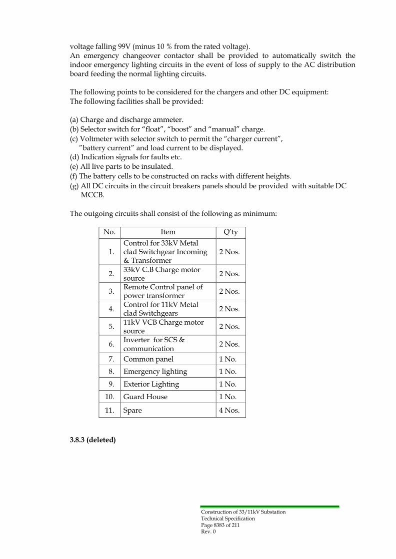
Construction of 33/11kV Substation Technical Specification Page 8383 of 211 Rev. 0
voltage falling 99V (minus 10 % from the rated voltage). An emergency changeover contactor shall be provided to automatically switch the indoor emergency lighting circuits in the event of loss of supply to the AC distribution board feeding the normal lighting circuits.
The following points to be considered for the chargers and other DC equipment:
The following facilities shall be provided:
(a) Charge and discharge ammeter.
(b) Selector switch for “float”, “boost” and “manual” charge.
(c) Voltmeter with selector switch to permit the “charger current”, ”battery current” and load current to be displayed.
(d) Indication signals for faults etc.
(e) All live parts to be insulated.
(f) The battery cells to be constructed on racks with different heights.
(g) All DC circuits in the circuit breakers panels should be provided with suitable DC MCCB.
The outgoing circuits shall consist of the following as minimum:
No. Item Q‟ty
1.
Control for 33kV Metal clad Switchgear Incoming & Transformer
2 Nos.
2. 33kV C.B Charge motor source
2 Nos.
3. Remote Control panel of power transformer
2 Nos.
4. Control for 11kV Metal clad Switchgears
2 Nos.
5. 11kV VCB Charge motor source
2 Nos.
6. Inverter for SCS & communication
2 Nos.
7. Common panel 1 No.
8. Emergency lighting 1 No.
9. Exterior Lighting 1 No.
10. Guard House 1 No.
11. Spare 4 Nos.
3.8.3 (deleted)

Construction of 33/11kV Substation Technical Specification Page 8484 of 211 Rev. 0
Section-3.9: Station LV AC System
The Contractor shall provide the 400/230V, 3-phase, 4-wire, 50 Hz system with solidly
earthed neutral for the AC station services.
The supply will be taken from the 11/0.416kV Aux. transformer. Arrangement and connection details of the AC system are as shown in drawings.
The LV AC switchboard shall be of free standing metal clad totally clad indoor type designed for 400/230V, 3-phase, 4-wire, 50Hz with solidly earthed neutral and bus-bar rating of 500A. The switchboard shall comply with IEC 60947.
The incoming of the main 400/230V distribution circuit shall be supplied through a 4-pole Molded Case Circuit Breaker (MCCB) of nominal current rating of not less than 400A. The protection to be provided by thermal and magnetic release for over load and short circuit trip with time lag and compensation for ambient temperature .The adjustment of the over load protection shall be between 80 to 120% of the full load rating.
The incoming circuit shall also be provided with voltage meter & ampere meter, AC under-voltage relay, phase-sequence relay, earth fault sensing relay and the respective alarm indication.
The rated symmetrical breaking capacity shall be not less than 35kA. The outgoing feeders from the main distribution circuit shall be individually controlled and protected by means of MCCB rated at the pertaining circuit loads. The nominal rating of each unit shall not be less than 20A.
The outgoing circuits shall consist of the following:
No. Item Q‟ty
1.
MV switchgear Building service (air conditioning equipment, lights, sockets)
As suitable
2.
Guard man house service (air conditioning equipment, light, socket)
2 Nos.
3. 33 kV switchgear panels 2 Nos.
4. Remote Control panel of power transformer
2 Nos.
5. 11 kV switchgear panels 2 Nos.
6. 110V battery & charger incoming circuit.
2 Nos.
7. Outdoor lighting panel 1 No.
8. Spare 4 Nos.

Construction of 33/11kV Substation Technical Specification Page 8585 of 211 Rev. 0
Section-3.10: Cables
3.10.1 General
The Contractor shall provide the 33kV & 24kV Power cables in substation and all LV auxiliary control and protection cables of a suitable design is used for site operation equipment.
The materials shall be of first class quality and designed for continuous satisfactory operation as continuity of supply is of prime importance and to operate satisfactorily under variation of load, voltage and short circuit or other conditions which may occur on the system provided that these variations are within the assigned rating of the apparatus.
The materials used shall be suitable for the clause 2.1.1.3 service conditions and the soil conditions. All cables provided under this Contract shall be of type approved by Owner and shall be provided with the cover which resists a termite and a vermin.
3.10.2 Medium Voltage Power Cables
Note: all the cables used in 11kV system should be of a rated voltage 12/20 (24) kV.
33kV, 24kV Power Cables shall, as a minimum, meet all the requirements of IEC standard IEC 60502, 60228, 60949 and BS 6622. Cables laid within buildings and shall have a low emission of smoke and corrosive gasses and shall also meet the Flame Propagation, smoke emission and corrosive and acid gas test requirements of BS7835.
The Contractor is required to provide calculations to demonstrate that the cables meet the required cable cyclic loadings as specified for the transformers at the site conditions.
(a) Continuous rating calculations are to be performed in accordance with
IEC 60287. (b) Short circuit ratings must be calculated using the adiabatic methods
described in IEC 60949. (c) Cyclic and emergency ratings should be calculated in accordance with
IEC 60853.
33kV and 24kV Power Cables connecting from switchgears to power transformer‟s primary and secondary shall be of XLPE (cross linked polyethylene), unarmored single core cable. 24kV Power Cables connecting from switchgear to Aux. transformer‟s primary shall be of XLPE (cross linked polyethylene), armored three cores cable.

Construction of 33/11kV Substation Technical Specification Page 8686 of 211 Rev. 0
General Cable Characteristics
For Conductor
Compact electrolytic annealed stranded plain circular copper Conductor of high conductivity 99.9% purity in accordance with IEC 60228.
For Conductor Screen
A layer of extruded semi-conducting compound forming a non metallic screen. The extruded semi- conducting compound shall be firmly bonded to the insulation.
For Insulation
Extruded XLPE cured with dry curing process (a) 24kV nominal thickness 5.5 mm (b) 36kV nominal thickness 8 mm
For Insulation screen
(a) Non metallic screen applied directly over the XLPE insulation and shall consist of a layer of extruded semi conducting compound and of 50% overlap semi- conducting swelling tape.
(b) The metallic screen must be a combination of copper stranded and copper tape.
• For 33kv cable the equivalent cross-section area to be 35 mm2
• For 24kv cable the equivalent cross-section area to be 25 mm2
For Filler & bedding
The three cores then laid up with suitable extruded (low thermal resistivity material easy to remove good flexibility and to be mentioned with the offer such as (EPR) or (PP)) fillers, a compact circular assembly and bedded with a layer of extruded P.V.C. 2mm thickness.
For Waterproof tape
A layer or suitable tape (swelling tape) for water proofing to be laid over the bedding.
For Metallic Armor
The three cores then armored with double galvanized steel wires according to IEC60502 clause 12.4.
For PVC Jacket
Over all extruded PVC seamless sheath to prevent moisture from penetrating and provides good corrosion protection thickness not less than 3 mm and to be antitermite treated (non polluted material).
Marking of 24kV or 33kV in the English language should be stamped each one meter length and treated. Also name, year of manufacture, Voltage & cross section in the English language. The colors are to be :
(a)RED for 33kV (b)BLACK for 24kV

Construction of 33/11kV Substation Technical Specification Page 8787 of 211 Rev. 0
Clause 14.3 IEC 60502 Note: the thickness shall be checked and meet the following formula as minimum: Ts = 0.035D+1mm where D = Fictitious diameter immediately after the sheath Ts = thickness in mm
Type of Cables
36kV Cables (1 x 400 mm2) with rated voltage VO/V=18000/30000 V (suitable for highest system voltage of 36000 V)
11kV Cables (1 x 400 mm2) with rated voltage VO/V=12000/20000 V (suitable for highest system voltage of 24000 V)
11kV Cables (3x 150 mm2) with rated voltage VO/V=12000/20000 V (suitable for highest system voltage of 24000 V)
The power cables in substation are to be thermally independent circuits laid in trenches and ducts generally as shown in the layout drawing.
(a) 33kV cables from switchgear to 33/11.5kV 31.5MVA transformer
(b) 11kV cables from 33/11.5kV 31.5MVA transformer to 11kV switchgear
(c) 24kV cables from 11kV switchgear to 11/0.416kV Aux. transformer circuit
Technical Information for cables
The Contractor shall be required to give following information in Section 2 Technical Data in the Bidder.
(a) Resistance of copper per km of cable
(b) Inductance per km of Cable
(c) Capacitance per km of Cable
(d) Insulation resistance in M.ohms between core /screen
(e) Weight of copper per km of cable
(f) Overall weight of cable per km of cable
(g) Overall diameter of finished cable in mm
(h) Type of chemical treatment against termite in the outer sheath
(i) Cross section drawing and details of cable layers and catalogues
33 kV, 24 kV cables accessories shall, as a minimum, meet all the requirements of the latest editions of IEC standard IEC 60502-4 and BS 7888.
Tests
Cables and accessories shall be subjected to inspections and tests by the Owner‟s inspectors or international inspectors at any time during manufacture. The manufacturers shall provide inspection facilities for the said inspection shall be made at place of manufacture or at international testing facilities.

Construction of 33/11kV Substation Technical Specification Page 8888 of 211 Rev. 0
Cable terminations 33kV 400mm2 Cables Termination & 24kV 400mm2 & 150 mm2 Cables should be fitted by cable terminations.
Cable terminations to be slip on or cold/heat shrinkable type complete with all necessary materials suitable for 36 kV Cable & 24kV Cable from qualified manufacturers, The terminations should be as follows:
(a) For 33kV 31.5MVA transformer cables
• Outdoor terminations suitable for cable (Tr Cable box)
• Indoor terminations suitable for cable(Metal clad Switchgear)
(b) For 11kV 31.5MVA transformer cables
• Outdoor terminations suitable for cable (Tr Cable box)
• Indoor terminations suitable for cable(Metal clad Switchgear)
(c) For 11kV Aux. transformer cables
• Outdoor terminations suitable for cable
• Indoor terminations suitable for cable
3.10.3 Low voltage Power Cables
Low voltage Power Cables shall, as a minimum, meet all the requirements of IEC standard IEC 60502-1, 60228.
General Cable Characteristics
For Conductor Compact electrolytic annealed stranded plain circular copper Conductor of high conductivity 99.9% purity in accordance with IEC 60228.
For Insulation
Extruded PVC (polyvinyl chloride) according to IEC table.
Core colors
Colored for identifications (Red, Yellow, blue for phase) and black neutral.
For Filler & bedding
The four cores then laid up with suitable fillers to form a compact circular assembly and bedded with a layer of extruded P.V.C.
For Metallic Armor (for multi-core cables)
The four cores then armored with double galvanized steel wires according to IEC60502- 1 clause 12.4.
For PVC Jacket (PVC grade: ST2 table 4 in IEC 60502-1)
Over all extruded PVC sheath water proof gray color of thickness according to IEC6052-1 and across section marking of (400V) in the Arabic language should be

Construction of 33/11kV Substation Technical Specification Page 8989 of 211 Rev. 0
stamped each one meter length and treated. Also name, year of manufacture, Voltage & cross section in the Arabic language.
Type of Cables
400V Cables (1 x 240 mm2) with rated voltage VO/V=600/1000 V (suitable for highest system voltage of 1200 V)
Four cores cables
These cables are required to meet the current rating of each circuit.
Technical Information for cables
The Contractor shall be required to give following information in Section 2 Technical Data in the Bidder:
(a) Resistance of copper per km of cable
(b) Inductance per km of Cable
(c) Capacitance per km of Cable
(d) Insulation resistance in M.ohms between core /screen
(e) Weight of copper per km of cable
(f) Overall weight of cable per km of cable
(g) Overall diameter of finished cable in mm
(h) Type of chemical treatment against termite in the outer sheath
(i) Cross section drawing and details of cable layers and catalogues
400V cables accessories shall, as a minimum, meet all the requirements of the latest editions of IEC standard IEC 60502-1.
Tests
Cables shall be subjected to inspections and tests by the Owner‟s inspectors or international inspectors at any time during manufacture. The manufacturers shall provide inspector‟s facilities for any said inspection shall be made at place of manufacture or at international testing facilities.
3.10.4 Control & Auxiliary Cables
All control, alarm and indication cables shall be of single-core or multi-core, PVC insulation and overall over sheath, stranded copper conductors with galvanized steel wire armor as a minimum, meet all the requirements of IEC standard IEC 60502-1 and BS6346.
The conductors shall be plain annealed copper wire complying with IEC 60228 as applicable or equivalent and all cores shall be clearly identified by printed numbers at regular intervals.
Many instances of rats eating away the outer PVC insulation cover are reported, therefore, a suitable non-corrosive wire armor to make the cable vermin-proof shall be provided for all low voltage auxiliary and control and protection cables.
The minimum conductor size shall be not less than seven strands of 0.67 mm diameter

Construction of 33/11kV Substation Technical Specification Page 9090 of 211 Rev. 0
wire, or in the case of single wire conductors the minimum cross-sectional area shall be not less than 2.5 mm2 for control and auxiliary circuits and 4 mm2 for current transformer circuits. When the Contractor uses a less than 2.5mm conductor for an electronic circuit, the approval of Owner shall be needed.
The Contractor is responsible for checking all cable routes for burden on CT's and VTs for voltage drop on DC control and trip circuits and for satisfactory service with the supplied equipment. It is also the Contractor's responsibility to take precautions to prevent damage to cable sheaths from system earth fault current.
The Contractor shall provide fully detailed wiring diagrams covering all parts of the substation.
3.10.5 Termination of cables and wires
The cable cores shall be long enough to be terminated to any terminal in an enclosure without extension.
All cables shall enter cubicles and boxes from bottom side. PVC sheathed cables shall be terminated by compression glands complying with BS 6121 or equivalent.
Where cable cores are liable to be in contact with oil or oil vapor the insulation shall be unaffected by oil. The Contractor must terminate all power and control cables inside the appropriate cubicle.
The spare cores of all multicore cables shall be numbered and terminate at a terminal block in the cubicle. AC terminals shall be clearly color coded and shrouded.
Colors shall be marked on cable box, cable tail ends and single core cables at all connecting points and/or any positions. Cable boxes shall be marked with stamped stainless steel labels indicating the purpose of the supply where such supply is not obvious.
3.10.6 Cable installation requirement
The following requirements shall apply
LV power cables, multicore cables and communication cables (if necessary) shall each be routed in separate trays, racks, ducts, troughs or compartments separated by steel sheet barriers.
Fibre optic cable (if necessary) shall be routed and installed such that they are protected from deformation or damage by auxiliary power or control cables throughout their installed length when available.
Sufficient space shall be allowed to run in each duct or compartment the necessary draw wires, being of non-corrosive metal and having devices for securing the conductors. A spare capacity of 20% shall be provided on cable trays, ladder racks, ducts, compartments, or openings in walls and floors.
Construction of 33/11kV Substation Technical Specification Page 9191 of 211 Rev. 0
Openings in floors and foundation pads shall be large enough to permit free movement of cables during installation. Openings in walls and floors shall be sealed after the cable installation with a fireproof barrier.
Cabling and wiring installations shall be arranged to minimize the risk of fire and damage which might be caused in the event of fire.
Only one layer of power cables shall be laid on one tray or in one cable channel. All cables leaving buildings for outside plant shall be laid in cable ducts or trenches when available.
Where cables emerge from grade they shall be protected by a section of steel pipe extending 150mm above grade. Cables above ground shall be run on galvanized cable racks, tray or supports, suitably clipped to prevent movement. Care shall be taken to provide for differential movement between structures.
Protection from direct sunlight shall be provided by means of suitable continuously covering the cable and of the same materials as the rack/tray. Cable strap shall be made of stainless steel.
3.10.7 Cable trays, racks, ladders and associated materials
The Contractor shall furnish and install all cable trays, horizontal and vertical, required as specified below. Cable tray systems shall be made of straight sections, fitting and accessories. Trays shall have an overall side rail height of 100mm, with a minimum loading depth of 75mm.
Widths shall be 300mm and 600mm.
Straight section side rails shall be of I-Beam design with a rung retaining weld bead. All straight sections shall be supplied in standard lengths of 4000mm.
Bolted joints between tray sections shall be made up tight and rigid, using a full complement of splice plates, bolts, washers, and locking devices, as called for by the manufacturer‟s design.
Cable tray covers shall be provided for all trays located outdoors, including open building structures, and wherever exposed to falling debris in all areas. Cable trays shall be supported not more than 2000mm.
The vertical distance between the two (2) cable trays shall be minimum 300 mm, unless specifically indicated.
Where equipment is mounted on walls and/or columns, Contractor shall provide structural steel supports and suitable anchors.

Construction of 33/11kV Substation Technical Specification Page 9292 of 211 Rev. 0
3.10.8 Conduit and installation of conduit system
All rigid conduits to be furnished shall be galvanized, unless otherwise noted. Minimum size of all conduits shall be 20mm. All embedded lighting conduits shall be galvanized intermediate metallic conduit (IMC). Exposed lighting conduit may be electrical metallic tubing (EMT). Switches and receptacles may be surface or flush mounted.
Each piece of conduit shall be straight, free from blisters and other defects and threaded at each end. Coupling shall be cleanly cut. The manufacturer‟s name shall be attached to or stamped on each piece. In areas with corrosive atmosphere, steel conduit shall be provided with an epoxy coating. In no case shall the conduit be filled by more than 40%.
Flexible metallic tubing may be used for small runs. Flexible conduit shall be used only in location dry, non-hazardous, and not exposed to oil, corrosive fume or steam. Minimum size of the flexible metallic tubing shall be 12mm.
Exposed conduit shall be run in straight lines parallel to column lines, walls, or beans. Where conduits are grouped, the bends and fittings shall be installed so as to present an orderly appearance. Unnecessary bending or crossing shall be avoided.
Conduit shall be supported on approved type of galvanized wall brackets, ceiling trapeze, strap hangers, or pipe straps, secured by means of anchor bolts on hollow masonry units, expansion bolts in concrete or brick, and machine screws on metal surfaces. Wooden plugs inserted in masonry or concrete shall not be used as a base to secure conduit support.
Concealed horizontal and vertical runs in hollow space shall be supported at intervals of 3 m or less. Tapped conduits and conduits terminating in end boxes or fittings shall be supported not farther than 300mm from the terminals.
The groups of exposed conduits run together, the conduits shall be supported by racks, made of steel channel or angle iron, which shall be hung from floor slab or the building steel. All conduits shall be clamped to the supporting channel or angle with “U”-bolts, each being clamped at every rack. Special wrenches shall be used to avoid injuring the galvanized coating on conduits.
Conduit joints and connections shall be made thoroughly watertight and rustproof by means of the application of a thread compound, which will not insulate the joint. Each threaded joint shall be thoroughly cleaned to remove all cutting oil before the compound is applied. Red lead is suitable for application for embedded conduits, and white lead is suitable for application for exposed conduits. Running threads shall be avoided.
Coupling may be used in dry and exposed locations. They may also be used in wet exposed locations in vertical runs only, provided they are installed with fixed threaded connection at top.

Construction of 33/11kV Substation Technical Specification Page 9393 of 211 Rev. 0
They may be used in concrete if adequately waterproofed to prevent leakage. Standard radius bends are generally to be used for steel conduits but special long radius bends shall be used whenever specifically required. The long radius bends are to have radii as the physical conditions will permit. Field bends of metallic conduit shall be made in such a manner the internal diameter of the conduit is not materially changed, and the protective coating on the inside of the conduit is not injured. The bends shall be free of kinks, indentation, or flattened surfaces. Heat shall not be applied in making any conduit bends.
Galvanized structural steel members may be drilled or punched for conduit supporting bolts, provided the holes are immediately painted with aluminum paint and galvanized or rust-resisting bolt are used. Templates shall be provided where embedded they shall be properly braced on the inside so that the concrete will not defect them. Thread holes in box frames shall be protected from injury.
Conduits shall be provided wherever possible, at least 300mm away from heating devices, or similar equipment, when it is evident that such proximity might impair the service life of cables.
3.10.9 Painting
The painting at site of electrical apparatus and equipment shall be limited to touching up any surfaces scratched or marred during shipment or inland transportation or installation.

Construction of 33/11kV Substation Technical Specification Page 9494 of 211 Rev. 0
Section-3.11: Earthing System
The earthing system shall be designed to meet the requirements of this specification and shall be in accordance with IEEE 80. The Contractor shall present calculations to show the earthing system meets these requirements and can be shown to be safe in terms of touch, step and transferred potentials.
The Soil Resistivity of all substations sites are preliminary measured and found as shown on Appendix E, these measurements are preliminary, the Contractor himself should perform a new measurements to be used in the substations earthing calculations.
A maximum earth resistance of one (1) ohm shall be obtained. The calculation shall take into consideration the soil resistivity of the places where the substation will be installed. Design calculations must be provided by the Contractor to obtain the above result together with calculations for the step and touch voltages.
Earth rods of copper weld type 19 mm diameter and 2500 mm long shall be disposed in groups at locations in particular adjacent to surge diverters to ensure that the connections from these items to the earthing system are as short and as straight as possible. A separate set of rods shall also be installed for independently earthing each substation fence at suitable intervals.
Main earth bar installed in the form of a ring around the substation comprising stranded copper cable of not less than 95 mm2 minimum cross sectional area.
Subsidiary connections from this main earth bar shall be not less than 70 mm2 cross sectional area. The size of the earth bar to be used at each specific site shall need to be supported with calculations.
The subsidiary and branch connections also being stranded copper cables, where these earth conductors run through concrete, they shall be PVC sheathed in order to protect the conductors against corrosion.
All apparatus and cable glands may be earthed by a separate connection. These branch connections being grouped and each group jointed to the main earth bar by a subsidiary connection. Mechanism boxes for disconnectors and earthing switches shall have earth connections separate from these for the associated equipment. Each piece of equipment shall be provided with a separate earthing terminal on a vertical face above ground level, fixing and foundation bolts will not be used for making earth connections.
All metal parts of 33kV and 11kV switchgear other than those forming part of an electrical circuit shall be connected to a hard drawn, high conductivity, copper earth conductor on each unit.
It shall be bolted to the main frame and shall be located so as to provide convenient facilities for earthing cable sheaths and for use with the earthing devices. Means shall be provided for coupling earth bars of adjacent units to form a continuous

Construction of 33/11kV Substation Technical Specification Page 9595 of 211 Rev. 0
earth bar. The joints shall be tinned, bolted and sweated.
The neutral of the 11 kV side of the transformer shall be separately connected to around with a Lightning arrester in parallel with a single pole on-load disconnector connected in series with a 21.1 ohm resistor as shown in the attached single line diagram including the equipment complete with all necessary structures and connections.
After installation of earth system the Contractor shall measure the resistance of the substation earthing mesh.
The method used shall preferably be the “fall of potential” method, requiring the availability of a local low voltage supply but other methods using an earth resistance megger will be acceptable in the event of a local supply being unavailable.
Construction of 33/11kV Substation Technical Specification Page 9696 of 211 Rev. 0
Section-3.12 Inspection and Tests
3.12.1 General
The Contractor shall carry out Factory tests, Type test and Site test in accordance with the latest IEC standard. The Contractor shall submit all test procedures to the Owner for approval. All tests shall be carried out in accordance with the approval test procedures. All tests results shall be approved by Owner. The approval of the tests, acceptance of the test certificates or waiving of tests shall not relieve the contractor from his contractual obligations.
3.12.2 Inspection and Tests
The equipments/material shall be subjected to inspection and tests by the Owner at any time during manufacture. The Contractor shall provide all inspection facilities for the said inspection and testing.
All testing and inspection shall be made at the place of manufacture. The Owner shall have the right of rejecting any portion of the equipments/material at any time during manufacture if it does not meet the requirements of this specification in all particulars. He shall oversee the packing and shipping of all equipments/materials to be supplied.
3.12.3 Test at manufacture's work
Test at Contractor work shall comprise type tests and routine tests.
3.12.3.1 Type test
These tests are in general those detailed in the IEC which pertain to the equipment being tested. Type tests are to prove the general design of the equipment and the manufacturer may submit test certificates of tests which have been carried out on identical equipment not withstanding any provision in an IEC, the Owner shall have the right to accept such certificate in lieu of the specified type test or to reject them. The type test prescribed shall be carried out in all cases where such certificates are not available or are rejected.
Certified test certificate issued by ASTA, KEMA or other internationally recognized testing authority for type test carried out on identical C.B will be accepted in lieu.
1) One circuit breaker of each type and rating shall be subjected to following
type test in accordance with the latest issue of the IEC specifications (a) Operation test.
(b) Mechanical endurance.
(c) Test of temperature rise.
(d) Making capacity, breaking capacity and short time current test.
(e) Short circuit test.
(f) Insulation level.

Construction of 33/11kV Substation Technical Specification Page 9797 of 211 Rev. 0
2) 33kV & 11kV Metal Clad Switchgear
Should be type tested according to the relevant IEC.
3) 33/11kV 31.5MVA Transformer
One transformer shall be subjected to the relevant type tests including the following tests in accordance with the latest issue of IEC.
(a) Dielectric type test (IEC 60076-2).
(b) Sound level measurement.
(c) Determination of capacitance winding- to- earth and between windings.
(d) Measurements of insulation resistance to earth of the windings and dissipation factor (Tan Delta) of the insulation system capacitances.
(e) Temperature rise test (only the first unit need for a type test)
(f) Lightning Impulse chopped on the tail as item 14.3 of IEC 60076- 3.
Short circuit test shall be submitted for a transformer of the same rating and voltages with tap changer in accordance with IEC 60076-5 A certified test short circuit test issued by ASTA, KEMA or other internationally recognized testing authority for type test carried out on a transformer with higher rating and relevant calculations may be accepted in lieu.
4) 11/0.416kV 250kVA Auxiliary Transformer
One transformer shall be subjected to the relevant type tests including chopped wave test in accordance with the latest issue of IEC.
5) Protection relays are to be type tested in accordance with the latest IEC 60068, IEC60255. One relay from the outgoing feeders protection relays shall be type tested according to applicable IEC and to be witnessed by MoE staff.
3.12.3.2 Routine Tests
The following routine test items, but not limited to, shall be carried out at manufacturer's factory in accordance to the latest issue of IEC specifications:
The test of the Substation control system shall be executed referring to item 3.5.12 (SCS Testing). 1) 33kV Metal Clad Switchgear
- 33kV Circuit Breaker cubicle
(a) Design and Visual check
(b) Functional operation test ( Interlocking test D.S and C.B)
(c) Insulation resistance test
(d) Power-frequency voltage withstand test
(e) Mechanical operating tests of C.B
(f) Timing test of closing and open operation of C.B
(g) Primary injection tests on current transformer including measurement of current ratio and check of relative polarity

Construction of 33/11kV Substation Technical Specification Page 9898 of 211 Rev. 0
(h) Residual voltage test of arrester
(i) Partial discharge test of arrester
(j) Operation test of surge counter and surge recorder
(k) Protection relays test
(l) Indicating meters test
Note: Magnetization curves and DC resistance values shall be submitted for each current transformer.
- 33kV disconnector, earthing switch and lightning arrester cubicle
(a) Design and Visual check
(b) Functional operation test ( Interlocking test DS and E.S)
(c) Insulation resistance test
(d) Power-frequency voltage withstand test
(e) Tests on voltage transformer including measurement of voltage ratio and check of relative polarity
(f) Indicating meters test
Note: DC resistance values to be given for voltage transformers
2) 33/11kV 31.5 MVA Transformer
(a) Design and Visual check
(b) Measurement of winding resistance
(c) Measurement of voltage ratio and check of phase displacement
(d) Measurement of short-circuit impedance and on-load loss
(e) Measurement of no-load loss and current
(f) Function test of instruments
(g) AC voltage Dielectric routine tests
(h) Mechanical test for tank (Oil tightness check and Vacuum test)
(i) Tests of on-load tap-changer
(j) Temperature rise test (only the first unit need for a type test) (k) Impulse test (only the first unit need for a type test)
(l) Measurement of acoustic sound level (only the first unit need for a type test)
- Transformer control cubicle
(a) Design and Visual check
(b) Insulation resistance test
(c) Function test for control circuit, indicating circuit and alarm circuit
3) Neutral Earthing Resister cubicle & arrester of 33/11kV neutral
(a) Design and Visual check
(b) Functional operation test of DS
(c) Insulation resistance test
(d) Power-frequency voltage withstand test
(e) Primary injection tests on current transformer including measurement of current ratio and check of relative polarity
(f) Tests on voltage transformer including measurement of voltage ratio and check of relative polarity
(g) Residual voltage test of arrester
(h) Partial discharge test of arrester

Construction of 33/11kV Substation Technical Specification Page 9999 of 211 Rev. 0
(i) Operation test of surge counter and surge recorder
(j) Protection relays test
(k) Indicating meters test
Note: Magnetization curves and DC resistance values shall be submitted for each current transformer. DC resistance values to be given for voltage transformers as well.
4) 11kV Metal Clad Switchgear
- 11 kV transformer cubicle
(a) Design and Visual check
(b) Functional operation test ( Interlocking test C.B and E.S)
(c) Insulation resistance test
(d) Power-frequency voltage withstand test
(e) Mechanical operating tests of C.B
(f) Timing test of closing and open operation of C.B
(g) Tests on voltage transformer including measurement of voltage ratio and check of relative polarity
(h) Primary injection tests on current transformer including measurement of current ratio and check of relative polarity
(i) Protection relays test
(j) Indicating meters test
Note: Magnetization curves and DC resistance values shall be submitted for each current transformer. DC resistance values to be given for voltage transformers as well.
- 11kV Outgoing , Future capacitor bank and Aux. transformer cubicle
(a) Design and Visual check
(b) Functional operation test ( Interlocking test C.B and E.S)
(c) Insulation resistance test
(d) Power-frequency voltage withstand test
(e) Mechanical operating tests of C.B
(f) Timing test of closing and open operation of C.B
(g) Primary injection tests on current transformer including measurement of current ratio and check of relative polarity
(h) Protection relays test
(i) Indicating meters test
- 11kV Bus coupler cubicle
(a) Design and Visual check
(b) Functional operation test
(c) Insulation resistance test
(d) Power-frequency voltage withstand test
(e) Mechanical operating tests of C.B
(f) Timing test of closing and open operation of C.B
(g) Primary injection tests on current transformer including measurement of current ratio and check of relative polarity
(h) Protection relays test
(i) Indicating meters test

Construction of 33/11kV Substation Technical Specification Page 100100 of 211 Rev. 0
5) Communication equipment
(a) Design and Visual check
(b) Functional operation test
(c) Insulation resistance test
6) 11/0.416kV 250kVA Auxiliary transformer
(a) Design and Visual check
(b) Measurement of winding resistance
(c) Measurement of voltage ratio and check of phase displacement
(d) Dielectric routine tests
7) DC system (Battery and Chargers)
(a) Design and Visual check
(b) Circuit test (conductive check by tester)
(c) Insulation resistance test
(d) Discharge test
(e) Operation test for load voltage compensator
(f) Relay operation test
(g) Indicating meter test
(h) Function test for control circuit, indicating circuit and alarm circuit
(i) Measurement of no-load current and DC voltage
(j) Low voltage test (Check of voltage decrease from threshold setting)
8) DC panel
(a) Design and Visual check
(b) Insulation resistance test
(c) Function test for control circuit, indicating circuit and alarm circuit
9) Inverter
(a) Design and Visual check
(b) Function test for control circuit, indicating circuit and alarm circuit
10) UPS AC panel
(a) Design and Visual check
(b) Insulation resistance test
(c) Function test for control circuit, indicating circuit and alarm circuit
11) AC LV panel
(a) Design and Visual check
(b) Insulation resistance test
(c) Function test for control circuit, indicating circuit and alarm circuit
12) 33kV and 11kV power cables
(a) Design and visual check
(b) Measurement of electrical resistance of conductors
(c) Partial discharge test
(d) Voltage test
(e) Check of dimensions

Construction of 33/11kV Substation Technical Specification Page 101101 of 211 Rev. 0
13) LV power & control cables
(a) Design and visual check
(b) Measurement of electrical resistance of conductors
(c) Voltage test
(d) Check of dimensions
3.12.4 Site test
After complete installation, the equipment shall be tested at Site to ensure the proper operation and the readiness for service. All tests shall be performed according to specifications of the equipment manufacturer. All tests shall be performed to verify that the equipment comply with approved drawings, specifications and manufactures instructions.
The test of the Substation control system shall be executed referring to item 3.5.12 (SCS Testing).
1) 33kV & 11kV Switchgear
The following items have to be tested after installation.
(a) General inspection
(b) Checking against the complete assembly equipment specification for compliance of ratings of all major components, i.e. bus, circuit breaker, fuses, relays, etc.
(c) Checking the correct phasing of equipment connections.
(d) Checking of tightness of connections and fastenings for bus insulators, supports, etc., and use of proper tools
(e) Measurement of gas condition (If any).
(f) Measurement of the resistance of the main circuits.
(g) Testing of measuring instruments
(h) Secondary injection tests on all protection relays.
(i) Primary inject test on all protection relays and associated current
(j) transformer circuit
(k) Complete electrical functioning tests from Local/Remote/ DCC for CB‟s, DS‟s, Earthing Switches etc including the function of all interlocks.
(l) Power frequency voltage withstand test
(m) Dielectric tests on auxiliary circuits
(n) Gas tightness tests (If any)
Measurements and tests of circuit breakers shall include as a minimum:
• Insulation resistance measurement;
• Measurement of contact timing and travel analysis in accordance with manufacturer's instructions;
• Testing of mechanical operating;
• Testing of operating, such as, installation and removal from breaker cell, test position operation, tripping via relays & controls, correct interlocks operation, alarms, meters, etc.
Measurements and tests of current transformers shall include as a minimum:
• Inspection of the general condition

Construction of 33/11kV Substation Technical Specification Page 102102 of 211 Rev. 0
• Insulation resistance measurements to earth and between windings
• Secondary winding resistance measurement and burden checks
• Ratio checks
• Magnetizing voltage
• Polarity test
Measurements and tests of voltage transformers shall include as a minimum:
• Inspection of the general condition.
• Insulation resistance measurements to earth and between winding.
• No-load test with normal applied voltage on secondary terminals for a minimum of 30 minutes (1VTs only)
• Ratio checks.
• Polarity test
• Burden measurement.
2) 33/11kV 31.5MVA Power transformer
After the transformer has been assembled the following tests shall be executed as a minimum requirement.
(a) General inspection
(b) Measurement of Winding Ratio on all tap positions
(c) Vector group test
(d) Turns ratio test
(e) Dielectric Strength of the Insulation Oil
(f) Insulation resistance tests between windings and each winding to earth
(g) Measurement of dc winding resistance (All taps)
(h) OLTC function tests including remote control systems.
(i) Alarm and trip function tests of protection i.e. Bucholz Relays, Oil levels, Pressure protection.
(j) Measurements and tests of bushing current transformers
(k) Energizing and setting to work.
(l) Measurement of noise level.
3) Communication equipment
(a) Physical Site Inspection
(b) Operational checks
4) 11/0.416kV 250kVA Auxiliary transformer
(a) General inspection
(b) Measurement of Winding Ratio on all tap positions
(c) Vector group test
(d) Turns ratio test
(e) Dielectric Strength of the Insulation Oil
(f) Insulation resistance tests between windings and each winding to earth
(g) Measurement of dc winding resistance (All taps)
(h) Energizing and setting to work.
Construction of 33/11kV Substation Technical Specification Page 103103 of 211 Rev. 0
5) 33kV and 11kV power cables (a) General inspection of the cable routes, verification of proper installation, fixing
to the racks, bending radius, etc. (b) Verification of proper earthing of the screen and armouring.
(c) Measurement of Conductor Resistance; (d) The Contractor shall measure and record the following as-installed circuit data;
• As-installed circuit length in m
• DC conductor resistance
• AC conductor resistance(Measured and/or derived) (e) Verification of proper condition of external surfaces.
(f) Measurement of cables insulation resistance.
(g) Circuit phasing check and marking.
(h) Capacitance of circuit
(i) Sheath continuity checks.
Test On Sheath Protective Covering; A voltage of 12kV DC for one minute shall be applied between the sheath and ground on each length of cable sheath, with all sheath voltage limiters disconnected
6) LV cables and multi-core control cable
(a) General inspection of the cable routes, verification of proper installation, (b) fixing to the racks, bending radius, etc. (c) Verification of proper earthing of the screen and armouring.
(d) Measurement of cables insulation resistance.
(e) Verification of proper condition of external surfaces.
7) DC Systems
- Battery charger
(a) Physical Site Inspection
(b) Testing of breaker trip settings
(c) Measurement the continuity of each current carrying connections by MEGGER
(d) Testing the changing output voltage function by disconnected battery
(e) Testing the quick charge and trickle charge mode;
(f) Testing the charging current limiting (maximum current) by short-circuited DC output;
(g) Testing earth-fault monitoring
(h) Testing the Battery Charger inputs/digital outputs and control (LED‟s) and protection functions at/from the Battery Charger Board , from the station level via the SCS System (in control room) and from the Regional DCC.
Testing the Battery Charger inputs/digital outputs, alarm indications (LED‟s) and fault monitoring at the Battery Charger Board and at the sequence event recorder (in control room) and at the Regional DCC.
- Batteries
(a) General Inspection
(b) Checking of the battery assembly to verify clearances
(c) Checking of properly installed cell terminal coverings

Construction of 33/11kV Substation Technical Specification Page 104104 of 211 Rev. 0
(d) Battery cells are properly installed and numbered;
(e) Check Battery electrolyte i.e., level, color and specific gravity
(f) Charging the battery with constant-current in manual mode and recording the charging current, voltage of each cell and electrolyte temperature of pilot cell(s) every hour.
(g) Discharging the battery to a final voltage of min. 1.0 V and recording the battery voltage, cell voltage and electrolyte temperature of pilot cell(s) every hour.
(h) Measurement of insulation resistance against the ground. For new batteries
the value shall not be > 1 MΩ.
- Distribution panel
(a) General inspection (Physical and visual checks)
(b) Operational checks
(c) Voltage test 2000 V, 50 Hz, 1 min
(d) Insulation resistance 500 VDC, R > 50 M Ohm
8) Grounding System-Inspection
Measuring of earthing impedance, touch and step voltage will check the effectiveness of the installed earthing system. Measurements will be carried out with the current injection using „Current and voltage measurement‟ method.
(a) Evidence of damage to cables. Repair or replace damaged cables.
(b) Bolted connections made up tight.
(c) Welded or brazed connections are tight.
(d) Exposed cable runs adequately supported and clamped.
(e) Test the resistance of the grounding system by use of Ground Megger Method. (Resistance to earth shall not exceed 1 ohm.)
(f) Test shall be made at the following locations:
(g) All grounding wells
(h) Substation transformer
9) Cable Tray Systems
- Physical Site Inspection
Checking of the cable tray attachments to brackets and supports, if according to instructions and this specification and whether appropriate number and quality of anchor bolts or expansion bolts have been used;
10) Station Auxiliary
- LV AC Distribution panel
Checking of interior to verify clearances between live electrical parts, insulation of phase and neutral bus from panel, and tightness of all mechanical connections;
(a) General Inspection
(b) Checking of wiring termination and conductor sizes including cable identification
(c) Electrical & Mechanical Operational tests
(d) Voltage test 2000 V, 50 Hz, 1 min
(e) Measurement of insulation resistance 500 VDC, R > 50 Mohm

Construction of 33/11kV Substation Technical Specification Page 105105 of 211 Rev. 0
Part 4- Civil Specification
1. General 1.1 Scope of Work:
The Civil Works, including foundations, buildings, roads, path ways, etc., to be constructed, shall consist of design, construction, testing, supply, delivery, supervision, installation, commissioning and guaranteeing of all works shown on the drawings and specified herein.
The material and workmanship shall be the best of their respective kinds and to standards not less than specified herein.
1.1.1 Extent of Work
Reference should be made to the drawings and soil investigation reports. The details shown on the drawings and soil investigation reports(which is made by the contractor) shall be used for the purpose of tendering. The Contractor shall note that it is his responsibility to submit all designs and engineering drawings for all elements of the works as required and specified, in accordance with the actual soil conditions and design data that prevail at each substation site
Make provision to prepare and design drawings to approval of the Owner, liaise with all local, government, and other relevant authorities for activities including and not limited to obtaining approvals and clearances for services, obtaining building permit and permanent services connections such as water, drainage, telephone and making necessary payments, etc.
The Contractor is bound to provide complete works, even if the constructions, equipment or services to be provided are not specifically mentioned in the specification. The Contractor shall be responsible for, but not limited to, the following for all substations civil works;
- Detailed design, construction drawings including bar bending schedule, overall construction schedule and documents necessary for completion and maintenance of required civil works. - Topographical surveys and soil investigations. - Testing of soils, water and materials used. - Earthworks, grading and landscaping. - Temporary access roads to the Substation from public roads, and temporary service roads inside the Substation. - Asphalt or concrete paved permanent access roads from gate of Substation to outside the Substation based on site layout of the Tender drawings. - Concrete paved permanent service roads inside the Substation. - MV switchgear and auxiliary building to accommodate the 33 kV and 11 kV switchgears and associated control as well as protection equipment. - 33/11 kV Transformer foundations, bunds, oil containments and fire walls. - Guard house. - Cable trenches should be with a depth of 180 cm (-30 cm from zero level
and +150 cm from the zero level), ducts and draw pits. - Boundary wall with main, sub and personnel gates based on site layout of the Tender drawings.
Construction of 33/11kV Substation Technical Specification Page 106106 of 211 Rev. 0
- All structure and plant foundations. - Foul, surface water drainage systems and septic tank. - Building services including plumbing system, heating, ventilation and air conditioning system, drainage and sewers, small power installations, normal and emergency lighting, telephones, fire detection and alarm as well as firefighting systems, etc. - Water storage tanks. - All temporary works. - Preparation of as-built documents and drawings. - Any other works required and approved by the Owner.
1.1.2 Site Facilities for the Owner & Consultant / Contractor:
The Contractor shall provide all necessary temporary construction facilities such as site office with facilities, electric power supply, water etc. for each substation. The Contractor's site office shall include at least two desks and chairs for the Owner.
After the completion of the work covered by the Contract, all facilities at work are as shall be removed by the Contractor, except those directed by the Owner to remain. The Site shall be cleared and cleaned by the Contractor.
1.1.3 Standards and Design Criteria
Except where otherwise specified, implied or otherwise agreed in the Contract, the design, and the specification of materials and workmanship shall comply in all respects with the requirements of the latest applicable ACI,ASTM,AASHTO and Other International Standards
The Contractor shall submit all design calculations to the Owner for his approval prior to the commencement of preparation of working and shop drawings. After the Owner has approved the calculations, the Contractor shall prepare all necessary working and shop drawings and submit same for approval by the Owner, as specified under the "Submittal" Section of the Specifications.
1.1.4 Design Loading
(a) Dead and live loading International standards shall be used to determine all dead and imposed loads amended only as follows. Snow loading shall be considered if appropriate. Roofs without access should be designed for sand loading of 1 kN/m2, and where access is provided it should be designed for a loading of 1.50 kN/m2.
(b) Wind loading Wind loadings as determined in CP3 Chapter V plus all amendments, shall be applied to all buildings and structures. Although CP3 is a superseded document it may be used for reference in this case. In determining Vs in the code for wind loading, basic wind speed of 40 m/s equivalent to V of 34.2 m/s 12 m above GL,at 15 °C, should be used and factors S1 and S3 should be taken as unity. Factor S2should be determined from Table 3 in Part 2 of the Code surface category 1 -"Open country with no obstruction”.
(c) Seismic loading
Construction of 33/11kV Substation Technical Specification Page 107107 of 211 Rev. 0
All structures including buildings and their foundations shall be designed for seismic events as defined in the “Uniform Building Code” Zone 3.
(d) Short Circuit forces The dynamic load during the short circuit loading shall be considered.
(e) Operation Loads Any kind of operation loads during the maintenance shall be considered.
1.1.5 Load Combinations and Factors of Safety
The load combinations for Dead, Live and Wind loadings, and factors of safety, shall be in accordance with the design Standard being used for the building or structure being analyzed as followings;
Load Combination
Loading Condition
Load Factor
Dead Load
Conductor
Tension (if applicable)
Imposed
Wind /
Earthquake Adverse
Beneficial
1 Dead + Short Circuit +wind
1.2 1.0 1.2 1.2 1.2
2 Dead + Short Circuit + Earthquake
1.2 1.0 1.2 1.2 1.2
3 Dead + Mechanical Operation + wind
1.2 1.0 N/A 1.2 1.2
1.1.6 Submittals
The Contractor shall comply fully with the requirements specified in these documents. The following requirements are specific to the Civil and Building works under the contract. The Contractor shall not commence manufacturing or fabricating any structure, building or other civil works until his working and shop drawings have been approved by the Owner. The Contractor shall submit the following preliminary drawings for approval, together with such details of his calculations and methods adopted as the Owner may require, all in accordance with these Specifications and the Contract Schedule.
(a) The General Arrangement of each Substation showing the principal dimensions and positions of buildings, roads, services, transformers, etc. (b) Drawings showing the dimensions of the principal members of all structures. The final working and shop drawings, which shall be submitted to the Owner, after the approval of the preliminary drawings and details of calculations specified above, shall be in sufficient detail to show:
i. The general arrangement, details and dimensions of all parts of buildings, steel structures and of all other civil works to be supplied under the Contract.
ii. The nature of the materials from which the various parts are to be made together with their surface finish.
iii. Weld details, machining and assembly tolerances for all assemblies. iv. The manner in which such parts are designed to function. v. Schedules of materials and details in full for all structural steel members and
reinforcing bars.
Construction of 33/11kV Substation Technical Specification Page 108108 of 211 Rev. 0
vi. Detailed arrangement of various equipments in the MV switchgear and auxiliary buildings.
In addition to the above, the Contractor shall submit to the Owner any further information that the Owner may require to enable him to approve the final working and shop drawings. After the drawings have been approved, no changes shall be made to the drawings without the written permission of the Owner. The Changes to facilitate fabrication, to speed up delivery or to permit substitutions of material, which is in short supply, may be made if approved in writing by the Owner. The Contractor shall furnish the Owner with duplicate copies of certified mill test reports before fabrication is commenced on any materials covered by such reports.
Approval by the Owner of the Contractor's drawings shall not relieve the Contractor of responsibility for the correctness thereof, nor for the results arising from errors or omissions, nor for any faults or defects, nor for failure in the matter of guarantee, which may become evident during erection or subsequent operation.
1.1.7 Soil Investigations
The details shown on the soil investigation reports(contractor responsibility) shall be used The Contractor shall carry out whatever soil investigations and the testing deemed necessary for the proper foundation design and construction to suit the site conditions. No claim from the Contractor for price adjustment on account of any changes in the foundation works will be accepted under any circumstances.
The results and interpretation of all soil investigations including the testing and the calculations in respect of the soil bearing capacity values for the sites shall be submitted for approval by the Owner prior to the foundation design and the drawings.
No working drawing(s) will be approved by the Owner until such test values have been submitted and approved. Where necessary the Contractor shall adopt pile foundations for heavy equipments and buildings with no extra cost . The design loading capacity of piles shall be confirmed by pile loading tests, as directed by, and to the approval of the Owner. The type of loading test shall confirm to the international standards or equivalent, and the number and location of actual piles to be tested shall be designated by the Owner. 1.1.8 Topography and Finished Grade Elevation
The topographical survey for the Substation shall be responsibility of the Contractor. No extra cost shall be paid to the Contractor on account of any increase in quantity of the work to fulfill the requirement given in the tender documents and the drawings. The dimensions and elevations shown on the site layout of the tender drawings are only for reference for the tender purpose. The Zero level will be based on the nearest main road 1.2 Clearing and Site Preparation 1.2.1 General
The work in this Section shall consist of all clearing, grubbing and stripping of the topsoil from the Sites as directed by the Owner and specified herein. The Work shall

Construction of 33/11kV Substation Technical Specification Page 109109 of 211 Rev. 0
also include the transportation and disposal of all waste materials off the site to the areas arranged for by the Contractor, and to the approval of the Owner.
1.2.2 Clearing and Grubbing
Clearing shall include cutting and removing trees, bushes and other vegetation and removing fallen timber and other surface litter. Grubbing shall consist of digging out and removing stumps and roots remaining after the clearing operation.
1.2.3 Stripping of Topsoil
The Contractor shall, after clearing and grubbing, strip to a minimum depth of 200mm all topsoil or other surface deposits. If, in the opinion of the Owner, topsoil extends to a greater depth than 200 mm, the Contractor shall remove all such soil as directed by the Owner. The Contractor may stockpile approved topsoil for reuse as specified herein subject to the Owner's approval. The stripped surface should be compacted to 95% proctor dry density before the starting of the filling operations.
1.3 Excavation
1.3.1 General
Excavation shall include the removal of all material of any nature including rock, which interferes with the construction work. The Contractor must clear all excavations of mud, loose material, dirt and debris, and if required by the Owner, the bottom 150 mm of excavation shall not be removed until just before the commencement of construction. All necessary safety precautions shall be taken to avoid injuries. The surfaces of excavation shall be protected at all times from erosion or collapse due to weather or other conditions. Sides of excavations shall be shored up where necessary to the satisfaction of the Owner.
The Contractor shall at all times keep all excavations and trenches free from water. The contractor shall use pumps, well points or any other method necessary to remove water in a manner that will prevent loss of soil and maintain stability of the sides and bottom of the excavation, all to the approval of the Owner. If excavations are carried beyond the lines or elevations shown on the drawings or specified herein, the Contractor shall be required to backfill such excavation with C15 concrete or crushed stone as directed by the Owner at the Contractor's own expenses. The Contractor shall investigate the water table level at the proposed Substation Site, and no extra cost on account of any difficulty arising out of a high water table will be entertained.
1.3.2 Excavation for Foundations
The underside of all foundations shall be at a minimum depth of 200 mm below the stripped surface. Immediately after excavation for foundations is completed and approved by the Owner, C15 concrete 100 mm, thick is to be laid as blinding for the structural concrete foundations.
1.3.3 Excavation for Underground Services
The minimum area of excavation shall be the project plan area of the various items being installed. However, the Contractor shall make due allowance for working space that the Contractor considers necessary and also for placing the specified concrete or other bedding material as shown on the drawings. Variances in unit cost shall be based on the above. Trenches shall be excavated to the general lines and

Construction of 33/11kV Substation Technical Specification Page 110110 of 211 Rev. 0
depths specified and as shown on the drawings.
If the bottom of any trench or excavation is found to be unstable or unsatisfactory, the Contractor shall excavate such unsuitable material to the width and depth ordered by the Owner. The sub-grade shall then be restored by back-filling with approved materials so as to provide a uniform and continuous bearing and support for the service pipe or duct.
1.3.4 Excavation for Roads Areas
Any soft areas, which develop during rolling, as specified herein, shall be excavated as directed by the Owner. All loose rock or boulders and all ridge rock encountered in the excavation shall be removed. The excavated surface shall be compacted to 95%modified proctor dry density.
1.3.5 Disposal of Excavated Materials
All materials obtained from the excavations, and approved by the Owner, for use as general backfilling materials shall be laid aside and afterwards deposited as and where directed by the Owner. Any materials not so approved shall be removed by the Contractor and disposed of in areas off the site arranged for by the Contractor at his own cost, and approved by the Owner. The deposited material shall be spread and trimmed to a uniform surface.
1.4 Fill and Back Fill
1.4.1 Materials
(a) General filling material The general fill material shall consist of approved natural material obtained directly from the excavation or from borrow areas approved by the Owner. Only material approved by the Owner shall be used for general fill, and such material shall be free of vegetation, topsoil, roots, logs, stumps or any other organic, perishable or unsuitable material. All necessary precautions, to the approval of the Owner shall be taken to exclude termites from the filling material.
(b) Borrow area operations Detailed planning of the excavation shall be the responsibility of the Contractor and shall be subject to approval by the Owner. The Contractor shall pay particular attention to the natural water content of the material. Prior to the commencement of the work, the Contractor shall submit for approval by the Owner, a plan showing details of the Contractor's proposed methods, and the sequence, and the schedule of operations in the borrow area. During construction, the plan shall be reviewed and modified as required. A copy of the modified plan and schedule shall be provided for the Owner's approval prior to implementation of any changes.
A system of surface drainage in the borrow area consisting of ditches and other means shall be installed to ensure that precipitation drains away from the borrow area; and that pounding and infiltration is prevented. After completion of excavations, the drainage system shall be left in such a condition that drainage of the borrow area shall continue to be effective. All final slopes shall be trimmed to stable slopes and shall not be steeper than three horizontal to one vertical.
(c) Granular class A and class B materials

Construction of 33/11kV Substation Technical Specification Page 111111 of 211 Rev. 0
All granular materials intended for use on the work shall first be approved by the Owner. The Contractor shall submit an analysis from an approved testing laboratory, to show that the materials conform to the specifications. If, in the opinion of the Owner, further tests are required, then these tests shall be carried out as directed by the Owner at the expense of the Contractor.
1) Granular class A Fill material shall consist of crushed rock or gravel obtained from quarries, deposits of pit-run gravel, Talus rock, disintegrated granite, mine waste and slag, clinkers, cinders and other material which has a physical structure not affected by water or the elements. Materials such as shale, limestone or stratified limestone are not acceptable. The material shall contain a minimum of 30 per cent of crushed particles. Crushed particle shall have at least one surface or face formed by its fracture from a larger particle. The percentage of crushed material shall be determined by examining the fraction retained on a 5 mm mesh sieve and dividing the weight of the crushed particles by the total weight of the sample. The sizing and grading of granular Class materials shall conform to the requirements specified herein.
2) Granular class B Fill material shall consist of either:
(i) Gravel from bank run material; where no crushing is required, but oversize
particles shall have been removed and the physical characteristics and sizing and grading shall be according to the specification ,or
(ii) Crushed rock screening; having physical characteristics in sizing and grading according to the specification.
Materials shall have a physical structure not affected by water or the elements; and materials such as shale, shale limestone and clay will not be acceptable in any quantity whatsoever.
(d) Grading of granular fill materials The grading of the granular Class A and Class B fill materials shall be within the following limits for B.S or equivalent AASHTO: Percentage by Weight Passing
Sieve No. Granular Type A Granular Type B
Crushed stone Gravel or Crushed Rock Screenings
B.S. Sieve No. or Equivalent metric sizes
100 0-15 0-25
52 5-20 5-40
25 10-30 5-60
14 15-35 10-85
Aperture Sizes (mm)
7 25-45 15-95
5 35-60 25-100
10 50-80 40-100 20 90-100 55-100
25 - 60-100
100 - -

Construction of 33/11kV Substation Technical Specification Page 112112 of 211 Rev. 0
Where rock is deficient in the grading in Granular A, the Contractor may add an approved filler to meet the grading specifications. The Granular B material shall contain no particle over the maximum of 100 mm. The oversize material may be used if crushed to the required size or it may be removed by screening at the Contractor's expense. All material passing 5 mm sieve shall be recently well graded. Filler may be used to add to the Granular B material to bring the final product to the required grading. The filler shall be acceptable to the Owner and shall not contain any organic matter or hard cohesive lumps.
1.4.2 Workmanship
(a) General The work in this Section shall include handling, transporting, depositing, compacting, grading of surfaces and trimming of side slopes and verges. The Contractor will be required, as the Owner may direct, to adjust the moisture content of the materials used for filling, either by spraying with water or allowing it to dry before placing. No fill of backfill material shall be placed until the formation level has been inspected and approved by the Owner.
(b) General filling The general filling, approved by the Owner, shall be deposited in regular successive layers, not exceeding 250 mm in depth and shall be thoroughly compacted passing at least twice over all parts of each layer, or by any other approved means to the required grades and levels. The dry density of the soil after compaction shall be at least 95% of the maximum obtainable Standard Proctor dry density measured in accordance with the requirements of B.S. 1377 or other approved standards. The general fill shall be laid and compacted in layers as specified, until the elevation at the top of the compacted fill is 50 mm below finished grade level. The Site shall be drained properly to the satisfaction of the Owner.
(c) Chemical treatment of soil To prevent the ingress of termites into the works at the Substations, soil treatment shall be carried out by the Contractors as specified below and to the entire satisfaction of the Owner. The chemical used to treat the soil shall be of chlordane or equivalent approved by the Owner.
The rate of application to the soil of the ready for use solution shall be as follows:
(i) Before casting walkways surrounding buildings, excavate perimeter
trench1.0 (one) m deep by 500 mm wide adjacent to the external walls. Apply 6 liters/m2 to the excavated bottom of the trench and to each of the 250 mm compacted layers of backfill.
(ii) The protection shall be 6 liters/m2 over all building area and associated paved walkway area including the outer faces of all trenches. Applications to be on top of fill below concrete slabs.
(iii) The entire Substation Site including the bermed areas outside the boundary wall shall be treated with an approved vegetation/weed killer to the complete satisfaction of the Owner. This treatment shall be chemically compatible with the soil treatment for termites outlined above.

Construction of 33/11kV Substation Technical Specification Page 113113 of 211 Rev. 0
Once the soil has been treated, it is important that it should not subsequently be disturbed. Any areas of soil, which are subsequently disturbed, shall be retreated at the expense of the Contractor to the satisfaction of the Owner.
(d) Backfilling of trenches and foundations Class "B" material shall be used for backfilling trenches and foundations. Backfill for trenches shall be considered as starting at the top of the bedding over the pipe or conduit. Any materials below this point shall be considered as bedding. Backfill shall be placed in layers not exceeding 250 mm in thickness. Backfill for manholes shall start at the sugared and shall be brought up simultaneously to the same elevation on all sides of the manhole in layers not exceeding 250 mm. Except where the pipe must remain exposed for leakage tests and subject to the provisions herein, the Contractor shall proceed as soon as possible with the backfilling operations. Care shall be exercised so that the pipe will not be damaged or displaced.
The material shall be compacted to 95% of maximum density as determined by the modified Proctor density test. The backfill material shall not be dropped from the side of the trench so that there is a clear fall onto the partially covered pipe. Backfill material may be pushed from the filled and of the trench into the partially filled section so that it will roll down onto the covered pipe.
(e) Road foundations Following the site strip to a minimum depth of 200 mm, described previously, the areas of the Site covered by a road, and for a distance of 1 m outside the roadway, shall be compacted to a dry density in the upper 500 mm of at least 95% of the maximum density as determined by the modified Proctor test. Soft areas, which develop during compaction, shall be removed and replaced at the Contractor's expense with approved fill material. When completed the formation shall be smooth and free from ridges, cracks or loose material.
Approved granular materials shall be placed in-layers, such that, after compaction, the thickness of each layer does not exceed 100 mm, up to the underside of the road. Each layer shall be compacted to obtain 95% modified Proctor density before proceeding to apply a subsequent layer. Compaction shall be performed with a wobbly wheel roller or an equivalent vibratory roller, as approved by the Owner.
The rolling shall be done longitudinally, commencing at the edge and overlapping each run until the centre line is reached. The rolling shall continue until satisfactory compaction is obtained. On sections inaccessible to the larger equipment, the compaction shall be obtained using approved mechanical vibratory equipment. The compaction requirements shall be the same as for the rest of the base.
Any irregularities or depressions, which develop from the rolling, shall be corrected by loosening, adding or removal of material and re-rolling until the surface is smooth and uniform. The layers of material shall be bladed to the required shape, and the material shall be sprinkled with water to aid compaction and/or reduce dust nuisance. When used to aid compaction, water shall be applied immediately ahead of the compaction equipment. The amount of water added shall be controlled so that the optimum moisture content of the material is not exceeded.
Construction of 33/11kV Substation Technical Specification Page 114114 of 211 Rev. 0
1.5 Concrete and Asphalt Paving, Finish Grading and Reinstatement
1.5.1 General
The work of this Section consists of paving roads, general surfacing and surface grading, Kerbs and paving slabs. The work shall include supply of all materialsplaced and compacted as specified herein, all to the satisfaction of the Owner.
Roads shall be concrete paved service roads inside the Substation and asphalt or concrete paved access roads from gate of Substation to outside the Substation based on Site layout of the Tender drawings, except where fuel spillage may occur where suitable concrete block paving shall be provided.
1.5.2 Concrete Paved Service Roads
The concrete roads shall be designed and constructed to resist stresses and deflections produced by maximum applied axle loads from the transformer, delivery vehicles and all other construction and delivery vehicles. The minimum longitudinal and transverse reinforcing steel area shall be 0.4% of the gross cross-sectional area of the road.
Keyed contraction joints shall be provided at intervals not exceeding 12 m and the longitudinal reinforcement shall be continuous across these joints. No panel section shall be poured adjacent to another panel, which is less than 7 days old. Where expansion joints are provided they shall be adequately dowelled and totally effective in providing load transfer across the joints.
1.5.3 General Site Grading and Landscaping
The whole are of the Substation sites, except for areas surfaced with other material as specified herein, is to be surfaced with approved gravel or crushed stone of particle size between 20 mm and 40 mm. The thickness of the surfacing layer shall be 100 mm minimum.
1.5.4 Asphalt Paved Access Road
(a) General Foundations and base courses for roads may be laid early in the contract and used for construction purposes. Roads shall be designed on the basis of a 25 year life assuming 325 commercial vehicles/day, including construction and plant delivery traffic. After the construction wear is over, and as near to the end of the contract as possible, the surface shall be cleaned of any debris and foreign matter, and any damage to the foundations and base courses of the new roads shall be repaired to the satisfaction of the Owner before the wearing course is laid. Traffic shall not be allowed on any road until the Owner permission for it has been obtained. Notwithstanding the following requirements, the Contractor shall be responsible for ensuring that the loads he proposes to transport do not overstress the final road designs shown on the drawings.
(b) Materials The Contractor shall be entirely responsible for the design mixes for the asphalt which shall be designed in accordance with international standards approved by the Owner. Aggregates for the base and wearing courses shall be approved by the Owner.

Construction of 33/11kV Substation Technical Specification Page 115115 of 211 Rev. 0
Coarse aggregate shall consist of clean river gravel, screened and if necessary regarded. Fine aggregate shall consist of clean natural sand, free from organic or other injurious material. These aggregates shall be thoroughly combined in such proportions as will give an analysis conforming to the grading specified below for base and wearing courses.
(c) Workmanship Before laying the base course, a tack coat of approximately 0.4 kg/m2, bitumen shall be sprayed on the road formation. The base course shall consist of between4% and 5.2% by weight of bitumen mixed with the base course aggregate and shall have a consolidated thickness as shown on the drawings.
Mixing is to be carried out in mechanical mixers of a type approved by the Owner and suitable for giving accurate control in batching. Immediately before mixing, the bitumen shall be heated to 120° - 150 °C and the aggregate to 90° -120 °C. The hot bitumen shall be added to the aggregate and mixed for three minutes.
The mixture shall be laid hot by means of an approved mechanical spreader. Rolling shall be carried out by means of a roller weighing at least 10 tons (or metric equivalent) and passing at least twice over each part.
Before laying a wearing course, the surface of the base course shall be sprayed with a tack coat of approximately 0.4 kg/m2 of bitumen.
The wearing course shall consist of between 5.5% and 6.5% by weight of bitumen mixed with between 10% and 12% by weight of Portland cement and with the wearing course aggregate.
Mixing and application shall be carried out in a similar manner to that specified above except that the mixing shall be interrupted after one minute for the addition of the cement. All internal roads shall be of reinforced concrete suitable for transporting transformers, heavy machinery and equipment. Necessary drains slopes, camber etc. shall be provided.
1.5.5 Kerbs and Paving Slabs
Kerbs shall be provided to roads. The kerbs shall be constructed in accordance with minimum C25 concrete to the sizes and forms as shown on the drawings. Expansion joints shall be formed with bitumen impregnated fiberboard approved by the Owner and as shown on the drawings.
Paving slabs shall be cast on site from minimum C25 concrete. The slabs shall be 1000mm x 800 mm x 100 mm thick as shown on the drawings.
Joints between adjacent slabs shall be filled with a lean sand/cement mix brushed into the joints to the approval of the Owner. The paving slabs shall be laid on a bed of Grade M grit sand, as specified herein to a compacted depth of 35 to 50mm, or on lean sand/cement mortar if a stronger bed is required.

Construction of 33/11kV Substation Technical Specification Page 116 of 211 Rev. 0
1.5.6 Reinstatement
The work shall include the reinstatement of all excavated and filled areas and areas damaged by the Contractor during the execution of this Contract. Each area shall be reinstated to match in line, grade, type, texture and appearance the material removed by the excavation work and the surfaces adjacent to the reinstated work.
1.6 Building and Associated Work
MV switchgear and auxiliary building shall be single 1-storey or single 2-storeys buildings in the Tender drawings containing 33/11kv switchgear room, Control room, Communication room, Panel room, Corridor, Battery room and Toilet shall be designed as reinforced concrete framed structure with reinforced concrete foundations, columns, floors and roofs, and non-load block work walls unless otherwise noted in the offer .
The overall dimensions will be the Contractor's responsibility to ensure that the actual room sizes and arrangements are adequate for the satisfactory operation and maintenance of the type of equipment that he proposed to provide.
The Guard house shall be single 1-storey building containing Guard room, Shower room and Toilet shall be designed as reinforced concrete framed structures with reinforced concrete foundations, columns, floors and roofs, and non load brick work walls unless otherwise noted in the offer .
All buildings shall be provided with suitable ladders to roof for inspection and maintenance.
Details of these foundations shall be as indicated on the drawings and as specified herein. The structural framing for all buildings and roof slabs shall be designed in accordance with international standards for reinforced concrete design. Infill panels between the structural frames shall be constructed using insulated block work to achieve the required 'U' value. External walls shall be insulated to achieve a thermal transmittance value of 0.57 W/m2 K or better. This 'U' value must also achieve the requirements of the Local Authority if greater.
All structural roofs shall be doubling pitched or flat and be overlaid with a screed, to create falls towards the drainage outlet points as shown on the drawings. The buildings shall incorporate a parapet for architectural effect, and have direct rainwater run-off from the roof gutters at predetermined locations by downpipes discharging into the surface water system.
A protected bituminous membrane inverted roof waterproofing system shall be provided as specified, and shop drawings showing the buildup of the complete waterproofing system and the detailing at all junctions, abutments and penetrations shall be submitted for approval prior to the commencement of the installation. The protective slabs over the roof insulation shall be of a weight to prevent them being dislodged by suction forces in high winds.
Live load deflections of beams shall be limited to 1/500 of the span. Fire exit signage shall be provided on all escape routes and at all fire exit doors. The construction and finishes required for the Substation buildings are set out below:

Technical Specification Page 117117 of 211 Rev. 0
Building frame Cast in-situ reinforced concrete columns, and beams integrated with concrete roof and floor slabs.
Roof and floor slabs
Cast in-situ reinforced concrete slabs integral with the beams, with roof slabs overlaid with a screed laid to 1 to 80 minimum fall with minimum thickness of 50 mm,
Reinforcement Deformed high yield bar to be used. Walls (external) Block or brick works incorporating insulation to give the
specified "U" values.
Walls (internal) Non-load bearing block or brick works with soft joint between the top of block or brick works and the underside of the concrete slabs and beams. Where the internal walls have a fire rating, the soft head joint should incorporate a fire seal of the same fire rating as the rest of the wall.
Wall finishes (external)
Block or brick works to be rendered with a painted finish above DPC level, and bituminous paint to all areas below DPC level. The finished face of the render should be in the same plane as the surface of surrounding exposed fair faced concrete, and should have render stops at all edges. Exposed fair-faced concrete in beams, columns, parapets etc. - painted finish to match the rendered areas. The external wall finishes should be suitable to withstand the heavy pollution in the area.
Wall finishes (internal)
Generally painted plaster to all internal wall surfaces unless noted under. Battery Room shall be alkaline resistant ceramic wall tiles with a low surface permeability shall be used to resist the alkaline electrolyte in the nickel cadmium batteries. The tiles shall be bedded on alkaline resistant adhesive and be finished with an alkaline resistant grout up to a height of at least 600 mm above the top of batteries, or to the top of the door frame. Toilets and Shower rooms shall be glazed ceramic tiles up to top of doorframe, and plaster with paint finish above, up to soffit level.
Ceilings Fair-faced concrete with a paint finish. Exposed building services fixed to the underside of the slabs should be painted the same color as the concrete.
Floor Finishes Control room, Communication room, Guard room, Weaponry, Hall and Corridor shall be mosaic floor tiles.
33/11 kV switchgear and Panel rooms shall be terrazzo floor tiles.
Store shall be 75 mm sand/cement screed with wire mesh finish with proprietary floor paint.
Battery room shall be 6 mm thick. Non-slip alkali resistant ceramic floor tiles with a low surface permeability. The tiles
Construction of 33/11kV Substation

Technical Specification Page 118118 of 211 Rev. 0
shall be bedded on alkaline resistant adhesive and be finished with an alkaline resistant grout. Movement joints at the perimeter of the tiling, and any intermediate movement joints shall have an alkaline resistant filler, and be finished with an alkaline resistant sealant. Toilet and Shower rooms shall be non-slip ceramic floor tiles. Cableways shall be non-slip epoxy paint.
Windows Aluminum thermal break frames with SynthaPulvin powder coated colored finish to the Owner's approval, complete with security grills. All windows double-glazed with solar reflecting glazing with low heat transfer value.
Doors (external) Steel doors with paint and tempered bar provided with sun shaded/canopies. Steel doors should meet thermal transmission requirements and all doors shall be provided with door closers.
Doors (internal) Steel doors with paint and doors to all rooms shall be provided with door closers. The provision of locking for internal doors shall be agreed with the Owner. Electrolyte resistant paint to be provided on internal surface of Battery room door. Battery room doors should have seals to prevent air movement from the battery room and have door signs “keep this door closed”.
Roof waterproofing:
Bituminous roofing and protective precast concrete tiles. The insulation shall achieve the specified 'U' value.
Stairs Stairs and landings shall be constructed in concrete, with stair flights a minimum of 1000 mm wide, with tubular posts and rail balustrade.
Skirting Control room, Communication room, Guard room, Weaponry, Hall, Entrance and Corridor shall be 150mm height mosaic floor tiles. 33/11kV Switchgear room shall be 150mm height terrazzo floor tiles. Store shall be 150mm height varnished hardwood skirting. Battery room shall be 150mm height alkali resistant ceramic tiles. Toilet and Shower rooms shall be ceramic tiles. Cableways shall be epoxy paint
Construction of 33/11kV Substation
Construction of 33/11kV Substation Technical Specification Page 119119 of 211 Rev. 0
1.7 Oil Containment for Transformer Bunds, and Firewalls
(a) Oil Containment Power transformers and reactors shall be sited in oil containment areas and drain via a flame trap to an underground facility to remove oil away from a fire in the event of an incident. The capacity of the underground containment shall be equal tithe volume of oil contained within the transformer plus 50% to allow for firefighting materials externally applied by the fire fighting service.
Where there is more than one power transformer on a site, it may be economic to link the oil containment drainage areas of these to a single underground tank with capacity for the largest transformer alone, thus reducing the excavation required. Connecting pipe work shall be designed to ensure rapid discharge of oil to the underground facility that, together with the pipe work, shall be resistant to transformer oil at a temperature of up to 80°C. Underground oil containment facilities shall be provided with a means of inspection and allow for pumping out of accumulated rainwater or oil. The area within the transformer enclosure shall be designed as water retaining structure to international standards and coated with 2 coats of bituminous paint and be surfaced with a 100 mm thick layer of gravel on steel grating.
The road immediately adjacent to transformers used by oil handling equipment for maintenance shall be bounded/kerbed to contain any oil, and shall also drain to the containment facility to prevent ground pollution in the event of accidental spillage.
(b) Firewalls Plant within close proximity of power transformers shall be protected by reinforced concrete fire barrier walls. Protection should be provided for other circuits and transformers, control equipment, and external property. Fire barrier walls and building fireproof walls will be designed for 4-hour fire resistance and a blast pressure of 0.5 kN/ m2. Each fire barrier wall width shall be a minimum of 1,000 mm wider at each side than the transformer, and the height shall be a minimum of 500 mm above the highest part of the transformers.
1.8 Concrete
1.8.1 Design, Materials and Workmanship
Standards of design, materials and workmanship are to be equal to or better than those laid down in the latest amended editions of international standards .
1.8.2 Testing General
Testing methods are to be in accordance with the international standard approved or requested by the Owner. Tests required by the Owner will normally be carried out at an independent testing station. The cost preparing, storing and transporting test specimen to the place of testing is to be borne by the Contractor. The Owner shall have the right to order that any materials, which do not meet with his approval, shall not be used in the Works. The Contractor shall have the right to sample, test and give an opinion on such materials. If after this, the materials are rejected by the Owner they shall be immediately removed from the Site by the Contractor. The Contractor shall provide the Owner with facilities for materials

Construction of 33/11kV Substation Technical Specification Page 120120 of 211 Rev. 0
testing on Site. The facilities may be those normally used by the Contractor. All testing facilities on site shall be calibrated at regular intervals in the presence of the Owner's representative and whenever deemed necessary by the Owner.
1.8.3 Ready Mixed Concrete
Ready mixed concrete(if used), batched off the Site, may be used only with the agreement of the Owner and comply with all requirements of the Contract. Truck mixers shall carry the concrete. The concrete shall be compacted and in its final position within two hours of the introduction of cement to the aggregates, unless longer time is agreed by the Owner. The time of such introduction shall be recorded on the delivery note, together with the weight of the constituents of each mix. When truck-mixed concrete is used, no additional water should be added after the batching process is complete.
Unless otherwise agreed by the Owner, truck mixer units and their mixing and discharge performance shall comply with the manufacturer's requirement. Mixing shall continue for the number and rate of revolutions recommended in manufacturer's instructions. In the absence of instructions, mixing shall continue for not less than 100 revolutions at the rate of not less than seven revolutions per minute.
1.8.4 Cements - General
The cements shall comply with all the requirements international Standards latest edition. Sulphate resisting cement shall be used for concrete below ground level. All cement shall be obtained only from a source approved by the Owner. The Contractor shall not use cement varying from that used in the preparation of trial mixes until the permission of the Owner has been obtained and until any further trial mixes required by the Owner have been made and tested. Additional protective measures such as bituminous painting should be applied on below concrete surfaces.
1.8.5 Cement Total Alkali Content
The cement shall be tested to determine the total alkali content in accordance with international standards . 1.8.6 Cement Delivery and Storage
The cement shall be delivered to site packed in sealed bags or proper containers, bearing the name of the brand and manufacturer and the number of the consignment. The approximate weight of the cement shall be legibly marked on each bag. The Contractor shall make the necessary arrangements for deliveries to be made sufficiently frequently to ensure freshness and in sufficient quantities to ensure that there is no suspension or interruption of the concreting work at any time.
The Contractor may use cement delivered in bulk; delivery arrangements shall be to the Owner's approval and each delivery must be accompanied by a manufacturer's test certificate. Each consignment of cement shall be brought to the site in sufficient time to allow any tests to be carried out before the cement is required to be used.
Cement in bags shall be unloaded under cover and stored in a well ventilated and weatherproof building used exclusively for this purpose. The floor of the building shall be at least 150 mm off the ground and an air space shall be left between the floor and bottom layer of bags.

Construction of 33/11kV Substation Technical Specification Page 121121 of 211 Rev. 0
If delivered in bulk an approved type of cement silo shall be used. Each consignment shall be stored separately so as to permit easy access for inspection and a record shall be kept so that each consignment may be identified. Storage shall be arranged so that the cement is used in order of delivery. Cement, which is more than 12 weeks old from the date of delivery, shall be retested on site for fineness, setting time strength and soundness in the presence of the Owner's representative and full test reports shall be submitted within 24 hours.
1.8.7 Cement Test Certificates and Samples
All cement shall be certified by the manufacturer as complying with the requirements of the appropriate specification. The Contractor shall, when required by the Owner, obtain for him the manufacturer's test certificate for any consignments soon as possible after delivery. For every 50 ton of cement delivered to site and whenever required by the Owner the Contractor shall take samples, under supervision, of the cement stored on, or delivered to the site. The Contractor shall test all samples as required/instructed by the Owner. 1.8.8 Aggregates General
Before the Owner can approve any aggregate source the Contractor shall furnish the following data: (a) Petro logical group of rock (b) Rock type within the group (c) Shape (d) Surface texture (e) Site content (f) Grading curves (g) Specific gravity (h) Impact value (i) Water absorption (j) Soundness (k) Salt content (l) Alkali reactivity
Where quarries win aggregate from bedrock, especially limestone of the dolomite type, the rock shall be checked for surface alternation to hardpan. This may affect the surface for well over a meter depth and result in salt concentrations near the surface. Such rocks are also prone to other undesirable characteristics, including pockets of clay, salt, chalk or other friable material. Rigorous initial physical inspection is essential.
1.8.9 Aggregate Chemical Requirements
(a) Fine and coarse aggregates shall not be potentially reactive with alkalis and shall be regularly tested in accordance with ASTM standard tests C228, C289, C342 andC586.
(b) Fine and coarse aggregate shall not contain more than 0.5% by weight of acid soluble sulphates (as SO3).
(c) Fine aggregate shall contain no more than 0.1% by weight of chlorides (as NaC1)and coarse aggregate not more than 0.03% should these figures be exceeded the aggregate may still be considered acceptable in this respect provided the total

Construction of 33/11kV Substation Technical Specification Page 122122 of 211 Rev. 0
sodium chloride concentration is not greater than 0.32% by weight of cement in the mix, irrespective of the origin of the chloride.
(d) Marine aggregates may be used provided that the content of chloride salt in the aggregate, expressed as the equivalent anhydrous calcium chloride percentage by weight of the cement to be used in the concrete, does not exceed 0.3% but where the proportion exceeds 0.1% by weight of cement, marine aggregates must not be used with high alumina cement or for pre-stressed concrete in circumstances where calcium chloride admixtures are not permitted. In addition, in concrete containing embedded metal, calcium chloride shall not be added.
1.8.10 Aggregate Storage
The aggregate shall be stored at mixer positions in such a manner that intermingling of different sizes and types of aggregate is prevented. The stockpiles are to be protected from rubbish or windblown dust. Heaps of fine aggregate shall be capable of draining freely. Wet fine aggregate shall not be used until, in the opinion of the Owner, it has drained sufficiently to ensure proper control of the water/cement ratio.
1.8.11 Aggregate Sampling and Testing
The Owner shall have the right to require the Contractor at any time, to draw samples of aggregate from stockpiles on the Site or any other location to be indicated by the Owner. All sampling and testing shall be in accordance with international standards. For each new source of aggregate and for each class of aggregate to be used sampling and testing shall be done at the rate of six samples and set of tests for each new source and each new class.
The Contractor shall allow for the whole range of tests to be carried out. For routine sampling and testing from an approved source the rate shall be one sample per 50m3 of aggregate to be used or one sample per month whichever is greater. Such testing shall include those tests international standards as are considered useful by the Owner for comparison with the results of the initial set of tests but the Contractor shall allow for the full range to be carried out. Testing is to be carried out at an independent laboratory approved by the Owner or else on the site in the presence of the Owner's representative, where approved by the Owner.
1.8.12 Water for Concrete
The water used for making concrete, mortar and grout shall be clean, fresh and freeform injurious amounts of oil, vegetable or organic matter or any other deleterious substance in suspension or solution. The mix water shall be continually monitored for salt content and the concrete mix designed accordingly to limit total salt content. The water should comply with the requirements of BS 3148.
1.8.13 Admixtures
Ad mixtures shall not be used without the approval of the Owner. Before the use of any admixture can be approved the Contractor must prove by trial mix procedures that the concrete will in no way be adversely affected even when twice the recommended dose is batched.

Construction of 33/11kV Substation Technical Specification Page 123123 of 211 Rev. 0
1.8.14 Plant
The concreting plant shall be suitable in type, capacity and design for its purpose. The performance of the plant and its disposition shall be to the satisfaction of the Owner. The plant shall be maintained regularly and standby plant shall be available to avoid any delay in the progress of the works.
1.8.15 Concrete Strength Requirements
All concrete mixes shall be in accordance with the requirements of approved and as designated on drawings approved by the Owner.
(a) Reinforced compressive cube strength shall not be less than 30 N/mm2 after28 days, designated C28 for transformer foundations.
(b) Reinforced compressive cube strength shall not be less than 30 N/mm2 after28 days, designated C25 for other reinforced concrete foundations and structures.
(c) Compressive cube strength of the plain concrete shall not be less than 15N/mm2after 28 days. Plain concrete shall be laid under reinforced concrete foundations, ground beams, trenches etc., with thickness not less than 100mm, designated C15.
(d) Compressive strength of the plain concrete, which is used for unreinforced parts of the structures, shall not be less than 20 N/mm2 after 28 days, designated C20.
At least seven weeks before concrete construction is programmed to start the Contractor shall submit for approval all the details as listed in tender/contract documents for each proposed grade of concrete. No concrete drawing will be approved until this data is received. Sampling rates shall comply generally with international standards. The strength requirements for each grade of concrete proposed in the design shall be proven by means of preliminary trial tests as specified later. The minimum cement content shall be 240 kg/m3 for 40 mm nominal size aggregate and 280 k/m3for 20 mm aggregate. The maximum free water-cement ratio shall be 0.55. These figures shall be revised if the sulphate content of the soil is greater than 0.5% (totalSO3.)
The Contractor's designs and drawings shall show clearly the characteristic strengths, mix proportion and permissible deviation proposed for each grade of concrete to be used. The Contractor shall carry out frequent tests to the satisfaction of the Owner to check the relationship of the strength of concrete cured under site conditions to that cured under laboratory conditions.
1.8.16 Concrete Mixing
All concrete except where specially permitted by the Owner in writing shall be mixed in weight batch mixing machines. The machine shall have a large water storage tank with a gauge so that a predetermined quantity of water can be injected direct into the mixer drum. The dry concrete ingredients shall be mixed until a uniform color is obtained. After the addition of the water the concrete shall be mixed for a further two minutes or until a uniform color is achieved. The total water in the mix shall not exceed the amount used in the trial mix.

Construction of 33/11kV Substation Technical Specification Page 124124 of 211 Rev. 0
In computing the quantity of water to be added, due account must be taken of the water contained in the aggregates. The amount of water shall be sufficient to ensure through hydration, good workability and high strength. The Contractor shall take all precautions to the satisfaction of the Owner to protect the concrete from the injurious effects of the elements.
1.8.17 Workability
The concrete shall be of such consistency that it can be readily worked into the corners and angles of the formwork and around reinforcement without segregation of the materials or bleeding of free water at the surface. On striking the formwork it shall present a face which is uniform, free from honey combing, surface crazing or excessive dusting and which shall not, in the opinion of the Owner, be inferior to the standards laid down in later clauses in this section.
In order to satisfy the Owner that the workability of the proposed mixes in the various grades is adequate for the requirements of the Specification, the Contractor shall carry out a series of workability tests on the preliminary trial mixes required elsewhere in this section. These tests shall be carried out in accordance with BS 1881, or such other procedure as may be approved by the Owner. When a specific workability is called for a check shall be maintained by measuring slump at the rate of one test for each ten cubic meters of concrete or three tests for each day of concreting.
1.8.18 Transportation
The concrete shall be discharged from the mixed and transported to the Works by means that shall be approved by the Owner and which shall prevent adulteration, segregation or loss of ingredients and ensure that the concrete is of the required workability at the point and time of placing.
1.8.19 Placing
The concrete shall be placed in the positions and sequences indicated on approved drawings, in the specification or as directed by the Owner, within one hour of mixing. All formwork and reinforcement contained in it shall be clean and free from standing water, snow or ice immediately before the placing of the concrete. The Owner shall be given 24 hours notice of concrete placement in order that its concerned staff may check the work. Except where otherwise directed, concrete shall not be placed unless the Owner or his representative is present and has previously examined and approved the positioning, fixing and condition of the reinforcement and of any other items to be embedded, the cleanliness, alignment and suitability of the containing surfaces and the adequacy and position of the plant. The concrete shall be deposited as nearly as possible in its final position and in such a manner as to avoid segregation, displacement of the reinforcement, formwork or other embedded items. Placing shall be continuous between specified or approved construction joints. Works shall be brought up to full thickness in 500 mm maximum compacted layers as the work proceeds.
Where chutes are used to convey the concrete, their slopes shall not be such as to cause segregation and suitable spouts or baffles shall be provided to obviate segregation during discharge. Concretes shall not be allowed to fall freely more than1.5 m except with the approval of the Owner. Where pneumatic placers are used

Construction of 33/11kV Substation Technical Specification Page 125125 of 211 Rev. 0
the velocity of discharge shall be regulated by suitable baffles or hoppers where necessary to prevent segregation or damage and distortion of the reinforcement, other embedded items and formwork, caused by impact.
Upon arrival at the places of deposition the concrete truck driver must present to the Owner's representative a chit from the concrete batcher stating (a) the grade of concrete (b) the workability (c) the aggregate size (d) type of cement and (e) time of batching of the concrete. Records shall be maintained detailing the placement location of each batch within the works.
If concreting is not started within 24 hours of approval being given, approval shall again be obtained from the Owner. Concreting shall then proceed continuously over the area between construction joints. Fresh concrete shall not be placed against in-sit concrete, which has been in position for more than 30 minutes unless a construction joint is formed in accordance with this specification. When in-sit concrete has been in place for four hours, or less as directed by the Owner depending upon the mix, type of cement and weather conditions, no further concrete shall be placed against it for a further 20 hours.
The Concrete, when deposited, shall have a temperature of not less than 5°C and not more than 32°C. It shall be compacted in its final position within 30 minutes of discharge from the mixer unless carried in purpose made agitators, operating continuously, when the time shall be within two hours of the introduction of cement to the mix and within 30 minutes of discharge from the agitator.
Except where otherwise agreed by the Owner, concrete shall be deposited in horizontal layers to a compacted depth note exceeding 500 mm where internal vibrators are used or 300 mm in all other cases. Unless otherwise agreed by the Owner, concrete shall not be dropped into place from a height exceeding 1.5 m.
When trucking or chutes are used they shall be kept clean and used in such a way as to avoid segregation.
No concrete shall be placed in flowing water. Underwater concrete shall be placed in position by tremie tube, or by pipeline from the mixer. Full details of the method proposed shall be submitted in advance to the Owner and his approval obtained before placing begins. Where the concrete is placed by tremie tube, its size and method of operation shall be in accordance with BS 8004. During and after concreting under water, pumping or de-watering operations in the immediate vicinity shall be suspended until the Owner permits them to be continued.
1.8.20 Compaction of Concrete
The concrete shall be fully compacted throughout the full extent of the layer. It shall be thoroughly worked against the formwork and around reinforcement and other embedded items, without displacing them. Successive layers of the same lift shall be thoroughly worked together. All concrete shall be compacted to produce a dense homogenous mass. Unless otherwise agreed by the Owner, it shall be compacted with the assistance of vibrators. Sufficient vibrators in serviceable condition shall be on site so that spare equipment is always available in the event of breakdowns.
Construction of 33/11kV Substation Technical Specification Page 126126 of 211 Rev. 0
Vibration shall not be applied by way of the reinforcement. Where vibrators of the immersion type are used, contact with reinforcement and all inserts shall be avoided, so far as is practicable. Concrete shall not be subjected to vibration between 2 and 24 hours after compaction.
1.8.21 Vibrators
Unless otherwise directed by the Owner, approved power driven vibrators of the immersion type shall be used. They shall be inserted at such distances apart or applied in such a manner as will ensure that the concrete is satisfactorily and uniformly compacted. The Contractor shall ensure that a sufficient number ofvibrators are on hand at all times including allowance for breakdown of vibrators. As a general rule, one working vibrator shall be available for each 6m3/hr of concrete being placed.
Vibrators shall penetrate the full depth of the layer and where concrete is placed over previously placed concrete not more than four hours old the vibrators shall enter and re-vibrate that layer to ensure that successive layers are well knitted together. Over vibration, causing segregation, surface laitance or leakage through formwork, shall be avoided. Immersion vibrators shall be withdrawn slowly to prevent the formation of voids. Vibrators shall not be used to work the concrete along the forms, or in such a way as to damage formwork or other parts of the structure, or displace the reinforcement of other embedded items. The internal vibrators shall be the producing no less than 10,000 cycles/minute, and external vibrators shall be no less than 3,000 cycles/minute.
1.8.22 Construction Joints
Concreting shall be carried out continuously up to construction joints, the position and arrangement of which shall be indicated on the drawings and approved by the Owner.
When not indicated on the drawings the following general rule shall apply;
Columns: Joints in columns are to be made at the underside of floor members
and at floor levels. Haunches and column capitals are to be considered as part of and continues with the floor or roof.
Floors: Joints in the floor system are to be located at or near the quarter
points of the span in slabs and beams, except where otherwise instructed.
Walls: Vertical joints away from corners and Horizontal joints above splaysoropenings.
Whenever the placing of the concrete is discontinued other than at the exposed faces, this dis-continuity shall form a construction joint. Construction joints are to be made only along a horizontal or vertical plan except that in the case of inclined or curved members they shall be at right angles to the principal axis. Care shall be taken to prevent off setting of the joint and to ensure water tightness. The joints shall in every way satisfy the requirement of the Owner, and be fully detailed on drawings prior to submission for approval.
Construction of 33/11kV Substation Technical Specification Page 127127 of 211 Rev. 0
When work is resumed adjacent to a surface, which has set, the whole surface shall be thoroughly roughened. It shall be cleaned of all loose and foreign matter and laitance and washed with water immediately before placing the fresh concrete which shall be well compacted against the joint.
1.8.23 Construction Bays
The Contractor shall agree with the Owner, prior to the commencement of concreting, upon the sequence of placing concrete and positions of vertical and horizontal joints, whether shown or not on the drawings. In general, slabs in excess of 6 m in length and/or width and walls exceeding 6 m in length shall not be poured in one operation and subsequent adjacent bays shall not be concreted within seven days. The maximum area of any pour shall be 100 m2. In the light of experience the Owner may consider the above pour size limits to be excessive and will have the authority to reduce them.
As an alternative to alternate bay construction, shrinkage gaps of up to 1 (one) m in the width may be left a 6 m intervals; the shrinkage gaps shall not be concreted until concrete on all sides is at least seven days old. Expansion joints shall be fully detailed on construction drawings before submission for approval. Minimum width of expansion joints to be 25 mm except for shaded areas 12 mm. Expansion joints shall be filled with bitumen impregnated fiberboard to full depth and width. The infilling will be permitted to be used as permanent formwork only for the second casting.
Where the fiberboard is exposed it shall be cut back for a depth of at least 2 cm from the chamfered edge, filled and pointed with a resilient liquid polysulphide polymer sealant to the manufacturer's instructions.
Where dowel bars are indicated on the drawings forming part of a joint they shall be held securely horizontal and perpendicular to the joint during concreting.
Dowel bars shall be plain mild steel bars conforming with international standards; they shall be straight and coated at one end with approved bond breaking compound, which shall consist essentially of 66% of 200 pen bitumen blended not with 14% light creosote oil and, when cold, brought to the consistence of paint by the addition of 20% solvent naphtha, or other approved compound.
Plastic caps used in expansion joints shall be rigid and securely fixed to the dowel to prevent the ingress of concrete during casting of the slab. The packing used within the cap shall be an insert compressible material. All dimensions must be shown on drawings prior to submission for approval.
1.8.24 Joining New Concrete Work to Existing
Existing concrete shall be broken out as described or directed and scabbled to form a suitable key for the concrete. Where necessary the reinforcement in existing concrete shall be exposed, cleaned and bent to its correct shape. New reinforcement shall be securely wired to the existing.

Construction of 33/11kV Substation Technical Specification Page 128128 of 211 Rev. 0
1.8.25 Curing
Concrete shall be protected during the first stage of hardening from the harmful effects of sunshine, drying winds, cold, rain or running water. The protection shall be applied as soon as practicable after completion of placing by a method to be approved by the Owner.
The Contractor shall put forward his proposals for curing concrete to the Owner for approval, before any concreting work commences. On vertical surfaces, the curing membrane shall be applied immediately after removing the formwork. No concrete shall be allowed to become alternately wet and dry. The temperature of curing water shall be the same as the concrete +10°C. General concrete shall be wet cured for at least seven days with further four days of dry protection.
1.8.26 Trial Mixes
The Contractor shall submit not less than three weeks before the commencement of manufacture of preliminary trial design mixes the following information to the Owner in respect of each grade of concrete.
(a) Grade of concrete. (b) Title of particular trial mix. (c) The grading of the aggregates. (d) The ratio by weight of all the constituents of the concrete. (e) The expected compacting factor and slump. (f) Full details of the proposed site quality control. (g) Full details of the proposed laboratory for testing.
The Contractor shall also confirm his proposed testing regime and acceptance criteria for the Preliminary Trial Mixes, which should be based on BS 5328. Should the proposal not be approved by the Owner, then the Contractor shall comply with the paragraph on preliminary test cubes and the two following paragraphs below. At least four weeks before commencing any concreting in the Works, the Contractor shall make trial mixes using samples of aggregates and cements typical of those to be used. If possible, the concreting plant and the means of transport to be employed in the Works shall be used to make the trial mixes and to transport them a representative distance. A clean dry mixer shall be used to make the trial mixes and the first batch shall be discarded.
Before commencing the Works the Contractor shall submit to the Owner for his approval, full details of the mixes he proposes to use, with their anticipated strength, which must be based on the satisfactory results of these preliminary tests. The Owner shall if he so desires be present at all preliminary tests. The Contractor shall inform the Owner of his intention to carry out such tests and the time and place of the tests at least 24 hours before they take place. Neither the mix proportions nor the source of supply of materials shall be altered without the prior approval of the Owner except that the Contractor shall adjust the proportions of the mix, as required, to take account of permitted variations in the materials. Such approval shall be subject to the execution, to the Owner's satisfaction, of trial mix procedures set out herein.
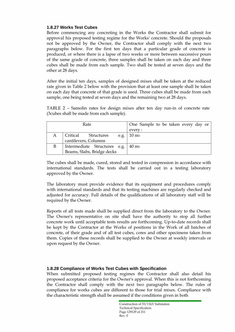
Construction of 33/11kV Substation Technical Specification Page 129129 of 211 Rev. 0
1.8.27 Works Test Cubes
Before commencing any concreting in the Works the Contractor shall submit for approval his proposed testing regime for the Works' concrete. Should the proposals not be approved by the Owner, the Contractor shall comply with the next two paragraphs below. For the first ten days that a particular grade of concrete is produced, or where there is a lapse of two weeks or more between successive pours of the same grade of concrete, three samples shall be taken on each day and three cubes shall be made from each sample. Two shall be tested at seven days and the other at 28 days.
After the initial ten days, samples of designed mixes shall be taken at the reduced rate given in Table 2 below with the provision that at least one sample shall be taken on each day that concrete of that grade is used. Three cubes shall be made from each sample, one being tested at seven days and the remaining two at 28 days.
TABLE 2 – Samolin rates for design mixes after ten day run-in of concrete rate (3cubes shall be made from each sample).
Rate One Sample to be taken every day or
every :
A Critical Structures e.g. cantilevers, Columns
10 m3
B Intermediate Structures e.g. Beams, Slabs, Bridge decks
40 m3
The cubes shall be made, cured, stored and tested in compression in accordance with international standards. The tests shall be carried out in a testing laboratory approved by the Owner.
The laboratory must provide evidence that its equipment and procedures comply with international standards and that its testing machines are regularly checked and adjusted for accuracy. Full details of the qualifications of all laboratory staff will be required by the Owner.
Reports of all tests made shall be supplied direct from the laboratory to the Owner. The Owner's representative on site shall have the authority to stop all further concrete work until acceptable tests results are forthcoming. Up-to-date records shall be kept by the Contractor at the Works of positions in the Work of all batches of concrete, of their grade and of all test cubes, cores and other specimens taken from them. Copies of these records shall be supplied to the Owner at weekly intervals or upon request by the Owner.
1.8.28 Compliance of Works Test Cubes with Specification
When submitted proposed testing regimes the Contractor shall also detail his proposed acceptance criteria for the Owner's approval. When this is not forthcoming the Contractor shall comply with the next two paragraphs below. The rules of compliance for works cubes are different to those for trial mixes. Compliance with the characteristic strength shall be assumed if the conditions given in both

Construction of 33/11kV Substation Technical Specification Page 130130 of 211 Rev. 0
(a) The average strength from any group of four consecutive test results exceeds the specified characteristic strength by 3 N/mm2 for concrete of grade C25 and above (i.e. characteristic strength = 25 N/mm2). 2 N/mm2
for concrete of gradeC15 and below (i.e. characteristic strength = 15 N/mm2).
(b) The strength determined from any test result is not less than the specified characteristic strength minus.
3 N/mm2 for concrete of grade C25 and above 2 N/mm2 for concrete of grade C15 and below
The quantity of concrete represented by any group of four consecutive test results shall include the batches from which the first and last samples were taken, together with all intervening batches. When a test result fails to comply with (b), only the particular batch from which the sample was taken shall be at risk. Compliance criteria remain the same irrespective of every rate of sampling or the same grade concrete in different structures.
Where a minimum or maximum cement content of a designed mix is specified and compliance is assessed by observation of the batching or from autographic records, the cement content shall not be less than 95% of the specified minimum or more than105% of the specified maximum. Where compliance of cement content is assessed from the results of analysis tests on fresh concrete, the cement content shall not be less than 90% of the specified minimum or more than 110% of the specified maximum.
1.8.29 Failure of Concrete to Meet Test Requirements
If t he strength of the specimen is less than the appropriate specified minimum crushing strength or if, in the opinion of the Owner, the concrete fails to meet the specified requirements in other respects, the concrete in that part of the Works of which it is a sample will be considered not to comply with the specified requirements. As and where directed by the Owner, cylindrical core specimens shall be cut from the hardened concrete in the Works for the purposes of examination and testing. The cutting equipment and the method of doing the work shall be approved by the Owner. Prior to the preparation for testing, the specimens shall be made available for examination by the Owner. Testing of the core shall be in accordance with approved standards.
Recourse may also be made by the Owner to such non-destructive means of testing as ultrasonic pulsing and Schmidt rebound hammers. If the specified requirements have not been met, the Contractor shall propose such remedial action as may be required. Such action is subject to the Owner's satisfaction and approval. If no satisfactory remedial measures are proposed by the Contractor and approved by the Owner then the Owner shall order the removal of all work not complying with the Specification at the Contractor's expense. Before preceding with similar work the Contractor shall submit to the Owner, for his approval, details of action proposed to ensure future concrete to be placed in the Works will comply with the Specification.

Construction of 33/11kV Substation Technical Specification Page 131 of 211 Rev. 0
1.8.30 Formwork
For ms shall be so designed and constructed that the concrete can be properly placed and thoroughly compacted and that the hardened concrete while still supported by the forms shall conform accurately to the required shape, position and level, subject to the tolerances specified and to the standards of finish specified later in this Section.
The Owner may request the Contractor to provide sample panels of formwork for approval, at the Contractor's expense. When concrete is to be vibrated, special care shall be taken to maintain the stability of the formwork and the tightness of the joints during vibrating operations.
The material and position of any ties passing through the concrete shall be approved by the Owner. The whole or part of the tie shall be capable of being removed so that no part remaining embedded in the concrete shall be nearer the surface of the concrete than the specified thickness of cover to the reinforcement. Any holes left after the removal of ties shall be filled, unless otherwise directed by the Owner, with concrete or mortar of approved composition.
1.8.31 Removal of Formwork
All forms shall be removed without damage to the concrete. The use of mould oil or other material to facilitate this shall be subject to the approval of the Owner. All formwork for pits, ducts and holding down bolt holes must be so constructed that it can be easily collapsed to facilitate withdrawal after the initial set of the concrete. The Contractor's proposed method for the construction and fixing of the formwork for bolt holes pockets shall be submitted to the Owner for approval before construction.
The top of the shuttering shall be suitably covered to prevent entry of excess grout, materials used for curing, etc.
Solid timber must not be used for forming holding down bolt holes. Bolt holes formers may be made of plywood, expanded metal, polystyrene or other method approved by the Owner, who may require the Contractor to carry out a test pour, using the proposed bolt holes former. The Owner shall be informed in advance when the Contractor intends to strike any formwork. The time at which the formwork is struck shall be the Contractor's formwork may be struck when the concrete has, in the opinion of the compressive strength of not less than 10 N/mm2 or twice the stress to subjected, whichever is the greater. In the absence of cube test results the periods before striking given in be used for ordinary Portland cement:
Location Surface Temperature of Concrete
Not less than 16 °C Not less than 7 °C
Beam side, Walls and Columns 12 hr 18 hr Slab soffits (formwork) 4 days 7 days
Formwork props to slabs 11 days 15 days
Beam (formwork props undisturbed) 10 days 15 days
Formwork props to beams 15 days 21 days

Construction of 33/11kV Substation Technical Specification Page 132132 of 211 Rev. 0
Formwork shall be constructed so that the side forms of members can be removed without disturbing the soffit forms and its props are to be left in place, when the soffit forms are removed these props shall not be disturbed during the striking.
1.8.32 Finishes of Concrete
The Contractor shall state precisely on his plans which of the types of finishes described hereunder he intends to use in the various locations. Any defective concrete finish will be rejected. The Owner may at his discretion order the defects to be cut out and made good. Plastering of defective concrete, as a means of making good will not be permitted, except that in case of minor porosity on the surface the Owner may approve a surface treatment by rubbing down with cement and sand mortar of the same richness as in the concrete. This treatment shall be made immediately after removing the formwork.
1.8.33 Formed Finishes for Concrete
(a) Type F.1 This finish is for surfaces against which backfill or further concrete
will be placed. Formwork shall consist of sawn boards, sheet metal or any other suitable material, which will prevent the loss of grout when the concrete is vibrated. (b) Type F.2
This finish is for surfaces, which are permanently exposed to view but where the highest standard of finish is not required. Forms to provide a Type F.2 finish shall be smooth and boards shall be not less than 18mm thick with edges, arranged in a uniform pattern. Alternatively, metal panels may be used if they are free from defects likely to detract from the general appearance of the finished surface. Joints between the boards and panels shall be horizontal and vertical unless otherwise directed. This finish shall be such as to require no general feeling of surface pitting, but fines, surface discoloration and other minor defects shall be remedied by methods approved by the Owner. (c) Type F.3
This finish is for surfaces prominently exposed to view where good appearance and alignment are of special importance. To achieve this finish, which shall be free of board marks, the formwork shall be faced with plywood or equivalent material in large sheets. The sheets shall be arranged in an approved uniform pattern whenever possible. Joints between sheets shall be arranged with architectural feature, sills, window heads or drainages in direction of the surface. All joints between panels shall be vertical and horizontal unless otherwise directed. Suitable joints shall be provided between sheets to maintain accurate alignment in the place of the sheets. The joints shall be arranged and fitted so that no blemish or mark is imported to the finished surface. Un faced wrought boarding or standard steel panels will not be permitted for Type F.3 finish. Permanent forms shall be constructed of slabs or blocks of precast concrete, natural stone, brickwork of other approved material as directed. Such slabs or blocks shall have an exposed surface of the quality shown on the drawings and as specified. They shall be fixed to the structure by approved means and the joints between them shall be made tight with mortar or other means of preventing leakage. The use of internal metal ties shall not be allowed. (d) Type F.4

Construction of 33/11kV Substation Technical Specification Page 133133 of 211 Rev. 0
This finish is identical to type F.3 except that internal metal ties are permitted.
1.8.34 Unformed Finishes to Concrete
(a) Type U.1 This is a screened finish for surfaces of roads or of foundations, beds,
slabs and structured members to be covered by backfills, subsequent stages of construction, bonded concrete, topping or cement mortar beds to receive paving and on exposed surfaces or paving where superior finish is not required. It is also the first stage for finishes Type U.2 and U.3. The finishing operations shall consist of leveling and screeding the concrete to produce a uniform plane or ridged surface, surplus concrete being struck off by straightedge immediately after compaction. (b) Type U.2
This is a floated finish for surfaces of beds and slabs to receive mastic paving or block or tile pavings where a hard smooth steel toweled surface is not required. Floating shall be done only after the concrete hardens sufficiently and may be done by hand or machine. Care shall be taken that the concrete is worked no more than is necessary to produce a uniform surface free from screed marks. (c) Type U.3
This is a hard smooth steel-toweled finish for surfaces of concrete pavings, tops of walls, exposed surfaces of engine and plant foundations and in the vicinity of holding down bolt chases, copings and other members exposed to weathering, surface beds and slabs to receive thin flexible sheet and tile pavings bedded in adhesive and seatings for bearing plates and the like, where the metal is in dire contact with the concrete.
Toweling shall not commence until the moisture film has disappeared and the concrete has hardened sufficiently to prevent excess laitance from being worked to the surface. The surface shall be toweled under firm pressure and left free from trowel marks.
1.8.35 Surface Treatments
Where concrete is to be treated with sodium silicate or a similar dust preventive coating, this must be carried out within 14 days of the concreting of the foundation and be applied in accordance with the manufacturer's instructions.
1.8.36 Reinforcement
Steel reinforcement shall be one of the following; (a) Hot rolled mild steel round bars complying with international standards, as approved by the Owner.
(b) High tensile steel either (i) cold worked deformed bars or (ii) hot rolled bars complying with international standards approved by the Owner.
(d) Welded steel mesh reinforcement complying with international
standards The reinforcement bar greater than 40 mm diameter will not be used, and shall be stored clear of the ground on sufficient supports to prevent distortion of the bars. Mild steel and high tensile steel are to be stored separately. The Contractor shall

Construction of 33/11kV Substation Technical Specification Page 134134 of 211 Rev. 0
supply the Owner with a certificate for each consignment from the steel manufacturers showing that the steel meets the requirements of the Specification. One tension test and one bond test shall be made for each lot of 50 tons or less supplied for the permanent works.
Steel reinforcing bars shall be kept clean and shall be free from pitting, loose rust, mill scale, oil, grease mortar, earth paint or any material which may impair the bond between the concrete and reinforcement or disintegration of the concrete.
Reinforcement may be bent on site, or alternatively off the site, by an approved method. The Contractor shall arrange for bending equipment suitable for bending both mild steel and intermediate grade bars. Mild steel shall be bent at temperatures in the range 5 °C to 100 °C.
The shapes of the bends and lengths must comply with the applicable recommendations of international standards or otherwise specified on the Drawings and Bending Schedules as approved by the Owner. The Contractor shall provide any chairs or other subsidiary reinforcement necessary to keep the reinforcement in its correct position. The concrete cover over such subsidiary reinforcement shall not be less than that over the reinforcement generally. The Contractor shall provide adequate scaffold boards to ensure that the reinforcement is not displaced by being walked upon during the placing of the concrete or other operations.
Mesh reinforcement shall be fixed flat in the works over the whole of the areas indicated on the approved drawings. Adjoining sheets of mesh shall overlap by at least 300 mm. loose small pieces of fabric shall only be used where they are essential for fitting into small confined parts of the works. Areas of fabric reinforcement shall be net with no allowance included for laps or waste. Fabric reinforcement shall be delivered to site only in flat sheets. Bends, cranks and other shapes of reinforcement shall be to the dimensions specified; otherwise all bars shall be truly straight.
Bending of reinforcement shall be carried out round a former having a diameter of at least four times the diameter of the bar. The bending dimensions shall comply with international standards. Cover blocks used for the correct positioning of reinforcement shall be of a type approved by the Owner. They shall be rigid, inert and capable of supporting the reinforcement in its correct position with the required cover without deforming.
They shall not impair the finish on the concrete nor cause the formwork to deform locally. Reinforcing bars shall be tied together at every intersection using 16 swg soft pliable annealed steel wires. When an F3 finish soffit is specified, stainless steel tying wire shall be used to prevent rust staining. Immediately prior to concreting, all reinforcement shall be cleaned as required or directed by the Owner by suitable approved methods to ensure the absence of any contaminates such as windblown salt.
Concrete Cover to Reinforcement The minimum concrete cover for durability to any reinforcing bar shall be as follows:

Construction of 33/11kV Substation Technical Specification Page 135135 of 211 Rev. 0
(a) Concrete above Ground Internal faces of suspended slabs 30 mm Exposed faces of slabs, beams, wall and columns 50 mm Internal faces of columns and walls 50 mm
(b) Concrete below Ground Faces in contact with soil including blinding concrete 75 mm All other faces (e.g. internal faces of basement wall) 50 mm
For other locations the exposure condition and cover shall be approved by the Owner. On completion of installation of steel reinforcement the Contractor shall notify the Owner that it is ready for inspection .No reinforcement shall be covered up without the prior approval of the Owner.
1.8.37 Testing of Reinforcement
The Owner shall have the right to select at any time samples of steel reinforcement for testing in accordance with the relevant approved standard.
1.8.38 Bar Bending Schedules
The Contractor shall provide fully dimensioned Bending Schedules giving the location and bending of every bar shown on the drawings. Unless otherwise stated on the Bending Schedules all bars shown will be dimensioned in accordance with a national or international standard to be approved by the Owner, e.g. British Standard8666 and IEC ISO 4066.
1.8.39 Bituminous Protection of Concrete
The Contractor shall provide additional protection for concrete foundations from the action of sulphates in the soil by the application, to the satisfaction of the Owner, of a protective coating of bitumen not less than two millimeters thick to contact surfaces. The bitumen coating on the underside of the foundations shall be applied to the surface of the blinding concrete before the deposition thereon of the structural concrete. The bitumen coating on vertical faces shall be applied in more than one layer to ensure the complete absence of pinholes and bare patches. Alternatively protection may be achieved by a self-adhesive waterproofing membrane approved by the Owner.
1.8.40 Additional Requirements in Hot Weather
(a) General In hot weather the Contractor shall present for the Owner approval hisproposalsfor dealing with the following problems: -
(i) Reduced workability (ii) Excessive plastic shrinkage (iii) Rapid strength gain but possible low final strength (iv) Rapid drying out of concrete
(b) Concrete mixing Aggregate stock piles shall be shielded from the directed rays of the sun or cooled by spraying with water; and water tanks and pipes shall be insulated to ensure that the temperature of concrete when deposited shall not exceed 32 °C. With the approval of the Owner admixtures may be employed to related

Construction of 33/11kV Substation Technical Specification Page 136136 of 211 Rev. 0
setting time or enhance workability, or induce early bleeding etc. Concrete batched offsite shall be transported by truck mixer with the mixer rotating only after it arrives on site. Alternatively, the aggregates and 80% of the required water maybe batched off-site with the cement and remaining water being added on site not more than 15 minutes before the pour commences. Concrete transporters shall be kept as cool as practicable.
(c) Concrete placing Placing shall not commence until sufficient standby pumps and vibrators are onsite to cope with breakdowns. No concrete shall be batched until formwork is ready and all reinforcement fixed in place. The area of each concrete pour frontage shall be kept to a minimum and suitable means shall be provided to avoid premature stiffening of concrete placed in contact with hot dry surfaces. Where necessary the surface, including reinforcement, against which the concrete is to be placed shall be shielded from the rays of the sun and shall be sprayed with water to prevent excessive absorption by the surfaces of water from the fresh concrete. In hot weather concrete shall be deposited in horizontal layers to a compacted depth not exceeding 300mm and internal mechanical vibrators shall be used. Due to rapid stiffening in hot weather all clean-up operations such as application to resin cure membranes and dust reducers and surface finishing, etc. shall follow closely behind final tamping.
(d) Curing All concrete shall be covered for at least 14 days after placing and kept continuously wet for the initial 7 days. The temperature of curing water shall be within 10 °C of that of the concrete. Air shall not be permitted to circulate between concrete and curing materials.
(e) Testing Initially the Contractor shall double the number of test cubes made. A limited number shall be cured under site conditions in order to ascertain the relationship between site-cured samples and lab-cured samples. The number of slump tests shall initially be twice that normally required. Air temperature shall be measured every two hours, and the temperature of every batch of concrete shall be recorded as it is deposited at the work place.
1.8.41 Additional Requirements in Cold Weather
During cold weather daily temperature forecasts shall be obtained from a source approved by the Owner, and concreting programmed accordingly. The precautions detailed below shall be taken when either the ambient temperature is 2 °C and falling or the temperature of the freshly placed concrete is 9 °C and falling, to ensure that the temperature of the concrete when placed does not fall below 5 °C until it has thoroughly hardened. Calcium chloride may be used as an accelerator only with mass concrete. No concrete containing embedded metal may have calcium chloride added.
Adequate measures to the Owner's approval shall be taken to ensure that the aggregates are free from frost, ice and snow and that the mixing water which shall not exceed 60 °C, is of sufficient warmth to ensure that the temperature of the freshly

Construction of 33/11kV Substation Technical Specification Page 137137 of 211 Rev. 0
placed concrete shall be not less than 5 °C. No aggregate shall be drawn from a storage bin or stockpile covered with ice, frost or snow unless the top layer is removed in such a manner as to ensure that any aggregate used is not contaminated by ice, frost or snow.
If the ambient temperature is likely to fall below 0 °C all freshly placed concrete shall be protected by means of braziers, lagging or steam heat under covers, the method to be used being left to the discretion of the Contractor provided it prevents the water in or on the surface of the concrete from freezing. The method to be used shall be agreed by the Owner before the cast has commenced and the necessary steps taken to ensure that the protective measures are ready to be carried out as soon as required. All concreting shall cease, as soon as it is practicable to stop placing, immediately the air temperature falls below 5 °C. In the case of large masses of concrete this may be waived at the Owner's discretion.
1.8.42 Foundations for all Buildings and Structures
Transformer foundations shall be of reinforced concrete minimum grade C28 and other foundations to all buildings and structures shall be of reinforced concrete minimum C25 or other specification in the design after the approval of the owner . The foundations shall be designed in accordance with international standards approved by owner . The type of footing/foundation selected for each Substation shall be suitable for the soil conditions and subject to approval of the Owner. Dimensions of all footings/foundations shall be governed by the most critical combination of down thrust, uplift and horizontal shear. Factors of safety shall be as specified in the System Performance Section of these specifications or stated elsewhere in this specification.
The uplift forces on foundation shall be assumed to be resisted by the self-weight of the concrete plus the weight of the inverted frustum of a pyramidal cone of soil whose sides form an angle with the vertical of 30 degrees for cohesive soils and 20degrees for non-cohesive soils. A protective coat of bitumen, as specified else wherein these specifications, shall be applied to surfaces of formed footings in contact with the soil. All reinforcing steel augured footings shall be galvanized. All foundations shall be 150 mm minimum above finishing substation ground level or floor level if indoor.
1.8.43 Cable Trenches, Draw pits and Duct Banks
Reinforced concrete cable trenches draw pits and duct banks shall be cast in C25 Concrete and to suit the requirements of the cable arrangements, all to the approval of the Owner. Reinforced concrete duct banks shall be provided at all road crossings with transition chambers at each end. The ducts shall be sloped to a low point and drained. The duct banks shall consist of Transit or equivalent approved pipes with sufficient concrete cover to pipes and shall be designed safely to carry all loads to be transported over the roads. All necessary fittings and inserts shall be cast in place and slots shall be provided in the center walls of cable trenches to suit the cable arrangement requirements. Reinforced concrete draw-pits shall be constructed where required to facilitate pulling cables. They shall be covered with suitable covers, designed to accommodate their likely loading, and be suitable for ease and safe removal. Reinforced pre-cast concrete shall be cast in C25 concrete. The maximum weight of each unit shall be 80 kg and every fourth unit shall be provided with lifting loops.
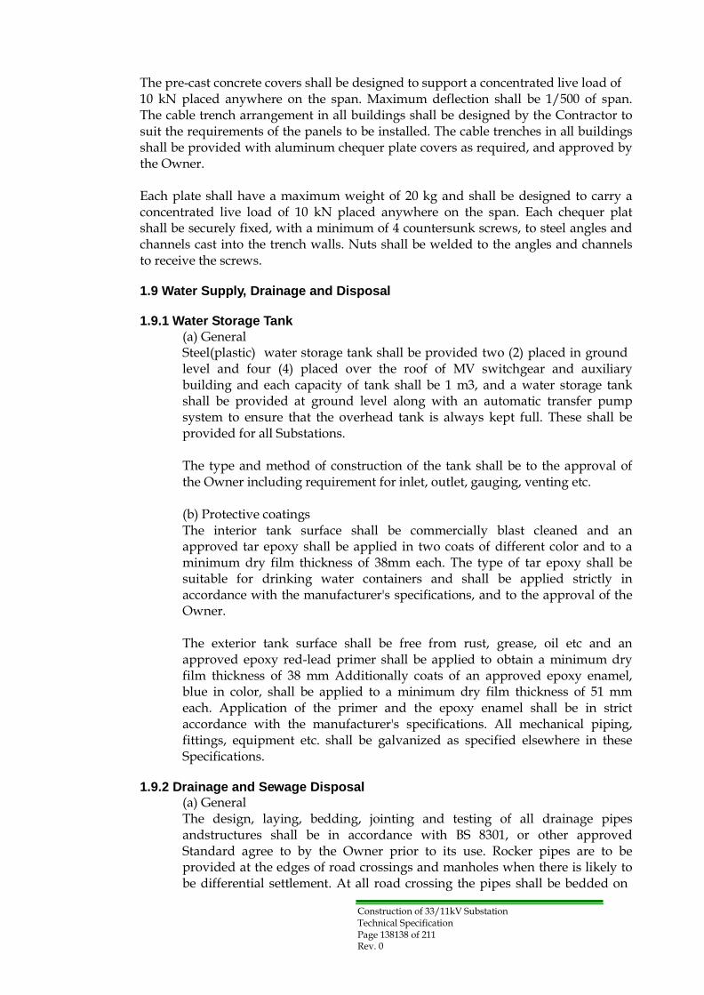
Construction of 33/11kV Substation Technical Specification Page 138138 of 211 Rev. 0
The pre-cast concrete covers shall be designed to support a concentrated live load of 10 kN placed anywhere on the span. Maximum deflection shall be 1/500 of span. The cable trench arrangement in all buildings shall be designed by the Contractor to suit the requirements of the panels to be installed. The cable trenches in all buildings shall be provided with aluminum chequer plate covers as required, and approved by the Owner.
Each plate shall have a maximum weight of 20 kg and shall be designed to carry a concentrated live load of 10 kN placed anywhere on the span. Each chequer plat shall be securely fixed, with a minimum of 4 countersunk screws, to steel angles and channels cast into the trench walls. Nuts shall be welded to the angles and channels to receive the screws.
1.9 Water Supply, Drainage and Disposal
1.9.1 Water Storage Tank
(a) General Steel(plastic) water storage tank shall be provided two (2) placed in ground level and four (4) placed over the roof of MV switchgear and auxiliary building and each capacity of tank shall be 1 m3, and a water storage tank shall be provided at ground level along with an automatic transfer pump system to ensure that the overhead tank is always kept full. These shall be provided for all Substations.
The type and method of construction of the tank shall be to the approval of the Owner including requirement for inlet, outlet, gauging, venting etc.
(b) Protective coatings The interior tank surface shall be commercially blast cleaned and an approved tar epoxy shall be applied in two coats of different color and to a minimum dry film thickness of 38mm each. The type of tar epoxy shall be suitable for drinking water containers and shall be applied strictly in accordance with the manufacturer's specifications, and to the approval of the Owner.
The exterior tank surface shall be free from rust, grease, oil etc and an approved epoxy red-lead primer shall be applied to obtain a minimum dry film thickness of 38 mm Additionally coats of an approved epoxy enamel, blue in color, shall be applied to a minimum dry film thickness of 51 mm each. Application of the primer and the epoxy enamel shall be in strict accordance with the manufacturer's specifications. All mechanical piping, fittings, equipment etc. shall be galvanized as specified elsewhere in these Specifications.
1.9.2 Drainage and Sewage Disposal
(a) General The design, laying, bedding, jointing and testing of all drainage pipes andstructures shall be in accordance with BS 8301, or other approved Standard agree to by the Owner prior to its use. Rocker pipes are to be provided at the edges of road crossings and manholes when there is likely to be differential settlement. At all road crossing the pipes shall be bedded on

Construction of 33/11kV Substation Technical Specification Page 139139 of 211 Rev. 0
and surrounded with C20 concrete to a minimum thickness of 150 mm, and the concrete surrounded shall extend for a minimum distance of 1 m beyond the road edges. The class and type of pipe shall be capable of sustaining the maximum design wheel loads that the contractor proposes to use.
(b) Ker b drainage All road surface runoff shall be directed into soak away pits through slots inthekerbs and as detailed on the drawings. The sides and bottoms of these pits shall be lined with Celanese "Mirafi 140 Fabric" or approved equivalent, to prevent the migration of fine material from the pits. After the placing of the filter fabric the pits shall be backfilled with 20 mm crushed stone or gravel to the level of finish grade.
(c) Building drainage Roof drainage for all Substations shall be disposed of by means of soak away pits. The locations and sizes of these pits shall be as shown on the drawings or suitably fixed. These pits shall not be located closer than 5 m from the building face. The sides of these pits shall be lined with Celanese "Mirafi 140 Fabric" or approved equivalent and the pits shall be backfilled with 20 mm crushed stone or gravel to the level of finished grade.
The roof drainage shall be collected in a manhole from which a pipe of suitable diameter shall be laid with a slope in accordance with the design to the soak away pits.
The laying, bedding, jointing and testing of the pipe shall be in accordance with BS 8301, or any other approved Standard. Roof drainage from all other buildings shall be disposed of by means of rainwater down spouts and discharged at grade in a direction away from the buildings.
(d) Sewage disposal Effluent from the buildings is to be drained into septic tank and disposed of through filter beds or seepage pits all as shown on the drawings. The general arrangement of pipe routing, including the locations of manholes etc. shall be as shown on the drawings. The pipes inside of buildings shall be cast iron pipes surrounding by concrete 100 mm thick. At all road crossings the pipes shall be bedded on and surrounded with C20 concrete to a minimum thickness of 150mm, and the concrete surround shall extend for a minimum distance of 1 beyond the road edges. The class and type of pipe shall be capable of sustaining the maximum design wheel loads that the Contractor proposes to use. The laying, bedding, jointing and testing of the pipes shall be in accordance with BS8301.
(e) Manholes Manholes shall be constructed with brick walls of 150 mm thick. The bottoms of the manholes shall be benched up to fall with C20 concrete and the remaining internal brick surfaces and the tops of the brick walls rendered with cement mortar to a minimum thickness of 10 mm, and then toweled smooth. The internal dimensions of each manhole shall be 1 m square where more than two pipes enter and leave the manhole. All other manholes shall

Construction of 33/11kV Substation Technical Specification Page 140140 of 211 Rev. 0
be 600 mm square, with depth to suit and to the approval of the Owner. In addition they shall be equipped with 75 mm thick reinforced concrete covers with lifting holes. (f) Concrete culvert If necessary a reinforced concrete pipe culvert or box-culvert of suitable size shall be provided under the new access roads and adjacent to the existing main road, to provide continuity of drainage. The invert and slope of the culvert shall suit the existing grade and slope of the drainage ditch or stream. The reinforced concrete pipe shall be of sulphate resisting Portland cement and shall comply with the requirements of BS 4027. The class of pipe and bedding shall be in accordance with the maximum loads the Contractor proposes to transport. If more culverts are needed these shall also be provided.
1.10 Boundary Walls
1.10.1 General
Each of the new Substations shall be surrounded with a boundary wall, and with gates providing access. The walls are to be designed and constructed to have a pleasing appearance.
1.10.2. Boundary Wall
The boundary wall shall be 2.5 m high and a minimum 240 mm thick, rendered if required, and topped with 3 strands of barbed/razor wire on galvanized steel posts0.75m height built into the wall. Expansion and contraction joints shall be provided as required and to the approval of the Owner, to prevent cracking in the walls. Wall and gate foundations shall be designed to suit allowable bearing pressure on the subsoil and take account of the worst combination of dead, live, wind, seismic and erection loads. The foundations shall be contained within the property line. To prevent gates jamming on roads when the road gradient rises in the same direction as the gate opening, the area adjacent to the gates shall be kept level whilst maintaining road profile.
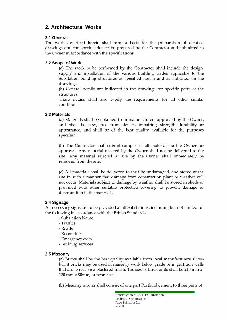
Construction of 33/11kV Substation Technical Specification Page 141141 of 211 Rev. 0
2. Architectural Works
2.1 General
The work described herein shall form a basis for the preparation of detailed drawings and the specification to be prepared by the Contractor and submitted to the Owner in accordance with the specifications.
2.2 Scope of Work
(a) The work to be performed by the Contractor shall include the design, supply and installation of the various building trades applicable to the Substation building structures as specified herein and as indicated on the drawings. (b) General details are indicated in the drawings for specific parts of the structures. These details shall also typify the requirements for all other similar conditions.
2.3 Materials
(a) Materials shall be obtained from manufacturers approved by the Owner, and shall be new, free from defects impairing strength durability or appearance, and shall be of the best quality available for the purposes specified.
(b) The Contractor shall submit samples of all materials to the Owner for approval. Any material rejected by the Owner shall not be delivered to the site. Any material rejected at site by the Owner shall immediately be removed from the site.
(c) All materials shall be delivered to the Site undamaged, and stored at the site in such a manner that damage from construction plant or weather will not occur. Materials subject to damage by weather shall be stored in sheds or provided with other suitable protective covering to prevent damage or deterioration to the materials.
2.4 Signage
All necessary signs are to be provided at all Substations, including but not limited to the following in accordance with the British Standards;
- Substation Name - Traffics - Roads - Room titles - Emergency exits - Building services
2.5 Masonry
(a) Bricks shall be the best quality available from local manufacturers. Over- burnt bricks may be used in masonry work below grade or in partition walls that are to receive a plastered finish. The size of brick units shall be 240 mm x 120 mm x 80mm, or near sizes.
(b) Masonry mortar shall consist of one part Portland cement to three parts of

Construction of 33/11kV Substation Technical Specification Page 142142 of 211 Rev. 0
sand by volume. Mortar shall be mixed in batches. Any mortar not used within one hour of the addition of cement shall be discarded.
(c) Brick units shall be wetted before building into the work to prevent absorption of moisture from the mortar. Adequate measures shall be taken to prevent efflorescence occurring in the finished work.
(d) Masonry shall be carried up in a uniform manner, no one portion of the work being carried up more than 750 mm above another at one time. Completed bed joints shall be maintained in a wet condition during construction before mortar is placed for succeeding courses. The tops of walls on which work has been interrupted shall be moistened before work is resumed.
(e) All masonry corners and intersections shall be properly bonded together using the best trade practice. Masonry walls shall be securely anchored to the building structure using galvanized steel ties or equivalent at approximately every four courses in height. Ample provision shall be made for expansion and contraction at junctions of masonry with the structural frame and in long lengths of masonry walls. Details of expansion joints shall be subject to approval by the Owner.
(f) Mortar joints in masonry that is to be left exposed shall be made concave at the exposed face using a non-staining pointing tool. Mortar joints in masonry that is to receive plaster or cement rendering shall be raked, after curing, to a depth of 6 mm to provide a key.
(g) A bituminous felt or equivalent approved damp proof course shall be installed in masonry walls for their full thickness at grade floor levels, copings, window and door heads as indicated on the drawings. A further damp proof course consisting of a 100 mm thick continuous concrete course, with Sikadensifying additive as specified elsewhere, shall be placed at grade floor levels as indicated on the drawings.
2.6 Cement Rendering
(a) Cement rendering shall be applied to exterior masonry, exterior concrete surfaces, eaves and balcony soffits, wall bases above concrete floors and over tiled areas of Sanitary Rooms as indicated on the drawings.
(b) Cement rendering shall be applied in three coats producing a minimum total thickness of 20 mm having a course, granular finish texture except where required on interior work which shall be trowel led to a smooth, dense finish. Cement it ious materials shall comply with current British Standards and shall consist of Normal Portland Cement, White Portland Cement (finishing coat) and hydrated lime. Aggregates shall consist of clean, fine granular material composed of natural sand free from any impurities, and shall be well graded from course to fine consistent with good workability. Water shall be drinkable.
(c) Suspended soffits shall be securely attached to the building structure using corrosion resistant metal components. Metal lath shall be expanded

Construction of 33/11kV Substation Technical Specification Page 143143 of 211 Rev. 0
sheet steel as locally supplied. The metal lath shall be supported from the suspension system at600 mm maximum spacing between supports.
(d) All rendering coats shall consist of one part Portland cement to between three and five parts damp, loose aggregate and 1/4 part (maximum) hydrated lime. All ingredients shall be thoroughly dry-mixed. Water shall be added until mix is in uniformly plastic condition for good plastering consistency. When necessary, plasticity shall be restored by reworking mix without further addition of water.
(e) Before each application, the base material shall be evenly dampened to control suction. The "first" coat shall be applied with sufficient pressure to form a good bond and shall be uniformly scratched. The "second" coat shall be applied a minimum of 24 hours after the "first" coat and shall be floated to a true surface and left rough. The finish coat shall be applied a minimum of 24 hours after the "second "coat. The Contractor shall submit samples of the finish coat texture and color for approval by the Owner. Each intermediate coat shall be kept moist for a 48 hours period following application. The final coat shall be moisture cured for a 7 days period.
(f) The Contractor shall make all necessary provision for expansion joints in the cement rendering. Cracked or crazed areas shall be removed and replaced at no additional cost to the Owner. Decorative sink age joints shall be formed in the finish coat where indicated on the drawings.
2.7 Roofing
(a) Bituminous roofing materials shall be of the best quality obtainable from local suppliers.
(b) Concrete structural roof decks shall be cleaned of all loose and deleterious materials before application of roofing is commenced.
(c) The concrete deck and lower portion of parapet walls shall receive a continuous coating of asphalt primer that shall be allowed to cure before application of the waterproof membrane.
(d) The waterproof membrane shall be built-up as follows:
(i) One layer bitumen 20/30 (locally made) of 3 mm thickness to be laid directly on the reinforced concrete slab (ii) One layer of ply roofing felt (iii) One layer bitumen 1200 or equivalent to be laid off 3 mm thick (iv) Roof insulation (v) Repeat (i), (ii) and (iii) above over the roof insulation.
Bitumen shall be hot applied. Roofing felts shall be embedded in the hot bitumen with joints lapped a minimum of 200 mm and sealed with bitumen in the lapped area. The membrane shall be carried up the inside face or parapet walls and into a chase formed in the concrete surface.
(e) For all buildings the roofing shall be rigid, impervious insulation compatible with adjacent materials and of a thickness conforming to the "U"
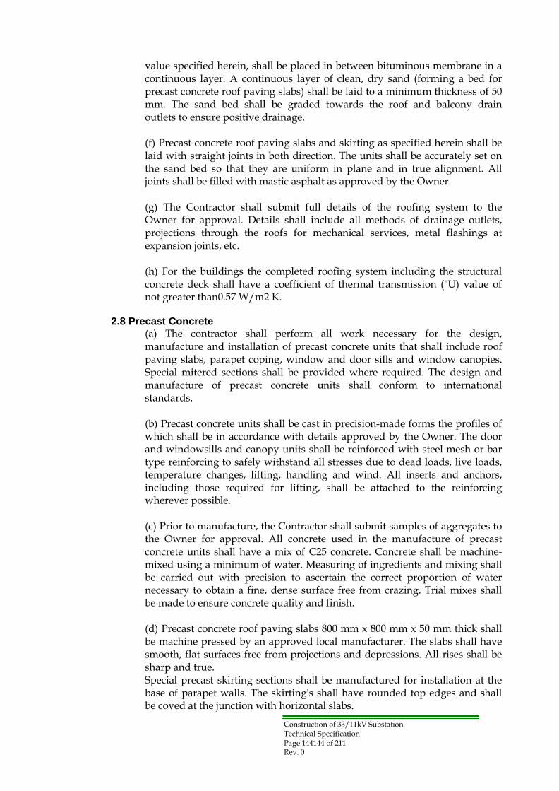
Construction of 33/11kV Substation Technical Specification Page 144144 of 211 Rev. 0
value specified herein, shall be placed in between bituminous membrane in a continuous layer. A continuous layer of clean, dry sand (forming a bed for precast concrete roof paving slabs) shall be laid to a minimum thickness of 50 mm. The sand bed shall be graded towards the roof and balcony drain outlets to ensure positive drainage.
(f) Precast concrete roof paving slabs and skirting as specified herein shall be laid with straight joints in both direction. The units shall be accurately set on the sand bed so that they are uniform in plane and in true alignment. All joints shall be filled with mastic asphalt as approved by the Owner.
(g) The Contractor shall submit full details of the roofing system to the Owner for approval. Details shall include all methods of drainage outlets, projections through the roofs for mechanical services, metal flashings at expansion joints, etc.
(h) For the buildings the completed roofing system including the structural concrete deck shall have a coefficient of thermal transmission ("U) value of not greater than0.57 W/m2 K.
2.8 Precast Concrete
(a) The contractor shall perform all work necessary for the design, manufacture and installation of precast concrete units that shall include roof paving slabs, parapet coping, window and door sills and window canopies. Special mitered sections shall be provided where required. The design and manufacture of precast concrete units shall conform to international standards.
(b) Precast concrete units shall be cast in precision-made forms the profiles of which shall be in accordance with details approved by the Owner. The door and windowsills and canopy units shall be reinforced with steel mesh or bar type reinforcing to safely withstand all stresses due to dead loads, live loads, temperature changes, lifting, handling and wind. All inserts and anchors, including those required for lifting, shall be attached to the reinforcing wherever possible.
(c) Prior to manufacture, the Contractor shall submit samples of aggregates to the Owner for approval. All concrete used in the manufacture of precast concrete units shall have a mix of C25 concrete. Concrete shall be machine- mixed using a minimum of water. Measuring of ingredients and mixing shall be carried out with precision to ascertain the correct proportion of water necessary to obtain a fine, dense surface free from crazing. Trial mixes shall be made to ensure concrete quality and finish.
(d) Precast concrete roof paving slabs 800 mm x 800 mm x 50 mm thick shall be machine pressed by an approved local manufacturer. The slabs shall have smooth, flat surfaces free from projections and depressions. All rises shall be sharp and true. Special precast skirting sections shall be manufactured for installation at the base of parapet walls. The skirting's shall have rounded top edges and shall be coved at the junction with horizontal slabs.

Construction of 33/11kV Substation Technical Specification Page 145145 of 211 Rev. 0
(e) All precast concrete components shall be moisture-cured under cover for a period not less than 7 days.
2.9 Aluminum Windows
(a) All windows shall be of anodized aluminum in accordance, with the international standards They shall be provided with all necessary anchors at the perimeter of the frames for building-in. Jamb anchors shall be adjustable for locating in masonry coursing.
(b) Opening lights for windows shall be either side hung or bottom projected as indicated on the drawings. All opening lights shall be inward opening and shall be completely dust-proofed by neoprene, vinyl or other approved gaskets fitted to the contact surfaces. The method of dust-proofing shall be subject to approval and inspection by the Owner. Opening sashes that are deemed not to be dust-proof by the Owner will be rejected.
(c) Fasteners, stays and hinges shall be of a non-ferrous, heavy-duty design as approved by the Owner. High-level windows shall be remotely controlled from 1 m above floor level by a hand-operated, mechanical system approved by the Owner.
(d) Active leafs shall be fitted to the outside with mosquito-proof bronze in removable metal frames.
(e) Windows shall be fabricated with aluminum frames and glazing bars and have fixed lights. The size and gauge of the sections shall be suitable for the design, loading, sizes and arrangements used. All windows shall be constructed with thermal break frames. All windows shall be fitted with double-glazing with solar reflecting glass, 6mm thick minimum with low heat transfer values. All windows shall be fitted with security grills with fixing points located in precast concrete surrounds. Windows that can be subject to direct sunlight at any time of the day throughout the year should be provided with external shading. Glazing in Sanitary room windows shall be obscured type.
(f) All windows shall be securely mounted in their openings and shall be plumb and in a flat plane. Each window shall be properly sealed and made perfectly weather tight at the head jamb and sill in a manner approved by the Owner.
2.10 Steel Door and Frame
(a) All exterior and interior doors and frames shall be steel with paint. Shop drawings and catalogues shall be submitted by Contractor to the Owner for approval. All exterior doors shall be provided with dust seals on all edges to the approval of the Owner.

Construction of 33/11kV Substation Technical Specification Page 146146 of 211 Rev. 0
2.11 Door Hardware
(a) Door hardware furniture, fixtures and fittings shall be the best commercial quality available and of a manufacture and type approved by the Owner. Locksets, latchets, push and pull plates, shall be manufactured from wrought brass of bronze having a satin-chrome finish. All lock mechanisms shall be corrosion-resistant.
(b) Hinges shall be non-ferrous, ball bearing type. Three hinges per door shall be provided in all buildings.
(c) All exterior and interior doors shall be fitted with mortise type cylinder locksets with integral dead bolts and latch bolts. Latch shall be operable by knob on each side of door.
(d) All exterior and interior doors shall be automatic, hydraulic piston type closer shaving machined cast-iron casings and malleable iron control/relay arms shall befitted.
(e) Interior and exterior entrance doors and vestibule doors shall be fitted with ornamental push-pull hardware as approved by the Owner. Doors to Sanitary
Rooms shall be provided with push plates and pull handles. Doors to water closets shall have slide bolts, self-closing hinges and coat hooks.
(f) The Contractor shall submit to the Owner for approval full specifications, manufacturer's data and an itemized list indicating details of all hardware to be installed on each door.
(g) All emergency exits such as exterior doors to the control rooms, shall be fitted with approved “panic” locks and push-bars.
(h) All cylinder locks included herein shall be keyed separately and conform to the following key schedule.
- Three (3) nos. of normal keys of all buildings (for permanent use). - One (1) no. of key box for each Substation which is able to hold normal keys.
2.12 Gypsum Plaster
(a) Masonry and concrete surfaces to receive a plaster finish shall be thoroughly brushed to remove all dust and loose matter and shall be rough- textured to form key. The surfaces thus prepared shall receive a spattering coat of 1:1 cement/sand applied before plastering commences. All surfaces shall be dampened with clean water immediately before each coat is applied. Each base coat shall be moisture cured to ensure proper setting and shall be allowed to dry thoroughly before the finish coat is applied. Plaster work shall include all small and narrow areas, internal angles, square or pencil rounded external arises, joints at flush or projecting corners rounded to openings, making good around pipes and other projections through walls, roof slabs, etc. (b) Gypsum plaster shall be best quality local just conforming to B.S.1191 for

Construction of 33/11kV Substation Technical Specification Page 147147 of 211 Rev. 0
Class Band C finishing plaster. Gypsum shall be stored in weather tight enclosures until ready for use.
(c) Plaster work shall be 16 mm thick applied in two layers. The first layer shall consist of one part gypsum bond plaster to three parts sand (by volume) applied with sufficient material and pressure to cover well and provide good bond. Before setting, double back with additional material to bring plaster out to grounds, straighten to a true surface and leave rough for finish coat. Gypsum bond plaster shall consist of calcined gypsum with 2% to 5% lime by weight. The second or finish coat shall consist of one part gypsum to three parts lime putty, applied as thinly as possible and finished to a smooth, even, steel-toweled finish. Under no circumstances shall gypsum plaster be wetted after it has fully set.
2.13 Tile Work
(a) Mosaic floor tiles, glazed, with smooth, even surface, uniform in texture and free from blemishes, chips or other imperfections. Skirting sections shall be 250 mm by 125 mm coved at the base and rounded at their top edges. The floor tiles shall have a water absorption rating between 0.5% and 3.0% by weight after oven drying, boiling in distilled water for 2hours and cooling in water up to 24 hours. The floor tiles shall be of a color approved by the Owner.
(b) Glazed wall tiles shall, flat and free from flaws. The wall tiles shall be
white in color and shall be complete with all special edge, trim and corner sections. Glazed tiles shall be to the full height of the wall.
(c) Surfaces to receive tile works shall be cleaned of all dust and loose matter. Floor surfaces shall be free from oil and other impurities that may prevent the proper bonding of the tile mortar bed.
(d) Floors to receive tiles shall be wetted down. A slurry-bonding coat consisting of Portland cement and water mixed to a creamy consistency shall be brushed onto the floor surface. The mortar setting bed consisting of one part Portland cement, one-half part hydrated lime, four parts sand, and one part water (by volume) shall be placed to a thickness of 30 mm, uniformly toweled and slightly sloped towards floor drains. The floor tiles shall receive a 3 mm setting coat of one part Portland cement to one part water (by volume) and shall be firmly and accurately set into place. Tile joints shall be straight, uniform and true in both directions. 24 hours later, the tile shall be wetted, and the joints grouted, using a mixture of one part white "Medusa" grouting cement or approved equivalent to two parts sand mixed with clean water. Foot traffic shall not be permitted for minimum of 48 hours.
(e) Walls to receive tiles shall be dampened and shall receive a 6 mm scratch coat consisting of one part Portland cement; half part hydrated lime, four parts sand anode part water (by volume), troweled rough and scored. The scratch coat shall be allowed to cure at least 24 hours, before applying a 9 mm thick mortar bed using same mix as scratch coat. Soak tiles in water for at least 30 minutes, and drain off excess water prior to installation. Apply a 3 mm setting coat of one part Portland cement to one part water (by volume)

Construction of 33/11kV Substation Technical Specification Page 148148 of 211 Rev. 0
and tap firmly into position. Tile joints shall be straight uniform and true in the both directions, accurately cut and fitted at all intersections and projections. 24 hours later, the tile shall be wetted and the joints grouted using a mixture of one part white "Medusa" grouting cement or approved equivalent to two parts sand mixed with clean water.
(f) All floor and wall tile shall be thoroughly cleaned following installation. Protective coverings shall be used as directed by the Owner.
2.14 Carpentry
(a) Carpentry work shall include all necessary wood grounds and blocking, counters, plastic laminate counter tops, cupboards, benches, partition framing and shelving.
(b) All materials shall be of the best merchantable species suitable for the intended use. Moisture content shall not exceed 12% for softwood and 8% for hardwood. Plywood shall be best quality hardwood-faced veneer, paint grade, sanded. Hardboard shall have a minimum density of 800 kg/m3 and shall have one face suitable for sanding and painting
(c) Work benches shall be strongly constructed from wood members of 40 mm minimum thickness with open shelving and tool drawers 400 mm wide fitted below bench tops. Bench tops shall be constructed of heavy tongued and grooved boards. Bench tops in Battery Rooms shall be covered in sheet lead.
(d) Guard house benches shall be constructed of hardwood planks with
chamfered edges fixed to metal brackets attached to adjacent walls. (e) Shelving where indicated, shall be plywood with hardwood edging.
2.15 Miscellaneous Metal
(a) Tubular hand railing shall be fabricated from 40 mm nominal diameter steel pipe, hot dipped galvanized, and securely anchored to concrete steps. Steel ladders shall consist of flat bar stringers with 20 mm diameter rungs spaced at 300 mm centers. Ladder rungs shall be tennoned to stringers and plug-welded. Safety cages shall be provided to the ladders.
(b) The Contractor shall provide and install all miscellaneous steel lintels, frames, embedded steel parts, anchors and bolts, not specifically described herein, but which are essential to the proper completion of the work.
(c) Actual member sizes shall be suited to their intended functions and shall be subject to the approval of the Owner. All steel components if any shall be thoroughly cleaned of all rust, oil and other deleterious matter before fabrication, and shall receive one coat of rust inhibiting primer before shipment to site.

Construction of 33/11kV Substation Technical Specification Page 149149 of 211 Rev. 0
2.16 Bronze Plaque
(a) The Contractor shall provide and install a cast bronze plaque, wall- mounted adjacent to the main entrance of each Substation main building. The plaque shall consist of the Owner's graphic symbol (The Owner) and lettering all in accordance with design to be provided by the Owner. All fastenings shall be concealed and tamper proof. Size of plaque shall be approximately 500 mm x 700 mm. (b) An eight-cornered star emblem shall be suitably and conspicuously displayed at the entrance to the Substation.
2.17 Painting
(a) Paint materials shall be of the best quality available and shall be obtained from a single manufacturer approved by the Owner. All materials shall be delivered to the site in unbroken, sealed and labeled containers of the paint manufacturer. They shall be stored in separate buildings or rooms well- ventilated and free from excessive heat, sparks, flame or direct sunlight.
(b) All containers of paints shall remain unopened until required for use containers that have been opened shall be used first. Paint that has deteriorated during storage shall not be used.
(c) Paints shall be thoroughly stirred, strained and kept to a uniform consistency during the application. Mixing of pigments to be added shall be done strictly as recommended by the manufacturer. Where thinning is required, only the products of the manufacturer furnishing the paint and recommended for the particular purpose shall be allowed, according to the manufacturer's instructions.
(d) All surfaces to be painted shall be thoroughly cleaned, by effective means, of all foreign substances. Cleaning shall be done with approved solvents, or wire brushing. Hardware, electrical fixtures and similar accessories shall be removed or suitably masked during preparation and painting operations.
(e) Metal surfaces shall be cleaned and free from flaking, bubbling, rust, loose scale and welding splatter. Sharp edges shall be dulled by grinding. Oil and grease shall be thoroughly removed by Varsol or similar approved. Priming shall be done immediately after cleaning to prevent new rusting. Damaged prime coats of items delivered to site shop primed shall be repaired using same type primers. Edges shall be "feathered" to make patching inconspicuous. The Contractor shall apply one full coat of primer to all items to be finish painted which have not been previously shop primed.
(f) Wood surfaces shall be sanded to a smooth surface. No wood shall be painted unless it is sufficiently dry. All sapwood, streaks and knots shall be sealed with knotting to BS 1336. Excess resin shall be removed with a blowtorch, scraper or solvent. The prime coat shall then be applied and, when dry, nail and knot holes shall be filled with putty, allowed to dry and sandpapered.
(g) Plaster surfaces shall be brushed to remove dust and efflorescence. Any holes or cracks shall be cut with edges undercut, made good and rubbed
Construction of 33/11kV Substation Technical Specification Page 150150 of 211 Rev. 0
down.
(h) Concrete and masonry surfaces shall be left at least one month before painting. They shall be etched using a 15% to 20% muriatic acid solution completely removing all foreign matter and efflorescence, then thoroughly rinsed with water and allowed to dry. Concrete and masonry surfaces to be painted shall include precast concrete window canopies, parapet coping, window sill and decorative grillage blocks.
(i) Paint shall not be applied in rain, or when the relative humidity exceeds 85%. Paint shall not be applied to wet or damp surfaces. When paint must be applied during inclement weather, the surfaces shall be protected under cover. Such surfaces shall remain under cover until weather conditions permit exposure.
(j) The work shall be done strictly in accordance with the paint manufacturer's printed instructions and recommendations. The Contractor shall apply paint coatings producing an even film of uniform thickness using brush, roller or spray gun. If paint has thickened, or must be diluted for application by spray gun, the coating shall be built up to the same film thickness achieved with undiluted material. The coverage of paint shall remain the same whatever method of application is used.
Each coat of paint shall be in a different tint to the succeeding one. All surfaces shall be sanded lightly between coats and be dusted before the succeeding coat is applied.
(m) Each coat of paint shall be in a proper state of cure before the application of the succeeding coat. Paint will be considered dry when an addition coat can be applied without the development of any detrimental film irregularities such as lifting or loss of adhesion of the undercoat. The manufacturer's recommended drying time shall be regarded as the minimum permissible time and shall in no way relieve the Contractor of his obligation to produce a satisfactory succeeding coat.
(n) Paint shall be applied either with brushed, or by means of rollers or spraying machines to obtain a uniform even coating.
(i) By Brush The primary movement of the brush shall describe a series of small circles to thoroughly fill all irregularities in the surface, after which the coating shall be smoother and thinned by a series of parallel stroke.
(ii) By Roller This application shall be done by rolling the second coat at right angles to the first coat.

Construction of 33/11kV Substation Technical Specification Page 151151 of 211 Rev. 0
(iii) By Sprayer Spray equipment shall be of ample capacity for the work and shall at all times be kept clean and in good working order. Spray guns shall be suited to the type of paint specified and shall be operated with orifices, nozzles and air pressure adjusted to consistency.
Paint pots shall be of ample capacity and shall be equipped with means of controlling air pressure on the pot independently of the pressure of the gun. Airlines shall be equipped with water traps to positively remove condensed moisture.
(p) If satisfactory work with one of the application methods is not expected or not obtained, the Owner will decide which method shall be used. Where surfaces are inaccessible for brushes, and where spraying is not being employed, the paint shall be applied with sheepskin daubers specially constructed for the purpose. To the maximum extent practicable, each coat of paint shall be applied as a continuous film of uniform thickness, free of pores. Any thin spots or areas missed in the application shall be repainted and permitted to dry before the next coat of paint is applied. Doors to be weather-stripped shall be fully painted before weather-stripping is installed.
(q) Shop painting shall be carried out to the extent and as required elsewhere in these specifications. The Contractor shall be responsible for checking the compatibility of the previous coating with the finish coats specified herein.
(r) The finished surfaces shall be free from runs, drops, sags and brush marks, exhibiting good coverage, spreading and leveling.
(s) Colors shall be as shown in a painting color schedule to be approved by the Owner. The Contractor shall submit before start of work, actual paint color samples to the Owner for approval.
(t) The Contractor shall conduct a thorough inspection of all surfaces finished by him before work is considered complete. This is to be done to ensure that all surfaces are properly and satisfactorily retouched wherever damaged by his tradesmen, prior to the removal of his equipment and materials. Surfaces to be painted shall receive the following coating systems:
(i) For interior exposed galvanized steel ductwork and piping: - 1 coat vinyl pre-treatment - 2 coats alkyd interior enamel, semi-gloss finish
(ii) For interior primed structural steel framing, steel doors and frames:
- 2 coats alkyd interior enamel, semi-gloss finish (iii) For exterior steel doors and interior and exterior primed miscellaneous steel stairs, ladders and railings:
- 2 coats alkyd equipment enamel, gloss finish (iv) For interior wood surfaces
- 2 coats latex, flat finish (v) For interior wood surfaces
- 1 coat interior primer

Construction of 33/11kV Substation Technical Specification Page 152152 of 211 Rev. 0
- 2 coats alkyd enamel, semi-gloss finish (vi) For unprimed steel piping:
- 1 coat iron oxide zinc chromate - 2 coats alkyd equipment enamel, gloss finish
(vii) For concrete and masonry surfaces: - 2 coats polyvinyl acetate latex, flat finish
The Contractor shall perform the following inspections in the presence of the Owner: appearance, dimension, painting (film thickness, coverage,
appearance) and completion inspection. The places, time and contents of the inspection shall be subject to approval of the Owner.

Construction of 33/11kV Substation Technical Specification Page 153153 of 211 Rev. 0
3. Building Services 3.1 General:
This section should be read in conjunction with other relevant sections of the specifications related to civil works. The following building services are covered in this section: • Plumbing services. • Mechanical ventilation. • Internal lighting. • External lighting. • Small power installations. • Earthing and bonding connections. • Fire detection and alarm as well as firefighting systems. • Telephone installation. • Other related works approved by the Owner.
The detailed calculations, designs and layouts shall be submitted on time for the Owner approval before placement of any order or site work is undertaken. For Tender purposes the Contractor must identify the capacity, manufacture/make, model number, construction standard and type of any equipment or subcomponent being offered together with the selection procedure prior to the agreement that will be signed with the Owner, later on and after evaluating all submitted offers. Any exclusion to the complete and satisfactory performance of the design and installation must be clearly indicated in the offer otherwise it will be assumed that everything necessary has been included at the Contractor's cost.
3.2 Scope of Works
The supply and services to be performed by the Contractor shall comprise the design, manufacture, shop testing, packing, transport, insurance, unloading, storage on site, construction works and erection, corrosion protection, site testing, submission of documentation, commissioning, training of the Owner's personnel and warranty of all works. The Contractor is bound to provide complete works, even if the equipment or services to be provided are not specifically mentioned in the specification.
3.3 Design Standards for Building Services
The design for the electrical building services shall be in accordance with international standards requirements for all Electrical Installation (the sixteenth edition) of the Institution of Electrical Engineer's Wiring Regulations including latest amendments. Individual items of equipment shall be in accordance with the latest issue relevant of IEC or British Standard. The design of fire detection and alarm systems shall comply with the requirements of BS 5839. The design of the mechanical building services elements shall be in accordance with the following;
(a) The Contractor shall ensure that all designs and calculations, of required building services, to be carried out by a qualified consultant approved by the Owner.
(b) Chartered Institution of Building Services Engineers (CIBSE) Guides to Good Practice, Inter-related Documents and TM4.
(c) American Society of Heating, Refrigerating and Air Conditioning Engineers (ASHRAE) Reference Handbooks.
Construction of 33/11kV Substation Technical Specification Page 154154 of 211 Rev. 0
(d) Latest issues of relevant IEC or British Standards. (e) Building Services Research and Information Association Technical Notes. (f) UK Heating and Ventilation Contractors Association (1982) Specifications for metal ductwork DW/143/144 (HVAC) UK.
3.4 Electrical Power Supplies
The electrical power supply available will be 230/400 ± 5% V, 3 phase 4 wire, with earthed neutral, and 50 Hz. All equipment shall be suitable for use with this electric supply system unless otherwise specified. The main and local distribution boards shall be located in the 33/11kV switchgear room of the Substation, from which final sub-circuits shall supply the lighting circuits and all other current consuming accessories, socket outlets, etc. LV combined power/control board for ventilation (and may be air conditioning) shall have duplicate supplies to ensure that at least one of the duplicate plants is available on loss of one source of supply.
3.5 Lighting and Small Power 3.5.1 General
This Specification covers the rating, design, equipment requirements, installation, inspection and testing of complete lighting and small power installations.
This Specification does not enumerate nor describe all materials and equipment to be supplied nor all the services to be performed in this project. All materials and equipment shall be provided as required to make a complete, properly functioning installation and shall conform to the highest standards of engineering design and workmanship. The design and installation of lighting and small power installations shall be based on the following Standards and/or regulations;
• Requirements for Electrical Installations, IEE wiring regulations BS 7671 as issued by the Institution of Electrical Engineers, and British Standards. • The Code for Lighting, Lighting Guides, as issued by the Chartered Institution of Building Services Engineers (CIBSE), U.K. • BS 5266, Emergency Lighting Code of Practice for the Emergency Lighting of Premises. • IEC Standards as applicable. • Local laws, rules and regulations including those of statutory authorities. • Other Standards as detailed in the specification text.
Materials, workmanship and tests shall conform at least to the following Standards and Codes of Practice:
IEC 60364-5-54: Earthing Arrangements and Protective Conductors for Indoor
Installations up to 1000 V AC and 1500 V DC. IEC 60064: Specification for Tungsten Filament Lamps for General Service (BS 161) (Batch testing). BS 5649: Steel Columns for Street Lighting IEC 60598: Luminaries IEC 60081: Tubular Fluorescent Lamps for General Lighting Service IEC 60921: Specification for Ballast for Tubular Fluorescent Lamps IEC 60309: Plug and Socket Outlets IEC 60188: High-Pressure Mercury Vapor Lamps IEC 62035: Discharge Lamps (excluding Fluorescent Lamps) IEC 60898: Specification for Circuit Breakers for Over-Current Protection for Household and Similar Installations.

Construction of 33/11kV Substation Technical Specification Page 155155 of 211 Rev. 0
IEC 61024: Protection of Structures against Lightning. IEC 60923: Specification for Performance Requirements for Ballasts for Discharge Lamps (excluding tubular fluorescent lamps) IEC 61347: (Various parts) Lamp Control-gear IEC 60947: Low-Voltage Switchgear and Control-gear IEC 60227: PVC - Insulated Cables of Rated Voltage up to and including 450/750 IEC 6004: Electric Cables. PVC insulated, non-armored cables for voltages up to and including 450/750 V, for electric power, lighting and internal wiring BS 6500: Electric Cables. Flexible cords rated up to 300/500 V, for use with appliances and equipment intended for domestic, office and similar environments. BS 6724: Specification for 600/1000 V and 1900/3300 V Armored Cables having thermosetting insulation and low emission of smoke and corrosive gases when affected by fire. BS 6121: Mechanical Cable glands for elastomeric and plastics insulated cables The Contractor shall be aware of all relevant standards and regulations that are applicable to works under this Contract. The detailed design shall be approved before proceeding with any purchase of equipment or any installation works.
The Contractor shall submit adequate and full supporting documentation (calculations, schematics, schedules, general arrangement drawings, technical and descriptive manufacturer's data, his own text and/or samples, etc.), for the Owner to ascertain that the requirements of the Specification are being fully complied with. The Calculations shall identify all assumptions made which must be agreed with the Owner before the detailed design is finalized and approved.
Location of the lighting and small power equipment shall be reviewed at site before installation so that satisfactory co-ordination with piping network, ductwork, power cables and other equipment can be assured. Each laminar/socket outlet or any other item of equipment shall have a unique code that comprises letters and figures so compiled that the following information can be readily identified:
• The lighting distribution board to which the luminaries or socket outlet is connected. • Connection to the normal supplies or to the emergency supplies. • The circuit number and phase of distribution board to which the equipment is connected. • The sequence of the equipment in a particular circuit. • The lighting and small power systems are broadly divided into the following categories:
1) Indoor, normal lighting system. 2) Outdoor, normal lighting system. 3) Indoor, emergency lighting system. 4) Small power socket outlet system. 5) Access road lighting. 6) Guard house supplies including associated lighting and small power installations.

Construction of 33/11kV Substation Technical Specification Page 156156 of 211 Rev. 0
All lighting systems are to be fed by final sub-circuits from distribution boards located in 33/11kV switchgear room. There shall be separate distribution boards for both the normal and emergency lighting, and also small power loads which include socket outlets. The types of luminaries to be installed in different areas of the Substation will vary from normal indoor fluorescent types to external, specially sealed, luminaries selected to suit the specific location and environment.
All lighting circuits shall operate on a 230 V, 50 Hz supply from miniature circuit breakers within their respective distribution boards. Each outgoing circuit shall supply a varying number of luminaries and the lighting in an individual room shall be controlled by local room light switches within individual rooms, separately. External lighting shall be controlled automatically by photocells that will operate and switch a number of relays or contactors for these final sub circuits.
All emergency lighting circuits are to be supplied from the designated emergency lighting distribution board and 110 V DC supplies shall be used for emergency lighting.
No local facilities shall be used to control emergency lighting circuits. If required control can be achieved at the emergency lighting distribution board, Illuminated Exit and Escape Signs are also to be part of the emergency lighting system. These shall be provided to cover all areas of the Substation's buildings.
Main Technical Data The lighting and small power distribution boards shall be rated for 230/400 V, 50 Hz. Supplies shall be taken from the LV AC distribution switchboard to the installations for normal supplies, and from the 110 V DC switchboards for emergency supplies. Local distribution boards shall be provided for each of the systems as follows:
• One board to feed all normal internal lighting. • One board to feed small power installations. • One board to feed external lighting.
Separate boards shall be provided for the Guard house, if required. Each of the local distribution boards shall be equipped at least with:
• Four-pole incoming differential circuit breaker. • Four-pole outgoing differential circuit breakers (for socket outlets). • Two-pole outgoing differential circuit breakers (for socket outlets). • Three-pole outgoing circuit breakers. • One-pole outgoing circuit breakers. • Three-phase busbar system. • Neutral bar. • Earthing bar. • Push button and contactors as necessary. • Other equipment and material as necessary. • Each board shall be equipped with 20% spare feeders.
The local distribution boards may be proposed as the integral parts of the board with separate compartments, subject to the Owner's approval. The distribution board for emergency lighting shall be equipped, at least, with:

Construction of 33/11kV Substation Technical Specification Page 157157 of 211 Rev. 0
• Two-pole incoming circuit breaker. • Two-pole outgoing circuit breaker. • Earthing Bar. • Other equipment and material as necessary and each board shall be equipped with 20% spare feeders.
3.5.2 Scope of Supply and Services
The lighting and small power systems include but not limited to: • Distribution boards. • Cables. • Cable trunking, containment systems • Socket outlets and plugs. • Luminaries. • Lighting switches. • External lighting control systems • Earthing and bonding • Lightning Protection of all buildings. • Labeling and identification of all the installation. • Special tools and equipment for maintenance, inspection and repair. • All standard equipment and accessories which are normally included in the schedule but which are not separately listed. • Spare parts • Complete documentation as specified, etc.
3.5.3 Equipment Requirements 3.5.3.1 General
All fixings shall be of a type approved by the Owner. All supporting metalwork used in surface installations shall be galvanized. Fixing to structural steelworks shall be with purpose-made brackets or clamps. Drilling of structural steel works will not be permitted. Switches and pushbuttons for lighting circuits shall be mounted 1300 mm above the finished floor level.
Socket outlets shall be mounted 300 mm above the finished floor level. Any socket outlets required that are associated with work benches shall be mounted150 mm clear of the bench working surface. All lighting switches shall have a minimum continuous rating of 13 A and a 50% de-rating factor shall be applied for fluorescent lighting loads.
Luminaries shall be secured to ceilings, walls, trunking systems, roof steel work or suspended as required by the approved design and the Owner's confirmation. Final connections to all suspended luminaries shall be by heat resistant flexible cable terminated in heat resisting connectors in the ceiling or junction box which shall also terminate the final sub-circuit cable. The cable length shall be such that the suspension unit supports take the full weight of the luminaries. Where luminaries are mounted fixed to walls or ceilings the final sub-circuit cables may be connected into the luminaries own terminal block provided that the cables are routed to avoid any heat generating components inside the luminaries. Where terminal blocks are not provided as part of the luminaries "flexible heat-resistant cable shall be used and connected to a separate external junction box.

Construction of 33/11kV Substation Technical Specification Page 158158 of 211 Rev. 0
3.5.3.2 Distribution Boards
The distribution boards and all component parts shall be manufactured and tested in accordance with IEC 60947 and be capable of withstanding, without damage, the mechanical and electrical stresses that can exist by any fault current. The withstanding shall be for twice the period required to disconnect such fault on any circuit. Each distribution board shall have a dustproof metal case of sheet steel with an enameled finish and shall have hinged doors. The doors shall incorporate a gasket and have a push-button handle incorporating cylinder type lock. Each lock shall be unique and shall be supplied with 3keys. The color of the enamel finish shall match the color of other switchgears installed in this project. The distribution board metal casing shall be provided with a gland plate for cable entry corresponding to the cable size required for the overall design circuit capacity of the distribution board. It shall also incorporate and a suitable screened brass earthing stud.
Each current carrying component shall be designed so that under continuous rated full load conditions in the environmental conditions at site and that the maximum total temperatures permitted under the relevant Standards are not exceeded. All distribution boards shall incorporate a disconnect or which shall be used to isolate the incoming supply to the distribution board this shall be anon-load switch.
Outgoing circuits for socket outlets as well as ventilation, and may be air- conditioning; equipment shall be provided with residual current protection with a tripping sensitivity of 30 mA. Where a distribution board feeds critical equipment individual residual current protection shall be used to avoid loss of all power supplies. The cables feeding the distribution boards shall be connected directly to the incoming disconnector or neutral bar as appropriate unless indicated otherwise by the Specification.
Neutral bars shall have an appropriate number of ways relative to the size of the board.
The metal surface adjacent to any live part and all spaces between phases shall be protected by barriers made of fireproof insulation material. The current rating of the busbars in each distribution board shall not be less than the sum of maximum current rating of all outgoing circuits. The neutral connection for each circuit is to be direct to the neutral busbar. Approved type labels shall befitted externally on the front cover of each distribution board giving details of the points controlled by each circuit. The circuit list shall be typed or printed stating the location of the equipment served, rating of the protective unit, circuit loading and the cabling size and type. The lists shall be mounted on the inside of the cover door and shall be protected by an acrylic sheet slid into a frame over the circuit list, the list and cover to be easily removable to permit circuit modifications.
3.5.3.3 Main Switches
Air break switches, Disconnector and Molded Case Circuit Breakers shall be used as appropriate. They shall be designed and rated in accordance with IEC60947-3 and IEC 60898 as appropriate for expected symmetrical fault rating and shall be capable of breaking rated load current.

Construction of 33/11kV Substation Technical Specification Page 159159 of 211 Rev. 0
3.5.3.4 Miniature and Moulded Case Circuit Breakers
All Moulded Case Circuit Breakers (MCCB's) and Miniature Circuit Breakers (MCB's) shall be constructed according to IEC 60947. Circuit breakers shall be of the high-speed fault limiting, thermal/magnetic type with quick-make and quick-break trip free mechanisms which prevent the breaker being held-in against overloads of fault conditions. Breakers shall have silver tungsten contacts and be derated to suit the environmental nature of the enclosure and/or load. Tripping arrangements shall ensure simultaneous opening of all phases.
3.5.4 Cables
The cables for indoor lighting and socket systems installed between distribution boards and final connections and the cables for outdoor lighting and socket systems installed between distribution boards and final connections and all cables up to distribution boards shall be XLPE insulated 3 and 5 cores or 4 cores (P+N+E and 3P+N+E or 3P+N with earth conductor separate): Steel wire armored, Copper conductor, PVC sheathed and 0.6/1 kV.
All cables shall include an adequately sized neutral and earth continuity conductors. All cables shall be protected from direct sunlight. The Contractor shall select conductor sizes for the respective final circuits to meet the following conditions:
• The minimum conductor size for lighting and socket outlets circuits is 2.5mm2. • The size is adequate for the current to be carried as set out in the cable
manufacturers‟ specification taking account the site specific ambient temperatures. • The size is sufficient to keep the voltage drop in the phase and neutral conductor to the farthest lighting or power point under normal full load conditions to the final circuit limit specified in the BS 7671 (IEE Wiring Regulations). No diversity is to be applied in any calculations.
Cables shall run at least 150 mm clear of all plumbing and mechanical services. The space factor for cables shall not exceed 40%.
3.5.5 Socket Outlets and Plugs 3.5.5.1 General
The Contractor shall supply and install and test all power outlets, containment systems, trunking and accessories to form a complete power installation. These outlets shall be:
• 400V AC, 3-phase, neutral and earth IEC 60309 socket outlet for oil-filled transformer bay areas rated to suit the connection of the mobile oil purification plant. • 63 A, 400V AC, 3-phase, neutral and earth IEC 60309 socket outlets in Store for connection to portable welding equipment. • 13 A, 230 V AC, single-phase, neutral and earth socket outlets in Control rooms, Communication room, Battery room, Store, Guard Room etc. • 16 A, 110 V AC, 2-pole and earth IEC 60309 socket outlets in Control rooms, Communication room, etc. • 32 A, 400V AC, 3 - Phase, neutral and earth IEC 60309 socket outlets in Control room etc.

Construction of 33/11kV Substation Technical Specification Page 160160 of 211 Rev. 0
All socket outlets shall be supplied complete with plugs. Installation and/or samples of all socket outlets and plugs that the Contractor proposes to use on the project shall be submitted to the Owner for approval.
3.5.5.2 Socket Outlet for Oil-Filled Transformer Bays
Oil filtration plant sockets are required and one socket shall be provided on the wall between two transformers in the Substations. The sockets shall be suitably rated for the oil treatment plant. The plug and socket shall be of 5 pole type (3ph + E + N) of the metal-clad type complete with a switch-fuse unit, IP65 rated, for outdoor use and incorporating a spring return flap cover over the plug socket. A sunshade should be provided over the box. These should be directly fed from the 400V LV AC switchboard. The plug and socket shall be interlocked such as that the socket cannot be switched on until the matching plug is fully inserted, nor can the plug be withdrawn with the switch closed.
The socket unit shall be provided with the following:
• Facility for incoming supply cable looping, and • Provision for padlocking the switch in the off position.
3.5.5.3 Welding Socket Outlets
The Contractor shall supply and install welding socket outlets complete with plugs in the Maintenance rooms. Socket outlets shall be 400 V, 63 A, 3 phases, neutral and earth to IEC 60309. They shall incorporate an on-load disconnector, MCB rated to suit the switch and a residual current circuit device rated at 30 mA. The socket outlets shall be metal-clad to IP 65 in IEC, weatherproof and incorporate spring- return flap cover. The plug and socket shall be interlocked such that the unit cannot be switched on until the matching plug is fully inserted, nor can the plug be withdrawn with the switch closed. Each socket unit shall be provided with the following:
• Facility for incoming supply cable looping, and • Provision for padlocking the switch in the off position.
3.5.5.4 - 13 A and 20 A Socket Outlets
13 A socket outlets shall comply with BS 1363, for use with three-pin fused 13Amp plugs on a 230 V AC supply. 16 A sockets, 110 V AC. and 32 A 400 V AC, 3 phase, neutral and earth sockets shall comply with IEC 60309. 13 A, 230Vsocket outlets shall be provided in all areas, 16 A , 110 V socket outlet shall be provided for power tool use in all areas, 32 A three phase sockets shall be provided in Control rooms, Switchgear rooms and Transformer bays. All socket outlets shall be fed via Residual Current Circuit Devices (RCCD). They shall have a tripping sensitivity of 30 mA and a maximum operating time of 30 ms, according to relevant British Standard. Socket outlets shall be of a flush fitting pattern where the wiring installation is concealed. In general the wiring installation for socket outlets and lighting shall be kept separate except where run in common trunking. 2-gang socket outlets shall be installed in a density of one per 10 m2 and a minimum of 2 per room, excluding bathrooms and toilets. Fascia plates shall be of an insulated type colored white and a plug shall be provided for each socket outlet and in the case of fused plugs a fuse shall be provided.

Construction of 33/11kV Substation Technical Specification Page 161161 of 211 Rev. 0
3.5.6 Lighting
3.5.6.1 General
A complete lighting installation shall be provided in all areas of the MV switchgear and auxiliary building and Guard house. Lighting shall be designed to provide visual performance, safety and economical usage of power. Visual performance shall be free of excessive stroboscopic effects and flicker from discharge type lighting. Where visual display units are to be installed, the design shall take into account the need for avoiding operator's fatigue.
Fluorescent luminaries shall be used for general lighting and High-pressure sodium luminaries shall be used for area floodlighting. Low-pressure sodium luminaries shall be used for road lighting and security lighting.
The Contractor shall establish the parameters for the lighting design and ensure that the latest definition of maintenance factor is applied in the calculations. This includes for taking into account all losses associated with the luminaries including lamp lumen maintenance, anticipative switching and lighting operation. The Contractor shall assume that the luminaries will be cleaned once a year.
The design adopted shall ensure satisfactory operation over the life of the Substation. The lighting design shall take full account of the drop-off in performance of lamps and luminaries over their expected working life and shall indicate required maintenance to maintain these minimum lighting levels.
3.5.6.2 Luminaries
Illustrations and/or samples of all luminaries that the Contractor proposes to purchase shall be submitted to the Owner for approval before issuing any orders or suborders. Luminaries for interior and exterior use shall be manufactured and tested in accordance with IEC 60598 or equivalent and together with all components shall be suitable for service and operation in the environmental conditions stated. Each laminar shall be complete with lamp holders, control gear, internal wiring, fused terminal block, earth terminal and reflectors or diffusers as specified. The design of each fitting shall be such as to minimize the effect of glare, and such that the ingress of dust, flies and insects is prevented.
Preference shall be given to fittings with low maintenance and high efficiency. Fluorescent luminaries shall be of the high efficiency electronic start, having hermetically sealed ballasts of the low noise level pattern. The power factor of the luminaries control gear shall not be less than 0.9. Internal connections shall comprise stranded conductors not less than 0.75 mm2 covered with heat resistant insulation to IEC 60245-3 or equivalent. All internal wiring shall be adequately secured inside the luminaries casing with an approved form of cleat. The final finish of fittings for interior use shall have a vitreous enamel, natural aluminum or galvanized finish according to the manufacturer's standard product.
Lamp holders as applicable shall be suitable for the lamps specified. Luminaries shall be of the type specified. The type references used shall be repeated in the Technical Schedules. The lighting installations shall be designed to give the standards service illuminations specified in this specification. The number of

Construction of 33/11kV Substation Technical Specification Page 162162 of 211 Rev. 0
different types of luminaries shall be rationalized by the Contractor to keep the number of types of luminaries on the project to a minimum.
3.5.6.3 Lamps
The Contract includes the supply and erection of all lamps and tubes necessary to complete the installation, together with one complete spare set for the first change, plus an additional 10% to allow for early failures. This shall include all normal and emergency lamps. Fluorescent lamps shall be manufactured and tested in accordance with IEC 60081 and shall have natural color rendering for internal use and daylight color rendering for external use.
Tungsten lamps shall be manufactured and tested in accordance with IEC60064 and shall have Edison screw caps. Discharge lamps shall be manufactured and tested in accordance with IEC 60188 or equivalent.
Mercury vapor lamps shall be of the fluorescent type having a 10% red ratio correction fluorescent coating. High Pressure Sodium (HPS) lamps shall have a hot re-strike time not exceeding 1 minute. Low Pressure Sodium (LPS) lamps shall have a hot re-strike time not exceeding 1 minute. All lamps used in this project shall be of types and sizes that can be readily obtained in Iraq. The Contractor shall indicate suppliers in the O&M manuals.
3.5.6.4 External Lighting Columns for Roadway, Boundary Wall and General Floodlighting
Lighting Columns shall be of hot-dip galvanized steel of octagonal shape, and shall be approved by the Owner. Columns for roadway and boundary wall lighting shall support the lanterns at a normal 10 m above ground level and columns for floodlighting may exceed 10 m. Each column shall be equipped with a weatherproof base section of sufficient size to house an inspection trap, lockable door, fused cut- out, cable entry and terminations for both the incoming and secondary cables feeding the light source. Facility shall be included for cable looping. All luminaries for external lighting shall be suitable for outdoor duty and shall be adequately earthed and all earth terminations and fittings, fixing brackets and supports shall be included. The Contractor shall ensure that each column is provided with foundations suitable for the ground conditions existing at the site.
The Substation site boundary wall shall be provided with a lighting system that shall be mounted 1 m above ground level at the wall line and shall be placed 1 m inside the perimeter wall boundary. The distance between lights shall provide the illumination levels specified. Low-pressure sodium discharge lamps shall be used having the following characteristics:
• The lamp shall be tubular horizontal burning, clear quartz. • Lamps, ballast and control gear shall be suitable for operation with a power supply 230 V, 50 Hz, single-phase. • The lamps shall have a minimum lighting design output of 20,000lumens.
All exterior lighting shall be designed so that it shall be automatically switched by photo-sensitive switches (photocells) and the Contractor shall arrange that there is a time delay between the various groups of circuits being energized to even out the switching peaks. Manual override facilities shall also be provided so that each circuit can be controlled individually. All external doors of building including switch

Construction of 33/11kV Substation Technical Specification Page 163163 of 211 Rev. 0
rooms and stores shall have external luminaries installed adjacent to the doors to provide illumination immediately outside entrances. This is in addition to the requirements for any roadway or other external lighting.
3.5.6.5 Emergency Lighting
An emergency lighting system shall be provided to allow for the safe movement of personnel at all times in the event of a failure of the normal lighting system. Emergency lighting shall also be provided at the entrances of the 33/11kV switchgear rooms and in the transformer areas. The emergency lighting system shall comply with BS 5266. The emergency operational lighting shall operate from a separate distribution board supplied from the 110V DC main switchyard. A method of testing emergency lighting shall be provided if it is not part of a maintained system which is directly connected to the distribution boards Escape routes, egress lighting and associated signs shall be clearly marked and lit to facilitate emergency escape in safety. The luminaries shall be self-contained battery pack units. At least one emergency light must be visible from every point in every room. "Fire Exit" signs to be provided throughout the buildings, at appropriate places in the MV switchgear and auxiliary building and Guard house. These shall be self-contained battery backed units with a three (3) hours minimum emergency duration.
The design procedure in BS 5266 shall be followed to provide the escape lighting/signage as detailed in IEC 1838. All self-contained emergency luminaries shall have a minimum guaranteed life of 5 years. The contract shall allow for one complete set of replacement batteries to allow for the first change. The battery packs may be mounted remote if the temperatures within the luminaries will not allow the Contractor to guarantee the minimum life required.
3.5.6.6 Photocells
Photocells shall be mounted within a waterproof and dustproof enclosure toIP65 which shall be fully corrosion resistant. Means shall be provided for onsite adjustment of the ambient light threshold levels at which the photocell actuates the lighting systems.
3.5.6.7 Lighting Switches
Switches for use in AC circuits shall be rated for 16 or 20 A and shall be single pole type provided with an earth terminal. Switches for use in areas designated for surface installation shall be quick-make quick-break fixed grid industrial types mounted in galvanized malleable iron boxes with protected dolly and these shall be arranged where for multi-gang switching in a room if more than one switch is required in a room. Switches for use in areas designated for flush installation shall be micro-break types fixed to white plastic cover plates and mounted in galvanized steel flush type boxes.
Lighting switches which are used in external locations shall be of the surface mounting 13 A rotary quick-make quick-break pattern mounted in a cast iron galvanized weather proof box to IP65.
The terminals for all switches shall be adequate to accommodate 2 conductors, each with a CSA of 2.5 mm2. Lighting circuits shall be designated such that no individual light switch has to operate with more than 50% of its nominal rating. Toilets and shower rooms shall have light switches located outside of the entrance doors.

Construction of 33/11kV Substation Technical Specification Page 164164 of 211 Rev. 0
Light switches shall be installed such that the operating dolly shall be pushed up for OFF and down for ON. Similarly, rocker-operated switches shall be installed such that the upper portion of the rocker is pushed for OFF and the lower portion for ON.
3.5.6.8 Service Illumination Levels
The following levels of minimum luminance shall be provided; • 33/11kV switchgear room 400 lux • Control room 400 lux • Communication room 400 lux • Corridor 100 lux • Guard room 200 lux • Battery room 200 lux • Weaponry room 200 lux • Store 150 lux • Entrance and Hall 200 lux • Toilet/shower rooms 150 lux
On local measuring, control tends and instrument panels a 200 lux shall to be provided. Illumination shall be of uniform intensity free from glare. Illumination level generally shall be measured in a horizontal plane 1 (one) above the floor level. Illumination levels at control in instrument panel shall be measured in a vertical plane at the panel position.
3.5.6.9 Emergency Lighting
The emergency lighting system shall be designed as emergency escape rout lighting and shall cover all of the defined escape routes, and operation areas, with average luminance as follows:
• 33/11kV Switchgear room 50 lux • Control room 50 lux • Communication room 50 lux • Battery room 50 lux • Guard room 50 lux • Transformer area 50 lux • Entrances to switchgear rooms 50 lux • Exits 50 lux
At least one emergency light must be visible from every point in every room (emergency portable lighting should fixed and added for all rooms).
3.5.6.10 External Lighting
The following minimum external horizontal illumination levels are to be provided in external locations:
• Access roads 20 lux • Service roads 20 lux • External lighting 20 lux • Outdoor equipment locations 20 lux • Boundary wall 50 lux • Transformer areas 50 lux • A/C plant areas 50 lux • Main entrance 100 lux

Construction of 33/11kV Substation Technical Specification Page 165165 of 211 Rev. 0
3.6 Earthing and Bonding
The Earthing provided for the Building Service shall be coordinated with the Substation equipment earthing requirements. All equipment shall be effectively bonded to ensure electrical continuity throughout the system. A separate earth continuity conductor shall be included with all wiring in conduits or trunking. No reliance shall be placed on metal-to-metal joints in conduits, trunking or trays for earth continuity. The earth continuity conductors shall be, as far as possible, in one continuous length to the conductor connecting all metal cases housing electrical equipment. The branches shall be connected to the main conductor by permanently soldered-on mechanically clamped joints.
3.7 Lightning protection
The Substation buildings shall be protected within the overall substation lightning and earthing system as specified for the substation equipment. All buildings shall be protected in accordance with the requirements of BS 6651 or IEC 60124 generally to comprise a copper tape grid at roof level with copper down conductors at all corners and at 20 m spacing for longer walls. The down droppers from the building shall be earthed individually to separate earth rods.
3.8 Fire Detection and Alarm System 3.8.1 General
This clause deals with the technical requirements for Fire Detection and Alarm System to be used for the MV switchgear and auxiliary building and Guard house that shall be designed to comply with the requirements of the British Standard5839 Fire detection and alarm systems for buildings. This Fire Detection and Alarm System shall comprise of fire detectors to be installed in station rooms, control and indicating equipment as well as a linear heat detection systems to be designed and installed in all concrete cable trenches, cable basements and tunnels in the Substation buildings to provide early detection of any possible fire which might occur to the cabling system.
The detection and alarm system should be supplied by either 110 V DC (used to Supply protection and Controls), which are available in the Substation.
3.8.2 Scope of Supply and Services
The Substation shall be split into protected areas that shall be divided into zones. The number of zones and number of devices shall be determined by the Contractor in accordance with the applicable standards and regulations, as well as manufacturer's recommendations. The works shall include the supply of spare parts and the following items: 5% or a minimum of two, of each type of automatic fire detectors, fire alarm devices, response indicators, heat detection system accessories (including line type cable which shall be the maximum length required for the longest zone) and 10 frangible elements for Manual Pull Stations.
In addition to the above specified spare parts the Contractor shall recommend and include in his offer the spare parts which considered necessary for two years safe and normal operation of the Fire Detection and Alarm System. The Contractor shall recommend and include in the offer special equipment, tools and test and calibration instruments for the line type heat detection cable that is considered as necessary for the proper maintenance of the Fire Detection and Alarm System Equipment. To enable satisfactory maintenance of the equipment by the Owner staff, the Contractor

Construction of 33/11kV Substation Technical Specification Page 166166 of 211 Rev. 0
shall provide complete sets of as-built wiring diagrams showing all interconnections, alarms, contacts for air-conditioning system shutdown, wiring diagram of each device used in the system, plan drawings, etc., together with operational and maintenance instructions.
All catalogues and literature shall be provided in original form of the manuals with the final submission of Operation and Maintenance (O&M) Manuals, which provide:
• General description • Feature of each device • Principle of operation and design selection criteria • Fire risk classification and assessment • Full specification and physical details • Engineering drawings • Battery sizing calculations.
3.8.3 Equipment Requirements
System Operation The fire alarm and detection system shall comply with the requirements of British Standard 5839 and European Standard for fire alarm system EN 54 in all respects. The fire alarm system devices shall be wired to the fire alarm control panel located inside the Control room of MV switchgear and auxiliary building. Wiring for the fire alarm system shall be in accordance with the British Standards, and wiring shall be surface mounted.
All devices and cables that belong to the Fire Alarm System and Line Type (linear) Heat detection system shall be properly labeled. All cable terminations and cores shall be provided with ferrules as detailed on the Contractors approved wiring diagrams. System to be zoned, non-coded, open circuit, supervised, electronically monitored type, with facilities for selective zone alarm initiation from key positions for evacuation purposes where specifically indicated hereinafter. The control panel is divided into a number of zones. The number of zones required shall be the responsibility of the Contractor. Connection to the control panel with the fire alarm devices, including cabling, relay, etc., shall be provided by the Contractor.
The actuation of any manual or automatic alarm initiating device is to light its respective zone lamp on the control panel. The general audible alarm shall be enunciated immediately upon initiation of a fire alarm signal, the system controls shall cause the alarm sounders to pulse 1.0 second 'ON' and 1.0 second 'OFF'.
A 'SILENCE ALARM' blue colored push button shall be incorporated in the control panel which shall silence the alarm. A 'RESET' green colored push button shall be incorporated in the control panel which shall restore the system to normal on-alarm mode. The fire alarm system devices shall be wired to the fire alarm control panel located in the Substation. All rooms and areas throughout the Substation shall have a system installed which shall contain a sufficient number of detectors and manual alarm call points. In the case of fire, the fire control panel that monitors all automatic fire detectors shall generate commands to:
• Shut-off ventilation and air conditioning systems, and • Activate alarm bells or siren on the Substation site
3.8.4 Control Panel Provisions

Construction of 33/11kV Substation Technical Specification Page 167167 of 211 Rev. 0
The Control and indicating equipment panel shall be of the flush mounting pattern with the alarm and fault indication by illuminated numbered panels, cross- referenced to adjacent mimic diagram in English lettering. Panel facilities to comprise from:
• Power on lamp. • Battery fault lamp. • Earth fault lamp. • System fault lamp. • Reset alarm push button. • Silence alarm push button. • Test key switch and supervisory lamp. This test shall permit testing of zone detectors and break-glass stations without activating plant alarm relays. • Lamp test bush button.
The required number of zone alarm and fault lamp displays for the panel shall be a minimum number of zones as determined by the Contractor. Provide facilities for individual simulation of alarm and fault conditions, located inside the control panel enclosures. Provide output terminals for each ring wired zone sounder circuit and a supervisory trouble sounder within the control, enclosure. Provide monitored output terminal and the necessary control modules for repeating of all zone alarm and fault conditions to the control engineers at the DCC.
Zone legend and schematic diagram/general layout of fire alarm and detection system, as well as the Line Type Heat Detection System should be provided and installed near the respective Control Panel. All outside cable trenches (troughs) installed with the Line Type Heat Detection System shall be marked in red, zone wise for proper identification.
A separate control panel, located next to the Main Fire Alarm Control Panel, shall be provided for the Line Type Heat Detection System provided for high voltage and low voltage cables in cable trenches. This shall connect into the main building fire alarm control panel on a zone-by-zone basis. Fault and fire indication signals shall be sent from the line type heat detection panel to the main fire alarm panel. A "Fire Action" signboard should be provided on the wall in the Switch room.
3.8.5 Alarm Signals to Control Centre
Provision shall be made for remote transmission of fire alarm and fault signals from control and indicating equipment panel to the DCC.
3.8.6 Automatic Detectors
Automatic detectors (optical and heat type) shall be suitable for a ceiling mounting box fitted with terminals and contacts. The mounting box shall be fixed in position and fully wired before the detector head is plugged in and locked into position. All detectors shall operate on the open circuit monitored circuit principle. Detectors should not be sited within 2 m of the suitable ventilation supply or extract grilles and should be located away from the direction of airflow.
All detectors shall have encapsulated electronic circuitry. The body of each detector shall have a visible red light emitting diode in the side which shall illuminate when the head is in an alarm state. The detectors shall require no replacements after initiating an alarm to restore it to its original quiescent condition, when the alarm

Construction of 33/11kV Substation Technical Specification Page 168168 of 211 Rev. 0
condition has been reset. All detectors shall be suitable for reliable operation within the environmental temperature and humidity ranges given in this Specification.
Duct mounted smoke detectors shall be provided as required for the heating ventilation and air conditioning systems and provide alarm/fault indication on the main panel.
Thermal rate of rise type detectors shall meet the following requirements.
These shall be electronic combined rate of rise and fixed temperature type detectors complying with EN 54. The detectors shall have an electronic temperature responsive element of heat detection and shall be suitable for operating continuously in up to 95% R.H. The rate of rise sensing circuitry shall be calibrated to respond to an increase in ambient temperature of 3 °C per minute.
All cables trenches within the MV switchgear and auxiliary building shall be protected by line type heat sensing cables. These cables should be resistant to rodent attack and installed over the cables throughout the areas. If rodent resistant cables are not provided, protection against attack should be provided by mechanical means.
3.8.7 Manual Call Points
All manual call point units shall be of open circuit monitored type, and shall be generally flush red enamel surface pattern. Breaking the glass shall operate the contacts and raise an alarm.
All call points shall be complete with a glazed, hinged front covering fascia labeled "FIRE BREAK GLASS" in English and Arabic. The glass element shall incorporate a translucent plastic coating to eliminate loose fragments of glass when broken. It shall be possible to break the glass element of station without the use of a hammer. The frangible glass elements shall be easily replaced and spares provided for 10 call points. Call points installed indoors shall incorporate a key test facility and outdoor units shall be weather proof and provided as complete set with hammer. These shall be protected from exposure to direct sunlight.
3.8.8 Alarm Bells and Sounders
Notification of a fire shall be by either alarm bells or electronic sounders suitable for 110 or 48 V DC operation; these shall have a minimum sound output of 85dBA at 3 m from the device. The notification device shall have a unique sound that is different from any other used on the project. If a similar sound is used in the site an electronic two tones sounder shall be used. Bell mechanisms shall be contactless, totally enclosed type, polarized and suppressed, so that operation does not interfere with radio or television. There shall be automatic compensation for plunger wear.
Bell domes shall be finished red stove enamel, and labeled "FIRE ALARM" in English and Arabic. Bells when located outdoors shall be weatherproof type suitable for mounting to surface conduit box. Elsewhere bells shall be suitable for internal application and mounting to a flush conduit box. For the Line Type Heat Detection System, a separate sounder shall be installed just above the Heat detector cable

Construction of 33/11kV Substation Technical Specification Page 169169 of 211 Rev. 0
Sensing Control Panel.
3.9 Fire Fighting System 3.9.1 General
Portable and mobile fire-fighting apparatus as specified shall be for the suppression of major and minor fires in the MV switchgear and auxiliary building and outside in the Transformer Yard. Equipment shall also be provided for the Guard house. The portable apparatus shall be suitable for use by only one person and shall be able to be readily recharged on site. These shall be installed on walls around the project with a maximum spacing of 15 m. The fire extinguisher shall be suitable for use on oil or electrical fires and shall not include toxic gases or corrosive fluids. Toxic gases shall not be emitted by the discharge when heated.
Suitable recharges shall be supplied for the foam extinguishers and replacement cylinders for the portable CO2 extinguisher. For portable and mobile equipment a suitable weighing machine shall be supplied. The large extinguishers shall be provided with wheeled trolleys. Sun shade structures shall be provided for outdoor wheel mounted fire extinguishers. The hand held extinguishers shall be complete with wall brackets and fittings to be positioned to the Owner's approval. Full details of the proposed equipment shall be included in the Tender.
3.9.2 Scope of Supply and Services
Within buildings, portable fire extinguishers should be provided and located in an adequate number of locations such that personnel movement is not affected. In addition they shall be installed at easily visible and accessible places. In addition to the portable extinguishers within all buildings, mobile extinguishers shall be provided and installed for outside yards. The location, choice and number of fire extinguishing equipment shall be arranged so such that it is possible for operatives to undertake an effective extinguishing attacks to any given point in all rooms or areas that contain high technology or otherwise valuable apparatus or equipment.
Basically all areas where cabinets or cubicles for switchgear, measurement and control devices for automatic systems and protective gear are installed, shall be provided with portable gas extinguishers and these shall be sized to cover all of the cabinets in that room. Outbreak of fire will be indicated by means of the fire alarm system specified elsewhere under the contract. The layout of the switchgear installations, and the cabinets and housings for measurement and control devices for automatic systems and protective gear, for the computer and other control equipment can be seen in the relevant layout and construction drawings.
3.9.3 Equipment Requirements
The firefighting equipment shall consist of portable and mobile fire extinguishers as follows:
• In technical rooms of the MV switchgear and auxiliary building, wall mounted, hand-operated CO2-gas extinguishers shall be permanently installed and spaced adequately all round. • These fire extinguishers shall be appropriate to their purpose for the "protection of electrical apparatus". To suit their purpose these hand operated gas fire extinguishers shall be graded under fire class E (live electrical apparatus and installations) without restriction, in accordance with DIN 14406 or equivalent.

Construction of 33/11kV Substation Technical Specification Page 170170 of 211 Rev. 0
• The hand operated CO2 fire extinguishers shall be filled with a minimum of5 kg capacity, and shall be equipped with the necessary extension hose and fire -quenching nozzles. They must be fitted with spring-loaded, interchangeable safety valves, in accordance with the acknowledged international standards. • In other non-technical rooms of the MV switchgear and auxiliary building as well as in the Guard house portable dry-powder extinguishers with 6 kg content of extinguishing powder shall be installed. Dry-powder extinguishers should be stored pressure type with ABC powder and a gauge fitted. • In addition to the above mentioned portable equipment the following mobile equipment mounted on handcart with solid rubber tires shall be installed outside in the transformer yard at a shelter specially foreseen for this purpose. • Portable fire extinguishers shall comply with requirements of IEC 3-1, IEC 3-2 and IEC 3-6 and be sized to match the anticipative fire risk. Wall- mounted extinguishers shall be mounted on secure brackets in such a manner that base of the appliance is approximately 760 mm from the floor. • "Know your fire extinguishers" color code sign (in English and Arabic) should be provided near the fire extinguishers. • The operational instructions of all extinguishers to be both in Arabic and English. • Technical specifications and features along with a sample of all firefighting equipment should be submitted to the Owner for approval and may be approval from local Fire Brigade authorities shall be obtained for all firefighting equipment. • One mobile foam extinguisher, 20 Lit. Capacity CO2 cartridge type.
3.10 Building Arrangements
All ductwork and cabling penetrations shall be positively sealed to moisture, dust, vermin etc., and to suit local weather conditions. Weather drainage shall be externally piped to the perimeter of the ground level in order to prevent the ingress of condensation into the building.
3.11 Plumbing Services 3.11.1 General
The Contractor shall include for the design, supply and installation of the internal plumbing work associated with the Substation permitted by the Owner. The hot and cold water installations shall be constructed to ensure that the water delivered is not liable to become contaminated, is not hazardous to health, and is fit for its intended use. The relevant provisions of BS 6700 shall be used for the specification for design, installation, testing and maintenance of services supplying water for domestic use within buildings.
The work comprises the hot and cold water supplies, including electric water heater, hot and cold supplies to the bathroom, battery room, toilet and Guardhouse, and drainage from all sinks, wash hand basins, toilets, eye-wash fountain and all work associated with the cold water supplies to and from the storage tanks. The water supplies to the Substation shall preferably be by a connection to the Water Authority's mains or to the Substation water tank (6pc x 1m3), which should be provided 2 placed in ground level and the other 4 placed on top (i.e. on the roof) of
Construction of 33/11kV Substation Technical Specification Page 171171 of 211 Rev. 0
the MV switchgear and auxiliary building.
3.11.2 Pipe Materials
(a) Copper pipe works shall comply with the relevant provisions of international standards
(b) Polyethylene pipe works shall comply with the relevant provisions of international standards
(c) Unplasticized polyvinyl chloride (PVC-U) pipes shall comply with the international standards All piping and fittings shall be cleaned internally and be free from particles of sand, dirt, grease, and metal filings. All jointing works shall be in accordance with the requirements of related British Standards and the
manufacturers‟ instructions.
Pipe works above ground shall only be used where strictly necessary, and shall be insulated and protected with galvanized steel or aluminum; and all materials, fittings and fixtures should be approved by the Owner prior to work commencing.
3.11.3 Pipe Installations
To reduce the risk of air locks forming, pipes within buildings shall be laid to a gentle fall (i.e. acceptable gradual slop). The Contractor shall be responsible for measures to control the thermal movement of piping and apparatus. Where possible, the provision for movement shall be obtained by providing changes indirection, special expansion joints or loops in the pipe runs, supplemented by the necessary guides, anchors and limit stops.
Pipes entering buildings shall be installed through sleeves solidly built in, and the annular space between the sleeve and pipe shall be filled with non-cracking, on hardening, water resistant, and vermin proof material.
3.11.4 Plumbing Fixtures
Unless otherwise noted, all plumbing fixtures shall be white glazed stone-ware (vitreous china) without cracks or blemished, and be complete installations. They shall be connected to hot and cold water, drain and vent as required. Water closets and urinals shall be flushable.
(a) Iraqi type water closets shall be elongated bowl type, flush mounted with the floor and complete with integral trap.
(b) European type water closets shall be floor-mounted with integral trap, complete with close coupled or elevated flush tank.
(c) Urinals shall be wall hung.
(d) Sinks in battery rooms to be 14.5% silicon content acid resistant cast iron.
(e) Shower fittings shall consist of a combination hot and cold water fitting and an adjustable spray pattern shower head with volume control.
3.11.5 Disinfection

Construction of 33/11kV Substation Technical Specification Page 172172 of 211 Rev. 0
Before being placed in service, the hot and cold water distribution network shall be thoroughly flushed and chlorinated by the application of an approved chlorinating agent. The chlorinating solution shall have a chlorine dosage of 50mg/litter and shall be injected into the system at one end through a cock or trapped connection. All valves and accessories on the system shall be operated to ensure treatment of the entire system. The solution shall be retained in the system for a period of at least 24 hours. At the end of this period the water shall be flushed from the line at its extremities, and tested using a Comparator, until the water at these points is of the same quality as the source of supply.
3.12 Telephone Installation
The Contractor shall design, supply and install the necessary infrastructure (Oviduct, draw pits or manholes) and block wiring for the connection of one telephone in the MV switchgear and auxiliary building and Guard house. Design and works shall be done fully in accordance with Telecommunication system required for the New Buildings. In case of the Rehabilitation of the Substation, the Contractor shall clear the part to be improved, and shall agree with the Owner.
3.13 Heating, Ventilation & Air Conditioning 3.13.1 Technical Requirements and Design of Heating Ventilation and Air Conditioning
The design parameters and necessary requirements to meet the design intent must be read in conjunction with other appropriate sections. The services to be allowed for in the design and construction of the substations are
• Heating, ventilation and air conditioning, • Associated electrical distribution, including cabling.
Heating and air conditioning shall be provided within all areas, as necessary, and shall be achieved using wall or floor mounted split package units. Units should consist of not more than two standard sizes.
The Contractor shall develop fully detailed site working drawings to the approval of the Owner in accordance with the prescribed standards. Detailed calculations and layouts shall be submitted on time for approval before any order, place mentor site work is undertaken. For tender purposes the Contractor must identify the capacity, manufacture/make, model, construction standard and type of any equipment or subcomponent being offered together with the selection procedure.
Capacity and model numbers shall be subject to the approval of design calculations, by the Owner whose decision will be final in this respect. Any exclusions to the complete and satisfactory performance of the design and installations must be clearly delineated within the offer; otherwise it will be assumed that everything necessary has been included at the Contractor's cost.
3.13.2 Design Standards for Heating, Ventilation and Air Conditioning
The design of the electrical building services elements shall be in accordance with BS 7671 (the sixteenth edition) of the Institution of Electrical Engineers Wiring Regulations including latest amendments. Individual items of equipment shall be in accordance with the relevant IEC or British Standard.
The design of mechanical services‟ elements shall be in accordance with the

Construction of 33/11kV Substation Technical Specification Page 173173 of 211 Rev. 0
following standards provided that necessary corrections and provisions are made to suit Iraq climate and design conditions, power supply system and other required codes:
(a) ASHRAE : American Society of Heating, Refrigerating and Air Conditioning Engineers (USA).
(b) CIBSE : Chartered Institution of Building Services Engineers (UK).
(c) ASME : American Society of Mechanical Engineers (USA). (d) ARI : Air Conditioning Refrigeration Institute (USA). (e) ASTM : American Society for Testing and Materials (USA). (f) AWS : American Welding Society (USA). (g) UL : Underwriter Laboratories (USA). (h) HVCA : Heating and Ventilation Contractor's Association (UK).
(i) Other International Standards may be considered provided they meet with the above standards as a minimum.
The Contractor must clearly state in his proposal which standards or codes shall be applied. Materials or workmanship that is not in accordance with the standards mentioned above may be accepted at the discretion of the Owner. A copy in the English language of any such alternative standard proposed by the Contractor shall be submitted to the Owner for approval. The Contractor shall include for the HVAC design and calculations, including associated electrical design, to be carried out by a specialized consultant approved by the Owner.
In preparing the design for the purpose of tendering, the Contractor shall calculate and advise the following for each building in relation to the HVACsystems:
• Cooling loads • Heating loads • Ventilation (air change) rates • Air handling plant and equipment capacities
The Contractor shall review the entire HVAC design prior to commencement of construction and provide all calculations to show compliance with the Specification. During engineering stage the Contractor shall submit all calculations and working drawings of each system that shall be subject to review and approval by the Owner.
3.13.3 Scope of Works
The supply and service to be performed by the Contractor shall comprise the design, manufacture, shop testing, packing, transport, insurance unloading, storage on site, construction works and erection, corrosion protection, site testing, submission of documentation, commissioning, training the Owner's personnel and warranty of the works.
The Contractor is bound to provide complete works, even if the equipment or services to be provided are not specifically mentioned in the specification.
3.13.4 HVAC Design Conditions

Construction of 33/11kV Substation Technical Specification Page 174174 of 211 Rev. 0
3.13.4.1 External (Outside) Design Conditions:
Refer to the clause 2.1.1.4 Service Conditions, Volume III Technical Specification for external design condition of HVAC.
3.13.4.2 Indoor Design Conditions
Room Temperature (Dry Bulb) & %RH Noise Level (dpA)
Summer Winter MV switchgear and aux. building Control room Communication room 33/11 kV switchgear room
25 °C (±2 °C) 50% R.H. (See Note 1)
Cooling not controlled (<30 °C) Heating to 18 °C d.b (±2 °C)
45
Guard house Guard room
25 °C (±2 °C) 50% R.H.
22 °C 45
Buildings common Battery room Store Corridor Hall Weaponry Toilets and Shower rooms
(See Note 2) (See Note 2) 45
Notes:
1. As specified by contractor. R.H. not controlled and nominal value only for calculations. 2. Indirect cooling/heating only by spill air.
3.13.4.3 Building Construction
Reference shall be made to the thermal insulation regulations and requirements in order to achieve economic design. All necessary precautions shall be taken by the Contractor to ensure that insulation values and other factors used in theHVAC design calculations are reflected in the building design and construction.
3.13.5 Functional Scheme Requirements 3.13.5.1 Air conditioning
An air-conditioning system is required to serve all areas cooled to 25 °C in summer, as indicated in the table above. The system shall comprise wall or floor mounted, split package air-conditioning units. Extract ventilation shall be provided from the Battery room, Weaponry, Toilets and Shower rooms.
3.13.5.2 Mechanical Ventilation
All rooms, other than Battery room, Toilets and Shower rooms shall be kept under positive pressure to reduce dust penetration, by providing 1.0 AC/h fresh air to air conditioned areas and 1.0 AC/h fresh air to ventilated areas.
Toilets and Shower rooms shall be kept under negative pressure by extract
Construction of 33/11kV Substation Technical Specification Page 175175 of 211 Rev. 0
ventilation (8 AC/h), with spill air from the cooled supply air system to corridor or adjacent areas.
Battery room shall be provided with dedicated extract ventilation, and kept under slight negative (20 Pa) pressure. Extract ventilation rate shall be sufficient to maintain hydrogen level at below 1% under maximum charge conditions, but be not less than 6 AC/h. Duplicate (duty/standby) bifurcated extract fans shall be provided. Re-circulation of the air from the Battery room will not be permitted. Supply ventilation shall be provided to the following non-air conditioning areas to provide pressurization and reduce the ingress of dust.
• Weaponry • Other places as required
3.13.6 External Louvers
All fresh air inlet and exhaust louvers shall be designed to prevent rain and excess deposit entry at the operating velocities of the flesh air inlet louvers. All construction joints shall be fully weather sealed. Unless otherwise indicated all louvers in the external walls of the building required for exhaust or fresh air inlets to the systems shall be of mild construction heavily galvanized after manufacture and finally degreased, etched, printed and painted two coats of paint to approved color. The blades shall be formed from not less than 1.63 mm thick sheet plate carried in a robust galvanized mild steel channel frame suitable for fixing direct to the building structure. The bottom channel of the frame shall be drilled at each end to receive a small bore copper weep pipe. The maximum length of louver blade shall not exceed 1.0 meter without intermediate bracing supports.
Bird and vermin proof wire guards shall be fitted behind each louver. The louvers shall be designed for a maximum free area and designed to pass the required air volume with a minimum pressure drop.
Sand louvers shall be manufactured in galvanized steel enclosed within a galvanized flanged holding frame. Louvers shall be complete with insect screen and sand collection gravity chamber. Sand louvers shall have an efficiency of 97%when tested particles between 150 to 450 microns. Face velocities shall not exceed1.5 m/s. Wherever possible louver sub-frames shall be vertically hinged to permit ease of cleaning.
3.14 Inspection and Tests 3.14.1 General
Tests shall be carried out in order to determine whether the material and equipment comply with the specified requirements.
All tests on the materials and equipment shall be made in accordance with IEC standards. If some tests are not covered or a method of testing is not specified in IEC standard, or if there are options in relevant IEC standards, the Contractor shall submit the method by which he proposes to conduct the test to the Owner for approval. Test certificates shall be submitted for approval to the Owner. The Contractor shall submit a program of testing to be performed for the Owner's approval. 3.14.2 Insulation Tests
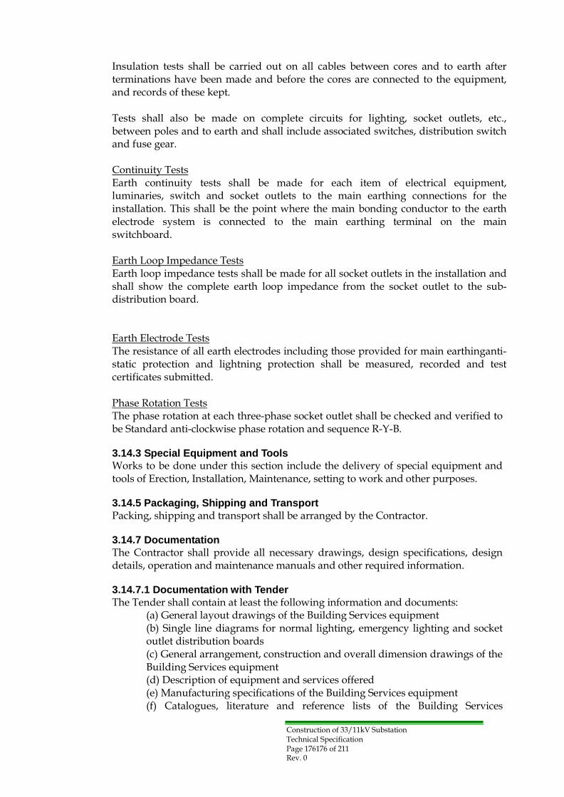
Construction of 33/11kV Substation Technical Specification Page 176176 of 211 Rev. 0
Insulation tests shall be carried out on all cables between cores and to earth after terminations have been made and before the cores are connected to the equipment, and records of these kept.
Tests shall also be made on complete circuits for lighting, socket outlets, etc., between poles and to earth and shall include associated switches, distribution switch and fuse gear.
Continuity Tests Earth continuity tests shall be made for each item of electrical equipment, luminaries, switch and socket outlets to the main earthing connections for the installation. This shall be the point where the main bonding conductor to the earth electrode system is connected to the main earthing terminal on the main switchboard.
Earth Loop Impedance Tests Earth loop impedance tests shall be made for all socket outlets in the installation and shall show the complete earth loop impedance from the socket outlet to the sub- distribution board.
Earth Electrode Tests The resistance of all earth electrodes including those provided for main earthinganti- static protection and lightning protection shall be measured, recorded and test certificates submitted.
Phase Rotation Tests The phase rotation at each three-phase socket outlet shall be checked and verified to be Standard anti-clockwise phase rotation and sequence R-Y-B.
3.14.3 Special Equipment and Tools
Works to be done under this section include the delivery of special equipment and tools of Erection, Installation, Maintenance, setting to work and other purposes.
3.14.5 Packaging, Shipping and Transport
Packing, shipping and transport shall be arranged by the Contractor.
3.14.7 Documentation
The Contractor shall provide all necessary drawings, design specifications, design details, operation and maintenance manuals and other required information.
3.14.7.1 Documentation with Tender
The Tender shall contain at least the following information and documents: (a) General layout drawings of the Building Services equipment (b) Single line diagrams for normal lighting, emergency lighting and socket outlet distribution boards (c) General arrangement, construction and overall dimension drawings of the Building Services equipment (d) Description of equipment and services offered (e) Manufacturing specifications of the Building Services equipment (f) Catalogues, literature and reference lists of the Building Services

Construction of 33/11kV Substation Technical Specification Page 177177 of 211 Rev. 0
equipment (g) Quality Management System Manual and ISO Certificate of the equipment manufacturer
3.14.7.2 Documentation after Award of Contract
All documents required for the Owner's approval shall be submitted by the Contractor. In addition, the Operating and Maintenance manuals shall be produced in sufficient details to enable inexperienced operatives to maintain and adjust the plant and systems.
They shall be written in a clear concise technical style. Operating and maintenance manuals shall contain the following:
(a) A description of the building to which services are applied stating their duty and functions. (b) A listing and description of the services as installed. (c) Functional diagrams and wiring diagrams for the main and subsystems. (d) Details of the manufacturer's installation, operating and maintenance requirements that must be edited or otherwise reproduced to be specific for the installation. (e) A detailed list of equipment supplied, manufacturer, address, telephone number and official order number/date. (f) A schedule detailing the regular maintenance requirements with space forremarks and service history. (g) A fault tree analysis of the system(s). (h) A copy of the'As fitted' record drawings.
(i) Copies of all test and commissioning data including pre- commissioning check lists including those required by BS 7671. (j) A schedule giving the finally adjusted set points for plant, equipment and controls. (k) A detailed listing of all spare parts giving part number and description, typical cost and availability. (l) Any item deemed necessary by the Owner to clearly identify to the use/operator the function and intended performance of the plant and systems.
3.15 Security surveillance System:
The substation should be supplied and installed with security monitoring system to be controlled localy and remotely from the dispatch center.

Construction of 33/11kV Substation Appendices Page 178178/212 Rev. 0
Appendices Appendix-A: Schedule of Materials for 2x31.5MVA Substation
a) The 33 kV incoming feeder switchgear shall comprise the following:
No. Item Specification for component Q‟ty
1.
Disconnecting Switch 33 kV, 1250 A, 25 kA/ 1 sec, On-load type.
1 set
2. Position Indicator (For Disconnecting switch)
DC110V
1 set
3. Earthing Switch 33 kV, ≥60 kA for fault making 1 set
4. Position Indicator (For Earthing switch)
DC110V
1 set
5. Interlocking between D.S and E.S
Mechanical type
1 set
6. Lightning arrester for line 36 kV, 10 kA 3 pcs
7. 3 phase air insulated bus bars chamber
33 kV, 1250 A, 25 kA/1 sec.
1 set
8.
Voltage transformer (Single phase) with suitable fuses on the HT and MCCB LT sides
33 kV/√3, 110 V/√3 class 1.0/3 P
3 pcs
9. Voltmeter ( digital type ) with selector switch
0 -36 k V scale
1 set
10. Voltage Transducer (Three phase)
DC110V, 0-36kV(4-20mA)
11. Lamp indicators for 33kV incoming voltage
White lamp for each phase ( capacitor VT+ Neon lamps)
1 set
12. Annunciator with lamp test and reset sw
DC110V
1 set
13. Space heater with humidistat
100W AC 230 V with 2- pole MCB
1 set
14. Fluorescent lamp AC 230 V with door switch 1 set
15. Indoor type enclosure IP 40 1 set
16.
All necessary items to complete the 33 kV circuit whether specifically mentioned or not shall be deemed to be included in the above items.
1 lot

Construction of 33/11kV Substation Appendices Page 179179/212 Rev. 0
b) The 33 kV transformer feeder switchgear shall comprise the following:
No. Item Specification for component Q‟ty
1.
Circuit breaker (CB) Draw-out type VCB, 33 kV, 1250 A, 25 kA/1 sec
1 set
2. Position Indicator (For C.B) DC110V 1 set
3.
Provision for Interlocking between 33 kV C.B and 33 kV D.S
Electrical type
1 set
4. Interlocking between 33 kV C.B and 11 kV C.B
Electrical type
1 set
5. 3 phase air insulated busbars chamber
33 kV, 1250 A, 25 kA/ 1sec
1 set
6. Current transformer for metering & protection
600/5/5A, Class 1.0/5P10
2 pcs per phase
7. Current transformer for differential protection
600/1 A, 5P20 1 pc per phase
8.
Three Ammeters (not required if included in the relay set)
0 – 800 A scale
1 lot
9.
Multi function over-current (50, 51) & earth fault relay (50N, 51N) with test terminal blocks
Numerical type, IDMTL characteristic
1 set
10. C.B on-off push buttons ON/OFF ( red/green ) 1 set 11. C.B mechanical indication ON/OFF ( red/green ) 1 set 12. Local –Remote Switch Lockable 1 set 13. Emergency stop 1 set
14.
TR Neutral point Earth fault relay with test terminal blocks
Numerical type, Adjustable Definite time characteristic
1 set
15. Lamp indicators for 33kV TR incoming voltage
White lamp for each phase ( capacitor VT + Neon lamps)
1 set
16. Aux. trip relay hand reset 1 set 17. electric reset alarm 1 set 18. Trip circuit supervion relay 1 set
19. Trip counting (not required if included in the relay set)
1 set
20. MW meter 0-30 MW scale (4-20mA) 1 set 21. MWh Class 1.0 1 set 22. MVAr Class 1.0 1 set 23. (IED) for SCS 1 set
24. Space heater with humidistat
100W AC230V with 2-Pole MCCB
1 set
25.
2 Pole suitable MCCB For Control alarm indication & Motor circuit ….etc circuits.
Pertinents
26. Fluorescent lamp AC230V,with door switch 1 set
27. 33 kV cables to power 33 kV, XLPE, 1 set

Appendices Page 180180/212 Rev. 0
transformer 3 x 1c x 400mm2
28. Connection materials for 33 kV cables
Terminals, cable glands and cleats, etc.
1 set
29. Indoor type enclosure IP 40 1 set
30.
All necessary items to complete the 33 kV circuit whether specifically mentioned or not shall be deemed to be included in the above items.
1 lot
Construction of 33/11kV Substation

Appendices Page 181181/212 Rev. 0
c) The 11kV transformer feeder switchgear shall comprise the following:
No. Item Specification for component Q‟ty
1.
Circuit breaker (CB) Draw-out type VCB, 11 kV, 2500 A, 25 kA/1 sec
1 set
2. Position Indicator (For C.B) DC110V 1 set
3.
Provision for Interlocking between 11 kV C.B and 11 kV E.S
Mechanical type
1 set
4. Interlocking between 33 kV C.B and 11 kV C.B
Electrical type
1 set
5. 3 phase air insulated busbars chamber
11 kV, 2500 A, 25 kA/ 1sec
1 set
6.
Current transformers for metering & protection
1800/5/5/1 A, Class 1.0/5P10/5P20
3 core CT‟s per phase
7.
Current transformer for differential protection
( with correction CT ) if needed to match the CT on 33 kV side
1 pc per phase
8.
Three Ammeters (not required if included in the relay set)
0 – 2000 A scale (4-20mA)
1 lot
9.
Multi function over-current (50, 51) & earth fault relay (50N, 51N) with test terminal blocks
Numerical type, IDMTL characteristic
1 set
10.
Differential protection relay ( with correction CT ) for the transformer (87T)
Numerical type
1 set
11. 3 phase unbalanced load PF meter
1 set
12. C.B on-off push buttons with Indication lamps
ON/OFF ( red/green )
1 set
13. C.B mechanical indication ON/OFF ( red/green ) 1 set
14.
Cable earthing device fully interlocked with 11kV C.B and the relevant potential transformers.
1 set
15.
Local –Remote Switch
Lockable
1 set
16. Emergency stop 1 set
17. Lamp indicators for 33kV TR outgoing voltage
White lamp for each phase ( capacitor VT + Neon lamps)
1 set
18. Aux. trip relay hand reset 1 set
19. electric reset alarm 1 set
20. Trip circuit supervion relay and audible alarm
1 set
21. Trip counting (not required 1 set
Construction of 33/11kV Substation

Appendices Page 182182/212 Rev. 0
if included in the relay set)
22. MW meter 0-30 MW scale (4-20mA) 1 set
23.
Voltage transformer with suitable fuses on the HT and LT sides (Single phase) for earth fault indication and instruments, drawable type
11 kV/√3, 110 V/√3, 110 V/3 class 1.0/3P
3 pcs
24. Lamp Voltage indication 1 set
25.
Voltmeter ( digital type, but not required if included in the relay set) with selector switch
0 – 13 k V scale (4-20mA) 6 position (phase to phase and phase to neutral ) and off
1 set
26.
Voltage earth fault relay Numerical type, Adjustable Definite time characteristic
1 set
27. Load shading under frequency relay
With four stages with selector switch for each stage and off
1 set
28. Contacts for local remote alarm indication
1 set
29.
Voltmeter transducer (not required if included in the relay set).
1 set
30. MWh with MDI Class 1.0 1 set
31. MVArh Class 1.0 1 set
32. VARM (VAr control Relay) 1 set
33. (IED) for SCS 1 set
34. Space heater with thermostat
AC230V, with 2-Pole MCCB
1 set
35.
2 Pole suitable MCCB For Control alarm indication & Motor circuit ….etc circuits.
Pertinents
36. Fluorescent lamp AC230V,with door switch 1 set
37. 24 kV suitable copper XLPE cables to Power transformer
24 kV, XLPE, 9 x 1c x 400mm2
1 lot
38.
Connection materials for 11 kV cables suitable copper XLPE cable with gland complete with all necessary jointing materials (as required)
Terminals, cable glands and cleats, etc.
1 lot
39. Indoor type enclosure IP 40 1 set
40.
All necessary items to complete the 11 kV circuit whether specifically mentioned or not shall be deemed to be included in the above items.
1 lot
Construction of 33/11kV Substation

Construction of 33/11kV Substation Appendices Page 183183/212 Rev. 0
d) The 11kV Busbar sectionalizer switchgear shall comprise the following:
No. Item Specification for component Q‟ty
1.
Circuit breaker (CB) Draw-out type VCB, 11 kV, 2500 A, 25 kA/1 sec
1 set
2. Automatic Change over Switch
Electrical type
1 set
3. 3 phase air insulated busbars chamber
11 kV, 2500 A, 25 kA/ 3sec
1 set
4.
Current transformers for metering & protection
1800/5/5A, Class 1.0/5P10 2 pcs per each phase
5.
Three Ammeters (not required if included in the relay set) One ammeter
0 – 2000 A scale (4-20mA)
1 lot
6.
Multi function over-current (50, 51) & earth fault relay (50N, 51N) with test terminal blocks
Numerical type, IDMTL characteristic
1 set
7. C.B on-off push buttons with Indication lamps
ON/OFF ( red/green )
1 set
8. C.B mechanical indication lamps
ON/OFF ( red/green )
1 set
9. Control switch with lamps Local/remote (White) 1 set
10. Trip circuit supervion relay and audible alarm
1 set
11. DC healthy lamp 1 set
12. Contacts for local remote alarm indication
1 set
13. Alarm bell 1 set
14. Trip counting (not required if included in the relay set).
1 set
15. (IED) for SCS 1 set
16. Space heater with thermostat
AC230V, with 2-Pole MCCB
1 set
17.
2 Pole suitable MCCB For Control alarm indication & Motor circuit ….etc circuits.
Pertinents
18. Fluorescent lamp AC230V,with door switch 1 set
19. Indoor type enclosure IP 40 1 set
20.
All necessary items to complete the 11 kV circuit whether specifically mentioned or not shall be deemed to be included in the above items.
1 lot

Construction of 33/11kV Substation Appendices Page 184184/212 Rev. 0
e) The 11kV Outgoing switchgear shall comprise the following:
No. Item Specification for component Q‟ty
1.
Circuit breaker (CB) Draw-out type VCB, 11 kV, 630A, 25 kA/1 sec
1 set
2. 3 phase air insulated busbars chamber
11 kV, 2500 A, 25 kA/ 1sec
1 set
3.
Current transformers for metering & protection
300/5/5A, Class 1.0/5P10
2 pcs per each phase
4.
Three Ammeters (not required if included in the relay set) One thermal ammeter with Max. Demand indicator with scale (0-300) Amp.
0 –300 A scale (4-20mA)
1 lot
5.
Over-current & earth fault relay (50, 51) & (50N, 51N) with test terminal blocks
Electronic type, IDMTL characteristic
1 set
6. C.B on-off push buttons with Indication lamps
ON/OFF ( red/green )
1 set
7. C.B mechanical indication lamps
ON/OFF ( red/green )
1 set
8. Local-Remote Control switch with lamps
Local/remote (White)
1 set
9.
Metering transducers (not required if included in the relay set)
1 set
10. Trip circuit supervion relay and audible alarm
1 set
11. Trip counting (not required if included in the relay set)
1 set
12. Contacts for local remote alarm indication
1 set
13. (IED) for SCS 1 set
14. Space heater with thermostat
AC230V, with 2-Pole MCCB
1 set
15.
2 Pole suitable MCCB For Control alarm indication & Motor circuit ….etc circuits.
Pertinents
16.
Lamp indicators for 11kV outgoing voltage neon potential indicators on the cable side.
White lamp for each phase ( capacitor VT + Neon lamps)
1 set
17. Cable earthing device fully interlocked with C.B
1 set
18. Load shedding selector switch
1 set
19. Fluorescent lamp AC230V,with door switch 1 set

Appendices Page 185185/212 Rev. 0
20. Indoor type enclosure IP 40 1 set
21.
suitable copper XLPE cable with gland complete with all necessary jointing materials (as required)
22.
All necessary items to complete the 11 kV circuit whether specifically mentioned or not shall be deemed to be included in the above items.
1 lot
Construction of 33/11kV Substation

Appendices Page 186186/212 Rev. 0
f) The 11kV Future Capacitor Bank switchgear shall comprise the following:
No. Item Specification for component Q‟ty
1.
Circuit breaker (CB) Draw-out type VCB, 11 kV, 630A, 25 kA/1 sec
1 set
2. 3 phase air insulated busbars chamber
11 kV, 2500 A, 25 kA/ 1sec
1 set
3.
Current transformers for metering & protection
300/5/5A, Class 1.0/5P10 2 pcs per each phase
4.
Three Ammeters (not required if included in the relay set) One thermal ammeter with Max. Demand indicator with scale (0-300) Amp.
0 –300 A scale (4-20mA)
1 lot
5.
Multi function over-current (50, 51) & earth fault relay (50G, 51G) with test terminal blocks
Numerical type, IDMTL characteristic
1 set
6.
Unbalanced Relay
Electronic type
1 set
7. MVArh Class 1.0 1 set
8. C.B on-off push buttons with Indication lamps
ON/OFF ( red/green )
1 set
9. C.B mechanical indication lamps
ON/OFF ( red/green )
1 set
10. Local-Remote Control switch with lamps
Local/remote (White)
1 set
11.
Metering transducers (not required if included in the relay set)
1 set
12. Trip circuit supervion relay and audible alarm
1 set
13. Trip counting (not required if included in the relay set)
1 set
14. Contacts for local remote alarm indication
1 set
15. (IED) for SCS 1 set
16. Space heater with thermostat
AC230V, with 2-Pole MCCB
1 set
17.
2 Pole suitable MCCB For Control alarm indication & Motor circuit ….etc circuits.
Pertinents
18.
Lamp indicators for 11kV outgoing voltage neon potential indicators on the cable side.
White lamp for each phase ( capacitor VT + Neon lamps)
1 set
19. Cable earthing device fully interlocked with C.B
1 set
Construction of 33/11kV Substation

Appendices Page 187187/212 Rev. 0
20. Load shedding selector switch
1 set
21.
Fluorescent lamp
AC230V,with door switch
1 set
22. Indoor type enclosure IP 40 1 set
23.
suitable copper XLPE cable with gland complete with all necessary jointing materials (as required)
24.
All necessary items to complete the 11 kV circuit whether specifically mentioned or not shall be deemed to be included in the above items.
1 lot
Construction of 33/11kV Substation

Construction of 33/11kV Substation Appendices Page 188188/212 Rev. 0
g) The 11kV Aux. TR switchgear shall comprise the following:
No. Item Specification for component Q‟ty
1.
Circuit breaker (CB) Draw-out type VCB, 11 kV, 630A, 25 kA/1 sec
1 set
2. 3 phase air insulated busbars chamber
11 kV, 2500 A, 25 kA/ 1sec
1 set
3.
Current transformers for metering & protection
30/5/5A, Class 1.0/5P10 2 pcs per each phase
4.
Three Ammeters (not required if included in the relay set)
0 –30 A scale (4-20mA)
1 lot
5.
Multi function over-current (50, 51) & earth fault relay (50N, 51N) with test terminal blocks
Numerical type, IDMTL characteristic
1 set
6. C.B on-off push buttons with Indication lamps
ON/OFF ( red/green )
1 set
7. C.B mechanical indication lamps
ON/OFF ( red/green )
1 set
8. Local-Remote Control switch with lamps
Local/remote (White)
1 set
9. Aux. trip relay hand reset 1 set
10. electric reset alarm 1 set
11. Trip circuit supervion relay and audible alarm
1 set
12. Trip counting (not required if included in the relay set)
1 set
13. Contacts for local remote alarm indication
1 set
14. (IED) for SCS 1 set
15. Space heater with thermostat
AC230V, with 2-Pole MCCB
1 set
16.
2 Pole suitable MCCB For Control alarm indication & Motor circuit ….etc circuits.
Pertinents
17.
11 kV suitable copper XLPE cables to Auxiliary transformer
11 kV, XLPE, 3 x 1c x 150mm2
1 lot
18. Connection materials for 11 kV cables
Terminals, cable glands and cleats, etc.
1 lot
19. Lamp indicators for 11kV outgoing voltage
White lamp for each phase ( capacitor VT + Neon lamps)
1 set
20. Cable earthing device fully interlocked with C.B
1 set
21. Fluorescent lamp AC230V,with door switch 1 set
22. Indoor type enclosure IP 40 1 set

Construction of 33/11kV Substation Appendices Page 189189/212 Rev. 0
23.
All necessary items to complete the 11 kV circuit whether specifically mentioned or not shall be deemed to be included in the above items.
1 lot
One cable end box with gland suitable for XLPE copper cables complete with all necessary materials

Construction of 33/11kV Substation Appendices Page 190190/212 Rev. 0
h) The NER cubicle of TR shall comprise the following:
No. Item Specification for component Q‟ty
1. Earthing Resister Resister plate: Anticorrosion 1 set
Rated voltage 11 kV
Rated current 300 A
Rated time 30 sec.
Resistance at 55 °C 21.1 ohm
Number of phase Single
Rated insulation level a) Impulse withstand
voltage
75 kV Peak
b) One minute 50Hz withstand voltage
28 kV rms
2.
Equipment to be accommodated with
a) 7.5 kV 10kA arrestor b) 11000/110 VT ( Outdoor
type) c) 11 kV, 400 A on-load
disconnector d) 300-150/5 A CT
e) O/V relay
1 lot
3.
Outdoor type enclosure
Punched (IP33) Painted galvanneal steel or Stainless steel Cable entry: Bottom
1 set
4. (IED) for SCS 1 set
5.
All necessary items to complete the NER circuit whether specifically mentioned or not shall be deemed to be included in the above items.
1 lot

Construction of 33/11kV Substation Appendices Page 191191/212 Rev. 0
i) DC 110V equipment (One Battery & Two Chargers and One Distribution panel ) shall comprise the following:
No. Item Specification for component Q‟ty 1 Charger 1 set
1.
AC Input 1 phase 2 -wire, 50 Hz, 230 V + 10%, - 15%
2.
DC Output
DC busbar voltage : 110 V +/- 10% DC busbar current : not less than 40 A
3.
Output voltage regulation Load voltage : Low 99 V – High 121 V
4. System efficiency 100%
Load
Up to 94%
5.
Di-electric strength
AC phases and earth: AC 2000 V for 1 min. DC : ditto
6. -AC VM with V/S or LCD Display
Voltage switch : OFF-RY-YB-BR –OFF
1 set
7. -DC VM with V/S or LCD Display
Voltage switch: OFF-Charge-Battery-Load-OFF
1 set
8. -DC AM or LCD Display For DC output current 1 set
9. -Battery current AM or LCD Display
Center zero pointer type (Charger or Discharge)
1 set
10. -Signal lamp (LED) or LCD Display
AC Input, Manual operation, trickle and boost
1 lot
11.
-Change over switch MAN-AUTO, TRICKLE-BOOST
1 set
12.
-Voltage adjustment knob For initial charging control
1 set
13. Auto-trip visual and audible alarm
(* 1)
1 set
14.
-Alarm reset/test button Alarm stop, reset and lamp test facility
1 set
15.
(IED) for SCS
1 set
16. Fluorescent lamp AC230V,with door switch 1 set
17. Indoor type enclosure IP 41 1 set
18.
All necessary items to complete the 11 kV circuit whether specifically mentioned or not shall be deemed to be included in the above items.
1 lot
19. Battery 1 set a)Type Nickel-Cadmium
b)Number of battery cell 92 cells

Construction of 33/11kV Substation Appendices Page 192192/212 Rev. 0
c)Nominal Voltage 1.2 V/cell
d)Nominal capacity Minimum 100 AH/8 hour
e)Necessary provision
-Multi-tier mounting rack Double tier for containing cell groups
-Fixing plates with rubber Fixing the cell group in the rack for anti-vibration
-DC main conductors Connecting strip
-Signal wire For electrolyte decrease
20. DC distribution circuit 1 set
Type Self
DC outgoing feeders
12 feeders as detailed shown on the SLD of DC system diagram
21. Standard of accessories 1 lot
- Funnel
- Syringe
- Suction type hydrometer Specific Gravity 1.10-1.30
- Rod type thermometer -20 to +100
- Jug For 1 litter
- Digital tester 0-3 V for batter cell vo tage measurement
- Filling pump
- Spanner
- Container case (* 1) The following items shall be provided for alarm indication as a minimum: a) DC Undervoltage b) DC Earth fault (positive) c) DC Earth fault (negative) d) Charger failure e) Electrolyte decrease

Construction of 33/11kV Substation Appendices Page 193193/212 Rev. 0
j) AC system (11/0.416kV 250kVA TR and One LVAC Distribution Board ) shall comprise the following:
No. Item Specification for component Q‟ty
1.
Auxiliary transformer 11/0.416 kV, 250 KVA Dyn11 ONAN
1 set
2.
LV AC Distribution Board 3-phase, 4-wire, 400/230V, 50Hz
1 set
3.
Incoming Feeder
400A MCCB (4 pole) with adjustable solid state trip unit,
2 Nos.
4. Interlocking device 1 set
5.
Outgoing feeder
100AF MCCB 2 Nos.
50AF MCCB 8 Nos.
30AF MCCB 7 Nos.
6.
Equipment to be accommodated with
a) 400/5/5 A CT b) O/C and E/F relay
c) U/V relay
1 lot
7. -AC AM with A/S or LCD Display
For AC 3 phase input current
1 set
8. -AC VM with V/S or LCD Display
Voltage switch : OFF-RY-YB-BR –OFF
9. (IED) for SCS 1 set
10.
Zero-sequence CT For detecting current in the neutral earthing system
1 No.
11. Difinit time Zero-sequence relay
1 No.
12.
All necessary items to complete the 11 kV circuit whether specifically mentioned or not shall be deemed to be included in the above items.
1 lot

Construction of 33/11kV Substation Appendices Page 194194/212 Rev. 0
k) Safety equipment shall comprise the following:
No. Item Specification for component Q‟ty
1. Breathing masks for fire fighting
2 Nos.
2. Plastic helmets 3 Nos.
3. 20kV insulating gloves 3 set
4. Suitable insulated stool 1 set
5.
33kV & 11kV voltage indicator rod of the telescopic type
1 set
6. Rechargeable torch light 2 Nos.
7.
Portable carriage mounted fire extinguishers suitable for electrical fires
3 Nos.
8.
Instructions against electrical shocks and artificial breathing
In the English language. Arabic
4 set
9.
Safety regulation signs for open circuits earth circuits, danger zone...etc.
In the English Language. Arabic
1 set

Construction of 33/11kV Substation Appendices Page 195195/212 Rev. 0
l) Spare parts: (Each substation)
for each substation , the following quantities should be quoted with unit price:
No. Item Specification for component
Q‟ty
1. 33kV Metal-clad Switchgear
1.1 Complete C.B 1 pc
1.2
Bushing insulators of each type 1 set
(3 phase)
1.3 Lightning arrester 36kV 10kA 1 pc
1.4
Tripping coil of C.B 1 set
(3 phase)
1.5 Auxiliary contact of C.B 1 lot
1.6 Closing coil of C.B 1 lot
1.7
Complete mechanism of C.B 1 set
(3 phase)
1.8 Complete Earth switch 1 set
1.9 Shutters 1 set
1.10
Complete Voltage transformer with suitable fuses on the HT and LT sides (Single phase)
33 kV/√3, 110 V/√3 c ass 1.0/3 P
1 set (3 phase)
1.11
Current transformer for metering & protection
600/5/5/1 A, Class1.0 / 5P10 /5P20 (Differential)
1pc each (1 phase)
1.12 Protection Relay (O/C, E/F) 1 set
1.13
Meters KWh , KVAr, A, V and W (not required if included in the relay set)
Each one
1 lot
1.14 MCCB of each type Each one 1 lot
1.15 H.T fuses for 33KV voltage transformer
1 set (3 phase)
1.16 Indicating lamps (LED) and Bulbs of all types used
Each one
1 lot
1.17 Push button Each one 1 lot
1.18 Control /selector switch Each one 1 lot
1.19 Aux. relay and aux. contactor of each type used
Each one
1 lot
1.20
Lamp indicators for 33kV TR incoming voltage
White lamp for each phase ( capacitor VT + Neon lamps)
2 set (3 phase)
1.21 LV socket and plug 1 set

Appendices Page 196196196/212 Rev. 0
2. 33/11.5kV 31.5MVA Transformer
2.1 Bushing for 33kV 1 pc
2.2 Bushing for 11.5kV 1 pc
2.3 Insulation Oil (10% of Total volume for 31.5MVA TR)
1 lot
2.4 Silicagel breather Each one 1 set
2.5 Protection Relay (Bucholz, Oil level and Oil temp)
Each one
1 lot
2.6 Diverter switch spares such as moving contacts
1 set
2.7 Driving gear mechanism with driving motor for tap changer
1 set
2.8 All seals and gaskets used for each 1 lot
2.9 Position indicator of OLTC 1 set
2.10 Lightning arrester 7kV 10kA 1 pc
2.11
Complete Voltage transformer with suitable fuses on the HT and LT sides (Single phase)
11/0.11kV 3 P
1 pc
2.12 Current transformer for protection 300-150/5A, 5P10 1 pc
3. 11kV Metal-clad Switchgear 3.1 Complete Circuit breaker (For Outgoing feeder) 1 pc
3.2 Main interrupter chambers for vacuum C.B
(For Outgoing feeder) 1 set (3 phase)
3.3 Complete C.B (For TR feeder) 1 pc
3.4
Bushing insulators (Each for TR & Outgoing feeder)
2 set (3 phase)
3.5
Tripping coil of C.B (Each for TR & Outgoing feeder)
2 set (3 phase)
3.6 Auxiliary contact of C.B (For Outgoing feeder) 1 lot 3.7 Closing coil of C.B (For Outgoing feeder) 1 lot
3.8
Complete mechanism of C.B (Each for TR & Outgoing feeder)
2 set (3 phase)
3.9 Complete Earth switch (For Outgoing feeder) 1 set 3.10 Shutters (For Outgoing feeder) 1 set
3.11
Complete Voltage transformer with suitable fuses on the HT and LT sides (Single phase)
11 kV/√3, 110 V/√3, 110 V/3 class 1.0/3 P
1 set
3.12
Current transformer for metering & protect on
1800/5/5/1 A and 300/5/5A Class 1.0/5P10/5P20 (Differential l)
1pc each
3.13 Protection Relay (O/C, E/F and Differential etc.)
Each one
1 l
3.14
Meters KWh, A, V and W (not required if included in the relay set)
Each one
1 lot
Construction of 33/11kV Substation

Appendices Page 197197197/212 Rev. 0
3.15 A with maximum demand indicator assembly
300A
2 pc
3.16 MCCB of each type Each one 1 lot
3.17 H.T fuses for 11KV voltage transformer
1 set (3 phase)
3.18 Indicating lamps (LED) and Bulbs of all types used
Each one
1 lot
3.19 Push button Each one 1 lot
3.20 Control /selector switch Each one 1 lot
3.21 Aux. relay and aux. contactor of each type used
Each one
1 lot
3.22
Lamp indicators for 11kV outgoing voltage
White lamp for each phase ( capacitor VT + Neon lamps)
2 set (3 phase)
3.23 LV socket and plug 1 set
4. DC110V Battery & charger
4.1 Protection Relay Each one 1 lot
4.2 Meters A, V (not required if included on the LCD)
Each one
1 lot
4.3 MCCB of each type Each one 1 lot
4.4 Indicating lamps (LED) of all types used
Each one
1 lot
4.5 Printed circuit boards of control unit
Each type
1 lot
4.6 5% of the total No. of battery cells Four (4) 1 lot
4.7 Electrolyte (10% of Total volume ) 1 lot
5. Inverter & Distribution panel
5.1 Protection Relay Each one 1 lot
5.2 Meters A, V (not required if included on the LCD)
Each one
1 lot
5.3 MCCB of each type Each one 1 lot
5.4 Indicating lamps (LED) of all types used
Each one
1 lot
5.5 Printed circuit boards of control for inverter
1 set
6. Station LVAC Distribution panel
6.1
Protection Relay Each one 1 lot
6.2 Meters A, V Each one 1 lot
6.3 MCCB of each type Each one 1 lot
6.4 Indicating lamps (LED) of all types used
Each one
1 lot
Construction of 33/11kV Substation

Appendices Page 198198198/212 Rev. 0
7. Lighting
7.1 All kinds of lamps and tubes including emergency lamps
10% each
8. Fire Detection and Alarm System
8.1 Each type of automatic fire detectors
Each two
1 lot
8.2 Each type of fire alarm devices Each two 1 lot
8.3 Each type of response indicator Each two 1 lot
8.4
Line type of cable for heat detector system
Maximum length for longest zone
8.5 Frangible elements for manual pull station
10 PC
Construction of 33/11kV Substation

Appendices Page 199199199/212 Rev. 0
m) Recommended Operational Spare Parts for 5 years
The tenderer should recommend necessary spare parts for each substation and operation of five year as a whole, the following quantities should be quoted with unit price:
(1) 33kV Metal-clad Switchgear
(2) 33/11.5kV 31. 5MVA Transformer
(3) 11kV Metal-clad Switchgear
(4) DC110V Battery, Charger and Distribution panel
(5) Inverter & Distribution panel
(6) Station LVAC Distribution panel
(7) Lighting
(8) Fire Detection and Alarm System
(9) SCS
(10) Others
n) Any special tools recommended for maintenance of circuit breakers,
Transformer and On load tap changer.
The above is only a guide and the manufacturer may offer, other items if necessary, or suggest a set of recommended spare parts for normal operation for a period for five years.
Notes :
Any missing item, necessary for operation will be considered included in the tender.
Earthing trip for an adjoining each panel with the other will be provided with its dimensions according to short circuit rating.
The Tools and Appliances for the equipment as per the itemized list given in the Bill of Quantities (Volume-II) shall be provide as Firm items, which will be subject to Owner confirmation during Contract execution stage.
Construction of 33/11kV Substation

Appendices Page 200/212 Rev. 0
Appendix D: Reference Drawings
Construction of 33/11kV Substation

Appendices Page 201201/212 Rev. 0
Construction of 33/11kV Substation

Construction of 33/11kV Substation Appendices Page 202202/212 Rev. 0
Backup
11 KV 2500 A
BUSBAR, 25 kA
11 KV CB
2500 A 25 kA

Construction of 33/11kV Substation Appendices Page 203203/212 Rev. 0
DC/DC Converter

Appendices Page 204204/212 Rev. 0
Construction of 33/11kV Substation
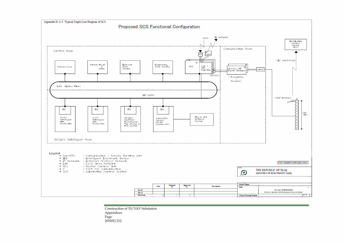
Appendices Page 205205/212 Rev. 0
Construction of 33/11kV Substation

Appendices Page 206206/212 Rev. 0
Construction of 33/11kV Substation

Appendices Page 207207/212 Rev. 0
Construction of 33/11kV Substation

Appendices Page 208208/212 Rev. 0
Construction of 33/11kV Substation

Appendices Page 209209/212 Rev. 0
Construction of 33/11kV Substation
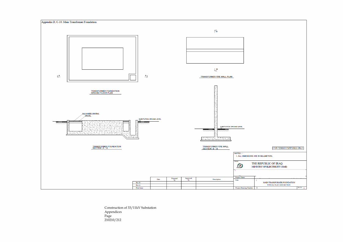
Appendices Page 210210/212 Rev. 0
Construction of 33/11kV Substation
Appendices Page 211211/212 Rev. 0
Construction of 33/11kV Substation

Appendices Page 212212/212 Rev. 0
Construction of 33/11kV Substation
Related Documents


