CONSTRUCTION AND CHARACTERIZATION OF AN OMNIDIRECTIONAL PARAMETRIC LOUDSPEAKER CONSISTING OF ULTRASOUND TRANSDUCERS SET ON A SPHERE Marc Arnela 1* , Patricia S´ anchez-Mart´ ın 1 , Marcos Herv´ as 1 , Joan Camps 1 , Oriol Guasch 1 , Carme Mart´ ınez-Suqu´ ıa 1 and Rosa Ma Alsina-Pag` es 1 1 GTM Grup de recerca en Tecnologies M` edia, La Salle, Universitat Ramon Llull C/ Quatre Camins 30, Barcelona 08022, Catalonia * Email: [email protected] ABSTRACT Standard omnidirectional sound sources typically consist of conventional loudspeakers arranged in a dodecahedral configuration. For such devices, a microphone in a circular trajectory around the source should measure a constant sound pressure level. However, the directivity of loudspeak- ers sharpens with increasing frequency. The omnidirectionality of the source therefore wanes at the high range of the spectrum, the effect being very noticeable at the vertices of the dodecahe- dron. In this work it is proposed to circumvent this problem by exploiting the parametric acoustic ar- ray (PAA) phenomenon. An omnidirectional parametric loudspeaker (OPL) is built by setting hundreds of small piezo-electric transducers (PZTs) on a sphere. Each PZT emits a collimated primary beam consisting of a carrier ultrasonic wave modulated by an audible signal. Thanks to non-linear propagation of sound in air, the air itself demodulates the primary beam giving rise to an emission cone of audible acoustic pressure (secondary field). For an appropriate distribution of PZTs on the sphere, the emission cones are such that an omnidirectional acoustic pressure field is recovered. In practice, a balance is required between an optimal PZT distribution and the prac- tical needs for a prototype construction. Our choice has been to follow an equal-area partitioning strategy on the sphere surface, which aligns the PZTs in parallels and performs almost as well as an optimal PZT distribution, as shown by theoretical prediction models. The parallel PZT align- ment strongly facilitates the PZT welding process and setting the cable circuitry. An equal-area distributed OPL prototype has been built resorting to 3D printing for the spherical casing. The prototype has been tested in an anechoic chamber showing a remarkable omnidirectional charac- ter for all frequencies. 175945 - 1

Welcome message from author
This document is posted to help you gain knowledge. Please leave a comment to let me know what you think about it! Share it to your friends and learn new things together.
Transcript

CONSTRUCTION AND CHARACTERIZATION OF ANOMNIDIRECTIONAL PARAMETRIC LOUDSPEAKER
CONSISTING OF ULTRASOUND TRANSDUCERSSET ON A SPHERE
Marc Arnela1* , Patricia Sanchez-Martın1, Marcos Hervas1, Joan Camps1, Oriol Guasch1, CarmeMartınez-Suquıa1 and Rosa Ma Alsina-Pages1
1GTM Grup de recerca en Tecnologies Media, La Salle, Universitat Ramon LlullC/ Quatre Camins 30, Barcelona 08022, Catalonia
*Email: [email protected]
ABSTRACT
Standard omnidirectional sound sources typically consistof conventional loudspeakers arrangedin a dodecahedral configuration. For such devices, a microphone in a circular trajectory aroundthe source should measure a constant sound pressure level. However, the directivity of loudspeak-ers sharpens with increasing frequency. The omnidirectionality of the source therefore wanes atthe high range of the spectrum, the effect being very noticeable at the vertices of the dodecahe-dron.In this work it is proposed to circumvent this problem by exploiting the parametric acoustic ar-ray (PAA) phenomenon. An omnidirectional parametric loudspeaker (OPL) is built by settinghundreds of small piezo-electric transducers (PZTs) on a sphere. Each PZT emits a collimatedprimary beam consisting of a carrier ultrasonic wave modulated by an audible signal. Thanks tonon-linear propagation of sound in air, the air itself demodulates the primary beam giving rise toan emission cone of audible acoustic pressure (secondary field). For an appropriate distributionof PZTs on the sphere, the emission cones are such that an omnidirectional acoustic pressure fieldis recovered. In practice, a balance is required between an optimal PZT distribution and the prac-tical needs for a prototype construction. Our choice has been to follow an equal-area partitioningstrategy on the sphere surface, which aligns the PZTs in parallels and performs almost as well asan optimal PZT distribution, as shown by theoretical prediction models. The parallel PZT align-ment strongly facilitates the PZT welding process and setting the cable circuitry. An equal-areadistributed OPL prototype has been built resorting to 3D printing for the spherical casing. Theprototype has been tested in an anechoic chamber showing a remarkable omnidirectional charac-ter for all frequencies.
175945 - 1
1 INTRODUCTION
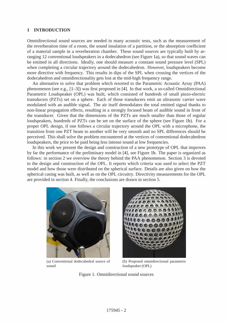
Omnidirectional sound sources are needed in many acoustic tests, such as the measurement ofthe reverberation time of a room, the sound insulation of a partition, or the absorption coefficientof a material sample in a reverberation chamber. These soundsources are typically built by ar-ranging 12 conventional loudspeakers in a dodecahedron (see Figure1a), so that sound waves canbe emitted in all directions. Ideally, one should measure a constant sound pressure level (SPL)when completing a circular trajectory around the dodecahedron. However, loudspeakers becomemore directive with frequency. This results in dips of the SPL when crossing the vertices of thedodecahedron and omnidirectionality gets lost at the mid-high frequency range.
An alternative to solve that problem which resorted to the Parametric Acoustic Array (PAA)phenomenon (see e.g., [1–3]) was first proposed in [4]. In that work, a so-called OmnidirectionalParametric Loudspeaker (OPL) was built, which consisted ofhundreds of small piezo-electrictransducers (PZTs) set on a sphere. Each of those transducers emit an ultrasonic carrier wavemodulated with an audible signal. The air itself demodulates the total emitted signal thanks tonon-linear propagation effects, resulting in a strongly focused beam of audible sound in front ofthe transducer. Given that the dimensions of the PZTs are much smaller than those of regularloudspeakers, hundreds of PZTs can be set on the surface of the sphere (see Figure1b). For aproper OPL design, if one follows a circular trajectory around the OPL with a microphone, thetransition from one PZT beam to another will be very smooth and no SPL differences should beperceived. This shall solve the problem encountered at the vertices of conventional dodecahedronloudspeakers, the price to be paid being less intense sound at low frequencies.
In this work we present the design and construction of a new prototype of OPL that improvesby far the performance of the preliminary model in [4], see Figure1b. The paper is organized asfollows: in section 2 we overview the theory behind the PAA phenomenon. Section 3 is devotedto the design and construction of the OPL. It reports which criteria was used to select the PZTmodel and how those were distributed on the spherical surface. Details are also given on how thespherical casing was built, as well as on the OPL circuitry. Directivity measurements for the OPLare provided in section 4. Finally, the conclusions are drawn in section 5.
(a) Conventional dodecahedral source ofsound
(b) Proposed omnidirectional parametricloudspeaker (OPL)
Figure 1. Omnidirectional sound sources
175945 - 2
2 PARAMETRIC ACOUSTIC ARRAY THEORY
Let us briefly review the foundations of the PAA phenomenon, first derived in Westervelt’s originalpaper [1]. Westervelt considered sound propagation in a thermoviscous fluid described by theequation
1
c20
∂2p
∂t2−∇2p =
δ
c40
∂3p
∂t3+
β
ρ0c40
∂2p2
∂t2, (1)
wherep represents the acoustic pressure,c0 andρ0 respectively stand for the speed of sound andthe ambient density, andδ andβ designate the sound diffusivity and the non-linearity parameter.The left hand side (l.h.s) of (1) can be recognized as the standard lossless linear wave equation,whereas the first term in the right hand side (r.h.s) accountsfor thermoviscosity and the second onefor non-linear propagation effects.
For weak non-linearity, one may attempt a quasilinear approximation to (1) (see e.g., [2]) bydecomposing the acoustic pressure asp = p1+p2 (|p2| ≪ |p1|), with the primary fieldp1 satisfyingthe linearized version of (1), and the secondary one,p2, arising as a non-linear byproduct ofp1.Substitutingp = p1 + p2 into (1) results in the following linear equations for the primary andsecondary fields,
1
c20
∂2p1∂t2
−∇2p1 −δ
c40
∂3p1∂t3
= 0, (2a)
1
c20
∂2p2∂t2
−∇2p2 −δ
c40
∂3p2∂t3
=β
ρ0c40
∂2p21
∂t2. (2b)
It can be easily checked that the solution to (2a) consists of attenuated traveling waves which, oncesquared, act as a source term for equation (2b) governing the secondary pressure fieldp2. If theprimary field is made of two collimated plane waves emitted bya PZT in the positivez-axis,
p1 = P1e−α1z cos (w1t− k1z) + P2e
−α2z cos (w2t− k2z), (3)
(αi = δω2
i /2c3
0, i = 1, 2, being the wave attenuation factors), the squared amountp2
1in the source
of (2b) will give place to a term involving twice the frequencies2ω1 and2ω2, another one contain-ing the frequency summationω1+ω2, and a last one with the difference frequencyωd = |ω1 − ω2|.Chooseω1 andω2 close together and to lie in the ultrasonic range, say, for instance, 40 kHz and41 kHz, and the difference frequency component (secondary field p2) would result in a 1 kHz au-dible sound. This is the essential behind the PAA, where in typical applications the primary fieldconsists of a plane wave made from an ultrasonic carrier modulated by a broadband signal in theaudible range (see e.g., [5, 6]).
Inserting (3) into (2b) solely retaining the difference frequency component in the source termand solving the equation using the standard Green function approach, yields the celebrated West-ervelt expression for the audible secondary pressure,pd, at a far-field point(r0, θ0) (see [e.g.,1, 2, 7]),
pd(r0, θ0) = KS0P1P2DW (θ0) cos (wdt− kdr0 − φ), (4)
with
K =βω2
d
4πρ0c40r0(α1 + α2), DW (θ0) =
α1 + α2√
(α1 + α2)2 + k2d(1− cos θ0)2, tanφ =
kd(1− cos θ0)
α1 + α2
.
(5)
175945 - 3

In (5) r0 is the distance from the PZT to the observer,θ0 is the sustained angle between the PZTemission axis and the position of the observer, andkd is the wave number of the difference fre-quency wave,kd = ωd/c0. DW (θ) is known as the Westervelt directivity and is responsible fora very sharp secondary audible field without lobes, which is at the core of the audio spotlightapplications [6].
When applied to determine the far field pressure of parametric loudspeaker arrays (PLAs), how-ever, equation (4) suffers from severe limitations, the assumption of collimated primary waves be-ing too stringent. Several proposals can be found in literature to remedy that situation, starting withthe incorporation of the product of the primary field directivities into (4) (see [7] and also [3, 8] fora review on further approaches). Just a few years ago, an alternative model was proposed to dealwith PLAs consisting of arrays of PZTs with beam widths up to80◦ [9]. The model provides thefollowing prediction formula for the far field, to be compared to (4),
pd(r0, θ0) = K cos (wdt− kdr0)
∫ ψ0
−ψ0
D1(ψ)D2(ψ)DW (θ0 − ψ) dψ, (6)
ψ0 being half the PZT beam width. As seen from (6), in this case the directivity of the audible fieldis obtained from the convolution between Westervelt’s directivity and the product of the primaryfield directivities. The convolution model was reported to provide better predictions than previousmodels for planar PLAs in [9]. Very recently, the convolution model has been generalized to dealwith PLAs set on curved surfaces [10], which could be useful to predict the performance of severalnon-conventional PLA devices ([11–13]). In particular, the generalized convolution model in [10]has been used as a guidance for the design of the OPL prototypereported in this paper.
3 CONSTRUCTION OF AN OMNIDIRECTIONAL PARAMETRIC LOUDSPEAKER
3.1 Design
Several parameters need to be considered when designing an omnidirectional parametric loud-speaker made of hundreds of PZT transducers on a sphere. Probably the most important ones arethe transducer model, the sphere radius, and the transducerdistribution on the sphere surface. Af-
(a) (b)
Figure 2: Distribution of PZTs on the OPL (a) force-equilibrium distribution (b) equal-area parti-tioning
175945 - 4

ter experimentally testing many commercial PZT transducers on the market, we have selected theMulticomp 16mm Transmitter (ST160), since it presented high pressure levels with a quite widedirectivity pattern at a reasonable price. Knowing that thecircular base of this transducer has aradius ofr = 0.008 m, the next problem to address is how to distribute all transducers on thespherical surface.
Looking for an optimal distribution of points on the surfaceof a sphere is a classical, non simpleproblem [14]. Some approaches to it rely on minimizing an associated energy problem [14, 15], oron supposing that all points are connected by struts and finding a force equilibrium solution [16].The last procedure, hereinafter called theforce-equilibriumPZT distribution, has been first adoptedin this work. In Figure2a we show a realization of such a distribution in a sphere of radiusR = 0.125 m. Every circle on the surface represents a PZT. They have allbeen set a distance of0.0001 m apart to avoid contact. This configuration gave a total of 755 PZTs.
To achieve an optimal, or at least very efficient, distribution of PZTs is desirable, but simplicityof construction is also essential. For this reason, anothermethod to set the PZTs on the spherehas been investigated. The alternative configuration consists in dividing each parallel band of thesphere intoNPZT equal-areas. The parallel bands have the width of a PZT, and each band is filledwith PZTs, again with an inter-separation of0.0001 m. Figure2b shows this distribution, whichwill be hereafter refereed to as theequal-areapartition, on the same sphere used for theforce-equilibrium case. 750 PZTs fill the sphere for the equal-area partitioning scheme, as comparedto the 755 of theforce-equilibriumdistribution. The advantage of the equal-areas distribution is,however, that its strongly facilitates the cable circuitryand the welding process. The price to pay:a worse transducer distribution which may affect the directivity pattern.
Some theoretical predictions were performed to analyze theperformance of the force-equilibriumand equal-area partition strategies [10]. In Figure3 we show some of the results corresponding tothe far-field SPL obtained for a difference frequency of 2 kHz, at 4 m from the OPL surface forthree different half orbits (from top to bottom: an orbit around the equator, around a meridian, andwith an inclination of 45◦; the three trajectories crossing at90o). As can be observed, the secondaryfield obtained by either distributions is very omnidirectional, with almost constant SPLs in both
0 20 40 60 80 100 120 140 160 180-1
-0.5
0
0.5
1(a)
0 20 40 60 80 100 120 140 160 180-1
-0.5
0
0.5
1(b)
0 20 40 60 80 100 120 140 160 180Angle [degrees]
-1
-0.5
0
0.5
1(c)
SP
L [d
B]
Figure 3: Far-field for the force-equilibrium (blue line) and for the equal-area (red line) OPL. Halforbits around the (a) equator, (b) a meridian and (c) with an inclination of 45◦. Sound pressureleves are normalized with respect to the value at 90o, where the three trajectories cross.
175945 - 5

cases. On the other hand, this theoretical model also helpedus to determine a proper sphere radius.This was selected toR = 0.125 m, since the predicted directivity pattern and sound pressure levelswere good enough for our purposes while keeping a reasonablenumber of transducers.
In summary, the OPL was designed to have 750 PZT transducers (Multicomp 16mm Transmitter(ST160)) distributed on a sphere of radiusR = 0.125 m following an equal-area partitioningstrategy.
3.2 Spherical casing
The spherical casing of the OPL had to fulfill with the following construction requirements. First,its interior had to be accessible so as to wire and sold all transducers. Second, the exact locationof the transducers should be somehow marked in the casing to avoid deviations with respect to thetheoretical design. Third, the prototype had to be rigid andconsistent enough to resist user ma-nipulation without damage. Fourth, the resulting prototype shall be supported with a microphonestand.
We have complied with the above requirements with a design that splits the sphere into 6 pieces(see Figure4); 4 pieces for the laterals and 2 for the spherical caps, which greatly simplifies thewiring and soldering of the transducers. The two caps were easy to determine because the equal-area strategy ensures that all the transducers are aligned in a parallel. However, this task was moredifficult for the lateral pieces. If we look along any meridian we will find that the transducersare not aligned. The lateral pieces were thus divided in a waythat avoided transducers to liebetween two different pieces. Besides, each piece containsthe exact location of the transducers,the transducer base and the two holes for the pins being marked on the piece surface.
All six pieces can be joined to form the spherical casing, as if it were the six pieces of a puzzle.However, with that configuration the resulting structure was not rigid enough. To get more stiffnesssome additional pieces were designed. This resulted in a central piece located in the center of thesphere, which is connected to all surface pieces through bars (see Figure4b) and prevents thesurface pieces from collapsing within the sphere. On the other hand, the bottom spherical capcontains a hole that is connected to this central piece. A microphone stand can be introduced there,up to the center of the spherical casing, which ensures a highstability. All the casing pieces were3D-printed in white color. They were small enough so as to be printable in any regular commercial3D printer.
(a) (b)
Figure 4: Spherical casing (a) before and (b) after setting the transducers on it. In (b) one of thelateral pieces is removed to better observe the interior.
175945 - 6

3.3 Circuitry
As detailed in section3.2, the spherical casing of the OPL was divided into 6 pieces. All pieceswere star-form electrically connected from the central connector of the OPL, as shown in Figure5.All transducers in the OPL pieces were connected in parallel.
20V@10 A
Figure 5. Scheme of the internal wiring of the OPL
Two types of wiring were used in the connection design. On theone hand, a naked wiring forconnecting all the transducers in a piece. The wire has a section of 0.2mm2, which allows a max-imum current of 15 A, and completely suffices for the1.67 A current flow needed for each piece(this corresponds to a sixth of the total10 A current for the OPL). The union of the transducerswithin each piece was zigzagged to minimize the length of thewiring, thus simplifying the weldingprocess. On the other hand, a second type of wire with section1mm2 (suitable for currents up to20 A) was employed to connect the six pieces as described in Figure5.
The setup scheme of the OPL is shown in Figure6. A passive protection circuit has beendesigned to be inserted between the power amplifier (Ecler XPA3000) and the OPL. This circuitprotects the entire set of both, overvoltage and overcurrent, avoiding possible damage to the OPLand also to the power amplifier. The protection circuit contains a relay that selects the most suitablepath between the OPL and a resistive load (whose impedance isrecommended by the manufacturerof the amplifier). The second path (through the resistive load) is activated when the peak envelopeis higher than a predetermined threshold, settled to 20 V.
Amplifier ProtectionSignal
Generator
6 1.5kW
Figure 6. Scheme of the setup of the OPL
175945 - 7

4 EXPERIMENTAL TESTING
The directivity pattern of the OPL was measured within the anechoic chamber of La Salle, Uni-versitat Ramon Llull (see Figure7). Pure tones, of frequency equal to the central frequenciesof
Figure 7. Experimental setup used to measure the directivity pattern of the OPL.
1/1 octave-bands from 250 Hz to 8 kHz, were emitted while the OPL rotated continuously from0o to 360o by means of a turntable. Each pure tone was modulated with Upper Side Band Am-plitude Modulation (USBAM) and emitted trough a Data Translation 9832 card. This signal wasamplified using an Ecler XPA3000 with an input voltage of 16 Vpeak. This value was selectedto avoid to damage the OPL, as it is clearly below the maximum voltage of 20 Vrms that theultrasound transducers can tolerate. The generated sound pressure levels were measured with afree field microphone 1/4 inch (G.R.A.S. 40BF) and recorded with the acquisition card througha Nexus conditioning amplifier. The microphone was located at 1 meter distance from the OPL.For comparison purposes, the directivity pattern of a conventional dodecahedral loudspeaker wasalso measured using the same experimental setup. In this case the pure tones were emitted withoutmodulation.
Figure8 presents the experimental results obtained for the directivity pattern of the OPL andthe conventional dodecahedral loudspeaker, with a resolution of 1o. The results are expressed inthe usual polar representation and normalized to the mean sound pressure level for each frequency.In addition, the Directivity Index (DI) is also computed from each directivity pattern as describedin the ISO 16283-1 [17]. This is defined as
DIi = L360o − L30,i, (7)
withL360o being the mean pressure value along the arc from0o to360o, andL30,i the mean pressurevalue along a30o arc. Thei index indicates the different intervals that cover each30o arc, that is,from 0o to 30o, from 30o to 60o, etc.
As can be observed in Figure8a, the dodecahedral loudspeaker has a very good omnidirectionalbehaviour for low frequencies, but for higher ones, above2 kHz, there are some regions in whichthe pressure levels can decay up to about−25 dB. As explained in the Introduction, this is pro-duced because the directivity of regular loudspeakers sharpens with increasing frequency, so thatacoustic shadow regions appear in the vicinity of the dodecahedron vertices. Looking now at thedirectivity pattern of the OPL (see Figure8b), it fluctuates very quickly for all frequencies, com-pared to the dodecahedral loudspeaker. Moreover, some large pressure drops are also produced.
175945 - 8

0°
15°
30°
45°
60°
75°90°
105°
120°
135°
150°
165°
±180°
−165°
−150°
−135°
−120°
−105°−90°
−75°
−60°
−45°
−30°
−15°
−30dB−20−100+10
250Hz
500Hz
1kHz
2kHz
4kHz
8kHz
(a) Dodecahedron - Directivity pattern
0°
15°
30°
45°
60°
75°90°
105°
120°
135°
150°
165°
±180°
−165°
−150°
−135°
−120°
−105°−90°
−75°
−60°
−45°
−30°
−15°
−30dB−20−100+10
250Hz
500Hz
1kHz
2kHz
4kHz
8kHz
(b) OPL - Directivity pattern
−10dB−5
0+5
0°
30°
60°
90°
120°
150°
±180°
−150°
−120°
−90°
−60°
−30°
250Hz
500Hz
1kHz
2kHz
4kHz
8kHz
(c) Dodecahedron - Directivity Index
−10dB−5
0+5
0°
30°
60°
90°
120°
150°
±180°
−150°
−120°
−90°
−60°
−30°
250Hz
500Hz
1kHz
2kHz
4kHz
8kHz
(d) OPL - Directivity Index
Figure 8: Directivity pattern and Directivity Index of a conventional dodecahedral loudspeaker andthe OPL.
However, these are focused in narrower areas compared to the dodecahedral loudspeaker, and thefluctuations seem to oscillate along a mean pressure value. The DI can shed light on this pointas it relates the mean pressure value along a30o arc with the total mean pressure, giving a betteridea about the omnidirectionallity of each sound source. Comparing the DI of the OPL againstthat of the dodecahedral loudspeaker (see Figure8d and Figure8c), it can be observed in fact thatthe OPL is more omnidirectional at higher frequencies than the dodecahedral loudspeaker. On theother hand, note that all the frequency curves are very similar for the OPL, which means that itmaintains its omnidirectional behaviour independently of the introduced frequency. In contrast,larger differences can be observed in the DI of the dodecahedral loudspeaker when changing thefrequency. However, as it could be expected, this conventional loudspeaker performs better thanthe OPL for frequencies lower than 2 kHz, since the problem with the dodecahedron vertices doesnot exist in the low frequency range.
175945 - 9
5 CONCLUSIONS
In this work a new omnidirectional parametric loudspeaker prototype was build. 750 piezo-electrictransducers were used for this purpose, equally distributed in the parallels of a sphere of radius0.125 m. 3D-printing technology was employed to construct the 6 pieces that form the sphericalcasing of the OPL, together with some additional elements that provide robustness. This designgreatly simplified the wiring and soldering of all transducers. The OPL prototype was tested in ananechoic chamber. The preliminary results showed that the OPL has an omnidirectional behaviour,although its directivity pattern fluctuates very quickly compared to a conventional dodecahedronloudspeaker. However, when examining the Directivity Index, the OPL presented clear improve-ments at higher frequencies, although it performed worst for the lower ones. Future works willdetermine the potential of the OPL to perform standard measurements in building acoustics, suchas reverberation time of a room or the airborne sound insulation of a partition. Moreover, moreexperiments will be performed to better examine the behaviour of this new sound of source.
ACKNOWLEDGMENTS
This work has been supported by the BUILT2SPEC project, which has received funding from theEuropean Union’s Horizon 2020 Research and Innovation Program under Grant Agreement no.637221. The authors acknowledge the support from the Secretaria d’Universitats i Recerca delDepartament d’Economia i Coneixement (Generalitat de Catalunya) under grant ref. 2017-SGR-966.
REFERENCES
[1] P. J. Westervelt. Parametric acoustic arrays.J. Acoust. Soc. Am., 35(4):535–537, 1963.
[2] M. F. Hamilton. Sound beams. InNonlinear Acoustics: Theory and Applications, pages233–261. Academic Press Inc., 1997.
[3] W. Gan, J. Yang, and T. Kamakura. A review of parametric acoustic array in air. Appl.Acoust., 73(12):1211–1219, 2012.
[4] U. Sayin, P. Artıs, and O. Guasch. Realization of an omnidirectional source of sound usingparametric loudspeakers.J. Acoust. Soc. Am., 134(3):1899–1907, 2013.
[5] M. Yoneyama, Y. Kawamo, J. Fujimoto, and S. Sasabe. The audio spotlight: An applicationof nonlinear interaction of sound waves to a new type of loudspeaker design.J. Acoust. Soc.Am., 73(5):1532–1536, 1983.
[6] F. J. Pompei. The use of airborne ultrasonics for generating audible sound beams.J. AudioEng. Soc., 47(9):726, 1999.
[7] H. O. Berktay and D. J. Leahy. Far-field performance of parametric transmitters.J. Acoust.Soc. Am., 55(3):539, 1974.
[8] C. Shi and W. Gan. Product directivity models for parametric loudspeakers.J. Acoust. Soc.Am., 131(3):1938–1945, 2012.
[9] C. Shi and Y. Kajikawa. A convolution model for computingthe far-field directivity of aparametric loudspeaker array.J. Acoust. Soc. Am., 137(2):777–784, 2015.
175945 - 10

[10] O. Guasch and P. Sanchez-Martın. Far-field directivity of parametric loudspeaker arrays seton curved surfaces.Submitted, 2018.
[11] N. Tanaka and M. Tanaka. Active noise control using a steerable parametric array loud-speaker.J. Acoust. Soc. Am., 127(6):3526–3537, 2010.
[12] N. Tanaka and M. Tanaka. Mathematically trivial control of sound using a parametric beamfocusing source.J. Acoust. Soc. Am., 129(1):165–172, 2011.
[13] U. Sayin and O. Guasch. Directivity control and efficiency of parametric loudspeakers withhorns.J. Acoust. Soc. Am., 134(2):EL153–EL157, 2013.
[14] E. B Saff and A. BJ Kuijlaars. Distributing many points on a sphere.Math. Intell., 19(1):5–11, 1997.
[15] A. Katanforoush and M. Shahshahani. Distributing points on the sphere, I.Exper. Math.,12(2):199–209, 2003.
[16] P. Persson and G. Strang. A simple mesh generator in matlab. SIAM review, 46(2):329–345,2004.
[17] ISO 16283-1.Acoustics—Field measurement of sound insulation in buildings and of buildingelements — Part 1: Airborne sound insulation. International Organisation for Standardiza-tion, Geneva, Switzerland, 1998.
175945 - 11
Related Documents