Constructal multiscale cylinders rotating in cross-flow T. Bello-Ochende ⇑ , J.P. Meyer, O.I. Ogunronbi Department of Mechanical and Aeronautical Engineering, University of Pretoria, Pretoria 0002, South Africa article info Article history: Received 8 October 2010 Accepted 14 January 2011 Available online xxxx Keywords: Co-rotating Counter-rotating Heat transfer rate density Centreline Leading edge abstract This work describes the effect of steady-state laminar forced convection on multiscale rotating cylinders in cross-flow. The objective was to numerically maximise the heat-transfer-rate-density from the multi- scale cylinder assembly under a prescribed pressure drop. Two main configurations were studied, the first was with two different-sized cylinders aligned along the same centreline, and the second configura- tion was that in which the axis of rotation of the two cylinders was not on the same centreline but the leading edges of the cylinders were on the same line. In both configurations, the cylinders were subjected to two types of rotations, counter-rotation and co-rotation. Numerical solutions for stationary and rota- tional cylinders were solved to determine the optimum cylinder diameter, spacing and the corresponding maximum heat transfer rate density. The effects of different centres of rotation and the dimensionless pressure drop on the cylinder-to-cylinder spacing, optimal diameter of the cylinder and the maximum heat transfer rate density were reported. Results show that the optimal smaller cylinder diameter was robust with respect to the dimensionless pressure drop number, for both configurations. Results further showed that rotation was only beneficial for cylinders with the same axis of rotation and the effect was minimal when the axis of rotation is different. Ó 2011 Elsevier Ltd. All rights reserved. 1. Introduction Due to the need for more effective heat removal from heat gen- erating equipment such as heat sinks, research has been and is still being conducted on this subject with the aim of removing more and more heat from a given heat generating volume. The research assists in the design, manufacture and operation of such equip- ment. Modern electronic systems produce high amounts of heat due to the power-to-volume ratio employed in such systems. An- other example of high heat transfer to volume ratio is from a rotat- ing solid to a moving fluid. This is used in different applications from the cooling of rotating machinery to re-entry space vehicles. Badr and Dennis [1] considered the problem of laminar forced convective heat transfer from an isothermal cylinder rotating on its own axis and located in a uniform stream. Their results empha- sised the effect of the rotation on the thermal boundary layer and the local Nusselt number distribution. Contradictory to expecta- tion, they found that the overall heat transfer coefficient tended to decrease as the speed of rotation increased. They attributed this to the existence of a rotating fluid layer that acted as insulation from the main-stream coolant, Chiou and Lee [2] also investigated convection from a rotating cylinder cooled by an air jet. The results confirmed that at lower rotational velocities, the overall heat trans- fer was enhanced and at higher rotational velocities, the effect be- came reversed, which they attributed to the presence of a layer of dead air circling the cylinder and thus reducing the heat transfer. Similar research includes the works of Mahfouz and Badr [3], Ozer- dem [4], Gschwendtner [5], Sanitjai and Goldstein [6], Misirlioglu [7], Paramane and Sharma [8,9], and Yan and Zu [10]. Optimisation of the spacing between cylinders has been con- ducted by Stanescu et al. [11], who found conclusively that with an increase in the Reynolds number, the spacing between the cyl- inders consequently decreased. Mohanty et al. [12]compared the flow around a rotating cylinder with the model of transport from the leading edge of a turbine blade. Comparisons were made be- tween the heat transfer coefficient of pure cross-flow across the cylinder and the heat transfer coefficient of pure rotation of the cylinder. Experiments showed that the heat transfer from the stag- nation point under pure rotation was lower than that of pure cross- flow. Additionally, the heat transfer coefficient of pure cross-flow was seen to undergo a huge drop, attributable to laminar separa- tion. The drop of the heat transfer coefficient of a rotating cylinder was much less, leading to a higher average heat transfer coefficient for a rotating cylinder than that seen on a stationary cylinder. It was also noted by Mohanty et al. [12] that the heat transfer is high- er for rotational convection than it is for pure cross-flow. This view is somewhat contradicted by Tzeng et al. [13] who found that at higher Reynolds numbers the cooling efficiency was increased on high-velocity rotating machines. Jones et al. [14] studied mixed convection with the goal of determining the overall heat transfer rate dependence on the 0017-9310/$ - see front matter Ó 2011 Elsevier Ltd. All rights reserved. doi:10.1016/j.ijheatmasstransfer.2011.02.004 ⇑ Corresponding author. Tel.: +27 12 4203105; fax: +27 12 362 5124. E-mail address: [email protected] (T. Bello-Ochende). International Journal of Heat and Mass Transfer xxx (2011) xxx–xxx Contents lists available at ScienceDirect International Journal of Heat and Mass Transfer journal homepage: www.elsevier.com/locate/ijhmt Please cite this article in press as: T. Bello-Ochende et al., Constructal multiscale cylinders rotating in cross-flow, Int. J. Heat Mass Transfer (2011), doi:10.1016/j.ijheatmasstransfer.2011.02.004

Welcome message from author
This document is posted to help you gain knowledge. Please leave a comment to let me know what you think about it! Share it to your friends and learn new things together.
Transcript
International Journal of Heat and Mass Transfer xxx (2011) xxx–xxx
Contents lists available at ScienceDirect
International Journal of Heat and Mass Transfer
journal homepage: www.elsevier .com/locate / i jhmt
Constructal multiscale cylinders rotating in cross-flow
T. Bello-Ochende ⇑, J.P. Meyer, O.I. OgunronbiDepartment of Mechanical and Aeronautical Engineering, University of Pretoria, Pretoria 0002, South Africa
a r t i c l e i n f o
Article history:Received 8 October 2010Accepted 14 January 2011Available online xxxx
Keywords:Co-rotatingCounter-rotatingHeat transfer rate densityCentrelineLeading edge
0017-9310/$ - see front matter � 2011 Elsevier Ltd. Adoi:10.1016/j.ijheatmasstransfer.2011.02.004
⇑ Corresponding author. Tel.: +27 12 4203105; fax:E-mail address: [email protected] (T. Bello-Oche
Please cite this article in press as: T. Bello-Ocdoi:10.1016/j.ijheatmasstransfer.2011.02.004
a b s t r a c t
This work describes the effect of steady-state laminar forced convection on multiscale rotating cylindersin cross-flow. The objective was to numerically maximise the heat-transfer-rate-density from the multi-scale cylinder assembly under a prescribed pressure drop. Two main configurations were studied, thefirst was with two different-sized cylinders aligned along the same centreline, and the second configura-tion was that in which the axis of rotation of the two cylinders was not on the same centreline but theleading edges of the cylinders were on the same line. In both configurations, the cylinders were subjectedto two types of rotations, counter-rotation and co-rotation. Numerical solutions for stationary and rota-tional cylinders were solved to determine the optimum cylinder diameter, spacing and the correspondingmaximum heat transfer rate density. The effects of different centres of rotation and the dimensionlesspressure drop on the cylinder-to-cylinder spacing, optimal diameter of the cylinder and the maximumheat transfer rate density were reported. Results show that the optimal smaller cylinder diameter wasrobust with respect to the dimensionless pressure drop number, for both configurations. Results furthershowed that rotation was only beneficial for cylinders with the same axis of rotation and the effect wasminimal when the axis of rotation is different.
� 2011 Elsevier Ltd. All rights reserved.
1. Introduction
Due to the need for more effective heat removal from heat gen-erating equipment such as heat sinks, research has been and is stillbeing conducted on this subject with the aim of removing moreand more heat from a given heat generating volume. The researchassists in the design, manufacture and operation of such equip-ment. Modern electronic systems produce high amounts of heatdue to the power-to-volume ratio employed in such systems. An-other example of high heat transfer to volume ratio is from a rotat-ing solid to a moving fluid. This is used in different applicationsfrom the cooling of rotating machinery to re-entry space vehicles.
Badr and Dennis [1] considered the problem of laminar forcedconvective heat transfer from an isothermal cylinder rotating onits own axis and located in a uniform stream. Their results empha-sised the effect of the rotation on the thermal boundary layer andthe local Nusselt number distribution. Contradictory to expecta-tion, they found that the overall heat transfer coefficient tendedto decrease as the speed of rotation increased. They attributed thisto the existence of a rotating fluid layer that acted as insulationfrom the main-stream coolant, Chiou and Lee [2] also investigatedconvection from a rotating cylinder cooled by an air jet. The resultsconfirmed that at lower rotational velocities, the overall heat trans-fer was enhanced and at higher rotational velocities, the effect be-
ll rights reserved.
+27 12 362 5124.nde).
hende et al., Constructal mult
came reversed, which they attributed to the presence of a layer ofdead air circling the cylinder and thus reducing the heat transfer.Similar research includes the works of Mahfouz and Badr [3], Ozer-dem [4], Gschwendtner [5], Sanitjai and Goldstein [6], Misirlioglu[7], Paramane and Sharma [8,9], and Yan and Zu [10].
Optimisation of the spacing between cylinders has been con-ducted by Stanescu et al. [11], who found conclusively that withan increase in the Reynolds number, the spacing between the cyl-inders consequently decreased. Mohanty et al. [12]compared theflow around a rotating cylinder with the model of transport fromthe leading edge of a turbine blade. Comparisons were made be-tween the heat transfer coefficient of pure cross-flow across thecylinder and the heat transfer coefficient of pure rotation of thecylinder. Experiments showed that the heat transfer from the stag-nation point under pure rotation was lower than that of pure cross-flow. Additionally, the heat transfer coefficient of pure cross-flowwas seen to undergo a huge drop, attributable to laminar separa-tion. The drop of the heat transfer coefficient of a rotating cylinderwas much less, leading to a higher average heat transfer coefficientfor a rotating cylinder than that seen on a stationary cylinder. Itwas also noted by Mohanty et al. [12] that the heat transfer is high-er for rotational convection than it is for pure cross-flow. This viewis somewhat contradicted by Tzeng et al. [13] who found that athigher Reynolds numbers the cooling efficiency was increased onhigh-velocity rotating machines.
Jones et al. [14] studied mixed convection with the goal ofdetermining the overall heat transfer rate dependence on the
iscale cylinders rotating in cross-flow, Int. J. Heat Mass Transfer (2011),
Nomenclature
Be Bejan numbercP heat capacity, J kg�1 K�1
D diameter of large cylinder, md diameter of small cylinder, mk thermal conductivity, W m�1 K�1
L length of numerical domainS tip-to-tip distance between two consecutive cylinders,
mP pressure, N m�2
Pr Prandtl numberq0 heat transfer rate per unit length, W m�1
q000 heat-transfer-rate-density, W m�3
T temperature, KU velocityu, v velocity components, m s�1
x, y Cartesian coordinates, m
Greek symbolsd boundary layer thickness, ml viscosity, kg m�1 s�1
m viscosity, m2 s�1
h angle, radq density, kg m�3
x angular velocity, rad s�1
Subscripts/superscriptsCL centrelined downstreamdt boundary layer, small cylinderDt boundary layer, big cylinderLE leading edgeopt optimumu upstreamw wall1 inlet� dimensionless
2 T. Bello-Ochende et al. / International Journal of Heat and Mass Transfer xxx (2011) xxx–xxx
free-stream Reynolds number, the rotational Reynolds number andthe Rayleigh number. Their work presents three mechanismsthrough which convection transports heat, namely forced convec-tion from the free-stream coolant, forced convection due to rota-tion and natural convection. Part of the assumptions made in thiswork disregard the third mechanism mentioned above. It was fur-ther stated by Jones et al. [14] and confirmed by Joucaviel et al. [15]that rotation does enhance heat transfer, ‘‘viscous forces acting inthe fluid due to rotation cause mixing of the fluid and augmentheat transport in a way similar to turbulence’’.
Bejan and Morega [16] investigated, by analytical means, theoptimal spacing of stacked plates which emit heat and are cooledby free-stream flow of the ambient fluid. Their work helps in defin-ing the rationale behind the optimisation of space among heat-generating materials. Optimisation was conducted for a single-scale structure, with the said scale being the distance betweenthe plates. Bejan and Morega further state that the optimal spacingin a turbulent flow increases as the Prandtl number and the width-to-length ratio increases.
In the words of Bello-Ochende and Bejan [17], ‘‘Strategy andsystematic search mean that architectural features that have beenfound beneficial in the past can be incorporated and compoundedinto more complex flow structures of the present’’. This work in-volves the addition of more length scales to those of Joucavielet al. [15]. The length scales are the number of cylinders, the differ-ence in diameters of subsequent cylinders and the spacing be-tween the cylinders.
This study builds on prior research conducted by Bello-Ochendeand Bejan [17] and more recently added to by Joucaviel et al. [15],in which it could be seen that the optimal spacing between therotating cylinders decreased when the Bejan number is increasedwhile the heat transfer rate density increased with an increase inBejan number. It was also shown that rotational effects increasedthe heat-transfer-rate density for single-scale cylinders.
This study focuses on the optimisation of the heat-transfer-ratedensity of multiscale cylinders cooled by cross-flow fluid in thelaminar regime. The flow is driven by a fixed pressure differenceacross the domain in consideration. In the first part of this paperthe maximization of the heat transfer rate density is studied withthe cylinders aligned along the same centreline and in the secondpart of the paper the maximization of the heat transfer rate density
Please cite this article in press as: T. Bello-Ochende et al., Constructal multdoi:10.1016/j.ijheatmasstransfer.2011.02.004
is studied with the cylinders aligned along the same leading edge,in the final part of the paper, the effects of different mode of rota-tion on the optimal configurations is studied. Applications of heattransfer from rotating cylinders are found in rotating machineries,heat exchangers, viscous pumps, rotating electrodes, spinning pro-jectiles as well as contact cylinder dryers in the paper industry.
2. Models and mathematical formulation
We start by considering a case where the cylinders are alignedalong the same centre-line. Fig. 1 depicts the model which repre-sents a multiscale array of cylinders set along the same centreline,and due to the repetitive nature of the stack, a domain containingtwo different-sized cylinders is chosen to represent the numericalregion of interest. The figure further shows that the flow across thedomain is driven by a fixed pressure drop DP. The tip-to-tip dis-tance between the cylinder being S, and is assumed equal for a casewith no eccentricity. The cylinders rotate with an angular velocityx. The fluid inlet temperature T1 is fixed and lower than the tem-perature of the wall of the cylinders, Tw, which is assumedconstant.
Additional assumptions include steady, laminar, incompress-ible and two-dimensional flow, negligible heat transfer due toradiation and negligible viscous dissipation due to the nature ofthe flow. It is thus assumed that the tube length is long in com-parison to the tube diameters. All the thermophysical propertiesare assumed constant. In this set-up, two types of rotation areinvestigated, that is, the cylinders that are rotating in the samedirection and secondly, the cylinders that are rotating in coun-ter-directions to each other and this would be discuss later in thispaper. The domain upper and lower walls are chosen as periodicwith the rotational direction reversed for cases of counter-rota-tion. The heat flux q
0removed from the assembly per unit length
perpendicular to the above figure can be written in the followingform,
q0 ¼ DZ 2p
0qwdhþ d
Z 2p
0dh ð1Þ
The volume per unit depth occupied by the modelled assemblyis D � (D + d + 2S). The ensuing heat transfer rate density is
iscale cylinders rotating in cross-flow, Int. J. Heat Mass Transfer (2011),
1
1.5
2
2.5
3
3.5
4
4.5
0 0.2 0.4 0.6 0.8 1 1.2
= 0.1 = 0.25 = 0.5 = 0.7
d~
d~
d~
d~
S~
q~
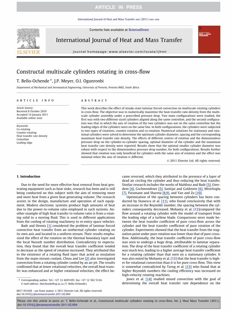
Fig. 2. Heat transfer rate density at Be = 103 as function of small diameter size andspacing between cylinders.
Table 1Grid independence study with ~Lu ¼ 4; ~Ld ¼ 7 , Be = 103 and ~S ¼ 1.
Nodes Cells ~q ~qi�~qiþ1~qi
��� ���4013 3864 19.90 –6960 6692 19.64 0.0139665 9309 19.74 0.005
U
T
P
D
D
S
S
d
d
S
S/2
S/2
Fig. 1. Cylinders aligned along the same centreline.
T. Bello-Ochende et al. / International Journal of Heat and Mass Transfer xxx (2011) xxx–xxx 3
q000 ¼ q0
DðDþ dþ 2SÞ ð2Þ
This represents the total heat transfer rate per unit volume.The governing equations of the fluid flow for the multiscale
rotating and stationary cylinders are the conservation of mass,momentum and energy equations. The computational domain isin two dimensions as shown in Figs. 1 and 2 and the assumptions
Please cite this article in press as: T. Bello-Ochende et al., Constructal multdoi:10.1016/j.ijheatmasstransfer.2011.02.004
made with respect to its solution were given in the previoussection.
The equations, which represent the conservation of mass,momentum and energy equations are given in its dimensionlessform as
@~u@~xþ @
~v@~y¼ 0 ð3Þ
BePr
~u@~u@~xþ ~v @
~u@~y
� �¼ � @
~P@~xþr2~u ð4Þ
BePr
~u@~v@~xþ ~v @
~v@~y
� �¼ � @
~P@~yþr2 ~v ð5Þ
Be ~u@~T@~xþ ~v @
~T@~y
!¼ r2~T ð6Þ
The non-dimensionalised variables used are:
ð~x; ~y; ~dÞ ¼ ðx; y; dÞD
; ð~u; ~vÞ ¼ ðu;vÞDPD=l
~T ¼ T � T1Tw � T1
; P ¼~P
DP
ð7Þ
where the Bejan and Prandtl numbers are Be ¼ DPD2=la and Pr = m/a.
The flow boundary conditions are: ~P ¼ 1 at the inlet plane, andzero normal stress at the outlet plane. The thermal boundary con-ditions are ~T ¼ 0 at the inlet plane and ~T ¼ 1 on the cylinders sur-faces. The upper and lower horizontal surfaces of the domaincorrespond to periodic conditions due to the rotations of the mul-ti-scale cylinders. The cylinders are rotating at ~x, and therefore anangular velocity is imposed as a boundary condition on the cylin-der surfaces,
~x ¼ xl2DP
ð8Þ
The objective function (i.e. heat transfer rate density), Eq. (2), can bewritten in dimensionless form as
~q ¼ q000D2
kðTw � T1Þ¼ 1
ð1þ ~dþ 2~SÞ
Z 2p
0�r~T þ dð�r~TÞnh i
dh ð9Þ
3. Numerical method and grid analysis
A finite volume, computational fluid dynamics code [18] wasemployed to solve Eqs. (3)–(6). The domain was discretised usinga second-order discretisation scheme. The pressure–velocity cou-pling was done with the SIMPLE algorithm. Numerical convergencecan be obtained in two ways, firstly, convergence was obtainedwhen the scaled residuals for mass and momentum equationswere smaller than 10�4 and the energy residual was less than10�7. In the second option, numerical convergence was obtainedwhen there was no further change in the value of residuals for con-secutive iterations in terms of the specified criteria such as conser-vation of mass flow rate in the domain.
iscale cylinders rotating in cross-flow, Int. J. Heat Mass Transfer (2011),
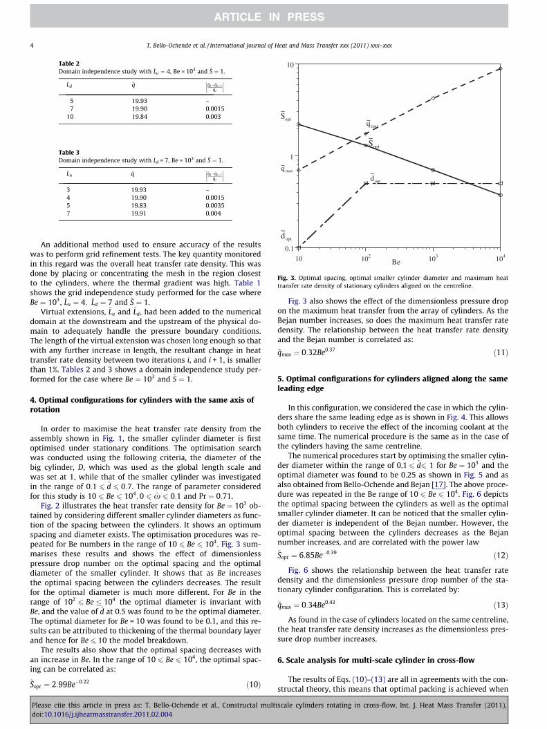
Table 2Domain independence study with ~Lu ¼ 4, Be = 103 and ~S ¼ 1.
Ld ~q ~qi�~qiþ1~qi
��� ���5 19.93 –7 19.90 0.0015
10 19.84 0.003
Table 3Domain independence study with Ld = 7, Be = 103 and ~S ¼ 1.
Lu ~q ~qi�~qiþ1~qi
��� ���3 19.93 –4 19.90 0.00155 19.83 0.00357 19.91 0.004
0.1
1
10
10 102 103 104
optS~
maxq~
optd~
optd~
optS~
maxq~
Be
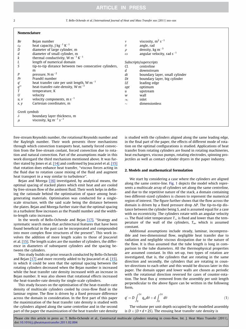
Fig. 3. Optimal spacing, optimal smaller cylinder diameter and maximum heattransfer rate density of stationary cylinders aligned on the centreline.
4 T. Bello-Ochende et al. / International Journal of Heat and Mass Transfer xxx (2011) xxx–xxx
An additional method used to ensure accuracy of the resultswas to perform grid refinement tests. The key quantity monitoredin this regard was the overall heat transfer rate density. This wasdone by placing or concentrating the mesh in the region closestto the cylinders, where the thermal gradient was high. Table 1shows the grid independence study performed for the case whereBe ¼ 103, ~Lu ¼ 4; ~Ld ¼ 7 and ~S ¼ 1.
Virtual extensions, ~Lu and ~Ld, had been added to the numericaldomain at the downstream and the upstream of the physical do-main to adequately handle the pressure boundary conditions.The length of the virtual extension was chosen long enough so thatwith any further increase in length, the resultant change in heattransfer rate density between two iterations i, and i + 1, is smallerthan 1%. Tables 2 and 3 shows a domain independence study per-formed for the case where Be ¼ 103 and ~S ¼ 1.
4. Optimal configurations for cylinders with the same axis ofrotation
In order to maximise the heat transfer rate density from theassembly shown in Fig. 1, the smaller cylinder diameter is firstoptimised under stationary conditions. The optimisation searchwas conducted using the following criteria, the diameter of thebig cylinder, D, which was used as the global length scale andwas set at 1, while that of the smaller cylinder was investigatedin the range of 0:1 6 ~d 6 0:7. The range of parameter consideredfor this study is 10 6 Be 6 104;0 6 ~x 6 0:1 and Pr ¼ 0:71.
Fig. 2 illustrates the heat transfer rate density for Be ¼ 103 ob-tained by considering different smaller cylinder diameters as func-tion of the spacing between the cylinders. It shows an optimumspacing and diameter exists. The optimisation procedures was re-peated for Be numbers in the range of 10 6 Be 6 104. Fig. 3 sum-marises these results and shows the effect of dimensionlesspressure drop number on the optimal spacing and the optimaldiameter of the smaller cylinder. It shows that as Be increasesthe optimal spacing between the cylinders decreases. The resultfor the optimal diameter is much more different. For Be in therange of 102
6 Be � 104 the optimal diameter is invariant withBe, and the value of ~d at 0.5 was found to be the optimal diameter.The optimal diameter for Be = 10 was found to be 0.1, and this re-sults can be attributed to thickening of the thermal boundary layerand hence for Be 6 10 the model breakdown.
The results also show that the optimal spacing decreases withan increase in Be. In the range of 10 6 Be 6 104, the optimal spac-ing can be correlated as:
~Sopt ¼ 2:99Be�0:22 ð10Þ
Please cite this article in press as: T. Bello-Ochende et al., Constructal multdoi:10.1016/j.ijheatmasstransfer.2011.02.004
Fig. 3 also shows the effect of the dimensionless pressure dropon the maximum heat transfer from the array of cylinders. As theBejan number increases, so does the maximum heat transfer ratedensity. The relationship between the heat transfer rate densityand the Bejan number is correlated as:
~qmax ¼ 0:32Be0:37 ð11Þ
5. Optimal configurations for cylinders aligned along the sameleading edge
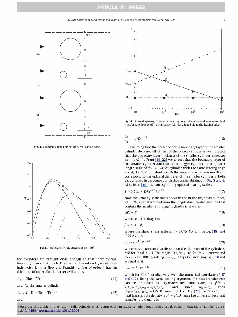
In this configuration, we considered the case in which the cylin-ders share the same leading edge as is shown in Fig. 4. This allowsboth cylinders to receive the effect of the incoming coolant at thesame time. The numerical procedure is the same as in the case ofthe cylinders having the same centreline.
The numerical procedures start by optimising the smaller cylin-der diameter within the range of 0.1 6 ~d6 1 for Be ¼ 103 and theoptimal diameter was found to be 0.25 as shown in Fig. 5 and asalso obtained from Bello-Ochende and Bejan [17]. The above proce-dure was repeated in the Be range of 10 6 Be 6 104. Fig. 6 depictsthe optimal spacing between the cylinders as well as the optimalsmaller cylinder diameter. It can be noticed that the smaller cylin-der diameter is independent of the Bejan number. However, theoptimal spacing between the cylinders decreases as the Bejannumber increases, and are correlated with the power law~Sopt ¼ 6:85Be�0:39 ð12Þ
Fig. 6 shows the relationship between the heat transfer ratedensity and the dimensionless pressure drop number of the sta-tionary cylinder configuration. This is correlated by:
~qmax ¼ 0:34Be0:43 ð13Þ
As found in the case of cylinders located on the same centreline,the heat transfer rate density increases as the dimensionless pres-sure drop number increases.
6. Scale analysis for multi-scale cylinder in cross-flow
The results of Eqs. (10)–(13) are all in agreements with the con-structal theory, this means that optimal packing is achieved when
iscale cylinders rotating in cross-flow, Int. J. Heat Mass Transfer (2011),
6.2
6.4
6.6
6.8
7
7.2
7.4
S0.3 0.4 0.5 0.6 0.7 0.8~
q~
Fig. 5. Heat transfer rate density at Be = 103.
0.1
1
10
102
10 102 103 104
Be
optd~
maxq~
optS~
optS~
optd~
maxq~
Fig. 6. Optimal spacing, optimal smaller cylinder diameter and maximum heattransfer rate density of the stationary cylinder aligned along the leading edge.
U∞
T∞
∆P
D
D
S
S
d
d
S
S/2
S/2
Fig. 4. Cylinders aligned along the same leading edge.
T. Bello-Ochende et al. / International Journal of Heat and Mass Transfer xxx (2011) xxx–xxx 5
the cylinders are brought close enough so that their thermalboundary layers just touch. The thermal boundary layers of a cyl-inder with laminar flow and Prandtl number of order 1 has thethickness of order, for the larger cylinder as
dDt � DRe�1=2Pr�1=3 ð14Þ
and, for the smaller cylinder
ddt � d1=2D�1=2Re�1=2Pr�1=3 ð15Þ
and
Please cite this article in press as: T. Bello-Ochende et al., Constructal multdoi:10.1016/j.ijheatmasstransfer.2011.02.004
dDt
ddt� ðd=DÞ�1=2 ð16Þ
Assuming that the presence of the boundary layer of the smallercylinder does not affect that of the bigger cylinder we can predictthat the boundary layer thickness of the smaller cylinder increasesas � ðd=DÞ1=2. From [19–22] we expect that the boundary layer ofthe smaller cylinder and that of the bigger cylinder to merge at alength scale of d=D � 1=4 for cylinder with the same leading edgeand d=D � 1=2 for cylinder with the same centre of rotation. Thesecorrespond to the optimal diameter of the smaller cylinder in bothcase and are in agreement with the results obtained in Fig. 3 and 6.Also, from [19] the corresponding optimal spacing scale as
S � 0:5dDt � DRe�1=2Pr�1=3 ð17Þ
Now the velocity scale that appear in the in the Reynolds number,Re ¼ UD=m is determined from the longitudinal control volume thatcontain the smaller and bigger cylinder is given as
DPS � F ð18Þ
where F is the drag force
f � sðDþ dÞ ð19Þ
where the shear stress scale is s � lU=S. Combining Eq. (18) and(19) we find
Re � eBe1=2Pr�5=6 ð20Þ
where e is a constant that depend on the diameter of the cylinders,and for D > d, e � 1. The range 10 6 Be 6 104 for Pr � 1, correspondto 2 6 Re 6 100. By setting S � Sopt in Eq. (17) and using Eq. (20) andwe find that
~S � Be�1=4Pr�1=12 ð21Þ
which for Pr � 1 predict very well the numerical correlation (10)and (12). Using the same scaling argument the heat transfer ratecan be predicted. The cylinders heat flux scales as qPrime �kðTw � T1ÞðdDt þ ddtÞ=dDtddt , and since dDt � ddt thenðdDt þ ddtÞ=dDtddt � 1=S. Because S < D, cf. Eq. (21) for Be >> 1, theheat transfer rate density is q000 � q00=D hence the dimensionless heattransfer rate density is
iscale cylinders rotating in cross-flow, Int. J. Heat Mass Transfer (2011),
3
5 = 0 = 0.005 = 0.01 = 0.05 = 0.1
ω~ω~ω~
ω~ω~
6 T. Bello-Ochende et al. / International Journal of Heat and Mass Transfer xxx (2011) xxx–xxx
~q � q000D2
kðTwT1Þ� Be1=4Pr1=12 ð22Þ
and for Pr � 1, this prediction agrees with the numerical optimiza-tion obtain from Eqs. (11) and (13).
0.6
0.8
1
optS~
7. Effects of rotation on cylinders with the same axis of rotation
For this configuration simulations were conducted while thediameter of the smaller cylinder was kept constant at ~dopt ¼ 0:5while rotating the cylinders at different angular velocities. In thissection, the effects of rotation on the heat transfer rate densityare considered.
0.4
10 102 103 104Be
Fig. 8. Optimal spacing for co-rotating cylinders ð~dopt ¼ 0:5Þ as function of Bejannumber.
1
10
= 0 = 0.01
max~q
ω~
ω~
7.1. Co-rotation
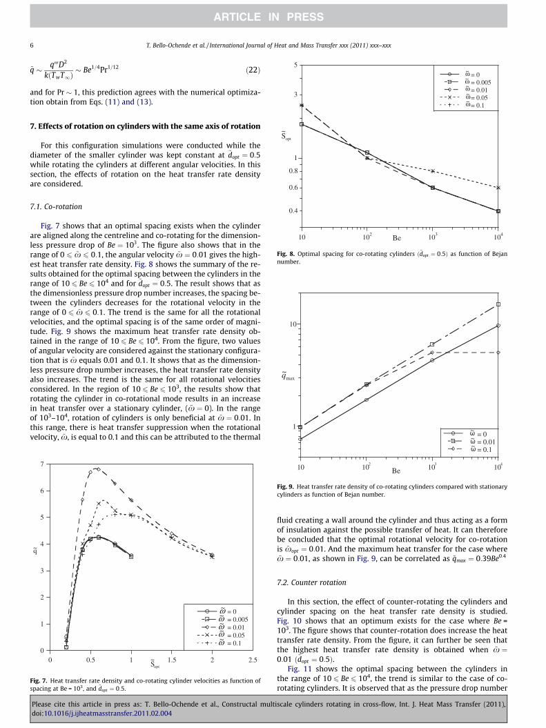
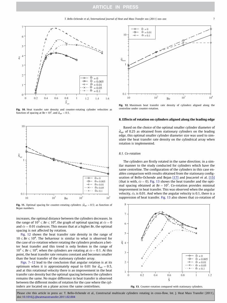
Fig. 7 shows that an optimal spacing exists when the cylinderare aligned along the centreline and co-rotating for the dimension-less pressure drop of Be ¼ 103. The figure also shows that in therange of 0 6 ~x 6 0:1, the angular velocity ~x ¼ 0:01 gives the high-est heat transfer rate density. Fig. 8 shows the summary of the re-sults obtained for the optimal spacing between the cylinders in therange of 10 6 Be 6 104 and for ~dopt ¼ 0:5. The result shows that asthe dimensionless pressure drop number increases, the spacing be-tween the cylinders decreases for the rotational velocity in therange of 0 6 ~x 6 0:1. The trend is the same for all the rotationalvelocities, and the optimal spacing is of the same order of magni-tude. Fig. 9 shows the maximum heat transfer rate density ob-tained in the range of 10 6 Be 6 104. From the figure, two valuesof angular velocity are considered against the stationary configura-tion that is ~x equals 0.01 and 0.1. It shows that as the dimension-less pressure drop number increases, the heat transfer rate densityalso increases. The trend is the same for all rotational velocitiesconsidered. In the region of 10 6 Be 6 103, the results show thatrotating the cylinder in co-rotational mode results in an increasein heat transfer over a stationary cylinder, ( ~x ¼ 0). In the rangeof 103–104, rotation of cylinders is only beneficial at ~x ¼ 0:01. Inthis range, there is heat transfer suppression when the rotationalvelocity, ~x, is equal to 0.1 and this can be attributed to the thermal
0
1
2
3
4
5
6
7
= 0 = 0.005 = 0.01 = 0.05 = 0.1
optS0 0.5 1 1.5 2 2.5~
q~
ω~ω~ω~ω~ω~
Fig. 7. Heat transfer rate density and co-rotating cylinder velocities as function ofspacing at Be = 103, and ~dopt ¼ 0:5.
10 102
103
10 4
= 0.1
Be
ω~
Fig. 9. Heat transfer rate density of co-rotating cylinders compared with stationarycylinders as function of Bejan number.
Please cite this article in press as: T. Bello-Ochende et al., Constructal multdoi:10.1016/j.ijheatmasstransfer.2011.02.004
fluid creating a wall around the cylinder and thus acting as a formof insulation against the possible transfer of heat. It can thereforebe concluded that the optimal rotational velocity for co-rotationis ~xopt ¼ 0:01. And the maximum heat transfer for the case where~x ¼ 0:01, as shown in Fig. 9, can be correlated as ~qmax ¼ 0:39Be0:4
7.2. Counter rotation
In this section, the effect of counter-rotating the cylinders andcylinder spacing on the heat transfer rate density is studied.Fig. 10 shows that an optimum exists for the case where Be =103. The figure shows that counter-rotation does increase the heattransfer rate density. From the figure, it can further be seen thatthe highest heat transfer rate density is obtained when ~x ¼0:01 ð~dopt ¼ 0:5Þ.
Fig. 11 shows the optimal spacing between the cylinders inthe range of 10 6 Be 6 104, the trend is similar to the case of co-rotating cylinders. It is observed that as the pressure drop number
iscale cylinders rotating in cross-flow, Int. J. Heat Mass Transfer (2011),
0
1
2
3
4
5
6
7
0 0.2 0.4 0.6 0.8 1 1.2 1.4 1.6
= 0 = 0.005 = 0.01 = 0.05 = 0.1
optS~
q~
ω~ω~ω~ω~ω~
Fig. 10. Heat transfer rate density and counter-rotating cylinder velocities asfunction of spacing at Be = 103, and ~dopt ¼ 0:5.
0.1
1
10
10 102 103 104
= 0 = 0.005 = 0.01 = 0.05 = 0.1
Be
optS~
ω~ω~ω~ω~ω~
Fig. 11. Optimal spacing for counter-rotating cylinders ð~dopt ¼ 0:5Þ as function ofBejan numbers.
0.1
1
10
10 102 103 104
= 0 = 0.01 = 0.1
maxq~
Be
ω~ω~ω~
Fig. 12. Maximum heat transfer rate density of cylinders aligned along thecentreline under counter-rotation.
1
2
3
4
5
6
7
8
= 0 = 0.005 = 0.01 = 0.05 = 0.1
S
0 0.2 0.4 0.6 0.8 1 1.2 ~
q~
ω~ω~ω~ω~ω~
Fig. 13. Counter-rotation compared with stationary cylinders.
T. Bello-Ochende et al. / International Journal of Heat and Mass Transfer xxx (2011) xxx–xxx 7
increases, the optimal distance between the cylinders decreases. Inthe range of 103
6 Be 6 104, the graph of optimal spacing at ~x ¼ 0and ~x ¼ 0:01 coalesces. This means that at a higher Be, the optimalspacing is not affected by rotation.
Fig. 12 shows the heat transfer rate density in the range of10 6 Be 6 104. The behaviour is similar to what is observed forthe case of co-rotation where rotating the cylinders produces a bet-ter heat transfer and this trend is only broken in the range of1036 Be 6 104, when the cylinders are rotating at ~x ¼ 0:1. At this
point, the heat transfer rate remains constant and becomes smallerthan the heat transfer of the stationary cylinder array.
Figs. 7–12 lead to the conclusion that angular rotation is at itsoptimum when it is approximately equal to 0.01 for ~dopt ¼ 0:5,and at this rotational velocity there is an improvement in the heattransfer rate density but the optimal spacing between the cylindersremains the same. No major difference in heat transfer is observedbetween the different modes of rotation for the case where the cyl-inders are located on a plane across the same centrelines.
Please cite this article in press as: T. Bello-Ochende et al., Constructal multdoi:10.1016/j.ijheatmasstransfer.2011.02.004
8. Effects of rotation on cylinders aligned along the leading edge
Based on the choice of the optimal smaller cylinder diameter of~dopt of 0.25 as obtained from stationary cylinders on the leadingedge, this optimal smaller cylinder diameter size was used to sim-ulate the heat transfer rate density on the cylindrical array whenrotation is implemented.
8.1. Co-rotation
The cylinders are firstly rotated in the same direction; in a sim-ilar manner to the study conducted for cylinders which have thesame centreline. The configuration of the cylinders in this case en-ables comparison with results obtained from the stationary config-uration of Bello-Ochende and Bejan [17] and Joucaviel et al. [15](that is with, ~x ¼ 0). Fig. 13 shows the heat transfer and the opti-mal spacing obtained at Be ¼ 103. Co-rotation provides minimalimprovement in heat transfer. This was observed when the angularvelocity, ~x, is 0.01. And when the angular velocity is 0.1, there is asuppression of heat transfer. Fig. 13 also shows that co-rotation of
iscale cylinders rotating in cross-flow, Int. J. Heat Mass Transfer (2011),
0.1
1
10
10 102
103
10 4
= 0 = 0.005 = 0.01 = 0.05 = 0.1
optS~
Be
ω~ω~ω~ω~ω~
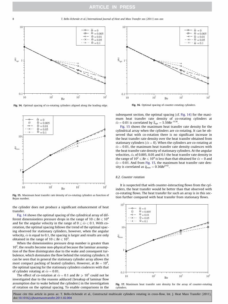
Fig. 14. Optimal spacing of co-rotating cylinders aligned along the leading edge.
1
10
10 102
103
10 4
= 0 = 0.005 = 0.01 = 0.05 = 0.1
maxq~
ω~ω~ω~ω~ω~
Be
Fig. 15. Maximum heat transfer rate density of co-rotating cylinders as function ofBejan number.
0.1
1
10
10 102
103
10 4
= 0 = 0.005 = 0.01 = 0.05 = 0.1
optS~
Be
ω~ω~ω~ω~
ω~
Fig. 16. Optimal spacing of counter-rotating cylinders.
0.1
1
10
10 2
10 102 103 10 4
= 0 = 0.005 = 0.01 = 0.05 = 0.1
Be
maxq~
ω~ω~
ω~
ω~ω~
Fig. 17. Maximum heat transfer rate density for the array of counter-rotatingcylinders.
8 T. Bello-Ochende et al. / International Journal of Heat and Mass Transfer xxx (2011) xxx–xxx
the cylinder does not produce a significant enhancement of heattransfer.
Fig. 14 shows the optimal spacing of the cylindrical array of dif-ferent dimensionless pressure drops in the range of 10 6 Be 6 104
and for the angular velocity in the range of 0 � ~x 6 0:1. With co-rotation, the optimal spacing follows the trend of the optimal spac-ing observed for stationary cylinders, however, when the angularvelocity, ~x is equal to 0.1, the spacing is larger and results are onlyobtained in the range of 10 6 Be 6 103.
When the dimensionless pressure drop number is greater than103, the results become non-physical because the laminar assump-tion of the flow disintegrates due to the wake and consequent tur-bulence, which dominates the flow behind the rotating cylinders. Itcan be seen that in general the stationary cylinder array allows themost compact packing of heated cylinders. However, at Be ¼ 104,the optimal spacing for the stationary cylinders coalesces with thatof cylinder rotating at ~x ¼ 0:01.
The effect of co-rotation at ~x ¼ 0:1 and Be P 103 could not beinvestigated due to the reasons adduced (breakup of laminar flowassumption due to wake behind the cylinders) in the investigationof rotation on the optimal spacing. To enable comparisons in the
Please cite this article in press as: T. Bello-Ochende et al., Constructal multdoi:10.1016/j.ijheatmasstransfer.2011.02.004
subsequent section, the optimal spacing (cf. Fig. 14) for the maxi-mum heat transfer rate density of co-rotating cylinders at~x ¼ 0:01 is correlated by ~Sopt ¼ 5:59Be�0:36.
Fig. 15 shows the maximum heat transfer rate density for thecylindrical array when the cylinders are co-rotating. It can be ob-served that with co-rotation there is no significant increase inthe heat transfer rate density over the heat transfer obtained fromstationary cylinders ( ~x ¼ 0). When the cylinders are co-rotating at~x ¼ 0:01, the maximum heat transfer rate density coalesces withthe heat transfer rate density of stationary cylinders. At the angularvelocities, ~x, of 0.005, 0.05 and 0.1 the heat transfer rate density inthe range of 102
6 Be 6 104 is less than that obtained for ~x ¼ 0 and~x ¼ 0:01. And from Fig. 15, the maximum heat transfer rate den-sity is correlated as ~qmax ¼ 0:36Be0:42.
8.2. Counter rotation
It is suspected that with counter-interacting flows from the cyl-inders, the heat transfer would be better than that observed withco-rotating flows. The heat transfer for such an array is in this sec-tion further compared with heat transfer from stationary flows.
iscale cylinders rotating in cross-flow, Int. J. Heat Mass Transfer (2011),
0.1
1
10
102
10 102 103 104
= 0 = 0.01 = 0 = 0.01
maxq ~
Be
CLω~
CLω~
LEω~
LEω~
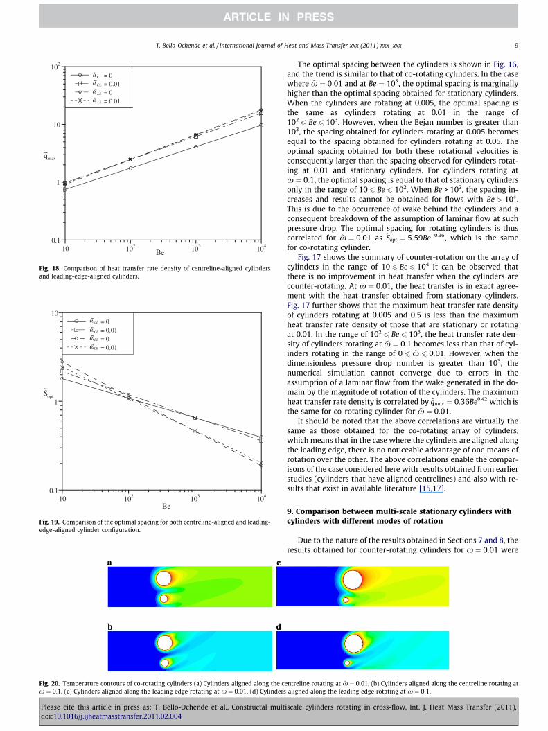
Fig. 18. Comparison of heat transfer rate density of centreline-aligned cylindersand leading-edge-aligned cylinders.
0.1
1
10
10 102 103 104
= 0 = 0.01 = 0 = 0.01
optS~
Be
LEω~
CLω~
CLω~
LEω~
Fig. 19. Comparison of the optimal spacing for both centreline-aligned and leading-edge-aligned cylinder configuration.
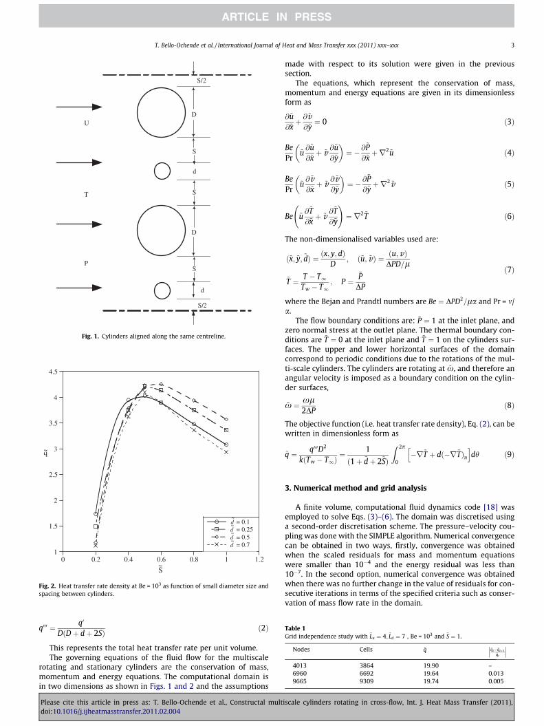
Fig. 20. Temperature contours of co-rotating cylinders (a) Cylinders aligned along the ce~x ¼ 0:1, (c) Cylinders aligned along the leading edge rotating at ~x ¼ 0:01, (d) Cylinders
T. Bello-Ochende et al. / International Journal of Heat and Mass Transfer xxx (2011) xxx–xxx 9
Please cite this article in press as: T. Bello-Ochende et al., Constructal multdoi:10.1016/j.ijheatmasstransfer.2011.02.004
The optimal spacing between the cylinders is shown in Fig. 16,and the trend is similar to that of co-rotating cylinders. In the casewhere ~x ¼ 0:01 and at Be ¼ 103, the optimal spacing is marginallyhigher than the optimal spacing obtained for stationary cylinders.When the cylinders are rotating at 0.005, the optimal spacing isthe same as cylinders rotating at 0.01 in the range of1026 Be 6 103. However, when the Bejan number is greater than
103, the spacing obtained for cylinders rotating at 0.005 becomesequal to the spacing obtained for cylinders rotating at 0.05. Theoptimal spacing obtained for both these rotational velocities isconsequently larger than the spacing observed for cylinders rotat-ing at 0.01 and stationary cylinders. For cylinders rotating at~x ¼ 0:1, the optimal spacing is equal to that of stationary cylindersonly in the range of 10 6 Be 6 102. When Be > 102, the spacing in-creases and results cannot be obtained for flows with Be > 103.This is due to the occurrence of wake behind the cylinders and aconsequent breakdown of the assumption of laminar flow at suchpressure drop. The optimal spacing for rotating cylinders is thuscorrelated for ~x ¼ 0:01 as ~Sopt ¼ 5:59Be�0:36, which is the samefor co-rotating cylinder.
Fig. 17 shows the summary of counter-rotation on the array ofcylinders in the range of 10 6 Be 6 104 It can be observed thatthere is no improvement in heat transfer when the cylinders arecounter-rotating. At ~x ¼ 0:01, the heat transfer is in exact agree-ment with the heat transfer obtained from stationary cylinders.Fig. 17 further shows that the maximum heat transfer rate densityof cylinders rotating at 0.005 and 0.5 is less than the maximumheat transfer rate density of those that are stationary or rotatingat 0.01. In the range of 102
6 Be 6 103, the heat transfer rate den-sity of cylinders rotating at ~x ¼ 0:1 becomes less than that of cyl-inders rotating in the range of 0 6 ~x 6 0:01. However, when thedimensionless pressure drop number is greater than 103, thenumerical simulation cannot converge due to errors in theassumption of a laminar flow from the wake generated in the do-main by the magnitude of rotation of the cylinders. The maximumheat transfer rate density is correlated by ~qmax ¼ 0:36Be0:42 which isthe same for co-rotating cylinder for ~x ¼ 0:01.
It should be noted that the above correlations are virtually thesame as those obtained for the co-rotating array of cylinders,which means that in the case where the cylinders are aligned alongthe leading edge, there is no noticeable advantage of one means ofrotation over the other. The above correlations enable the compar-isons of the case considered here with results obtained from earlierstudies (cylinders that have aligned centrelines) and also with re-sults that exist in available literature [15,17].
9. Comparison between multi-scale stationary cylinders withcylinders with different modes of rotation
Due to the nature of the results obtained in Sections 7 and 8, theresults obtained for counter-rotating cylinders for ~x ¼ 0:01 were
ntreline rotating at ~x ¼ 0:01, (b) Cylinders aligned along the centreline rotating ataligned along the leading edge rotating at ~x ¼ 0:1.
iscale cylinders rotating in cross-flow, Int. J. Heat Mass Transfer (2011),
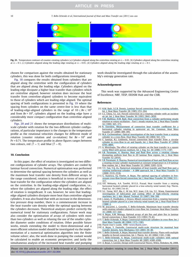
Fig. 21. Temperature contours of counter-rotating cylinders (a) Cylinders aligned along the centreline rotating at ~x ¼ 0:01, (b) Cylinders aligned along the centreline rotatingat ~x ¼ 0:1, (c) Cylinders aligned along the leading edge rotating at ~x ¼ 0:01, (d) Cylinders aligned along the leading edge rotating at ~x ¼ 0:1.
10 T. Bello-Ochende et al. / International Journal of Heat and Mass Transfer xxx (2011) xxx–xxx
chosen for comparison against the results obtained for stationarycylinders, this was done for both configurations investigated.
Fig. 18 compares the results obtained from cylinders that arealigned along the centreline with the configuration of cylindersthat are aligned along the leading edge. Cylinders aligned on theleading edge dissipate a higher heat transfer than cylinders whichare centreline aligned, however rotation does increase the heattransfer from centreline-aligned cylinders to become equivalentto those of cylinders which are leading edge aligned. The optimalspacing of both configurations is presented in Fig. 19 where thespacing from cylinders on the same centre-line is less than thatof leading-edge-aligned cylinders in the range of 10 6 Be 6 102
and from Be > 102, cylinders aligned on the leading edge have aconsiderably more compact configuration than centreline-alignedcylinders.
Figs. 20 and 21 shows the temperature distributions of multi-scale cylinder with rotation for the two different cylinder configu-rations, of particular importance is the changes in the temperatureprofile as the rotational velocities changes for different mode ofrotation (counter rotation and co-rotation) for Be ¼ 103 andPr = 0.71. The temperature profile in above figures ranges betweentwo colours, red ð~T ¼ 1Þ and blue (~T ¼ 0).
10. Conclusion
In this paper, the effect of rotation is investigated on two differ-ent configurations of cylinder arrays. The cylinders are cooled bylaminar forced convection. Numerical optimisation was performedto determine the optimal spacing between the cylinders as well asthe maximum heat transfer rate density from different arrays. Inthe range considered, rotation is beneficial in terms of increase ofheat transfer for the configuration where the cylinders are alignedon the centreline. In the leading-edge-aligned configuration, i.e.,where the cylinders are aligned along the leading edge, the effectof rotation is insignificant. It can, however, be seen that leading-edge-aligned cylinders dissipate more heat than centreline-alignedcylinders. It was also found that with an increase in the dimension-less pressure drop number, there is a commensurate increase inthe heat transfer rate density while the optimal spacing betweenthe cylinders decreases. Theoretical analyses predict correctly thenumerical trend for stationary configurations. Future work mayalso consider the optimisation of arrays of cylinders with morethan two cylinders as well as relaxing the use of the smaller cylin-der diameter under conditions of rotation. Other possible futureworks, entails extending the model to three-dimensional and amore efficient solution model should be investigated via the imple-mentation of a numerical optimisation algorithm into the finitevolume solver; also, the work done in pumping the coolant wouldbe calculated to enable an economic perspective; and lastly thesimultaneous analysis of the increased heat transfer and pumping
Please cite this article in press as: T. Bello-Ochende et al., Constructal multdoi:10.1016/j.ijheatmasstransfer.2011.02.004
work should be investigated through the calculation of the assem-bly’s entropy generation rate.
Acknowledgement
This work was supported by the Advanced Engineering Centreof Excellence, NRF, TESP, EEDSM Hub and the CSIR.
References
[1] H.M. Badr, S.C.R. Dennis, Laminar forced convection from a rotating cylinder,Int. J. Heat Mass Transfer 28 (1985) 253–264.
[2] C.C. Chiou, S.L. Lee, Forced convection on a rotating cylinder with an incidentair jet, Int. J. Heat Mass Transfer 36 (1993) 3841–3850.
[3] F.M. Mahfouz, H.M. Badr, Heat convection from a cylinder performing steadyrotation or rotary oscillation – Part I: steady rotation, Int. J. Heat Mass Transfer34 (1999) 365–373.
[4] B. Ozerdem, Measurement of convective heat transfer coefficient for ahorizontal cylinder rotating in quiescent air, Int. Commun. Heat MassTransfer 27 (2000) 389–395.
[5] M.A. Gschwendtner, Optical investigation of the heat transfer from a rotatingcylinder in a cross-flow, Heat Mass Transfer 40 (2004) 561–572.
[6] S. Sanitjai, R.J. Goldstein, Forced convection heat transfer from a circularcylinder in cross-flow to air and liquids, Int. J. Heat Mass Transfer 47 (2004)4795–4805.
[7] A. Misirlioglu, The effect of rotating cylinder on the heat transfer in a squarecavity filled with porous medium, Int. J. Eng. Sci. 44 (2006) 1173–1187.
[8] S.B. Paramane, A. Sharma, Heat and fluid flow across a rotating cylinderdissipating uniform heat flux in 2D laminar flow regime, Int. J. Heat MassTransfer 52 (2010).
[9] S.B. Paramane, A. Sharma, Numerical investigation of heat and fluid flow acrossa rotating circular cylinder maintained at constant temperature in 2-D laminarflow regime, Int. J. Heat Mass Transfer 52 (2009) 3205–3216.
[10] Y.Y. Yan, Y.Q. Zu, Numerical simulation of heat transfer and fluid flow past arotating isothermal cylinder – A LBM approach, Int. J. Heat Mass Transfer 51(2008) 2519–2536.
[11] G. Stanescu, A.J. Fowler, A. Bejan, The optimal spacing of cylinders in free-stream cross-flow forced convection, Int. J. Heat Mass Transfer 39 (1996) 311–317.
[12] A.K. Mohanty, A.A. Tawfek, B.V.S.S. Prasad, Heat transfer from a rotatinghorizontal heated cylinder placed in a low-velocity wind tunnel, Exp. Therm.Fluid Sci. 10 (1995) 54–61.
[13] S.C. Tzeng, W.P. Ma, C. W Lin, W.Y. Jywe, C.H. Liu, Y.C. Wang, Experimentalinvestigation of lubrication and cooling effect of high-velocity rotatingmachines, Int. J. Adv. Manuf. Technol. 35 (2007) 394–399.
[14] J. Jones, D. Poulikakos, J. Orozco, Mixed convection from a rotating horizontalheated cylinder placed in a low-velocity wind tunnel, Int. J. Heat Fluid Flow 9(1988) 2.
[15] M. Joucaviel, L. Gosselin, T. Bello-Ochende, Maximum heat transfer densitywith rotating cylinders aligned in cross-flow, Int. Commun. Heat Mass Transfer35 (2008) 557–564.
[16] A. Bejan, A.M. Morega, Optimal arrays of pin fins and plate fins in laminarforced convection, J. Heat Transfer 115 (1993) 75–81.
[17] T. Bello-Ochende, A. Bejan, Constructal multiscale cylinders in cross-flow, Int. JHeat Mass Transfer 48 (2004) 1373–1383.
[18] Fluent User’s Guide, 1998 <www.fluent.com>.[19] A. Bejan, Y. Fautrelle, Constructal multi-scale structure for maximal heat
transfer density, Acta Mechanica 163 (2003) 39–49.[20] T. Bello-Ochende, A. Bejan, Maximal heat transfer density: Plates with multiple
lengths in forced convection, Int. J. Therm. Sci. 43 (2004) 1181–1186.[21] T. Bello-Ochende, A. Bejan, Constructal multi-scale cylinders with natural
convection, Int. J. Heat Mass Transfer 48 (2005) 4300–4306.[22] A. Bejan, S. Lorente, Design with Constructal Theory, Wiley, Hoboken, NJ, 2008.
iscale cylinders rotating in cross-flow, Int. J. Heat Mass Transfer (2011),
Related Documents